User Manual

BluKey Module User Manual.docx 1 5/10/2016 11:09 AM
PayRange BluKey Module
User Manual
Introduction
The turnkey PayRange payment system includes several BluKey hardware devices for making payments
with a mobile app. Consumers maintain a prepaid balance on their smartphones and use it to make
payments at a variety of machines that can include vending, amusement, parking, transit ticketing, and
laundry equipment.
BluKey Module (BK Module) provides BluKey in a form factor suitable for easy integration into latest
generation of controller boards of vending and other kinds of machines that accept payments. It
provides a low-cost additional BOM for controller board and easy future upgrade path without redesign
of the controller board.
BK Module is implemented in a form factor and complies with mini PCI Express board standard (half-
size), so existing low-cost connectors and holders can be used, though it does not use PCI bus and
instead uses lower-end interfaces for easier software integration. Typically there is no change to the
software needed (if integration is performed using UART lines for MDB).
Usage
Usage selection requires software support from Payrange application. See Payrange.com for details.
I2C
The Blukey Module can control numerous I/Os through the I2C interface. Connect one or more
port expander circuits.
UART
The Blukey Module can communicate with a host over USB or UART using the Payrange Host
Protocol Version 1.0
Logic
The Blukey module can use its own internal GPIO to control payment devices such to imitate a
coin switch.
Specification
Electrical Characteristics
Absolute Maximum Ratings
Symbol
Description
Min
Max
Unit
Notes
TSTG
Storage temperature
-40
85
°C
1
VDD
+3.3V supply
-0.3
3.8
V
VDIO
Digital input voltage
-0.3
VDD + 0.3
V
1. Determined according to JEDEC Standard JESD22-A103, High Temperature Storage Life.
BluKey Module User Manual.docx 2 5/10/2016 11:09 AM
Operating Conditions
Symbol
Description
Min
Typ
Max
Unit
TO
Operating temperature range
-30
-
85
°C
VDD
+3.3V supply voltage
3.0
3.3
3.6
V
IDD
+3.3V supply current
-
200
mA
VIL
input logic level low
-0.4
-
0.35 x VDD
V
VIH
input logic level high
0.7 x
VDD
-
VDD + 0.4
V
VOH
Output high voltage
VDD –
0.5
-
-
V
VOL
Output low voltage
-
-
0.5
V
ESD handling ratings
Symbol
Description
Min.
Max.
Unit
Notes
VHBM
Electrostatic discharge voltage, human body model
-2000
+2000
V
1
VCDM
Electrostatic discharge voltage, charged-device
model
-500
+500
V
2
ILAT
Latch-up current at ambient temperature of 105°C
-100
+100
mA
3
1. Determined according to JEDEC Standard JESD22-A114, Electrostatic Discharge (ESD) Sensitivity
Testing Human Body Model (HBM).
2. Determined according to JEDEC Standard JESD22-C101, Field-Induced Charged-Device Model
Test Method for Electrostatic-Discharge-Withstand Thresholds of Microelectronic Components.
3. Determined according to JEDEC Standard JESD78, IC Latch-Up Test.
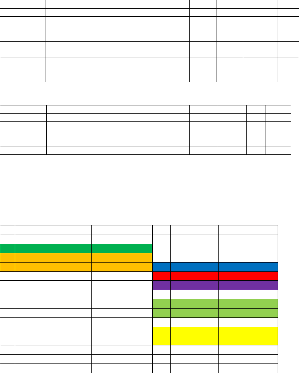
Connector Pinout
BK Module connector is standard 52-pin mini PCI Express edge connector.
Pin
Name
Type
Pin
Name
Type
51
SATA Presence Detection
output, NC
52
+3.3V
power
49
Button
Input
50
GND
power
47
GPIO2
in/out
48
+1.5V
power
45
GPIO1
in/out
46
LED_Blue
output, open drain
43
PCIe Presence Detection
output, NC
44
LED_Red
output, open drain
41
+3.3V
power
42
LED_Option
output, open drain
39
+3.3V
power
40
GND
power
37
GND
power
38
USB_D+
in/out
35
GND
power
36
USB_D-
in/out
33
Reserved
NC
34
GND
power
31
Reserved
NC
32
I2C_SDA
in/out
29
GND
power
30
I2C_SCL
output, open drain
27
GND
power
28
+1.5V
power
25
Reserved
NC
26
GND
power
23
Reserved
NC
24
+3.3V
power

BluKey Module User Manual.docx 3 5/10/2016 11:09 AM
21
GND
power
22
[PERST#]
input
19
UART_AUX_TxD
output
20
[W_DISABLE#]
input
17
UART_AUX_RxD
input
18
GND
power
Mechanical Key
15
GND
power
16
Reserved
NC
13
Reserved
NC
14
Reserved
NC
11
Reserved
NC
12
Reserved
NC
9
GND
power
10
Reserved
NC
7
[CLKREQ#]
output, open drain
8
Reserved
NC
5
UART_TxD
output
6
+1.5V
power
3
UART_RxD
input
4
GND
power
1
[WAKE#]
output, open drain
2
+3.3V
power
Host Device Design Requirements
All signals are in +3.3V domain.
The following table lists requirements for each pin.
Pin
Notes
Pin
Notes
51
NC, detect mSATA if GND
52
+3.3V
49
Optional, connect to a button dedicated to BK
function (other end to GND), mSATA: DA/DSS
50
GND
47
NC, Vendor (mSATA)
48
+1.5V
45
NC, Vendor (mSATA)
46
Optional, Blue LED for BK status, max
9mA, Vol 400mV
43
NC, detect mini PCIe if GND
44
Optional, Red LED for BK status, max
9mA, Vol 400mV
41
+3.3V
42
Optional, LED 3 for BK status, max
9mA, Vol 400mV
39
+3.3V
40
GND
37
GND
38
USB_D+ master / hub
35
GND
36
USB_D- master / hub
33
NC, PETp0 (PCIe), +A (mSATA)
34
GND
31
NC, PETn0 (PCIe), -A (mSATA)
32
Optional, I2C_SDA (slaves only),
provide pullup*
29
GND
30
Optional, I2C_SCL (slaves only),
provide pullup*
27
GND
28
+1.5V
25
NC, PERp0 (PCIe), -B (mSATA)
26
GND
23
NC, PERn0 (PCIe), +B (mSATA)
24
+3.3V
21
GND
22
Optional, PERST# (PCIe), NC (mSATA)
19
NC or 2nd MDB, UIM_IC_DP (PCIe)
20
Optional, W_DISABLE1# (PCIe), NC
(mSATA)
17
NC or 2nd MDB, UIM_IC_DM (PCIe)
18
GND
BluKey Module User Manual.docx 4 5/10/2016 11:09 AM
Mechanical Key
15
GND
16
NC, UIM_SPU/C6 (PCIe)
13
NC, REFCLK+ (PCIe)
14
NC, UIM_RESET/C2 (PCIe)
11
NC, REFCLK- (PCIe)
12
NC, UIM_CLK/C3 (PCIe)
9
GND
10
NC, UIM_DATA (PCIe)
7
Optional, CLKREQ# (PCIe, handshake for
PERST#), NC (mSATA)
8
NC, UIM_PWR/C1 (PCIe)
5
MDB master RxD/input
6
+1.5V
3
MDB master TxD/output
4
GND
1
WAKE# (BK, PCIe), NC (mSATA)
2
+3.3V
Notes:
Host should provide +3.3V power in low power / stand-by / suspend state.
Host may not provide +1.5V power in the low power state. BK Module does not use +1.5V.
Host must provide I2C pullups (can be to +3.3V or 5V). BK Module is a master, but it is capable of
5V I/O on I2C Bus.
Blue and Red LEDs, if implemented, should be co-located (preferably in a single device), as BK
Module may use the combination color (Magenta).
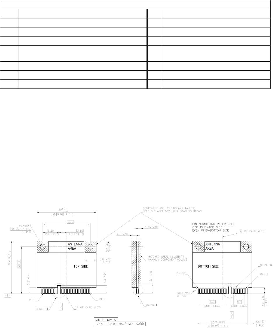
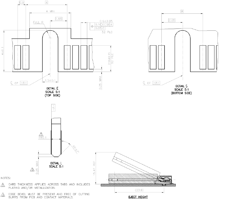
Mechanical
BK Module dimensions are the same as standard mini PCI Express half-size card, see below (RF
connector and antenna are not shown).
BluKey Module User Manual.docx 5 5/10/2016 11:09 AM
System Integration
BK Module should be placed optimally with regard to RF performance of its antenna. BK Module should
be placed so that its antenna area is near the edge of the controller board and is not obstructed by
metal and conductive parts, shields and cables.
BK Module connector requires connection to GND and 3.3V power supply and logical connection to CPU
on the controller board.
There are few ways to connect BK Module to the CPU on the controller board, with #1 being the
recommended method:
1. Use UART (3.3V domain signals)
2. Use SMB Bus (or I2C bus). This method requires special BK Module firmware.
3. Use USB bus. This method requires BK Module with USB option.
The above connections are sufficient to fully enable BK Module for operation in PayRange system. Few
other options are provided for further level of integration:
A. BK Module RF Interface – Internal Bluetooth antenna. The RF connector is only intended for
manufacturing test.
B. BK Module User interface – LEDs and button. If mechanical integration blocks service access to
BK Module LEDs and / or button, controller board may provide LEDs and/or button to mirror BK
Module indication and replacement button control.
BluKey Module User Manual.docx 6 5/10/2016 11:09 AM
C. Aux UART – BK Module with slave port option can support secondary devices (e.g. credit card
reader interface).
D. BK Module reset. If controller board should be able to reset its peripherals (e.g. for entering
service mode without power cycle), BK Module reset should be connected to controller board
reset line.
E. BK Module radio disable. If controller board should be able to disable all RF transmissions, BK
Module radio disable should be connected to corresponding controller board line. An alternative
soft command could be defined in customized BK Module firmware.
F. GPIO lines – for custom functionality (e.g. mechanical controls, or coin collector counter), BK
Module can support additional functions with customized firmware.
G. I2C interface – additional peripherals can be accessed by BK Module with customized firmware.
Please inquire with PayRange support for custom options.
United States FCC Requirements
Labeling
The BK Module has been labeled with its own FCC ID number, and if the FCC ID is not visible when the
module is installed inside another device, then the outside of the finished product into which the
module is installed must also display a label referring to the enclosed module. This exterior label can use
wording as follows:
Contains Transmitter Module FCC ID: 2AF78-00370 or Contains FCC ID: 2AF78-00370
User Manual
The User Manual must contain the following:
This device complies with Part 15 of the FCC Rules.
Operation is subject to the following two conditions:
(1) this device may not cause harmful interference, and
(2) this device must accept any interference received, including interference that may cause
undesired operation This equipment has been tested and found to comply with the limits for a
Class B digital device, pursuant to part 15 of the FCC Rules.
These limits are designed to provide reasonable protection against harmful interference in a
residential installation. This equipment generates, uses and can radiate radio frequency energy,
and if not installed and used in accordance with the instructions, may cause harmful
interference to radio communications. However, there is no guarantee that interference will not
occur in a particular installation. If this equipment does cause harmful interference to radio or
television reception, which can be determined by turning the equipment off and on, the user is
encouraged to try to correct the interference by one or more of the following measures:
• Reorient or relocate the receiving antenna.
• Increase the separation between the equipment and receiver.

BluKey Module User Manual.docx 7 5/10/2016 11:09 AM
• Connect the equipment into an outlet on a circuit different from that to which the receiver is
connected.
• Consult the dealer or an experienced radio/TV technician for help.
CAUTION: Per FCC 15.21, changes or modifications not expressly approved by the party
responsible for compliance could void the user's authority to operate the equipment.
RF EXPOSURE
The BluKey Module is certified as a modular transmitter device for integration into fixed products under
the following conditions:
1. The antenna(s) must be installed such that a minimum separation distance of 20cm is
maintained between the radiator (antenna) and all persons at all times.
2. The transmitter module must not be co-located or operating in conjunction with any other
antenna or transmitter.
As long as the two conditions above are met, further transmitter testing will not be required. However,
the OEM integrator is still responsible for testing their end-product for any additional compliance
requirements required with this module installed (for example, digital device emissions, PC peripheral
requirements, etc.). IMPORTANT NOTE: In the event that these conditions cannot be met (for certain
configurations or co-location with another transmitter), then the FCC and Industry Canada
authorizations are no longer considered valid and the FCC ID and IC Certification Number cannot be
used on the final product. In these circumstances, the OEM integrator will be responsible for re-
evaluating the end product (including the transmitter) and obtaining a separate FCC and Industry
Canada authorization.
HELPFUL WEB SITES
Federal Communications Commission (FCC):
http://www.fcc.gov
FCC Office of Engineering and Technology (OET) Laboratory Division Knowledge Database (KDB):
http://apps.fcc.gov/oetcf/kdb/index.cfm
Canada IC Requirements
The Blukey Module has been certified for use in Canada under Industry Canada (IC) Radio Standards
Specification (RSS) RSS-247 and RSP-100. Modular approval permits the installation of a module in a
host device without the need to recertify the device.
LABELING AND USER INFORMATION REQUIREMENTS
Labeling Requirements for the Host Device (from Section 3.2, RSP-100, Issue 11, January 2016): The host
device shall be properly labeled to identify the module within the host device.
Per section 3.2
The Host Marketing Name (HMN) must be displayed (according to e-labelling requirements) or indicated
at any location on the exterior of the host product or product packaging or product literature, which
shall be available with the host product or online.
BluKey Module User Manual.docx 8 5/10/2016 11:09 AM
The host product shall be properly labeled to identify the modules within the host product.
The Innovation, Science and Economic Development Canada certification label of a module shall be
clearly visible at all times when installed in the host product; otherwise, the host product must be
labeled to display the Innovation, Science and Economic Development Canada certification number for
the module, preceded by the word “Contains” or similar wording expressing the same meaning, as
follows:
Contains IC: XXXXXX-YYYYYYYYYYY
where: XXXXXX-YYYYYYYYYYY is the module’s certification number.
User Manual Notice
User manuals shall contain the following text, or an equivalent notice that shall be displayed in a
conspicuous location, either in the user manual or on the device, or both:
This device complies with Industry Canada’s license-exempt RSSs. Operation is subject
to the following two conditions:
(1) This device may not cause interference; and
(2) This device must accept any interference, including interference that may cause
undesired operation of the device.
Le présent appareil est conforme aux CNR d'Industrie Canada applicables aux appareils radio
exempts de licence. L'exploitation est autorisée aux deux conditions suivantes: (1) l'appareil ne
doit pas produire de brouillage, et (2) l'utilisateur de l'appareil doit accepter tout brouillage
radioélectrique subi, même si le brouillage est susceptible d'en compromettre le fonctionnement.
The above notice may be affixed to the device instead or displayed in the user manual.
RF EXPOSURE
All transmitters regulated by IC must comply with RF exposure requirements listed in RSS-102 - Radio
Frequency (RF) Exposure Compliance of Radiocommunication Apparatus (All Frequency Bands).
This module is certified for integration into fixed products and must not be collocated or operating in
conjunction with any other antenna or transmitter except in accordance with Industry Canada's multi-
transmitter guidelines. The antenna used for this transmitter must be installed >20 cm from all persons,
or it will separate approval.
APPROVED EXTERNAL ANTENNA TYPES
Transmitter Antenna: The Blukey module can only be sold or operated with internal antenna with which
it was approved.
HELPFUL WEB SITES
Industry Canada: http://www.ic.gc.ca/