Pcs Us5 Users Manual 5.0
2015-09-01
: Pcs Pcs-Us5-Users-Manual-804562 pcs-us5-users-manual-804562 pcs pdf
Open the PDF directly: View PDF ![]() .
.
Page Count: 32
PCS™US«5™OPERATOR’S MANUAL 1.2
Protective goggles and headgear specifically designed for paintball must be worn
by all persons within range when a paintball marker is in use. Paintball safety
rules must be followed at all times.
The PCS™US«5®is a paintball marker designed to shoot .68 caliber paintballs
for use in the sport of paintball. Paintball is a recreational and competitive sport
played worldwide. Special equipment used in paintball includes paintball markers,
which are airguns; and paintballs, which are liquid-filled gelatin capsules that
mark with a bright color. The object of the game is to capture the opposing team’s
flag; while on that quest, players try to mark their opponents to eliminate them
from the game.
STATEMENT OF LIABILITY
This PCS™US«5®semi-automatic paintball marker is surrendered by Pursuit
Marketing, Inc. (PMI), with the express understanding that the purchaser assumes all
liability arising out of any unsafe handling of this marker or any action that violates
any applicable laws or regulations. PMI assumes no liability for, and shall not be
responsible for, any personal injury or loss of property or life resulting from the use
of this paintball marker under anycircumstances, including but not limited to those
resulting from intentional, reckless, negligent or accidental discharges.
READ THIS OPERATOR’S MANUAL COMPLETELY BEFORE LOADING, PRESSURIZING, OR
OPERATING THE PCS™US«5®PAINTBALL MARKER.
PCS™US«5®is a registered trademark of Pursuit Marketing, Inc.
Pursuit Marketing, Inc. (PMI), founded in 1982 and manufacturer of the PCS™US«5®
line of semi-automatic paintball markers, is an industry-leading manufacturer and
wholesale distributor with warehouses in key locations throughout the U.S.A.
Headquarters: PMI, 55 Howard Ave, Des Plaines, Illinois 60018 USA;
phone 1.800.579.1633; www.pcs-paintball.com.
Pursuit Marketing, Inc. (PMI, Inc.), reserves the right to modify or change its markers
without incurring any obligation to incorporate such modifications or changes in any
of its products that were sold prior to the modification. The information in this
operator’s manual may be updated or changed without notice.
1
The PCS™US«5®paintball marker is not a toy. Misuse may cause serious injury
or death. Eye protection designed for paintball use must be worn by the user
and anyperson within range. Read this operator’s manual completely before
loading, pressurizing or operating the PCS™US«5®paintball marker.
!
W
W
A
AR
RN
NI
IN
NG
G
!
W
W
A
AR
RN
NI
IN
NG
G
This paintball marker is intended for sale to adults 18 years of age or older only, for use in compliance
with all applicable laws and regulations. Adult supervision is recommended at all times whenever a minor
is handling this paintball marker. Protective goggles and headgear specifically designed for paintball must be
worn by all persons within range when a paintball marker is in use. Paintball safety rules must be followed
at all times.
PCS™US«5®OPERATOR’S MANUAL
TABLE OF CONTENTS
TOP 5 QUESTIONS ANSWERED ..................……3
PAINTBALL SAFETY RULES ............................4
OPERATING INSTRUCTIONS ...........................6
COMPRESSED GAS/AIR...................................8
VELOCITY ADJUSTMENT...............................10
PCS™US«5®SPECIFICATIONS .........................11
Safety .....................................................12
Switching Clip..........................................12
ADVANCED ELECTRONIC CLIP INSTRUCTIONS .......13
Tournament Lock ....................................14
Hopper & Foregrip..................................16
Feed Tube.................................................17
LUBRICATION .............................................18
DISASSEMBLY .............................................19
Exploded US«5 DIAGRAM...........................21
TROUBLESHOOTING ....................................23
WARRANTY.................................................25
2
This operator’s manual is intended to remain with the paintball marker upon any subsequent transfer of the
marker, whether through sale, resale, or furnishing in any manner. An updated or replacement operator’s manual
may be obtained from: Pursuit Marketing, Inc., 55 Howard Ave, Des Plaines, IL 60018 USA; phone 1.800.579.1633;
www.pcs-paintball.com. Questions about the operation of the PCS™US«5®paintball marker may be directed to
Pursuit Marketing Inc., or visit www.pcs-paintball.com for updates regarding your US«5®purchase.
!
W
W
A
AR
RN
NI
IN
NG
G

TOP 5 QUESTIONS ANSWERED
4. Why is my US«5® leaking down
the barrel?
1. Check that air source is adequately filled.
2. Adjust velocity by turning the velocity adjusting
screw counter clockwise. See Page 10.
3. Oil Marker. See Page 18.
4. Never chrono the marker over 300fps.
5. Why is my US«5®not working
right out of the box?
3
Make sure marker is cocked before attaching air.
Check cup seal for wear or grooves. Replace if
leak continues. See page 24 for more information.
1. Why is my US«5® not shooting
hard enough?
1. Fill tank.
2. Check velocity. See Page 10.
3. Oil Marker. See Page 18.
2. Why does my US«5® only shoot once?
See page 16-20.
3. How do I maintain my US«5®?
1. Is the tank filled? All tanks ship empty.
2. Is the marker cocked? Always cock marker before
airing it up. See page 6.
3. Is safety “off”? See page 12.
4. Is marker charged & turned on? See page 15.
5. Call us at 1.800.579.1633. M-F 9am-5pm CST.

PAINTBALL BASIC SAFETY RULES
SAFETY FIRST!
!!
!!
!!
!!
!!
!!
!!
!!
!!
Always wear protective goggles and headgear specifically designed for paintball when shooting this or
any paintball marker.
Every person within range of a paintball marker is in use must wear protective goggles and headgear specifically
designed for paintball.
Operate a paintball marker only in areas where it is safe and lawful to do so.
Misuse of this paintball marker can result in criminal penalties, including jail time.
This marker is intended for sale to adults 18 years of age or older only. Adult supervision is recommended at all
times whenever a minor is handling this marker in any manner.
During game play, follow referee’s instructions and all field safety rules. Avoid shooting at a player’s
head, neck, or groin area.
Play paintball only where the rules of safe paintball play are followed.
All paintball markers must be chronographed regularly. Adjust marker to shoot paintballs at a velocity less than
300 feet per second (fps) and that does not exceed the velocity limit set by the paintball park where the marker
is in use. Chronograph the marker at regular intervals during the day, as well as any time the air source is refilled
or changed, any time the barrel is changed, and upon request of any player or game official.
There is always a chance that a paintball is lodged in the barrel of the marker even when it is not visible in the
chamber. To check if the marker is unloaded: remove air system and shoot marker in a safe
direction. Remove hopper, visually inspect chamber for a paintball, remove and inspect barrel for the presence of
a paintball. Never look down the barrel of any paintball marker once the barrel is screwed into the marker.
Markers with regulators hold pressure even after tank is removed. Shoot marker in a safe direction after tank is
removed to de-gas it completely.
4
!!
The PCS™US«5®paintball marker is not a toy. Misuse may cause serious injury or death.
Eye protection designed for paintball use must be worn by the user and any person within
range. Read this operator’s manual completely before loading, pressurizing or operating the
PCS™US«5®paintball marker.
!
W
W
A
AR
RN
NI
IN
NG
G

This paintball marker operates using compressed gas or air at specified pressure ranges. Follow safety
procedures when handling compressed gas or air. All filling of compressed gas or air cylinders must be
done by qualified persons.
Always cock marker before attaching air or gas source to it. Failure to always cock marker before
attaching air to it may cause accidental firing or discharge of paintballs.
Follow the rules of safe marker handling: Keep finger off trigger until ready to shoot. Keep muzzle
pointed in a safe direction. In addition, firmly insert a barrel plug or barrel bag into the muzzle and
push the electronic or mechanical safety “on” when the marker is not in use and when in any non-
shooting area.
Paintball markers with electronic frames have extremely sensitive triggers. Take extra safety precautions
anytime handling or shooting an electronic paintball marker. To avoid accidentally firing the marker,
keep the marker off until you are ready to fire.
Never shoot at domestic animals or wildlife.
Never mark objects outside the confines of the game or authorized shooting areas.
Never look down the barrel of the marker.
Never aim or shoot a paintball marker (loaded or unloaded) toward any person who is not wearing
protective goggles and headgear specifically designed for paintball.
Before disassembly, storage, or transport of the marker, remove all paintballs from the marker, barrel,
and loader; remove air source; and remove all gas or air from the marker. Insert barrel plug and put
mechanical safety in “no shoot” position.
Carry marker in case or sturdy bag when in public.
Safely and securely store marker to prevent access to it by unauthorized persons.
PAINTBALL BASIC SAFETY RULES
!!
!!
!!
!!
!!
!!
!!
!!
!!
Safety standards information is available from the American Society for Testing and Materials, 100 Barr
Harbor Drive, West Conshohocken, PA 19428-2959; phone 1.610.832.9500; www.astm.org. “Standard Practice
for Paintball Field Operation” is publication F1777-97, and “Standard Specification for Eye Protective Devices
for Paintball Sports” is publication F1776-97; inquire about additional publications which may be available
at the time your request is made.
5
!!
!!
1. Attach threaded barrel firmly to marker.
2. At this time, do not attach air source or loader and do not
load paintballs into marker.
3. Insert barrel plug firmly into barrel.
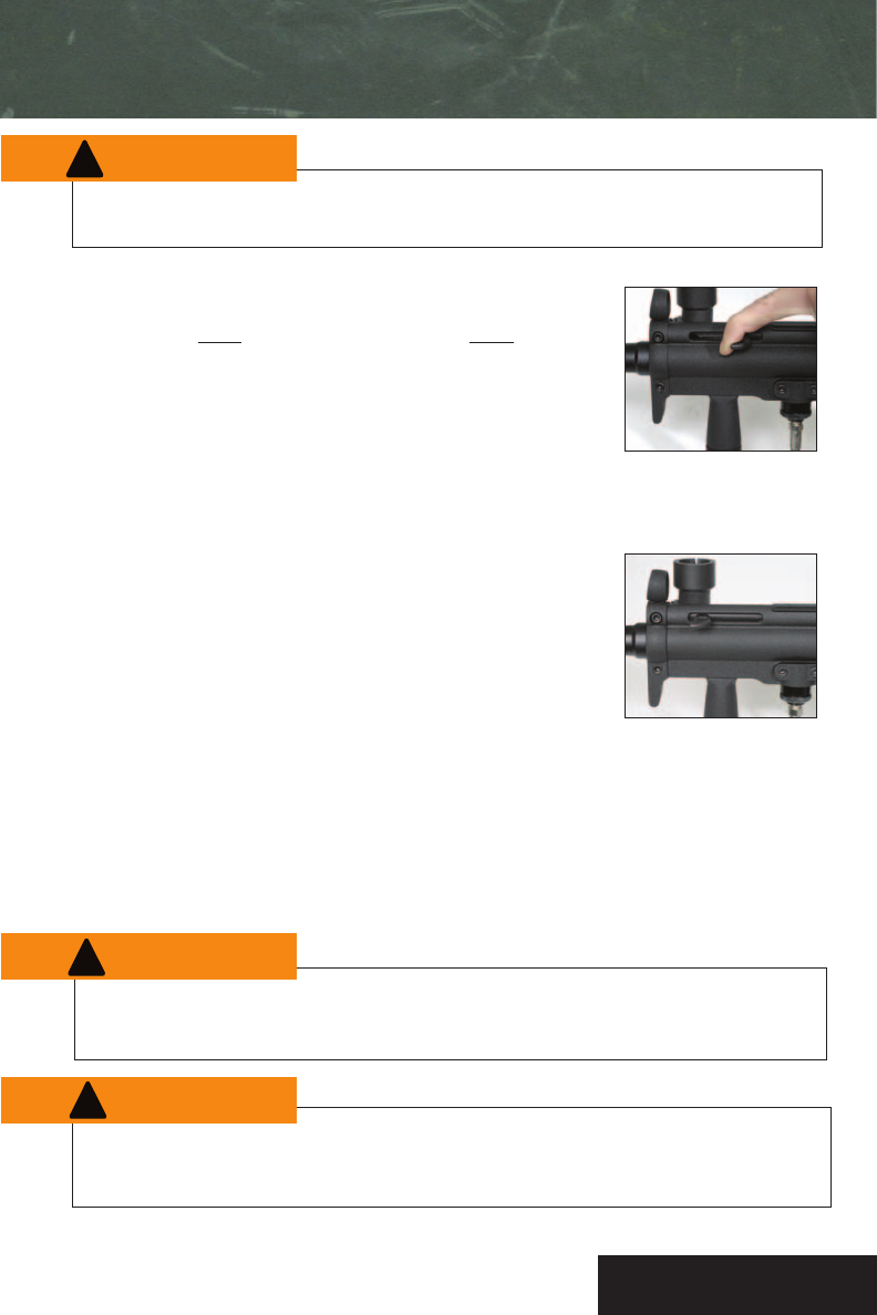
4. Pull the cocking knob straight back from the left side of the marker
until the cocking mechanism locks back in the cocked position. See
Figure 1. Always cock marker before airing it up. During cocking the
cocking rod will recoil or spring back forward once released and will
only move slightly during marker operation. See Figure 2.
5. Push safety “off” (see page 12), and turn the marker “on”
(see page 13) if it is an electronic trigger frame.
6. Squeeze the trigger with an even pressure and listen as the marker
un-cocks. The PCS™US«5® needs air to recock. Electronic markers
must be charged before operation. See page 15.
7. Cock the marker again.
Figure 1. Pull Back
Figure 2. Fully Cocked
The marker contains compressed gas or air when pressurized. Never disassemble marker until removing all
gas or air from the system. Rules for safe handling of compressed gas or air must be followed at all times.
operating the pcs™us«5®marker
6
Always cock marker before attaching air source. Marker can discharge if air source is attached before
marker is cocked.
Every person within range of an area where a paintball marker is in use must wear protective goggles
and headgear specifically designed for paintball.
!
W
W
A
AR
RN
NI
IN
NG
G
!
W
W
A
AR
RN
NI
IN
NG
G
!
W
W
A
AR
RN
NI
IN
NG
G

operating the pcs™us«5®marker
8. Before attaching air source, read and understand the section in this manual on “Compressed Gas/Air” (Found
on page 8 & 9). Follow safety rules for handling compressed gas/air. If any leak occurs in the marker, refer to
troubleshooting guide or to a qualified airsmith. Use only cylinders for compressed gas or air that comply with
all applicable laws and regulations, including but not limited to those of the U.S. Department of Transportation,
OSHA, Compressed Gas Association, and/or American Society for Testing and Materials.
9. Bottom line: First check the tank O-ring for rips or tears, then attach the air source by screwing the
threads of the tank or air source adapter into the threaded bottom line ASA at the base of the grip. Make
sure marker is cocked before attaching air. If leaks occur, recheck tank O-ring. If damaged, replace.
When cocking the pressurized marker do not release the cocking knob until after the cocking mechanism
has locked back into the cocked position; releasing the cocking knob during cocking can cause the marker
to shoot.
10. With goggles on, test for function after attaching air source. Squeeze the trigger. The marker should shoot.
Repeat several times.
11. Turn the marker off (AEC version) and push the safety in (both versions). Paintballs may then be loaded.
Before disassembly, storage or transport of the marker, remove air source first, then remove all paintballs
from the marker, barrel, and loader. Remove all gas or air from the marker. Insert barrel plug and push
the safety in so it is engaged.
7
The PCS™US«5®semi-automatic marker shoots one paintball for each squeeze of the trigger, and
recocks itself after each shot. See page 13 if you have a US«5®with an Advanced Electronic Clip (AEC) for
the different modes of fire.
!
W
W
A
AR
RN
NI
IN
NG
G
!
W
W
A
AR
RN
NI
IN
NG
G
!
W
W
A
AR
RN
NI
IN
NG
G
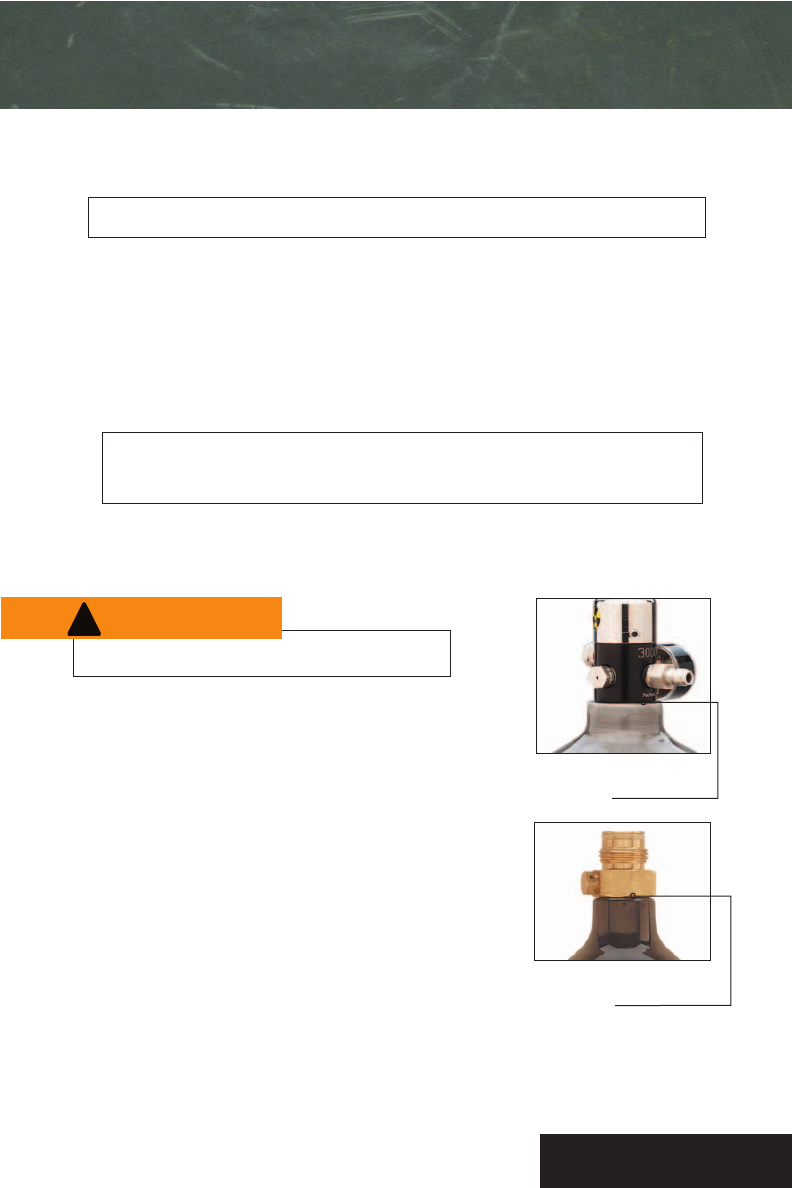
Figure 3. Valve-cylinder
connection.
Figure 4. Valve-cylinder
connection.
COMPRESSED GAS/AIR
The PCS™US«5®paintball marker may be powered by CO2, regulated compressed air, or regulated nitrogen.
The safety rules for handling compressed gas or air must be followed at all times.
OPERATING PRESSURE AND INPUT PRESSURE
• Operating pressure range: 600 to 1000 p.s.i.
• Recommended maximum input pressure is 1000 p.s.i.
• Do not exceed recommended pressures.
Do not leave cylinder or pressurized marker in direct sunlight or exposed to heat source.
Increased temperature will increase the pressure of compressed gas or air to dangerous levels.
Do not exceed recommended input or operating pressure.
VALVE-CYLINDER CONNECTION
The valve on a cylinder is to remain screwed into the cylinder; Figures 3
and 4. Should it loosen, the cylinder may detach from the valve with
extremely dangerous force. Call manufacturer or take to qualified
personnel for inspection.
Every time a cylinder is filled, the connection between the valve and
cylinder must be inspected. If any looseness or leak is detected
between the valve and the cylinder, do not fill. Drain cylinder and
call manufacturer or take to qualified personnel for inspection.
During filling, if any looseness or leak is detected between the valve
and the cylinder, filling must stop immediately. Drain cylinder and
call manufacturer or take to qualified personnel for inspection.
8
!
W
W
A
AR
RN
NI
IN
NG
G
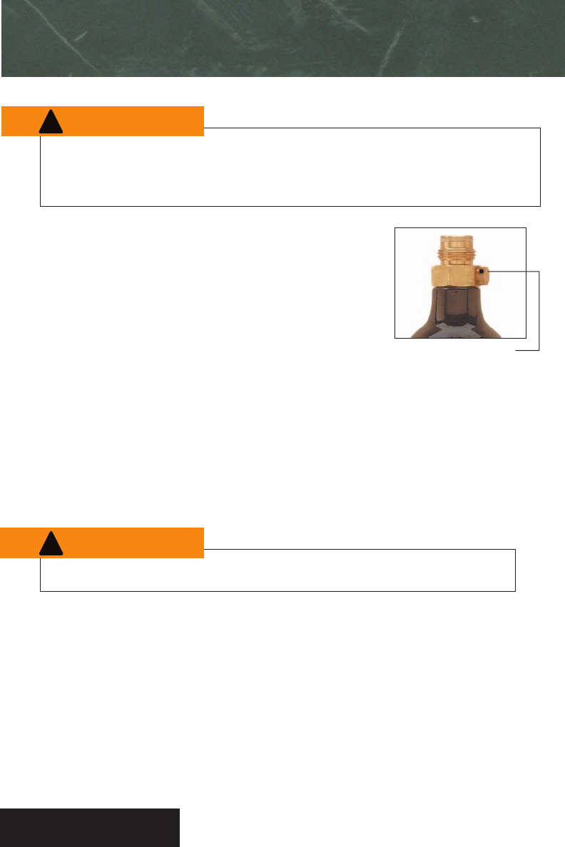
Figure 5. Safety burst disk.
A compressed gas or air cylinder is a pressure vessel. Follow rules for safe handling of compressed gas or
air. All filling of compressed gas or air cylinders, and all repairs to a marker or its components must be
performed by qualified personnel.
FILLING COMPRESSED GAS/AIR
An overfill of any compressed gas or air cylinder can cause the safety burst
disk (Figure 5) on the cylinder to burst, or the cylinder itself to rupture.
A cylinder may rupture with extremely dangerous force. Use a properly rated
disk only. Inspect the burst disc for a vent hole. If no hole is present contact
a local store or PMI immediately. DO NOT FILL!
A scale must be used for all CO2fills to prevent an overfill. A pressure gauge
must be used for all compressed gas or air fills to prevent an overfill.
Fills must be performed by qualified personnel. A cylinder must not be filled
beyond the cylinder’s capacity per the U.S. Department of Transportation. A
cylinder’s rated capacity appears on the cylinder itself.
Do not overfill any cylinder. An overfill can cause the safety burst disk or the cylinder itself to rupture.
HYDROSTATIC TESTING DATE
Many cylinders are required by the U.S. Department of Transportation to be hydro-tested at periodic
intervals, with the interval varying according to cylinder type. The date of the cylinder’s initial or later
testing appears on the cylinder. A cylinder that is out of date for hydrostatic testing must not be filled
or used.
9
COMPRESSED AIR/GAS
!
W
W
A
AR
RN
NI
IN
NG
G
!
W
W
A
AR
RN
NI
IN
NG
G
All paintball markers must be chronographed regularly. Adjust marker to shoot paintballs at a velocity
that is less than 300 feet per second (fps) and that does not exceed the velocity limit set by the
paintball park where the marker is in use.
Chronograph the marker at regular intervals during the day, as well as any time the air source is
refilled or changed, any time the barrel or any part in the marker is changed, and upon request of any
player or game official.
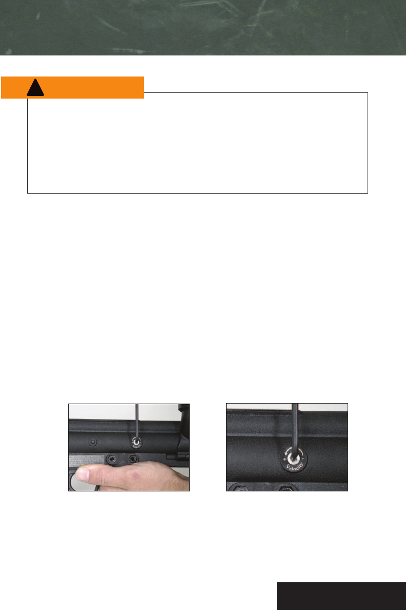
Figure 6. 1
/ 8" allen wrench is used to
adjust velocity.
VELOCITY ADJUSTMENT
Figure 7. Clockwise decreases velocity.
Counterclockwise increases velocity.
1. Chronograph the marker using standard chronograph procedures and following safety rules. Shooting
velocity will vary based upon many factors, such as paint, weather, and air system.
2. Adjust velocity by using a 1
/ 8" allen wrench (provided) to turn the velocity adjuster on the right side
of marker. See Figure 6. Turn adjuster clockwise to lower velocity. Turn adjuster counter-clockwise to
raise velocity. See Figure 7. Turning the velocity adjuster changes the amount of air flowing through
the valve.
3. Chronograph the marker after every velocity adjustment.
4. Chronograph the marker at regular intervals during the day, as well as any time the air source is
refilled or changed, any time the barrel or any part in the marker is changed, and upon request of
any player or game official.
10
!
W
W
A
AR
RN
NI
IN
NG
G
PCS™ US«5®SPECIFICATIONS
Action:
Paintballs:
Safety:
Barrel Length:
Barrel:
Height:
Length:
Air Source:
Tournament grade semi-automatic powered by
either N2or CO2
9 inches
Threaded aluminum; Piranha/Spyder threads
8 1/2 inches
19 1/2 inches overall (with 9 in. barrel and
without attachments)
Input Pressure:
Operating Pressure:
Air Source Input:
Mechanical push button/barrel plug
For use only with standard “.68 caliber” (.68-inch
diameter) paintballs. RPS paintballs recommended
Accepts standard connections for CO2, regulated N2,or
regulated compressed air
Recommended 600 psi to 1000 psi
Not to exceed 1000 psi
Bottom line ASA accepts standard
paintball threading
11
Weight: 3.25 lbs.
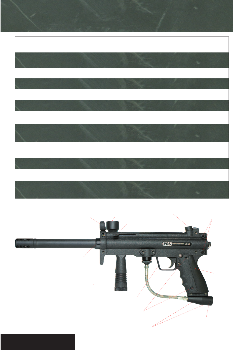
Top Tube
Flip Down for Easy Cleaning Field Strip Pins
Adjustable Foregrip
Side Cocking
Iron Sight
(MPS) Style
Piranha/Spyder
Barrel Threads
Inline Bottomline Holes
Field Strip Pins to
Remove Clip
Removable Trigger
Guard
10oBottom Line Adapter
Clip
Rear Sight
12
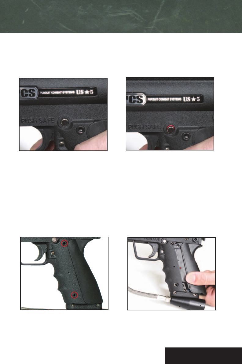
PCS™ US«5® SAFETY & CLIP
Figure 3. Figure 4.
Safety Switch
Push on left hand side of safety to activate. See Figure 1. Push on right hand side of safety to disengage which
allows the marker to fire. Red O-Ring should be showing. See Figure 2. Always put marker in safe when not in use.
Switching from mechanical to electronic
Unscrew the 2 clip bolts with a 5/32 allen key, or remove the 2 fieldstrip clip pins. See Figure 3. Remove
Mechanical Clip and replace with Advanced Electronic Clip (AEC). See Figure 4. Re-install either the 2 clip bolts or
clip field strip pins.
Figure 2.Figure 1.
13
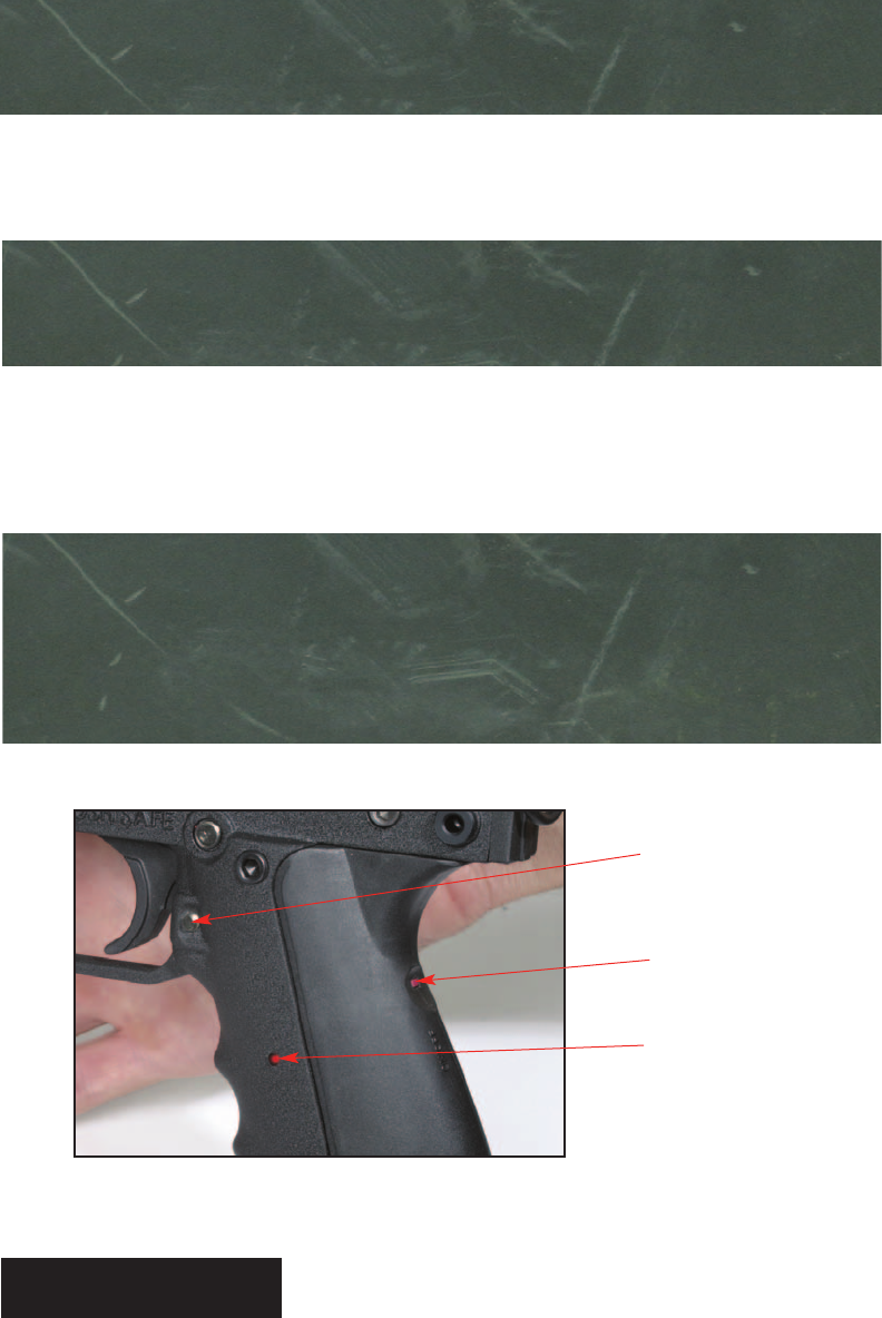
US«5 ADVANCED ELECTRONIC CLIP
BURST BUTTON
Press the Burst Button once to turn the marker on 3 Shot Burst. Press the Burst Button again to
turn the frame to Full Auto. Press the Burst Button again to turn it back to semi-auto.
INSTRUCTIONS FOR USING YOUR AEC FRAME
ON/OFF BUTTON
The on/off is located on the back of the marker. Push it once to turn your AEC on. Push it again
and the frame will turn off. The frame should be left off when not using the marker or you will
drain the battery.
ADVANCED ELECTRONIC CLIP (AEC) BATTERY
The AEC frame comes with a 9 volt rechargeable battery. You must charge it for a full 22 hours
before initial use since it does not come fully charged. For best long term battery life, repeat this
process every time it is drained. You can also use a regular 9 volt battery with this frame if your
rechargeable battery is dead or if you want to play with the frame right away. You will need to
remove the AEC when you need to replace or charge the battery. A blinking on/off indicator light
means your AEC frame needs to be charged right away.
Battery
Indicator Light
On/Off Button
*Adjustable modes of fire and rechargeable frames are not currently available in all countries.
MODE Button
(AEC Only)
(AEC Only)
(Mechanical frames do not have modes)
All US«5®markers come with a mechanical frame. An AEC can be
purchased with the marker or as an aftermarket accessory.
(AEC Only)
PURSUIT MARKETING INC.
55 Howard Ave
Des Plaines, IL 60018 USA
First Class
Stamp
Here
Tape Here
Detach and Mail
WARRANTY REGISTRATION

Please fill out this PCS™US«5®Warranty Registration form entirely, including the checklist and mail it to:
PMI, Inc., 55 Howard Ave, Des Plaines, IL 60018 USA, or register online at www.pcs-paintball.com. Save
your original sales purchase receipt or packing slip. A copy must accompany the marker when warranty
repairs are sought. Consult page 25 & 26 of the operator’s manual for warranty information and instructions
on obtaining repair service.
PCS™US«5®WARRANTY REGISTRATION
Purchaser’s name:
Mailing address:
City, State, Zip:
Phone number:
E-Mail Address:
Age:
Model purchased:
Serial number:
Where purchased:
Date of purchase:
Seller’s name:
Seller’s address:
City, State, Zip:
Purchase price:
(Serial number is located on the left hand side towards rear of marker)

Pursuit Combat Systems, Inc., thanks you for purchasing
this high quality PCS™US«5®paintball marker. Please
read each of the following items and initial that you have
read and understood it before operating the PCS™US«5®
paintball marker:
1. This paintball marker is intended for sale to adults
only, for use in compliance with all applicable laws
and regulations. Adult supervision is recommended at
all times whenever a minor is handling this paintball
marker in any manner. Please initial: ______
2. Always wear protective goggles and headgear
specifically designed for paintball when shooting this
marker. Please initial: ______
3. Every person within range of an area where a
paintball marker is in use must wear protective
goggles and headgear specifically designed for
paintball. Please initial: ______
4. Operate a paintball marker only in areas where it
is safe and lawful to do so. Please initial: ______
5. Misuse of this paintball marker can result in criminal
penalties including jail time. Please initial: ______
6. Read this operator’s manual completely before
loading, pressurizing, or operating the PCS™US«5®
paintball marker. Please initial: ______
7. Never aim or shoot a paintball marker toward any
person who is not wearing protective goggles and
headgear specifically designed for paintball.
Please initial: ______
8. During game play, follow referee’s instructions and
all field safety rules. Avoid shooting at a player’s
head, neck, or groin area. Please initial: ______
9. Play paintball only where the rules of safe paintball
play are followed. Please initial: ______
10. All paintball markers must be chronographed
regularly. Adjust marker to shoot paintballs at a
velocity that is less than 300 feet per second (fps)
and that does not exceed the velocity limit set by the
paintball park where the marker is in use.
Chronograph the marker at regular intervals during
the day, as well as any time the air source is refilled
or changed, any time the barrel or any part in the
marker is changed, and upon request of any
player or game official. Please initial: ______
11. This paintball marker operates using compressed
gas or air at specified input pressure ranges. Follow
safety procedures when handling compressed gas or
air. All filling of compressed gas or air cylinders must
be done by qualified persons. Please initial:
______
12. Follow the rules of safe marker handling: Keep fin-
ger off trigger until ready to shoot. Keep muzzle
pointed in a safe direction. In addition, firmly insert
a barrel plug into the muzzle and push the mechani-
cal safety “on” when the marker is not in use and
when in any non-shooting area. Please initial:
______
13. Paintball markers with electronic frames have
extremely sensitive triggers. Take extra safety
precautions anytime handling or shooting an
electronic paintball marker. To avoid accidentally
firing the marker, keep your finger away
from the trigger until you are ready to fire.
Please initial: ______
14. Never shoot at domestic animals or wildlife.
Please initial: ______
15. Never mark objects outside the confines of the game
or authorized shooting areas. Please initial:
______
16. Never look down the barrel of the marker.
Please initial: ______
17. Before disassembly, storage, or transport of the
marker, remove all paintballs from the marker,
barrel, and loader. Remove air source and all gas or
air from the marker. Insert barrel plug and put
mechanical safety in “no shoot” position.
Please initial: ______
18. Carry marker in case or sturdy bag when in public.
Please initial: ______
19. Safely and securely store marker to prevent
unauthorized access. Please initial: ______
THE PCS™US«5®PAINTBALL MARKER IS NOT A TOY.
MISUSE MAY CAUSE SERIOUS INJURY OR DEATH. EYE
PROTECTION DESIGNED FOR PAINTBALL USE MUST BE
WORN BY THE USER AND ANY PERSON WITHIN RANGE.
READ THIS OPERATOR’S MANUAL COMPLETELY BEFORE
LOADING, PRESSURIZING, OR OPERATING THE PCS™
US«5®PAINTBALL MARKER. Please initial: ______
!
W
W
A
AR
RN
NI
IN
NG
G
Detach and Mail
14
US«5®ADVANCED ELECTRONIC CLIP
TOURNAMENT LOCK SWITCH
The Tournament Lock Switch enables you to play in a tournament or at a field that does not allow full
auto and burst modes by restricting the marker to semi-automatic only. All AEC frames come with the
Tournament Lock off so you can immediately put the marker in full auto or burst mode.
Never use water to clean the marker, or you run the risk of damaging the Advanced
Electronic Clip (AEC).
Take extra safety precautions when handling or shooting since markers with electronic
frames have EXTREMELY sensitive triggers.
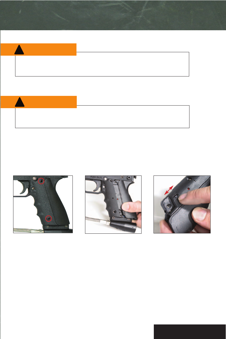
Unscrew the 2 clip bolts
with a 5/32 allen key, or
remove the 2 fieldstrip clip
pins to release AEC frame.
To access the Tournament
Lock, you have to take the
AEC frame off the receiver.
lock off lock on
Turn on Tournament Lock by
pushing the button up and
turn it off by pushing the
button down.
Flip the switch upwards to engage the tournament lock restricting the PCS™US«5®into semi-auto mode
only. Flipping the Switch downward disengages the tournament lock allowing the PCS™US«5®’s firing modes
to be switched between semi-auto, 3 round burst, and full auto. Re-install either the 2 clip bolts or clip field
strip pins before firing marker.
*Mechanical frames do not need a tournament lock switch. They are already tournament ready.
!
W
W
A
AR
RN
NI
IN
NG
G
!
W
W
A
AR
RN
NI
IN
NG
G
15
charging the AEC
PMI recommends the included 9V rechargeable battery for optimal performance.
Do not use the battery charger when using any non-rechargeable battery.
Charging battery
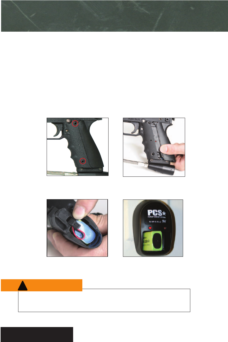
1. Unscrew the 2 clip bolts with a 5/32 allen key, or remove the 2 fieldstrip clip pins. See Figure 1.
2. Remove the Advanced Electronic Clip (AEC). See Figure 2.
3. Flip up the battery latch and slide the battery out the bottom of the AEC. See Figure 3. Be careful not to
damage the battery wires or connectors.
4. Insert the rechargeable battery into the wall charger and allow to charge for 22 hours. See figure 4. Do not
leave plugged in for more than 22 hours.
Figure 3. Figure 4.
Figure 2.Figure 1.
!
W
W
A
AR
RN
NI
IN
NG
G
16
Maintenance & Adjustments
Installing Hopper
adjusting Foregrip
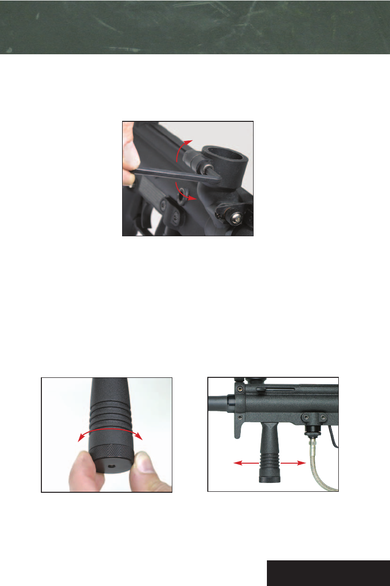
Rotate the bottom foregrip nut counter clockwise (Figure 2) to loosen up the foregrip allowing you to slide
the foregrip forward or back (Figure 3) to better suit your playing style. Rotate the foregrip nut clockwise
to lock the foregrip back into place.
Using a 3/16 allen key, turn the allen key to the right to constrict the feed tube after the hopper is in place. Turn
the allen key to the left to loosen up the feed tube. See Figure 1.
Figure 1.
Figure 3.
Figure 2.
Tighten
Loosen
Loosen Tighten
17
cleaning & Maintenance
Figure 3. Figure 4.
Figure 2.Figure 1.
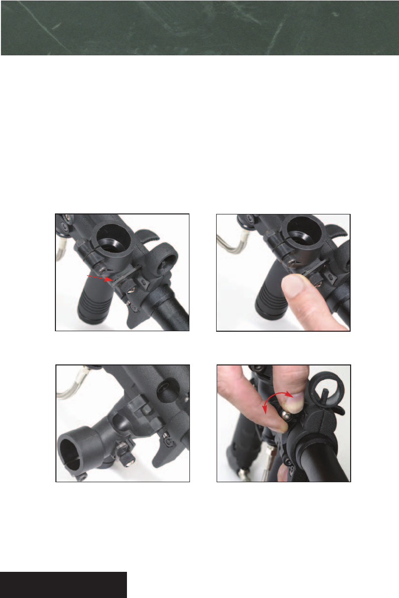
Cleaning feed tube
1. Locate feed tube latch. See Figure 1.
2. Push down on the rear of the feed tube latch. See Figure 2.
3. Rotate feed tube away from body. See Figure 3. This allows for easy cleaning on or off the field.
4. If feed tube latch is too difficult to push down, loosen the feed tube latch screw by turning counter clock
wise. See Figure 4. If the latch is too easy to open, tighten the screw by hand.
Feed tube
latch
Tighten
Loosen
18
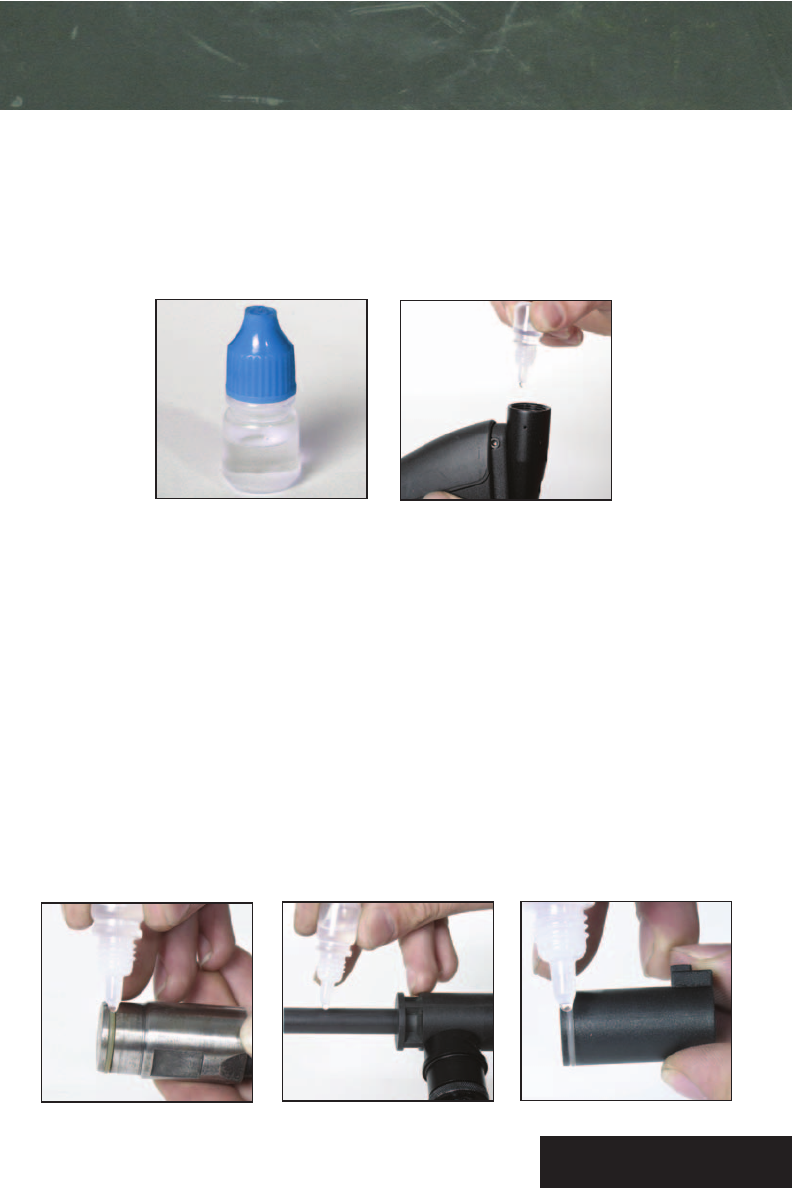
lubrication
Basic Lubrication
Put 3-4 drops of US«5®oil into the ASA. See Figure 1. Remove barrel and install tank. Cycle marker 15-20
times. This will cycle the oil through the marker and should be done after 4 times of normal use or after
each heavy use. DO NOT USE WD40, ANY PETROLEUM BASED LUBRICANT OR REAL
FIREARM OIL. THIS WILL HARM THE MARKER AND WILL VOID WARRANTY.
Use US«5®Oil ONLY!
Included in package. Figure 1.
Figure 3.
Figure 2. Figure 4.
Advanced Lubrication
1. See Page 20, Figures 1-9, for disassembly instructions.
2. Place 2 drops of US«5®oil onto the hammer o-ring and wipe around with your finger. See Figure 2.
3. Remove the bolt hammer linkage arm. Remove the bolt and powertube placing one drop of oil on the front of
the powertube. See Figure 3.
4. Place one drop of oil on the bolt o-ring. See Figure 4.
5. Re-install bolt onto power tube and place back into the right hand body shell. Insert front of linkage pin into
the hole on the top rear of the bolt and the rear end into the upper front of the hammer.
6. See Page 19, steps 5 & 6, for re-assembly instructions.

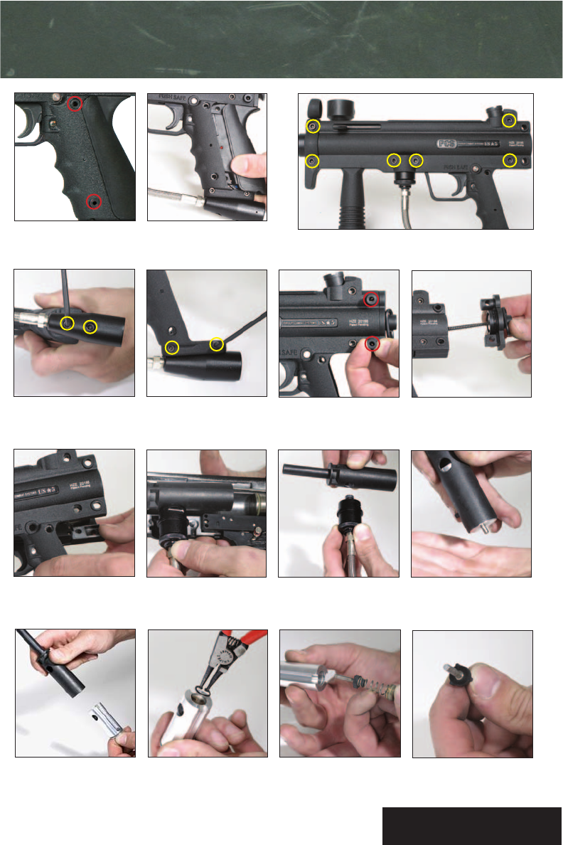
Before performing any repairs or maintenance, make sure to take off tank and remove all paint and air.
Tools needed for disassembly: 1/8 allen key, 5/32 allen key and retaining ring pliers.
See page 21 for part numbers in parenthesis.
1. Unscrew the 2 clip bolts (#17 & 18) with a 5/32 allen key, or remove the 2 field strip clip pins. See Figure 1.
2. Remove either the AEC (#10) or mechanical clip. See Figure 2.
3. Remove the 6 body bolts (#35A, B & C) with a 5/32 allen key. See Figure 3.
4. Remove the 2 bottomline screws (#35) on the underside of the grip frame with a 5/32 allen key. See Figure 4.
5. Remove the 2 lower grip frame bolts (#41) with a 1/8th allen key. See Figure 5.
6. Remove the 2 rear block field strip pins (#14). See Figures 6.
7. Remove the rear block (#9). See Figure 7.
8. Lift the left hand side of the body shell (#2) off of the right hand side of the body (#1). See Figure 8.
9. Remove the powertube assembly (#28). See Figure 9.
10.Remove the vertical adapter (#4) from the powertube assembly (#28). See Figure 10.
11.Remove the valve assembly (#53) by holding the powertube in your hand and lightly striking the rear of it
against your palm. See Figure 11.
12.The valve body (#53) will slide out. See Figure 12.
13.Remove the c-clip (#59) with retaining ring pliers. See Figure 13.
14.Slide out the valve spring retainer (#55), valve spring (#57), and cupseal (#56). See Figure 14.
19
disassembly and maintenance
Disassembly
re-assembly
1. Re-install cupseal (#56), valve spring (#57), valve spring retainer (#55) and c-clip (#59).
2. Slide the valve body (#53) back into the powertube (#28) with the cupseal shaft facing the rear of the
powertube. Make sure the hole in the valve body and the powertube line up.
3. Install the vertical adapter (#4) back into the powertube.
4. Place the powertube assembly back into the righthand side of the body.
5. Re-install the 6 body bolts,rear block, 2 rear block pins, 2 lower grip frame bolts, and 2 bottomline screws.
6. Re-install the AEC or mechanical clip, and replace the 2 clip bolts or field strip clip pins.
20
disassembly and maintenance
Figure 1. Figure 2. Figure 3.
Figure 4. Figure 5. Figure 6. Figure 7.
Figure 8. Figure 9. Figure 10. Figure 11.
Figure 12. Figure 13. Figure 14. Figure 15.
21
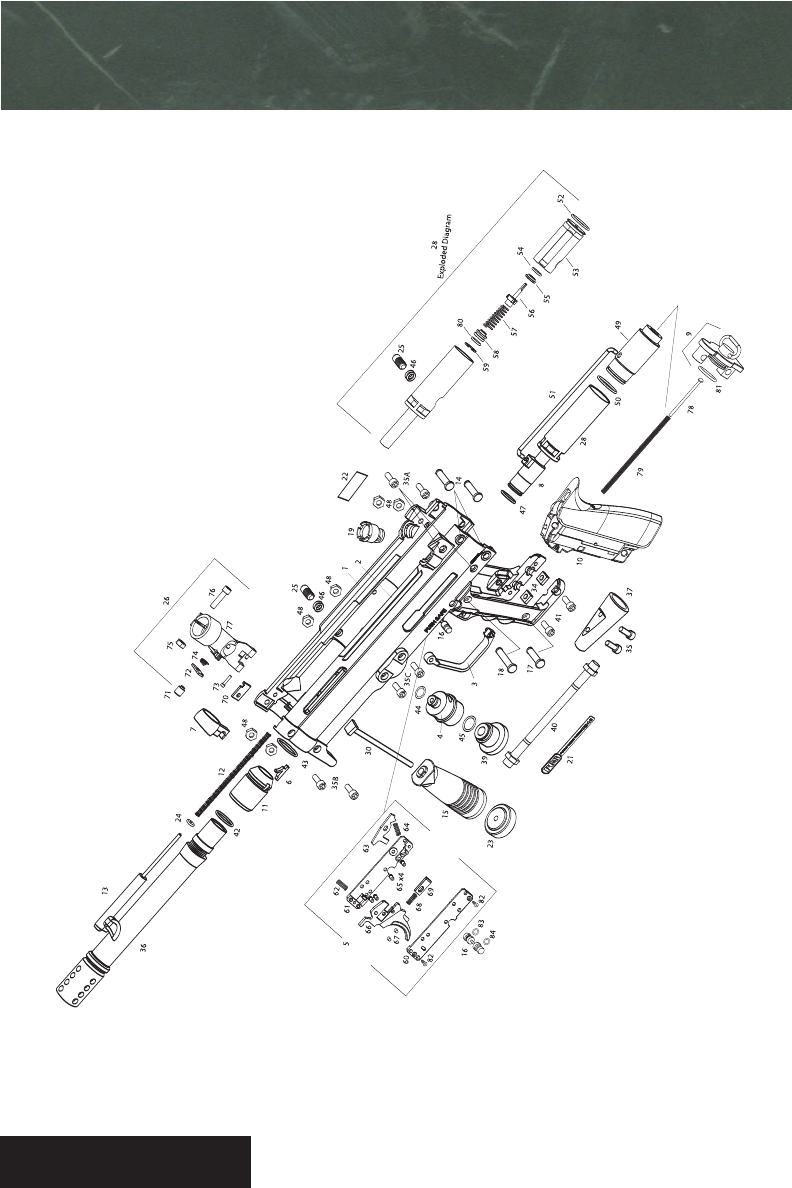
US«5®PARTS DIAGRAM

22
US«5®PARTS DIAGRAM
1 Body Right 72150
2 Body Left 72155
3 Trigger Guard 72175
4 Vertical Adapter 72210
5 Trigger Assembly 72100
6 Ball Detent 72211
7 Front Sight 72212
8Bolt 72213
9 Rear Block Assembly 72180
10 Electronic Clip 72190
11 Barrel Adapter 72214
12 Cocking Rod Spring 72215
13 Cocking Rod 72216
14 Rearblock Fieldstrip Pin 72217
15 Foregrip 72160
16 Safety 72218
17 Lower Grip Fieldstrip Pin 72219
18 Upper Grip Fieldstrip Pin 72220
19 Rear Sight 72221
20 Mechanical Clip 72200
21 PCS Badge 72223
22 Warning Badge 72224
23 Foregrip Retainer 72165
24 Cocking Rod Washer 72225
25 Velocity Adjuster 72226
26 Feedtube Assembly 72120
28 Powertube 72130
30 Foregrip Bolt 72227
34 Bottom Line Nut 72228
35 Bottom Line Screws 42016
35A 10x32 Bolt Short 72229
35B 10x32 Bolt Medium 72230
35C 10x32 Bolt Long 72231
36 US-5 SI Barrel 72170
37 Bottom Line 72232
39 Male ASA Port Reducer 72233
40 7” SS Hose 47015
41 Lower Grip Bolt 72234
42 Barrel O-ring .795x.05 Buna 72250
43 Barrel Adapter O-ring 20x2.5mm Buna 72251
44 Vertical Adapter O-ring 010/90U 10138
45 Male ASA Port Reducer O-ring 015/90U 41010
46 Velocity Adjuster 4x1.5mm Buna x 2 72252
47 Bolt O-ring 015/70U 57738
48 10-32 Bolt 72235
49 Hammer 72236
50 Hammer O-ring 019/90U 72253
51 Bolt Hammer Link Pin 72237
52 Valve Body O-ring 019/90U 72253
53 Valve Body 72238
54 Seal O-ring 012/90U 40919
55 Valve Spring Retainer 72131
56 Cupseal 72132
57 Valve Spring 72133
58 Valve Seal 72134
59 C-Clip 72135
60 Left Plate 72101
61 Right Plate 72102
62 Trigger Spring 72103
63 Sear 72104
64 Sear Spring 72105
65 Plate Pin 72106
66 Trigger 72107
67 Plate Pin 72108
68 Trigger Pal Spring 72109
69 Trigger Pal 72110
70 Feedtube Latch Plate 72128
71 Feedtube Latch Screw 72121
72 Feedtube Latch 72122
73 Feedtube Retainer Bolt 72123
74 Feedtube Latch Spring 72124
75 Feedtube Clamping Nut 72125
76 Feedtube Clamping Bolt 72126
77 Feedtube 72127
78 Spring Guide 72239
79 Hammer Spring 72240
80 Spring Retainer O-ring 012/90U 40919
81 Rearblock O-ring 26x2.5mm Buna 72254
82 Trigger Plate Screw 72241
83 Safety O-ring 6x2mm Buna 72255
84 Safety Red O-ring 6x2mm Buna 72256

Low Check that air source is adequately filled
Low Adjust velocity adjuster counter clockwise
Low Oil marker
TROUBLESHOOTING
23
TRIGGER AND SHOOTING
Marker runs on (partially cycles more than Check that air source is correctly attached to
once when trigger is squeezed) marker. Check that air source is adequately filled.
Oil Marker. Lower velocity.
Trigger pulls back, marker will not shoot Check that the marker is cocked, air source is
correctly attached and air source is properly
filled. If the frame is electronic, make sure
battery is properly charged and turned on.
VELOCITY (DO NOT EXCEED 300 FEET PER SECOND)
SHOOT ONLY QUALITY RPS PAINTBALLS. PCS™ COMBAT .68, PMI PREMIUM, EL TIGRE™, ALL STAR®
AND MARBALLIZER®PAINTBALLS ARE RECOMMENDED FOR USE IN THE PCS™US«5®.
Not flying straight
Break in Barrel
Does not drop into feed tube
Two paintballs shoot at a time
Always check for poor quality paintballs prior to playing.
Any time paint gets too cold or too warm, there’s always the chance it is ruined.
PAINTBALLS
Check for broken paint or oil in barrel, loader, feed
tube and chamber. The bolt assembly area must also
be free of broken paint. Check that marker is not
shooting over 300 fps. Disassemble and clean.
Check ball detent and replace if necessary.
Check that velocity does not exceed 300 fps.
Shake loader. Check loader and feed tube
for broken paint.
Check ball detent (#6) and replace if necessary.
High Adjust velocity adjuster clockwise

TROUBLESHOOTING
Do not attempt to perform maintenance procedures unless qualified to do so.
CONTACT PMI FOR REPAIR ASSISTANCE AND INFORMATION REGARDING AUTHORIZED PCS™US«5®REPAIR FACILITIES.
PHONE: 1.800.579.1633 WEB: www.pcs-paintball.com
Before disassembly of the marker, remove air source; remove all paintballs from the marker, barrel, and loader.
To check if the marker is unloaded: remove air system and shoot marker in a safe direction.
Remove hopper, visually inspect chamber for a paintball, remove and inspect barrel for the presence of a paintball.
Never look down the barrel of any paintball marker once the barrel is screwed into the marker.
The paintball marker air system must be repaired or replaced with the correct pressure rated components.
Check barrel O-ring and firmly tighten barrel.
Do not oil barrel O-ring. Make sure the front 2 body
bolts are tight.
If it is difficult to tighten the threads onto the
receiver, check to see that the threads on the barrel
match. If threading is mismatched, barrel is not
designed for use with the PCS™US«5®.The barrel
threading on the PCS™US«5® is only Piranha/Spyder
compatible.
Aftermarket barrel does not tighten
BARREL
Barrel comes loose
24
Leak in pressure source between tank valve Do not fill cylinder. Immediately take to qualified
and cylinder personnel for inspection. Cylinder must be drained.
Leaks at connection between ASA and tank Check tank O-ring at connection or on remote
hose connector.
AIR LEAK
Connection must be unscrewed and teflon taped.
Contact factory or factory authorized repair center.
Leaks at connection between braided air hose
and fitting
Fixing barrel leak See page 19 for disassembly. Inspect the cupseal for
dirt and/or nicks and scratches (see page 19, Figure
15). Clean and test for leaks. Also inspect inside the
valve body for nicks and scratches. If no dirt, nicks or
scratches are found inside the valve body, a new
cupseal may need to be purchased.
!
W
W
A
AR
RN
NI
IN
NG
G

Technical support
PMI takes pride in manufacturing high quality paintball products that will provide you with many years of
trouble free enjoyment. Should you experience any difficulty in operating or maintaining this PCS™US«5®
paintball marker, please re-read the operator’s manual carefully. If further assistance is needed, contact our
Tech Support office: Phone - 1.847.233.2545 Toll Free - 1.800.579.1633 Email - info@pcs-paintball.com
ORIGINAL SALES PURCHASE RECEIPT OR
PACKING SLIP
Save your original sales purchase receipt or packing slip. That receipt will be needed to show the date of
purchase for any warranty repairs.
WARRANTY REGISTRATION FORM
Please fill out entirely the enclosed PCS™US«5®Warranty Registration form and mail it to:
Pursuit Marketing, Inc., 55 Howard Ave, Des Plaines, Illinois 60018 USA.
WARRANTY DETAILS
Pursuit Marketing, Inc. (PMI), extends a warranty to the original purchaser of the PCS™US«5®paintball
marker that the product is free from defects in materials and workmanship for a period of one year from the
date of purchase. PMI’s obligation under this warranty shall be limited to repairing or replacing any part of
the product which is defective
REPAIR RETURN PROCEDURE
In some extreme cases, your marker may need to be returned to PMI for repair. Please call PMI at
1.800.579.1633 to obtain a Return Authorization (RA) repair number before shipping any product to PMI. All
returned products must be accompanied by a RA repair number on the outside of the box. Any product
returned to PMI without a RA number on the outside of the box may be returned to sender with no work
performed. All warranty returns must be accompanied by the owner’s name, address, and telephone number.
Include owner’s e-mail if possible. Owner must remove all paintballs before shipping, and must pack product
securely to avoid damage during shipping. Include a brief description of what does not appear to work cor-
rectly. Please make sure to ship your marker through a shipping company that allows you to track and
insure your package.PMI is not responsible for markers that never reach us. Ship to: PMI, 55 Howard Ave, Des
Plaines, Illinois 60018 USA.
Service for warranty repairs will be done free of charge upon delivery of the product to Pursuit Marketing,
Inc. Please include a copy of your sales purchase receipt with all warranty repairs.
WARRANTY
25

REPAIR PROCEDURE
The PCS™US
«
5®is a registered trademark. Design rights & all rights reserved. All patterns, drawings,
photographs, instructions or manuals remain the intellectual property of the manufacturer. Patents pending.
All rights will be strictly enforced.
26
Out OF WARRANTY REPAIRS
Please note that there will be a minimum labor charge of $20 and there may be additional charges for parts
to repair a product that is not covered by warranty. An estimate of repair cost will be provided to the cus-
tomer and authorization to complete the repairs will be obtained prior to additional repairs being done.
WARRANTY EXCLUSIONS AND LIMITATIONS
This warranty does not apply in the event of misuse or abuse of the product, use of any parts other than
original factory parts, or unauthorized repairs, modifications, or alterations, and does not apply to any parts
that are made defective by modification, misuse, abuse, or accident. This warranty does not apply to O-rings,
cup seals, or springs, or to normal fading of anodized finish, scratches, or other cosmetic wear, or to any items
or parts not manufactured by PMI.
Other than as expressly stated herein, PMI does not make any warranties, express or implied, including but not
limited to implied warranties of merchantability or fitness, for any purpose other than that for which the
PCS™US«5®was designed. This warranty gives you specific legal rights. You may have other rights which may
vary from state to state. PMI is not liable for any consequential damages or incidental damages which may
arise from the use or operation of the PCS™US«5®or from any breach of the warranty herein set forth.
PCS™US«5®Paintball Markers
Manufactured by:
Pursuit Marketing, Inc.
55 Howard Ave
Des Plaines, Illinois 60018 USA
Toll Free Phone 1.800.579.1633
Phone 847.233.2545
www.pcs-paintball.com
Printed in China
The PCS™US«5®paintball marker is not a toy. Misuse may cause serious injury or death. Eye protection
designed for paintball use must be worn by the user and any person within range. Read this operator’s
manual completely before loading, pressurizing or operating the PCS™US«5®paintball marker.
#72001
!
W
W
A
AR
RN
NI
IN
NG
G
