0440637 5 EN Fin Lock Surgical Technique
2016-11-07
: Pdf 0440637-5-En Fin-Lock Surgical Technique 0440637-5-EN_Fin-Lock_Surgical_Technique 11 2016 pdf
Open the PDF directly: View PDF ![]() .
.
Page Count: 44

Integra®
Titan™ Modular Shoulder System, 2.5
Featuring Fin-Lock™ Surgical Technique
SURGICAL TECHNIQUE

Table of Contents
Introduction
Indications ............................................................................................................................................................................................................ 2
Contraindications ................................................................................................................................................................................................ 2
Warnings ............................................................................................................................................................................................................... 2
Precautions ............................................................................................................................................................................................................ 3
Sterility ...................................................................................................................................................................................................................3
Adverse Events ......................................................................................................................................................................................................3
Surgical Technique – Visual Step By Step ....................................................................................................................................................... 4
Design Rationale ................................................................................................................................................................................................. 6
Surgical Technique
Step 1: Preoperative Templating and Patient Positioning ..............................................................................................................................7
Step 2: Exposure ................................................................................................................................................................................................... 7
Step 3: Subscapularis Tendon Management ....................................................................................................................................................8
Step 4: Capsule Release and Humeral Head Dislocation .............................................................................................................................. 9
Step 5: Humeral Head Preparation and Resection ........................................................................................................................................ 10
Step 6: Glenoid Preparation and Implantation
Step 6a: Fin-Lock™ Glenoid Preparation and Implantation ................................................................................................................ 13
Step 6b: Pegged Glenoid Preparation and Implantation .................................................................................................................... 17
Step 6c: Keeled Glenoid Preperation and Implantation ......................................................................................................................19
Step 7: Humeral Canal Preparation ................................................................................................................................................................. 20
Step 8: Body and Stem Trial Insertion ............................................................................................................................................................. 21
Step 9: Humeral Head Trial ...............................................................................................................................................................................21
Step 10: Soft Tissue Balancing and Trial Removal ........................................................................................................................................ 23
Step 11: Preparation for Repair of Subscapularis Tendon ............................................................................................................................ 23
Step 12: Body and Stem Implant Assembly ................................................................................................................................................... 23
Step 13: Stem/Body Implantation and Head Assembly ............................................................................................................................... 24
Step 14: Revision Procedure ............................................................................................................................................................................. 26
Long Stem Option ............................................................................................................................................................................................. 26
Step 15: Wound Closure. .................................................................................................................................................................................. 28
Postoperative Therapy Protocol ..................................................................................................................................................................... 29
Instrumentation ................................................................................................................................................................................................. 30
Ordering Information and Implant Dimensions ............................................................................................................................................ 41

2
Total Shoulder Arthroplasty or Hemiarthroplasty is indicated for:
• Severely painful and/or disabled joint resulting from osteoarthritis, traumatic arthritis or rheumatoid arthritis.
• Fracture-dislocations of the proximal humerus where the articular surface is severely comminuted, separated from its blood
supply or where the surgeon’s experience indicates that alternative methods of treatment are unsatisfactory.
• Other difficult clinical problems where shoulder arthrodesis or resection arthroplasty are not acceptable
(e.g. revision of a failed primary component).
Shoulder Hemiarthroplasty is also indicated for:
• Ununited humeral head fractures
• Avascular necrosis of the humeral head
• Rotator cuff arthropathy
• Deformity and/or limited motion
The humeral component is intended for cemented or uncemented use. The glenoid component is intended
for cemented use only.
Contraindications
The following conditions are contraindications for total shoulder arthroplasty and hemiarthroplasty:
• Active local or systemic infection
• Inadequate bone stock in the proximal humerus or glenoid fossa for supporting the components
• Poor bone quality, such as osteoporosis, where there could be considerable migration of the prosthesis and/or
a chance of fracture of the humerus or glenoid
• Absent, irreparable or nonfunctional rotator cuff or other essential muscles
• Pregnancy
• Muscular, neurologic, or vascular deficiencies that compromise the affected extremity
• Known metal allergies
The following conditions are contraindications for total shoulder arthroplasty and hemiarthroplasty:
• Absent, irreparable or nonfunctional rotator cuff or other essential muscles
Warnings
The use of a glenoid prosthesis in patients with cuff tear arthropathy could increase the risk of glenoid component loosening
due to non-anatomic loading conditions. The following conditions tend to adversely affect shoulder replacement implants:
• Excessive patient weight
• High levels of patient activity
• Likelihood of falls
• Poor bone stock
• Metabolic disorders
• Disabilities of other joints
ESSENTIAL PRODUCT USE INFORMATION: For additional important information pertaining to the use of this product, please see product package insert.
This information was current at the time of printing, but may have been revised after that date.
Indications

3
Precautions
• Do not reuse this device. Reuse of this product may result in infection or other systemic complication that may affect the
patient’s overall health. Additionally, the reuse of this product could adversely affect function of the device. Any implant
that has been damaged, mishandled, or removed from the sterile field may have surface damage that could result in
implant fracture and/or particulate and should be discarded.
• The Titan™ Modular Shoulder System has not been evaluated for safety and compatibility in the MR environment. It has
not been tested for heating, migration, or image artifact in the MR environment. The safety of the Titan Modular Shoulder
System in the MR environment is unknown. Scanning a patient who has this device may result in patient injury.
Sterility
The Fin-Lock™ Glenoid implant has been sterilized by Ethylene Oxide (EO) and is sterile in the unopened, undamaged
package. If either the implant or the package appears to be damaged or has been opened, or if sterility is questioned for any
reason, the implant should not be used. Do not resterilize this product. All other Titan™ System Implants have been sterilized
by gamma radiation and are sterile in the unopened, undamaged package. If either the implant or the package appears
damaged or has been opened, or if sterility is questioned for any reason, the implant should not be used. Do not resterilize
this product.
Adverse Events
• Potential adverse events include early or late postoperative infection, allergic reaction, intraoperative or postoperative bone
fracture and/or postoperative pain.
• Intraoperative bone perforation or fracture may occur, particularly in the presence of poor bone stock caused by
osteoporosis, bone defects from previous surgery, bone resorption, or while inserting the device.
• Loosening or migration of the implants can occur due to loss of fixation, trauma, malalignment, bone resorption, and/or
excessive activity.
• Surgical intervention may be required to treat adverse effects.
• MDR Reporting Reminder: Medical device manufacturers and users are required by law and regulation to report serious
injuries and death.
4
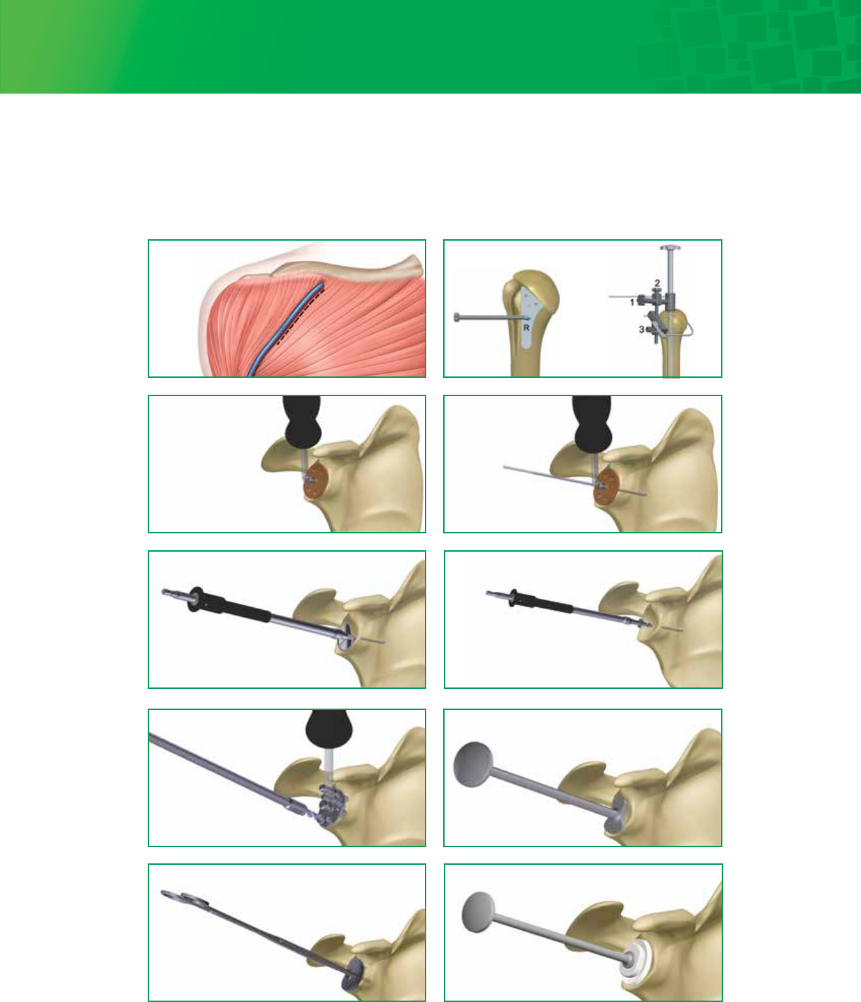
Exposure
Surgical Technique – Visual Step By Step with Fin-Lock™ Glenoid
Head Resection
Size and place wire
Drill peripheral holes Punch
Trial
Ream Drill center holes
Implant
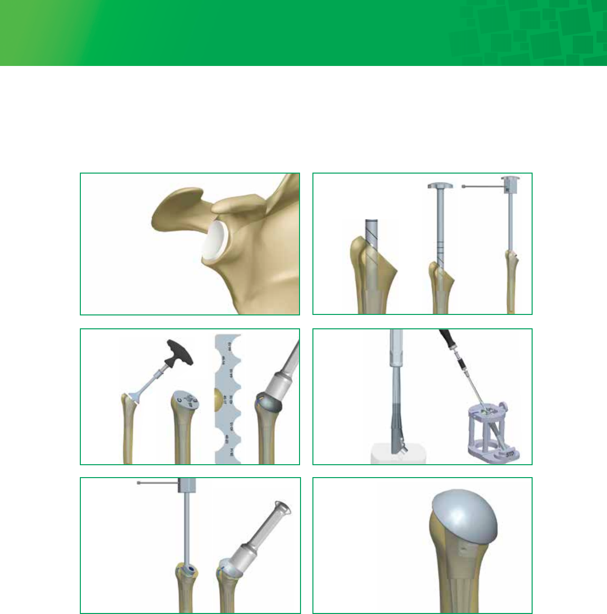
5
Final Glenoid
Implantation
Trialing Distal Stem
and Proximal Body
Osteotomy,
Evaluation &
Head Trialing
Head
Assembly
Final Humeral
Implantation
Implant
Assembly
Surgical Technique – Visual Step By Step with Fin-Lock™ Glenoid (continued)
6
Design Rationale
Redefining Modularity
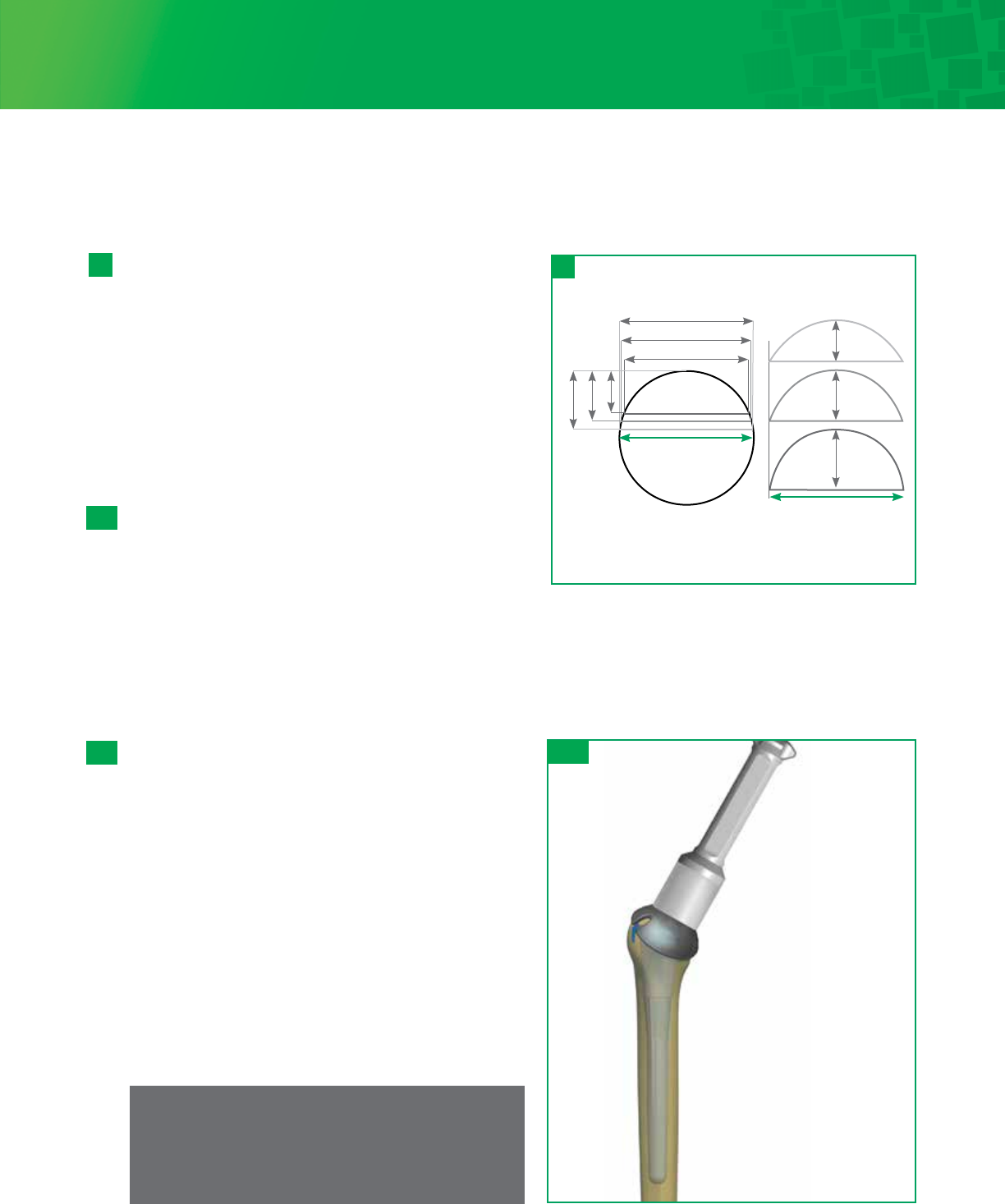
• 26 Humeral Head options based on published anthropomorphic data of over 300 human humeri to provide
anatomic fit by respecting the varying radius of curvature which allows for simplified sizing and soft tissue
balancing.
1,2
• Interchangeable proximal bodies and distal stems to accommodate varying patient anatomy.
Platform Convertibility
• Well-fixed press-fit stem options provide an intraoperative building platform and a pathway for revision.
• Modularity allows for convertibility from Total Shoulder Arthroplasty to Reverse Shoulder Arthroplasty with
version adjustment.
Enhanced Instrumentation
• Compaction technique to impact and preserve bone.
• Consistent instrumentation is utilized for primary, fracture and revision procedures aiding in familiarity and more
efficient use of space.
1. Iannotti JP, Gabriel JP, Schneck SL, et al: The normal glenohumeral relationships. An anatomical study of one hundred and forty shoulders. J Bone Joint Surg (Am), 1992; 74:491-500.
2. Hertel R, Knothe U and Ballmer F: Geometry of the proximal humerus and implications for prosthetic design. J Shoulder Elbow Surg. Vol. 11, No 4, 2002; 331-338.
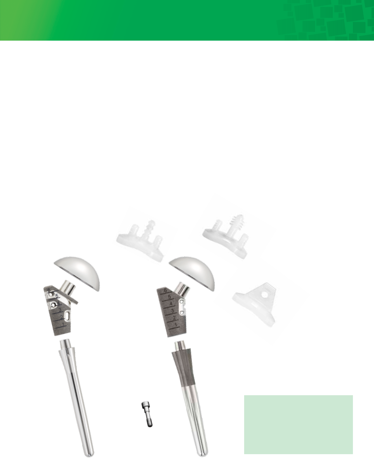
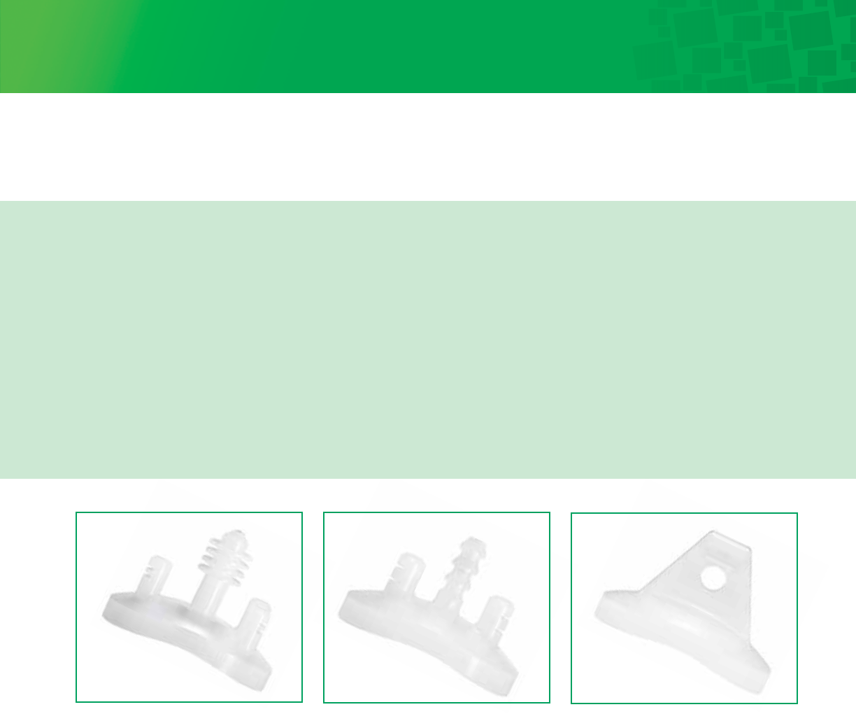
Body
Screw
Fin-Lock™ Glenoid
• Center peg features fins to
aid in stability
• Highly crosslinked polyethylene
for improved wear resistance
Pegged Glenoid
Eccentric
Head
Keeled Glenoid
Fin-Lock™ Glenoid
Press-Fit
Stem
Cemented
Stem
Concentric
Head
Fracture
Body
Body
Screw
Primary
Body
7
1 - 1
2 - 1
2 - 2
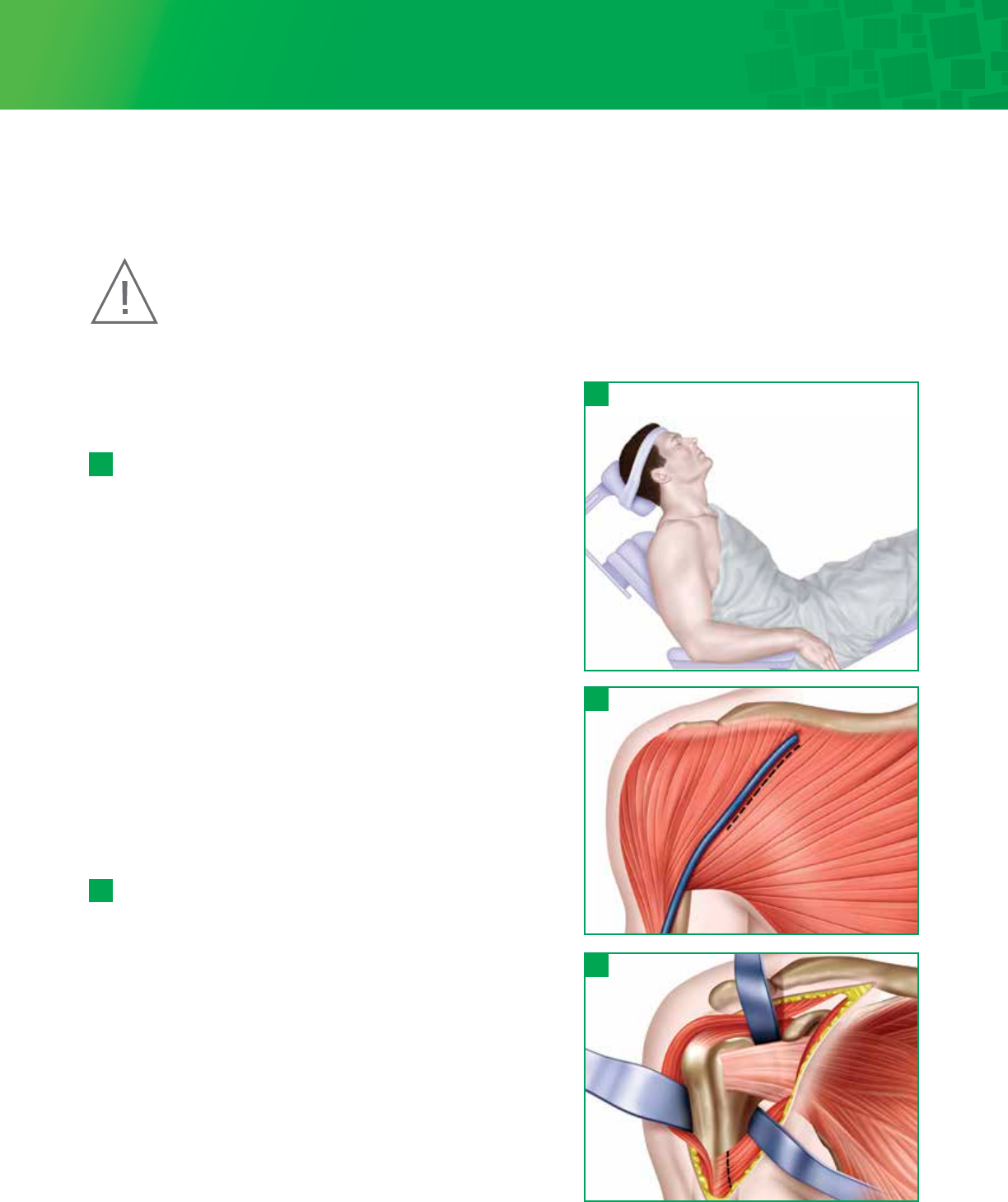
Step 1 • Preoperative Templating
and Patient Positioning
Preoperative evaluation of the humerus using the Titan
Modular Shoulder System X-ray Templates helps determine the
size of the prosthesis and level of the humeral head resection.
The goal is to remove the humeral head at the anatomic neck
using the patient’s own neck shaft angle, generally between
130-135°, and humeral version indicated by the patient’s natural
version.
1 - 1
Hemi and Total Shoulder Arthroplasty can be performed using
general anesthesia, regional anesthesia (i.e., interscalene block),
or a combination. Place the patient in beach chair position.
This position would have the patient supine with the hips
flexed approximately 30°, knees bent approximately 30° and
back elevated approximately 30°. Specialized headrests, such as
the MAYFIELD® or the McConnell, arm mounts or operating
tables with breakaway side panels can facilitate further access
to the top and back of shoulder.
Step 2 • Exposure
A deltopectoral approach is used to provide exposure to the
anterior aspect of the glenohumeral joint, the upper humeral
shaft and the humeral head. The initial incision line runs from
the mid-clavicle, over the top of the coracoid and extends in a
straight line down the anterior aspect of the arm. It should
follow the path of the cephalic vein along the interval between
the deltoid and the pectoralis major. The length of the
initial incision along this line can vary, depending on the
exposure needed to provide adequate access and visualization
of the joint, and is determined by patient body habitus.
Once the initial incision is made, expose, incise and release the
fascia. Locate the cephalic vein at the deltopectoral interval.
Separate the deltoid and pectoralis major muscles so that
the deltoid muscle is completely free from its origin to its
insertion, especially along its deep surface. Abduct and
externally rotate the arm. Gently retract the cephalic vein
medially or laterally along with the deltoid and pectoralis
muscle.
2 - 1
As the manufacturer of this device, Integra does not practice medicine and does not recommend this or any
other surgical technique for use on a specific patient. The surgeon who performs any implant procedure is
responsible for determining and using the appropriate techniques for implanting the device in each patient.
Caution: Federal law restricts this device to sale by or on the order of a physician or practitioner.
Surgical Technique
The Titan Modular Shoulder System was developed in conjunction with Joseph Abboud, MD; Phillip Duke, MB.BS, FRACS, FA(ORTH)A;
William Geissler, MD; Sanford Kunkel, MD; Anand Murthi, MD; Matthew Ramsey, MD; Mark Ross, MB.BS, FRACS, FA(ORTH)A

8
3 - 1
3 - 2
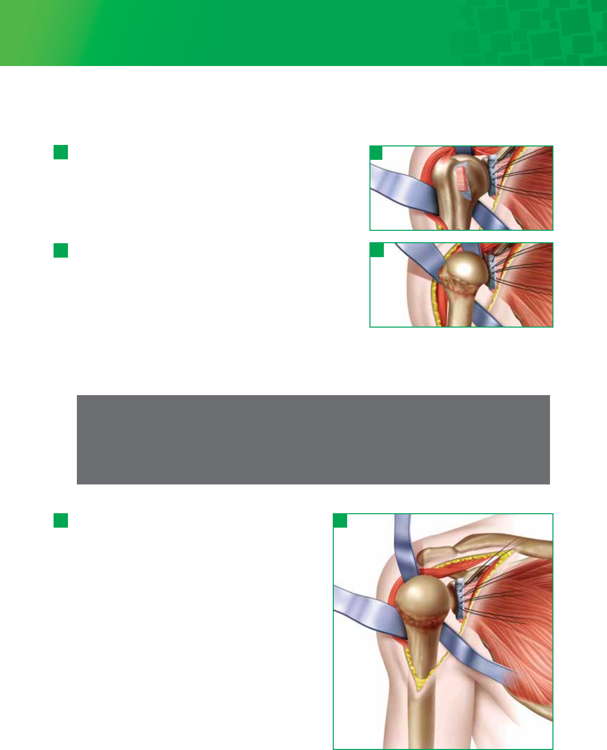
However, a small triangle can be removed from the coracoacromial ligament which will allow visualization of the
subscapularis and supraspinatus interval.
Release the biceps tendon from the bicipital groove and along the rotator interval down to its glenoid attachment.
Resect the long head of the biceps at the origin of the superior glenoid. Open the rotator interval along the line of the
biceps to define the superior margin of the subscapularis.
Isolate, clamp and ligate or coagulate the anterior humeral circumflex vessels lying across the anterior/inferior third of
the subscapularis tendon.
It is important to be aware of the musculocutaneous nerve, which penetrates the coracobrachialis muscle
2.54cm-5.08cm distally from the coracoid. The nerve may not be palpable within the surgical field, but remember its
proximity to the conjoined tendon. Digitally locate the axillary nerve. Introduce a Hohmann retractor and carefully
retract the nerve along with the latissimus dorsi tendon. This is especially important as it will protect the axillary nerve,
define and expose the inferior capsule.
Step 3 • Subscapularis Tendon Management
Lesser Tuberosity Osteotomy
Locate the insertion of the subscapularis tendon onto the lesser
tuberosity. Place the saw blade or osteotome just lateral to the
subscapularis insertion point and osteotomize approximately 4-5mm
of the lesser tuberosity.
3 - 1
3 - 2
Subscapularis Tenotomy
Alternatively the tendon can be removed from its insertion with
sharp dissection about 1cm medial to the lesser tuberosity. This
will allow for tendon to tendon reattachment of the subscapularis.
Step 2 • Exposure (continued)
Incise the clavipectoral fascia lateral to the conjoined tendon. If needed, release the upper 25% of the pectoralis major
tendon from its insertion on the humerus, using an electrocautery cutting blade. Place a Hohmann retractor over the
top of the humeral head, pulling the upper part of the deltoid posteriorly.
Check that rotator cuff tendons are intact. Introduce self-retaining Weitlander and Kobel retractors underneath
conjoined tendon and underneath the middle deltoid. It is important to always save or preserve the coracoacromial
ligament.
2- 2
9
Note
If the capsule is tented over large inferior osteophytes, it may be safer to remove the osteophytes with an
osteotome, moving away from the articular surface in an inferior direction. Once the osteophyte has been separated
from the bone, it may be peeled off the capsule, and the capsular release can then be completed adjacent to the
capsular attachment to the humerus. This decreases the risk of inadvertently damaging the axillary nerve when
attempting to mobilize the capsule out from beneath large inferior osteophytes.
Place a large Darrach retractor underneath the upper part of
the humeral head and dislocate the humerus. Put a medium
size retractor on the inferior part of the humeral head and
continue to bring the arm into full external rotation. The
entire humeral head should now be in vision, with all
capsular tissues removed from around the neck to provide
excellent exposure.Release of the anterior, inferior and
posterior glenohumeral ligaments is vital to properly and
concentrically centralize the humeral head as noted above.
At this point, the humeral head should freely rotate into
maximum external rotation, slight abduction and significant
extension allowing the head to dislocate anteriorly for
preparation of the humeral head. Proper anterior and inferior
capsular releases are needed for ease of dislocation and
proper humeral head preparation as well as re-establishing
concentricity of the glenohumeral joint. Releasing the
inferior capsule off the humerus past the 6 o’clock position
is essential in gaining exposure. Bone preparation is initiated
by debridement of sufficient amount of anterior inferior
osteophytes to properly identify the anatomic neck.
4 - 3 4 - 3
4 - 1
4 - 2
Step 4 • Capsule Release and Humeral Head Dislocation
Using blunt dissection, separate the capsule from the subscapularis,
inferiorly and medially. Release the rest of the anterior capsule from
the subscapularis to the glenoid rim. Release the coracohumeral
ligament from the base of the coracoid. Place traction sutures in the
subscapularis tendon to control and mobilize it from the anterior
glenoid neck. The subscapularis traction sutures will be utilized as a
“shoe horn” to control the humeral head dislocation and relocation.
The ‘subscapularis tendon-capsule complex’ is dissected and elevated
as one unit from the humerus at the medial aspect of the bicipital
groove. If this complex is contracted, a superior 180° release of the
subscapularis must be performed to mobilize the tendon to gain
eventual external rotation.
4- 1
4 - 2
Further humeral neck joint capsule release may be performed medially,
anteriorly or inferiorly as needed. The posterior capsule is maintained to
facilitate centralization and prevent posterior subluxation. Take care to protect the axillary nerve as it passes inferior to
the subscapularis and capsule. The location of the axillary nerve should be kept in mind at all times during capsular
release.
10
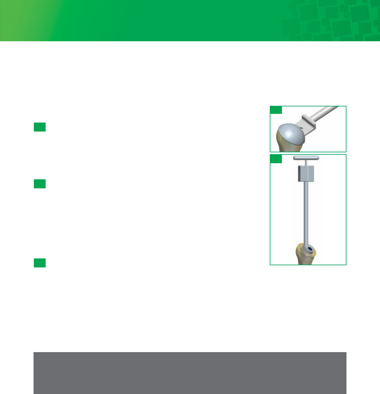
30°
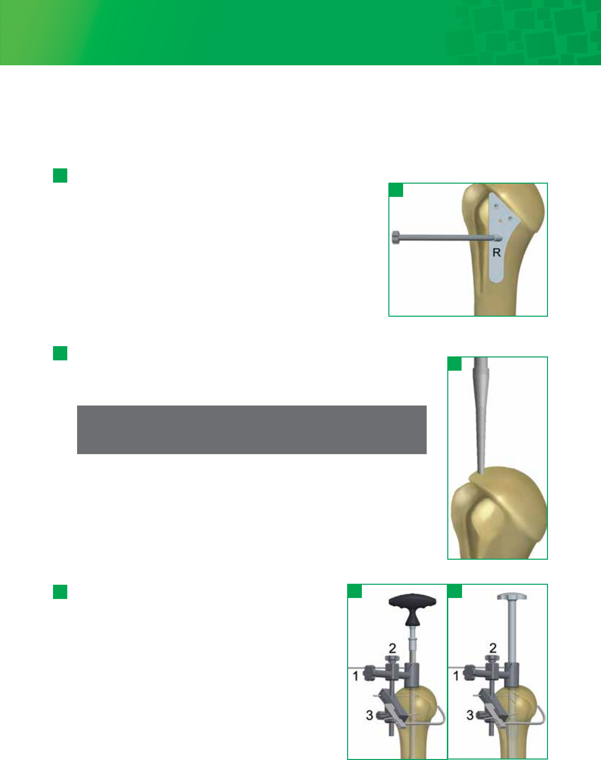
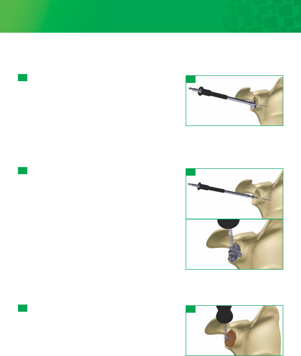
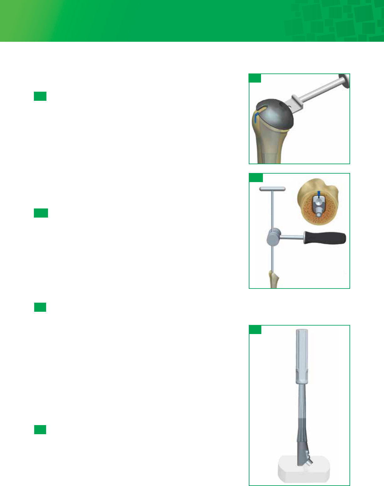
Head Resection with an Intramedullary Cutting Guide
Attach the T-Handle to the Starter Awl and create a pilot hole at the top of the humerus,
in line with the long axis of the humerus just lateral to the articular surface of the head
of the humerus and medial to the attachment of the rotator cuff.
5 - 2
The Head Cutting Depth Gauge can be used to assess the
cutting plane. The gauge should enter the anterior surface of
the humerus along the line of the anatomic neck and exit
2-3mm proximal to the posterior cuff attachment. Before the
oscillating saw blade (33 x 0.8mm) is placed along the flat
surface of the cutting plate, drill two 3.2mm Fixation Pins
through the cutting plate and into the underlying bone which
will stabilize the guide. Remove the Cutting Guide-Starter Awl
assembly by loosening knob 3 on the cutting plate and
removing the Starter Awl out of the humerus. Use an
oscillating saw through the capture to remove the humeral
head. If additional head resection is needed, lower the blade to
the next slot. This will remove 3mm of additional bone. After
removing the humeral head, extract the Fixation Pins using the
Pin Puller.
5 - 3
5 - 2
5 - 3
30°
5 - 4
Note
This surgical step should not be performed with power reamers or drills.
Leave the Starter Awl in place and clamp the Head Cutting Guide around the awl by
tightening knob 1. The Version Rod is then passed through the holes in the cutting guide
and is rotated into the desired retroversion. The holes denote 20°, 30°, and 40° of
retroversion, in reference to the forearm axis. If more or less retroversion is required,
use the orientation holes on the cutting guide collar and rotate the forearm to desired
angle accordingly. Slide the cutting plate against the humerus and tighten knob 2.
Then adjust the resection level by sliding the cutting plate up or down and tightening
knob 3.
Step 5 • Humeral Head Preparation and Resection
Assess the humeral head and remove any unwanted osteophytes to return the proximal humerus to near native anatomy.
Freehand Head Resection Technique
Place the Head Cutting Template along the anterior aspect of the arm
parallel to the shaft of the humerus, and mark the angle at which the
humeral head will be resected with an oscillating power saw or mallet and
large osteotome. There are two proximal holes on the Head Cutting
Template for 3.2mm Fixation Pin placement, if preferred. A 30° threaded
version hole for the Head Cutting Template Handle / Version Rod is also
available to assess retroversion.
The saw or osteotome should enter the anterior surface of the humerus
along the line of the anatomic neck and exit 2-3mm proximal to the
posterior cuff attachment. Once complete, the resection should be at the
level of the articular surface of the supraspinatus insertion site.
30°
5 - 1
5 - 1

11
Note
For larger canals, it may be preferable to start impacting up, using the Stem Trials, until a solid fit is achieved in the
canal. The cutting guide can then be attached to the Stem Trial Handle in the same manner as above.
Head Sizing
Use the Head Sizing Gauge to measure the resected head diameter
and thickness. Be sure to remove all osteophytes for accurate sizing.
After measuring and selecting the humeral head size, place the
humeral head on the back table to remove the cancellous bone. Use
the cancellous graft later in the procedure if impaction bone grafting
is needed for the metaphyseal body and humeral distal stem.
5 - 5 5 - 5
Note
The Humeral Osteotomy Covers provided in the instrument
tray can be used to protect the proximal humeral
preparation area.
Step 5 • Humeral Head Preparation and Resection (continued)
12
Step 6 • Glenoid System Preparation and Implantation
Exposure
Place a Fukuda retractor in the joint to retract the humerus posteriorly. Identify the axillary nerve by digital palpation and place a
blunt Hohmann retractor between the axillary nerve and the subscapularis. Dissect the inferior capsule from the inferior border
of the subscapularis. Release the capsule above the blunt Hohmann retractor to the glenoid margin. Release the rotator interval
to the base of the corocoid to complete the superior and inferior release of the subscapularis. Release the capsule between the
labrum and the subscapularis, leaving the labrum attached to the glenoid. With the subscapularis circumferentially released,
the remnant capsule on the undersurface of the subscapularis can either be resected or retained to bolster the bulk of the
subscapularis. Place the subscapularis with its attached tuberosity fragment behind a retractor. Grasp the remaining biceps tendon
and excise the posterosuperior labrum from within the joint to the inferior labrum. Similarly, excise the anterosuperior labrum to
the inferior labrum. This leaves a small fragment of inferior labrum with attached capsule that needs to be released. Protect the
axillary nerve with an index finger and release the inferior capsule from the labrum. After release of the inferior capsule, exposure
to glenoid is improved. Glenoid exposure is complete once the inferior capsule is released and the remnant labrum is excised.
6a: Fin-Lock Glenoid 6b: Pegged Glenoid 6c: Keeled Glenoid
Pegged Glenoid Keeled Glenoid
Fin-Lock Glenoid
13
Insert the 2.8mm Guide Wire through the selected Sizer. Advance the Guide Wire until adequate purchase is achieved in the
glenoid. Remove the Angled Handle and slide the Sizer anteriorly to remove, leaving the guide wire in the bone. The Glenoid
Holder can be used to remove the sizer. Do not grasp the Sizer at the hex to prevent damaging the connection with the handle.
Note
Optional version-correction Sizers are included in the tray. Assess
posterior wear on the glenoid and if version correction is necessary,
select the appropriate 5 or 10 degree Sizer to accommodate off
centered reaming and retroversion correction. The amount of
version correction is typically established on preoperative CT scan.
If more than 10° to 15° of version correction is required, asymmetric
reaming of the glenoid will not adequately correct the version
without compromising glenoid implantation.
6a- 1
Size Selection and Guide-Wire Placement
Select a Fin-Lock Sizer and attach the Angled Handle to the center post of
the Sizer. The handle can be adjusted to an anterior superior angle. Select
the size that covers as much of the glenoid surface as possible, without
overhanging the periphery of the bone.
6a- 1
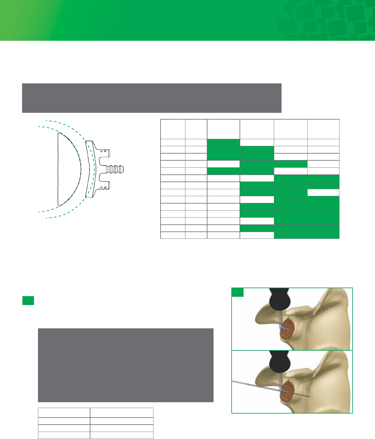
Version Correction Step Height
None +0 mm
5º +3 mm
10º +5 mm
6a: Fin-Lock Glenoid System
Cannulated Glenoid Preparation
Head Size
(mm)
Spherical
Ø
Radial
Mismatch with
ExtraSmall
Glenoid (54 Ø)
Radial Mismatch
with Small
Glenoid (59 Ø)
Radial
Mismatch
with Medium
Glenoid (64 Ø)
Radial
Mismatch
with Large
Glenoid (66 Ø)
38x14* 41 6.5mm 9.0mm 11.5mm 12.5mm
40x15* 43 5.5mm 8.0mm 10.5mm 11.5mm
42x16 45 4.5mm 7.0mm 9.5mm 10.5mm
44x16 48 3.0mm 5.5mm 8.0mm 9.0mm
44x19 45 4.5mm 7.0mm 9.5mm 10.5mm
46x14 54 0.0mm 2.5mm 5.0mm 6.0mm
46x17 49 2.5mm 5.0mm 7.5mm 8.5mm
46x20 47 3.5mm 6.0mm 8.5mm 9.5mm
48x15 56 -1.0mm 1.5mm 4.0mm 5.0mm
48x18 51 1.5mm 4.0mm 6.5mm 7.5mm
48x21 49 2.5mm 5.0mm 7.5mm 8.5mm
50x19 53 0.5mm 3.0mm 5.5mm 6.5mm
50x22 51 1.5mm 4.0mm 6.5mm 7.5mm
52x20 55 -0.5mm 2.0mm 4.5mm 5.5mm
*38mm and 40mm Offset/Eccentric Head option only.
*Green boxes represent the ideal glenohumeral sizing options as it relates to the Humeral Head and
Glenoid implant sizes.
48 mm x 15mm Head:
Spherical Diameter = 56mm
Medium Glenoid:
Spherical Diameter = 64mm
Diametrical Mismatch = 8mm
Radial Mismatch = 4mm
Note
When sizing the glenoid, care should be taken to create the recommended 4.0 - 8.5mm radial mismatch
of the Humeral Head and Glenoid components. See chart below.
Step 6 • Glenoid System Preparation and Implantation (continued)
14
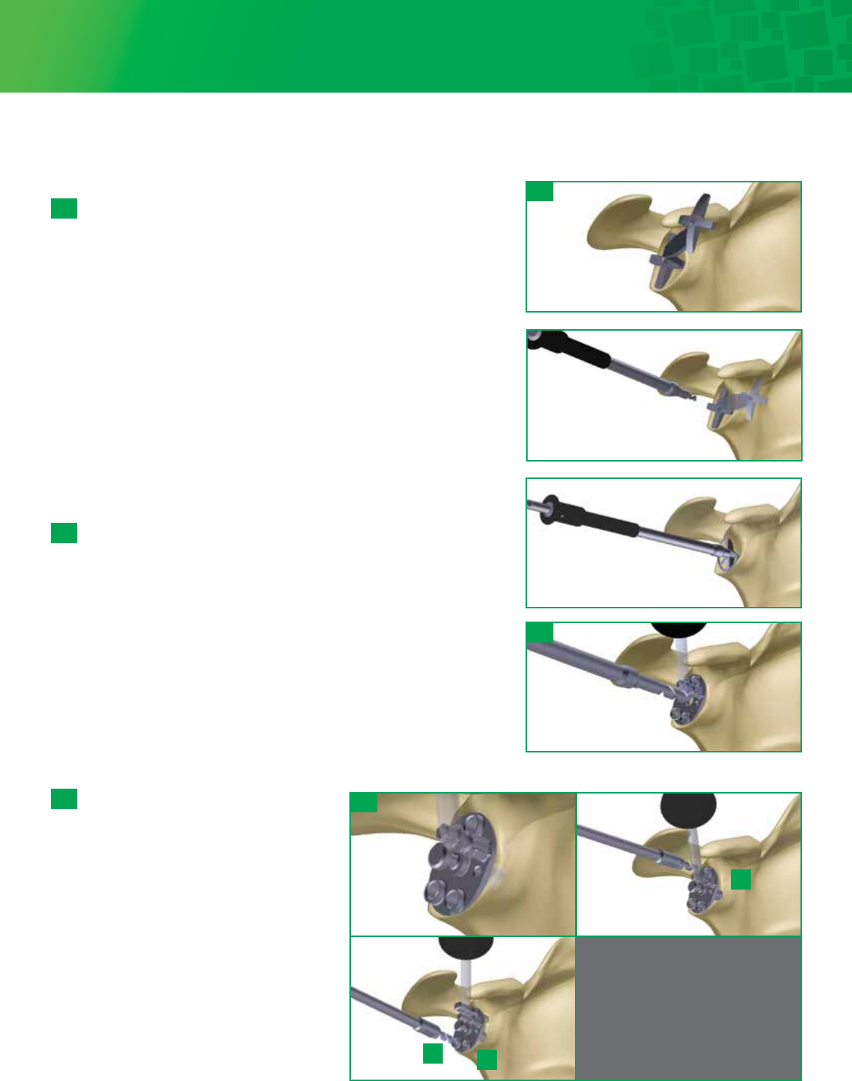
6a-2
Cannulated Glenoid Reaming
Select the appropriate sized Cannulated Reamer and attach the
reamer to the 2.8mm Drill Shaft. Start the reamer prior to
contacting the glenoid surface. Ream accordingly until proper
concavity has been achieved and cartilage has been removed.
Remove the reamer, leaving the Guide Wire in the bone. It is
important to remember that over-reaming will both decrease
the surface area of the glenoid face and reduce the depth of
the glenoid vault. Excessive glenoid reaming should be avoided
(See recommendations, in section 6a-1, on the limits of asymmetric
glenoid reaming)
If manual reaming is preferred, attach the 2.8mm Drill Shaft to
the T-Handle located in the Fin-Lock instrument tray.
6a-3
Cannulated Center Peg Preparation
Select the appropriate Cannulated Central Peg Drill: 15mm
for XS/S and 18mm for M/L. Attach the Cannulated
Central Peg Drill to the 2.8mm Drill Shaft. Slide the drill
over the Guide Wire and drill to the stop. Remove the
Guide Wire. Attach the Angled Handle to the Drill Guide
and align the Drill Guide over the central hole. Place a
Central Anti-Rotation Peg to stabilize the Drill Guide.
Continue to step 6a-7
6a-3
6a-4
Size selection
Select a Fin-Lock Sizer and attach the Angled Handle to the
center post of the Sizer. The handle can be adjusted to an
anterior superior angle. Select the size that covers as
much of the glenoid surface as possible, without
overhanging the periphery of the bone.
6a-2
6a-4
Non-Cannulated Glenoid Preparation
6a: Fin-Lock Glenoid System (continued)
15
6a-5
Glenoid Reaming
Attach the Starter Drill to the 2.8mm Drill Shaft. Select
the appropriate Starter Drill Guide and align the guide
centrally on the glenoid. Drill through the center hole
until the drill stops to create a hole for the
non-cannulated reamer post.
Select the appropriate Non-Cannulated reamer and attach
it to the 2.8 mm Drill Shaft. Start the Reamer prior to
contacting the glenoid surface. Ream accordingly until
proper concavity has been achieved and cartilage has been
removed. It is important to remember that over-reaming
will both decrease the surface area of the glenoid face and
reduce the depth of the glenoid vault. Excessive glenoid
reaming should be avoided.
If manual reaming is preferred, attach the 2.8mm Drill Shaft
to the T-Handle located in the Fin-Lock instrument tray.
6a-6
Center Peg Preparation
Attach the Angled Handle to the 2.8mm Drill Guide.
Select the appropriate Central Peg Drill: 15mm for XS/S
and 18mm for M/L. Attach the Central Peg Drill to the
2.8mm Drill Shaft. Align the Drill Guide with the center
hole and drill until the collar of the drill bit contacts the
guide. Place a Central Anti-rotation Peg in the hole.
Option: An alternative to holding the Drill Guide in place
is to insert the 2.8mm Guide Pin through one of two
holes in the Drill Guide directly and securely into the
glenoid fossa. This alleviates the need to hold the Drill
Guide in place by hand, and allows for better visibility
and maneuverability in the joint space.
6a-7
Peripheral Peg preparation
Attach a Peripheral Drill to the Self-retaining
Drill Adaptor. Ensure the Drill Guide is
aligned so that the two adjacent holes are
inferior. Drill the superior hole (1) until the
collar of the drill bit contacts the guide. Pull
the Self-retaining Drill Adaptor gently and
the drill will remain in the hole and act as an
anti-rotation peg. Select another Peripheral
Drill and drill the posterior inferior (2), hole.
Leave the drill in as an anti-rotation peg.
Select another Peripheral Drill and drill the
anterior inferior hole (3). Remove the Drill
Guide, Central Anti-rotation Peg and
Peripheral Drills.
Note
Peripheral drills should be left in
place to act as an anti-rotation peg.
6a-5
6a-6
6a-7
1
23
6a: Fin-Lock Glenoid System (continued)
16
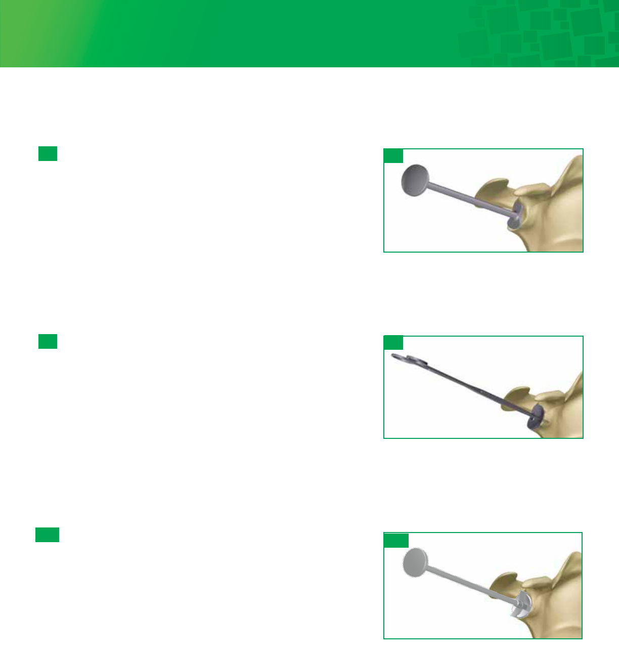
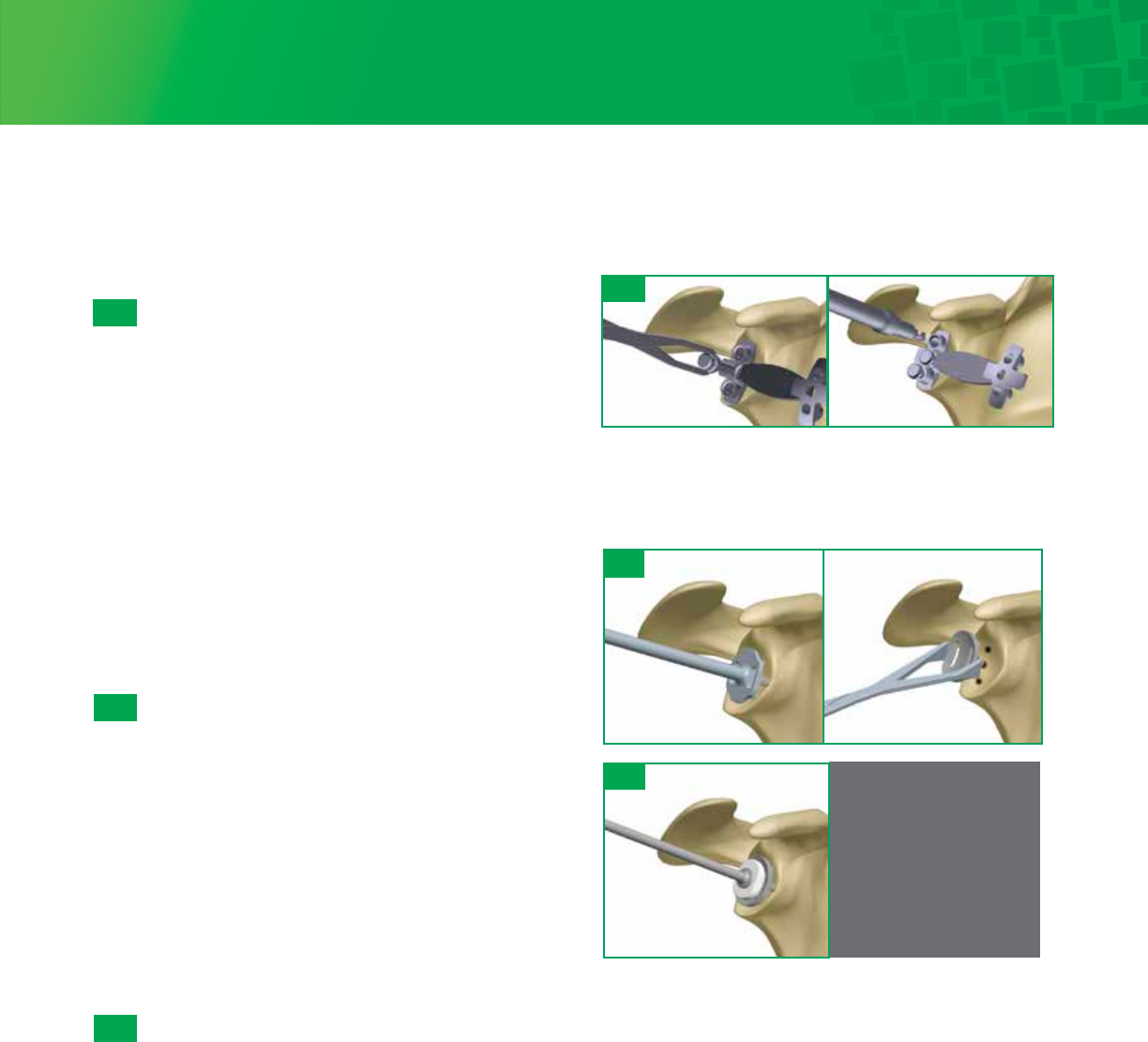
6a-8
Punch
A Punch is available to check hole positioning/depth in
addition to being used as a cement pressurizer. Check
each peripheral hole to determine whether it penetrates
the scapula at its base. If penetration is detected consider
bone grafting the hole with cancelleous bone harvested
from the resected humeral head. The Punch can be
utilized to impact the graft.
6a-9
Trial
Select the appropriate Fin-Lock Trial and impact the trial
onto the glenoid using the Glenoid Impactor. The trial
matches the drill diameter and will give you a secure trial fit.
Visually verify that the trial component sits flush with the
prepared glenoid surface through the slots in the trial.
Remove the trial and irrigate the glenoid using pulsative
lavage to remove blood and tissue debris from the drill holes.
6a-10
Cement and Implant
While cement is being prepared, obtain hemostasis by
packing each of the peg holes with thrombin and surgical
gauze or gel foam. Mix cement using manual or syringe
application. Place the cement into a 60 cc Catheter/Toomey
syringe. Insert the tip and pressurize the cement into each of
the peg holes. Further pressurize the cement using the
Punch, remove the Punch and refill the drill holes with
cement. This will allow for cement pressurization as well as
removal of any excess cement on the glenoid surface.
Attach the appropriately sized Combo Inserter/Extractor to the
corresponding Fin-Lock implant and screw on the Glenoid
Impactor Handle. Apply cement to cover the entire backside of
the Fin-Lock implant and impact the implant construct with a
mallet until there is complete contact between the back side of
the implant and the prepared glenoid surface. It may be
necessary to use the oval Glenoid Impactor to fully seat the
component. Maintain pressure directly on the glenoid
component until the cement has hardened.
6a-8
6a-9
6a-10
6a: Fin-Lock Glenoid System (continued)
17
6b- 2
Cannulated Drill/Cannulated Reaming
When exposure is deemed adequate, use the Glenoid Sizers and
Glenoid Holder to size the glenoid. Mark the center of the glenoid
using the hole in the Glenoid Sizer with a skin marker. Attach the
appropriately sized Pin Bushing onto the selected size Glenoid
Drill Guide. Align with the center mark, and using the included
2.0mm Guide Pin, drive through the Pin Bushing until adequate
purchase is achieved into the glenoid. If increased retroversion is
noted on preoperative imaging studies, then orient the Glenoid
Drill Guide to correct this retroversion by placing the drill guide in
a plane that is anteverted from the native glenoid plane prior to
Guide Pin insertion. Remove the Drill Guide/Pin Bushing. Attach
the appropriately sized 5-fluted Glenoid Reamer to the Straight
Drill Shaft. Slide over the Guide Pin, start the reamer before
making contact with the bone and ream accordingly until proper
concavity has been achieved and cartilage has been removed. It is
important to remember that over-reaming will both decrease the
surface area of the glenoid face and reduce the depth of the
glenoid vault. Excessive glenoid reaming should be avoided.
Leaving the Guide Wire secure in the bone, use the Cannulated
Peg Drill to create the center hole. Remove the Guide Wire.
Alternative Non-Cannulated Drill/Reaming
When exposure is deemed adequate, use the Glenoid Sizers and
Glenoid Holder to size the glenoid. Also, mark the center of the
glenoid using the hole in the Glenoid Sizer with a skin marker.
Attach the Glenoid Solid Peg Drill onto the Straight Drill Shaft and
use the center hole in the appropriately sized Glenoid Drill Guide.
Drill the central hole. Attach the appropriately sized Glenoid
Reamer to the Straight Drill Shaft.
Insert the nub of the reamer into the central hole. Start the
Reamer before making contact with the bone and ream
accordingly until proper concavity has been achieved and
cartilage has been removed. It is important to remember that
over-reaming will both decrease the surface area of the glenoid
face and reduce the depth of the glenoid vault. Excessive glenoid
reaming should be avoided. Align the Glenoid Drill Guide with the
current center hole and drill using the Peg Drill.
6b- 1
Step 6b • Pegged Glenoid Preparation and Implantation
6b- 1
6b-2
18
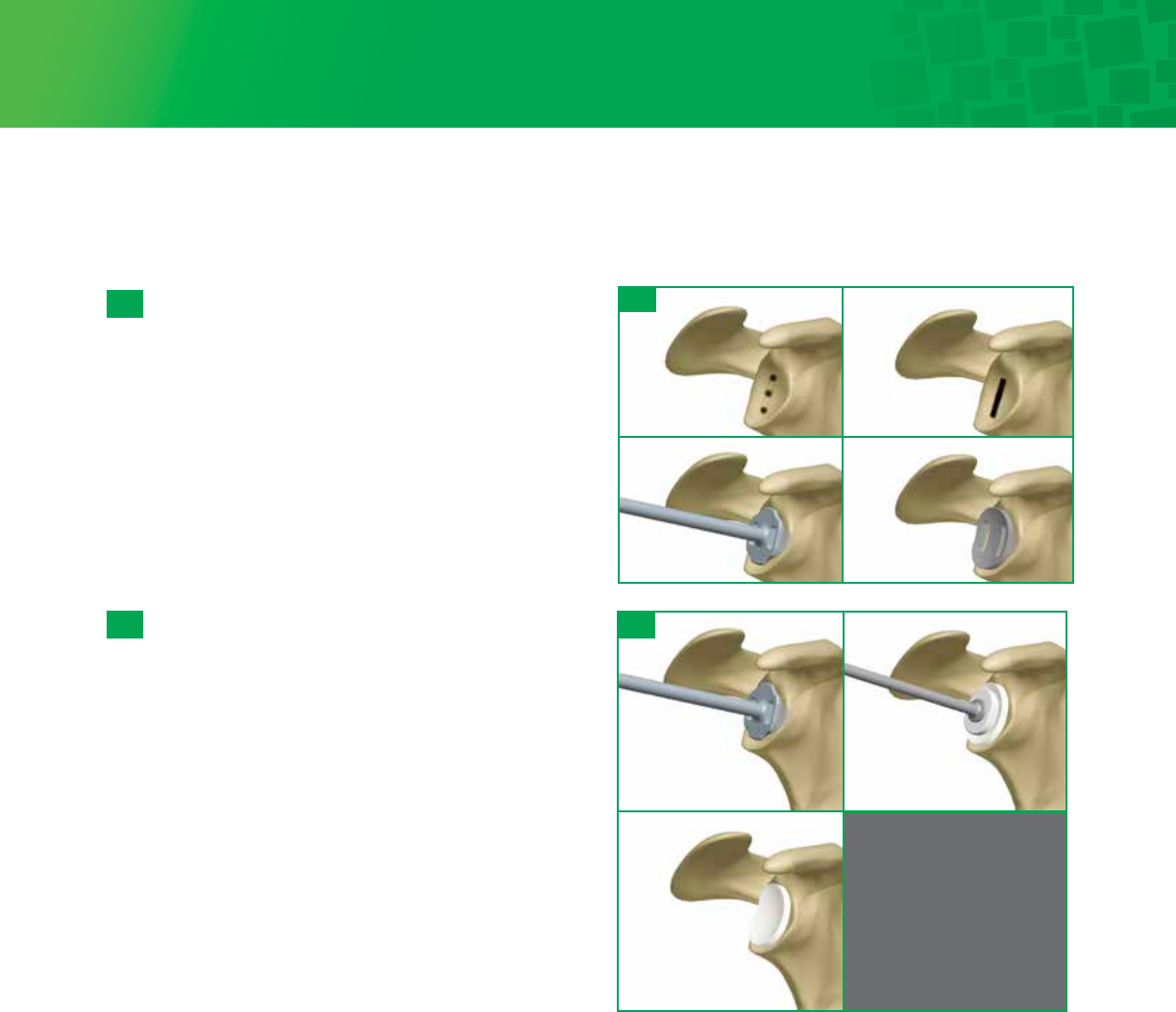
Step 6b • Pegged Glenoid Preparation and Implantation (continued)
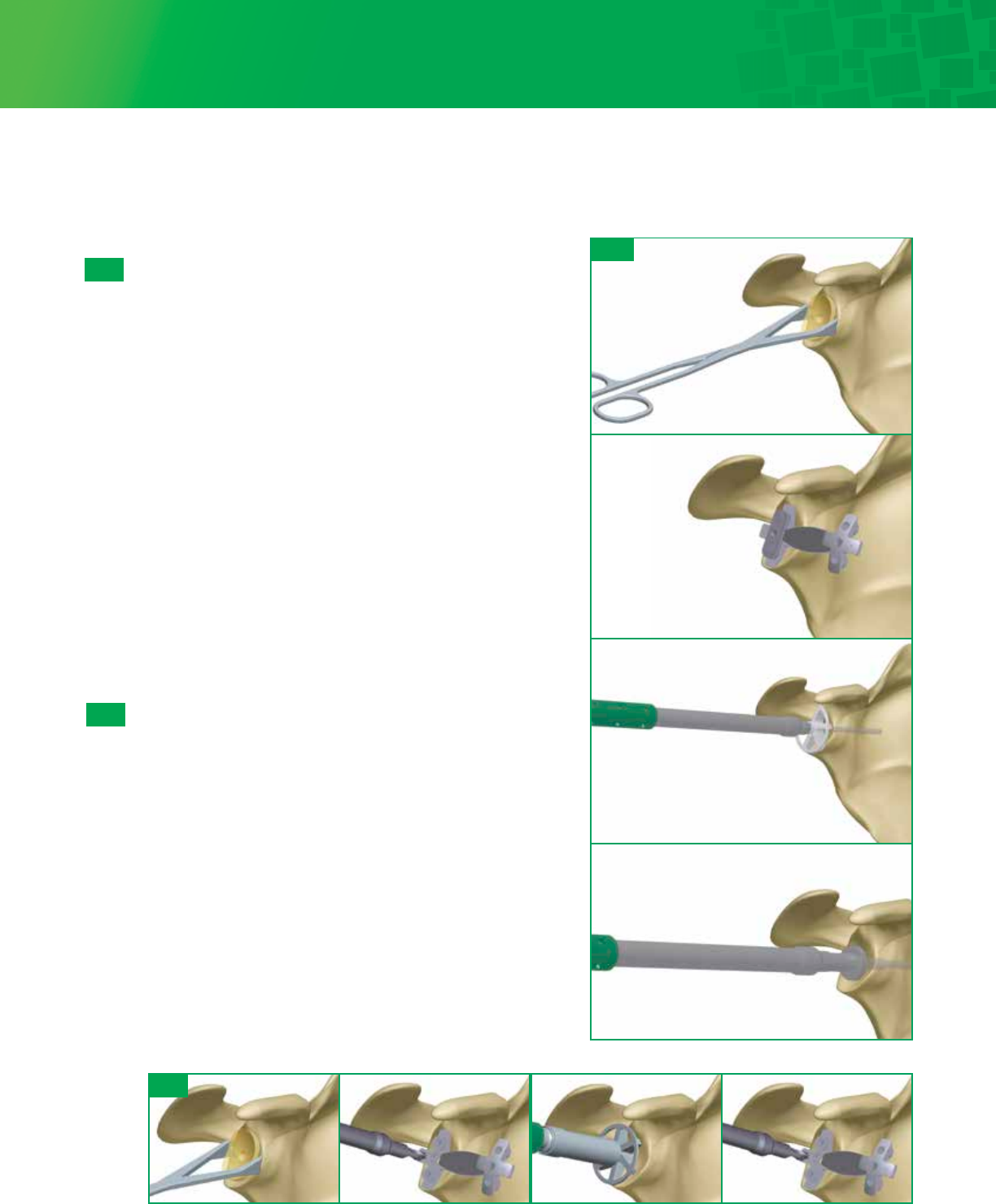
Peripheral Peg Drilling
Place an Anti-rotation Peg in the center hole using the
Anti-rotation Peg Holder. This will help stabilize the drill
guide during the drilling of the peripheral peg holes.
Rotate the drill guide to desired orientation and drill the
peripheral peg holes.
After each peripheral peg hole is drilled, insert an Anti-
rotation Peg to maintain alignment of the drill guide. The
preferred scenario is drilling so as not to penetrate the
scapula which will allow you to pressurize the cement
mantle. Check the quality of the glenoid bone
preparation by determining if the component is directly
supported by precisely contoured bone, which should
prevent the component from rocking, even when an
eccentric load is applied to the rim of the implant.
Punch/Trial
A Glenoid Peg Punch is available to check hole
positioning/depth. Check each peripheral hole to
determine whether it penetrates the scapula at its base.
If penetration is detected consider bone grafting the
hole. The Glenoid Peg Punch can be utilized to impact
the graft. Select the appropriate Glenoid Peg Trial and
impact the trial onto the glenoid using the Glenoid
Impactor. The trial matches the drill diameter and will
give you a secure trial fit. Visualize that the trial
component sits flush with the prepared glenoid surface
through the slots in the trial. Remove the trial and
irrigate the glenoid using pulsative lavage to remove
blood and tissue debris from the three drill holes.
Open the appropriately sized pegged glenoid implant. While cement is being prepared, obtain hemostasis by using the
Cement Pressurizer and attaching it to the T-Handle. Hemostasis may also be achieved by packing each of the peg
holes with thrombin and surgical gauze or gel foam. Mix cement using manual or syringe application. The cement is
placed into a 60cc Catheter/Toomey syringe. The end of the syringe is cut with scissors. The tip is inserted, and the
cement pressurized into each of the peg holes. Further pressurize the cement and refill the drill holes with cement. This
will allow for cement pressurization as well as removal of any excess cement on the glenoid surface.
Apply cement to cover the entire backside of the pegged glenoid component, insert the implant, and use the Glenoid
Impactor to seat the component until there is complete contact with the perimeter of the glenoid. Maintain pressure
directly on the glenoid component until the cement has hardened.
6b- 3
6b- 4
6b- 5
Note
The Peg Punch is the same
dimension as the final
implant. Additional cement
must be placed in the
holes after pressurization
or the implant will not be
adequately cemented.
6b- 4
6b- 4
6b- 3
19
If using the Keeled Glenoid implant, prepare the glenoid
as previously described. As mentioned in Step 6b-1 and
6b-2, size, then drill the central hole and ream the
glenoid. Proceed with drilling the peripheral peg holes.
Use a burr, rongeur or curette to connect the peg holes
for the keel of the prosthesis. Excavate the bone in the
base of the coracoid and down the lateral border of the
scapula to help lock the keeled prosthesis with cement.
Use the Glenoid Keel Punch to impact the bone in the
glenoid fossa for proper fit of the Glenoid Keel Trial. The
Glenoid Keel Trials have slots in them to visualize that
the back of the prosthesis will sit flush on the bone of
the glenoid fossa. Commence with trialing.
Open the appropriately sized keeled glenoid implant.
While cement is being prepared, obtain hemostasis by
packing the keel hole with thrombin and surgical gauze
or gel foam. Mix cement using manual or syringe
application. The cement is placed into a 60cc Catheter/
Toomey syringe. The end of the syringe is cut with
scissors. The tip is inserted, and the cement pressurized
into the keel hole. Further pressurize the cement using
the Glenoid Keel Punch, remove the punch and refill the
keel hole with cement. This will allow for cement
pressurization as well as removal of any excess cement
on the glenoid surface.
Apply cement to cover the entire backside of the keeled
glenoid component, insert the implant, and use the
Glenoid Impactor to seat the component until there is
complete contact with the perimeter of the glenoid.
Maintain pressure directly on the glenoid component
until the cement has hardened.
6c-2
6c- 1
6c- 2
6c- 1
Note
The Keel Punch is the same
dimension as the final
implant. Additional cement
must be placed in the
holes after pressurization
or the implant will not be
adequately cemented.
Step 6c • Keeled Glenoid Preparation and Implantation
20
7- 2
7- 1
LRG
STD
SML
7 - 2
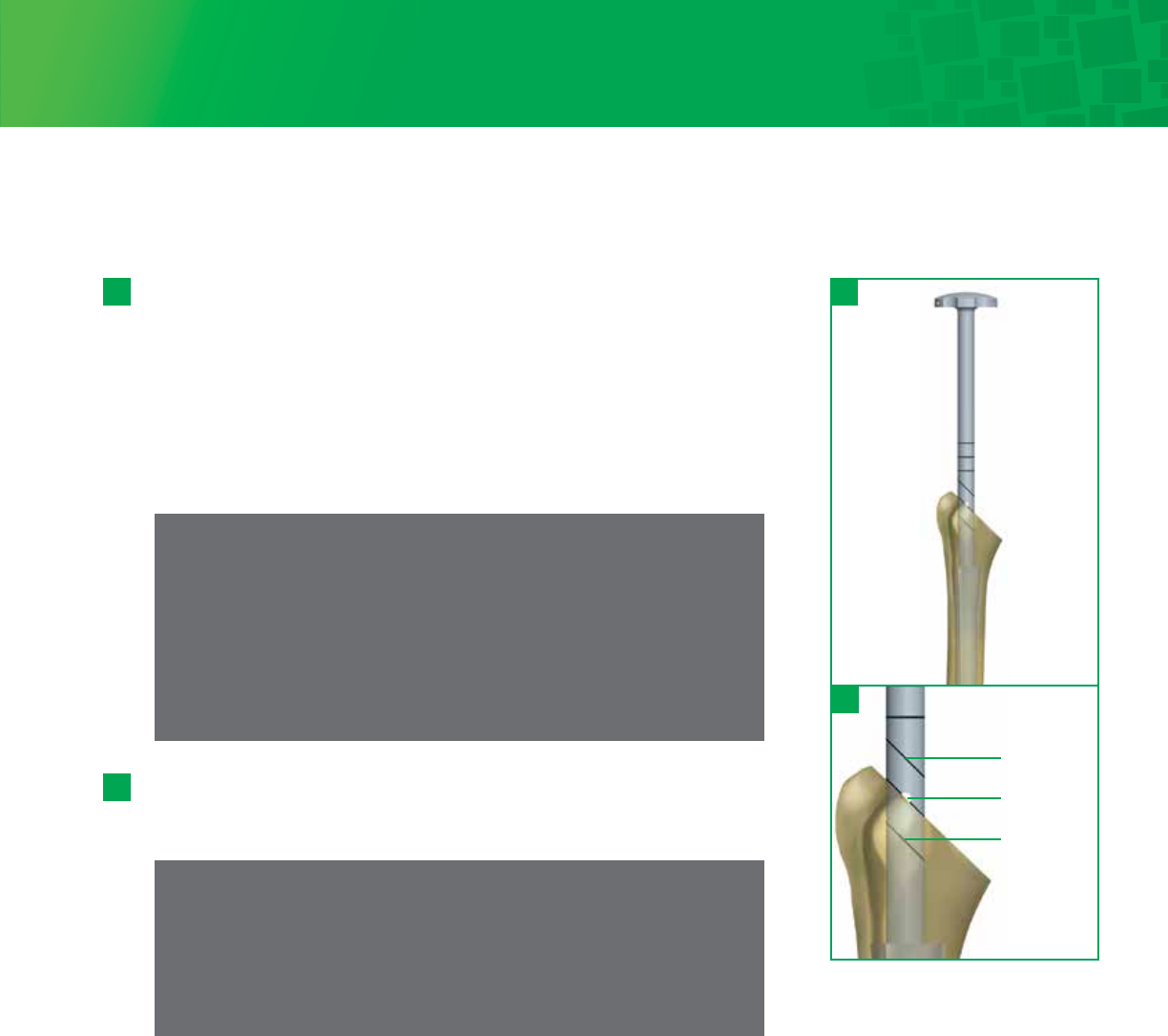
Step 7 • Humeral Canal Preparation
Side the Depth Stop onto the Stem Trial Handle prior to attaching it to the 6mm
Humeral Stem Trial. Place the tip of the stem trial at the most superior point on
the resected humerus just behind the long head of the biceps groove, so
that it is aligned with and ready to pass directly down the intramedullary canal.
Using the Stem Trial, create a pilot hole and then sequentially trial/impact the
medullary canal in line with its long axis. If the extramedullary cutting guide was
used the Starter Awl can be used to create the pilot hole. Continue sequential
trialing/impacting, following the path created through the intramedullary canal,
increasing the Stem Trial diameter in 1mm increments until a solid fit is achieved
in the humerus.
7 - 1
The laser etching below the hole is for the Small Proximal Body and the etching
above the hole is for the Large Proximal Body. If using a Small or Large body
height, impact until the appropriate laser etching is parallel with the osteotomy.
Tip
With the Stem Trial Handle attached to the stem trial,note the final Stem
Trial diameter. This will determine the size of the final distal stem implant.
When trialling to determining the appropriate body and stem size,
trialling to the Small Body line will allow you up-size during a conversion
to a Reverse.
Note
The diagonal laser markings and hole on the inserter handle correspond to
the depth required for the Small, Standard, and Large Proximal Bodies. If a
depth stop is not available, for the Standard Body, place a 3.2mm Fixation
Pin through the hole and drive the trial down until the pin sits flush on the
osteotomy. Remove the pin and ensure the trial does not advance further. If
trial advances, additional sequential trialing/impacting to a larger diameter
is needed, be sure to stop when resistance within the canal is felt.
21
9- 1
9- 2
9- 3
9- 1
9- 2
9- 3
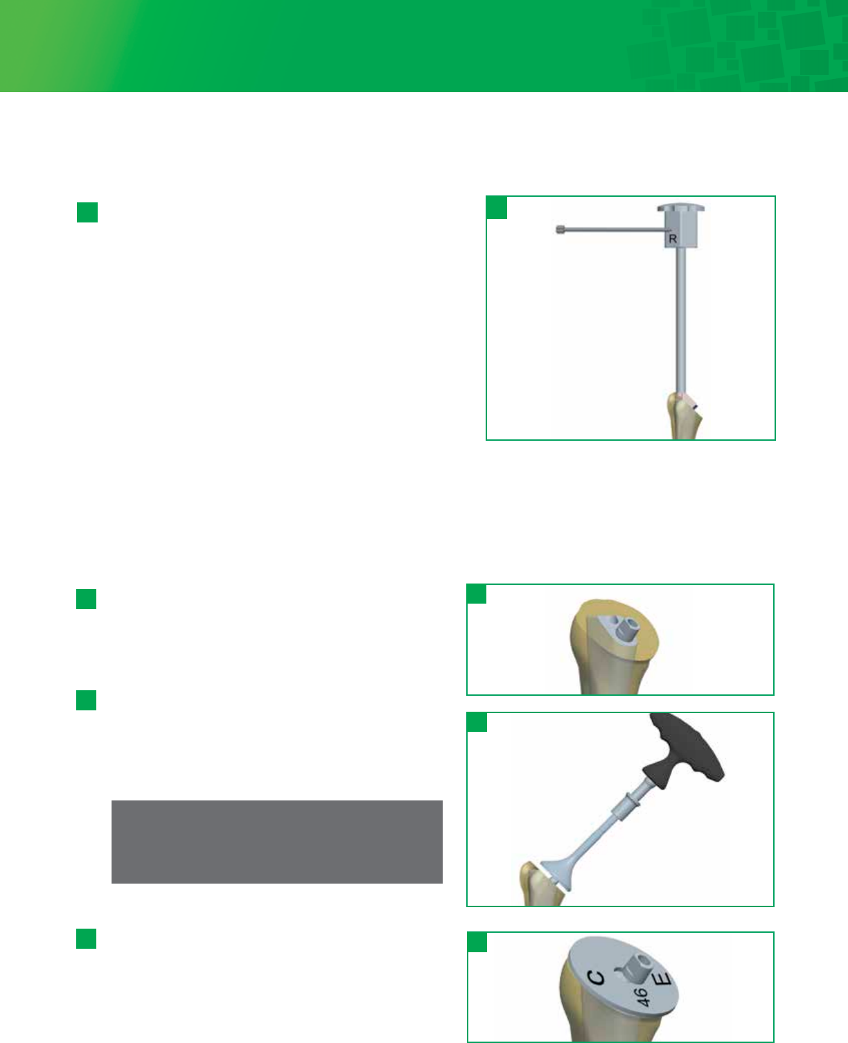
Step 9 • Humeral Head Trial
Osteotomy Evaluation/Calcar Reaming
Place the Taper Adaptor onto the Body Trial. Attach the
Trial Calcar Planar onto the ratcheting T-Handle to remove
any excess bone on the surface of the osteotomy
The angle of the Trial Calcar Planar when fixed onto the
Taper Adaptor will be parallel to the standard neckshaft
angle at 135°. Assess its relationship to the resected plane.
If the angle diverges by only a few degrees then the Calcar
Planar can be used to finalize the plane.
Note
Ensure all boney protrusions are clear before moving
on to head trialing.
Osteotomy Sizing Template
Select the Head Sizing Plate that most closely covers the
cut surface of the humeral osteotomy.
After determining the diameter of the measured humeral
head, use the Head Sizing Plate to determine if a
concentric or eccentric head is necessary.
Select the appropriately sized Humeral Head Trial.
8 - 1
8 - 1
Step 8 • Body And Stem Trial Insertion
Remove the Stem Trial and attach it to the closest
corresponding Body Trial. Proximal Bodies are interchangeable
and can be used with all stem sizes. If the Trial Stem is
between Proximal Body sizes, it is suggested to start with the
smaller diameter Body Trial and go up to the larger diameter
Body Trial if needed. Attach the Body/Stem Trial construct to
the Humeral Trial Inserter/Extractor inserting the D feature in
the taper hole for alignment, then tightening the top of the
Humeral Trial Inserter/Extractor until the Body/Stem Trial is
secure.
Using the Cutting Template Handle for a threaded version rod
on the Humeral Trial Inserter/Extractor (which is set at 30° of
retroversion), impact the stem in the correct retroversion,
which corresponds to the version set during the humeral head
osteotomy. Seat the Body/Stem Trial until the Humeral Trial Inserter/Extractor sits on the resected surface.
At this point, the Body Trial is seated flush to the resection. Remove the Humeral Trial Inserter/Extractor.
30°
22
Step 8 • Body And Stem Trial Insertion
9-4b
Note
If the Humeral Head Trial does not lock onto the
Taper
Adaptor, it may be necessary to Calcar plane further to
clear any boney impingement.
Eccentric Head Trialing
If the Stem Trial is off-center in relation to the humeral
osteotomy, the Eccentric Head Trial will allow the head to
be rotated into the head position that allows maximum
coverage of the proximal humerus.
Place the Eccentric Head Trial onto the Taper Adaptor on
the Body Trial and rotate the head trial to the desired
position. Once the Eccentric Head Trial position is selected,
lock the Head Trial position with the Head Impactor. Mark
the final position of the Eccentric Head Trial peripheral
notch on the humeral surface for later reference with the
final implant.
Ensure the taper adapter remains in the head for proper
eccentricity assessment if using the back table assembly
technique.
Head Trialing
This system measures its humeral heads using a base
width x height measurement. A 46x17 head is 46mm wide x
17mm tall. This makes different spherical radii in one base
width as height changes. Some systems use a spherical
diameter measurement which keeps a constant spherical
radii, yet this causes the base width to change as height
changes. With this system, you choose the diameter that
best fits your osteotomy, then choose the head height that
best matches the glenoid component while allowing for
adequate soft tissue balancing.
9- 4
9- 4a
9- 4b
Concentric Head Trialing
Once trial is selected, place the Concentric Head Trial
onto the Taper Adapter on the Body Trial. Check that the
head trial achieves appropriate coverage of cortical bone,
with 5-8mm height above the greater tuberosity. Proper
head thickness can be determined during trial reduction. If
necessary, increase or decrease selected head size/type and
reassess in place. A final decision will be made during trial
reduction, with the glenoid component in place.
Spherical Diameter vs. Base Width Diameter
(Drawings are not actual size)
Spherical Diameters:
base width changes
with each height Base Width Diameters:
base width same for each height
48mm
Titan Base Width Diameter Sizing:
48-15 / 48-18 / 48-21
21 mm 18 mm 15 mm
48mm
Spherical Diameter Sizing:
48-15 / 48-18 / 48-21
43.5mm
45.5mm
46.5mm
21mm
18mm
15mm
9- 4
23
12- 1
Step 11 • Preparation for Repair of Subscapularis Tendon
If the subscapularis tendon was removed with a small portion of lesser
tuberosity, two permanent sutures are passed through two sets of holes for
later tension band suturing of the lesser tuberosity fragment to its native
bed. In this circumstance, we recommend placing the sutures through the
suture holes and/or around the stem of the prosthesis and pulling the slack
out of the sutures just before the prosthesis is placed into its final seated
position within the humeral canal.
If the subscapularis tendon was cut using sharp dissection a tendon to
tendon repair can be performed after final prosthesis has been implanted.
Step 12 • Body and Stem Implant Assembly
Proximal Body and Distal Stem Assembly
Select and remove from their packaging the final Humeral Body and
Humeral Stem sizes that correspond to the trials. Seat and secure the
Humeral Body implant onto the Stem Impaction Stand. Place the
Humeral Stem implant onto the Humeral Body with finger pressure.
Place the Stem Impactor over the tip of the humeral stem and engage
the tapers with a few mallet strikes.
11- 1
12- 1
10- 1
10 - 2
Step 10 • Soft Tissue Balancing and Trial Removal
With the Body/Stem Trial and Humeral Head Trial in place, use a burr or a
rongeur to remove any residual osteophytes extending beyond the
periphery of the humeral head. It is important to balance soft tissue tension
with the appropriate trial humeral head in place. It should be possible to
fully internally rotate the arm across the chest so that the hand of the
involved shoulder easily rests on top of the opposite shoulder, without
elevating the involved shoulder off the table. It should also be possible to
externally rotate the arm 30-40° and still re-approximate the subscapularis
tendons to the cut surface of the neck of the humerus. With the arm in
neutral rotation, the humeral head should posteriorly sublux 50%
or more but should spontaneously reduce when the posterior force is
released. Remove the Head Trial/Taper Adapter construct by hand.
If difficult to remove use the Head Extractor tool under the trial head.
Stem Trial Removal
Mark the osteotomy in line with the laser etching on the back of the Body
Trial. This will be used as a reference for matching rotation with the final
implant. Extract Body/Stem Trial construct from the humeral canal using
the Threaded T-Handle or Humeral Trial Inserter/Extractor and Slotted
Mallet.
10 - 2
10- 1
24
Step 12 • Body and Stem Implant Assembly (continued)
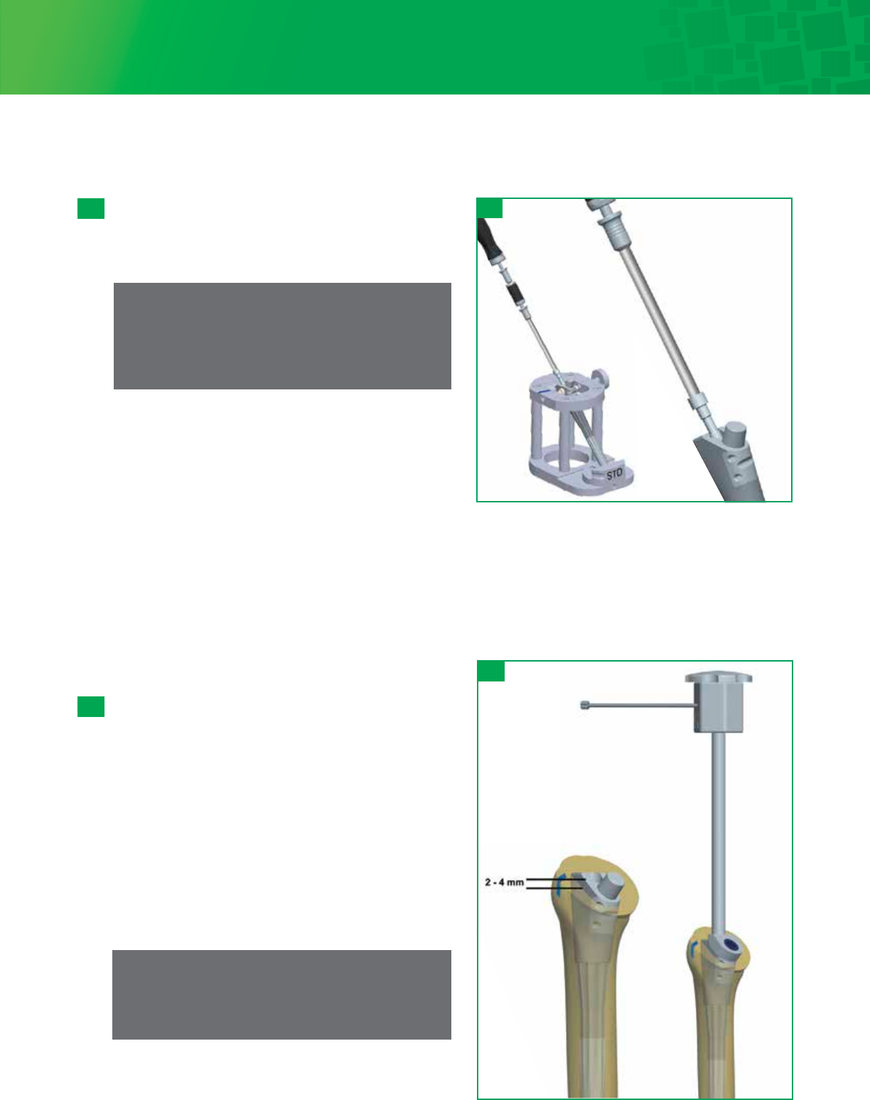
13- 1
Stem Insertion
Insert the assembled Body/Stem implant into the prepared
humerus using the Humeral Implant Inserter/ Extractor. Use
the Head Cutting Template Handle / Version Rod on the
Humeral Implant Inserter/Extractor to set the stem in the
correct anatomic retroversion, which should match the
version set at the time of the humeral osteotomy and
trialing. The body has a laser mark that can be lined up with
the previous mark placed on the osteotomy. Slowly impact
the implant and stop once the stem is firmly seated and the
top of the body is approximately 2-4mm above the
osteotomy. This will ensure Morse taper assembly with
Humeral Head.
If desired, use the gold Implant Calcar Planar to remove any
excess bone at the osteotomy.
Note
Thoroughly clean and dry both tapers to ensure
proper fit.
12- 2 12- 2
Remove the Humeral Body Screw from its packaging
and insert into the Humeral Body with the Driver Handle,
Torque Limiter and 1/8 Hex Driver. Tighten the screw until
the torque limiter clicks.
Note
The implant stand can be used to hold the implant
while tightening the Humeral Body Screw.
The torque
limiter is designed to tighten the screw to 2 Nm.
Step 13 • Stem/Body Implantation and In-Situ Head Assembly
This system is designed as a press-fit prosthesis, in which the press-fit is achieved via the tapering and splines of the
distal stem. The use of cement is not necessary or recommended. Cemented stems are available for cases
in which a press-fit stem would not be appropriate.
13 - 1
25
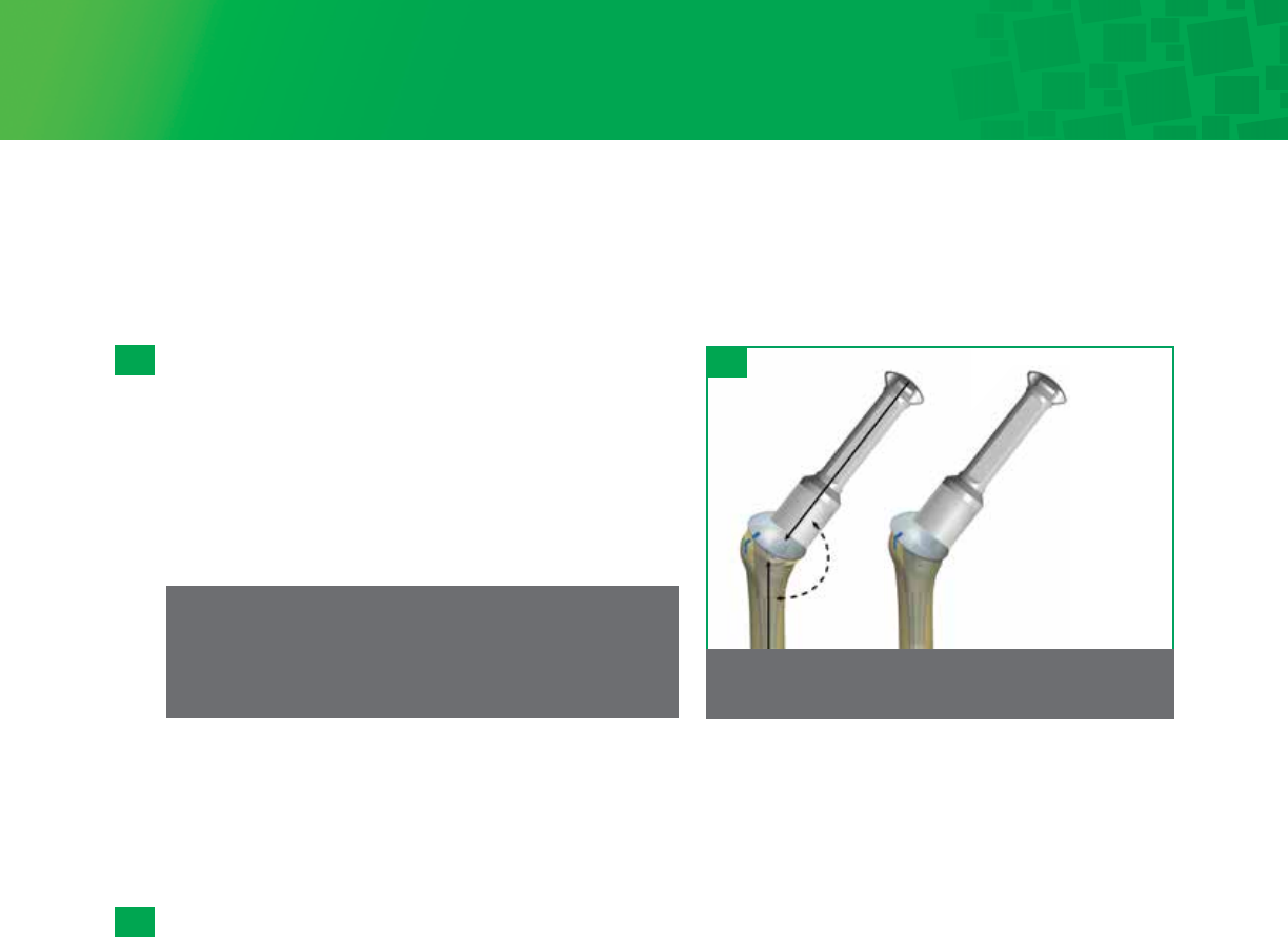
Step 1: Impact directly
in line with the
taper to lock.
135°
Step 2: Final implant
seating – impact
directly in line with
taper to ensure loc
13- 2
13- 3
13- 2
Humeral Head Assembly
In–Situ
Place the selected Humeral Head onto the clean and dry Morse
taper. If using an Eccentric Humeral Head you can place a
mark on the articular surface of the Humeral Head reflecting
the eccentric etching on the bottom of the Humeral Head. This
will allow you to line up the mark on the head with the
previously recorded position on the osteotomy. Once Humeral
Head position is satisfactory, impact the head in line with
the taper using the Head Impactor.
Note
The implant must be seated by impacting the head
in line with the taper.
Remove any further osteophytes. The Humeral Head should be about 5mm above the top of the greater tuberosity. If a
lesser tuberosity osteotomy was performed, there is often a portion of the anterior part of the humeral prosthesis that
overhangs the bone. This is where the lesser tuberosity is going to fit. Now perform the final checks for range of motion,
correct version and stability.
Note
Once secured, check the humeral head by hand to confirm
taper lock.
Back Table Assembly Option
Seating the Standard/Concentric Humeral Head
With the Humeral Body/Stem prosthesis in the stand, the proximal plane of the proximal body will be parallel to the
table top and allow the final humeral head to be driven down perpendicular to the table top, ensuring proper seating of
the Morse taper. With the final head in place, impact it into the Humeral Body using the rubber tipped Head Impactor
and the Slotted Mallet. Impact the head 3-4 times to ensure proper seating and Morse taper.
Seating the Eccentric Humeral Head
There is an etching on the nonarticular surface of the final Eccentric Humeral Head that corresponds to the peripheral
slot on the Eccentric Head Trial. Line the etching up to the referenced position previously marked on the Head
Impaction Stand. It may be helpful to use a skin marker to place a mark on the articular surface near the etching. This
technique ensures that the final prosthesis will have the same orientation as the Trial construct. Firmly impact the head
by placing the rubber tipped Head Impactor on the Humeral Head and striking the impactor three to four times with the
Slotted Mallet.
Insertion of Final Humeral Head, Body and Stem Assembly
Place the final assembled Humeral Head/Body/Stem down the humeral canal checking rotation as it is seated. Use the
Head Impactor to insert the assembly to the final seated position. The Humeral Head should sit flush on the osteotomy.
Remove any further osteophytes. The Humeral Head should be about 5 mm above the top of the greater tuberosity. If a
lesser tuberosity osteotomy was performed there is often a portion of the anterior part of the humeral prosthesis that
overhangs the bone. This is where the lesser tuberosity is going to fit. Now perform the final checks for range of
motion, correct version and stability.
Step 13 • Stem/Body Implantation and In-Situ Head Assembly (continued)
26
Long Stem Option and Implantation
The surgical technique for implanting a Titan Modular Shoulder System Long Stem differs slightly from the standard stem
process.
Long Stem Trialing
Attach the T-Handle to the Starter Awl and create a 6mm pilot hole in the humerus. Continue progressively reaming using
cylindrical reamers of increasing diameter to 8, 10, or 12mm in either the 125mm or 165mm stem length options. The canal is
reamed until cortical chatter is present and inserted to the depth of the laser mark associated with the desired height of humeral
body.
It is important to prepare the medullary canal over its total length. The final reamer used will correlate to the proper Trial Long
Stem selected. The reamer, trial, and implant are line to line; minimizing cement to the stem flutes and within the surrounding
trabecular bone.
Removing the Humeral Head
The Humeral Head can be removed using the Humeral Head Extractor. Place the two
prongs of the extractor between the humeral head and the osteotomy surface so
that the prongs will advance in each side of the linking component. Lift the head off
the proximal humeral body taper by impacting the end of the extractor with the
slotted mallet.
Removing the Stem
The stem is designed to remain in the humeral canal in a revision or conversion to
reverse. If removing the Stem is necessary, leave the Humeral Body on and the Body
Screw fully inserted. Insert the Implant Inserter/Extractor over the taper and use the
slotted mallet against the strike plate until the stem and body are removed from the
bone intact. It is recommended to also have the Titan Modular Shoulder System
Long Stem tray available and use the stem adapter with the slap hammer.
Removing only the Proximal Humeral Body
The Humeral Body can be removed using the T-Handle and the final Implant
Inserter/ Extractor. First disengage the Humeral Body Screw and remove using the
1/8 Hex Driver. Unthread the inner rod from the Implant Inserter/Extractor and
replace with the T-Handle. Place the Inserter/Extractor over the taper, and thread
the T-Handle into the Humeral Body until resistance is felt. Grip the Inserter/
Extractor firmly to control rotation of implant and continue to tighten the T-Handle
to disengage the Morse taper between the Humeral Body and distal stem. Remove
the Humeral Body, which will be threaded onto the T-Handle.
Step 14 • Revision Procedure
Removal of the humeral head and/or proximal humeral body during revision surgery
can be achieved without disturbing a well-fixed distal stem.
14- 1
14- 2
14- 1
14- 2
14- 3
Note
Long stems are intended for cemented use only
The Long Stem Reamers, within the Long Stem instrument set, are a special order item and do not come with the standard
TSS and RSS instrumentation set

27
If a greater cement mantle is desired, choose a Long Stem Implant diameter smaller than the reamer and Trial Long Stem
diameter used for preparation.
Humeral Body Trial
Attach the selected Body Trial/Long Stem Trial construct to the Humeral Trial Inserter/Extractor by inserting the D feature in the
taper hole for alignment. Tighten the top of the Humeral Trial Inserter/Extractor knob until the selected Body Trial/Long Stem
Trial construct is secure.
Affix the Cutting Template Handle / Version Rod to the Humeral Trial Inserter/Extractor to ensure proper version. The Cutting
Template Handle / Version Rod is aligned parallel with the patient’s forearm and initially sets the trial construct in 30° of
retroversion. Using the Slotted Mallet, carefully drive the Body Trial/Long Stem Trial into the proximal humerus so that it is in
line with the long axis. Seat the Body Trial/ Long Stem Trial until the desired fit is achieved.
The Body Trial/Long Stem Trial should be positioned at the correct height to preserve the anatomic reconstruction. If the
desired Body Trial size is between the available options after the appropriate Long Stem Trial has been determined, its
suggested to start with the smaller height/diameter Body Trial and go up to the larger height/diameter Body Trial if needed.
Humeral Body and Long Stem Implant Assembly
Remove the final Humeral Body and Long Stem implants that correspond to the trials from their packaging. Seat and secure
the selected Body Implant onto the Stem Impaction Stand. Place the Long Stem Implant onto the Humeral Body with finger
pressure. Place the Stem Impactor over the tip of the humeral stem and engage the tapers with a few mallet strikes. Then
insert the body screw using the 1/8 Hex Driver, attached to the Torque Limiter. Once the Body/Stem construct is secure, place
the selected Humeral Head implant onto the clean and dry Morse taper. Impact the head in line with the taper using the Head
Impactor with a few strikes of a mallet.
Cementing the Stem
Thoroughly irrigate the medullary canal to remove debris. Use either a small piece of cancellous bone or utilize a cement
restrictor and place 1-2 cm below distal stem to prevent cement from extruding to the elbow. Use either medium or high
viscosity cement, place cement down the humeral canal using finger pressure. Now insert the full implant construct.
Note
The Primary Body Trials from the Total Shoulder System Humeral Tray 1 can be used with the Trial Long Stems to determine
proper prosthesis height prior to cementing.
Note
For further instructions, please refer to:
Step 9 – Humeral Head Trialing
Step 10 – Soft Tissue Balancing
Long Stem Option and Implantation (continued)

28
Once final implant is in place, the subscapularis tendon repair can be completed with the previously placed sutures.
When necessary, perform a biceps tenodesis prior to wound closure.
Thoroughly irrigate the wound with antibiotic solution. If a regional anesthetic is not used then infiltrate the soft tissue
with a local anesthetic that will last 6-8 hours. A wound drainage system is recommended to prevent formations of
postoperative hematoma.
The wound may be closed according to surgeon preference. Careful attention to wound closure will result in a
cosmetically acceptable incision. After the dressing and shoulder immobilizer are in place, the use of a cold wrap is
recommended. This prefrozen wrap can be placed on the shoulder in the operating room and replaced with another unit
every three hours. The combination of regional anesthetic or local anesthetic and the immediate cooling seems to
decrease the amount of postoperative pain.
Step 15 • Wound Closure

29
The patient is placed in a comfortable immobilizer with arm at their side and regional block analgesia as preferred.
Active pendulum exercises are not encouraged in order to prevent stretch of the anterior repair. However, supine
passive range of motion within 24-72 hours of surgery is of the utmost importance. The limits to the extent of passive
range of motion performed should not exceed the safe zone of rotation observed at surgery after subscapularis closure.
Supervised physical therapy program is recommended after 24-48 hours. Supervised active assisted and passive range of
motion mobilization is suggested for the first 72 hours. Active assisted and passive assistance is recommended for 6
weeks after which terminal stretching and active range of motion is initiated. Home pulley system is initiated at 72
hours.
The sling immobilizer may be abandoned at approximately 6 weeks to protect the subscapularis repair. Most patients
are able to perform all their exercises at home in a physician supervised therapy program. Supervision of all post-
operative therapy is recommended. Therapy should be individualized and based on the status of the repaired tissues and
muscle strength. Most importantly, protection of the subscapularis repair and/or rotator cuff repair will dictate the
amount of stretching or resistance as well as the duration of immobilization. Progressive resistance for the rotator cuff
including the subscapularis is initiated at 10-12 weeks depending on the quality of rotator cuff tissue and of the repair.
Guarded loading of the shoulder should be observed for the first 4-6 months post-operatively. Complete recovery from
surgery generally occurs at 9-12 months.
Postoperative Therapy Protocol
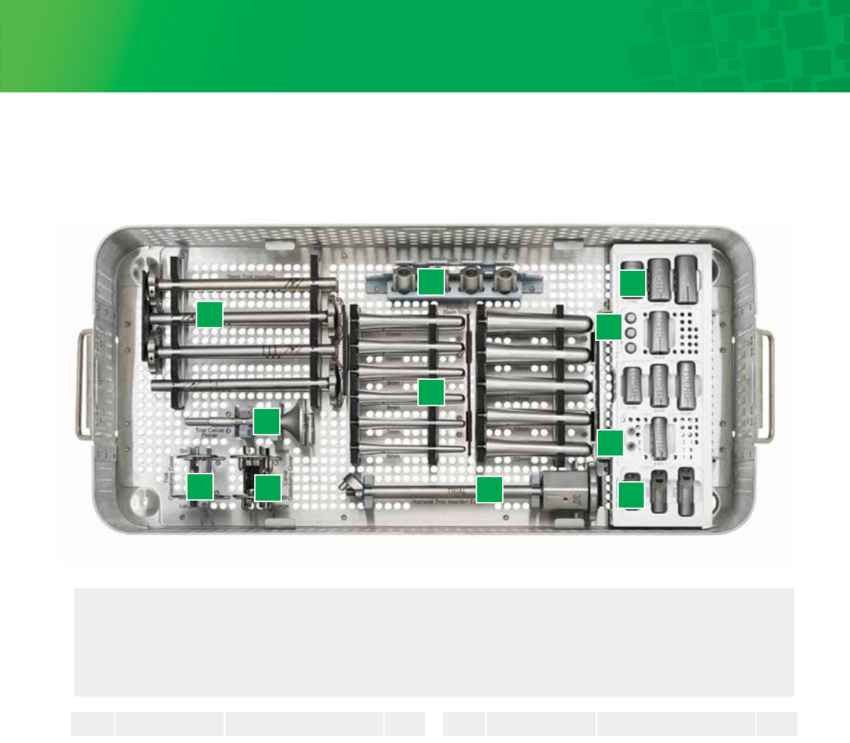
30
Humeral Tray 1: Base
1. Stem Trial Handles
2. Trial Calcar Planer
3. Trial Osteotomy Cover
4. Canal Osteotomy Cover
5. Total Shoulder Depth Stops
6. Humeral Stem Trials
7. Humeral Trial Inserter/Extractor
8. Humeral Body Trials
9. Taper Adaptors
10. Locking Body Screws
11. Fracture Body Trials
1
2
34
5
6
7
8
9
10
11
1
2
3
3
4
4
5
6
6
6
6
6
6
6
6
6
6
6
7
8
8
8
8
8
8
8
8
9
10
11
11
11
1
4
1
1
1
1
1
4
1
1
1
1
1
1
1
1
1
1
1
4
1
1
1
1
1
4
1
1
1
1
1
1
1
Reference ReferenceDescription DescriptionQTY QTYNo. No.
CSA-000-14
HDL-0920-043-001
RMR-0923-050-002
CVR-0920-076L
CVR-0920-076S
CVR-0920-077L
CVR-0920-077S
HDS-0920-069-001
TRL-0920-025-06
TRL-0920-025-07
TRL-0920-025-08
TRL-0920-025-09
TRL-0920-025-10
TRL-0920-025-11
TRL-0920-025-12
TRL-0920-025-13
TRL-0920-025-14
TRL-0920-025-15
TRL-0920-025-16
INS-0923-046-001
TRL-0920-020-08STD
TRL-0920-020-10LRG
TRL-0920-020-10SML
TRL-0920-020-10STD
TRL-0920-020-12STD
TRL-0920-020-14LRG
TRL-0920-020-14SML
TRL-0920-020-14STD
ADT-0923-065-001
BSW-0920-01NS
TRL-0923-021-08LRG
TRL-0923-021-08SML
TRL-0923-021-08STD
Generic Case Lid – Full DIN
Stem Trial Handle
TSS Trial Calcar Planer, 2.5
Trial Osteotomy Cover, Large
Trial Osteotomy Cover, Small
Canal Osteotomy Cover, Large
Canal Osteotomy Cover, Small
Depth Stop
Humeral Stem Trial, 6mm
Humeral Stem Trial, 7mm
Humeral Stem Trial, 8mm
Humeral Stem Trial, 9mm
Humeral Stem Trial, 10mm
Humeral Stem Trial, 11mm
Humeral Stem Trial, 12mm
Humeral Stem Trial, 13mm
Humeral Stem Trial, 14mm
Humeral Stem Trial, 15mm
Humeral Stem Trial, 16mm
TSS Trial Inserter/Extractor, 2.5
Body Trial, 8 Standard
Body Trial, 10 Large
Body Trial, 10 Smal
Body Trial, 10 Standard
Body Trial, 12 Standard
Body Trial, 14 Large
Body Trial, 14 Small
Body Trial, 14 Standard
TSS Taper Adapter, 2.5
Locking Body Screw
TSS Fracture Body Trial Lrg, 2.5
TSS Fracture Body Trial Sml, 2.5
TSS Fracture Body Trial Std, 2.5
31
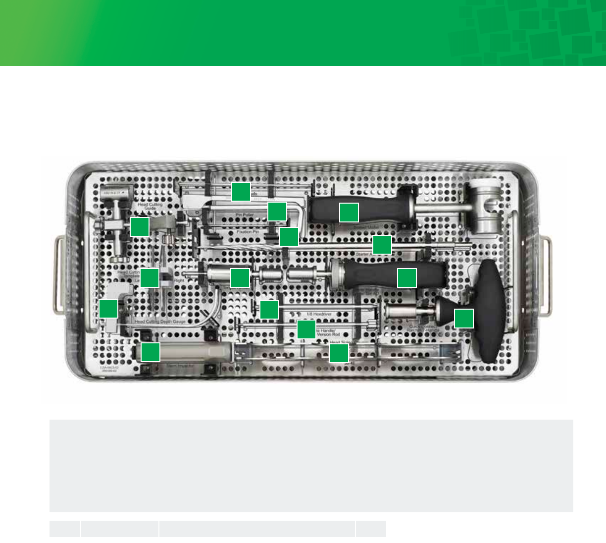
1. Head Resection Guide
2. Head Cuing Templates
3. Head Cuing Depth Gauge
4. Body/Stem Impactor
5. Version Rods
6. Pin Puller
7. Fixation Pin
8. Torque Limiter
9. Hex Driver
10. Cuing Template Handle
11. Head Sizing Templates
12. Sloed Mallot
13. Starter Awl
14. Driver Handle
15. Quick Connect Ratchet Handle
Humeral Tray 1: Insert
1
2
3
4
8
5
6
7
12
13
14
15
9
10
11
SET189-A001 Head Cuing Guide 1
TMP-0920-040-001L Head Cuing Template, Le 1
TMP-0920-040-001R Head Cuing Template, Right 1
GAU-0920-058-001 Head Cuing Depth Gauge 1
IMP-0920-055-001 Stem Impactor 1
SET189-D007 Version Rod 1
PUL-0920-087-01 Pin Puller 1
PIN-0920-051-001 Fixation Pin 2
TRQ-0920-086-01 Torque Limiter 1
SCR-0920-060-001 1/8 Hexdriver 1
ROD-0923-040-001 TSS Head Cuing Template Rod, 2.5 1
MAL-0920-085-01 Sloed Mallet 1
AWL-0920-042-001 Starter Awl 1
G107992_B Driver Handle w/ Sm AO 1
HSG-0920-041-001 Head Sizing Gauge 38-46 1
HSG-0920-041-002 Head Sizing Gauge 48-52 1
NR135004-J-004 T-Handle w/ Lg AO or Quick Connect Ratchet T-Handle
1
2
2
3
4
5
6
7
8
9
10
11
11
12
13
14
15
Reference Description QTY
No.
1
32
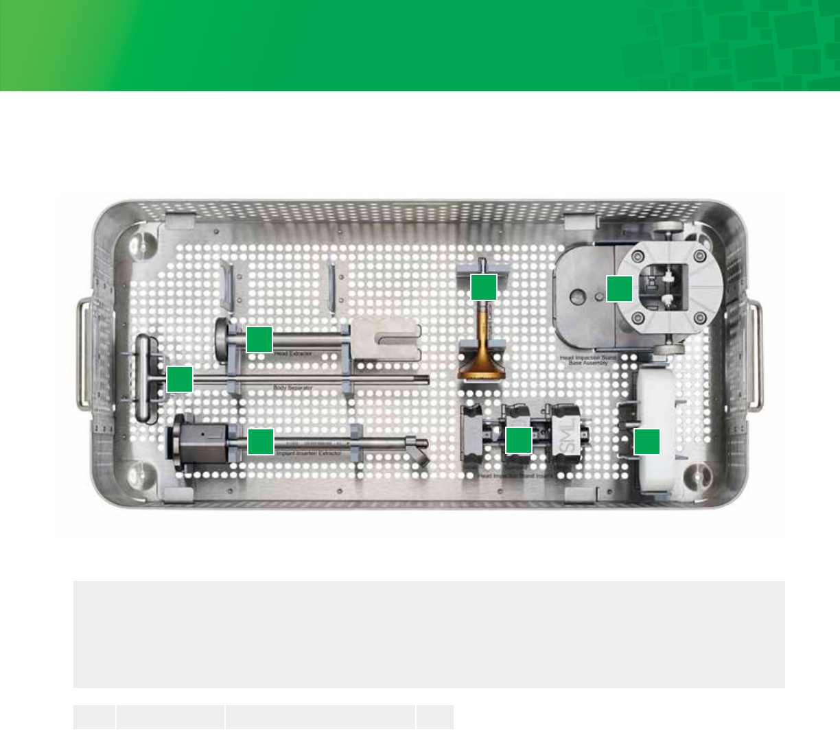
Humeral Tray 2: Base
1. Head Extractor
2. Body Separator
3. Humeral Implant Inserter/Extractor
4. Implant Calcar Planer
5. Head Impaction Stand Inserts
6. Head Impaction Stand Base Assembly
7. Stem Impaction Stand
1
2
3
4
5
6
7
SET188-A001 Head Extractor 1
SEP-0920-068-001 Body Separator 1
INS-0923-045-001 TSS Implant Inserter/Extractor, 2.5 1
RMR-0923-050-001 TSS Implant Calcar Planer, 2.5 1
INS-0920-071-LRG Head Impaction Stand Insert, Large 1
INS-0920-071-SML Head Impaction Stand Insert, Small 1
INS-0920-071-STD Head Impaction Stand Insert, Std. 1
STD-0920-071-001 Head Impaction Stand, Base Assembly 1
SIS-0920-054-001 Stem Impaction Stand 1
1
2
3
4
5
5
5
6
7
Reference Description QTYNo.
33
Humeral Tray 2: Insert
1. Head Impactor
2. Taper Disassembly Tool
3. Humeral Head Sizing Plate
4. Humeral Head Trails
1
234
IMP-0920-079-501 TSS Head Impactor
TDT-0920-044-001 Taper Disassembly Tool
HSP-0923-070-001E TSS Head Sizing Plates 38-40, 2.5 - 38E
HSP-0923-070-002E TSS Head Sizing Plates 38-40, 2.5 - 40E
HSP-0923-070-003 TSS Head Sizing Plates 42-52, 2.5 - 42
HSP-0923-070-004 TSS Head Sizing Plates 42-52, 2.5 - 44
HSP-0923-070-005 TSS Head Sizing Plates 42-52, 2.5 - 46
HSP-0923-070-006 TSS Head Sizing Plates 42-52, 2.5 - 48
HSP-0923-070-007 TSS Head Sizing Plates 42-52, 2.5 - 50
HSP-0923-070-008 TSS Head Sizing Plates 42-52, 2.5 - 52
TRL-0923-010-3814E TSS Head Trial Eccentric, 2.5 38x14mm
TRL-0923-010-4015E TSS Head Trial Eccentric, 2.5 40x15mm
TRL-0923-010-4216C TSS Head Trial Concentric, 2.5 42x16mm
TRL-0923-010-4216E TSS Head Trial Eccentric, 2.5 42x16mm
TRL-0923-010-4416C TSS Head Trial Concentric, 2.5 44x16mm
TRL-0923-010-4416E TSS Head Trial Eccentric, 2.5 44x16mm
TRL-0923-010-4419C TSS Head Trial Concentric, 2.5 44x19mm
TRL-0923-010-4419E TSS Head Trial Eccentric, 2.5 44x19mm
TRL-0923-010-4614C TSS Head Trial Concentric, 2.5 46x14mm
TRL-0923-010-4614E TSS Head Trial Eccentric, 2.5 46x14mm
TRL-0923-010-4617C TSS Head Trial Concentric, 2.5 46x17mm
TRL-0923-010-4617E TSS Head Trial Eccentric, 2.5 46x17mm
TRL-0923-010-4620C TSS Head Trial Concentric, 2.5 46x20mm
TRL-0923-010-4620E TSS Head Trial Eccentric, 2.5 46x20mm
TRL-0923-010-4815C TSS Head Trial Concentric, 2.5 48x15mm
TRL-0923-010-4815E TSS Head Trial Eccentric, 2.5 48x15mm
TRL-0923-010-4818C TSS Head Trial Concentric, 2.5 48x18mm
TRL-0923-010-4818E TSS Head Trial Eccentric, 2.5 48x18mm
TRL-0923-010-4821C TSS Head Trial Concentric, 2.5 48x21mm
TRL-0923-010-4821E TSS Head Trial Eccentric, 2.5 48x21mm
TRL-0923-010-5019C TSS Head Trial Concentric, 2.5 50x19mm
TRL-0923-010-5019E TSS Head Trial Eccentric, 2.5 50x19mm
TRL-0923-010-5022C TSS Head Trial Concentric, 2.5 50x22mm
TRL-0923-010-5022E TSS Head Trial Eccentric, 2.5 50x22mm
TRL-0923-010-5220C TSS Head Trial Concentric, 2.5 52x20mm
TRL-0923-010-5220E TSS Head Trial Eccentric, 2.5 52x20mm
1
2
3
3
3
3
3
3
3
3
4
4
4
4
4
4
4
4
4
4
4
4
4
4
4
4
4
4
4
4
4
4
4
4
4
4
1
1
1
1
1
1
1
1
1
1
1
1
1
1
1
1
1
1
1
1
1
1
1
1
1
1
1
1
1
1
1
1
1
1
1
1
Reference ReferenceDescription DescriptionQTY QTYNo. No.
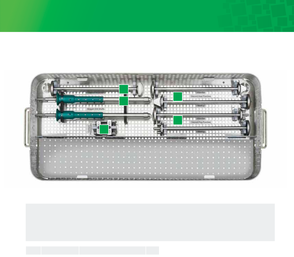
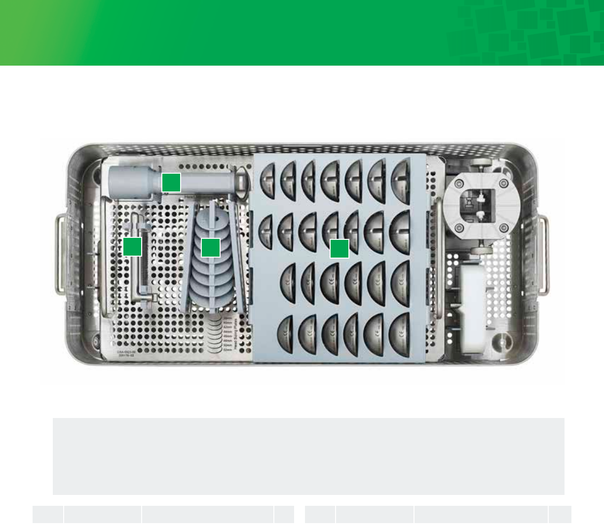
34
1. Glenoid Impactor
2. Straight Drill Sha
3. Cement Pressurizer
4. Glenoid Keeled Punches
5. Glenoid Peg Punches
QTY
Pegged/Keeled Glenoid Tray: Base
1
2
3
5
4
AREA TO REMAIN OPEN DURING REPROCESSING
IMP-0920-064-001 Glenoid Impactor 1
HDL-0922-082-01 Glenoid Drill Sha 2
PRS-0923-073-001 Pressurizer xsm/s 1
PRS-0923-073-002 Pressurizer m/l 1
PUN-0920-062-001 Glenoid Keel Punch, XSm/Sm 1
PUN-0920-062-002 Glenoid Keel Punch, Med/Lg 1
PUN-0920-072-001 Glenoid Peg Punch, XSm/Sm 1
PUN-0920-072-002 Glenoid Peg Punch, Med/Lg 1
1
2
3
3
4
4
5
5
Reference Description QTYNo.
35
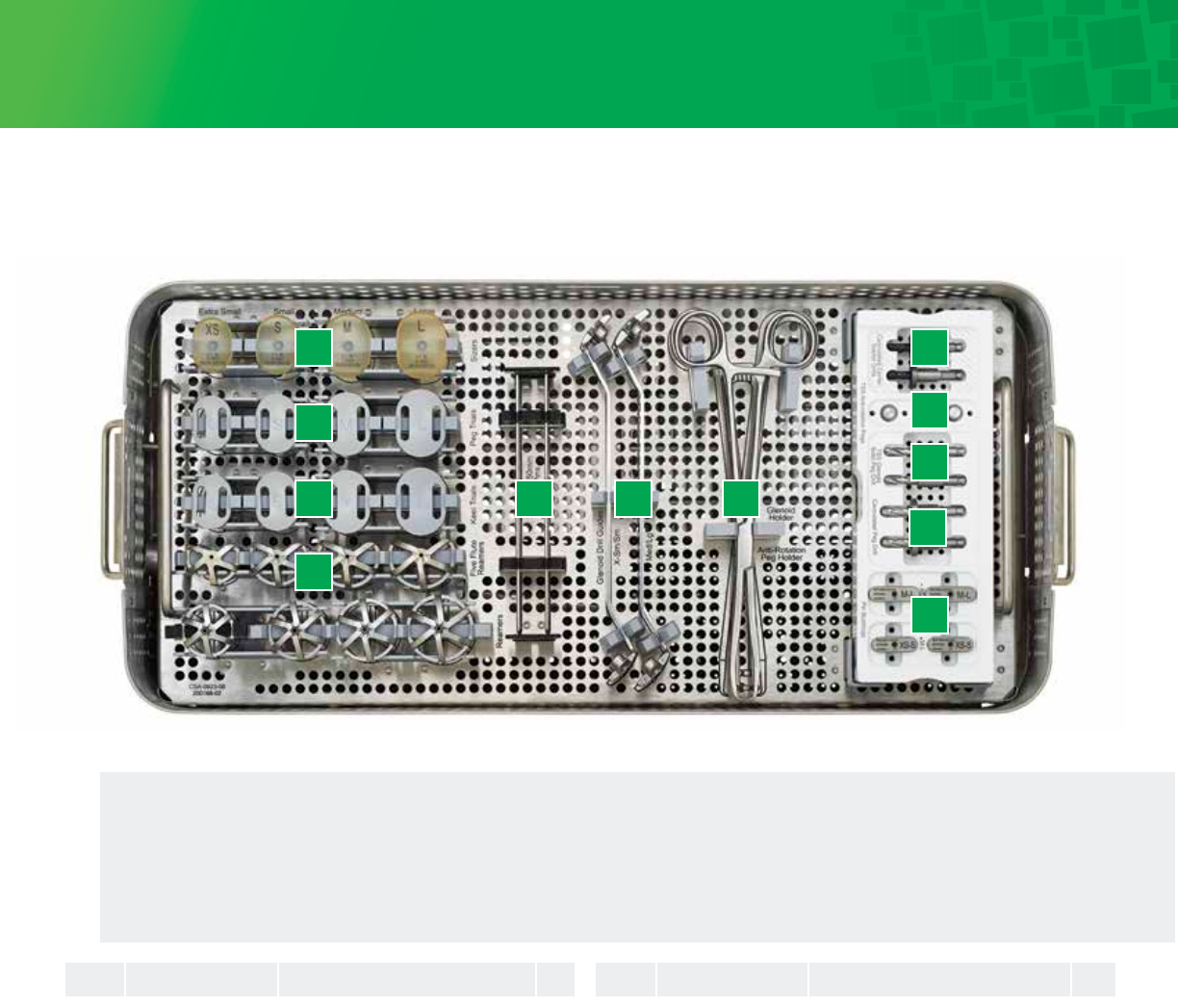
Glenoid Tray: Insert
1. Glenoid Sizers
2. Glenoid Peg Trials
3. Glenoid Keeled Trials
4. Glenoid Reamers
5. Guide Pins
6. Glenoid Drill Guides
7. Glenoid Trial Holder /
Anti-Rotation Peg Holder
8. Cannulated Center Starter Drill
9. Anti-Rotation Pegs
10. TSS Glenoid Solid Peg Drill
11. Pin Bushings
12. Cannulated Peg Drills
1 8
9
10
12
11
2
3 5 6 7
4
SZR-0920-052-000 Glenoid Sizer, Extra Small
SZR-0920-052-001 Glenoid Sizer, Small
SZR-0920-052-002 Glenoid Sizer, Medium
SZR-0920-052-003 Glenoid Sizer, Large
TRL-0920-030-00P Glenoid, Peg Trial, Extra Small
TRL-0920-030-01P Glenoid, Peg Trial, Small
TRL-0920-030-02P Glenoid, Peg Trial, Medium
TRL-0920-030-03P Glenoid, Peg Trial, Large
TRL-0920-030-00K Glenoid, Keel Trial, Extra Small
TRL-0920-030-01K Glenoid, Keel Trial, Small
TRL-0920-030-02K Glenoid, Keel Trial, Medium
TRL-0920-030-03K Glenoid, Keel Trial, Large
RMR-0920-057-000 Glenoid Reamer, Extra Small
RMR-0920-057-001 Glenoid Reamer, Small
RMR-0920-057-002 Glenoid Reamer, Medium
RMR-0920-057-003 Glenoid Reamer, Large
RMR-0920-059-000 Glenoid Five Flute Reamer, XS
RMR-0920-059-001 Glenoid Five Flute Reamer, S
RMR-0920-059-002 Glenoid Five Flute Reamer, M
RMR-0920-059-003 Glenoid Five Flute Reamer, L
GDW-0920-061-501 2.0mm x 150mm Guide Pin
DRG-0922-067-01 Glenoid Drill Guide, X-Sm/Sm
DRG-0922-067-02 Glenoid Drill Guide, Med/Lg
HDL-0920-075-001 Anti-rotation Peg Holder
HDR-0920-063-001 Glenoid Holder
DRL-0920-047-001 Cannulated Center Starter Drill
PEG-0922-074-02 TSS Anti-rotation Peg
DRL-0922-080-01 TSS Glenoid Solid Peg Drill
BSH-0923-048-001 Pin Bushing XS/S
BSH-0923-048-002 Pin Bushing M/L
DRL-0923-047-001 Cannulated Peg Drill
1
1
1
1
2
2
2
2
3
3
3
3
4
4
4
4
4
4
4
4
5
6
6
7
7
8
9
10
11
11
12
1
1
1
1
1
1
1
1
1
1
1
1
1
1
1
1
1
1
1
1
4
1
1
1
1
2
3
2
2
2
2
Reference ReferenceDescription DescriptionQTY QTYNo. No.
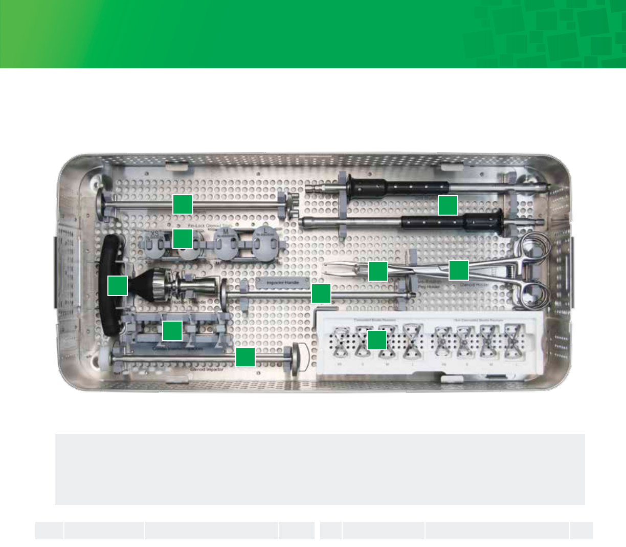
36
QTY
Fin-Lock Glenoid Tray: Base
1. Glenoid Punch
2. Fin-Lock Trials
3. Hudson T-Handle
4. Combo Inserter/Impactors
5. Glenoid Impactor
6. 2.8mm Drill Sha
7. Anti-Rotation Peg Holder
8. Glenoid Holder
9. Bowtie Reamer Caddy
(ordered separately)
10. Glenoid Handle
PN-0926-001 Punch 1
TRL-0926-030-00A Trial, Fin-Lock Glenoid, XS 1
TRL-0926-030-01A Trial, Fin-Lock Glenoid, S 1
TRL-0926-030-02A Trial, Fin-Lock Glenoid, M 1
TRL-0926-030-03A Trial, Fin-Lock Glenoid, L 1
HDL-0926-002 Hudson T-Handle 1
IMP-0926-030-00A Combo Inserter/Impactor, XS 1
IMP-0926-030-01A Combo Inserter/Impactor, S 1
IMP-0926-030-02A Combo Inserter/Impactor, M 1
IMP-0926-030-03A Combo Inserter/Impactor, L 1
IMP-0920-064-001 Glenoid Impactor 1
DRS-0926-001 2.8mm Drill Sha 2
HDL-0920-075-001 Anti-Rotation Peg Holder 1
HDR-0940-048-001 Glenoid Holder 1
RMR-0926-00BC Cannulated Bowtie Reamer, XS 1
RMR-0926-01BC Cannulated Bowtie Reamer, S 1
RMR-0926-02BC Cannulated Bowtie Reamer, M 1
RMR-0926-03BC Cannulated Bowtie Reamer, L 1
1
2
2
2
2
3
4
4
4
4
5
6
7
8
9
9
9
9
1
2
3
6
4
78
9
RMR-0926-00BN Noncannulated Bowtie Reamer, XS 1
RMR-0926-01BN Noncannulated Bowtie Reamer, S 1
RMR-0926-02BN Noncannulated Bowtie Reamer, M 1
RMR-0926-03BN Noncannulated Bowtie Reamer, L 1
IMH-0926-000 Glenoid Impactor Handle 1
Reference ReferenceDescription DescriptionQTY QTYNo. No.
9
9
9
9
10
5
10
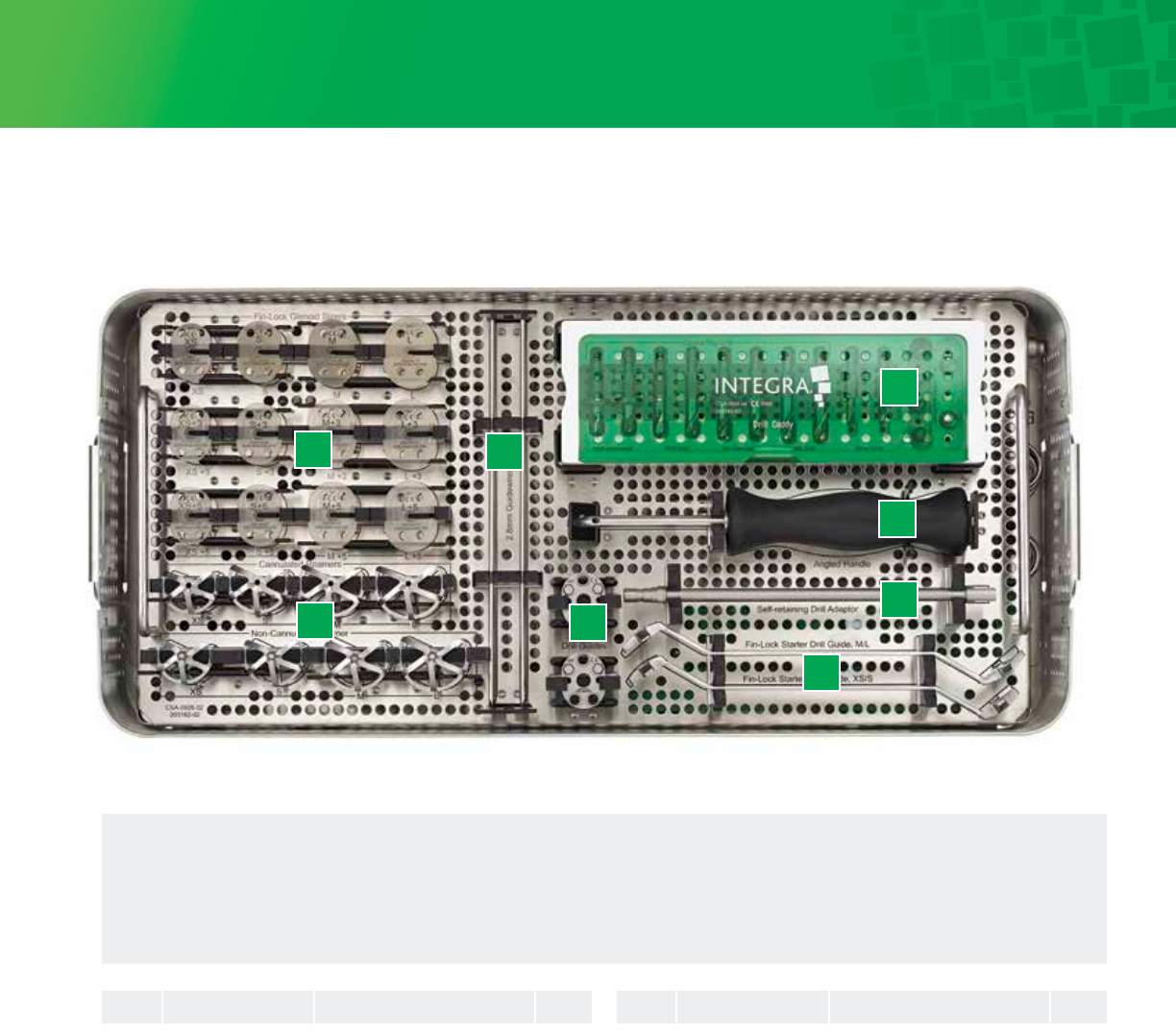
37
Fin-Lock Glenoid Tray: Insert
1. Fin-Lock Sizers
2. Five Fluted Glenoid Reamers
3. 2.8mm Guide Wire
4. Glenoid Drill Caddy
5. Angled Handle
6. Fin-Lock Modular Drill Guide
7. Self-Retaining Drill Adaptor
8. Fin-Lock Starter Drill Guides
SZR-0926-030-000 Sizer, Fin-Lock Glenoid, XS
SZR-0926-030-010 Sizer, Fin-Lock Glenoid, S
SZR-0926-030-020 Sizer, Fin-Lock Glenoid, M
SZR-0926-030-030 Sizer, Fin-Lock Glenoid, L
SZR-0926-030-003 Sizer, Fin-Lock Glenoid, XS, +3
SZR-0926-030-013 Sizer, Fin-Lock Glenoid, S, +3
SZR-0926-030-023 Sizer, Fin-Lock Glenoid, M, +3
SZR-0926-030-033 Sizer, Fin-Lock Glenoid, L, +3
SZR-0926-030-005 Sizer, Fin-Lock Glenoid, XS, +5
SZR-0926-030-015 Sizer, Fin-Lock Glenoid, S, +5
SZR-0926-030-025 Sizer, Fin-Lock Glenoid, M, +5
SZR-0926-030-035 Sizer, Fin-Lock Glenoid, L, +5
RMR-0926-00C Cannulated Reamer, XS
RMR-0926-01C Cannulated Reamer, S
RMR-0926-02C Cannulated Reamer, M
RMR-0926-03C Cannulated Reamer, L
RMR-0926-00N Non-Cannulated Reamer, XS
RMR-0926-01N Non-Cannulated Reamer, S
RMR-0926-02N Non-Cannulated Reamer, M
RMR-0926-03N Non-Cannulated Reamer, L
GDW-0926-001 2.8mm Guidewire
DRL-0926-015-S Drill, Central Peg, 15mm, Solid
DRL-0926-018-S Drill, Central Peg, 18mm, Solid
DRL-0926-015-C Drill, Central Peg, 15mm, Cannulated
DRL-0926-018-C Drill, Central Peg, 18mm, Cannulated
DRL-0926-001 Starter Drill
DRL-0926-002 Peripheral Drill
PEG-0926-000 Central Anti-rotation Peg
HDL-0926-001 Angled Handle
DRG-0926-001 Fin-Lock Drill Guide
ADP-0980-105-00 Self-retaining Drill Adaptor
DRG-0926-002 Starter Drill Guide, XS/S
DRG-0926-003 Starter Drill Guide, M/L
1
1
1
1
1
1
1
1
1
1
1
1
2
2
2
2
2
2
2
2
3
4
4
4
4
4
4
4
5
6
7
8
8
1
1
1
1
1
1
1
1
1
1
1
1
1
1
1
1
1
1
1
1
4
2
2
2
2
2
4
2
1
1
1
1
1
Reference ReferenceDescription DescriptionQTY QTYNo. No.
1
2
3
6
4
5
7
8
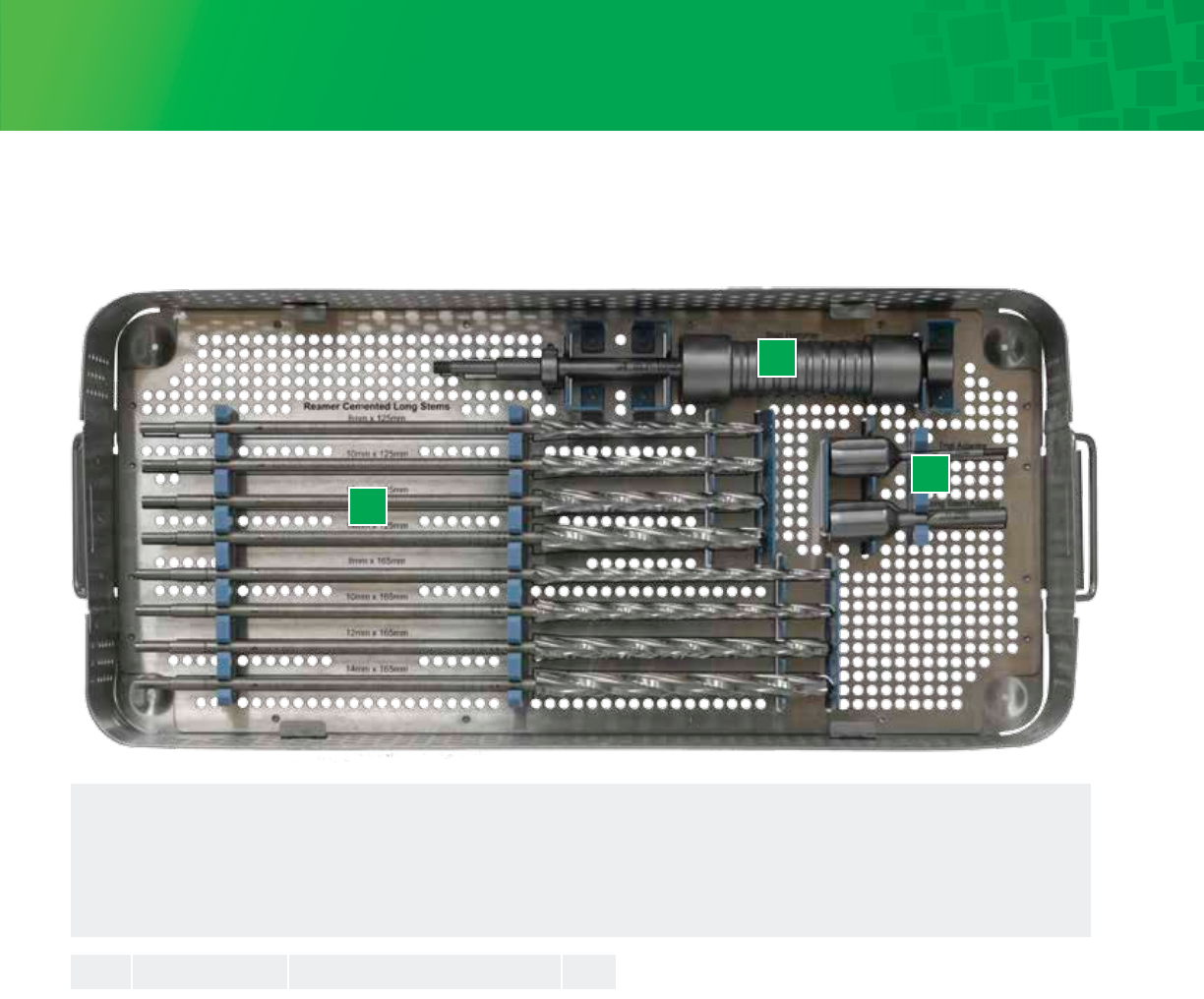
38
1
2
3
1 Reamers
2 Slap Hammer
3 Adapters
Cemented Long Stem Base
QTY
RMR-0950-025-08125 Reamer Cemented Long Stem, 8mm x 125mm 1
RMR-0950-025-10125 Reamer Cemented Long Stem, 10mm x 125mm 1
RMR-0950-025-12125 Reamer Cemented Long Stem, 12mm x 125mm 1
RMR-0950-025-08165 Reamer Cemented Long Stem, 8mm x 165mm 1
RMR-0950-025-10165 Reamer Cemented Long Stem, 10mm x 165mm 1
RMR-0950-025-12165 Reamer Cemented Long Stem, 12mm x 165mm 1
SLP-1002-519 Slap Adaptor 1
ADA-0950-040-501 Trial Adaptor 1
ADA-0950-040-502 Stem Adaptor 1
1
1
1
1
1
1
2
3
3
Catalog No. Description QTYNo.
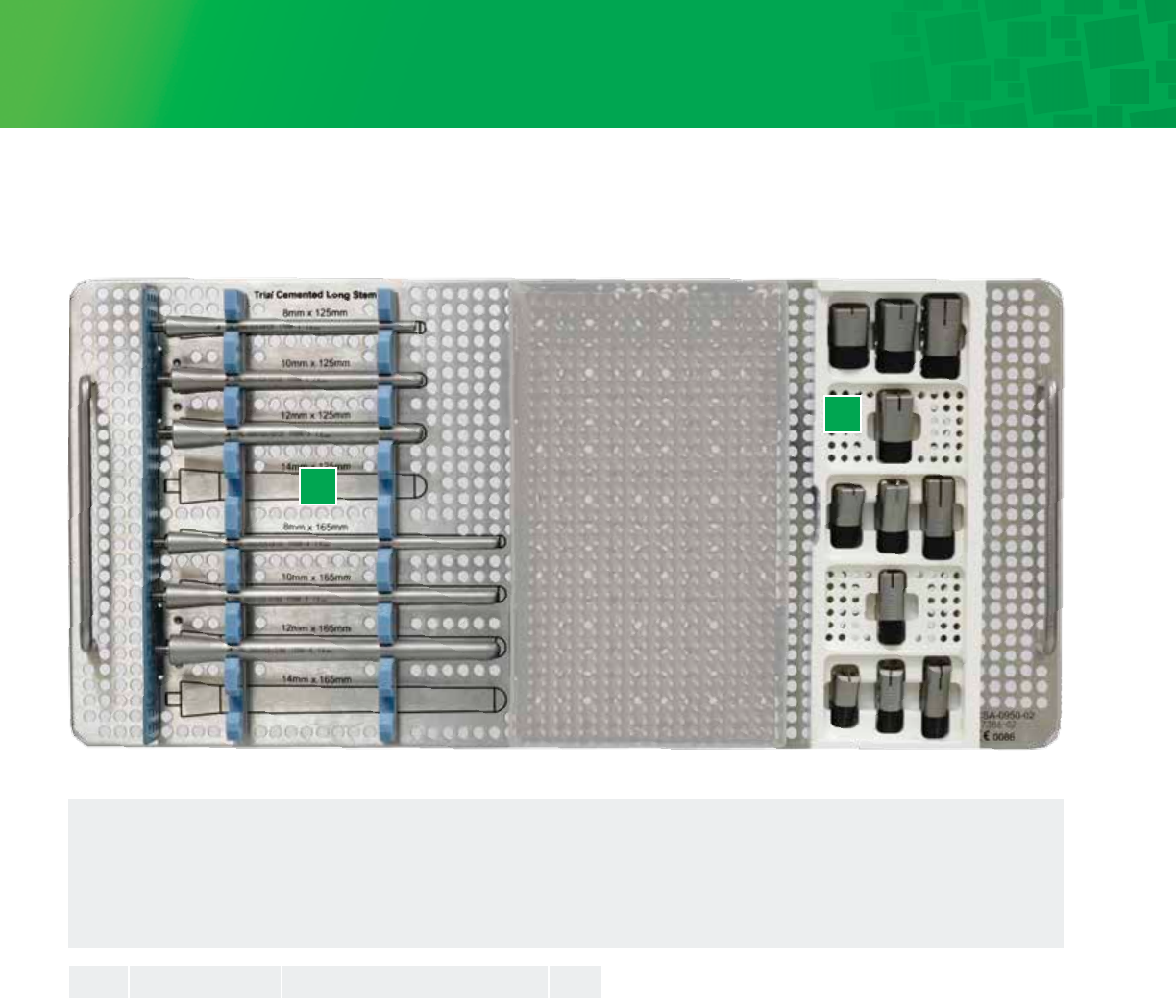
39
Cemented Long Stem Insert
1
2
1 Trial Cemented Long Stems
2 Definitive Stem Primary Body Trials
AREA TO REMAIN OPEN
DURING REPROCESSING
TRL-0950-025-08125 Trial Cemented Long Stem, 8mm x 125mm 1
TRL-0950-025-10125 Trial Cemented Long Stem, 10mm x 125mm 1
TRL-0950-025-12125 Trial Cemented Long Stem, 12mm x 125mm 1
TRL-0950-025-18165 Trial Cemented Long Stem, 8mm x 165mm 1
TRL-0950-025-10165 Trial Cemented Long Stem, 10mm x 165mm 1
TRL-0950-025-12165 Trial Cemented Long Stem, 12mm x 165mm 1
TRL-0920-120-08STD Definitive Stem Primary Body Trial - 08 Std 1
TRL-0920-120-10SML Definitive Stem Primary Body Trial - 10 Sml 1
TRL-0920-120-10STD Definitive Stem Primary Body Trial - 10 Std 1
TRL-0920-120-10LRG Definitive Stem Primary Body Trial - 10 Lrg 1
TRL-0920-120-12STD Definitive Stem Primary Body Trial - 12 Std 1
TRL-0920-120-14SML Definitive Stem Primary Body Trial - 14 Sml 1
TRL-0920-120-14STD Definitive Stem Primary Body Trial - 14 Std 1
TRL-0920-120-14LRG Definitive Stem Primary Body Trial - 14 Lrg 1
TRL-0923-121-08SML Definitive Stem Fracture Body Trial - 2.5 Sml 1
TRL-0923-121-08STD Definitive Stem Fracture Body Trial - 2.5 Std 1
TRL-0923-121-08LRG Definitive Stem Fracture Body Trial - 2.5 Lrg 1
1
1
1
1
1
1
2
2
2
2
2
2
2
2
2
2
2
Catalog No. Description QTYNo.
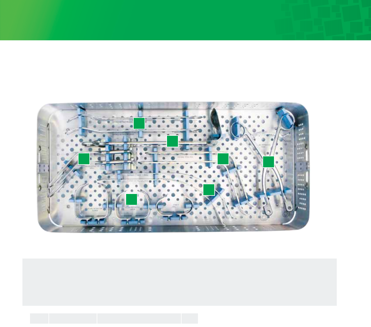
40
1
1
1
1
1
2
1
2
2
2
1
1
Titan Modular Shoulder Instrumentation
1
2
3
45
67
Retractor Tray
1. Fukuda Retractors
2. Darrach Retractors
3. Deltoid Retractor
4. Curved Hohmann Retractors
5. Kolbel Retractor Frame
6. Kolbel Retractor Blades –
Small, Large, Extra Large
7. Spiked Glenoid Retractors
RET-920-50S
RET-920-50L
RET-920-11
SRET-920-11L
RET-920-20
RET-920-31
RET-920-60
RET-920-61S
RET-920-61L
RET-920-61XL
RET-920-41S
RET-920-41L
1
1
2
2
3
4
5
6
6
6
7
7
Catalog No. Description QTYNo.
Fukuda Retractor-Small
Fukuda Retractor-Large
Darrach Retractor-Small
Darrach Retractor-Large
Deltoid Retractor-Large
Hohman Retractor
Kolbel Retractor Frame
Kolbel Retractor-Small
Kolbel Retractor-Large
Kolbel Retractor-XLarge
Glenoid Retractor-Small
Glenoid Retractor-Large
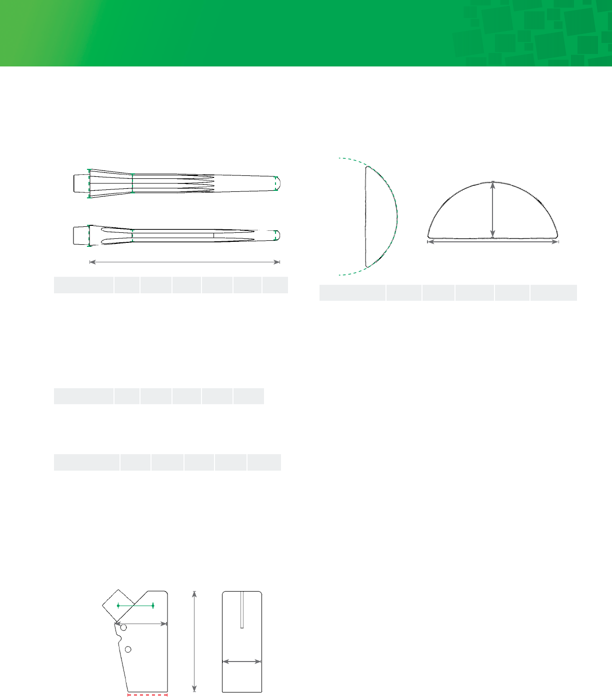
41
Ordering Information and Implant Dimensions
Length
Press-Fit Stem Dimensions (mm), Ti
Diameter A Diameter B Diameter C
A B C
Primary Body Dimensions (mm), Ti
Base Diameter
Height
Trunnion
Offset
Max Length
Max Width
Cemented Stem Dimensions (mm), CoCr
Spherical Diameter Ø
Humeral Head Dimensions (mm), CoCr
Height
Width
Humeral Head Spherical Offset
Catalog Number Height Width Diameter Ø (Eccentric) Concentric
MHH-0923-010-3814X 14 38 41 2.5 No Option
MHH-0923-010-4015X 15 40 43 2.5 No Option
MHH-0923-010-4216X 16 42 45 4 C
MHH-0923-010-4416X 16 44 48 4 C
MHH-0923-010-4419X 19 44 45 4 C
MHH-0923-010-4614X 14 46 54 4 C
MHH-0923-010-4617X 17 46 49 4 C
MHH-0923-010-4620X 20 46 47 4 C
MHH-0923-010-4815X 15 48 56 4 C
MHH-0923-010-4818X 18 48 51 4 C
MHH-0923-010-4821X 21 48 49 4 C
MHH-0923-010-5019X 19 50 53 4 C
MHH-0923-010-5022X 22 50 51 4 C
MHH-0923-010-5220X 20 52 55 4 C
Cemented Stem Diameter Diameter Diameter No. of
Catalog Number Length A B C Flutes
STEM-0950-025-06 90.4 9.6 6.1 4.6 4
STEM-0950-025-08 90.4 11.6 8.1 6.7 4
STEM-0950-025-10 90.4 13.4 9.9 8.5 4
STEM-0950-025-12 90.4 15.4 11.9 10.6 4
STEM-0950-025-14 90.4 17.5 14.0 12.6 4
Press-fit Stem Diameter Diameter Diameter Spline No. of
Catalog Number Length A B C Depth Splines
STEM-0920-025-06 90.4 11.6 6.8 4.6 1 12
STEM-0920-025-07 90.4 12.4 7.6 5.3 1 12
STEM-0920-025-08 90.4 13.7 9.0 6.6 1 12
STEM-0920-025-09 90.4 14.4 9.9 7.4 1 12
STEM-0920-025-10 90.4 15.4 10.9 8.5 1 12
STEM-0920-025-11 90.4 16.5 12.1 9.5 1 12
STEM-0920-025-12 90.4 17.5 13.2 10.6 1 12
STEM-0920-025-13 90.4 18.5 14.2 11.6 1 12
STEM-0920-025-14 90.4 19.5 15.3 12.6 1 12
STEM-0920-025-15 90.4 20.5 16.4 13.5 1 12
STEM-0920-025-16 90.4 21.5 17.4 14.7 1 12
Primary Body Max Max Base Trunnion
Catalog Number Height Length Width Diameter Offset
BOD-0923-020-08STD 35 16.9 11.6 11.6 8
BOD-0923-020-10SML 30 17.8 13.7 13.7 8
BOD-0923-020-10STD 35 18.1 13.7 13.7 8
BOD-0923-020-10LRG 40 18.3 13.7 13.7 8
BOD-0923-020-12STD 35 19.2 15.4 15.4 8
BOD-0923-020-14SML 30 20.4 17.5 17.5 8
BOD-0923-020-14STD 35 20.6 17.5 17.5 8
BOD-0923-020-14LRG 40 20.7 17.5 17.5 8
BSW-0920-021-01 Body Screw
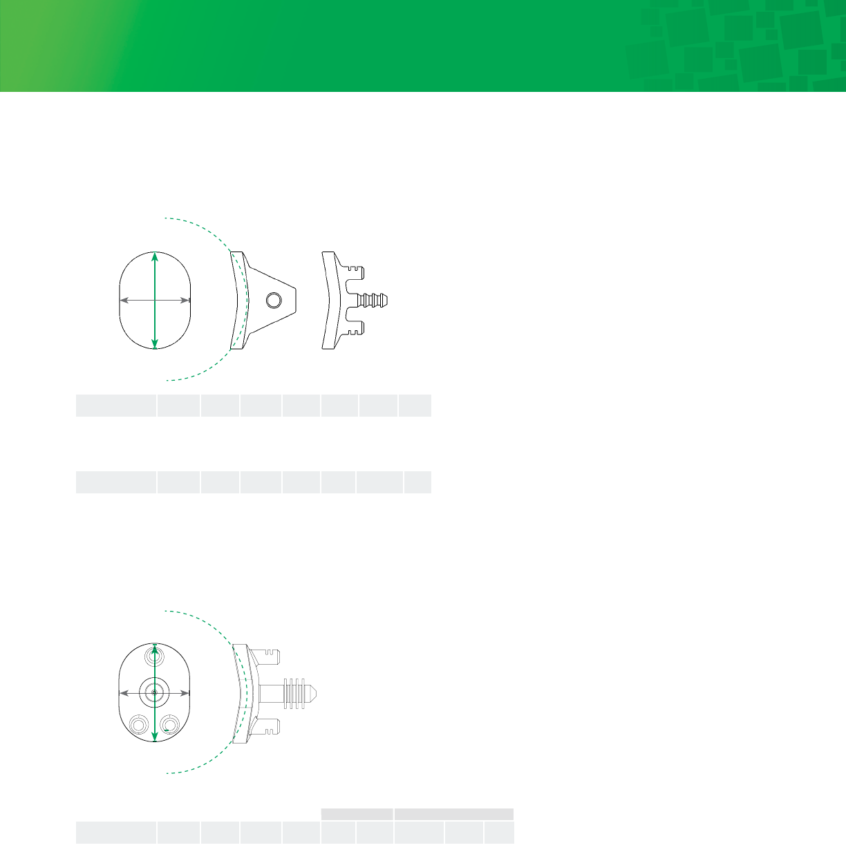
42
Ordering Information and Implant Dimensions (continued)
Spherical Diameter Ø
Spherical Diameter Ø
Height
Height
Width
Width
Pegged and Keeled Glenoid Dimensions (mm), UHMWPE
Fin-Lock™ Glenoid Dimensions (mm), HXLPE
Keeled Glenoid Keel Keel Keel
Catalog Number Size H W Ø L H W
GLN-0920-030-00K X-Small 31.8 22.9 54 14.0 22.9 4.1
GLN-0920-030-01K Small 34.3 24.9 59 14.0 22.9 4.1
GLN-0920-030-02K Medium 36.8 26.9 64 15.2 25.4 5.1
GLN-0920-030-03K Large 39.4 28.9 66 15.2 25.4 5.1
Pegged Glenoid Peg L Peg L Peg
Catalog Number Size H W Ø Center Peripheral D
GLN-0920-030-00P X-Small 31.8 22.9 54 14.0 6.4 5.0
GLN-0920-030-01P Small 34.3 24.9 59 14.0 6.4 5.0
GLN-0920-030-02P Medium 36.8 26.9 64 15.2 6.4 5.0
GLN-0920-030-03P Large 39.4 28.9 66 15.2 6.4 5.0
Fin-Lock Glenoid Peg D Peg L Peg Outer Peg Inner Peg L
Catalog Number Size H W Ø D D
GLN-0926-030-00A X-Small 31.8 22.9 54 5.0 6.4 9.5
GLN-0926-030-01A Small 34.3 24.9 59 5.0 6.4 9.5
GLN-0926-030-02A Medium 36.8 26.9 64 5.0 6.4 9.5
GLN-0926-030-03A Large 39.4 28.9 66 5.0 6.4 9.5
Peripheral Center
5.5
5.5
5.5
5.5
15.0
15.0
18.0
18.0
24
A
R
23 2345678910111213141516171819202122 1
115 1322 1124 917 7 521 19 214 1216 1023 820 618 4 3
B
Q
P
N
M
L
K
J
H
G
F
E
D
C
A
P
M
K
H
F
D
R
Q
B
N
L
J
G
E
C
DRAWN
CHK'D
APPV'D
MFG
Q.A
UNLESS OTHERWISE SPECIFIED:
DIMENSIONS ARE IN MILLIMETERS
SURFACE FINISH:
TOLERANCES:
LINEAR:
ANGULAR:
FINISH:
DEBURR AND
BREAK SHARP
EDGES
NAME
SIGNATURE
DATE
MATERIAL:
DO NOT SCALE DRAWING
REVISION
TITLE:
DWG NO.
SCALE:5:1
SHEET 1 OF 1
A0
WEIGHT:
mod-04-0926-030

Integra®
Titan™ Modular Shoulder System
USA 800-654-2873
n
888-980-7742 fax
International +1 609-936-5400
n
+1 609-750-4259 fax
integralife.com/contact
International +33 (0)4 37 47 59 50
n
+33 (0)4 37 47 59 25 fax
Benelux +32 (0)2 257 4130
n
+32 (0)2 253 2466 fax
France +33 (0)4 37 47 59 10
n
+33 (0)4 37 47 59 29 fax
Switzerland +41 (0)22 721 23 00
n
+41 (0)22 721 23 99 fax
United Kingdom +44 (0)1 264 345 781
n
+44 (0)1 264 363 782 fax
integralife.eu/contact
United States, Canada, Asia, Pacific, Latin America
Europe, Middle-East, Africa
Integra LifeSciences Services (France)
Immeuble Séquoia 2, 97 allée Alexandre Borodine
Parc technologique de la Porte des Alpes
69800 Saint Priest
n
France
EC REP
Ascension Orthopedics, Inc.
8700 Cameron Road, Suite 100
Austin, Texas 78754
USA
Manufacturer:
Availability of these products might vary from a given country or region to another, as a result of specific local regulatory approval or clearance requirements for sale in such country or region.
n
Always refer to the appropriate instructions for use for complete clinical instructions.
n
Non contractual document. The manufacturer reserves the right, without prior notice, to modify the products in order to improve their quality.
n
Warning: Applicable laws restrict these products to sale by or on the order of a physician.
For more information or to place an order, please contact:
Integra and the Integra logo are registered trademarks of Integra LifeSciences Corporation or its subsidiaries in the United States and/or other countries.
Titan and Fin-Lock are trademarks of Integra LifeSciences Corporation or its subsidiaries. ©2016 Integra LifeSciences Corporation. All rights reserved.
Printed in USA. 0M 0440637-5-EN LC04-0926-003 Rev B
