0612 51 506r5 Sigma HP Revision Surgical Technique
2014-03-27
: Pdf 0612-51-506R5 Sigma Hp Revision Surgical Technique 0612-51-506r5_Sigma_HP_Revision_Surgical_Technique 3 2014 pdf
Open the PDF directly: View PDF ![]() .
.
Page Count: 88
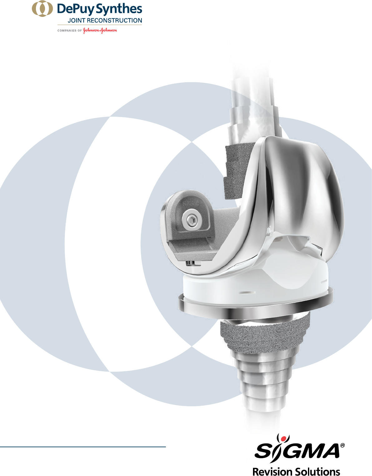
SIGMA®
REVISION
AND M.B.T.
REVISION
TRAY
SURGICAL TECHNIQUE

TABLE OF CONTENTS
2 SIGMA Revision and M.B.T. Revision Tray Surgical Technique
Surgical Technique Key Surgical Steps Summary 4
SIGMA® Revision/M.B.T. Revision Tray Knee Surgery 6
The SIGMA Revision System Overview 7
Incision and Exposure 8
Intra-operative Evaluation 10
Initial Preparation of the Tibia 11
Preparation of the Metaphyseal Bone – Tapered Reamer 13
Proximal Tibial Resection – Tapered Reamer 14
Preparation of the Metaphyseal Bone – Broach 16
Tibial Trial Assembly 18
Joint Space Assessment 19
Preparation of Femoral Diaphysis 20
Reaming the Medullary Canal 21
Preparation of the Metaphysis – Stem Use 23
Preparation of the Metaphysis – Sleeve Use 24
Femoral Preparation – Distal Resection 27
Femoral Preparation – A/P and Chamfer Cuts 30
Femoral Preparation – Notch Resection 35
Femoral Trial Assembly 37
Femoral Trial Assembly – Sleeve and Stem Use 39
Femoral Trial Assembly – Stem-Only Use 41

Surgical Technique SIGMA Revision and M.B.T. Revision Tray 3
Femoral Trial Assembly – Sleeve-Only Use 42
Final Preparation of the Tibia 43
Preparation of the Patella 44
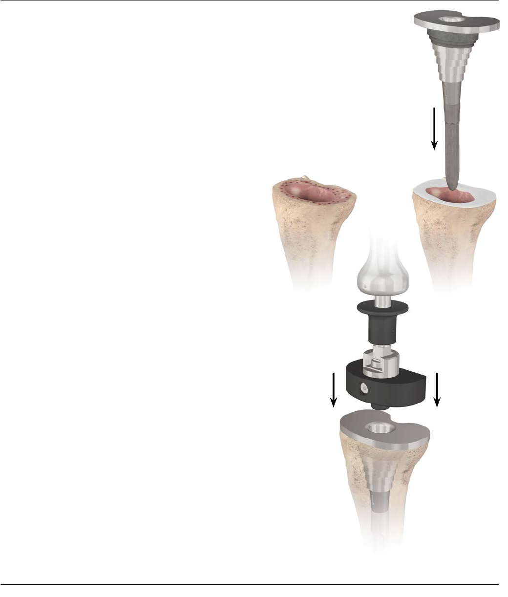
Implant Assembly - Tibia 46
Tibial Implantation 47
Implant Assembly – SIGMA Femoral Adapter 48
Implant Assembly – SIGMA Femoral Augments 50
Implant Assembly – Sleeve and Stem Use 51
Implant Assembly – Stem-Only Use 53
Implant Assembly – Sleeve-Only Use 54
Final Trial with Implants 55
APPENDICES Key Surgical Steps Summary 4
Appendix 1: The Cemented Tibial Stem Extensions 56
Appendix 2: Step Wedge Preparation 59
Appendix 3: Thick Tray Preparation 62
Appendix 4: Femoral Revision and Tibial Insert Compatibility 63
Appendix 5: SIGMA Revision
Anteroposterior Chart (With Sleeve Use) 64
Instrument Glossary 65
4 SIGMA Revision and M.B.T. Revision Tray Surgical Technique
KEY SURGICAL STEPS SUMMARY
ImplantationPatella Preparation
Final Trialing
Femoral Medullary
Canal Preparation
Distal Femoral Resection Femoral Preparation -
A/P and Chamfer Cuts
Tibial Resection
Tibial Medullary Canal Preparation
Incision and Exposure
Surgical Technique SIGMA Revision and M.B.T. Revision Tray 5
Femoral Trial AssemblyFemoral Preparation
- Notch Resection
Tibial Trial Assembly Joint Space Assessment

6 SIGMA Revision and M.B.T. Revision Tray Surgical Technique
SIGMA
®
REVISION / M.B.T. REVISION TRAY
KNEE SURGERY*
Introduction
In total knee arthroplasty (TKA), failure may result
from many causes including: wear, aseptic loosening,
infection, osteolysis, ligamentous instability,
arthrofibrosis and patellofemoral complications. In
approaching revision procedures, the surgeon must
address such considerations as the planning of an
incision in a previously operated site, the condition of
the soft tissue, mobilization of the extensor mechanism,
extraction of the primary prosthesis and the attendant
conservation of bone stock. Among the goals of
successful revision arthroplasty are the restoration of
anatomical alignment and functional stability, fixation
of the revision implants and accurate re-establishment
of the joint line. Careful selection of the appropriate
prosthesis is of paramount importance. Ideally, the
revision knee replacement system will offer the options
of adjunctive stem fixation and variable stem positions,
femoral and tibial augmentation, sleeve, and various
levels of prosthetic constraint.
Pre-operative Planning
Revision total knee arthroplasty begins with thorough
clinical and roentgenographic evaluation. Physical
evaluation includes the examination of the soft
tissues, taking into account previous skin incisions,
range of motion, motor strength, the condition of all
neurovascular structures, ligamentous stability and
the integrity of the extensor mechanism. Biplanar
radiographic views are obtained, as are tangential views
of the patella and full-length standing bilateral extremity
views for the assessment of alignment and bone stock,
documentation of the joint line and evaluation of the
present implant fixation. Stress views are helpful in
evaluating ligamentous instability. CAT and MRI scans
may at times be of value in cases of massive bone loss
or substantial anatomic distortion from trauma and
metabolic bone disorders. Templates are employed to
establish replacement implant size and the alignment of
bone cuts, to indicate augmentation of skeletal deficits
and to confirm the anatomic joint line.
*The SIGMA Revision Knee System is intended for cemented use only.

Surgical Technique SIGMA Revision and M.B.T. Revision Tray 7
THE SIGMA REVISION SYSTEM OVERVIEW
The M.B.T. Revision Knee System is comprised
of the following components:
· Tibial Components are available in eight sizes
· Tibial Metaphyseal Sleeves are available in 29 mm, 37
mm, 45 mm, 53 mm and 61 mm sizes (M/L dimension)
· Tibial Wedge Augmentation Components: Step Wedge
in 5, 10 and 15 mm thicknesses
· 75, 115 and 150 mm Fluted Stem lengths in 10 to 24
mm diameters in 2 mm increments
· 30 and 60 mm Cemented Stem lengths in 13 mm
diameters. 90, 120, 150 Cemented Tapered Stem
lengths in 13 mm diameters
· Thick Trays are available in three different sizes (2, 3
and 4) and two different thicknesses
(+15 mm and +25 mm)
· Accepts Rotating Platform inserts from LCS®
Complete™, SIGMA RP, LCS Complete Revision and
SIGMA TC3 RP inserts
· Accepts rotating platform hinged insert, Universal
LPS Hinged insert, from the Orthogenesis LPS™ (Limb
Preservation System), which is compatible with the
S-ROM® NOILES™ Rotating Hinge (NRH) femoral
component and LPS femoral component
The SIGMA Revision Knee System is comprised of
the following components:
· Stabilized Femoral Component is available
in seven sizes
· TC3 Femoral Component is available in six sizes
· Modular Femoral Stem, known as the SIGMA Femoral
Adapter, which allows the use of the Universal
Femoral Metaphyseal Sleeves and Universal Stems.
The SIGMA Femoral Adapter is available in 5 and 7
degree valgus angles
· The Universal Femoral Metaphyseal Sleeves are
available in
20 mm, 31 mm, 34 mm, 40 mm and 46 mm sizes
(M/L dimension), and can be used with or without a
stem
· 4 mm, 8 mm, 12 mm and 16 mm Distal Femoral
Augmentations
· 4 mm and 8 mm Posterior Femoral Augmentations
· Three anteroposterior stem positions: 0 mm, +2 mm
and -2 mm
· 75 mm, 115 mm and 150 mm Fluted Universal Stem
lengths in 10 mm to 24 mm diameters in 2 mm
increments
· 30 mm and 60 mm Cemented Stem lengths in 13 mm
diameter
· 30 mm and 60 mm Cemented Stem lengths in 15 mm
diameter (Must be used with a sleeve)
· 90 mm, 120 mm, and 150 mm Tapered Cemented
Stem lengths in 13 mm diameter
· 90 mm Tapered Cemented Stem length in 15 mm
diameter (Must be used with a sleeve)
8 SIGMA Revision and M.B.T. Revision Tray Surgical Technique
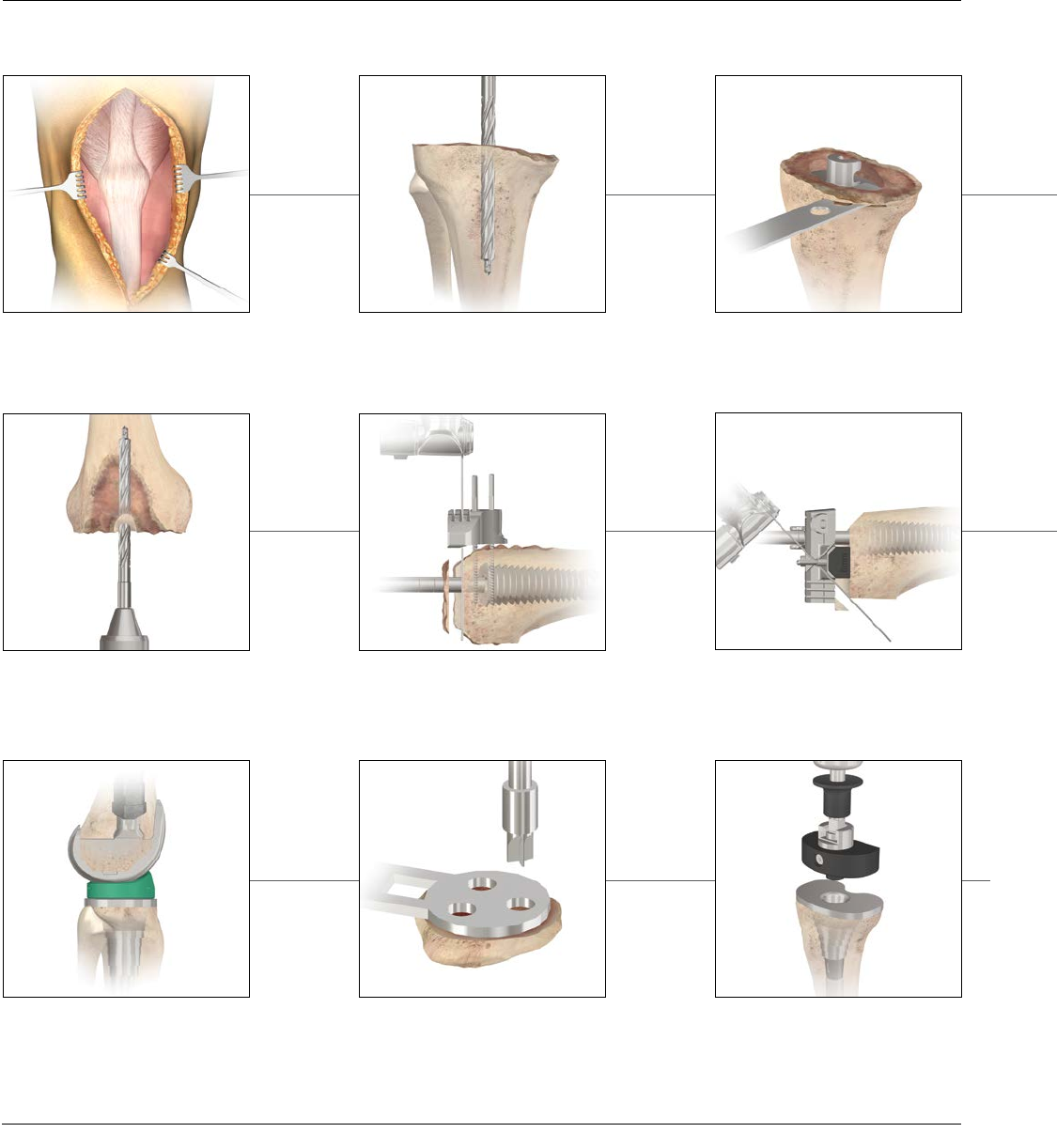
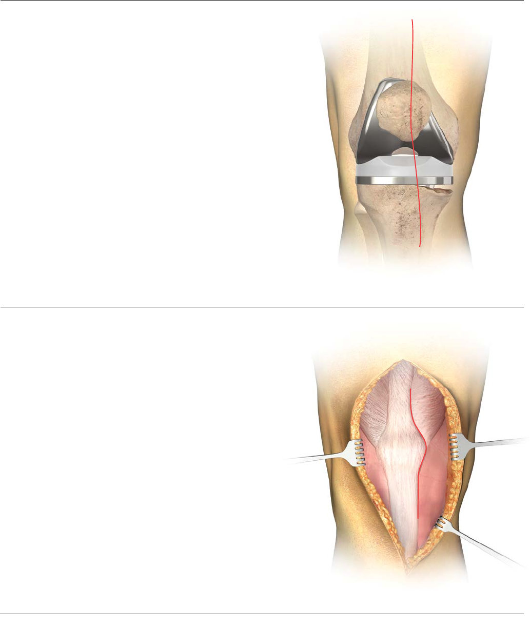
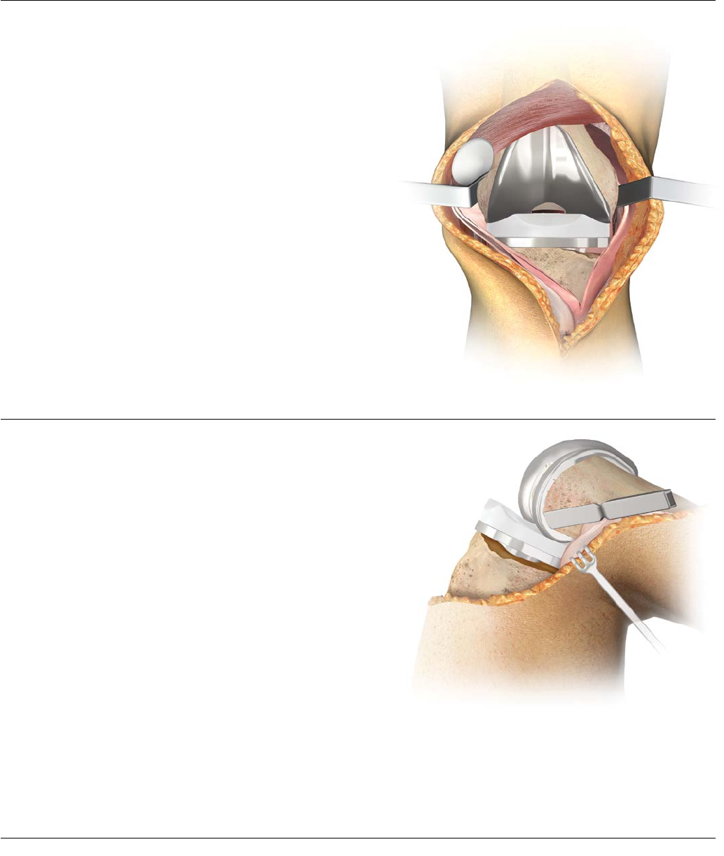
INCISION AND EXPOSURE
Initial Incision
When possible, follow the scar from the primary
procedure (Figure 1). Where parallel incisions are
present, the more lateral is usually preferred, as
the blood supply to the extensor surface is medially
dominant. Where a transverse patellectomy scar is
present, the incision should transect it at 90 degrees.
Where there are multiple incision scars or substantial
cutaneous damage (burn cases, skin grafting, etc.), one
may wish to consult a plastic surgeon prior to surgery
to design the incision, determine the efficacy of pre-
operative soft tissue expansion and plan for appropriate
soft tissue coverage at closure.
Capsular Incision
The fascial incision extends from the rectus femoris
proximal margin to the distal margin of the tibial
tubercle following the patella’s medial border,
maintaining a 3-4 mm cuff for reapproximation of the
vastus medialis aponeurosis at closure (Figure 2). Where
mobilization of the extensor mechanism and patella
is problematic, extend the skin and capsular incisions
proximally.
Figure 1
Figure 2
Surgical Technique SIGMA Revision and M.B.T. Revision Tray 9
INCISION AND EXPOSURE
Figure 3
Figure 4
Occasionally an early retinacular release is indicated to
assist with patellar eversion. Where eversion difficulties
persist, a quadriceps snip, a proximal inverted quadriceps
incision (modified V-Y) or a tibial-tubercle osteotomy
may be indicated. Perform appropriate ligamentous
release based upon pre-operative and intra-operative
evaluation. Release fibrous adhesions to re-establish
the suprapatellar pouch and medial and lateral gutters
(Figure 3).
In many revision cases, the posterior cruciate ligament
will be absent or non-functional; when this is the
situation, excise any residual portion. Exercise care when
everting the patella. Frequently, subluxing the patella
laterally is adequate. Doing so will help avoid patella
tendon avulsion.
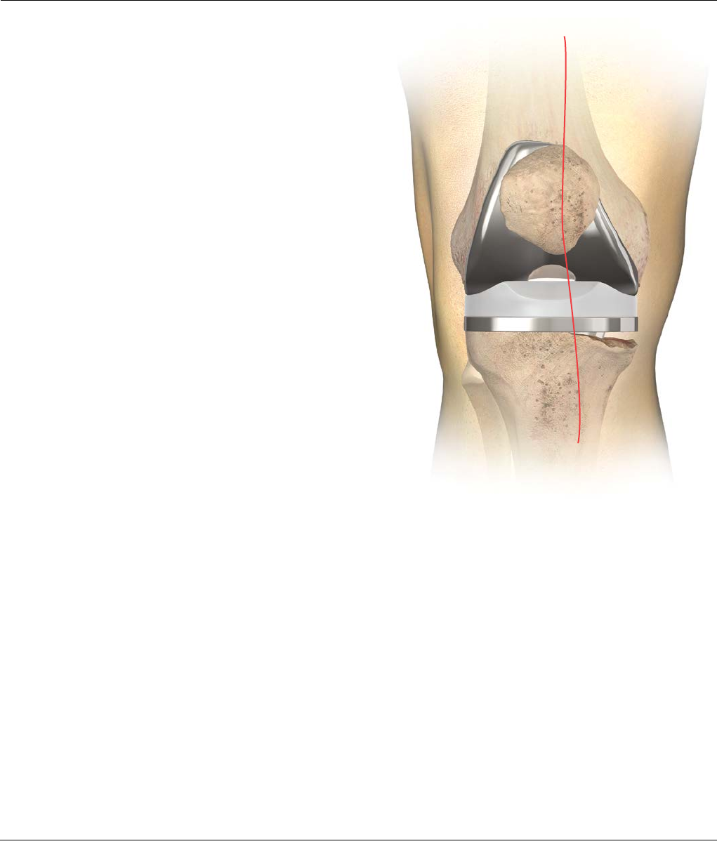
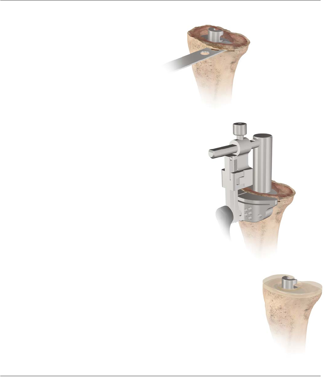
Implant Extraction from the Primary Procedure
Take care to preserve as much bone as possible.
To this end, assemble a selection of tools, including
thin Osteotomes, an Oscillating Saw, a Gigli Saw, a
highspeed Burr and various extraction devices, but many
cases will require only the thin Osteotome. Carefully
disrupt the bone/cement or bone prosthesis interface
before attempting extraction (Figure 4).
Disengage the implanted components and extract
as gently as possible, in such manner as to avoid fracture
and unnecessary sacrifice of bone stock. Where the
entire prosthesis is to be replaced, it is advantageous to
remove the femoral component first, as this will enhance
access to the proximal tibia. Clear all residual methyl
methacrylate with hand (chisels) or power tools.
10 SIGMA Revision and M.B.T. Revision Tray Surgical Technique
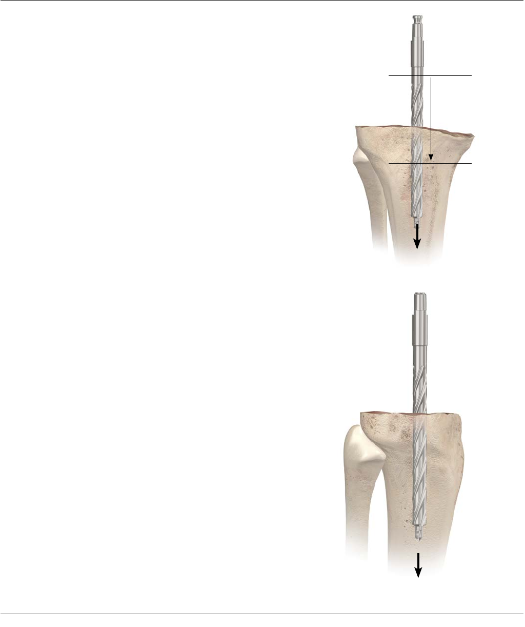
INTRA-OPERATIVE EVALUATION
The surgeon should establish two anatomic conditions
to facilitate revision arthroplasty: the level of the joint
line and the disparity in the flexion and extension gaps
(Figure 5).
Joint Line Evaluation
In an average knee in full extension, the true joint line
can be approximated in reference to several landmarks.
· It lies 12–16 mm distal to the femoral PCL
attachment
· It lies approximately 3 cm distal to the medial
epicondyle and 2.5 cm distal to the lateral
epicondyle
· It lies distal to the inferior pole of the patella
(approximately one finger width)
· Level with the old meniscal scar, if available
Additional pre-operative joint line assessment
tools include:
1) Review of original pre-operative radiograph
of the TKA
2) Review of radiograph of contralateral knee
if non-implanted
Figure 5
Surgical Technique SIGMA Revision and M.B.T. Revision Tray 11
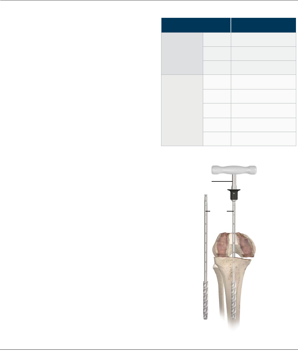
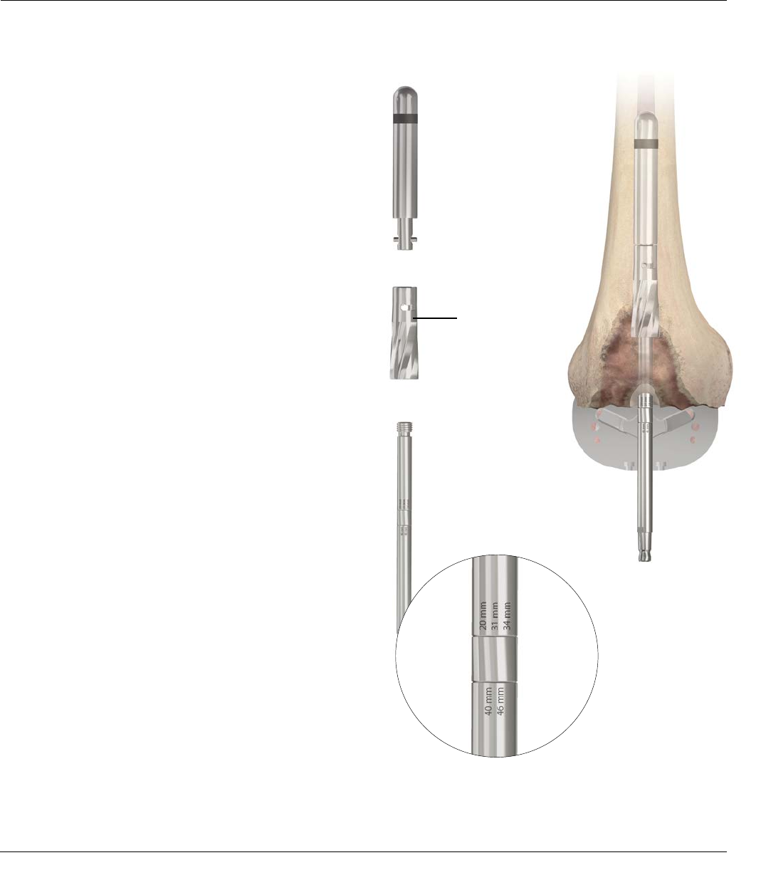
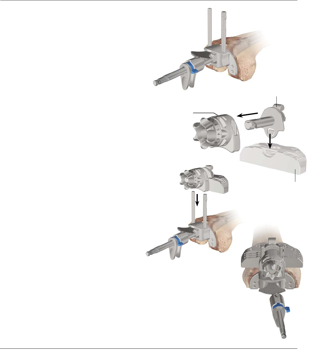
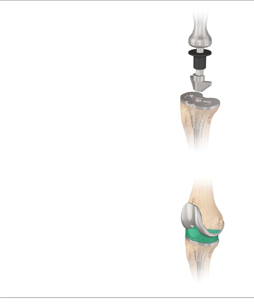
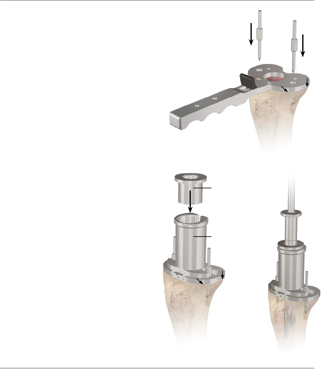
INITIAL PREPARATION OF THE TIBIA
The Tibial Alignment System
When pre-operative evaluation and radiographs indicate
that fluted stem extensions, metaphyseal sleeves or
Wedges are required, it is recommended that the
proximal tibia be prepared with reference to the position
of the IM Rod.
Note: Where a Cemented Stem Extension is
indicated, see Appendix 1 (page 56).
Place the knee in maximal flexion with the patella
laterally retracted and the tibia distracted anteriorly and
stabilized. Release fibrosis around the tibial border or
excise as required to ensure complete visualization of its
periphery.
Approximate the location of the medullary canal with
reference to pre-operative anterior/posterior (A/P) and
lateral radiographs and to the medial third of the tibial
tubercle.
Introduce a 9 mm Drill into the canal to a depth of
2 to 4 cm. Avoid cortical contact (Figures 6 and 7).
4 cm
2 cm
Figure 6
Figure 7
12 SIGMA Revision and M.B.T. Revision Tray Surgical Technique
Reaming the Medullary Canal
Assemble the straight reamer to the T-handle.
If power reaming, it will be necessary to attach the
modified Hudson Adapter to the straight reamer. The
shaft of the Reamer contains markings in 25.4 mm
(1 inch) increments. Each marking is numbered to
use as a reference when reaming to the appropriate
depth. Fluted stem lengths are available in 75, 115
and 150 mm. Determine the length and diameter of
the Prosthetic Stem Extension with Templates (Cat. No.
2178-30-100) applied to pre-operative Radiographs.
Use the Reamer Depth Chart (Figure 8) to determine
the appropriate mark on the reamer for canal reaming
depth. Another option to determine Reamer depth is to
measure the trial assembly against the Reamer and note
the corresponding depth mark for reaming. Sequentially
open the canal with progressively larger Reamers until
firm endosteal engagement is established (Figure 9).
Note: Simple cortical contact should not be
construed as engagement.
The fixed relationship of the reamer to the cortices
ensures the secure fit of the appropriate reamer
and, subsequently, the corresponding fluted stem.
It is equally important to not over-ream osteopenic bone.
While reaming the proximal tibia, pay close attention
to the reamer to assure that it is somewhat centrally
located to the exposed proximal tibial surface. Eccentric
reaming can occur, which could lead to undersizing of
the tibial component.
The size of the final reamer indicates the diameter
of the implant stem. The fluted stems are available in
even sizes (10 through 24 mm). Perform final reaming
with an even-sized reamer. The final implant will have a
.4 mm press fit versus the reamer.
Note: Refer to Appendix 1 (page 56) for cemented
stem preparation.
T-handle
Straight
Reamer
INITIAL PREPARATION OF THE TIBIA
Figure 9
Figure 8
Reamer Depth Chart
M.B.T. Revision Tray Reamer Line Depth
Press Fit
Stems
75 mm 2
115 mm 3
150 mm 4
Cemented
Stems
30 mm 1
60 mm 2
90 mm 2.5
120 mm 3.5
150 mm 4
Surgical Technique SIGMA Revision and M.B.T. Revision Tray 13
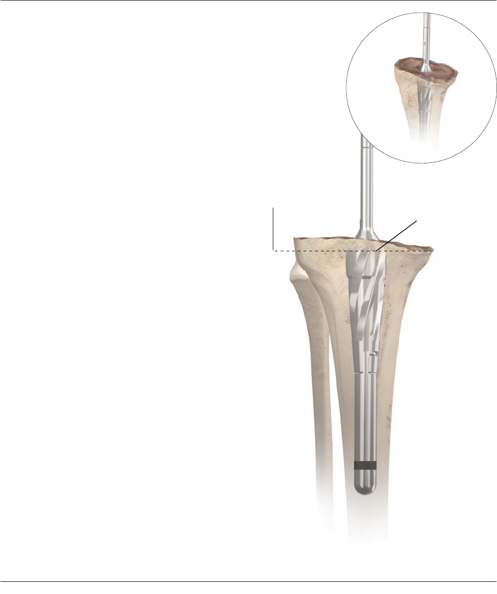
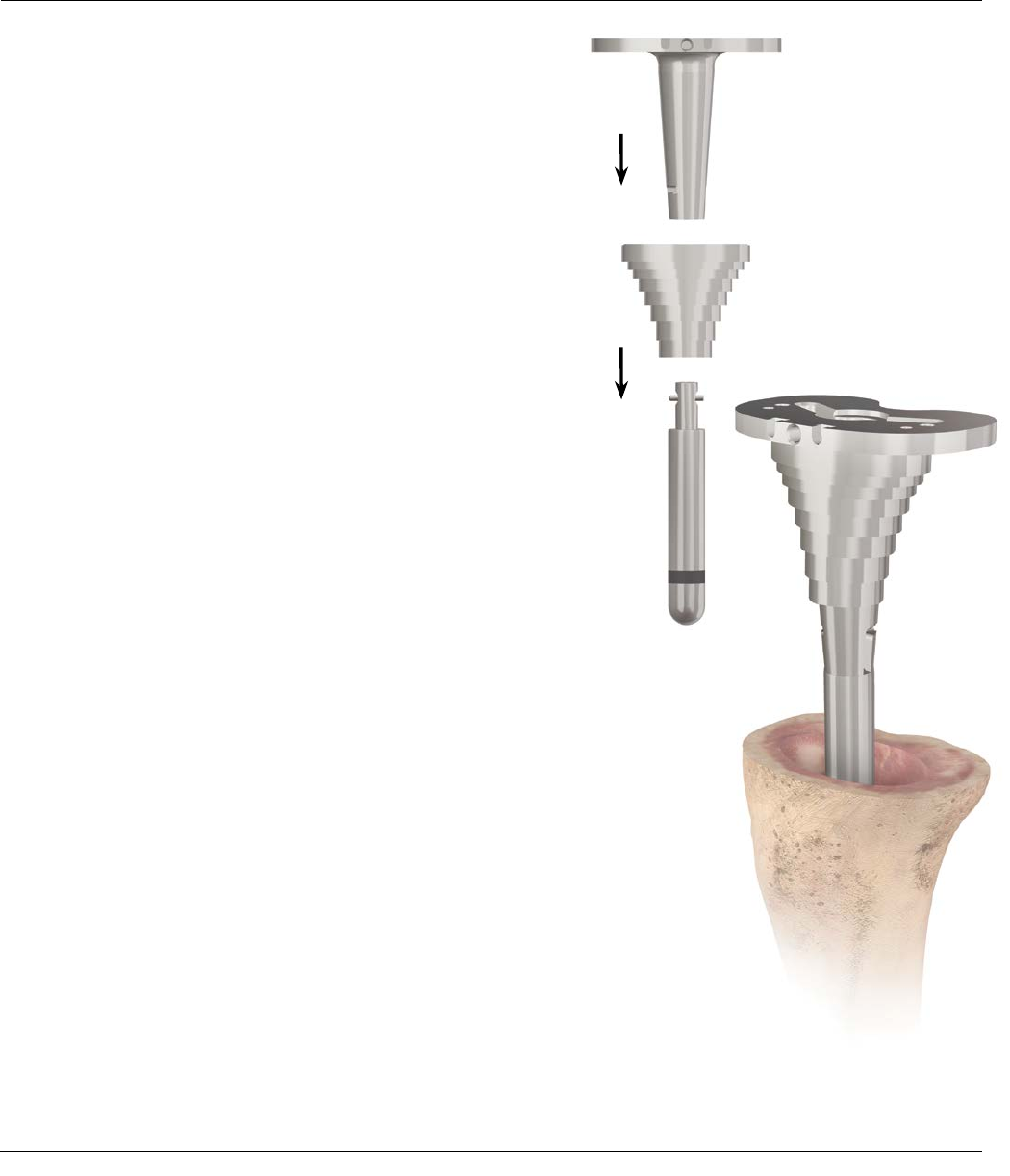
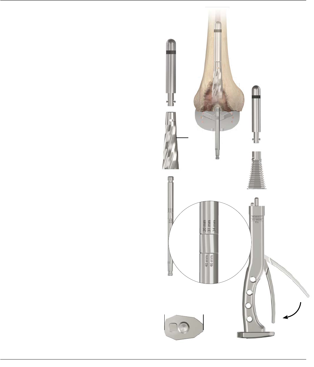
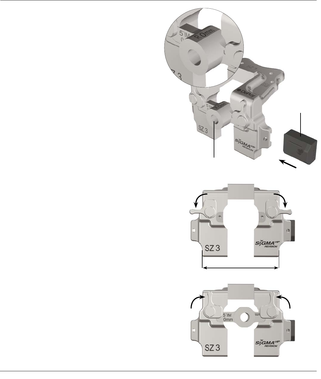
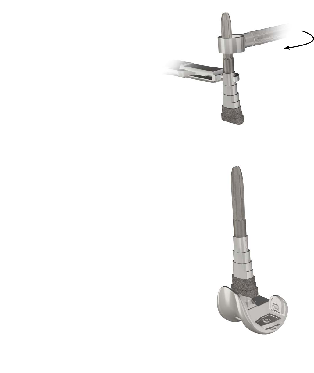
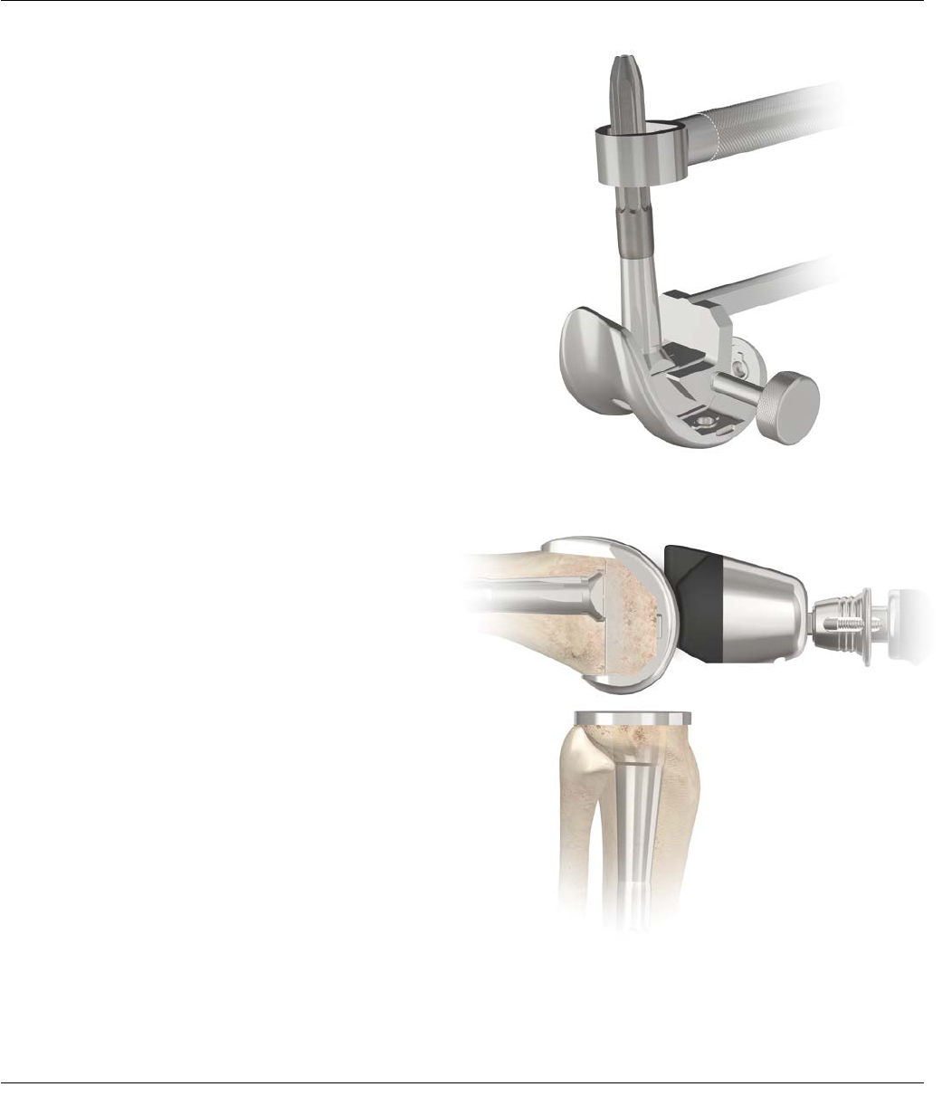
PREPARATION OF THE METAPHYSEAL BONE
– TAPERED REAMER
Tibial Resection Plane
Notches on the Drill
Figure 10
For Diaphyseal Engaging Stem and
Metaphyseal Filling Sleeve
Attach the appropriately sized stem trial to the end of
the M.B.T. Revision Tapered Reamer.
Note: Assembly of the stem trial may be aided by
the pre-attachment of the T-handle to the M.B.T.
Revision Tapered Reamer.
Taper ream to the planned proximal tibial resection level
(Figure 10). When finished reaming, the notches on
the drill should line up with the planned proximal tibial
resection level.
Note: Use the “cemented” taper reamer when
requiring a cement mantle or when utilizing a
sleeve. Use the press-fit tapered reamer when line-
to-line fit is desired and a sleeve will not be utilized
(Figure 10). Use End-Cutting Primary Reamer (Cat.
No. 2178-63-199) when a stem or sleeve will not be
used.
Note: To avoid stem trial disengagement, do not
reverse ream.
At this point, intra-operatively determine if a
metaphyseal sleeve will be used.
Note: Metaphyseal sleeves are ideal to provide
filling of Engh Type II or III defects in revision TKA.
The steps of the metaphyseal sleeve also provide
progressive loading of the bone with porous coating,
which enhances fixation.
If a metaphyseal sleeve is selected, see page 16 in order
to broach the metaphyseal bone.
If a metaphyseal sleeve will not be used, see the
following page to prepare for the proximal tibial
resection.
14 SIGMA Revision and M.B.T. Revision Tray Surgical Technique
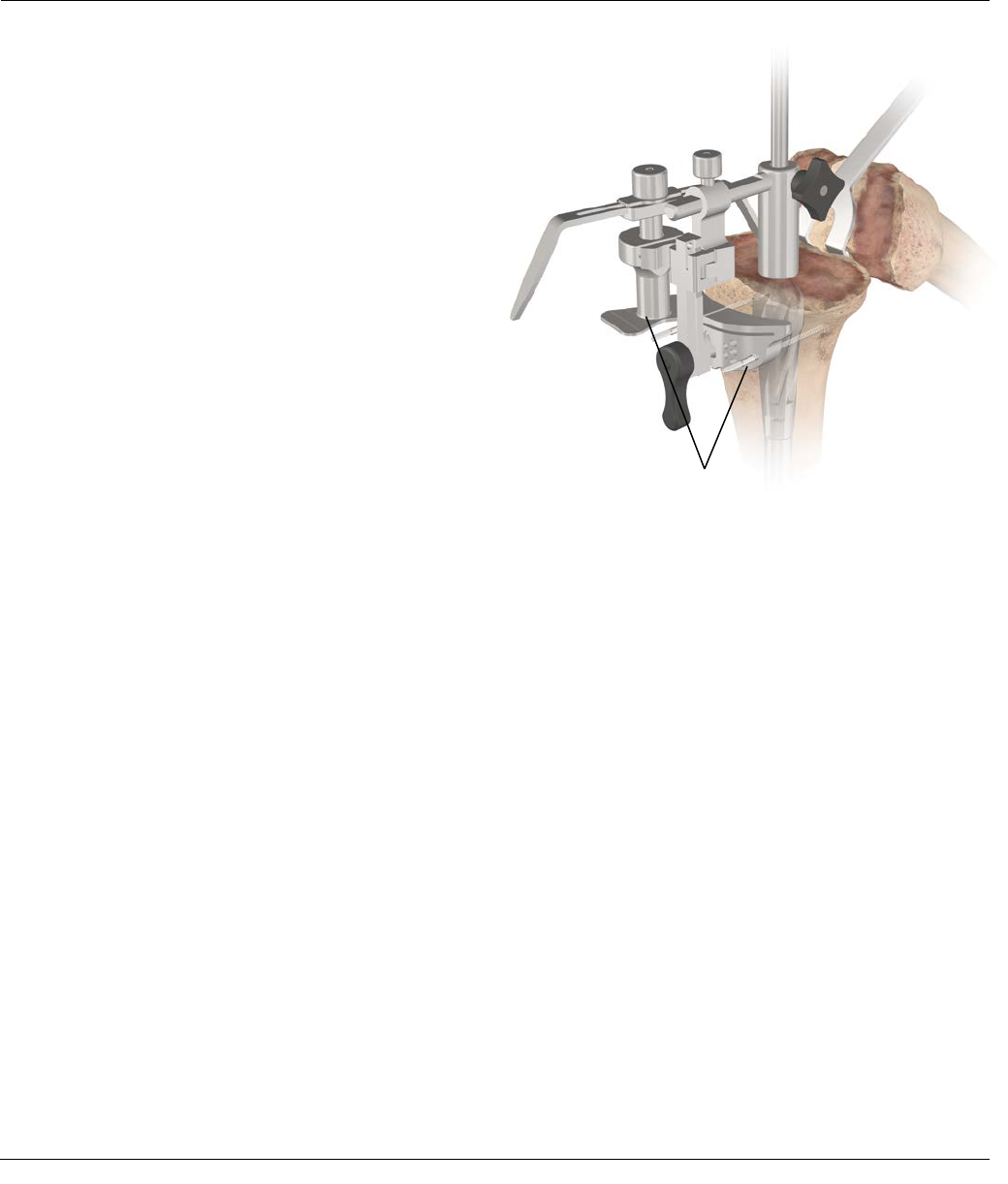
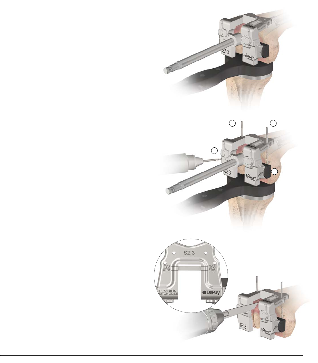
PROXIMAL TIBIAL RESECTION
– TAPERED REAMER
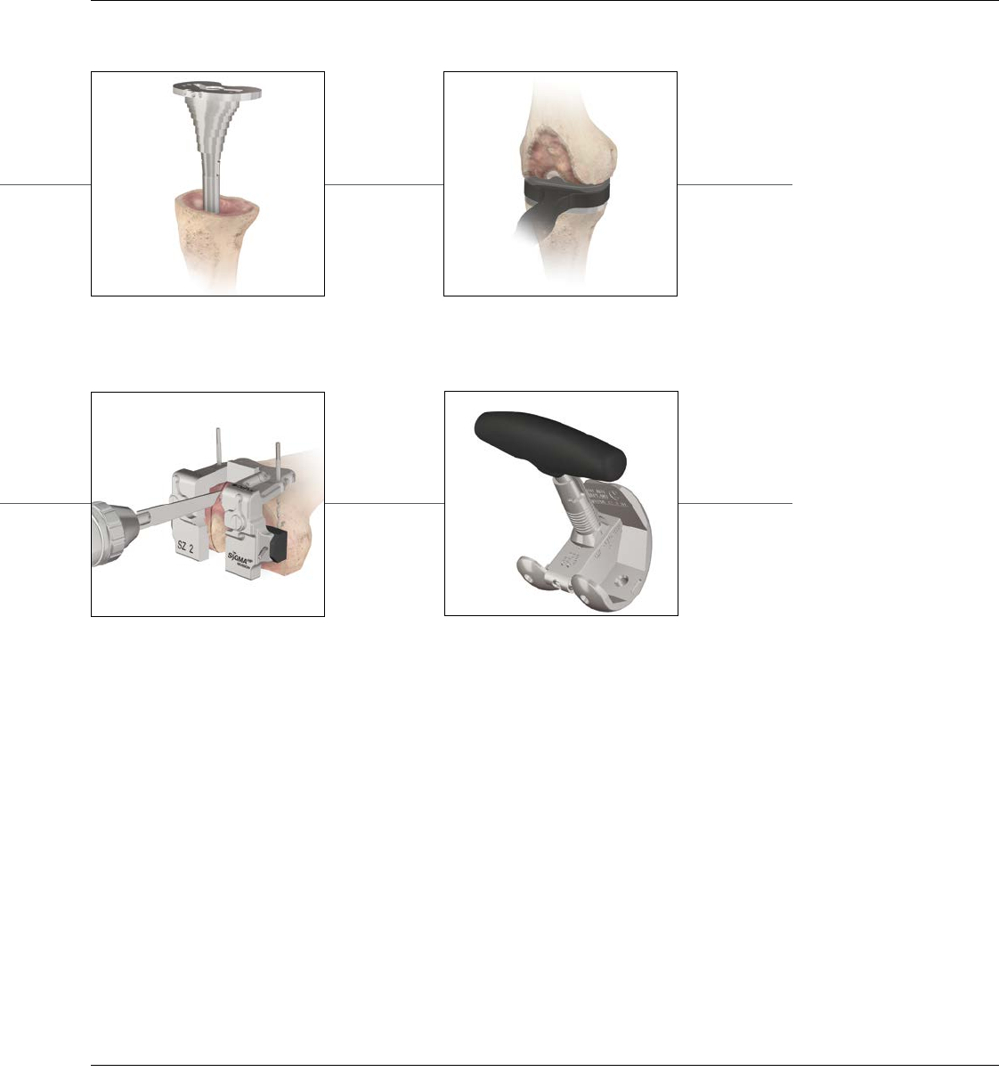
Attach the 2 degree Tibial Cutting Block to the I.M.
Tibial Referencing Device. Attach the I.M. Tibial
Referencing Device to the shaft of the tapered reamer.
Position the I.M. Tibial Referencing Device with the
pre-attached 2 Degree Cutting Block onto the shaft
and allow it to descend to the proximal tibial surface.
Since considerable bone stock may have been sacrificed
in the primary total knee arthroplasty, minimize the
amount resected: no more than 1-2 mm from the most
prominent condyle, managing residual defects of the
contralateral condyle with either prosthetic augment or
bone graft.
Resection is based on tibial deficiency and the level of
the joint line. Compensate deficiencies with sleeves,
wedges and/or bone grafts. Advance the cutting block
to the anterior tibial cortex and lock into position
by tightening the knurled knob on the outrigger.
Preliminary rotational alignment is based on the medial
third of the tibial tubercle. Secure the alignment device
to the reamer shaft with the lateral Setscrew (Figure 11).
Pin the Tibial Cutting Block so a minimal resection is
made from the proximal tibia. Utilize the stylus when
necessary (Figure 11).
Note: There is a slotted and non-slotted end to the
stylus. The difference between the two
is 5 mm.
Note: If a metaphyseal sleeve is to be used the tibial
resection will be performed using the Tibial Sleeve
Broach (see page 17, Figure 14).
Figure 11
Pins
Surgical Technique SIGMA Revision and M.B.T. Revision Tray 15
Figure 12
PROXIMAL TIBIAL RESECTION
– TAPERED REAMER
Remove the I.M. device while leaving the 2 degree
Cutting Block in place. Remove the tapered reamer and
resect the proximal tibia (Figure 12).
Note: At this point determine whether a Step Wedge
is necessary on either the medial or lateral side to
augment a defect, or both sides in order to restore
the joint line. If a wedge is necessary on one side,
it is recommended that the step wedge be prepared
after rotational position of both the femoral and
tibial components have been determined. For step
wedge preparation see Appendix 2 (page 59).
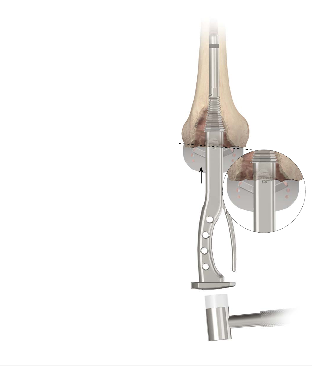
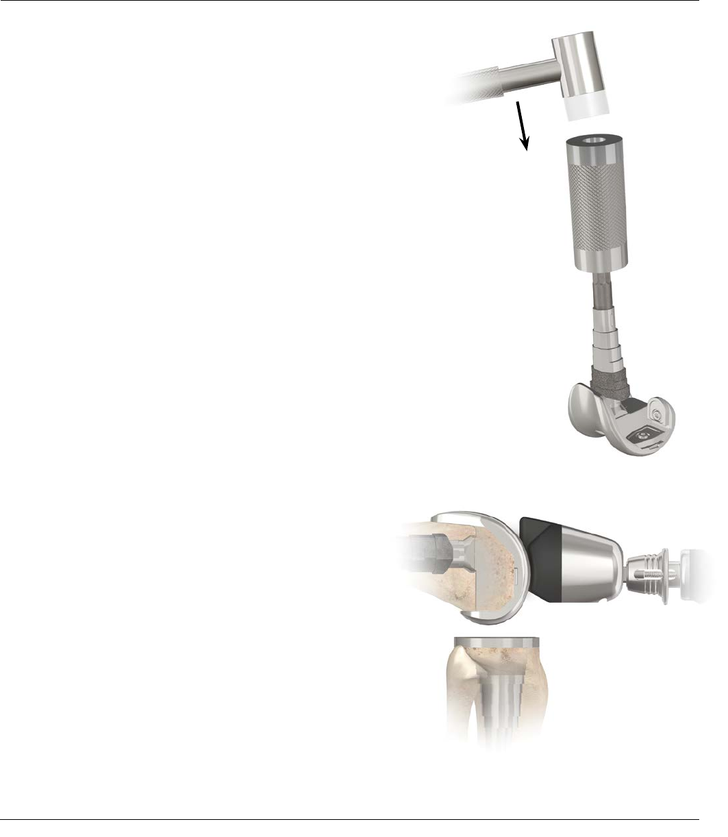
PREPARATION OF THE
METAPHYSEAL BONE – BROACH
16 SIGMA Revision and M.B.T. Revision Tray Surgical Technique
For Sleeve Utilization Only
Note: The M.B.T. Revision Tibial Tray will accept
either a tibial metaphyseal sleeve or a tibial step
wedge. Only the 29 mm Sleeve is indicated for use
with a tibial step wedge.
Attach the M.B.T. Revision Broach Handle to the smallest
broach and then attach the appropriately sized Stem
Trial. The broaches are asymmetrical, position the “ANT”
engraving on the broach anteriorly. Impact the broach
into the tibia until the top surface of the broach is at the
desired proximal tibial resection level. When broaching
the proximal metaphysis, take care to assure the
appropriate rotation of the broach.
Note: The corresponding tibial sleeve implant
allows up to +/- 20 degrees of rotation from
the centerline of the M.B.T. Revision Tray.
Check for rotational stability of the broach. If the broach
(not the handle) moves in the canal, it is not rotationally
stable.
If the broach is unstable or the defect is unfilled, repeat
with consecutively larger broaches until the desired
fit is achieved (Figure 13). Remove the broach handle,
leaving the last broach in place. Any defects remaining
can be filled with allograft or autologous bone placed in
intimate contact with the sleeve.
Two common tibial broaching techniques:
1) Chase the defect by rotating the broach to fill the
defect until reaching rotational stability of the broach.
If utilizing this technique the surgeon must be aware
that the sleeves are allowed to rotate +/-20 degrees
with respect to the M.B.T. Revision Tibial Tray.
2) Align the broach with the medial third of the tibial
tubercle and progressively broach until rotational
stability of the broach is attained.
Figure 13
Tibial Resection Plane
Surgical Technique SIGMA Revision and M.B.T. Revision Tray 17
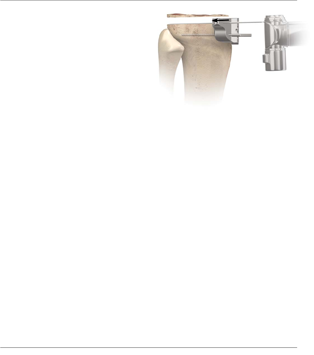
PREPARATION OF THE
METAPHYSEAL BONE – BROACH
Resect the proximal tibia utilizing the top of the broach
as a guide (Figure 14). The top of the broach has a 2
degree slope built in. The proximal cut should be parallel
to the top of the broach.
Note: If a cutting guide is desired for resecting
the proximal tibia with the tibial broach in place,
assemble the SP2 0 degree Tibial Cutting Block
to the SP2 IM Tibial Guide and slide over the
Broach Adapter Outrigger (2178-01-108). Slide this
assembly onto the boss of the seated tibial broach,
pin the block, remove the outrigger, and resect
through the slot of the cutting block (Figure 15).
Slide the tibial view plate which best covers the proximal
tibial over the broach post. Note the view plate size as
it will dictate the size of the M.B.T. Revision Tibial Base
Trial that will be used. The tibial view plate is transparent
to help visualize tibial coverage (Figure 16). The template
matches the implant to aid in orienting the tibial sleeve
to the tibial base during assembly.
Figure 16
Figure 15
Figure 14
18 SIGMA Revision and M.B.T. Revision Tray Surgical Technique
18
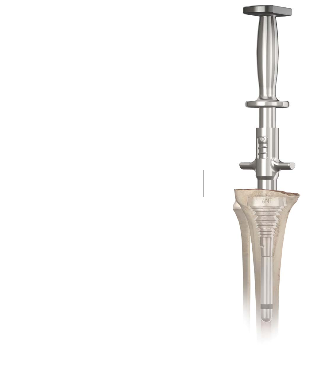
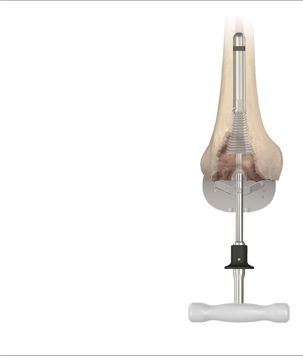
TIBIAL TRIAL ASSEMBLY
Assemble the tibial tray trial with the stem extension and
sleeve trial, if applicable (Figure 17). Position the tibial
trial construct into the prepared tibial canal (Figure 18).
Assess proximal tibial coverage and rotation of tibial
component. The base plate should be positioned to
provide the best coverage of the tibial condylar surface.
Note: The M.B.T. Revision Tibial Keel Punch with
the Universal Handle may be utilized to assist with
seating of tibial trial construct. Once the tibial trial
construct is seated the keel punch must be removed
in order to accommodate the use of the HP Revision
M.B.T. Spacer Blocks.
Leave the trial in place and proceed to femoral
preparation, final tibial preparation will occur after
femoral preparation is complete.
Note: A 14 mm or smaller size stem implant can be
pulled through the sleeve implant. If the stem is 16
mm or greater it will not pull through the sleeve.
Figure 17
Figure 18

Surgical Technique SIGMA Revision and M.B.T. Revision Tray 19
18
After tibial preparation has been performed you may utilize
the HP Revision M.B.T. Spacer Blocks to assess the flexion
and extension gaps (Figures 19 and 20). For common
scenarios, potential solutions are explained below.
Where flexion gap >extension gap:
· To decrease flexion gap without affecting extension gap,
apply a larger femoral component. This is particularly
important where an IM Stem Extension is indicated, as
the Stem Extension will determine the anteroposterior
positioning of the component and the consequent
flexion gap
· Where stem positioning will not permit posterior
augmentation, translate the Femoral Adapter Trial on the
TC3 Box Trial to the +2 (Fem Pos) position. This will result
in translating the femoral component 2 mm posteriorly
(Refer to page 38 for further explanation)
· Where there is insufficient stability, a cemented femoral
stem may be substituted, allowing the component to be
seated further posteriorly
· Where the joint line is elevated, the preferred correction
is posterior femoral augmentation. The alternative–
additional distal femoral resection and use of a
thicker tibial insert to tighten the flexion gap–is not
recommended, as considerable bone stock has been
sacrificed in the primary procedure, and it is important
that additional resection of the distal femur be avoided.
The possible exception is where the joint line is not
elevated and minimal distal resection will increase the
extension gap toward equivalency with the flexion gap
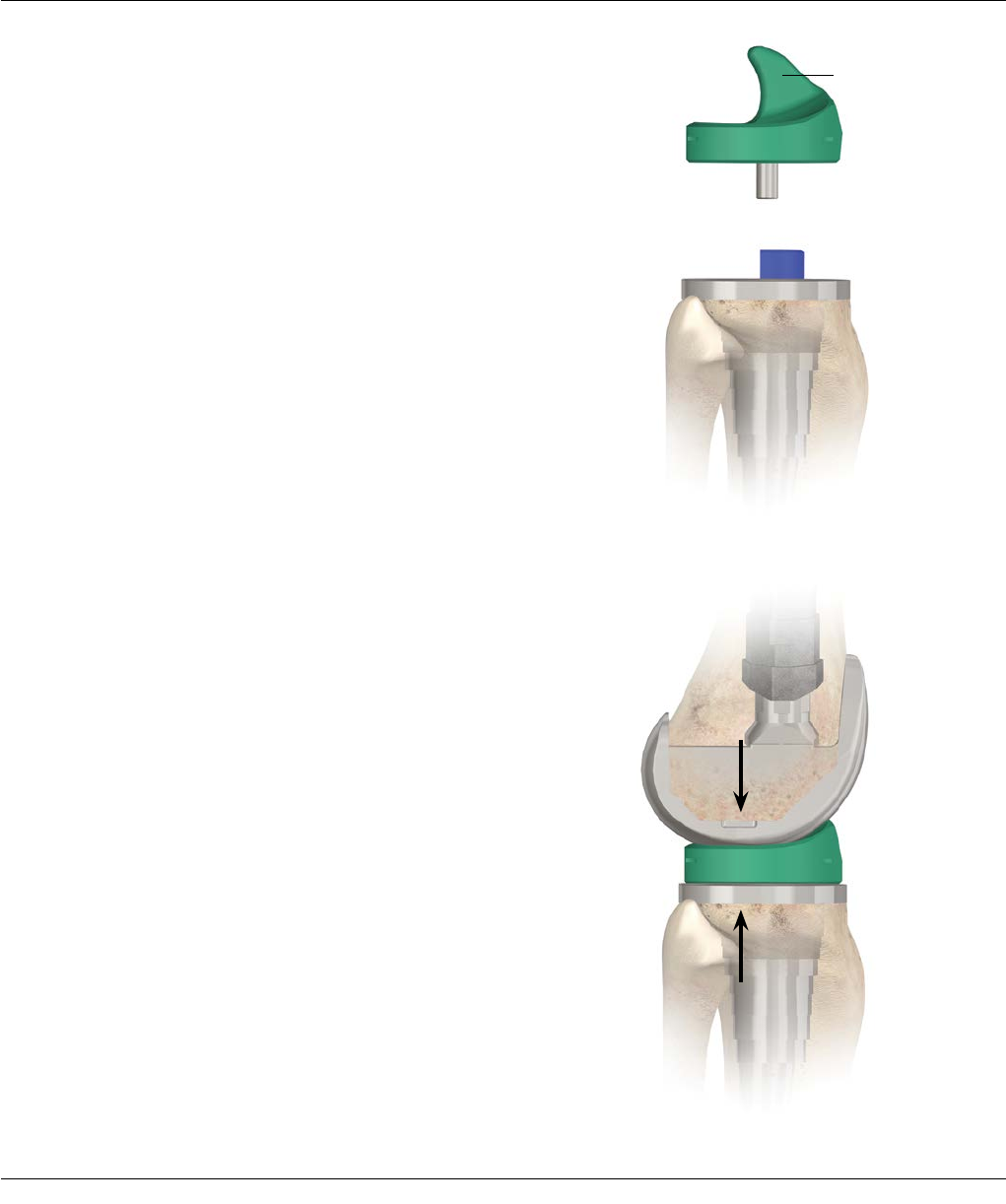
JOINT SPACE ASSESSMENT
Figure 19 Figure 20

20 SIGMA Revision and M.B.T. Revision Tray Surgical Technique
Flexion/Extension Balancing
Where extension gap >flexion gap:
· To decrease extension gap without affecting flexion
gap, augment the distal femur with bone graft or
prosthetic augmentation. It is important to note that
this will lower the joint line, which is usually desirable
as it is generally found to be elevated in revision cases.
This will lessen the incidence of post-operative
patella infera
Note: In the initial assessments of the joint space
the Extension Shim may be utilized to help evaluate
the flexion space. This will only be used to evaluate
gap differences. It is important to keep in mind
that the use of the Extension Shim in flexion will
be approximately 1 mm thicker than the final
flexion gap. If the Extension Shim is not used
here to evaluate flexion, the Spacer Block will be
approximately 4 mm thinner than the final
flexion gap.
JOINT SPACE ASSESSMENT
Loose Extension Tight Extension Stable Extension
Loose Flexion
Cause
Flexion and extension gaps are too
large.
Possible Solution
Thicker tibial insert.
Cause
Inadequate resection of the distal
femur (i.e. extension gap < flexion
gap).
Possible Solution
1. Recut distal femur.
2. Recut chamfers.
Cause
Extension gap < flexion gap.
Can be tolerated to a small extent,
but verify stability.
Possible Solution
1. Increase tibial bearing thickness and
reset more distal femur.
2. Upsize femoral component.
Tight Flexion
Cause
1. Extension gap > flexion gap.
2. Posterior osteophytes.
Possible Solution
1. Check for presence of
posterior femoral osteophytes.
2. Downsize femoral component.
3. Cut Posterior slope on the tibia
(not to exceed 10 degrees) and
increase tibial bearing thickness.
Cause
Flexion and extension gaps are too
small.
Possible Solution
1. Thinner tibial component.
2. If the smallest PE is still too tight,
resect more tibia.
Cause
Flexion gap is too small.
Possible Solution
1. Check for posterior femoral
osteophytes.
2. Ensure that there is no soft
tissue impingement.
3. Recut the tibia with a posterior slope.
4. Possibly downsize femoral component.
Cause
1. Extension gap > flexion gap.
Possible Solution
Upsize the tibial components. Might
be necessary to recut tibia with
biggerposterior slope (not to exceed
10 degrees) to obtain full range of
motion (ROM).
Cause
Extension gaps are too small.
Possible Solution
Recut the distal femur and chamfers.
Cause
Excellent ligament balance.
Possible Solution
You have already found it.
Surgical Technique SIGMA Revision and M.B.T. Revision Tray 21
21
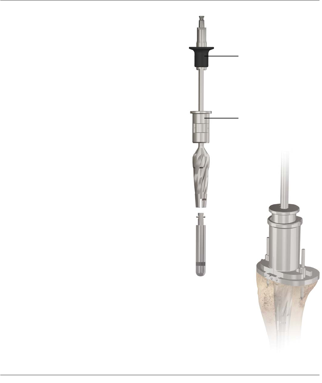
PREPARATION OF FEMORAL DIAPHYSIS
Intramedullary Femoral Alignment System
This technique is designed to flow in a logical sequence,
from reaming the diaphysis, to broaching the metaphysis
and cutting the bone. The length and diameter of the
stem extension is determined with templates applied to
pre-operative radiographs.
Begin the procedure with the preparation of the
medullary canal (Figures 21 and 22).
Enter the medullary canal with a 9 mm Drill to a depth
of 3-5 cm (Figure 23). Take care that the drill avoids the
cortices. It is helpful to palpate the distal femoral shaft
as the drill is advanced.
Where impedance of the intramedullary canal is
anticipated, adjust the entry point accordingly.
Figure 21
Figure 23
Figure 22
22 SIGMA Revision and M.B.T. Revision Tray Surgical Technique
22
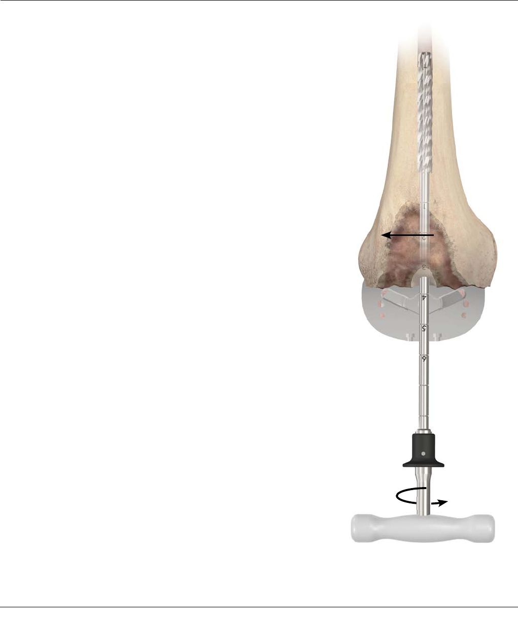
REAMING THE MEDULLARY CANAL
Connect the Reamer Handle to a small diameter M.B.T.
Revision Reamer. If power reaming, it will be necessary
to attach the modified Hudson Adapter to the Straight
Reamer.
Note: The Reamer shaft contains markings in
25.4 mm increments to accommodate the various
Universal stem/sleeve length combinations (Figure
24).
Use the Reamer Depth Chart (Figure 25) to determine
reamer depth for each combination of components.
Another option to determine reamer depth is to measure
the trial assembly against the reamer and note the
corresponding depth mark for reaming.
You may also determine the length and diameter of
the prosthetic stem extension with templates (Cat. No.
2294-99-035: SIGMA Femoral Adapter Sleeve and Stem
Template) applied to pre-operative Radiographs.
The P.F.C.® SIGMA Femoral Component accepts:
· Universal Fluted Stems available in lengths of 75, 115
and 150 mm in diameters of 10-24 mm
· Cemented Stems available in lengths of 30 and 60 mm
lengths and diameters of 13 and 15 mm (15 mm with
sleeve use only)
· Cemented Tapered Stems available in lengths of 90,
120, 150 mm (13 mm diameter) and also a 90 mm in
15 mm diameter (with sleeve use only)
Figure 24

Surgical Technique SIGMA Revision and M.B.T. Revision Tray 23
22 23
REAMING THE MEDULLARY CANAL
In 1 mm diameter increments, sequentially open
the medullary canal with M.B.T. Revision Reamers
of progressively greater size until firm endosteal
engagement is established.
Take care to ream the canal in line with the femoral axis
to avoid putting the implant in flexion.
Note: Do not reverse ream.
It is important that simple cortical contact of the tip not
be construed as engagement as it is the fixed
relationship of the reamer to the cortices that ensures
the secure fit of the appropriate sleeve and subsequently,
the corresponding fluted or cemented stem.
Figure 25
PS Femur No
Sleeve
20 mm
31 mm
34 mm
40 mm
46 mm
Cemented
Stems
30 mm 1 2 2
60 mm 2 3 3
90 mm 4 5 5
120 mm 4 6 6
150 mm 5 7 7
Universal
Slotted
Stems
75 mm 2 4 4
115 mm 4 5 6
150 mm 5 7 7
TC3 Femur No
Sleeve
20 mm
31 mm
34 mm
40 mm
46 mm
Cemented
Stems
30 mm 1 2 2
60 mm 2 3 4
90 mm 4 5 5
120 mm 4 6 6
150 mm 6 7 7
Universal
Slotted
Stems
75 mm 3 4 4
115 mm 4 5 6
150 mm 6 7 7
24 SIGMA Revision and M.B.T. Revision Tray Surgical Technique
24
Figure 26
Figure 27
Stem Reamer
Universal Fluted Stem Use:
As Fluted Stems are available in even sizes (10 through
24 mm diameters), perform final reaming with the
appropriate even-sized reamer.
Note: For stem-only applications, where a Fluted
Stem less than 16 mm in diameter is chosen, use the
Stem Reamer to clear the area around the adapter.
Attach the threaded shaft to the Stem Reamer and then
attach the appropriate Stem Trial to this assembly (Figure
26). Ream the canal (Figure 27).
Sink the Threaded Shaft, Stem Reamer, Stem Trial assembly
until the 20 mm, 31 mm, 34 mm mark corresponds with
the planned level of distal resection.
For trial and implant assembly with stem-only use, please
see page 41.
Cemented Stem Use:
Where a Cemented Stem Extension is indicated, perform
final reaming with a 15 mm Diameter Reamer for the
13 mm diameter stem extension; similarly, a 17 mm
Diameter Reamer is used to accommodate the 15 mm
diameter stem extension. This allows for creation of a
cement mantle.
PREPARATION OF THE METAPHYSIS – STEM USE
Surgical Technique SIGMA Revision and M.B.T. Revision Tray 25
24
After reaming the intramedullary canal, attach the
threaded shaft to the broach reamer and then to the
appropriate Stem Trial as determined by straight reaming
(Figure 28).
Ream to the 20 mm, 31 mm, 34 mm etch mark on the
Threaded Shaft (Figure 29).
When using the broach reamer, the next smaller diameter
stem trial may be used to allow for easier reaming. The
broach reamer will be necessary when utilizing a 20
mm Sleeve and for the beginning of larger sequential
broaching when using a 31 mm or larger sleeve. After
broach reaming has been completed, attach the 31
mm broach to the broach handle (Figure 30). Attach the
appropriate stem trial to the broach as determined by
straight reaming. Give close attention to the medial
orientation of the broach.
Note: The broach is asymmetrical; and the narrow
side of the broach must point medially (Figure 31).
Note: When prepping for a 20 mm Sleeve, leave the
broach reamer and threaded shaft in the canal and
perform the subsequent femoral cuts off the reamer.
PREPARATION OF THE METAPHYSIS – SLEEVE USE
Figure 28
Figure 29
Broach
Reamer
Medial SideLateral Side
Figure 31 Figure 30
26 SIGMA Revision and M.B.T. Revision Tray Surgical Technique
Planned Level of Distal Resection
PREPARATION OF THE METAPHYSIS – SLEEVE USE
Sequentially broach to the desired TC3 or SIGMA CS
Line (Figure 32). When the appropriate etch mark on the
broach handle is at the planned distal resection level,
check the broach’s rotational stability. If the broach (not
the handle) moves in the canal, it is not rotationally
stable.
If the stability of the broach is unsatisfactory, move up
to the next broach size. The last broach used will be the
femoral sleeve size. The broach depth sets the extension
gap/joint line.
In patients with a large degree of distal femoral bow,
closely monitor the anterior progression of the broach
during impaction. Excessive anterior placement of the
broach may result in a loose flexion gap.
Figure 32
Surgical Technique SIGMA Revision and M.B.T. Revision Tray 27
27
Figure 33
After broaching is complete, remove the broach handle
from the broach. With the broach seated in the femur,
attach the threaded shaft to the broach (Figure 33), and
continue with the distal, 4-in-1, and notch cuts.
PREPARATION OF THE METAPHYSIS – SLEEVE USE
28 SIGMA Revision and M.B.T. Revision Tray Surgical Technique
28
Distal Resection
Set the valgus angle to 5 degrees and Left/Right on the
Distal Femoral Alignment Guide by compressing the two
triggers and lock in place by rotating the blue locking
lever clockwise. Place the Femoral Alignment Guide on
the threaded shaft and seat against the distal femur
(Figure 34).
Rotate the knob on the Femoral Resection Guide
counterclockwise until the arrow is pointing to the
padlock symbol. Slide the femoral distal connector
into the Femoral Resection Guide. Rotate the knob
on the Femoral Resection Guide clockwise. Every
click moves the Revision Distal Cutting Block 1 mm
proximal or distal. Turn the knob clockwise from
15 all the way down to 0 (which is the padlock
symbol). This will set the block up for a 0 mm
resection (Figure 35).
Slide the femoral Distal Cutting Block onto the Distal
Femoral Block attachment. The tang on the block
connector will slide into the 0 mm cutting slot on the
cutting block. The trigger should engage in the hole
behind the 0 mm slot (Figure 36).
Note: An open resection will resect 4 mm less
femur. When a 0 mm, open resection is desired, the
dial should be set to 4 mm.
Position the Resection Guide over the two legs of the
Distal Femoral Alignment Guide until the Distal Cutting
Block touches the anterior femur (Figure 37).
Note: The Revision Distal Block is equipped with 0,
4, and 8 mm saw slots. Please keep in mind that if
the resection level is not at 0 (the padlock symbol)
this will alter the resection. If the resection knob is
set at 2, for instance, the saw slots will perform 2, 6,
and 10 mm resections.
FEMORAL PREPARATION – DISTAL RESECTION
Distal Femoral
Connector
Revision Distal
Cutting Block
Figure 34
Distal Femoral
Resection Guide
Figure 35
Figure 37
Figure 36
Surgical Technique SIGMA Revision and M.B.T. Revision Tray 29
28
FEMORAL PREPARATION – DISTAL RESECTION
Figure 39
0 mm
8 mm
4 mm
Secure the cutting block to the femur with Non-Headed
HP Pins through the holes marked with a .
Optional: A Convergent Pin can also be used to provide
better block stability/fixation (Figures 38 and 39).
Figure 38
30 SIGMA Revision and M.B.T. Revision Tray Surgical Technique
FEMORAL PREPARATION – DISTAL RESECTION
Figure 41
An example of a medial
4 mm augment resection
Figure 40
1. Slide femoral
resection guide
upwards
2. Remove femoral
alignment guide
towards the
T-handle
Release
attachment
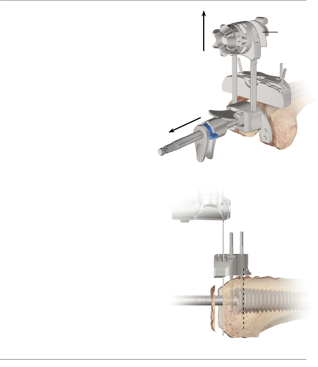
Once the pins are in place, unlock the Distal Cutting
Block from the distal block connector, using your thumb
and index finger to release the attachment. Slide the
Femoral Resection Guide upwards on the Alignment
Guide legs until the block connector disengages from
the cutting block and in one motion remove the Femoral
Alignment Guide by pulling the instruments distally over
the threaded shaft (Figure 40).
In many cases, little, if any, bone is removed from the
distal femur as the joint line is effectively elevated with
the removal of the primary femoral component. As the
level of resection is based on the preservation of bone
stock, each condyle is cut only to the level required to
establish a viable surface, with augmentation employed
to correct imbalance
The resection is then performed through the slot
appropriate for each condyle, using a standard 1.19 mm
Thick Blade (Figure 41).
Note: If a ½ inch wide Standard Saw Blade is used
it can complete both medial and lateral distal
femoral cuts with the entire jig still in place.
Surgical Technique SIGMA Revision and M.B.T. Revision Tray 31
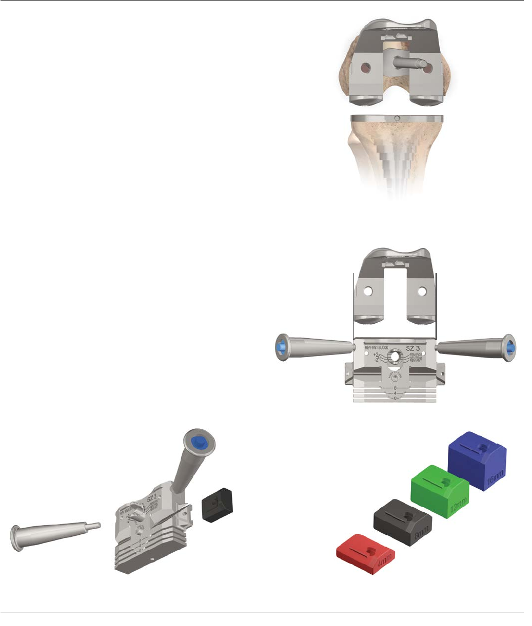
To size the femur, turn the femoral trial around so the
posterior condyles point away from the distal surface
(Figure 42). The M/L width of the trial should provide the
femoral size. Once the femoral size is determined, select
the appropriately sized Revision 4-in-1 Cutting Block.
Note: The Revision 4-in-1 Cutting Blocks may also
be used to assess the femoral size, as the block is
the same M/L width as the implant (See Figure 43).
If augment cuts were made during the distal resection,
assemble the appropriate distal spacer (4, 8, 12 or
16 mm) to the proximal side of the cutting block to
compensate for the condylar discrepancy. The distal
spacers slide in from the side using a dovetail connection
on the 4-in-1 Block (Figure 44).
Each distal spacer thickness is represented by a different
color (Figure 45).
Red = 4 mm
Black = 8 mm
Green = 12 mm
Blue = 16 mm
Figure 43
FEMORAL PREPARATION – A/P AND CHAMFER CUTS
Figure 42
Width of femoral trial
matches 4-in-1 block
16 mm
12 mm
8 mm
4 mm
Figure 45
Figure 44
32 SIGMA Revision and M.B.T. Revision Tray Surgical Technique
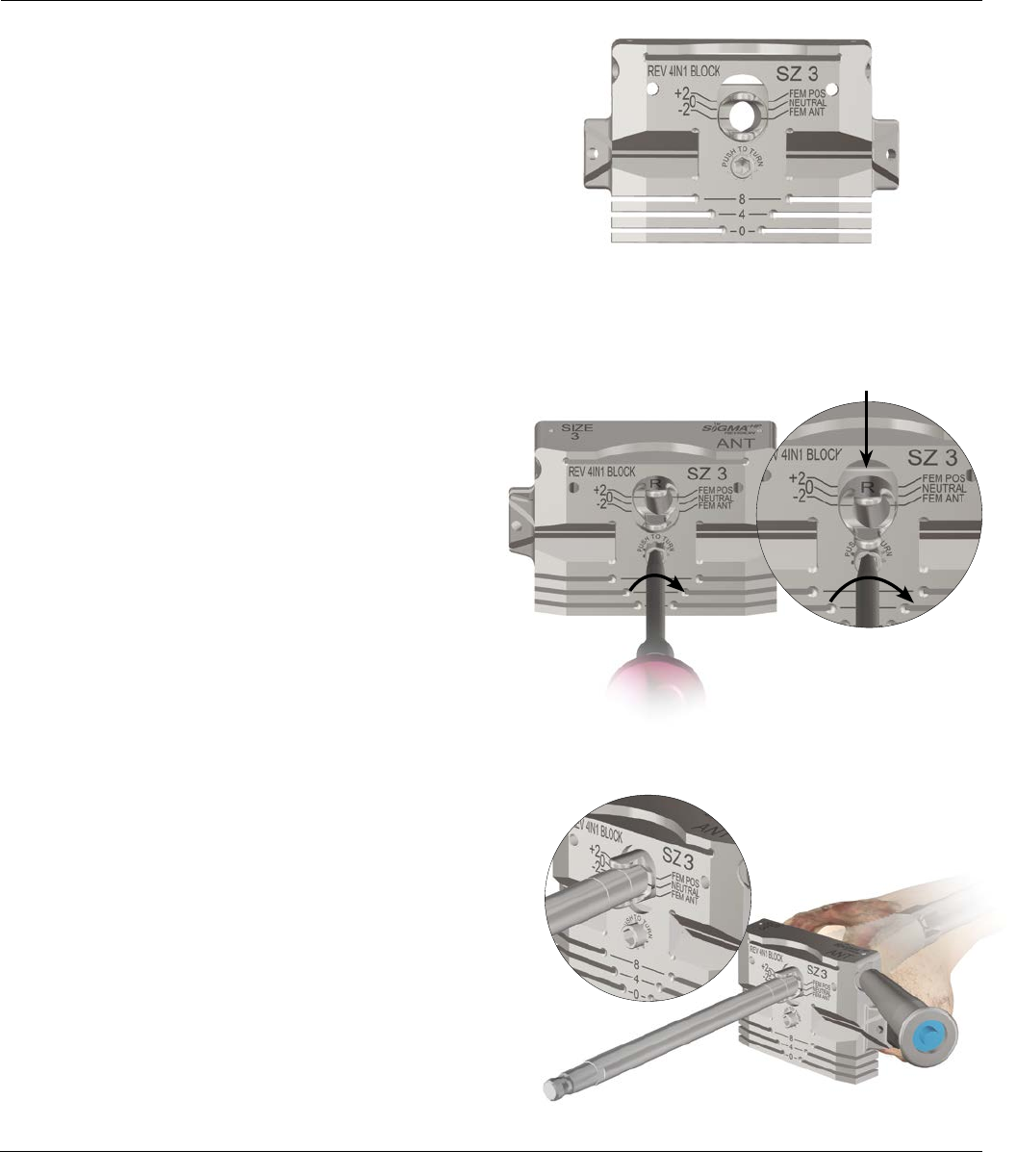
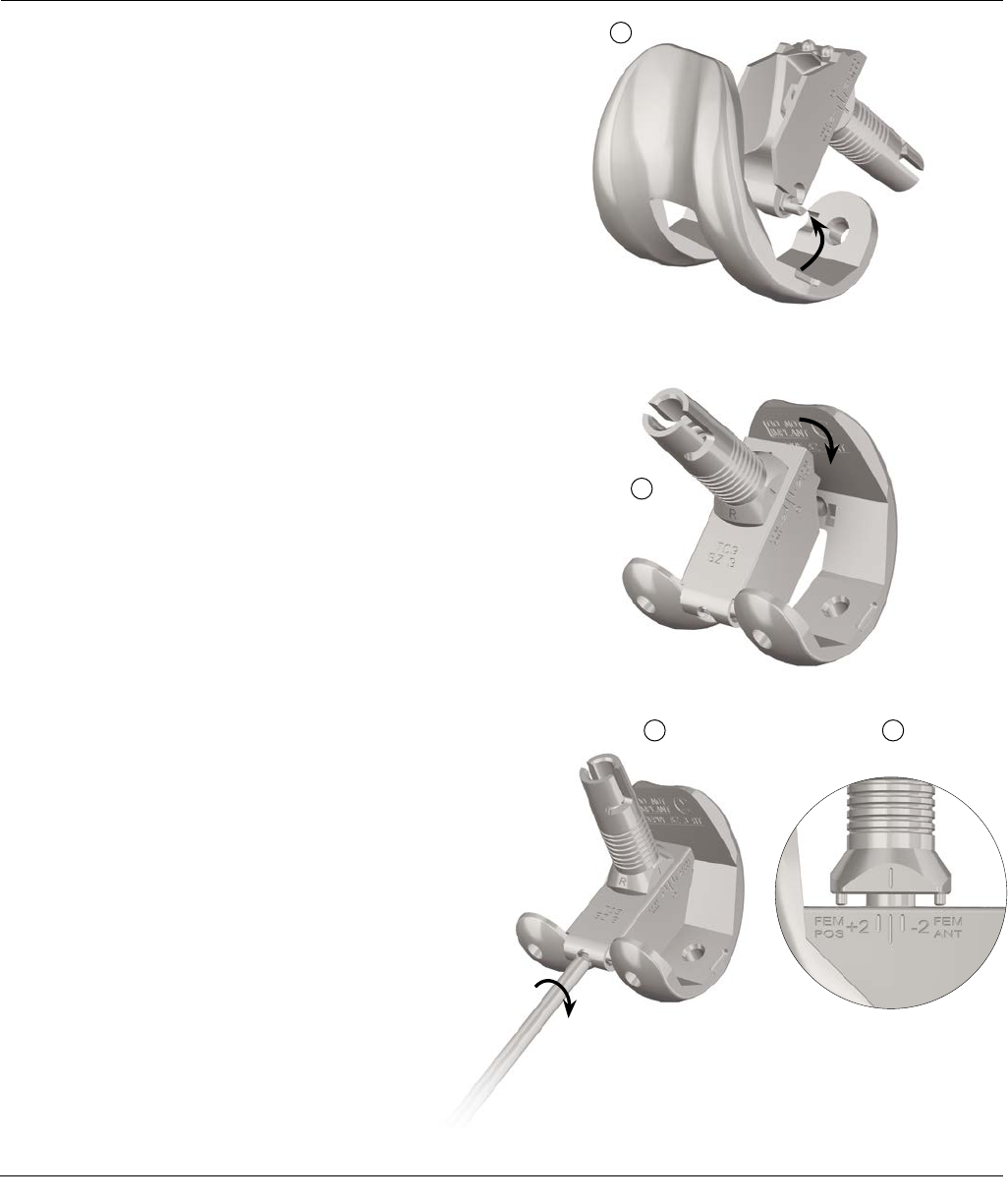
The HP Revision 4-in-1 Cutting Block is fixed at a 5
degree angle. To change the block’s orientation for left
5 degrees or right 5 degrees, flip over the block’s knob
until the L is on top for Left or the R is on top for Right
Note: To assist in changing the Left or Right
orientation (L/R), the shaft of the Revision
Screwdriver may be placed lengthwise between the
two knobs of the L/R dial and rotated 180 degrees.
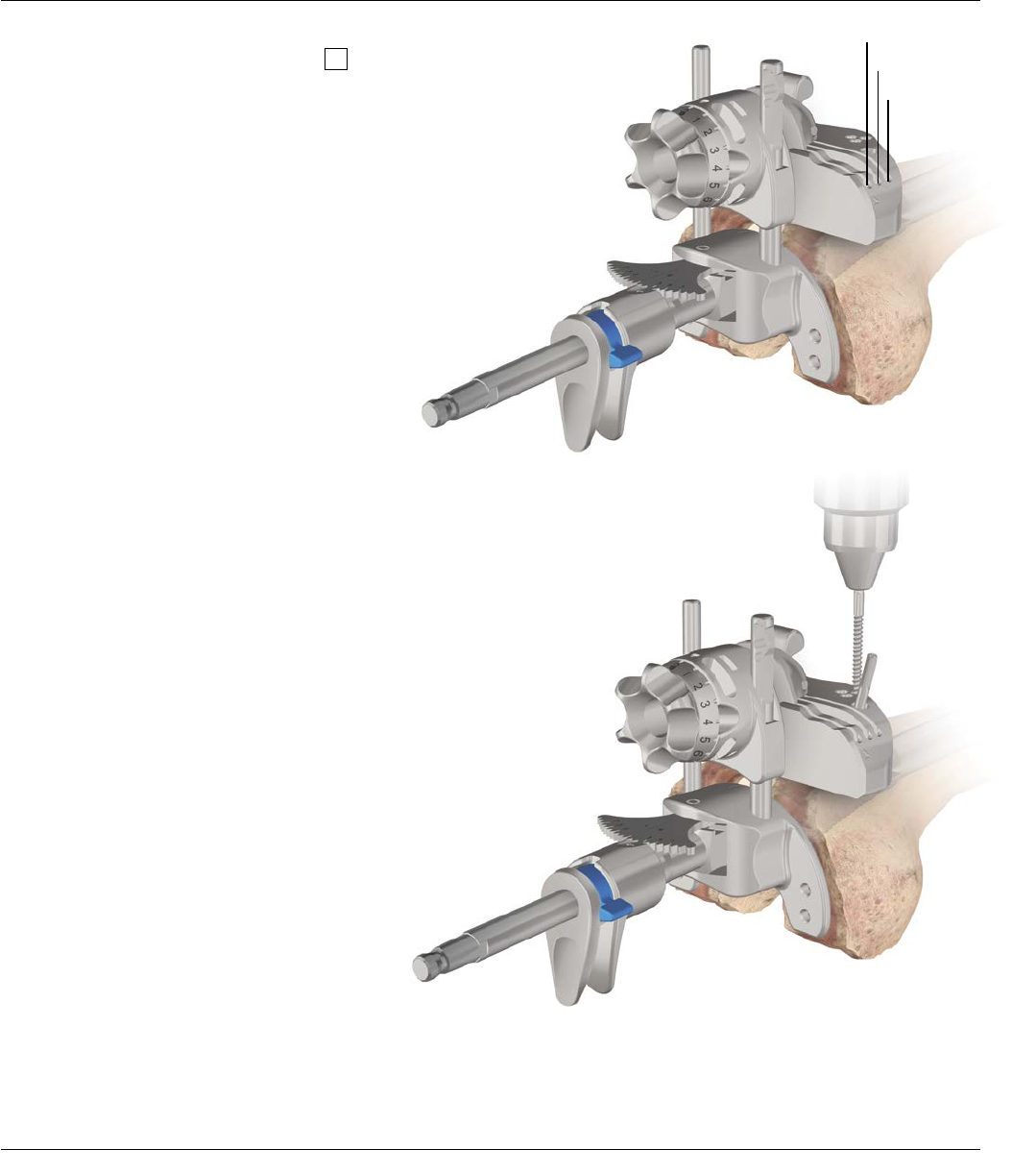
To set the block to the correct A/P starting position,
Insert the Revision Screwdriver into the hex head on the
block, PUSH and turn clockwise. (To change the setting,
the hex head must first be pushed in to shift the block)
(Figure 46).
Note: The block should be set up in the +2 position
(Fem Post) to begin. The lines on the side of the
knob should line up with the etched lines for the
desired position.
Once done, slide the block proximally onto the threaded
shaft with the appropriate Left/Right (L/R) orientation on
top (Figure 47).
FEMORAL PREPARATION – A/P AND CHAMFER CUTS
The Revision 4-in-1 Cutting Block
As the Screwdriver is turned
clockwise, the +2,0,-2 knob shifts
downwards
Figure 47
To adjust A/P position:
1. Push Screwdriver into Hex Head
2. Rotate Screwdriver to adjust +2,0,-2 position
Figure 46
Surgical Technique SIGMA Revision and M.B.T. Revision Tray 33
FEMORAL PREPARATION – A/P AND CHAMFER CUTS
Figure 48
Figure 49
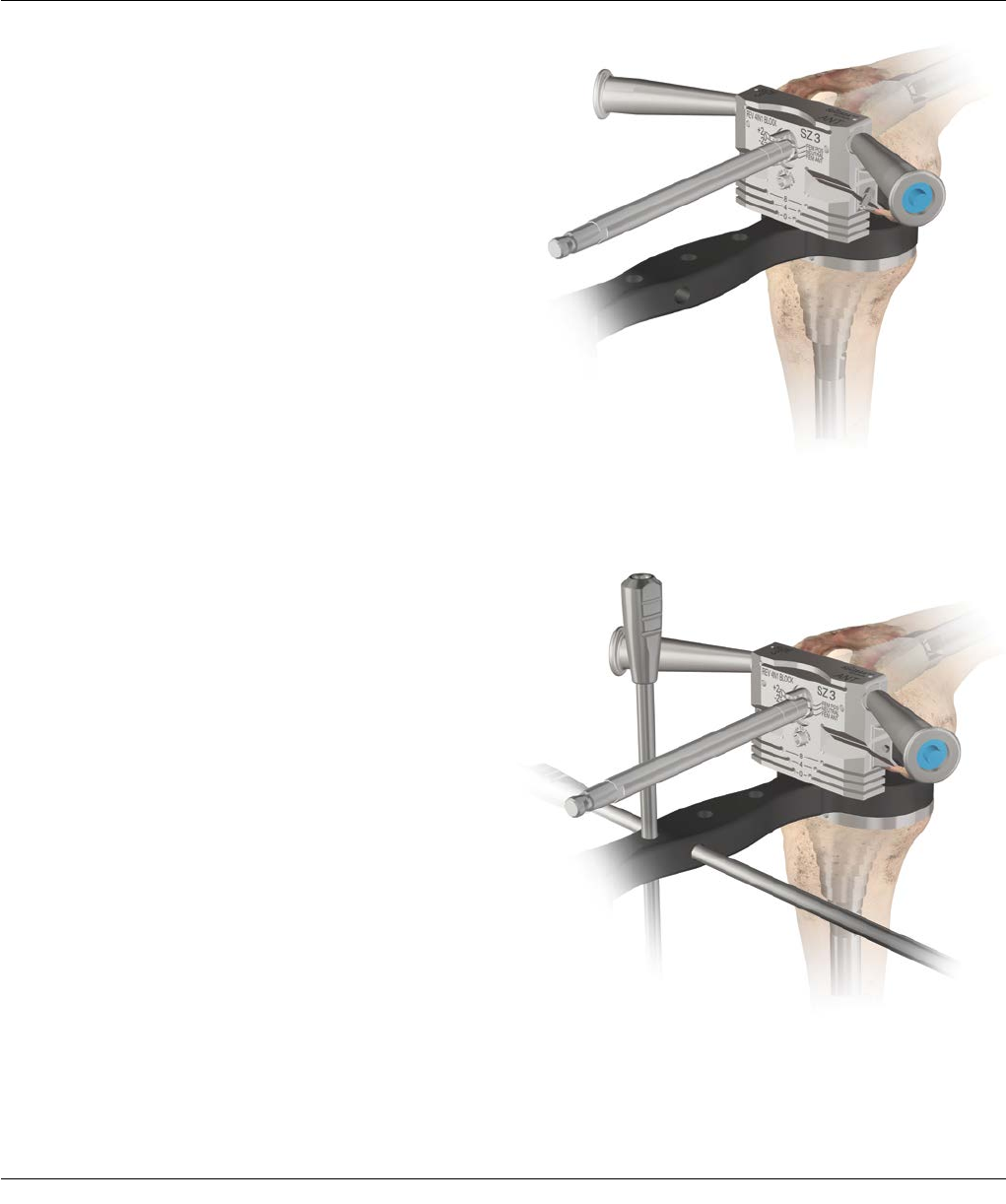
Rotational positioning of the Revision 4-in-1 Cutting Block
is critical to the establishment of a symmetrical flexion gap
and patellofemoral alignment. The correct block rotation
should have the posterior surface of the cutting block
parallel to the resurfaced proximal tibia under tension.
Validate symmetry with the HP Revision M.B.T. Spacer
Blocks (Figure 48).
Note: The Revision M.B.T. Spacer Blocks are
designed to rest on top of the M.B.T. Revision Tray
Trial and underneath the posterior portion of the
4-in-1 Cutting Block, providing both the appropriate
tension and the correct insert thickness.
Optional: If desired, Alignment Rods may be introduced
through the handle of the spacer block. This may be
helpful in assessing alignment. Rods can be inserted
vertically (to assess the mechanical axis) and horizontally
(to assess tibial cut accuracy) (Figure 49).
Optional: Balanced Block Handles can be used to rotate
the block and to hold the block in place during final
resection.
Where asymmetry exists, additional soft-tissue balancing
may be indicated. Confirm positioning
by assuring parallel alignment of the cutting block with
the transepicondylar axis or the proximal tibia.
Introduce the Angel Wing into the anterior saw slot
to check the anterior resection and ensure femoral
notching does not occur.
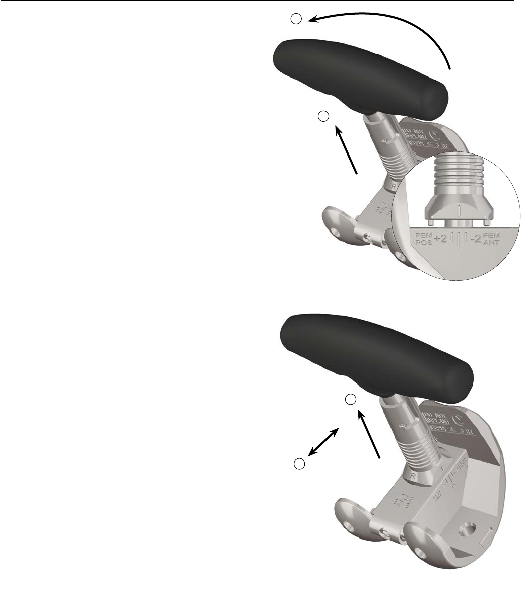
34 SIGMA Revision and M.B.T. Revision Tray Surgical Technique
Figure 50
Figure 51
FEMORAL PREPARATION – A/P AND CHAMFER CUTS
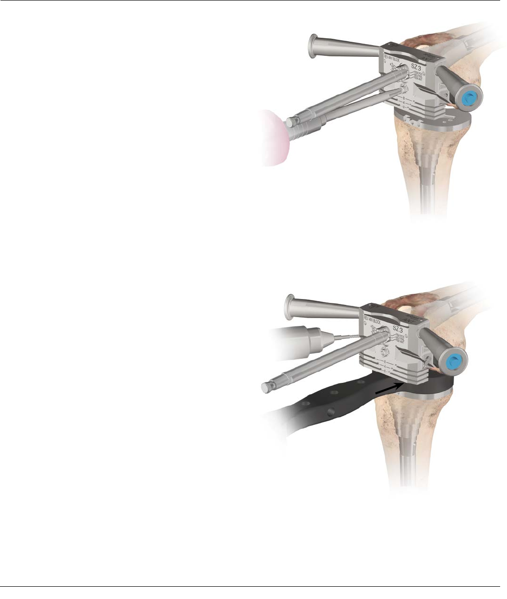
If the flexion gap is loose relative to the extension gap,
the next larger size femoral component can be used and
the posterior condyles augmented.
If the flexion gap is too tight relative to the extension
gap, the block can be moved from the +2 setting
(Femoral Posterior) to the 0 (Neutral) or -2 setting
(Femoral Anterior) (Figure 50).
Note: The block should not be shifted from one
setting to another with the spacer block, pins, or
any tensioning device in place.
With rotation and gap balancing confirmed, secure the
Cutting Block with HP Threaded Pins introduced through
the side Convergent Pin holes.
Note: If additional fixation is required use threaded
non-headed pins in the anterior pin holes. Use
caution when using headed threaded pins if a gap
exists between the distal spacers and the distal
bone.
The pins will pass through the block and then through
the Distal Spacer (if used), fixing the block in place
(Figure 51). Once locked in place perform the anterior,
posterior, and chamfer cuts.
Surgical Technique SIGMA Revision and M.B.T. Revision Tray 35
Figure 52
Anterior resection is performed through the
anterior slot using a 1.19 mm ½ inch wide Saw Blade
(Figure 52).
Note: The blocks feature an etched line on the side
of the block. This line on the block represents the
distal joint line of the femoral component.
Posterior resection is through the slot designated 0
or, where there is posterior condylar deficiency, use
the appropriate 4 or 8 mm slot to accommodate the
projected augmentation (Figure 53).
Once Anterior and Posterior resections are complete
proceed with the Anterior and Posterior chamfer cuts
(Figures 54 and 55).
Note: If pins were used in the straight anterior pin
holes for additional fixation, they must
be removed prior to making the anterior
chamfer cut.
FEMORAL PREPARATION – A/P AND CHAMFER CUTS
Figure 53
Figure 55
Figure 54
Etch Line Represents Joint Line
36 SIGMA Revision and M.B.T. Revision Tray Surgical Technique
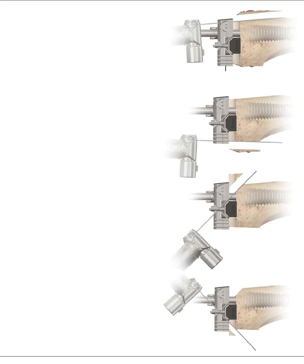
Select the appropriate sized Revision Notch Guide, based
upon the size of the Revision 4-in-1 Block used. If distal
spacers were used for the 4-in-1 cuts, insert the same
distal spacers into the Notch Guide on the appropriate
side (Figure 56).
Select the appropriate Notch Guide Bushing. This
corresponds to the Right/Left Block knob position and
the 0 mm (Neutral), +2 mm (Fem Pos) or -2 mm (Fem Ant)
position that was used on the 4-in-1 Cutting Block.
Assemble it onto the Notch Guide with the appropriate
Right/Left and 0, +2 or -2 designation facing up and lock
into position by rotating the tabs anteriorly to the stop
(Figure 57).
Note: The width of the Notch Guide corresponds to
the final implant width (Figure 57).
Figure 57
Distal Spacer
Notch Guide Bushing
Figure 56
FEMORAL PREPARATION – NOTCH RESECTION
Final Implant Width
Surgical Technique SIGMA Revision and M.B.T. Revision Tray 37
FEMORAL PREPARATION – NOTCH RESECTION
Figure 59
Figure 60
Figure 58
Assemble the Notch Guide onto the threaded shaft and
advance to the prepared distal surface (Figure 58).
If assistance is needed in re-establishing the rotation of
the Notch Guide, the HP Revision M.B.T. Spacer Block
may be used between the M.B.T. Revision Tibial Trial
and the posterior side of the Notch Guide to re-establish
desired rotation from the 4-in-1 Block.
Once desired rotation is set, use Non-Headed Pins in the
convergent pin holes to lock the Notch Guide in place.
The pins will go through both the Notch Guide and the
distal spacers (if used) (Figure 59).
If necessary, introduce Non-Headed Pins in the sequence
displayed (Figure 59):
1. Anterior
2. Contralateral distal
3. Anterior
4. Distal
Note: Care should be taken not to insert pins too far
into anterior bone.
Remove the notch bushing and the threaded shaft (if
used). Ensure the Notch Guide orientation does not
change and the Notch Guide is still rigidly fixed in place.
Note: The length of the intercondylar box differs
for the P.F.C. SIGMA Stabilized and TC3 femoral
components. Care should be taken to ensure that
the appropriate cut is made through the Notch
Guide.
The TC3 box cut is made through the proximal surface
of the anterior Notch Guide (through the slot) and
the Stabilized or PS box cut is made on top of the
slot (Figure 60). Perform the resection either with
an Oscillating Saw and a ½’inch wide blade or a
Reciprocating Saw (Figure 60).
TC3 and STAB markings
3
4
2
1
FEMORAL TRIAL ASSEMBLY
38 SIGMA Revision and M.B.T. Revision Tray Surgical Technique
3
2
1
4
Figure 61
Figure 62
Figure 63 Figure 64
The Femoral Component Box Assembly
1) Place the two outrigger tabs of the box trial into
the recesses of the posterior condyles on the
corresponding size trial femoral component (Figure
61).
2) Insert the two anterior tabs into the recesses of the
anterior flange (Figure 62). If the anterior tabs won't
fit, take the box out, insert the Screwdriver into the
hex head and rotate counter clockwise, then reinsert.
3) Using the Screwdriver, adjust the hex screw at the
posterior of the box trial until a "click" is heard from
the Screwdriver (Figure 63).
4) Adjust the Femoral adapter position to the
corresponding position 0 (Neutral), +2 (Fem Post), or
-2 (Fem Ant and Right/Left (R/L)) from the Revision
4-in-1 Cutting Block and the notch guide bushing.
(Pull up then translate to desired position (Figure
64). This can be done by hand or with the Femoral
Adaptor Shift Tool. For further instructions, see Page
38 on how to adjust this positioning).
Note: Using the Screwdriver, tighten the hex screw
until a "click" is heard from the Screwdriver. This
will ensure secure assembly of the Box Trial to the
Femoral Trial. Do not overtighten the Screw or
attempt to remove the Screw from the Box Trial as
this will result in damage to the Box Trial
attachment.
Note: Do not over-loosen the Hex Screw when
disassembling the femoral trial construct. The
Screwdriver does not limit torque in the reverse
direction.
FEMORAL TRIAL ASSEMBLY
If the box trial adapter orientation needs to be adjusted,
pull the adapter up and rotate 180 degrees to set the
orientation to left or right. The correct orientation
marking will be pointing towards the posterior condyles
of the trial femoral component and will be indicated by
an L for left and an R for right (Figure 65).
Ensure that the A/P positioning is correct. There are
indicators on the side of the box to indicate +2 (which
shifts the femoral component posteriorly/closes the
flexion space), 0 (neutral), and -2 (which shifts the
femoral component anteriorly/opens the flexion space)
(Figure 65). This positioning should match the A/P
setting established on the Revision 4-in-1 Block.
Note: To change the positioning, pull up on
the Adapter and move the Adapter forward or
backwards on the box until the desired +2, 0, or -2
location is reached. If this adjustment is difficult the
Femoral Adapter Shift Tool may be used to aid in
setting this adjustment (Figure 66).
Surgical Technique SIGMA Revision and M.B.T. Revision Tray 39
Figure 65
2
1
2
Figure 66
To adjust the setting:
1. Pull up
2. Translate posterior
or anterior
1
To adjust the
L/R setting:
1. Pull up
2. Rotate Adapter
180 degrees
Trial assembly order
(with sleeve and stem use, see Figure 67):
· Assemble HP Revision TC3 Box Trial to the
corresponding size Femoral Trial
· Assemble sleeve trial over adapter trial
· Partially tighten HP Revision Sleeve Bolt Trial with the
Screwdriver to hold the construct in place
· Add stem trial to trial assembly
· Add posterior and distal augment trials, if needed
· Seat trial assembly on femur
· Once sleeve trial has achieved proper orientation,
completely tighten with the Screwdriver until the
"click" is heard
After assembling the HP Revision TC3 Box Trial to the
femoral trial, set the femoral adapter on the box trial to
the correct side (Left or Right) and position (+2,0,-2 mm)
from the 4-in-1 Cutting Block and Notch Guide Bushing
(Figure 67 - Step 1). Assemble the femoral sleeve trial
corresponding in size to the final broach employed to
the TC3 femoral trial assembly (Figure 67 - Step 2) and
pass the HP Sleeve Bolt Trial through the hole in the box
of the distal femoral trial and partially tighten using the
Screwdriver (Figure 67 - Step 3). Make sure to properly
orient the sleeve trial with the narrow side facing
medially. Assemble the proper stem trial to the sleeve
trial (Figure 67 - Step 4).
Note: Trial bolt lengths are different for adapter/
sleeve use than for adapter/stem-only use, the bolt
trials are marked accordingly "SLEEVE BOLT" or
"STEM BOLT".
Note: Do not completely tighten down the bolt prior
to seating the trial construct into the canal. Leave
the sleeve slightly loose so that it finds its proper
rotation/orientation as it is being inserted into the
canal.
40 SIGMA Revision and M.B.T. Revision Tray Surgical Technique
FEMORAL TRIAL ASSEMBLY
– SLEEVE AND STEM USE
Figure 67
Step 3
Step 1
Step 2
Step 4
Surgical Technique SIGMA Revision and M.B.T. Revision Tray 41
Figure 69
FEMORAL TRIAL ASSEMBLY – SLEEVE AND STEM USE
Figure 68
The sleeve bolt mechanical connection to the sleeve trial/
adapter/femoral trial construct helps to ensure that the
parts do not disassociate during use.
Note: Please consult the anterior width chart on
page 64 (in the Appendix) to determine the sleeve/
femoral component compatibility and the distance
between the anterior chamfer and the anterior
aspect of the sleeve.
Where augmentation is employed, assemble the
appropriate trial distal and posterior augmentation
components to the trial femoral component
(Figure 68).
Remove the sleeve broach with the broach handle.
Seat the femoral trial in the femur. The sleeve trial will
achieve the rotation and orientation of final broach
used. After the femoral trial with sleeve is seated
securely in the metaphysis, tighten the sleeve bolt trial
with the screwdriver until the "click" is heard (Figure
69).
42 SIGMA Revision and M.B.T. Revision Tray Surgical Technique
Trial assembly order (with stem-only use, Figure 70):
· Assemble HP Revision TC3 Box Trial to the
corresponding size femoral trial
· Tighten HP Revision Stem Bolt Trial
with the Screwdriver
· Add stem trial to trial assembly
· Add posterior and distal augment trials, if needed
· Seat trial assembly on femur
After assembling the HP Revision TC3 Box Trial to the
Femoral Trial, set the Femoral Adapter on the box trial to
the correct side (Left or Right) and position (+2,0,-2 mm)
from the Revision 4-in-1 Cutting Block and Notch Guide
Bushing (Figure 70 - Step 1). Pass the Stem Bolt Trial
through the hole in the box of the distal femoral trial
and tighten using the HP Revision Screwdriver (Figure 70
- Step 2). Assemble the proper stem trial to the box trial
(Figure 70 – Step 3).
Note: Trial bolt lengths are different for adapter/
sleeve use than for adapter/stem-only use, the bolt
trials are marked accordingly "SLEEVE BOLT" or
"STEM BOLT".
The stem bolt mechanical connection to the Adapter/
Femoral Trial construct helps to ensure that the parts do
not translate during use.
Where augmentation is employed, assemble the
appropriate trial distal and posterior augmentation
components to the trial femoral component.
Seat the femoral trial in the femur.
Note: The stem bolt must be used for a stem only
trial. Failure to use the stem bolt will result in an
inaccurate reading of varus/valgus stability during
trialing.
Step 2
Step 1
Step 3
Figure 70
FEMORAL TRIAL ASSEMBLY – STEM-ONLY USE
Surgical Technique SIGMA Revision and M.B.T. Revision Tray 43
Trial assembly order (with Sleeve-only use, Figure 71):
· Assemble HP Revision TC3 Box Trial to the
corresponding size Femoral Trial
· Assemble sleeve trial over adapter trial
· Partially tighten HP Revision Sleeve Bolt Trial
with the Screwdriver to hold the construct in place
· Add posterior and distal augment trials, if needed
· Seat trial assembly on femur
· Once sleeve trial has achieved proper orientation,
completely tighten with the Screwdriver until the
"click" is heard
After assembling the HP Revision TC3 Box Trial to the
femoral trial, set the femoral adapter on the box trial to
the correct side (Left or Right) and position (+2,0,
-2 mm) from the Revision 4-in-1 Cutting Block and
Notch Guide Bushing (Figure 71 - Step 1). Assemble the
femoral sleeve trial corresponding in size to the final
broach employed to the TC3 Femoral Trial assembly
(Figure 71 - Step 2) and pass the HP Revision Sleeve Bolt
Trial through the hole in the box of the distal femoral
trial and partially tighten using the Screwdriver (Figure
71 - Step 3). Make sure to properly orient the sleeve trial
with the narrow side facing medially. Do not completely
tighten down the bolt. Leave the sleeve trial slightly
loose so that it find its proper rotation/orientation as it is
being inserted into the canal.
Note: Trial bolt lengths are different for adapter/
sleeve use than for adapter/stem-only use, the bolt
trials are marked accordingly "SLEEVE BOLT" or
"STEM BOLT".
FEMORAL TRIAL ASSEMBLY – SLEEVE-ONLY USE
Figure 71
Step 3
Step 1
Step 2

44 SIGMA Revision and M.B.T. Revision Tray Surgical Technique
FEMORAL TRIAL ASSEMBLY – SLEEVE-ONLY USE
The sleeve bolt mechanical connection to the adapter/
femoral trial construct helps to ensure that the parts do
not disassociate during use.
Note: Please consult the anterior width chart
on page 64 (in the Appendix) to determine the
sleeve/femoral component compatibility and the
distance between the anterior chamfer and the
anterior aspect of the sleeve.
Where augmentation is employed, assemble the
appropriate trial distal and posterior augmentation
components to the trial femoral component. Remove
the sleeve broach with the broach handle. Seat the
femoral trial in the femur. The sleeve trial will achieve
the rotation and orientation of final broach used. After
the sleeve trial is seated securely in the metaphysis,
tighten the sleeve bolt trial with the screwdriver until the
"click" is heard.
Surgical Technique SIGMA Revision and M.B.T. Revision Tray 45
FINAL PREPARATION OF THE TIBIA
Figure 73
Figure 72
Assess proximal tibial coverage and rotation of tibial
component. Impact the appropriate Keel Punch (utilize
the cemented Keel Punch if a cement mantle is desired
or the press-fit Keel Punch if line-to-line contact is
desired) (Figure 72). The base plate should be positioned
to provide the best coverage of the tibial condylar
surface.
Leave the Keel Punch in place for trial reduction and
insert the polyethylene Trial (Figure 73).
Note: PS or CR M.B.T. Insert Trials may be used at
this point to assess construct stability. Using these
trials will allow easier insertion onto the keel and
will provide a better idea on how well the gaps are
balanced.
46 SIGMA Revision and M.B.T. Revision Tray Surgical Technique
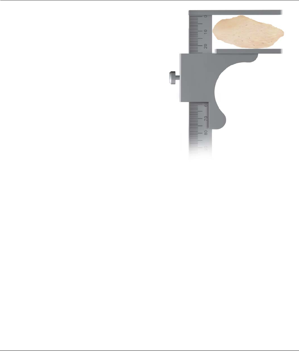
PREPARATION OF THE PATELLA
Where replacement of the patellar component is
indicated, it is important that the anteroposterior
dimension be maintained and that adequate bone
stock be preserved. Problems arise from inadequate,
excessive or uneven resection resulting in abnormal
anteroposterior dimension to the complex, subsequent
patellar tilt and implant wear.
Free sufficient soft tissue at the prepatellar bursa to
position Calipers at the anterior cortex.
Where residual bone stock is adequate, implantation of
the replacement prosthesis is essentially routine. Where
inadequate, patelloplasty may be indicated.
Note: The normal anteroposterior patellar
dimension is 22–24 mm in the female, 24–26 mm in
the male (Figure 74).
Figure 74
Surgical Technique SIGMA Revision and M.B.T. Revision Tray 47
PREPARATION OF THE PATELLA
Figure 75
Figure 76
Meticulous disruption of the bone/prosthesis interface
is essential. It is performed with thin Osteotomes and
thin Oscillating Saw Blades. Avoid excessive leverage to
minimize possible fracturing.
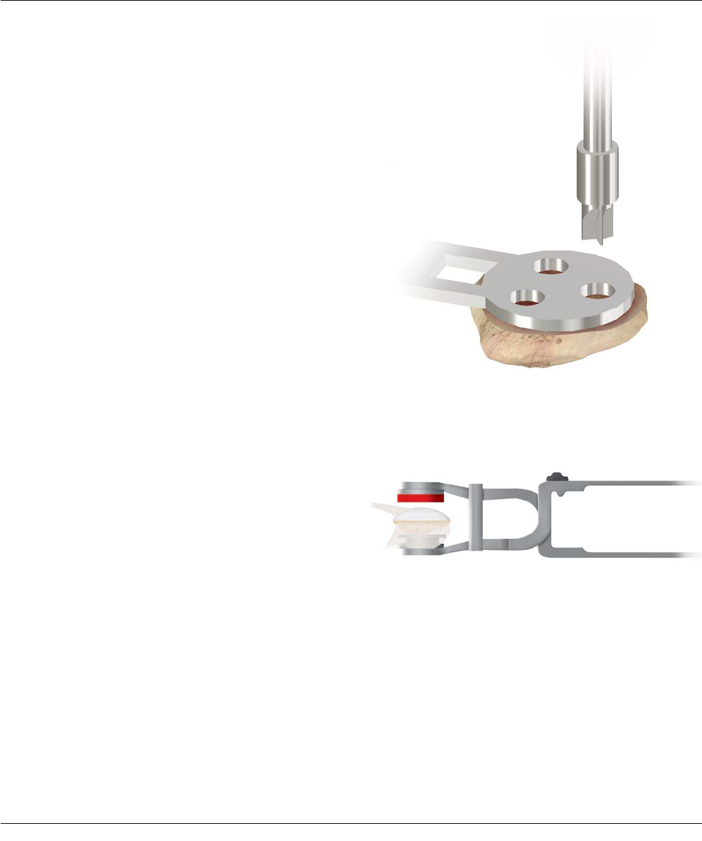
Position the Patellar Template that most adequately
covers the prepared surface along the horizontal axis
of the patella and firmly engage. Fashion the three
holes for the fixation pegs of the component with the
appropriate drill (Figure 75). Depth is governed by the
collar.
Implanting the Patellar Component
Perform patellar implantation when convenient.
Cleanse the site with pulsatile lavage, dry, and apply
methyl methacrylate cement. Insert the component into
the prepared holes and position thePatellar Clamp.
The clamp is designed to fully seat and stabilize the
implant. Position it with the silicone O-ring centered
over the articular surface of the implant and the metal
backing plate against the anterior patellar cortex,
avoiding skin entrapment. When snug, the handles are
closed and held by the ratchet until polymerization is
complete (Figure 76). Avoid excessive compression as
it can fracture osteopenic bone. Remove all extruded
cement with a Curette.
Tibial Sleeve Assembly
Note: It is imperative to assemble the sleeve prior to
stem attachment.
Note: Sleeves and step wedges can only be used
together if using a 29 mm Sleeve.
Remove trial component in one piece (use as guide for
assembly of implants).
Place the M.B.T. Revision Tray on a firm, stable, padded
surface. Set the tibial sleeve in an orientation that
matches the prepared canal. Matching the orientation of
the tray/sleeve trial is helpful in determining appropriate
rotation of the final tibial tray/sleeve implant (Figure 77).
The sleeve can rotate 20 degrees internally or externally.
Using the Sleeve Impactor and a mallet, impact the
sleeve onto the M.B.T. Revision Tray. Deliver several
strikes to engage the two components (Figure 78).
Stem Component Assembly
Attach the stem extension to the prosthetic tray using
the two appropriate wrenches to ensure full
engagement (Figure 79).
48 SIGMA Revision and M.B.T. Revision Tray Surgical Technique
IMPLANT ASSEMBLY - TIBIA
Figure 77 Figure 78
Figure 79
Surgical Technique SIGMA Revision and M.B.T. Revision Tray 49
Implanting the Tibial Component
Thoroughly cleanse the site with pulsatile lavage.
Perforate with small drill holes on the prepared tibial
surface to facilitate penetration of methyl methacrylate
cement (Figure 80). Pack residual small cavitary bone
defects with cancellous autograft, if available, or
allograft.
Apply methyl methacrylate cement to the proximal tibial
surface (Figure 81) or directly to the underside of the
tibial tray component.
When a fluted stem or a fluted stem with a metaphyseal
sleeve is used, ensure the medullary canal remains free
of cement. Clear all extruded cement with a curette.
Seat the tibial implant construct into the prepared tibia
by impacting the RP Tray Impactor and Universal Handle
assembly (Figure 82).
TIBIAL IMPLANTATION
Figure 82
Figure 80 Figure 81
50 SIGMA Revision and M.B.T. Revision Tray Surgical Technique
Remove the assembled femoral trial components and
clean the site thoroughly using pulse lavage before
implantation. Before prostheses implantation proceeds,
attach all augments, sleeves and modular stems to the
femoral component.
Pass the appropriate P.F.C. SIGMA Femoral Adapter
Bolt, neutral or +/-2 mm, corresponding to the position
selected for the Revision 4-in-1 Cutting Block and the
bushing for the notch guide through the hole of the
distal femoral component and into the P.F.C. SIGMA
Femoral Adapter (Figure 83).
IMPLANT ASSEMBLY – SIGMA FEMORAL ADAPTER
Figure 83
Arrow Indicator Box Trial Final Implant
+2 mm
0 mm
-2 mm
Surgical Technique SIGMA Revision and M.B.T. Revision Tray 51
Tighten the construct until the base of the adapter is
flush with the femoral box. The three A/P etch marks
on the base of the adapter implant should face laterally.
From the posterior view of the assembly, the angle
(5 degrees) and orientation (L or R) will be legible
(Figure 84).
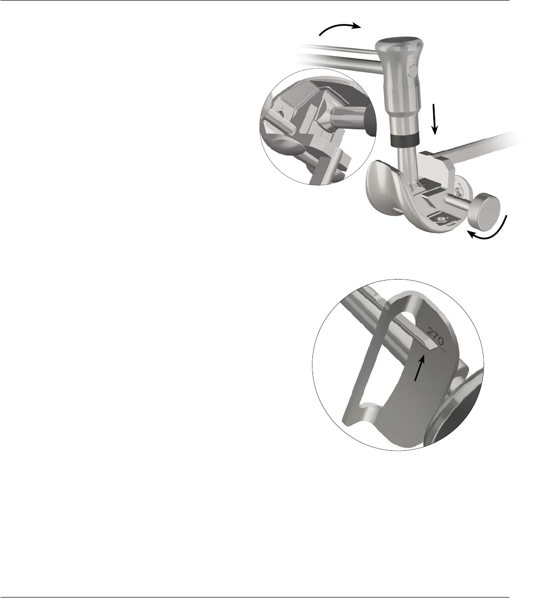
Attach the P.F.C. SIGMA Femoral Adapter holding
clamp to the femoral implant and tighten it. The clamp
provides the second moment arm needed to assemble
the parts. Place the torque wrench over the P.F.C. SIGMA
Femoral Adapter implant and move it clockwise to
tighten the adapter to the femoral implant
(Figure 84). The torque wrench has a deflection beam,
which indicates when sufficient torque has been applied
(Figure 85).
Note: Torque the assembly to the 270 in. lb mark on
the torque wrench to ensure proper assembly torque
(Figure 85).
IMPLANT ASSEMBLY – SIGMA FEMORAL ADAPTER
Figure 84
Figure 85
52 SIGMA Revision and M.B.T. Revision Tray Surgical Technique
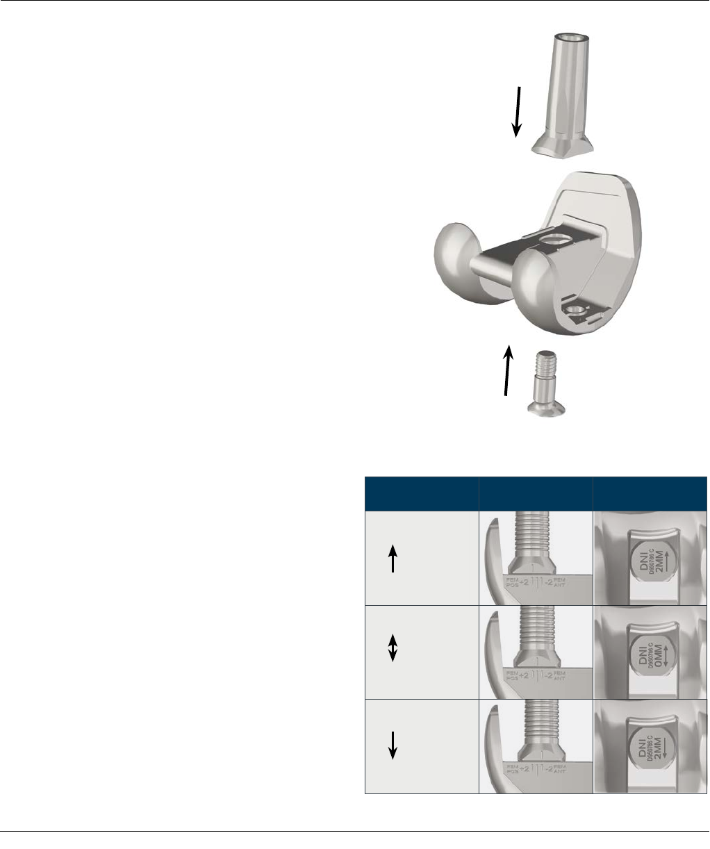
IMPLANT ASSEMBLY – SIGMA FEMORAL AUGMENTS
Figure 87
Figure 86
Attach the femoral augments using the wobble bits
included in the augment package. Attach the femoral
augments to the femoral component using the augment
T-handle provided (Figures 86 and 87).It may be
necessary to use the T-handle extension in conjunction
with the T-handle to attach the augments.
Fully seat the augments on the component before
tightening the screw thread mechanism. Carefully
tighten with the large T-handle Torque Driver until an
audible "click" is discerned.
The augment assembly sequence is shown below. For
implant assembly: sleeve and stem proceed to page 51,
stem-only proceed to page 53, and sleeve-only proceed
to page 54.
Assembly Rules for Femoral Augmentation
1. For Size 1.5 Femoral Components
· Distal augmentation component augments in
4, 8 and 12 mm thicknesses
· Assemble last
2. For Size 4n PS Femoral Components
· Use size 2 distal and posterior augments
3. For 4 mm/8 mm Augments
· They are fully interchangeable
· If using 4 mm or 8 mm distal with posterior augment,
install distal first
4. For 12 mm/16 mm Distal Augment
· Use 16 mm distal augment with TC3 femoral only
· Femoral stem is indicated
· On size 2, 2.5 and 3 femoral component, use
4 mm posterior only
· On size 4, 5 femoral component, may use 4
or 8 mm posterior
(Note: No size 6 augments available - use size 5
distal augments and size 3 posterior augments
with size 6 femoral component)
· If using with posterior augment, install posterior
augment first
Surgical Technique SIGMA Revision and M.B.T. Revision Tray 53
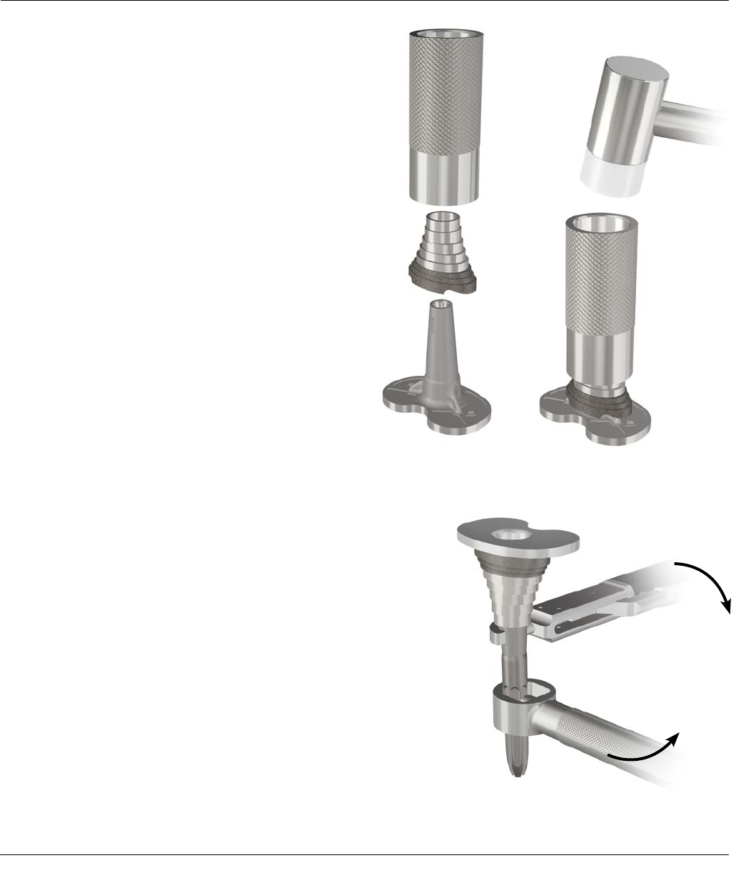
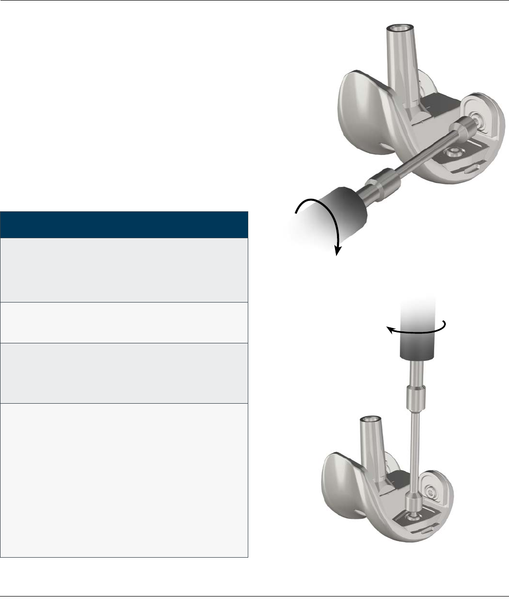
Implant Assembly - Sleeve and Stem Use
Implant assembly order (with sleeve and stem use):
· Femoral adapter-to-femoral component
· Add posterior and distal augments, if necessary
· Sleeve-to-stem
· Sleeve construct-to-femoral adapter construct
To attach the Universal Stem to the universal femoral
sleeve, thread the stem onto the sleeve. Grasp the sleeve
with the tibial sleeve clamp and use the stem Extension
Wrench to grasp the Universal Stem and tighten
(Figure 88).
Apply sufficient force to both wrenches to ensure that
the stem is secure.
Place the femoral component with the femoral adapter
on a firm, stable surface. Place the appropriate sleeve
and stem construct on top of the femoral adapter
assembly (Figure 89).
Use the sleeve and femoral trial construct trial to help
set the final sleeve and femoral component implant
rotation.
Figure 88
IMPLANT ASSEMBLY – SLEEVE AND STEM USE
Figure 89
54 SIGMA Revision and M.B.T. Revision Tray Surgical Technique
IMPLANT ASSEMBLY – SLEEVE AND STEM USE
Slide the femoral stem/sleeve impactor on top of the
stem and forcefully apply three strikes with a mallet to
engage the two component assemblies (Figure 90).
Note: The femoral stem/sleeve Impactor has two
uses, one end for use of a sleeve without a stem
extension and one end for a sleeve and stem
combination.
The definitive components are implanted in the
following order:
· Tibial tray (with stem, sleeve and/or wedges)
· Femoral component (with stem, sleeve and/or
augments)
· SIGMA Rotating Platform PS or TC3 inserts
Implant the femoral component using the Femoral
Impactor (Figure 91).
Figure 91
Figure 90
Surgical Technique SIGMA Revision and M.B.T. Revision Tray 55
IMPLANT ASSEMBLY – STEM-ONLY USE
Figure 93
Figure 92
Implant Assembly - Stem Only
Implant assembly order (with Stem-only use):
· Femoral adapter-to-femoral component
· Add posterior and distal augments, if necessary
· Stem-to-femoral adapter
To attach the Universal Stem to the P.F.C. SIGMA
Femoral Adapter, thread the stem onto the adapter.
With the P.F.C. SIGMA Femoral Adapter holding clamp
in place, use the Stem Extension Wrench to grasp the
Universal Stem and tighten (Figure 92). Apply sufficient
force to both the P.F.C. SIGMA Femoral Adapter holding
clamp and Stem Extension Wrench to ensure that stem
is secure.
The definitive components are implanted in
the following order:
· Tibial Tray (with stem, sleeve and/or wedges)
· Femoral component (with stem and/or augments)
· SIGMA Rotating Platform PS or TC3 inserts
Implant the femoral component using the Femoral
Impactor (Figure 93).
56 SIGMA Revision and M.B.T. Revision Tray Surgical Technique
IMPLANT ASSEMBLY – SLEEVE-ONLY USE
Implant Assembly - Sleeve Only
Implant assembly order (with sleeve-only use):
· Femoral adapter-to-femoral component
· Add posterior and distal augments, if necessary
· Sleeve-to-femoral adapter
Slide the femoral stem/sleeve Impactor on top of
the sleeve and forcefully apply three strikes with a Mallet
to engage the two components (Figure 94).
Note: The femoral stem/sleeve impactor has
two uses, one end for the sleeve without a stem
extension and one end for a sleeve and stem
combination.
The definitive components are implanted in
the following order:
· Tibial tray (with stem, sleeve and/or wedges)
· Femoral component (with sleeve and/or augments)
· SIGMA Rotating Platform PS or TC3 inserts
Implant the femoral component using the femoral
impactor.
Figure 94
Surgical Technique SIGMA Revision and M.B.T. Revision Tray 57
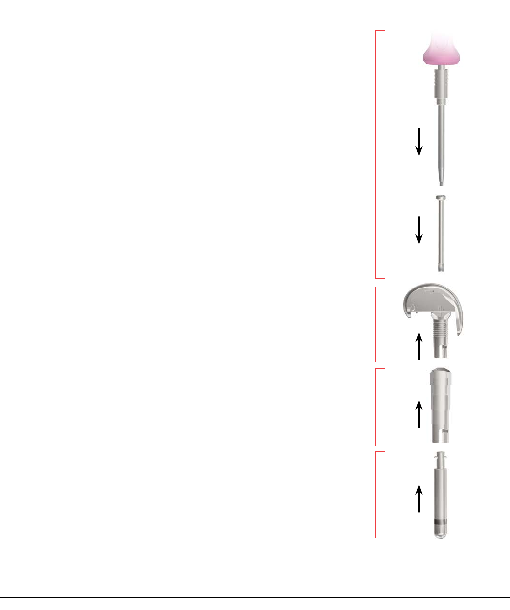
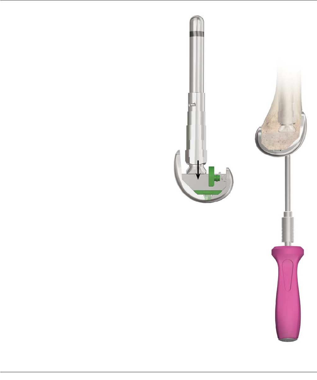
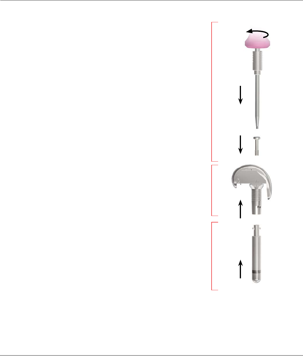
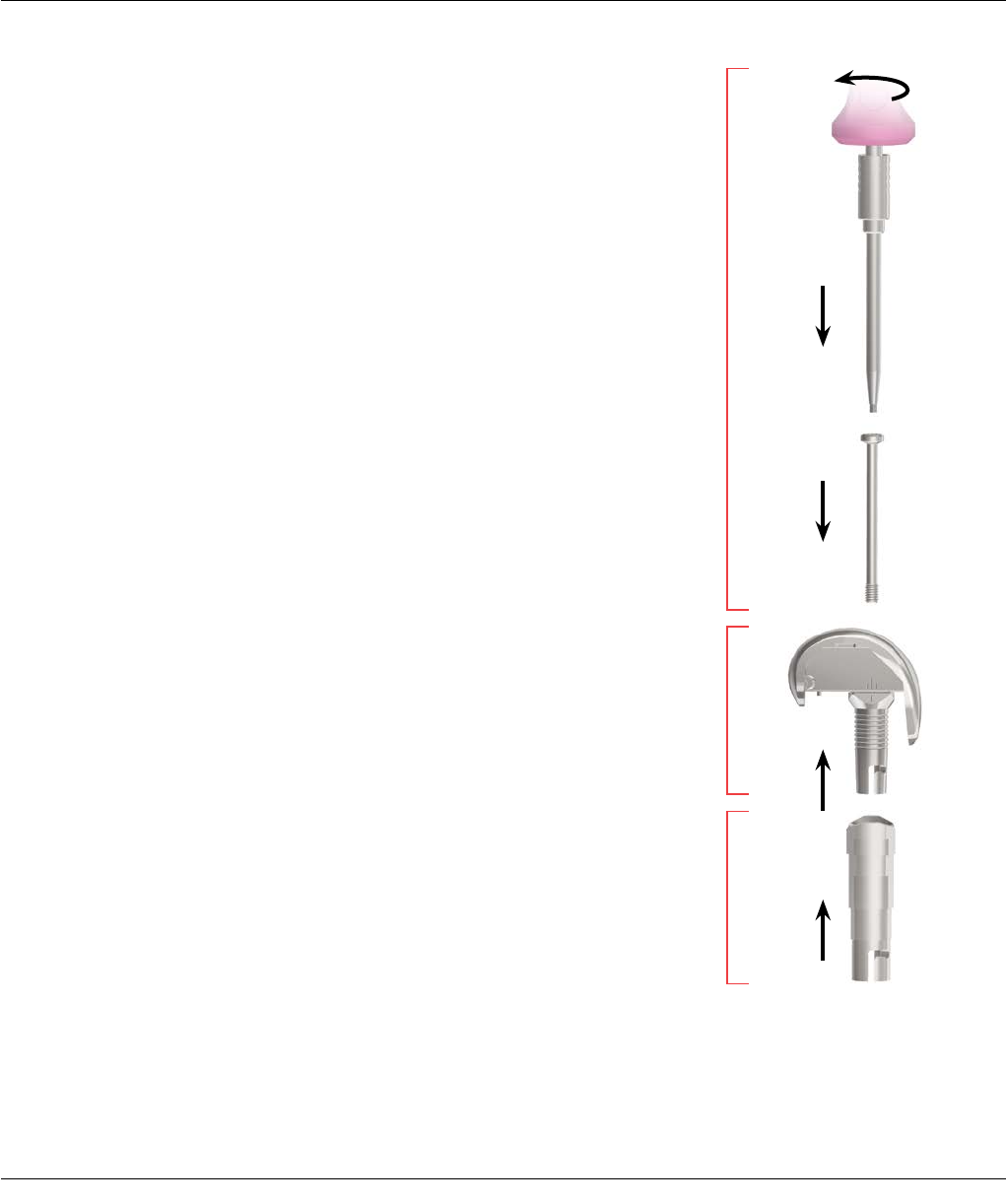
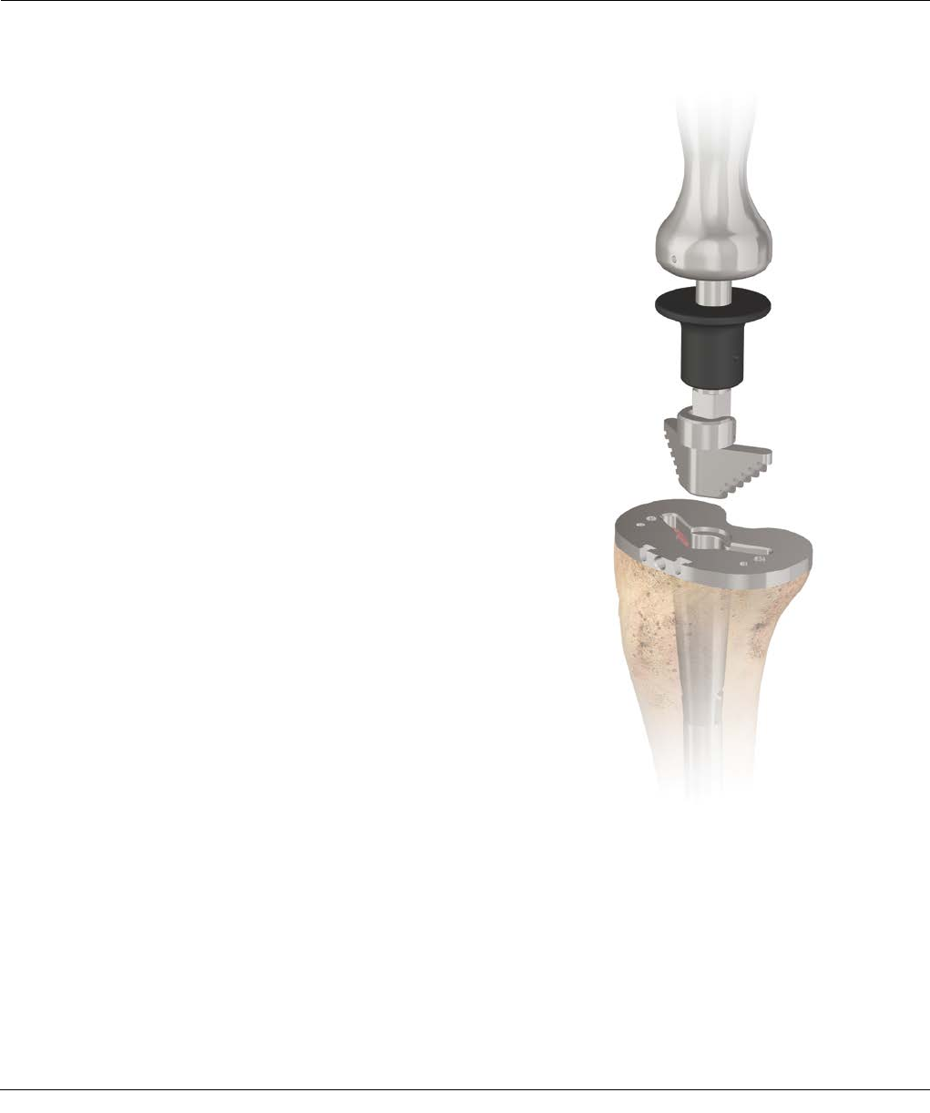
Place the Revision Trial Post into the cone of the M.B.T.
Revision implant. Seat the appropriate trial insert in the
trial post/tray (Figure 95).
Assemble the appropriate femoral implant construct
(see pages 51-54), apply the appropriate cementation
technique and impact the femoral implant construct into
the prepared femur.
Fully extend the knee to maintain pressure as the cement
polymerizes (Figure 96).
Note: With constrained femoral and tibial
components in trial reduction, it may be
appropriate to cement the tibial tray implant and
the femoral implant using the insert trial. This will
allow visibility of final rotation.
Note: PS or CR M.B.T. Insert Trials may be used in
the place of TC3 insert trials during this step. Using
these trials will allow easier insertion onto the keel
and will provide a better idea on how well the gaps
are balanced.
FINAL TRIAL WITH IMPLANTS
Revision Trial Post
Figure 95
Figure 96
58 SIGMA Revision and M.B.T. Revision Tray Surgical Technique
APPENDIX 1: THE CEMENTED TIBIAL
STEM EXTENSIONS
Cemented Stem Reamer
Align the tibial tray and secure with two Fixation Pins
inserted through the holes designated (Figure 1).
Seat the M.B.T. Revision Drill Bushing onto the tibia trial.
Place in the posterior holes.
Place the cemented drill bushing into the M.B.T. Revision
Drill Bushing (Figure 2).
Use the “cemented” reamer to ream to the
predetermined selected depths for tray only or the tray
with a 30 or 60 mm cemented stem.
Remove the reamer and “cemented” bushing, leaving
the tray trial and M.B.T. Revision Drill Bushing in place
(Figure 3).
Note: Only a 13 mm diameter cemented stem should
be used in conjunction with the M.B.T. Revision Tray
to avoid a step off at the stem/tray junction.
Cemented
Drill Bushing
M.B.T. Revision
Drill Bushing
Figure 1
Figure 2 Figure 3
Surgical Technique SIGMA Revision and M.B.T. Revision Tray 59
APPENDIX 1: THE CEMENTED TIBIAL
STEM EXTENSIONS
Tapered Reamer
Assemble the revision reamer adapter onto the
cemented tapered reamer.
Next, attach the modified Hudson Adapter to the
tapered reamer, if power reaming.
Attach the appropriately sized cemented stem trial
(13 x 30 mm or 13 x 60 mm) to the tapered reamer, if
utilizing a cemented stem extension (Figure 4). Ream
until the revision reamer adapter is flush with the M.B.T.
Revision Drill Bushing (Figure 5).
Note: To avoid stem trial disengagement,
do not reverse ream.
Figure 4
Figure 5
Modified Hudson Adapter
Revision Reamer Adapter
60 SIGMA Revision and M.B.T. Revision Tray Surgical Technique
APPENDIX 1: THE CEMENTED
TIBIAL STEM EXTENSIONS
Tapered Cemented Stems
Note: Tapered cemented stem sizes 13 x 90/120/150
mm are compatible with M.B.T. Revision Trays.
Ream the canal with a reamer two sizes larger than the
stem. Ream the medullary canal with a 15 mm reamer
to implant a 13 mm tapered cemented stem, which
allows for a 1 mm circumferential cement mantle at the
proximal end of the stem. The cement mantle will be
greater around the distal end of the cemented tapered
stem (3 mm per side).
This provides the following benefits:
· Thicker cement mantle distally helps assure that a
circumferential mantle is present and reduces the
possibility of thin or non-existent cement coverage of
the stem distally
· Stresses are greatest at the tip of the stem. A larger
cement mantle is advantageous in dissipating these
stresses. Thinner cement mantles are more prone to
breakdown when exposed to higher stresses
Tibial Keel Preparation
Place the knee in full extension and determine
appropriate rotation of the tibial tray. Mark the
appropriate rotation with electrocautery on the anterior
tibial cortex at the center and sides of the alignment
handle.
Assemble the appropriate stem trial to the M.B.T.
Revision Tray Trial and seat in the prepared bone bed.
Impact the cemented keel punch (Figure 6).
Disconnect the Universal Handle leaving the Keel Punch
in place for trial reduction (if appropriate).
It is recommended that a Cement Restrictor be placed at
the appropriate level prior to cementing the component.
Use a Cement Gun to fill the canal with methyl
methacrylate.
Figure 6
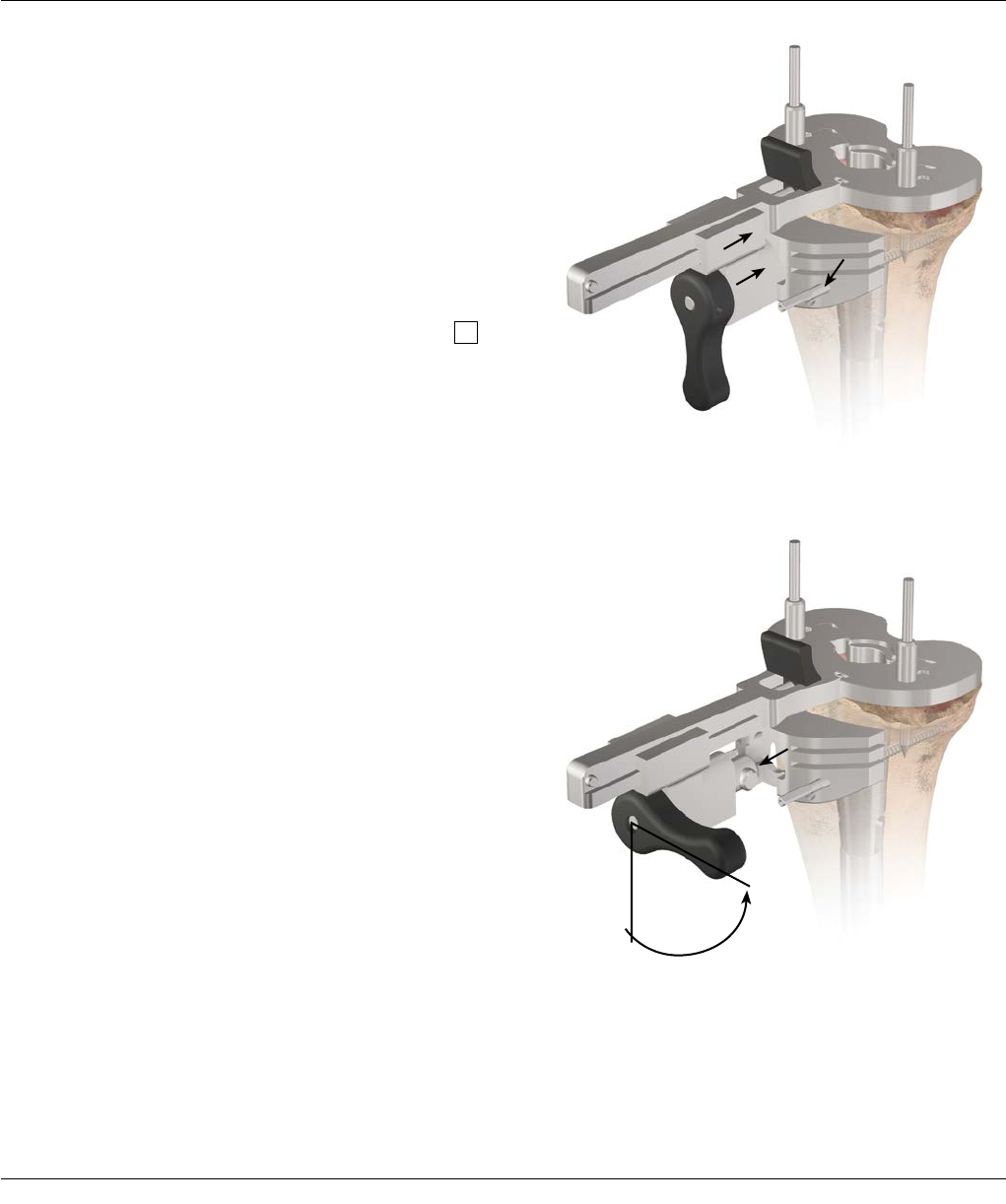
Surgical Technique SIGMA Revision and M.B.T. Revision Tray 61
Step Wedge Augmentation
Resection for supplementary tibial augmentation
may be based on the established position of the
trial tray. Remove the femoral trial to provide greater
access. Confirm rotational alignment of the Tibial Tray
Stem Trial. Secure the tray with two Fixation Pins.
Attach the tray trial wedge cutting attachment with the
Step Wedge Cutting Guide to the trial tray. The Step
Wedge Cutting Block allows for a 5, 10, or 15 mm step
wedge preparation, as necessary. Slide the block forward
to the anterior proximal tibia and secure in place with
two Steinmann Pins through the holes marked with
(Figure 1).
Unlock the block and slide the assembly out of the
block. Disconnect the handle from the trial tray
(Figure 2).
Figure 2
APPENDIX 2: STEP WEDGE PREPARATION
Figure 1
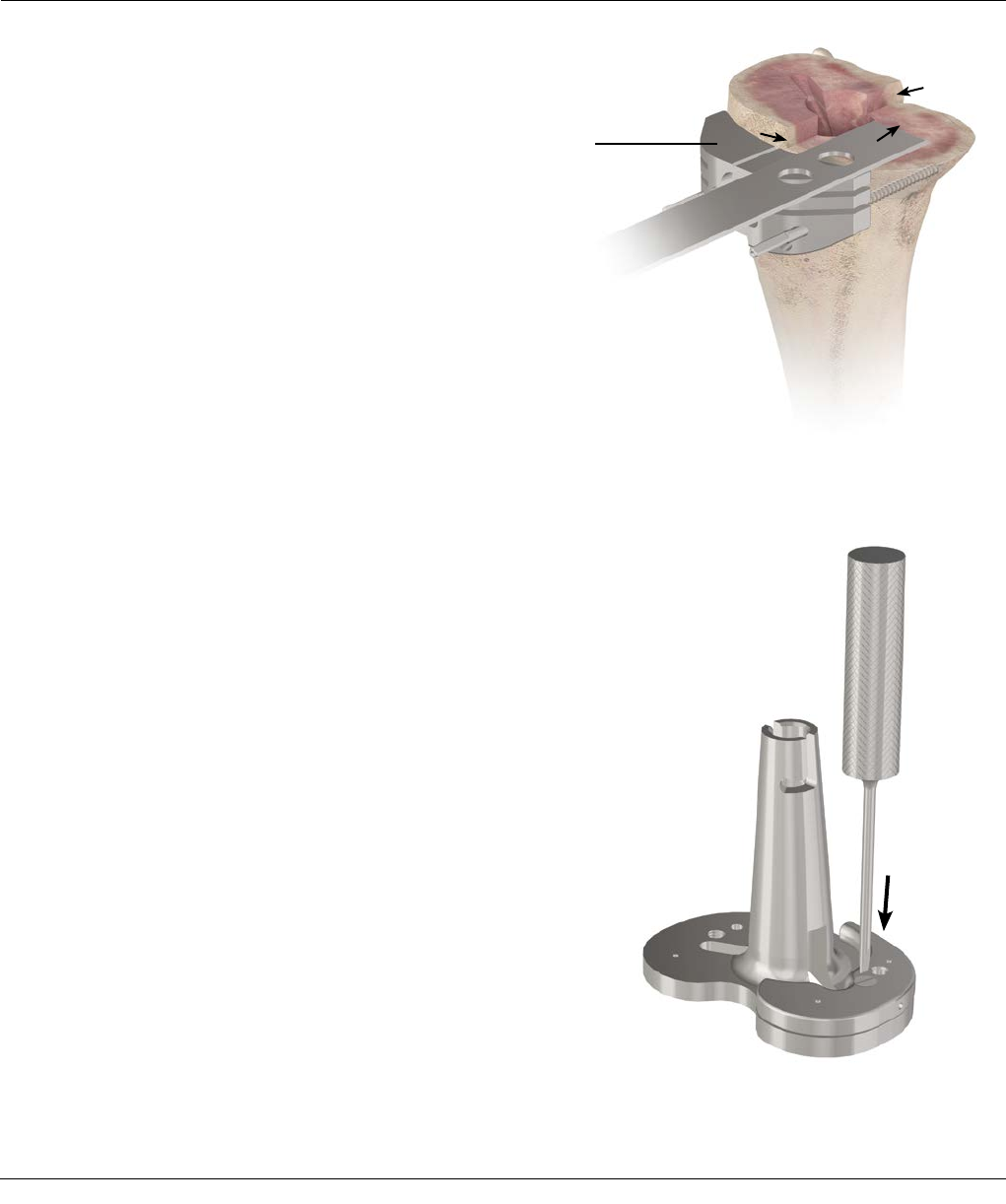
62 SIGMA Revision and M.B.T. Revision Tray Surgical Technique
APPENDIX 2: STEP WEDGE PREPARATION
Trim the tibia accordingly with an Oscillating Saw so the
cut does not extend beyond the central riser (Figure 3).
Remove the block and pins.
Assemble the trial wedge to the appropriate tibial tray
trial (Figure 4) and introduce into the prepared site.
Perform minimal correction with a Bone File where
indicated to ensure maximal contact.
Figure 3
Figure 4
Step Wedge
Cutting Block
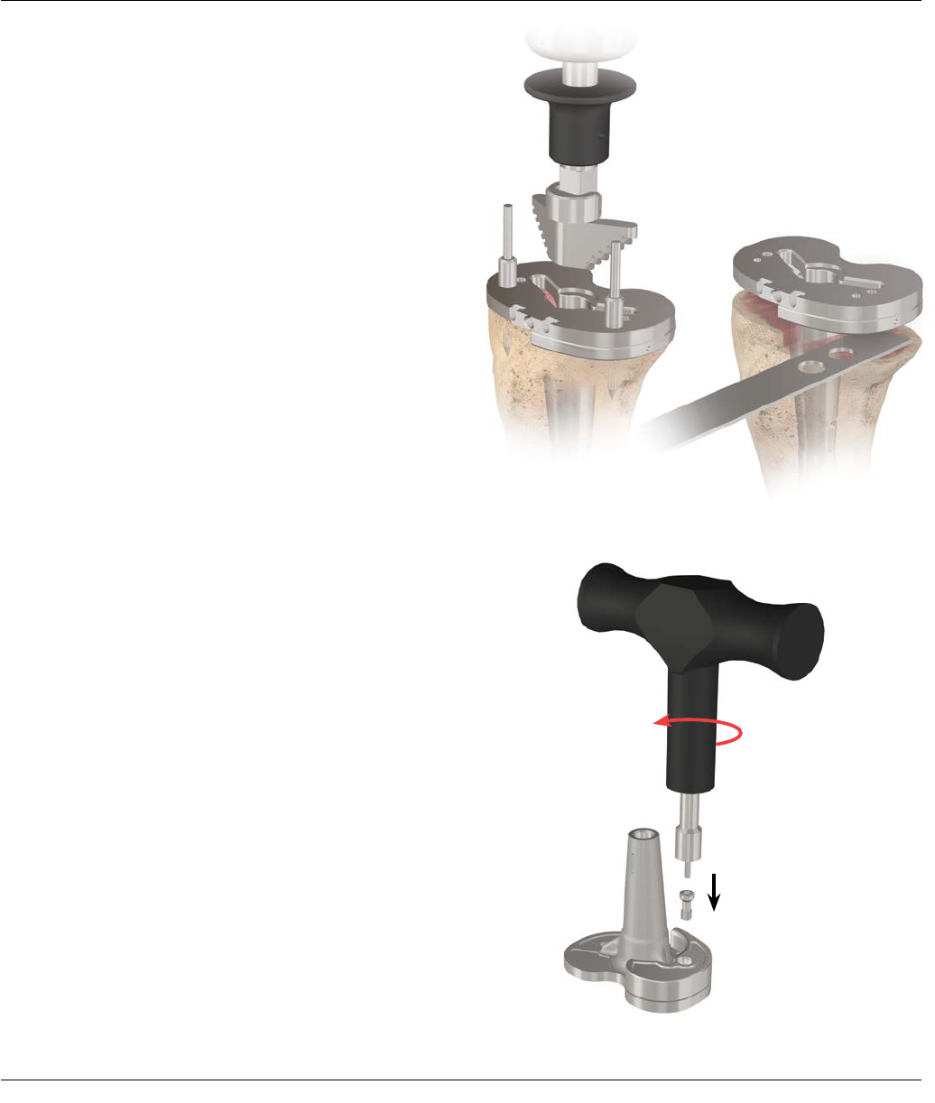
Surgical Technique SIGMA Revision and M.B.T. Revision Tray 63
Figure 7
Figure 5 Figure 6
APPENDIX 2: STEP WEDGE PREPARATION
Confirm positioning, alignment and security of the tray
assembly. If there is old cement or sclerotic bone, remove
this first with a saw blade or burr prior to punching.
Position the M.B.T. Revision Tibial Keel Punch at the tray
and cancellous bone interface and impact into the keel
configuration (Figure 5). Leave the punch in place and
perform a final trial reduction if necessary.
Note: Utilize the “cemented” keel punch when a
cement mantle is desired.
Alternative Step Wedge Preparation
This is a “free-hand” resection. Assemble the wedge
trial and stem trial to the tibial tray trial. Position the
device slightly proximal to the planned resection level.
Make a conservative “free-hand” wedge resection and
then check cuts with the trials (Figure 6).
Wedge Implant Assembly
Note: To aid wedge implant assembly, attach wedge
prior to stem attachment.
Assemble the designated wedge to the tray and secure
using the appropriate screw. Carefully tighten with the
large T-handle torque driver until an audible "click" is
discerned, ensuring a full and permanent interlock
(Figure 7).
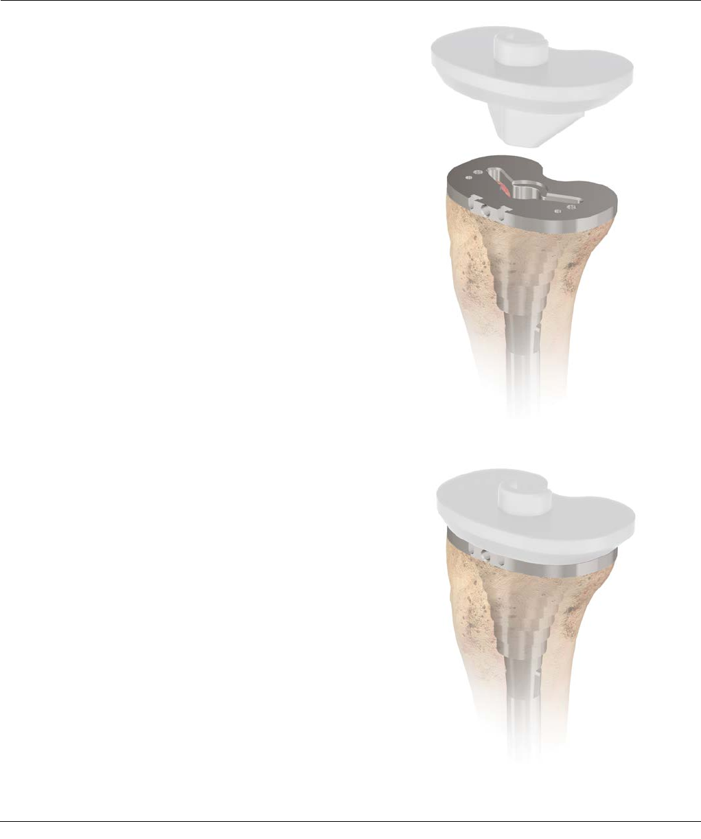
64 SIGMA Revision and M.B.T. Revision Tray Surgical Technique
After impacting the cement or press-fit keel punch,
remove the keel punch. Insert the M.B.T. Thick Tray Trial
Adapter (15 or 25 mm) onto the tibial tray trial (Figures
1 and 2).
Note: The tibial tray trial must be used with the
thick tray adapters as the two pieces equal the
appropriate sizing – 15 or 25 mm.
Perform the final trial reductions utilizing the same
technique as the standard M.B.T. Revision Tray. Implant
assembly and implantation is also the same as with the
standard M.B.T. Revision Tray. If utilizing a wedge, refer
to the step wedge preparation in Appendix 2.
Note: A tibial wedge can be used with all thick tray
sizes, except for size 2. Sleeves may be used with all
thick trays.
Note: Due to the taper, trial with appropriate tray
trial size. For example, a size 4 thick tray tapers
down to a size 2. Use the size 2 tray trial with the
size 4 thick tray adapter. The size 3 thick tray
tapers down to a size 1. And the size 2 thick tray
tapers down to a size 0. The size 0 tray trial can be
found in the M.B.T. thick tray instrument set. Figure 1
Figure 2
APPENDIX 3: THICK TRAY PREPARATION

Surgical Technique SIGMA Revision and M.B.T. Revision Tray 65
APPENDIX 4: FEMORAL REVISION AND
MBT REVISION TRAY COMPATIBILITY
FEMORAL COMPONENTS
Size 1.5
53AP/57ML
Size 2
56AP/60ML
Size 2.5
59AP/63ML
Size 3
61AP/66ML
Size 4N
65AP/66ML
Size 4
65AP/71ML
Size 5
69AP/73ML
Size 6
74AP/78ML
PS TC3 PS TC3 PS TC3 PS TC3 PS ** PS TC3 PS TC3 PS **
M.B.T
REVISION TRAYS
Size 1
39AP/59ML X X
Size 1.5
41AP/62ML XXXX
Size 2
43AP/65ML XXXXXX
Size 2.5
44AP/67ML XXXXXX
Size 3
46AP/70ML XXXXX XX
Size 4
49AP/75ML XXX XXXX
Size 5
53AP/81ML X XXXXX
Size 6
57AP/87ML XXX
**TC3 FEMURS ARE NOT AVAILABLE IN SIZE 4N OR 6
Note: RP insert must match femur size for size.
Note: For a size 4N femur, use a size 4 RP insert.
M.B.T. Revision Trays
· Made of Cobalt Chrome
· Tray thickness is 4.8 mm
M.B.T. Revision Thick Trays
· Made of Cobalt Chrome
· Tray thickness is 15 mm and 25 mm
· All thick trays taper distally by two sizes
to match tibial anatomy.
M.B.T. Revision Thick Tray Sizing Chart
Size 2 Size Three Size Four
Proximal size two size three size four
Distal size zero
(38ap/54ml) size one size two

66 SIGMA Revision and M.B.T. Revision Tray Surgical Technique
APPENDIX 5: SIGMA REVISION
ANTEROPOSTERIOR CHART (WITH SLEEVE USE)
The following chart shows the distance (mm) between
the anterior flange of a femoral component and the
sleeve, based on the size of the component and the
anteroposterior option chosen. Fields with an X denote
that the sleeve, femoral component and offset option is
not possible.
Femoral Size and A/P Position
1.5
Ant
1.5
Neut
1.5
Post
2
Ant
2
Neut
2
Post
2.5
Ant
2.5
Neut
2.5
Post
3
Ant
3
Neut
3
Post
Size of sleeve (M/L)
20 mm 0.9 2.7 4.7 1.8 3.8 5.8 2.6 4.6 6.6 3.2 5.2 7.2
31 mm 2.1 4.5 5.8 2.7 5.0 7.0 3.8 5.8 7.8 4.6 6.7 8.6
34 mm X 3.4 4.6 2.1 4.4 5.9 3.2 5.2 7.0 3.6 5.7 7.6
40 mm X 2.4 3.9 1.2 3.2 5.6 2.0 3.9 6.0 2.7 4.6 6.5
46 mm X 2.6 3.6 X 2.6 4.8 1.5 3.6 5.5 2.4 4.6 6.4
Femoral Size and A/P Position
4
Ant
4
Neut
4
Post
5
Ant
5
Neut
5
Post
6
Ant
6
Neut
6
Post
Size of sleeve (M/L)
20 mm 4.9 6.9 8.9 6.4 8.4 10.4 8.5 10.5 12.5
31 mm 6.3 8.3 10.2 7.8 9.7 11.8 9.9 11.9 13.9
34 mm 5.3 7.3 9.3 6.8 8.9 10.8 8.8 10.9 13.0
40 mm 4.2 6.1 8.1 5.6 7.6 9.6 7.8 9.9 11.8
46 mm 4.3 6.2 8.2 5.7 7.6 9.6 7.9 9.9 11.7
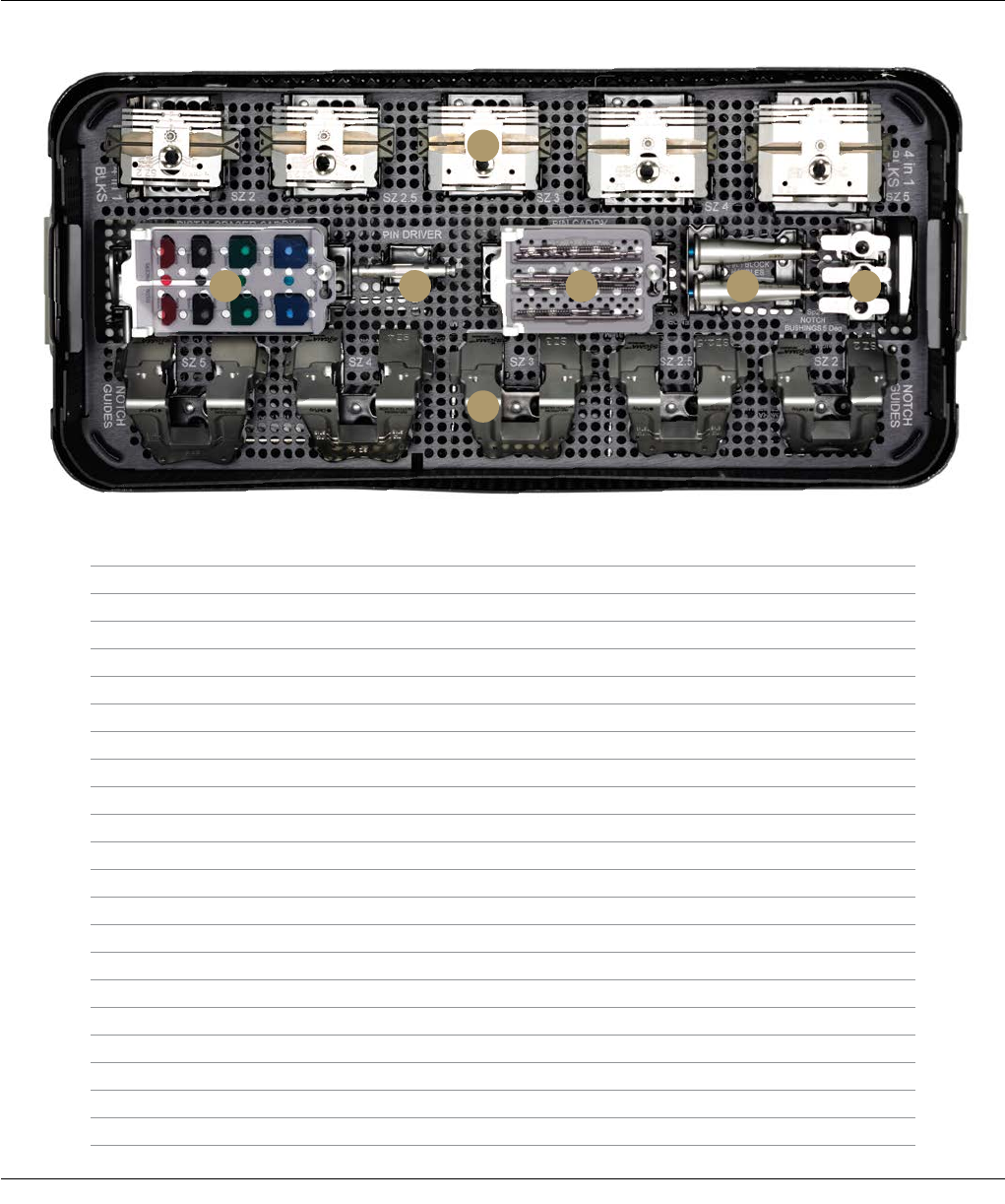
Surgical Technique SIGMA Revision and M.B.T. Revision Tray 67
SIGMA HP REVISION FEMORAL PREP INSTRUMENT
CASE CAT. NO. 2011-03-049
Description Cat. No.
A SIGMA HP Revision 4-in-1 Cutting Block Size 2 2011-03-000
SIGMA HP Revision 4-in-1 Cutting Block Size 2.5 2011-03-001
SIGMA HP Revision 4-in-1 Cutting Block Size 3 2011-03-002
SIGMA HP Revision 4-in-1 Cutting Block Size 4 2011-03-003
SIGMA HP Revision 4-in-1 Cutting Block Size 5 2011-03-004
B SIGMA HP Revision Notch Guide Size 2 2011-03-005
SIGMA HP Revision Notch Guide Size 2.5 2011-03-006
SIGMA HP Revision Notch Guide Size 3 2011-03-007
SIGMA HP Revision Notch Guide Size 4 2011-03-008
SIGMA HP Revision Notch Guide Size 5 2011-03-009
C SP2 Femoral Notch Guide Bushing 5 degree +2L/-2R 96-6531
SP2 Femoral Notch Guide Bushing 5 degree 0 mm offset 96-6532
SP2 Femoral Notch Guide Bushing 5 degree +2R/-2L 96-6533
D SP2 Removable Handles 96-6147
E Pin Caddy
F SIGMA HP Power Pin Driver 9505-02-071
G Distal Spacer Caddy
SIGMA HP Revision Distal Spacer 4 mm 2011-03-021
SIGMA HP Revision Distal Spacer 8 mm 2011-03-022
SIGMA HP Revision Distal Spacer 12 mm 2011-03-023
SIGMA HP Revision Distal Spacer 16 mm 2011-03-024
A
B
FG E D C
Top Tray
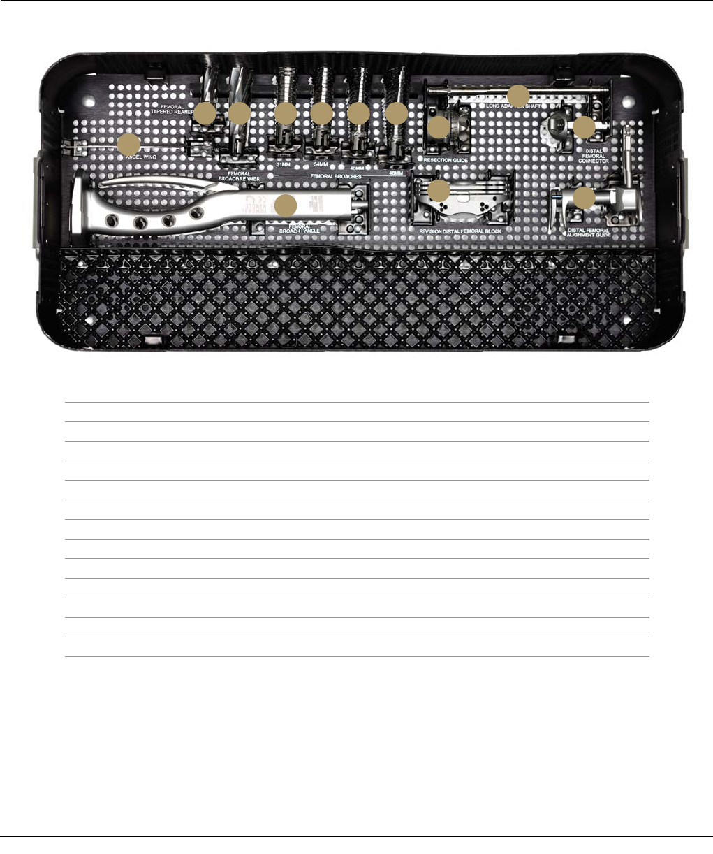
68 SIGMA Revision and M.B.T. Revision Tray Surgical Technique
Bottom Tray
SIGMA HP REVISION FEMORAL PREP INSTRUMENT
CASE CAT. NO. 2011-03-049
Description Cat. No.
A Visualization Wing 96-6530
B Completion Revision Femoral Tapered Reamer 2178-60-030
C Universal Revision Femoral Broach Reamer 96-1671
D Universal Revision Femoral Broach 31 mm 96-1683
E Universal Revision Femoral Broach 34 mm 96-1684
F Universal Revision Femoral Broach 40 mm 96-1685
G Universal Revision Femoral Broach 46 mm 96-1686
H SIGMA HP Revision Adapter Removable Shaft 2011-03-029
I SIGMA HP Distal Femoral Resection Guide 9505-01-235
J SIGMA HP Distal Femoral Connector 9505-01-238
K SIGMA HP Revision Distal Femoral Block 9505-01-239
L SIGMA HP Distal Femoral Alignment Guide 9505-01-234
M Universal Revision Femoral Broach Handle 96-1682
A
B C D
M
E F G
I
K
J
L
H
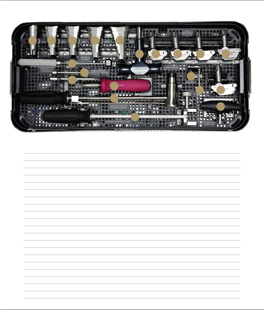
Surgical Technique SIGMA Revision and M.B.T. Revision Tray 69
SIGMA HP REVISION FEMORAL TRIAL INSTRUMENT
CASE CAT. NO. 2011-03-050
Top Tray
Description Cat. No.
A LCS/SIGMA Revision Femoral Sleeve Trial 20 mm 2294-53-100
B LCS/SIGMA Revision Femoral Sleeve Trial 31 mm 2294-53-110
C LCS/SIGMA Revision Femoral Sleeve Trial 34 mm 2294-53-120
D LCS/SIGMA Revision Femoral Sleeve Trial 40 mm 2294-53-130
E LCS/SIGMA Revision Femoral Sleeve Trial 46 mm 2294-53-140
F Modular Plus Torque Driver 86-0284
G SIGMA HP Revision TC3 Box Trial Size 2 2011-03-011
H SIGMA HP Revision TC3 Box Trial Size 2.5 2011-03-012
I SIGMA HP Revision TC3 Box Trial Size 3 2011-03-013
J SIGMA HP Revision TC3 Box Trial Size 4 2011-03-014
K SIGMA HP Revision TC3 Box Trial Size 5 2011-03-015
L SIGMA HP Revision Femoral Adapter Shift Tool 2011-03-057
M SIGMA Femoral Adapter Sleeve Bolt Trial Neutral 2011-03-052
N SIGMA Femoral Adapter Stem Bolt Trial Neutral 2011-03-051
O Femoral Augment Plug Puller 86-5151
P SP2 Torque Driver Handle Extension 96-6301
Q Large Fragment Screwdriver Shank 8242-19-000
R 2.0 Nm Torque-limiting Screwdriver 2141-18-001
S Femoral Adapter Torque Wrench 96-1673
T Femoral Adapter Holding Clamp 96-1674
A B C
O
Q
P
R
N
M K
L
S
T
ED
F G H I J
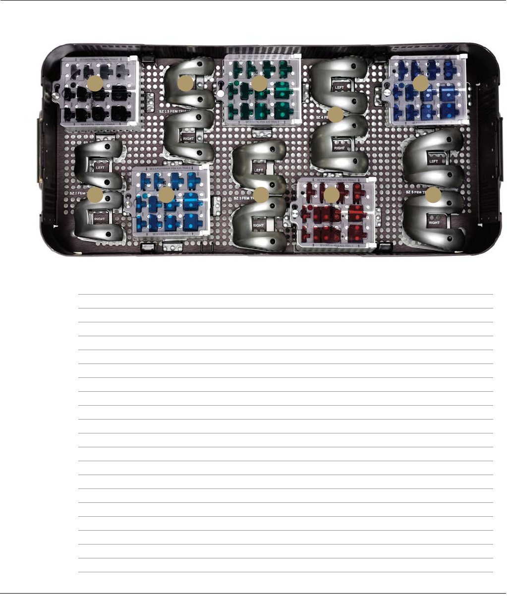
70 SIGMA Revision and M.B.T. Revision Tray Surgical Technique
Bottom Tray
SIGMA HP REVISION FEMORAL TRIAL INSTRUMENT
CASE CAT. NO. 2011-03-050
Description Cat. No
A PFC SIGMA C/R Femoral Left Size 2 Trial 96-1002
PFC SIGMA C/R Femoral Right Size 2 Trial 96-1012
B Size 2 Femoral Augment Trial Caddy
PFC SIGMA Distal Femoral Augment Trial 4 mm Size 2 96-1820
PFC SIGMA Distal Femoral Augment Trial 8 mm Size 2 96-1822
PFC SIGMA Posterior Femoral Augment Trial 4 mm Size 2 96-1826
PFC SIGMA Posterior Femoral Augment Trial 8 mm Size 2 96-1828
PFC SIGMA Distal Femoral Augment Trial 12 mm Size 2 96-1830
PFC SIGMA Distal Femoral Augment Trial 16 mm Size 2 96-1832
C PFC SIGMA C/R Femoral Left Size 2.5 Trial 96-1008
PFC SIGMA C/R Femoral Right Size 2.5 Trial 96-1018
D Size 2.5 Femoral Augment Trial Caddy
PFC SIGMA Distal Femoral Augment Trial 4 mm Size 2.5 96-1840
PFC SIGMA Distal Femoral Augment Trial 8 mm Size 2.5 96-1842
PFC SIGMA Posterior Femoral Augment Trial 4 mm Size 2.5 96-1846
PFC SIGMA Posterior Femoral Augment Trial 8 mm Size 2.5 96-1848
PFC SIGMA Distal Femoral Augment Trial 12 mm Size 2.5 96-1850
PFC SIGMA Distal Femoral Augment Trial 16 mm Size 2.5 96-1852
E PFC SIGMA C/R Femoral Left Size 3 Trial 96-1003
PFC SIGMA C/R Femoral Right Size 3 Trial 96-1013
B
A D E H I
C F J
G
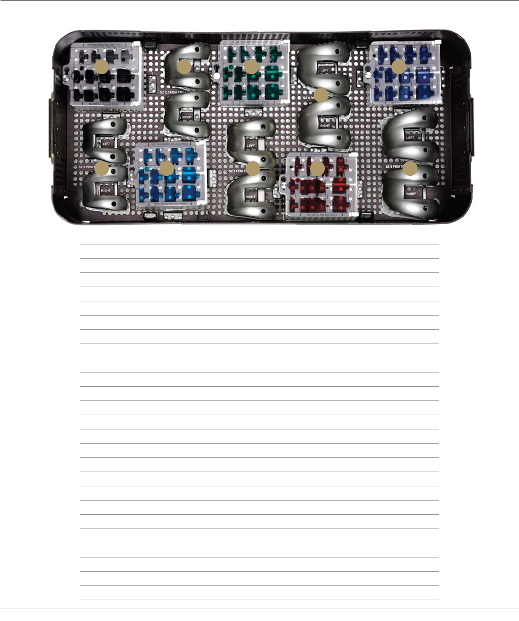
Surgical Technique SIGMA Revision and M.B.T. Revision Tray 71
SIGMA HP REVISION FEMORAL TRIAL CASE
CAT. NO. 2011-03-050
Bottom Tray
Description Cat. No
F Size 3 Femoral Augment Trial Caddy
PFC SIGMA Distal Femoral Augment Trial 4 mm Size 3 96-1860
PFC SIGMA Distal Femoral Augment Trial 8 mm Size 3 96-1862
PFC SIGMA Posterior Femoral Augment Trial 4 mm Size 3 96-1866
PFC SIGMA Posterior Femoral Augment Trial 8 mm Size 3 96-1868
PFC SIGMA Distal Femoral Augment Trial 12 mm Size 3 96-1870
PFC SIGMA Distal Femoral Augment Trial 16 mm Size 3 96-1872
G PFC SIGMA C/R Femoral Left Size 4 Trial 96-1004
PFC SIGMA C/R Femoral Right Size 4 Trial 96-1014
H Size 4 Femoral Augment Trial Caddy
PFC SIGMA Distal Femoral Augment Trial 4 mm Size 4 96-1880
PFC SIGMA Distal Femoral Augment Trial 8 mm Size 4 96-1882
PFC SIGMA Posterior Femoral Augment Trial 4 mm Size 4 96-1886
PFC SIGMA Posterior Femoral Augment Trial 8 mm Size 4 96-1888
PFC SIGMA Distal Femoral Augment Trial 12 mm Size 4 96-1890
PFC SIGMA Distal Femoral Augment Trial 16 mm Size 4 96-1892
I PFC*SIGMA C/R Femoral Left Size 5 Trial 96-1005
PFC SIGMA C/R Femoral Right Size 5 Trial 96-1015
J Size 5 Femoral Augment Trial Caddy
PFC SIGMA Distal Femoral Augment Trial 4 mm Size 5 96-1900
PFC SIGMA Distal Femoral Augment Trial 8 mm Size 5 96-1902
PFC SIGMA Posterior Femoral Augment Trial 4 mm Size 5 96-1906
PFC SIGMA Posterior Femoral Augment Trial 8 mm Size 5 96-1908
PFC SIGMA Distal Femoral Augment Trial 12 mm Size 5 96-1910
PFC SIGMA Distal Femoral Augment Trial 16 mm Size 5 96-1912
B
A D E H I
C F J
G
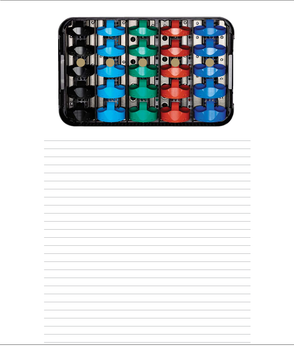
72 SIGMA Revision and M.B.T. Revision Tray Surgical Technique
Top Tray
SIGMA HP REVISION TC3 RP INSERT TRIAL
AND SPACER BLOCK CASE CAT. NO. 2011-03-070
Description Cat. No.
A TC3 RP Tibial Insert Trial Size 2 10 96-3321
TC3 RP Tibial Insert Trial Size 2 12.5 96-3322
TC3 RP Tibial Insert Trial Size 2 15 96-3323
TC3 RP Tibial Insert Trial Size 2 17.5 96-3324
TC3 RP Tibial Insert Trial Size 2 20 96-3325
B TC3 RP Tibial Insert Trial Size 2.5 10 96-3331
TC3 RP Tibial Insert Trial Size 2.5 12.5 96-3332
TC3 RP Tibial Insert Trial Size 2.5 15 96-3333
TC3 RP Tibial Insert Trial Size 2.5 17.5 96-3334
TC3 RP Tibial Insert Trial Size 2.5 20 96-3335
C TC3 RP Tibial Insert Trial Size 3 10 96-3341
TC3 RP Tibial Insert Trial Size 3 12.5 96-3342
TC3 RP Tibial Insert Trial Size 3 15 96-3343
TC3 RP Tibial Insert Trial Size 3 17.5 96-3344
TC3 RP Tibial Insert Trial Size 3 20 96-3345
D TC3 RP Tibial Insert Trial Size 4 10 96-3351
TC3 RP Tibial Insert Trial Size 4 12.5 96-3352
TC3 RP Tibial Insert Trial Size 4 15 96-3353
TC3 RP Tibial Insert Trial Size 4 17.5 96-3354
TC3 RP Tibial Insert Trial Size 4 20 96-3355
E TC3 RP Tibial Insert Trial Size 5 10 96-3361
TC3 RP Tibial Insert Trial Size 5 12.5 96-3362
TC3 RP Tibial Insert Trial Size 5 15 96-3363
TC3 RP Tibial Insert Trial Size 5 17.5 96-3364
TC3 RP Tibial Insert Trial Size 5 20 96-3365
A B C D E
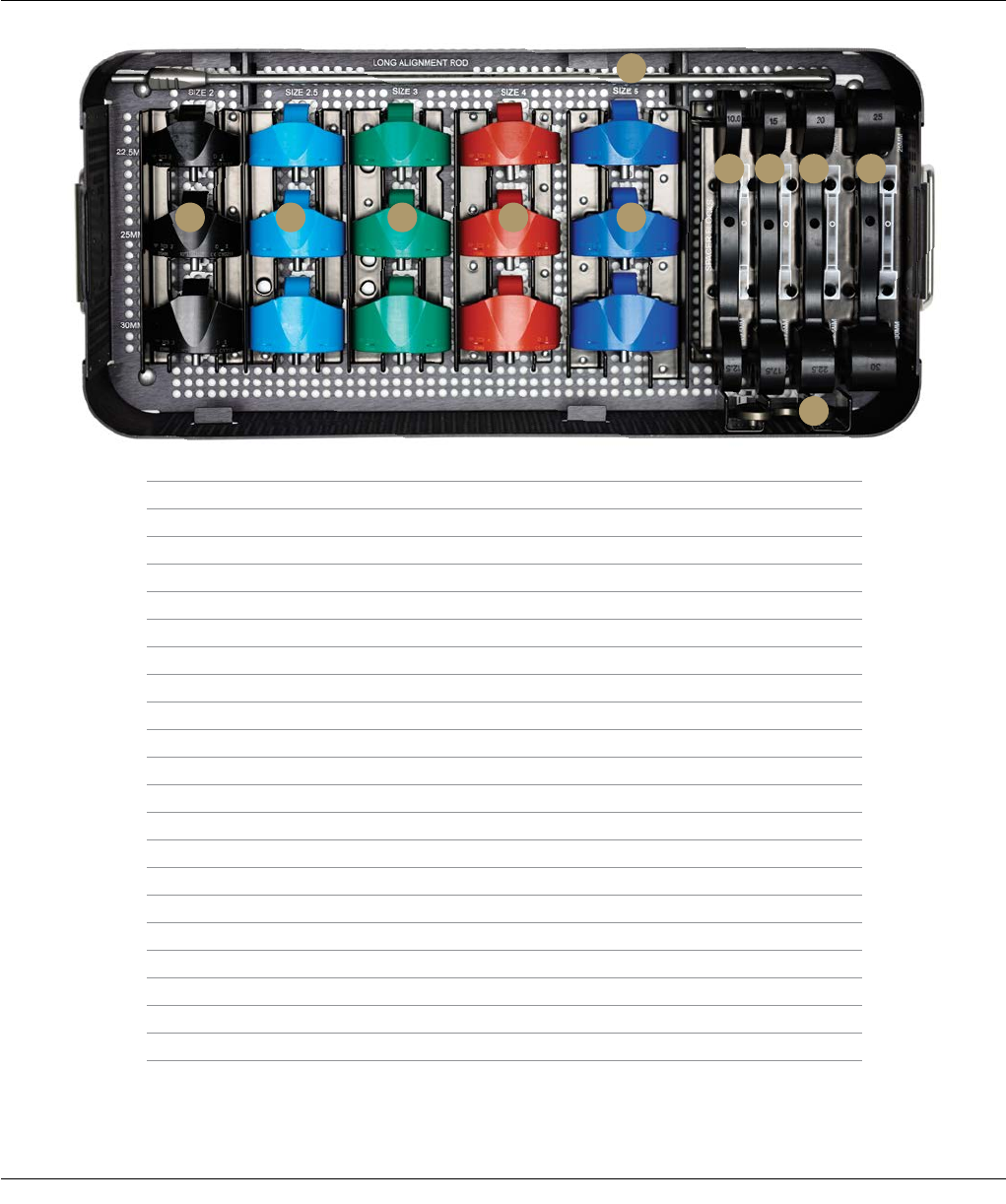
Surgical Technique SIGMA Revision and M.B.T. Revision Tray 73
Bottom Tray
A B C D E
F
G H I
K
J
Description Cat. No.
A TC3 RP Tibial Insert Trial Size 2 22.5 96-3326
TC3 RP Tibial Insert Trial Size 2 25 96-3327
TC3 RP Tibial Insert Trial Size 2 30 96-3328
B TC3 RP Tibial Insert Trial Size 2.5 22.5 96-3336
TC3 RP Tibial Insert Trial Size 2.5 25 96-3337
TC3 RP Tibial Insert Trial Size 2.5 30 96-3338
C TC3 RP Tibial Insert Trial Size 3 22.5 96-3346
TC3 RP Tibial Insert Trial Size 3 25 96-3347
TC3 RP Tibial Insert Trial Size 3 30 96-3348
D TC3 RP Tibial Insert Trial Size 4 22.5 96-3356
TC3 RP Tibial Insert Trial Size 4 25 96-3357
TC3 RP Tibial Insert Trial Size 4 30 96-3358
E TC3 RP Tibial Insert Trial Size 5 22.5 96-3366
TC3 RP Tibial Insert Trial Size 5 25 96-3367
TC3 RP Tibial Insert Trial Size 5 30 96-3368
F HP Alignment Rod 9505-01-207
G SIGMA HP Revision M.B.T. Spacer Block 10/12.5 2011-03-017
H SIGMA HP Revision M.B.T. Spacer Block 15/17.5 2011-03-018
I SIGMA HP Revision M.B.T. Spacer Block 20/22.5 2011-03-019
J SIGMA HP Revision M.B.T. Spacer Block 25/30 2011-03-020
K SIGMA HP Revision Extension Shim 2011-03-061
SIGMA HP REVISION TC3 RP INSERT TRIAL
AND SPACER BLOCK CASE CAT. NO. 2011-03-070
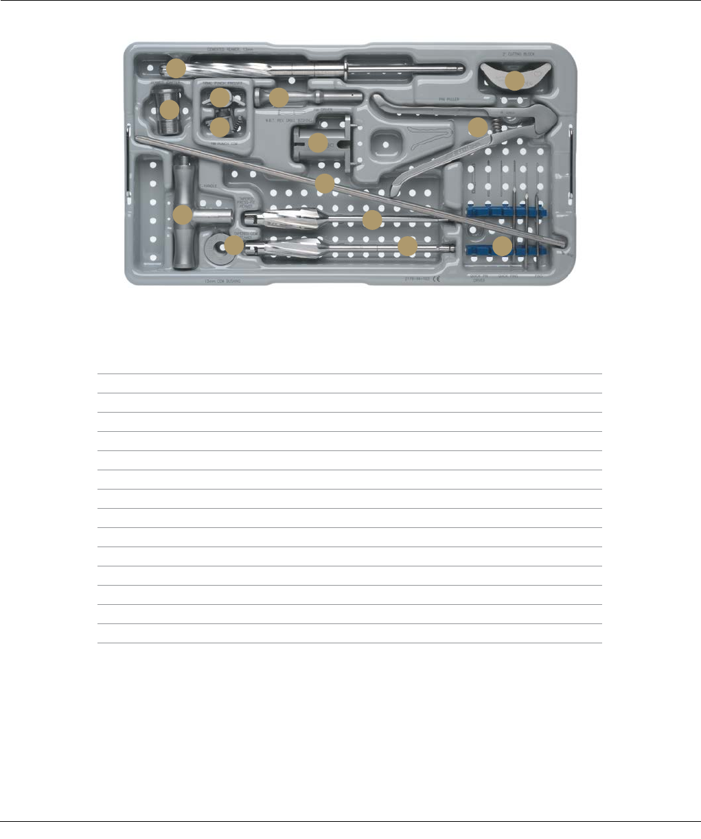
74 SIGMA Revision and M.B.T. Revision Tray Surgical Technique
Top Tray
A
C
D F
G
B
H
NM
L
I
E
J
K
Description Cat. No.
A M.B.T. Revision Cemented Stem Reamer, 13 mm 2178-63-185
B Tibial Cutting Block, 2 Degree 2178-40-086
C M.B.T Revision Reamer Adapter 2178-63-128
D M.B.T. Revision Press-fit Tibial Punch 2178-63-118
E M.B.T. Revision Cemented Tibial Punch 2178-63-120
F Pin Driver 2490-94-000
G M.B.T. Revision Drill Bushing 2178-63-100
H Pin Puller 96-6515
I SP2 IM Rod, 400 mm 96-6120
J SP2 IM Rod Handle 99-2011
K M.B.T. Revision Cemented Bushing, 13 mm 2178-63-196
L M.B.T. Revision Tapered Press-fit Reamer 2178-63-104
M M.B.T. Revision Tapered Cemented Reamer 2178-63-106
N Steinman Pins (Package of 10) 86-9117
M.B.T. REVISION PREPARATION CASE
CAT. NO. 2178-64-100
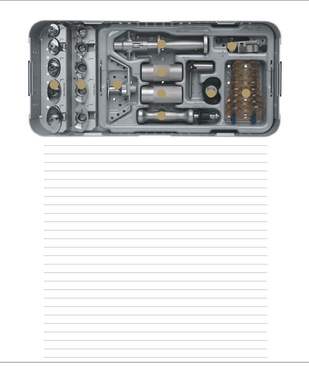
Surgical Technique SIGMA Revision and M.B.T. Revision Tray 75
M.B.T. REVISION PREPARATION CASE
CAT. NO. 2178-64-100
Bottom Tray
A B C
E
DH
FI J
G
Description Cat. No.
A M.B.T. Revision 2-Degree Tibial Broaches 29 mm 2178-63-109
M.B.T. Revision 2-Degree Tibial Broaches 37 mm 2178-63-111
M.B.T. Revision 2-Degree Tibial Broaches 45 mm 2178-63-113
M.B.T. Revision 2-Degree Tibial Broaches 53 mm 2178-63-115
M.B.T. Revision 2-Degree Tibial Broaches 61 mm 2178-63-117
B M.B.T. Tray Sleeve Trials 29 mm 2294-54-000
M.B.T. Tray Sleeve Trials 37 mm 2294-54-100
M.B.T. Tray Sleeve Trials 45 mm 2294-54-110
M.B.T. Tray Sleeve Trials 53 mm 2294-54-120
M.B.T. Tray Sleeve Trials 61 mm 2294-54-130
C LCS Completion Tibial Stylus 2178-40-045
D M.B.T. Revision Tibial Broach Handle 96-6521
E Revision Sleeve Impactor 2178-63-124
F Revision Femoral Sleeve/Stem Impactor 2178-63-126
G SP2 Universal Handle 96-6520
H SP2 IM Tibial Alignment Device 96-6315
I M.B.T. Tibial Impactor 9505-01-558
J M.B.T. Revision Tibial View Plate, Size 1 2178-65-110
M.B.T. Revision Tibial View Plate, Size 1.5 2178-65-115
M.B.T. Revision Tibial View Plate, Size 2 2178-65-120
M.B.T. Revision Tibial View Plate, Size 2.5 2178-65-125
M.B.T. Revision Tibial View Plate, Size 3 2178-65-130
M.B.T. Revision Tibial View Plate, Size 4 2178-65-140
M.B.T. Revision Tibial View Plate, Size 5 2178-65-150
M.B.T. Revision Tibial View Plate, Size 6 2178-65-160
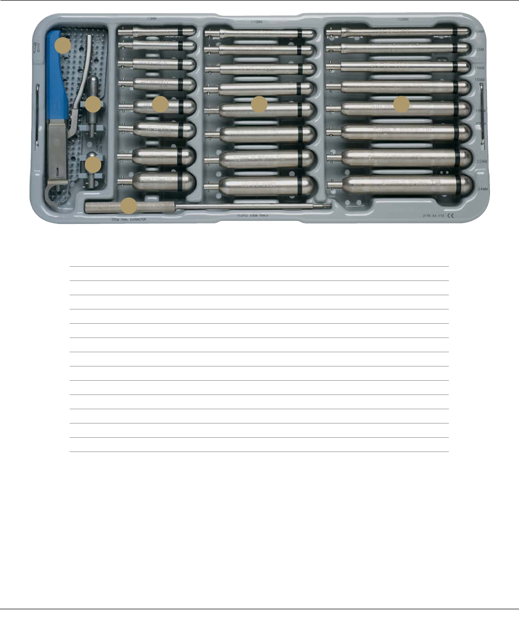
76 SIGMA Revision and M.B.T. Revision Tray Surgical Technique
M.B.T. REVISION STEM TRIALS AND INSTRUMENTS
CASE CAT. NO. 2178-64-110
Top Tray
Description Cat. No.
A Revision Femoral/Tibial Sleeve Clamp 2178-63-134
B SIGMA Tibial Cemented Stem Trial, Sizes 2-3, 13 x 60 mm 86-6502
C SIGMA Tibial Cemented Stem Trial, Sizes 1.5-3, 13 x 30 mm 86-6501
D Stem Trial Extractor 86-5226
E Fluted Tibial Stem Trials – 75 mm
75 x 10 mm 86-6874
75 x 12 mm 86-6875
75 x 14 mm 86-6876
75 x 16 mm 86-6877
75 x 18 mm 86-6878
75 x 20 mm 86-6879
75 x 22 mm 86-6880
75 x 24 mm 86-6881
A
B F GE
C
D
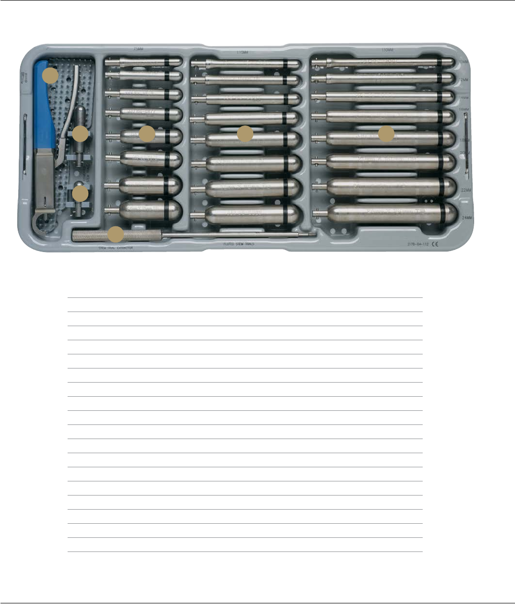
Surgical Technique SIGMA Revision and M.B.T. Revision Tray 77
M.B.T. REVISION STEM TRIALS AND INSTRUMENTS
CASE CAT. NO. 2178-64-110
Top Tray
Description Cat. No.
F Fluted Tibial Stem Trials – 115 mm
115 x 10 mm 86-6882
115 x 12 mm 86-6883
115 x 14 mm 86-6884
115 x 16 mm 86-6885
115 x 18 mm 86-6886
115 x 20 mm 86-6887
115 x 22 mm 86-6888
115 x 24 mm 86-6889
G Fluted Tibial Stem Trials – 150 mm
150 x 10 mm 86-6890
150 x 12 mm 86-6891
150 x 14 mm 86-6892
150 x 16 mm 86-6893
150 x 18 mm 86-6894
150 x 20 mm 86-6895
150 x 22 mm 86-6896
150 x 24 mm 86-6897
A
B F GE
C
D
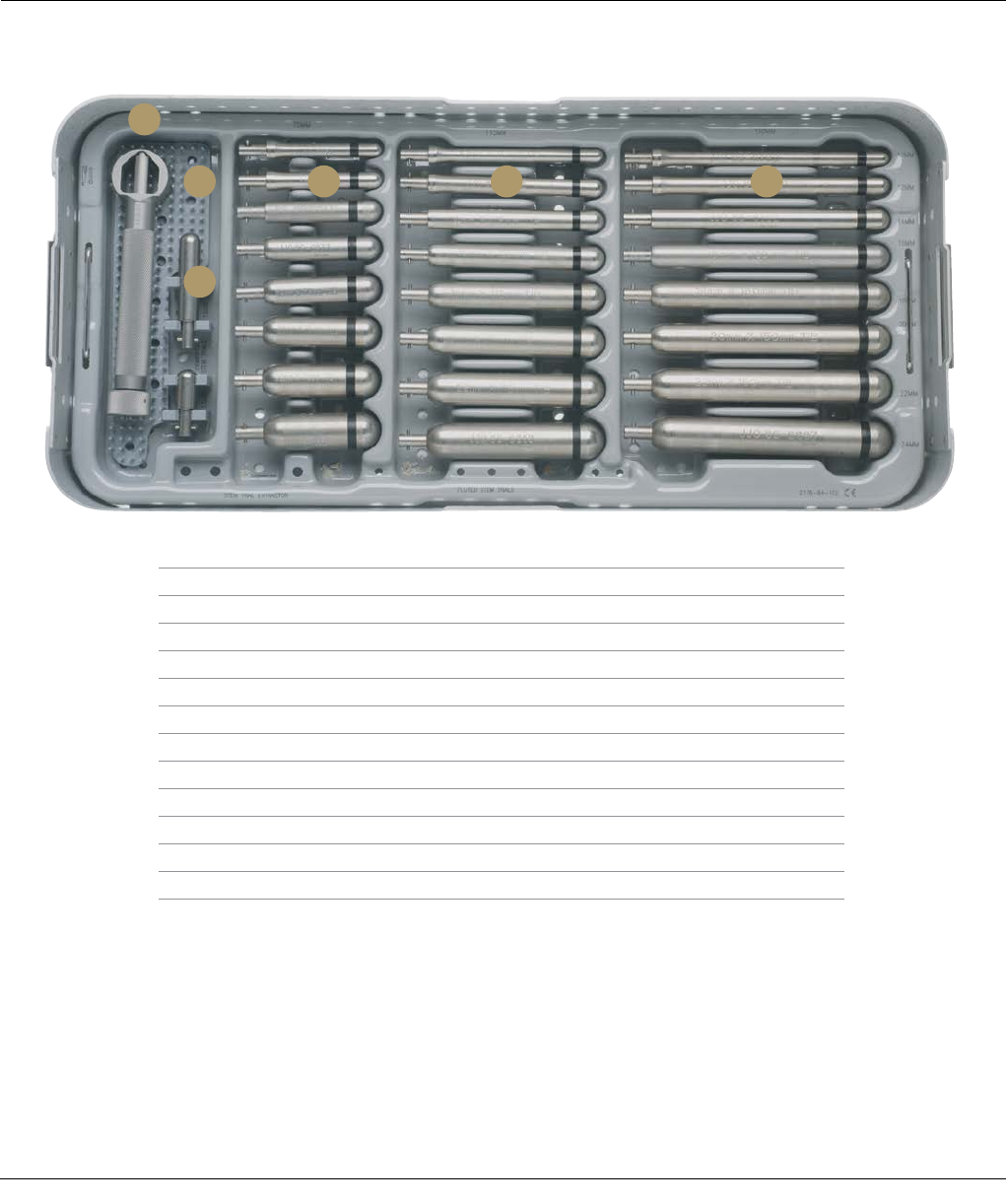
78 SIGMA Revision and M.B.T. Revision Tray Surgical Technique
M.B.T. REVISION STEM TRIALS AND INSTRUMENTS
CASE CAT. NO. 2178-64-110
Bottom Tray
Description Cat. No.
A Press-fit Rod Wrench 86-5189
B SIGMA Tibial Cemented Stem Trial, Sizes 2-3, 13 x 60 mm 86-6502
C SIGMA Tibial Cemented Stem Trial, Sizes 1.5-3, 13 x 30 mm 86-6501
D Fluted Tibial Stem Trials – 75 mm
75 x 10 mm 86-6874
75 x 12 mm 86-6875
75 x 14 mm 86-6876
75 x 16 mm 86-6877
75 x 18 mm 86-6878
75 x 20 mm 86-6879
75 x 22 mm 86-6880
75 x 24 mm 86-6881
A
B D E F
C
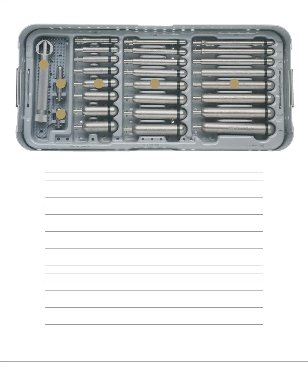
Surgical Technique SIGMA Revision and M.B.T. Revision Tray 79
M.B.T. REVISION STEM TRIALS AND INSTRUMENTS
CASE CAT. NO. 2178-64-110
Bottom Tray
Description Cat. No.
E Fluted Tibial Stem Trials – 115 mm
115 x 10 mm 86-6882
115 x 12 mm 86-6883
115 x 14 mm 86-6884
115 x 16 mm 86-6885
115 x 18 mm 86-6886
115 x 20 mm 86-6887
115 x 22 mm 86-6888
115 x 24 mm 86-6889
F Fluted Tibial Stem Trials – 150 mm
150 x 10 mm 86-6890
150 x 12 mm 86-6891
150 x 14 mm 86-6892
150 x 16 mm 86-6893
150 x 18 mm 86-6894
150 x 20 mm 86-6895
150 x 22 mm 86-6896
150 x 24 mm 86-6897
A
B D E F
C
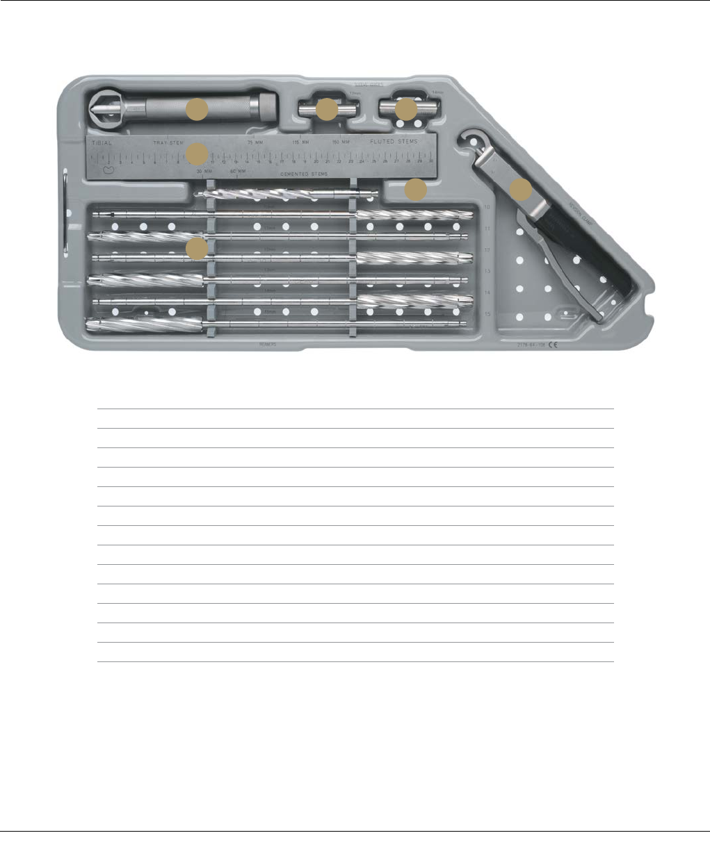
80 SIGMA Revision and M.B.T. Revision Tray Surgical Technique
M.B.T. REVISION REAMERS CASE
CAT. NO. 2178-64-105
Description Cat. No.
A Press-fit Rod Wrench 86-5189
B IM Rod Sleeve Guide, 12 mm 2178-63-187
C IM Rod Sleeve Guide, 14 mm 2178-63-188
D LCS Reamer Depth Scale 2178-63-102
E Revision Femoral/Tibial/Sleeve Clamp 2178-63-134
F I.M. Reamer, 9 mm 2178-56-045
G M.B.T. Revision Reamers
M.B.T. Revision Reamer, 10 mm 2178-63-170
M.B.T. Revision Reamer, 11 mm 2178-63-171
M.B.T. Revision Reamer, 12 mm 2178-63-172
M.B.T. Revision Reamer, 13 mm 2178-63-173
M.B.T. Revision Reamer, 14 mm 2178-63-174
M.B.T. Revision Reamer, 15 mm 2178-63-175
Top Tray
A
D
G
F E
B C
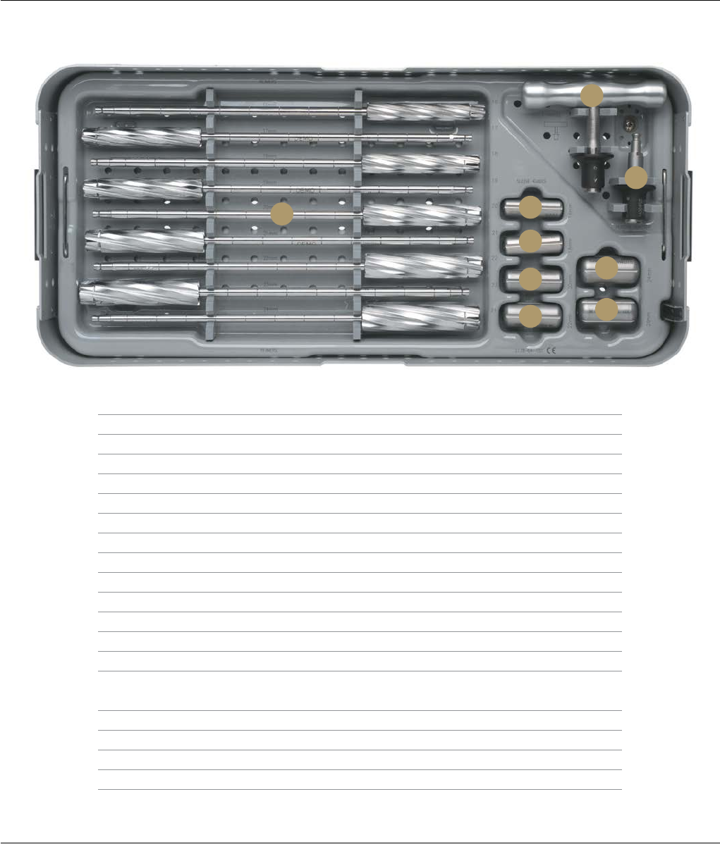
Surgical Technique SIGMA Revision and M.B.T. Revision Tray 81
Description Cat. No.
A M.B.T. Revision Reamers
M.B.T. Revision Reamer, 16 mm 2178-63-176
M.B.T. Revision Reamer, 17 mm 2178-63-177
M.B.T. Revision Reamer, 18 mm 2178-63-178
M.B.T. Revision Reamer, 19 mm 2178-63-179
M.B.T. Revision Reamer, 20 mm 2178-63-180
M.B.T. Revision Reamer, 21 mm 2178-63-181
M.B.T. Revision Reamer, 22 mm 2178-63-182
M.B.T. Revision Reamer, 23 mm 2178-63-183
M.B.T. Revision Reamer, 24 mm 2178-63-184
B IM Rod Sleeve Guide, 16 mm 2178-63-189
C IM Rod Sleeve Guide, 18 mm 2178-63-190
D IM Rod Sleeve Guide, 20 mm 2178-63-
191
E IM Rod Sleeve Guide, 22 mm 2178-63-192
F IM Rod Sleeve Guide, 24 mm 2178-63-193
G IM Rod Sleeve Guide, 26 mm 2178-63-194
H M.B.T. Revision T-Handle 2178-63-137
I Modified Hudson Adapter 2178-63-136
M.B.T. REVISION REAMERS CASE
CAT. NO. 2178-64-105
Bottom Tray
A
H
I
B
C
DF
EG
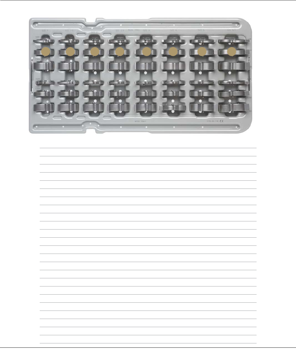
82 SIGMA Revision and M.B.T. Revision Tray Surgical Technique
M.B.T. REVISION WEDGE TRIALS AND INSTRUMENTS
CAT. NO. 2178-64-115
Top Tray
Description Cat. No.
A Size 1, 5 mm 2294-56-110
Size 1, 10 mm 2294-56-111
Size 1, 15 mm 2294-56-112
B Size 1.5, 5 mm 2294-56-115
Size 1.5, 10 mm 2294-56-116
Size 1.5, 15 mm 2294-56-117
C Size 2, 5 mm 2294-56-120
Size 2, 10 mm 2294-56-121
Size 2, 15 mm 2294-56-122
D Size 2.5, 5 mm 2294-56-125
Size 2.5, 10 mm 2294-56-126
Size 2.5, 15 mm 2294-56-127
E Size 3, 5 mm 2294-56-130
Size 3, 10 mm 2294-56-131
Size 3, 15 mm 2294-56-132
F Size 4, 5 mm 2294-56-135
Size 4, 10 mm 2294-56-136
Size 4, 15 mm 2294-56-137
G Size 5, 5 mm 2294-56-140
Size 5, 10 mm 2294-56-141
Size 5, 15 mm 2294-56-142
H Size 6/7, 5 mm 2294-56-145
Size 6/7, 10 mm 2294-56-146
Size 6/7, 15 mm 2294-56-147
A B C D E F G H
Size 1
5 mm
10 mm
15 mm
5 mm
10 mm
15 mm
Size 1.5 Size 2 Size 2.5 Size 3 Size 4 Size 5 Size 6/8
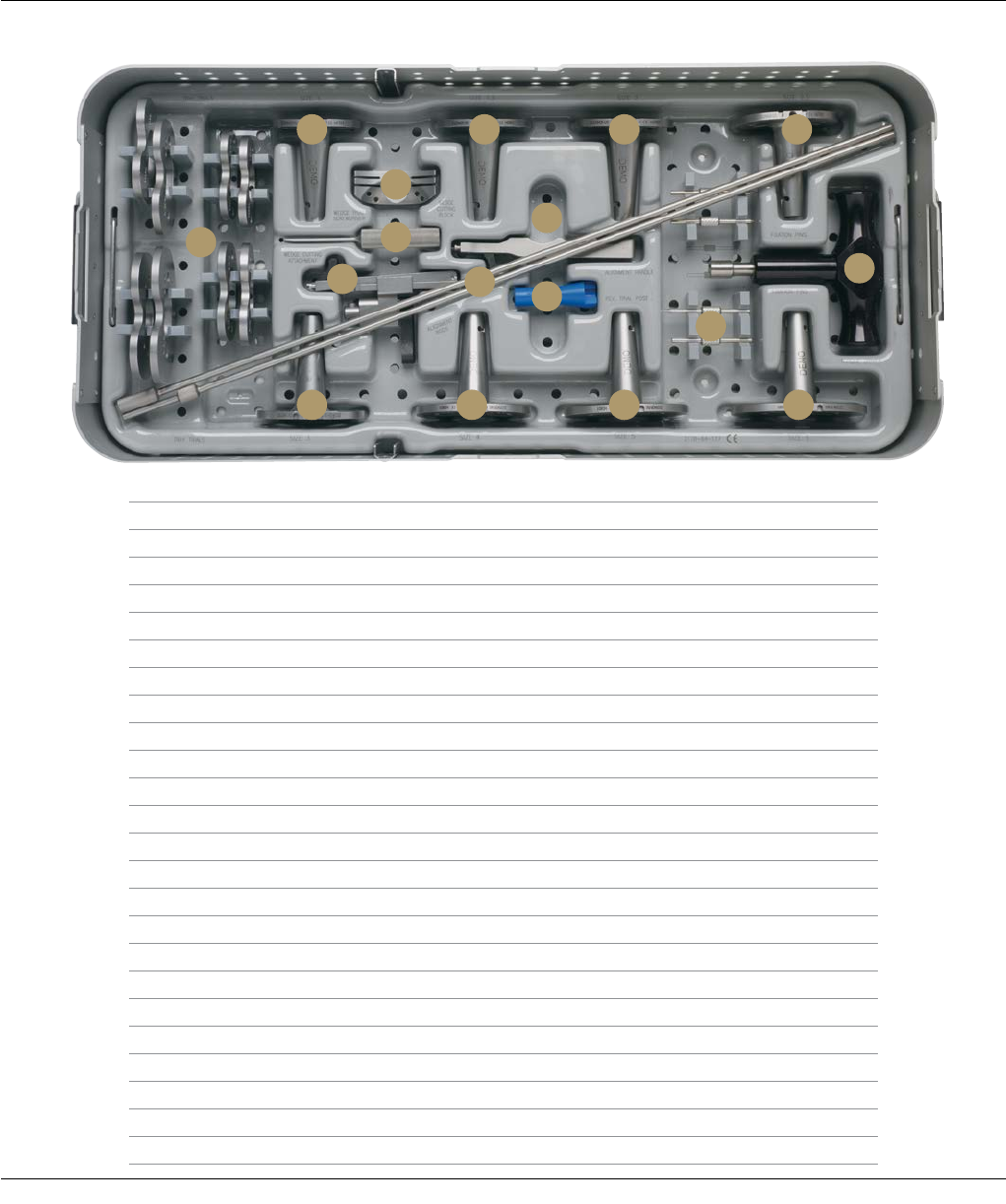
Surgical Technique SIGMA Revision and M.B.T. Revision Tray 83
M.B.T. REVISION WEDGE TRIALS AND INSTRUMENTS
CAT. NO. 2178-64-115
Bottom Tray
Description Cat. No.
A M.B.T. Revision Tray Trial, Size 1 2294-36-110
M.B.T. Revision Tray Trial, Size 1.5 2294-36-115
M.B.T. Revision Tray Trial, Size 2 2294-36-120
M.B.T. Revision Tray Trial, Size 2.5 2294-36-125
M.B.T. Revision Tray Trial, Size 3 2294-36-130
M.B.T. Revision Tray Trial, Size 4 2294-36-140
M.B.T. Revision Tray Trial, Size 5 2294-36-150
M.B.T. Revision Tray Trial, Size 6 2294-36-160
B M.B.T. Revision Tray Trial with Stem, Size 1 2294-35-110
C M.B.T. Revision Tray Trial with Stem, Size 1.5 2294-35-115
D M.B.T. Revision Tray Trial with Stem, Size 2 2294-35-120
E M.B.T. Revision Tray Trial with Stem, Size 2.5 2294-35-125
F M.B.T. Revision Cutting Block 2178-63-122
G Tibial Wedge Trial Screwdriver 86-0277
H M.B.T. Wedge Cutting Attachment 2178-63-130
I SP2 Alignment Rods 99-1016
J Tibial Trial Alignment Handle 96-6330
K M.B.T. Revision Trial Post 2178-63-132
L Modular Plus Torque Driver 86-0284
M M.B.T. Tray Trial Fixation Pins 2178-30-123
N M.B.T. Revision Tray Trial with Stem, Size 3 2294-35-130
O M.B.T. Revision Tray Trial with Stem, Size 4 2294-35-140
P M.B.T. Revision Tray Trial with Stem, Size 5 2294-35-150
Q M.B.T. Revision Tray Trial with Stem, Size 6 2294-35-160
A
B C
F
G
HIK
J
D E
M
QPON
L

84 SIGMA Revision and M.B.T. Revision Tray Surgical Technique

Surgical Technique SIGMA Revision and M.B.T. Revision Tray 85

86 SIGMA Revision and M.B.T. Revision Tray Surgical Technique

Surgical Technique SIGMA Revision and M.B.T. Revision Tray 87

DePuy Orthopaedics, Inc.
700 Orthopaedic Drive
Warsaw, IN 46582
T. +1 (800) 366-8143
www.depuysynthes.com
0612-51-506 (Rev. 5) 3M 10/13
