U219855 Installation Directions
2016-08-16
: Pdf 1000219601-Installationsheet 1000219601-InstallationSheet B3 unilog
Open the PDF directly: View PDF ![]() .
.
Page Count: 6
LEDIMPORTANTSAFETYINSTRUCTIONS
Toreducetheriskofdeath,personalinjuryorpropertydamagefromfire,electricshock,fallingparts,cuts/abrasions,and
otherhazardspleasereadallwarningsandinstructionsincludedwithandonthefixtureboxandallfixturelabels.
Beforeinstalling,servicing,orperformingroutinemaintenanceuponthisequipment,followthesegeneralprecautions.
Installationandserviceofluminairesshouldbeperformedbyaqualifiedlicensedelectrician.
Maintenanceoftheluminairesshouldbeperformedbyperson(s)familiarwiththeluminaires’constructionandoperation
andanyhazardsinvolved.Regularfixturemaintenanceprogramsarerecommended.
Itwilloccasionallybenecessarytocleantheoutsideoftherefractor/lens.Frequencyofcleaningwilldependonambient
dirtlevelandminimumlightoutputwhichisacceptabletouser.Refractor/lensshouldbewashedinasolutionofwarm
waterandanymild,non‐abrasivehouseholddetergent,rinsedwithcleanwaterandwipeddry.Shouldopticalassembly
becomedirtyontheinside,wiperefractor/lensandcleaninabovemanner,replacingdamagedgasketsasnecessary.
DONOTINSTALLDAMAGEDPRODUCT!Thisluminairehasbeenproperlypackedsothatnopartsshouldhavebeen
damagedduringtransit.Inspecttoconfirm.Anypartdamagedorbrokenduringorafterassemblyshouldbereplaced.
Recycle:ForinformationonhowtorecycleLEDelectronicproducts,pleasevisitwww.epa.gov.
Theseinstructionsdonotpurporttocoveralldetailsorvariationsinequipmentnortoprovideeverypossiblecontingency
tomeetinconnectionwithinstallation,operation,ormaintenance.Shouldfurtherinformationbedesiredorshould
particularproblemsarisewhicharenotcoveredsufficientlyforthepurchaser’sorowner’spurposes,thismattershouldbe
referredtoAcuityBrandsLighting,Inc.
READ AND FOLLOW ALL SAFETY INSTRUCTIONS!
SAVE THESE INSTRUCTIONS AND DELIVER TO OWNER AFTER INSTALLATION
Disconnectorturnoffpowerbefore
installationorservicing.
Verifythatsupplyvoltageiscorrectby
comparingitwiththeluminairelabel
information.
Makeallelectricalandgrounded
connectionsinaccordancewiththeNational
ElectricalCode(NEC)andanyapplicable
localcoderequirements.
Allwiringconnectionsshouldbecapped
withULapprovedrecognizedwire
connectors.
WARNING
RISKOFELECTRICSHOCK
Allowlamp/fixturetocoolbeforehandling.
Donottouchenclosureorlightsource.
Followallmanufacturer’swarnings,
recommendationsandrestrictionsfor:driver
type,burningposition,mounting
locations/methods,replacementand
recycling.
WARNING
RISKOFBURN
Wearglovesandsafetyglassesatalltimes
whenremovingluminairefromcarton,
installing,servicingorperforming
maintenance.
Avoiddirecteyeexposuretothelightsource
whileitison.
CAUTION
RISKOFINJURY
Keepcombustibleandothermaterialsthat
canburn,awayfromlamp/lens.
Donotoperateincloseproximityto
persons,combustiblematerialsor
substancesaffectedbyheatordrying.
CAUTION
RISKOFFIRE
LEDIMPORTANTSAFETYINSTRUCTIONS
Please see product specific installation instructions for additional warnings or any applicable FCC or other regulatory
statements.
Failure to follow any of these instructions could void product warranties. For a complete listing of product Terms and
Conditions, please visit www.acuitybrands.com.
OurBrandsIndoor/Outdoor IndoorLighting OutdoorLighting Controls
LithoniaLighting Gotham AmericanElectricLightingDARKTOLIGHT
Carandini MarkArchitecturalLightingAntiqueStreetLampsLightingControl&Design
Holophane Peerless Hydrel ROAM
RELOC RenaissanceLightingTersen SensorSwitch
WinonaLightingSynergy
AcuityBrandsLighting,Inc.assumesnoresponsibilityforclaimsarisingoutofimproperorcarelessinstallationorhandlingofitsproducts.
ABL LED General Warnings, Form No. 503.203
+© 2015 Acuity Brands Lighting, Inc. All rights reserved. 4/06/15
Neverconnectcomponentsunderload.
Donotmountorsupportthesefixturesinamannerthatcancuttheouterjacketordamagewire
insulation.
Unlessindividualproductspecificationsdeemotherwise:NeverconnectanLEDproductdirectlytoa
dimmerpacks,occupancysensors,timingdevices,orotherrelatedcontroldevices.LEDfixturesmustbe
powereddirectlyoffaswitchedcircuit.
Unlessindividualproductspecificationsdeemotherwise:Donotrestrictfixtureventilation.Allowfor
somevolumeofairspacearoundfixture.AvoidcoveringLEDfixtureswithinsulation,foam,orother
materialthatwillpreventconvectionorconductioncooling.
Unlessindividualproductspecificationsdeemotherwise:Donotexceedfixturesmaximumambient
temperature.
Onlyusefixtureinitsintendedlocation.
ElectrostaticDischarge(ESD):ESDcandamageLEDfixtures.Personalgroundingequipmentmustbe
wornduringallinstallationorservicingoftheunit.
DonottouchindividualelectricalcomponentsasthiscancauseESD,shortenlamplife,oralter
performance.
Somecomponentsinsidethefixturemaynotbeserviceable.Intheunlikelyeventyourunitmayrequire
service,stopusingtheunitimmediatelyandcontactanABLrepresentativeforassistance.
Alwaysreadthefixturescompleteinstallationinstructionspriortoinstallationforanyadditionalfixture
specificwarnings.
CAUTION: RISK OF PRODUCT
DAMAGE
DMW2
TM Installation and
Enclosed and Gasketed Maintenance
Luminaire Manual
Lithonia Lighting
INDUSTRIAL VALUE STREAM
One Lithonia Way, Conyers, GA 30012
Phone: 800-315-4963 Fax: 770-981-8141
www.lithonia.com
Part Number: U219855
Revision Date:
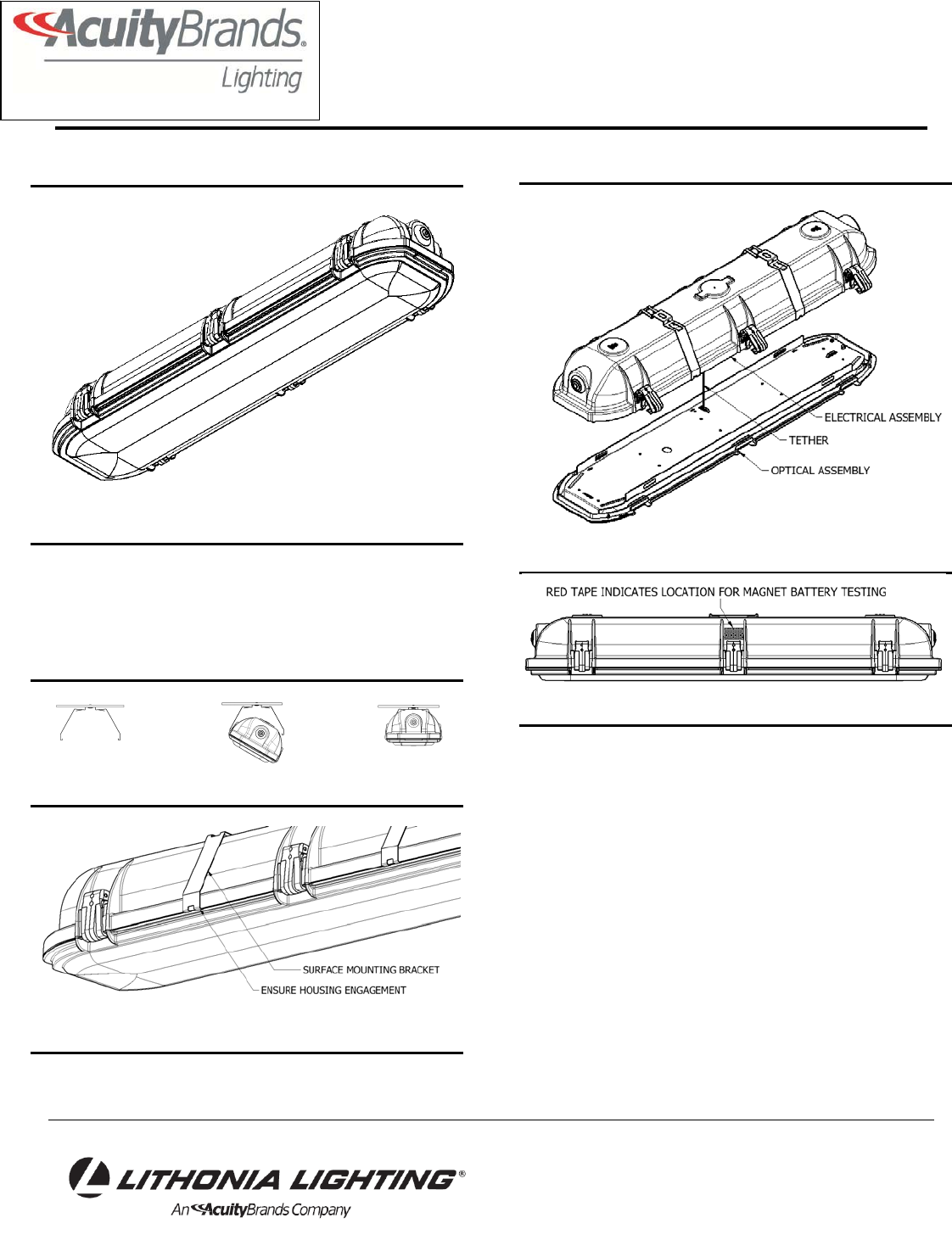
Figure 1 – Assembled Luminaire
1 Introduction
1.1 Product Description. The DMW2 luminaires have
been designed and tested in accordance with applicable
UL/CSA standards and are suitable for use in wet
locations. Max luminaire weight is 9 lbs.
Figure 2 – Surface Mount Bracket Installation Process
Figure 3 – Mounting Bracket Engaged
Figure 4 – Hanging Luminaire
Figure 5 – Hanging Luminaire
2 Installation
2.1 Standard Mounting type (Surface Mounting
Bracket) (see figure 2 – 5 and 12)
2.1.1 Attach two (2) surface mounting brackets to ceiling
or wall using ¼” fasteners (customer supplied). Install
brackets 5” – 14” apart.
2.1.2 Install one side of housing in brackets. Ensure
housing fully engages with brackets.
2.1.3 Rotate up and snap the other side of the housing
into the bracket.
For fixtures with cord options, make all cord supply
wire connections in accordance with all local electrical
codes. Skip to section 2.1.9. If cord not supplied with
plug, use appropriate wet location strain relief fitting at
junction box.
Page 3 of 6
Lithonia Lighting
INDUSTRIAL VALUE STREAM
One Lithonia Way, Conyers, GA 30012
Phone: 800-315-4963 Fax: 770-981-8141
www.lithonia.com
Part Number: U219855
Revision Date:
2.1.4 Disengage all lens latches and unsnap the optical
assembly by pulling it from the electrical assembly. The
optical assembly will hang from a tether.
2.1.5 For standard fixtures, luminaire is supplied with
hole plugs at both ends. Remove plugs as needed while
providing suitable 1/2” wet location fittings.
For fixtures supplied with fittings, ensure all
openings are sealed with pipe sealant before
proceeding.
2.1.6 Make all supply wire connections in accordance
with local electrical codes. For fixtures with PS1050
(EM) option, connect test switch connector to battery
pack. Wire only un-switched power to battery pack.
Emergency fixtures are supplied with a magnet for
performing monthly emergency tests. Press magnet
against red tape on outside of housing.
2.1.7 Re-install optical assembly by snapping into
housing and engage all lens latches, ensuring all leads
are completely inside luminaire and not pinched.
2.1.8 Ensure lens latches are fully engaged with lens
and remove lens protective film.
2.1.9 Energize power to the luminaire and check for
proper operation.
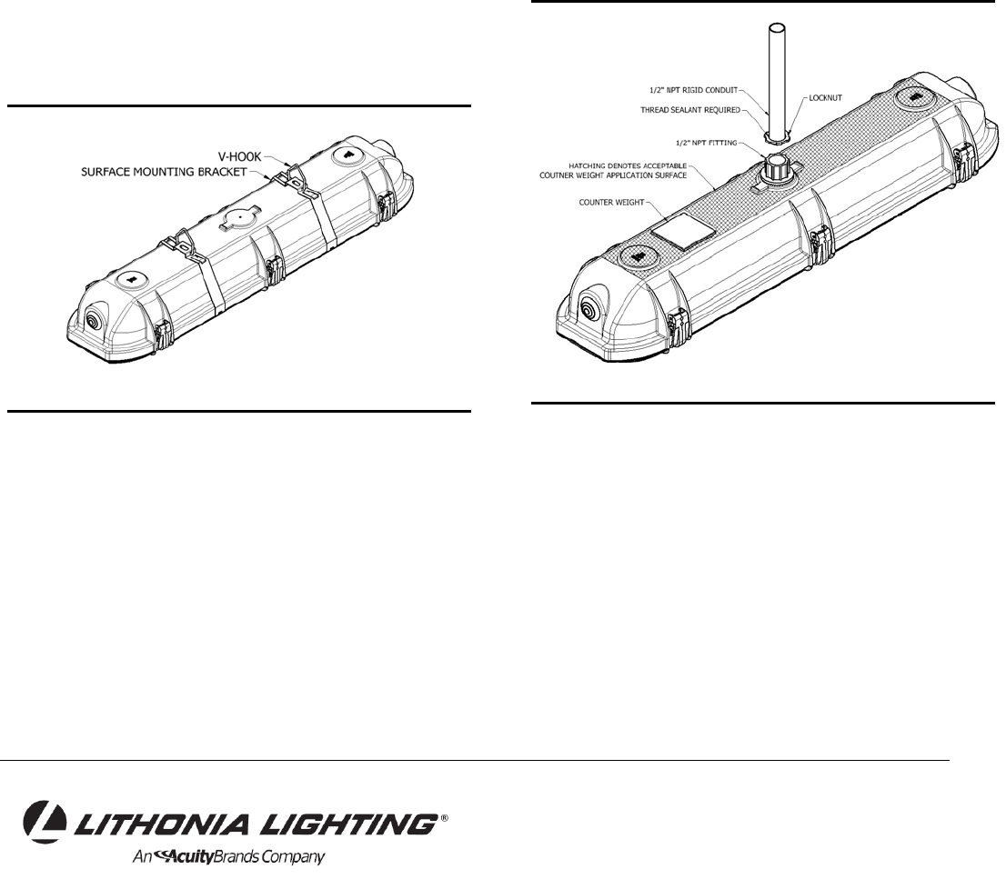
Figure 6 – Pendant Mounting
2.2 Chain mounting type (see figures 3-6 and 12)
2.2.1 Attach Surface Mounting Brackets to fixture
housing
2.2.2 Attach V-hooks to Surface Mounting Brackets.
2.2.3 Connect chain (customer supplied) to V-hooks.
Ensure chain can withstand four times the fixture weight.
2.2.4 Disengage all lens latches and unsnap the optical
assembly by pulling it from the electrical assembly. The
optical assembly will hang from a tether.
2.2.5 For standard fixtures, luminaire is supplied with
hole plugs at both ends. Remove plugs as needed while
providing suitable 1/2” wet location fittings for
application.
For fixtures supplied with fittings, ensure all
openings are sealed with pipe sealant before
proceeding.
2.2.6 Make all supply wire connections in accordance
with local electrical codes. For fixtures with PS1050
(EM) option, connect test switch connector to battery
pack. Wire only un-switched power to battery pack.
Emergency fixtures are supplied with a magnet for
performing monthly emergency tests. Press magnet
against red tape on outside of housing, location shown in
figure 5.
2.2.7 Re-install optical assembly by snapping into
housing and engage all lens latches, ensuring all leads
are completely inside luminaire and not pinched.
2.2.8 Ensure lens latches are fully engaged with lens
and remove lens protective film.
2.2.9 Energize power to the luminaire and check for
proper operation.
Figure 7 – Pendant Mounting
2.3 PMP4X Mounting type (Pendant Mono-point) (see
figure 4 and 7)
2.3.1 Install locknut and thread sealant to ½” NPT rigid
conduit (customer supplied) prior to attaching luminaire.
½” NPT fitting is not to be removed from the fixture.
2.3.2 Install luminaire onto conduit with a minimum of 3.5
turns and until tight, ensuring locknut does not engage
fitting. Use a wrench to tighten fitting to conduit. DO
NOT USE FIXTURE TO TIGHTEN FITTING.
2.3.3 Tighten locknut until suitable engagement with
fitting.
Page 4 of 6
Lithonia Lighting
INDUSTRIAL VALUE STREAM
One Lithonia Way, Conyers, GA 30012
Phone: 800-315-4963 Fax: 770-981-8141
www.lithonia.com
Part Number: U219855
Revision Date:
WARNING
FAILURE TO TIGHTEN LOCKNUT COULD CAUSE
LUMINAIRE TO FALL RESULTING IN INJURY,
DEATH OR SERIOUS PROPERTY DAMAGE.
AVERTISSEMENT
NE PAS SERRER CORRECTEMENT LA CONTRE-
ÉCROU PEUT PROVOQUER LA CHUTE DE LA
FIXATION ET CAUSER DES BLESSURES,
PROVOQUER LA MORT OU DE SÉRIEUX
DOMMAGES MATÉRIELS.
2.3.2 Disengage all lens latches and unsnap the optical
assembly by pulling it from the electrical assembly. The
optical assembly will hang from a tether.
2.3.3 Make all supply wire connections in accordance
with all local electrical codes.
2.3.4 Re-install optical assembly by snapping into
electrical assembly and engage all lens latches,
ensuring all leads are completely inside luminaire and
not pinched.
2.3.5 Ensure lens latches are fully engaged with lens
and remove lens protective film.
2.3.6 Energize power to the luminaire and check for
proper operation.
2.3.7 For non-rigid pendant mounting, counter balance
weights are provided. See Figure 7 for acceptable flat
installation surfaces. Counter weights provided with
double sided tape. Remove tape backing and apply
counterweight to housing top surface. Apply necessary
quantity of counterweights (max 7) to level fixture.
Ensure counterbalances are securely attached to
housing.
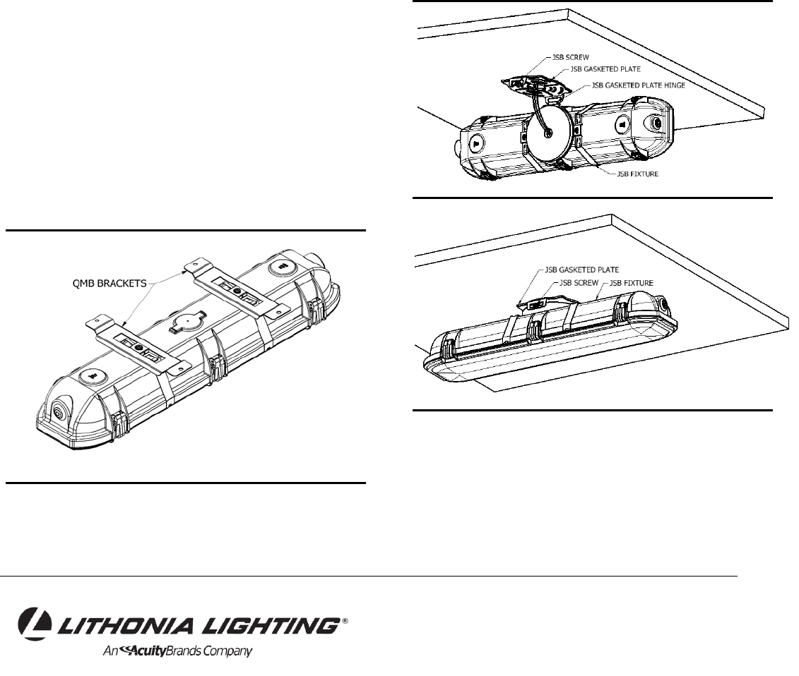
Figure 8 – Quick Installation Sub-Assembly
2.4 QMB Mounting type (Quick Mount Bracket) (see
figures 4, 5, 8, and 12)
2.4.1 QMB fixture shipped with 2X QMB bracket pre-
installed on fixture. Install fixture to ceiling or wall with
(4) #10 fasteners (customer supplied). Bracket can slide
along housing to align with mounting structure.
For fixtures with cord options, make all cord
supply wire connections in accordance with all local
electrical codes. Skip to 2.4.7.
2.4.2 Disengage all lens latches and unsnap the optical
assembly by pulling it from the electrical assembly. The
optical assembly will hang from a tether.
2.4.3 Make all supply wire connections in accordance
with all local electrical codes. For fixtures with PS1050
(EM) option, connect test switch connector to battery
pack. Wire only un-switched power to battery pack.
2.4.4 Re-install optical assembly and engage all lens
latches, ensuring all leads are completely inside
luminaire and not pinched.
2.4.5 Ensure lens latches are fully engaged with lens
and remove lens protective film.
2.4.6 Energize power to the luminaire and check for
proper operation.
Figure 9 – Junction Mount Pre-Assembly
Figure 10 – Junction Mount Type Assembled
Page 5 of 6
Lithonia Lighting
INDUSTRIAL VALUE STREAM
One Lithonia Way, Conyers, GA 30012
Phone: 800-315-4963 Fax: 770-981-8141
www.lithonia.com
Part Number: U219855
Revision Date:
2.5 JSB Mounting type (Junction Mount Bracket)
(see figures 9 – 10)
2.5.1 JSB fixture assembly is intended to be mounted to
a 2”, 3”, or 4” Junction box. To retain fixture wet location
listing, junction box should be wet location listed. JSB
fixture assembly shipped with JSB fixture and mating
JSB gasketed plate.
2.5.2 Orient JSB gasketed plate for proper fixture
orientation once fixture is installed. Attach JSB gasketed
plate to Junction box with (4) #10 min fasteners
(customer supplied).
2.5.3 Hang JSB fixture on JSB gasketed plate hinge.
JSB fixture supplied with supply wires extending from
fixture. Make all supply wire connections in accordance
with all local electrical codes.
2.5.4 Remove JSB screw, then rotate JSB fixture until
plates snap together. While rotating, feed supply wires in
Junction box, ensure no wires are pinched between
fixture gasket and JSB gasketed plate. Reinstall the
JSB screw to ensure fixture is secure.
2.5.5 Remove lens protective film
2.5.6 Energize power to the luminaire and check for
proper operation.
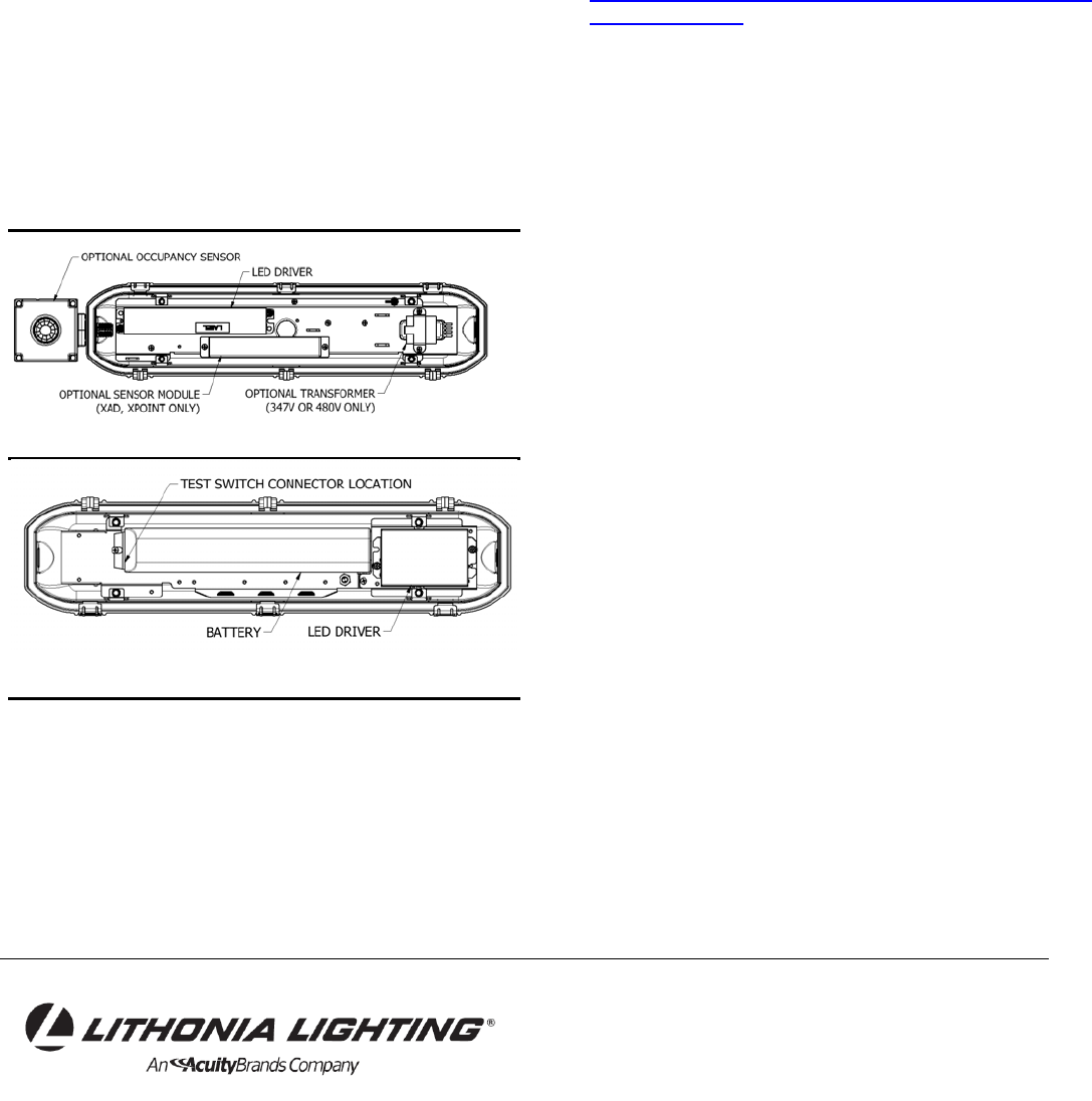
Figure 11 – Electrical Assembly
Figure 12 – Electrical Assembly - Emergency
3.0 Maintenance
3.1 Electrical Component Replacement (Driver,
Surge protector, internal controller) (see figure 11 –
12)
3.1.1 Disconnect power to the luminaire location before
maintenance. Disengage all lens latches and unsnap the
optical assembly by pulling it from the electrical
assembly. The optical assembly will hang from a tether.
3.1.2 Tag leads before disconnecting.
3.1.3 Replace components using Lithonia approved
replacement parts.
3.1.4 Re-connect electrical leads
3.1.5 Re-install optical assembly and engage all lens
latches, ensuring all leads are completely inside
luminaire and not pinched.
3.1.6 Ensure lens latches are fully engaged with lens.
3.1.7 Energize power to the luminaire and check for
proper operation.
4.0 Limited Warranty and Limitation of Liability
5-year limited warranty. Complete warranty terms
located at:
www.acuitybrands.com/CustomerResources/Terms_and
_Conditions.aspx.
Page 6 of 6
