1000246616 Catalog
2016-06-25
: Pdf 1000246616-Catalog 1000246616-Catalog B1 unilog
Open the PDF directly: View PDF ![]() .
.
Page Count: 40
Electric Service Bulletin No. 759A – April 2014
Supplemen
t
to
Specifications
f
or
Electrical
Installations
Underground
R
e
siden
t
ial Distribution (URD)
Installation
and
R
e
sponsibility
Guide
Liberty Utilities / Supplement to Specifications for Electrical Installations / ESB 759A April 2014
1
For the latest authorized version, please refer to the company’s website at http://www.libertyutilities.com/electricalspecifications.
Table of Contents
URD Specifications and Installation Guide Acknowledgement (Job Spec/Signoff Forms) .......................... 1
URD Specifications and Installation Guide Acknowledgement (Job Spec/Signoff Forms) .......................... 3
1.0 Scope ...................................................................................................................................................... 5
2.0 General Requirements ............................................................................................................................ 5
3.0 Type of Service ....................................................................................................................................... 5
4.0 Plans ....................................................................................................................................................... 6
5.0 Permits .................................................................................................................................................... 6
6.0 Division of Responsibility ........................................................................................................................ 7
7.0 Easements .............................................................................................................................................. 7
8.0 Trench Construction Requirements ........................................................................................................ 8
9.0 Trench and Conduit System Inspection .................................................................................................. 9
10.0 Conduit Installation ................................................................................................................................ 9
11.0 Transformer Box Pad Installation ........................................................................................................ 10
12.0 Transformer Secondary ...................................................................................................................... 11
13.0 Transformer Grounding and Bonding ................................................................................................. 11
14.0 Spacing of Boxpads, Pullboxes, and Handholes ................................................................................ 11
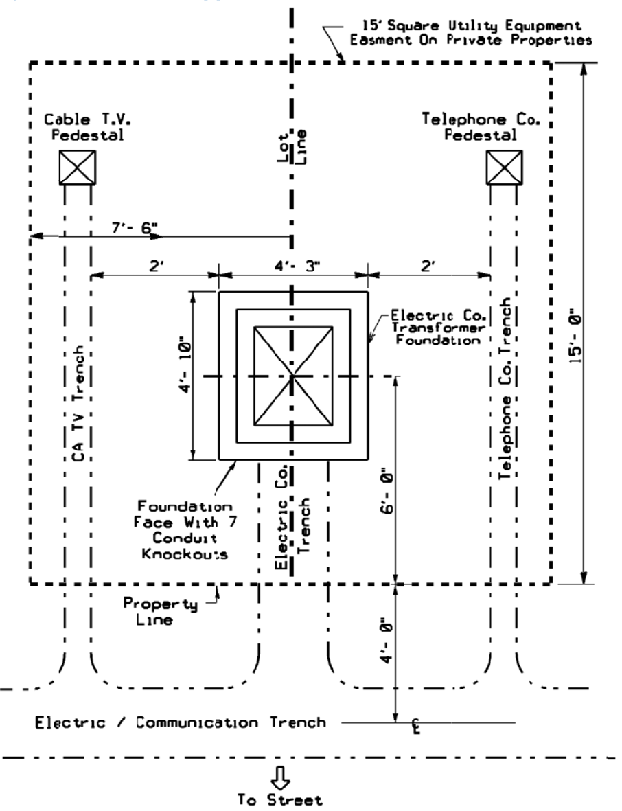
15.0 Proper Transformer Pad and Conduit Layout ..................................................................................... 12
Figure 15.0-1 Preferred Location of Equipment in Easement Area ....................................................... 12
Figure 15.0-2 Single Phase Padmount Transformer — Typical Layout .................................................. 13
15.0-3 Single Phase Padmount Transformer — Direct Burial Layout ..................................................... 13
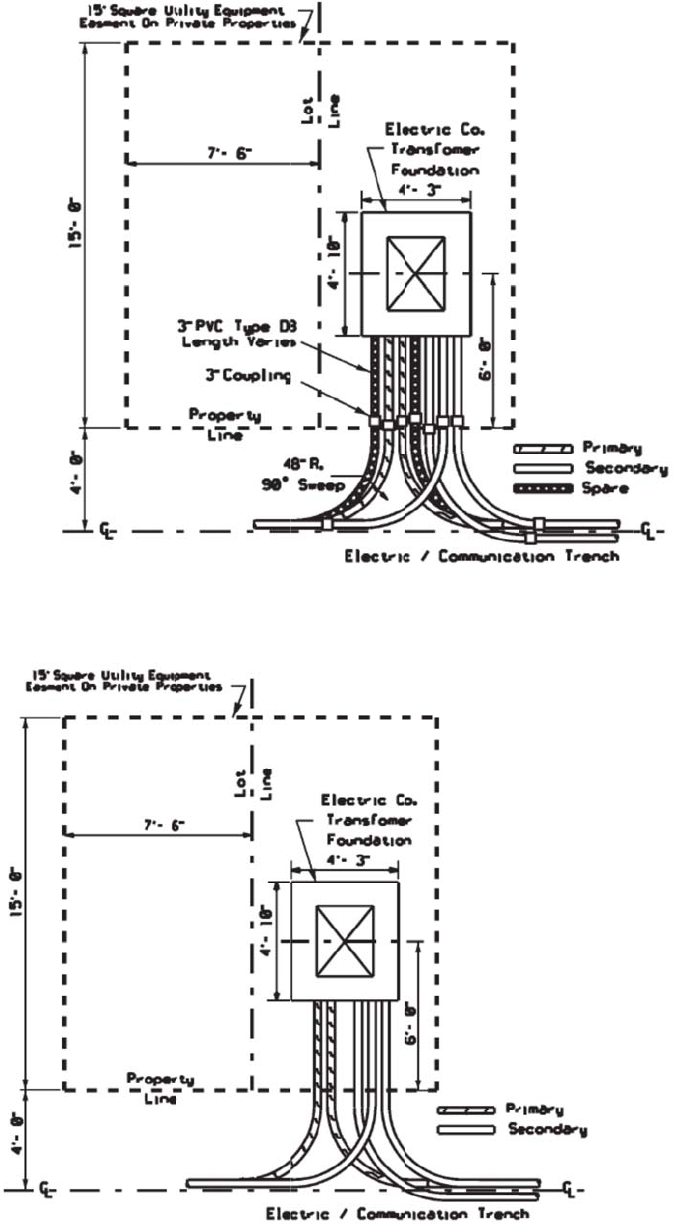
16.0 Transformer Ground Grid Bonding ..................................................................................................... 14
Figure 16.0-1 Single Phase Padmount Transformer Ground Grid .......................................................... 14
Figure 16.0-2 Single Phase Padmount Transformer Ground Grid — Front Elevation ............................ 15
17.0 Proper Transformer Pad and Conduit Installations ............................................................................. 16
17.0-1 Proper Conduit Bank Installation (Pre-Backfill) ............................................................................ 16
17.0-2 Proper Installation of Conduit with Pullbox used for Drainage (Pre-backfil) ................................ 16
17.0-3 Proper Conduit and Handhole Installation (Pre-backfil) ............................................................... 17
17.0-4 Properly Completed Transformer Installation (Final Grade) ........................................................ 18
17.0-5 Properly Completed Handhole Installations (Final Grade) .......................................................... 19
18.0 Transformer Oil Containment .............................................................................................................. 20
Figure 18.0-1 Single Phase Oil Containment for Cables in Conduit ....................................................... 20
Figure 19.0-2 Single Phase Oil Containment for Direct Buried Cables .................................................. 21
19.0 Riser Pole ............................................................................................................................................ 23
20.0 Primary Cable Pull/Splice Box ............................................................................................................ 25
21.0 Trench Requirements .......................................................................................................................... 27
Figure 21.0-1 Typical Trenches ............................................................................................................... 28
22.0 Conduit Requirements ........................................................................................................................ 28
Liberty Utilities / Supplement to Specifications for Electrical Installations / ESB 759A April 2014
2
For the latest authorized version, please refer to the company’s website at http://www.libertyutilities.com/electricalspecifications.
22.1 Pulling Tape ........................................................................................................................................ 28
22.3 Communication Systems .................................................................................................................... 29
22.4 Non-Company Water, Gas and Sewer ............................................................................................... 29
23.0 Metering .............................................................................................................................................. 29
24.0 Easement Applications........................................................................................................................ 30
25.0 Approved Material – Underground Residential Installations ............................................................... 32
26.0 Job Checklists ..................................................................................................................................... 35
27.0 Revision History .................................................................................................................................. 36

Liberty Utilities / Supplement to Specifications for Electrical Installations / ESB 759A April 2014
1
For the latest authorized version, please refer to the company’s website at http://www.libertyutilities.com/electricalspecifications.
URD Specifications and Installation Guide Acknowledgement (Job Spec/Signoff Forms)
The requirements and specifications outlined in this guide book must be strictly followed. Any requirements not
adhered to can pose safety problems, can be detrimental to the installed system and must be corrected before final
acceptance. The Customer will bear full cost to make corrections to sub-standard installations.
The Customer is responsible to provide enough lead time for the Company to design job, provide inspections and
install Company equipment where applicable.
Typical lead times are shown below.
Lead-Time
Notes
Design and Layout
Eight weeks
Company receives all required
plans, load data and easement
information
Trench, Conduit and Equipment Inspection
Three days
Company inspector
Company Installation
Four weeks
After all inspections are
approved and permits/
easements are procured
Material Pick up
10 Days
Company inspector
NOTE: The above times are estimates only.
Project Title ______________________________________________________________________________
Location _________________________________________________________________________________
Owner/Developer __________________________________________________________________________
Customer’s Representative _____________________________________ Date _______________________
Company Representative _______________________________________ Date _______________________
Company’s Copy
Liberty Utilities / Supplement to Specifications for Electrical Installations / ESB 759A April 2014
2
For the latest authorized version, please refer to the company’s website at http://www.libertyutilities.com/electricalspecifications.

Liberty Utilities / Supplement to Specifications for Electrical Installations / ESB 759A April 2014
3
For the latest authorized version, please refer to the company’s website at http://www.libertyutilities.com/electricalspecifications.
URD Specifications and Installation Guide Acknowledgement (Job Spec/Signoff Forms)
The requirements and specifications outlined in this guide book must be strictly followed. Any requirements not
adhered to can pose safety problems, can be detrimental to the installed system and must be corrected before final
acceptance. The Customer will bear full cost to make corrections to sub-standard installations.
The Customer is responsible to provide enough lead time for the Company to design job, provide inspections and
install Company equipment where applicable.
Typical lead times are shown below.
Lead-Time
Notes
Design and Layout
Eight weeks
Company receives all required
plans, load data and easement
information
Trench, Conduit and Equipment Inspection
Three days
Company inspector
Company Installation
Four weeks
After all inspections are
approved and permits/
easements are procured
Material Pick up
10 Days
Company inspector
NOTE: The above times are estimates only.
Project Title ______________________________________________________________________________
Location _________________________________________________________________________________
Owner/Developer __________________________________________________________________________
Customer’s Representative _____________________________________ Date _______________________
Company Representative _______________________________________ Date _______________________
Customer’s Copy
Liberty Utilities / Supplement to Specifications for Electrical Installations / ESB 759A April 2014
4
For the latest authorized version, please refer to the company’s website at http://www.libertyutilities.com/electricalspecifications.

Liberty Utilities / Supplement to Specifications for Electrical Installations / ESB 759A April 2014
5
For the latest authorized version, please refer to the company’s website at http://www.libertyutilities.com/electricalspecifications.
1.0 Scope
The purpose of this specification is to define, interpret and clarify the scope of work and material dealing with
providing service to URD’s and is a Supplement to Electrical System Bulletin (ESB) 750.
It is important that the Specifications for Electrical Installations book (ESB 750) be obtained and referred to in
conjunction with this supplement for these installations. Any reference to the Company in this specification
shall mean the Liberty Utilities. Any reference to the Customer or Developer in this specification shall mean
the property owner or the designee of the property owner of the URD.
2.0 General Requirements
All electrical wiring to be connected to the Company equipment shall be installed in accordance with one or all
of the following:
Local Municipal Inspection Authority
State’s Electrical Code
National Electrical Code
National Electrical Safety Code
Applicable Distribution Construction Standards of the Company
Liberty Utilities’ Specifications for Electrical Installations
There shall be no attempt to deviate from either the Distribution Standards of the Company or the Company
construction plan without the approval of the Company. Any specifications noted shall supersede the
Specifications for Electrical Installations booklet unless otherwise approved by the Company.
It is mandatory that the Customer and all parties involved attend a documented pre-construction meeting with a
Company representative to discuss the project and ensure it a timely completion. A Company representative
will make the necessary arrangements for the pre-construction meeting. Company representatives will also be
available throughout the job life cycle to discuss construction problems when requested or during a field visit.
References:
ESB 750 - Specifications for Electrical Installations
ESB 759B – UCD Installation and Responsibility Guide
All ESB’s are available at http://www.libertyutilities.com/electricalspecifications
The Customer shall be responsible to have all electrical and physical design documents prepared and updated
by a design professional, in accordance with Section 1.7 of ESB 750 for the trenching, conduit, transformer
pad, and handhole installations.
3.0 Type of Service
Electric service shall be single phase, three wire, 120/240V supplied from a padmount transformer or handhole
to be located on the Customer’s premises. The primary electrical service to the URD will be supplied from a
pole or cable system owned by the Company.
Liberty Utilities / Supplement to Specifications for Electrical Installations / ESB 759A April 2014
6
For the latest authorized version, please refer to the company’s website at http://www.libertyutilities.com/electricalspecifications.
4.0 Plans and Other Documents
The total number of house lots proposed to be constructed will be provided in advance to the Company by the
Customer, along with a complete copy of the subdivision plans approved by the planning board in the
municipality, if such is required by the municipality. The Company will not begin design work prior to receipt
of the approved plans.
The Company may require the Customer to provide, in advance and at no cost to the Company, the following:
i. A copy of the approval of the planning board for the subdivision;
ii. Copy of all permits and approvals that have been obtained for constructing the development;
iii. Easements, drafted by the Company, for all facilities required to serve the development;
iv. The name and address of the financial institution providing financing for the development,
including a contact person and phone number;
v. A copy of a street light proposal for the development, approved by the municipality, or written
notice from the municipality that street lighting will not be required; if installation is requested
after construction is complete, additional costs, may be borne by the municipality and/or
Customer if the tariff does not collect all costs of construction;
vi. A schedule of Customer’s best estimate for the construction of homes in the development; and
vii. Such other reasonable information that may be requested to confirm the viability of the
development.
Conduit Systems in general: will be designed to support a looped primary system with no spare conduit. The
Company requires a spare conduit for all Company owned radial duct systems, as shown in Company plans.
Other utilities must maintain clearances as outlined in the NESC.
5.0 Permits
In general, all applicable permits necessary to trench and excavate, including street openings and
environmental permits, shall be obtained by the Customer and made available upon request of Company prior
to design. The Customer shall be responsible for including these padmount and conduit/trench specifications
with the wetlands application for developments located in or near wetlands. A copy of the wetlands permit
may be requested by the Company prior to acceptance of the conduit/trench system by the Company.
The Customer/Company doing the excavation shall obtain the required DIGSAFE permits before any
excavation may take place in a public way. The Customer/Company doing the excavation is urged to obtain
copies of the applicable statute and become familiar with its requirements. Similarly, the Customer/Company
shall determine if the municipality in which the excavation is to be done requires that water, sewer or other
utility, municipal or private, be contacted separately due to the possibility they may not be members of
DigSafe® (for New England). The Customer is also responsible to notify the company of all as built changes
that may conflict with design).
The Customer shall certify to the Company that areas in which the Company is to perform installation or
maintenance work is free of pre-existing contamination by hazardous wastes or materials and to indemnify the
Company for any claims, costs, expensed, suits, demands, citations, fines or damages of any kind arising from
the presence of any such contamination.
The Company may, at its discretion, construct the underground distribution line in segments, rather than all at
once in the proposed development. The Company may, at its option, be exempt from undertaking construction
during the period of December 1 to April 1 each year.

Liberty Utilities / Supplement to Specifications for Electrical Installations / ESB 759A April 2014
7
For the latest authorized version, please refer to the company’s website at http://www.libertyutilities.com/electricalspecifications.
6.0 Division of Responsibility
The division of ownership and responsibility shall be as outlined below. Typical installation specifications to
reflect installation practices are shown in the back of this guide.
New Hampshire
a. The Company will:
i. Develop the plan to provide underground electric service,
ii. Supply a list of approved manufacturers and their part numbers for equipment to be
supplied by the customer, (See Pages 32 – 34)
iii. Designate the location of all Company owned equipment,
iv. Provide Company owned street light foundations and any cable-in-conduit required for
street light applications,
v. Provide, install, own and maintain all transformers, Company owned street lights,
primary and secondary cable, except services,
vi. Make all connections to Company equipment,
vii. Inspect the underground conduit system, equipment foundations and ground grids
installed by the Customer, prior to backfilling and before Company acceptance of conduit
system,
viii. Determine if oil containment shall be required for padmount transformer installation,
b. The Customer, at no cost to the Company, will:
i. Provide, prior to the start of the Company’s construction, all applicable documents
required for the Company to prepare easements for its facilities to be installed on private
property,
ii. Install foundations and conduit, provided by the Company, for Company owned street
lights, which locations have been approved by the local municipality,
iii. Provide and install all required handholes, boxpads, pull/splice boxes, grounding systems,
and conduit including spacers, galvanized conduit and sweeps for riser poles including
bonding clamps and neutral tap, glue and pulling tape, etc. as indicated on the Company’s
plan and related construction documents,
iv. Supply copies of all invoices, when requested, indicating manufacturer and part number
for all such equipment above; equipment that is not approved shall not be used without
the prior written consent of the Company,
v. Install, own and maintain all secondary services and service conduit from the Company’s
equipment to each designated meter location,
vi. Turn over ownership of the conduit system, excluding the service conduit, to the
Company upon inspection and acceptance of the conduit system by the Company,
vii. Provide and install material for oil containment under padmounted transformers where
required.
7.0 Easements
In general, Company-owned equipment shall not be installed on the Customer’s property prior to the execution
of suitable easement(s). The Customer will have to provide to the Company (for the purposes of securing an
easement) the following items, including but not limited to:
Copy of property deed showing: owner, date, book number, page number county registry, and survey
and/or plan of record, if available.
Note: When electronic maps are used, the Customer must consult the Company for submittal.
Copy of mortgages showing: holder, date, book number, page number and county registry.

Liberty Utilities / Supplement to Specifications for Electrical Installations / ESB 759A April 2014
8
For the latest authorized version, please refer to the company’s website at http://www.libertyutilities.com/electricalspecifications.
Copy of any applicable trusts showing: date, book number, page number and county registry, and who
is authorized to sign legal documents on behalf of the Trust.
Easement application forms are located on Page 31. Refer to Sections 3.1.3 and 4.1.1 in ESB 750 for further
easement requirements applicable to the Applicant or Customer.
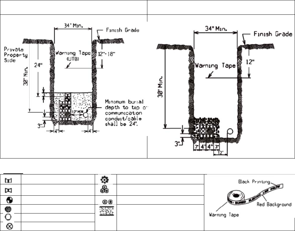
8.0 Trench Construction Requirements
a. Layout and Grading
i. Final grades shall be established and the binder coat installed, and easement boundaries,
street, lot and trench lines staked by the Customer before any trenching is started (except for
Company inspected road crossings).
b. Trenching and Backfilling
i. The Customer shall adhere to the construction plan specifying trench locations and
depths, with any deviation being subject to approval by the Company.
ii. Minimum burial depths specified for all electrical conduit and direct burial trenches shall
be maintained during all phases of construction. Temporary mechanical protection over
buried conduit during construction to prevent conduit crushing or damage due to
unusually heavy construction equipment shall be the responsibility of the Customer.
iii. Trench detail shown in attached Company Standards shall be adhered to. The trench
bottom shall be solid, undisturbed earth. Earth showing signs of peat, cinders, rubble or
any conditions not suitable for a stable foundation shall be reported to the Company
Representative for recommendation. Pockets of unsuitable soil shall be replaced with
compacted sand.
iv. For work done by Customer, a Company representative shall be notified in advance of the
backfilling of any electric facility, i.e., conduit, foundation, handhold, pull-box, cable-in-
conduit, grounding, cables, etc.
If any facility is backfilled without the Company’s prior approval, the Company reserves the right to require re-
excavation of the facility.
aa. Sand for conduit installation - A minimum of three inches of sand shall be placed,
under, beside, around and on top of all electric conduits. The sand shall pass through
3/8 inch mesh screen and shall not contain any sharp stones. Sand shall be placed and
suitably tamped over installed conduit in reasonably small quantities (not a front end
loader bucketful all at once) to avoid conduit damage. Sand shall be evenly
distributed between and around all electric conduits.
v. Remainder of backfill shall not contain stones greater than once inch and shall not
contain ashes, cinders, shell, or frozen material,
vi. Trenches shall be immediately backfilled following cable or conduit system inspection
and approval by authorized Company representative,
vii. Backfilling shall be accomplished in a continuous manner from one terminal, i.e., riser
pole, foundation, handhold, etc. to the next,
viii. Backfilling shall not take place over any open-ended (unplugged) conduits,

Liberty Utilities / Supplement to Specifications for Electrical Installations / ESB 759A April 2014
9
For the latest authorized version, please refer to the company’s website at http://www.libertyutilities.com/electricalspecifications.
ix. Company approved red cable “Warning” or “Marking” tape shall be installed in the
trench 12 inches below finished grade and directly above the cable or conduit.
9.0 Trench and Conduit System Inspection
In the applicable area, a designated Company inspector shall be responsible for the inspection of the trench
and/or conduit system being prepared and installed by the Customer at various stages of installation. The
Customer shall provide the Company inspector with a minimum of 24 to 72 hours’ notice.
Inspections shall be conducted:
1) After conduit, ground system are completed; but before concrete is poured
2) After concrete is poured, but before backfilling if applicable
3) After backfilling
The inspection shall include, but not be limited to the following:
All trenches and excavations
All material supplied by the Customer
All backfill and base sand material during or after installation as applicable
All foundations, pull-boxes, boxpads, handholes, ground grid, and other facilities, after setting in
place, but prior to backfilling
All galvanized steel riser pole and sweep conduit installations, all conduit, including cemented joint,
bends, sweeps, bell-ends, and conduit spacers, prior to backfilling, or concrete encasement
All conduit terminations and supports at boxpads, pull-boxes, handholes, riser poles, streetlight
foundations, and at other applicable locations
The pouring of any required concrete encasement and subsequent backfilling around the conduit runs
All backfilling operations
Witnessing mandrelling of all conduits
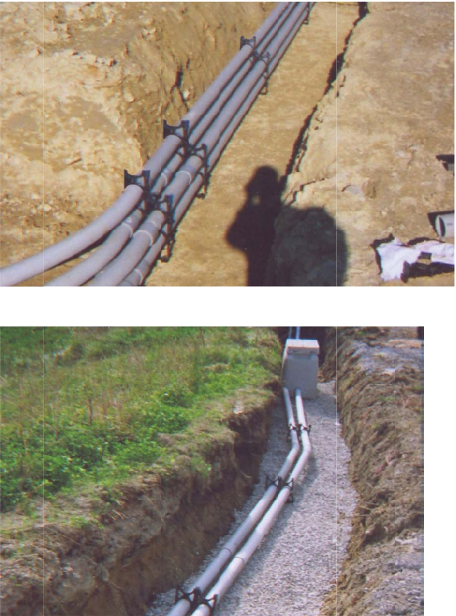
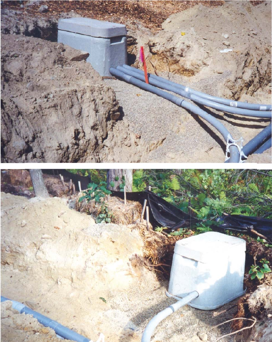
10.0 Conduit Installation
a. Conduit shall be installed, by Customer, in accordance with the Company Standards and
Construction Plans which accompany this specification package.
b. Plastic spacers shall be used to separate all ducts where more than one duct is installed. Spacers
shall not exceed eight foot intervals. Spacers shall be placed at each coupling. Spacers are required to
maintain proper separation from adjacent conduits and to aid in proper sand placement for thermal
reasons.
c. Type DB conduit shall be employed whether duct is direct buried or encased in concrete.
d. All galvanized steel sweeps at risers shall have a minimum radius of 36 inches. 48 inch radius
sweeps are required at transformer foundations and secondary handholes. See Page 13 for details.

Liberty Utilities / Supplement to Specifications for Electrical Installations / ESB 759A April 2014
10
For the latest authorized version, please refer to the company’s website at http://www.libertyutilities.com/electricalspecifications.
e. Curves and bends in conduit runs shall be gradual, and the radius of curvature shall not be less than
40 feet. Only five Degree Angled Couplings shall be used to make these gradual bends.
f. Conduit grade shall be such as to cause all ducts to drain toward one or both equipment foundations,
primary pull/splice boxes or handholes. Minimum pitch shall be three inches per 100 feet. Pull/splice
boxes may be required near riser pole if grade at pole is low compared to the first boxpad to alleviate
water buildup in risers.
g. Conduit shall have a maximum penetration inside walls of primary pull/splice boxes, equipment
foundations or handholes of three inches. All unused conduits and conduit knockouts shall be sealed
with conduit plugs. Bell ends shall be installed at the end of all conduit runs.
h. The minimum separation between electrical conduit and foreign conduit or pipes shall be
as follows:
Communication systems – 12 inches
Water, Gas and Sewer – 12 inches where the paths of these utilities intersect electrical
conduits at approximately right angles. A minimum separation of 24 inches shall be
maintained between parallel placement of any of these utilities and electrical conduits.
i. All road crossings shall, when practical, be perpendicular to the sidelines of the road.
j. All road crossings shall have 30 inch minimum burial depth, top of conduit to finished grade, for
primary and 24 inch minimum for secondary voltages. (including street lighting cable-in-conduit)
Main electric trench shall maintain conduit depths as shown in on Page 28. A primary burial depth
could be lessen to 24 inch minimum where supplemental protection is provided (i.e. concrete or steel
barrier). Approval of Company representative is required.
k. Where foreign objects threaten to interfere with the installation of conduit in the sidewalk area or
other areas, the Company may require concrete encasement of the conduit.
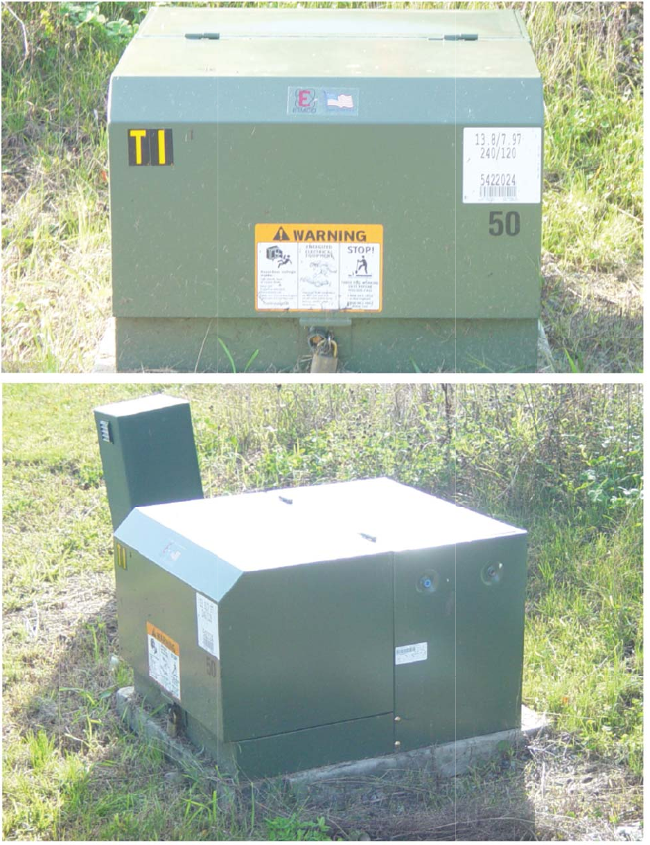
11.0 Transformer Box Pad Installation
All foundations shall be level and installed in accordance with drawing on Pages 12-13.
A minimum of four inches base course of crushed stone (3/4 in maximum stone size) shall be placed
under all transformer foundation excavations and thoroughly compacted using a vibratory compactor.
Certain soil conditions may require removal below normal depth and subsequent additional clean sand
or stone added and compacted to insure sound base course for foundation. For direct burial cable
installation, cables are to be surrounded by at least 4” of sand at base area crossing from the trench
into the box pad.
Transformer foundation top surfaces shall be four inches above final grade. In no instance shall final
grades hamper proper access or operation of equipment.
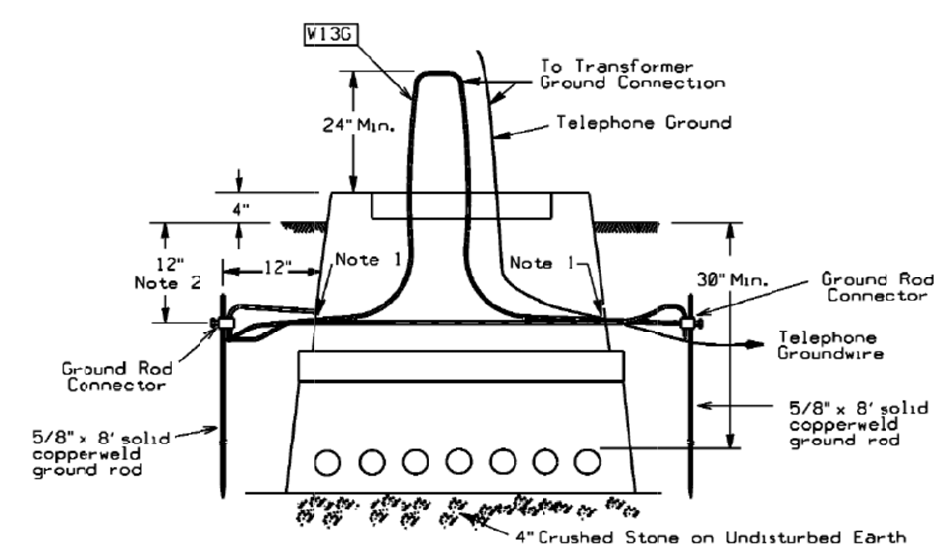
A buried ground grid shall be installed in accordance with details shown on Pages 14 and 15. Ground
loop around transformer to be buried 12” below finish grade (not at foundation base depth). Telephone
Company bond wires shall be tied to the ground grid. Such bonding or connection shall not interfere
with connecting Company equipment.

For th
e
R
e
q
U
s
e
T
I
n
i
n
12.0 Tran
s
Customer
approved
b
size of se
c
No more
t
with five
f
transform
e
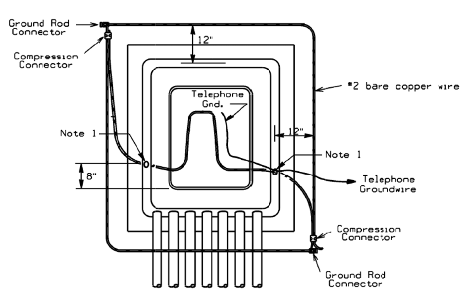
13.0 Tran
s
The grou
n
finished g
r
conduit a
n
Two ⅝in
c
12” belo
w
ground gr
i
b
e made
w
weld") sh
a
for the gr
o
transform
e
14.0 Spac
i
All com
mu
Also, co
m
NOT
E
reaso
n
they h
a
Libert
y
e
latest authorize
d
R
etaining wall
s
q
uipment, suc
U
pon completi
n
e
aled with
a
s
u
ransformer fo
n
some locati
o
n
stallation pro
s
former Seco
n
secondary se
r
b
y the wire i
n
c
ondary cable
t
han five seco
n
f
eet of slack c
o
e
r.
s
former Gro
u
n
d grid shall b
e
r
ade and loca
t
n
d leave three
h diameter, e
i
w
finished gra
d
i
d is to
b
e co
m
w
ith compress
i
a
ll be an acce
p
o
und grid con
n
e
r.
i
n
g
of Boxpa
d
u
nication bo
x
m
munication e
q
E
:
I
n most ins
t
n
ably level. Al
s
a
mper door o
p
y
Utilities / Supple
d
version, please r
e
s
or other dev
i
h as transfor
m
n
g the install
a
u
itable match
i
undation shal
l
o
ns oil contai
n
c
edure.
n
dar
y
r
vice wires en
t
n
spector or A
H
to be physica
l
n
dary service
s
o
iled inside t
h
u
ndin
g
and B
o
e
#2, bare, so
f
t
ed around th
e
feet of wire a
b
i
ght feet long
c
d
e. Leave the
g
m
plete and ba
c
i
on connector
s
p
table alternat
n
ections to th
e
d
s, Pull/Splice
es shall be a
m
q
uipment shal
t
ances, the C
o
s
o, all retaini
n
p
enings or pl
a
ment to Specifica
t
e
fer to the compan
y
i
ces shall be i
n
m
ers due to sh
a
a
tion of the tr
a
i
ng cover.
l
be complete
l
n
ment may be
t
ering the bo
x
H
J (Authority
H
l
ly connected
s
shall be con
n
h
e pad in orde
r
o
ndin
g
f
t drawn, 7 str
a
e
transformer
p
b
ove pad for
g
c
opper weld
g
g
round rods a
n
c
kfilled prior
t
s
as shown o
n
ive to a comp
r
e
ground rods.
boxes, and H
a
m
inimum of 2
l not be place
d
o
mpany shall
r
n
g walls shall
a
cement of su
c
th
e
t
ions for Electrica
l
y
’s website at htt
p
n
stalled wher
e
a
rp drop-off o
a
nsformer fou
n
l
y backfilled
p
required for
b
x
pad shall be
i
H
aving Juris
d
to the Compa
n
n
ected at any
C
r
to reach to t
h
a
nd copper w
i
p
ad as shown
g
rounding tra
n
g
round rods a
n
n
d grid expos
e
t
o energizing
t
n
Pages 14 an
d
r
ession conne
The Compan
y
a
ndholes
’ away from
a
d
in front of a
n
r
equire that e
q
fall outside o
f
c
h equipment.
e
Company.
l
Installations / E
S
p
://www.libertyu
t
e
slopes exist
t
o
r rise.
n
dation, the t
o
p
rior to com
m
b
ox pad instal
l
i
n accordance
d
iction) of the
ny's pad-mou
n
C
ompany sup
p
h
e secondary
c
i
re. The wire
s
on Page 14.
B
n
sformer.
n
d approved c
o
e
d until inspe
c
t
he transform
e
d
15. Howeve
r
ction. Bolted
ny
shall install
a
ny Company
b
ny Company
e
q
uipment eas
e
f
equipment e
a
Retaining wa
l
S
B 759A April 20
1
t
ilities.com/elect
r
t
hat would un
d
o
p opening sh
a
m
encing any c
a
l
ation, Pages
2
with the NE
C
town or city i
n
n
ted transfor
m
p
ly point. Ca
b
c
onnection p
o
s
hall
b
e instal
l
B
ond to all ex
p
o
nnectors sha
l
c
ted by the C
o
e
r. Connectio
n
r
exothermic
w
connectors ar
e
the ground ta
p
b
oxpad, pull
b
e
quipment.
e
ments on pri
v
asements and
l
l design shal
l
1
4
r
icalspecification
s
d
ermine or c
o
a
ll be securel
y
a
ble pulling.
2
0 and 21 sho
w
C
and shall be
n
volved. Ma
x
m
er is 500 kc
m
b
les shall be l
e
o
ints on the
l
ed 12 inches
b
p
osed metalli
c
l
l be installed
o
mpany. The
n
s to ground
g
w
elding ("cad
e
only accept
a
p
s onto the
b
ox or handho
l
v
ate property
b
in no case sh
a
l
be approved
11
s
.
o
ve
r
y
w
x
imum
m
il.
e
ft
b
elow
c
to
g
rid to
a
ble
l
e.
b
e
a
l
l
by
For th
e
15.0 Prop
e
Figure 15.
0
Libert
y
e
latest authorize
d
e
r Transform
0
-1 Preferred L
o
y
Utilities / Supple
d
version, please r
e
e
r Pad and C
o
o
cation of Equ
i
ment to Specifica
t
e
fer to the compan
y
o
nduit La
y
ou
t
i
pment in Ease
m
t
ions for Electrica
l
y
’s website at htt
p
t
m
ent Area
l
Installations / E
S
p
://www.libertyu
t
S
B 759A April 20
1
t
ilities.com/elect
r
1
4
r
icalspecification
s
12
s
.
For th
e
Figure 15.
0
15.0-3 Sin
g
Libert
y
e
latest authorize
d
0
-2 Single Phas
e
g
le Phase Padm
o
y
Utilities / Supple
d
version, please r
e
e
Padmount Tr
a
o
unt Transfor
m
ment to Specifica
t
e
fer to the compan
y
a
nsformer —
T
m
er — Direct B
t
ions for Electrica
l
y
’s website at htt
p
T
ypical Layout
urial Layout
l
Installations / E
S
p
://www.libertyu
t
S
B 759A April 20
1
t
ilities.com/elect
r
1
4
r
icalspecification
s
13
s
.
For th
e
16.0 Tran
s
Figure 16.
0
Notes:
1.
D
m
2.
G
3.
A
Libert
y
e
latest authorize
d
s
former Gro
u
0
-1 Single Phas
e
D
rill 5/8 inch
d
m
anufacturer.
G
round loop a
r
A
lthou
g
h cond
u
y
Utilities / Supple
d
version, please r
e
u
nd Grid Bon
d
e
Padmount Tr
a
d
iameter holes
r
ound founda
u
it s
y
stem is
s
ment to Specifica
t
e
fer to the compan
y
d
in
g
a
nsformer Gro
u
as shown in
s
tion to be bu
r
s
hown, direct
b
t
ions for Electrica
l
y
’s website at htt
p
u
nd Grid
s
ides of found
a
r
ied 12 inches
b
uried s
y
ste
m
l
Installations / E
S
p
://www.libertyu
t
ation if not p
r
below finish
g
m
s shall incor
p
S
B 759A April 20
1
t
ilities.com/elect
r
r
ovided b
y
fo
u
g
rade.
p
orate the sa
m
1
4
r
icalspecification
s
u
ndation
m
e
g
round
g
ri
d
14
s
.
d
.
For th
e
Figure 16.
0
Notes:
1.
D
m
2.
G
3.
A
Libert
y
e
latest authorize
d
0
-2 Single Phas
e
D
rill 5/8 inch
d
m
anufacturer.
G
round loop a
r
A
lthough cond
u
y
Utilities / Supple
d
version, please r
e
e
Padmount Tr
a
d
iameter holes
r
ound founda
u
it system is
s
ment to Specifica
t
e
fer to the compan
y
a
nsformer Gro
u
as shown in
s
tion to be bu
r
s
hown, direct
b
t
ions for Electrica
l
y
’s website at htt
p
u
nd Grid — F
r
s
ides of found
a
r
ied 12 inches
b
uried syste
m
l
Installations / E
S
p
://www.libertyu
t
r
ont Elevation
a
tion if not p
r
below finish
g
m
s shall incor
p
S
B 759A April 20
1
t
ilities.com/elect
r
r
ovided by fo
u
g
rade.
p
orate the sa
m
1
4
r
icalspecification
s
u
ndation
m
e ground gri
d
15
s
.
d
.
For th
e
17.0 Prop
e
17.0-1 Pro
p
17.0-2 Pro
p
Libert
y
e
latest authorize
d
e
r Transform
p
er Conduit Ba
n
p
er Installation
y
Utilities / Supple
d
version, please r
e
e
r Pad and C
o
n
k Installation
of Conduit wit
ment to Specifica
t
e
fer to the compan
y
o
nduit Install
a
(Pre-Backfill)
h
Pullbox used
t
ions for Electrica
l
y
’s website at htt
p
a
tions
for Drainage (
P
l
Installations / E
S
p
://www.libertyu
t
P
re-backfil)
S
B 759A April 20
1
t
ilities.com/elect
r
1
4
r
icalspecification
s
16
s
.
For th
e
17.0-3 Pro
p
Libert
y
e
latest authorize
d
p
er Conduit an
d
y
Utilities / Supple
d
version, please r
e
d
Handhole Ins
ment to Specifica
t
e
fer to the compan
y
tallation (Pre-
b
t
ions for Electrica
l
y
’s website at htt
p
b
ackfil)
l
Installations / E
S
p
://www.libertyu
t
S
B 759A April 20
1
t
ilities.com/elect
r
1
4
r
icalspecification
s
17
s
.
For th
e
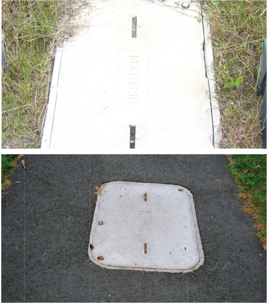
17.0-4 Pro
p
Libert
y
e
latest authorize
d
p
erly Complete
d
y
Utilities / Supple
d
version, please r
e
d
Transformer
ment to Specifica
t
e
fer to the compan
y
Installation (F
i
t
ions for Electrica
l
y
’s website at htt
p
i
nal Grade)
l
Installations / E
S
p
://www.libertyu
t
S
B 759A April 20
1
t
ilities.com/elect
r
1
4
r
icalspecification
s
18
s
.
For th
e
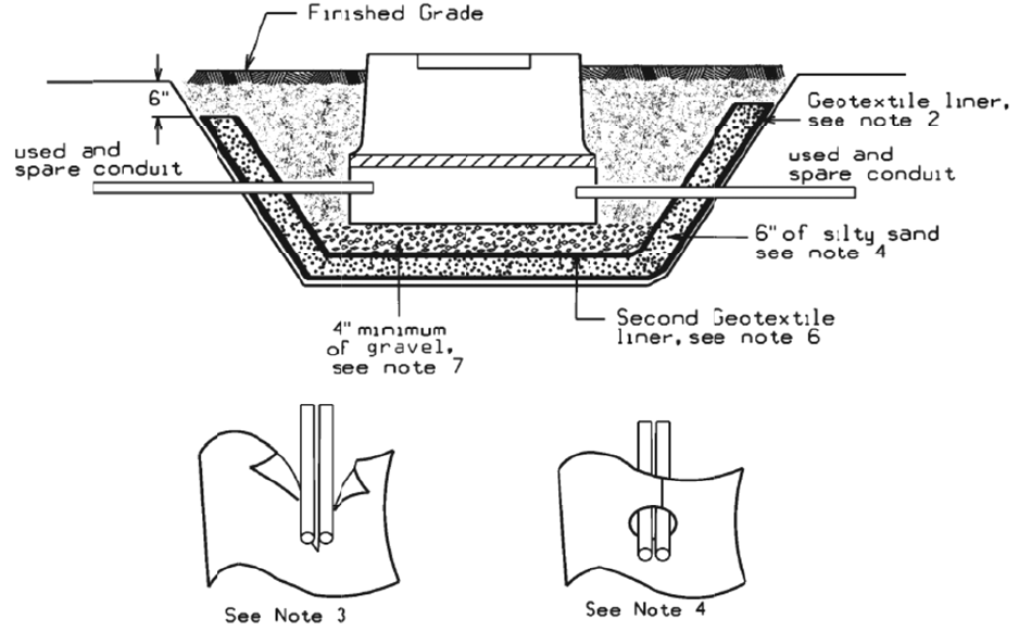
17.0-5 Pro
p
Libert
y
e
latest authorize
d
p
erly Complete
d
y
Utilities / Supple
d
version, please r
e
d
Handhole In
s
ment to Specifica
t
e
fer to the compan
y
s
tallations (Fin
a
t
ions for Electrica
l
y
’s website at htt
p
a
l Grade)
l
Installations / E
S
p
://www.libertyu
t
S
B 759A April 20
1
t
ilities.com/elect
r
1
4
r
icalspecification
s
19
s
.
For th
e
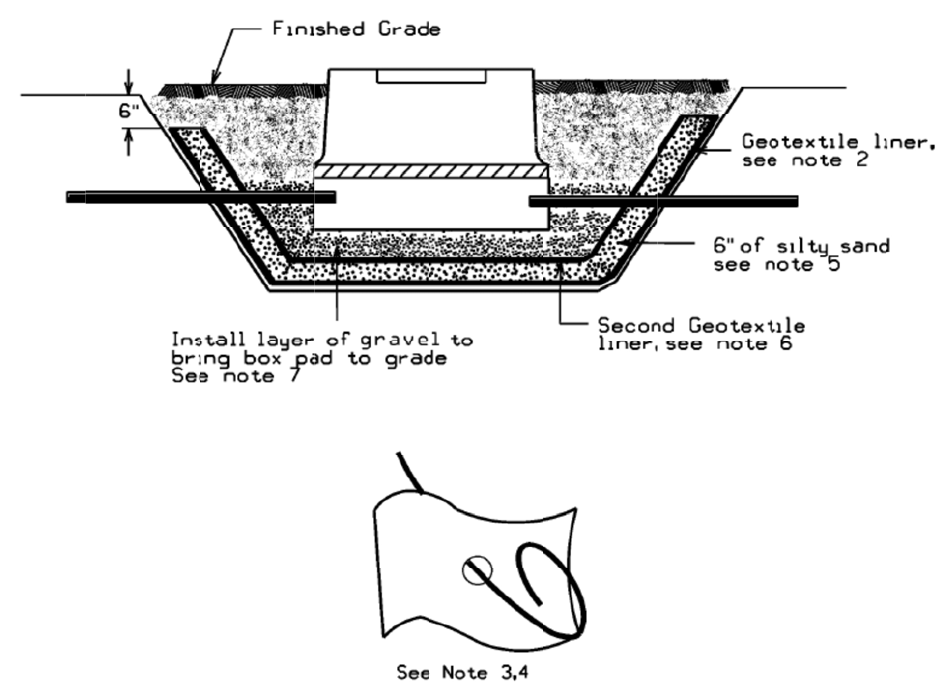
18.0 Tran
s
Figure 18.
0
NOTES:
1.
D
i
n
2. I
n
3.
M
4.
O
w
5. F
6. I
n
7. I
n
8. S
e
9. I
n
Libert
y
e
latest authorize
d
s
former Oil
C
0
-1 Single Phas
e
D
ig out as lea
s
n
to the pit.
n
stall geotext
i
M
ake vertical
O
verlap the li
n
w
ith expandi
n
ill in area wi
t
n
stall second
n
stall 4” min
i
e
t boxpad an
n
stall groun
d
y
Utilities / Supple
d
version, please r
e
C
ontainment
e
Oil Containm
e
s
t an additio
n
i
le liner in pi
t
cuts in liner
t
n
er flaps aro
u
g foam.
t
h 6” of com
p
layer of geot
e
i
mum of gra
v
d make up c
o
d
grid and ba
c
ment to Specifica
t
e
fer to the compan
y
e
nt for Cables
i
n
al foot on bo
t
t
along the b
o
t
o accommo
d
u
nd the cond
u
p
acted silty s
a
e
xtile liner b
y
v
el base for b
o
o
nduits into i
t
c
kfill after co
t
ions for Electrica
l
y
’s website at htt
p
i
n Conduit
t
tom and sid
e
o
ttom and si
d
d
ate conduits
.
u
it and seal
b
a
nd.
y
repeating s
t
o
xpad to be
a
t
.
mpany inspe
c
l
Installations / E
S
p
://www.libertyu
t
e
s for boxpa
d
d
es up to 6” f
r
.
b
oth liner sea
t
eps 2 and 3.
a
t proper gra
d
ction.
S
B 759A April 20
1
t
ilities.com/elect
r
d
area and st
u
r
om finished
m and in bet
w
de.
1
4
r
icalspecification
s
u
b conduits o
grade.
w
een condui
t
20
s
.
ut
t
s
For th
e
Figure 19.
0
NOTES:
1.
D
i
n
2. I
n
3.
M
4.
O
5. F
6. I
n
7. I
n
8. S
e
9. I
n
Libert
y
e
latest authorize
d
0
-2 Single Phas
e
D
ig out as lea
s
n
to the pit.
n
stall geotext
i
M
ake small h
o
O
nce cable is
p
ill in area wi
t
n
stall second
n
stall layer o
f
e
t boxpad, tr
n
stall groun
d
y
Utilities / Supple
d
version, please r
e
e
Oil Containm
e
s
t an additio
n
i
le liner in pi
t
o
les in the lin
e
p
ulled, seal t
h
t
h 6” of com
p
layer of geot
e
f
gravel for c
a
ain cables in
t
d
grid and ba
c
ment to Specifica
t
e
fer to the compan
y
e
nt for Direct
B
n
al foot on bo
t
t
along the b
o
e
r, feed liner
h
e liner arou
n
p
acted silty s
a
e
xtile liner a
n
a
ble routing
a
t
o boxpad an
d
c
kfill after co
t
ions for Electrica
l
y
’s website at htt
p
B
uried Cables
t
tom and sid
e
o
ttom and si
d
through hol
e
n
d the cable
w
a
nd.
n
d cut holes
fo
a
nd base for
b
d
fill on top
o
mpany inspe
c
l
Installations / E
S
p
://www.libertyu
t
e
s for boxpa
d
d
es up to 6” f
r
e
s into pit.
w
ith expandi
n
f
or cables as
i
b
oxpad to be
o
f cables wit
h
ction.
S
B 759A April 20
1
t
ilities.com/elect
r
d
area and st
u
r
om finished
n
g foam.
i
n note 2.
e
at proper g
r
h
sand.
1
4
r
icalspecification
s
u
b conduits o
grade.
r
ade.
21
s
.
ut

Liberty Utilities / Supplement to Specifications for Electrical Installations / ESB 759A April 2014
22
For the latest authorized version, please refer to the company’s website at http://www.libertyutilities.com/electricalspecifications.
Geo-textile Liner
Generic name is: 16 oz. polypropylene geotextile. Also called filter fabric weighing 16 oz./square yard.
Brand names / Suppliers are:
AME1680 available from
American Engineering Fabrics (AEF), Inc.
(Emphasize polypropylene not polyester)
New Bedford, MA
1-617-965-0007 / 1-800-770-2666 or from
Vellano Bros. Lancaster, NY
1-716-684-7222
Several other locations in New York, Massachusetts, Rhode Island and New Hampshire
www.vellano.com
Synthetic Industries ST 160 available from
Spartan Mills Inc
Spartanburg, NC
1-803-576-2353
Carthage Mills FX-160HS
US Construction Fabrics LLC
90 Range Road
Windham, NH 03087
1-603-898-0532
For th
e
19.0 Rise
r
The Com
p
this inclu
d
at least 8’
The Cust
o
the bond
c
b
onded al
s
Libert
y
e
latest authorize
d
r
Pole
p
any shall des
i
d
es the 90 deg
r
high from fin
o
mer is respo
n
c
onnection fr
o
s
o. Approved
y
Utilities / Supple
d
version, please r
e
i
gnate condui
t
r
ee sweep. Pe
r
ished grade.
n
sible for prov
m the riser b
o
materials ref
e
ment to Specifica
t
e
fer to the compan
y
t
riser locatio
n
r
NESC all st
e
iding and inst
o
nd tap to the
g
e
rence is locat
e
t
ions for Electrica
l
y
’s website at htt
p
n
s on the pole.
e
el risers mus
t
alling the bo
n
g
round syste
m
e
d on Page 3
2
l
Installations / E
S
p
://www.libertyu
t
.
All primary
r
t
be
b
onded 6
”
n
d clamps and
m
on the pole.
2
.
S
B 759A April 20
1
t
ilities.com/elect
r
r
isers shall be
”
from top an
d
the tap. The
C
Spare riser s
w
1
4
r
icalspecification
s
Galvanized
S
d
the bond m
u
C
ompany will
w
eep shall be
23
s
.
S
teel,
u
st be
make
For th
e
Properly
Riser Pol
e
Rigid Gal
v
least 6” fr
o
Libert
y
e
latest authorize
d
Installed Pri
m
e
Bonding
v
anized Steel.
o
m top.
y
Utilities / Supple
d
version, please r
e
m
ary Risers
Bond highe
r
Sp
a
Sp
a
gr
o
ment to Specifica
t
e
fer to the compan
y
than 8’ and a
t
a
re Riser Sw
e
a
re sweep sha
l
o
und and capp
t
ions for Electrica
l
y
’s website at htt
p
t
Compl
e
The Co
m
pole th
e
e
ep
l
l be bonded t
o
ed at riser pol
l
Installations / E
S
p
://www.libertyu
t
e
ted Riser P
o
m
pany will s
p
e
riser shall b
e
o down
l
e.
S
B 759A April 20
1
t
ilities.com/elect
r
o
le
p
ecify on whi
c
e
installed, aw
1
4
r
icalspecification
s
c
h quarter of t
h
ay from traffi
c
24
s
.
h
e
c
.
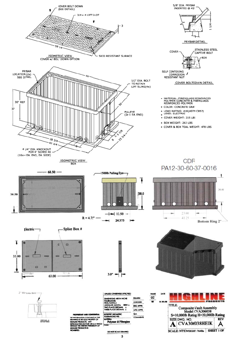
For th
e
20.0 Prim
a
This prim
a
where du
c
installed i
n
the Custo
m
Libert
y
e
latest authorize
d
a
r
y
Cable Pu
l
a
ry conduit e
q
c
t length or de
n
locations n
o
m
e
r
.
y
Utilities / Supple
d
version, please r
e
l
l/Splice Box
q
uipment may
sign requires
e
o
t frequently t
r
ment to Specifica
t
e
fer to the compan
y
be specified
i
e
xtra pulling
l
r
aveled ove
r
b
t
ions for Electrica
l
y
’s website at htt
p
i
n the design
f
l
ocations or s
p
y vehicles. P
u
l
Installations / E
S
p
://www.libertyu
t
f
or installatio
n
p
lices. The sp
l
u
ll/splice box
e
S
B 759A April 20
1
t
ilities.com/elect
r
n
in sidewalks
l
ice box is H2
0
e
s are supplie
d
1
4
r
icalspecification
s
or grass plot
a
0
rated and s
h
d
and installe
d
25
s
.
areas
h
all be
d
by
For th
e
Properly
Libert
y
e
latest authorize
d
Installed Pri
m
y
Utilities / Supple
d
version, please r
e
m
ary Pullbo
x
ment to Specifica
t
e
fer to the compan
y
x
t
ions for Electrica
l
y
’s website at htt
p
l
Installations / E
S
p
://www.libertyu
t
S
B 759A April 20
1
t
ilities.com/elect
r
1
4
r
icalspecification
s
26
s
.
Liberty Utilities / Supplement to Specifications for Electrical Installations / ESB 759A April 2014
27
For the latest authorized version, please refer to the company’s website at http://www.libertyutilities.com/electricalspecifications.
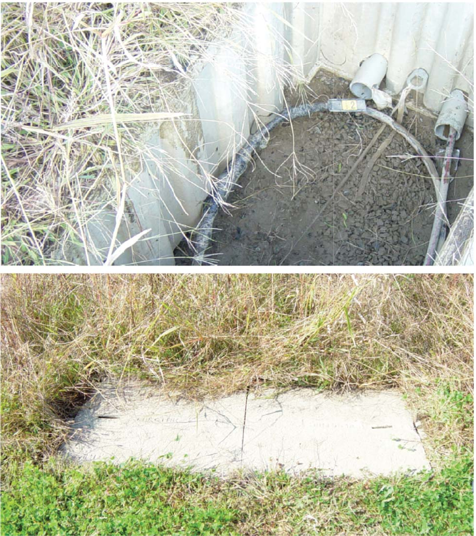
21.0 Trench Requirements
Final grades shall be established; the surface rough graded within 6” of finished grade, and roadway and
property boundaries shall be staked or marked by the Customer before any trenching is started.
The Customer shall adhere to the construction plan and specifications regarding trench locations, trench depth,
and concrete encasement. Any deviation shall be subject to approval by the Company.
The Company shall be notified in advance of the backfilling of any electric facility. The Company reserves the
right to require re-excavation of the conduits and foundations if the Customer fails to have inspection done or
backfills before inspection.
For special circumstances that call for concrete encasement, such as crossing a culvert or stream, trenches
shall not be backfilled until concrete has set (for at least two hours) and after approval by authorized Company
personnel. All backfill shall be sand or gravel containing stones less than 1" in any dimension. Backfilling
shall not take place over any open-ended (unplugged) conduits. Company approved red “Warning” tape shall
be installed directly above the Company’s cable eight to 12 inches below finished grade. Laying the warning
tape directly on the cable, concrete or conduit is not acceptable. Certain installations in the public way may
require flowable fill instead in place of normal backfill.
21.1 Trench Depth Concrete Encased Conduit
Burial depths for electrical conduit shall be maintained not less than 30" from the top of the concrete
encasement to grade during all phases of construction. The trench bottom shall be solid, undisturbed earth.
Earth showing signs of peat, cinders, rubble, or any conditions not suitable for a stable foundation shall be
reported to the Company for recommendation. Small pockets of unsuitable soil shall be replaced with
compacted gravel (maximum 2" stone). At riser pole, end concrete encasement just before riser sweep.
For th
e
Figure 21.
0
Conduit T
r
Legend
B
a
In
t
Se
c
Pr
C
o
S
p
22.0 Con
d
The Cust
o
duct syste
m
b
e provid
e
of Respo
n
22.1 Pulli
n
All condu
i
tensile str
e
22.2 New
The Cust
o
located. F
o
direct the
Libert
y
e
latest authorize
d
0
-1 Typical Tre
n
r
ench
a
se Spacer
t
ermediate Spac
e
c
ondary Electric
imary Electric D
u
o
mmunication D
u
p
are Duct
d
uit Require
m
o
mer shall be
r
m
. The Custo
m
e
d and install
e
n
sibility.
ng
Tape
i
ts shall have
e
ngth. Manuf
a
Hampshire:
o
mer shall asc
e
o
r example, s
o
i
nstallation o
f
y
Utilities / Supple
d
version, please r
e
n
ches
e
r
Duct
u
ct
u
ct or Cable
m
ents
r
esponsible fo
r
m
er is also re
s
e
d by the Cust
o
a
pulling tape
a
cturers of thi
s
e
rtain the req
u
o
me municip
a
f
all conduit i
n
ment to Specifica
t
e
fer to the compan
y
Libert
y
Libert
y
and/or
Comm
u
Sand o
r
shall n
o
may b
e
sandy l
r
all trenchin
g
s
ponsible to i
n
o
mer as speci
f
, also known
a
s
tape are list
e
u
irements of t
h
a
lities may re
q
n
tended for el
e
t
ions for Electrica
l
y
’s website at htt
p
Condui
t
y
Utilities Primar
y
y
Utilities Electri
c
Street Light Ca
b
u
nication Cable
r
Rock-Free San
d
o
t be acceptable.
S
reused if sand o
r
oam.)
g
, excavation,
n
stall any nec
e
f
ied by the C
o
a
s “Mule Tap
e
e
d on Page 34
.
h
e specific m
u
q
uire that the
C
e
ctric facilitie
s
l
Installations / E
S
p
://www.libertyu
t
t
in Concrete
T
y Cable
c
secondary
b
le
d
y Loam (Clay
Site material
r
rock free
backfilling, a
n
e
ssar
y
pullbo
x
o
mpany when
e
.” This tape
i
.
u
nicipality in
w
C
ustomer em
p
s
.
S
B 759A April 20
1
t
ilities.com/elect
r
T
rench
n
d installatio
n
x
es. Concrete
e
required. Re
fe
i
s to be rated
f
w
hich the dev
p
loy a license
d
1
4
r
icalspecification
s
n
of the prima
r
e
ncasement s
h
fe
r to 6.0 Divi
s
f
o
r
2,500 lbs.
o
v
elopment is
d
electrician t
o
28
s
.
r
y
h
all
s
ion
o
f
o
Liberty Utilities / Supplement to Specifications for Electrical Installations / ESB 759A April 2014
29
For the latest authorized version, please refer to the company’s website at http://www.libertyutilities.com/electricalspecifications.
Temporary mechanical protection over buried conduit and encasements is recommended to prevent crushing or
damage during construction, and is the Customer’s responsibility.
All road crossings shall, when practical, be perpendicular to the sidelines of the road.
The minimum conduit size shall be 4” for three phase and 3” for single phase cable installations. All sweeps at
foundations and risers shall have a minimum radius of 36 inches. The riser sweep shall be galvanized steel.
The Customer shall install conduit plugs in all unused conduits and pulling tape. At the riser pole, the
galvanized rigid steel sweeps and the PVC/steel adaptors shall not be concrete encased. The Customer shall be
responsible to install rigid galvanized steel straight conduit up the pole high enough to meet NESC code
referenced on the riser pole requirements on Page 23, including conduit ground straps, up the riser pole (unless
directed otherwise by the Company). The Company will specify on which quarter of the pole the riser shall be
installed, usually away from oncoming traffic.
Except as noted on construction prints, curves and bends in conduit shall be gradual, and the radius of
curvature shall not be less than 40 feet. All curves shall be formed with five-degree couplings. The minimum
length between single, five-degree couplings is 42".
Conduit grade shall be such as to cause all ducts to drain toward one or both equipment foundations or
pullboxes. Minimum pitch shall be three inches per 100 feet.
The Customer shall insure that clearances are met and maintained, and that they are inspected by the Company.
Unless local jurisdictions require greater clearances, the minimum clearances shall be as follows:
22.3 Communication Systems – Company conduit shall not be directly above or below communication
conduit, except when crossing below communication conduit at approximately right angles. Company conduit
and communication conduit shall be separated by a minimum of 3" of concrete encasement.
22.4 Non-Company Water, Gas and Sewer – Company conduit shall not be directly above or below any of
these foreign utilities, except when crossing above these utilities at approximately right angles. Where the
paths of these foreign utilities cross under Company conduits at approximately right angles, the minimum
separation is 12". A minimum separation of 24" shall be maintained between parallel placement of any of these
utilities and electrical conduit.
A six-inch clearance shall be between conduit envelopes and major subsurface pipes (e.g. drainage pipes).
The Customer shall rod and mandrel all primary conduits to insure their integrity before the Company shall
attempt to pull any primary cable. The Customer shall furnish and install an approved synthetic, 2,500 pound
test tape in each primary conduit run including risers. Pulling tape installation and rodding the duct shall be
witnessed by the Company.
Company-owned duct shall not share a concrete encasement with foreign utilities (e.g. do not place
communication or private electrical duct in the same concrete encasement as Company duct).
At those locations where manholes or above ground switchgear are required, additional specifications will be
provided by the Company.
23.0 Metering
Refer to the Company’s Specification for Electrical Installations book for the type of installation. Division of
work and material will be performed with the approval and authorization of the Company’s Metering Services
department. In most instances, the Company will furnish, install, own, maintain and connect all meters
required for billing purposes at the delivery voltage on the customer’s side of the service point.

Liberty Utilities / Supplement to Specifications for Electrical Installations / ESB 759A April 2014
30
For the latest authorized version, please refer to the company’s website at http://www.libertyutilities.com/electricalspecifications.
24.0 Easement Applications Form
LIBERTY UTILITIES EASEMENT APPLICATION FORM
FOR LIBERTY UTILITIES’ USE ONLY
Application for Easements (check one): ❒ OH (jointly owned or solely owned)
❒ Padmount transformer only
❒ UG
❒ URD
❒ Electric
❒ Gas
Work Request Number ______________________________________________________________________________
Utility Engineer’s Name: ___________________________________________ Telephone Number: _________________
Please complete ALL of the sections below so that we may prepare an easement for your signature.
Do not leave any sections unanswered. If a section does not apply to you simply put “n/a” on that line.
Incorrect or incomplete information will delay service installation.
Property Owner(s): __________________________________________________________________________________
Property Owner Mailing Address Property Address of Easement
(if different from mailing address)
Address: Address:
City:
City:
State & County
State & County
Zip
Zip
Customer Contact Person:
Daytime Phone(s):
Re: Subdivision Title:
1. Provide us with a RECORDED copy of the present owner’s deed, Book________ Page________
a) If multiple deeds make up the whole parcel, please include all deeds.
b) If the Property Owner is a b1) CORPORATION, b2) TRUST, b3) PARTNERSHIP, or b4) LIMITED
LIABILITY COMPANY, provide the following which is applicable:
b1) President Name: _____________________Treasurer Name: _____________________________
See Footnote1 Below
Or
Vice President:________________________Asst. Treasurer:_______________________________
1 If neither “Name Combinations” is available, the person(s) signing the easement must have a Corporate vote authorizing them to sign on behalf of the
Corporation.

For th
e
2. a
)
b
)
3. I
s
I
f
a)
N
b)
A
c)
D
D
Additional
C
Pleas
e
Libert
y
e
latest authorize
d
b
2) Tr
u
Name
o
b
3) Pa
r
b
4) LL
C
)
Provide us wi
t
Plan Book:__
_
If there is no r
e
Assessor’s Ma
p
s
your property
f
“YES”, please
N
ame of Bank/
C
A
ddress of mort
g
D
ate and recordi
n
D
ate:_________
C
omments:
contact your
A
y
Utilities / Supple
d
version, please r
e
u
st: No. Of Tru
s
o
f Trust:_____
_
r
tnership: Num
b
C
: Authorizati
o
t
h an approved:
_
___________
_
e
corded subdiv
i
p
:__________
_
mortgaged (cir
c
complete this
s
C
ompany/Perso
n
g
age holder(s):
n
g information
County Recor
d
A
ccount Manag
e
ment to Specifica
t
e
fer to the compan
y
s
tees:________
_
_
___________
_
b
er of Partners:
_
o
n to Sign, Na
m
“Definitive S
u
_
______ Plan:_
_
i
sion plan pleas
_
______Block:
_
c
le one)?
s
ection:
n
holding mort
g
___________
_
of mortgage(s
)
d
ed:_________
_
e
r or Service A
d
t
ions for Electrica
l
y
’s website at htt
p
_
___________
_
_
___________
_
_
___________
_
m
e(s):________
_
u
bdivision Plan
”
_
___________
_
e include the f
o
_
___________
_
YES
g
age(s):______
_
_
___________
__
: __________
_
_
_______ Boo
k
d
ministrator if
y
l
Installations / E
S
p
://www.libertyu
t
_
__Name(s):
__
_
__________
__
_
_Name(s):__
_
_
__________
__
”
__
______ Date
d
o
llowing infor
m
_
________ and
NO
_
___________
_
_
___________
_
_
______
_
____
_
k
:__________
_
y
ou have any
q
S
B 759A April 20
1
t
ilities.com/elect
r
_
___________
_
_
___________
_
_
___________
_
_
___________
_
d
:___________
_
m
ation:
Lot:________
_
_
___________
_
_
___________
_
_
___________
_
_
___ Page:___
_
q
uestions regar
d
1
4
r
icalspecification
s
_
___________
_
_
___________
_
_
___________
_
_
____
_
______
_
_
__________
_
___________
_
______
_
________
_
________
_
_________
d
ing this form.
31
s
.
_
____
_
_____
_
_____
_
____

Liberty Utilities / Supplement to Specifications for Electrical Installations / ESB 759A April 2014
32
For the latest authorized version, please refer to the company’s website at http://www.libertyutilities.com/electricalspecifications.
25.0 Approved Material – Underground Residential Development (URD) Installations
Liberty Utilities
Item ID Item Description Manufacturer 1
Part Number Manufacturer 2
Part Number Manufacturer 3
Part Number
Conduit – Straight
8830-2010404 Conduit DB, 4", PVC Carlon: 48815 IPEX: 8741 Cantex: A79EA42
8830-2011024 Conduit, Galvanized, 4" By Description
8830-5692158 Conduit DB, 3", PVC Carlon: 48815 IPEX: 8731 AMERICAN PIPE
TC7215752
8830-5692107 Conduit, Galvanized, 3" BAYNEJONES
300R
Conduit—Blends
8830-5690446 Bend, Galvanized, 4"
36” BaynesJones
400R9036
Conditmfg
TUB490D36RGA
LEL
8830-5690493 Bend, PVC Sch 40, 4",
90 Degree, 36" Rad. Carlon: UA9FNB Cantex: 5233842
8830-5690436 Bend, Galvanized, 3"
36” BaynesJones
400R9036
Conditmfg
TUB490D36RGA
LEL
8830-5690419 Bend, PVC DB, 3",
90 Degree, 36" Rad. Carlon: PF9FL Cantex: 5123872 Certisaft 59734
Spacers
8830-5646963 Spacer, 4", Base GS Industries: 186-1 IPEX: 29573
8830-5646960 Spacer, 4", Inter. GS Industries: 185-1 IPEX: 29557
8830-5646958 Spacer, 3", Base GS Industries: 157-1 IPEX: 29569
8830-5646956 Spacer, 3", Inter. GS Industries: 156-1 IPEX: 29553

Liberty Utilities / Supplement to Specifications for Electrical Installations / ESB 759A April 2014
33
For the latest authorized version, please refer to the company’s website at http://www.libertyutilities.com/electricalspecifications.
Liberty Utilities
Item ID Item Description Manufacturer 1
Part Number Manufacturer 2
Part Number Manufacturer 3
Part Number
Conduit Accessories
8830-5641210 Riser Strap, 4” Electrical Materials:
50-4 USHD
BaynesJones
MINRLAC
HD-296
8830-5641205 Riser Strap, 3” Electrical Materials:
50-3 USHD
BaynesJones
MINRLAC
HD-294
8830-7011830 Lag Screw, ¼” x 2” Elect. Materials:
106 or 106M Joslyn J26486.1 PLH
LSNW-142
8830-3503074 Pipe Grd. Connector,
4” and 5” T & B:
(0)3905-BU Burndy
GAR3905-BU
8830-3503075 Pipe Grd. Connector,
2.5” and 3.5” T & B: (O)3904-BU
Burndy: GAR3904-BU
8830-2010424 Duct Plug, 4” DB Carlon: P258NT BGAR3905-BU
8830-5645682 Duct Plug, 3” DB CSNTEX:
5315260 CARLON:
P258L CERTIFSAFT:
59653
8830-2011254 Duct Plug
Galvanized 4” Crousehind PLG105
8830-9201659 Duct Plug
Galvanized 3”
8830-2010434 Adapter, Female,
PVC-Steel, 4” Carlon: E942N Cantex: 5140052 Scepter FA55
8830-2010433 Adapter, Female,
PVC-Steel, 3” Carlon: E942N OZGEDNEY: PLG-
300C
8830-5693359 Coupling, 5 Degree,
Bell-Spigot, 4” Carlon: E244N Cantex: 6151452 Certisaft 59544
8830-5693356 Coupling, 5 Degree,
Bell-Spigot, 3” Cantex: 6151450 Carlon: E244L
8830-2010444 Coupling, 5 Degree,
Bell-Bell, 4” Ameripipe: FT518 Carlon E2440NF Scepter
7604360040
8830-5100696 Coupling, 5 Degree,
Bell-Bell, 3”0 Ameripipe: NS141 Carlon: 6151458
8830-2010454 Straight Coupling, 4”,
EB/DB Carlon: E240N Cantex: 6151450
8830-2010453 Straight Coupling, 3”,
EB/DB Cantex: 6151450 Carlon: E2544L

Liberty Utilities / Supplement to Specifications for Electrical Installations / ESB 759A April 2014
34
For the latest authorized version, please refer to the company’s website at http://www.libertyutilities.com/electricalspecifications.
Liberty Utilities
Item ID Item Description Manufacturer 1
Part Number Manufacturer 2
Part Number Manufacturer 3
Part Number
Grounding Accessories
8830-961285 Grounding
Bushing,
4" and 5”
Burndy
GAR3905-BU T&B:
(0)3905-BU
8830-3500313 Grounding Rod
5/8’ x 8’
Solid Copperweld
Galvin
6258 ERITECH
615880 Joslyn:
J8338
8830-4015032 #2 AWG,
7 strand,
soft drawn
South Wire -
By description
8830-3503328 Ground Rod
Clamp Burndy: GRC58 Blackburn:
JAB58H Electromotion
EM58DBW
8830-5960412 “C” Connector,
2/0 – 2/0 Burndy:
YC26C26TN
Primary Pull/Splice box, Secondary Handholes and transformer foundations
Graybar – Manchester, NH
8830-5640808 Primary Pull/Splice
Box Quazite (Hubbell):
PA12-3060-37-0271 Highline:
CVA306038HEIK
8830-5643082 Secondary
Handhole Quazite (Hubbell):
PA10-1730-30-0319 Highline:
CHA173030SE1-NG
8830-5642500 Transformer
Foundation Quazite (Hubbell):
BP10-3843-42-0096 Highline:
PBP374342NEPS
Other Materials
Secondary
Connections Bundy Richards
Pulling Tape Arnco: DLWP25 Condux: 08096303 Neptco: WP2500P
Liberty Utilities / Supplement to Specifications for Electrical Installations / ESB 759A April 2014
35
For the latest authorized version, please refer to the company’s website at http://www.libertyutilities.com/electricalspecifications.
26.0 Job Checklists
URD CONDUIT INSPECTION CHECKLIST
Do not back fill BEFORE conduit system inspection and approval by the Company have been
obtained. Every item below must be inspected and checked off by the Company representative.
Any item found unacceptable must be initialed and rectified by Customer by next inspection.
N* Y* PRE-TRENCH
❒ ❒ Final Grade established
❒ ❒ Surface rough graded
❒ ❒ Roadways staked
TRENCH
❒ ❒ Minimum 30” depth from finishing grade to top of primary conduit
❒ ❒ Minimum 24” depth from finishing grade to top of secondary conduit
❒ ❒ Minimum 12”separation between Electric conduits and Telecommunications conduits
❒ ❒ Min, 24” separation between Electric conduits and water, sewer or gas if placing parallel
❒ ❒ Minimum 12” separation between Electric conduits and water, sewer or gas if placing perpendicular
❒ ❒ Conduit plugs installed
❒ ❒ Plastic spacers properly installed no more than every 8’ and at every junction point
❒ ❒ 4” screened backfill (with less than 1” stones) on-site for backfilling entire trench,
(inspector may witness backfilling)
❒ ❒ Warning tape installed 12” below finish grade and directly above electrical conduit system
❒ ❒ All curves properly formed with five degree couplings
❒ ❒ No parallel utilities directly above electrical system
Secondary Handhole
❒ ❒ 4” crushed stone under handhole
❒ ❒ Handhole covers installed and properly secured with pentahead bolts
❒ ❒ Top surface flush with final grade
❒ ❒ Conduit plugs installed from the outside in all unused conduit knockouts
❒ ❒ No more than 3” of extended PVC into handhole
Transformer Foundation
❒ ❒ 4”of crushed stone under transformer foundation
❒ ❒ Top surface 4” above final grade
❒ ❒ No more than 3” extended PVC through foundation
❒ ❒ Pulling eyes properly installed in front and back of box pad (ring part on the inside)
❒ ❒ Conduit plugs installed from the outside in all unused conduit knockouts
❒ ❒ Two ground rods installed at opposite corners of foundation – exposed for inspection
❒ ❒ Ground grid buried 12" below finish grade and placed 12" away from edge of boxpad
❒ ❒ Loop ground grid around and into foundation through two sides of foundation
❒ ❒ Correct orientation to road and lot lines
❒ ❒ All non-Company owned pedestals are a minimum of 2’ away from all sides
Pullbox
❒ ❒ 4” or crushed stone under pullbox foundation
❒ ❒ Pullbox covers installed and properly secured with pentahead bolts
❒ ❒ Top surface flush with final grade
❒ ❒ No more than 3” extended PVC into pullbox
❒ ❒ Conduit plugs installed from the outside in all unused conduit knockouts
❒ ❒ All non-Company owned pedestals are a minimum of 2’ away from all sides
RISER POLE
❒ ❒ 90° bend and 10’ straight riser pipe galvanized steel conduit. (3” for single Phase, 4” for three phase)
❒ ❒ Steel-PVC adapter and steel sweep shall not be encased in concrete
❒ ❒ Ground clamp installed with tap
❒ ❒ Install 2500 lb. Pulling Tape in all conduit after rodding with mandrell
*NOTE Y – Acceptable N – Deficient

Liberty Utilities / Supplement to Specifications for Electrical Installations / ESB 759A April 2014
36
For the latest authorized version, please refer to the company’s website at http://www.libertyutilities.com/electricalspecifications.
27.0 Revision History
Date Rev # Description Author/Lead Person
07/03/12 0 Initial version of document Robert J. Johnson
04/01/14 1.0 Update to reflect new Liberty Utilities Policy 2 Line
Extension Policy for Residential Developments (URD) Robert J. Johnson

Liberty
Utilities is an
independen
t
w
a
ter
,
natural
gas,
and electric company providing local
utility
management, service
and
suppor
t
to small and mid-
sized
communities
across
the
United
States.
Serving over
470
,
000
customers in ten states, Liberty
Utilities is committed
to local
decision
making tha
t
dir
ec
t
ly meets the
needs
of its
customers.
This means
providing walk in customer
service cen
t
ers
,
creating
jobs,
and providing
responsive
and
reliable service
. As
a
company, Liberty
Utilities promotes local
conservation
and
energy
efficiency initiatives and
programs
for
businesses
and r
esiden
t
ial
customers,
including the
low-income
sec
t
or
.
The company measures
its performance on customer
experience,
public
and workplace
safety,
and
service
reliability
.
Liberty
Utilities currently
opera
t
es
in
Arizona,
Arkansas,
C
alif
ornia,
Illinois
,
Iowa, Georgia, Massachusetts, Missouri,
New
Hampshire, and Texas.
For
more information,
please
visit www
.Liber
tyUtilities.c
om.
Liberty Utilities
15 Buttrick Rd
Londonderry, NH 03053
1
-
800
-
375-7
413
www.libertyutilities.com
