Brochure
51699-Attachment 51699-Attachment 51699-Attachment 785901 Batch5 unilog cesco-content
69709-Catalog 69709-Catalog 69709-Catalog 785901 Batch5 unilog cesco-content
111400-Catalog 111400-Catalog 111400-Catalog 785901 Batch6 unilog cesco-content
2016-07-29
: Pdf 1000256006-Brochure 1000256006-Brochure B2 unilog
Open the PDF directly: View PDF ![]() .
.
Page Count: 64
7-1
© 2012 Schneider Electric
All Rights Reserved
7MINIATURE AND MOLDED CASE
CIRCUIT BREAKERS
Table of Contents
Section 7
Miniature and Molded Case Circuit Breakers
H-Frame J-Frame
L-Frame
M-Frame
P-Frame
R-Frame
Selection Information 7-2
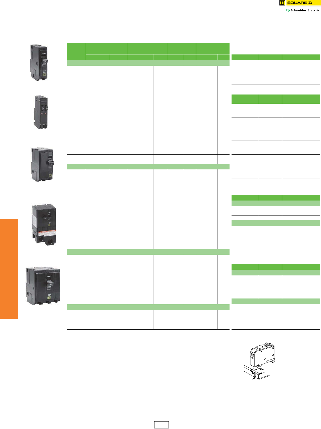
QO™ and QOU Miniature Circuit Breakers 7-10
QO™ Miniature Circuit Breakers 7-10
QO™ Circuit Breaker Accessories 7-12
QO™ and Multi 9™ Mounting Bases 7-13
QOU Miniature Circuit Breakers and QYU Supplementary Protectors 7-14
QOU Accessories 7-15
Multi 9™ Miniature Circuit Breakers 7-16
PowerPact™ Molded Case Circuit Breakers 7-21
PowerPact Family 7-21
H- and J-Frame Circuit Breakers 7-22
Q-Frame Circuit Breakers 7-24
L-Frame Circuit Breakers 7-25
M-Frame Circuit Breakers 7-26
P-Frame Circuit Breakers 7-27
R-Frame Circuit Breakers 7-28
Motor Circuit Protectors 7-29
PowerPact™ H- and J-Frame Electronic Motor Circuit Protectors 7-29
H-Frame and J-Frame MCP Selector 7-30
Motor Circuit Protectors and Motor Protector Circuit Breakers 7-31
H-, J-, and LA-Frame MCP Selection 7-32
Motor Protection Selection Tables 7-33
Automatic Switches 7-34
500 Vdc Circuit Breakers 7-35
Mission Critical Circuit Breakers 7-37
PowerPact™ Circuit Breaker Accessories 7-39
Micrologic™ Electronic Trip Units 7-46
Masterpact™ Universal Power Circuit Breakers 7-50
Ground-Fault Protection 7-51
Dimensions and Shipping Weights 7-54
Circuit Breaker Enclosures 7-56
Photovoltaic Circuit Breakers and Switches 7-59
7-2 © 2012 Schneider Electric
All Rights Reserved
www.schneider-electric.us
7MINIATURE AND MOLDED CASE
CIRCUIT BREAKERS
Selection Information Miniature Circuit Breakers
Class 500, 600
HOM Circuit Breakers QO™ Circuit Breakers
Circuit
Breaker
Type
Plug-on HOM HOM-
CAFI
HOM-
DF
HOM-
GFI
HOM-
EPD HOMT QO QO-H QO-VH QH QOT QO-
CAFI
QO-
VHCAFI
QO-
DF
QOVH-
DF QO-GFI QO-
VHGFI
QO-EPD
QO-EPE
Bolt-on —— — — ———— — QOB QOB-
H— — — QOB-VH QHB — QOB-
CAFI
QOB-
VHCAFI
QOB-
DF
QOB-
VHDF QOB-GFI QOB-
VHGFI
QOB-EPD
QOB-EPE
Unit Mount —— — — ———— — — — ———— — — — — — — — — ——— — — — —
Number of Poles 1 2 1, 2 1 1 2 1 2 1 1 2 3 2 1 2 3 1 2, 3 a1,23 1 1, 2 1, 2 1 1 123 1 1 2 3
Current Range
15–50
15–200m
15–20
15–20
15–20
15–50
15–20
15–50
15–50b
10–70
10–200m
10–100
15–100
15–70
15–125
15–100
15–70
15–150
15–30
15–30
15–30
15–20
15–20
15–20
15–20
15–30
15–60
15–50
15–30
15–30
15–60
15–50
Interrupting Ratings
UL/CSA
Rating
(kA)
(50/60 Hz)
120 Vac 10 10 10 10 10 10 10 10 10 10 10 10 10 22 22 22 22 22 65 65 10 10 22 10 22 10 10 — 22 10 10 —
120/240 Vac 10 10 — — — 10 — 10 10 10 10 10 10 22 22 22 22 22 65 65 10 — — — — — 10 — — — 10 —
208Y/120 —— — — ———— — ——— — ———— — —— — — — — — ——10 — — — —
240 Vac d —— — — ———— — ——10 10 ——22—22e— 65 — — — — — ——— — — — 10
277 Vac —— — — ———— — ——— — ———— — —— — — — — — ——— — — — —
480Y/277 Vac—— — — ———— — ——— — ———— — —— — — — — — ——— — — — —
DC Ratings
48 Vdc — — — — — — — — — 5f5 f5 f— ———— — — — — — — — — ——— — — — —
60 Vdc —— — — ———— — ——— — ———— — —— — — — — — ——— — — — —
65 Vdc —— — — ———— — ——— — ———— — —— — — — — — ——— — — — —
125 Vdc —— — — ———— — ——— — ———— — —— — — — — — ——— — — — —
250 Vdc —— — — ———— — ——— — ———— — —— — — — — — ——— — — — —
IEC 60947-2
(50/60 Hz)g
IEC
(Icu)
—— — — ———— — ——— — ———— — —— — — — — — ——— — — — —
—— — — ———— — ——— — ———— — —— — — — — — ——— — — — —
Special Ratings
CCC —— — — ———— — ——— — ———— — —— — — — — — ——— — — — —
Fed. Specs
W-C-375B/GEN XX X X XXXX X X—— — X———— X— X X — X X X— — X —
Other Standard HACR h
NOM HACR hHACRi
NOM HACR i—— — HACR
i—HACR
i
HACR
iNOM — NOM
Accessories and Modifications
Shunt Trip j— — — — — — — — — X X X X X X X X X kX X X — — — — — — — — — — —
Undervoltage Trip — — — — — — — — — — — — — — — — — — — — — — — — — — — — — — — —
Auxiliary Switches j— — — — — — — — — X X X X X X X X X
kX X X — X — — X X X X X X X
Alarm Switch j— — — — — — — — — X X X X X X X X X
kX X X — X — — X X X X X X X
Handle Operators — — — — — — — — — — — — — — — — — — — — — — — — — — — — — — — —
Handle Padlock
Attachment XX X X ————X lXXXXXXXXX XXX X X X X XXX X XXX
Trip System Type
Thermal-magnetic X X X X X X X X X X X X X X X X X X X X X X X X X X X X X X X X
Molded Case Switch — — — — — — — — — X X X — — — — — — — — — — — — — — — — — — — —
Dimensions (1P Unit Mount)
Dimensions
(1P Unit Mount)
in. (mm)
Height 3.13 (79) 3.5 (89) a4.75 (121) 4.75
(121)
4.75
(121) 4.12 (103)
Width 1.00 (25) 0.75 (19) a
Depth 2.98 (76) 2.92 (74) a
Pages Page 1-13 Pages 7-10, 7-11
aSee page 7-54 for dimensions for: QOB2150VH, QOB3110VH, QOB3125VH and QOB3150VH.
bHOMT tandem is 30 A maximum. HOMT quad tandem has 20 A maximum on outside poles, and 50 A maximum on the inside poles.
cAFI, EPD and GFI products are rated 60 Hz only.
dSee the Supplemental Digest Page 3-22 for 3Ø corner grounded systems.
e22 kA @ 240 Vac for 3P only.
f1P and 2P, 10–70 A and 3P 10–60 A only.
gSee the Supplemental Digest Section 10 for circuit breakers with IEC ratings.
hHACR on HOM 1P 15–50 A and 2P 15–100 A
iHACR on QO, QOB 1P 10–70 A, 2P 15–100 A, 3P 10–100 A; QOB-VH 1P 15–70 A, 2P 15–125 A, 3P 15–100 A
jFactory-installed option only
kFactory-installed accessories are not available on QOB-VH 2P150 A and 3P 110–150 A
lHandle padlock attachment available for HOMT quad tandem only.
m2P 150–200 A requires 4P width.
www.schneider-electric.us
7MINIATURE AND MOLDED CASE
CIRCUIT BREAKERS
© 2012 Schneider Electric
All Rights Reserved 7-3
Selection Information Miniature Circuit Breakers
Class 500, 600
QOU
Circuit Breakers
QOM1 and QOM2 Main
Circuit Breakers
Multi 9™ Circuit Breakers and
Supplementary Protectors EDB Circuit Breakers
Circuit
Breaker
Type
Plug-on ———— — — ———
Bolt-on — — QOM1-VH QOM2-VH — — EDB EGB EJB
Unit Mount QOU QYUa—— UL 489
C60
UL1077
C60bC60H-DC — — —
Number of Poles 123 1 2 2 123123,4 1 2 12, 312, 312, 3
Current Range
10–100
10–125
10–100
10–30
50–125
100–225
0.5–35
0.5–35
0.5–35
0.5–63
1–63
1–63
0.5–40
0.5–40
15–70
15–125
15–70
15–125
15–70
15–125
Interrupting Ratings
UL/CSA
Rating
(kA RMS)
(50/60 Hz)
120 Vac 10 10 10 — 22 22 10 — — 10 10 10 — — 25 25 65 65 100 100
120/240 Vac 10 10 10 — 22 22 5 10 10 10 10 10 — — 18 25 35 65 65 100
240 Vacc — — 10 — — — 5 10 10 10 10 10 — — 18 25 35 65 65 100
277 Vac — — — 5 — — — — — 5 5 5 — — 18 18 35 35 65 65
480Y/277 Vac — — — — — — 10 10 10 — 5 5 — — — 18 — 35 — 65
DC Ratings
48 Vdc 5d5d5d— — — ———1010— 5 5 ——————
60 Vdc 5e5e5e— — — 1010———— 5 5 ——————
65 Vdc ——— — — — ———1010— 5 5 ——————
125 Vdc ——— — — — —10——10— 5 5 ——————
250 Vdc ——— — — — —————— 5 5 ——————
500 Vdc ——— — — — —————— — 5k——————
IEC 60947-2
(50/60 Hz)
Icu
240 Vac — —— — — — 202020101010 20 10 20— — — — —
415 Vac — — — — — — — 10 10 — 5 5 — — 10 — — — — —
Special Ratings
CCC XlXlXl— — — —————— — — ——————
Fed. Specs
W-C-375B/GEN XXX X X X XXX——— — — XXXXXX
Other Standard HACR f — — — ——— g— — — — HACR
Accessories and Modifications
Shunt Trip XhXhXhXh—X h XXXXXX X XX h X h X h X h X h X h
Undervoltage Trip ———— — — XXXXXX X X ——————
Auxiliary Switches XhXhXhXh— — XXXXXX X X XhXhXhXhXhXh
Alarm Switch XhXhXhXh— — XXXXXX X X XhXhXhXhXhXh
Handle Operators ———— — — XXXXXX X X ——————
Handle Padlock
Attachment XXX X X X XXXXXX X X XXXXXX
Trip System Type
Thermal-magnetic XXX X X X XXXXXX X X XXXXXX
Molded Case Switch — X X — — — —————— — — ——————
Dimensions (1P Unit Mount)
Dimensions
(1P Unit Mount)
in. (mm)
Height 4.05 (103) 5.09 (129)i5.60 (142)i4.21 (107)j3.19 (81) 3.19 (81) 5.66 (144)
Width 0.75 (19) 5.00 (127)i5.07 (129)i0.71 (18) 0.71 (18) 0.71 (18) 1.42 (36) 0.98 (25)
Depth 2.92 (74) 3.47 (88)i3.60 (91)i2.76 (70) 2.76 (70) 2.56 (65) 4.05 (103)
Pages Pages 7-14 Pages 1-2 Pages 7-16 through 7-19 Page 9-17
Note: All circuit breakers on this chart are UL Listed and CSA Certified unless otherwise noted.
aQYU is a UL 1077 supplementary protector.
bC60 are recognized components per UL 1077.
cFor information regarding 3Ø corner grounded systems see the Supplemental Digest. Page 3-22
d1P and 2P, 10–70 A and 3P 10–60 A only.
eQOU is UL Listed for 60 Vdc per pole 80–100 A, 1P; 80–125 A, 2P; and 70–100 A, 3P.
fHACR on QOU 1P and 3P 15–100 A, 2P 15–125 A;
gUL 489A for DC Telecom applications (1-pole only).
hFactory-installed option only
iQOM1 and QOM2 dimensions are for 2-pole unit.
j480 V C60 height is 5.56 in. (141 mm).
k2 poles must be wired in series for 500 Vdc.
l15–70 A 1P and 2P, 15–60 A 3P
7-4 © 2012 Schneider Electric
All Rights Reserved
www.schneider-electric.us
7MINIATURE AND MOLDED CASE
CIRCUIT BREAKERS
Selection Information Molded Case Circuit Breakers
Class 500, 600, 800
PowerPact™
150 A H-Frame PowerPact 250 A J-Frame
Circuit Breaker Type HD HG HJ HL HR JD JG JJ JL JR
Number of Poles 2, 3 2, 3 2, 3a2, 3a32, 3a2, 3a2, 3a2, 3a 3
Current Range 15–150 A 15–150 A 15–150 A 15–150 A 15–150 A 70–250 Ab70–250 Ab70–250 Ab70–250 Ab70–250 Ab
Interrupting Ratings
UL/CSA/NOM
Rating
(kA RMS)
(50/60 Hz)
240 Vac 25 65 100 125 200 25 65 100 125 200
480Y/277 Vac 18 35 65 100 200 18 35 65 100 200
480 Vac 18 35 65 100 200 18 35 65 100 200
600Y/347 Vac 14 18 25 50 100 14 18 25 50 100
600 Vac 14 18 25 50 100 14 18 25 50 100
DC Ratings 250 Vdcc20 20 20 20 — 20 20 20 20 —
500 Vdcc———— — —20———
IEC Rating
(kA RMS)
Icu/lcsd
240 Vac 25/25 65/65 100/100 125/125 125/125 25/25 65/65 100/100 125/125 125/125
415 Vac 18/18 35/35 65/65 100/100 100/100 18/18 35/35 65/65 100/100 100/100
IEC 50/60 Hz
Special Ratings
CCC XXXX X XXXXX
Fed. Specs W-C-375B/GENXXXX X XXXXX
HACR (2P, 3P) XXXX X XXXXX
Connections/Terminations
Unit Mount XXXX X XXXXX
I-Line™ XXXX X XXXXX
Rear Connection XeXeXX X XXXXX
Drawout XeXeXX X XXXXX
Optional Lugs XeXeXX X XXXXX
Accessories and Modifications
Shunt Trip XXXX X XXXXX
Undervoltage Trip XXXX X XXXXX
Auxiliary Switches XXXX X XXXXX
Alarm Switch XXXX X XXXXX
Motor Operator XeXeXX X XXXXX
Handle Operators XeXeXX X XXXXX
Mechanical Interlocks (3P)XXXX X XXXXX
Handle Padlock Attachment XeXeXX X XXXXX
Cylinder Lock (3P) ———— — —————
Optional GF Protection — — — — — — — — — —
Trip System Type
Thermal-magnetic X X X X —XXXXX
Instantaneous-only (MCP) — — XfXfXf—XfXfXX
Molded Case Switch (Automatic)XXXX X XXXXX
Electronic XfXfXfXfXfXfXfXfXfXf
Enclosures (Pages 7-56–7-58)
General Purpose (NEMA 1) X X X X — X X X — —
Raintight (NEMA 3R) XXXX— XXX——
Dust-tight (NEMA 12) XXXX— XXX——
Watertight (NEMA 4, 4X, 5) X X X X — X X X — —
Explosion Proof (NEMA 7, 9) — — — — — — — — — —
Dimensions
(3P Unit Mount)
in. (mm)
Height 6.4 (163) 7.5 (191)
Width 4.1 (104) 4.1 (104)
Depth 3.4 (86) 3.4 (86)
Pages (Unit Mount)/(I-Line) Pages 7-22, 7-23, 7-29, 7-34/9-25 Pages 7-22, 7-23, 7-29, 7-34, 7-35/9-25
Note: All circuit breakers on this chart are UL Listed and CSA Certified unless otherwise noted.
a2P in a 3P module.
b70–250 A with electronic trip system
cNot available with electronic trip units
dDual UL and IEC ratings and CE markings on circuit breakers. For additional IEC ratings, see the Supplemental Digest. Section 10
eNot available in HD and HG 2P rating (2P module).
f3P only.
Electronic
Trip
Version
Electronic
Trip
Version
www.schneider-electric.us
7MINIATURE AND MOLDED CASE
CIRCUIT BREAKERS
© 2012 Schneider Electric
All Rights Reserved 7-5
Selection Information Molded Case Circuit Breakers
Class 500, 600, 800
PowerPact 250 A Q-Frame PowerPact 600 A L-Frame
Circuit Breaker Type QB QD QG QJ LD LG LJ LL LR
Number of Poles 2, 3 2, 3 2, 3 2, 3 3, 4 3, 4 3, 4 3, 4 3, 4
Current Range 70–250b70–250b70–250b70–250b70–600 70–600 70–600 70–600 70–600
Interrupting Ratings
UL/CSA/NOM
Rating
(kA RMS)
(50/60 Hz)
240 Vac 10 25 65 100 25 65 100 125 200
480Y/277 Vac — — — — 18 35 65 100 200
480 Vac — — — — 18 35 65 100 200
600Y/347 Vac — — — — 14 18 25 50 100
600 Vac — — — — 14 18 25 50 100
DC Ratings 250 Vdci—————————
500 Vdcci —————————
IEC Rating
(kA RMS)
Icu/lcsd
240 Vac 10/5 10/5 10/5 10/5 25/25 65/65 100/100 125/125 125/125
415 Vac 10/5 10/5 10/5 10/5 18/18 35/35 65/65 100/100 100/100
IEC 50/60 Hz
Special Ratings
CCC ———— X X X X X
Fed. Specs W-C-375B/GEN X X X X — — — — —
HACR (2P, 3P) X X X — X X X X X
Connections/Terminations
Unit Mount XXXXXXXXX
I-Line™ XXXXXXXXX
Rear Connection — — — — X X X X X
Drawout ————XXXXX
Optional Lugs — — — — X X X X X
Accessories and Modifications
Shunt Trip ———— X X X X X
Undervoltage Trip — — — — X X X X X
Auxiliary Switches — — — — X X X X X
Alarm Switch ———— X X X X X
Motor Operator — — — — X X X X X
Handle Operators — — — — X X X X X
Mechanical Interlocks (3P) XXXXXXXXX
Handle Padlock AttachmentXXXXXXXXX
Cylinder Lock (3Pf) —————————
Optional GF Protectione———— X X X X X
Trip System Type
Thermal-magnetic X X X X — — — — —
Instantaneous-only (MCP) — — — — X X X X X
Molded Case Switch (Automatic) X — — — — X — X X
Electronic ———— X X X X X
Enclosures (Pages 7-56–7-58)
General Purpose (NEMA 1) X X X X — — — — —
Raintight (NEMA 3R) X X X X — — — — —
Dust-tight (NEMA 12) —————————
Watertight (NEMA 4, 4X, 5) —————————
Explosion Proof (NEMA 7, 9) — — — — — — — — —
Dimensions
(3P Unit Mount)
in. (mm)
Height 6.47 (164) 13.38 (340)
Width 4.5 (114) 5.51 (140)
Depth 3.93 (100) 4.33 (110)
Pages (Unit Mount)/(I-Line) Pages 7-24/9-24 Pages 7-25/7-33
Note: All circuit breakers on this chart are UL Listed and CSA Certified unless otherwise noted.
a2P in a 3P module
bI-Line Q-frame circuit breakers are available 70–225 A only. 250 A Q-frame unit-mount circuit breakers are limited to Cu conductors only.
cUngrounded UPS systems only. See page 7-35. Special DC J-Frame only.
dDual UL and IEC ratings and CE markings on circuit breakers. For additional IEC ratings, see the Supplemental Digest, Section 10.
eRequires factory-installed “G” shunt trip and 3P module.
fFactory-installed option only.
g3P only.
h70–250 A with electronic trip system
iNot available with electronic trip units
7-6 © 2012 Schneider Electric
All Rights Reserved
www.schneider-electric.us
7MINIATURE AND MOLDED CASE
CIRCUIT BREAKERS
Selection Information Molded Case Circuit Breakers
Class 600, 612, 800
PowerPact 800 A M-Frame PowerPact 1200 A P-Frame PowerPact 3000 A R-Frame
Circuit Breaker Type MG MJ PG PJ PK PL RG RJ RK RL
Number of Poles 2, 3 2, 3 2, 3, 4 2, 3, 4 2, 3, 4 2, 3, 4 2, 3, 4 2, 3, 4 2, 3, 4 2, 3, 4
Current Range 300–800 300–800 100–1200 100–1200 100–1200 100–1200 240–3000 240–3000 240–3000 240–3000
Interrupting Ratings
UL/CSA/NOM
Rating
(kA RMS)
(50/60 Hz)
240 Vac 65 100 65 100 65 125 65 100 65 125
480Y/277 Vac 35 65 35 65 50 100 35 65 65 100
480 Vac 35 65 35 65 50 100 35 65 65 100
600Y/347 Vac18 25 18255025 18 25 65 50
600 Vac 18 25 18255025 18 25 65 50
DC Ratings 250 Vdc — — ———— — — — —
500 Vdca— — ———— — — — —
IEC
(kA RMS)
Icu/lcsb
240 Vac 50/25 65/35 50/25 65/35 50/25 125/65 50/25 65/35 85/65 125/65
415 Vac 35/20 50/25 35/20 50/25 50/25 85/45 35/20 50/25 70/55 85/45
IEC 50/60 Hz
Special Ratings
CCC X X X X X X X X X X
Fed. Specs W-C-375B/GEN X X X X X X X X X X
HACR (2P, 3P) X X X X X X X X X X
Connections/Terminations
Unit Mount X X X X X X X X X X
I-Line™ X X X X X X XeXeXeXe
Rear Connection — — ———— — — — —
Drawout — — XdXdXdXd————
Optional Lugs X X X X X X X X X X
Accessories and Modifications
Shunt Trip X X XXXX X X X X
Undervoltage Trip X X X X X X X X X X
Auxiliary Switches X X XXXX X X X X
Alarm Switch X X XXXX X X X X
Motor Operator — — XdXdXdXd————
Handle Operators — — XdXdXdXd————
Mechanical Interlocks (3P) — — X X X X — — — —
Handle Padlock Attachment X X X X X X X X X X
Cylinder Lock (3P) — — ———— — — — —
Optional GF Protection — — X X X X X X X X
Trip System Type
Thermal-magnetic — — ———— — — — —
Instantaneous-only (MCP) — — — X X — — — — —
Molded Case Switch (Automatic) — — X X X X X X X X
Electronic X X XXXX X X X X
Enclosures (Pages 7-56–7-58)
General Purpose (NEMA 1) X X X X X X — — — —
Raintight (NEMA 3R) X X X X X X — — — —
Dust-tight (NEMA 12) X X X X X X — — — —
Watertight (NEMA 4, 4X, 5) X X ———— — — — —
Explosion Proof (NEMA 7, 9) — — ———— — — — —
Dimensions
(3P Unit Mount)
Height–in. (mm) 12.80 (325) 16.20 (413) 15 (381)
Width—in. (mm) 8.30 (210) 8.30 (210) 16.50 (420)
Depth—in. (mm) 8.10 (205) 8.10 (205) 14.40 (366)
Pages (Unit Mount)/(I-Line) Page 7-26/9-28 Page 7-27, 7-31, 7-34/9-29 Page 7-28, 7-34/9-30
Note: All circuit breakers on this chart are UL Listed and CSA Certified unless otherwise noted.
aUngrounded UPS systems only. See page 7-35.
bDual UL and IEC ratings and CE markings on circuit breakers. For additional IEC ratings, see the Supplemental Digest, Section 10.
cRequires breaker with WB suffix
d65/50 kA Icu/Ics for 450–600 A ratings.
e1000 A and 1200 A only..
www.schneider-electric.us
7MINIATURE AND MOLDED CASE
CIRCUIT BREAKERS
© 2012 Schneider Electric
All Rights Reserved 7-7
Selection Information Insulated Case Circuit Breakers
Class 600, 800
Masterpact 1200 A Masterpact 6000 A
Circuit Breaker Type NT-N NT-H NT-L1 NT-L NT-LF aNW-N NW-H NW-L NW-LF aNW-H NW-L NW-H NW-L
Number of Poles 3 , 4 3, 4 3 3 3 3, 4 3, 4 3 3 3 , 4 3 3, 4 3
Current Range 100–1200 100–1200 100–1200 100–1200 100–1200 100–2000 100–2000 100–2000 100–2000 640–3000 640–3000 1200–6000 1200–6000
Interrupting Ratings
UL/CSA/NOM
Rating
(kA RMS)
(50/60 Hz)
240 Vac 50 65 100 200 200 65 100 200 200 100 200 100 200
480Y/277 Vac 50 50 65 100 100 65 100 150 150 100 150 100 150
480 Vac 50 50 65 100 100 65 100 150 150 100 150 100 150
600Y/347 Vac 35 50 — — — 50 85 100 100 85 100 85 100
600 Vac 35 50 — — — 50 85 100 100 85 100 85 100
DC Ratings 250 Vdc —————————————
500 Vdc —————————————
IECb
(kA RMS)
Icu/Ics
240 Vac —————————————
415 Vac —————————————
Special Ratings
CCC —————————————
Fed. Specs W-C-375B/GEN —————————————
HACR (2P, 3P) —————————————
Connections/Terminations
Unit Mount XXXXXXXXXXXXX
I-Line™ —————————————
Rear Connection XXXXXXXXXXXXX
Drawout XXXXXXXXXXXXX
Optional Lugs —————————————
Accessories and Modifications
Shunt Trip XXXXXXXXXXXXX
Undervoltage Trip XXXXXXXXXXXXX
Auxiliary Switches XXXXXXXXXXXXX
Alarm Switch XXXXXXXXXXXXX
Motor Operator XXXXXXXXXXXXX
Handle Operators —————————————
Mechanical Interlocks XXXXXXXXXXXXX
Padlock Attachment XXXXXXXXXXXXX
Cylinder Lock —————————————
Optional GF Protection XXXXXXXXXXXXX
Trip System Type
Thermal-magnetic —————————————
Instantaneous-only (MCP) —————————————
Molded Case Switch (Automatic)XXXXXXXXXXXXX
Electronic XXXXXXXXXXXXX
Enclosures
General Purpose (NEMA 1) —————————————
Raintight (NEMA 3R) —————————————
Dust-tight (NEMA 12) —————————————
Watertight (NEMA 4, 4X, 5) —————————————
Explosion Proof (NEMA 7, 9) —————————————
Dimensions
(3P Unit Mount)
in. (mm)
Height 12.67 (322) 17.28 (439) 17.28 (439) 17.28 (439)
Width 11.25 (286) 17.74 (450) 17.74 (450) 30.94 (786)
Depth 13.00 (331) 18.38 (467) 18.38 (467) 18.38 (467)
Pages Page 7-50 and Catalog 0613CT0001 Page 7-50 and Catalog 0613CT0001
Note: All circuit breakers on this chart are UL Listed and CSA Certified unless otherwise noted.
aTested to show arc flash hazard risk category as reference by NFPA70E.
bSee Catalog 0613CT0001 for additional ratings and other information.
7-8 © 2012 Schneider Electric
All Rights Reserved
www.schneider-electric.us
7MINIATURE AND MOLDED CASE
CIRCUIT BREAKERS
Selection Information Molded Case Circuit Breakers
Class 500, 600, 800
100 A Frame 100 A F-Frame
Circuit Breaker Type FA (240 V) FA FH FHbFH FI FY
Number of Poles 1, 2, 3 1 2, 3 1 1 2, 3 2, 3 1
Current Range 15–100 15–100 15–100 15–30 35–100 15–100 20–100 15–30
Interrupting Ratings
UL/CSA/NOM
Rating
(kA RMS)
(50/60 Hz)
240 Vac 10k25k25 65 25 65 200 14
480Y/277 Vac — 18 18 65 25 25 200 14
480 Vac — — 18 — — 25 200 —
600Y/347 Vac — — 14 — — 18 100 —
600 Vac — — 14 — — 18 100 —
DC Ratings 250 Vdcl5c10c10 10c10c50 — —
500 Vdcal —————20——
IEC Rating
(kA RMS)
Icu/lcsd
240 Vac — 18/9 — 18/9 — — — —
415 Vac 10/2.5 10/2.5 10/2.5 10/2.5 10/2.5 10/2.5 6/1.5 —
IEC 50/60 Hz For additional IEC ratings, see the Supplemental Digest, Section 10. For additional IEC ratings, see the
Special Ratings
CCC — — — — — — — —
Fed. Specs W-C-375B/GEN X X X X X X X —
HACR (2P, 3P) X — X — — — — —
Connections/Terminations
Unit Mount X X X X X X X —
I-Line™ X XXXXX X X
Rear Connection X X X — — — — —
Drawout — ————— — —
Optional Lugs X X X X X X X —
Accessories and Modifications
Shunt Trip Xfe —Xf——XfXf—
Undervoltage Trip Xfe —Xf——XfXf—
Auxiliary Switches Xfe —Xf——XfXf—
Alarm Switch Xfe X fXfXfXfXfXf—
Motor Operator — — X — — X X —
Handle Operators X — X X X X — —
Mechanical Interlocks (3P) — — X —— X ——
Handle Padlock Attachment X X X X X X X X
Cylinder Lock (3Pf)——X ——X ——
Optional GF Protectiong— — X — — X X —
Trip System Type
Thermal-magnetic X X X X X X X X
Instantaneous-only (MCP) — — X — — X — —
Molded Case Switch (Automatic) — — — — — X — —
Electronic — ————— — —
Enclosures (Pages 7-56–7-58)
General Purpose (NEMA 1) X X X X X X X —
Raintight (NEMA 3R) X X X X X X X —
Dust-tight (NEMA 12) X X X X X X X —
Watertight (NEMA 4, 4X, 5) X X X X X X X —
Explosion Proof (NEMA 7, 9) X X X X X X — —
Dimensions
(3P Unit Mount)
in. (mm)
Height 6 (152) 6 (152) 8 (203)
Width 4.5 (114) 4.5 (114) 4.5 (114)
Depth 4.13 (105) 4.13 (105) 4.75 (121)
Pages (Unit Mount)/(I-Line) Supplemental Digest Section 3 /
Pages 9-23 Supplemental Digest Section 3/Page 9-24 Supplemental Digest Section 3/Pages 9-24
Note: All circuit breakers on this chart are UL Listed and CSA Certified unless otherwise noted.
aUngrounded UPS systems only. See page 7-35.
b65 kA @120 Vac
c1Ø 125 Vdc rating only.
dDual UL and IEC ratings and CE markings on circuit breakers. For additional IEC ratings, see
the Supplemental Digest. Section 10
eNot available on 1P FA (240 V).
fFactory-installed option only.
gRequires factory-installed “G” Shunt trip and 3P module.
hNot available in HD and HG 2P rating (2P module).
i2P in a 3P module.
j3P only.
k1P FA is 120 Vac.
lNot available with electronic trip units

www.schneider-electric.us
7MINIATURE AND MOLDED CASE
CIRCUIT BREAKERS
© 2012 Schneider Electric
All Rights Reserved 7-9
Selection Information Molded Case Circuit Breaker
Class 500, 600, 800
250 A K-Frame 400 A L-Frame 600 A L-Frame
Circuit Breaker Type KI Q4 LA LH LI LXI
Number of Poles 2, 3 2, 3 2, 3 2, 3 2, 3 3
Current Range 110–250 250–400 125–400 125–400 300–600 100–600
Interrupting Ratings
UL/CSA/NOM
Rating
(kA RMS)
(50/60 Hz)
240 Vac 200 25 42 65 200 200
480Y/277 Vac 200 — 30 35 200 200
480 Vac 200 — 30 35 200 200
600Y/347 Vac 100 — 22 25 100 100
600 Vac 100 — 22 25 100 100
DC Ratings 250 Vdc — — 10 50 — —
500 Vdca———20——
IEC 60947-2
(kA RMS)
Icu/lcsb
240 Vac — — — — — —
415 Vac 130/65 — 20/5 20/5 — —
IEC 50/60 Hz For additional IEC ratings, see the Supplemental Digest Section 10.
Special Ratings
CCC — —————
Fed. Specs W-C-375B/GEN X X X X X X
HACR (2P, 3P) — — X X — —
Connections/Terminations
Unit Mount X X X X X X
I-Line™ X XXXXX
Rear Connection — X X X — —
Drawout — —————
Optional Lugs X X X X X X
Accessories and Modifications
Shunt Trip XcXXXX
Undervoltage Trip XcXXXXX
Auxiliary Switches XcXXXXX
Alarm Switch XcXXXXX
Motor Operator X X X X — —
Handle Operators — X X X — —
Mechanical Interlocks (3P) — — XdXd——
Handle Padlock Attachment X X X X X X
Cylinder Lock (3P) — X X X — —
Optional GF Protection Xec ————Xd
Trip System Type
Thermal-magnetic X X X X X
Instantaneous-only (MCP) — — X X — —
Molded Case Switch (Automatic) — — — X — —
Electronic — — — — — X
Enclosures (Pages 7-56–7-58)
General Purpose (NEMA 1) — X X X —
Raintight (NEMA 3R) X X X X — —
Dust-tight (NEMA 12) X X X X X X
Watertight (NEMA 4, 4X, 5) X X X X — —
Explosion Proof (NEMA 7, 9) — — — — — —
Dimensions
(3P Unit Mount)
in. (mm)
Height 8 (203) 11 (279) 11.86 (301)
Width 4.5 (114) 6 (152) 7.5 (190)
Depth 4.75 (121) 5.84 (148) 6.74 (171)
Pages (Unit Mount)/(I-Line) Supplemental Digest Section 3 /
Pages 9-26 Supplemental Digest Section 3 / Pages 9-27 Supplemental Digest Section 3 / Pages 9-27
Note: All circuit breakers on this chart are UL Listed and CSA Certified unless otherwise noted.
aUngrounded UPS systems only. See page 7-35.
bDual UL and IEC ratings and CE markings on circuit breakers. For additional IEC ratings, see the Supplemental Digest, Section 10.
cFactory-installed option only.
dRequires circuit breaker with WB suffix .
eRequires factory-installed “G” Shunt trip. Available only for 3P.
f65/50 kA Icu/Ics for 450 A–600 A ratings
7-10 © 2012 Schneider Electric
All Rights Reserved
www.schneider-electric.us
7MINIATURE AND MOLDED CASE
CIRCUIT BREAKERS
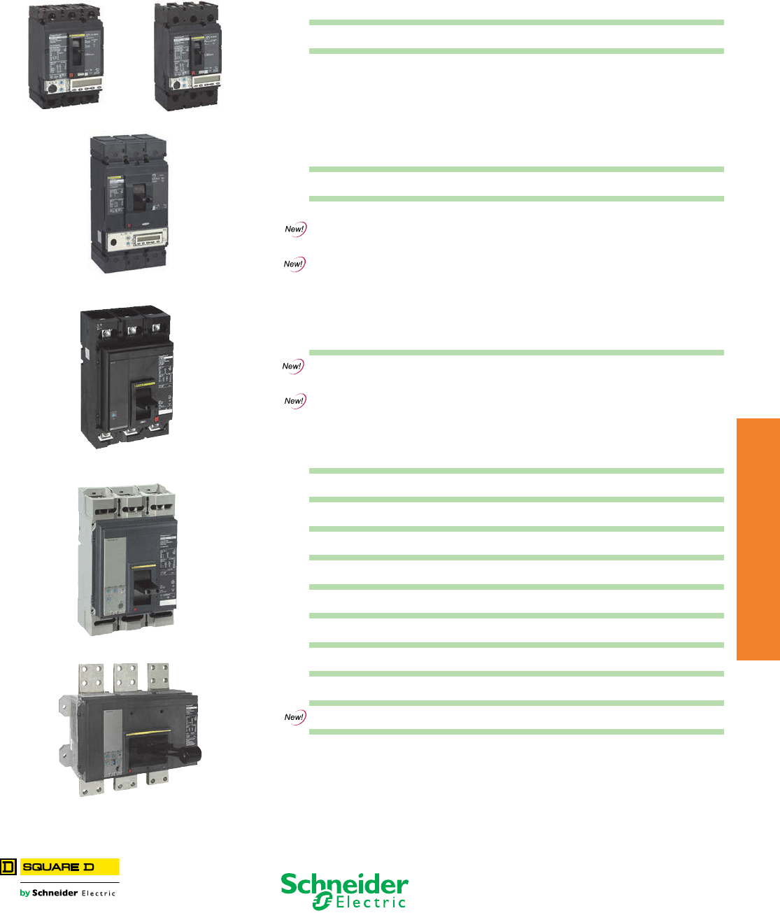
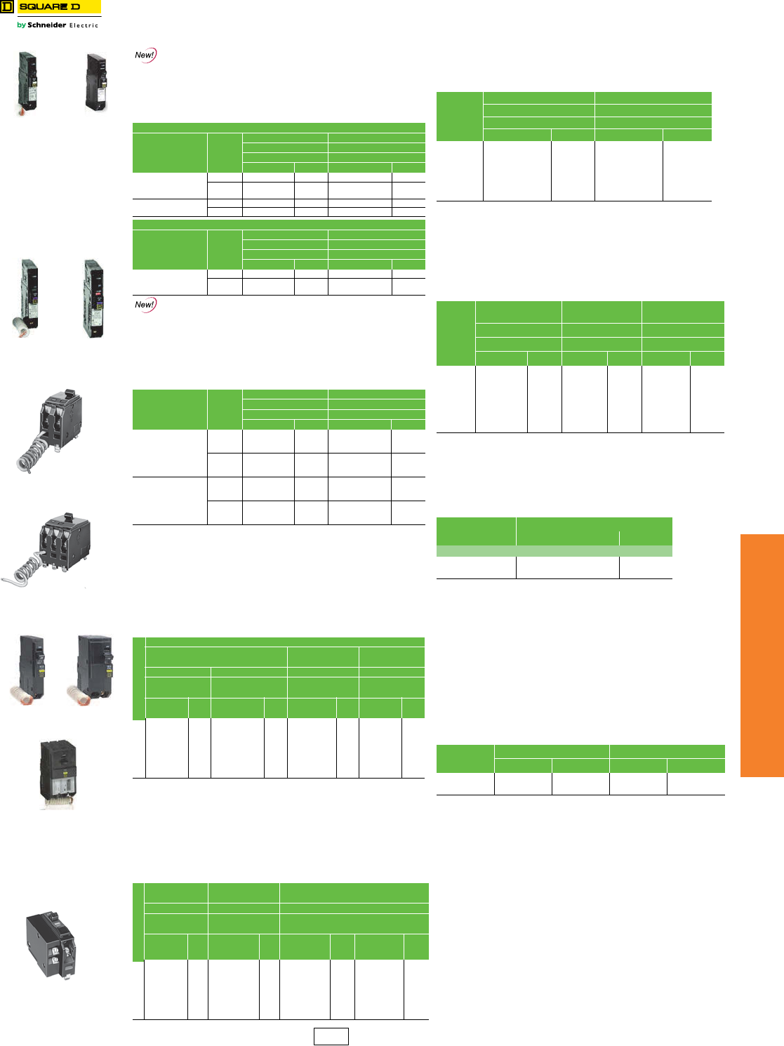
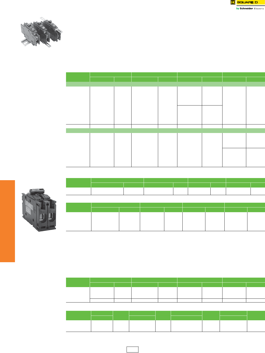
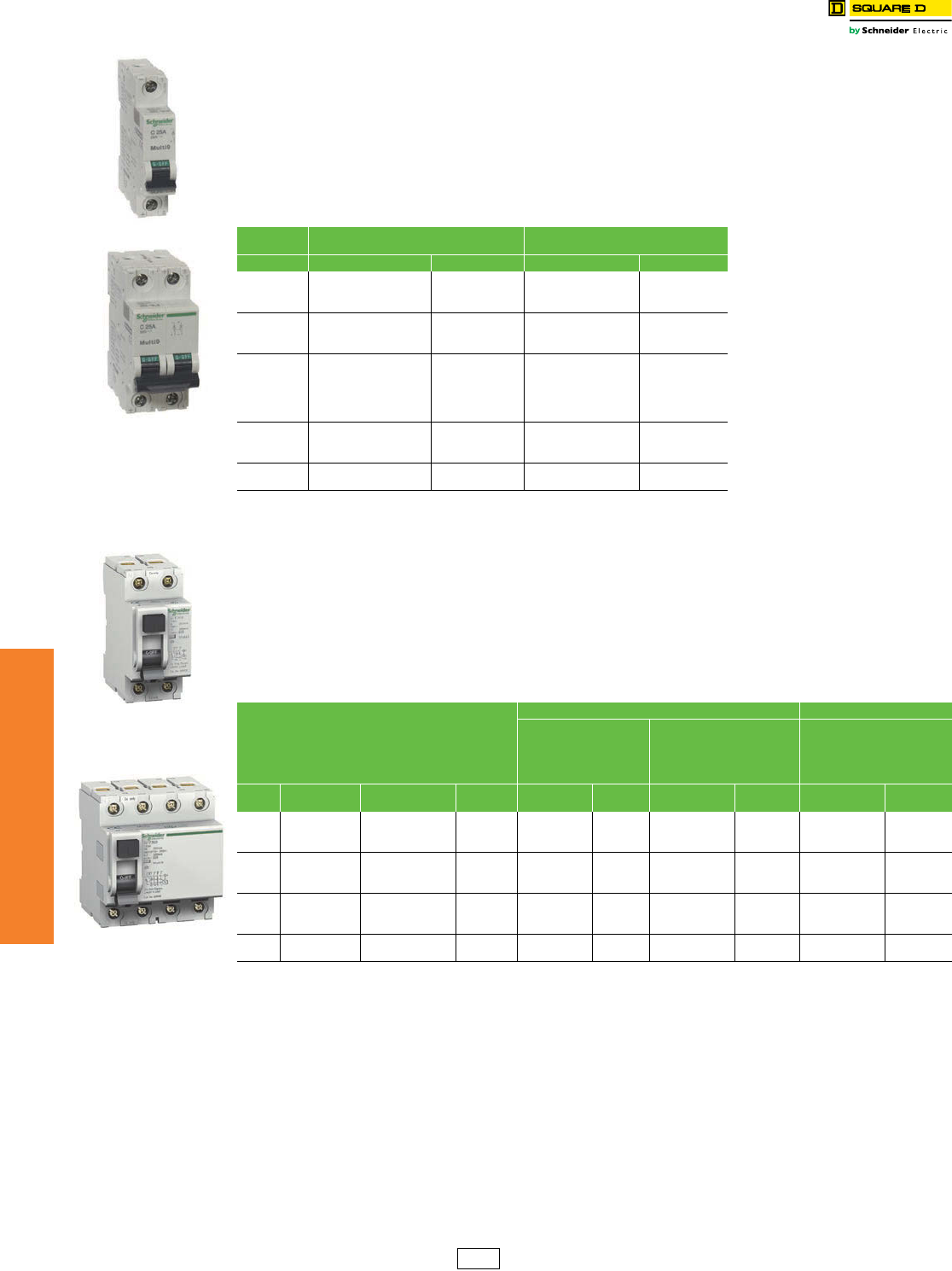
QO™ and QOU Miniature
Circuit Breakers
QO™ Miniature Circuit Breakers
Class 730, 731, 733 / Refer to Catalog 0730CT9801
Interrupting Ratings . . . . . . . . . . . . . . . . . . . . . . . . . . . . . . . . . . . . . . Page 7-2
Accessories . . . . . . . . . . . . . . . . . . . . . . . . . . . . . . . . . . . . . . . . . . . Page 7-12
DimensionsPage 7-54
QO™ miniature circuit breakers are plug-on products for use in QO load centers, NQOD panelboards, NQOD OEM interiors or Speed-D™
switchboard distribution panels. Bolt-on QOB circuit breakers are for use in NQOD panelboards or interiors.a
The QO exclusive Qwik-Open™ mechanism, with a trip reaction within 1/60th of a second, is standard on all 1P 15 A and 20 A QO circuit breakers.
Table 7.1: Plug-On Circuit Breakers Table 7.2: QO-QOB Ring Terminal
(20% $ Price Adder)—
Factory Installed Only
Amperes
Rating b
1P—120/240 Vac 2P—120/240 Vac
Common Trip
2P—240 Vacc
Common Trip
3P—240 Vac
Common Trip
Ampere Rating Poles SuffixCat. No. $ Price Cat. No. $ Price Cat. No. $ Price Cat. No. $ Price
10 k AIR 10–30 A 1, 2, 3 5237
10 A QO110 29.10 QO210 67.00 ——QO310 248.00 35–60 A 1,2 5238
15 A QO115 de29.10 QO215d67.00 QO215H 200.00 QO315d248.00 35–50 A 3
20 A QO120de29.10 QO220d67.00 QO220H 200.00 QO320d248.00 70–110 A 2 5273
25 A QO125d29.10 QO225d67.00 QO225H 200.00 QO325d248.00 60–100 A 3
30 A QO130d29.10 QO230d67.00 QO230H 200.00 QO330d248.00
35 A QO135d29.10 QO235d67.00 ——QO335d248.00 Table 7.3: Wire Sizesb
40 A QO140d29.10 QO240d67.00 QO240H 200.00 QO340d248.00 Circuit Breaker
Type
Ampere
Rating
Wire Size
(AWG/kcmil)
45 A QO145d29.10 QO245d67.00 ——QO345d248.00
50 A QO150d29.10 QO250d67.00 QO250H 200.00 QO350d248.00 QO
1P
10–30 A 14–8 Al/Cu
60 A QO160d29.10 QO260d67.00 QO260H 200.00 QO360d248.00 10–30 A (2) 14–10 Cu
70 A QO170d67.00 QO270d134.00 QO270H 224.00 QO370d315.00 35–70 A 8–2 Al/Cu
80 A — — QO280d189.00 QO280H 315.00 QO380d366.00
QO
2P
10–30 A 14–8 Al/Cu
90 A — — QO290d189.00 QO290H 315.00 QO390d366.00 10–30 A (2) 14–10 Cu
100 A — — QO2100d189.00 QO2100H 315.00 QO3100d366.00 35–70 A 8–2 Al/Cu
110 A — — QO2110d428.00 — — — — 80–125 A 4–2/0 Al/Cu
125 A — — QO2125d428.00 — — — — 150–200 A 4–300 Al/Cu
150 A — — QO2150dfk 491.00 —— — — QO
3P
10–30 A 14–8 Al/Cu, (2) 14-10 Cu
175 A — — QO2175dfk 491.00 — — — — 35–70 A 8–2 Al/Cu
200 A — — QO2200dfk 491.00 — — — — 80–125 A 4–2/0 Al/Cu
Molded Case Switch 60 A max.–240 Vac — — QO200 70.00 QO300 248.00 QOB-VH 110–150 A 4–300 Al/Cu
Molded Case Switch 100 A max.–240 Vac — — QO2000i200.00 QO3000i366.00 QOT 15–20 A 12–8 Al 14–8 Cu
22 k AIRdQO-AFI, QO-GFI
& QO-EPD
15–30 A 12–8 Al 14–8 Cu
15 A QO115VHe63.00 QO215VHg146.00 ——QO315VHg371.00 40, 50, 60 A 12–4 Al 14–6 Cu
20 A QO120VHe63.00 QO220VHg146.00 ——QO320VHg371.00 QO-PL 10–60 A 12–2 Al 14–2 Cu
25 A QO125VH 73.00 QO225VHg146.00 ——QO325VHg371.00
30 A QO130VH 73.00 QO230VHg146.00 ——QO330VHg371.00 Table 7.4: QOT Tandem Circuit
Breakers
40 A QO140VH 73.00 QO240VHg146.00 ——QO340VHg371.00
50 A QO150VH 73.00 QO250VHg146.00 ——QO350VHg371.00 Ampere RatingbCat. No.d$ Price
60 A QO160VH 73.00 QO260VHg146.00 ——QO360VHg371.00 1P—120/240 Vac
70 A QO170VH 112.00 QO270VHg224.00 ——QO370VHg477.00 15 A & 15 A QOT1515 58.00
80 A — — QO280VHg315.00 ——QO380VHg530.00 15 A & 20 A QOT1520 58.00
90 A — — QO290VHg315.00 ——QO390VHg530.00 20 A & 20 A QOT2020 58.00
100 A — — QO2100VHgh 315.00 ——QO3100VH g530.00 2P—120/240 Vac
110 A — — QO2110VHgh 1034.00 —— — —
Order two QOT1515 or QOT2020 circuit breakers and
handle tie QOTHT for common switching of center two poles.
125 A — — QO2125VHgh 1034.00 —— — —
150 A — — QO2150VHfgk1061.00 —— — —
175 A — — QO2175VHfgk1061.00 —— — —
200 A — — QO2200VHfgk1061.00 —— — —
Table 7.5: Replacement Tandem
Circuit Breakers
For Use in Old Style Non-Class CTL
QO Load Centers—10 k AIR
42 k AIRd
40 A — — QOH240i317.00 —— — —
45 A — — QOH245i317.00 —— — —
50 A — — QOH250i317.00 —— — —Ampere RatingbCat. No.d$ Price
60 A — — QOH260i317.00 —— — — 1P—120/240 Vac—1 Space Required
70 A — — QOH270 528.00 — — — — 15 &A 15 A QO1515 73.00
80 A — — QOH280 651.00 — — — — 15 A & 20 A QO1520 73.00
90 A — — QOH290 651.00 — — — — 20 A & 20 A QO2020 73.00
100 A — — QOH2100 651.00 — — — — 20 A & 30 A QO2030 73.00
110 A — — QOH2110i1389.00 — — — — 30 A & 20 A QO3020 73.00
125 A — — QOH2125 1389.00 —— — —Two 1P Individual Trip—120/240 Vac—2 Spaces Required
65 k AIRd15 A & 15 A Order Two QO1515 or QO2020 circuit
breakers and handle tie QOTHT for
common switching of center two poles.
15 A QH115e117.00 QH215 293.00 ——QH315d507.00 15 A & 20 A
20 A QH120e117.00 QH220 293.00 ——QH320 507.00 20 A & 20 A — —
25 A QH125i117.00 QH225i293.00 ——QH325i507.00 20 A & 30 A QO20303020j134.00
30 A QH130 117.00 QH230 293.00 ——QH330 507.00 30 A & 20 A — —
aSee Digest Section 1 for load centers, and Section 9 for panelboards and interiors.
b10–30 A circuit breakers are suitable for use with 60oC or 75oC conductors. 35–125 A circuit
breakers are suitable for use with 75oC conductors.
cUL Listed 5 k AIR on corner grounded Delta systems.
dUL Listed as HACR type for use with air conditioning, heating and refrigeration equipment having
motor group combinations and marked for use with HACR type circuit breakers.
eUL Listed as SWD (switching duty) rated. Suitable for switching 120 Vac fluorescent lighting loads.
fRequires four spaces (1 AWG–300 kcmil Al/Cu.) Suitable for switching 120 Vac fluorescent lighting
loads.
gUL Listed for use ahead of QO, QO-GFI, QO-EPD, QO-AFI, QOT,QOCAFI, and QO-PL 10 k AIR
circuit breakers to permit their application at 22 kA fault level.
h100 A maximum branch mounted opposite.
iOrder only. Contact your local Field Office.
jIncludes two circuit breakers (one QO2030 and one QO3020) and handle tie QOTHT.
kNot suitable for use in 3Ø panels. Use only in 1Ø panel rated 150 A or greater.
QO 1P
1 Space Required
QOT 1P Tandem
1 Space Required
QO 2P
2 Spaces Required
4 Spaces Required
QO2200 2P 200 A
QO 3P
3 Spaces Required
Pan Rail Slot
Rail Bead
Mounting Cam
QOT Tandem Circuit limiting QOT
tandem circuit
breakers have a
mounting cam as
shown. Installation
into a QO load center
can only be made in
those positions
having a mounting
pan rail slot. Meets
Paragraph 408.15 of
the NEC®. UL Listed
as Class CTL
DE2A Discount
Schedule
www.schneider-electric.us
7MINIATURE AND MOLDED CASE
CIRCUIT BREAKERS
© 2012 Schneider Electric
All Rights Reserved 7-11
QO™ and QOU Miniature
Circuit Breakers
QO™ Miniature Circuit Breakers
Class 685, 690, 730, 912, 950 / Refer to Catalog 0730CT9801
QO™ Arc-Fault Circuit Breaker
(Pigtail and Plug-On Neutral)
QO arc-fault circuit breakers provide protection for Series
and Parallel Type Arcing as required by the NEC and local
code adoption, and comply with UL1699.
QO™ Dual Function Circuit Breaker
QO Combination Arc Fault and Ground Fault Circuit
Interrupters (Dual Function) provide overload and short circuit
protection, plus arc fault and ground fault protection in a
single device in accordance with the NEC, UL1699 and
UL943.
QO-GFI
Qwik-Gard™ circuit breakers provide overload and short
circuit protection, combined with Class A ground fault
protection. Class A denotes a ground fault circuit interrupter
that will trip when a fault current to ground is 6 mA or more, for
people protection. Do not connect to more than 250 feet of
load conductor for the total one-way run to prevent nuisance
tripping.
QO-EPD/EPE
QO-EPD/EPE circuit breakers provide overload and short
circuit protection combined with Class B ground fault
protection. They are designed to provide ground fault
protection of equipment at a 30 milliampere level (EPD) or
100 milliamp level (EPE). They are not designed to protect
people from electrical shock.
QO-SWN
Switch Neutral Common Trip 2008 NEC™ 514.11
QO-HID
HID circuit breakers are for use on circuits feeding
fluorescent and high intensity discharge (HID) lighting
systems such as mercury vapor, metal halide, or high
pressure sodium. These circuit breakers are physically
interchangeable with QO circuit breakers.
NOTE: QO-K Circuit Breakers are on page 7-63.
QO-HM
High magnetic trip circuit breakers are recommended for
applications where high initial inrush may occur and for
individual dimmer applications.
Non-automatic (Standard) Miniature Switches
Miniature non-automatic switches have the same physical
packaging as miniature circuit breakers, but open only
when the handle is switched to the OFF position.
Non-automatic switches provide no overcurrent protection
or short circuit protection. They must not be used on
systems that have an available fault current greater than
the values listed in the table.
Non-automatic switches are UL Listed per UL 1087 and
are CSA certified.
aUL Listed as HACR type for use with air conditioning, heating and
refrigeration equipment having motor group combinations and marked
for use with HACR type circuit breakers.
bUL Listed as SWD (switching duty) rated. Suitable for switching 120 Vac
fluorescent lighting loads.
c10–30 A circuit breakers are suitable for use with 60° C or 75° C
conductors. 35–60 A circuit breakers are suitable for use with 75° C
conductors.
dSuitable only for feeding 240 Vac and 208 Vac two-wire loads. Does not
contain load neutral connection.
eSee note in Instruction Bulletin when using in an enclosure with a
QO403 or QON prefix.
Interrupting Ratings. . . . . . . . . . . . . . . . . . . . . . . . . . . . . . . . . . . . . . .Page 7-2
Accessories . . . . . . . . . . . . . . . . . . . . . . . . . . . . . . . . . . . . . . . . . . . .Page 7-12
Dimensions . . . . . . . . . . . . . . . . . . . . . . . . . . . . . . . . . . . . . . . . . . . .Page 7-54
Table 7.6: QO Arc Fault Circuit Breakersa
One-Pole
Circuit Breaker
Type
Ampere
Rating
1P 120 Vac 1P 120 Vac
10 k AIR 22 k AIR
1 Space Required 1 Space Required
Cat. No. $ Price Cat. No. $ Price
Combination
Arc-fault Interrupter
(Pigtail Neutral)
15 A QO115CAFI 282.00 QO115VHCAFI 534.00
20 A QO120CAFI 282.00 QO120VHCAFI 534.00
Plug-On Neutral
Arc-Fault Interrupter
15 A QO115PCAFI 282.00 QO115VHPCAFI 534.00
20 A QO120PCAFI 282.00 QO120VHPCAFI 534.00
Two-Pole
Circuit Breaker
Type
Ampere
Rating
2P 120/240 Vac 2P 120/240 Vac
10 k AIR 22 k AIR
2 Space Required 2 Space Required
Cat. No. $ Price Cat. No. $ Price
Combination
Arc-Fault Interrupter
(Pigtail Neutral)
15 A QO215CAFI 636.00 QO215VHCAFI 1068.00
20 A QO220CAFI 636.00 QO220VHCAFI 1068.00
Table 7.7: QO Dual Function Circuit Breakers
Circuit Breaker
Type
Ampere
Rating
1P 120 Vac 1P 120 Vac
10 k AIR 22 k AIR
1 Space Required 1 Space Required
Cat. No. $ Price Cat. No. $ Price
Combination
Arc-fault and Ground
Fault Circuit
Interrupter with
Pigtail Neutral
15 A QO115DF 326.00 QO115VHDF 578.00
20 A QO120DF 326.00 QO120VHDF 578.00
Plug-On Neutral
Combination
Arc-fault and Ground
Fault Circuit
Interrupter
15 A QO115PDF 326.00 QO115VHPDF 578.00
20 A QO120PDF 326.00 QO120VHPDF 578.00
Table 7.8: QO-GFI Circuit Breakers
Ampere Ratingc (A)
Qwik-Gard Circuit Breakers With Ground Fault Circuit Interrupter
1P 120 Vac 2P Common Trip
120/240 Vac
3P Common Trip
208Y/120 Vac
10 k AIR 22 k AIR 10 k AIR 10 k AIR
1 Space
Required 1 Space Required 2 Spaces Required 3 Spaces
Required
Cat. No. $
Price Cat. No. $
Price Cat. No. $
Price Cat. No. $
Price
15 QO115GFI 233. QO115VHGFI 482. QO215GFI 413. QO315GFI 791.
20 QO120GFI 233. QO120VHGFI 482. QO220GFI 413. QO320GFI 791.
25 QO125GFI 233. QO125VHGFI 482. QO225GFI 413. ——
30 QO130GFI 233. QO130VHGFI 482. QO230GFI 413. QO330GFI 791.
40 — — — — QO240GFI 413. QO340GFI 791.
50 — — — — QO250GFI 413. QO350GFI 791.
60 — — — — QO260GFId413. ——
Table 7.9: QO-EPD Circuit Breakers
Ampere Ratingc (A)
1P
120 Vac
2P Common Trip
120/240 Vac
3P Common Trip
240 Vac
10 k AIR 10 k AIR 10 k AIR
1 Space
Required 2 Spaces Required 3 Spaces Required
Cat. No. $
Price Cat. No. $
Price Cat. No. $
Price Cat. No. $
Price
15 QO115EPD 410. QO215EPD 660. QO315EPDe1077. QO315EPEe1077.
20 QO120EPD 410. QO220EPD 660. QO320EPDe1077. QO320EPEe1077.
25 QO125EPD 410. QO225EPD 660. ————
30 QO130EPD 410. QO230EPD 660. QO330EPDe1077. QO330EPEe1077.
40 — — QO240EPD 660. QO340EPDe1077. QO340EPEe1077.
50 — — QO250EPD 660. QO350EPDe1077. QO350EPEe1077.
60 — — QO260EPDd660. ————
1P
QO-CAFI
1P
QO-PCAFI
1P
QO-DF
1P
QO-PDF
2P
QO-GFI
1P
QO-GFI
3P
QO-GFI
Table 7.10: QO-SWN Circuit Breakers
Ampere
Ratingc
2 Wire 120 Vac 3 Wire 120/240 Vac
10 k AIR 10 k AIR
2 Spaces Required 3 Spaces Required
Cat. No. $ Price Cat. No. $ Price
10 A QO210SWN 95.00 ——
15 A QO215SWN 95.00 QO315SWN 143.00
20 A QO220SWN 95.00 QO320SWN 143.00
25 A QO225SWN 95.00 ——
30 A QO230SWN 95.00 QO330SWN 143.00
40 A QO240SWN 95.00 QO340SWN 143.00
50 A QO250SWN 95.00 QO350SWN 143.00
Table 7.11: QO-HID Circuit Breakers
Ampere
Ratingc
1P 120/240 Vac 2P Common Trip
120/240 Vac
3P Common Trip
240 Vac
10 k AIR 10 k AIR 10 k AIR
1 Space Required 2 Spaces Required 3 Spaces Required
Cat. No. $ Price Cat. No. $ Price Cat. No. $ Price
15 A QO115HIDb38.10 QO215HID 87.00 QO315HID 300.00
20 A QO120HIDb38.10 QO220HID 87.00 QO320HID 300.00
25 A QO125HID 38.10 QO225HID 87.00 QO325HID 300.00
30 A QO130HID 38.10 QO230HID 87.00 QO330HID 300.00
40 A QO140HID 38.10 QO240HID 87.00 ——
50 A QO150HID 38.10 QO250HID 87.00 ——
Table 7.12: QO-HM Circuit Breakers
Ampere Ratingc1P
Cat. No $ Price
120 Vac—10 k AIR
15 A QO115HMab30.60
20 A QO120HMab30.60
Table 7.13: QO Non-Automatic Miniature Switches,
240 Vac 10 kA
Ampere
Rating
2P 3P
Cat. No. $ Price Cat. No. $ Price
60 A QO200 70.00 QO300 248.00
100 A QO2000 200.00 QO3000 366.00
Two-wire
QO-SWN
Three-wire
QO-SWN
QO 1P
With Shunt Trip
DE2A Discount
Schedule
www.schneider-electric.us
7MINIATURE AND MOLDED CASE
CIRCUIT BREAKERS
7-12 © 2012 Schneider Electric
All Rights Reserved
QO™ and QOU Miniature
Circuit Breakers
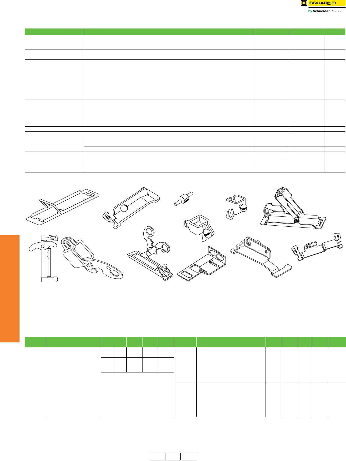
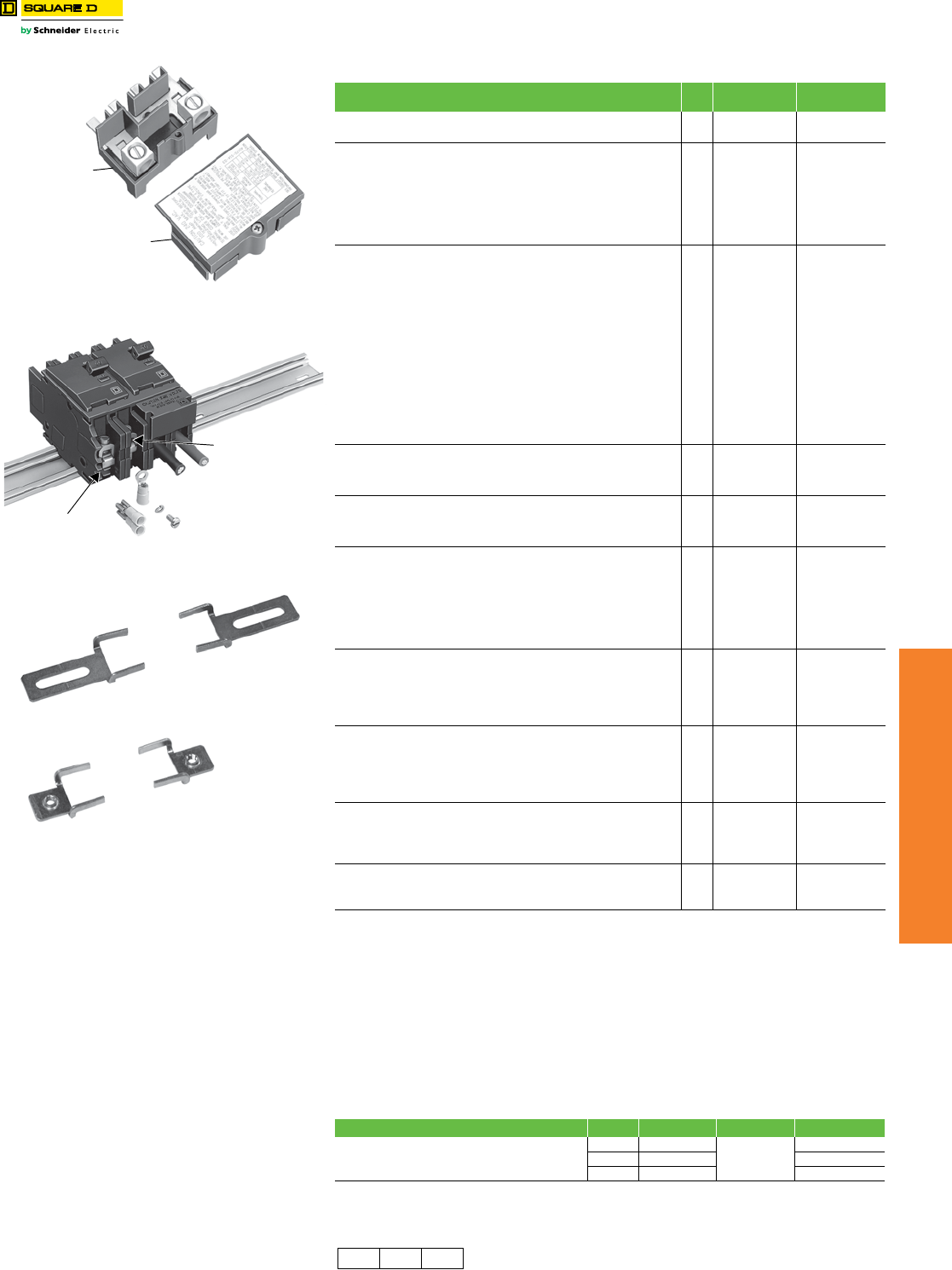
QO™ Circuit Breaker Accessories
Class 1130 / Refer to Catalog 0730CT9801
Factory-Installed Accessories for Use with QO and QOB Miniature Circuit Breakers
Factory-installed electrical accessories take up an additional pole space on QO™, QO-GFI, QO-EPD, QO-SWN and
QOU circuit breakers. All AC electrical accessories shown below are rated for 50/60 Hz. Accessories are not available
for QOB-VH (2P 150 A and 3P 110–150 A) circuit breakers or QO, QOU molded case switches. QO circuit breakers will
accept only one accessory per circuit breaker. Undervoltage trip is not available on miniature circuit breakers. Factory-
installed accessories are not available for QO-AFI, QO-CAFI or OQ-PCAFI Arc Fault Circuit Breakers or on QO2150,
QO2175, or QO2200 circuit breakers.
Table 7.14: Accessories for Use with QO™ and QOB Miniature Circuit Breakers
Handle Attachments Description Cat. No. $ Price Schedule
Handle Tie:
Converts any two adjacent 120/240 Vac 1P QO circuit breakers to independent trip 2P QO1HT 3.80 DE2E
Converts any two adjacent 120/240 Vac 1P side-by-side QOT circuit breakers to independent trip 2P QOTHT 3.80 DE2E
Handle tie and lock-off for three 1P QO, QOB circuit breakers QO3HT 13.40 DE2E
Handle Clamp: Clamp for holding QO 1P handle in ON or OFF position QO1LO 3.80 DE2E
Clamp for holding QO or Q1 1P, 2P or 3P circuit breaker handles in ON or OFF position HLO1 9.90 DE2E
Handle Padlock Attachment: for
Padlocking in ON or OFF position
For padlocking 1P QO circuit breaker in ON or OFF position
Loose attachment QOHPL 9.50 DE2E
Fixed attachment QO1PA 10.70 DE2E
For padlocking 1P side-by-side QOT circuit breaker in ON or OFF position QOTHPA 11.10 DE2E
For padlocking 2P and 3P QO-GFI, QO-EPD, and QO-EPE in either ON or OFF position, fixed attachment. GFI2PA 9.20 DE2A
For 2P and 3P QO and Q1 standard circuit breakers which require padlocking in either ON or OFF position.
Loose attachment QO1HPL 10.70 DE2E
Fixed attachment QO1PL 10.70 DE2E
Handle Padlock Attachment: for
Padlocking in OFF position
For padlocking 1P QO circuit breaker in OFF position only, fixed attachment. QO1PAF 43.50 DE2E
For padlocking 2P and 3P QO circuit breakers in OFF position only, fixed attachment. QO2PAF 25.80 DE2E
For padlocking 1P QO-GFI, QO-AFI, QO-CAFI, QO-PCAFI, and QO-EPD circuit breakers in OFF position
only, fixed attachment. QOGFI1PAF 51.00 DE2E
For padlocking 2P and 3P QO-GFI, QO-EPD, and QO-EPE circuit breakers in OFF position only, fixed
attachment. QOGFI2PAF 38.40 DE2E
Ring Terminal Ring terminals are available as a factory-installed option. See Page 7-10 +20% Price Adder DE2A
Sub-Feed Lugs 60 A 2P plug-on – 2 spaces required (6–2 Al/Cu) QO60SL 47.10 DE2A
125 A 2P plug-on – 2 spaces required (12–2/0 Al/Cu) QO2125SL 137.00 DE2A
225 A 2P plug-on – 4 spaces required (4–300 Al/Cu) QO2225SLa308.00 DE2A
125 A 3P plug-on – 3 spaces required (12–2/0 Al/Cu) QO3125SL 137.00 DE3
Mechanical Interlock Attachment For interlocking the handles of two 2P or one 2P and one 1P QO and Q1 circuit breakers mounted side-by-
side so that only one circuit breaker can be ON at a time (Not QOU) QO2DTI 24.90 DE2E
With Retaining Kit:
QO2DTI mechanical interlock attachment with retaining kits for securing two adjacent back-fed circuit
breakers in dual power supply applications. Can be used with (2) 2Ps or (1) 2P and (1) 1P QO circuit breakers
in QO816L100 load centers.
QO2DTIM 63.00 DE2E
aNot suitable for use in 3Ø panels. Use only in 1Ø panel rated 150 A or greater.
QOHPL
QO1PA
QO1PL
QO2DTI
QO1HT
QO1HPL
HLO1
QO1LO
QOTHPA
QO2PAF
QO1PAF
QOGFI2PAF
Table 7.15: Factory-Installed Accessories
Accessory Description Rated
Vol tage
Coil
Burden
Cat. No.
Suffix
$ Price
Adder Accessory Description Contact
Comb.
Max.
Vol tage
Max.
Load
Cat. No.
Suffix
$ Price
Adder
Shunt Trip
Trips the circuit breaker from a
remote location by means of a trip
coil energized from a separate
circuit. A 120 Vac shunt trip will
operate at 55% or more of rated
voltage. All other shunt trips will
operate at 75% or more of rated
voltage.
Application
•For use with momentary or
maintained push button.
•Not available on QO-GFI,
QO-EPD, QO-AFI,
QO-CAFI, QO-PCAFI.
•Shunt trip terminals accept
(2) 14–12 AWG Cu.
AC/DC 12 60 VA -1042 189.00
Auxiliary
Switches
Monitors circuit breaker contact status and
provides a remote signal indicating the
circuit breaker contacts are OPEN or
CLOSED.
Application
•Auxiliary switch terminals accept
(2) 14–12 AWG Cu leads.
1A
1B
AC 120
AC 120
5 A
5 A
-1200
-1201
132.00
132.00
24 168 VA
AC
120 72 VA
-1021 189.00208 228 VA
240 288 VA
Alarm
Switches
Used with control circuits and is actuated
only when the circuit breaker has tripped.
Standard construction includes a normally-
open contact.
Application
•Alarm switch terminals accept
(2) 14–12 AWG Cu leads.
1A AC 120 5 A -2100 132.00
DE2A DE2E DE3 Discount
Schedule
www.schneider-electric.us
7MINIATURE AND MOLDED CASE
CIRCUIT BREAKERS
© 2012 Schneider Electric
All Rights Reserved 7-13
QO™ and QOU Miniature
Circuit Breakers
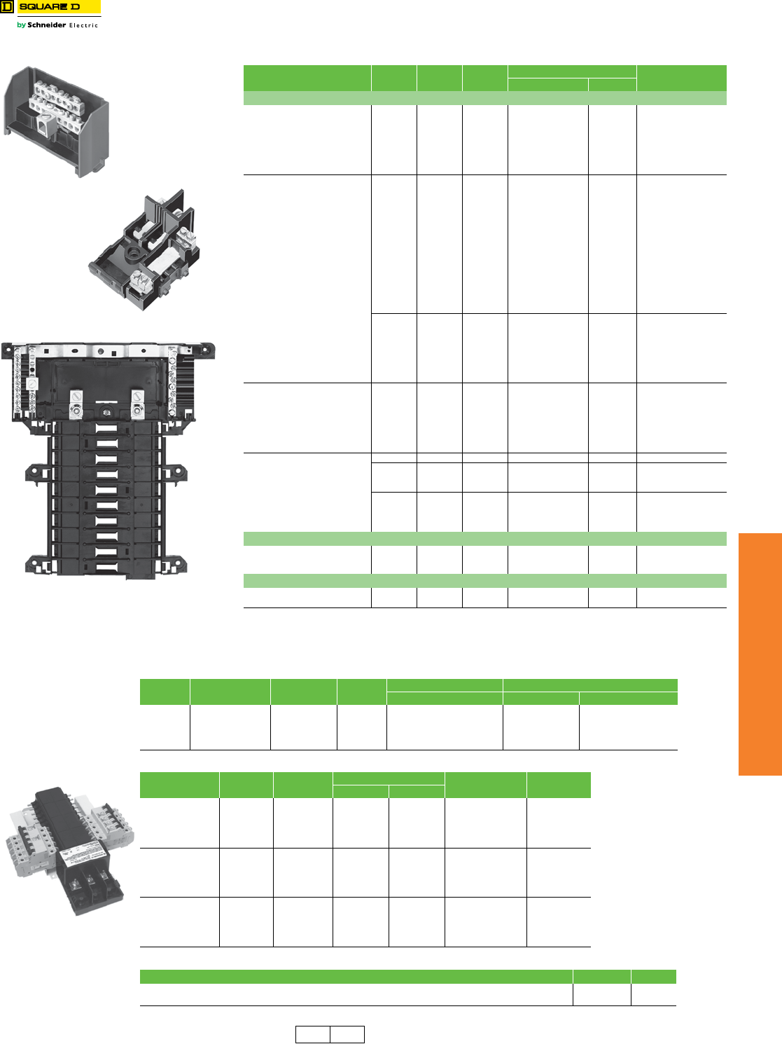
QO™ and Multi 9™ Mounting Bases
Class 652 / Catalog 0730CT9801, 0860CT0201
eDE2 Discount Schedule
Table 7.16: QO OEM Mounting Bases—UL Recognized Components
Voltage System Main Lug
Rating
1P
Spaces
Max. No.
1P
Mounting Bases Main Wire Size
AWG/kcmil
Cat. No. $ Price
QO Plug-On Mounting Bases—For unit mounting QO, QO-GFI, QO-AFI and QO-EPD circuit breakers
1Ø2W 240 Vac Max. 10 k AIC
(Without Neutral Assembly)
70 A 2 2 QON2L70 27.30 14–4 Cu, 12–3 Al
125 A 4 4 SK9948BW 75.00 12–1/0 Cu/Al
125 A 4 4 SK9842 78.00 12–1/0 Cu/Al
125 A 6 6 SK9795 84.00 12–1/0 Cu/Al
125 A 6 6 SK9801 108.00 12–1/0 Cu/Al
150 A 6 6 SK9796BW 131.00 8–3/0 Cu/Al
150 A 8 8 SK9797 140.00 8–3/0 Cu/Al
1Ø3W 240 Vac Max. 10 k AIC
40 A 2 2 QON2L40 35.00 14–6 Cu, 12–6 Al
70 A 2 4 QON24L70 50.00 14–4 Cu, 12–3 Al
100 A 6 12 QON612L100 70.00 8–1/0 Cu/Al
100 A 8 16 QON816L100 92.00 8–1/0 Cu/Al
100 A 12 12 QON12L100 113.00 12–2/0 Cu/Al
100 A 12 12 QON12L100SFb161.00 6–2/0 Cu/Al
125 A 12 12 QON112L125I 120.00 4–2/0 Cu/Al
125 A 12 24 QON11224L125I 168.00 4–2/0 Cu/Al
125 A 16 16 QON116L125I 131.00 4–2/0 Cu/Al
125 A 16 24 QON11624L125I 191.00 4–2/0 Cu/Al
125 A 20 20 QON120L125I 225.00 4–2/0 Cu/Al
125 A 24 24 QON124L125I 263.00 6–2/0 Cu/Al
125 A 32 32 QON132L125I 360.00 4–2/0 Cu/Al
125 A 20 24 QON12024L125I 263.00 4–2/0 Cu/Al
150 A 24 24 QON124L150I 263.00 4–250 Cu/Al
200 A 12 12 QON124L200I 339.00 4–250 Cu/Al
200 A 12 12 QON12L200FTLc500.00 4–250 Cu/Al
200 A 24 24 QON124L200I 339.00 4–250 Cu/Al
200 A 24 24 QON124L200DLd500.00 (2) 4–300 Cu/Al
200 A 30 30 QON130L200I 417.00 4–250 Cu/Al
225 A 42 42 QON142L225I 599.00 4–300 Cu/Al
3Ø3W 240 Vac Max. 10 k AIC
(Without Neutral Assy.)
125 A 12 12 QON312L125 251.00 4–2/0 Cu/Al
125 A 20 20 QON320L125 380.00 4–2/0 Cu/Al
125 A 24 24 QON324L125 395.00 4–2/0 Cu/Al
200 A 18 18 QON318L200 327.00 4–300 Cu/Al
200 A 24 24 QON324L200 402.00 4–300 Cu/Al
200 A 30 30 QON330L200 477.00 4–300 Cu/Al
225 A 42 42 QON342L225 674.00 4–300 Cu/Al
3Ø4W 240 Vac Max.
10 k AIC
60 A 3 3 QON403L60N 49.80 12–6 Cu/Al
125 A 12 12 QON312L125I 281.00 4–2/0 Cu/Al
125 A 20 20 QON320L125I a441.00 4–2/0 Cu/Al
125 A 24 24 QON324L125I 461.00 4–2/0 Cu/Al
200 A 18 18 QON318L200I 426.00 4–300 Cu/Al
200 A 24 24 QON324L200I 468.00 4–300 Cu/Al
200 A 30 30 QON330L200I a528.00 4–300 Cu/Al
225 A 42 42 QON342L225I 716.00 4–300 Cu/Al
QO Plug-On Mounting Bases—For unit mounting QO, QO-GFI and QO-EPD circuit breakers
1Ø2W 240 Vac Max. 10 k AIC
(Without Neutral Assembly)
70 A
70 A
70 A
1
2
3
1
2
3
QOMB1
QOMB2
QOMB3
29.60
59.00
87.00
14–4 Cu 12–2 Al
14–4 Cu 12–2 Al
14–4 Cu 12–2 Al
QOB Bolt-On Mounting Bases—For unit mounting QOB, QOB-GFI, QOB-EPD circuit breakers
3Ø3W 240 Vac Max.10 k AIC
(Without Neutral Assembly) 100 A 3 3 QON3B 56.00 12–1 Cu/Al
aAlso IEC rated and CE marked for IEC 60439-1. Use only Square D brand Type QOXC, QOXD, QOHX and QOE circuit
breakers for 415Y/240 Vac max. systems.
bDevice comes with factory-installed sub-feed lugs.
cDevice comes with factory-installed feed-thru lugs.
dDevice comes with factory-installed dual-line lugs.
QON2L40
QON120L125I
SN12125
Table 7.17: Solid Neutral Assemblies
Main Lug
Rating
Number of Branch
Neutral Terminals Cat. No. $ Price Main Neutral Lug Wire Size Branch Neutral Terminal Wire Size
Cu/Al Cu Al
125 A
125 A
200 A
200 A
225 A
12
20
12
30
42
SN12125
SN20
SN12200
SN30
SN42
36.30
39.50
40.70
54.00
63.00
4–2/0 AWG
4–2/0 AWG
4 AWG–300 kcmil
4 AWG–300 kcmil
4 AWG–300 kcmil
14–4 AWG
14–4 AWG
14–4 AWG
14–4 AWG
14–4 AWG
12–4 AWG
12–4 AWG
12–4 AWG
12–4 AWG
12–4 AWG
Table 7.18: Multi-9 Mounting Bases for UL489 C60, 240 Vac max.
Description Poles Amperes Length Cat. No.e$ Price
in. mm
One-conductor
Mounting Base
12
200 A
10.4 264 US11220018 330.00
24 14.4 366 US12420018 476.00
36 19 483 US13620018 632.00
48 23 584 US14820018 810.00
60 27.5 699 US16020018 972.00
Two-conductor
Mounting Base
12 150 A 10.4 264 US21215018 429.00
24
200 A
14.4 366 US22420018 645.00
36 19 483 US23620018 887.00
48 23 584 US24820018 1140.00
60 27.5 699 US26020018 1359.00
Three-conductor
Mounting Base
12 100 A 10.4 264 US31210018 467.00
24
200 A
14.4 366 US32420018 701.00
36 19 483 US33620018 960.00
48 23 584 US34820018 1245.00
60 27.5 699 US36020018 1547.00
Table 7.19: Accessories for US Mounting Base for UL489 C60
Description Cat. No.e$ Price
Main lug kit for US mounting bases, 1 lug per kit, for 6 AWG to 300 kcmil cable USMBLK 24.00
Terminal cover for US mounting base; provides IP20 ingress protection per IEC 60529; suitable for jumper bars or cable USMBTC 49.50
US Mounting Base
for UL489 C60
(3 conductor shown)
DE3A DE2 Discount
Schedule
7-14 © 2012 Schneider Electric
All Rights Reserved
www.schneider-electric.us
7MINIATURE AND MOLDED CASE
CIRCUIT BREAKERS
QO™ and QOU Miniature
Circuit Breakers
QOU Miniature Circuit Breakers / QYU Supplementary Protectors
Class 720 / Refer to Catalog 0730CT9801
Low Ampere QOU Miniature Circuit Breakers
QOU unit mount miniature circuit breakers (cable-in/cable-out) are ideal for OEM applications. They have the Square D™
circuit breaker’s unique Visi-Trip™ feature and can be DIN rail-mounted or surface- or flush-mounted using mounting feet.
aQOU-H interrupting rating is 10 kA at 240 Vac.
High Ampere QOU Circuit Breakers
Interrupting Ratings . . . . . . . . . . . . . . . . . . . . . . . . . . . . . . . . . . . . . . Page 7-3
Accessories . . . . . . . . . . . . . . . . . . . . . . . . . . . . . . . . . . . . . . Page 7-12, 7-15
Dimensions. . . . . . . . . . . . . . . . . . . . . . . . . . . . . . . . . . . . . . . . . . . . Page 7-54
General Specifications Common to All Low Ampere QOU Circuit Breakers
•For convenient flush mount, surface mount or DIN mount
(symmetrical rail 35 x 7.5 DIN/EN 50 022)
•Single handle with internal common trip
•Terminal lug wire size (1) 14–2 AWG Cu or Al
•Reversible line and load lugs
•Field-installable quick connectors
•UL Listed 48 Vdc (5 k AIR)
•UL Listed as HACR Type: 10–70 A
•High magnetic trip circuit breakers (QOU-HM) are recommended
for applications where high initial inrush may occur and for
individual dimmer applications.
•For DIN mounting rails, see IEC Starters and Relays, Section 18.
Table 7.20: QOU Low Ampere Miniature Circuit Breakers
Ampere
Rating
1P 120/240 Vac 2P 120/240 Vac 2P 240 Vac 3P 240 Vac
Cat. No. $ Price Cat. No. $ Price Cat. No.a$ Price Cat. No. $ Price
10 k AIR
10 A QOU110
40.20
QOU210
87.00
—
168.00
QOU310
285.00
15 A QOU115 QOU215 QOU215H QOU315
20 A QOU120 QOU220 QOU220H QOU320
25 A QOU125 QOU225 QOU225H QOU325
30 A QOU130 QOU230 QOU230H QOU330
35 A QOU135 QOU235 ——QOU335
40 A QOU140 QOU240 ——QOU340
45 A QOU145 QOU245 ——QOU345
50 A QOU150 QOU250 ——QOU350
60 A QOU160 QOU260 ——QOU360
70 A QOU170 78.00 QOU270 171.00 ——QOU370 363.00
22 k AIR
15 A QOU115VH
101.00
QOU215VH
189.00
——QOU315VH
426.00
20 A QOU120VH QOU220VH ——QOU320VH
25 A QOU125VH QOU225VH ——QOU325VH
30 A QOU130VH QOU230VH ——QOU330VH
35 A QOU135VH QOU235VH ————
40 A QOU140VH QOU240VH ————
45 A QOU145VH QOU245VH ————
50 A QOU150VH QOU250VH ————
60 A QOU160VH QOU260VH ————
Table 7.21: QOU-HM Miniature Circuit Breakers (10 k AIR)
Ampere
Rating
1P 120/240 Vac 2P 120/240 Vac 2P 240 Vac 3P 240 Vac
Cat. No. $ Price Cat. No. $ Price Cat. No. $ Price Cat. No. $ Price
15 A QOU115HM 40.20 ——————
20 A QOU120HM ——————
Table 7.22: QYU UL1077 Recognized Supplementary Protectors (5 k AIR)
Ampere
Rating
1P 277 Vac 2P 120/240 Vac 2P 240 Vac 3P 240 Vac
Cat. No. $ Price Cat. No. $ Price Cat. No. $ Price Cat. No. $ Price
10 A QYU110
122.00
——————
15 A QYU115 ——————
20 A QYU120 ——————
25 A QYU125 ——————
30 A QYU130 ——————
General Specifications Common to All High Ampere QOU Circuit Breakers
•Flush mount, surface mount, and DIN rail mount.
•Internal common trip.
•Non-reversible line and load lugs.
•Terminal lug wire size (1) 12– 2/0 AWG Cu or Al.
•UL Listed 60 Vdc per pole (5 k AIR). (Note: except switches)
•UL Listed as HACR type, 80–125 A.
•Non-automatic switches have the same physical packaging
as miniature circuit breakers, but provide no overcurrent or
short circuit protection. They are UL Listed per UL1087 and
are CSA certified.
Table 7.23: QOU High Ampere Miniature Circuit Breakers (10 k AIR)
Ampere
Rating
1P 120/240 Vac 2P 120/240 Vac 2P 240 Vac 3P 240 Vac
Cat. No. $ Price Cat. No. $ Price Cat. No. $ Price Cat. No. $ Price
80 A QOU180
176.00
QOU280
246.00
——QOU380
416.0090 A QOU190 QOU290 ——QOU390
100 A QOU1100 QOU2100 ——QOU3100
125 A — — QOU2125 452.00 ————
Table 7.24: QOU Non-Automatic Switches
Ampere
Rating
1P 120 Vac $ Price 2P 120/240 Vac $ Price 2P 240 Vac $ Price 3P 240 Vac $ Price
Cat. No. Cat. No. Cat. No. Cat. No.
60 A — — — — QOU200 87.00 QOU300 285.00
100 A — — — — QOU2000 246.00 QOU3000 416.00
125 A — — — — QOU20001 452.00 QOU30001 716.00
Low Ampere QOU
High Ampere QOU
DE2 Discount
Schedule
www.schneider-electric.us
7MINIATURE AND MOLDED CASE
CIRCUIT BREAKERS
© 2012 Schneider Electric
All Rights Reserved 7-15
QO™ and QOU Miniature
Circuit Breakers
QOU Accessories
Class 720 / Refer to Catalog 0730CT9801
aFor use on low and high ampere QOU.
b10–70 A 1P and 2P, 10–60 A 3P.
cDE2E Discount Schedule
For QOUQ Low Ampere Circuit Breakers with Four-Point Quick-Connect
Terminals
QOUQ low ampere circuit breakers with four-point quick-connect terminals are provided
with permanent factory-installed terminals which are affixed to the Load or OFF end of the
circuit breaker. This special terminal will accommodate up to four 1/4-inch insulated female
quick connect wire terminations. Total ampacity of these connections must not exceed the
rating of the circuit breaker.
Electrical Accessories for QOU . . . . . . . . . . . . . . . . . . . . . . . . . . . .Page 7-12
Table 7.25: Accessories for QOU Low Ampere Circuit Breakers (Except as Noted)
Description Order
Qty. Cat. No. Unit $ Price
Factory-installed ring tongue terminal, 10–32 screw, for 1P, 2P, 3P QOU, 10–60 A — Suffix -5283 Add 20% to price
Hex drive 5/32 in. wire binding screw for QOU — Suffix -5280 Add 20% to price
For padlocking 1P low ampere QOU circuit breaker in OFF or ON position — QOU1PA 10.10
For padlocking 2P and 3P low ampere QOU circuit breaker in OFF or ON
position —QOU1PL 10.10
For padlocking 1P low ampere QOU circuit breaker in OFF position only — QOU1PAFLAc43.50
For padlocking 2P and 3P low ampere QOU circuit breaker in OFF position only — QOU2PAFLAc25.80
For padlocking 2P and 3P high ampere QOU circuit breaker in OFF position only — Suffix -7100 Add 20% to price
Handle lock-out, ON or OFF position — HLO1c9.90
4P 100 A Jumper bar assy. w/front wiring with base, cover and screw 1 QOU14100JBAF 73.00
4P 100 A Jumper bar assy. w/right side wiring with base, cover and screw 1 QOU14100JBAR 73.00
4P 100 A Jumper bar assy. w/left side wiring with base, cover and screw 1 QOU14100JBAL 73.00
1Ø, 4P, 100 A Jumper bar base with front wiring 40 QOU14100BAFB 53.00
1Ø, 4P, 100 A Jumper bar base with left side wiring 40 QOU14100BALB 53.00
1Ø, 4P, 100 A Jumper bar base with right side wiring 40 QOU14100BARB 53.00
4P Jumper bar cover 40 QOU14100CAB 13.20
Mounting screw for jumper bar cover 40 QOU1CMSB 0.35
6P 150 A Jumper bar assy. w/front wiring with base, cover and screw 1 QOU16150JBAF 99.00
1Ø, 6P, 150 A Jumper bar base with front wiring 40 QOU16150BAFB 69.00
1Ø, 6P, 150 A Jumper bar base with left side wiring 40 QOU16150BALB 69.00
1Ø, 6P, 150 A Jumper bar base with right side wiring 40 QOU16150BARB 69.00
6P jumper bar cover 40 QOU16150CAB 17.10
Vertical rainproof cover 2P and 3P QO, QOU, FA and KA 1
10
BCVac
BCVBac
30.80
30.80
Horizontal rainproof cover 2P QO, QOU, and 3P Q2, EH 1
10
BCHac
BCHBac
30.80
30.80
1P Fingersafe™ cover for high ampere QOU circuit breaker 1
40
QOUHFSC1
QOUHFSC1B
2.60
2.10
1P Fingersafe cover for low ampere QOU circuit breaker 1
40
QOULFSC1
QOULFSC1B
2.60
2.10
Cover plate for one 2P QOU circuit breaker 1
40
QOUCP2
QOUCP2B
8.30
6.60
Cover plate for one 3P QOU circuit breaker 1
40
QOUCP3
QOUCP3B
15.80
12.80
Cover plate for two 2P QOU circuit breakers 1
40
QOUCP4
QOUCP4B
9.90
7.90
Cover plate for three 2P QOU circuit breakers 1
40
QOUCP6
QOUCP6B
15.60
12.20
Field-installable ring tongue terminal adaptor 1
80
QOURT
QOURTB
5.70
4.40
Quick connector end connection wiring 1
40
QOUEC
QOUECB
5.70
4.40
Quick connector forward or reverse wiring 1
40
QOUFR
QOUFRB
5.70
4.40
1P QOU mounting foot 1
80
QOUMF1a
QOUMF1Ba
0.71
0.54
2P QOU mounting foot 1
40
QOUMF2a
QOUMF2Ba
1.40
1.10
3P QOU mounting foot 1
24
QOUMF3a
QOUMF3Ba
2.30
1.70
Tapped mounting foot for QOU, 1P and 2P 10–70 A, 3P 10–60 A
Packaged with circuit breaker Suffix -3100 Add 20% to price
Individually packaged 1 QOUMFS1 2.40
Bulk packed 80 QOUMFS1B 2.30
Mechanical interlock attachment: Used to interlock two circuit breakers mounted
side-by-side so that only one circuit breaker can be ON at a time. A 1P or 2P
circuit breaker can be mounted on the left and interlocked with a 2P or 3P circuit
breaker on the right.
1QOU2DTILA b24.90
Table 7.26: QOUQ Four-Point Quick-Connect Terminals
Poles Order Qty. Cat. No. Unit $ Price Adder
Four-Point Quick-Connect Terminals
11
Change QOU to
QOUQ
8.90
21 17.70
31 26.40
QOU14100JBAF
4P Jumper Bar
Assembly Base
Cover and Cover Screw
QOUEC Field-
installable
Quick Connector
Crimp connectors are
not included with
Square D brand connectors
QOURT
Field-installable
Ring Tongue Terminal
Connector
2P DIN Mounted QOU Circuit Breakers
Mounting Foot
QOUMF1
Tapped Mounting Foot
Suffix–3100
DE2 DE2A DE2E Discount
Schedule
www.schneider-electric.us
7MINIATURE AND MOLDED CASE
CIRCUIT BREAKERS
7-16 © 2012 Schneider Electric
All Rights Reserved
Multi 9™ Miniature Circuit
Breakers
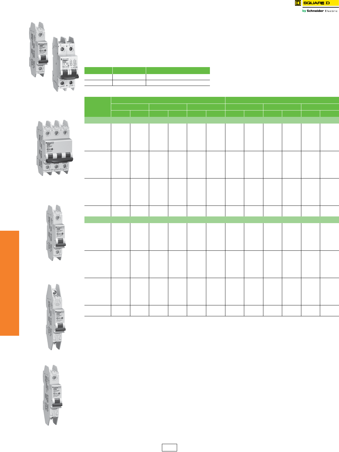
UL 489 C60 Miniature Circuit Breakers
Class 860 / Refer to Catalog 0860CT0201
Multi 9 C60 UL 489 Listed 240 V Miniature
Circuit Breakers
•UL 489 Listed and CSA 22.2 No. 5.1 for branch
circuit protection
•Eliminates concerns and uncertainty of using a UL 1077
device where a UL 489 device is required
•Replaces fuses in low-ampere range; 17 ratings up to 35 A
•10 k AIR (1P @ 120 Vac; 2P and 3P @ 240 Vac)
•60 Vdc for 1P and 125 Vdc for 2P (on C-curve circuit breakers
only, see table below)
•Increased installation flexibility with standard box lugs or
optional ring terminals
•Allows easy front-mounting and rear wiring when using ring
terminals
•A wide range of electrical and mechanical accessories
•Suitable for reverse feeding
•Trip-free mechanism
•Positive indication of contact disconnect
a1P dual rated 120 Vac/60 Vdc.
b2P dual rated 240 Vac/125 Vdc.
Interrupting ratings . . . . . . . . . . . . . . . . . . . . . . . . . . . . . . . . . . . . . . . Page 7-3
Accessories . . . . . . . . . . . . . . . . . . . . . . . . . . . . . . . . . . . . . . . . . . . Page 7-20
Dimensions. . . . . . . . . . . . . . . . . . . . . . . . . . . . . . . . . . . . . . . . . . . . Page 7-54
Mounting Bases . . . . . . . . . . . . . . . . . . . . . . . . . . . . . . . . . . . . . . . . Page 7-13
DIN Mounting Rail . . . . . . . . . . . . . . . . . . . . . . . . . . . . . . . . . . . . . . Section 18
Trip Curve Use Magnetic Release
C For typical loads 7–10 x ampere rating (7–14 for DC)
D For high inrush 10–14 x ampere rating
1P C60
2P C60
3P C60
Box Lug C60
Ring Tongue C60
Box/Ring C60
Table 7.27: UL 489 Circuit Breakers (120/240 V)
Rating (A)
C Curve—7–10 Times Ampere Rating (7–14 DC) D Curve—10–14 Times Ampere Rating
1Pa2Pb3P 1P 2P 3P
Cat. No. $ Price Cat. No. $ Price Cat. No. $ Price Cat. No. $ Price Cat. No. $ Price Cat. No. $ Price
Box Lug/Box Lug
0.5 60100 125.00 60134 269.00 ——60117 125.00 60151 269.00 ——
160101 125.00 60135 269.00 60168 387.00 60118 125.00 60152 269.00 60184 387.00
1.5 60102 125.00 60136 269.00 60169 387.00 60119 125.00 60153 269.00 60185 387.00
260103 125.00 60137 269.00 60170 387.00 60120 125.00 60154 269.00 60186 387.00
360104 125.00 60138 269.00 60171 387.00 60121 125.00 60155 269.00 60187 387.00
460105 125.00 60139 269.00 60172 387.00 60122 125.00 60156 269.00 60188 387.00
560106 125.00 60140 269.00 60173 387.00 60123 125.00 60157 269.00 60189 387.00
660107 114.00 60141 246.00 60174 356.00 60124 114.00 60158 246.00 60190 356.00
760108 114.00 60142 246.00 60175 356.00 60125 114.00 60159 246.00 60191 356.00
860109 114.00 60143 246.00 60176 356.00 60126 114.00 60160 246.00 60192 356.00
10 60110 114.00 60144 246.00 60177 356.00 60127 114.00 60161 246.00 60193 356.00
13 60111 114.00 60145 246.00 60178 356.00 60128 114.00 60162 246.00 60194 356.00
15 60112 114.00 60146 246.00 60179 356.00 60129 114.00 60163 246.00 60195 356.00
20 60113 114.00 60147 246.00 60180 356.00 60130 114.00 60164 246.00 60196 356.00
25 60114 114.00 60148 246.00 60181 356.00 60131 114.00 60165 246.00 60197 356.00
30 60115 120.00 60149 257.00 60182 372.00 60132 120.00 60166 257.00 60198 372.00
35 60116 120.00 60150 257.00 60183 372.00 60133 120.00 60167 257.00 60199 372.00
Ring Tongue/Ring Tongue
0.5 60200 131.00 60234 282.00 ——60217 131.00 60251 282.00 ——
160201 131.00 60235 282.00 60268 410.00 60218 131.00 60252 282.00 60284 410.00
1.5 60202 131.00 60236 282.00 60269 410.00 60219 131.00 60253 282.00 60285 410.00
260203 131.00 60237 282.00 60270 410.00 60220 131.00 60254 282.00 60286 410.00
360204 131.00 60238 282.00 60271 410.00 60221 131.00 60255 282.00 60287 410.00
460205 131.00 60239 282.00 60272 410.00 60222 131.00 60256 282.00 60288 410.00
560206 131.00 60240 282.00 60273 410.00 60223 131.00 60257 282.00 60289 410.00
660207 122.00 60241 261.00 60274 378.00 60224 122.00 60258 261.00 60290 378.00
760208 122.00 60242 261.00 60275 378.00 60225 122.00 60259 261.00 60291 378.00
860209 122.00 60243 261.00 60276 378.00 60226 122.00 60260 261.00 60292 378.00
10 60210 122.00 60244 261.00 60277 378.00 60227 122.00 60261 261.00 60293 378.00
13 60211 122.00 60245 261.00 60278 378.00 60228 122.00 60262 261.00 60294 378.00
15 60212 122.00 60246 261.00 60279 378.00 60229 122.00 60263 261.00 60295 378.00
20 60213 122.00 60247 261.00 60280 378.00 60230 122.00 60264 261.00 60296 378.00
25 60214 122.00 60248 261.00 60281 378.00 60231 122.00 60265 261.00 60297 378.00
30 60215 126.00 60249 273.00 60282 395.00 60232 126.00 60266 273.00 60298 395.00
35 60216 126.00 60250 273.00 60283 395.00 60233 126.00 60267 273.00 60299 395.00
DE2 Discount
Schedule
www.schneider-electric.us
7MINIATURE AND MOLDED CASE
CIRCUIT BREAKERS
© 2012 Schneider Electric
All Rights Reserved 7-17
Multi 9™ Miniature Circuit
Breakers
UL 489 C60 480 Vac and UL489A C60 Miniature Circuit Breakers
Class 860 / Refer to Catalog 0860CT0201
Multi 9 C60 UL 489 Listed 480V Miniature Circuit Breakers
•UL 489 Listed, CSA C22.2 No. 5.1; Also IEC 60947-2; CE marked
•480Y/277 Vac @ 10 kA (2P and 3P), 277 Vac @ 10 kA (1P)
•0.5 A through 20 A
•1P, 2P, 3P, 18 mm wide per pole
•UL 486B Listed single-barrel lug: (2) 18–10 AWG (1-25 mm2) cables, Cu only
•Optional ring tongue terminals
•A wide range of electrical and mechanical accessories
•Suitable for reverse feeding
•Trip-free mechanism
•Positive indication of contact disconnect
Multi 9 C60 UL 489A Listed Miniature Circuit Breakers for DC Telecommunication Applications
A limited range of C60 products are UL Listed as UL 489A circuit breakers for protection of DC telecommunications circuits.
Interrupting Rating. . . . . . . . . . . . . . . . . . . . . . . . . . . . . . . . . . . . . . . .Page 7-3
Accessories . . . . . . . . . . . . . . . . . . . . . . . . . . . . . . . . . . . . . . . . . . . Page 7-20
Dimensions . . . . . . . . . . . . . . . . . . . . . . . . . . . . . . . . . . . . . . . . . . . Page 7-54
Trip Curve Use Magnetic Release
C For typical loads 7–10 x ampere rating (7–14 for DC)
D For high inrush 10–14 x ampere rating
Table 7.28: UL 489 Circuit Breakers (480Y/277 Vac)
Rating
(A)
C Curve—7–10 Times Ampere Rating (7–14 DC) D Curve—10–14 Times Ampere Rating
1P 2P 3P 1P 2P 3P
Cat. No. $ Price Cat. No. $ Price Cat. No. $ Price Cat. No. $ Price Cat. No. $ Price Cat. No. $ Price
Single-Barrel Wire Lug
0.5 MGN61300 168.00 ————MGN61333 168.00 ————
1MGN61301 168.00 MGN61312 357.00 MGN61323 519.00 MGN61334 168.00 MGN61345 357.00 MGN61356 519.00
2MGN61302 168.00 MGN61313 357.00 MGN61324 519.00 MGN61335 168.00 MGN61346 357.00 MGN61357 519.00
3MGN61303 168.00 MGN61314 357.00 MGN61325 519.00 MGN61336 168.00 MGN61347 357.00 MGN61358 519.00
4MGN61304 168.00 MGN61315 357.00 MGN61326 519.00 MGN61337 168.00 MGN61348 357.00 MGN61359 519.00
5MGN61305 168.00 MGN61316 357.00 MGN61327 519.00 MGN61338 168.00 MGN61349 357.00 MGN61360 519.00
6MGN61306 168.00 MGN61317 357.00 MGN61328 519.00 MGN61339 168.00 MGN61350 357.00 MGN61361 519.00
8MGN61307 168.00 MGN61318 357.00 MGN61329 519.00 MGN61340 168.00 MGN61351 357.00 MGN61362 519.00
10 MGN61308 168.00 MGN61319 357.00 MGN61330 519.00 MGN61341 168.00 MGN61352 357.00 MGN61363 519.00
15 MGN61309 168.00 MGN61320 357.00 MGN61331 519.00 MGN61342 168.00 MGN61353 357.00 MGN61364 519.00
20 MGN61310 168.00 MGN61321 357.00 MGN61332 519.00 MGN61343 168.00 MGN61354 357.00 MGN61365 519.00
Ring Tongue Terminal
0.5 MGN61366 168.00 ————MGN61399 168.00 ————
1MGN61367 168.00 MGN61378 357.00 MGN61389 519.00 MGN61400 168.00 MGN61411 357.00 MGN61422 519.00
2MGN61368 168.00 MGN61379 357.00 MGN61390 519.00 MGN61401 168.00 MGN61412 357.00 MGN61423 519.00
3MGN61369 168.00 MGN61380 357.00 MGN61391 519.00 MGN61402 168.00 MGN61413 357.00 MGN61424 519.00
4MGN61370 168.00 MGN61381 357.00 MGN61392 519.00 MGN61403 168.00 MGN61414 357.00 MGN61425 519.00
5MGN61371 168.00 MGN61382 357.00 MGN61393 519.00 MGN61404 168.00 MGN61415 357.00 MGN61426 519.00
6MGN61372 168.00 MGN61383 357.00 MGN61394 519.00 MGN61405 168.00 MGN61416 357.00 MGN61427 519.00
8MGN61373 168.00 MGN61384 357.00 MGN61395 519.00 MGN61406 168.00 MGN61417 357.00 MGN61428 519.00
10 MGN61374 168.00 MGN61385 357.00 MGN61396 519.00 MGN61407 168.00 MGN61418 357.00 MGN61429 519.00
15 MGN61375 168.00 MGN61386 357.00 MGN61397 519.00 MGN61408 168.00 MGN61419 357.00 MGN61430 519.00
20 MGN61376 168.00 MGN61387 357.00 MGN61398 519.00 MGN61409 168.00 MGN61420 357.00 MGN61431 519.00
Table 7.29: UL 489A Circuit Breakers for DC Telecommunications Applications
(1P, 2 Modules, C curve)
Rating (A) Cat. No. $ Price Rating (A) Cat. No. $ Price
0.5 60406 120.00 10 60414 101.00
160407 101.00 13 60415 101.00
260408 101.00 15 60416 101.00
360409 101.00 20 60417 101.00
460410 101.00 30 60418 101.00
560411 101.00 40 60419 111.00
660412 101.00 50 60420 117.00
860413 101.00 60 60421 123.00
1P
UL489 C60
2P
UL489 C60
3P
UL489 C60
DE2 Discount
Schedule
7-18 © 2012 Schneider Electric
All Rights Reserved
www.schneider-electric.us
7MINIATURE AND MOLDED CASE
CIRCUIT BREAKERS
Multi 9™ Miniature
Circuit Breakers
UL1077 C60H Circuit Breakers, UL1053 Ground Fault Protectors
Class 860 / Refer to Catalog 0860CT0201
Multi 9 C60H-DC UL 1077 Recognized Supplementary Protectors (250 and 500 Vdc)
The C60H-DC supplementary protectors are used in direct current circuits (industrial control and automation, transport,
renewable energy, etc.). They provide overcurrent protection within appliances or electrical equipment.
•Range from 0.5–40 A
•5 k AIR at 250 Vdc (1-pole) and 5 k AIR at 500 Vdc (2-pole, wired in series)
•Trip-free mechanism
•Positive indication of contact disconnect
•C-Curve: 7 to14 times ampere rating
•UL 1077, IEC 60947-2, EN 60947-2, GB 14048.2, CCC and CE mark
.
aAt 25°C/77°F, for other temperatures see temperature derating table in Multi 9 Catalog 0860CT0201R1/08
Multi 9 UL1053 Listed GFP Ground Fault Protectors
•Provides ground fault protection for electrical circuits.
•Available in 2P (2-wire) and 4P (3- or 4-wire) versions
•Provides no thermal or magnetic protection. The circuit must be protected by an upstream device.
•Contains Si Technology to increase immunity to noise and to minimize the potential for nuisance tripping in noisy electrical
environments.
•Tripped condition due to a ground fault is displayed on the front face by a red mechanical indicator.
•DIN rail mounting for easy installation.
.
Interrupting Ratings . . . . . . . . . . . . . . . . . . . . . . . . . . . . . . . . . . . . . . Page 7-3
Accessories . . . . . . . . . . . . . . . . . . . . . . . . . . . . . . . . . . . . . . . . . . . Page 7-20
Dimensions. . . . . . . . . . . . . . . . . . . . . . . . . . . . . . . . . . . . . . . . . . . . Page 7-54
Table 7.30: Multi 9 C60H-DC UL 1077 Recognized Supplementary Protectors
1-Pole
24–250 Vdc
2-Pole
24–500 Vdc
Current (A)aCat. No. $ Price Cat. No. $ Price
0.5 MGN61500 182.00 MGN61520 392.00
1MGN61501 182.00 MGN61521 392.00
2MGN61502 182.00 MGN61522 392.00
3MGN61503 182.00 MGN61523 392.00
4MGN61504 182.00 MGN61524 392.00
5MGN61505 182.00 MGN61525 392.00
6MGN61506 182.00 MGN61526 392.00
10 MGN61508 182.00 MGN61528 392.00
13 MGN61509 182.00 MGN61529 392.00
15 MGN61510 182.00 MGN61530 392.00
16 MGN61511 182.00 MGN61531 392.00
20 MGN61512 182.00 MGN61532 392.00
25 MGN61513 182.00 MGN61533 392.00
30 MGN61514 182.00 MGN61534 392.00
32 MGN61515 182.00 MGN61535 392.00
40 MGN61517 200.00 MGN61537 412.00
Table 7.31: Multi 9 UL 1053 Listed GFP Ground Fault Protectors
2P 4P
UL1053
120/240 Vac, 240 Vac, 60 Hz
IEC 61008
230 Vac, 240 Vac, 50 Hz
UL1053
277 Vac, 480Y/277 Vac, 60 Hz
IEC 61008
230/400 Vac, 240/415 Vac, 50 Hz
UL1053
240 Vac, 480Y/277 Vac, 60 Hz
IEC 61008
230/400 Vac, 240/415 Vac, 50 Hz
Current
(A)
Maximum
Sensitivity (mA) Tripping Range Family Cat. No. $ Price Cat. No. $ Price Cat. No. $ Price
25
30 22.1 to 29.9 mA GFP 30 60949 633.00 60969 696.00 60989 720.00
100 73.1 to 98.9 mA GFP 100 60950 570.00 60970 627.00 60990 648.00
300 221 to 299 mA GFP 300 60951 444.00 60971 488.00 60991 504.00
40
30 22.1 to 29.9 mA GFP 30 60952 666.00 60972 734.00 60992 758.00
100 73.1 to 98.9 mA GFP 100 60953 600.00 60973 660.00 60993 683.00
300 221 to 299 mA GFP 300 60954 467.00 60974 513.00 60994 531.00
63
30 22.1 to 29.9 mA GFP 30 60955 1001.00 60975 1100.00 60995 1136.00
100 73.1 to 98.9 mA GFP 100 60956 900.00 60976 990.00 60996 1023.00
300 221 to 299 mA GFP 300 60957 701.00 60977 770.00 60997 795.00
80 300 221 to 299 mA GFP 300 60958 933.00 60978 1026.00 60998 1272.00
100 300 221 to 299 mA GFP 300 60959 1097.00 60979 1206.00 60999 1496.00
1P C60H-DC
2P C60H-DC
4P GFP (3- or 4-wire)
2P GFP
DE2 Discount
Schedule
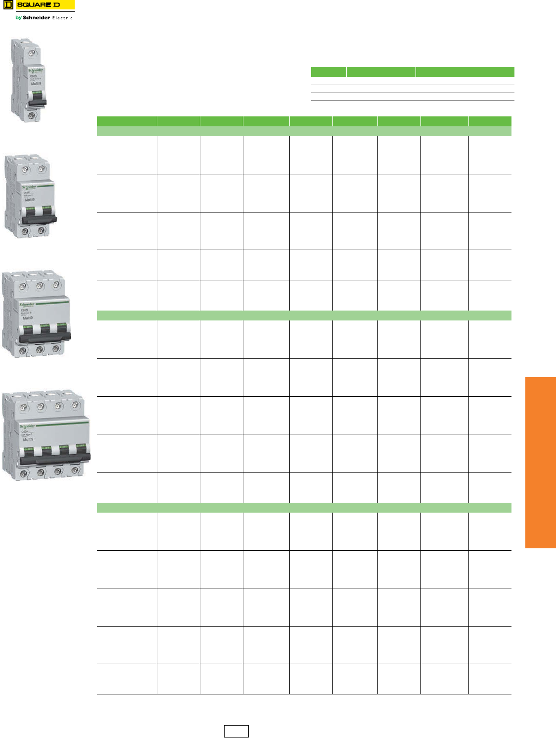
www.schneider-electric.us
7MINIATURE AND MOLDED CASE
CIRCUIT BREAKERS
© 2012 Schneider Electric
All Rights Reserved 7-19
Multi 9™ Miniature
Circuit Breakers
UL 1077 C60 Supplementary Protectors
Class 860 / Refer to Catalog 0860CT0201
Intended for use within equipment where branch circuit
protection is already provided or not needed
•Range from 0.5 to 63 A
•10 k AIR @ 120/240 Vac; 5 k AIR at 480Y/277; 10 k AIR @ 60
Vdc (1P) and 125 Vdc (2P)
•Suitable for reverse feeding
•DIN mounting for easy installation
•Suitable for reverse feeding
•A wide range of electrical and mechanical accessories
•Trip-free mechanism
•Positive indication of contact disconnect
Interrupting Ratings. . . . . . . . . . . . . . . . . . . . . . . . . . . . . . . . . . . . . . .Page 7-3
Accessories. . . . . . . . . . . . . . . . . . . . . . . . . . . . . . . . . . . . . . . . . . . .Page 7-20
Dimensions . . . . . . . . . . . . . . . . . . . . . . . . . . . . . . . . . . . . . . . . . . . .Page 7-54
1P
UL 1077 C60
2P
UL 1077 C60
3P
UL 1077 C60
4P
UL 1077 C60
Trip Curve Use Magnetic Release
B For sensitive equipment 3.2–4.8 x ampere rating
C For typical loads 7–10 x ampere rating (7–14 for DC)
D For high inrush 10–14 x ampere rating
Table 7.32: UL 1077 Supplementary Protectors
Rating (A) 1P $ Price 2P $ Price 3P $ Price 4P $ Price
B Curve—Magnetic Setting Between 3.2 and 4.8 Times Ampere Rating
1MG24110 101.00 MG24125 218.00 MG24140 315.00 MG24155 416.00
1.2 MG17402 101.00 MG17432 218.00 ————
1.5 MG17403 101.00 MG17433 218.00 ————
2MG24111 101.00 MG24126 218.00 MG24141 315.00 MG24156 416.00
3MG24112 101.00 MG24127 218.00 MG24142 315.00 MG24157 416.00
4MG24113 101.00 MG24128 218.00 MG24143 315.00 MG24158 416.00
5MG17404 101.00 MG17434 218.00 ————
6MG24114 101.00 MG24129 218.00 MG24144 315.00 MG24159 416.00
7MG17405 101.00 MG17435 218.00 ————
8MG24115 101.00 MG24130 218.00 MG24145 315.00 MG24160 416.00
10 MG24116 101.00 MG24131 218.00 MG24146 315.00 MG24161 416.00
13 MG24117 101.00 MG24132 218.00 MG24147 315.00 MG24162 416.00
15 MG17406 101.00 MG17436 218.00 MG17461 315.00 ——
16 MG24118 101.00 MG24133 218.00 MG24148 315.00 MG24163 416.00
20 MG24119 101.00 MG24134 218.00 MG24149 315.00 MG24164 416.00
25 MG24120 101.00 MG24135 218.00 MG24150 315.00 MG24165 416.00
30 MG17407 101.00 MG17437 218.00 MG17462 315.00 ——
32 MG24121 101.00 MG24136 218.00 MG24151 315.00 MG24166 416.00
35 MG17408 101.00 MG17438 218.00 MG17463 315.00 ——
40 MG24122 111.00 MG24137 224.00 MG24152 324.00 MG24167 420.00
50 MG24123 117.00 MG24138 240.00 MG24153 338.00 MG24168 438.00
60 MG17409 123.00 MG17439 252.00 MG17464 353.00 ——
63 MG24124 123.00 MG24139 252.00 MG24154 353.00 MG24169 450.00
C Curve—Magnetic Setting Between 7 and 10 Times Ampere Rating
0.5 MG17411 120.00 ——————
1MG24425 101.00 MG24442 218.00 MG24459 315.00 MG24476 416.00
1.2 MG17412 101.00 MG17442 218.00 ————
1.5 MG17413 101.00 MG17443 218.00 ————
2MG24426 101.00 MG24443 218.00 MG24460 315.00 MG24477 416.00
3MG24427 101.00 MG24444 218.00 MG24461 315.00 MG24478 416.00
4 MG24428 101.00 MG24445 218.00 MG24462 315.00 MG24479 416.00
5 MG17414 101.00 MG17444 218.00 ————
6MG24430 101.00 MG24447 218.00 MG24464 315.00 MG24481 416.00
7MG17415 101.00 MG17445 218.00 ————
8MG24431 101.00 MG24448 218.00 MG24465 315.00 MG24482 416.00
10 MG24432 101.00 MG24449 218.00 MG24466 315.00 MG24483 416.00
13 MG24433 101.00 MG24450 218.00 MG24467 315.00 MG24484 416.00
15 MG17416 101.00 MG17446 218.00 MG17466 315.00 ——
16 MG24434 101.00 MG24451 218.00 MG24468 315.00 MG24485 416.00
20 MG24435 101.00 MG24452 218.00 MG24469 315.00 MG24486 416.00
25 MG24436 101.00 MG24453 218.00 MG24470 315.00 MG24487 416.00
30 MG17417 101.00 MG17447 218.00 MG17467 315.00 ——
32 MG24437 101.00 MG24454 218.00 MG24471 315.00 MG24488 416.00
35 MG17418 101.00 MG17448 218.00 MG17468 315.00 ——
40 MG24438 111.00 MG24455 224.00 MG24472 324.00 MG24489 420.00
50 MG24439 117.00 MG24456 240.00 MG24473 338.00 MG24490 438.00
60 MG17419 123.00 MG17449 252.00 MG17469 353.00 ——
63 MG24440 123.00 MG24457 252.00 MG24474 353.00 MG24491 450.00
D Curve—Magnetic Setting Between 10 and 14 Times Ampere Rating
0.5 MG17421 120.00 ——————
1MG24500 101.00 MG24516 218.00 MG24532 315.00 MG24548 416.00
1.2 MG17422 101.00 MG17452 218.00 ————
1.5 MG17423 101.00 MG17453 218.00 ————
2MG24501 101.00 MG24517 218.00 MG24533 315.00 MG24549 416.00
3MG24502 101.00 MG24518 218.00 MG24534 315.00 MG24550 416.00
4MG24503 101.00 MG24519 218.00 MG24535 315.00 MG24551 416.00
5MG17424 101.00 MG17454 218.00 ————
6MG24504 101.00 MG24520 218.00 MG24536 315.00 MG24552 416.00
7MG17425 101.00 MG17455 218.00 ————
8MG24505 101.00 MG24521 218.00 MG24537 315.00 MG24553 416.00
10 MG24506 101.00 MG24522 218.00 MG24538 315.00 MG24554 416.00
13 MG24507 101.00 MG24523 218.00 MG24539 315.00 MG24555 416.00
15 MG17426 101.00 MG17456 218.00 MG17471 315.00 ——
16 MG24508 101.00 MG24524 218.00 MG24540 315.00 MG24556 416.00
20 MG24509 101.00 MG24525 218.00 MG24541 315.00 MG24557 416.00
25 MG24510 101.00 MG24526 218.00 MG24542 315.00 MG24558 416.00
30 MG17427 101.00 MG17457 218.00 MG17472 315.00 ——
32 MG24511 101.00 MG24527 218.00 MG24543 315.00 MG24559 416.00
35 MG17428 101.00 MG17458 218.00 MG17473 315.00 ——
40 MG24512 111.00 MG24528 224.00 MG24544 324.00 MG24560 420.00
50 MG24513 117.00 MG24529 240.00 MG24545 338.00 MG24561 438.00
60 MG17429 123.00 MG17459 252.00 MG17474 353.00 ——
63 MG24514 123.00 MG24530 252.00 MG24546 353.00 MG24562 450.00
DE2 Discount
Schedule
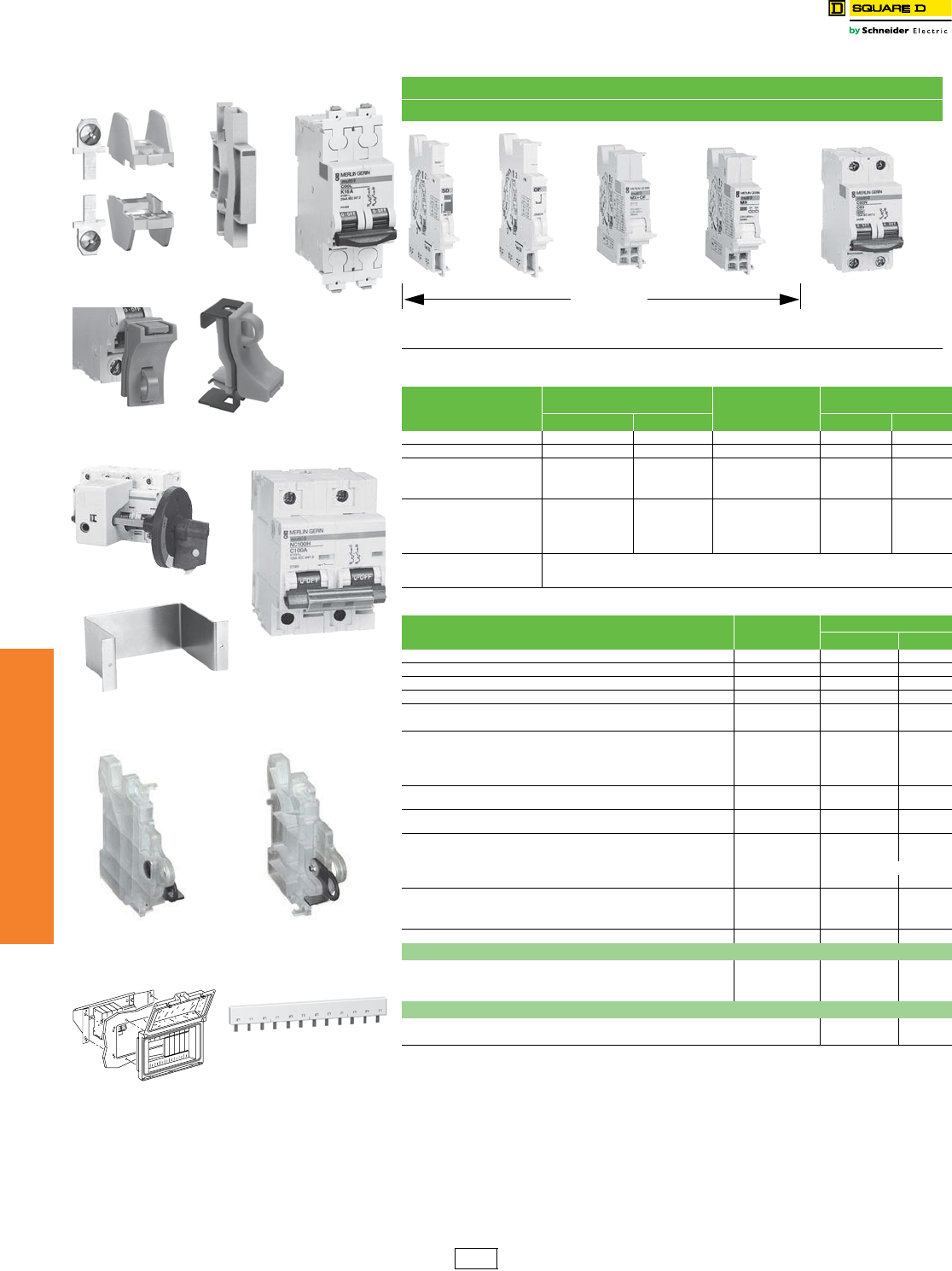
www.schneider-electric.us
7MINIATURE AND MOLDED CASE
CIRCUIT BREAKERS
7-20 © 2012 Schneider Electric
All Rights Reserved
Multi 9™ Miniature
Circuit Breakers
C60 Accessories
Class 860 / Refer to Catalog 0860CT0201
Electrical Accessories for C60 Circuit Breakers and Supplementary Protectors
aLeft-side mounted padlocking device cannot be used in conjunction with accessories SD, OF, MX or MN. Use right-
side mounted padlocking device when accessories are required.
bRight-side mounted padlocking device cannot be used in conjunction with VIGI module. Use left-side mounted
padlocking device when VIGI Module is required..
Possible Combinations
Mounted to the left of the circuit breaker with a maximum width of 54 mm.
++ + +
SD
Alarm Switch
OF
Auxiliary Switch
MX
Shunt trip + Aux
Switch
MN
Undervoltage
Release
C60
Table 7.33: Multi 9 C60 Electrical Accessories
Descriptions Control Voltage Width in 9 mm
modules
C60
UL/IEC
Vac Vdc Cat. No. $ Price
OF Auxiliary Switch (1a1b) 12–277 12–125 1 MG26925 60.00
SD Alarm Switch (1a1b) 12–277 12–125 1 MG26928 60.00
MX Shunt Trip + OF Auxiliary
Switch (1a1b)
24 24 2 27118
140.0048 48 2 27110
110–240–277 125 2 27109
MN Undervoltage Release
24 24 2 27108
201.00
48 48 2 27106
120 — 2 27107
240 — 2 27105
Multi-9 GFP UL 1053 Listed
Ground Fault Protectors
120 to 480Y/277 Vac; 30, 100, and 300 mA; 2P and 4Ps.
See page 7-18 Handout, 0860HO0602 or Catalog 0860CT0201
Table 7.34: Multi 9 C60 Mechanical Accessories
Descriptions C60
Cat. No. $ Price
Ring tongue terminal kit for UL1077 C60 For one pole 17400 15.80
Spacer for DIN rail, Not UL Recognized 9 mm wide MG27062 9.30
Padlock Attachment (1 per for 1P, 2P, 3P or 4P) 2 per pack MG26970 33.20
Heavy-duty Padlock Attachment for C60, Locks OFF only 2 per pack M9PAF 60.00
Padlocking Device Left Side Mount, Locks OFF onlya1 per pack MGN26380 37.50
Padlocking Device Right Side Mount, Locks OFF onlybMGN26381 37.50
Front Mounting Kit
1P MG26983 16.80
2P MG26984 16.80
3P MG26985 16.80
4P MG26989 16.80
Label holders for 2, 3 or 4P C60
(Not UL Recognized) Bag of 10 MG27150 51.00
Terminal Screw Shield (Not UL Recognized) Bag of two
4P shields MG26981 51.00
Terminal cover (Not UL Recognized)
1P MG26975 26.10
2P MG26976 51.00
3P MG26975+MG26976
4P MG26978 102.00
Comb Bus Bar Kit for UL1077 C60, 12 poles, Fixed Length
1Ø MG10285 63.00
2Ø MG10286 69.00
3 Ø MG10287 80.00
Tooth Caps for UL Comb Bus Bar, Bag of 20 60488 37.80
Rotary Handle for C60 (Non UL Recognized)
Operating Subassembly
2P/3P/4P
MG27046 129.00
Door Interlock Handle MG27047 107.00
Fixed Handle (Front or Lateral) MG27048 117.00
Multi-pole Front Mounting Kit
Rail Support (20 of 9 mm modules) 14211 54.00
Hinged Transparent Cover 14210 158.00
Max. 54 mm
Spacer
Label Holders for
2, 3 or 4P C60
Ring Tongue
Terminal Kit
C60 Padlock
Attachment
Front Mounting Kit for C60
1P, 2P, 3P, 4P
(1 per circuit breaker)
Terminal
Screw Shield
Rotary Handle
Heavy-duty Padlock
Attachment
MGN26381 Locking Device
Right Side Mount
MGN26380 Locking
Device Left Side Mount
Multi-pole
Front Mounting Kit
Comb Bus Bar
DE2 Discount
Schedule
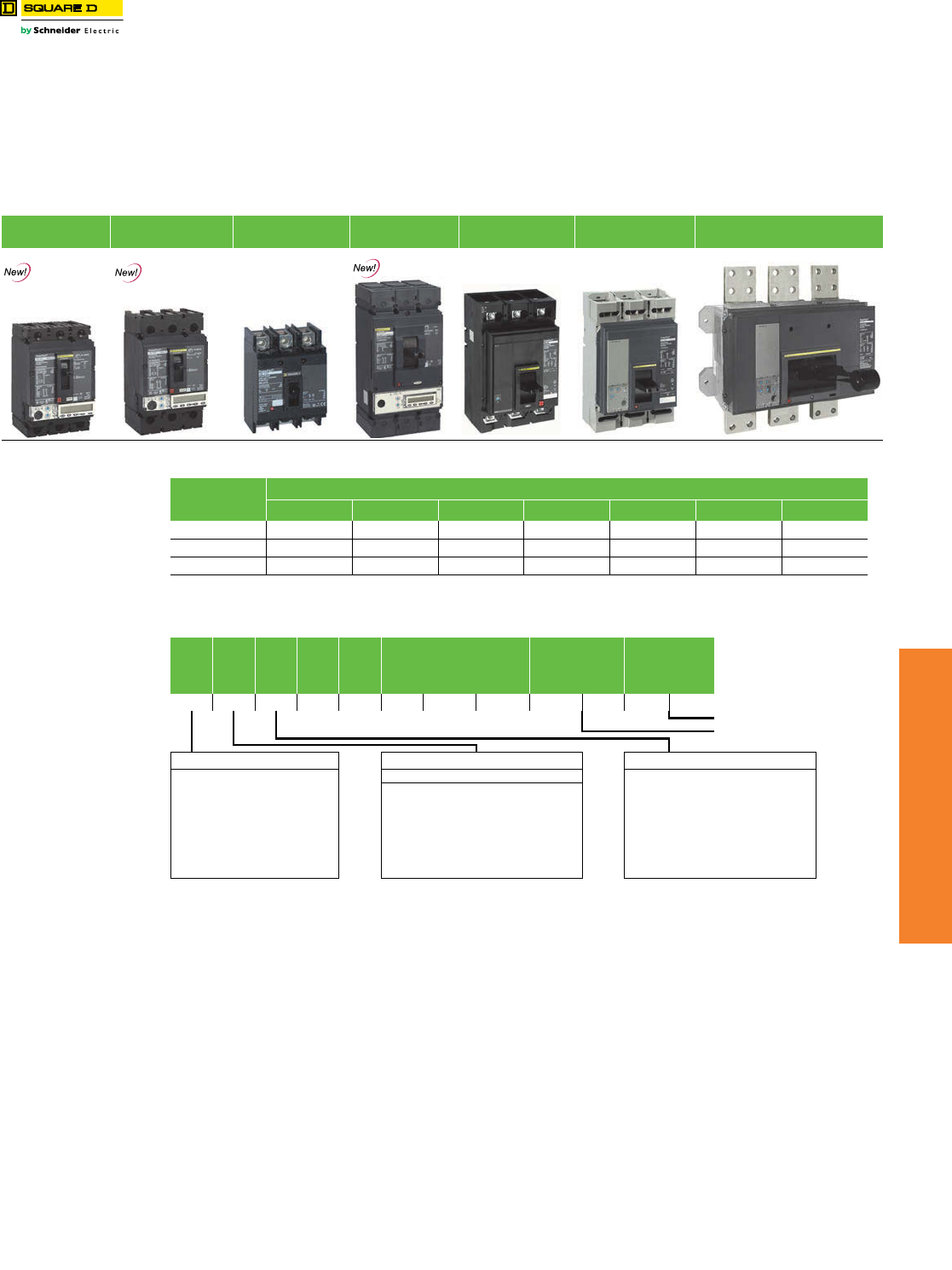
www.schneider-electric.us
7MINIATURE AND MOLDED CASE
CIRCUIT BREAKERS
© 2012 Schneider Electric
All Rights Reserved 7-21
PowerPact™ Molded
Case Circuit Breakers
PowerPact Family
Class 611
The PowerPact Advantage
•Proven Performance: Industry-leading circuit breaker innovation and protection for heavy-duty commercial and industrial
applications.
•Smart: Integrated metering options provide a cost-effective solution to reduce energy consumption, optimize energy costs, and
improve energy availablility for your facilities.
•Flexible: Full range of thermal-magnetic and electronic trip molded case circuit breakers from 15 A to 3000 A, delivering the ratings,
configurations, and operators for your unique applications.
•Simple: Common catalog numbers, standardized ratings, and a full range of field-installable accessories make product selection,
installation and maintenance easier than ever.
•Common Design Features: Mounting holes, door trim, and handle accessories
aP-frame K interrupting is 50 kA at 480 and 600 Vac.
bP-frame L interrupting is 25 kA at 600 Vac.
cFor amperage of M-, P- or R-frame circuit breakers, add a zero to the three amperage digits; for example, 120 = 1200 A.
Description. . . . . . . . . . . . . . . . . . . . . . . . . . . . . . . . . . . . . . . . . . . . . . . .Page
H- and J-Frame Circuit Breakers . . . . . . . . . . . . . . . . . . . . . . . . . . . . . . . 7-22
H- and J-Frame Circuit Breakers . . . . . . . . . . . . . . . . . . . . . . . . . . . . . . . 7-23
Q-Frame Circuit Breakers . . . . . . . . . . . . . . . . . . . . . . . . . . . . . . . . . . . . . 7-24
L-Frame Circuit Breakers . . . . . . . . . . . . . . . . . . . . . . . . . . . . . . . . . . . . . 7-25
P-Frame Circuit Breakers . . . . . . . . . . . . . . . . . . . . . . . . . . . . . . . . . . . . . 7-27
R-Frame Circuit Breakers . . . . . . . . . . . . . . . . . . . . . . . . . . . . . . . . . . . . . 7-28
PowerPact™ H- and J-Frame Electronic Motor Circuit Protectors . . . . . 7-29
Motor Circuit Protectors and Motor Protector Circuit Breakers . . . . . . . . 7-31
Automatic Switches . . . . . . . . . . . . . . . . . . . . . . . . . . . . . . . . . . . . . . .7-34
500 Vdc Circuit Breakers . . . . . . . . . . . . . . . . . . . . . . . . . . . . . . . . . . .7-35
Mission Critical Circuit Breakers . . . . . . . . . . . . . . . . . . . . . . . . . . . . . .7-37
PowerPact™ Circuit Breaker Accessories . . . . . . . . . . . . . . . . . . . . . . . . 7-39
Motor Operators and Rotary Handles . . . . . . . . . . . . . . . . . . . . . . . . . . . 7-40
Locks, Installation Accessories, and Rear Connections . . . . . . . . . . . . . 7-41
Mechanical Lugs . . . . . . . . . . . . . . . . . . . . . . . . . . . . . . . . . . . . . . . . . . . . 7-41
Compression Lugs and Power Distribution Connectors (PDC). . . . . . . . 7-43
Terminal Nuts, Terminal Pads, Terminal Shields and Accessories . . . . . 7-44
Plug-In and Drawout Mountings . . . . . . . . . . . . . . . . . . . . . . . . . . . . . . . . 7-45
Micrologic™ Electronic Trip Units . . . . . . . . . . . . . . . . . . . . . . . . . . . . . . . 7-46
Micrologic™ Trip Unit Accessories . . . . . . . . . . . . . . . . . . . . . . . . . . . . . . 7-48
H-Frame
150 A
J-Frame
250 A
Q-Frame
250 A
L-Frame
600 A
M-Frame
800 A
P-Frame
1200 A
R-Frame
3000 A
Electronic
Trip Version
Electronic
Trip Version
Table 7.35: PowerPact Interrupting Ratings
Vol tag e
Interrupting Rating
B D G J K L R
240 Vac 10 kA 25 kA 65 kA 100 kA 65 kA 125 kA 200 kA
480 Vac 18 kA 35 kA 65 kA 65 kA a100 kA 200 kA
600 Vac 14 kA 18 kA 25 kA 65 kA a50 kAb100 kA
Table 7.36: Common Catalog Numbering System
Frame
Rating
Termination
Poles
Voltag e
Amperage
c
Suffix
Code
Suffix
Code
HGL361 5 0 A BS A
110 Vac Shunt Trip
2A/2B Auxiliary Switch
Frame Designation Interrupting Rating Terminations
240 Vac 480 Vac 600Vac A I-Line
H 150 A Frame B 10 kA L Lugs on Both Ends
J 250 A Frame D 25 kA 18 kA 14 kA F Bus Bar (No Lugs)
Q 250 A Frame G 65 kA 35 kA 18 kA M Lugs Line Side Only
L 600 A Frame J 100 kA 65 kA 25 kA P Lugs Load End Only
M 800 A Frame K 65 kA 65 kA 65 kA N Plug-in
P 1200 A Frame L 125 kA 100 kA 50 kA D Drawout
R 3000 A Frame R 200 kA 200 kA 100 kA S Rear Connected Studs
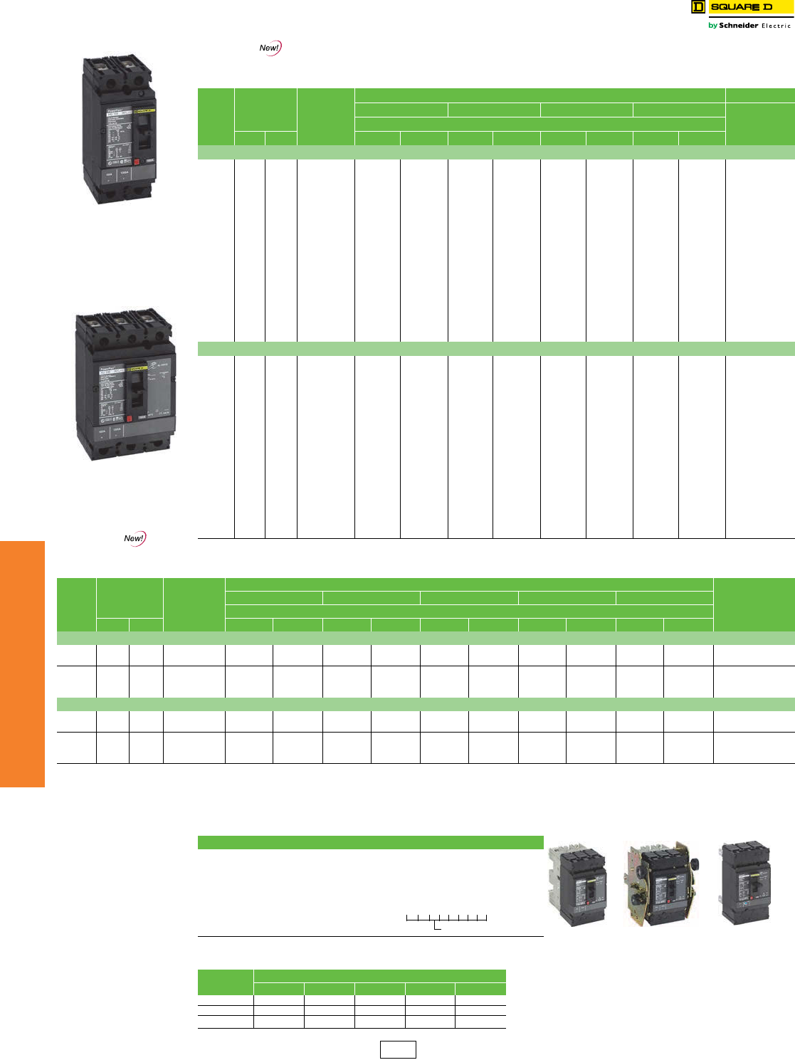
www.schneider-electric.us
7MINIATURE AND MOLDED CASE
CIRCUIT BREAKERS
7-22 © 2012 Schneider Electric
All Rights Reserved
PowerPact™ Circuit
Breakers
H- and J-Frame Circuit Breakers
Class 611 / Refer to Catalog 0611CT1001
HD and HG 2P
Thermal-Magnetic Trip Unit
(2P HJ, HL in 3P module)
H-Frame
Thermal-Magnetic Trip Unit
Table 7.37: H-Frame 150 A Thermal-Magnetic UL Current-Limitingd Circuit Breakers(600 Vac, 250 Vdc) With
Factory Sealed Trip Unit Suitable for Reverse Connectiona
Current
Rating @
40o C
Fixed AC
Magnetic
Trip Cat. No.bc
Interrupting Rating (2nd Letter of Catalog Number)
D G JdLd
Terminal
Wire Range
$ Price
Hold Trip 80% Rated 100% Rated 80% Rated 100% Rated 80% Rated 100% Rated 80% Rated 100% Rated
H-Frame, 150A 2P, 600 Vac 50/60 Hz, 250 Vdc
15 A 350 A 750 A H( )L26015(C) 870.00 1044.00 1269.00 1523.00 1559.00 1871.00 2364.00 2837.00
AL150HD
14–3/0 AWG
Al or Cu
20 A 350 A 750 A H( )L26020(C) 870.00 1044.00 1269.00 1523.00 1559.00 1871.00 2364.00 2837.00
25 A 350 A 750 A H( )L26025(C) 870.00 1044.00 1269.00 1523.00 1559.00 1871.00 2364.00 2837.00
30 A 350 A 750 A H( )L26030(C) 870.00 1044.00 1269.00 1523.00 1559.00 1871.00 2364.00 2837.00
35 A 400 A 850 A H( )L26035(C) 870.00 1044.00 1269.00 1523.00 1559.00 1871.00 2364.00 2837.00
40 A 400 A 850 A H( )L26040(C) 870.00 1044.00 1269.00 1523.00 1559.00 1871.00 2364.00 2837.00
45 A 400 A 850 A H( )L26045(C) 870.00 1044.00 1269.00 1523.00 1559.00 1871.00 2364.00 2837.00
50 A 400 A 850 A H( )L26050(C) 870.00 1044.00 1269.00 1523.00 1559.00 1871.00 2364.00 2837.00
60 A 800 A 1450 A H( )L26060(C) 870.00 1044.00 1269.00 1523.00 1559.00 1871.00 2364.00 2837.00
70 A 800 A 1450 A H( )L26070(C) 1062.00 1274.00 1497.00 1797.00 1721.00 2066.00 2613.00 3137.00
80 A 800 A 1450 A H( )L26080(C) 1062.00 1274.00 1497.00 1797.00 1721.00 2066.00 2613.00 3137.00
90 A 800 A 1450 A H( )L26090(C) 1062.00 1274.00 1497.00 1797.00 1721.00 2066.00 2613.00 3137.00
100 A 800 A 1700 A H( )L26100(C) 1062.00 1274.00 1497.00 1797.00 1721.00 2066.00 2613.00 3137.00
110 A 900 A 1700 A H( )L26110(C) 2072.00 2486.00 3059.00 3671.00 4449.00 5339.00 5534.00 6641.00
125 A 900 A 1700 A H( )L26125(C) 2072.00 2486.00 3059.00 3671.00 4449.00 5339.00 5534.00 6641.00
150 A 900 A 1700 A H( )L26150(C) 2072.00 2486.00 3059.00 3671.00 4449.00 5339.00 5534.00 6641.00
H-Frame 150A 3P, 600 Vac 50/60 Hz, 250 Vdc
15 A 350 A 750 A H( )L36015(C) 1088.00 1305.00 1493.00 1791.00 1949.00 2339.00 2849.00 3419.00
AL150HD
14–3/0 AWG
Al or Cu
20 A 350 A 750 A H( )L36020(C) 1088.00 1305.00 1493.00 1791.00 1949.00 2339.00 2849.00 3419.00
25 A 350 A 750 A H( )L36025(C) 1088.00 1305.00 1493.00 1791.00 1949.00 2339.00 2849.00 3419.00
30 A 350 A 750 A H( )L36030(C) 1088.00 1305.00 1493.00 1791.00 1949.00 2339.00 2849.00 3419.00
35 A 400 A 850 A H( )L36035(C) 1088.00 1305.00 1493.00 1791.00 1949.00 2339.00 2849.00 3419.00
40 A 400 A 850 A H( )L36040(C) 1088.00 1305.00 1493.00 1791.00 1949.00 2339.00 2849.00 3419.00
45 A 400 A 850 A H( )L36045(C) 1088.00 1305.00 1493.00 1791.00 1949.00 2339.00 2849.00 3419.00
50 A 400 A 850 A H( )L36050(C) 1088.00 1305.00 1493.00 1791.00 1949.00 2339.00 2849.00 3419.00
60 A 800 A 1450 A H( )L36060(C) 1088.00 1305.00 1493.00 1791.00 1949.00 2339.00 2849.00 3419.00
70 A 800 A 1450 A H( )L36070(C) 1328.00 1592.00 1701.00 2042.00 2099.00 2519.00 3149.00 3779.00
80 A 800 A 1450 A H( )L36080(C) 1328.00 1592.00 1701.00 2042.00 2099.00 2519.00 3149.00 3779.00
90 A 800 A 1450 A H( )L36090(C) 1328.00 1592.00 1701.00 2042.00 2099.00 2519.00 3149.00 3779.00
100 A 800 A 1700 A H( )L36100(C) 1328.00 1592.00 1701.00 2042.00 2099.00 2519.00 3149.00 3779.00
110 A 900 A 1700 A H( )L36110(C) 2600.00 3120.00 3599.00 4319.00 5174.00 6209.00 6749.00 8099.00
125 A 900 A 1700 A H( )L36125(C) 2600.00 3120.00 3599.00 4319.00 5174.00 6209.00 6749.00 8099.00
150 A 900 A 1700 A H( )L36150(C) 2600.00 3120.00 3599.00 4319.00 5174.00 6209.00 6749.00 8099.00
Table 7.38: J-Frame 250 A Thermal-Magnetic UL Current-Limitingd Circuit Breakers (600 Vac, 250 Vdc) With Factory Sealed Trip Unit
Suitable for Reverse Connectiona
Current
Rating @
40oC
Adjustable AC
Magnetic
Trip Cat. No.bc
Interrupting Rating (2nd Letter of Catalog Number)
Terminal
Wire Range
D G JdLdRd
$ Price
Low High 80% Rated 100% Rated 80% Rated 100% Rated 80% Rated 100% Rated 80% Rated 100% Rated 80% Rated 100% Rated
J-Frame 250A 2P, 600 Vac 50/60 Hz, 250 Vdc
150 A 750 A 1500 A J( )L26150(C) 2175.00 2610.00 3212.00 3854.00 4671.00 5606.00 5811.00 6972.00 —— AL175JD
4–4/0 AWG Al or Cu
175 A 875 A 1750 A J( )L26175(C) 2175.00 2610.00 3212.00 3854.00 4671.00 5606.00 5811.00 6972.00 ——
200 A 1000 A 2000 A J( )L26200(C) 2175.00 2610.00 3212.00 3854.00 4671.00 5606.00 5811.00 6972.00 —— AL250JD
3/0 AWG–350 kcmil
Al or Cu
225 A 1125 A 2250 A J( )L26225(C) 2175.00 2610.00 3212.00 3854.00 4671.00 5606.00 5811.00 6972.00 ——
250 A 1250 A 2500 A J( )L26250(C) 2988.00 3585.00 4251.00 5102.00 6225.00 7469.00 7194.00 8633.00 ——
J-Frame 250A 3P, 600 Vac 50/60 Hz, 250 Vdc
150 A 750 A 1500 A J( )L36150(C) 2730.00 3276.00 3779.00 4535.00 5432.00 6519.00 7086.00 8504.00 9212.00 11055.00 AL175JD
4–4/0 AWG Al or Cu
175 A 875 A 1750 A J( )L36175(C) 2730.00 3276.00 3779.00 4535.00 5432.00 6519.00 7086.00 8504.00 9212.00 11055.00
200 A 1000 A 2000 A J( )L36200(C) 2730.00 3276.00 3779.00 4535.00 5432.00 6519.00 7086.00 8504.00 9212.00 11055.00 AL250JD
3/0 AWG–350 kcmil
Al or Cu
225 A 1125 A 2250 A J( )L36225(C) 2730.00 3276.00 3779.00 4535.00 5432.00 6519.00 7086.00 8504.00 9212.00 11055.00
250 A 1250 A 2500 A J( )L36250(C) 3749.00 4499.00 5001.00 6002.00 7238.00 8685.00 8993.00 10791.00 11169.00 13402.00
aSee Supplemental Digest pages 3-2 and 3-3 for circuit breakers with field interchangeable trip units.
bTo complete catalog number, replace the blank with the appropriate rating (D, G, J, L).
cFor 100% rated circuit breakers add a “C” in the 9th character place (for example, HDL26015C or JDL26150C).
100% rated H- and J-frame circuit breakers have copper lugs and can only be used with copper wire.
dCircuit breakers with J, L, and R interrupting ratings are UL certified as current limiting..
Table 7.39: H- and J-Frame Termination Options
Termination Letter
A = I-Line (See Section 9)
F = No Lugs (includes terminal nut kit on both ends)
L = Lugs both ends
M = Lugs ON end Terminal Nut Kit OFF end
P = Lugs OFF end Terminal Nut Kit ON end
N = Plug-in e
D = Drawout e
S = Rear Connected e
eFor N and D pricing, add termination pricing on page 7-45 to price. For S pricing, add termination pricing on page 7-41 to price.
Plug-in
Drawout
Rear Connected
H G L 3 6 1 0 0
For factory-installed
termination, place termination
letter in the third block of the
circuit breaker catalog number.
Termination Letter
Table 7.40: H- and J-Frame Interrupting Ratings
Vol tage Interrupting Rating Accessories . . . . . . . . . . . . . . . . . . . . . . . . . . . . . . . . . . . . . . . . . . Page 7-39
Optional Lugs . . . . . . . . . . . . . . . . . . . . . . . . . . . . . . . . . . . . . . . . . Page 7-42
Dimensions . . . . . . . . . . . . . . . . . . . . . . . . . . . . . . . . . . . . . . . . . . . Page 7-55
Enclosures . . . . . . . . . . . . . . . . . . . . . . . . . . . . . . . . . . . . . . . . . . . Page 7-56
D G J L R
240 Vac 25 kA 65 kA 100 kA 125 kA 200 kA
480 Vac 18 kA 35 kA 65 kA 100 kA 200 kA
600 Vac 14 kA 18 kA 25 kA 50 kA 100 kA
DE2 Discount
Schedule
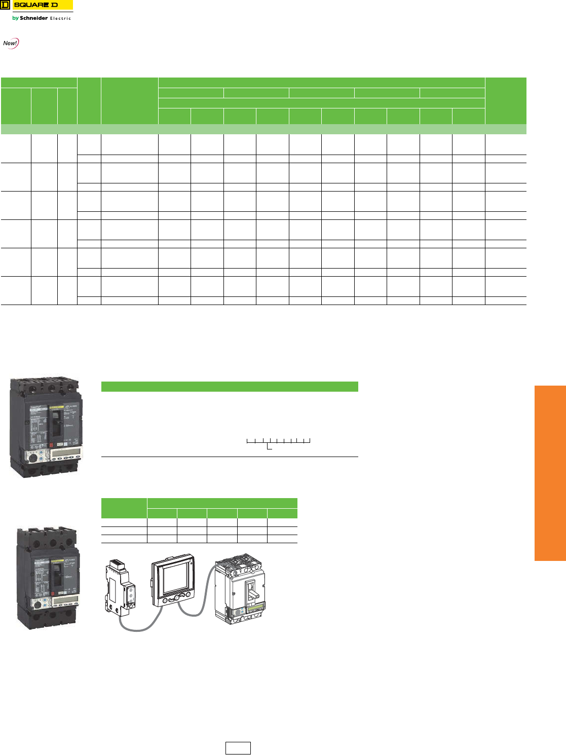
www.schneider-electric.us
7MINIATURE AND MOLDED CASE
CIRCUIT BREAKERS
© 2012 Schneider Electric
All Rights Reserved 7-23
PowerPact™ Circuit
Breakers
H- and J-Frame Circuit Breakers
Class 611 / Refer to Catalog 0611CT1001
Accessories . . . . . . . . . . . . . . . . . . . . . . . . . . . . . . . . . . . . . . . . . . .Page 7-39
Optional Lugs . . . . . . . . . . . . . . . . . . . . . . . . . . . . . . . . . . . . . . . . . .Page 7-42
Dimensions . . . . . . . . . . . . . . . . . . . . . . . . . . . . . . . . . . . . . . . . . . . .Page 7-55
Enclosures . . . . . . . . . . . . . . . . . . . . . . . . . . . . . . . . . . . . . . . . . . . .Page 7-56
Electronic Trip
Version
Table 7.41: H-Frame 150 A and J-Frame 250 A Electronic Trip UL Current-Limitinga Circuit Breakers
(600 Vac) With Factory Sealed Trip Unitb Suitable for Reverse Connection g
Electronic Trip Unit
Sensor
Rating Cat. No.c
Interrupting Rating (2nd Letter of Catalog Number)
Terminal
Type Function Trip
Unit
D G Ja La Ra
$ Price
80%
Rated
100%
Rated
80%
Rated
100%
Rated
80%
Rated
100%
Rated
80%
Rated
100%
Rated
80%
Rated
100%
Rated
600 Vac, 50/60 Hz, 3P
Micrologic
Standard LI 3.2f
60 A
100 A
150 A
H( )L36060(C)U31X
H( )L36100(C)U31X
H( )L36150(C)U31X
1247.00
1487.00
2759.00
1455.00
1735.00
3220.00
1652.00
1860.00
3758.00
1928.00
2171.00
4386.00
2108.00
2258.00
5333.00
2460.00
2635.00
6224.00
3008.00
3308.00
6908.00
3510.00
3860.00
8062.00
3971.00
4367.00
9119.00
4633.00
5095.00
10642.00
AL150HDd
250 A J( )L36250(C)U31X 2957.00 3451.00 4006.00 4675.00 5659.00 6604.00 7313.00 8534.00 9653.00 11265.00 AL250JDe
Micrologic
Standard LSI 3.2Sf
60 A
100 A
150 A
H( )L36060(C)U33X
H( )L36100(C)U33X
H( )L36150(C)U33X
1433.00
1673.00
2945.00
1641.00
1921.00
3405.00
1838.00
2046.00
3944.00
2113.00
2356.00
4571.00
2294.00
2444.00
5519.00
2646.00
2821.00
6409.00
3194.00
3494.00
7094.00
3696.00
4046.00
8247.00
4216.00
4612.00
9364.00
4879.00
5341.00
10886.00
AL150HDd
250 A J( )L36250(C)U33X 3221.00 3715.00 4270.00 4939.00 5923.00 6868.00 7577.00 8798.00 10002.00 11613.00 AL250JDe
Micrologic
Ammeter LSI 5.2A
60 A
100 A
150 A
H( )L36060(C)U43X
H( )L36100(C)U43X
H( )L36150(C)U43X
2031.00
2271.00
3543.00
2240.00
2520.00
4004.00
2436.00
2644.00
4542.00
2712.00
2955.00
5170.00
2892.00
3042.00
6117.00
3244.00
3419.00
7008.00
3792.00
4092.00
7692.00
4295.00
4645.00
8846.00
5005.00
5401.00
10153.00
5669.00
6131.00
11677.00
AL150HDd
250 A J( )L36250(C)U43X 4075.00 4569.00 5124.00 5793.00 6777.00 7722.00 8431.00 9653.00 11129.00 12742.00 AL250JDe
Micrologic
Energy LSI 5.2E
60 A
100 A
150 A
H( )L36060(C)U53X
H( )L36100(C)U53X
H( )L36150(C)U53X
2391.00
2631.00
3903.00
2599.00
2879.00
4363.00
2796.00
3004.00
4902.00
3072.00
3314.00
5529.00
3252.00
3402.00
6477.00
3604.00
3779.00
7367.00
4152.00
4452.00
8052.00
4654.00
5004.00
9205.00
5481.00
5877.00
10629.00
6143.00
6605.00
12151.00
AL150HDd
250 A J( )L36250(C)U53X 4588.00 5082.00 5637.00 6306.00 7290.00 8235.00 8944.00 10165.00 11806.00 13418.00 AL250JDe
Micrologic
Ammeter LSIG 6.2A
60 A
100 A
150 A
H( )L36060(C)U44X
H( )L36100(C)U44X
H( )L36150(C)U44X
2751.00
2991.00
4263.00
2960.00
3240.00
4724.00
3156.00
3364.00
5262.00
3432.00
3675.00
5890.00
3612.00
3762.00
6837.00
3964.00
4139.00
7728.00
4512.00
4812.00
8412.00
5015.00
5365.00
9566.00
5956.00
6352.00
11104.00
6620.00
7082.00
12627.00
AL150HDd
250 A J( )L36250(C)U44X 5100.00 5594.00 6149.00 6818.00 7802.00 8747.00 9456.00 10678.00 12482.00 14095.00 AL250JDe
Micrologic
Energy LSIG 6.2E
60 A
100 A
150 A
H( )L36060(C)U54X
H( )L36100(C)U54X
H( )L36150(C)U54X
3111.00
3351.00
4623.00
3319.00
3599.00
5083.00
3516.00
3724.00
5622.00
3792.00
4034.00
6249.00
3972.00
4122.00
7197.00
4324.00
4499.00
8087.00
4872.00
5172.00
8772.00
5374.00
5724.00
9925.00
6431.00
6827.00
11579.00
7094.00
7556.00
13101.00
AL150HDd
250 A J( )L36250(C)U54X 5613.00 6107.00 6662.00 7331.00 8315.00 9260.00 9969.00 11190.00 13159.00 14771.00 AL250JDe
aCircuit breakers with J, L, and R interrupting ratings are UL certified as current limiting.
bSee Supplemental Digest page 3-2 for circuit breakers with field-interchangeable trip units
cFor 100% rated circuit breakers, add a “C” in the 9th character place (for example, HGL36150CU31X, JGL36250CU43X)
100% rated H- and J-frame circuit breakers have copper lugs and can only be used with copper wire.
dAL150HD wire range is 14–3/0 AWG Al or Cu.
eAL250JD wire range is 3/0 AWG–350 kcmil Al or Cu. For smaller wire range (4–4/0 AWG Al or Cu), replace the lug’s wire binding screws with the larger binding screws provided.
f3P circuit breakers with this trip unit can be used for 2P applications.
gFor applications requiring communications see page 7-49.
H-Frame
Micrologic™ Trip Unit
J-Frame
Micrologic™ Trip Unit
Table 7.42: H- and J-Frame Termination Options
Termination Letter
A - I-Line (See Section 9)
F = No Lugs (includes terminal nut kit on both ends)
L = Lugs both ends
M = Lugs ON end Terminal Nut Kit OFF end
P = Lugs OFF end Terminal Nut Kit ON end
N = Plug-in h
D = Drawout h
S = Rear Connected h
hFor N and D pricing, add termination pricing on page 7-45 to price. For S pricing, add
termination pricing on page 7-41 to price.
Table 7.43: H- and J-Frame Interrupting Ratings
Vol tage Interrupting Rating
D G J L R
240 Vac 25 KA 65 kA 100 kA 125 kA 200 kA
480 Vac 18 kA 35 kA 65 kA 100 kA 200 kA
600 Vac 14 kA 18 kA 25 kA 50 kA 100 kA
H D L 3 6 0 1 5 T
For factory-installed
termination, place termination
letter in the third block of the
circuit breaker catalog number.
Termination Letter
rciMcigolo
E
2
.5
rI%
A
03
>
03>011>
.9
2
9
.
3
9.
4
9. 59
.
1
89.
7
9
.
6
9
.
Ir )
o
I
x(
5.
1
2
5.2
34
01
8
6
5
dsI)rIx(
H-Frame Circuit Breaker with
Optional FDM and IFM Modules
DE2 Discount
Schedule
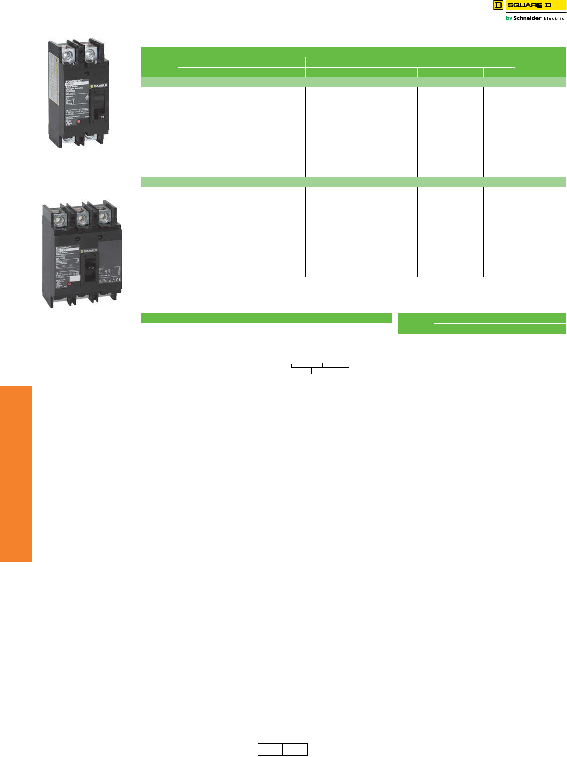
7-24 © 2012 Schneider Electric
All Rights Reserved
www.schneider-electric.us
7MINIATURE AND MOLDED CASE
CIRCUIT BREAKERS
PowerPact™ Circuit
Breaker
Q-Frame Circuit Breakers
Class 0734 / Refer to Catalogs: 0734CT0201
aReplacement lugs and electrical accessories are not available for PowerPact Q-frame circuit breakers.
b250 A requires the use of copper cables only.
250 A lugs are suitable for copper conductors only
Table 7.44: PowerPact Q-Framea250 A Thermal-Magnetic Circuit Breaker (240 Vac)
Ampere
Rating
Fixed AC
Magnetic Trip
Interrupting Rating
Terminal Wire
Range
B D G J
Hold Trip Cat. No. $ Price Cat. No. $ Price Cat. No. $ Price Cat. No. $ Price
2P, 240 Vac
70 A 1000 A 1800 A QBL22070 474.00 QDL22070 1143.00 QGL22070 1521.00 QJL22070 1890.00
#4 AWG - 300 kcmil
Al/Cu
80 A 1000 A 1800 A QBL22080 474.00 QDL22080 1143.00 QGL22080 1521.00 QJL22080 1890.00
90 A 1000 A 1800 A QBL22090 474.00 QDL22090 1143.00 QGL22090 1521.00 QJL22090 1890.00
100 A 1200 A 2400 A QBL22100 474.00 QDL22100 1143.00 QGL22100 1521.00 QJL22100 1890.00
110 A 1200 A 2400 A QBL22110 474.00 QDL22110 1143.00 QGL22110 1521.00 QJL22110 1890.00
125 A 1200 A 2400 A QBL22125 474.00 QDL22125 1143.00 QGL22125 1521.00 QJL22125 1890.00
150 A 1200 A 2400 A QBL22150 474.00 QDL22150 1143.00 QGL22150 1521.00 QJL22150 1890.00
175 A 1200 A 2400 A QBL22175 474.00 QDL22175 1143.00 QGL22175 1521.00 QJL22175 1890.00
200 A 1200 A 2400 A QBL22200 474.00 QDL22200 1143.00 QGL22200 1521.00 QJL22200 1890.00
225 A 1200 A 2400 A QBL22225 474.00 QDL22225 1143.00 QGL22225 1521.00 QJL22225 1890.00
250 Ab1200 A 2400 A QBL22250 693.00 QDL22250 1544.00 QGL22250 1970.00 QJL22250 2348.00
3P, 240 Vac
70 A 1000 A 1800 A QBL32070 1248.00 QDL32070 1784.00 QGL32070 2442.00 QJL32070 2796.00
#4 AWG - 300 kcmil
Al/Cu
80 A 1000 A 1800 A QBL32080 1248.00 QDL32080 1784.00 QGL32080 2442.00 QJL32080 2796.00
90 A 1000 A 1800 A QBL32090 1248.00 QDL32090 1784.00 QGL32090 2442.00 QJL32090 2796.00
100 A 1200 A 2400 A QBL32100 1248.00 QDL32100 1784.00 QGL32100 2442.00 QJL32100 2796.00
110 A 1200 A 2400 A QBL32110 1248.00 QDL32110 1784.00 QGL32110 2442.00 QJL32110 2796.00
125 A 1200 A 2400 A QBL32125 1248.00 QDL32125 1784.00 QGL32125 2442.00 QJL32125 2796.00
150 A 1200 A 2400 A QBL32150 1248.00 QDL32150 1784.00 QGL32150 2442.00 QJL32150 2796.00
175 A 1200 A 2400 A QBL32175 1248.00 QDL32175 1784.00 QGL32175 2442.00 QJL32175 2796.00
200 A 1200 A 2400 A QBL32200 1248.00 QDL32200 1784.00 QGL32200 2442.00 QJL32200 2796.00
225 A 1200 A 2400 A QBL32225 1248.00 QDL32225 1784.00 QGL32225 2442.00 QJL32225 2796.00
250 Ab1200 A 2400 A QBL32250 1812.00 QDL32250 2442.00 QGL32250 3150.00 QJL32250 3465.00
Table 7.45: Q-Frame Termination Options Table 7.46: Q-Frame Interrupting Ratings
Termination Letter Vol tage Interrupting Rating
A = I-Line (See Section 9) B D G J
E = Bolt-on I-Line (See Section 9) 240 Vacc10 kA 25 kA 65 kA 100 kAd
F = No lugs cQ-frame circuit breakers are 240 Vac only.
d3P QJ circuit breakers are rated at 208Y/120 Vac only.
L = Lugs both ends
M = Lugs ON end, studs on OFF end
P = Lugs OFF end, studs on ON end
DimensionsPage 7-55
EnclosuresPage 7-56
eAdd TS suffix for studs on both ends without
nuts and washers. See Catalog 0734CT0201
for additional information.
QBL 3P
70–250 A
QBL 2P
70–250 A
Q G L 3 2 2 0 0
For factory-installed termination,
place termination letter in the
third block of the circuit breaker
catalog number.
Termination Letter
DE2A Discount
Schedule
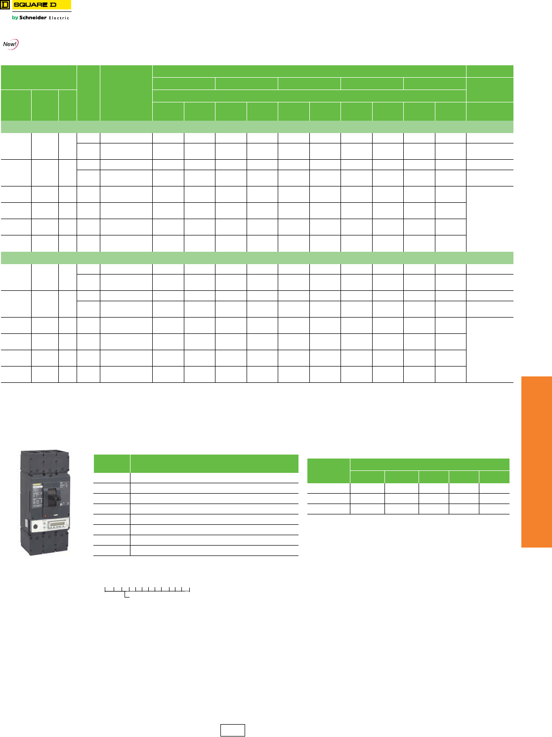
www.schneider-electric.us
7MINIATURE AND MOLDED CASE
CIRCUIT BREAKERS
© 2012 Schneider Electric
All Rights Reserved 7-25
PowerPact™ Circuit
Breakers
L-Frame Circuit Breakers
Class 611 / Refer to Catalogs: 0611CT1001
mFor N and D pricing, add termination pricing on page 7-45 to price. For
S pricing, add termination pricing on page 7-41 to price.
Accessories . . . . . . . . . . . . . . . . . . . . . . . . . . . . . . . . . . . . . . . . . . .page 7-39
Optional Lugs . . . . . . . . . . . . . . . . . . . . . . . . . . . . . . . . . . . . . . . . . .page 7-42
Dimensions . . . . . . . . . . . . . . . . . . . . . . . . . . . . . . . . . . . . . . . . . . . .page 7-55
Enclosures. . . . . . . . . . . . . . . . . . . . . . . . . . . . . . . . . . . . . . . . . . . . .page 7-56
Table 7.47: L-Frame 600 A Circuit Breakers with Lugs and Factory-Sealed Electronic Trip Units Suitable for Reverse Connectionfl
Electronic Trip Unit
Sensor
Rating
Cat. No.g
Interrupting Rating (2nd Letter of Catalog Number)
D G J hL hR h
Terminal
Type Function Trip
Unit
$ Price
80%
Rated
100%
Rated
80%
Rated
100%
Rated
80%
Rated
100%
Rated
80%
Rated
100%
Rated
80%
Rated
100%
Rated
600 Vac, 50/60 Hz, 3P
Micrologic
Standard LI 3.3i
250 A L( )L36250(C)U31X 4827.00 5648.00 5081.00 5945.00 8478.00 9919.00 9918.00 11604.00 11406.00 13345.00 AL400L61K3j
400 A
600 A
L( )L36400(C)U31X
L( )L36600U31X
4827.00
7109.00
5648.00
—
5081.00
7484.00
5945.00
—
8478.00
10541.00
9919.00
—
9918.00
11837.00
11604.00
—
11406.00
13613.00
13345.00
—AL600LS52K3k
Micrologic
Standard LSI 3.3Si
250 A L( )L36250(C)U33X 5391.00 6211.00 5674.00 6538.00 9071.00 10513.00 10511.00 12198.00 12088.00 14028.00 AL400L61K3j
400 A
600 A
L( )L36400(C)U33X
L( )L36600U33X
5391.00
7673.00
6211.00
—
5674.00
8077.00
6538.00
—
9071.00
11134.00
10513.00
—
10511.00
12430.00
12198.00
—
12088.00
14295.00
14028.00
—AL600LS52K3k
Micrologic
Ammeter LSI 5.3A 400 A
600 A
L( )L36400(C)U43X
L( )L36600U43X
6253.00
8535.00
7073.00
—
6582.00
8984.00
7445.00
—
9979.00
12041.00
11420.00
—
11419.00
13337.00
13105.00
—
13132.00
15338.00
15071.00
—
AL600LS52K3k
Micrologic
Energy LSI 5.3E 400 A
600 A
L( )L36400(C)U53X
L( )L36600U53X
7200.00
9483.00
8021.00
—
7579.00
9982.00
8443.00
—
10976.00
13039.00
12418.00
—
12416.00
14335.00
14103.00
—
14278.00
16485.00
16218.00
—
Micrologic
Ammeter LSIG 6.3A 400 A
600 A
L( )L36400(C)U44X
L( )L36600U44X
8149.00
10431.00
8969.00
—
8578.00
10980.00
9441.00
—
11975.00
14037.00
13416.00
—
13415.00
15333.00
15101.00
—
15427.00
17633.00
17366.00
—
Micrologic
Energy LSIG 6.3E 400 A
600 A
L( )L36400(C)U54X
L( )L36600U54X
9097.00
11379.00
9917.00
—
9575.00
11978.00
10439.00
—
12972.00
15035.00
14414.00
—
14412.00
16331.00
16099.00
—
16574.00
18781.00
18514.00
—
600 Vac, 50/60 Hz, 4P
Micrologic
Standard LI 3.3
250 A L( )L46250(C)U31X 5327.00 6233.00 5581.00 6530.00 8978.00 10501.00 10418.00 12189.00 11981.00 14017.00 AL400L61K4j
400 A
600 A
L( )L46400(C)U31X
L( )L46600U31X
6227.00
8509.00
6233.00
—
6481.00
8884.00
7583.00
—
9878.00
11941.00
11557.00
—
11318.00
13237.00
13242.00
—
13016.00
15223.00
15228.00
—AL600LS52K4k
Micrologic
Standard LSI 3.3S
250 A L( )L46250(C)U33X 5891.00 6796.00 6174.00 7123.00 9571.00 11098.00 11011.00 12783.00 12663.00 14700.00 AL400L61K4j
400 A
600 A
L( )L46400(C)U33X
L( )L46600U33X
6791.00
9073.00
7849.00
—
7074.00
9477.00
8176.00
—
10471.00
12534.00
12151.00
—
11911.00
13830.00
13836.00
—
13698.00
15905.00
15911.00
—AL600LS52K4k
Micrologic
Ammeter LSI 5.3A 400 A
600 A
L( )L46400(C)U43X
L( )L46600U43X
7653.00
9935.00
8711.00
—
7982.00
10384.00
9083.00
—
11379.00
13441.00
13058.00
—
12819.00
14737.00
14743.00
—
14742.00
16948.00
16954.00
—
AL600LS52K4k
Micrologic
Energy LSI 5.3E 400 A
600 A
L( )L46400(C)U53X
L( )L46600U53X
8600.00
10883.00
9659.00
—
8979.00
11382.00
10081.00
—
12376.00
14439.00
14056.00
—
13816.00
15735.00
15741.00
—
15888.00
18095.00
18102.00
—
Micrologic
Ammeter LSIG 6.3A 400 A
600 A
L( )L46400(C)U44X
L( )L46600U44X
9549.00
11831.00
10607.00
—
9978.00
12380.00
11079.00
—
13375.00
15437.00
15054.00
—
14815.00
16733.00
16739.00
—
17037.00
19243.00
19250.00
—
Micrologic
Energy LSIG 6.3E 400 A
600 A
L( )L46400(C)U54X
L( )L46600U54X
10497.00
12779.00
11555.00
—
10975.00
13378.00
12077.00
—
14372.00
16435.00
16052.00
—
15812.00
17731.00
17791.00
—
18184.00
20391.00
20460.00
—
fSee Supplemental Digest page 3-4 for circuit breakers with field-interchangeable trip units
gFor 100% rated circuit breakers (250 A and 400 A only), add a “C” in the 9th character place (for example, LGL36400CU31X)
hCircuit breakers with J, L, and R interrupting ratings are UL certified as current limiting.
i3P circuit breakers with this trip unit can be used for 2P applications.
jAL400L61K3 terminal wire ranges are (1) 2 AWG–600 kcmil Cu or 1) 2 AWG–500 kcmil Al.
kAL600LS52K3 terminal wire range is (2) 2/0 AWG–500 kcmil Al/Cu.
lFor applications requiring communicatins see page 7-49.
L-Frame Circuit Breaker
Table 7.48: Termination Options
Termination
Letter Termination Option
A I-Line (See Section 9)
F No lugs
L Lugs both ends
M Lugs ON end, terminal nut kit OFF end
P Lugs OFF end, terminal nut kit ON end
NmPlug In
DmDrawout
SmRear Connected
For factory-installed termination, place termination letter
in the third block of the circuit breaker catalog number.
Termination Letter
L G L 3 6 6 0 0 U 4 4 X
Table 7.49: Interrupting Ratings
Vol tage
Interrupting Rating
D G J L R
240 Vac 25 kA 65 kA 100 kA 125 kA 200 kA
480 Vac 18 kA 35 kA 65 kA 100 kA 200 kA
600 Vac 14 kA 18 kA 25 kA 50 kA 100 kA
DE2 Discount
Schedule
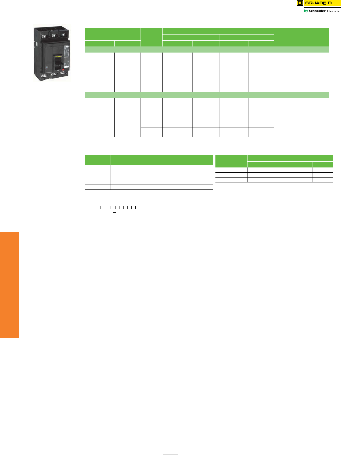
www.schneider-electric.us
7MINIATURE AND MOLDED CASE
CIRCUIT BREAKERS
7-26 © 2012 Schneider Electric
All Rights Reserved
PowerPact™ Circuit
Breakers
M-Frame Circuit Breakers
Class 612 / Refer to Catalogs: 0612CT0101
Accessories . . . . . . . . . . . . . . . . . . . . . . . . . . . . . . . . . . . . . . . . . . page 7-39
Optional Lugs . . . . . . . . . . . . . . . . . . . . . . . . . . . . . . . . . . . . . . . . . page 7-42
Dimensions. . . . . . . . . . . . . . . . . . . . . . . . . . . . . . . . . . . . . . . . . . . . page 7-55
Enclosures . . . . . . . . . . . . . . . . . . . . . . . . . . . . . . . . . . . . . . . . . . . . page 7-56
M-Frame Circuit Breaker
Table 7.50: M-Frame 800 A, Basic Electronic Trip System Type ET 1.0n Factory-Sealed Trip Unit
Electronic Trip Unit Sensor
Rating
Interrupting Rating
Terminal Wire Range
(AWG/kcmil)
G J
Type Function Cat. No. $ Price Cat. No. $ Price
2P, 600 Vac 50/60 Hz
Basic
Fixed
Long-time,
Adjustable
Instantaneous
Tr i p
300 A MGL26300 5960.00 MJL26300 7829.00
AL800M23K
(3) 3/0–500 Al/Cu
350 A MGL26350 5960.00 MJL26350 7829.00
400 A MGL26400 5960.00 MJL26400 7829.00
450 A MGL26450 5960.00 MJL26450 7829.00
500 A MGL26500 5960.00 MJL26500 7829.00
600 A MGL26600 5960.00 MJL26600 7829.00
700 A MGL26700 7719.00 MJL26700 9657.00
800 A MGL26800 7719.00 MJL26800 9657.00
3P, 600 Vac 50/60 Hz
Basic
Fixed
Long-time,
Adjustable
Instantaneous
Tr i p
300 A MGL36300 7560.00 MJL36300 9456.00
AL800M23K
(3) 3/0–500 Al/Cu
350 A MGL36350 7560.00 MJL36350 9456.00
400 A MGL36400 7560.00 MJL36400 9456.00
450 A MGL36450 7560.00 MJL36450 9456.00
500 A MGL36500 7560.00 MJL36500 9456.00
600 A MGL36600 7560.00 MJL36600 9456.00
700 A MGL36700 9927.00 MJL36700 11882.00
800 A MGL36800 9927.00 MJL36800 11882.00
nThe ET 1.0 trip unit cannot be field replaced or have the long-time trip point setting adjusted. It is considered an electronic equivalent of a thermal-
magnetic circuit breaker.
Table 7.51: Termination Options
Termination
Letter Termination Option
A I-Line (See Section 9)
F No lugs
L Lugs both ends
M Lugs ON end, terminal nut kit OFF end
P Lugs OFF end, terminal nut kit ON end
M G L 3 6 4 0 0
For factory-installed termination, place termination letter in
the third block of the circuit breaker catalog number.
Termination Letter
Table 7.52: Frame Interrupting Ratings
Vol tage Interrupting Rating
D G J L
240 Vac 25 kA 65 kA 100 kA 125 kA
480 Vac 18 kA 35 kA 65 kA 100 kA
600 Vac 14 kA 18 kA 25 kA 50 kA
DE2 Discount
Schedule
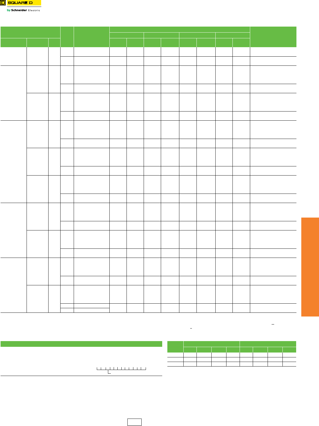
www.schneider-electric.us
7MINIATURE AND MOLDED CASE
CIRCUIT BREAKERS
© 2012 Schneider Electric
All Rights Reserved 7-27
PowerPact™ Circuit
Breakers
P-Frame Circuit Breakers
Class 612 / Refer to Catalog 0612CT0101
R-frame catalog numbers and pricing . . . . . . . . . . . . . . . . . . . . . . .Page 7-28
Dimensions . . . . . . . . . . . . . . . . . . . . . . . . . . . . . . . . . . . . . . . . . . . .Page 7-55
Trip Unit Options . . . . . . . . . . . . . . . . . . . . . . . . . . . . . . . . . . . . . . . .Page 7-47
Optional Lugs . . . . . . . . . . . . . . . . . . . . . . . . . . . . . . . . . . . . . . . . . .Page 7-42
Alternate Rating Plugs . . . . . . . . . . . . . . . . . . . . . . . . . . . . . . . . . . .Page 7-48
Enclosure . . . . . . . . . . . . . . . . . . . . . . . . . . . . . . . . . . . . . . . . . . . . .Page 7-56
Accessories . . . . . . . . . . . . . . . . . . . . . . . . . . . . . . . . . . . . . . . . . . . .Page 7-39
Table 7.53: P-Frame 1200 A (600 Vac, 50/60 Hz) 3Pa Circuit Breaker with Electronic Trip Unit
Electronic Trip Unit Sensor
Rating Cat. No.bc
$ Price
Terminal
Wire Range
GbJbKbLbd
Type Function Trip
Unit
80%
Rated
100%
Ratedc
80%
Rated
100%
Ratedc
80%
Rated
100%
Rated c
80%
Rated
100%
Ratedc
Basic Electronic
Trip Unit
(Not
Interchangeable)
Fixed long-
time,
Adjustable
Instantaneous
ET1.0I
600 A P( )L36060 13905.00 —14783.00 —14783.00 —15660.00 —AL800M23K
(3) 3/0 AWG–500 kcmil Al or Cu
800 A P( )L36080 — — — —
1000 A P( )L36100 19049.00 —20250.00 —20250.00 —21452.00 —AL1200P25K
(4) 3/0 AWG–500 kcmil Al or Cu
1200 A P( )L36120 — — — —
Micrologic
Interchangeable
Standard
Trip Unit
LI 3.0
250 A P( )L36025(C)U31A
14693.00 21510.00 15570.00 22868.00 15570.00 22868.00 16448.00 24224.00 AL800M23K
(3) 3/0 AWG–500 kcmil Al or Cu
400 A P( )L36040(C)U31A
600 A P( )L36060(C)U31A
800 A P( )L36080(C)U31A
1000 A P( )L36100(C)U31A 19836.00 30239.00 21038.00 32147.00 21038.00 32147.00 22239.00 34052.00 AL1200P25K
(4) 3/0 AWG–500 kcmil Al or Cu
1200 A P( )L36120(C)U31A
LSI 5.0
250 A P( )L36025(C)U33A
15032.00 21812.00 15909.00 23187.00 15909.00 23187.00 16787.00 24564.00 AL800M23K
(3) 3/0 AWG–500 kcmil Al or Cu
400 A P( )L36040(C)U33A
600 A P( )L36060(C)U33A
800 A P( )L36080(C)U33A
1000 A P( )L36100(C)U33A 20177.00 30540.00 21378.00 32466.00 21378.00 32466.00 22580.00 34392.00 AL1200P25K
(4) 3/0 AWG–500 kcmil Al or Cu
1200 A P( )L36120(C)U33A
Micrologic
Interchangeable
Ammeter
Trip Unit
LI 3.0A
250 A P( )L36025(C)U41A
15543.00 22266.00 16421.00 23670.00 16421.00 23670.00 17298.00 25076.00 AL800M23K
(3) 3/0 AWG–500 kcmil Al or Cu
400 A P( )L36040(C)U41A
600 A P( )L36060(C)U41A
800 A P( )L36080(C)U41A
1000 A P( )L36100(C)U41A 20688.00 30995.00 21890.00 32949.00 21890.00 32949.00 23091.00 34904.00 AL1200P25K
(4) 3/0 AWG–500 kcmil Al or Cu
1200 A P( )L36120(C)U41A
LSI 5.0A
250 A P( )L36025(C)U43A
17043.00 23597.00 17921.00 25085.00 17921.00 25085.00 18798.00 26574.00 AL800M23K
(3) 3/0 AWG–500 kcmil Al or Cu
400 A P( )L36040(C)U43A
600 A P( )L36060(C)U43A
800 A P( )L36080(C)U43A
1000 A P( )L36100(C)U43A 22185.00 32324.00 23387.00 34364.00 23387.00 34364.00 24590.00 36402.00 AL1200P25K
(4) 3/0 AWG–500 kcmil Al or Cu
1200 A P( )L36120(C)U43A
LSIG 6.0A
250 A P( )L36025(C)U44A
18909.00 25256.00 19787.00 26849.00 19787.00 26849.00 20664.00 28442.00 AL800M23K
(3) 3/0 AWG–500 kcmil Al or Cu
400 A P( )L36040(C)U44A
600 A P( )L36060(C)U44A
800 A P( )L36080(C)U44A
1000 A P( )L36100(C)U44A 24054.00 33983.00 25256.00 36128.00 25256.00 36128.00 26457.00 38270.00 AL1200P25K
(4) 3/0 AWG–500 kcmil Al or Cu
1200 A P( )L36120(C)U44A
Micrologic
Interchangeable
Power
Trip Unit
LSI 5.0P
250 A P( )L36025(C)U63AE1
21455.00 27516.00 22332.00 29252.00 22332.00 29252.00 23210.00 30986.00 AL800M23K
(3) 3/0 AWG–500 kcmil Al or Cu
400 A P( )L36040(C)U63AE1
600 A P( )L36060(C)U63AE1
800 A P( )L36080(C)U63AE1
1000 A P( )L36100(C)U63AE1 26597.00 36243.00 27800.00 38529.00 27800.00 38529.00 29001.00 40814.00 AL1200P25K
(4) 3/0 AWG–500 kcmil Al or Cu
1200 A P( )L36120(C)U63AE1
LSIG 6.0P
250 A P( )L36025(C)U64AE1
22536.00 28476.00 23414.00 30272.00 23414.00 30272.00 24291.00 32067.00 AL800M23K
(3) 3/0 AWG–500 kcmil Al or Cu
400 A P( )L36040(C)U64AE1
600 A P( )L36060(C)U64AE1
800 A P( )L36080(C)U64AE1
1000 A P( )L36100(C)U64AE1 27680.00 37203.00 28881.00 39551.00 28881.00 39551.00 30083.00 41895.00 AL1200P25K
(4) 3/0 AWG–500 kcmil Al or Cu
1200 A P( )L36120(C)U64AE1
Micrologic
Interchangeable
Harmonic
Trip Unit
LSI 5.0H
250 A P( )L36025(C)U73AE1
25538.00 31140.00 26415.00 33104.00 26415.00 33104.00 27291.00 35067.00 AL800M23K
(3) 3/0 AWG–500 kcmil Al or Cu
400 A P( )L36040(C)U73AE1
600 A P( )L36060(C)U73AE1
800 A P( )L36080(C)U73AE1
1000 A P( )L36100(C)U73AE1 30680.00 39867.00 31881.00 42381.00 31881.00 42381.00 33083.00 44895.00 AL1200P25K
(4) 3/0 AWG–500 kcmil Al or Cu
1200 A P( )L36120(C)U73AE1
LSIG 6.0H
250 A P( )L36025(C)U74AE1
26619.00 32100.00 27497.00 34125.00 27497.00 34125.00 28374.00 36150.00 AL800M23K
(3) 3/0 AWG–500 kcmil Al or Cu
400 A P( )L36040(C)U74AE1
600 A P( )L36060(C)U74AE1
800 A P( )L36080(C)U74AE1
1000 A P( )L36100(C)U74AE1 31761.00 40829.00 32963.00 43404.00 32963.00 43404.00 34166.00 45978.00 AL1200P25K
(4) 3/0 AWG–500 kcmil Al or Cu
1200 A P( )L36120(C)U74AE1
aFor 2P and 4P information see Catalog 0612CT0101.
bTo complete the catalog number, replace the ( ) with the appropriate interrupting rating (G, J, K or L).
cFor 100% rated circuit breakers add a “C” in the 9th character place. For example, the catalog number for a 100% trip unit with LI trip functions at 250A would be PGL36025CU31A.
dFor all L interrupting rating, change the 5th character (voltage rating) from a 6 (600V) to a 4 (480V); for example, PLL34025U31A. The 480V AIR is standard 100 kA.
Table 7.54: P-Frame Termination Options Table 7.55: P-Frame and R-Frame Interrupting Ratings
Termination Letter Volta g e P-Frame Interrupting Rating R-Frame Interrupting Rating
F = No Lugs (Includes terminal nut kit on both ends) G J K L G J K L
L = Lugs both ends 240 Vac 65 kA 100 kA 65 kA 125 kA 65 kA 100 kA 65 kA 125 kA
M = Lugs ON end, terminal nut kit OFF end 480 Vac 35 kA 65 kA 50 kA 100 kA 35 kA 65 kA 65 kA 100 kA
P = Lugs OFF end, terminal nut kit ON end 600 Vac 18 kA 25 kA 50 kA 25 kA 18 kA 25 kA 65 kA 50 kA
D = Drawouta
A = I-Line (See Section 9)
aFor D pricing add termination pricing on page 7-45.
P G L 3 6 0 4 0 U 4 1 A
For factory-installed termination, place
termination letter in the third block of
the circuit breaker catalog number.
Termination Letter
DE2 Discount
Schedule
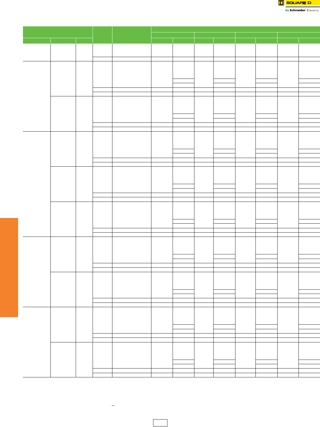
7-28 © 2012 Schneider Electric
All Rights Reserved
www.schneider-electric.us
7MINIATURE AND MOLDED CASE
CIRCUIT BREAKERS
PowerPact™ Circuit
Breakers
R-Frame Circuit Breakers
Class 612 / Refer to Catalog 0612CT0101
Table 7.56: R-Frame 3000 A (600 Vac, 50/60 Hz) 3Pa Circuit Breaker with Electronic Trip Unit
Electronic Trip Unit Sensor
Rating Cat. No.bc
$ Price
Gbd Jbd Kbd Lbd
Type Function Trip Unit 80% Rated 100% Rated 80% Rated 100% Rated 80% Rated 100% Rated 80% Rated 100% Rated
Basic Electronic
Trip Unit
(Not
Interchangeable)
Fixed
long-time,
Adjustable
Instantaneous
ET1.0I
1200 A R( )F36120
22373.00
—
23549.00
—
23549.00
—
24723.00
—
1600 A R( )F36160 — — — —
2000 A R( )F36200 — — — —
2500 A R( )F36250 35639.00 —37512.00 —37512.00 —39383.00 —
Micrologic
Interchangeable
Standard Trip Unit
LI 3.0
600 A R( )F36060(C)U31A
23160.00
27759.00
24336.00
29301.00
24336.00
29301.00
25511.00
30843.00
800 A R( )F36080(C)U31A
1000 A R( )F36100(C)U31A
1200 A R( )F36120(C)U31A
1600 A R( )F36160(C)U31A 29775.00 31430.00 31430.00 33083.00
2000 A R( )F36200(C)U31A 35042.00 36989.00 36989.00 38936.00
2500 A R( )F36250(C)U31A 36426.00 57075.00 38300.00 60248.00 38300.00 60248.00 40170.00 63417.00
3000 A R( )F36300(C)U31A 54027.00 62451.00 57236.00 65738.00 57236.00 65738.00 60246.00 69024.00
LSI 5.0
600 A R( )F36060(C)U33A
23501.00
28065.00
24675.00
29624.00
24675.00
29624.00
25851.00
31184.00
800 A R( )F36080(C)U33A
1000 A R( )F36100(C)U33A
1200 A R( )F36120(C)U33A
1600 A R( )F36160(C)U33A 30081.00 31752.00 31752.00 33423.00
2000 A R( )F36200(C)U33A 35348.00 37313.00 37313.00 39276.00
2500 A R( )F36250(C)U33A 36767.00 57383.00 38640.00 60570.00 38640.00 60570.00 40511.00 63758.00
3000 A R( )F36300(C)U33A 54513.00 62757.00 57542.00 66060.00 57542.00 66060.00 60570.00 69363.00
Micrologic
Interchangeable
Ammeter
Trip Unit
LI 3.0A
600 A R( )F36060(C)U41A
24012.00
28493.00
25188.00
30075.00
25188.00
30075.00
26363.00
31658.00
800 A R( )F36080(C)U41A
1000 A R( )F36100(C)U41A
1200 A R( )F36120(C)U41A
1600 A R( )F36160(C)U41A 30509.00 32202.00 32202.00 33897.00
2000 A R( )F36200(C)U41A 35775.00 37763.00 37763.00 39750.00
2500 A R( )F36250(C)U41A 37278.00 57809.00 39152.00 61020.00 39152.00 61020.00 41022.00 64232.00
3000 A R( )F36300(C)U41A 54918.00 63185.00 57969.00 66510.00 57969.00 66510.00 61020.00 69836.00
LSI 5.0A
600 A R( )F36060(C)U43A
25511.00
29874.00
26685.00
31533.00
26685.00
31533.00
27860.00
33194.00
800 A R( )F36080(C)U43A
1000 A R( )F36100(C)U43A
1200 A R( )F36120(C)U43A
1600 A R( )F36160(C)U43A 31889.00 33662.00 33662.00 35433.00
2000 A R( )F36200(C)U43A 37158.00 39221.00 39221.00 41286.00
2500 A R( )F36250(C)U43A 38777.00 59190.00 40649.00 62478.00 40649.00 62478.00 42521.00 65768.00
3000 A R( )F36300(C)U43A 56231.00 64569.00 59354.00 67968.00 59354.00 67968.00 62480.00 71367.00
LSIG 6.0A
600 A R( )F36060(C)U44A
27378.00
31556.00
28553.00
33308.00
28553.00
33308.00
29729.00
35061.00
800 A R( )F36080(C)U44A
1000 A R( )F36100(C)U44A
1200 A R( )F36120(C)U44A
1600 A R( )F36160(C)U44A 33570.00 35436.00 35436.00 37301.00
2000 A R( )F36200(C)U44A 38838.00 40995.00 40995.00 43154.00
2500 A R( )F36250(C)U44A 40644.00 60870.00 43368.00 64253.00 43368.00 64253.00 44388.00 67635.00
3000 A R( )F36300(C)U44A 57827.00 66255.00 60965.00 69743.00 60965.00 69743.00 64254.00 73230.00
Micrologic
Interchangeable
Power Trip Unit
LSI 5.0P
600 A R( )F36060(C)U63AE1
29922.00
33845.00
31097.00
35724.00
31097.00
35724.00
32273.00
37605.00
800 A R( )F36080(C)U63AE1
1000 A R( )F36100(C)U63AE1
1200 A R( )F36120(C)U63AE1
1600 A R( )F36160(C)U63AE1 35859.00 37853.00 37853.00 39845.00
2000 A R( )F36200(C)U63AE1 41129.00 43413.00 43413.00 45698.00
2500 A R( )F36250(C)U63AE1 43188.00 63161.00 45062.00 66671.00 45062.00 66671.00 46932.00 70179.00
3000 A R( )F36300(C)U63AE1 60003.00 68553.00 63338.00 72161.00 63338.00 72161.00 66671.00 75858.00
LSIG 6.0P
600 A R( )F36060(C)U64AE1
31004.00
34818.00
32180.00
36753.00
32180.00
36753.00
33354.00
38687.00
800 A R( )F36080(C)U64AE1
1000 A R( )F36100(C)U64AE1
1200 A R( )F36120(C)U64AE1
1600 A R( )F36160(C)U64AE1 36834.00 38880.00 38880.00 40926.00
2000 A R( )F36200(C)U64AE1 42102.00 44441.00 44441.00 46779.00
2500 A R( )F36250(C)U64AE1 44270.00 64136.00 46143.00 67698.00 46143.00 67698.00 48014.00 71261.00
3000 A R( )F36300(C)U64AE1 60929.00 69528.00 64313.00 73188.00 64313.00 73188.00 67698.00 76848.00
Micrologic
Interchangeable
Harmonic Trip
Unit
LSI 5.0H
600 A R( )F36060(C)U73AE1
34005.00
37518.00
35180.00
39603.00
35180.00
39603.00
36354.00
41687.00
800 A R( )F36080(C)U73AE1
1000 A R( )F36100(C)U73AE1
1200 A R( )F36120(C)U73AE1
1600 A R( )F36160(C)U73AE1 39534.00 41730.00 41730.00 43928.00
2000 A R( )F36200(C)U73AE1 44801.00 47291.00 47291.00 49779.00
2500 A R( )F36250(C)U73AE1 47271.00 66836.00 49143.00 70548.00 49143.00 70548.00 51015.00 74262.00
3000 A R( )F36300(C)U73AE1 63494.00 72236.00 67020.00 76038.00 67020.00 76038.00 70550.00 79841.00
LSIG 6.0H
600 A R( )F36060(C)U74AE1
35087.00
38493.00
36261.00
40631.00
36261.00
40631.00
37436.00
42770.00
800 A R( )F36080(C)U74AE1
1000 A R( )F36100(C)U74AE1
1200 A R( )F36120(C)U74AE1
1600 A R( )F36160(C)U74AE1 40509.00 42758.00 42758.00 45009.00
2000 A R( )F36200(C)U74AE1 45776.00 48320.00 48320.00 50862.00
2500 A R( )F36250(C)U74AE1 48353.00 67809.00 50225.00 71576.00 50225.00 71576.00 52097.00 75344.00
3000 A R( )F36300(C)U74AE1 64419.00 73212.00 67997.00 77066.00 67997.00 77066.00 71577.00 80919.00
Note: R-frame circuit breakers can be bus- or cable-connected. For cable connections, optional terminal pad kit RLTB or equivalent bus structure is required. Each RLTB kit contains terminal pads
for one end of the circuit breaker only and has provisions for mounting a maximum of 8 lugs per phase (9 lugs for 3000 A). RLTB kits are included with 2500 A 100% rated circuit breakers.
The RL3TB kits are included with the 3000 A, 80% and 100% rated circuit breakers. For other circuit breakers, order terminal pad kit (RLTB) and optional lugs separately. See pages 7-42–7-44.
aFor 2P and 4P information see Catalog 0612CT0101.
bTo complete the catalog number, replace the blank ( ) with the appropriate interrupting rating (G, J, K or L).
cListed catalog numbers are for 80% rated circuit breakers. For 100% rated circuit breakers add a “C” in the 9th character place. For example, the catalog number for a 100% standard trip unit
with LI trip functions at 2500A would be RGF36250CU31A.
dSee page 7-27 for interrupting ratings table.
DE2 Discount
Schedule

www.schneider-electric.us
7MINIATURE AND MOLDED CASE
CIRCUIT BREAKERS
© 2012 Schneider Electric
All Rights Reserved 7-29
Motor Circuit Protectors PowerPact™ H- and J-Frame Electronic Motor Circuit Protectors
Class 611 / Refer to Catalog 0611CT1001
PowerPact H- and J-frame electronic Motor Circuit Protectors (MCP) are magnetic-only
instantaneous-trip circuit breakers. They are designed to offer short circuit protection and
are National Electrical Code (NEC) compliant when installed as part of a combination
controller having motor overload protection. MCP circuit breakers accept the same
accessories and terminals as the equivalent thermal-magnetic circuit breakers.
Determine the hp rating from the nameplate of the motor. Select a MCP with an ampere
rating recommended for the hp and voltage involved. When using the automatic settings the
MCP microprocessor automatically adjusts the trip settings for both current and time to
align with the start-up characteristic for the motor type, whether it is a standard or energy-
efficient motor. This includes a dampening means to accommodate a transient motor in-
rush current without nuisance tripping of the circuit breaker.
aBased on 2005 NEC Table 430.52.
bSee NEC Exception No. 1 to Table 430.52. The NEC 1300% maximum setting may be inadequate for instantaneous
trip circuit breakers to withstand current surges typical of the magnetization current of autotransformer type reduced
voltage starters, or open transition wye-delta starters during transfer from “start” to “run,” constant hp multi-speed
motors, and motors labeled “high efficiency.”
cBased on 2005 NEC Table 430.250.
dPer NEC 430.3, part-winding motors should select two circuit breakers, each at not more than one-half the allowable
trip setting for the horsepower rating. The two circuit breakers should operate simultaneously as a disconnecting
means per NEC 430.103.
eListed voltages are rated motor voltages. Corresponding system voltages are 200 Vac, 220–240 Vac, 440–480 Vac
and 550–600 Vac. Select wire and circuit breakers based on horsepower rather than nameplate full-load current per
NEC 430.6 (A) for general motor applications.
Short Circuit Current Rating (SCCR)
Tested to meet NEC and UL508A requirements for short circuit current ratings as part of an
approved combination controller.
See www.us.schneider-electric.us for specific ratings and combination ID numbers.
Accessories. . . . . . . . . . . . . . . . . . . . . . . . . . . . . . . . . . . . . . . . . . . .Page 7-39
Optional Lugs . . . . . . . . . . . . . . . . . . . . . . . . . . . . . . . . . . . . . . . . . .Page 7-42
Dimensions . . . . . . . . . . . . . . . . . . . . . . . . . . . . . . . . . . . . . . . . . . . .Page 7-55
Enclosures. . . . . . . . . . . . . . . . . . . . . . . . . . . . . . . . . . . . . . . . . . . . .Page 7-56
To select combination starters and motor controllers using MCP’s meeting NEC
Article 430, refer to pages 16-35—16-37.
Table 7.57: H- and J-Frame Electronic Motor Circuit Protectors (MCP)
Frame Sensor
Rating
Full Load
Amperes
Range
Adjustable
Instantaneous
Trip Range
Suffix
Interrupting Rating
J
(See SCCR Table Below)
L
(See SCCR Table Below)
Cat. No. $ Price Cat. No. $ Price
H-Frame
30 A 1.5–25 A 9–325 A M71 HJL36030M71 1089.00 HLL36030M71 1223.00
50 A 14–42 A 84–546 A M72 HJL36050M72 1385.00 HLL36050M72 1553.00
100 A 30–80 A 180–1040 A M73 HJL36100M73 1646.00 HLL36100M73 1827.00
150 A 58–130 A 348–1690 A M74 HJL36150M74 2069.00 HLL36150M74 2306.00
J-Frame 250 A 114–217 A 684–2500 A M75 JJL36250M75 2393.00 JLL36250M75 2673.00
Table 7.58: Maximum Rating or Setting of Motor Protective Devicesa
Type of Motor
Percentage of Full-load Current
Setting Not to Exceedb
A, B, C, D Standard 800% 1300%
B, E Energy Efficient 1100% 1700%
Table 7.59: MCP Selection by HP Ratingsc of Induction-type Squirrel-Cage and
Wound-rotor Motorsd
3Ø 60 Hz Voltagese
Full-Load Amperes Suffix
200 Vac 230 Vac 460 Vac 575 Vac
.5–5 .5–7.5 .75–15 1–20 1.5–25 M71
5–10 5–15 10–30 15–40 14–42 M72
10–25 15–30 25–60 30–75 30–80 M73
20–40 25–50 50–100 60–125 58–130 M74
40–60 50–75 100–150 125–200 114–217 M75
Table 7.60: Short Circuit Current Ratings (SCCR)
Contactor/Starter
Interrupting Rating
J L
200–240 Vac 480 Vac 600 Vac 200–240 Vac 480 Vac 600 Vac
Tesys D-line and F-line 100 kA 65 kA 25 kA 125 kA 100 kA 50 kA
NEMA Type S 100 kA 65 kA 25 kA 125 kA 100 kA 50 kA
Standard
Energy Efficient
Energie Efficace
Energia Eficiente
Standard
Energy Efficient
Energie Efficace
Energia Eficiente
I
t
Standard
Energy Efficient
Energie Efficace
Motor Type / Tipo de Motor / Type de Moteur
Energia Eficiente
DE2 Discount
Schedule
7-30 © 2012 Schneider Electric
All Rights Reserved
www.schneider-electric.us
7MINIATURE AND MOLDED CASE
CIRCUIT BREAKERS
Motor Circuit Protectors H-Frame and J-Frame MCP Selector
Class 611 / Refer to Catalog 0611CT1001
Table 7.61: Application of PowerPact™ H-Frame and J-Frame Electronic Motor Circuit Protectors (MCP)
Horsepower Rating of Induction-type Squirrel-cage and Wound-rotor Motors 3Ø 60 Hz NEC Full Load
Amperes
PowerPact H-Frame and
J-Frame Electronic MCP
Starter Size 200 Vac 230 Vac 480 Vac 575 Vac
00
1/2 0.9 A
HJL36030M71
and
HLL36030M71
1/2–10 hp
1/2 1.1 A
3/4 1.3 A
3/4 1 1.7 A
12.1 A
1/2 2.2 A
1-1/2 2.4 A
1/2 2.5 A
22.7 A
1-1/2 3 A
3/4 3.2 A
23.4 A
3/4 3.7 A
33.9 A
14.2 A
14.8 A
34.8 A
1-1/2 6 A
56.1 A
26.8 A
1-1/2 6.9 A
0
57.6 A
27.8 A
7-1/2 9 A
39.6 A
37-1/21011 A
1
10 14 A
HJL36050M72
and
HLL36050M72
10–25 hp
515.2 A
15 17 A
517.5 A
15 21 A
7-1/2 20 22 A
7-1/2 25.3 A
2
20 25 27 A
10 28 A
30 32 A
HJL36100M73
and
HLL36100M73
15–50 hp
10 32.2 A
3
25 34 A
30 40 A
40 41 A
15 42 A
15 48.3 A
40 50 52 A
20 54 A
20 60 62 A
HJL36150M74
and
HLL36150M74
30–100 hp
50 65 A
25 68 A
60 75 77 A
25 78.2 A
4
30 80 A
30 92 A
75 96 A
100 99 A
40 104 A
40 120 A
JJL36250M75
and
JLL36250M75
50–150 hp
100 124 A
5
125 125 A
50 130 A
150 144 A
50 150 A
60 154 A
125 156 A
60 177.1 A
150 180 A
75 200 192 A
75 221 A
200 240 A
100 248 A
Shaded area is not covered by J-frame electronic motor circuit protector.
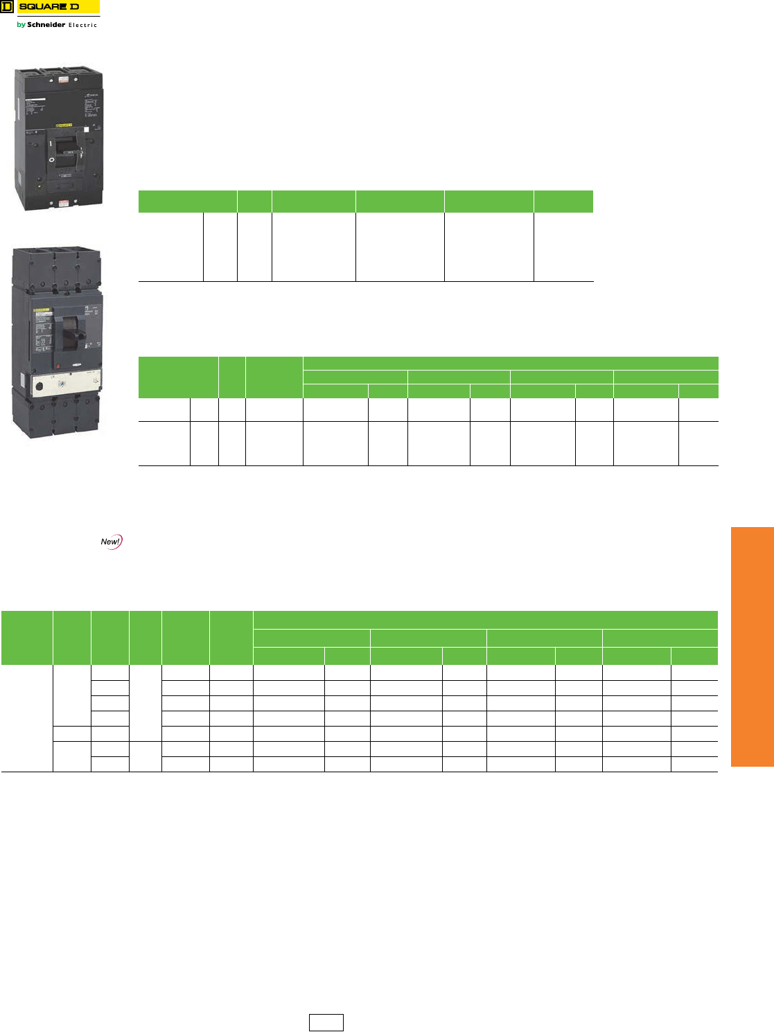
www.schneider-electric.us
7MINIATURE AND MOLDED CASE
CIRCUIT BREAKERS
© 2012 Schneider Electric
All Rights Reserved 7-31
Motor Protectors Motor Circuit Protectors and Motor Protector Circuit Breakers
Class 580, 585, 680, 685
Motor Circuit Protectors
Mag-Gard™ Motor Circuit Protectors (MCP) are instantaneous-trip magnetic-only circuit breakers. They have a single
adjustment which simultaneously sets the magnetic trip level of each individual pole. Mag-Gard™ circuit breakers
comply with NEC requirements for providing motor circuit protection when installed as part of a UL Listed combination
controller having motor overload protection. Interrupting ratings are established for these UL Recognized Components
only when they are used in combination with motor starters with properly sized overload relays and contactors.
All Mag-Gard circuit breakers will accept the same lugs and accessories as equivalent circuit breakers. Mag-Gard
circuit breakers are available with I-Line construction.i High-interruption (H) construction Mag-Gard circuit breakers
(LHL) are also available.
For PowerPact L- and P-Frames, an instantaneous-only version of the electronic trip circuti breaker is also available for
motor circuit protection. These MCPs comply with NEC® requirements for providing short-circuit protection when
installed as part of a Listed combination controller having motor overload protection.
fUL magnetic trip tolerances are -20%/+30% from the nominal values shown.
gThree-device solutions are the traditional solutionss: motor circuit protector plus motor starter plus overload relay.
h250 Vdc ratings are available. No UL component recognition
iThese electronic magnetic only motor circuit protectors are available with I-Line constructions. Consult the factory.
Motor Protector Circuit Breakers
Motor protection circuit breakers provide built-in thermal and magnetic protection. They are used in two-device motor
feeder solutions to provide protection against short-circuits, overloads, and phase unbalance.
Accessories . . . . . . . .Page 7-39 and Supplemental Digest Pages 3-24–3-31
Optional Lugs . . . . . .Page 7-42 and Supplemental Digest Pages 3-29–3-30
Dimensions . . . . . . . . . . . . . . . . . . . . . . . . . . . . . . . . . . .Pages 7-54 and 7-55
Enclosures. . . . . . . . . . . . . . . . . . . . . . . . . . . . . . . . . . . . . . . . . . . . Page 7-56
To select combination starters and motor controllers using MCP’s meeting NEC Article 430, refer to
pages 16-35—16-37.
Motor Circuit Protector
Motor Protector Circuit
Breaker
Table 7.62: Magnetic Only 3 Pole, 600 Vac, 50/60 Hzi—Three Device Solutionsg
Ampere Rating Trip
Unit
Adjustablef
Trip Range (A) 24 Vdc Multiplier Cat. No. $ Price
LAL 400
500–1000 A
750–1600 A
1000–2000 A
1125–2250 A
1250–2500 A
1500–3000 A
1750–3500 A
2000–4000 A
High = 1.2
Low = 1.4
LAL3640022M
LAL3640028M
LAL3640030M
LAL3640031M
LAL3640032M
LAL3640033M
LAL3640035M
LAL3640036M
4619.00
4619.00
4619.00
4619.00
4619.00
4619.00
4619.00
4619.00
Table 7.63: Magnetic Only 3 Pole, 600 Vac, 50/60 Hzi—Three Device Solutionsg
Sensor Rating Trip
Unit
Adjustablef
Trip Range (A)
Interrupting Rating
G J L R
Cat. No. $ Price Cat. No. $ Price Cat. No. $ Price Cat. No. $ Price
PowerPact
L-Framei
400 1.3 M 500–1200% LGL36400M37X 4619.00 LJL36400M37X 4727.00 LLL36400M37X 5007.00 LRL36400M37X 5307.00
600 500–1200% LGL36600M37X 6790.00 LJL36600M37X 6949.00 LLL36600M37X 7360.00 LRL36600M37X 7802.00
PowerPact
PJL, PLLi
600 1200–10000 A ——PJL36060M68 7560.00 PLL34060M68 8006.00 ——
800 1200–10000 A ——PJL36080M68 9927.00 PLL34080M68 10514.00 ——
1000 1500–10000 A ——PJL36100M69 12705.00 PLL34100M69 13455.00 ——
1200 1800–10000 A ——PJL36120M70 16517.00 PLL34120M70 17492.00 ——
Table 7.64: H-Frame (150 A), J-Frame (250 A) and L-Frame (600 A) Electronic Motor Protector Circuit Breakers (UL Ratings)—
Two Device Solutionsj
Electronic
Trip Unit
Type
Frame Sensor
Rating
Trip
Unit
Full Load
Amperes
Range
(FLA)
Isd (x
FLA)
Interrupting Rating
G J L R
Cat. No. $ Price Cat. No. $ Price Cat. No. $ Price Cat. No. $ Price
Standardk
H-Frame
30
2.2 M
14–25 5-13 x FLA HGL36030M38X 1608.00 HJL36030M38X 1658.00 HLL36030M38X 1812.00 HRL36030M38X 1993.00
50 14–42 5-13 x FLA HGL36050M38X 1938.00 HJL36050M38X 1998.00 HLL36050M38X 2191.00 HRL36050M38X 2410.00
100 30–80 5-13 x FLA HGL36100M38X 2229.00 HJL36100M38X 2298.00 HLL36100M38X 2506.00 HRL36100M38X 2757.00
150 58–130 5-13 x FLA HGL36150M38X 2701.00 HJL36150M38X 2785.00 HLL36150M38X 3057.00 HRL36150M38X 3363.00
J-Frame 250 114–217 5-13 x FLA JGL36250M38X 3105.00 JJL36250M38X 3201.00 JLL36250M38X 3523.00 JRL36250M38X 3875.00
L-Frame 400 2.3 M 190–348 5-13 x FLA LGL36400M38X 6041.00 LJL36400M38X 6160.00 LLL36400M38X 6468.00 LRL36400M38X 7115.00
600 312–520 5-13 x FLA LGL36600M38X 8429.00 LJL36600M38X 8604.00 LLL36600M38X 9156.00 LRL36600M38X 10072.00
jTwo-device solutions (these electronic motor protector circuit breakers include short circuit and overload protection)
—1 electronic motor circuit protector with a Micrologic 2.2 M plus
—1 contactor
kThe standard trip unit offers Class 5, 10 and 20 and phase unbalance or phase loss protection.
DE2 Discount
Schedule
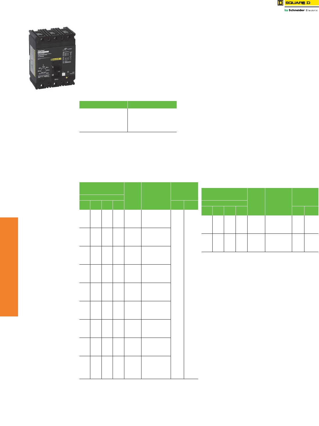
www.schneider-electric.us
7MINIATURE AND MOLDED CASE
CIRCUIT BREAKERS
7-32 © 2012 Schneider Electric
All Rights Reserved
Motor Circuit Protectors H-, J-, and LA-Frame MCP Selection
Class 680
Adjustable instantaneous-trip circuit breakers are intended
for use in combination with motor starters with overload
relays for the protection of motor circuits from short circuits.
Other specific applications include rectifiers and resistance
welders. These circuit breakers contain a magnetic trip
element in each pole with the trip point adjustable from the
front. Interrupting ratings are determined by testing the
instantaneous-trip circuit breakers in combination with a
contactor and overload relay.
Select instantaneous-trip circuit breakers as follows:
This selection table is suitable for motors, other than
NEMA Design E, with locked-rotor indicating code letters
per NEC® Table 430.7 (b) as follows:
1. For other motors order a special thermal-magnetic circuit
breaker with magnetic trip settings for the specific motor—
specify motor horsepower, voltage, frequency, full-load
current and code letter or locked rotor current.
2. Determine motor hp rating from the motor nameplate.
3. Refer to the tables and select an instantaneous-trip circuit
breaker with an ampere rating recommended for the hp and
voltage involved.
4. Select an adjustable trip setting of at least 800%, not to
exceed 1300%, of the motor full-load amperes (FLA) for other
than Design E motors. For Design E motors, select an
adjustable trip setting of at least 1100% not to exceed 1700%
of FLA.
5. The NEC 1300% maximum setting may be inadequate for
instantaneous-trip circuit breakers to withstand current surges
typical of the magnetization current of autotransformer type
reduced voltage starters, or open transition wye-delta starters
during transfer from “start” to “run,” constant hp multi-speed
motors, and motors labeled “high efficiency.” Select thermal-
magnetic circuit breakers from page 7-33 for those applications.
6. Part-winding motors, per NEC 430.3, should have two circuit
breakers selected from the above at not more than one half
the allowable trip setting for the horsepower rating. The two
circuit breakers should operate simultaneously as a
disconnecting means per NEC 430.103.
7. Based on NEC 430.52 and NEC Table 430.150. See page 7-31
for available Adjustable Instantaneous-Trip Circuit Breakers.
Table 7.65: Locked-Rotor Indicating Codes
Horsepower Motor Code letter
1/2 or less
3/4 to 1-1/2
2 to 3
5 to 25
30 to 125
150 or more
A–L
A–K
A–J
A–H
A–G
A–F
Table 7.66: PowerPact H-Frame and L-Frame Motor
Protector Circuit Breaker
Hp Ratings of Induction Type
Squirrel-Cage and
Wound Rotor Motors Full
Load
Amperesa
PowerPact Family
Motor Protector
Circuit Breaker
Cat. No.b
Magnetic Trip
Settingsc
3Ø 60 Hz
200
Vac
230
Vac
460
Vac
575
Vac MIN MAX
10 14 H( )L36030M38X
500% 1300%
5 15..2 H( )L36030M38X
15 17 H( )L36030M38X
5 17.5 H( )L36030M38X
15 21 H( )L36030M38X
7-1/2 20 22 H( )L36030M38X
7-1/2 25.3 H( )L36030M38X
20 25 27 H( )L36050M38X
10 28 H( )L36050M38X
30 32 H( )L36050M38X
10 32.2 H( )L36050M38X
25 34 H( )L36050M38X
30 40 H( )L36050M38X
40 41 H( )L36050M38X
15 42 H( )L36050M38X
15 48.3 H( )L36100M38X
40 50 52 H( )L36100M38X
20 54 H( )L36100M38X
20 60 62 H( )L36100M38X
50 65 H( )L36100M38X
75 221 L( )L36400M38X
200 240 L( )L36400M38X
250 242 L( )L36400M38X
100 248 L( )L36400M38X
100 285 L( )L36400M38X
300 289 L( )L36400M38X
250 302 L( )L36400M38X
125 312 L( )L36400M38X
350 336 L( )L36400M38X
125 359 L( )L36600M38X
150 360 L( )L36600M38X
300 361 L( )L36600M38X
400 382 L( )L36600M38X
150 350 414 L( )L36600M38X
500 472 L( )L36600M38X
400 477 L( )L36600M38X
200 480 L( )L36600M38X
Table 7.67: LAL Adjustable Instantaneous-Trip
Circuit Breakers for Single Motor
Circuit Protection
Hp Ratings of Induction Type
Squirrel-Cage and
Wound Rotor Motors Full
Load
Amperesa
Mag-Gard
Circuit Breaker
Cat. No.
Magnetic Trip
Settingsc
3Ø 60 Hz
200
Vac
230
Vac
460
Vac
575
Vac MIN MAX
75 221 LAL3640033M 700% 1400%
200 240 LAL3640035M 700% 1500%
250 242 LAL3640035M 700% 1400%
100 248 LAL3640035M 700% 1400%
100 285 LAL3640036M 700% 1400%
300 289 LAL3640036M 700% 1400%
250 302 LAL3640036M 700% 1300%
125 312 LAL3640036M 600% 1300%
aMotor full-load currents are taken from NEC Table 430.150. Select
wire and circuit breakers on basis of horsepower rather than
nameplate full-load current per NEC 430.6 (A) for general motor
applications. Do not use these values to select overload relay thermal
units. See Digest pages 14-129–14-152 for selection of thermal units
when actual full load current is not known. The voltages listed are rated
motor voltages. Corresponding nominal system voltages are 200–208,
220–240, 440–480 and 550–600 V.
bTo complete catalog number, replace the blank with the appropriate
rating (G, J, or L). M38X is for standard trip units. For advanced trip
units (LCD display, metering and communication, replace with M58X).
cOnly MIN and MAX settings are shown, intermediate settings are
available on all circuit breakers.
dSee NEC 430.52(A) for circuit breaker settings above 800%.
eIf due to motor starting characteristics, trip settings at the 1300%
maximum permitted level are needed, the next size Mag-Gard circuit
breaker should be chosen.
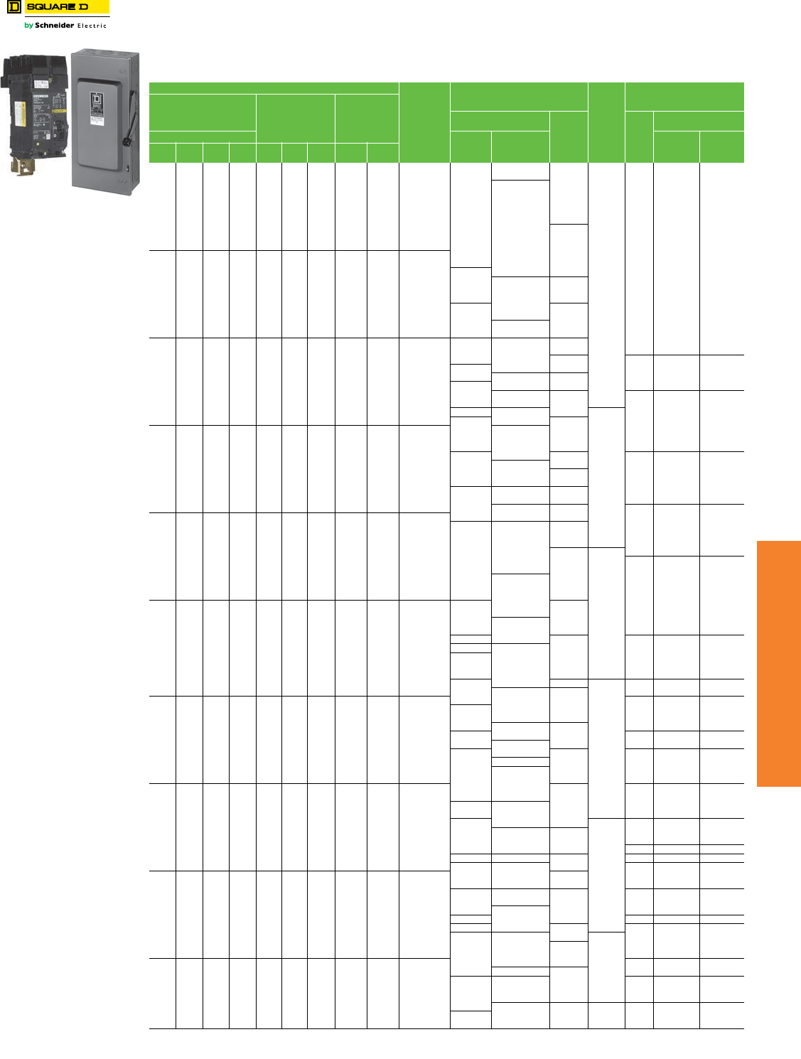
www.schneider-electric.us
7MINIATURE AND MOLDED CASE
CIRCUIT BREAKERS
© 2012 Schneider Electric
All Rights Reserved 7-33
Motor Circuit Protectors Motor Protection Selection Tables
Class 601
Table 7.68: Selection Tables for Conductors, Safety Switches and Thermal-Magnetic Circuit Breakers
Based on 2005 NEC® Tables 430.147, 430.148 & 430.150
Horsepower Ratings
Full
Load
Amperagef
Amperage of Thermal-
Magnetichj Inverse Time Circuit
Breaker
QMB
and
Heavy
Duty
Switch
with
Time
Delay
Fusesg
Minimum Size metallic
Conduit 75° C, C Wire Field-
Installed Sized for 125% FLAe
Squirrel-Cage and Wound-
Rotor Motors with Norm.
Torque Characteritics
Operating at usual Speeds
1Ø
10 Hz ac
Average Direct
Current Motors
Operating at
Base Speed
For Motor Code
Letter B to E For
Motor
Code
Letter F
to Vi
AWG
kcmil
Conduit 3 W
3Ø 60 Hz Ordinary
Servicec
Heavy Service
and Energy
Efficientd
THHN
THWN
XHHW
THW
200
Vacb
230
Vac
460
Vac
575
Vac
115
Vac
200
Vacb
230
Vac
120
Vdc
240
Vdc
3/4 6.9 A
15 A
15 A
20 A
30 A
14 1/2 in. N/A
1/3 7.2 A
53.47.6 A
20 A
27.8 A
3/4 7.9 A
18.0 A
28.5 A
7-1/2 9.0 A
25 A
19.2 A
19.5 A
39.6 A
1/2 9.8 A
1-1/2 10.0 A
20 A
3 7-1/2 10 11.0 A
25 A
30 A1-1/2 11.5 A
2 12.0 A
3 12.2 A
25 A 35 A
1-1/2 13.2 A
3/4 2 13.8 A
10 14.0 A
5 15.2 A
30 A 35 A
40 A
1 16.0 A
15 3 2 17.0 A 45 A
12 1/2 in. N/A
5 17.5 A 35 A
3 19.6 A 40 A 50 A
1-1/2 5 20.0 A
40 A15 21.0 A 45 A 60 A
10 1/2 in. N/A
7-1/2 22.0 A
2 24.0 A 45 A 50 A
60 A
3 25.0 A
50 A 70 A
7-1/2 25.3 A
60 A
20 25 27.0 A
10 5 28.0 A
7-1/2 29.0 A
60 A
80 A
8 1/2 in.aN/A
30 32.0 A
70 A10 32.2 A 90 A
25 3 34.0 A
10 38.0 A
80 A
80 A 100 A
7-1/2 5 40.0 A
41.0 A 90 A 110 A
6 3/4 in. 1 in.
15 42.0 A
7--1/2 46.0 A
90 A
110 A
125 A15 48.3 A
10 50.0 A
40 50 52.0 A
150 A
100 A
20 54.0 A
4 1 in. 1 in.
15 55.0 A
5 56.0 A
125 A
10 57.5 A
7-1/2 58.0 A
60 62.0 A
100 A 175 A
20 62.1 A
50 65.0 A
150 A25 68.0 A
20 72.0 A 110 A
200 A 3 1 in. 1-1/4 in.
10 76.0 A 125 A
175 A
60 75 77.0 A
110 A25 78.2 A
30 7-1/2 80.0 A
25 89.0 A
125 A
225 A
200 A
2 1 in. 1-1/4 in.
30 92.0 A
200 A 250 A
75 96.0 A
1 1-1/4 in. 1-1/2 in.
100 99.0 A
150 A10 100.0 A
40 104.0 A 225 A 300 A30 106.0 A 175 A 1/0 1-1/4 in. 1-1/2 in.
40 120.0 A 250 A
100 124.0 A
200 A
350 A 2/0 1-1/2 in. 1-1/2 in.
125 125.0 A 250 A
50 130.0 A
300 A
40 140.0 A
150 144.0 A
400 A 3/0 1-1/2 in. 2 in.
50 150.0 A
60 154.0 A 225 A 350 A125 156.0 A
50 173.0 A
250 A
400 A
4/0 2 in. 2 in.60 177.0 A
400 A 500 A150 180.0 A
75 200 192.0 A 250 2 in. 2 in.
75 221.0 A 300 A 450 A 600 A 300 2 in. 2-1/2 in.
200 240.0 A
350 A 500 A 350 2-1/2 in. 2-1/2 in.250 242.0 A 700 A
100 248.0 A
100 285.0 A
400 A 600 A
800 A 500 3 in. 3 in.300 289.0 A
250 302.0 A
700 A125 312.0 A 450 A (2) 3/0 (2) 2-1/2 in. (2) 2 in.
350 336.0 A 500 A 900 A
(2) 4/0 (2) 2 in. (2) 2 in.
125 359.0 A
600 A 800 A
600 A
150 360.0 A
1000 A300 361.0 A
400 382.0 A (2)300 (2) 2 in. (2) 2-1/2 in.
150 350 414.0 A 900 A
1200 A
500 472.0 A
800 A 1000 A (2) 350 (2) 2-1/2 in. (2) 2-1/2 in.400 477.0 A
200 480.0 A
200 552.0 A
1200 A 1600 A — (3) 300 (3) 2 in. (3) 2-1/2 in.500 590.0 A 900 A
250 602.0 A
a 8 XHHW requires 3/4 in. conduit for
3W.
b200 V motors are commonly used
on 208 V services.
cOrdinary service for normal
starting duty only, acceleration time
of 10 sec. or less.
dHeavy service is jogging or plugging
duty or cycling load with over 25
starts per hour or over 5 starts per
minute. Energy efficient motors are
polyphase motors defined in NEMA
Standard MG1 and exhibit high
starting current.
eNEC 430.22 for Single Motor,
Smaller conductors may be
permitted for light duty-cycle service
per 430.22 (B) Exception No. 1. DC
motors operating from rectified 1Ø
power supply will require larger
conductors per 430.22 (A) Exception
No. 1. For motor-generator arc
welders, see 630.11.
fMotor full load currents thru 200 hp
are taken from NEC Tables 430.147,
148 and 150. Above 200 hp from UL
98. Select wire size, circuit breakers,
or fuses on basis of hp rather than
nameplate full load current per NEC
430.6. Do not use these values to
select overload relay thermal
units. See Digest pages 16-129—
16-152 for selection of thermal units
when actual full load current is not
known. Voltages listed are rated
motor voltages. Corresponding
nominal system voltages are 110–
120 V, 200–208 V, 220–240 V, 440–
480 V and 550–600 V.
gSwitch size only is shown in table.
Selected fuses should not exceed
maximum percent of full-load current
as given in NEC Table 430.52.
Above 50 hp dc switches are not hp
rated by UL as Motor Circuit
Switches, but as General Use
Switches only and are not
necessarily capable of interrupting
the max. operating overload current
of a motor. See NEC 100 for
definition of General Use Switch.
When protecting a 3Ø, Design E
energy efficient motor, the switch is
required by NEC 430.109 to have a
hp rating of not less than 1.4 times
that of a motor rated 3–100 hp, or not
less than 1.3 times that of a motor
rated over 100 hp. Switches shown in
this table do not necessarily comply
with that requirement.
hThermal-magnetic circuit breaker
ampere ratings recommended are
approximate for average conditions,
based on trip characteristics of
Square D circuit breakers and NEC
Table 430.52. Under some
conditions, the next size larger switch
or circuit breaker rating may be
necessary to accommodate the
motor starting current and is
permitted by NEC 430.52(C)(1)
Exception 2. High starting currents
are anticipated with Design E and
other energy efficient motors. For
explanation of Code letter markings,
see NEC 430.7(B). For Busway Plug-
in units, see page 9-7.
iThermal-magnetic breaker ampere
ratings recommended are
approximate for average conditions
and based on trip characteristics of
Square D circuit breakers and NEC
Tables 430.7(B) and 430.52.
jType LC, LI, LX, LXI, and LE circuit
breakers are NOT recommended
for use on single motor branch
circuits.
Contact your local Field Office for
circuit breaker selection on
constant horsepower multi-speed
motors.
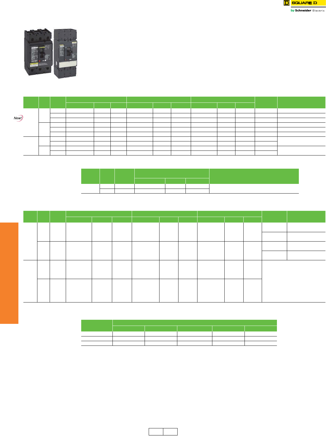
7-34 © 2012 Schneider Electric
All Rights Reserved
www.schneider-electric.us
7MINIATURE AND MOLDED CASE
CIRCUIT BREAKERS
Automatic Switches
Class 600 / Refer to Catalog 0612CT0101
Automatic molded case switches open instantaneously at a factory preset magnetic trip point, calibrated to protect only
the molded case switch itself, when it is subjected to high fault currents. The trip point is nonadjustable and provides no
overload or low level fault protection.
Molded case switches open when the handle is switched to the OFF position or in response to an auxiliary tripping
device such as a shunt trip.
All molded case switches will accept the same lugs and accessories as equivalent thermal-magnetic circuit breakers,
with the exception of Q-frame switches which do not have electrical accessories available.
Automatic molded case switches are UL Listed per UL 489 and are CSA Certified.
aTrue 2P device. Others are a 2P in a 3P module.
bWithstand rating of 10 kA at 240 Vac.
cDE2A discount schedule.
dP-frame L-interrupting is available in 480 Vac only.
eUL magnetic trip tolerances are -20% / +30% from the nominal values shown.
fThe withstand rating is the fault current at rated voltage that the molded case switch will withstand without damage when protected by a circuit breaker
with an equal continuous current rating.
gR-frame withstand is 65 kA.
Accessories . . . . . . . Page 7-39 and Supplemental Digest Pages 3-24–3-31
Optional Lugs . . . . . . Page 7-42 and Supplemental Digest Pages 3-29–3-30
Dimensions. . . . . . . . . . . . . . . . . . . . . . . . . . . . . . . . . . . Pages 7-54 and 7-55
Enclosures . . . . . . . . . . . . . . . . . . . . . . . . . . . . . . . . . . . . . . Pages 7-56–7-58
J-Frame
Switch
L-Frame
Switch
Table 7.69: H-Frame, J-Frame, and L-Frame PowerPact™ Automatic Molded Case Switches, 600 Vac
Circuit
Breaker Poles Ampere
Rating
G Withstand L Withstand R Withstand Terminal Wire Range
Cat. No. $ Price Trip Point Cat. No. $ Price Trip Point Cat. No. $ Price Trip Point
H-Frame
J-Frame
2
150 A HGL26000S15a1349.00 2250A HLL26000S15 1590.00 2250 A — — — AL150HD 14 AWG–3/0 AWG Al/Cu
175 A JGL26000S17 1827.00 3125 A JLL26000S17 1980.00 3125 A — — — AL175JD 4–4/0 AWG Al/Cu
250 A JGL26000S25 1827.00 3125 A JLL26000S25 1980.00 3125 A — — — AL250JD 3/0 AWG–350 kcmil Al/Cu
3
150 A HGL36000S15 1799.00 2250 A HLL36000S15 1988.00 2250 A — — — AL150HD 14 AWG–3/0 AWG Al/Cu
175 A JGL36000S17 2286.00 3125 A JLL36000S17 2475.00 3125 A JRL36000S17 2673.00 3125 A AL175JD 4–4/0 AWG Al/Cu
250 A JGL36000S25 2286.00 3125 A JLL36000S25 2475.00 3125 A JRL36000S25 2673.00 3125 A AL250JD 3/0 AWG–350 kcmil Al/Cu
L-Frame
3400 A LGL36000S40X 4572.00 4800 A LLL36000S40X 4972.00 4800 A LRL36000S40X 5370.00 4800 A AL150HD AL600LS52K3
(2) 2/0 AWG–500 kcmil Al/Cu
600 A LGL36000S60X 5065.00 6600A LLL36000S60X 5465.00 6600 A LRL36000S60X 5902.00 6600 A AL250JD
4400 A LGL46000S40X 5972.00 4800 A LLL46000S40X 6372.00 4800 A LRL46000S40X 6882.00 4800 A AL150HD AL600LS52K4
(2) 2/0 AWG–500 kcmil Al/Cu
600 A LGL46000S60X 6465.00 6600A LLL46000S60X 6865.00 6600 A LRL46000S60X 7414.00 6600 A AL250JD
Table 7.70: Q-Frame (240 Vac) PowerPact™ Automatic Molded Case Switches
Circuit
Breaker Poles Ampere
Rating
J Withstand
Wire Range
Cat. No. $ Price Trip Point
Q-Frameb2225 AQBL22000S22c440.00 4500 A 4 AWG–300 kcmil
3225 AQBL32000S22c1193.00 4500 A
Table 7.71: P-Frame and R-Frame PowerPact™ Automatic Molded Case Switchese, 600 Vac
Frame Poles Ampere
Rating
J Withstand K Withstand L Withstand Terminal Wire Range
Cat. No. $ Price Trip Point Cat. No. $ Price Trip Point Cat. No. $ Price Trip Point
P
2
600 A PJL26000S60 5340.00 10 kA PKL26000S60 5340.00 24 kA PLL24000S60d5715.00 10 kA AL800M23K (3) 3/0 AWG–500 kcmil
Al or Cu
800 A PJL26000S80 5991.00 10 kA PKL26000S80 5991.00 24 kA PLL24000S80d6414.00 10 kA
1000 A PJL26000S10 7469.00 10 kA PKL26000S10 7469.00 24 kA PLL24000S10d7995.00 10 kA AL1200P25K (4) 3/0 AWG–500 kcmil
Al or Cu
1200 A PJL26000S12 11744.00 10 kA PKL26000S12 11744.00 24 kA PLL24000S12d10887.00 10 kA
3
600 A PJL36000S60 6584.00 10 kA PKL36000S60 6584.00 24 kA PLL34000S60d6974.00 10 kA AL800M23K (3) 3/0 AWG–500 kcmil
Al or Cu
800 A PJL36000S80 7236.00 10 kA PKL36000S80 7236.00 24 kA PLL34000S80d7667.00 10 kA
1000 A PJL36000S10 9287.00 10 kA PKL36000S10 9287.00 24 kA PLL34000S10d9837.00 10 kA AL1200P25K (4) 3/0 AWG–500 kcmil
Al or Cu
1200 A PJL36000S12 11867.00 10 kA PKL36000S12 11867.00 24 kA PLL34000S12d12570.00 10 kA
R
2
1200 A — — — RKF26000S12 12213.00 57 kA RLF26000S12 12855.00 48 kA
R-frame circuit breakers can be
bus-connected or cable-connected.
For cable connections, RLTB kit or
equivalent bus structure is required.
Kit is included with 3000 A switches.
For all others, see page 7-44.
1600 A — — — RKF26000S16 14685.00 57 kA RLF26000S16 14825.00 48 kA
2000 A — — — RKF26000S20 15687.00 57 kA RLF26000S20 15837.00 48 kA
2500 A — — — RKF26000S25 24948.00 57 kA RLF26000S25 25185.00 48 kA
3
1200 A — — — RKF36000S12 13602.00 57 kA RLF36000S12 14318.00 48 kA
1600 A — — — RKF36000S16 15911.00 57 kA RLF36000S16 16062.00 48 kA
2000 A — — — RKF36000S20 19374.00 57 kA RLF36000S20 19559.00 48 kA
2500 A — — — RKF36000S25 30836.00 57 kA RLF36000S25 31130.00 48 kA
3000 A — — — RKF36000S30 41104.00 57 kA RLF36000S30 41496.00 48 kA
Table 7.72: H-, J-, L- P-, and R-Frame Withstand Ratingsf
Volta g e Withstand
G J K L R
240 Vac 65 kA 100 kA 65 kA 125 kA 200 kA
480 Vac 35 kA 65 kA 50 kAg100 kA 200 kA
600 Vac 18 kA 25 kA 50 kAg50 kA 100 kA
DE2 DE2A Discount
Schedule
www.schneider-electric.us
7MINIATURE AND MOLDED CASE
CIRCUIT BREAKERS
© 2012 Schneider Electric
All Rights Reserved 7-35
500 Vdc Circuit Breakers UL Listed 500 Vdc Circuit Breakers
Class 500, 600
The UL Listed thermal-magnetic molded case circuit breakers shown below are specifically
designed for use on ungrounded dc systems having a maximum short-circuit voltage of 500
Vdc or a maximum floating (unloaded) voltage of 600 Vdc. The circuit breakers are suitable
for use only with UPS (uninterruptable power supplies) and ungrounded systems.
This two-level voltage rating allows these circuit breakers to be applied to battery sources
having a short-circuit availability of 20,000 amperes for LH, and MH circuit breakers and
25,000 amperes for PAF circuit breakers at 500 Vdc.
LH and MH circuit breakers are provided with an adjustable magnetic trip that is readily
accessible by means of a single adjustment on the face of the circuit breaker. PAF circuit
breakers have a fixed magnetic trip range.
These circuit breakers are UL Listed for the interrupting ratings shown only if applied with
three poles connected in series (series connection is external to circuit breaker). See
diagram below.
NOTE: Due to external series connection, I-Line™ circuit breakers are not available for
this application.
aMagnetic trip tolerances are -20%/+30% from the nominal values shown.
bSuitable for use only in a ventilated enclosure. Minimum enclosure dimensions are 38" h x 20" w x 7" d with a
minimum of 300 square inches of ventilation near the top and bottom of the enclosure.
Accessories. . . . . . . .Page 7-39 and Supplemental Digest Pages 3-24–3-31
Optional Lugs . . . . . . . . . . . Page 7-42 and Supplemental Digest Page 3-29
Dimensions . . . . . . . . . . . . . Page 7-55 and Supplemental Digest Page 3-33
Enclosures. . . . . . . . . . . . . . . . . . . . . . . . . . . . . . . . . . . . . . . Pages 7-56–7-58
Table 7.73: DC Molded Case Circuit Breakers
Ampere Rating Circuit Breaker
Cat. No.
Adjustable Magnetic Trip Range—
DC AmperesaInterrupting Rating
@ 500 Vdc $ Price
Low High
100 A JGL37100D81 400 600
20 k AIR
3779.00
125 A JGL37125D81 400 600 3779.00
150 A JGL37150D81 400 600 3779.00
175 A JGL37175D81 400 600 3779.00
200 A JGL37200D82 500 850
20 k AIR
3779.00
225 A JGL37225D82 500 850 3779.00
250 A JGL37250D82 500 850 5001.00
250 A LHL3625025DC 625 1250
20 k AIR
7598.00
300 A LHL3630026DC 750 1500 7598.00
350 A LHL3635029DC 875 1750 7598.00
400 A LHL3640030DC 1000 2000 7598.00
450 A MHL3645031DC 1125 2250
20 k AIR
9456.00
500 A MHL3650032DC 1250 2500 9456.00
600 A MHL3660033DC 1500 3000 9456.00
700 A MHL3670035DC 1750 3500 11882.00
800 A MHL3680036DC 2000 4000 11882.00
900 A MHL3690039DC 2500 5000 14078.00
1000 A MHL36100040DC 2500 5000 14078.00
1200 A MHL36120040DCb2500 5000 25 k AIR 16758.00
450 A MHL3645031DCH 1125 2250
50 k AIR
12506.00
500 A MHL3650032DCH 1250 2500 12506.00
600 A MHL3660033DCH 1500 3000 12506.00
700 A MHL3670035DCH 1750 3500 14932.00
800 A MHL3680036DCH 2000 4000 14932.00
900 A MHL3690039DCH 2500 5000 17128.00
1000 A MHL36100040DCH 2500 5000 17128.00
1200 A MHL36120040DCHb2500 5000 50 k AIR 19808.00
Ampere Rating Circuit Breaker
Cat. No.
Fixed Magnetic Trip Range—DC
AmperesaInterrupting Rating
@ 500 Vdc $ Price
Hold Trip
1200 A PAF361200DC 1200 1620
25 k AIR
24726.00
1600 A PAF361600DC 1600 2160 24726.00
2000 A PAF362000DC 2000 2700 24726.00
2500 A PCF362500DC 2500 3375 25 k AIR 39365.00
CAUTION/PRECAUCION/
ATTENTION
Connect only as shown/Conectar solo asi/
Francher seulement comme suit:
300 V 300 V
Load/Carga/
Charge
600 V MAX.
MAX. MAX.
Load/Carga/
Charge
or
o
ou
CAUTION/PRECAUCION/
ATTENTION
Connect only as shown/Conectar solo asi/
Brancher seulement comme suit:
or
o
ou
-
600 V MAX.
600 V MAX.
+
Load/Carga/
Charge
+
600 V MAX.
-
Load/Carga/
Charge
Source = 600 Vdc max. (floating)
500 Vdc max. (loaded)
DC Circuit Breaker Label
Source = 600 Vdc max. (floating)
500 Vdc max. (loaded)
MHL–DCH Breaker Only
DE2 Discount
Schedule
www.schneider-electric.us
7MINIATURE AND MOLDED CASE
CIRCUIT BREAKERS
7-36 © 2012 Schneider Electric
All Rights Reserved
500 Vdc Circuit Breakers UL Listed 500 Vdc NW Circuit Breakers
Class 500, 600
Masterpact NW DC Circuit Breaker
Table 7.74: Masterpact NW DC Circuit Breakers
Ampere Rating Circuit Breaker
Cat. No.
Interrupting Rating 500 Vdc
(max 600 Vdc unloaded)
$ Price Fixed Circuit Breaker $ Price Drawout Circuit Breaker $ Price Cradle
Version C Version C1 Version C Version C1 Version C Version C1
800 A NW08NDC 35 kA 42214.00 42746.00 39824.00 40888.00 11778.00 12842.00
1200 A NW12NDC 35 kA 42214.00 42746.00 39824.00 40888.00 11778.00 12842.00
1600 A NW16NDC 35 kA 42214.00 42746.00 39824.00 40888.00 11778.00 12842.00
2000A NW20NDC 35 kA 42214.00 42746.00 39824.00 40888.00 11778.00 12842.00
2500 A NW25NDC 35 kA 56158.00 56690.00 56662.00 57726.00 11778.00 12842.00
3000 A NW30NDC 35 kA 70100.00 70632.00 73500.00 74564.00 11778.00 12842.00
4000 A NW40NDC 35 kA 84044.00 84576.00 90338.00 90142.00 11778.00 12842.00
800 A NW08HDC 85 kA 46858.00 47448.00 44205.00 45386.00 11778.00 12842.00
1200 A NW12HDC 85 kA 46858.00 47448.00 44205.00 45386.00 11778.00 12842.00
1600 A NW16HDC 85 kA 46858.00 47448.00 44205.00 45386.00 11778.00 12842.00
2000A NW20HDC 85 kA 46858.00 47448.00 44205.00 45386.00 11778.00 12842.00
2500 A NW25HDC 85 kA 62335.00 62926.00 64076.00 64076.00 11778.00 12842.00
3000 A NW30HDC 85 kA 77811.00 78402.00 81585.00 82766.00 11778.00 12842.00
4000 A NW40HDC 85 kA 93289.00 93879.00 100275.00 100058.00 11778.00 12842.00
DE2 Discount
Schedule
www.schneider-electric.us
7MINIATURE AND MOLDED CASE
CIRCUIT BREAKERS
© 2012 Schneider Electric
All Rights Reserved 7-37
Mission Critical Circuit
Breakers
Selective Coordination
Designed for selectively coordinated systems, mission critical circuit breakers maximize continuity of the electrical
service by allowing the branch circuit breaker to clear the fault.
Mission critical circuit breakers are engineered with technology that optimizes current, time and energy selectivity
so the fault is cleared by the circuit breaker immediately upstream of the occurrence. This technology (see figure
below) allows the remaining areas of the electrical system to continue operation without disruption. In addition to
unique design attributes, Square D mission critical circuit breakers have also undergone rigorous testing
procedures to certify the coordination with downstream circuit breakers—combining innovative engineering with
validated test results.
Apply Square D mission critical circuit breakers in emergency power distribution systems, data centers, hospitals
or anywhere continuity of service is desired.
The PowerPact™ J- and L-Frame Mission Critical circuit breakers deliver high levels of selective coordination in a flexible design that can be easily
configured for a variety of applications. Tested to be selectively coordinated with the QO™ family of miniature circuit breakers and the ED, EG, and EJ
circuit breakers, this solution provides peace of mind when power availability is critical.
An electronic trip unit provides adjustable long-time settings in four sensor sizes, allowing coverage from 70 A through 600 A on a 120–240, 208Y/120,
240, 480Y/277, and 480 V systems.
aStandard rated (80%). Not available in 100% rated.
bAL250JD terminal wire range is (1) 3/0 AWG–350 kcmil Al or Cu.
aStandard rated (80%). Not available in 100% rated.
bAL400L61K3 terminal wire ranges are (1) #2 AWG–500 kcmil Al or (1) #2 AWG–600 kcmil Cu.
cAL600LS52K3 terminal wire ranges are (2) 2/0 AWG–500 kcmil Al or Cu.
Table 7.75: PowerPact J- and L-Frame Mission Critical Circuit Breakers
Ratings Available Configurations
UL 489 Listed
CSA Certified
Voltage: 480 V
I-Line mounting
Main circuit breaker in NQ and NF panelboards
Unit mount for OEM users
Plug-in base for OEM users
Drawout base ofr OEM users
Table 7.76: J-Frame 250 A Electronic Trip Mission Critical Circuit Breakers (480/277 Vac)
with Factory Sealed Trip Units Suitable for Reverse Connectiona
Electronic Trip
Unit Type
Trip
Function Trip Unit Continuous
Current
D Interrupting G Interrupting J Interrupting L Interrupting Terminal
Cat. No. $ Price Cat. No. $ Price Cat. No. $ Price Cat. No. $ Price
Standard LI 3.2 W 250 JDL34250WU31X 3489. JGL34250WU31X 4727. JJL34250WU31X 6678. JLL34250WU31X 8629. AL250JDb
Standard LSI 3.2S-W 250 JDL34250WU33X 3801. JGL34250WU33X 5039. JJL34250WU33X 6989. JLL34250WU33X 8941. AL250JDb
High Perf. Ammerter LSI 5.2A-W 250 JDL34250WU43X 4809. JGL34250WU43X 6046. JJL34250WU43X 7997. JLL34250WU43X 9949. AL250JDb
High Perf. Energy LSI 5.2E-W 250 JDL34250WU53X 5414. JGL34250WU53X 6652. JJL34250WU53X 8602. JLL34250WU53X 10554. AL250JDb
High Perf. Ammerter LSIG 6.2A-W 250 JDL34250WU44X 6018. JGL34250WU44X 7256. JJL34250WU44X 9206. JLL34250WU44X 11158. AL250JDb
High Perf. Energy LSIG 6.2E-W 250 JDL34250WU54X 6623. JGL34250WU54X 7861. JJL34250WU54X 9812. JLL34250WU54X 11763. AL250JDb
Table 7.77: L-Frame 600 A Electronic Trip Mission Critical Circuit Breakers (480/277 Vac)
with Factory Sealed Trip Units Suitable for Reverse Connectiona
Electronic Trip
Unit Type
Trip
Function Trip Unit Continuous
Current
D Interrupting G Interrupting J Interrupting L Interrupting Terminal
Cat. No. $ Price Cat. No. $ Price Cat. No. $ Price Cat. No. $ Price
480/277 Vac, 50/60 Hz, 3P
Standard LI 3.3 W
250 LDL34250WU31X 5696. LGL34250WU31X 5996. LJL34250WU31X 10004. LLL34250WU31X 11703. AL400L61K3b
400 LDL34400WU31X 5696. LGL34400WU31X 5996. LJL34400WU31X 10004. LLL34400WU31X 11703. AL600LS52K3c
600 LDL34600WU31X 8389. LGL34600WU31X 8831. LJL34600WU31X 12438. LLL34300WU31X 13968.
Standard LSI 3.3S-W
250 LDL34250WU33X 6361. LGL34250WU33X 6695. LJL34250WU33X 10704. LLL34250WU33X 12403. AL400L61K3b
400 LDL34400WU33X 6361. LGL34400WU33X 6695. LJL34400WU33X 10704. LLL34400WU33X 12403. AL600LS52K3c
600 LDL34600WU33X 9054. LGL34600WU33X 9531. LJL34600WU33X 13138. LLL34300WU33X 14667.
High Perf. Ammeter LSI 5.3A-W 400 LDL34400WU43X 7379. LGL34400WU43X 7767. LJL34400WU43X 11775. LLL34400WU43X 13474. AL600LS52K3c
600 LDL34600WU43X 10071. LGL34600WU43X 10601. LJL34600WU43X 14208. LLL34300WU43X 15738.
High Perf. Energy LSI 5.3E-W 400 LDL34400WU53X 8496. LGL34400WU53X 8943. LJL34400WU53X 12952. LLL34400WU53X 14651. AL600LS52K3c
600 LDL34600WU53X 11190. LGL34600WU53X 11779. LJL34600WU53X 15386. LLL34300WU53X 16915.
High Perf. Ammeter LSIG 6.3A-W 400 LDL34400WU44X 9616. LGL34400WU44X 10122. LJL34400WU44X 14131. LLL34400WU44X 15830. AL600LS52K3c
600 LDL34600WU44X 12309. LGL34600WU44X 12956. LJL34600WU44X 16844. LLL34300WU44X 18093.
High Perf. Energy LSIG 6.3E-W 400 LDL34400WU54X 10734. LGL34400WU54X 11299. LJL34400WU54X 15307. LLL34400WU54X 17006. AL600LS52K3c
600 LDL34600WU54X 13427. LGL34600WU54X 14134. LJL34600WU54X 17741. LLL34300WU54X 19271.
480/277 Vac, 50/60 Hz, 4P
Standard LI 3.3 W
250 LDL44250WU31X 6196. LGL44250WU31X 6496. LJL44250WU31X 10504. LLL44250WU31X 12203. AL400L61K4b
400 LDL44400WU31X 7096. LGL44400WU31X 7396. LJL44400WU31X 11404. LLL44400WU31X 13103. AL600LS52K4c
600 LDL44600WU31X 9789. LGL44600WU31X 10231. LJL44600WU31X 13838. LLL44300WU31X 15368.
Standard LSI 3.3S-W
250 LDL44250WU33X 6861. LGL44250WU33X 7195. LJL44250WU33X 11204. LLL44250WU33X 12903. AL400L61K4b
400 LDL44400WU33X 7761. LGL44400WU33X 8095. LJL44400WU33X 12104. LLL44400WU33X 13803. AL600LS52K4c
600 LDL44600WU33X 10454. LGL44600WU33X 10931. LJL44600WU33X 14538. LLL44300WU33X 16067.
High Perf. Ammeter LSI 5.3A-W 400 LDL44400WU43X 8779. LGL44400WU43X 9167. LJL44400WU43X 13175. LLL44400WU43X 14874. AL600LS52K4c
600 LDL44600WU43X 11471. LGL44600WU43X 12001. LJL44600WU43X 15608. LLL44300WU43X 17138.
High Perf. Energy LSI 5.3E-W 400 LDL44400WU53X 9896. LGL44400WU53X 10343. LJL44400WU53X 14352. LLL44400WU53X 16051. AL600LS52K4c
600 LDL44600WU53X 12590. LGL44600WU53X 13179. LJL44600WU53X 16786. LLL44300WU53X 18315.
High Perf. Ammeter LSIG 6.3A-W 400 LDL44400WU44X 11016. LGL44400WU44X 11522. LJL44400WU44X 15531. LLL44400WU44X 17230. AL600LS52K4c
600 LDL44600WU44X 13709. LGL44600WU44X 14356. LJL44600WU44X 18244. LLL44300WU44X 19493.
High Perf. Energy LSIG 6.3E-W 400 LDL44400WU54X 12134. LGL44400WU54X 12699. LJL44400WU54X 16707. LLL44400WU54X 18406. AL600LS52K4c
600 LDL44600WU54X 14827. LGL44600WU54X 15534. LJL44600WU54X 19141. LLL44300WU54X 20671.
Table 7.78: J-Frame Termination Options
Termination Letter
A = I-Line (See Section 9)
F = No Lugs (includes terminal nut kit on both ends)a
L = Lugs both ends
M = Lugs ON end Terminal Nut Kit OFF end
P = Lugs OFF end Terminal Nut Kit ON end
N = Plug-in b
D = Drawout b
S = Rear Connected b
aAdd TS suffix for circuit breaker without terminal nut kit.
bFor N and D pricing, add termination pricing on page 7-45 to price. For S pricing, add termination pricing on page 7-41 to price.
Table 7.79: H- and J-Frame Interrupting Ratings
Vol tage Interrupting Rating Accessories . . . . . . . . . . . . . . . . . . . . . . . . . . . . . . . . . . . . . . . . . . .Page 7-39
Optional Lugs . . . . . . . . . . . . . . . . . . . . . . . . . . . . . . . . . . . . . . . . . .Page 7-42
Dimensions . . . . . . . . . . . . . . . . . . . . . . . . . . . . . . . . . . . . . . . . . . . .Page 7-55
Enclosures . . . . . . . . . . . . . . . . . . . . . . . . . . . . . . . . . . . . . . . . . . . .Page 7-56
D G J L
240 Vac 25 kA 65 kA 100 kA 125 kA
480 Vac 18 kA 35 kA 65 kA 100 kA
Plug-in
Drawout
Rear Connected
H G L 3 6 1 0 0
For factory-installed
termination, place termination
letter in the third block of the
circuit breaker catalog number.
Termination Letter
DE2 Discount
Schedule
FAULT
QO 20 A 1P
PowerPact D-Frame Mission Critical Circuit Breaker
QO 100 A 2P
208 Y/120 V 3 Phase Panel
Load
Load
06163051
7-38 © 2012 Schneider Electric
All Rights Reserved
www.schneider-electric.us
7MINIATURE AND MOLDED CASE
CIRCUIT BREAKERS
Mission Critical Circuit
Breakers
Selective Coordination
LA Mission Critical Circuit Breakers
The LA High Magnetic Withstand MC Circuit Breakers are designed to trip at a higher magnetic trip level (18–20 times
handle rating) than typical molded case circuit breakers (MCCBs) (which trip at 5–10 times the handle rating).
The high magnetic withstand value of these LA circuit breakers allow the downstream branch circuit breaker to clear
the fault.
PowerPact™ Circuit Breakers with Micrologic™ Electronic Trip Units
The advantages of being able to adjust the trip curve of a circuit breaker equipped with an electronic trip system are
obvious. There are other advantages, such as being able to adjust or turn off the instantaneous trip function on some
circuit beakers and models of trip units.
Accessories . . . . . . . . . . . . . . . . . . . Supplemental Digest Pages 3-29–3-30
Compression and PDC Lugs. . . . . . . . . . . . Supplemental Digest Page 3-30
Dimensions. . . . . . . . . . . . . . . . . . . . . . . . . . . . . . . . . . . . . . . . . . . . Page 7-54
Enclosures . . . . . . . . . . . . . . . . . . . . . . . . . . . . . . . . . . . . . . . . . . . . Page 7-56
Table 7.80: L-Frame—400 A, Thermal-Magnetic, High Magnetic Withstand Circuit Breakers For Mission
Critical Loads
Ampere
Rating
AC Magnetic Level
Factory Set Standard Interrupting High Interrupting Terminal
Hold Trip Cat. No. $ Price Cat. No. $ Price Cat. No. Wire Range
LA/LH MC Circuit Breaker, 3P, 480 Vac
200 A 3400 A 4000 A LAL34200MC 4962.00 LHL34200MC 7941.00
AL250LAMC (1) 250–350 kcmil Al
(1) 3/0 AWG–350 kcmil Cu
225 A 3825 A 4500 A LAL34225MC 4962.00 LHL34225MC 7941.00
250 A 4250 A 5000 A LAL34250MC 5355.00 LHL34250MC 8336.00
400 A 6000 A 7200 A LAL34400MC 6615.00 LHL34400MC 9596.00 AL400LA (1) 1 AWG–600 kcmil Al or
(2) 1 AWG–250 kcmil Al
Table 7.81: L-Frame Interrupting Table
LAL LHL
240 Vac 42 kA 65 kA
480 Vac 30 kA 35 kA
DE2 Discount
Schedule
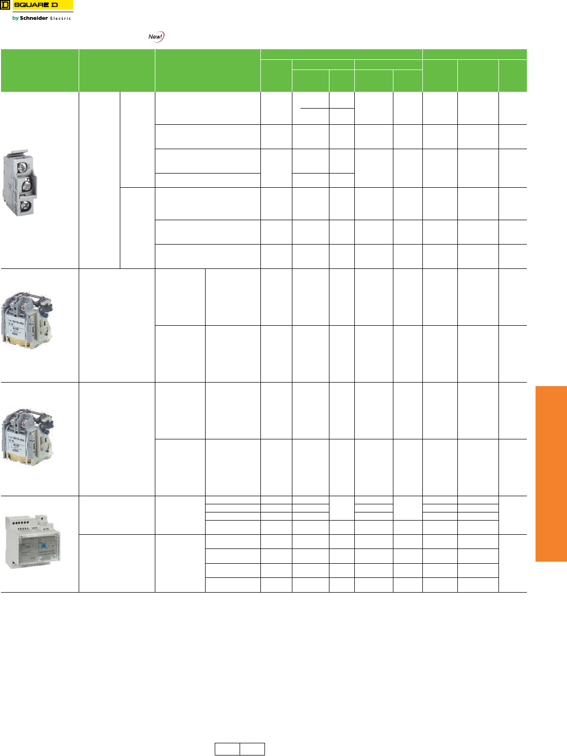
www.schneider-electric.us
7MINIATURE AND MOLDED CASE
CIRCUIT BREAKERS
© 2012 Schneider Electric
All Rights Reserved 7-39
PowerPact™ Circuit
Breaker Accessories
Electrical Accessories
Class 612 / Refer to Catalog 0612CT0101
Table 7.82: Electrical Accessories
Accessory Description Rated Voltage
H-, J-, and L-Frame M-, P-, and R-Frame
Factory-
Installed
Cat. Suffix
H- and J-Frame L-Frame Factory
Installed
Cat. Suffix
Field-
Installable
Cat. No.
$ Price
Field-
Installable
Cat. No.
$ Price
Field-
Installable
Cat. No.
$ Price
Auxiliary and
Alarm Switches
(OF, SD, SDE)
Provides circuit
breaker
contact status.
Note: The
location of the
accessory in
the circuit
breaker
determines its
function.
Standard
Min
Load =
10mA with
24V
1 auxiliary switch (OF) 1a1b AA S29450 297.00 S29450 297.00 AA S29450 297.00
2 auxiliary switch (OF) 2a2b AB 2x S29450 594.00 2x S29450 594.00 AB 2x S29450 594.00
3 auxiliary switch (OF) 3a3b AC — — 3x S29450 891.00 AC 3x S29450 891.00
Alarm Switch (SD) 1a1b BC S29450 297.00 S29450 297.00 BC S29450 297.00
Overcurrent trip switch (SDE) 1a1b BD — 338.00 S29450 297.00 BD S29450 297.00
Consisting of: OF Switch — S29450 297.00 —— — — —
SDE Adapter — S29451 40.00 —— — — —
Alarm switch and Overcurrent trip switch BE — 635.00 2x S29450 594.00 BE 2x S29450 594.00
Consisting of: OF Switch — 2x S29450 594.00 —— — — —
SDE Adapter — S29451 40.00 —— — — —
Auxiliary Switch/Alarm Switch/Adapter
(OF/SD/SDE) Kit ——————S33801c297.00
Low Level
Min
Load =
1mA with
24V
One auxiliary switch (OF) 1a1b AE S29452 372.00 S29452 372.00 AE S29452 372.00
Two auxiliary switches (OF) 2a2b AF 2x S29452 744.00 2x S29452 744.00 AF 2x S29452 744.00
3 auxiliary switches (OF) 3a3b AG — — 3x S29452 1116.00 AG 3x S29452 1116.00
Alarm Switch (SD) 1a1b BH S29452 372.00 S29452 372.00 BH S29452 372.00
Overcurrent trip switch (SDE) 1a1b BJ — 413.00 S29452 372.00 BJ eS29452 372.00
Consisting of: OF Switch — S29452 372.00 —— — — —
SDE Adapter — S29451 40.00 —— — — —
Alarm switch and Overcurrent trip switch BK — 785.00 2x S29452 744.00 BKe2x S29452 744.00
Consisting of: OF Switch — 2x S29452 744.00 —— — — —
SDE Adapterd—S29451 40.00 —— — — —
Shunt Trip (MX)
Trips the circuit breaker from
a remote location by means
of a trip coil energized from a
separate supply voltage
circuit.
AC
24 SK S29384
717.00
S29384
717.00
SK S33659
755.00
48 SL S29385 S29385 SL S33660
110–130 SA S29386 S29386 SA S33661
220–240 — — — SC S33662
208–277 SD S29387 S29387 SD S33663
380–480 SH S29388 S29388 SH S33664
525–600 SJ S29389 S29389 ——
DC
12 SN S29382
717.00
S29382
717.00
SN S33658
755.00
24 SO S29390 S29390 SK S33659
30 SU S29391 S29391 SK S33659
48 SP S29392 S29392 SL S33660
60 SV S29383 S29383 SL S33660
125 SR S29393 S29393 SA S33661
250 SS S29394 S29394 SC S33662
Undervoltage Trip (MN)
Instantaneously opens the
circuit breaker when the
under-voltage trip supply
voltage drops to a value
between 35% and 70% of its
rated voltage. Closing is
allowed when the supply
voltage of the undervoltage
trip reaches 85% of rated
voltage.
AC
24 UK S29404
717.00
S29404
717.00
UK S33668
755.00
48 UL S29405 S29405 UL S33669
110–130 UA S29406 S29406 UA S33670
220–240 — — — UC S33671
208–277 UD S29407 S29407 ——
380–480 UH S29408 S29408 UH S33673
525–600 UJ S29409 S29409 ——
DC
12 UN S29402
717.00
S29402
717.00
——
755.00
24 UO S29410 S29410 UK S33668
30 UU S29411 S29411 UK S33668
48 UP S29412 S29412 UL S33669
60 UV S29403 S29403 UL S33669
125 UR S29413 S29413 UA S33670
250 US S29414 S29414 UC S33671
Undervoltage trip with
externally mounted
adjustable time delay unit for
UVR of 0.5, 0.9, 1.5, 3.0
seconds before circuit
breaker trips
AC/DC
48 — S33680
1140.00
S33680
1140.00
—S33680ab
1140.00
100–130 — S33681 S33681 —S33681ab
220–250 — S33682 S33682 —S33682ab
380–480 — — — — — — S33683ab
Undervoltage trip with
externally mounted non-
adjustable time delay unit of
0.25 sec before circuit
breaker trips.
AC/DC
48 — S29426 930.00 S29426 930.00 ——
930.00
100–130 — — — — — — S33684ab
200–250 — — — — — — S33685ab
220–240 — S29427 930.00 S29427 930.00 ——
aField-installable kit includes time delay module only. Order undervoltage trip separately.
bDiscount schedule DE2F.
cP-frame drawout circuit breaker only.
dSDE Adapter used for H- and J-frame only.
eNot available on electrically operated P-frame.
H-, J-, L-, M-, P,
and R-Frame
H-, J-, and
L-Frame
H-, J-, and
L-Frame
Time Delay Unit
DE2 DE2F Discount
Schedule
www.schneider-electric.us
7MINIATURE AND MOLDED CASE
CIRCUIT BREAKERS
7-40 © 2012 Schneider Electric
All Rights Reserved
PowerPact™ Circuit
Breaker Accessories
Motor Operators and Rotary Handles
Class 612 / Refer to Catalog 0612CT0101
Table 7.83: Motor Operators for H-, J-, and L-Frame Circuit Breakers
Description Rated Voltage
Factory
Installed
Cat. No. Suffix
Field--Installable Kit
H-FrameaJ-Frame L-Frame 600 A
Cat. No. $ Price Cat. No. $ Price Cat. No. $ Price
Standard motor for electrically-
operated circuit breakersd
AC
48–60 ML S29440
1161.00
S31548
3123.00
S432639
3395.00
110–130 MA S29433 S31540 S432640
208–277
220–240 MD S29434 S31541 S432641
380–415 MF — — S432642
440–480 MH S29435 S31542 S432647
DC
24–30 MO S29436
1161.00
S31543
3123.00
S432643
3545.00
48–60 MV S29437 S31544 S432644
110–130 MR S29438 S31545 S432645
250 MS S29439 S31546 S432646
Communicating motor for electrically-
operated circuit breakerseAC 220–240 NC S429441 1509.00 S431549 4060.00 S432652 4414.00
Locking device
Mounting hardware — — — — — S32649 59.00
Ronis lock — S41940 146.00 S41940 146.00 S41940 146.00
Profalux lock — S42888 146.00 S42888 146.00 S42888 146.00
Mounting hardware plus
Ronis lock —S429449 155.00 S429449 155.00 ——
Operations counter — — — — — S32648 225.00
Adapter for I-Line circuit breaker — S37420 119.00 S37420 119.00 ——
Table 7.84: Spring-Charging Motors for Electrically-Operated P-Frame Circuit Breakers
Description Rated Voltage Factory Installed P-Frame (For Field-replacement Only) Replacement Coils
Cat. No. Suffix $ Price Spring Charging Motor Cat. No. $ Price cOpening/Closing Coil Cat. No. $ Price
Standard motor for electrically-
operated circuit breakers.
Factory-installed includes
motor and opening/closing
coils.
AC
48 ML
5090.00
S47391
3580.00
S33660
755.00
100–130 MA S47395 S33661
220–240 MC S47396 S33662
380–415 MF S47398 S33664
DC
24–30 MO
5090.00
S47390
3580.00
S33659
755.00
48–60 MV S47391 S33660
110–130 MR S47392 S33661
200–250 MS S47393 S33662
Communicating motor
mechanism for electrically
operated circuit breakers.
Factory-installed includes
motor
and opening/closing coils.
AC
48 NL
5090.00
S47391
3580.00
S33034
755.00
100–130 NA S47395 S33035
220–240 NC S47396 S33036
380–415 NF S47398 S33038
DC
24–30 NO
5090.00
S47390
3580.00
S33033
755.00
48–60 NV S47391 S33034
110–130 NR S47392 S33035
200–250 NS S47393 S33036
Table 7.85: Rotary Operated Handles
Device Description
H- and J-FrameaL-Frame P-Frame
Factory
Installed
Cat. No. Suffix
Field Installable
Cat. No. $ Price Factory Installed
Cat. No. Suffix
Field Installable
Cat. No. $ Price
Factory
Installed
Cat. No. Suffix
$ Price
Direct
Mounted
Standard black handle Handle only RD10 S29337 225.00 RD10 S32597 366.00 RD10 539.00
Standard black handle with
Two early-break and two early make
switches — — — — — — RD16 822.00
One early-break switch RD12 S29337 + S29345 345.00 RD12 S32597 + S32605 486.00 ——
Two early-make switches RD13 S29337 + S29346 404.00 RD13 S32597 + S29346 545.00 ——
Red handle on yellow bezel
Handle only RD20 S29339 234.00 RD20 S32599 407.00 ——
One early-break switch RD22 S29339 + S29345 354.00 RD22 S32599 + S32605 527.00 ——
Two early-make switches RD23 S29339 + S29346 413.00 RD23 S32599 + S29346 586.00 ——
MCC conversion accessory — S429341 102.00 —S32606 102.00 ——
CNOMO conversion accessory — — — — S32602 102.00 ——
Door
Mounted
Standard black handle Handle only RE10 S29338 383.00 RE10 S32598 557.00 RE10 971.00
Standard black handle
with:
Two early-break and two early make
switches — — — — — — RE16 1268.00
Two early make switches RE13 S29338 + S29346 503.00 RE13 S32598 + S29346 736.00 ——
Red handle on yellow bezel Handle only RE20 S29340 399.00 RE20 S32600 597.00 ——
Rotary Handle Replacement Kit — — —— — — S33875 795.00
Telescoping RT10 S29343 492.00 RT10 S32603 617.00 ——
Accessories
Key lock adapter —S429344 58.00 —S32604 58.00 ——
Key locks
Ronis 1351.500 —S41940 146.00 —S41940 146.00 ——
Profalux KS5 B24 D4Z —S42888 146.00 —S42888 146.00 ——
2 Ronis keylocks with 1 key —S41950 185.00 —S41950 185.00 ——
2 Profalux keylocks with 1 key —S42878 185.00 —S42878 185.00 ——
Indication Auxiliary Switch One early-break switch —S29445 120.00 —S32605 120.00 ——
Two early-make switches —S29346 179.00 —S29346 179.00 ——
aNot available in H-frame 2P modules.
bCP1 discount schedule.
cDE2F discount schedule.
dFactory and field-installed standard motor operators for H- and J-frame circuit breakers require the SDE switch
and SDE adapter (both included).
Factory and field-installed standard motor operators for L-frame circuit breakers require the SDE switch
(included).
eInstallation requires BSCM with NSX Cord. SeeTable 7.118, page 7-49 for ordering information.
Motor Operator
Spring-charging
Motor
Door-Mounted
Handle
Direct-Mounted
handle
DE2F CP1 DE2 Discount
Schedule
www.schneider-electric.us
7MINIATURE AND MOLDED CASE
CIRCUIT BREAKERS
© 2012 Schneider Electric
All Rights Reserved 7-41
PowerPact™ Circuit
Breaker Accessories
Locks, Installation Accessories, and Rear Connections
Class 612 / Refer to Catalog 0612CT0101
Table 7.86: Locks, Interlocking
Device Description
H- and J-Frame Q-Frame L-Frame M- and P-Frame R-Frame
Factory
Installed
Cat. No.
Suffix
Field-
Installed
Cat. No.
$ Price
Field-
Installed
Cat. No.
$ Price
Field-
Installed
Cat. No.
$ Price
Factory
Installed
Cat. No.
Suffix
Field-
Installed
Cat. No.
$ Price
Factory
Installed
Cat. No.
Suffix
Field-
Installed
Cat. No.
$ Price
Handle
Padlocking
Device
Removable (lock OFF only) — S29370 50.00 S29370 50.00 —S44936 50.00 —S33996 50.00
Fixed (lock OFF or ON) YP S29371 77.00 QBPA 77.00 S32631 122.00 YP S32631 122.00 YP S32631 122.00
Fixed (lock OFF only)aYQ S37422 122.00 QBPAF 77.00 NJPAF 122.00 YQ MPRPAF 122.00 YQ MPRPAF 122.00
Fixed (lock OFF only)–2P YQ H2PHLA 122.00 ————— — — — — —
Interlocking
(Not UL listed)
Mechanical for circuit breakers with rotary
handlesa—S29369 494.00 ——S32621 494.00 —S33890 1220.00 ———
Mechanical for circuit breakers with togglesa—S29354 494.00 QBMIK 90.00 S32614 494.00 ———— ——
Provision only, vertical
mount, 1 or 2 locks Kirk — ——————JA —323.00 —
Provisions only, vertical
mounting one key interlock
including padlock provision,
open position only.
Kirk — ——————JEbd —445.00 JEd—445.00
Provision only, horizontal
mount
1 lock, M- and P-frame
1 or 2 locks, R-frame
Kirk — ——————JK —323.00 JK — 323.00
Ronis — ——————JBc—323.00 JB — 323.00
Profalux — — — — — — — JDc—323.00 JD — 323.00
Provision and 1 lock, vertical
mount Kirk — ——————JG—1796.00 ———
Provision and 1 lock,
horizontal mount
Kirk — ——————JL —1796.00 JL — 1796.00
Ronis — ——————JCc—2285.00 JC — 2285.00
Profalux — — — — — — — JFc—2285.00 JF — 2285.00
Provision and 2 locks keyed
alike Kirk — ——————JN —2285.00 JN — 2285.00
Provision and 2 locks keyed
differently Kirk — ——————JP —3269.00 JP — 3269.00
aNot available in M frame or HD and HG 2P modules.
bNot available on M-frame.
cNot available for M, P or P frame drawout. Only available on P frame electronic.
dNot available on I-Line.
Key Locking
Table 7.87: Installation Accessories fo H-, J-, and L-Frame Circuit Breakers
Description
H- and J-Frame L-Frame
Field-
Installed
Cat. No.
$ Price
Field-
Installed
Cat. No.
$ Price
Front Panel Escutcheon for Toggle Breakers S29315 48.00 32556 55.00
Front Panel Escutcheon for Rotary Handle, Motor Operator, or extended
escutcheon S29317 63.00 S32558 74.00
Phase Barriers (set of 6) S29329 53.00 32570 72.00
Handle Rubber BooteS29319 135.00 S32560 171.00
Sealing Accessories (for front cover screws) S29375 42.00 S29375 42.00
DIN rail mounting kit (requires 15 mm depth on a 35 mm DIN rail)eS29305 188.00 ——
DIN rail adapter — — — —
Handle Extensions (set of 5) S29313 140.00 S432553 165.00
eNot available in HD and HG 2P modules.
Table 7.88: Installation Accessories for M-, P-, and R-Frame Circuit Breakers
Description Frame
Field-
Installed
Cat. No.
$ Price
Door Escutcheon
Accessory Cover M-, P-Frame S33718f176.00
R-Frame S33929 176.00
Toggle Handle M-, P-Frame S33717 47.00
Drawout P-Frame S33857f308.00
Terminal Covers
Short lug cover 3P
P-Frame
S33932 165.00
Short lug cover 4P S33933 216.00
Long lug cover 3P S33934 216.00
Long lug cover 4P S33935 281.00
Replacement Handle
Standard R-Frame S33997 111.00
Standard Short M-, P-Frame S46998 44.00
Long M-, P-Frame S46996 44.00
fDE2F discount schedule.
Handle Rubber Boot Door Escutcheon
Terminal Covers
Rear Connection
Removable Padlock
Attachment
Fixed Padlock
Attachment
Table 7.89: Rear Connections
Device Description
H-Frame J-Frame L-Frame
Poles
Factory-
Installed
Termination
No.
Field-
Installable
Cat. No.
$ Price Poles
Factory-
Installed
Termination
No.
Field-
Installed
Cat. No.
$ Price Poles
Factory-
Installed
Termination
No.
Field-Installed
Cat. No. $ Price
Mixed Rear
Connection Kitg
2S ——2S ——3 S S32477 1059.00
3S S37432 381.00 3S S37437 381.00 4S S32478 1344.00
Consisting of:
Short rear connections (set of 2) 2 or 3 —2xS37433h84.00 2 or 3 —2xS37438h84.00 3—2xS432475h219.00
Long rear connections (set of 2) — S37434 105.00 —S37439i105.00 —2xS432476h261.00
Short terminal cover (3P) 3 — S37436 119.00 3— S37440 119.00 3—2xS32562h149.00
Short terminal cover (4P) 4 — — — — — — — 4 — 2x S32563h161.00
gKit contains 4 short rear connections, 2 long rear connections (4 long rear connections for 4P), hardware, and 2 terminal covers..
hPrice shown is for quantity one.
iFor use with 3P circuit breakers only.
DE2 DE2F Discount
Schedule
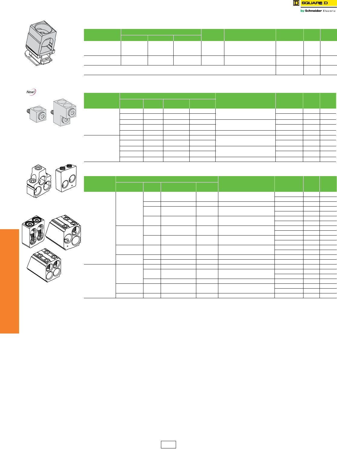
7-42 © 2012 Schneider Electric
All Rights Reserved
www.schneider-electric.us
7MINIATURE AND MOLDED CASE
CIRCUIT BREAKERS
PowerPact™ Circuit
Breaker Accessories
Mechanical Lugs
Class 612 / Refer to Catalog 0612CT0101
aSee page 7-44 for terminal nuts/bus bar connections.
bDoes not fit onto ON end of unit-mount P-frame circuit breakers.
cFor unit-mount circuit breaker only.
dAll unit-mount R-frame circuit breakers require terminal pads for mounting lugs of any type. See page 7-44.
eFor lug with a tapped hole for control wire, add a “T” before the “K” in the catalog number (for example, AL800P6TK).
fThis lug can only be used on low amp PJ frame breakers where the Instantaneous setting must not be turned OFF. The cables must be laced with rope
per lug instructions.
gNot available with tapped hole for control wire.
Table 7.90: Mechanical Lug Kits for H-Frame and J-Frame Circuit Breakersa
Description Circuit Breaker Application Ampere
Rating
Number of Wires
Per Lug and Wire Range Kit Cat. No. Qty
Per Kit
$ Price
Per Kit
Standard Ampere Rating Optional
Al Lugs for Use with Al
or Cu Wire
HD, HG, HJ, HL 15–150 A (1) 14–3/0 AWG Al or Cu AL150HD 375.00
JD, JG, JJ, JL 150–175 A (1) 4-4/0 AWG Al or Cu AL175JD 3113.00
JD, JG, JJ, JL 200–250 A JD,JG,JJ,JL 150–175 A (1) 3/0–350 kcmil Al or Cu AL250JD 3113.00
Cu Lugs for Use with
Cu Wire Only
HD,HG,HJ,HL 15–150 A (1) 14–2/0 AWG Cu CU150HD 3156.00
JD,JG,JJ,JL 150–250 A (1) 1/0–300 kcmil Cu CU250JD 3314.00
Control Wire Terminal for H-frame lug kit S37423 253.00
Control Wire Terminal for J-frame lug kit S37424 253.00
Table 7.91: Mechanical Lug Kits for L-Frame Circuit Breakers
Description
Circuit Breaker Application Number of Wires
Per Lug and Wire Range Kit Cat. No. Qty
Per Kit
$ Price
Per Kit
Ampere
Rating Poles Unit Mount I-Line
Al Lugs for Use with Al
or Cu Wire
250 3 X X (1) 2 AWG–500 kcmil Al
(1) 2 AWG–600 kcmil Cu
AL400L61K3 3143.00
4X — AL400L61K4 4176.00
400/600 3 X — (2) 2/0 AWG–500 kcmil Al or Cu AL600LS52K3 3341.00
4X — AL600LS52K4 4449.00
400/600 3 X X (2) 3/0 AWG–500 kcmil Al or Cu AL600LF52K3 3831.00
Cu Lugs for Use with
Cu Wire Only
250/400 3 X X (1) 2 AWG–600 kcmil Cu CU400L61K3 3755.00
4X — CU400L61K4 4983.00
400/600 3 X — (2) 2/0 AWG–500 kcmil Cu CU600LS52K3 31832.00
4X — CU600LS52K4 42385.00
400/600 3 X X (2) 3/0 AWG–500 kcmil Cu CU600LF52K3 32395.00
Table 7.92: Mechanical Lug Kits for M-Frame, P-Frame and R-Frame Circuit Breakerse
Description
Circuit Breaker Application Wires per Lug
and Wire Range Cat. No. Lugs
Per Kit
$ Price
Per Kit
Standard Rating Optional Ampere
Rating
Al Lugs
for AL or Cu Wire
M-, P-Frame
800 A — 800 A (3) 3/0 AWG-500 kcmil AL800M23K 3284.00
AL800M23K4 4378.00
1200 A PG, PJ, PL, MG, MJ 800 A (4) 3/0 AWG-500 kcmil AL1200P24Kb1155.00
— PG, PJ, PL, MG, MJ 800 A (2) 3/0 AWG-600 kcmil AL800P6Kb3416.00
AL800P6K4b4554.00
— PG, PJ, PL, MG, MJ 800 A (2) 3/0 AWG-750 kcmil
750 kcmil: compact AL only
AL800P7Kb3464.00
AL800P7K4b4602.00
P-Frame
1200 A PG ,PJ, PL 800 A (4) 3/0 AWG-500 kcmil AL1200P25Kc3378.00
AL1200P25K4c4504.00
— PG, PJ,P L 800–1200 A (3) 350-600 kcmil AL1200P6KUc3786.00
AL1200P6KU4c41038.00
PG,PJ,PL — PG, PJ, PL 1200 A (3) 3/0 AWG-750 kcmil
750 kcmil: compact AL only
AL1200P7KUc31233.00
AL1200P7KU4c41635.00
R-Frame 1200 A I-Line — (4) 3/0 AWG-600 kcmil AL1200R53K 1215.00
2500 A Unit Mount — (1) 3/0 AWG-750 kcmil AL2500RKd2132.00
Cu Lugs
for Cu Wire Onlyg
M-, P-Frame
— PJ 100–150 A (1) 1-1/0 AWG CU250P1Kf3990.00
800 A MG, MJ, PG, PJ, PL — (3) 3/0 AWG-500 kcmil CU800M23K 31647.00
CU800M23K4 42190.00
1200 A MG, MJ, PG, PJ, PL 800–1200 A (4) 3/0 AWG-500 kcmil CU1200P24Kb1569.00
P-Frame 1200 A PG, PJ, PL 800–1200 A (4) 3/0 AWG-500 kcmil CU1200P25Kc34886.00
CU1200P25K4 46503.00
R-Frame 1200 A I-Line — (4) 3/0 AWG-500 kcmil CU1200R53K 1548.00
J-Frame Lug
L-Frame Lugs
M- and P-Frame Lugs
(800 A and below)
P-Frame Lugs
(Above 800 A)
DE2 Discount
Schedule
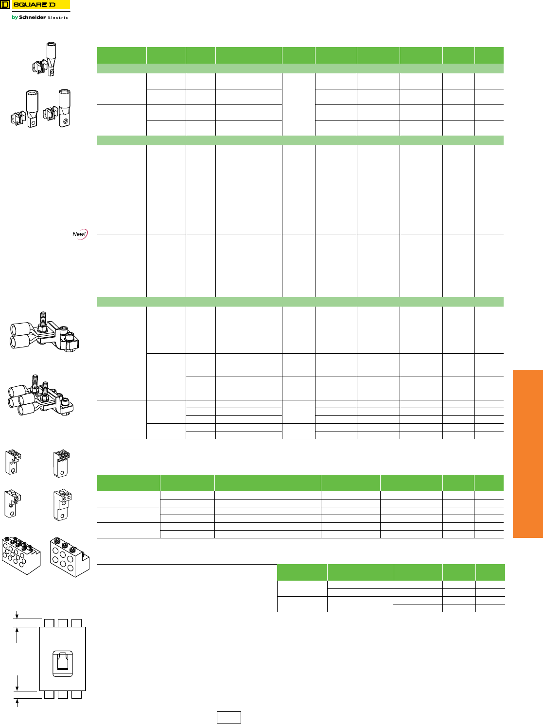
www.schneider-electric.us
7MINIATURE AND MOLDED CASE
CIRCUIT BREAKERS
© 2012 Schneider Electric
All Rights Reserved 7-43
PowerPact™ Circuit
Breaker Accessories
Compression Lugs and Power Distribution Connectors (PDC)
Class 612 / Refer to Catalog 0612CT0101
aAll unit-mount R-frame circuit breakers require terminal pads for mounting lugs of any type. See page 7-44.
b9 lugs for 3000 A circuit breakers
cNot for use on I-Line™ circuit breakers unless wire bending space is adequate.
dOFF end only when OFF end is the load end.
eNot for use with I-Line™ circuit breakers.
fKit includes long terminal shield and cover, which adds 1.65 inches to standard lug with short terminal shield.
Table 7.93: Compression Lug Kits for PowerPact™ Circuit Breakers
Description Circuit
Breaker Type
Ampere
Rating System Range Mounting
Type
Dimension A
(in)
Max. Lugs per
Terminal Cat. No. Qty.
Per Kit
$ Price
Per Kit
Compression Lug Kits for H-Frame and J-Frame Circuit Breakers
Aluminum
Compression
Lug Kits
H-frame 60 A 6–2 AWG Al or Cu
Unit/I-linec
1.2 1 YA060HD 3194.00
150 A 1/0–4/0 AWG Al or Cu 2.5 1 YA150HD 3294.00
J-frame 150 A 1–3/0 AWG Al or Cu 1.2 1 YA150JD 3237.00
250 A 3/0–350 kcmil Al or Cu 2.5 1 YA250J35 3305.00
Copper
Compression
Lug Kits
H-frame 60 A 6–1/0 AWG Cu 1.0 1 CYA060HD 3194.00
150 A 4–2/0 AWG Cu 1.2 1 CYA150HD 3194.00
J-frame 150 A 6–1/0 AWG Cu 0.7 1 CYA150JD 3194.00
250 A 2/0–300 kcmil Cu 1.1 1 CYA250J3 3194.00
Compression Lug Kits for L-Frame Circuit Breakers
Aluminum
Compression
Lug Kits
L-frame
250 A 4-300 kcmil Al/Cu
Unit/I-linec
1.2 1 YA400L31K3 3294.00
400 A 4-300 kcmil Al/Cu 2.5 2 YA600L32K3 6540.00
250 A 2/0-500 kcmil Al/Cu 1 YA400L51K3 3361.00
600 A 2/0-500 kcmil Al/Cu 2 YA600L52K3 6718.00
400 A 500-750 kcmil Al
500 kcmil Cu 1YA400L71K3 3425.00
250 A 4-300 kcmil Al/Cu 1 YA400L31K4 4383.00
400 A 4-300 kcmil Al/Cu 2 YA600L32K4 8709.00
250 A 2/0-500 kcmil Al/Cu 1 YA400L51K4 4474.00
600 A 2/0-500 kcmil Al/Cu 1.2 2 YA600L52K4 8950.00
400 A 500-750 kcmil Al
500 kcmil Cu 2.5 1 YA400L71K4 4560.00
Copper
Compression
Lug Kits
L-frame
250 A 2/0-300 kcmil Cu
Unit/I-linec
1.2 1 CYA400L31K3 3461.00
400 A 2/0-300 kcmil Cu 2.5 2 CYA600L32K3 6873.00
250 A 250-500 kcmil Cu 1 CYA400L51K3 3384.00
600 A 250-500 kcmil Cu 2 CYA600L52K3 6764.00
250 A 2/0-300 kcmil Cu 1 CYA400L31K4 4606.00
400 A 2/0-300 kcmil Cu 2 CYA600L32K4 81147.00
250 A 250-500 kcmil Cu 1 CYA400L51K4 4505.00
600 A 250-500 kcmil Cu 2 CYA600L52K4 81011.00
Compression Lug Kits for M-Frame, P-Frame, and R-Frame Circuit Breakers
Aluminum
Compression
Lug Kits
M-, P-frame
250 A 2/0-300 kcmil
Unit/I-linec
3.7 2 YA250P3 1663.00
300 A 4/0-500 kcmil 3.9 2 YA300P5 1519.00
400 A 2/0-300 kcmil 4.3 2 YA400P3 2542.00
400 A 500-750 kcmil 3.7 2 YA400P7 1747.00
600 A 4/0-500 kcmil 3.9 2 YA600P5 2788.00
800 A 500-750 kcmil 4.3 2 YA800P7 2845.00
R-framea
1200 A 2/0-300 kcmil
I-linec
3.8 4 YA1200R3 4663.00
1200 A 4/0-500 kcmil 4.0 4 YA1200R5 4707.00
1200 A 500-750 kcmil 4.4 4 YA1200R7 4888.00
2000 A 2/0-300 kcmil
Unitc
a8YA2000R3 2317.00
2000 A 4/0-500 kcmil a8YA2000R5 2291.00
2500 A 500-750 kcmil a8bYA2500R7 2350.00
Copper
Compression
Lug Kits
M-, P-frame
400 A 4/0-500 kcmil
Unitc
3.3 2 CYA400P5 1651.00
600 A 4/0-500 kcmil 3.3 2 CYA600P5 2753.00
800 A 500-750 kcmil 3.6 2 CYA800P7 2554.00
R-frame 1200 A 4/0-500 kcmil I-Linec3.5 4 CYA1200R5 4987.00
1200 A 500-750 kcmil 3.8 4 CYA1200R7 4920.00
Table 7.94: Power Distribution Connectors for H-Frame, J-Frame and L-Frame Circuit Breakers
Use with Circuit
Breaker Type
Circuit Breaker
Ampere Rating
Wires Per Terminal &
Wire Range Dimension A (in.) Cat. No. Qty.
Per Kit
$ Price
Per Kit
HD, HG, HJ, HLd15–150 (6) 14–6 AWG Cu 1.0 PDC6HD6 3443.00
15–150 (3) 14–2 AWG Cu 1.2 PDC3HD2 3434.00
JD, JG, JJ, JLd150–250 (6) 14–4 AWG Cu 1.0 PDC6JD4 3305.00
150–250 (2) 14–1 AWG and (1) 3–2/0 AWG Cu 1.5 PDC3JD20 3594.00
LD, LG, LJ, LL 150–600 (3) 14–1 AWG and (2) 3–2/0 AWG 1.28fPDC5DG20L3 3387.00
150–600 (12) 14–4 AWG 1.31fPDC12DG4L3 3387.00
Table 7.95: Power Distribution Connectors for M-Frame and P-Frame Circuit Breakerse
Use for multiple load connections on one circuit breaker in place of
standard distribution block to save space and time.
• Use on load end of circuit breaker only
• Use in UL508 Industrial Control applications only.
• Use in UL1995/CSA C22.2 No. 236 heating and cooling equipment.
• For Cu wire only.
Ampere Rating (Wires Per Terminal)
Wire Range Cat. No. Qty Per Kit $ Price
Per Kit
250–1200 A (6) 12–2/0 AWG Cu PDC6P20 3573.00
(6) 12–2/0 AWG Cu PDC6P204 4756.00
250–1200 A (12) 10–4 AWG Cu PDC12P4 3866.00
PDC12P44 4929.00
J-Frame Compression Lugs
P-Frame Compression Lug Kit
R-Frame Compression Lug Kit
PDC6HD6 PDC6JD4
PDC3HD2 PDC3JD20
Crimp lug or PDC connectors
extension past end or circuit
breaker “A” See Table
Extremity
of
Molded Case
w/Mechanical
Lugs
“A” See Table
PDC12P4 PDC6P20
DE2 Discount
Schedule
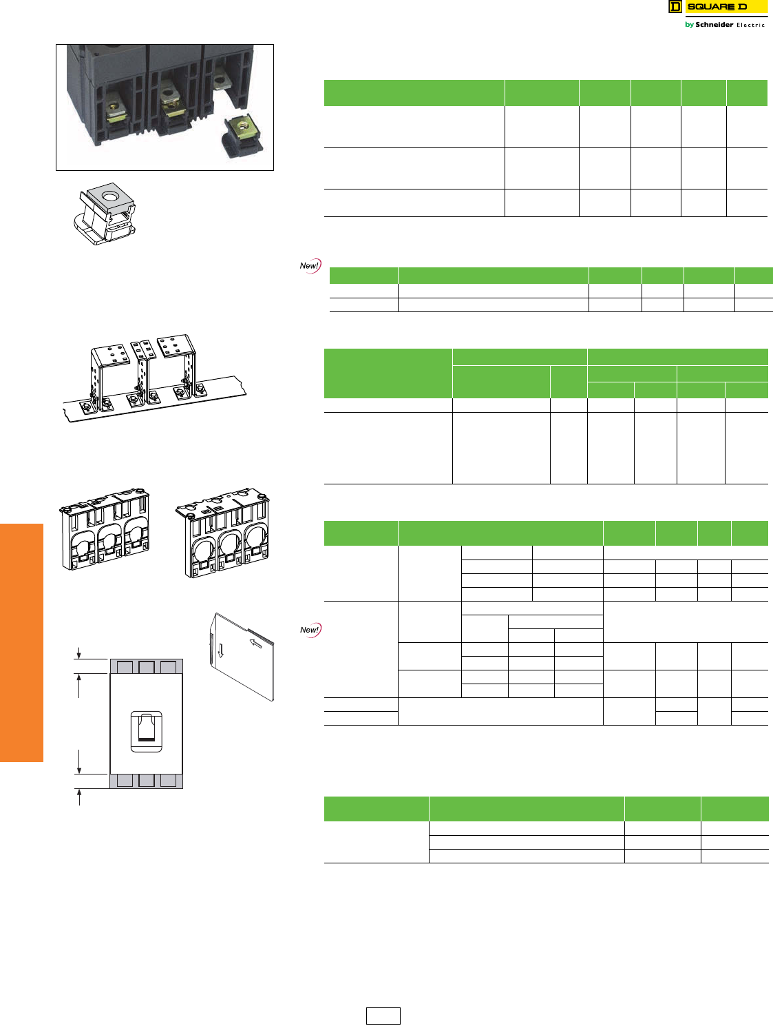
www.schneider-electric.us
7MINIATURE AND MOLDED CASE
CIRCUIT BREAKERS
7-44 © 2012 Schneider Electric
All Rights Reserved
PowerPact™ Circuit
Breaker Accessories
Terminal Nuts, Terminal Pads, Terminal Shields and Accessories
Class 612 / Refer to Catalog 0612CT0101
For cable connection to RLTB, use AL2500RK lug. See page 7-43.
aShort lug shields provide IP20 protection for mechanical lugs and are compatible with control wire terminals.
bJ-frame terminal shield is not compatible with the YA250J35 compression terminal.
cDE5A Discount Schedule
Table 7.96: Terminal Nuts for Bus Bar Connection of H-Frame and J-Frame Circuit
Breakers
Description Frame Tap Cat. No. Qty Per Kit $ Price
Per Kit
H-Frame Terminal Nut Insert–English HD/HG/HJ/HL 1/4-20 S37425 253.00
H-Frame Terminal Nut Insert–English HD/HG/HJ/HL 1/4-20 S37444 375.00
H-Frame Terminal Nut Insert–Metric HD/HG/HJ/HL M6 S37426 253.00
J-Frame Terminal Nut Insert–English JD/JG/JJ/JL 1/4-20 S37427 275.00
J-Frame Terminal Nut Insert–English JD/JG/JJ/JL 1/4-20 S37445 3113.00
J-Frame Terminal Nut Insert–Metric JD/JG/JJ/JL M8 S37428 275.00
Control Wire Terminal for H-Frame Terminal Nut HD/HG/HJ/HL S37429 253.00
Control Wire Terminal for J-Frame Terminal Nut JD/JG/JJ/JL S37430 253.00
Table 7.97: Bus Bar Connections Hardware for L-Frame, M-Frame and P-Frame
Circuit Breakers
Frame Description Term. No. Poles Cat. No. $ Price
L-Frame Set of 4 terminal screws and washers for one side F 4 S36967 31.00
M- and P-Frame Bus Connector Kit for one pole, one end 1 S33928 28.00
Table 7.98: Terminal Pad Kits for R-Frame Circuit Breakers
R-Frame
Circuit Breaker
Terminal Pad Kit Field-Installable Kits
Usage Lugs per
Phase
3P Kit (One End Only) 4P Kit (One End Only)
Cat. No. $ Price. Cat. No. $ Price
3000 A, 100% Rated Required for cable or bus 9 RL3TB 1440.00 RL3TB4 2016.00
3000 A, Standard (80% Rated) Required for cable or bus
8RLTB 914.00 RLTB4 1280.00
2500 A, 100% Rated Required for cable or bus
2500 A, Standard (80% Rated) Required for cable, optional
for bus
All Other R-Frame CIrcuit Breakers Required for cable, optional
for bus
Table 7.99: Terminal Shields and Phase Barriers
Used With Description Dimension B
(in.) Cat. No. Qty Per
Kit $ Price
H- and J-Frame
Mechanical Lugs
Short Lug
Shielda
Frame Max. Wire Size
H-Frame 60 A 3 AWG 0.50 S37446 1149.00
H-Frame 150 A 3/0 AWG 0.50 S37447 1149.00
J-Frame 350 kcmil 0.24 S37448 1149.00
H- and J-Frame
Power Distribution
Connectors and
Compression Lugs
Compatible with:
PDC Compression Lugs
Aluminum Copper
H-Frame Long
Lug Shield
PDC6HD6 YA060HD CYA060HD 2.24 S37449 1209.00
PDC3HD2 YA150HD CYA150HD
J-Frame Long Lug
Shield
PDC6JD4 YA150JD CYA150JD 1.68 S37450 1209.00
PDC3JD2 bCYA250J3
M-, P-Frame Phase Barriers S33646 347.00
R-Frame S33998 47.00
Table 7.100: Miscellaneous H-, J-, and L-Frame Circuit Breaker Accessories
Accessory Description Field-Installed
Cat. No, $ Price
Spare Parts
Bag of screws for accessory cover, L-frame S432552 63.00
1 spare toggle extension, L-frame 32595 342.00
Set of 10 identification labels LV429226 82.00
Terminal Nut Insert
H-Frame Lug With
Terminal Nut
RLTB Terminal Pad Kit
Extremity
of
Molded Case
w/Mechanical
Lugs
“B” See Table
Phase barrier or
terminal shield
extension past end
of circuit breaker
“B” See Table
H-Frame Short Lug
Shield J-Frame Short Lug
Shield
R-Frame Phase Barrier
DE2 Discount
Schedule
www.schneider-electric.us
7MINIATURE AND MOLDED CASE
CIRCUIT BREAKERS
© 2012 Schneider Electric
All Rights Reserved 7-45
PowerPact™ Circuit
Breaker Accessories
Plug-In and Drawout Mountings
Class 611, 612 / Refer to Catalog 0611CT1001, 0612CT0101
aPrice shown is for quantity of 1.
bNeeds 2 kits per cradle.
cDiscount Schedule DE2F
Table 7.101: Plug-In and Drawout Mountings for H- and J-Frame Circuit Breakers
(3P or 2P in a 3P module)
Description
Factory
Installed
Cat. No.
Field-
Installed
Cat. No.
$ Price
Complete Factory-Assembled
Circuit Breakers
Plug-in base shipped with circuit breaker N 638.00
Drawout cradle shipped with circuit breaker D 1419.00
Special Order Options for
Plug-In and Drawout Circuit
Breakers
Plug-In Base Circuit breaker Only HJ00 290.00
Plug-in base kit S29278 348.00
Drawout Cradle
Circuit breaker only HJ00 485.00
Plug-in base kit S29278 348.00
Cradle side plates (fixed part of chassis) S29282 587.00
Circuit breaker side plates (moving part of
chassis) S29283 195.00
Accessories for Plug-In and
Drawout
H-Frame Shutter Kit (set of two) S37442 48.00
J-Frame Shutter Kit (set of two) S37443 48.00
Secondary
Disconnect
Blocks
Fixed part 9-wire connector (mounted on
base) S29273 95.00
Moving part 9-wire connector (mounted on
circuit breaker) S29274 60.00
Support for 2-moving connectors S29275 33.00
Extended escutcheon with extended toggle handle S29284 77.00
Two position indicating switches (connected/disconnected) S29287 207.00
H-Frame Short Terminal Cover (3P S37436 119.00
J-Frame Short Terminal Cover (3P) S37440 119.00
Table 7.102: Plug-In and Drawout Mountings for L-Frame Circuit Breakers
Description Poles
Plug-in Mounting Drawout Mounting
Factory
Installed
Cat. No.
Field-
Installed
Cat. No.
$ Price
Factory
Installed
Cat. No.
Field-
Installed
Cat. No.
$ Price
Kit (stationary and moving parts) 3N 1542.00 D2466.00
4N 2082.00 D3281.00
Stationary Part Plug-in base 3S32514 1065.00 S32514 1065.00
4S32515 1439.00 S32515 1439.00
Fixed part of chassis S32532 693.00
Moving Part
Circuit breaker only HJ00 710.00 HJ00 710.00
Moving part of chassis S32533 231.00
Short terminal covers 32xS32562 149.00 2x S32562 149.00
42xS32563 161.00 2x S32563 161.00
Table 7.103: Plug-In and Drawout Accessories for L-Frame Circuit Breakers
Description
Field-
Installed
Cat. No.
$ Price
Secondary Disconnecting Blocks
Fixed Part 9-wire connector S29273 95.00
Moving Part 9-wire connector S32523 60.00
Support for 3 moving connectors S32525 43.00
Fixed + Moving 9-wire manual auxiliary connector S29272 480.00
Shutters Two shutters for plug-in base 32521 81.00
Chassis Accessories
Extended escutcheon for toggle S32534 104.00
Locking device (key lock is not included) S29286 164.00
Two position indicating switches (connected/disconnected) 29287 207.00
Table 7.104: Termination Options
Termination Letter
N = Plug-in
D = Drawout
Table 7.105: Drawout Cradle and Accessories for P-Frame Circuit Breakers
Description Cat. No. $ Price
Drawout Cradle Product Selector 6400.00
Cradle
Connectors
Front Connected Flat (FCF) SFCF12bc 716.00
Rear Connected T Horizontal/Vertical (RCTH/RCTV) SRCTV12bc 408.00
Cradle
Accessories
Modbus™ cradle communication module S33852 2237.00
Safety shutters S48933c342.00
Secondary disconnects terminal shield S33763c220.00
Cradle position switch 1a/1b Form C— Connected/test/disconnected S33170c148.00
Low level cradle position switch 1a/1b Form C—Connected/test/disconnected S33171c216.00
Cell keying kit S33767c97.00
Disconnected position key locking—provision for Kirk or Federal Pioneer Lock S33772c908.00
Door interlock kit S33786c330.00
Racking interior kit S33788c358.00
Door escutcheon (for replacement only, included with circuit breaker) S33857c308.00
Transparent cover S33859c1290.00
Push-in terminal kit (3 wires) S33098c120.00
Push-in terminal kit (6 wires) S33099c240.00
Finger cluster S33166c164.00
Cluster grease (12 oz. tube) S48899c132.00
H-Frame and J-Frame
Plug-in Mounting
H-Frame and J-Frame
Drawout Mounting
L-Frame Plug-In
Mounting
L-Frame Drawout
Mounting
L-Frame Disconnecting
Blocks
L-Frame Locking
Device
L G L 3 6 4 0 0 U 3 1 X
For factory-installed termination, place
termination letter in the third block of the
circuit breaker catalog number.
Termination No.
P-Frame Drawout Cradle Connections
DE2 DE2F Discount
Schedule
www.schneider-electric.us
7MINIATURE AND MOLDED CASE
CIRCUIT BREAKERS
7-46 © 2012 Schneider Electric
All Rights Reserved
Micrologic™ Electronic Trip Units
Class 611 / Refer to Catalog 0611CT1001
PowerPact™ H-, J-, and L-frame molded case circuit breakers may be
specified with any of the following Micrologic Electronic Trip Units.
Micrologic Standard 3.2/3.3 Trip Units
•True RMS sensing
•LI, LSI trip configurations
•Field-interchangeable trip units
•LED long-time pickup and trip indication
•Test kits available
•Thermal imaging
Micrologic Ammeter 5.2A/5.3A/6.2A/6.3A Trip Units
Includes all features listed for Micrologic standard trip unit, as well as:
•Advanced user interface
•Neutral protection
•Incremental fine tuning of settings
•Up to 12 alarms
•Digital ammeter—phase and neutral (4-pole only)
•Phase loading bar graph
•Maintenance indicators including contact wear, number of operations,
operating hours, and load profiles
•Cause of trip information for troubleshooting assistance
•LCD Display
•Zone-selective interlocking (ZSI) (short-time & ground-fault)
•Optional Modbus™ communications—PowerLogic™ compatible
Micrologic Energy 5.2E/5.3E/6.2E/6.3E Trip Units
Includes all features listed for Micrologic ammeter trip unit, as well as:
•Ground-fault trip with programmable ground fault alarm (available on
6.2E/6.3E only)
•Power and energy measurement
•Power quality measurements
•Current demand and power demand measurements
dThe LSI with 3.2S/3.3S trip units have fixed short time and long time delays.
eRequires neutral current transformer on the three-phase four-wire loads
fZSI for H/J frames in only IN. for L-frame ZSI is In and OUT.
gIndication available using the communication system only.
h% of hours in 4 current ranges: 0–49%, 50–79%, 80–89%, and >90% In.
iDC not available with electronic trip units.
Micrologic Standard
Trip Unit
Micrologic Ammeter and
Energy Trip Unit
PowerPact™ H-, J-, and L-Frame Micrologic™ Trip Units
Table 7.106: Micrologic Trip Unitsi for PowerPact H-, J-, and
L-Frame Circuit breakers
x– Standard Feature o – Available Option
Features Standard Ammeter Energy
3.2/3/3 3.2S/3.3S 5.2A/5.3A 6.2A/6.3A 5.2E/5.3E 6.2E/6.3E
LI x
LSIdxx x
LSIG / Ground-Fault Tripexx
Ground-Fault Alarm/Tripexx
Current Setting Directly in Amperes x x x x x x
True RMS Sensing x x x x x x
UL Listed xxxxxx
Thermal Imaging x x x x x x
LED for Long-time Pickup x x x x x x
LED for Trip Indication x x x x x x
LED for Green “Ready” x x x x x x
Up to 12 Alarms Used Together x x x x
Digital Ammeter x x x x
Zone-selective Interlockingfxxxx
Communications o o o o o o
LCD Display x x x x
Front Display Module FDM121 o o o o
Advanced User Interface x x x x
Neutral Protectionexxxx
Contact Wear Indicationgxxxx
Incremental Fine Tuning of Settings x x x x
Load Profileg,hxxxx
Power Measurement x x
Power Quality Measurements x x
Table 7.107: Micrologic Trip Unit Settings for H- and J-Frame
Model Trip Function Trip Unit Ampere Setting
Standard
LI 3.2
15-20-25-30-35-40-45-50-60
35-40-45-50-60-70-80-90-100
50-60-70-80-90-100-110-125-150
70-80-100-125-150-175-200-225-250
LSI 3.2S
15-20-25-30-35-40-45-50-60
35-40-45-50-60-70-80-90-100
50-60-70-80-90-100-110-125-150
70-80-100-125-150-175-200-225-250
Ammeter
LSI 5.2A
15–60
35–100
50–150
70–250
LSIG 6.2A
15–60
35–100
50–150
70–250
Energy
LSI 5.2E
15–60
35–100
50–150
70–250
LSIG 6.2E
15–60
35–100
50–150
70–250
Table 7.108: Micrologic Trip Unit Settings for L-Frame
Model Trip Function Trip Unit Ampere Setting
Standard
LI 3.3
70-80-100-125-150-175-200-225-250
125-150-175-200-225-250-300-350-400
200-225-250-300-350-400-450-500-600
LSI 3.3S
70-80-100-125-150-175-200-225-250
125-150-175-200-225-250-300-350-400
200-225-250-300-350-400-450-500-600
Ammeter
LSI 5.3A 125–400
200–600
LSIG 6.3A 125–400
200–600
Energy
LSI 5.3E 125–400
200–600
LSIG 6.3E 125–400
200–600
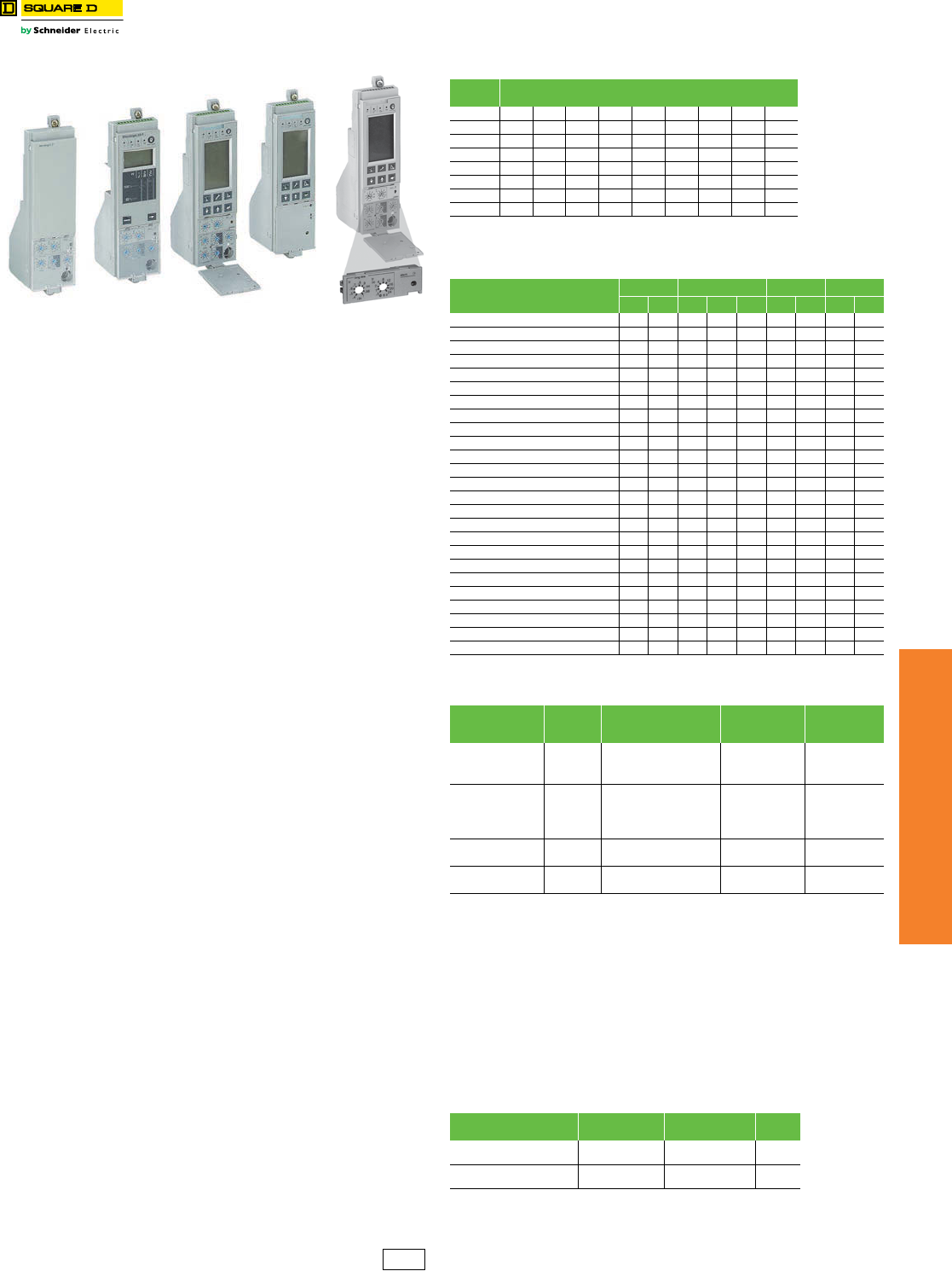
www.schneider-electric.us
7MINIATURE AND MOLDED CASE
CIRCUIT BREAKERS
© 2012 Schneider Electric
All Rights Reserved 7-47
Micrologic™ Electronic Trip Units
Class 612 / Refer to Catalog 0612CT0101
PowerPact™ P- and R-frame molded case circuit breakers may be
specified with any of the following Micrologic Electronic Trip Units.
Micrologic (Standard) 3.0 and 5.0 Trip Units
•True RMS sensing
•LI, LSI trip configurations
•Field-interchangeable long-time rating plugs
•LED long-time pickup indication
•Test kits available
•Thermal imaging
Micrologic (Ammeter) 3.0A, 5.0A and 6.0A Trip Units
Includes all features listed for Micrologic standard trip unit, as well as:
•LSIG trip configurations
•Digital ammeter—phase and neutral (4-pole only)
•Phase loading bar graph
•LED trip indication
•Zone-selective interlocking (ZSI) (short-time & ground-fault)
•Optional Modbus™ communications—PowerLogic™ compatible
Micrologic (Power) 5.0P and 6.0P Trip Units
Power measurement and advanced protection features includes all
features listed for Micrologic ammeter trip unit, as well as:
•LSI trip configuration with programmable ground fault alarm
•LSIG (Ground-fault trip) with programmable ground fault alarm
•Incremental “fine tuning” of L, S, I, and G pickup and delay settings
•LCD dot matrix display and LED trip indication
•Advanced user interface
•Advanced protection IDMTL—selectable long-time delay bands
•Neutral protection
•Power measurement
•Contact wear indication
•Modbus communications—PowerLogic compatible
•Local and remote settings
Micrologic (Harmonic) 5.0H and 6.0H Trip Units
Power quality measurement and advanced protection features. Includes
all features listed for the Micrologic power trip unit, as well as:
•Enhanced power measurements functions
•Power quality measurements
Adjustable Rating Plugs for PowerPact™ P-Frame and R-Frame and
Masterpact™ NT and NW Circuit Breakers—Selection
To provide maximum design flexibility, system protection, and field
upgradeability, each Micrologic™ trip unit is equipped with an
interchangeable long-time rating plug. Each trip unit requires an
adjustable rating plug to determine the long-time pickup range of the
circuit breaker. These plugs are factory installed on new trip units, or can
be ordered separately for field-installable upgrades.
Adjustable rating plugs are offered in eight different ranges of long-time
pickup adjustments. The following chart show the ranges of
adjustments. Each adjustment times the sensor rating (lr X In) of the
circuit breaker sets the long-time pickup value of the circuit breaker.
aRequires neutral current transformer in 3Ø4W systems.
bRequires M2C or M6C Programmable Contact Module.
cThe standard rating plug supplied with a trip unit will be the “A” rating plug. To specify an
alternative adjustable rating plug, please add the letter designation to the end of the
catalog number. Please refer to page 7-48 for a complete listing of adjustable settings
available with each plug. (Example: S143B would specify a “B” rating plug instead of the
standard "A" plug.) Use suffix “N” if no rating plug is required, deduct $200.00 from the
complete trip unit kit price.
dWhen replacing a standard trip unit with Type A (Ammeter), P (Power metering) or H
(Harmonic analysis) trip unit, order the 12-pin connector kit S33101 for the Masterpact NW
and NT and the PowerPact P-frame drawout circuit breakers or kit S33100 for PowerPact
P-frame and R-frame unit-mount and I-Line circuit breakers. See page 7-48.
eRequires Circuit Breaker Communications Module.
fThe LSI with 3.2S/3.3S trip units have fixed short time and long time delays.
gRequires neutral current transformer on the three-phase four-wire loads
hZSI for H/J frames in only IN. for L-frame ZSI is In and OUT.
iIndication available using the communication system only.
j% of hours in 4 current ranges: 0–49%, 50–79%, 80–89%, and >90% In.
Standard
Trip Unit
Ammeter
Trip Unit
Power
Trip Unit
Harmonic
Trip Unit
PowerPact P- and R-Frame Micrologic Trip Units
Adjustable
Rating Plug
Table 7.109: Long-time Pickup Settings
Rating
Plug Long-time Pickup Settings
A .40 .45 .50 .60 .63 .70 .80 .90 1.0
B .40 .44 .50 .56 .63 .75 .88 .95 1.0
C .42 .50 .53 .58 .67 .75 .83 .95 1.0
D .40 .48 .64 .70 .80 .90 .93 .95 1.0
E .60 .70 .75 .80 .85 .90 .93 .95 1.0
F .84 .86 .88 .90 .92 .94 .96 .98 1.0
G .66 .68 .70 .72 .74 .76 .78 .80 .82
H .48 .50 .52 .54 .56 .58 .60 .62 .64
Table 7.110: Micrologic Trip Units
x– Standard Feature o – Available Option
Features Standard Ammeter Power Harmonic
3.0 5.0 3.0A 5.0A 6.0A 5.0P 6.0P 5.0H 6.0H
LI x x
LSI (Instantaneous can be turned off) x xxxxxx
LSIG / Ground-Fault Tripaxxx
Ground-Fault Alarm (No Trip) ab xx
Ground-Fault Alarm and Trip axx
Adjustable Rating Plugs xxxxxxxxx
True RMS Sensing xxxxxxxxx
UL Listed xxxxxxxxx
Thermal Imaging xxxxxxxxx
Phase Loading Bar Graph xxxxxxx
LED for Long-time Pickup xxxxxxxxx
LED for Trip Indication xxxxxxx
Digital Ammeter xxxxxxx
Zone-selective Interlocking xxxxxxx
Communications o o o x x x x
LCD Dot Matrix Display x x x x
Advanced User Interface x x x x
Protective Relay Functions x x x x
Neutral Protection x x x x
Contact Wear Indication x x x x
Incremental Fine Tuning of Settings x x x x
Selectable Long-time Delay Bands x x x x
Power Measurement x x x x
Power Quality Measurements x x
Waveform Capture x x
Table 7.111: Micrologic Trip Unit and Options
Model Protection Additional Features Field-Installable
Cat. No.c
Kit $ Price /
Circuit Breaker
$ Price Adder
2.0 (IEC only) LSO
None
S132R 2920.00
3.0 (UL/ANSI only) LI S131A 2920.00
5.0 LSI S133A 4176.00
2.0A (IEC only) LSO
Ammeter
S142Rd4554.00
3.0A (UL/ANSI only) LI S141Ad4554.00
5.0A LSI S143Ad5812.00
6.0A LSIG S144Ad7418.00
5.0P LSI Metering, Adv. Protection S163Ade 8720.00
6.0P LSIG S164Ade 10324.00
5.0H LSI Metering, Adv. Protection
& Harmonic Analysis
S173Ade 14770.00
6.0H LSIG S174Ade 16374.00
Table 7.112: Special Options
Description Factory-Installed
Suffix
Field-Installable
Cat. No. $ Price
Ship circuit breaker in closed
position YK N/A N/C
CT Characterization
(Calibrated trip system) QN/A3308.00
DE2F Discount
Schedule
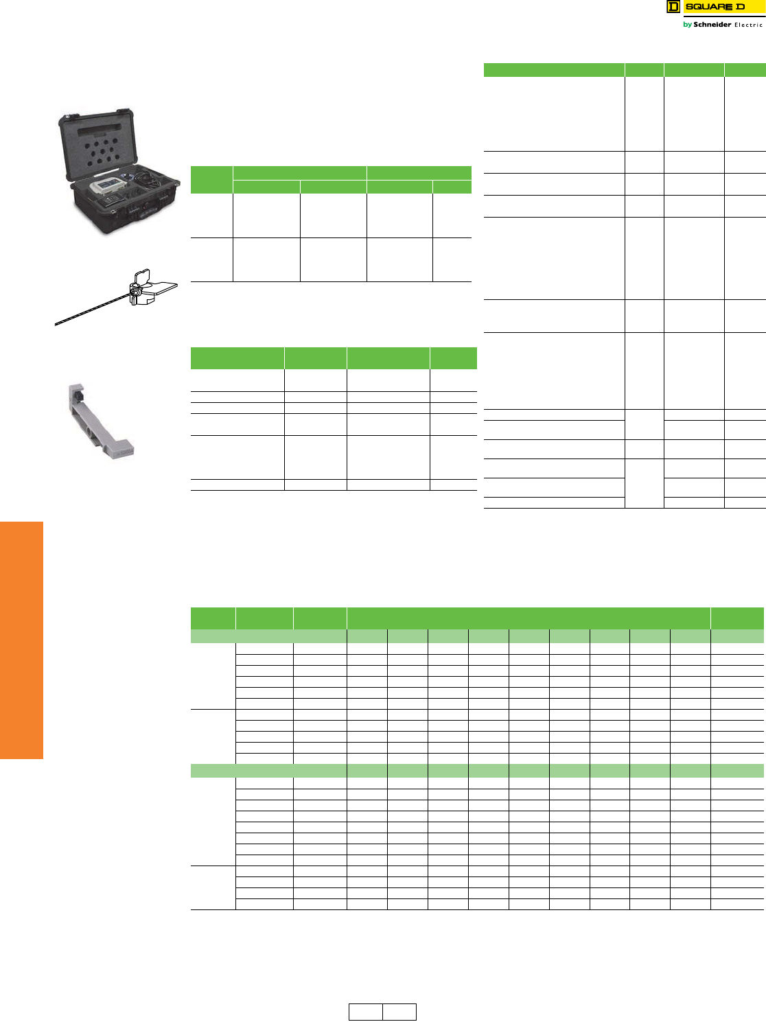
www.schneider-electric.us
7MINIATURE AND MOLDED CASE
CIRCUIT BREAKERS
7-48 © 2012 Schneider Electric
All Rights Reserved
Micrologic™ Electronic
Trip Unit
Micrologic™ Trip Unit Accessories
Class 612, 612/ Refer to Catalog 0611CT1001, 0612CT0101
Adjustable rating plug "A" is installed as standard on all
Micrologic trip unit orders. However, an alternative
selection may be specified from the "Assembled" table
below, and factory installed with your trip unit order at no
additional charge. To order, please attach the appropriate
catalog suffix to the end of the trip unit Cat. No. (after
specifying trip unit options). Adjustable rating plugs may
also be purchased as field-installable components from
the table below.
aLong-time pickup amperes (Ir) = Sensor Rating (In) X Setting of rating
plug. “Fine adjustment tuning” is included on Micrologic Power and
Harmonic trip units, allowing for incremental settings of 1 A between
the plug setting and.40 X Sensor Rating.
bDE2F Discount Schedule
cDE2F Discount Schedule
dIncludes NCTWIRING kit.
eUsed for testing Micrologic trip units. Included in the price of the Hand-
held/Full-function Test Kits. Kit for replacement only.
fUsed for testing STR trip units. Included in the price of the Hand-
held/Full-function Test Kits. Kit for replacement only.
gIncluded in the price of the Full-function Test Kit. Kit for replacement
only.
hDE2F Discount Schedule.
iDE2 Discount Schedule.
jFor use only with circuit breakers with date codes later than 07011.
kDE2F Discount Schedule.
lIEC Only.
mSee rating plug for long-time pickup range on page 7-47.
Table 7.113: Rating Plugs
Rating
Pluga
Factory-Installed Field-Installable
Cat. Suffix $ Price Adder Cat. No.b$ Price
A A (standard) N/C S48818 200.00
BB N/C S48819 200.00
CC N/C S48820 200.00
DD N/C S48836 200.00
EE N/C S48837 200.00
FF N/C S48838 200.00
GG N/C S48839 200.00
HH N/C S48840 200.00
Table 7.114: Neutral Current Transformers
For Use with
Circuit Breaker Cat. No. Sensor $ Price
H-Frame S429521 60–100 588.00
S430562 150 588.00
J-Frame S430563 250 588.00
L-Frame S432575 400–600 647.00
P-Frame S33575c,d250 1914.00
S33576c,d400–1600 1914.00
R-Frame
S48916c,d250 2014.00
S34036c,d400–1600 2014.00
S48896c,d2000 2044.00
S48182c,d3000 2208.00
All NCTWIRING All 204.00
Table 7.115: Trip Unit Accessories
Device Frame Cat. No.h$ Price
Pocket Tester
H/J/L
S434206 1000.00
UTA Tester STRV00910 16365.00
Spare UTA Tester STRV00911 6000.00
BLuetooth/Modbus for UTA Tester SVW3A8114 2800.00
Spare Power Supply for UTA Tester
110–120 Vac TRV00915 771.00
Micrologic Cord for UTA Tester TRV00917 1210.00
Micrologic 5/6 Cover, Transparent H/J S429478 19.00
Micrologic 2/3 Cover, Transparent S429481 41.00
Micrologic 5/6 Cover, Transparent LS432459 36.00
Micrologic 2/3 Cover, Transparent S432461 156.00
LCD Display for Micrologic 5 H/J/L S429483 575.00
LCD Display for Micrologic 6 S429484 575.00
Hand-held Test Kit
P/R
S33594 5386.00
Primary Injection Test Adaptor S33937 252.00
Full-function Adapter Kit S48981 19699.00
Full-function Test Kit S33595 33792.00
Seven-pin Test Cable (for connection
between test kit and trip unit)eS48907 1488.00
Two-pin Test Cable (for connection
between test kit and trip unit)fS48908 784.00
230 Vac Filtered Power Cordg
P/R
S48856 166.00
120 Vac Filtered Power CordgS48855 61.00
Trip Unit Battery for Trip Indicator Lights S33593 438.00
Power supply with:
H/J/L/P/R
24–30 Vdc input 685823
1130.00
48/60 Vdc input 685824
125 Vdc input 685825
110–130 Vac input 685826
200–240 Vac input 685827
380–415 Vac input 685829
Micrologic A Trip Unit Cover, clear
P/R
S33592 16.00
Micrologic P/H Trip Unit Cover,
opaque gray S47067 16.00
Trip Unit Seal (6 pieces)
for compliance with NEC 240.6(c) H/J/L/P/R MICROTUSEAL 60.00
12-pin Trip Unit Connector for
NT/NW Masterpact Circuit Breakers
P/R
S33101 228.00
12-pin Trip Unit Connector for
P- and R-Frame Circuit Breakers S33100i255.00
Battery Back-up (12 Hours) 685831 3570.00
Full Function Test Kit
Trip Unit Seal
Sensor Plug
Table 7.116: Sensor Plugs for P- and R-Frame Circuit Breakersjm
Circuit
Breaker
Sensor Plug
Range
Sensor Plug
Catalog No. Circuit Breaker Frames Accepting Sensor Plug $ Pricek
P-Frame Circuit Breaker 250 A 400 A 600 A 630 Al800 A 1000 A 1200 A 1250 Al1600 A
UL
250 A S47052 X1040.00
400 A S47053 XX X 1040.00
600 A S48823 X XXX 1040.00
800 A S33092 XXX 1040.00
1000 A S33093 XX 1040.00
1200 A S48824 X1040.00
IEC
630 A S33091 XXX XX 1040.00
800 A S33092 XX XX 1040.00
1000 A S33093 XXX1040.00
1250 A S33094 XX 1040.00
1600 A S33095 X1040.00
R-Frame Circuit Breaker 600 A 800 A 1000 A 1200 A 1600 A 2000 A 2500 A 3000 A 3200 A
UL
600 A S48823 XX 1040.00
800 A S33092 XXXX 1040.00
1000 A S33093 XXXX 1040.00
1200 A S48824 XXXX 1040.00
1600 A S33095 XXXX 1040.00
2000 A S33982 XXX 1040.00
2500 A S33983 XX 1040.00
3000 A S48825 X1040.00
IEC
1600 A S33095 XXXXX 1040.00
2000 A S33982 XXXX 1040.00
2500 A S33983 XXX 1040.00
3200 A S33984 X1040.00
DE2 DE2F Discount
Schedule
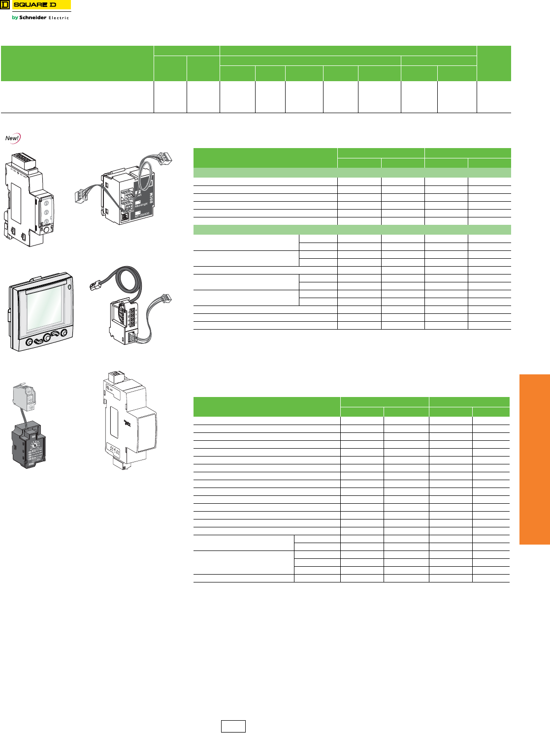
www.schneider-electric.us
7MINIATURE AND MOLDED CASE
CIRCUIT BREAKERS
© 2012 Schneider Electric
All Rights Reserved 7-49
Micrologic™ Electronic
Trip Unit
Micrologic™ Trip Unit Accessories
Class 611, 612 / Refer to Catalog 0611CT1001, 0612CT0101
aRequire NSX Cord
bInstallation requires IFM (STRV00210) for Modbus communication and/or FDM (STRV00121) for external display
cRemote indication relay for motor applications
dRemote indication relay
eFor proper selection, see catalog 0611CT1001.
fIf using with motor operator requires communicating motor operator (suffix NC).
gWire harness is required for I-Line applications, optional for unit-mount applications
YH1 = all installed accessories but ZSI and ENCT
YH2 = ENCT and all installed accessories
YH3 = ZSI and all installed accessories
YH4 = ZSI, ENCT and all installed accessories
hPrice adder is for each accessory ordered.
iI-Line wire harness is included for communication network accessories.
Optional wire harness for unit mount requires YH1 suffix.
Table 7.117: Trip Unit Field-Installable Accessories for P- and R-Frame Circuit Breakers
Description
Factory-Installed Field-Installable Kit Cat. No.
$ Price
Cat. No.
Suffix
$ Price
Adder
P-Frame R-Frame
Unit Mount I-Line Motor
Operated Drawout With Rotary
Handle Unit Mount I-Line
Circuit Breaker Communication Module (BCM) (Modbus) E1 1778.00 S64205 S64205 S64207 S64206 S64205 S64205 S64205 2805.00
Two Programmable Contacts Module (M2C) V 1248.00 S64273 S64273 S64273 S64273 S64273 S64273 S64273 1248.00
Six Programmable Contacts Module (M6C) W 1599.00 S64204 S64204 S64204 S64202 S64204 S64201 S64201 1665.00
External Voltage Sensing (EVS) YV 290.00 S64203 S64203 S64210 S64209 S64210 S64208 S64208 330.00
NSX Cord for
Modbus Communications
Front Display Module
(FDM)
SDTAM Module
(Remote indication relay
for motor applications)
Breaker Status and
Control Module (BSCM)
ZSI Interface Module
(Connects PowerPact H/J/L
circuit breakers to
PowerPact P/R and
Masterpact NT/NW circuit
breakers)
Modbus Interface
Module (IFM)
Table 7.118: Trip Unit Field-Installable Accessories for H-, J-, and L-Frame Circuit
Breakerse
Description Factory-Installed Field-Installable Kit Cat. No.
Cat. No. Suffix $ Price Adder Cat. No. $ Price
External Accessories
Modbus Interface Module IFMa——STRV00210 1000.00
Stacking Connections for IFM (10) — — TRV00217 946.00
Front Display Module FDM121a——STRV00121 1500.00
FDM Mounting Accessory (Dia. 22 mm) — — TRV00128 26.00
Isolated Modbus Repeater Module — — STRV00211 1508.00
ZSI Interface Module — — S434212 975.00
Internal Accessories
NSX Cord b
(for Modbus Communication)
L = 1.3 m EA 576.00 S434201 480.00
L = 3 m EB 600.00 S434202 500.00
BSCM (Breaker Status and Control
Module) with NSX Cordb
L = 1.3 m EGf1776.00 S434201BS 1480.00
L = 3 m EHf1800.00 S434202BS 1500.00
Replacement BSCM — — S434205 1000.00
NSX Cord for V > 480 VacbL = 1.3 m ED 2880.00 S434204 2400.00
L = 3 m EE 3000.00 S434303 2500.00
BSCM with NSX Cord for V > 480 VacbL = 1.3 m EKf4080.00 S434204BS 3400.00
L = 3 m ELf4200.00 S434303BS 3500.00
24 Vdc Terminal Block EN 480.00 S434210 400.00
SDTAM 24/415 Vac/dc ModulecV1114.00 S429424 928.00
SDX Module 24/415 Vac/dcdV1820.00 S429532 1517.00
Table 7.119: Wire Harnessg and ULP Cords for H-, J-, and L-Frame Circuit Breakers
Description Factory-Installed Field-Installable Kit Cat. No.
Cat. No. Suffix $ Price AdderhCat. No. $ Price
ZSI Wire Harness, H/J Frame YH3 237.00 S434300 197.00
ZSI Wire Harness, L-Frame YH3 237.00 S434301 197.00
ENCT Wire Harness YH2 237.00 S434302 197.00
OF Wire Harness YH1 237.00 S434500 197.00
SD/SDE Wire Harness YH1 237.00 S434501 197.00
SDx/SDTAM Wire Harness YH1 237.00 S434502 197.00
MN Wire Harness YH1 237.00 S434503 197.00
MX Wire Harness YH1 237.00 S434504 197.00
24 Vdc Terminal Block Wire HarnessiYH1 237.00 S434505 197.00
Motor Operator Wire Harness YH1 237.00 S434506 197.00
Communicating Motor Operator Wire Harness YH1 237.00 S434507 197.00
NSX Wire HarnessiYH1 237.00 S434508 197.00
ENCT and ZSI Wire Harness YH4 237.00 ——
10 RJ45 Connectors female/female — — TRV00870 195.00
10 ULP Line Terminations — — TRV00880 130.00
10 RJ45/RJ45 Male Cords L = 0.3 m — — TRV00803 200.00
L = 0.6 m — — TRV00806 320.00
5 RJ45/RJ45 Male Cords
L = 1 m — — TRV00810 195.00
L = 2 m — — TRV00820 300.00
L = 3m — — TRV00830 500.00
1 RJ45/RJ45 Male Cord L = 5 m — — TRV00850 155.00
DE2F Discount
Schedule
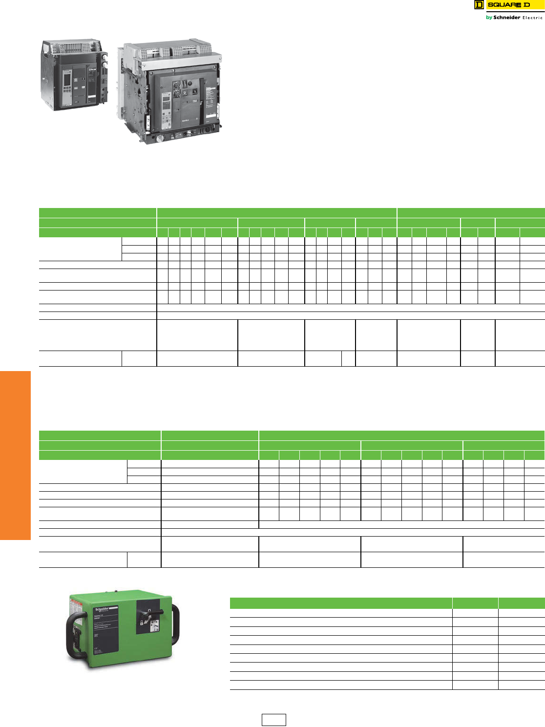
www.schneider-electric.us
7MINIATURE AND MOLDED CASE
CIRCUIT BREAKERS
7-50 © 2012 Schneider Electric
All Rights Reserved
Masterpact™ Universal
Power Circuit Breakers
Masterpact™ NT/NW Circuit Breakers
Class 613 / Refer to Catalog 0613CT0001
The Masterpact universal power circuit breaker offers a family of circuit protection products
meeting the most common world standards, ANSI, UL and IEC. The basic design platform
for each is common. The final result is UL, ANSI and IEC circuit breakers with the same
basic external dimensions, features and accessories.
Full-Featured Performance
•Complete product offering up to 200 k AIR without fuses
•Circuit breakers tested to show arc flash hazard risk category as referenced by NFPA70E
•800 A to 6000 A frames, fixed and draw-out
•Rated for AC voltage systems through 600 V (635 V ANSI)
•Short-time withstand ratings up to 100 kA
•Cradle position indicator: connected, test and disconnected
•Simple, visual contact wear indicators
•Full complement of field-installable accessories common to all standards
•Four interchangeable Micrologic trip units to choose from
•Available PowerLogic™ based power metering and monitoring capabilities
•Available protective relay functions as defined by ANSI C37.2 and C37.90
The following charts show the Masterpact NW and NT ratings for ANSI and UL 489. See
Pricing Guide 0613PL0001 and Catalog 0613CT0001.
Masterpact NT
Masterpact NW
Table 7.120: Masterpact NW Circuit Breaker Ratings
Standard ANSI C37 Certified/UL 1066 Listed UL 489 Listed
Frame Rating 800–1600 A 2000 A 3200/4000 Af4000/5000 A 800/1200/1600/2000 A 2500/3000 A 4000/5000/6000 A
Interrupting Code N1 H1 H2 H3 L1gL1FgH1 H2 H3 L1gL1FgH1 H2 H3 L1gH2 H3 L1gN H LgLFgH LgH Lg
Interrupting Current
(kA RMS) 50/60 Hz
240 Vac 42 65 85 100 200 200 65 85 100 200 200 65 85 100 200 85 100 200 65 100 200 200 100 200 100 200
480 Vac 42 65 85 100 200 200 65 85 100 200 200 65 85 100 200 85 100 200 65 100 150 150 100 150 100 150
600 Vac 42 65 85 85 130 130 65 85 85 130 130 65 85 85 130 85 85 130 50 85 100 100 85 100 85 100
Short-time Withstand Current (kA RMS) 42 65 85 85 30 22 65 85 85 30 22 65 85 85 100 85 85 100 42a65a30ab 22 65 65 85 100
Built-in Instantaneous Override
(kA RMS ±10%) ccc85 35c24 — — 85 35 24 — — 85 117 — — 117 40 40 35ab 24 65 65 75 75
Close and latch rating (kA RMS) 42 65 40 40 25 22 65 40 40 25 22 65 40 40 40 85 75 40 40 40 25d22 40 40 40 40
Tested to show the arc flash hazard risk
category as referenced by NFPA70E ——— — — Yes —— — — Yes —— — — — — — — — — Yes — — — —
Breaking time 25–30 ms with no intentional delay (9 ms for L1, L1F, L and LF)
Closing time 70 ms
Sensor Rating
100–250 A
400–800 A
800–1600 A
1000–2000 A 1600–3200 A 2000–4000 A
2500–5000 A
100–250 A
400–800 A
600–1200 A
800–1600 A
1000–2000 A
1200–2500 A
1600–3000 A
2000–4000 A
2500–5000 A
3000–6000 A
Endurance Rating (C/O Cycles)
With No Maintenance
Mechanical 12,500 10,000 10,000 5k 5,000 12,500e10,000 5,000
Electrical 2800 1,000 1,000 1k 1,000 2800e1,000 1,000
a24 kA RMS for 800 A circuit breaker frame with 100 A or 250 A sensor.
b65 kA RMS for 2000 A.
cNone except 24 kA RMS for 800 A circuit breaker frame with 100 A or 250 A sensor.
d40 kA RMS for 2000 A.
eThe endurance rating for 2000 A, N/H/L/LF is 10,000 for mechanical and 1000 for electrical.
f4000 A standard width circuit breaker is not available in L1 interrupting rating code or drawout construction (fixed mounting only).
gDrawout mounted only.
Table 7.121: Masterpact NT Circuit Breaker Ratings
Standard ANSI C37 Certified/UL 1066 Listed UL 489 Listed
Frame Rating 800 A 800 A 1200 A 1600 Ah
Interrupting Code N1 N H L1 LLFiN H L1 LLFiN H L1 L
Interrupting Current
(kA RMS) 50/60 Hz
240 Vac 42 50 65 100 200 200 50 65 100 200 200 50 65 100 200
480 Vac 42 505065100100505065100100505065100
600 Vac — 35 50 — — — 35 50 — — — 35 50 N/A N/A
Short-time Withstand Current (kA RMS) 42 35 35 10 10 10 35 35 10 10 10 35 35 10 10
Built-in Instantaneous Override (kA RMS ±10%) — 40 40 10 10 10 40 40 10 10 10 40 40 10 10
Close and latch rating (kA RMS) 40 25 25 10 10 10 25 25 10 10 10 25 25 10 10
Tested to show the arc flash hazard risk
category as referenced by NFPA70E — ————Yes————Yes————
Breaking time 25–30 ms with no intentional delay 25–30 ms with no intentional delay (9 ms for L and LF)
Closing time < 50 ms
Sensor Rating 100–250 A 100–250 A 600–1200 A 800–1600 A
400–800 A 400–800 A —
Endurance Rating (C/O Cycles)
With No Maintenance
Mechanical 12,500 12,500 12,500 12,500
Electrical 2800 2800 2800 2800
hFixed-mounted only.
iDrawout mounted only.
Table 7.122: Masterpact NW/NT Circuit Breaker Remote Racking
Description Cat. No. $ Price
Masterpact NW/NT Remote Racking DevicesjNWNTMPRRT 32000.00
Masterpact NW Remote Racking DevicejNWMPRRT 21500.00
Masterpact NT Remote Rackign DevicejNTMPRRT 21500.00
Mounting Bracket Kit for NW Remote Racking (contains 10 mounting brackets)kS47100 215.00
Mounting Bracket Kit for NT Remove Racking (contains 10 mounting brackets)kS47104 215.00
Control Unit for NW Remote RackingkS47101 3650.00
30 ft Control Cable for NW Remote RackingkS47102 620.00
Drive Shaft for NW Remote RackingkS47103 290.00
Drive Shaft for NT Remote RackingkS47105 290.00
jUnit comes with 10 mounting brackets included.
kFor replacement only.
NWMPRRT
DE2F Discount
Schedule
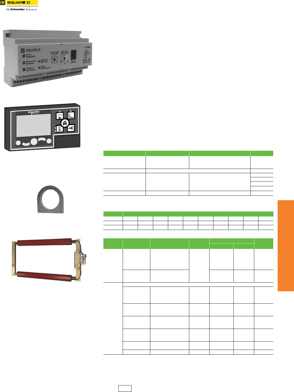
www.schneider-electric.us
7MINIATURE AND MOLDED CASE
CIRCUIT BREAKERS
© 2012 Schneider Electric
All Rights Reserved 7-51
Ground-Fault Protection GC-200 Ground-Fault Relay System
Class 931, 940, 960
GC-200 Ground-Fault Relay System
The GC-200 Ground-fault relay system protects a grounded distribution system from low-
level arcing ground faults. The system includes the GC-200 relay, a sensor (current
transformer), and optional GC DSP display and is used with a bolted pressure switch or
circuit breaker to open a circuit upon detection of a ground fault. (Replaces GC-100 relay.)
GC-200 Relay Features
•Five models with sensitivities suitable for main, feeder, or branch circuits
•Ten adjustable pickup settings for each model
•Small, non-metallic enclosure mounts on DIN rail
•10 A and 5 A output contacts for trip and alarm
•Zone-selective interlocking (ZSI) to optimize coordinated systems
•I2t inverse time characteristics
GC2DSP Display (Optional)
•Real-time display of ground-fault values
•Also recalls ground-fault at last trip or at maximum since reset
•Allows remote testing or resetting of the relay
•LCD back-lit display
•Surface mounts over panel meter cutout
•Fine adjust pickup settings (D and E versions only)
Sensors
•Zero sequence sensing current transformers for all phases and neutral
•Several sizes of toroids and rectangular CTs
•Many are split-core or open frame for ease of installation
aOne GC12 twelve foot cable is included with GCDSP display modules.
bDiscount schedule CP4C
Table 7.123: Ground-Fault Relay
Cat. No. Description Specifications $ Price
GC200C
Ground-fault relay
3.0 A–30.0 A 2960.00
GC200D 30.0 A–300 A 2960.00
GC200E 120 A–1200 A 2960.00
GC2DSP Display module 948.00
VW3A1104R10
Display cable b
1 m 35.00
VW3A1104R30 3 m 35.00
VW3A1104R50 5m 35.00
VW3A1104R100 10 m 45.00
GC2ADAPTER Adapter plate To replace GSDSP with GC2DSP 59.00
Table 7.124: GC-200 Relay Settings
Cat. No. Adjustable Pickup Settings (in Amperes)
GC200C 3 6 9 12 15 18 21 24 27 30
GC200D 30 90 90 120 150 180 210 240 270 300
GC200E 120 240 360 480 600 720 840 960 1080 1200
Table 7.125: GC-200 Sensors
Relay Cat.
No.
Sensor
Cat. No. Type CT
Ratio
Window Dimensions $ Price
in mm
GC200C
GC200D
T2A To r o i d
1000:1
1.875 dia. 48 dia. 704.00
T3A Toroid 2.75 dia. 70 dia. 774.00
T6A Toroid 5.75 dia. 146 dia. 774.00
T6AS Toroid, split-core 5.75 dia. 146 dia. 1326.00
T9A Toroid 8.75 dia. 222 dia. 1106.00
R713A
Rectangular
7.5 x 13.5 191 x 343 3063.00
R417A 4.25 x 17.625 108 x 448 3650.00
R826A 8 x 26.5 203 x 674 4446.00
GC200E
All "A" type sensors above, plus:
RZ511
Rectangular, Open Frame
1000:1 4.5. x 11 114 x 280 1914.00
RZ521 1000:1 4.5 x 21 114 x 534 2255.00
RZ531 1000:1 4.5 x 31 114 x 788 2706.00
RZ535 1000:1 4.5 x 35 114 x 890 2834.00
RZ1011
Rectangular, Open Frame
1000:1 10.5 x 11 267 x 280 2450.00
RZ1021 1000:1 10.5 x 21 267 x 514 3075.00
RZ1031 1000:1 10.5 x 31 114 x 788 4233.00
GT912
Rectangular, Open Frame
600:1 5.5 x 8.5 140 x 216 1769.00
GT918 600:1 5.5 x 14.5 140 x 368 2058.00
GT930 600:1 5.5 x 26.5 140 x 673 2766.00
GT1218
Rectangular, Open Frame
600:1 8.5 x 14.5 216 x 368 2645.00
GT1224 600:1 8.5 x 20.5 216 x 521 2901.00
GT1230 600:1 8.5 x 26.5 292 x 673 3246.00
GT1327 Rectangular, Open Frame 600:1 9.5 x 24 241 x 610 2844.00
GT1330 600:1 9.5 x 27 241 x 686 3219.00
GT1530 Rectangular, Open Frame 600:1 11.5 x 26.5 292 x 673 3726.00
GC-200 Relay
GC2DSP Display
T3B Toroid Sensor
GT912 Rectangular Sensor
DE2 Discount
Schedule
www.schneider-electric.us
7MINIATURE AND MOLDED CASE
CIRCUIT BREAKERS
7-52 © 2012 Schneider Electric
All Rights Reserved
Ground-Fault Protection Vigirex™ Ground-Fault Relay System
Class 931, 840, 960
Vigirex™ Ground-Fault Relay System
The Vigirex ground-fault relays, with associated sensors (current transformers), measure
the residual current in an electrical installation to detect levels which may be damaging.
When used for protection, they cause an associated circuit breaker or switch to interrupt the
supply of power to the protected system. They may also be used for monitoring only, with
output to an alarm. The product line includes fixed sensitivities from 30 mA to 1 A and
adjustable sensitivities up to 30 A.
The Vigirex relays may be easily mounted on DIN rail or may be panel mounted in a meter
cutout. Sensors for conductors range from a little more than an inch diameter toroids, to
large rectangular sensors measuring 6 x 18 inches. The compact size of the relay and its
sensor make it ideal for protection of OEM equipment as well as branch circuits.
a30 mA is instantaneous only, except for RH99M and RH99P models. Their suffix TD indicates time delay at 30 mA.
For models with no time delay (IEC compliant) consult catalog 0972CT0401.
bPOA and GOA are not UL recognized
cUse as a guideline for sizing wire through sensor.
Table 7.126: Vigirex Ground-Fault Relays (UL 1053 Listed)
Model Delay Reset Control Voltage Sensitivity Cat. No. $ Price
DIN Rail Mounted
RH10M Instantaneous Manual
12–24 Vac/12–48 Vdc
30 mA 56300
1988.00
100 mA 56302
300 mA 56305
500 mA 56306
1 A 56307
110–130 Vac
30 mA 56320
1988.00
100 mA 56322
300 mA 56325
500 mA 56326
1 A 56327
220–240 Vac
30 mA 56330
1988.00
100 mA 56332
300 mA 56335
500 mA 56336
1 A 56337
RH21M
Instantaneous
or 60 msec
(2 settings)
Manual
12–24 Vac/12–48 Vdc 30 mAa or 300 mA
(2 settings)
56360
2363.00
110–130 Vac 56362
220–240 Vac 56363
RH99M
Adjustable
(9 settings):
0, 0.06, 0.15,
0.23, 0.31, 0.5,
0.8, 1.0, 4.5 sec
Manual
12–24 Vac/12–48 Vdc
Adjustable,
(9 settings):
0.03a, 0.1, 0.3, 0.5, 1,
3, 5, 10, 30 A
56370TD
2700.00110–130 Vac 56372TD
220–240 Vac 56373TD
Automatic
12–24 Vac/12–48 Vdc 56390TD
2700.00110–130 Vac 56392TD
220–240 Vac 56393TD
Panel Mounted
RH10P Instantaneous Manual
12–24 Vac/12–48 Vdc
30 mA 56400
2063.00
100 mA 56402
300 mA 56405
500 mA 56406
1 Amp 56407
110–130 Vac
30 mA 56420
2063.00
100 mA 56422
300 mA 56425
500 mA 56426
1 Amp 56427
220–240 Vac
30 mA 56430
2063.00
100 mA 56432
300 mA 56435
500 mA 56436
1 A 56437
RH21P
Instantaneous
or 60 msec
(2 settings)
Manual
12–24 Vac/12–48 Vdc 30 mAa or 300 mA
(2 settings)
56460
2438.00
110–130 Vac 56462
220–240 Vac 56463
RH99P
Adjustable
(9 settings):
0, 0.06, 0.15,
0.23, 0.31, 0.5,
0.8, 1.0, 4.5 sec
Manual
12–24 Vac/12–48 Vdc
Adjustable
(9 settings):
0.03a, 0.1, 0.3, 0.5, 1,
3, 5, 10, 30 A
56470TD
2813.00110–130 Vac 56472TD
220–240 Vac 56473TD
Automatic
12–24 Vac/12–48 Vdc 56490TD
2813.00110–130 Vac 56492TD
220–240 Vac 56493TD
Table 7.127: Sensors for Vigirex Ground-Fault Relays
Sensors Type Maximum
Currentc
Inside Diameter Cat. No. $ Price
in. mm
Closed Toroids, Type A
TA30 65 A 1.18 30 50437 375.00
PA50 85 A 1.97 50 50438 488.00
IA80 160 A 3.15 80 50439 615.00
MA120 250 A 4.72 120 50440 833.00
SA200 400 A 7.87 200 50441 1253.00
GA300 630 A 11.81 300 50442 2295.00
Vigirex Sensor Iron Rings
(Optional)
TA30 65 A 0.79 20 56055 56.00
PA50 85 A 1.58 40 56056 59.00
IA80 160 A 2.76 70 56057 62.00
MA120 250 A 4.33 110 56058 83.00
Split toroids, Type OA POAb85 A 1.81 46 50485 1718.00
GOAb250 A 4.33 110 50486 3015.00
Rectangular Sensors 280 x 115 1600 A 11.02 x 4.53 280 x 115 56053 5333.00
470 x 160 3200 A 18.50 x 6.30 470 x 160 56054 7088.00
RH99M
RH99P
SA200
PA50
DE2 Discount
Schedule
www.schneider-electric.us
7MINIATURE AND MOLDED CASE
CIRCUIT BREAKERS
© 2012 Schneider Electric
All Rights Reserved 7-53
Ground-Fault Protection
Equipment
Add-On Ground-Fault and Earth-Leakage Modules
Class 931, 940, 960
Micrologic™ Add-on Ground-Fault Module (GFM)
The Micrologic Ground-Fault Module (GFM) is a UL Listed/CSA Certified circuit breaker
accessory which protects equipment from damage caused by ground faults. It is an add-on
module which, when connected to a PowerPact H- or J-frame thermal-magnetic circuit
breaker only, provides ground-fault sensing and ground-fault relay functions.
HD/JD ground-fault modules feature:
•Adjustable ground-fault pickup levels
•Adjustable ground-fault time delays
•Integral ground fault push-to-test feature
•Ground-fault indicator (mechanical for local, contacts for remote)
•All GFMs are supplied for I-Line™ mounting as standard, easily convertible to unit mount by
removing the I-Line bracket
•Fault-powered (through the sensing current transformer) for electronics, shunt trip, and integral test
feature. Meets NEC 230.95(C)
•A 12 Vdc shunt trip module (Catalog No. S29382) is required in the circuit breaker. This may be field
installed or factory installed when the circuit breaker is ordered with an -SN suffix.
•UL 1053 — Ground-fault Sensing and Relaying Equipment
The GFM system requires the following:
•H-frame (15–150 A) or J-frame (150–250 A) molded case circuit breaker
•Shunt trip is required for the function of the GFM (may be factory-installed or field-installed)
•Bus bar connection (terminal nut inserts) for OFF end of circuit breaker
•Optional neutral current transformer, catalog number GFM25CT (must be ordered for 4-wire
applications)
NOTE: Ground-fault modules cannot be used for alarming only.
aAt 250 A, the GFM250JD can be used with 80% rated circuit breakers only.
bSee Supplemental Digest page 3-37 for additional GFMs.
Earth Leakage Module (ELM) for PowerPact H- and J-Frame MCCBs
The Earth Leakage Module (ELM) is an add-on module which, when connected to a
PowerPact H- or J-frame MCCB, provides low-level ground-fault sensing and ground-fault
relay functions.
Because these ELMs are highly sensitive (30 mA to 3 A), they provide much greater
protection than GFMs (20 Amps to 200 Amps sensitivity). The ELMs provide greater
protection of control circuits and other sensitive equipment. The associated circuit breaker
must have a 48 Vdc shunt trip, which may be field-installed (kit S29392) or factory-installed
(suffix –SP) in the H- or J-Frame circuit breaker.
Add-on Earth Leakage Module (ELM) Features:
•Adjustable ground-fault pickup levels as low as 30 mA
•Adjustable ground-fault time delays from instantaneous to 500 msec
(Time delay can be applied to the 30 mA setting)
•Integral ground fault push-to-test feature
•Ground-fault indicator (LED for local status; contacts for remote indication)
•All ELMs are supplied for I-Line™ mounting and are easily convertible to unit-mount by removing the
I-Line brackets
•Three poles; 240 to 600 Vac maximum: 3-wire applications only (no neutral)
•Line-power obtained through internal bus to provide power for electronics, shunt trip, and integral
test feature.
•A shunt trip is required in the circuit breaker; it may be field-installed or factory-installed in the
PowerPact H and J circuit breakers.
•UL 1053 – Ground-fault Sensing and Relaying Equipment
cAt 250 A, the ELM250JD can be used with 80% rated circuit breakers only.
dFor Factory Installation of ELM Module: For termination designation (3rd letter of catalog number) use ONLY “M”.
Add factory installed 48 Vdc shunt trip (suffix SP) to breaker plus suffix VL or VM.
SP – $717. adder.
Use VL for H frame – $4736. adder.
Use VM for J frame – $4886. adder.
Plus the List Price of the H or J breaker.
Table 7.128: Module/Enclosure Selection Charta
Companion Circuit
Breaker Prefix Cat. No.bI-Line
Switchboard
Ground-fault Pickup
Adjustment Range GFM $ Price
HD, HG, HJ, HL GFM150HD LA 20–100 A 4250.00
JD, JG, JJ, JL GFM250JD LA 40–200 A 4250.00
Accessories
H & J GFM25CT Optional Neutral Current Transformer (required for 4-wire loads) 375.00
GFM250
Optional GFM25CT
I-Line™ J-Frame with ELM installed
Table 7.129: ELM Selection Chartc
Companion Circuit BreakerdEnclosure Space
Required I-Line
Switchboard
Pick-Up Adjustment
Range Catalog Number $ Price
Prefix Size
HD, HG, HJ, HL 15–150 A LA 30 mA–3 A ELM150HD 4500.00
JD, JG, JJ, JL 150–250 A LA 30 mA–3 A ELM250JD 4650.00
DE2 Discount
Schedule

www.schneider-electric.us
7MINIATURE AND MOLDED CASE
CIRCUIT BREAKERS
7-54 © 2012 Schneider Electric
All Rights Reserved
Dimensions and Shipping Weights
Miniature and Molded Case Circuit Breakers
gDimensions E are 1.59 in at ON end and 0.63 in at OFF end.
hAll weights are for 3P circuit breakers unless otherwise noted.
BE
A
G
Figure 2
BE
A
G
Figure 1
BE
A
G
Figure 3
D
C
QO, QOB
QO-GFI, QO-PL
QO-EPD
D
C
Figure 5
A
G
B
E
A
B
E
G
Figure 4
B
A
G
E
Figure 6
A
G
BE
Figure 7
A
G
BE
Figure 8
D
C
F
QOU, QYU
Low Ampere
A
D
C
B
Figure 9
QO-PLPS
Figure 10
A
BE
Figure 11
A
BE
Figure 12
A
BE
QOU
High Ampere
C
D
FB
Figure 13
A
B
Figure 14
A
B
Figure 15
A
B
Figure 16
A
B
C
D
C60
E
Figure 17
A
B
Figure 18
A
B
Figure 19
A
B
Figure 20
A
B
C120
C
D
E
B
Figure 21
B
E
FA
E
G
C/L
Figure 22
B
E
E
FA
Figure 23
C/L
B
D
C
G
HH
E
E
FA
B
G
E
E
FA
D
C
Figure 24
Table 7.130: QO™, QOU, Multi 9™ Circuit Breakers
Circuit Breaker
Cat. No. Prefix Poles Fig.
No.
Dimensions—Inches
A B C D E F G
QO, QOB
1 1 0.75 3.00a2.31 2.91 2.25 — 0.59
2 2 1.50 3.00a2.31 2.91 2.25 — 1.34
3 3 2.25 3.00a2.31 2.91 2.25 — 2.09
QOB-VH 150 A
QOB-VH 110–150 A
2 2 3.0 5.72 2.53 4.90 3.78 — 2.85
3 3 4.50 5.72 2.53 4.90 3.78 — 4.35
QO-PL
QO-GFI
QO-EPD
1 4 0.75 4.12b2.31 2.91 2.25 — 0.59
2 5 1.50 4.12b2.31 2.91 2.25 — 1.34
3 5 2.25 4.12b2.31 2.91 2.25 — 2.09
QOU
QYU
Low Ampere
1 6 0.75 4.05c2.38 2.98 2.25 5.00d0.62
2 7 1.50 4.05c2.38 2.98 2.25 5.00d1.37
3 8 2.25 4.05d2.38 2.98 2.25 5.00f2.12
QOU
High Ampere
1 10 0.75 4.45 2.37 2.96 2.25 6.78 —
2 11 1.50 4.45 2.37 2.96 2.25 6.78 —
3 12 2.25 4.45 2.37 2.96 2.25 6.78 —
Multi 9™ C60
1 13 0.71 3.19 1.73 2.76 1.77 — —
2 14 1.42 3.19 1.73 2.76 1.77 — —
3 15 2.13 3.19 1.73 2.76 1.77 — —
4 16 2.84 3.19 1.73 2.76 1.77 — —
QO-PLPS Power Supply 2 9 1.45 4.35 2.42 3.11 — — —
a35–70 A is 3.12 in; 80–100 A 2P and 70–100 A 3P are 3.50 in.
bQO-PL is 4.55 in.
c80–100 A 1P and 80–125 A 2P are 4.45 in
d80–100 A 1P and 80–125 A 2P are 6.78 in.
e70–100 A 4.45 in.
f70–100 A is 6.78 in.
Table 7.131: QB, QD, QG, QJ, Q4, FA, FI, KI, LA, LI, LX, LXI Circuit
Breakers
Circuit Breaker
Cat. No. Prefix Poles Fig.
No.
Dimensions—Inches
A B C D E F G H
QB, QD,
QG, QJ
2 22 6.47 3.00 3.02 3.93 g4.25 — —
3 23 6.47 4.50 3.02 3.93 g4.25 1.50 0.75
FAL, FHL
1 21 6.00 1.50 3.16 4.13 0.44 5.13 1.50 —
2 22 6.00 3.00 3.16 4.13 0.44 5.13 — —
3 23 6.00 4.50 3.16 4.13 0.44 5.13 1.50 0.75
FIL, KIL 2 & 3 23 8.00 4.50 3.66 4.75 0.44 7.13 1.50 0.75
Q4L, LAL, LHL 2 & 3 23 11.00 6.00 4.06 5.84 0.88 9.25 2.00 1.00
LIL, LXIL 2 & 3 24 11.86 7.50 5.48 6.74 0.55 10.75 2.50
Table 7.132: Shipping Weightsh
Frame Size Approx. Shipping
Weight (Lbs.) Frame Size Approx. Shipping
Weight (Lbs.)
FAL, FHL 1P 2 KIL 9
FAL, FHL 2P 3 LAL, LHL 15
FAL, FHL 3P 5 LIL LXIL 25
FIL 8 Q4L 15
QB, QD, QG, QJ 4
www.schneider-electric.us
7MINIATURE AND MOLDED CASE
CIRCUIT BREAKERS
© 2012 Schneider Electric
All Rights Reserved 7-55
Dimensions and Shipping Weights
Molded Case Circuit Breakers
aOnly HD and HG are in 2P module, HJ, HL and HR 2P are in 3P module.
aAll weights are for 3P circuit breakers unless otherwise noted.
A
B
E
F
C
D
Figure 26
A
E
F
B
G
Figure 25
E
G
A
B
C
D
F
Figure 27
A
C
D
B
G
F
Figure 28
A
AA
EBBEEB
C
D
Figure 29 Figure 30Figure 31
Figure 32
A
E
B
C
D
F
E
E
A
D
C
G
B
Figure 33
G
B
F
E
A
D
C
Figure 34
Table 7.133: HD, HG, HJ, HL, HR, JD, JG, JJ, JL, JR, LG, LJ, LL,
and LR Circuit Breakers
Circuit Breaker
Cat. No.
Prefix
No. of
Poles Fig. No.
Dimensions — Inches
A B C D E F G
HD, HG, HJ,
HL, HR
2a25 6.40 2.74 2.87 4.36 0.74 4.92 —
3 26 6.40 4.12 2.87 4.36 0.74 4.92 1.38
JD, JG, JJ, JL, JR 3 27 7.52 4.12 2.87 5.00 1.30 4.92 1.38
LG, LJ, LL, LR 3 28 13.38 5.51 3.75 6.61 2.22 7.87 1.77
Table 7.134: ED, EG, and EJ Circuit Breakers
Circuit Breaker
Cat. No.
Prefix
No. of
Poles Fig. No.
Dimensions — Inches
A B C D E
ED, EG, EJ 1 29 0.98 5.66 3.09 4.05 3.32
ED, EG, EJ 2 30 1.96 5.66 3.09 4.05 3.32
ED, EG, EJ 3 31 2.94 5.66 3.09 4.05 3.32
GJ 3 32 3.54 4.72 2.76 3.94 2.20
Table 7.135: MG, MJ, PG, PJ, PL, RG, RJ and RL Circuit Breakers
Circuit Breaker
Cat. No.
Prefix
No. of
Poles
Fig.
No.
Dimensions — Inches
A B C D E F G
MG, MJ
(800 A and below) 2, 3 33 12.86 8.27 5.77 8.05 2.49 7.87 7.83
PG, PJ, PK, PL
(1000–1200 A) 2, 3 33 16.16 8.27 5.77 8.05 4.19 7.87 7.83
RG, RJ, RL 2, 3 34 16.24 16.54 6.63 14.49 8.73 14.25 15.35
Table 7.136: Shipping Weightsa
Frame Size Approx. Shipping
Weight (Lbs.) Frame Size Approx. Shipping
Weight (Lbs.)
HD, HG, HJ, HL 2P 4 JD, JG, JJ, JL, JR 5
HD, HG, HJ, HL, HR 3P 5 LD, LG, LJ, LL, LR 14
ED, EG, EJ 1P 2 MG, MJ
29
ED, EG, EJ 2P 3 PG, PJ, PK, PL 32
ED, EG, EJ 3P 4 RG, RJ, RK, RL (Without RLTB) 52
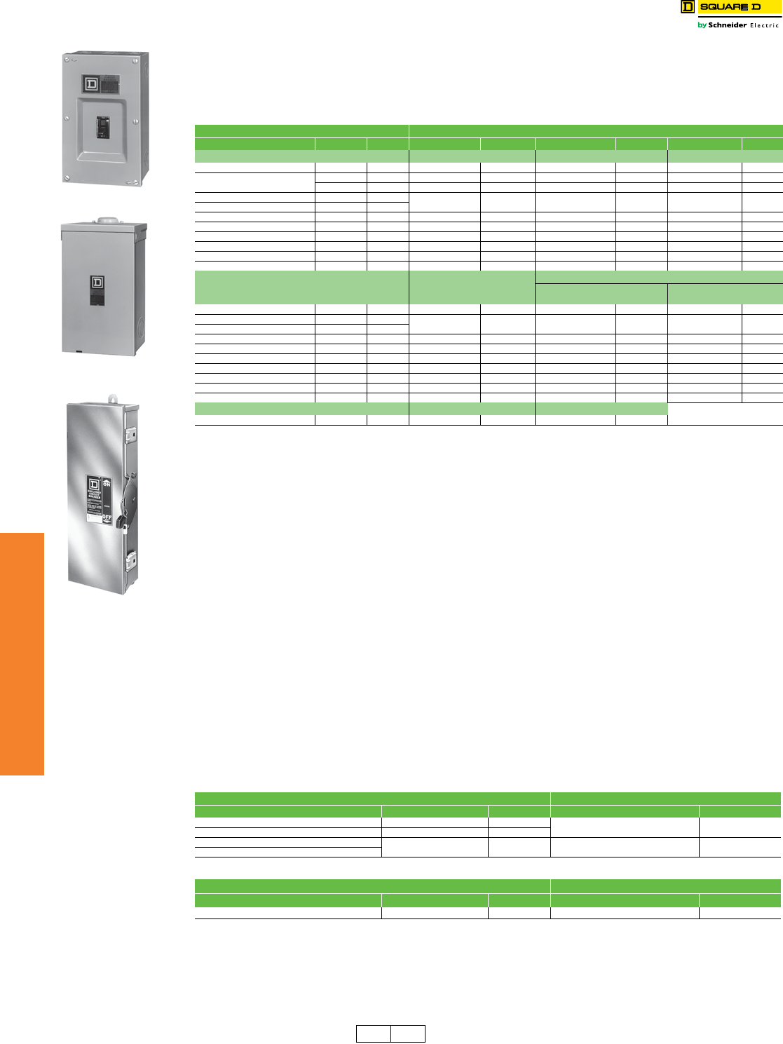
7-56 © 2012 Schneider Electric
All Rights Reserved
www.schneider-electric.us
7MINIATURE AND MOLDED CASE
CIRCUIT BREAKERS
Circuit Breaker
Enclosures
Enclosures
Class 610
•Circuit breaker enclosures are UL Listed, CSA Certified and are suitable for use as service equipment except as footnoted.
•The short circuit rating of an enclosed circuit breaker is equal to the rating of the circuit breaker installed, except as footnoted.
•Circuit breakers are ordered and shipped separately for field installation.
•For enclosure accessories and dimensions refer to page 7-58.
•See Supplemental Digest page 3-35 for NEMA 7 and 9 enclosures for FAL circuit breakers.
aEnclosures with NRB or RB suffix have provisions for 3/4 in. through 2-1/2 in. bolt-on hubs in top endwall. Enclosures with R suffix have blank endwalls
and require field cut opening. For details and hub catalog numbers see page 3-9.
bNot CSA Certified.
cAccepts standard rated 80% breakers. Not rated at 100%.
dMaximum short circuit rating is 25 kAIR at 600 Vac, 65 kAIR at 480 Vac, 125 kAIR at 240 Vac.
eEarth Leakage Module and Ground Fault Module are not compatible with these enclosures.
fMaximum short circuit rating is 25 kAIR, 240 Vac.
gOrder service ground kit PKOGTA2 if required.
hMaximum short circuit rating is 18 kAIR, 480 Vac and 240 Vac.
iCopper wire only.
jWhen using a CT in the M800S and R enclosure the unit will no longer accommodate a 200% neutral solution.
kCE certified per IEC60439-1, IP20D, PE type TN-C or TN-S
lAccepts MGL or MJL standard rated (80%) breakers. Accepts PGL, PJL or PLL circuit breakers rated 80% (1200 A maximum) or
100% rated breakers, (800A maximum).
mCE certified per IEC60439-1, IP24D, PE type TN-C or TN-S
nSuitable for rainproof NEMA 3R application by removing drain screw from bottom endwall.
oCE certified per IEC60439-1, IP56, PE type TN-C or TN-S
pLEL 100% rated circuit breaker except for 600 A sensor.
qShort circuit rating is 100 k AIR at 480 Vac maximum.
rNEMA 7—Indoor Hazardous Locations—Division 1 and 2, Class I, Groups C and D; Class II, Groups E, F,and G; Class III.
s80% rated circuit breakers only; SCCR 65 kA @ 240 Vac, 25 kA @ 480 Vac, 18 kA @ 600 Vac.
tNot UL Listed due to wire bending space.
uNEMA 9—Indoor Hazardous Locations—Division 1 and 2, Class II, Groups E, F,and G; Class III.
vHas a tapped 2-1/2 in. conduit opening on top and bottom end wall
wShort circuit current rating is 30 k AIR at 480 Vac.
xProduct also accepts PowerPact L Frame Motor Protector Circuit Breakers with suffix M38X.
yViewing Window factory installed.
zProduct accepts PowerPact L-Frame Automatic Molded Case Switches.
316 Grade Stainless Steel Circuit Breaker Enclosures—NEMA 3, 3R, 4X, 5 and 12
Type 316 stainless steel circuit breaker enclosures offer superior corrosion resistance to a wider range of chemicals
than Type 304 stainless steel enclosures. Type 316 better resists chloride and is often used in marine, waste treatment
and transportation applications. Use watertight hubs from Section 3 page 10 of Digest 176. For other accessories
reference Table 7.142 and Table 7.143. For dimensional information, reference Table 7.144.
aa UL Listed Only
ab Use 500 Vdc or 250 Vdc rated circuit breakers only.
Accessories . . . . . . . . . . . . . . . . . . . . . . . . . . . . . . . . . . . . . . . . . . . Page 7-58
Dimensions. . . . . . . . . . . . . . . . . . . . . . . . . . . . . . . . . . . . . . . . . . . . Page 7-58
Table 7.137: Circuit Breaker Enclosures
Circuit Breaker Enclosure
Cat. No. Prefix Rating Poles Cat. No. $ Price Cat. No. $ Price Cat. No. $ Price
NEMA 1 Flush NEMA 1 Surface NEMA 3Ra
FAL, FHL, FCL 15–100 A 1, 2, 3 FA100F 189.00 FA100S 189.00 FA100RB 500.00
QBL, QDL, QGL, QJL 100–200 A 2 — — Q22200NSb176.00 Q22200NRBb380.00
100–225 A 2, 3 Q23225NFb218.00 Q23225NSb218.00 Q23225NRBb417.00
HDL, HGL, HJL, HLL 15–150 A 2, 3 J250Fcde 285.00 J250Scde 285.00 J250Rcde 840.00
JDL, JGL, JJL, JLL 150–250 A 2, 3
HDL 15–100 A 3 — — HD100Sfgcei 285.00 ——
JDL 150–250 A 3 — — JD250Sigfce 285.00 ——
LAL, LHL, Q4L 125–400 A 2, 3 LA400F 356.00 LA400S 356.00 LA400R 1655.00
LAL 125–400 A 3 — — LA400LSgiw 356.00 ——
MGL, MJL, PGL, PJL, PKL, PLL 300–800 A 2, 3 — — M800Sjk 783.00 M800Rjm2159.00
PGL, PJL, PKL, PLLl250–1200 A 2, 3 — — P1200Sk1260.00 P1200Rm2790.00
NEMA 4, 4X, 5, 3, 3R Stainless
Steel (Hubs—See page 3-9)
NEMA 12/3R, 12K (Hubs—See page 3-9)
With Knockouts (NEMA 12K) Without Knockoutsn
(NEMA 12/3R, 5)
FAL, FHL, FCL 15–100 A 1, 2, 3 FA100DS 1431.00 FA100A 351.00 FA100AWK 335.00
HDL, HGL, HJL, HLL 15–150 A 2, 3 J250DScde 3405.00 ——J250AWKcde 582.00
JDL, JGL, JJL, JLL 150–250 A 2, 3
KILq, KCL 110–250 A 2, 3 IK250DS 5238.00 ——IK250AWK 878.00
LAL, LHL, Q4L 125–400 A 2, 3 LA400DS 5673.00 ——LA400AWK 903.00
LDL, LGL, LJL, LLL, LRL 250–600 A 3 — — — — L600AWKx3728.00
LDL, LGL, LJL, LLL, LRL 250–600 A 3 — — — — L600AWKVWy3928.00
LGL, LLL, LRL 400–600 A 3 — — — — L600AWKMCz3728.00
MGL, MJL, PGL, PJL, PKL, PLL 300–800 2, 3 M800DSo10125.00 ——M800AWKo2459.00
PGL, PJL, PKL, PLLl600–1200 2, 3 — — — — P1200AWKo5700.00
Nema 7r Cast Aluminum Nema 9u Cast Aluminum
JDL, JGLstv 150–250 A 2, 3 J225X 4083.00 J225Y 2834.00
Table 7.138: 316 Grade Stainless Steel CIrcuit Breaker Enclosures
Circuit Breakerab NEMA 3, 3R, 4X, 5 and 12
Cat. No. Prefix...Suffix Ampere Rating Poles Enclosure Cat. No. $ Price
HDL, HGL, HJL, HLL 15–150 A 2, 3 J250SS 4698.00
JDL, JGL, JJL, JLL 150–250 A 2, 3
MGL, MJL, PGL, PJL 300–800 A 2, 3 M800SS 13972.00
PKL, PLL
Table 7.139: DC CIrcuit Breaker Enclosures for MA and MH DC-Rated Circuit Breakers
Circuit Breakerab NEMA 1 Surface Enclosureaa
Cat. No. Prefix...Suffix Ampere Rating Poles Enclosure Cat. No. $ Price
MAL, MHL 125–1000 A 2, 3 MA1200S 1355.00
FA100S
FA100RB
FA100DS
DE1 DE2A Discount
Schedule
www.schneider-electric.us
7MINIATURE AND MOLDED CASE
CIRCUIT BREAKERS
© 2012 Schneider Electric
All Rights Reserved 7-57
Circuit Breaker
Enclosures
Enclosed Circuit Breaker Special Applications
Class 610
aCatalog number in table is enclosure only. For complete installation, the following must be ordered separately: WB Circuit Breakers (qty. 2, Supplemental
Digest page 3-27), Walking Beam Assembly (Supplemental Digest page 3-27), Mounting Pan (Supplemental Digest) page 3-27, Neutral (page 7-56) and
Service Ground Kit (page 7-58).
bEnclosure has blank top endwall.
cFor applications above 200 A requiring a neutral, use copper wire only.
Enclosed Motor-Operated Molded Case Circuit Breakers
For information on Enclosed Motor-Operated Molded Case Circuit Breakers see the Supplemental Digest page 3-35.
Enclosed Molded Case Switches
For ordering information on molded case switches see page 7-34. For ordering information on enclosed molded case
switches, see Supplemental Digest 175 Section 3-36.
Enclosed Walking Beam Mechanical Interlock
NOTE: Contact local Field Office for catalog number prior to quoting or placing an order.
Industrial molded case circuit breakers with walking beam mechanical interlocks are available in NEMA 1 and 3R
construction as completely enclosed device. Walking beam mechanical interlock is available manually operated or
electrically operated using (2) 120 Vac motor operators. Not UL Listed.
Enclosed walking beam mechanically interlocked circuit breaker.
•Specify circuit breaker catalog numbers
•Specify manually or electrically operated (electrically operated factory installed only)
•Specify enclosure type (NEMA 1 or 3R)
•Specify if neutrals are required. (Same price)
aPrice includes (2) walking beam 3P circuit breakers, walking beam operator and mounting pan, (2) neutrals (if specified), and
(2) motor operators (if specified) factory assembled in specified enclosure.
bNot available factory assembled. Refer to page 7-56 for merchandise enclosure.
NOTE: Contact local Field Office for catalog number prior to quoting or placing an order.
Table 7.140: Enclosures for Walking Beam Manually Operated Mechanical Interlock
Circuit Breakers (UL Listed)a
Circuit Breaker NEMA 1 SurfacebNEMA 3R bc
Cat. No.
Prefix...Suffix
Ampere
Rating Poles Enclosure
Cat. No. $ Price Enclosure
Cat. No. $ Price
FAL...WB, FHL...WB 15–250 A 2, 3 KA250SWB 1040.00 KA250RWB 1827.00
Table 7.141: Enclosed Walking Beam Mechanical Interlock
Circuit Breaker
Cat. No. Prefix
(Standard Thermal-
Magnetic Only)
$ Pricea
Manually Operated Electrically Operated
NEMA 1 NEMA 3R NEMA 1 NEMA 3R
FAL—240 V 100 A
FAL—480 V 100 A
FAL—600 V 100 A
—
—
—
—
—
—
5783.00
6311.00
6879.00
3675.00
6896.00
7446.00
FHL—600 V 100 A — — 8691.00 9407.00
www.schneider-electric.us
7MINIATURE AND MOLDED CASE
CIRCUIT BREAKERS
7-58 © 2012 Schneider Electric
All Rights Reserved
Circuit Breaker
Enclosures
Enclosure Accessories and Dimensions
Class 610
See Supplemental Digest 3-37 and 3-38 for:
•Special paint
•Stainlee steel fronts
•Pilot lights, push buttons
•Lock-on SPL0
•Key interlock systems
•Legend plates
Table 7.142: Insulated Groundable Neutral Assembly
Circuit Breaker Neutral Assembly For Use With Terminal Lug Data—Total Available
(Line plus Load)
AWG/kcmil
Cat. No. Prefix Ampere
Rating
NEMA 1 & 3R NEMA 4, 4X, 5, 12 & 12K NEMA 7 & 9
Cat. No. $ Price Cat. No. Price Cat. No. $ Price
FAL, FHL, FCL 100 SN100FA 72.00 SN100FA 72.00 —— (4) 14–1/0 Cu or (4) 12–1/0 Al
FA060X/Y—(1) 14– 6 Cu, plus (1) 14–4 Cu
FA100X/Y—(1) 14– 3 Cu, plus (1) 14–4 Cu
FAL, FHL, FIL 100 — — — — 100SNA 150.00
HDL,HGL,HJL,HLL 15–100 SN100FA 72.00 SN100FA 72.00 — — (4) 14–1/0 Cu or (4) 12–1/0 Al
HDL,HGL,HJL,HLL 125-150 SN400LA 251.00 SN400LA 251.00 225SNA 198.00 (2) 1–600 or (4) 1–250 Al/Cu, plus (2) 4–300 Al/Cu
JDL,JGL,JJL,JLL 150–250 SN400LA 251.00 SN400LA 251.00 — — (2) 1–600 or (4) 1–250 Al/Cu, plus (2) 4–300 Al/Cu
FAL...WB, FHL...WB 200 Requires (2) SN20A
plus (1) SN20NI link
(2) @$200.00 ea
plus (1) @$27.60 ea — — — — (4) 6–250 Al/Cu, plus (2) 14–1/0 Al/Cu
LDL, LGL, LJL, LLL, LRL 250–400 — — SN400LA 251.00 ——
(2) 1–600 or (4) 1–250 Al/Cu, plus (2) 4–300 Al/Cu
SNC400LX 1152.00 (2) 2–600 Cu, plus (2) 2–4/0 Cu
LDL, LGL, LJL, LLL, LRL 250–600 — — SN800LX 1506.00 —— (4) 2–600 Cu, plus (1) 2–4/0 Cu
SN1000MA 365.00 (6) 3/0–500 Al/Cu, plus (1) 1–4/0 Al/Cu
LDL, LGL, LJL, LLL, LRL 250–600 — — SNC600LXCT 2506.00 —— (4) 2–600 Cu, plus (2) 2–4/0 Cu
SN600LXCT 1065.00 (4) 3/0–500 Al/Cu, plus (2) 2–4/0 Al/Cu
LDL, LGL, LJL, LLL, LRL 250–600 — — SNC800LXc1506.00 — — (4) 2–600 Cu, plus (1) 2–4/0 Cu
MGL, MJLd300–800 AL800SN 365.00 AL800SN 365.00 — — (6) 3/0–500 Al/Cu, plus (2) 6–250 Al/Cu
PGL, PJL, PKL, PLLe250–1200 SN1200 1034.00 SN1200 1034.00 — — (8) 3/0–500 Al/Cu, plus (2) 350 4–300 Al/Cu
cAll Cu neutral assembly.
dFor NEMA 1 and 3R 200% neutral applications order Jumper kit SN800SNI and 2 of kit SN1200. (No 200% neutral is available for NEMA 4X or 12 devices.)
eFor applications with integral ground fault protection order Neutral Mounting Kit S33576MK and Neutral CT S33576 (400–1200 A only).
Table 7.143: Service Ground Kits
Circuit Breaker Cat. No. Prefix Ground Bar
Cat. No.
Number of
Terminals
Conductors
Per Terminal
Wire Range
AWG/kcmil
$ Price
Field-Installable Factory-Installed
QBL, QDL, QGL, QJL
FAL, FHL, FCL, FIL, FAL...WB, FHL...WB
KCL, KIL, LAL, LHL, Q4L
PKOGTA2f2 1 10–2/0 Cu or 6–2/0 Al 56.00 191.00
HDL,HGL,HJL,HLL,JDL,JGL,JJL,JLL PKOGTJ250 2 1 6–300 Al/Cu 75.00 195.00
LDL, LGL, LJL, LLL, LRL
MGL, MJL
PGL, PJL, PKL, PLL
PKOGTA4 4 1 6–250 Al or Cu 213.00 263.00
fQuantity (2) required if ground wires are run in parallel.
W
NEMA Type 1
Q2, FA, J, SWB
LA, MG, PG
W
D
H
H
WB enclosure
uses 2 circuit breakers
WD
H
NEMA Type 3R
Q2, FA, LA, MG, J, PG, RWB
(uses side hinge cover)
WB enclosure uses
2 circuit breakers
NEMA Type 7, Type 9
FA, JDL, JGL
W
H
D
NEMA Type 4, 4X, 5, 12, 12K
IK, FA, J, LA, LX, MG, PG
W
H
D
Table 7.144: Dimensions
Cat. No.
Approximate Dimension
Cat. No.
Approximate Dimension
Series H W D Series H W D
in. mm in. mm in. mm in. mm in. mm in. mm
FA100A, AWK E2 19.50 495 9.13 232 4.88 124 LA400AWK E2 42.25 1073 13.75 349 7.25 184
FA100DS E2 19.50 495 9.13 232 4.88 124 LA400DS E2 42.25 1073 13.75 349 7.25 184
FA100F E2 19.50 495 9.88 251 4.13 105 LA400F E2 45.63 1159 16.50 419 6.50 165
FA100RB E2 18.00 457 8.88 226 4.88 124 LA400R E2 44.00 1118 15.38 391 7.88 200
FA100S E2 18.13 461 8.63 219 4.13 105 LA400S E2 44.50 1130 15.38 391 6.50 165
IK250AWK E2 42.25 1073 13.88 353 7.50 191 LA400LS A1 27.40 696.0 15.40 391.2 6.625 168.3
IK250DS E2 42.25 1073 13.88 353 7.50 191 M800S A1 40-3/8 1025.52 21 533.4 9-3/4 247.65
HD100S A1 17.00 431.8 7.90 200.7 4.75 120.7 M800R A1 40-3/8 1025.52 21 533.4 9-3/4 247.65
J250F A01 32.40 823 15.40 391 6.00 152 M800DS A1 40-7/8 1036.96 20-3/4 527.05 9-1/2 241.3
J250S A01 31.36 797 14.36 365 6.00 152 M800SS A1 40-7/8 1036.96 20-3/4 527.05 9-1/2 241.3
J250R A01 31.05 789 14.47 368 6.28 160 M800AWK A1 40-7/8 1036.96 20-3/4 527.05 9-1/2 241.3
J250DS A01 32.26 819 9.72 247 7.94 202 P1200S A1 52-1/8 1323.98 21 533.4 9-3/4 247.65
J250SS A01 32.26 819 9.72 247 7.94 202 P1200R A1 52-1/8 1323.98 21 533.4 9-3/4 247.65
J250AWK A01 32.26 819 9.72 247 7.94 202 P1200AWK A1 53 1346.20 20-3/4 527.05 9-1/2 241.3
JD250S A1 26.40 670.6 8.90 226.1 5.50 139.7 Q22200NRB E3 23.38 594 7.63 194 4.75 121
J225X A1 22.70 577 10.93 278 7.70 196 Q22200NS E3 23.13 588 7.63 194 4.25 108
J225Y A1 22.70 577 10.93 278 7.70 196 Q23225NF E3 26.25 667 9.88 251 4.75 121
KA250SWB E2 20.00 508 19.00 483 5.63 143 Q23225NRB E3 26.25 667 9.88 251 5.50 140
KA250RWB E2 20.25 514 19.00 483 7.12 181 Q23225NS E3 26.25 667 9.88 251 4.75 121
L600AWK A01 57.50 1461 20.38 518 8.25 210
L600AWKVW A01 57.50 1461 20.38 518 8.25 210
L600AWKMC A01 57.50 1461 20.38 518 8.25 210
DE1 Discount
Schedule
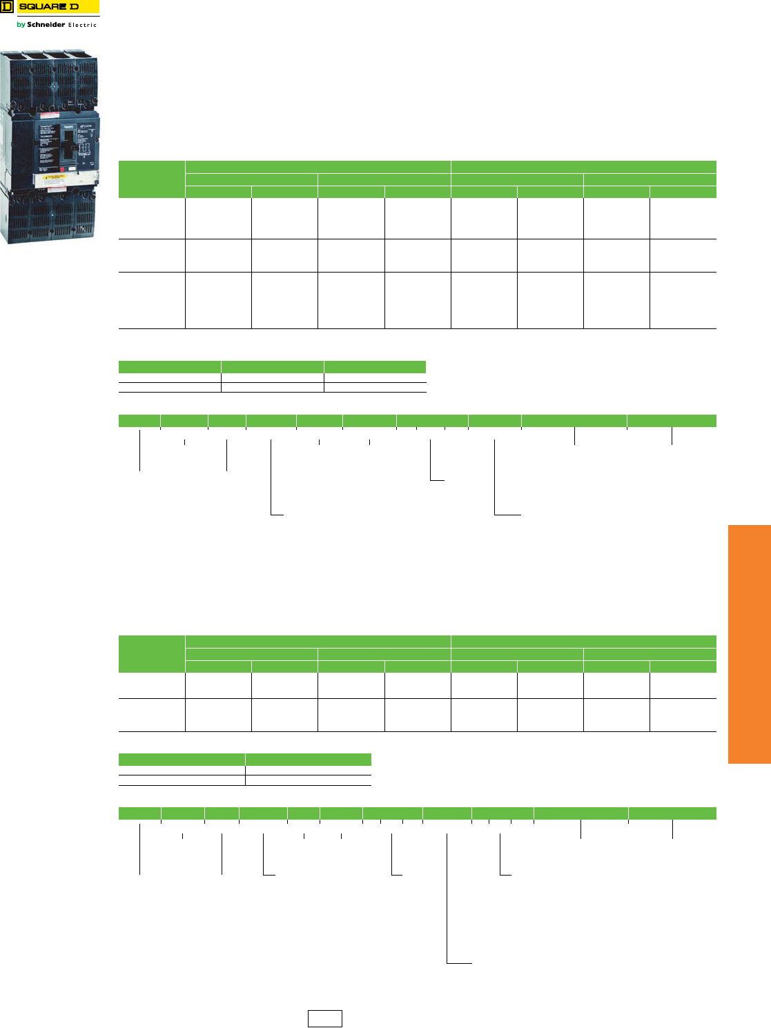
www.schneider-electric.us
7MINIATURE AND MOLDED CASE
CIRCUIT BREAKERS
© 2012 Schneider Electric
All Rights Reserved 7-59
Photovoltaic Circuit
Breakers and Switches
600 Vdc and 1000 Vdc PV Circuit Breakers and Switches
Class 611 / Refer to Catalog 0611CT1302
The UL listed thermal-magnetic molded case circuit breakers and switches shown below are specifically designed for use
in PV applications, rated at 50°C, offering grounded or ungrounded configurations.
The products are fully tested and calibrated under the PV UL489B standard.
The products come ready to install, including specially designed serial connectors for optimal thermal response, and
adapted terminal covers for optimal isolation. Circuit Breakers come 100% rated for ease of use and selection.
These two new frames are fully compatible with the current line of PowerPact accessories, from aux contacts and shunt
trips to motor operators and rotary handles.
a500 A 80% rated.
Table 7.145: PV Molded Case Circuit Breakers
Ampere
Rating
600 Vdc (3 poles) 1000 Vdc (4 poles)
Ungrounded Grounded Ungrounded Grounded
Part Number $ Price Part Number $ Price Part Number $ Price Part Number $ Price
50 TGL36050L 911.00 TGL36050K 984.00 TBL41050L 1212.00 TBL41050K 1309.00
60 TGL36060L 911.00 TGL36060K 984.00 TBL41060L 1212.00 TBL41060K 1309.00
70 TGL36070L 1013.00 TGL36070K 1094.00 TBL41070L 1212.00 TBL41070K 1309.00
80 TGL36080L 1013.00 TGL36080K 1094.00 TBL41080L 1212.00 TBL41080K 1309.00
100 TGL36100L 1125.00 TGL36100K 1215.00 TBL41100L 1347.00 TBL41100K 1455.00
125 TGL36125L 1250.00 TGL36125K 1350.00 TBL41125L 1496.00 TBL41125K 1616.00
150 TGL36150L 1250.00 TGL36150K 1350.00 TBL41150L 1496.00 TBL41150K 1616.00
175 TGL36175L 1438.00 TGL36175K 1553.00 TBL41175L 1721.00 TBL41175K 1859.00
200 TGL36200L 1438.00 TGL36200K 1553.00 TBL41200L 1721.00 TBL41200K 1859.00
225 UGL36225L 1703.00 UGL36225K 1839.00 UCL41225L 2044.00 UCL41225K 2207.00
250 UGL36250L 1892.00 UGL36250K 2043.00 UCL41250L 2271.00 UCL41250K 2453.00
300 UGL36300L 2270.00 UGL36300K 2451.00 UCL41300L 2611.00 UCL41300K 2820.00
350 UGL36350L 2270.00 UGL36350K 2451.00 UCL41350L 2611.00 UCL41350K 2820.00
400 UGL36400L 2306.00 UGL36400K 2490.00 UCL41400L 2765.00 UCL41400K 2986.00
450 UGL36450L 2536.00 UGL36450K 2739.00 UCL41450L 3041.00 UCL41450K 3284.00
500aN/A . . . UGL36500G 2739.00 UCL41500J 3041.00 UCL41500G 3284.00
Table 7.146: PV Circuit Breaker Max. Interrupting Ratings
Frame 600 Vdc 1000 Vdc
T-Frame 10 kA 3 kA
U-Frame 10 kA 5 kA
Table 7.147: Circuit Breaker Numbering
Brand Frame Rating Termination Poles Voltage Amperage Grounding Suffix Code Suffix Code
TG L 3 6050G A B S A
Frame
T: T-Frame
U: U-Frame
Poles
3: 3P
4: 4P
Vol tage
6: 600 Vdc
1: 1000 Vdc
Accessory Suffix Cells
(See Table 7.151 to
Table 7.1 55)
Accessory Suffix Cells
(See Table 7.151 to
Table 7.1 55)
Amperage
050: 50 A
060: 60 A
070: 70 A
080: 80 A
100: 100 A
125: 125 A
150: 150 A
175: 175 A
200: 200 A
225: 225 A
250: 250 A
300: 300 A
350: 350 A
400: 400 A
450: 450 A
500: 500 A
Brand
Blank:
Schneider
Electric
Ratings
B: 3 kA
C: 5 kA
G: 10 kA
Terminations
L: Lugs Line/Load Side
F: Bus Bar
S: Rear Connected
Grounding
G: Grounded, 80% rated (500 A Only)
J: Ungrounded, 80% rated (500 A Only)
K: Grounded, 100% rated
L: Ungrounded, 100% rated
Table 7.148: PV Molded Case Non-Automatic Switches
Ampere
Rating
600 Vdc (3 poles) 1000 Vdc (4 poles)
Ungrounded Grounded Ungrounded Grounded
Part Number $ Price Part Number $ Price Part Number $ Price Part Number $ Price
100 TBL36000JZ10 872.00 TBL36000GZ10 934.00 TBL41000JZ10 1048.00 TBL41000GZ10 1122.00
150 TBL36000JZ15 960.00 TBL36000GZ15 1028.00 TBL41000JZ15 1156.00 TBL41000GZ15 1237.00
200 TBL36000JZ20 1104.00 TBL36000GZ20 1182.00 TBL41000JZ20 1332.00 TBL41000GZ20 1426.00
250 UDL36000JZ25 1455.00 UDL36000GZ25 1557.00 UDL41000JZ25 1748.00 UDL41000GZ25 1870.00
300 UDL36000JZ30 1676.00 UDL36000GZ30 1794.00 UDL41000JZ30 2012.00 UDL41000GZ30 2153.00
400 UDL36000JZ40 1876.00 UDL36000GZ40 2007.00 UDL41000JZ40 2254.00 UDL41000GZ40 2412.00
500 UDL36000JZ50 2401.00 UDL36000GZ50 2569.00 UDL41000JZ50 2711.00 UDL41000GZ50 2901.00
Table 7.149: PV Switches Withstand Ratings
Frame 600/1000 Vdc
T- F r a m e 3 k A
U-Frame 7.5 kA
Table 7.150: Switch Numbering
Brand Frame Rating Termination Poles Voltage Amperage Grounding Trip System Suffix Code Suffix Code
TD L 36000GZ10A B S A
Frame
T: T-Frame
U: U-Frame
Poles
3: 3P
4: 4P
Vol tage
6: 600 Vdc
1: 1000 Vdc
Accessory Suffix Cells
(See Table 7.151 to
Table 7.155)
Accessory Suffix Cells
(See Table 7.151 to
Table 7.155)
Terminations
L: Lugs Line/Load Side
F: Bus Bar
S: Rear Connected
Amperage
000: Switch
Trip System—##
(Z: Non-Automatic Switch)
(##: Amerage Rating)
Z10: 100 A
Z15: 150 A
Z20: 200 A
Z25: 250 A
Z30: 300 A
Z40: 400 A
Z50: 500 A
Brand
Blank:
Schneider
Electric only
Ratings
B: 3 kA
D: 7.5 kA
Grounding
G: Grounded, 80% rated
J: Ungrounded, 80% rated
DE2 Discount
Schedule
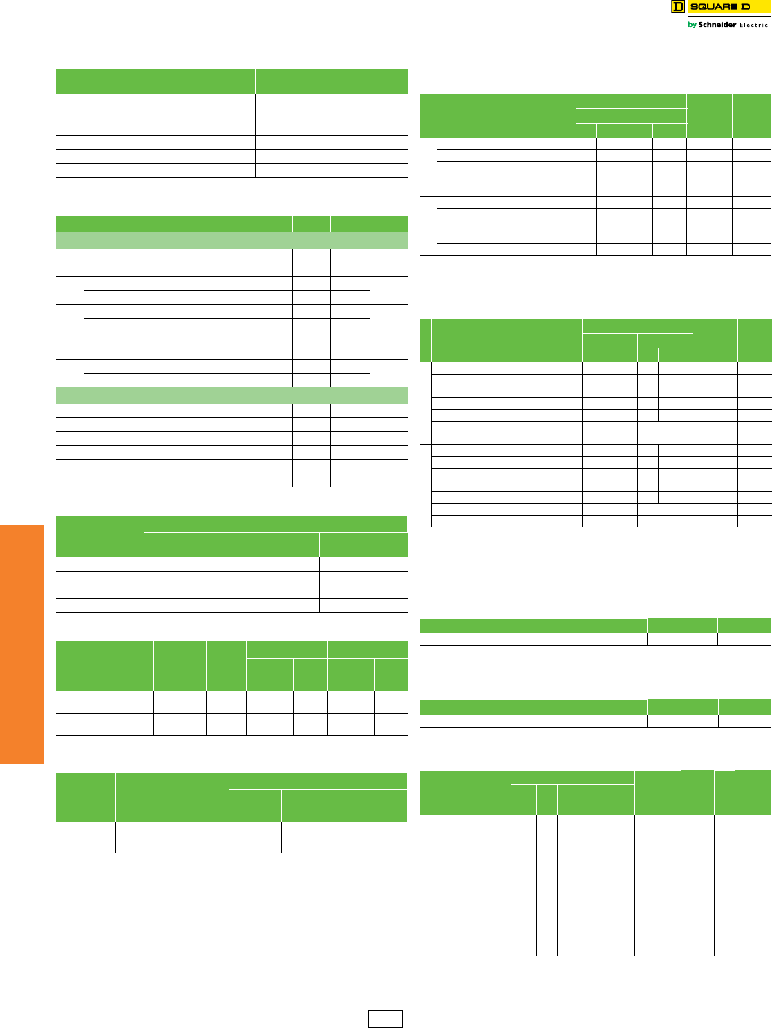
www.schneider-electric.us
7MINIATURE AND MOLDED CASE
CIRCUIT BREAKERS
7-60 © 2012 Schneider Electric
All Rights Reserved
Photovoltaic Circuit
Breakers and Switches
Factory Installed Accessories
Class 611 / Refer to Catalog 0611CT1302
aU-Frame only.
NOTE: For a complete list of Field installable accessories and
details, including also motor operator (electrical only) and
locks, refer to accessories information for the PowerPact,
J-Frame (compatible with T-Frame) and L-Frame
(Compatible with U-Frame). Or consult Photovoltaic offer
catalog 0611CT1302.
aP: Poles, SC: Serial connector.
aThe ungrounded configurations (3P or 4P) need 2 short and 2 long rear connectors. The
grounded configurations only use 2 short rear connectors.
bParts only, no hardware is included. See Table 7.159 U-Frame, below.
cP: Poles, SC: Serial connector.
NOTE: For availability dates of field installable accessories in
Tables 7.156. 7.157, 7.158 and 7.160 contact Schneider
Electric.
Table 7.151: Auxiliary Switches
Contacts Factory-Installed
Suffix
Field-Installable
Kit No. Kit Qty. $ Price
1A/1B Standard AA S29450 1297.00
2A/2B Standard AB S29450 2594.00
3A/3B StandardaAC S29450 3891.00
1A/1B Low-Level (Gold) AE S29452 1372.00
2A/2B Low-Level (Gold) AF S29452 2744.00
3A/3B Low-Level (Gold)aAG S29452 31116.00
Table 7.152: Alarm/Overcurrent Trip Switches
Suffix Switch Kit No. Kit Qty. $ Price
PowerPact T-Frame
BC Alarm Switch S29450 1297.00
BH Alarm Switch, Low-Level S29452 1372.00
BD Overcurrent Trip Switch, Standard S29450 1338.00
SDE Actuator S29451 1
BJ Overcurrent Trip Switch, Low-Level S29452 1413.00
SDE Actuator S29451 1
BE Alarm Switch and Overcurrent Trip Switch, Standard S29450 2635.00
SDE Actuators S29451 2
BK Alarm Switch and Overcurrent Trip Switch, Low-Level S29452 2785.00
SDE Actuators S29451 2
PowerPact U-Frame
BC Alarm Switch S29450 1297.00
BH Alarm Switch, Low-Level S29452 1372.00
BD Overcurrent Trip Switch, Standard S29450 1297.00
BJ Overcurrent Trip Switch, Low-Level S29452 1372.00
BE Alarm Switch and Overcurrent Trip Switch, Standard S29450 2594.00
BK Alarm Switch and Overcurrent Trip Switch, Low-Level S29452 2744.00
Table 7.153: Shunt Trips
Vol tag e
Shunt Trip (MX)
Factory-Installed
Suffix
Field-Installable
Kit No. $ Price
120 Vac SA S29386 717.00
24 Vdc SO S29390 717.00
48 Vdc SP S29392 717.00
125 Vdc SR S29393 717.00
Table 7.154: Rotary Operated Handles
Device Description
Factory
Installed
Suffix
T- F r a m e U-Frame
Field
Installable
Kit No.
$ Price
Field
Installable
Kit No.
$ Price
Direct
Mounted
Standard
Handle Black Handle Only RD10 S29337 255.00 S32597 366.00
Door
Mounted
Standard
Black Handle Handle Only RE10 S29338 383.00 S32598 557.00
Table 7.155: Locks
Device Description
Factory
Installed
Suffix
T- F r a m e U-Frame
Field
Installable
Kit No.
$ Price
Field
Installable
Kit No.
$ Price
Handle
Padlocking
Device
Handle Padlock,
ON or OFF YP S29371 77.00 S32631 122.00
Table 7.156: PV Unit Mount Terminal Covers
Choose termination “L” for having the termination kit factory installed
with the breaker (Lugs, Term Covers, Serial Connectors)
Frame
Descriptiona
Poles
Configuration Field
Installable
Catalog
No.
$ PriceUngrounded Grounded
Top Bottom Top Bottom
T- F ra m e
Long Terminal Cover (3P) 3 X S35175 145.00
Long Terminal Cover (3P/1SC) 3 X X X S35176 145.00
Long Terminal Cover (4P) 4 X S35177 162.00
Long Terminal Cover (4P/2SC) 4 X X S35178 162.00
Long Terminal Cover (4P/1SC) 4 X S35179 162.00
U-Frame
Long Terminal Cover (3P) 3 X S32593 185.00
Extended Term Cover (3P/1SC) 3 X X X S38291 205.00
Long Terminal Cover (4P) 4 X S32594 198.00
Extended Term Cover (4P/2SC) 4 X X S38293 215.00
Extended Term Cover (4P/1SC) 4 X S38294 215.00
Table 7.157: PV Rear Connection Terminal Covers and Connectors
Choose termination “S” for having the termination kit included with the
breaker (Rear Connectors, Term Covers, Serial Connectors)
Frame
Descriptionc
Poles
Configuration Field
Installable
Catalog
No.
$ PriceUngrounded Grounded
Top Bottom Top Bottom
T- F ra m e
Short Terminal Cover (3P) 3 X S29515 121.00
Long Terminal Cover (3P/1SC) 3 X X X S35169 145.00
Short Terminal Cover (4P) 4 X S29516 141.00
Long Terminal Cover (4P/1SC) 4 X S35170 162.00
Long Terminal Cover (4P/2SC) 4 X X S35178 162.00
Short Rear Connector (set of 2)a3, 4 X X S29235 162.00
Long Rear Connector (set of 2)a3, 4 X S29236 206.00
U-Frame
Short Terminal Cover (3P) 3 X S32562 149.00
Extended Terminal Cover (3P/1SC) 3 X X X S35171 205.00
Short Terminal Cover (4P) 4 X S32563 161.00
Extended Term Cover (4P/1SC) 4 X S35172 215.00
Extended Term Cover (4P/2SC) 4 X X S38293 215.00
Short Rear Connector (set of 2)ab 3, 4 X X S432475 219.00
Long Rear Connector (set of 2)ab 3, 4 X S432476 261.00
Table 7.158: PV T-Frame Bus Bar and Rear Connections Hardware
Choose termination “F” for having the termination kit included with the
breaker (Terminal Nuts, Term Covers, Serial Connectors)
Description Cat. No. $ Price
T-Frame Term Nut Insert-Metric/M8 (12) S30554 150.00
Table 7.159: PV U-Frame Bus Bar and Rear Connections Hardware
Choose termination “F” for having the termination kit included with the
breaker (Screws and Washers, Term Covers, Serial Connectors)
Description Cat. No. $ Price
Set of 4 M10 x 25 terminal screws and washers for one side S36967 31.00
Table 7.160: Mechancal Lug Kits for T- and U-Frame Circuit
Breakers and Switches
Frame
Description
Conductor
Current Cat.
No.
Qty.
Per
Kit
$ Price
Type
No.
Per
Lug
Size
T- F r a m e
Lug(2) T-Frame,
12–4 AWG, Al/Cu
Al 1 #12–#4 AWG
(4–25 mm2)50–60 A S35167 286.00
Cu 1 #14–#4 AWG
(2.5–25 mm2)
Lugs(2) T-Frame,
4–4/0 AWG, Al/Cu Al/Cu 1 #4–#4/0 AWG
(25–95 mm2)70–150 A S29255 286.00
Lug(2) T-Frame,
250–350 kcmil,
Al/Cu
Al 1 #250–350 AWG
(120–185 mm2)175–200 A S35168 286.00
Cu 1 #2/0–350 AWG
(70–185 mm2)
U-Frame
Lug(2) U-Frame,
2/0 AWG–500 kcmil,
Al/Cu
Al 2 2/0 AWG–500 kcmil
(70–240 mm2)225–500 A S35180 2225.00
Cu 2 2/0 AWG–500 kcmil
(70–240 mm2)
DE2 Discount
Schedule
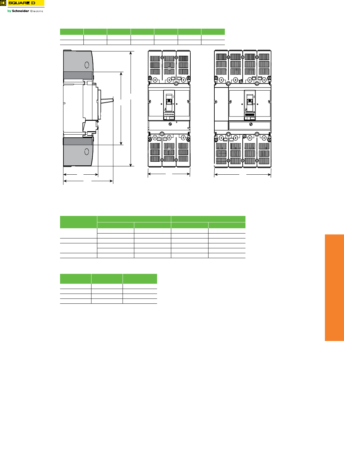
www.schneider-electric.us
7MINIATURE AND MOLDED CASE
CIRCUIT BREAKERS
© 2012 Schneider Electric
All Rights Reserved 7-61
Photovoltaic Circuit
Breakers and Switches
T-Frame Dimensions and Shipping Weights
Class 611 / Refer to Catalog 0611CT1302
A2: Short
A3: Long
Table 7.161: PV T-Frame Circuit Breaker and Switches Dimensions
A2 A3 B1 B2 C2 C3
in 7.40 11.42 4.13 5.51 3.39 4.96
mm 188 290 105 140 86 126
Table 7.162: Terminal Cover Configuration According to Wiring Configuration
Wiring Configuration Connection Type Terminal Cover Configuration
Unit Mount/Bus Rear Connected Top Bottom
3P Ungrounded X Long Long
X Short Long
3P Grounded X X Long Long
4P Ungrounded X Long Long
X Long Short
4P Grounded X X Long Long
Table 7.163: Approximate Weights
T- F r a m e s Product Weight
(lbs)
Shipping Weights
(lbs)
3P Ungrounded 5 8
3P Grounded 5.5 8.5
4P Ungrounded 6.3 9.3
4P Grounded 6.7 9.7
C3
C2
A2
A3
B1 B2
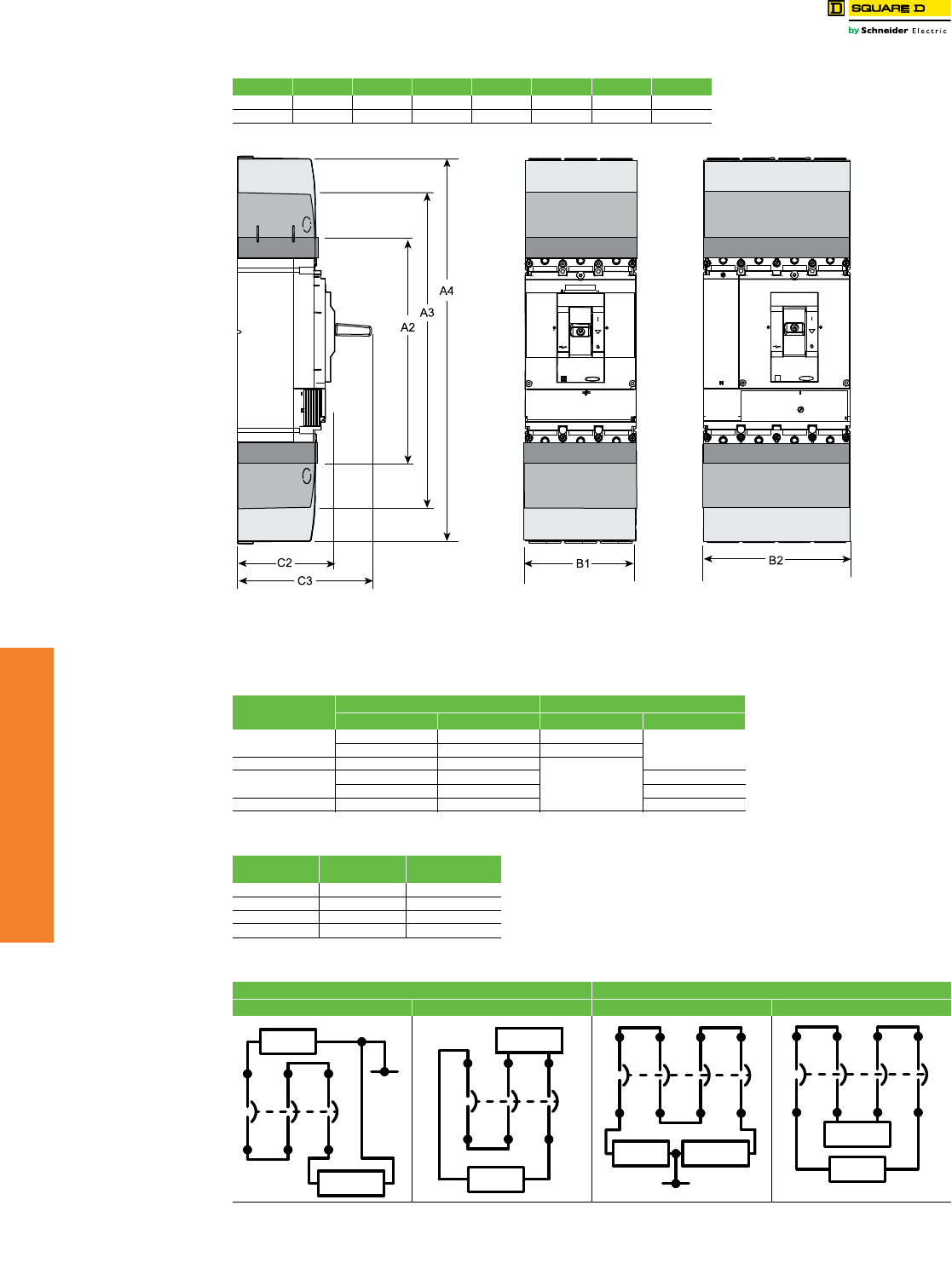
www.schneider-electric.us
7MINIATURE AND MOLDED CASE
CIRCUIT BREAKERS
7-62 © 2012 Schneider Electric
All Rights Reserved
Photovoltaic Circuit
Breakers and Switches
U-Frame Dimensions and Shipping Weights
Class 611 / Refer to Catalog 0611CT1302
A2: Short
A3: Long
A4: Extended
Table 7.164: PV U-Frame Circuit Breaker and Switches Dimensions
A2 A3 A4 B1 B2 C2 C3
in 11.2 15.7 19.1 5.5 7.2 4.3 6.6
mm 285 400 484 140 183 110 168
Table 7.165: Terminal Cover Configuration According to Wiring Configuration
Wiring Configuration Connection Type Terminal Cover Configuration
Unit Mount/Bus Rear Connected Top Bottom
3P Ungrounded XLong
ExtendedXShort
3P Grounded X X
Extended4P Ungrounded XLong
XShort
4P Grounded X X Extended
Table 7.166: Approximate Weights
U-Frames Product Weight
(lbs)
Shipping Weights
(lbs)
3P Ungrounded 15 19.5
3P Grounded 17 21.5
4P Ungrounded 21 25.5
4P Grounded 23 27.5
Table 7.167: PV T- and U-Frame Circuit Breakers and Switches Wiring Configurations
600 Vdc (3 Poles) 1000 Vdc (3 Poles)
Grounded Ungrounded Grounded Ungrounded
PV Source /
FV Fuente
GND
Load /
Charge / Carga
Load /
Charge / Carga
PV Source /
FV Fuente
PV Source /
FV Fuente
GND
Load /
Charge / Carga
PV Source /
FV Fuente
Load /
Charge / Carga

www.schneider-electric.us
7MINIATURE AND MOLDED CASE
CIRCUIT BREAKERS
© 2012 Schneider Electric
All Rights Reserved 7-63
QO™ and QOU Miniature
Circuit Breakers
QO™ Miniature Circuit Breakers
Class 685, 690, 730, 912, 950 / Refer to Catalog 0730CT9801
QO-K
Key operated QO circuit breakers are available in single-
pole construction and can be mounted in any single-pole
space which will accept a standard QO. These circuit
breakers can be turned ON or OFF or to RESET with a
special key (catalog number QOK10) included with the
circuit breaker. These circuit breakers are UL Listed and
available as shown in the table.
Table 7.168: QO-K Circuit Breakers
120 Vac—10 k AIR (1 Space Required)
Ampere Ratingc Cat. No. $ Price
10 A QO110K 164.00
15 A QO115K 164.00
20 A QO120K 164.00
30 A QO130K 164.00
DE2A Discount
Schedule

www.schneider-electric.us
7MINIATURE AND MOLDED CASE
CIRCUIT BREAKERS
7-64 © 2012 Schneider Electric
All Rights Reserved
