QO Load Center 1000262687 Catalog
143085-Catalog 143085-Catalog 143085-Catalog B5 unilog cesco-content
2016-09-04
: Pdf 1000262687-Catalog 1000262687-Catalog B4 unilog
Open the PDF directly: View PDF ![]() .
.
Page Count: 84
- Product Description
- General information and Application Data
- Service
- Ratings
- Branch Circuit Breakers
- Indoor Enclosures (NEMA Type 1)
- Indoor Covers
- Rainproof Enclosures (NEMA Type 3R)
- Bolt-On Hubs
- Class CTL
- Phasing
- Line Lugs
- Neutral Assemblies
- UL Listed
- CSA Certified
- Short Circuit Current Rating
- Interior
- Mains
- Cover
- UL Listed
- Short Circuit Current Rating
- Interior
- Mains
- Covers
- Main Lugs Kits
- Main Circuit Breaker Kits
- Field Installable Main Circuit Breaker (Convertible Main Load Centers Only)
- Recreational Vehicle and Manufactured Housing Load Centers
- Load Centers with Covers
- Non-Metallic Load Center
- Main Circuit Breaker with Feed-Thru Lugs
- Generator Panel
- WIREGATOR™ Qwik-Grip Cable System
- UL Listed
- Short Circuit Current Rating
- Mains
- Cover
- Interior
- Branch Neutral Termination
- Main Lugs Kits
- Main Circuit Breakers
- UL Listed
- Short Circuit Current Rating
- Mains
- Cover
- Interior
- Enclosures
- Grounding Bar Kits
- Flush Lock Kits
- Auxiliary Neutral Lugs
- Cover Filler Plates
- Back-Fed Main Circuit Breaker Retaining Kits
- UL Listed Manual Transfer Equipment Kits
- Auxiliary Gutters and Tap Kits
- Auxiliary Gutter (SDAG26) to Load Center Catalog Number Reference
- UL Listed Bolt-On Hubs for RB Devices
- UL Listed Enclosure Coupling for RB Devices
- Technical Information
- Grounding Bar Kits
- Single-Phase – Convertible Main Lugs, Series S1 and S2
- Feed-Thru – Main Circuit Breakers, Series S1
- Three-Phase – Fixed Main Lugs, Series S1 and S2
- Three-Phase – Convertible Main Circuit Breakers, Series S1 and S2
- Single-Phase – Fixed Main Lugs, Series 1, G1, and G3
- Single-Phase – Fixed Main Lugs, Series 1, G1, and G3, Continued
- General Information and Application Data
- Technical Information
- Product Description
- general information and application data
- Type
- Service
- Ratings
- UL Listed
- Class CTL
- Branch Circuit Breakers
- Main Circuit Breaker Kits
- Indoor Enclosures (NEMA Type 1)
- Indoor Covers
- Rainproof Enclosures (NEMA Type 3R)
- Bolt-On Hubs
- Single-Phase, 12–42 Circuits, 100–225 A, Convertible Mains
- UL Listed
- Short Circuit Current Rating
- Interior
- Mains
- Cover
- Main Circuit Breaker with Feed-Thru Lugs
- Universal Mains Load Centers, Studs Only
- Universal Mains Load Center with Feed-Thru Lugs
- Main Circuit Breaker Mobile Home Load Centers
- Bolt-On Hubs
- UL Listed Bolt-On Hubs for RB Devices
- UL Listed Enclosure Coupling for RB Devices
- Grounding Bar Kits
- Auxiliary Neutral Lugs
- Cover Filler Plates
- Back-Fed Main Circuit Breaker Retaining Kits
- Flush Lock Kits
- Main Lugs Kits
- Main Circuit Breaker Kits
- Technical Information
- Grounding Bar Kits
- Single-Phase – Fixed Main Lugs, Series 1 and 2
- Single-Phase – Fixed Main Lugs, Series 1
- Single-Phase – Convertible Main Lugs, Series S01 and S02
- Single-Phase – Convertible Main Circuit Breakers, Series S01 and S02
- Universal – Main Lugs or Main Circuit Breakers, Series S01
- Feed-Thru – Main Circuit Breakers, Series S01
- Feed-Thru – Universal Main Circuit Breakers, Series S02
Class 1130, 1131, and 1170
CONTENTS
Description Page
QO Circuit Breaker Load Centers—Class 1130 . . . . . . . . . . . . . . . . . . . . . . . . . . . . 3
QO, QO2, and QOM2 Enclosed Circuit Breakers—Class 1131 . . . . . . . . . . . . . . . 45
HOMELINE Circuit Breaker Load Centers—Class 1170 . . . . . . . . . . . . . . . . . . . . . 53
Index . . . . . . . . . . . . . . . . . . . . . . . . . . . . . . . . . . . . . . . . . . . . . . . . . . . . . . . . . . . . 79
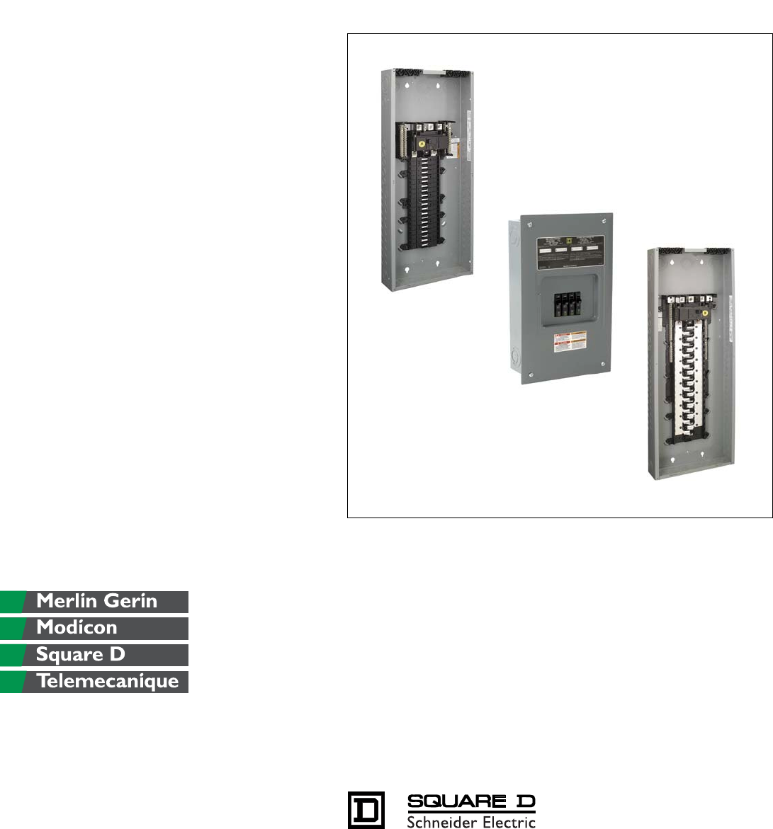
QO® and HOMELINE®
Circuit Breaker Load Centers and Enclosures
Schneider Electric Brands

QO Circuit Breaker Load Centers—Class 1130
Table of Contents
3
09/00 © 2000 Schneider Electric All Rights Reserved
PRODUCT DESCRIPTION . . . . . . . . . . . . . . . . . . . . . . . . . . . . . . . . . . . . . . . . . . . . . . . . . . . . . . . . . . 5
Features . . . . . . . . . . . . . . . . . . . . . . . . . . . . . . . . . . . . . . . . . . . . . . . . . . . . . . . . . . . . . . . . . . . . . 5
GENERAL INFORMATION AND APPLICATION DATA . . . . . . . . . . . . . . . . . . . . . . . . . . . . . . . . . . . . 7
Service . . . . . . . . . . . . . . . . . . . . . . . . . . . . . . . . . . . . . . . . . . . . . . . . . . . . . . . . . . . . . . . . . . . . . . 7
Ratings . . . . . . . . . . . . . . . . . . . . . . . . . . . . . . . . . . . . . . . . . . . . . . . . . . . . . . . . . . . . . . . . . . . . . . 7
Branch Circuit Breakers . . . . . . . . . . . . . . . . . . . . . . . . . . . . . . . . . . . . . . . . . . . . . . . . . . . . . . . . 7
Indoor Enclosures (NEMA Type 1) . . . . . . . . . . . . . . . . . . . . . . . . . . . . . . . . . . . . . . . . . . . . . . . .8
Indoor Covers . . . . . . . . . . . . . . . . . . . . . . . . . . . . . . . . . . . . . . . . . . . . . . . . . . . . . . . . . . . . . . . . 8
Rainproof Enclosures (NEMA Type 3R) . . . . . . . . . . . . . . . . . . . . . . . . . . . . . . . . . . . . . . . . . . . . 8
Bolt-On Hubs . . . . . . . . . . . . . . . . . . . . . . . . . . . . . . . . . . . . . . . . . . . . . . . . . . . . . . . . . . . . . . . . . 8
Class CTL . . . . . . . . . . . . . . . . . . . . . . . . . . . . . . . . . . . . . . . . . . . . . . . . . . . . . . . . . . . . . . . . . . . 9
Phasing . . . . . . . . . . . . . . . . . . . . . . . . . . . . . . . . . . . . . . . . . . . . . . . . . . . . . . . . . . . . . . . . . . . . . 9
Line Lugs . . . . . . . . . . . . . . . . . . . . . . . . . . . . . . . . . . . . . . . . . . . . . . . . . . . . . . . . . . . . . . . . . . . . 9
Neutral Assemblies . . . . . . . . . . . . . . . . . . . . . . . . . . . . . . . . . . . . . . . . . . . . . . . . . . . . . . . . . . . . 9
Single Phase, 2–16 Circuits, 30–125 A, Fixed Mains . . . . . . . . . . . . . . . . . . . . . . . . . . . . . . . . . 10
Single-Phase, 12–42 Circuits, 100–225 A, Convertible Mains . . . . . . . . . . . . . . . . . . . . . . . . . . 11
Special Purpose . . . . . . . . . . . . . . . . . . . . . . . . . . . . . . . . . . . . . . . . . . . . . . . . . . . . . . . . . . . . . . 13
Three-Phase, 3–42 Circuits, 60–225 A, Convertible or Fixed Mains . . . . . . . . . . . . . . . . . . . . . . 15
Single- or Three Phase, 12–42 Circuits, 300–400 A, Fixed Mains . . . . . . . . . . . . . . . . . . . . . . . 17
Accessories . . . . . . . . . . . . . . . . . . . . . . . . . . . . . . . . . . . . . . . . . . . . . . . . . . . . . . . . . . . . . . . . . 18
TECHNICAL INFORMATION . . . . . . . . . . . . . . . . . . . . . . . . . . . . . . . . . . . . . . . . . . . . . . . . . . . . . . . 21
Grounding Bar Kits . . . . . . . . . . . . . . . . . . . . . . . . . . . . . . . . . . . . . . . . . . . . . . . . . . . . . . . . . . . 21
Main Lugs and Main Circuit Breakers Ratings . . . . . . . . . . . . . . . . . . . . . . . . . . . . . . . . . . . . . . . 22
DIMENSIONS AND KNOCKOUTS . . . . . . . . . . . . . . . . . . . . . . . . . . . . . . . . . . . . . . . . . . . . . . . . . . . 29
SPECIFICATIONS . . . . . . . . . . . . . . . . . . . . . . . . . . . . . . . . . . . . . . . . . . . . . . . . . . . . . . . . . . . . . . . 32
Single-Phase Labels . . . . . . . . . . . . . . . . . . . . . . . . . . . . . . . . . . . . . . . . . . . . . . . . . . . . . . . . . . 32
Three-Phase Labels . . . . . . . . . . . . . . . . . . . . . . . . . . . . . . . . . . . . . . . . . . . . . . . . . . . . . . . . . . 33
WIRING DIAGRAMS . . . . . . . . . . . . . . . . . . . . . . . . . . . . . . . . . . . . . . . . . . . . . . . . . . . . . . . . . . . . . 34
REPLACEMENT PARTS . . . . . . . . . . . . . . . . . . . . . . . . . . . . . . . . . . . . . . . . . . . . . . . . . . . . . . . . . . 37
Single-Phase – Convertible Main Lugs, Series S1 and S2 . . . . . . . . . . . . . . . . . . . . . . . . . . . . . 37
Single-Phase – Convertible Main Circuit Breakers, Series S1 and S2 . . . . . . . . . . . . . . . . . . . . 39
Feed-Thru – Main Circuit Breakers, Series S1 . . . . . . . . . . . . . . . . . . . . . . . . . . . . . . . . . . . . . . 40
Three-Phase – Fixed Main Lugs, Series S1 and S2 . . . . . . . . . . . . . . . . . . . . . . . . . . . . . . . . . . 41
Three-Phase – Convertible Main Circuit Breakers, Series S1 and S2 . . . . . . . . . . . . . . . . . . . . 42
Single-Phase – Fixed Main Lugs, Series 1, G1, and G3 . . . . . . . . . . . . . . . . . . . . . . . . . . . . . . . 43

QO Circuit Breaker Load Centers—Class 1130
4
09/00
© 2000 Schneider Electric All Rights Reserved
QO Circuit Breaker Load Centers—Class 1130
Product Description
5
09/00 © 2000 Schneider Electric All Rights Reserved
PRODUCT DESCRIPTION
QO® Circuit Breaker Load Centers from Square D are Underwriters
Laboratories® (UL®) Listed panelboards. They are designed to meet residential,
commercial, and industrial requirements to protect electrical systems,
equipment, and people.
Features
• Single- or three-phase construction
• 30–400 A main lug or main circuit breaker ratings
• 2–42 circuit indoor or outdoor versions
• Flush or surface mounting
• Copper bus construction on convertible mains panels
• Aluminum bus construction on fixed mains panels
• Service entrance equipment capable panels
• Straight-in wiring to minimize service cable installation
• Convertible mains to meet changing job site requirements
• Standard 22/10 k AIR series rating on main circuit breaker panels, increasing
application capability
• 65 k AIR ratings for main lugs panels for industrial applications
• 65 k AIR rating with optional main circuit breaker on three-phase panels for
industrial applications
• Shielded one-piece plated copper bus, an industry exclusive for protection
and performance
• Single captive screw interior mounting on indoor panels to ease removal
• Split branch neutral for clutter-free wiring
• Top or bottom feed by rotating convertible mains panels 180 degrees
• Top or bottom feed for three-phase convertible panels by removing main
circuit breaker and rotating panel 180 degrees
• Combination slot/square drive neutral, ground, and cover screws for positive
drive and improved torque
• Three ground bar mounting locations for ease of wiring
• Automatic flush adjustment cover to speed installation
• Tangential main service knockouts that eliminate offsets
• Equipment ground bar included with main lug load centers
• Covers sold separately
• Provisions for door lock on convertible mains panel covers
• Two branch circuit breaker twistouts that are factory removed for easier
installation of circuit breakers
• New side hinge doors on outdoor convertible main panels
• Outdoor panel covers lockable with padlock
•WIREGATOR
™ Qwik-Grip Cable System on selected load centers
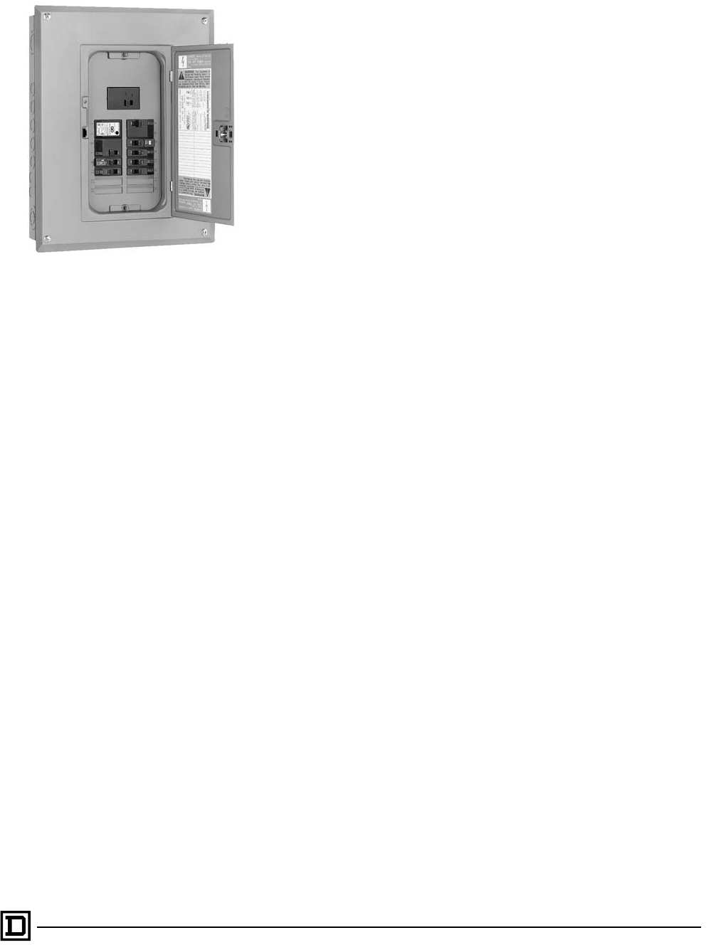
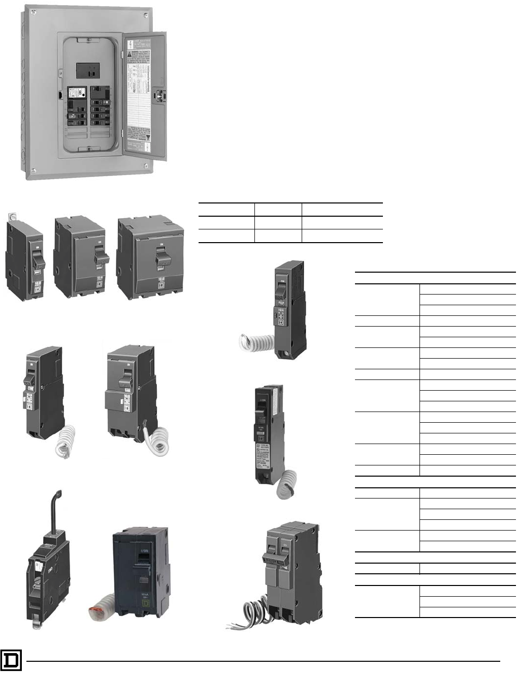
QO Circuit Breaker Load Center

QO Circuit Breaker Load Centers—Class 1130
Product Description
6
09/00
© 2000 Schneider Electric All Rights Reserved
115QO __
DEVICE NAME
Blank: 10,000 AIR
EPD: 30 mA equipment ground fault protection
GFI: Ground fault circuit interruption
HID: For use on high intensity discharge
lighting systems
HM: High magnetic trip circuit breakers are
recommended for applications where
high initial inrush current may occur
K: Key operated
PL: Remote control switching capability
SWN: Switch neutral common trip
VH: 22,000 AIR
AFI: ARC fault circuit interruption
AMPS
NUMBER OF POLES
BRAND
QO: Full size
QOT: Tandem
KG200L30401QO __ __
DEVICE NAME
WIREGATOR
COVER
Blank: Purchase cover separately
C: Combination flush/surface indoor cover
RB: Rainproof
SPECIAL CONSTRUCTION
WG: Wide gutter
FT: Feed thru
GROUND BAR
G: Included
T: Factory installed
Blank: Purchase separately
AMPS
MAINS TYPE
M: Main circuit breaker
L: Main lugs
SPACES/CIRCUITS
PHASE
1: Single
3: Three
BRAND
QO: UL and NOM Listed
CQO: CSA certified
QO Load Center and Circuit Breaker Catalog Number Descriptions
QO Circuit Breaker Load Centers—Class 1130
General Information and Application Data
7
09/00 © 2000 Schneider Electric All Rights Reserved
GENERAL INFORMATION AND APPLICATION DATA
Circuit breaker load centers for use on electrical systems are UL Listed under
File E-6294 (panelboards) and meet Federal Specifications W-P-115c, NEMA
Type 1, Class 2 for use in government housing. Select from QO, QOT, QO-PL,
QO-GFI (UL Class A ground fault protection), QO-AFI (arc fault circuit
interrupter) and QO-EPD (30 mA equipment ground fault protection) branch
circuit breakers.
Service
•120 Vac, 1f2W
• 120/240 Vac, 1f3W
• 240 Vac delta, 3f3W
• 208Y/120 Vac, 3f4W
Ratings
Branch Circuit Breakers
Main Lugs Main Circuit Breaker
Single-phase 30–400 A 100–400 A
Three-phase 60–400 A 100–400 A
10,000 AIR
QO
1-pole, 10–70 A
2-pole, 10–125 A
3-pole, 10–100 A
QOT 1-pole, 15–20 A
QO-EPD 1-pole, 15–30 A
2-pole, 15–60 A
QO-GFI 1-pole, 15–30 A
2-pole, 15–60 A
QO-AFI 1-pole, 15–20 A
QO-HID
1-pole, 15–50 A
2-pole, 15–50 A
3-pole, 15–30 A
QO-PL
1-pole, 10–20 A, 30 A
2-pole, 10–60 A
3-pole, 15–60 A
QO-SWN 2-wire, 10–50 A
3-wire, 10–50 A
QOK 1-pole, 10–30 A
22,000 AIR
QO-VHGFI 1-pole, 15–30 A
QO-VH
1-pole, 15–30 A
2-pole, 15–125 A
3-pole, 15–100 A
QOB-VH 2-pole, 150 A ▲
3-pole, 110–150 A ▲
42,000 AIR
QOH 2-pole, 40–125 A
65,000 AIR
QH
1-pole, 15–30 A
2-pole, 15–30 A
3-pole, 15–30 A
▲ For use with 300 A and 400 A load centers only.
Requires PK3CA mounting kit, ordered separately.
QO
1-Pole
QO
2-Pole
QO
3-Pole
QO-GFI
1-Pole
QO-GFI
2-Pole
QOK, 1-Pole QO-SWN, 1-Pole
QO Circuit Breaker Load Center
• 240/120 Vac delta, 3f4W
• 240 Vac corner grounded delta, 3f3W
• 48 Vdc maximum (1f convertible
main lug 12–42 circuit only)
QO-PL 2-Pole
QO-EPD 1-Pole
QO-AFI 1-Pole

QO Circuit Breaker Load Centers—Class 1130
General Information and Application Data
8
09/00
© 2000 Schneider Electric All Rights Reserved
Indoor Enclosures (NEMA Type 1)
• Welded sheet steel with knockouts at top, bottom, back, and sides
• Finish: gray baked enamel, electrodeposited over cleaned,
phosphatized steel
• Most 100–225 A indoor enclosures are 14.25 in. (362 mm) wide
(see”Dimensions and Knockouts” on page 29 )
• 300 A and 400 A indoor enclosures are 20 in. (508 mm) wide
• Top or bottom feed by rotating enclosure
•WIREGATOR
™ Qwik-Grip Cable System, for easy branch wiring, on selected
load centers
Indoor Covers
• Doors to cover circuit breaker handles, except on 2–4, 4–8, 6–12,
and 8–16 circuit models
• Shutter-type twistouts
• Flush and surface covers available, sold separately
• Flush covers have automatic flush adjustment
• Field-installed door lock provisions available on most covers
• QOFP filler plates available for all covers
• QOM1FP filler plates available for 100–125 A convertible load center covers
• QOM2FP filler plates available for 150–225 A convertible load center covers
• KFP filler plates available for 3-phase load center covers
• Triple lead cover screws for fast cover installation
Rainproof Enclosures (NEMA Type 3R)
• Complete enclosure includes interior trim and door
• Welded, galvannealed steel
• Finish: gray baked enamel, electrodeposited over cleaned, phosphatized,
galvannealed steel
• RB devices have provisions for interchangeable bolt-on hub
• Top-centered rainproof mounting boss on the back of the enclosure simplifies
installation and saves time
• Stainless steel door latch on the enclosure provides secure closure and
maximum durability
• Convertible main panels are side hinge door devices
• Allow 1.25 in. (32 mm) on the left side for the door to open
• Side-hinged door provides full wiring access without door removal
Bolt-On Hubs
• Hubs available from .75 in. (19 mm) to 4 in. (102 mm) conduit size
• No gasket required with hubs from .75 in. (19 mm) to 2.50 in. (64 mm) when
used on RB type load centers
NEMA Type 1, WIREGATOR
Indoor Cover
QO140M200RB
Bolt-On Hubs

QO Circuit Breaker Load Centers—Class 1130
General Information and Application Data
9
09/00 © 2000 Schneider Electric All Rights Reserved
Class CTL
• Class CTL load centers are UL Listed
• Circuit breaker mounting rails have slots to accept tandem circuit breakers,
on specified load centers
• Meets paragraph 384-15 of the National Electric Code® (NEC®)
Phasing
• Load centers have distributed phase bussing
• Most branch circuit breakers can be mounted in any position
Line Lugs
• All lugs suitable for 75 °C copper or aluminum wires (see “Technical
Information” on pages 22–29)
• Main lugs and main circuit breaker load centers have wire binding screw
tightening values on the wiring diagrams and circuit breaker labels
Neutral Assemblies
• All lugs suitable for copper or aluminum wire (see “Technical Information” on
pages 22–29)
• Branch neutral terminals suitable for one #14–#4 AWG copper or one
#12–#4 AWG aluminum wire
• Three #14–1/0 AWG copper or #14–#6 AWG aluminum terminals provided
on 12–42 circuits, 100–225 A load centers
• Suitable lugs provided on the neutrals for termination of the
grounding conductor
• All unused neutral terminals may be used to terminate bare or green
equipment grounding conductors when the load center is used as
service equipment:
— one or two #14–#12 AWG copper
— one or two #12–#10 AWG aluminum
Tandem circuit breaker mounts on rails.
Branch Circuit Breaker
Neutral assemblies accept copper or aluminum wire.

QO Circuit Breaker Load Centers—Class 1130
General Information and Application Data
10
09/00
© 2000 Schneider Electric All Rights Reserved
Single Phase, 2–16 Circuits, 30–125 A, Fixed Mains
UL Listed
• File E-6294
• Suitable for use as service equipment
• 75 °C wire rating (see “Technical Information” on pages 22–29)
• Federal Specification W-P-115c, NEMA Type 1, Class 2
CSA Certified
• File LL-89066-21
• For other CSA certified load centers, see Supplemental Digest 172.
Short Circuit Current Rating
• Main lugs up to 10,000 AIR (see “Technical Information” on pages 22–29)
Interior
• Tin plated aluminum bus
• Tin plated copper bus is an available option on 6–12 and 8–16 circuit
load centers
• Tin plated copper bus is standard on 4–8 circuit load centers
Mains
• Factory-installed main lugs
• Top mains positioning only
• Top or bottom feed
• A backfed main circuit breaker can be field-installed in 4–8, 6–12 and 8–16
load centers using the PK2MB retaining kit
Cover
• Flush- or surface-mounted cover included with load centers
• A cover with a door is an available option on 6–12 and 8–16 circuit
load centers
QO24L70S
QO816L100DS
QO148L125GF

QO Circuit Breaker Load Centers—Class 1130
General Information and Application Data
11
09/00 © 2000 Schneider Electric All Rights Reserved
Single-Phase, 12–42 Circuits, 100–225 A, Convertible Mains
UL Listed
• File E-6294
• Federal Specification W-P-115c, NEMA Type 1, Class 2
• Suitable for use as service equipment
• 75 °C wire rating (see “Technical Information” on pages 22–29)
Short Circuit Current Rating
• Main lugs: up to 65,000 AIR (depends on lowest interrupting rating of branch
circuit breakers installed)
• Main circuit breaker: 22,000 AIR standard
• 22,000 AIR main circuit breaker kits (refer to page 12 and “Technical
Information” on pages 22–29)
Interior
• Shielded, one-piece tin plated copper bus
• Removable interior with single, captive mounting screw
• Split branch neutral with up to 50% more terminations than required
• Multiple mounting locations for equipment ground bar kits: left, right,
and bottom
• Main lugs load centers have equipment ground bar kits included (not
factory-installed)
Mains
Factory-installed main lugs convertible to main circuit breaker
Factory-installed main circuit breaker convertible to main lugs
Load Center Amperage Main Circuit Breaker Kit Amperage
125 50–125
150 100–150
200 100–200
225 100–225
Main Circuit Breaker Amperage Main Lug Kit Amperage Load Center Amperage
100 125 100
125 125 125
150 225 150
200 225 200
225 225 225
Main Circuit Breaker
Main Lug
Top or bottom mains positioning. Rotate
entire load center 180 degrees.

QO Circuit Breaker Load Centers—Class 1130
General Information and Application Data
12
09/00
© 2000 Schneider Electric All Rights Reserved
Single-Phase, 12–42 Circuits, 100–225 A, Convertible Mains, Continued
Covers
• Flush and surface covers sold separately
• Flush covers have spring loaded interior trim for automatic flush adjustment
• Positive action, easy open door latch
Main Lugs Kits
• Field installable in main circuit breaker or main lugs load centers
• QOL125 kit for use in 100–125 A load centers
• QOL225 kit for use in 150–225 A load centers
Main Circuit Breaker Kits
• Field installable in main lugs or main circuit breaker load centers
• 50–225 A main circuit breaker kit is 22,000 AIR series rated with 10,000 AIR
branch circuit breakers
Field Installable Main Circuit Breaker (Convertible Main Load Centers Only)
Main Circuit
Breaker Ampere
Rating ▲
Use with
Convertible Load
Center Mains
Rating
22,000 AIR Lug Wire Size ■
AWG/kcmil
Al or Cu
Lug Torque
lb-in/N•m
Main Circuit
Breaker
QOM1 Frame Size
50 100–125 A QOM50VH
#12–2/0 50 lb-in.
(6 N•m)
60 100–125 A QOM60VH
70 100–125 A QOM70VH
80 100–125 A QOM80VH
90 100–125 A QOM90VH
100 100–125 A QOM100VH
110 125 A QOM110VH
125 125 A QOM125VH
QOM2 Frame Size ◆
100 150–225 A QOM2100VH
#4–300 250 lb-in.
(28 N•m)
125 150–225 A QOM2125VH
150 150–225 A QOM2150VH
175 200–225 A QOM2175VH
200 200–225 A QOM2200VH
225 225 A QOM2225VH
▲Do not exceed the load center mains rating.
■Wire range listed for QOM circuit breaker kits is the wire range of that circuit breaker. To find out maximum wire
size permitted in a particular load center per UL, see “Main Wire Size AWG/kcmil” on pages 22–29.
◆Add suffix 1021 for shunt trip.
QOL125 Kit
QOL225 Kit
Cover
QOM1
Main Frame Size
50–125 A
QOM2
Main Frame Size
150–225 A

QO Circuit Breaker Load Centers—Class 1130
General Information and Application Data
13
09/00 © 2000 Schneider Electric All Rights Reserved
Special Purpose
Recreational Vehicle and Manufactured Housing Load Centers
• UL Listed (File E-6294) and CSA Certified (LL89066-14)
• Single-phase, 2- and 3-wire
• Factory-installed equipment ground bar
• Covers included with load centers
Load Centers with Covers
• Combination flush/surface cover included with load centers
• Included equipment ground bar on main lug load centers
• Top or bottom feed on incoming service by rotating complete load
center 180 degrees
• Convertible main load centers
Non-Metallic Load Center
• UL Listed
• Suitable for use as service equipment
• Side hinge door device
• 10,000 AIR rating
• Single-phase, 2- and 3-wire
• Factory-installed ground bar
• Cover included with load center
• Knockouts in bottom endwall, side and back
Main Circuit Breaker with Feed-Thru Lugs
• Available rainproof enclosure only
• Side hinge door devices
• Allow 1.25 in. (32 mm) on the left side for the door to open
• 125, 150, and 200 A mains rating
• 125, 150, and 200 A sub-feed lugs
• Space for up to 8 single-pole circuit breakers
QO130M150
QO24L60NRNM
QO1816M200FTRB
QO2L30TTS
QO Circuit Breaker Load Centers—Class 1130
General Information and Application Data
14
09/00
© 2000 Schneider Electric All Rights Reserved
Special Purpose, Continued
Generator Panel
• Connects utility and standby power to installed branch circuits
• Includes two factory-installed 2-pole main circuit breakers tied together with
a mechanical interlock
• 30 A and 60 A main circuit breaker versions
• 30 A pre-wired main circuit breaker version
• Supply up to 8 branch circuits using tandem circuit breakers
• Available indoor enclosure only
• Cover with door included
WIREGATOR™ Qwik-Grip Cable System
• Factory-installed system on selected load centers
• Eases branch wire installation
• Wire sizes from 10/3–14/2 AWG
• Quickly secures branch wires and eliminates need for connector clamps
• Available on 5 main circuit breaker and 5 main lug load centers
• Accepts 28 branch circuits per load center
• Can be positioned on the left and right side of top endwall
• WIREGUARD™ shield included with load center
• Field replaceable system
• Knockouts also provided for larger wire sizes
QO140M200K
QO48M60DSGP

QO Circuit Breaker Load Centers—Class 1130
General Information and Application Data
15
09/00 © 2000 Schneider Electric All Rights Reserved
Three-Phase, 3–42 Circuits, 60–225 A, Convertible or Fixed Mains
UL Listed
• File E-6294
• Suitable for use as service equipment
• 75 °C wire rating (see “Technical Information” on pages 22–29)
Short Circuit Current Rating
• Main lugs: up to 65,000 AIR (depends on lowest interrupting rating of branch
circuit breakers installed)
• Main circuit breaker up to 225 A: 22,000 AIR standard; optional up to
65,000 AIR for 100 A to 225 A main circuit breakers
• Main circuit breaker 300 A and 400 A: up to 10,000 AIR (see “Technical
Information” on pages 22–29)
Mains
• Factory-installed main lugs or main circuit breaker
• Main neutral terminal located next to the phase terminals on 125–225 A main
circuit breaker devices
• Top or bottom feed (see “Technical Information” on pages 22–29)
• Fully convertible from main circuit breaker to fixed main lugs (100–225 A)
• 100 A maximum back-fed main QO circuit breaker; requires the use of
retaining kit PK3MB
Cover
• Flush- and surface-mount covers sold separately
• Flush covers have spring loaded interior trim for automatic flush adjustment
• Positive action, easy-to-open door latch
Interior
• Shielded one-piece plated copper bus on 100–225 A
• Removable interior with single, captive mounting screw on 100–225 A
(indoor only)
• Main lugs load centers have equipment ground bar kits included
(not factory-installed)
Branch Neutral Termination
• Suitable for copper or aluminum wire
• Terminals suitable for one #14–#4 AWG copper or one #12–#4 AWG
aluminum wire
• Positioned on both sides of the mains compartment
• Slot/square drive wire binding screws
• Three (3) #14–1/0 AWG copper or #14–#6 AWG aluminum terminations
standard on 12–42 circuits, 100–225 A load centers
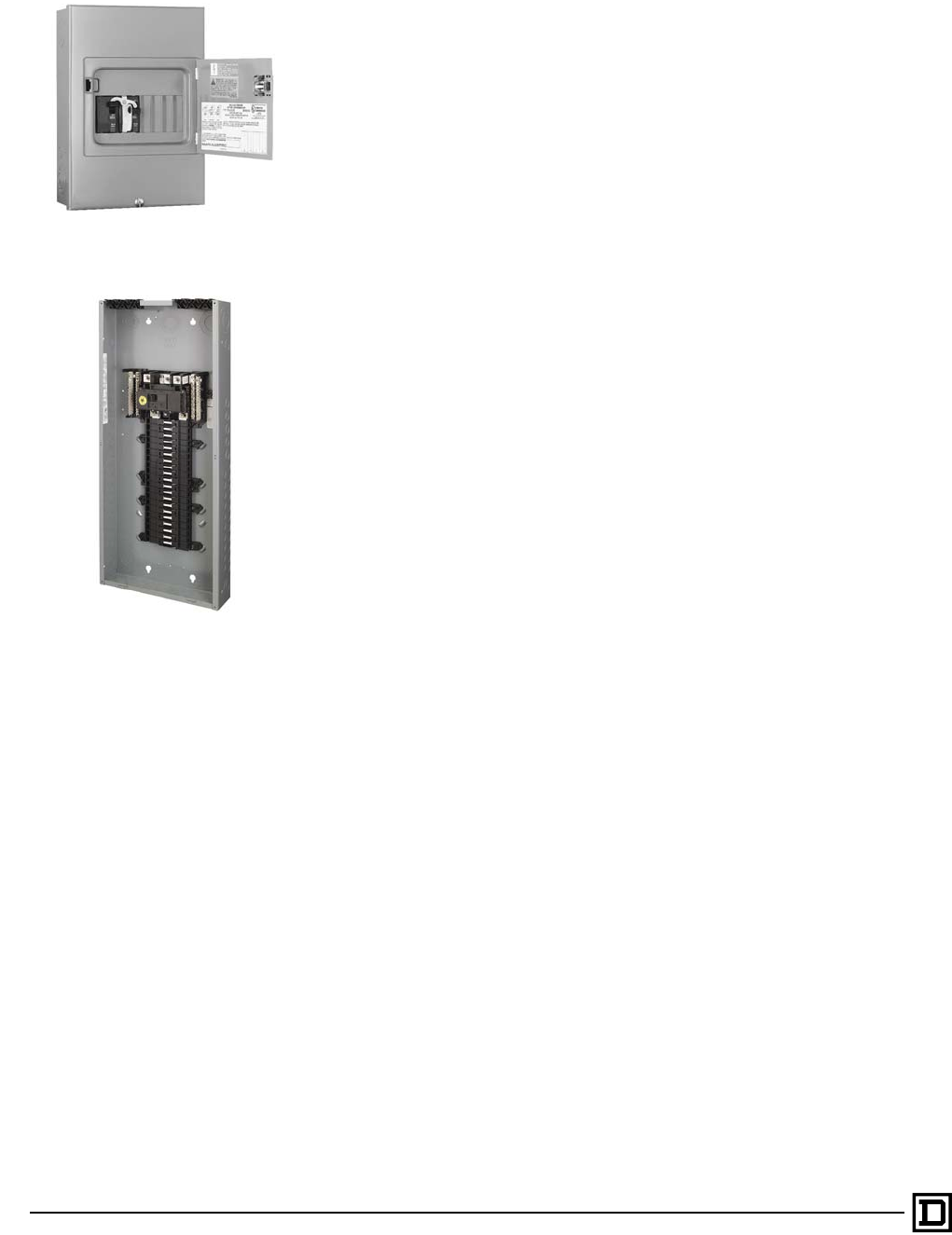
QO330L200G
QO330M150

QO Circuit Breaker Load Centers—Class 1130
General Information and Application Data
16
09/00
© 2000 Schneider Electric All Rights Reserved
Three-Phase, 3–42 Circuits, 60–225 A, Convertible or Fixed Mains
(Continued)
Main Lugs Kits
• Field installable in main circuit breaker or main lugs load centers
• QOL3125 kit for use in 100–125 A load centers
• QOL3225 kit for use in 150–225 A load centers
Main Circuit Breakers
• Field installable in main circuit breaker load centers
• 22,000 AIR main circuit breakers series rated with 10,000 AIR branch
circuit breakers
• 100–225 A main circuit breakers are series rated up to 65,000 AIR with
10,000 AIR branch circuit breakers in 30 circuit or larger main circuit breaker
load centers with optional KGL main circuit breaker
• Back-fed QO-VH main circuit breaker may be field installed in main lugs and
main circuit breaker load centers (requires PK3MB retaining kit)
• 27 circuit, 100 A main circuit breaker load center includes factory-installed
back-fed QO-VH main circuit breaker
• Electrical accessories are not available on KDL or KGL circuit breakers
• 30–42 circuit, 125–225 A main circuit breaker load centers include integral
KDL circuit breakers:
Amperage 25,000 AIR ▲65,000 AIR
100 KDL32100 KGL32100
110 KDL32110 KGL32110
125 KDL32125 KGL32125
150 KDL32150 KGL32150
175 KDL32175 KGL32175
200 KDL32200 KGL32200
225 KDL32225 KGL32225
▲When used as main circuit breaker in load center, the short circuit
current rating is 22,000 A.
QOL3225
Main Lugs Kit
KDL Circuit Breaker
100–225 A

QO Circuit Breaker Load Centers—Class 1130
General Information and Application Data
17
09/00 © 2000 Schneider Electric All Rights Reserved
Single- or Three Phase, 12–42 Circuits, 300–400 A, Fixed Mains
UL Listed
• File E-6294
• Suitable for use as service equipment
• 75 °C wire rating (see “Technical Information” on pages 22–29)
Short Circuit Current Rating
• Main lugs: up to 65,000 AIR
• Main circuit breaker: 42,000 AIR fully rated
(see “Technical Information” on pages 22–29)
Mains
• Factory-installed main lugs and main circuit breaker
• Multiple wire terminals for phases and neutral
• Top or bottom mains positioning
(see “Technical Information” on pages 22–29)
Cover
• Flush- and surface-mount covers sold separately
Interior
• Available in single- and three-phase construction
• Interiors accept QO and QOB-VH 110–150 A maximum circuit breakers
(QOB-VH circuit breakers require connector kit PK3CA)
• Tin plated aluminum bus
• Tin plated copper connector fingers
• Neutral assemblies positioned opposite the mains compartment
Enclosures
• 20 in. (508 mm) wide galvanized steel
• Embossed .25 in. (6 mm) standoffs
• End walls, one blank and one with knockouts, are standard; both are
removable and interchangeable
• Embossed keyholes centered at both ends and in visual positioning
• Multiple ground bar mounting locations
• Wire management braces
QON42MS400 and MH68
QON42LS400 and MH53

QO Circuit Breaker Load Centers—Class 1130
General Information and Application Data
18
09/00
© 2000 Schneider Electric All Rights Reserved
Accessories
Grounding Bar Kits
• Field installable in all load centers
• Same wire size as terminals (see page 21)
• Suitable for copper or aluminum wire
• Available with #1–4/0 lug PK15GTA-L, PK18GTA-L, and PK23GTA-L
(see page 21)
Flush Lock Kits
• Available for indoor load centers
• Two keys provided with each lock kit
• PK6FL for convertible 12–42 circuit load centers
• PK4FL for 300 and 400 A load centers
Auxiliary Neutral Lugs
• UL Listed for copper or aluminum wire
• Field installable on neutral assembly
— LK70AN: #12–#2 AWG Al or #14–#4 AWG Cu
— LK100AN: #6–2/0 AWG (Al/Cu)
— LK125AN: #14–2/0 AWG (Al/Cu)
— LK150AN: #2–3/0 AWG (Al/Cu)
Cover Filler Plates
• Fast to install, snap-in type
• QOFP branch circuit
• QOM1FP for 70–125 A, single-phase, main circuit breakers
• QOM2FP for 150–225 A, single-phase, main circuit breakers
• KFP for 125–225 A, three-phase, main circuit breakers
PG18GTA Grounding Bar Kit
PK6FL Flush Lock Kit
PK4FL Flush Lock Kit
LK150AN
LK70AN
LK100AN
Auxiliary Neutral Lugs
QOFP Cover Filler Plate KFP Cover Filler Plate

QO Circuit Breaker Load Centers—Class 1130
General Information and Application Data
19
09/00 © 2000 Schneider Electric All Rights Reserved
SURGEBREAKER™ Secondary Surge Arrester
• QO2175SB UL Listed secondary surge arrester
• Easy plug-on installation for QO load centers
• LED indicates operational status
• Plug-on design requires two pole spaces
• Designed to protect electrical service and “major household appliances”
excluding electronic devices
Back-Fed Main Circuit Breaker Retaining Kits
Back-fed main circuit breaker retaining kits secure 2-pole, 10–125 A
circuit breakers to single-phase or three-phase mains interiors when used as
back-fed main circuit breakers. Mounting of retaining kits is based on
top-feed applications.
UL Listed Manual Transfer Equipment Kits
Manual transfer equipment kits secure two 2-pole, 10–125 A circuit breakers.
Auxiliary Gutters and Tap Kits
• Field installable on the left or right side of load centers
(see “Technical Information” on pages 22–29)
• Flush cover included with auxiliary gutter
• Tap kits required for each wire to be tapped
• Wire range on tap kits is #4 AWG to 750 kcmil copper or aluminum
• Tap kits include mechanical type lugs
• Crimp-type lugs not included in tap kits (order separately)
Auxiliary Gutter (SDAG26) to Load Center Catalog Number Reference
Catalog No. Description
PK2MB QO 6–12 and 8–16 load centers
PK3MB Three-phase load centers
PK4MB2LA Mounts on the right side of QO single-phase, 100–125 A convertible main load center, series S01
and S02. Retains one 2-pole QO circuit breaker with or without electrical accessories.
PK4MB2HA Mounts on the right side of QO single-phase, 150–225 A convertible main load center, series S01
and S02. Retains one 2-pole QO circuit breaker with or without electrical accessories.
Catalog No. Description
PK4DTIM4LA
Mounts on the right side of QO single-phase, 100–125 A convertible main load center, series
S01 and S02. Retains two 2-pole QO circuit breakers with a QO2DTI kit included for dual
power supply applications.
PK4DTIM4HA
Mounts on the right side of QO single-phase, 150–225 A convertible main load center, series
S01 and S02. Retains two 2-pole QO circuit breakers with a QO2DTI kit included for dual
power supply applications.
PK4DTIM4LAL
Mounts on the left side of QO single-phase, 100–125 A convertible main load center, series
S01 and S02. Retains two 2-pole QO circuit breakers with a QO2DTI kit included for dual
power supply applications.
QO Single-Phase QO112L125G
QO11224L125G
QO112L125GC
QO11224L125GC
QO116L125G
QO11624L125G
QO120L125G
QO12024L125G
QO124L125G
QO120L125GC
QO112M100
QO116M100
QO120M100
QO124M100
QO124M125
QO112M100C
QO11220M100C
QO116M100C
QO120M100C
QO Three-Phase QO312L125G
QO320L125G
QO324L125G
QO2175SB
SDAG26
With Tap Kits Installed
Tap Kit with
Mechanical Lugs
Tap Kit for
Crimp Lugs

QO Circuit Breaker Load Centers—Class 1130
General Information and Application Data
20
09/00
© 2000 Schneider Electric All Rights Reserved
Bolt-On Hubs
Equipment with an “RB” suffix, meaning Rainproof NEMA Type 3R construction,
uses the bolt-on hubs listed below. “RB” devices will accept .75 in. (19 mm)
through 2.50 in. (64 mm) bolt-on hubs without the use of reducers. Off-center
conduit thread openings and elongated mounting holes provide quick and easy
adjustment to eliminate costly conduit offsets and bends. Hubs are suitable for
use with conduit having ANSI standard taper pipe thread.
UL Listed Bolt-On Hubs for RB Devices
NOTE: Closing cap (catalog number B-CAP) is provided factory-installed on each device having the RB suffix.
UL Listed Enclosure Coupling for RB Devices
Conduit Size .75 in.
(19 mm)
1.00 in.
(25 mm)
1.25 in.
(32 mm)
1.50 in.
(38 mm)
2.00 in.
(51 mm)
2.50 in.
(64 mm)
Hub Cat. No. B075 B100 B125 B150 B200 B250
Cat. No. Designed for connecting wireway or other enclosures to units having RB bolt-on conduit
provisions. Provides a bushed opening equal to 2 in. conduit. Eliminates the need for
conduit nippling.
BC200
RB Hub
BC200 Enclosure Coupling

QO Circuit Breaker Load Centers—Class 1130
Technical Information
21
09/00 © 2000 Schneider Electric All Rights Reserved
TECHNICAL INFORMATION
Grounding Bar Kits
All PK equipment grounding kits are supplied with mounting screws,
necessary installation instructions, and an “Equipment Grounding Terminal”
self-adhesive label.
Catalog
Number
Total
Qty.
Terminals Approximate
Overall
Length
Distance
Between
Mounting Holes Mounting
Quantity Each Size
See “Wire Range Table” below.
I II III IV V VI in. mm in. mm
PK0GTA2 ◆2 2 1.75 44 One hole One hole Top
PK0GTA6 ■6 6 4.61 117 1.69 43 Top
PK3GTA1 ✚3 3 1.38 35 One hole One hole Top
PK4GTA ✚4 4 1.63 41 One hole One hole Top
PK5GTA ▼5 5 2.25 57 1.25 32 Top
PK7GTA ✚7 7 2.88 73 1.25 32
Top
or
side
PK9GTA1 ✚9 9 3.25 83 One hole One hole Top
PK9GTA ✚9 9 3.78 96 3.13 80 Top
PK12GTA ✚12 12 4.70 119 3.13 80 Top
PK15GTA ✚15 15 5.63 143 3.13 80 Top
PK15GTAL ★16 15 1 8.13 207 3.13 80 Top
PK15GTA6 ❖21 15 6 5.88 149 ▲▲ Top
PK18GTA ✚18 18 6.56 167 3.13 80 Top
PK18GTAL ★19 18 1 8.81 224 3.13 80 Top
PK23GTA ✚23 23 8.11 206 3.13 80 Top
PK23GTAL ★24 23 1 9.44 240 3.13 80 Top
PK27GTA ● ✚
27
or
26
27
26 1 9.36 238 3.13 80 Top
●PK27GTA includes one main grounding lug that mounts with two terminal screws and requires three terminals for
mounting.
▲3.13 in. (80 mm) on small terminals; 5.25 in. (133 mm) on large terminals.
◆Mounting screw 40205-065-01 (one required).
✚Mounting screw 21594-14220 (two required).
★Mounting screw 21594-14302 (two required).
■Mounting screw 21922-18360 (two required).
▼Mounting screw 21594-14241 (two required).
❖Mounting screws 21594-14241(two required) and 21594-17121(two required).
Wire Range Table
Size Cu (AWG) Al (AWG)
I (1) #14–#4 or (2) #14 or #12 (1) #12–#4 or (2) #12 or #10
II (1) #1–4/0 (1) #1–4/0
III (1) #6–2/0 (1) #6–2/0
IV (1) #6–3/0 (1) #6–3/0
V (1) #14–1/0 (1) #14–1/0
VI (1) #10–2/0 (1) #6–2/0
Slot/Robertson screw
Cross Section of Size 1 Ground Bar
.437
11
.3125
8

QO Circuit Breaker Load Centers—Class 1130
Technical Information
22
09/00
© 2000 Schneider Electric All Rights Reserved
Main Lugs and Main Circuit Breakers Ratings
Single-Phase, Three-Wire, 120/240 Vac; Main Lugs – Indoor
Mains
Rating
in
Amps
Load
Center
Catalog
Number
Load
Center
Cover
Catalog
Number
UL Listed
Service
Equipment
(See
notes)
Maximum
UL Short
Circuit
Rating ◆
M a i n W i r e S i z e
AWG/kcmil
Al/Cu
Enclosure
No.
Top
or
Bottom
Mains
Position
UL Listed
for Corner
Grounded
Delta
Systems
Fixed Mains – Factory-Installed Main Lugs
30 QO2L30S Included No 10,000 A #12–10
#14–10 1TopNo
70 QO24L70F/S Included B 10,000 A #12–3 2TopNo
100
QO612L100F/S Included B, C 10,000 A #8–1 4 Top
NoQO612L100DF/S Included B, C 10,000 A #8–1 4 Top
QO612L100DFCU/SCU Included B, C 10,000 A #8–1 4 Top
100
QO816L100F/S Included B, C 10,000 A #8–1 4 Top
NoQO816L100DF/S Included B, C 10,000 A #8–1 4 Top
QO816L100DFCU/SCU Included B, C 10,000 A #8–1 4 Top
125 QO148L125GF/S Included B, C 10,000 A #4–2/0 21 Top No
Convertible Mains – Factory-Installed Main Lugs
QOM1 Main Frame Size – Convertible to Main Circuit Breaker – Copper Bus
125
QO112L125G QOC16UF/S B, C 65,000 A ■ ▲ #4–2/0 6 Both
Ye s
QO11224L125G QOC16UF/S B, C 65,000 A ■ ▲ #4–2/0 6 Both
QO116L125G QOC24UF/S B, C 65,000 A ■ ▲ #4–2/0 7 Both
QO11624L125G QOC24UF/S B, C 65,000 A ■ ▲ #4–2/0 7 Both
QO120L125G QOC24UF/S B 65,000 A ■ ▲ #4–2/0 7 Both
QO12024L125G QOC24UF/S B 65,000 A ■ ▲ #4–2/0 7 Both
QO124L125G QOC24UF/S B 65,000 A ■ ▲ #4–2/0 7 Both
QO112L125GK QOC16UF/S B, C 65,000 A ■ ▲ #4–2/0 7K Both
QO120L125GK QOC24UF/S B 65,000 A ■ ▲ #4–2/0 7K Both
QO124L125GK QOC24UF/S B 65,000 A ■ ▲ #4–2/0 7K Both
Convertible Mains – Factory-Installed Main Lugs
QOM2 Main Frame Size – Convertible to Main Circuit Breaker – Copper Bus
150
QO12030L150G QOC30UF/S B, C 65,000 A ■ ▲ #4–250 9 Both
Ye sQO124L150G QOC30UF/S B, C 65,000 A ■ ▲ #4–250 9 Both
QO13040L150G QOC30UF/S B, C 65,000 A ■ ▲ #4–250 9 Both
200
QO112L200G QOC30UF/S B, C 65,000 A ■ ▲ #4–250 9 Both
Ye s
QO130L200G QOC30UF/S B, C 65,000 A ■ ▲ #4–250 9 Both
QO13040L200G QOC30UF/S B, C 65,000 A ■ ▲ #4–250 9 Both
QO13040L200GK QOC30UF/S B, C 65,000 A ■ ▲ #4–250 9K Both
225 QO142L225G QOC42UF/S B 65,000 A ■ ▲ #4–300 11 Both Ye s
QO142L225GK QOC42UF/S B 65,000 A ■ ▲ #4–300 11K Both
Fixed Mains – Factory-Installed Main Lugs
400
QON12LS400 (Interior) MHC50VF/S C 65,000 A ●(1)1/0–750 15 Both Yes
MH50 (Enclosure) (2)1/0–300
QON30LS400 (Interior) MHC50VF/S No 65,000 A ● (1)1/0–750 15 Both Yes
MH50 (Enclosure) (2)1/0–300
QON42LS400 (Interior) MHC53VF/S No 65,000 A ●(1)1/0–750 17 Both Yes
MH53 (Enclosure) (2)1/0–300
◆Short circuit current rating depends on the lowest AIR rating of main or branch circuit breaker installed.
▲22,000 A rms symmetrical maximum when supplied by integral type QOMVH main circuit breaker from Square D with 22,000 A rms symmetrical
minimum interrupting rating and when all installed QO branch circuit breakers have 10,000 A rms symmetrical minimum interrupting rating.
■UL Listed for 5000 A rms symmetrical short circuit rating when used in 3-phase, 240 Vac, corner grounded Delta systems, when used as main lugs
load center only. Use 240 Vac circuit breakers only.
●UL Listed for 5000 A rms symmetrical short circuit rating when used on 3-phase, 240 Vac, corner grounded Delta systems. Use 240 Vac circuit
breakers only.
B UL Listed as suitable for use as service equipment (neutral bonded at the time of installation) with field-installed service disconnect.
C UL Listed as suitable for use as service equipment (neutral bonded at the time of installation) when not more than six service disconnecting means
are provided and when not used as a lighting and appliance branch circuit panelboard.
K WIREGATOR Qwik-Grip Cable System.

QO Circuit Breaker Load Centers—Class 1130
Technical Information
23
09/00 © 2000 Schneider Electric All Rights Reserved
Single-Phase, Three-Wire, 120/240 Vac; Main Circuit Breaker – Indoor
Mains
Rating
in
Amps
Load
Center
Catalog
Number
Load
Center
Cover
Catalog
Number
UL Listed
Service
Equipment
(See
Notes)
Maximum
UL Short
Circuit
Rating ◆
M a i n W i r e S i z e
AWG/kcmil
Al/Cu
Enclosure
No.
Top
or
Bottom
Mains
Position
UL Listed
for Corner
Grounded
Delta
Systems
Convertible Mains – Factory-Installed Main Circuit Breaker
QOM1 Main Frame Size – Convertible to Main Lugs or Lower Amperage Main Circuit Breaker – Copper Bus
100
QO112M100 QOC12UF/S A, B 22,000 A ★#4–1 5 Both
No
QO116M100 QOC20U100F/S A, B 22,000 A ★#4–1 6 Both
QO120M100 QOC20U100F/S A 22,000 A ★ #4–1 6 Both
QO124M100 QOC24UF/S A 22,000 A ★ #4–1 7 Both
QO132M100 QOC32UF A 22,000 A ★#4–1 8 Both
QO112M100K QOC16UF/S A, B 22,000 A ★#4–1 6K Both
QO120M100K QOC24UF/S A 22,000 A ★#4–1 7K Both
125 QO124M125 QOC24UF/S A 22,000 A ★#4–2/0 7 Both No
QO132M125 QOC32UF A 22,000 A ★#4–2/0 8 Both
Convertible Mains – Factory-Installed Main Circuit Breaker
QOM2 Main Frame Size – Convertible to Main Lugs or Lower Amperage Main Circuit Breaker – Copper Bus
150
QO12030M150 QOC30UF/S A, B 22,000 A ★ #4–250 9 Both
No
QO124M150 QOC30UF/S A, B 22,000 A ★ #4–250 9 Both
QO130M150 QOC30UF/S A, B 22,000 A ★ #4–250 9 Both
200
QO12040M200 QOC30UF/S A, B 22,000 A ★ #4–250 9 Both
No
QO124M200 QOC30UF/S A, B 22,000 A ★ #4–250 9 Both
QO130M200 QOC30UF/S A, B 22,000 A ★ #4–250 9 Both
QO13040M200 QOC30UF/S A, B 22,000 A ★ #4–250 9 Both
QO140M200 QOC40UF/S A, B 22,000 A ★ #4–250 10 Both
QO130M200K QOC30UF/S A, B 22,000 A ★ #4–250 9K Both
QO13040M200K QOC30UF/S A, B 22,000 A ★ #4–250 9K Both
QO140M200K QOC40UF/S A, B 22,000 A ★ #4–250 10K Both
225 QO140M225 QOC42UF/S A, B 22,000 A ★#4–300 11 Both No
Fixed Mains – Factory-Installed Main Circuit Breaker
300 QON42MS300 MHC68VF/S A 42,000 A ● (1)#4–500 16 Both Yes
MH68 (Enclosure) (2)#4–3/0
400 QON42MS400 MHC68VF/S A 42,000 A ●
(1)#4–600 16 Both Yes
MH68 (Enclosure) (2)#4–250
◆Short circuit current rating depends on lowest AIR rating of main or branch circuit breaker installed.
★22,000 A rms symmetrical maximum when supplied by integral type QOM-VH main circuit breaker from Square D with 22,000 A rms symmetrical
minimum interrupting rating and when all installed QO branch circuit breakers have 10,0000 A rms symmetrical minimum interrupting rating.
65,000 A rms symmetrical maximum when main lugs kits are installed.
●UL Listed for 5000 A rms symmetrical short circuit current rating when used in 3-phase, 240 Vac, corner grounded Delta systems. Use 240 Vac
circuit breakers only.
A UL Listed as suitable for use as service equipment (neutral bonded at the time of installation) with factory-installed service disconnect.
B UL Listed as suitable for use as service equipment (neutral bonded at the time of installation) with field installed main lugs when not more than six
disconnecting means are provided and when not used as a lighting and appliance branch circuit panelboard. See NEC Section 384-14.
K WIREGATOR Qwik-Grip Cable System.

QO Circuit Breaker Load Centers—Class 1130
Technical Information
24
09/00
© 2000 Schneider Electric All Rights Reserved
Single-Phase, Three-Wire, 120/240 Vac; Main Lugs – Rainproof
Mains
Rating
in
Amps
Load
Center
Catalog
Number
Load
Center
Cover
Catalog
Number ★
UL Listed
Service
Equipment
(See
Notes)
Maximum
UL Short
Circuit
Rating ◆
M a i n W i r e S i z e
AWG/kcmil
Al/Cu
Enclosure
No.
Top
or
Bottom
Mains
Position
UL Listed
for Corner
Grounded
Delta
Systems
Fixed Mains – Factory-Installed Main Lugs
40 QO2L40RB Included B 10,000 A #12–6
#14–10 1R Top No
70 QO24L70RB Included B 10,000 A #12–3
#14–4 1R Top No
100
QO612L100RB Included B, C 10,000 A #8–1 2R Top
NoQO612L100TRB Included B, C 10,000 A #8–1 2R Top
QO612L100RBCU Included B, C 10,000 A #8–1 2R Top
100 QO816L100RB Included B, C 10,000 A #8–1 2R Top No
QO816L100RBCU Included B, C 10,000 A #8–1 2R Top
125 QO148L125GRB Included B, C 10,000 A #4–2/0 15R Top No
Convertible Mains – Factory-Installed Main Lugs
QOM1 Main Frame Size – Convertible to Main Circuit Breaker – Copper Bus
125
QO112L125GRB Included B, C 65,000 A ■ ▲ #4–2/0 3R Top
Yes
QO11224L125GRB Included B, C 65,000 A ■ ▲ #4–2/0 3R Top
QO11624L125GRB Included B, C 65,000 A ■ ▲ #4–2/0 4R Top
QO124L125GRB Included B 65,000 A ■ #4–2/0 4R Top
Convertible Mains – Factory-Installed Main Lugs
QOM2 Main Frame Size – Convertible to Main Circuit Breaker – Copper Bus
150 QO130L150GRB Included B, C 65,000 A ■ ▲ #4–250 6R Top Yes
200
QO112L200GRB Included B, C 65,000 A ■ #4–250 5R Top
Yes
QO130L200GRB Included B, C 65,000 A ■ #4–250 6R Top
QO13040L200GRB Included B, C 65,000 A ■ ▲ #4–250 6R Top
225 QO142L225GRB Included B 65,000 A ■ #4–300 8R Top Yes
★Convertible mains load center has a side-hinge door. Allow 1.25 in. (32 mm) on the left side for the door to open.
◆Short circuit current rating depends on lowest AIR rating of main or branch circuit breaker installed.
▲22,000 A rms symmetrical maximum when supplied by integral type QOMVH main circuit breaker from Square D with 22,000 A rms symmetrical
minimum interrupting rating and when all QO installed branch circuit breakers have 10,000 A rms symmetrical minimum interrupting rating.
■UL Listed at 5000 A rms symmetrical short circuit current rating when used in 3-phase, corner grounded, Delta systems, when used as main lugs
load center only. Use 240 Vac circuit breakers only.
B UL Listed as suitable for use as service equipment (neutral bonded at the time of installation) with field-installed service disconnect.
C UL Listed as suitable for use as service equipment (neutral bonded at the time of installation) when not more than six service disconnecting means
are provided and when not used as a lighting and appliance branch circuit panelboard. See NEC Section 384-14.

QO Circuit Breaker Load Centers—Class 1130
Technical Information
25
09/00 © 2000 Schneider Electric All Rights Reserved
Single-Phase, Three-Wire, 120/240 Vac; Main Circuit Breaker – Rainproof
Mains
Rating
in
Amps
Load
Center
Catalog
Number
Load
Center
Cover
Catalog
Number ▲
UL Listed
Service
Equipment
(See
Notes)
Maximum
UL Short
Circuit
Rating ◆
M a i n W i r e S i z e
AWG/kcmil
Al/Cu
Enclosure
No.
Top
or
Bottom
Mains
Position
UL Listed
for Corner
Grounded
Delta
Systems
Convertible Mains – Factory-Installed Main Circuit Breaker
QOM1 Main Frame Size – Convertible to Main Lugs or Lower Amperage Main Circuit Breaker – Copper Bus
100
QO112M100RB Included A, D 22,000 A ★#4–1 3R Top
No
QO116M100RB Included A, D 22,000 A ★#4–1 4R Top
QO120M100RB Included A 22,000 A ★#4–1 4R Top
125 QO124M125RB Included A 22,000 A ★#4–2/0 4R Top No
Convertible Mains – Factory-Installed Main Circuit Breaker
QOM2 Main Frame Size – Convertible to Main Lugs or Lower Amperage Main Circuit Breaker – Copper Bus
150 QO12030M150RB Included A, D 22,000 A ★#4–250 5R Top No
QO130M150RB Included A, D 22,000 A ★#4–250 6R Top
200
QO12040M200RB Included A, D 22,000 A ★#4–250 5R Top
No
QO130M200RB Included A, D 22,000 A ★#4–250 6R Top
QO140M200RB Included A, D 22,000 A ★#4–250 7R Top
Main Circuit Breaker with Feed-Thru Lugs
125 QO1612M125FTRB Included A 22,000 A ★#4–2/0 3R Top No
150 QO1816M150FTRB Included A 22,000 A ★#4–2/0 6R Top No
200 QO1816M200FTRB Included A 22,000 A ★#4–2/0 6R Top No
▲Convertible mains load center has a side-hinge door. Allow 1.25 in. (32 mm) on the left side for the door to open.
◆Short circuit current rating depends on lowest AIR rating of main or branch circuit breaker installed.
★22,000 A rms symmetrical maximum when supplied by integral type QOM-VH main circuit breaker from Square D with 22,000 A rms symmetrical
minimum interrupting rating and when all installed QO branch circuit breakers have 10,000 A rms symmetrical minimum interrupting rating.
65,000 A rms symmetrical maximum when main lug kits installed.
A UL Listed as suitable for use as service equipment (neutral bonded at time of installation) with factory-installed service disconnect.
D UL Listed as suitable for use as service equipment (neutral bonded at the time of installation) with field-installed main lugs when not more than six
service disconnecting means are provided and when not used as a lighting and appliance branch circuit panelboard. See NEC Section 384-14.

QO Circuit Breaker Load Centers—Class 1130
Technical Information
26
09/00
© 2000 Schneider Electric All Rights Reserved
3-Phase, 4-Wire, 208Y/120 Vac; 3-Phase, 4-Wire, 240/120 Vac, Delta;
3-Phase, 3-Wire, 240 Vac, Delta; Main Lugs, Main Circuit Breaker – Indoor
Mains
Rating
in
Amps
Load
Center
Catalog
Number
Load
Center
Cover
Catalog
Number
UL Listed
Service
Equipment
(See
Notes)
Maximum
UL Short
Circuit
Rating ◆
M a i n W i r e S i z e
AWG/kcmil
Al/Cu
Enclosure
No.
Top
or
Bottom
Mains
Position
UL Listed
for Corner
Grounded
Delta
Systems
Fixed Mains – Factory-Installed Main Lugs
60 QO403L60NF/S Included B 22,000 A ◆– #10-6 13 Top No
125
QO312L125G QOC16UF/S B, C 65,000 A ◆#4–2/0 #4–2/0 6 Both
NoQO320L125G QOC24UF/S B, C 65,000 A ◆#4–2/0 #4–2/0 7 Both
QO324L125G QOC24UF/S B, C 65,000 A ◆#4–2/0 #4–2/0 7 Both
200 QO318L200G QOC30UF/S B, C 65,000 A ◆#4–250 #4–250 9 Both No
QO330L200G QOC30UF/S B, C 65,000 A ◆#4–250 #4–250 9 Both
225 QO342L225G QOC42UF/S B 65,000 A ◆#4–300 #4–300 11 Both No
400 QON442LS400 MHC53VF/S No 65,000 A ◆ (1)1/0–750 17 Both No
MH53 (Enclosure) 65,000 A ◆(2)1/0–300
Convertible Mains – Factory-Installed Main Circuit Breaker
100 QO327M100 QOC30UF/S A 22,000 A #4–1/0 #4–1 9 Both No
125 QO330M125 QOC342MF/S A 65,000 A ■ ▲ #4–250 #4–250 12 ★No
150 QO330M150 QOC342MF/S A, D 65,000 A ■ ▲ #4–250 #4–250 12 ★
No
QO342M150 QOC342MF/S A 65,000 A ■ ▲ #4–250 #4–250 12 ★
200 QO330M200 QOC342MF/S A, D 65,000 A ■ ▲ #4–250 #4–250 12 ★
No
QO342M200 QOC342MF/S A 65,000 A ■ ▲ #4–250 #4–250 12 ★
225 QO342M225 QOC342MF/S A 65,000 A ■ ▲ #4–250 #4–250 12 ★No
Fixed Mains – Factory-Installed Main Circuit Breaker
300 QON442MS300 MHC68VF/S A 10,000 A ◆(1)#4–500 16 ★No
MH68 (Enclosure) (2)#4–3/0
400 QON442MS400 MHC68VF/S A 10,000 A ◆(1)#4–600 16 ★No
MH68 (Enclosure) (2)#4–250
◆Short circuit current rating depends on lowest AIR rating of branch circuit breaker installed.
▲22,000 A rms symmetrical maximum when supplied by integral type KDL main circuit breaker from Square D with 22,000 A rms minimum interrupting
rating and when all installed QO and Q1 branch circuit breakers have 10,000 A rms symmetrical minimum interrupting rating.
■65,000 A rms symmetrical maximum when type KGL main circuit breaker from Square D with 65,000 A rms minimum interrupting rating is installed
and when all installed QO and Q1 branch circuit breakers have 10,000 A rms symmetrical minimum interrupting rating.
A UL Listed as suitable for use as service equipment (neutral bonded at the time of installation) with factory-installed service disconnect.
B UL Listed as suitable for use as service equipment (neutral bonded at the time of installation) with field-installed service disconnect.
C UL Listed as suitable for use as service equipment (neutral bonded at the time of installation) when not more than six service disconnecting means
are provided and when not used as a lighting and appliance branch circuit panelboard. See NEC Section 384-14.
D UL Listed as suitable for use as service equipment (neutral bonded at the time of installation) with field-installed main lugs, when not more than six
service disconnecting means are provided and when not used as a lighting and appliance branch circuit panelboard. See NEC Section 384-14.
★Mains positioning from top to bottom feed; first rotate the main circuit breaker 180°, then rotate the complete load center 180°.

QO Circuit Breaker Load Centers—Class 1130
Technical Information
27
09/00 © 2000 Schneider Electric All Rights Reserved
3-Phase, 4-Wire, 208Y/120 Vac; 3-Phase, 4-Wire, 240/120 Vac, Delta;
3-Phase, 3-Wire, 240 Vac, Delta; Main Lugs, Main Circuit Breaker – Rainproof
Recreational Vehicle and Manufactured Housing
Mains
Rating
in
Amps
Load
Center
Catalog
Number
Load
Center
Cover
Catalog
Number ❋
UL Listed
Service
Equipment
(See
Notes)
Maximum
UL Short
Circuit
Rating ◆
M a i n W i r e S i z e
AWG/kcmil
Al/Cu
Enclosure
No.
Top
or
Bottom
Mains
Position
UL Listed
for Corner
Grounded
Delta
Systems
Fixed Mains – Factory-Installed Main Lugs
60 QO403L60NRB Included B 22,000 A ◆– #10–6 10R Top No
125 QO312L125GRB Included B, C 65,000 A ◆#4–4/0 #4–2/0 3R Top No
QO320L125GRB Included B, C 65,000 A ◆#4–4/0 #4–2/0 4R Top
200 QO318L200GRB Included B, C 65,000 A ◆#4–250 #4–250 6R Top No
QO330L200GRB Included B, C 65,000 A ◆#4–250 #4–250 6R Top
225 QO342L225GRB Included B, C 65,000 A ◆#4–300 #4–300 8R Top No
Convertible Mains – Factory-Installed Main Circuit Breaker
100 QO327M100RB Included A 22,000 A #4–1/0 #4–1 6R Top No
125 QO330M125RB Included A 65,000 A ■ ▲ #4–250 #4–250 14R Top No
150 QO330M150RB Included A, D 65,000 A ■ ▲ #4–250 #4–250 14R Top No
200 QO330M200RB Included A, D 65,000 A ■ ▲ #4–250 #4–250 14R Top No
QO342M200RB Included A 65,000 A ■ ▲ #4–250 #4–250 14R Top
225 QO342M225RB Included A 65,000 A ■ ▲ #4–250 #4–250 14R Top No
Mains
Rating
in
Amps
Load
Center
Catalog
Number
Load
Center
Cover
Catalog
Number
UL Listed
Service
Equipment
(See
Notes)
Maximum
UL Short
Circuit
Rating ◆
M a i n W i r e S i z e
AWG/kcmil
Al/Cu
Enclosure
No.
Top
or
Bottom
Mains
Position
UL Listed
for Corner
Grounded
Delta
Systems
1-Phase, 2-Wire, 120 Vac – Main Lugs Only
30 QO2L30TTS ▼ ✙ Included No 10,000 A #12–10 #14–10 1 Top No
50 QO24L50TTS ▼ ★ Included No 10,000 A – #14–6 2 Top No
1-Phase, 2-Wire, 120 Vac – Main Circuit Breaker
30 QO35FM30TTF/S ▼Included No 10,000 A See circuit breaker
info 3TopNo
1-Phase, 3-Wire, 120/240 Vac – Main Lugs Only
70 QO24L70TS ▼ Included B 10,000 A #12–3 #14–4 2 Top No
100 QO612L100TF/S ▼ ● Included B, C 10,000 A #4–1 #4–1 4 Top No
QO612L100DTF/S ▼ ● Included B, C 10,000 A #4–1 #4–1 4 Top
100 QO816L100TF/S ●Included B, C 10,000 A #4–1 #4–1 4 Top No
QO816L100DTF/S ●Included B, C 10,000 A #4–1 #4–1 4 Top
❋Side-hinge door device, allow 1.25 in. (32 mm) on the left side for the door to open, except QO403L60NRB.
◆Short circuit current rating depends on lowest AIR rating of main or branch circuit breaker installed.
▲22,000 A rms symmetrical maximum when supplied by integral type QOM-VH main circuit breaker from Square D with 22,000 A rms symmetrical
minimum interrupting rating and when all installed QO branch circuit breakers have 10,000 A rms symmetrical minimum interrupting rating.
■Short gutter side limited to #3 AWG wire maximum.
▼CSA Certified.
✙Will not accept QWIK-GARD QO-GFI circuit breaker.
★Use #10 AWG maximum size wire for QO-GFI circuit breaker.
● 70 A maximum branch circuit breaker and 70 A maximum back-fed main circuit breaker.
A UL Listed as suitable for use as service equipment (neutral bonded at the time of installation) with factory-installed service disconnect.
B UL Listed as suitable for use as service equipment (neutral bonded at the time of installation) with field-installed service disconnect.
C UL Listed as suitable for use as service equipment (neutral bonded at the time of installation) when not more than six service disconnecting means
are provided and when not used as a lighting and appliance branch circuit panelboard. See NEC Section 384-14.
D UL Listed as suitable for use as service equipment (neutral bonded at the time of installation) with field-installed main lugs and not more than six
service disconnecting means are provided and when not used as a lighting and appliance branch circuit panelboard. See NEC Section 384-14.

QO Circuit Breaker Load Centers—Class 1130
Technical Information
28
09/00
© 2000 Schneider Electric All Rights Reserved
Tap Ki t s
1-Phase, 3-Wire, 120/240 Vac – Main Circuit Breaker
200 QO12040M200TC Included A, D 22,000 A ▲#4–250 9 Both No
Non-Metallic
1-Phase, 3-Wire, 120/240 Vac – Main Lugs Only
60 QO24L60NRNM Included B, C 10,000 A #14–4 1NM Bottom No
Riser
1-Phase, 3-Wire, 120/240 Vac – Factory-Installed Main Lugs – Offset Interior Wide Gutter QOM1 Main Frame Size –
Convertible to Main Circuit Breaker – Copper Bus ■
125 QO11224L125GWGC Included B, C 65,000 A ▲#4–2/0 14 Both Ye s
QO12024L125GWGC Included B 65,000 A ▲#4–2/0 14 Both
Generator Panel
1-Phase, 3-Wire, 120/240 Vac – Factory-Installed Main Circuit Breakers with Mechanical Interlock
30 QO48M30DSGP Included No 10,000 A #14–8 4 Bottom No
60 QO48M60DSGP Included A 10,000 A #8–2 4 Bottom
Pre-Wired
30 QO48M30DFGPW1 Included No 10,000 A #10 23 Bottom No
Auxiliary Gutter
UL Listed for Use with Standard Load Centers for Riser Applications
– SDAG26 Flush No N/A See Tap Kit – – No
UL Listed for Use with Auxiliary Gutter SDAG26
Riser Wire Tap Off Wire
Catalog Number Lug Type Wire Size Lug Type Wire Size
SDGT30020 Mechanical (2) #6 AWG–300 kcmil Mechanical (1) #6 AWG–2/0 AWG
SDGT300300 Mechanical (2) #6 AWG–300 kcmil Mechanical (1) #6 AWG–300 kcmil
SDGT300C10C Crimp (2) #4 AWG–300 kcmil Crimp (1) #8 AWG–1/0 AWG
SDGT300C300C Crimp (2) #4 AWG–300 kcmil Crimp (1) #4 AWG–300 kcmil
QOGL20 Mechanical (2) #6 AWG–2/0 AWG – –
Mains
Rating
in
Amps
Load
Center
Catalog
Number
Load
Center
Cover
Catalog
Number
UL Listed
Service
Equipment
(See
Notes)
Maximum
UL Short
Circuit
Rating ◆
M a i n W i r e S i z e
AWG/kcmil
Al/Cu
Enclosure
No.
Top
or
Bottom
Mains
Position
UL Listed
for Corner
Grounded
Delta
Systems
❋Side-hinge door device, allow 1.25 in. (32 mm) on the left side for the door to open, except QO403L60NRB.
◆Short circuit current rating depends on lowest AIR rating of main or branch circuit breaker installed.
▲22,000 A rms symmetrical maximum when supplied by integral type QOM-VH main circuit breaker from Square D with 22,000 A rms symmetrical
minimum interrupting rating and when all installed QO branch circuit breakers have 10,000 A rms symmetrical minimum interrupting rating.
■Short gutter side limited to #3 AWG wire maximum.
▼CSA Certified.
✙Will not accept QWIK-GARD QO-GFI circuit breaker.
★Use #10 AWG maximum size wire for QO-GFI circuit breaker.
● 70 A maximum branch circuit breaker and 70 A maximum back-fed main circuit breaker.
A UL Listed as suitable for use as service equipment (neutral bonded at the time of installation) with factory-installed service disconnect.
B UL Listed as suitable for use as service equipment (neutral bonded at the time of installation) with field-installed service disconnect.
C UL Listed as suitable for use as service equipment (neutral bonded at the time of installation) when not more than six service disconnecting means
are provided and when not used as a lighting and appliance branch circuit panelboard. See NEC Section 384-14.
D UL Listed as suitable for use as service equipment (neutral bonded at the time of installation) with field-installed main lugs and not more than six
service disconnecting means are provided and when not used as a lighting and appliance branch circuit panelboard. See NEC Section 384-14.

QO Circuit Breaker Load Centers—Class 1130
Dimensions and Knockouts
29
09/00 © 2000 Schneider Electric All Rights Reserved
WIREGATOR™ Qwik-Grip Cable System
WIREGATOR™
Qwik-Grip Cable System
WIREGUARD™ Shield
Front
Middle
Back
Wide slot
Ranura amplia
Narrow slot
Ranura angosta
12–3
12–2
10–3
14–3
&
Narrow slot
Ranura angosta
Narrow slot
Ranura angosta
Narrow slot
Ranura angosta
14~3 & 10–2
12–2 & 14–2
A,B
A
C,D,E,F
6K
B,C,D,E
A,B,C,D
C,D,E,F
D,E,F,G
C,D,E,F A,B
A,B
A
A,B
B,C
A
C,D,E,F
7K
B,C,D,E
C,D,E,F C,D,E,F C,D,E,F
B,C,D,E
B,C,D,E D,E,F,G
B,C,D,E
A,B,C,D A,B,C,D A,B,C,D A,B,C,D
C,D,E,F A,B
C,D,E,F A,B
D,E,F,G
C,D,E,F
D,E,F,G
C,D,E,F
D,E,F,G
A,B
B,C
A
C,D,E,F A,B
10K9K
A,B
B,C
A
C,D,E,F A,B
A,B,C
A,B,C
A,B,C
A,B,C
11K
B,C,D,E B,C,D,E B,C,D,E B,C,D,E B,C,D,E
A,B,C
Indoor Dimensions and Knockouts–WIREGATOR™ Gwik-Grip Cable System
Indoor Dimensions
Enclosure
No.
WHD
in. mm in. mm in. mm
6K 14.25 362 17.92 455 3.75 95
7K 14.25 362 20.92 531 3.75 95
9K 14.25 362 29.86 758 3.75 95
10K 14.25 362 33.78 858 3.75 95
11K 14.25 362 37.98 965 3.75 95
WIREGATOR™ Qwik-Grip Cable System Wire Size Per Slot
Position Wide
Slot
Narrow
Slot
Narrow
Slot
Narrow
Slot
Narrow
Slot
Front 12–3
10–3
14–3,
14–2
12–2
10–2
14–3,
14–2
12–2
10–2
14–3,
14–2
12–2
10–2
14–3,
14–2
12–2
10–2
Middle
14–3
12–3
10–2
14–2
12–2
14–2
12–2
14–2
12–2
14–2
12–2
Back
14–3
12–3
10–2
14–2
12–2
14–2
12–2
14–2
12–2
Indoor Knockouts
Symbol AB C D E F G H I
Conduit Size .50 in.
(13 mm)
.75 in.
(19 mm)
1.00 in.
(25 mm)
1.25 in.
(32 mm)
1.50 in.
(38 mm)
2.00 in.
(51 mm)
2.50 in.
(64 mm)
3.00 in.
(76 mm)
3.50 in.
(89 mm)

QO Circuit Breaker Load Centers—Class 1130
Dimensions and Knockouts
30
09/00
© 2000 Schneider Electric All Rights Reserved
Enclosure 9R
A,B,C
A,B,C,D
A
Enclosure 1R
A,B
2-1/2 in. hub maximum
2-1/2 in. hub maximum
2-1/2 in. hub maximum
2-1/2 in. hub maximum
2-1/2 in. hub maximum
Enclosure 2R
A,B,C,D
A,B,C,D
A
A,B
A,B,C,D
Enclosure 3R, 4R
AA,B C,D,E,F A,B,C
C,D,E,F
C,D,E,F
Enclosure 6R, 7R, 8R
AA,B D,E,F,G A,B,C
D,E,F,G
D,E,F,G
Enclosure 5R
AD,E,F,G A,B,C
C,D,E,F
A,B
C,D,E,F
Enclosure 1NM
2-1/2 in. hub maximum
D,E,F,G
A,B A,B,C
A
Enclosure 14R
D,E,F,G
2-1/2 in. hub maximum
D,E,F,G
Enclosure 11R
2-1/2 in. hub maximum
Enclosure 15R
A,B,C,D
A,B,C,D
A
A,B
A,B,C,D
Enclosure 12R
D,E,F,G
E,F,G,H E,F
2-1/2 in. hub maximum
2-1/2 in. hub maximum
A,B,C,D
C,D,E,F
Enclosure 10R, 13R
B,C,D,E
B,C,D,E
A,B,C
Outdoor Dimensions and Knockouts
Outdoor Dimensions
Enclosure
No.
WHD
in. mm in. mm in. mm
1NM 6.52 166 8.79 223 3.90 99
1R 4.88 124 9.38 238 4.00 102
2R 8.88 226 12.65 321 4.27 108
3R 14.75 375 18.92 481 4.52 115
4R 14.75 375 22.06 560 4.52 115
5R 14.75 375 26.04 661 4.52 115
6R 14.75 375 29.86 758 4.52 115
7R 14.75 375 33.78 858 4.52 115
8R 14.75 375 37.98 965 4.52 115
9R 4.56 116 6.50 165 3.88 99
10R 6.92 176 13.18 335 4.12 105
11R 7.56 192 23.24 590 4.75 121
Outdoor Dimensions
Enclosure
No.
WHD
in. mm in. mm in. mm
12R 9.62 244 26.24 666 5.50 140
13R 6.92 176 16.18 411 4.12 105
14R 14.75 375 39.37 1000 4.52 115
15R 8.88 226 14.80 376 4.27 108
Outdoor Knockouts
Symbol ABC D E F G H
Conduit Size .50 in.
(13 mm)
.75 in.
(19 mm)
1.00 in.
(25 mm)
1.25 in.
(32 mm)
1.50 in.
(38 mm)
2.00 in.
(51 mm)
2.50 in.
(64 mm)
3.00 in.
(76 mm)

QO Circuit Breaker Load Centers—Class 1130
Specifications
31
09/00 © 2000 Schneider Electric All Rights Reserved
Single-Phase Labels
The labels below represent typical labels. Information may not be applicable or
may change without notice. See the actual label in the load center for the latest
information.
Short circuit ratings.
Short circuit ratings and additional of replacement
circuit breakers.
LISTED
Electric
Cabinet Box
Issue No. V-2813
QO ® LOAD CENTER
See Panelboard interior for Catalog No.
Box Cat. No. / Caja No. de Catalogo:
BX18C
Use Cover Cat. No. /
Utilice la Cubierta No. de Catalogo:
QOC16US or/or QOC16UF
Mains 125A max.
Lina principal de 125A maximo.
See main or service disconnect
rating if installed.
240 V ~ Max. 1Ø, 50 / 60 Hz.
24 circuit max. / 24 circuitos maximo.
Type 1 Enclosure
Gabinete Tipo 1
For installation, repairs or alterations,
Call an electrical contractor or electrician.
Panel
Rating
Remote
Main
Integral
Main
Branch (min.)/
Cat. prefix
*65,000 ---- Lugs 65,000 / QH
*42,000 ---- Lugs 42,000 / QOH
*22,000 ---- Lugs 22,000 / OQ.VH
*10,000 ---- Lugs 10,000 / OO, QOT & Q1
**5,000 ---- Lugs 5,000 / QO...H (2 pole)
100,000 --100-200A,300V T Fuse Lugs 10,000 / QO & QOT
42,0000 QOH Lugs 10,000 / QO & QOT
22,000 Q2...H, KD, QO...VH Lugs 10,000 / QO & QOT
65,000 KG Lugs 10,000 / QO & QOT
22,000 ---- QOM...VH 10,000 / QO, QOT & Q1
** 240 v ~ 3Ph. 3W. Grounded “B” phase requires 240 V ~ branch
breakers.
* The rating is equal to the lowest interrupting rating of any circuit breaker
installed. Refer to branch breaker for individual ratings. Additional or
replacement branch circuit breakers, main breaker, or service disconnect
MUST have an interrupting rating equal to or greater than that of the
circuit breaker with the lowest interrupting rating presently installed.
See panelboard interior for breaker types.
LUG TORQUE DATA
See circuit breakers and field installed
units for wire binding screw torque
Branch Neutral and Equipment Ground Bar
Equipment Ground Combinations
Wire Range (AWG/kcmil) Torque (in/lbs.)
Line Neutral
Lug 4 - 2/0 CU/AL 50
Main Lug 6 - 2/0 CU/AL 50
Alternate
Main Breaker
See Main
Breaker
See Main
Breaker
Wire Range (AWG) Torque (in./lbs.) Bar with 1
Bar with 2 screw sizes screw size
1/0 - 3 CU / AL Large 50 Small — —
4 CU / AL Large 45 Small — 35
6 CU / AL Large 45 Small 25 35
8 CU / AL Large 40 Small 10 25
10-14 CU, 10-12 AL Large 35 Small 10 20
Two 14 or 12 CU, Two 12 AL 35 10 25
Two 10 AL 35 — 25
SHORT CIRCUIT RATING
RMS Symmetrical Amperes at 120 / 240 V ~ Maximum
Underwriter’s
Laboratories, Inc.®
Number of circuits maximum.
Enclosure catalog number.
Catalog number of covers; flush
or surface.
See panelboard interior for the
catalog number.
Voltage ratings.
Amperage rating. Wire range for lug torque data table. UL listing.
001021 40265-381-0315
®
Install loose label with Spanish translation
on back of cover.
Adhiera la etiqueta suelta con las traducciones
en espanol en la parte posterior del frente.
Please read information before installing
Por favor lea la informacion antes de instalar.
~
/
Made in U.S.A. 40265-668-0215
Suitable for use with 75oC
Copper or Aluminum
main conductors. See
branch breakers for
branch wire ratings.
* Suitable for use as service equipment when
service disconnect (main breaker) is installed.
* Suitable for use as service equipment when
not more than six main disconnecting means
are provided and when not used as a lighting
and appliance branch circuit panelboard.
See Article 384-14 of the NEC.
* When used as service equipment, all unused
neutral terminals may be used for terminating
equipment ground wires.
1. Box bonding when required. / Conexion a la caja
cuando fuese necesario.
2. Main breaker type: QOM1 or QOM1A. / Interruptor
automatico principal tipo: QOM1 o QOM1A.
3. Service ground
when required. /
Tierra de acometida
cuando fuese
necesario
4. Main lugs kit no:
QOL125. / No. de
accesorio de las
zapatas
principales:
QOL125.
Two single poles. One plug
on space or may use one
single pole. One two pole
requires two spaces.
Torque Note: When main
breaker or main lug
connector mounting nuts
are loosened or removed,
retighten to 75 lbs./in.
torque.
* May plug on two adjacent spaces.
Torque Note: When interior mounting screw is
loosened or removed, retighten to 35 lbs./in.
Load Center Accessories - Kits
PK4MB2LA Back-fed Main Cir. Brkr. Retaining
QO2175SB Plug-0n Surge Arrestor *
SDSA1175 1 Phase Surge Arrestor
QOSAMK SDSA1175 Mounting Bracket
QOL2125 1 Phase Plug-on Subfeed Lugs *
PK9--27GTA(L) Equipment Ground Bar
PKGTAB Equipment Ground Bar Insulator
LK70AN 70A Max. Neutral Lug
LK100AN 125A Max. Neutral Lug
QOL125 Main Lugs
PK6FL Indoor Cover Lock
Equipment Grounding
Terminals
Service Equipment marking.
Use of unused neutral branch terminal for
equipment grounding, service equipment
application only.
Installation of back-fed main circuit breaker and
required kit.
Alternate wiring diagram for main circuit breaker or
main lug.
Load center accessories.
Neutral lug for 1/0 AWG or larger wire.
Type of circuit breakers
from Square D that
may be used in this
panelboard.
Line / Linea
N
N
OO
3
NO
O12
4
LOAD / CARGAS
LOAD / CARGAS
LOAD / CARGAS
Main Breaker diagram Main Lugs diagram
NN

QO Circuit Breaker Load Centers—Class 1130
Specifications
32
09/00
© 2000 Schneider Electric All Rights Reserved
Three-Phase Labels
The labels below represent typical labels. Information may not be applicable or may change without
notice. See the actual label in the load center for the latest information.
LISTED
Electric
Cabinet Box
Issue No. V-2813
QO ® LOAD CENTER
See Panelboard interior for Catalog No.
Box Cat. No. / Caja No. de Catalogo:
BX338C
Use Cover Cat. No. /
Utilice la Cubierta No. de Catalogo:
QOC42US or/or QOC42UF
Mains 225A / Lina principal de
225A maximo.
See main or service disconnect
rating if installed.
240 V ~ Max. 3Ø, 50 / 60 Hz.
42 circuit max. / 42 circuitos maximo.
Type 1 Enclosure
Gabinete Tipo 1
240V, 3PH, 3W: For this system neutral is not
used and only breakers rated 240V are to be used.
240V, 3PH, 4W: When wired for delta system,
phase “B” must be 208V to neutral. Breaker
poles connected to phase “B” must be rated 240V.
1PH: Single pole breakers can not be connected
to phase B.
Pane l
Rating
Remote
Main
Integral
Main
Branch (min.)/
Cat. prefix
*65,000 ---- Lugs 65,000 / QH
*42,000 ---- Lugs 42,000 / QOH
*22,000 ---- Lugs 22,000 / OQ.VH
*10,000 ---- Lugs 10,000 / OO&Q1,QO...H
**5,000 ---- Lugs 5,000 / QO...H(2 POLE)
100,000 100-200A,300V T Fuse Lugs 10,000 / QO
22,000 KD, QO...VH Lugs 10,000 / QO
22,000 Q2...H Lugs 10,000 / QO (10A-60A)
65,000 KG Lugs 10,000 / QO
65,000 ---- KG 10,000 QO&Q1
22,000 ---- KD 10,000 QO&Q1
22,000 ---- QO...VH 10,000 / QO
** 240 v ~ 3Ph. 3W. Grounded “B” phase requires 240 V ~ branch
breakers.
* The rating is equal to the lowest interrupting rating of any circuit breaker
installed. Refer to branch breaker for individual ratings. Additional or
replacement branch circuit breakers, main breaker, or service disconnect
MUST have an interrupting rating equal to or greater than that of the
circuit breaker with the lowest interrupting rating presently installed.
See panelboard interior for breaker types.
LUG TORQUE DATA
See circuit breakers and field installed
units for wire binding screw torque
Branch Neutral and Equipment Ground Bar
Equipment Ground Combinations
Wire Range (AWG/kcmil) Torque (in/lbs.)
Line Neutral
Lug 4 - 300 CU/AL 250
Main Lug 4 - 300 CU/AL 250
Alternate
Main Breaker
See Main
Breaker
See Main
Breaker
Wire Range (AWG) Torque (in./lbs.) Bar with 1
Bar with 2 screw sizes screw size
1/0 - 3 CU / AL Large 50 Small — —
4 CU / AL Large 45 Small — 35
6 CU / AL Large 45 Small 25 35
8 CU / AL Large 40 Small 10 25
10-14 CU, 10-12 AL Large 35 Small 10 20
Two 14 or 12 CU, Two 12 AL 35 10 25
Two 10 AL 35 — 25
SHORT CIRCUIT RATING
RMS Symmetrical Amperes at 120 / 240 V ~ Maximum Underwriter’s
Laboratories, Inc.®
Number of circuits maximum.
Enclosure catalog number.
Catalog number of covers; flush
or surface.
See panelboard interior for the
catalog number.
Voltage ratings.
Amperage rating. Wire range for lug torque data table.
Short circuit ratings.
Short circuit ratings and additional of replacement
circuit breakers. UL listing.
001021 40265-381-0315
®
For installation, repairs or alterations,
Call an electrical contractor or electrician.
Install loose label with Spanish translation
on back of cover.
Adhiera la etiqueta sauelat con la traduccion
en Espanol en la parte posterior de la cubierta.
Please read information before installing.
Por favor lea la informacion antes de instalor.
~
/
N
N
2
Load /
Cargas
Load /
Cargas
NN
1
3
4
Line / Linea
OO O
O O O
6.
Line /
Linea
5. Line /
Linea
O
O
O
Made in U.S.A. 40265-545-01
15
Suitable for use with 75oC
Copper or Aluminum
main conductors. See
branch breakers for
branch wire ratings.
* Suitable for use as service equipment when
service disconnect (main breaker) is installed.
* Suitable for use as service equipment when
not more than six main disconnecting means
are provided and when not used as a lighting
and appliance branch circuit panelboard.
See Article 384-14 of the NEC.
* When used as service equipment, all unused
neutral terminals may be used for terminating
equipment ground wires.
1. Box bonding when required. /
Conexion a la caja cuando fuese
necesario.
2. Service ground when required. /
Tierra de acometida cuando fuese
necesario
3. Main lugs kit no: QOL3225. / No.
de accesorio de las zapatas principales:
QOL3225.
4. Lug kit when installed. / Accesorio
de la zapata, cuando se instala.
5. Back fed main circuit breaker
when installed. / Interruptor
automatico principal de alimentacion
posterior, cuando se instala.
6. Integral main circuit breaker when
installed. / Interruptor automatico
integral principal, cuando se instala.
One single pole. One plug
on space. One two pole
requires two plug on
spaces. One three pole
requires three plug on spaces.
Torque Note: When main
breaker or main lug
connector mounting nuts
are loosened or removed,
retighten to 75 lbs./in.
torque.
Equipment Grounding
Terminals
* May plug on two adjacent spaces.
+ May plug on three adjacent spaces.
Torque Note: When interior or main breaker
mounting screws are loosened or removed,
retighten to 35 lbs./in.
Load Center Accessories - Kits
PK3MB Back-fed Main Cir. Brkr. Retaining
SDSA3650 3 Phase Surge Arrestor
QO60SL 1 Phase Plug-on Subfeed Lugs *
QO2125SL 1 Phase Plug-on Subfeed Lugs *
QO3125SL 3 Phase Plug-on Subfeed Lugs +
PK9-27GTA(L) Equipment Ground Bar
PKGTAB Equipment Ground Bar Insulator
LK100AN 125A Max. Neutral Lug
LK150AN 150A Max. Neutral Lug
QOL3225 Main Lugs
PK6FL Indoor Cover Lock
~/
Service Equipment marking.
Use of unused neutral branch terminal for
equipment grounding, service equipment
application only.
Alternate wiring diagram for main circuit breaker or
main lug.
Installation of back-fed main circuit breaker and
required kit.
Load center accessories.
Neutral lug for 1/0 AWG or larger wire.
Type of circuit breakers
from Square D that
may be used in this
panelboard.
/
~

QO Circuit Breaker Load Centers—Class 1130
Specifications
33
09/00 © 2000 Schneider Electric All Rights Reserved

QO Circuit Breaker Load Centers—Class 1130
Wiring Diagrams
34
09/00
© 2000 Schneider Electric All Rights Reserved
QO2L30S
QO2L40RB
S
N
QO2L30TTS
S
N
G/B
QO112L125G
QO112L125GRB
QO112L200G
QO112L200GRB
QO112L125GK
S
N
S
N
S
N
S
N
QO11224L125G
QO11224L125GRB
QO11224L125GWGC
QO11224L125GC
QO24L70F/S
QO24L70RB
S
N
QO24L50TTS
S
N
G
B
QO35FM30TTF/S
G
B
Line
S/N
QO612L100F/S
QO612L100DF/S
QO612L100DFCU/SCU
QO612L100RB
QO612L100RBCU
S/N
QO148L125GF/S
QO148L125GRB
QO612L100TF/S
QO612L100DTF/S
QO612L100TRB
S/N
G
B
QO816L100F/S
QO816L100DF/S
QO816L100DFCU/SCU
QO816L100RB
QO816L100RBCU
S/N
QO816L100TF/S
QO816L100DTF/S
S/N
G
B
QO116L125G
S
N
S
N
QO11624L125G
QO11624L125GRB
S
N
S
N
S
N
S
N
QO120L125G
QO120L125GK
QO120L125GC
S
N
S
N
QO12030L150G
S
N
S
N
QO12024L125G
QO12024L125GWGC
S
N
S
N
QO124L125G
QO124L150G
QO124L125GRB
QO124L125GK
S
N
S
N
QO130L150G
QO130L200G
QO130L150GRB
QO130L200GRB
S
N
S
N
QO13040L200G
QO13040L200GRB
QO13040L200GK
QO13040L200GC
S
N
S
N
QO142L225G
QO142L225GRB
QO142L225GK
QON30LS400
S/N
QON42LS400
S/N
S/N
1-Phase, 3-Wire Main Lugs
QO24L70TS
S
N
G/B
QO24L60NRNM
S
N
G
B
S/N
QON12LS400

QO Circuit Breaker Load Centers—Class 1130
Wiring Diagrams
35
09/00 © 2000 Schneider Electric All Rights Reserved
MAIN S
N
QO1612M125FTRB
S
F
S
N
MAIN S
N
QO1816M150FTRB
QO1816M200FTRB
MAIN S
N
S
N
QO112M100
QO112M100RB
QO112M100K
QO112M100C
MAIN S
N
S
N
QO116M100
QO116M100RB
QO116M100C
MAIN S
N
S
N
QO120M100
QO120M100RB
QO120M100K
QO120M100C
MAIN S
N
S
N
QO12030M150
QO12030M150RB
QO12030M150C
MAIN S
N
S
N
QO12040M200
QO12040M200RB
QO12040M200C
MAIN S
N
S
N
QO124M125
QO124M125RB
QO124M150
QO124M200
QO124M100
MAIN S
N
S
N
QO130M150
QO130M200
QO130M150RB
QO130M200K
QO130M150C
QO130M200C
QO130M200RB
QON42MS300
QON42MS400
MAIN
S/N
MAIN S
N
S
N
QO140M200
QO140M225
QO140M200RB
QO140M200K
QO140M200C
1-Phase, 3-Wire Main Circuit Breakers
MAIN S
N
S
N
QO13040M200
QO13040M200K
QO13040M200C
MAIN S
N
S
N
QO12040M200TC
G
B
MAIN S
N
S
N
QO132M100
QO132M125
QO48M30DSGP
QO48M60DSGP
QO48M30DFGPW1
S/N
Main Main

QO Circuit Breaker Load Centers—Class 1130
Wiring Diagrams
36
09/00
© 2000 Schneider Electric All Rights Reserved
QO403L60NF/S
QO403L60NRB
S
N
QO312L125G
QO312L125GRB
S
N
S
N
QO324L125G
S
N
S
N
QO320L125G
QO320L125GRB
S
N
S
N
QO342M150
QO342M200
QO342M225
QO342M200RB
QO342M225RB
S
N
S
N
MAIN
QO342L225G
QO342L225GRB
S
N
S
N
QON442MS300
QON442MS400
S/N
MAIN
QON442LS400
S/N
QO327M100
QO327M100RB
S
N
S
N
QO318L200G
QO318L200GRB
S
N
S
N
QO330L200G
QO330L200GRB
S
N
S
N
M
A
I
N
QO330M125
QO330M150
QO330M200
QO330M125RB
QO330M150RB
QO330M200RB
S
N
S
N
MAIN
3-Phase, 4-Wire Main Lugs
3-Phase, 4-Wire Main Circuit Breakers

QO Circuit Breaker Load Centers—Class 1130
Replacement Parts
37
09/00 © 2000 Schneider Electric All Rights Reserved
Single-Phase – Convertible Main Lugs, Series S1 and S2
Illustration Code A B C D E F
Catalog
Number Series Cover or
RB Door
Interior
Trim Interior Assembly Neutral Bonding
Hardware Main Lugs Neutral
Assembly
QO112L125G S1 QOC16UF/S – QO112L125GI 40283-458-50 QOL125 N/A
QO112L125GK S1 QOC16UF/S – QO112L125GI 40283-458-50 QOL125 N/A
QO112L125GRB S2 40563-178-50 40563-128-01 QO112L125GRBI 40283-458-50 QOL125 N/A
QO11224L125G S1 QOC16UF/S – QO11224L125GI 40283-458-50 QOL125 N/A
QO11224L125GC S1 QOC16UF – QO11224L125GI 40283-458-50 QOL125 N/A
QO11224L125GRB S2 40563-178-50 40563-128-01 QO11224L125GRBI 40283-458-50 QOL125 N/A
QO11224L125GWGC S1 QOC20WGC – QO11224L125GI 40283-458-50 QOL125 N/A
QO116L125G S1 QOC24UF/S – QO116L125GI 40283-458-50 QOL125 N/A
QO11624L125G S1 QOC24UF/S – QO11624L125GI 40283-458-50 QOL125 N/A
QO11624L125GRB S2 40563-177-50 40563-130-01 QO11624L125GRBI 40283-458-50 QOL125 N/A
QO120L125G S1 QOC24UF/S – QO120L125GI 40283-458-50 QOL125 N/A
QO120L125GK S1 QOC24UF/S – QO120L125GI 40283-458-50 QOL125 N/A
QO120L125GC S1 QOC24UF – QO120L125GI 40283-458-50 QOL125 N/A
QO12024L125G S1 QOC24UF/S – QO12024L125GI 40283-458-50 QOL125 N/A
QO12024L125GWGC S1 QOC20WGC – QO12024L125GI 40283-458-50 QOL125 N/A
QO124L125G S1 QOC24UF/S – QO124L125GI 40283-458-50 QOL125 N/A
QO124L125GK S1 QOC24UF/S – QO124L125GI 40283-458-50 QOL125 N/A
QO124L125GRB S2 40563-177-50 40563-130-01 QO124L125GRBI 40283-458-50 QOL125 N/A
QO12030L150G S1 QOC30UF/S – QO12030L150GI 40283-448-50 QOL225 N/A
Indoor cover mounting screw .75 in. (19 mm): 40205-130-02
Indoor cover door hinge: 40283-564-50
Indoor cover latch:
Latch: 40545-087-01
Latch spring: 40545-413-01
WIREGATOR inserts: 40556-153-01, quantify = 1
Outdoor cover latch: 40563-147-01
Latch rivet: 24102-121-60
RB trim mounting screw .50 in. (13 mm): 40205-130-01
RB door mounting screws: 21422-171-01
Main circuit breaker and main lugs keps nut: 23427-020-01
N/A - not available
Replacement enclosures are not available
WIREGUARD shields: 40559-435-50, quantity = 2
B
A
C
E

QO Circuit Breaker Load Centers—Class 1130
Replacement Parts
38
09/00
© 2000 Schneider Electric All Rights Reserved
Single-Phase – Convertible Main Lugs, Series S1 and S2, Continued
Illustration Code A B C D E F
Catalog
Number Series Cover or
RB Door
Interior
Trim Interior Assembly Neutral Bonding
Hardware Main Lugs Neutral
Assembly
QO124L150G S1 QOC30UF/S – QO124L150GI 40283-448-50 QOL225 N/A
QO130L150G S1 QOC30UF/S – QO130L150GI 40283-448-50 QOL225 N/A
QO130L150GRB S2 40563-175-50 40563-135-01 QO130L150GRBI 40283-448-50 QOL225 N/A
QO112L200G S1 QOC30UF/S – QO112L200GI 40283-448-50 QOL225 N/A
QO112L200GRB S2 40563-176-50 40563-131-01 QO112L200GRBI 40283-448-50 QOL225 N/A
QO130L200G S1 QOC30UF/S – QO130L200GI 40283-448-50 QOL225 N/A
QO130L200GRB S2 40563-175-50 40563-135-01 QO130L200GRBI 40283-448-50 QOL225 N/A
QO13040L200G S1 QOC30UF/S – QO13040L200GI 40283-448-50 QOL225 N/A
QO13040L200GK S1 QOC30UF/S – QO13040L200GI 40283-448-50 QOL225 N/A
QO13040L200GC S1 QOC30UF – QO13040L200GI 40283-448-50 QOL225 N/A
QO13040L200GRB S2 40563-175-50 40563-135-01 QO13040L200GRBI 40283-448-50 QOL225 N/A
QO142L225G S1 QOC42UF/S – QO142L225GI 40283-448-50 QOL225 N/A
QO142L225GK S1 QOC42UF/S – QO142L225GI 40283-448-50 QOL225 N/A
QO142L225GRB S2 40563-173-50 40563-140-01 QO142L225GRBI 40283-448-50 QOL225 N/A
Indoor cover mounting screw .75 in. (19 mm): 40205-130-02
Indoor cover door hinge: 40283-564-50
Indoor cover latch:
Latch: 40545-087-01
Latch spring: 40545-413-01
WIREGATOR inserts: 40556-153-01, quantify = 1
Outdoor cover latch: 40563-147-01
Latch rivet: 24102-121-60
RB trim mounting screw .50 in. (13 mm): 40205-130-01
RB door mounting screws: 21422-171-01
Main circuit breaker and main lugs keps nut: 23427-020-01
N/A - not available
Replacement enclosures are not available
WIREGUARD shields: 40559-435-50, quantity = 2

QO Circuit Breaker Load Centers—Class 1130
Replacement Parts
39
09/00 © 2000 Schneider Electric All Rights Reserved
Single-Phase – Convertible Main Circuit Breakers, Series S1 and S2
Illustration Code A B C D E F
Catalog
Number Series Cover or
RB Door
Interior
Trim Interior Assembly Neutral Bonding
Hardware
Main Circuit
Breaker
Neutral
Assembly
QO48M30DSGP G03 40553-108-50 – 40553-302-50 – QO230 N/A
QO48M60DSGP G03 40553-108-50 – 40553-297-50 40205-069-03 QO260 N/A
QO48M30DFGPW1 G03 40553-107-50 – 40553-339-50 – QO230 N/A
QO112M100 S1 QOC12UF/S – QO112M100I 40283-458-50 QOM100VH N/A
QO112M100K S1 QOC12UF/S – QO112M100I 40283-458-50 QOM100VH N/A
QO112M100C S1 QOC12UF/S – QO112M100I 40283-458-50 QOM100VH N/A
QO112M100RB S2 40563-178-50 40563-128-02 QO112M100RBI 40283-458-50 QOM100VH N/A
QO11220M100C S1 QOC12UF – QO11220M100I 40283-458-50 QOM100VH N/A
QO116M100 S1 QOC20U100F/S – QO116M100I 40283-458-50 QOM100VH N/A
QO116M100C S1 QOC20U100F – QO116M100I 40283-458-50 QOM100VH N/A
QO116M100RB S2 40563-177-50 40563-130-02 QO116M100RBI 40283-458-50 QOM100VH N/A
QO120M100 S1 QOC20U100F/S – QO120M100I 40283-458-50 QOM100VH N/A
QO120M100K S1 QOC20U100F/S – QO120M100I 40283-458-50 QOM100VH N/A
QO120M100C S1 QOC20U100F – QO120M100I 40283-458-50 QOM100VH N/A
QO120M100RB S2 40563-177-50 40563-130-02 QO120M100RBI 40283-458-50 QOM100VH N/A
QO124M100 S1 QOC24UF/S – QO124M100I 40283-458-50 QOM100VH N/A
QO132M100 S1 QOC32UF – QO132M100I 40283-458-50 QOM100VH N/A
QO124M125 S1 QOC24UF/S – QO124M125I 40283-458-50 QOM125VH N/A
QO124M125RB S2 40563-177-50 40563-130-02 QO124M125RBI 40283-458-50 QOM125VH N/A
QO12030M150 S1 QOC30UF/S – QO12030M150I 40283-448-50 QOM2150VH N/A
QO12030M150C S1 QOC30UF – QO12030M150I 40283-448-50 QOM2150VH N/A
QO12030M150RB S2 40563-176-50 40563-131-02 QO12030M150RBI 40283-448-50 QOM2150VH N/A
QO124M150 S1 QOC30UF/S – QO124M150I 40283-448-50 QOM2150VH N/A
Indoor cover mounting screw .75 in. (19 mm): 40205-130-02
Indoor cover door hinge: 40283-564-50
Indoor cover latch:
Latch: 40545-087-01
Latch spring: 40545-413-01
WIREGATOR inserts: 40556-153-01, quantify = 1
RB trim mounting screw .50 in. (13 mm): 40205-130-01
RB door mounting screws: 21422-171-01
Main circuit breaker and main lugs keps nut: 23427-020-01
N/A - not available
Replacement enclosures are not available
WIREGUARD shields: 40559-435-50, quantity = 2
Outdoor cover latch: 40563-147-01
Latch rivet: 24102-121-60
QOM2 frame size
150–125 A
QOM1 frame size
100–125 A
B
A
C
E

QO Circuit Breaker Load Centers—Class 1130
Replacement Parts
40
09/00
© 2000 Schneider Electric All Rights Reserved
Single-Phase – Convertible Main Circuit Breakers, Series S1 and S2, Continued
Feed-Thru – Main Circuit Breakers, Series S1
Illustration Code A B C D E F
Catalog
Number Series Cover or
RB Door
Interior
Trim Interior Assembly Neutral Bonding
Hardware
Main Circuit
Breaker
Neutral
Assembly
QO130M150 S1 QOC30UF/S – QO130M150I 40283-448-50 QOM2150VH N/A
QO130M150C S1 QOC30UF – QO130M150I 40283-448-50 QOM2150VH N/A
QO130M150RB S2 40563-175-50 40563-135-02 QO130M150RBI 40283-448-50 QOM2150VH N/A
QO132M125 S1 QOC32UF – QO132M125I 40283-458-50 QOM125VH N/A
QO12040M200 S1 QOC30UF/S – QO12040M200I 40283-448-50 QOM2200VH N/A
QO12040M200C S1 QOC30UF – QO12040M200I 40283-448-50 QOM2200VH N/A
QO12040M200RB S2 40563-176-50 40563-131-02 QO12040M200RBI 40283-448-50 QOM2200VH N/A
QO12040M200TC S1 QOC30UF – QO12040M200I 40283-448-50 QOM2200VH N/A
QO124M200 S1 QOC30UF/S – QO124M200I 40283-448-50 QOM2200VH N/A
QO130M200 S1 QOC30UF/S – QO130M200I 40283-448-50 QOM2200VH N/A
QO130M200K S1 QOC30UF/S – QO130M200I 40283-448-50 QOM2200VH N/A
QO130M200C S1 QOC30UF – QO130M200I 40283-448-50 QOM2200VH N/A
QO130M200RB S2 40563-175-50 40563-135-02 QO130M200RBI 40283-448-50 QOM2200VH N/A
QO13040M200 S1 QOC30UF/S – QO13040M200I 40283-448-50 QOM2200VH N/A
QO13040M200K S1 QOC30UF/S – QO13040M200I 40283-448-50 QOM2200VH N/A
QO13040M200C S1 QOC30UF – QO13040M200I 40283-448-50 QOM2200VH N/A
QO140M200 S1 QOC40UF/S – QO140M200I 40283-448-50 QOM2200VH N/A
QO140M200K S1 QOC40UF/S – QO140M200I 40283-448-50 QOM2200VH N/A
QO140M200C S1 QOC40UF – QO140M200I 40283-448-50 QOM2200VH N/A
QO140M200RB S2 40563-174-50 40563-139-02 QO140M200RBI 40283-448-50 QOM2200VH N/A
QO140M225 S1 QOC42UF/S – QO140M225I 40283-448-50 QOM2225VH N/A
Indoor cover mounting screw .75 in. (19 mm): 40205-130-02
Indoor cover door hinge: 40283-564-50
Indoor cover latch:
Latch: 40545-087-01
Latch spring: 40545-413-01
WIREGATOR inserts: 40556-153-01, quantify = 1
RB trim mounting screw .50 in. (13 mm): 40205-130-01
RB door mounting screws: 21422-171-01
Main circuit breaker and main lugs keps nut: 23427-020-01
N/A - not available
Replacement enclosures are not available
WIREGUARD shields: 40559-435-50, quantity = 2
Outdoor cover latch: 40563-147-01
Latch rivet: 24102-121-60
Illustration Code A B C D E F
Catalog
Number Series Cover or
RB Door
Interior
Trim Interior Assembly Neutral Bonding
Hardware
Main Circuit
Breaker
Neutral
Assembly
QO1612M125FTRB S2 40563-178-50 40563-129-01 QO1612M125FTRBI 40283-458-50 QOM125VH N/A
QO1816M150FTRB S2 40563-175-50 40563-134-01 QO1816M150FTRBI 40283-448-50 QOM2150VH N/A
QO1816M200FTRB S2 40563-175-50 40563-134-01 QO1816M200FTRBI 40283-448-50 QOM2200VH N/A
Indoor cover mounting screw .75 in. (19 mm): 40205-130-02
Indoor cover door hinge: 40283-564-50
Indoor cover latch:
Latch: 40545-087-01
Latch spring: 40545-413-01
WIREGATOR inserts: 40556-153-01, quantify = 1
RB trim mounting screw .50 in. (13 mm): 40205-130-01
RB door mounting screws: 21422-171-01
Main circuit breaker and main lugs keps nut: 23427-020-01
N/A - not available
Replacement enclosures are not available
WIREGUARD shields: 40559-435-50, quantity = 2
Outdoor cover latch: 40563-147-01
Latch rivet: 24102-121-60
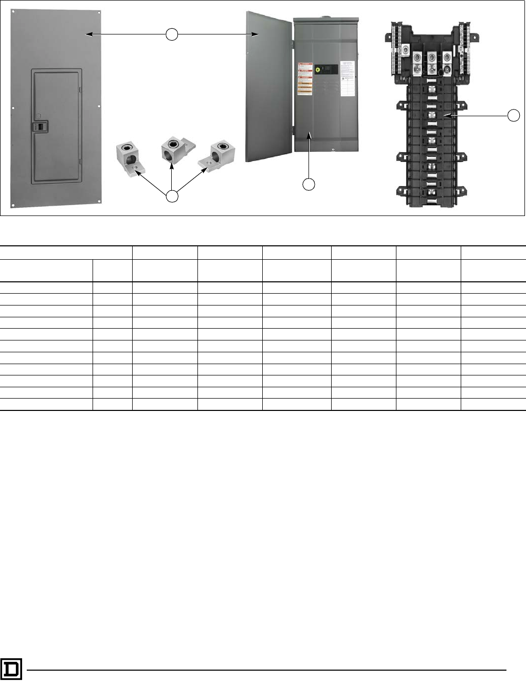
QO Circuit Breaker Load Centers—Class 1130
Replacement Parts
41
09/00 © 2000 Schneider Electric All Rights Reserved
Three-Phase – Fixed Main Lugs, Series S1 and S2
Illustration Code A B C D E F
Catalog
Number Series Cover or
RB Door
Interior
Trim Interior Assembly Neutral Bonding
Hardware Main Lugs Neutral
Assembly
QO312L125G S1 QOC16UF/S – QO312L125I 40283-448-50 QOL3125 N/A
QO312L125GRB S2 40563-178-50 40563-128-01 QO312L125RBI 40283-448-50 QOL3125 N/A
QO320L125G S1 QOC24UF/S – QO320L125I 40283-448-50 QOL3125 N/A
QO320L125GRB S2 40563-177-50 40563-130-01 QO320L125RBI 40283-448-50 QOL3125 N/A
QO324L125G S1 QOC24UF/S – QO324L125I 40283-448-50 QOL3125 N/A
QO318L200G S1 QOC30UF/S – QO318L200I 40283-448-50 QOL3225 N/A
QO318L200GRB S2 40563-175-50 40563-135-01 QO318L200RBI 40283-448-50 QOL3225 N/A
QO330L200G S1 QOC30UF/S – QO330L200I 40283-448-50 QOL3225 N/A
QO330L200GRB S2 40563-175-50 40563-135-01 QO330L200RBI 40283-448-50 QOL3225 N/A
QO342L225G S1 QOC42UF/S – QO342L225I 40283-448-50 QOL3225 N/A
QO342L225GRB S2 40563-173-50 40563-140-01 QO342L225RBI 40283-448-50 QOL3225 N/A
Indoor cover mounting screw .75 in. (19 mm): 40205-130-02
Indoor cover door hinge: 40283-564-50
Indoor cover latch:
Latch: 40545-087-01
Latch spring: 40545-413-01
RB trim mounting screw .50 in. (13 mm): 40205-130-01
RB door mounting screws: 21422-171-01
Outdoor cover latch: 40563-147-01
Latch rivet: 24102-121-60
N/A - not available
Replacement enclosures are not available
Interior assembly is provided with main lugs
Main lug mounting hardware:
125 A: 23427-020-01
200 and 225 A: 23427-020-00
B
A
C
E

QO Circuit Breaker Load Centers—Class 1130
Replacement Parts
42
09/00
© 2000 Schneider Electric All Rights Reserved
Three-Phase – Convertible Main Circuit Breakers, Series S1 and S2
Illustration Code A B C D E F G
Catalog
Number Series Cover or
RB Door
Interior
Trim Interior Assembly Neutral Bonding
Hardware
Main Circuit
Breaker
Neutral
Assembly
Main Breaker
Connecting Strap
QO327M100 S1 QOC30UF/S – QO327M100I 40283-448-50 QO3100VH N/A -
QO327M100RB S2 40563-175-50 40563-479-01 QO327M100RBI 40283-448-50 QO3100VH N/A -
QO330M125 S1 QOC342MF/S – QO330M125I 40283-448-50 KDL32125 N/A 40559-019-01
QO330M125RB S2 40563-172-50 40563-141-01 QO330M125RBI 40283-448-50 KDL32125 N/A 40559-019-01
QO330M150 S1 QOC342MF/S – QO330M150I 40283-448-50 KDL32150 N/A 40559-019-01
QO330M150RB S2 40563-172-50 40563-141-01 QO330M150RBI 40283-448-50 KDL32150 N/A 40559-019-01
QO342M150 S1 QOC342MF/S – QO342M150I 40283-448-50 KDL32150 N/A 40559-019-01
QO330M200 S1 QOC342MF/S – QO330M200I 40283-448-50 KDL32200 N/A 40559-019-01
QO330M200RB S2 40563-172-50 40563-141-01 QO330M200RBI 40283-448-50 KDL32200 N/A 40559-019-01
QO342M200 S1 QOC342MF/S – QO342M200I 40283-448-50 KDL32200 N/A 40559-019-01
QO342M200RB S2 40563-172-50 40563-141-01 QO342M200RBI 40283-448-50 KDL32200 N/A 40559-019-01
QO342M225 S1 QOC342MF/S – QO342M225I 40283-448-50 KDL32225 N/A 40559-019-01
QO342M225RB S2 40563-172-50 40563-141-01 QO342M225RBI 40283-448-50 KDL32225 N/A 40559-019-01
Indoor cover mounting screw .75 in. (19 mm): 40205-130-02 RB trim mounting screw .50 in. (13 mm): 40205-130-01
Indoor cover door hinge 40283-564-50 RB door mounting screws 21422-171-01
Indoor cover door latch: N/A - not available
Latch 40545-087-01 Replacement enclosures are not available
Latch spring 40545-413-01 Interior Assembly does not include main circuit breaker
Outdoor cover latch: 40563-147-01 Main circuit breaker connecting strap mounting hardware: 23427-020-01
Latch rivet: 24102-121-60
G
E
B
A
C

QO Circuit Breaker Load Centers—Class 1130
Replacement Parts
43
09/00 © 2000 Schneider Electric All Rights Reserved
Single-Phase – Fixed Main Lugs, Series 1, G1, and G3
Illustration Code A B C D E F
Catalog
Number Series Cover or
RB Door
Interior
Trim Interior Assembly Neutral Bonding
Hardware Main Lugs Neutral
Assembly
QO2L30S G1 40504-180-01 – 40504-967-50 - N/A N/A
QO2L30TTS G1 40504-180-01 – 40504-959-50 - N/A N/A
QO2L40RB G1 137109 40500-270-01 40504-967-50 40283-371-50 N/A N/A
QO24L50TTS G1 40504-977-01 – 40504-960-50 - N/A N/A
QO24L70F G1 40504-978-01 – 40504-171-50 40283-370-50 N/A N/A
QO24L70RB G1 137109 40500-270-01 40504-171-50 40283-371-50 N/A N/A
QO24L70S G1 40504-977-01 – 40504-171-50 40283-372-50 N/A N/A
QO24L70TS G1 40504-977-01 – 40504-171-50 - N/A N/A
QO612L100DF G3 40553-107-50 – QON6-12L100 40283-141-50 N/A N/A
QO612L100DFCU G1 40553-107-50 – 40553-249-50 40283-141-50 N/A N/A
QO612L100DS G3 40553-108-50 – QON6-12L100 40283-297-50 N/A N/A
QO612L100DSCU G1 40553-108-50 – 40553-249-50 40283-297-50 N/A N/A
QO612L100DTF G3 40553-107-50 – 40553-284-50 40283-141-50 N/A N/A
QO612L100DTS G3 40553-108-50 – 40553-284-50 40283-297-50 N/A N/A
QO612L100F G3 40553-091-01 – QON6-12L100 40283-325-50 N/A N/A
QO612L100RB G3 40553-103-01 40553-093-01 QON6-12L100 40283-297-50 N/A N/A
QO612L100RBCU G1 40553-103-01 40553-093-01 40553-249-50 40283-297-50 N/A N/A
QO612L100S G3 40553-090-01 – QON6-12L100 40283-297-50 N/A N/A
QO612L100TF G3 40553-091-01 – 40553-284-50 40283-325-50 N/A N/A
QO612L100TRB G3 40553-103-01 40553-093-01 40553-284-50 40283-297-50 N/A N/A
QO612L100TS G3 40553-090-01 – 40553-284-50 40283-297-50 N/A N/A
QO816L100DF G3 40553-107-50 – QON8-16L100 40283-141-50 N/A N/A
QO816L100DFCU G2 40553-107-50 – 40553-250-50 40283-141-50 N/A N/A
QO816L100DS G3 40553-108-50 – QON8-16L100 40283-297-50 N/A N/A
QO816L100DSCU G2 40553-108-50 – 40553-250-50 40283-297-50 N/A N/A
Indoor cover mounting screw .75 in. (19 mm): 40205-130-02
Indoor cover door hinge: 40283-564-50
Indoor cover latch:
Latch: 40545-087-01
Latch spring: 40545-413-01
RB trim mounting screw .50 in. (13 mm): 40205-130-01
RB door mounting screws: 21422-171-01
Main circuit breaker and main lugs keps nut: 23427-020-01
N/A - not available
Replacement enclosures are not available
Replacement covers do not have labels applied
B
A
C

QO Circuit Breaker Load Centers—Class 1130
Replacement Parts
44
09/00
© 2000 Schneider Electric All Rights Reserved
Single-Phase – Fixed Main Lugs, Series 1, G1, and G3, Continued
Illustration Code A B C D E F
Catalog
Number Series Cover or
RB Door
Interior
Trim Interior Assembly Neutral Bonding
Hardware Main Lugs Neutral
Assembly
QO816L100DTF G3 40553-107-50 – 40553-280-50 40283-141-50 N/A N/A
QO816L100DTS G3 40553-108-50 – 40553-280-50 40283-297-50 N/A N/A
QO816L100F G3 40553-091-01 – QON8-16L100 40283-325-50 N/A N/A
QO816L100RB G3 40553-103-01 40553-093-01 QON8-16L100 40283-297-50 N/A N/A
QO816L100RBCU G2 40553-103-01 40553-093-01 40553-250-50 40283-297-50 N/A N/A
QO816L100S G3 40553-090-01 – QON8-16L100 40283-297-50 N/A N/A
QO816L100TF G3 40553-091-01 – 40553-280-50 40283-325-50 N/A N/A
QO816L100TS G3 40553-090-01 – 40553-280-50 40283-297-50 N/A N/A
QO148L125GF G1 40553-320-01 – 40553-329-50 40283-297-50 N/A N/A
QO148L125GS G1 40553-319-01 – 40553-329-50 40283-297-50 N/A N/A
QO148L125GRB G1 40553-323-01 40553-322-01 40553-329-50 40283-297-50 N/A N/A
QON12LS400 1 MHC50VF/S – QON12LS400 80110-805-50 N/A N/A
QON30LS400 1 MHC50VF/S – QON30LS400 80110-805-50 N/A N/A
QON42LS400 1 MHC53VF/S – QON42LS400 80110-805-50 N/A N/A
Indoor cover mounting screw .75 in. (19 mm): 40205-130-02
Indoor cover door hinge: 40283-564-50
Indoor cover latch:
Latch: 40545-087-01
Latch spring: 40545-413-01
RB trim mounting screw .50 in. (13 mm): 40205-130-01
RB door mounting screws: 21422-171-01
Main circuit breaker and main lugs keps nut: 23427-020-01
N/A - not available
Replacement enclosures are not available
Replacement covers do not have labels applied

QO, QO2, and QOM2 Enclosed Circuit Breakers—Class 1131
Table of Contents
45
09/00 © 2000 Schneider Electric All Rights Reserved
GENERAL INFORMATION AND APPLICATION DATA . . . . . . . . . . . . . . . . . . . . . . . . . . . . . . . . . . . 47
Type . . . . . . . . . . . . . . . . . . . . . . . . . . . . . . . . . . . . . . . . . . . . . . . . . . . . . . . . . . . . . . . . . . . . . . . 47
Service . . . . . . . . . . . . . . . . . . . . . . . . . . . . . . . . . . . . . . . . . . . . . . . . . . . . . . . . . . . . . . . . . . . . . 47
Ratings . . . . . . . . . . . . . . . . . . . . . . . . . . . . . . . . . . . . . . . . . . . . . . . . . . . . . . . . . . . . . . . . . . . . . 47
Enclosure . . . . . . . . . . . . . . . . . . . . . . . . . . . . . . . . . . . . . . . . . . . . . . . . . . . . . . . . . . . . . . . . . . . 47
NEMA Type 3R Rainproof . . . . . . . . . . . . . . . . . . . . . . . . . . . . . . . . . . . . . . . . . . . . . . . . . . . . . . 47
Circuit Breakers . . . . . . . . . . . . . . . . . . . . . . . . . . . . . . . . . . . . . . . . . . . . . . . . . . . . . . . . . . . . . . 48
Knockouts . . . . . . . . . . . . . . . . . . . . . . . . . . . . . . . . . . . . . . . . . . . . . . . . . . . . . . . . . . . . . . . . . . 48
Equipment Grounding Bar . . . . . . . . . . . . . . . . . . . . . . . . . . . . . . . . . . . . . . . . . . . . . . . . . . . . . . 48
Neutral Assemblies . . . . . . . . . . . . . . . . . . . . . . . . . . . . . . . . . . . . . . . . . . . . . . . . . . . . . . . . . . . 48
Bolt-On Hubs . . . . . . . . . . . . . . . . . . . . . . . . . . . . . . . . . . . . . . . . . . . . . . . . . . . . . . . . . . . . . . . . 48
TECHNICAL INFORMATION . . . . . . . . . . . . . . . . . . . . . . . . . . . . . . . . . . . . . . . . . . . . . . . . . . . . . . . 49
Enclosed Molded-Case Circuit Breaker Ratings . . . . . . . . . . . . . . . . . . . . . . . . . . . . . . . . . . . . . 49
DIMENSIONS AND KNOCKOUTS . . . . . . . . . . . . . . . . . . . . . . . . . . . . . . . . . . . . . . . . . . . . . . . . . . . 50
REPLACEMENT PARTS . . . . . . . . . . . . . . . . . . . . . . . . . . . . . . . . . . . . . . . . . . . . . . . . . . . . . . . . . . 51
Molded-Case – Enclosed Circuit Breakers, Series QO2TR – Q23225NS . . . . . . . . . . . . . . . . . . 51

QO, QO2, and QOM2 Enclosed Circuit Breakers—Class 1131
46
09/00
© 2000 Schneider Electric All Rights Reserved

QO, QO2, and QOM2 Enclosed Circuit Breakers—Class 1131
General Information and Application Data
47
09/00 © 2000 Schneider Electric All Rights Reserved
GENERAL INFORMATION AND APPLICATION DATA
Type
Enclosed molded-case circuit breakers are UL Listed, File E136861, for
enclosures and File E10027 for circuit breakers.
Molded-case circuit breakers meet Federal Specifications W-C-375-B.
Enclosed molded-case switches are UL Listed, File E59921.
Service
120/240 Vac, 1f3W
240 Vac, 1f2W
240 Vac, 1f3W
240/120 Vac, 3f4W
208Y/120 Vac, 3f4W
Ratings
Enclosure
• NEMA Type 1 general purpose
• Welded sheet steel with knockouts at top, bottom, back, and sides
• Finish: gray baked enamel, electrodeposited over cleaned,
phosphatized steel
• Padlock provisions for locking circuit breaker handle in ON or OFF position
NEMA Type 3R Rainproof
• Welded, galvannealed sheet steel
• Finish: gray baked enamel, electrodeposited over cleaned, phosphatized,
galvannealed steel
• Provisions to padlock cover closed
• RB devices have provisions for interchangeable bolt-on hubs
Enclosed Molded-Case Circuit Breakers
QO 10,000 A
QOM2 22,000 A
Q2
UL Listed short circuit current rating equal to the
interrupting rating at the supply voltage marked on the
circuit breaker installed.
QOM22225NS QO2100BNS
QOM22225NRB QO2100BNRB

QO, QO2, and QOM2 Enclosed Circuit Breakers—Class 1131
General Information and Application Data
48
09/00
© 2000 Schneider Electric All Rights Reserved
Circuit Breakers
• VISI-TRIP® indication (QO Circuit Breakers)
• Lugs suitable for aluminum or copper wire
(refer to catalog sections listed below:)
Knockouts
• Located in back, side, and bottom of all devices
Equipment Grounding Bar
• Field installable PKOGTA2
• Suitable for #6 AWG–2/0 AWG aluminum or #10 AWG–2/0 AWG copper wire
Neutral Assemblies
• Insulated, groundable (except QO2TR)
• Suitable for aluminum or copper wire
• Grounding terminal provided
Bolt-On Hubs
• Hubs available from .75 in. (19 mm) to 2.50 in. (64 mm) conduit size
• Off-center thread openings keep conduit close to wall
• No gasket required with hubs
QO Class 730
Q2 Class 734
QOM2 Class 736
Molded-case switches Class 601
Circuit Breakers
QOM2200VH
Factory Installed equipment ground bar.
PK0GTA2 field installed.
QOM2 Base
QO Base Assemblies
Neutral Assemblies
Hubs

QO, QO2, and QOM2 Enclosed Circuit Breakers—Class 1131
Technical Information
49
09/00 © 2000 Schneider Electric All Rights Reserved
TECHNICAL INFORMATION
Enclosed Molded-Case Circuit Breaker Ratings
Service
Rating
in
Amps
Enclosure
Enclosure
No.
Circuit Breaker ✖Neutral Assembly
Terminal Wire Size
AWG/kcmil
NEMA Type 1
Catalog
Number
NEMA Type 3R
Catalog
Number
Catalog
Number
UL Listed
Interrupting
Rating in
RMS Amps
Symmetrical
Terminal
Lug Wire
Size
AWG/
kcmil
Neutral
Terminals
Grounding
Terminals
Enclosed Circuit Breaker Mounting Base
60 A ●– QO2TR ◆1R QO210 to
QO260 10,000 AIR #14–4
Al or Cu ★–#14–8
Al or Cu
Enclosed Circuit Breakers
100 A QO2100BNF/S ■QO2100BNRB ■1, 2R
QO 10,000 AIR #12–1 Al
or
#14–1 Cu
#12–1 Al
or
#14–1 Cu
#12–2 Al
or
#14–2 Cu
QOVH 22,000 AIR
125 A QO2125BNF/S ■QO2125BNRB ■2, 3R
QO 10,000 AIR
#12–2/0 Al
#14–2/0 Cu
#12–2/0 Al
#14–2/0 Cu
QOVH 22,000 AIR
100-225 A QOM22225NS ▲QOM22225NRB ▲6, 6R QOM2VH 22,000 AIR #4–250
kcmil
2-#4–250
kcmil
4-#14–2/0
Al or Cu
2–#2/0 Al/
Cu max.
100 A QO3100BNF/S ■QO3100BNRB ■1, 2R
QO 10,000 AIR #12–1 Al
or
#14–1 Cu
#12–1 Al
or
#14–1 Cu
#12–2 Al
or
#14–2 Cu
QOVH 22,000 AIR
100-225 A
Q22200NS ✙ ▼ Q22200NRB ✙ ▼ 3, 4R Q2L
Q2L-H
Q2LH
10,000 AIR
22,000 AIR
42,000 AIR
#4–300
Al or Cu
#4–250
Al or Cu
#12–1/0 Al
or
#14–1/0 Cu
Q23225NF/S ▼Q23225NRB ▼4, 5R #4–300
Al or Cu
100-225 A Q23225NF/S ▼Q23225NRB ▼4, 5R Q2L
Q2LH
10,000 AIR
22,000 AIR
#4–300
Al or Cu
✙Accepts 200 A maximum Q2L, Q2LH or Q2L-H circuit breakers.
●Not suitable for service equipment.
◆Top endwall has no hub opening; back and bottom feed only.
★Load terminals – use #6 maximum.
▼Equipment ground kit factory installed.
■Enclosures will accept QO circuit breakers with factory-installed
accessories.
▲Enclosure will accept QOM2 circuit breaker with factory-
installed accessories.
✖Order circuit breaker separately.
G
B
240 Vac
S
N
120/240 Vac
S
N
240 Vac
S
N
2-pole
240 Vac Max.
S
N
3-pole
240 Vac

QO, QO2, and QOM2 Enclosed Circuit Breakers—Class 1131
Dimensions and Knockouts
50
09/00
© 2000 Schneider Electric All Rights Reserved
Box 1R
A,B,C
A,B,C,D
Box 1, 2
C,D,E,F
Box 3
D,E,F,G
A,B
Box 6
C,D,E,F
C,D,E,F
A,B
2-1/2 in.
Hub Max.
Box 5R
E,F,G,H
D,E,F,G
C,D,E,F
A,B
Box 6R
C,D,E,F
2-1/2 in.
Hub Max.
Box 2R, 3R
B,C,D,E
C,D,E,F
A,B,C,D
2-1/2 in.
Hub Max.
Box 4R
D,E,F,G
A,B
2-1/2 in.
Hub Max.
Box 4
E,F,G,H
C,D,E,F
D,E,F,G
Outdoor Dimensions and Knockouts
Outdoor Dimensions
Enclosure
No.
WHD
in. mm in. mm in. mm
1 5.88 149 13.12 333 3.38 86
2 5.88 149 16.12 409 3.38 86
1R 4.56 116 6.50 165 3.88 99
2R 6.92 176 13.12 333 4.12 105
3R 6.92 176 16.12 409 4.12 105
3 7.56 192 23.12 587 4.25 108
4 9.62 244 26.12 663 4.75 121
4R 7.56 192 23.24 590 4.75 121
5R 9.62 244 26.24 666 5.50 140
6 8.55 217 23.92 608 3.95 100
6R 8.55 217 24.75 629 4.16 106
Outdoor Knockouts
Symbol ABC D E F G H
Conduit Size .50 in.
(13 mm)
.75 in.
(19 mm)
1.00 in.
(25 mm)
1.25 in.
(32 mm)
1.50 in.
(38 mm)
2.00 in.
(51 mm)
2.50 in.
(64 mm)
3.00 in.
(76 mm)

QO, QO2, and QOM2 Enclosed Circuit Breakers—Class 1131
Replacement Parts
51
09/00 © 2000 Schneider Electric All Rights Reserved
Molded-Case – Enclosed Circuit Breakers, Series QO2TR – Q23225NS
A
F
B
EG
C
D
Illustration Code ✖BCDE F G
Catalog
Number Series
Cover or
NEMA Type 3R
Door ▼
Interior
Trim
Circuit
Breaker or
Molded
Switch
Base/
Assembly
Neutral
Assembly
Neutral Bonding
Hardware
QO260NATR G02 137109 40500-264-01 QO200 40504-436-50 ▲40230-184-75 ★–
QO260NATS E02 40504-997-02 – QO200 40504-436-50 ▲40230-171-51 ★–
QO200TR G03 40500-238-51 ●– QO200
40500-237-01 ❖
40500-241-01 ➁ ❖
40251-054-52 ➁ ❖
40205-109-01 ➁ ❖
40230-184-58 ★–
QO2TR G02 40500-238-51 ●–✙
40500-237-01 ❖
40500-241-01 ➁ ❖
40251-054-52 ➁ ❖
40205-109-01 ➁ ❖
40230-184-58 ★–
QO2000NS E01 40515-719-01 – QO2000 40515-453-50 ■21490-17342
QO2000NRB E01 40515-599-01 40515-600-02 QO2000 40515-453-50 ■21490-17342
QO2100BNF 001 40515-720-01 – ✙40515-571-50 ■21490-17342
QO2100BNS 001 40515-722-01 – ✙40515-571-50 ■21490-17342
QO2100BNRB 001 40515-599-01 40515-600-02 ✙40515-571-50 ■21490-17342
QO2125BNF 001 40515-721-01 – ✙40515-571-50 ■21490-17342
QO2125BNS 001 40515-723-01 – ✙40515-571-50 ■21490-17342
QO2125BNRB 001 40515-598-01 40515-601-01 ✙40515-571-50 ■21490-17342
QO3100BNF 002 40515-720-01 – ✙40515-620-50 ■21490-17342
QO3100BNS 002 40515-722-01 – ✙40515-620-50 ■21490-17342
QO3100BNRB 002 40515-599-01 40515-600-01 ✙40515-620-50 ■21490-17342
QOM22225NS S01 40559-407-01 – ✙40559-389-50 ■40283-458-50
QOM22225NRB S01 40559-406-01 – ✙40559-389-50 ■40283-458-50
Q22200NS E03 40505-781-02 – ✙– 40515-201-51 21903-17481
Q22200NRB E03 40505-770-01 40505-782-01 ✙– 40515-201-51 21903-17481
Q23225NF E03 40505-784-02 – ✙– 40515-201-51 21903-17481
Q23225NS E03 40505-783-02 – ✙– 40515-201-51 21903-17481
Q23225NRB E03 40505-779-01 40505-785-01 ✙– 40515-201-51 21903-17481
✖Illustration Code A, Enclosure Assembly, is not available (order the complete device)
▼Replacement covers and NEMA Type 3R doors have no markings (nameplates, wiring diagrams, etc.)
●Part number includes cover, sides and top of enclosure
✙See Digest
▲Complete base assembly
➁Two required
★Part number for grounding bar (no neutral)
■Included in base assembly (order base assembly)
❖❘ All part numbers required

QO, QO2, and QOM2 Enclosed Circuit Breakers—Class 1131
Replacement Parts
52
09/00
© 2000 Schneider Electric All Rights Reserved
Molded-Case – Enclosed Circuit Breakers, Series QO2TR – Q23225NS, Continued
Catalog
Number Series Neutral
Lug
Neutral Lug
Mounting
Screw
Neutral Assembly
Mounting Screw
Base or Pan
Mounting
Hardware
Mounting
Pan
QO260NATR G02 – – 21594-14220 21966-17201 –
QO260NATS E02 – – 21594-14220 21966-17201 –
QO200TR G03 – – 21594-14163 21594-17081 –
QO2TR G02 – – 21594-14163 21594-17081 –
QO2000NS E01 ■■ ■ 21966-17201 –
QO2000NRB E01 ■■ ■ 21966-17201 –
QO2100BNF 001 ■■ ■ 21966-17201 –
QO2100BNS 001 ■■ ■ 21966-17201 –
QO2100BNRB 001 ■■ ■ 21966-17201 –
QO2125BNF 001 ■■ ■ 21966-17201 –
QO2125BNS 001 ■■ ■ 21966-17201 –
QO2125BNRB 001 ■■ ■ 21966-17201 –
QO3100BNF 002 ■■ ■ 21966-17201 –
QO3100BNS 002 ■■ ■ 21966-17201 –
QO3100BNRB 002 ■■ ■ 21966-17201 –
QOM22225NS S01 ■■ ■ 40205-156-02 –
QOM22225NRB S01 ■■ ■ 40205-156-02 –
Q22200NS E03 ▲▲21903-20160 ➁––
Q22200NRB E03 ▲▲21903-20160 ➁––
Q23225NF E03 ▲▲21903-20160 ➁23001-00200 ➁40505-777-03
Q23225NS E03 ▲▲21903-20160 ➁–◆
Q23225NRB E03 ▲▲21903-20160 ➁–◆
NEMA Type 3R Door Hinge Screws: #21427-1716
Closing Cap: #40230-002-01
Closing Cap Mounting Screws: #21427-20241 ➁
NEMA Type 1 Cover Mounting Screws:
.50 in (13 mm) (40205-130-01) surface
.75 in (19 mm) (40205-130-02) flush
Interior trim mounting screw – (40205-130-01)
■Included in base assembly (order base assembly)
▲Included in neutral assembly (order neutral assembly)
◆Included in box assembly (order complete device)
➁Two required
❖All part numbers required

HOMELINE Circuit Breaker Load Centers—Class 1170
Table of Contents
53
09/00 © 2000 Schneider Electric All Rights Reserved
PRODUCT DESCRIPTION . . . . . . . . . . . . . . . . . . . . . . . . . . . . . . . . . . . . . . . . . . . . . . . . . . . . . . . . . 55
Features . . . . . . . . . . . . . . . . . . . . . . . . . . . . . . . . . . . . . . . . . . . . . . . . . . . . . . . . . . . . . . . . . . . . 55
GENERAL INFORMATION AND APPLICATION DATA . . . . . . . . . . . . . . . . . . . . . . . . . . . . . . . . . . . 57
Type . . . . . . . . . . . . . . . . . . . . . . . . . . . . . . . . . . . . . . . . . . . . . . . . . . . . . . . . . . . . . . . . . . . . . . . 57
Service . . . . . . . . . . . . . . . . . . . . . . . . . . . . . . . . . . . . . . . . . . . . . . . . . . . . . . . . . . . . . . . . . . . . . 57
Ratings . . . . . . . . . . . . . . . . . . . . . . . . . . . . . . . . . . . . . . . . . . . . . . . . . . . . . . . . . . . . . . . . . . . . . 57
UL Listed . . . . . . . . . . . . . . . . . . . . . . . . . . . . . . . . . . . . . . . . . . . . . . . . . . . . . . . . . . . . . . . . . . . 57
Class CTL . . . . . . . . . . . . . . . . . . . . . . . . . . . . . . . . . . . . . . . . . . . . . . . . . . . . . . . . . . . . . . . . . . 57
Branch Circuit Breakers . . . . . . . . . . . . . . . . . . . . . . . . . . . . . . . . . . . . . . . . . . . . . . . . . . . . . . . . 57
Main Circuit Breaker – QOM . . . . . . . . . . . . . . . . . . . . . . . . . . . . . . . . . . . . . . . . . . . . . . . . . . . . 57
Indoor Enclosures (NEMA Type 1) . . . . . . . . . . . . . . . . . . . . . . . . . . . . . . . . . . . . . . . . . . . . . . . 58
Indoor Covers . . . . . . . . . . . . . . . . . . . . . . . . . . . . . . . . . . . . . . . . . . . . . . . . . . . . . . . . . . . . . . . 58
Rainproof Enclosures (NEMA Type 3R) . . . . . . . . . . . . . . . . . . . . . . . . . . . . . . . . . . . . . . . . . . . 58
Bolt-On Hubs . . . . . . . . . . . . . . . . . . . . . . . . . . . . . . . . . . . . . . . . . . . . . . . . . . . . . . . . . . . . . . . . 58
Single-Phase, 2–12 Circuits, 70–125 A, Fixed Mains . . . . . . . . . . . . . . . . . . . . . . . . . . . . . . . . . 59
Single-Phase, 12–42 Circuits, 100–225 A, Convertible Mains . . . . . . . . . . . . . . . . . . . . . . . . . . 59
Accessories . . . . . . . . . . . . . . . . . . . . . . . . . . . . . . . . . . . . . . . . . . . . . . . . . . . . . . . . . . . . . . . . . 62
TECHNICAL INFORMATION . . . . . . . . . . . . . . . . . . . . . . . . . . . . . . . . . . . . . . . . . . . . . . . . . . . . . . . 63
Grounding Bar Kits . . . . . . . . . . . . . . . . . . . . . . . . . . . . . . . . . . . . . . . . . . . . . . . . . . . . . . . . . . . 63
Main Lugs and Main Circuit Breakers Ratings . . . . . . . . . . . . . . . . . . . . . . . . . . . . . . . . . . . . . . . 64
DIMENSIONS AND KNOCKOUTS . . . . . . . . . . . . . . . . . . . . . . . . . . . . . . . . . . . . . . . . . . . . . . . . . . . 67
SPECIFICATIONS . . . . . . . . . . . . . . . . . . . . . . . . . . . . . . . . . . . . . . . . . . . . . . . . . . . . . . . . . . . . . . . 70
Single-Phase Labels . . . . . . . . . . . . . . . . . . . . . . . . . . . . . . . . . . . . . . . . . . . . . . . . . . . . . . . . . . 70
WIRING DIAGRAMS . . . . . . . . . . . . . . . . . . . . . . . . . . . . . . . . . . . . . . . . . . . . . . . . . . . . . . . . . . . . . 71
REPLACEMENT PARTS . . . . . . . . . . . . . . . . . . . . . . . . . . . . . . . . . . . . . . . . . . . . . . . . . . . . . . . . . . 73
Single-Phase – Fixed Main Lugs, Series 1 and 2 . . . . . . . . . . . . . . . . . . . . . . . . . . . . . . . . . . . . 73
Single-Phase – Fixed Main Lugs, Series 1 . . . . . . . . . . . . . . . . . . . . . . . . . . . . . . . . . . . . . . . . . 74
Single-Phase – Convertible Main Lugs, Series S01 and S02 . . . . . . . . . . . . . . . . . . . . . . . . . . . 75
Single-Phase – Convertible Main Circuit Breakers, Series S01 and S02 . . . . . . . . . . . . . . . . . . 76
Universal – Main Lugs or Main Circuit Breakers, Series S01 . . . . . . . . . . . . . . . . . . . . . . . . . . . 77
Feed-Thru – Main Circuit Breakers, Series S01 . . . . . . . . . . . . . . . . . . . . . . . . . . . . . . . . . . . . . 78
Feed-Thru – Universal Main Circuit Breakers, Series S02 . . . . . . . . . . . . . . . . . . . . . . . . . . . . . 78
INDEX . . . . . . . . . . . . . . . . . . . . . . . . . . . . . . . . . . . . . . . . . . . . . . . . . . . . . . . . . . . . . . . . . . . . . . . . . 79

HOMELINE Circuit Breaker Load Centers—Class 1170
54
09/00
© 2000 Schneider Electric All Rights Reserved

HOMELINE Circuit Breaker Load Centers—Class 1170
Product Description
55
09/00 © 2000 Schneider Electric All Rights Reserved
PRODUCT DESCRIPTION
HOMELINE® circuit breaker load centers from Square D are UL Listed
panelboards. They are designed to meet residential, commercial and
industrial requirements to protect electrical systems, equipment, and people.
Features
• Single-phase construction
• 30–225 A main lug or main circuit breaker ratings
• 2–42 circuit indoor or outdoor versions
• Combination cover for flush or surface mounting
• Aluminum bus construction on main lug or main circuit breaker panels
• Service entrance equipment capable panels
• Straight-in wiring to help minimize service cable installation
• Convertible mains meet changing job site requirements
• Standard 22/10 k AIR series rating on main circuit breaker panels increases
application capability
• Single captive screw interior mounting on indoor panels to ease removal
• Split branch neutral for clutter-free wiring
• Top or bottom feed by rotating convertible mains panels 180 degrees
• Combination slot/square drive neutral, ground, and cover screws for positive
drive and improved torque
• Three ground bar mounting locations for ease of wiring
• Automatic flush adjustment cover speeds installation
• Tangential main service knockouts eliminate offsets
• Equipment ground bar included with main lug load centers
• Cover supplied with load center
• Provisions for door lock on convertible mains panel covers
• Two branch circuit breaker twistouts are factory removed for easier
installation of circuit breakers
• New side hinge doors on outdoor convertible main panels
• Outdoor panel covers are lockable with padlock
•WIREGATOR
™ Qwik-Grip Cable System on selected load centers
HOMELINE Circuit Breaker Load Center

HOMELINE Circuit Breaker Load Centers—Class 1170
Product Description
56
09/00
© 2000 Schneider Electric All Rights Reserved
115HOM __
DEVICE NAME
Blank: 10,000 AIR
GFI: Ground fault circuit interruption
AFI: ARC fault circuit interruption
AMPS
NUMBER OF POLES
BRAND
HOM: Full size
HOMT: Tandem
K
C
200L3040HOM __
DEVICE NAME
WIREGATOR
COVER
C: Combination flush/surface indoor cover
RB: Rainproof
SPECIAL CONSTRUCTION
FT: Feed thru
GROUND BAR
T: Factory installed
Blank: Purchase separately
AMPS
MAINS TYPE
M: Main circuit breaker
L: Main lugs
U: Universal mains
SPACES/CIRCUITS
BRAND
HOM: UL Listed
HOMELINE Load Center and Circuit Breaker Catalog Number Descriptions

HOMELINE Circuit Breaker Load Centers—Class 1170
General Information and Application Data
57
09/00 © 2000 Schneider Electric All Rights Reserved
GENERAL INFORMATION AND APPLICATION DATA
Type
Circuit breaker load centers for use on ac systems. They are UL Listed under
file E-6294 (panelboards) and meet Federal Specifications W-P-115b NEMA
Type 1, Class 2.
Service
120 Vac, 1f2W
120/240 Vac, 1f3W
Ratings
• Main lugs: 70–225 A
• Main circuit breaker: 50–225 A
UL Listed
• File E-6294 (panelboards)
• Suitable for use as service equipment
• 75 °C wire rating
Class CTL
• UL Listed Class CTL load centers
• Meets paragraph 384-15 of the National Electric Code® (NEC®)
Branch Circuit Breakers
Main Circuit Breaker Kits
• 50–225 A main circuit breaker kit is 22,000 AIR series rated with 10,000 AIR
branch circuit breakers
• Refer to “Main Circuit Breaker Kits” on page 12 for listing
10,000 AIR
HOM 1-pole, 15–50 A
2-pole, 15–125 A
HOMT 1-pole, 15–30 A
2-pole, 15–50 A
HOM-GFI 1-pole, 15–20 A
2-pole, 15, 20, 30, 40, 50 A
HOM-AFI 1-pole, 15–20 A
HOM24M125C
HOM 1-Pole
1 space required.
HOM 2-Pole
2 spaces required.
HOMT Quad
Circuit Breaker
2 spaces required.
HOMT 1-Pole
Tandem
1 space required.
HOM 1-Pole GFI
with ground fault
circuit interrupter;
1 space required.
HOM 2-Pole GFI
with ground fault
circuit interrupter;
2 spaces required. HOM AFI
1 space required.
QOM2 Frame Size
100–225 A
QOM1 Frame Size
50–125 A

HOMELINE Circuit Breaker Load Centers—Class 1170
General Information and Application Data
58
09/00
© 2000 Schneider Electric All Rights Reserved
Indoor Enclosures (NEMA Type 1)
• Welded sheet steel with knockouts at top, bottom, back, and sides
• Finish: gray baked enamel electrodeposited over cleaned,
phosphatized steel
• Most indoor enclosures are 14.25 in (362 mm) wide (see “Dimensions and
Knockouts” on page 67)
• Top or bottom feed by rotating enclosure
• WIREGATOR for easy branch wiring on select load centers
Indoor Covers
• Doors to cover circuit breaker handles, except on 2–4, 4–8, and 6–12
circuit models
• Combination flush and surface cover with latch opening door included with
load centers
• Automatic flush adjustment is standard.
• Triple lead cover screws for fast cover installation
• Shutter type twistouts
• HOMFP snap-in type filler plates available for all covers
• QOM1FP filler plates available for 100–125 A convertible load center covers
• QOM2FP filler plates available for 150–225 A convertible load center covers
Rainproof Enclosures (NEMA Type 3R)
• Complete enclosure includes interior trim and door
• Welded galvannealed steel
• Finish: gray baked enamel electrodeposited over cleaned, phosphatized,
galvannealed steel
• RB devices have provisions for interchangeable bolt-on hub
• Top centered rainproof mounting boss on the back of the enclosure simplifies
installation and saves time
• Stainless steel door latch on the enclosure provides a secure closure and
maximum durability
• Convertible main panels are side-hinge door devices
• Side-hinged door provides full wiring access without door removal
• Allow 1.25 in. (32 mm) on the left side for the door to open
Bolt-On Hubs
• Hubs available for .75 in. (19 mm) to 4 in. (102 mm) conduit size
• No gasket required with hubs from .75 in. (19 mm) to 2.50 in. (64 mm) when
used on RB type load centers
HOM40M200C Without A Cover
Bolt-On Hubs
New RB Device

HOMELINE Circuit Breaker Load Centers—Class 1170
General Information and Application Data
59
09/00 © 2000 Schneider Electric All Rights Reserved
Single-Phase, 2–12 Circuits, 70–125 A, Fixed Mains
UL Listed
• File E-6294
• Suitable for use as service equipment
• 75 °C wire rating (see “Technical Information” on pages 64–66)
Short Circuit Current Rating
Main lugs: up to 10,000 AIR (see “Technical Information” on pages 64–66)
Interior
Tin plated aluminum bus
Mains
• Factory-installed fixed main lugs
• Top mains positioning only
• Top or bottom feed (see “Technical Information” on pages 64–66)
• A backfed main circuit breaker can be field installed in a 6–12 load center
using the HOM1RK retaining kit.
Cover
Combination flush and surface cover
Single-Phase, 12–42 Circuits, 100–225 A, Convertible Mains
UL Listed
• File E-6294
• Suitable for use as service equipment
• 75 °C wire rating (see “Technical Information” on pages 64–66)
Short Circuit Current Rating
• Main lugs: up to 10,000 AIR
• Main circuit breaker: 22,000 AIR standard (see “Technical Information” on
pages 64–66)
Interior
• Tin plated aluminum bus
• Removable interior with single, captive mounting screw
• Split branch neutral with up to 50% more terminations than required
• Multiple mounting locations for equipment ground bar kits: left, right, bottom
Mains
Factory-Installed Main Lugs
Convertible to Main Circuit Breaker
Factory-Installed Main Circuit Breaker
Convertible to Main Lugs
Load Center
Amperage
Main Circuit
Breaker Kit
Amperage
Main Circuit
Breaker
Amperage
Main Lug Kit
Amperage
Load Center
Amperage
125 50 - 125 100 125 100
150 100 - 150 125 125 125
200 100 - 200 150 225 150
225 100 - 225 200 225 200
– – 225 225 225
Top or bottom mains positioning, by rotating the complete indoor load center 180 degrees.
(see “Technical Information” on pages 64–66)
HOM612L100F
Flush Cover
Combination Cover with Door

HOMELINE Circuit Breaker Load Centers—Class 1170
General Information and Application Data
60
09/00
© 2000 Schneider Electric All Rights Reserved
Single-Phase, 12–42 Circuit, 100–225 A, Convertible Mains, Continued
Cover
• Combination flush and surface cover included with load centers
• Optional door lock kit for indoor load centers
• Positive action, easy open door latch
Main Circuit Breaker with Feed-Thru Lugs
• Rainproof only, side hinged
• 150 and 200 A mains rating
• Space for up to 8 single-pole circuit breakers
• Factory-installed main circuit breaker
• Factory-installed feed-thru lugs
Universal Mains Load Centers, Studs Only
• No factory-installed main circuit breaker or main lugs
• 200 A mains rating
• Indicated by a “U” in the catalog number
• Purchase main lug kit or main circuit breaker kit and field install
• Combination flush/surface cover included with indoor load center
• Factory-installed ground bar kit
Universal Mains Load Center with Feed-Thru Lugs
• No factory-installed main circuit breaker or main lugs
• 200 A mains rating
• Feed-thru lugs are factory-installed
• Rainproof only, side hinged
• Space for up to 8 single-pole circuit breakers
• Purchase main lug kit or main circuit breaker kit and field install
Main Circuit Breaker Mobile Home Load Centers
• Covers included with load centers
• Factory-installed grounding bar, indicated by a “T” in the catalog number
• Top or bottom feed on incoming service by rotating the complete load
center 180 degrees
HOM816M200FTRB
HOM816U200FTRB
HOM3040U200TC

HOMELINE Circuit Breaker Load Centers—Class 1170
General Information and Application Data
61
09/00 © 2000 Schneider Electric All Rights Reserved
WIREGATOR™ Qwik-Grip Cable System
• Factory-installed system on selected load centers
• Eases branch wire installation
• Wire sizes from 10/3–14/2 AWG
• Quickly secures branch wires and eliminates need for connector clamps
• Available on 5 main circuit breaker and 5 main lug load centers
• Accepts 28 branch circuits per load center
• Can be positioned on the left and right side of top endwall
• WIREGUARD™ shield included with load center
• Field replaceable system
• Knockouts also provided for larger wire sizes
Bolt-On Hubs
Equipment with an “RB” suffix, meaning Rainproof NEMA Type 3R construction,
uses bolt-on hubs listed below. “RB” devices will accept .75 in. (19 mm) through
2.5 in. (64 mm) bolt-on hubs without the use of reducers.
Off-center conduit thread openings and elongated mounting holes provide quick
and easy adjustment to eliminate costly conduit offsets and bends. Hubs are
suitable for use with conduit having ANSI standard taper pipe thread.
UL Listed Bolt-On Hubs for RB Devices
NOTE: Closing cap (catalog number B-CAP) is provided factory installed on each device having the RB suffix.
UL Listed Enclosure Coupling for RB Devices
SURGEBREAKER™ Secondary Surge Arrester
• HOM2175SB UL Listed secondary surge arrester
• Easy plug-on installation for HOMELINE load center
• LED indicates operational status
• Plug-on design requires two pole spaces
• Designed to protect electrical service and “major household appliances”
excluding electronic devices
Conduit Size .75 in.
(19 mm)
1.00 in.
(25 mm)
1.25 in.
(32 mm)
1.50 in.
(38 mm)
2.00 in.
(51 mm)
2.50
(64 mm)
Hub Cat. No. B075 B100 B125 B150 B200 B250
Cat. No. Designed for connecting wireway or other enclosures to units having RB bolt-on conduit
provisions. Provides a bushed opening equal to 2 in. conduit. Eliminates the need for
conduit nippling.
BC200
RB Hub
BC200 Enclosure Coupling
HOM40M200CK
HOM
SURGEBREAKER™
Surge Arrester
2 spaces required.

HOMELINE Circuit Breaker Load Centers—Class 1170
General Information and Application Data
62
09/00
© 2000 Schneider Electric All Rights Reserved
Accessories
Grounding Bar Kits
• Field installable in all load centers
• Wire size of terminals (see “Technical Information” on page 63)
• Suitable for copper or aluminum wire
• Available with #1–4/0 AWG lug PK15GTA-L, PK18GTA-L, and PK23GTA-L
(see “Technical Information” on page 63)
Auxiliary Neutral Lugs
• UL Listed for copper or aluminum wire
• Field installable on neutral assembly
— LK70AN: #12–2 Al or #14–4 Cu AWG
— LK100AN: #6–2/0 Al/Cu AWG
— LK125AN: #14–2/0 Al/Cu AWG
Cover Filler Plates
• Fast to install; snap-in type
• HOMFP branch circuit
• QOM1FP 50–125 A main circuit breaker
• QOM2FP 150–225 A main circuit breaker
Back-Fed Main Circuit Breaker Retaining Kits
• HOM1RK: secures circuit breaker to interior when used as back-fed main for
HOM612L100F/S and RB load centers
• HOM4RK2LA: mounts on the right side of HOM 100–125 A convertible main
load centers, series S01 and S02 (retains one 2-pole HOM breaker)
• HOM4RK2HA: mounts on the right side of HOM 150–225 A convertible main
load centers, series S01 and S02 (retains one 2-pole HOM breaker)
Flush Lock Kits
• Available for indoor load centers
• Two keys provided with each lock kit
• PK6FL for single-phase convertible 8–42 circuit load centers
Main Lugs Kits
• Field installable in main circuit breaker or main lugs load centers
• 125 A kit usable in 100–125 A load centers, QOL125
• 225 A kit usable in 150–225 A load centers, QOL225
Main Circuit Breaker Kits
• Field installable in main lugs or main circuit breaker load centers
• 50–225 A main circuit breaker kit with 22,000 AIR usable with 10,000 AIR
branch circuit breakers
HOMFP
QOM1FP
QOM2FP
PK6FL
PK15GTA
LK100AN
QOL125
QOL225
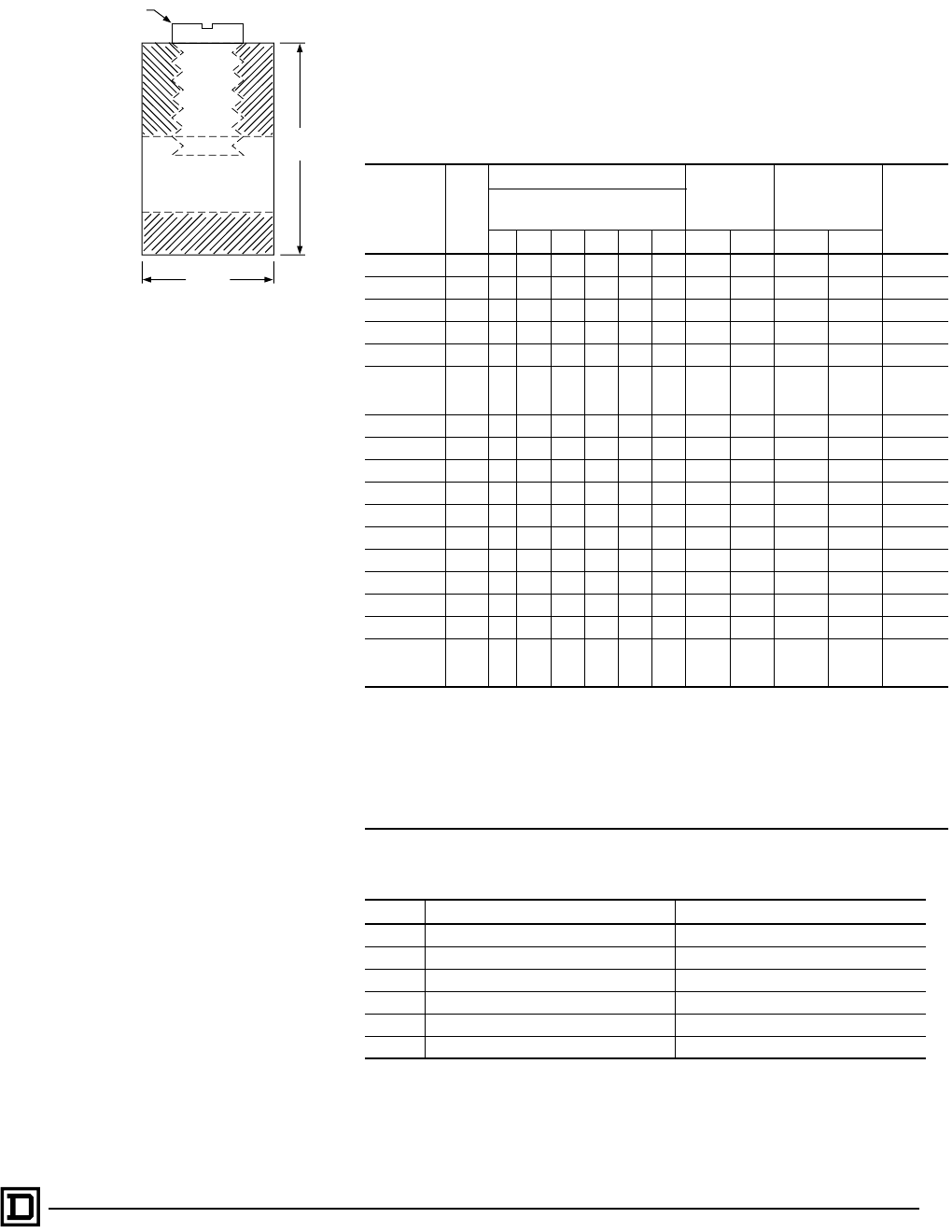
HOMELINE Circuit Breaker Load Centers—Class 1170
Technical Information
63
09/00 © 2000 Schneider Electric All Rights Reserved
TECHNICAL INFORMATION
Grounding Bar Kits
All PK equipment grounding kits are supplied with mounting screws,
necessary installation instructions, and an “Equipment Grounding Terminal”
self-adhesive label.
Catalog
Number
Total
Qty.
Terminals Approximate
Overall
Length
Distance
Between
Mounting Holes Mounting
Quantity Each Size
See “Wire Range Table” below.
I II III IV V VI in. mm in. mm
PK0GTA2 ◆2 2 1.75 44 One hole One hole Top
PK0GTA6 ■6 6 4.61 117 1.69 43 Top
PK3GTA1 ✚3 3 1.38 35 One hole One hole Top
PK4GTA ✚4 4 1.63 41 One hole One hole Top
PK5GTA ▼5 5 2.25 57 1.25 32 Top
PK7GTA ✚7 7 2.88 73 1.25 32
Top
or
side
PK9GTA1 ✚9 9 3.25 83 One hole One hole Top
PK9GTA ✚9 9 3.78 96 3.13 80 Top
PK12GTA ✚12 12 4.70 119 3.13 80 Top
PK15GTA ✚15 15 5.63 143 3.13 80 Top
PK15GTAL ★16 15 1 8.13 207 3.13 80 Top
PK15GTA6 ❖21 15 6 5.88 149 ▲▲ Top
PK18GTA ✚18 18 6.56 167 3.13 80 Top
PK18GTAL ★19 18 1 8.81 224 3.13 80 Top
PK23GTA ✚23 23 8.11 206 3.13 80 Top
PK23GTAL ★24 23 1 9.44 240 3.13 80 Top
PK27GTA ●
✚
27
or
26
27
26 1 9.36 238 3.13 80 Top
●PK27GTA includes one main grounding lug that mounts with two terminal screws and requires three terminals for
mounting.
▲3.13 in. (80 mm) on small terminals; 5.25 in. (133 mm) on large terminals.
◆Mounting screw 40205-065-01 (one required).
✚Mounting screw 21594-14220 (two required).
★Mounting screw 21594-14302 (two required).
■Mounting screw 21922-18360 (two required).
▼Mounting screw 21594-14241 (two required).
❖Mounting screws 21594-14241(two required) and 21594-17121(two required).
Wire Range Table
Size Cu (AWG) Al (AWG)
I (1) #14–#4 or (2) #14 or #12 (1) #12–#4 or (2) #12 or #10
II (1) #1–4/0 (1) #1–4/0
III (1) #6–2/0 (1) #6–2/0
IV (1) #6–3/0 (1) #6–3/0
V (1) #14–1/0 (1) #14–1/0
VI (1) #10–2/0 (1) #6–2/0
Slot/Robertson screw
Cross Section of Size 1 Ground Bar
.437
11
.3125
8

HOMELINE Circuit Breaker Load Centers—Class 1170
Technical Information
64
09/00
© 2000 Schneider Electric All Rights Reserved
Main Lugs and Main Circuit Breakers Ratings
Single-Phase, Three-Wire, 120/240 Vac Main Lugs – Indoor
Mains
Rating
in
Amps
Load
Center
Catalog
Number
Load
Cen te r
C o v e r
Catalog
Number
UL Listed
S e r v i c e
Equipment
(See
Notes)
MaxImum
UL Short
Circuit
Rating ▲
M a i n W i r e S i z e
AWG/kcmil
Al/Cu
Enclosure
No.
Top
or
Bottom
Mains
Position
UL Listed
for
Corner
Grounded
Delta
Systems
Fixed Mains – Factory-Installed Main Lugs
70 HOM24L70F/S Included B 10,000 A #12–3
#14–4 2 Top No
100 HOM6-2L100F/S Included B, C 10,000 A #8–1 4 Top No
125 HOM48L125GC Included B, C 10,000 A #4–2/0 21 Top No
Convertible Mains – Factory-Installed Main Lugs
QOM1 Main Frame Size – Convertible to 22,000 AIR Main Circuit Breaker
125
HOM816L125C Included B, C 10,000 A #4–2/0 6 Both
Yes
HOM816L125TC Included B, C 10,000 A #4–2/0 6 Both
HOM12L125C Included B, C 10,000 A #4–2/0 6 Both
HOM1224L125TC Included B, C 10,000 A #4–2/0 6 Both
HOM1624L125C Included B 10,000 A #4–2/0 8 Both
HOM20L125C Included B 10,000 A #4–2/0 8 Both
HOM20-24L125TC Included B 10,000 A #4–2/0 8 Both
HOM24L125TC Included B 10,000 A #4–2/0 8 Both
HOM20L125CK Included B 10,000 A #4–2/0 8K Both
HOM2024L125TCK Included B 10,000 A #4–2/0 8K Both
Convertible Mains – Factory-Installed Main Lugs
QOM2 Main Frame Size – Convertible to 22,000 AIR Main Circuit Breaker
150 HOM30L150C Included B 10,000 A #4–250 10 Both
Yes
200
HOM1632L200TC Included B 10,000 A $4–250 9 Both
HOM30L200C Included B 10,000 A #4–250 10 Both
HOM30-40L200TC Included B 10,000 A #4–250 10 Both
HOM40L200C Included B 10,000 A #4–250 12 Both
HOM40L200CK Included B 10,000 A #4–250 12K Both
HOM3040L200TCK Included B 10,000 A #4–250 10K Both
HOM30L200TCK Included B 10,000 A #4–250 10K Both
▲UL short circuit rating with optional QOM-VH main circuit breaker, 22,000 AIR.
B UL Listed as suitable for use as service equipment (neutral bonded at the time of installation) with field-installed service disconnect.
C UL Listed as suitable for use as service equipment (neutral bonded at the time of installation) when not more than six service disconnecting means
are provided and when not used as a lighting and appliance branch circuit panelboard.
K WIREGATOR Qwik-Grip Cable System.

HOMELINE Circuit Breaker Load Centers—Class 1170
Technical Information
65
09/00 © 2000 Schneider Electric All Rights Reserved
Single-Phase, Three-Wire, 120/240 Vac Main Circuit Breaker – Indoor
Mains
Rating
in
Amps
Load
Center Catalog
Number
Load
Center
C ov er
Catalog
Number
U L L i s t e d
S e r v i c e
Equipment
(See Notes)
Maximum
UL Short
Circuit
Rating ▲
M a i n W i r e S i z e
AWG/kcmil
Al/Cu
Enclosure
No.
Top
or
Bottom
Mains
Position
UL Listed
for
Corner
Grounded
Delta
Systems
Convertible Mains – Factory-Installed Main Circuit Breaker
QOM1 Main Frame Size – Convertible to Main Lugs
100
HOM816M100C Included A, D 22,000 A #4–1 5 Both
Ye s
HOM816M100TC Included A, D 22,000 A #4–1 5 Both
HOM12M100C Included A, D 22,000 A #4–2/0 6 Both
HOM1224M100TC Included A, D 22,000 A #4–2/0 6 Both
HOM20M100C Included A 22,000 A #4–2/0 8 Both
HOM20M100CK Included A 22,000 A #4–2/0 8K Both
HOM1224M100TCK Included A 22,000 A #4–2/0 6K Both
HOM24M100C Included A 22,000 A #4–2/0 8 Both
125
HOM1224M125C Included A, D 22,000 A #4–2/0 6 Both
Ye sHOM1224M125TC Included A, D 22,000 A #4–2/0 6 Both
HOM24M125C Included A 22,000 A #4–2/0 8 Both
Convertible Mains – Factory-Installed Main Circuit Breaker
QOM2 Main Frame Size – Convertible to Main Lugs
150
HOM1632M150TC Included A 22,000 A #4–250 9 Both
Ye sHOM2030M150TC Included A 22,000 A #4–250 9 Both
HOM30M150C Included A 22,000 A #4–250 10 Both
200
HOM1224M200TC Included A, D 22,000 A #4–250 9 Both
Ye s
HOM1632M200TC Included A 22,000 A #4–250 9 Both
HOM2040M200C Included A 22,000 A #4–250 9 Both
HOM2040M200TC Included A 22,000 A #4–250 9 Both
HOM30M200C Included A 22,000 A #4–250 10 Both
HOM3040M200TC Included A 22,000 A #4–250 10 Both
HOM40M200CK Included A 22,000 A #4–250 12K Both
HOM3040M200TCK Included A 22,000 A #4–250 10K Both
HOM2040M200TCK Included A 22,000 A #4–250 9K Both
HOM40M200C Included A 22,000 A #4–250 12 Both
225 HOM42M225C Included A 22,000 A #4–250 12 Both Yes
Universal Mains – No Factory-Installed Main Circuit Breaker or Main Lugs
QOM2 Main Frame Size – Field-Installed Main Lugs or 22,000 AIR Main Circuit Breaker
200
HOM1632U200TC Included B 10,000 A #4–250 9 Both
Ye sHOM2040U200TC Included B 10,000 A #4–250 9 Both
HOM3040U200TC Included B 10,000 A #4–250 10 Both
▲UL short circuit rating with optional QOM-VH main circuit breaker, 22,000 AIR.
A UL Listed as suitable for use as service equipment (neutral bonded at the time of installation) with a factory-installed service disconnect.
B UL Listed as suitable for use as service equipment (neutral bonded at the time of installation) with field-installed service disconnect.
C UL Listed as suitable for use as service equipment (neutral bonded at the time of installation) with field-installed main lugs when not more than six
disconnecting means are provided and when not used as lighting and appliance branch circuit panelboard.
K WIREGATOR Qwik-Grip Cable System.

HOMELINE Circuit Breaker Load Centers—Class 1170
Technical Information
66
09/00
© 2000 Schneider Electric All Rights Reserved
Single-Phase, Three-Wire, 120/240 Vac Main Lugs – Rainproof
Mains
Rating
in
Amps
Load
Center Catalog
Number
Load
Center
C ov er
Catalog
Number
U L L i s t e d
S e r v i c e
Equipment
(See
Notes)
Maximum
UL Sh or t
Circuit
Rating ▲
M a i n W i r e S i z e
AWG/kcmil
Al/Cu
Enclosure
No.
Top
or
Bottom
Mains
Position
UL Listed
for Corner
Grounded
Delta
Systems
Fixed Mains – Factory-Installed Main Lugs
70 HOM24L70RB Included B 10,000 A #12–3 Al
#14–4 Cu 1R Top No
100 HOM612L100RB Included B, C 10,000 A #8–1 2R Top No
125 HOM48L125GRB Included B, C 10,000 A #4–2/0 16R Top No
Convertible Mains – Factory-Installed Main Lugs
QOM1 Main Frame Size – Convertible to 22,000 AIR Main Circuit Breaker
125
HOM816L125RB Included B, C 10,000 A #4–2/0 3R Top
Ye sHOM12L125RB Included B, C 10,000 A #4–2/0 3R Top
HOM20L125RB Included B 10,000 A #4–2/0 4R Top
Convertible Mains – Factory-Installed Main Lugs
QOM2 Main Frame Size – Convertible to 22,000 AIR Main Circuit Breaker
200
HOM12L200RB Included B, C 10,000 A #4–250 5R Top
Ye sHOM30L200RB Included B 10,000 A #4–250 7R Top
HOM40L200RB Included B, C 10,000 A #4–250 8R Top
Single-Phase Three Wire 120/240 Vac Main Breaker – Rainproof
Convertible Mains – Factory-Installed Main Circuit Breaker
QOM1 Main Frame Size – Convertible to Main Lugs or Lower Amperage Main Circuit Breaker
100
HOM816M100RB Included A, D 22,000 A #4–2/0 3R Top
NoHOM12M100RB Included A, D 22,000 A #4–2/0 3R Top
HOM20M100RB Included A 22,000 A #4–2/0 4R Top
125 HOM24M125RB Included A 22,000 A #4–2/0 6R Top No
Convertible Mains – Factory-Installed Main Circuit Breaker
QOM2 Main Frame Size – Convertible to Main Lugs or Lower Amperage Main Circuit Breaker
150 HOM30M150RB Included A 22,000 A #4–250 7R Top No
200
HOM2040M200RB Included A 22,000 A #4–250 6R Top
No
HOM30M200RB Included A 22,000 A #4–250 7R Top
HOM3040M200RB Included A 22,000 A #4–250 7R Top
HOM40M200RB Included A 22,000 A #4–250 8R Top
Main Circuit Breaker with Feed-Thru Lugs
150 HOM816M150FTRB Included A 22,000 A #4–250 6R Top No
200 HOM816M200FTRB Included A 22,000 A #4–250 6R Top No
Universal Main Circuit Breaker with Feed-Thru Lugs
200 HOM816U200FTRB Included B 22,000 A #4–250 6R Top No
▲UL short circuit rating with optional QOM-VH main circuit breaker, 22,000 AIR.
A UL Listed as suitable for use as service equipment (neutral bonded at time of installation) with factory-installed service disconnect.
B UL Listed as suitable for use as service equipment (neutral bonded at time of installation) with field-installed service disconnect.
C UL Listed as suitable for use as service equipment (neutral bonded at time of installation) when not more than six service disconnecting means are
provided and when not used as a lighting and appliance branch circuit panelboard. See NEC Sec. 384-14.
D UL Listed as suitable for use as service equipment (neutral bonded at the time of installation) with field-installed main lugs when not more than six
service disconnecting means are provided and when not used as a lighting and appliance branch circuit panelboard. See NEC Sec. 384-14.

HOMELINE Circuit Breaker Load Centers—Class 1170
Dimensions and Knockouts
67
09/00 © 2000 Schneider Electric All Rights Reserved
WIREGATOR Qwik-Grip Cable System
WIREGATOR™
Qwik-Grip Cable System
WIREGUARD™ Shield
Front
Middle
Back
Wide slot
Ranura amplia
Narrow slot
Ranura angosta
12–3
12–2
10–3
14–3
&
Narrow slot
Ranura angosta
Narrow slot
Ranura angosta
Narrow slot
Ranura angosta
14~3 & 10–2
12–2 & 14–2
C,D,E,F
D,E,F,G
A,B
B,C
A
C,D,E,F C,D,E,F
B,C,D,E
B,C,D,E
C,D,E,F A,B
D,E,F,G
C,D,E,F
D,E,F,G
A,B
B,C
A
C,D,E,F A,B
10K9K 12K
8K
A,B
C,D,E,F
A,B,C,D
B,C,D,E
C,D,E,F
C,D,E,F
D,E,F,G
C,D,E,F
B,C,D,E D,E,F,G
A,B
B,C
A
C,D,E,F A,B
A,B
A
C,D,E,F
6K
B,C,D,E
A,B,C,D
C,D,E,F A,B
A,B,C
B,C,D,E B,C,D,E
A,B,C,D
B,C,D,E
A,B,C,D
B,C,D,E
A,B,C,D
B,C,D,E
A,B,C
A,B,C
A,B,C
A,B,C
Indoor Dimensions and Knockouts–WIREGATOR™ Gwik-Grip Cable System
Indoor Dimensions
Enclosure
No.
WH D
in.mmin.mmin.mm
6K 14.25 362 17.92 455 3.75 95
8K 14.25 362 26.04 661 3.75 95
9K 14.25 362 29.86 758 3.75 95
10K 14.25 362 33.78 858 3.75 95
12K 14.25 362 39.37 1000 3.75 95
WIREGATOR™ Qwik-Grip Cable System Wire Size Per Slot
Position Wide
Slot
Narrow
Slot
Narrow
Slot
Narrow
Slot
Narrow
Slot
Front 12–3
10–3
14–3,
14–2
12–2
10–2
14–3,
14–2
12–2
10–2
14–3,
14–2
12–2
10–2
14–3,
14–2
12–2
10–2
Middle
14–3
12–3
10–2
14–2
12–2
14–2
12–2
14–2
12–2
14–2
12–2
Back
14–3
12–3
10–2
14–2
12–2
14–2
12–2
14–2
12–2
Indoor Knockouts
Symbol ABC D E F G H I
Conduit Size .50 in.
(13 mm)
.75 in.
(19 mm)
1.00 in.
(25 mm)
1.25 in.
(32 mm)
1.50 in.
(38 mm)
2.00 in.
(51 mm)
2.50 in.
(64 mm)
3.00 in.
(76 mm)
3.50 in.
(89 mm)

HOMELINE Circuit Breaker Load Centers—Class 1170
Dimensions and Knockouts
68
09/00
© 2000 Schneider Electric All Rights Reserved
A,B,C,D
A,B,C
A
A,B,C
A
Enclosure 2Enclosure 1
A,B,C
A
A
A
Enclosure 5
A
A,B,C C,D,E,F,G A,B
B,C,D,E
A,B,C,D
A,B
A
A,B,C,D
A,B,C,D
A
A,B
A
Enclosure 4
Enclosure 13
A,B,C,D
C,D,E,F
A,B
C,D,E,F
C,D,E,F
D,E,F,G,H,I
D,E,F,G,H
Enclosures 15, 16, 17
A,B,C,D
A,B,C,D
A,B,C,D
A,B,C,D
C,D,E,F
A,B
A
C,D,E,F
Enclosure 6
B,C,D,E
A,B,C,D
C,D,E,F
D,E,F,G
Enclosure 18
A,B,C,D
C,D,E,F
Enclosure 19
D,E,F,G
Enclosure 20
C,D,E,F
D,E,F,G
E,F,G,H
A
A,B,C C,D,E,F,G A,B
A,B
A
A,B
B,C
A
C,D,E,F
Enclosure 7
B,C,D,E
C,D,E,F C,D,E,F
C,D,E,F
B,C,D,E D,E,F,G
B,C,D,E
D,E,F,G
B,C,D,E
A,B,C,D
A,B,C,D
B,C,D,E
A,B,C,D
B,C,D,E
A,B,C,D
B,C,D,E
A
A,B,C C,D,E,F,G A,B A
A,B,C C,D,E,F,G A,B
D,E,F,G
C,D,E,F
D,E,F,G
C,D,E,F
B,C,D,E
A,B,C,D
B,C,D,E
D,E,F,G
C,D,E,F
D,E,F,G
C,D,E,F
D,E,F,G
A,B
B,C
A
A
A,B,C C,D,E,F,G A,B
Enclosure 11
Enclosure 10Enclosure 9
A,B
B,C
A
A
A,B,C C,D,E,F,G A,B
Enclosure 14
A,B
A
B,C,D,E
B,C,D,E
A,B,C,D
A,B,C D,E,F,G
AA,B
Enclosure 12
A,B
B,C
A
A
A,B,C C,D,E,F,G A,B
A
Enclosure 3
A,B
Enclosure 8
AA,B
A,B,C C,D,E,F,G
A,B,C,D
B,C,D,E
C,D,E,F
A,B,C,D
A,B,C,D
A
A,B
A
Enclosure 21
A,B,C,D
A,B,C,D
A,B,C,D
A,B,C,D
Indoor Dimensions and Knockouts
A,B,C
Indoor Dimensions
Enclosure
No.
WH D
in. mm in. mm in. mm
1 3.81 97 6.72 171 3.00 76
2 4.81 122 9.30 236 3.19 81
3 4.81 122 9.30 236 3.19 81
4 8.88 226 12.57 319 3.80 97
5 14.25 362 14.92 379 3.75 95
6 14.25 362 17.92 455 3.75 95
7 14.25 362 20.92 531 3.75 95
8 14.25 362 26.04 661 3.75 95
9 14.25 362 29.86 758 3.75 95
10 14.25 362 33.78 858 3.75 95
11 14.25 362 37.98 965 3.75 95
12 14.25 362 39.37 1000 3.75 95
Indoor Dimensions
Enclosure
No.
WHD
in. mm in. mm in. mm
13 5.88 149 13.12 333 3.38 86
14 14.25 362 20.92 531 3.75 95
15 20.00 508 50.00 1270 5.75 146
16 20.00 508 68.00 1727 5.75 146
17 20.00 508 53.00 1346 5.75 146
18 5.88 149 16.12 409 3.38 86
19 7.56 192 23.12 587 4.25 108
20 9.62 244 26.12 663 4.75 121
21 8.88 226 14.80 376 3.80 97
Indoor Knockouts
Symbol AB C D E F G H I
Conduit Size .50 in.
(13 mm)
.75 in.
(19 mm)
1.00 in.
(25 mm)
1.25 in.
(32 mm)
1.50 in.
(38 mm)
2.00 in.
(51 mm)
2.50 in.
(64 mm)
3.00 in.
(76 mm)
3.50 in.
(89 mm)

HOMELINE Circuit Breaker Load Centers—Class 1170
Dimensions and Knockouts
69
09/00 © 2000 Schneider Electric All Rights Reserved
Enclosure 9R
A,B,C
A,B,C,D
A
Enclosure 1R
A,B
2-1/2 in. Hub Maximum
2-1/2 in. hub maximum
2-1/2 in. Hub Maximum
2-1/2 in. hub maximum
2-1/2 in. hub maximum
Enclosure 2R
A,B,C,D
A,B,C,D
A
A,B
A,B,C,D
Enclosure 3R, 4R
AA,B C,D,E,F A,B,C
C,D,E,F
C,D,E,F
Enclosure 6R, 7R, 8R
AA,B D,E,F,G A,B,C
D,E,F,G
D,E,F,G
Enclosure 5R
AD,E,F,G A,B,C
C,D,E,F
A,B
C,D,E,F
2-1/2 in. Hub Maximum
D,E,F,G
A,B A,B,C
A
Enclosure 14R
D,E,F,G
2-1/2 in. hub maximum
D,E,F,G
Enclosure 11R
2-1/2 in. hub maximum
Enclosure 15R
A,B,C,D
A,B,C,D
A
A,B
A,B,C,D
Enclosure 12R
D,E,F,G
E,F,G,H E,F
2-1/2 in. hub maximum
2-1/2 in. hub maximum
A,B,C,D
C,D,E,F
Enclosure 10R, 13R
B,C,D,E
B,C,D,E
Enclosure 16R
A,B
C,D,E,F
2-1/2 in. hub maximum
Outdoor Dimensions and Knockouts
Outdoor Dimensions
Enclosure
No.
WH D
in. mm in. mm in. mm
1R 4.88 124 9.38 238 4.00 102
2R 8.88 226 12.65 321 4.27 108
3R 14.75 375 18.92 481 4.52 115
4R 14.75 375 22.06 560 4.52 115
5R 14.75 375 26.04 661 4.52 115
6R 14.75 375 29.86 758 4.52 115
7R 14.75 375 33.78 858 4.52 115
8R 14.75 375 37.98 965 4.52 115
9R 4.56 116 6.50 165 3.88 99
10R 6.92 176 13.18 335 4.12 105
11R 7.56 192 23.24 590 4.75 121
12R 9.62 244 26.24 666 5.50 140
Outdoor Dimensions
Enclosure
No.
WHD
in. mm in. mm in. mm
13R 6.92 176 16.18 411 4.12 105
14R 14.75 375 39.37 1000 4.52 115
15R 6.25 166 8.79 223 3.90 99
16R 8.88 226 14.80 376 4.27 108
Outdoor Knockouts
Symbol ABC D E F G H
Conduit Size .50 in.
(13 mm)
.75 in.
(19 mm)
1.00 in.
(25 mm)
1.25 in.
(32 mm)
1.50 in.
(38 mm)
2.00 in.
(51 mm)
2.50 in.
(64 mm)
3.00 in.
(76 mm)
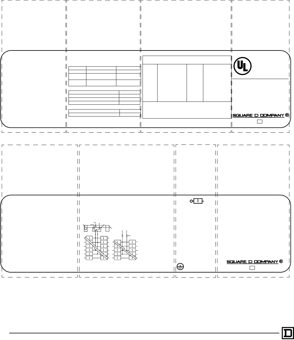
HOMELINE Circuit Breaker Load Centers—Class 1170
Specifications
70
09/00
© 2000 Schneider Electric All Rights Reserved
Single-Phase Labels
The labels below represent typical labels. Information may not be applicable or
may change without notice. See the actual label in the load center for the latest
information.
Install loose label with Spanish translation
on back of cover.
Adhiera la etiqueta suelta con las traducciones
en espanol en la parte posterior del frente.
Please read information before installing
Por favor lea la informacion antes de instalar.
~
/
LISTED
Electric
Cabinet Box
Issue No. V-2813
HOM LOAD CENTER
See Panelboard interior for Catalog No.
Box Cat. No. / Caja No. de Catalogo:
BXH34A
Use Cover Cat. No. /
Utilice la Cubierta No. de Catalogo:
HOMC30UC
Mains 200A max. / Lina Principal de.
200A maximo.
See main or service disconnect
rating if installed.
120/240 V ~ Max. 1Ø, 50 / 60 Hz.
30 circuit max. / 30 circuitos maximo.
Type 1 Enclosure
Gabinete Tipo 1
For installation, repairs or alterations,
Call an electrical contractor or electrician.
Panel
Rating
Remote
Main
Integral
Main
Branch (min.)/
Cat. prefix
42,000 QOH Lugs 10,000 / HOM
22,000 QOME..VH Lugs 10,000 / HOM
*10,000 ---- Lugs 10,000 HOM
22,000 ---- QOM2...VH 10,000 HOM
10,000 ---- QOM2 10,000 HOM
* The rating is equal to the lowest interrupting rating of any circuit breaker
installed. Refer to branch breaker for individual ratings. Additional or
replacement branch circuit breakers, main breaker, or service disconnect
MUST have an interrupting rating equal to or greater than that of the
circuit breaker with the lowest interrupting rating presently installed.
See panelboard interior for breaker types.
LUG TORQUE DATA
See circuit breakers and field installed
units for wire binding screw torque
Branch Neutral and Equipment Ground Bar
Equipment Ground Combinations
Wire Range (AWG/kcmil) Torque (in/lbs.)
Main Lug 4 - 250 CU/AL 250
Service
Ground Lug 6 - 2/0 CU/AL 50
Alternate
Main Breaker
See Main
Breaker
See Main
Breaker
Wire Range (AWG) Torque (in./lbs.)
6 CU / AL Large 45
8 CU / AL Large 40
14-10 CU, 12-10 AL Large 35
Two 14 or 12 CU 25
Two 12 or 10 AL 10
SHORT CIRCUIT RATING
RMS Symmetrical Amperes at 120 / 240 V ~ Maximum
Underwriter’s
Laboratories, Inc.®
Number of circuits maximum.
Enclosure catalog number.
Catalog number of covers; flush
or surface.
See panelboard interior for the
catalog number.
Voltage ratings.
Amperage rating. Wire range for lug torque data table.
Short circuit ratings.
Short circuit ratings and additional of replacement
circuit breakers. UL listing.
001021 40265-381-0315
®
Line / Lines
N
NO O
3
NO
O
12
4
LOAD / CARGAS
LOAD / CARGAS
LOAD / CARGAS
Main Breaker diagram Main Lugs diagram
Service Equipment marking.
Use of unused neutral branch terminal for
equipment grounding, service equipment
application only.
Made in U.S.A. 40265-668-0215
1. Box bonding when required. / Conexion a la caja
cuando fuese necesario.
2. Main breaker type: QOM1 or QOM1A. / Interruptor
automatico principal tipo: QOM1 o QOM1A.
3. Service ground
when required. /
Tierra de acometida
cuando fuese
necesario
4. Main lugs kit no:
QOL125. / No. de
accesorio de las
zapatas
principales:
QOL125.
One single pole. One plug
on space. One two pole
requires two plug on
spaces.
Torque Note: When main
breaker or main lug
connector mounting nuts
are loosened or removed,
retighten to 75 lbs./in.
torque.
* May plug on two adjacent spaces.
Torque Note: When interior mounting screw is
loosened or removed, retighten to 35 lbs./in.
Load Center Accessories - Kits
HOM4K2LA Back-fed Main Cir. Brkr. Retaining
HOM2175SB Plug-0n Surge Arrestor *
SDSA1175 1 Phase Surge Arrestor
QOSAMK SDSA1175 Mounting Bracket
HOML2125 1 Phase Plug-on Subfeed Lugs *
PK9--27GTA(L) Equipment Ground Bar
PKGTAB Equipment Ground Bar Insulator
LK70AN 70A Max. Neutral Lug
LK100AN 125A Max. Neutral Lug
QOL125 Main Lugs
PK6FL Indoor Cover Lock
Equipment Grounding
Terminals
Type of circuit breakers
from Square D that
may be used in this
panelboard.
Installation of back-fed main circuit breaker and
required kit.
Alternate wiring diagram for main circuit breaker or
main lug.
Load center accessories.
Neutral lug for 1/0 AWG or larger wire.
Suitable for use with 75oC
Copper or Aluminum
main conductors. See
branch breakers for
branch wire ratings.
* Suitable for use as service equipment when
service disconnect (main breaker) is installed.
* Suitable for use as service equipment when
not more than six main disconnecting means
are provided and when not used as a lighting
and appliance branch circuit panelboard.
See Article 384-14 of the NEC.
* When used as service equipment, all unused
neutral terminals may be used for terminating
equipment ground wires.

HOMELINE Circuit Breaker Load Centers—Class 1170
Wiring Diagrams
71
09/00 © 2000 Schneider Electric All Rights Reserved
1-Phase, 3-Wire Main Lugs
HOM24L70F/S
HOM24L70RB
S
N
HOM612L100F/S
HOM612L100RB
S/N
HOM48L125GC
HOM48L125GRB
S/N
HOM816L125C
HOM816L125RB
HOM816L125TC
HOM12L125C
HOM12L125RB
HOM12L200RB HOM1224L125TC HOM1624L125C
S
N
S
N
S
N
S
N
S
N
S
N
G
B
S
N
S
N
G
B
S
N
S
N
G
B
S
N
S
N
S
N
HOM2024L125TC
HOM2024L125TCK
S
N
S
N
HOM20L125C
HOM20L125RB
HOM20L125CK
S
N
S
N
HOM1632L200TC
S
N
G
B
G
B
S
N
HOM30L150C
HOM30L200C
HOM30L200RB
HOM30L200TCK
S
NS
N
HOM3040L200TC
HOM3040L200TCK
S
N
G
B
S
N
HOM40L200C
HOM40L200RB
HOM40L200CK
S
N
S
N
HOM42L225C
S
N
HOM246125TC
Universal Mains
HOM1632U200TC
S
N
G
B
S
N
HOM2040U200TC
S
N
G
B
S
N
S
N
HOM3040U200TC
S
N
G
B
S
N
HOM816U200FTRB
S
N
Requires Field Installed Main

HOMELINE Circuit Breaker Load Centers—Class 1170
Wiring Diagrams
72
09/00
© 2000 Schneider Electric All Rights Reserved
1-Phase, 3-Wire Main Circuit Breakers
S
N
HOM816M100C
HOM816M100RB
S
N
G
B
MAIN S
N
HOM816M100TC
S
N
MAIN
S
N
HOM816M150FTRB
HOM816M200FTRB
S
N
MAIN
S
N
HOM12M100C
HOM12M100RB
S
N
MAIN
G
B
S
N
HOM1224M125C
S
N
MAIN
S
N
HOM1224M100TC
HOM1224M125TC
HOM1224M200TC
HOM1224M100TCK
S
N
MAIN
G
B
S
N
HOM1632M150TC
HOM1632M200TC
S
N
MAIN
S
N
HOM20M100C
HOM20M100RB
HOM20M100CK
S
N
MAIN
S
N
HOM2040M200C
HOM2040M200RB
S
N
MAIN
HOM2040M200TC
HOM2040M200TCK
S
N
MAIN
G
B
S
N
HOM2030M150TC
G
B
S
N
S
N
MAIN
S
N
HOM24M100C
HOM24M125C
HOM24M125RB
S
N
MAIN
MAIN
MAIN
S
N
HOM30M150C
HOM30M200C
HOM30M150RB
HOM30M200RB
S
NS
N
HOM3040M200TC
HOM3040M200RB
HOM3040M200TCK
S
N
G
B
MAIN
S
N
HOM40M200C
HOM40M200RB
HOM40M200CK
S
NMAIN
S
N
HOM42M225C
S
N

HOMELINE Circuit Breaker Load Centers—Class 1170
Replacement Parts
73
09/00 © 2000 Schneider Electric All Rights Reserved
Single-Phase – Fixed Main Lugs, Series 1 and 2
Illustration Code A B C D F
Catalog Number Series Cover or RB Door Interior Trim Interior Assembly Main Lugs Neutral Bonding Screw
HOM24L70F 1, 2 40558-007-01 – 40558-085-50 N/A 21490-173-42
HOM24L70S 1, 2 40558-008-01 – 40558-085-50 N/A 21490-173-42
HOM24L70RB 1, 2 137109 40558-011-01 40558-085-50 N/A 21490-173-42
Flush and surface cover mounting screw .75 in. (19 mm): 40205-130-02
Replacement covers do not have labels applied
Replacement enclosures are not available
RB trim mounting screw .50 in. (13 mm): 40205-130-01
N/A: Not available
C
B
A

HOMELINE Circuit Breaker Load Centers—Class 1170
Replacement Parts
74
09/00
© 2000 Schneider Electric All Rights Reserved
Single-Phase – Fixed Main Lugs, Series 1
Illustration Code A B C D E
Catalog Number Series Cover or RB Door Interior Trim Interior Assembly Main Lugs Neutral Bonding Screw
HOM48L125GC 1 40558-448-01 – 40558-452-50 N/A 40205-020-01
HOM48L125GRB 1 40553-323-01 40558-449-01 40558-452-50 N/A 40205-020-01
HOM612L100F 1 40558-018-01 – 40558-057-50 N/A 40205-020-01
HOM612L100S 1 40558-017-01 – 40558-057-50 N/A 40205-020-01
HOM612L100RB 1 40558-103-01 40558-021-01 40558-057-50 N/A 40205-020-01
Flush and surface cover mounting screw .75 in. (19 mm): 40205-130-02
Replacement covers do not have labels applied
Replacement enclosures are not available
RB trim mounting screw .50 in. (13 mm): 40205-130-01
RB door mounting screws: 21427-171-61
N/A: Not available
B
C
A

HOMELINE Circuit Breaker Load Centers—Class 1170
Replacement Parts
75
09/00 © 2000 Schneider Electric All Rights Reserved
Single-Phase – Convertible Main Lugs, Series S01 and S02
Illustration Code A B C D E F
Catalog Number Series Cover or RB Door Interior Trim Interior Assembly Neutral Assembly Main Lugs Neutral Bonding
Hardware
HOM816L125C S01 HOMC12UC – HOM816L125CI N/A QOL125 40283-458-50
HOM816L125TC S01 HOMC12UC – HOM816L125TCI N/A QOL125 40283-458-50
HOM816L125RB S02 40563-178-50 40563-127-01 HOM816L125RBI N/A QOL125 40283-458-50
HOM12L125C S01 HOMC12UC – HOM12L125CI N/A QOL125 40283-458-50
HOM12L125RB S02 40563-178-50 40563-127-01 HOM12L125RBI N/A QOL125 40283-458-50
HOM1224L125TC S01 HOMC12UC – HOM1224L125TCI N/A QOL125 40283-458-50
HOM1624L125C S01 HOMC20U100C – HOM1624L125CI N/A QOL125 40283-458-50
HOM20L125C S01 HOMC20U100C – HOM20L125CI N/A QOL125 40283-458-50
HOM20L125CK S01 HOMC20U100C – HOM20L125CI N/A QOL125 40283-458-50
HOM20L125RB S02 40563-177-50 40563-150-01 HOM20L125RBI N/A QOL125 40283-458-50
HOM2024L125TC S01 HOMC20U100C – HOM2024L125TCI N/A QOL125 40283-458-50
HOM2024L125TCK S01 HOMC20U100C – HOM2024L125TCI N/A QOL125 40283-458-50
HOM24L125TC S01 HOMC24UC – HOM24L125TCI N/A QOL125 40283-458-50
HOM30L150C S01 HOMC30UC – HOM30L150CI N/A QOL225 40283-458-50
HOM12L200RB S02 40563-176-50 40563-132-01 HOM12L200RBI N/A QOL225 40283-458-50
HOM30L200TCK S01 HOMC30UC – HOM30L200C1 N/A QOL225 40283-458-50
HOM2040L200TC S01 HOMC20UC – HOM2040L200TCI N/A QOL225 40283-458-50
HOM30L200RB S02 40563-174-50 40563-138-01 HOM30L200RBI N/A QOL225 40283-458-50
HOM3040L200TC S01 HOMC30UC – HOM3040L200TCI N/A QOL225 40283-458-50
HOM3040L200TCK S01 HOMC30UC – HOM3040L200TCI N/A QOL225 40283-458-50
HOM40L200C S01 HOMC40UC – HOM40L200CI N/A QOL225 40283-458-50
HOM40L200CK S01 HOMC40UC – HOM40L200CI N/A QOL225 40283-458-50
HOM40L200RB S02 40563-172-50 40563-142-01 HOM40L200RBI N/A QOL225 40283-458-50
HOM42L225C S01 HOMC42UC – HOM42L225CI N/A QOL225 40283-458-50
Indoor cover mounting screw .75 in. (19 mm): 40283-564-50
Indoor cover door hinge: 40283-564-50
Indoor cover latch:
Latch: 40545-087-01
Latch spring: 40545-413-01
WIREGATOR inserts: 40556-153-01, quantity = 1
WIREGUARD shields: 40559-435-50, quantity = 2
RB trim mounting screw .50 in. (13 mm): 40205-130-01
RB door mounting screws: 21422-171-01
Main circuit breaker and main lugs keps nut: 23427-020-01
N/A - not available
Replacement enclosures are not available
Replacement covers do not have labels applied
Outdoor cover latch: 40563-147-01
Latch rivet: 24102-121-60
B
A
C
E

HOMELINE Circuit Breaker Load Centers—Class 1170
Replacement Parts
76
09/00
© 2000 Schneider Electric All Rights Reserved
Single-Phase – Convertible Main Circuit Breakers, Series S01 and S02
Illustration Code A B C D E F
Catalog Number Series Cover or RB Door Interior Trim Interior Assembly Neutral
Assembly
Main Circuit
Breaker
Neutral Bonding
Hardware
HOM816M100C S01 HOMC8UC – HOM816M100CI N/A QOM100VH 40283-458-50
HOM816M100TC S01 HOMC8UC – HOM816M100TCI N/A QOM100VH 40283-458-50
HOM816M100RB S02 40563-178-50 40563-127-02 HOM816M100RBI N/A QOM100VH 40283-458-50
HOM12M100C S01 HOMC12UC – HOM12M100CI N/A QOM100VH 40283-458-50
HOM12M100RB S02 40563-178-50 40563-127-02 HOM12M100RBI N/A QOM100VH 40283-458-50
HOM1224M100TC S01 HOMC12UC – HOM1224M100TCI N/A QOM100VH 40283-458-50
HOM1224M100TCK S01 HOMC12UC – HOM1224M100TCI N/A QOM100VH 40283-458-50
HOM20M100C S01 HOMC20U100C – HOM20M100CI N/A QOM100VH 40283-458-50
HOM20M100CK S01 HOMC20U100C – HOM20M100CI N/A QOM100VH 40283-458-50
HOM20M100RB S02 40563-177-50 40563-150-02 HOM20M100RBI N/A QOM100VH 40283-458-50
HOM24M100C S01 HOMC24UC – HOM24M100CI N/A QOM100VH 40283-458-50
HOM1224M125C S01 HOMC12UC – HOM1224M125CI N/A QOM125VH 40283-458-50
HOM1224M125TC S01 HOMC12UC – HOM1224M125TCI N/A QOM125VH 40283-458-50
HOM24M125C S01 HOMC24UC – HOM24M125CI N/A QOM125VH 40283-458-50
HOM24M125RB S02 40563-175-50 40563-136-01 HOM24M125RBI N/A QOM125VH 40283-458-50
HOM1632M150TC S01 HOMC16UC – HOM1632M150TCI N/A QOM2150VH 40283-458-50
HOM2030M150TC S01 HOMC20UC – HOM2030M150TCI N/A QOM2150VH 40283-458-50
HOM30M150C S01 HOMC30UC – HOM30M150CI N/A QOM2150VH 40283-458-50
HOM30M150RB S02 40563-174-50 40563-138-02 HOM30M150RBI N/A QOM2150VH 40283-458-50
HOM1224M200TC S01 HOMC16UC – HOM1224M200TCI N/A QOM2200VH 40283-458-50
HOM1632M200TC S01 HOMC16UC – HOM1632M200TCI N/A QOM2200VH 40283-458-50
HOM2040M200C S01 HOMC20UC – HOM2040M200CI N/A QOM2200VH 40283-458-50
HOM2040M200CK S01 HOMC20UC – HOM2040M200CI N/A QOM2200VH 40283-458-50
HOM2040M200TC S01 HOMC20UC – HOM2040M200TCI N/A QOM2200VH 40283-458-50
HOM2040M200RB S02 40563-175-50 40563-137-01 HOM2040M200RBI N/A QOM2200VH 40283-458-50
HOM30M200C S01 HOMC30UC – HOM30M200CI N/A QOM2200VH 40283-458-50
HOM30M200RB S02 40563-174-50 40563-138-02 HOM30M200RBI N/A QOM2200VH 40283-458-50
HOM3040M200TC S01 HOMC30UC – HOM3040M200TCI N/A QOM2200VH 40283-458-50
HOM3040M200TCK S01 HOMC30UC – HOM3040M200TCI N/A QOM2200VH 40283-458-50
HOM3040M200RB S02 40563-174-50 40563-138-02 HOM3040M200RBI N/A QOM2200VH 40283-458-50
HOM40M200C S01 HOMC40UC – HOM40M200CI N/A QOM2200VH 40283-458-50
HOM40M200CK S01 HOMC40UC – HOM40M200CI N/A QOM2200VH 40283-458-50
HOM40M200RB S02 40563-172-50 40263-142-02 HOM40M200RBI N/A QOM2200VH 40283-458-50
HOM42M225C S01 HOMC42UC – HOM42M225CI N/A QOM2225VH 40283-458-50
Indoor cover door hinge: 40283-564-50
Indoor cover mounting screw .75 in. (19 mm): 40205-130-02
Indoor cover door latch:
Latch: 40545-087-01
Latch spring: 40545-413-01
WIREGATOR inserts: 40556-153-01, quantity = 1
RB trim mounting screw .50 in. (13 mm): 40205-130-01
RB door mounting screws: 21422-171-01
Main circuit breaker & main lugs keps nut: 23427-020-01
N/A: Not available
Replacement enclosures are not available
WIREGUARD shields: 40559-435-50, quantity = 2
Outdoor cover latch: 40563-147-01
Latch rivet: 24102-121-60
E
B
A
C

HOMELINE Circuit Breaker Load Centers—Class 1170
Replacement Parts
77
09/00 © 2000 Schneider Electric All Rights Reserved
Universal – Main Lugs or Main Circuit Breakers, Series S01
Illustration Code A B C D E F
Catalog Number Series Cover or RB
Door Interior Trim Interior Assembly Neutral Assembly Main Lugs or Main
Circuit Breaker
Neutral Bonding
Hardware
HOM1632U200TC S01 HOMC16UC – HOM16-32U200TCI N/A QOL225 or QOM2-VH main
circuit breaker (200 A Max.)
See table below.
40283-458-50
HOM2040U200TC S01 HOMC30UC – HOM20-40U200TCI N/A 40283-458-50
HOM3040U200TC S01 HOMC30UC – HOM30-40U200TCI N/A 40283-458-50
Indoor cover door hinge: 40283-564-50
Indoor cover mounting screw .75 in. (19 mm): 40205-130-02
Indoor cover door latch:
Latch: 40545-087-01
Latch spring: 40545-413-01
Main circuit breaker and main lugs keps nut: 23427-020-01
N/A: Not available
Replacement enclosures are not available
Field Installable Main Circuit Breaker
See field-installed main circuit breaker in load center for ampere rating.
QOM2 Frame Size
Ampere Rating Main Breaker Catalog Number
100 QOM2100VH
125 QOM2125VH
150 QOM2150VH
175 QOM2175VH
200 QOM2200VH
E
AQOL225 main lugs
QOM2 frame size
main circuit breaker 100–200 A
C

HOMELINE Circuit Breaker Load Centers—Class 1170
Replacement Parts
78
09/00
© 2000 Schneider Electric All Rights Reserved
Feed-Thru – Main Circuit Breakers, Series S01
Feed-Thru – Universal Main Circuit Breakers, Series S02
Illustration Code A B C D E F
Catalog Number Series Cover or RB
Door Interior Trim Interior Assembly Neutral Assembly Main Circuit
Breaker
Neutral Bonding
Hardware
HOM816M150FTRB S02 40563-175-50 40563-133-01 HOM8-16M150FTRBI N/A QOM2150VH 40283-458-50
HOM816M200FTRB S02 40563-175-50 40563-133-01 HOM8-16M200FTRBI N/A QOM2200VH 40283-458-50
RB trim mounting screw .50 in. (13 mm): 40205-130-01
RB door mounting screws: 21422-171-01
Main circuit breaker keps nut: 23427-020-01
N/A: Not available
Replacement enclosures are not available
Outdoor cover latch: 40563-147-01
Latch rivet: 24102-121-60
Illustration Code A B C D E F
Catalog Number Series Cover or RB
Door Interior Trim Interior Assembly Neutral Assembly Main Circuit
Breaker
Neutral Bonding
Hardware
HOM816U200FTRB S02 40563-175-50 40563-133-01 HOM8-16U200FTRBI N/A
QOM2-VH main circuit
breaker (200A Max.).
See table below.
40283-458-50
RB trim mounting screw .50 in. (13 mm): 40205-130-01
RB door mounting screws: 21422-171-01
Main circuit breaker keps nut: 23427-020-01
N/A: Not available
Replacement enclosures are not available
Outdoor cover latch: 40563-147-01
Latch rivet: 24102-121-60
Field Installable Main Circuit Breaker
See field-installed main circuit breaker in load center for ampere rating.
QOM2 Frame Size
Ampere Rating Main Breaker Catalog Number
100 QOM2100VH
125 QOM2125VH
150 QOM2150VH
175 QOM2175VH
200 QOM2200VH
EC
QOM1 frame size
main circuit breaker 100–125 A
A
B

Class 1130, 1131, and 1170
Index
79
09/00 © 2000 Schneider Electric All Rights Reserved
A
accessories . . . . . . . . . . . . . . . . . . . . . . . . . . . . . . . . . . . . . . . . . . . . . . . . . . . . . . . . . . . . . . . . . .18, 62
assemblies
base . . . . . . . . . . . . . . . . . . . . . . . . . . . . . . . . . . . . . . . . . . . . . . . . . . . . . . . . . . . . . . . . . . . . . . . 48
neutral . . . . . . . . . . . . . . . . . . . . . . . . . . . . . . . . . . . . . . . . . . . . . . . . . . . . . . . . . . . . . . . . . . . 9, 48
auxiliary
gutters and tap kits . . . . . . . . . . . . . . . . . . . . . . . . . . . . . . . . . . . . . . . . . . . . . . . . . . . . . . . . . . . 19
neutral lugs . . . . . . . . . . . . . . . . . . . . . . . . . . . . . . . . . . . . . . . . . . . . . . . . . . . . . . . . . . . . . . 18, 62
B
back-fed circuit breaker retaining kit . . . . . . . . . . . . . . . . . . . . . . . . . . . . . . . . . . . . . . . . . . . . . . .19, 62
base assemblies . . . . . . . . . . . . . . . . . . . . . . . . . . . . . . . . . . . . . . . . . . . . . . . . . . . . . . . . . . . . . . . . .48
bolt-on hubs . . . . . . . . . . . . . . . . . . . . . . . . . . . . . . . . . . . . . . . . . . . . . . . . . . . . . . . . .8, 20, 48, 58, 61
branch circuit breakers . . . . . . . . . . . . . . . . . . . . . . . . . . . . . . . . . . . . . . . . . . . . . . . . . . . . . . . . . .7, 57
C
cable system, WIREGATOR™ qwik-grip . . . . . . . . . . . . . . . . . . . . . . . . . . . . . . . . . . . . . . . .14, 58, 61
catalog number description . . . . . . . . . . . . . . . . . . . . . . . . . . . . . . . . . . . . . . . . . . . . . . . . . . . . . . .6, 56
circuit breakers
back-fed . . . . . . . . . . . . . . . . . . . . . . . . . . . . . . . . . . . . . . . . . . . . . . . . . . . . . . . . . . . . . . . . . 19, 62
branch . . . . . . . . . . . . . . . . . . . . . . . . . . . . . . . . . . . . . . . . . . . . . . . . . . . . . . . . . . . . . . . . . . . 7, 57
enclosed molded-case . . . . . . . . . . . . . . . . . . . . . . . . . . . . . . . . . . . . . . . . . . . . . . . . . . . 47, 51–52
lugs . . . . . . . . . . . . . . . . . . . . . . . . . . . . . . . . . . . . . . . . . . . . . . . . . . . . . . . . . . . . . . . . . . . . . . . 17
main . . . . . . . . . . . . . . . . . . . . . . . . . . . . . . . . . . . . . . . . . . . . . . . . . . . . . . . . . . . . . . 11, 15–16, 57
ratings . . . . . . . . . . . . . . . . . . . . . . . . . . . . . . . . . . . . . . . . . . . . . . . . . . . . . . 12, 16, 47, 49, 64–66
with VISI-TRIP . . . . . . . . . . . . . . . . . . . . . . . . . . . . . . . . . . . . . . . . . . . . . . . . . . . . . . . . . . . . . . . 48
class CTL . . . . . . . . . . . . . . . . . . . . . . . . . . . . . . . . . . . . . . . . . . . . . . . . . . . . . . . . . . . . . . . . . . . .9, 57
convertible
main circuit breakers, single-phase . . . . . . . . . . . . . . . . . . . . . . . . . . . . . . . . . . . . . . . . . . . . 39, 76
main lugs, single-phase . . . . . . . . . . . . . . . . . . . . . . . . . . . . . . . . . . . . . . . . . . . . . . . . . . 37–40, 75
mains, single-phase . . . . . . . . . . . . . . . . . . . . . . . . . . . . . . . . . . . . . . . . . . . . . . . . . . 11–12, 59–60
mains, three-phase . . . . . . . . . . . . . . . . . . . . . . . . . . . . . . . . . . . . . . . . . . . . . . . . . . . . . . . . 15–16
cover filler plates . . . . . . . . . . . . . . . . . . . . . . . . . . . . . . . . . . . . . . . . . . . . . . . . . . . . . . . . . . . . . .18, 62
covers
indoor . . . . . . . . . . . . . . . . . . . . . . . . . . . . . . . . . . . . . . . . . . . . . . . . . . . . . . . . 8, 12, 15, 17, 58–60
load centers . . . . . . . . . . . . . . . . . . . . . . . . . . . . . . . . . . . . . . . . . . . . . . . . . . . . . . . . . . . . . . 10, 13
CSA certified . . . . . . . . . . . . . . . . . . . . . . . . . . . . . . . . . . . . . . . . . . . . . . . . . . . . . . . . . . . . . . . . . . . .10
D
dimensions and knockouts
indoor . . . . . . . . . . . . . . . . . . . . . . . . . . . . . . . . . . . . . . . . . . . . . . . . . . . . . . . . . . . . . . . . . . . 30, 68
outdoor . . . . . . . . . . . . . . . . . . . . . . . . . . . . . . . . . . . . . . . . . . . . . . . . . . . . . . . . . . . . . . . 31, 50, 69
WIREGATOR™ qwik-grip cable system, indoor . . . . . . . . . . . . . . . . . . . . . . . . . . . . . . . . . . 29, 67

Class 1130, 1131, and 1170
Index
80
09/00
© 2000 Schneider Electric All Rights Reserved
E
enclosures
NEMA type 1, indoor . . . . . . . . . . . . . . . . . . . . . . . . . . . . . . . . . . . . . . . . . . . . . . .8, 17, 30, 47, 58
NEMA type 3R, outdoor . . . . . . . . . . . . . . . . . . . . . . . . . . . . . . . . . . . . . . . . . . . . . . . .8, 31, 47, 58
WIREGATOR™ qwik-grip cable system . . . . . . . . . . . . . . . . . . . . . . . . . . . . . . . . . . . . . . . .29, 67
F
feed-thru
lugs . . . . . . . . . . . . . . . . . . . . . . . . . . . . . . . . . . . . . . . . . . . . . . . . . . . . . . . . . . . . . . . . . . . . 13, 60
main circuit breakers . . . . . . . . . . . . . . . . . . . . . . . . . . . . . . . . . . . . . . . . . . . . . . . . . . . . . . .40, 76
universal main circuit breakers . . . . . . . . . . . . . . . . . . . . . . . . . . . . . . . . . . . . . . . . . . . . . . . . . . 78
fixed
main lugs, single-phase . . . . . . . . . . . . . . . . . . . . . . . . . . . . . . . . . . . . . . . . . . . . . . .43–44, 73–74
main lugs, three-phase . . . . . . . . . . . . . . . . . . . . . . . . . . . . . . . . . . . . . . . . . . . . . . . . . . . . . . . .41
mains, single-phase . . . . . . . . . . . . . . . . . . . . . . . . . . . . . . . . . . . . . . . . . . . . . . . . . . . . . 10, 17, 59
mains, three-phase . . . . . . . . . . . . . . . . . . . . . . . . . . . . . . . . . . . . . . . . . . . . . . . . . . . . . . . . 15–17
flush lock kits . . . . . . . . . . . . . . . . . . . . . . . . . . . . . . . . . . . . . . . . . . . . . . . . . . . . . . . . . . . . . . . . .18, 62
G
generator panels . . . . . . . . . . . . . . . . . . . . . . . . . . . . . . . . . . . . . . . . . . . . . . . . . . . . . . . . . . . . . . . . .14
grounding bar kits . . . . . . . . . . . . . . . . . . . . . . . . . . . . . . . . . . . . . . . . . . . . . . . . . . . .18, 21, 48, 62–63
H
hubs, bolt-on . . . . . . . . . . . . . . . . . . . . . . . . . . . . . . . . . . . . . . . . . . . . . . . . . . . . . . . . .8, 20, 48, 58, 61
I
interiors . . . . . . . . . . . . . . . . . . . . . . . . . . . . . . . . . . . . . . . . . . . . . . . . . . . . . . . . . . . .10–11, 15, 17, 59
K
kits
auxiliary gutters and taps . . . . . . . . . . . . . . . . . . . . . . . . . . . . . . . . . . . . . . . . . . . . . . . . . . . . . . .19
back-fed main circuit breakers . . . . . . . . . . . . . . . . . . . . . . . . . . . . . . . . . . . . . . . . . . . . . . . . . . . 19
flush lock . . . . . . . . . . . . . . . . . . . . . . . . . . . . . . . . . . . . . . . . . . . . . . . . . . . . . . . . . . . . . . . . 18, 62
grounding bar . . . . . . . . . . . . . . . . . . . . . . . . . . . . . . . . . . . . . . . . . . . . . . . . . . . . 18, 21, 48, 62–63
main circuit breakers . . . . . . . . . . . . . . . . . . . . . . . . . . . . . . . . . . . . . . . . . . . . . . . . . . . . . . .12, 62
main lugs . . . . . . . . . . . . . . . . . . . . . . . . . . . . . . . . . . . . . . . . . . . . . . . . . . . . . . . . . . . . .12, 16, 62
manual transfer . . . . . . . . . . . . . . . . . . . . . . . . . . . . . . . . . . . . . . . . . . . . . . . . . . . . . . . . . . . . . . 19
retaining . . . . . . . . . . . . . . . . . . . . . . . . . . . . . . . . . . . . . . . . . . . . . . . . . . . . . . . . . . . . . . . . . . . .62

Class 1130, 1131, and 1170
Index
81
09/00 © 2000 Schneider Electric All Rights Reserved
L
labels
single-phase . . . . . . . . . . . . . . . . . . . . . . . . . . . . . . . . . . . . . . . . . . . . . . . . . . . . . . . . . . . . . 32, 70
three-phase . . . . . . . . . . . . . . . . . . . . . . . . . . . . . . . . . . . . . . . . . . . . . . . . . . . . . . . . . . . . . . . . . 33
load centers
HOMELINE circuit breaker . . . . . . . . . . . . . . . . . . . . . . . . . . . . . . . . . . . . . . . . . . . . . . . . . . 55–78
QO circuit breaker . . . . . . . . . . . . . . . . . . . . . . . . . . . . . . . . . . . . . . . . . . . . . . . . . . . . . . . . . . 5–44
lugs
auxiliary neutral . . . . . . . . . . . . . . . . . . . . . . . . . . . . . . . . . . . . . . . . . . . . . . . . . . . . . . . . . . . 18, 62
feed-thru . . . . . . . . . . . . . . . . . . . . . . . . . . . . . . . . . . . . . . . . . . . . . . . . . . . . . . . . . . . . . . . . 13, 60
line . . . . . . . . . . . . . . . . . . . . . . . . . . . . . . . . . . . . . . . . . . . . . . . . . . . . . . . . . . . . . . . . . . . . . . . . . 9
main . . . . . . . . . . . . . . . . . . . . . . . . . . . . . . . . . . . . . . . . . . . . . . . . . . . . . . . . . . . . . . 11, 15, 17, 59
ratings . . . . . . . . . . . . . . . . . . . . . . . . . . . . . . . . . . . . . . . . . . . . . . . . . . . . . . . . . . . . . . . . . . . . . . 7
M
main circuit breakers . . . . . . . . . . . . . . . . . . . . . . . . . . . . . . . . . . . . . . . . . . . . . . . . . . . . . . . . . . . . . .16
features . . . . . . . . . . . . . . . . . . . . . . . . . . . . . . . . . . . . . . . . . . . . . . . . . . . . . . . . . . . . . . . . . 15, 57
kits . . . . . . . . . . . . . . . . . . . . . . . . . . . . . . . . . . . . . . . . . . . . . . . . . . . . . . . . . . . . . . . . . . . . . 12, 62
mobile home load centers . . . . . . . . . . . . . . . . . . . . . . . . . . . . . . . . . . . . . . . . . . . . . . . . . . . . . . 60
ratings . . . . . . . . . . . . . . . . . . . . . . . . . . . . . . . . . . . . . . . . . . . . . . . . . . . . . . . . . . . . . 7, 11–12, 59
sizes . . . . . . . . . . . . . . . . . . . . . . . . . . . . . . . . . . . . . . . . . . . . . . . . . . . . . . . . . . . . . . . . . . . . . . . 12
mains
back-fed . . . . . . . . . . . . . . . . . . . . . . . . . . . . . . . . . . . . . . . . . . . . . . . . . . . . . . . . . . . . . . . . . . . . 10
convertible, single-phase . . . . . . . . . . . . . . . . . . . . . . . . . . . . . . . . . . . . . . . . . . . . . . 11–12, 59–60
convertible, three-phase . . . . . . . . . . . . . . . . . . . . . . . . . . . . . . . . . . . . . . . . . . . . . . . . . . . . 15–16
fixed, single-phase . . . . . . . . . . . . . . . . . . . . . . . . . . . . . . . . . . . . . . . . . . . . . . . . . . . . . . 10, 17, 59
fixed, three-phase . . . . . . . . . . . . . . . . . . . . . . . . . . . . . . . . . . . . . . . . . . . . . . . . . . . . . . . . . 15–17
lug kits . . . . . . . . . . . . . . . . . . . . . . . . . . . . . . . . . . . . . . . . . . . . . . . . . . . . . . . . . . . . . . . 12, 16, 62
lugs . . . . . . . . . . . . . . . . . . . . . . . . . . . . . . . . . . . . . . . . . . . . . . . . . . . . . . . . . . . 10–11, 15, 17, 59
manual transfer kits . . . . . . . . . . . . . . . . . . . . . . . . . . . . . . . . . . . . . . . . . . . . . . . . . . . . . . . . . . . . . . .19
N
neutral assemblies . . . . . . . . . . . . . . . . . . . . . . . . . . . . . . . . . . . . . . . . . . . . . . . . . . . . . . . . . . . . .9, 48
R
ratings
circuit breakers . . . . . . . . . . . . . . . . . . . . . . . . . . . . . . . . . . . . . . . . . . . . . . . . . . . 2, 11, 16, 49, 57
enclosed molded-case circuit breakers . . . . . . . . . . . . . . . . . . . . . . . . . . . . . . . . . . . . . . . . . . . . 47
grounding bar . . . . . . . . . . . . . . . . . . . . . . . . . . . . . . . . . . . . . . . . . . . . . . . . . . . . . . . . . . . . . 21, 63
main circuit breakers . . . . . . . . . . . . . . . . . . . . . . . . . . . . . . . . . . . . . . . . . . . . . . . . . . . . . . . 16, 59
main circuit breakers–indoor, single-phase . . . . . . . . . . . . . . . . . . . . . . . . . . . . . . . . . . . . . . 23, 65
main circuit breakers–indoor, three-phase . . . . . . . . . . . . . . . . . . . . . . . . . . . . . . . . . . . . . . . . . 26
main circuit breakers–rainproof, single-phase . . . . . . . . . . . . . . . . . . . . . . . . . . . . . . . . . . . . . . . 25
main circuit breakers–rainproof, three-phase . . . . . . . . . . . . . . . . . . . . . . . . . . . . . . . . . . . . . . . 27

Class 1130, 1131, and 1170
Index
82
09/00
© 2000 Schneider Electric All Rights Reserved
main lugs . . . . . . . . . . . . . . . . . . . . . . . . . . . . . . . . . . . . . . . . . . . . . . . . . . . . . . . . . . . . . . . . . . . 57
main lugs and main circuit breakers . . . . . . . . . . . . . . . . . . . . . . . . . . . . . . . . . . .7, 22–28, 64–66
main lugs–indoor, single-phase . . . . . . . . . . . . . . . . . . . . . . . . . . . . . . . . . . . . . . . . . . . . . . .22, 64
main lugs–indoor, three-phase . . . . . . . . . . . . . . . . . . . . . . . . . . . . . . . . . . . . . . . . . . . . . . . . . .26
main lugs–rainproof, single-phase . . . . . . . . . . . . . . . . . . . . . . . . . . . . . . . . . . . . . . . . . . . . . 24, 66
main lugs–rainproof, three-phase . . . . . . . . . . . . . . . . . . . . . . . . . . . . . . . . . . . . . . . . . . . . . . . .27
recreational vehicle and manufactured housing . . . . . . . . . . . . . . . . . . . . . . . . . . . . . . . . . . . . . 27
short circuit . . . . . . . . . . . . . . . . . . . . . . . . . . . . . . . . . . . . . . . . . . . . . . . . . . . . . . . . . 11, 15, 17, 59
tap kits . . . . . . . . . . . . . . . . . . . . . . . . . . . . . . . . . . . . . . . . . . . . . . . . . . . . . . . . . . . . . . . . . . . . .28
RB devices . . . . . . . . . . . . . . . . . . . . . . . . . . . . . . . . . . . . . . . . . . . . . . . . . . . . . . . . . .8, 20, 47, 58, 61
recreational vehicle and manufactured housing . . . . . . . . . . . . . . . . . . . . . . . . . . . . . . . . . . . . . .13, 27
replacement parts
convertible main circuit breakers, single-phase . . . . . . . . . . . . . . . . . . . . . . . . . . . . . . . .39, 40, 76
convertible main lugs, single-phase . . . . . . . . . . . . . . . . . . . . . . . . . . . . . . . . . . . . . . . . .37–38, 75
enclosed molded-case circuit breakers . . . . . . . . . . . . . . . . . . . . . . . . . . . . . . . . . . . . . . . . .51–52
feed-thru main circuit breakers . . . . . . . . . . . . . . . . . . . . . . . . . . . . . . . . . . . . . . . . . . . . . . . 40, 78
feed-thru universal main circuit breakers . . . . . . . . . . . . . . . . . . . . . . . . . . . . . . . . . . . . . . . . . . . 78
fixed main lugs, single-phase . . . . . . . . . . . . . . . . . . . . . . . . . . . . . . . . . . . . . . . . . . . 43–44, 73–74
fixed main lugs, three-phase . . . . . . . . . . . . . . . . . . . . . . . . . . . . . . . . . . . . . . . . . . . . . . . . .41–42
universal main lugs . . . . . . . . . . . . . . . . . . . . . . . . . . . . . . . . . . . . . . . . . . . . . . . . . . . . . . . . . . . 77
retaining kits . . . . . . . . . . . . . . . . . . . . . . . . . . . . . . . . . . . . . . . . . . . . . . . . . . . . . . . . . . . . . . . . .19, 62
S
service . . . . . . . . . . . . . . . . . . . . . . . . . . . . . . . . . . . . . . . . . . . . . . . . . . . . . . . . . . . . . . . . . . . .7, 47, 57
short circuit ratings . . . . . . . . . . . . . . . . . . . . . . . . . . . . . . . . . . . . . . . . . . . . . . . . . . . . . .11, 15, 17, 59
special purpose . . . . . . . . . . . . . . . . . . . . . . . . . . . . . . . . . . . . . . . . . . . . . . . . . . . . . . . . . . . . . . .13–14
surge arrestors, secondary . . . . . . . . . . . . . . . . . . . . . . . . . . . . . . . . . . . . . . . . . . . . . . . . . . . . . .19, 61
U
UL listed . . . . . . . . . . . . . . . . . . . . . . . . . . . . . . . . . . . . . . . . . . . . . . . . . . . . . . . .10–11, 15, 17, 57, 59
W
WIREGATOR™ qwik-grip cable system
dimensions and knockouts . . . . . . . . . . . . . . . . . . . . . . . . . . . . . . . . . . . . . . . . . . . . . . . . . . . 29, 67
features . . . . . . . . . . . . . . . . . . . . . . . . . . . . . . . . . . . . . . . . . . . . . . . . . . . . . . . . . . . . . . . . .14, 61
WIREGUARD™ shield . . . . . . . . . . . . . . . . . . . . . . . . . . . . . . . . . . . . . . . . . . . . . . . . . . .14, 29, 61, 67
wiring diagrams . . . . . . . . . . . . . . . . . . . . . . . . . . . . . . . . . . . . . . . . . . . . . . . . . . . . . . . . .34–36, 71–72

Catalog No. 1100CT9901 September 2000. Replaces 1130CT9501 dated 10/95, 1130SB9501
dated 10/95, 1131CT9601 dated 12/97, 1131SB9301 dated 11/93, 1170CT9501 dated 5/95,
1170SB9501 dated 5/95, and 6660CT9601 dated 9/96.
Square D Company
1601 Mercer Road
Lexington, KY 40501
1-888-Square D
(1888-788-2733)
www.squared.com
Schneider Canada Inc.
19 Waterman Avenue,
M4B 1 Y2
Toronto, Ontario
(416) 752-8020
www.schneider.ca
