2012CatalogDecember16 1000268014 Catalog
89207-Catalog 89207-Catalog 89207-Catalog B4 unilog cesco-content
1000308260-Catalog 1000308260-Catalog 1000308260-Catalog B5 unilog cesco-content
598975-Catalog 598975-Catalog 598975-Catalog 640181 Batch2_1 unilog cesco-content
603614-Catalog 603614-Catalog 603614-Catalog 640181 Batch3 unilog cesco-content
533615-Catalog 533615-Catalog 533615-Catalog 640181 Batch3 unilog cesco-content
2016-07-29
: Pdf 1000268014-Catalog 1000268014-Catalog B2 unilog
Open the PDF directly: View PDF ![]() .
.
Page Count: 105 [warning: Documents this large are best viewed by clicking the View PDF Link!]
Hubbell Building Automation
Product Catalog
Wireless Distributed Lighting Controls
Lighting Control Panels
Occupancy | Vacancy Sensors
Daylight Harvesting
High Bay Lighting Controls
Energy Saving Lighting Controls
Hubbell Building Automation. . . . . . . . . . . . . . . . . . . . . . . . . . . . . . . . . . . . . . . . . . . . . . . . . . . . . . . . . . . . . . . . . . . . . . . . . . . . . . . 2
Hubbell Building Automation Bene ts . . . . . . . . . . . . . . . . . . . . . . . . . . . . . . . . . . . . . . . . . . . . . . . . . . . . . . . . . . . . . . . . . . . . . . . . 3
HBA Energy Conservation. . . . . . . . . . . . . . . . . . . . . . . . . . . . . . . . . . . . . . . . . . . . . . . . . . . . . . . . . . . . . . . . . . . . . . . . . . . . . . . . . . . . . 4
Building Codes and Standards . . . . . . . . . . . . . . . . . . . . . . . . . . . . . . . . . . . . . . . . . . . . . . . . . . . . . . . . . . . . . . . . . . . . . . . . . . . . . . . . 5
Business Services . . . . . . . . . . . . . . . . . . . . . . . . . . . . . . . . . . . . . . . . . . . . . . . . . . . . . . . . . . . . . . . . . . . . . . . . . . . . . . . . . . . . . . . . . . . . . 6
Wireless Distributed Lighting Controls. . . . . . . . . . . . . . . . . . . . . . . . . . . . . . . . . . . . . . . . . . . . . . . . . . . . . . . . . . . . . . . . . . . . . . 8
Wireless Distributed Lighting Controls Quick Reference Guide . . . . . . . . . . . . . . . . . . . . . . . . . . . . . . . . . . . . . . . . . . . . . . . .10
Lighting Control Panels . . . . . . . . . . . . . . . . . . . . . . . . . . . . . . . . . . . . . . . . . . . . . . . . . . . . . . . . . . . . . . . . . . . . . . . . . . . . . . . . . . . .12
Networked Lighting Controls . . . . . . . . . . . . . . . . . . . . . . . . . . . . . . . . . . . . . . . . . . . . . . . . . . . . . . . . . . . . . . . . . . . . . . . . . . . . . .13
Networked Lighting Controls Quick Reference Guide . . . . . . . . . . . . . . . . . . . . . . . . . . . . . . . . . . . . . . . . . . . . . . . . . . . . . . . . .14
Commercial Lighting Controls . . . . . . . . . . . . . . . . . . . . . . . . . . . . . . . . . . . . . . . . . . . . . . . . . . . . . . . . . . . . . . . . . . . . . . . . . . . . .16
Commercial Lighting Controls Quick Reference Guide . . . . . . . . . . . . . . . . . . . . . . . . . . . . . . . . . . . . . . . . . . . . . . . . . . . . . . . .18
High Bay Controls . . . . . . . . . . . . . . . . . . . . . . . . . . . . . . . . . . . . . . . . . . . . . . . . . . . . . . . . . . . . . . . . . . . . . . . . . . . . . . . . . . . . . . . . . .20
High Bay Controls Quick Reference Guide . . . . . . . . . . . . . . . . . . . . . . . . . . . . . . . . . . . . . . . . . . . . . . . . . . . . . . . . . . . . . . . . . . . .22
Daylighting Controls . . . . . . . . . . . . . . . . . . . . . . . . . . . . . . . . . . . . . . . . . . . . . . . . . . . . . . . . . . . . . . . . . . . . . . . . . . . . . . . . . . . . . . .24
Daylighting Controls Quick Reference Guide . . . . . . . . . . . . . . . . . . . . . . . . . . . . . . . . . . . . . . . . . . . . . . . . . . . . . . . . . . . . . . . . .26
Occupancy | Vacancy Sensors . . . . . . . . . . . . . . . . . . . . . . . . . . . . . . . . . . . . . . . . . . . . . . . . . . . . . . . . . . . . . . . . . . . . . . . . . . . . . .28
Occupancy | Vacancy Sensors Quick Reference Guide . . . . . . . . . . . . . . . . . . . . . . . . . . . . . . . . . . . . . . . . . . . . . . . . . . . . . . . . .30
Numerical Index. . . . . . . . . . . . . . . . . . . . . . . . . . . . . . . . . . . . . . . . . . . . . . . . . . . . . . . . . . . . . . . . . . . . . . . . . . . . . . . . . . . . . . . . . . . .205
®Registered trademarks of Hubbell Building Automation, Inc. (HBA),
MYTECH Corporation and Unenco. TMTrademark of Hubbell Building
Automation, Inc. LightOWL, LightHAWK, The OMNI, MYzerPORT,
MYzerSTART, Daylight Tracker, IntelliDAPT, HBA WASP2, wiHUBB, Zone5,
and CX are registered trademarks of Hubbell Building Automation, Inc.
Other product and company names mentioned herein may be the
trademarks of their respective owners.
Printed in the United States of America.
©Copyright 2012, Hubbell Building Automation, Inc.
Hubbell Building Automation, Inc. products are protected under the
following United States of American Patents: 6,222,191; 439,853; 435,
798; 430,056; 430,055; 6,078,253; 5,986,357; 404,326; 404,325; 401,175;
and 5,640,143.
Speci cations Subject to Change Without Noti cation.
Product photography throughout the Hubbell Building Automation product
catalog, except where noted, including cover photography by Jesse Knish
Photography – Austin, Texas USA. Product Catalog design production by Matt
Whitehead Design – Austin, Texas USA.
On the Cover:
Hubbell Building
Automation’s
award-winning line of
energy saving lighting
switches.
See Index on page 205 for a
complete listing of products.
T
T
a
a
b
b
l
l
e
e
o
o
f
f
C
C
o
o
n
n
t
t
e
e
n
n
t
t
s
s
HUBBELL BUILDING AUTOMATION | hubbell-automation.com
Hubbell Building Automation
h
ubb
ell-
au
t
o
m
a
ti
o
n
.
c
om
PAGE 1 | HUBBELL BUILDING AUTOMATION
A
A
N
N
a
a
m
m
e
e
Y
Y
o
o
u
u
C
C
a
a
n
n
T
T
r
r
u
u
s
s
t
t
–
H
H
u
u
b
b
b
b
e
e
l
l
l
l
Hubbell Building Automation, a subsidiary of Hubbell
Incorporated (A Delaware Corporation), manufactures
a complete suite of energy-saving lighting control
solutions.
A Name You Can Trust - Hubbell
Founded in 1888 by Harvey Hubbell II, Hubbell Inc.
has been a long-time contributor to new product
design and manufacturing innovation. In 1896, Hubbell
invented the world’s rst lighting control device: the pull
chain switch.
More than 100 years later, Hubbell Building Automation,
headquartered in Austin, Texas, continues a tradition
of innovation with the development of a vast array of
energy-saving lighting controls.
Wireless Lighting Controls
Hubbell proudly introduces wiHUBB™ indoor and
outdoor wireless lighting controls. While installation of
wired systems is often complicated and costly, Hubbell
Building Automation’s wiHUBB features a future-proof
design including a self-healing wireless mesh network.
Many wireless-enabled xtures are available through
our family of quality brands under the umbrella of
Hubbell.
wiHUBB provides e cient solutions for energy savings
and sustainability by automatically and e ectively
turning lights on when an area is occupied and o when
it is vacant.
Innovative Occupancy Sensors
Traditional occupancy|vacancy sensors need
adjustments throughout the year:
• As seasons change
• When air ow is modi ed
• If furniture layout or occupancy patterns change
When these sensors are not constantly monitored and
adjusted, energy savings objectives are not met.
HBA introduced the industry’s rst self-adapting
sensor in response. HBA’s patented IntelliDAPT®
technology is the key to maximizing energy
savings—from open o ces to the manufacturing
oor, digital microprocessor technology makes all
sensor adjustment decisions. Smart software monitors
the controlled area, and makes sensitivity and timer
adjustments automatically. Occupancy|vacancy
sensors with IntelliDAPT provide maintenance-free
“install-and-forget” operations.
Integrated Networked Lighting Controls
Lighting control system and device capabilities have
evolved to suit the needs of buildings of all ages.
Hubbell Building Automation’s innovative CX
Commercial Lighting Panel o ers expanded
programming options to increase energy conservation,
and can save up to 50% in labor and materials when
used in place of conventional time clock and contactor
combinations.
The LX Series delivers networked lighting controls
with rich functionality, an easy-to-use graphical user
interface for local and remote system management,
and unmatched integration support for other building
systems and network protocols.
For further information about Hubbell Building
Automation, visit Hubbell-automation.com or contact us
directly at (888) 698-3242 or (512) 450-1100.
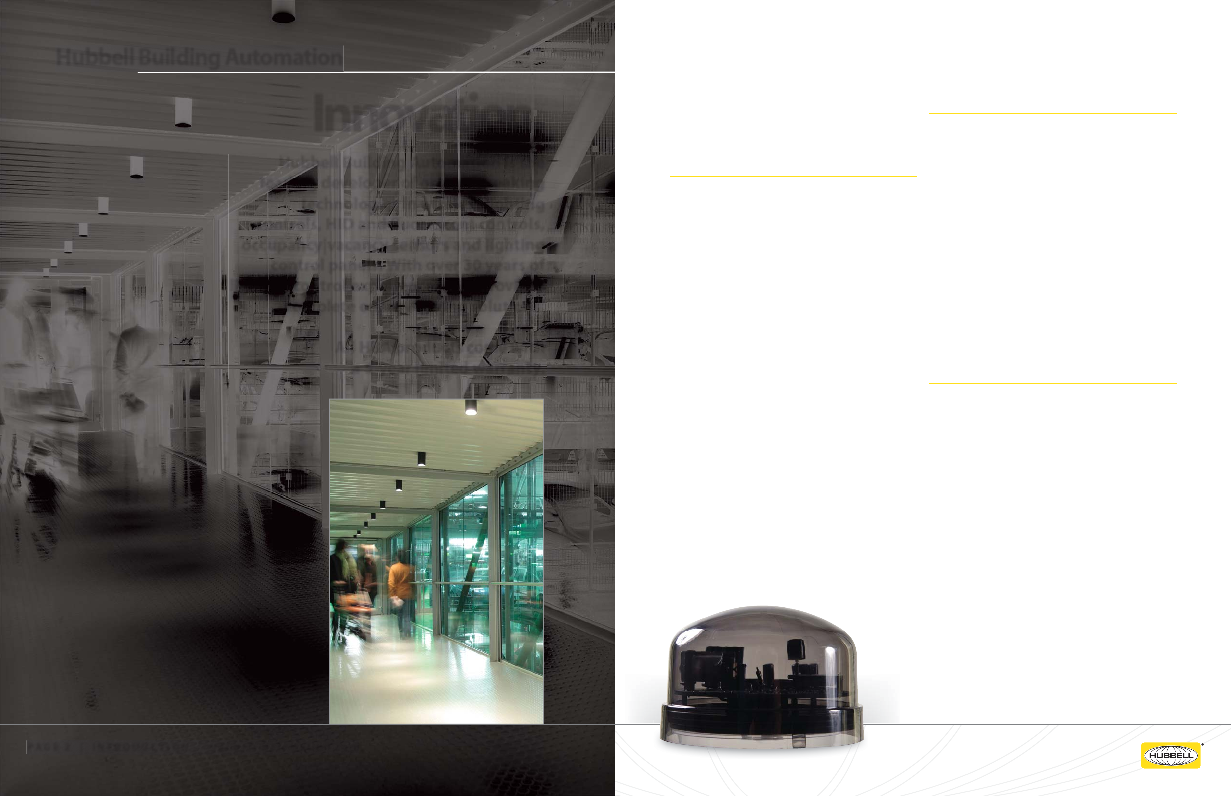
Hubbell Building Automation is the
leading developer of groundbreaking
technologies in wireless lighting
controls, HID and uorescent controls,
occupancy|vacancy sensors and lighting
control panels. With over 30 years of
lighting control experience, HBA provides
complete energy-saving solutions.
All HBA products come with
a 5-year limited warranty.
Innovation.
PAGE 2 | INTRODUCTION | hubbell-automation.com
Hubbell Building Automation
h
ubb
ell-
au
t
o
m
a
ti
o
n
.
c
om
PAGE 3 | INTRODUCTION
WIH-OM
wiHUBB On-Fixture Module
h
ubb
ell-
au
t
o
m
a
ti
o
n
.
c
om
E
E
n
n
e
e
r
r
g
g
y
y
C
C
o
o
n
n
s
s
e
e
r
r
v
v
a
a
t
t
i
i
o
o
n
n
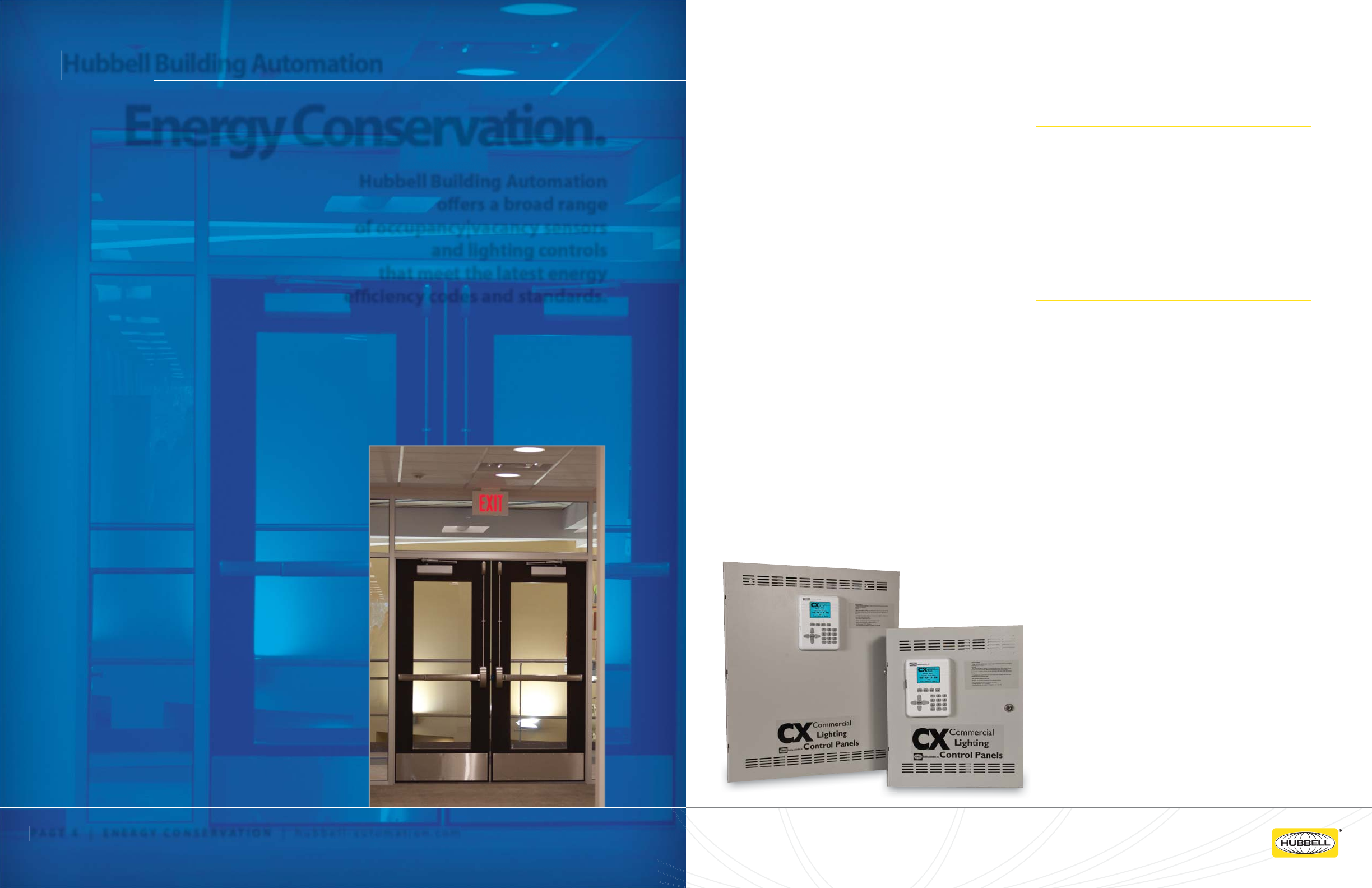
Hubbell Building Automation
o ers a broad range
of occupancy|vacancy sensors
and lighting controls
that meet the latest energy
e ciency codes and standards.
PAGE 4 | ENERGY CONSERVATION | hubbell-automation.com
Energy Conservation. Energy conservation has become a signi cant global
movement, with nations, states, and local municipalities
creating new codes and standards of e ciency for both
commercial and residential buildings. These codes and
standards include:
• LEED® (Leadership in Energy and Environmental
Design) certi cation in new and renovated facilities
through the U.S. Green Building Council (USGBC)
promotes sustainable building design.
• California Energy Commission’s (CEC) Title
24 program enforces stringent standards and
regulations to reduce energy consumption,
including automatic lighting control and shut-o .
• ASHRAE/IESNA 90.1 energy e ciency code
requires interior lighting in buildings larger than
5000 sq. ft. to be controlled with automatic devices.
• IECC® (International Energy Conservation Code)
compliance requires automatic shut-o of lighting
which is now adopted by most states in some form.
As energy concerns increase, the “greening” of
commercial and residential buildings will continue
through stringent standards and energy conservation
initiatives like the EPA’s ENERGY STAR program, or the
2030 Challenge which aims to reduce energy use by
50% before 2030.
HBA Occupancy Sensors Play a Key Role
In the U.S., lighting consumes 22% of electricity and
represents $40 billion a year in energy costs. Hubbell
Building Automation’s Occupancy Sensors save energy
and provide sustainability by automatically and
e ectively turning lights on when a room is occupied
and o when a room is vacant. In a typical o ce
building, where lighting accounts for 35 to 45% of
energy use, HBA Occupancy Sensors have the potential
to reduce wasted lighting by 13 to 90% for a signi cant
return on investment (ROI).
Backed by HBA Service and Support
HBA Occupancy Sensors are backed by Hubbell Building
Automation’s sustainability initiative and superior
service with support including:
• Valuable online ROI worksheet for calculating
energy savings
• Product selection guide for choosing the right HBA
Occupancy Sensor and technology
• Online speci cation assistance through
HBAControls.com, AutoCAD drawings, templates
and documentation
• Comprehensive design assistance for deploying
occupancy sensors in a variety of applications
• Highly knowledgeable network of speci cation
professionals and trained, dedicated sales sta
• A commitment to safeguard the environment
through environmental stewardship, innovative
products and e cient operations
For more information about Hubbell Building
Automation’s sustainability initiative and access to
our complete suite of on-line tools, visit our website at
hubbell-automation.com.
PAGE 5 | ENERGY CONSERVATION
Hubbell Building Automation
CX16 and CX24
CX Series Commecial Lighting Control panels.

h
ubb
ell-
au
t
o
m
a
ti
o
n
.
c
om
B
B
u
u
s
s
i
i
n
n
e
e
s
s
s
s
S
S
e
e
r
r
v
v
i
i
c
c
e
e
s
s
HBA’s Business Services group
provides thorough answers
to your questions and ensures the best
service: You get a sta member equipped
with in-house resources because
our products are designed
and manufactured under the same roof.
PAGE 6 | ENERGY CONSERVATION | hubbell-automation.com
Support, Service and
Quotations.
HBA’s Business Services group is available daily
from 8am to 6pm CST.
Customer Service
Get a personalized level of service:
• Detailed product knowledge
• Fast and accurate order entry
• Timely order acknowledgements
• Order management from initial ordering
to shipping
Technical Services
HBA’s technical services include quotations,
factory-certi ed occupancy sensor layouts, technical
phone support, application support, and technical
documentation.
Quotations
HBA’s Quotations Group coordinates with the Technical
Services Group to provide detailed drawings and
accurate quotations, working with you to ensure all
needs of your project are ful lled. Get detailed submittal
packages, necessary product documentation and
project-speci c information.
Factory-Certi ed Layouts
We guarantee the type and placement of each control
on every drawing. Send electronic AutoCAD les and
we’ll create a factory-certi ed layout and a competitive
layout with a detailed Bill of Materials. If you would like
hard copies, we create professional paper drawings in
any size speci cation upon request.
PAGE 7 | ENERGY CONSERVATION
Hubbell Building Automation
CONTACT
INFORMATION
TELEPHONE AUSTIN, TX USA
512.450.1100
TELEPHONE TOLLFREE
888.698.3242
FAX ORDERS ONLY
512.450.0864
FAX GENERAL
512.450.1215
FAX TOLLFREE CUSTOMER SERVICE
877.783.9201
CORPORATE WEBSITE
hubbell-automation.com
TECHNICAL DRAWING SUBMITTAL
hba-cad@hubbell-automation.com
h
ubb
ell-
au
t
o
m
a
ti
o
n
.
c
om
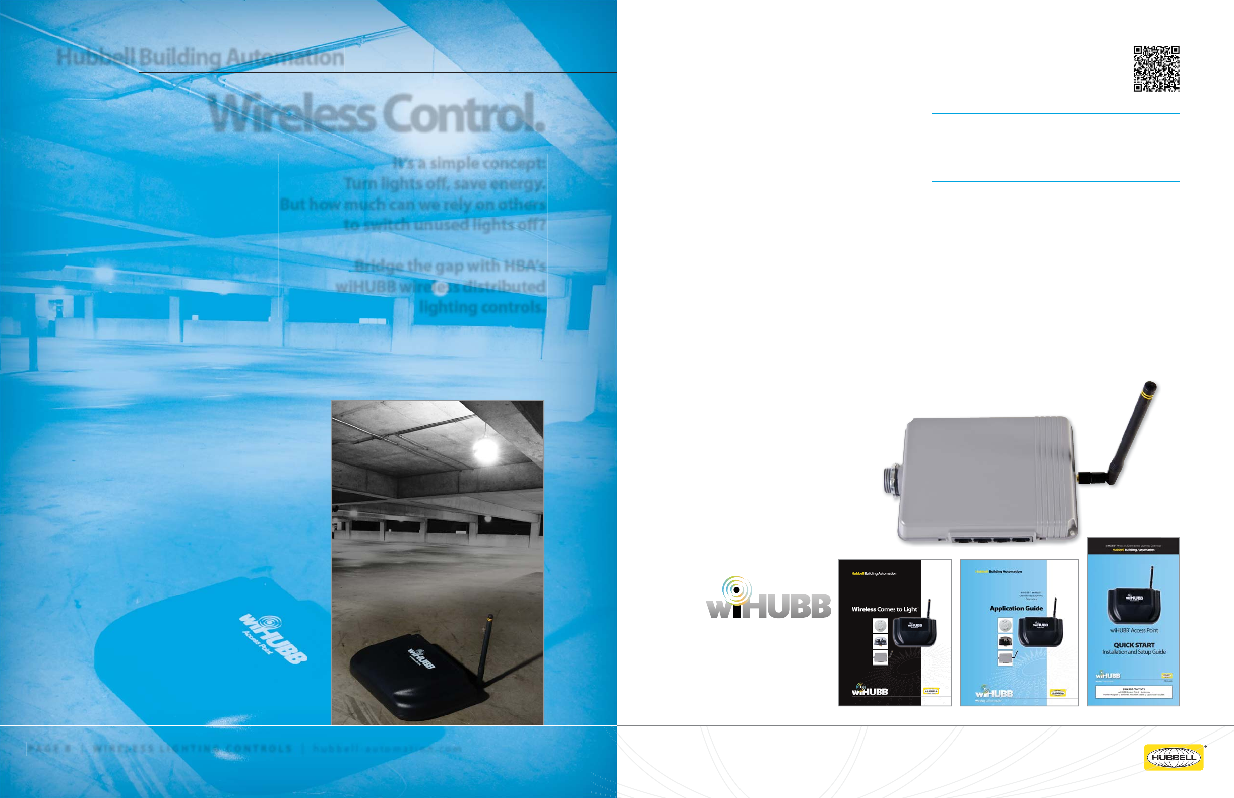
Wireless Lighting Controls
It’s a simple concept:
Turn lights o , save energy.
But how much can we rely on others
to switch unused lights o ?
Bridge the gap with HBA’s
wiHUBB wireless distributed
lighting controls.
PAGE 8 | WIRELESS LIGHTING CONTROLS | hubbell-automation.com
Wireless Control. In the U.S., lighting consumes 22% of electricity and
represents $40 billion a year in energy costs. In a typical
o ce building, lighting accounts for 35-45% of energy
use. wiHUBB™, HBA’s wireless distributed lighting control
system can reduce wasted lighting energy by 13-90% for
a signi cant return on investment.
The wiHUBB system wirelessly controls indoor and
outdoor applications including area/site lighting, parking
garage lighting, and interior facility lighting. It is simple to
install and con gure, and provides a virtually unlimited
wireless network size that can grow and change with your
building’s needs.
With wiHUBB, it’s easy to control, con gure and recon-
gure individual devices or groups of devices over-the-air
with the click of a mouse. All devices within the wiHUBB
mesh network are peers that act as repeaters by
forwarding messages to devices that may be out of range
from the device originating the message.
While installation of wired systems can be complicated
and expensive, wiHUBB is simple to use, requiring
minimal installation time and wiring costs. wiHUBB’s
future proof design features a self-organizing and
self-healing wireless mesh network. It requires no
special software or physical addressing of devices
and can be accessed from your local network or the
Internet using any standard browser.
Easy to Retro t
Add wiHUBB wireless controls to existing lighting
systems without having to rewire or change existing
circuits.
Flexibility
Con gure and control individual devices or groups
of devices—including indoor and outdoor lighting
xtures, occupancy sensors, daylight sensors and switch
stations— over the air with the click of a mouse.
Savings
Reduce lighting-based energy waste by 13-90% when
wiHUBB automatically and intelligently turns lights on
when a space is occupied, and o when the space is not.
PAGE 9 |
WI
W
RELESS LIGHT
N
IN
G CONTROLS
Hubbell Building Automation
Pictured above - wiHUBB Smart Pack.
For more information on wiHUBB,
please see the following HBA publications
available online at hubbell-automation.com
or simply scan the QRcode at the top
of this page.
g
B
B’
s
n
d
o
s
h
e
h
ubb
ell-
au
t
o
m
a
ti
o
n
.
c
om
wiHUBB™ Wireless Distributed Lighting Controls
Quick Reference Guide
PAGE 10 | WIRELESS LIGHTING CONTROLS | hubbell-automation.com
PAGE 11 | WI
E
R
LE
S
SS
LIGHTING CONTROLS
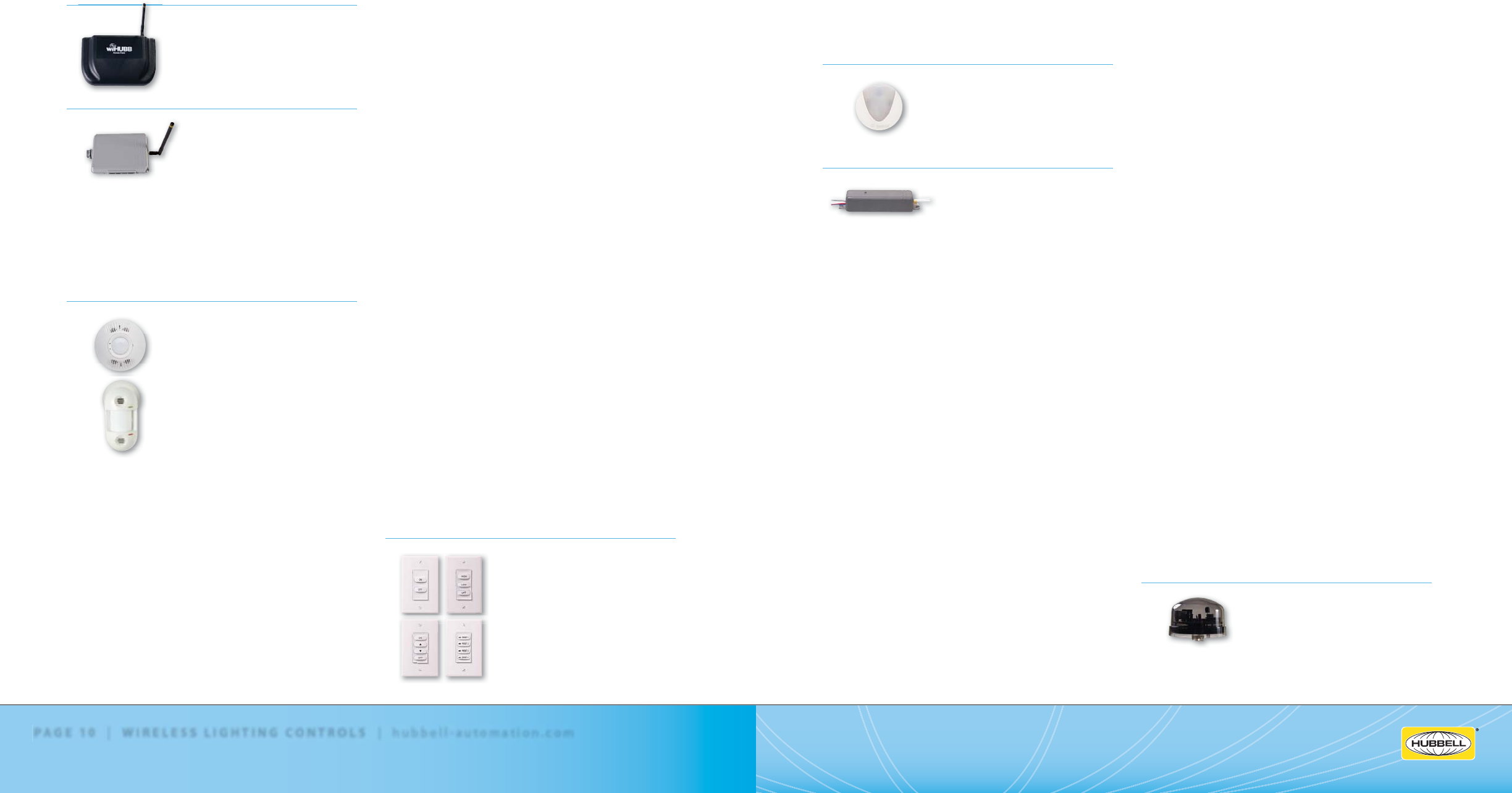
wiHUBB Access Point
Page 37
WIH-AP wiHUBB Access Point
wiHUBB Smart Pack
Page 39
WIH-SP-1R-1277 wiHUBB Smart Pack
1 SPST Output, 120/277VAC
WIH-SP-1RD-1277 wiHUBB Smart Pack
1 SPST Output, 0-10VDC Dimming,
120/277VAC
WIH-SP-2R-1277 wiHUBB Smart Pack
2 SPST Outputs, 120/277VAC
WIH-SP-2RD-1277 wiHUBB Smart Pack
2 SPST Outputs, 0-10VDC Dimming,
120/277VAC
wiHUBB Ceiling and Wall Mount Occupancy Sensors
Page 41
WIH-OS-OMDT2 Ceiling Mount,
PIR and Ultrasonic, 2000 Sq. Ft.
WIH-OS-OMDT2R Ceiling Mount, PIR
and Ultrasonic, 2000 Sq. Ft., Form C Relay
WIH-OS-OMDT1 Ceiling Mount,
PIR and Ultrasonic, 1000 Sq. Ft.
WIH-OS-OMDT1R Ceiling Mount,
PIR and Ultrasonic, 1000 Sq. Ft.,
Form C Relay
WIH-OS-OMDT5 Ceiling Mount,
PIR and Ultrasonic, 500 Sq. Ft.
WIH-OS-OMDT5R Ceiling Mount,
PIR and Ultrasonic, 500 Sq. Ft.,
Form C Relay
WIH-OS-OMUS2 Ceiling Mount,
Ultrasonic, 2000 Sq. Ft.
WIH-OS-OMUS2R Ceiling Mount,
Ultrasonic, 2000 Sq. Ft., Form C Relay
WIH-OS-OMUS1 Ceiling Mount,
Ultrasonic, 1000 Sq. Ft.
WIH-OS-OMUS1R Ceiling Mount,
Ultrasonic, 1000 Sq. Ft., Form C Relay
WIH-OS-OMUS5 Ceiling Mount,
Ultrasonic, 500 Sq. Ft.
WIH-OS-OMUS5R Ceiling Mount,
Ultrasonic, 500 Sq. Ft., Form C Relay
WIH-OS-OMIR Ceiling Mount,
Passive Infrared, 450 Sq. Ft.
WIH-OS-OMIRR Ceiling Mount,
Passive Infrared, 450 Sq. Ft., Form C Relay
WIH-OS-OMIRL Ceiling Mount,
Passive Infrared, 1500 Sq. Ft.
WIH-OS-OMIRLR Ceiling Mount,
Passive Infrared, 1500 Sq. Ft.,
Form C Relay
WIH-OS-OMIDIA Ceiling Mount,
PIR and Acoustic, 450 Sq. Ft.
WIH-OS-OMIDIAR Ceiling Mount,
PIR and Acoustic, 450 Sq. Ft.,
Form C Relay
WIH-OS-LODT Wall Mount,
PIR and Ultrasonic, 1600 Sq. Ft.
WIH-OS-LODTR Wall Mount,
PIR and Ultrasonic, 1600 Sq. Ft.,
Form C Relay
WIH-OS-LOIRWV Wall Mount,
Passive Infrared, 2500 Sq. Ft.
WIH-OS-LOIRWVR Wall Mount,
Passive Infrared, 2500 Sq. Ft.,
Form C Relay
WIH-OS-LOIRHB Wall Mount,
Passive Infrared, 50’ at 30’ Height
WIH-OS-LOIRHBR Wall Mount,
Passive Infrared, 50’ at 30’ Height,
Form C Relay
WIH-OS-LODIA Wall Mount,
PIR and Acoustic, 1600 Sq. Ft.
WIH-OS-LODIAR Wall Mount,
PIR and Acoustic, 1600 Sq. Ft.,
Form C Relay
wiHUBB Switch Stations
Page 45
WIH-SW-OO ON/OFF Switch, White
WIH-SW-GAV General – A/V Mode
Switch, White
WIH-SW-HLO High/Low/O Switch,
White
WIH-SW-ORLO On/Raise/Lower/O
Switch, White
WIH-SW-RL Raise/Lower Switch, White
WIH-SW-TO Timed On Switch, White
WIH-SW-PRESET Preset Switch
(4-button), White
wiHUBB Daylight Sensor
Page 47
WIH-DS wiHUBB Daylight Sensor
wiHUBB In-Fixture Module
Page 49
WIH-IM-1R-1277 1 SPST Output
(Antenna not included), 120/277VAC
WIH-IM-1R-347 1 SPST Output
(Antenna not included), 347VAC
WIH-IM-1RD-1277 1 SPST Output,
0-10VDC Dimming Output
(Antenna not included), 120/277VAC
WIH-IM-1RD-347 1 SPST Output,
0-10VDC Dimming Output
(Antenna not included), 347VAC
WIH-IM-1RA-1277 1 SPST Output,
Articulating Antenna, 120/277VAC
WIH-IM-1RA-347 1 SPST Output,
Articulating Antenna, 347VAC
WIH-IM-1RDA-347 1 SPST Output,
0-10VDC Dimming Output,
Articulating Antenna, 347VAC
WIH-IM-1RDA-1277 1 SPST Output,
0-10VDC Dimming Output,
Articulating Antenna, 120/277VAC
WIH-IM-1RDA-347 1 SPST Output,
0-10VDC Dimming Output,
Articulating Antenna, 347VAC
WIH-IM-1RF-1277 1 SPST Output,
Fixed Antenna with 24” Extension Cable,
120/277VAC
WIH-IM-1RF-347 1 SPST Output,
Fixed Antenna with 24” Extension Cable,
347VAC
WIH-IM-1RDF-1277 1 SPST Output,
0-10VDC Dimming Output,
Fixed Antenna with 24” Extension Cable,
120/277VAC
WIH-IM-1RDF-347 1 SPST Output,
0-10VDC Dimming Output,
Fixed Antenna with 24” Extension Cable,
347VAC
WIH-IM-2R-1277 2 SPST Outputs
(Antenna not included), 120/277VAC
WIH-IM-2R-347 2 SPST Outputs
(Antenna not included), 347VAC
WIH-IM-2RD-1277 2 SPST Outputs,
0-10VDC Dimming Output
(Antenna not included), 120/277VAC
WIH-IM-2RD-347 2 SPST Outputs,
0-10VDC Dimming Output
(Antenna not included), 347VAC
WIH-IM-2RA-1277 2 SPST Outputs,
Articulating Antenna, 120/277VAC
WIH-IM-2RA-347 2 SPST Outputs,
Articulating Antenna, 347VAC
WIH-IM-2RDA-1277 2 SPST Outputs,
0-10VDC Dimming Output,
Articulating Antenna, 120/277VAC
WIH-IM-2RDA-347 2 SPST Outputs,
0-10VDC Dimming Output,
Articulating Antenna, 347VAC
WIH-IM-2RF-1277 2 SPST Outputs,
Fixed Antenna with 24” Extension Cable,
120/277VAC
WIH-IM-2RF-347 2 SPST Outputs,
Fixed Antenna with 24” Extension Cable,
347VAC
WIH-IM-2RDF-1277 2 SPST Outputs,
0-10VDC Dimming Output,
Fixed Antenna with 24” Extension Cable,
120/277VAC
WIH-IM-2RDF-347 2 SPST Outputs,
0-10VDC Dimming Output,
Fixed Antenna with 24” Extension Cable,
347VAC
wiHUBB On-Fixture Module
Page 51
WIH-OM-UNV 120-347VAC, 50/60Hz
W
(
W
HUBB
Access
Poin
g
e 37
e
39
W
1
W
1
h
ubb
ell-
au
t
o
m
a
ti
o
n
.
c
om
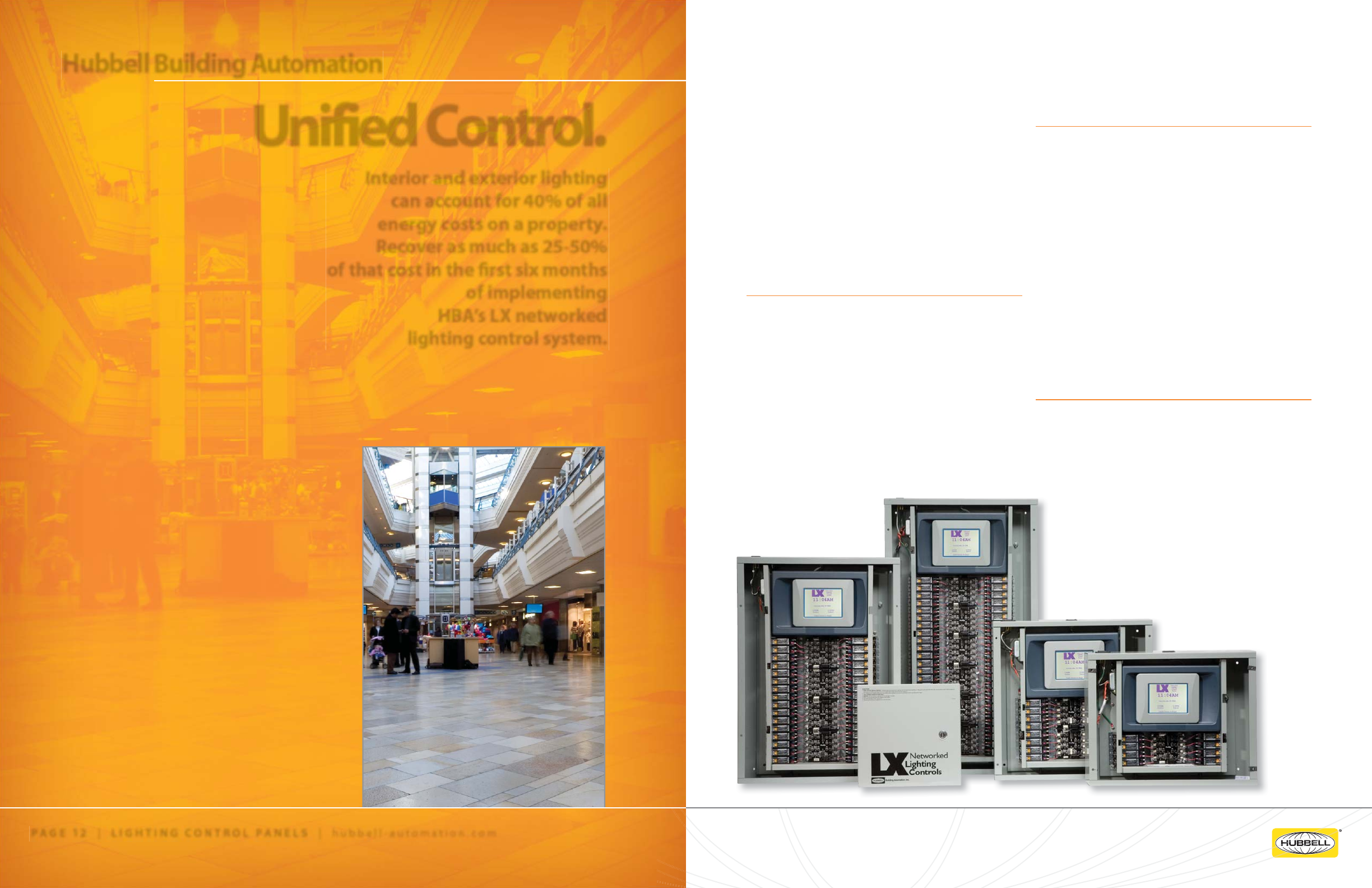
LX Networked Lighting Controls
Interior and exterior lighting
can account for 40% of all
energy costs on a property.
Recover as much as 25-50%
of that cost in the rst six months
of implementing
HBA’s LX networked
lighting control system.
PAGE 12 | LIGHTING CONTROL PANELS | hubbell-automation.com
Unified Control. LX is a network of expandable and modular relay
panels, sensors and switches. Take control of your
lighting near or far with its intuitive programming
interface, touchscreen tablet and remote access via LAN
and Internet.
Connect to any point on the topology-free,
polarity-insensitive, 2-wire LON communication network
with our LonMark® certi ed architecture. Install sensors
and switches “plug-and-play” for endless possibilities in
control and savings.
Save Time
LX control panels are simple to install and use. The
LX series utilizes LonMark® certi ed architecture so
sensors and switches can be installed plug-and-play
by connecting to any point on the topology-free,
polarity-insensitive 2-wire communication network.
Inprove the ease of owning and using lighting
• Unique handheld touchscreen GUI
• Robust and reliable 20 Amp mechanically-latching
relays
• Multiple size enclosures available
(4, 8, 16, 32, and 48 relays)
• Powered, topology-free, polarity-insensitive,
2-wire communication
• LonMark® certi ed
• Seamless integration with major building protocols,
such as LON, BACNET® and MODBUS®
• Feature-rich scheduling functions
• 365-day time clock
• Automatic daylight savings time and leap year
compensation
• Built-in astronomical time clock for sunrise
and sunset programming
• UL and cUL listed
Flexibility
The LX networked lighting controls use a handheld
touchscreen GUI interface that keeps up with the
constant progression of lighting control systems.
PAGE 13 | LIGHTING CONTROL PANELS
Hubbell Building Automation
LX4, LX8, LX16, LX32, LX48
LX Lighting Control Panels
h
ubb
ell-
au
t
o
m
a
ti
o
n
.
c
om
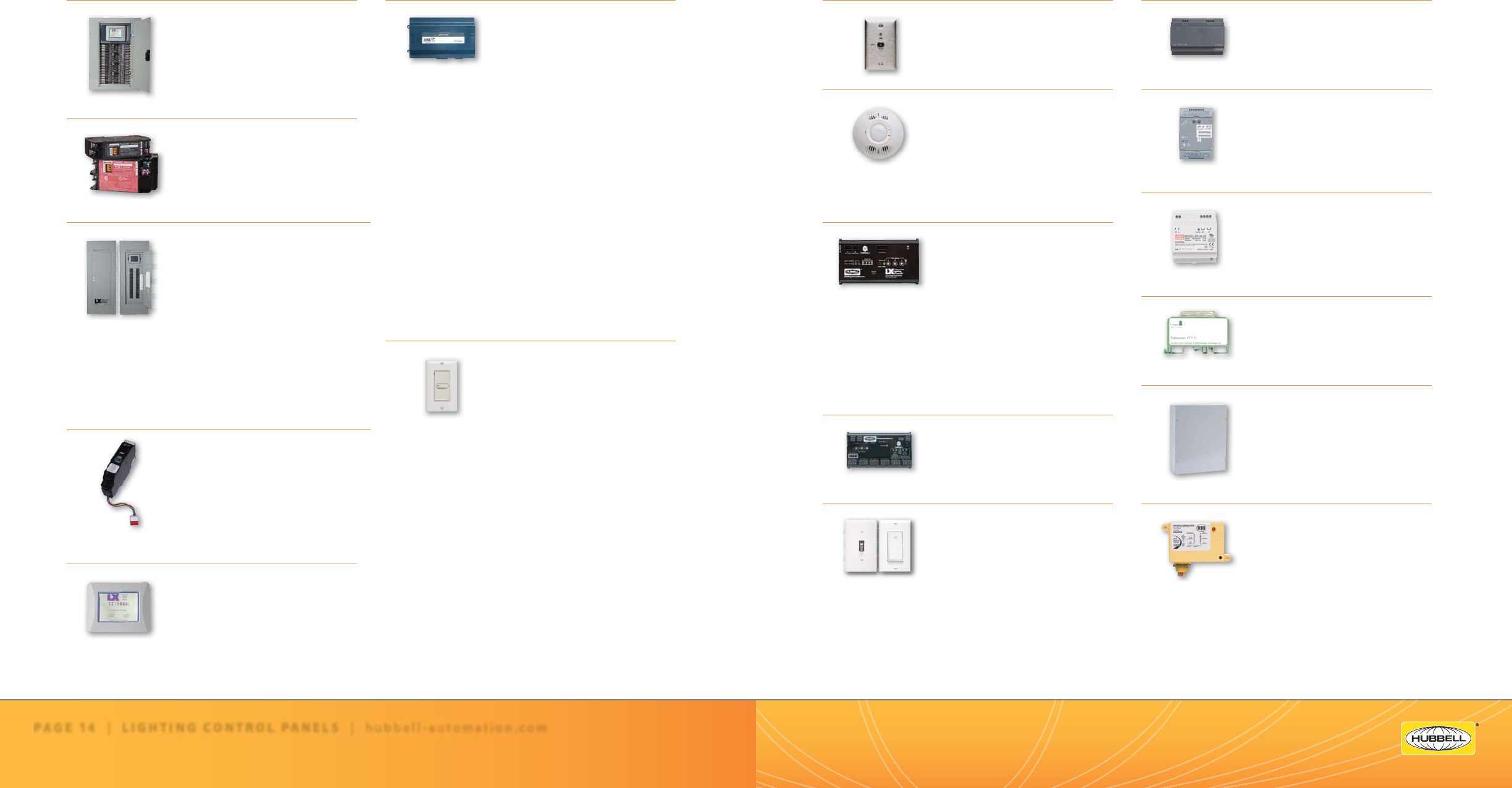
LX Networked Lighting Control Panels
Quick Reference Guide
PAGE 14 | LIGHTING CONTROL PANELS | hubbell-automation.com
PAGE 15 | LIGHTING CONTROL PANELS
LX Link Power Module
Page 81
LXLPM2 LX Link Power Module, 120VAC
LX Router/Repeater
Page 83
LXRRM LX Router/Repeater Module
LX Power Supply
Page 85
LXPWRSPLY LX Power Supply
LX Terminator
Page 87
LXTERMINATOR LX Free
Topology Bus Terminator
LX Enclosure for DIN Rail Modules
Page 89
LXENDM LX Enclosure
for DIN Rail Device Modules
LXUL924
Page 91
LXUL924BR1 LX UL924 Enclosed Relay
20 Amp SPDT with 24 VAC/DC/120 VAC Coil
LXUL924BR2 LX UL924 Enclosed Relay
20 Amp SPDT with 24 VAC/DC/
208-277 VAC Coil
LX Keyed Switch Station
Page 71
LXKEY1LP LX Keyed Switch
Station, Link Power Version
LX Occupancy Sensor Featuring IntelliDAPT
Page 73
LXOMDT2000FT LX Intelligent
Ultrasonic and PIR Occupancy
Sensor, FT-10
LXOMDT2000LP LX Intelligent
Ultrasonic and PIR Occupancy
Sensor, Link Power
LX Photo Sensor Control Module and Sensors
Page 75
LXPSCMLP LX Photo Sensor
Control Module – Link Power
LXPSCMFT LX Photo Sensor
Control Module – FT
LXPSPCI LX Photo Sensor
Photocell Indoor
LXPSPCO LX Photo Sensor
Photocell Outdoor
LXPSPCS LX Photo Sensor
Photocell Skylight/Atrium
LX Dry Contact Interface Modules
Page 77
LXDCIMFT LX Dry Contact
Interface Module
LX Sentry Switch
Page 79
LXS05T 5A 120/240/277VAC
LXS05DW 5A 120/240/277VAC
LXS05DI 5A 120/240/277VAC
LXS05T3 5A 120/240/277VAC
LXS05T3W 5A 120/240/277VAC
LXS05T3I 5A 120/240/277VAC
LXS20T 20A 120/240/277VAC
LXS20DW 20A 120/240/277VAC
LXS20DI 20A 120/240/277VAC
LXS20T3 20A 120/240/277VAC
LXS20T3W 20A120/240/277VAC
LXS20T3I 20A 120/240/277VAC
LXJENEsys Network Interface Components
Page 67
LXJNSYS LX JENEsys Controller with
Management Software
LXJNSYS2LON LX JENEsys Controller
with Management Software
LXJNSYS2BACNETIP LX JENEsys
Controller with Management Software,
BACNET IP Integration Support
LXJNSYS2BACNETMSTP
LX JENEsys Controller with Management
Software, BACNET MS/TP Integration
Support
LXJNSYS3BACNETMSTP
LX JENEsys Controller with Management
Software, BACNET MS/TP Integration
Support
LXJNSYS2MODBUS LX JENEsys
Controller with Management Software,
MODBUS Integration Support
LXJNCOM56KM1 LX JENEsys
56kbps Modem for LX JENEsys Controller
LX Networked Switch Stations
Page 69
LXSW1LP 1 Button
LXSW2LP 2 Buttons
LXSW3LP 3 Buttons
LXSW4LP 4 Buttons
LXSW5LP 5 Buttons
LXSW6LP 6 Buttons
LXSW1FT 1 Button
LXSW2FT 2 Buttons
LXSW3FT 3 Buttons
LXSW4FT 4 Buttons
LXSW5FT 5 Buttons
LXSW6FT 6 Buttons
LX Lighting Control Panels 4, 8, 16, 32, 48 Relays
Page 57
LX4 up to 4 Relays
LX8 up to 8 Relays
LX16 up to 16 Relays
LX32 up to 32 Relays
LX48 up to 48 Relays
LX Relays
Page 59
LXRL1 LX Relay, Single Pole,
120/277/347VAC
LXRL2 LX Relay, Double Pole,
208/240/480VAC
LXBC Breaker Control Panels 12, 18, 30, 42 Breaker/Relays
Page 61
LXBC11LB Panels
LXBC11CB Panels
LXBC12LB Panels
LXBC12CB Panels
LXBC14LB Panels
LXBC14CB Panels
LXBC21LB Panels
LXBC22LB Panels
LXBC22CB Panels
LXBC24LB Panels
LXBC24CB Panels
LXBR Circuit Breaker Relays/Circuit Breakers
Page 63
LXBR “C” Series
20A-30A, 1P or 2P
Controlled Circuit Breaker/Relay
LXBR “N” Series
20A, 3P, Non-Controlled Circuit breaker
15A - 100A, 1P, 2P or 3P
LX Touch Tablet Graphical User Interface
Page 65
LXTB LX Touch Screen Tablet
g
P.Z10013
Easylon Bus Terminator
Free Topology
3
g
hubb
e
ll
-
au
t
o
m
a
ti
o
n
.
c
om
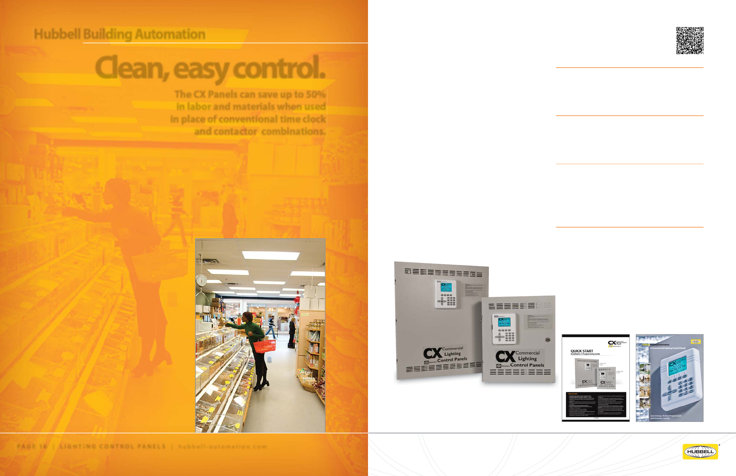
CX Commercial Lighting Controls
The CX Panels can save up to 50%
in labor and materials when used
in place of conventional time clock
and contactor combinations.
PAGE 16 | LIGHTING CONTROL PANELS | hubbell-automation.com
Clean, easy control. CX Commercial Lighting Control Panels replace
costly and labor-intensive conventional time clocks and
contactors to provide feature-rich and cost-e ective
lighting control for maximum energy savings.
The CX panel’s LCD user interface is located in the
door and utilizes simple and intuitive scrolling menus
to program, check status or update the panel. The
easy-to-use pre-programmed Scenarios Menu makes
project commissioning simple and fast.
CX utilizes an astronomical clock rather than
roof-mounted photocells. This increases cost savings,
improves reliability and lowers maintenance.
Save Time.
• Easy-to-follow, intuitive programming user interface
• All inputs are software assignable to any HBA
low-voltage input device including switches,
motion sensors and photocells.
Save Energy.
• Meets ASHRAE 90.1, IEEC, California (CEC) Title 24
energy codes.
• CX panels contribute to LEED certi cation
requirements
Save Money.
• Save up to 50% in parts and labor cost over
conventional timeclock and contactor systems
• Expanded programming options lowers energy
consumption
• Astronomical clock eliminates need for
roof-mounted photocells
Increase Control.
• Create scenarios for easy-to-use control
combinations
• Customize customer-centric control solutions
with priorities and masking
PAGE 17 | LIGHTING CONTROL PANELS
Hubbell Building Automation
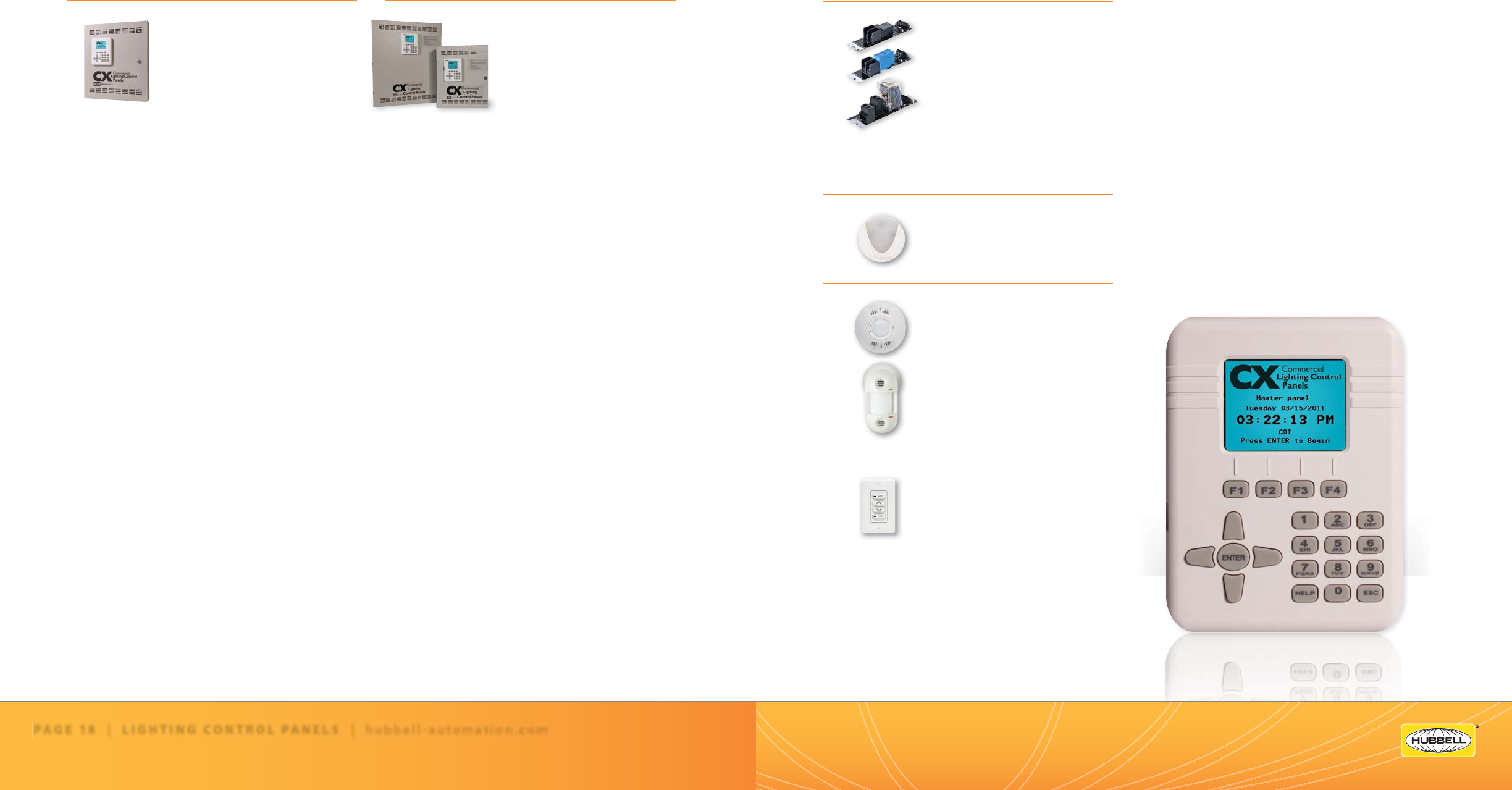
Pictured above - CX24 and CX08 panels.
For more information on CX Commercial Lighting Control panels ,
please see the following HBA publications available online at
hubbell-automation.com or simply scan the QR code at the top of this page.
h
ubb
ell-
au
t
o
m
a
ti
o
n
.
c
om
CX Commercial Lighting Control Panels
Quick Reference Guide
PAGE 18 | LIGHTING CONTROL PANELS | hubbell-automation.com
PAGE 19 | LIGHTING CONTROL PANELS
CX Commercial Lighting Control Panels 4 and 8 Relays
Page 101
4-Relay Stand Alone Panels
CX042S042NN
CX042S043LN
CX042S04TNN
CX042S00SPN
CX043S043LN
CX043S00SPN
8-Relay Master and Secondary Panels
CX082S082NM
CX082S083LM
CX082S08TNM
CX082S00SPM
CX083S083LM
CX083S00SPM
CX082S00SPS
CX082S082NS
CX082S083LS
CX082S08TNS
CX083S00SPS
CX083S083LS
CX Commercial Lighting Control Panels 16 and 24 Relays
Page 105
CX162S00SPM
CX162S00SPS
CX162S162NM
CX162S162NS
CX162S163LM
CX162S163LS
CX162S16TNM
CX16261TNS
CX163S00SPM
CX163S00SPS
CX163S163LM
CX163S163LS
CX242S00SPM
CX242S00SPS
CX242S242NM
CX242S242NS
CX242S243LM
CX242S243LS
CX242S24TNM
CXR Relays
Page 107
CXR2N 20A 1-Pole Electrically Held N/O
120-277V 12KSCCR@277VAC
CXR2C 20A 1-Pole Electrically Held N/C
120-277V 14SCCR @ 277VAC
CXR3L 30A 1-Pole Latching 120-277-347V
18KSCCR @ 277VAC, 14KSCCR@347VAC
CXRTN 20A 2-Pole Elecrically Held N/O
480V 14KSCCR @ 480VAC
CXRTC 20A 2-Pole Elecrically Held N/C
480V 14KSCCR @ 480VAC
CX Panel Photocells
Page 109
LUXSTATLS Indoor
LUXSTATLO Outdoor
CX Motion Sensors
Page 109
Consult hubbell-automation.com
for detailed catalog numbers, speci ca-
tions and application guidelines.
CX Panel Low Voltage Switches
Page 109
LVSM1NP Momentary, 1 Button, No Pilot
LVSM1PL Momentary, 1 Button,
w/Pilot LED
LVSM2NP Momentary, 2 Button, No Pilot
LVSM2PL Momentary, 2 Button,
w/Pilot LED
LVSM3NP Momentary, 3 Button, No Pilot
LVSM3PL Momentary, 3 Button,
w/Pilot LED
LVSM4NP Momentary, 4 Button, No Pilot
LVSM4PL Momentary, 4 Button,
w/Pilot LED The CX panel User Interface
LCD Display / Keypad allows access to all programming, system
status, and manual controls.
h
ubb
ell-
au
t
o
m
a
ti
o
n
.
c
om
High Bay Lighting Controls
Hubbell Building Automation’s Fluorescent High Bay
sensors reduce energy waste by automatically and
e ectively turning lights on when a room is occupied
and o when a room is vacant.
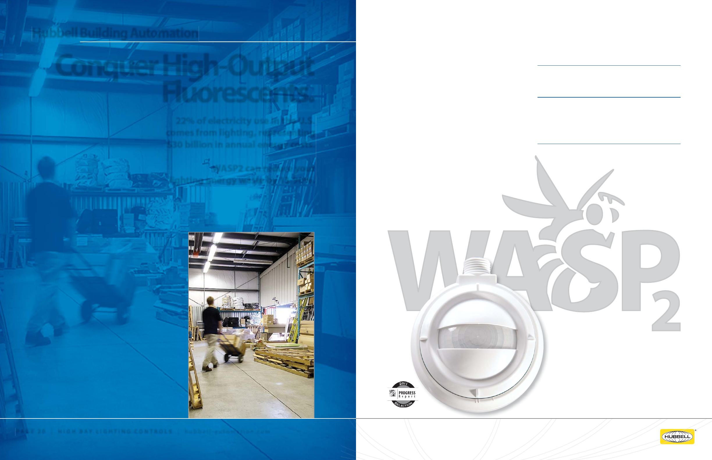
The HBA WASP2 Fluorescent High Bay Occupancy
Sensor features a daylight sensor for increased energy
savings, and is speci cally designed for ON/OFF
control of high bay uorescent xtures in warehouses,
distribution centers and similar facilities.
WASP2 is an intelligent, microprocessor-based Passive
Infrared (PIR) occupancy sensor designed for T5, T5HO,
and T8 uorescent xtures. WASP2 contains zero arc
point switching, minimizing relay contact wear from
high inrush loads.
WASP2 meets the latest energy e ciency codes and
standards, including ASHRAE/IESNA 90.1 and CEC’s Title
24, and can provide LEED (Leadership in Energy and
Environmental Design) points in categories including
Sustainable Sites, Energy and Atmosphere, Indoor
Environmental Quality and Innovative Design Process.
Savings.
WASP2 decreases energy consumption by 50% during
periods of no occupancy.
Flexibility.
WASP2 supports mounting heights up to 45 feet and
features multiple outputs, mounting options and
lens options. Additionally, low-temperature (-40°C),
water-tight and outdoor versions are available.
Control.
WASP2 features ON/OFF, stepped dimming and
daylight harvesting control. WASP2 also improves
lamp life by utilizing HBA’s unique Smart Cycling™
technology, ensuring all lamps receive the same number
of switching cycles.
PAGE 21 | HIGH BAY LIGHTING CONTROLS
22% of electricity use in the U.S.
comes from lighting, representing
$30 billion in annual energy costs.
WASP2 can reduce your
lighting energy waste by 13-90%.
PAGE 20 | HIGH BAY LIGHTING CONTROLS | hubbell-automation.com
Conquer High-Output
Fluorescents.
Hubbell Building Automation

h
ubb
ell-
au
t
o
m
a
ti
o
n
.
c
om
High Bay Lighting Controls
Quick Reference Guide
PAGE 22 | HIGH BAY LIGHTING CONTROL | hubbell-automation.com
PAGE 23 | HIGH BAY LIGHTING CONTROLS
HBA WASP2
Page 113
WSPEM24V
HBA WASP2 Fl. High Bay Sensor with
Daylighting, End Mnt, 24VDC
(Power Pack Required), Form C Relay
WSPEMUNV HBA WASP2 Fl. High
Bay Sensor with Daylighting, End Mnt,
1 SPST Output, 120/277/347VAC
WSPEMUNV2R
HBA WASP2 Fl. High Bay Sensor with
Daylighting, End Mnt, 2 SPST Outputs,
120/277/347VAC
WSPEM208
HBA WASP2 Fl. High Bay Sensor with
Daylighting, End Mnt, 1 DPST Output,
208/240VAC
WSPEM480
HBA WASP2 Fl. High Bay Sensor with
Daylighting, End Mnt, 1 DPST Output,
480VAC
WSPEM24VLTWT
HBA WASP2 Fl. High Bay Sensor with
Daylighting, End Mnt, 24VDC (Power Pack
Required), Form C Relay, Low Temp,
Water Tight
WSPEMUNVLTWT
HBA WASP2 Fl. High Bay Sensor with
Daylighting, End Mnt, 1 SPST Output,
120/277/347VAC, Low Temp, Water Tight
WSPEMUNV2RLTWT
HBA WASP2 Fl. High Bay Sensor with
Daylighting, End Mnt, 2 SPST Outputs,
120/277/347VAC, Low Temp, Water Tight
HBA WASP2 (continued)
Page 113
HBA WASP2 (continued)
Page 113
HBA WASP2 (continued)
Page 113
WSPEM208LTWT
HBA WASP2 Fl. High Bay Sensor with
Daylighting, End Mnt, 1 DPST Output,
208/240VAC, Low Temp, Water Tight
WSPEM480LTWT
HBA WASP2 Fl. High Bay Sensor with
Daylighting, End Mnt, 1 DPST Output,
480VAC, Low Temp, Water Tight
WSPSM24V
HBA WASP2 Fl. High Bay Sensor with
Daylighting, Surface Mnt, 24VDC (Power
Pack Required), Form C Relay
WSPSMUNV
HBA WASP2 Fl. High Bay Sensor with
Daylighting, Surface Mnt, 1 SPST Output,
120/277/347VAC
WSPSMUNV2R
HBA WASP2 Fl. High Bay Sensor with
Daylighting, Surface Mnt, 2 SPST Outputs,
120/277/347VAC
WSPSM208
HBA WASP2 Fl. High Bay Sensor with
Daylighting, Surface Mnt, 1 DPST Output,
208/240VAC
WSPSM480
HBA WASP2 Fl. High Bay Sensor with
Daylighting, Surface Mnt, 1 DPST Output,
480VAC
WSPSM24VLTWT
HBA WASP2 Fl. High Bay Sensor with
Daylighting, Surface Mnt, 24VDC (Power
Pack Required), Form C Relay, Low Temp,
Water Tight
WSPSMUNVLTWT
HBA WASP2 Fl. High Bay Sensor with
Daylighting, Surface Mnt, 1 SPST Output,
120/277/347VAC, Low Temp, Water Tight
WSPSMUNV2RLTWT
HBA WASP2 Fl. High Bay Sensor with
Daylighting, Surface Mnt, 2 SPST Outputs,
120/277/347VAC, Low Temp, Water Tight
WSPSM208LTWT
HBA WASP2 Fl. High Bay Sensor with
Daylighting, Surface Mnt, 1 DPST Output,
208/240VAC, Low Temp, Water Tight
WSPSM480LTWT
HBA WASP2 Fl. High Bay Sensor with
Daylighting, Surface Mnt, 1 DPST Output,
480VAC, Low Temp, Water Tight
WSPLENS360
HBA WASP2 Fl. High Bay Sensor Lens,
360 Degree Coverage Area
WSPLENSAISLE
HBA WASP2 Fl. High Bay Sensor Lens,
Aisle Coverage Area
WSPLENSHALF
HBA WASP2 Fl. High Bay Sensor Lens,
180 Degree Coverage Area
WSPLENSHAISLE
HBA WASP2 Fl. High Bay Sensor Lens,
Half Aisle Coverage Area
WSPLENS360LTWT
HBA WASP2 Fl. High Bay Sensor Lens,
360 Degree Coverage Area, Low Temp,
Water Tight
WSPLENSAISLELTWT
HBA WASP2 Fl. High Bay Sensor Lens,
Aisle Coverage Area, Low Temp,
Water Tight
WSPLENSHALFLTWT
HBA WASP2 Fl. High Bay Sensor Lens,
180 Degree Coverage Area, Low Temp,
Water Tight
WSPLENSHAISLELTWT
HBA WASP2 Fl. High Bay Sensor Lens,
Half Aisle Coverage Area, Low Temp,
Water Tight
WSPADAPTOR
HBA WASP Fluorescent High Bay Sensor
Mounting Extension Adaptor

h
ubb
ell-
au
t
o
m
a
ti
o
n
.
c
om
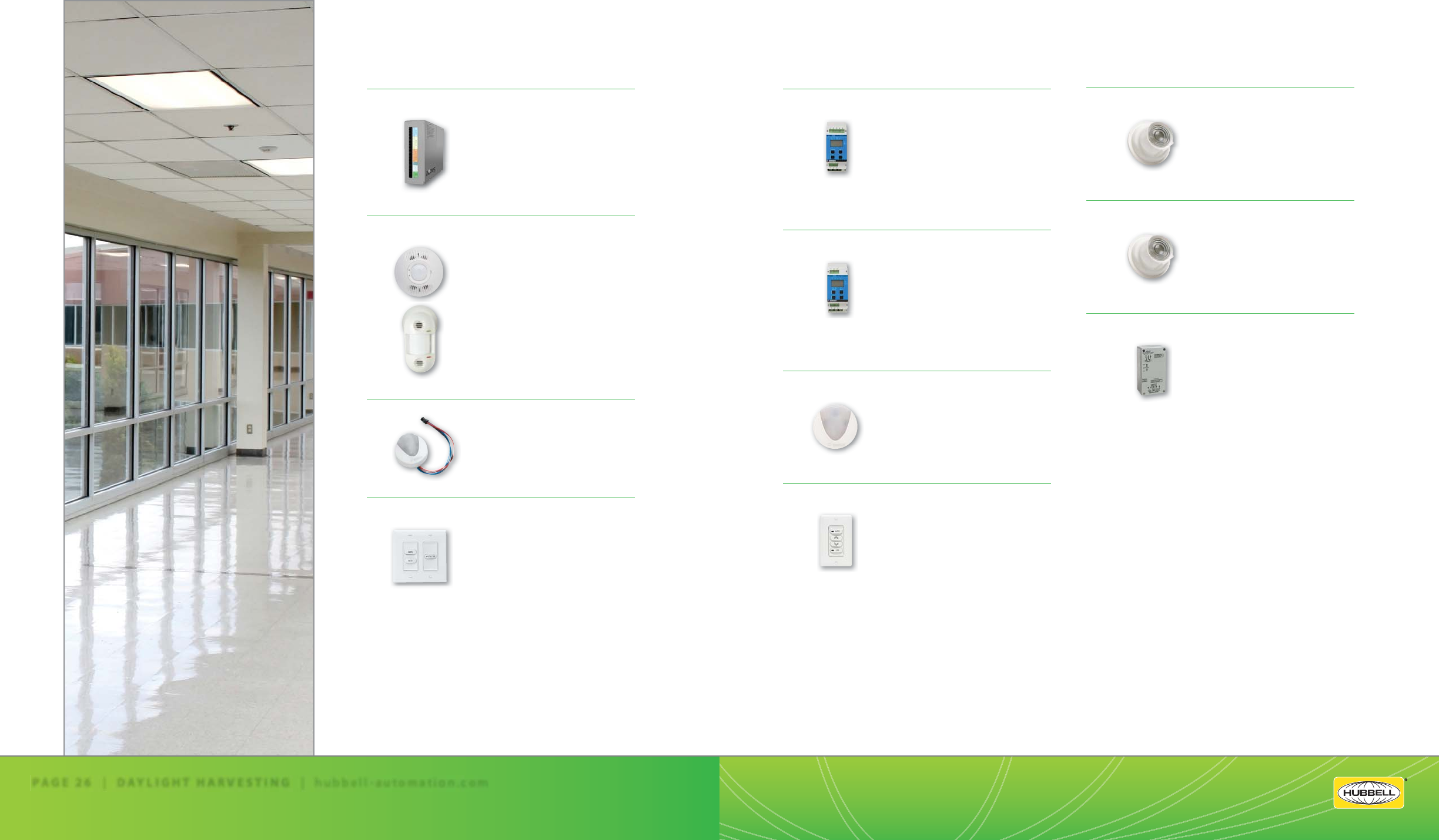
Daylight Harvesting
PAGE 25 | DAYLIGHT HARVESTING
Harvest the most abundant
energy source around: daylight.
Daylight harvesting can decrease
lighting by 75%.
PAGE 24 | DAYLIGHT HARVESTING | hubbell-automation.com
Let the sun
be your light source.
Hubbell Building Automation
Pictured at left, Z5-CM – Zone5 Control Module
and above left, Z5-DS – Zone5 Daylight Sensor
For more information on Zone5 Daylight Harvesting
System, please see the following HBA publication
available online at hubbell-automation.com or
simply scan the QR code at the top of this page.
The U.S. Department of Energy lists lighting as the most
signi cant use of electricity in commercial buildings.
On average, lighting uses more power than cooling,
ventilation and refrigeration combined. The easiest route
to energy savings is to shed lighting loads.
Daylighting controls like HBA’s newest Zone5 Harvesting
System impact budgets by harnessing the sun’s power
to reduce energy consumption. HBA’s solutions for
daylighting control include dimming, stepped dimming,
and switching systems.
Dimming systems continuously adjust light output
by signaling dimming ballasts, and stepped dimming
o ers the advantages of full-range dimming without
the expense of dimming ballasts. Lamps are either fully
turned o or partially turned o , depending on natural
light levels.
Switching systems turn lighting OFF or ON in accordance
with available natural light. With a lower initial cost than
dimming systems, switching systems are most often
recommended for warehouses, storage areas, atriums,
lobbies and parking facilities, where non-stationary tasks
are performed.
HBA introduces the Zone5 Daylight Harvesting System,
which combines all three daylighting approaches and
controls tailored to the speci c and demanding needs of
daylight harvesting applications.
The Zone5 Control Module accurately analyzes and
interprets signals from the plug-and-play occupancy
sensors, daylight sensors and low-voltage lighting control
switches.
Save Money.
Cut lighting costs by up to 75%. Master O and Row O
functions can contribute to additional energy savings
when users turn the lights o ahead of the occupancy
sensor detecting that the room is empty.
Save time.
Zone5 controls are plug-and-play, eliminating wiring
labor costs.
User-friendly programming.
SD Card interface provides a simple way to commission,
log, verify and update the Zone5 system. Control
parameters can be copied to the card from one Zone5
Control Module to another, HBA website template page,
email from speci er, or Zone5 PC-based template builder.
Intuitive, easy-to-use LCD menu.
The two-line LCD interface is intuitive, easy-to-use and
interactive. The interface allows users to quickly change
system settings or monitor system diagnostics in real
time.
Flexibility.
All Zone5 switches can be ganged together to form
custom switch stations, maximizing exibility in multi-use
rooms. Color-coded plug-and-play jumper cables are
available to be ordered separately, making installation
e ortless.
™
™
™
™
™
™
™
™
™
™
™
™
h
ubb
ell-
au
t
o
m
a
ti
o
n
.
c
om
Daylight Harvesting
Quick Reference Guide
PAGE 26 | DAYLIGHT HARVESTING | hubbell-automation.com
PAGE 27 | DAYLIGHT HARVESTING
DLC7
Continuous Dimming Control
Page 133
DLC7
Single Zone Continuous Dimming
Control
DLCPCI/DLCPCO DLCPCA/DLCPCS
Photocell Sensors
Page 135
DLCPCI/DLCPCO DLCPCA/DLCPCS
Photocell Sensors
DLCPCC
Photocell Controller
Page 137
DLCPCC
Photocell Controller
LUXSTATOCM1Z
Luxstat Single Zone ON/OFF Control Module
Page 125
LUXSTATOCM1Z120
Luxstat Single Zone
ON/OFF Control Module, 120VAC
LUXSTATOCM1Z277
Luxstat Single Zone
ON/OFF Control Module, 277VAC
LUXSTATDNCM
Luxstat Day/Night Control Module with Clock
Page 127
LUXSTATDNCM120
Luxstat Day/Night Control Module
with Clock, 120VAC, DIN Rail Mount
LUXSTATDNCM277
Luxstat Day/Night Control Module
with Clock, 277VAC, DIN Rail Mount
LUXSTATLS
Luxstat Light Sensor
Page 129
LUXSTATLS
Luxstat Light Sensor - Indoor
LUXSTATLSO
Luxstat Light Sensor – Outdoor
LUXSTATSW
Low Voltage Wall Switches for Luxstat
Page 131
LUXSTATSW4IV 4-Button Wall Switch
LUXSTATSW4WH 4-Button Wall Switch
LUXSTATSW2AUTOIV
2-Button Wall Switch
LUXSTATSW2AUTOWH
2-Button Wall Switch
LUXSTATSW2DIMIV
2-Button Wall Switch
LUXSTATSW2DIMWH
2-Button Wall Switch
LUXSTATSW1IV 1-Button Wall Switch
LUXSTATSW1WH 1-Button Wall Switch
Z5-CM
HBA Zone5 Control Module
Page 117
Z5-CM
Zone5 Control Module
Z5-OS
HBA Zone5 Ceiling and Wall Mount Occupancy Sensors
Page 119
Z5-OS-OMDT2000RP
Zone5 Occupancy Sensor, Ceiling Mount,
PIR and Ultrasonic, Form C Relay,
2000Sq. Ft.
Z5-OS-LODTRP
Zone5 Occupancy Sensor, Wall Mount,
PIR and Ultrasonic, Form C Relay,
1600 Sq. Ft.
Z5-DS
HBA Zone5 Daylight Sensor
Page 121
Z5-DS
Zone5 Daylight Sensor
Z5-SW
HBA Zone5 Low Voltage Wall Switches
Page 123
Z5SWGAV
Zone5 General-A/V Mode Switch
Z5SWAVD
Zone5 General-A/V Dimming Switch
Z5SWST Zone5 Study Time Switch
Z5SWWB Zone5 Whiteboard Switch
Z5SWMC Zone5 Master ON/OFF Switch
Z5SWRCR1
Zone5 Row 1 Control Switch
Z5SWRCR2
Zone5 Row 2 Control Switch
Z5SWRCR3
Zone5 Row 3 Control Switch
Z5SWRCR4
Zone5 Row 4 Control Switch
1
21

u
t
o
m
a
ti
o
n
.
c
om
Occupancy | Vacancy Sensors
IntelliDAPT® technology comes standard in many
of HBA’s Occupancy|Vacancy sensors,
enabling automatic sensitivity and timing
adjustments for true install-and-forget operation.
PAGE 28 | OCCUPANCY | VACANCY SENSORS | hubbell-automation.com
Control energy costs. The Right Technology for the Right Application.
IntelliDAPT® IntelliDAPT comes standard in HBA’s OMNI,
LightOWL and LightHAWK sensors and switches. It works
in conjunction with Passive Infrared, Ultrasonic and Dual
technology Products.
Passive Infrared Technology
Passive infrared (PIR) technology detects the movement
of heat emitted from the human body contrasted against
the ambient temperature of the background space. These
sensors use a segmented lens to divide the coverage area
into zones. Movement between zones is then interpreted
as occupancy. PIR sensors require an unobstructed
line-of-sight for occupancy detection and work best
in small, enclosed spaces with high levels of occupant
movement.
Bene ts:
• Long-range detection
• Reliable triggering
• Cost-e cient
Ultrasonic Technology
Ultrasonic (US) technology senses occupancy by
bouncing sound waves (32 kHz or 40 kHz) o of
objects to detect frequency shifts between emitted
and re ected sound waves. Movement causes a shift in
frequency, which the sensor interprets as occupancy.
US occupancy|vacancy sensors do not require an
unobstructed line-of-sight and are excellent at detecting
minor motions such as typing and ling. US technology
sensors are ideal for hallways or a restroom with stalls.
Bene ts:
• Excellent Minor motion detection
• Sees around obstructions
• Cost-e cient
Dual Technology
Dual technology occupancy|vacancy sensors o er the
best performance for most applications. The combined
use of passive infrared (PIR) and ultrasonic (US) minimizes
the risk of false triggering: lights will only turn on when
both technologies detect occupancy, and will remain on
so long as one continues to detect occupancy.
Bene ts:
• Track occupancy with two sensing methods
• Minimizes false triggering
• Consistent, reliable operation
PAGE 29 | OCCUPANCY | VACANCY SENSORS
Hubbell Building Automation
QTI
Quick To Install System
and Accessories
n
i
n
g
gy
.
PA
G
E 2
9
|
|
|
OC
O
O
O
O
O
O
O
O
O
CUP
Q
QT
I
Quick To Install System
a
nd Accessories
h
ubb
ell-
au
t
o
m
a
ti
o
n
.
c
om
LightOWL LODT | LODTRP Page 187
LODT Ultrasonic and Passive Infrared
Wall and Ceiling Sensor
LODTRP Ultrasonic and Passive Infrared
Wall and Ceiling Sensor
LightOWL LOIRWV | LOIRWVRP Page 189
LOIRWV Passive Infrared Wall and Ceiling Sensor
LOIRWVRP Passive Infrared Wall
and Ceiling Sensor
LightOWL LODIA | LODIARP Page 191
LODIA Passive Infrared and Acoustic
Wall and Ceiling Sensor
LODIARP Passive Infrared and Acoustic
Wall and Ceiling Sensor
UVPP Page 195
UVPP Universal Voltage Power Pack
UVPPM Page 197
UVPPM Universal Voltage Power Pack
with Manual ON/OFF
Quick to Install System Page 199
CAB10 10’ Plenum rated
CAB20 20’ Plenum rated
S1M2F Splitter 1 male, 2 female
RRU Page 201
RRU120
RRU277
RR1SPDTC Page 203
RR2SPDTC
RR2SPDTC120
RR2SPDTC270
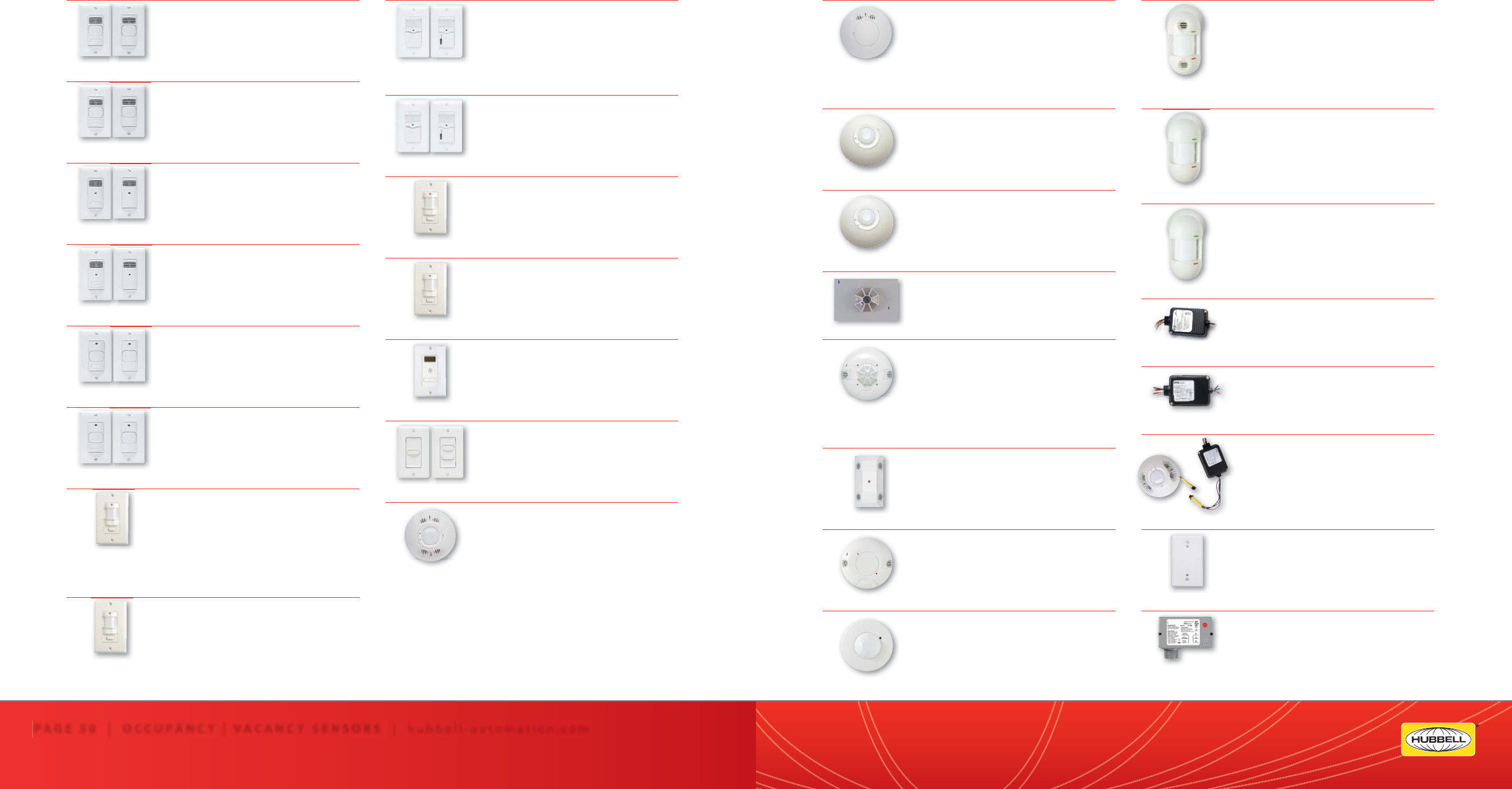
Occupancy | Vacancy Sensors
Quick Reference Guide
PAGE 30 | OCCUPANCY | VACANCY SENSORS | hubbell-automation.com
PAGE 31 | OCCUPANCY | VACANCY SENSORS
OMNI OMNIUS | OMNIUSRP Page 171
OMNIUS500 Ultrasonic Ceiling Sensor
OMNIUS500RP Ultrasonic Ceiling Sensor
OMNIUS1000 Ultrasonic Ceiling Sensor
OMNIUS1000RP Ultrasonic Ceiling Sensor
OMNIUS2000 Ultrasonic Ceiling Sensor
OMNIUS2000RP Ultrasonic Ceiling Sensor
OMNI OMNIIR | OMNIIRP Page 173
OMNIIR Passive Infrared Ceiling Sensor
OMNIIRRP Passive Infrared Ceiling Sensor
OMNIIRL Passive Infrared Ceiling Sensor
OMNIIRLRP Passive Infrared Ceiling Sensor
OMNI OMNIDIA | OMNIDIARP Page 175
OMNIDIA Dual Technology Acoustic
and Passive Infrared Ceiling Sensor
OMNIDIARP Dual Technology Acoustic
and Passive Infrared Ceiling Sensor
PIR1000H Page 177
PIR1000H Passive Infrared Ceiling Sensor
for Hallway Applications
CUI5002000P Page 179
CUI5002000P120 Dual Technology Ultra-
sonic and Passive Infrared Line Voltage
Ceiling Sensor
CUI5002000P277 Dual Technology Ultra-
sonic and Passive Infrared Line Voltage
Ceiling Sensor
C5002000P Page 181
C5002000P120Ultrasonic Line Voltage
Ceiling Sensor
C5002000P277Ultrasonic Line Voltage
Ceiling Sensor
C8001500P Page 183
C8001500P120Ultrasonic Line Voltage
Ceiling Sensor
C8001500P277Ultrasonic Line Voltage
Ceiling Sensor
PIR10 Page 185
PIR10P Passive Infrared Line Voltage
Ceiling Sensor
PIR10EMS Passive Infrared Low Voltage
Ceiling Sensor
RWSOSINC | Residential Wall Switch Sensors Page 157
RWSOSINC120 Residential Occupancy
Sensor for Incandescent Lighting
RWSOSDINC120 Residential Occupancy
Sensor with Dimmer for Incandescent
Lighting
RWSVSINC | Residential Wall Switch Sensors Page 159
RWSVSINC120 Residential Vacancy
Sensor for Incandescent Lighting
RWSVSDINC120 Residential Vacancy
Sensor with Dimmer for Incandescent Lighting
IWSZP3P Page 161
IWSZP3PW Passive Infrared Wall Switch
Sensor
IWSZP3PI Passive Infrared Wall Switch Sensor
IWSZPM Page 163
IWSZPMW Passive Infrared Wall Switch Sensor
IWSZPMI Passive Infrared Wall Switch Sensor
TD200 Page 165
TD200 Digital Programmable Timer
LVS | Low Voltage Switches Page 167
LVSM1NP Momentary, 1 button
LVSM2NP Momentary, 2 button
LVSM1PL Momentary, 1 button, w/Pilot LED
LVSM2PL Momentary, 2 button, w/Pilot LED
OMNI OMNIDT | OMNIDTRP Page 169
OMNIDT500 Dual Technology Ultrasonic
and Passive Infrared Ceiling Sensor
OMNIDT500RP Dual Technology Ultrasonic
and Passive Infrared Ceiling Sensor
OMNIDT1000 Dual Technology Ultrasonic
and Passive Infrared Ceiling Sensor
OMNIDT1000RP Dual Technology Ultra-
sonic and Passive Infrared Ceiling Sensor
OMNIDT2000 Dual Technology Ultrasonic
and Passive Infrared Ceiling Sensor
OMNIDT2000RP Dual Technology Ultra-
sonic and Passive Infrared Ceiling Sensor
C
C
S
LightHAWK LHMTS Page 141
LHMTS1 Ultrasonic and PIR
Wall Switch Sensor
LHMTS0 Ultrasonic and PIR
Wall Switch Sensor
LightHAWK LHMTD Page 143
LHMTD2 Ultrasonic and PIR Dual
Circuit Wall Switch Sensor
LHMTD0 Ultrasonic and PIR Dual
Circuit Wall Switch Sensor
LightHAWK LHUSS Page 145
LHUSS1 Ultrasonic Wall Switch Sensor
LHUSS0 Ultrasonic Wall Switch Sensor
LightHAWK LHUSD Page 147
LHUSD2 Ultrasonic Dual Circuit
Wall Switch Sensor
LHUSD0 Ultrasonic Dual Circuit
Wall Switch Sensor
LightHAWK LHIRS Page 149
LHIRS1 Passive Infrared Wall Switch Sensor
LHIRS0 Passive Infrared Wall Switch Sensor
LightHAWK LHIRD Page 151
LHIRD2 Passive Infrared Dual Circuit
Wall Switch Sensor
LHIRD0 Passive Infrared Dual Circuit
Wall Switch Sensor
RWSOSCFL | Residential Wall Switch Sensors Page 153
RWSOSCFL120IV Residential
Occupancy Sensor for Incandescent
and CFL Lighting
RWSOSCFL120WH Residential
Occupancy Sensor for Incandescent
and CFL Lighting
RWSVSCFL | Residential Wall Switch Sensors Page 155
RWSVSCFL120IV Residential Vacancy
Sensor for Incandescent and CFL Lighting
RWSVSCFL120WH Residential Vacancy
Sensor for Incandescent and CFL Lighting
|
|
Business Services
Support, Service and Quotations
HBA’s Business Services group is available daily from
7am to 6pm CST, ensuring that you receive the best
service. Our products are designed and manufactured
under one roof, providing our sta with in-house
resources to handle your questions.
Get a personalized level of service:
• Detailed product knowledge
• Fast and accurate order entry
• Timely order acknowledgements
• Order management from initial ordering to shipping
Technical Services
HBA’s technical services include quotations, Factory
Certi ed Occupancy Sensor Layouts, technical
phone support, application support, and technical
documentation.
Quotations
HBA’s Quotations Group coordinates with the Technical
Services group to provide detailed drawings and
accurate quotations, working with you to ensure all
needs of your project are ful lled. Get detailed submittal
packages, all necessary product documentation and
project-speci c information.
Factory Certi ed Occupancy Sensor Layouts
We guarantee the type and placement of each sensor
on every drawing. Send electronic AutoCAD les and
we’ll create a Factory Certi ed Layout and a competitive
layout with a detailed Bill of Materials. We also convert
paper drawings to electronic format, and if you would
like hard copies, we create professional paper drawings
in any size speci cation.
Contact Information
Telephone – Austin, TX USA . . . . . . [512] 450.1100
Telephone – Toll-Free . . . . . . . . . . . . [888] 698.3242
Fax – Orders Only . . . . . . . . . . . . . . . . [512] 450.0864
Fax – General . . . . . . . . . . . . . . . . . . . . .[512] 450.1215
Fax – Toll-Free Customer Service . . [877] 783.9201
Corporate Website . . . . hubbell-automation.com
Technical Drawing submittal
hba-cad@hubbell-automation.com Wireless Distributed Lighting Controls
page 35
Lighting Control Panels
page 55
High Bay Lighting Controls
page 111
Daylight Harvesting
page 115
Occupancy | Vacancy Sensors
page 139
h
ubb
ell-
au
t
o
m
a
ti
o
n
.
c
om
PAGE 32 | HUBBELL BUILDING AUTOMATION | hubbell-automation.com
Hubbell Building Automation
Hubbell Building Automation, a division of Hubbell Lighting, Inc., is one of many quality brands
under the umbrella of Hubbell Incorporated (A Delaware Corporation).
Our inclusion in this distinct family of brands garners the support, creativity and enthusiasm to continue designing
and delivering the most advanced commercial, outdoor, industrial lighting control systems available anywhere.
For more information please visit HubbellLighting.com or any of the brands listed below.
Hubbell Lighting, Inc.
701 Millennium Boulevard | Greenville, South Carolina 29607 USA
Phone: 864-678-1000 | Fax: 864-678-1065
hubbelllighting.com
Alera Lighting
aleralighting.com
Architectural Area
Lighting
aal.net
Beacon
beaconproducts.com
Columbia Lighting
columbialighting.com
Devine Lighting
devine-ltg.com
Dual Lite
dual-lite.com
Hubbell Building
Automation
hubbell-automation.com
Hubbell Industrial
Lighting
hubbellindustrial.com
Hubbell Outdoor
Lighting
hubbelloutdoor.com
Kim Lighting
kimlighting.com
Prescolite
prescolite.com
Sportsliter Solutions
sportslighting.com
Spaulding Lighting
spauldinglighting.com
Sterner
sternerlighting.com
PAGE 33 | HUBBELL BUILDING AUTOMATION

Area/Site Lighting
Parking Garage
Lighting
Interior Facility Lighting
Area/Site
Lighting
wiHUBB™ Wireless Distributed Lighting Controls
Table of Contents
WIH-AP—wiHUBB Access Point ........................................................................................................................................................................................37
WIH-SP—wiHUBB Smart Pack ...........................................................................................................................................................................................39
WIH-OS—wiHUBB Ceiling and Wall Mount Occupancy Sensors ........................................................................................................................41
WIH-OS—wiHUBB Ceiling and Wall Mount Occupancy Sensors Range Diagrams .....................................................................................43
WIH-SW—wiHUBB Switch Stations .................................................................................................................................................................................45
WIH-DS—wiHUBB Daylight Sensors ...............................................................................................................................................................................47
WIH-IM—wiHUBB In-Fixture Module ..............................................................................................................................................................................49
WIH-OM—wiHUBB On-Fixture Module .........................................................................................................................................................................51
wiHUBB Applications and Design Guide .......................................................................................................................................................................53
wiHUBB™ APPLICATIONS
AREA/SITE LIGHTING
• In-Fixture or On-Fixture Modules
installed in or on lighting xtures
• Access Point for scheduling of ON/OFF
and dimmed levels
• Demand Response ready
PARKING GARAGE LIGHTING
• In-Fixture Modules installed
in lighting xtures
• Time-based scheduling of ON/OFF
and dimming levels
• Access Point for scheduling
of ON/OFF and dimmed levels
• Demand Response ready
INTERIOR FACILITY LIGHTING
• In-Fixture Modules installed
in lighting xtures
• Smart Pack installed con-
trolling lighting circuits
• Access Point for scheduling
and device management
• Switch Stations for Manual
ON/OFF control
• Occupancy|Vacancy sensors
for Auto/Manual ON,
Auto OFF control
• Daylight sensor for daylight
harvesting applications
(888) 698-3242 | Fax orders (512) 450-0864 | hubbell-automation.com
bbell-automation.com
hubb
hubbe
PAGE 34 | (888) 698-3242 | Fax orders (512) 450-0864 | hubbell-automation.com
PAGE 35 | WIRELESS LIGHTING CONTROLS
Hubbell Building Automation

WIH-AP
wiHUBB™ Access Point
KEY FEATURES
• Web-based commissioning and monitoring of the wiHUBB
lighting control system
• Integrated web server provides connection via standard web browsers
• Easy system access from the local network or Internet
• Intuitive and easy-to-use Graphical User Interface (GUI)
• Ability to schedule wiHUBB-enabled devices or groups of devices
• Provides ON/OFF and dimming control of wiHUBB-enabled devices
and groups of devices
• Robust and reliable 900Mhz wireless self-organizing and self-healing
mesh network
SPECIFICATIONS
Power Requirements • 120VAC with plug-in power supply (included)
RF Frequency • 902 - 928MHz
• Wireless Peer-To-Peer, Self-Organizing and Self-Healing Mesh Network
• Advanced Encryption Standard AES-128 Security
• Spread Spectrum Frequency Hopping
RF Range • Supported distance between wireless devices: 100 meters (328 feet)
• Maximum Transmission Output Power: +20 dBm
• Maximum Receive Sensitivity: -118 dBm
Operating Environment • Operating Temperature: 0°C to 40°C
• Relative humidity (non-condensing): 0 – 95%
Construction • Housing: Flame retardant ABS plastic, UL ame rating of 94-5VA
Size and Weight • Size: 5.00”L x 7.50”W x 1.75”H
• Weight: 6 oz
Color • Black
Mounting • Surface or wall mount (mounting screws provided)
Patents • Patent(s) Pending
Certi cations • FCC Certi ed
• IC Approved
ORDERING INFORMATION
WIH-AP
(888) 698-3242 | Fax orders (512) 450-0864 | hubbell-automation.com
h
ubb
ell-
au
t
o
m
a
ti
o
n
.
c
om
PAGE 37 | WIRELESS LIGHTING CONTROLS
MODEL / DESCRIPTION
WIHAP wiHUBB Access Point
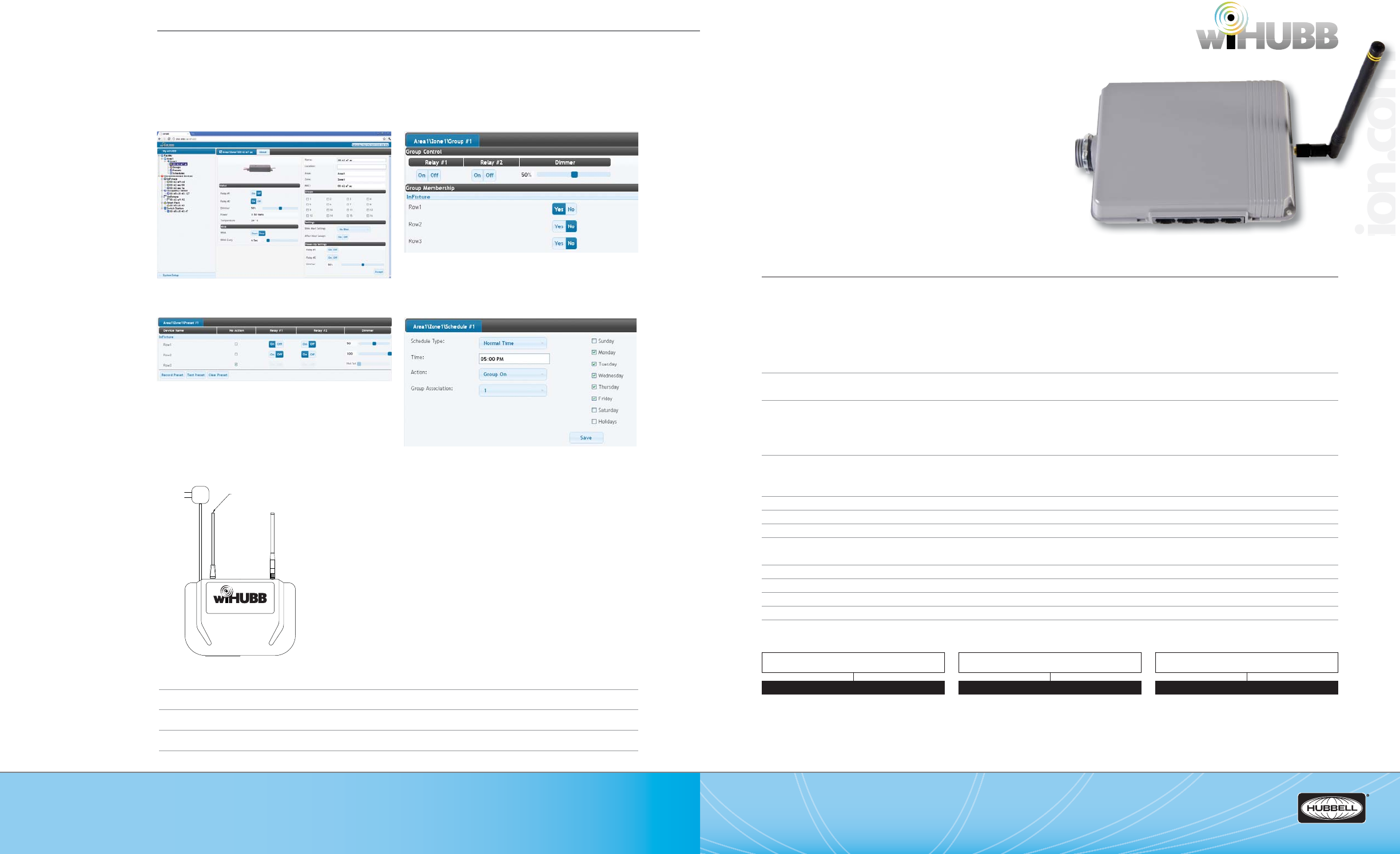
WIH-SP
wiHUBB™ Smart Pack
KEY FEATURES
• Single or dual relay versions for ON/OFF or High/Low control
• Optional 0 – 10VDC interface for full range dimming control
• Plug-and-play support for wiHUBB occupancy sensors,
daylight sensors and switch stations
• Device intelligently and automatically responds to sensors
and switches in the most energy- e cient manner
• Schedules are held in the devices themselves – no need
for a master scheduling device
• Monitors, measures, and records energy consumption
and runtime data
SPECIFICATIONS
Electrical Ratings • Input: 120/277VAC, 20A Max, 60Hz
• Output*: 20A, Tungsten, 120VAC only; 20A, Magnetic Ballast; 16A, Electronic Ballast
1 H.P. Motor @120V, 3/4 H.P. @277V
*For (2) relay models the maximum combined output of both relays: 20A
Low Voltage Ports:
• Class 2
• 24VDC, 150mA MAX (all outputs combined)
Optional Dimming Interface • 0-10VDC, 30mA output
• For use with low-voltage, two-wire dimming ballast and LED drivers.
RF Frequency • 902 - 928MHz
• Wireless Peer-To-Peer, Self-Organizing and Self-Healing Mesh Network
• Advanced Encryption Standard AES-128 Security
• Spread Spectrum Frequency Hopping
RF Range • Supported distance between wireless devices: 100 meters (328 feet)
• Maximum Transmission Output Power: +20 dBm
• Maximum Receive Sensitivity: -118 dBm
Operating Environment • Operating Temperature: 0°C to +40°C; Relative humidity (non-condensing): 0 – 95%
Construction • Housing: GSM UL Rated 94 HB Plastic
Plenum rated • Complies with requirements for use in a plenum area; Plenum rated for external junction box mounting
Size and Weight • Size: 5.75”L x 3.85”W x 1.30”H
• Weight: 4 oz
Color • Gray
Mounting • Mounts directly to an external junction box through an extended ½” chase nipple.
Patents • Patent(s) Pending
Certi cations • Conforms with UL916 and Certi ed to CAN/CSA C22.2 No. 205-M1983; FCC Certi ed; IC Approved
ORDERING INFORMATION
Group ManagementDevice Settings
Scheduling
Preset Management
(888) 698-3242 | Fax orders (512) 450-0864 | hubbell-automation.com
hubbell-automation.com
PAGE 38 | (888) 698-3242 | Fax orders (512) 450-0864 | hubbell-automation.com
PAGE 39 | WIRELESS LIGHTING CONTROLS
Hubbell Building Automation
NOTES
WIH-SP-2RD-1277
SCREEN CAPTURES
WIRING DIAGRAMS
For more wiring diagrams, visit http://www.hubbell-automation.com/resources/wiring_diagrams/
OUTPUT
1R 1 SPST Output
1RD 1 SPST Output, 0-10VDC Dimming Output
2R 2 SPST Outputs
2RD 2 SPST Outputs, 0-10VDC Dimming
Output
INPUT VOLTAGE
1277 120/277VAC
MODEL
WIH-SP
Access from Local
Network or Internet
Power
Connector
wiHUBB Smart Pack
Violet
G
V
H
N
Dimming Ballast
White (Neutral) Grey
Red
White
Black (120-277 VAC)
WIH-SP-1RD-1277
(888) 698-3242 | Fax orders (512) 450-0864 | hubbell-automation.com
h
ubb
ell-
au
t
o
m
a
ti
o
n
.
c
om
PAGE 40 | (888) 698-3242 | Fax orders (512) 450-0864 | hubbell-automation.com
PAGE 41 | WIRELESS LIGHTING CONTROLS
Hubbell Building Automation
NOTES
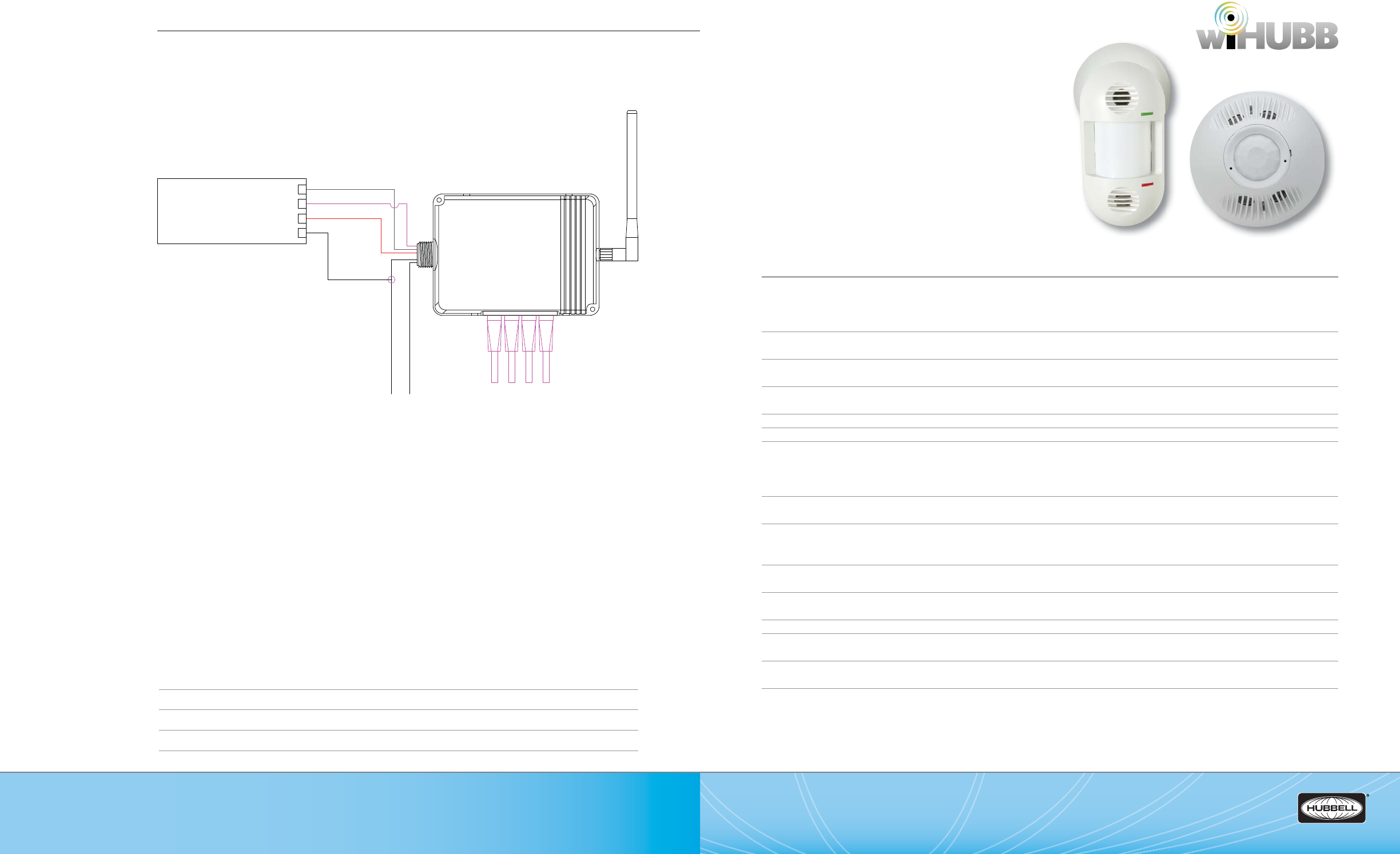
WIH-OS
wiHUBB™ Ceiling and Wall Mount
Occupancy Sensors
KEY FEATURES
• IntelliDAPT® self-adaptive technology – no manual
adjustment required
• All-digital passive infrared, ultrasonic, acoustic and dual technology
models available
• Non-volatile memory for sensor settings
• Coverage range: 500 sq. ft. to 2,000 sq. ft. (based on model)
• Optional Isolated Form C relay with NO/NC outputs
• Plug-and-play integration with wiHUBB Smart Pack
SPECIFICATIONS
IntelliDAPT • Auto reset from test setting
• Self-adjusting timer
• Self-adjusting ultrasonic and passive infrared thresholds
• Automatic false-on, false-o corrections
LED Indicators • Red: motion detected by Passive Infrared sensing technology
• Green: motion detected by Ultrasonic sensing technology
Timer Timeout • Automatic mode: 8-30 min. (self-adjusts based on occupancy)
• Test mode: 8 seconds (for an easy check at installation)
Ultrasonic Output • Maximum amount of radiation output allowed: 115dB @ 1 ft. from source
• Frequency: 32.768kHz or 40kHz (based on model)
Passive Infrared • Dual element pyrometer and 12 element cylindrical rugged lens
Form C Relay • Relay: NO + NC contacts, SPDT, 500 mA rated @ 24VDC, three wire, isolated relay
Coverage • Ceiling mount sensor: 500 sq. ft. (Major motion) / 250 sq. ft.
(Minor motion) to 2000 sq. ft. (Major motion) / 1000 sq. ft.
(Minor motion) –(based on model)
• Wall mount sensor: 1600 sq. ft. (Major motion) / 800 sq. ft. (Minor motion)
Power Requirements • Powered by wiHUBB Smart Pack SmartPORT using plenum rated SmartPORT plug-and-play cables
(ordered separately)
Operating environment • Indoor use only
• Operating Temperature: 0°C to +40°C
• Relative humidity (non-condensing): 0 – 95%
Construction • Casing – rugged, high-impact, injection-molded plastic KJB ABS Cycolac (UV-945VA) ame class rating,
UV inhibitors; Quick to Install Connectors
Size and weight • Size: 4.5” diameter, 1.5” height (114 mm diameter, 38mm height)
• Weight: 5.0 oz (142g)
Color • O White
Mounting • Mounting base provided
• Recommended MAX mounting height: 12 ft.
Patents • U.S. Patents: 6151529, 5946209, 5699243, 5640143, 6415205, 6078253, D404326, 6222191, 5986357, 6759954
• Patent(s) Pending
Certi cations • UL and cUL listed
WIH-OS-OMDT2WIH-OS-LODT
WIRING DIAGRAMS
For more wiring diagrams, visit http://www.hubbell-automation.com/resources/wiring_diagrams/
(888) 698-3242 | Fax orders (512) 450-0864 | hubbell-automation.com
h
ubb
ell-
au
t
o
m
a
ti
o
n
.
c
om
PAGE 42 | (888) 698-3242 | Fax orders (512) 450-0864 | hubbell-automation.com
PAGE 43 | WIRELESS LIGHTING CONTROLS
Hubbell Building Automation
NOTES
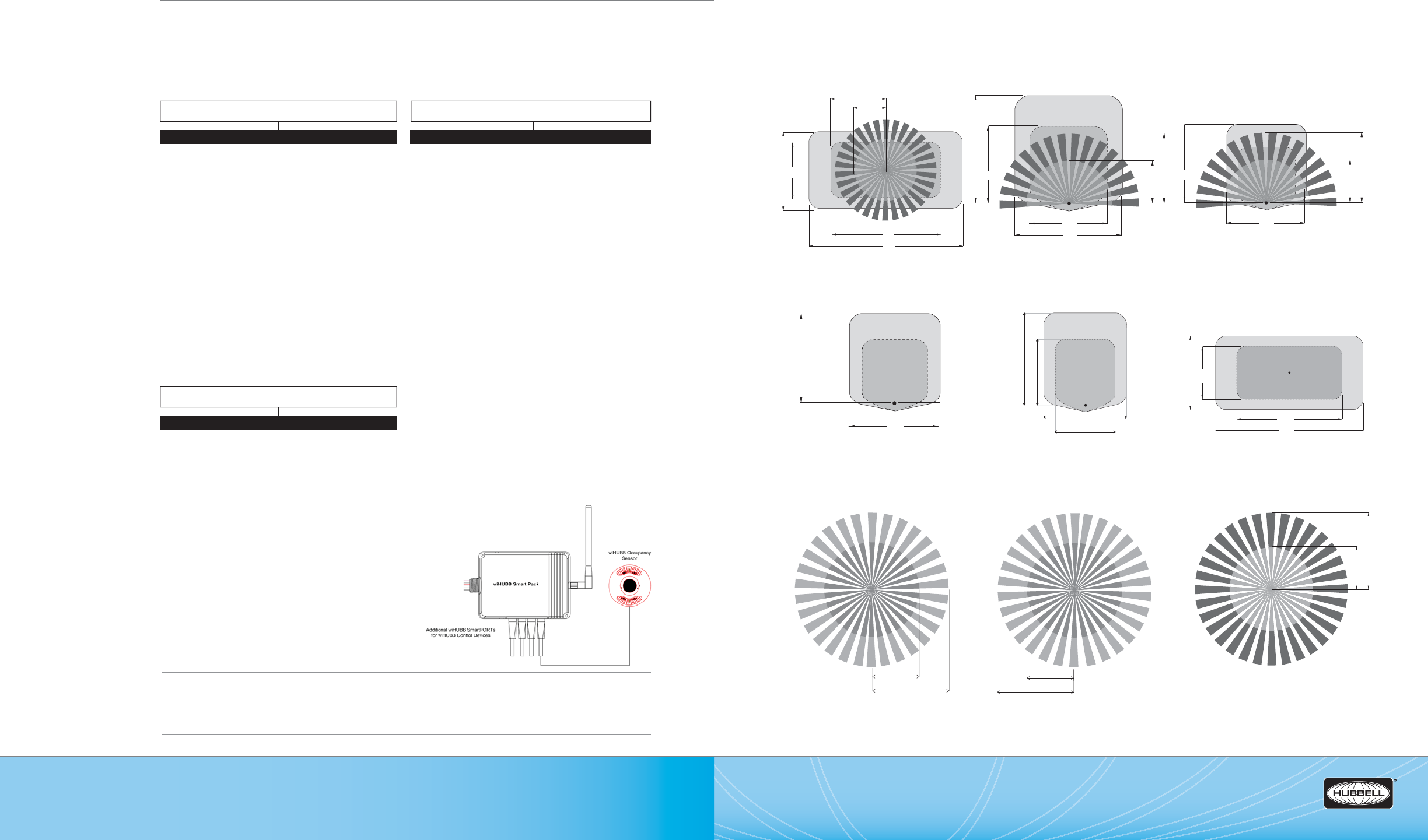
WIH-OS
wiHUBB™ Ceiling Mount and Wall Mount Occupancy Sensors
RANGE DIAGRAMS
3
2' 23'
64'
45'
12'
22'
12'
23
'
2
2
23'
12'
32'
23'
22'
23'
32'
64'
45'
23'
32'
23
'
23'
23'
23'
32'
32'
12'
6' 12'
22'
12'
22'
WIH-OS-OMDT2 Ceiling Mount Sensor
WIH-OS-OMUS5 Ceiling Mount Sensor
WIH-OS-OMIR Ceiling Mount Sensor
WIH-OS-OMDT1 Ceiling Mount Sensor
WIH-OS-OMUS1 Ceiling Mount Sensor
WIH-OS-OMIRL Ceiling Mount Sensor
WIH-OS-OMDT5 Ceiling Mount Sensor
WIH-OS-OMUS2 Ceiling Mount Sensor
WIH-OS-OMDIA Ceiling Mount Sensor
ORDERING INFORMATION
WIRING DIAGRAM
For more wiring diagrams, visit http://www.hubbell-automation.com/resources/wiring_diagrams/
MODEL / DESCRIPTION
WIH-CAB-50F-WH SmartPORT Cable, 50ft, White –
for Occupancy Sensors
WIH-CAB-100F-WH SmartPORT Cable, 100ft, White – for Occupancy
Sensors
Occupancy Sensors
Cables
SENSOR TYPE
OMDT2 Ceiling Mount, PIR and Ultrasonic, 2000 Sq. Ft.
OMDT2R RCeiling Mount, PIR and Ultrasonic, 2000 Sq. Ft., Form C Relay
OMDT1 Ceiling Mount, PIR and Ultrasonic, 1000 Sq. Ft.
OMDT1R Ceiling Mount, PIR and Ultrasonic, 1000 Sq. Ft., Form C Relay
OMDT5 Ceiling Mount, PIR and Ultrasonic, 500 Sq. Ft.
OMDT5R Ceiling Mount, PIR and Ultrasonic, 500 Sq. Ft., Form C Relay
OMUS2 Ceiling Mount, Ultrasonic, 2000 Sq. Ft.
OMUS2R Ceiling Mount, Ultrasonic, 2000 Sq. Ft., Form C Relay
OMUS1 Ceiling Mount, Ultrasonic, 1000 Sq. Ft.
OMUS1R Ceiling Mount, Ultrasonic, 1000 Sq. Ft., Form C Relay
OMUS5 Ceiling Mount, Ultrasonic, 500 Sq. Ft.
OMUS5R Ceiling Mount, Ultrasonic, 500 Sq. Ft., Form C Relay
OMIR Ceiling Mount, Passive Infrared, 450 Sq. Ft.
OMIRR Ceiling Mount, Passive Infrared, 450 Sq. Ft., Form C Relay
OMIRL Ceiling Mount, Passive Infrared, 1500 Sq. Ft.
OMIRLR Ceiling Mount, Passive Infrared, 1500 Sq. Ft., Form C Relay
OMDIA Ceiling Mount, PIR and Acoustic, 450 Sq. Ft.
OMDIAR Ceiling Mount, PIR and Acoustic, 450 Sq. Ft., Form C Relay
LODT Wall Mount, PIR and Ultrasonic, 1600 Sq. Ft.
LODTR Wall Mount, PIR and Ultrasonic, 1600 Sq. Ft., Form C Relay
LOIRWV Wall Mount, Passive Infrared, 2500 Sq. Ft.
LOIRWVR Wall Mount, Passive Infrared, 2500 Sq. Ft., Form C Relay
LOIRHB Wall Mount, Passive Infrared, 50’ at 30’ Height
LOIRHBR Wall Mount, Passive Infrared, 50’ at 30’ Height, Form C Relay
LODIA Wall Mount, PIR and Acoustic, 1600 Sq. Ft.
LODIAR Wall Mount, PIR and Acoustic, 1600 Sq. Ft., Form C Relay
MODEL
WIH-OS

(888) 698-3242 | Fax orders (512) 450-0864 | hubbell-automation.com
h
ubb
ell-
au
t
o
m
a
ti
o
n
.
c
om
PAGE 44 | (888) 698-3242 | Fax orders (512) 450-0864 | hubbell-automation.com
PAGE 45 | WIRELESS LIGHTING CONTROLS
Hubbell Building Automation
NOTES
WIH-SW
wiHUBB™ Switch Stations
KEY FEATURES
• Attractive, architecturally-pleasing decorator style design
• Multiple switch options available
• All switches mount to standard single or multi-gang wall boxes
• Plug-and-play integration with wiHUBB Smart Pack
SPECIFICATIONS
Power Requirements • Powered by wiHUBB Smart Pack SmartPORT using plenum rated SmartPORT plug-and-play cables
(ordered separately)
Operating environment • Indoor use only
• Operating Temperature: 0°C to +40°C
• Relative humidity (non-condensing): 0 – 95%
Construction • Housing – Rugged, high impact, injection molded plastic
Size & Weight • Size: 4.2” L x 1.6” W x 1.4” D
• Weight: 1.6 oz
Color • White
Mounting • Switches may be mounted individually in a single gang switch box or ganged together in a multi-gang
switch box
• Decorator-style wall plates available separately
Patents • Patent(s) Pending
ORDERING INFORMATION
WIH-SW-OO WIH-SW-HLO WIH-SW-ORLO WIH-SW-PRESET WIH-SW-GAV WIH-SW-RL WIH-SW-TO
WIH SW OO
WIHSW HLO
WIHSW ORLO
WIHSW PRESE
T
WIH SW GAV
WIH SW RL
WIH SW TO
20'
40'
20'
40'
20'
32'
23'
40'
23'
32'
WIH-OS-LODT
Wall Mount Sensor
WIH-OS-LOIRWV
Wall Mount Sensor
WIH-OS-LOIRHB
Wall Mount Sensor
WIH-OS-LODIA
Wall Mount Sensor
WIH-OS RANGE DIAGRAMS continued
COLOR
WH White
SWITCH TYPE
OO ON/OFF Switch
HLO High/Low/O Switch
ORLO On/Raise/Lower/O Switch
PRESET Preset/Scene Switch (4-button)
GAV General – A/V Mode Switch
RL Raise/Lower Switch
TO Timed On Switch
MODEL
WIH-SW

(888) 698-3242 | Fax orders (512) 450-0864 | hubbell-automation.com
h
ubb
ell-
au
t
o
m
a
ti
o
n
.
c
om
PAGE 46 | (888) 698-3242 | Fax orders (512) 450-0864 | hubbell-automation.com
PAGE 47 | WIRELESS LIGHTING CONTROLS
Hubbell Building Automation WIH-DS
wiHUBB™ Daylight Sensor
KEY FEATURES
• Open loop operation
• Mounts vertically or horizontally
• Architecturally attractive design
• Plug-and-play integration with wiHUBB Smart Pack
SPECIFICATIONS
Electrical • Three jumper-selectable foot candle ranges: 3-300fc; 30-3,000fc; 60-6,000fc
• Powered by wiHUBB Smart Pack SmartPORT using plenum rated SmartPORT plug- and- play cables
(ordered separately)
Operating environment • Indoor use only
• Operating Temperature: 0°C to +40°C
• Relative humidity (non-condensing): 0 – 95%
Construction • Protective hard plastic cover and housing
Dimension • 2’ diameter x 1.2” height (50.8 diameter x 30.5mm height)
Patents • Patent(s) Pending
ORDERING INFORMATION
WIH-DS
WIH-SW ORDERING INFORMATION continued
WIRING DIAGRAM
For more wiring diagrams, visit http://www.hubbell-automation.com/resources/wiring_diagrams/
MODEL / DESCRIPTION
WIHDS wiHUBB Daylight Sensor
MODEL / DESCRIPTION
WIH-CAB-50F-GN SmartPORT Cable, 50ft, Green - for Daylight Sensor
WIH-CAB-100F-GN SmartPORT Cable, 100ft, Green - for Daylight Sensor
Daylight Sensor Cables
Violet
G
V
H
N
Dimming Ballast
#1
G
V
H
N
Dimming Ballast
#2
White (Neutral) Grey
Red
Blue
Violet
Grey
White
wiHUBB Smart Pack
White
wiHUBB Daylight Sensor
wiHUBB Occupancy
Sensor
wiHUBB Switch Stations
Additional wiHUBB SmartPORTs
for wiHUBB Control Devices
Black (120-277 VAC)
NOTES:
1. MAC address labels from each wiHUBB module (does not
include switches and sensors) need to be attached to as-builts
or a log book delineating device location.
2. wiHUBB switches and sensors need to be wired to a wiHUBB
Smart Pack with CAT 5 cable.
3. Only 1 photocell is needed per area being controlled.
WIH-SW-
PRESET
PRESET 4
SVC
PWRSVC PIN
PRESET 3
PRESET 2
PRESET 1
SVC
PWRSVC PIN
ON
OFF
WIH-SW-
ORLO
SVC
PWRSVC PIN
GEN
A/V
WIH-SW-
GAV
SWITCH CABLES
DECORATOR STYLE WALL PLATES
MODEL
WIH-WP
MODEL/DESCRIPTION
SWITCH TYPE
1G Wall Switch Plate, Decorator Style, 1-gang
2G Wall Switch Plate, Decorator Style, 2-gang
3G Wall Switch Plate, Decorator Style, 3-gang
4G Wall Switch Plate, Decorator Style, 4-gang
5G Wall Switch Plate, Decorator Style, 5-gang
COLOR
WH White
WIH-CAB-50F-BL Cable, 50ft, Blue for Switches
WIH-CAB-100F-BL Cable, 50ft, Blue for Switches
WIH-CAB-3IN-BL Jumper Cable for Switches
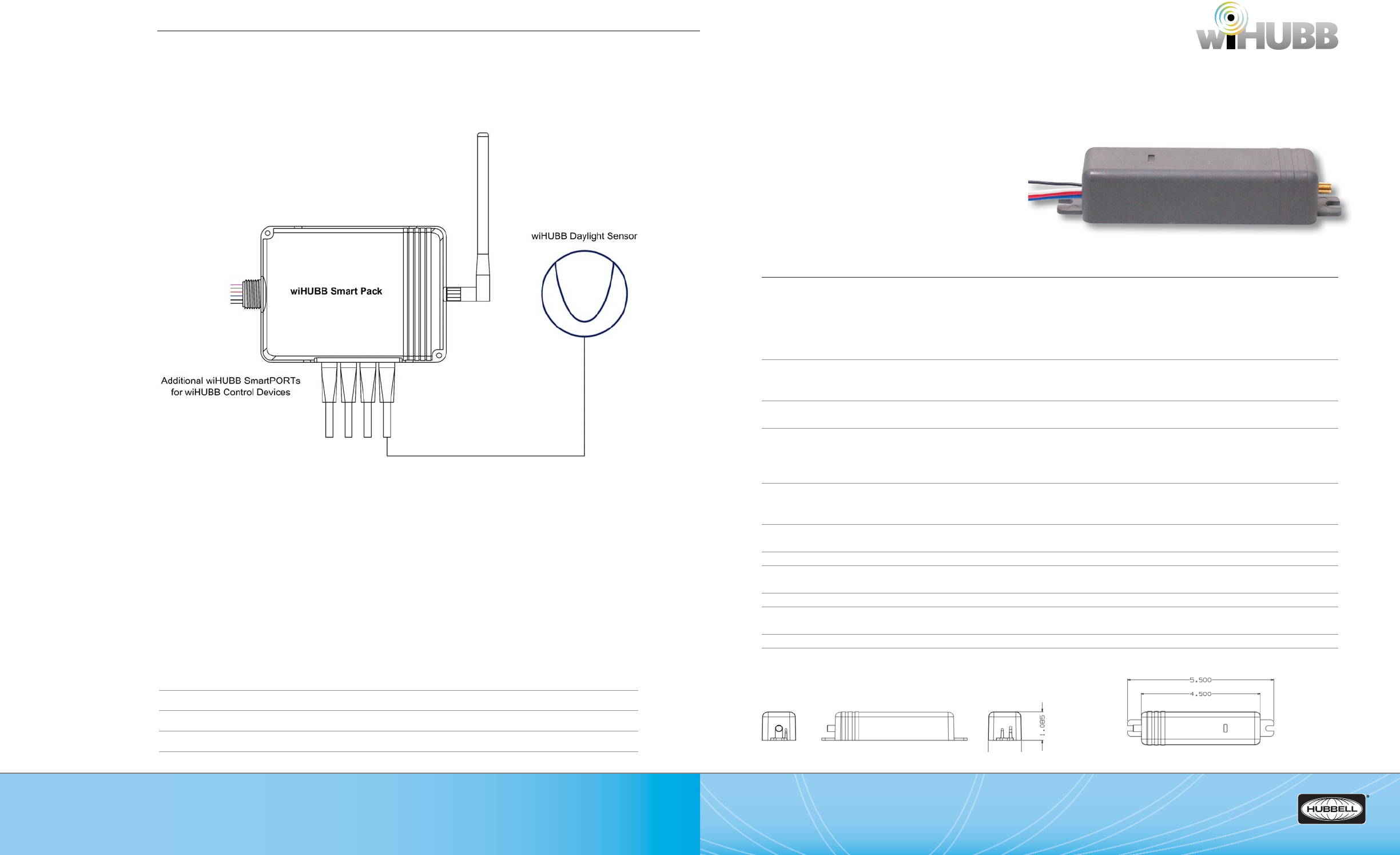
(888) 698-3242 | Fax orders (512) 450-0864 | hubbell-automation.com
h
ubb
ell-
au
t
o
m
a
ti
o
n
.
c
om
PAGE 48 | (888) 698-3242 | Fax orders (512) 450-0864 | hubbell-automation.com
PAGE 49 | WIRELESS LIGHTING CONTROLS
Hubbell Building Automation
NOTES
WIH-IM
wiHUBB™ In-Fixture Module
KEY FEATURES
• Single or dual relay versions for ON/OFF or High/Low control
• Optional 0 – 10VDC interface for full range dimming control
• Device intelligently and automatically responds to sensors
and switches in the most energy-e cient manner
• Schedules are held in the devices themselves – no need
for a master scheduling device
• Retains data during power outages
• Future-proof design – rmware updateable over the air
• Multiple antenna options available
SPECIFICATIONS
Electrical Ratings • Input: 120-277VAC, 10A Max, 60Hz
(-1277 version) • Output: 10A, Tungsten, 120VAC only
10A, Magnetic Ballast
5A, Electronic Ballast (max each relay)
¼ H.P. Motor, 120 & 277VAC
For (2) relay models the maximum combined output of both relays: 10A
Electrical Ratings • Input: 347VAC, 10A Max, 60Hz
(-347 version) • Output: 10A, Ballast
For (2) relay models the maximum combined output of both relays: 10A
Optional Dimming Interface • 0-10VDC, 30mA output
• For use with low-voltage, two-wire dimming ballast and LED drivers.
RF Frequency • 902 - 928MHz
• Wireless Peer-To-Peer, Self-Organizing and Self-Healing Mesh Network
• Advanced Encryption Standard AES-128 Security
• Spread Spectrum Frequency Hopping
RF Range • Supported distance between wireless devices: 100 meters (328 feet)
• Maximum Transmission Output Power: +20 dBm
• Maximum Receive Sensitivity: -118 dBm
Operating Environment • Operating Temperature: -40°C to +90°C
• Relative humidity (non-condensing): 0 – 95%
Construction • Housing: GSM UL Rated 94 HB Plastic
Size and Weight • Size: 5.50”L x 1.27”W x 1.08”H
• Weight: 4 oz
Color • Gray
Mounting • Mounts inside xture ballast cavity or housing
• Optional mounting adaptor available (p/n WIH-IM-ADAPTER) for external junction box mounting
Patents • Patent(s) Pending
Certi cations • Conforms with UL916 and Certi ed to CAN/CSA C22.2 No. 205-M1983; FCC Certi ed; IC Approved
DIMENSIONAL DRAWINGS
WIH-IM-2RD-1277
WIRING DIAGRAMS
For more wiring diagrams, visit http://www.hubbell-automation.com/resources/wiring_diagrams/
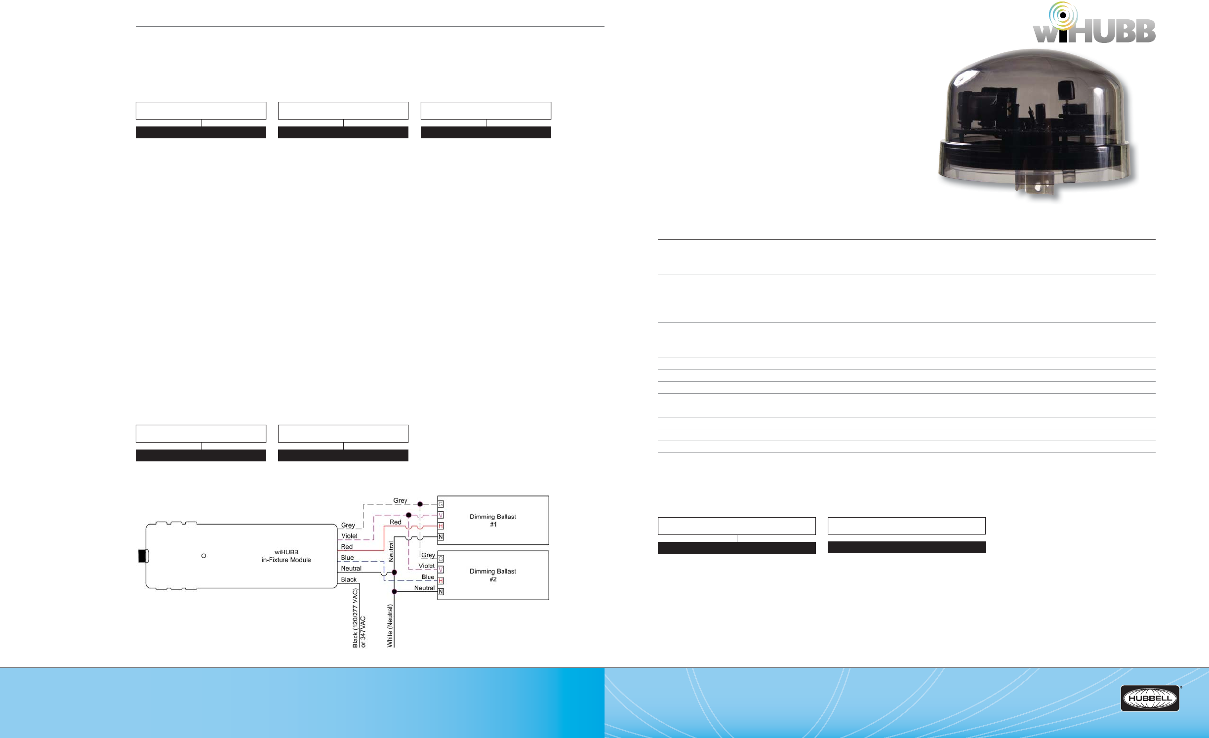
(888) 698-3242 | Fax orders (512) 450-0864 | hubbell-automation.com
h
ubb
ell-
au
t
o
m
a
ti
o
n
.
c
om
PAGE 50 | (888) 698-3242 | Fax orders (512) 450-0864 | hubbell-automation.com
PAGE 51 | WIRELESS LIGHTING CONTROLS
Hubbell Building Automation WIH-OM
wiHUBB™ On-Fixture Module
KEY FEATURES
• ON/OFF outdoor lighting control
• Compatible with all lighting loads including LED drivers
• Integrated daylight sensor
• Schedules are held in the devices themselves –no need
for a master scheduling device
• Retains data during power outages
• Robust & reliable 900MHz wireless self-organizing
and self-healing mesh network
SPECIFICATIONS
Electrical Ratings • Input: 120-347VAC, 50/60Hz
• Output: 20A, Tungsten, 120VAC only
20A, Magnetic and Electronic Ballast
RF Frequency • 902 - 928MHz
• Wireless Peer-To-Peer, Self-Organizing and Self-Healing Mesh Network
• Advanced Encryption Standard AES-128 Security
• Spread Spectrum Frequency Hopping
RF Range • Supported distance between wireless devices: 100 meters (328 feet)
• Maximum Transmission Output Power: +20 dBm
• Maximum Receive Sensitivity: -118 dBm
Daylight Sensor • 0.5 FC – 50 FC
Operating Environment • Operating Temperature: -40°C to +90°C
Construction • Housing: GSM UL Rated 94 HB Plastic
Size and Weight • Size: 3.50”D x 2.275”H
• Weight: 4 oz
Color • Smoked Plastic Housing
Mounting • Standard twist lock photo-sensor receptacle
Patents • Patent(s) Pending
Certi cations • Conforms with UL916 and Certi ed to CAN/CSA C22.2 No. 61010-1-04
• FCC Certi ed
• IC Approved
ORDERING INFORMATION
WIH-OM-UNV
ORDERING INFORMATION
WIRING DIAGRAM
ACCESSORY
MODEL
WIH-IM
MODEL
WIH-IM
OUTPUT
1R 1 SPST Output (Antenna not
included)
1RD 1 SPST Output, 0-10VDC Dimming
Output (Antenna not included)
1RA 1 SPST Output, Articulating
Antenna
1RDA 1 SPST Output, 0-10VDC Dimming
Output, Articulating Antenna
1RF 1 SPST Output, Fixed Antenna
with 24” Extension Cable
1RDF 1 SPST Output, 0-10VDC Dimming
Output, Fixed Antenna with 24”
Extension Cable
2R 2 SPST Outputs (Antenna not
included)
2RD 2 SPST Outputs, 0-10VDC
Dimming Output (Antenna not
included)
2RA 2 SPST Outputs, Articulating
Antenna
2RDA 2 SPST Outputs, 0-10VDC
Dimming Output, Articulating
Antenna
2RF 2 SPST Outputs, Fixed Antenna
with 24” Extension Cable
2RDF 2 SPST Outputs, 0-10VDC
Dimming Output, Fixed Antenna
with 24” Extension Cable
ACCESSORY
ADAPTER In-Fixture Module J-Box
Mounting Adapter
INPUT VOLTAGE
1277 120/277VAC
347 347VAC
INPUT VOLTAGE
UNV 120-347VAC, 50/60Hz
MODEL
WIH-OM
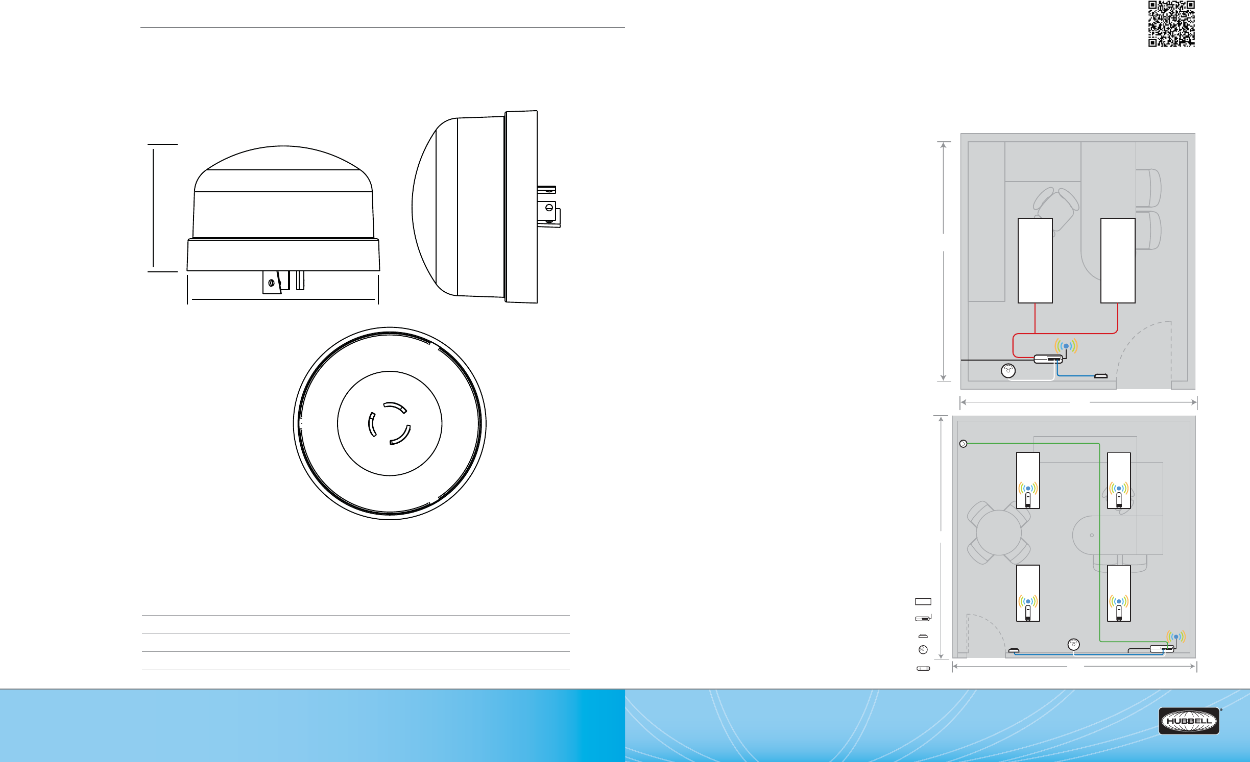
(888) 698-3242 | Fax orders (512) 450-0864 | hubbell-automation.com
h
ubb
ell-
au
t
o
m
a
ti
o
n
.
c
om
PAGE 52 | (888) 698-3242 | Fax orders (512) 450-0864 | hubbell-automation.com
PAGE 53 | WIRELESS LIGHTING CONTROLS
Hubbell Building Automation
NOTES
WIH-AP
wiHUBB™ Applications
wiHUBB DESIGN GUIDE
For more wiHUBB Design Applications, please see HBA’s wiHUBB Wireless Distributed Lighting Controls Application Guide.
Typical layout / coverage Small O ce Design
Control Strategies:
• Automatic Shut-O
• Individual Space Control
Recommended Technology:
• wiHUBB Single Relay Smart Pack
• wiHUBB Dual Technology Occupancy Sensors
with IntelliDAPT™, 500 Sq. Ft. Coverage
• wiHUBB ON/OFF Switch
Typical layout / coverage Large O ce Design
Control Strategies
• Automatic Shut-O
• Multi-Level Lighting Control
• Daylighting Control
Recommended Technology:
• wiHUBB Access Point
• wiHUBB Single Relay Smart Pack
• wiHUBB Dual Technology Occupancy Sensor with IntelliDAPT™,
1000 Sq. Ft. Coverage
• wiHUBB Daylight Sensor
• wiHUBB High/Low/O Switch
• wiHUBB-Enabled Fixtures
12'
12'
Main Feed
18'
18'
Main Feed
Lighting Fixture
Smart Pack
Switch
Occupancy Sensor
In-Fixture Module
DIMENSIONAL DIAGRAM
3.50” Diameter
2.275”
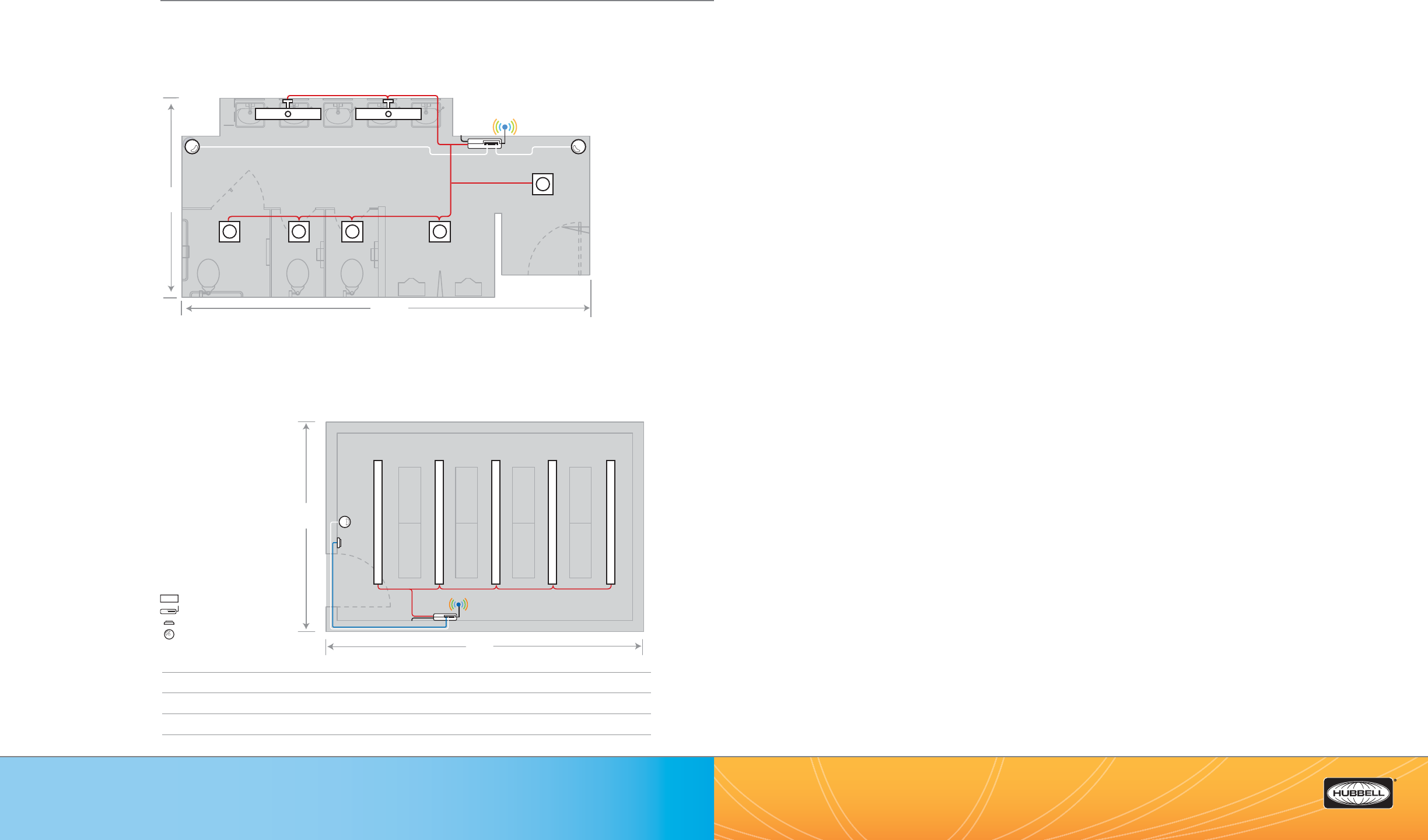
LX—Lighting Control Panels 4, 8, 16, 32, 48 Relays ................................................................................................................................................... 57
LXRL—LX Relays ...................................................................................................................................................................................................................... 59
LXBC—LX Breaker Control Panels 12, 18, 30, 42 Breaker|Relays .......................................................................................................................... 61
LXBR—Circuit Breaker|Relays and Circuit Breakers for LXBC ................................................................................................................................ 63
LXTB—Touch Tablet Graphical User Interface ............................................................................................................................................................. 65
LXJNSYS—LX JENESYS™ Network Components........................................................................................................................................................ 67
LXSW—LX Networked Switch Stations .......................................................................................................................................................................... 69
LXKEY—LX Keyed Switch Station ..................................................................................................................................................................................... 71
LXOMNDT—LX Occupancy Sensor featuring IntelliDAPT™ .................................................................................................................................. 73
LXPSCM—LX Photo Sensor Control Module and Sensors ..................................................................................................................................... 75
LXDCIM—LX Dry Contact Inteface Module .................................................................................................................................................................77
LXS—LX Sentry Switch .......................................................................................................................................................................................................... 79
LXLPM2—LX Link Power Module ..................................................................................................................................................................................... 81
LXRRM—LX Router Repeater ............................................................................................................................................................................................. 83
LXPWRSPLY—LX Power Supply ....................................................................................................................................................................................... 85
LXTERMINATOR—LX Terminator ..................................................................................................................................................................................... 87
LXUL924—UL924 Enclosed 20 AMP SPDT Bypass Relays ...................................................................................................................................... 89
LXENDM—LX Enclosure for DIN Rail Modules ............................................................................................................................................................ 91
LXWRDV—Panel Wire Way Divider Accessory Kit ...................................................................................................................................................... 93
LXSW Custom Buttons—Custom Engraved Switch Station Buttons ............................................................................................................... 95
LX Networked Cable|Plenum Rated—Plenum Rated Windy city Wire 104500 Cable .............................................................................97
LX Networked Cable|Riser Rated—Riser Rated Belden 8471 Cable ............................................................................................................... 99
CX4—CX Series Commericial Lighting Control Panel 4-Relays ..........................................................................................................................101
CX8—CX Series Commericial Lighting Control Panel 8-Relays ..........................................................................................................................103
CX 16, 24—CX Series Commericial Lighting Control Panel 16- and 24-Relays ............................................................................................105
CXR—CX Series Commericial Lighting Control Panel Relays ..............................................................................................................................107
CX Panel Accessories—CX Panel Accessories ..........................................................................................................................................................109
(888) 698-3242 | Fax orders (512) 450-0864 | hubbell-automation.com
h
ubb
ell-
au
t
o
m
a
ti
o
n
.
c
om
PAGE 55 | LIGHTING CONTROL PANELS
PAGE 54 | (888) 698-3242 | Fax orders (512) 450-0864 | hubbell-automation.com
Hubbell Building Automation
NOTES
Lighting Control Panels
Table of Contents
Lighting Fixture
Smart Pack
Switch
Occupancy Sensor
23' 2"
11' 4"
Main
Feed
12' 2"
20'
Main Feed
Typical layout / coverage Large Restroom Design
Control Strategies:
• Automatic Shut-O
Recommended Technology:
• wiHUBB Single Relay Smart Pack
• wiHUBB Ultrasonic Technology Occupancy Sensors with IntelliDAPT™, 500 Sq. Ft. Coverage
Typical layout / coverage
Large Closet / Storeroom
Design
Control Strategies:
• Automatic Shut-O
• Individual Space Control
Recommended Technology:
• wiHUBB Single Relay
Smart Pack
• wiHUBB Ultrasonic
Technology Occupancy
Sensors with IntelliDAPT™,
1000 Sq. Ft. Coverage
• wiHUBB ON/OFF switch
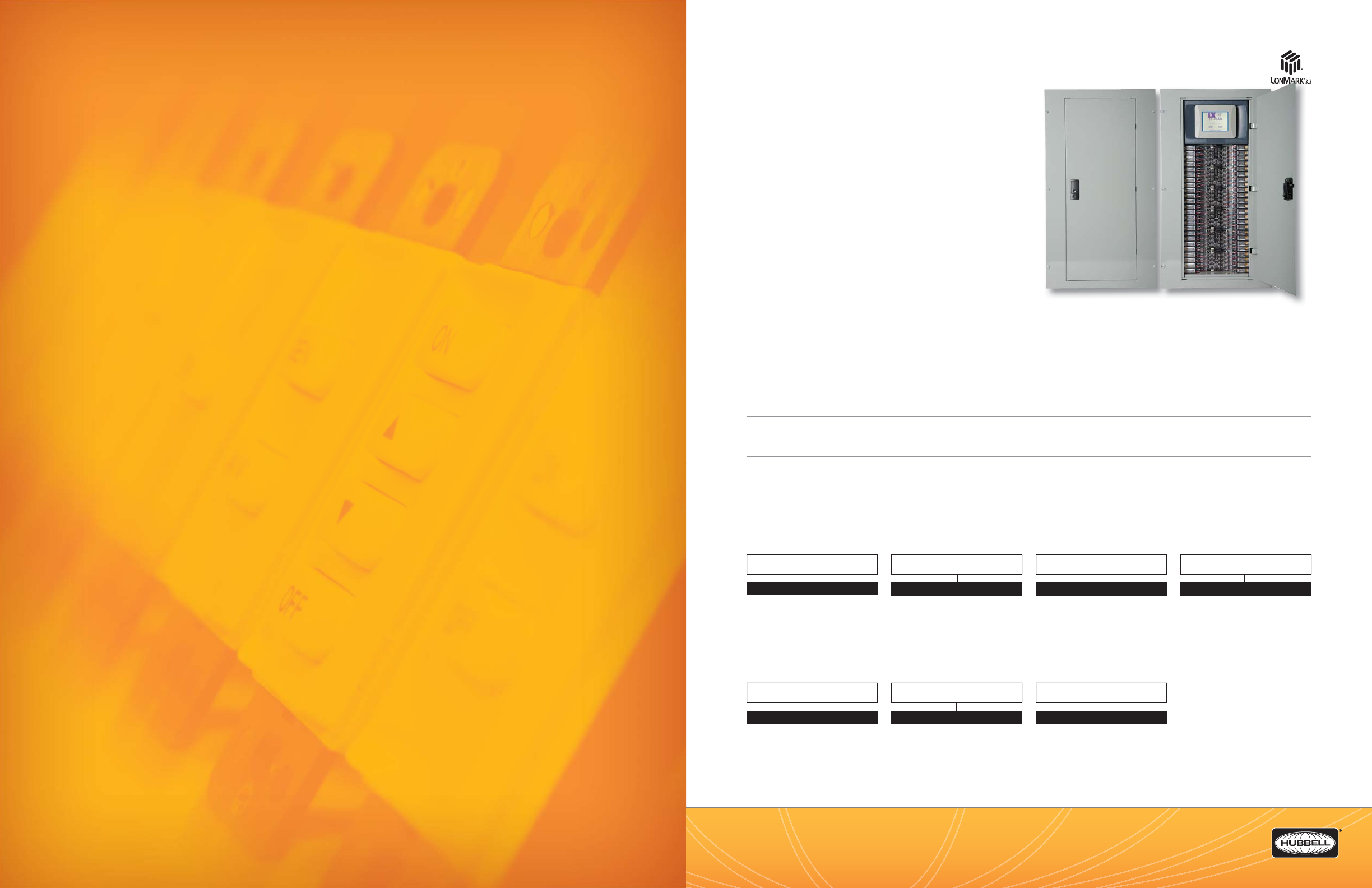
(888) 698-3242 | Fax orders (512) 450-0864 | hubbell-automation.com
h
ubb
ell-
au
t
o
m
a
ti
o
n
.
c
om
PAGE 57 | LIGHTING CONTROL PANELS
LX
Lighting Control Panels
4, 8, 16, 32 and 48 Relays
KEY FEATURES
• Unique handheld touchscreen graphical user interface (GUI)
(Order Seperately)
• Robust and reliable 20 Amp mechanically latching-relays
• Multiple size enclosures available (4, 8, 16, 32, and 48 relays)
• Topology-free, polarity-insensitive, 2-wire communication
• LonMark® certi ed
• 365-day time clock
• Automatic Daylight Savings Time and leap-year compensation
• Built-in astronomical time clock for sunrise and
sunset programming
SPECIFICATIONS
Programming and con guration
• Programmable via the LX Touch Tablet or LX JENEsys™
Physical • NEMA 1 enclosure—designed for quick and easy installation
• Pre-drilled mounting holes for easy mounting either to the uni-strut framing or directly to wall,
KOs provided on top and bottom
• Removable interior sub panel
• 4, 8, 16, 32, and 48 relay enclosures with hinged locking door
Electrical • 120/277/347 VAC multi-tap transformer
• 120, 277, and 347 VAC 20 Amp Single Pole Relays
• 208, 240, and 480 VAC 20 Amp Double Pole Relays
Operating environment • Location: interior space
• Operating temperature: 0°–50°C (32°–112°F)
• Relative humidity (non-condensing): 10%–90%
Certi cations • UL and cUL listed (UL 508, 916 and UL 924)
• LonMark 3.3 Certi ed
ORDERING INFORMATION
LonMark ® is a registered trademark of LonMark International.
MODEL
LXIN LX Relay Panel Interiors
RELAY CAPACITY
4
8
16
32
48
NUMBER OF SINGLE POLE RELAYS
00-48*
(Depending on Size)
NUMBER OF DOUBLE POLE RELAYS
00-24*
(Depending on Size)
*NOTE: Number of poles cannot exceed the relay panel size.
Example: A LX Series Relay Panel is comprised of 2 separate part numbers, 1 for the interior
and 1 for the enclosure — they must be the same size.
MODEL
LXEN LX Relay Panel Enclosure
LXEN
SIZE
4
8
16
32
48
TRIM
FFlush
SSurface
NOTE: LXTB Graphic User Interface
not included. Order Seperately.
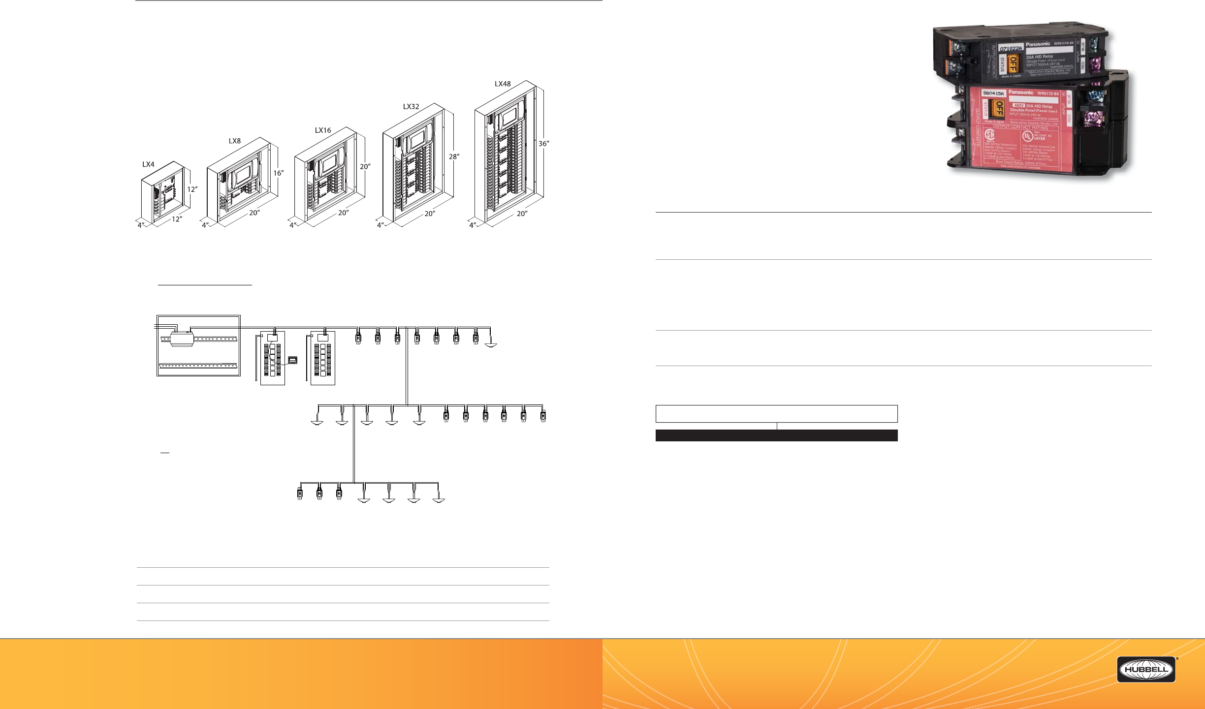
(888) 698-3242 | Fax orders (512) 450-0864 | hubbell-automation.com
h
ubb
ell-
au
t
o
m
a
ti
o
n
.
c
om
PAGE 58 | (888) 698-3242 | Fax orders (512) 450-0864 | hubbell-automation.com
PAGE 59 | LIGHTING CONTROL PANELS
Hubbell Building Automation
NOTES
LXENDM
EQUIPMENT CABINET
12" x 15" x 4" SURFACE MTD.
LX-LPM2 (DIN Rail)
Link Power Unit
120VAC
Neutral
Ground
LX48
Panel
LX48
Panel
120/277/347
LXTB
120/277/347
VAC In
LXSW2LP Switch Stations LXSW2LP Switch Stations
LXSW2LP Switch Stations
LXOMNDT2000FT
LXOMNDT2000FTs
LXOMNDT2000FTs
Motion Sensors Motion Sensors
Motion Sensors
Motion Sensors
LXOMNDT2000FTs
2 Wire Network
Belden 8471
2 Wire Network
Belden 8471
2 Wire Network
Belden 8471
All Network Segments
Note: Each network segment shall not exceed 56 devices (panels, switches,
sensors) or 1500 ft of wire. The quanity of panels, switches, and sensors shown
is to illustrate conceptual wiring scheme only. The actual connection and
number of devices will be determined by actual locations on the plans.
LX Communication Network Notes:
1. The LX network is a 2-wire communication network. It
can operate using any topology (layout) or combination of
topologies including Star and T-configurations.
2. Network cable shall be Belden 8471 or Windy City Wire
104500 only. Maximum total wire length per network
segment (without requiring the use of the LX Router/
Repeater Module, p/n LXRRM) shall not exceed 1,500 feet.
Up to 56 devices can be supported per network segment.
3. Additional Link Power Modules (LXLPM2) will be needed
if the network exceeds 1,500 feet per network segment, or
56 devices per network segment. When multiple Link
Powered Modules(LXLPM2) are used, they must have a LX
Router/Repeater Module(LXRRM) between them.
4. All network wiring must be routed through the top of the
lighting control panel enclosure to the low voltage section of
the interior.
5. Do not use shielded cable.
Typical LX Relay Panel System
LXRL
LX Relays
KEY FEATURES
• Robust and reliable mechanically-latching relay
• Suitable for high in-rush loads up to 2,000 Amps
• 14,000 Amp SCCR @277VAC
• 120, 277 & 347 VAC Single Pole
• 208, 240 & 480 VAC Double Pole
• Built-in manual override lever & ON/OFF indicator
• True relay status
SPECIFICATIONS
Physical • Mechanically-held latching relay
• Mounts in LX panel to supplied mounting bracket
• Built-in manual override lever & ON/OFF indicator on each relay
• Toolless insertion and removal of relay
Electrical • UL Endurance Test 150k Operations at 20A, 300VAC 60k Operations @20A, 300 VAC
• UL endurance test Mechanical - 120k operations at 20A, 300VAC
• 14,000 Amp SCCR (Short Circuit Current Rating) @ 277VAC*
• 20 Amp Single Pole – 120, 277 & 347 VAC
• 20 Amp Double Pole – 208, 240 & 480 VAC
• ½HP@110-125VAC, 1 ½HP@220-277VAC
Operating environment • Location: Interior space
• Operating temperature: 0° to 50°C (32° to 122°F)
• Relative Humidity: 10% to 90% non-condensing
Certi cations • UL & cUL Listed (UL 508)
ORDERING INFORMATION
LXRL1
L
L
LX
RL
1
LXRL2
DIMENSIONAL INFORMATION
Touch Screen Tablet Graphic User Interface (GUI) Order Seperately (Typical)
WIRING DIAGRAM
For more wiring diagrams, visit http://www.hubbell-automation.com/resources/wiring_diagrams/
MODEL
LXRL1 LX Relay, Single Pole, 120/277/347VAC
LXRL2 LX Relay, Double Pole, 208/240/480VAC
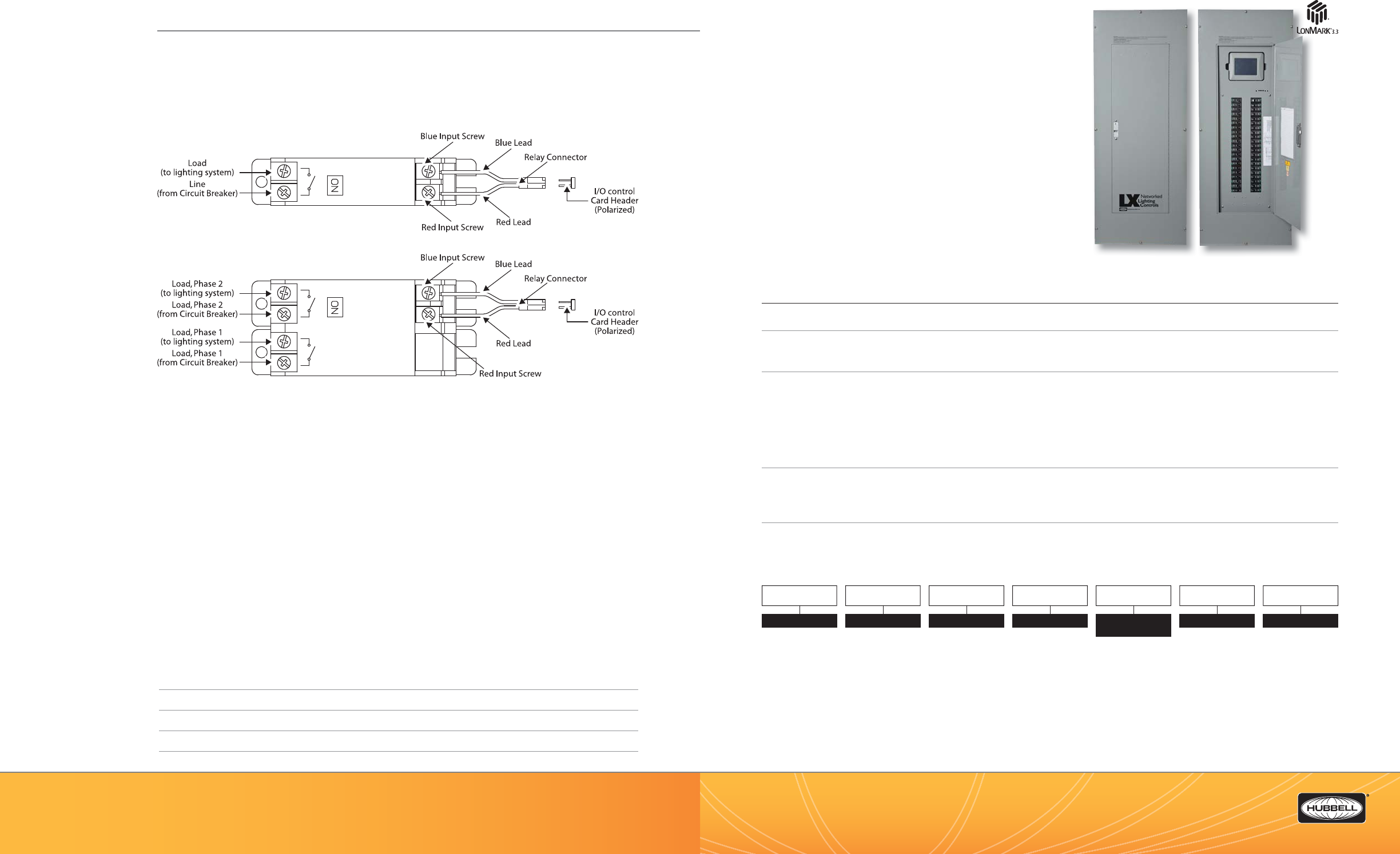
(888) 698-3242 | Fax orders (512) 450-0864 | hubbell-automation.com
h
ubb
ell-
au
t
o
m
a
ti
o
n
.
c
om
PAGE 60 | (888) 698-3242 | Fax orders (512) 450-0864 | hubbell-automation.com
PAGE 61 | LIGHTING CONTROL PANELS
Hubbell Building Automation
NOTES
LXBC
LXBC Breaker Control Panels
12, 18, 30, 42 Breaker|Relays
KEY FEATURES
• Unique, handheld touchscreen graphical user interface
(GUI) (Order Separately)
• Robust and reliable 20 and 30 Amp mechanically latching
circuit breaker/relays
• Multiple size enclosures available (12, 18, 30, and 42 spaces)
• 100 AMP, 225 AMP or 400 AMP bussing Main Lugs
or Main Circuit Breaker
• 120/208V, 3PH, 4W or 277/480V, 3PH, 4W
• Topology-free, polarity-insensitive, 2-wire communication
• 365-day time clock
• Automatic Daylight Savings Time and leap year compensation
• Built-in astonomical time clock for sunrise and sunset programming
SPECIFICATIONS
Programming and con guration
• Programmable via the LX Touch Tablet or LX JENEsys™
Physical • NEMA 1 enclosure, surface or ush mount
• KOs provided on top and bottom
• 12, 18, 30, and 42 space enclosures with hinged locking door
Electrical • 120 VAC input control voltage at terminal block
• 20 Amp and 30 Amp 1-pole and 2-pole Circuit Breaker/Relays
• Non-Control circuit breakers 15A – 100A, 1,2, and 3-pole
• 100 AMP, 225 AMP or 400 AMP Lugs Only or Main Circuit Breaker, CU/AL Lugs Bottom Feed only,
Top Feed is not available.
• 120/208V, 3PH, 4W or 277/480V, 3PH, 4W system voltage, 14KAIC @277/480V,
65KAIC Series Rated with main CB
Operating environment for NEMA 1 rated equipment
• Location: interior space
• Operating temperature: 0°–50° C (32°–112° F)
• Relative humidity (non-condensing): 10%–90%
Certi cations • UL listed (UL 916)
• LonMark 3.3 Certi ed
ORDERING INFORMATION
NOTE: Touch Screen Graphic User Interface
(GUI) not included. Order Seperately.
MODEL
LXBC LX Breaker
Control Panel
SYSTEM VOLTAGE
1120/208, 3 Phase,
4 Wire
2277/480, 3 Phase,
4 Wire
MAINS
IL 100 Amp Main
Lugs Only
IC 100 Amp Main
Circuit Breaker
2L 225 Amp Main
Lugs Only
2C 225 Amp Main
Circuit Breaker
4L 400 Amp Main
Lugs Only
4C 400 Amp Main
Circuit Breaker
FEED
BBottom Feed
Only
(Top Feed is
not available)
BREAKER RELAY
SPACES
12 12 Spaces
18 18 Spaces
30 30 Spaces
42 42 Spaces
NOTE: 42 space is
available in 225A and
400A main size only.
COMMUNICATIONS
HHBA LX-Lon
ENCLOSURE
1S NEMA 1 Surface
1F NEMA 1 Flush
LXBC B H
LonMark ® is a registered trademark of LonMark
International.
WIRING DIAGRAM
For more wiring diagrams, visit http://www.hubbell-automation.com/resources/wiring_diagrams/
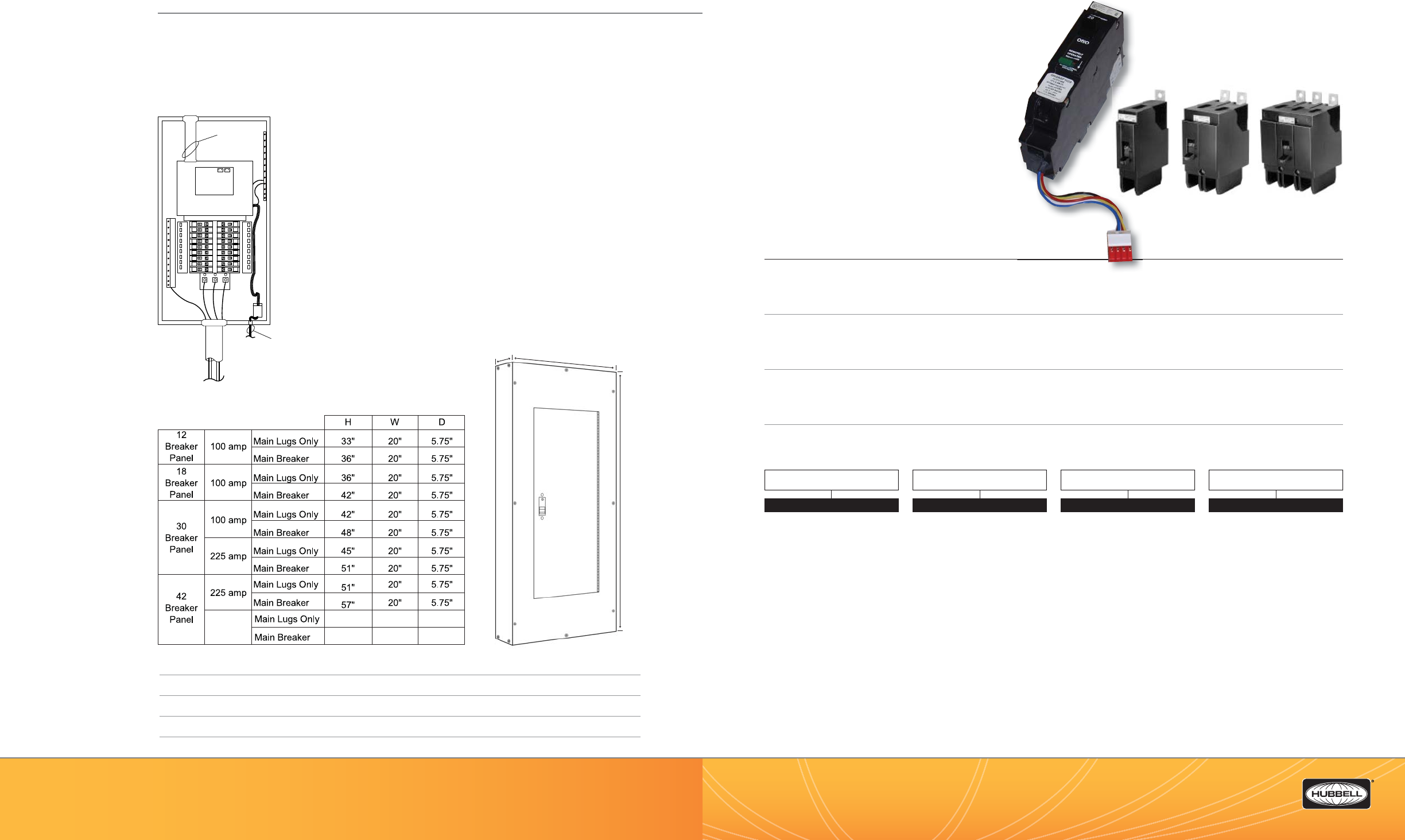
(888) 698-3242 | Fax orders (512) 450-0864 | hubbell-automation.com
h
ubb
ell-
au
t
o
m
a
ti
o
n
.
c
om
PAGE 62 | (888) 698-3242 | Fax orders (512) 450-0864 | hubbell-automation.com
PAGE 63 | LIGHTING CONTROL PANELS
Hubbell Building Automation
NOTES
LXBR
Circuit Breaker | Relays
and Circuit Breakers for LXBC
KEY FEATURES
• Robust and reliable 20 and 30 Amp mechanically-
latching Circuit Breaker/Relays
• Circuit Breaker/Relays are available in 1-pole to 277V
and 2-pole to 480V
• Non-controlled Circuit Breakers are available in 1-pole
to 277V and 2-pole or 3-pole to 480V
• All devices are rated for switching duty (SWD)
• 14,000 Amp interrupting capacity (AIC)
• Built-in ON/OFF indicator lever
• True relay status
SPECIFICATIONS
Physical • Mechanically-held latching circuit breaker/relay or non-controlled circuit breaker
• Mounts in LXBC panel bus with bolt into pre-drilled and tapped hole
• Built-in ON/OFF indicator lever on each circuit breaker/relay
• Power to panel must be disconnected for insertion and removal of devices
Electrical • 600 VAC 20 Amp and 30 Amp Single and Double Pole Circuit Breaker/Relays
• Non-Control circuit breakers 15A – 60A, 1,2, and 3-pole
• 14KAIC @277/480V, 65KAIC Series Rated with main CB
• Circuit Breaker Relays – Maximum duty cycle of 6 Open/Close cycles per minute
Operating environment for NEMA 1 rated equipment
• Location: interior space
• Operating temperature: 0°–50° C (32°–112° F)
• Relative humidity (non-condensing): 10%–90%
Certi cations • UL listed (UL 489)
ORDERING INFORMATION
1-Pole 2-Pole 3-Pole
Non-controlled Circuit Breakers
Controlled Circuit Breaker/Relay
1-Pole shown (2-Pole also available)
120/277/347
VAC I n
Seperate Incoming
Control Circuit
N
Incoming Power Feeder
(By Others)
Cross Feeder
Lugs
ABC
Low Voltage
Raceway
Processor Board
LON
Network
LX 18 Relay
Breaker Panel
DW
H
400 amp 57"
69"
20"
20"
5.75"
5.75"
c
uit breaker/relay or non-contr
o
1
-
P
C
1
-
P
WIRING DIAGRAM
For more wiring diagrams, visit http://www.hubbell-automation.com/resources/wiring_diagrams/
PRODUCT DIMENSIONS
MODEL
LXBR LX Breaker Relay or Breaker
NO. OF POLES
11-Pole
22-Pole
33-Pole
AMP RATING
15 15 Amp
20 20 Amp
30 30 Amp
40 40 Amp
50 50 Amp
60 60 Amp
70 70 Amp
80 80 Amp
90 90 Amp
100 100 Amp
CONTROL
CControlled
NNon-Controlled
NOTE: Controlled Breaker/Relays are
available in 20A and 30A 1-Pole and
2-Pole ONLY.
LXBR

(888) 698-3242 | Fax orders (512) 450-0864 | hubbell-automation.com
h
ubb
ell-
au
t
o
m
a
ti
o
n
.
c
om
PAGE 64 | (888) 698-3242 | Fax orders (512) 450-0864 | hubbell-automation.com
PAGE 65 | LIGHTING CONTROL PANELS
Hubbell Building Automation
NOTES
LXTB
Touch Tablet Graphical User Interface
KEY FEATURES
• Portable handheld touchscreen
• Graphical user interface (GUI)
• Context-sensitive help
• Quarter VGA display (320 x 240 pixels)
• High-contrast backlit LCD screen
• Programmable security codes
SPECIFICATIONS
Programming and con guration
• Device used to program the functionality of other LX lighting control system devices
• Can program security codes
Physical • Handheld device
• Quarter VGA display (320 x 240 pixels)
Electrical • 5 VDC power—supplied from the LX panel
Operating environment • Location: interior space
• Operating temperature: 0°–50°C (32°–122°F)
• Relative humidity (non-condensing): 10%–90%
Tablet Dimensions • 7.5”W x 6”H x 1”D
ORDERING INFORMATION
LXTB
Seperate Incoming
Control Circuit
N
Processor Board
LON
Network
LX 30 Relay
Breaker Panel
120/277/347
VAC In
Incoming Power Feeder
(By Others)
Cross Feeder
Lugs
ABC
Low Voltage
Raceway
LonMark ® is a registered trademark of LonMark International.
WIRING DIAGRAM
For more wiring diagrams, visit http://www.hubbell-automation.com/resources/wiring_diagrams/
LXTB
MODEL
LXTB LX Touch Screen Tablet
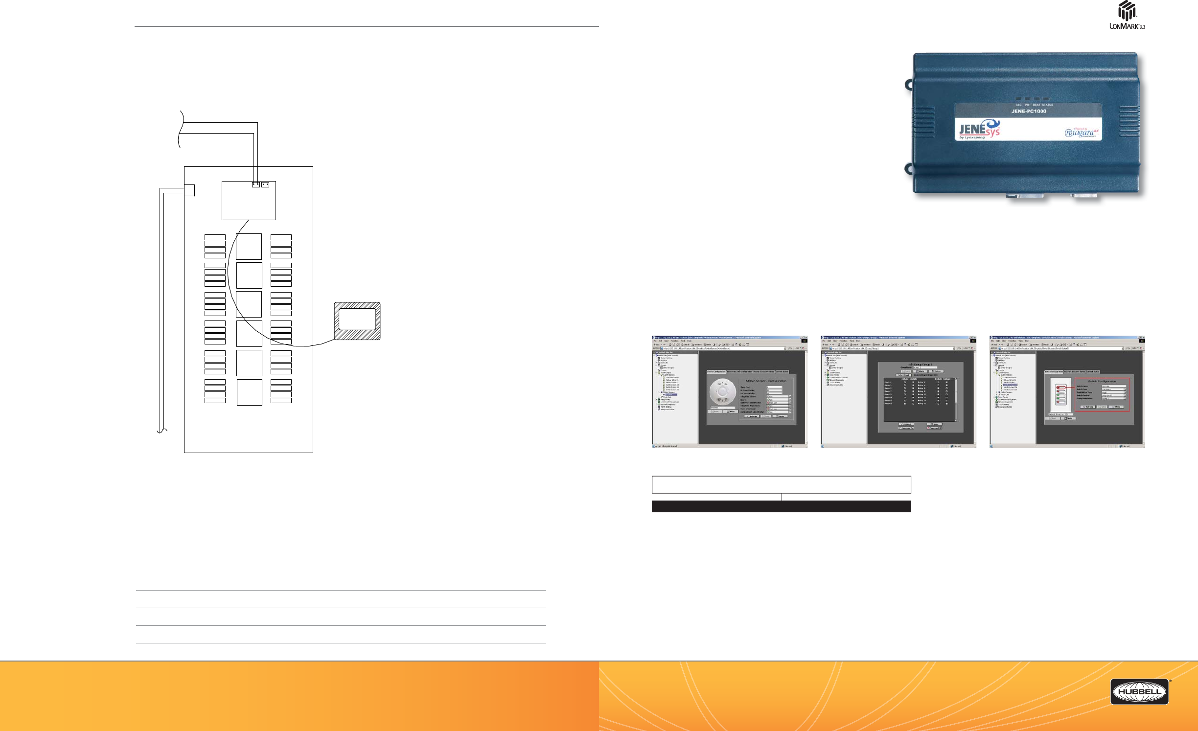
(888) 698-3242 | Fax orders (512) 450-0864 | hubbell-automation.com
h
ubb
ell-
au
t
o
m
a
ti
o
n
.
c
om
PAGE 66 | (888) 698-3242 | Fax orders (512) 450-0864 | hubbell-automation.com
PAGE 67 | LIGHTING CONTROL PANELS
Hubbell Building Automation
NOTES
LXJNSYS
LXJENEsys™ Network Interface Components
KEY FEATURES
• Programming Interface:
• Real-time programming and monitoring of the LX lighting
control system through your PC
• No software required—built-in web server provides
connection via any Internet Explorer®-compatible browser
• Graphical User Interface (GUI) makes programming both
intuitive and simple
• Local or remote access via the local network or Internet
• Can connect multiple users at once
• Sophisticated user account/password manager
• System Integration:
• Integrates LX lighting control systems and Building Automation Systems (BAS)
• Integrates with LonWorks ®, BACnet™ (IP and MSTP), and Modbus™ standards
• Automatically generates all required control points and documentation for integration
with the selected protocol
• Powered by NiagaraAX Framework®
• Maximum of 127 Integration Point per Network Jenesys™ Device (Consult HBA for requirements for larger networks.)
INTERFACE SCREEN SHOTS
ORDERING INFORMATION
LX48 Panel
120/277/347
VAC In
CPT
Relays Relay
Boards
Relays
Notes:
LXTB Graphical User Interface Tablet connects to any
LX Panel with RJ45 Cat 5E Cable included with tablet.
LXTB Graphical
User Interface
Processor Board
LON Network
JENEsys™ is a trademark of LynxSpring Inc.
LonWorks ® is a registered trademark of Echelon Corporation.
LonMark ® is a registered trademark of LonMark International.
LXJNSYS
WIRING DIAGRAM
For more wiring diagrams, visit http://www.hubbell-automation.com/resources/wiring_diagrams/
MODEL
LXJNSYS LX JENEsys Controller with Management Software, LON Network
Module and Power Supply
LXJNSYS2LON LX JENEsys Controller with Management Software, LON Integration
Support, LON Network Modules and Power Supply
LXJNSYS2BACNETIP LX JENEsys Controller with Management Software, BACNET IP
Integration Support, LON Network Module and Power Supply
LXJNSYS2BACNETMSTP LX JENEsys Controller with Management Software, BACNET MS/TP
Integration Support, LON Network Module and Power Supply
LXJNSYS2MODBUS LX JENEsys Controller with Management Software, MODBUS
Integration Support, LON Network Module and Power Supply
LXJNCOM56KM1* LX JENEsys 56Kps Modem for LX JENEsys Controller

(888) 698-3242 | Fax orders (512) 450-0864 | hubbell-automation.com
h
ubb
ell-
au
t
o
m
a
ti
o
n
.
c
om
PAGE 68 | (888) 698-3242 | Fax orders (512) 450-0864 | hubbell-automation.com
PAGE 69 | LIGHTING CONTROL PANELS
Hubbell Building Automation
NOTES
LXSW
LX Networked Switch Stations
KEY FEATURES
• Attractive, architecturally-pleasing design
• Flexible programming of switch functionality
• Programmable active and inactive times
•
Topology-free, polarity-insensitive, 2-wire communication
• FT-10 and LPT-10 versions available
• LonMark® certi ed
• 1–6 buttons with or without pilot
• Mounts to standard single-gang box
SPECIFICATIONS
Network interface • FTT-10 or LPT-10
Programming and con guration
• Programmable over a network using the LX Touch Tablet or any other LX programming device
Physical • Injection-molded switch plate and switches
• Fits standard (Decorator style) wall switch plates (not included)
• Mounts to standard electrical gang box
Electrical • LPT-10 version: powered from Link Power Module
• FTT-10 version: 24 volts AC or DC; .5Amps required
Operating environment • Location: interior space
• Operating temperature: 0°–50°C (32°–122°F)
• Relative humidity (non-condensing): 10%–90%
Capacities • 1–6 buttons
Certi cations • LonMark 3.3 certi ed
ORDERING INFORMATION
LXSW1 LXSW2 LXSW3 LXSW4 LXSW5 LXSW6
JENEsys
120AC
15 VDC
WALL
PLUG
ADAPTER
Ethernet
Not Used
LON Network
LXJNSYS
CONNECTION TO BUILDING AUTOMATION
SYSTEM (BY BUILDING INERGRATOR)
OR
CONNECTION TO BUILDING
INTRANET (ETHERNET STATIC IP)
LX LON NETWORK
CONNECTION
DIN RAIL MOUNTED
REQUIRES LXENDM
ENCLOSURE
REQUIRES 120VAC
RECEPTACLE
LonWorks ® is a registered trademark of Echelon Corporation.
LonMark ® is a registered trademark of LonMark International.
WIRING DIAGRAM
For more wiring diagrams, visit http://www.hubbell-automation.com/resources/wiring_diagrams/
APPLICATION NOTES
• The LX JENEsys device is used to allow the end-user remote access to the LX Networked Lighting Control
System. A connection to the building’s local network is required. The device contains a user-settable static IP
for this connection.
• The LX JENEsys requires a 120 VAC 15 or 20 Amp receptacle for connection of the included power supply.
• All versions of the LX JENEsys contain the on-board web server for remote access.
• Each LX JENEsys device is Building Automation System speci c. The integration system standard needs
to be determined in order to obtain the correct device prior to ordering.
NO. OF BUTTONS
1
2
3
4
5
6
NETWORK INTERFACE
LP
FT
COLOR
WWhite
IIvory
MODEL
LXSW
EXAMPLE:
White 4 Button FT Switch Station: LXSW4FTW
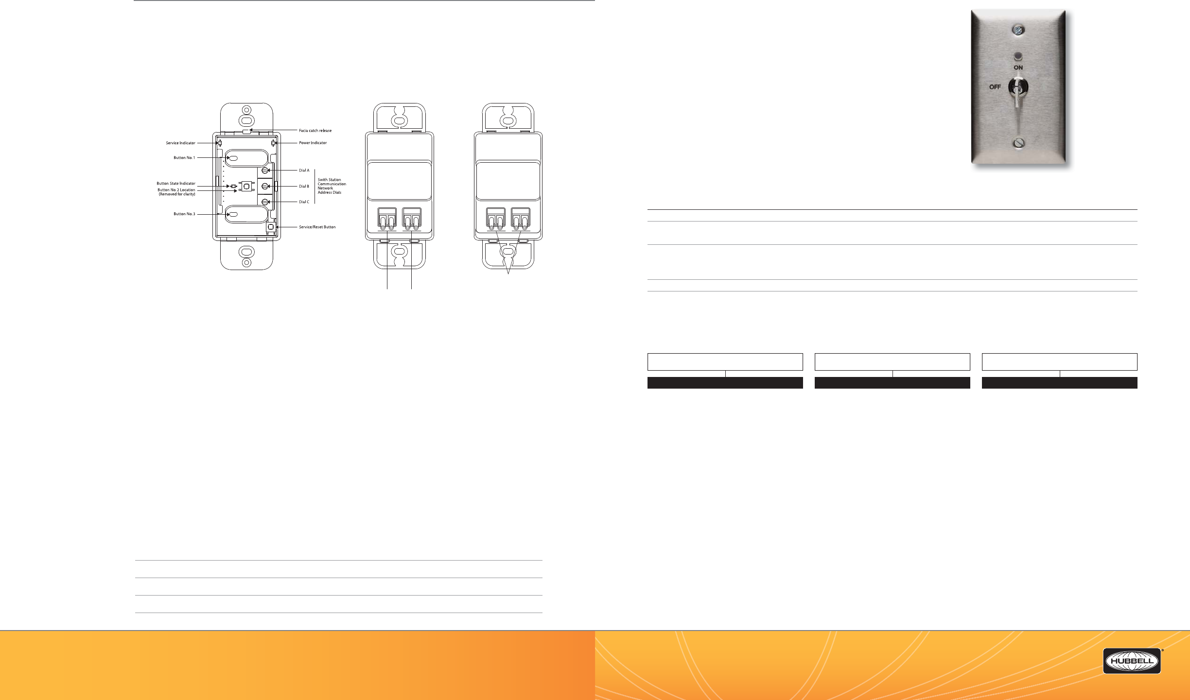
(888) 698-3242 | Fax orders (512) 450-0864 | hubbell-automation.com
h
ubb
ell-
au
t
o
m
a
ti
o
n
.
c
om
PAGE 70 | (888) 698-3242 | Fax orders (512) 450-0864 | hubbell-automation.com
PAGE 71 | LIGHTING CONTROL PANELS
Hubbell Building Automation
NOTES
LXKEY
LX Keyed Switch Station
KEY FEATURES
• Stainless steel face plate with barrel-lock mechanism and pilot light
• Flexible programming of switch functionality
• Programmable Active & Inactive times
• Topology-Free, Polarity-Insensitive, 2-wire communication
• Mounts in standard single-gang box
SPECIFICATIONS
Network Interface • LPT-10
Programming / Configuration
• Programmed over network using the LX Touch Tablet or any other LX programming device
Physical • Stainless steel faceplate
• Barrel-style locking switch mechanism
• Mounts to standard electrical single gang box (multiple gang version are not available)
Electrical • LPT-10: Powered from Link Power Module
Operating environment • Location: Interior space
• Operating temperature: 0° to 50°C (32° to 122°F)
• Relative Humidity: 10% to 90% non-condensing
ORDERING INFORMATION
LXKEY
Switch Station Controls Diagram
Switch Station Controls Diagram
Connection to
FT Network
FT Version
(view of back)
LP Version
(view of back)
Connection to
24 VAC / DC
Power Supply
Connection to LP Network
(Network Connections are
wired together internally)
WIRING DIAGRAM
For more wiring diagrams, visit http://www.hubbell-automation.com/resources/wiring_diagrams/
NETWORK INTERFACE
LP
COLOR
Blank Stainless Steel2
MODEL
LXKEY1
NOTES:
1. LXKEY is available with 1 keyswitch only and "LP" Link Power only.
2. LXKEY available in Stainless Steel only (not available in white or ivory).
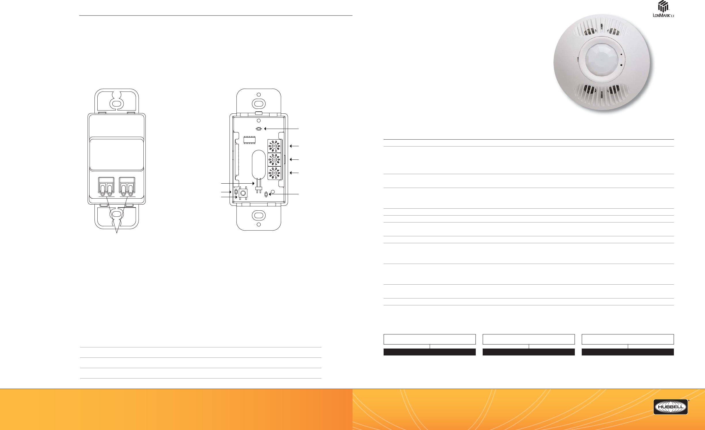
(888) 698-3242 | Fax orders (512) 450-0864 | hubbell-automation.com
h
ubb
ell-
au
t
o
m
a
ti
o
n
.
c
om
PAGE 72 | (888) 698-3242 | Fax orders (512) 450-0864 | hubbell-automation.com
PAGE 73 | LIGHTING CONTROL PANELS
Hubbell Building Automation
NOTES
LXOMNDT
LX Occupancy Sensor
Featuring IntelliDAPT®
KEY FEATURES
• FT-10 and LPT-10 versions available
• Topology-free, polarity-insensitive, 2-wire communication
• IntelliDAPT self-adaptive technology – no manual adjustment required
• All-Digital, dual-technology
(Ultrasonic [US] and passive infrared [PIR]) sensor
• Sensors can be adjusted remotely from LX Touch Screen Tablet
• Non-volatile memory for sensor settings
• 2000 square feet coverage
• LonMark® 3.3 certi ed; UL and cUL listed
SPECIFICATIONS
Network Interface • FTT-10 or LPT-10
IntelliDAPT • Auto reset from test setting
• Self-adjusting timer
• Self-adjusting ultrasonic and passive infrared thresholds
• Automatic false-on/false-o corrections
LED lamp • Red—infrared motion
• Green—ultrasonic motion
Timer timeout • Automatic mode: 8 -30 min. (self-adjusts based on occupancy)
• Manual Mode: 2-30 min.
• Test mode: 8 seconds (for an easy check at installation)
Ultrasonic output • 32kHz
Passive infrared • Dual element pyrometer; 12-element cylandrical rugged lens
Programming and con guration
• LX mode—programmed over network using the LX Touch Tablet, JENEsys™
Coverage • 2,000 square feet
Operating environment • Indoor use only
• Operating temperature: 32°–104°F (0°–40°C)
• Relative humidity (non-condensing): 0% to 95%
Construction • Housing—rugged, high-impact, injection-molded plastic KJB ABS Cycolac (UL-945VA) ame class rating,
UV inhibitors
• Color coded leads are 6” long
Size and weight • Size: 4.5” diameter, 1.5” height (114 mm diameter, 38mm height)
• Weight: 5.0 oz (142g)
Color • O -white
Mounting • Mounting base provided with sensor
• Recommended MAX Mounting height: 12ft
ORDERING INFORMATION
LXOMDT2000
Switch Station Wiring Diagram Switch Station Control Diagram
LP Version
(view of back)
Connection to LP Network
(Network Connections are
wired together internally)
Key Switch
Connector
Service LED
Switch
State LED
Address Dials
100’s “A”
10’s “B”
1’s “C”
Power
Service Switch
LonMark ® is a registered trademark of LonMark International.
WIRING DIAGRAM
For more wiring diagrams, visit http://www.hubbell-automation.com/resources/wiring_diagrams/
MODEL
LX
LX
DEVICE TYPE
OMDT 2000
NETWORK INTERFACE
LP
FT
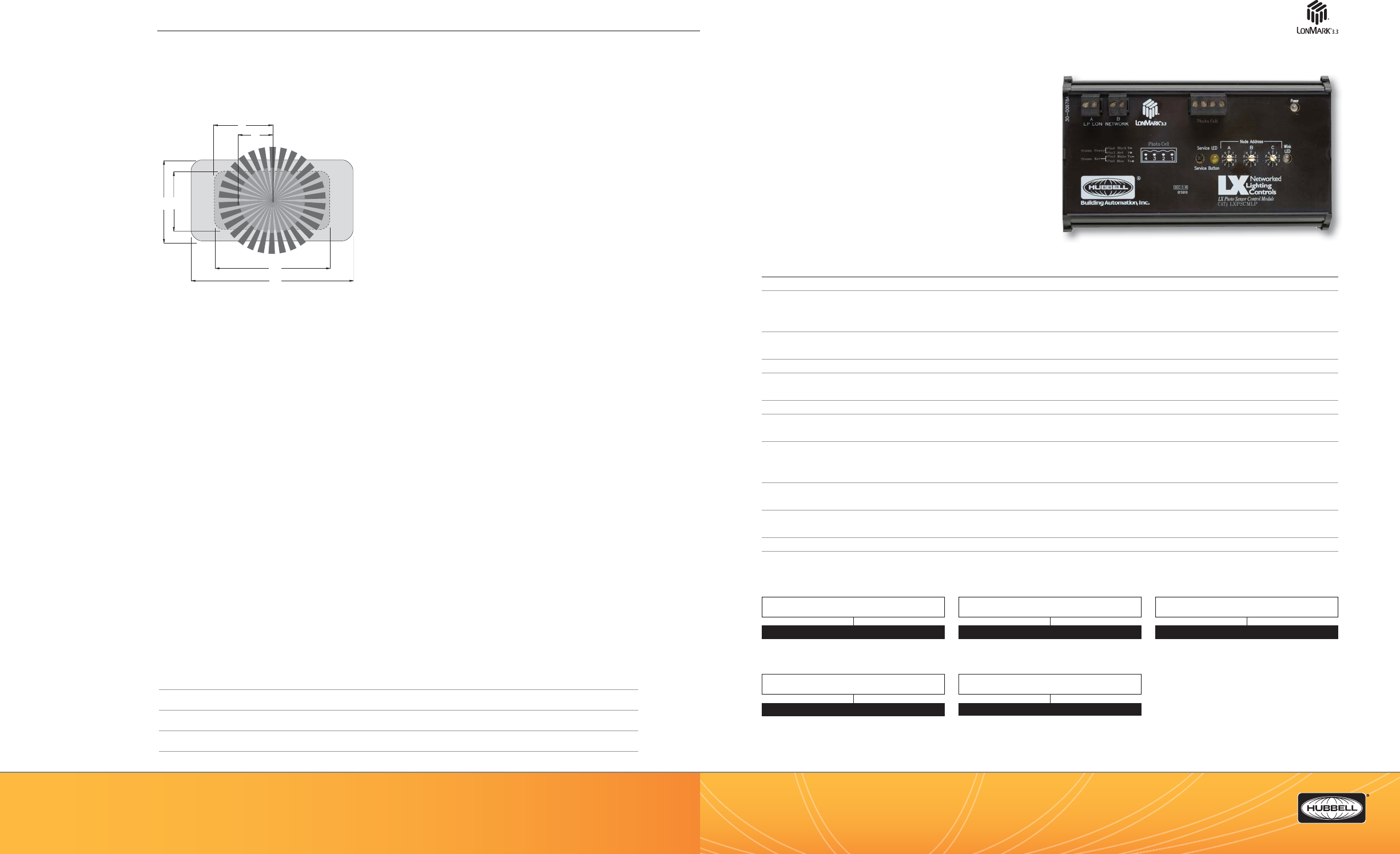
(888) 698-3242 | Fax orders (512) 450-0864 | hubbell-automation.com
h
ubb
ell-
au
t
o
m
a
ti
o
n
.
c
om
PAGE 74 | (888) 698-3242 | Fax orders (512) 450-0864 | hubbell-automation.com
PAGE 75 | LIGHTING CONTROL PANELS
Hubbell Building Automation
NOTES
LXPSCM
LX Photo Sensor Control Module
and Sensors
KEY FEATURES
• Turns lighting on and o based on available natural light
• Network-based photosensor control module
• Real-time foot-candle levels transmitted over a network
on demand to a tablet
• 3 available sensor heads—Indoor, Outdoor, and Skylight/Atrium
• 0–1,000 foot-candle range with 1 foot-candle resolution
• 6 programmable on and o set points
• Programmable active and inactive times
• Topology-free, polarity-insensitive, 2-wire communication
• Mounts to standard DIN Rail
SPECIFICATIONS
Network interface • FTT-10 or LPT-10
Programmable functionality
• Each on and o set point can be programmed to control a single relay, group of relays, or preset scene
• Active and inactive times
Programming and con guration
• Programmable over a network using the LX Touch Tablet or via the LX Photo Sensor Control Module
Capacities • 6 programmable on and o set points with adjustable deadband
Network modes • LX Lighting Control System
• LON-based networks (Set Address to “000”)
Photocell ranges • 0–1,000 foot-candle range with 1 foot-candle resolution
Electrical • LXPSCMLP: Powered from the Link Power network
• LXPSCMFT: 16–30 Volts AC or DC; .5 Amps required
Operating environment • Indoor use only
• Operating temperature: 32°–104°F (0°–40°C)
• Relative humidity (non-condensing): 0% –95%
Size and weight • Size: 6.25” x 3.75” x 1.5”
• Weight: 6.0 oz
Color • Photo Sensor Modules—black
• Photo Sensor Photocells—white
Mounting • Mounts to a 35mm DIN rail
Certi cations • LonMark 3.3 certi ed
ORDERING INFORMATION
LXPSCM
32' 23'
64'
45'
12'
22'
LonMark ® is a registered trademark of LonMark International.
RANGE DIAGRAM
MODEL
LX
LX
DEVICE TYPE
PSCM
DEVICE TYPE
LXPSPC Photocell Head
NETWORK INTERFACE
LP
FT
NOTE:
1. FT only.
LXPSPC
PHOTOCELL TYPE
IIndoor
OOutdoor
SSkylight/Atrium

(888) 698-3242 | Fax orders (512) 450-0864 | hubbell-automation.com
h
ubb
ell-
au
t
o
m
a
ti
o
n
.
c
om
PAGE 76 | (888) 698-3242 | Fax orders (512) 450-0864 | hubbell-automation.com
PAGE 77 | LIGHTING CONTROL PANELS
Hubbell Building Automation
NOTES
LXDCIM
LX Dry Contact Interface Module
KEY FEATURES
• Programmable interface for dry contact devices
• Flexible programming of switch functionality
• 6 individual dry contact inputs with or without pilots
• Accommodates 2- and 3-wire devices
(momentary or maintained)
• Programmable active and inactive times
• Topology-free, polarity-insensitive, 2-wire communication
• LonMark® certi ed
• Mounts to standard DIN rail
SPECIFICATIONS
Network interface • FTT-10
Programmable functionality
• Maintained contact switch input:
- toggle, on only, o only
• Momentary contact switch input:
- push button toggle, on only, o only
• Preset
• Timed on
Programming and con guration
• Programmable over a network using the LX Touch Tablet or via the LX Dry Contact Interface Module
Capacities • Maximum of 6 momentary or maintained switches (2- or 3-wire)
Network modes • LX Lighting Control System
• LON-based networks
Electrical • 16–30 Volts AC or DC; .5 Amps required
Operating environment • Indoor use only
• Operating temperature: 32°–104°F (0°–40°C)
• Relative humidity (non-condensing): 0%–95%
Size and weight • Size: 6.25” x 3.75” x 1.5”
• Weight: 6.0 oz
Color • Black
Mounting • Mounts to a 35mm DIN rail
Certi cations • LonMark 3.3 certi ed
ORDERING INFORMATION
LXDCIM
30-00678A
LonMark ® is a registered trademark of LonMark International.
ADDITIONAL PRODUCT VIEWS
WIRING DIAGRAM
For more wiring diagrams, visit http://www.hubbell-automation.com/resources/wiring_diagrams/
MODEL
LX
LX
DEVICE TYPE
DCIM1
NETWORK INTERFACE
FT
NOTE:
1. FT only.
LXPCPCS
LXPSPCI
LXPSPCO
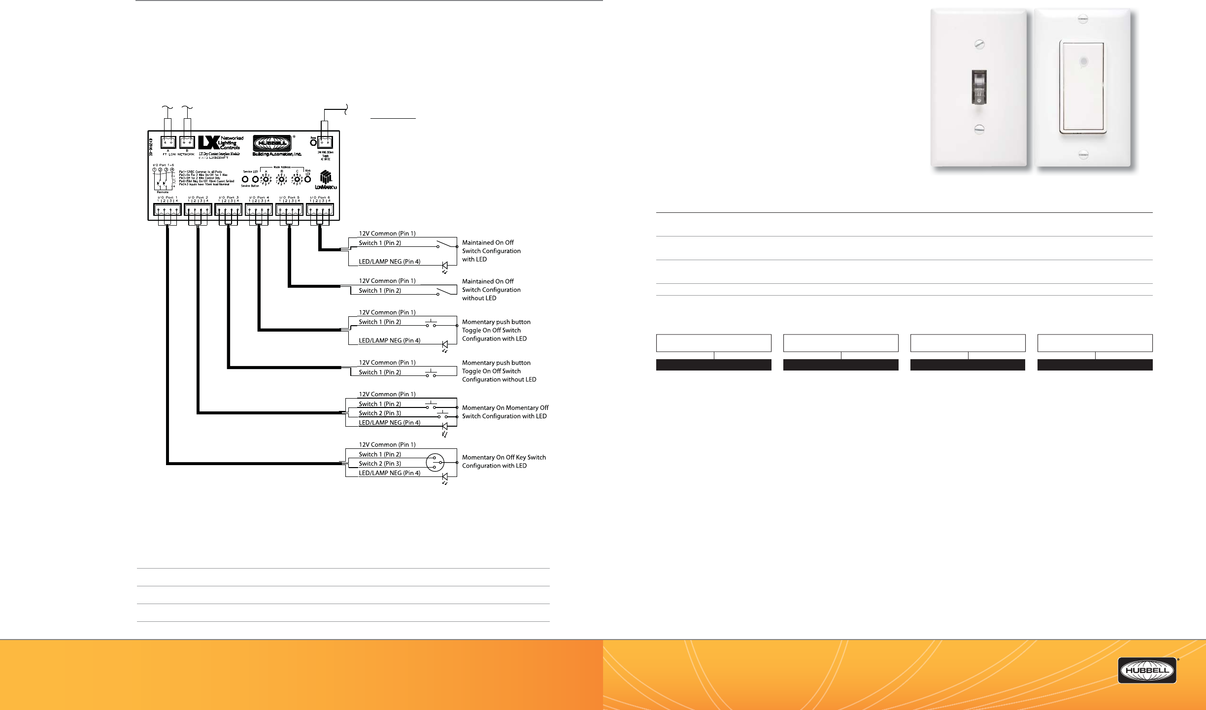
(888) 698-3242 | Fax orders (512) 450-0864 | hubbell-automation.com
h
ubb
ell-
au
t
o
m
a
ti
o
n
.
c
om
PAGE 78 | (888) 698-3242 | Fax orders (512) 450-0864 | hubbell-automation.com
PAGE 79 | LIGHTING CONTROL PANELS
Hubbell Building Automation
NOTES
LXS
LX Sentry Switch
KEY FEATURES
• Standard wall switch ON/OFF operation
• Toggle or Decorator style
• Mechanically switches to OFF position when power
is interrupted for 5 seconds
• Locator light illuminates switch when lights are o
• UL and cUL listed
• Switches operate between speci c load ranges listed below
SPECIFICATIONS
Load requirements • LXS05—0.2A minimum; 5.0A maximum
• LXS20—1.0A minimum; 20.0A maximum
Power requirement • 120, 240, or 277 VAC
• No neutral required
Connections • 2-wire connection; SPST
• 3-wire connection; SPDT—three-way
Certi cations • UL and cUL listed
Mounting • Single-gang NEMA style switch box
• Standard or Decorator style wall plate (not included)
ORDERING INFORMATION
LXST LXSD
Use 2, 3, or 4-conductor, 20AWG non-shielded cable as appropriate.
1000ft. maximum length.
24V DC Power Supply
Use LXPWRSLPY
LON Network Interface
WIRING DIAGRAM
For more wiring diagrams, visit http://www.hubbell-automation.com/resources/wiring_diagrams/
COLOR
Blank No Color
WWhite
IIvory
MODEL
LXS
LXS
SWITCH AMPS
05 5 Amp
20 20 Amp
TYPE
TToggle, SP5T1
T3 Toggle, DP5T - Three way1
DDesigner Series, SP5T2
D3 Designer Series, DP5T -
Three way2
NOTES:
1. Not available in white or ivory.
2. Available in white or ivory only.
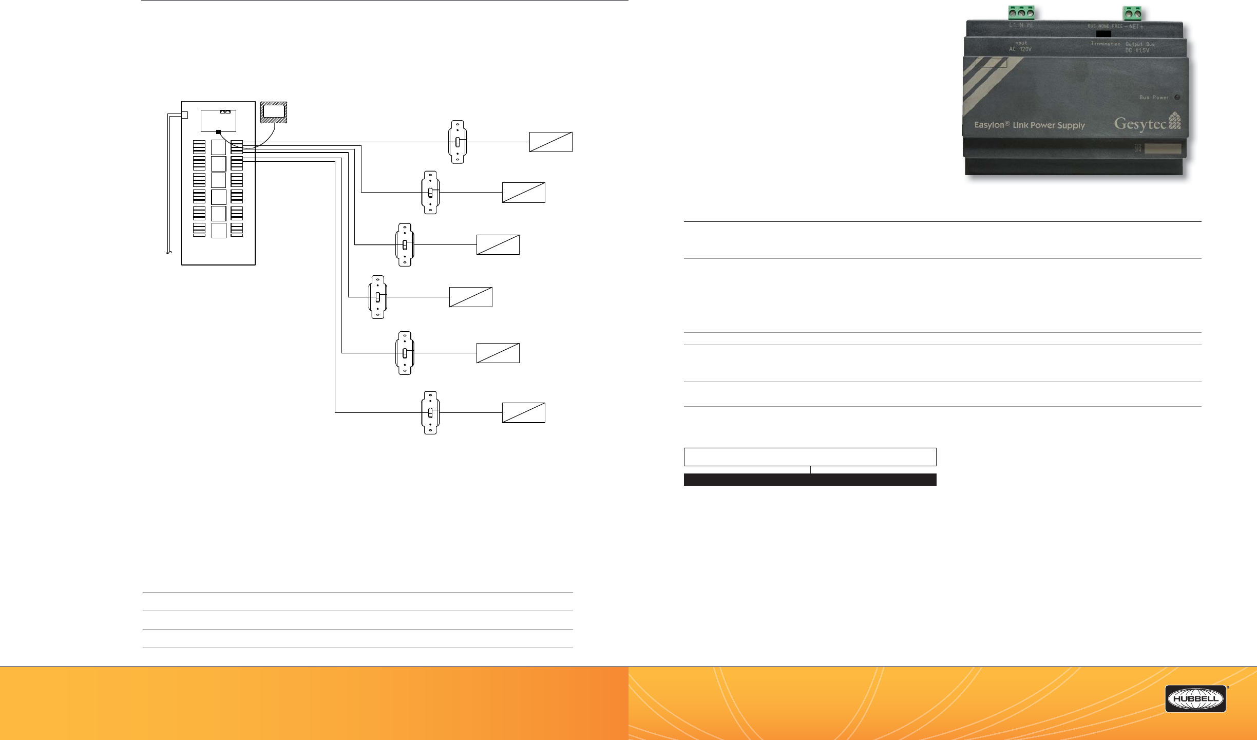
(888) 698-3242 | Fax orders (512) 450-0864 | hubbell-automation.com
h
ubb
ell-
au
t
o
m
a
ti
o
n
.
c
om
PAGE 80 | (888) 698-3242 | Fax orders (512) 450-0864 | hubbell-automation.com
PAGE 81 | LIGHTING CONTROL PANELS
Hubbell Building Automation
NOTES
LXLPM2
LX Link Power Module
KEY FEATURES
• Power supply for LX Series Link Power-based devices
• Short-circuit and overcurrent monitoring
• Bus termination by switch
• DIN rail mount
SPECIFICATIONS
Power supply • Rated input voltage: 120 VAC (85-132V)
• Rated frequency: 50/60 Hz
• Rated input current: 0.7A
Output to bus • Output voltage: 41.5V; +/-2.2%
• Residual ripple: <80mV at 10 kHz (200mV at f>200kHz)
• Output current: 1A (supports approximately 56 LX Series devices)
(For larger networks, an additional LX Link Power Module and LX Router/Repeater Module can be added
to expand the LX network)
• Overload protection: typical at 1.6A; permanent short circuit proof with pulsing “try of restart”
Connectors • Screw terminal
Operating environment • Indoor use only
• Operating temperature: 32°–104°F (0°–40°C)
• Relative humidity (non-condensing): 0%–95%
EMC • Emission: EN61,000-6-3; class B; EN50090-2-2
• Immunity: EN61,000-4-2/3/4/5/6; class A
Dimensions • 4.96” x 2.28” x 3.54”
ORDERING INFORMATION
APPLICATION NOTES
• The LXLPM2 Link Power Module is used to provide power over the 2-wire LX Network for a maximum of 56 devices OR 1500 feet
of cable. This device is DIN rail mounted and includes a network termination device.
• The LXLPM2 requires a 120 VAC hardwire connection and can be placed anywhere in the network segment.
• LX Relay or LXBC Breaker Relay panel networks without any devices do not require a LXLPM2 Link Power Module.
• When using a Link Power Module to supply power for devices, the devices should be speci ed with the “LP” option.
• When networks grow larger than 56 devices or 1500 feet of cable then additional Link Power Modules will be required.
When additional LXLPM2 modules are connected they require an LXRRM repeater to separate each powered segment.
• The LXRRM Repeater performs the function of isolating the separate power supplies while allowing network data to be transmitted
through the repeater.
• The LXRRM Repeater requires 24VAC input power that can be provided with a LXPWRSLPY Power Module. The LXPWRSLPY requires a
120 VAC hardwire connection.
LXLPM2
LX48 Panel
120/277/347
VAC In
CPT
Relay
Board
Relays Relays
LX Sentry
Switch
Load
LX Sentry
Switch
LX Sentry
Switch
LX Sentry
Switch
LX Sentry
Switch
LX Sentry
Switch
Load
Load
Load
Load
Load
Processor
Board
LXTB Graphical
Interface User
WIRING DIAGRAM
For more wiring diagrams, visit http://www.hubbell-automation.com/resources/wiring_diagrams/
MODEL
LXLPM2 LX Link Power Module
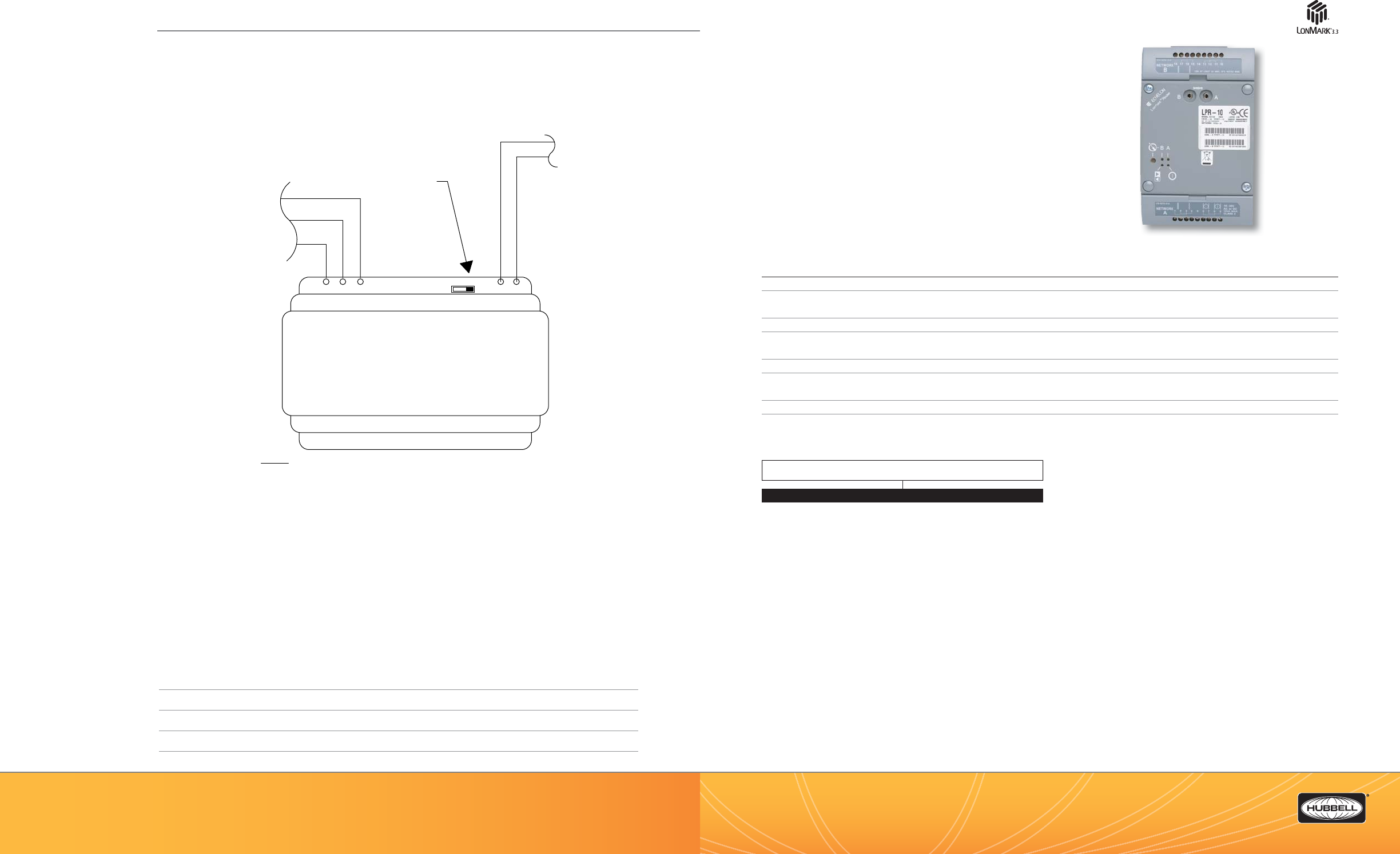
(888) 698-3242 | Fax orders (512) 450-0864 | hubbell-automation.com
h
ubb
ell-
au
t
o
m
a
ti
o
n
.
c
om
PAGE 82 | (888) 698-3242 | Fax orders (512) 450-0864 | hubbell-automation.com
PAGE 83 | LIGHTING CONTROL PANELS
Hubbell Building Automation
NOTES
LXRRM
LX Router|Repeater
KEY FEATURES
• Repeater for LX Series networks
• Screw terminal wiring connections
• 16–30 VAC or VDC operation
• LonMark® certi ed
• UL listed
SPECIFICATIONS
Processor • 2 Neuron 3150® Chips; 10MHz
Service function • Recessed service switch and service (wink) LED.
• Dual tear-o barcode Neuron ID self-adhesive tag
Channel type • TP/FT-10 to TP/FT-10
Input power • 16–30 VAC or DC @ 24VA
• Requires a separate power supply (the LXPWRSPLY)
Mounting • DIN Rail
Operating environment • -40°–185°F (-40°–85°C)
• Relative humidity (non-condensing): 10%–95%
Dimensions • 3.9” x 6.3” x 1.0” (10cm x 10cm x 2.5cm)
Certi cations • UL 916; FCC A; CE Mark
ORDERING INFORMATION
LX-LPM2
PE
N
L1 -+
INPUT AC 120VAC OUTPUT BUS
120VAC
SUPPLY
CIRCUIT
FREENONEBUS
NET
LINK POWER MODULE
LON
NETWORK
FACTORY DEFAULT
SWITCH SETTING IN
THE "FREE" POSITION
DIN RAIL
MOUNTED
REQUIRES
LXENDM
ENCLOSURE
NOTES:
1. EACH LXLPM2 LINK POWER MODULE CAN SUPPLY POWER FOR UP TO
56 DEVICES OR 1,500 FT OF CABLE PER NETWORK.
2. ADDITIONAL SEGMENTS REQUIRE ONE LINK POWER EACH.
3. LXRRM REPEATERS ARE REQUIRED BETWEEN SEGMENTS.
4. SEGMENTS CAN ONLY HAVE ONE LINK POWER SUPPLY CONNECTED.
5. LINK POWER CAN BE CONNECTED AT ANY LOCATION ON THE SEGMENT.
LXRRM
WIRING DIAGRAM
For more wiring diagrams, visit http://www.hubbell-automation.com/resources/wiring_diagrams/
MODEL
LXRRM LX Repeater
LonMark ® is a registered trademark of LonMark International.
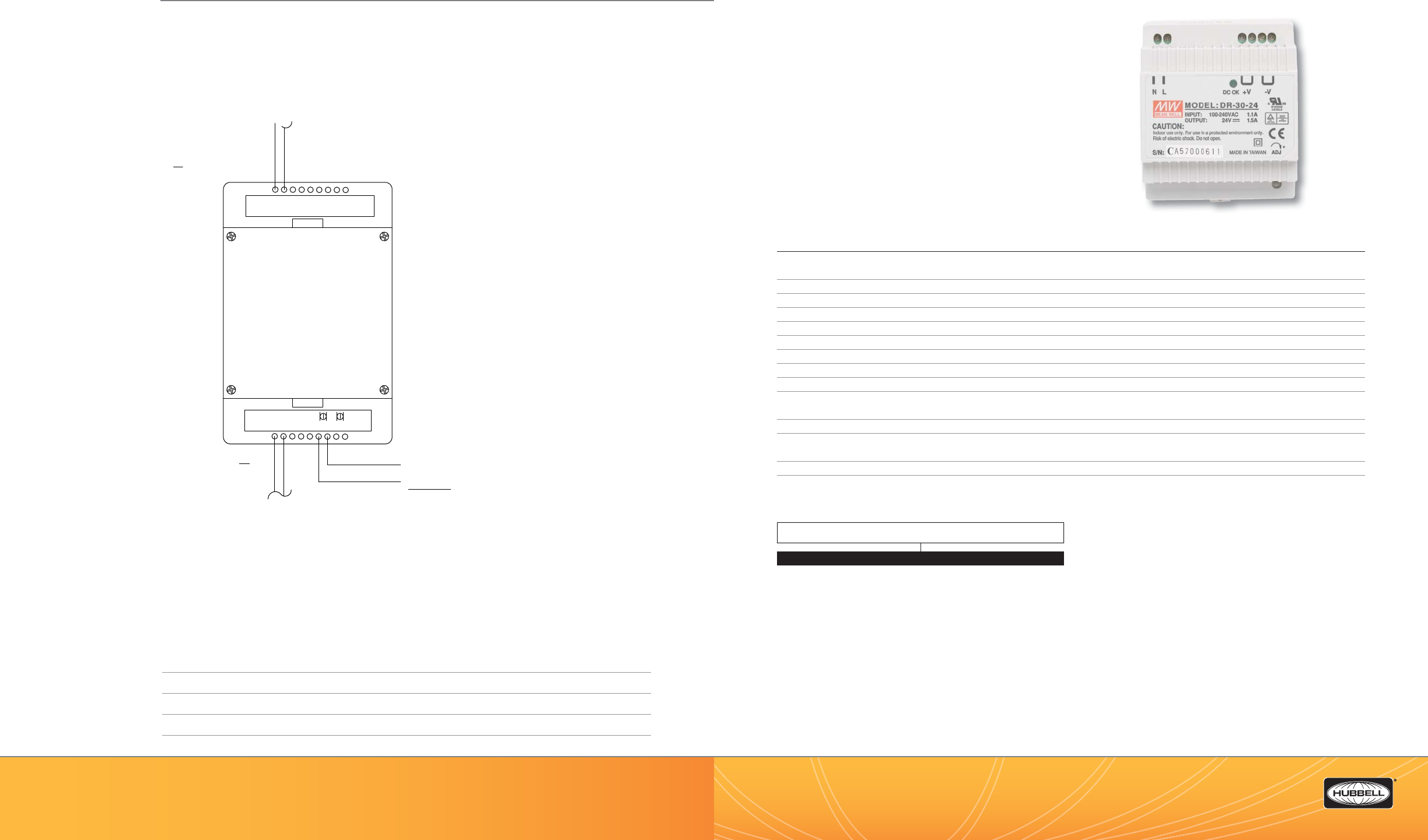
(888) 698-3242 | Fax orders (512) 450-0864 | hubbell-automation.com
h
ubb
ell-
au
t
o
m
a
ti
o
n
.
c
om
PAGE 84 | (888) 698-3242 | Fax orders (512) 450-0864 | hubbell-automation.com
PAGE 85 | LIGHTING CONTROL PANELS
Hubbell Building Automation
NOTES
LXPWRSPLY
LX Power Supply
KEY FEATURES
• Universal AC input 120 VAC (100–240V); line and nuetral single
phase only
• DIN rail mountable: TS35/7.5; TS35/15
• Protection: short circuit, overload, and overvoltage
• LED indicator for power on
• UL listed
SPECIFICATIONS
AC input voltage range • 120 VAC (100–240V), 50-60HZ
• Line and Nuetral Single Phase only
Output • 24V; 0–1.5A
Tolerance: • +/-1%
E ciency • 83%
DC adjustment range • Rated output voltage: +/-10%
Overload protection • 105%–160% constant current limiting; auto-recovery
Overvoltage protection • Rated output voltage: 115%–135%
Setup; rise; hold-up time • 100ms, 70ms, 100ms at full load and 132VAC
Withstand voltage • I/P-O/P:3KVAC
Connection • I/P: 2 poles
• O/P: 4 poles screw DIN terminal
Dimensions • 3.0” x 3.5” x 2.5”
Operating environment • -4°–122°F (-20°–50°C) @100% load
• 140° F (60° C) @ 80% load
Certi cations • UL60950-1; TUV EN60950-1
EMC • EN55022 class B; EN61,000-3-2,3; EN61,000-6-2; EN61,000-4-2,3,4,5,6,8,11; ENV50204; EN61204-3
ORDERING INFORMATION
APPLICATION NOTES
• The LXPWRSLPY Power Supply is used to provide 24 VAC power “FT” style LX Network devices. The maximum recommended number
of devices for each power supply is 4 within a maximum wire distance of 50 feet. This device is DIN rail mounted.
• The LXPWRSLPY requires a 120 VAC hardwire connection.
• The LXPWRSLPY is also used to supply power to the LXRRM Repeater.
• All LX network segments require termination. The LXTERMINATOR provides network termination when LXLPM2 Link Power Modules
are not in use.
• The LXENDM DIN Rail Enclosure is a convenient way to mount various DIN Rail mounting network devices such as LXLPM2 or LXDCIM.
LXPWRSPLY
LXRRM
LX Router/Repeater
Module
NETWORK B
16-30V
AC or DC
10VA MAX.
Class 2
18 17 16 15 14 13 12 11 10
NETWORK
A123456789
SEGMENT "B" CAN SUPPORT
UP TO 1,500 FT OF CABLE
OR 56 DEVICES
SEGMENT "A" CAN SUPPORT UP
TO 1,500 FT OF CABLE OR 56
DEVICES
DIN RAIL MOUNT REQUIRES
LXENDM
ENCLOSURE
24 VDC
SUPPLY
REQUIRES
LXPWRSPLY
LON NETWORK A
LON NETWORK B
WIRING DIAGRAM
For more wiring diagrams, visit http://www.hubbell-automation.com/resources/wiring_diagrams/
MODEL
LXPWRSPLY LX Power Supply
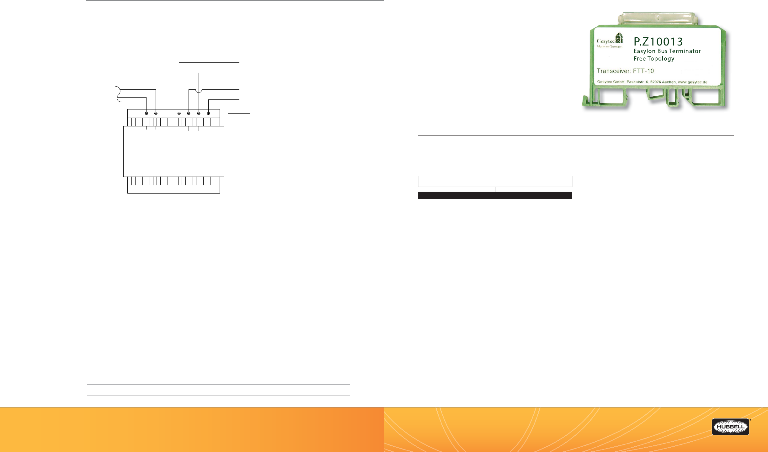
(888) 698-3242 | Fax orders (512) 450-0864 | hubbell-automation.com
h
ubb
ell-
au
t
o
m
a
ti
o
n
.
c
om
PAGE 86 | (888) 698-3242 | Fax orders (512) 450-0864 | hubbell-automation.com
PAGE 87 | LIGHTING CONTROL PANELS
Hubbell Building Automation
NOTES
LXTERMINATOR
LX Terminator
KEY FEATURES
• LX network segment terminator
• DIN Rail Mounting
SPECIFICATIONS
Network interface • Screw terminal connector
Operating environment • 32°–140°F (0°–60°C)
• Relative humidity (non-condensing): 5%–95%
ORDERING INFORMATION
APPLICATION NOTE
• All LX network segments require termination. The LXTERMINATOR provides network termination when LXLPM2
Link Power Modules are not in use.
LXTERMINATOR
(24VDC)
LX FT
Power Supply
LXPWRSPLY
NL+V
(120VAC)
-V
DIN RAIL MOUNT
REQUIRES
LXENDM
ENCLOSURE
120VAC
SUPPLY
CIRCUIT
TO DEVICES
REQUIRING 24VDC
LXPWRSPLY
REQUIRED FOR:
LXRRM
LXDCIM
LXOMNDT2000FT
LXSWxFTx
LSPSCMFT
TO DEVICES
REQUIRING 24VDC
+
-
+
-
WIRING DIAGRAM
For more wiring diagrams, visit http://www.hubbell-automation.com/resources/wiring_diagrams/
MODEL
LXTERMINATOR LX Free Topology Bus Terminator
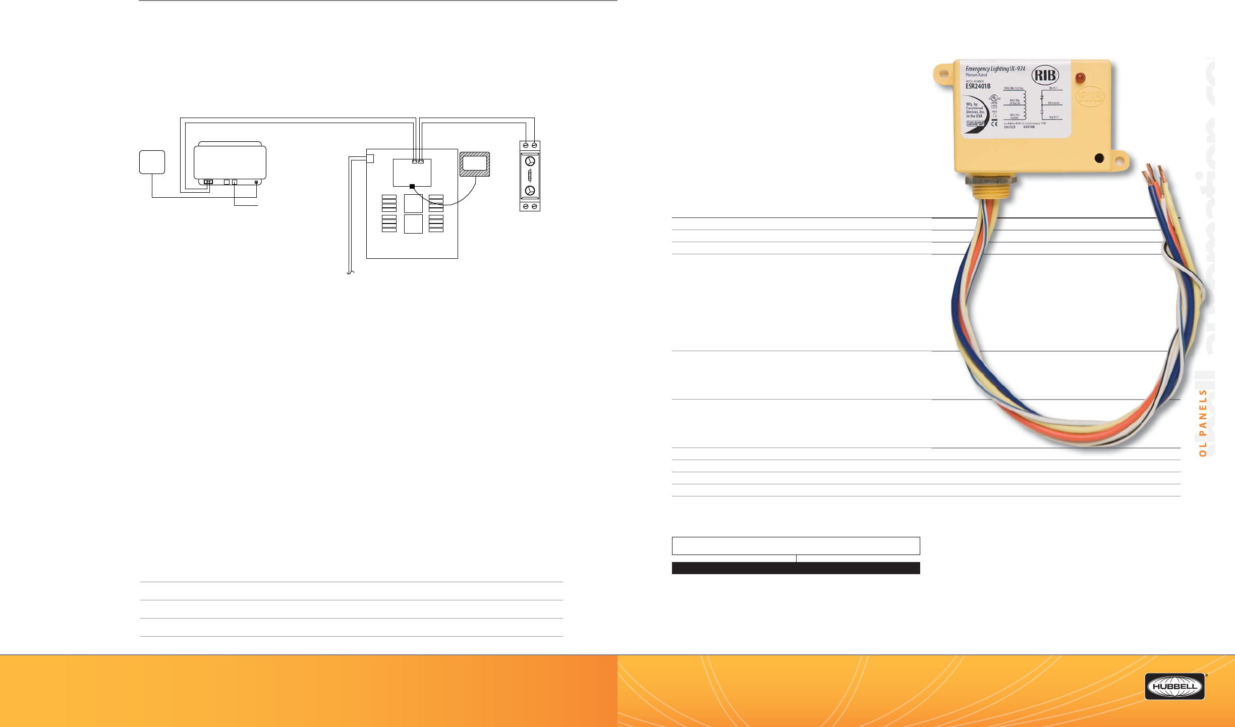
(888) 698-3242 | Fax orders (512) 450-0864 | hubbell-automation.com
hubbell-automation.com
hb
PAGE 88 | (888) 698-3242 | Fax orders (512) 450-0864 | hubbell-automation.com
PAGE 89 | LIGHTING CONTROL PANELS
Hubbell Building Automation
NOTES
LXUL924
UL924 Enclosed 20 Amp SPDT
Bypass Relays
KEY FEATURES
• 20 Amp 120/277 VAC SPDT Relay
• Available with either 24 VAC/DC/120 VAC Coil
or 24 VAC/DC/208-277 VAC Coil
• LED status indicator
• N/O isolated contacts
• UL and cUL listed
SPECIFICATIONS
# Relays & Contact Type • One (1) SPST Continuous Duty Coil
Expected Relay Life • 10 million cycles minimum mechanical
Gold Flash • No
Contact Ratings • 20 Amp Resistive @ 277 VAC
• 20 Amp Ballast N/O @ 120/277 VAC
• 10 Amp Ballast N/C @ 120/277 VAC
• 10 Amp Tungsten @ 120 VAC
• 770 VA Pilot Duty @ 120 VAC
• 1110 VA Pilot Duty @ 277 VAC
• 2 HP @ 277 VAC
• 1 HP @ 120 VAC
Coil Current • 45 mA @ 18 VAC 30 mA @ 22 VDC
• 75 mA @ 24 VAC 32 mA @ 24 VDC
• 42 mA @ 120 VAC 42 mA @ 30 VDC
• 62 mA @ 208-277 VAC
Coil Voltage Input • LX924BR1: 24 VAC/DC, 120 VAC; 50-60Hz
• LX924BR2: 24 VAC/DC, 208-277 VAC; 50-60Hz
• Drop Out = 2.1 VAC / 3.8 VDC
• Pull In = 18 VAC / 22 VDC
Operating environment • -30° to 140°F
Dimensions • 2.3” x 3.2” x 1.8” with 0.5 “ NPT nipple
Housing Rating • Plenum, NEMA 1
Wires • 16”, 600V Rated
Certi cations • UL and cUL Listed, UL924, UL916, UL864, California State Fire Marshal, CE
ORDERING INFORMATION
2
VDC
4
VDC
0
VDC
0Hz
LXUL924BR
JENEsys
120AC
15 VDC
Adapter
Ethernet
Not Used
LON Network
LXJNSYS
100BT Network
(by others)
CPT
LX TERMINATOR
120/277/347
VAC In
LX16 Panel
2 Wire Network
Belden 8471
LXTB Graphical
User Interface
Processor
Board
LON Network
WIRING DIAGRAM
For more wiring diagrams, visit http://www.hubbell-automation.com/resources/wiring_diagrams/
MODEL
LXUL924BR1 LX UL924 Enclosed Relay 20 Amp SPDT with 24 VAC/DC/120 VAC Coil
LXUL924BR2 LX UL924 Enclosed Relay 20 Amp SPDT with 24 VAC/DC/208-277
VAC Coil
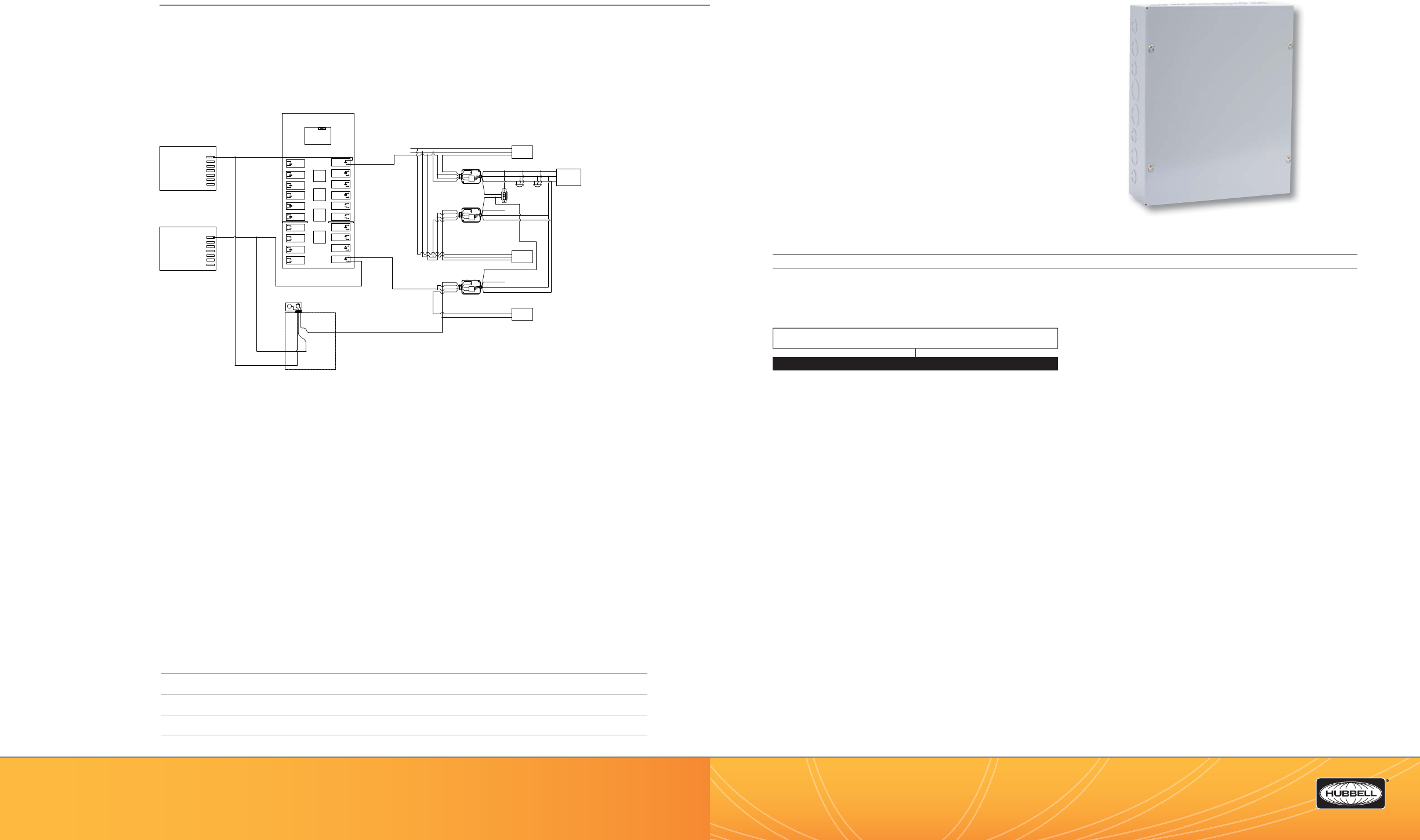
(888) 698-3242 | Fax orders (512) 450-0864 | hubbell-automation.com
h
ubb
ell-
au
t
o
m
a
ti
o
n
.
c
om
PAGE 90 | (888) 698-3242 | Fax orders (512) 450-0864 | hubbell-automation.com
PAGE 91 | LIGHTING CONTROL PANELS
Hubbell Building Automation
NOTES
LXENDM
LX Enclosure for DIN Rail Modules
KEY FEATURES
• NEMA 1 rated metal enclosure
• Screw-mount cover
• Includes 2 DIN rails
SPECIFICATIONS
Dimensions • 12” x 15” x 4”
NEMA 1 rated • Provides a degree of protection for people against contact with the enclosed devices
• Provides a degree of protection for the enclosed devices against falling dirt
ORDERING INFORMATION
APPLICATION NOTE
• The LXENDM DIN Rail Enclosure is a convenient way to mount various DIN Rail mounting network devices such as LXLPM2 or
LXDCIM.
LX LV Lighting Panel
Standard Breaker
Panel
EM Breaker Panel
Lighting
Load A
Red
Black
Blue
Neutral
Hot
Ground
Red (+24VDC)
Black (common)
Blue (control)
Black (common)
Blue (control)
Red
Red
Black
White
Hubbell Building Automation
Low Voltage Sensors(devices)
REQUIRE 33mA each
Orange 2 Button Manual-ON /
Override-OFF Low-voltage
Momentary Switch
Lighting
Load B
Red (+24VDC)
Red
Red
Black
White
Orange
No more
than
4 devices
Neutral
Hot
Ground
X
Ground
Neutral
Hot
Emergency
Power
Normal Power
UL924 BYPASS
RELAY
UL924 RELAY OPERATION: When Normal Power
is applied to the Relay Coil the Contacts are
held in the open position. Upon loss of
Normal Power the UL924 Relay shunts
mechanically closed to supply Emergency
Power to the lighting load.
LXENDM
C
UL924 RELAY and enclosure
is mounted near or next to the LX Panel
LON Network
Processor
Board
Relay
Boards
Lighting
EM
Power Pack contacts
rated for 20 Amps
Power Pack contacts
rated for 20 Amps
Power Pack contacts
rated for 20 Amps
Black (common)
Blue (control)
Red
Red
Black
White
UVPPM Power Pack
Supplies 150mA
UVPPM Power Pack
Supplies 150mA
UVPPM Power Pack
Supplies 150mA
EM Neutral
Hot
X
Do Not tie the
Low-voltage red
wires (+24 vdc)
together
You should not attempt to power more
than 4 devices (sensors or slave
packs) from a single power pack.
LXUL924BR
WIRING DIAGRAM
For more wiring diagrams, visit http://www.hubbell-automation.com/resources/wiring_diagrams/
MODEL
LXENDM LX Enclosure for DIN Rail Device Modules

(888) 698-3242 | Fax orders (512) 450-0864 | hubbell-automation.com
h
ubb
ell-
au
t
o
m
a
ti
o
n
.
c
om
PAGE 92 | (888) 698-3242 | Fax orders (512) 450-0864 | hubbell-automation.com
PAGE 93 | LIGHTING CONTROL PANELS
Hubbell Building Automation
NOTES
LXWRDV
Panel Wire Way Divider Accessory Kit
KEY FEATURES
• Provides physical code-gauge steel separation between di erent
voltages or sources that share the same relay panel
• Field-installed
• Can be mounted at any location
• Fits between relays – no loss of relay spaces
• For use with LX Series Lighting Control Panels
(Except 4 relay LX panels)
SPECIFICATIONS
Each Kit Includes: • 2 ea - Wire Way Divider Plates
• 2 ea - Stainless Steel mounting Screws
• Installation Instructions
Operating environment • Indoor use only
Size & Weight • Size: 4.25” W x 3.25” L
• Weight: 3.0 oz
Color • ANSI 61 Gray Polyester Powder Coat
Certi cations • For use with LX Series UL and cUL Listed LXIN and LXEN
network lighting control panels (except LXEN04)
ORDERING INFORMATION
MODEL
LXWRDV Wireway Divider Kit for LX Series Relay Panels
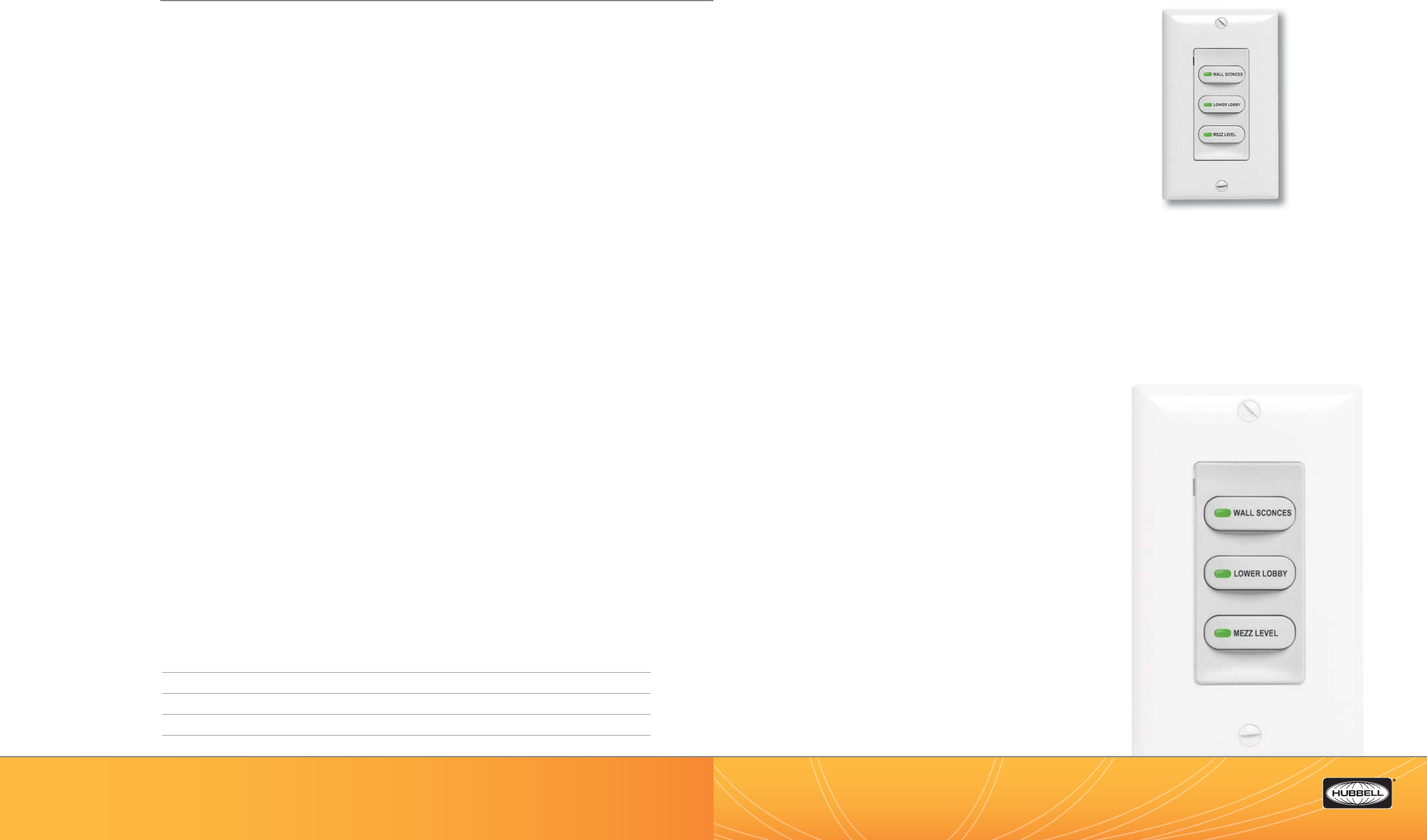
(888) 698-3242 | Fax orders (512) 450-0864 | hubbell-automation.com
h
ubb
ell-
au
t
o
m
a
ti
o
n
.
c
om
PAGE 94 | (888) 698-3242 | Fax orders (512) 450-0864 | hubbell-automation.com
PAGE 95 | LIGHTING CONTROL PANELS
Hubbell Building Automation
NOTES
LXSW CUSTOM BUTTONS
Custom Engraved
LX Switch Station Buttons
LX Series Networked Switch Stations are available with custom
laser-engraved button labeling. These are ideal for public areas,
conference rooms and other locations where visitors or infrequent
occupants may be unfamiliar with the lighting controls.
ORDERING INFORMATION
For each individual switch station, please indicate with your order the text for each button and if the button will have an LED light-pipe.
We suggest a spreadsheet format for large orders.
Engraved buttons are a custom item and we recommend that you call your HBA customer service representative when ordering to ensure
your required lettering and speci cations can conform to the engraver’s requirements.
The engraved buttons will not come pre-installed on the switch stations. At your request, the buttons can come in a large unsorted bag,
or they can be packaged in small bags to accompany the switch station with which they were ordered.
TYPE SPECIFICATION
• Font: Arial Narrow
• Size: 9 point
• Color: Charcoal Grey
• Durability: Permanent Laser Engraving
• Character Limit: 1 or 2 lines of text 10 characters including spaces
per line for buttons with light pipe and 14 characters / line
for buttons without light pipe
Product Pictured is full scale (1:1).
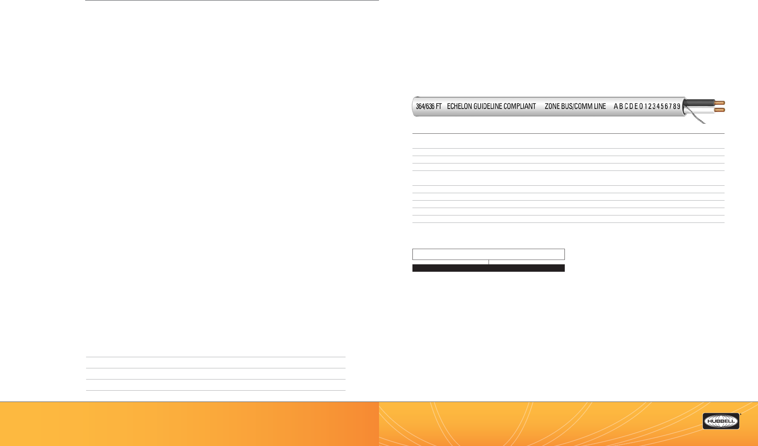
(888) 698-3242 | Fax orders (512) 450-0864 | hubbell-automation.com
h
ubb
ell-
au
t
o
m
a
ti
o
n
.
c
om
PAGE 96 | (888) 698-3242 | Fax orders (512) 450-0864 | hubbell-automation.com
PAGE 97 | LIGHTING CONTROL PANELS
Hubbell Building Automation
NOTES
LX Network Cable | Plenum Rated
Plenum Rated Windy City Wire 104500 Cable
KEY FEATURES
• Interconnects LX Lighting Control Panels and LX network devices
• Cable carries both power and data in a single twisted pair
• Windy City Wire #104500 - twisted pair #16 tinned copper
• Single cable type connects to all types of LX network devices
• Echelon Guideline Compliant for LON networks
• Available in 100 ft and 500 ft reels
SPECIFICATIONS
Description • 1 pair - 16 AWG stranded tinned copper conductors, PVC Insulation, unshielded twisted pair (UTP),
PVC jacket
Shielding • Unshielded
Overall Nominal Diameter • 0.182 inches
Plenum Rating • Plenum Rated
Operating Temperature Range
• 0°C to +75°C (Indoor use only)
Maximum Pulling Tension • 61 lbs
Minimum Bend Radius • 5.1 inches
Color • Pair Color - Black/White, Outer Jacket - White
Certi cations • NEC (UL) Subject 444 Type CL2P/CMP, CSA (cUL)
Flame Test • NFPA 262 Steiner Tunnel Test
Warranty • One year
ORDERING INFORMATION
LX SYSTEM NETWORK CABLE REQUIREMENTS
Hubbell Building Automation’s LX Lighting Control System requires the use of Belden #8471 cable for Riser Rated applications OR Windy
City Wire #104500. for Plenum Rated applications. These are the ONLY cables that can be used for network wiring with the LX System.
The use of substitute cables based on similar physical characteristics is not allowed and will VOID any HBA warranty for the LX system or
any LX component connected to the substitute cable.
MODEL
LX104500CBL100 LX Cable Windy City 104500 Plenum Rated 100 ft Reel
LX104500CBL500 LX Cable Windy City 104500 Plenum Rated 500 ft Reel
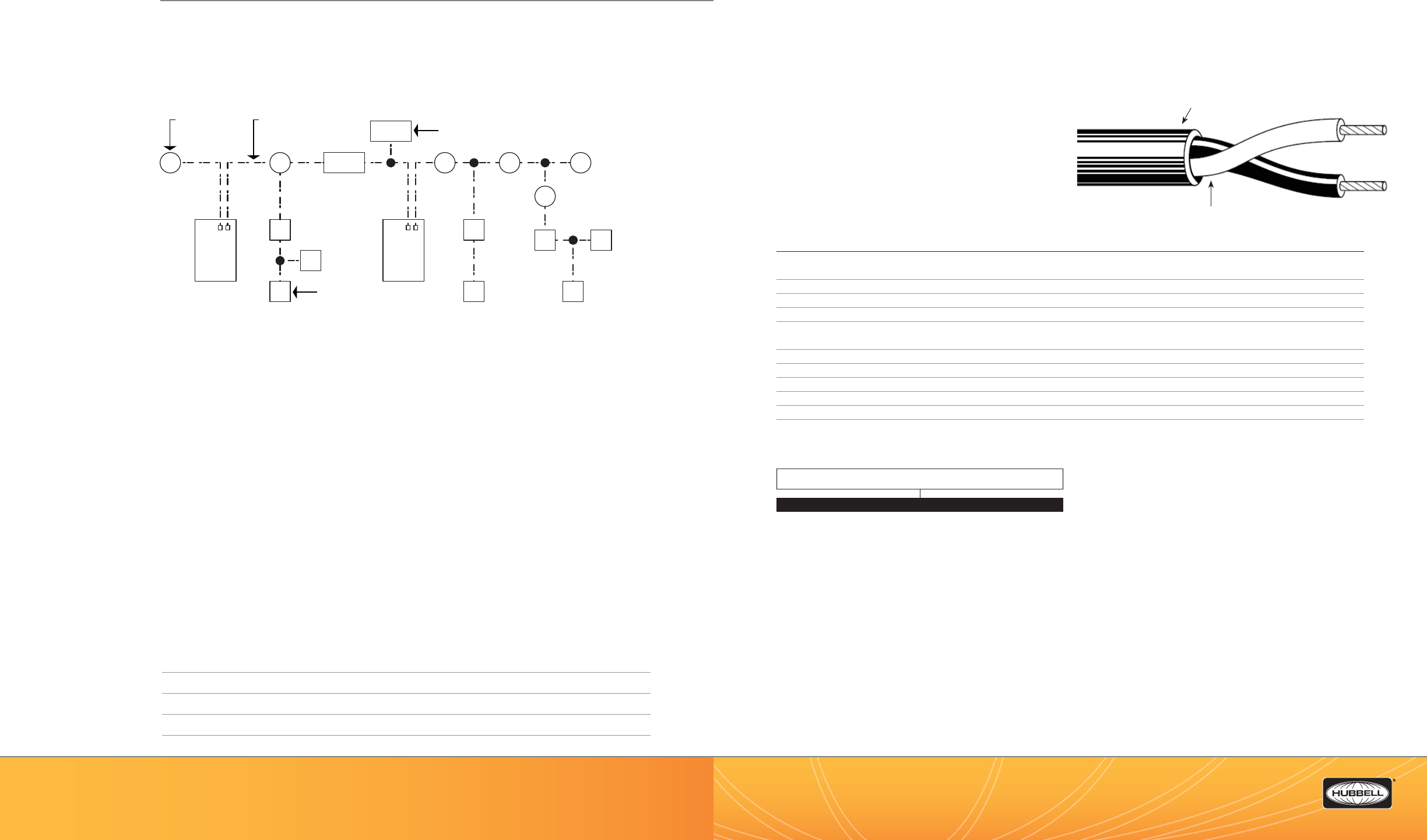
(888) 698-3242 | Fax orders (512) 450-0864 | hubbell-automation.com
h
ubb
ell-
au
t
o
m
a
ti
o
n
.
c
om
PAGE 98 | (888) 698-3242 | Fax orders (512) 450-0864 | hubbell-automation.com
PAGE 99 | LIGHTING CONTROL PANELS
Hubbell Building Automation
NOTES
LX Network Cable | Riser Rated
Riser Rated Belden 8471 Cable
KEY FEATURES
• Interconnects LX Lighting Control Panels and LX network devices
• Cable carries both power and data in a single twisted pair
• Belden #8471 - twisted pair #16 tinned copper
• Single cable type connects to all types of LX network devices
• Echelon Guideline Compliant for LON networks
• Available in 100 ft and 500 ft reels
• Riser Rated
• Connects to terminal blocks or with twist on connectors
• UL and cUL Listed
SPECIFICATIONS
Description • 1 pair - 16 AWG stranded tinned copper conductors, PVC Insulation, unshielded twisted pair (UTP),
PVC jacket
Shielding • Unshielded
Overall Nominal Diameter • 0.274 inches
Plenum Rating • Not Plenum Rated
Operating Temperature Range
• -20°C to +80°C (Indoor use only)
Maximum Pulling Tension • 61 lbs
Minimum Bend Radius • 5.1 inches
Color • Pair Color - Black/White, Outer Jacket - Gray
Certi cations • NEC (UL) CMG, CEC/C (UL) CMG,
Flame Test • UL Flame Test – UL1685 FT4 Loading, C (UL) Flame Test FT4
Warranty • One year
ORDERING INFORMATION
LX SYSTEM NETWORK CABLE REQUIREMENTS
Hubbell Building Automation’s LX Lighting Control System requires the use of Belden #8471 cable for Riser Rated applications OR
Windy City Wire #104500 for Plenum Rated applications. These are the ONLY cables that can be used for network wiring with the LX
System.
The use of substitute cables based on similar physical characteristics is not allowed and will VOID any HBA warranty for the LX system
or any LX component connected to the substitute cable.
M
S
PCMM
S
S
LP LINK POWER MODULE
LX-LP
M M M
S
S
S S
S
M
LX-LP
MOTION SENSOR
(TYPICAL)
LX-LP
SWITCH STATION
(TYPICAL)
TYPICAL SEGMENT = MAXIMUM 56 DEVICES OR MAXIMUM 1,500FT
LX
NETWORK CABLE
(TYPICAL)
LX
Relay
Panel
LX
Relay
Panel
BELDEN
PVC Jacket
(Unshielded)
Twisted Pair #16 Tinned Copper Conductors
PVC Insulation
WIRING DIAGRAM
For more wiring diagrams, visit http://www.hubbell-automation.com/resources/wiring_diagrams/
INSTALLATION NOTES
1. DO NOT exceed 1500 feet of cable OR connect more than 56 devices per network segment.
2. Each network segment using LP style devices requires an LXLPM2 Link Power Module for device power.
Each additional segment requires
an additional LXLPM2 Link Power Module and an LXRRM Repeater for data transmission between segments.
3. Each network segment existing of panels only or that use FT style devices only require termination
with LXTERMINATOR instead of LXLPM2 Link Power Module.
4. Run cable and connect network with the shortest distances possible. The most e cient network is wired
similar to branch circuit outlets.
5. When using twist-on wire connectors with network cable use no more than three wires per connector.
6. The use of T-taps to minimize cable length is encouraged. Daisy chain topology is allowed, but most often
increases overall cable length.
7. DO NOT homerun all devices individually, or leave spare cable at ceiling mounted devices. If devices need
to be relocated, cables can be extended with twist-on wire connectors.
8. DO NOT mix plenum and NON-plenum cables on the same segment.
9. Keep 12” minimum from line voltage, do nut run in the same raceway
with line voltage.
*All sales are nal, no returns are allowed.
MODEL
LX8471CBL100* LX Cable Belden 8471 Riser Rated 100 ft Reel
LX8471CBL500* LX Cable Belden 8471 Riser Rated 500 ft Reel
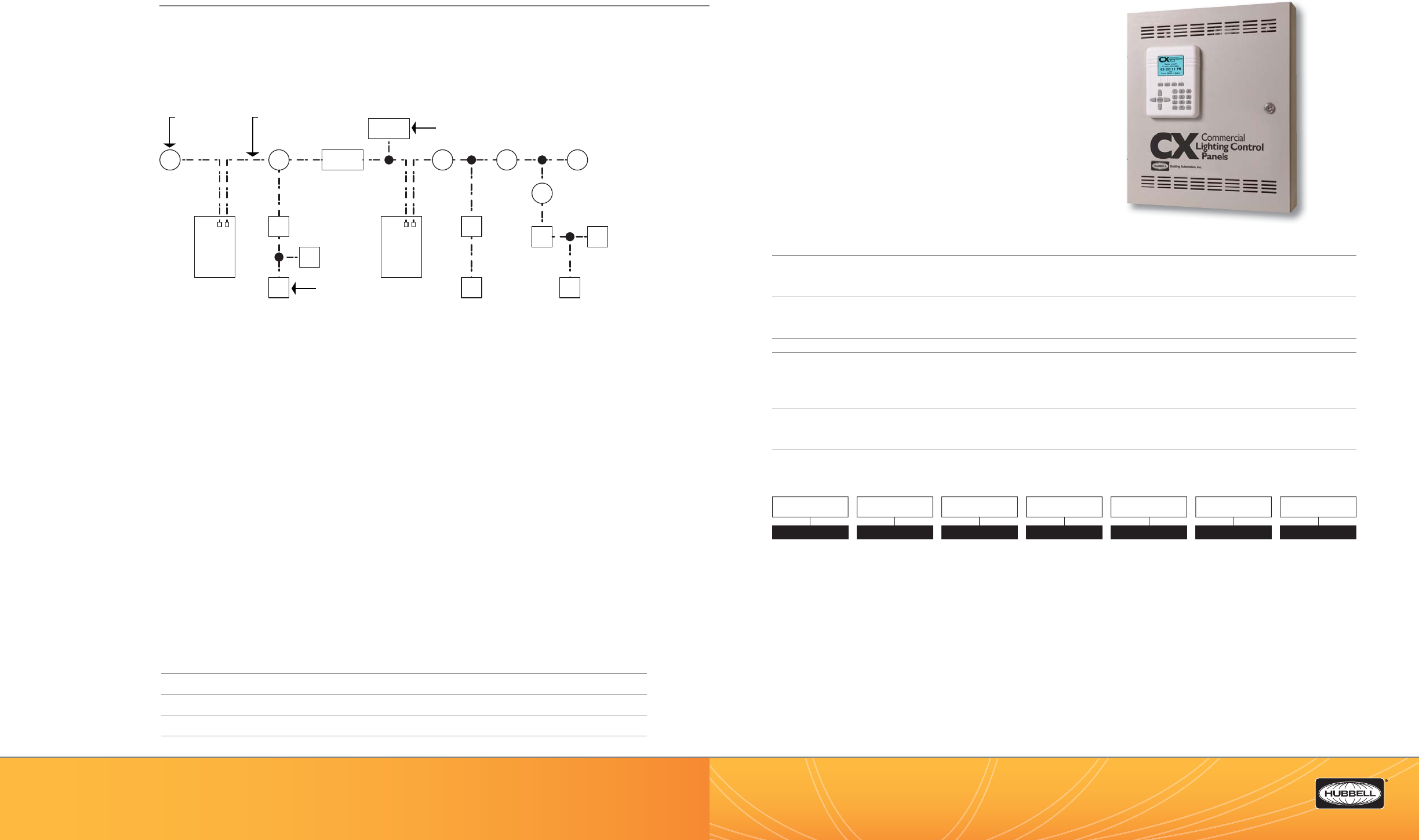
(888) 698-3242 | Fax orders (512) 450-0864 | hubbell-automation.com
h
ubb
ell-
au
t
o
m
a
ti
o
n
.
c
om
PAGE 100 | (888) 698-3242 | Fax orders (512) 450-0864 | hubbell-automation.com
PAGE 101 | LIGHTING CONTROL PANELS
Hubbell Building Automation
NOTES
CX04
CX Series Lighting Control Panel 4-Relays
KEY FEATURES
• Relay panel size – 4 relay spaces
• Five types of relays – 20A/1P and 20A/2P, N/O, N/C and 30A/P latching
• LCD user interface with keypad
• 365 day programming with 64 schedules
• Astronomical and real time clock
• 6 Programmable dry contact inputs for 4 relay panel
• Selectable pre-programmed scenarios
• Programmable inputs accept low voltage switches, photocells,
or motion sensors
• Program uploads via removable SD memory card
SPECIFICATIONS
Programming and con guration
• Programmable via user interface mounted on door
• Fully programmable by users with door closed and locked
Physical • NEMA 1 surface enclosure
• Pre-drilled mounting holes for mounting to wall, KOs provided on top and bottom
• 4 relay enclosures with hinged locking door
Electrical input • 120/208/240/277VAC Standard, 120/277/347 Optional
Relays • 120 and 277 VAC 20 Amp Single Pole Relays (14K SCCR)
• 120 and 277 VAC 30 Amp Single Pole Relays (18K SCCR)
• 347 VAC, 20A, IP Relay (14K SCCR)
• 208, 240, and 480 VAC 20 Amp Double Pole Relays(14K SCCR)
Operating environment • Location: interior space
• Operating temperature: 0°–50°C (32°–112°F)
• Relative humidity (non-condensing): 10%–90%
Certi cations • Listed to UL916, UL924 and cUL
ORDERING INFORMATION
M
S
PCMM
S
S
LP LINK POWER MODULE
LX-LP
M M M
S
S
S S
S
M
LX-LP
MOTION SENSOR
(TYPICAL)
LX-LP
SWITCH STATION
(TYPICAL)
TYPICAL SEGMENT = MAXIMUM 56 DEVICES OR MAXIMUM 1,500FT
LX
NETWORK CABLE
(TYPICAL)
LX
Relay
Panel
LX
Relay
Panel
CX4
WIRING DIAGRAM
For more wiring diagrams, visit http://www.hubbell-automation.com/resources/wiring_diagrams/
INSTALLATION NOTES
1. DO NOT exceed 1500 feet of cable OR connect more than 56 devices per network segment.
2. Each network segment using LP style devices requires an LXLPM2 Link Power Module for device power.
Each additional segment requires an additional LXLPM2 Link Power Module and an LXRRM Repeater for data
transmission between segments.
3. Each network segment existing of panels only or that use FT style devices only require termination with
LXTERMINATOR instead of LXLPM2 Link Power Module.
4. Run cable and connect network with the shortest distances possible. The most e cient network is wired
similar to branch circuit outlets.
5. When using twist-on wire connectors with network cable use no more than three wires per connector.
6. The use of T-taps to minimize cable length is encouraged. Daisy chain topology is allowed, but most often
increases overall cable length.
7. DO NOT homerun all devices individually, or leave spare cable at ceiling mounted devices. If devices need to
be relocated, cables can be extended with twist-on wire connectors.
8. DO NOT mix plenum and NON-plenum cables on the same segment.
9. Keep 12” minimum from line voltage, do nut run in the same raceway with line voltage.
MODEL
CX CX Lighting
Control Panel
SPACES
04 4 Relay Spaces
INPUT VOLTAGE
2120/277V Dual
Tap
3120/347V Dual
Tap
ENCLOSURE
SNEMA 1 Surface
RELAY QUANTITY
00 No Relays -
Spaces Only
(See Note 3)
04 4 Relays
Installed(See
Note 2)
RELAY TYPE
SP Space Only
2N 20A Electrically
Held N/O 120-
277V
2C 20A Electrically
Held N/C
(120-277V)
3L Latching 120-
277-347V
(See Note 4)
TN 20A Electrically
Held N/O 480V
(See Note 1)
TC 20A Electrically
Held N/C 480V
(See Note 1)
OPTIONS
NStand Alone
Panel
CX 04 S N
NOTES:
1. 2-Pole relays take the same amount of space as 1-Pole relays.
2. Installed relays must be all of the same type. Relay Type TC and 2C not available in fully populate panels
3. “00” option has no relays, all must be installed in the eld.
4. 3L relay rated 30A at 120-277VAC, 20A at 347VAC.
Example: CX42S42NN
4-Relay CX Stand Alone Panel with 4-20A / IP electrically held N/O relays, surface enclosure, 120 - 277 input power, Stand Alone Panel
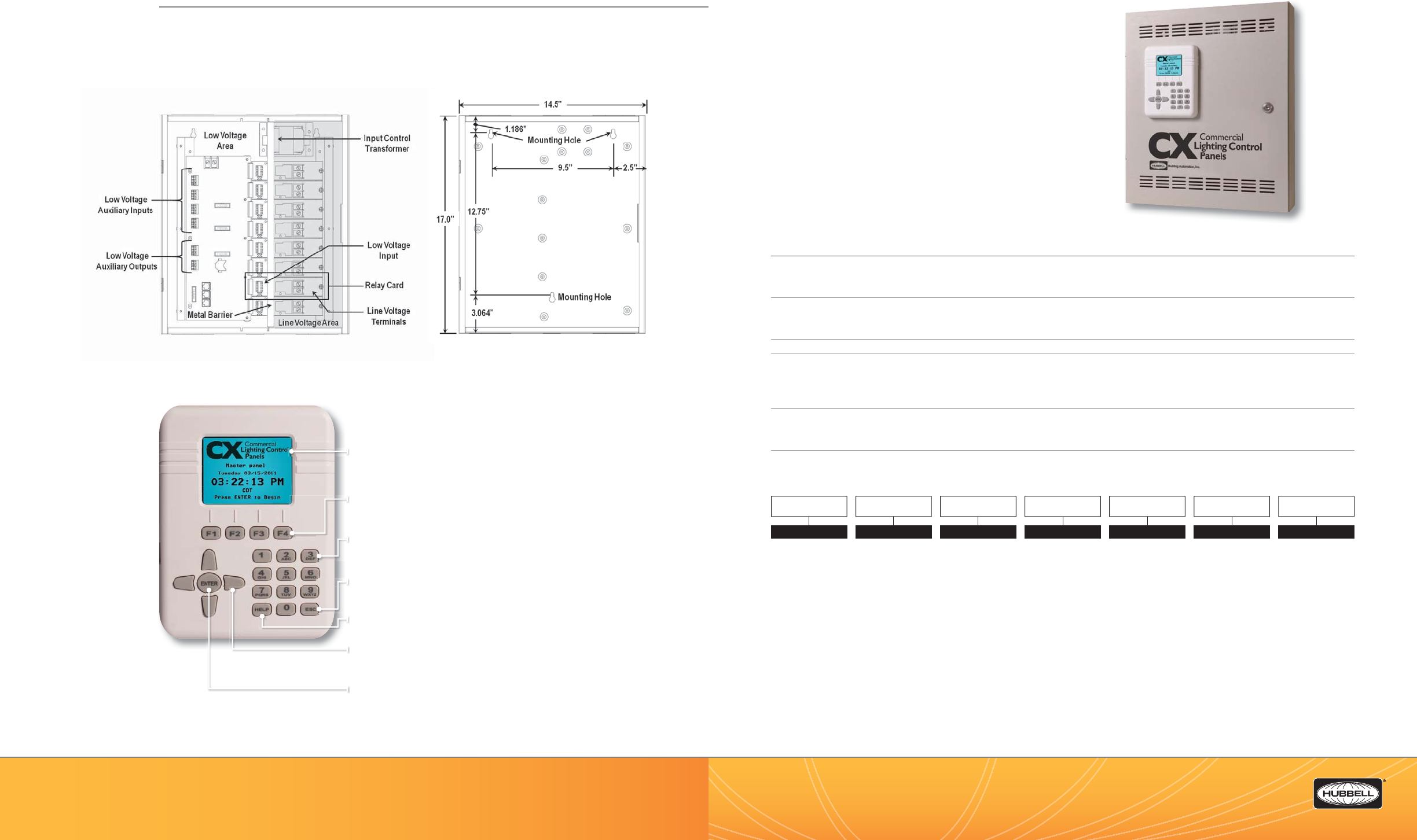
Color LCD Display – Allows for most programming to be
completed in a single screen. Right side scroll bars appear when
more choices are available than are currently visible.
Function Keys – These keys provide programming choices in
various screens. Key labels appear on-screen when keys are
available.
Alpha-Numeric Keypad – This keypad is used to populate names
and numeric values while programming. Tap/Scroll operation is
similar to that used for cell phones.
Escape Key – This key takes the user to the previous screen.
Warning prompts when changes have been made but not saved.
Help Key – This key will bring up help screens in speci c
locations driven by the eld that is highlighted.
Navigation Keys – Allows user to navigate Up/Down/Right/Left/
Toggle through editable elds to select program choices.
Enter Key – Use this key to make selections.
(888) 698-3242 | Fax orders (512) 450-0864 | hubbell-automation.com
h
ubb
ell-
au
t
o
m
a
ti
o
n
.
c
om
PAGE 102 | (888) 698-3242 | Fax orders (512) 450-0864 | hubbell-automation.com
PAGE 103 | LIGHTING CONTROL PANELS
Hubbell Building Automation CX08
CX Series Lighting Control Panel 8-Relays
KEY FEATURES
• Relay panel size – 8 relay spaces
• Five types of relays – 20A/1P and 20A/2P, N/O, N/C and 30A/P latching
• LCD user interface with keypad
• 365 day programming with 64 schedules
• 12 Programmable dry contact inputs for 8 relay panel
• Selectable pre-programmed scenarios
• Programmable inputs accept low voltage switches, photocells,
or motion sensors
• Two-low voltage dry contact output relays
• Program uploads via removable SD memory card
SPECIFICATIONS
Programming and con guration
• Programmable via user interface mounted on door
• Fully programmable by users with door closed and locked
Physical • NEMA 1 surface enclosure
• Pre-drilled mounting holes for mounting to wall, KOs provided on top and bottom
• 8 relay enclosures with hinged locking door
Electrical input • 120/208/240/277VAC Standard, 120/277/347 Optional
Relays • 120 and 277 VAC 20 Amp Single Pole Relays (14K SCCR)
• 120 and 277 VAC 30 Amp Single Pole Relays (18K SCCR)
• 347 VAC, 20A, IP Relay (14K SCCR)
• 208, 240, and 480 VAC 20 Amp Double Pole Relays(14K SCCR)
Operating environment • Location: interior space
• Operating temperature: 0°–50°C (32°–112°F)
• Relative humidity (non-condensing): 10%–90%
Certi cations • Listed to UL916, UL924 and cUL
ORDERING INFORMATION
CX8
NOTES:
1. “00” option has no relays, all must be installed in the eld.
2. Installed relays must be all of the same type. Relay Type TC and 2C not available in fully populate panels.
3. 2-Pole relays take the same amount of space as 1-Pole relays.
4. Secondary panel includes two (2) master/secondary panel interface cards.
5. 3L relay rated 30A at 120-277VAC, 20A at 347VAC.
Example: CX82S82NM
8-Relay CX Stand Alone Panel with 8-20A / IP electrically held N/O relays, surface enclosure, 120 - 277 input power, Master Panel
MODEL
CX CX Lighting
Control Panel
SPACES
08 8 Relay Spaces
INPUT VOLTAGE
2120/277V Dual
Tap
3120/347V Dual
Tap
ENCLOSURE
SNEMA 1 Surface
RELAY QUANTITY
00 No Relays -
Spaces Only
(See Note 1)
08 8 Relays
Installed
(See Note 2)
RELAY TYPE
SP Space Only
2N 20A Electrically
Held N/O 120-
277V
2C 20A Electrically
Held N/C
(120-277V)
3L Latching 120-
277-347V
(See Note 5)
TN 20A Electrically
Held N/O 480V
(See Note 3)
TC 20A Electrically
Held N/C 480V
(See Note 3)
OPTIONS
MMaster Panel
SSecondary Panel
(See Note 4)
CX 08 S
DIMENSIONAL INFORMATION
Panel Layout and Interior—Panel Dimensions – 24”H x 20”W x 4”D
CX Panels Programming Capabilities
The easy to use and understand color LCD Display has been designed based on input styles of commonly used devices
such as cell phones.
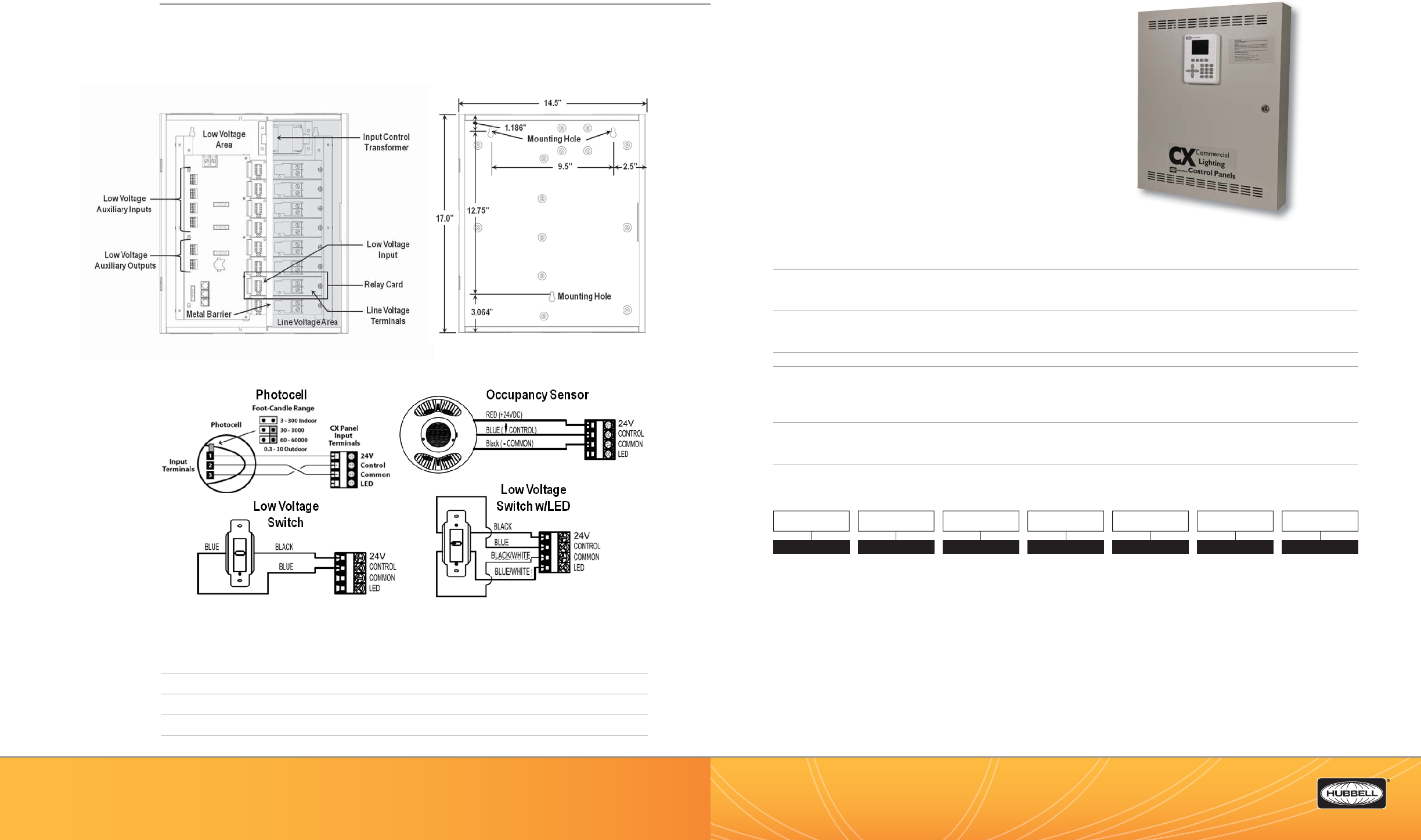
(888) 698-3242 | Fax orders (512) 450-0864 | hubbell-automation.com
h
ubb
ell-
au
t
o
m
a
ti
o
n
.
c
om
PAGE 104 | (888) 698-3242 | Fax orders (512) 450-0864 | hubbell-automation.com
PAGE 105 | LIGHTING CONTROL PANELS
Hubbell Building Automation
NOTES
CX16 and CX24
CX Series Commercial Lighting
Control Panels 16- and 24-Relays
KEY FEATURES
• Two relay panel sizes – 16 and 24 relay spaces
• Five types of relays – 20A/1P and 20A/2P, N/O, N/C
and 30A/P latching
• LCD user interface with keypad
• 20 Programmable dry contact inputs for 16 relay panel,
30 for 24 relay panel
• Programmable inputs accept low voltage switches, photocells,
or motion sensors
• Two low-voltage dry contact output relays on 16 relay panel,
three for 24 relay panel
• Program uploads via removable SD memory card
SPECIFICATIONS
Programming and con guration
• Programmable via user interface mounted on door
• Fully programmable by users with door closed and locked
Physical • NEMA 1 surface enclosure
• Pre-drilled mounting holes for mounting to wall, KOs provided on top and bottom
• 16 and 24 relay enclosures with hinged locking door
Electrical input • 120/208/240/277VAC Standard, 120/277/347 Optional
Relays • 120 and 277 VAC 20 Amp Single Pole Relays (14K SCCR)
• 120 and 277 VAC 30 Amp Single Pole Relays (18K SCCR)
• 347 VAC, 20A, IP Relay (14K SCCR)
• 208, 240, and 480 VAC 20 Amp Double Pole Relays(14K SCCR)
Operating environment • Location: interior space
• Operating temperature: 0°–50°C (32°–112°F)
• Relative humidity (non-condensing): 10%–90%
Certi cations • Listed to UL916, UL924 and cUL
ORDERING INFORMATION
CX24 and CX16
DIMENSIONAL INFORMATION
Panel Layout and Interior—Panel Dimensions – 24”H x 20”W x 4”D
WIRING DIAGRAMS
Low Voltage Device
NOTES:
1. 2-Pole relays take the same amount of space as 1-Pole relays.
2. Installed relays must be all of the same type. Relay Type TC and 2C not available in fully populate panels
3. “00” option has no relays, all must be installed in the eld.
4. Secondary panel includes (2) master/secondary panel interface cards.
5. 3L relay rated 30A at 120-277VAC, 20A at 347VAC
Example: CX162S162NM
16-Relay CX Master Panel with 16-20A / IP electrically held N/O relays, surface enclosure, 120 - 277 input power, Master Panel
MODEL
CX CX Lighting
Control Panel
SPACES
16 16 Relay Spaces
24 24 Relay Spaces
INPUT VOLTAGE
2120/277V
Universal
3120/347V
Universal
ENCLOSURE
SNEMA 1 Surface
RELAY QUANTITY
00 No Relays -
Spaces Only
(See Note 3)
16 16 Relays
Installed
(See Note 2)
24 24 Relays
Installed
(See Note 2)
RELAY TYPE
SP Space Only
2N 20A Electrically
Held N/O 120-
277V
2C 20A Electrically
Held N/C
(120-277V)
3L Latching 120-
277-347V
(See Note 5)
TN 20A Electrically
Held N/O 480V
(See Note 1)
TC 20A Electrically
Held N/C 480V
(See Note 1)
OPTIONS
MMaster Panel
SSecondary Panel
(See Note 4)
CX S
CX
24
a
nd
C
X1
6
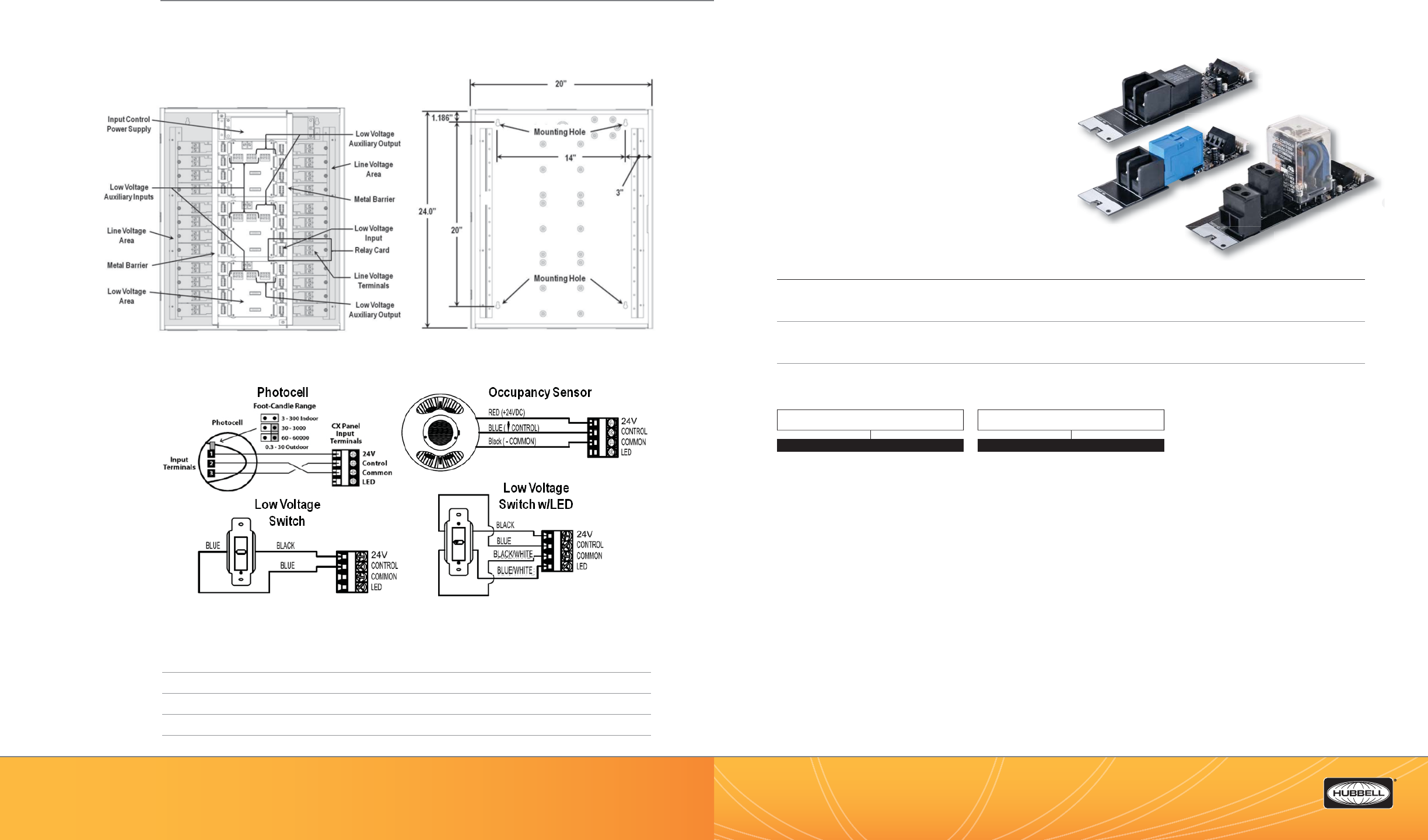
(888) 698-3242 | Fax orders (512) 450-0864 | hubbell-automation.com
hubbell-automation.com
PAGE 106 | (888) 698-3242 | Fax orders (512) 450-0864 | hubbell-automation.com
PAGE 107 | LIGHTING CONTROL PANELS
Hubbell Building Automation
NOTES
CXR
CX Series Lighting Control Panel Relays
KEY FEATURES
• Relays are mounted to individual relay cards
• Five types of relays – 20A/1P and 20A/2P, N/O, N/C (14K SCCR)
and 30A 1P latching (18K SCCR)
• Smart Relay card self-identi es type automatically to panel
• Each relay includes 1 programmable input for low voltage
switches, photocells, or motion sensors
• Panels are ordered fully populated with the same relay type
or with space only for eld installation of relay combinations
• Relay cards include a plugging connector to panel motherboard
and a single screw to secure it to the panel enclosure
• Relay cards include a manual override control button
and LED status indication
SPECIFICATIONS
Physical • Mounts inside NEMA 1 surface panel enclosure
• Pre-drilled mounting hole for securing relay cards
• Individual relay cards – 1P and 2P are equal in size
Operating environment • Location: interior space
• Operating temperature: 0°–50°C (32°–112°F)
• Relative humidity (non-condensing): 10%–90%
Certi cations • UL Certi ed to UL 916, UL 924 and cUL
ORDERING INFORMATION
CXR2N & CXR2C
20A/1P Relays
CXRTN & CXRTC
20A/2P Relays
CXR3L 30A/1P Relay
CX
C
2
C
C
CX
CX
RTN
&
CXRTC
20A/2P Rel
ay
s
CXR3L 30A/1P Relay
MODEL
CXR
RELAY TYPE
2N 20A 1-Pole Electrically Held N/O 120-277V
14KSCCR @ 277VAC
2C 20A 1-Pole Electrically Held N/C 120-277V
14KSCCR @ 277 VAC
3L 30A 1-Pole Latching 120-277-347V 18KSCCR
@ 277VAC, 14KSCCR @ 347VAC
TN 20A 2-Pole Electrically Held N/O 480V 14KSCCR
@ 480VAC
TC 20A 2-Pole Electrically Held N/C 480V 14KSCCR
@ 480VAC
DIMENSIONAL INFORMATION
Panel Layout and Interior—Panel Dimensions – 24”H x 20”W x 4”D
WIRING DIAGRAMS
Low Voltage Device
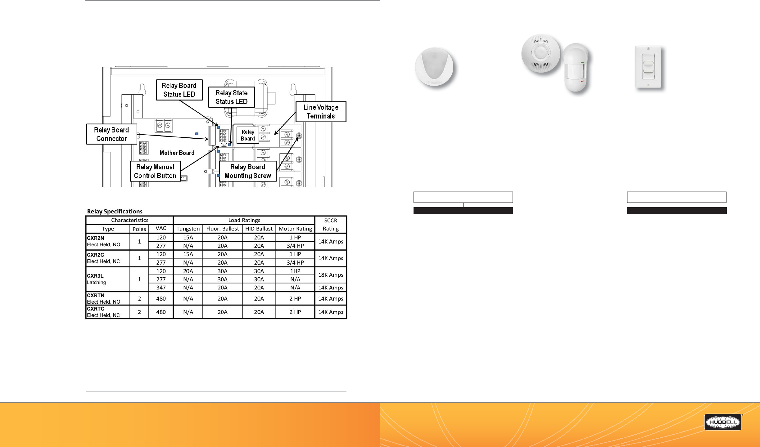
(888) 698-3242 | Fax orders (512) 450-0864 | hubbell-automation.com
h
ubb
ell-
au
t
o
m
a
ti
o
n
.
c
om
PAGE 108 | (888) 698-3242 | Fax orders (512) 450-0864 | hubbell-automation.com
PAGE 109 | LIGHTING CONTROL PANELS
Hubbell Building Automation
NOTES
CX Panel Accessories
Photocells, Motion Sensors and Switches
Photocells
Low Voltage
Switches
Motion Sensors
The CX Panels support direct connection
to HBA Omni™ Series Stand Alone Motion
Sensors featuring IntelliDAPT®.
The ceiling mount OMNI™ series and wall
mount LightOWL™ series sensors can be
used with the CX Panel inputs without the
use of power packs.
Consult hubbell-automation.com for detailed
catalog numbers, speci cations and applica-
tion guidelines.
Low Voltage Switches
The CX Panels support direct connection
to HBA LVS Series Low Voltage momentary
contact switches. These switches are
available with or without LED indication.
NOTE: Add WH for White or IV for Ivory nish
at the end of the part number.
ORDERING INFORMATION
Photocells
The CX Panels support direct connection to
HBA Low Voltage Photocells.
Features
• Open Loop photosensor
• Foot-candle range: 0.3–6,000 fc
• Indoor and outdoor versions
• Mounts vertically and horizontally
• Architecturally attractive design
• UL and cUL listed
ORDERING INFORMATION
LightOWL™
Motion
Sensors
OMNI™
DIMENSIONAL INFORMATION
Relay Location and Mounting
Relay Card Dimensions – 5.5”L x 1.625”W
RELAY TYPE
LVSM1NP Momentary, 1 Button, No Pilot
LVSM1PL Momentary, 1 Button, w/Pilot LED
LVSM2NP Momentary, 2 Buttons, No Pilot
LVSM2PL Momentary, 2 Button, w/Pilot LEDs
LVSM3NP Momentary, 3 Buttons, No Pilot
LVSM3PL Momentary, 3 Buttons, w/Pilot LEDs
LVSM4NP Momentary, 4 Buttons, No Pilot
LVSM4PL Momentary , 4 Buttons, w/Pilot LEDs
PHOTOCELL TYPE
LUXSTATLS Indoor
LUXSTATLSO Outdoor
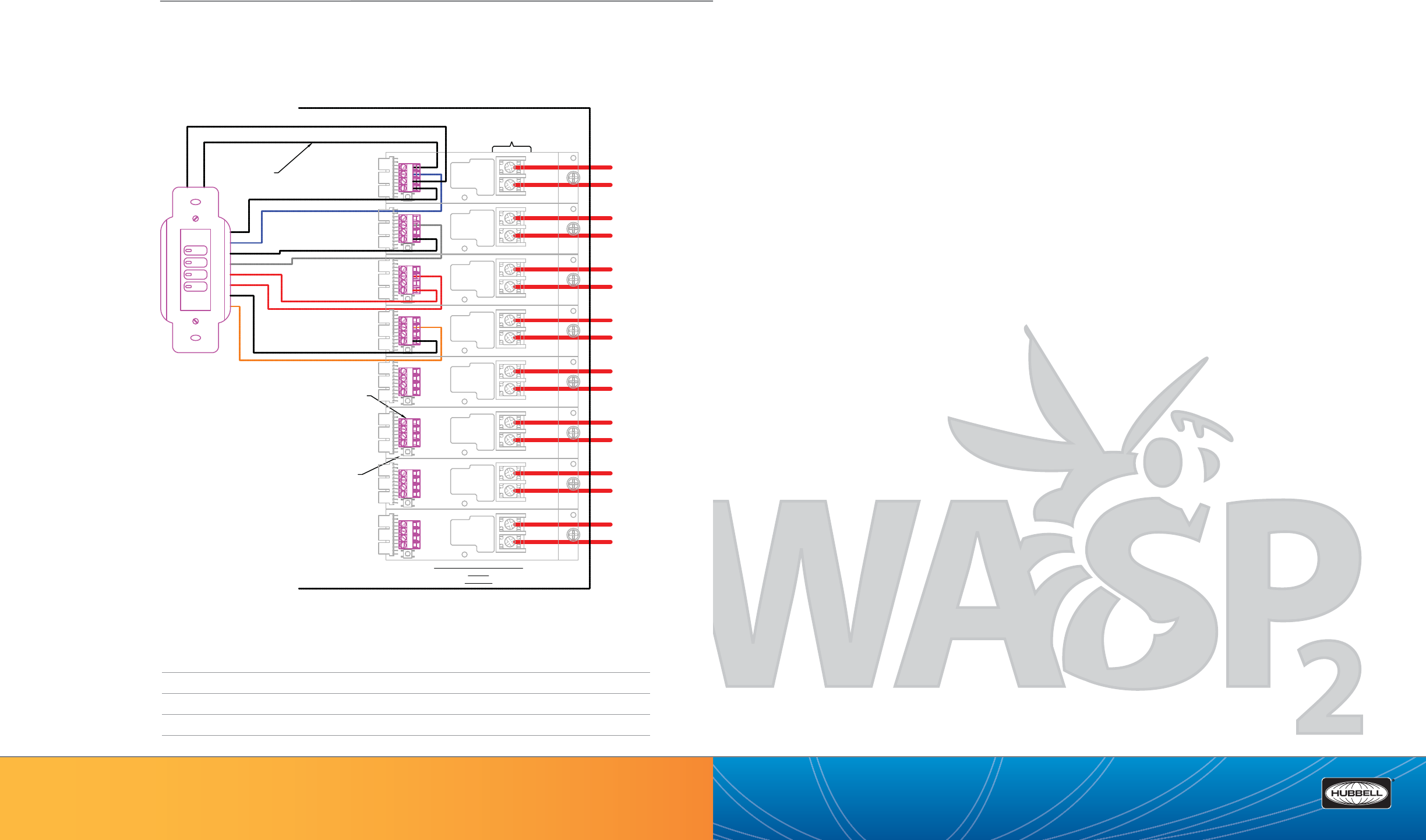
WSP—HBA WASP2™ Fluorescent High Bay Occupancy Sensor .........................................................................................................................113
(888) 698-3242 | Fax orders (512) 450-0864 | hubbell-automation.com
h
ubb
ell-
au
t
o
m
a
ti
o
n
.
c
om
PAG E 111 | HIGH BAY LIGHTING CONTROLS
PAGE 110 | (888) 698-3242 | Fax orders (512) 450-0864 | hubbell-automation.com
Hubbell Building Automation
NOTES
High Bay Lighting Controls
Table of Contents
BLUE/WHITE PILOT #1
LVSM4PL
4-Button Switch
Station
Black
SINGLE POLE RELAY 20AMP
CXR2x
TYPICAL
LOW VOLTAGE
CONTROL INPUT
TERMINALS
MANUAL
OVERRIDE
SWITCH
MOTHER
BOARD
CONNECTOR
LINE 1
HOT
LINE 1
SWITCHED
LINE
VOLTAGE
TERMINALS
LINE 2
HOT
LINE 2
SWITCHED
LINE 3
HOT
LINE 3
SWITCHED
LINE 4
HOT
LINE 4
SWITCHED
LINE 5
HOT
LINE 5
SWITCHED
LINE 6
HOT
LINE 6
SWITCHED
LINE 7
HOT
LINE 7
SWITCHED
LINE 8
HOT
LINE 8
SWITCHED
CX PANEL ENCLOSURE
24V
BLUE
BUTTON #1 - CONTROL
GREY
BUTTON #2 - CONTROL
RED
BUTTON #3 - CONTROL
ORANGE
BUTTON #4 - CONTROL
24V
CTRL
COM
LED
20AMP
1 POLE
RELAY
24V
CTRL
COM
LED
20AMP
1 POLE
RELAY
24V
CTRL
COM
LED
20AMP
1 POLE
RELAY
24V
CTRL
COM
LED
20AMP
1 POLE
RELAY
24V
CTRL
COM
LED
20AMP
1 POLE
RELAY
24V
CTRL
COM
LED
20AMP
1 POLE
RELAY
24V
CTRL
COM
LED
20AMP
1 POLE
RELAY
24V
CTRL
COM
LED
20AMP
1 POLE
RELAY
18AWG
Low Voltage Wire
(Typical)
GREY/WHITE PILOT #2
RED/WHITE PILOT #3
YELLOW/WHITE PILOT #4
BLACK/WHITE
WIRING DIAGRAM
For more wiring diagrams, visit http://www.hubbell-automation.com/resources/wiring_diagrams/

(888) 698-3242 | Fax orders (512) 450-0864 | hubbell-automation.com
hubbell-automation.com
PAGE 113 | HIGH BAY LIGHTING CONTROLS
WSP
HBA WASP2™ Fluorescent High Bay
Occupancy Sensor
KEY FEATURES
• Digital Passive Infrared (PIR) sensor
• Supports mounting heights up to 45 ft.
• Multiple (single and dual) output versions
• Unique Smart Cycling™ for improved lamp life
• Interchangeable area and aisle lens options
• Low voltage and line voltage
(120/277/347VAC, 208/480VAC, 480VAC) models available
• Low-temperature (-40°C)/water-tight versions available
SPECIFICATIONS
Power Requirements • Line Voltage sensors: 120/277/347VAC, 208/240VAC, 480VAC, 60 Hz
• Low Voltage sensors: 24VDC (uses UVPP or MP-Series power pack – not included)
Load Ratings • 120VAC: 0-800W ballast or 0-600W tungsten, 60Hz
(Line voltage sensors) • 277VAC: 0-1200W ballast
• 347VAC: 0-1500W ballast
• 208/240VAC: 0-1200W ballast
• 480VAC: 0-2400W ballast
• ¼ HP motor load @ 120VAC, 1/6HP @ 347VAC
Output (Low voltage sensors)
• 24VDC active high-logic control signal
• Relay: N/O + N/C contacts; 500mA rated @ 24VDC; three wire isolated relay
User Interface • (1) Twelve pin dip switch
Timer Timeouts • Primary: 8-second test mode - 4, 8, 16 and 30 minute timeouts
• Secondary: Can be disabled (switches o with primary timer) - 30, 60 and 90 minute timeouts
Passive Infrared • Dual element pyrometer and spherical Fresnel lens designed for robust detection of a walking person.*
Daylight Sensor • Range: 30 – 2500FC
• End mount sensor: Downward and upward looking daylight sensors (Direction selectable via dip switch)
• Surface mount sensor: Downward looking daylight sensor only
Interchangeable Lens Options
• Lens options: 360° area lens, aisle lens, 180° area lens, half aisle lens and Coverage
(Lenses sold separately – not included with sensor module)
• All lenses provide 1.4:1 coverage up to 30ft., 1.1:1 coverage from 30 – 45ft.
Operating environment • Standard version: Indoor use only; Operating temperature: 32° to 149°F (0° to 65°C);
Relative humidity (non-condensing): 0% to 95%
• Low-temperature/Water-tight version: Indoor use only; Operating temperature: -40° to 149°F (-40° to 65°C)
Construction • Sensor Module and Lens Assembly – high impact, injection-molded plastic
Size & Weight • Size: 4.0” Diameter x 1.5” Height
• Weight: 7 oz.
Color • White
Mounting • End mount sensor: Mounts directly to end of xture through extended ½” chase nipple. For deeper body
xtures, an optional Extender Adapter (available separately) positions the sensor ush or below the bottom
of the re ector for a full eld-of-view.
• Surface mount sensor: Mounts directly to xture or j-box via (2) 1.25” stainless steel screws and locking nuts
Certi cations • Conforms to UL STD 508, UL STD 244A - Conforms to IP65 (Low-temperature/Water-tight version)
*When used with program start ballast, a 1-2 second delay from occupancy detection to lamp turn-on may be experienced.
WASP2 End Mount Sensor with lens
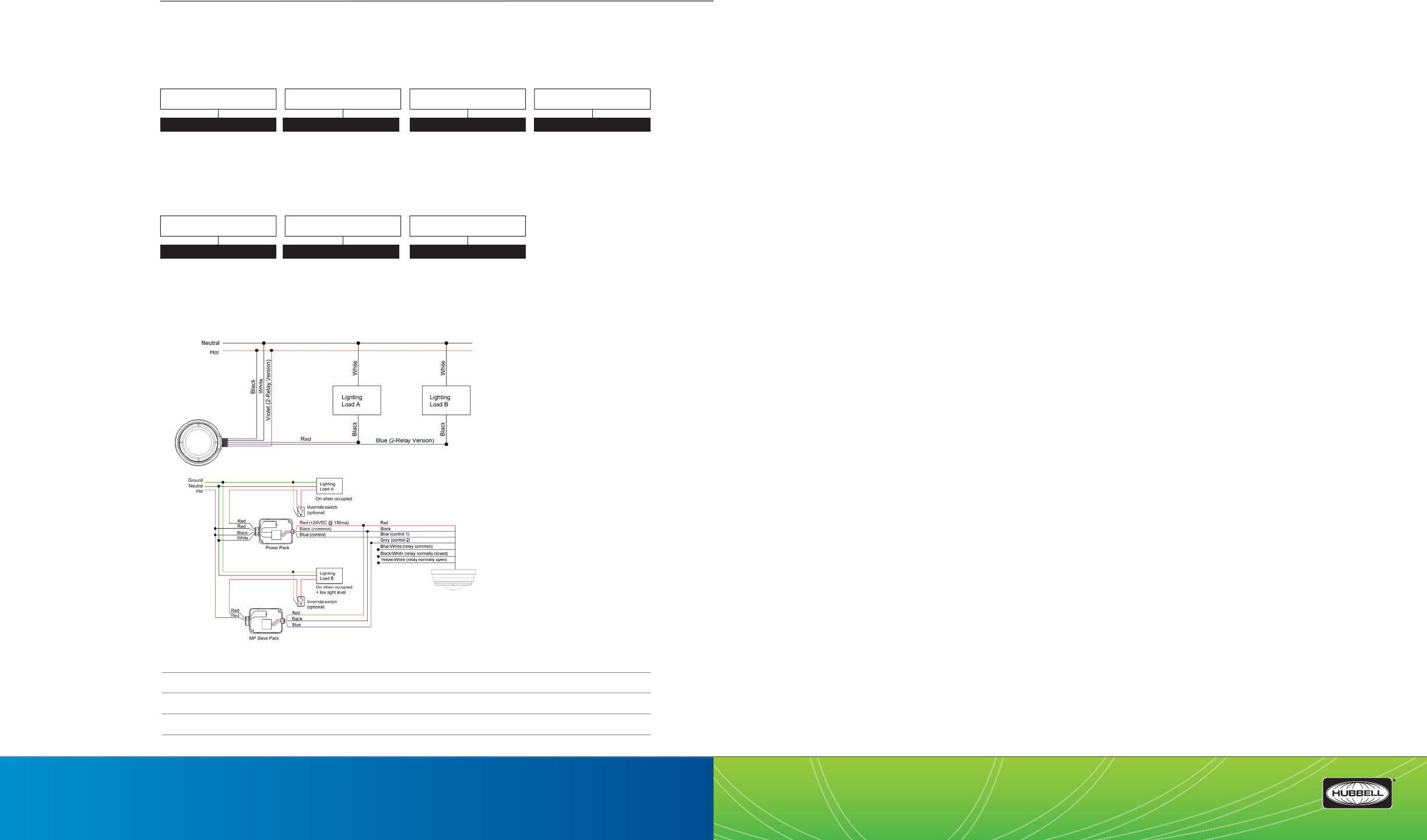
Z5-CM—Zone5 Control Module .....................................................................................................................................................................................117
Z5-OS—Zone5 Ceiling and Wall Mount Occupancy Sensors .............................................................................................................................119
Z5-DS—Zone5 Daylight Sensor ......................................................................................................................................................................................121
Z5-SW—Zone5 Low Voltage Wall Switches ................................................................................................................................................................123
LUXSTATOCM1Z—Luxstat Single Zone ON/OFF Control Module ...................................................................................................................125
LUXSTATDNCM—Luxstat Day|Night Control Module with Clock ....................................................................................................................127
LUXSTATLS—Luxstat Light Sensor ................................................................................................................................................................................129
LUXSTATSW—Luxstat Low Voltage Wall Switches ..................................................................................................................................................131
DLC7—Continuous Dimming Control ..........................................................................................................................................................................133
DLCPCI|DLCPCO|DLCPCA|DLCPCS—Photocell Sensors ....................................................................................................................................135
DLCPCC—Photocell Controller ........................................................................................................................................................................................137
(888) 698-3242 | Fax orders (512) 450-0864 | hubbell-automation.com
h
ubb
ell-
au
t
o
m
a
ti
o
n
.
c
om
PAGE 115 | DAYLIGHT HARVESTING
PAGE 114 | (888) 698-3242 | Fax orders (512) 450-0864 | hubbell-automation.com
Hubbell Building Automation
NOTES
Daylight Harvesting
Table of Contents
120/277/347VAC Line voltage wiring diagram for single and dual relay sensors (Single Phase Only).
Low voltage sensor wiring diagram.
ORDERING INFORMATION
WIRING DIAGRAM
For more wiring diagrams, visit http://www.hubbell-automation.com/resources/wiring_diagrams/
MODEL
WSPLENS
MODEL
WSP
LOWTEMP / WATERTIGHT
Blank Standard Version
LTWT Low-Temp/Water-Tight
(For use with LTWT
sensor module)
INPUT VOLTAGE / OUTPUTS
UNV 120/277/347VAC
UNV2R 120/277/347VAC
(2 Outputs)
208 208/240VAC
480 480VAC
24V 24VDC (Low Voltage)
LOWTEMP / WATERTIGHT
Blank Standard Version
LTWT Low-Temp/Water Tight
COVERAGE
360 360° Area Lens
AISLE Aisle Lens
HALF 180° Area Lens
HAISLE Half Aisle Lens
MOUNTING
EM End Mount
SM Surface Mount
(888) 698-3242 | Fax orders (512) 450-0864 | hubbell-automation.com
h
ubb
ell-
au
t
o
m
a
ti
o
n
.
c
om
PAGE 116 | (888) 698-3242 | Fax orders (512) 450-0864 | hubbell-automation.com
PAGE 117 | DAYLIGHT HARVESTING
Hubbell Building Automation
NOTES
Z5-CM
Zone5 Control Module
KEY FEATURES
• Supports up to 4 zones of lighting control
• Daylight switching, stepped dimming or continuous dimming – per zone
• Controls both General and A/V lighting
• Whiteboard lighting control
• Intuitive menu-driven LCD user interface
• Seamless integration with Zone5 sensors and lighting control switches
• SD card interface for saving and loading system settings
• Event logging
• Contractor-friendly, color coded plug and play installation
• UL and cUL listed
SPECIFICATIONS
User Interface • 2-line LCD display
• 4 navigational buttons
• SD Card interface – used for system settings, logging and rmware updates
Daylight Harvesting Options • For each zone
• Switched
• Stepped dimming
• Full range dimming
• None
Color Coded Low Voltage Ports
• Uses standard RJ45 connectors
• Plenum rated, low voltage system cabling (sold separately)
• Blue – lighting control
• Yellow – master and row control
• Orange - 0-10v dimming
• White – occupancy sensor
• Green – daylight sensor
Demand Response • Dry contact input
Electrical • Each Zone (1-4)
• 1 relay: general lighting
• 1 relay: A/V lighting
• Dimming: 0-10VDC, capable of controlling up to 50 low voltage, 2-wire, 0-10v dimming ballasts
• Additional relay for whiteboard lighting
• Switched output per relay
• 15A tungsten (120v only,) 20A magnetic ballast, 16A electronic ballast
• Maximum combined output not to exceed 20A
Dimension • 15” W x 12” H x 4” D (385mm x 310mm x 110mm)
Weight • 20.75 lbs
ORDERING INFORMATION
Z5-CM
MODEL
Z5CM Zone5 Control Module
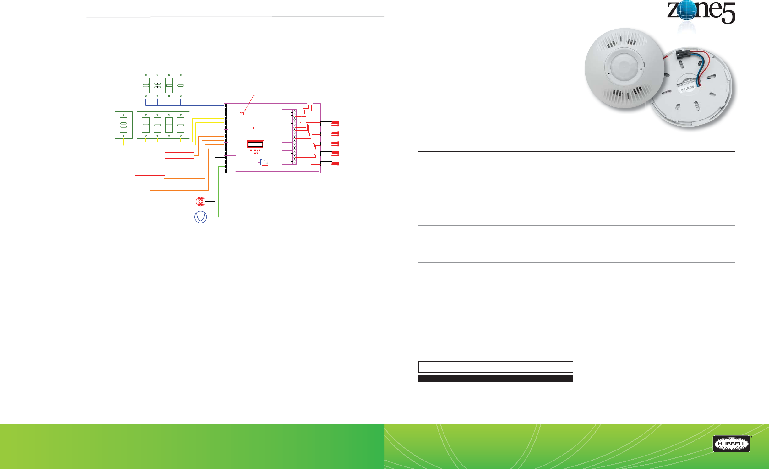
(888) 698-3242 | Fax orders (512) 450-0864 | hubbell-automation.com
h
ubb
ell-
au
t
o
m
a
ti
o
n
.
c
om
PAGE 118 | (888) 698-3242 | Fax orders (512) 450-0864 | hubbell-automation.com
PAGE 119 | DAYLIGHT HARVESTING
Hubbell Building Automation
NOTES
Z5-OS
Zone5 Ceiling and Wall Mount
Occupancy Sensors
KEY FEATURES
• Occupancy Sensors for Zone5 Daylight Harvesting System
• IntelliDAPT® self-adaptive technology –
no manual adjustment required
• All-digital dual technology (ultrasonic [US]
and passive infrared [PIR]) sensor
• Non-volatile memory for sensor settings
• 1,600 and 2,000 square-foot coverage area
• Form C relay with N/O + N/C outputs
• Color coded, plug and play installation
• UL and cUL listed
SPECIFICATIONS
IntelliDAPT • Auto reset from test setting
• Self-adjusting timer
• Self-adjusting ultrasonic and passive infrared thresholds
• Automatic false-on/ false-o corrections
LED lamp • Red – infrared motion
• Green – ultrasonic motion
Timer timeout • Automatic mode: 8 – 30 min. (self adjusts based on occupancy)
• Test mode: 8 seconds (for an easy check at installation)
Ultrasonic (US) output • Operating frequency: 32 kHz
Passive infrared (PIR) • Dual-element pyrometer and 12-element cylindrical rugged lens
Form C relay • Relay: N/O + N/C contacts; SPDT; 500 mA rated @ 24VDC; three-wire isolated relay
Coverage • Ceiling mount sensor: 2,000 square feet
• Wall mount sensor: 1,600 square feet
Power Requirements • 24VDC, 33mA Power and 24VDC active high-logic output control signal provided through Zone5 low voltage
color coded (white) plug-and-play cable (ordered separately)
Operating environment • Indoor use only
• Operating temperature: 32° - 104°F (0°-40°C)
• Relative humidity (non-condensing): 0%-95%
Construction • Casing – rugged, high-impact, injection-molded plastic KJB ABS Cycolac (UV-945VA) ame class rating,
UV inhibitors
• Quick to Install Connectors
Size and weight • Size: 4.5” diameter, 1.5” height (114 mm diameter, 38mm height)
• Weight: 5.0 oz (142g)
Color • O white
Mounting • Mounting base provided
• Recommended MAX mounting height: 12 ft.
ORDERING INFORMATION
Z5-OS-OMDT
WIRING DIAGRAM
For more wiring diagrams, visit http://www.hubbell-automation.com/resources/wiring_diagrams/
MODEL
Z5-OS-OMDT2000RP Zone5 Occupancy Sensor, Ceiling Mount, PIR and
Ultrasonic, Form C Relay, 2000 Sq. Ft.
Z5-OS-LODTRP Zone5 Occupancy Sensor, Wall Mount, PIR and Ultrasonic,
Form C Relay, 1600 Sq. Ft.
NEUTRAL
WHT BRD
A/V
NEUTRAL
GENERAL
A/V
NEUTRAL
GENERAL
A/V
NEUTRAL
GENERAL
A/V
NEUTRAL
GENERAL
120 VAC
277 VAC
NEUTRAL
LINE
120\277 VAC
NEUTRAL
GENERAL
POWER TO CONTROLLER
INPUT
LIGHTING
CIRCUIT
ROW 1ROW 2ROW 3ROW 4
Whiteboard
LINE IN
BACK SELECT
INSERT SD
CARD
(card shipped in
SD card slot)
MASTER/ROW
CONTROL
TEACHER
CONTROL
GENERAL - A/V LTG
DIM CONTROL
AUX
LTG
DIM
CTRL
OCCUPANCY
SENSOR
DAYLIGHT
SENSOR
Main Power Feed
(277 input shown)
Z-5 CLASSROOM CONTROL MODULE
(One Z-5 SYSTEM REQUIRED PER CLASSROOM NOT
TO EXCEED LOAD CAPACITY OF 20AMPS)
PLUG AND PLAY
TERMINALS
(50' COLOR CODED
CAT5 CABLE
INCLUDED, STANDARD)
FINAL INSTALLATION
TO BE WIRED BY THE
CONTRACTOR
1. INSTALLATION MUST BE PERFORMED BY QUALIFIED
PROFESSIONAL ELECTRICIAN ACCORDANCE WITH
ALL LOCAL, STATE AND NATIONAL CODES.
2. THE LOAD IN THIS APPLICATION MUST NOT EXCEED
20 AMPS.
3. THE WHITE BOARD LOAD IS CONTROLLED BY THE
TEACHER CONTROL STATION. (LOCATION OF
STATION TO BE DETERMINED BY DESIGNER.
RECOMMENDED PLACEMENT: ADJACENT TO
PRIMARY TEACHING AREA)
4. THE OCCUPANCY SENSOR(S) CONTROLS ENTIRE
LOAD.
5. SYSTEMS COMMISSIONING TO BE PERFORMED BY A
CERTIFIED FACTORY TECHNICIAN.
NOTES:
RESET
Demand Response Dry Contacts
(for future use if desired -
DO NOT wire unless indicated in
plans and specifications)
ROW 1 OUT
ROW 2 OUT
ROW 3 OUT
WHITE BOARD
OUT
To Z- 5
White board
Lighting
To dual circuit
Z-5
Lighting Row 3
To dual circuit
Z-5
Lighting Row 2
To dual circuit
Z-5
Lighting Row 1
ROW 4 OUT
To dual circuit
Z-5
Lighting Row 4
TEACHER CONTROL
SWITCH STATION
(Includes Low Voltage
Switches, Labeled
Switch Buttons, Switch
Plates and CAT5 Blue
Jump Connectors)
MASTER SWITCH
STATION
(Includes Low Voltage
Switch with Labeled
Buttons and Switch Plate)
BLUE
YELLOW
YELLOW
ORANGE
ORANGE
ORANGE
ORANGE
WHITE
GREEN
GEN
A/V
STUDYTIME WHITEBOARD
ROW4ROW3ROW2ROW1
ON
OFF
OCCUPANCY
SENSOR
DAYLIGHT
SENSOR
FOR Z-5
Dimming Ballast
0-10V Dimming Lead
Required for these options: Daylight
Dimming and/or AVD, GMD.
One Connection is required for any row
which participates in one or more 0-10V
dimming function(s)
CAT5 Port 1: Dims line voltage Row 1
CAT5 Port 2: Dims line voltage Row 2
CAT5 Port 3: Dims line voltage Row 3
CAT5 Port 4: Dims line voltage Row 4
Note: Whiteboard line voltage circuit does not
align to any dimming function.
ZONE 1
FOR Z-5
Dimming Ballast
ZONE 2
FOR Z-5
Dimming Ballast
ZONE 3
FOR Z-5
Dimming Ballast
ZONE 4
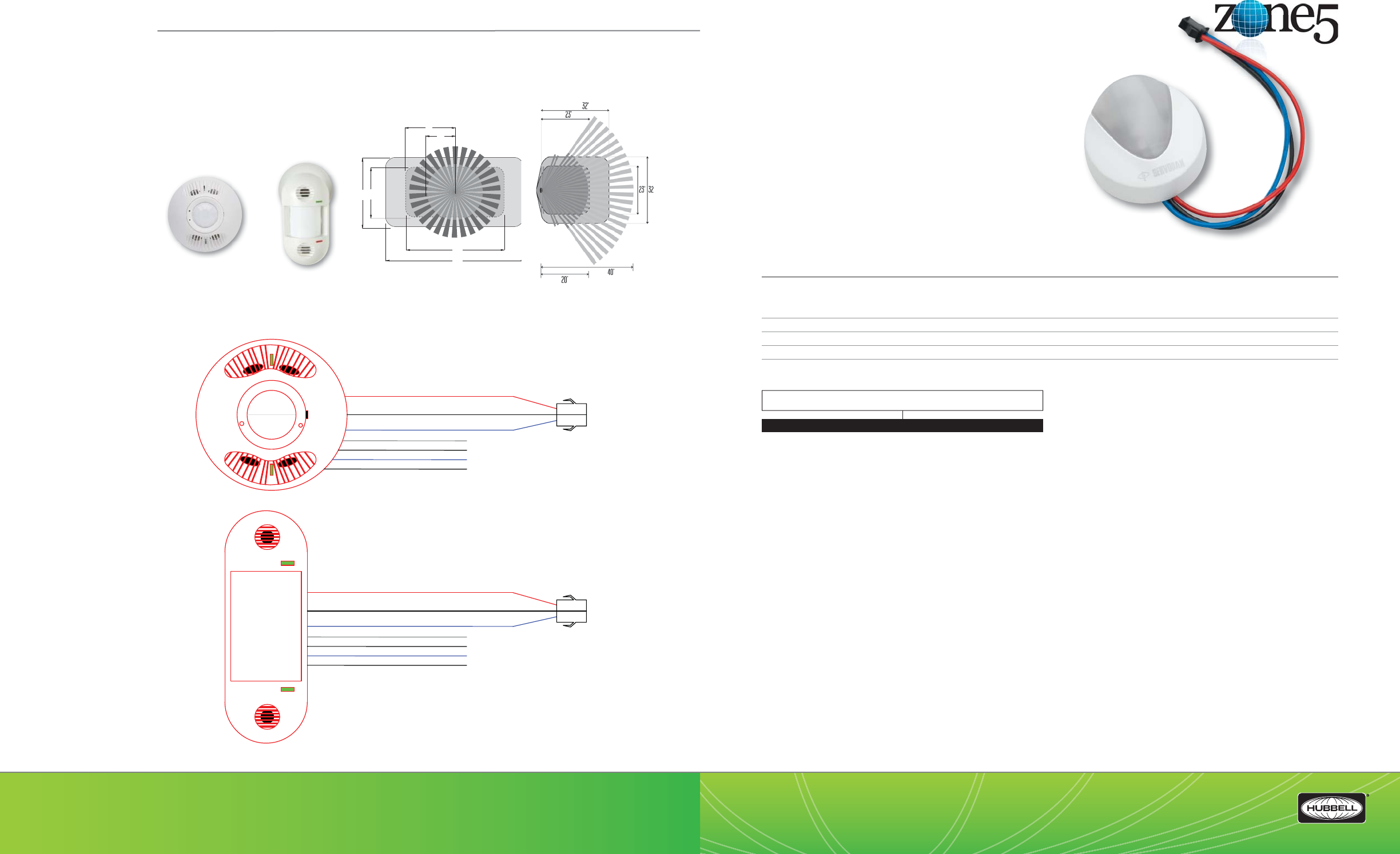
(888) 698-3242 | Fax orders (512) 450-0864 | hubbell-automation.com
h
ubb
ell-
au
t
o
m
a
ti
o
n
.
c
om
PAGE 120 | (888) 698-3242 | Fax orders (512) 450-0864 | hubbell-automation.com
PAGE 121 | DAYLIGHT HARVESTING
Hubbell Building Automation
HBA ZONE5 CEILING AND WALL MOUNT OCCUPANCY SENSORS | RANGE DIAGRAMS
WIRING DIAGRAM
For more wiring diagrams, visit http://www.hubbell-automation.com/resources/wiring_diagrams/
Z5-DS
Zone5 Daylight Sensor
KEY FEATURES
• Daylight sensor for Zone5 Daylight Harvesting System
• Open loop operation
• Foot-candle range: 3-6,000 fc
• Mounts vertically or horizontally
• Architecturally attractive design
• Color coded, plug-and-play installation
• UL and cUL listed
SPECIFICATIONS
Electrical • Three jumper-selectable foot candle ranges: 3-300fc; 30-3,000fc; 60-6,000fc
• 24VDC Power provided through Zone5 low voltage color coded (green) plug and play cable
(ordered separately)
Construction • Protective hard plastic cover and housing
Dimension • 2’ diameter x 1.2” height (50.8 diameter x 30.5mm height)
Certi cations • UL and cUL listed
ORDERING INFORMATION
Z5-DS
Z5-OS-OMNIDT2000RP
Z5-OS-LODTRP
3
2' 23'
64'
45'
12'
22'
Z5-OS-OMNIDT2000RP Z5-OS-LODTRP
MODEL
Z5-DS Zone5 Daylight Sensor
BLUE
BLACK
RED
GREY
BLACK / WHITE
BLUE / WHITE
YELLOW / WHITE
BLUE
BLACK
RED
GREY
BLACK / WHITE
BLUE / WHITE
YELLOW / WHITE

(888) 698-3242 | Fax orders (512) 450-0864 | hubbell-automation.com
h
ubb
ell-
au
t
o
m
a
ti
o
n
.
c
om
PAGE 122 | (888) 698-3242 | Fax orders (512) 450-0864 | hubbell-automation.com
PAGE 123 | DAYLIGHT HARVESTING
Hubbell Building Automation
NOTES
Z5-SW
Zone5 Low Voltage Wall Switches
KEY FEATURES
• Supports up to 4 zones of lighting control
• Attractive, architecturally pleasing design
• General – A/V lighting control with optional dimming control
• Whiteboard lighting control
• Master and individual row ON/OFF control
• Color-coded, plug and play installation
• All switches mount to standard single or multi-gang wall boxes
• Multi-gang wall plates available
SPECIFICATIONS
Power Requirements • Each switch: 100mA @ 30VDC Max – Provided by Zone5 low voltage color coded plug-and-play cable
(ordered separately)
• Master/Row control switches: Use with yellow cable
• Lighting Control Switches: Use with blue cable
Operating environment • Indoor use only
• Operating temperature: 32°–122°F (0°-50°C)
• Relative humidity (non-condensing): 10%-90%
Construction • Housing – Rugged, high-impact, injection-molded plastic
Size & Weight • Size: 4.2” L x 1.6” W x 1.4” D
• Weight: 1.6 oz
Color • White
Mounting • Switches may be mounted individually in a single gang switch box or ganged together in a multi-gang
switch box
NOTE: When ganging multiple switches make sure the switches are of the same color-coded type.
Decorator-style wall plates available separately
ORDERING INFORMATION
Z5-SW-GAV-ST
WIRING DIAGRAM
For more wiring diagrams, visit http://www.hubbell-automation.com/resources/wiring_diagrams/
MODEL
Z5SWGAV Zone5 General-A/V Mode Switch
Z5SWAVD Zone5 General-A/V Dimming Switch
Z5SWST Zone5 Study Time Switch
Z5SWWB Zone5 Whiteboard Switch
Z5SWMC Zone5 Master ON/OFF Switch
Z5SWRCR1 Zone5 Row 1 Control Switch
Z5-SW-RCR2 Zone5 Row 2 Control Switch
Z5-SW-RCR3 Zone5 Row 3 Control Switch
Z5-SW-RCR4 Zone5 Row 4 Control Switch
BLUE
BLACK
RED

(888) 698-3242 | Fax orders (512) 450-0864 | hubbell-automation.com
h
ubb
ell-
au
t
o
m
a
ti
o
n
.
c
om
PAGE 124 | (888) 698-3242 | Fax orders (512) 450-0864 | hubbell-automation.com
PAGE 125 | DAYLIGHT HARVESTING
Hubbell Building Automation
NOTES
LUXSTATOCM1Z
Luxstat Single Zone ON|OFF Control Module
KEY FEATURES
• Open Loop ON/OFF Daylight Harvesting control
• Pushbutton programming
• LCD display provides Real Time light level readings
• 3 to 3000 FC Range
• Single-zone switching
• Adjustable OFF delay
• Integration with occupancy sensors and manual override controls
• DIN rail mounting
• California Title 24 compliant
SPECIFICATIONS
Electrical (Input) • LUXSTATOCM1Z120: 120V
• LUXSTATOCM1Z277: 277V
• Max Load: 40mA
• Power Consumption: Approximately 2W
• Signal from Light Sensor: 0-10V
Electrical (Output) • Relay Contact: NO, m10A
• Load:
• Incandescent Lamps - 1200W
• Fluorescent - 620VA
• Halogen Incandescent - 500W
• Secondary Voltage: 24VDC
Programmable Features • FC Range:
• 0.3-30 FC
• 3-300 FC
• 30-3000 FC
• Setting Range
• 0.3-27 FC
• 3-270 FC
• 30-2700 FC
• OFF delay: 0-60 Minutes
Dimensions • 3.5” x 2.81” x 2.5” (98mm x 71mm x 64mm) LxWxD
Operating Environment • Operating Temperature 41°F - 122°F (+5°C - +50°C)
Mounting • DIN Rail
Accessories • Indoor Light Sensor - LUXSTATLS
• Outdoor Light Sensor - LUXSTATLSO
• LUXSTAT 1-Button Momentary Switch - LUXSTATSW1WHor LUXSTATSW1IV
Certi cations • UL Listed
ORDERING INFORMATION
LUXSTATOCMIZ
LUXSTATOCM
IZ
MODEL
LUXSTATOCM1Z120 Luxstat Single Zone ON/OFF Control Module, 120VAC
LUXSTATOCM1Z277 Luxstat Single Zone ON/OFF Control Module, 277VAC

(888) 698-3242 | Fax orders (512) 450-0864 | hubbell-automation.com
h
ubb
ell-
au
t
o
m
a
ti
o
n
.
c
om
PAGE 126 | (888) 698-3242 | Fax orders (512) 450-0864 | hubbell-automation.com
PAGE 127 | DAYLIGHT HARVESTING
Hubbell Building Automation LUXSTATDNCM
Luxstat Day|Night Control Module with Clock
KEY FEATURES
• Open Loop ON/OFF daylight harvesting control
• Integrated clock for night blocking
• Pushbutton programming
• DIN rail mounting
SPECIFICATIONS
Electrical (Input) • LUXSTATDNCM120: 120VAC
• LUXSTATDNCM277: 277VAC
• Load: Max 40mA
• Power Consumption: Approximately 2W
• Signal from Light Sensor: 0-10V
Electrical (Output) • Relay Contact: N/O, m10A
• Load:
Incandescent Lamps – 1200W
Fluorescent – 620VA
Halogen Incandescent – 500W
• Secondary Voltage: 24VDC
Performance • Fc Range: 0.3 – 30Fc
• Adjustment range for Fc on: 1 – 30Fc
Adjustment range for Fc o :
• Minimum: 10% of Fc on, but not less than 0.3 Fc
• Maximum: 70% of Fc on but not more than 9 Fc
• Tolerance of Fc range: +-10%
• Backup for clock: > 2 hours, when the unit has been connected at least 5 minutes
Operating Environment • Temperature range: 41°F – 122°F (+5°C – +50°C)
Mounting • DIN Rail
Accessories • Outdoor Light Sensor – LUXSTATLSO
Certi cations • UL and CE Listed
ORDERING INFORMATION
LUXSTATDNCM
Lighting
Load A
B
White
Gray
Black
Black (common)
Blue (control)
Red
Red
Red (+24VDC @ 150mA)
Black
White
Power Pack
contacts rated
for 20 Amps.
UVPP Power Pack
Supplies 150mA each
Hubbell Building
Automation
Low Voltage
Sensors(devices)
Requires 33mA each
B
12
36-080
D
LUXSTATLS
(PHOTOCELL HEAD)
12345
GREEN
WHITE
BLACK
LUXSTATOCM1Z120/277
(Minilux Control Module) 3
12
C
3
D
C
B
Minilux
Control
HOT
NEUTRAL
HOT
HOT
NEUTRAL
B
12
36-080
D
LUXSTATLS
(PHOTOCELL HEAD)
12345
GREEN
WHITE
BLACK
LUXSTATOCM1Z120/277
(Luxstat On/Off Control Module)
Hubbell Building Automation
Low Voltage Sensors(devices)
Up to 2 sensors can be powered
via LUXSTATOCM1Z
BLUE
BLACK
RED
3
12
C3
D
C
B
Minilux Control
* Light switches ON when the occupancy sensor detects occupancy
and the light level is below the preset level (Fc on).
* Light is switched OFF after a preset period when sensor no
longer detects movement OR the light level is above the preset
level.
* Light can be switched OFF via the push-button. Occupancy
sensor will not be able to switch ON for 10 seconds, after which
the occupancy sensor will switch on the light automatically.
HOT 120V/277V
ZONE 4
NEUTRAL Switched HOT
LXSTATSW1WH
WIRING DIAGRAM
For more wiring diagrams, visit http://www.hubbell-automation.com/resources/wiring_diagrams/
MODEL
LUXSTATDNCM120 Luxstat Day/Night Control Module with Clock, 120VAC,
DIN Rail Mount
LUXSTATDNCM277 Luxstat Day/Night Control Module with Clock, 277VAC,
DIN Rail Mount
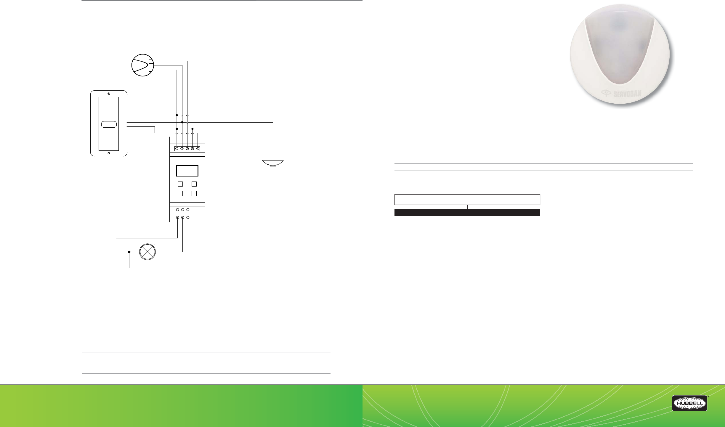
(888) 698-3242 | Fax orders (512) 450-0864 | hubbell-automation.com
h
ubb
ell-
au
t
o
m
a
ti
o
n
.
c
om
PAGE 128 | (888) 698-3242 | Fax orders (512) 450-0864 | hubbell-automation.com
PAGE 129 | DAYLIGHT HARVESTING
Hubbell Building Automation
NOTES
LUXSTATLS
Luxstat Light Sensor
KEY FEATURES
• Open Loop photosensor
• Foot-candle range: 3–6,000 fc
• Provides daylight levels to Luxstat daylight harvesting
control modules
• Indoor and outdoor versions
• Mounts vertically and horizontally
• Architecturally attractive design
• UL and cUL listed
• California Title 24 compliant
SPECIFICATIONS
Electrical • Three jumper-selectable foot candle ranges: 3–300fc; 30–3,000fc; 60–6,000fc
• Low-voltage Class 2 device
• Protective hard-plastic cover
• 3-conductor 22 AWG twisted cable—equal to Belden 8443
• Maximum wire length: 250 feet (76.2m)
Dimension • 2” diameter x 1.2” height (50.8 diameter x 30.5mm height)
Certi cations • UL and cUL listed
ORDERING INFORMATION
LUXSTATLS
SS
B
12
36-093
D
LUXSTATLS
(PHOTOCELL HEAD)
12345
GREEN (3)
WHITE (2)
BLACK (1)
LUXSTATDNCM1Z120/277
(Minilux Control Module)
3
12
C3
D
C
B
Minilux Control
* Light switches ON when the occupancy sensor detects occupancy
and the light level is below the preset level (Fc on).
* Light is switched OFF after a preset period when sensor no
longer detects movement OR the light level is above the preset
level.
* Light can always be switched ON via the push-button, regardless
of daylight level.
HOT 120V/277V
ZONE 4
NEUTRAL Switched HOT
-
+
LXSTATSW1WH
Hubbell Building Automation
Low Voltage Sensors(devices)
Up to 2 sensors can be powered
via LUXSTATDNCM1Z
BLUE
BLACK
RED
WIRING DIAGRAM
For more wiring diagrams, visit http://www.hubbell-automation.com/resources/wiring_diagrams/
MODEL
LUXSTATLS Luxstat Light Sensor - Indoor
LUXSTATLSO Luxstat Light Sensor - Outdoor

(888) 698-3242 | Fax orders (512) 450-0864 | hubbell-automation.com
h
ubb
ell-
au
t
o
m
a
ti
o
n
.
c
om
PAGE 130 | (888) 698-3242 | Fax orders (512) 450-0864 | hubbell-automation.com
PAGE 131 | DAYLIGHT HARVESTING
Hubbell Building Automation
NOTES
LUXSTATSW
Luxstat Low Voltage Wall Switches
KEY FEATURES
• Attractive, architecturally pleasing design
• Multiple button con gurations available
• Manual ON/OFF control
• Low voltage operation; Class 2 device
• Mounts to standard single-gang box
SPECIFICATIONS
Electrical Ratings • Each switch: 100mA @ 30VDC Max
• Each pilot LED: 18-30VDC, internal 2.2kohm, ½ Watt resistor
Operating environment • Indoor use only
• Operating temperature: 32° – 122°F (0° - 50°C)
• Relative humidity (non-condensing): 10%-90%
Construction • Housing – Rugged, high impact, injection molded plastic
• Color-coded leads
Size & Weight • Size: 4.87” dia., 2.44” deep (123.7 mm dia., 62mm deep)
• Weight: 3.0 oz
Color • White, Ivory
Mounting • Single-gang NEMA-style switch box (standard switch box)
• Decorator-style wall plate not included
ORDERING INFORMATION
LUXSTATSW4 LUXSTAT2AUTO LUXSTAT2DIM LUXSTATSW1
COLOR
WH White
IV Ivory
MODEL
LUXSTATSW4
LUXSTATSW2 AUTO
LUXSTATSW2 DIM
LUXSTAT SW1
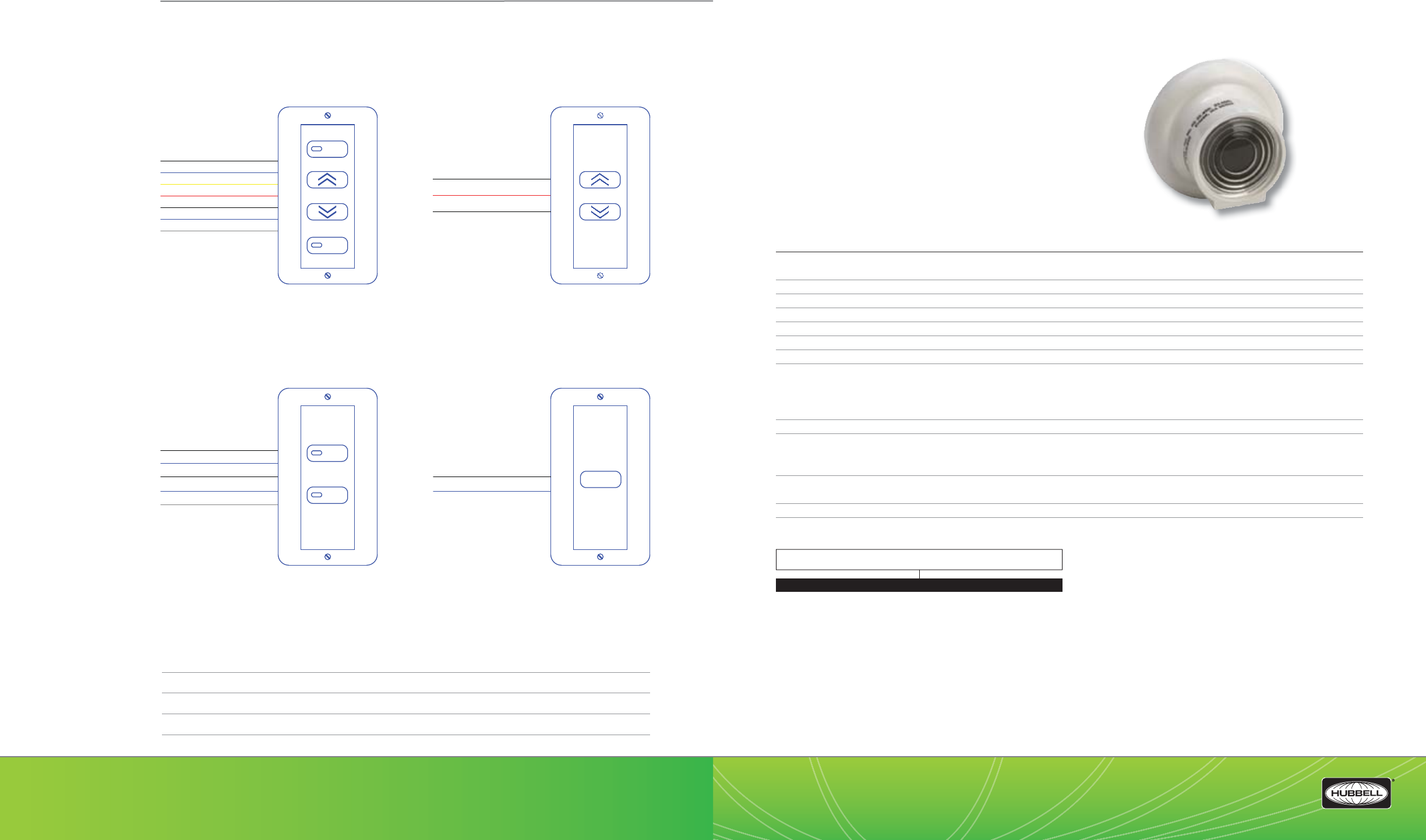
(888) 698-3242 | Fax orders (512) 450-0864 | hubbell-automation.com
h
ubb
ell-
au
t
o
m
a
ti
o
n
.
c
om
PAGE 132 | (888) 698-3242 | Fax orders (512) 450-0864 | hubbell-automation.com
PAGE 133 | DAYLIGHT HARVESTING
Hubbell Building Automation
NOTES
DLC7
Continuous Dimming Control
KEY FEATURES
• Controls 2-wire 0–10V dimming ballasts
• Light-sensitivity range of 0–500 foot-candles
• Selectable 3- or 8-second dimming rate
• Multiple calibration options
• Low-pro le design
SPECIFICATIONS
Accuracy • +/-1% @ 70°F (21°C);
• Derated to +/-5% when above 120°F or below 50°F (18° –49°C)
Supported ballasts • Capable of controlling up to 80 Advance Mark VII ballasts,
Operating environment • -13°F to +140°F (-11°C–60°C)
Sensitivity ranges • 0–500 foot-candles
Adjustment range • 7–140 foot-candles
Input voltage • 10 VDC (9 supplied by ballast)
Output voltage • 1VDC (light)–10 VDC (dark)
Wire leads • 22 gauge
- Gray and violet to the Advance ballast
- Blue and black for remote calibration dial
- White-green 2-wire loop cut for 3-second delay. Leave intact for 8-second delay to ballast
Sensor type • Blue enhanced photodiode
Size • Base diameter: 2.00”
Sensor diameter: 1.29”
Height: 1.23”
Mounting • Mounting hole: 3/8”
Mounting medium: 3M™ double adhesive tape
Construction • Sensor housing meets ame-retardant requirements of UL standard 94HB
ORDERING INFORMATION
WIRING DIAGRAM
For more wiring diagrams, visit http://www.hubbell-automation.com/resources/wiring_diagrams/
MODEL
DCL7 Continuous Dimming Control
DLC7
BLACK / WHITE
BLUE / WHITE
YELLOW / WHITE
RED
BLUE
BLACK
GREY
LUXSTATSW4WH
AUTO
I/O
BLACK / WHITE
RED
BLACK
LUXSTATSW2DIM
BLACK / WHITE
YELLOW / WHITE
BLUE / WHITE
GREY
BLUE
LUXSTATSW2AUTO
AUTO
I/O
LUXSTATSW1
BLACK / WHITE
BLUE
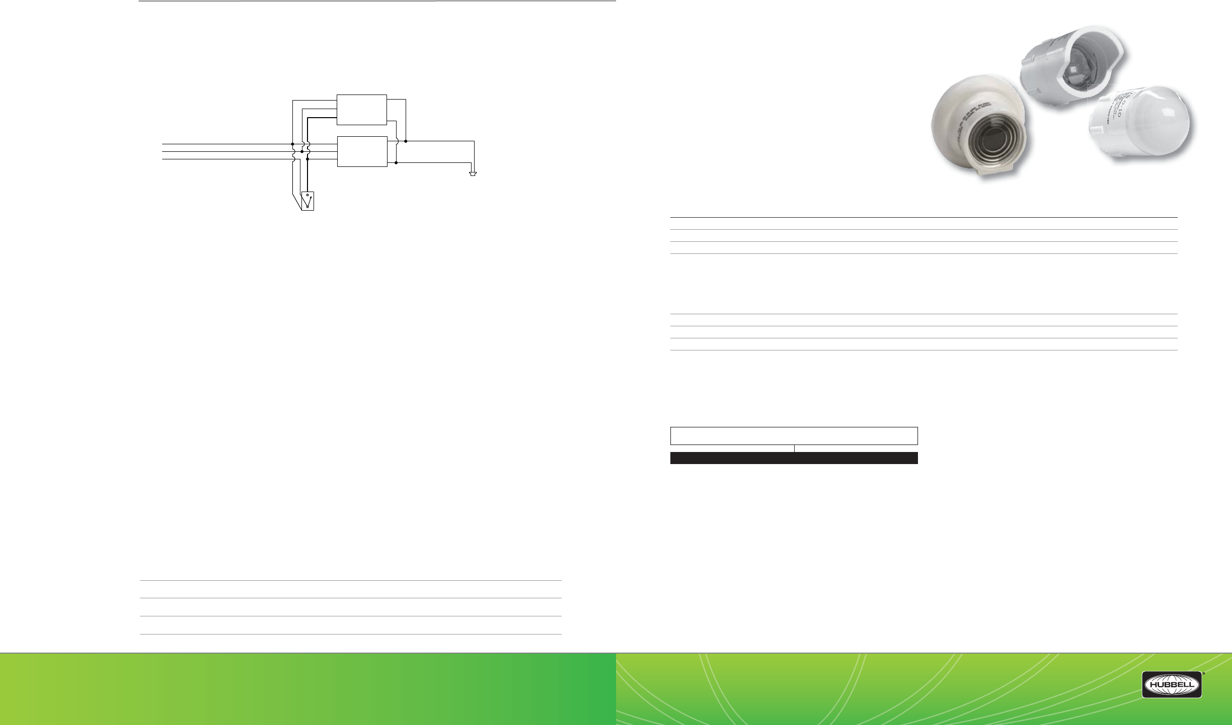
(888) 698-3242 | Fax orders (512) 450-0864 | hubbell-automation.com
hubbell-automation.com
PAGE 134 | (888) 698-3242 | Fax orders (512) 450-0864 | hubbell-automation.com
PAGE 135 | DAYLIGHT HARVESTING
Hubbell Building Automation
NOTES
DLCPCI | DLCPCO | DLCPCA | DLCPCS
Photocell Sensors
KEY FEATURES
• Multiple sensor options available
• Interfaces with Energy Management Systems
SPECIFICATIONS
Accuracy • +/-1% @ 70°F (21°C Derated to +/-5% when above 120°F or at 50°F (18° –49°C)
Operating environment • -13°F to +140°F (-11°C–60°C)
Sensor Type • Blue enhanced photo diode
Sensor Ranges • Housing Minimum Adjustable Maximum
DLCPCI Indoor 5-750FC
DLCPCO Outdoor 5-750FC
DLCPCA Atruim 200-2,500FC
DLCPCS Skylight 1,000-7,500FC
Input voltage • 24 VDC
Output Voltage • 10 VDC full output
Output O set • 0 VDC or 1 VDC - total darkness
Wiring • Three conductor 18-gauge standard cable
Red: Pos. DC input
Black: DC common
Yellow: Output to EMS
ORDERING INFORMATION
Dimming
Ballast
Neutral
Hot
Ground
Override
Switch
(optional)
DLC-7
Violet
Grey
Dimming
Ballast
Up to 50 ballasts can
be controlled by the
DLC-7
DLCPCI
DLCPCA
DLCPCO
WIRING DIAGRAM
For more wiring diagrams, visit http://www.hubbell-automation.com/resources/wiring_diagrams/
MODEL
DLCPCI Indoor Photocell Sensor, 5FC - 750FC
DLCPCO Outdoor Photocell Sensor, 5FC - 750FC
DLCPCA Atrium Photocell Sensor, 200FC - 2500FC
DLCPCS Skylight Photocell Sensor, 1000FC - 7500FC

(888) 698-3242 | Fax orders (512) 450-0864 | hubbell-automation.com
h
ubb
ell-
au
t
o
m
a
ti
o
n
.
c
om
PAGE 136 | (888) 698-3242 | Fax orders (512) 450-0864 | hubbell-automation.com
PAGE 137 | DAYLIGHT HARVESTING
Hubbell Building Automation
NOTES
DLCPCC
Photocell Controller
KEY FEATURES
• Adjustable ON/OFF set points
• Dual power unit input: 24 VAC or 24 VDC
• Flexible control options
• Input time delay
• Two set points available for separate on and o levels
SPECIFICATIONS
Accuracy • +/- 1 percent at 70°F (21°C) Derated +/- 5 percent above 120°F or below 0°F (49°F / -18°C)
Sensor Type • CD S Photoconductive 2 wire
Power Requirements • 24 VAC or 24 VDC standard
Dead Band • Adjustable: 5-95%
Indicators • Red High and Low LEDs
Input Delay • Standard 30-second sensor (removable for adjustment)
Control Inputs • Photoconductive Sensor Calibration / Simulator (for optional DLCSIMM)
Output • Standard form C SPDT relay 10A resistive
Operating environment • Operating Temp: -13°F to 140°F (-11°C to 60°C)
• Indoor use only
Construction • Sensor is mounted on a wall switch faceplate
Size & Weight • 4.75” height x 2.5” width x 1.5”depth
Color • White
ORDERING INFORMATION
DLCPCC
Red (+24VDC)
Black (common)
Blue (control)
High
Low
Red
Yellow
Black
Neutral
Hot
Ground
5431 2
86 7
DLC-PC-x Photo Sensor
(3-wire)
DLC-PCC Controller
Override Switch (optional)
Setpoints
N.O. N.C.
Lighting
Load
Red
Red
Black
White
Red
Black
Blue
UVPP Power Pack
Supplies
150mA each
Hubbell Building Automation
Low Voltage Sensors(devices)
Requires 33mA each
Power Pack contacts
rated for 20 Amps.
NOTES:
1. DO NOT attempt to power more than 4 devices (sensors or slave packs) from
a single power pack.
2. When using 3-wire sensor, operation of DLC-PCC is reversed from labeling on
unit. Use N.C. connection and setpoints as shown.
WIRING DIAGRAM
For more wiring diagrams, visit http://www.hubbell-automation.com/resources/wiring_diagrams/
MODEL
DLCPCC Photocell Controller
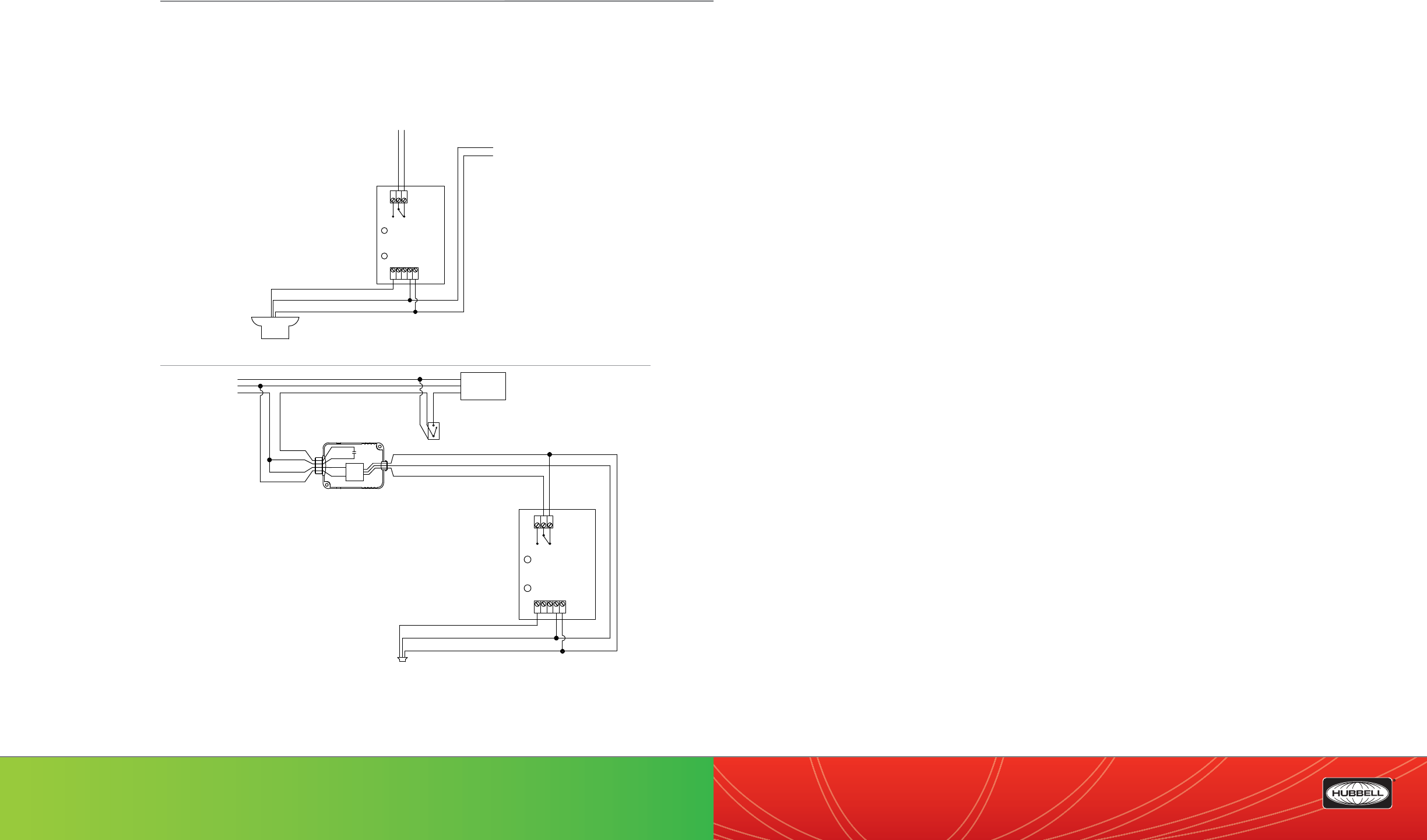
LHMTS LightHawk™—Multi-Technology Wall Switch Sensor featuring IntelliDAPT® ...........................................................................141
LHMTD LightHawk—Multi-Technology Dual Circuit Wall Switch Sensor featuring IntelliDAPT® .....................................................143
LHUSS LightHawk—Ultrasonic Wall Switch Sensor featuring IntelliDAPT® ...............................................................................................145
LHUSD LightHawk—Ultrasonic Dual Circuit Wall Switch Sensor featuring IntelliDAPT® ......................................................................147
LHIRS LightHawk—Passive Infrared Wall Switch Sensor featuring IntelliDAPT® ......................................................................................149
LHIRD LightHawk—Passive Infrared Wall Switch Sensor featuring IntelliDAPT® .....................................................................................151
RWSOSCFL—Residential Occupancy Sensor for Incandescent and CFL Lighting....................................................................................153
RWSVSCFL— Residential Vacancy Sensor for Incandescent and CFL Lighting .........................................................................................155
RWSOSINC— Residential Occupancy Sensors for Incandescent Lighting ...................................................................................................157
RWSVSINC— Residential Vacancy Sensors for Incandescent Lighting .........................................................................................................159
IWSZP3P—Automatic Passive Infrared Wall Switch Sensor ...............................................................................................................................161
IWSZPM—Manual ON | Automatic OFF Passive Infrared Wall Switch Sensor .............................................................................................163
TD200—Digital Programmable Time ...........................................................................................................................................................................165
LVS—LVS Series – Low Voltage Switches ....................................................................................................................................................................167
OMNIDT | OMNIDTRP—OMNI™ Dual Technology Ultrasonic and Passive Infrared Ceiling Sensor featuring IntelliDAPT® .......169
OMNIUS | OMNIUSRP—OMNI Ultrasonic Ceiling Sensor featuring IntelliDAPT®.....................................................................................171
OMNIIR | OMNIIPR—OMNI Passive Infrared Ceiling Sensor featuring IntelliDAPT® ................................................................................173
OMNIDIA | OMNIDIAPR—OMNI Dual Technology Acoustic and Passive Infrared Ceiling Sensor featuring IntelliDAPT® .........175
PIR1000H—Passive Infrared Ceiling Sensor for Hallway Applications ..........................................................................................................177
CUI5002000P—Dual Technology and Passive Infrared Line Voltage Ceiling Mount Sensor ...............................................................179
C5002000P—Ultrasonic Line Voltage Ceiling Mount Sensor ............................................................................................................................181
C8001500P—Ultrasonic Line Voltage Ceiling Mount Sensor ............................................................................................................................183
PIR10—Low Pro le Passive Infrared Line Voltage Ceiling Sensor ....................................................................................................................185
LODT | LODTRP—LightOWL™ Dual Technology Ultrasonic and PIR Wall Sensor featuring IntelliDAPT™ ......................................187
LOIR—LightOWL Passive Infrared Wall Sensor featuring IntelliDAPT™ ..........................................................................................................189
LODIA | LODIARP—LightOWL Dual Technology Passive Infrared and Acoustic Sensor featuring IntelliDAPT™ .........................191
Ceiling and Wall Mount Sensor Accessories .........................................................................................................................................................193
UVPP—Universal Voltage Power Pack .........................................................................................................................................................................195
UVPPM—Universal Voltage Power Pack with Manual ON|OFF Control ........................................................................................................197
QTI—QTI™ Quick to Install System and Accessories...............................................................................................................................................199
RRU—Line Voltage Auxiliary Relays ..............................................................................................................................................................................201
RR1SPDTC—Enclosed 10 Amp SPDT Relays .............................................................................................................................................................203
(888) 698-3242 | Fax orders (512) 450-0864 | hubbell-automation.com
h
ubb
ell-
au
t
o
m
a
ti
o
n
.
c
om
PAGE 139 | OCCUPANCY | VACANCY SENSORS
PAGE 138 | (888) 698-3242 | Fax orders (512) 450-0864 | hubbell-automation.com
Hubbell Building Automation
Occupancy | Vacancy Sensors
Table of Contents
Red (+24VDC)
Black (common)
Blue (control)
High
Low
Red
Yellow
Black
Neutral
Hot
Ground
5431 2
86 7
DLC-PC-x Photo Sensor
(3-wire)
DLC-PCC
Controller
Override Switch
(optional)
Setpoints
N.O. N.C.
Lighting
Load
Red
Red
Black
White
UVPP Power Pack
Supplies 150mA each
Hubbell Building Automation
Low Voltage Sensors (devices)
Requires 33mA each
Power Pack
contacts rated
for 20 Amps.
NOTES:
1. DO NOT attempt to power more than 4 devices
(sensors or slave packs) from a single power pack.
2. When using 3-wire sensor, operation of DLC-PCC is
reversed from labeling on unit. Use N.C. connection and
setpoints as shown.
PLEASE NOTE: When
using 3-wire sensor,
operation of DLC-PCC
is reversed from
labeling on unit. Use
N.C. connection and
setpoints as shown.
High
Low
Red
Yellow
Black
5431 2
86 7
DLC-PC-x Photo Sensor
(3-wire)
DLC-PCC
Controller
Setpoints
N.O. N.C.
24VDC (provided by
others)
(-)
(+)
to low voltage, dry
contact inputs (provided
by others)
WIRING DIAGRAM
For more wiring diagrams, visit http://www.hubbell-automation.com/resources/wiring_diagrams/
(888) 698-3242 | Fax orders (512) 450-0864 | hubbell-automation.com
h
ubb
ell-
au
t
o
m
a
ti
o
n
.
c
om
PAGE 140 | (888) 698-3242 | Fax orders (512) 450-0864 | hubbell-automation.com
PAGE 141 | OCCUPANCY | VACANCY SENSORS
Hubbell Building Automation
NOTES
LHMTS
LightHawk™ Multi-Technology
Wall Switch Sensor
featuring IntelliDAPT®
KEY FEATURES
• All-digital dual technology
(ultrasonic [US] and passive infrared [PIR]) sensor
• IntelliDAPT self-adaptive technology—no manual
adjustment required
• Auto-on and manual-on operating modes (depending on model)
• 1,000 square-foot, 180° coverage area
• Built-in photocell with SuperSaver™ mode
• RhinoTu ™ lens
• California Title 24 compliant
SPECIFICATIONS
IntelliDAPT technology • Self-adjusting timer
• Self-adjusting ultrasonic (US) and passive infrared (PIR) sensitivity
• Automatic false-on/false-o corrections
• No manual adjustments required
Timer timeout • Auto mode: 4–30 minutes; self-adjusts based on occupancy
• Fixed mode: 4, 8, 15, and 30 minutes
• Test mode: 5 seconds
Ultrasonic (US) output • 40kHz output
Passive infrared (PIR) • Dual-element pyrometer and 12-element cylindrical RhinoTu lens
Photocell • Natural light override range: 10–500 foot-candles
Coverage • 1,000 square-foot, 180° coverage area
Power requirements • 120/277 VAC; 50/60Hz
Electrical ratings • 120 VAC: 800W Incandescent; 1,000W Fluorescent; 1/6 HP
• 277 VAC: 1,800W Fluorescent; 1/6 HP
Operating environment • Indoor use only
• Operating temperature: 32°–104°F (0°–40°C)
• Relative humidity (non-condensing): 0–95%
Construction • Casing—high-impact injection-molded plastic (UL-94-5V)
• Impact-resistant lens
• Color-coded leads are 6” long
Size and weight • Size: 4.2” x 1.8” x 2.1”; .37” extension
• Weight: 2.9 oz
Color • White; Ivory; Light Almond; Gray; Black
Mounting • Single-gang NEMA-style switch box (average switch box)
• Decorator-style wall plate not included
Certi cations • ETL, UL, and cUL listed
ORDERING INFORMATION
LHMTS1 LHMTS0
WIRING DIAGRAM
For more wiring diagrams, visit http://www.hubbell-automation.com/resources/wiring_diagrams/
MODEL
LH LightHAWK™
LH MT S
TECHNOLOGY
MT Multitech
CONTROL
SSingle Circuit
NO. OF BUTTONS
1
0
BUTTONS
WWhite
IIvory
ALight Almond
GGray
BBlack
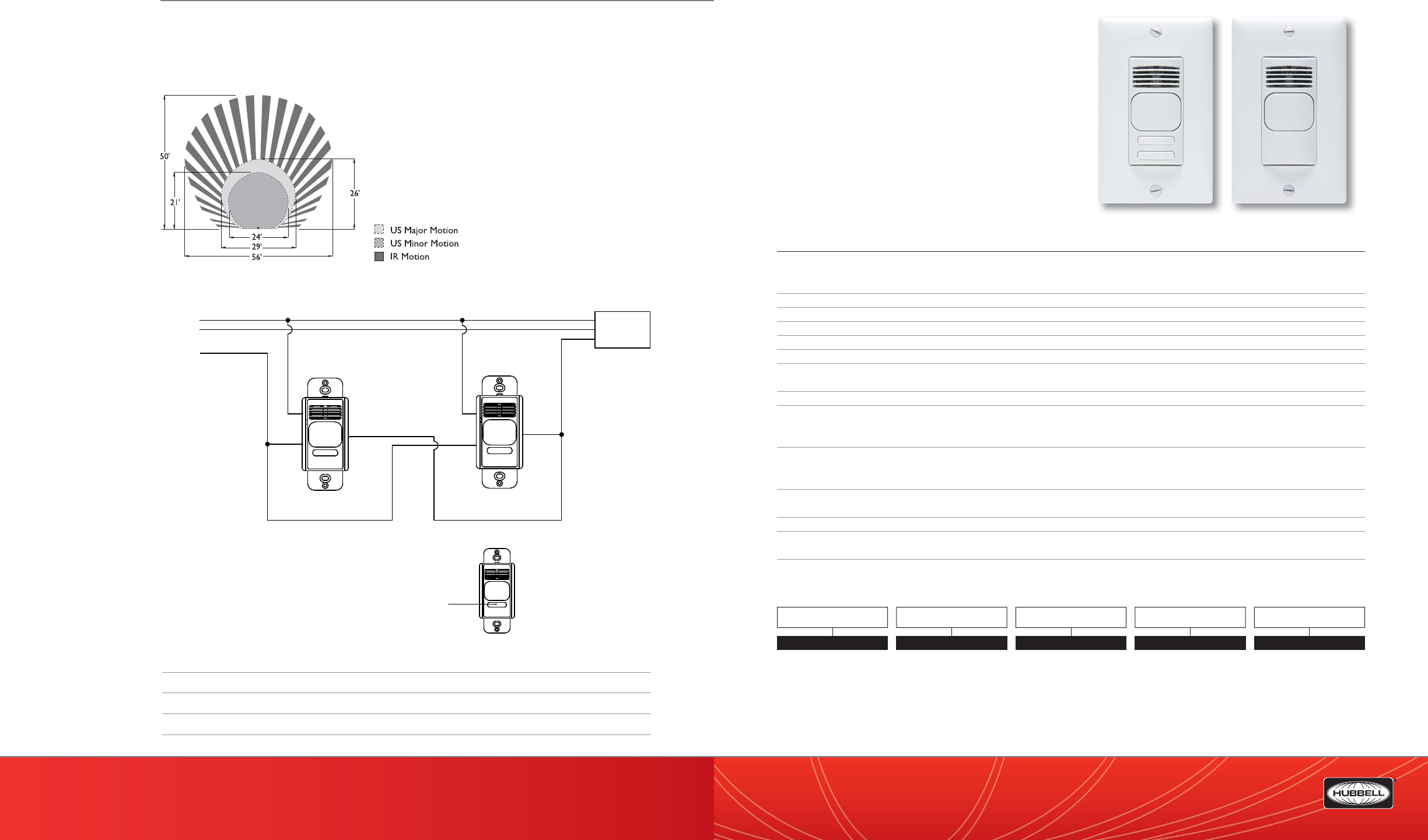
(888) 698-3242 | Fax orders (512) 450-0864 | hubbell-automation.com
h
ubb
ell-
au
t
o
m
a
ti
o
n
.
c
om
PAGE 142 | (888) 698-3242 | Fax orders (512) 450-0864 | hubbell-automation.com
PAGE 143 | OCCUPANCY | VACANCY SENSORS
Hubbell Building Automation
NOTES
LHMTD
LightHawk™ Multi-Technology
Dual Circuit Wall Switch Sensor
featuring IntelliDAPT®
KEY FEATURES
• All-digital dual technology (ultrasonic [US]
and passive infrared [PIR]) sensor
• IntelliDAPT self-adaptive technology—
no manual adjustment required
• Dual 120/277 VAC operation
• No minimum load requirement
• California Title 24 compliant
SPECIFICATIONS
Timer timeout • Auto mode: 4–30 minutes (self-adjusts based on occupancy)
• Fixed mode: 4, 8, 15, and 30 minutes
• Test mode: 5 seconds
Ultrasonic (US) output • 40kHz output
Passive infrared (PIR) • Dual-element pyrometer and 12-element cylindrical RhinoTu lens
Photocell • Natural light override range: 10–500 foot-candles
Coverage • 1,000 square-foot, 180° coverage area
Power requirements • 120/277 VAC, 50/60Hz
Electrical ratings • 120VAC: 800W Incandescent; 1,000W Fluorescent; 1/6 HP
• 277VAC: 1,800W Fluorescent; 1/6 HP
Load requirements • None
Operating environment • Indoor use only
• Operating temperature: 32°–104°F (0°–40°C)
• Relative humidity (non-condensing): 0–95%
Construction • Casing—high-impact injection-molded plastic (UL-94-5V)
• Impact-resistant lens
• Color-coded leads are 6” long
Size and weight • Size: 4.2” x 1.8” x 2.1”; .37” extension
• Weight: 2.9 oz
Color • White; Ivory; Light Almond; Gray; Black
Mounting • Single-gang NEMA-style switch box (average switch box)
• Decorator-style wall plate not included
Certi cations • ETL, UL, and cUL listed
ORDERING INFORMATION
Neutral
Hot
Ground Lighting
Load A
Black Red
Green
Note:
1. Sensor is shipped with all dip switches in the
OFF position (Factory Default)
Button 1
Black
Red
Green
LHMTD2 LHMTD0
RANGE DIAGRAM
WIRING DIAGRAM
For more wiring diagrams, visit http://www.hubbell-automation.com/resources/wiring_diagrams/
MODEL
LH LightHAWK™
LH MT D
TECHNOLOGY
MT Multitech
CONTROL
DDual Circuit
NO. OF BUTTONS
2
0
BUTTONS
WWhite
IIvory
ALight Almond
GGray
BBlack
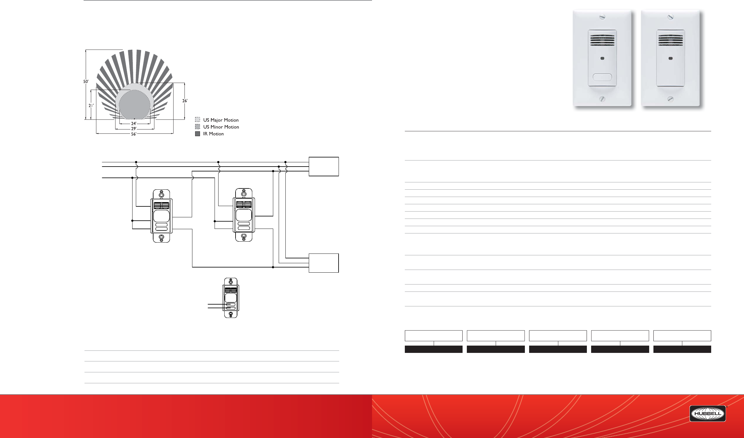
(888) 698-3242 | Fax orders (512) 450-0864 | hubbell-automation.com
h
ubb
ell-
au
t
o
m
a
ti
o
n
.
c
om
PAGE 144 | (888) 698-3242 | Fax orders (512) 450-0864 | hubbell-automation.com
PAGE 145 | OCCUPANCY | VACANCY SENSORS
Hubbell Building Automation
NOTES
LHUSS
LightHawk™ Ultrasonic
Wall Switch Sensor
featuring IntelliDAPT®
KEY FEATURES
• All-digital ultrasonic (US) sensor
• IntelliDAPT self-adaptive technology—no manual
adjustment required
• 2 relays for two-level switching or dual-circuit control
• Auto-on and manual-on operating modes
(depending on model)
• 400 square-foot, 180° coverage area
• Built-in photocell with SuperSaver™ mode
• California Title 24 compliant
SPECIFICATIONS
IntelliDAPT technology • Self-adjusting timer
• Self-adjusting ultrasonic (US) sensitivity
• Automatic false-on/false-o corrections
• No manual adjustments required
Timer timeout • Auto mode: 4–30 minutes; self-adjusts based on occupancy
• Fixed mode: 4, 8, 15, and 30 minutes
• Test mode: 5 seconds
Ultrasonic (US) output • 40kHz output
Photocell • Natural-light override range: 10–500 foot-candles
Coverage • 400 square-foot, 180° coverage area
Power requirements • 120/277VAC; 50/60Hz
Electrical ratings • 120VAC: 800W Incandescent; 1,000W Fluorescent; 1/6 HP
• 277VAC: 1,800W Fluorescent; 1/6 HP
Load requirements • No minimum load
Operating environment • Indoor use only
• Operating temperature: 32°–104°F (0°–40°C)
• Relative humidity (non-condensing): 0–95%
Construction • Casing—high-impact injection-molded plastic (UL-94-5V)
• Color-coded leads are 6” long
Size and weight • Size: 4.2” x 1.8” x 2.1”; .37” extension
• Weight: 2.9 oz
Color • White; Ivory; Light Almond; Gray; Black
Mounting • Single-gang NEMA-style switch box (average switch box)
• (Decorator-style wall plate not included)
Certi cations • ETL, UL, and cUL listed
ORDERING INFORMATION
Neutral
Hot
Ground Lighting
Load A
Black Red
Green
Note:
1. Sensor is shipped with all dip switches in the
OFF position (Factory Default)
Button 1
Button 2
Lighting
Load B
Violet
Blue
Black
Green
Blue
Red
Violet
LHUSS1 LHUSS0
RANGE DIAGRAM
WIRING DIAGRAM
MODEL
LH LightHAWK™
LH US S
TECHNOLOGY
US Ultrasonic
CONTROL
SSingle Circuit
NO. OF BUTTONS
2
0
BUTTONS
WWhite
IIvory
ALight Almond
GGray
BBlack
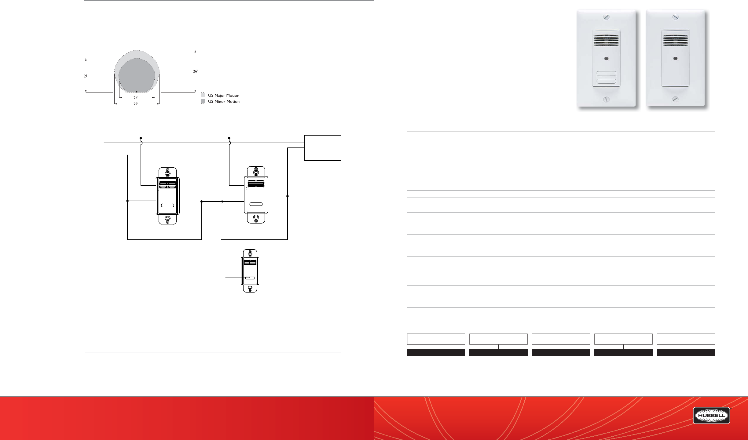
(888) 698-3242 | Fax orders (512) 450-0864 | hubbell-automation.com
h
ubb
ell-
au
t
o
m
a
ti
o
n
.
c
om
PAGE 146 | (888) 698-3242 | Fax orders (512) 450-0864 | hubbell-automation.com
PAGE 147 | OCCUPANCY | VACANCY SENSORS
Hubbell Building Automation
NOTES
LHUSD
LightHawk™ Ultrasonic
Dual Circuit Wall Switch Sensor
featuring IntelliDAPT®
KEY FEATURES
• All-digital ultrasonic (US) sensor
• IntelliDAPT self-adaptive technology—no manual
adjustment required
• 2 relays for two-level switching or dual-circuit control
• Auto-on and manual-on operating modes
(depending on model)
• 400 square-foot, 180° coverage area
• Built-in photocell with SuperSaver™ mode
• California Title 24 compliant
SPECIFICATIONS
IntelliDAPT technology • Self-adjusting timer
• Self-adjusting ultrasonic (US) sensitivity
• Automatic false-on/false-o corrections
• No manual adjustments required
Timer timeout • Auto mode: 4–30 minutes; self-adjusts based on occupancy
• Fixed mode: 4, 8, 15, and 30 minutes
• Test mode: 5 seconds
Ultrasonic (US) output • 40kHz output
Photocell • Natural light override range: 10–500 foot-candles
Coverage • 400 square-foot, 180° coverage area
Power requirements • 120/277 VAC; 50/60Hz
Electrical ratings • 120VAC: 800W Incandescent; 1,000W Fluorescent; 1/6 HP
• 277VAC: 1,800W Fluorescent; 1/6 HP
Load requirements • None
Operating environment • Indoor use only
• Operating temperature: 32°–104°F (0°–40°C)
• Relative humidity (non-condensing): 0–95%
Construction • Casing—high-impact injection-molded plastic (UL-94-5V)
• Color-coded leads are 6” long
Size and weight • Size: 4.2” x 1.8” x 2.1”; .37” extension
• Weight: 2.9 oz
Color • White; Ivory; Light Almond; Gray; Black
Mounting • Single-gang NEMA-style switch box (average switch box)
• Decorator-style wall plate not included
Certi cations • ETL, UL, and cUL listed
ORDERING INFORMATION
Neutral
Hot
Ground
Lighting
Load A
Black Red
Green
Note:
1. Sensor is shipped with all dip switches in the
OFF position (Factory Default)
Button 1
Green
Black
Red
LHUSD2 LHUSD0
RANGE DIAGRAM
WIRING DIAGRAM
For more wiring diagrams, visit http://www.hubbell-automation.com/resources/wiring_diagrams/
MODEL
LH LightHAWK™
LH US D
TECHNOLOGY
US Ultrasonic
CONTROL
D Dual Circuit
NO. OF BUTTONS
2
0
BUTTONS
WWhite
IIvory
ALight Almond
GGray
BBlack
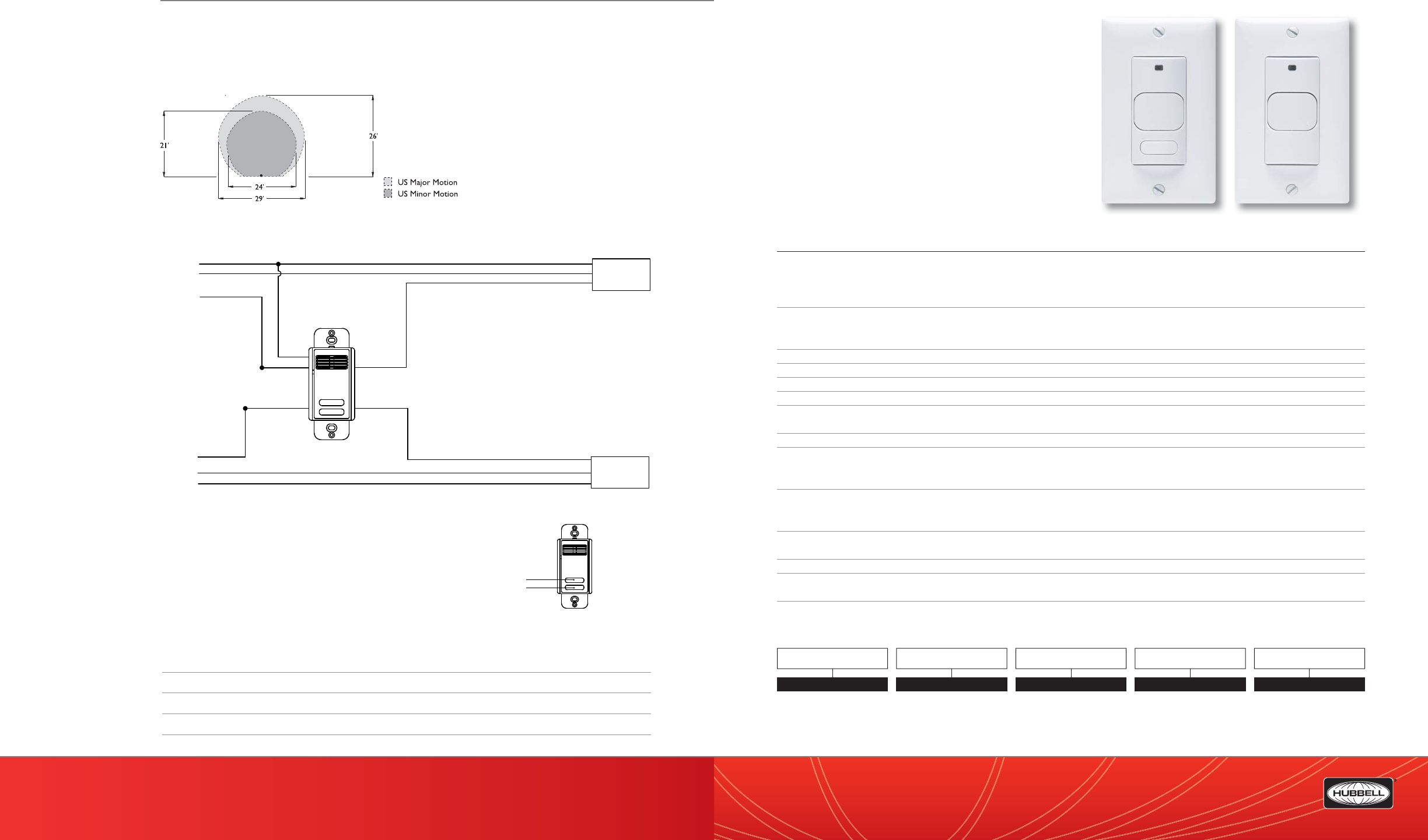
(888) 698-3242 | Fax orders (512) 450-0864 | hubbell-automation.com
h
ubb
ell-
au
t
o
m
a
ti
o
n
.
c
om
PAGE 148 | (888) 698-3242 | Fax orders (512) 450-0864 | hubbell-automation.com
PAGE 149 | OCCUPANCY | VACANCY SENSORS
Hubbell Building Automation
NOTES
LHIRS
LightHawk™ Passive Infrared
Wall Switch Sensor
featuring IntelliDAPT®
KEY FEATURES
• All-digital passive infrared (PIR) sensor
• IntelliDAPT self-adaptive technology
• Auto-on and manual-on operating modes (depending on model)
• 1,000 square-foot, 180° coverage area
• Built-in photocell with SuperSaver™ mode
• RhinoTu ™ lens
• Dual 120/277 VAC operation
• No minimum load requirement
• Zero Arc Point Switching
• California Title 24 compliant
SPECIFICATIONS
IntelliDAPT technology • Self-adjusting timer
• Self-adjusting passive infrared (PIR) sensitivity
• Automatic false-on/false-o corrections
• No manual adjustments required
Timer timeout • Auto mode: 4–30 minutes (self-adjusts based on occupancy)
• Fixed mode: 4, 8, 15, and 30 minutes
• Test mode: 5 seconds
Passive infrared (PIR) • Dual-element pyrometer and 12-element cylindrical RhinoTu lens
Photocell • Natural light override range: 10–500 foot-candles
Coverage • 1,000 square-foot, 180° coverage area
Power requirements • 120/277 VAC; 50/60Hz
Electrical ratings • 120 VAC: 800W Incandescent; 1,000W Fluorescent; 1/6 HP
• 277 VAC: 1,800W Fluorescent; 1/6 HP
Load requirements • None
Operating environment • Indoor use only
• Operating temperature: 32°–104°F (0°–40°C)
• Relative humidity (non-condensing): 0%–95%
Construction • Casing—high-impact injection-molded plastic (UL-94-5V)
• Impact-resistant lens
• Color-coded leads are 6” long
Size and weight • Size: 4.2” x 1.8” x 2.1”; .37” extension
• Weight: 2.9 oz
Color • White; Ivory; Light Almond; Gray; Black
Mounting • Single-gang NEMA-style switch box (average switch box)
• Decorator-style wall plate not included
Certi cations • ETL, UL, and cUL Listed
ORDERING INFORMATION
LHIRS1 LHIRS0
Neutral
Hot
Ground Lighting
Load A
Lighting
Load B
Blue
Black
Violet
Red
Green
Notes:
1. If only controlling 1 load, use Black, Red, and Green wires
2. Black and Red wires operate through Button 1
3. Blue and Violet wires operate through Button 2
Button 2
Button 1
Neutral
Ground
Hot
RANGE DIAGRAM
WIRING DIAGRAM
For more wiring diagrams, visit http://www.hubbell-automation.com/resources/wiring_diagrams/
MODEL
LH LightHAWK™
LH IR S
TECHNOLOGY
IR Passive Infrared
CONTROL
SSingle Circuit
NO. OF BUTTONS
1
0
BUTTONS
WWhite
IIvory
ALight Almond
GGray
BBlack
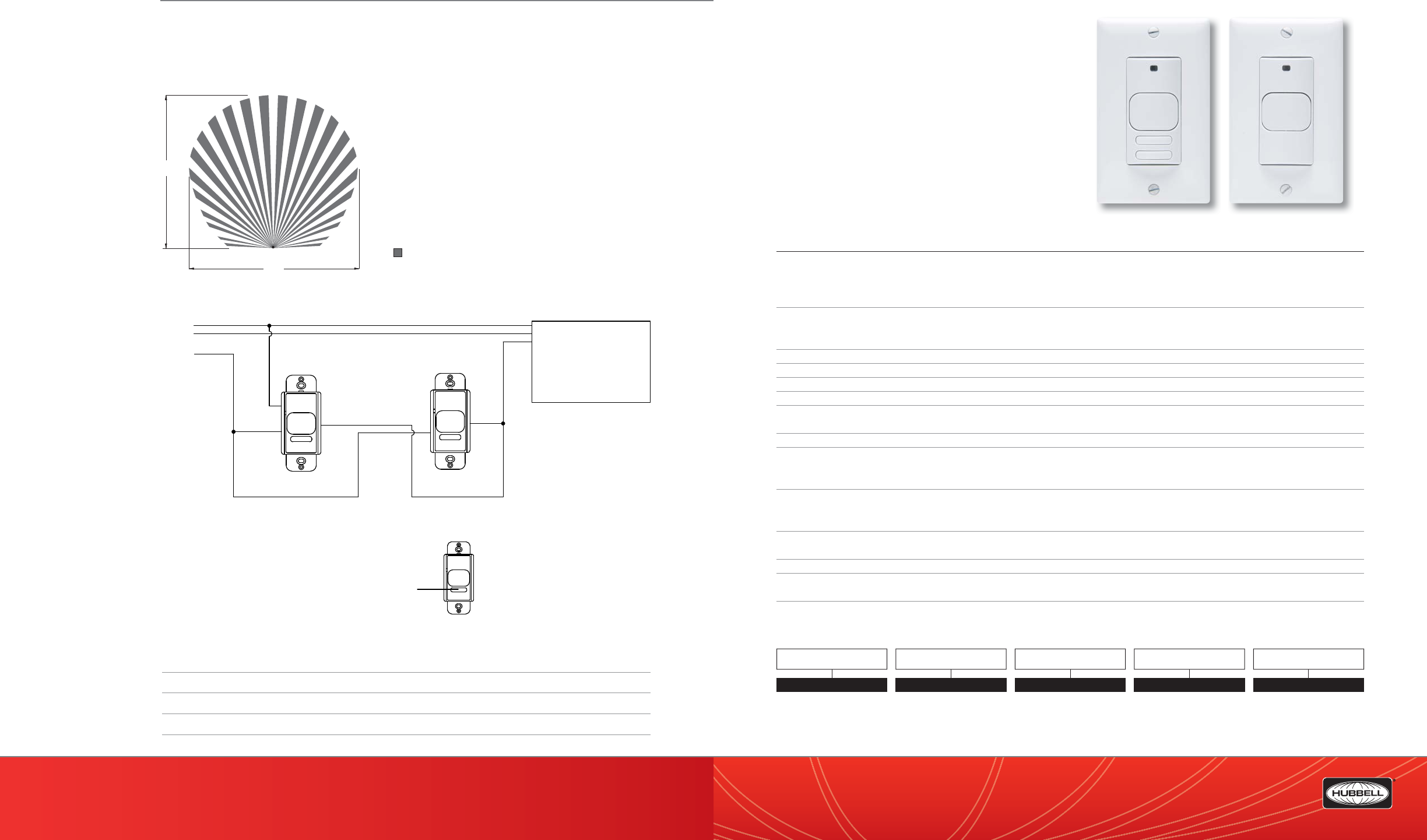
(888) 698-3242 | Fax orders (512) 450-0864 | hubbell-automation.com
h
ubb
ell-
au
t
o
m
a
ti
o
n
.
c
om
PAGE 150 | (888) 698-3242 | Fax orders (512) 450-0864 | hubbell-automation.com
PAGE 151 | OCCUPANCY | VACANCY SENSORS
Hubbell Building Automation
NOTES
LHIRD
LightHawk™ Passive Infrared
Dual Circuit Wall Switch Sensor
featuring IntelliDAPT®
KEY FEATURES
• All-digital passive infrared (PIR) sensor
• Auto-on and manual-on operating modes
(depending on model)
• 1,000 square-foot, 180° coverage area
• No minimum load requirement
• California Title 24 compliant
SPECIFICATIONS
IntelliDAPT technology • Self-adjusting timer
• Self-adjusting passive infrared (PIR) sensitivity
• Automatic false-on/false-o corrections
• No manual adjustments required
Timer timeout • Auto mode: 4–30 minutes; self-adjusts based on occupancy
• Fixed mode: 4, 8, 15, and 30 minutes
• Test mode: 5 seconds
Passive infrared (PIR) • Dual-element pyrometer and 12-element cylindrical RhinoTu lens
Photocell • Natural light override range: 10–500 foot-candles
Coverage • 1,000 square-foot, 180° coverage area
Power requirements • 120/277 VAC; 50/60Hz
Electrical ratings • 120VAC: 800W Incandescent; 1,000W Fluorescent; 1/6 HP
• 277VAC: 1,800W Fluorescent; 1/6 HP
Load requirements • None
Operating environment • Indoor use only
• Operating temperature: 32°–104°F (0°–40°C)
• Relative humidity (non-condensing): 0%–95%
Construction • Casing—high-impact injection-molded plastic (UL-94-5V)
• Impact-resistant lens
• Color-coded leads are 6” long
Size and weight • Size: 4.2” x 1.8” x 2.1”; .37” extension
• Weight: 2.9 oz
Color • White; Ivory; Light Almond; Gray; Black
Mounting • Single-gang NEMA-style switch box (average switch box)
• Decorator-style wall plate not included
Certi cations • ETL, UL, and cUL listed
ORDERING INFORMATION
50’
56’
IR Motion
LHIRS1 LHIRS0
Neutral
Hot
Ground
Lighting
Load A
Black Red
Green
Note:
1. Sensor is shipped with all dip switches in the
OFF position (Factory Default)
Button 1
RANGE DIAGRAM
WIRING DIAGRAM
For more wiring diagrams, visit http://www.hubbell-automation.com/resources/wiring_diagrams/
MODEL
LH LightHAWK™
LH IR D
TECHNOLOGY
IR Passive Infrared
CONTROL
DDual Circuit
NO. OF BUTTONS
2
0
BUTTONS
WWhite
IIvory
ALight Almond
GGray
BBlack
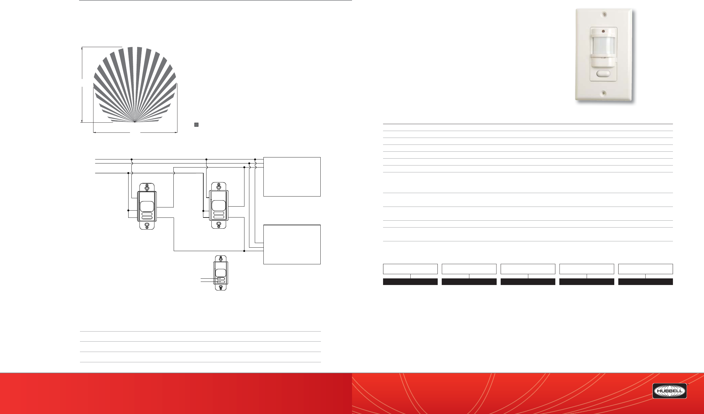
(888) 698-3242 | Fax orders (512) 450-0864 | hubbell-automation.com
h
ubb
ell-
au
t
o
m
a
ti
o
n
.
c
om
PAGE 152 | (888) 698-3242 | Fax orders (512) 450-0864 | hubbell-automation.com
PAGE 153 | OCCUPANCY | VACANCY SENSORS
Hubbell Building Automation
NOTES
RWSOSCFL
Residential Occupancy Sensor
for Incandescent and CFL Lighting
KEY FEATURES
• Title 24 compliant—manual-on/auto-o operation
• Zero Arc Point Switching
• No minimum load requirement
• Adjustable time delay and sensitivity
• Walk test indicator
• 900 square-feet, 180° coverage area
• UL and cUL listed
SPECIFICATIONS
Timer timeout • Fully adjustable: 30 seconds–30 minutes
Sensitivity • Fully adjustable: 20%–100%
Passive infrared (PIR) • Multi-segment infrared (IR) Fresnel lens
Coverage • 900 square-foot, 180° coverage area
Power requirements • 120 VAC; 60 Hz
Electrical ratings • 120 VAC: 800W Incandescent; 1,000W Fluorescent
Load requirements • None
Operating environment • Indoor use only
• Operating temperature: 32°–122°F (0°–50°C)
• Relative humidity (non-condensing): 0%–95%
Construction • Casing—high-impact injection-molded
• Color-coded leads are 6” long
Size and weight • Size: 4.5” x 2.75” x 1.625”
• Weight: 2.9 oz
Color • Ivory; White
Mounting • Single-gang NEMA-style switch box (average switch box)
• Decorator-style wall plate included
Certi cations • UL and cUL listed
ORDERING INFORMATION
RWSOSCFL120
50’
56’
IR Motion
Neutral
Hot
Ground
Lighting
Load A
Black
Red
Green
Note:
1. Sensor is shipped with all dip switches in the
OFF position (Factory Default)
Button 1
Button 2
Lighting
Load B
Violet
Blue
Violet
Red
Violet
Red
Black
Blue
RANGE DIAGRAM
WIRING DIAGRAM
For more wiring diagrams, visit http://www.hubbell-automation.com/resources/wiring_diagrams/
MODEL
RWS
RWS OS CFL 120V
TYPE
OS Occupancy Sensor
CONTROL
CFL Compact Fluorescent &
Incandescent
VOLTAGE
120V
COLOR
WH White
IV Ivory
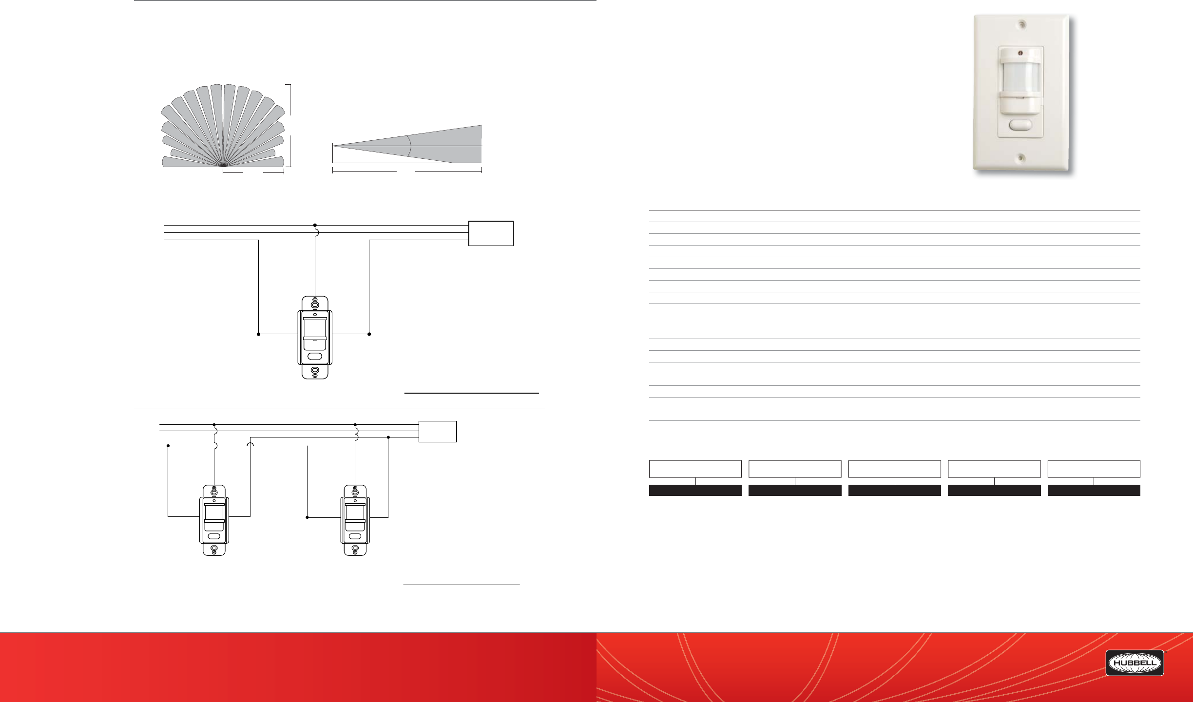
16'
(4.9m)
35'
(10.8m)
floor
15°
15°
4.0'
(
1.2m)
35'
(10.8m)
(888) 698-3242 | Fax orders (512) 450-0864 | hubbell-automation.com
h
ubb
ell-
au
t
o
m
a
ti
o
n
.
c
om
PAGE 154 | (888) 698-3242 | Fax orders (512) 450-0864 | hubbell-automation.com
PAGE 155 | OCCUPANCY | VACANCY SENSORS
Hubbell Building Automation RWSVSCFL
Residential Vacancy Sensor
for Incandescent and CFL Lighting
KEY FEATURES
• Auto-on/auto-o operation
• Zero Arc Point Switching
• No minimum load requirement
• Adjustable time delay and sensitivity
• Built-in photocell for daylight control
• Walk test indicator
• 900 square-foot, 180° coverage area
• UL and cUL listed
• California Title 24 compliant
SPECIFICATIONS
Timer timeout • Fully adjustable: 30 seconds–30 minutes
Sensitivity • Fully adjustable: 20%–100%
Passive infrared (PIR) • Multi-segment infrared (IR) Fresnel lens
Photocell • Natural light override range: 5–200 foot-candles (50–2000 lux)
Coverage • 900 square-foot, 180° coverage area
Power requirements • 120 VAC; 60 Hz
Electrical ratings • 120 VAC: 800W Incandescent; 1,000W Fluorescent
Load requirements • None
Operating environment • Indoor use only
• Operating temperature: 32°–122°F (0°–50°C)
• Relative humidity (non-condensing): 0%–95%
Construction • Casing—high-impact injection-molded plastic
• Color-coded leads are 6” long
Size and weight • Size: 4.5” x 2.75” x 1.625”
• Weight: 2.9 oz
Color • Ivory; White
Mounting • Single-gang NEMA-style switch box (average switch box)
• Decorator-style wall plate included
Certi cations • UL and cUL listed
ORDERING INFORMATION
RWSVSCFL120
Neutral
Hot
Ground Lighting
Load
Black Red
Green
RWSOSCFL
Notes:
1. Lights turn OFF automatically or when
button is pushed.
3. This is a ground-leakage powered sensor.
It must be grounded to function.
4. The Residential Occupancy Sensor is for
Incandescent Lighting and CFL Lighting.
Neutral
Hot
Ground Lighting
Load
Black Black
Red Red
Green Green
RWSOSCFL
RWSOSCFL
Sensors connected in parallel loops
Notes:
1. Lights turn OFF only after BOTH sensors time out.
2. This is a ground-leakage powered sensor. It
must be grounded to function.
3. The Residential Occupancy Sensor is for
Incandescent Lighting and CFL Lighting.
RANGE DIAGRAM
WIRING DIAGRAMS
For more wiring diagrams, visit http://www.hubbell-automation.com/resources/wiring_diagrams/
MODEL
RWS
RWS VS CFL 120V
TYPE
VS Vacancy Sensor
CONTROL
CFL Compact Fluorescent &
Incandescent
VOLTAGE
120V
COLOR
WH White
IV Ivory
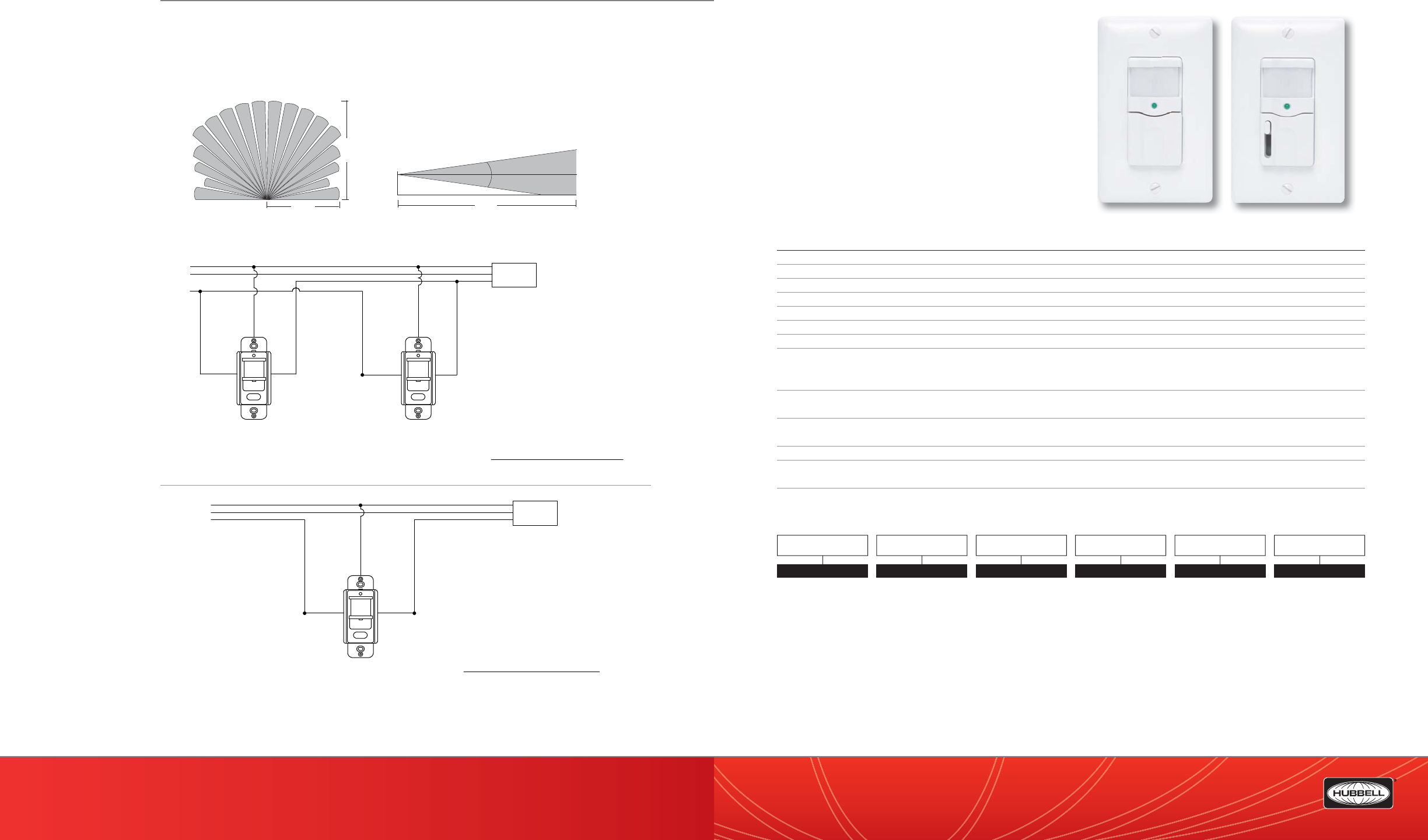
(888) 698-3242 | Fax orders (512) 450-0864 | hubbell-automation.com
h
ubb
ell-
au
t
o
m
a
ti
o
n
.
c
om
PAGE 156 | (888) 698-3242 | Fax orders (512) 450-0864 | hubbell-automation.com
PAGE 157 | OCCUPANCY | VACANCY SENSORS
Hubbell Building Automation RWSOSINC
Residential Occupancy Sensors
for Incandescent Lighting
KEY FEATURES
• Patent Pending Alert-to-OFF noti cation
• Manual dimming control option available
• Zero Arc Point Switching
• Adjustable time delay
• Walk test indicator
• 800 square-foot., 180° coverage area
• UL and cUL listed
• California Title 24 compliant
SPECIFICATIONS
Timer timeout • Fully adjustable: 30 seconds–30 minutes
Passive infrared (PIR) • Multi-segment infrared (IR) Fresnel lens
Photocell • Natural light override range: 5–200 foot-candles (50–2,000 lux)
Coverage • 800 square-foot., 180° coverage area
Power requirements • 120 VA;, 60 Hz
Electrical ratings • 120 VAC: 500W Incandescent only (do not use with uorescent or compact uorescent lamps)
Load requirements • 25W minimum; 500W maximum
Operating environment • Indoor use only
• Operating temperature: 32°–122°F (0°–50°C)
• Relative humidity (non-condensing): 0%–95%
Construction • Casing—high-impact injection-molded plastic
• Color-coded leads are 6” long
Size and weight • Size: 4.5” x 2.75” x 1.625”
• Weight: 2.9 oz
Color • Almond; Ivory; Light Almond; White
Mounting • Single-gang NEMA-style switch box (average switch box)
• Decorator-style wall plate not included
Certi cations • UL and cUL listed
ORDERING INFORMATION
RWSOSINC RWSOSINCD
Neutral
Hot
Ground Lighting
Load
Black Red
Green
RWSVSCFL
Notes:
1. Lights turn ON when manual button is pushed.
2. Lights turn OFF automatically or when
button is pushed.
3. This is a ground-leakage powered sensor.
It must be grounded to function.
4. The Residential Vacancy Sensor is for
Incandescent Lighting and CFL Lighting.
Neutral
Hot
Ground Lighting
Load
Black Black
Red Red
Green Green
RWSVSCFL
RWSVSCFL
Sensors connected in parallel loops
Notes:
1. Lights turn ON when manual button is pushed.
2. Lights turn OFF only after BOTH sensors time out.
3. This is a ground-leakage powered sensor. It
must be grounded to function.
4. The Residential Vacancy Sensor is for
Incandescent Lighting and CFL Lighting.
RANGE DIAGRAM
WIRING DIAGRAM
For more wiring diagrams, visit http://www.hubbell-automation.com/resources/wiring_diagrams/
VOLTAGE
120V
COLOR
WH White
IV Ivory
LA Lt. Almond
AL Almond
TYPE
OS Occupancy Sensor
LIGHTING
INC Incandescent Only
DIMMING
Blank No Dimming
DDimming
MODEL
RWS
120V
RWS OS INC
16'
(4.9m)
35'
(10.8m)
floor
15°
15°
4.0'
(
1.2m)
35'
(10.8m)
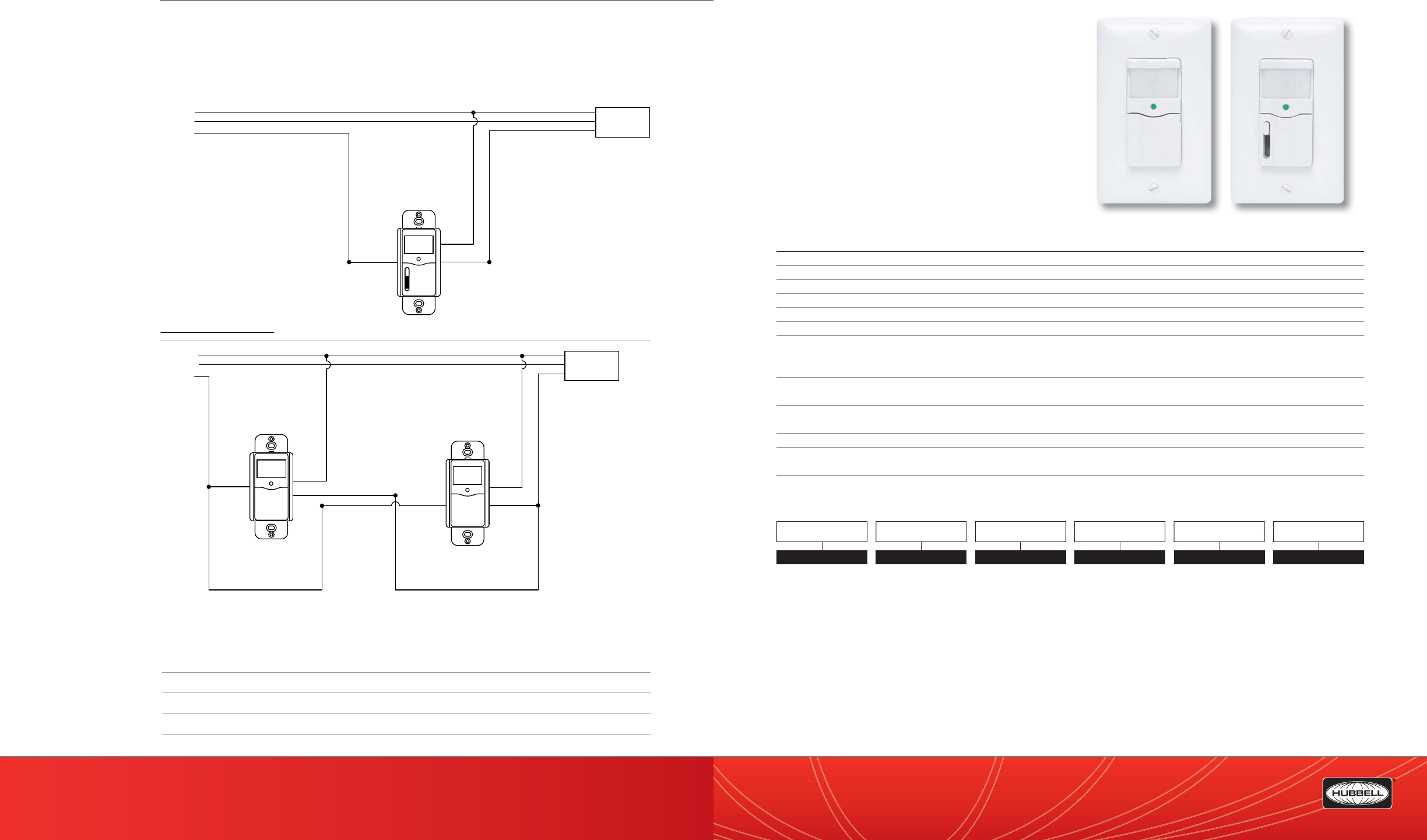
(888) 698-3242 | Fax orders (512) 450-0864 | hubbell-automation.com
h
ubb
ell-
au
t
o
m
a
ti
o
n
.
c
om
PAGE 158 | (888) 698-3242 | Fax orders (512) 450-0864 | hubbell-automation.com
PAGE 159 | OCCUPANCY | VACANCY SENSORS
Hubbell Building Automation
NOTES
RWSVSINC
Residential Vacancy Sensor
for Incandescent Lighting
KEY FEATURES
• Title 24 compliant—manual-on/auto-o operation
• Patent Pending Alert-to-OFF noti cation
• Manual dimming control option available
• Zero Arc Point Switching
• Adjustable time delay
• Walk test indicator
• 800 square-foot, 180° coverage area
• UL and cUL listed
• California Title 24 compliant
SPECIFICATIONS
Timer timeout • Fully adjustable: 30 seconds–30 minutes
Passive infrared (PIR) • Multi-segment infrared (IR) Fresnel lens
Coverage • 800 square-foot, 180° coverage area
Power requirements • 120 VAC; 60 Hz
Electrical ratings • 120 VAC: 500W Incandescent only (Do not use with uorescent or compact uoresent lamps.)
Load requirements • 25W minimum; 500W maximum
Operating environment • Indoor use only
• Operating temperature: 32°–122°F (0°–50°C)
• Relative humidity (non-condensing): 0%–95%
Construction • Casing—high-impact injection-molded plastic
• Color-coded leads are 6” long
Size and weight • Size: 4.5” x 2.75” x 1.625”
• Weight: 2.9 oz
Color • Almond; Ivory; Light Almond; White
Mounting • Single-gang NEMA-style switch box (average switch box)
• Decorator-style wall plate not included
Certi cations • UL and cUL listed
ORDERING INFORMATION
RWSVSINC RWSVSINCD
Neutral
Hot
Ground Lighting
Load
RWSVSINC
Black
Black
Green
Black Black
Green
Sensors connected in parallel loops
RWSVSINC
Neutral
Hot
Ground Lighting
Load
Black Black
Green
RWSOSDINC
Notes:
1. This is a ground-leakage powered sensor.
It must be grounded to function.
2. The Residential Occupancy Sensor is for
Incandescent Lighting only.
Residential
Occupancy Sensor
with Dimmer
for Incandescent
Lighting
WIRING DIAGRAMS
For more wiring diagrams, visit http://www.hubbell-automation.com/resources/wiring_diagrams/
VOLTAGE
120V
COLOR
WH White
IV Ivory
LA Lt. Almond
AL Almond
TYPE
VS Vacancy Sensor
LIGHTING
INC Incandescent Only
DIMMING
Blank No Dimming
DDimming
MODEL
RWS
120V
RWS VS INC

(888) 698-3242 | Fax orders (512) 450-0864 | hubbell-automation.com
h
ubb
ell-
au
t
o
m
a
ti
o
n
.
c
om
PAGE 160 | (888) 698-3242 | Fax orders (512) 450-0864 | hubbell-automation.com
PAGE 161 | OCCUPANCY | VACANCY SENSORS
Hubbell Building Automation IWSZP3P
Automatic Passive Infrared
Wall Switch Sensor
KEY FEATURES
• Zero Arc Point Switching
• No minimum load requirement
• Adjustable time delay and sensitivity
• Built-in photocell
• Walk test indicator
• Dual 120/277 VAC operation
• UL and cUL listed
SPECIFICATIONS
Timer Timeout • Fully adjustable from 30 seconds to 30 minutes
Sensitivity • Fully adjustable from 20% to 100%
Passive Infrared • Multi-segment IR Fresnel lens
Photocell • Adjustable ambient light override ranges from approximately 5 foot-candles (50 lux) to 200 foot-candles
(2000 lux)
Coverage • 900 sq. ft., 180 degrees
Power Requirements • 120 or 277 VAC, 60 Hz
Electrical Ratings • 120 VAC: 800W Incandescent, 1000W Fluoresent, 1/6 HP
• 277 VAC: 1800W Fluoresent, 1/6 HP
Load Requirements • No minimum load
Operating environment • Indoor use only
• Operating temperature: 32 – 122 F (0 to 50 C) 0% to 95% relative humidity, non-condensing
Construction • Housing – high-impact, injection-molded plastic
• Color-coded leads are 6” long
Size & Weight • Size: 4.5” x 2.75” x 1.625”
• Weight: 2.9 oz
Color • White
Mounting • Single gang NEMA style switch box, decorator style wall plate
Certi cations • UL and cUL Listed
ORDERING INFORMATION
IWSZP3P
Neutral
Hot
Ground Lighting
Load
Black Black
Green
RWSVSDINC120
Notes:
1. Sensor is shipped with all dip switches in the
OFF position (Factory default).
2. The Residential Vacancy Sensor is for
Incandescent Lighting only.
Residential Vacancy
Sensor with Dimmer
for Incandescent
Lighting
Neutral
Hot
Ground Lighting
Load
Black Black
Green
RWSVSINC120
Note:
2. The Residential Vacancy Sensor is for
Incandescent Lighting only.
1. Sensor is shipped with all dip switches in the
OFF position (Factory default).
4. The Residential Vacancy Sensor is for
Incandescent Lighting Only.
Neutral
Hot
Ground
RWSVSINC
Black
Black
Green
Black Black
Green
Sensors connected in parallel loops
RWSVSINC
Notes:
1. Lights turn ON when manual button is pushed.
2. Lights turn OFF only after BOTH sensors time out.
3. Sensor is shipped with all dip switches in the
OFF position (Factory default).
Lighting
Load
WIRING DIAGRAMS
For more wiring diagrams, visit http://www.hubbell-automation.com/resources/wiring_diagrams/
COLOR
WWhite
IIvory
MODEL
IWSZP
IWSZP 3P
CONTROL
3P Auto On/Auto O
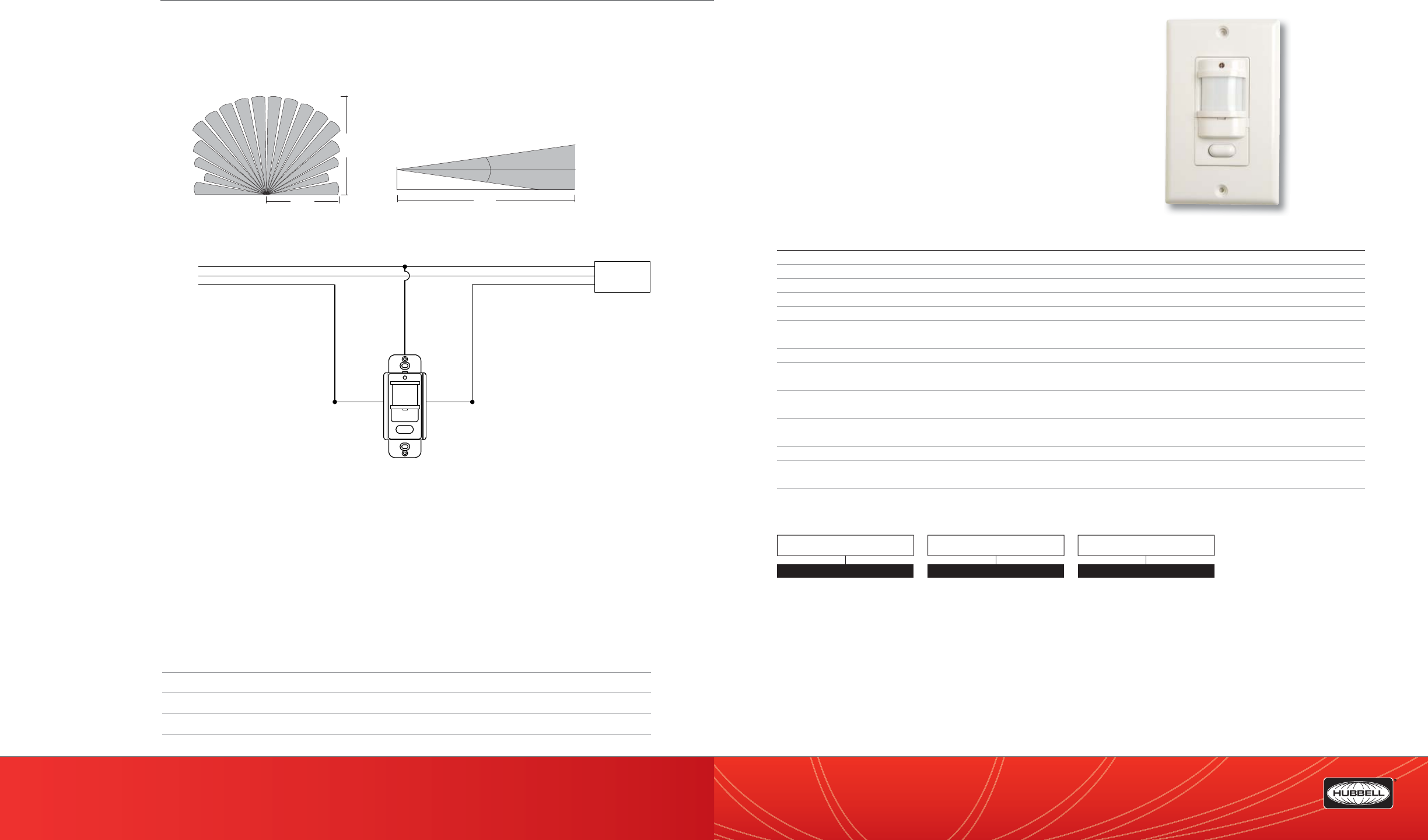
(888) 698-3242 | Fax orders (512) 450-0864 | hubbell-automation.com
h
ubb
ell-
au
t
o
m
a
ti
o
n
.
c
om
PAGE 162 | (888) 698-3242 | Fax orders (512) 450-0864 | hubbell-automation.com
PAGE 163 | OCCUPANCY | VACANCY SENSORS
Hubbell Building Automation
NOTES
IWSZPM
Manual ON|Automatic OFF Passive
Infred Wall Switch Sensor
KEY FEATURES
• Title 24 compliant manual-on/auto-o operation
• Zero Arc Point Switching
• No minimum load requirement
• Adjustable time delay and sensitivity
• Walk test indicator
• Dual 120/277 VAC operation
• UL and cUL listed
• California Title 24 compliant
SPECIFICATIONS
Timer timeout • Fully adjustable: 30 seconds–30 minutes
Sensitivity • Fully adjustable: 20–100%
Passive infrared • Multi-segment infrared (IR) Fresnel lens
Coverage • 900 square feet; 180 degrees
Power requirements • 120 or 277 VAC; 60 Hz
Electrical ratings • 120 VAC: 800W Incandescent; 1000W Fluoresent; 1/6 HP
• 277 VAC: 1800W Fluoresent; 1/6 HP
Load requirements • None
Operating environment • Indoor use only
• Operating temperature: 32–122 F (0–50 C) 0%–95% relative humidity; non-condensing
Construction • Casing—high-impact injection-molded plastic
• Color-coded leads are 6” long
Size & weight • Size: 4.5” x 2.75” x 1.625”
• Weight: 2.9 oz
Color • White
Mounting • Single-gang NEMA-style switch box (average switch box)
• (Decorator-style wall plate not included)
Certi cations • UL and cUL Listed
ORDERING INFORMATION
IWSZPM
Neutral
Hot
Ground Lighting
Load
Black Red
Green
IWSZPM
Notes:
1. Lights turn OFF automatically or when
button is pushed.
2. This is a ground-leakage powered sensor.
It must be grounded to function.
RANGE DIAGRAM
WIRING DIAGRAM
For more wiring diagrams, visit http://www.hubbell-automation.com/resources/wiring_diagrams/
COLOR
WWhite
IIvory
MODEL
IWSZP
IWSZP M
CONTROL
MManual On/Auto O
16'
(4.9m)
35'
(10.8m)
floor
15°
15°
4.0'
(
1.2m)
35'
(10.8m)
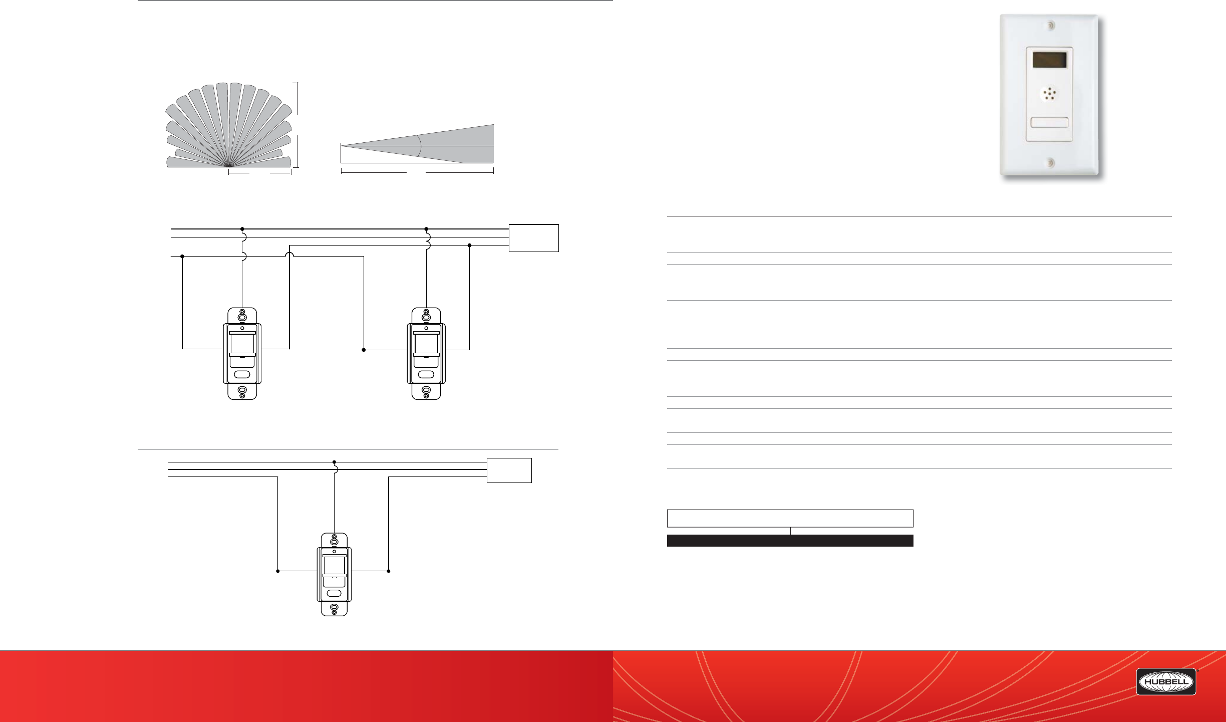
(888) 698-3242 | Fax orders (512) 450-0864 | hubbell-automation.com
h
ubb
ell-
au
t
o
m
a
ti
o
n
.
c
om
PAGE 164 | (888) 698-3242 | Fax orders (512) 450-0864 | hubbell-automation.com
PAGE 165 | OCCUPANCY | VACANCY SENSORS
Hubbell Building Automation TD200
Digital Programmable Time
KEY FEATURES
• Supports multiple timer intervals
• Dip switch control of features
• Manual scroll-up for overrides
• Visual and audio turno warning
• Zero Arc Point Switching
• UL and cUL listed
SPECIFICATIONS
Timer timeout • A turno timer can be programmed for the following times:
- 5, 15, or 30 minutes
- 1, 3, 6, 9, or 12 hours
Power requirements • 120 or 277 VAC; 60 Hz
Electrical ratings • 120 VAC:
- 800W Tungsten
- 800W Fluorescent
- 1/6 HP Motor
- 240VA Pilot Duty
• 277 VAC:
- 1200W Fluorescent
Load requirements • None
Operating environment • Indoor use only
• Operating temperature: 32°–122°F (0°–50°C)
• Relative humidity (non-condensing): 0%–95%
Construction • Casing—high-impact injection-molded plastic
Size and weight • Size: 3.28” x 1.72” x 1.42”
• Weight: 2.9 oz
Color • White
Mounting • Single-gang NEMA-style switch box (average switch box)
• Decorator-style wall plate not included
Certi cations • UL and cUL listed
ORDERING INFORMATION
TD200
Neutral
Hot
Ground Lighting
Load
Black Red
Green
IWSZPM
Notes:
1. Lights turn OFF automatically or when
button is pushed.
2. This is a ground-leakage powered sensor.
It must be grounded to function.
Neutral
Hot
Ground Lighting
Load
Black Black
Red Red
Green Green
IWSZPM
IWSZPM
Sensors connected in parallel loops
RANGE DIAGRAM
WIRING DIAGRAM
For more wiring diagrams, visit http://www.hubbell-automation.com/resources/wiring_diagrams/
MODEL
TD200 Digital Programmable Timer
16'
(4.9m)
35'
(10.8m)
floor
15°
15°
4.0'
(
1.2m)
35'
(10.8m)
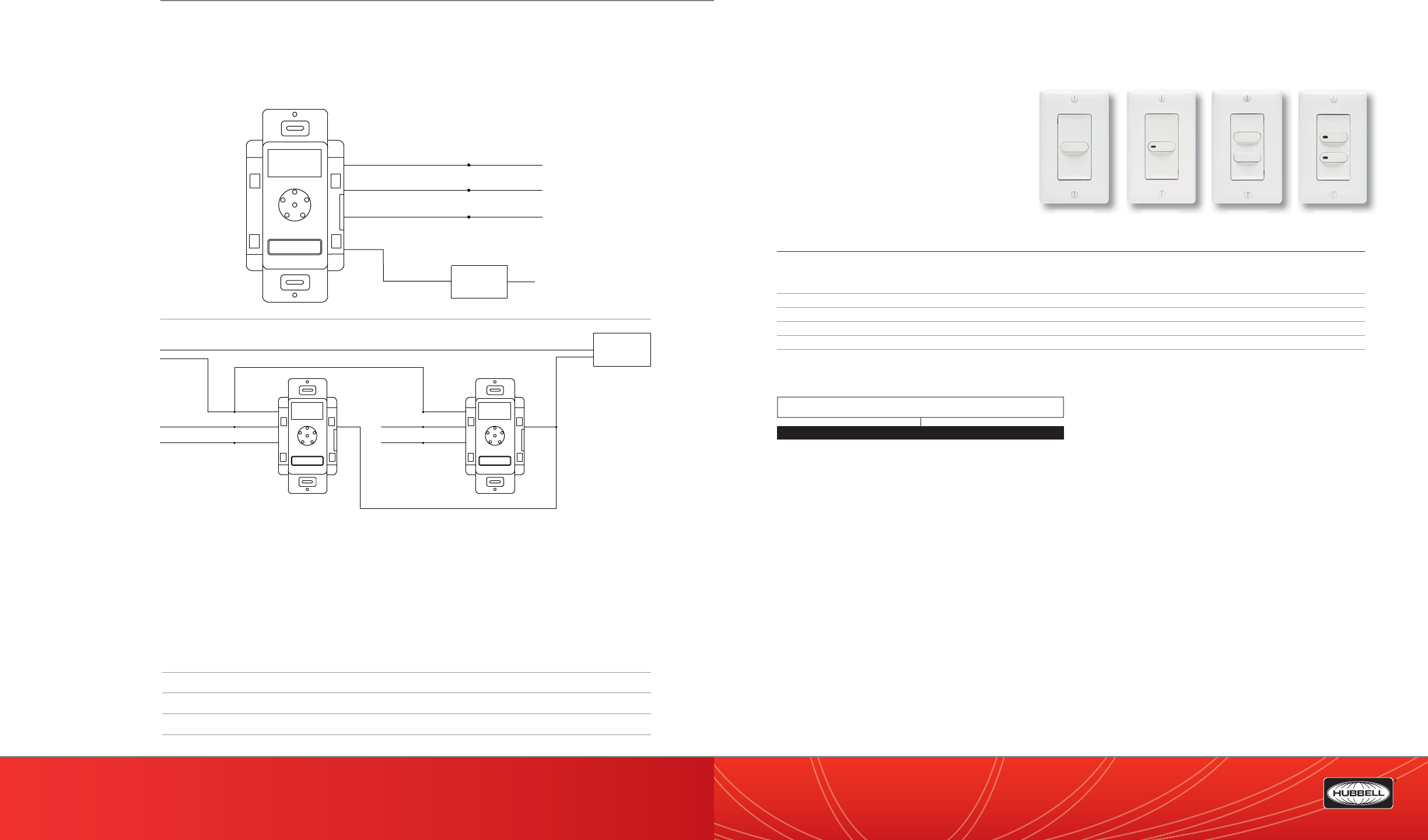
(888) 698-3242 | Fax orders (512) 450-0864 | hubbell-automation.com
h
ubb
ell-
au
t
o
m
a
ti
o
n
.
c
om
PAGE 166 | (888) 698-3242 | Fax orders (512) 450-0864 | hubbell-automation.com
PAGE 167 | OCCUPANCY | VACANCY SENSORS
Hubbell Building Automation
NOTES
LVS
LV Series—Low Voltage Switches
KEY FEATURES
• Attractive, architecturally pleasing design
• Momentary and latching versions available
• 1-4 buttons with or without LED
• Mounts to standard single-gang box
• California Title 24 compliant
FOR USE WITH
• HBA Low Voltage Occupancy Sensors
• LX Networked Lighting Controls
• HBA Daylighting Controls
SPECIFICATIONS
Each Kit Includes: • 2 ea - Wire Way Divider Plates
• 2 ea – Stainless Steel mounting Screws
• Installation Instructions
Operating environment • Indoor use only
Size & Weight • Size: 4.25” W x 3.25” L
• Weight: 3.0 oz
Color • ANSI 61 Gray Polyester Powder Coat
Certi cations • For use with LX Series UL and cUL Listed LXIN and LXEN network lighting control panels
ORDERING INFORMATION
LVSM1NP LVSM1PL LVSM2NP LVSM2PL
LV
LV
SM
SM
1N
1N
P
P
LV
LV
SM
SM
2N
2N
P
P
LV
LV
SM
SM
2P
2P
L
L
LV
LV
SM
SM
1P
1P
L
L
Lighting
Load A
Black
Green
Red Neutral
Hot
120V Ground
Green/Yellow 277V Ground
Lighting
Load A
Black
Green
Hot
120V Ground
Green/Yellow
277V Ground
Red
Hot
Neutral
Green120V Ground
Green/Yellow277V Ground
Black
Hot
Red
Note:
1. Sensor is shipped with all dip switches in the
OFF position (Factory Default)
WIRING DIAGRAMS
For more wiring diagrams, visit http://www.hubbell-automation.com/resources/wiring_diagrams/
MODEL
LVSM1NPIV Low Voltage Switch, Momentary, 1 Button, No Pilot, Ivory
LVSM1NPWH Low Voltage Switch, Momentary, 1 Button, No Pilot, White
LVSM1PLIV Low Voltage Switch, Momentary, 1 Button, w/Pilot LED, Ivory
LVSM1PLWH Low Voltage Switch, Momentary, 1 Button, w/Pilot LED, White
LVSM2NPIV Low Voltage Switch, Momentary, 2 Button, No Pilot, Ivory
LVSM2NPWH Low Voltage Switch, Momentary, 2 Button, No Pilot, White
LVSM2PLIV Low Voltage Switch, Momentary, 2 Button, w/Pilot LED’s, Ivory
LVSM2PLWH Low Voltage Switch, Momentary, 2 Button, w/Pilot LED’s, White
LVSL1NPIV Low Voltage Switch, Latching, 1 Button, No Pilot, Ivory
LVSL1NPWH Low Voltage Switch, Latching, 1 Button, No Pilot, White
LVSL1PLIV Low Voltage Switch, Latching, 1 Button, w/Pilot LED, Ivory
LVSL1PLWH Low Voltage Switch, Latching, 1 Button, w/Pilot LED, White
LVSL2NPIV Low Voltage Switch, Latching, 2 Button, No Pilot, Ivory
LVSL2NPWH Low Voltage Switch, Latching, 2 Button, No Pilot, White
LVSL2PLIV Low Voltage Switch, Latching, 2 Button, w/Pilot LED’s, Ivory
LVSL2PLWH Low Voltage Switch, Latching, 2 Button, w/Pilot LED’s, White
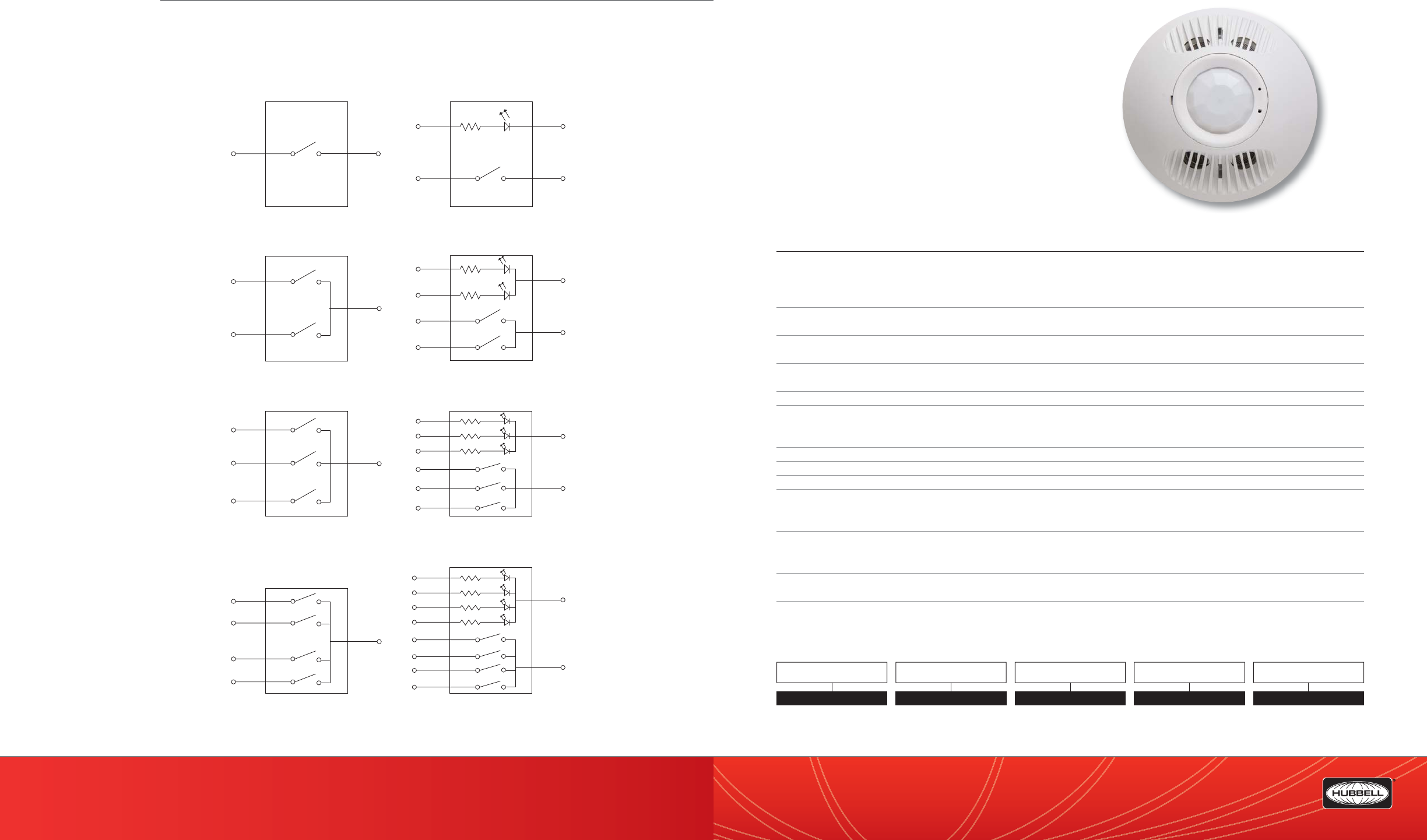
(888) 698-3242 | Fax orders (512) 450-0864 | hubbell-automation.com
h
ubb
ell-
au
t
o
m
a
ti
o
n
.
c
om
PAGE 168 | (888) 698-3242 | Fax orders (512) 450-0864 | hubbell-automation.com
PAGE 169 | OCCUPANCY | VACANCY SENSORS
Hubbell Building Automation OMNIDT | OMNIDTRP
OMNI™ Dual Technology Ultrasonic
and Passive Infrared Ceiling Sensor
featuring IntelliDAPT®
KEY FEATURES
• IntelliDAPT self-adaptive technology—no manual adjustment
required
• All-digital dual technology
(ultrasonic [US] and passive infrared [PIR]) sensor
• Non-volatile memory for sensor settings
• 500–2,000 square-foot coverage area (depending on model)
• UL and cUL listed
SPECIFICATIONS
IntelliDAPT • Auto reset from test setting
• Self-adjusting timer
• Self-adjusting ultrasonic and passive infrared thresholds
• Automatic false-on/false-o corrections
LED lamp • Red—infrared motion
• Green—ultrasonic motion
Timer timeout • Automatic mode: 8–30 min. (self-adjusts based on occupancy)
• Test mode: 8 seconds (for an easy check at installation)
Ultrasonic (US) output • OMNIDT500: 40kHz output
• OMNIDT1000 and OMNIDT2000: 32kHz
Passive infrared (PIR) • Dual-element pyrometer and 12-element cylindrical rugged lens
RP option • Relay and photocell included
• Relay: N/O + N/C contacts; SPDT; 500 mA rated @ 24VDC; three-wire isolated relay
• Photocell: adjustable natural-light override ranges from 0 to 100 foot-candles (0–1,000 lux)
Coverage • 500–2,000 square feet (depending on model)
Power requirements • 24 VDC, 33 mA (uses UVPP and MP-Series power pack—not included)
Output • 24 VDC active high-logic control signal with short circuit protection and optional dry contact (see: RP Option)
Operating environment • Indoor use only
• Operating temperature: 32°–104°F (0°–40°C)
• Relative humidity (non-condensing): 0%–95%
Construction • Casing—rugged, high-impact, injection-molded plastic KJB ABS Cycolac (UL-945VA) ame class rating,
UV inhibitors
• Color-coded leads are 6” long
Size and weight • Size: 4.5” diameter, 1.5” height (114 mm diameter, 38mm height)
• Weight: 5.0 oz (142g)
Mounting • Mounting base provided
• Recommended MAX Mounting height: 12ft.
ORDERING INFORMATION
OMNIDT2000
Blue Black
SW1
Blue
Black
SW1
SW2
Blue/White
Blue Black
Pilot 1
SW1
Blue/White Black/White
Grey
Blue
Black
Pilot 1
Pilot 2
SW1
SW2
Yellow/White
Blue/White
Black/White
Wiring Diagram A - LVS 1-Button Latching
or Momentary Switch, No Pilot
Wiring Diagram C - LVS 2-Button Latching
or Momentary Switch, No Pilot
Red
Black
SW1
SW3
Blue/White
Grey SW2
Wiring Diagram E - LVS 3-Button Latching
or Momentary Switch, No Pilot
Wiring Diagram B - LVS 1-Button Latching
or Momentary Switch, with Pilot LED*
Wiring Diagram D - LVS 2-Button Latching
or Momentary Switch, with Pilot LEDs*
Red
Blue
Black
Pilot 1
Pilot 3
SW1
SW3
Red/White
Blue/White
Black/White
Grey SW2
Wiring Diagram F - LVS 3-Button Latching
or Momentary Switch, with Pilot LEDs*
Pilot 2
Grey/White
Orange
Black
SW1
SW4
Blue
Grey SW2
Red SW3
Wiring Diagram G - LVS 4-Button Latching
or Momentary Switch, No Pilot
Orange
Blue
Black
Pilot 1
Pilot 4
SW1
SW4
Yellow/White
Blue/White
Black/White
Red SW3
Wiring Diagram H - LVS 4-Button Latching
or Momentary Switch, with Pilot LEDs*
Pilot 2
Grey/White
Pilot 3
Red/White
Grey SW2
*Note Pilot Polarity Marks
WIRING DIAGRAMS
For more wiring diagrams, visit http://www.hubbell-automation.com/resources/wiring_diagrams/
MODEL
OMNI
OMNI DT
TECHNOLOGY
DT Dual Technology
COVERAGE
500 500 sq. ft.
1000 1,000 sq. ft.
2000 2,000 sq. ft.
RELAY / PHOTOCELL OPTION
RP Relay & Photocell
Blank No Option
QTI
QTI Quick to Install
Blank No QTI
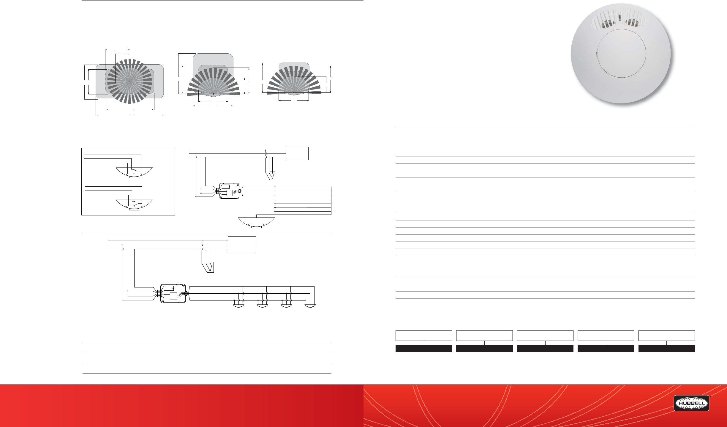
(888) 698-3242 | Fax orders (512) 450-0864 | hubbell-automation.com
h
ubb
ell-
au
t
o
m
a
ti
o
n
.
c
om
PAGE 170 | (888) 698-3242 | Fax orders (512) 450-0864 | hubbell-automation.com
PAGE 171 | OCCUPANCY | VACANCY SENSORS
Hubbell Building Automation
NOTES
RANGE DIAGRAMS
WIRING DIAGRAMS
For more wiring diagrams, visit http://www.hubbell-automation.com/resources/wiring_diagrams/
OMNIUS | OMNIUSRP
OMNI™ Ultrasonic Ceiling Sensor
featuring IntelliDAPT®
KEY FEATURES
• IntelliDAPT self-adaptive technology—no manual adjustment
required
• All-digital ultrasonic (US) technology
• Non-volatile memory for sensor settings
• 500–2,000 square-foot coverage area (depending on model)
• California Title 24 compliant
• UL and cUL listed
SPECIFICATIONS
IntelliDAPT • Auto reset from test setting
• Self-adjusting timer
• Self-adjusting ultrasonic thresholds
• Automatic false-on/false-o corrections
LED lamp • Green—ultrasonic motion
Timer timeout • Automatic mode: 8–30 min. (self-adjusts based on occupancy)
• Test mode: 8 seconds (for an easy check at installation)
Ultrasonic (US) output • OMNIUS500: 40kHz output
• OMNIUS1000 and OMNIUS2000: 32kHz output
RP option • Relay and photocell included
• Relay: N/O + N/C contacts; SPDT; 500 mA rated @ 24VDC; three-wire isolated relay
• Photocell: adjustable natural-light override ranges from 0 to 100 foot-candles (0–1,000 lux)
Coverage • 500–2,000 square feet (depending on model)
Power requirements • 24 VDC, 33 mA (uses UVPP and MP-Series power pack—not included)
Output • 24 VDC active high-logic control signal with short circuit protection and optional dry contact (see: RP Option)
Operating environment • Indoor use only
• Operating temperature: 32°–104°F (0°–40°C)
• Relative humidity (non-condensing): 0%–95%
Construction • Casing—rugged, high-impact, injection-molded plastic KJB ABS Cycolac (UL-945VA) ame class rating,
UV inhibitors
• Color-coded leads are 6” long
Size and weight • Size: 4.5” diameter, 1.5” height (114 mm diameter, 38mm height)
• Weight: 5.0 oz (142g)
Color • O -white
Mounting • Mounting base provided
• Recommended MAX mounting height: 12ft.
ORDERING INFORMATION
OMNIUS500
DT2000 DT1000 DT500
3
2' 23'
64'
45'
12'
22'
12'
23
'
2
2
23'
12'
32'
23'
22'
23'
32'
Lighting
Load
Red
Black
Blue
Power Pack
contacts rated
for 20 Amps.
Neutral
Hot
Ground
Red (+24VDC)
Black (common)
Blue (control)
Red
Red
Black
White
UVPP Power Pack
Supplies 150mA
Hubbell Building Automation
Low Voltage Sensors (devices)
Requires 33mA each
Override
Switch
(optional)
NOTE:
1.DO NOT attempt to power more than 4 devices (sensors
or slave packs) from a single power pack.
Hubbell Building
Automation Omni or
LightOWL sensors with
-RP option
Neutral
Hot
Red (+24VDC)
Blue (control)
Blue/White (Relay Common)
Yellow/White (Relay Normally Open)
Lighting
Load
Ground
Red (+24VDC)
Black (common)
Black (common)
Blue (control)
Red
Red
Black
White
Blue/White (Relay Common)
Yellow/White (Relay Normally Open)
-Sensor not
powered
-No occupancy
Blue/White (Relay Common)
Black/White (Relay Normally Closed)
Yellow/White (Relay Normally Open)
-Occupancy
detected
RP option
Relay detail
Override
Switch
(optional)
Power Pack
contacts rated
for 20 Amps.
UVPP Power Pack
Supplies 150mA
Black/White (Relay Normally Closed)
Grey (control + photocell)
Black/White (Relay Normally Closed)
MODEL
OMNI
OMNI US
TECHNOLOGY
US Ultrasonic
COVERAGE
500 500 sq. ft.
1000 1,000 sq. ft.
2000 2,000 sq. ft.
RELAY / PHOTOCELL OPTION
RP Relay & Photocell
Blank No Option
QTI
QTI Quick to Install
Blank No QTI
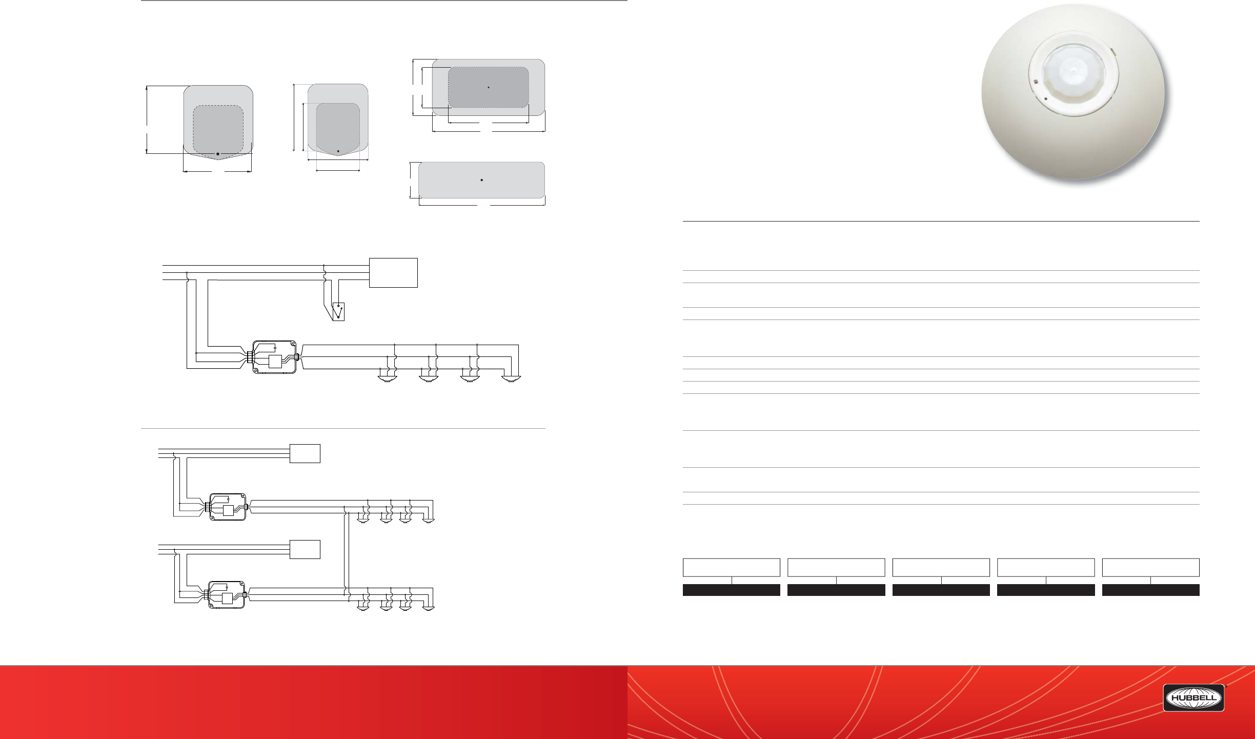
(888) 698-3242 | Fax orders (512) 450-0864 | hubbell-automation.com
h
ubb
ell-
au
t
o
m
a
ti
o
n
.
c
om
PAGE 172 | (888) 698-3242 | Fax orders (512) 450-0864 | hubbell-automation.com
PAGE 173 | OCCUPANCY | VACANCY SENSORS
Hubbell Building Automation
RANGE DIAGRAMS
WIRING DIAGRAMS
For more wiring diagrams, visit http://www.hubbell-automation.com/resources/wiring_diagrams/
OMNIIR | OMNIIRPR
OMNI™ Passive Infrared Ceiling Sensor
featuring IntelliDAPT®
KEY FEATURES
• IntelliDAPT self-adaptive technology—no manual adjustment
required
• All-digital passive infrared (PIR) sensor
• Non-volatile memory for sensor settings
• 450–1,500 square-foot coverage area (depending on model)
• UL and cUL listed
SPECIFICATIONS
IntelliDAPT • Auto reset from test setting
• Self-adjusting timer
• Self-adjusting passive infrared thresholds
• Automatic false-on/false-o corrections
LED lamp • Red—infrared motion
Timer timeout • Automatic mode: 8–30 min. (self-adjusts based on occupancy)
• Test mode: 8 seconds (for an easy check at installation)
Passive infrared (PIR) • Dual-element pyrometer and 12-element cylindrical rugged lens
RP option • Relay and photocell included
• Relay: N/O + N/C contacts; SPDT; 500 mA rated @ 24VDC; three-wire isolated relay
• Photocell: adjustable natural-light override ranges from 0 to 100 foot-candles (0–1,000 lux)
Coverage • 450–1,500 square feet (depending on model)
Power requirements • 24 VDC, 33 mA (uses UVPP and MP-Series power pack—not included)
Output • 24 VDC active high-logic control signal with short circuit protection and optional dry contact (see: RP Option)
Operating environment • Indoor use only
• Operating temperature: 32°–104°F (0°–40°C)
• Relative humidity (non-condensing): 0%–95%
Construction • Casing—rugged, high-impact, injection-molded plastic KJB ABS Cycolac (UL-945VA) ame class rating,
UV inhibitors
• Color-coded leads are 6” long
Size and weight • Size: 4.5” diameter, 1.5” height (114 mm diameter, 38mm height)
• Weight: 5.0 oz (142g)
Color • O -white
Mounting • Mounting base provided
• Recommended MAX mounting height: 12ft.
ORDERING INFORMATION
OMNIIR
OMNIUS2000
OMNIUS2000 - Hallway
OMNIUS500
64'
45'
23'
32'
23
'
23'
56'
16'
23'
23'
32'
32'
OMNIUS1000
Lighting
Load
Red
Black
Blue
Power Pack
contacts rated
for 20 Amps.
Neutral
Hot
Ground
Red (+24VDC)
Black (common)
Blue (control)
Red
Red
Black
White
UVPP Power Pack
Supplies 150mA
Hubbell Building Automation
Low Voltage Sensors (devices)
Requires 33mA each
Override
Switch
(optional)
NOTE:
1.DO NOT attempt to power more than 4 devices (sensors
or slave packs) from a single power pack.
Lighting
Circuit 1
Lighting
Circuit 2
Red (+24VDC)
Black (common)
Blue (control)
Ground
Neutral
Hot
Neutral
Hot
Ground
Red
Red
Black
White
Red
Red Black (common)
Blue (control)
Hubbell Building Automation
Low Voltage Sensors(devices)
Requires 33mA each
Power Pack
contacts rated
for 20 Amps.
UVPP Power Pack
Supplies 150mA
NOTES:
1. Lighting load turns on when at least
one sensor detects motion.
2. DO NOT attempt to power more than
4 devices (sensors or slave packs)
from a single power pack.
3. No more than 4 power packs should
be connected in this way.
Red (+24VDC)
DO NOT connect the
Red Low Voltage wires
together between
power packs.
Black
White
Power Pack
contacts rated
for 20 Amps.
UVPP Power Pack
Supplies 150mA
MODEL
OMNI
OMNI IR
TECHNOLOGY
IR Passive Infrared
COVERAGE
LLong Range IR,
1,500 sq. ft.
Blank 450 sq. ft.
RELAY / PHOTOCELL OPTION
RP Relay & Photocell
Blank No Option
QTI
QTI Quick to Install
Blank No QTI
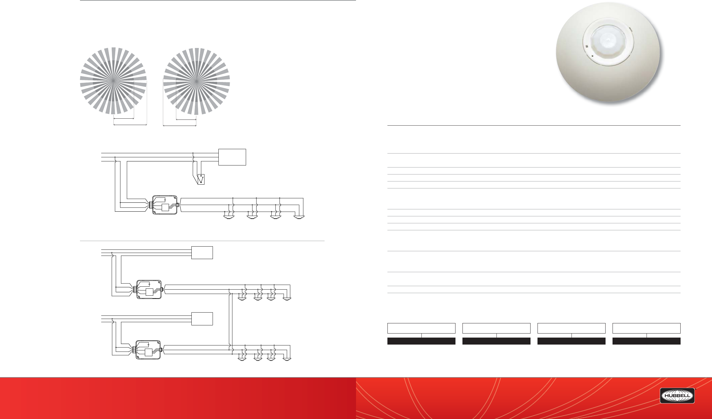
(888) 698-3242 | Fax orders (512) 450-0864 | hubbell-automation.com
h
ubb
ell-
au
t
o
m
a
ti
o
n
.
c
om
PAGE 174 | (888) 698-3242 | Fax orders (512) 450-0864 | hubbell-automation.com
PAGE 175 | OCCUPANCY | VACANCY SENSORS
Hubbell Building Automation OMNIDIA | OMNIDIAPR
OMNI™ Dual Technology Acoustic
and Passive Infrared Ceiling Sensor
featuring IntelliDAPT®
KEY FEATURES
• IntelliDAPT self-adaptive technology—no manual adjustment
required
• All-digital dual technology
(acoustic and passive infrared [PIR]) sensor
• 450 square-foot coverage
• California Title 24 compliant
• UL and cUL listed
SPECIFICATIONS
IntelliDAPT • Auto reset from test setting
• Self-adjusting timer
• Self-adjusting passive infrared and acoustic thresholds
• Automatic false-on/false-o corrections
LED lamp • Red—infrared motion
• Green—acoustic detection
Timer timeout • Automatic mode: 8–30 min. (self-adjusts based on occupancy)
• Test mode: 8 seconds (for an easy check at installation)
Passive infrared (PIR) • Dual-element pyrometer and 12-element cylindrical rugged lens
RP option • Relay and photocell included
• Relay: N/O + N/C contacts; SPDT; 500 mA rated @ 24VDC; three-wire isolated relay
• Photocell: adjustable natural-light override ranges from 0 to 100 foot-candles (0–1,000 lux)
Coverage • 450 square feet
Power requirements • 24 VDC, 33 mA (uses UVPP and MP-Series power pack—not included)
Output • 24 VDC active high-logic control signal with short circuit protection and optional dry contact (see: RP Option)
Operating environment • Indoor use only
• Operating temperature: 32°–104°F (0°–40°C)
• Relative humidity (non-condensing): 0%–95%
Construction • Casing—rugged, high-impact, injection-molded plastic KJB ABS Cycolac (UL-945VA) ame class rating,
UV inhibitors
• Color-coded leads are 6” long
Size and weight • Size: 4.5” diameter, 1.5” height (114 mm diameter, 38mm height)
• Weight: 5.0 oz (142g)
Color • O -white
Mounting • Mounting base provided
• Recommended MAX mounting height: 12ft.
ORDERING INFORMATION
OMNIDIA
12'
6' 12'
22'
Lighting
Load
Red
Black
Blue
Power Pack
contacts rated
for 20 Amps.
Neutral
Hot
Ground
Red (+24VDC)
Black (common)
Blue (control)
Red
Red
Black
White
UVPP Power Pack
Supplies 150mA
Hubbell Building Automation
Low Voltage Sensors (devices)
Requires 33mA each
Override
Switch
(optional)
NOTE:
1.DO NOT attempt to power more than 4 devices (sensors
or slave packs) from a single power pack.
Lighting
Circuit 1
Lighting
Circuit 2
Red (+24VDC)
Black (common)
Blue (control)
Ground
Neutral
Hot
Neutral
Hot
Ground
Red
Red
Black
White
Red
Red Black (common)
Blue (control)
Hubbell Building Automation
Low Voltage Sensors(devices)
Requires 33mA each
Power Pack
contacts rated
for 20 Amps.
UVPP Power Pack
Supplies 150mA
Red (+24VDC)
DO NOT connect the
Red Low Voltage wires
together between
power packs.
Black
White
Power Pack
contacts rated
for 20 Amps.
UVPP Power Pack
Supplies 150mA
RANGE DIAGRAMS
WIRING DIAGRAMS
For more wiring diagrams, visit http://www.hubbell-automation.com/resources/wiring_diagrams/
OMNI DIA
QTI
QTI Quick to Install
Blank No QTI
MODEL
OMNI
TECHNOLOGY
DIA Dual Technology Acoustic &
Passive Infrared
RELAY/PHOTOCELL OPTION
RP Relay & Photocell
Blank No Option
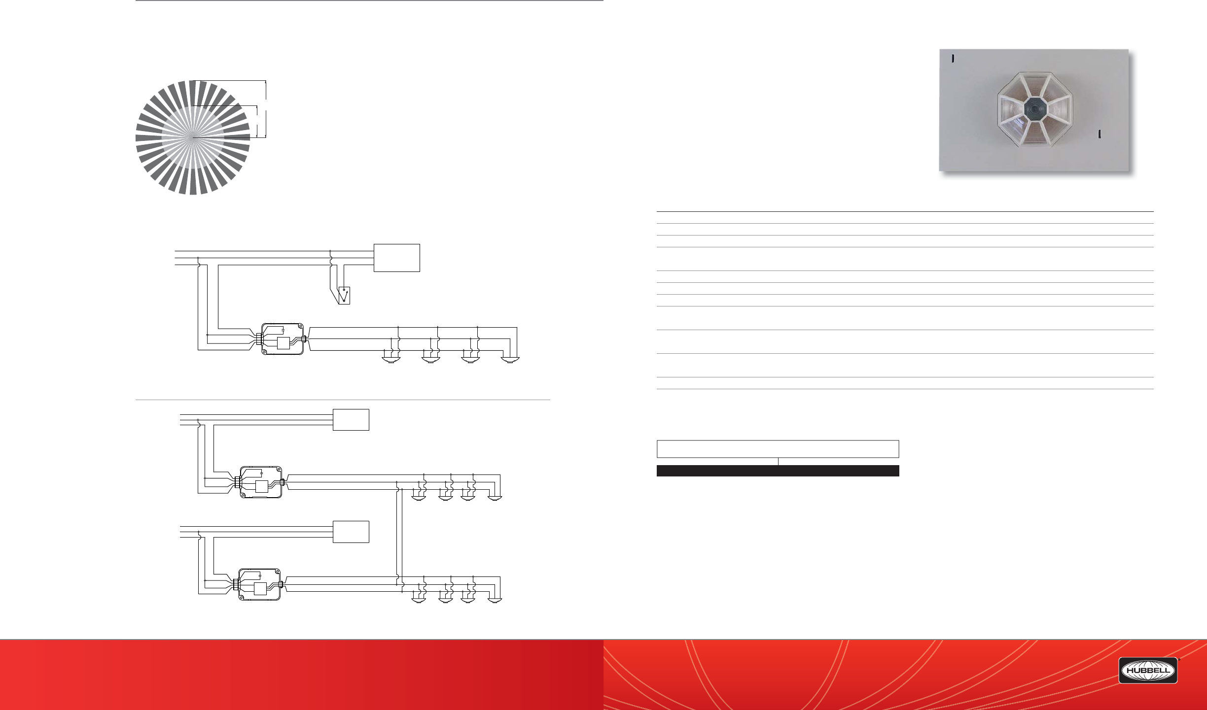
(888) 698-3242 | Fax orders (512) 450-0864 | hubbell-automation.com
h
ubb
ell-
au
t
o
m
a
ti
o
n
.
c
om
PAGE 176 | (888) 698-3242 | Fax orders (512) 450-0864 | hubbell-automation.com
PAGE 177 | OCCUPANCY | VACANCY SENSORS
Hubbell Building Automation
RANGE DIAGRAM
WIRING DIAGRAMS
For more wiring diagrams, visit http://www.hubbell-automation.com/resources/wiring_diagrams/
PIR1000H
Passive Infrared Ceiling Sensor
for Hallway Applications
KEY FEATURES
• 16’ x 80’ linear feet of coverage
• LED walk test indicator
• 30 second – 30 minute time delay
• UL and cUL listed
• California Title 24 compliant
SPECIFICATIONS
Sensitivity • Fully adjustable: 0% - 100%
Timer Timeout • Fully adjustable: 30 sec. to 30 min.
Passive Infrared • Multi-segmented, high-density Fresnel™ IR lens
LED Lamp • Walk test indicator
• Red – Infrared motion
Coverage • 16’ x 80’ linear feet
Power Requirements • 24VDC (uses UVPP power pack – not included)
Output • 24 VDC active high logic control signal
Operating environment • Indoor use only
• Operating temperature: 0°F – 100°F (-18°C – 38°C)
Construction • Housing – Rugged, high impact, injection molded plastic
• Color-coded leads
Size & Weight • Size: 4.72” L x 2.76” W x “1.10” D (119.8mm L x 70.0mm W x 27.9mm D)
• Weight: 3.0 oz
Color • White
Mounting • Sensors may be mounted using a single gang mud ring attached to a 4-inch square electrical box
• Recommended MAX mounting height: 10 Ft.
ORDERING INFORMATION
PIR1000H
12'
22'
Lighting
Load
Red
Black
Blue
Power Pack
contacts rated
for 20 Amps.
Neutral
Hot
Ground
Red (+24VDC)
Black (common)
Blue (control)
Red
Red
Black
White
UVPP Power Pack
Supplies 150mA
Hubbell Building Automation
Low Voltage Sensors (devices)
Requires 33mA each
Override
Switch
(optional)
NOTE:
1.DO NOT attempt to power more than 4 devices (sensors
or slave packs) from a single power pack.
Lighting
Circuit 1
Lighting
Circuit 2
Red (+24VDC)
Black (common)
Blue (control)
Ground
Neutral
Hot
Neutral
Hot
Ground
Red
Red
Black
White
Red
Red Black (common)
Blue (control)
Hubbell Building Automation
Low Voltage Sensors(devices)
Requires 33mA each
Power Pack
contacts rated
for 20 Amps.
UVPP Power Pack
Supplies 150mA
Red (+24VDC)
DO NOT connect the
Red Low Voltage wires
together between
power packs.
Black
White
Power Pack
contacts rated
for 20 Amps.
UVPP Power Pack
Supplies 150mA
MODEL
PIR1000H Passive Infrared Ceiling Sensor for Hallway Applications, White
16’ x 80’ Linear ft.
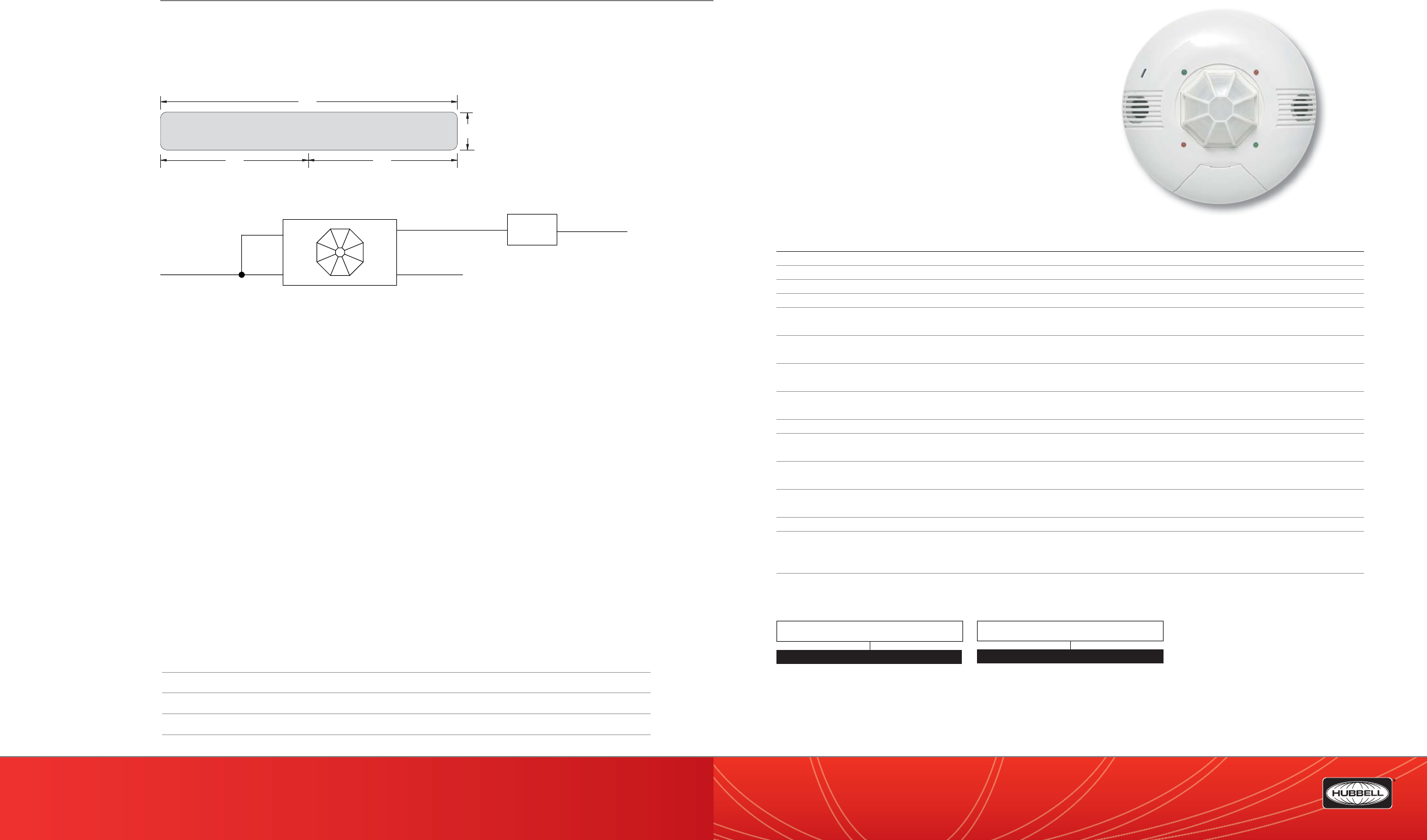
(888) 698-3242 | Fax orders (512) 450-0864 | hubbell-automation.com
h
ubb
ell-
au
t
o
m
a
ti
o
n
.
c
om
PAGE 178 | (888) 698-3242 | Fax orders (512) 450-0864 | hubbell-automation.com
PAGE 179 | OCCUPANCY | VACANCY SENSORS
Hubbell Building Automation
NOTES
CUI5002000P
Dual Technology and Passive Infrared
Line Voltage Ceiling Mount Sensor
KEY FEATURES
• Self-contained power supply
• 2000 sq. ft. coverage
• 5 Programming options
• Adjustable time delay
• Adjustable sensitivity
• California Title 24 compliant
SPECIFICATIONS
Sensitivity • Fully adjustable: 0% - 100%
Timer Timeout • Fully adjustable: 30 sec. to 30 min.
Ultrasonic output • Operating frequency: 32.7kHz
Passive Infrared • Multi-segmented, high-density Fresnel™ IR lens
LED Lamp • Walk test indicator
• Red – Infrared motion, Green – Ultrasonic motion
Coverage • 360°
• Up to 2000 sq. ft.
Power Requirements • CUI5002000P120 – 120 VAC, 50/60 Hz
• CUI5002000P277 – 277 VAC, 50/60 Hz
Electrical Ratings • CUI5002000P120 – 2400 watts @ 120 VAC 50/60 Hz
• CUI5002000P277 – 5000 watts @ 277 VAC 50/60 Hz
Output • 24 VDC active high logic control signal
Operating environment • Indoor use only
• Operating temperature: 32° – 122°F (0° to 50°C)
Construction • Housing – Rugged, high-impact, injection-molded plastic
• Color-coded leads
Size & Weight • Size: 4.87” dia., 2.44” deep (123.7 mm dia., 62mm deep)
• Weight: 3.0 oz
Color • White
Mounting • Sensors may be mounted using a single gang mud ring
attached to a 4-inch square electrical box
• Recommended MAX mounting height: 9 Ft.
Certi cations • UL and cUL Listed
ORDERING INFORMATION
CUI5002000P
80'
16'
40' 40'
Lighting
Load
Black
Red
Neutral
Line
White
Neutral
Note:
This diagram is for any line voltage sensor.
PIR1000H
Red
RANGE DIAGRAM
WIRING DIAGRAM
For more wiring diagrams, visit http://www.hubbell-automation.com/resources/wiring_diagrams/
VOLTAGE
120 120V
277 277V
MODEL
CUI5002000P Dual Technology Ultrasonic &
Passive Infrared Line Voltage
Ceiling Sensor
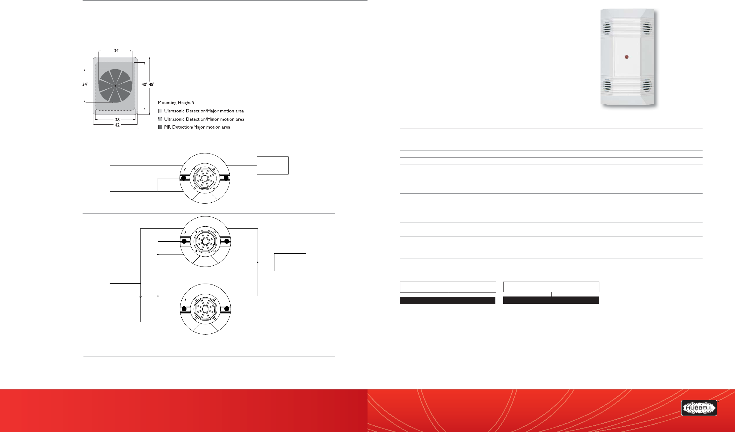
(888) 698-3242 | Fax orders (512) 450-0864 | hubbell-automation.com
h
ubb
ell-
au
t
o
m
a
ti
o
n
.
c
om
PAGE 180 | (888) 698-3242 | Fax orders (512) 450-0864 | hubbell-automation.com
PAGE 181 | OCCUPANCY | VACANCY SENSORS
Hubbell Building Automation
NOTES
C5002000P
Ultrasonic Line Voltage
Ceiling Mount Sensor
KEY FEATURES
• Self-contained power supply
• 2,000 square-foot coverage
• Adjustable time delay
• Adjustable sensitivity
• California Title 24 compliant
SPECIFICATIONS
Sensitivity • Fully adjustable: 0% –00%
Timer timeout • Fully adjustable: 30 seconds–30 minutes
Ultrasonic output • Operating frequency: 32.7kHz
LED lamp • Walk test indicator (a blinking light indicates the sensor is working)
Coverage • 2,000 square feet
Power requirements • C5002000P120: 120 VAC; 50/60 Hz
• C5002000P277: 277 VAC; 50/60 Hz
Electrical ratings • C5002000P120: 2400 watts @ 120 VAC; 50/60 Hz
• C5002000P277: 5000 watts @ 277 VAC; 50/60 Hz
Operating environment • Indoor use only
• Operating temperature: 32°–122°F (0°–50°C)
Construction • Casing—rugged, high-impact, injection-molded plastic
• Color-coded leads
Size and weight • Size: 5.0” x 2.87” x 1.37” (127.5 mm x 73.0 mm x 35.0 mm)
• Weight: 3.0 oz
Color • White
Mounting • Sensors can be mounted using a single-gang mud ring attached to a 4-inch square electrical box
• Recommended MAX mounting height: 10ft.
Certi cations • UL and cUL listed
ORDERING INFORMATION
C5002000P
Red
Red
Black
White
Hot
Neutral Lighting
Load
NOTE:
1. This is a Line Voltage
Sensor that is to be ordered
Line Voltage specific (120VAC or 277VAC).
Red
Red
Black
White
Neutral
Red
Red
Black
White
Hot
Lighting
Load
NOTE:
1. This is a Line Voltage
Sensor that is to be ordered
Line Voltage specific (120VAC or 277VAC).
RANGE DIAGRAM
WIRING DIAGRAMS
For more wiring diagrams, visit http://www.hubbell-automation.com/resources/wiring_diagrams/
VOLTAGE
120 120V
277 277V
MODEL
C5002000P Ultrasonic Line Voltage Sensor,
2,000 ft.
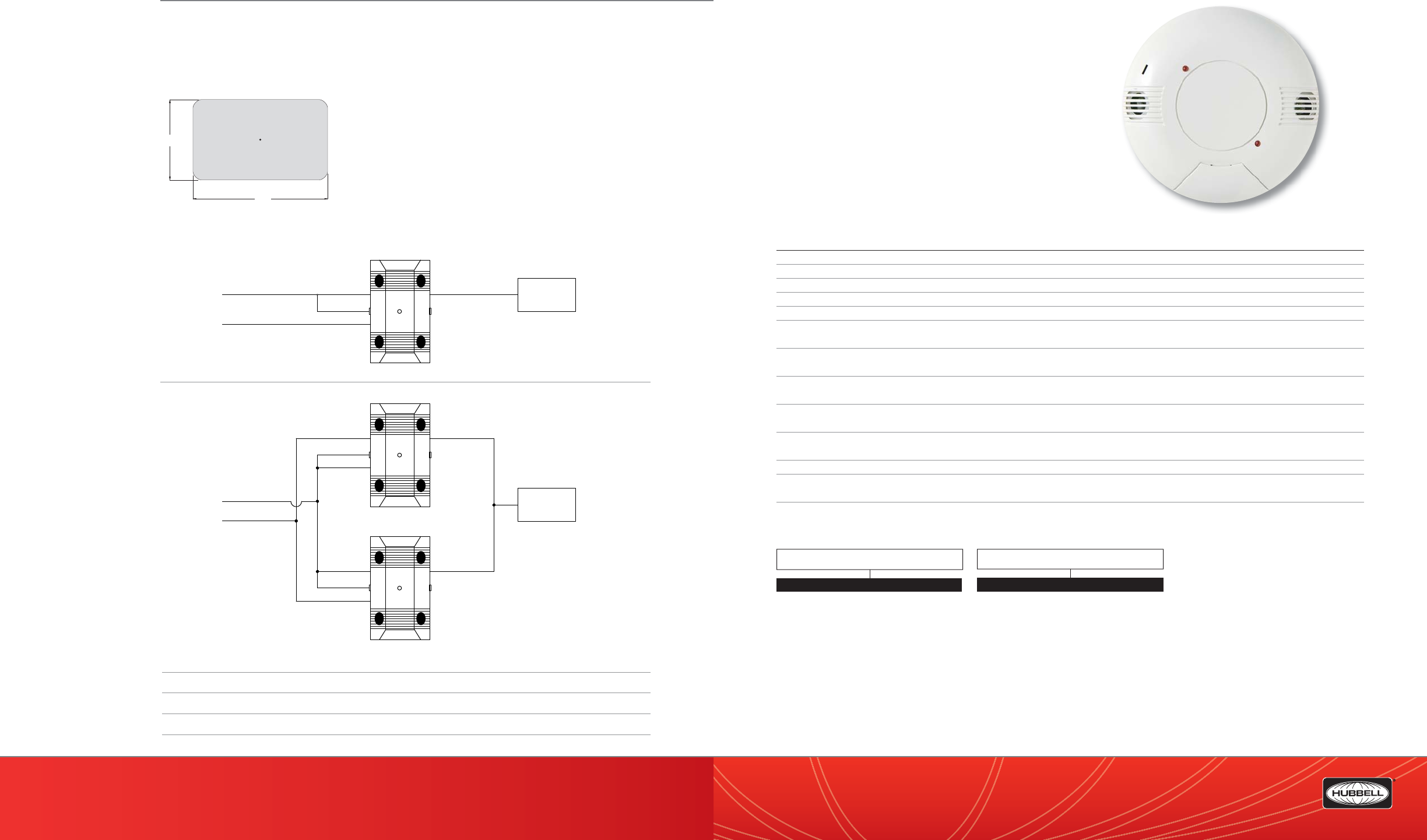
(888) 698-3242 | Fax orders (512) 450-0864 | hubbell-automation.com
h
ubb
ell-
au
t
o
m
a
ti
o
n
.
c
om
PAGE 182 | (888) 698-3242 | Fax orders (512) 450-0864 | hubbell-automation.com
PAGE 183 | OCCUPANCY | VACANCY SENSORS
Hubbell Building Automation
NOTES
C8001500P
Ultrasonic Line Voltage
Ceiling Mount Sensor
KEY FEATURES
• Self-contained power supply
• 1,500 square-foot coverage
• Adjustable time delay
• Adjustable sensitivity
• California Title 24 compliant
SPECIFICATIONS
Sensitivity • Fully adjustable: 0%–100%
Timer timeout • Fully adjustable: 30 seconds–30 minutes
Ultrasonic output • Operating frequency: 32.7kHz
LED lamp • Walk test indicator (a blinking light indicates the sensor is working)
Coverage • 1,500 square feet
Power requirements • C8001500P120: 120 VAC; 50/60 Hz
• C8001500P277: 277 VAC; 50/60 Hz
Electrical ratings • C8001500P120: 2,400 watts @ 120 VAC; 50/60 Hz
• C8001500P277: 5,000 watts @ 277 VAC; 50/60 Hz
Operating environment • Indoor use only
• Operating temperature: 32°–122°F (0°–50°C)
Construction • Casing—rugged, high-impact, injection-molded plastic
• Color-coded leads
Size and weight • Size: 4.87” diameter, 1.65” height (123.7 mm diameter, 41.9 mm height)
• Weight: 3.0 oz
Color • White
Mounting • Sensors can be mounted using a single-gang mud ring attached to a 4-inch square electrical box
• Recommended MAX mounting height: 10ft.
Certi cations • UL and cUL Listed
ORDERING INFORMATION
63’
38’
Hot
Black
NEUTRAL
Red Red
White
Lighting
Load
NOTE:
1. This is a Line Voltage Sensor that is to be
ordered Line Voltage specific (120VAC or 277VAC).
Black
Red
Red
White
Lighting
Load
Black
Red Red
White
Hot
NEUTRAL
NOTE:
1. This is a Line Voltage Sensor that is to be
ordered Line Voltage specific (120VAC or 277VAC).
C8001500P
RANGE DIAGRAM
WIRING DIAGRAMS
For more wiring diagrams, visit http://www.hubbell-automation.com/resources/wiring_diagrams/
VOLTAGE
120 120V
277 277V
MODEL
C8001500P Ultrasonic Line Voltage Sensor,
1,500 ft.
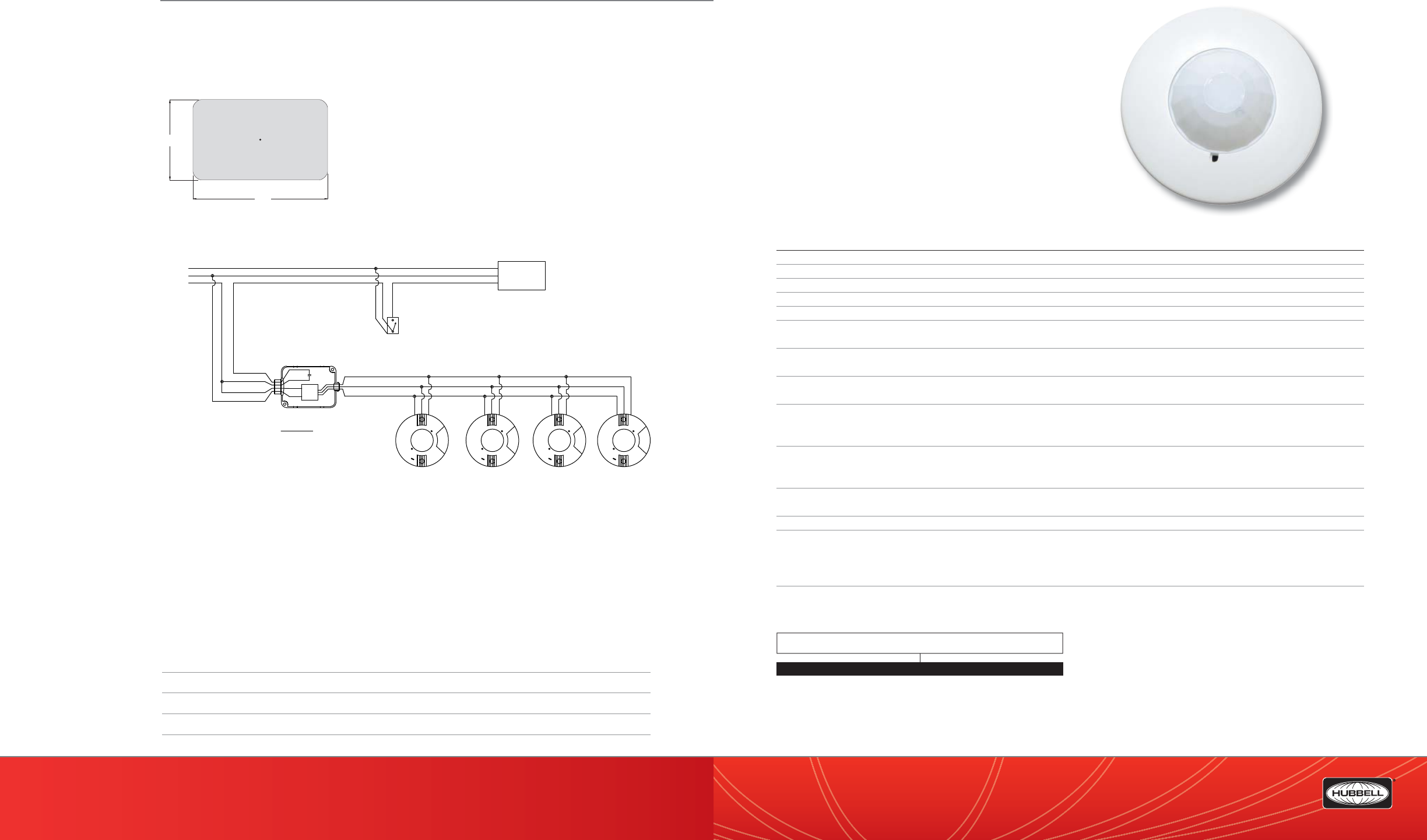
(888) 698-3242 | Fax orders (512) 450-0864 | hubbell-automation.com
h
ubb
ell-
au
t
o
m
a
ti
o
n
.
c
om
PAGE 184 | (888) 698-3242 | Fax orders (512) 450-0864 | hubbell-automation.com
PAGE 185 | OCCUPANCY | VACANCY SENSORS
Hubbell Building Automation
NOTES
PIR10
Low Pro le Passive Infrared
Ceiling Sensor
KEY FEATURES
• Low-pro le design
• Integral photocell control
• Auxiliary relay version available
• 1,500 square-foot, 360° coverage area
• California Title 24 compliant
SPECIFICATIONS
Sensitivity • Fully adjustable: 20% –100%
Timer timeout • Fully adjustable: 30 seconds–30 minutes
LED lamp • Walk test indicator (blinking light indicates the sensor is working)
Integral photocell • Natural-light override range: 5–200 foot-candles (5–200 lux)
Auxiliary relay • SPDT; 1 A rated @ 24VDC (Model PIR10EMS only)
Coverage • 360° coverage area
• 1,500 square feet @ 10’ mounting height
Power requirements • PIR10P: 120–347 VAC
• PIR10EMS: 24 VDC, 10 mA (uses MP-Series power pack—not included)
Output • 24 VDC active high-logic control signal with short-circuit protection and optional dry contact
(see: RP Option)
Operating environment • Indoor use only
• Operating temperature: 32°–131°F (0°–55°C)
• Relative humidity (non-condensing): 0%–95%
Construction • Housing – Rugged, high-impact, injection-molded plastic KJB
• ABS Cycolac (UL-945VA) ame class rating, UV inhibitors
• Color-coded leads are 6” long
Size and weight • Size: 4.0” diameter, 1.9” height (101 mm diameter, 48mm height)
• Weight: 3.0 oz
Color • White
Mounting • Metal mounting ring provided (PIR10EMS only)
• PIR10 sensors can be mounted using a 3-0 round mud ring
• attached to a 4” square electrical box
• Recommended MAX mounting height: 10ft.
Certi cations • UL and cUL listed
ORDERING INFORMATION
PIR10
63’
38’
Lighting
Load
Red (+24VDC)
Black (common)
Blue (control)
Red
Black
Blue
Neutral
Hot
Ground
Override Switch
(optional)
Red
Red
Black
White
Hubbell Building Automation
Low Voltage Sensors(devices)
Requires 23mA each
Power Pack
contacts rated
for 20 Amps.
UVPP Power Pack
Supplies 150mA
Neutral
Hot
Ground
NOTE:
1.DO NOT attempt to power more than 4 devices (sensors
or slave packs) from a single power pack.
RANGE DIAGRAM
WIRING DIAGRAM
For more wiring diagrams, visit http://www.hubbell-automation.com/resources/wiring_diagrams/
MODEL
PIR10P Passive Infrared Line Voltage Ceiling Sensor
PIR10EMS Passive Infrared Low Voltage Sensor with Aux. Relay
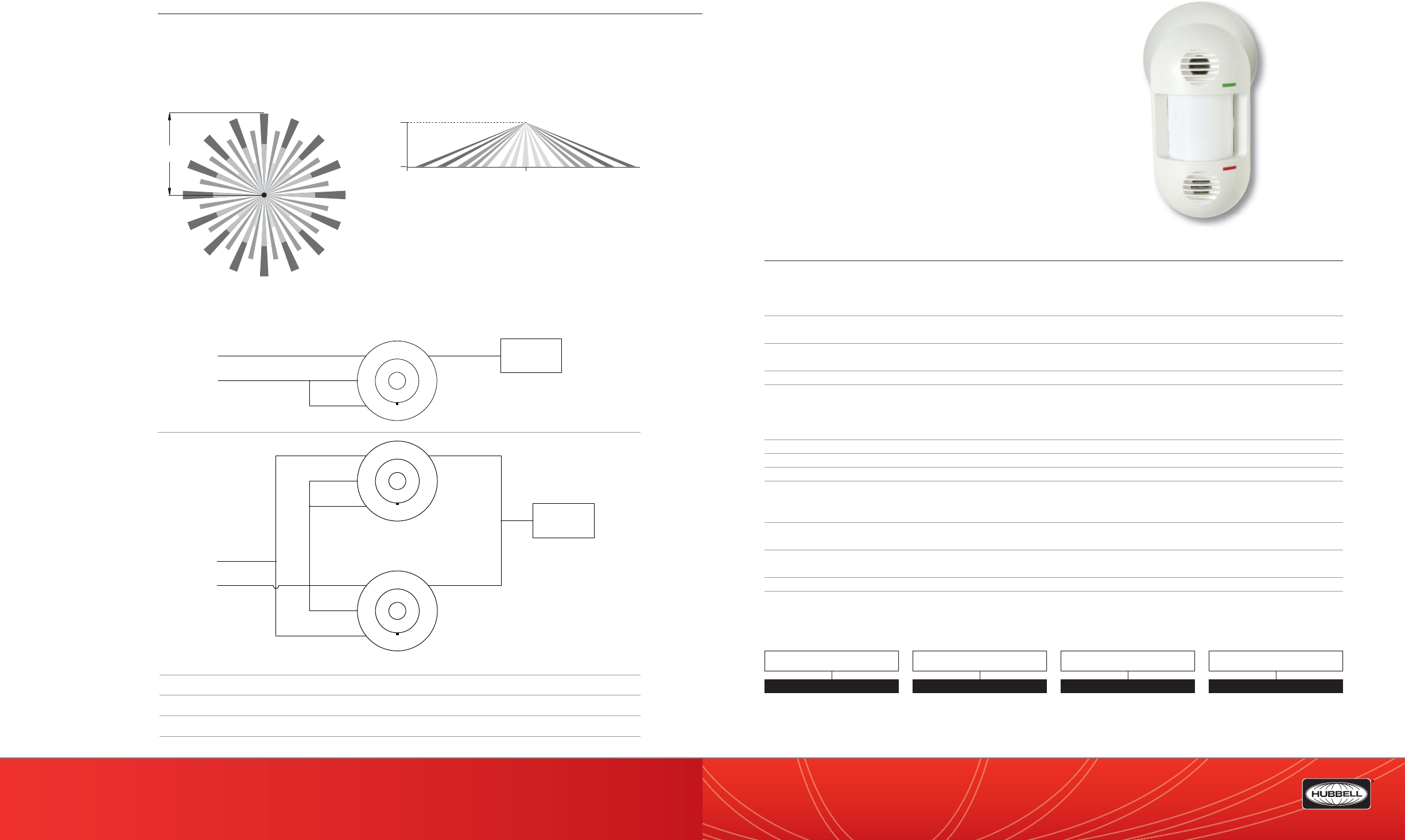
(888) 698-3242 | Fax orders (512) 450-0864 | hubbell-automation.com
h
ubb
ell-
au
t
o
m
a
ti
o
n
.
c
om
PAGE 186 | (888) 698-3242 | Fax orders (512) 450-0864 | hubbell-automation.com
PAGE 187 | OCCUPANCY | VACANCY SENSORS
Hubbell Building Automation
NOTES
LODT | LODTRP
LightOWL™ Dual Technology
Ultrasonic and PIR Sensor
featuring IntelliDAPT™
KEY FEATURES
• IntelliDAPT self-adaptive technology—no manual adjustment required
• All-digital dual technology (ultrasonic [US] and passive infrared [PIR]) sensor
• Non-volatile memory for sensor settings
• 1,600 square-foot coverage area
• Optional relay and photocell control
• California Title 24 compliant
• UL and cUL listed
SPECIFICATIONS
IntelliDAPT technology • Auto reset from test setting
• Self-adjusting timer
• Self-adjusting ultrasonic and passive infrared thresholds
• Automatic false-on/false-o corrections
LED lamps • Red – infrared motion
• Green – ultrasonic motion
Timer timeout • Automatic mode: 8–30 minutes (self-adjusts based on occupancy)
• Test mode: 8 seconds (for an easy check at installation)
Ultrasonic (US) output • Operating frequency: 32kHz
RP option • Relay and photocell included
• Relay: N/O + N/C contacts; SPDT; 500 mA rated @ 24 VDC; three-wire isolated relay
• Photocell: adjustable natural-light override ranges from 0 to 100 foot-candles (0–1,000 lux)
• Factory set at 3,000 lux (disable photocell)
Coverage • 1,600 square feet
Power requirements • 24 VDC, 33 mA (uses UVPP and MP-Series power pack—not included)
Output • 24 VDC active high-logic control signal with short circuit protection and optional dry contact (see: RP Option)
Operating environment • Indoor use only
• Operating temperature: 32° –104°F (0°–40°C)
• Relative humidity (non-condensing): 0%–95%
Construction • Casing—rugged, high-impact, injection-molded plastic KJB ABS Cycolac (UL-945VA)
• Color-coded leads are 6” long
Size and weight • Size: 6.58” x 3.63” x 3.72”
• Weight: 5.0 oz (142g)
Color • O -white
Mounting • Mounting base provided
• Recommended MAX mounting height: 12ft.
ORDERING INFORMATION
LODT
20'
10'
0'
0'
25'
Red
Red
Black
White
Neutral
Hot
Lighting
Load
NOTE:
1. This sensor accepts line voltage inputs from
120VAC through 347VAC.
Red
Red
Black
White
Neutral
Red
Red
Black
White
Hot
Lighting
Load
NOTES:
1. The PIR-10-P sensor is to be wired in parallel
to acheive 3-way control.
2. This sensor accepts line voltage inputs from
120VAC through 347VAC.
RANGE DIAGRAMS
WIRING DIAGRAMS
For more wiring diagrams, visit http://www.hubbell-automation.com/resources/wiring_diagrams/
LO DT
QTI
QTI Quick to Install
Blank No QTI
MODEL
LO
TECHNOLOGY
DT Dual Technology Ultrasonic &
Passive Infrared
RELAY / PHOTOCELL OPTION
RP Relay Photocell
Blank No Relay Photocell
LODT

(888) 698-3242 | Fax orders (512) 450-0864 | hubbell-automation.com
h
ubb
ell-
au
t
o
m
a
ti
o
n
.
c
om
PAGE 188 | (888) 698-3242 | Fax orders (512) 450-0864 | hubbell-automation.com
PAGE 189 | OCCUPANCY | VACANCY SENSORS
Hubbell Building Automation
NOTES
LOIR
LightOWL™ Passive Infrared Sensor
featuring IntelliDAPT™
KEY FEATURES
• IntelliDAPT self-adaptive technology—no manual adjustment required
• All-digital passive infrared (PIR) sensor
• Non-volatile memory for sensor settings
• 1,600 square-foot coverage area
• California Title 24 compliant
• UL and cUL listed
SPECIFICATIONS
IntelliDAPT technology • Auto reset from test setting
• Self-adjusting timer
• Self-adjusting passive infrared thresholds
• Automatic false-on/false-o corrections
LED lamp • Red—infrared motion
Timer timeout • Automatic mode: 8–30 minutes (self-adjusts based on occupancy)
• Test mode: 8 seconds (for an easy check at installation)
RP option • Relay and photocell included
• Relay: N/O + N/C contacts; SPDT; 500 mA rated @ 24 VDC; three-wire isolated relay
• Photocell: adjustable natural-light override ranges from 2 to 300 foot-candles (20–3000 lux)
Coverage • LOIRWV (Wide View): 1,600 square feet
• LOIRHB (High Bay): 50’ @ 30’ height
Power requirements • 24 VDC, 33 mA (uses UVPP and MP-Series power pack—not included)
Output • 24 VDC active high-logic control signal with short circuit protection and optional dry contact
(see: RP Option)
Operating environment • Indoor use only
• Operating temperature: 32°–104° F (0°–40° C)
• Relative humidity (non-condensing): 0%–95%
Construction • Casing – rugged, high-impact, injection-molded plastic KJB ABS Cycolac (UL-945VA) ame class rating,
UV inhibitors
• Color-coded leads are 6” long
Size and weight • Size: 6.58” x 3.63” x 3.72”
• Weight: 5.0 oz (142g)
Color • O -white
Mounting • Mounting base provided
• Recommended MAX mounting height: 12ft.
ORDERING INFORMATION
LOIR
20'
32'
23'
40'
23'
32'
Hubbell Building Automation
Omni or LightOWL sensors
with -RP option
Neutral
Hot
Red (+24VDC)
Blue (control)
Yellow/White (Relay Normally Open)
Lighting
Load
Ground
Red (+24VDC)
Black (common)
Black (common)
Blue (control)
Red
Red
Black
White
Blue/White (Relay Common)
Black/White (Relay Normally Closed)
Yellow/White (Relay Normally Open)
-Sensor not powered
-No occupancy
Blue/White (Relay Common)
Black/White (Relay Normally Closed)
Yellow/White (Relay Normally Open)
-Occupancy detected
RP option
Relay detail
Override
Switch
(optional)
Power Pack
contacts rated
for 20 Amps.
UVPP Power Pack
Supplies 150mA
Grey (control + photocell)
Blue/White (Relay Common)
Black/White (Relay Normally Closed)
RANGE DIAGRAM
WIRING DIAGRAM
For more wiring diagrams, visit http://www.hubbell-automation.com/resources/wiring_diagrams/
LO IRWV
QTI
QTI Quick to Install
Blank No QTI
MODEL
LO
TECHNOLOGY
IRWV Passive Infrared Wide View
RELAY / PHOTOCELL OPTION
RP Relay Photocell
Blank No Relay Photocell
LO
IR
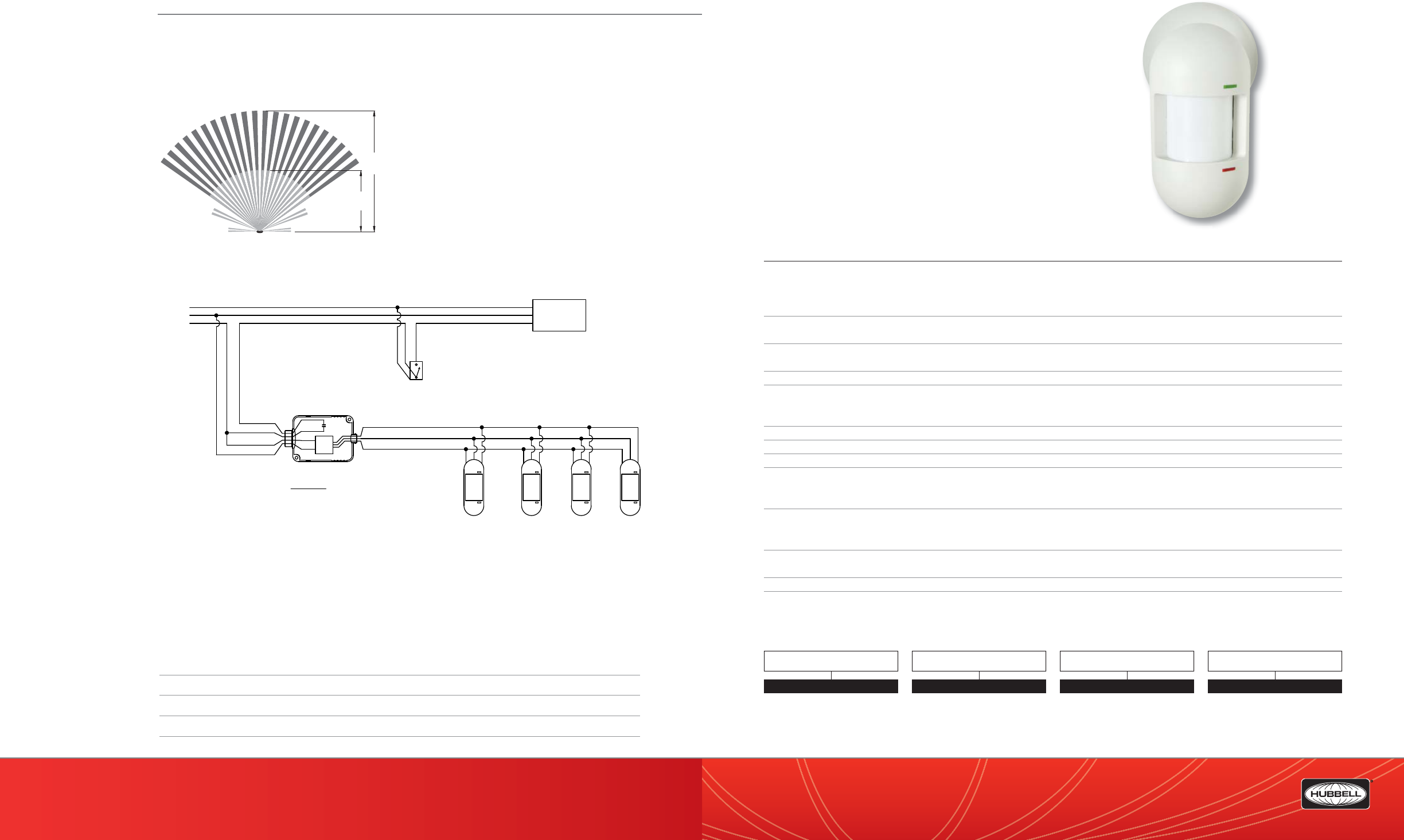
(888) 698-3242 | Fax orders (512) 450-0864 | hubbell-automation.com
h
ubb
ell-
au
t
o
m
a
ti
o
n
.
c
om
PAGE 190 | (888) 698-3242 | Fax orders (512) 450-0864 | hubbell-automation.com
PAGE 191 | OCCUPANCY | VACANCY SENSORS
Hubbell Building Automation
NOTES
LODIA | LODIARP
LightOWL™ Dual Technology
Passive Infrared and Acoustic Sensor
featuring IntelliDAPT™
KEY FEATURES
• IntelliDAPT self-adaptive technology—no manual adjustment required
• All-digital dual technology (passive infrared [PIR] and acoustic) sensor
• Non-volatile memory for sensor settings
• 1,600 square-foot coverage area
• Optional relay and photocell control
• California Title 24 compliant
• UL and cUL listed
SPECIFICATIONS
IntelliDAPT technology • Auto reset from test setting
• Self-adjusting timer
• Self-adjusting passive infrared and acoustic thresholds
• Automatic false-on/false-o corrections
LED lamp • Red—infrared motion
• Green—acoustic detection
Timer timeout • Automatic mode: 8–30 minutes (self-adjusts based on occupancy)
• Test mode: 8 seconds (for an easy check at installation)
Passive infrared (PIR) • Dual-element pyrometer and 12-element cylindrical rugged lens
RP option • Relay and photocell included
• Relay: N/O + N/C contacts; SPDT; 500 mA rated @ 24 VDC; three-wire isolated relay
• Photocell: adjustable natural-light override ranges from 0 to 100 foot-candles (0–1,000 lux)
Coverage • 1,600 square feet
Power requirements • 24 VDC, 33 mA (uses UVPP and MP-Series power pack—not included)
Output • 24 VDC active high-logic control signal with short circuit protection and optional dry contact (see: RP Option)
Operating environment • Indoor use only
• Operating temperature: 32°–104°F (0°–40°C)
• Relative humidity (non-condensing): 0%–95%
Construction • Casing – Rugged, high-impact, injection-molded plastic KJB ABS Cycolac (UL-945VA) ame class rating,
UV inhibitors
• Color-coded leads are 6” long
Size and weight • Size: 6.58” x 3.63” x 3.72”
• Weight: 5.0 oz (142g)
Color • O -white
Mounting • Mounting base provided
• Recommended MAX mounting height: 12ft.
ORDERING INFORMATION
LODIA
20'
40'
Lighting
Load
Red (+24VDC)
Black (common)
Blue (control)
Red
Black
Blue
Neutral
Hot
Ground
Override Switch
(optional)
Red
Red
Black
White
Hubbell Building Automation
Low Voltage Sensors(devices)
Requires 33mA each
Power Pack contacts
rated for 20 Amps.
UVPP Power Pack
Supplies 150mA
Neutral
Hot
Ground
NOTE:
1. DO NOT attempt to power more than 4 devices (sensors
or slave packs) from a single power pack.
RANGE DIAGRAM
WIRING DIAGRAM
For more wiring diagrams, visit http://www.hubbell-automation.com/resources/wiring_diagrams/
LO DIA
QTI
QTI Quick to Install
Blank No QTI
MODEL
LO
TECHNOLOGY
DIA Passive Infrared and Acoustic
RELAY / PHOTOCELL OPTION
RP Relay Photocell
Blank No Relay Photocell
LODIA

(888) 698-3242 | Fax orders (512) 450-0864 | hubbell-automation.com
h
ubb
ell-
au
t
o
m
a
ti
o
n
.
c
om
PAGE 192 | (888) 698-3242 | Fax orders (512) 450-0864 | hubbell-automation.com
PAGE 193 | OCCUPANCY | VACANCY SENSORS
Hubbell Building Automation
NOTES
Accessories
Ceiling and Wall Mount Occupancy Sensors
ACAK ACOUSTIC CEILING MOUNTING KIT
for ceiling and wall mount sensors used with acoustic ceiling tile.
ACAK uses integral cutting teeth for quicker installation.
Color: White.
LMRA LIGHTOWL MUD RING ADAPTER
A LightOWL goof ring for covering oversized holes.
Color: White.
HCRA HARD CEILING RACEWAY ADAPTER
for OMNI™ sensors. The HCRA is compatible with
Hubbell™ and Wiremold™ raceway. The HCRA has
knockout raceway holes for quick and clean installation.
Color: White.
OPE – OMNI Protective Enclosure
The OPE is a NEMA Type 4X enclosure speci cally designed for use
with HBA’s OMNIIR ceiling mount occupancy sensor. Designed
to provide protection from foreign materials and water, the enclosure
is acceptable for use in a variety of environments including
applications in the pharmaceutical and food preparation
industries.
Size: 6.5” dia., 2” height.
Color: White.
Wire guards are heavy-duty coated wire guards
for sensors to protect from destructive strikes.
Mounting clips are included.
Color: White.
WGWS – Wall mount wire guard for wall switches,
6.25”H x 4.0”W x 2.25”D
WGOMNI – Ceiling mount guard for OMNI sensors,
7.0”W x 3.25”D (circular guard)
WGLO – Wall mount wire guard for LightOWL sensors,
7.0”H x 5.75”W x 4.5”D
ORDERING INFORMATION
use
HCRA
LMRA
OPE
Top left - WGLO;
Top right - WGWS;
Lower center - WGOMNI
ACAK
(Shown with LightOWL
mounting arm.)
20'
32'
23'
40'
23'
32'
Hubbell Building Automation
Omni or LightOWL sensors
with -RP option
Neutral
Hot
Red (+24VDC)
Blue (control)
Yellow/White (Relay Normally Open)
Lighting
Load
Ground
Red (+24VDC)
Black (common)
Black (common)
Blue (control)
Red
Red
Black
White
Blue/White (Relay Common)
Black/White (Relay Normally Closed)
Yellow/White (Relay Normally Open)
-Sensor not powered
-No occupancy
Blue/White (Relay Common)
Black/White (Relay Normally Closed)
Yellow/White (Relay Normally Open)
-Occupancy detected
RP option
Relay detail
Override
Switch
(optional)
Power Pack
contacts rated
for 20 Amps.
UVPP Power Pack
Supplies 150mA
Grey (control + photocell)
Blue/White (Relay Common)
Black/White (Relay Normally Closed)
RANGE DIAGRAM
WIRING DIAGRAM
For more wiring diagrams, visit http://www.hubbell-automation.com/resources/wiring_diagrams/
ACCESSORIES
OPE OMNI Protective Enclosure
TD200 Digital Programmable Timer
WGNS Wire Guard for Wall Switches
WGOMNI Ceiling Mount Guard for OMNI Sensors
WGLO Wire Guard for LightOWL Sensors

(888) 698-3242 | Fax orders (512) 450-0864 | hubbell-automation.com
h
ubb
ell-
au
t
o
m
a
ti
o
n
.
c
om
PAGE 194 | (888) 698-3242 | Fax orders (512) 450-0864 | hubbell-automation.com
PAGE 195 | OCCUPANCY | VACANCY SENSORS
Hubbell Building Automation
NOTES
UVPP
Universal Voltage Power Pack
KEY FEATURES
• Universal voltage (100–277 VAC; 50/60Hz)
• Automatic voltage detection
• Electrical load switching capablity: maximum of 20 Amps
• Regulated 24 VDC current; 150mA output; short circuit protected
• Zero Arc Point Switching
• Plenum rated
• Mounts: inside or outside a junction box; inside a uorescent
ballast cavity
• Available with exclusive Quick-to-Install (QTI) connector
SPECIFICATIONS
Power requirements • 100–277 VAC; 50/60Hz
• Single phase only
Output • 24 VDC; 150mA nominal, isolated, and regulated
Relay contact rating • 20A: 120 VAC Incandescent
• 20A: 120 or 277 VAC Ballast
• 1HP: 120 or 277 VAC Motor Load
Construction • High-impact UL 94-5V plastic
Plenum rated • Complies with requirements for use in a plenum area
• Plenum rated for external junction box mounting
Operating environment • Indoor use only
• Operating temperature: 32°–104°F (0°–40°C)
• Relative humidity (non-condensing): 0%–95%
Size • 3.69” x 2.33” x 1.36”
Color • Black
Certi cations • UL and cUL listed
ORDERING INFORMATION
UVPP
MODEL
UVPP Universal Voltage Power Pack
UVPPQTI Universal Voltage Power Pack with QTI Connector
UVPP Universal Voltage Power Pack
UVPPQTI Universal Voltage Power Pack with QTI Connector
UVPP Universal Voltage Power Pack
UVPPQTI Universal Voltage Power Pack with QTI Connector
UVPP Universal Voltage Power Pack
UVPPQTI Universal Voltage Power Pack with QTI Connector
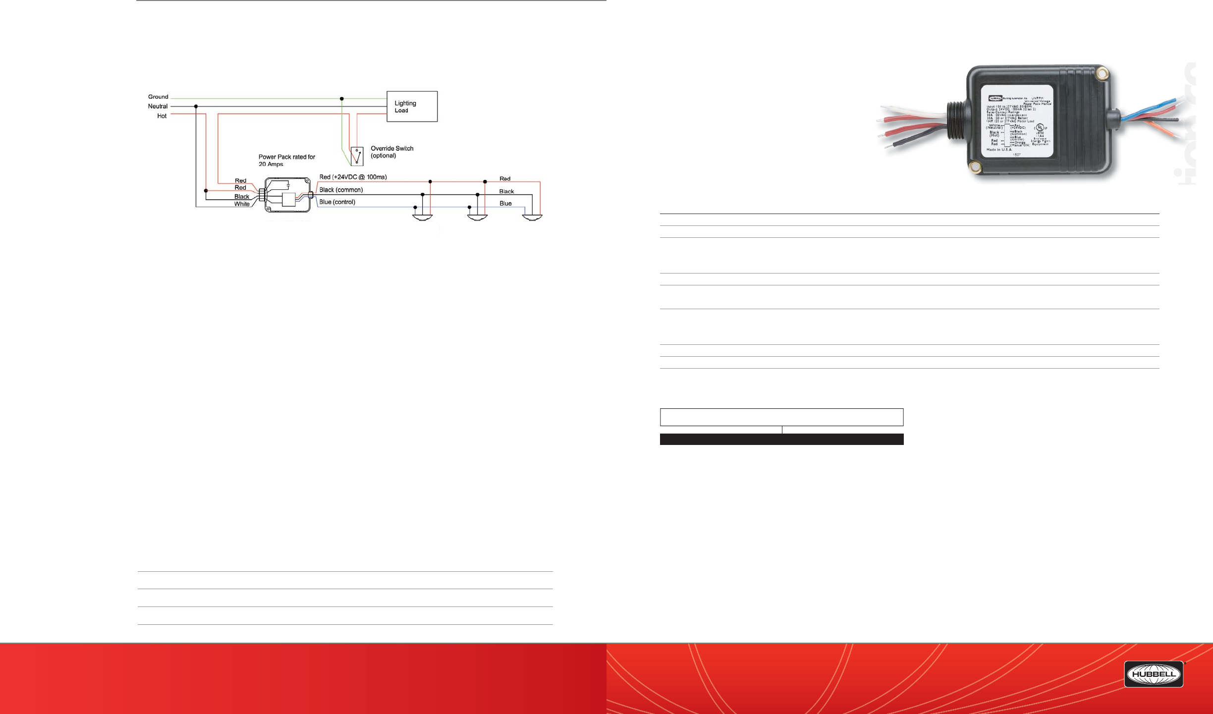
(888) 698-3242 | Fax orders (512) 450-0864 | hubbell-automation.com
hubbell-automation.com
PAGE 196 | (888) 698-3242 | Fax orders (512) 450-0864 | hubbell-automation.com
PAGE 197 | OCCUPANCY | VACANCY SENSORS
Hubbell Building Automation
NOTES
UVPPM
Universal Voltage Power Pack
with Manual ON|OFF Control
KEY FEATURES
• Manual ON/OFF support
• Universal voltage (100 to 277VAC, 50/60Hz)
• Automatic voltage detection
• Capable of switching up to 20 Amps
of electrical load
• Regulated 24VDC current,
150mA output, short circuit protected
SPECIFICATIONS
Power Requirements • 100-277VAC, 50/60Hz
Output • 24VDC, 150mA nominal, isolated and regulated
Relay Contact Rating • 20A, 120VAC Incandescent
• 20A, 120 or 277VAC Ballast
• 1HP, 120 or 277VAC Motor Load
Construction • High-impact, UL 94-5V plastic
Plenum Rated • Complies with requirements for use in a compartment handling conditioned air (plenum)
• Plenum rated for external junction box mounting
Operating environment • Indoor use only
• Operating temperature: 32°– 104°F (0°– 40°C)
• 0% to 95% relative humidity, non-condensing
Size • 3.69”L x 2.33”W x 1.36”H
Color • Black
Certi cations • UL and cUL Listed
ORDERING INFORMATION
UVPPM
UVPP Power Pack
WIRING DIAGRAM
For more wiring diagrams, visit http://www.hubbell-automation.com/resources/wiring_diagrams/
MODEL
UVPPM Universal Voltage Power Pack with Manual ON/OFF Control
UV
PP
M
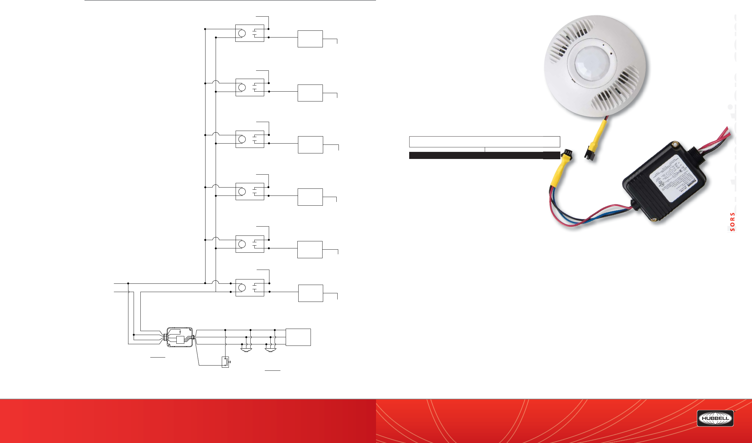
(888) 698-3242 | Fax orders (512) 450-0864 | hubbell-automation.com
hubbell-automation.com
hubbel
PAGE 198 | (888) 698-3242 | Fax orders (512) 450-0864 | hubbell-automation.com
PAGE 199 | OCCUPANCY | VACANCY SENSORS
Hubbell Building Automation QTI
QTI™—Quick To Install System and Accessories
KEY FEATURES
• Dramatically reduce installation cost
• Easy to install; fast and e cient
• Completely removable and reusable if necessary
• UL-approved plenum cable in accordance
with NEC Article 725
• Eliminates need for large spools of cable
for installation of plenum cable runs
• Reduces possibility of transposing wires as
in conventional splicing wire terminations
ORDERING INFORMATION
Contactor
Red
Black
Blue
Power Pack
contacts rated
for 20 Amps.
Neutral
Hot
Red (+24VDC )
Black (common)
Blue (control)
Red
Red
Black
White
UVPP Power Pack
Supplies 150mA
Hubbell Building Automation
Low Voltage Sensors(devices)
Requires 33mA each
Orange
Manual-ON /
Override-OFF
Low-voltage
Momentary Switch
NOTE:
1.DO NOT attempt to power more than 4 devices (sensors
or slave packs) from a single power pack.
No more
than
4 devices
C
Contactor
C
Contactor
C
Contactor
C
Contactor
C
Contactor
C
Hot - Circuit 1
Circuit 1 Load
Circuit 2 Load
Circuit 3 Load
Circuit 4 Load
Circuit 5 Load
Circuit 6 Load
Hot - Circuit 2
Hot - Circuit 3
Hot - Circuit 4
Hot - Circuit 5
Hot - Circuit 6
Neutral
Neutral
Neutral
Neutral
Neutral
Neutral
WIRING DIAGRAM
For more wiring diagrams, visit
http://www.hubbell-automation.com/
resources/wiring_diagrams/
MODEL
CAB10 10’ Plenum rated QTI Cable
CAB20 20’ Plenum rated QTI Cable
S1M2F QTI Splitter 1 male, 2 female

(888) 698-3242 | Fax orders (512) 450-0864 | hubbell-automation.com
h
ubb
ell-
au
t
o
m
a
ti
o
n
.
c
om
PAGE 200 | (888) 698-3242 | Fax orders (512) 450-0864 | hubbell-automation.com
PAGE 201 | OCCUPANCY | VACANCY SENSORS
Hubbell Building Automation
NOTES
RRU
Line Voltage Auxiliary Relays
KEY FEATURES
• 120 or 277VAC models available
• 20 Amp switching capacity
• N/O isolated contact
SPECIFICATIONS
Electrical Ratings • RRU120 – 2400 watts @ 120 VAC 50/60 Hz, 1 HP
• RRU277 – 5000 watts @ 277 VAC 50/60 Hz, 1.5 HP
Operating environment • Indoor use only
Size & Weight • Size: 2.75” W x 4.5” L x 1.10” D
• Weight: 3.0 oz
Color • White
Certi cations • UL and cUL Listed
ORDERING INFORMATION
RRU
MODEL
RRU120 Auxiliary Relay for 120V Line Voltage Sensors
RRU277 Auxiliary Relay for 277V Line Voltage Sensors
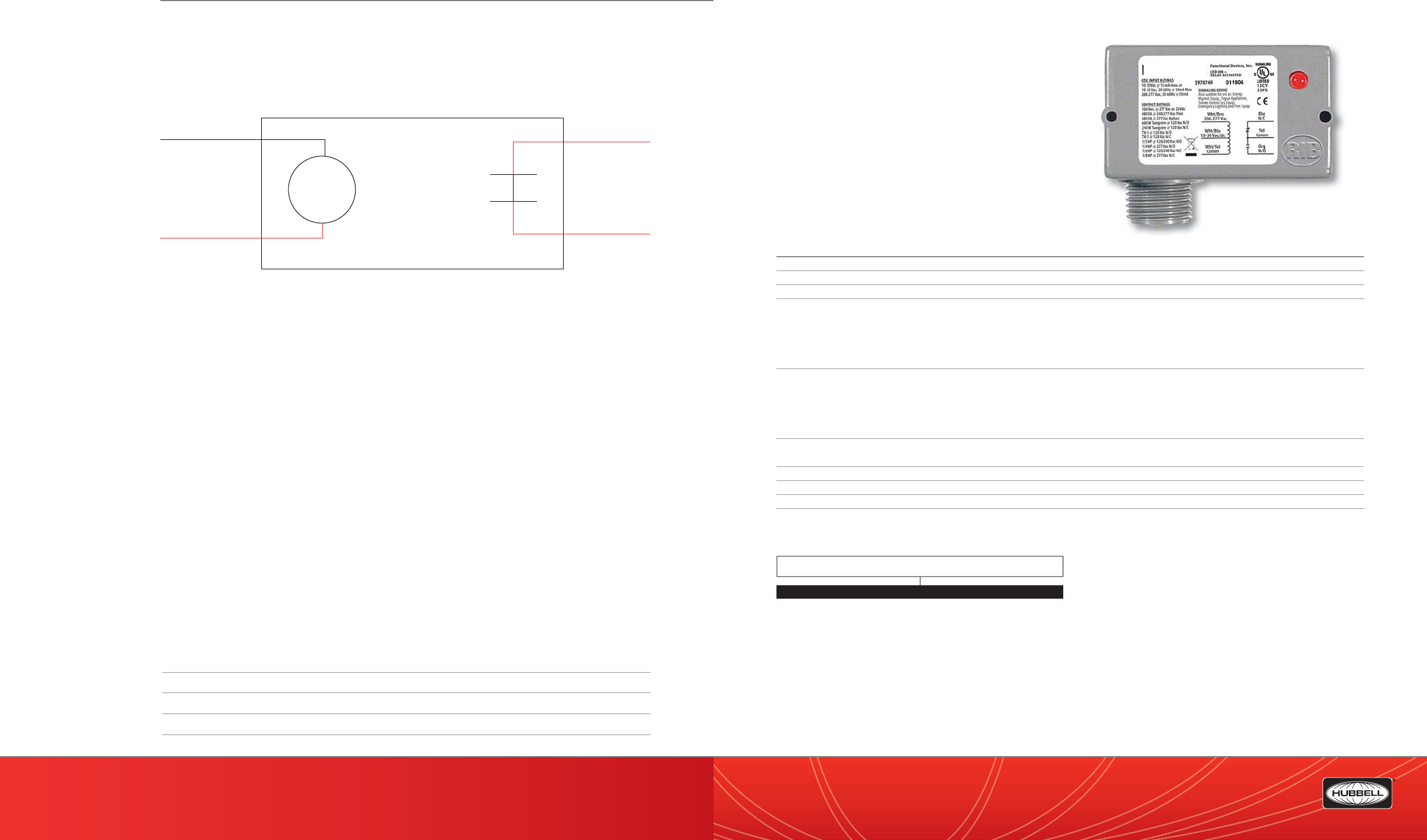
(888) 698-3242 | Fax orders (512) 450-0864 | hubbell-automation.com
h
ubb
ell-
au
t
o
m
a
ti
o
n
.
c
om
PAGE 202 | (888) 698-3242 | Fax orders (512) 450-0864 | hubbell-automation.com
PAGE 203 | OCCUPANCY | VACANCY SENSORS
Hubbell Building Automation
NOTES
RR1SPDTC
Enclosed 10 Amp SPDT Relays
KEY FEATURES
• 10 Amp SPDT Relay
• Available with either 10-30 VAC/DC/120 VAC Coil
or 10-30 VAC/DC/208-277 VAC Coil
• LED status indicator
• N/O and N/C isolated contacts
SPECIFICATIONS
# Relays & Contact Type • One (1) SPDT Continuous Duty Coil
Expected Relay Life • 10 million cycles minimum mechanical
Gold Flash • Yes
Contact Ratings • 10 Amp resistive @ 120-277 VAC • 240 Watt Tungsten @ 120 VAC N/C
• 10 Amp resistive @ 28 VDC • 1/3 HP for N/O @ 120-240 VAC
• 480 VA Pilot Duty @ 240-277 VAC • 1/6 HP for N/C @ 120-240 VAC
• 480 VA Ballast @ 277 VAC • 1/4 HP for N/O @ 277 VAC
• 600 Watt Tungsten @ 120 VAC N/O • 1/8 HP for N/C @ 277 VAC
Coil Current • 30 mA @ 10 VAC 12 mA @ 10 VDC
• 32 mA @ 12 VAC 14 mA @ 12 VDC
• 42 mA @ 24 VAC 16 mA @ 24 VDC
• 50 mA @ 30 VAC 18 mA @ 30 VDC
• 25 mA @ 120 VAC
Coil Voltage Input • RR1SPDTC120: 10-30 VAC/DC, 120 VAC; 50-60Hz
• RR1SPDTC277: 10-30 VAC/DC, 208-277 VAC; 50-60Hz
Operating environment • -30 to 140°F
Housing Rating • Plenum, NEMA 1
Wires • 16”, 600V Rated
Certi cations • UL and cUL Listed, UL916, UL864
ORDERING INFORMATION
RR1SPDTC
MODEL
RR1SPDTC120 Enclosed Relay 10 Amp SPDT with 10-30 VAC/DC/
120 VAC Coil
RR1SPDTC277 Enclosed Relay 10 Amp SPDT with 10-30 VAC/DC/
208-277 VAC Coil
Coil RRU
120/277
Neutral
Hot
WIRING DIAGRAM
For more wiring diagrams, visit http://www.hubbell-automation.com/resources/wiring_diagrams/
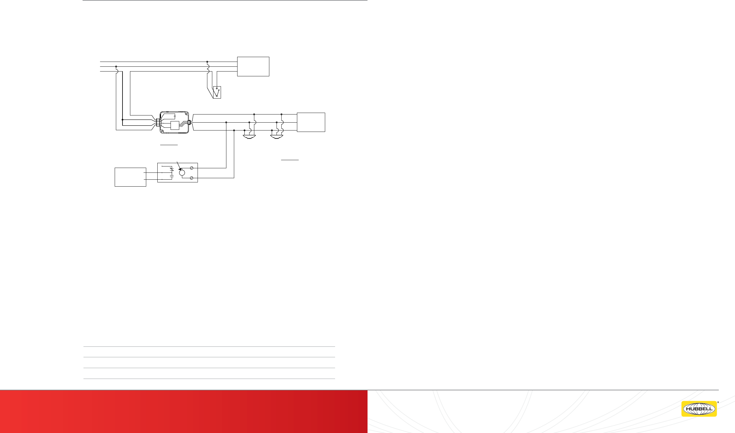
PAGE 204 | (888) 698-3242 | Fax orders (512) 450-0864 | hubbell-automation.com
Hubbell Building Automation
NOTES
h
ubb
ell-
au
t
o
m
a
ti
o
n
.
c
om
C5002000P ..................................................................................... 181
C8001500P ..................................................................................... 183
Ceiling and Wall Mount Sensor Accessories ................... 195
CUI5002000P ................................................................................ 179
CX 16, 24 .......................................................................................... 105
CX Panel Accessories ................................................................. 109
CX4 ..................................................................................................... 101
CX8 ..................................................................................................... 103
CXR ..................................................................................................... 107
DLC7 .................................................................................................. 133
DLCPCI | DLCPCO | DLCPCA | DLCPCS ................................ 135
IWSZP3P .......................................................................................... 161
IWSZPM ............................................................................................ 163
LHIRD Lighthawk™ .................................................................... 151
LHIRS Lighthawk™ ..................................................................... 149
LHMTD Lighthawk™ .................................................................. 143
LHMTS Lighthawk™ ................................................................... 141
LHUSD Lighthawk™ ................................................................... 147
LHUSS Lighthawk™ ................................................................... 145
LODIA | LODIARP ......................................................................... 191
LODT | LODTRP ............................................................................. 187
LOIR .................................................................................................... 189
LUXSTATDNCM ............................................................................. 127
LUXSTATLS ...................................................................................... 129
LUXSTATOCM1Z ........................................................................... 125
LUXSTATSW .................................................................................... 131
LVS ...................................................................................................... 167
LX ...........................................................................................................57
LX Networked Cable | Plenum Rated .................................... 97
LX Networked Cable | Riser Rated ..........................................99
LXBC .....................................................................................................61
LXBR .....................................................................................................63
LXDCIM ...............................................................................................77
LXENDM ..............................................................................................91
LXJNSYS .............................................................................................. 67
LXKEY ...................................................................................................71
LXLPM2 ...............................................................................................81
LXOMNDT...........................................................................................73
LXPR .....................................................................................................85
I
I
n
n
d
d
e
e
x
x
PAGE 205 | HUBBELL BUILDING AUTOMATION
Lighting
Load
Red
Black
Blue
Power Pack
contacts rated
for 20 Amps.
Neutral
Hot
Ground
Red (+24VDC)
Black (common)
Blue (control)
Red
Red
Black
White
UVPP Power Pack
Supplies 150mA
Hubbell Building Automation
Low Voltage Sensors(devices)
Requires 33mA each
Override
Switch
(optional)
24VAC/dc coil
RR1SPDTC Relay
Binary Input Low Voltage
HVAC or Panel (Example)
No more
than
4 devices
NOTE:
1.DO NOT attempt to power more than 4 devices (sensors
or slave packs) from a single power pack.
WIRING DIAGRAM
For more wiring diagrams, visit http://www.hubbell-automation.com/resources/wiring_diagrams/
LXPSCM ...............................................................................................75
LXRL ......................................................................................................59
LXRRM .................................................................................................83
LXSW ....................................................................................................69
LXS.........................................................................................................79
LXSW Custom Buttons ................................................................. 95
LXTB......................................................................................................65
LXTERMINATOR ...............................................................................87
LXUL924 .............................................................................................89
LXWRDV..............................................................................................93
OMNIDIA | OMNIDIAPR ............................................................ 175
OMNIDT | OMNIDTRP ............................................................... 169
OMNIIR | OMNIIPR ...................................................................... 173
OMNIUS | OMNIUSRP ................................................................ 171
PIR10 ................................................................................................ 185
PIR1000H ........................................................................................ 177
QTI ...................................................................................................... 199
RR1SPDTC ....................................................................................... 203
RRU..................................................................................................... 201
RWSOSCFL ...................................................................................... 153
RWSOSINC ...................................................................................... 157
RWSVSCFL ...................................................................................... 155
RWSVSINC ....................................................................................... 159
TD200 ............................................................................................... 165
UVPP .................................................................................................. 195
UVPPM.............................................................................................. 197
WIH-AP ...............................................................................................37
WIH-DS ...............................................................................................47
WIH-IM ................................................................................................49
WIH-OM .............................................................................................51
WIH-OS ...............................................................................................41
WIH-SP ................................................................................................39
WIH-SW ..............................................................................................45
WSP .................................................................................................... 115
Z5-CM................................................................................................ 117
Z5-DS ................................................................................................. 121
Z5-OS ................................................................................................ 119
Z5-SW ................................................................................................ 123

WIRELESS LIGHTING CONTROLS
HBA’s wiHUBB™ Wireless Lighting Control System provides indoor and outdoor wireless controls. The use of
wireless controls o ers signi cant bene ts over traditional wired solutions for both existing buildings and new
construction. wiHUBB devices communicate through the air utilizing radio frequency (RF) waves, eliminating
the need for expensive, dedicated control communications wiring.
LIGHTING CONTROL PANELS
NETWORKED SYSTEMS AND COMMERCIAL CONTROL
LX Networked Lighting Control – Multiple panels systems with intelligent devices that provide broad
programming capabilities, interface to users via LAN/Internet or touch screen tablet and communications to
Building Automation Systems.
CX Commercial Control – Master and secondary panels up to 24 relays per panel with simple easy to use
programming and connections to a wide variety of low voltage devices.
OCCUPANCY | VACANCY SENSORS
HBA occupancy sensors meet a wide range of applications. Ceiling and wall-mounted sensors are available
with the most advanced sensing technologies on the market today. HBA o ers passive infrared and ultrasonic
sensors as well as a dual technology version. HBA occupancy sensors provide simple installation, easy setup,
and reliable maintenance free operation.
DAYLIGHT HARVESTING
HBA’s suite of Daylight Harvesting controls provides the ideal solution to save energy by taking advantage
of natural daylight. Daylight Harvesting systems consist of two basic types, dimmed and switched. Dimming
control varies the arti cial light output over a wide range to maintain the desired light level. Switching controls
turn individual lamps o or on as required.
HIGH BAY LIGHTING CONTROLS
HBA delivers energy saving controls for most high bay lighting applications using HID and high-output
uorescent xtures. The LightBAT uses passive infrared sensing for bi-level HID switching for up to 50 feet
mounting heights. The HBA WASP o ered in a wide variety of versions controls T5HO and T8 xtures up to 45
feet high.
HUBBELL A Name You Can Trust
Founded in 1888 by Harvey Hubbell II, Hubbell Inc. has been a long time contributor to new product design and manufacturing
innovation. In 1896, Hubbell invented the world’s rst lighting control device, the pull chain switch. Over 120 years later, Hubbell
Building Automation, headquartered in Austin, Texas continues this tradition of innovation with the development of a vast array of
innovative energy saving lighting controls.
hubbell-automation.com | 888.698.3242 | 9601 Dessau Road, Building One, Austin, Texas 78754 USA
HUBBELL BUILDING AUTOMATION
The leader in building controls for complete energy-saving solutions.
