1000273216 Catalog
1000498562-Brochure 1000498562-Brochure 1000498562-Brochure B4 unilog cesco-content
2016-06-25
: Pdf 1000273216-Catalog 1000273216-Catalog B1 unilog
Open the PDF directly: View PDF ![]() .
.
Page Count: 166 [warning: Documents this large are best viewed by clicking the View PDF Link!]
- 1200CT0701.pdf
- 1200CT0902R0110 Product Guide Addendum
- ABOUT THIS ADDENDUM
- REVISIONS BY PAGE NUMBER
- Page 7: Commercial Grade Occupancy Sensor – Ultrasonic Single Circuit Wall Switch
- Page 8: Commercial Grade Occupancy Sensor – Ultrasonic Dual Circuit Wall Switch
- Page 9: Commercial Grade Occupancy Sensor – Dual Technology Single Circuit Wall Switch
- Page 10: Commercial Grade Occupancy Sensor – Dual Technology Dual Circuit Wall Switch
- Page 14: Wall Mount Occupancy Sensor – Passive Infrared (PIR)
- Page 25: Enclosure Cabinet Dimensions – Track Limiting Panels
- Page 50: CBus™ Neo DLT Keypad – List of Available Colors
- Page 60: CBus PCIUSB – Revised Product Features
- Page 89: 12M Enclosure – Revised Dimensions
- Page 90: 24M Enclosure – Revised Dimensions
- Page 92: 36MS Enclosure – Revised Dimensions
- Page 117: CBus IR Reader – IR Transmitter Revised Description
- Page 129: CBus RF Wireless Controls/RF Switch and Scene Controllers
- Page 138: CBus Software/Schedule Plus
Make the most of your energySM
Products Guide
Lighting Control and Integrated Home Systems

Occupancy Sensors 1-22
Introduction 1
Wall Switch Occupancy Sensors 3
Ceiling Mounted Occupancy Sensors 11
Wall Mounted Occupancy Sensors 14
Power Pack & Auxiliary Relays 17
High Bay HID 18
Technical Section 19
Track-limiting Panels 23-26
Track-limiting Panels 25
Powerlink® Lighting Control 27-46
Introduction 28
G3 Panelboards 29
NF Panelboards 30
G3 Remotely-operated Circuit Breakers 31
G3 Control Bus 33
Power Supply 34
Controllers 35
Remote-source Controller 37
Accessories 38
Device Power Supply 39
Device Router 40
Technical Section 41
C-BusTM Lighting Control 47-85
Introduction 48
Keypads 49
Touch Screens 55
System Units 58
Input Units 67
Sensors 70
Output Units 76
Contents

C-Bus
Area Lighting Panels 85-108
Introduction 86
C-Bus Enclosures 88
Technical Section 94
C-Bus Multi-room Audio,
Remote Controls and
IR Accessories 109-120
Introduction 110
Matrix Switcher 111
Multi-room Ampliers 112
Distribution Unit 113
Speakers 114
Universal Remote 115
4 & 8 Button Remotes 116
IR Accessories 117
Technical Section 118
C-Bus HVAC Controls 121-124
Introduction 122
Basic and Programmable Thermostats 123
Technical Section 124
C-Bus
RF Wireless Controls 125-134
Introduction 126
600W Dimmer 127
1000W Dimmer 128
Switch and Scene Controllers 129
Plug Adaptor 130
Wireless RF Remote 131
Wireless Gateway 132
Technical Section 133
C-Bus Software 135-138
Design Guide 139-154
One Line Diagrams 155-158
Commercial 155
Residential 157
Contents
Occupancy Sensors
1

Occupancy sensors help building owners
achieve energy savings and energy code
compliance with sensors that are easy to
select, install and commission. Employing
passive infrared (PIR), ultrasonic and dual
technology to accurately detect occupancy
and control lighting loads, occupancy sensors
automatically shut-off lighting in unoccupied
areas – eliminating waste, reducing energy
costs and meeting code requirements.
Schneider Electric innovations help building
owners not only comply with energy codes, but
they also maximize energy savings.
• Adaptive Technology: Patent pending
technology employs advanced algorithms
to achieve convenient energy savings and
reduced lamp and ballast maintenance.
• Integral light level sensors maximize
energy savings in day-lit areas by holding
off articial lighting when adequate natural
light is available.
• Walk-through mode detects brief periods
of occupancy in private ofces, allowing
the sensor to shut-off lighting with less
time delay.
• Lamp saver mode alternates the A- and
B-loads in rooms using 50/50 bi-level
lighting control to maximize lamp life and
reduce maintenance.
• Isolated relays may be used to communicate
with other control systems, such as building
automation and energy management
systems that control other building systems,
like HVAC and lighting, to further maximize
energy savings.
Schneider Electric makes lighting control
easy with a full line of versatile occupancy
sensors. For most applications, the sensors
may be installed right out of the box with no
adjustment. When needed, adjustments are
simple to understand and easy to access,
making commissioning a breeze.
Schneider Electric occupancy sensors were
designed to interface with other systems,
including Powerlink® and C-BusTM lighting
control systems, using normally open and
normally closed contacts. As lighting control
needs change and more sophisticated
lighting control is desired, Schnieder Electric
occupancy sensors interface with other
systems to maximize energy savings and
enhance occupant satisfaction.
Introduction to
Occupancy Sensors
2
Technical Information
Input 120 or 277Vac 60 Hz
Output 120Vac 277Vac
1000 W max. incandescent load
1000 VA max. ballast load 1800 VA max. ballast load
¼ hp max. motor load
Operating Temperature 32 - 122° F (0 - 50°C)
Humidity 90% max. relative humidity non-condensing
Standard UL and cUL Listed FCC Part 15
Home and Ofce Use (Class B) Title 24 Certied
*For Diagram see technical section page 19
Catalog Number Description
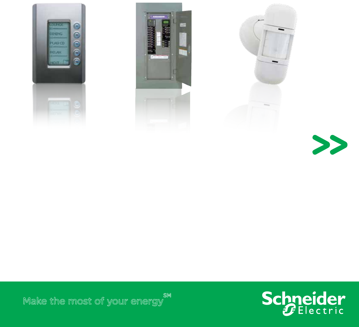
SLSPWS1277AI Wall Switch Occupancy Sensor (ivory)
SLSPWS1277AW Wall Switch Occupancy Sensor (white)
OCCUPANCY SENSORS + WALL SWITCH OCCUPANCY SENSORS
Schneider Electric Wall Switch Occupancy Sensors employ the latest passive infrared
(PIR) technology to automatically control lighting in ofces, private restrooms and
employee break rooms.
Each Sensor employs a special 180° multi-segmented lens and PIR motion detector
circuit to detect motion. This unit will automatically switch the lights off after a preset
delay if no motion is detected.
Schneider Electric Wall Switch Occupancy Sensor ts in place of existing wall switches,
connecting to existing active line and ground wiring similar to a typical wall switch. No
neutral or minimum load is required.
To assure long relay life, Schneider Electric has developed a low energy switch circuit
to assure maximum contact life. These sensors are compatible with electronic and
magnetic ballast loads, and require no minimum load.
Product Features
• Available in white and ivory with
matching decorator wall plate
cover
• Auto On / Auto Off
• Manual bypass
• 120 or 277Vac input (no neutral
required)
• No power pack required
• No minimum load
• 180° eld of view (Up to 1000
sq. ft.)
• User adjustable time delay from
15 sec - 30 minutes
• Red LED motion indicator blinks
to indicate motion detection
• Suitable for use on all electronic
and magnetic ballasts
• Furnished with (3) x 6 inch
external wires (pig tails)
• UL and cUL Listed
• Five-year warranty
Wall Switch
Occupancy Sensor
Wall Switch
Occupancy Sensor
3
Technical Information
Input 120 or 277Vac 60 Hz
Output 120Vac 277Vac
1000 W max. incandescent load
1000 VA max. ballast load 1800 VA max. ballast load
¼ hp max. motor load
Operating Temperature 32 - 122° F (0 - 50°C)
Humidity 90% max. relative humidity non-condensing
Standard UL and cUL Listed FCC Part 15
Home and Ofce Use (Class B) Title 24 Certied
*For Diagram see technical section page 19
Catalog Number Description
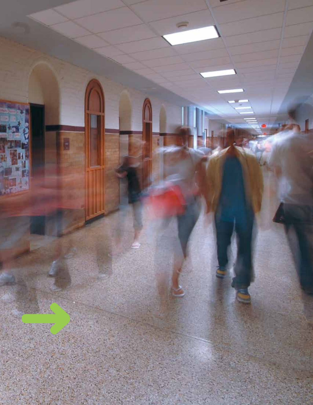
SLSPWS1277MW Wall Switch Occupancy Sensor With Manual On (white)
SLSPWS1277MI Wall Switch Occupancy Sensor With Manual On (ivory)
OCCUPANCY SENSORS + WALL SWITCH OCCUPANCY SENSORS
Schneider Electric Wall Switch Occupancy Sensor with Manual-On employs the latest
passive infrared (PIR) technology to automatically control lighting in ofces, employee
break rooms and utility rooms.
For maximum energy savings, the Schneider Electric Wall Switch Occupancy Sensor
with Manual-On requires the user to switch on lighting manually by pressing the button
on the front. Employing a special 180° multi-segmented lens and PIR motion sensor, the
sensor reliably detects occupancy to keep lights on while the room is occupied. This unit
will automatically switch the lights off after a pre-set delay if no motion is detected.
Schneider Electric Wall Switch Occupancy Sensor is easy to install. Connecting to
existing active line and ground wiring similar to a typical wall switch, the Wall Switch
Occupancy Sensor is the simplest way to achieve energy-saving lighting control with
minimal installation time.
To assure long relay life, Schneider Electric has developed a low energy switch circuit
to assure maximum contact life. These sensors are compatible with electronic and
magnetic ballast loads, and require no minimum load.
Product Features
• Available in white and ivory with
matching decorator wall plate
cover
• Auto On / Auto Off
• Manual bypass
• 120 or 277Vac input (no neutral
required)
• No power pack required
• No minimum load
• 180° eld of view (Up to 1000
sq.ft.)
• User adjustable time delay from
15 sec - 30 minutes
• Red LED motion indicator blinks
to indicate motion detection
• Suitable for use on all electronic
and magnetic ballasts
• Furnished with (3) x 6 inch
external wires (pig tails)
• UL and cUL Listed
• Five-year warranty
Wall Switch
Occupancy Sensor w/Manual On
Wall Switch
Occupancy Sensor W/ Manual On
4
Technical Information
Input 120-277Vac +/-10% 50/60 Hz
Output 120Vac 277Vac
1000 W max. tungsten
incandescent load
¼ hp max. motor load 277Vac
1000 VA max. ballast load 1800 VA max. ballast load
Operating Temperature 32 - 122° F (0 - 50°C)
Humidity 0 - 90% RH Non-condensing
Time Delay Adjustment
Normal 0.5 - 30 minutes
Walk Through Mode 2 minutes if no activity is detected after 30 seconds
Test Mode 15 seconds
Light Level adjustment 0.5 - 250 FC
Detection 180° passive infrared (PIR)
Audible Alert Selectable
Service Switch OFF / Auto / ON
Manual Operation Push-button ON/OFF
Lens Impact Resistant
Relay Switching 0° +/- 500uS
Standards UL and cUL Listed FCC Part 15,
Home and Ofce Use (Class B) Title 24 Certied
*For Diagram see technical section page 19
Catalog Number Description
SLSPWS1277UW White
SLSPWS1277UI Ivory
SLSPWS1277UG Gray
SLSPWS1277UL Light Almond
SLSPWS1277UB Black
OCCUPANCY SENSORS + WALL SWITCH OCCUPANCY SENSORS
Product Features
• Available in white, ivory, gray, light
almond and black with matching
wall switch cover plate
• Color matching multi-segmented
lens
• Selectable auto-on and manual-
on modes
• 120-277Vac 50/60Hz input
• 180° eld of view
• 1000 sq. ft. major motion and
300 sq. ft. minor motion
coverage area
• Light level sensor
• Walk-through mode
• Adjustable light level, time delay
and sensitivity
• Red LED motion indicator
• For use with electronic and
magnetic ballasts
• No neutral connection, minimum
load or power pack required
• UL and cUL Listed for United
States and Canada
• Test mode (15 second time delay)
• Five-year warranty
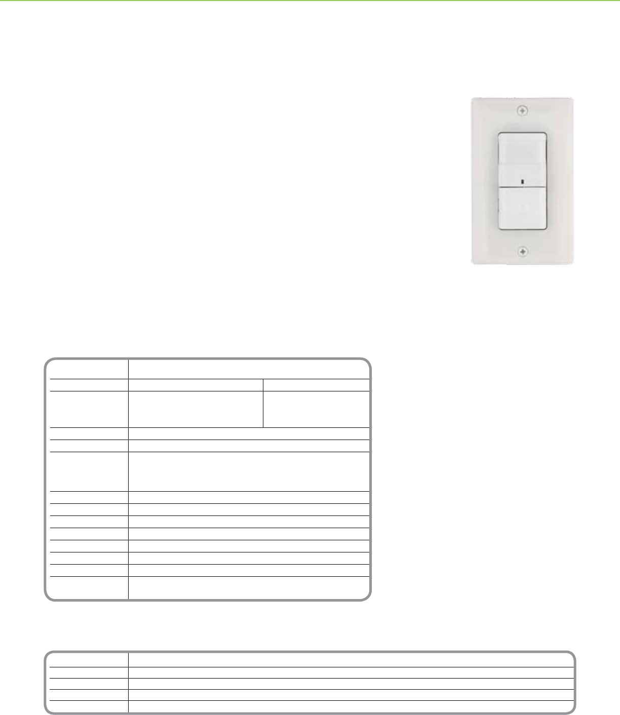
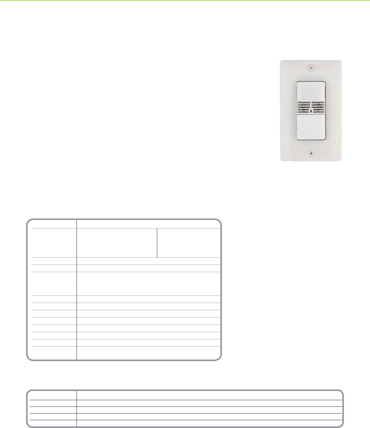
Schneider Electric Single Circuit PIR Wall Switch Occupancy Sensor with Light Level features
passive infrared (PIR) technology to conveniently control lighting in ofces, private bathrooms,
utility rooms and employee break rooms. Low prole sensor available in white, ivory, gray, light
almond and black with color-matched segmented lens to meet any décor need.
Adaptive Technology: New patent pending technology employs advanced algorithms to achieve
convenient energy savings and reduced lamp and ballast maintenance
Walk-Through Mode: To maximize energy savings, the sensor detects when areas are briey
occupied as a result of a person walking through and turns off lighting based on a shorter time delay.
Light Level Sensor Mode: Each sensor includes an adjustable light level sensor to hold off articial
lighting when adequate natural light is present. When natural light levels drop below the threshold, the
sensor will turn on articial lighting in occupied spaces.
The sensor does not require a neutral connection or minimum load, making it great for retrots.
Easily replaces an existing wall switch using existing wiring – no wiring modications required.
Matching wall switch cover plate makes retrots clean and simple.
Commercial Grade Occupancy Sensor
PIR Single Circuit Wall Switch
Single Circuit Wall Switch
Occupancy Sensor
5
Catalog Number Description Blank Catalog Number Toggle Catalog Number Description
SLSPWD1277UW White SLSPWP2DBW SLSPWP2DTW White
SLSPWD1277UI Ivory SLSPWP2DBI SLSPWP2DTI Ivory
SLSPWD1277UG Gray SLSPWP2DBG SLSPWP2DTG Gray
SLSPWD1277UL Light Almond SLSPWP2DBL SLSPWP2DTL Light Almond
SLSPWD1277UB Black SLSPWP2DBB SLSPWP2DTB Black
Technical Information
Input 120-277Vac +/-10% 50/60 Hz
Output 120Vac 277Vac
1000 W max. tungsten
incandescent load
¼ hp max. motor load 277Vac
1000 VA max. ballast load 1800 VA max. ballast load
Operating Temperature 32 - 122° F (0 - 50°C)
Humidity 0 - 90% RH Non-condensing
Time Delay Adjustment
Normal 0.5 - 30 minutes
Walk Through Mode 2 minutes if no activity is detected after 30 seconds
Test Mode 15 seconds
Light Level adjustment 0.5 - 250 FC
Detection 180° passive infrared (PIR)
Audible Alert Selectable
Service Switch OFF / Auto / ON
Manual Operation Push-button ON/OFF
Lens Impact Resistant
Relay Switching 0° +/- 500uS
Standards UL and cUL Listed FCC Part 15,
Home and Ofce Use (Class B) Title 24 Certied
*For Diagram see technical section page 19
OCCUPANCY SENSORS + WALL SWITCH OCCUPANCY SENSORS
Product Features
• Available in white, ivory, gray, light
almond and black with matching
wall switch cover plate
• Color matching multi-segmented
lens
• Selectable auto-on and manual-
on modes
• 120-277Vac 50/60Hz input
• 180° eld of view
• 1000 sq. ft. major motion and
300 sq. ft. minor motion coverage
area
• Light level sensor
• Walk-through mode
• Adjustable light level, time delay
and sensitivity
• Red LED motion indicator
• For use with electronic and
magnetic ballasts
• No neutral connection, minimum
load or power pack required
• UL and cUL Listed for United
States and Canada
• Test mode (15 second time delay)
• Five-year warranty
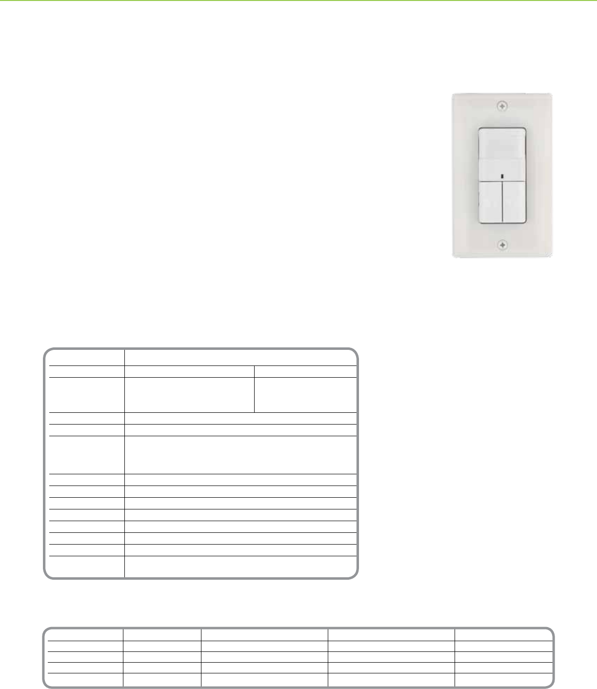
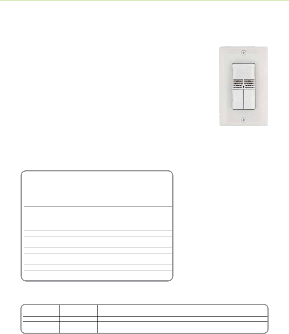
Dual Circuit Wall Switch Occupancy Sensors independently control two lighting circuits with bi-level
switching to reduce lighting by 50% which may be required by energy codes. The dual circuit wall
switch occupancy sensor employs passive infrared (PIR) technology and a 180 degree segmented lens
to achieve minor motion coverage up to 300 square feet (27.87 sq. meters) to reliably control lighting in
ofces, conference rooms and employee break rooms.
Adaptive Technology: New patent pending technology employs advanced algorithms to achieve
convenient energy savings and reduced lamp and ballast maintenance.
Lamp Saver Mode: When the lamp saver feature is enabled, the sensor automatically alternates which
circuit responds to motion. The result is more predictable lamp life and reduced maintenance.
Walk-Through Mode: To maximize energy savings, the sensor detects when areas are briey
occupied as a result of a person walking through and turns off lighting based on a shorter time delay.
Light Level Sensor Mode: Each sensor includes an adjustable light level sensor to hold off articial
lighting when adequate natural light is present. When natural light levels drop below the threshold, the
sensor will turn on articial lighting in occupied spaces.
The sensor easily replaces two wall switches using existing wiring with no wiring modications required.
Optional 2-gang wall switch cover plates available in matching colors.
Commercial Grade Occupancy Sensor
PIR Dual Circuit Wall Switch
Dual Circuit Wall Switch
Occupancy Sensor
6
Technical Information
Input 120-277Vac +/-10% 50/60 Hz
Output 120Vac 277Vac
1000 W max. tungsten
incandescent load
¼ hp max. motor load 277Vac
1000 VA max. ballast load 1800 VA max. ballast load
Operating Temperature 32 - 122° F (0 - 50°C)
Humidity 0 - 90% RH Non-condensing
Time Delay Adjustment
Normal 0.5 - 30 minutes
Walk Through Mode 2 minutes if no activity is detected after 30 seconds
Test Mode 15 seconds
Light Level adjustment 0.5 - 250 FC
Detection 180° passive infrared (PIR)
Audible Alert Selectable
Service Switch OFF / Auto / ON
Manual Operation Push-button ON/OFF
Lens Impact Resistant
Relay Switching 0° +/- 500uS
Standards UL and cUL Listed FCC Part 15,
Home and Ofce Use (Class B) Title 24 Certied
*For Diagram see technical section page 19
Catalog Number Description
SLSUWS1277UW White
SLSUWS1277UI Ivory
SLSUWS1277UG Gray
SLSUWS1277UL Light Almond
SLSUWS1277UB Black
OCCUPANCY SENSORS + WALL SWITCH OCCUPANCY SENSORS
Product Features
• Available in white, ivory, gray, light
almond and black with matching
wall switch cover plate
• Color matching multi-segmented
lens
• Selectable auto-on and manual-
on modes
• 120-277Vac 50/60Hz input
• 180° eld of view
• 1000 sq. ft. major motion and
300 sq. ft. minor motion coverage
area
• Light level sensor
• Walk-through mode
• Adjustable light level, time delay
and sensitivity
• Red LED motion indicator
• For use with electronic and
magnetic ballasts
• No neutral connection, minimum
load or power pack required
• UL and cUL Listed for United
States and Canada
• Test mode (15 second time delay)
• Five-year warranty
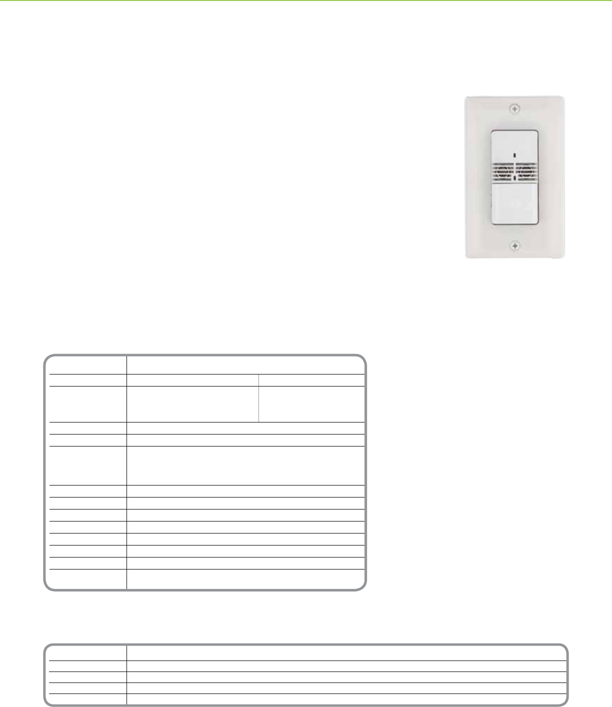
Schneider Electric Single Circuit PIR Wall Switch Occupancy Sensor with Light Level features
passive infrared (PIR) technology to conveniently control lighting in ofces, private bathrooms,
utility rooms and employee break rooms. Low prole sensor available in white, ivory, gray, light
almond and black with color-matched segmented lens to meet any décor need.
Adaptive Technology: New patent pending technology employs advanced algorithms to achieve
convenient energy savings and reduced lamp and ballast maintenance
Walk-Through Mode: To maximize energy savings and reduce waste, the sensor detects when
areas are briey occupied as a result of an occupant walking through and turns off lighting
based on a shorter time delay.
Light Level Sensor Mode: Each sensor includes an adjustable light level sensor to hold off
articial lighting when adequate natural light is present. When natural light levels drop below the
threshold, the sensor will turn on articial lighting in occupied spaces.
The sensor does not require a neutral connection or minimum load, making it great for retrots.
Easily replaces an existing wall switch using existing wiring – no wiring modications required.
Matching wall switch cover plate makes retrots clean and simple.
Commercial Grade Occupancy Sensor
Ultrasonic Single Circuit Wall Switch
Single Circuit Wall Switch
Occupancy Sensor
7
Catalog Number Description Blank Catalog Number Toggle Catalog Number Description
SLSUWD1277UW White SLSPWP2DBW SLSPWP2DTW White
SLSUWD1277UI Ivory SLSPWP2DBI SLSPWP2DTI Ivory
SLSUWD1277UG Gray SLSPWP2DBG SLSPWP2DTG Gray
SLSUWD1277UL Light Almond SLSPWP2DBL SLSPWP2DTL Light Almond
SLSUWD1277UB Black SLSPWP2DBB SLSPWP2DTB Black
Technical Information
Input 120-277Vac +/-10% 50/60 Hz
Output 120Vac 277Vac
1000 W max. tungsten
incandescent load
¼ hp max. motor load 277Vac
1000 VA max. ballast load 1800 VA max. ballast load
Operating Temperature 32 - 122° F (0 - 50°C)
Humidity 0 - 90% RH Non-condensing
Time Delay Adjustment
Normal 0.5 - 30 minutes
Walk Through Mode 2 minutes if no activity is detected after 30 seconds
Test Mode 15 seconds
Light Level adjustment 0.5 - 250 FC
Detection 180° passive infrared (PIR)
Audible Alert Selectable
Service Switch OFF / Auto / ON
Manual Operation Push-button ON/OFF
Lens Impact Resistant
Relay Switching 0° +/- 500uS
Standards UL and cUL Listed FCC Part 15,
Home and Ofce Use (Class B) Title 24 Certied
*For Diagram see technical section page 19
OCCUPANCY SENSORS + WALL SWITCH OCCUPANCY SENSORS
Product Features
• Available in white, ivory, gray, light
almond and black with matching
wall switch cover plate
• Color matching multi-segmented
lens
• Selectable auto-on and manual-
on modes
• 120-277Vac 50/60Hz input
• 180° eld of view
• 1000 sq. ft. major motion and
300 sq. ft. minor
motion coverage area
• Light level sensor
• Walk-through mode
• Adjustable light level, time delay
and sensitivity
• Red LED motion indicator
• For use with electronic and
magnetic ballasts
• No neutral connection, minimum
load or power pack required
• UL and cUL Listed for United
States and Canada
• Test mode (15 second time delay)
• Five-year warranty
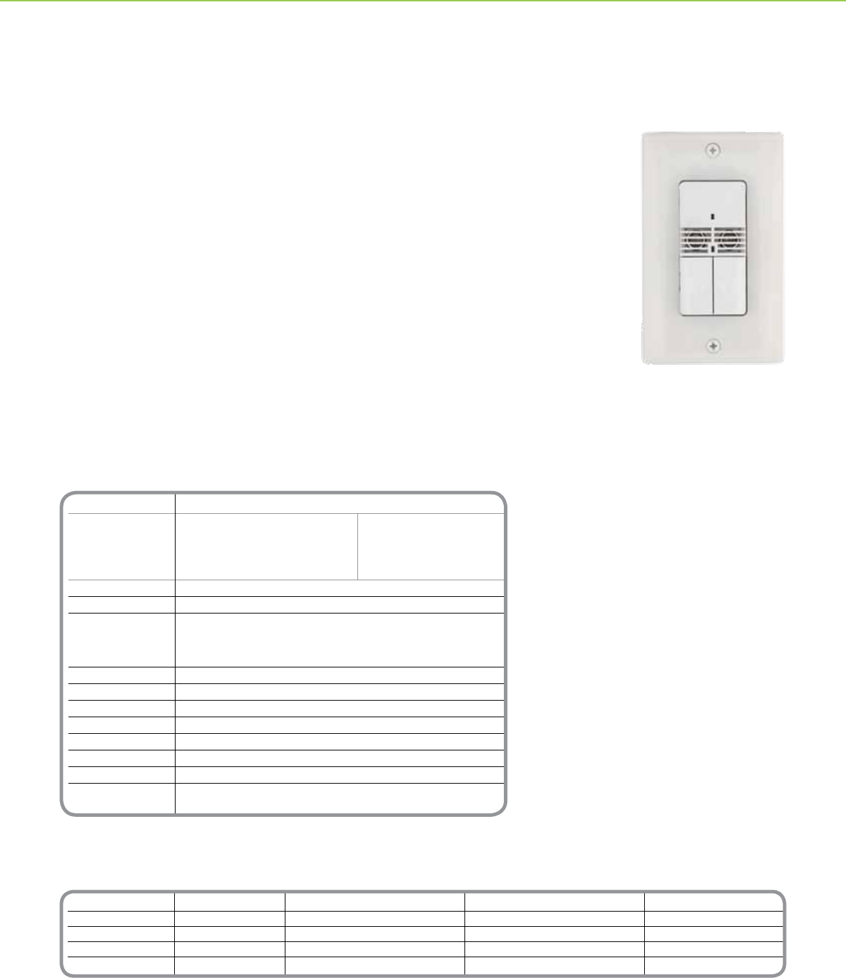
Dual Circuit Wall Switch Occupancy Sensors independently control two lighting circuits with
bi-level switching to reduce lighting by 50% which may be required by energy codes. The
dual circuit wall switch occupancy sensor employs passive infrared (PIR) technology and a
180 degree segmented lens to achieve minor motion coverage up to 300 square feet (27.87
sq. meters) to reliably control lighting in ofces, conference rooms and employee break
rooms.
Adaptive Technology: New patent pending technology employs advanced algorithms to
achieve convenient energy savings and reduced lamp and ballast maintenance.
Lamp Saver Mode: When the lamp saver feature is enabled, the sensor automatically
alternates which circuit responds to motion. The result is more predictable lamp life and
reduced maintenance.
Walk-Through Mode: To maximize energy savings, the sensor detects when areas are
briey occupied as a result of a person walking through and turns off lighting based on a
shorter time delay.
Light Level Sensor Mode: Each sensor includes an adjustable light level sensor to hold off
articial lighting when adequate natural light is present. When natural light levels drop below
the threshold, the sensor will turn on articial lighting in occupied spaces.
The sensor easily replaces two wall switches using existing wiring with no wiring
modications required. Optional 2-gang wall switch cover plates available in matching colors.
Commercial Grade Occupancy Sensor
Ultrasonic Dual Circuit Wall Switch
Dual Circuit Wall Switch
Occupancy Sensor
8
Technical Information
Input 120-277Vac +/-10% 50/60 Hz
Output 120Vac 277Vac
1000 W max. tungsten
incandescent load
¼ hp max. motor load 277Vac
1000 VA max. ballast load 1800 VA max. ballast load
Operating Temperature 32 - 122° F (0 - 50°C)
Humidity 0 - 90% RH Non-condensing
Time Delay Adjustment
Normal 0.5 - 30 minutes
Walk Through Mode 2 minutes if no activity is detected after 30 seconds
Test Mode 15 seconds
Light Level adjustment 0.5 - 250 FC
Detection 180° passive infrared (PIR)
Audible Alert Selectable
Service Switch OFF / Auto / ON
Manual Operation Push-button ON/OFF
Lens Impact Resistant
Relay Switching 0° +/- 500uS
Standards UL and cUL Listed FCC Part 15,
Home and Ofce Use (Class B) Title 24 Certied
*For Diagram see technical section page 20
Catalog Number Description
SLSDWS1277UW White
SLSDWS1277UI Ivory
SLSDWS1277UG Gray
SLSDWS1277UL Light Almond
SLSDWS1277UB Black
OCCUPANCY SENSORS + WALL SWITCH OCCUPANCY SENSORS
Product Features
• Available in white, ivory, gray, light
almond and black with matching
wall switch cover plate
• Color matching multi-segmented
lens
• Selectable auto-on and manual-
on modes
• 120-277Vac 50/60Hz input
• 180° eld of view
• 1000 sq. ft. major motion and
300 sq. ft. minor motion coverage
area
• Light level sensor
• Walk-through mode
• Adjustable light level, time delay
and sensitivity
• Red LED motion indicator
• For use with electronic and
magnetic ballasts
• No neutral connection, minimum
load or power pack required
• UL and cUL Listed for United
States and Canada
• Test mode (15 second time delay)
• Five-year warranty
Schneider Electric Single Circuit PIR Wall Switch Occupancy Sensor with Light Level features
passive infrared (PIR) technology to conveniently control lighting in ofces, private bathrooms,
utility rooms and employee break rooms. Low prole sensor available in white, ivory, gray, light
almond and black with color-matched segmented lens to meet any décor need.
Adaptive Technology: New patent pending technology employs advanced algorithms to
achieve convenient energy savings and reduced lamp and ballast maintenance
Walk-Through Mode: To maximize energy savings, the sensor detects when areas are briey
occupied as a result of a person walking through and turns off lighting based on a shorter time
delay.
Light Level Sensor Mode: Each sensor includes an adjustable light level sensor to hold off
articial lighting when adequate natural light is present. When natural light levels drop below the
threshold, the sensor will turn on articial lighting in occupied spaces.
The sensor does not require a neutral connection or minimum load, making it great for retrots.
Easily replaces an existing wall switch using existing wiring – no wiring modications required.
Matching wall switch cover plate makes retrots clean and simple.
Commercial Grade Occupancy Sensor
Dual Technology Single Circuit Wall Switch
Single Circuit Wall Switch
Occupancy Sensor
9
Catalog Number Description Blank Catalog Number Toggle Catalog Number Description
SLSDWD1277UW White SLSPWP2DBW SLSPWP2DTW White
SLSDWD1277UI Ivory SLSPWP2DBI SLSPWP2DTI Ivory
SLSDWD1277UG Gray SLSPWP2DBG SLSPWP2DTG Gray
SLSDWD1277UL Light Almond SLSPWP2DBL SLSPWP2DTL Light Almond
SLSDWD1277UB Black SLSPWP2DBB SLSPWP2DTB Black
Technical Information
Input 120-277Vac +/-10% 50/60 Hz
Output 120Vac 277Vac
1000 W max. tungsten
incandescent load
¼ hp max. motor load 277Vac
1000 VA max. ballast load 1800 VA max. ballast load
Operating Temperature 32 - 122° F (0 - 50°C)
Humidity 0 - 90% RH Non-condensing
Time Delay Adjustment
Normal 0.5 - 30 minutes
Walk Through Mode 2 minutes if no activity is detected after 30 seconds
Test Mode 15 seconds
Light Level adjustment 0.5 - 250 FC
Detection 180° passive infrared (PIR)
Audible Alert Selectable
Service Switch OFF / Auto / ON
Manual Operation Push-button ON/OFF
Lens Impact Resistant
Relay Switching 0° +/- 500uS
Standards UL and cUL Listed FCC Part 15,
Home and Ofce Use (Class B) Title 24 Certied
*For Diagram see technical section page 20
OCCUPANCY SENSORS + WALL SWITCH OCCUPANCY SENSORS
Product Features
• Available in white, ivory, gray, light
almond and black with matching
wall switch cover plate
• Color matching multi-segmented
lens
• Selectable auto-on and manual-
on modes
• 120-277Vac 50/60Hz input
• 180° eld of view
• 1000 sq. ft. major motion and
300 sq. ft. minor motion coverage
area
• Light level sensor
• Walk-through mode
• Adjustable light level, time delay
and sensitivity
• Red LED motion indicator
• For use with electronic and
magnetic ballasts
• No neutral connection, minimum
load or power pack required
• UL and cUL Listed for United
States and Canada
• Test mode (15 second time delay)
• Five-year warranty
Dual Circuit Wall Switch Occupancy Sensors independently control two lighting circuits with bi-level
switching to reduce lighting by 50% which may be required by energy codes. The dual circuit wall switch
occupancy sensor employs passive infrared (PIR) technology and a 180 degree segmented lens to
achieve minor motion coverage up to 300 square feet (27.87 sq. meters) to reliably control lighting in
ofces, conference rooms and employee break rooms.
Adaptive Technology: New patent pending technology employs advanced algorithms to achieve
convenient energy savings and reduced lamp and ballast maintenance.
Lamp Saver Mode: When the lamp saver feature is enabled, the sensor automatically alternates which
circuit responds to motion. The result is more predictable lamp life and reduced maintenance.
Walk-Through Mode: To maximize energy savings, the sensor detects when areas are briey
occupied as a result of a person walking through and turns off lighting based on a shorter time delay.
Light Level Sensor Mode: Each sensor includes an adjustable light level sensor to hold off articial
lighting when adequate natural light is present. When natural light levels drop below the threshold, the
sensor will turn on articial lighting in occupied spaces.
The sensor easily replaces two wall switches using existing wiring with no wiring modications required.
Optional 2-gang wall switch cover plates available in matching colors.
Commercial Grade Occupancy Sensor
Dual Technology Dual Circuit Wall Switch
Dual Circuit Wall Switch
Occupancy Sensor
10
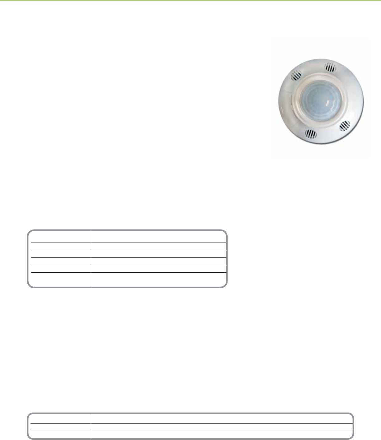
Catalog Number Description
SLSCPS1000 Ceiling Mounted PIR Occupancy Sensor
SLSPP1277 Power Pack (required)
SLSSP24 Auxiliary Relay
Technical Information
Current Consumption @ 24Vdc 21mA Nominal
Supply Voltage 24Vdc
Isolated Relay 1A @ 24Vdc Resistive
Operating Temperature 32 - 122° F (0 - 50°C)
Max. Humidity 90% RH Non-condensing
Standards UL and cUL Listed FCC Part 15,
Home and Ofce Use (Class B) Title 24 Certied
*For Diagram see technical section page 20
OCCUPANCY SENSORS + CEILING MOUNTED OCCUPANCY SENSORS
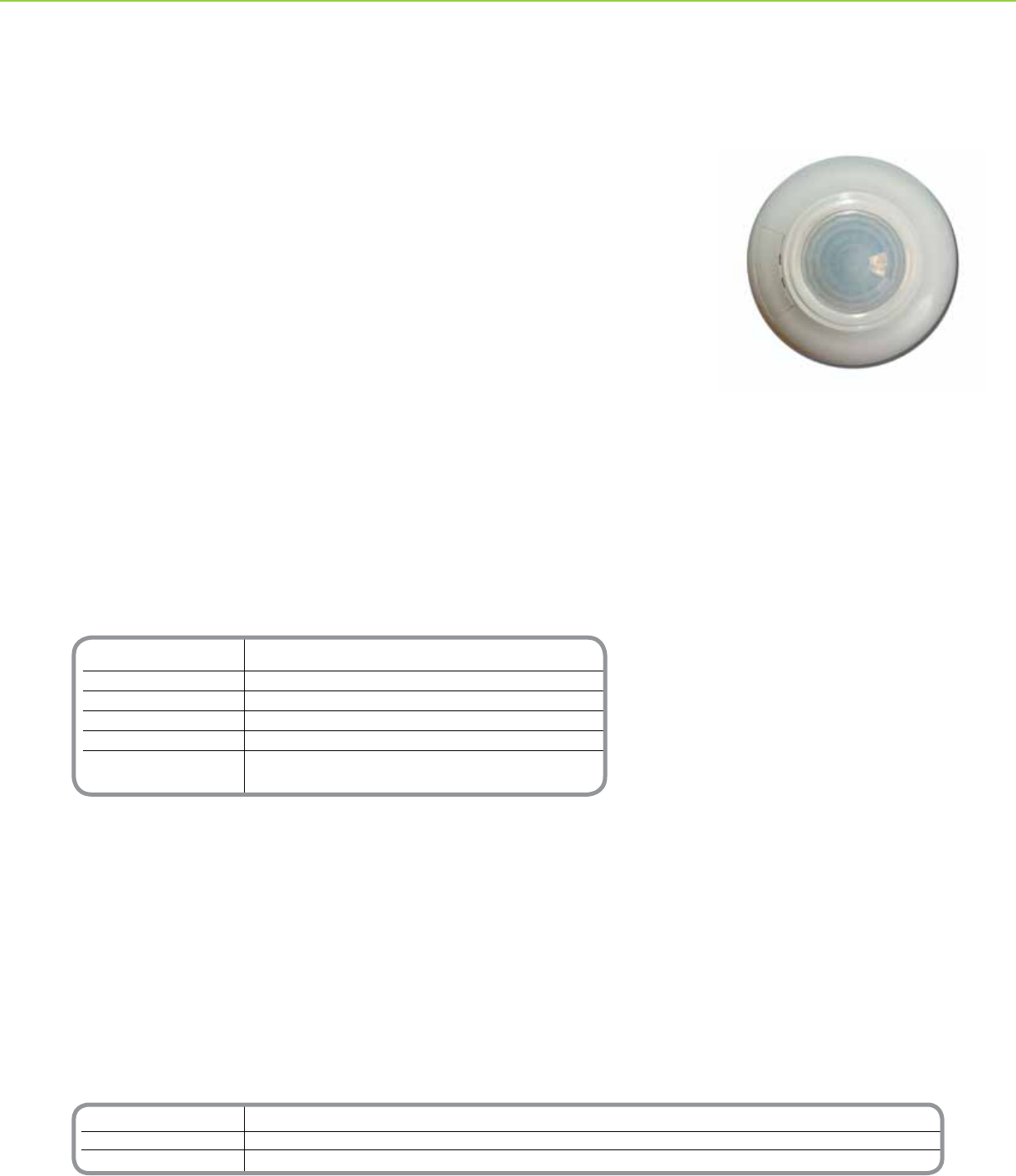
Ceiling Mounted Passive Infrared (PIR) Occupancy Sensor accurately detects
occupancy and automatically switches lighting on and off as needed. This low prole
sensor is ceiling mounted for superior motion detection.
With a 360 degree eld of view and up to 1000 square feet (92.90 sq. meters) of
coverage area, the Schneider Electric Ceiling Mounted PIR Occupancy Sensor is ideal
for ofces, break rooms and copier rooms.
Ceiling mount sensors also incorporate an integral light level sensor to prevent lighting
from switching On when sufcient ambient light is present, such as is commonly found
in windowed areas.
Installation and conguration is simple. The sensor readily mounts to drop ceilings and
features front located adjustments for setting sensitivity and time delay. Features an
isolated relay for use with building automation, security and HVAC systems.
Product Features
• 1000 sq. ft. (92.90 sq. meters)
coverage area
• 24Vac for use with BAS systems
• 360 degree eld of view
• Light Level Sensing (from 0.5 to
250 foot-candles)
• Adjustable Time Delay (pre-set
time delays from 15 seconds
(test) to 30 minutes)
• Adjustable Sensitivity (from 60
to 100%)
• Isolated Relay (1A at 24Vdc NO
and NC Form C Relay)
• Red LED Motion Indicator
• Adjustment compartment cover
equipped with retention clip
• UL/cUL Listed
• Manual Bypass
• Five-year warranty
Ceiling Mounted Occupancy Sensor
PIR
Ceiling Mounted Occupancy
Sensor PIR
11
Technical Information
Current Consumption @ 24Vdc1 34mA Nominal (125mA maximum)
Supply Voltage 24Vdc
Isolated Relay 1A @ 24Vdc Resistive
Operating Temperature 32 - 122° F (0 - 50°C)
Max. Humidity 90% RH Non-condensing
Standards UL and cUL Listed FCC Part 15
Home and Ofce Use (Class B) Title 24 Certied
*For Diagram see technical section page 20
Catalog Number Description
SLSCUS2000 Ceiling Mounted Ultrasonic Occupancy Sensor
SLSPP1277 Power Pack (required)
SLSSP24 Auxiliary Relay
OCCUPANCY SENSORS + CEILING MOUNTED OCCUPANCY SENSORS
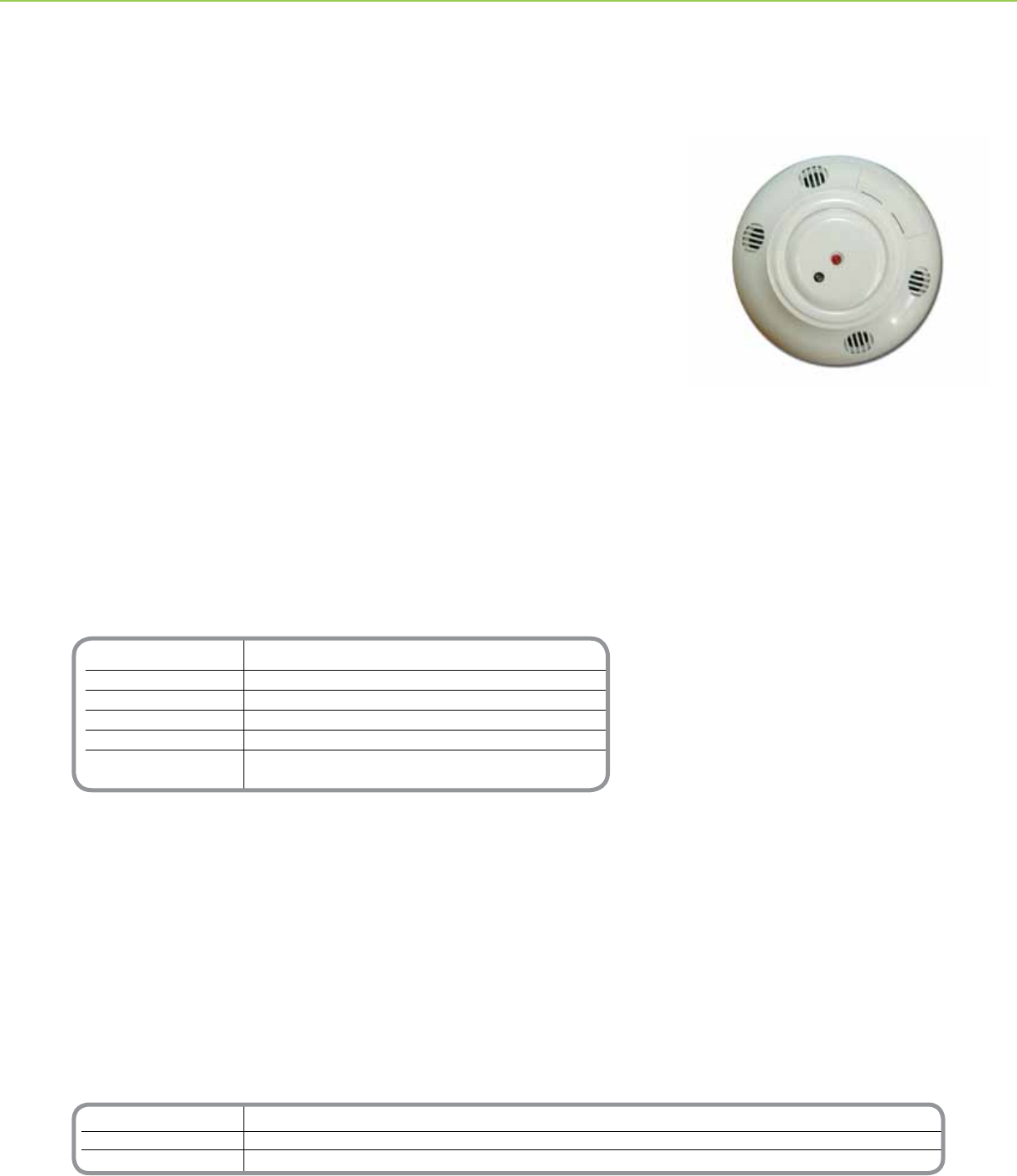
The Ceiling Mounted Ultrasonic Occupancy Sensor accurately detects occupancy and
automatically switches lighting On and Off as needed. This low prole sensor is ceiling
mounted for superior motion detection over partitions and other common obstructions.
With a 360 degree eld of view and up to 2000 square feet (185.8 sq. meters) of
coverage area, the Schneider Electric Ceiling Mounted Ultrasonic Occupancy Sensor is
ideal for storage rooms, multi-stalled bathrooms and open ofce areas.
Ceiling mount sensors also incorporate an integral light level sensor to prevent lighting
from switching On when sufcient ambient light is present, such as is commonly found in
windowed areas.
Installation and conguration is simple. The sensor readily mounts to drop ceilings and
features front located adjustments for setting sensitivity and time delay. Features an
isolated relay for use with building automation, security and HVAC systems.
Product Features
• 2000 sq. ft. (185.8 sq. meters)
coverage area
• 360 degree eld of view
• 24Vac input for use with building
automation systems
• Light Level Sensing (from 0.5 to
250 foot-candles)
• Adjustable Time Delay (pre-set
time delays from 15 seconds
(test) to 30 minutes)
• Adjustable Sensitivity (from 60 to
100%)
• Isolated Relay (1A at 24Vdc NO
and NC Form C Relay)
• Red LED Motion Indicator
• Adjustment compartment cover
equipped with retention clip
• UL/cUL Listed
• Manual Bypass
• Five-year warranty
Ceiling Mounted Occupancy Sensor
Ultrasonic
Ceiling Mounted Occupancy
Sensor Ultrasonic
12
Catalog Number Description
SLSCDS2000 Ceiling Mounted Dual Technology Occupancy Sensor
SLSPP1277 Power Pack (required)
SLSSP24 Auxiliary Relay
Technical Information
Current Consumption 37mA Nominal
Supply Voltage 24Vdc
Isolated Relay 1A @ 24Vdc Resistive
Operating Temperature 32 - 122° F (0 - 50°C)
Max. Humidity 90% RH Non-condensing
Standards UL and cUL Listed FCC Part 15
Home and Ofce Use (Class B) Title 24 Certied
*For Diagram see technical section page 21
OCCUPANCY SENSORS + CEILING MOUNTED OCCUPANCY SENSORS
The Mounted Dual Technology Occupancy Sensor employs both passive infrared (PIR) and
ultrasonic technology to accurately detect occupancy and automatically turn on lighting.
To reduce the occurrence of false-on events, this sensor employs PIR technology to
detect major motion. Once lighting has been turned on, it employs highly sensitive PIR and
ultrasonic technology to detect minor motion and keep lighting on while the area remains
occupied. When the room or area is no longer occupied, the sensor turns off lighting after a
pre-set time delay.
The low prole sensor is ceiling mounted for greatest sensitivity to detect motion in large
areas with obstructions. With a 360 degree eld of view and up to 2000 square feet (185.8
sq. meters) of coverage area, the Ceiling Mounted Dual Technology Occupancy Sensor is
ideal for conference rooms, classrooms and large meeting rooms.
These ceiling mount sensors also incorporate an integral light level sensor to prevent lighting
from switching On when sufcient ambient light is present, such as is commonly found in
windowed areas.
Installation and conguration is simple. The sensor readily mounts to drop ceilings and
features front-located adjustments for setting sensitivity and time delay. The sensor also
features an isolated relay for use with building automation and HVAC systems.
Product Features
• Available in white, ivory, gray, light
almond and black with matching
wall switch cover plate
• Color matching multi-segmented
lens
• Selectable auto-on and manual-
on modes
• 120-277Vac 50/60Hz input
• 180° eld of view
• 1000 sq. ft. major motion and
300 sq. ft. minor motion coverage
area
• Light level sensor
• Walk-through mode
• Adjustable light level, time delay
and sensitivity
• Red LED motion indicator
• For use with electronic and
magnetic ballasts
• No neutral connection, minimum
load or power pack required
• UL and cUL Listed for United
States and Canada
• Test mode (15 second time delay)
• Five-year warranty
Ceiling Mounted Occupancy Sensor
Dual Technology
Dual Circuit Wall Switch
Occupancy Sensor
13
Technical Information
Current Consumption @ 24Vdc1 34mA Nominal (125mA maximum)
Supply Voltage 24Vdc
Isolated Relay 1A @ 24Vdc Resistive
Operating Temperature 32 - 122° F (0 - 50°C)
Max. Humidity 90% RH Non-condensing
Standards UL and cUL Listed FCC Part 15
Home and Ofce Use (Class B) Title 24 Certied
*For Diagram see technical section page 21
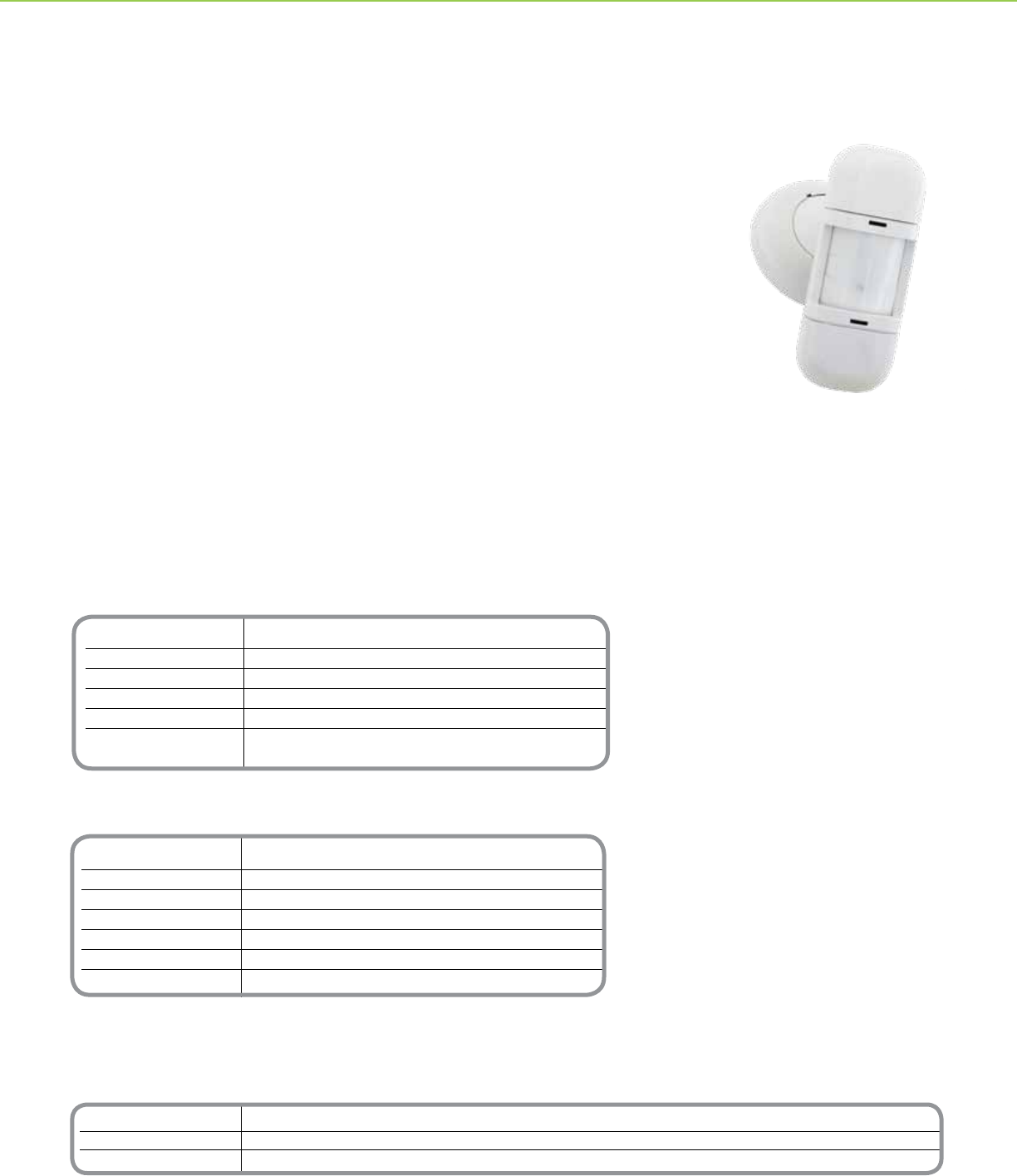
Catalog Number Description
SLSWPS1500 Wall Mounted Occupancy Sensor PIR
SLSPP1277 Power Pack (required)
SLSSP24 Auxiliary Relay
Wiring Color Table
Wire Color Functions
Black 0Vdc
Red +24Vdc
Green Isolated Contact (N.C.)
Yellow Isolated Contact Common
Orange Isolated Contact (N.O.)
Blue Control Output
*For Diagram see technical section page 21
*Control power must be provided by Schneider Electric Power Pack SLSPP1277 or approved equivalent. Confirm the
sensor is connected to the Class 2 side of the Power Pack. Refer to the Schneider Electric Power Pack SLSPP1277
Instruction Bulletin for additional information
C-BUSTM OCCUPANCY SENSORS + WALL MOUNTED OCCUPANCY SENSORS
Schneider Electric Wall Mounted Passive Infrared (PIR) Occupancy Sensor accurately
detects occupancy and automatically switches lighting on and off as needed. This
sensor is wall or ceiling mounted for superior motion detection.
The PIR Occupancy Sensor includes 3 interchangeable lenses for custom coverage
patterns. The Wide Angle lens has a 2500 square foot coverage area when the sensor is
mounted 8 feet high, the Long Range lens has a 102 linear foot coverage area @ 10 ft.
high and the High Bay lens has a 54 linear foot coverage area @ 30 ft. high. With a 110
degree eld of view the Schneider Electric Wall Mounted PIR Occupancy Sensor is ideal
for warehouse, business and ofce settings.
Wall mount sensors also incorporate an integral light level sensor to prevent lighting from
switching On when sufcient ambient light is present, such as is commonly found in
windowed areas.
Installation and conguration is simple. The sensor readily mounts to walls as well as
drop ceilings and features front located adjustments for setting sensitivity and time delay.
Features an isolated relay for use with building automation, security and HVAC systems.
Product Features
• Interchangeable lenses for
custom coverage pattern
• Wide Angle - 2500 sq. ft. @ 8 ft.
mounting height
• Long Range - 102 linear ft. @ 10
ft. mounting height
• High Bay - 54 linear ft. @ 30 ft.
mounting height
• 110 degree eld of view
• Light Level Sensing (from 0.5 to
250 foot-candles)
• Adjustable Time Delay
(pre-set time delays from 15
seconds to 30 minutes)
• Adjustable Sensitivity (from 60 to
100%)
• Isolated Relay
• Red LED Motion Indicator
• Front located adjustment access
cover
• UL®/cUL Listed
Wall Mounted Occupancy
Sensor PIR
Wall Mounted Occupancy Sensor
PIR
14
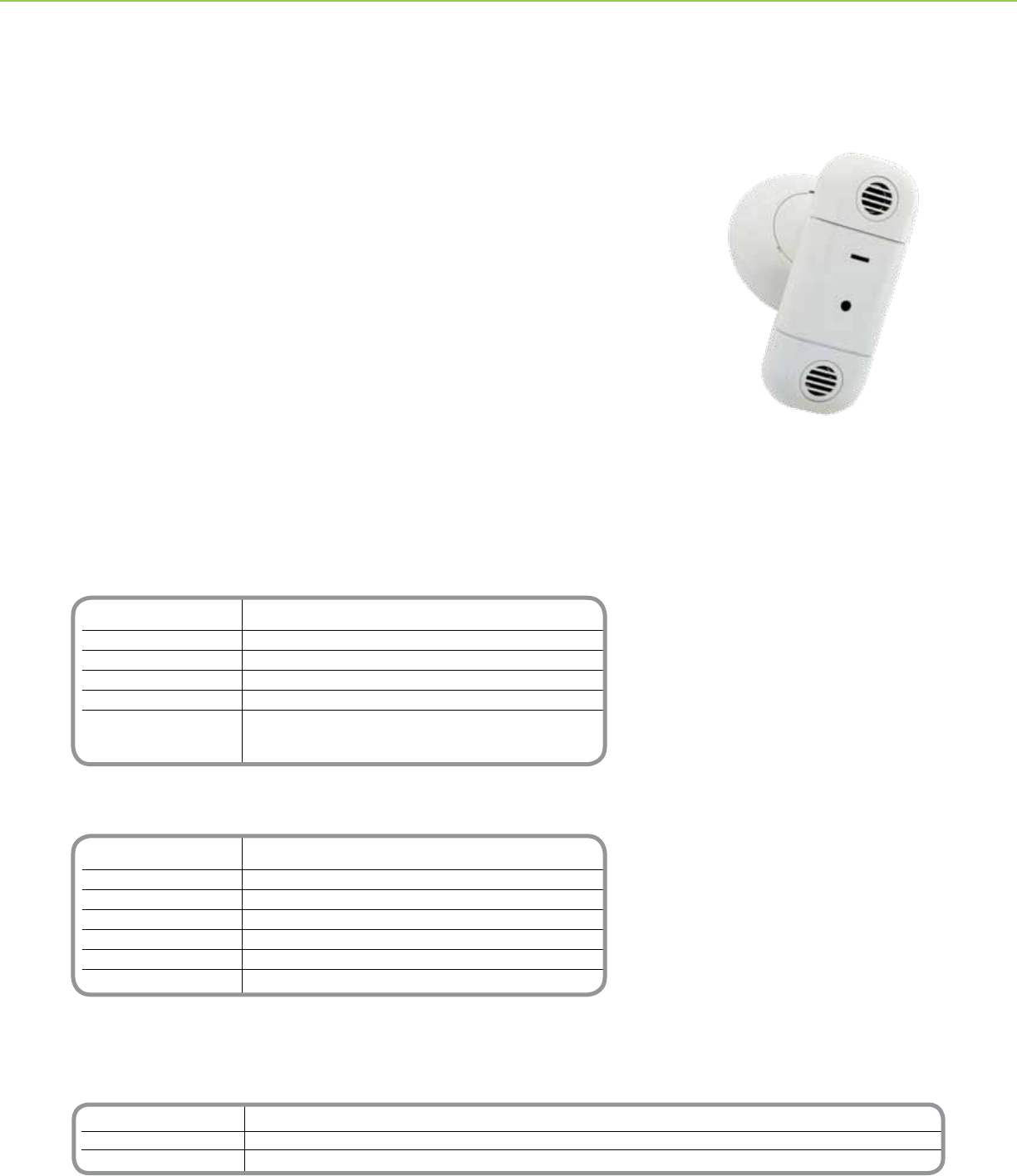
Catalog Number Description
SLSWUS1500 Wall Mounted Occupancy Sensor Ultrasonic
SLSPP1277 Power Pack (required)
SLSSP24 Auxiliary Relay
*Control power must be provided by Schneider Electric Power Pack SLSPP1277 or approved equivalent. Confirm the
sensor is connected to the Class 2 side of the Power Pack. Refer to the Schneider Electric Power Pack SLSPP1277
Instruction Bulletin for additional information
Technical Information
Current Consumption 37mA Nominal
Supply Voltage 24Vdc
Isolated Relay 1A @ 24Vdc Resistive
Operating Temperature 32 - 122° F (0 - 50°C)
Max. Humidity 90% RH Non-condensing
Standards UL and cUL Listed FCC Part 15
FCC Part 15, Home and Ofce Use (Class B)
Title 24 Certied
*For Diagram see technical section page 21
Wiring Color Table
Wire Color Functions
Black 0Vdc
Red +24Vdc
Green Isolated Contact (N.C.)
Yellow Isolated Contact Common
Orange Isolated Contact (N.O.)
Blue Control Output
*For Diagram see technical section page 21
Wall Mounted Occupancy
Sensor Ultrasonic
C-BUSTM OCCUPANCY SENSORS + WALL MOUNTED OCCUPANCY SENSORS
Schneider Electric® Wall Mounted Ultrasonic Occupancy Sensor accurately detects
occupancy and automatically switches lighting on and off as needed. This low prole
sensor is wall or ceiling mounted for superior motion detection over partitions and other
common obstructions.
With 1000 square feet of coverage area, the Schneider Electric® Wall Mounted
Ultrasonic Occupancy Sensor is ideal for storage rooms, hallways, bathrooms,
conference rooms, classrooms and open ofce areas.
Wall mount sensors also incorporate an integral light level sensor to prevent lighting
from switching on when sufcient ambient light is present, such as is commonly found in
windowed areas.
Installation and conguration is simple. The sensor readily mounts to walls or drop
ceilings and features front located adjustments for setting sensitivity and time delay.
Features an isolated relay for use with building automation, security and HVAC systems.
Product Features
• 1000 sq. ft. coverage area
• Light Level Sensing (from 0.5 to
250 foot-candles)
• Adjustable Time Delay
(pre-set time delays from 15
seconds to 30 minutes)
• Adjustable Sensitivity (from 60
to 100%)
• Isolated Relay
• Red LED Motion Indicator
• Manual Bypass
• Front located adjustment access
cover
• UL®/cUL Listed
Wall Mounted Occupancy Sensor
Ultrasonic
15
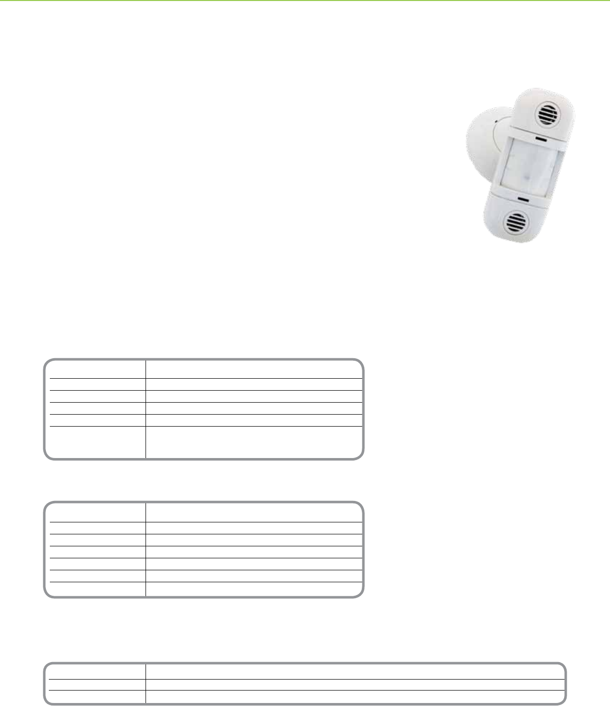
Catalog Number Description
SLSWDS1500 Wall Mounted Occupancy Sensor Dual Technology
SLSPP1277 Power Pack (required)
SLSSP24 Auxiliary Relay
Technical Information
Current Consumption 37mA Nominal
Supply Voltage 24Vdc
Isolated Relay 1A @ 24Vdc Resistive
Operating Temperature 32 - 122° F (0 - 50°C)
Max. Humidity 90% RH Non-condensing
Standards UL and cUL Listed FCC Part 15
FCC Part 15, Home and Ofce Use (Class B)
Title 24 Certied
*For Diagram see technical section page 22
Wiring Color Table
Wire Color Functions
Black 0Vdc
Red +24Vdc
Green Isolated Contact (N.C.)
Yellow Isolated Contact Common
Orange Isolated Contact Common
Blue Control Output
*For Diagram see technical section page 22
*Control power must be provided by Schneider Electric Power Pack SLSPP1277 or approved equivalent. Confirm the
sensor is connected to the Class 2 side of the Power Pack. Refer to the Schneider Electric Power Pack SLSPP1277
Instruction Bulletin for additional information
Wall Mounted Occupancy Sensor
Dual Technology
C-BUSTM OCCUPANCY SENSORS + WALL MOUNTED OCCUPANCY SENSORS
Schneider Electric® Wall Mounted Dual Technology Occupancy Sensor employs both
passive infrared (PIR) and ultrasonic technology to accurately detect occupancy and
automatically turn on lighting.
To reduce the occurrence of false on events, this sensor employs PIR technology to
detect major motion. Once lighting has been turned on, it employs highly sensitive PIR
and ultrasonic technology to detect minor motion and keep lighting on while areas remain
occupied. When the room or area is no longer occupied, the sensor turns off lighting after a
pre-set time delay.
The low prole sensor is wall mounted for greatest sensitivity to motion in large areas with
obstructions. With a 110 degree eld of view and up to 2500 square feet of coverage area
when mounted at 8 ft. off the ground, the Wall Mounted Dual Technology Occupancy
Sensor is ideal for conference rooms, classrooms, bathrooms, and large ofce areas.
These wall mount sensors also incorporate an integral light level sensor to prevent lighting
from switching On when sufcient ambient light is present, such as is commonly found in
windowed areas.
Installation and conguration is simple. The sensor readily mounts to walls and drop ceilings
and features front located adjustments for setting sensitivity and time delay. The sensor also
features an isolated relay for use with building automation and HVAC systems.
Product Features
• 2500 sq. ft. coverage area @ 8 ft.
• 110 degree eld of view
• Light Level Sensing (from 0.5 to
250 foot-candles)
• Adjustable Time Delay
(pre-set time delays from 15
seconds to 30 minutes)
• Adjustable Sensitivity (from 60
to 100%)
• Isolated Relay
• Red and green LED motion
indicators
• Manual Bypass
• Front located adjustment access
cover
• UL®/cUL Listed
Wall Mounted Occupancy Sensor
Dual Technology
16
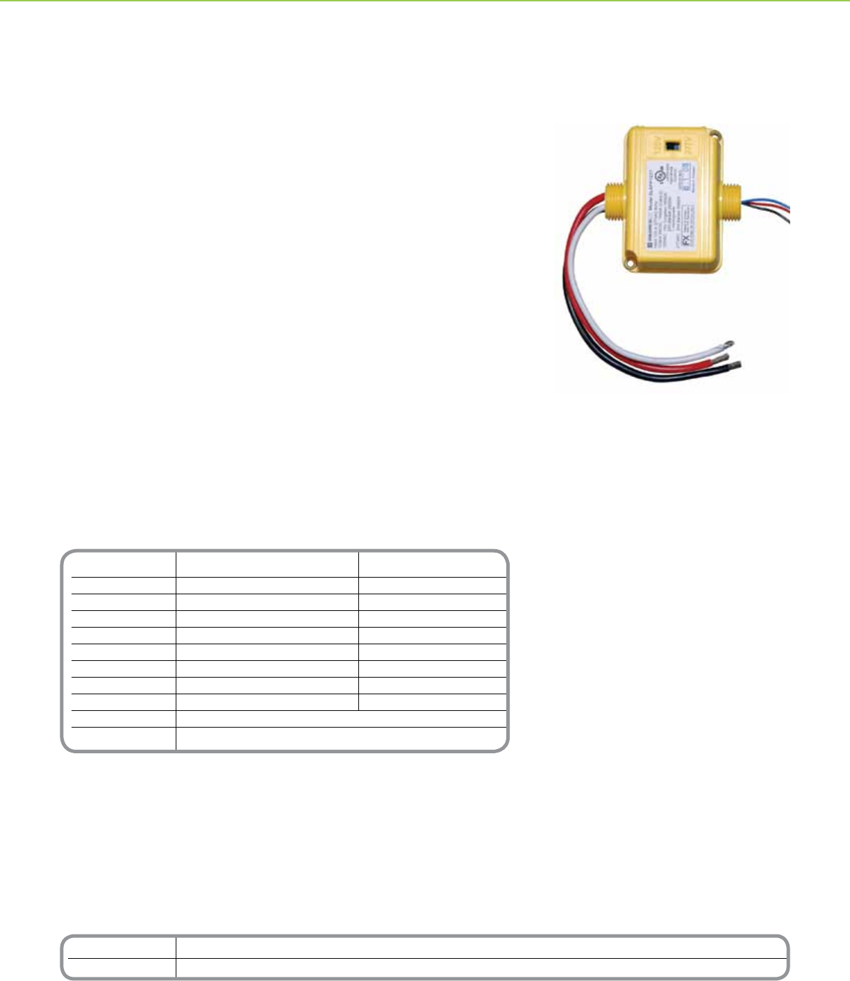
Technical Information
Item Power Pack Auxiliary Relay
Storage Temp -20°F to 150°F (-29C to 65C) -20°F to 150°F (-29C to 65C)
Operating Temperature 32°F to 104°F (0C to 40C) 32°F to 104°F (0C to 40C)
Max. Humidity 90% RH Non-condensing 90% RH Non-condensing
Input 120 or 277Vac / 60Hz 24Vdc / 36 mA
Output 24Vdc/100 mA Nominal No Power Supply
Max Load Ratings 120Vac/60Hz 277Vac/60Hz 120Vac/60Hz 277Vac/60Hz
Tungsten 15A/1800W 15A/1800W 15A/1800W 15A/1800W
Ballast 20A 20A 20A 20A
AC Motor 1HP at 120Vac/ No HP rating at 277Vac
Dimensions 3 in. (76mm) tall x 2.25 in. (57mm) wide x 1.75 in. ( 44mm) deep
*For Diagram see technical section page 22
Catalog Number Description
SLSPP1277 Ceiling Mounted Occupancy Sensor Power Pack
SLSSP24 Ceiling Mounted Occupancy Sensor Auxiliary Relay
OCCUPANCY SENSORS + POWER PACK AND AUXILIARY RELAY OCCUPANCY SENSORS + HIGH BAY OCCUPANCY SENSORS
The Power Pack supplies low voltage power to Schneider Electric ceiling and wall
mounted occupancy sensors, and employs a heavy duty 20A relay to switch lighting and
HVAC loads based on a control signal received from the occupancy sensor. The power
pack accepts both 120V and 277V input and supplies up to 100 mA at 24Vdc
The power pack employs a micro-controller that switches loads at minimum voltage,
protecting relay contacts from high in-rush current common when switching electronic
ballasts. This switching method reduces the stress across the relay contacts, preventing
arc-over and assuring long reliable contact life.
Similar to the power pack, the auxiliary relay does not supply power, but switches
lighting and HVAC loads based on a control signal from the occupancy sensor.
Both the power pack and auxiliary relay are housed in a rugged plenum rated enclosure.
Flexible mounting scheme allows for installation inside or outside a standard 4 x 4 inch
junction box.
Product Features
• 120V & 277V Input
• Plenum Rated
• Flexible Mounting Options
• UL and cUL Listed
• FCC Part 15, Class B
• Heavy duty relay rated to switch
electronic ballast loads
• External color coded leads for
quick installation
• Mounts to a standard 4 in. (101
mm) x 4 in. (101 mm) junction
box using a ½ in. (12.7 mm)
threaded EMT nipple
Power Pack and Auxiliary Relay
Power Jack
17
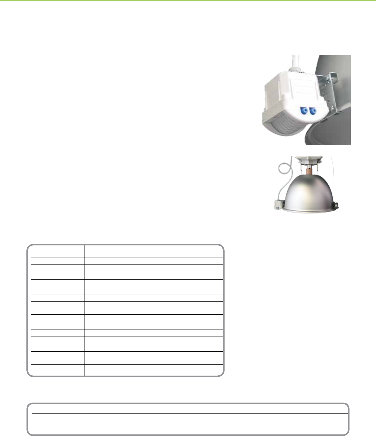
Catalog Number Description
SLSPIP210 Basic Occupancy Sensor
SLSPIP211 Single Output Occupancy Sensor
SLSPIP212 Dual Output Occupancy Sensor
SLSPCW001 Optional Counterweight
Technical Information
Fixture Compatibility HID with constant wattage auto-transformer ballast
Dimming Method Relay-switched dual-section capacitor*
Switching Congurations Parallel (preferred) or series capacitors
Relay Current Rating 4 amperes RMS maximum
Maximum Fixture Wattage 1000 watts parallel mode/250 watts series mode
AC Line Voltage 208/240/277/347/480VAC
Power Consumption 3 watts maximum
Maximum Fiber Spacing 200 ft.
Between Nodes
Ambient Temperature Range 32O to 122O F (0O to 50O C) non-condensing
Observed Motion ON Time 0 to 15 minutes (user-adjustable)
Lamp Warm Up Interval 15 minutes
Wire Harness 4 conductor 18 AWG stranded copper wire
Wire Harness Length 36 inches (91.44 cm)
Dimensions 3.25 in. (L) x 3.25 in. (W) x 3.25 in.(H)
(including mounting nipple) [82.56 mm (L) x 82.56 mm (W) x 82.56 mm (H)]
Standards UL®: Listed 916 Energy Management Equipment cUL: Listed
*For Diagram see technical section page 22
Sensor and optional counterweight
mounted on luminaire
OCCUPANCY SENSORS + HIGH BAY OCCUPANCY SENSORS
Schneider Electric High Bay HID Basic, Single and Dual Output Occupancy Sensors
work with a single HID (high intensity discharge) luminaire to reduce the lamp wattage
by approximately 50% and then return the lamp wattage to 100% when occupancy is
detected in an aisle or room. Motion is detected using passive infrared (PIR) technology.
Basic HID Sensors are used in sensor-per-xture conguration, while single output
sensors include a connector to send and receive ber optic signals. Single output
sensors are commonly used in daisy chain congurations. Dual output sensors have two
connectors that send ber optic signals, and are commonly used in congurations that
interleave switch packs and sensors. All Sensors are compatible with single magnetic
HID luminaires.
Product Features
• Compatible with HID luminaires rated
between 208 and 480VAC/60Hz,
without adding taps or jumpers
• Up to 40’ mounting height
• User-adjustable 1 to 15 minute activity
timer
• User-adjustable range dial to
customize PIR sensitivity
• Available with interchangeable aisle
and area lenses
• Lamp always starts on high to provide
full rated HID lamp life, even after AC
power bumps or loss of ber optic
signals
• Includes a manual test switch for self
diagnostics that assist with installation
and debugging networks
High Bay Occupancy Sensor
HID
High Bay Occupancy Sensor
18
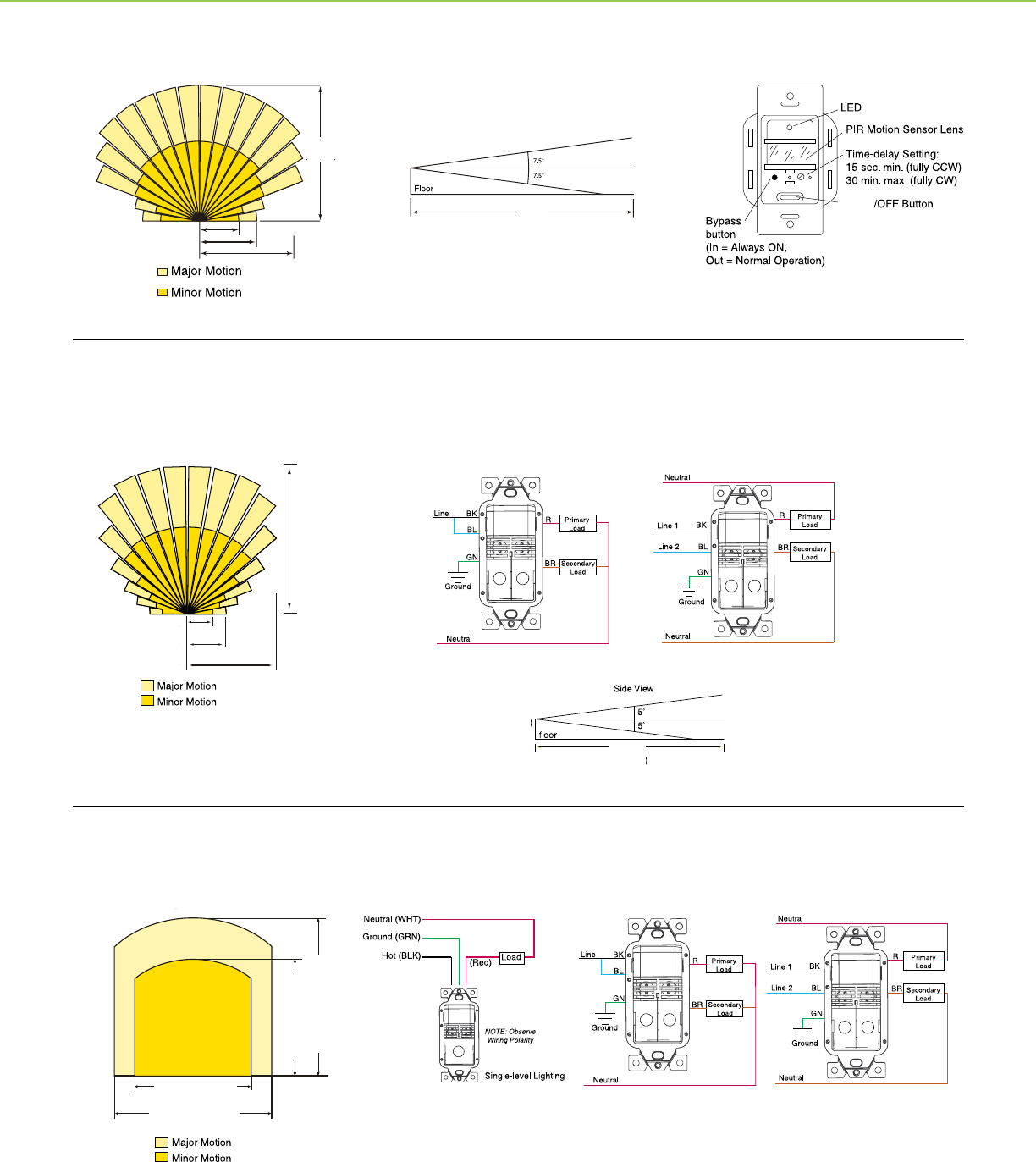
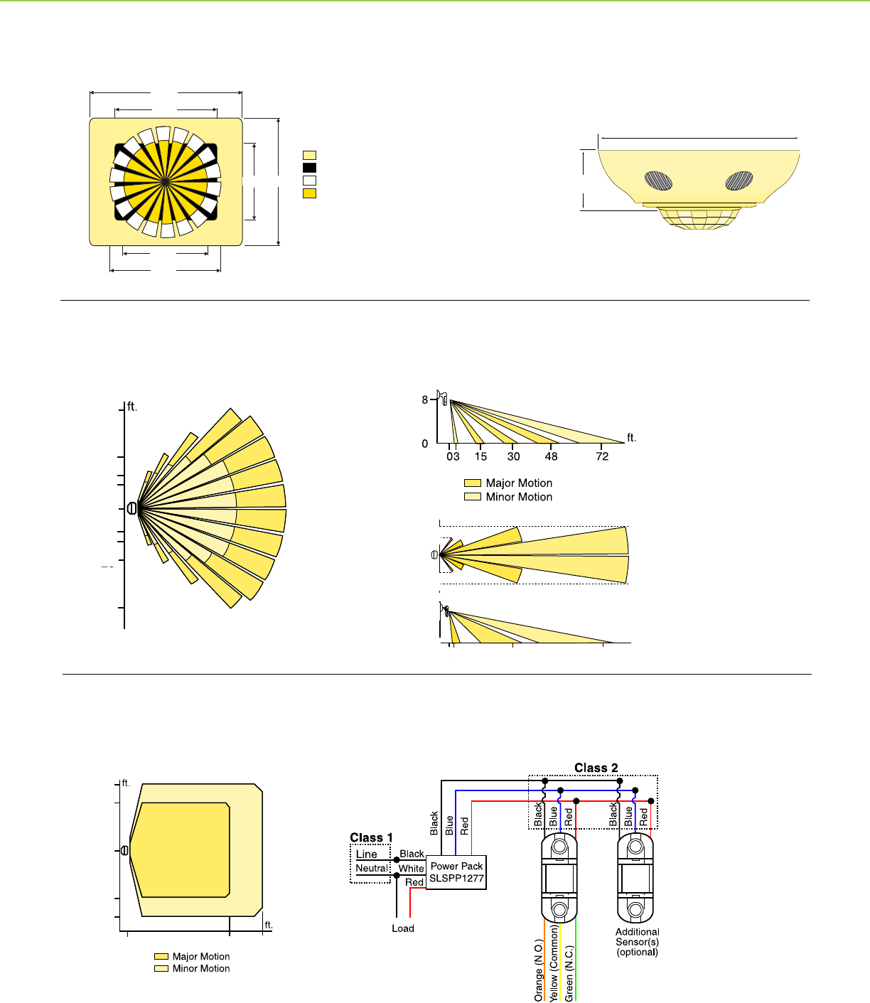
Sensor features
Sensor eld of view
Manual
Auto
Side view of sensor eld of view
6 ft. (1.83 m)
9 ft. (2.74 m)
21 ft. (6.4 m)
35 ft.
(10.7 m)
35 ft.
(10.7 m)
4 ft.
(1.2 m)
Ultrasonic Sensor Field of View, Top
Sensor Wiring, Bi-level Sensor Wiring, Dual Circuit
Sensor Wiring Sensor Wiring, Bi-level Sensor Wiring, Dual Circuit
20ft. (6.1m)
27ft. (8.23m)
20ft. (6.1m)
27ft. (8.23m)
(7.62 m)
(9.75 m)
(7.62 m)
(9.75 m)
(2.74 m)
(7.62 m)
(9.75 m)
(7.62 m)
(9.75 m)
(2.74 m)
OCCUPANCY SENSORS + TECHNICAL SECTION
35 ft.
(10.7 m)
35 ft.
(10.7 m)
10 ft. (3.1 m)
15 ft. (4.6 m)
25 ft. (7.6 m)
4 ft.
(31.2 m)
Wall Switch Occupancy Sensor
Commercial Grade Occupancy Sensors
PIR Wall Switch
Commercial Grade Occupancy Sensors
Ultrasonic Wall Switch
19
Side view of ceiling mounted sensor
48 ft.
42 ft.
Area of Detection
Major Motion
Minor Motion
24 ft.
30 ft.
48 ft.
42 ft.
Area of Detection
Major Motion
Minor Motion
24 ft.
30 ft.
1.25 in.
(31 mm)
(7.62 m)
(9.75 m)
(7.62 m)
(9.75 m)
(2.74 m)
25 ft.
32 ft. (9.75 m)
(7.62 m)
Side view of sensor eld of view
(7.62 m)
(9.75 m)
(7.62 m)
(9.75 m)
(2.74 m)
(7.62 m)
(9.75 m)
(7.62 m)
(9.75 m)
(2.74 m)
25 ft.
32 ft. (9.75 m)
(7.62 m)
9 ft.
(2.74 m)
4.5 in. (115 mm)
1.75 in.
(44 mm)
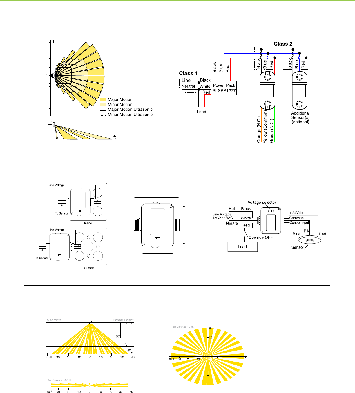
Single and Dual Technology Sensor Field of View, Top
Dual Technology Sensor Field of View, Side
Sensor Wiring, Bi-level Sensor Wiring, Dual Circuit
10 ft.
(3.05 m)
6 ft.
(1.83 m)
13.5 ft.
(4.11 m)
21 ft. (6.4 m)
9 ft.
(2.74 m)
35 ft.
(10.67m)
20 ft.
(6.1 m)
27 ft.
(8.23 m)
35 ft.
(10.67 m)
4 ft.
(1.22 m)
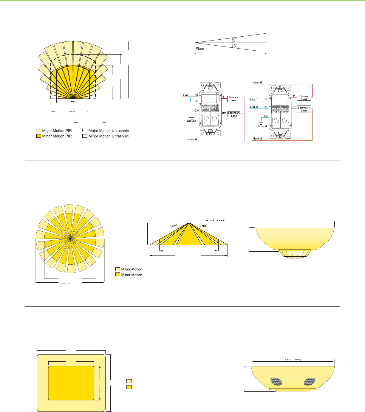
OCCUPANCY SENSORS + TECHNICAL SECTION
Ceiling Mounted Occupancy Sensor
Ultrasonic
Ceiling Mounted Occupancy Sensor
PIR
Commercial Grade Occupancy Sensors
Dual Technology Wall Switch
20
Area of Detection
Ultrasonic Major Motion
Ultrasonic Minor Motion
PIR Major Motion
PIR Minor Motion
48 ft.
42 ft.24 ft.
30 ft.
25 ft.
32 ft.
4.5 in. (115 mm)
1.75 in.
(44 mm)
Area of Detection
Ultrasonic Major Motion
Ultrasonic Minor Motion
PIR Major Motion
PIR Minor Motion
48 ft.
42 ft.24 ft.
30 ft.
25 ft.
32 ft.
48 ft.
25 ft.
30 ft.
32 ft.
24 ft. 42 ft.
Ceiling Mounted Occupancy Sensor
Dual Technology
25
48
16
11
11
16
48
25
0
11.5
11.5
0
16
16
Ultrasonic Major Motion
Ultrasonic Major Motion
PIR Major Motion
PIR Major Motion
023 32
30ft
(9.14m)
18ft
(5.49m)
18ft
(5.49m)
30ft
(9.14m)
10ft
(3.1m)
0
0 3ft
(0.9m)
42ft
(12.8m)
102ft
(31.1m)
OCCUPANCY SENSORS + TECHNICAL SECTION
Wall Mounted Occupancy Sensor
PIR
Wall Mounted Occupancy Sensor
Ultrasonic
21
Coverage pattern for area / aisle lenses (side view)
Coverage pattern for aisle lens (top view)
0
0
0
Coverage pattern for area lens (top view)
3 in. (76 mm)
2.25 in. (57 mm)
3 in.
(76 mm)
25
48
16
11
11
16
48
25
0
23 48
15
8
332 72
0
0
OCCUPANCY SENSORS + TECHNICAL SECTION
Flexible Mounting System DiagramFront View Dimensions
High Bay Occupancy Sensors
HID
Power Pack and Auxiliary Relay
Wall Mounted Occupancy Sensor
Dual Technology
22

Track-Limiting
Panels
23

Energy codes typically require lighting power density
calculations for track lighting to be based on the linear
feet of installed track. Some codes stipulate multipliers as
low as 30W per foot of track, while others use a multiplier
as high as 70W per foot of track. When energy efcient
lighting is used, the connected load is typically much less
than the per-foot multipliers given in the energy codes.
This penalizes lighting designs that employ track lighting
and may threaten retail environments where higher light
levels are needed.
Many codes also provide provisions to compute the
luminaire wattage based off the maximum wattage that
the circuit can provide. For example, 2005 CA Title 24,
130(c)3 states:
“Luminaire wattage incorporated into the installed lighting
power shall be determined in accordance with the
following criteria... The wattage of line-voltage lighting
track and plug-in busway which allows the addition or
relocation of luminaires without altering the wiring of the
system shall be the volt-ampere rating of the branch
circuits feeding the luminaires...”
Introduction to
Track-Limiting Panels
24
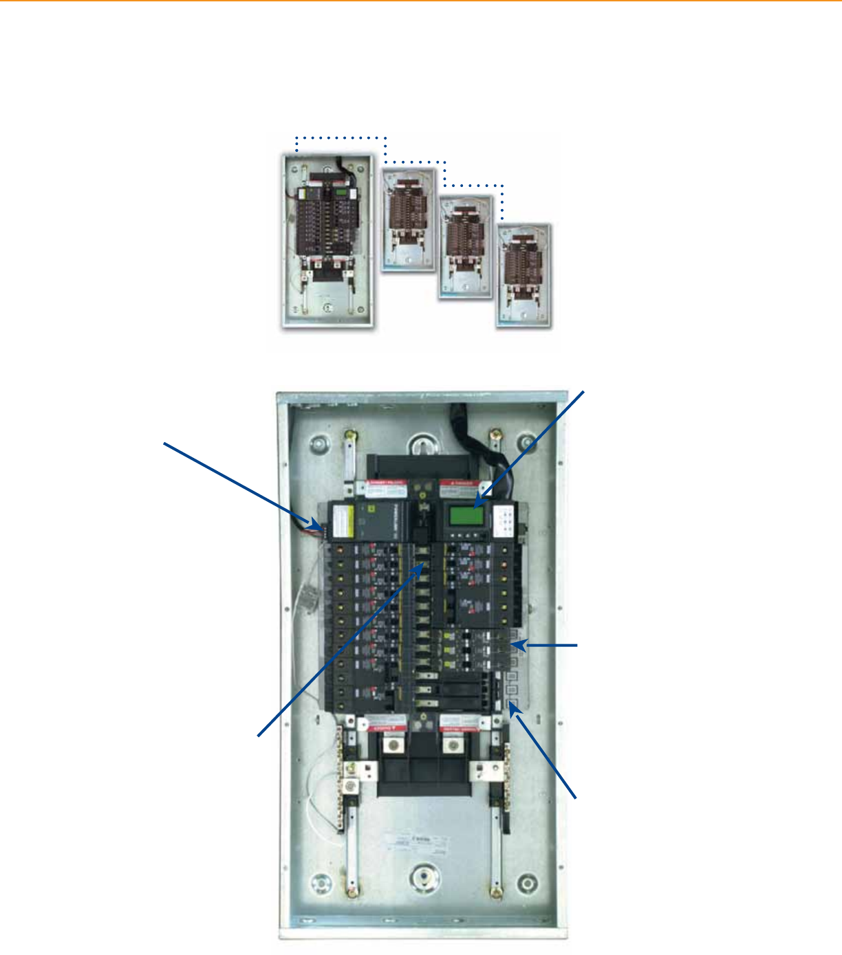
Technical Information
Item Track-Limiting Panel
Type NEMA 1 Indoor
Box Galvanized steel
Finish ANSI 49 Gray
Voltage Rating 120Vac
Short Circuit Current Rating 10,000A
Branch Circuit Ampere Ratings 0.5A, 1A, 2A, 3A, 4A, 5A, 6A, 7A, 8A, 10A, 15A, 16A
Branch Circuit Terminals Box lugs: #18-4 AWG (1-25mm2)
Operating Environment 77°F (25°C)
Standards UL1077, UL508A
Listings/Certications/Compliance California Title 24, ASHRAE 90.1 compliant
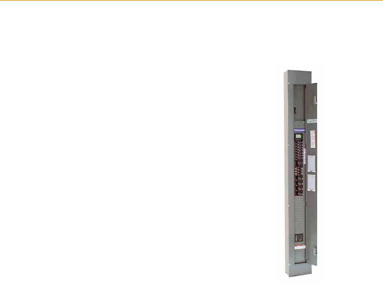
Enclosures are available for mounting up to 21 or 42 circuits. Both enclosures are available for ush or
surface mounting.
Enclosure Enclosure Cabinet Dimensions (H x W x D)
12M 14.25 x 9 x 3.75 (362 x 229 x 95)
21M 14.25 x 3.75 x 17.92 in. (362 x 95 x 455mm)
42M 14.25 x 3.75 x 33.78 in. (362 x 95 x 858mm)
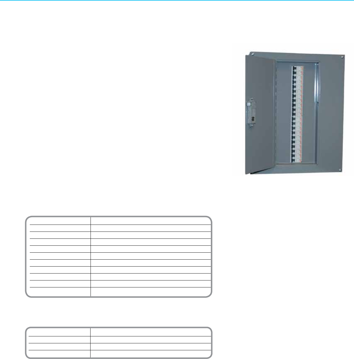
Track-Limiting Panel
SCHNEIDER ELECTRIC TRACK-LIMITING PANELS + TRACK-LIMITING PANELS
Track-Limiting Panels eases the burden of meeting today’s stringent energy codes like
California Title 24. Typically used for track lighting applications, these panels limit the
power available to a lighting branch circuit by incorporating a special circuit breaker into
the branch circuit.
Because the Track-Limiting panel limits the available power to a specied level,
designers can better reect the actual power requirements into their load density
calculations. Power level will be substantially lower than by using the standard multipliers
given for track lighting.
Panels are readily accessible providing easy access for inspection and maintenance.
These panels also incorporate circuit breakers rated for the higher available fault currents
found on many 120V systems. In addition, the use of supplementary protectors provides
a convenient means for isolating individual track circuits.
Product Features
• Readily accessible panel mounted enclosures
• Flush or surface mounting
• Hinged door with key-locking latch
• Up to 42 circuit breakers per enclosure
• Circuit breakers rated 0.5A – 16A
• Factory assembled, tested, and labeled
• CA Title 24 compliant
Track-Limiting Panels
25
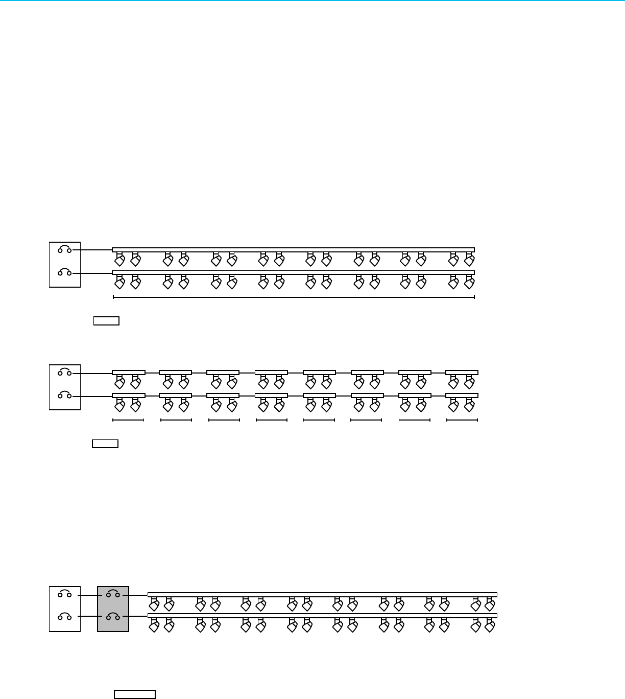
20A
Standard Layout
Revised Layout Using Short Track Segments
Track length determines wattage calculation
Track length determines wattage calculation
The Square D Track-Limiting Panel installs between the branch circuit breaker and the track lighting, solving
the energy code calculation discrepancy, making the wattage calculation independent of track length.
20A
20A
20A
20A
20A
6A
6A
Branch Circuit
Breaker Panel
Branch Circuit
Breaker Panel
Branch Circuit
Breaker Panel
Track-Limiting
Panel
With the Track-Limiting Panel
100 ft of track = 4500W*
64 ft of track = 2880W*
Same 100 ft. of track: 6A @ 120V = 720W
6A @ 120V - 720W
1440W total
*Based on 45W/ft multiplier of California Title 24
(plus significantly higher
installed costs and reduced
layout flexibility)
20A
Standard Layout
Revised Layout Using Short Track Segments
Track length determines wattage calculation
Track length determines wattage calculation
The Square D Track-Limiting Panel installs between the branch circuit breaker and the track lighting, solving
the energy code calculation discrepancy, making the wattage calculation independent of track length.
20A
20A
20A
20A
20A
6A
6A
Branch Circuit
Breaker Panel
Branch Circuit
Breaker Panel
Branch Circuit
Breaker Panel
Track-Limiting
Panel
With the Track-Limiting Panel
100 ft of track = 4500W*
64 ft of track = 2880W*
Same 100 ft. of track: 6A @ 120V = 720W
6A @ 120V - 720W
1440W total
*Based on 45W/ft multiplier of California Title 24
(plus significantly higher
installed costs and reduced
layout flexibility)
The Track-Limiting Panel installs between the branch circuit breaker and the track lighting, solving the energy code
calculation discrepancy, making the wattage calculation independent of track length.
SCHNEIDER ELECTRIC TRACK-LIMITING PANELS + TRACK-LIMITING PANELS
Energy codes typically calculate track lighting loads based on linear feet of installed track. Some codes use a multiplier as low as
30 watts/foot while others use a multiplier as high as 70 watts/foot. When using the energy efcient lighting technologies available
today, the connected load is typically much less than the per-foot multipliers used by most energy codes. This penalizes lighting
designs that employ track lighting and wastes available lighting watts that could be used more effectively.
Below is a typical track lighting example. The Standard Layout consists of two 50’ runs of single circuit track, each with sixteen
39W track heads for a total connected load of 1376W. The Revised Layout Using Short Track Segments has the same 1376W
connected load but uses sixteen short 4’ track segments (64’), each fed separately, to help minimize the impact of the watts per
foot multiplier. The scenario with the Track-Limiting Panel uses the original two 50’ runs of single circuit track, with each monitored
by a 6 Amp current limiting circuit breaker that is closely matched to the actual connected load of 1376W. This results in the
minimum calculated watts per the energy codes.
With the Track-Limiting Panel
Without the Track-Limiting Panel
26
Powerlink®
Lighting Control
27

For many designers, the engineering of a suitable
lighting control system has become a daunting
task. The designer must balance space constraints,
equipment/installation costs, maintenance and
operational concerns, while ensuring a code-compliant
installation. Fortunately, the Powerlink® G3 lighting
control system addresses concerns by:
Using standard lighting
panelboards
All Powerlink G3 components mount in the panel
just like a standard circuit breaker. Documenting
your control system layout is as simple as indicating
which branch circuits are to be controlled.
Saving space
Since the lighting control system is located inside
the lighting panelboard, valuable wall and oor
space is available for more productive uses.
Schneider Electric also offers space-saving, column-
width panelboards and exible modular panelboard
systems.
Complying with codes
With today’s high available fault currents, it’s
extremely important that your system meets code
requirements. The Powerlink G3 system is fully UL
listed and meets NEC® 110.10 requirements.
Building Integration & Control
Today more than ever, building owners and facility
managers want to get the most out of every dollar
invested in their building infrastructure. Powerlink
lighting control systems integrate easily with other
building systems as part of an energy management
system or building automation system, supporting
common open protocols such as BACnet
and Modbus®. Compared to standard lighting
panelboards, Powerlink lighting control systems
typically achieve enough energy savings to pay for
the panelboard many times over.
Introduction to
Powerlink® Lighting Control
Powerlink®
Lighting Control
28
POWERLINK® LIGHTING CONTROL + PANEL BOARDS
Innovative Schneider Electric
remote-operated circuit breakers
combine the protective features
of conventional circuit breakers
with the switching functions of a
contactor.
Conventional EDB circuit
breakers can be readily
incorporated into a G3 panel.
The intelligence of the Powerlink
G3 system comes from its
microprocessor- based controller. It
processes many signals that originate
externally from control devices, such
as switches or sensors, or from its
powerful internal time scheduler
that switches breakers according to
predened daily schedules.
Plug-on control bus strips
act as the bridge between
the circuit breakers and the
electronic control components
of a Powerlink G3 system.
A self-contained power supply
furnishes the power for remotely
operated circuit breaker switching
and for the system’s electronics.
Up to eight panels can be operated from a single
controller.
Powerlink®
G3 Panel Mounted Components
29
POWERLINK® LIGHTING CONTROL + PANEL BOARDS
The NF Panelboard offers superior performance and application exibility for
commercial and industrial electrical systems up to 480Y/277V. Schneider Electric is
the only lighting control supplier that offers a full range of enclosure options including
NEMA Type 3R, 5 and 12. The following designs are available to suit your needs:
• Standard – The NF Panelboard offers superior performance and application exibility
for commercial and industrial electrical systems up to 480Y/277V. This versatile
lighting and power distribution panelboard features a wide selection of circuit
breakers, accessories, and ready-to-install kits, as well as 200% rated neutrals for
non-linear loads.
• Column-width – These innovative panels are designed to t into a standard size W,
H, or I-beam support columns commonly found in distribution and industrial facilities.
Column-width panelboards can also be wall mounted, saving valuable oor and wall
space where tight equipment space is a concern.
• Modular Panelboard Systems (MPS) – This panel system bundles electrical
distribution equipment into a single, factory assembled and wired integrated system.
This approach replaces the traditional method of independently mounting each
panelboard and lighting control system, which saves space and reduces installation
time. Modular panelboard systems are tailored to specications and are available
with a mix of Schneider Electric NQOD, NF, NF Column-width and Schneider
Electric Powerlink interiors, as well as optional power and control wiring, dry type
transformers, lighting contactors, transient voltage surge suppression (TVSS)
units, and enclosure space for eld installed equipment. All MPS panelboards are
Underwriters Laboratories (UL) Listed under File E33139 (Panelboard UL67).
• Integrated Power Center (IPC) – This integrated system offers the wide range of
factory assembled and wired panelboards interiors, dry type transformers, and
lighting control as offered with the MPS line. In addition, the IPC offers factory
installed and programmed building management systems, automatic transfer
switches, and motor starters. Regardless of your system complexity, Schneider
Electric has the expertise to integrate your requirements into one optimized, cost
effective, space saving solution. IPCs are Underwriters Laboratories (UL) Listed
under le E83877 (Dead-Front Switchboard UL891).
NF Column Width Panelboard
NF Panelboards, Column Width
& Custom Panel Boards
30
Technical Information
Voltage 120Vac 240Vac 480/277Vac
Interrupting capacity 65 kAIR 65 kAIR 14 kAIR
Terminals (1) #14 - 8 AL or (1) #14 - 8 CU
Standards UL Listed 489, NEMA Standard AB-1-1986, CSA Standard 22.5
*For series connector ratings, see page 44
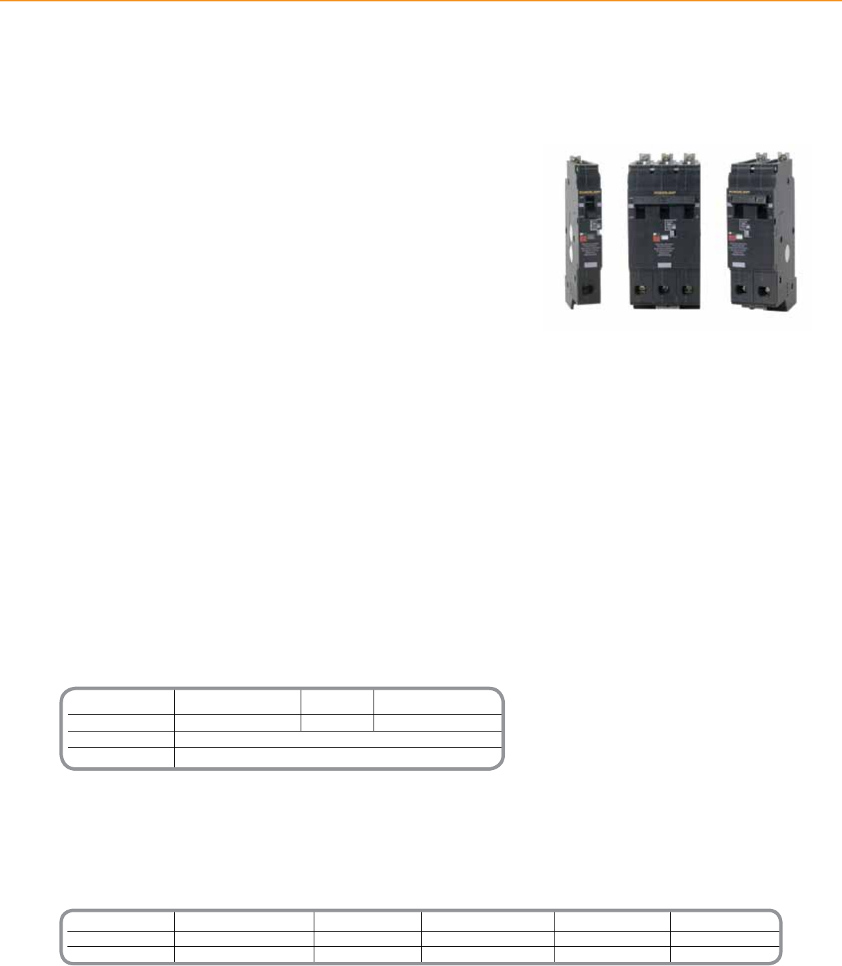
Catalog Number One-Pole Catalog Number Two-Pole Catalog Number Three-Pole
ECB14015G3** 15 Amp ECB24015G3** 15 Amp ECB34015G3** 15 Amp
ECB14020G3** 20 Amp ECB24020G3** 20 Amp ECB34020G3** 20 Amp
ECB14030G3 30 Amp ECB24030G3 30 Amp ECB32030G3 30 Amp*
* Not available in 480V
** Switch Duty Rated
POWERLINK® LIGHTING CONTROL + CIRCUIT BREAKERS
Powerlink® G3 remotely operated circuit breakers are designed for installation in
Schneider Electric NF Lighting Panelboards as part of the Schneider Electric Powerlink
G3 Lighting Control System. These circuit breakers provide the same overcurrent
protection as found in standard circuit breakers.
The Best in Remote Operation
• Robust 24Vdc motor and highly effective trip mechanism provide unequaled remote
operation capability in terms of compact size, electrical ratings, and mechanical life.
• Motor and drive train can open and close the contacts when the circuit breaker handle
is in the ON position.
• Contacts cannot be closed remotely when the handle is in the OFF position or the
circuit breaker is tripped.
• Manual override selector located on the front of the breaker provides by-pass of
automated control command .
• In manual mode, the motor drive train is disconnected from the contact, allowing the
circuit breaker handle to operate the contacts like a conventional circuit breaker.
• Remote contact status indication – determines the presence or absence of voltage on
the load side terminal of the circuit breaker.
Tripping System with True RMS Sensing
• Schneider Electric Powerlink ECB-G3 circuit breakers have a permanent trip unit that
contains a factory preset thermal (overload) trip element and a magnetic (short circuit)
trip element in each pole.
• The thermal trip element – true RMS sensing and is calibrated to carry the continuous
current rating of the circuit breaker at 140°F (40°C) free air ambient temperature.
Product Features
• 200,000 cycles (ON/OFF) load
endurance
• Remote and local status
• Manual override
• Extra large load terminal
ECB-G3 Series Remotely
Operated Circuit Breakers
Powerlink®
Remotely Operated ECB-G3 Circuit Breakers
31
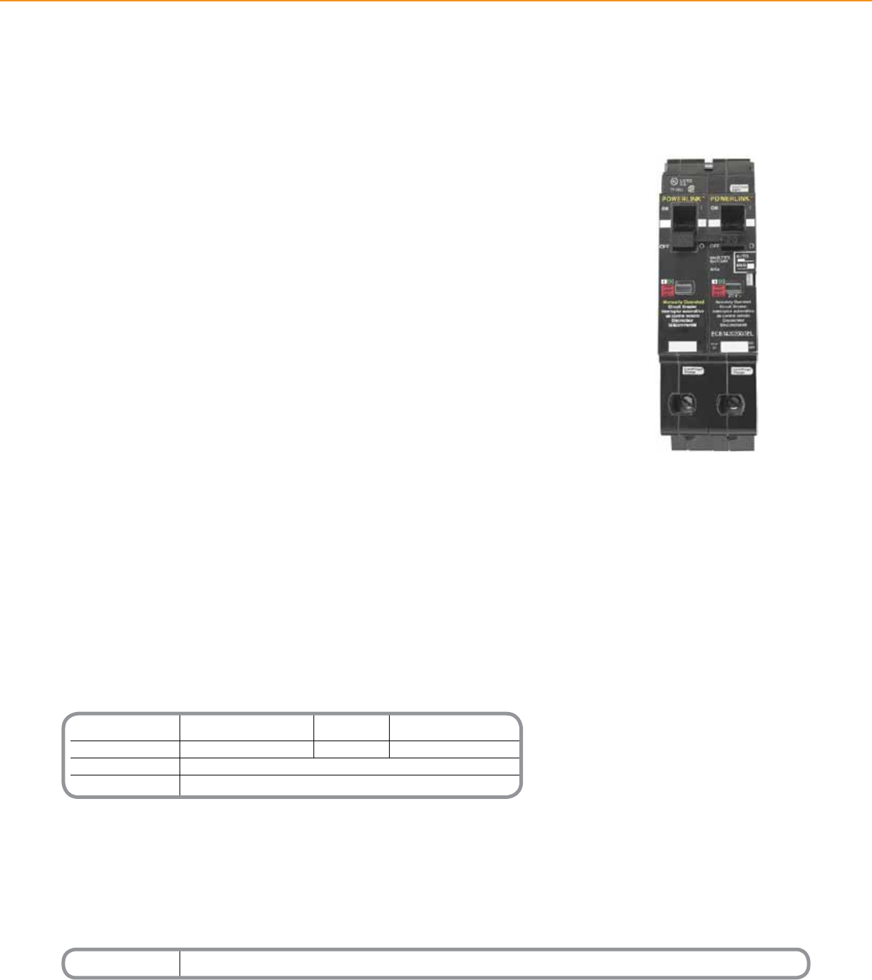
Catalog Number Ampere Rating
ECB142020G3EL 20 Amp
Technical Information
Voltage 120Vac 240Vac 480/277Vac
Interrupting capacity 65 kAIR 65 kAIR 14 kAIR
Terminals (1) #14 - 8 AL or (1) #14 - 8 CU
Standards UL Listed 489, NEMA Standard AB-1-1986, CSA Standard 22.5
POWERLINK® LIGHTING CONTROL + CIRCUIT BREAKERS
Powerlink® ECB-G3EL circuit breakers provide a means to comply with the requirements
of the NEC, 700.12(E). The circuit breaker contains both a remotely operated switched
circuit for controlling the luminaires, and a manually operated unswitched circuit, which
provides power to the unit emergency equipment’s charging and detection circuit. Both
circuits are electrically tied to the same source via a single common bolt-on connection
that receives its supply from the panelboard bus.
Both circuits of the ECB-G3EL breaker contain a thermal-magnetic trip mechanism that
protects their associated conductors from overcurrent. The circuit breaker provides a
common trip function ensuring that both circuits will open whenever a fault occurs on
either of the circuits. It also provides a common handle tie to ensure that both circuits
are manually switched together.
Product Features
• 200,000 cycles load endurance
• Remote and local status
• Manual override
• Extra large load terminal
ECB-G3EL Remotely Operated
Circuit Breakers for Emergency
Lighting Circuits
ECB-G3EL Remotely Operated Circuit Breakers
for Emergency Lighting Circuits
32
Technical Information
Operating Temperature 23°F to 104°F (-5°C to 40 °C)
(external panelboard
ambient)
Storage Temperature -4°F to 185°F (–20°C to 85°C)
Operating Humidity 5% to 95% (non-condensing)
ESD Immunity IEC 1000, Level 4
RF Susceptibility IEC 1000, Level 3
Electrical Fast IEC 1000, Level 3
Transient Susceptibility
Electrical Surge Susceptibility, IEC 1000, Level 4
power line
Electrical Surge Susceptibility, IEC 1000, Level 3
interconnection lines
Standards FCC Part 15, Class A; UL Listed
916 Energy Management Equipment
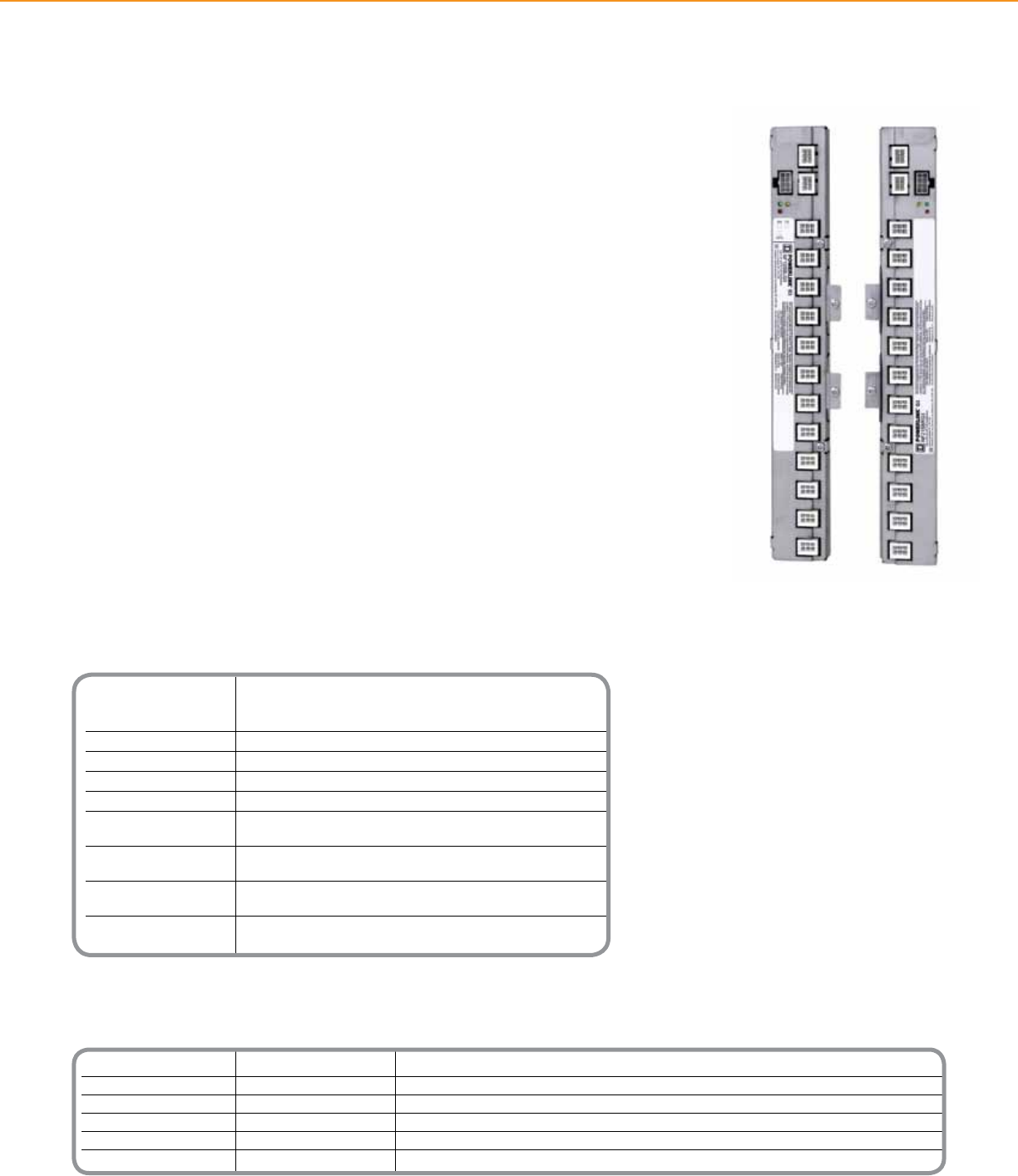
Catalog Number Max. Control Circuits Orientation
NF12SBLG3 12 Left
NF12SBRG3 12 Right
NF18SBLG3 18 Left
NF18SBRG3 18 Right
NF21SBLG3 21 Left
NF21SBRG3 21 Right
POWERLINK® LIGHTING CONTROL + CONTROL BUS
Powerlink® G3 Control Buses provide the interface between the system controller and
remotely operated circuit breakers. Specically, they distribute 24Vdc switching power
and control signals to switch remotely operated circuit breakers and report circuit
breaker status back to the system controller.
One to four control bus strips can be mounted in a single panelboard. If only one control
bus is required, it is always mounted on the left-hand side of a standard panelboard or at
the top of a column-width panelboard.
Product Features
• Attaches to NF Panelboard
interior mounting rail
• Modular connectors provide
secure plug-in connections for
remotely operated circuit breakers
and control electronics.
• No open electronics
Ceiling Mounted Occupancy
Sensor Ultrasonic
Powerlink®
G3 Control Bus
33
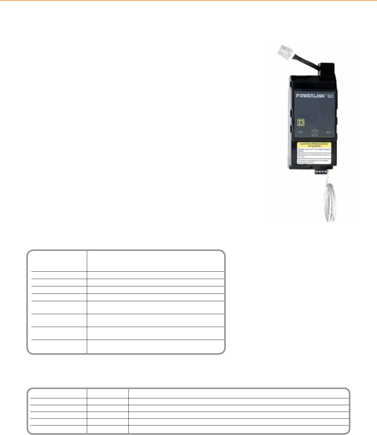
Catalog Number Voltage Primary Source
NF120PSG3 120V Panel Bus
NF240PSG3 240V Panel Bus
NF277PSG3 277V Panel Bus
NF120PSG3L 120V External Leads
NF240PSG3L 240V External Leads
NF277PSG3L 277V External Leads
Technical Information
Operating Temperature 23°F to 104°F (-5°C to 40 °C)
(external panelboard
ambient)
Storage Temperature -4°F to 185°F (–20°C to 85°C)
Operating Humidity 5% to 95% (non-condensing)
ESD Immunity IEC 1000, Level 4
RF Susceptibility IEC 1000, Level 3
Electrical Fast IEC 1000, Level 3
Transient Susceptibility
Electrical Surge Susceptibility, IEC 1000, Level 4
power line
Electrical Surge Susceptibility, IEC 1000, Level 3
interconnection lines
Standards FCC Part 15, Class A; UL Listed
916 Energy Management Equipment
POWERLINK® LIGHTING CONTROL + POWER SUPPLY
Powerlink® G3 Power Supply provides power to operate the controller, control buses
and remotely operated circuit breakers. The power supply attaches to an NF Panelboard
interior in the same manner as a standard 3-pole circuit breaker.
The power supply derives its power from the panelboard interior bus and converts the
line voltage into two separate supplies: one supply furnishes the controller with a 24Vdc,
Class 2 source; the other supply furnishes the control bus and subnet with a 24Vdc,
Class 1 source.
An optional type of power supply, furnished with primary leads, is available for use with
a separately derived primary power source. This option is often used in applications
where the system must remain operational during power outages. In such applications,
the external leads are connected to an uninterruptible power supply (UPS) or alternate
power source.
In 20-inch (508 mm) wide panels, the power supply is always located in the upper left-
hand corner of the interior. The controller is mounted adjacent to the power supply on
the right-hand side.
Product Features
• Attaches to panelboard interior,
occupies three adjacent pole
spaces.
• External lead for connection to
panel neutral.
• Modular connectors provide
secure plug-in connections for
connection to left-hand side
control bus and controller.
• LED indication of Class 1
and Class 2 voltage sources
operational status.
• Removable communication
terminal block for making subnet
connections.
• Internally self-protected against
short circuits and electrical
surges.
• Low continuous power draw, less
than 20VA.
• Optional external leads for
connection to remote
power source.
• No open electronics
Power Supply
Powerlink®
Power Supply
34
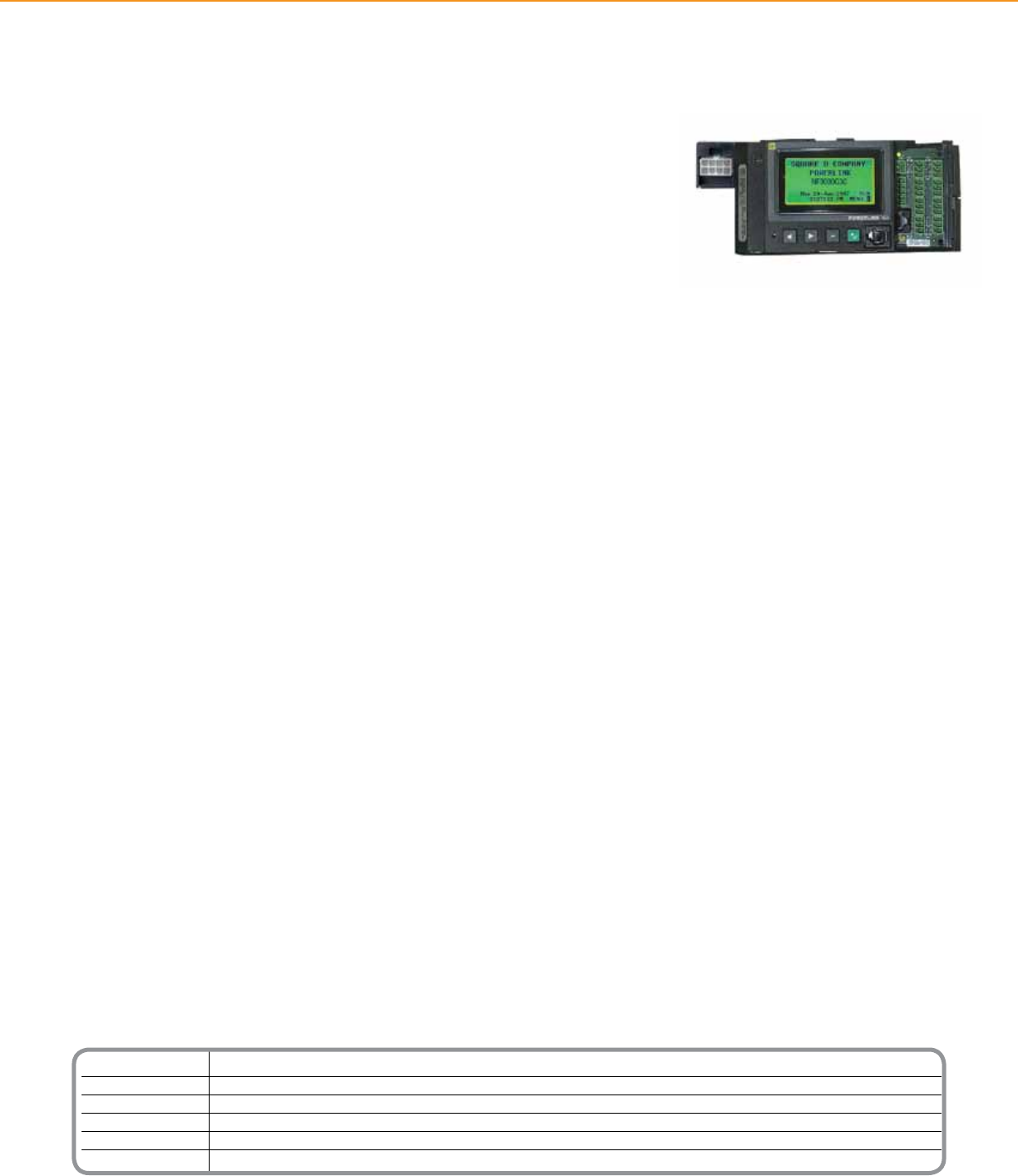
Catalog Number Controller Type
NF500G3 500 Level Powerlink G3 Controller
NF1000G3 1000 Level Powerlink G3 Controller
NF1000G3N2 1000 Level Powerlink G3 Controller w/N2 Protocol
NF2000G3 2000 Level Powerlink G3 Controller
NF3000G3 3000 Level Powerlink G3 Controller
NF3000G3C 3000 Level Powerlink G3 Controller w/C-Bus Capabilities
POWERLINK® LIGHTING CONTROL + CONTROLLERS
Controller
Powerlink® G3 product line offers a simple, cost-effective means for controlling branch
lighting circuits. Five distinct systems provide a variety of capabilities to meet virtually any need.
500 Level System
• Designed to be used in conjunction with other control devices such as:
External time clocks, access readers, occupancy sensors, or other building systems.
• Control devices provide either dry-contact closures or digital serial communications.
• Incorporates internal programmable timers.
• Controller responds to commands from control devices by automatically switching a programmed group of
lighting circuits.
1000 Level System
• Includes all the features of the 500 level system, Plus:
• Incorporates a exible time scheduler that eliminates the need for external time clocks. Includes many control
features not found in traditional, mechanical time clocks or energy management systems.
• Ideally suited for stand-alone systems in retail, ofce, institutional, and industrial facilities.
2000 Level System
• Includes all the features of the 1000 level system, Plus:
• Combines the control, input, and scheduling features of the NF1000 with the added benet of embedded
Ethernet connectivity.
• Peer-to-peer (P2P) control network connectivity allows different controllers to share input signals, schedules,
and lighting zone states.
• Ethernet connectivity reduces network installation costs by eliminating the need for a dedicated lighting
control network.
3000 Level System
• Combines control, input, and scheduling features of the 2000 level controller, Plus:
• Embedded web server for remote access without dedicated software
• Automated alarms notify users via email when pre-dened events occur (eg: trip breakers)
3000C Level System
• 3000C controller adds all the features of the 3000 level controller, plus the ability to integrate with C-BusTM
devices on the C-Bus network
BacNet Capability
• The Building Automation and Control network (BACnet) communication protocol is being incorporated into the
existing Powerlink G3 controller design. The BACnet protocol allows Powerlink panels to be easily integrated
into a Building Automation System (BAS) employing this open communication standard without the need for
communication bridges or gateways.
Controller Models
The following Powerlink G3 controller models support ‘native’ BACnet communications, BACnet IP, and
BACnet MS/TP on RS-485:
• NF2000G3 - Ethernet communications, shared remote inputs, network time synchronization
• NF3000G3 - Email upon alarm, onboard web pages for status/control/conguration
• NF3000G3C - C-Bus communications (ability to interface with a C-Bus lighting control network)
Powerlink®
Controllers
35
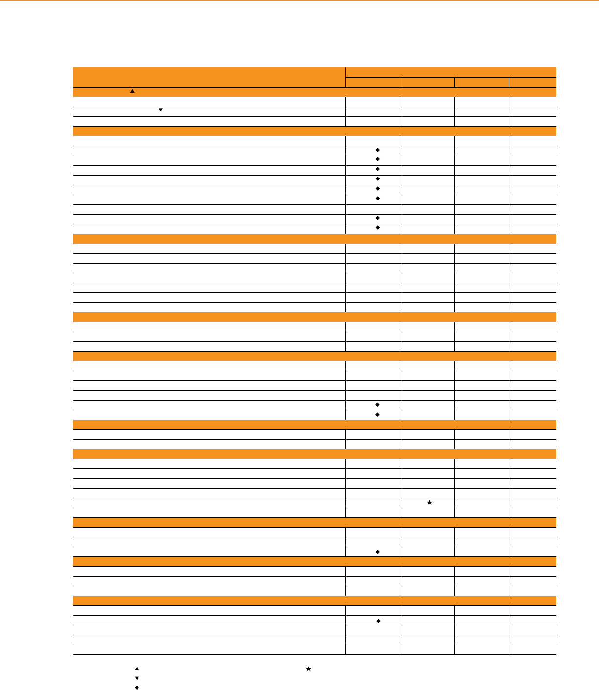
Input Terminals
2-wire 8 16 16 16
2-wire with status feedback 8 8 8 8
3-wire 8 8 8 8
Input Types
2-wire normally open (NO) or normally closed (NC) X X X X
2-wire NO or NC, with automatic blink notication X X X X
2-wire maintained toggle X X X X
2-wire momentary toggle X X X X
2-wire momentary ON or momentary OFF X X X X
3-wire momentary X X X X
Input timers (1 sec. up to 18 hours) X X X X
Input synchronization - X X X
Sentry® Switch support X X X X
ON delay/OFF delay X X X X
Time Scheduler
Independent schedules - 16 16 16
ON-OFF periods/schedule - 24 24 24
7-day 24-hour repeating schedule - X X X
32 special event/holiday periods - X X X
Automatic daylight savings - X X X
Sunrise/sunset with offsets - X X X
Network time synchronization (requires TCP connection) - - X X
Network Variables
Communications inputs (network accessible) 64 64 64 64
Remote sources (per controller) - - 32 32
Maximum subscriptions - - 256 256
Zones
Maximum number 64 64 64 64
Maximum sources per zone 1 2 4 4
Congurable source logic (OR, AND, XOR, XNOR, NOR, NAND, LAST EVENT) - ^ X X
Maximum remotely operated circuit breakers (per subnet) 168 168 168 168
Blink notice (single, double, delay no blink) X X X X
ON-time X X X X
Networking
RS-232 port/RS-485 port X X X X
Ethernet (10BaseT port) - - X X
Protocols
BACnet - - X X
C-Bus - - - X †
Modbus® ASCI/RTU X X X X
Modbus TCP - - X X
Johnson Controls N2 - X - -
DMX512 - X X X
Front Panel
LED display with cover X - - -
Backlit LCD display - X X X
Password or front panel disable X X X X
Memory
Non-volatile memory for programs and conguration X X X X
On-board capacitor to power clock chip during power outage - X X X
Flash memory for rmware upgrade X X X X
Viewing Options
Event Log - + X X
Strike Counter X X X X
Alarm viewing via Event Log - + X X
Alarm viewing via e-mail - - - X
Web-based setup, control and status monitoring - - - X
Feature System Level
500 1000 2000 3000
Terminals accept 24-18 AWG conductors Order NF1000G3N2 controller for use with Johnson Controls.
7.5mA maximum load per input terminal. + Not available with NF1000G3N2 controllers.
Requires conguration software for setup. † 3000G3C controller
^ And/or last event
POWERLINK® LIGHTING CONTROL + CONTROLLERS
Controller Feature Comparison
36

Technical Information
Dimensions 12” x 12” x 6” (304.8 mm x 304.8 mm x 152.4 mm)
Mounting Wall mount
Ethernet Port (1) 10BaseT port
Inputs (16) dedicated 2-wire inputs or (8) 3-wire inputs
Outputs (8) outputs (max of 60mA total for all outputs combined)
Auxiliary Power 24Vdc (100 mA max)
Terminal Wire Range #24-18AWG
Input Voltage 120/240/277Vac
Input Power Requirements 20VA max
Standards UL Listed 916 Energy Management Equipment
*For Diagram see technical section page 44
Catalog Number Description
RSC16G3120 120V
RSC16G3240 240V
RSC16G3277 277V
POWERLINK® LIGHTING CONTROL + CONTROLLERS
The Powerlink® Remote Source Controller (RSC) provides additional scheduling and
dry-contact inputs via high speed Ethernet connectivity that links a wide variety of input
devices to a 2000 or 3000 level Square D Powerlink system.
Product Features
• High Speed Connectivity
• Ethernet communication eliminates bottlenecks typically associated with serial devices.
• Uses existing LAN infrastructure to reduce input wiring cost.
• Uses convenient radial feeds to independent input devices; this avoids pitfalls that are
typically associated with daisy-chained network digital switches.
Powerful Control Capability
• Supports (16) 2-wire inputs, (8) 2-wire inputs with status output, or (8) 3-wire inputs.
• Fully congurable from LCD display/keypad or via LCS/PCS software.
• Specically designed to operate in conjunction with 2000 and 3000 level controllers.
• Any RSC input can be set up to control any remotely operated circuit breaker
connected to the system.
• Assignable input timers, input synchronization, and programmable behavior according
to specied time period.
• Provides an additional (16) independent time schedules that can be congured to
operate any circuit breaker or zone congured on the system.
Product Features
• NEMA Type 1 enclosure w/knockouts
• UL Listed
Remote Source Controller
Powerlink®
Remote Source Controller
37
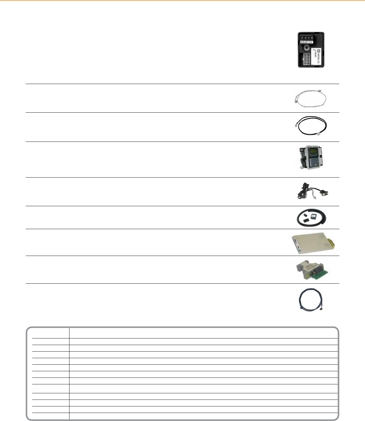
Catalog Number Description
NFSELG3 Slave address selector
NF2HG3 Slave bus connect harness
NFCW3G Column width controller cable
NFADAPTERG3 Remote mounting adaptor
NFFPC3G Controller front panel serial cable
NFASBKG3 Custom barrier kit
6382G3MODEM Modem kit
6382RS485G3KIT RS-485 converter kit
Subnet Cable
NFSN06 6’ (1.83 m) sub-net cable
NFSN10 10’ (3.05 m) sub-net cable
NFSN25 25’ (7.62 m) sub-net cable
NFSN50 50’ (15.24 m) sub-net cable
POWERLINK® LIGHTING CONTROL + ACCESSORIES
Slave Address Selector
The Slave Address Selector is required for each slave panel connected to a subnet. The slave address selector
establishes a unique system address for the panel that is both essential for system operation and useful when the
system is accessed from a remote location. The slave address selector plugs directly onto control buses.
• Rotary operated switch labeled 0–7 for addressing panels
• Removable terminal block for connecting subnet cable
• Modular plug for connecting the Slave Address Selector to smart bus using the Slave Bus Connect Harness
Slave Bus Connect Harness Assembly
The Slave Bus Connect Harness assemblies are required in slave panels furnished with two control buses.
The harness contains modular plugs on each end.
Column-width Controller Cable
A Column-width Controller Cable is required to connect the power supply to the controller when used in an
NF Column-width Panelboard.
Remote Mounting Adapter
The Remote Mounting Adapter provides a means for mounting a Powerlink controller and power supply in a
separate enclosure. This bracket is ideal for retrot applications where all 42 circuit spaces in the panelboard are
required for branch circuit breakers.
Controller Front Panel Serial Cable
The Controller Front Panel Serial Cable is used to make direct RS-232 connections from the controller to a PC or
laptop computer.
Custom Barrier Kit
The custom barrier kit provides a heavy-duty barrier for separating class II control circuits from power wiring.
Modem Kit
This kit, which is designed specically for Schneider Electric Powerlink G3 controllers, contains all the necessary
components for use with the controller.
RS-485/RS-232 Converter Kit
The RS-485/RS-232 converter kit allows connection from the RS-485 port of the controller to the serial port of a
personal computer.
Subnet Cable
Four wire cable for connecting panels together in a subnet conguration
Accessories
38
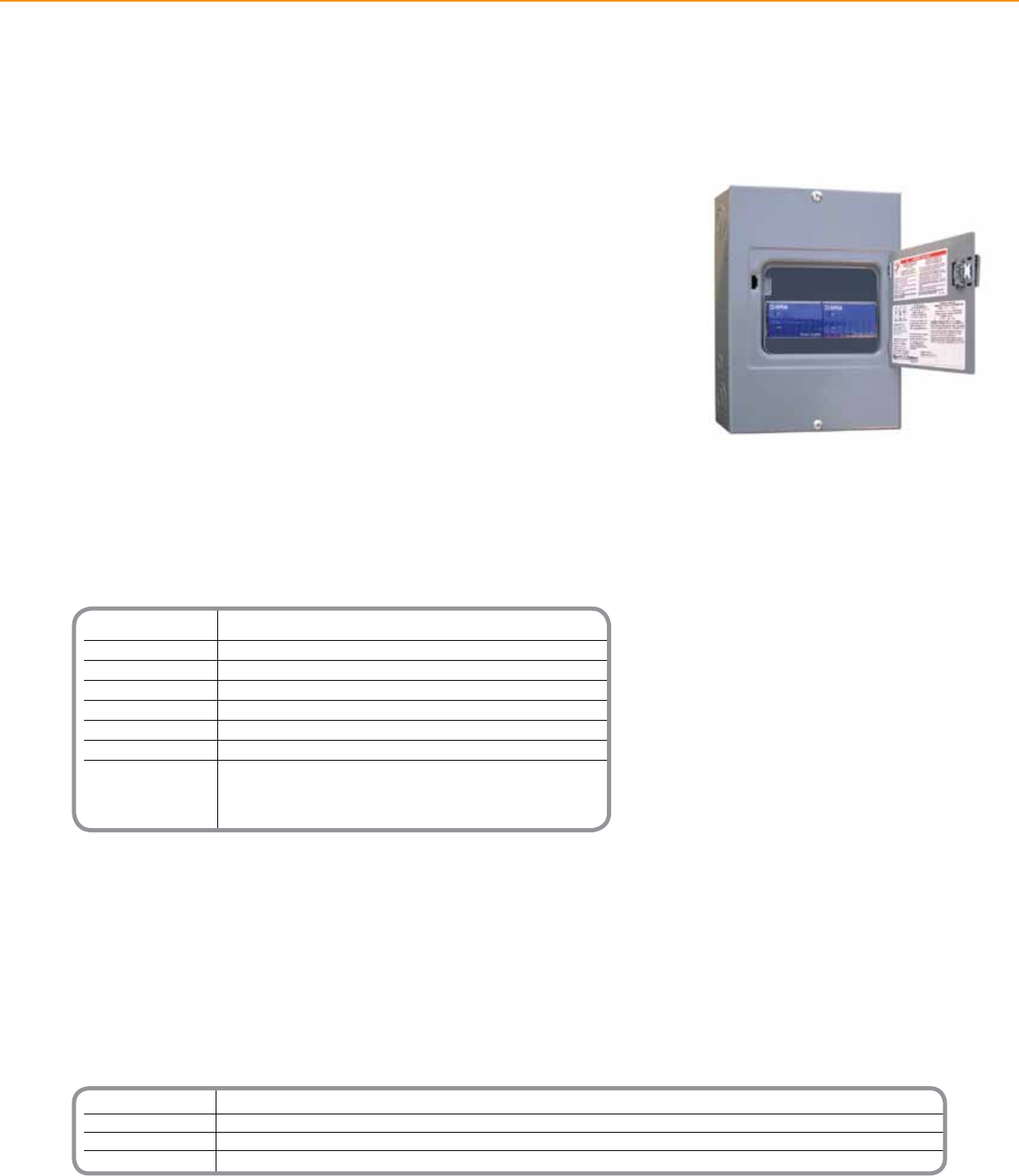
Technical Information
Nominal Line Voltage Operates at 120 or 277Vac, ± 10%, with a frequency range from 50–60 Hz
Maximum Line Current 9.9 mA for 120V power supply 4.3 mA for 277V power supply
Electrical Isolation 3.75 kV RMS from C-Bus to the line
Current Output 350 mA (single power supply unit) 700 mA (dual power supply unit)
Dimensions 12.57 in. (L) x 8.88 in. (W) x 3.8 in. (D) [319 mm (L) x 226 mm (W) x 97 mm (D)]
Weight One power supply: 8.84 lb (4.01 kg) Two power supplies: 9.28 lb (4.21 kg)
Operating Environment Temp.: 32°F to 113°F (0°C to 45°C) RH: 95%, noncondensing
Standards UL: Listed 508A Industrial Control Equipment
CSA 22.2 Spec 205 Signal Equipment
FCC: Part 15.101, Class B Digital Device
EN61000-4-2 Immunity to ESD
*For Diagram see technical section page 41
Catalog Number Description
NFDP1120G3C 120V Powerlink Single Power Supply
NFDP2120G3C 120V Powerlink Dual Power Supply
NFDP1277G3C 277V Powerlink Single Power Supply
NFDP2277G3C 277V Powerlink Dual Power Supply
POWERLINK® LIGHTING CONTROL + POWER SUPPLY
The Powerlink® Device Power Supply is used to distribute power on a C-BusTM network.
Placed on the network, device power supplies will provide the current necessary for
operating a variety of passive Schneider Electric C-Bus devices.
A Device Power Supply consists of a 8M enclosure containing one or two Power
Supplies (120 or 277Vac).
Product Features
• Surface-mount NEMA Type 1
enclosure with cover
• Unit and C-Bus LEDs indicate the
status of the line voltage and the
network
• Sources up to 700 mA (dual
power supplies) to the C-Bus
network
• 120 or 277Vac models available
Powerlink Device Power Supply
Powerlink®
Device Power Supply
39
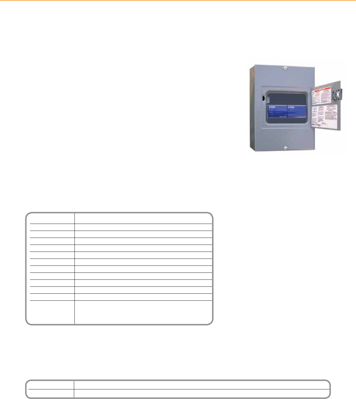
Catalog Number Description
NFDR120G3C 120V Powerlink Device Router
NFDR277G3C 277V Powerlink Device Router
Technical Information
Nominal Line Voltage Operates at 120 or 277Vac, ± 10%, with a frequency range from 50–60 Hz
Maximum Line Current 9.9 mA for 120V device router 4.3 mA for 277V device router
Electrical Isolation 3.75 kV RMS from C-Bus to the line
Current Output 350 mA to the C-Bus network
Status Indicators Unit and Unit/Comms: Line voltage, unit power, and data transmission
C-Bus: Power levels and presence of C-Bus clock
Serial Connection (1) 9-pin RS-232 D-type serial connector; (2) RS-232 RJ-45 connectors
C-Bus Connection (2) RJ-45 sockets for connection to the C-Bus network
Data Cable 50 ft serial
Dimensions 12.57 in. (L) x 8.88 in. (W) x 3.8 in. (D) [319 mm (L) x 226 mm (W) x 97 mm (D)]
Weight 9.1 lbs (4.13 kg)
Operating Environment Temp.: 32° to 113°F (0° to 45°C) RH: 95%, noncondensing
Standards UL: Listed 508A Industrial Control Equipment
CSA 22.2 Spec 205 Signal Equipment
FCC: Part 15.101, Class B Digital Device
EN61000-4-2 Immunity to ESD
*For Diagram see technical section page 41
POWERLINK® LIGHTING CONTROL + DEVICE ROUTER
The Powerlink® Device Router allows the exchange of data between a Powerlink
NF3000G3C controller and Schneider Electric C-BusTM devices.
The bidirectional device router can receive data from the C-Bus input devices and send
the data to the Powerlink panel/network. It can also receive data such as a contact
closure from the Powerlink input and send that data to a C-Bus output/network.
The device router consists of a C-Bus 8M enclosure containing a PC Interface and a
Power Supply (120Vac or 277Vac). Communication between the device router and the
NF3000G3C controller is made with the included 50-foot serial cable.
Product Features
• Surface-mount NEMA 1
enclosure, with cover
• Unit, Unit/Comms, and C-Bus
LEDs indicate the status of data
transmission and power to the
unit and the network
• System network clock for
synchronizing communications
data
• Network power source, supplying
up to 350 mA
• 120 or 277Vac models available
Powerlink Device Router
Powerlink®
Device Router
40
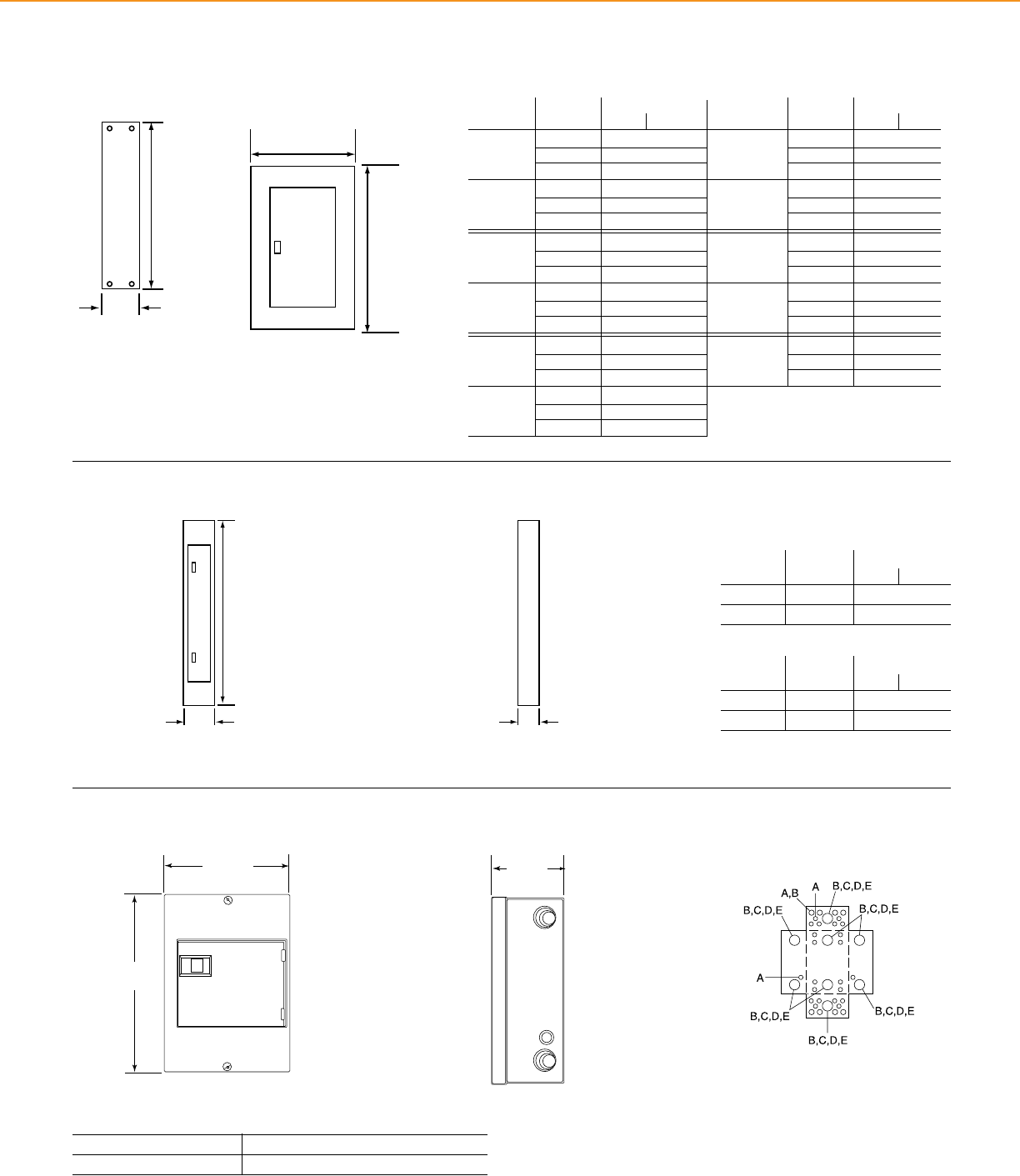
125A 12 26 660
18 26 660
30† 32 813
250A 30 38 965
42 44 1118
54 50 1270
100A 12 38 965
(FIL) 18 38 965
30† 44 1118
250A 30 50 1270
(JDL, JGL, 42 56 1422
JJL, JLL) 54 62 1575
800A* 30 50 1270
42 56 1422
54 62 1575
400A 30 62 1575
(LAL, LHL) 42 68 1727
54 74 1880
†34W only *800A Panelboards are 8¾ in. deep
Max. Main Lug Max. Number (H) Enclosure Height
Ampere Rating of Circuits In. mm
125A 18 32 813
(EDB, EGB, EJB) 30 38 965
42 44 1118
100A 12 38 965
(HDL, HGL, 18 38 965
HJL, HLL) 30† 44 1118
400A 30 50 1270
42 56 1422
54 62 1575
600A 30 50 1270
42 56 1422
54 62 1575
400/600A 30 68 1727
(LCL, LIL) 42 74 1880
54 80 2032
Max. Main Lug Max. Number (H) Enclosure Height
Ampere Rating of Circuits In. mm
30 125A 59 1499
42 225A 71 1803
Max. Number Max. Main Lug (H) Enclosure Height
of Circuits Ampere Rating In. mm
Ready-to-Assemble (Also Available Factory Assembled)
Column Width - Main Lugs Only
30 125A 59 1499
42 225A 71 1803
Max. Number Max. Main Lug (H) Enclosure Height
of Circuits Ampere Rating In. mm
Column Width - Main Circuit Breaker
C-BusTM 8M Enclosure Knockouts
Symbol A B C D E
Conduit Size ½ ¾ 1 1¼ 1½
Typical Enclosure Front View
Typical Enclosure Front View
59 in.
(1.4 m)
H
9.69 in.
(246 mm)
Typical Enclosure Side View
59 in.
(1.4 m)
5.60 in.
(142 mm)
Typical Enclosure Side View
H
Flush Mounting W + 1.50 (38mm)
Surface Mounting W + 0.12 (3mm)
Flush Mounting W + 1.50 (38mm)
Surface Mounting W + 0.12 (3mm)
H
5.75 in.
(146 mm)
Conduit knockouts for the 8M enclosureSide view showing depth
3.8 in.
97 mm
3.8 in.
(97 mm)
Front view showing height and width
8.9 in.
226 mm
12.57 in.
319 mm
8.9 in.
(226 mm)
12.57 in.
(319 mm)
POWERLINK® LIGHTING CONTROL + TECHNICAL SECTION
*These dimensions are standard. Please consult factory for special requirements.
Column Width Panelboard
Dimensional Drawings
Powerlink® Device Power Supply/Device Router
NF Panelboard (indoor enclosure)
41
POWERLINK® LIGHTING CONTROL + TECHNICAL SECTION
This table lists the UL short-circuit current ratings for NF panelboards including ECB-G3 circuit breakers. The ratings apply to an integral main
located in the same enclosure or a remote main located in a separate enclosure.
EDB, EDB-EPD
ECB-G3
EDB, EDB-EPD, EGB
ECB-G3
EDB, EDB-EPD, EGB, ECB-G3
EDB, EDB-EPD, EGB, EJB
ECB-G3
EDB, EDB-EPD
ECB-G3
EDB, EDB-EPD, EGB
ECB-G3
EDB, EDB-EPD, EGB, EJB
EDB, EDB-EPD, EGB, EJB
ECB-G3
EDB, EDB-EPD, EGB, EJB, ECB-G3
EG, FH, FG, KH, LH, MH, MX, HG, JG
EG
EJ, FC, FJ, KC, LC, LX, HJ, JJ
EJ, FC, KC, HJ, JJ
HL, JL
FI, KI, LI, LXI
FI, KI
Class J or T (600 V) 200 A max. fuses
EG, FG, HG, JG, KH, LH
EG, HG, JG
EJ, FC, FJ, KC, LC, LX, HJ, JJ
EJ, FC, KC, HJ, JJ
HL, JL
400 A max. fuses
FI, KI, LI, LXI
FI, KI
200 A max. fuses
65,000
100,000
125,000
200,000
35,000
65,000
100,000
200,000
120 120/240 240
277
480Y/277
Max. System Voltage Max. Short Circuit
Current Rating
Integral or Remote Main Circuit Breaker Schneider Electric Branch Circuit Breaker
Catalog Designation
RMS Symmetrical Amperes
NF Panelboard SCCR Table
Short Circuit Current Rating Table
42
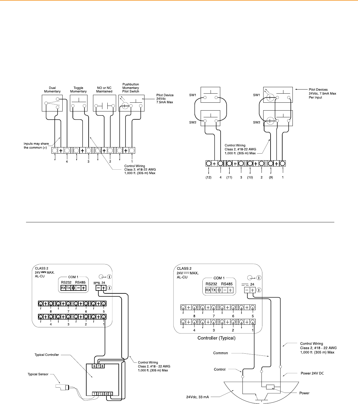
POWERLINK® LIGHTING CONTROL + TECHNICAL SECTION
This section contains wiring diagrams for the Schneider Electric Powerlink® G3
systems
Wiring Diagrams
Typical Switch Types Wired in Parallel
Various Low Voltage Switch Types
Typical Low Voltage Input Connections
Typical Photo Controller Wiring Diagram
43
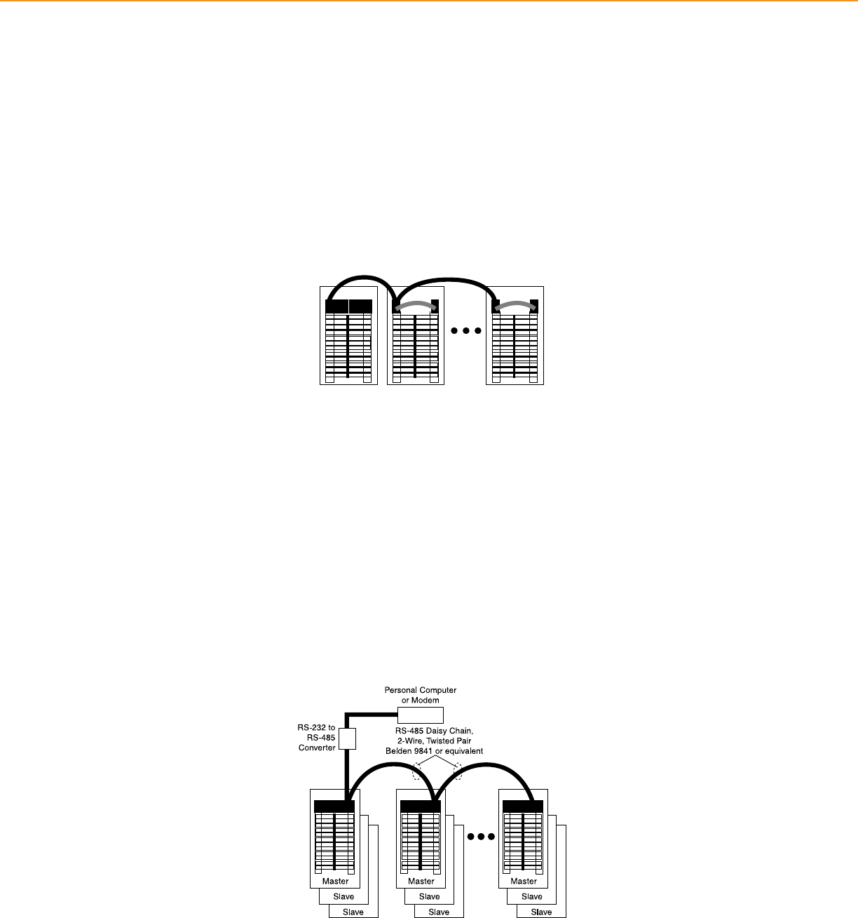
Subnet communications allow one controller to
operate up to 168 remotely operated branch circuits.
Automation networks provide remote access to the lighting control
system over an RS-485 network. An RS-485 network consists of low
cost, 2-wire, Class 2communications cable, Belden 9841 or equivalent.
POWERLINK® LIGHTING CONTROL + TECHNICAL SECTION
Three levels of communications are provided that can be easily tailored to individual application requirements.
Subnet Communications
• Each Schneider Electric Powerlink® G3 Controller can directly operate up to eight control buses.
• Controller signals the control buses to switch the associated branch circuits and polls each Schneider Electric Powerlink G3 Circuit Breaker to
determine its actual status.
• Communications between the controller and the control buses are made with a 4-wire, Class 1 communications cable (Belden 27326 or
equivalent).
• Slave panels (those containing control buses and remotely operated circuit breakers, but no controller) may be mounted up to 400 feet away
from the master panel that contains the controller.
Automation Network
• Each controller provides both RS-485 and RS-232 serial ports. Provides access up to 247 controllers using an RS-485 multi-drop conguration.
• An automation level network can also be used to communicate with other building systems such as energy management systems and card
access controllers. The automation network uses widely accepted and supported industrial-proven protocols used by many building automation
manufacturers and systems integrators
- Modbus® ASCII/RTU open protocol in all Schneider Electric Powerlink G3 Controllers
- DMX512 protocol in automation level network for theatrical lighting applications in 1000, 2000, and 3000 level controllers
- Optional JCI-N2 protocol for 1000 level controllers
- Optional C-Bus™ Network capability with NF3000G3C controller and device router
- BACnet MS/TP open protocol in 2000 and 3000 level controllers
System Architecture
44
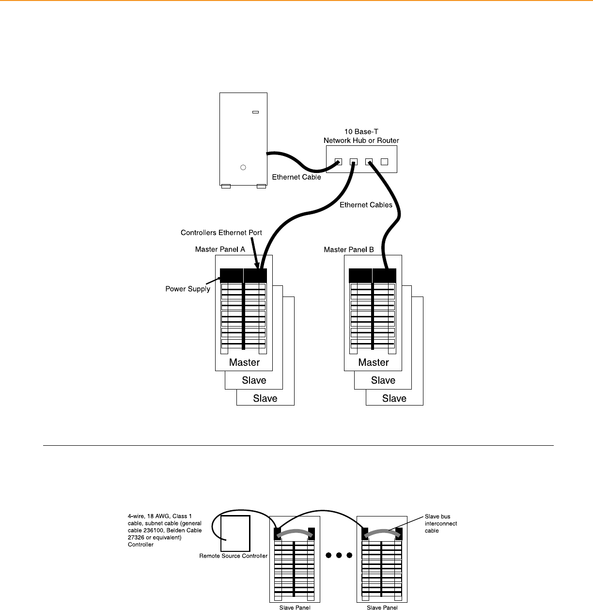
POWERLINK® LIGHTING CONTROL + TECHNICAL SECTION
Ethernet Connectivity
Schneider Electric Powerlink® G3 2000 and 3000 level controllers have integrated onboard Ethernet capability. In addition to providing high-
speed Ethernet access, these controllers allow fast peer-to-peer (P2P) connectivity between panels. With 2000 and 3000 level systems, master
panels can share inputs, schedules, and zone status.
• BACnet IP open protocol in 2000 and 3000 level controllers
• Modbus TCP/IP open protocol in 2000 and 3000 level controllers
Powerlink® Remote Source Controller
45
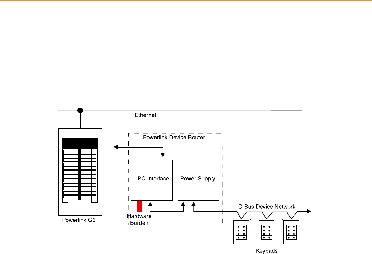
POWERLINK® LIGHTING CONTROL + TECHNICAL SECTION
Below is a typical one-line diagram for creating a local area network using the C-BusTM Network capability of level 3000G3C controllers. All
cables shown below are CAT-5.
C-BusTM Network
46

C-BusTM Lighting
Control
47

The availability of low-cost, powerful
microprocessors for building and home control
and management systems has created
unprecedented customer expectations for
increased control, connectivity and integration
of electrical and low-voltage systems.
Sophisticated styling
C-BusTM brings a distinctly sophisticated
look to lighting applications. Clean lines.
Sleek glass. Every detail and surface of these
keypads and touch screens are designed to
complement contemporary commercial
and residential environments.
System simplicity
With its unique distributed control system
installation couldn’t be easier. You can place
relays and dimmers in various locations
and connect them directly to the network –
eliminating the need to run cable back to a
separate enclosure near centrally located
processors. Keeping the design simple also
adds up to greater system reliability.
C-Bus keypads
These aesthetically pleasing faceplates
lend a sophisticated look to virtually any
space. They’re as elegant as they are
well-engineered.
Simple cabling/any topology
Since the C-Bus system uses standard
Cat-5 cabling, using any topology, there’s no
special cable to order or keep in supply.
So it’s much easier to address last-minute
change orders or to complete a job without
wondering if you have the right materials
on hand.
Fully-scalable solution
Whether you’re creating a lighting control
system for a single room or a whole facility,
Schnieder Electric lighting control offers
scalable systems to t your exact needs.
Our C-Bus solutions are designed around
the size and requirements of your
application. All this with a common platform
and easy installation practices. Talk about
exibility.
C-Bus touch screens
Our unied wall-mounted panels allow you
to control lighting systems and accessories
with the touch of a nger. Designed with
versatility in mind, these sleek touch screens
are easy to install, customize and use.
They’re compact yet powerful. Simple to
operate yet highly exible. A desktop model
is available when wall space is limited or for
added convenience.
Introduction to
C-BusTM Lighting Control
48
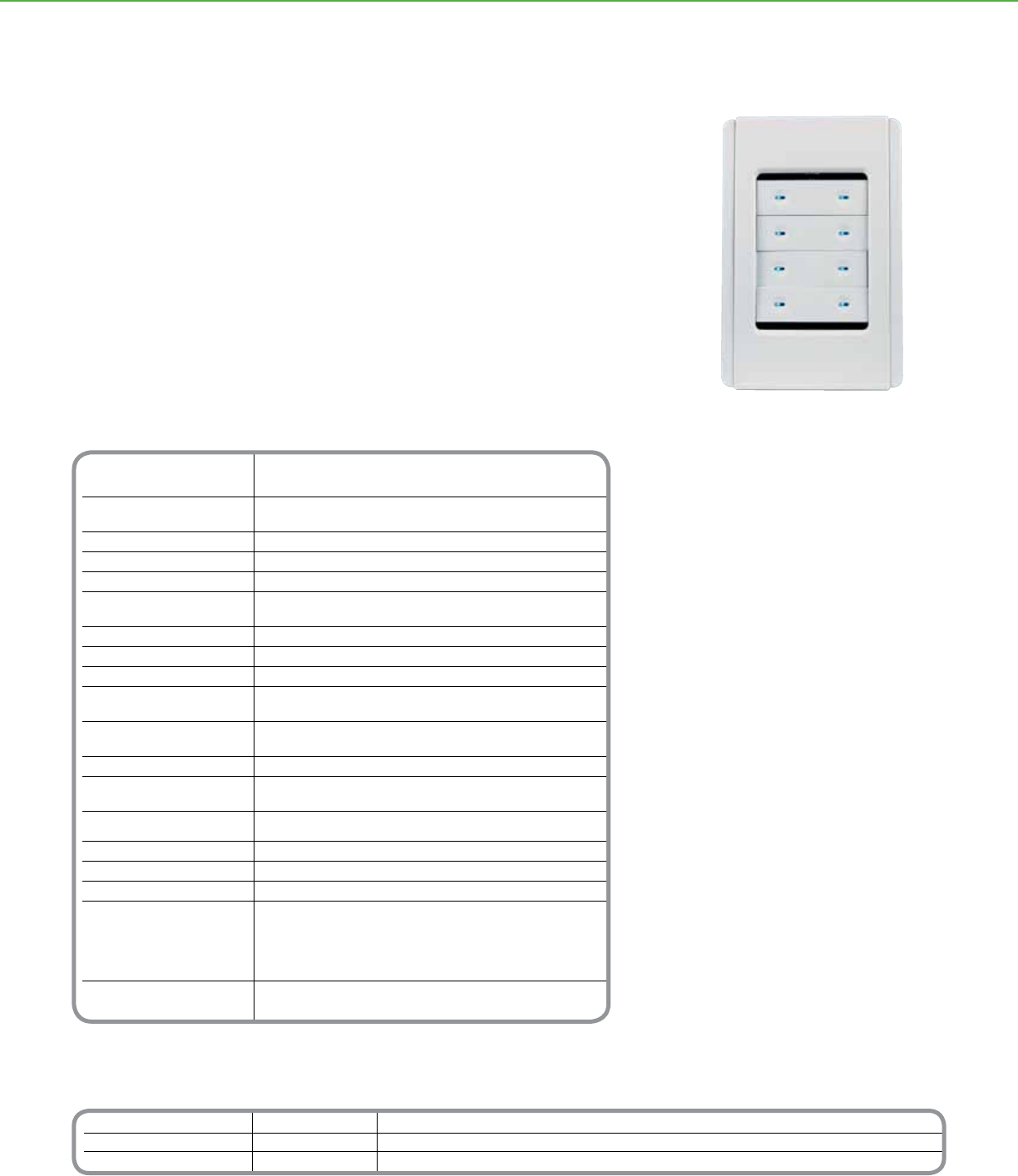
Technical Information
Voltage Requirements 15–36Vdc @ 22 mA required for normal operation,
drawn from the C-Bus network
Number of Units on a Network Calculated with the C-Bus Calculator, a software utility used to
evaluate the total network current load
Electrical Isolation 3.75 kV RMS from C-Bus to power (provided externally)
Control Functions Load switching, dimming, timing, scene control
Status Indicators Two-color (orange and blue) user-congurable LEDs
Locator Option User-congurable, adjustable blue LED illumination for locating
the unit in darkness, with “ignore rst button press” option
Scene Control Up to four scenes per keypad, ten addresses per scene
Timers 1 sec–18 hr, 1 sec intervals
Response Time 200 m sec or less
C-Bus Connection One terminal block to accommodate 24–16 AWG (0.2–15 mm2),
CAT 5 UTP cable required
Dimensions 4.57 in. (L) x 2.95 in. (W) x 0.87 in. (D) [116 mm
(L) x 75 mm (W) x 22 mm (D)]
Mounting: Centers 3.31 in. (84 mm)
Enclosure (Not Provided) Plaster mud ring (Raco 8771 or equal) w/
minimum internal width 2.05 in. (52 mm) (not provided)
Single gang box (Carlon A58381D-CAR or equal) w/minimum
internal width 2.05 in. (52 mm) (not provided)
Weight 2.7 oz (77 g)
Operating Environment Temp.: 32°F to 113°F (0°C to 45°C) • RH: 95%, noncondensing
Storage Environment Temp.: 14°F to 140°F (–10°C to 60°C) • RH: 95%, noncondensing
Standards: UL: Listed 916 Energy Management
CSA 22.2 Spec 205 Signal Equipment
FCC: Part 15.101, Class B Digital Device
EN61000-4-2 Immunity to ESD
Color Options Slate, white, cream, gold, black, brown,
soft gray, desert sand and brushed aluminum
** For additional ordering information see technical section page 95
Order numbers for the Neo Keypad assemblies indicate the number of buttons desired on the keypad and the color of each customizable
component (inner surround, outer surround, and button cover). Color numbers are taken from the “Neo Colors” table (page 78) and must
be given in the following order: outer surround, inner surround, and button covers.
Catalog Number Description Acessories
SLC5052NL( ) Number of Buttons (2) Neo Keypad Assembly Button Covers SLC5052NRP( ) - 2 button keypads (5 pack) Button Covers SLC5052NRI( ) with ID Windows
SLC5054NL( ) Number of Buttons (4) (2, 4, or 8 buttons) Button Covers SLC5054NRP( ) - 4 button keypads (5 pack) Inner Surround SLC5050IS( ) (pack of 5)
SLC5058NL( ) Number of Buttons (8) Button Covers SLC5058NRP( ) - 8 button keypads (5 pack) Outer Surround SLC5050OS( ) (pack of 5)
C-BUSTM LIGHTING CONTROL + KEYPADS
The C-BusTM Neo™ Keypads offer localized nger-tip control of lighting and other
electrical devices. With over 1,000 custom color combinations available, these elegant
keypads are suitable for virtually any decor.
One compact Neo keypad can take the place of many single switches, ON/OFF toggles,
dimmers, and timers. Available in your choice of a two-, four-, or eight-button keypad,
Neo’s modern style is complemented by orange and blue LEDs that instantly show the
status of controlled devices.
Product Features
• Button congurations include multi-point
switching and dimming, master ON/OFF
switching, and scene settings
• Scene control includes ten group addresses
per scene, four scenes per keypad
• Independent timers available for each
button
• Standard built-in infrared receiver permits
keypad control at a distance with an
optional infrared handheld remote
(Sold Separately)
• Dual-color LED windows on each
button can glow in cool blue, orange, or
combinations of both, indicating when a
controlled device is ON or OFF
• Auto “fallback” can dim button LEDs at a
set time after the last key press
• Locator LEDs can illuminate the top and
bottom of the button area in cool blue,
helping a user nd the keypad in dim light
Functional Aesthetics
• Clean-lined low-prole keypads are wall
mounted without external ttings
• Optional button covers have ID windows,
enabling quick identication of lighting
scenes or controlled devices
(Sold Separately)
• Distinctively designed multi-layer cover
plate consists of button covers, an outer
surround, and an inner surround
• Color schemes are easily customized and
modied to suit personal taste or the decor
Distributed Intelligence
• Compatible with all C-Bus devices and
Powerlink NF3000G3C controllers
• Congured by using Learn Mode or a
personal computer connected to the
network
Neo Style 8 Button Keypad
Neo™ Keypads
49
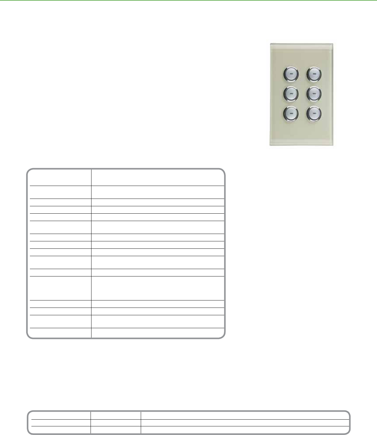
Technical Information
Voltage Requirements 15–36Vdc @ 22 mA required for normal operation,
drawn from the C-Bus network
Number of Units Determined with the C-Bus Calculator, a software utility
on a Network used to evaluate the total network current load
Electrical Isolation 3.75 kV RMS from C-Bus to power (provided externally)
Control Functions Load switching, dimming, timing, scene control
Status Indicators Two-color (orange and blue) user-congurable LEDs
Locator User-congurable, adjustable LED to help locate the unit in
Option darkness, has “ignore rst button press” option
Scene Control Up to four scenes per keypad, ten addresses per scene
Timers 1 sec–18 hr, 1 sec intervals
Response Time 200 m sec or less
C-Bus Connection One terminal block to accommodate 24-16 AWG
(0.2–1.31 mm2), CAT 5 UTP cable required
Dimensions 4.57 in. (L) x 2.95 in. (W) x 1.1 in. (D) [116 mm (L) x 75 mm (W) x 28 mm (D)]
Mounting Plaster mud ring (Raco 8771 or equal) w/
minimum internal width 2.05 in. (52 mm) (not provided)
Single gang box (Carlon A58381DCAR or equal) w/minimum
internal width 2.05 in. (52 mm) (not provided)
Weight 4.66 oz (132 g)
Operating Environment Temp.: 32°F to 113°F (0°C to 45°C) RH: 95%, noncondensing
Standards UL: Listed 916 Energy Management, CSA 22.2 Spec 205 Signal Equipment
FCC: Part 15.101, Class B Digital Device, EN61000-4-2 Immunity to ESD
Color Options White, cream, black, and mocha
*For Diagram see technical section page 95
Order numbers for the Saturn keypad assemblies indicate the number of buttons desired on the keypad and the color of
the cover plate. White (WE), Black (BK), Mocha (BR), Cream (CM)
For example, SLC5086NLBK represents an order for a Saturn keypad with six buttons and a black cover plate. The order
number for a two-button keypad in mocha would be SLC5082NLBR
Catalog Number Description Accessories
SLC5082NL( )Number of Buttons (2) Saturn Keypad Assembly SLC5080LC8: Pre-labeled button caps (1 ea. of 66 frequently used labels such as Lounge, Meeting, Scene 1, etc.)
SLC5084NL( )Number of Buttons (4) (2, 4, or 6 buttons)
SLC5086NL( )Number of Buttons (6)
C-BUSTM LIGHTING CONTROL + KEYPADS
The C-BusTM SaturnTM Keypads offer localized nger-tip control of lighting and electrical
services. These elegant keypads incorporate a unique glass cover plate that is easy to
install, customize, and use.
By virtue of the variety of button congurations available, one compact Saturn keypad
can take the place of many single operation switches, ON/OFF toggles, dimmers, and
timers.
Available in a two-, four-, or six-button keypad, Saturn’s modern style is complemented
by orange and blue LEDs that can instantly show the status of controlled devices.
Product Features
• Button congurations include multi-point
switching and dimming, master ON/OFF
switching, and scene settings
• Scene control includes up to ten group
addresses per scene and four scenes per
keypad
• Independent timers available for each button
• Dual-color LED windows on each
button can glow in cool blue, orange, or
combinations of both, indicating when a
controlled device is ON or OFF
• Auto “fallback” can dim button LEDs at a
set time after the last button press
• Locator LED can illuminate the keypad,
helping a user nd it in dim light
Functional Aesthetics
• Distinctively designed transparent impact-
resistant glass cover plate with silver
buttons that can glow blue or orange
• Clean-lined keypads are wall mounted
without external ttings
• Low-prole keypad extends only 0.5 in. out
from the wall
• Colors are easily modied to suit personal
taste or the décor
• Optional button covers with labels, enabling
quick identication of lighting scenes or
controlled devices
Distributed Intelligence
• Compatible with all C-Bus devices and
Powerlink NF3000G3C controllers
• Congured by using Learn Mode or a
personal computer connected to the
network
Saturn Style 6 Button Keypad
SaturnTM Keypads
50
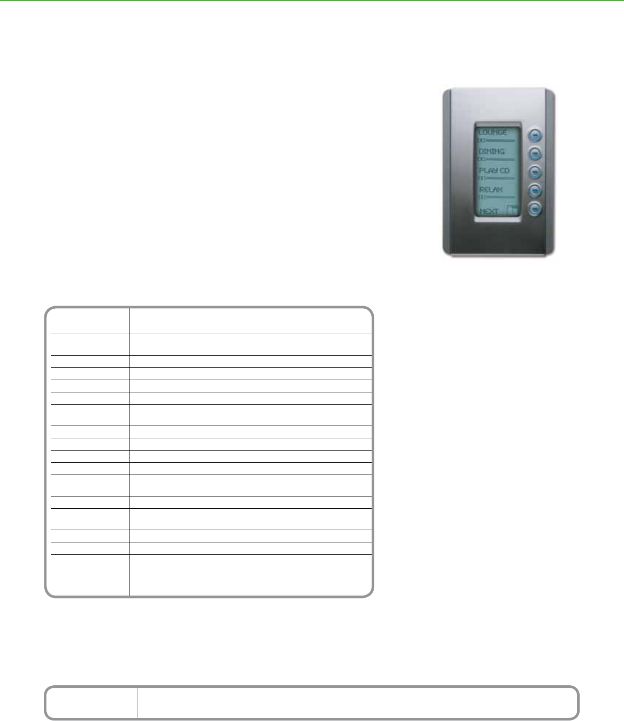
Technical Information
Voltage 15–36Vdc @ 22 mA required for normal operation,
Requirements drawn from the C-Bus network
Number of Units Use the C-Bus Calculator, a software utility, to determine
on a Network the total network current load
Electrical Isolation 3.75 kV RMS from C-Bus to power (provided externally)
Control Functions Load switching, dimming, timing, scene control
Status Indicators Blue, one dimmable LED per button
Backlight White, dimmable, user congurable
Locator User-congurable, adjustable blue LED for locating the unit in darkness,
Option with “ignore rst button press” option
Scene Control 4 scenes per keypad, 10 addresses per scene
Timers 1 sec–18 hr, 1 second intervals
Screen 64 x 128 pixels LCD
Response Time 200 m sec or less
C-Bus Connection One terminal block to accommodate 24–16 AWG (0.2–1.31 mm2),
CAT 5 UTP cable required
Dimensions 4.57 in. (L) x 2.95 in. (W) x 1.20 in. (D) [116 mm (L) x 76 mm (W) x 32 mm (D)]
Mounting Standard plaster (mud) ring or wall box (not provided), minimum internal
width 2.05 in. (52 mm) Centers: 3.31 in. (84 mm)
Weight 3.35 oz (95 g)
Operating Environment Temp.: 32°F to 113°F (0°C to 45°C) RH: 95%, noncondensing
Standards UL: Listed 916 Energy Management Equipment
CSA 22.2 Spec 205 Signal
FCC: Part 15.101, Class B Digital Device
EN61000-4-2 Immunity to ESD
*For Diagram see technical section page 95
Order numbers for the Neo DLT keypad assemblies indicate the color of the cover plate. White (WE), Brushed Aluminum
and Slate (GB), Soft Grey (SG), Cream (CM), Desert Sand (DS).
Example: Order number SLC5055DL(WE), represents a Neo DLT keypad in white.
Catalog Number Description
SLC5055DL( ) Neo DLT Keypad
C-BUSTM LIGHTING CONTROL + KEYPADS
Product Features
• Button congurations include multi-point
switching and dimming, master ON/OFF
switching, and scene settings
• Keypads have ve physical buttons–four
control buttons and one scroll/page button–
combined with two screens of labels, for a
total of eight control buttons and two scroll/
page buttons
• Scene control includes ten group addresses
per scene, four scenes per keypad
• Independent timers available for each button
• Button LEDs can be used as locator lights in
the dark
• Time clock can be displayed at the bottom
of the screen
• Displays up to 8 languages from a set of
more than 65
Functional Aesthetics
• 64 x 128 pixel LCD screen with a white
backlight
• Editable LCD labels, available for each
button or control group, can display text,
symbols, and graphics
• Dynamic graphic displays, such as bar
graphs, can be enabled or disabled
• Bitmaps can be downloaded for each group
address or scene
• Clean-lined low-prole keypads are wall
mounted without external ttings
• Distinctive two-layer cover plate consists of
an outer surround and an inner surround
Distributed Intelligence
• Compatible with all C-Bus devices and the
Powerlink® NF3000G3C controller
• Easily congured by using Learn Mode
or a personal computer connected to the
network
The C-BusTM Neo™ Keypads with Dynamic Labeling Technology™ (DLT) combine a
Neo style cover plate, programmable keypad buttons, and easily customized labels on a
backlit LCD screen that eliminates the need for custom labels.
These keypads are designed to be easy to install, customize, and use. By virtue of the
variety of button congurations available, one compact DLT keypad can take the place of
many single operation switches, ON/OFF toggles, dimmers, and timers.
Cool blue LEDs light the ve keypad buttons, complementing the keypad’s sleek lines
and instantly showing the status of controlled devices.
Neo Style DLT Keypad
Neo™ Keypads
with Dynamic Labeling Technology™
51
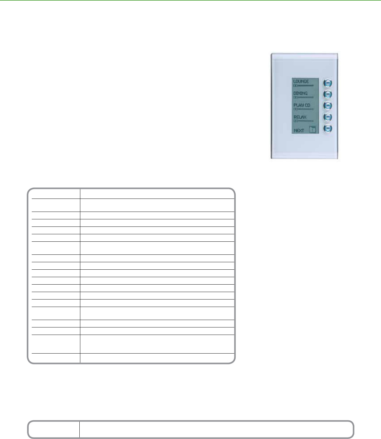
Technical Information
Voltage Requirements 15–36Vdc @ 22 mA required for normal operation, drawn from the C-Bus network
Number of Units Use the C-Bus Calculator, a software utility, to determine
on a Network the total network current load
Electrical Isolation 3.75 kV RMS from C-Bus to power (provided externally)
Control Functions Load switching, dimming, timing, scene control
Status Indicators Blue, one dimmable LED per button
Backlight White, dimmable, user congurable
Locator User-congurable, adjustable blue LED illumination for locating the unit
Option in darkness, with “ignore rst button press” option
Scene Control 4 scenes per keypad, 10 addresses per scene
Timers 1 sec–18 hr, 1 second intervals
Screen 64 x 128 pixels LCD
Response Time 200 m sec or less
C-Bus One terminal block to accommodate 24–16 AWG (0.2–1.31 mm2),
Connection CAT 5 UTP cable required
Dimensions 4.57 in. (L) x 2.95 in. (W) x 1.20 in. (D) [116 mm (L) x 75 mm (W) x 30.4 mm (D)]
Mounting Standard plaster (mud) ring or wall box (not provided), minimum internal
width 2.05 in. (52 mm) Centers: 3.31 in. (84 mm)
Weight 5.29 oz (150 g)
Operating Environment Temp.: 32°F to 113°F (0°C to 45°C) RH: 95%, noncondensing
Standards UL: Listed 916 Energy Management Equipment
CSA 22.2 Spec 205 Signal Equipment
FCC: Part 15.101, Class B Digital Device, EN61000-4-2 Immunity to ESD
Cover-Plate Colors White, cream, black, mocha
*For Diagram see technical section page 96
Catalog Number Description
SLC5085DL ( ) Saturn Keypad with DLT in white (WE), cream (CM), black (BK), or mocha (BR)
Order numbers for the Saturn DLT keypads include the stock number (SLC5085DL) and the code for the color of the cover
plate: Black (BK), Mocha (BR), White (WE) and Cream (CM)
For example, SLC5085DLBR represents a complete catalog number for a Saturn DLT keypad with a mocha cover plate.
C-BUSTM LIGHTING CONTROL + KEYPADS
The C-BusTM Saturn™ Dynamic Labeling Technology™ (DLT) Keypads combine a Saturn
style glass cover plate, programmable keypad buttons, and easily customized labels on a
backlit LCD screen that eliminates the need for custom labels.
These keypads are designed to be easy to install, customize, and use. By virtue of the
variety of button congurations available, one compact Saturn Keypad with DLT can take
the place of many single operation switches, ON/OFF toggles, dimmers, and timers. The
ve keypad buttons are lit with cool blue LEDs that complement the keypad’s sleek lines
and show the status of controlled devices.
Product Features
• Button congurations include multi-point
switching and dimming, master ON/OFF
switching, and scene settings
• Keypads have ve physical buttons-four
control buttons and one scroll/page button-
combined with two screens of labels, for a
total of eight control buttons and two scroll/
page buttons
• Scene control includes ten group addresses
per scene, four scenes per keypad
• Independent timers available for each button
• Button LEDs can be used as locator lights in
the dark
• Time clock can be displayed at the bottom of
the screen
• Displays up to 8 languages from a set of
more than 65
Functional Aesthetics
• 64 x 128 pixel LCD screen with a white
backlight
• Editable LCD labels, available for each button
or control group, can display text, symbols,
and graphics.
• Dynamic graphic displays, such as bar
graphs, can be enabled or disabled
• Bitmaps can be downloaded for each group
address or scene
• Clean-lined low-prole keypads are wall
mounted without external ttings
Distributed Intelligence
• Compatible with all C-Bus devices and the
Powerlink® NF3000G3C controller
• Easily congured by using Learn Mode or a
personal computer connected to the network
Saturn Style DLT Keypad
Saturn™ Keypads
with Dynamic Labeling Technology™
52
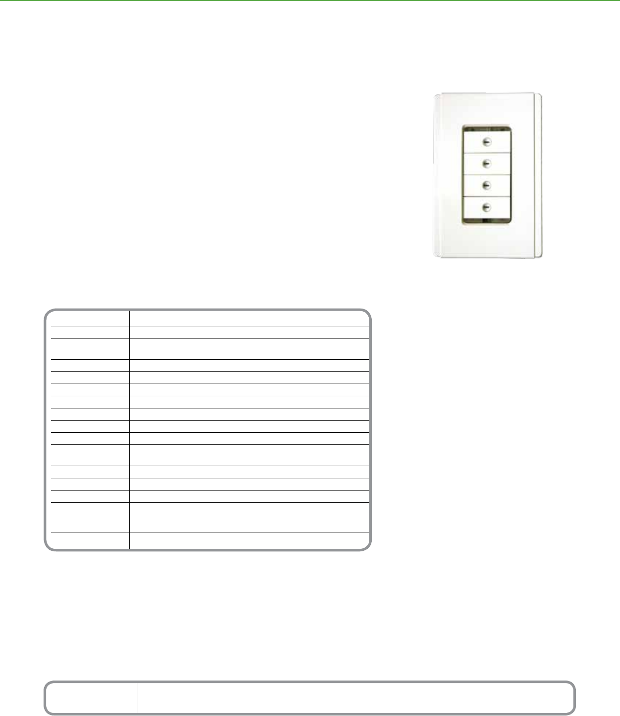
Technical Information
Voltage 15–36Vdc @ 22 mA required for normal operation,
Requirements drawn from the C-Bus network
Number of Units Determined with the C-Bus Calculator, a software utility
on a Network used to evaluate the total network current load
Electrical Isolation 3.75 kV RMS from C-Bus to power (provided externally)
Control Functions Load switching, dimming, timing, scene control
Locator User-congurable, adjustable LED to help locate the unit in darkness,
Option has “ignore rst button press” option
Scene Control Up to 4 scenes per keypad, 10 addresses per scene
Timers 1 sec–18 hr, 1 second intervals
Response Time 200 m sec or less
C-Bus Connection One terminal block to accommodate 24–16 AWG (0.2–1.31 mm2),
CAT 5 UTP cable required
Dimensions 4.57 in. (L) x 3.0 in. (W) x .91 in. (D) [116 mm (L) x 76 mm (W) x 23 mm (D)]
Weight 2.9 oz (82 g)
Operating Environment Temp.: 32°F to 113°F (0°C to 45°C) RH: 95%, noncondensing
Standards UL: Listed 916 Energy Management Equipment
CSA 22.2 Spec 205 Signal
FCC: Part 15.101, Class B Digital Device
Color Options Slate, White, Cream, Brown, Black, Soft Grey, Desert Sand
*For Diagram see technical section page 96
Order numbers for the Neo Decorator keypads include the stock number, the number of buttons (1 thru 4) and the code for
the button color: Black (BK), Brown (BR), White (WE), Cream (CM), Slate (GB), Soft Grey (SG) and Desert Sand (DS)
For example, SLC505(4)NLM(WE) represents a Neo Decorator style keypad with 4 buttons in white.
* Note: Wallplate Sold Separately. Refer to individual product manual for order information.
Catalog Number Description
SLC505( )NLM( )* Neo Decorator Style Keypad
C-BUSTM LIGHTING CONTROL + KEYPADS
Schneider Electric C-BusTM Decorator Style NeoTM Keypads offer localized nger-tip
control of lighting and electrical services. These elegant keypads incorporate a unique
cover plate (ordered separately) that is easy to install, customize, and use. These
Decorator style keypads are ordered without a face plate and can t in any existing
Decorator style keypad face plate. Matching face plates are also available in a variety of
colors.
By virtue of the variety of button congurations available, one compact Neo Decorator
style keypad can take the place of many single operation switches, ON/OFF toggles,
dimmers, and timers.
Available in a one-, two-, three- or four- button keypad, Neo’s modern style is
complemented by blue LEDs that can instantly show the status of controlled devices.
Neo 4 Button Decorator Style Keypad
Multi-Functional
Capabilities
• Button congurations include multi-point
switching and dimming, master ON/OFF
switching, and scene settings
• Scene control includes up to ten group
addresses per scene and four scenes per
keypad
• Independent timers available for each
button
• LED windows on each button can glow
in cool blue or orange, indicating when a
controlled device is ON or OFF
• Auto “fallback” can dim button LEDs at a set
time after the last button press
• Locator LED can illuminate the keypad,
helping a user nd it in dim light
• Has infra red remote capabilities with
Schneider Electric C-Bus remotes
Distributed Intelligence
• Compatible with all C-Bus devices and
Powerlink® NF3000G3C controllers
• Congured by using Learn Mode or
C-Bus software
Neo™
Decorator Style Keypads
53
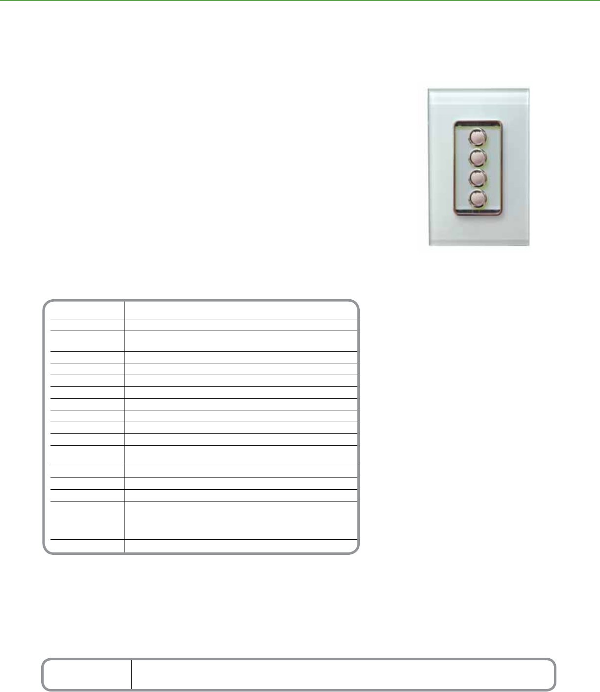
Technical Information
Voltage 15–36Vdc @ 22 mA required for normal operation,
Requirements drawn from the C-Bus network
Number of Units Determined with the C-Bus Calculator, a software utility
on a Network used to evaluate the total network current load
Electrical Isolation 3.75 kV RMS from C-Bus to power (provided externally)
Control Functions Load switching, dimming, timing, scene control
Status Indicators Two-color (orange and blue) user-congurable LEDs
Locator User-congurable, adjustable LED to help locate the unit in darkness,
Option has “ignore rst button press” option
Scene Control Up to 4 scenes per keypad, 10 addresses per scene
Timers 1 sec–18 hr, 1 second intervals
Response Time 200 m sec or less
C-Bus Connection One terminal block to accommodate 24–16 AWG (0.2–1.31 mm2),
CAT 5 UTP cable required
Dimensions 4.57 in. (L) x 3.0 in. (W) x .91 in. (D) [116 mm (L) x 76 mm (W) x 23 mm (D)]
Weight 2.9 oz (82 g)
Operating Environment Temp.: 32°F to 113°F (0°C to 45°C) RH: 95%, noncondensing
Standards UL: Listed 916 Energy Management Equipment
CSA 22.2 Spec 205 Signal
FCC: Part 15.101, Class B Digital Device
EN61000-4-2 Immunity to ESD
Color Options White, Cream, Mocha and Black
*For Diagram see technical section page 96
Order numbers for the Saturn Decorator keypads include the stock number, the number of buttons (1 thru 4) and the code
for the button color: Black (BK), Mocha (BR), White (WE), and Cream (CM)
For example, SLC508(4)NLM(WE) represents a Saturn Decorator style keypad with 4 buttons in white.
* Note: Wallplate Sold Separately. Refer to individual product manual for order information.
Catalog Number Description
SLC508( )NLM( ) Saturn Decorator Style Keypad
C-BUSTM LIGHTING CONTROL + KEYPADS
Schneider Electric C-BusTM Decorator Style SaturnTM Keypads offer localized nger-tip
control of lighting and electrical services. These elegant keypads incorporate a unique
glass face plate that is aesthetically pleasing with silver buttons that glow blue or amber.
Also, these Decorator style keypads can be ordered separately without a face plate to t
in any existing Decorator style keypad cover plate.
By virtue of the variety of button congurations available, one compact Saturn Decorator
style keypad can take the place of many single operation switches, ON/OFF toggles,
dimmers, and timers.
Available in a one-, two-, three- or four- button keypad, Saturn’s modern style is
complemented by orange and blue LEDs that can instantly show the status of controlled
devices.
Multi-Functional
Capabilities
• Button congurations include multi-point
switching and dimming, master ON/OFF
switching, and scene settings
• Scene control includes up to ten group
addresses per scene and four scenes per
keypad
• Independent timers available for each button
• Standard built-in infrared receiver permits
keypad control at a distance with an optional
infrared handheld universal remote
• Dual-color LED windows on each button can
glow in cool blue, amber, or combinations of
both, indicating when a controlled device is
ON or OFF
• Auto “fallback” can dim button LEDs at a set
time after the last button press
• Locator LED can illuminate the keypad,
helping a user nd it in dim light
Distributed Intelligence
• Compatible with all C-Bus devices and
Powerlink® NF3000G3C controllers
• Congured by using Learn Mode or
C-Bus software
Saturn 4 Button Decorator Style Keypad
Saturn™
Decorator Style Keypads
54
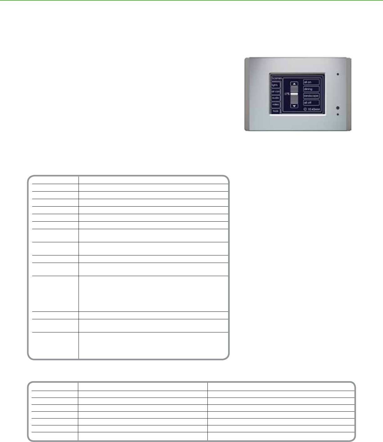
Technical Information
Screen
Type LCD active matrix
Size 4.7 in. (119 mm) diagonal
Resolution VGA, 320 x 240 pixels
Viewing Area Left, right: 45°, up 50°, down 30°
Luminance 120 cd/m2
Weight 13.05 oz (370 g), excluding cover
Voltage 15–36Vdc @ 65 mA required for normal
Requirements operation, drawn from the C-Bus network
Number of Units Determined with the C-Bus Calculator,
per Network a software utility for evaluating the total network current load
RS-232 Connector (1) x 3.5 mm plug
C-Bus Connection Loop in/loop out removable terminal block to accommodate 24-16
AWG (0.2-1.31 mm2), CAT 5 UTP cable required
Overall Dimensions Neo Style Faceplate: 7.56 in. (W) x 5.39 in. (H) x 1.65 in. (D)
[192 mm (W) x 137 mm (H) x 42 mm (D)]
Saturn Style Faceplate: 7.68 in. (W) x 5.35 in. (H) x 1.65 in. (D)
[195 mm (W) x 136 mm (H) x 42 mm (D)]
Stainless Faceplate: 7.60 in. (W) x 5.28 in. (H) x 1.65 in. (D)
[193 mm (W) x 134 mm (H) x 42 mm (D)]
Weight 13.05 oz (370 g), excluding cover
Operating Environment Temp.: 32°F to 113°F (0°C to 45°C)
RH: 95%, noncondensing
Standards UL: Listed 916 Energy Management Equipment
CSA 22.2 Spec 205 Signal Equipment
FCC: Part 15.101, Class B Digital Device
EN61000-4-2 Immunity to ESD
*For Diagram see technical section page 97
Catalog Number Description Accessories
SLC5050CTL2WE Mark II w/Neo Style White Cover Plate SLC5000CT2WB Mark II touch screen wallbox
SLC5050CTL2GB Mark II w/Neo Style Brushed Alum. and Slate Cover Plate SLC5000CT2RS Mark II mono RS-232 cable (3.5 mm to DB9 female connection)
SLC5050CTL2BK Mark II w/Neo Style Black Cover Plate
SLC5080CTL2WE Mark II w/Saturn Style White Cover Plate
SLC5080CTL2CM Mark II w/Saturn Style Cream Cover Plate
SLC5080CTL2BR Mark II w/Saturn Style Mocha Cover Plate
SLC5080CTL2BK Mark II w/Saturn Style Black Cover Plate
SLC5000CTL2SS Mark II w/Stainless Steel Cover Plate
C-BUSTM LIGHTING CONTROL + TOUCH SCREENS
Product Features
• Multiple control screens can include multi-
point switching and dimming, master ON/OFF
switching, schedules, and scenes from a menu
driven interface
• Astronomical clock with full scheduling and
holidays
• Full feature logic engine provides ability to create
custom controls and integrate 3rd party devices
• Locator option to help users nd the screen in
dim light
• Built-in infrared receiver w/remote control
• RS-232 port for third party device integration
• USB programming port accessible from the front
of the unit
Functional Aesthetics
• Clean-lined low-prole touch screen can be wall-
mounted without external ttings
• Display and controls can be congured with
symbols, images, clocks and time, and text in
multiple languages
• Area plans and other scenes can be graphically
depicted
Distributed Intelligence
• Compatible with all C-Bus devices and
Powerlink® NF3000G3C controllers
• Easily congured by using the C-Bus PICED
software program
The Mark II Touch Screen is a unied wall-mounted panel for controlling lighting systems
and accessories with the touch of a nger.
Designed with versatility in mind, these sleek touch screens are easy to install,
customize, and use. Compact yet powerful, the touch screen has numerous
congurations available, making it an attractive alternative to multiple single operation
switches, ON/OFF toggles, dimmers, and timers which can clutter up even the nicest
wall.
Schneider Electric C-BusTM Mark II touch screens are available in stainless steel, as
well as the Saturn™ and Neo™ style cover plates with a wide assortment of colors to
choose from.
Mark II Touch Screen
Mark II
Touch Screen
55
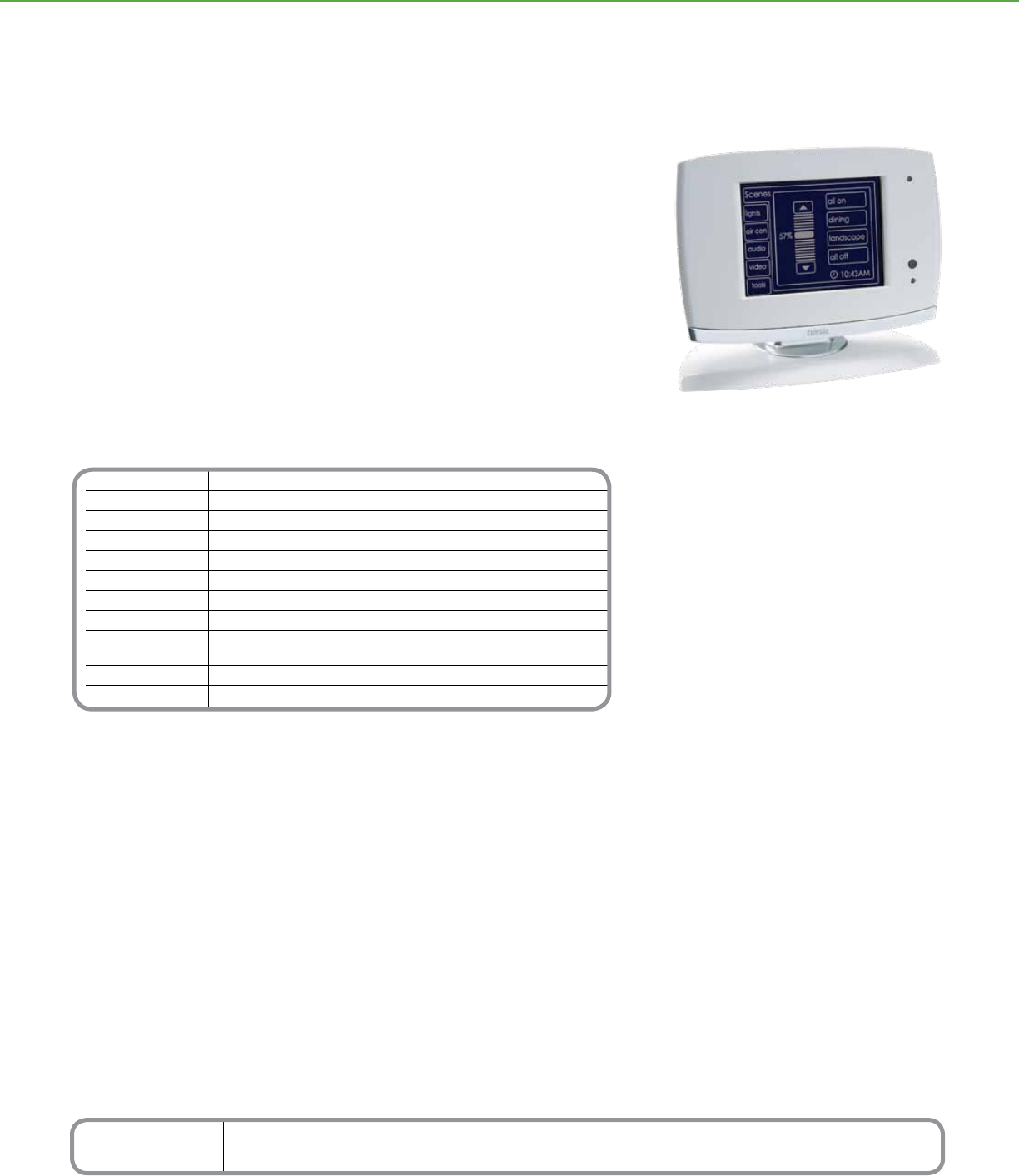
Technical Information
Screen
AC input impedance 13 K ohms @ 1kHz
Display type 4.7 inch (119 mm) active black and white LCDl
Resolution 320 x 240 pixels
Viewing Area Left, right: 45∞; up: 50∞; down: 30∞
Luminance 120 cd/m≤
Backlight type White LED
Touch surface durability 1 million presses (typical)
Maximum number 255 group addresses on each
of controlled loads of the 10 applications
Third party interface RS-232 port
Programming port USB type
*For Diagram see technical section page 97
Catalog Number Description
SLC5000CTD2BK Mark II Desktop Touch Screen in Black
SLC5000CTD2WE Mark II Desktop Touch Screen in White
C-BUSTM LIGHTING CONTROL + TOUCH SCREENS
Product Features
• Multiple control screens can include multi-
point switching and dimming, master ON/OFF
switching, schedules, and scenes from a menu
driven interface
• Astronomical clock with full scheduling and
holidays
• Locator option to help users nd the screen in
dim light
• Built-in infrared receiver w/remote control
• RS-232 port for third party device integration
• USB programming port accessible from the front
of the unit
Functional Aesthetics
• Clean-lined low-prole touch screen can be wall-
mounted without external ttings
• Display and controls can be congured with
symbols, images, clocks and time, and text in
multiple languages
• Area plans and other scenes can be graphically
depicted
Distributed Intelligence
• Compatible with all C-Bus devices and
Powerlink® NF3000G3C controllers
• Easily congured by using the C-Bus PICED
software program
The Mark II Desktop Touch Screen is a unied panel for controlling lighting systems and
accessories with the touch of a nger.
Designed with versatility in mind, these sleek touch screens are easy to install,
customize, and use. Compact yet powerful, the touch screen has numerous
congurations available, making it an attractive alternative to multiple single operation
switches, ON/OFF toggles, dimmers, and timers which can clutter up even the nicest
wall.
Schneider Electric C-BusTM Mark II Desktop Touch Screens are available in both black
and white.
Mark II Desktop Touch Screen
Mark II
Desktop Touch Screen
56
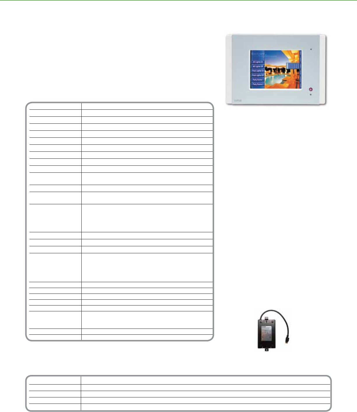
Technical Information
Screen
Type LCD active matrix
Size 6.4 in. (diagonal)
Resolution VGA, 640 x 480 pixels
Pixel Pitch 0.01 in. (H) x 0.01 in. (V) [0.204 mm (H) x 0.202 mm (V)]
Viewing Area 5.14 in. (H) x 3.82 in. (V) [130.6 mm (H) x 97.0 mm (V)]
Touch Overlay Type Resistive membrane
Viewing Angle Typical horizontal: 70° left and right / Typical vertical: 40° up, 70° down
Luminance 300 cd/m2
Backlight Cold cathode with light sensor for automatic backlight level control
Memory 256 MB compact Flash memory, pre-programmed with panel rmware
Backup: Lithium battery retains current date and time for 5 years.
Components and Connectors
Front Ethernet 10/100/RJ-45 terminal (hidden)
Speaker (hidden), Infrared receiver, RS-232 via DB 9 terminal
Rear C-Bus RJ-45 terminals (2) • Ethernet 10/100/RJ-45 terminal
Composite video output via RCA terminal (75 ohm) • RS-232 via DB 9 terminal
USB type A terminals (2) for future software support
Remote infrared (IR) terminal (hardwired via a 3.5 mm mini-jack)
External speaker/headphone terminal (3.5 mm mini-jack)
Overall Dimensions 9.8 in. (W) x 6.9 in. (H) x 2.9 in. (D) [246 mm (W) x 173 mm (H) x 72.5 mm (D)]
Weight 3.02 lbs. (1375 g) (excluding cover plate)
Operating Environment Temp.: 50°F to 86°F (10°C to 30°C) / RH: 95% noncondensing
Standards UL Listed 916 Energy Management Equipment
CSA 22.2 Spec. 205 Signal Equipment
FCC: Part 15.101, Class B Digital Device • EN61000-4-2 Immunity to ESD
Required Accessories
Power Supply (Sold Separately)
Power Supply 6.9 in. (L) x 3.1 in. (W) x 1.8 in. (H)
Dimensions 175 mm (L) x 80 mm (W) x 45 mm (H)
Adaptor Box 5.2 in. (L) x 2 in. (W) x .4 in. (H)
Dimensions 113 mm (L) x 50 mm (W) x 11 mm (H)
Weight 4.2 lb (1.925 kg)
Standards UL: Listed 60950 Information Technology Equipment - Safety:
General Requirements • CSA 22.2 Spec. 205 Signal Equipment
FCC: Part 15.101, Class B Digital Device • EN61000-4-2 Immunity to ESD
Output Cable 65.6 ft (20 m)
DC Plug 7 pin, DIN, male
*For Diagram see technical section page 97
Order numbers for the Neo and Saturn style touch screens include the stock number, and the code for the cover color. Saturn
Colors: Black (BK), Mocha (BR), White (WE), and Cream (CM). Neo Colors: Brushed Aluminum and Slate (GB), White (WE) and
Black (BK) For example, SLC5050CTC(WE) represents a Neo Style Touch Screen in white.
Catalog Number Description Accessories Description
SLC5050CTC( ) NeoTM Style Touch Screen SLC5000CTCPS * Color Touch Screen Power Supply
SLC5080CTC2( ) Saturn™ Style Touch Screen SLC5000CTCWB * * Color Touch Screen Wall Box
SLC5000CTCNA* * Color Touch Screen Wall Nail Bracket
SLC5000CTCRM* * Color Touch Screen Wall Plaster Board Bracket
* Note: Required for every color touch screen installation.
** Note: Color touch screen must be mounted with one of these options
C-BUSTM LIGHTING CONTROL + TOUCH SCREENS
Power supply for color touch screen
(sold separately)
The
C-BusTM
Color Touch Screen is a unied panel for controlling lighting systems and
accessories with the touch of a nger.
The touch screen's sophisticated appearance reects the underlying craftsmanship of its
design. Among its many capabilities, this powerful PC-based system supports graphical
depiction of area plans, monitoring of various C-Bus devices, scheduling of lighting and
other loads, nger-tip control of preset scenes, and operation from the touch screen or by
remote controller.
Product Features
• Ability to congure controls including scenes,
schedules, state changes and graphic animation
• Ability to customize buttons, sliders, photos and
drawings
• Audio tools support use of custom WAV les for
audible feedback and voice prompts
• Internal amplied speaker has volume control and
external speaker terminal
• Built-in RJ-45 Ethernet and C-Bus network, RS-
232, and USB terminals
• Infrared receiver for remote control and infrared
input for accessories
• Controls can be password protected at multiple
levels
• Astronomical and real time clocks
Functional Aesthetics
• Touch sensitive 6.4 inch (640 x 480) color LCD
panel
• Light sensor for automatic backlight control
• Flush wall-mount design
• Cover plates available in NeoTM and SaturnTM styles
• Five color schemes available, complementing any
décor
Distributed Intelligence
• Compatible with Powerlink® G3 3000C controller
and all C-Bus components, including keypads,
sensors, and dimmers
• Easily congured by using the C-Bus PICED
Software
Color Touch Screen
Color
Touch Screen
57
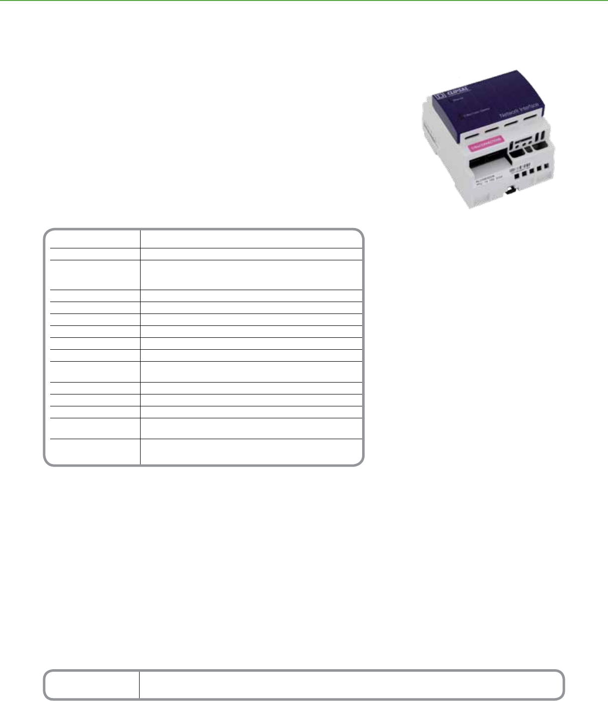
Technical Information
C-Bus Voltage Requirements 15–36Vdc
Supply Current 12V AC or DC @ 300 mA
C-Bus Input Voltage 15 to 36V DC
Does not draw current from
the C-Bus Network
External Power Supply (provided) 12Vdc @ 500 mA
Electrical Isolation 500V RMS continuous C-Bus/RS-232
Status Indicators Ethernet LED/Comms LED
C-Bus System Clock Software selectable
C-Bus Network Burden Software selectable
Ethernet Connection RJ-45 socket for connection to Ethernet
Dimensions 3.35 in. (H) x 2.83 in. (W) x 2.56 in. (D)
[85 mm (H) x 72 mm (W) x 65 mm (D)]
Weight 4.59 oz (130 g)
Operating Temp.: 32°F to 113°F (0°C to 45°C)
Environment RH: 95%, noncondensing
Storage Environment Temp.: 14°F to 140°F (-10°C to 60°C)
RH: 95%, noncondensing
Standards UL: Listed 916 Energy Management Equipment
CSA 22.2 Spec 205 Signal Equipment
*For Diagram see technical section page 98
Catalog Number Description
SLC5500CN Ethernet Network Interface
C-BUSTM LIGHTING CONTROL + SYSTEM UNITS
The Schneider Electric C-Bus™ Ethernet Network Interface unit is a C-Bus system support
device designed to provide an isolated communications path between an Ethernet Network
and a C-Bus Network.
The following functions can be achieved through this interface: programming C-Bus Units,
issuing commands to a C-Bus Network including scheduled activities as well as monitoring
and data logging of activities on a C-Bus Network.
The C-Bus Ethernet Network Interface may also generate the system clock for
communications data synchronization on the C-Bus Network and provide a software
selectable Network Burden.
For ease of installation the unit is DIN rail mounted.
Product Features
• Programming C-Bus Units
• Issuing commands to a C-Bus Network, including
scheduled activities
• Monitoring and Data Logging of activities on a
C-Bus Network
• Software selectable C-Bus System Clock
Distributed Intelligence
• Compatible with all C-Bus devices and
Powerlink
®
NF3000G3C controllers
• Easily congured by using the C-Bus Toolkit
software
Ethernet Network Interface
C-BusTM
Ethernet Network Interface
58
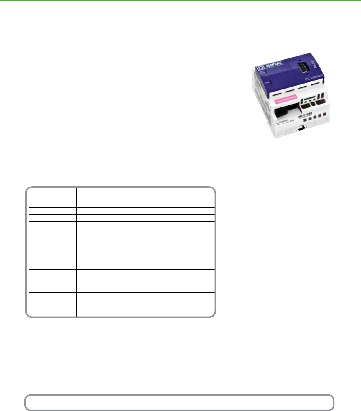
Catalog Number Description
SLC5500PC PC Interface
Technical Information
Voltage 15–36Vdc @ 32 mA required for normal operation,
Requirements drawn from the C-Bus network
Electrical Isolation 500V RMS continuous C-Bus/RS-232
Status Unit/Comms: Unit power and data transmission
Indicators C-Bus: Power levels and presence of C-Bus clock
Serial (1) 9-pin RS-232 D-type serial connector
Port (2) RS-232 RJ-45 connectors
Cable 6.6 ft (2 m), with DB9 connectors
C-Bus Connection (2) RJ-45 sockets for connection to a C-Bus network
Dimensions 2.84 in. (H) x 3.35 in. (W) x 2.60 in. (D)
[72 mm (H) x 85 mm (W) x 66 mm (D)]
Mounting DIN rail, 4M wide
Serial Termination Temp.: 32°F to 113°F (0°C to 45°C)
RH: 95%, noncondensing
Storage Environment Temp.: 14°F to 140°F (-10°C to 60°C)
RH: 95%, noncondensing
Standards UL: Listed 916 Energy Management Equipment
CSA 22.2 Spec 205 Signal Equipment
FCC: Part 15.101, Class B Digital Device
EN61000-4-2 Immunity to ESD
*For Diagram see technical section page 98
C-BUSTM LIGHTING CONTROL + SYSTEM UNITS
The C-BusTM PC Interface (PCI) expands options for conguring, controlling, and
monitoring C-Bus networks by providing an interface between the network and a
personal computer (PC) or other external device.
The C-Bus PCI module easily mounts to a DIN rail and connects to external devices
through its built-in connector ports. Power to the unit is provided through the C-Bus
network.
Product Features
•
Unit/Comms LED shows the status of the
unit’s power and of any data transmissions
• C-Bus LED shows the status of the network
at the unit, including the level of network
power and the presence of the C-Bus clock
• System network clock for synchronizing
communications data
• Three RS-232 serial connectors for con-
necting to a PC or to external devices: (1)
9-pin D-type serial connector (female) and
(2) 8-pin RJ-45 connectors
• Two C-Bus network connector ports: RJ-45
sockets
• Data cable for connecting PCI and personal
computer, including DB9 connectors
Distributed Intelligence
•
Compatible with all C-Bus devices and the
Powerlink
®
NF3000G3C controller
PC Interface
C-BusTM
PC Interface
59
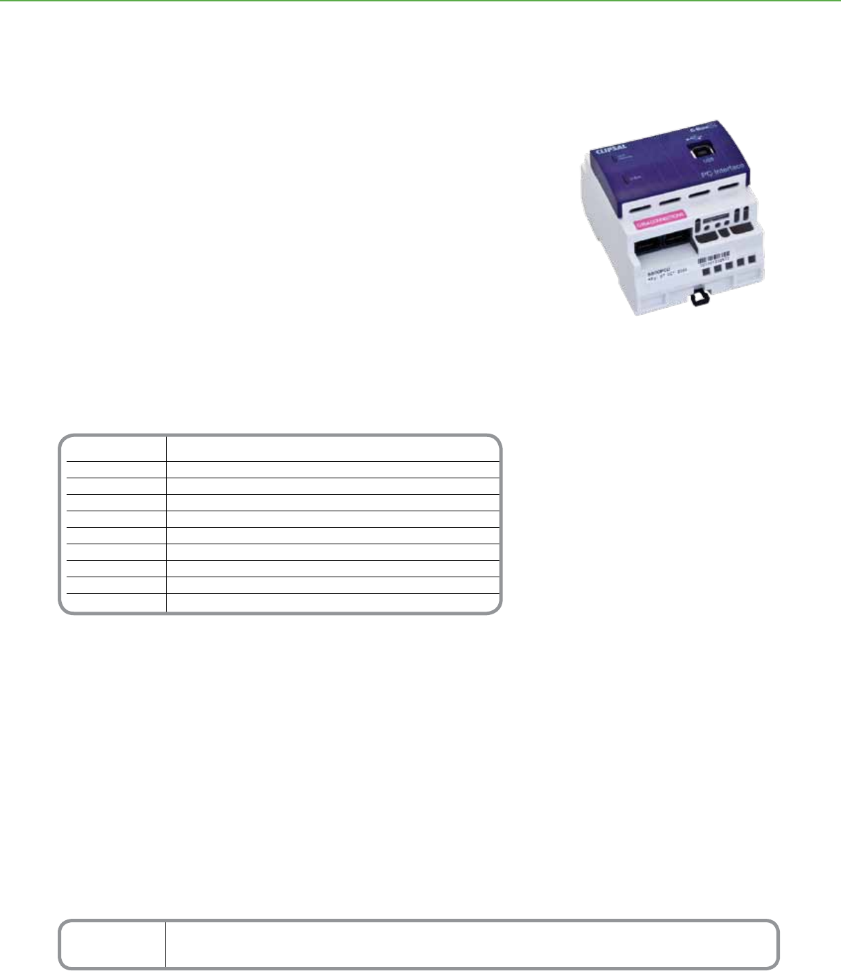
Catalog Number Description
SLC5500PCU PC Interface, USB Model
Technical Information
C-bus input voltage 15-36Vd
Current drawn 22mA
Electrical isolation rating 500Vrms continuous C-Bus/RS232
Communications USB Type A to B
Operating temperature 32-113°F (0-45°C)
Operating humidity range 95% RH; non-condensing
Terminals C-Bus, RJ45 connectors (2), USB to PC
Dimensions 2.84 in. (L) x 3.35 in. (W) x 2.60 in. (D)
[72 mm (L) x 85 mm (W) x 66 mm (D)]
Weight 0.23 lbs (104g)
*For Diagram see technical section page 98
C-BUSTM LIGHTING CONTROL + SYSTEM UNITS
The C-BusTM PC Interface (PCI) expands options for conguring, controlling, and
monitoring C-Bus networks by providing an interface between the network and a
personal computer (PC) or other external device.
The C-Bus PCI module easily mounts to a DIN rail and connects to external devices
through its built-in connector ports. Power to the unit is provided through the C-Bus
network.
PC Interface USB
Product Features
•
Unit/Comms LED shows the status of the
unit’s power and of any data transmissions
• C-Bus LED shows the status of the network
at the unit, including the level of network
power and the presence of the C-Bus clock
• System network clock for synchronizing
communications data
• USB (B-Type) Connector
• Two C-Bus network connector ports: RJ-45
sockets
• Data cable for connecting PCI and personal
computer, including DB9 connectors
Distributed Intelligence
•
Compatible with all C-bus devices and the
Powerlink
®
NF3000G3C controller
C-BusTM
PC Interface USB
60
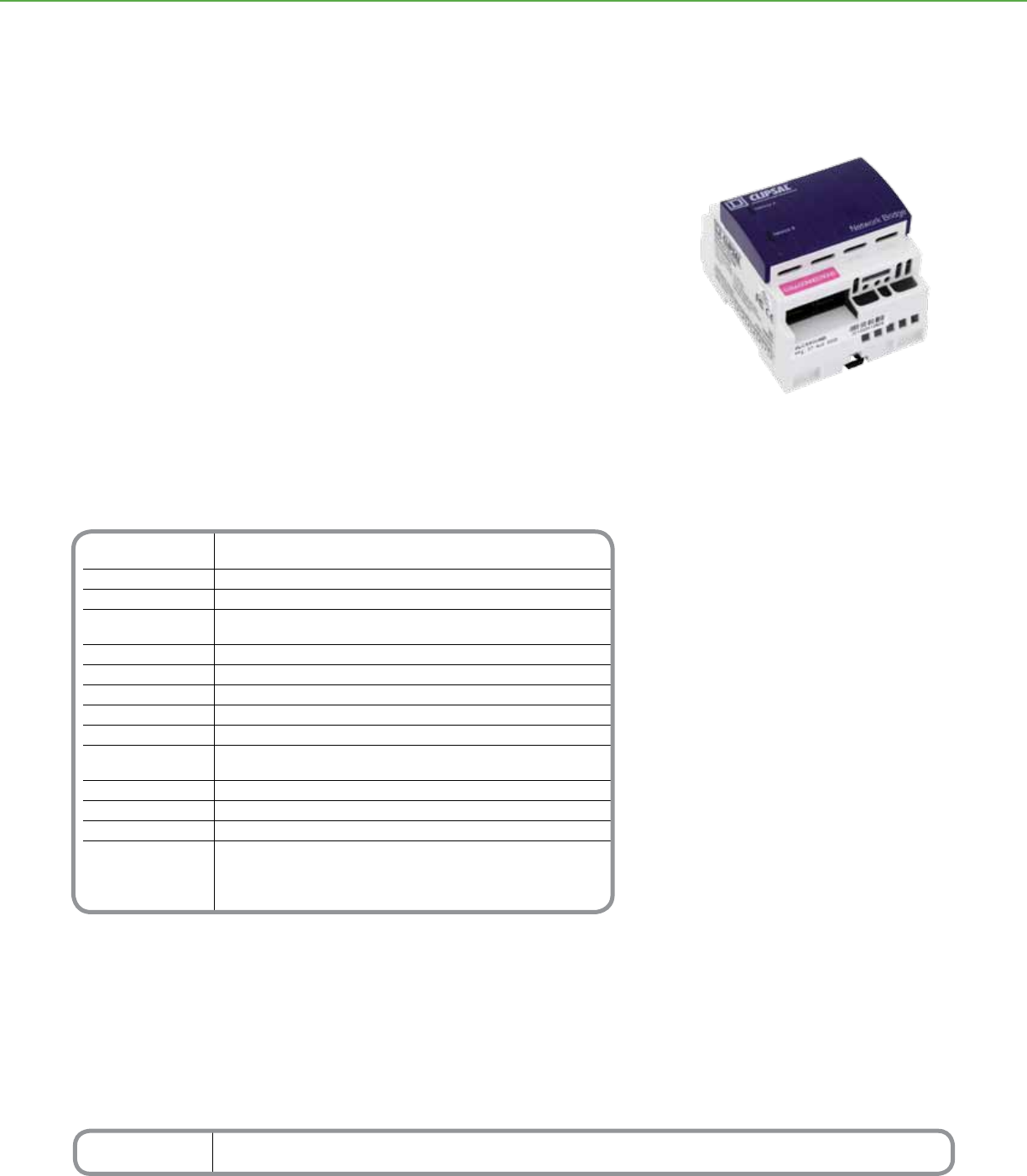
Catalog Number Description
SLC5500NB Network Bridge
Technical Information
Voltage 15–36Vdc @ 18 mA required for normal operation,
Requirements drawn from each connected C-Bus network
Electrical Isolation 3.5 kV RMS for 1 min (between networks)
Status Network A, Network B
Indicators Power ON, Communications in progress
Power OFF - Not connected/insufcient power
Propagation Delay 250 ms (delay for message transfer between two adjacent C-Bus Networks)
Interconnect In parallel: 51 networks (50 network bridges)
Capacity In series: 7 networks (6 network bridges)
C-Bus System Clock Software selectable
C-Bus Network Burden Software selectable
C-Bus Connection (2) pair of RJ-45 sockets for connection
to C-Bus networks
Dimensions 2.84 in. (H) x 3.35 in. (W) x 2.60 in. (D) [72 mm (H) x 85 mm (W) x 66 mm (D)]
Weight 3.35 oz (95 g)
Operating Environment Temp.: 32°F to 113°F (0°C to 45°C) RH: 95%, noncondensing
Standards UL: Listed 916 Energy Management Equipment
CSA 22.2 Spec 205 Signal Equipment
FCC: Part 15.101, Class B Digital Device
EN61000-4-2 Immunity to ESD
*For Diagram see technical section page 99
C-BUSTM LIGHTING CONTROL + SYSTEM UNITS
The C-BusTM Network Bridge provides a communication channel between C-Bus units
on separate networks, expanding the total number of units that can be congured,
controlled, and monitored.
Network Bridge
Product Features
• Increases transmission distances by acting as
a repeater station for data transmission
• Expands the total number of C-Bus devices
that can operate on the system by isolating
devices to individual networks [In parallel: 50
networks (50 network bridges) In series: 7
networks (6 network bridges)]
• Indicates each network’s status level
• Stores operating status in non-volatile memory
for recovery from a power outage
• Uses built-in connectors to connect to a
C-Bus network
Distributed Intelligence
• Compatible with all C-Bus devices and
Powerlink® NF3000G3C controllers
• Easily congured by using the C-Bus Tool Kit
software
C-BusTM
Network Bridge
61
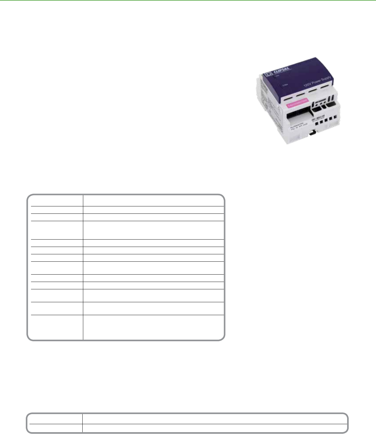
Catalog Number Description
SLC5500TPS 120Vac Power Supply
SLC5500HPS 277Vac Power Supply
Technical Information
Nominal Line Voltage Operates at 120 or 277Vac, ± 10%, with a frequency range from 50–60 Hz
Electrical Isolation 3.75 kV RMS from C-Bus to the line
Current Output 350 mA to the C-Bus network
Status Indicators Unit: Unit power
C-Bus: Network voltage level and
presence of system clock
Power Supplies per Network Up to ve power supplies on a single C-Bus network
C-Bus Connection (2) RJ-45 sockets for connection to the C-Bus network
Cable (1) 15.75 in. (400 mm) patch lead included
Dimensions 3.35 in. (H) x 2.84 in. (W) x 2.60 in. (D)
[85 mm (H) x 72 mm (W) x 66 mm (D)]
Mounting DIN rail, 4M wide
Weight 7 oz (200 g)
Operating Temp.: 32°F to 104°F (0°C to 40°C)
Environment RH: 95%, noncondensing
Storage Temp.: 14°F to 140°F (–10°C to 60°C)
Environment RH: 95%, noncondensing
Standards UL: Listed 916 Energy Management Equipment
CSA 22.2 Spec 205 Signal Equipment
FCC: Part 15.101, Class B Digital Device
EN61000-4-2 Immunity to ESD
*For Diagram see technical section page 99
C-BUSTM LIGHTING CONTROL + SYSTEM UNITS
The C-BusTM Power Supply is specically designed to operate with the C-Bus network
as a power source for passive C-Bus devices.
The power supply mounts to a DIN rail and connects to the C-Bus network through
built-in RJ-45 connectors.
These devices are UL listed as Class 2 power supplies and are suitable for parallel
operation. Up to ve power supplies can be connected to a single C-Bus network.
Power Supply
Product Features
• Available in 120 and 277Vac models
• Regulating power supply compensates for
line voltage and frequency variations, so there
is constant output
• Sources up to 350 mA to the C-Bus network
• UL listed to operate in parallel with other
C-Bus power supplies, up to ve on a single
C-Bus network
• Incorporates short circuit and reverse polarity
protection
• Indicates the line voltage status with a Unit
LED
• Indicates the network status, including the
network power and the presence of the
C-Bus clock, with a C-Bus LED
• Standard built-in C-Bus network connectors:
(2) RJ-45
Distributed Intelligence
• Compatible with all C-Bus devices and
Powerlink® NF3000G3C controllers
• Easily congured by using the C-Bus Tool Kit
software
C-BusTM
Power Supply
62
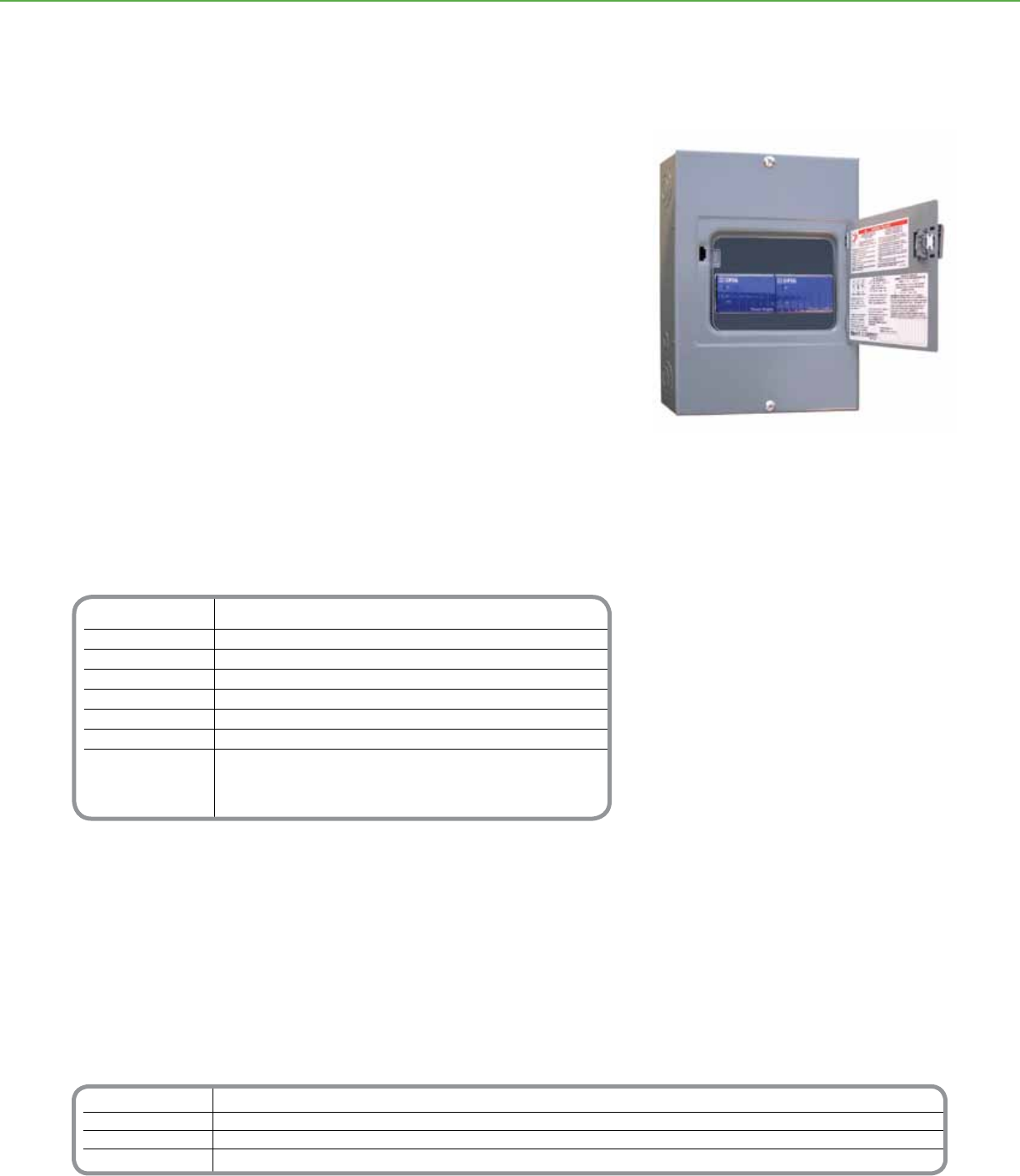
Technical Information
Nominal Line Voltage Operates at 120 or 277Vac, ± 10%, with a frequency range from 50–60 Hz
Maximum Line Current 9.9 mA for 120V power supply 4.3 mA for 277V power supply
Electrical Isolation 3.75 kV RMS from C-Bus to the line
Current Output 350 mA (single power supply unit) 700 mA (dual power supply unit)
Dimensions 12.57 in. (L) x 8.88 in. (W) x 3.8 in. (D) [319 mm (L) x 226 mm (W) x 97 mm (D)]
Weight One power supply: 8.84 lb (4.01 kg) Two power supplies: 9.28 lb (4.21 kg)
Operating Environment Temp.: 32°F to 113°F (0°C to 45°C) RH: 95%, noncondensing
Standards UL: Listed 508A Industrial Control Equipment
CSA 22.2 Spec 205 Signal Equipment
FCC: Part 15.101, Class B Digital Device
EN61000-4-2 Immunity to ESD
*For Diagram see technical section page 99
Catalog Number Description
NFDP1120G3C 120V Powerlink Single Power Supply
NFDP2120G3C 120V Powerlink Dual Power Supply
NFDP1277G3C 277V Powerlink Single Power Supply
NFDP2277G3C 277V Powerlink Dual Power Supply
C-BUSTM LIGHTING CONTROL + SYSTEM UNITS
The Powerlink® Device Power Supply is used to distribute power on a C-BusTM network.
Placed at critical points on the network, device power supplies will provide the current
necessary for operating a variety of passive Schneider Electric C-Bus devices.
A Powerlink Device Power Supply consists of a C-Bus 8M enclosure containing one or
two 4M Power Supplies.
Product Features
• Surface-mount NEMA 1 enclosure with trim
assembly
• Unit and C-Bus LEDs indicate the status of
the line voltage and the network
• Sources up to 700 mA (dual power supplies)
to the C-Bus network
• 120 or 277Vac models available
• UTP connection jumper included for dual
supply
Distributed Intelligence
• Compatible with all C-Bus devices
and Powerlink NF3000G3C controllers
• Easily congured by using the C-Bus Tool Kit
software
Powerlink Device Power Supply
Powerlink®
Device Power Supply
63
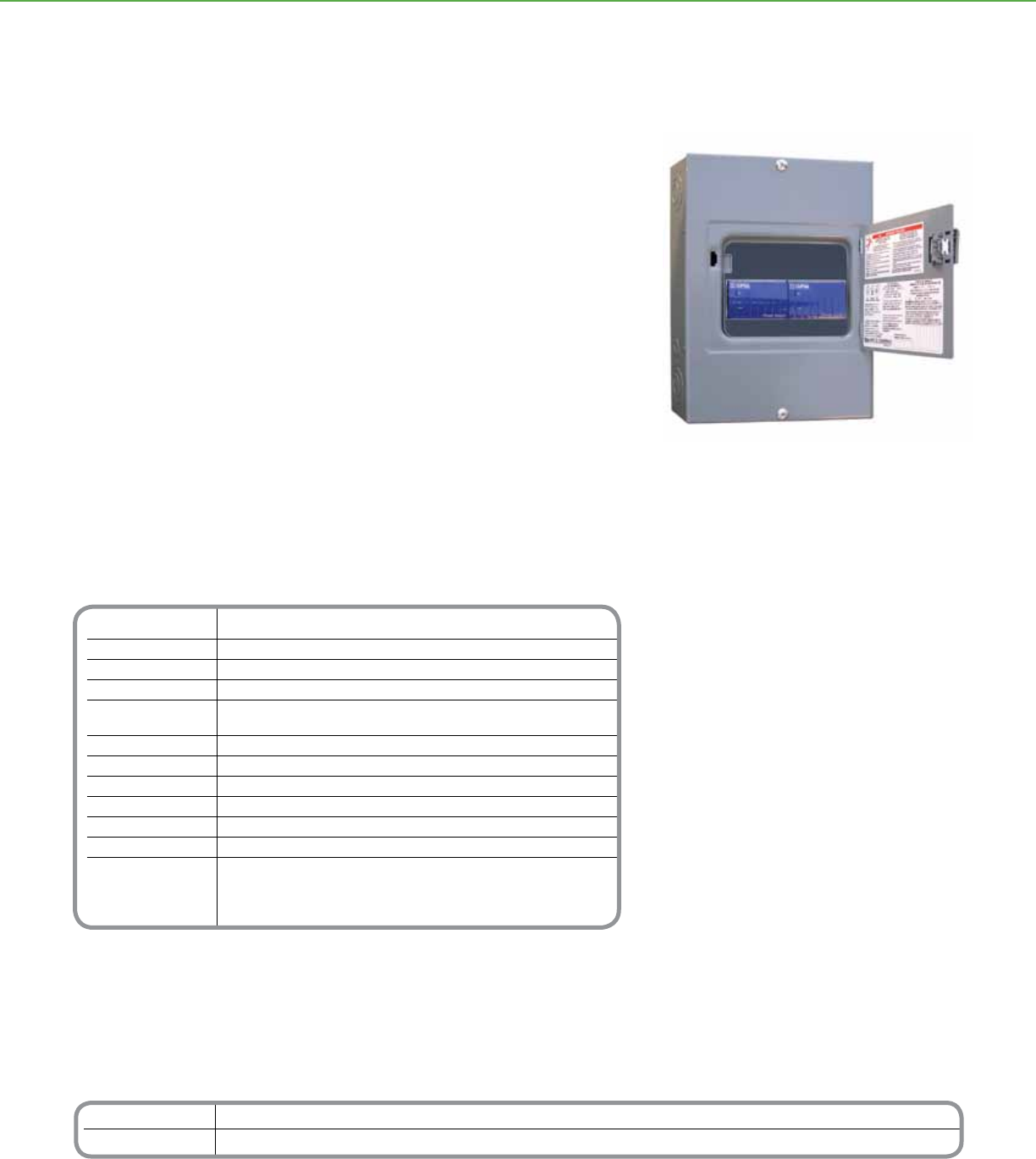
Catalog Number Description
NFDR120G3C 120V Powerlink Device Router
NFDR277G3C 277V Powerlink Device Router
Technical Information
Nominal Line Voltage Operates at 120 or 277Vac, ± 10%, with a frequency range from 50–60 Hz
Maximum Line Current 9.9 mA for 120V device router 4.3 mA for 277V device router
Electrical Isolation 3.75 kV RMS from C-Bus to the line
Current Output 350 mA to the C-Bus network
Status Indicators Unit and Unit/Comms: Line voltage, unit power, and data transmission
C-Bus: Power levels and presence of C-Bus clock
Serial Connection (1) 9-pin RS-232 D-type serial connector (2) RS-232 RJ-45 connectors
C-Bus Connection (2) RJ-45 sockets for connection to the C-Bus network
Data Cable 50 ft serial
Dimensions 12.57 in. (L) x 8.88 in. (W) x 3.8 in. (D) [319 mm (L) x 226 mm (W) x 97 mm (D)]
Weight 9.1 lbs (4.13 kg)
Operating Environment Temp.: 32° to 113°F (0° to 45°C) RH: 95%, noncondensing
Standards UL: Listed 508A Industrial Control Equipment
CSA 22.2 Spec 205 Signal Equipment
FCC: Part 15.101, Class B Digital Device
EN61000-4-2 Immunity to ESD
*For Diagram see technical section page 99
C-BUSTM LIGHTING CONTROL + SYSTEM UNITS
The Powerlink® Device Router allows the exchange of data between a Powerlink
NF3000G3C controller and Schneider Electric C-BusTM devices.
The bidirectional device router can receive data from C-Bus input devices and send the
data to the Powerlink panel/network. It can also receive data such as a contact closure
from the Powerlink input and send that data to a C-Bus output/network.
The device router consists of a 8M enclosure containing a PC Interface and a Power
Supply. Communication between the device router and the NF3000G3C controller is
made with the included 50-foot serial cable.
Product Features
• Surface-mount NEMA 1 enclosure with trim
assembly
• Unit, Unit/Comms, and C-Bus LEDs indicate the
status of data transmission and power to the
unit and the network
• System network clock for synchronizing
communications data
• Network power source, supplying up to 350 mA
• 120 or 277Vac models available
Distributed Intelligence
• Compatible with all C-Bus devices and
Powerlink NF3000G3C controllers
• Easily congured by using the C-Bus Tool Kit
software
Powerlink Device Router
Powerlink®
Device Router
64
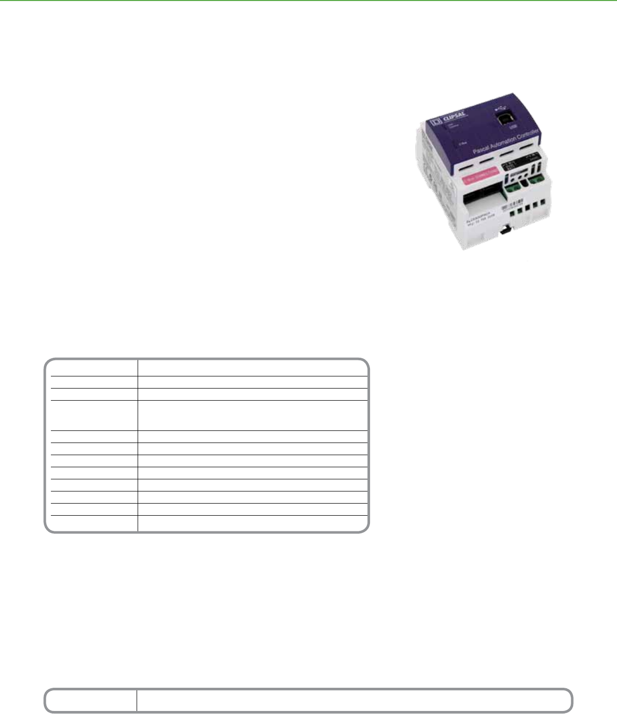
Technical Information
C-BusTM Supply Voltage 15-36Vdc @ 32 mA Drawn from the C-Bus network
RS-232 Supply Voltage 24Vac @ 20 mA (power source not provided)
Battery Backup Supply Voltage 12Vdc @ 30 mA (power source not provided)
Connections 2 C-Bus RJ-45 sockets (in parallel), 2 RS-232 RJ-45 sockets,
1 USB type B socket,
screw terminals for 12Vdc battery and 24Vac power
C-Bus System Clock Software selectable
Network Burden Software selectable
Status Indicators Unit/Comms, C-Bus, Status and User
Dimensions 2.83 x 3.62 x 2.48 inches (72 x 92 x 63mm)
Weight 5.29 oz (150g)
Mounting DIN 4M wide
Operating Environment 32°F to 113°F (0°C to 45°C) 10% - 95% RH, noncondensing
Standards CSA 22.2 Spec 205 Signal Equipment
*For Diagram see technical section page 100
Catalog Number Description
SLC5500PACA Pascal Automation Controller
C-BUSTM LIGHTING CONTROL + SYSTEM UNITS
The C-BusTM Pascal Automation Controller (PAC) provides extended conditional
and real-time event programming to C-Bus systems. The PAC supports a full range
of programming commands including conditional logic, ow control, variables and
scheduling.
Systems integrators will appreciate the built-in scheduling tools, scene tools, and
wizards for creating basic logic programs. Full programming capabilities can be achieved
utilizing the free-form script editor based off the PASCAL programming language.
The PAC directly connects to a wired C-Bus system. Programs are downloaded from a
personal computer through a USB connection.
Product Features
• Conditional and real-time events programming
for C-Bus.
• Connects directly to C-Bus network
• Powered from the C-Bus network
• USB port for connection to personal computer
• (2) RS-232 ports for third party device control
• Real time, astronomical and C-Bus system
clock included with 24 hour internal capacitor
backup and external 12Vdc battery terminals
Programming
capabilities including:
• Conditional logic (if, then, and, or, not, etc.)
• Flow Control (for, repeat, while)
• Variables (integer, real, Boolean, character,
string)
• Control and monitoring of group addresses
• Control and monitoring of scenes
Distributed Intelligence
• Compatible with all C-Bus devices and the
Powerlink® NF3000G3C controller
• Easily congured with the C-Bus Toolkit
Software
Pascal Automation Controller
C-BusTM
Pascal Automation Controller
65
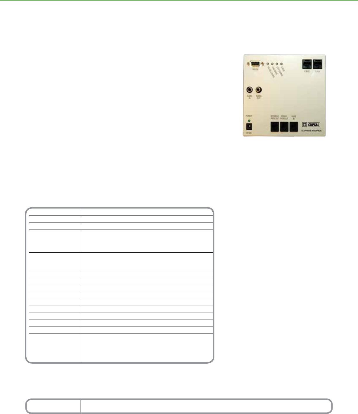
Catalog Number Description
SLC5100TUS Telephone Interface Unit
Technical Information
C-Bus Supply Voltage 15 36Vdc @ 18 mA Nominal
DC Plug Pack 12Vdc @ 300-500 mA, 2.1mm plug with Center pin +VE
Audio Output Line output, 1 Vp-p (nominal) into 10K Ohms
Control Functions Dial in and Dial out functionality, control and status monitoring for a
C-Bus system. Audio output. Standard C-Bus PCI allowing remote dial in
and operation as a PCI with modem connection for remote
operation of installation software
Status Indicators Green LED- Power
Orange LED-RS232 Comms, Line Grab
Unit Comms and C-Bus
Start Up Time 10 seconds nominal after Power Up
Storage Temperature 32° to 140°F (0° to 60°C)
Operating Temperature Range 32° to 113°F (0° to 45°C)
Operating Humidity Range 0° to 95% RH, noncondensing
C-Bus Input Terminals RJ45 sockets
Color White with Black lettering and markings
Dimensions 5.8 x 5.7 x 1.2 in. (146.5 x 145 x 30mm)
Weight 1.31 lbs. (580g)
Mounting Centers 3.2 in. (80mm)
Standards UL916 Energy Management Equipment
CSA 22.2 Spec. 205 Signal Equipment
FCC Part 15.101, Class B Digital
FCC Part 68 Connections of Terminal Equipment
to the Telephone Network
*For Diagram see technical section page 100
C-BUSTM LIGHTING CONTROL + SYSTEM UNITS
Product Features
• Audio OUT
• Local or remote site access to C-Bus system
• 12Vdc power pack
• RS-232 connection
• 1 RJ45 patch lead
• 2 RJ12 patch leads
• Software available via website download
The C-Bus™ Telephone Interface offers a dial-in and dial-out functionality, permitting
control and status monitoring for a C-Bus system. It also includes an audio output, so
that C-Bus events can be audibly announced.
The Telephone Interface is programmed using a connection to a PC running special
conguration software. The interface can also act as a C-Bus PC Interface. In this way
C-Bus can be programmed and congured either locally or from a remote site using a
data modem.
The Telephone Interface is suitable for connection to the telephone network using a
RJ31X connection, in parallel, or by insertion into a local circuit.
Telephone Interface Unit
C-BusTM
Telephone Interface Unit
66
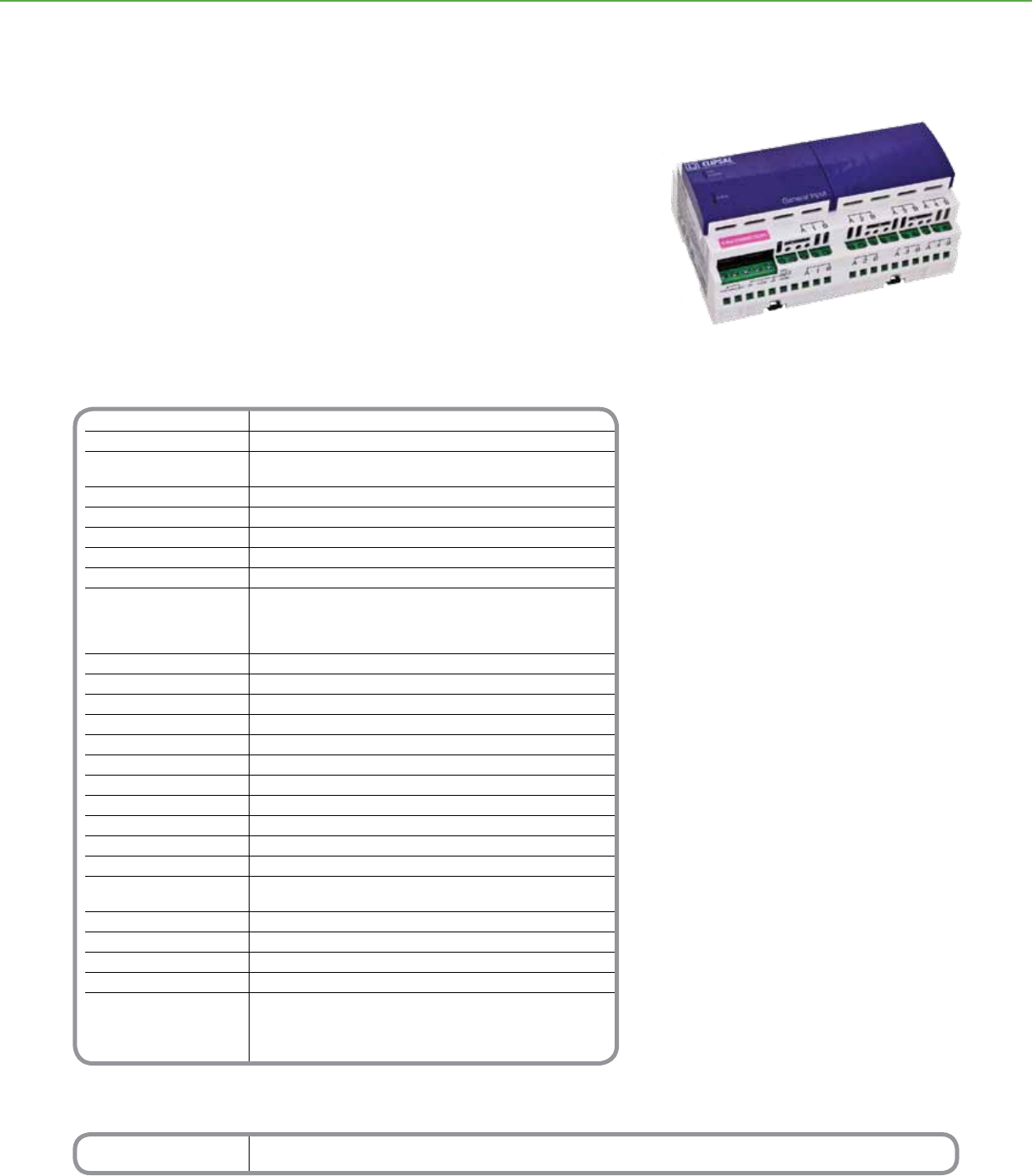
Technical Information
Nominal Voltage Requirements 15-36 volts @18 mA from the C-Bus network
Nominal 120Vac
Nominal Supply Voltage 16-27V AC/DC, +/- 10%, 50-60 Hz,
provided by an external power supply (included)
AC Input Impedance 100 kOhm @ 1 kHz
External Power Supply 24Vac @ 500 mA
Electrical Isolation 500 V RMS per input
Nominal 24Vdc Output Voltage 24Vdc @ 250 mA, ±10% General Input
Digital Sensor Input TTL, 5V from external source
Analog Sensor Inputs:
Voltage Ranges 0–1, 0–5, 0–10, 0–20Vdc
Input Current Ranges 0–20 mA DC, 4–20 mA DC
Resistance Ranges 0–500 ohm, 0–1000 ohm, 0–3000 ohm, 0–10000 ohm
Maximum Input Voltages -20 V to 60Vdc
Input Voltage Range Impedance At least 100 kOhm
Current Sense Impedance 249 ohm
Resistance Range Injection Current 500 μA
Basic Accuracy after Calibration 0.5% of full scale
Maximum Input Frequency 10 Hz
Broadcast Rates 2–1024 sec
Number of Units per Network 10
C-Bus Connections (2) RJ-45 connectors, CAT 5 UTP cable required
Cable 15.75 in. (400 mm) patch lead included
Terminals Accommodate 16–12 AWG cable (2 x 1.31 mm2 or 1 x 3.31 mm2)
Status Indicators Unit/Comms: Unit power and data transmission
C-Bus: Power levels and presence of C-Bus clock
Dimensions 5.7 in. (L) x 3.4 in. (W) x 2.6 in.(H) [144 mm (L) x 85 mm (W) x 65 mm (H)]
Weight 7 oz (190 g)
Mounting DIN rail, 8M wide
Operating Environment 32°F to 113°F (0°C to 45°C) RH: 95%, noncondensing
Standards CSA 22.2 Spec 205 Signal Equipment
FCC: Part 15.101, Class B Digital
EN61000-4-2 Immunity to ESD
UL Listed 916 Energy Management Equipment
*For Diagram see technical section page 100
Catalog Number Description
SLCE5504TGI 4 Channel General Input Unit
C-BUSTM LIGHTING CONTROL + INPUT UNITS
The C-BusTM Four-Channel General Input Units are DIN-rail mounted devices that
measure TTL digital and real-world analog quantities and generate messages about the
measurements to the C- Bus network. By acting as an interface with various external
sensors, the general input unit enables integration of the C-Bus network with a variety of
system types, such as those for HVAC and for power monitoring.
Conguration options include selectable input types, eight adjustable decision thresholds
per channel, denable actions, selectable ltering, broadcast rates, and a separate
hysteresis value per channel.
General Input Unit
Product Features
• Measures TTL digital quantities including
voltage, current, or resistance from external
sensors such as light level, pressure, and
temperature
• Four channels of input, each with an
adjustable hysteresis value, eight decision
thresholds, and a software-selectable input
value transformation in the form y = ax +b
• Input channels are compatible with a range of
third-party sensors
• Look-up table with interpolation
• Capable of threshold switching or
broadcasting values onto the network
• Control functions include load switching,
dimming, trigger applications, enable control
applications, and measurement applications
• Measures input signals up to 10 Hz and has
an adjustable input-signal lter to reduce
susceptibility to impulse and noise
• Supplies 250 mA to external sensors
• LEDs indicate the status of the network
at the unit and the unit’s power and data
transmissions
• Software-selectable network burden and
C-Bus system clock
• Standard built-in C-Bus network connectors:
(2) RJ-45
• Non-volatile memory stores operating status
for recovery from a power outage
• Includes 120V/24V AC power pack
Distributed Intelligence
• Compatible with all C-Bus devices and the
Powerlink® NF3000G3C controller
• Easily congured with the C-Bus Toolkit
Software
C-BusTM
General Input Unit
67
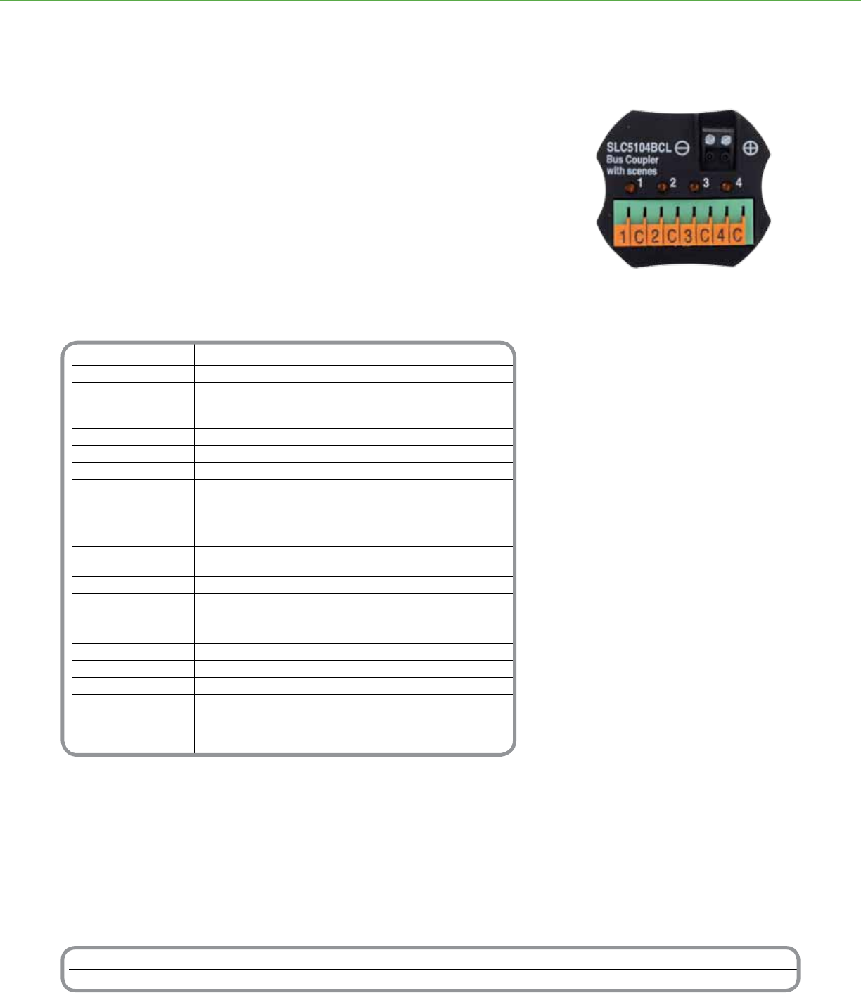
Catalog Number Description
SLC5102BCLEDL Two-Channel Bus Coupler
SLC5104BCL Four-Channel Bus Coupler
Technical Information
Nominal Voltage 15-36Vdc @ 18 mA, drawn from the
Requirements C-Bus network
Electrical Isolation None
Voltage Across Input External Switch Opens: 5Vdc
External Switch Closes: 0Vdc
Current–Switch Closed Less than 50 μA
Distance Between 2-Channel Coupler: Up to 1 ft (0.3 m) each
Switch and Bus Coupler 4-Channel Coupler: Up to 3 ft (1 m) each
LED Drive Output 2-Channel Coupler only: 2 mA @ 12 V
Maximum Input Voltages -20 to 60Vdc
Number of Units Use the C-Bus Calculator, a software utility, to determine
per Network the total network current load
C-Bus Connections Two-way removable screw-type terminals accommodating
24–16 AWG cable (0.2–1.31 mm2)
Channel Input Spring-loaded terminal block accommodating
Connections 24–12 AWG cable (0.2–3.31 mm2)
Status Indicators Channel (2 or 4)
Timers 1 sec–18 hr, 1 sec intervals
Dimensions 2.2 in. (L) x 1.9 in. (W) x 0.7 in. (H)) [55 mm (L) x 49 mm (W) x 18 mm (H)]
Weight 1.1 oz (32 g)
Operating Environment 32°F to 113°F (0°C to 45°C) RH: 95%, noncondensing
Standards UL: Listed 916 Energy Management Equipment
CSA 22.2 Spec 205 Signal Equipment
FCC: Part 15.101, Class B Digital,
EN61000-4-2 Immunity to ESD
*For Diagram see technical section page 100
C-BUSTM LIGHTING CONTROL + INPUT UNITS
The C-BusTM Bus Couplers are non-isolated input devices that provide an interface
between dry-contact mechanical switches and a C-Bus network. The bus coupler
increases the versatility of the C-Bus network by facilitating remote access with any dry-
contact switch mechanism offered by Schneider Electric and other manufacturers.
A system’s exibility can be further enhanced by using the bus coupler with various other
switch types, including reed, pressure, or micro switches.
Available in two- and four-channel models, the bus coupler is small enough to be used in
restricted spaces. Conguration options include standard control functions such as ON/
OFF, toggle, dimmers, and timers.
Product Features
• Provides two or four non-isolated inputs for
external voltage-free mechanical switches.
Two-channel units feature independent remote
LED outputs
• Control options include ON/OFF, toggle,
dimmer, or timer
• Orange LED for each channel to indicate
operational status
• Two-way removable terminal block for the
C-Bus connection
• Terminal block allows connection of up to four
external switches (four-channel coupler) or two
external switches and two external LEDs (two-
channel coupler)
• Small size for adaptation to restricted spaces
• Non-volatile memory stores operating status
for recovery from a power outage
• Receives data and power over a network, so
it does not require power packs or line voltage
connections
Distributed Intelligence
• Compatible with all C-Bus devices and the
Schneider Electric Powerlink® NF3000G3C
controller
• Easily congured by using Learn Mode or the
C-Bus Toolkit Software
Four-Channel Bus Coupler
C-BusTM
Bus Coupler
68
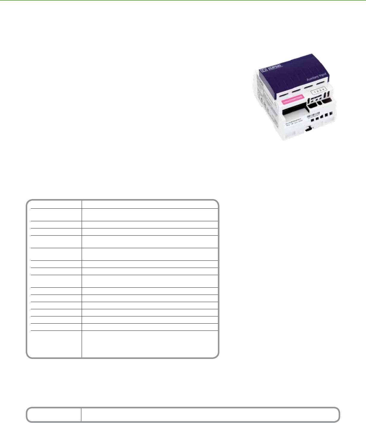
Catalog Number Description
SLCLE5504AUX 4 Channel Auxiliary Input Unit
Technical Information
Nominal Voltage Requirements 15-36Vdc @ 18 mA, drawn from the C-Bus network
Electrical Isolation C-Bus/Remote Input: 500 V RMS
Remote Input: 500 V RMS
Voltage Across Input External Switch Opens: 5Vdc External Switch Closes: 0Vdc
Current–Switch Closed 0.4 mA
Switch Resistance Up to 1000 ohm, including cable resistance (26.5 ohms per km
resistance for #18 copper wire coated DC current resistance)
Number of Units Use the C-Bus Calculator, a software utility,
per Network to determine the total network current load
C-Bus Connections (2) RJ-45 connectors, CAT 5 UTP cable required
Cable 15.75 in. (400 mm) patch lead included
Terminals Accommodate one 12 or two 14-22 AWG cables
(1 x 3.1 mm2) or 2 x 2.0-0.3 mm2)]
Status Indicators Channel: (4) orange LEDs to indicate the load status for each channel
Timers 1 sec–18 hr, 1 sec intervals
Dimensions 3.4 in. (L) x 2.8 in. (W) x 2.6 in. (H)) [85 mm (L) x 72 mm (W) x 65 mm (H)]
Weight 4.6 oz (130 g)
Mounting DIN rail, 4M wide
Operating Environment 32°F to 113°F (0°C to 45°C) RH: 95%, noncondensing
Standards UL: Listed 916 Energy Management Equipment
CSA 22.2 Spec 205 Signal Equipment
FCC: Part 15.101, Class B Digital Device
EN61000-4-2 Immunity to ESD
*For Diagram see technical section page 101
C-BUSTM LIGHTING CONTROL + INPUT UNITS
The C-BusTM Four-Channel Auxiliary Inputs are isolated four-channel input units that
provide an interface between voltage-free mechanical switches and a C-Bus network.
An auxiliary unit increases the versatility of the C-Bus network by facilitating remote
access with any dry-contact switch mechanism offered by Schneider Electric or other
manufacturers.
DIN-rail mounted for quick installation, the auxiliary unit can be congured with standard
C-Bus control functions such as remote scene triggering, ON/OFF, toggle, dimmer, or
timer.
Product Features
• Provides four isolated inputs for external
voltage-free mechanical switches
• Control options include remote scene
triggering, ON/OFF, toggle, dimmer, or timer
operations
• Orange LEDs indicate operational status, one
for each channel
• Standard built-in C-Bus network connectors:
(2) RJ-45
• Non-volatile memory stores operating status
for recovery from a power outage
Distributed Intelligence
• Compatible with all C-Bus devices and the
Powerlink® NF3000G3C controller
• Easily congured by using Learn Mode or the
C-Bus Toolkit Software
Four-Channel Auxiliary Input Unit
C-BusTM
Four-Channel Auxiliary Input
69
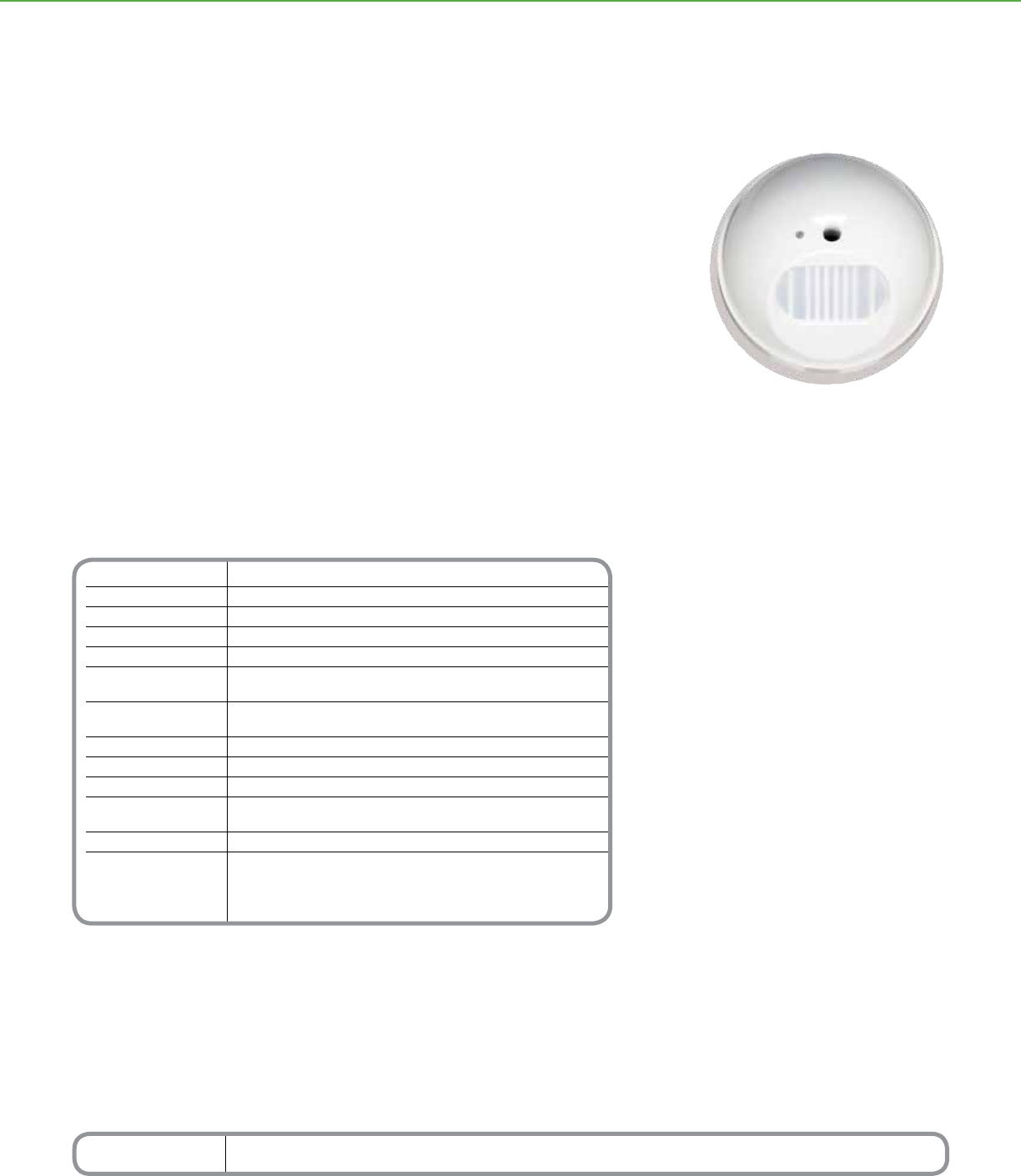
Technical Information
Nominal Voltage Requirements 15-36Vdc @ 18 mA, drawn from the C-Bus network
Field of View 90°
PIR Detection Field Typically 400 sq ft (37 sq m)
Light-Level inhibit Threshold 0.1 footcandle (1 lux) to full sunlight
Timer Delay Range 0 sec-18 hr, 1 sec interval
Number of Units Use the C-Bus Calculator, a software utility, to
per Network determine the total network current load
C-Bus Connection Screw-type terminals, input terminals accommodate
24-16 AWG cable (0.2-1.31 mm2)
Status Indicators LED can be congured to turn on when movement is detected
Dimensions 3.9 in. (W) x 2.2 in. (H) [100 mm (W) x 57 mm (H)]
Weight 4.4 oz (125 g)
Mounting Surface: Ceiling or wall
Ht: 8 ft (2.4 m) above oor
Operating Environment Indoor 32°F to 122°F (0°C to 50°C)
Standards UL: Listed 916 Energy Management Equipment
CSA 22.2 Spec 205 Signal Equipment
FCC: Part 15.101, Class B Digital Device
EN61000-4-2 Immunity to ESD
*For Diagram see technical section page 101
Catalog Number Description
SLC5751L 90° Indoor PIR Occupancy Sensor
C-BUSTM LIGHTING CONTROL + SENSORS
Product Features
• Indoor use, wall or ceiling-mounted unit with
a 90° eld of view and a detection area of 400
square feet
• LED can be congured to indicate motion
detection
• Light-level sensor has Sunrise/Sunset settings,
clock overrides, and adjustable sensitivity
ranging from 0.1 foot candle to full sunlight
• Advanced circuitry to help prevent false
triggering, including electrostatic and
electromagnetic shields, dual element
detectors, pyroelectric ceramic sensors, and
an optical band pass lter
• Controls up to four C-Bus group addresses
that can be individually scheduled
• Non-volatile memory stores operating status
for recovery from a power outage
• Receives data and power over a network, so
the sensor does not require power packs or
line voltage connections
Distributed Intelligence
• Compatible with all C-Bus devices and the
Powerlink® NF3000G3C controller
• Easily congured by using Learn Mode or the
C-Bus Toolkit Software
Indoor PIR Occupancy Sensor
The C-BusTM Indoor PIR Occupancy Sensor provides reliable thermal-radiation-based
control of lighting and other C-Bus output devices.
Suitable for wall or ceiling mounting, this sensor offers a continuous detection eld of
400 square feet and a 90° eld of view. The entire detection eld has uniform sensitivity
and no dead zones, making it an ideal lighting-control solution for ofces, corridors, and
conference rooms.
Conguration options include an adjustable light-level sensor that can be set to
automatically turn off lights when ambient light levels are sufcient or turn on lights when
ambient light levels are insufcient.
C-BusTM
Indoor PIR Occupancy Sensor
70
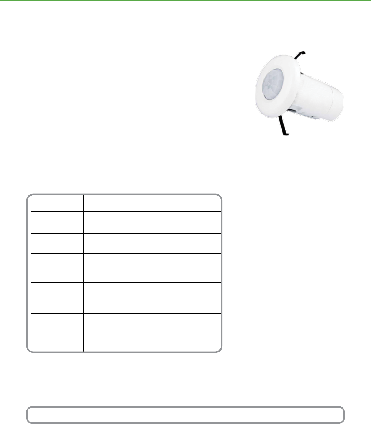
Technical Information
Nominal Voltage Requirements 15-36Vdc @ 18 mA, drawn from the C-Bus network
Field of View 360°
PIR Rated Typically 800 sq ft (74 sq m) when sensor is
Detection Field mounted 8 ft (2.4 m) above oor
Light-Level inhibit Threshold 0.1 footcandle (1 lux) to full sunlight
Timer Delay 0 sec to 18 hr
Number of Units Use the C-Bus Calculator, a software utility, to
per Network determine the total network current load
C-Bus Connection Two removable terminal blocks, requires CAT 5 data cable
Status Indicators LED can be congured to turn on when movement is detected
Dimensions 4.1 in. (L) x 2.8 in. (W) [103 mm (L) x 72 mm (W)]
Weight 4.4 oz (125 g)
Mounting Surface: Ceiling
Ht: 8 ft (2.4 m) above oor
Max. Ht: 12 ft (3.7 m) above oor
Min. Ceiling Thickness: 0.4 - 0.75 in. (10 - 19.1 mm)
Operating Indoor only
Environment 32°F to 113°F (0°C to 45°C)
RH: 95%, noncondensing
Standards UL: Listed 916 Energy Management Equipment
CSA 22.2 Spec 205 Signal Equipment
FCC: Part 15.101, Class B Digital Device
EN61000-4-2 Immunity to ESD
*For Diagram see technical section page 101
Catalog Number Description
SLC5753L 360° PIR Occupancy Sensor
C-BUSTM LIGHTING CONTROL + SENSORS
Product Features
• 360° detection pattern, indoor use
• Effective coverage area is more than 800 square
feet when unit is mounted 8 feet above the oor
• Dual element detectors minimize false triggering
• LEDs indicate movement detection and status
of the IR receiver, and the light-level sensor
• Can control up to four scenes or group
addresses that can be individually scheduled
• Adjustable light-level sensor with Sunrise/
Sunset and clock overrides
• Attractive, low prole unit can be ush mounted
on ceiling or suspended from wall tiles where it
is unobtrusive, with a face diameter of only 2.8
inches
• Non-volatile memory stores operating status for
recovery from a power outage
• Receives data and power over a network.
No power packs or line voltage connections
required
Distributed Intelligence
• Compatible with all C-Bus devices and the
Powerlink® NF3000G3C controller
• Easily congured by using Learn Mode or the
C-Bus Toolkit Software
The C-BusTM 360° Indoor PIR Occupancy Sensor combines a passive infrared receiver
(PIR) for occupancy sensing and a light-level sensor into a small, highly versatile unit. The
multi-sensor’s 2.8 inch face diameter makes it unobtrusive and ideally suited for ush
mounting on the ceiling.
This sensor has a 360 degree eld of view with an effective coverage pattern of more
than 800 feet, so it is ideally suited for ofces, copier rooms, closets, and restrooms.
Multiple sensors can be connected to the same C-Bus network to provide larger
coverage patterns.
Conguration options include adjustable time delays for automatic shut-off following a
preset time period without detected motion and an adjustable light-level sensor that can
be set to automatically turn off lights when ambient light levels are sufcient or turn on
lights when ambient light levels are insufcient.
360° PIR Occupancy Sensor
C-BusTM
360° PIR Occupancy Sensor
71
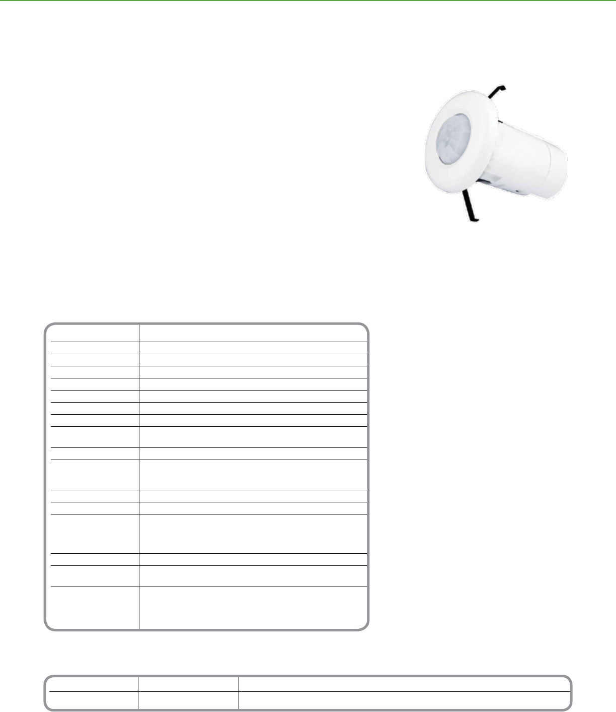
Catalog Number Description Accessories
SLC5753PEIRL 360° PIR Multi-Sensor SLC5084TX IR 4-Button Remote Controller (ordered separately)
SLC5088TX IR 8-Button Remote Controller (ordered separately)
Technical Information
Nominal Voltage Requirements 15-36Vdc @ 18 mA, drawn from the C-Bus network
Field of View 360°
PIR Rated Typically 800 sq ft (74 sq m) when sensor is
Detection Field mounted 8 ft (2.4 m) above oor
IR Receiver Rated Typically 800 sq ft (74 sq m) when sensor is
Detection Field mounted 8 ft (2.4 m) above oor
Light-Level inhibit Threshold 0.1 footcandle (1 lux) to full sunlight
Timer Delay 0 sec to 18 hr
Number of Units Use the C-Bus Calculator, a software utility, to
per Network determine the total network current load
C-Bus Connection Two removable terminal blocks, requires CAT 5 data cable
Status Indicators PIR Sensor or IR Receiver (activity)
PIR Sensor (enabled/disabled)
Light Level Maint. (enabled/disabled)
Dimensions 4.1 in. (L) x 2.8 in. (W) [103 mm (L) x 72 mm (W)]
Weight 4.4 oz (125 g)
Mounting Surface: Ceiling
Ht: 8 ft (2.4 m) above oor
Max. Ht: 12 ft (3.7 m) above oor
Min. Ceiling Thickness: 0.4 - 0.75 in. (10 - 19.1 mm)
Operating Indoor only
Environment 32°F to 113°F (0°C to 45°C)
RH: 95%, noncondensing
Standards UL: Listed 916 Energy Management Equipment
CSA 22.2 Spec 205 Signal Equipment
FCC: Part 15.101, Class B Digital Device
EN61000-4-2 Immunity to ESD
*For Diagram see technical section page 102
C-BUSTM LIGHTING CONTROL + SENSORS
Product Features
• 360° detection pattern, indoor use
• Effective detection area of occupancy sensor
is more than 800 square feet when unit is
mounted 8 feet above the oor. Effective IR
coverage is 800 square feet.
• Dual element detectors minimize false
triggering
• LEDs indicate movement detection and status
of the IR receiver, the occupancy sensor, and
the light-level sensor
• Can control up to eight C-Bus scenes or
directly control up to eight C-Bus group
addresses that can be individually scheduled
• Adjustable light-level sensor has Sunrise/
Sunset and clock overrides
• Attractive, low prole unit can be ush
mounted on ceiling or suspended from wall
tiles where it is unobtrusive, with a face
diameter of only 2.8 inches
• Optional handheld remote controller
(SLC5084TX, SLC5088TX)
• Non-volatile memory stores operating status
for recovery from a power outage
• Receives data and power over a network, so
the sensor does not require power packs or
line voltage connections
Distributed Intelligence
• Compatible with all C-Bus devices and the
Powerlink® NF3000G3C controller
• Easily congured by using Learn Mode or the
C-Bus Toolkit Software
The C-BusTM 360° PIR Multi-Sensor combines a passive infrared receiver (PIR) for
occupancy sensing, a light-level sensor, and an infrared remote receiver into a small,
highly versatile unit. The sensor’s 2.8 inch face diameter makes it unobtrusive and ideally
suited for ush mounting on the ceiling.
Conguration options for the occupancy sensor include adjustable time delays for
automatic shut-off following a preset time period without detected motion and an
adjustable light-level sensor to turn on lights automatically when ambient light levels
are low or turn off lights when ambient light levels are sufcient. The built-in IR receiver
accepts commands from an optional handheld remote controller, making the sensor
ideal for classrooms and conference room areas.
360° PIR Multi-Sensor
C-BusTM
360° PIR Multi-Sensor
72
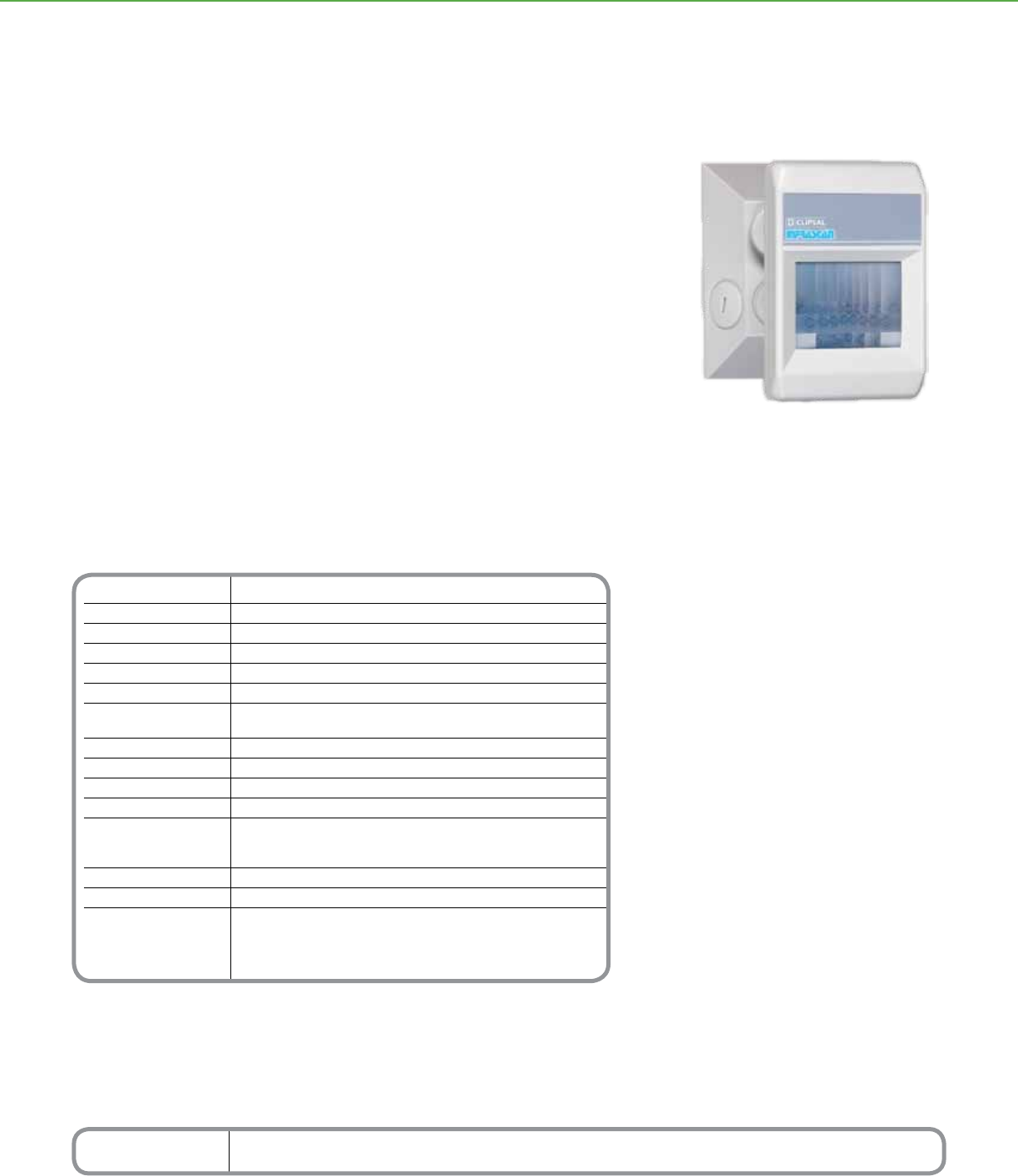
Technical Information
Nominal Voltage Requirements 15-36Vdc @ 18 mA, drawn from the C-Bus network
Field of View 110°
PIR Detection Field Typically 3000 sq ft (279 sq m)
Light-Level inhibit Threshold 0.1 footcandle (1 lux) to full sunlight
Number of Detection Zones 18 Long Range, 16 Intermediate Range, 10 Short Range, 4 ultra Short
Timer Delay Range 0 sec to 18 hr
Number of Units Use the C-Bus Calculator, a software utility, to
per Network determine the total network current load
C-Bus Connection One terminal block
Status Indicators LED can be congured to turn on when movement is detected
Dimensions 4.5 in. (L) x 2.9 in. (W) x 5.5 in. (D) [114 mm (L) x 74 mm (W) x 140 mm (D)]
Weight 8 oz (227 g)
Mounting Standard plate/box with 3.3 in. (84 mm) mounting centers
Surface: Ceiling or wall
Ht: 8 ft (2.4 m) above oor
Operating Outdoor only
Environment 32°F to +122°F (0°C to +50°C)
Standards UL: Listed 916 Energy Management Equipment
CSA 22.2 Spec 205 Signal Equipment
FCC: Part 15.101, Class B Digital Device
EN61000-4-2 Immunity to ESD
*For Diagram see technical section page 102
Catalog Number Description
SLC5750WPL 110° Outdoor PIR Motion Sensor
C-BUSTM LIGHTING CONTROL + SENSORS
The C-BusTM Outdoor PIR Motion Sensor combines reliable thermal-radiation-based
control of lighting with rugged construction suitable for outdoor requirements. The unit’s
advanced circuits and at multi-segmented lens provide coverage of up to 3000 square
feet in a 110° eld of view.
The detection area incorporates a multi-faceted lens, which ensures fast response to
motion and few dead zones. Electrostatic and electromagnetic shields, dual element
detectors, an optical bandpass lter, and pyroelectric ceramic sensors are used to
reduce the incidence of false triggering.
Conguration options include an adjustable light-level sensor that can be set to
automatically turn off lights when ambient light levels are sufcient or turn on lights when
ambient light levels are insufcient.
Product Features
• Outdoor use, wall or ceiling-mounted unit with
a 110° eld of view and a detection area up to
3000 square feet in diameter
• Lens has 12 overlapping zones on each of 4
levels, forming a continuous detection eld
• Rugged construction and pre-wired exible
cord
• LED indicates motion detection
• Light-level sensor has Sunrise/Sunset
settings, clock overrides, and adjustable
sensitivity ranging from 0.1 footcandle to full
sunlight
• Controls up to four C-Bus group addresses
that can be individually scheduled
• Non-volatile memory stores operating status
for recovery from a power outage
• Receives data and power over a network, so
the sensor does not require power packs or
line voltage connections
Distributed Intelligence
• Compatible with all C-Bus devices and the
Powerlink® NF3000G3C controller
• Easily congured by using Learn Mode or the
C-Bus Toolkit Software
Outdoor PIR Motion Sensor
C-BusTM
Outdoor Motion Sensor
73
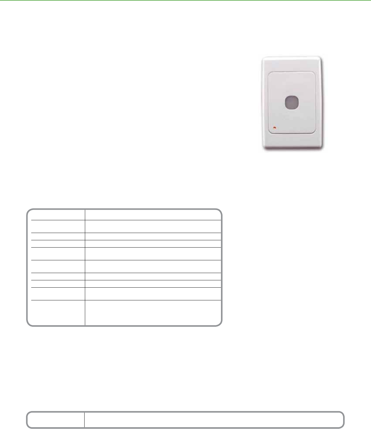
Technical Information
Nominal Voltage Requirements 15-36Vdc @ 18 mA, drawn from the C-Bus network
Light Level Reads: 2-278 footcandles (20-3000 lux)
Controls: 5-148 footcandles (40-1600 lux)
Field of View 180°
C-Bus Connection Accommodates 6 x 24 AWG cable (6 x 0.2 mm2)
Status Indicators Can be congured to report state of any one
of three group addresses: Enabled, ON/OFF, or Ramp
Dimensions 4.57 in. (L) x 2.99 in. (W) x 1.93 in. (D)
[116 mm (L) x 76 mm (W) x 49 mm (D)]
Weight 3 oz (85 g)
Operating Indoor only
Environment 32°F to 122°F (0°C to 50°C)
RH: 95%, noncondensing
Standards UL: Listed 916 Energy Management Equipment
CSA 22.2 Spec 205 Signal Equipment
FCC: Part 15.101, Class B Digital Device
EN61000-4-2 Immunity to ESD
*For Diagram see technical section page 102
Catalog Number Description
SLC5031PE Light-Level Sensor
C-BUSTM LIGHTING CONTROL + SENSORS
Product Features
• Can maintain constant illumination levels of
5-150 footcandles
• Controls up to two C-Bus group addresses,
one set for ON/OFF operations and one set
for ramping operations
• 180° eld of view
• Can be enabled or disabled over the C-Bus
network
• Stores operating status in non-volatile
memory for recovery from a power outage
• Receives data and power over a single C-Bus
twisted pair cable
• Veries status of input and output devices on
same C-Bus application address, updating
input status if necessary
• LED can be congured to indicate current
status of any C-Bus group address
• Attractive, wall-mounted, low-prole unit
Distributed Intelligence
• Compatible with all C-Bus devices and the
Powerlink® NF3000G3C controller
• Easily congured by using the C-Bus Toolkit
Software and a personal computer connected
to the C-Bus network
The C-BusTM Light-Level Sensor measures ambient light levels and automatically issues
ON, OFF, or ramp commands over a C-Bus network. The light-level sensor can control
relays, dimmers, or remotely operated circuit breakers, changing their status according
to pre-set ambient lighting levels.
The C-Bus light-level sensor has a dynamic range between 5-150 footcandles, and
compensates for noise and rapid light intensity uctuations by using ltering and
hysteresis.
The light-level sensor can control up to two C-Bus group addresses: one address
controls the switching ON/OFF of a lamp circuit according to the amount of ambient
light, while the other is used to continuously regulate the light-level output of any number
of lamps.
Light Level Sensor
C-BusTM
Light-Level Sensor
74
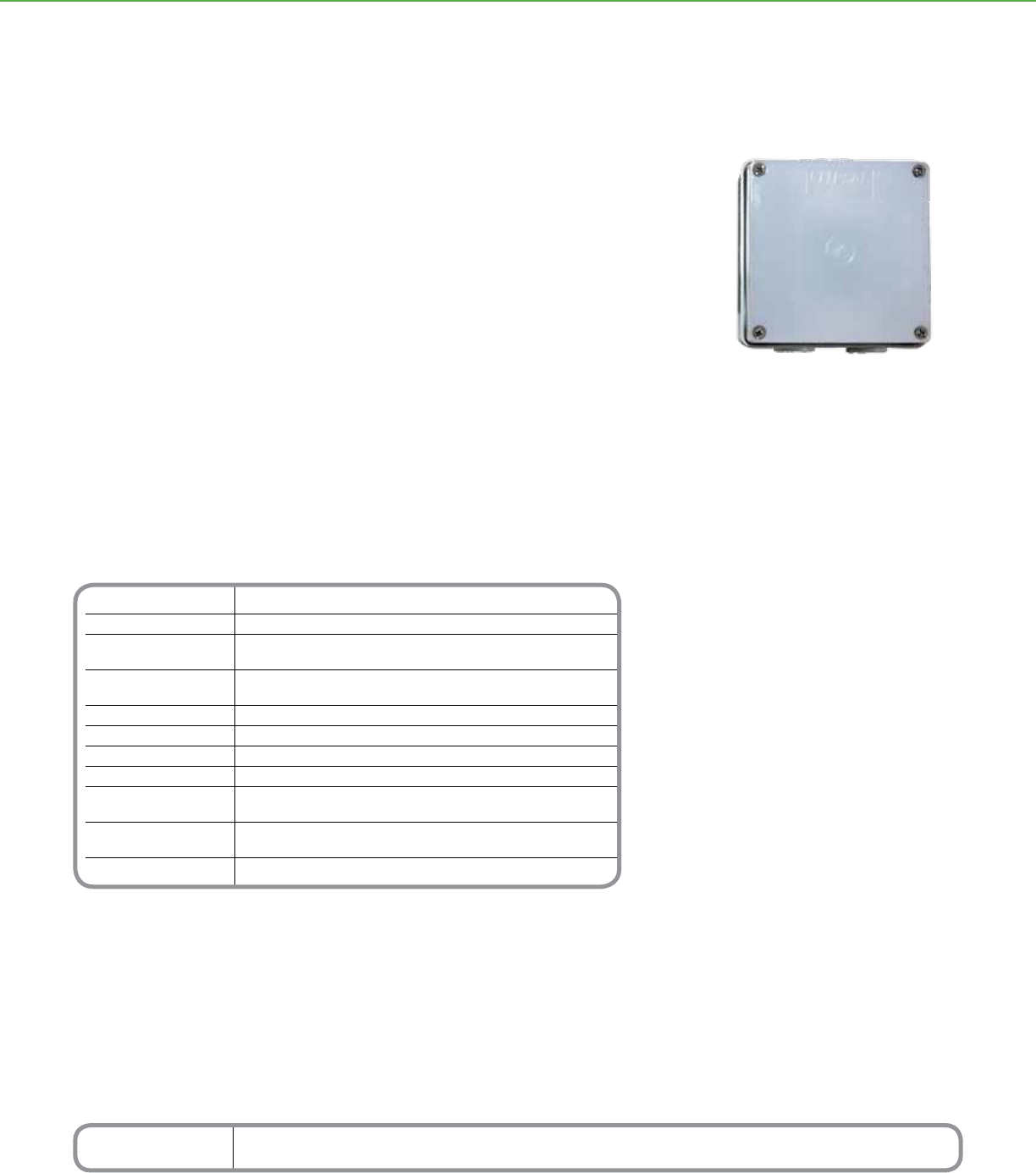
Technical Information
Nominal Voltage Requirements 15–36Vdc @ 18 mA, drawn from the C-Bus network
Field of View 180°
Light-Level Range Reads: 2-278 footcandles (20-3000 lux)
Controls: 5-148 footcandles (40-1600 lux)
C-Bus Connection Screw-type input terminals accommodate 6 x 24 AWG cable (6 x 0.2 mm²)
Connection requires CAT 5 data cable
Max. Units/Network Based on the total network current load and available power
Conduit Openings Sized for 20 mm and 25 mm conduit ttings
Dimensions 4 in. (L) x 4 in. (W) x 2.5 in. (D) [102 mm (L) x 102 mm (W) x 65 mm (D)]
Weight 10.8 oz (305 g)
Mounting Indoor or outdoor, wall or ceiling
Indoor Height: At least 6.5 ft (1.9 m) above oor
Operating Environment Outdoor or indoor –22°F to 122°F (–30°C to 50°C)
RH: 95%, noncondensing
Standards FCC: Part 15.101, Class B Digital Device
*For Diagram see technical section page 102
Catalog Number Description
SLC5031PEWP Outdoor Light-Level Sensor
C-BUSTM LIGHTING CONTROL + SENSORS
The C-BusTM light-level sensor measures ambient light levels and automatically issues
ON/OFF or ramp commands over a C-Bus network to maintain outdoor lighting levels.
Primarily designed for outdoor use, this light-level sensor is also suitable for indoor
settings in which a water resistant casing is desirable.
Product Features
• Outdoor use, wall- and ceiling-mounted
low-prole unit
• Can maintain a constant illumination level
of 5-150 footcandles
• Control of up to two C-Bus group addresses
• Sensors receive data and power over a single
C-Bus twisted-pair cable, so they do
not require power packs or line-voltage
connections
• 180° eld of view
Outdoor Light Level Sensor
C-BusTM
Outdoor Light-Level Sensor
75
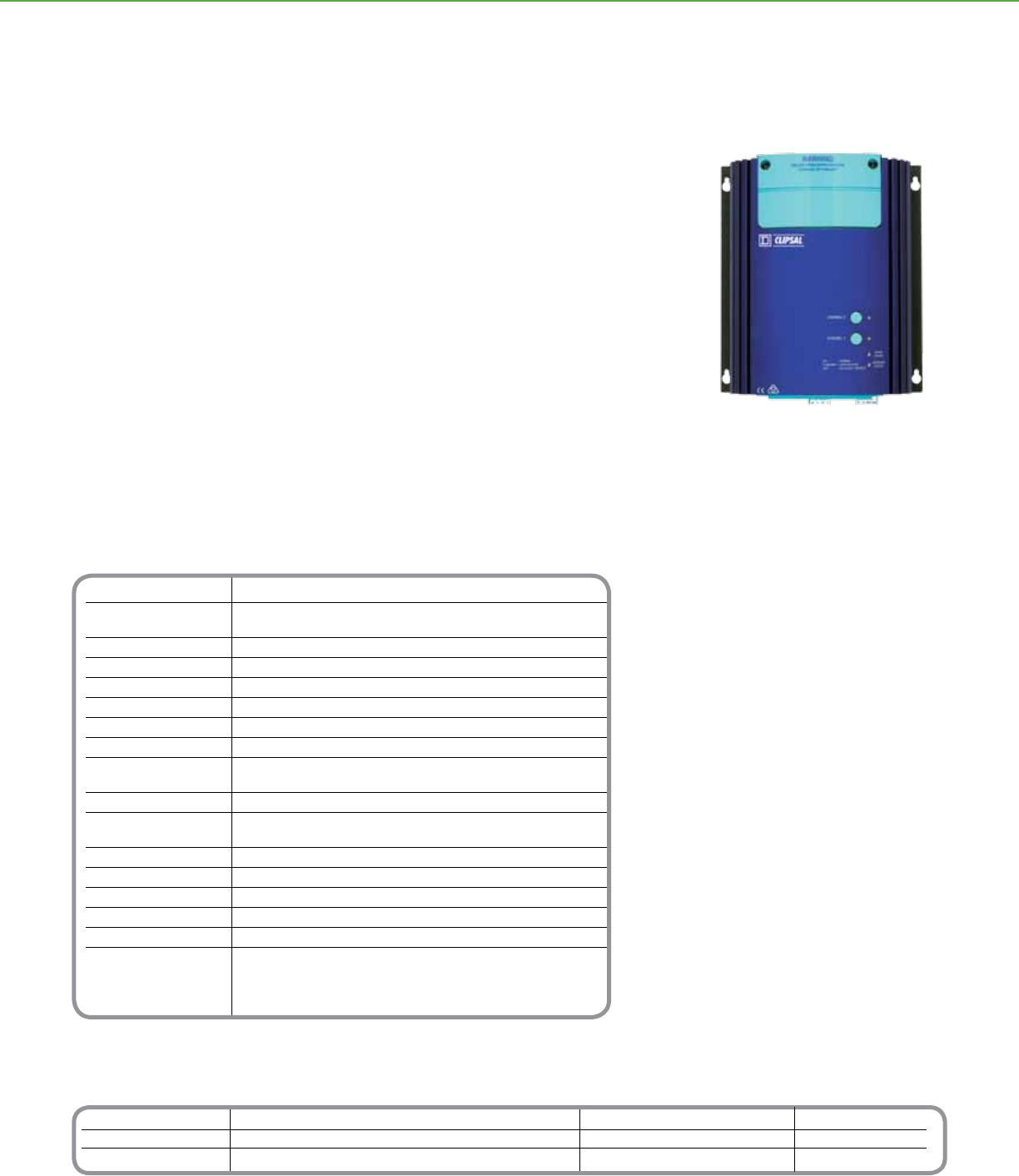
Catalog Number Description Accessories Description
SLC5104TD5 Professional Dimmer 5A, 4 Channel, 120Vac SLCU5100TB Terminal Box
SLC5102TD10 Professional Dimmer 10A, 2 Channel, 120Vac
SLC5101TD20 Professional Dimmer 20A, 1 Channel 120Vac
Technical Information
Nominal Voltage Requirements C-Bus voltage 15–36Vdc
Nominal Line Supply 110–120Vac, ±10%, 50/60 Hz
Voltage and Frequency
Useable Output Current 60 mA
Frequency Drift 3 Hz per minute, maximum
Frequency Step Change 0.1 Hz (maximum)
Minimum Load 100 W per channel
Current Sensing 5–100% of full-rated load, 5% accuracy
Efciency 98%
Number of Units per Network Use the C-Bus Calculator, a software utility,
to determine the total network current load
C-Bus Connections Four-way removable screw terminals, CAT 5 UTP cable required
Load Terminals Accommodates one #12 or up to two #14 AWG cable
[(3.31 mm2 - 1.3 mm2)]
Auxiliary Contacts 2.5 A @ 120Vac, normally open, voltage free, resistive
Status Indicators Channel, Unit and C-Bus
Dimensions 9.45 in. (L) x 7.95 in. (W) x 2.95 in. (H)) [240 mm (L) x 202 mm (W) x 75 mm (H)]
Weight 4.85 lb (2.2 kg)
Operating Environment 32°F to 113°F (0°C to 45°C) RH: 95%, noncondensing
Standards UL508 Industrial Control Equipment
CSA 22.2 Spec 205 Signal Equipment
FCC: Part 15.101, Class B Digital Device
EN61000-4-2 Immunity to ESD
*For Diagram see technical section page 103
C-BUSTM LIGHTING CONTROL + OUTPUT UNITS
The C-BusTM Professional Dimmers are designed to control incandescent and
compatible low-voltage lighting. These dimmers are ideal for tight space applications
where traditional rack mounted assemblies are not practical.
Professional dimmer units are available in 5 A (4 channels), 10 A (two channels), and 20
A (one channel) models. Each channel provides independent dimming and incorporates
thermal overload and over-current protection. These dimmer units automatically
compensate for voltage and frequency uctuations and employ advanced phase-control
techniques to reduce icker and increase lamp life.
The aluminum enclosure acts as a heat sink and is designed for easy wall mounting,
including keyhole mounts and removable terminals for the C-Bus and override
connections. An optional terminal box is available for conduit connections.
Conguration options include network monitoring of the channel load and network
voltages, adjustable delays for dimming levels, and master override.
Product Features
• Suitable for use with resistive and inductive
loads and low-voltage lamps utilizing iron
core or electronic transformers
• Quick-mounting design, including keyhole
mounts, front and rear cable access, and
removable terminals for C-Bus connections
• Specialized dimming modes–soft turn on/off
and linearized brightness control
• Built-in power supply sources 60 mA to the
C-Bus network
• Compensates for uctuations in frequency
and voltage of power source
• Monitors load current by channel
• Integral thermal overload protection on each
channel
• Individual channels can be turned On/Off at
the unit or via C-Bus commands
• LEDs indicate the status of the network at
the unit and the status of the unit’s load and
power
• Optional terminal box for connecting conduit
• Non-volatile memory stores operating status
for recovery from a power outage
Distributed Intelligence
• Compatible with all C-Bus devices and the
Powerlink® NF3000G3C controller
• Easily congured with the C-Bus Toolkit
Software
10A, 2-Channel Professional Dimmer Unit
C-BusTM
Professional Series Dimmer
76
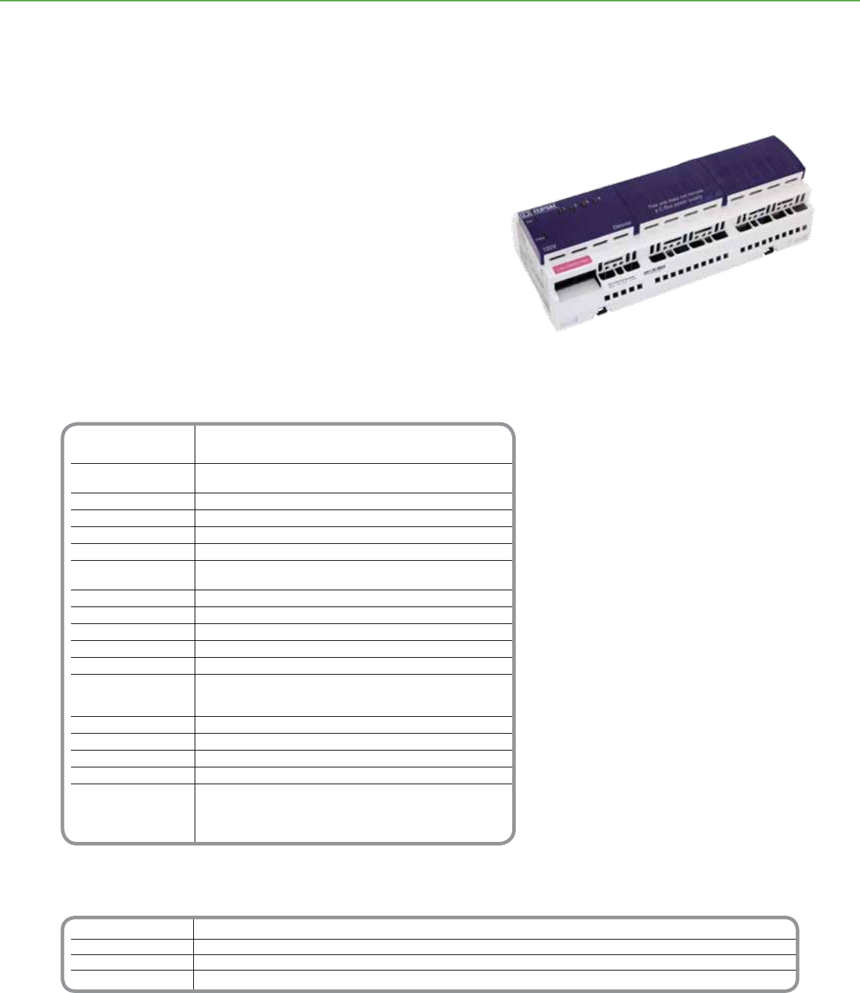
Technical Information
Nominal Voltage Requirements 15–36Vdc @ 18 mA from the C-Bus network
when there is no external power source
Nominal Line Supply Voltage 110 - 120Vac, ±10%, 50–60 Hz
and Frequency
C-Bus Source Current 200 mA (Models: SLC5508TD2A, SLC5504TD4A)
Load Rating per Channel 2A (SLC5508TD2A), 4A (SLC5504TD4A)
Minimum Load 15 W per channel
Efciency 98%
Number of Units per Network Use the C-Bus Calculator, a software utility,
to determine the total network current load
C-Bus Connections (2) RJ-45 connectors, CAT 5 UTP cable required
Cable 15.75 in. (400 mm) patch lead included
Remote Override Connection RJ-45 connector
Power Terminals Accommodate 16–12 AWG cable
Load Terminals 2 x #14-16 gauge or 1 x #12 gauge
Status Indicators Channel: (1) per channel
Unit (1): Unit power
C-Bus (1): Power levels and presence of C-Bus clock
Dimensions 8.5 in. (L) x 3.6 in. (W) x 2.5 in. (H)) [216 mm (L) x 92 mm (W) x 63 mm (H)]
Weight 23 oz (647 g)
Mounting DIN rail, 12M wide
Operating Environment 32°F to 113°F (0°C to 45°C) RH: 95%, noncondensing
Standards UL508 Industrial Control Equipment
CSA 22.2 Spec 205 Signal Equipment
FCC: Part 15.101, Class B Digital Device
EN61000-4-2 Immunity to ESD
*For Diagram see technical section page 103
Catalog Number Description
SLC5504TD4A Four-Channel 4A Dimmer, with power supply
SLC5504TD4AP Four-Channel 4A Dimmer, without power supply
SLC5508TD2A Eight-Channel 2A Dimmer, with power supply
SLC5508TD2AP Eight-Channel 2A Dimmer, without power supply
C-BUSTM LIGHTING CONTROL + OUTPUT UNITS
The C-BusTM Phase Angle Dimmers are C-Bus controlled output units suitable for
incandescent and compatible low-voltage lighting. These units are designed to be rack
mounted in suitable DIN style enclosures.
Each of the unit’s channels can independently control loads to create dynamic lighting
scenes. These dimmer units automatically compensate for voltage and frequency
uctuations and employ advanced phase-control techniques to reduce icker and
increase lamp life.
Product Features
• Suitable for use with incandescent lamps
and low-voltage lamps utilizing iron core or
electronic transformers
• Specialized dimming modes - soft turn On/Off
and linearized brightness control.
• Can supply up to 200 mA to the C-Bus
network (models SLC5504TD4A and
SLC5508TD2A with built-in power supply)
• Integral thermal overload protection on each
channel
• Individual channels can be turned ON/OFF at
unit or via C-Bus commands
• LEDs indicate the status of the network at
the unit, the status of the unit’s load and
power, and the status of each channel
• Non-volatile memory stores operating status
for recovery from a power outage
Distributed Intelligence
• Compatible with all C-Bus devices and the
Powerlink® NF3000G3C controller
• Easily congured with the C-Bus Toolkit
Software
Phase Angle Dimmer Unit with Power Supply
C-BusTM
Phase Angle Dimmers
77
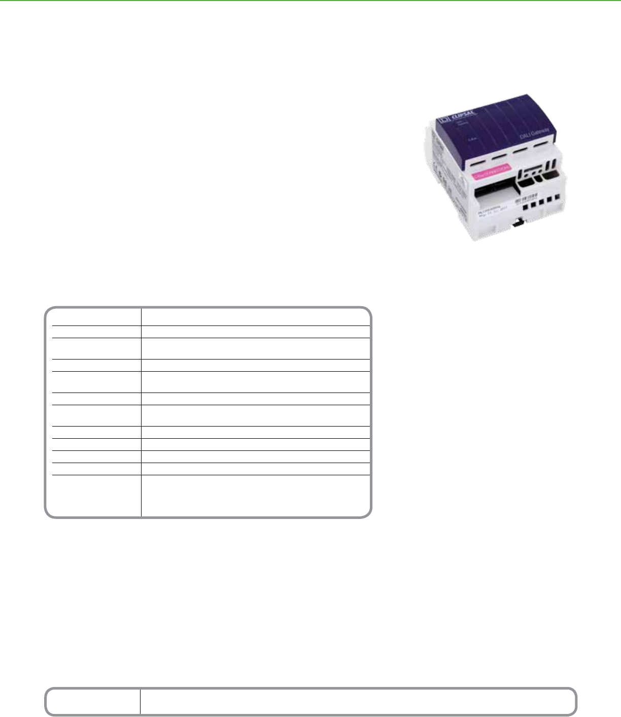
Technical Information
Nominal Voltage Requirements 15-36Vdc @ 32 mA, drawn from the C-Bus network
Electrical Isolation 3.75 kV RMS, from interface to C-Bus network
Number of Units Use the C-Bus Calculator, a software utility,
per Network to determine the total network current load
C-Bus Connections Built-in RJ-45 sockets (2) for connection to the C-Bus network
DALI Connections Two screw-type terminal blocks accommodating 16–12 AWG cable
(2 x 1.31 mm2 or 1 x 2.5 mm2)
Cable (1) 15.75 in. (400 mm) patch lead included
Status Indicators Unit/Comms: Unit power and data transmission
C-Bus: Power levels and presence of C-Bus clock
Dimensions 3.4 in. (L) x 2.8 in. (W) x 2.6 in.(H) [85 mm (L) x 72 mm (W) x 65 mm (H)]
Weight 4.6 oz (130 g)
Mounting DIN rail, 4M wide
Operating Environment 32°F to 113°F (0 °C to 45 °C) RH: 95%, noncondensing
Standards UL: Listed 916 Energy Management Equipment
CSA 22.2 Spec 205 Signal Equipment
FCC: Part 15.101, Class B Digital Device
EN61000-4-2 Immunity to ESD
*For Diagram see technical section page 103
Catalog Number Description
SLC5502DAL Two-Channel DALI Gateway
C-BUSTM LIGHTING CONTROL + OUTPUT UNITS
The C-BusTM Digital Addressable Lighting Interface (DALI) Gateway provides an isolated
two-way communications path between a C-Bus network and two DALI networks,
making it possible to use the C-Bus network to control and monitor DALI ballasts.
The DALI gateway constantly monitors both DALI networks and can detect and report
faulty lamps in uorescent ballasts or non-functional DALI ballasts.
Product Features
• Provides two-way communications between
C-Bus and DALI networks, routing selected
messages from one to the other
• Unit is transparent and invisible to DALI
ballasts
• Pre-programmed C-Bus to DALI and DALI to
C-Bus addressing structure
• Unit/Comms and C-Bus LEDs show the
status of data transmissions, the unit’s power,
the C-Bus network’s power, and the presence
of the C-Bus clock
• Software-selectable network burden and
network clock
• Standard built-in C-Bus network connectors:
(2) RJ-45
• Non-volatile memory to store operating status
for recovery from a power outage
• Receives data and power over the network,
so the unit does not require power packs or
line-voltage connections
Distributed Intelligence
• Compatible with all C-Bus devices and the
Powerlink® NF3000G3C controller
• C-Bus side of interface is easily congured
with the C-Bus Toolkit Software
DALI Gateway
C-BusTM
2 Channel DALI Gateway
78
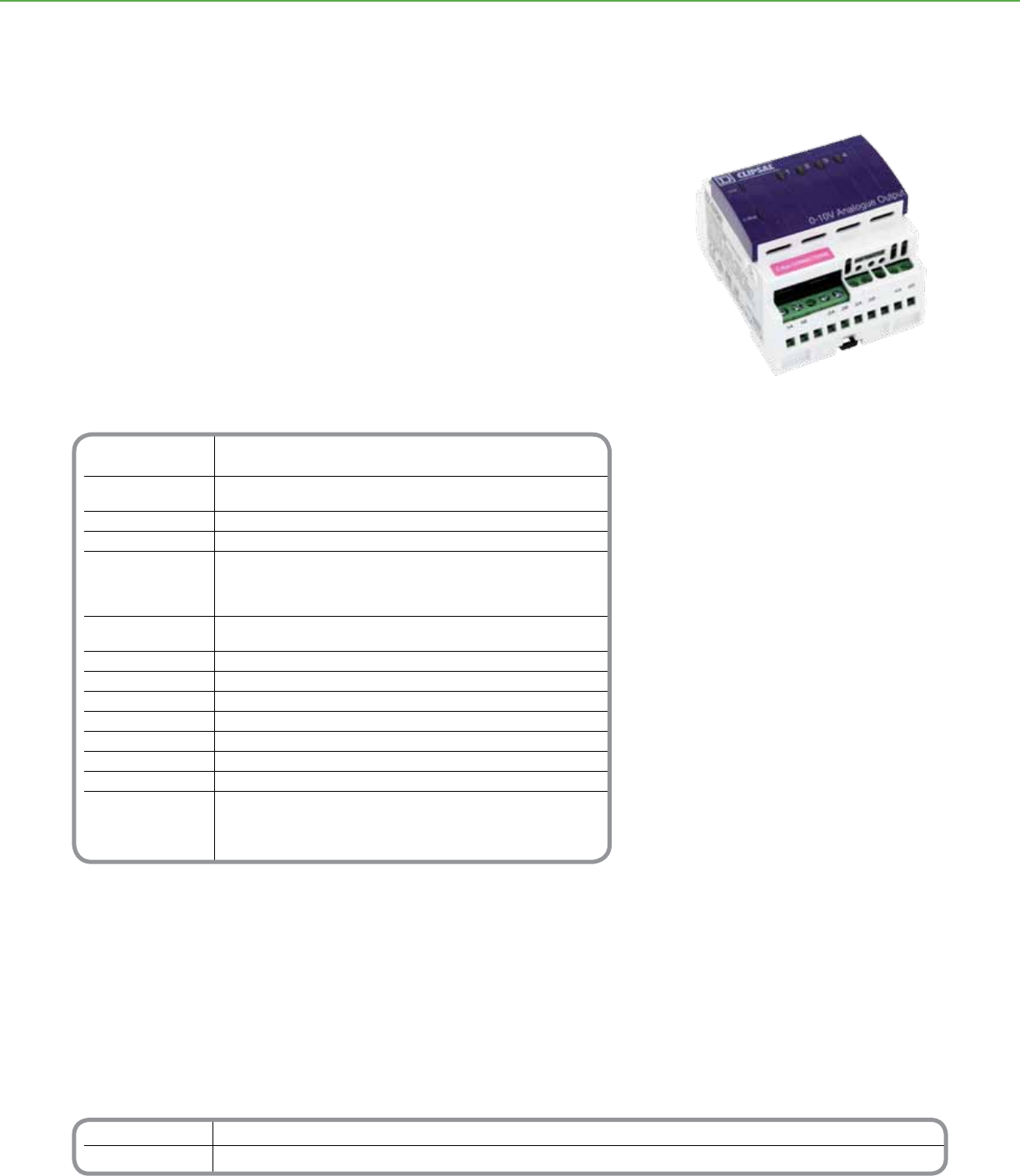
Technical Information
Power Requirements C-Bus: 15–36Vdc @ 22 mA required for normal operation.
Power: 120V or 277Vac connection, 10 W
Number of Units Use the C-Bus Calculator, a software utility, to
per Network determine the total network current load
Electrical Isolation 3.5 kV RMS from C-Bus to the line
Output Voltage Range 0-10Vdc (±0.5)
Output Rating Sourcing: 2.5 mA (minimum of 4 kohm)
Sinking: 15 mA at Vout = 0V
8 mA at Vout = 10V
[i.e., I = 15-(0.7 x Vout)mA]
Status Indicators Unit: Unit power
C-Bus: Network voltage level and presence of system clock
C-Bus Connection (2) RJ-45 terminals
Cable (1) 15.75 in. (400 mm) CAT 5 patch lead with pre-terminated RJ-45 connectors
Output Terminals Accommodates 2 X 16 AWG or 1 X 12 AWG cable (2 x 1.3 mm2 or 1 x 3.3 mm2)
Mounting DIN rail, 4M wide
Dimensions 3.35 in. (L) x 2.83 in. (W) x 2.56 in. (D) [85 mm (L) x 72 mm (W) x 65 mm (D)]
Weight 8.64 oz (245 g)
Operating Environment 32°F to 122°F (0°C to 50°C) RH: 95%, noncondensing
Standards UL: Listed 916 Energy Management Equipment
CSA 22.2 Spec 205 Signal Equipment
FCC: Part 15.101, Class B Digital Device
EN61000-4-2 Immunity to ESD
*For Diagram see technical section page 104
Catalog Number Description
SLCLE5504TAMP Analog Output Unit, 0-10V, 120V
SLCLE5504HAMP Analog Output Unit, 0-10V, 277V
C-BUSTM LIGHTING CONTROL + OUTPUT UNITS
The C-BusTM 4 Channel 0-10V Fluorescent Ballast Dimmer provides four channels of
analog 0-10Vdc that can be used as the control signals for various peripheral devices,
including electronically dimmable uorescent lighting ballasts.
This analog output unit can sink or source current as appropriate for the connected load,
and produces 0-10 V in response to commands from the C-Bus network.
Each channel can be individually adjusted from 0 to 100% at the unit, by C-Bus
commands or remotely, and each can drive multiple loads.
Product Features
• Produces four independently controllable
channels of 0-10Vdc for controlling dimmable
lighting ballasts or other loads
• Each channel can sink or source current and
drive multiple loads
• Two RJ-45 connectors facilitate quick
connections to the C-Bus network and
between similar units
• Unit and C-Bus LEDs show the status of the
unit and the network
• Non-volatile memory stores operating status
for recovery from a power outage
• 120 or 277Vac models available
Distributed Intelligence
• Compatible with all C-Bus devices and the
Powerlink® NF3000G3C controller
• Easily congured by using Learn Mode or the
C-Bus Toolkit Software
4 channel 0-10V Fluorescent Ballast Dimmer
C-BusTM
4 Channel 0-10V Fluorescent Ballast Dimmer
79
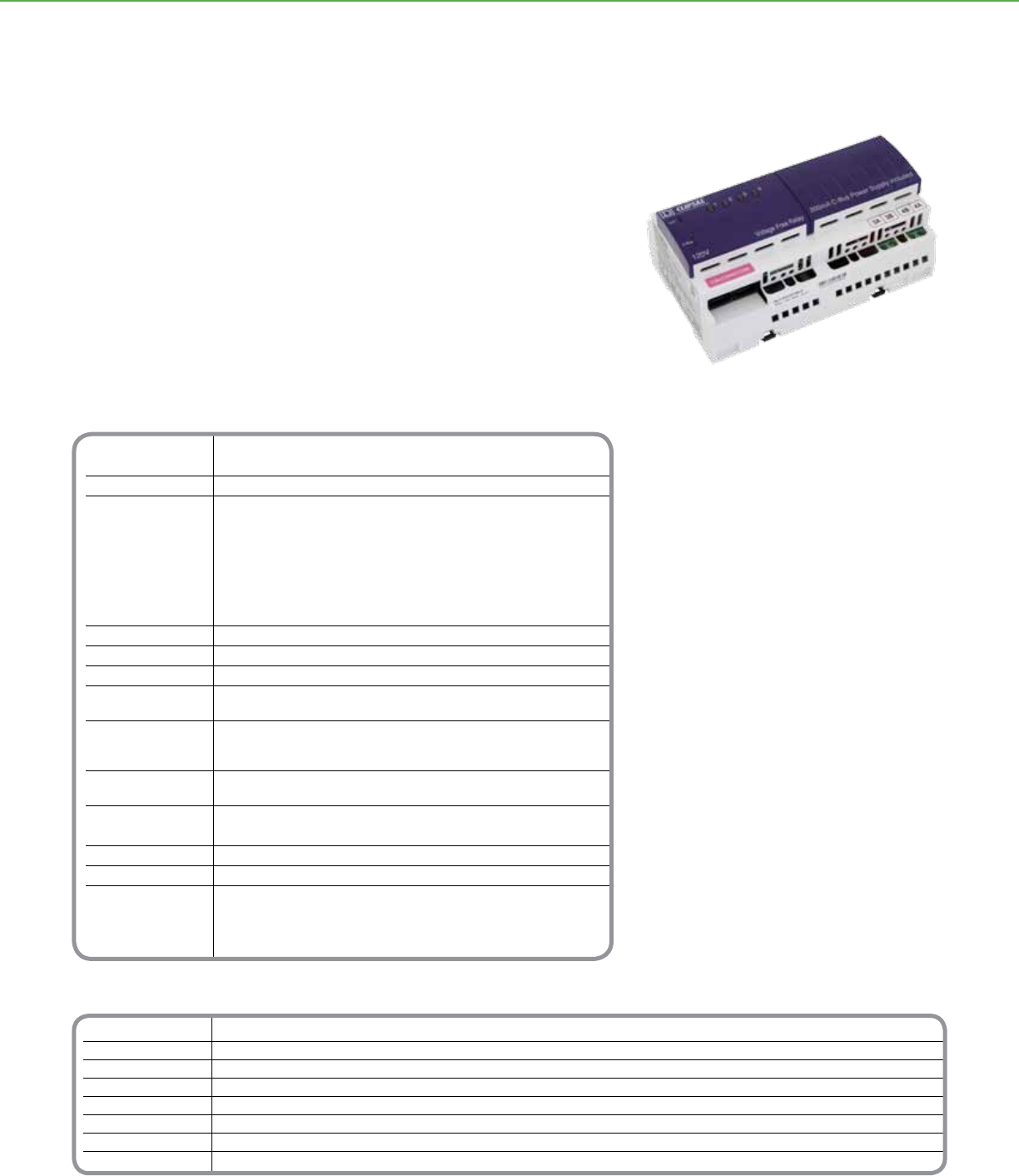
Catalog Number Description
SLC5504TRVF 4 Channel, 120V, 10A w/power supply
SLC5504TRVFP 4 Channel, 120V, 10A w/o power supply
SLC5504HRVF 4 Channel, 277V, 10A w/ power supply
SLC5504HRVFP 4 Channel, 277V, 10A w/o power supply
SLC5512TRVF 12 Channel, 120V, 10A w/power supply
SLC5512TRVFP 12 Channel, 120V, 10A w/o power supply
SLC5512HRVF 12 Channel, 277V, 10A w/power supply
SLC5512HRVFP 12 Channel, 277V, 10A w/o power supply
Technical Information
Nominal Supply Voltage 110-120V (SLC5504TRVF, SLC5504TRVFP, SLC5512TRVF and SLC5512TRVFP)
277V (SLC5504HRVF, SLC5504HRVFP, SLC5512HRVF and SLC5512HRVFP)
Frequency Range(s) 50 - 60Hz
C-Bus C-Bus 15–36Vdc @ 18 mA required for programming
Supply Voltage when electrical power source is not connected
Sources 200 mA to the C-Bus Network
with electrical power source connected (non-power supply versions)
15–36Vdc @ 0 mA is required for programming
when electrical power source is connected
Electrical isolation 3.75 kV RMS from C-Bus to power source
Contact Type Voltage Free, magnetically latched
C-Bus Connections 2 RJ-45 connectors, CAT 5 UTP cable req.
Electrical Terminals Accommodates (1) #12 or up to (2) #14 - 16 AWG (3.31mm2
- (2) x 2.08 - 1.31mm2)
Status Indicators C-Bus Indicator
Unit Status Indicator
Load Indicator
Dimensions 4 Channel - 5.67 x 3.35 x 2.56 inches (144 x 85 x 65mm)
12 Channel - 8.46 x 3.35 x 2.56 inches (215 x 85 x 65mm)
Weight 4 Channel - 14 oz (400g) (w/o Power Supply) 18 oz (510g) (w/Power Supply)
12 Channel - 21 oz (600g) (w/o Power Supply) 28 oz (800g) (w/Power Supply)
Mounting DIN rail, 4 Channel - 8M wide 12 Channel - 12M wide
Operating Environment 32°F to 113°F (0°C to 45°C) RH: 95%, noncondensing
Standards UL: Listed 508 Industrial Control Equipment
CSA 22.2 No. 14 Industrial Control Equipment
FCC: Part 15, Class B Digital Device
EN61000-4-2 Immunity to ESD
*For Diagram see technical section page 104
C-BUSTM LIGHTING CONTROL + OUTPUT UNITS
The C-BusTM Relays are DIN-rail mounted units with four or twelve independent, voltage
free, relay contacts for general switching applications. They are suitable for use with
resistive, inductive, incandescent and uorescent loads.
Each channel is independently congurable and features a zero crossing magnetically
latching relay designed for switching the harsh electrical loads associated with today’s
high efciency lighting systems. Local toggle buttons are provided on each unit to allow
individual channels to be toggled at each unit or via C-Bus network commands. Remote
ON and OFF facilities are available, permitting all channels to be turned ON or OFF
without C-Bus Network communications.
Product Features
• Four or twelve independently operating
voltage free relay contacts
• Two convenient built-in C-Bus network
connectors (RJ-45)
• Units available both with and without a 200
mA power supply
• Non-volatile memory stores operating status
for recovery from power outage
• LED Indicators show the status of the
network and the unit
• Load Rating (4 and 12 channel 10 Amp rated
relay)
Resistive-10A
Inductive-10A
Fluorescent -10A
Motor -2A
Distributed Intelligence
• Compatible with all C-Bus devices and the
Powerlink® NF3000G3C controller
• Easily congured with the C-Bus Toolkit
Software
4 Channel 10 Amp Relay
C-BusTM
10 Amp Relay Unit
80
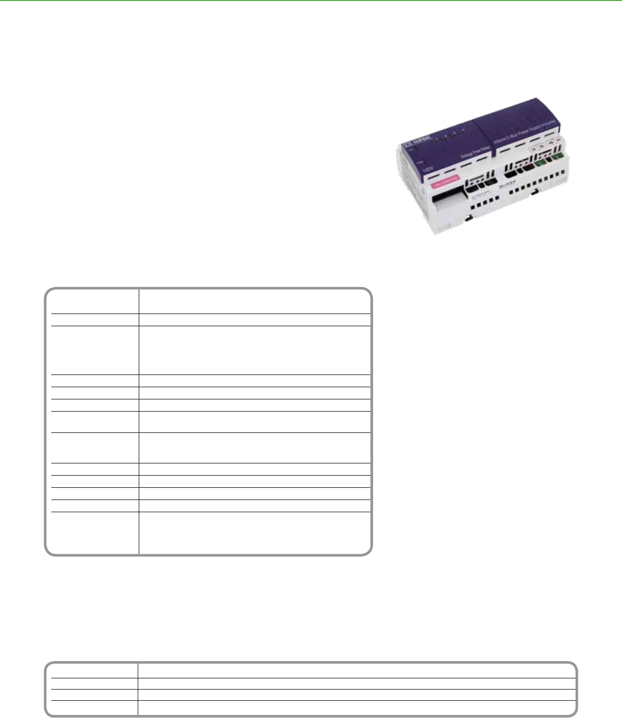
Technical Information
Nominal Supply Voltage 110-120V (SLC5504TRVF20 and SLC5504TRVF20P)
277V (SLC5504HRVF20 and SLC5504HRVF20P)
Frequency Range(s) 50 - 60Hz
C-Bus Supply Voltage 15–36Vdc @ 18 mA required for programming
when electrical power source is not connected.
Sources 200 mA to the C-Bus Network with
electrical power source connected.
Electrical isolation 3.75 kV RMS from C-Bus to power source
Contact Type Voltage Free, magnetically latched
C-Bus Connections 2 RJ-45 connectors, CAT 5 UTP cable req.
Electrical Terminals Accommodates (1) #12 or up to (2) #14 - 16 AWG
(2 x 1.3 mm2 or 1 x 3.3 mm2)
Status Indicators C-Bus Indicator
Unit Status Indicator
Load Indicator
Dimensions 8.46 x 3.35 x 2.56 inches (215 x 85 x 65mm)
Weight 20.46 oz (580g)
Mounting DIN rail, 12M wide
Operating Environment 32°F to 113°F (0°C to 45°C) RH: 95%, noncondensing
Standards UL508 Industrial Control Equipment
CSA 22.2 Spec 205 Signal Equipment
FCC: Part 15.101, Class B Digital Device
EN61000-3-2 Low Frequency Emissions
*For Diagram see technical section page 104
Catalog Number Description
SLC5504TRVF20 4 Channel, 120V, 20A with power supply
SLC5504TRVF20P 4 Channel, 120V, 20A without power supply
SLC5504HRVF20 4 Channel, 277V, 20A with power supply
SLC5504HRVF20P 4 Channel, 277V, 20A without power supply
C-BUSTM LIGHTING CONTROL + OUTPUT UNITS
Product Features
• Four independently operating voltage free
relay contacts
• Two convenient built-in C-Bus network
connectors (RJ-45)
• Units available both with and without a
200mA power supply
• Non-volatile memory stores operating status
for recovery from power outage
• LED Indicators show the status of the
network and the unit
• Remote ON/OFF override capabilities
• Load Rating (4 channel 20 Amp rated relay)
Resistive 20A
Inductive 20A
Fluorescent 20A
Motor 4A
Distributed Intelligence
• Compatible with all C-Bus devices and the
Powerlink® NF3000G3C controller
• Easily congured with the C-Bus Toolkit
Software
4 Channel 20A Relay
The C-BusTM 20 Amp Relays are DIN-rail mounted units with four independent, voltage
free, relay contacts. They are suitable for use with resistive, inductive, incandescent and
uorescent loads.
Each channel is independently congurable and features a zero crossing magnetically
latching relay designed for switching the harsh electrical loads associated with today’s
high efciency lighting systems. Local toggle buttons are provided on each unit to allow
individual channels to be toggled at each unit or via C-Bus network commands. Remote
ON and OFF facilities are available, permitting all channels to be turned ON or OFF
without C-Bus Network communications.
C-BusTM
20 Amp Relay Units
81
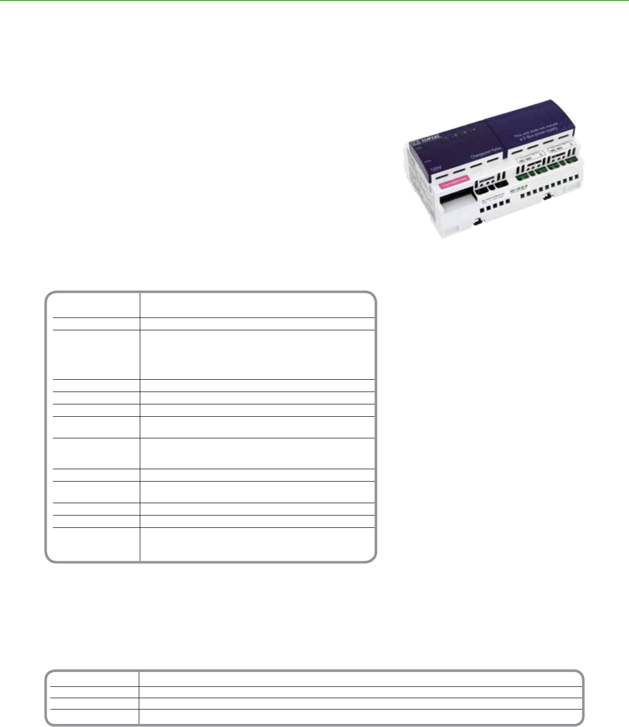
Catalog Number Description
SLC5504TRVFC 4 Channel changeover relay unit 120Vac, with power supply
SLC5504TRVFCP 4 Channel changeover relay unit 120Vac, without power supply
SLC5504HRVFC 4 Channel changeover relay unit 277Vac, with power supply
SLC5504HRVFCP 4 Channel changeover relay unit 277Vac, without power supply
Technical Information
Nominal Supply Voltage 110-120V (SLC5504TRVFC and SLC5504TRVFCP)
250-277V (SLC5504HRVFC and SLC5504HRVFCP)
Frequency Range(s) 50 - 60Hz
C-Bus Supply Voltage 15–36Vdc @ 18 mA required for programming
when electrical power source is not connected.
Sources 200 mA to the C-Bus Network
with electrical power source connected.
Electrical isolation 3.75 kV RMS from C-Bus to power source
Contact Type Changeover, Non-latching
C-Bus Connections 2 RJ-45 connectors, CAT 5 UTP cable req.
Electrical Terminals Accommodates (1) #12 or up to (2) #14 - 16 AWG
(2 x 1.3 mm2 or 1 x 3.3 mm2)
Status Indicators C-Bus Indicator
Unit Status Indicator
Load Indicator
Dimensions 5.67 x 3.35 x 2.60 inches (144 x 85 x 65mm)
Weight 13 oz (370g) (With Power Supply)
17 oz (490g) (Without Power Supply)
Mounting DIN rail, 8M wide
Operating Environment 32°F to 113°F (0°C to 45°C) RH: 95%, noncondensing
Standards UL: Listed 508 Industrial Control Equipment
CSA 22.2 No. 14 Industrial Control Equipment
FCC: Part 15, Class B Digital Device
*For Diagram see technical section page 105
C-BUSTM LIGHTING CONTROL + OUTPUT UNITS
The C-BusTM Changeover Relays are DIN-rail mounted devices with four independent,
voltage free, changeover relay contacts.
Schneider Electric C-Bus Changeover Relays are designed to operate three-speed
motors and two-way motor control devices. Some of their most common applications
include operating motorized blinds, shutters, curtains and skylights (open/closed) where
they provide a much simpler alternative to traditional and obtrusive relay interlocking
systems.
Product Features
• Four (4) isolated independently operating
relay channels
• Two (2) convenient built-in C-Bus™ network
connectors (RJ-45)
• Non-volatile memory stores operating status
for recovery from power outage
• LED Indicators show the status of the
network and the unit
• Changeover Relays ratings: (120V AC Max)
• 2A Exhaust fans (shaded pole induction
motors)
• 2A Ceiling fans (split-phase induction motors)
Distributed Intelligence
• Compatible with all C-Bus devices and the
Powerlink® NF3000G3C controller
• Easily congured with the C-Bus Toolkit
Software
Changeover Relay Unit
C-BusTM
Changeover Relay Units
82
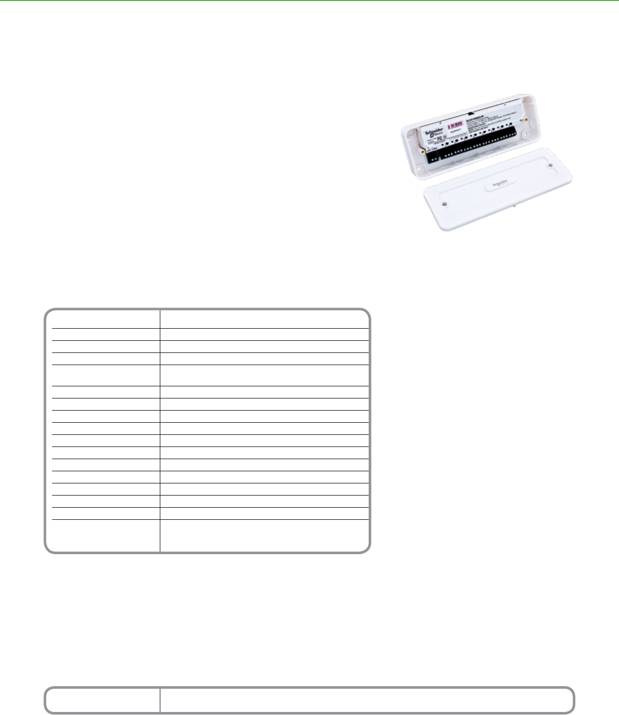
Technical Information
C-Bus network supply voltage 15 to 36Vdc @ 32mA required for programming and operation
Maximum units per C-Bus network 50
C-Bus connections 2 wire, twisted pair
Warm up time 5 seconds
Load rating per relay channel 2A at 30Vdc maximum or
30Vac RMS suitable for resistive and inductive loads
Contact type Voltage free, SPDT (changeover)
Relay terminal connections C common, N/O normally open, N/C normally closed
Types of electrical connection Fixed load terminal for: 1 x 1.0mm² wire per tunnel (13AWG),
Fixed aux (C-Bus) connectors for: 2 x 1.5mm²
Dimensions (W x H x D) 8.66 x 3.15 x 1.50in. (220 x 80 x 38mm)
Weight 11.64oz (330g)
Mounting mode Surface: 4 mounting screw holes and keyhole mount
EMC environment Environment A
Operating ambient temperature 32 to 122°F (0 to 50°C)
Storage temperature 32 to 140°F (0 to 60°C)
Operating humidity 10 to 90% non condensing
Standards: CSA C22.2 No. 205 - Signal Equipment
UL916 - Energy Management Equipment, FCC Part
15 - Class B Digital Device for Home or Ofce Use
*For Diagram see technical section page 105
C-BUSTM LIGHTING CONTROL + OUTPUT UNITS
Catalog Number Description
SLC5108RELVP C-Bus 8 Channel Low Voltage Relay
The C-BusTM 8 Channel Low Voltage Relay is used for switching loads such as irrigation
solenoids, and LV air conditioning dampers. The Relay may also be used for switching LV
pulse signal control loads into third party products.
The C-Bus 8 Channel Low Voltage Relay is a C-Bus output device that controls eight
low voltage relay channels. The unit is powered from the C-Bus network and requires
no other power source. The unit can be daisy chained or placed at the end of a C-Bus
network.
Product Features
• Software-selectable C-Bus system clock
• Synchronize data communication on the
C-Bus network
• Switch Low Voltage Loads
• Control 3rd party products
• 2 Status Indicator Lights
Low Voltage Relay
C-BusTM
Low Voltage Relay
83
84

C-BusTM Enclosures
and Area Lighting
Panels
85

Area lighting panels from Schneider Electric
are a simple, convenient way to area
dimming and multi-scene controls, as well as
daylight harvesting schemes in an individual
conference room or suite within a commercial
building. They are ideally suited to meet
energy code requirements related to reduction
in lighting loads by dimming, or integrating
natural light with articial light.
Area lighting panels offer the exibility of being
set up as a stand-alone system or connected
as a part of a larger C-BusTM network. A
simple Cat-5 cable connection gives the
pre-engineered enclosed panels the ability
to integrate light-level detection, occupancy
detection, keypads and switching. Along with
ease of network connectivity and simplied
programming, area lighting panels also provide
easy installation and reduced eld-wiring costs.
Outtting a conference room or suite with a
C-Bus light-level sensor allows an area lighting
panel to automatically dim lights to capitalize
on available natural light. When using C-Bus
occupancy sensors, the panel automatically
turns lights off after everyone leaves.
Additionally, various pre-programmed lighting
scenes can be automatically executed by the
panel by pressing a button on a C-Bus lighting
control keypad.
Area lighting panels provide unparalleled
installation exibility for electrical contractors.
They provide the ability to integrate C-Bus
keypads and light-level sensors and
occupancy sensors without the complexity of
line-voltage wiring connections. A single Cat-5
cable is all that is required in most applications
to connect the inputs to a panel, which may
be mounted in either an electrical closet
or ceiling space. Power is distributed to
the panel from a single home-run connection
to the power source. Consultants will nd
that designing rooms in a commercial building
with a focus on energy savings and tasteful
lighting scenes is easier, because there is
less wiring complexity.
Introduction to
C-BusTM Enclosures and
Area Lighting Panels
86
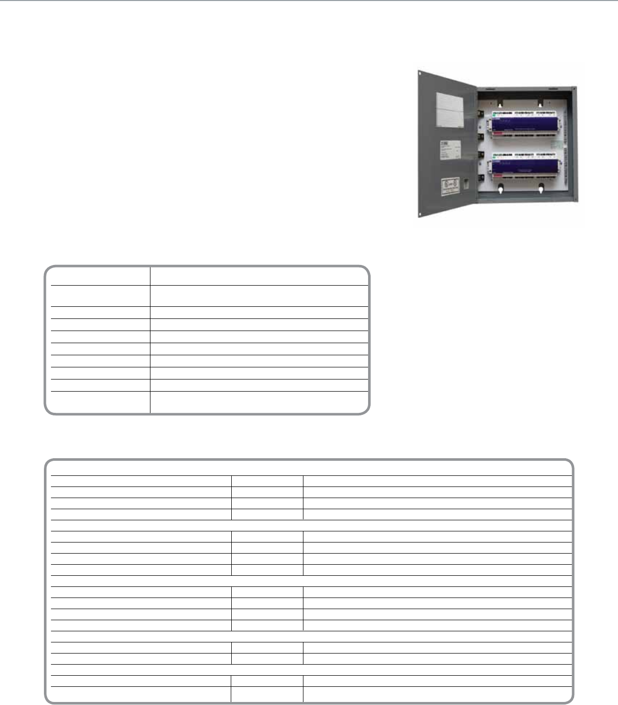
Technical Information
Rated Voltage 120V & 277V 50/60Hz
Number of Units Use the C-Bus calculator, a software utility to
per Network determine total network current load or Toolkit software
Electrical isolation 3.5kV RMS from C-Bus to the line
Relays 20A
Short Circuit Current Rating 65kA (120V), 14kA (277V)
C-Bus Connections RJ45
Dimensions
12M Enclosure 12.78 in. x 9.09 in. x 4.0 in.
24M Enclosure 14.50 in. x 14.94 in. x 4.0 in.
Standards UL: Listed 508A, FCC part 15.101, Class B Device
EN61000-4-2 Immunity to ESD
*For Enclosure Diagram see technical section page 106
Catalog Number Enclosure Description
4 Channel 20A Relay Models
SLCZ042000T 12M 4 Channel 20A Relay @ 120V with power supply*
SLCZ042000H 12M 4 Channel 20A Relay @ 277V with power supply*
SLCZ042000TP 12M 4 Channel 20A Relay @ 120V without power supply
SLCZ042000HP 12M 4 Channel 20A Relay @ 277V without power supply
8 Channel 20A Relay Models
SLCZ082000T 24M 8 Channel 20A Relay @ 120V with power supply*
SLCZ082000H 24M 8 Channel 20A Relay @ 277V with power supply*
SLCZ082000TP 24M 8 Channel 20A Relay @ 120V without power supply
SLCZ082000HP 24M 8 Channel 20A Relay @ 277V without power supply
4 Channel 20A Relay Models with 0-10V Output Units
SLCZ04204AT 24M 4 Channel 20A Relay @ 120V with power supply and 4 Channel 0-10V Output Unit*
SLCZ04204AH 24M 4 Channel 20A Relay @ 277V with power supply and 4 Channel 0-10V Output Unit*
SLCZ04204ATP 24M 4 Channel 20A Relay @ 120V without power supply and 4 Channel 0-10V Output Unit
SLCZ04204AHP 24M 4 Channel 20A Relay @ 277V without power supply and 4 Channel 0-10V Output Unit
4 Channel Phase Angle Dimmer Models
SLCZ00004DT 12M 4 Channel Phase Angle Dimmer @ 120V with power supply
SLCZ00004DTP 12M 4 Channel Phase Angle Dimmer @ 120V without power supply
4 Channel 20A Relay Models with Phase Angle Dimmer Units
SLCZ04204DT 24M 4 Channel 20A Relay @ 120V with power supply and 4 channel phase angle dimmer unit
SLCZ04204DTP 24M 4 Channel 20A Relay @ 120V without power supply and 4 channel phase angle dimmer unit
* For stand-alone applications order unit with power supply
C-BUSTM LIGHTING CONTROL + AREA LIGHTING PANEL
The C-BusTM Area Lighting Panels are ideally suited to meet lighting control energy code
requirements in classrooms, ofces and other small spaces. These devices provide the
ability to integrate keypads, occupancy sensing, light level detection, and switching
without the mess of complex control wiring. A simple CAT-5 cable is all that is required to
connect sensors and keypads.
Area Lighting Panels can operate as independent stand-alone islands or as part of an
entire facility wide lighting control system. Enclosures can easily be mounted in electrical
closets or in ceiling spaces. They include all necessary connections and are UL
Listed. Area Lighting Panels can also be used in conjunction with Powerlink® panels.
Area Lighting Panels can be used for on/off switching, stepped dimming or continuous
dimming applications. All relays feature rugged 20A rated contacts for switching
electronic ballast loads. Models with continuous dimming capabilities are rated for either
NEC Class 1 or Class 2 wiring.
Product Features
• Relay models: Four or eight relay outputs,
rated 20A
• 0-10V outputs for control of 0-10V dimmable
uorescent ballast (suitable for use with MARK
7®, Sylvania Quicktronic®, and Universal
SuperDim®)
• Integral neutral and ground bar terminal strips
• Plenum-rated for ceiling applications
• Bypass mode to facilitate quick start up
• Meets NEC Article 409
• UL Listed 508A, SCCR current ratings: 65kA
(120V), 14kA (277V)
• Surface Mount NEMA 1 Enclosure
Distributed Intelligence
• Compatible with all C-Bus devices and the
Powerlink® NF3000G3C controller
• Easily congured with Learn Mode or with
C-Bus Toolkit software
8 channel 20A Relay Area Lighting Panel
C-BusTM
Area Lighting Panels
87
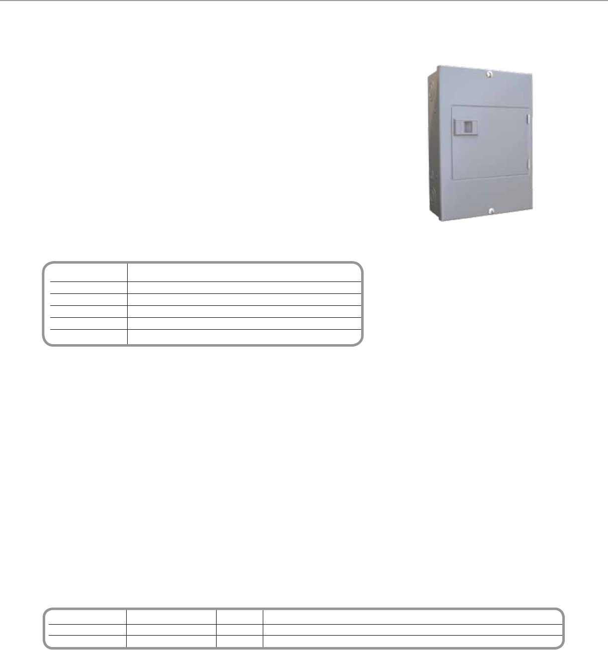
Catalog Number Description Accessories
SLC8M 8M DIN Enclosure* PK7GTA Ground/Neutral Bar†
PKGTAB Neutral Insulator Kit†
SLC4CSF8 Filler Plate, 4M
* Includes one ground bar, one ller plate, cable ties and mounts for wire management.
† Additional terminal bar and insulator for devices that require neutral connection points for loads, such as a relay unit.
Note: The C-Bus 8M Enclosure will accept one additional terminator bar (PK7GTA) intended for load neutral connections.
This is to be used when the C-Bus unit mounted inside requires neutral connection points for loads, i.e. a relay unit. Use in conjunction with a Neutral Insulator Kit (PKGTAB)
Technical Information
8M Enclosure
Type NEMA 1
DIN Module Capacity One 8M or two 4M C-Bus units
Dimensions 12.57 in. (L) x 8.88 in. (W) x 3.8 in. (D) [319 mm (L) x 226 mm (W) x 97 mm (D)]
Mounting DIN rail
Weight 8.4 lb (3.81 kg)
*For Diagram see technical section page 105
C-BUSTM LIGHTING CONTROL + ENCLOSURES
The C-BusTM Enclosures provide a housing for various C-Bus DIN-mounted devices. The
8M enclosure is specically designed for distributed applications that require physical
proximity between DIN units and keypads, sensors or controlled loads.
Suitable for surface mounting, the 8M enclosure consists of a box with a cover and a
DIN rail for mounting one 8M or two 4M units. The enclosure also has provisions for
mounting neutral and ground bars.
Product Features
• Surface-mount NEMA 1 enclosure
• Welded sheet steel with knockouts
• Gray baked enamel, electrodeposited over
cleaned, phosphatized steel
• Triple-lead cover screws for fast installation of
cover
• DIN rail, suitable for mounting one 8M or two
4M C-Bus DIN modules
• UL Listed
8M Enclosure
C-BusTM
8M Enclosure
88
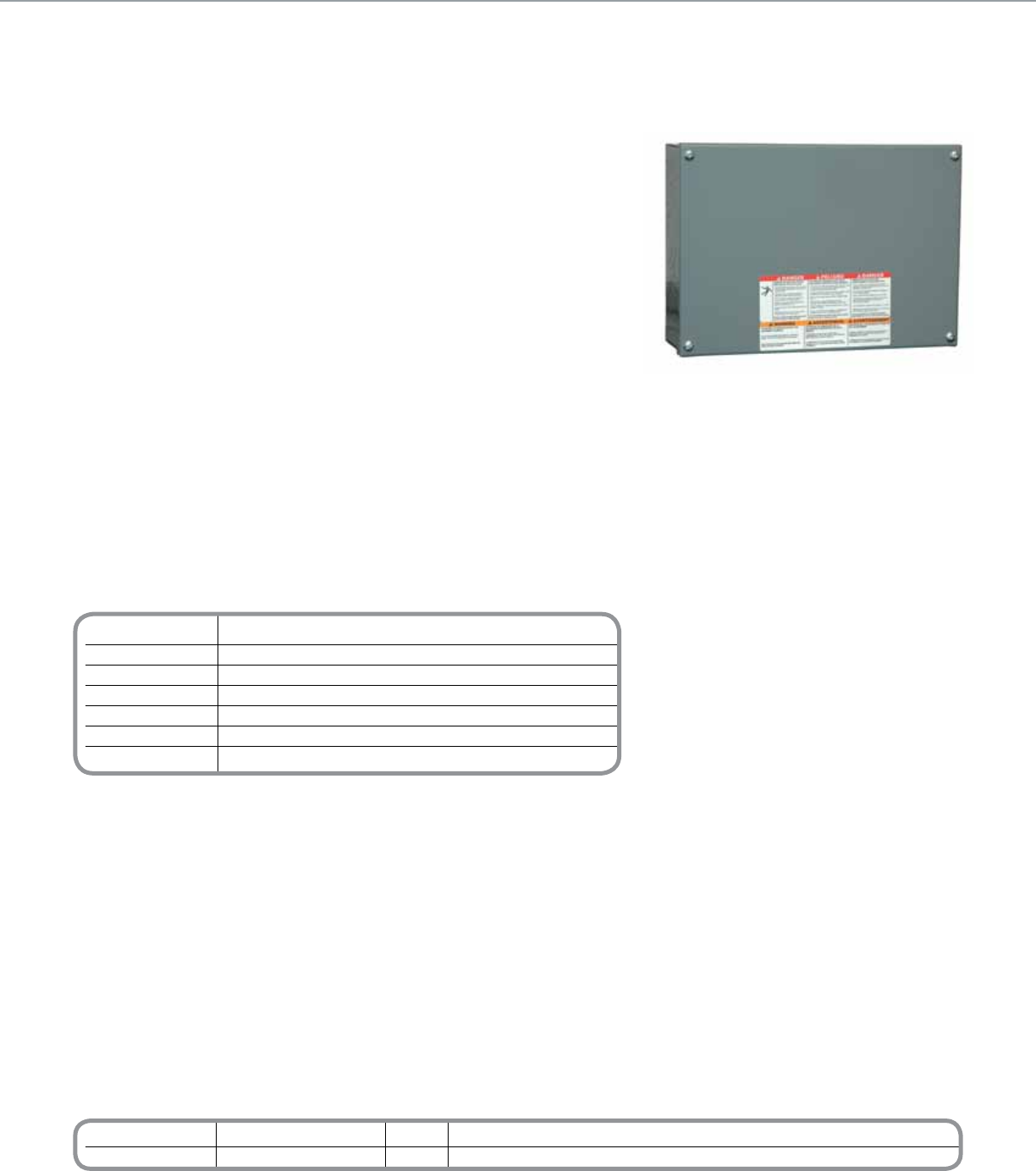
Technical Information
12M Enclosure
Type NEMA 1
DIN Module Capacity One 12M, one 8M + one 4M or three 4M C-Bus units
Dimensions 12.78 in. (W) x 9.09 in. (T) x 4.0 in. (D) [325 mm (L) x 231 mm (W) x 102 mm (D)]
Standard UL Standard 50 Enclosures for electrical equipment
Mounting DIN rail
Weight 11.7 lb (5.3 kg)
*For Diagram see technical section page 106
Catalog Number Description Accessories
SLC12MSG 12M DIN Enclosure* PK7GTA Ground/Neutral Bar
PKGTAB Neutral Insulator Kit
* Includes one DIN rail, one ground bar, and one insulated neutral terminal bar pre installed on the mounting pan. Also included are 2 ft. of exible, Class 2 barrier, four pan mounting
screws, four cover mounting screws, and two DIN rail stops.
C-BUSTM LIGHTING CONTROL + ENCLOSURES
The C-BusTM Enclosures provide a housing for various C-Bus DIN-mounted devices.
The 12M enclosure is specically designed for distributed applications that require
physical proximity between DIN units and keypads, sensors or controlled loads.
Suitable for surface mounting, the 12M enclosure consists of a box with a cover and
a DIN rail for mounting three 4M C-Bus units, one 8M unit plus one 4M unit or one
12M unit. The enclosure also has factory mounted neutral and ground bars.
Product Features
• Surface-mount NEMA 1 enclosure
• Welded sheet steel with knockouts
• Gray baked enamel, electrodeposited over
cleaned, phosphatized steel
• Triple-lead cover screws for fast installation
of cover
• DIN rail, suitable for mounting one 12M or
three 4M or one 8M and one 4M C-Bus DIN
module
• UL Listed
12M Enclosure
C-BusTM
12M Enclosure
89
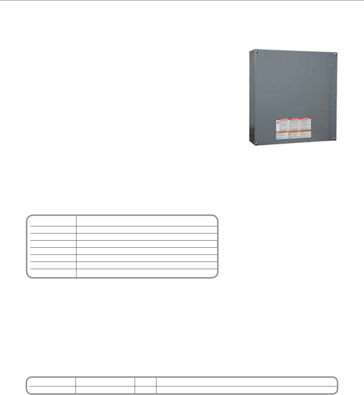
Catalog Number Description Accessories
SLC24MSG 24M DIN Enclosure* PK7GTA Ground/Neutral Bar†
PKGTAB Neutral Insulator Kit†
* The enclosure comes with two DIN rails, two ground bars, and two insulated neutral terminal bars pre-installed on the mounting pan. Also included are 2 ft. of exible, Class 2 barrier,
four pan mounting screws, and four door mounting screws, and four DIN rail stops.
† Additional terminal bar and insulator for devices that require neutral connection points for loads, such as a relay unit.
Note: The C-Bus 24M Enclosure will accept one additional terminator bar (PK7GTA) intended for load neutral connections. This is to be used when the C-Bus unit
mounted inside requires neutral connection points for loads, i.e. a relay unit. Use in conjunction with a Neutral Insulator Kit (PKGTAB)
Technical Information
24M Enclosure
Type NEMA 1
DIN Module Capacity Two rows for mounting C-Bus DIN-mounted units. Each row can
hold one 12M unit, one 8M unit plus one 4M unit, or three 4M units
Dimensions 14.50 in. (W) x 14.94 in. (T) x 4.0 in. (D) [368 mm (L) x 379 mm (W) x 102 mm (D)]
Mounting DIN rail
Standard UL Standard 50 Enclosures for electrical equipment
Weight 18.9 lb (8.6 kg)
*For Diagram see technical section page 106
C-BUSTM LIGHTING CONTROL + ENCLOSURES
The C-BusTM Enclosures provide a housing for various C-Bus DIN-mounted devices. The
24M enclosure is specically designed for distributed applications that require physical
proximity between DIN units and keypads, sensors or controlled loads.
Suitable for surface mounting, the 24M enclosure consists of a box with a hinged door and
two rows for mounting C-Bus DIN-mounted units. Each row can hold one 12M unit, one
8M unit plus one 4M unit, or three 4M units. The enclosure also has provisions for additional
neutral and ground bars.
Product Features
• Surface-mount NEMA 1 enclosure
• Welded sheet steel with knockouts
• Gray baked enamel, electrodeposited over
cleaned, phosphatized steel
• Triple-lead cover screws for fast installation
of cover
• Hinged trim for easy access
• DIN rail, suitable for mounting C-Bus DIN-
mounted C-Bus units. Each row can hold one
12M unit, one 8M unit plus one 4M unit, or
three 4M units.
• UL Listed
24M Enclosure
C-BusTM
24M Enclosure
90
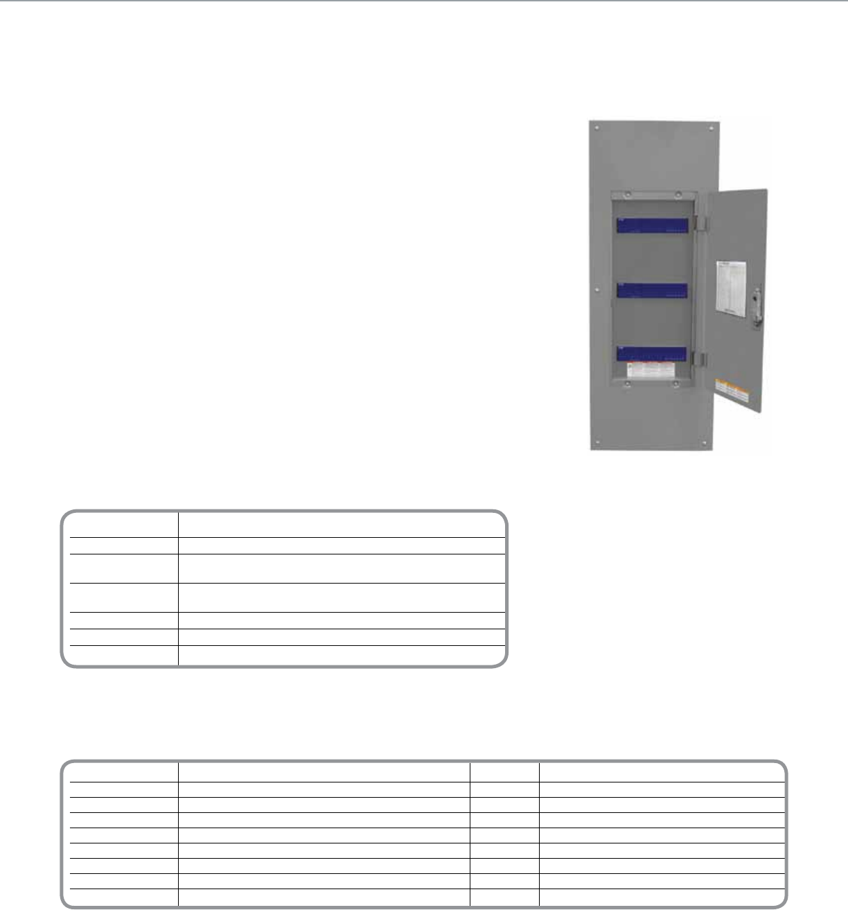
Catalog Number Description Accessories
SLC36C Enclosure Cabinet, 40 in. PK18GTA Neutral bar, 18 terminal1,2,3
SLC36MFG Mounting pan with gray ush-mount cover PKGTAB Neutral insulator kit
SLC36MSG Mounting pan with gray surface-mount cover PK23GTA Ground bar, 23 terminal4
SLC36MFW Mounting pan with white ush-mount cover SLCNT10 Isolated neutral terminal strip (10 position)3, 5
SDM4AC Two duplex power receptacles
SDM8AC Four duplex power receptacles
PK4FL Door latch, locking
SLC4CSF8 Filler plate, 4M
SLC36LB L barrier6
1 For use as a neutral bar; requires one grounding bar insulator kit (PKGTAB).
2 Maximum of four neutral terminal bars (two at top, two at bottom). Use neutral terminal bars in common neutral applications.
3 Mixing of neutral terminal bars and isolated neutral terminal strips is permitted. Mixing permits an additional bar at both top and bottom (three at top and three at bottom).
4 One ground bar is provided as standard. The pan will accept up to two additional ground bars.
5 Maximum of four isolated neutral terminal strips (two at top, two at bottom). Isolated neutral terminal strips allow individual neutrals to be maintained.
6
A second L barrier is required when neutral terminal bars or strips are mounted in both ends of the enclosure. A second L barrier cannot be used if a duplex power outlet
(SDM4AC or SDM8AC) is installed.
Technical Information
36M Enclosure
Type NEMA 1
DIN Module Capacity Three DIN rails, each with the capacity for one 12M,
one 8M with one 4M, or three 4M C-Bus DIN units
Dimensions with Cover 40.6 in. (L) x 15.4 in. (W) x 3.9 in. (D)
[1031 mm (L) x 392 mm (W) x 99 mm (D)]
Standard UL Standard 50 Enclosures for electrical equipment
Module Mounting DIN rail
Total Weight 57.7 lb (26.17 kg)
*For Diagram see technical section page 106
C-BUSTM LIGHTING CONTROL + ENCLOSURES
The C-BusTM Enclosures provide a multi-purpose means for housing various C-Bus
DIN-mounted devices. Suitable for ush or surface mounting, the enclosure consists of
a cabinet, a mounting pan assembly, and a cover assembly. The cabinet can be ordered
separately, allowing for its installation with the rough-in of eld wiring. The mounting
pan comes with one L barrier, four horizontal barriers, and three DIN rails pre-installed.
Optional accessories are available to meet the needs of particular installations.
The 36M enclosure provides three rows for mounting DIN-mounted C-Bus units. Each
row has the capacity to hold one 12M unit, one 8M unit with one 4M unit, or three 4M
units.
Schneider Electric 36M Enclosures are specically designed for conventional installation
near the main breaker panel. They provide a simple means of installing C-Bus
DIN-mounted units with all of the necessary wiring, neutral bar, barriers and other
components included. Once installed, the enclosure system allows for easy system
maintenance with the units accessible.
Additional barriers provide greater exibility to meet requirements of NEC Article 725 for
separation of class 2 circuits.
Product Features
• NEMA® 1 enclosure suitable for ush or
surface mounting
• Welded sheet steel with knockouts
• Gray baked enamel paint, electrodeposited
over cleaned, phosphatized steel
• Triple-lead cover screws for fast installation
of cover
• Three DIN rails, each suitable for mounting
C-Bus DIN units in one of the following
congurations:
One 12M unit
One 8M module with one (1) 4M unit
Three 4M units
• UL Listed
36M Enclosure
C-BusTM
36M Enclosures
91
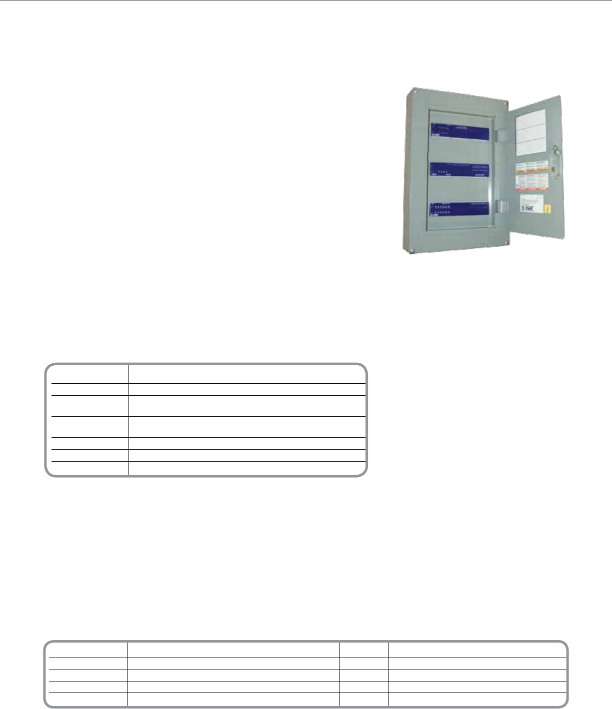
Catalog Number Description Accessories
SLC36SC Enclosure Cabinet PK7GTA Grnd/Neutral
SLCMSFG Flush Mount Gray PKGTAB Neutral Isolator Kit
SLCMSSG Surface Mount Gray SLC4CSF8 Filler Plate
SLCMSFW Flush Mount White
SLC2REC Dual Receptacle Bracket
Technical Information
36M Enclosure
Type NEMA 1
DIN Module Capacity Three DIN rails, each with the capacity for one 12M,
one 8M with one 4M, or three 4M C-Bus DIN units
Dimensions with Cover 40.6 in. (L) x 15.4 in. (W) x 3.9 in. (D)
[1031 mm (L) x 392 mm (W) x 99 mm (D)]
Standard UL Standard 50 Enclosures for electrical equipment
Module Mounting DIN rail
Total Weight 57.7 lb (26.17 kg)
*For Diagram see technical section page 107
C-BUSTM LIGHTING CONTROL + ENCLOSURES
The C-BusTM Enclosures provide a multi-purpose means for housing various C-Bus
DIN-mounted devices. Suitable for ush or surface mounting, the enclosure consists of a
mounting, pan assembly, and a cover assembly. The cabinet can be ordered separately,
allowing for its installation with the rough-in of eld wiring. Optional accessories are
available to meet the needs of particular installations.
The 36MS enclosure provides three rows for mounting DIN-mounted C-Bus units. Each
row has the capacity to hold one 12M unit, one 8M unit with one 4M unit, or three 4M
units.
36MS Enclosures are specically designed for conventional installation near the main
breaker panel. They provide a simple means of installing DIN-mounted units with all of
the necessary wiring, neutral bars, ground bars and other components included. Once
installed, the enclosure system allows for easy system maintenance with the C-Bus units
accessible.
Product Features
• NEMA® 1 enclosure suitable for ush or
surface mounting
• Welded sheet steel with knockouts
• Gray baked enamel paint, electrodeposited
over cleaned, phosphatized steel
• Triple-lead cover screws for fast installation of
cover
• Three (3) DIN rails, each suitable for mounting
C-Bus DIN units in one of the following
congurations:
- One (1) 12M unit
- One (1) 8M module with one (1) 4M unit
- Three (3) 4M units
36MS Enclosure
C-BusTM
36MS Enclosures
92
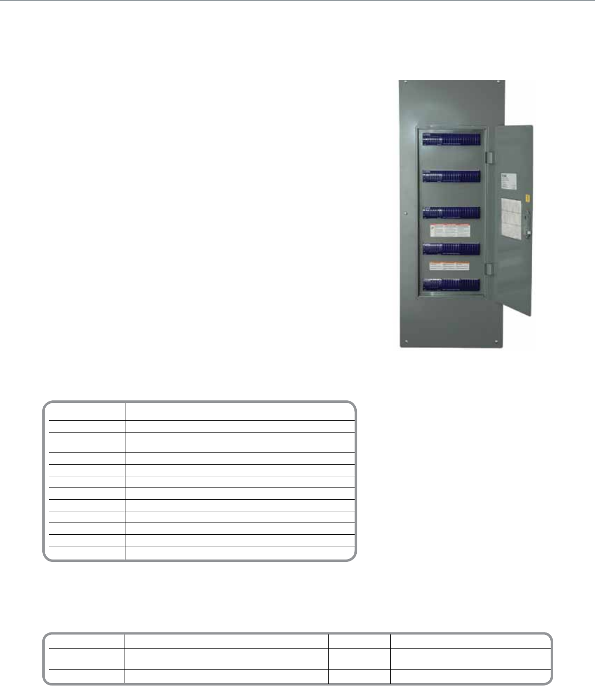
Technical Information
60M Enclosure
Type NEMA Type 1
DIN Module Capacity Five DIN rails, each with the capacity for
one 12M, one 8M with one 4M, or three 4M C-Bus DIN units
Dimensions with 40.6 in. (L) x 15.4 in. (W) x 3.9 in. (D)
Cover (ush mount) [1031 mm (L) x 392 mm (W) x 99 mm (D)]
Dimensions with 39.4 in. (L) x 14.2 in. (W) x 3.9 in. (D)
Cover (surface mount) [1000 mm (L) x 360 mm (W) x 99 mm (D)]
Dimensions of 39.4 in. (L) x 14.2 in. (W) x 3.69 in. (D)
Enclosure Cabinet [1000 mm (L) x 360 mm (W) x 99.8 mm (D)]
Standard UL Standard 50 Enclosures for electrical equipment
Module Mounting DIN rail
Total Weight 57.7 lb (26.17 kg)
*For Diagram see technical section page 107
Catalog Number Description Accessories Description
SLC36C Enclosure Cabinet, 40 in. SDM4AC Two duplex power receptacles
SLC60MFG Mounting pan with gray ush-mount cover PK4FL Door latch, locking
SLC60MSG Mounting pan with gray surface-mount cover SLC4CSF8 Filler plate, 4M
SLC60MFW Mounting pan with white ush-mount cover
C-BUSTM LIGHTING CONTROL + ENCLOSURES
The C-BusTM Enclosures provide a multi-purpose means for housing various C-Bus
DIN-mounted devices. Suitable for ush or surface mounting, the enclosure consists of a
cabinet, a mounting pan assembly, and a cover assembly. The cabinet can be ordered
separately, allowing for its installation with the rough-in of eld wiring. Options are available
to meet the needs of particular installations.
The 60M enclosure provides ve rows for mounting DIN-mounted C-Bus units. Each row
has the capacity to hold one 12M unit, one 8M unit with one 4M unit or three 4M units.
Schneider Electric 60M Enclosures are specically designed for conventional installation
near the main breaker panel. They provide a simple means of installing DIN-mounted units
with all of the necessary wiring, neutral bar, barriers and other components included.
Once installed, the enclosure system allows for easy system maintenance with the C-Bus
units accessible.
Product Features
• NEMA Type 1 enclosure suitable for ush or
surface mounting
• Welded sheet steel with knockouts
• ANSI Gray #49 baked enamel paint,
electrodeposited over cleaned,
phosphatized steel
• Triple-lead cover screws for fast installation
of cover
• UL listed, 600V rated Class 2 barrier
included
• (3) pre-installed 23 position ground bars and
(5) 12 position isolated neutral assemblies
included
• Five DIN rails, each suitable for mounting
C-Bus DIN units in one of the following
congurations:
One 12M unit
One 8M unit with one (1) 4M unit
Three 4M units
• UL Listed
60M Enclosure
C-BusTM
60M Enclosures
93
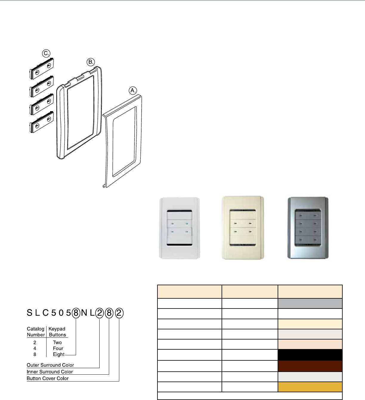
Illustration shows: Inner Surround (A), Outer Surround (B)
and Button Covers (C)
C-BUSTM LIGHTING CONTROL + TECHNICAL SECTION
Keypad Assemblies
Order numbers for the Neo Keypad assemblies indicate the number of buttons
desired on the keypad and the color of each customizable component (inner
surround, outer surround, and button cover).
Color numbers are taken from the “Neo Colors” table and must be given in the
following order: outer surround, inner surround, and button covers.
For example, in the diagram below, SLC5058NL282 represents an order for a Neo
Keypad with eight buttons, a white (#2) outer surround, a brushed aluminum (#8)
inner surround, and white (#2) button covers.
Keypad Assemblies Standard
For easy ordering there are 3 standard keypad colors available.
White: SLC505( )NLWE
Cream: SLC505( )NLCM
Brushed Aluminum w/Slate: SLC505( )NLGB
( ) - designates space for button configuration
SLC505( )NLWE SLC505( )NLCM SLC505( )NLGB
Name Color Number Color
Slate 1
White 2
Cream 3
Soft Gray 4
Desert Sand 5
Black 6
Brown 7
Brushed Aluminum* 8
Gold* 9
*Only the inner surround is available in Brushed Aluminum and Gold
NeoTM Keypad - Specifying Colors When Ordering
94
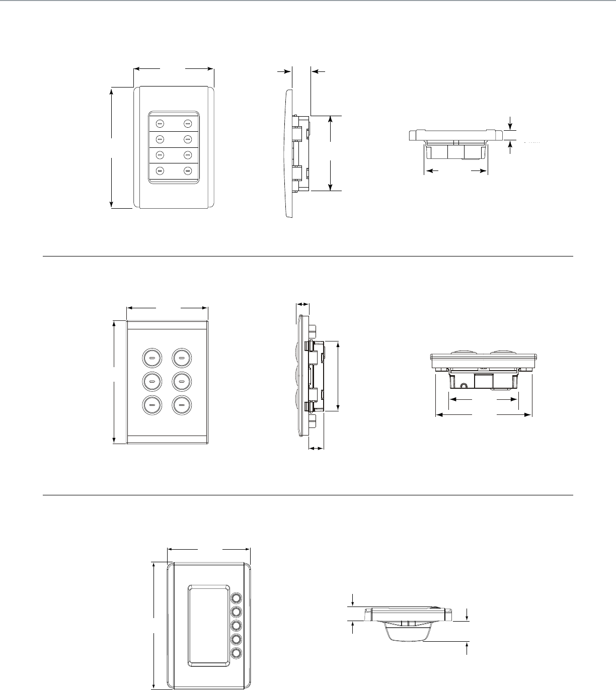
.63 in.
16 mm
2.64 in.
67 mm
2.05 in.
52 mm
.24 in.
6 mm
3.0 in.
76 mm
4.57 in.
116 mm
3.0 in.
76 mm
4.57 in.
116 mm
3.0 in.
76 mm
4.57 in.
116 mm
0.51 in.
13 mm
0.71 in.
18 mm
2.05 in.
52 mm
2.7 in.
69 mm
0.51 in.
13 mm
2.6 in.
66 mm
0.6 in.
15 mm
C-BUSTM LIGHTING CONTROL + TECHNICAL SECTION
Front view of keypad, including external height
and width measurements of case
Side view of keypad, including height and
depth requirements for insertion into wall
Bottom view of keypad, including measurements
for width of unit and depth case extends from wall
Top view of keypad showing widthFront view of keypad, including external
height and width measurements of case
Side view of keypad, including height and depth
requirements for insertion into wall
Top-side view of the Neo DLT keypad illustrates the
depth the case extends into and out of a wall
Front view of keypad, including external
height and width measurements of case
Neo™ Keypads
SaturnTM Keypads
Neo™ Keypads with Dynamic Labeling Technology™
95
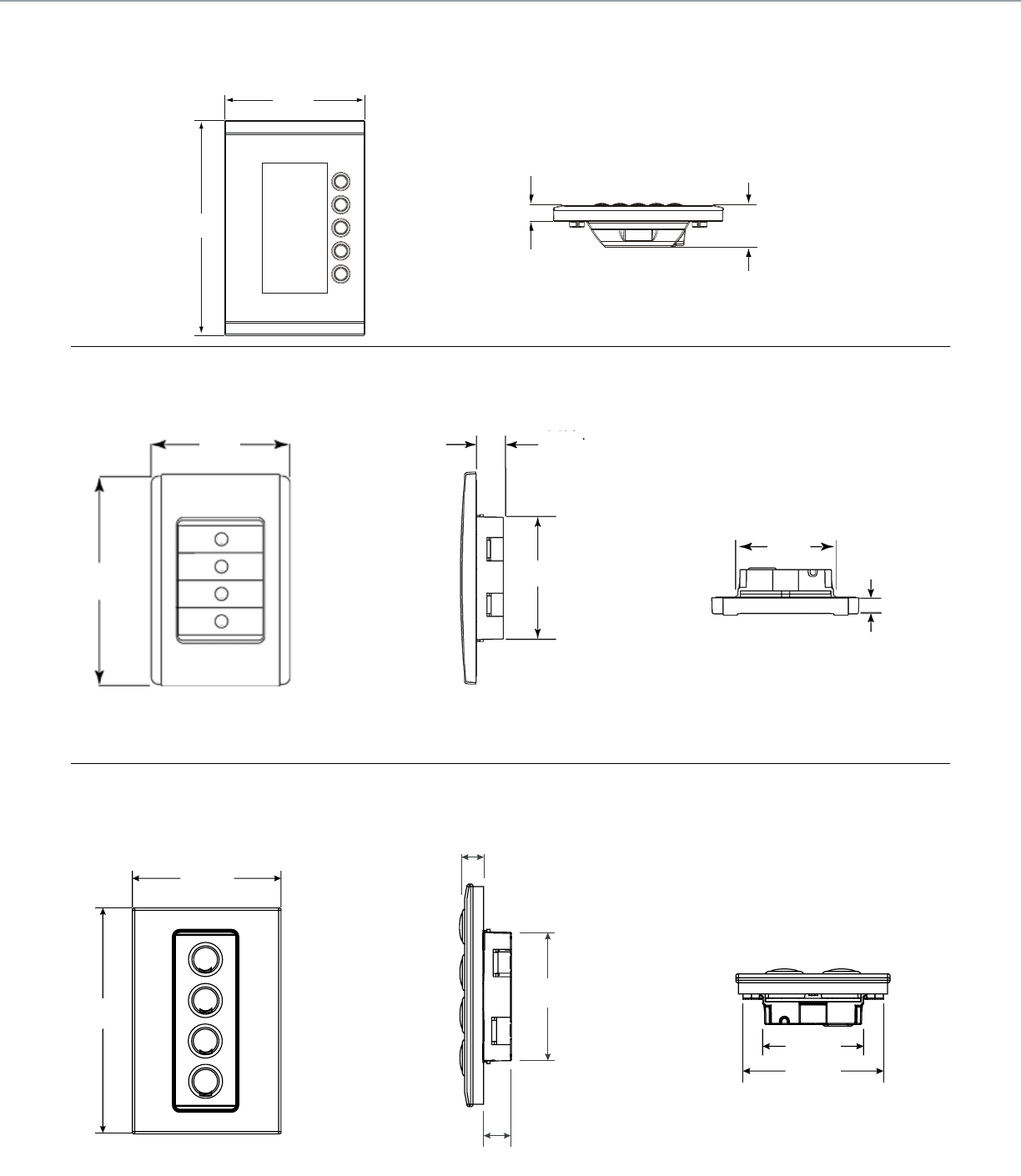
Front and top-side views of the Saturn DLT keypad illustrate
its length and width and the depth the case extends into and
out of a wall
.43 in.
10.8 mm 1.13 in.
28.8 mm
3.0 in.
76 mm
4.57 in.
116 mm
.71 in.
18 mm
2.76 in.
70 mm
2.99 in.
76 mm
.35 in.
9 mm
4.57 in.
116 mm
2.87 in.
73 mm
42 mm
1.65 in.
1.65 in.
42 mm
2.87 in.
73 mm
.71 in.
18 mm
2.76 in.
70 mm
2.99 in.
76 mm
.35 in.
9 mm
4.57 in.
116 mm
2.87 in.
73 mm
42 mm
1.65 in.
2.99 in.
76 mm
4.57 in.
116 mm
Side view of keypad, including height and
depth requirements for insertion into wall
0.63 in.
16 mm
2.76 in.
70 mm
Front view of keypad, including external height
and width measurements of Faceplate
3.0 in.
76 mm
4.57 in.
116 mm
Top view of keypad, including
depth of face plate
1.69 in.
43 mm
0.28 in.
7 mm
.71 in.
18 mm
2.76 in.
70 mm
2.99 in.
76 mm
.35 in.
9 mm
4.57 in.
116 mm
2.87 in.
73 mm
42 mm
1.65 in.
0.35 in.
9 mm
2.76 in.
70 mm
0.71 in.
18 mm
C-BUSTM LIGHTING CONTROL + TECHNICAL SECTION
Front view of keypad, including external height
and width measurements of face plate
Top view of keypad showing width
Side view of keypad, including height and depth
requirements for insertion into wall
Saturn™ Style Decorator Keypads
Saturn™ Keypads with Dynamic Labelling Technology™
Neo™ Style Decorator Keypads
96
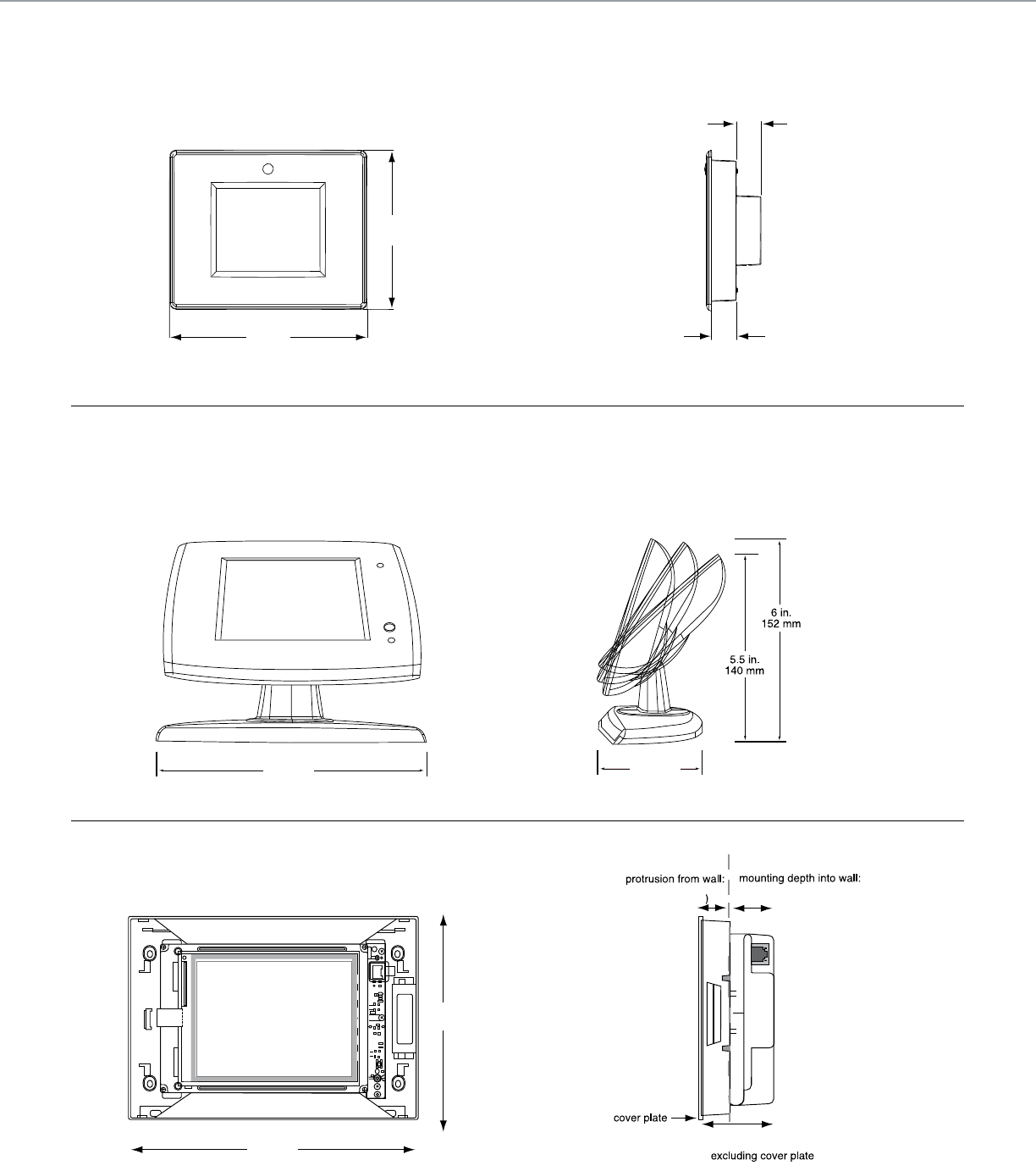
0.75 in.
19 mm
0.75 in.
19 mm
4.53 in.
115 mm
5.98 in.
152 mm
6.9 in. (173 mm)
9.8 in. (246 mm)
9.8 in.
246 mm
6.9 in.
173 mm
0.9 in. (23.5 mm) 2.2 in. (54 mm)
2.9 in. (72.5 mm)
7.5 in.
191 mm
3.75 in.
95 mm
C-BUSTM LIGHTING CONTROL + TECHNICAL SECTION
Side view of Mark II Touch
Screen
Side view of Color Touch ScreenFront view of Color Touch Screen
Front view of Mark II Touch Screen
Mark II Touch Screen
Color Touch Screen
Mark II Desktop Touch Screen
97
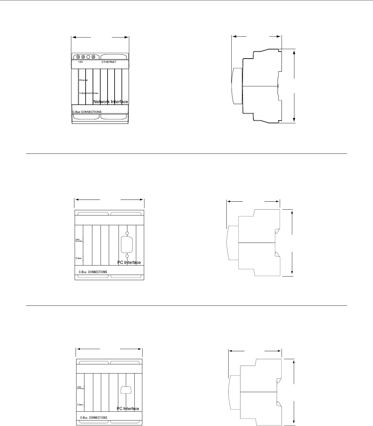
View of the Ethernet Network Interface showing width
2.83 in.
72 mm
2.56 in.
65 mm
3.35 in.
85 mm
Front view of the PC Interface showing width
2.84 in.
72 mm
Side view of the PC Interface showing height and depth
2.56 in.
65 mm
3.35 in.
85 mm
Side view of the PC Interface showing height and depth
2.60 in.
66 mm
3.35 in.
85 mm
USB Interface
Front view of the PC Interface showing width
2.84 in.
72 mm
C-BUSTM LIGHTING CONTROL + TECHNICAL SECTION
View of the Ethernet Network Interface showing height and depth
Ethernet Network Interface
PC Interface
98
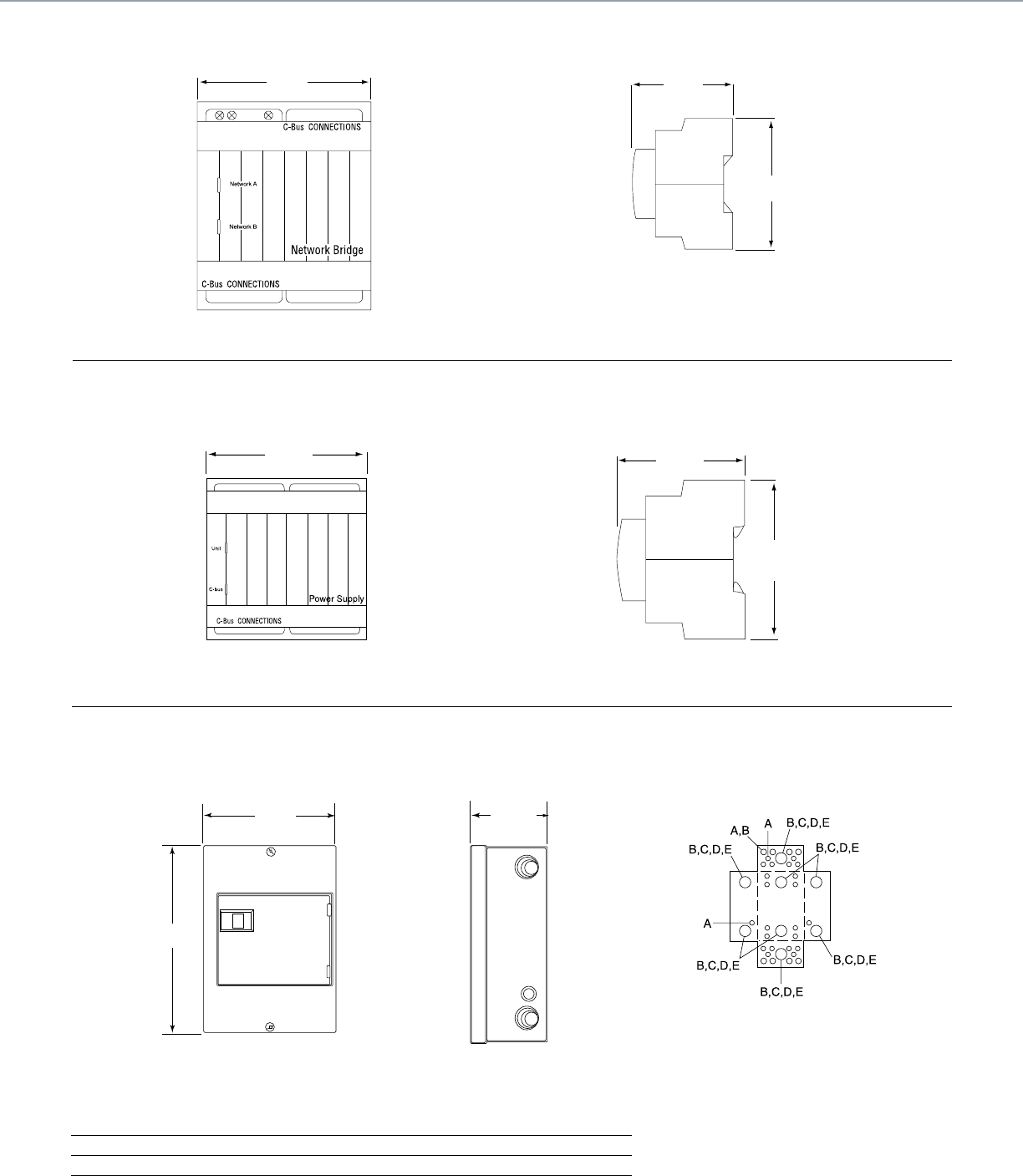
Conduit knockouts for the 8M Enclosure
Front view of 8M Enclosure box
showing height and width
Side view of 8M Enclosure
box showing depth
C-BusTM 8M Enclosure Knockouts
Symbol A B C D E
Conduit Size ½ ¾ 1 1 ¼ 1 ½
3.8 in.
97 mm
3.8 in.
97 mm
8.9 in.
226 mm
12.57 in.
319 mm
12.57 in.
319 mm
8.9 in.
226 mm
Front view of a Power Supply showing width
2.83 in.
72 mm
Side view of a Power Supply showing depth and height
2.56 in.
65 mm
3.35 in.
85 mm
Front view of the Network Bridge showing width
2.83 in.
72 mm
Side view of Network Bridge showing height and depth
2.56 in.
65 mm
3.35 in.
85 mm
C-BUSTM LIGHTING CONTROL + TECHNICAL SECTION
Device Router/Device Power Supply
Power Supply
Network Bridge
99
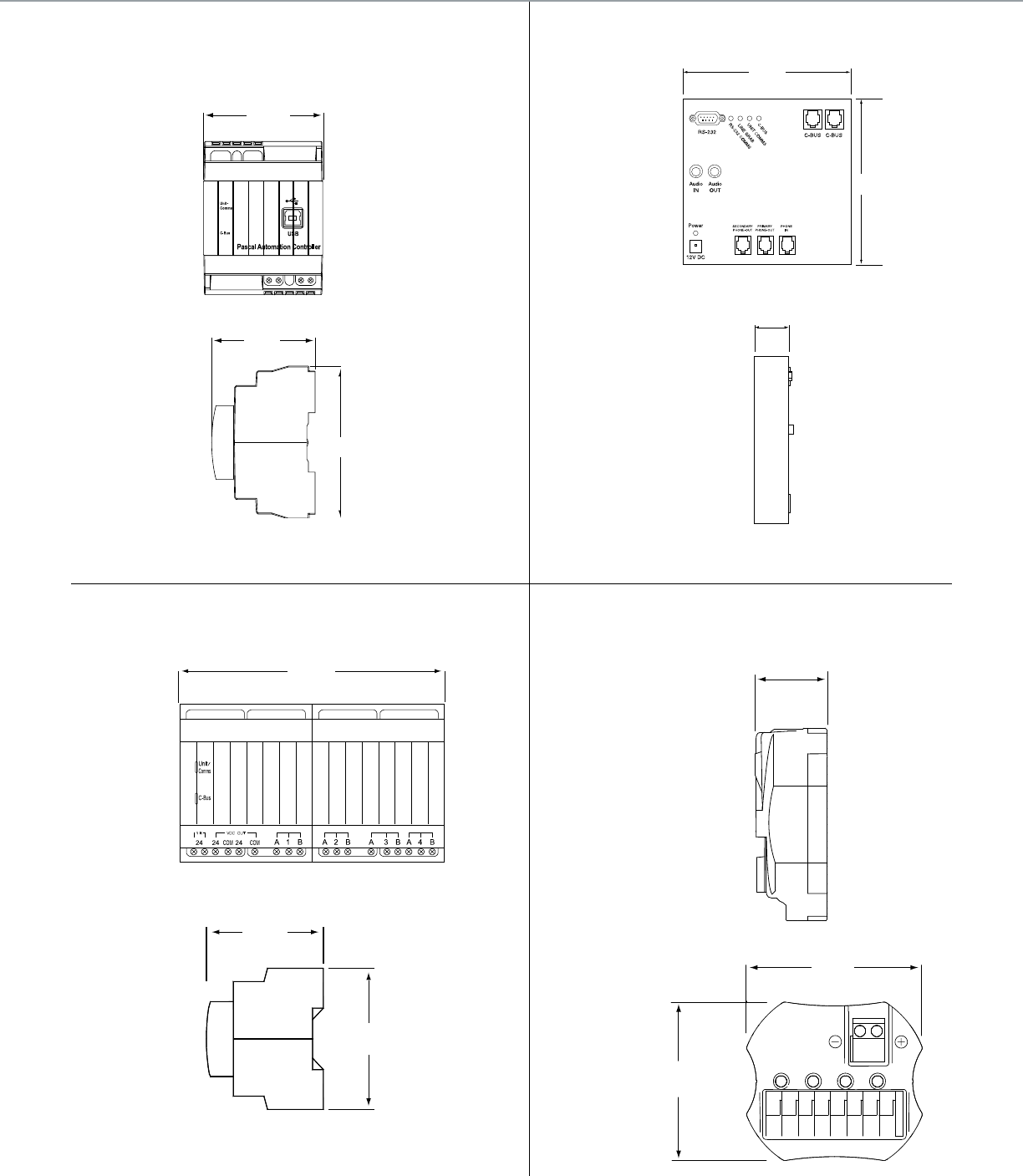
Front view of the Pascal Automation Controller
Side view of the Pascal Automation Controller
2.83 in.
72 mm
TELEPHONE INTERFACE
5.77 in.
146.5 mm
5.71 in.
145 mm
General Input
5.7 in.
144 mm
0.71 in.
18 mm
0.71 in.
18 mm
2.2 in.
1.9 in.
49 mm
55 mm
5104BCL
Bus Coupler
1C3 4
2C C C
1234
2.2 in.
55 mm
1.9 in.
49 mm
2.6 in.
65 mm
3.4 in.
85 mm
2.48 in.
63 mm
3.62 in.
92 mm
TELEPHONE INTERFACE
1.18 in.
30 mm
C-BUSTM LIGHTING CONTROL + TECHNICAL SECTION
Top view of General Input Unit
Front view of Telephone Interface Unit
Side view of General Input Unit
Side view of Telephone Interface Unit
Top view of Four-Channel Bus Coupler
Side view of the Four-Channel Bus Coupler
Bus Coupler
Telephone Interface Unit
Pascal Automation
Controller
General Input Unit
100
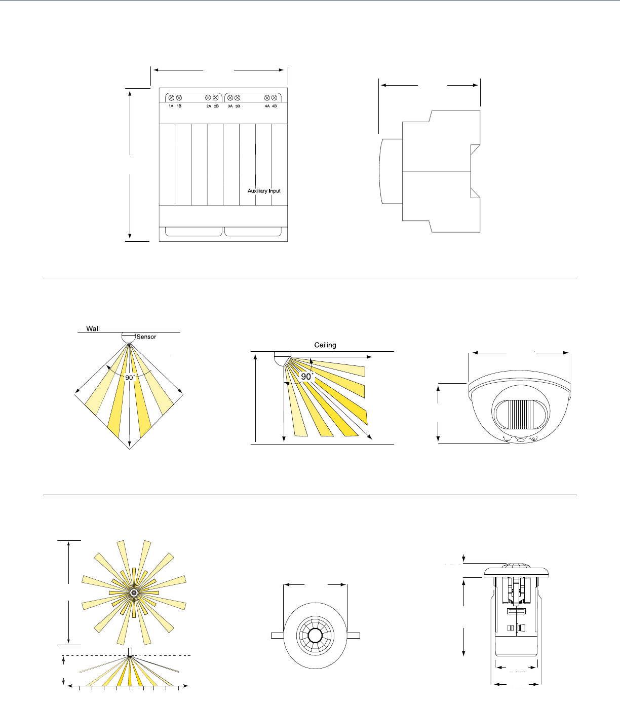
2.6 in.
65 mm
2.8 in.
72 mm
3.4 in.
85 mm
2.83 in.
72 mm
.59 in.
15 mm
3.46 in.
88 mm
1.85 in.
47 mm
1.97 in.
50 mm
26 ft
8 m
8 ft
2.4 m
13 ft
4 m
13 ft
4 m
7 ft
2 m
7 ft
2 m
0
28 ft
8.5 m
20 ft
6 m
28 ft
8.5 m
20 ft
6 m
2.2 in.
57 mm
3.9 in.
100 mm
8 ft
2.4 m 28 ft
8.5 m
28 ft
8.5 m
C-BUSTM LIGHTING CONTROL + TECHNICAL SECTION
Field of view from side of indoor occupancy sensor Front view of indoor occupancy sensor
Side view of C-Bus 360° PIR Occupancy Sensor
Front view of C-Bus 360° PIR Occupancy Sensor
Field of view from top and side for 360 PIR Occupancy
Sensor mounted 8 ft. above oor
Top view of Four-Channel Auxiliary Input Unit Side view of Four-Channel Auxiliary Input Unit
Field of view from top of indoor occupancy sensor
Four-Channel Auxiliary Input Unit
Indoor PIR Occupancy Sensor
360° PIR Occupancy and Multi-Sensor
101
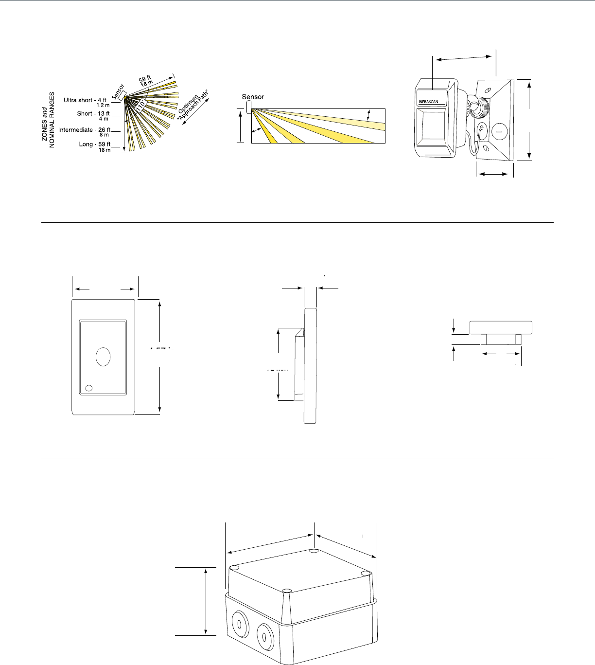
Field of view from side of Outdoor Motion SensorField of view from top of Outdoor Motion Sensor Side view of Outdoor Motion Sensor
5.5 in.
140 mm
4.5 in.
114 mm
2.9 in.
74 mm
Top view of light-level sensor
0.49 in.
12.5 mm
1.93 in.
49 mm
0.52 in.
13 mm
2.83 in.
72 mm
2.99 in.
76 mm
4.57 in.
116 mm
8 ft
2.4 m
30°
5°
2.5 in.
65 mm
4 in.
102 mm 4 in.
102 mm
C-BUSTM LIGHTING CONTROL + TECHNICAL SECTION
Side view of Light-Level Sensor Front view of Light-Level Sensor
View including height, width and depth dimensions
Outdoor Motion Sensor
Light-Level Sensor
Outdoor Light-Level Sensor
102
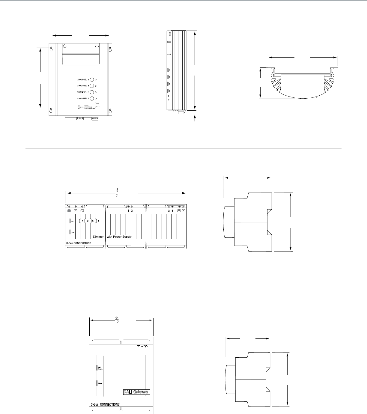
POWER
NETWORK
9 in.
230 mm
0.4 in.
10 mm
Front view of DALI Gateway
DALI Gateway
C-Bus CONNECTIONS
2.83 in.
72 mm
Unit/
Comms
C-Bus
DALI
1DALI
2
2.83 in.
72 mm
65 mm
85 mm
2.6 in.
3.4 in.
Side view of DALI Gateway
2.6 in.
65 mm
3.4 in.
85 mm
8 in.
202 mm
3 in.
75 mm
8.5 in.
215 mm
2.6 in.
65 mm
3.4 in.
85 mm
7.5 in.
190 mm
7.7 in.
195 mm
C-BUSTM LIGHTING CONTROL + TECHNICAL SECTION
Front view including mounting centers Side view Top view
Front view of the Phase Angle Dimmer Unit Side view of the Phase Angle Dimmer Unit
Professional Series Dimmer
Phase Angle Dimmer Unit
2 Channel DALI Gateway
103
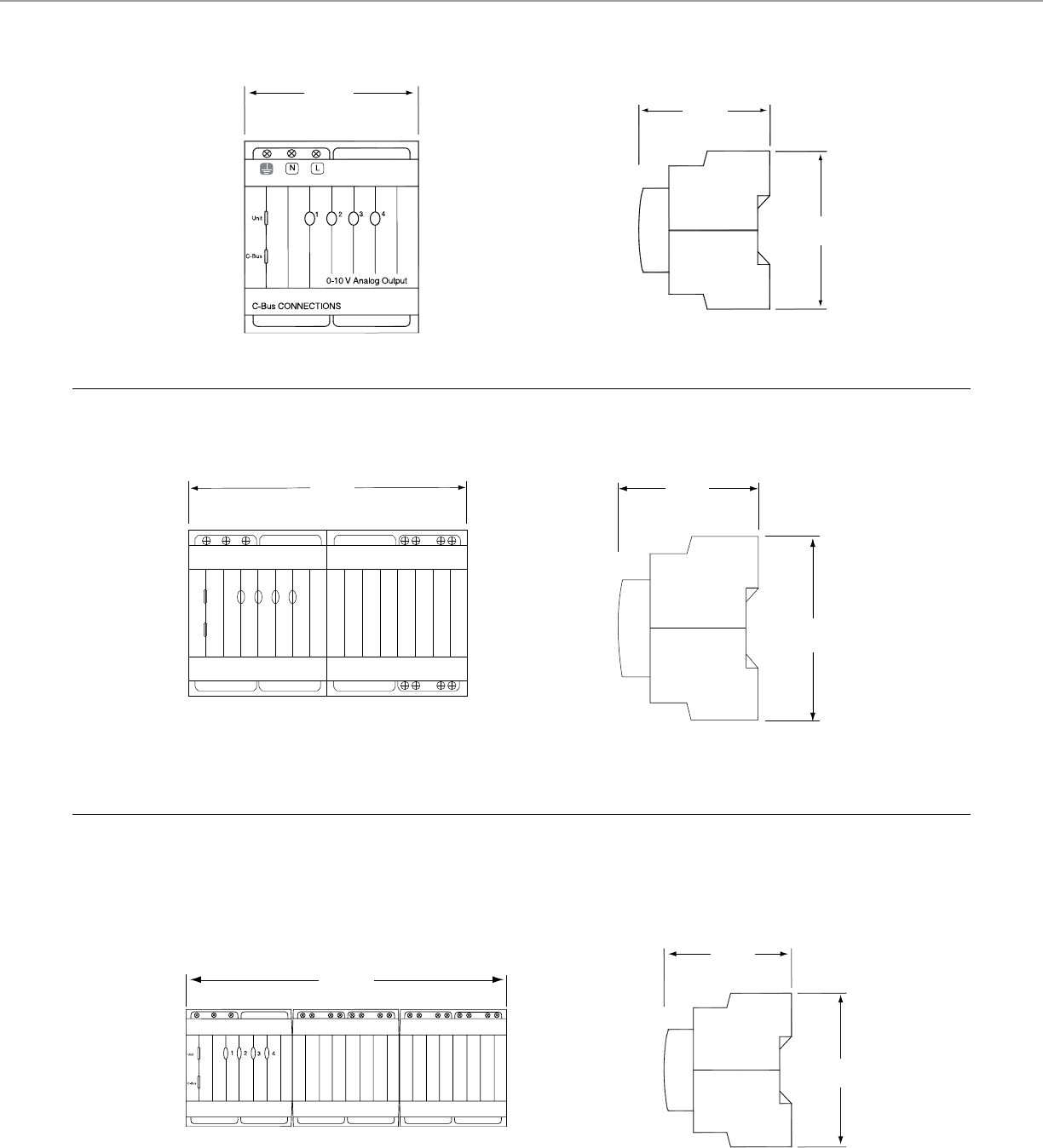
Front view of the 0-10V Fluorescent Ballast Dimmer
2.83 in.
72 mm
Side view of the 0-10V Fluorescent Ballast Dimmer
2.56 in.
65 mm
3.35 in.
85 mm
Front view of a C-Bus 4 Channel 10 Amp
Relay without power supply
5.67 in.
144 mm
Side view of a C-Bus 4 Channel 10 Amp Relay
2.56 in.
65 mm
3.35 in.
85 mm
Front view of a C-Bus 4 Channel 20 Amp Relay with Power Supply
8.46 in.
215 mm
Side view of a C-Bus 4 Channel 20 Amp Relay
2.56 in.
65 mm
3.35 in.
85 mm
C-BUSTM LIGHTING CONTROL + TECHNICAL SECTION
4 Channel 0-10V Fluorescent Ballast Dimmer
10 Amp Relay Unit
20 Amp Relay Units
104
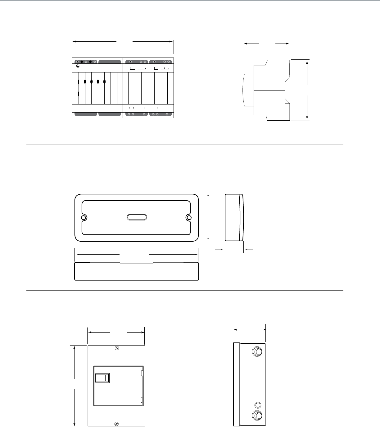
Front view of a C-Bus Changeover Relay
Changeover Relay
2 3 41
C-Bus CONNECTIONS
Unit
C-Bus
N
USE COPPER WIRE ONLY
LNO NCC NO NCC
NC NONC NO CC
3 4
1 2
5.67 in.
144 mm
Side view of a C-Bus Changeover Relay
Changeover Relay
2 3 41
C-Bus CONNECTIONS
Unit
C-Bus
N
USE COPPER WIRE ONLY
LNO NCC NO NCC
NC NONC NO CC
3 4
1 2
2.60 in.
66 mm
3.35 in.
85 mm
3.8 in.
97 mm
3.8 in.
97 mm
8.9 in.
226 mm
12.57 in.
319 mm
8.9 in.
226 mm
12.57 in.
319 mm
3.15 in.
(80 mm)
1.50 in.
(38 mm)
8.66 in.
(220 mm)
C-BUSTM LIGHTING CONTROL + TECHNICAL SECTION
Front view of 8M Enclosure box showing height and width Side view of 8M Enclosure box showing depth
Changeover Relay Units
8M Enclosure
Low Voltage Relay 8 Channel
105
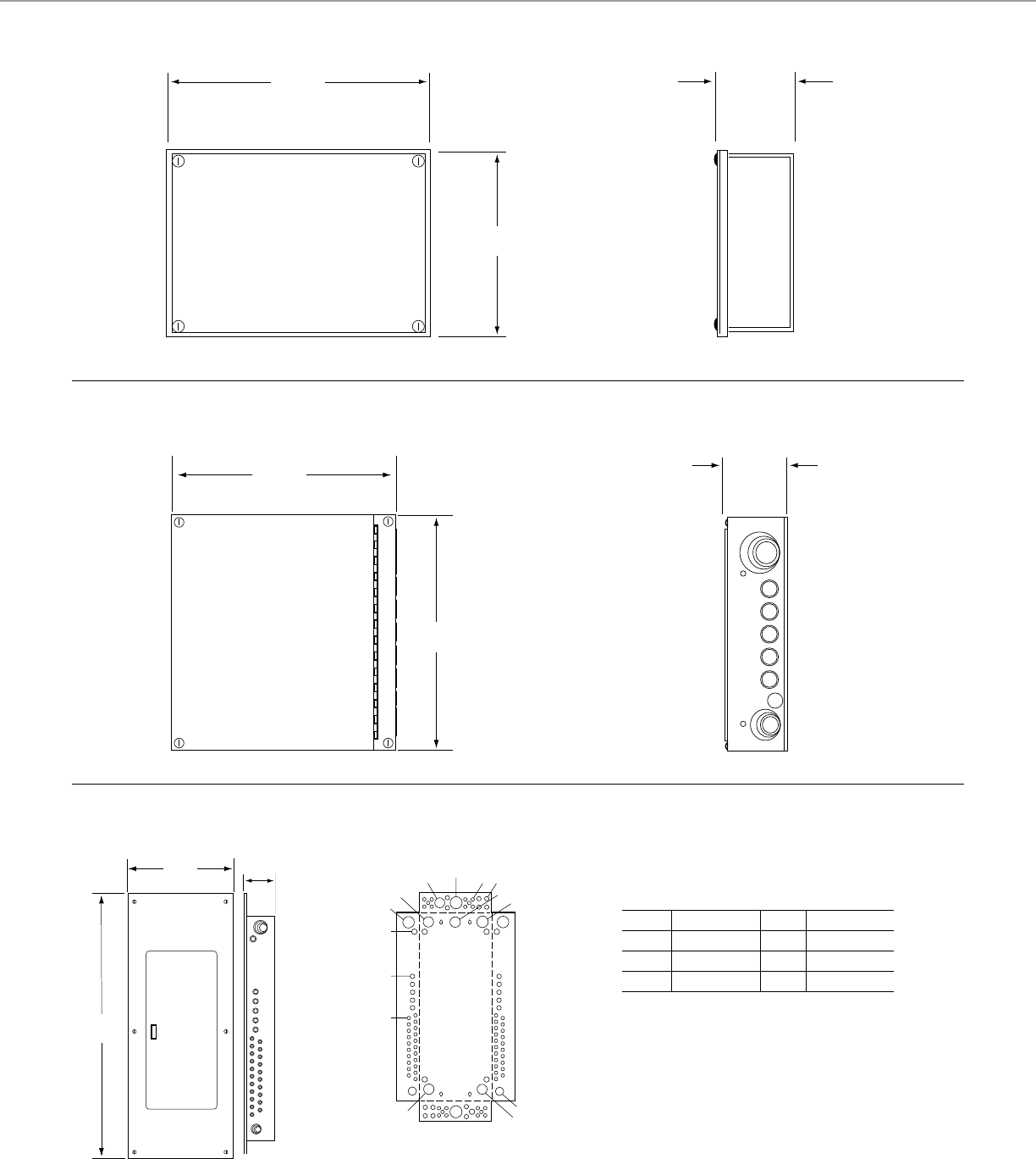
Front view of 12M Enclosure box showing height and width
12.78 in.
325 mm
9.09 in.
231 mm
Front view of 24M Enclosure box showing height and width
14.50 in.
368 mm
14.94 in.
379 mm
Side view of 24M Enclosure box showing depth
4.0 in.
102 mm
Side view of 12M Enclosure box showing depth
4.0 in.
102 mm
B,C,D,E A
C,D,E,F,G A,B
C,D,E,F
D,E,F,G
C,D,E,F
B,C,D,E
A,B,C,D
B,C,D,E
D,E,F,G
A,B
B,C
A
KnockoutsFront and side view (ush mount)
15.4 in.
392
mm 3.9 in.
99 mm
40.6 in.
1031 mm
36M Knockouts
Symbol Conduit Size Symbol Conduit Size
A ½ E 1 ½
B ¾ F 2
C 1 G 2 ½
D 1 ¼
C-BUSTM LIGHTING CONTROL + TECHNICAL SECTION
12M Enclosure
24M Enclosure
36M Enclosure
106
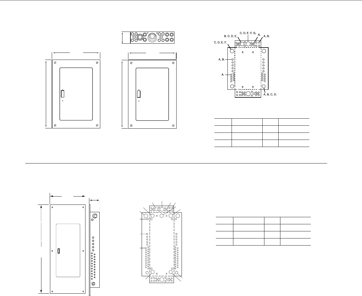
60M Knockouts
Symbol Conduit Size Symbol Conduit Size
A ½ E 1 ½
B ¾ F 2
C 1 G 2 ½
D 1 ¼
B,C,D,E A
C,D,E,F,G A,B
C,D,E,F
D,E,F,G
C,D,E,F
B,C,D,E
A,B,C,D
B,C,D,E
D,E,F,G
A,B
B,C
A
KnockoutsFront and side view (ush mount)
15.4 in.
392
mm 3.9 in.
99 mm
40.6 in.
1031 mm
15.44 in.
(392 mm)
22.12 in.
(562 mm)
14.24 in.
(362 mm)
3.81 in.
(97 mm)
20.93 in.
(532mm)
36MS Knockouts
Symbol Conduit Size Symbol Conduit Size
A ½ E 1 ½
B ¾ F 2
C 1 G 2 ½
D 1 ¼ H 3
C-BUSTM LIGHTING CONTROL + TECHNICAL SECTION
Dimensions for the 36MS
Enclosure Flush Mounted
Dimensions for the 36MS
Enclosure Surface Mounted
60M Enclosure
36MS Enclosure
107
108

C-BusTM Multi-Room
Audio, Remote Controls
and IR Accessories
109

Extend the capabilities of a C-Bus system by
incorporating award winning C-Bus multi-room
audio. Multi-room audio augments a C-Bus
lighting control system, providing high quality
sound throughout a home or business.
C-Bus multi-room audio readily integrates with
other C-Bus controls, providing a single source
for audio and lighting from a single keypad or
touch screen. Sound is distributed throughout
the home through the matrix switcher and
routed to local ampliers.
A typical C-Bus Multi-room Audio system
distributes up to four analog audio inputs,
ve if an audio distribution unit is used, and
one optical input. These inputs are distributed
up to eight zones, each consisting of one or
more amplier.
Additionally, each amplier is capable of
accepting a local analog audio input,
providing up to seven stereo audio channels
for each amplier.
Introduction to
C-BusTM Multi-Room Audio,
Remote Controls and
IR Accessories
110
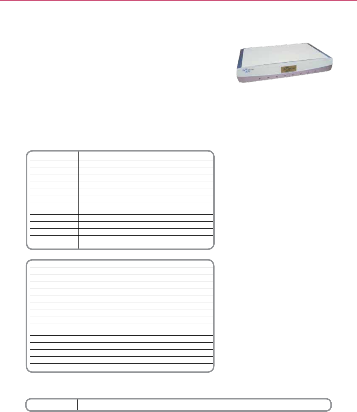
Catalog Number Description
SLC560884T Matrix Switcher
Technical Information
Supply Voltage 120V AC
Line Frequency Range 47 to 53 Hz and 57 to 63 Hz
AC Input Impedance 47 kΩ
Power Consumption 200 W maximum
C-Bus™ Output Voltage 36Vdc maximum
C-Bus Output Current ≤ 330 mA DA Conversion
Network Clock/Burden Software selectable
Analogue Input Signal 2.8V p-p maximum (47 kΩ)
Level (source inputs)
A/D Conversion 16 Bit PCM
Operating Temperature 50 - 104°F (10 to 40°C)
Operating Humidity Range 10 to 90% RH, non-condensing
Standards UL60065 - Audio, Video, and Similar Electronic Apparatus -
Safety Requirements
System Audio Performance
Parameter Matrix Switcher + Amplier
Frequency Response 40 Hz to 20 kHz (+ 2.4/-0.75 dB)
Total Harmonic Distortion 0.16% (1 kHz, 20 W RMS into 4 ohms)
Signal to Noise Ratio > 63 dB (peak, unweighted)
Input/Outputs
Infrared Outputs (2) 3.5 mm sockets to connect to IR Emitter Leads
Mono Broadcast Inputs (2)
USB (Type B) (1) To congure Matrix Switcher
Digital Optical Output (1)
Digital Optical Output (1) Digital audio format must be 44.1 or 48 kHz stereo. Some formats
(such as surround sound) are not compatible with the Matrix Switcher
Optical Inputs (1)
Digital Zone Outputs (8)
Digital Audio Input (1)
Stereo Analog Inputs (4) RCA pairs
Mono Level Adjustment (2)
*For Diagram see technical section page 115
C-BUSTM MULTI-ROOM + MULTI-ROOM AUDIO
The C-BusTM Audio Matrix Switcher provides a revolutionary means for distributing audio
throughout a home. This Matrix Switcher provides up to eight zones of audio output from
four source inputs. Audio sources can be switched via the front panel or by any C-Bus
input device such as touch screen keypads.
The matrix switcher is ideally suited for multi-room audio and structured wiring systems.
Keypads and other C-Bus devices connect to the matrix switcher with CAT-5 modular
jacks. Outputs to remote and desktop ampliers are made with low voltage wiring.
In addition to the six source inputs, two mono broadcast annunciation inputs are provided
for connection to intercoms or other systems. Broadcast annunciation input can be given
priority over other source inputs and feature fully adjustment volume and over-stepping
mute features.
Audio Matrix Switcher
Product Features
• Fully digital noise-free audio reproduction
• Stereo analog inputs (4 X RCA pairs)
• Two mono broadcast annunciation inputs
• One digital, one optical
• Voice annunciation of channel changes
(congurable)
• One ber optic SPDIF input (digital audio
compatible)
• One custom digital input for cascading on
multiple matrix switchers
• Eight stereo zone outputs (45m of ea. star
wired output)
• Cat-5 cable jack for connection to C-BusTM
network
• Reticulated IR support
• User interface LCD display and switches
• Integral C-Bus PC serial interface for
connection to personal computers
• Integral power supply for remote ampliers
• Congurable through serial or USB
connections
Distributed Intelligence
• Compatible with C-Bus devices
C-BusTM
Matrix Switcher
111
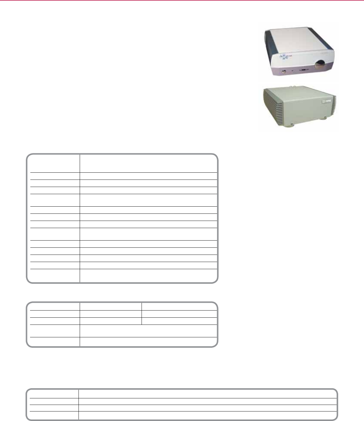
Technical Information
Supply Voltage 27Vdc (powered by Matrix Switcher via digital audio connection), and/or
24Vdc @ 3.75 A (via external switch mode power supply)
or 21Vac @ 3.5 A (via external linear power supply)
C-Bus™ Supply Voltage 15 to 36Vdc @ 22 mA
Power Consumption 90 W maximum
Network Clock and Burden Software selectable
Analog Input Signal Level 2.8V p-p maximum (47 kΩ)
(source inputs)
DA Conversion 16 Bit PCM
Maximum Power Output 28 W RMS into 4Ω (0.514% THD)
Frequency Response 40Hz to 20 kHz (+ 1 dB)
Total Harmonic Distortion 0.36% (using analog input)
(1 kHz, 20 W RMS into 4 ohms)
Signal to Noise Ratio > 67 dB (peak, unweighted)
Operating Desktop Amp: 50 - 104° F (10 to 40° C)
Temperature Remote Amp: 50 - 158° F (10 to 70° C)
Operating Humidity Range 0 - 95% RH, non-condensing
Standards UL60065 - Audio, Video, and Similar Electronic Apparatus -
Safety Requirements
System Audio Performance
Parameter Matrix Switcher + Amplier Distribution Unit + Amplier
Frequency 40Hz to 20 kHz 40Hz to 20 kHz
Response (+ 2.4/-0.75 dB) (+ 2.3 dB)
Total Harmonic Distortion 0.16% 0.20%
(1 kHz, 20 W RMS into 4 ohms)
Signal to Noise Ratio > 63 dB (peak, unweighted)
*For Diagram see technical section page 115
Catalog Number Description
SLC560125D Desktop Amplier
SLC560125R Remote Amplier
SLC5600P243750T Audio Amplier Power Supply
SLC560125MB Remote Amplier Mounting Bracket
C-BUSTM MULTI-ROOM + MULTI-ROOM AUDIO
The C-BusTM Multi-Room Ampliers provide efcient, high delity audio to individual rooms.
Available in either desktop or remote mount versions, these ampliers are specically
designed to operate on the C-Bus network as an extension of the lighting control system,
without third party gateways or custom integration. This means the ability to control
ampliers with the same keypad or touch screen used to control lighting levels.
When combined with the C-Bus Matrix Switcher (part SLC560884T), these ampliers
deliver excellent stereo sound at 10 Watts without a separate power supply. When
furnished with optional power supply these ampliers provide 25 Watts. Connections are
provided for up to two sets of 8 ohm speakers.
Both desktop and remote ampliers provide a local input connection for attaching to CD
or mp3 players, etc. In addition, the desktop amplier will accept remote commands via its
infrared receiver. Infrared remote included.
Product Features
• 10 Watt digital efcient stereo amplier, 25
Watts when connected to local power supply
(optional)
• Super quiet design
• On board 8 ohm loudspeaker connections
• Local source input - RCA jack
• C-Bus connection (connects with CAT-5
cable)
• Volume control (desktop model)
• On-board IR receiver (desktop model)
• Stereo headphone connection (desktop
model)
• Infrared remote included (desktop model
only)
Distributed Intelligence
• Compatible with C-Bus devices
Desktop Audio Amplier
Remote Mounted Audio Amplier
C-BusTM
Multi-Room Amplifiers
112
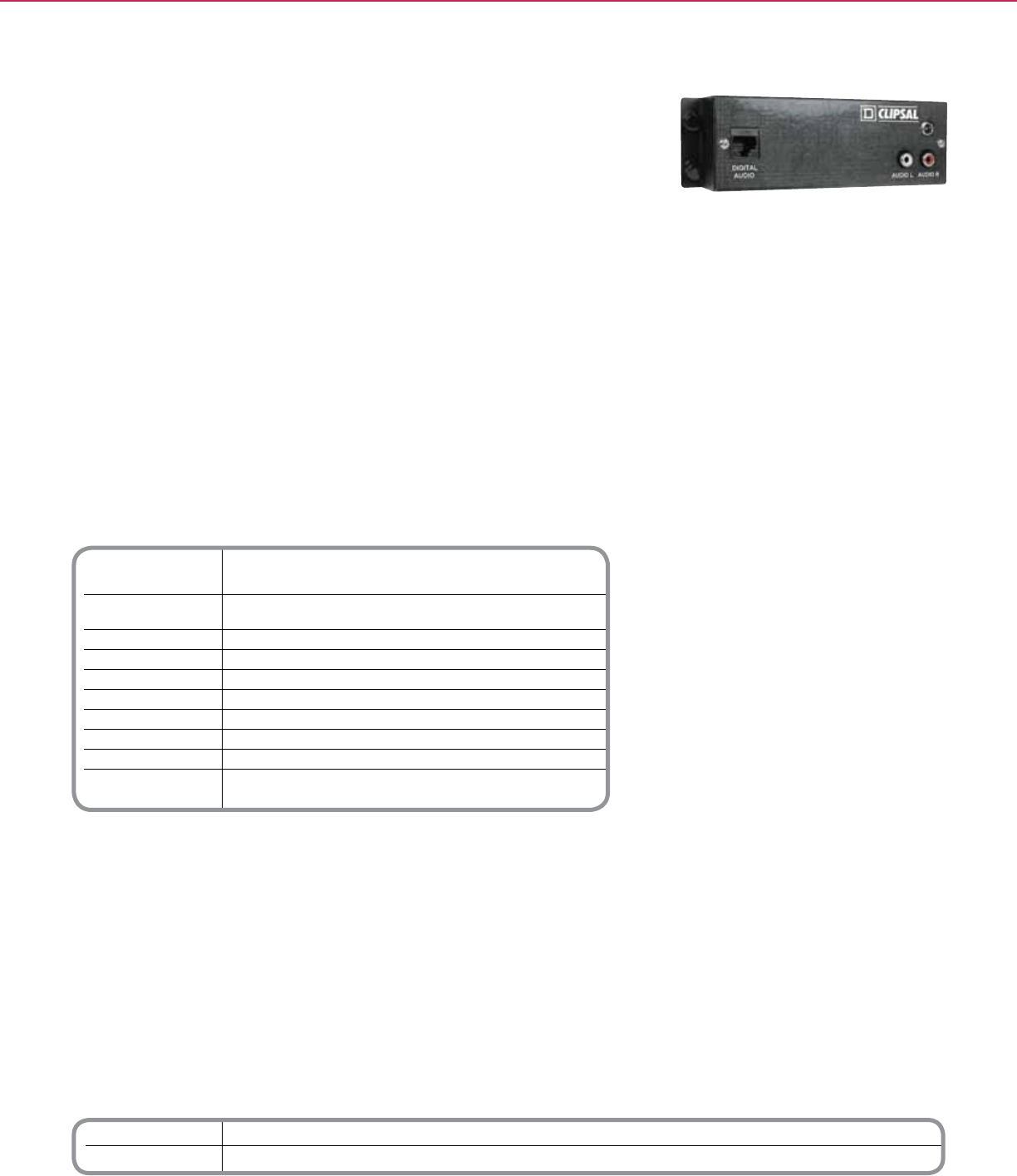
Technical Information
Supply Voltage 27Vdc (powered by Amplier via digital audio connection), or
24Vdc @ 500 mA (via external power pack)
Analog Input 2.8 V p-p maximum (31 k Ω)
Signal Level (audio inputs)
Harmonic Distortion ≤ 0.05%
Frequency Response 100 Hz to 20 kHz
Dimensions (WxHxD) 6.52 in. x 1.97 in. x 1.2 in. (165.5mm x 50mm x 30mm)
IR Port Yes
A/D Conversion 16 bit PCM
Operating Temperature 50-104OF (10-40OC)
Operating Humidity 90% RH (non-condensing)
Standard UL Listed 60065 Audio, Video and Similar
Electronic Apparatus - Safety Requirements
*For Diagram see technical section page 116
Catalog Number Description
SLC560011 Audio Distribution Unit
SLC5600P24500S Amp External Power Supply (only needed if Audio distribution unit is used to provide an additional digital input for the Matrix Switcher)
C-BUSTM MULTI-ROOM + MULTI-ROOM AUDIO
The C-BusTM Audio Distribution Unit is an optional device that can be used in
conjunction with the C-Bus Multi Room Audio System to further enhance C-Bus enabled
audio product family.
The C-Bus Audio Distribution Unit distributes a single digitized stereo audio input source
to multiple locations via ampliers wired in a parallel format. Functions such as Volume,
Bass, Treble and Balance can be adjusted from a C-Bus input device at any of the audio
output locations.
The C-Bus Audio Distribution Unit converts a single analog stereo audio input to a digital
audio output. That output can then be connected to the Matrix Switcher as an additional
input or to the C-Bus Desktop or Remote Amplier as a stand-alone conguration.
Product Features
• Distributes a single stereo audio source to
C-Bus Audio Ampliers via a digitized signal
over Cat-5 cable
• Does not require any C-Bus programming
(hardware only)
• One stereo analog audio source input (2
X RCA)
• One digital audio output
• Output can be looped between C-Bus
Audio Ampliers
• IR emitter port
Audio Distribution Unit
C-BusTM
Audio Distribution Unit
113
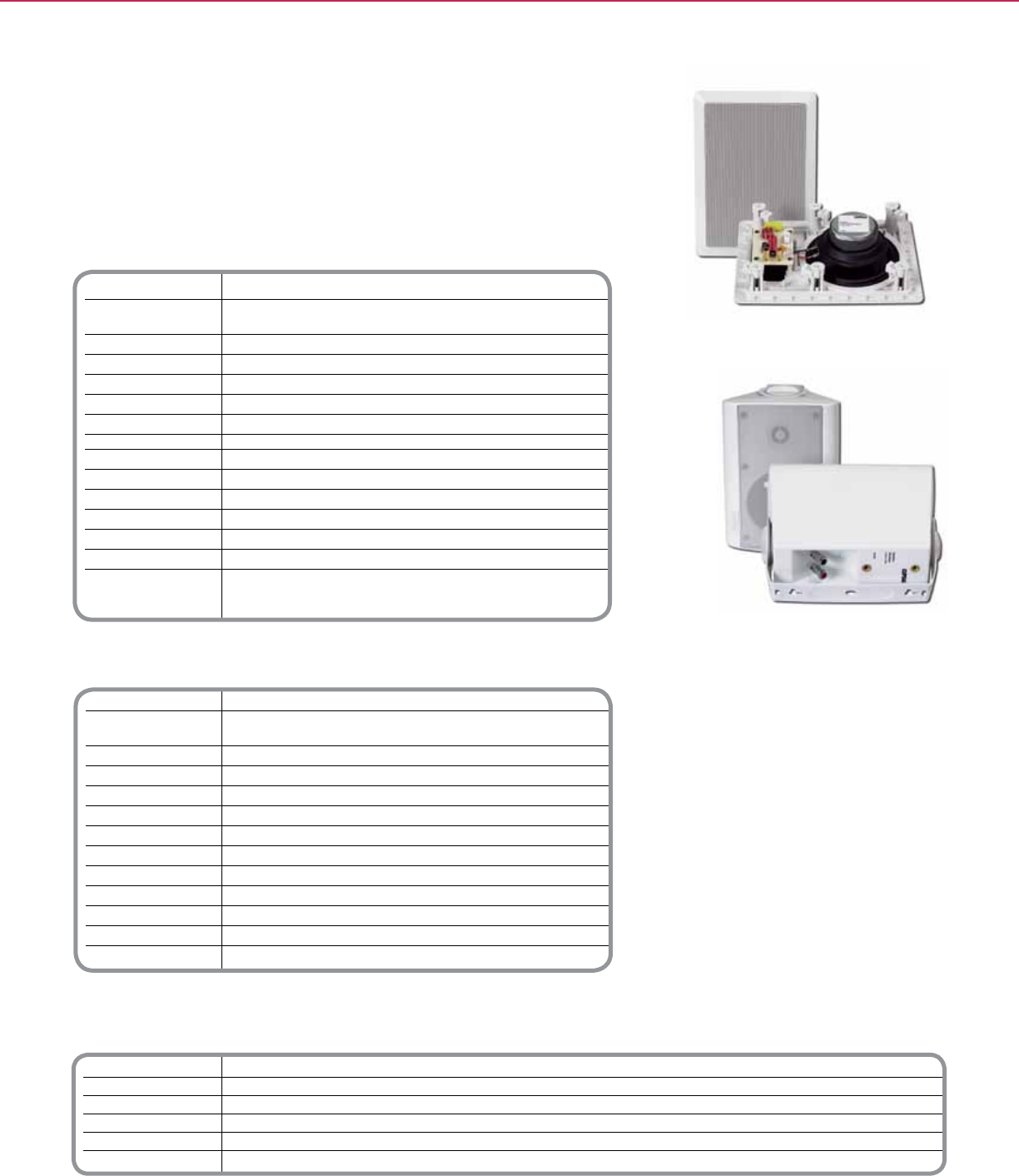
Catalog Number Description
SLC5600IWP In-Wall Polypropylene speakers
SLC5600IWK In-Wall Kevlar speakers
SLC5600ICP In-Ceiling Polypropylene speakers
SLC5600ICK In-Ceiling Kevlar speakers
SLC5600ODPBK Outdoor Black Polypropylene speakers
SLC5600ODPWE Outdoor White Polypropylene speakers
Indoor Audio Speakers
Installation Ceiling Mount or Wall Mount
Speaker Dimensions Ceiling Mount - 9.45 in. (Dia) x 3.125 in. (D) (240 mm x 79.38 mm)
Wall Mount -12.125 in. (H) x 8.7 in. (W) x 3.125 in. (D) (308 mm x 221 mm x 79 mm)
Speaker Diameter Ceiling Mount - 6.0 in. (152 mm) Wall Mount - 6.0 in. (152 mm)
Weight Ceiling Mount - 3.31 lb. Wall Mount - (1.5 kg) 3.31 lb. (1.5 kg)
Material Kevlar®**, Polypropylene*
Operating Environment
Temperature Ceiling Mount: -13°F - 158°F (-25°C - 70°C)
Wall Mount: -13°F - 158°F (-25°C - 70°C)
Relative Humidity 20 - 90% noncondensing
Audio Performance
Frequency Response Ceiling Mount - 48 Hz-20 kHz, 58 Hz-20 kHz
Wall Mount- 65 Hz-20 kHz, 58 Hz-20 kHz
Power Rating 60 W RMS
Impedance 8 Ohm
Sensitivity 48 Hz-20 kHz, 58 Hz-20 kHz: 90 dB
65 Hz-20 kHz: 91 dB
58 Hz-20 kHz: 88 dB
**Kevlar drivers have a fourth order 24/24 dB crossover for both tweeter and woofer
*Polypropylene drivers have a second order 12/12 dB crossover for both tweeter and woofer
Outdoor Audio Speakers
Installation Indoor, outdoor, shelf
Overall Dimensions 9.8 in. (H) x 6.75 in. (W/front) x 2.75 in. (W/rear) x 6 in. (D)
[248.9 mm (H) x 171.5 mm (W/f) x 69.9 mm (W/r) x 152.4 mm (D)]
Speaker Diameter 4.0 in. (102 mm)
Weight 4.41 lb. (2 kg)
Material Polypropylene*
Operating Environment
Temperature -13°F - 158°F (-25°C - 70°C)
Relative Humidity 20 - 90% noncondensing
Audio Performance
Frequency Response 70 Hz to 20 kHz
Nominal Power Rating 35 W RMS
Impedance 8 Ohm
Sensitivity 88 dB
*Polypropylene drivers have a second order 12/12 dB crossover for both tweeter and woofer
*For Diagram see technical section page 116
C-BUSTM MULTI-ROOM + MULTI-ROOM AUDIO
Product Features
• Flush-mount, shelf-mount, and surface-
mount models
• Indoor and outdoor models
• High-impact plastic components and
powder coated metal grills produce a long-
lasting unit suitable for indoor and outdoor
use
• Available with Kevlar® (indoor units only)
or polypropylene drivers (indoor and
outdoor units) for high-quality sound in all
applications
• All models are off the oor, saving oor
space
• Convenient and reliable sound coverage,
almost completely independent of furniture
or entertainment equipment layout
• Indoor/Outdoor Speakers have a pre-
installed, removable mounting bracket
• Indoor/Outdoor Speakers can be placed
on a shelf or hung from a surface by their
bracket (included)
• Tracing/painting template included
The C-BusTM Audio Speakers are available as indoor or outdoor models and are designed
to be used with home theater, multi-room, and outdoor audio applications that will accept 8
Ohm speakers, such as the Schneider Electric C-Bus Multi-Room Audio (MRA) system.
The indoor speakers come in wall- or ceiling-mount versions that are installed with the front
of the speaker ush with the mounting surface. The indoor/outdoor speakers can be placed
on a shelf or hung on a surface by using the included bracket.
Indoor Speakers
Outdoor Speakers
C-BusTM
Audio Speakers
114
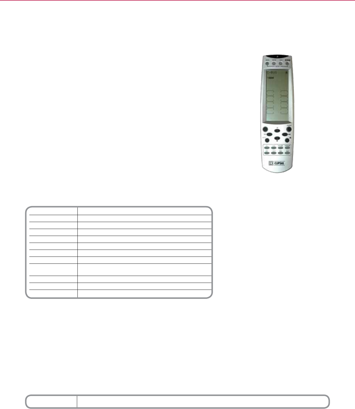
Technical Information
LCD Screen 1.6 in. (W) x 3.6 in. (H)
Backlighting Brilliant blue LED
Learning Frequency 20 kHz to 455 kHz & pulse
Memory 512 kB ash memory
Batteries Uses 4 (AAA) alkaline batteries (not included)
Touch Screen Soft Keys 42 keys
Rubber Hard Buttons 20 buttons
Power LCD Off: 35 µA
Consumption LCD On: 420 µA
Operation: 30-150 mA (Max)
Operating Distance Approx. 32 feet
Dimensions 2.4 in. (W) x 8.3 in. (H) x 1.0 in. (D) [61 mm (W) x 210 mm (H) x 25 mm (D)]
Weight (w/o batteries) 5.3 oz (150 g)
*For Diagram see technical section page 122
Catalog Number Description
SLC5030URC Universal Remote Control
C-BUSTM MULTI-ROOM + MULTI-ROOM AUDIO
Product Features
• Large touch screen display with LED backlight
• Macro function (up to 60 commands per macro)
• Learns infrared codes from original equipment
remote controls
• User programmable buttons for each device
• Pre-programmed manufacturer’s codes
• Multiple timers (day of week, date and “alarm”)
to automate functions (i.e., record movies, turn on
music)
• Quick channel buttons
• Favorite channels grouping
• Built in motion detector
• System set-up transmission
• Sleep mode
Distributed Intelligence
• Compatible with C-Bus Devices
The C-BusTM Universal Remote is a digital universal remote control that is easy to use,
allowing control of electronic devices that are equipped with an infrared remote.
The Schneider Electric C-Bus Universal Remote can control up to 16 devices, including
C-Bus devices, DVDs, TVs, VCRs and satellite receivers.
The remote is easily congured by using either automatic code detection or the learn
option. In addition, the advanced macro function allows the recording of a chain of up to 60
commands with the single touch of a button.
Universal Remote Control
C-BusTM
Universal Remote
115
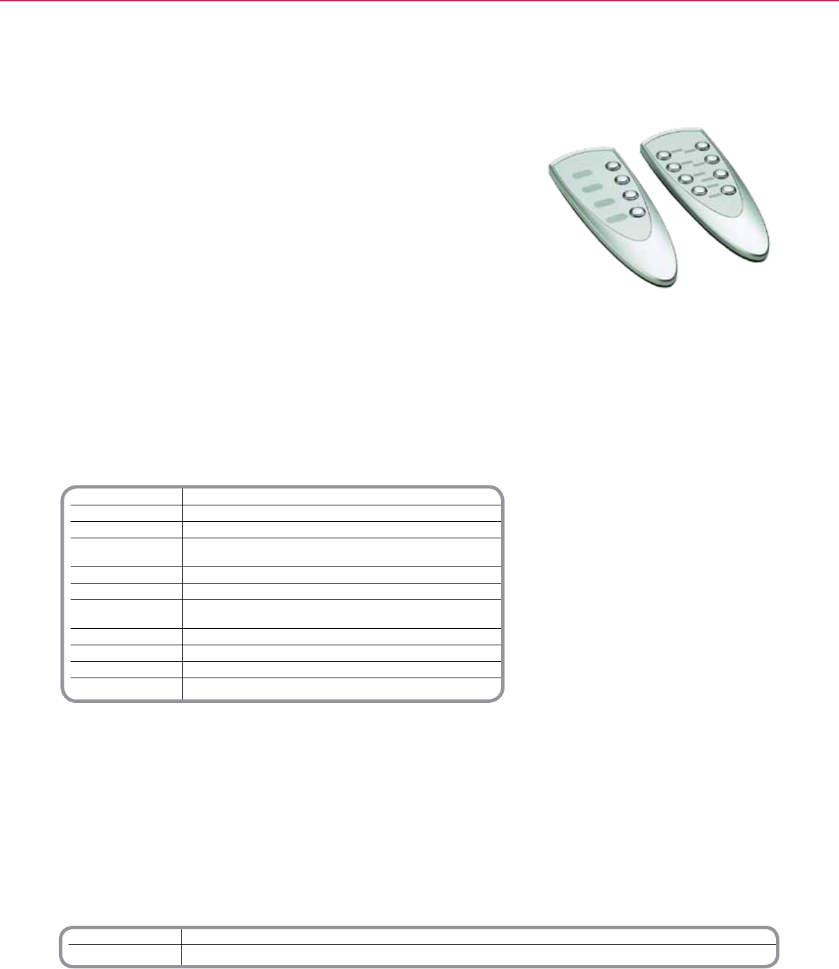
Catalog Number Description
SLC5084TX Four Button IR Remote Controller
SLC5088TX Eight Button IR Remote Controller
Technical Information
Supply Voltage 3 V DC required for normal operation
Battery Type (2) x AAA alkaline Speaker Diameter
IR Transmission Range Up to 49 ft. (15 m)
Dimensions 5.9 in. (L) x 2.1 in. (W) x 1.0 in. (D)
[149 mm (L) x 52 mm (W) x 25 mm (D)]
Weight (w/o batteries) 2 oz (61 g)
Remote Control Holder
Dimensions 4.3 in. (L) x 2.2 in. (W) x 1.3 in. (D)
[108 mm (L) x 55 mm (W) x 32 mm (D)
Mounting Centers 2.2 - 2.4 in. (55 - 60 mm)
Mounting Screw Size #6 (7/8 in.) athead wood screw (3.5 mm x 20 mm)
Wall Anchor Size 1/4 in. (7 mm x 25 mm)
Weight 1 oz (28 g)
*For Diagram see technical section page 122
4 and 8 Button Remote Controls
C-BUSTM MULTI-ROOM + MULTI-ROOM AUDIO
Product Features
• Four and Eight button options
• Wall mount storage holder included with
each remote control
• Removeable front cover for label insertion
(labels included)
• (2) AAA batteries included
Distributed Intelligence
• Compatible with C-Bus IR Input devices
The C-BusTM Four- and Eight- Button Infrared (IR) Remote Controllers provide hand held
remote control operation of lighting and other loads. Designed to work in conjunction with
C-Bus devices containing IR receivers, these convenient remote controls can switch, dim
and control lighting scenes.
C-Bus Four- and Eight- Button Remote Controllers control multiple input units as well as
separately congured units.
These versatile remote controls have a range of up to 49 feet (15 meters) and are easily
congured by programming the IR receiving device in the C-Bus Toolkit software.
C-BusTM
Four & Eight Button Remote Controllers
116
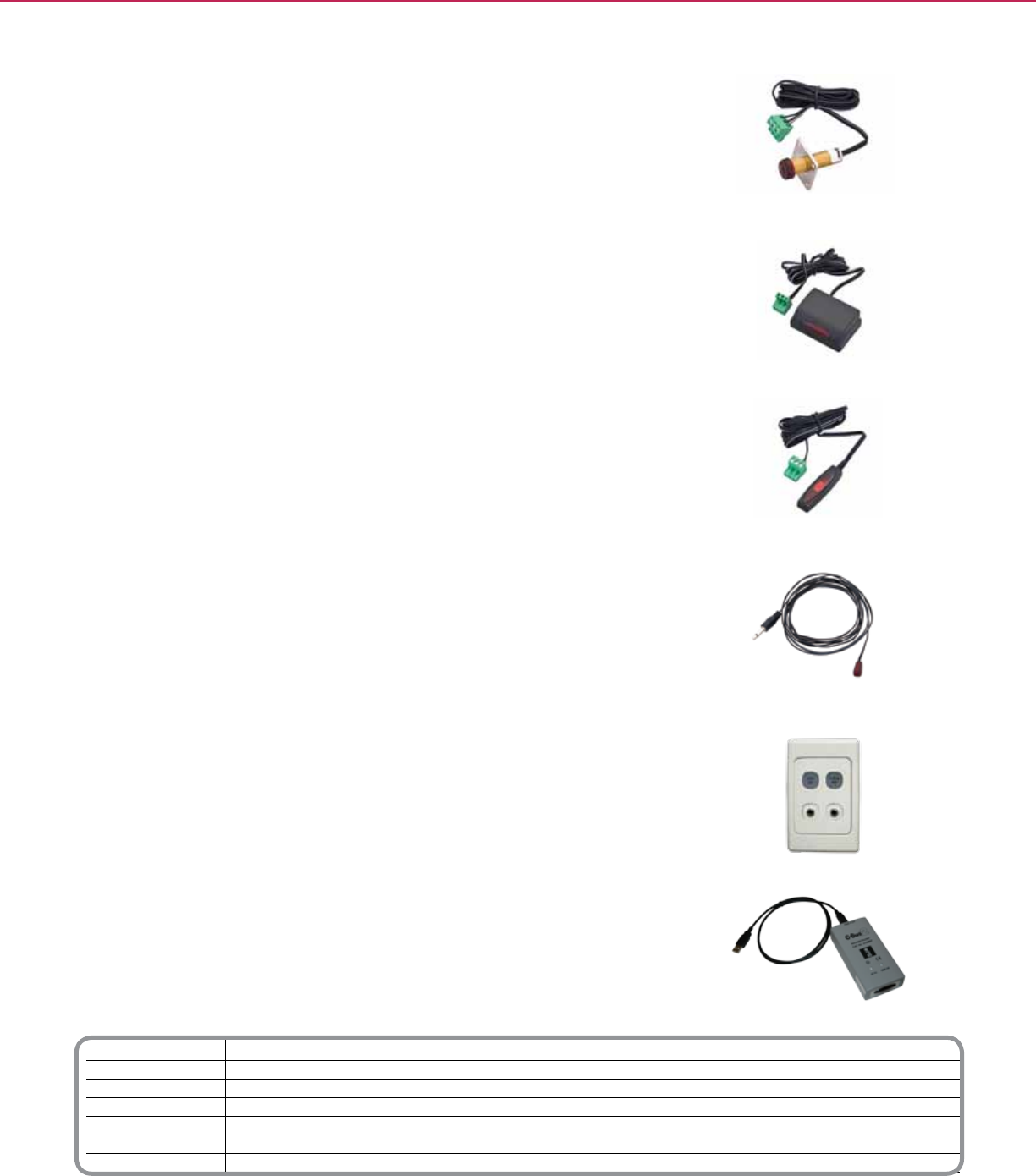
Catalog Number Description
SLC8050TT IR Tube Target
SLC8050ST IR Shelf Mount Target
SLC8050FT IR Flat Target
SLC8050LD IR Emitter Leads- Single
SLC80502LD IR Emitter Leads- Dual
SLC5034NIRT NIRT
SLC5100RP IR Reader
C-BUSTM MULTI-ROOM + MULTI-ROOM AUDIO
IR TUBE TARGET
Infra-red IR target designed to receive IR commands from Infra-red remote controls.
Simple in-ceiling mounting. Includes phoenix connector and 2 meters of wire. Comes
with optional clear lens.
IR Shelf Mount Target
Infra-red IR target designed to receive IR commands from Infra-red remote controls.
Simply set unit on shelf for easy IR command access. Includes phoenix connector and 2
meters of wire.
IR Flat Target
Infra-red IR target designed to receive IR commands from Infra-red remote controls.
Designed to mount in diffusers and small areas to mask appearance. Includes phoenix
connector and 2 meters of wire.
IR Emitter Leads
IR Leads plug into the C-Bus Multi room audio matrix switcher or C-Bus Nirts, and emit
IR codes to the third party devices. Single and dual emitter leads available. Includes
transparent adhesive sticker for application.
NIRT
The C-Bus NIRT is a wall mounted IR transmitter, that is designed to work with the
C-Bus control system. The NIRT transmits up to 2 channels of IR commands to control
third party components, ie: DVD players, TV’s, etc.
IR Reader
The C-Bus IR Reader is a programming tool that is used to learn 3rd party remote control
IR commands. Using Circa software (free download) plug IR Reader into a PC via USB
port and send remote control signal capture IR Code.
IR Accessories
117
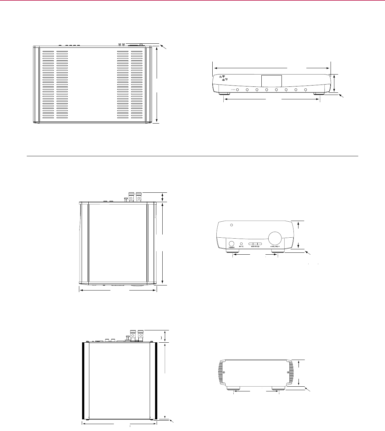
0.33 in.
8.3 mm
11 in.
280 mm
16.7 in.
424 mm
13.6 in.
346 mm
2.6 in.
66 mm
0.3 in.
8 mm
Front View
2.6 in.
66 mm
.31 in.
8 mm
4.1 in.
105 mm
Top View
Desktop Model
Audio
Amplier
11 in.
280 mm
7.6 in.
194 mm
7.09 in.
180 mm
Front View
2.44 in.
62 mm
4.13 in.
105 mm 0.31 in.
8 mm
Top View
Remote Model
Audio
Amplier
1.1 in.
28 mm
1.1 in.
28 mm
.11 in.
2.9 mm
6.89 in.
175 mm
C-BUS® MULTI-ROOM + TECHNICAL SECTION
Bottom ViewTop View
Matrix Switcher
Multi-Room Amplifiers
118
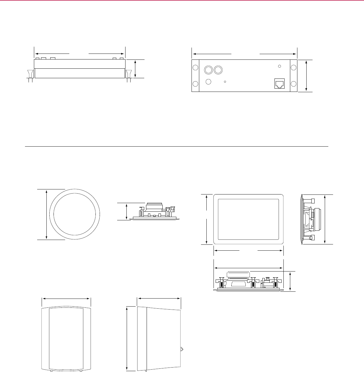
8.7 in.
221 mm
Wall Mount Speaker Dimensions
8.7 in.
221 mm
12.125 in.
308 mm
12.125 in.
308 mm
3.125 in.
79 mm
Outdoor Speaker Dimensions
6.75 in.
171 mm
6.0 in.
152 mm
9.8 in.
248 mm
Ceiling Mount Speaker Dimensions
9.45 in.
240 mm
3.125 in.
79.38 mm
Top View
6.52 in.
(165.5 mm)
5.61 in.
(142.5 mm)
1.97 in.
(50 mm)
1.20 in.
(30.5 mm)
5.61 in.
142.5 mm
1.20 in.
30.5 mm
Bottom
6.52 in.
(165.5 mm)
5.61 in.
(142.5 mm)
1.97 in.
(50 mm)
1.20 in.
(30.5 mm)
6.52 in.
165.5 mm
1.97 in.
50 mm
C-BUS® MULTI-ROOM + TECHNICAL SECTION
Audio Distribution Unit
Audio Speakers
119
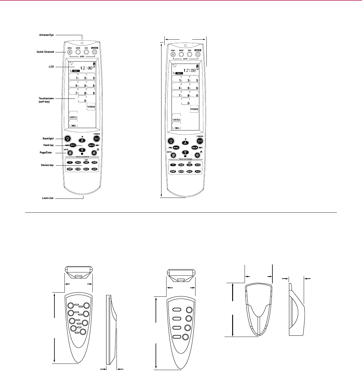
2.4 in.
61 mm
8.3 in.
210 mm
2.1 in
52 mm
5.9 in
149 mm
1 in
25 mm
2.2 in
55 mm
4.3 in
108 mm
1.3 in
32 mm
2.1 in
52 mm
5.9 in
149 mm
2.1 in
52 mm
5.9 in
149 mm
1 in
25 mm
2.2 in
55 mm
4.3 in
108 mm
1.3 in
32 mm
2.1 in
52 mm
5.9 in
149 mm
C-Bus 4 and 8 Button Remote Control Holder
2.1 in
52 mm
5.9 in
149 mm
1 in
25 mm
2.2 in
55 mm
4.3 in
108 mm
1.3 in
32 mm
2.1 in
52 mm
5.9 in
149 mm
C-Bus 8 Button Remote Control C-Bus 4 Button Remote Control
5.9 in.
149 mm
2.1 in.
52 mm
5.9 in.
149 mm
2.1 in.
52 mm
1 in.
25 mm
4.3 in.
108 mm
1.3 in.
32 mm
2.2 in.
55 mm
C-BUS® MULTI-ROOM + TECHNICAL SECTION
C-BusTM Universal Remote
C-BusTM
Four & Eight Button Remote Controllers
120

C-BusTM HVAC
Controls
121

C-BusTM thermostats are used to regulate the
air temperature of zones by controlling heating-
ventilation-air conditioning (HVAC) equipment.
With C-Bus thermostats, you have the
exibility of any keypad becoming a comfort
control point. C-Bus thermostats may operate
as stand alone devices, or be controlled via
other C-Bus devices such as wall switches or
touch screens.
Programmable four-zone Thermostats can
schedule up to four set points during a day,
and unique schedules can be programmed
for each day of the week. Both models include
setback mode (saves power by using a
wider acceptable temperature range within
which heating or cooling is not performed)
and temperature guard (ensures the
temperature is maintained within a specied
temperature range).
Introduction to
C-BusTM HVAC Controls
122
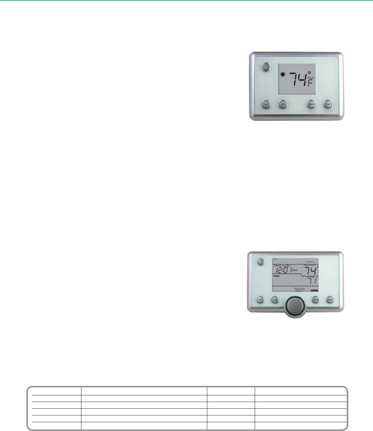
Catalog Number Description Catalog Number Description
SLC5070THBWE Single Zone Thermostat White (no on-board relays) SLC5070THPWE 4 Zone Thermostat White (no on-board relays)
SLC5070THBBK Single Zone Thermostat Black (no on-board relays) SLC5070THPBK 4 Zone Thermostat Black (no on-board relays)
SLC5070THBSS Single Zone Thermostat Stainless (no on-board relays) SLC5070THPSS 4 Zone Thermostat Stainless (no on-board relays)
SLC5070THBRWE Single Zone Thermostat White (w/relay) SLC5070PRWE 4 Zone Thermostat White (w/relay)
SLC5070THBRBK Single Zone Thermostat Black (w/relay) SLC5070PRBK 4 Zone Thermostat Black (w/relay)
SLC5070THBRSS Single Zone Thermostat Stainless (w/relay) SLC5070PRSS 4 Zone Thermostat Stainless (w/relay)
C-BUSTM CONTROL + HVAC
The C-Bus™ wall mounted, Single Zone Thermostats include support for control of
HVAC units via C-Bus or the internal HVAC relays. They also allow the user to manually
set the temperature and mode of operation (heating, cooling or ventilation). The easy to
use operator interface includes fan speed control, set back or economy mode and an
integral LCD to display the current temperature and mode of operation.
• Temperature adjustment from the unit
• A dedicated HVAC controller (via the on-board relays)
• A C-Bus Relay unit
• Mode button, i.e., heating, cooling, ventilation
• Manual fan speed control
• Incorporates ‘setback’ mode
• Programmable via C-Bus Toolkit software
• Broadcasts the displayed temperature on C-Bus
• Can fully integrate with the C-Bus Network
The C-BusTM Programmable 4 Zone Thermostats include on board 7-day HVAC time
scheduling (user programmable) manual fan speed control, set back mode and an easy
to use interface, comprising of an LCD, manual control buttons and a rotating dial with
an integral press switch. From the unit, the user can manually adjust the temperature set
point, the mode of operation (heating, cooling, ventilation) and time schedules.
• Full 7 day programmable schedule, 4 events per day
• Accepts up to four remote temperature sensor inputs (via C-Bus)
• Four zones plus common (un-switched) zone
• Set and control via other C-Bus devices
• Supports setback temperatures
• Powered from C-Bus
• Backlit LCD and buttons
• Integral temperature sensor
• Manual fan speed control
• Zone button sets the active zones in the system
• Can fully integrate with the C-Bus Network
Basic Thermostat
Programmable Thermostat (4 zone)
C-BusTM
Basic Single Zone Thermostats
C-BusTM
Programmable 4 Zone Thermostats
123
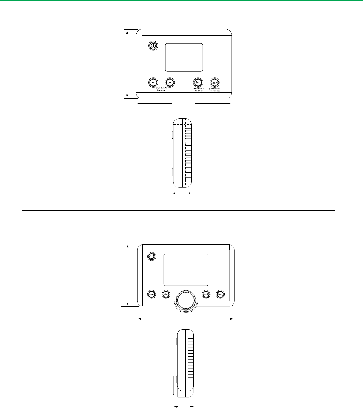
5.9 in.
150 mm
1.26 in.
32 mm
4.13 in.
105 mm
5.0 in.
127 mm
1.06 in.
27 mm
3.62 in.
92 mm
C-BUSTM CONTROL + TECHNICAL SECTION
C-BusTM Basic Single Zone Thermostats
C-BusTM Programmable 4 Zone Thermostats
124
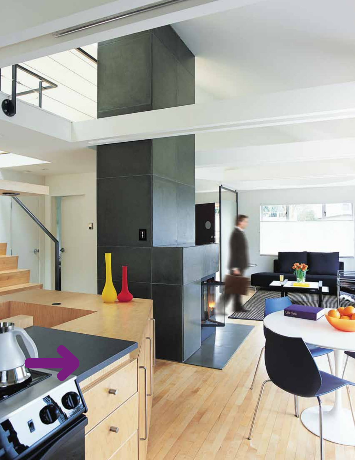
C-BusTM RF Wireless
Controls
125

Break loose from the cumbersome wiring
and associated cost of home control systems
with C-Bus™ RF wireless communication.
Designed to easily replace standard wall
switches, C-Bus RF offers seamless dimming
and scene control technology with the elegant
aesthetic of Neo™ and Saturn™ decorator-
style keypads.
Intelligent. Innovative. C-Bus RF features an
all-in-one solution that other wireless control
systems simply don’t have… complete
functionality in every device, eliminating the
need for stand-alone repeaters and central
controllers.
C-Bus RF Wireless Wall Units include
Switches, leading–edge Dimmers and Scene
Controllers. The units are designed to replace
standard wall switches and dimmers. By
eliminating the need for additional wiring runs,
C-Bus RF offers the perfect solution for retrot
applications.
Introduction to
C-BusTM RF
Wireless Controls
126
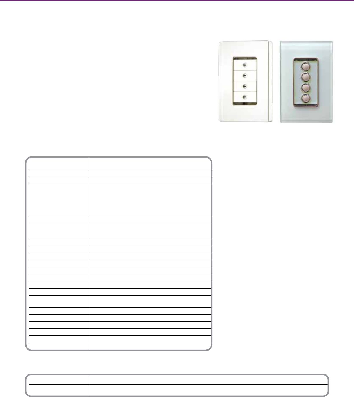
Technical Information
Supply Voltage 120V AC @ 60 Hz
RF Frequency 916 Mhz
Transmitting Power 5 mW
Typical Range 80 to 100 ft. (24.4 to 30.5m) in buildings with
(range depends on building timber frame / brick veneer construction
construction and proximity to 65 to 80 ft. (19.8 to 24.4m) in buildings with
dense or metallic objects) brick, stone, or steel frame construction
50 to 65 ft. (15.2 to 19.8m) in buildings with steel
reinforced concrete construction
Maximum Range 200 ft. (61m) in open air
Status Indicator Color Buttons and reset - blue
Learn – red (unit not set up as a repeater)
blue (unit set up as a repeater)
Warm-Up Time 5 Seconds
Operating Temperature Range 32 to 104O F (0 to 40O C)
Operating Humidity Range 10 to 95% RH
Off-State Power Consumption 5 W
Off-State Leakage Current 300 mA
Control Functions Load switching, dimming, timer, scenes
Min. Load Per Channel 25 W
Max. Load Per Channel 600 W
Compatible Loads / Rating Incandescent, Tungsten, Iron Core Trans. Low
Voltage Lighting / 5A
Dimensions ( H x W x D ) 2.8 in. x 1.7 in. x 1.8 in. (71mm x 44mm x 45mm)
Dimensions w/Heatsink 4.2 in. x 2.5 in. (107.5mm x 63mm)
Weight 3.7 oz. (105g)
Fixing Centers 3.3 in. (84mm)
Standards UL Listed - 244A Solid State Controls For Appliances
Appliances FCC Part 15 - Class B Digital Device for Home or Ofce Use
** For additional ordering information see technical section page 135
Catalog Number Description
SLC585(x)D4LUM(xx)* Neo Decorator Style RF 600 W Dimmer
SLC588(x)D4LUM(xx)* Saturn Decorator Style RF 600 W Dimmer
* Note: Wallplate Sold Separately. Refer to individual product manual for order information.
C-BUSTM WIRELESS CONTROLS + WIRELESS CONTROLS
C-BusTM RF Wireless dimmers operate all common lighting loads and work in
conjunction with other C-Bus wired and wireless controls to provide full dimming control.
These decorator style, leading edge dimmers are available in both the NeoTM and
SaturnTM styles with either 2 or 4 button conguration.
Product Features
2 and 4 button options
• Mounts in standard wall box
• Neo or Saturn Decorator Styling
• Multi-function buttons - congurable to
control any load on the C-Bus network
• Last level button recall (pre-set)
• Compatible with a wired C-Bus system
using wireless gateway (not included)
• Compatible with C-Bus wireless remote (not
included)
• No neutral required
Keypad ordering:
Neo Style
• Order numbers for the Neo RF decorator
style keypads indicate the number of
buttons desired on the keypad and the
color of the keypad itself.
• 2 and 4 buttons available, color codes are:
Slate (GB), White (WE), Cream (CM), Soft
gray (SG), Desert sand (DS), Black (BK),
and Brown (BR). For example, SLC585(4)
D8LUM(DS) represents an order for a Neo
RF keypad with four buttons in Desert
Sand.
Keypad ordering:
Saturn Style
• Order numbers for the Saturn RF decorator
style keypad indicate the number of buttons
desired on the keypad and the color of the
keypad itself.
• 2 and 4 buttons available, color codes are:
White (WE), Cream (CM), Black (BK),
and Mocha (BR).
• For example, SLC588(4)D8LUM(BK)
represents an order for a Saturn RF
decorator keypad with four buttons in black.
Neo and Saturn Decorator Style Keypads
C-BusTM RF Wireless Controls
600W RF Dimmers
127
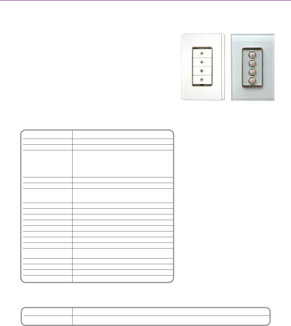
Technical Information
Supply Voltage 120V AC @ 60 Hz
RF Frequency 916 Mhz
Transmitting Power 5 mW
Typical Range 80 to 100 ft. (24.4 to 30.5m) in buildings with
(range depends on building timber frame / brick veneer construction
construction and proximity to 65 to 80 ft. (19.8 to 24.4m) in buildings with
dense or metallic objects) brick, stone, or steel frame construction
50 to 65 ft. (15.2 to 19.8m) in buildings with steel
reinforced concrete construction
Maximum Range 200 ft. (61m) in open air
Maximum Units on a Network 100 Units
Status Indicator Color Buttons and reset - blue
Learn – red (unit not set up as a repeater)
blue (unit set up as a repeater)
Warm-Up Time 5 Seconds
Operating Temperature Range 32 to 104O F (0 to 40O C)
Operating Humidity Range 10 to 95% RH
Off-State Power Consumption .5 W
Off-State Leakage Current 300 mA
Control Functions Load switching, dimming, timer, scenes
Min. Load Per Channel 25 W
Max. Load Per Channel 1000 W
Compatible Loads / Rating Incandescent, Tungsten, Iron Core Trans. Low
Voltage Lighting / 8A
Dimensions ( H x W x D ) 2.8 in. x 1.7 in. x 1.8 in. (71mm x 44mm x 45mm)
Dimensions w/Heatsink 4.2 in. x 2.5 in. (107.5mm x 63mm)
Weight 3.7 oz. (105g)
Fixing Centers 3.3 in. (84mm)
** For additional ordering information see technical section page 135
Catalog Number Description
SLC585(x)D8LUM(xx)* Neo Decorator Style RF 1000 W Dimmer
SLC588(x)D8LUM(xx)* Saturn Decorator Style RF 1000 W Dimmer
* Note: Wallplate Sold Separately. Refer to individual product manual for order information.
C-BUSTM WIRELESS CONTROLS + WIRELESS CONTROLS
C-BusTM RF Wireless dimmers operate all common lighting loads and work in
conjunction with other C-Bus wired and wireless controls to provide full dimming control.
These decorator style, leading edge dimmers are available in both the NeoTM and
SaturnTM styles with either 2 or 4 button conguration.
Product Features
2 and 4 button options
• Mounts in standard wall box
• Neo or Saturn Decorator Styling
• Multi-function buttons - congurable to
control any load on the C-Bus network
• Last level button recall (pre-set)
• Compatible with a wired C-Bus system
using wireless gateway (not included)
• Compatible with C-Bus wireless remote (not
included)
• No neutral required
Keypad ordering:
Neo Style
• Order numbers for the Neo RF decorator
style keypads indicate the number of
buttons desired on the keypad and the color
of the keypad itself.
• 2 and 4 buttons available, color codes are:
Slate (GB), White (WE), Cream (CM), Soft
gray (SG), Desert sand (DS), Black (BK), and
Brown (BR). For example, SLC585(4)
D8LUM(DS) represents an order for a Neo
RF keypad with four buttons in Desert Sand.
Keypad ordering:
Saturn Style
• Order numbers for the Saturn RF decorator
style keypad indicate the number of buttons
desired on the keypad and the color of the
keypad itself.
• 2 and 4 buttons available, color codes are:
White (WE), Cream (CM), Black (BK), and
Mocha (BR).
• For example, SLC588(4)D8LUM(BK)
represents an order for a Saturn RF
decorator keypad with four buttons in black.
Neo and Saturn Decorator Style Keypads
C-BusTM RF Wireless Controls
1000W RF Dimmers
128
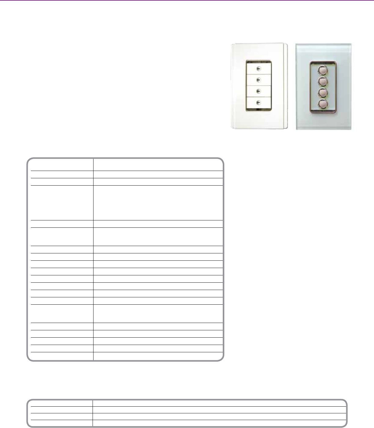
Technical Information
Supply Voltage 120V AC @ 60 Hz
RF Frequency 916 Mhz
Transmitting Power 5 mW
Typical Range 80 to 100 ft. (24.4 to 30.5m) in buildings with
(range depends on building timber frame / brick veneer construction
construction and proximity to 65 to 80 ft. (19.8 to 24.4m) in buildings with
dense or metallic objects) brick, stone, or steel frame construction
50 to 65 ft. (15.2 to 19.8m) in buildings with steel
reinforced concrete construction
Maximum Range 200 ft. (61m) in open air
Status Indicator Color Buttons and reset - blue
Learn – red (unit not set up as a repeater)
blue (unit set up as a repeater)
Warm-Up Time 5 Seconds
Operating Temperature Range 32 to 104O F (0 to 40O C)
Operating Humidity Range 10 to 95% RH
Off-State Power Consumption .5 W
Off-State Leakage Current 300 mA
Control Functions Load switching, timer, scenes
Min. Load Per Channel 25 W
Max. Load Per Channel 8A
Compatible Loads / Rating (switch) Incandescent, Tungsten, Fluorescent Ballast,
Magnetic/Electronic Low Voltage Lighting, HID
(High intensity discharge) / 8A
FLA. Motor 12 LRA / 2A
Dimensions ( H x W x D ) 2.8 in. x 1.7 in. x 1.8 in. (71mm x 44mm x 45mm)
Dimensions w/Heatsink 4.2 in. x 2.5 in. (107.5mm x 63mm)
Weight 3.7 oz. (105g)
Fixing Centers 3.3 in. (84mm)
** For additional ordering information see technical section page 135
Catalog Number Description
SLC585(x)R8FUM(xx)* Neo Decorator Style RF Switch
SLC588(x)R8FUM(xx)* Saturn Decorator Style RF Switch
SLC5854NL(xx)* Neo Decorator Style RF Scene Controller (4 button only)
SLC5884NL(xx)* Saturn Decorator Style RF Scene Controller (4 button only)
* Note: Wallplate Sold Separately. Refer to individual product manual for order information.
Neo and Saturn Decorator Style Keypads
C-BUSTM WIRELESS CONTROLS + WIRELESS CONTROLS
The C-Bus NeoTM and SaturnTM RF Switches and Scene Controllers are part of the
C-Bus wireless wall unit family. The switches are a two-wire retrot range using the
switching leg (line and load). Switches are available in 2 and 4 button models, and
come in a decorator style. Scene Controllers can be used for 3-way switching, 4-way
switching, or scene control. They use a line and neutral connection. Scene Controllers
are available in 4 button models.
Product Features
• Neo and Saturn Decorator Style Keypads
• Use in 3 and 4 way applications (Scene
Controller)
• Control Scenes and Loads
Switch - controls scenes & loads
Scene controller - multi location switching &
scene control
• Color options
Neo: Slate, White, Cream, Brown, Soft Grey,
Black and Desert Sand
Saturn: White, Cream, Mocha and Black
• Compatible with a wired C-Bus system
using wireless gateway (not included)
• Easy retrot option
• No neutral required
Keypad ordering:
Neo Style
• Order numbers for the Neo RF decorator
style keypads indicate the number of
buttons desired on the keypad and the
color of the keypad itself.
• 2 or 4 buttons available, color codes are:
Slate (GB), White (WE), Cream (CM), Soft
gray (SG), Desert sand (DS), Black (BK), and
Brown (BR).
• For example represents an order for a Neo
RF keypad with four buttons in Desert.
Keypad ordering:
Saturn Style
• Order numbers for the Saturn RF decorator
style keypad indicate the number of buttons
desired on the keypad and the color of the
keypad itself.
• 2 and 4 buttons available, color codes are:
White (WE), Cream (CM), Black (BK), and
Mocha (BR).
• For example, SLC585(4)R8FUM(DS)
represents an order for a Saturn RF
decorator keypad with four buttons in black.
C-BusTM RF Wireless Controls
RF Switch and Scene Controllers
129
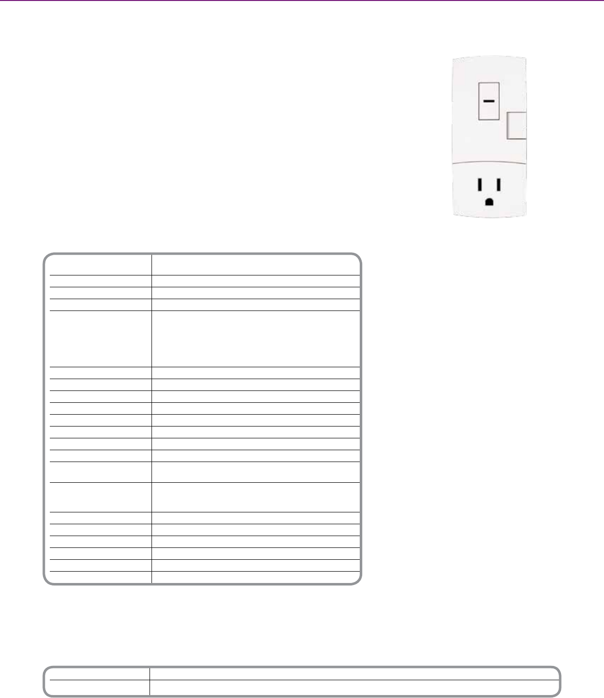
Catalog Number Description
SLC5812R8F1UD Plug Adaptor, 1 Channel Relay 8A
SLC5812D5L1UD Plug Adaptor, 1 Channel Leading Edge 600W
Technical Information
Supply Voltage 120V AC @ 60 Hz
Supply voltage 120V AC @ 60Hz
RF frequency 916Mhz
Transmitting power 5mW
Typical range 80 to 100 ft. (24.4 to 30.5m) in buildings with
(Range depends on building timber frame / brick veneer construction
construction and the proximity to 65 to 80 ft. (19.8 to 24.4m) in buildings with
dense or metallic objects) brick, stone, or steel frame construction
50 to 65 ft. (15.2 to 19.8m) in buildings with steel reinforced
concrete construction
Maximum range 200 ft. (61m) in open air
Control functions Load switching, timer, LE dimming (dimmer)
Status Indicator color Blue
Warm-up time 5 seconds
Operating temperature range 0 to 40 °C
Operating humidity range 10 to 95% RH
Min. load per channel 25 W
Max load per channel 600W (dimmer) 8A (Switch)
Compatible loads/rating: Dimmer Incandescent/Tungsten Iron core trans.
LV lighting - 5A
Compatible loads/rating: Switch Incandescent / Tungsten / Fluorescent Ballast / Magnetic/
Electronic LV lighting, HID - 8A
(High Intensity Discharge) 10A
FLA Motor 12LRA - 2A
Off state power consumption 0.5W
Off state leakage current 300mA
Dimensions ( H x W x D ) 4.5 in. x 2.0 in. x 1.7 in. (115mm x 51mm x 44mm)
Standards UL Listed - 244A Solid State Controls For Appliances
Appliances FCC Part 15 - Class B Digital Device for Home or Ofce Use
** For additional ordering information see technical section page 135
Plug Adaptor
C-BUSTM WIRELESS CONTROLS + WIRELESS CONTROLS
C-BusTM RF Plug Adaptors allow the control of appliances and/or lamps using C-Bus RF
Wireless Keypads. Plug adaptors come in two different models, a standard switch unit
(8A) or 600W dimmer unit. Both models are programed easily using Learn Mode, or by
using the C-Bus Toolkit Software.
Product Features
• Plugs into a standard general purpose
electrical outlet
• Communicates directly with other C-Bus
wireless devices
• Both dimming and relay output models
available
• Relay output version available (8A)
• Integral, easily accessible control/override/
programming buttons
• Can be controlled via C-Bus wired input
units (via a Wireless RF Gateway Unit)
• Unique C-Bus wireless house code
• 128-Encrypted communications
• Programmable via C-Bus learn mode or via
C-Bus Toolkit Software.
C-BusTM RF Wireless Controls
Plug Adaptors
130
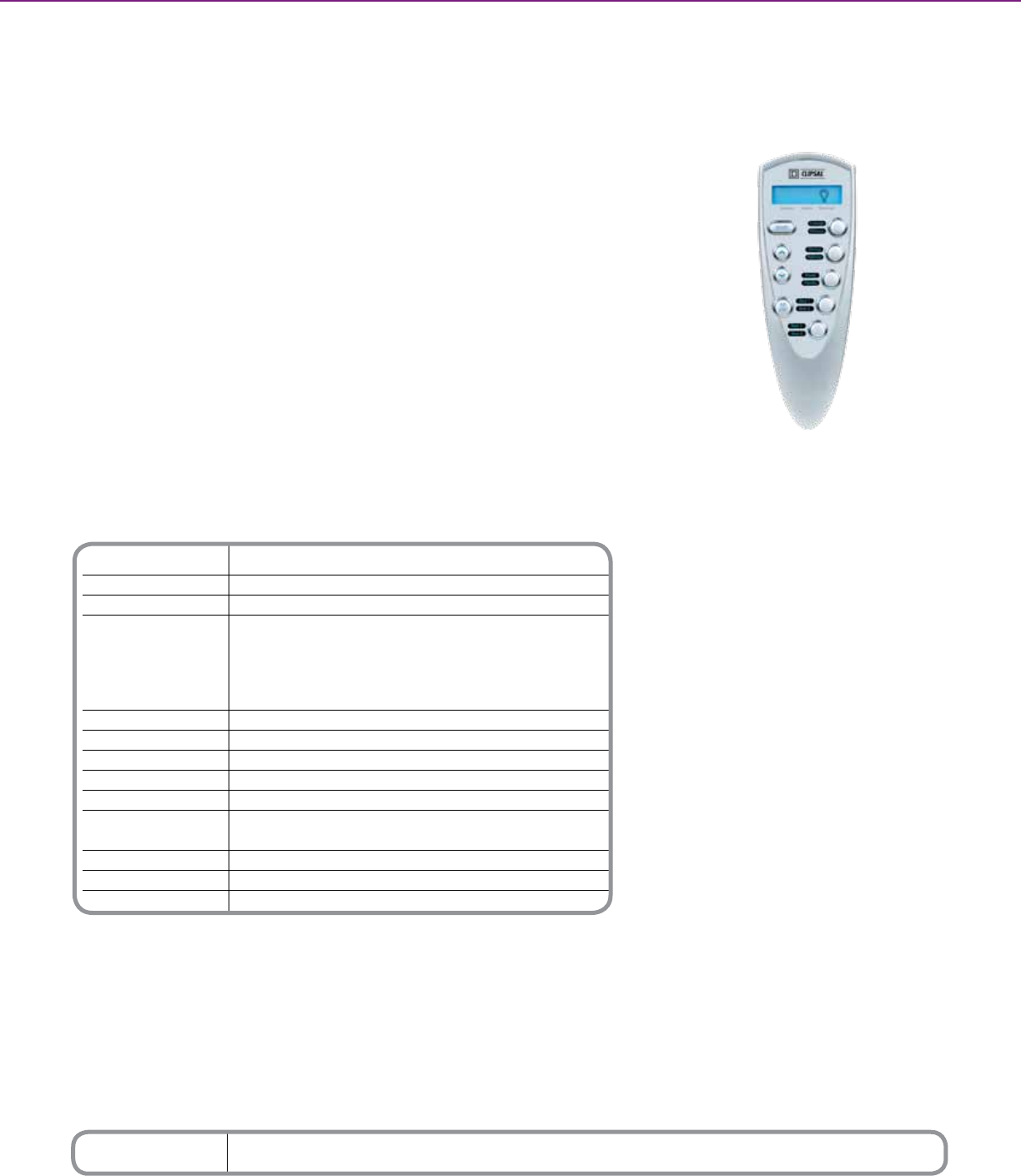
Technical Information
Supply Voltage 2 x AAA, batteries
Radio Frequency 916 MHz
Transmitting Power 10 mW
Typical range Wood frame / brick veneer construction
(range depends on building 49 to 66 feet (15 to 20 m)
construction and the proximity Brick, stone, or steel frame construction
to dense or metallic objects) 33 to 49 feet (10 to 15 m)
Steel reinforced concrete construction
16 to 33 feet (5 to 10 m)
Maximum Range (open air) 164 ft. (50m)
Dimensions 2.0 x 5.9 x 1.3 in. (52 mm x 149 mm x 33 mm)
Option darkness, has “ignore rst button press” option
Operating Environment Temp.: 32OF to 104OF (0OC to 40OC) RH: 95%, noncondensing
Standards FCC Part 15.101 - Class B digital device for home or ofce use
Remote Control Holder
Dimensions 2.2 x 4.3 x 1.3 in. (55 mm x 108 mm x 33 mm)
Mounting Centers 2.2 to 2.4 in. (55 to 60 mm)
Mounting Screw Size 0.1 x 0.8 in. (3.5 mm x 20 mm)
Wall Anchor 0.3 x 1.0 in. (7mm x 25mm)
*For Diagram see technical section page 136
Catalog Number Description
SLC5888TXBD C-Bus Wireless RF Handheld Remote Control
C-BUSTM WIRELESS CONTROLS + WIRELESS CONTROLS
The C-BusTM Wireless RF Remote Control provides control of C-Bus Wireless RF
Control Systems keypads and/or plug adapter units.
Up to ten separate keypad or plug adapter unit buttons can be controlled by the
remote control. The buttons can be on various units on different wireless networks.
A single button on a keypad or plug adapter unit can be controlled by up to two RF
remote controls.
C-Bus Wireless RF
Remote Control
Product Features
• Compatible with all C-Bus RF keypads
• 10 separate programmable buttons
• All OFF button
• Dim up/down button
• LCD screen w/button indicator and ‘learn
mode’ indicator
• Wall-mountable holder (included)
• Two AAA batteries (included)
C-BusTM RF Wireless Controls
RF Remote Control
131
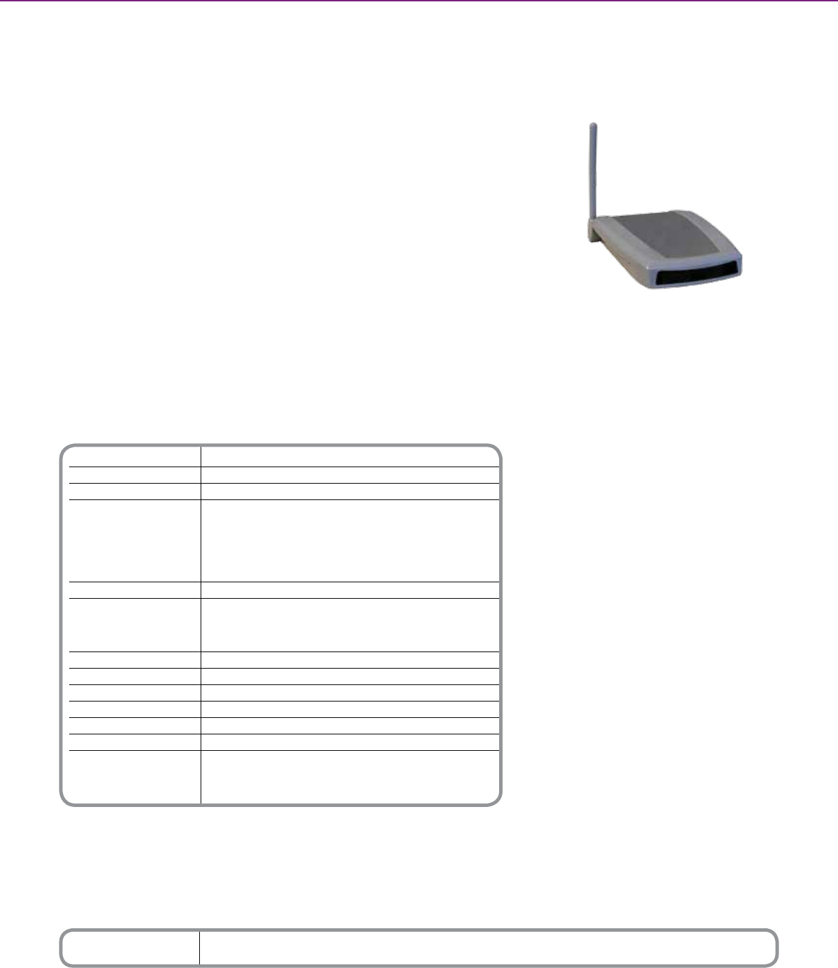
Technical Information
C-BusTM Supply Voltage 15 to 36 V DC, 32 mA
RF Frequency 916 Mhz
Transmitting Power 5 mW
Typical Range 50 to 65 ft. (15 to 20m) in buildings with timber
(range depends on building frame / brick veneer construction
construction and proximity to 30 to 50 ft. (9 to 15m) in buildings with brick,
dense or metallic objects) stone, or steel frame construction
15 to 30 ft. (5 to 9m) in buildings with steel
reinforced concrete construction
Maximum Range 200 ft. (61m) in open air
Status Indicator Color Off - No C-Bus connection or insufcient power
Slow Flashing – Normal connection to C-Bus network
Quick Flashing - Conrms that the RF Gateway
has been linked to the RF Wireless system
Operating Temperature Range 32 to 104O F (0 to 40O C) Timers
Operating Humidity Range Time 10 to 95% RH
Dimensions ( W x H x D ) 4.1 in. x 5.9 in. x 1.0 in.105mm x 149mm x 26mm)
Weight 3.7 oz. (105g)
Mounting Centers 1.6 in. (40mm)
Weight 2.7 oz (77 g)
Standards UL 916 - Energy Management Equipment
CSA C22.2 No. 205 - Signal Equipment
FCC Part 15 - Class B Digital Device for Home
or Ofce Use
*For Diagram see technical section page 136
Catalog Number Description
SLC5800WCGD RF Gateway
C-BUSTM WIRELESS CONTROLS + WIRELESS CONTROLS
The C-BusTM RF Gateway provides a C-Bus protocol communication bridge between a
single C-Bus RF wireless system and a single C-Bus wired network.
Both the wired and wireless C-Bus network types use the same protocol commands,
thus by using the Gateway, a C-Bus RF wireless and wired network can communicate
and seamlessly interact with each other. This allows a wireless C-Bus control system
third party functionality, with the ability to control audio, blinds, irrigation systems, etc.
The RF Gateway can be installed horizontally, by using the adhesive feet (included) or
vertically, using the keyhole cutouts on the base of the unit.
Product Features
• Easy to program
• Control between wired and wireless
C-Bus networks
• Mount horizontally or vertically
• Enable third party operability by connecting
a wireless network to a wired network
• Adjustable antenna for clear reception
• Simple Cat-5 connection to C-Bus wired
system
• C-Bus system clock
Wireless Gateway
C-BusTM RF Wireless Controls
Wireless Gateway
132
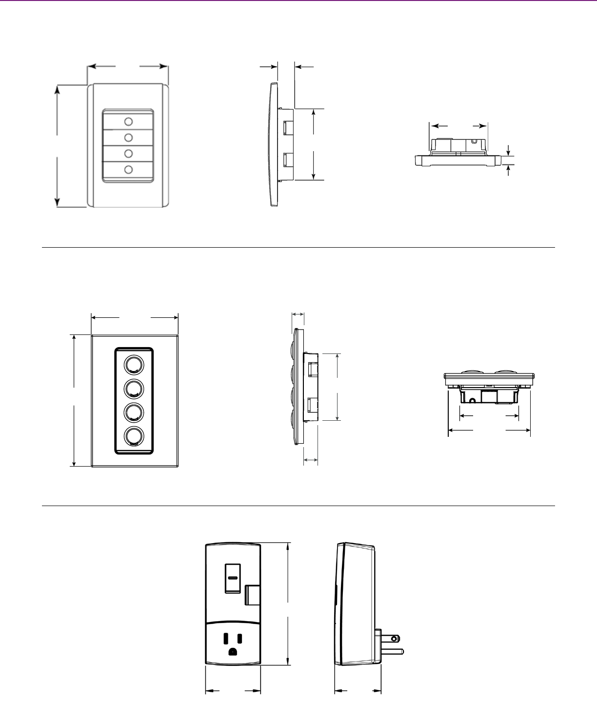
.71 in.
18 mm
2.76 in.
70 mm
2.99 in.
76 mm
.35 in.
9 mm
4.57 in.
116 mm
2.87 in.
73 mm
42 mm
1.65 in.
1.65 in.
42 mm
2.87 in.
73 mm
.71 in.
18 mm
2.76 in.
70 mm
2.99 in.
76 mm
.35 in.
9 mm
4.57 in.
116 mm
2.87 in.
73 mm
42 mm
1.65 in.
2.99 in.
76 mm
4.57 in.
116 mm
Side view of keypad, including height and
depth requirements for insertion into wall
0.91 in.
23mm
2.76 in.
70 mm
Front view of keypad, including external height
and width measurements of Faceplate
3.0 in.
76 mm
4.57 in.
116 mm
Top view of keypad, including
depth of face plate
1.69 in.
43 mm
0.28 in.
7 mm
.71 in.
18 mm
2.76 in.
70 mm
2.99 in.
76 mm
.35 in.
9 mm
4.57 in.
116 mm
2.87 in.
73 mm
42 mm
1.65 in.
0.98 in.
25 mm
2.76 in.
70 mm
0.71 in.
18 mm
1.7 in.
4.5 in.
2.0 in.
C-BUSTM WIRELESS CONTROLS + TECHNICAL SECTION
Top view of keypad showing width
Front view of keypad, including external
height and width measurements of case
Side view of keypad, including height and depth
requirements for insertion into wall
C-BusTM Neo™
Decorator Style RF Keypads
C-BusTM SaturnTM
Decorator Style RF Dimmers
C-BusTM RF Wireless Controls
Plug Adaptors
133
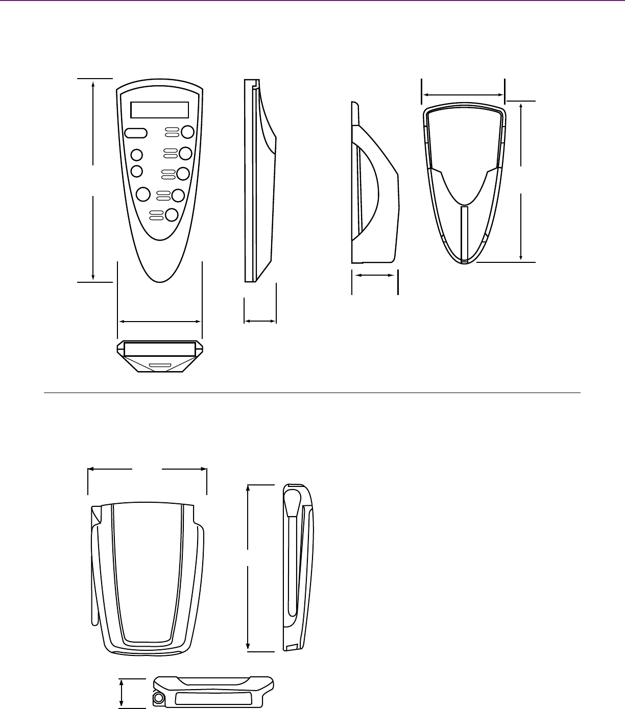
5.9 in.
149 mm
4.10 in.
105 mm
5.9 in.
149 mm
1.0 in.
26 mm
Front view of Gateway
Top view of Gateway
Side view of Gateway
C-BUSTM WIRELESS CONTROLS + TECHNICAL SECTION
Dimensions for the RF Remote Control
2.0 in.
52 mm
Dimensions for the RF Remote Holder
1.3 in.
33 mm
2.2 in.
55 mm
4.3 in.
108 mm
1.3 in.
33 mm
C-BusTM RF Wireless Controls
RF Remote Control
C-BusTM RF Wireless Controls
Wireless Gateway
134

C-BusTM Software
135

Residential Control:
The C-BusTM HomeGate Software provides
residential application PC control of a C-Bus
Control System. HomeGate can be accessed
from a local PC or remotely via an Internet
connection with a standard web browser.
The HomeGate graphical user interface is
designed for simplicity of use and provides
easy to use Menu and Tab based options.
The interface allows set-up of multiple user
pages and provides a way to easily navigate
between the pages.
Commercial Control:
The C-BusTM Schedule Plus Software
provides a powerful and simple to use
interface to a C-Bus control system. Schedule
Plus provides control and monitoring of a
commercial or industrial C-Bus system from
a PC running the Microsoft (R) Windows (R)
operating system. Access is obtained from a
local PC or remotely via an Internet connection
with a standard Web Browser.
Introduction to
C-BusTM Software
136
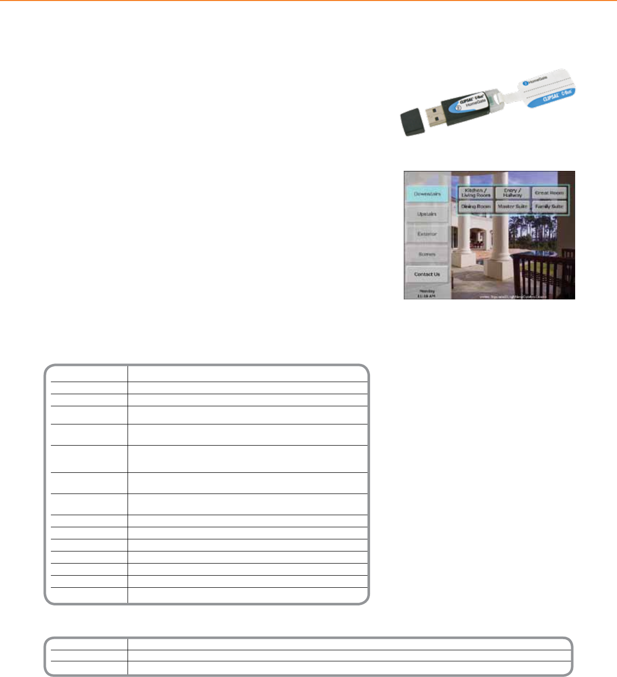
* Installer key allows installers to create/commission projects using HomeGate software. This code key is time restricted and allows the software to operate in
‘normal’ mode for anywhere between 48 to 72 hours per use (the software then returns to evaluation/demo mode).
NOTE: The installer code key will also be compatible with future software releases
Technical Information
Platform Windows 95, 98, 2000, NT, ME, Vista and XP
Server Technology C-Bus C-Gate
Connections Ethernet, RS-232
Graphical Objects Text, buttons, sliders, shapes, images, real time clock,
C-Bus timer, percentage indicator, light level, temperature, C-Bus network voltage
Component Properties C-Bus network parameters, position, size, font style and color, text and image
alignments, borders, stroke, background color/shading
Graphical Associations C-Bus command (on/off/ramp), scene activation, scene activation via
C-Bus scene controllers, page links, back one page,
operation over remote applications, exit simulation page
Scheduled Events Create, display edit and print. Daily, weekly, weekdays,
weekends, monthly and once off
Event Properties Send C-Bus command (on/off/ramp & ramp rate), send pulsed
C-Bus commands, set scenes, time of event, cycle of event
Password Protection Yes
Modes (2) Normal/Project Editing
Project Summary Yes
Event Log Yes
Page Templates Yes (included)
Image Library Yes (included)
Sound .WAV le capable
Catalog Number Description
SLC5000SDHG24 HomeGate license key for 2 networks
SLC5000SDHG104 HomeGate license key for 10 networks
SLC5000SDINST1 HomeGate installer Key*
C-BUSTM SOFTWARE + SOFTWARE
The C-BusTM HomeGate Software provides residential application PC control of a C-Bus
Control System.
HomeGate can be accessed from a local PC or remotely via an Internet connection
with a standard web browser. The HomeGate graphical user interface is designed for
simplicity of use and provides easy to use Menu and Tab based options. The interface
allows set-up of multiple user pages and provides a way to easily navigate between the
pages. The user also has the ability to password protect individual pages, as required.
HomeGate displays graphical items on user pages to perform a C-Bus function when
pressed. Examples of these items include: buttons, sliders, indicators, real-time clocks
and downloaded JPEG or Bitmap Images. Objects can be placed and sized as a user
requires and can be displayed in full color. HomeGate also reports the state of the C-Bus
group addresses on a network in real-time, with group addresses represented by text
or icons that change condition depending on status. Custom icons can be generated
to represent the various control states; alternatively icons from the icon library provided
with the package can be used.
As well as manual control and monitoring of a C-Bus system via a PC, HomeGate can
also be used to create and edit complete C-Bus scenes and initiate real-time based
schedules of events. The software supports a project editing mode for customizing the
user interface and an operation mode, where clicking components on the screen will
execute the programmed actions.
Product Features
• Supports Microsoft Platforms (Vista compatible)
• Support for 128 bit encrypted secure Internet
connectivity
• Connection to C-Bus via Ethernet or RS-232
• Single and Five Network software license options
• Fully functional logic engine
• Graphical components used to illustrate actions
• Scheduled events can be created, displayed, edited,
printed and scheduled daily, weekly, weekdays,
weekends and monthly
• Sound Files (WAV) capability
• Page templates and image library
• Event log
• Two modes, Normal Operation or Project Editing
Modes
• Individual pages can be password protected
• Application support for HVAC and Security
Example of a Customized HomeGate Screen Using
Downloaded Image and Buttons
HomeGate Application Software USB
C-BusTM Software
HomeGate
137
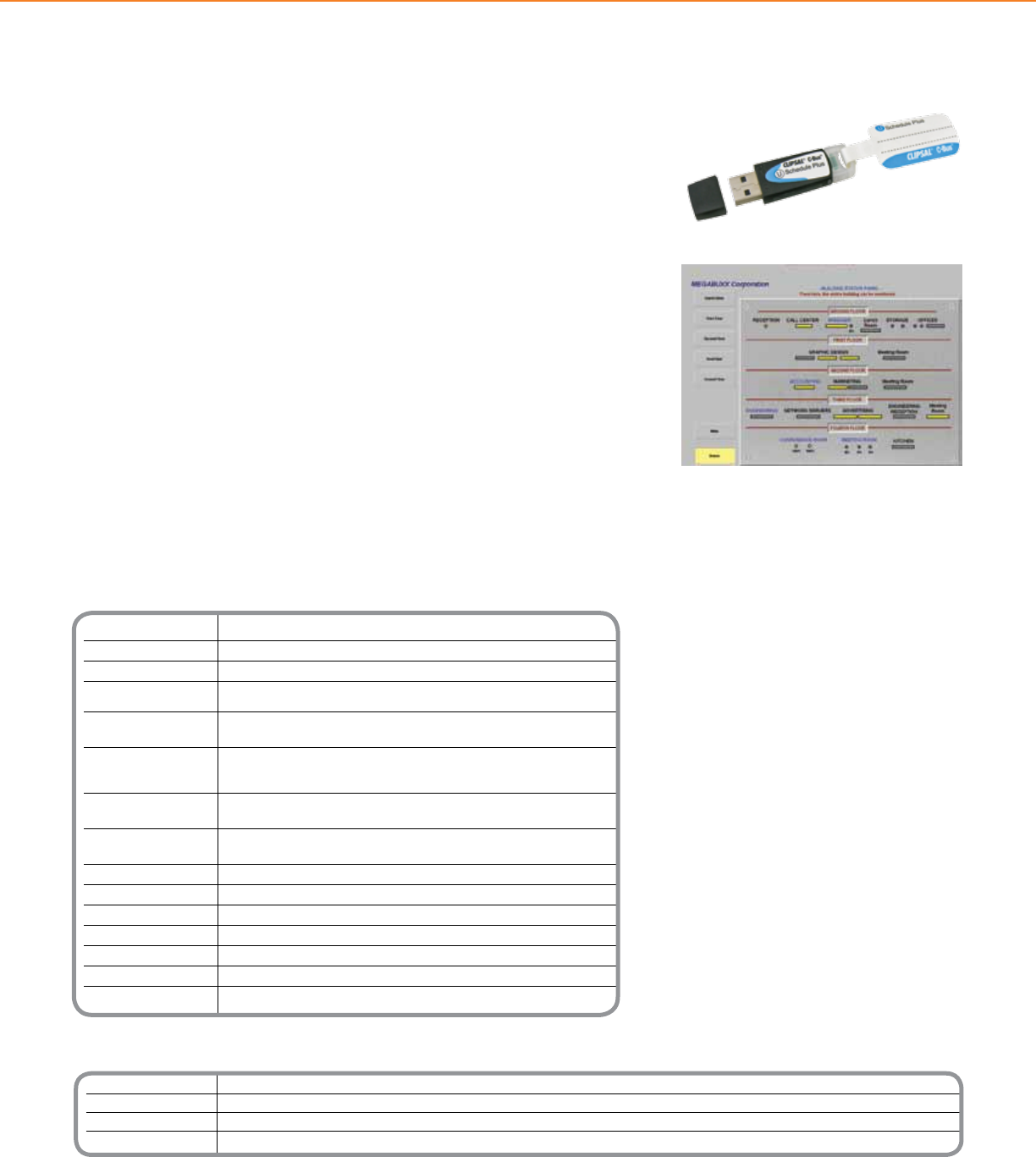
Catalog Number Description
SLC5000SDSP24 Schedule Plus license key for 2 networks
SLC5000SDSP104 Schedule Plus license key for 10 networks
SLC5000SDSPU4 Schedule Plus license key for unlimited networks
SLC5000SDSP24 Schedule Plus installer Key*
* Installer key allows installers to create/commission projects using HomeGate software. This code key is time restricted and allows the software to operate in
‘normal’ mode for anywhere between 48 to 72 hours per use (the software then returns to evaluation/demo mode).
NOTE: The installer code key will also be compatible with future software releases
Technical Information
Platform Windows 95, 98, 2000, NT, ME, Vista and XP
Server Technology C-Bus C-Gate
Connections Ethernet, RS-232
Graphical Objects Text, buttons, sliders, shapes, images, real time clock,
C-Bus timer, percentage indicator, light level, temperature, C-Bus network voltage
Component Properties C-Bus network parameters, position, size, font style and color, text and image
alignments, borders, stroke, background color/shading
Graphical Associations C-Bus command (on/off/ramp), scene activation, scene activation via
C-Bus scene controllers, page links, back one page,
operation over remote applications, exit simulation page
Scheduled Events Create, display edit and print. Daily, weekly, weekdays,
weekends, monthly and once off
Event Properties Send C-Bus command (on/off/ramp & ramp rate), send pulsed
C-Bus commands, set scenes, time of event, cycle of event
Password Protection Yes
Modes (2) Normal/Project Editing
Project Summary Yes
Event Log Yes
Page Templates Yes (included)
Image Library Yes (included)
Sound .WAV le capable
C-BUSTM SOFTWARE + SOFTWARE
The C-BusTM Schedule Plus Software provides a powerful and simple to use interface to
a C-Bus control system. Schedule Plus provides control and monitoring of a commercial
or industrial C-Bus system from a PC running the Microsoft® Windows® operating
system. Access is obtained from a local PC or remotely via an Internet connection with a
standard Web Browser.
Schedule Plus displays graphical items on user pages with simple Menu and Tab
based options. Graphic items can be programmed to perform C-Bus functions when
pressed. Examples of the type of items that can appear on Schedule Plus pages include
buttons, sliders, indicators, real-time clocks JPEG Images and Bitmap Images. These
can be placed and sized as a user requires and can be displayed in full color. Schedule
Plus also reports the state of the C-Bus group addresses on a network in real-time,
with group addresses represented by text or icons that change condition depending
on status. Custom icons can be generated to represent the various control states;
alternatively icons from the icon library provided with the package can be used.
As well as manual control and monitoring of a C-Bus system, Schedule Plus can also be
used to create and edit complete C-Bus scenes and initiate real-time based schedules
of events. The software supports a project editing mode for customizing the user
interface and an operation mode, where clicking components on the screen will execute
the programmed actions. Enhanced scheduling includes support for monitoring load run
times, load power and energy consumed.
Example of a Schedule Plus Software Display Screen
Product Features
• Supports Microsoft Platforms (Vista compatible)
• Supports 128 bit encrypted internet connectivity
• Automatic project error checking and reporting
• Connection to C-Bus via Ethernet or RS-232
• Two, ten and unlimited network software licence
key options
• Fully functional logic engine
• Graphical components used to illustrate actions
• Scheduled events can be created, displayed,
edited, printed and scheduled daily, weekly,
weekdays, weekends and monthly
• Monitoring of load run times, load power and
energy consumed
• Page templates and image library
• Event log
• Two modes, Normal Operation or Project
Editing Modes
• Individual pages can be password protected
• Application support for HVAC and Security
Schedule Plus Application Software USB
C-BusTM Software
Schedule Plus
138
Design guide
139

Introduction
a. Overview
Capabilities
a. Dimming
b. Multi-scene control
c. Daylighting control
d. C-Bus with Powerlink
Specifications
a. Programming
principles
b. Addressing
conventions
i. Group addressing
ii. Area addressing
iii. Application
addressing
iv. Network
addressing
c. C-Bus wiring
i. Network topology
ii. Network size
iii. Network cable
iv. Power supplies
v. Network burden
vi. System clock
vii. Connecting to the
C-Bus network
Planning
and design
a. Space considerations
b. Occupant control
needs (space-based)
c. Lighting
considerations
d. Occupancy
considerations
e. Energy code
considerations
f. Map system
requirements
(space worksheet)
g. Design project
i. Lighting
ii. Space control
iii. Control points
iv. Input unit selection
v. Sensor selection
and placement
vi. Output unit
selection
vii. Output unit
packaging
viii. Output unit
placement
ix. Bill of material
x. Finished design
Installation and
Commissioning
a. Order C-Bus units
b. Mark units with
part name
c. Build database and
mark plans
d. Congure unit
addresses
e. Send congured
units to site
f. Finish development
of database
i. Functional
ii. Relational
g. Download
conguration into
installed C-Bus
network
h. Commission
(troubleshoot)
Design guide contents
140

C-BUSTM LIGHTING CONTROL + DESIGN GUIDE
I. Introduction
a. Overview
II. Capabilities
a. Dimming
b. Multi-Scene Control
c. Daylighting Control
d. C-Bus with Powerlink
III. Specifications
a. Programming Principles
b. Addressing Conventions
i. Group Addressing
ii. Area Addressing
iii. Application Addressing
iv. Network Addressing
c. C-Bus Wiring
i. Network Topology
ii. Network Size
iii. Network Cable
iv. Power Supplies
v. Network Burden
vi. System Clock
vii. Connecting to the C-Bus
Network
IV. Planning and Design
a. Space Considerations
b. Occupant Control Needs (Space-based)
c. Lighting Considerations
d. Occupancy Considerations
e. Energy Code Considerations
f. Map System Requirements (Space
Worksheet)
g. Design Project
i. Lighting
ii. Space Control
iii. Control Points
iv. Input Unit Selection
v. Sensor Selection and Placement
vi. Output Unit Selection
vii. Output Unit Packaging
viii. Output Unit Placement
ix. Bill of Material
x. Finished Design)
V. Installation &
Commissioning
a. Order C-Bus Units
b. Mark Units with Part Name
c. Build Database and Mark Plans
d. Congure Unit Addresses
e. Send Congured Units to Site
f. Finish Development of Database
i. Functional
ii. Relational
g. Download Conguration into Installed
C-Bus Network
h. Commission (troubleshoot)
Contents
141
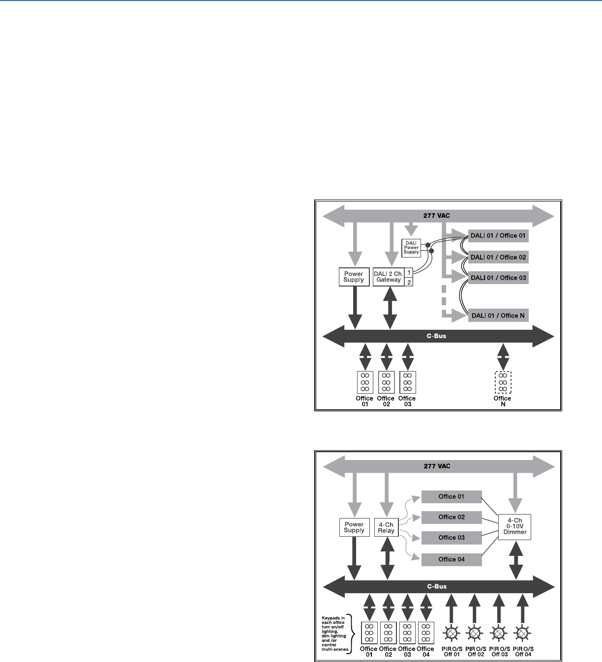
Illustration of DALI Network Control
Illustration of 0-10V Dimming
C-BUSTM LIGHTING CONTROL + DESIGN GUIDE
Lighting Control from Schneider Electric employs C-Bus™ network control for commercial lighting. Compared to conventional control systems,
C-Bus network controls reduce installation time, simplify lighting control circuits, save energy and achieve greater functionality. The C-Bus
network is a distributed intelligence network control system, incorporating microprocessor-based control. Each C-Bus device features an integral
microcontroller to achieve a robust and reliable distributed control system. Once installed, the installer programs the operating variables and control
relationships between C-Bus devices on the network. The C-Bus network may be scaled to t any size project from a single conference room up to
a very large building.
Objective
This guide provides lighting control designers with guidance needed to design and plan C-Bus network control systems. Additional support is
available through the Schneider Electric Lighting Control Technical Support Team at 1-888-SQUARED.
Dimming
Dimming is a critical part of today’s lighting control needs. In the past,
manual dimming controls were used in ofces, conference rooms,
and classrooms to allow occupants to adjust light levels to meet the
occupant needs or preferences. Now, more sophisticated lighting
control systems employ dimming to provide multi-scene control,
daylighting control and multi-level control in a variety of spaces and
building types, from schools and ofces to retail environments and
warehouses, to save energy and provide more occupant-friendly control.
C-Bus includes a variety of units to achieve continuous or stepped
dimming of uorescent, incandescent and even HID lighting.
Introduction
142
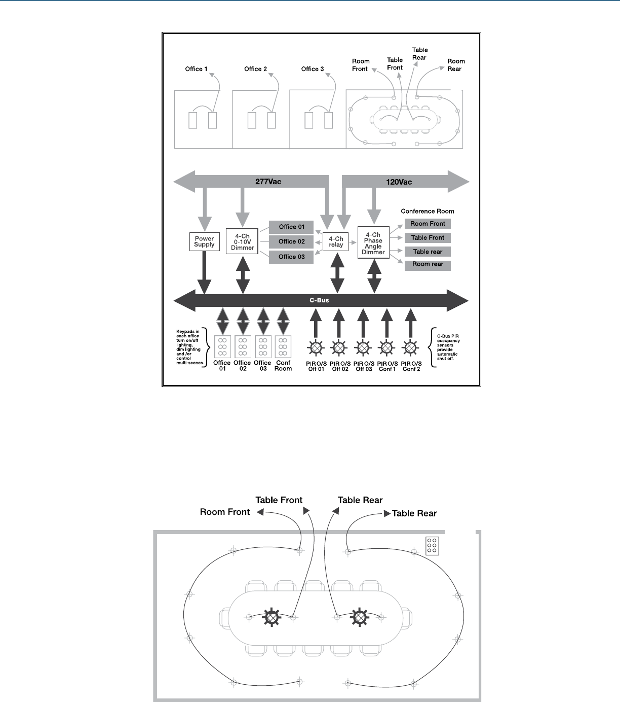
C-BUSTM LIGHTING CONTROL + DESIGN GUIDE
Multi-Scene Control
Presentation (scene 1)
Room Front = Off
Room Rear = 50%
Table Front = 50%
Table Rear = 50%
Meeting (scene 2)
Room Front = 0%
Room Rear = 50%
Table Front = 100%
Table Rear = 100%
Up to (8) scenes with
8-button keypad or DLT
Multi-Scene Control
The press of one button may control many individual loads. Loads may be turned on, off, or dimmed to a predetermined level. Depending on
how a space is used, it may be necessary to have certain lights set to various levels for different functions. For example, a conference room
may have multiple groups of lighting where one group illuminates the table, another group illuminates the perimeter in the back of the room
and another group illuminates the perimeter in the front of the room. During a meeting, it may be desirable to have the lighting over the table
set to 100% and have the lighting around the perimeter set to 50%. This could be accomplished with a single button press to create the
“meeting” scene. For presentations, perimeter lighting in the front of the room may be turned off, lighting over the table set at 50%, and
perimeter lighting in the back of the room set at 50%.
Illustration of Phase Angle
Control in Conference Room
143
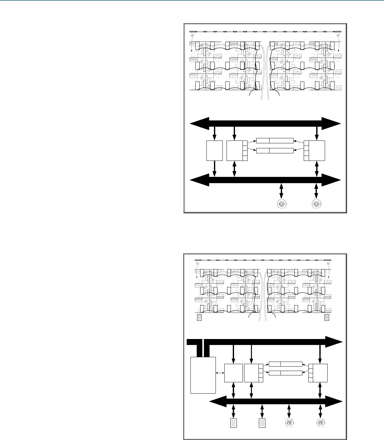
Illustration of C-Bus Connected to Powerlink G3 Panel
WINDOWS
DAYLIT AREA
Zone 1
Relay
Ch-1
Zone 2
Relay
Ch-2
C-Bus
Multi-Sensor C-Bus
Multi-Sensor
C-Bus C-Bus
Zone 1
Daylit
Area
Dimmer
Ch-1
Zone 2
Daylit
Area
Dimmer
Ch-2
277 VAC
C-Bus
DEVICE
ROUTER
PC Interface &
Power Supply
4-CH
RELAY
1
2
3
4
1
2
3
4
4-CH
0-10V
DIMMER
ZONE 1
ZONE 2
DAYLIT AREA
DAYLIT AREA
C-Bus
Multi-Sensors
Zone 1
Daylit
Area
Zone 2
Daylit
Area
C-Bus
Keypad
C-Bus
Keypad
POWERLINK
3000G3C Controller
Serial
Cable
C-Bus
Keypads
C-Bus keypads provide
schedule override and
occupant control of
lighting in both zones
WINDOWS
DAYLIT AREA
Zone 1
Relay
Ch-1
Zone 2
Relay
Ch-2
C-Bus
Multi-Sensor C-Bus
Multi-Sensor
C-Bus C-Bus
Zone 1
Daylit
Area
Dimmer
Ch-1
Zone 2
Daylit
Area
Dimmer
Ch-2
277 VAC
C-Bus
POWER
SUPPLY
4-CH
RELAY
1
2
3
4
1
2
3
4
4-CH
0-10V
DIMMER
ZONE 1
ZONE 2
DAYLIT AREA
DAYLIT AREA
C-Bus
Multi-Sensors
Zone 1
Daylit
Area
Zone 2
Daylit
Area
C-BUSTM LIGHTING CONTROL + DESIGN GUIDE
C-Bus™ with Powerlink®
C-Bus networks may be connected to Powerlink G3
intelligent lighting control panels utilizing the Powerlink
Device Router and the Powerlink 3000G3C controller.
Two-way communications between the C-Bus network
and the Powerlink panel allows C-Bus inputs to control
branch circuits at the Powerlink panel or override the
Powerlink schedule, and the Powerlink panel may
provide scheduled shutoff of C-Bus controlled lighting.
In the Daylighting System illustrated no shut off was
provided. To shut off lighting on a schedule, connect
the C-Bus network to Powerlink 3000G3C controller
via Powerlink Device Router. The Device Router
includes a C-Bus PCI and Power Supply, and is
connected to the Powerlink panel using a serial cable
between the RS-232 port on the PCI and the
3000G3C controller.
Daylighting Control
Daylighting control may be used to reduce articial
lighting of interior spaces when those spaces receive
adequate natural light from windows or skylights.
Daylighting controls are commonly installed in
California, where the state’s building code, Title 24,
requires the use of daylighting controls in daylit spaces.
Daylighting control may be used to save energy in
schools, ofces, warehouses, and even retail spaces.
More and more buildings, especially big box retail and
schools, are taking advantage of natural sunlight to
illuminate interior spaces. C-Bus light level sensors are
easily congured to provide daylighting control utilizing
relays for stepped dimming function or dimmer units for
continuous dimming.
Illustration of Daylighting Control
144
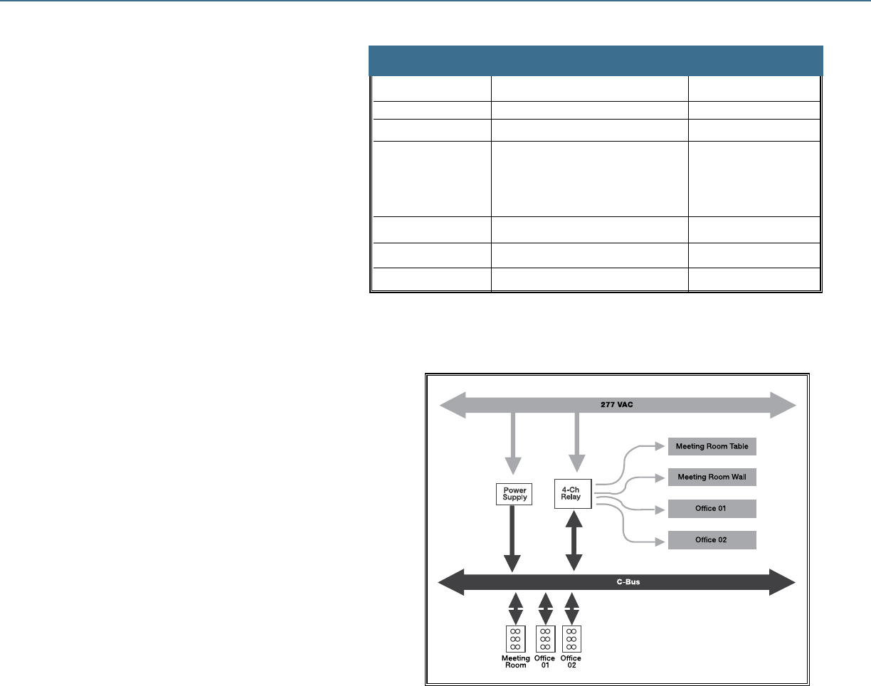
Programming Principles
All C-BusTM devices require programming, with
the exception of power supplies. Programming is
achieved with proprietary software using a PC. Unit
programming is performed to achieve the following
objectives:
• Create and dene units on the C-Bus network
• Identify each unit using the C-Bus addressing
convention
• Create, dene and edit control relationships
between inputs and outputs
• Edit unit operating parameters
The operating parameters vary from unit to unit,
depending on its type.
Keypad Functions
Timer Functions
Dimming Functions
Toggle (on/off) Control
Preset Levels
Custom / Other Functions
Scenes - Multiple location control
• Output Switching Logic Assignments
• Power Outage Recovery Status
• Power Up Sequences
• Dimming Rates
• Indicator Options
• Sensor Switching Conditions
• Override Controls (Enable/Disable)
• Error Status Options
Addressing Conventions
Once a preliminary list of hardware requirements has been
created, planning of the programming requirements may begin.
The C-Bus network uses a simple addressing scheme to
identify units, groups, areas and networks. The purpose of each
parameter will be discussed in the next section.
Alphanumeric Characters
Legal Alphanumeric Character Set: 0-9, a-z, A-Z, ‘ ‘, ‘_’
All descriptive addresses accept the above legal
characters. Other characters may be accepted, but are not
recommended.
Project Names and Part Names will force capital letters.
Hexadecimal Symbols
Hexadecimal Symbol Set: 0, 1, 2, 3, 4, 5, 6, 7, 8, 9, A, B, C, D, E, F
At a physical level, the programming information downloaded to C-BusTM Units consists of a two digit hexadecimal number,
represented be a combination of the above 16 symbols. Valid addresses include 12, AB, FE, 5E. The descriptive addressing is not downloaded.
This information is stored in a database on your PC. A programmed C-Bus network can be scanned using the C-Bus Installation Software. If
a Version 7.1 Project Database has not been dened by the user, the software will use the hexadecimal addressing uploaded to represent all
unknown addressing. Users should note that these hexadecimal addresses are automatically assigned. The Project and Topology Managers
may be used to reference or manipulate hexadecimal address as required.
Group Addressing
The Group Address is usually related to the load physically connected to the terminal of the output unit. Therefore, the group address
should accurately describe the load being controlled. Typically, numerical designators are used to describe lighting circuits. Up to 255
group addresses may be dened on a single network less any dened area addresses.Valid groups include: Ofce Lights, Hall Lights,
L4-2B, A4-2L-3 The default group is “unused.”
Parameter Format Example
PROJECT NAME 8 alphanumeric characters OFFICE01
NETWORK 20 alphanumeric characters Ofce Network
UNIT Three digit decimal number (000-255) 016, 067, . . . 145
OR OR
Two digit hexadecimal number (00-FF) 0A, 1A, . . . 5B
PART NAME 8 alphanumeric characters RELAY01
APPLICATION 20 alphanumeric characters Lighting (*)
AREA 20 alphanumeric characters First Floor Ofces
GROUP 20 alphanumeric characters Conference Rm Lights
C-Bus Installation Software version 2.0
C-BUSTM LIGHTING CONTROL + DESIGN GUIDE
Illustration of Group Addressing
Specifications
145
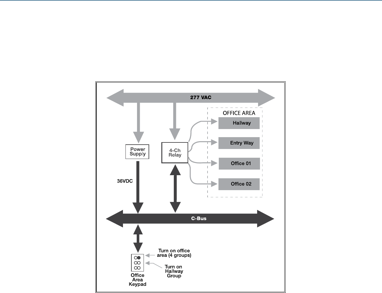
C-BUSTM LIGHTING CONTROL + DESIGN GUIDE
Area Addressing
The area address is a convenient method of addressing multiple output channels collectively. Large areas consisting of many C-BusTM output units
may be controlled from a single point on the C-Bus network. The area address is used in the group address eld to achieve control.
Illustration of Area Addressing
Each C-Bus input and output device in a control area must be assigned the same area address. The area address must be unique and must not
be repeated as a group address in that C-Bus network. Up to 255 areas may be dened less the number of dened groups.
146
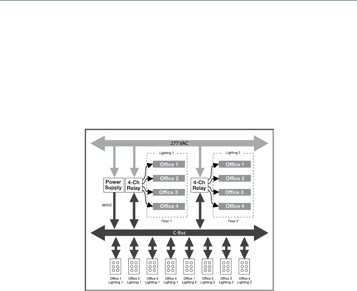
C-BUSTM LIGHTING CONTROL + DESIGN GUIDE
Application Addressing
Applications are used to divide the C-Bus network into independent functional systems. All group addresses in any unit are associated with
that unit’s applications, and commands issued by a C-Bus input device will affect only output devices with matching applications and group
addresses. Up to 255 application addresses may be used on a single C-Bus network. By default, ve applications are dened: Enable Control,
Heating (Legacy), Lighting, Telephony and Trigger Control. Other applications may be dened as needed. For example, in a multi-storied
building it may be desirable to have a separate application for each oor to satisfy the need to have more than 255 group addresses on the
network, or to allow the same group addresses to be used over and over (e.g. OFFICE01, MENS01, CONF01, etc.). In this case, dened
applications might be Lighting01, Lighting02, etc.
Illustration of Application Addressing;
Where Lighting 1 and Lighting 2 are Separate Applications
147
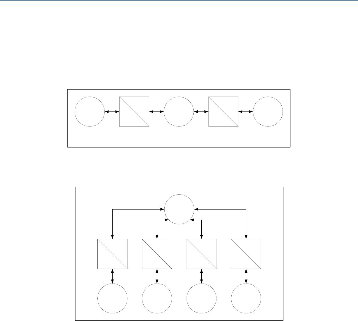
Unit
Address
254
Unit
Address
253
Network
Address
254
Network
Address
253
Network A
(Local)
Network B
(Remote)
Unit
Address
253
Unit
Address
252
Network
Address
252
Network C
(Remote)
C-Bus
Network
Bridge
C-Bus
Network
Bridge
Local Network
Address 254
Unit
Address
253
Unit
Address
254
Unit
Address
252
Unit
Address
254
Unit
Address
251
Unit
Address
254
Unit
Address
250
Unit
Address
254
Remote Network
Address 253
Remote Network
Address 252
Remote Network
Address 251
Remote Network
Address 250
Unit
Address
254
Unit
Address
253
Network
Address
254
Network
Address
253
Network A
(Local)
Network B
(Remote)
Unit
Address
253
Unit
Address
252
Network
Address
252
Network C
(Remote)
C-Bus
Network
Bridge
C-Bus
Network
Bridge
Local Network
Address 254
Unit
Address
253
Unit
Address
254
Unit
Address
252
Unit
Address
254
Unit
Address
251
Unit
Address
254
Unit
Address
250
Unit
Address
254
Remote Network
Address 253
Remote Network
Address 252
Remote Network
Address 251
Remote Network
Address 250
C-BUSTM LIGHTING CONTROL + DESIGN GUIDE
Network Addressing
The network address is used to identify networks in a multi-network system. Each C-BusTM network may be connected to other C-Bus networks
using a C-Bus Network Bridge. The C-Bus Network Bridge facilitates communications across networks, allowing device on one C-Bus network
to issue commands to devices on another C-Bus network.
Examples of valid network names are “First Floor”, “My House”, “Movie Theatre” or “Building 12A.” Up to 255 unique networks may be
connected together using C-Bus Network Bridges as shown.
For large installations where real time response is required from a central control, a C-Bus Ethernet Network Interface may be used to connect
multiple C-Bus networks together using a common Ethernet backbone. The C-Bus Ethernet Network Interface is a 10 Base T Ethernet
compliant device.
Multiple C-Bus networks connected in series using C-Bus Network Bridges
Multiple remote C-Bus networks connected to local network using star topology.
148

C-BUSTM LIGHTING CONTROL + DESIGN GUIDE
C-BusTM Wiring Rules
Schneider Electric C-Bus incorporates a distributed intelligence lighting control system that employs a low voltage network of intelligent input, output
and network communication units to control line rated loads. C-Bus network communications is achieved using proprietary C-Bus protocol over an
unshielded twisted pair LAN cable (Cat-5 UTP). Some simple rules should be observed when specifying or designing a Schneider Electric C-Bus
lighting control system.
Network Topology
Schneider Electric C-Bus lighting control system is comprised of C-Bus devices interconnected using Cat-5 UTP cable to achieve a topology-free
C-Bus network. The lighting control system may incorporate a single network or multiple networks to overcome the following C-Bus network limitations:
• Maximum cable length
• Addressing limitations
• Maximum 2A/36VDC per network
• Reduce network response time (reduce local communications trafc)
• Accommodate physical layout and building structure (network/oor)
When connecting multiple networks together, the following guidelines should be observed:
• Minimize the depth of the network topology for faster, more efcient communications.
• Distribute C-Bus Units on separate networks proportionally to avoid communications and power supply problems. For example if 120
C-Bus Units are required, split into two networks of 60 Units each, rather than 100 Units on the rst network and 20 Units on the second.
Network Size
The maximum number of C-Bus units on any network shall not exceed 100 units. If the lighting control system requires more than 100 units, an
additional network may be connected to the rst network through a C-Bus Network Bridge to allow communications between networks.
• Maximum of 100 C-Bus units per network
• Maximum of 255 networks per system
• No more than 50 DLT keypads on one network because of advanced operations
Network Cable
Maximum cable length is determined by the impedance of the cable used. The resistive and capacitive impedance of network cable varies based on
type. For Cat-5 UTP, the maximum length for reliable communications is 3280 ft.
• Maximum 3280 ft. of Cat-5 UTP cable per network
• C-Bus Network Bridges should be used to split a network into two or more networks when the total cable length required exceeds 3280 ft.
Power Supplies
The C-Bus Power Supply and Output units with integral power supply provide low voltage power to C-Bus devices on the network (36VDC). Current
required to operate C-Bus devices varies, depending on the device. Refer to installation instructions for specic C-Bus devices to determine current
requirements. Each C-Bus Power Supply supplies up to 350mA and C-Bus Output units with integral power supply will supply up to 200mA. Additional
C-Bus Power Supplies may be added to maintain optimum network voltage of 15-36VDC. Distribute power supplies evenly on the network to evenly
distribute voltage drop. All power supplies on a C-Bus network evenly share the network load. Typically, no more than (5) Power Supplies should
be connected to a single network. When utilizing Output Units with an integral power supply rated at 200mA, a maximum of (10) power supplies is
allowed. In no case shall the total available power exceed 2A at 36VDC.
Network Burden
A Network Burden must be connected to a C-Bus network to achieve reliable network communications. The Network Burden is comprised of a
capacitor in series with a resistor. One hardware Network Burden is included with each PC Interface (PCI) and two hardware Network Burdens are
included with each Network Bridge. The Network Burden may be software enabled on most other DIN rail mounted C-Bus units. One, and only one,
Network Burden is required for each C-Bus network. If more than one PCI or Network Bridge is used in a network, all but one Network Burden should
be disabled. For systems with multiple networks connected together via Network Bridges, each network within the
system should have only one Network Burden connected or enabled.
System Clock
The C-Bus network requires one system clock source to operate. This is not a real time clock; however, network communications are synchronized to
this source. The PCI and Network Bridge units may be used to provide the system clock. If more than one of these units is present on a network, the
network automatically determines which is active. A maximum of 3 network clocks should be enabled on a C-Bus network.
Connecting to the C-Bus Network
The C-Bus network is designed to operate at 36VDC. The C-Bus network is optically and/or galvanically isolated from line voltage rated circuits.
When installing C-Bus devices the installer should always follow applicable NEC requirements for Class 2 wiring. Operating at a low voltage of 36VDC
allows electrical work to be performed on the C-Bus side of the system while the system is powered on. Before working on C-Bus network wiring
or devices located in enclosures where Class 1 wiring is present, turn off power to Class 1 circuits. The C-Bus network is short circuit protected to
prevent damage to C-Bus devices if a short occurs. The C-Bus network will not work as long as the network is shorted. C-Bus devices are connected
in parallel on the network. Whether the devices are connected using a daisy-chain topology, a star topology, or a combination of both topologies, the
devices are always connected to the network in parallel to achieve a topology-free network. Homeruns are not recommended for C-Bus networks.
When connecting C-Bus devices to the network cable (typically Cat-5 UTP), care should be taken to observe polarity requirements clearly marked on
each device. It is recommended that installers use a Cat-5 UTP
cable with a distinguishable color, such as pink, to distinguish
C-Bus network cable from other network cable which may be
present. This simplies later servicing of the system by allowing
service personnel to quickly identify C-Bus network cables.
Correct wiring with the twist
being maintained between
the two positive conductors
and their respective negative
conductors.
149

C-BUSTM LIGHTING CONTROL + DESIGN GUIDE
Planning & Design
The most important phase of any Schneider Electric C-BusTM lighting control project is the planning and design phase. A complete plan starts with a
good understanding of the lighting control requirements. To determine what is required, start by asking the right questions.
1. Where is lighting control required?
For example, a school may have both exterior and interior lighting that requires control. Dene the exterior and interior lighting that requires control, and
segregate lighting by space.
2. How is each space used?
Private ofces within a building may share the same lighting control needs. Meeting and training rooms may have the same lighting control needs,
regardless of where these spaces fall within in a building. Functionally, a classroom differs from a restroom, so the entire site, including interior and
exterior spaces, should be segregated based on the way the space is used. Similarly used spaces may share basic lighting control needs.
3. How will occupants want to control lighting to best utilize the space?
Consider the needs of the occupant. For example, multi-scene control may be used in classrooms, conference rooms and training rooms. Restrooms,
employee break rooms, copier/mail rooms and utility closets may only require occupancy-based control. Exterior parking lot and pathway lighting that is
only needed at night may turn on and off based on time of day or sunrise and sunset. Private ofces may require multi-scene of dimming controls, while
open ofce areas may turn on and off with time of day schedule. While lighting control should save money, it should also enhance the functionality of
the space.
4. What type of lighting is to be controlled?
If dimming is required, the type of lighting must be considered when selecting a dimmer.
5. When is lighting used?
This is important. During working hours, lighting may be used differently than during cleaning hours, for example. Consider the lighting use on week-
ends and after hours. Lighting may not be used during holidays, so it is important to dene when lighting control will be needed giving consideration to
holidays, inventory, shutdown and other events that may occur only once per year.
6. Is occupancy predictable?
If an area has predictable days and hours of occupancy, it may be best to use a time of day schedule to control lighting in this area. For areas with less
predictable occupancy patterns, occupancy-based control may be required, or a combination of control schemes may best meet the functional needs
of occupants and the energy efciency needs of building owner. Having a clear understanding of the occupancy patterns of the building will help the
designer develop a lighting control system that is convenient for occupants and achieves energy efciency.
7. What are the energy code requirements?
Depending on the energy codes governing a particular building, based on its use, its location, and size, there may be specic requirements for lighting
control. Understanding the functional requirements as dened by the governing energy code is essential in the planning and design phase. Oversights
at this point could result in costly changes later to bring lighting and lighting control systems into compliance with building codes. In most energy codes,
lighting and lighting control requirements are intermingled, with some codes providing prescriptive lighting control requirements to bring otherwise non-
complying lighting systems into compliance.
8. What are the functional lighting control requirements for each space?
At this point in the planning process, start dening the functional lighting control needs for each space. This will aid the designer in the product selection
process. Keep in mind that spaces that are used in similar ways may have similar or identical lighting control needs. Grouping spaces based on use
may simplify this process. Lighting functions to consider are:
• Dimming or switching
• Manual or automatic
• Schedule-based shutoff or occupancy-based shutoff
• Mutli-scene or manual dimming control
• Manual or automatic daylighting control
• Zones or groups
9. Finally, what control functions are needed that include more than one space, zone, area or lighting group?
Will the occupant want a single switch to turn on and off all lighting in the building? Will the cleaning crew require special lighting controls to turn on
multiple groups or zones? What type of automatic shutoff shall be used to turn off lighting in the building when the building is unoccupied?
The planning phase usually involves mapping the system requirements, and determining the hardware needs of the system. Thought should be given
to placement and packaging of hardware, programming and cabling requirements. As planning transitions into designing, documentation of the system
layout and functionality becomes more critical.
150
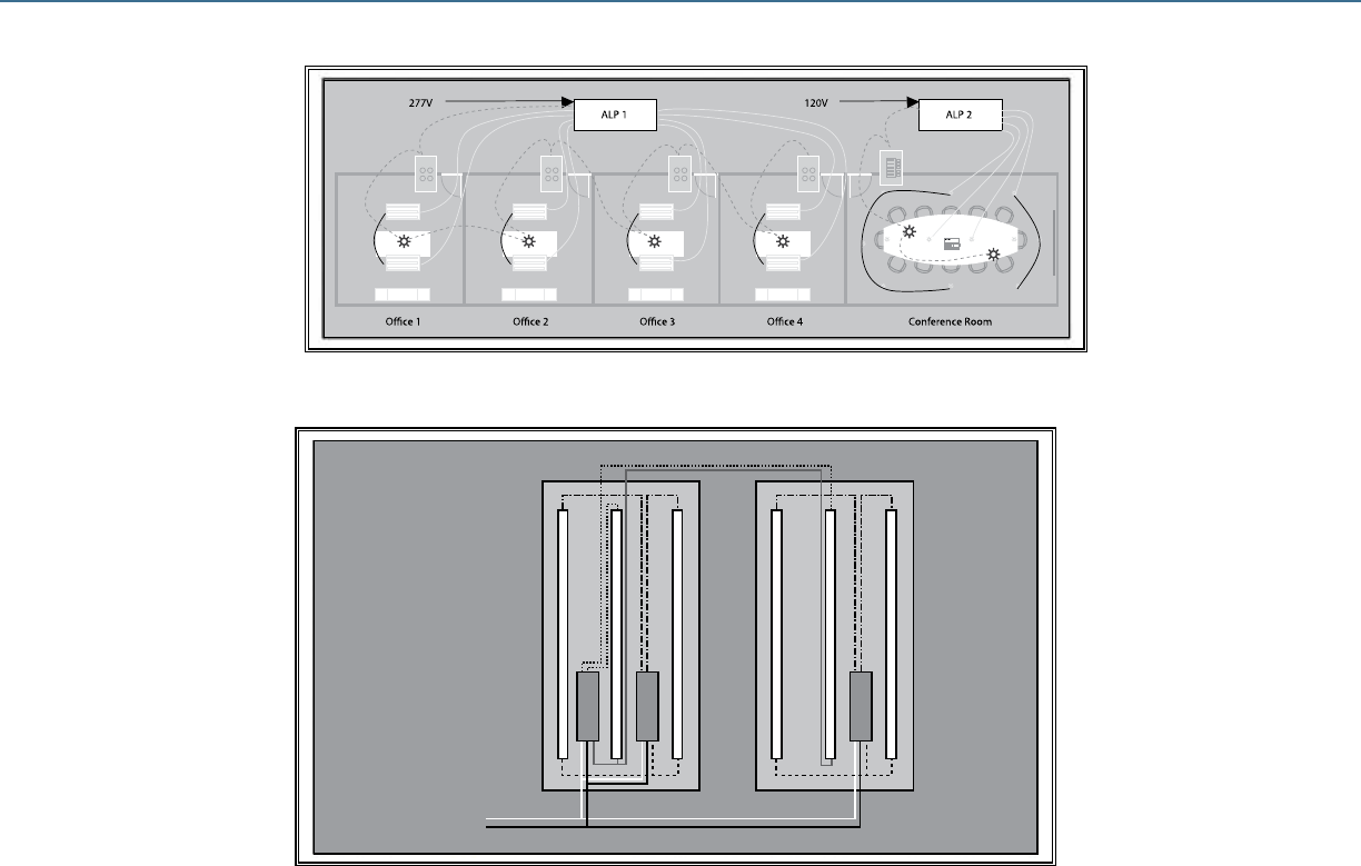
C-BUSTM LIGHTING CONTROL + DESIGN GUIDE
Ofces 1-4: Tandem wired 3-lamp uorescent luminaires (32W T8)
Lighting power density of 192W/225SF= .853 W/SF
Conf Room: Recessed 32W compact uorescent luminaires
120V phase angle dimming ballast per luminaire
Ofces 1-4: Multi-level control (0, 33%, 67%, 100%)
4-button keypad (all on, A on/off, B on/off, all off)
Occupancy sensor shutoff
Conf Room: Multi-Scene control with dimming control
Dynamic Labeling Technology keypad (4-buttons x 2 pages)
(6) preset scenes (all on, meeting, presentation, lecture, dining, all off)
Dim up/down table lights
Dim up/down room lights
Occupancy sensor shutoff
Equipment Selection by Space
Ofces 1-4: (1) C-Bus™ PIR 360° occupancy sensor per ofce
(1) 4-Button NeoTM Keypad per ofce
(2) 20A relay outputs per ofce
Conf Room: (2) C-Bus PIR 360° occupancy sensors
(1) DLTTMh Neo keypad
(4) 4A Phase angle dimmer outputs (1 per group)
C-Bus Input Unit Placement
Ofces 1-4: - Place keypad in wall box adjacent to entry
- Place occupancy sensor in ceiling over desk for best coverage
Conf Room: - Place DLT keypad in wall box adjacent to entry
- Place (2) occupancy sensors over table for best coverage
Space control
Offices 1-4
Tandem-Wired
3-Lamp
Luminaires
Neutral
Line
Ofce & Conference Room Design Project
Space Lighting
Design Project
151
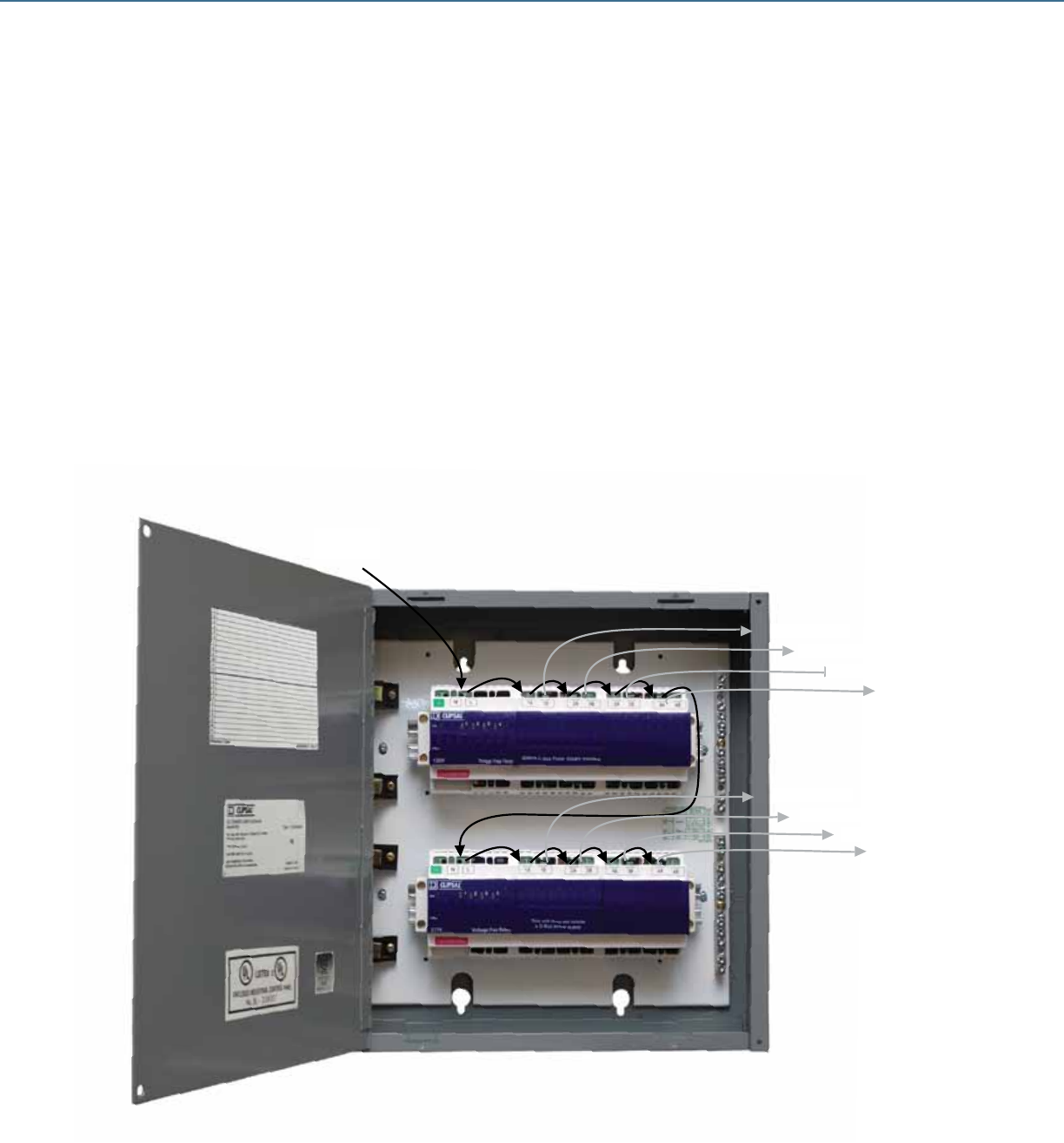
C-BUSTM LIGHTING CONTROL + DESIGN GUIDE
Conf Room: (2) C-BusTM PIR 360° occupancy sensors
(1) DLTTMh NeoTM keypad
(4) 4A Phase angle dimmer outputs (1 per group)
C-Bus Input Unit Placement
Ofces 1-4: - Place keypad in wall box adjacent to entry
- Place occupancy sensor in ceiling over desk for best
coverage
Conf Room: - Place DLT keypad in wall box adjacent to entry
- Place (2) occupancy sensors over table for best coverage
Packaging of Output Units
Ofces 1-4: In total, ofces require (2) 4-Ch 20A relay units.
Prepackaged Area Lighting Panel (ALP) SLCZ082000H
ALP 8-Ch 20A Relays SLCZ082000H
Office 1 - A
277V/20A
Branch Ckt.
Office 3 - A
Office 1 - B
Office 3 - B
Office 2 - A
Office 4 - A
Office 2 - B
Office 4 - B
152
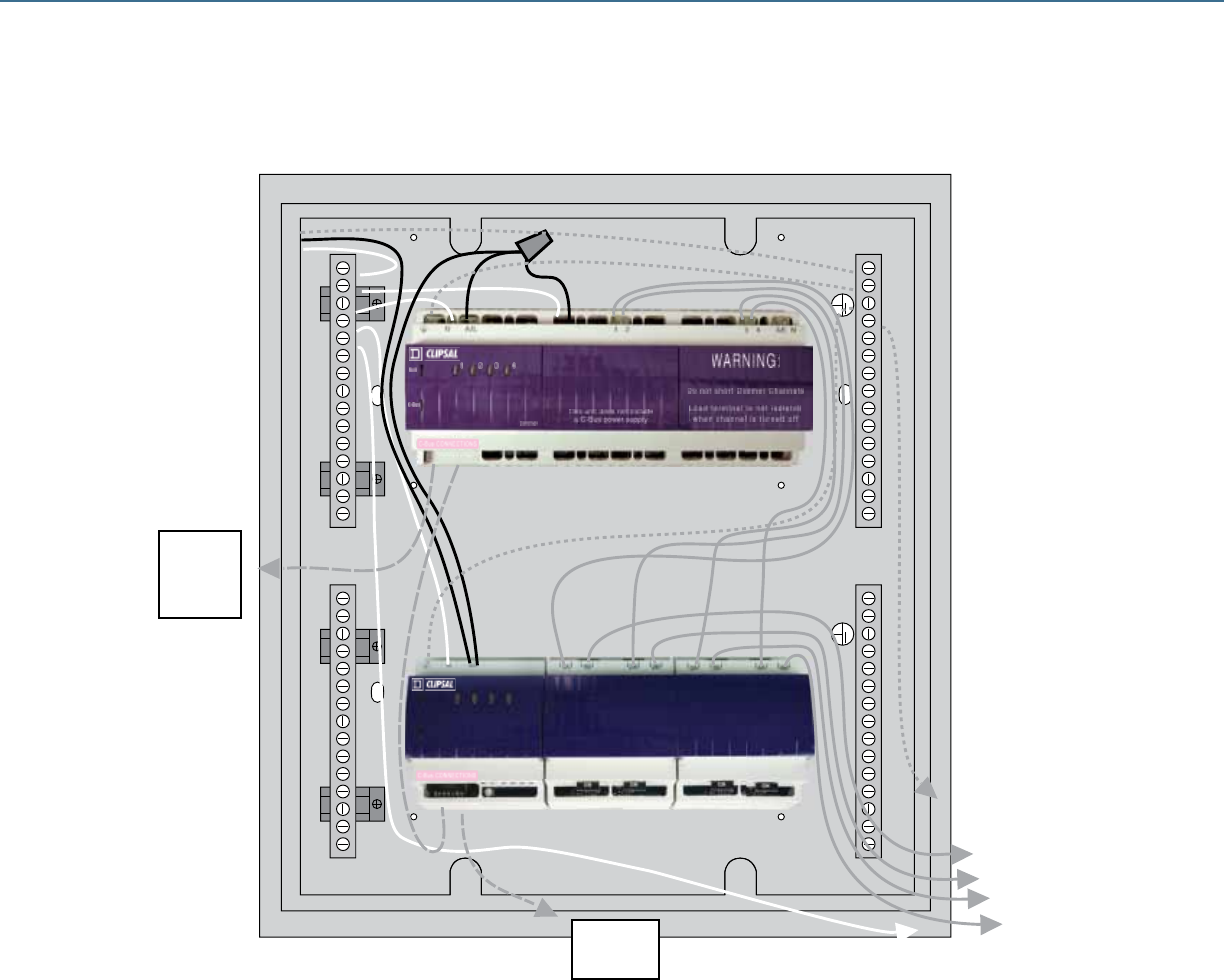
C-Bus
Unit
200mA C-Bus Power Supply included
Voltage Free Relay
4321
C-BUSTM LIGHTING CONTROL + DESIGN GUIDE
Bill of Material
Catalog # Description Qty
SLC5753L C-BusTM 360° PIR Occupancy Sensor 6
SLC2042004DT C-Bus 4x20A Relay 120V No P/S 1
SLC2042004DT SQDTM C-Bus 24M Enclosure 1
SLCZ082000H SQD C-Bus ALP 8x20A Relay 277V with P/S 1
SLC2042004DT C-Bus 4x4A Phase Angle Dimmer with P/S 1
SLC5084NL(WE) C-Bus 4-Button SaturnTM Keypad White 4
SLC5085DL(WE) C-Bus DLT Saturn Keypad White 1
ALP with 4x20A Relay & 4x4A Phase Angle Dimmer
Conf. Room: In total, requires (1) 4-Ch Phase Angle Dimmer unit and (1) 4-Ch 20A
relay unit. Custom packaged Area Lighting Panel in 24M enclosure.
To another
ALP or
Powerlink
Device
Router
To C-Bus
keypads and
sensors
Table Front
Table Rear
Room Front
Room Rear
153
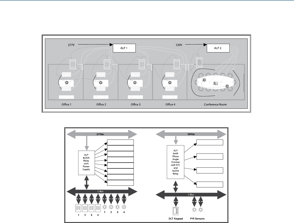
Table Front
Office 1 - A
Office 1 - B
Office 2 - A
Office 2 - B
Office 3 - A
Office 3 - B
Ofce 4 - A
Ofce 4 - B
Table Rear
Room Front
Room Rear
C-BUSTM LIGHTING CONTROL + DESIGN GUIDE
Illustration of Design Project Controls
Installation
Once the design phase is complete, installation may begin. Several simple steps are typically followed to achieve a fast and accurate
installation of the C-BusTM network control system.
1. Implementing programming requirements of the design on a PC. Build a database using C-Bus software that includes all the
C-Bus units used in the lighting control system. Each unit is assigned a unit address.
2. Using the PC and a PC Interface, initialize and program each C-Bus device one at a time. Each device is assigned a unit address.
3. Packaging, cabling and electrical installation of the hardware.
4. Finalization and additional programming of C-Bus devices as required.
Commissioning
Verify compliance with the specication and commission the system. A design review may be performed at this point in the process.
Modications or design changes seldom require installation of additional hardware, typically requiring only programming changes.
Completed Project Layout
Finished Design
154
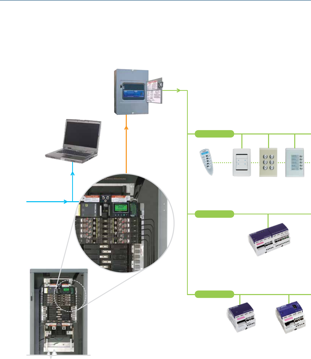
Schneider Electric occupancy sensors, Powerlink® and C-Bus™ control systems can be used independently
or combined to provide the optimal lighting control solution.
One-line Diagram
Ethernet
PC Web Browser
Device Router
Powerlink Lighting
Control Panelboard
Input Units
C-Bus
Remote
Control
Neo
Keypad
Saturn
Keypad
DLT
Keypad
Network Units
Output Units
Multi Channel Relays
PC InterfacePower Supply
C-BUSTM LIGHTING CONTROL + DESIGN GUIDE
155
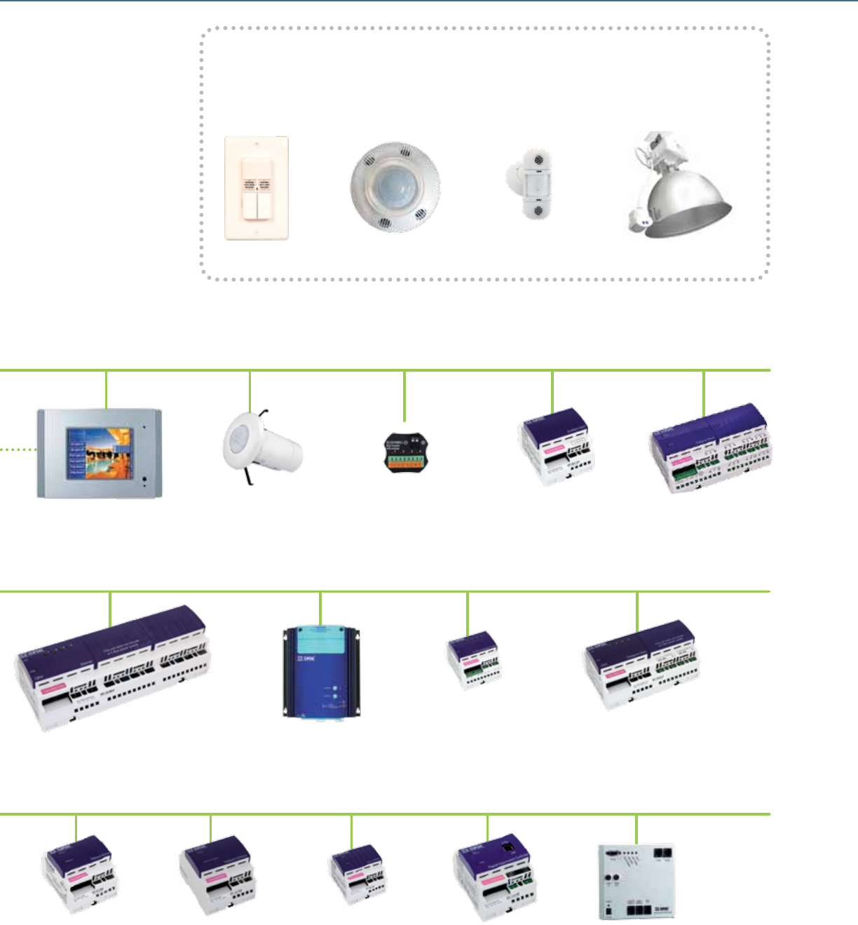
Schneider Electric Occupancy Sensors
Occupancy sensors from Schneider Electric are the perfect solution for applications needing
simple occupancy-based controls. Low-voltage ceiling- and wall-mounted occupancy
sensors can be tied into C-Bus network using simple dry contact input.
Wall Switch Ceiling Mount Wall Mount Fixture Mount
Bus Coupler
(Dry Contact Connections)
Auxiliary Input Unit General Input Unit
Touch Screen
Sensor
(PIR/IR/Light Level)
Telephone
Interface Unit
Professional
Series Dimmer
Changeover Relay Unit0-10 V
Dimming Unit
Phase Angle Dimmer
DALI GatewayEthernet GatewayNetwork Bridge Pascal Automation
Controller
C-BUSTM LIGHTING CONTROL + DESIGN GUIDE
156
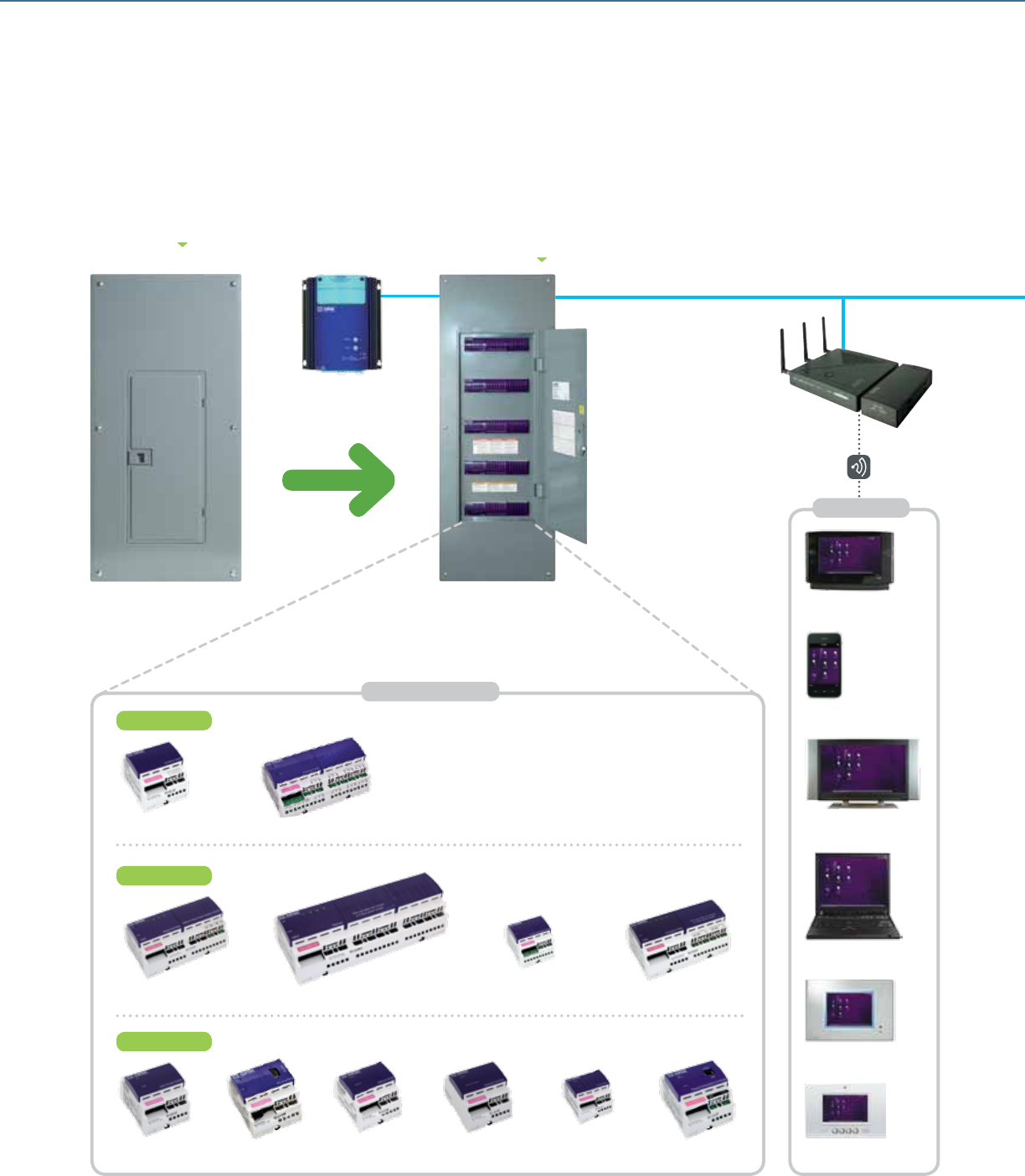
C-Bus DIN Rail Mounted Units provide a
vast array of capabilities, scalable for virtually
any size job, from a single room to an entire
home. Dimmers, relays, timers, controllers and
interface connections are all contained within
C-Bus enclosures.
C-Bus™ home control solutions provide the utmost in capabilities,
lower commissioning cost and greater customer appeal.
One-line Diagram
Professional
Series Dimmer
Auxiliary Input General Input
Input Units
Network Units
DALI GatewayEthernet GatewayNetwork Bridge Pascal Automation
Controller
Power Supply PC Interface
Output Units
Changeover Relay0-10 V DimmingPhase Angle DimmerMulti Channel Relays
C-Bus Din
Rail Enclosure
Load Center
Wiser Home
Controller
Model Shown: 60M
Variety of Sizes Available
C-Bus DIN Rail Units
User Interface
Mobile Phone
Personal Computer
Color Touch Screen
TV Screen
Web Tablet
Door Entry System
C-BUSTM LIGHTING CONTROL + DESIGN GUIDE
157
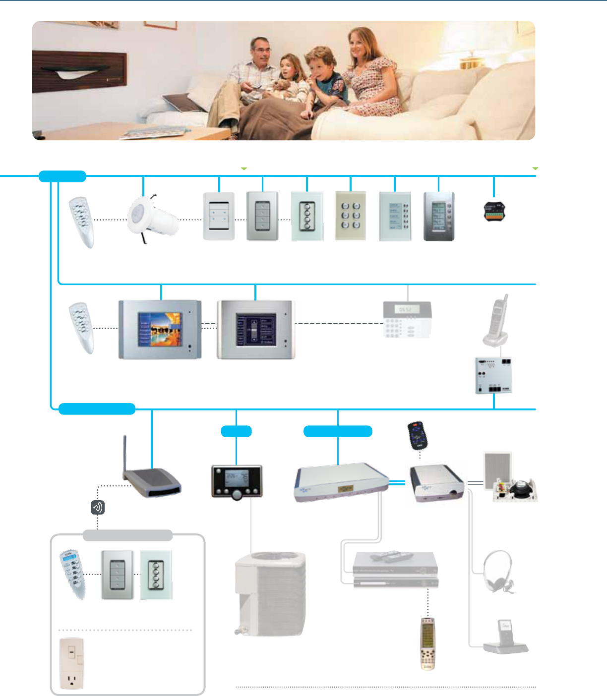
RS-232 and
Ethernet Connections
Security, Blind/Shade
Control, etc.*
Telephone
Interface Unit
Typical Cat-5 Cable (Any Topology) C-Bus Network
Input Units
Bus Coupler
(Dry Contact Connections)
Color Touch Screens Monochrome Touch Screens
Sensors
(PIR/IR/Light Level)
C-Bus
Remote
Control
C-Bus
Remote
Control
C-Bus
Remote
Control
Telephone *
C-Bus Audio
Remote Control
Saturn DLT
Keypad
Neo DLT
Keypad
Neo
Decorator
Keypad
Saturn™
Decorator
Keypad
Saturn
Keypad
Neo™
Keypad
Integrated Systems
C-Bus Matrix Switcher
[8 Zone Output, IR (2),
RCA (4) and Digital Input (1)]
Consumer Audio
Input Devices *
C-Bus Universal
Remote Control
Air Conditioning *
C-Bus Ampliers
(Desktop and
Remote Mount)
Headphone *
Local Source Input *
C-Bus Speakers
(Indoor and Outdoor)
Thermostat
C-Bus Wireless
Gateway
Plug Adaptor
Switches/Dimmers/Repeaters/
Multiple Location Devices/
Fan Controllers – All-in-one Keypad
HVAC Multi Room
C-Bus Wireless Devices
* Third-party Devices
C-BUSTM LIGHTING CONTROL + DESIGN GUIDE
158
Schneider Electric - North American Operating Division
320 Tech Park Drive, Suite 100
LaVergne, TN 37086
Tel: 1-888-SQUARED
www.schneider-electric.us
Document Number 1200CT0701R09/09
©2009 Schneider Electric. All rights reserved.
09-09 mq
C-Bus, Saturn and Neo are registered trademarks of
Schneider Electric and/or its afliates in the United States
and/or other countries. Other trademarks used herein are
property of their respective owners.
Addendum
1200CT0902R01/10
01/2010
Products Guide - Lighting Control and Integrated Home
Systems
ABOUT THIS ADDENDUM
This bulletin appends selection and technical information and catalog numbers
appearing in 1200CT0701R09/09 "Products Guide – Lighting Control and
Integrated Home Systems".
REVISIONS BY PAGE NUMBER
The information below references corresponding page number in the Products
Guide.
Page 7: Commercial Grade Occupancy Sensor – Ultrasonic Single Circuit Wall Switch
Catalog number Color
SLSUWS1277UI Ivory
SLSUWS1277UW White
SLSUWS1277UL Light Almond
SLSUWS1277UG Gray
SLSUWS1277UB Black
Page 8: Commercial Grade Occupancy Sensor – Ultrasonic Dual Circuit Wall Switch
Catalog Number Color
SLSUWD1277UI Ivory
SLSUWD1277UW White
SLSUWD1277UL Light Almond
SLSUWD1277UG Gray
SLSUWD1277UB Black
Page 9: Commercial Grade Occupancy Sensor – Dual Technology Single Circuit Wall Switch
Catalog Number Color
SLSDWS1277UI Ivory
SLSDWS1277UW White
SLSDWS1277UL Light Almond
SLSDWS1277UG Gray
SLSDWS1277UB Black
Page 10: Commercial Grade Occupancy Sensor – Dual Technology Dual Circuit Wall Switch
Catalog Number Color
SLSDWD1277UI Ivory
SLSDWD1277UW White
SLSDWD1277UL Light Almond
SLSDWD1277UG Gray
SLSDWD1277UB Black
© 2009 Schneider Electric. All Rights Reserved.

Products Guide - Lighting Control and Integrated Home Systems
Instruction Bulletin
Schneider Electric, USA
320 Tech Park Drive, Suite 100
La Vergne, TN, 37086
1-888-778-2733
www.schneider-electric.us
Square D, , Clipsal, C-Bus, Saturn and Neo are trademarks or registered trademarks
of Schneider Electric and/or its affiliates in the United States and/or other countries.
Electrical equipment should be installed, operated, serviced, and maintained only by
qualified personnel. No responsibility is assumed by Schneider Electric for any
consequences arising out of the use of this material.
© 2009 Schneider Electric. All Rights Reserved.
1200CT0902R01/10 01/2010
Page 14: Wall Mount Occupancy Sensor – Passive Infrared (PIR)
Catalog Number Color
SLSWPS1500 White
Page 25: Enclosure Cabinet Dimensions – Track Limiting Panels
Enclosure Cabinet Dimensions (H x W x D)
12M 9 x 14.25 x 3.75 in. (229 x 362 x 95mm)
21M 17.92 x 14.25 x 3.75 in. (455 x 362 x 95mm)
42M 33.78 x 14.25 x 3.75 in. (858 x 362 x 95mm)
Page 50: C-Bus™ Neo DLT Keypad – List of Available Colors
The Neo DLT™ keypad is also available in Black (BK).
Page 60: C-Bus PCI-USB – Revised Product Features
The Data cable for connecting PCI and personal computer does not include DB9 connectors.
Page 89: 12M Enclosure – Revised Dimensions
12.78 in. (W) x 9.09 in. (L) x 4.0 in. (D) [325 mm (W) x 231 mm (L) x 102 mm (D)]
Page 90: 24M Enclosure – Revised Dimensions
14.50 in. (W) x 14.94 in. (L) x 4.0 in. (D) [368 mm (W) x 379 mm (L) x 102 mm (D)]
Page 92: 36MS Enclosure – Revised Dimensions
22.12 in. (L) x 15.44 in. (W) x 3.9 in. (D) [562 mm (L) x 392 mm (W) x 99 mm (D)]
Page 117: C-Bus IR Reader – IR Transmitter Revised Description
Catalog Number Description
SLC5034NIRT IR Transmitter
Page 129: C-Bus RF Wireless Controls/RF Switch and Scene Controllers
Catalog Number Description
SLC5854NLM(xx)* Neo Decorator Style RF Scene Controller (4 button only)
SLC5884NLM(xx)* Saturn Decorator Style RF Scene Controller (4 button only)
NOTE: * Wallplate Sold Separately. Refer to individual product manual for order information.
Page 138: C-Bus Software/Schedule Plus
Catalog Number Description
SLC5000SDINST1 Schedule Plus installer Key*
* Installer key allows installers to create/commission projects using HomeGate software. This code
key is time restricted and allows the software to operate in ‘normal’ mode for anywhere between
48 to 72 hours per use (the software then returns to evaluation/demo mode).
NOTE: The installer code key will also be compatible with future software releases.
Contact the Customer Information Center for technical support by phone at
1-888-778-2733 or e-mail at
lightingcontrol.support@us.schneider-electric.com.
You may also find helpful information on our web site at
www.Schneider-Electric.us.
