Wiremold 2014 1000274892 Catalog
1000344943-Catalog 1000344943-Catalog 1000344943-Catalog B1 unilog cesco-content
2016-07-29
: Pdf 1000274892-Catalog 1000274892-Catalog B2 unilog
Open the PDF directly: View PDF ![]() .
.
Page Count: 740 [warning: Documents this large are best viewed by clicking the View PDF Link!]

Wiremold®
WIRE & CABLE MANAGEMENT
2014

WWW.LEGRAND.US/WIREMOLD
TABLE OF CONTENTS
TABLE OF CONTENTS
AVIP Series Device Plates
p.2
Wiremold® A/V
Quick Selection Guide
p.6
Using The Wiremold Catalog
After Table of Contents
Sustainability
After Table of Contents
New Products
After Table of Contents
Focus Markets
After Table of Contents
Index
p.703
Warranty Information
Inside Back Cover
Trademarks
Inside Back Cover
Quick Selection Guide
p.25
One-Piece Steel Raceway
Systems
500® & 700® Series Raceway
p.26
Two-Piece Steel Small
Single- & Dual-Channel
Raceway Systems
2000® Series Raceway
p.36
2400 Series™ Raceway
p.40
2400D Series™ Raceway
p.46
3000® Series Raceway
p.52
4000 Designer Series
Raceway
DS4000® Raceway
p.58
Two-Piece Steel Large
Multiple-Channel Raceway
Systems
4000® Series Raceway
p.63
4047 Series™ Device Plates
p.69
S4000® Series Stainless
Steel Raceway
p.74
6000® Series Raceway
p.81
STEEL RACEWAY
23
AUDIO/VIDEO
COMPATIBILITY 1
REFERENCE
17
COMMUNICATIONS
CONNECTIVITY
Ortronics® Connectivity
p.18
Wiremold® Open System
Connectivity
p.18
Wiremold® CM Series™
Communication Modules
p.19
WWW.LEGRAND.US/WIREMOLD
TABLE OF CONTENTS
TABLE OF CONTENTS
NONMETALLIC
RACEWAY
125
Quick Selection Guide
p.168
Small Single- & Dual-
Channel Raceways
AL2000 Series
p.170
AL2400 Series
p.174
AL3300 Series
p.177
ALDS400 Series Raceway
p.181
Large Single- & Dual-
Channel Raceways
ALA3800 Series
p.185
ALA4800 Series
p.189
AL5200 Series
p.193
Quick Selection Guide
p.112
Multiple-Channel Overfloor
Raceway Systems
OFR Series Overfloor
Raceway System
p.113
Steel Pancake Overfloor
Raceway Systems
1500 Series™ Raceway
p.118
2600 Series™ Raceway
p.122
111
OVERFLOOR
RACEWAY
Quick Selection Guide
p.126
Power-Rated Single- &
Dual-Channel Raceways
Eclipse™ PN03, PN05, PN10
Series Raceway
p.128
400, 800, 2300/2300D
Series™ Raceway
p.133
Large Capacity Multiple-
Channel Raceways
Access® 5000 Series
Raceway
p.142
CableSmart™ 40N2 Series
Raceway
p.148
5400 Series™ Raceway
p.151
5500 Series™ Raceway
p.158
5507 Series™ Faceplates
p.163
167
ALUMINUM
RACEWAY
Multi-Compartment
Surface Metal Raceway
Systems
AnySize™ Series Raceway
p.86
SpecMate™ Type 1 Wireway
& Enclosures – Type 1
Wireway
Type 1 Wireway
p.93
WWW.LEGRAND.US/WIREMOLD
TABLE OF CONTENTS
TABLE OF CONTENTS
Why Prewired
p.203
Single Channel,
Single Cover Aluminum
Raceway Systems
AL3000 Series Raceway
p.210
ALA3800 Series Raceway
p.211
Single/Dual Channel,
Single Cover Aluminum
Raceway Systems
AL3300 Series Raceway
p.213
AL4000 Series Raceway
p.215
AL4400 Series Raceway
p.217
AL4750 Series Raceway
p.219
Dual Channel, Dual Cover
Aluminum Raceway
Systems
AL4320 Series Raceway
p.221
AL4520 Series Raceway
p.223
ALA4800 Series Raceway
p.225
ALDS4000 Series
Raceway
p.227
Three Channel,
Dual Cover Aluminum
Raceway Systems
AL7320 Series Raceway
p.229
AL7450 Series Raceway
p.231
Prewired Steel Raceway
Systems
3000® Series, 4000® Series,
DS4000® & 6000®
Series Raceways
p.233
Prewired Nonmetallic
Raceway Systems
5400 Series™, 5500 Series™
& CableSmart™
40N2 Series Raceways
p.235
PREWIRED
RACEWAY
SYSTEMS 199
237
PLUGMOLD®
MULTIOUTLET
SYSTEMS
Plugmold® Steel
Multi-Outlet Systems
2000 Series™
p.240
2400 Series™
p.246
Plugmold® Plus Nonmetallic
Multi-Outlet Systems
NM2000 Series™
p.251
Plugmold® Aluminum
Multi-Outlet Systems
AL2000 Series™
p.256
Plugmold®
Tamper-Resistant
Multi-Outlet Systems
2000TR Series™
p.260
Plugmold®
Tamper-Resistant
GFCI Multi-Outlet Systems
p.263
Plugmold® Tamper-
Resistant USB Charging
Multi-Outlet Systems
p.264
adorne™ Under-Cabinet
Lighting System
p.265
CORD
MANAGEMENT
271
InteGreat™ Under Table
Cable Management
p.273
InteGreat™ Transition
Channel
p.274
InteGreat™ Cable Retractors
p.275
1200/1400/1600 Series
Overfloor Raceways
p.276
UniDuct® Series Raceways
p.278
300 Series™ Duct
p.286
WWW.LEGRAND.US/WIREMOLD
TABLE OF CONTENTS
TABLE OF CONTENTS
287
TABLE BOXES
InteGreat AV Table Box
p.290
InteGreat Cable Retractors
p.291
dequorum™ Recessed
Table Boxes
p.292
dequorum™ Flip-Up
Table Boxes
p.295
TableSource™ Table Boxes
p.297
Desktop Power Center
p.300
Desk Module
p.301
Lab Bench Pedestal
Table Box
p.303
4 Gang Lab Bench
Table Box
p.305
309
WALL/CEILING
BOXES
Evolution™ Series
Wall Boxes
p.311
WallSource™ Multiple
Service Boxes
p.313
Evolution™ Series
Ceiling Boxes
p.316
WAPE Series Wireless
Access Point Ceiling
Enclosures
p.322
WAPENCL Series Wireless
Access Point Ceiling
Enclosures
p.324
NME1250AP Nonmetallic
Wireless Access Point
Enclosure
p.325
WAPBRKT Wireless Access
Point Mounting Bracket For
Overhead Applications
p.326
Recessed Style
Poke-Thru Devices
Evolution™ 6AT Series
p.337
Evolution™ 8AT Series
p.345
331
POKETHRU
DEVICES
327
ZONE CABLING
ENCLOSURES
Zone Cabling Enclosures
CZE Series Zone Cabling
Enclosures
p.328
RFE Series Zone Cabling
Enclosures
p.329

WWW.LEGRAND.US/WIREMOLD
TABLE OF CONTENTS
TABLE OF CONTENTS
MODULAR WIRING
SOLUTIONS 529
Walkerflex® Modular
Wiring System
p.530
Work Surface
Modular Power
p.546
Evolution™ Series
Floor Boxes
p.389
Fire Classified Floor Boxes
p.405
Ratchet-Pro™ Series
Floor Boxes
p.423
Modulink™ 880MP Series
Floor Boxes
p.430
Resource RFB® Series
Floor Boxes
p.437
OmniBox™ Series
Floor Boxes
p.463
880 Series™ Floor Boxes
p.476
800 Series™ Floor Boxes
p.480
880W Series™ Floor Boxes
p.482
861 Series™ Floor Boxes
p.490
862 Series™ Floor Boxes
p.493
863 Series™ Floor Boxes
p.496
WMFB Series™ Floor Boxes
p.498
381
FLOOR BOX
SYSTEMS
FloorSource Series™
Raised Floor Boxes
AF Series™ Raised
Floor Boxes
p.501
AC Series™ Raised
Floor Boxes
p.508
CRFB Series™ Raised
Floor Boxes
p.513
FloorSource™ Series
Round Furniture Feed
Floor Boxes
p.518
CCFB Series™ Convention
Center Products
p.519
CCBB Series™ Ballroom
Floor Boxes
p.523
Surface Style
Poke-Thru Devices
RC7 Series™
p.352
RC9 Series™
p.354
RC9AMD Series™
p.356
AMD8 Series™
p.358
AV3 Series™
p.360
RC3 Series™
p.362
RC4 Series™
p.364
Furniture Feed Style
Poke-Thru Devices
4FFATC Series™
p.366
RC7AFFTC Series™
p.368
RC9AFFTC Series™
p.370
RC9AM2TC Series™
p.372
Pedestal Style
Poke-Thru Devices
FIT Series™
p.374
RC91GHBTC
& RC92GHBTC Series™
p.377

WWW.LEGRAND.US/WIREMOLD
TABLE OF CONTENTS
551
INFLOOR DUCT
SYSTEMS
Walkerduct® Underfloor
Duct Systems
p.557
Walkerduct®
Carpet/Tile Holders
p.569
Walkerduct® Pro Series
Service Fittings
p.572
PSRC9 Series™
Service Fittings
p.580
525 Series™
Service Fittings
p.582
525 & Multiplex™ Series
Activation Accessories
p.585
1200 Series™
Service Fittings
p.587
Multiplex™ Series
Service Fittings
p.588
Source I® Service Fittings
p.590
Flushduct Infloor
Duct Systems
p.594
Walkercell® Cellular
Raceway Systems
p.599
623
POLES AND
COLUMNS
TABLE OF CONTENTS
Floorport™ Series
Cover Assemblies
p.609
Trenchduct Feeder Systems
p.612
Wallduct Raceway Systems
p.616
Vista™ Architectural
Columns
p.627
Vista™ CP
Consolidation Point
p.634
Vista™ Point5
Architectural Columns
p.641
VLWAP VISTA™ Wireless
Access Point Enclosure
p.647
Tele-Power® Poles
p.648
Vertical Drop Poles
p.656
Custom Tele-Power® Poles
p.659
663
FIRE STOP
SOLUTIONS
FlameStopper™ Series
Thru-Wall &Thru-Floor
Fittings
p.665

WWW.LEGRAND.US/WIREMOLD
TABLE OF CONTENTS
693
TECHNICAL
INFORMATION
TABLE OF CONTENTS
Raceway Cross Sectional
Areas/Wire and Cable
Cross-Sectional Areas
p.694
Raceway Wire and Cable
Dimensions
p.695
Device Box Cubic Inch
Capacities
p.696
Calculating Wire and Cable
Capacities
p.697
Master Format 2004
Design Checklist
p.698
Conductor Derating
(Lighting and Power
Circuits) National Electrical
Code Articles
p.699
Mounting Methods for
Wiremold Raceways
p.700
Electrical Symbols in
Accordance with ANSI
Y32.9 – 1972
p.700
Steel Raceway
Color Specifications
p.702
683
SURGE
PROTECTIVE
DEVICES
Cabinet Surge Solutions
Surge Protected
CabinetMATE® Series
p.685
Rack Mounted Surge
Solutions
Surge Protected Products
p.687
Workstation Surge
Solutions
Surge Protected Plug-In
Outlet Center® Units
p.689
Hard-Wired Surge
Protection
PA/PB™ Series
p.692
667
POWER
DISTRIBUTION
Power Commander®
IQ Series
p.668
Power Commander® Plus
Series
p.671
Power Commander® Series
High Amperage Units
p.674
CabinetMate® Series
p.676
Rack Mounted Power
Solutions
p.677
Workstation Power
Solutions
p.678
Medical Grade/Special Use
Power Solutions
p.682

WWW.LEGRAND.US/WIREMOLD
Color Coding:
Color coding has been used throughout the Catalog including
in the Table of Contents and on the outside edge of the pages
of each section to help you quickly access the products or
information you need. A color key to the sections can also be
found on the right side of this page.
Organization:
Sections of this catalog have been reorganized to give you
faster access to key information about our products. System
layouts, wire fill capacity charts and UL Code Reference
information is located on the beginning pages of each
product section.
New Products:
The newest Wiremold product innovations are featured in the
New Products section. You’ll find color photos and information
on where these products are located in the Catalog.
Product Guide Available Online:
The Wiremold Catalog is also available online. With all the
same information as the print version, the online Catalog is
fully searchable and easy to use. You can access the online
catalog at: www.legrand.us/wiremold and then click on the
link for the Online Catalog.
Color Information:
Color swatches (see sample below) for each product line
are shown at the beginning of the product section. Each part
number listing also shows all the available color versions for
that part. Information on how the color values were developed
can be found in the Technical Section.
WELCOME
Product Sections are identified throughout the Catalog
with the following color coding:
CODE REFERENCE
cTUVus Listed:
File 30783215.002 EN60950-1
Code Reference Information:
UL Code Reference information
for each product line is indicated
at the beginning of the product
section (see example on right).
COLOR OPTIONS
500 and 700 Series Raceway Part Numbers with a “V” prefix have an
ivory finish. Part Numbers with a “-WH” suffix have a white finish.
Using the Wiremold Catalog
AUDIO/VIDEO COMPATIBILITY
COMMUNICATIONS CONNECTIVITY
STEEL RACEWAY
OVERFLOOR RACEWAY
NONMETALLIC RACEWAY
ALUMINUM RACEWAY
PREWIRED RACEWAY
PLUGMOLD® SYSTEMS
CORD MANAGEMENT
TABLE BOXES
WALL/CEILING BOXES
ZONE CABLING ENCLOSURES
POKETHRU DEVICES
FLOOR BOXES
MODULAR WIRING
INFLOOR DUCTS
POLES AND COLUMNS
FIRE STOP FITTINGS
POWER DISTRIBUTION
SURGE PROTECTIVE DEVICES
TECHNICAL INFORMATION

our commitment to sustainability
BETTER PERFORMANCE, BETTER OPERATIONS, BETTER SOLUTIONS
BETTER PERFORMANCE.
Our sustainability goals reach inside and
outside Legrand. We provide building solutions
to meet many building performance goals
from sustainability and energy efficiency to
productivity and occupant well being.
BETTER OPERATIONS.
We focus on operational
excellence because we believe
optimizing the way we manage
energy, water and waste is not only good for the environment,
it’s good for business. As part of the Department of Energy’s
Better Building, Better Plants Challenge (BBBP) Legrand has
reduced its energy intensity by over 30 percent across 14 sites
in the United States in just three years.
At Legrand, our sustainability commitment translates into greater
benefits and tangible value for our customers, business partners,
employees and the broader community.
DESIGNED FOR YOU.
Legrand is committed to
sharing key tools to reduce
energy intensity. Read more
about our journey and download
no-cost tools and resources at
www.legrand.us/sustainability.
SUSTAINABILITY
Flexible Infrastructure –
facilitate moves, adds & changes
Workplace Design –
open offices promote occupant productivity
Open Floor Designs –
take advantage of daylighting to save energy
Connecting Without Walls –
connections in open space fully optimize
workplace trends
Innovations – New products provide better performance and easier technology upgrades
WOOD USE – Post consumer content means a savings of more than 121 tons of wood.
GREENHOUSE GASES – Eliminated more than 82,000 pounds of greenhouse gases.
WATER – Saved more than 370,000 gallons of wastewater.
SOLID WASTE – 28,878 less pounds of solid waste was generated.*
*Source: Environmental Paper Network Online Paper Calculator. FSC
®
is not responsible for the savings calculations by using this paper.
The FSC certified papers used to print this catalog are made from 30% post-consumer recycled
paper. Over 286,000 pounds of paper were used to produce this catalog. By substituting recycled
paper for standard paper, the following savings were realized:
These savings would not have been possible without the assistance of:
NewPage Corporation – Manufacturer of Consoweb Gloss and other quality, certified and recycled printing papers.
Quad/Graphics – Printer, reduced environmental impact by using the highest practical renewable content ink.
Lindenmeyr Munroe – A leading paper broker
BETTER SOLUTIONS.
• Ultrasonic probes to detect air
leaks in the compressed air
systems used in manufacturing
at the West Hartford facility have
resulted in annual savings of over
300,000 kwh of electricity.
• Submeters installed throughout
the West Hartford manufacturing
facility to monitor electricity
usage have resulted in annual
savings of more that 116,000
kwh in electricity.
• Paint Line improvements at the
West Hartford facility, have
reduced water usage by over a
million gallons each year.
• Despite a 6% increase in
manufacturing output at the
West Hartford facility in 2013,
electricity usage has dropped by
nearly 3% and trash produced
from manufacturing has been
reduced by over 10%.
WWW.LEGRAND.US/WIREMOLD
WIREMOLD
NEW PRODUCTS
Wiremold® New Products are
the results of our constant
focus on developing and
improving the best wire and
cable management solutions
available. These products are
designed to provide users and
installers with enhanced ease
of installation and solution
innovations that meet the
constantly changing needs for
easy and dependable access
to power, communication and
A/V services. Saving installation
time while providing more
features, functionality, and
capacity, all with the reliability
and durability you’ve come to
expect from over 100 years of
Wiremold products.
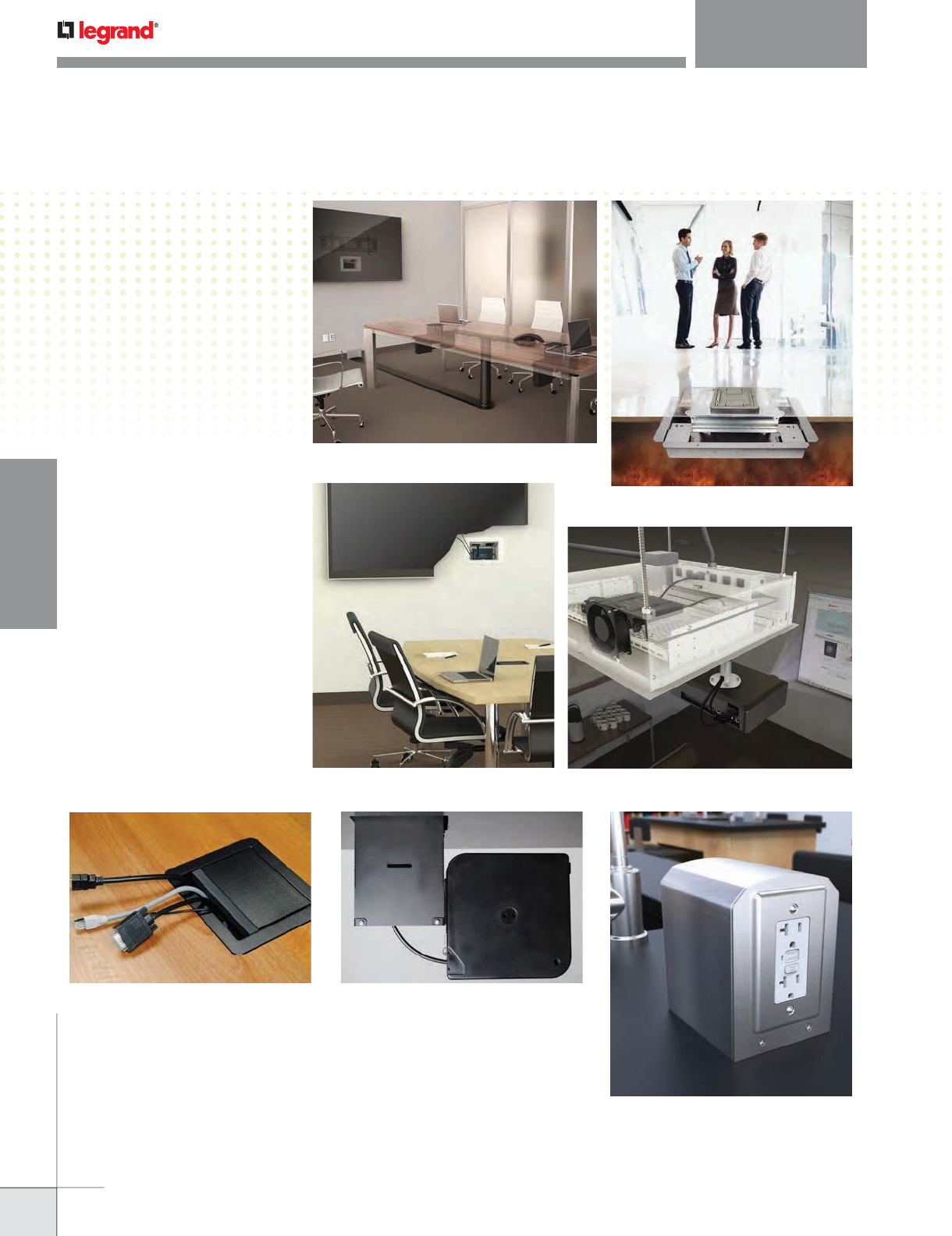
NEW PRODUCTS
Wire & Cable Management
InteGreat™ Meeting Room Solutions
Fire Classified Floor Boxes
Lab Bench Table Boxes
Evolution™ Series Ceiling Boxes
Evolution™ Series Wall Boxes
InteGreat™ A/V Table Boxes InteGreat™ Cable Retractors
WWW.LEGRAND.US/WIREMOLD
WIREMOLD
NEW PRODUCTS
NEW PRODUCTS
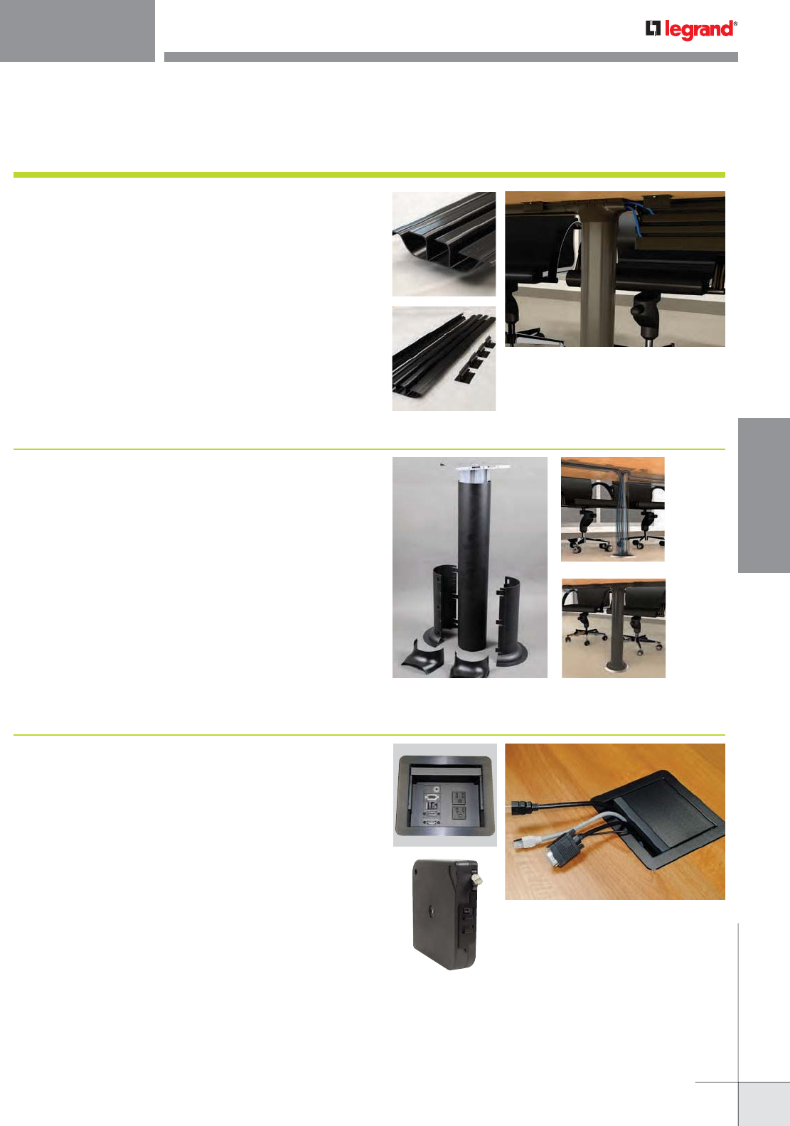
Wire & Cable Management
InteGreat™ Meeting Room Transition Channel (MRTC) is an integral
component in a “last meter” solution for bringing power and technology closer
to the user’s work area.
• Easy to order. Kit consists of aluminum center spine with steel mounting plate,
aluminum side channels, nonmetallic bottom boot and transition covers.
• Adapts to table height. Telescoping design accommodates installations between
26" and 30" in height to fit most standard table configurations.
• Seamless transitions. Boot allows for easy access to floor connections from floor
boxes, poke-thru devices, overfloor raceway or other wiring sources.
• Designed to mate with Wiremold Under Table Cable Management solution.
• Multiple channels. Allows separate channels to feed power, communication or
A/V services to each end of the work surface.
InteGreat™ Meeting Room Solutions
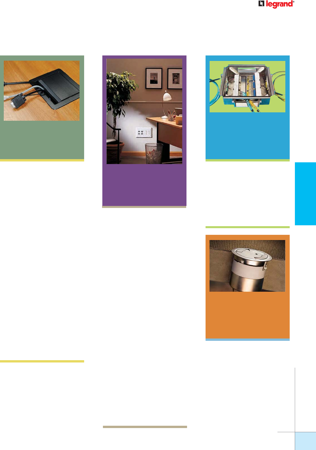
InteGreat™ Under Table Cable Management (UTCM) organizes and retains
cables, while providing easy access for future technology upgrades.
• Easy to order. One part number comes with base, mounting hinge rail and clips,
everything you need to complete your install.
• Easy to install. Adapts to underside of table and requires no special tools.
Simply cut to length to accommodate table length.
• Future flexibility. Tray opens with the push of a clip and organizes cables
with designed-in cable retaining dividers. Future technology upgrades or room
reconfigurations are a snap with minimal disruption.
• Totally Compatible. Can mate to InteGreat Transition Channel or used on its own.
• Field modifiable. Simply cut to length to accommodate table length.
Page 273
Under Table Cable Management (UTCM)
Meeting Room Transition Channel (MRTC)
InteGreat A/V Table Boxes are an elegant solution for extending power,
communication and A/V to the meeting presenter’s point-of use.
• Adjustable recessed device installation depth. Provides adjustability and the
extra depth required to mount devices especially A/V devices, below the table top.
• Convenience Receptacle. Unit comes with two 15A receptacles in the recessed
compartments and one 15A receptacle on the underside of the box to easily power
small devices mounted under the table surface.
• Extra device capacity. Can accept up to five Legrand AVIP device plates, five
Extron® Electronics MAAP device plates or five InteGreat Retractors.
• Multiple Cable Retractor mounting options. Cable Retractors can mounted
directly to A/V Table Box or to the underside of conference tables.
• Multiple cable options. Cable Retractors are available for Cat6, HDMI, VGA and
3/5mm audio cable.
A/V Table Box & Cable Retractors
Page 274
Pages 290
WWW.LEGRAND.US/WIREMOLD
WIREMOLD
NEW PRODUCTS
NEW PRODUCTS
Wire & Cable Management
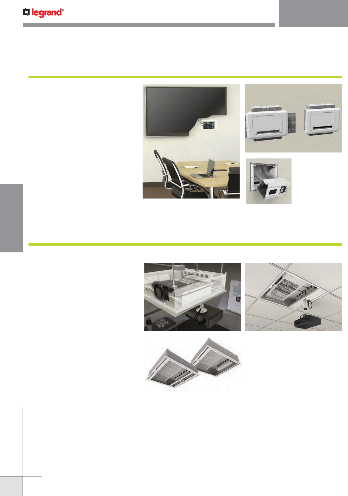
Evolution™ Series Ceiling Box
Evolution Series Ceiling Boxes are designed to go
above a false or permanent ceiling structure while
maintaining the aesthetics of the room. They provide
both storage capacity and the ability to support a
projector at the same time.
• Variety of Options. Evolution Series Ceiling Boxes are
offered in six different versions from a basic model to the
RackLink™ version; allowing the correct box to be selected
for a given job.
• Removable Shelf. The storage shelf is removable to allow
A/V equipment to be mounted outside the box, facilitating
a quicker, easier installation.
• Built-In Cooling. ECB2S-CR, ECB2SP-CR, ECB2S-RLNK,
and ECB2S-RLNK are equipped with a thermostatically
controlled AC fan to keep the A/V equipment cool while
keeping the environment quiet.
• Multiple Size Service Feeds. Evolution Series Ceiling
Boxes are equipped with multiple knockouts ranging
from 1/2" to 2" trade size openings to accommodate the
maximum amount of feed cables.
• Built-In Projector Mount. The Evolution Series Ceiling
Boxes are offered with a built in projector mount, allowing
the projector to be positioned laterally across the width of
the box with a load capacity of up to 50 lbs.
Page 316
Evolution™ Series Wall Box
Evolution Series Wall Boxes are ideal for any area
where a flat screen display is required, including:
conference rooms, airports, entertainment venues,
college campuses, and hospitals.
• New work or old work applications. Evolution Series
Wall Boxes have been designed to be able to be installed
in both new work and old work installations.
• Removable modules. Removable modules facilitate
quick and easy installations by allowing service feeds
to be connected outside the box.
• Low profile cover. The decorative trim flange and cover
(paintable) are low profile (less than 1/4" from the wall
surface) allowing the monitors to seat closer to wall.
• Multiple options. Evolution Series Wall Boxes are
available in both a 2-gang and a 4-gang version, allowing
for maximum flexibility to fit the capacity needs of the
task at hand.
• UL Listed to U.S. and Canadian safety standards.
Page 311
WWW.LEGRAND.US/WIREMOLD
WIREMOLD
NEW PRODUCTS
NEW PRODUCTS
Wire & Cable Management
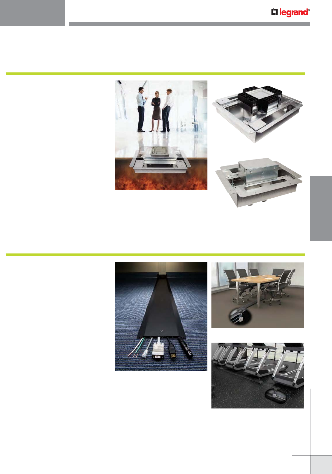
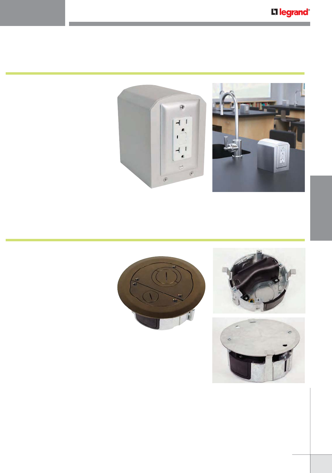
Fire Classified Floor Boxes
Wiremold® introduces seven recessed and flush
style Fire Classified Floor Boxes that meet or exceed
UL Fire Classification requirements. Available in both
single and multiple-gang versions, in both steel and
nonmetallic fabrications, they preserve the two-hour
fire rating of floors in which they have been installed.
• Maintains fire classification of fire rated floors.
Fire rated floor boxes preserve up to a two-hour fire rating
for floors in which they are installed. Eliminates the need
to install additional fireproofing to underfloor surfaces to
restore the floor’s fire rating.
• Fully adjustable boxes. Each floor box model is
adjustable both before and after the concrete pour.
• Triple service. Accommodates power, communication
and/or A/V devices reducing the need for multiple boxes.
• TopGuard Protection. Integral design components
prevent water, dirt and debris from entering power and
communication compartments.
• Available in one- to four-gang versions in both flush
and recessed models. Dividers can be removed in
several models for greater capacity and to provide multiple
configuration options for multi-service installations.
Page 405
OFR Series Overfloor Raceway
OFR Series Overfloor Raceway System provides four-
channels of capacity and access to a wide range of
power, communications, and A/V connectivity options in
the smallest, lowest, narrowest, ADA compliant profile
available in overfloor raceway systems.
• Lowest profile overfloor raceway available.
Smaller, narrower, lower raceway profile reduces
potential trip hazards while also being installer friendly
to speed installations.
• Multiple channel base. Four-channel raceway provides
space for multiple combinations of power, communication
and A/V to be provided through a single raceway
installation.
• Multiple options for communication and A/V
connectivity. OFR Series Raceway accepts Wiremold
Open System device plates that provide connectivity to
a wide range of devices from leading communication and
A/V providers.
• Meets ADA Accessibility Guidelines. Low profile,
unobtrusive design meets the ADA Accessibility Guidelines
that pertain to ADA Standard 4.5 which addresses changes
in floor and ground surface levels.
• Re-energize abandoned poke-thru holes. Brings a wide
variety of services to the work surface by re-using existing
openings from previous poke-thru installations
OFRPT3 Poke-Thru Transition Fitting
Page 113
WWW.LEGRAND.US/WIREMOLD
WIREMOLD
NEW PRODUCTS
NEW PRODUCTS
Wire & Cable Management
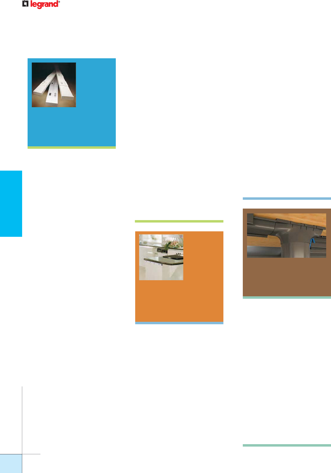
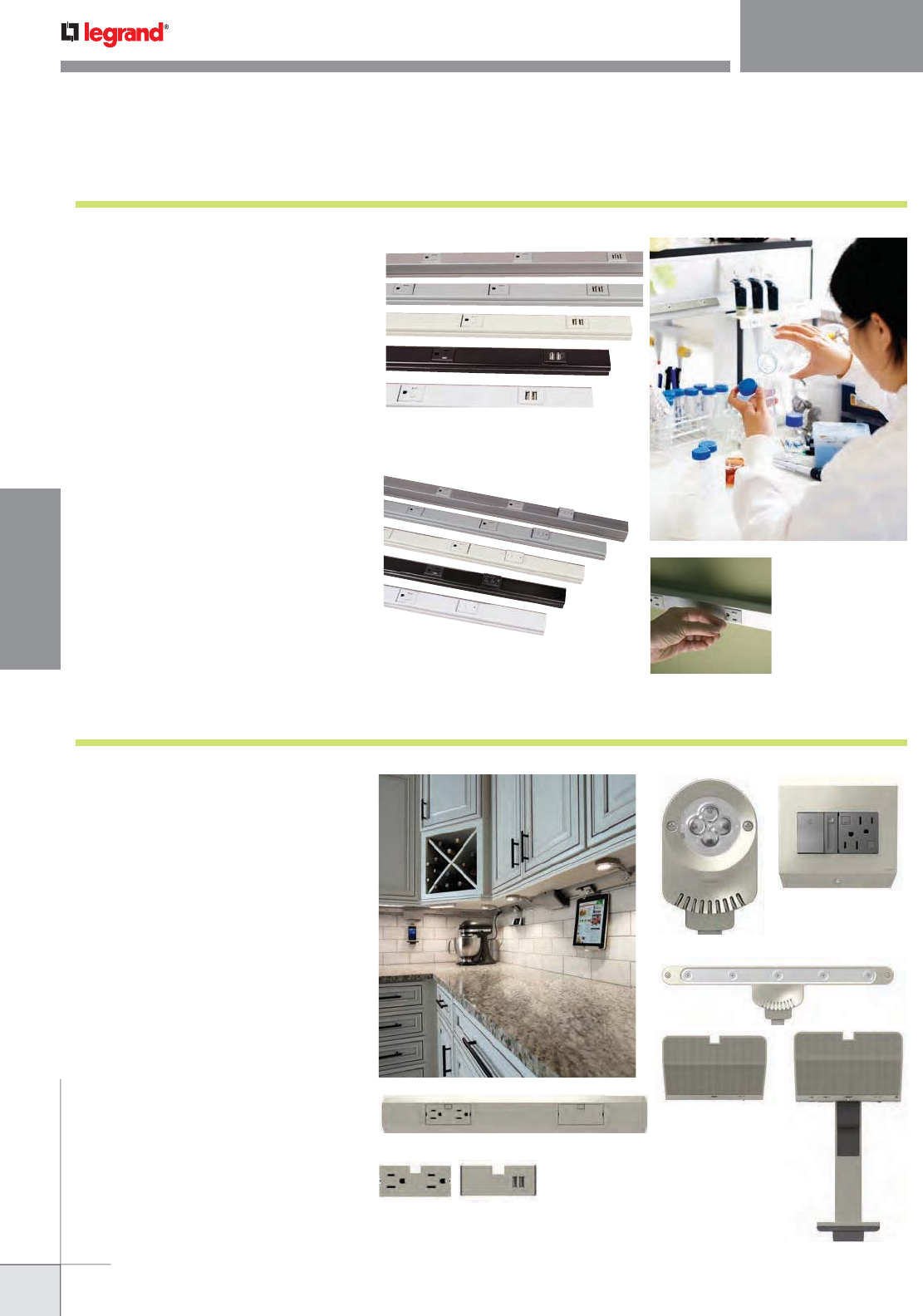
adorne™ Under-Cabinet Lighting System
adorne™ Under-Cabinet Lighting System is a fully
customizable and modular solution for eliminating
kitchen clutter. It is compatible with any kitchen layout,
such as a galley, L-shaped, or U-shaped, as well as with
any home wiring.
The adorne Under-Cabinet Lighting System brings an array of
modular components that swap out so easily, you’ll want to
reconfigure whenever the mood strikes. From speakers and
smart phone docks to lighting and outlets, there’s a world
of possibilities to choose from with these high-tech, highly
convenient building blocks.
Visit www.adornemyhome.com to use the Under-Cabinet
System Planning and Configuration Tool
Modular Track – in multiple lengths
Interchangeable Modules
Power Control Boxes
LED Linear Lighting
LED Puck Lighting
Digital Music Kit with
Bluetooth® connectivity
Page 265
Plugmold® Multi-outlet Systems with GFCI Protection, USB Charging
Plugmold® Multi-outlet Systems are now available in
a tamper-resistant version with USB charging. A great
solution for adding the convenience of multiple outlets
and USB charging to work or living spaces without the
work required to install multiple outlets.
The tamper-resistant GFCI version offers full GFCI protection
to multiple outlets without having to install multiple outlets.
• USB charging. 2.4A (Shared between 2 ports) USB type A
receptacle charges faster than other USB receptacles and
is compatible with USB 2.0 and 3.0 type devices.
• Built-in GFCI protection. Provides GFCI protection
for all outlets on the Plugmold strip and all connected
devices. Great for residential kitchens with multiple small
appliances, as well as laboratories.
• Tamper-resistant receptacles. Tamper-Resistant,
patented shutter system prevents improper insertion of
foreign objects. Meets 2011 National Electrical Code®
Tamper-Resistant requirements.
• Multiple colors and finishes. Painted finishes of black,
gray, ivory, and white, as well as anodized aluminum and
stainless steel versions, color options that integrate easily
into any room decor.
Pages 263
WWW.LEGRAND.US/WIREMOLD
WIREMOLD
NEW PRODUCTS
NEW PRODUCTS
Wire & Cable Management
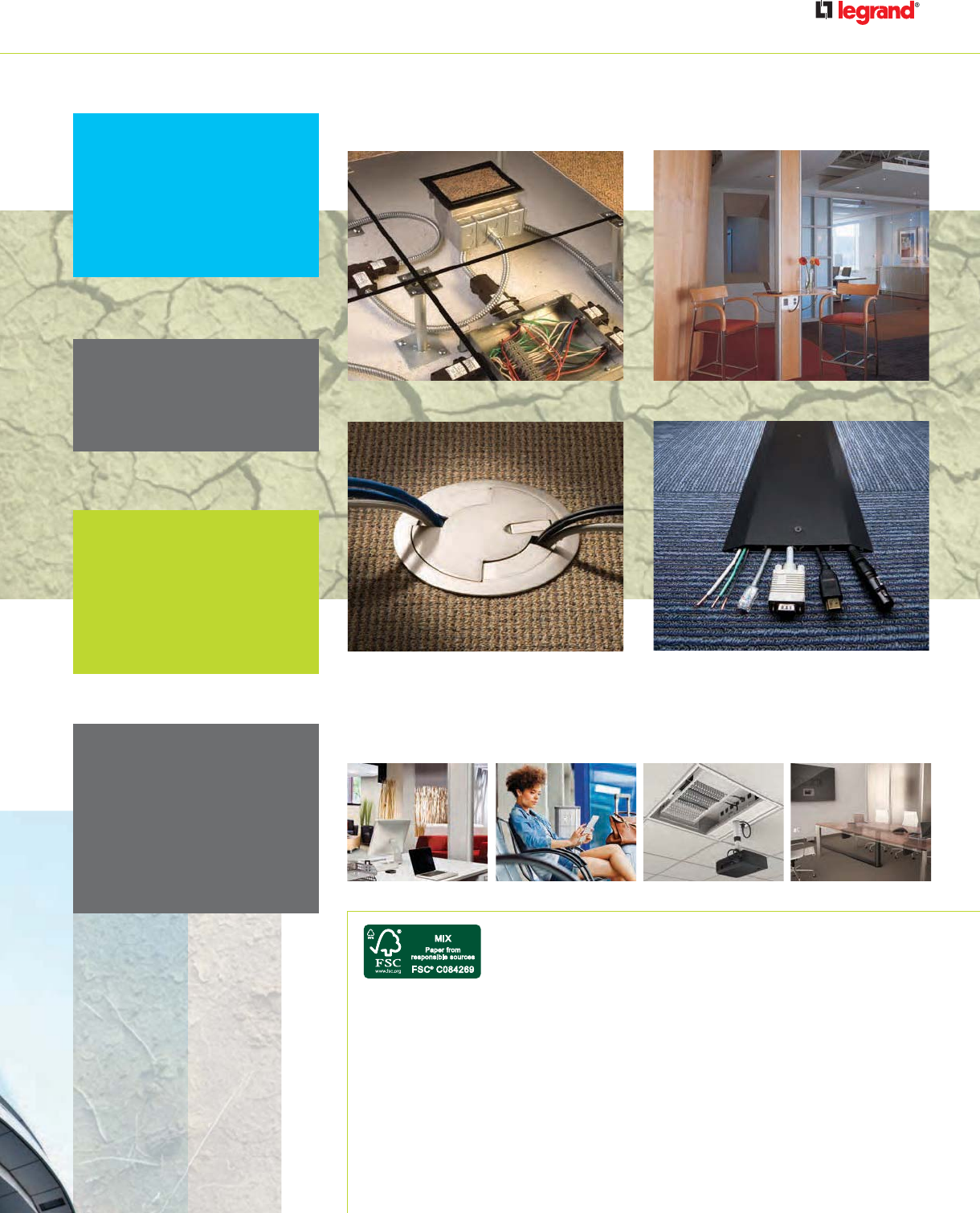
FloorSource 6FF Floor Boxes
FloorSource™ Series Round Furniture Feed Floor
Box is designed to work in both wood and raised floor
applications.
• Raised & wood floor applications. Designed so that it
can be installed in both raised and wood floors.
• Quicker and easier installation. The 6FF-AFB Furniture
Feed Floor Box fits into a standard 6" [152mm] diameter
hole. The round shape makes install easier and quicker,
increasing productivity and reducing jobsite cost.
• Suitable for use in air handling areas. In accordance
with Sec. 300-22(C) of the National Electrical Code.
• Multiple size knockouts. Available with multiple trade
size knockouts ranging in size from 1/2" to 1 1/2" allowing
for multiple activations and wiring configurations.
• Large capacity side entrance. With 2 in.2 [1290mm2]
there is plenty of capacity for a large bundle of
communication cables or preterminated A/V cables.
Page 518
Lab Bench Table Box
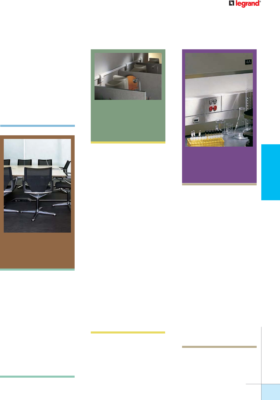
Lab Bench Table Box is designed specifically for the
unique challenges of the lab environment.
• Large Capacity. Lab Bench Table Boxes can be divided
into two gangs that each have the capacity to wire a 15A,
20A, GFCI, or a 30A twist lock receptacle. The LBP2 model
Table Box is currently the only third party listed table box
that can house back-to-back GFCIs.
• Protection against spills. Lab Bench Table Box is the
first lab bench activation to be tested to the proposed
UL111 standard for multi-outlet assemblies. This standard
includes a spill test, which proves there is no risk of shock
or short circuiting due to moisture when combined with
certain Pass and Seymour receptacles.
• Multiple Services. Lab Bench Table Boxes deliver power,
communication or A/V with the use of Wiremold AVIP Series
Device Plates. The removable divider, allows designers the
option to co-locate services in the same outlet box.
• Listed for Work Surfaces. Meets the NRTL listing for
work surfaces as well as UL514A for metallic outlet boxes.
Page 303
WWW.LEGRAND.US/WIREMOLD
WIREMOLD
FOCUS MARKETS
Wiremold® offers integrated connectivity and cable management solutions
needed for educational institutions that are taking advantage of new converging
technologies such as distance learning, distributed computing, interactive
teaching tools, wireless mobility and IP telephony. The combination of our
high-performing products, exceptional service and support ensures that your
learning community can take advantage of a customized solution designed to
exactly meet your needs.
EDUCATION SOLUTIONS
bringing technology everywhere you learn
Managing Time & Money
School budgets are tight and any allocated funds for
upgrades must demonstrate a return of investment
higher than most businesses.
PRODUCTS:
DS4000 Series Raceway, 4000 Series Steel Prewired
Raceway, Walkerflex Wiring System, Evolution
Series Poke-Thru Devices, Tele-Power Pole Extenders
Staying Connected
Any educational facility requires ample A/V
hook-ups, efficient data connectivity and proper
network infrastructure in order to run smoothly.
PRODUCTS:
Evolution Series Floor Box, Raceways, Table Boxes,
Power Distribution, Evolution Series Wall Box
Making Renovations Easy
Wiremold solutions provide an adaptable and flexible
technical infrastructure integrating electrical
equipment and communications networks just where
you need them.
PRODUCTS:
OFR Series Overfloor Raceway,
3000 Series Steel Prewired Raceway
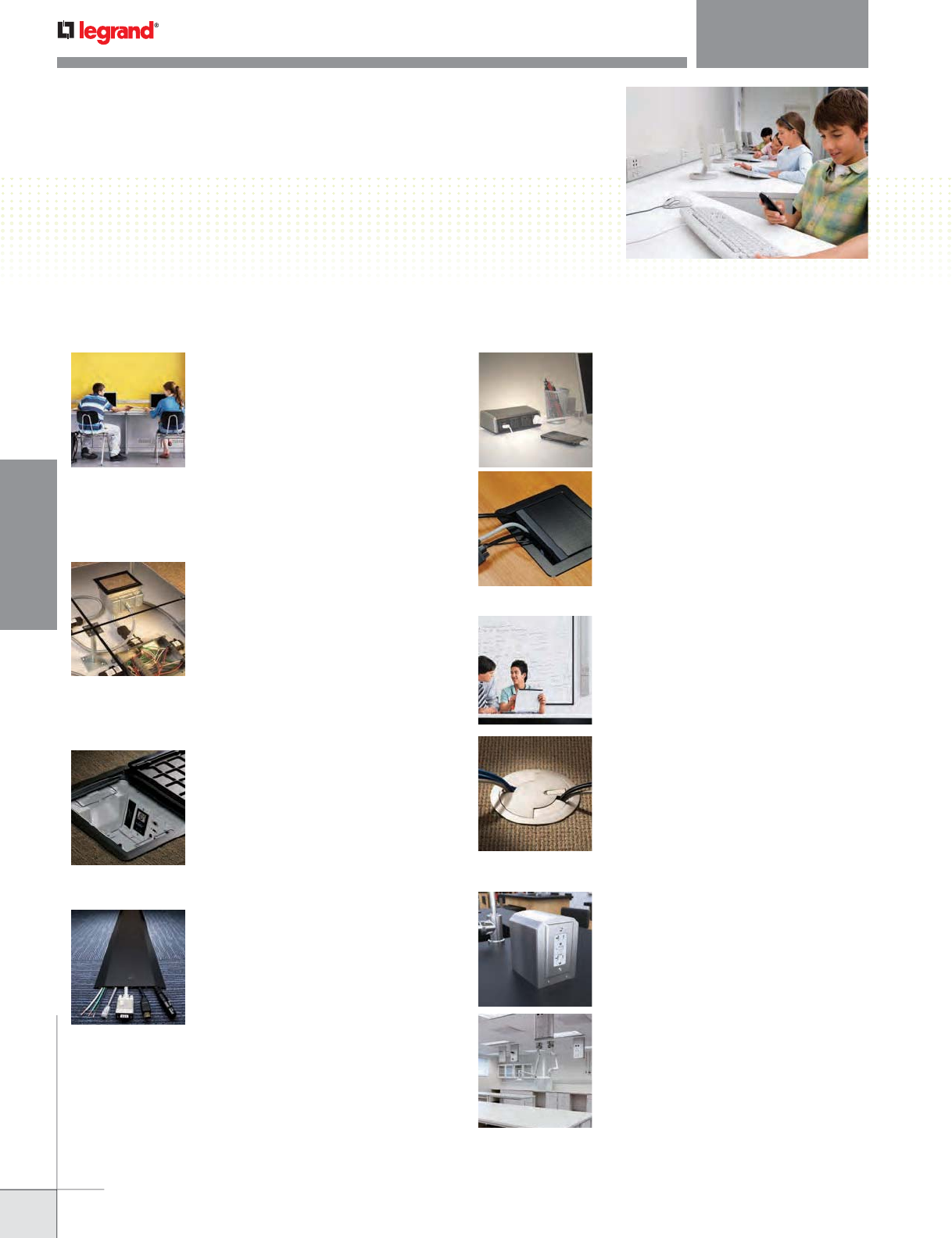
COLLEGE CAMPUS
Dorm Life
Ready Point-of-Use Access – Wiremold table
boxes provide students with access to power,
communications and A/V right at their desk or
study area.
PRODUCTS:
Work Surface Desk Module, Desktop Power Center
Table Box, InteGreat A/V Table Box,
TableSource Table Boxes,
College Classrooms
Wiremold offers a variety of pathways and A/V
connectivity that support the ever-changing
technology needs of today’s classrooms.
• Connecting students without walls
PRODUCTS: OFR Series Overfloor Raceway
• Enhanced A/V Performance
PRODUCTS: Evolution Series Poke-Thru Devices,
Wall & Ceiling Boxes
• Add or Extend power, communication &
A/V in the classroom
PRODUCTS: Steel or Prewired Raceway
Science Labs
• Configurable power and data – Wiremold power,
communications and A/V solutions meet the
demands of laboratory activity.
PRODUCTS:
Lab Bench Pedestal Table Box,
Vista Architectural Columns,
• Flexible Infrastructures – Facilitates moves,
adds & changes in labs.
PRODUCTS:
Prewired Aluminum & Stainless Steel Raceways
K-12
Preparing for the next generation
Technology in primary education is rising dramatically
as today’s students are growing up online and
connected. With tight school budgets, all upgrades
must show a significant return on investment.
PRODUCTS:
OFR Series Overfloor Raceway,
3000 Series Steel Prewired Raceway
Evolution Series Ceiling & Wall Boxes
WWW.LEGRAND.US/WIREMOLD
WIREMOLD
FOCUS MARKETS
Wiremold® recognizes that today’s buildings need to be as intelligent and efficient
as the workers who occupy them. Today’s high performing buildings are more
intelligent and connected than ever before. Wiremold’s infrastructure solutions
have been designed to seamlessly and reliably provide the critical connectivity that
both buildings and businesses rely on to operate at peak efficiency.
COMMERCIAL OFFICE SOLUTIONS
intelligent & efficient buildings
Zone Distribution
Zone distribution divides the commercial building
into small zones that support up to 48 ports or 3,600
ft². Moving to a distributed network architecture like
zone networking provides many practical benefits
while significantly reducing OPEX and CAPEX costs.
As commercial buildings migrate to access layer
environments, the benefits of centrally located
telecommunications closets are reduced. Employing
a fiber to the enclosure design extends the backbone
of the network closer to the user.
PRODUCTS:
Vista CP Consolidation Point Column, Vista Point5
Multi- Service Conference Column, Vista Wireless
Access Point Enclosure, Evolution Series Floor Box
Flexible Infrastructure
Getting your building into shape isn’t just about
increasing performance or managing your energy
better, it includes increasing flexibility too. By
retrofitting your building using Wiremold solutions,
you’ll be able to manage moves, adds and changes
easily, all while lowering the cost of ownership. That
means you can adapt your building to keep up with
the times without disrupting your existing structure.
Enabling you to make these changes non-invasively
and less expensively.
• Flexible Pathways
PRODUCTS: DS4000 Series Raceway.
• Streamline Moves, Adds & Changes
PRODUCTS:
Walkerflex Modular Wiring System,
FloorSource Raised Floor Boxes,
Evolution Series Floor Boxes
Workstation Performance
Building a better working environment goes
beyond just setting a standard for your network’s
performance. It’s about bringing everything your
network offers to your workstations easily and
efficiently. With Legrand’s end to-end solutions,
you’ll always be ready to address tomorrow’s
challenges. This includes increasing bandwidth and
performance requirements, new technologies and
the need to move, add or change your configurations
quickly and easily
• Zone Distribution-Reduce on-site installation
times and reconfiguration costs, while maximizing
performance and flexibility with field installable or
preterminated solutions.
PRODUCTS: FloorSource Series Raised Floor
Enclosures, Evolution Series Poke-Thru Devices
• Modular Connectivity – Select from a complete
range of high-performance workstation jacks,
faceplates, surface mount boxes and furniture
bezels to suit any workstation requirements.
PRODUCTS: Walkerflex Modular Wiring System,
FloorSource Raised Floor Boxes.
• Work Surface Modular Power – Provides table
access to power outlets and makes rearranging a
room layout as easy as unplugging, re-positioning
and plugging back together. Ideal for reconfiguring
meeting space to accommodate presentation,
training and collaboration configurations.
PRODUCTS: WSMP.
• Under Table Cable Management – Organizes and
retains cables and allows easy access to power,
communications and A/V cables. Ease of installing
and upgrading your meeting rooms enables power
and technology without cables getting in the way.
PRODUCTS: InteGreat Under-Table Cable
Management, Transition Channel, A/V Table Box.
• Consolidation Point – Bring voice, data and
power closer to the workstation while blending
with commercial interiors. For advanced cable
management with security and flexibility.
PRODUCTS: Vista CP, Vista Point5.
WWW.LEGRAND.US/WIREMOLD
WIREMOLD
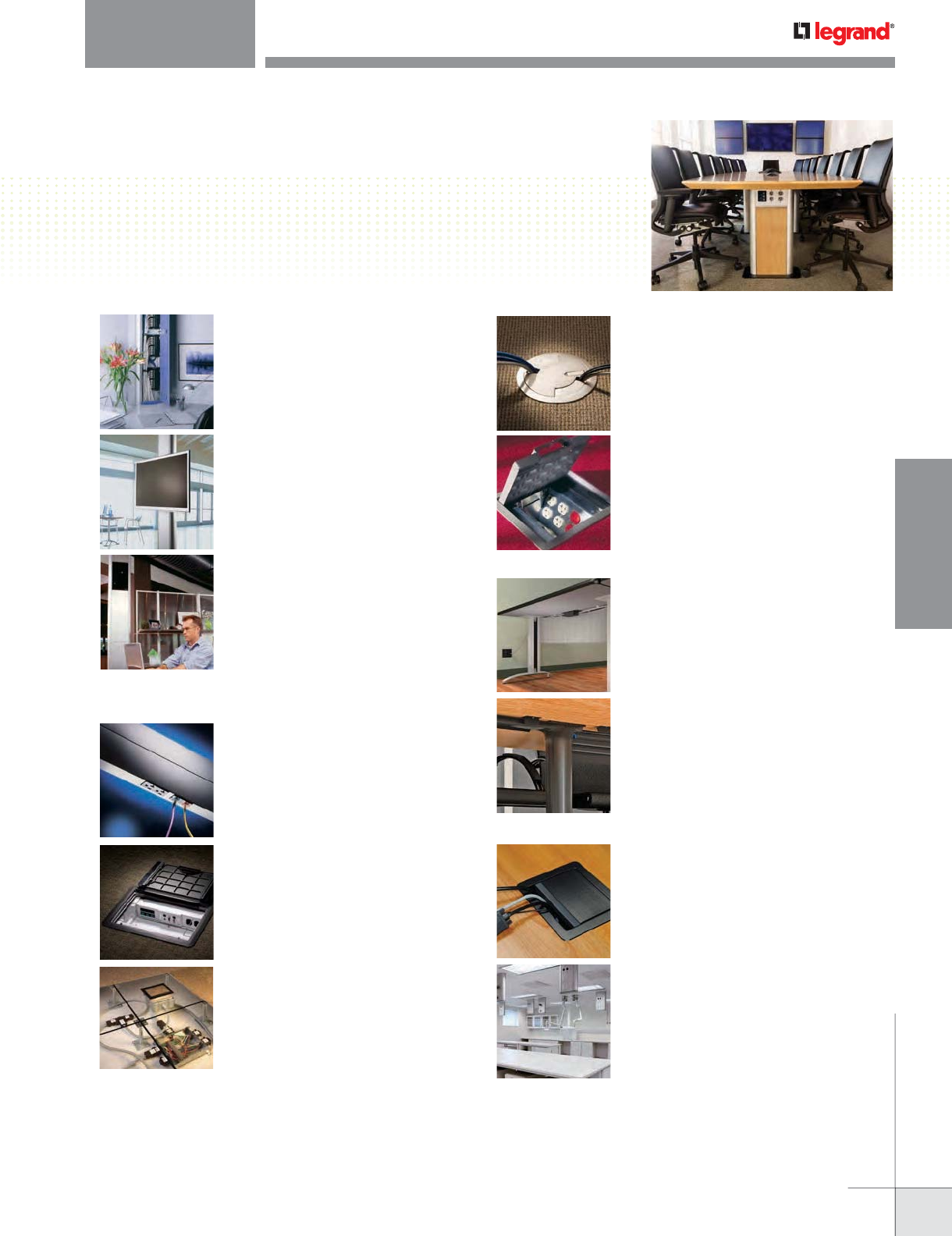
FOCUS MARKETS
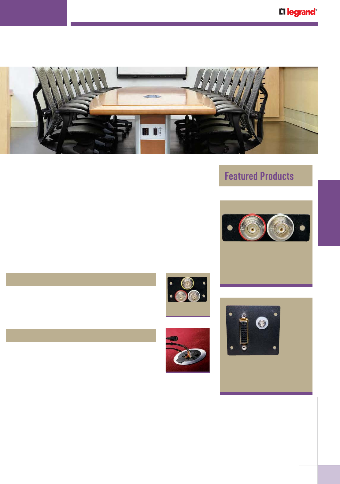
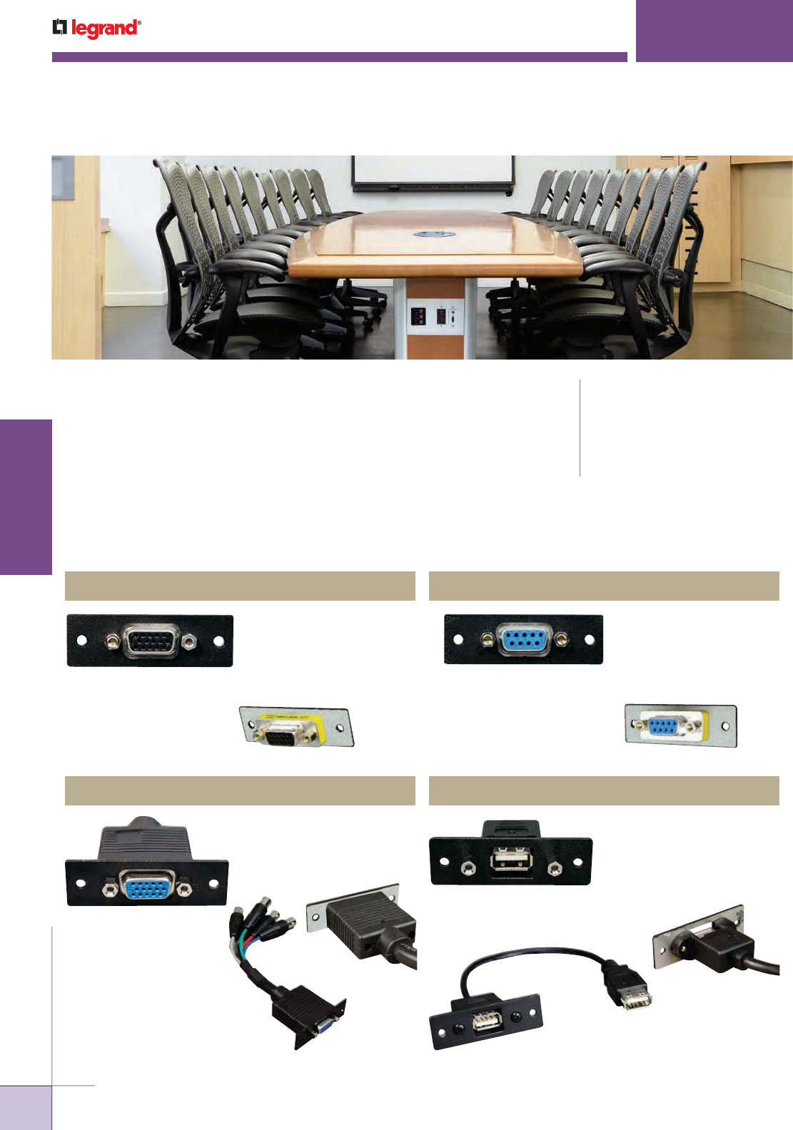
Take a good, hard look at your meeting rooms. Do you see a flexible, well-organized
spaces that can be easily adapted to a wide range of uses? Or do you see jumbles
of cords and cables running every which way, cluttering the floor and tables? If
chaos is what you see, then it’s time to open your eyes to Wiremold® Meeting Room
Solutions. Our innovative, easy-to-install systems and products are designed to keep
power, communications and A/V cords and cables neatly organized and contained.
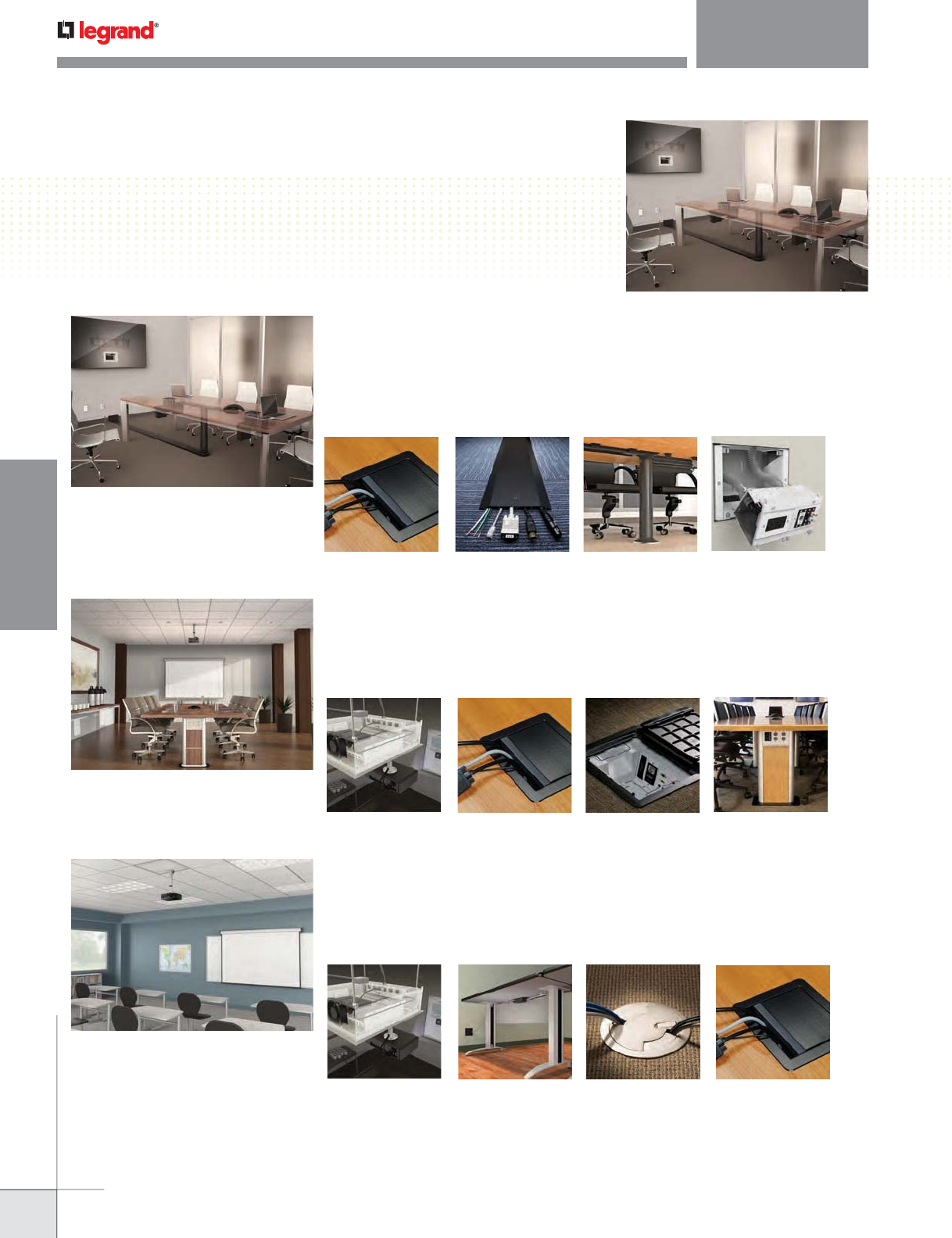
MEETING ROOM SOLUTIONS
are your meeting rooms meeting expectations?
Nothing detracts from sophisticated, multimedia conferences and presentations like seeing the
unsightly cables and cords these technologies require. That’s why Wiremold has introduced InteGreat™
Series – a series of smart, integrated solutions that keeps wires and cabling for A/V organized and
out of sight while also giving presenters and attendees easy access to the power and data capabilities
they need.
Today’s teaming and collaboration areas are becoming more dynamic. With furniture designed to be
easily moved and rearranged to accommodate a range of configurations. Regardless of the layout, every
attendee can have easy access to power and data. Which means wire and cable management solutions
must be highly flexible and adaptable – without getting in the way.
The era of the stuffy boardroom is over. Today’s formal meeting spaces need to support a wide range
of productivity enhancing technology – including interactive white boards, multimedia presentations,
smart phones, tablets and more. Providing easy access to A/V and high performance internet as well as
power is essential.
Meeting Rooms
Conference & Boardrooms
Table Boxes Overfloor Raceway Under-Table Cable
Management
A/V Flat Screen
Wall Boxes
Ceiling Boxes Table Boxes Floor Boxes Columns
Training & Collaboration Rooms
Ceiling Boxes Modular Power Poke-Thru Devices Table Boxes
WWW.LEGRAND.US/WIREMOLD
WIREMOLD
FOCUS MARKETS
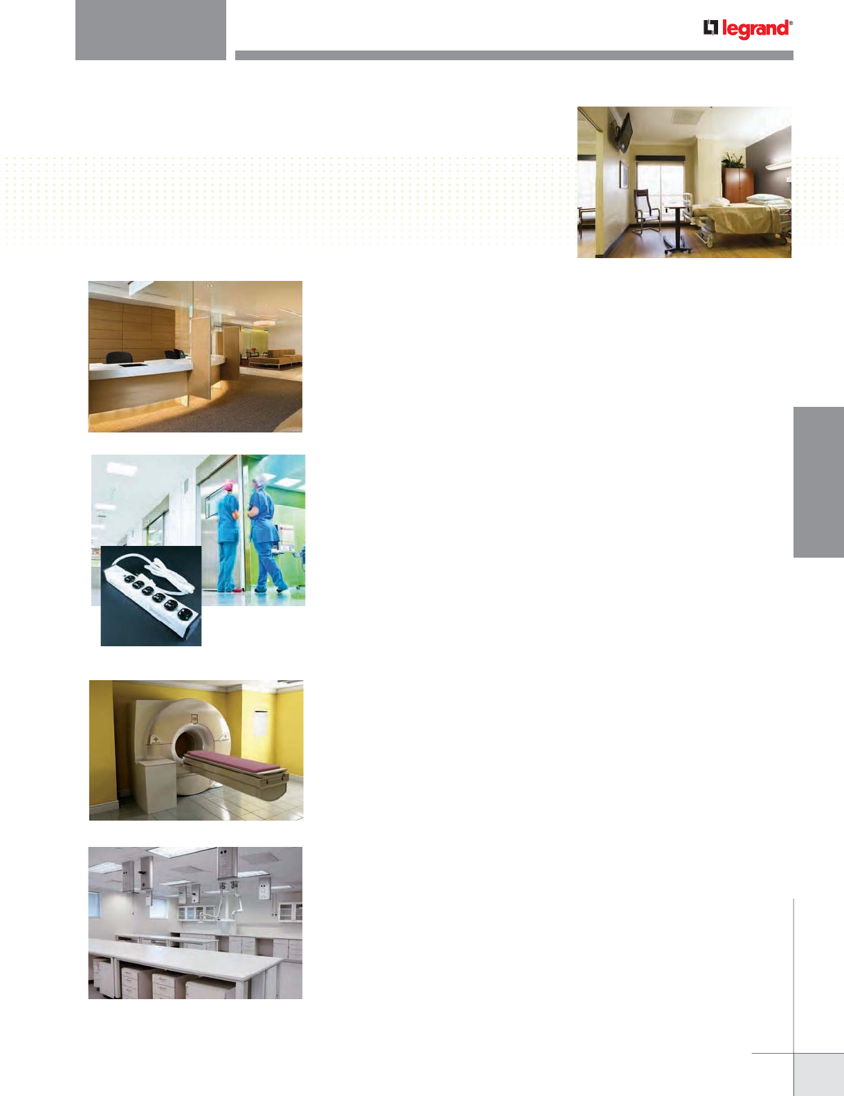
HEALTHCARE SOLUTIONS
keeping your infrastructure healthy and strong
Atrium & Admissions – Better first impressions
No-hassle patient check-ins, safe, open environments with access to internet and information is quickly
becoming the norm in today’s modern healthcare facilities. Legrand solutions allow you to create open floor
plans from the atrium to admissions while providing access to power and communications.
• Ready Point of Use Access – Power, communications & A/V at the point-of-use with Legrand work surface solutions.
PRODUCTS: Work Surface Desk Module, Desktop Power Center Table Box, TableSource Series Table Boxes,
InteGreat A/V Table Box, InteGreat Under Table Cable Management
• Open Floor Designs – Aesthetically bring power, communications and A/V wiring to open spaces.
PRODUCTS: Evolution Series Poke-Thru Devices, Evolution Series Floor Boxes, Vista Architectural Columns
Nurses Stations – Better support
Nurses are the first line of defense. From lighting control systems that help minimize eyestrain to advanced
data communications solutions that provide real-time access to patient information, Legrand has made
supporting these essential caregivers a top priority.
• Connecting without walls – Evolution Series Poke-Thru Devices offer twice the capacity of current designs. That means
one device can feed more workstations. Intumescent material maintains the fire rating of a 2-hour classified floor –
new construction or retrofit – means it provides capacity and meets fire codes.
PRODUCTS: Evolution Series Poke-Thru Devices
• High Performance Workstations – In today’s era of electronic health records, easy, efficient ways of keeping a wide
variety of mobile devices connected and charged are essential. Legrand work surface solutions provide easy access to
everything from multiple hospital grade power outlets (PIOCs) to USB ports, ensuring optimal connectivity and charging.
PRODUCTS: Work Surface Solutions, Medical PIOCs, USB Charging solutions
MRI/Operating Room – Better diagnostics
From robotic surgeries to sophisticated diagnostic imaging to outpatient surgical procedures, high-capacity
power systems are essential for every modern healthcare building. And because technologies can change
in a heartbeat, cabling and network systems must adapt easily to rapidly changing environments. All while
maintaining the highest standards for performance and reliability.
• Powerful Pathways – State-of-the-art medical equipment needs to be powered and connected to the hospital’s network.
PRODUCTS: Wallduct, Trenchduct, nonmetallic raceways
Labs – Better discovery
Flexibility and safety are of paramount importance in any lab environment. Legrand solutions allow you to
manage changing needs easily and safely with our power and protection products.
• Configurable Power and Data – From the TableSource series of worksurface products to hanging and floor-mounted Vista
multi-service columns, Legrand offers a wide range of integrated power, communications and A/V solutions to meet the
demanding needs of laboratory-specific activity.
PRODUCTS: TableSource, Lab Bench Pedestal Boxes, Vista columns
• Flexible Infrastructures – Facilitate moves, adds and changes in labs with prewired aluminum and steel raceways. Zone
cabling distribution brings modular flexibility to the point-of-use.
PRODUCTS: Aluminum, Steel, Prewired & Nonmetallic Raceways, Plugmold, Overfloor Raceway, Wireway
s
s
s
s
o
o
ns
ns
Be
Be
tt
t
e
e
fir
fir
s
s
i
i
m
m
p
p
e
e
ss
ss
i
i
n
n
s
s
At
At
ri
ri
u
u
m
m
&
&
A
A
d
d
m
m
Today more than ever, a healthcare facility’s infrastructure plays a vital role
in the delivery of better care. That’s why Legrand is as committed as you are
to keeping your infrastructure healthy and strong. We provide an unequalled
depth and breadth of smart, easy-to-install systems and products that maximize
capabilities while realizing energy and operational efficiencies – helping all who
come in contact with it to deliver better care.
WWW.LEGRAND.US/WIREMOLD
1
WIREMOLD
AUDIO/VIDEO COMPATIBILITY
Wiremold® A/V Quick Selection Guide
AVIP Series Device Plates
AVIP Series Device
Plates – Video 3
AUDIO/VIDEO COMPATIBILITY
For years, A/V installation has been an afterthought in the remodeling and
construction of buildings, leaving integrators with the challenge of creating
work-around solutions. Today, through Wiremold® Pathways, we are
changing the way integrators work, by incorporating A/V compatibility into
our broad product line from the start. Wiremold gives you
• Over 100 years of experience in pathway solutions.
• The market leader in cable management.
• The broadest product line in the industry.
• Cross-trade experience assures proper integration of power,
communication, and A/V into our products.
AVIP Series Device
Plates – A/V 5
Table of Contents
6
2
WWW.LEGRAND.US/WIREMOLD
2
WIREMOLD
AUDIO/VIDEO COMPATIBILITY
Wiremold audio/video interface plates (AVIP) allow for A/V connectivity in all
of Wiremold’s A/V compatible pathways. AVIP Series Device Plates are metal,
screwed-down connectors which ensure a secure connection that will resist
being pulled out or broken while in use.
From data to audio to video, Wiremold AVIP device plates help you stay
connected in your meetings and training rooms, collaboration spaces or work
areas. Wherever your connectivity needs are, we have the device plates and
pathways to get you there.
AUDIO/VIDEO COMPATIBILITY
Wiremold AVIP Connectivity
CODE REFERENCE
Please visit the individual
product sections located
throughout this Product Guide
for specific product Code
Reference information.
One USB A Female to
USB A Female Adapter,
single plate. Dimensions:
2.2" x 0.7" x 10" [53.89mm
x 17.78mm x 254mm].
One 9 Pin HD Female
to Female, single plate.
Dimensions: 2.2" x 0.7" x
0.7" [53.89mm x 17.78mm
x 17.78mm].
AVIP Series Device Plates – Computer
One 15 Pin HD Female
to Female, single plate.
Dimensions: 2.2” x 0.7” x 0.7”
[53.89mm x 17.78mm x
17.78mm].
One 15 Pin HD Female to Five
BNC on 4" Pigtails, single
plate. Dimensions: 2.2" x 0.7"
x 7.25" [53.89mm x 17.78mm
x 184.15mm].
AV1002BK AV4005BK
AV1000BK AV4000BK
WWW.LEGRAND.US/WIREMOLD
3
WIREMOLD
AUDIO/VIDEO COMPATIBILITY
AUDIO/VIDEO COMPATIBILITY
AVIP Connectivity Ordering Information
AV1002BK
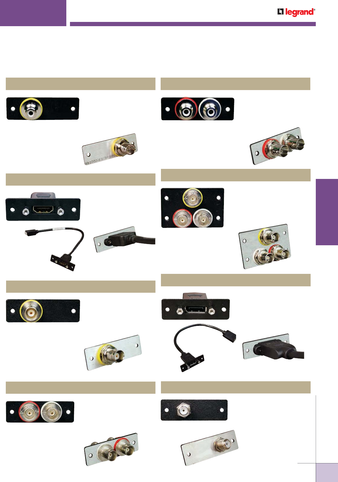
AVIP Series Device Plates – Video
One RCA Female to BNC
Female Adapter, single
plate. Dimensions: 2.2”
x 0.7” x 1.3” [53.89mm x
17.78mm x 33.02mm].
One HDMI Female to One
HMDI Female on 10" pigtail,
single plate. Dimensions:
2.2" x 0.7" x 10" [53.89mm x
17.78mm x 254mm].
One BNC Female to Female
Barrel, single plate.
Dimensions: 2.2" x 0.7" x
1.3" [53.89mm x 17.78mm x
33.02mm].
Two BNC Female to Female
Barrels, single plate.
Dimensions: 2.2" x 0.7" x
1.3" [53.89mm x 17.78mm x
33.02mm].
Three BNC Female to BNC
Female Barrels, double
plates. Dimensions: 2.2"
x 1.4" x 1.3" [53.89mm x
35.56mm x 33.02mm].
One Display Port Female to
One Display Port Female
on 10" Pigtail, single plate.
Dimensions: 2.2" x 0.7" x
10" [53.89mm x 17.78mm x
254mm].
One F-Connector Female to
Female Barrel, single plate.
Dimensions: 2.2" x 0.7" x
0.7" [53.89mm x 17.78mm x
17.78mm].
AV2002BK
AV3000BK
AV5000BK
AV5001BK
AV2003BK
AV5002BK
AV5004BK
AV9010BK
Two RCA Female to BNC
Female Adapters, single
plate. Dimensions: 2.2" x
0.7" x 1.3" [53.89mm x
17.78mm x
33.02mm].
WWW.LEGRAND.US/WIREMOLD
4
WIREMOLD
AUDIO/VIDEO COMPATIBILITY
AUDIO/VIDEO COMPATIBILITY
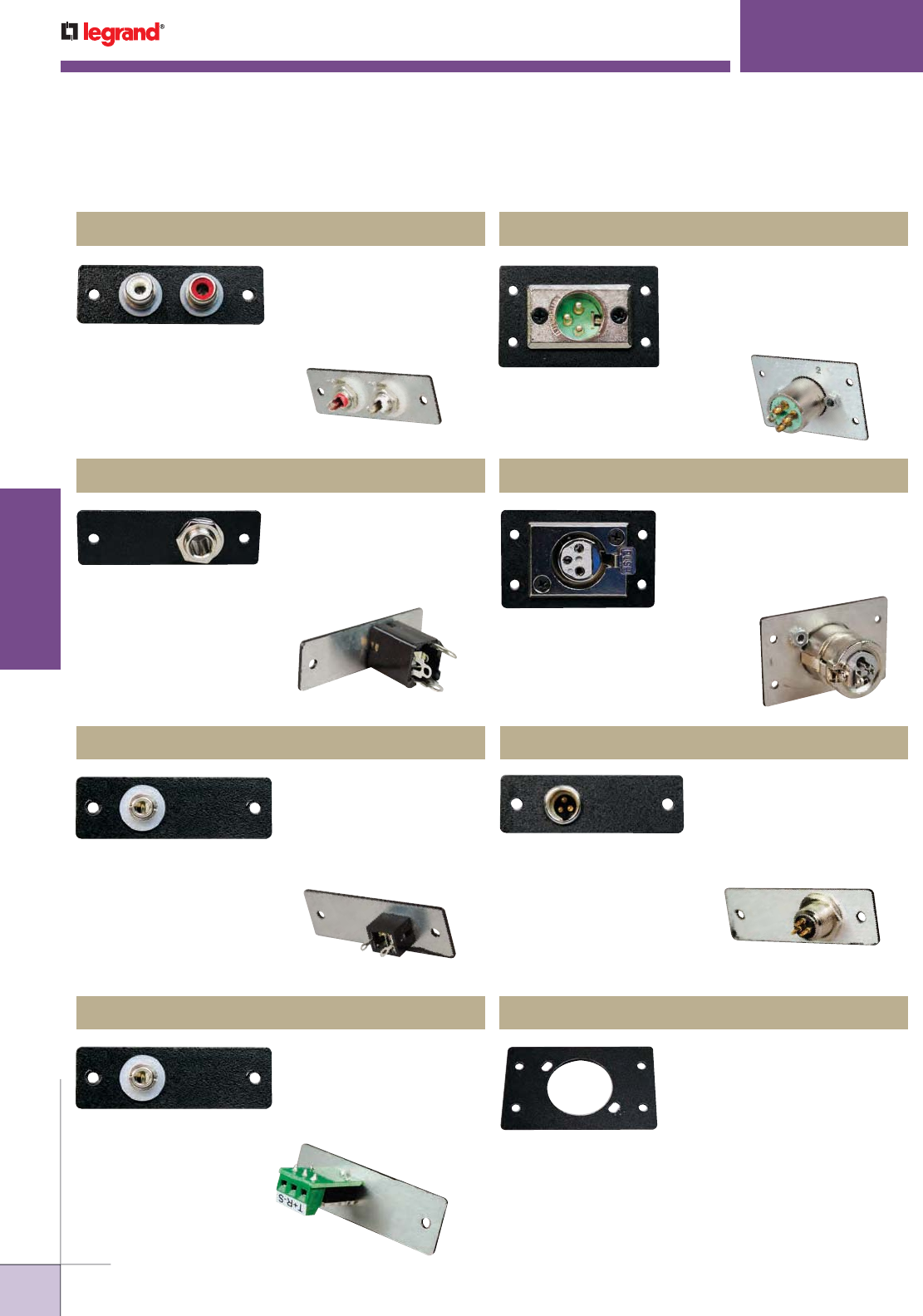
Wiremold AVIP Connectivity Ordering Information
AV1002BK
Two RCA Female to
Solder Cups, single plate.
Dimensions: 2.2" x 0.7" x
0.9" [53.89mm x 17.78mm x
33.86mm].
One XLR 3-pin Male to
Solder Cups, double plates.
Dimensions: 2.2" x 1.4" x
1.1" [53.89mm x 35.56mm x
27.94mm].
One 1/4" Stereo Phone
Female to Solder Tabs,
single plate. Dimensions:
2.2" x 0.7" x 1.4" [53.89mm x
17.78mm x 35.56mm].
One 3.5mm Stereo Mini Jack
to Solder Tabs, single plate.
Dimensions: 2.2" x 0.7" x
0.75" [53.89mm x 17.78mm x
19.04mm].
One Mini XLR 3-pin Male to
Solder Cups, single plate.
Dimensions: 2.2" x 0.7" x
0.7" [53.89mm x 17.78mm x
17.78mm].
One 3.5mm Stereo Mini
Jack to Captive Screw Term,
single plate. Dimensions:
2.2" x 0.7" x 1.2" [53.89mm x
35.56mm x 30.48mm].
One XLR Pane Mount Plate
(accepts D-Size Connectors),
double plates. Dimensions:
2.2" x 1.4" [53.89mm x
35.56mm].
AVIP Series Device Plates – Audio
AV6001BK
AV7000BK
AV7004BK
AV7005BK
AV8008BK
One XLR 3-pin Female to
Solder Cups, double plates.
Dimensions: 2.2" x 1.4" x
1.6" [53.89mm x 35.56mm x
40.64mm].
AV8009BK
AV8010BK
AV9016BK
WWW.LEGRAND.US/WIREMOLD
5
WIREMOLD
AUDIO/VIDEO COMPATIBILITY
AUDIO/VIDEO COMPATIBILITY
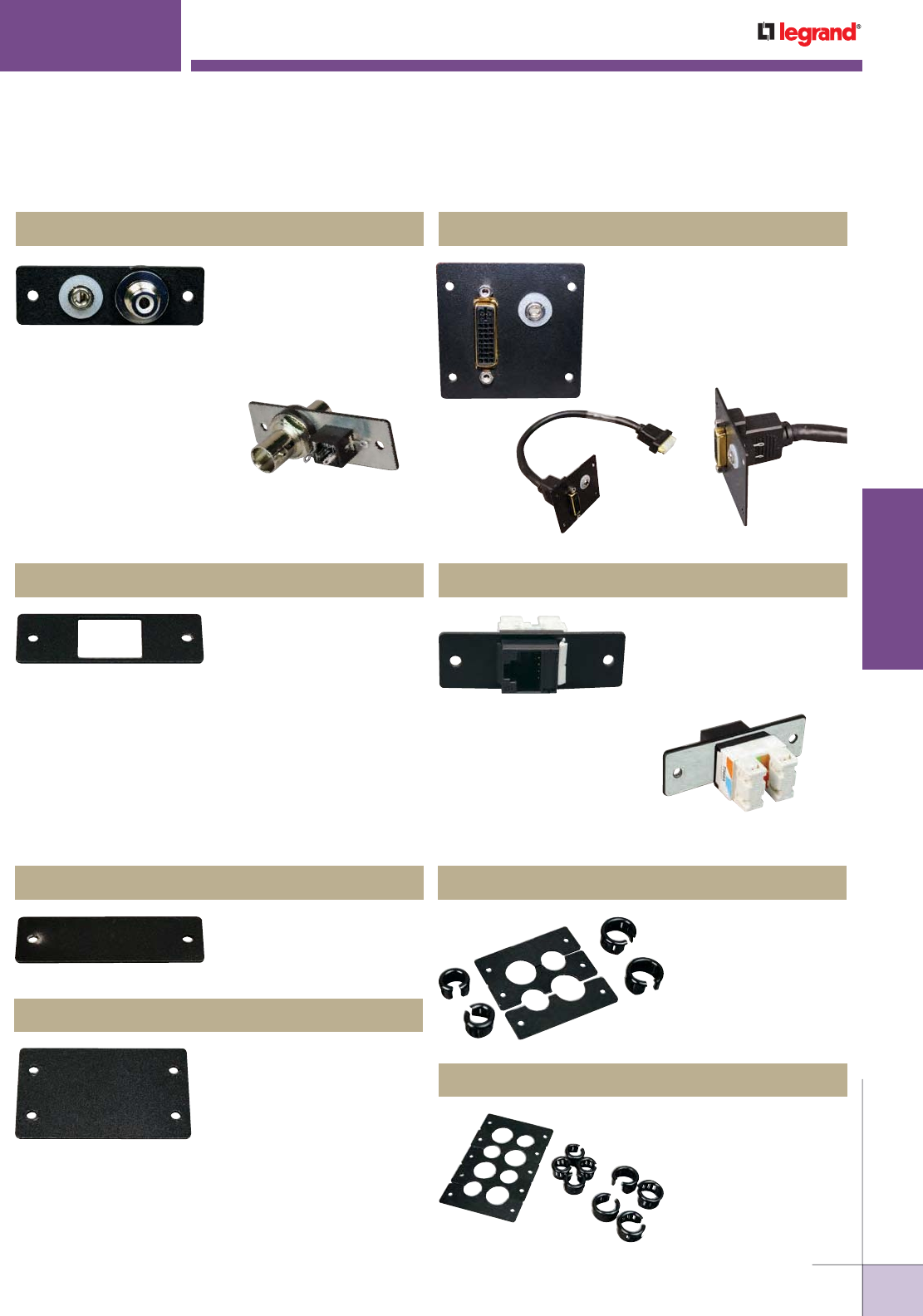
Wiremold AVIP Connectivity Ordering Information
One Keystone Jack Plate,
single plate. Dimensions:
2.2" x 0.7" [53.89mm x
17.78mm].
One Keystone CAT6
Jack Plate, single plate.
Dimensions: 2.2" x 1.7" x
1.2" [53.89mm x 17.78mm x
30.48mm].
AVIP Series Device Plates – Data
AVIP Series Device Plates – Accessories
Blank Plate-Single, single
plate. Dimensions: 2.2" x 0.7"
[53.89mm x 17.78mm].
Cable Kit, 4 Openings (2
small & 2 large), triple
plates. Dimensions:
2.2" x 2.1" [53.89mm x
53.34mm].
Blank Plate-Double, double
plates. Dimensions: 2.2" x
1.4" [53.89mm x 35.56mm].
Cable Kit, 8 Openings
(4 small & 4 large),
quintuple plates.
Dimensions: 2.2" x 3.5"
[53.89mm x 88.90mm].
One RCA Female to BNC
Female Adapter, one
3.5mm Stereo Mini Jack to
Solder Tabs, single plate.
Dimensions: 2.2" x 0.7" x 1.3"
[53.89mm x 17.78mm x
33.02mm].
One DVI Female to one DVI
Female on 10" [254mm]
pigtail, with 3.5mm Stereo
to Solder Tabs, triple plates.
Dimensions: 2.2" x 2.1" x 10"
[53.89mm x 53.34mm x
254mm].
AVIP Series Device Plates – Audio/Video
AV5005BKAV2004BK
AV9008BK AV9015BK
AV9003BK
AV9004BK
AV9012BK
AV9014BK
WWW.LEGRAND.US/WIREMOLD
6
WIREMOLD
AUDIO/VIDEO COMPATIBILITY
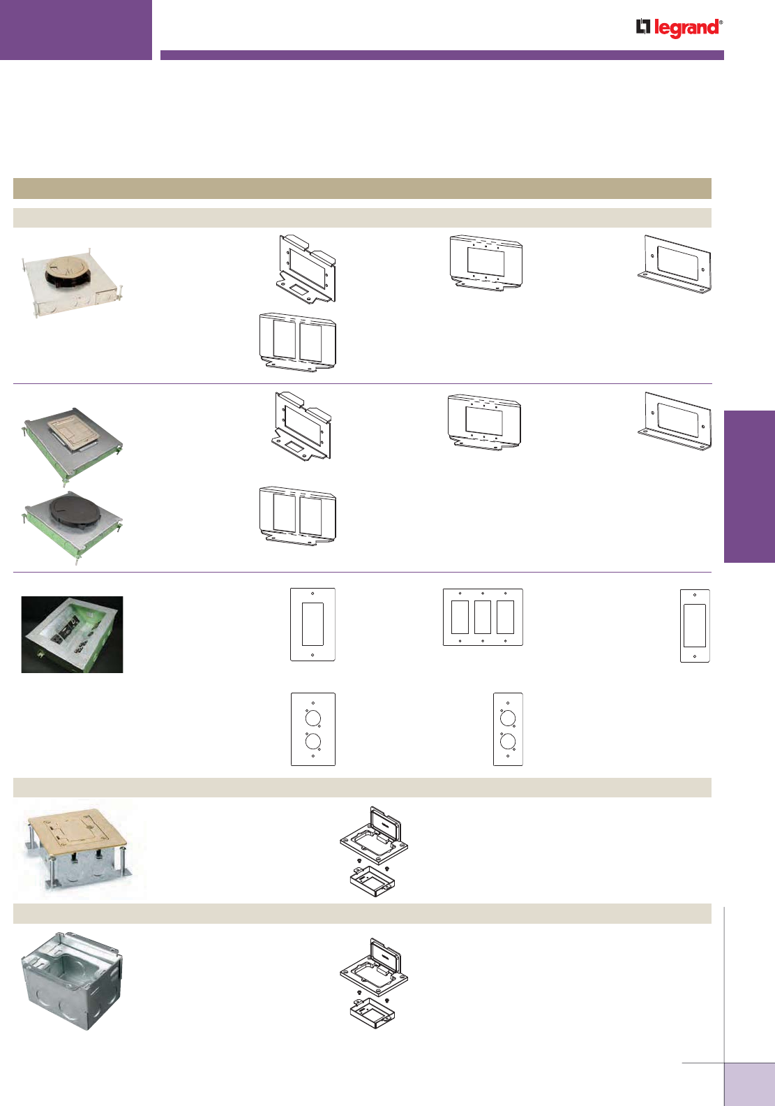
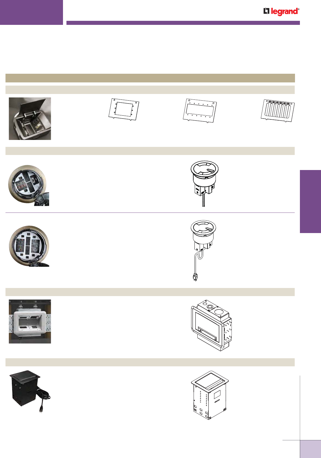
EFB10-AAP
Device Plate holds 2
Extron® Electronics AAP
devices.
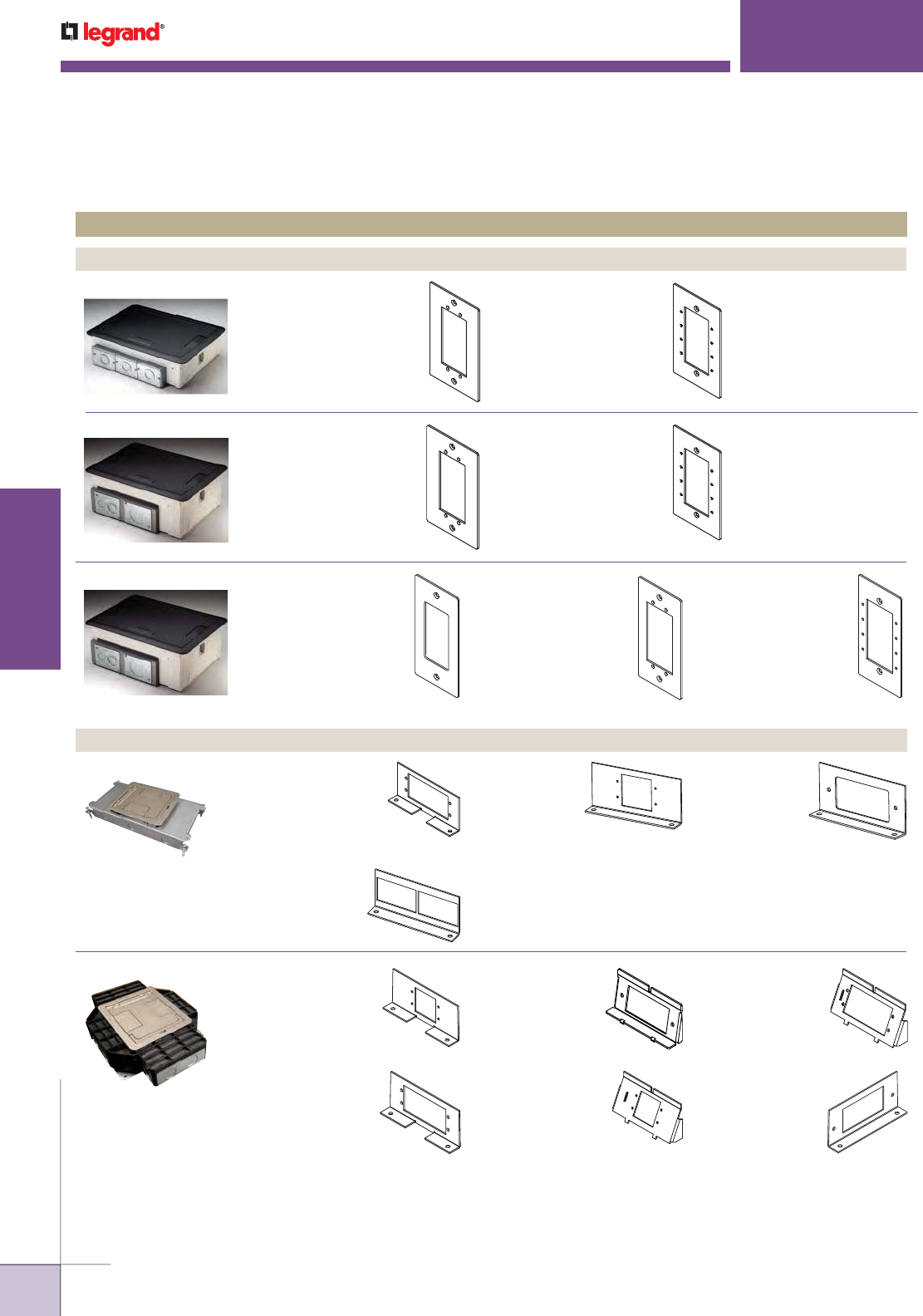
Resource RFB® Series
EFB8S Series EFB-AAP
Device Plate with Extron®
Electronics AAP opening.
EFB-MAAP
Device Plate with GFCI or
decorator style opening for
open A/V devices such as
Wiremold AVIP or Extron®
Electronics, Crestron® and
Atinex® Intera.
AUDIO/VIDEO COMPATIBILITY
Quick Selection Guide
Product Line Compatible A/V Device Plates
FLOOR BOXES
NOTE: Wiremold manufactures many additional pathway solutions. Those represented here have been designed/modified to provide the depth behind
the plate required for most A/V devices. For additional design and installation considerations, please contact the factory.
EFB6S Series EFB-AAP
Device Plate with Extron®
Electronics AAP opening.
EFB-MAAP
Device Plate with GFCI or
decorator style opening for
open A/V devices such as
Wiremold AVIP or Extron®
Electronics, Crestron® and
Atinex® Intera.
EFB10S Series EFB10-DEC
For use with decorator
style GFCI and A/V
devices.
EFB10-MAAP
Device Plate holds
4 Wiremold AVIP or
Extron® Electronics
MAAP devices.
RFB2 Series RFB2-AAP
Device Plate with
Extron® Electronics
AAP opening.
RFB2RT
Device Plate
with bracket that
accepts Ortronics®
Series II Devices.
RFB4 Series
RFB-GFI-SS
Shallow Device
Plate with GFCI
or decorator style
opening for open
A/V devices such as
Extron® Electronics,
Crestron® and
Atinex® Intera.
WTB-AAP
Device Plate with
Extron® Electronics
AAP opening.
RFB2EXT
Device Plate
with Wiremold
AVIP or Extron®
Electronics MAAP
opening.
RFB2GFI
Device Plate with
GFCI or decorator
style opening for
open A/V devices
such as Extron®
Electronics,
Crestron® and Atinex® Intera.
RFB4-GFI-4DB
Device Plate with
GFCI or decorator
style opening for
open A/V devices such
as Extron® Electronics,
Crestron® and Atinex® Intera.
RFB4-SS-MAAP
Shallow Device Plate
with Wiremold AVIP or
Extron® Electronics
MAAP opening.
RFB4-SS-AAP
Shallow Device
Plate with Extron®
Electronics AAP
opening.
WTB-MAAP
Device Plate with
Wiremold AVIP or
Extron® Electronics
MAAP opening.
Evolution™ Series
WWW.LEGRAND.US/WIREMOLD
7
WIREMOLD
AUDIO/VIDEO COMPATIBILITY
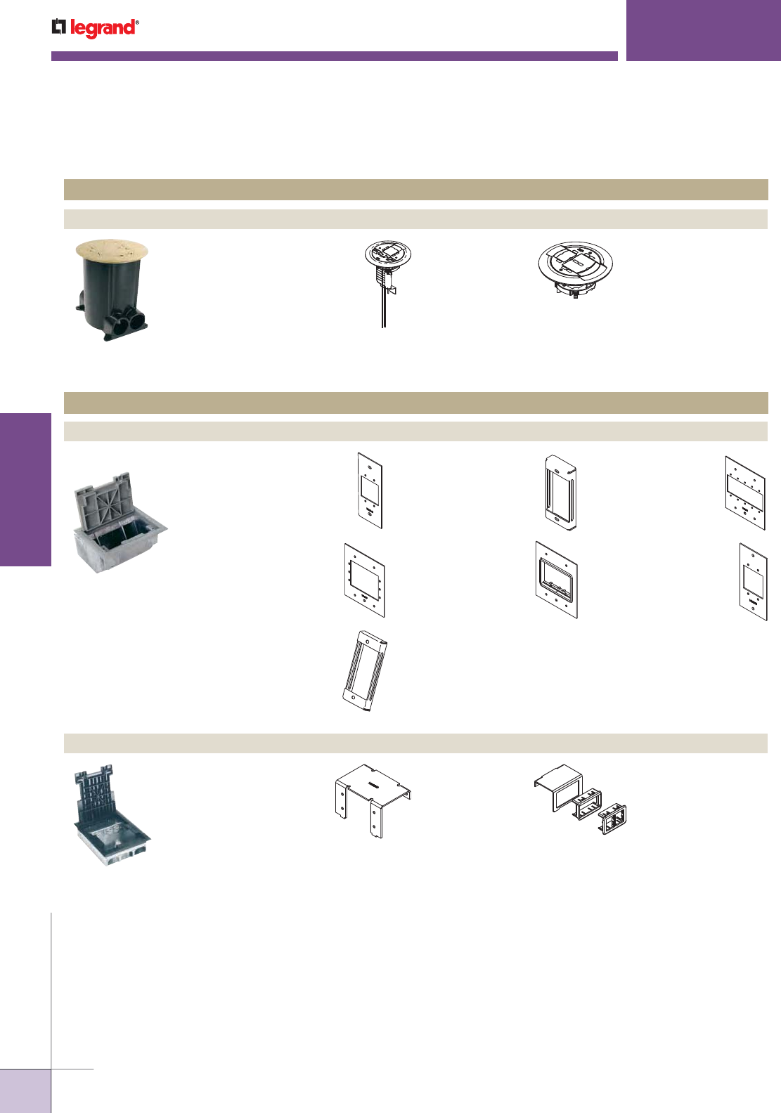
RFB4E Series RFB6EXT
Device Plate
accepts three (3)
Wiremold AVIP or
Extron® Electronics
MAAP Devices.
RFB6RT
Device Plate with
adapter to accept
two (2) Ortronics®
Series II Devices.
Product Line Compatible A/V Device Plates
FLOOR BOXES
RFB6, RFB6E Series RFB6EXT
Device Plate
accepts three
(3) Wiremold
AVIP or Extron®
Electronics MAAP
Devices.
RFB6RT
Device Plate with
adapter to accept
two (2) Ortronics®
Series II Devices.
RFB9 & RFB11 Series RFB119-SGFI
Device Plate with GFCI or
decorator style opening
for open A/V devices such
as Extron® Electronics,
Crestron® and Atinex®
Intera.
RFB119-SXLR
Device Plate with two
(2) openings to accept
microphone devices.
RFB6-AAP
Device Plate with
Extron® Electronics
AAP opening.
RFB6GFI
Device Plate with
GFCI or decorator
style opening for
open A/V devices
such as Extron® Electronics,
Crestron® and Atinex® Intera.
RFB6-AAP
Device Plate with
Extron® Electronics
AAP opening.
RFB6GFI
Device Plate with
GFCI or decorator
style opening for
open A/V devices
such as Extron®
Electronics, Crestron®
and Atinex® Intera.
RFB119-3GFI
Device Plate with
three (3) GFCI or
decorator style
openings for
open A/V devices
such as Extron®
Electronics, Crestron®
and Atinex® Intera.
RFB119-GFI
Device Plate with GFCI
or decorator style
opening for open A/V
devices such as Extron®
Electronics, Crestron®
and Atinex® Intera.
RFB119-XLR
Device Plate with two
(2) openings to accept
microphone devices.
OmniBox™ Series
Resource RFB® Series
828-MAAP
Device Plate for mounting
Wiremold AVIP or Extron®
Electronics MAAP Devices using
828GFI Covers. For use with
828GFITC or 828GFITCAL
Cover Plates (sold separately).
880W Series™
828-MAAP
Device Plate for mounting
Wiremold AVIP or Extron®
Electronics MAAP Devices using
828GFI Covers. For use with
828GFITC or 828GFITCAL
Cover Plates (sold separately).
NOTE: Wiremold manufactures many additional pathway solutions. Those represented here have been designed/modified to provide the depth
behind the plate required for most A/V devices. For additional design and installation considerations, please contact the factory.
AUDIO/VIDEO COMPATIBILITY
Quick Selection Guide
WWW.LEGRAND.US/WIREMOLD
8
WIREMOLD
AUDIO/VIDEO COMPATIBILITY
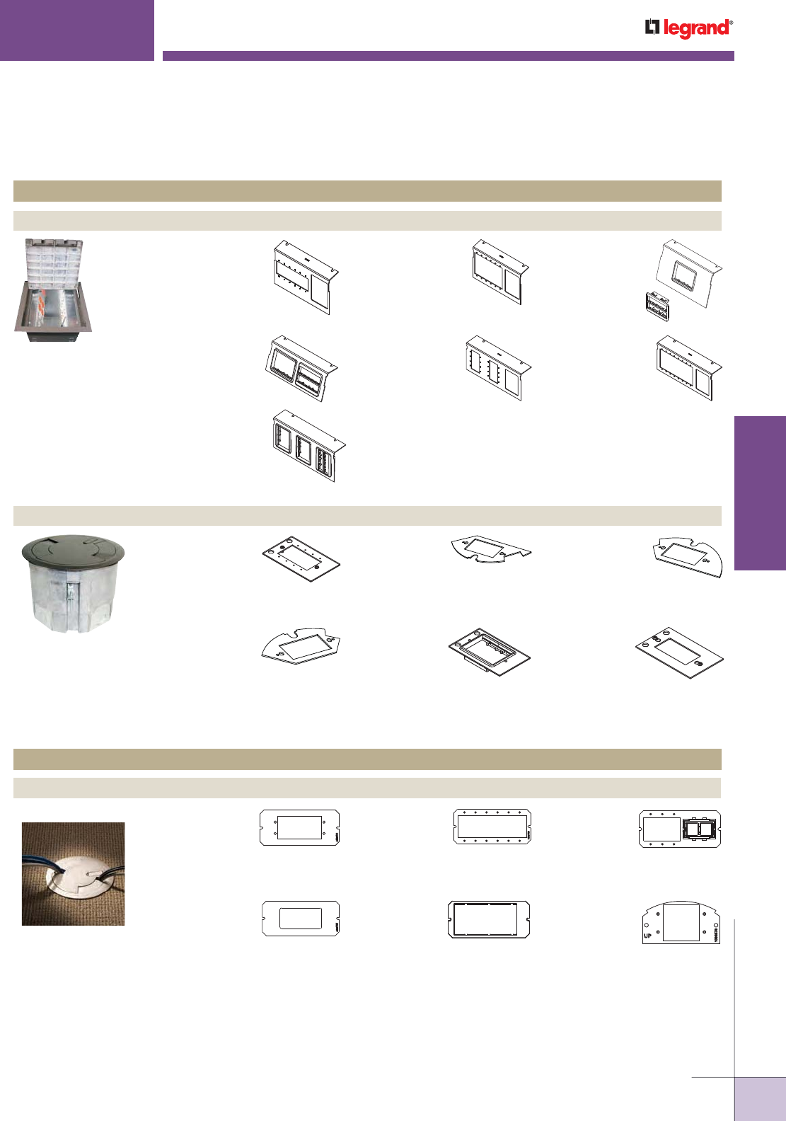
FloorSource AF Series™
RAISED FLOOR BOXES
Product Line Compatible A/V Device Plates
FloorSource AF Series™
FLOOR BOXES
NOTE: Wiremold manufactures many additional pathway solutions. Those represented here have been designed/modified to provide the depth
behind the plate required for most A/V devices. For additional design and installation considerations, please contact the factory.
Product Line Compatible A/V Device Plates
Ratchet-Pro™ Series
881AV3CTCGY
881AV3CTCBK
881AV3CTCAL
881AV3CTCBS
Floor Box Cover Kit with
Wiremold AVIP or Extron®
Electronics MAAP and
Ortronics® Series II Adapters.
881AMD8CTCGY
881AMD8CTCBK
881AMD8CTCAL
881AMD8CTCBS
Floor Box Cover Kit
with Ortronics® Series II
Adapters.
AF-1, AF-3 SGT-MAAP
Device Plate with Wiremold
AVIP or Extron® Electronics
MAAP opening.
DGT-MAAP
Device Plate with
Wiremold AVIP or Extron®
Electronics MAAP
opening.
DGT-AAP
Device Plate with
Extron® Electronics
AAP opening.
SGT-3S2
Device Plate accepts three
(3) Ortronics® Series II
Devices.
SGB-MAAP
Device Plate with Wiremold
AVIP or Extron® Electronics
MAAP opening.
DGT-RT
Device Plate includes one
(1) Ortronics® Series II
Adapter.
SGB-3S2
Device Plate accepts
three (3) Ortronics®
Series II Devices.
SGC2-MAAP
Device Plate accepts
two (2) Wiremold AVIP
or Extron® Electronics
MAAP Devices.
SAF SGC2-RT
Device Plate with
Adapter that
accepts one (1)
Ortronics® Series II
Device.
AUDIO/VIDEO COMPATIBILITY
Quick Selection Guide
WWW.LEGRAND.US/WIREMOLD
9
WIREMOLD
AUDIO/VIDEO COMPATIBILITY
AUDIO/VIDEO COMPATIBILITY
Quick Selection Guide
RAISED FLOOR BOXES
Product Line Compatible A/V Device Plates
NOTE: Wiremold manufactures many additional pathway solutions. Those represented here have been designed/modified to provide the depth behind
the plate required for most A/V devices. For additional design and installation considerations, please contact the factory.
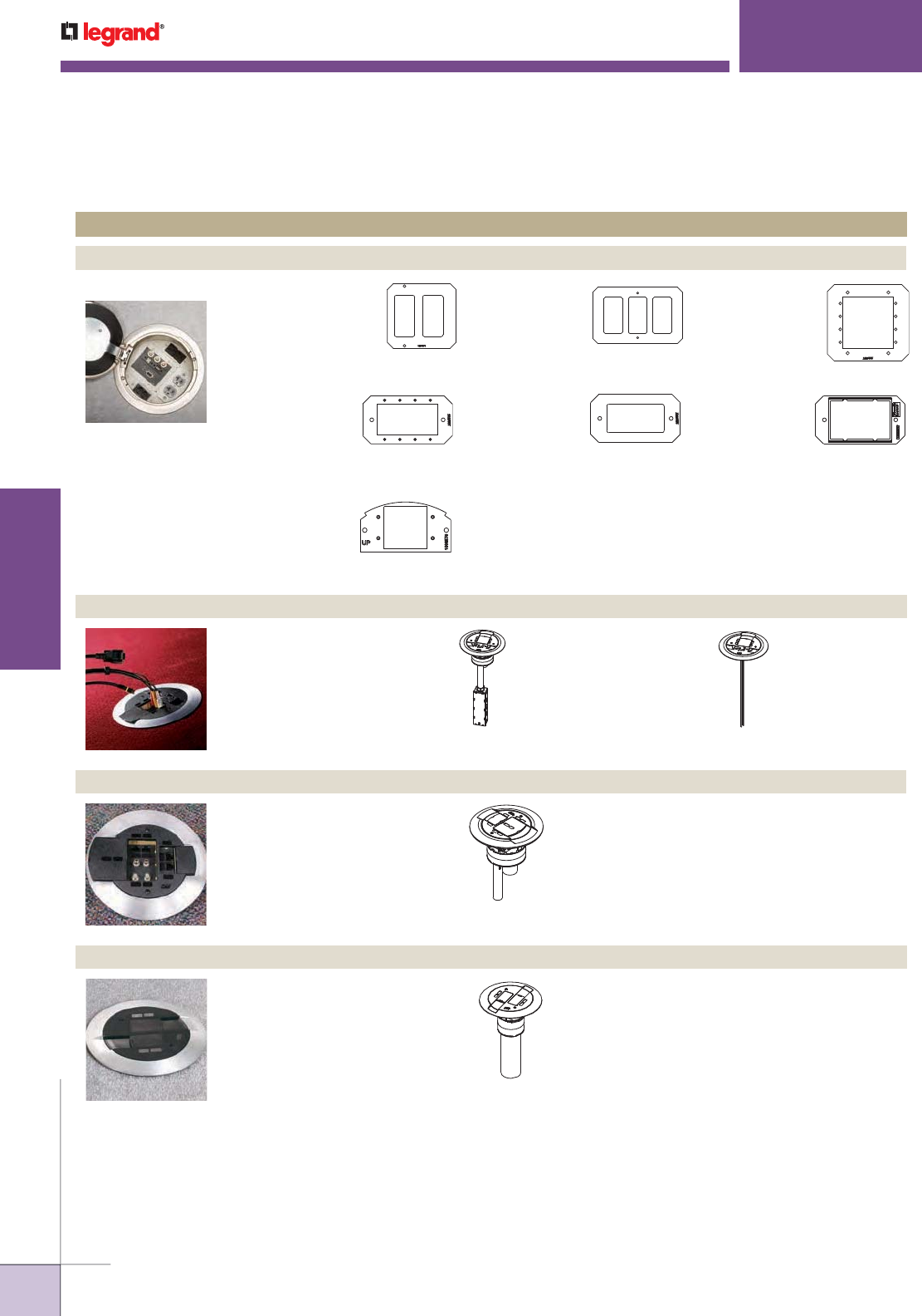
FloorSource AC Series™
C8005P-MAAP-6A
Device Plate with
Wiremold AVIP or
Extron® Electronics
MAAP opening.
C8005P-AAP-6A
Device Plate with
Extron® Electronics
AAP opening.
C8004P-2RT
Device Plate
with Adapters for
two (2) Ortronics®
Series II Devices.
C10105P-AAP-6A
Device Plate with
Extron® Electronics
AAP opening.
C8005P-RT
C8005P-2RT
C8005P-3RT
Device Plate with
Adapters for one (1),
two (2), or three (3)
Ortronics® Series II
Devices.
C10105P-MAAP-6A
Device Plate with
Extron® Electronics
MAAP opening.
C10105P-3RT
Device Plate with
Adapters for three
(3) Ortronics®
Series II Devices.
CRFB-MAAP-4
Device Plate with
Wiremold AVIP or
Extron® Electronics
MAAP opening.
CRFB-GFI-1
Device Plate
with standard
GFCI or decorator style
opening for open A/V devices such as
Extron® Electronics, Crestron® and
Atinex® Intera.
CRFB-GFI-2
Device Plate with
standard GFCI or
decorator style opening
for open A/V devices such as
Extron® Electronics, Crestron® and
Atinex® Intera.
CRFB-GFI-3
Device Plate with
standard GFCI or
decorator style
opening for open A/V devices such as
Extron® Electronics, Crestron® and
Atinex® Intera.
CRFB-BEZ-6A-4
Device Plate
with Adapter for
one (1)
Ortronics®
Series II Device.
CRFB-CGFI-4
Device Plate with
standard GFCI
or decorator style
opening for open A/V
devices such as Extron® Electronics,
Crestron® and Atinex® Intera.
FloorSource CFRB Series™
Evolution™ Series Poke-Thru Devices
POKETHRU DEVICES
Product Line Compatible A/V Device Plates
6AT Series 6MAAP
Device Plate
accepts six (6)
Wiremold AVIP or
Extron® Electronics MAAP Devices.
6SER
Device Plate
accepts up to
four (4)
Ortronics® Series II modular inserts.
6AAP
Device Plate
accepts two
(2) Extron®
Electronics AAP
Devices.
6MAAP-2A
Device Plate
accepts three (3)
Wiremold AVIP or
Extron® Electronics
MAAP Devices and up to two (2) ports
for communication devices.
6DEC
Device Plate
accepts standard
GFCI or decorator
style opening for open A/V devices
such as Extron® Electronics,
Crestron® and Atinex® Intera.
68MAAP
Device Plate
accepts up to
two (2) Wiremold
AVIP or Extron®
Electronics MAAP Devices.
WWW.LEGRAND.US/WIREMOLD
10
WIREMOLD
AUDIO/VIDEO COMPATIBILITY
AUDIO/VIDEO COMPATIBILITY
Quick Selection Guide
NOTE: Wiremold manufactures many additional pathway solutions. Those represented here have been designed/modified to provide the depth behind
the plate required for most A/V devices. For additional design and installation considerations, please contact the factory.
Evolution™ Series Poke-Thru Devices
POKETHRU DEVICES
Product Line Compatible A/V Device Plates
8AAP
Device Plate
accepts four (4)
Extron® Electronics
AAP Devices.
68MAAP
Device Plate
accepts up to
two (2) Wiremold
AVIP or Extron®
Electronics MAAP Devices.
8AT Series 8CREST
Device Plate accepts
Crestron® & Extron®
Electronics double
gang decorator style
devices.
8CREST3G
3 gang device
plate accepts
Crestron®
& Extron®
Electronics triple
gang decorator
style devices.
8MAAP
Device Plate
accepts four
(4) Wiremold
AVIP or Extron®
Electronics MAAP
Devices.
8DEC
Device Plate with
standard GFCI or
decorator style
opening for open
A/V devices such as Extron®
Electronics, Crestron® and Atinex®
Intera.
8SER
Device Plate
accepts up to
three (3)
Ortronics® Series II
modular inserts.
AV3 Series™ Poke-Thru Devices
AV3ATCGY
AV3ATCBK
AV3ATCAL
AV3ATCAA
AV3ATCBS
AV3ATCAB
AV3ATCVY
Assembled Poke-Thru
Device that includes
bezels to accepts one
Wiremold AVIP or
Extron® Electronics
MAAP device or one
Ortronics® Series II
insert.
AV3CTCGY
AV3CTCBK
AV3CTCAL
AV3CTCAA
AV3CTCBS
AV3CTCAB
AV3CTCVY
Assembled Poke-Thru
Device that includes
bezels to accept one
Wiremold AVIP or
Extron® Electronics
MAAP device or one
Ortronics® Series II
insert.
AMD8ATCGY
AMD8ATCBK
AMD8ATCAL
AMD8ATCAA
AMD8ATCBS
AMD8ATCAB
AMD8ATCVY
Assembled Poke-Thru
Device that includes
bezels to accept four
(4) Ortronics® Series II
inserts.
AMD8™ Series Poke-Thru Devices
RC9AMDTCGY
RC9AMDTCBK
RC9AMDTCAL
RC9AMDTCBS
RC9AMDTCAB
RC9AMDTCVY
RC9AMDTCAA
Assembled Poke-Thru
Device that includes
bezels to accept two
(2) Ortronics® Series II
inserts.
RC9AMD Series™ Poke-Thru Devices
WWW.LEGRAND.US/WIREMOLD
11
WIREMOLD
AUDIO/VIDEO COMPATIBILITY
AUDIO/VIDEO COMPATIBILITY
Quick Selection Guide
NOTE: Wiremold manufactures many additional pathway solutions. Those represented here have been designed/modified to provide the depth behind
the plate required for most A/V devices. For additional design and installation considerations, please contact the factory.
KA305
Device Plate
with Wiremold
AVIP or Extron®
Electronics MAAP
Opening.
KA302
Device Plate
holds cables
captive for easy
access when
active jacks are
not needed.
6" [152mm] Field-Wired or Cord-Ended Work Surface
Portals that can accept up to five (5) Wiremold AVIP
or Extron® Electronics MAAP device plates.
Field-Wired Field-Wired
WSF6FNK, WSF6FBS,
WSF6FGY, WSF6FBK,
WSF6FBZ,
WSF6SNK, WSF6SBS,
WSF6SGY, WSF6SBK,
WSF6SBZ
Evolution™ Series Work Surface Portals
WSF6 Series Cord-Ended
WS6FNK, WS6FBS,
WS6FGY, WS6FBK,
WS6FBZ,
WS6SNK, WS6SBS,
WS6SGY, WS6SBK,
WS6SBZ
dequorum™ Work Surface Portals
WORK SURFACE SOLUTIONS
Product Line Compatible A/V Device Plates
KA305-AAP
Device Plate
with Wiremold
AVIP or Extron®
Electronics
AAP Opening.
Cord-Ended
WSF8 Series
8" [203mm] Field-Wired or Cord-Ended Work Surface
Portals that can accept up to ten (10) Wiremold AVIP
or Extron® Electronics MAAP device plates.
Field-Wired
WSF8FNK, WSF8FBS,
WSF8FGY, WSF8FBK,
WSF8FBZ,
WSF8SNK, WSF8SBS,
WSF8SGY, WSF8SBK,
WSF8SBZ
Cord-Ended
WS8FNK, WS8FBS,
WS8FGY, WS8FBK,
WS8FBZ,
WS8SNK, WS8SBS,
WS8SGY, WS8SBK,
WS8SBZ
Evolution™ Series Wall Boxes
EFSB2 – 2 Gang Wall Box
EFSB4 – 4 Gang Wall Box
Designed to fit and be concealed behind 42" [1.067m]
or larger flat screen displays. Can be installed in
both new work and old work applications. Has 2 or
4 NEMA size openings for power, communication,
or A/V devices. EFSB 2 box is also equipped with
a storage module that will accept active A/V
equipment up to 6 7/8" x 9 1/8" [175mm x 232mm]
in size. Dimensions include wire and cables.
InteGreat™ A/V Table Boxes
TB672APBK
TB672APAL
Table Box with 12' [3.66m] cord. Unit comes with two
(2) 15A receptacles in the recessed compartments
and one 15A receptacle on the underside of the box.
Hardware bag includes Wiremold® AVIP Series Cable
Kit with eight (8) openings. Can accept up to five
(5) Wiremold AVIP device plates or five (5) Extron®
Electronics MAAP device plates. (Sold separately.)
Available in black (TB672APBK) or aluminum
(TB672APAL) finish.
WWW.LEGRAND.US/WIREMOLD
12
WIREMOLD
AUDIO/VIDEO COMPATIBILITY
AUDIO/VIDEO COMPATIBILITY
Quick Selection Guide
NOTE: Wiremold manufactures many additional pathway solutions. Those represented here have been designed/modified to provide the depth behind the
plate required for most A/V devices. For additional design and installation considerations, please contact the factory.
DSDWNS-BK
DSDWNS-BZ
DSDWNS-DG
DSDWNS-DV
Downward-Facing
Device Plate with
Ortronics® Series II
opening.
DSDWNU-BK
DSDWNU-BZ
DSDWNU-DG
DSDWNU-DV
Downward-Facing
Device Plate with
Extron® Electronics
MAAP opening.
DSDWNR-BK
DSDWNR-BZ
DSDWNR-DG
DSDWNR-DV
Downward-Facing
Device Plate with
decorator style
opening for open
A/V devices such as
Extron® Electronics,
Crestron® and
Atinex® Intera.
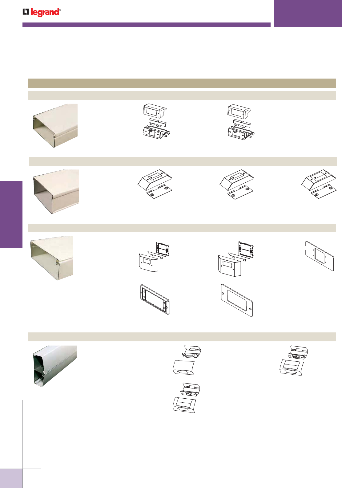
DS4000® Series Raceway
STEEL RACEWAY SYSTEMS
Product Line Compatible A/V Device Plates
5507MAAP
5507MAAP-G
5507 Series Device
Plate with Extron®
Electronics MAAP
opening.
4000 Series™ Raceway
5507AAP
5507AAP-G
5507 Series Device
Plate with Extron®
Electronics AAP
opening.
V4047UX
G4047UX
Bump-Up Device
Plate with Extron®
Electronics MAAP
opening.
V4047VX
G4046VX
Bump-Up Device
Plate with Extron®
Electronics AAP
opening.
5507R
5507R-G
5507 Series
Device Plate with
decorator style
opening for open A/V
devices such as Extron®
Electronics, Crestron® and
Atinex® Intera.
V24DWNU
24DWNU-FW
Downward-Facing
Device Plate
with Wiremold
AVIP or Extron®
Electronics MAAP
opening.
V24DWNS
24DWNS-FW
Downward-Facing
Device Plate with
Ortronics® Series II
opening.
V3046V
G3046V
Bump-Up Device
Plate with Extron®
Electronics AAP
opening.
V3046S
G3046S
Bump-Up Device
Plate with
Ortronics® Series
II opening.
3000 Series™ Raceway
2400 Series™ Raceway
V3046U
G3046U
Bump-Up
Device Plate
with Wiremold
AVIP or Extron®
Electronics MAAP
opening.
WWW.LEGRAND.US/WIREMOLD
13
WIREMOLD
AUDIO/VIDEO COMPATIBILITY
AUDIO/VIDEO COMPATIBILITY
Quick Selection Guide
NOTE: Wiremold manufactures many additional pathway solutions. Those represented here have been designed/modified to provide the depth behind
the plate required for most A/V devices. For additional design and installation considerations, please contact the factory.
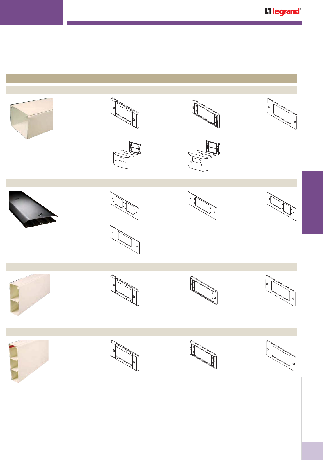
STEEL RACEWAY SYSTEMS
Product Line Compatible A/V Device Plates
5507R
5507R-FW
5507R-WH
5507R-BK
5507R-G
5507R-GY
5507 Series Device Plate
with decorator style opening
for open A/V devices such as
Extron® Electronics, Crestron® and
Atinex® Intera.
5400 Series™ Raceway
5507MAAP
5507MAAP-FW
5507MAAP-WH
5507MAAP-BK
5507MAAP-G
5507MAAP-GY
5507 Series Device Plate
with Wiremold AVIP or
Extron® Electronics
MAAP opening.
5507R
5507R-FW
5507R-WH
5507R-BK
5507R-G
5507R-GY
5507 Series Device Plate
with decorator style opening
for open A/V devices such as
Extron® Electronics, Crestron® and
Atinex® Intera.
5500 Series™ Raceway
5507AAP
5507AAP-FW
5507AAP-WH
5507AAP-BK
5507AAP-G
5507AAP-GY
5507 Series Device
Plate with Extron®
Electronics AAP
opening.
OFR Series™ Overflow Raceway
OFR47-R
For covering
rectangular
decorator style
devices.
OFR47-V
Accepts two (2)
Extron® Electronics
AAP single
space modules.
OFR47-U
Accepts up to
four (4) Wiremold
AVIP or Extron®
Electronics MAAP
style plates.
OFR47-U2A
Accepts up to
two (2) Wiremold
AVIP or Extron®
Electronics MAAP
style plates.
5507AAP
5507AAP-FW
5507AAP-WH
5507AAP-BK
5507AAP-G
5507AAP-GY
5507 Series Device
Plate with Extron®
Electronics AAP opening.
5507MAAP
5507MAAP-FW
5507MAAP-WH
5507MAAP-BK
5507MAAP-G
5507MAAP-GY
5507 Series Device
Plate with Wiremold
AVIP or Extron®
Electronics MAAP
opening.
5507AAP
5507AAP-G
5507 Series Device
Plate with Extron®
Electronics AAP
opening.
6000® Series Raceway
V4047UX
G4047UX
Bump-Up Device
Plate with Wiremold
AVIP or Extron®
Electronics MAAP
opening.
5507MAAP
5507MAAP-G
5507 Series
Device Plate
with Wiremold
AVIP or Extron®
Electronics MAAP opening.
5507R,
5507R-G
5507 Series
Device Plate with
decorator style
opening for open A/V
devices such as Extron®
Electronics, Crestron® and
Atinex® Intera.
V4047VX
G4047VX
Bump-Up
Device Plate
with Extron®
Electronics AAP
opening.
WWW.LEGRAND.US/WIREMOLD
14
WIREMOLD
AUDIO/VIDEO COMPATIBILITY
AUDIO/VIDEO COMPATIBILITY
Quick Selection Guide
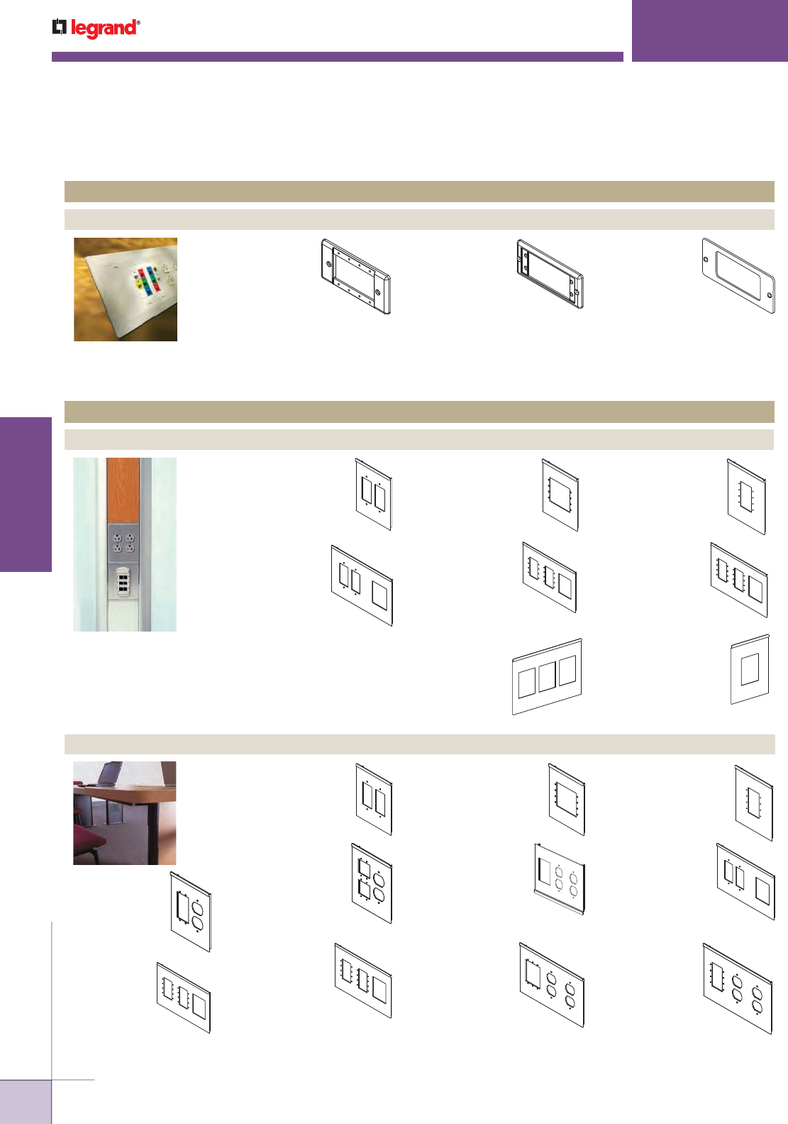
Vista™ Point5 Architectural Columns
VSCR
Crestron® & Extron®
Electronics Double-
Gang Decorator Style
Device Plate for Small
Vista Columns.
VSEA
Device Plate with
Extron® Electronics
AAP opening for
Small Vista Columns.
VSEAP5
Device Plate with
two (2) duplex
receptacles and
Extron® Electronics
AAP openings for
small Point 5 Vista.
VSEMP5
Device Plate with two
(2) duplex receptacles
and Wiremold AVIP or
Extron® Electronics
MAAP openings for
small Point 5 Vista.
VL2A
Device plate for
Wiremold CM Series
Open System for
Ortronics Series II
and TracJack devices
for large Point 5 Vista.
VLCR
Crestron® &
Extron® Electronics
Double-Gang
Decorator Style
Device Plate
for Large Vista
Columns.
VSEM
Device Plate with
Wiremold AVIP or
Extron® Electronics
MAAP opening for
Small Vista Columns.
VLEA
Device Plate
with Extron®
Electronics AAP
opening for Large
Vista Columns.
VLEM
Device Plate with
Extron® Electronics
MAAP opening
for Large Vista
Columns.
VLEAP5
Device Plate with
two (2) duplex
receptacles and
Extron® Electronics
AAP openings for
large Point 5 Vista.
VLEMP5
Device Plate with
two (2) duplex
receptacles and
Wiremold AVIP or
Extron® Electronics
MAAP openings for
large Point 5 Vista.
NOTE: Wiremold manufactures many additional pathway solutions. Those represented here have been designed/modified to provide the depth behind
the plate required for most A/V devices. For additional design and installation considerations, please contact the factory.
VSEA
Device Plate with
Extron® Electronics
AAP opening for Small
Vista Columns.
Vista™ Architectural Columns
VLEA
Device Plate with
Extron® Electronics
AAP opening for Large
Vista Columns.
VSCR
Crestron® & Extron®
Electronics Double-
Gang Decorator Style
Device Plate for Small
Vista Columns.
VSEM
Device Plate with
Wiremold AVIP or
Extron® Electronics
MAAP opening for
Small Vista Columns.
VLCR
Crestron® & Extron®
Electronics Double-
Gang Decorator Style
Device Plate for
Large Vista Columns.
VLEM
Device Plate with
Wiremold AVIP or
Extron® Electronics
MAAP opening for
Large Vista Columns.
VLRT
Device Plate with
opening for three
(3) Ortronics®
Series II devices
for Large Vista
Columns.
VSRT
Device Plate with
opening for one (1)
Ortronics® Series II
device for Small
Vista Columns.
VERTICAL SOLUTIONS
Product Line Compatible A/V Device Plates
5507MAAP
5507MAAP-FW
5507MAAP-WH
5507MAAP-BK
5507MAAP-G
5507MAAP-GY
5507 Series Device Plate
with Wiremold AVIP or Extron®
Electronics MAAP opening.
WallSource™ Multiple Service Boxes Raceway
IN WALL SYSTEMS
Product Line Compatible A/V Device Plates
5507AAP
5507AAP-FW
5507AAP-WH
5507AAP-BK
5507AAP-G
5507AAP-GY
5507 Series Device Plate with
Extron® Electronics AAP opening.
5507R
5507R-FW
5507R-WH
5507R-BK
5507R-G
5507R-GY
5507 Series Device Plate
with decorator style opening for
open A/V devices such as Extron®
Electronics, Crestron® and Atinex®
Intera.
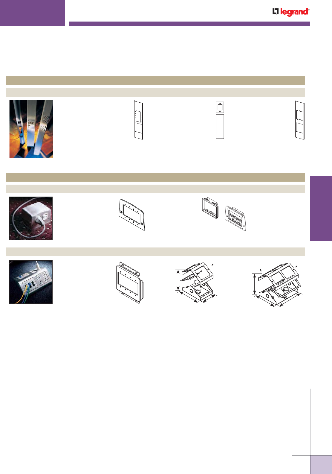
WWW.LEGRAND.US/WIREMOLD
15
WIREMOLD
AUDIO/VIDEO COMPATIBILITY
30TP-AAP
Device Plate with GFCI or
decorator style opening
for open A/V devices such
as Extron® Electronics,
Crestron® and Atinex® Intera.
Tele-Power® Poles
30TP-L
Device Plate with Extron®
Electronics AAP opening.
30TP-MAAP
Device Plate with Wiremold
AVIP or Extron® Electronics
MAAP opening.
3"
[76mm]
6 3/4"
[171mm]
4 3/4"
[121mm]
3"
[76mm]
6 3/4"
[171mm]
8 3/4"
[222mm]
1-GANG 2-GANG
500-MAAP
525 Series Device
Plate with Wiremold
AVIP or Extron®
Electronics
MAAP opening.
500RT
525 Series Device
Plate with opening for
one (1) Ortronics®
Series II Device.
LTF48-MAAP
Multiplex Series
Device Plate with
Wiremold AVIP or
Extron® Electronics
MAAP opening.
Multiplex™ Series Service Fittings
525 Series™ Service Fittings – For use with Walkerduct® Underfloor Duct Systems
INFLOOR SYSTEMS
Product Line Compatible A/V Device Plates
AUDIO/VIDEO COMPATIBILITY
Quick Selection Guide
NOTE: Wiremold manufactures many additional pathway solutions. Those represented here have been designed/modified to provide the depth behind
the plate required for most A/V devices. For additional design and installation considerations, please contact the factory.
VERTICAL SOLUTIONS
Product Line Compatible A/V Device Plates

WWW.LEGRAND.US/WIREMOLD
16
WIREMOLD
AUDIO/VIDEO COMPATIBILITY
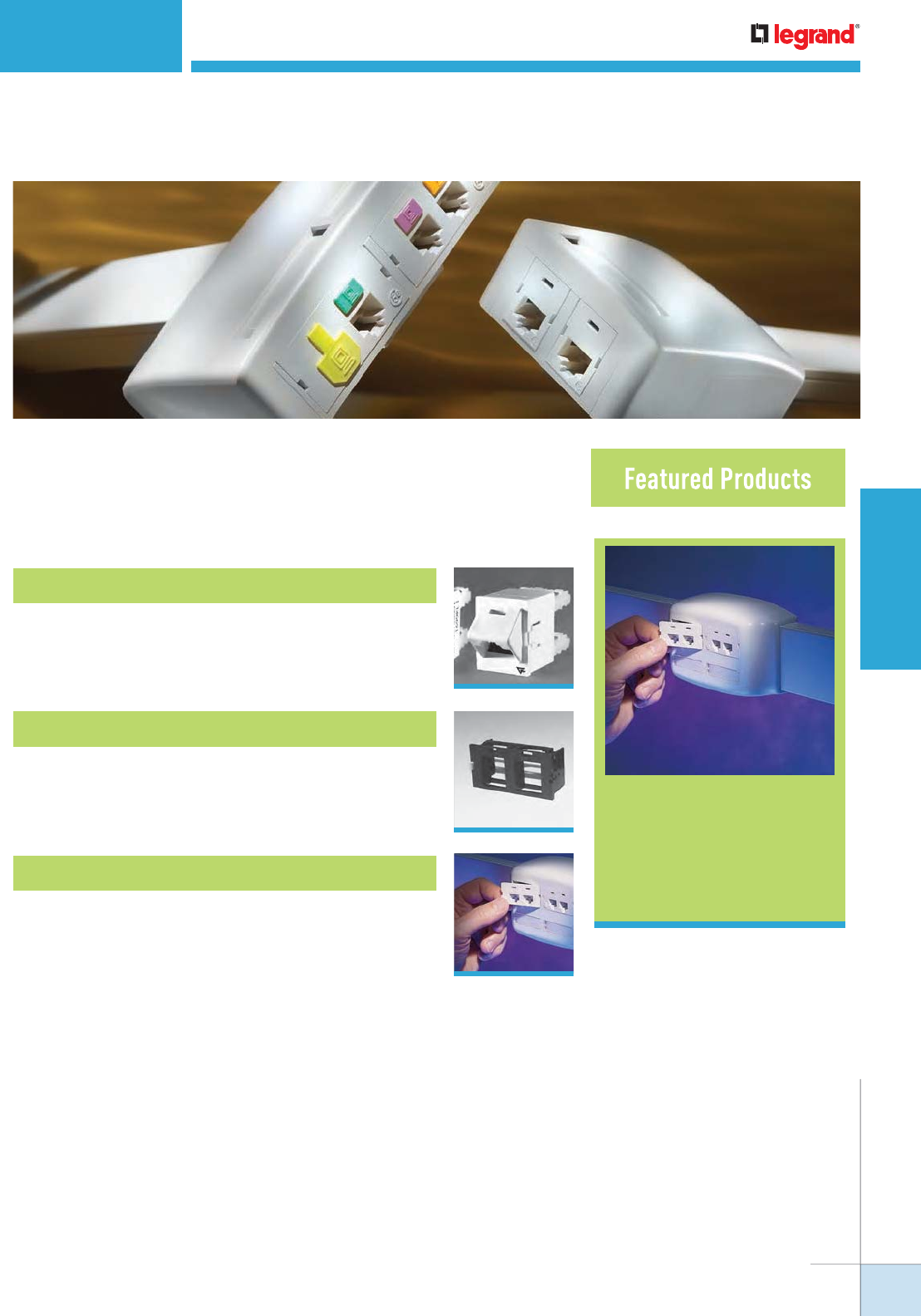
CM Series™
Communication
Modules
19
COMMUNICATIONS CONNECTIVITY
Wiremold® pathways and cable management systems offer a
wide range of options for providing datacom connectivity.
Ortronics® Connectivity
18
Wiremold® Open System Connectivity
18
Wiremold® CM Series™ Communication Modules
19
Table of Contents
WWW.LEGRAND.US/WIREMOLD
17
COMMUNICATIONS CONNECTIVITY
WIREMOLD
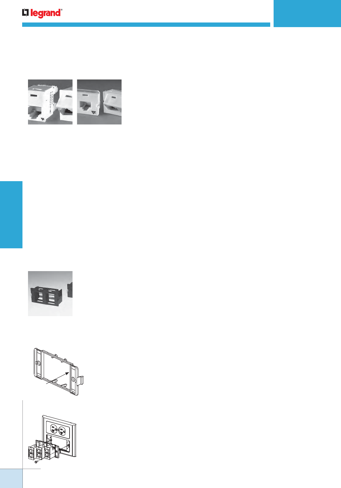
TracJack Individual Jack System
• Front-loading, snap-in design supports future moves adds and changes
• Inserts for voice, data, audio, and video
• Available Category 3, 5e, 6, USOC 6-position, and other media
• Flat or angled 45° exit configurations
• Choice of 13 colors and color matched to Wiremold systems
• Universal T568A/B wiring format
Series II Front-Loading, Module System
• Module design features easy snap-in front-loading design
• Linear 110 punch down format for easy termination
• Inserts for voice, data, audio, and video
• Available Category 3, 5e, 6, USOC 6-position, and other media
• Available in flat or angled 45° exit configurations
• Color matched to Wiremold Systems
For detailed product selection refer to the Ortronics Catalog or visit www.ortronics.com.
Wiremold Open System Communications Modules
• Accommodate a wide range of manufacturers’ communications outlets including keystone jacks,
as well as proprietary solutions from Systimax (Avaya) and NORDX
• Modules fit into a wide range of Wiremold Systems
• Pre-punched faceplates accept common communication devices
For more information on integrating connectivity into Wiremold Cable Management Systems, contact the
Wiremold Applications Engineering Team or your local Wiremold Sales Representative.
1. Bring all station cables through the opening in the device mounting bracket.
2. Mount communication devices in unloaded inserts and terminate or attach
cable per manufacturers instructions.
3. Reverse the module and snap into the device bracket. Entire faceplate must
be filled with inserts or blanks.
Typical Mounting Brackets (4050, 5450, 5550, 40N2, 2344SD-2A, 2444D-2A and WSA07A Device Mounting Plates)
Typical Installation for Cable Management Applications
CM-EPLA
Typical
raceway device
bracket holecut
Ortronics® Connectivity
Wiremold® Open Connectivity Solutions
1. Insert CM-EPLA end plate into the bracket opening.
2. Slide end plate to engage hooks into locking slots. (Be sure end plate edge is
seated against edge of trim plate opening.) Two end plates are required as shown.
3. After end plates are in place, install modules by aligning over space between end plates and
pushing inward until snaps engage. 6A configuring options apply to opening.
COMMUNICATIONS CONNECTIVITY
WWW.LEGRAND.US/WIREMOLD
18
COMMUNICATIONS CONNECTIVITY
WIREMOLD
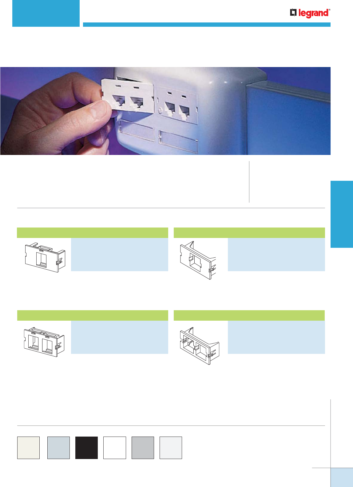
Accepts keystone jacks with a latching
area of 0.58" x 0.76" [14.7mm x 19.3 mm].
Accepts both M-series jacks and LC
fiber adapters.
Accepts keystone jacks with a latching
area of 0.58" x 0.76" [14.7mm x 19.3 mm].
Accepts both M-series jacks and LC
fiber adapters.
CM Series Communication Modules Ordering Information
Wiremold® CM Series™ Communication Modules provide a variety of unloaded
modules to accept devices from other manufacturers. These open system modules
provide a flexible and aesthetically pleasing way to connect communication cabling
at the point-of-use.
CM SERIES™ COMMUNICATION MODULES
CODE REFERENCE
cULus Listed Communication
Circuit Accessories:
File E145222 Guide DUXR.
Meets Article 800 of NEC.
Meets Article 60-308 of CEC.
COLOR OPTIONS
CM Series™ Communication Modules standard color is ivory. For other
colors, add one of the following suffixes: “-WH” for white, “-GY” for
light gray (matches aluminum and nonmetallic products), “-BK” for
black, or “-G” for gray (matches Wiremold gray steel products).
PART NUMBERS:
CM2-U1KEYA-WH (White)
CM2-U1KEYA-GY (Light Gray)
CM2-U1KEYA-BK (Black)
CM2-U1KEYA-G (Gray)
PART NUMBERS:
CM2-U1ATT-WH (White)
CM2-U1ATT-GY (Light Gray)
CM2-U1ATT-BK (Black)
CM2-U1ATT-G (Gray)
PART NUMBERS:
CM2-U2KEYA-WH (White)
CM2-U2KEYA-GY (Light Gray)
CM2-U2KEYA-BK (Black)
CM2-U2KEYA-G (Gray)
PART NUMBERS:
CM2-U2ATT-WH (White)
CM2-U2ATT-GY (Light Gray)
CM2-U2ATT-BK (Black)
CM2-U2ATT-G (Gray)
2A Single Flushmount Unloaded Keystone Module
2A Single Systimax (Avaya) Unloaded Module2A Dual Flushmount Unloaded Keystone Module
2A Single Systimax (Avaya) Unloaded Module
WWW.LEGRAND.US/WIREMOLD
19
COMMUNICATIONS CONNECTIVITY
WIREMOLD
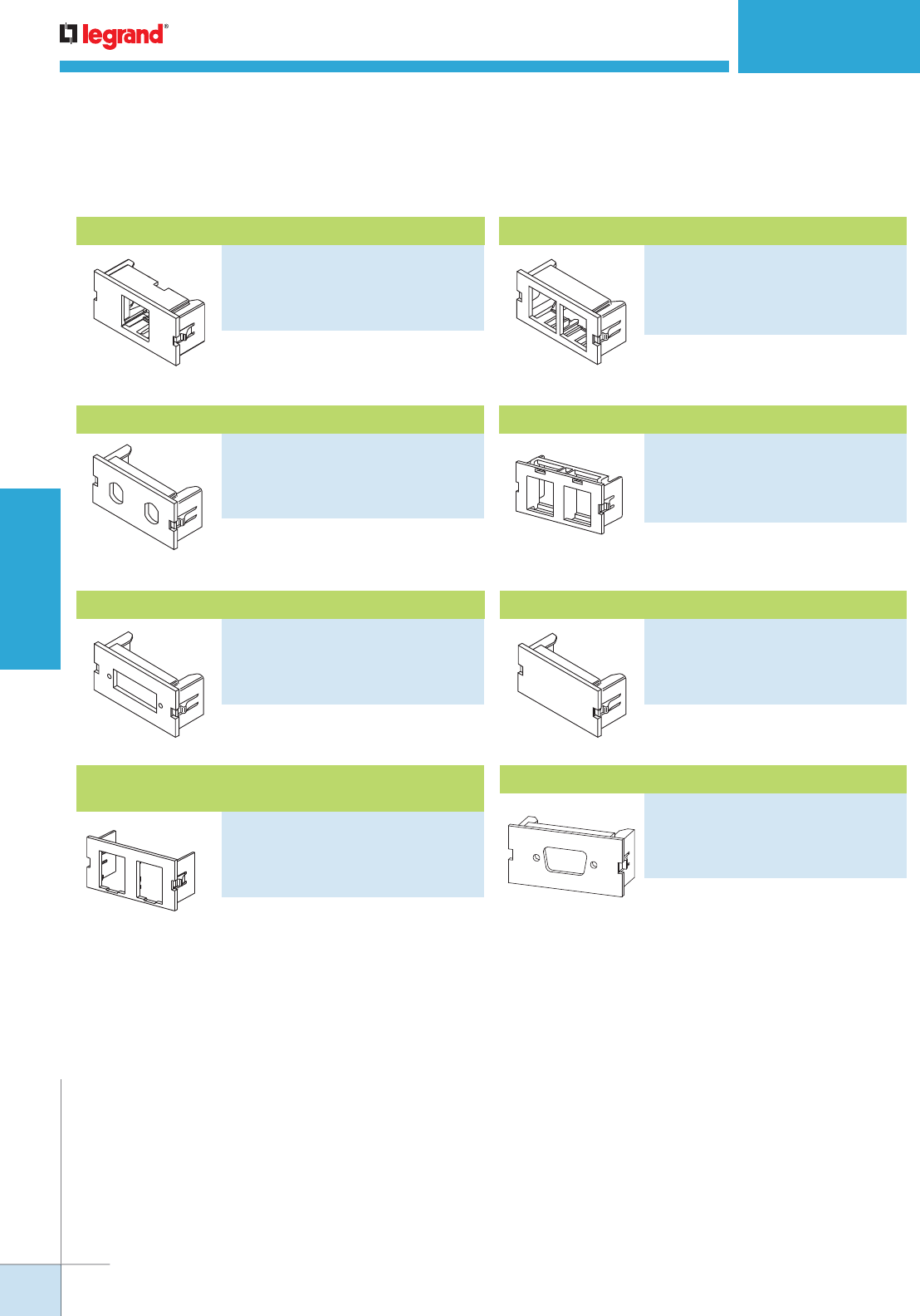
CM SERIES™ COMMUNICATION MODULES
Ordering Information
Accepts 2 ST adapters.
Accepts one SC adapter.
For mounting two AMP Netconnect
SL Series devices.
For mounting two Ortronics®
TracJack devices.
Required to fill unused openings.
Accepts one SVGA connector.
CM Series Communication Modules Ordering Information (continued)
Accepts MDVOFlex jacks and fiber
modules.
Accepts MDVOFlex jacks and fiber
modules.
PART NUMBERS:
CM2-U1NOR-WH (White)
CM2-U1NOR-GY (Light Gray)
CM2-U1NOR-BK (Black)
CM2-U1NOR-G (Gray)
PART NUMBERS:
CM2-U2NOR-WH (White)
CM2-U2NOR-GY (Light Gray)
CM2-U2NOR-BK (Black)
CM2-U2NOR-G (Gray)
PART NUMBERS:
CM2-U2ST-WH (White)
CM2-U2ST-GY (Light Gray)
CM2-U2ST-BK (Black)
CM2-U2ST-G (Gray)
PART NUMBERS:
CM2-U2AMP-WH (White)
CM2-U2AMP-GY (Light Gray)
CM2-U2AMP-BK (Black)
CM2-U2AMP-G (Gray)
PART NUMBERS:
CM2-U2SC-WH (White)
CM2-U2SC-GY (Light Gray)
CM2-U2SC-BK (Black)
CM2-U2SC-G (Gray)
PART NUMBERS:
CM2-BL-WH (White)
CM2-BL-GY (Light Gray)
CM2-BL-BK (Black)
CM2-BL-G (Gray)
PART NUMBERS:
CM2-U2TJ-WH (White)
CM2-U2TJ-GY (Light Gray)
CM2-U2TJ-BK (Black)
CM2-U2TJ-G (Gray)
PART NUMBERS:
CM2-U2SVGA-WH (White)
CM2-U2SVGA-GY (Light Gray)
CM2-U2SVGA-BK (Black)
CM2-U2SVGA-G (Gray)
2A Dual Unloaded ST Adapter Module
2A Unloaded Duplex SC Adapter Module
2A Unloaded Single AMP Netconnect Module
2A Dual Flushmount Unloaded
Ortronics® TracJack Module
2A Blank Module
2A SVGA Module
2A Single Flushmount NordX/CDT Unloaded Module 2A Dual Flushmount NordX/CDT Unloaded Module
WWW.LEGRAND.US/WIREMOLD
20
COMMUNICATIONS CONNECTIVITY
WIREMOLD
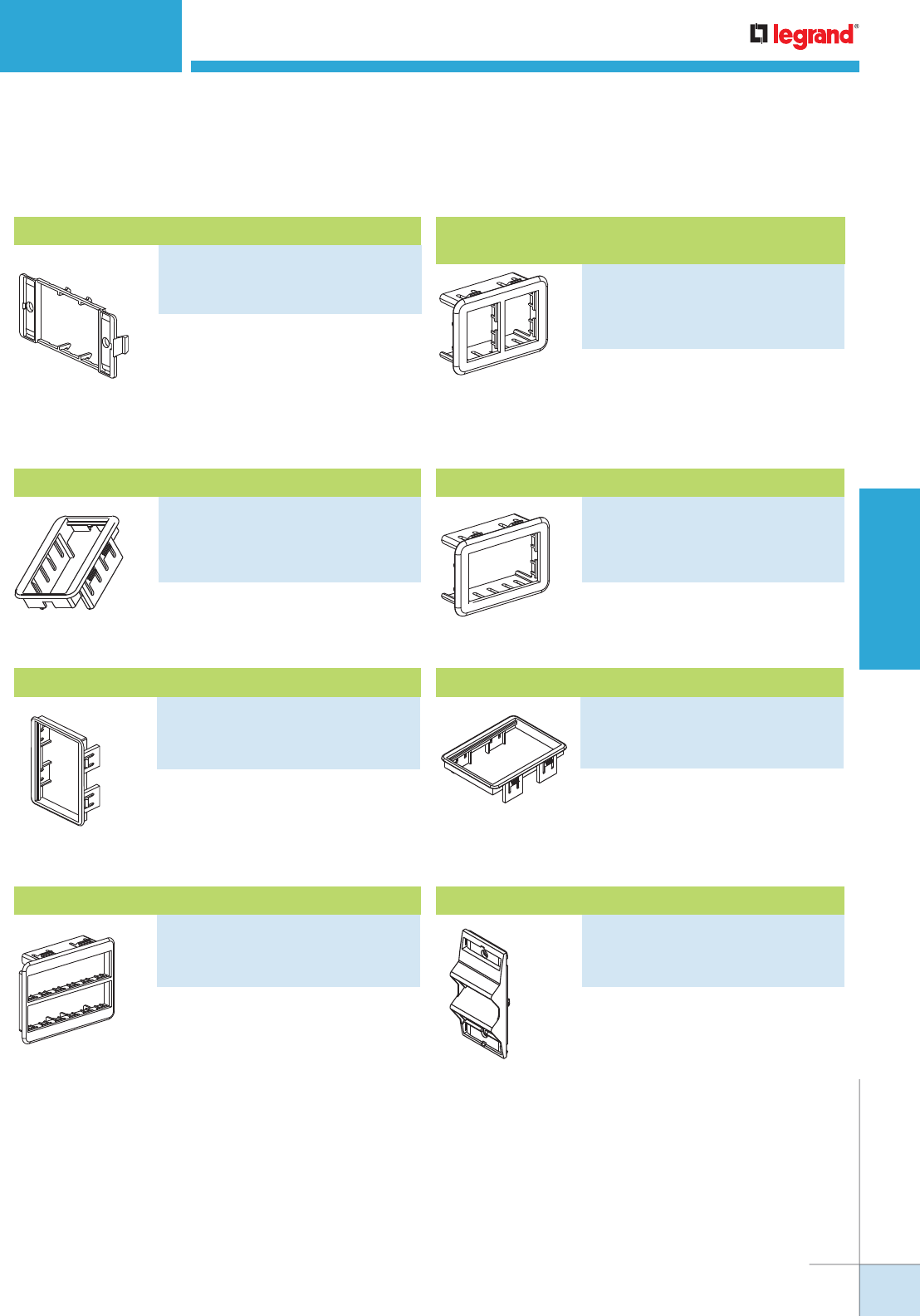
End plates with two outlet ID labels
with clear covers and two matching
screw covers. Required when mounting
modules into 4050, 5450, 5550, and
WSA07-4A device mounting brackets,
and the V2444D-2A and 2344SD-2A
2-gang divided raceway box.
CM Series Communication Modules Specialty Mounting Adapters Ordering Information
Accepts one CM2 Series
communication module or one Pass &
Seymour 2A Activate Series insert.
Accepts two Ortronics® TracJack
Inserts.
Accepts one Ortronics® Series II 1-unit
insert.
For use with multi-channel raceway
device brackets and WallSource
device mounting brackets. Angled exit
provides additional mounting depth
required for audio/visual connections
as well as ensuring the required bend
radius for UTP and fiber optic cabling.
Holds two CM2 Series modules or two
2A inserts. Fits 5507 Series Faceplate
opening.
6A opening. Must be purchased
separately for mounting
communication modules in service
fittings where it is indicated they are
not included.
Accepts six Ortronics® TracJack
inserts.
Accepts three Ortronics® Series II
1-unit inserts.
CM SERIES™ COMMUNICATION MODULES
Ordering Information
PART NUMBERS:
CM-EPLA-WH (White)
CM-EPLA-FW (Fog White)
CM-EPLA-G (Gray)
PART NUMBERS:
AB2TJ-WH (White)
AB2TJ-GY (Light Gray)
AB2TJ-BK (Black)
AB2TJ-G (Gray)
PART NUMBERS:
ABS2-WH (White)
ABS2-GY (Light Gray)
ABS2-BK (Black)
ABS2-G (Gray)
PART NUMBERS:
CM-2AB-WH (White)
CM-2AB-GY (Light Gray)
CM-2AB-BK (Black)
CM-2AB-G (Gray)
PART NUMBERS:
CM-MAB-GY (Light Gray)
CM-MAB-BK (Black)
CM-MAB-FW (Fog White)
PART NUMBERS:
MAB3S2-GY (Light Gray)
MAB3S2-BK (Black)
MAB3S2-G (Gray)
PART NUMBERS:
MAB6TJ-GY (Light Gray)
MAB6TJ-BK (Black)
MAB6TJ-G (Gray)
PART NUMBERS:
CM-ARA-WH (White)
CM-ARA-GY (Light Gray)
CM-ARA-G (Gray)
End Plate
CM2/Activate 2A Mini Mounting Adapter
AB2TJ
Ortronics® TracJack 2A Mini Mounting Adapter
Ortronics® Series II 2A Mini Mounting Adapter
Angled Raceway Adapter
6A Mini Mounting Adapter
Ortronics® TracJack 6A Mounting Adapter
Ortronics Series II 6A Mounting Adapter
WWW.LEGRAND.US/WIREMOLD
21
COMMUNICATIONS CONNECTIVITY
WIREMOLD
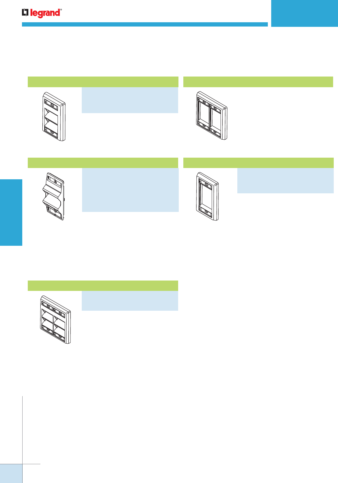
For use with multi-channel raceway
device brackets and WallSource
device mounting brackets. Angled exit
provides additional mounting depth
required for A/V connections as well
as ensuring the required bend radius
for UTP and fiber optic cabling. Holds
two Ortronics® Series II modules. Fits
5507 Series Faceplate opening.
For mounting two CM2 Series modules
or Pass & Seymour Activate Series
device modules.
CM Series Communication Modules Specialty Mounting Adapters Ordering Information (continued)
For mounting four CM2 Series
modules or Pass & Seymour Activate
Series device modules.
For mounting six CM2 Series modules
or Pass & Seymour Activate Series
device modules.
For mounting three CM2 Series
modules or Pass & Seymour Activate
Series device modules.
CM SERIES™ COMMUNICATION MODULES
Ordering Information
PART NUMBERS:
CM-SAP-WH (White)
CM-SAP-GY (Light Gray)
CM-SAP-G (Gray)
PART NUMBERS:
ARA-S2-WH (White)
ARA-S2-FW (Fog White)
ARA-S2-GY (Light Gray)
ARA-S2-BK (Black)
ARA-S2-G (Gray)
ARA-S2-IV (Ivory)
PART NUMBERS:
CM-SFP-WH (White)
CM-SFP (Ivory)
CM-SFP-G (Gray)
PART NUMBERS:
CM-DAP-WH (White)
CM-DAP (Ivory)
Angled Raceway Adapter
Single-Gang Angled Faceplate
Double-Gang Angled Faceplate
CM-DFP-WH Double-Gang Faceplate
Single-Gang Faceplate
WWW.LEGRAND.US/WIREMOLD
22
COMMUNICATIONS CONNECTIVITY
WIREMOLD
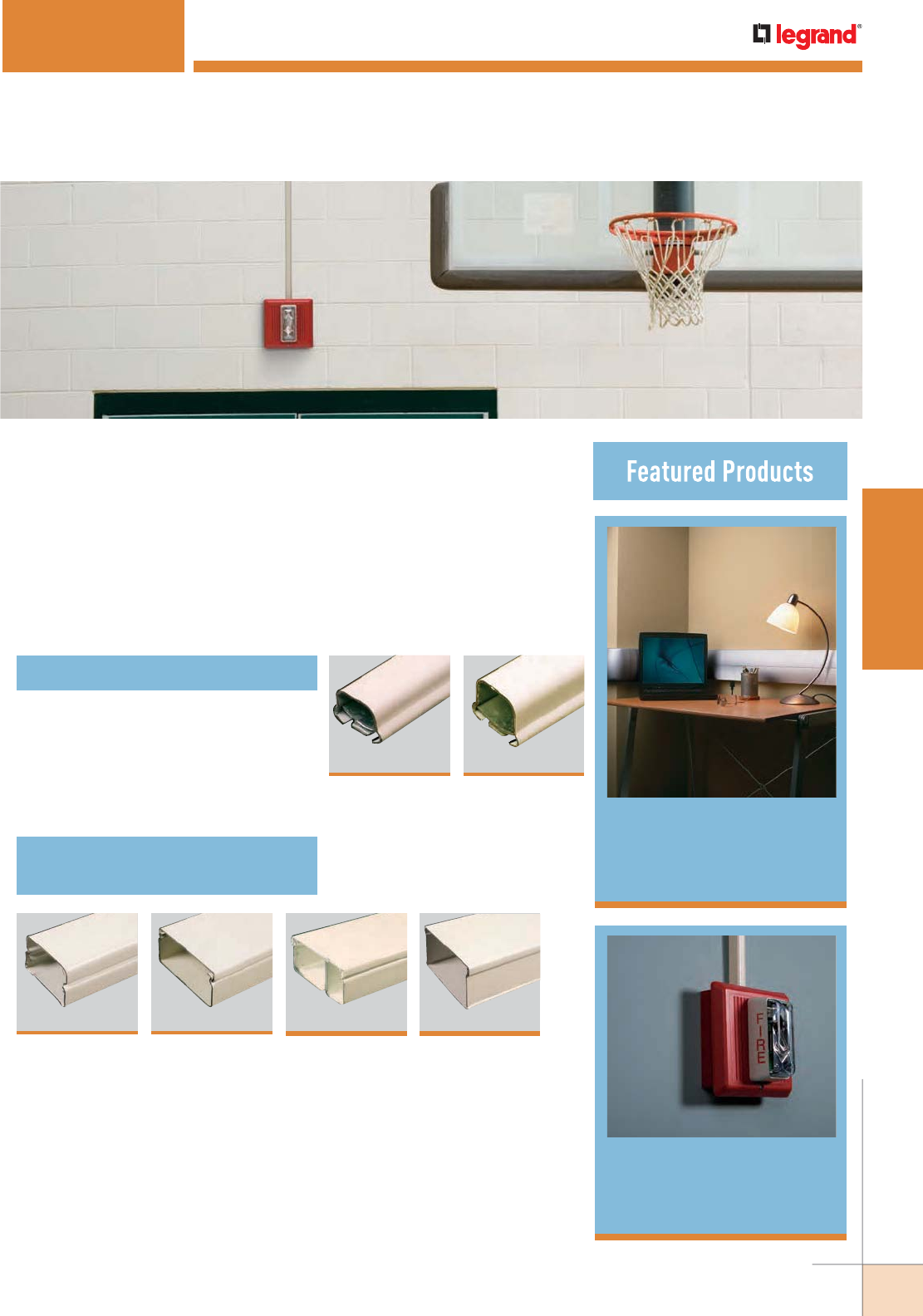
WWW.LEGRAND.US/WIREMOLD
23
STEEL RACEWAY
WIREMOLD
DS4000® Designer
Series Raceway 58
STEEL RACEWAY
Wiremold® Steel Surface Raceway Systems are the industry leaders in
quality, ease of installation, and for providing pathway solutions for all types
of installations. For over 50 years, Wiremold Steel Surface Raceway Systems
have provided the highest quality, most dependable solutions for installers,
building owners, and designers.
With the introduction of DS4000® Series Raceway, we’re again pushing the
envelope by expanding the capacity, capabilities, and aesthetics of surface
raceway systems.
500® & 700® Series
Raceway 26
52
3000® Series
Raceway
One-Piece Steel Raceway Systems
Two-Piece Steel Small Single-
& Dual-Channel Raceway Systems
26
500® Series
Raceway
26
700® Series
Raceway
36
2000® Series
Raceway
40
2400™ Series
Raceway
46
2400D Series™
Raceway
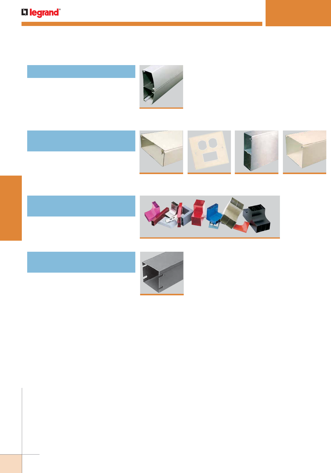
WWW.LEGRAND.US/WIREMOLD
24
STEEL RACEWAY
WIREMOLD
69
4047 Series™
Device Plates
63
4000® Series
Raceway
58
DS4000® Series
Raceway
86
AnySize™ Series Raceway
4000 Designer Series Raceway
Two-Piece Steel Large
Multiple-Channel Raceway Systems
Multi-Compartment Surface
Metal Raceway Systems
STEEL RACEWAY
Table of Contents
81
6000® Series
Raceway
74
S4000® Series
Stainless Steel
Raceway
SpecMate™ Type 1 Wireway
& Enclosures – Type 1 Wireway
93
Type 1 Wireway
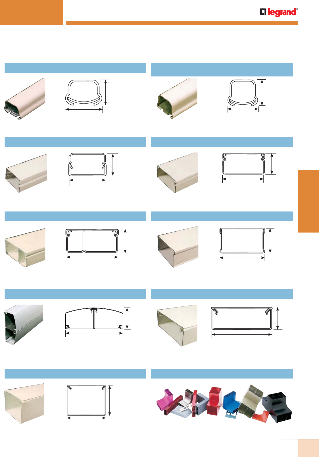
WWW.LEGRAND.US/WIREMOLD
25
STEEL RACEWAY
WIREMOLD
STEEL RACEWAY
Quick Selection Guide
500® Series Raceway 700® Series Raceway
Type: One-Piece, Single-Channel Capacity: 0.19 in2 [123mm2]
Colors: Ivory
17/32"
[13.5mm]
3/4"
[19.1mm]
Type: Two-Piece, Single-Channel Capacity: 0.26 in2 [168mm2]
Colors: Ivory, White
21/32"
[16.7mm]
3/4"
[19.1mm]
1 9/32"
[32mm]
3/4"
[19.1mm]
Type: Two-Piece, Single-Channel Capacity: 0.80 in2 [516mm2]
Colors: Ivory, Gray
7/8"
[22.2mm]
1 7/8"
[48mm]
Type: Two-Piece, Single-Channel Capacity: 1.39in2 [897mm2]
Colors: Ivory, Fog White
7/8"
[22.2mm]
1 7/8"
[48mm]
1/3 2/3
Type: Two-Piece, Dual-Channel
Capacity: 1/3 Comp.: 0.374in2 [241mm2]; 2/3 Comp.: 0.865in2 [558mm2]
Colors: Ivory, Fog White
2 3/4"
[70mm]
1 17/32"
[39mm]
Type: Two-Piece, Single-Channel
Capacity: 3.70in2 [2340mm2]
Colors: Ivory, Gray
2 1/8"
[54mm]
5 3/4"
[146mm]
Type: Three-Piece, Dual-Channel
Capacity: Each Compartment: 5.01in2 [3235mm2]
Colors: Designer Ivory, Designer Gray, Matte Black
1 3/4"
[44mm]
4 3/4"
[121mm]
Type: Two-Piece, Single- or Dual-Channel
Capacity: Divided: 3.10in2 [2000mm2], Undivided: 7.20in2 [4645mm2]
Colors: Ivory, Gray, Stainless
4 3/4"
[121mm]
3 9/16"
[90mm]
Type: Two-Piece, Single- or Dual-Channel
Capacity: Divided: 7.20in2 [4645mm2], Undivided: 16.00in2 [10320mm2]
Colors: Ivory, Gray
2000® Series Raceway 2400™ Series Raceway
2400D Series™ Raceway 3000® Series Raceway
DS4000® Series Raceway 4000® Series Raceway
6000® Series Raceway AnySize™ Series Raceway
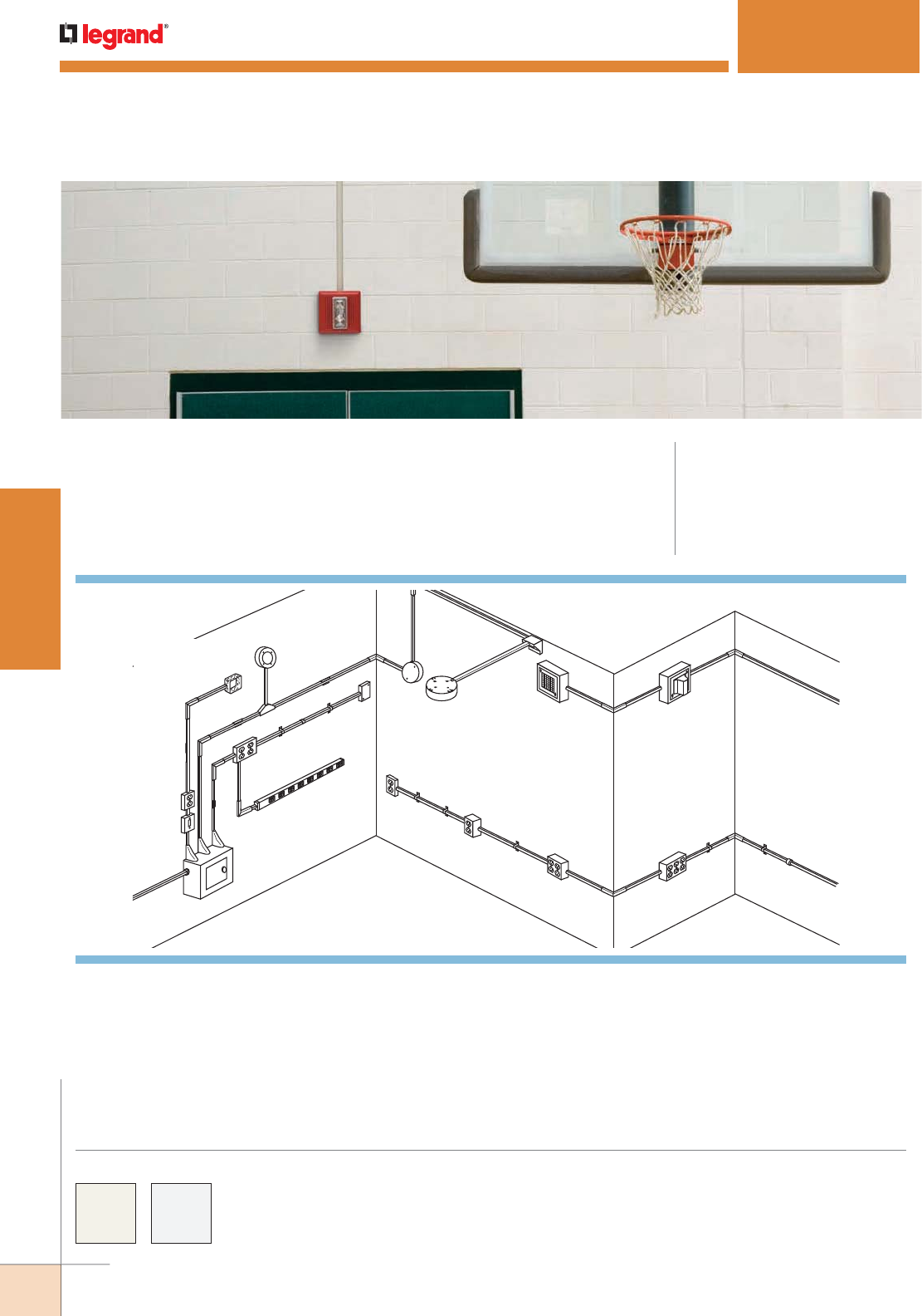
WWW.LEGRAND.US/WIREMOLD
26
STEEL RACEWAY
WIREMOLD
4 11/16" [119mm]
Utility Box
A
B
B
C
E
F
F
G
H
I
J
K
L
M
NO
PQ
RS
U
V
Plugmold
W
Y
D
T
Z
X
NOTE: Illustration is for showing product applications only.
500® & 700® SERIES RACEWAY
CODE REFERENCE
cULus Listed Raceway:
File E4376 Guide RJBT.
Fittings:
File E41751 Guide RJPR.
Meets Article 386 of NEC.
Meets Section 12-1600 of CEC.
One-piece, single-channel raceway. Easy-to-install and ideal for basic
power or communication/low voltage installations. Provides low profile
appearance that blends with any decor.
V. 5785 Combination Connector
W. V5786 Adjustable Offset
Connector
X. 5724O Single Pole Switch
and Box
Y. 57242 Utility Box
Z. 57243G Duplex Receptacle
and Box
COLOR OPTIONS
500® and 700® Series Raceway Part Numbers with a “V” prefix have an ivory finish.
Part Numbers with a “WH” suffix have a white finish. Some Device Boxes used in
safety applications are also available with a red painted finish.
Custom color options are also available. Consult the factory for more information.
System Layout
KEY
A. 2089E Reducing Fitting
B. 504 Mounting Strap
C. 506 Cover Clip
D. 511 Flat Elbow
E. 517 Internal Elbow
F. 518 External Elbow
G. 5703 Supporting Clip
H. 5715 Tee
I. 5719 Corner Box
J. 5734A Utility Box
K. 5738 Fixture Box Solid Base
L. V 5739 Fixture Box Solid Base
M. 5744 Extra Deep Device Box
N. 5747-2 Two-Gang Shallow
Device Box
O. 5748S Shallow Device Box
P. 5748-2 Two-Gang Device Box
Q. 5748-3 Three-Gang Device Box
R. 5752 Alarm Device Box
S. 5753 Extra Deep Alarm
Device Box
T. 5781 Box Connector
U. 5782
1/2" Trade Size
Conduit Connector
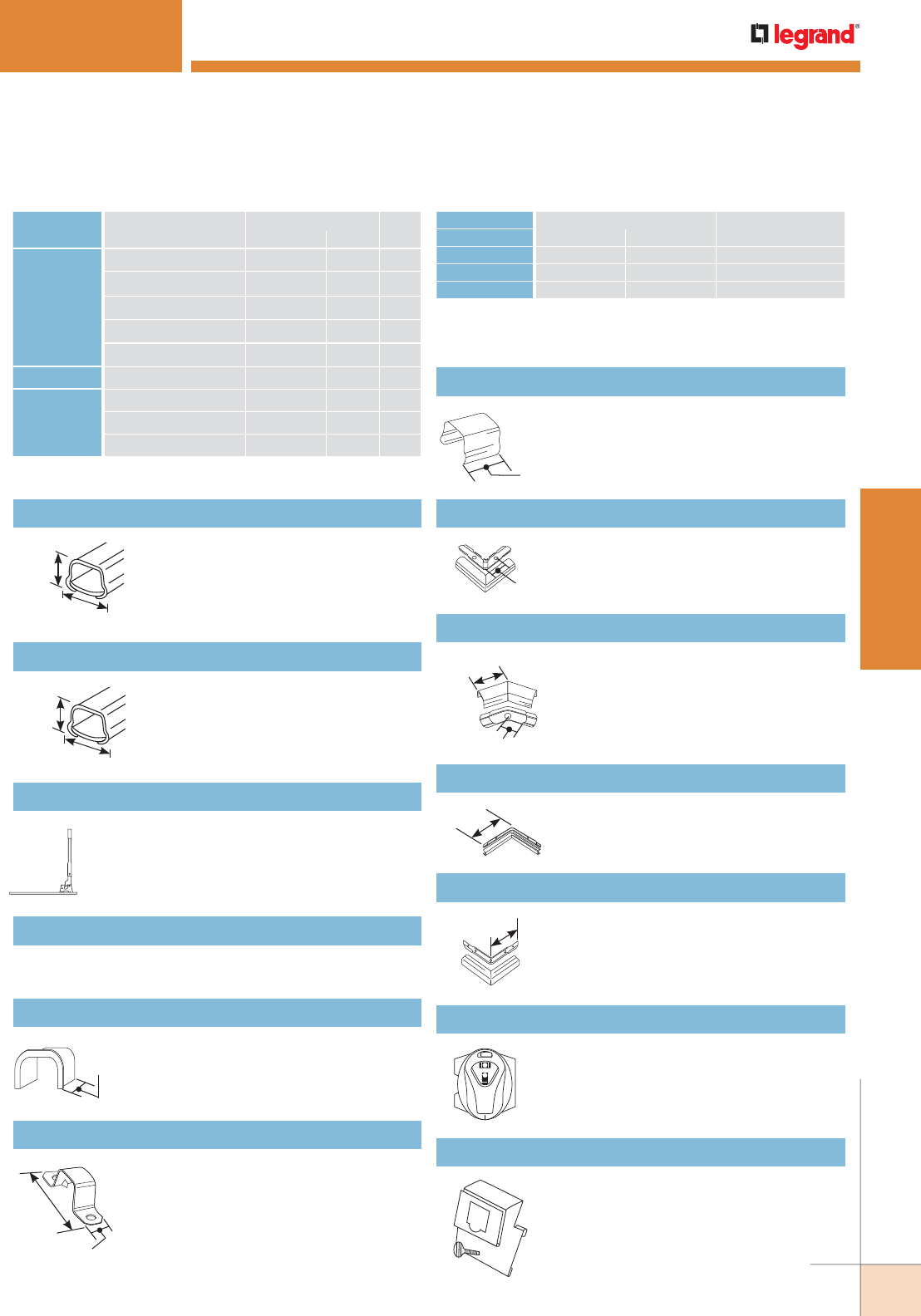
WWW.LEGRAND.US/WIREMOLD
27
STEEL RACEWAY
WIREMOLD
500® & 700® SERIES RACEWAY
NOTE: Use #8 flathead screws with all fittings
requiring screws except V504. With V504,
use #8 panhead screws.
CABLE/WIRE SIZE
O.D. APPROX. DIA. 40%
FILLInches [mm]
UNSHIELDED
TWISTED
PAIR
4-pair, 24 AWG, Cat 3 0.190 [4.8] 2
4-pair, 24 AWG, Cat 5e 0.210 (5.3) 2
4-pair, 24 AWG, Cat 6 0.250 (6.3) 1
4-pair, 24 AWG, Cat 6a* 0.354 (9.0) 0
25-pair, 24 AWG 0.410 (10.4) 0
COAXIAL RG6/U 0.270 [6.9] 1
FIBER ZipCord 0.118 x 0.236 [3 x 6] 2
Round 4 Strand Fiber 0.187 [4.8] 2
Round 6 Strand Fiber 0.256 [6.5] 1
500 Series Wire Fill Capacities For Communications
WIRE SIZE O.D. NO. OF CONDUCTORS
THHN/THWN Inches [mm] 40% FILL
14 AWG 0.111 [2.8] 7
12 AWG 0.130 [3.3] 5
10 AWG 0.164 [4.2] 3
NOTE: For additional information, refer to the Technical Section.
* Category 6 augmented (6a) cable for 10 gigabit ethernet – max allowed
cable diameter per addenda No. 11 ANSI TIA/EIA 568-B.2.
500 Series Wire Fill Capacities for Power
V500 One-Piece Raceway
.040" [1.0mm] steel. Ivory finish. Available
in 10' [3m] lengths, 100' [31m] per carton.
One (1) 5701 Coupling furnished with each
length.
3/4"
[19.1mm]
17/32"
[13.5mm]
Protects wires from abrasion. Slips into
open end of 500 Series Raceway.
502 Bushing
1/2"
[12.7mm]
(One- or Two-Hole) – Converts to one-hole
by breaking off at score. Lanced tab holds
strap in place while fastening to surface.
V504 Mounting Strap
1 13/16"
[46mm]
1/2"
[12.7mm]
V506 Connection Cover
Covers seam where two lengths of 500
Series Raceway come together.
3/4"
[19.1mm]
V511 Flat Elbow
Right angle turns on the same surface.
2"
[51mm]
Case hard steel replacement blades for 605 Raceway Cutter.
605K Replacement Blades
Single action portable cutter. Fast and
easy square cuts.
605 500 Series Raceway Cutter
Same as V500 Raceway except in 5' [1.5m]
lengths, 50' [15m] per carton. One (1) 5701
Coupling furnished with each 5' [1.5m]
length.
3/4"
[19.1mm]
17/32"
[13.5mm]
V500-5 One-Piece Raceway
Inside right angle turns.
2 3/4"
[70mm]
V517 Internal Elbow
1 1/4"
[32mm]
3/4"
[19.1mm]
Diagonal 45° turns on same surface.
V512 45° Flat Elbow
500 Series Raceway Ordering Information
For 500/700 Series Raceway. Attaches to
step ladder and holds raceway channel
securely for accurate cuts.
5700CG Cutting Guide
For 500/700 Series Raceway. Attaches to
outlet box base and raceway fittings for
perfect alignment of runs of raceway.
5700LL Laser Level
Outside right angle turns.
2 1/2"
[64mm]
V518 Outside Elbow
WWW.LEGRAND.US/WIREMOLD
28
STEEL RACEWAY
WIREMOLD
Covers seam where two lengths of
700 Series Raceway come together.
3/4"
[19.1mm]
(One- or Two-Hole) Converts to
one-hole by breaking off at score.
Lanced tab holds strap in place while
fastening to surface.
1 13/16"
[46mm]
5/8"
[15.9mm]
.040" [1.0mm] steel. Ivory finish.
Available in 10' [3m] lengths, 100'
[31m] per carton. One (1) 5701
Coupling furnished with each length.
Protects wires from abrasion. Slips
into open end of 700 Series Raceway.
1/2"
[12.7mm]
3/4"
[19.1mm]
21/32"
[16.7mm]
500® & 700® SERIES RACEWAY
WIRE SIZE O.D. NO. OF CONDUCTORS
THHN/THWN Inches [mm] 40% FILL
14 AWG 0.111 [2.8] 10
12 AWG 0.130 [3.3] 7
10 AWG 0.164 [4.2] 4
NOTE: For additional information, refer to the Technical Section.
* Category 6 augmented (6a) cable for 10 gigabit ethernet – max allowed
cable diameter per addenda No. 11 ANSI TIA/EIA 568-B.2.
700 Series Wire Fill Capacities for Power700 Series Wire Fill Capacities For Communications
CABLE/WIRE SIZE
O.D. APPROX. DIA. 40%
FILLInches [mm]
UNSHIELDED
TWISTED
PAIR
4-pair, 24 AWG, Cat 3 0.190 [4.8] 3
4-pair, 24 AWG, Cat 5e 0.210 (5.3) 3
4-pair, 24 AWG, Cat 6 0.250 (6.3) 2
4-pair, 24 AWG, Cat 6a* 0.354 (9.0) 1
25-pair, 24 AWG 0.410 (10.4) 0
COAXIAL RG6/U 0.270 [6.9] 1
FIBER ZipCord 0.118 x
0.236
[3 x 6] 3
Round 4 Strand Fiber 0.187 [4.8] 3
Round 6 Strand Fiber 0.256 [6.5] 2
Single action portable cutter. Fast and
easy square cuts.
607 700 Series Raceway Cutter
One-Piece Raceway 702 Bushing
Case hard steel replacement blades for 607 Raceway Cutter.
607K Replacement Blades
700 Series Raceways Ordering Information
NOTE: Use #8 flathead screws with all fittings requiring screws except V704.
With V704, use #8 panhead screws.
PART NUMBERS:
V700 (Ivory)
700WH (White)
Mounting Strap
PART NUMBERS:
V704 (Ivory)
704WH (White)
Connection Cover
PART NUMBERS:
V706 (Ivory)
706WH (White)
WWW.LEGRAND.US/WIREMOLD
29
STEEL RACEWAY
WIREMOLD
500® & 700® SERIES RACEWAY
Connects branches of 700 Series
Raceway at right angles. When used
with 700 Series Raceway, break out
crescent twistout in cover.
For feeding raceway from
ceiling or floor. Allows for
ample splice room. Base has
1/2" trade size KO.
1 5/16"
[33mm]
2 1/2"
[64mm]
2 1/2"
[64mm]
1 3/16"
[30mm]
1 3/16"
[30mm]
For installing raceway around offsets,
side bends, twisted turns, and curved
surfaces. Wire fill capacity is the same
as 500 & 700 Series Raceways. Consult
factory for custom lengths. Maximum
painted length 3' [915mm].
18" [457mm]
Overall
Joins and supports lengths of 500 or
700 Series Raceway. One coupling
included with each length of raceway.
2"
[51mm]
Supports lengths of 500 and 700
Series Raceway.
2 1/2"
[64mm]
Provides additional grounding for 500
or 700 Series Raceway or to ground
remotely located devices. Insert clamp
into raceway before installing. Attach
ground wire to screw as required by
National Electrical Code.
2"
[51mm]
Provides grounding means for 1/2"
trade size conduit using lock nut.
1"
[25mm]
2 1/2"
[64mm]
2 1/2"
[64
mm]
7/8"
[22.2mm]
2 1/2"
[64mm]
2 1/2"
[64mm]
5711RHA
90° twist with a 90° turn. For double
turn at right angles from one surface
to another. For transitions from a
sidewall to ceiling or edge of door or
window trim. Twistout in cover adapts
for use with 700 Series Raceway.
5709GC Grounding Connector
5709 Ground Clamp
Supporting Clip
5701 Coupling
V5700F Flexible Section
Right angle turns on the same surface.
2"
[51mm]
Flat Elbow
1 1/4"
[32mm]
3/4"
[19.1mm]
Diagonal 45° turns on same surface.
Inside right angle turns.
2 3/4"
[70mm]
Outside right angle turns.
2 1/2"
[64mm]
Outside Elbow
Internal Elbow
45° Flat Elbow
500 & 700 Series Raceway Fittings Ordering Information
PART NUMBERS:
V711 (Ivory)
711WH (White)
PART NUMBERS:
V712 (Ivory)
712WH (White)
PART NUMBERS:
V717 (Ivory)
717WH (White)
PART NUMBERS:
V718 (Ivory)
718WH (White)
PART NUMBERS:
V5703 (Ivory)
5703WH (White)
Corner Box
PART NUMBERS:
V5719 (Ivory)
5719WH (White)
Internal Twist Elbows
PART NUMBERS:
5711LHA, 5711RHA (Ivory)
5711LHAWH, 5711RHAWH (White)
Tee
PART NUMBERS:
V5715 (Ivory)
5715WH (White)

WWW.LEGRAND.US/WIREMOLD
30
STEEL RACEWAY
WIREMOLD
500® & 700® SERIES RACEWAY
V5784 Elbow Box Connector
2 1/8"
[54mm]
1 1/4"
[32mm]
Connects raceway at right angles to
1/2" trade size conduit or armored
cable connectors. When used with
700 Series Raceway, break out
crescent twistout in cover.
Connects raceway at right angles
to conduit boxes or panel boxes
that have 1/2" trade size conduit
KOs. When used with 700 Series
Raceway, break out crescent
twistout in cover.
1 1/4"
[32mm]
2 1/8"
[54mm]
1 1/4"
[32mm]
V5783 Elbow Box Connector
For hanging either 3/8" [9.5mm] or 1/2"
[12.7mm] fixtures to Wiremold fittings
with 1/2" trade size KOs. Has female
3/8" [9.5mm] pipe thread inside and
male 1/2" [12.7mm] pipe thread outside.
1/2"
[12.7mm]
Male connector for connecting raceway
to conduit boxes or panel boxes that
have KOs for conduit. Can also be used
with conduit type fittings. When used
with 700 Series Raceway, break out
crescent twistout in connector. 5781
has 1/2" trade size conduit opening
and 5781A has 3/4" trade size conduit
opening.
1/2"
[12.7mm]
3/4"
[19.1mm]
5780 Special Nipple
Box Connector (Galvanized)
Interior threaded female connector for
connecting raceway to conduit. When
used with 700 Series Raceway, break
out crescent twistout in connector.
5782 has 1/2" trade size conduit
opening and 5782A has 3/4" trade
size conduit opening.
3/4"
[19.1mm]
1 3/4"
[44mm]
Conduit Connector (Galvanized)
CONNECTION REQUIRED
USE CATALOG NUMBER
FROM TO
500 Series, 700 Series Raceway 1500 Series Raceway 1517B
500 Series Raceway Side of 2000 Series Raceway V2089
500 Series Raceway End of 2000 Series Raceway V2089E
Existing Outlet 500 or 700 Series Raceway V5751
Panel Box 500 or 700 Series Raceway V5786
1/2" trade size Conduit or Armored Cable 500 or 700 Series Raceway 5782, V5784
3/4" trade size Conduit or Armored Cable 500 or 700 Series Raceway 5782A
Boxes with 1/2" trade size KOs 500 or 700 Series Raceway 5781, V5785
Boxes with 3/4" trade size KOs 500 or 700 Series Raceway 5781A
3" [76mm] or 4" [102mm] Ceiling Boxes 500 or 700 Series Raceway V5737, V5737A, V5739
Single-Gang
Outlet Box
Two-Gang
Surface Box
V5735, V5744-2, V5744S-2,
V5747-2, V5748-2
14/2, 14/3, 12/2, 12/3 Armored Cable 500 or 700 Series Raceway 5790B
1/2" trade size EMT 5700 Series Boxes 5791
500 & 700 Series Raceways Interconnectivity Fittings
Extension for existing flush switch
and receptacle boxes to blank original
outlet. Closed base version available as
a special order.
4 5/8"
[118mm]
15/16"
[23.8mm]
2 7/8"
[73mm]
V5760 Blank Extension Box
500 & 700 Series Raceway Fittings Ordering Information (continued)
PART NUMBERS:
V5782 (1/2")
5782A (3/4")
PART NUMBERS:
V5781 (1/2")
5781A (3/4")
WWW.LEGRAND.US/WIREMOLD
31
STEEL RACEWAY
WIREMOLD
500 & 700 Series Raceways Device Boxes Ordering Information
5791 EMT Connector
5790B Armored Cable Connector (Galvanized)
Connects 14/2, 14/3, 12/2, and 12/3 “MC”
and armored cable to Wiremold fittings.
A short piece of 500 or 700 Series
Raceway (1 5/8" [41mm] min.) must be
used between connector and Wiremold
fittings. Not for use with 1/2” [12.7mm]
flex conduit.
1"
[25mm]
2"
[51mm]
Eliminates need to offset raceway
when connecting to surface type
panel boxes. Adjustment from
surface to center of bushings is
5/8" [15.9mm] minimum to 1 3/8"
[35mm] maximum. When used
as adjustable offset connector,
break out metal between the
two holes. When used with 700 Series Raceway, break out
crescent twistout in cover. 1/2" trade size chase nipple and
locknut furnished.
1 1/2"
[38mm]
2 3/8"
[61mm]
2 1/4"
[57mm]
7/8"
[22.2mm]
1 5/8"
[41mm]
3 7/8"
[98mm]
3 7/16"
[87mm]
Connects 1/2" trade size EMT to 5700
Series rectangular and round device
boxes (except 5733). Derates the fill
capacity of the EMT.
1 3/4"
[44mm]
V5731 Blank Cover
2 3/8" [61mm] Dia.
1/4"
[6.4mm] Use with 5733 Outlet Box to convert box
into pull or junction box. Has 1/2" trade
size KO in center.
500® & 700® SERIES RACEWAY
NOTE: 500 & 700 Series Raceway Systems Device Boxes that are identified
with this symbol are Certified to Canadian Safety Standards for sale
in Canada. When ordering these products (this page and the next
page), change the “V” color prefix to “VC” or the “WH” color suffix to
“WHC” to denote the Canadian versions.
4 3/4" sq.
[121mm]
1 3/8"
[35mm]
15/16"
[23.8mm]
3" Dia.
[76mm]
1/2" trade size KO in center. For
use with 5735, 5737, 5737A, 5738,
5738AF, 5739, 5739A or 2135 Device
Boxes. Converts these boxes into
pull or junction boxes or for hanging
lightweight pendant fixtures with 1/2"
trade size pipe stems.
7/16"
[11.1mm]
4 3/16"
[106mm]
For devices with mounting screw
centers of 1 15/32", 1 5/8", 1 11/16",
or 1 27/32" [37mm, 41mm, 44mm, or
46mm]. Will accept any device that
mounts on “G” or “H” type conduit
fittings.
V5733 Outlet Box
Twistouts permit use of three parallel
raceway runs on each side. Base
has 1/2" and 1" concentric trade size
KOs and a 1 13/16" [46mm] x 2 7/8"
[73mm] rectangular KO to mount on
a one-gang in-wall outlet box. Cover
accepts devices with mounting screw
centers of 2 3/4", 3 1/2" or 4 1/16" [70mm, 89mm or
103mm], and canopy fixtures no larger than 4 5/8" [117mm]
in diameter. With 5736 Blank Cover, this fitting can be used
as junction box, pull box, etc.
V5735 Distribution Box
Connects raceway, without off-
setting, to any surface-mounted
3 1/4" or 4" [83mm or 102mm]
outlet box with 1/2" trade size
conduit KOs. Base has two 1/2"
trade size KOs, one on end and one on bottom. Included
spring steel bushing eliminates need for conduit nipple and
locknut for end connection to box. When used with 700
Series Raceway, break off cover extension.
1 5/16"
[33mm]
1 5/8"
[41mm]
2 7/16"
[62mm]
3"
[76mm]
Combination Connector
500 & 700 Series Raceway Fittings Ordering Information (continued)
Blank Cover
PART NUMBERS:
V5736 (Ivory)
5736WH (White)
PART NUMBERS:
V5785 (Ivory)
5785WH (White)
Adjustable Offset Connector
PART NUMBERS:
V5786 (Ivory)
5786WH (White)
WWW.LEGRAND.US/WIREMOLD
32
STEEL RACEWAY
WIREMOLD
500® & 700® SERIES RACEWAY
2"
[51mm]
1 3/8"
[35mm]
4 1/8"
[105mm]
4 5/8"
[117mm] 1 3/8"
[35mm]
2 13/16"
[72mm]
L
W
2 3/4"
[70mm]
CAT. NO. L W GANGS
V5744,
5744-WH
4 5/8" [117mm] 2 7/8" [73mm] 1
V5744-2,
5744-2WH
4 3/4" [121mm] 4 3/4" [121mm] 2
V5744-3 4 5/8" [117mm] 6 1/2" [165mm] 3
NOTE: One-gang device boxes accept NEMA single-gang standard
faceplates. Two-gang device boxes accept NEMA double-gang
standard faceplates.
NOTE: 500 & 700 Series Raceway Systems Device Boxes that are identified
with this symbol are Certified to Canadian Safety Standards for sale
in Canada. When ordering these products (this page and the next
page), change the “V” color prefix to “VC” or the “WH” color suffix to
“WHC” to denote the Canadian versions.
For deep devices such as
momentary contact, remote control
switches, and hospital signaling
system devices. Base has 1/2"
trade size KOs. Larger gang boxes
available by special order.
Accommodates 15A (NEMA
5-15R) or 20A (NEMA 5-20R)
duplex devices in place of duplex
grounding receptacle included.
Cover has twistouts for 500 and
700 Series Raceway on each end
and sides. Twistouts on ends of box
permit running raceway close to
interior trim. Base has 1/2” trade
size KOs.
For shallow type switches (three-
way, single, and double pole) and
receptacles, including three-wire
locking receptacles and single-
gang combination devices. Base
has 1/2" trade size KO. Position of
twistouts on ends permits running
raceways close to interior trim.
V57243G 15A, 125V Duplex Grounding
Receptacle (NEMA 5-15R) & Box
Extra Deep Switch & Receptacle Box
500 & 700 Series Raceways Device Boxes Ordering Information (continued)
Open Base Extension Box
A
1"
[25mm]
Mounts on 3 1/4" or 4" [83mm or
102mm] conduit boxes or other re-
cessed outlets. Cover accepts devices
with mounting screw centers of 2
3/4", 3 1/2" or 4 1/16" [70mm, 89mm,
or 103mm]. Can be used with 5736
Blank Cover as a pull or junction box.
CAT. NO. DIA. A.
V5737, 5737WH 4 3/4" [121mm]
V5737A, 5737AWH 5 1/2" [140mm]
V5739A 6 3/8" [162mm]
V57240 15A, 125V Single Pole Switch & Box
V57242 Utility Box
A
1"
[25mm]
1"
[25mm]
5 1/2"
[140mm]
2"
[51mm]
1 3/8"
[35mm]
4 1/8"
[105mm]
CAT. NO. DIA. A.
V5738, 5738WH 4 3/4" [121mm]
V5738A, 5738AWH 5 1/2" [140mm]
V5739, 5739WH 6 3/8" [162mm]
Single pole switch included.
Accepts standard single-gang
switches including three-way. Cover
has twistouts for 500 or 700 Series
Raceway on each end and sides.
Twistouts on ends of box permit
running raceway close to interior
trim. Base has 1/2" trade size KOs.
2"
[51mm]
1 3/8"
[35mm]
4 1/8"
[105mm] Can be used as tee, cross, pull box,
junction box, or blank box. Cover
has 1/2" trade size KO and twistouts
for 500, and 700 Series Raceway on
each end and sides. Twistouts on
ends of box permit running raceway
close to interior trim. Base has 1/2"
trade size KOs.
Used to hang fixtures. Cover accepts
devices with mounting screw centers
of 2 3/4", 3 1/2", and 4 1/16" [70mm,
89mm, and 103mm]. Base has four
holes for fixture studs, four 1/2"
trade size KOs, and raised section for
no-bolt fixture-stud. Use as a junction
or pull box with 5736 Blank Cover.
Solid Base Fixture Box
Cover accepts fan bracket with
mounting centers of 3 3/16"
[81mm]. Base has six mounting
holes and 4 1/2" trade size KOs.
#10 mounting studs provided.
Rated for fans and fixtures up to
50 lbs.
Solid Base Fan Box
PART NUMBERS:
V5738AF (Ivory)
5738AFWH (White)
Switch & Receptacle Box
PART NUMBERS:
V5741 (Ivory)
5741WH (White)
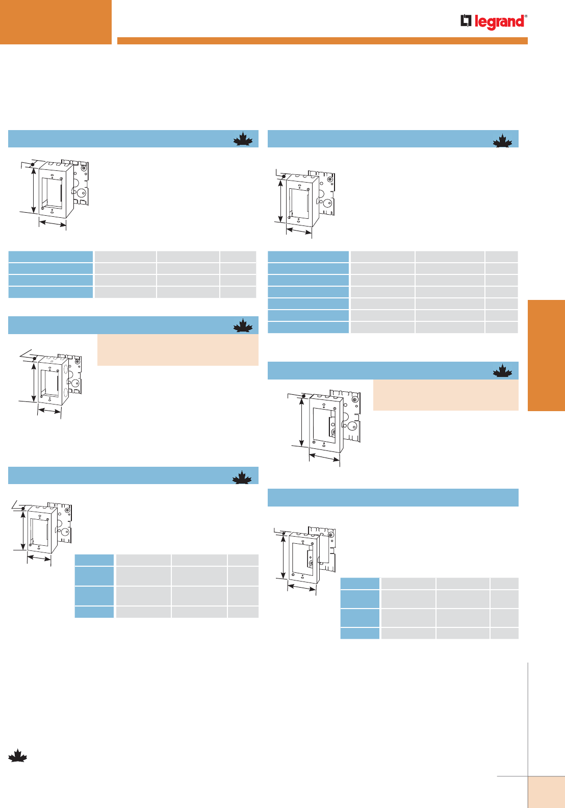
WWW.LEGRAND.US/WIREMOLD
33
STEEL RACEWAY
WIREMOLD
500® & 700® SERIES RACEWAY
L
W
2 1/4"
[57mm]
2 7/8"
[73mm]
4 5/8"
[117mm]
1 3/4"
[44mm]
L
1 3/8"
[35mm]
W
CAT. NO. L W GANGS
V5744S, 5744SWH 4 5/8" [117mm] 2 7/8" [73mm] 1
V5744S-2, 5744S-2WH 4 3/4" [121mm] 4 3/4" [121mm] 2
V5744S-3 4 5/8" [117mm] 6 1/2" [165mm] 3
Designed especially for use in the
instal la tion of signal system and alarm
wiring. Base has 1/2" trade size KOs.
Larger gang boxes are available by
special order.
Connects to surface runs of 1/2" trade
size conduit. Cover has 1/2” trade
size KO and two raceway twistouts on
one end and three raceway twistouts
on opposite end, two 1/2" KOs and a
raceway twistout on each side. Base has
two 1/2" trade size KOs. Larger gang
boxes are available by special order.
CAT. NO. L W GANGS
V5747,
5747WH
4 5/8" [117mm] 2 7/8" [73mm] 1
V5747-2,
5747-2WH
4 3/4" [121mm] 4 3/4" [121mm] 2
V5747-3 4 5/8" [117mm] 6 1/2" [165mm] 3
For standard shallow switches and
receptacles including single-gang
combination devices. Base has two
1/2" trade size KOs. Larger gang boxes
available by special order.
Deep Switch & Receptacle Box
Shallow Switch & Receptacle Box
L
W
1 3/4"
[44mm]
CAT. NO. L W GANGS
V5748, 5748WH
4 5/8" [117mm] 2 7/8" [73mm]
1
V5748-2, 5748-2WH
4 3/4" [121mm] 4 3/4" [121mm]
2
V5748-3, 5748-3WH
4 5/8" [117mm] 6 1/2" [165mm]
3
V5748-4
4 5/8" [117mm] 8 11/32" [212mm]
4
V5748-5
4 5/8" [117mm] 10 5/32" [258mm]
5
V5748-6
4 5/8" [117mm] 11 31/32" [304mm]
6
For deep switches and receptacles. Base
has two 1/2" trade size KOs. Larger gang
boxes available by special order.
Switch & Receptacle Box
4 5/8"
[117mm]
2 7/8"
[73mm]
15/16"
[23.8mm]
15/16"
[23.8mm]
L
W
For extensions from existing flush
switch and receptacle boxes.
Larger gang boxes available by
special order.
CAT. NO. L W GANGS
V5751,
5751WH 4 5/8" [117mm] 2 7/8" [73mm] 1
V5751-2,
5751-2WH 4 3/4" [121mm] 4 3/4" [121mm] 2
V5751-3 4 5/8" [117mm] 6 1/2" [165mm] 3
For shallow type switch and duplex
receptacles. Base has 1/2" trade
size KOs.
Flush Type Extension Adapter
500 & 700 Series Raceways Device Boxes Ordering Information (continued)
NOTE: 500 & 700 Series Raceway Systems Device Boxes that are identified
with this symbol are Certified to Canadian Safety Standards for sale
in Canada. When ordering these products (this page and the next
page), change the “V” color prefix to “VC” or the “WH” color suffix to
“WHC” to denote the Canadian versions.
Combination Switch & Receptacle Box
PART NUMBERS:
V5745 (Ivory)
5745WH (White)
Shallow Switch & Receptacle Box
PART NUMBERS:
V5748S (Ivory)
5748SWH (White)
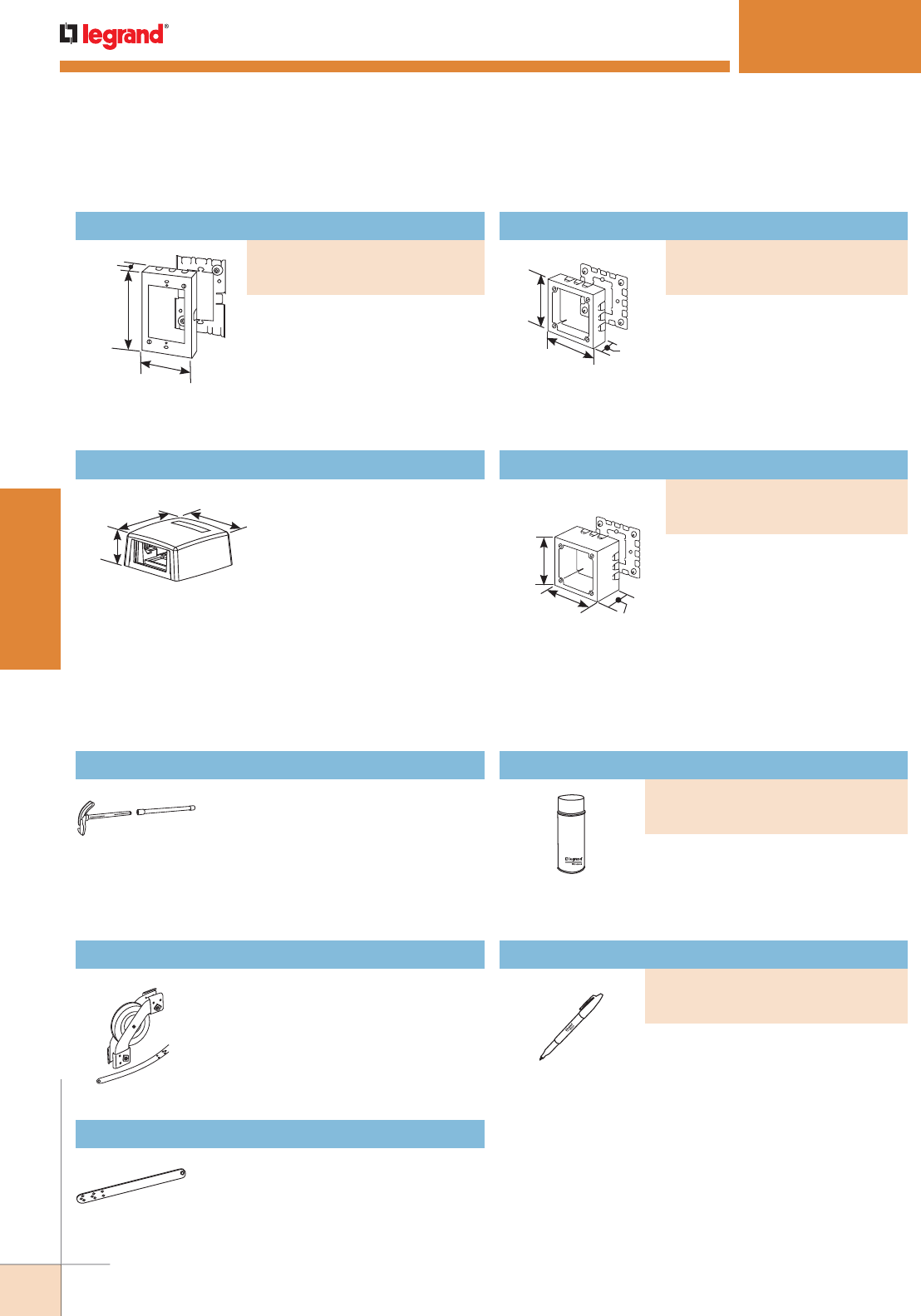
WWW.LEGRAND.US/WIREMOLD
34
STEEL RACEWAY
WIREMOLD
1 1/2"
[38mm]
3 1/4"
[83mm]
3 1/4"
[83mm] Accepts one CM2 Wiremold Open
System Communications Module
or one Pass & Seymour® Activate
Series Insert. Compatible with
500 and 700 Series Raceway.
Ivory finish.
1 3/8"
[35mm]
4 11/16"
[120mm]
4 11/16"
[120mm]
4 11/16"
[120mm]
4 11/16"
[120mm]
2 3/4"
[70mm]
For surface mounting of alarm
devices and safety signals designed
to fit into 4" [102mm] square back
boxes. Cover has three raceway
twistouts on each side. Base has
1/2" and 1" concentric and single-
gang box KOs.
For surface mounting of alarm
devices and safety signals designed
to fit into 4" [102mm] square back
boxes. Cover is 2 3/4" [70mm] deep
and has three twistouts for raceways
on each side. Base has 1/2" and 1"
concentric and single-gang box KOs.
NOTE: One-gang device boxes accept NEMA single-gang standard faceplates.
Two-gang device boxes accept NEMA double-gang standard
faceplates.
CM-MMB-571 One Insert Multimedia Box
500 & 700 Series Raceways Device Boxes Ordering Information (continued)
500® & 700® SERIES RACEWAY
600B Wiremold Bender
Touch-Up Paint Pen
500 & 700 Series Raceways Tools
For making smooth, accurate bends,
saddles and offsets in Wiremold 500
and 700 Series Raceways. Two-piece
handle fits in tool box.
For fishing wires around inside
corners of 500 or 700 Series Raceway.
When conductors are through the run,
detach pulley and snap on appropriate
internal elbow cover.
One 616 Fish Tape Leader included.
For pulling conductors through 500 or
700 Series Raceways. Holes provided
for up to eight conductors.
Used for touching up large areas.
Contains 12 oz. of paint.
NOTE: Can only be shipped via ground
transportation.
Used for touching up small areas.
Contains 0.3 oz. of paint.
Spray Paint
615 Wire Pulley
616 Fish Tape Leader
4 5/8"
[117mm]
2 7/8"
[73mm]
1 3/4"
[44mm]
For deep extensions from existing
wall boxes.
Deep Flush Type Extension Adapter
NOTE: Can only be shipped via ground
transportation.
PART NUMBERS:
V5751A (Ivory)
5751AWH (White)
PART NUMBERS:
IWE-S (Ivory)
WHWE-S (White)
PART NUMBERS:
IWE-P (Ivory)
WWE-P (White)
Two-Gang Alarm Device Box
PART NUMBERS:
V5752 (Ivory)
R5752 (Red)
Two-Gang Extra Deep Alarm Device Box
PART NUMBERS:
V5753 (Ivory)
R5753 (Red)
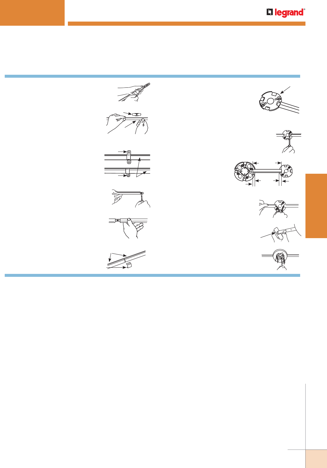
WWW.LEGRAND.US/WIREMOLD
35
STEEL RACEWAY
WIREMOLD
500 & 700 Series Raceways Installation Details
1. Each length of Wiremold raceway is
furnished with a coupling. Push coupling
out to expose clearance hole (5701).
4. For added support or to secure raceway
prior to installing straps, fasten
coupling to surface through clearance
holes (5701).
5. Slide adjoining section of raceway
onto coupling (5701).
NOTE: If raceway has been field cut,
it must be deburred prior to coupling.
2. Fasten support clips (V5703) to
surface at approximately 32"
[816mm] intervals. See the Technical
Information Section for surface
mounting methods. After support clips
are installed, snap raceway into clips.
Support Clip
Raceway
3. As an alternate method of mounting
(especially if the surface is uneven),
504 or 704 straps can be used. Hold
raceway in position and fasten strap
to surface. Straps should be spaced
no greater than 32" [816mm] O.C.
Strap
Raceway
Strap
6. If ends of adjoining raceways are
not square, use 506 or 706 Cover
Connection to fill gap.
Abutting Raceways
Snap Over Cover
10. Pull wiring in. (Use 502 or 702
Bushing to protect wires from
abrasion.)
12. Install fitting cover(s) over raceway(s)
and fasten to fitting base with screws
provided.
7. Couple raceway to fitting base by
slipping tongue of fitting under
the base of raceway. (Use 502 or
702 Bushing to protect wires from
abrasion.) Do not mount more than one
fitting base at a time. Sequence should
be base, raceway, base, raceway, etc.
Fitting Base
9. Determine desired location
of next fitting. Measure
and cut raceway as shown.
Install fitting base and
raceway as in steps 1
and 2.
Raceway
Length
5/8"
[15.9mm]
5/8"
[15.9mm]
Distance
Between
Bases
11. Remove proper twistouts in fitting
cover(s) with pliers. Twist
inward as shown.
Fitting Cover
8. Fasten base of fitting to surface using proper
flat head fastener: #8 with V500 and V700
Series. See Technical Information Section for
surface mounting methods.
500® & 700® SERIES RACEWAY

WWW.LEGRAND.US/WIREMOLD
36
STEEL RACEWAY
WIREMOLD
2000 SERIES® RACEWAY
KEY
A. 500 Series Raceway
B. 518 External Elbow Fitting
C. 2006 Cover Clip
D. 2010A3 Entrance End Fitting
E. 2010A2 Entrance End Fitting
F. 2010B Blank End Fitting
G. 2051H Flush Plate Adapter
H. 2011 90° Flat Elbow Fitting
I. 2015 Tee Fitting
J. 2017TC Internal Corner Coupling
K. 2018C External Elbow Cover
L. 2048 Single-Gang Device Box
M. 2048-2 Two-Gang Device Box
N. 20GB506 Plugmold Strip
O. 2089A Flush Plate Adapter
P. 2089E End-Reducing Connector
Q. 5748 Single-Gang Device Box
CODE REFERENCE
cULus Listed Raceway:
File E4376 Guide RJBT.
Fittings:
File E41751 Guide RJPR.
Meets Article 386 of NEC.
Meets Section 12-1600 of CEC.
Two-piece, single-channel raceway. Easy-to-install and ideal
for basic power or communication/low voltage installations
COLOR OPTIONS
2000® Series Raceway Part Numbers with a “V” prefix have an ivory finish.
Part Numbers with a “G” prefix have a gray finish. Part Numbers without a
prefix or suffix have a protective zinc finish.
Custom color options are also available. Consult the factory for more information.
System Layout
F
M
I
K
L
H
N
D
Q
P
B
A
A
E
O
R
L
G
C
J
NOTE: Illustration is for showing product applications only.
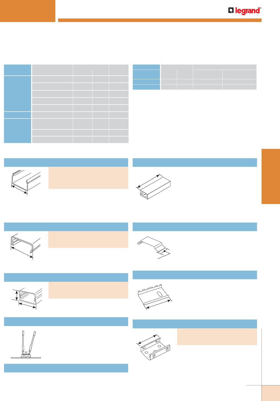
WWW.LEGRAND.US/WIREMOLD
37
STEEL RACEWAY
WIREMOLD
1 9/32"
[33mm]
2000 SERIES® RACEWAY
2000 Series Raceway Wire Fill Capacities For Communications
CABLE/WIRE SIZE
O.D. APPROX. DIA.
40% FILLInches [mm]
UNSHIELDED
TWISTED
PAIR
4-pair, 24 AWG, Cat 3 0.190 [4.8] 11
4-pair, 24 AWG, Cat 5e 0.210 (5.3) 9
4-pair, 24 AWG, Cat 6 0.250 (6.3) 6
4-pair, 24 AWG, Cat 6a* 0.354 (9.0) 3
25-pair, 24 AWG 0.410 (10.4) 2
COAXIAL RG6/U 0.270 [6.9] 5
FIBER ZipCord 0.118 x
0.236
[3 x 6] 11
Round 4 Strand Fiber 0.187 [4.8] 11
Round 6 Strand Fiber 0.256 [6.5] 6
WIRE SIZE O.D. NO. OF CONDUCTORS
THHN/THWN Inches [mm] WITHOUT
DEVICES
WITH PLUGMOLD
RECEPTACLE
14 AWG 0.111 [2.8] 7 5
12 AWG 0.130 [3.3] 7 5
NOTE: For additional information, refer to the Technical Section.
* Category 6 augmented (6a) cable for 10 gigabit ethernet – max allowed
cable diameter per addenda No. 11 ANSI TIA/EIA 568-B.2.
2000 Series Raceway Wire Fill Capacities For Power
1 5/16"
[33mm]
1/2"
[12.7mm]
Additional support for conductors.
2"
[51mm]
Connects lengths of 2000B Raceway
Base.
2"
[51mm]
Supports lengths of 2000 Series
Raceway at any point desired. Mounts
to surface with No. 6 flathead screw.
Portable cutter for both 2000 Series
Raceway Base and Cover. Provides
clean and easy square cuts every time.
2000 Series Raceway Ordering Information
W30 – Common connection of two,
three or four No. 12 or No. 14 solid
copper conductors.
W30G – Connection of equipment
grounding of 2, 3 or 4 solid conductors
No. 14 or No. 12 AWG. 300V maximum;
20A 105° C maximum.
NOTE: Not for use with aluminum conductors.
Pressure-Type Wire Connectors
.040" [1.0mm] steel. Packed twenty
(20) 5' [1.5m] lengths per carton.
10' [3m] lengths (V2000B-10,
G2000B-10) are also available. Packed
100’ [30.5m] per carton.
PART NUMBERS:
V2000B-5 (Ivory, 5' long)
V2000B-10 (Ivory, 10' long)
G2000B-10 (Gray, 10' long)
Raceway Base
620 2000 Series Raceway Base & Cover Cutter
1 9/32"
[33mm] .025" [.8mm] steel. Packed twenty
5' [1.5m] lengths per carton. Shipped
without receptacle hole cuts.
PART NUMBERS:
V2000C (Ivory)
G2000C (Gray)
Raceway Cover
3/4"
[19.1mm]
1 9/32"
[33mm]
Packed ten (10) 5' [1.5m] lengths per
carton.
PART NUMBERS:
V2000BC (Ivory)
G2000BC (Gray)
Raceway Base & Cover
PART NUMBERS:
V2003 (Ivory)
2003 (Plated)
Supporting Clip
2001 Coupling (Galvanized)
2000WC Wire Clip (Galvanized)
Case hard steel replacement blades and die set for 620
Cutter.
620BCK Replacement Blade Kit
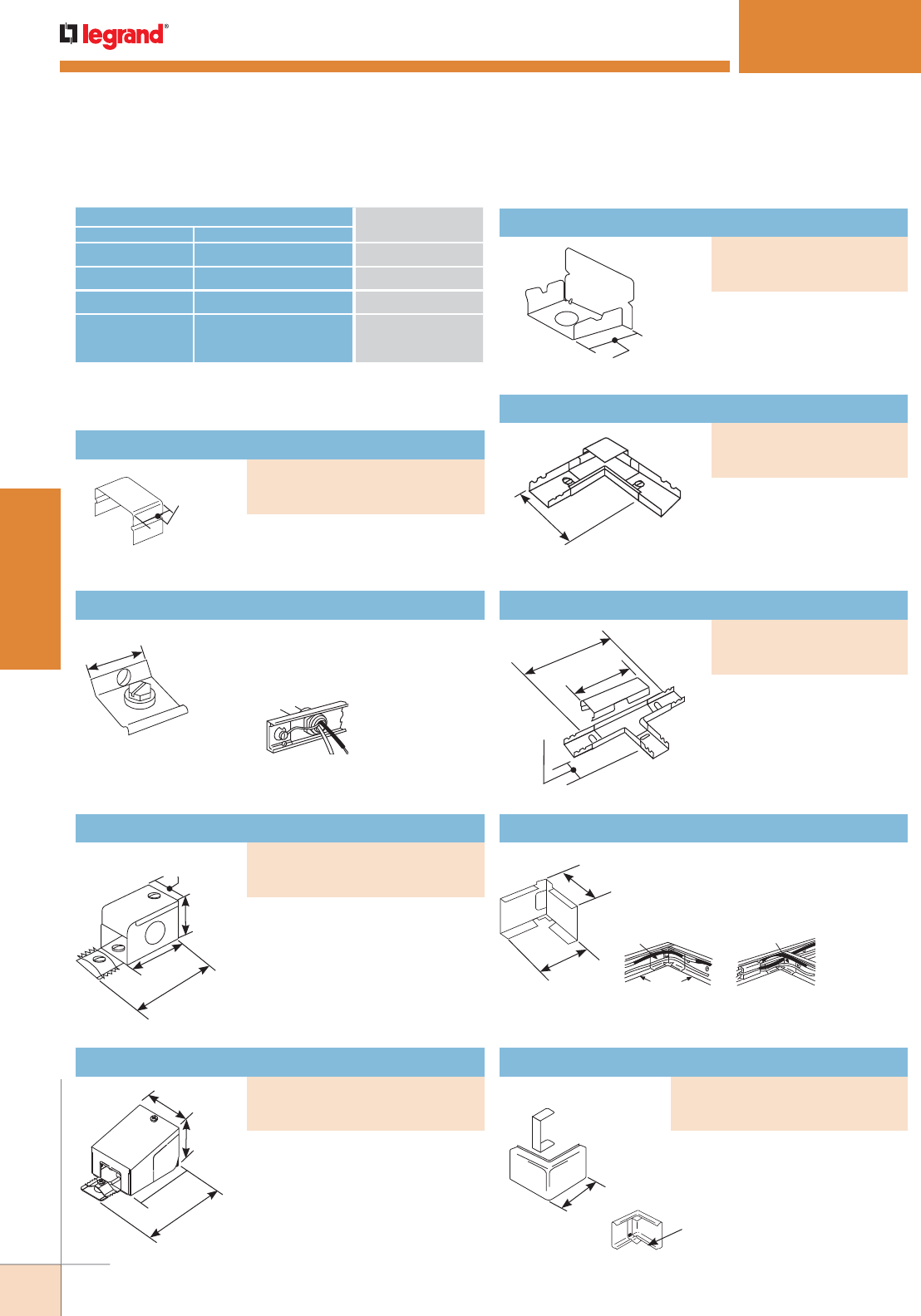
WWW.LEGRAND.US/WIREMOLD
38
STEEL RACEWAY
WIREMOLD
2000 SERIES® RACEWAY
3"
[76mm]
1 9/32"
[33mm]
1 1/2"
[38mm]
2 1/8"
[54mm]
Connects 2000 Series Raceway to
1/2" trade size conduit or armored
cable connectors. 1/2" trade size
KOs located on end, sides, and
bottom of fitting. Includes ground
screw. If more capacity is required,
use 2010A3.
2 1/8"
[54mm]
3"
[76mm]
1 29/32"
[47mm]
2 7/64"
[53mm]
1/2" trade size KOs located on end,
sides, and bottom of fitting. 3/4"
KOs on bottom and rear. Includes
ground screw.
3/4"
[19.1mm]
Closes off the open end of
2000 Series Raceway.
CONNECTION REQUIRED USE CATALOG
NUMBER
FROM TO
500 Series Raceway Side of 2000 Series Raceway V2089, V2048, V2048-2
500 Series Raceway End of 2000 Series Raceway V2089E, V2048, V2048-2
Existing Outlet 2000 Series Raceway V2051H
1/2" trade size
Conduit or
Armored Cable
2000 Series Raceway V2010A2, V2010A3
2000 Series Raceway Interconnectivity Fittings
2 1/2"
[64mm]
Each Leg
For right angle turns on
same surface. Cover stop
permits neat butting of
2000C Cover. Two couplings
included.
1 1/2"
[38mm]
4"
[102mm]
6"
[152mm]
For branching raceway at
right angles. Three couplings
included.
1 1/2"
[38mm]
1 1/2"
[38mm]
2017TC used as a
corner coupling.
2017TC
2000B
2017TC used as a corner
coupling and a straight-
through fitting.
2017TC
2000B
Can be used as inside corner
coupling or as coupling and
straight thru fitting. Furnished with
one fiber bushing.
2017TC Internal Corner Coupling
1 7/8"
[48mm]
Corner gap filler snapped
into place in 2018C
Covers gap when external corner
is made by notching and bending
2000B Base. Continues raceway
runs around outside corners.
Blank End Fitting
Flat Elbow Fitting
Tee Fitting
3/4"
[19.1mm]
Covers seam where two lengths
of 2000 Series Raceway come
together.
Cover Clip
How 2009 is used.
Connects equipment grounding
conductor. Provides an additional
ground for raceway.
1 13/64"
[30mm]
2009 Ground Clamp
2000 Series Raceway Ordering Information (continued)
PART NUMBERS:
V2010B (Ivory)
G2010B (Gray)
PART NUMBERS:
V2011 (Ivory)
G2011 (Gray)
PART NUMBERS:
V2015 (Ivory)
G2015 (Gray)
External Elbow Cover
PART NUMBERS:
V2018C (Ivory)
G2018C (Gray)
Entrance End Fitting
PART NUMBERS:
V2010A3 (Ivory)
G2010A3 (Gray)
Entrance End Fitting
PART NUMBERS:
V2010A2 (Ivory)
G2010A2 (Gray)
PART NUMBERS:
V2006 (Ivory)
G2006 (Gray)
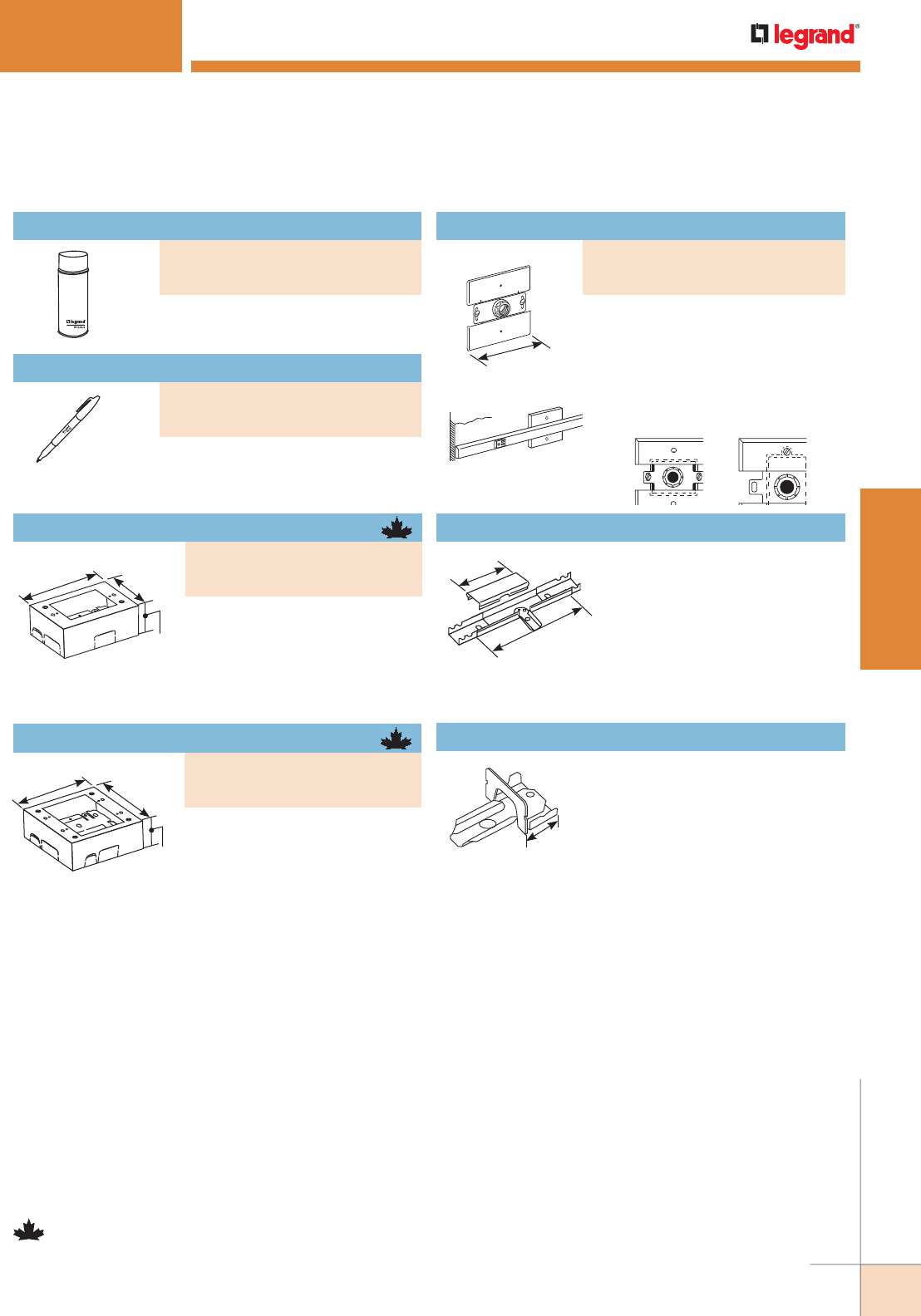
WWW.LEGRAND.US/WIREMOLD
39
STEEL RACEWAY
WIREMOLD
2000 SERIES® RACEWAY
Used for touching up large areas.
Contains 12 oz. of paint.
Used for touching up small areas.
Contains 0.3 oz. of paint.
NOTE: Parts identified with this symbol are Certified to Canadian Safety
Standards for sale in Canada. When ordering these products, change
the “V” color prefix to “CV” or the “G” color prefix to “CG” to denote
the Canadian versions.
2 7/8"
[73mm]
1 3/4"
[44mm]
4 5/8"
[117mm]
4 3/4"
[121mm] 4 3/4"
[121mm]
1 3/4"
[44mm]
Cover has twistouts for 2000,
500, and 700 Series Raceways.
Base has 1/2" trade size KO and
rectangular KO for extension to
wall box. Base has #10 threaded
hole for ground connection.
Cover has twistouts for 2000,
500, and 700 Series Raceways.
Base has 1/2" trade size KO and
rectangular KO for extension to
wall box. Base has #10 threaded
hole for ground connection.
4 1/2"
[114mm]
2051H fastened to
horizontally mounted
wall box.
2051H fastened to
vertically mounted
wall box.
2000 Raceway extended
from wall outlet using 2051H.
Feeds 2000 Series Raceway from an
existing wall outlet. Equipped with 1/2"
trade size threaded stud, toothed lock
washer for grounding, and conduit
bushing.
6"
[152mm]
3 1/4"
[83mm] Connects 2000 Series Raceway
with 500 Series Raceway through
the side of 2000 Series Raceway.
V2089 Side Reducing Connector
3/4"
[19.1mm]
Connects 2000 Series Raceway
with 500 Series Raceway through
the end of 2000 Series Raceway.
V2089E End Reducing Connector
2000 Series Raceway Ordering Information (continued)
Spray Paint
PART NUMBERS:
IWE-S (Ivory)
GWE-S (Gray)
NOTE: Can only be shipped via ground transportation.
Touch-Up Paint Pen
PART NUMBERS:
IWE-P (Ivory)
GWE-P (Gray)
Single-Gang Device Box
PART NUMBERS:
V2048 (Ivory)
G2048 (Gray)
Two-Gang Device Box
PART NUMBERS:
V2048-2 (Ivory)
G2048-2 (Gray)
Flush Plate Adapter
PART NUMBERS:
V2051H (Ivory)
G2051H (Gray)
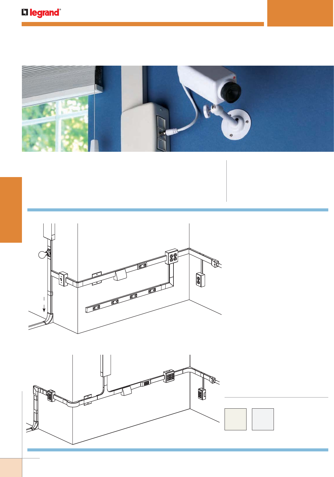
WWW.LEGRAND.US/WIREMOLD
40
STEEL RACEWAY
WIREMOLD
2400 SERIES™ RACEWAY
2400 Series Raceway System Layout for Power
C
D
CC
R
Z
X
BB
L
N
U
K
AA
E
2407 Series
106 Frame
DD
O
Q
A
KEY
A. 500 Series Raceway
B. 1500/2600 Raceway Feed
C. 2400 Series Raceway
D. 2406 Cover Clip
E. 2410C Entrance End Fitting
F. 2411M Flat Elbow Fitting
G. 2415M Tee Fitting
H. 2417M Internal Elbow Fitting
I. 2426 Lamp Holder
J. 2686FO Transition Fitting
K. 4089 Reducing Connector
L. 2448 One-Gang Device Box
M. 2418M External Elbow Fitting
N. 2451H Back Feed Fitting
O. 2448-2 Two-Gang Device Box
P. 2475D Bridge Fitting
Q. 2489 Reducing Adapter
R. 24DWND Downward Duplex Device Bracket
24DWNR Downward Decorator Device Bracket
S. 24S7218GBX99IV 2400 Series Plugmold Strip
U. U4000 Series Raceway
V. 5747 Shallow Switch Box
W. 2400BC 2400 Series Raceway
X. 2411FO Radiused Flat Elbow
Y. 2415H Back Feed Fitting
Z. 2415FO Radiused Tee Fitting
AA. 2417FO Radiused Internal Elbow
BB. 2418FO Radiused External Elbow
CC. 2686FO Transition Feed Fitting
DD. 5744 Extra Deep Device Box
J
D
L
I
G
V
A
NR
OH
Q
E
M
C
S
F
K
U
B
CODE REFERENCE
cULus Listed Raceway:
File E4376 Guide RJBT.
Fittings:
File E41751 Guide RJPR.
Meets Article 386 of NEC.
Meets Section 12-1600 of CEC.
Single Channel Raceway . Easy-to-install and ideal for
basic power or communication/low voltage installations in
classrooms, hotels, and anywhere a low profile raceway
solution is needed.
2400 Series Raceway System Layout for Communications
2400 Series™ Raceway
Part Numbers with a
“V” prefix have an ivory
finish. Part Numbers with
a “-FW” suffix have a fog
white finish.
COLOR OPTIONS
Custom color options are also available.
Consult the factory for more information.
NOTE: Illustrations are for showing product applications only.
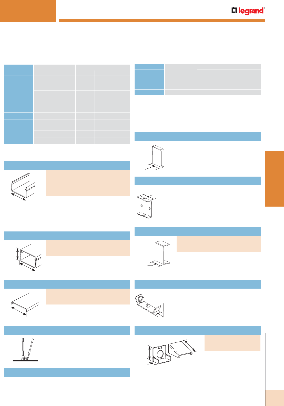
WWW.LEGRAND.US/WIREMOLD
41
STEEL RACEWAY
WIREMOLD
WIRE SIZE O.D. NO. OF CONDUCTORS 40%
THHN/THWN Inches [mm]
WITHOUT
DEVICES
WITH 2427
RECEPTACLE
14 AWG 0.111 [2.8] 57 12
12 AWG 0.130 [3.3] 41 9
10 AWG 0.164 [4.2] 26 0
NOTE: For additional information, refer to the Technical Section.
* Category 6 augmented (6a) cable for 10 gigabit ethernet max allowed
cable diameter per addenda No. 11 ANSI TIA/EIA 568-B.2.
CABLE/WIRE SIZE
O.D. APPROX. DIA. 40%
FILLInches [mm]
UNSHIELDED
TWISTED PAIR
4-pair, 24 AWG, Cat 3 0.190 [4.8] 19
4-pair, 24 AWG, Cat 5e 0.210 [5.3] 16
4-pair, 24 AWG, Cat 6 0.250 [6.3] 11
4-pair, 24 AWG, Cat 6a* 0.354 [9.0] 5
25-pair, 24 AWG 0.410 [10.4] 4
COAXIAL RG6/U 0.270 [6.9] 9
FIBER ZipCord 0.118 x
0.236
[3 x 6] 20
Round 4 Strand Fiber 0.187 [4.8] 20
Round 6 Strand Fiber 0.256 [6.5] 10
2400 Series Raceway Wire Fill Capacities for Communications 2000 Series Raceway Wire Fill Capacities For Power
1"
[25mm]
2"
[51mm]
1 1/2"
[38mm]
2400 SERIES™ RACEWAY
1 29/32"
[48mm]
7/8"
[22.2mm]
1 29/32"
[48mm]
1 29/32"
[48mm]
.040" [1.0mm] steel, 5' [1.5m] lengths.
Packed twenty 5' [1.5m] lengths per
carton (V2400B, 2400B-FW) or ten 10'
[3m] lengths per carton (V2400B-10,
2400B-10FW).
Raceway Base
.040" [1.0mm] steel. Packed ten
5' [1.5m] lengths of base and cover
per carton.
Raceway Base & Cover
Portable cutter for 2400 & 2400D Series
Raceway Base and Cover. Provides a
clean and easy square cut every time.
624 2400 Series Raceway Base & Cover Cutter
Case hard steel replacement blades and die set for
624 Cutter.
624BCK Replacement Blade Kit
2400 Series Raceways Ordering Information
Additional support for conductors.
(Nonmetallic)
2400WC Wire Clip
Joins lengths of 2400B Base together.
2401 Coupling
2"
[51mm]
1 5/8"
[41mm]
1 3/16"
[30mm]
Connects 2400 Series
Raceway with 1/2" trade
size conduit or armored
cable.
Entrance End Fitting
Covers seams where two lengths of
2400 Series Raceway come together
(nonmetallic).
Cover Clip
Connects equipment grounding conductor
to provide ground to 2400 Series Raceway.
No. 10 ground screw provided.
2409 Ground Clamp
1/2"
[2.7mm]
.040" [1.0mm] steel; packed twenty
5' [1.5m] lengths per carton.
Raceway Cover
2400 Series Raceway Fittings Ordering Information
PART NUMBERS:
V2400B (Ivory
V2400B-10 (Ivory, 10')
2400B-FW (Fog White)
2400B-10FW (Fog White, 10')
PART NUMBERS:
V2400BC (Ivory)
2400BC-FW (Fog White)
PART NUMBERS:
V2400C (Ivory)
2400C-FW (Fog White)
PART NUMBERS:
V2410A (Ivory)
2410A-FW (Fog White)
PART NUMBERS:
V2406 (Ivory)
2406-FW (Fog White)
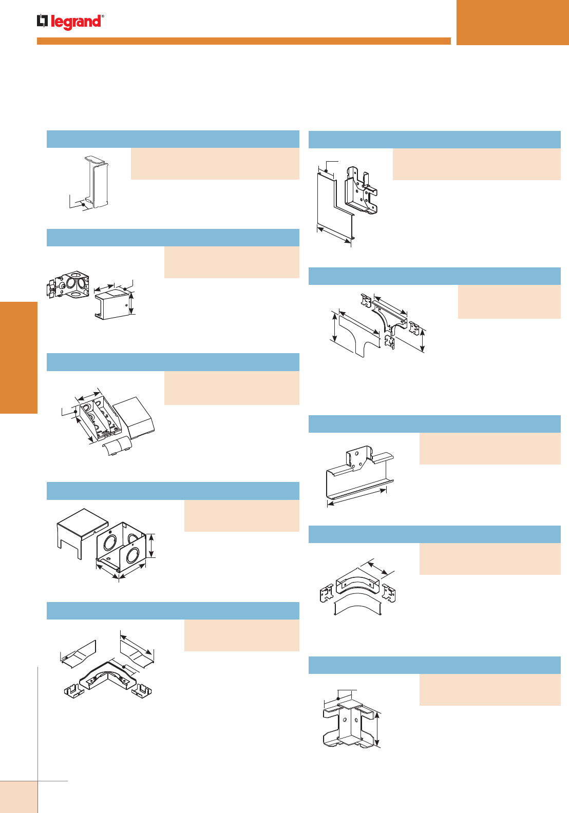
WWW.LEGRAND.US/WIREMOLD
42
STEEL RACEWAY
WIREMOLD
2400 SERIES™ RACEWAY
1 3/4"
[45mm]
1 29/32"
[49mm]
2 5/8"
[67mm]
3"
[76mm]
2 1/4"
[57mm]
5 1/2"
[140mm]
3/8"
[9.5mm]
6 1/2"
[165mm]
3 15/16"
[100mm]
1 29/32"
[49mm]
10"
[254mm]
5 7/8"
[149mm]
8"
[203mm]
4 7/8"
[124mm]
4"
[102mm]
4"
[102mm]
Feeds 2400 & 2400D Series
Raceway. Has 1/2", 3/4", and 1"
trade size KOs on back and end.
Removable divider and radiused
insert included.
4 3/4"
[121mm]
2 7/8"
[73mm]
7 1/8"
[181mm]
Feeds 2400 Series
Raceway. Has 3/4" and 1"
concentric trade size KOs
located on each side.
90° flat corner elbow
provides 2" [51mm] cable
bend radius control for
fiber optic and UTP/STP
cable installations. Ideal
for lay-in or pull-through
installations. Couplings
included.
Right angle turns on same surface.
For branching raceway at right
angles. Two couplings included.
For branches at right
angles. Provides 2"
[51mm] cable bend
radius control for fiber
optic and UTP/STP cable
installations. Couplings
included.
90° internal corner elbow
provides 2" [51mm] cable bend
radius control for fiber optic and
UTP/STP cable installations. Two
couplings included.
Inside 90° angle turns.
1 3/16"
[30mm]
Closes off open end of 2400 Series
Raceway.
2 11/16"
[68mm]
1 7/8"
[48mm]
2 1/8"
[54mm]
Feeds 2400 Series Raceway.
Includes 1/2" and 3/4" trade
size KOs on end and bottom.
Additional 1/2" trade size KOs
on each side.
2400 Series Raceway Fittings Ordering Information (continued)
Blank End Fitting
PART NUMBERS:
V2410B (Ivory)
2410B-FW (Fog White)
Entrance End Fitting
PART NUMBERS:
V2410C (Ivory)
2410C-FW (Fog White)
Divided Entrance End Fitting
PART NUMBERS:
V2410DFO (Ivory)
2410DFO-FW (Fog White)
Full Capacity Entrance End Fitting
PART NUMBERS:
V2410FC (Ivory)
2410FC-FW (Fog White)
Radiused Flat Elbow
PART NUMBERS:
V2411FO (Ivory)
2411FO-FW (Fog White)
Flat Elbow
PART NUMBERS:
V2411M (Ivory)
2411M-FW (Fog White)
Radiused Tee
PART NUMBERS:
V2415FO (Ivory)
2415FO-FW (Fog White)
Tee
PART NUMBERS:
V2415M (Ivory)
2415M-FW (Fog White)
Radiused Internal Elbow
PART NUMBERS:
V2417FO (Ivory)
2417FO-FW (Fog White)
Internal Elbow
PART NUMBERS:
V2417M (Ivory)
2417M-FW (Fog White)
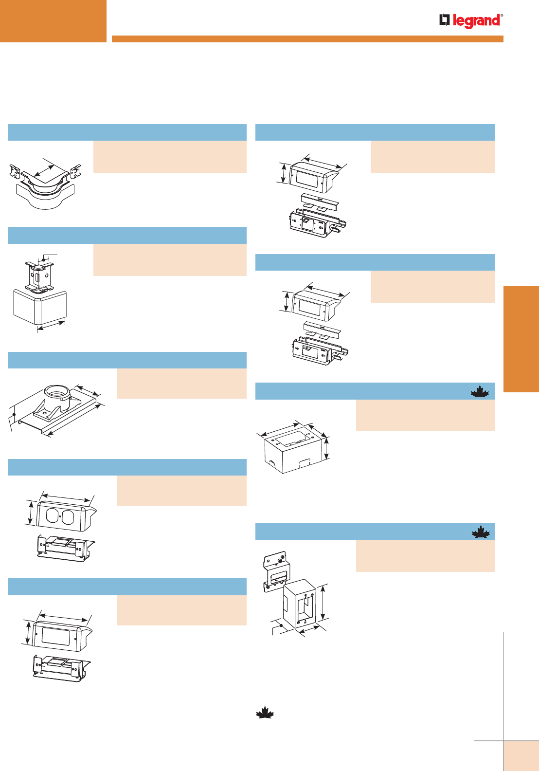
WWW.LEGRAND.US/WIREMOLD
43
STEEL RACEWAY
WIREMOLD
2400 SERIES™ RACEWAY
5"
[127mm]
3"
[76mm]
1 1/4"
[32mm]
4 3/4"
[120mm]
2 1/8"
[54mm]
4 3/4"
[121mm]
2 1/8"
[54mm]
5"
[127mm]
1 9/16"
[40mm]
1 29/32"
[49mm]
90° external elbow provides
2” [51mm] cable bend radius control
for fiber optic and UTP/STP cable
installations. Two couplings included.
90° external corners.
Medium base lamp holder
660W, 250V. Black general
purpose phenolic.
Labor saving, over-the-raceway
device bracket. Accepts 15A or
20A duplex receptacles or 106
style data frame.
Labor saving, over-the-raceway
device bracket. Accepts 15A
or 20A decorator receptacles,
GFCI receptacle, or 106 style
data frame.
2400 Series Raceway Fittings Ordering Information (continued)
4 3/4"
[121mm]
2 1/8"
[54mm]
Accepts two Extron®
Electronics MAAP single
space modules.
Accepts one Ortronics® Series
II module.
4 3/4"
[121mm]
2 1/8"
[54mm]
NOTE: One-gang device boxes accept NEMA single-gang standard
faceplates. Two-gang device boxes accept NEMA double-gang
standard faceplates.
NOTE: Parts identified with this symbol are Certified to Canadian Safety
Standards for sale in Canada. When ordering these products, add “C”
to the color prefix to denote the Canadian versions, i.e “CV2444”.
One-gang device box with extra
depth to allow installation of
cabling that requires greater bend
radius and storage. Cover has one
twistout for 2400 Series Raceway
on each side and one twistout for 500 and 700 Series
Raceway on the top and bottom. Accepts industry standard
faceplates for electrical and communication devices.
4 5/8"
[117mm] 2 7/8"
[73mm]
2 3/4"
[70mm]
2 3/4"
[70mm]
2 7/8"
[73mm]
4 5/8"
[117mm]
One-gang labor saving, over-the-
raceway device box. Cover has
twistout on each side for 2400
Series Raceway. Accepts industry
standard faceplates for electrical
and communication devices.
Radiused External Elbow
PART NUMBERS:
V2418FO (Ivory)
2418FO-FW (Fog White)
External Elbow
PART NUMBERS:
V2418M (Ivory)
2418M-FW (Fog White)
Downward Extron® MAAP Device Plate
PART NUMBERS:
V24DWNU (Ivory)
24DWNU-FW (Fog White)
Downward Ortronics® Series II Device Plate
PART NUMBERS:
V24DWNS (Ivory)
24DWNS-FW (Fog White)
Extra Deep Device Box
PART NUMBERS:
V2444 (Ivory)
2444-FW (Fog White)
Device Box
PART NUMBERS:
V2444D (Ivory)
2444D-FW (Fog White)
Lamp Holder
PART NUMBERS:
V2426 (Ivory)
2426-FW (Fog White)
Downward Duplex Device Bracket
PART NUMBERS:
V24DWND (Ivory)
24DWND-FW (Fog White)
Downward Decorator Device Bracket
PART NUMBERS:
V24DWNR (Ivory)
24DWNR-FW (Fog White)
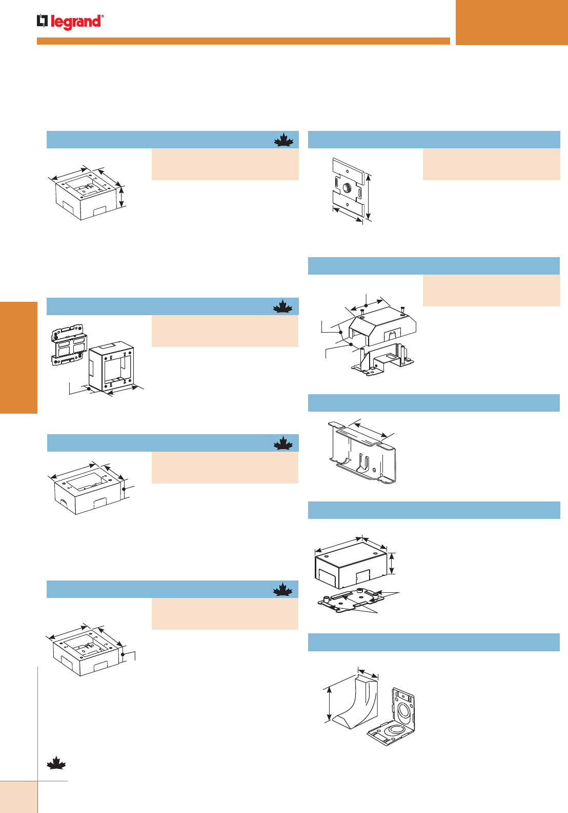
WWW.LEGRAND.US/WIREMOLD
44
STEEL RACEWAY
WIREMOLD
2400 SERIES™ RACEWAY
2 3/4"
[70mm]
4 3/4"
[121mm]
4 5/8"
[117mm] 2 7/8"
[73mm]
1 3/4"
[44mm]
1 3/4"
[44mm]
4 3/4"
[121mm] 4 3/4"
[121mm]
4 1/2"
[114mm]
4 1/2"
[114mm]
5 9/16"
[140mm]
1 7/8"
[48mm]
2 7/8"
[73mm]
2 3/4"
[70mm]
4 3/4"
[121mm] 4 3/4"
[121mm]
Two-gang labor saving, over-the-
raceway device box. Cover has
twistout on all four side for 2400
Series Raceway. Accepts industry
standard faceplates for electrical
and communication devices.
Feeds 2400 Series Raceway
from an existing outlet box.
Includes 1/2" trade size male
bushing and lock nut washer for
grounding.
Back Feed Fitting
Allows 2400 Series Raceway
runs to bridge over existing
installations of 2400, 500, and
700 Series Raceways.
2"
[51mm] Connects 2400 Series Raceway
with 500 Series Raceway.
V2489 Side Reducing Connector
4 5/8"
[117mm]
2 7/8"
[173mm]
1 3/4"
[44mm]
2100
2400
Connects existing installations
of 2100 Series Raceway to 2400
Series Raceway.
V2489TB Transition Box
2 1/2"
[63mm]
3 5/8"
[92mm]
Eliminates need to offset
2400 Series Raceway when
connecting with surface
panel boxes. Has 3/4" and 1"
concentric trade size KOs with
1" trade size KO elongated so
adjustment from surface to
center of bushing is 1" [25mm]
minimum to 1 5/8" [41mm]
maximum. Has twistouts
for transition to 1500 and 2600
Series Pancake Raceways.
2686FO Transition Feed Fitting
Extra Deep Device Box
Two-gang device box. Cover has
twistouts on all four sides for
2400 Series Raceway. Base has
knockout to enable extension from
existing single-gang, flush wall box
and 1/2" trade size KOs. Accepts
industry standard faceplates for
electrical and communication
devices.
Device Box
Device Box
One-gang device box. Cover has
twistout for 2400 Series Raceway
on each side and one twistout
for 500 and 700 Series Raceway on the top and bottom. Base
has knockout to enable extension from existing single-gang,
flush wall box and 1/2" trade size KOs. Accepts industry
standard faceplates for electrical and communication devices.
Device Box
2400 Series Raceway Fittings Ordering Information (continued)
Two-gang device box with extra
depth to allow installation of
cabling that requires greater bend
radius and storage. Cover has
twistout on all four sides for 2400 Series Raceway. Base
has knockout to enable extension from existing single-gang
flush wall box and 1/2" and 1" concentric trade size KOs.
Accepts industry standard faceplates for electrical and
communication devices.
NOTE: Parts identified with this symbol are Certified to Canadian Safety
Standards for sale in Canada. When ordering these products, add “C”
to the color prefix to denote the Canadian versions, i.e “CV2444”.
PART NUMBERS:
V2444-2 (Ivory)
2444-2FW (Fog White)
PART NUMBERS:
V2451H (Ivory)
2451H-FW (Fog White)
Bridge Fitting
PART NUMBERS:
V2475D (Ivory)
2475D-FW (Fog White)
PART NUMBERS:
V2444-2LS (Ivory)
2444-2LSFW (Fog White)
PART NUMBERS:
V2448 (Ivory)
2448-FW (Fog White)
PART NUMBERS:
V2448-2 (Ivory)
2448-2FW (Fog White)
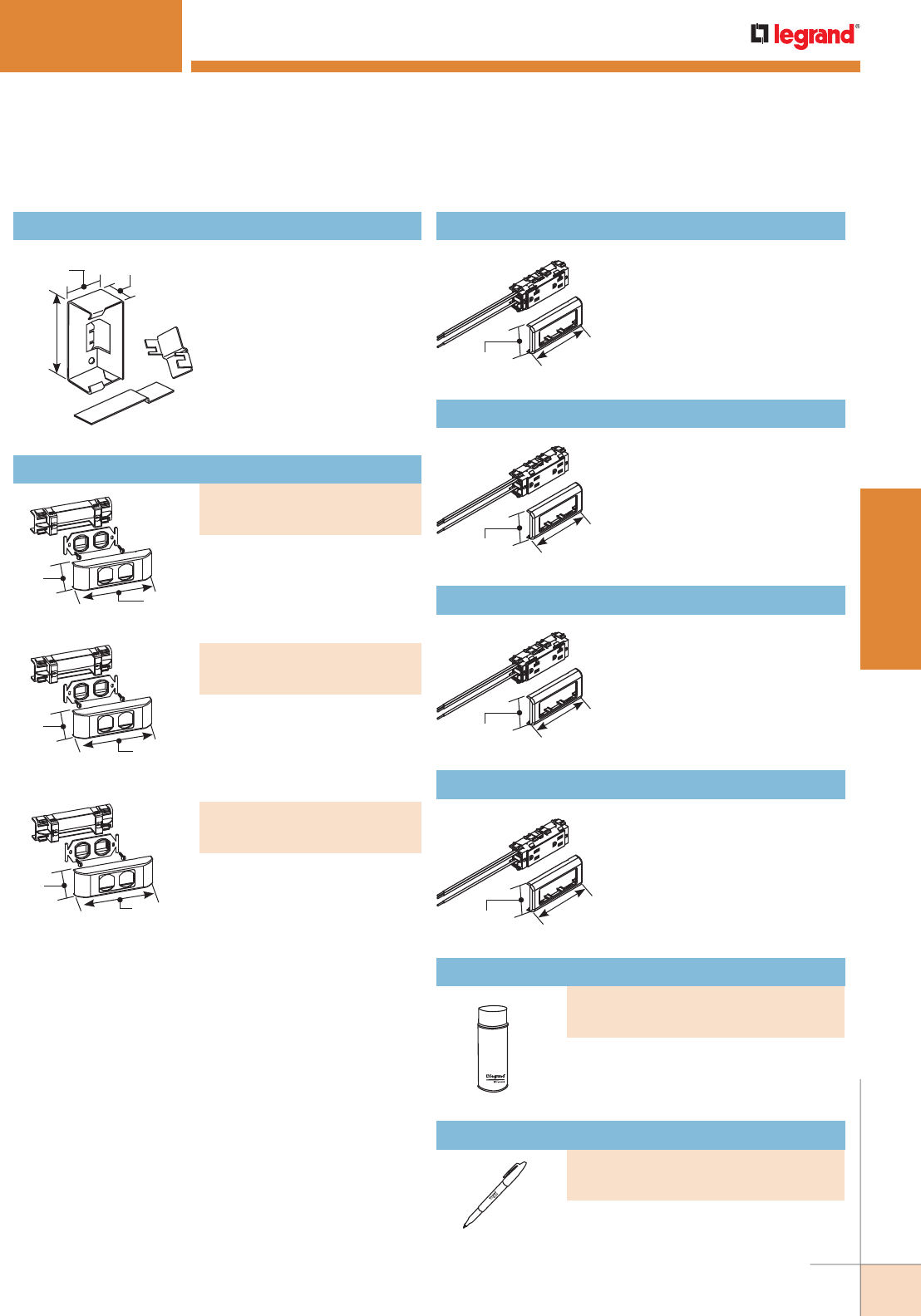
WWW.LEGRAND.US/WIREMOLD
45
STEEL RACEWAY
WIREMOLD
4 3/4"
[121mm]
1 5/8"
[41mm]
2"
[51mm]
Connects 4000 Series Raceway
to 2400 Series Raceway.
V4089 Reducing Connector
2 1/16"
[52mm]
4 1/2"
[114mm]
2400 SERIES™ RACEWAY
2 1/16"
[52mm]
4 1/2"
[114mm]
2 1/16"
[52mm]
4 1/2"
[114mm]
2 1/16"
[52mm]
4 1/2"
[114mm]
2 1/16"
[52mm]
6"
[152mm]
For installing two network wiring
keystone device modules in 2400
Series Raceway. Does not accept
Quad 106 Frame.
106 Device Bracket & Frame
2 1/16"
[52mm]
6"
[152mm]
For installing two Ortronics®
TracJack device modules in 2400
Series Raceway. Does not accept
Quad 106 Frame.
2 1/16"
[52mm]
6"
[152mm]
For installing three Ortronics®
TracJack device modules in 2400
Series Raceway. Does not accept
Quad 106 Frame.
3-Wire 125V NEMA 5-20R
receptacle. Includes 10-1/2"
[267mm] pigtails and inline
splice connectors. Also available
in fog white (2427GT-FW).
V2427GT 20A Duplex Receptacle
3-Wire 125V NEMA 5-15R
receptacle. Includes 10-1/2"
[267mm] pigtails and inline
splice connectors. Also available
in fog white (2427GA-FW).
V2427GA 15A Duplex Receptacle
3-Wire 125V NEMA 5-20R
orange receptacle. Includes
10-1/2" [267mm] pigtails and
inline splice connectors. Also
available in fog white (IG2427GT-
FW).
IG2427GT 20A Isolated Ground Duplex Receptacle
3-Wire 125V NEMA 5-15R orange
receptacle. Includes 10-1/2"
[267mm] pigtails and inline
splice connectors. Also available
in fog white (IG2427GA-FW).
IG2427GA 15A Isolated Ground Duplex Receptacle
Used for touching up large areas.
Contains 12 oz. of paint.
NOTE:
Can only be shipped via ground transportation
Used for touching up small areas.
Contains 0.3 oz. of paint.
2400 Series Raceway Fittings Ordering Information (continued)
PART NUMBERS:
V2407-2CM (Ivory)
2407-2CMFW (Fog White)
PART NUMBERS:
V2407-2TJ (Ivory)
2407-2TJFW (Fog White)
PART NUMBERS:
V2407-3TJ (Ivory)
2407-3TJFW (Fog White)
Spray Paint
PART NUMBERS:
IWE-S (Ivory)
DVWE-S (Fog White)
Touch-Up Paint Pen
PART NUMBERS:
IWE-P (Ivory)
DVWE-P (Fog White)
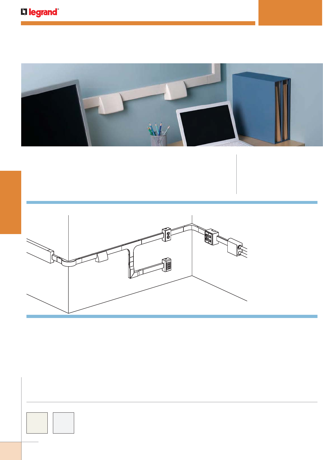
WWW.LEGRAND.US/WIREMOLD
46
STEEL RACEWAY
WIREMOLD
2400D® SERIES RACEWAY
CODE REFERENCE
cULus Listed Raceway:
File E4376 Guide RJBT.
Fittings:
File E41751 Guide RJPR.
Meets Article 386 of NEC.
Meets Section 12-1600 of CEC.
Dual channel version of 2400 Series Raceway. Easy-to-install and ideal for basic
power and communication/low voltage installations in classrooms, hotels, and
anywhere a low profile raceway solution is needed.
COLOR OPTIONS
2400 Series™ Raceway Part Numbers with a “V” prefix have an
ivory finish. Part Numbers with a “-FW” suffix have a fog white
finish.
Custom color options are also available. Consult the factory
for more information.
F
A
D
J
K
BG
I
A
L
E
C
H
2400D Series Raceway System Layout for Power & Data
NOTE: Illustrations are for showing product applications only.
KEY
A. 2400D 2400 Series Divided Raceway
B. 2411DFO Radiused Divided Flat Elbow
C. 2410DFO Divided Entrance End Fitting
D. 2415DFO Radiused Divided Tee
E. 2417DFO Radiused Divided Internal Elbow
F. 2418DFO Divided External Elbow
G. 2444 One-Gang Extra Deep Device Box
H. 2444D One-Gang Device Box
I. 2444D-2A Two-Gang Divided Device Box
J. 24DWND Downward Duplex Device Bracket
24DWNR Downward Decorator Device Bracket
K. 4089 Reducing Connector
L. U4000 Series Raceway
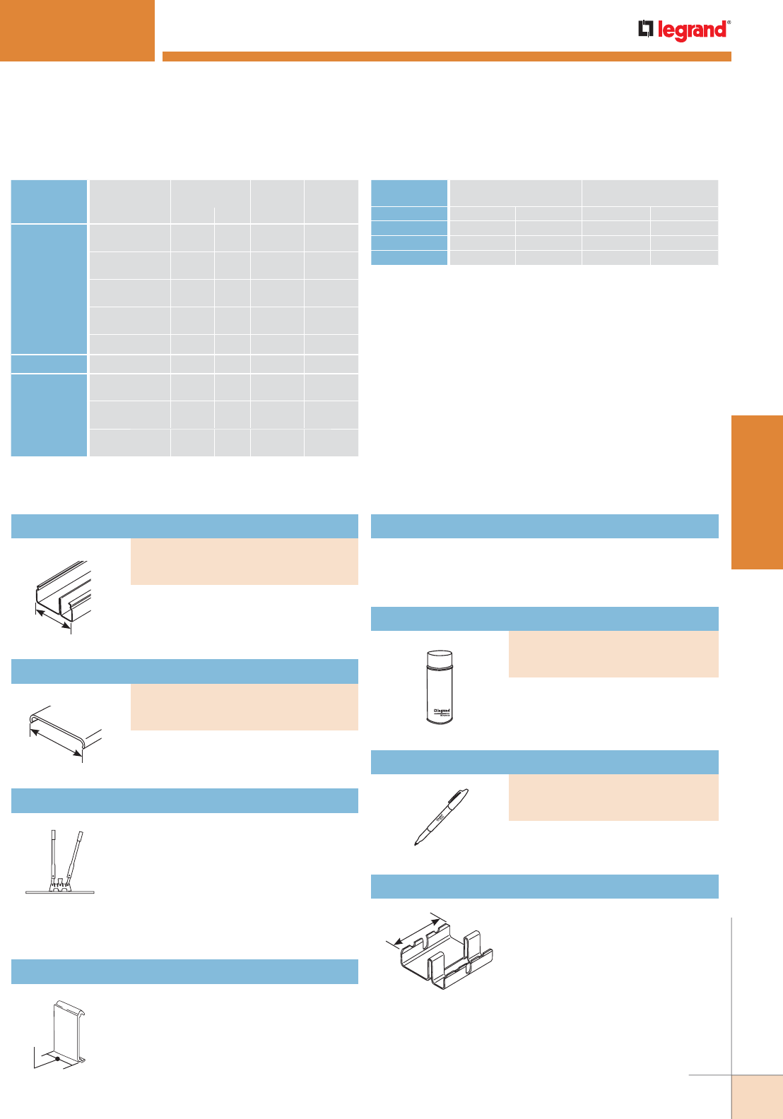
WWW.LEGRAND.US/WIREMOLD
47
STEEL RACEWAY
WIREMOLD
2400D Series Raceway Wire Fill Capacities for Communications
CABLE/
WIRE SIZE
O.D.
APPROX. DIA. 1/3 COMP
40% FILL
2/3 COMP
40% FILLInches [mm]
UNSHIELDED
TWISTED PAIR
4-pair, 24 AWG,
Cat 3
0.190 [4.8] 5 12
4-pair, 24 AWG,
Cat 5e
0.210 [5.3] 4 9
4-pair,24 AWG,
Cat 6
0.250 [6.3] 3 7
4-pair, 24 AWG,
Cat 6a*
0.354 [9.0] 1 3
25-pair, 24 AWG 0.410 [10.4] 1 2
COAXIAL RG6/U 0.270 [6.9] 2 6
Fiber ZipCord 0.118 x
0.236
[3 x 6] 5 12
Round 4 Strand
Fiber
0.187 [4.8] 5 12
Round 6 Strand
Fiber
0.256 [6.5] 2 6
WIRE SIZE O.D.
NUMBER OF CONDUCTORS
40%
THHN/THWN Inches [mm] 1/3 COMP 2/3 COMP
14 AWG 0.111 [2.8] 11 26
12 AWG 0.130 [3.3] 9 19
10 AWG 0.164 [4.2] 6 11
NOTE: For additional information, refer to the Technical Section.
* Category 6 augmented (6a) cable for 10 gigabit ethernet – max allowed
cable diameter per addenda No. 11 ANSI TIA/EIA 568-B.2.
2400D Series Raceway Wire Fill Capacities for Power
1 29/32"
[48mm]
1 29/32"
[48mm]
1"
[25mm]
2400D SERIES™ RACEWAY
.040" [1.0mm] steel. Divided into two
compartments (1/3 and 2/3 capacity).
Packed ten 10' [3.0m] lengths per carton.
Divided Raceway Base
.040" [1.0mm] steel. Packed twenty 5’
[1.5m] lengths per carton.
Raceway Cover
Portable cutter for 2400 & 2400D
Series Raceway Base and Cover.
Provides a clean and easy, square cut
every time.
624 2400 Series Raceway Base & Cover Cutter
Case hard steel replacement blades and die set for 624
Cutter.
624BCK Replacement Blade Kit
2400D Series Raceway Ordering Information
2400D Series Raceway Fittings Ordering Information
Additional support for conductors
(nonmetallic).
2400WC Wire Clip
2"
[51mm] Joins lengths of 2400BD
Divided Base.
2401D Divided Coupling
Used for touching up large areas.
Contains 12 oz. of paint.
NOTE: Can only be shipped via ground
transportation
Spray Paint
Used for touching up small areas.
Contains 0.3 oz. of paint.
Touch-Up Paint Pen
PART NUMBERS:
V2400BD (Ivory)
2400BD-FW (Fog White)
PART NUMBERS:
IWE-P (Ivory)
DVWE-P (Fog White)
PART NUMBERS:
V2400C (Ivory)
2400C-FW (Fog White)
PART NUMBERS:
IWE-S (Ivory)
DVWE-S (Fog White)
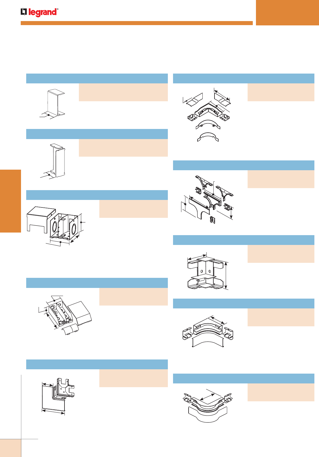
WWW.LEGRAND.US/WIREMOLD
48
STEEL RACEWAY
WIREMOLD
2400D SERIES™ RACEWAY
3 15/16"
[100mm]
1 29/32"
[49mm]
1 3/4"
[45mm]
1 29/32"
[49mm]
4 3/4"
[121mm]
2 7/8"
[73mm]
7 1/8"
[181mm]
Feeds 2400 & 2400D Series
Raceway. Includes 1/2",
3/4", and 1" trade size
KOs on back and end.
Removable/ adjustable
divider and radiused
insert included
Right angle turns on the
same surface.
90° flat elbow with integral
dividers. Provides 2" [51mm]
full capacity cable bend
radius control for fiber
optic and UTP/STP cable
installations. Ideal for lay-in
or pull-through installations.
Two couplings included.
6 1/2"
[165mm]
5 1/2"
[140mm]
3/8"
[9.5mm]
10"
[254mm]
5 7/8"
[149mm]
8"
[203mm]
4 7/8"
[124mm]
For branching raceway at
right angles. Provides 2"
[51mm] cable bend radius
control for fiber optic and
UTP/STP cable installations.
Couplings included.
Internal 90° corners.
4"
[102mm]
90° internal corner provides
2" [51mm] cable bend
radius control for fiber
optic and UTP/STP cable
installations. Two couplings
included.
5"
[127mm]
90° external elbow provides
2" [51mm] cable bend radius
control for fiber optic and
UTP/STP cable installations.
Two couplings included.
1 1/2"
[38mm]
1 3/16"
[30mm]
Covers seam where two lengths
of 2400D Series Raceway come
together (nonmetallic).
Closes off open end of 2400D Series
Raceway.
2 5/8"
[67mm]
3"
[76mm]
2 1/4"
[57mm] Feeds 2400D Series
Raceway. Back has two 1/2"
trade size KOs and two
rectangular KOs for
communication cabling.
Additional 1" and 3/4"
concen tric trade size KO on
each side.
2400D Series Raceway Fittings Ordering Information (continued)
Cover Clip
PART NUMBERS:
V2406 (Ivory)
2406-FW (Fog White)
Divided Blank End Fitting
PART NUMBERS:
V2410BD (Ivory)
2410BD-FW (Fog White)
Divided Entrance End Fitting
PART NUMBERS:
V2410D (Ivory)
2410D-FW (Fog White)
Divided Entrance End Fitting
PART NUMBERS:
V2410DFO (Ivory)
2410DFO-FW (Fog White)
Divided Flat Elbow
PART NUMBERS:
V2411D (Ivory)
2411D-FW (Fog White)
Radiused Divided External Elbow
PART NUMBERS:
V2418DFO (Ivory)
2418DFO-FW (Fog White)
Radiused Divided Internal Elbow
PART NUMBERS:
V2417DFO (Ivory)
2417DFO-FW (Fog White)
Divided Internal Elbow
PART NUMBERS:
V2417D (Ivory)
2417D-FW (Fog White)
Radiused Divided Tee
PART NUMBERS:
V2415DFO (Ivory)
2415DFO-FW (Fog White)
Radiused Divided Flat Elbow
PART NUMBERS:
V2411DFO (Ivory)
2411DFO-FW (Fog White)
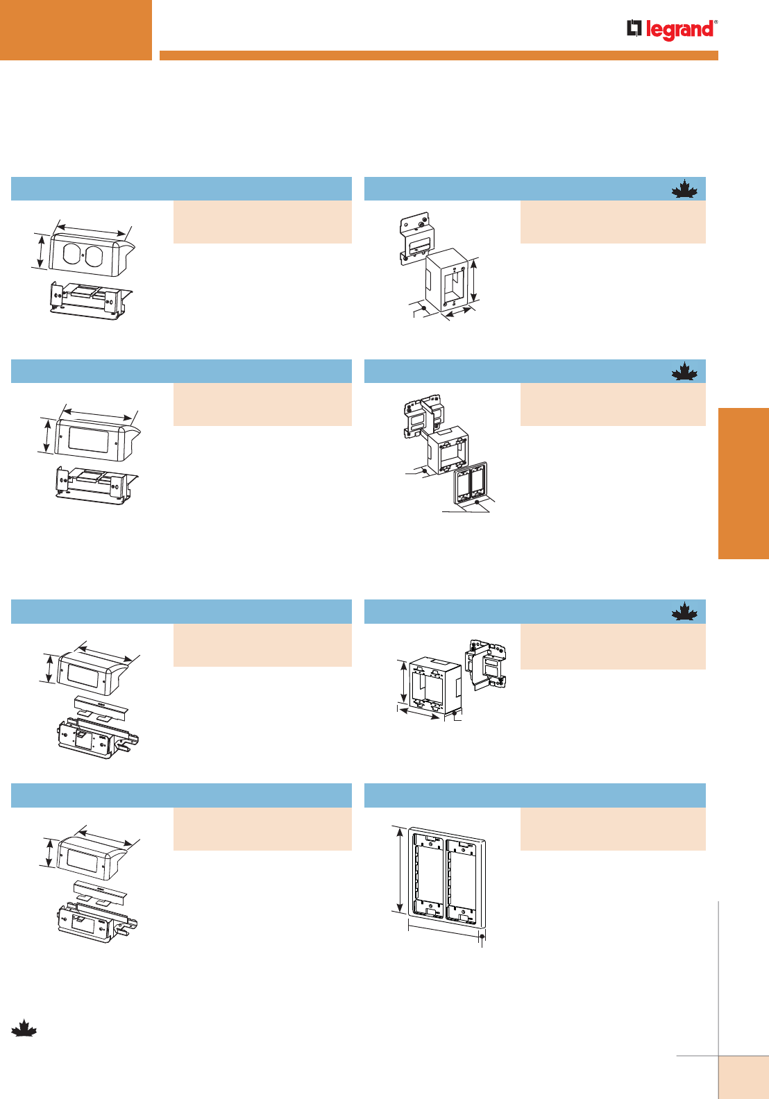
WWW.LEGRAND.US/WIREMOLD
49
STEEL RACEWAY
WIREMOLD
2400D SERIES™ RACEWAY
4 3/4"
[120mm]
2 1/8"
[54mm]
4 3/4"
[120mm]
2 1/8"
[54mm]
2 3/4"
[70mm]
2 7/8"
[73mm]
4 5/8"
[117mm]
2 3/4"
[70mm]
4 3/4"
[121mm]
4 3/4"
[121mm]
4 3/4"
[121mm]
2 3/4"
[70mm]
4 5/8"
[118mm]
3/8"
[9.5mm]
4 5/8"
[118mm]
4 3/4"
[121mm]
2 1/8"
[54mm]
4 3/4"
[121mm]
2 1/8"
[54mm]
NOTE: Parts identified with this symbol are Certified to Canadian Safety
Standards for sale in Canada. When ordering these products, add “C”
to the color prefix to denote the Canadian versions, i.e “CV2444” or
“C2444-FW”.
Labor saving, over-the-
raceway device bracket.
Accepts 15A or 20A duplex
receptacles or 106 style data
frame.
Downward Duplex Device Bracket
Labor saving, over-the-
raceway device bracket.
Accepts 15A or 20A decorator
receptacles, GFCI receptacle,
or 106 style data frame.
Accepts two Extron®
Electronics MAAP single space
modules.
Accepts one Ortronics® Series
II module.
Divided, two-gang, labor saving
over-the-raceway device box.
Allows both power and low
voltage at a single point-of-use.
Accepts 5507 Series Faceplates,
Ortronics® TracJack & Series II
Modules (requires S2-EPL
Plate), Pass & Seymour® Activate Series Inserts
(requires CM-EPLA Plate), and Wiremold Open System
Communication Modules (requires CM-EPLA Plate).
Labor saving, over-the-raceway
device box. Divided, two-gang
box allows both power and low
voltage at a single point-of-use.
For use with commercially
available faceplates.
For use with 2444D-2N. Allows
both power and low voltage at
a single point-of-use. Accepts
5507 Series Faceplates,
Ortronics® TracJack & Series
II Modules (requires S2-EPL
Plate), Pass & Seymour®
Activate Series Inserts (requires
CM-EPLA Plate), and Wiremold
Open System Communication
Modules (requires CM-EPLA
Plate).
One-gang labor saving, over-
the-raceway box. Cover has
two twistouts for 2400 Series
Raceway. Accepts industry
standard faceplates for electrical
and communication devices
Device Box
2400D Series Raceway Fittings Ordering Information (continued)
PART NUMBERS:
V24DWND (Ivory)
24DWND-FW (Fog White)
PART NUMBERS:
V2444D (Ivory)
2444D-FW (Fog White)
Divided Device Box
PART NUMBERS:
V2444D-2A (Ivory)
2444D-2AFW (Fog White)
Divided Device Box
PART NUMBERS:
V2444D-2N (Ivory)
2444D-2NFW (Fog White)
Device Bracket
PART NUMBERS:
V2450 (Ivory)
2450-FW (Fog White)
Downward Ortronics® Series II Device Plate
PART NUMBERS:
V24DWNS (Ivory)
24DWNS-FW (Fog White)
Downward Device Plate
PART NUMBERS:
V24DWNU (Ivory)
24DWNU-FW (Fog White)
Downward Decorator Device Bracket
PART NUMBERS:
V24DWNR (Ivory)
24DWNR-FW (Fog White)
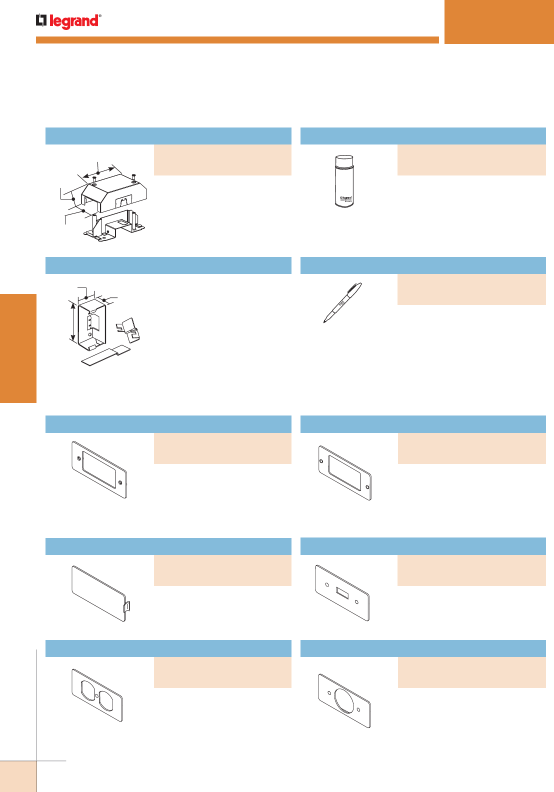
WWW.LEGRAND.US/WIREMOLD
50
STEEL RACEWAY
WIREMOLD
2400D SERIES™ RACEWAY
Covers Activate modular furniture
adapter and other modular
furniture adapters. Not for use
with decorator (rectangular) style
devices.
Covers unused compartments in
the device bracket.
Covers duplex style devices
including 106 Frame.
Covers rectangular decorator style
devices.
Covers standard toggle switches.
Covers single receptacles 1.59"
[40.4mm] diameter.
5 9/16"
[140mm]
1 7/8"
[48mm]
2 7/8"
[74mm]
4 3/4"
[121mm]
1 5/8"
[41mm]
2"
[51mm] Connects 4000 Series Raceway to
2400D Series Raceway.
V4089 Reducing Connector
Used for touching up large areas.
Contains 12 oz. of paint.
NOTE:
Can only be shipped via ground
transportation
Used for touching up small areas.
Contains 0.3 oz. of paint.
2400D Series Raceway Fittings Ordering Information (continued)
5507 Series Faceplates Ordering Information
Allows 2400D Series Raceway
runs to bridge over existing
installations of 2400, 2400D, 500,
and 700 Series Raceways.
Bridge Fitting
PART NUMBERS:
V2475D (Ivory)
2475D-FW (Fog White)
Modular Furniture Adapter
PART NUMBERS:
5507AD (Ivory)
5507AD-FW (Fog White)
Blank Faceplate
PART NUMBERS:
5507B (Ivory)
5507B-FW (Fog White)
Duplex Faceplate
PART NUMBERS:
5507D (Ivory)
5507D-FW (Fog White)
Single Receptacle Faceplate
PART NUMBERS:
5507T1 (Ivory)
5507T1-FW (Fog White)
Switch Faceplate
PART NUMBERS:
5507SW (Ivory)
5507SW-FW (Fog White)
Rectangular Faceplate
PART NUMBERS:
5507R (Ivory)
5507R-FW (Fog White)
Touch-Up Paint Pen
PART NUMBERS:
IWE-P (Ivory)
DVWE-P (Fog White)
Spray Paint
PART NUMBERS:
IWE-S (Ivory)
DVWE-S (Fog White)
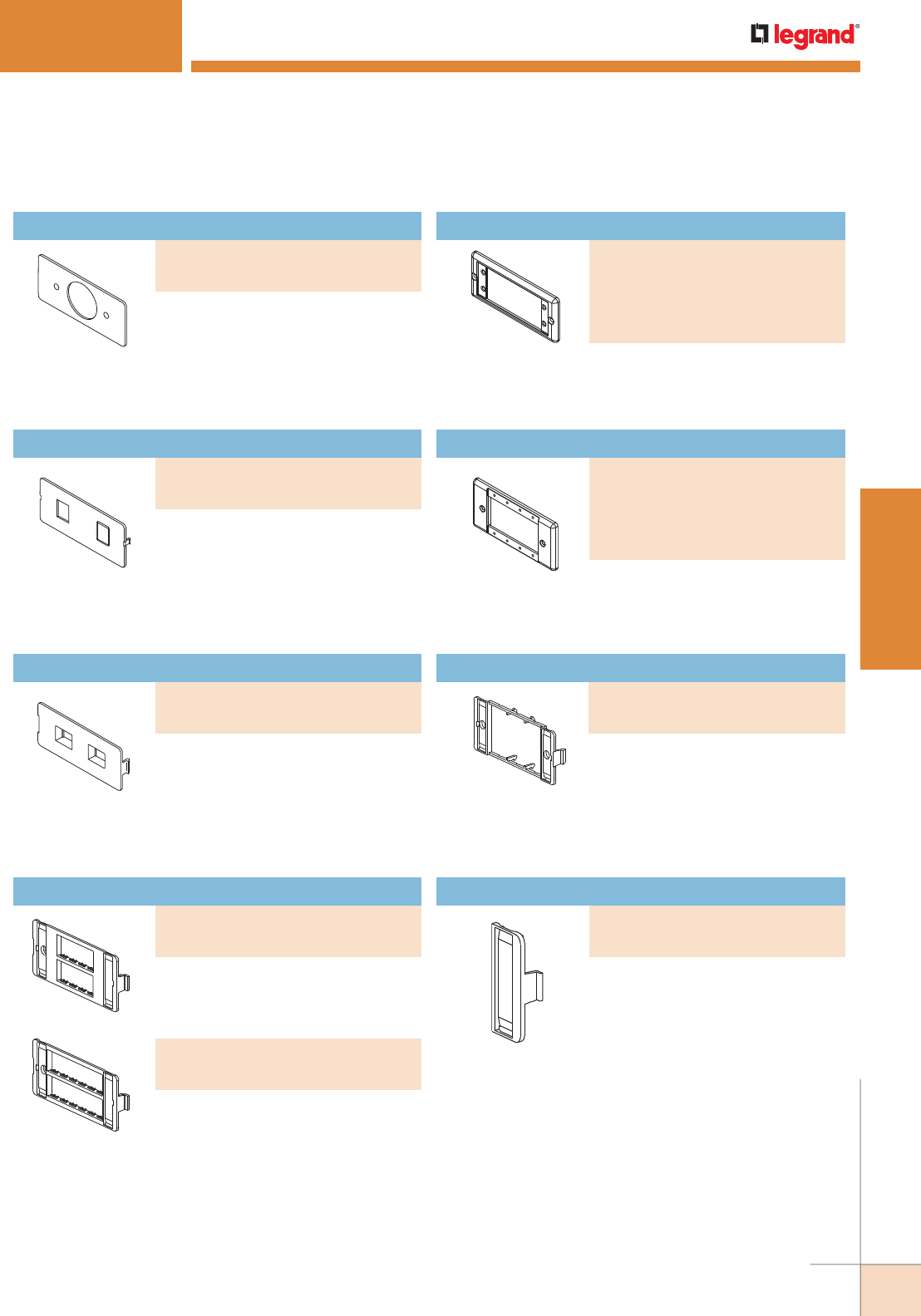
WWW.LEGRAND.US/WIREMOLD
51
STEEL RACEWAY
WIREMOLD
PART NUMBERS:
5507MAAP (Ivory)
5507MAAP-FW (Fog White)
5507MAAP-WH (White)
5507MAAP-G (Gray),
5507MAAP-BK (Black)
Covers single receptacles 1.41"
[35.8mm] diameter.
Accepts one or two keystone device
modules. Has one keystone opening
and a KO for the other.
Accepts one or two keystone device
modules, recessed to provide a flush
installation. Has one keystone opening
and a KO for the other.
Accepts four Ortronics® TracJack
Devices.
Accepts six Ortronics® TracJack
Devices.
5507MAAP Extron® MAAP Faceplate
Metal faceplate for use with four
Extron® Electronics MAAP single
space modules.
Mounts Pass & Seymour® Activate
and Wiremold Open System
communication modules into
5507 opening. Includes two outlet
identification labels with clear covers
and two matching screw covers.
Mounts Ortronics® Series II modules
into 5507 opening. Includes two
outlet identification labels with clear
covers and two matching screw
covers.
5507 Series Faceplates Ordering Information (continued)
2400D SERIES™ RACEWAY
Single Receptacle Faceplate
PART NUMBERS:
5507T2 (Ivory)
5507T2-FW (Fog White)
Dual RJ11/RJ45 Connector Faceplate
PART NUMBERS:
5507RJ (Ivory)
5507RJ-FW (Fog White)
Flush Dual RJ11/RJ45 Connector Faceplate
PART NUMBERS:
5507FRJ (Ivory)
5507FRJ-FW (Fog White)
Ortronics® Faceplate
PART NUMBERS:
5507-4TJ (Ivory)
5507-4TJFW (Fog White)
PART NUMBERS:
5507-6TJ (Ivory)
5507-6TJFW (Fog White)
End Plates
PART NUMBERS:
CM-EPLA (Ivory)
CM-EPLA-FW (Fog White)
End Plates
PART NUMBERS:
S2-EPL (Ivory)
S2-EPL-FW (Fog White)
Extron® AAP Faceplate
PART NUMBERS:
5507AAP (Ivory)
5507AAP-FW (Fog White)
5507AAP-WH (White)
5507AAP-G (Gray)
5507AAP-BK (Black)
Metal faceplate for use with two
Extron® Electronics AAP single space
modules.
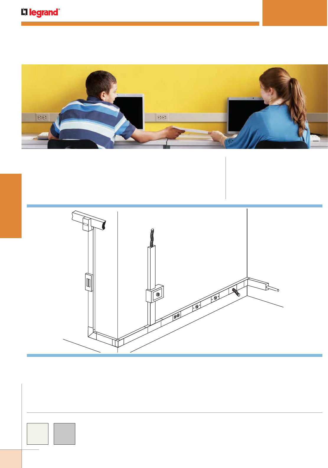
WWW.LEGRAND.US/WIREMOLD
52
STEEL RACEWAY
WIREMOLD
3000® SERIES RACEWAY
CODE REFERENCE
cULus Listed Raceway:
File E4376 Guide RJBT.
Fittings:
File E41751 Guide RJPR.
Meets Article 386 of NEC.
Meets Section 12-1600 of CEC.
Single-Channel Raceway. Easy-to-install and ideal for basic
power or communication/low voltage installations. Well-
suited for labs, hospitals, or anywhere that requires the
capacity of a medium size raceway.
COLOR OPTIONS
3000® Series Raceway Part Numbers with a “V” prefix have an
ivory finish. Part Numbers with a “G” prefix have a gray finish.
Custom color options are also available. Consult the factory
for more information.
KEY
A. 3010B Blank End Fitting
B. 3011E 90° Flat Elbow
C. 3015E Tee Fitting
D. 3017TCE Internal Corner
Coupling
E. 3018AE External Corner
Coupling
F. 3027AE Single Receptacle
Cover
G. 3033JE Single Receptacle
Cover
H. 3036HE Blank Cover
I. 3043GE Duplex Grounding
Receptacle & Cover
J. 3044-2 Extra Deep Switch &
Receptacle Box
K. 3046KD Circuit Breaker
Housing
L. 3082 Conduit Connector
M. 4074A Take Off Connector –
4000 to 3000 Series Raceway
N. 4000 Series Raceway
O. CONDUIT 1/2" [12.7mm]
Flexible Metal Conduit
K
BE
J
I
F
G
H0
D
A
N
M
L
C
O
NOTE: Illustration is for showing product applications only.
System Layout
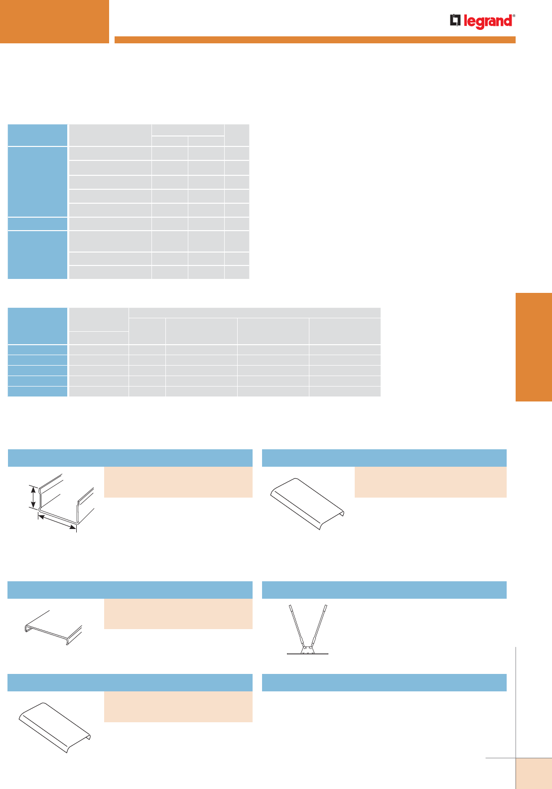
WWW.LEGRAND.US/WIREMOLD
53
STEEL RACEWAY
WIREMOLD
3000 SERIES® RACEWAY
1 15/32"
[37mm]
2 3/4"
[70mm]
3000 Series Raceway Wire Fill Capacities for Communications
CABLE/WIRE SIZE
O.D. APPROX. DIA. 40%
FILLInches [mm]
UNSHIELDED
TWISTED PAIR
4-pair, 24 AWG, Cat 3 0.190 [4.8] 52
4-pair, 24 AWG, Cat 5e 0.210 [5.3] 42
4-pair, 24 AWG, Cat 6 0.250 [6.3] 30
4-pair, 24 AWG, Cat 6a* 0.354 [9.0] 15
25-pair, 24 AWG 0.410 [10.4] 11
COAXIAL RG6/U 0.270 [6.9] 25
Fiber ZipCord 0.118 x
0.236
[3 x 6] 53
Round 4 Strand Fiber 0.187 [4.8] 53
Round 6 Strand Fiber 0.256 [6.5] 28
WIRE SIZE
THHN/THWN
O.D.
NUMBER OF CONDUCTORS 40% FILL
WITHOUT
DEVICES
WITH DUPLEX
RECT. DEVICES
1.59in.2 [1025mm2]
WITH SURGE/
GFCI DEVICES
2.30in.2 [1485mm2]
LARGE SINGLE
RECEPTACLES
3.00in.2 [1935mm2]Inches [mm}
14 AWG 0.111 [2.8] 152 70 40 28
12 AWG 0.130 [3.3] 111 51 29 21
10 AWG 0.164 [4.2] 70 32 18 13
8 AWG 0.216 [5.5] 40 18 10 7
6 AWG 0.254 [6.5] 29 13 7 5
NOTE: For additional information, refer to the Technical Section.
* Category 6 augmented (6a) cable for 10 gigabit ethernet – max allowed cable diameter per addenda No. 11 ANSI
TIA/EIA 568-B.2.
3000 Series Raceway Wire Fill Capacities for Power
.040" [1.0mm] steel, Packed in
ten 10' [3m] lengths, 100' [31m]
per carton. Base sections have
predrilled 1/2" and 3/4" trade size
entrance KOs and 9/32" [7.1mm]
diameter mounting screw KOs on
approx. 9 3/8" [238mm] centers.
.040" [1.0mm] steel. Packed in
twenty 5' [1.5m] lengths, 100' [31m]
per carton.
For mounting devices 12" [305mm]
on center using 3027AE, 3033JE,
3036HE, 3040CE, 3043, 3046, 3048R,
and 3051LE Series Device Plates.
For mounting devices 24" [610mm]
on center using 3027AE, 3033JE,
3036HE, 3040CE, 3043, 3046, 3048R,
and 3051LE Series Device Plates.
Portable cutter for 3000 Series
Raceway Base. Provides clean and
easy square cuts.
630B Raceway Base Cutter
Case hard steel replacement blades and die set for
630B Cutter.
630BDK Replacement Blade Kit
3000 Series Raceway Ordering Information
Raceway Base
PART NUMBERS:
V3000B (Ivory)
G3000B (Gray)
Raceway Cover
PART NUMBERS:
V3000CE (Ivory)
G3000CE (Gray)
7.5" [191mm] Precut Raceway Cover
PART NUMBERS:
V3000C075 (Ivory)
G3000C075 (Gray)
19.5" [495mm] Precut Raceway Cover
PART NUMBERS:
V3000C195 (Ivory)
G3000C195 (Gray)
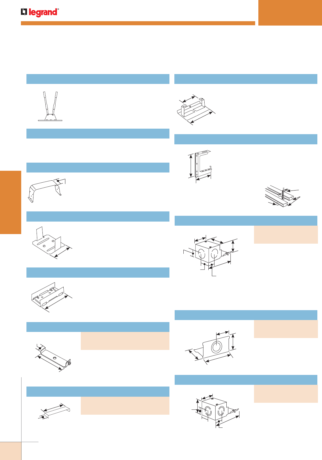
WWW.LEGRAND.US/WIREMOLD
54
STEEL RACEWAY
WIREMOLD
3000 SERIES® RACEWAY
1"
[25mm]
2 1/4"
[57mm]
Case hard steel replacement blades and die set for
630C Cutter.
630CDK Replacement Blade Kit
Holds conductors in place.
G3000WC Wire Clip (Galvanized)
Joins lengths of 3000 Series Raceway.
G3001 Coupling (Galvanized)
6"
[152mm]
3/4"
[19.1mm]
2 13/16"
[72mm]
2 13/16"
[72mm]
3/4"
[19.1mm]
1 3/8"
[35mm] 2 3/4"
[70mm]
1 7/16"
[37mm]
5/8"
[15.9mm]
1 3/8"
[35mm]
5/8"
[15.9mm]
3 7/16"
[87mm]
1 3/8"
[35mm]
1 7/16"
[37mm]
2 3/4"
[70mm]
1 7/8"
[48mm]
2 1/8"
[54mm]
2"
[51mm]
1"
[25mm]
1 3/8"
[35mm] 1 1/16"
[27mm]
4 1/4"
[108mm]
Joins lengths of 3000 Series Raceway
in installations where added rigidity
is required, such as when raceway is
suspended overhead.
G3001A Rigid Inside Coupling (Galvanized)
Connects 3000 Series
Raceway to 1/2" trade
size conduit and armored
cable connectors. 1/2"
trade size KOs on end and
each side of fitting. Can
be connected to conduit
boxes by using 1/2"
chase nipple.
Supports lengths of 3000 Series
Raceway at any point along length.
Mounts with #8 flat head fasteners.
Includes set screw for locking to
raceway.
Covers seam where two pieces of
3000 Series Raceway Cover come
together.
3 9/32"
[83mm]
4 1/2"
[115mm]
Mounts standard after-market devices
into 3000 Series Raceway. Accepts
single-gang devices with 3.281"
[95mm] mounting centers. Use with
commercially available flush plates
(not included).
G3007C Device Bracket
4 1/8"
[105mm]
5 5/16"
[135mm]
G3008C C-Hanger can
be mounted back-to-
back for double run of
3000 Series Raceway.
G3008C
G3008C
3000 Series
Raceway
Suspends 3000 Series Raceway from
structural ceilings. Designed for
use with 3/8" [9.5mm] threaded rod.
Hangers should be installed no more
than 5' [1.5m] apart along raceway run.
G3008C C-Hanger
Closes off open end of
3000 Series Raceway. Has
concentric 1/2" and 3/4"
trade size KOs.
Connects 3000 Series
Raceway to rigid or flexible
conduit. Concentric 1/2",
3/4" and 1" trade size KOs
on end and each side.
Portable cutter for 3000 Series
Raceway Cover. Provides clean and
easy square cuts.
630C Raceway Cover Cutter
3000 Series Raceway Ordering Information (continued)
Supporting Clip
PART NUMBERS:
V3003 (Ivory)
G3003 (Gray)
Cover Clip
PART NUMBERS:
V3006E (Ivory)
G3006E (Gray)
Entrance End Fitting
PART NUMBERS:
V3010AE (Ivory)
G3010AE (Gray)
Blank End Fitting
PART NUMBERS:
V3010B (Ivory)
G3010B (Gray)
Entrance End Fitting
PART NUMBERS:
V3010C (Ivory)
G3010C (Gray)
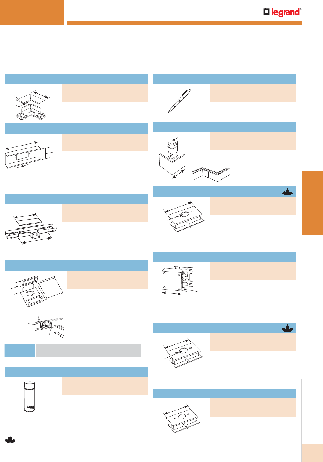
WWW.LEGRAND.US/WIREMOLD
55
STEEL RACEWAY
WIREMOLD
6" [152mm]
Each Leg
4" [102mm]
Each Leg
8"
[203mm]
10 1/4"
[260mm]
8"
[203mm]
2 7/8"
[73mm]
2 3/4"
[70mm]
Right angle turns on the same
surface.
Connects 3000 Series Raceway
from flushed-in wall box.
For branching raceway at right
angles. Three couplings included.
3000 SERIES® RACEWAY
2 3/4"
[70mm]
G3017TCE
G3017TCE used
as a straight-
through fitting.
For surfaces at right angles, or
for use as a straight-through
fitting. Solid leg of base has
concentric 1/2" and 3/4" trade
size KOs.
#6 AWG #8 AWG #10 AWG #12 AWG #14 AWG
THHN, THWN 13 18 24 55 75
NOTE: Parts identified with this symbol are Certified to Canadian Safety
Standards for sale in Canada. When ordering these products, change
the “V” color prefix to “CV” or the “G” color prefix to “CG” to denote
the Canadian versions.
3000 Series Raceway Ordering Information (continued)
Used for touching up large areas.
Contains 12 oz. of paint.
NOTE:
Can only be shipped via ground
transportation
Used for touching up small areas.
Contains 0.3 oz. of paint.
Flat Elbow Fitting
PART NUMBERS:
V3011E (Ivory)
G3011E (Gray)
Wall Box Connector
PART NUMBERS:
V3014C (Ivory)
G3014C (Gray)
Tee Fitting
PART NUMBERS:
V3015E (Ivory)
G3015E (Gray)
Internal Corner Coupling
PART NUMBERS:
V3017TCE (Ivory)
G3017TCE (Gray)
Spray Paint
PART NUMBERS:
IWE-S (Ivory)
GWE-S (Gray)
4 1/2"
[114mm]
1.58"
[40mm]
Dia.
Installs commercially available
straight blade and locking single
receptacles with face diameters of
1.56" -1.57" (approxi mately [40mm]) into 3000 Series
Raceway. G3007C Device Bracket included.
Single Receptacle Cover
PART NUMBERS:
V3033JE (Ivory)
G3033JE (Gray)
4 1/2"
[114mm]
Use as a blank cover or tap off KO
in center of plate for 1/2" trade size
conduit. G3007C Device Bracket
included.
Blank Cover
PART NUMBERS:
V3036HE (Ivory)
G3036HE (Gray)
6 3/8" [162mm] Sq.
1 7/8"
[47mm] Used as a tee, cross, junction box, or
for branch circuit extensions in 3000
Series Raceway. Cover has raceway
twistouts on all sides. Base has five
1/2” trade size KOs and four fixture mounting holes.
Utility Box
PART NUMBERS:
V3028 (Ivory)
G3028 (Gray)
4 1/2"
[114mm]
1.41"
[36mm]
Dia.
Installs commercially available
straight blade and locking single
receptacles with face diameters
of 1.38"-1.40" [35mm-36mm] into 3000 Series Race way.
G3007C Device Bracket included.
Single Receptacle Cover
PART NUMBERS:
V3027AE (Ivory)
G3027AE (Gray)
4"
[102mm]
1 1/4"
[32mm]
Use with G3017TCE to offset around columns
etc. (minimum 4" [102mm] offset).
Right angle turns around external
corners.
External Corner Coupling
PART NUMBERS:
V3018AE (Ivory)
G3018AE (Gray)
Touch-Up Paint Pen
PART NUMBERS:
IWE-P (Ivory)
GWE-P (Gray)
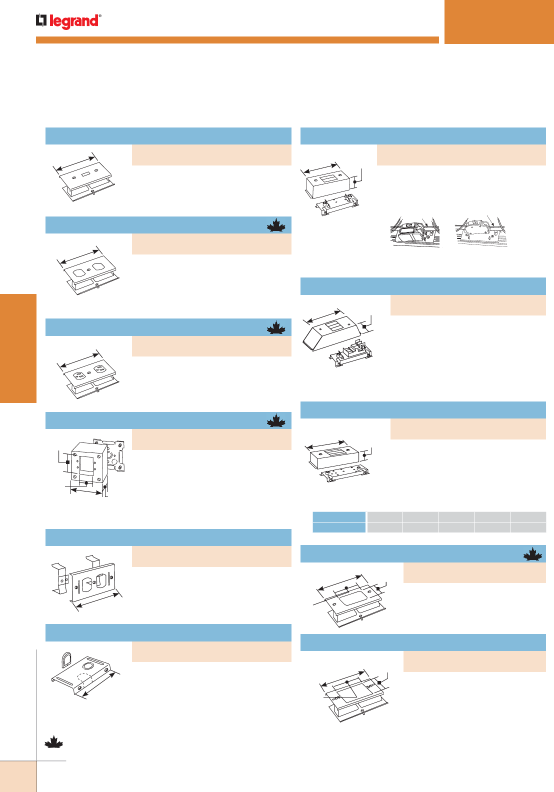
WWW.LEGRAND.US/WIREMOLD
56
STEEL RACEWAY
WIREMOLD
3000 SERIES® RACEWAY
5 3/8"
[137mm]
4 3/4"
[121mm]
Installs commercially available 15A
and 20A duplex receptacles or 106
style data frame into 3000 Series
Raceway.
Duplex Receptacle Cover
For feeding out of the bottom of
raceway. Has concentric 1/2" and
3/4" trade size KOs and twistout for
communication cables. Grommet
furnished for telephone KO.
Tap-Off Fitting
6"
[152mm] 1 15/16"
[49mm]
Two-pole circuit
breaker being mounted
on base of G3046KD.
Single-pole circuit
breaker being mounted
on base of G3046KD.
For use with the following
breakers rated 50A maximum.
General Electric: THQC, THHQC
Westinghouse: Quicklag C, QCH.
Cover used as is with single-pole breaker.
KO is removed for two-pole. For two-
pole circuit breakers where the toggle is
center located, web is snipped or cut out.
Circuit Breaker Housing
7 3/8"
[188mm]
2 3/4"
[70mm]
Mounts Square D™ Quik-Gard QOB bolt-
on circuit breakers into 3000 Series
Raceway. Rated up to 50A maximum
capacity. Includes Square D QON3B
Compact Base for single- to three-pole
circuit breakers. For GFI breakers, use
Square D QOB-GFI Series.
Circuit Breaker Housing
NOTE: Parts identified with this symbol are Certified to Canadian Safety
Standards for sale in Canada. When ordering these products, change
the “V” color prefix to “CV” or the “G” color prefix to “CG” to denote
the Canadian versions.
Accepts shallow-type 30A and
50A devices and flush plates. Also
Fustat devices SRU, SSU, SRW, SOU
and SOW, or equivalent. Deeper
devices can be accommodated with
a combination of G3051LE and any of the V5700 Series single-
gang, open base boxes. G3007C Device Bracket included.
4 1/2"
[115mm]
2 7/8"
[67mm]
2"
[51mm]
4 1/2"
[114mm]
4 1/2"
[114mm]
4 1/2"
[114mm]
2 3/4"
[70mm]
6 3/8"
[162mm]
2 7/8"
[73mm]
3 3/4"
[121mm]
Installs commercially available single-
pole, two-pole, three-way or four-way
switches into 3000 Series Raceway.
G3007C Device Bracket included.
Switch Cover
Installs commercially available 15A
and 20A duplex receptacles or 106
style data frame into 3000 Series
Raceway. G3007C Device Bracket
included.
Duplex Receptacle Cover
Installs commercially available
15A-125V (NEMA-15R) grounding
receptacles into 3000 Series Raceway.
Grounding receptacle included.
Duplex Grounding Receptacle Cover
Two-gang. For standard 30A, 50A, and
60A receptacles. Four sides of cover
have one set of combination twistouts
for 3000 Series Raceway. Hole cut in
cover: 3 3/4" x 2 7/8" [95mm x 73mm].
Base has five 1/2" trade size KOs.
Extra Deep Switch & Receptacle Box
3000 Series Raceway Ordering Information (continued)
PART NUMBERS:
V3040CE (Ivory), G3040CE (Gray)
PART NUMBERS:
V3043BE (Ivory), G3043BE (Gray)
PART NUMBERS:
V3043GE (Ivory), G3043GE (Gray)
PART NUMBERS:
V3044-2 (Ivory), G3044-2 (Gray)
PART NUMBERS:
V3046BE (Ivory), G3046BE (Gray)
PART NUMBERS:
V3046H-2 (Ivory), G3046H-2 (Gray)
PART NUMBERS:
V3046KD (Ivory), G3046KD (Gray)
PART NUMBERS:
V3046KTSQ (Ivory), G3046KTSQ (Gray)
7 3/8"
[187mm] 1 13/16"
46mm]
#6 AWG #8 AWG #10 AWG #12 AWG #14 AWG
THHN, THWN 6 8 10 18 26
Mounts Square D Type QOU one-,
two- or three-pole breakers, rated up
to 50A maximum capacity, into 3000
Series Raceway.
Wire capacity of 3000 Series Raceway with
G3046KD, KTSQO, QOU circuit breaker housings.
Circuit Breaker Housing
PART NUMBERS:
V3046QOU (Ivory), G3046QOU (Gray)
4 1/2"
[114mm]
2 5/8"
[67mm]
1 5/16"
[33mm]
Installs commercially available 15A
and 20A rectangular receptacles
into 3000 Series Raceway. G3007C
Device Bracket included.
Rectangular Decorator Receptacle Cover
PART NUMBERS:
V3048R (Ivory), G3048R (Gray)
Extension Cover
PART NUMBERS:
V3051LE (Ivory), G3051LE (Gray)
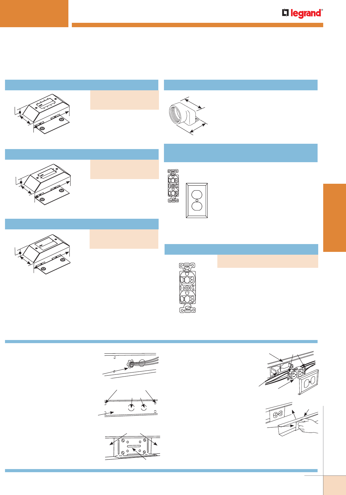
WWW.LEGRAND.US/WIREMOLD
57
STEEL RACEWAY
WIREMOLD
7 15/16"
[185mm]
2 13/16"
[72mm]
1 13/32"
[36mm]
Device plate for use with
four Extron® Electronics
MAAP single space
modules.
Bump-Up Extron® MAAP Plate
2 11/16"
[68mm]
2 13/16"
[71mm]
7 15/16"
[185mm]
2 13/16"
[72mm]
1 13/32"
[36mm]
7 15/16"
[185mm]
2 13/16"
[72mm]
1 13/32"
[36mm]
Device plate for use with
two Extron® Electronics
AAP single space modules.
Bump-Up Extron® AAP Plate
Device plate for use with
three Ortronics® Series
II modules. 6 TracJacks,
or Wiremold CM Series
inserts.
Bump-Up Ortronics® Series II Plate
Connects end of 3000 Series Raceway
to 1 1/2" trade size conduit or
armored cable.
G3082 Conduit Connector
3000 SERIES® RACEWAY
Specification grade rated 20A 125V
NEMA 5-20R receptacle with color
matched nylon faceplate. Receptacle
has nylon face and thermoplastic
base. One-piece brass triple-wipe
line contacts and double-wipe ground
contacts. Locked in wrap-around
steel yoke. Break off tab for two
circuit wiring. 2.7" W x 4.5" H [69mm
x 114mm]. Verified under Fed. Spec.
#WC596F.
DRP20A-V
Colormatch Ivory Duplex Receptacle & Plate
Specification grade rated 20A 125V
NEMA 5-20R receptacle. Receptacle
has nylon face and thermoplastic
base. One-piece brass triple-wipe
line contacts and double-wipe ground
contacts. Locked in wrap-around
steel yoke. Break off tab for two
circuit wiring. 2.7" W x 4.5" H [69mm
x 114mm]. Verified under Fed. Spec.
#WC596F.
Colormatch Gray or Ivory Receptacle
3000 Series Raceway Installation Details
1. Determine the method of feeding
raceway using an entrance end
fitting or through 1/2" or 3/4"
trade size KO in raceway
base (shown). Conduit
Connector
3000 Series Raceway Base
2. To mount 3000 Base on surface:
Remove mounting screw KOs
(approx. 9 3/8" [238mm] O.C.
along base) as required.
Mount base with No. 8
flathead fasteners.
Mounting Screw KOs
Feed KOs
9 3/8" [238mm] Approx.
3000 Series
Raceway Base
3. For coupling lengths of 3000B,
insert either the G3001 or G3001A
(shown) into one base section
centered on joint. Slide other length
of base onto coupling. Tighten
locking screws.
Base Sections
3001A
4. To install devices: Install device
bracket in 3000 Base. Wire device
and assemble on bracket. Install
cover over 3000 Base and device
(if device has plaster ears,
break off before mounting
on device bracket).
3000 Base
Device
Bracket
Break Off
Device Cover
5. Cut sections of 3000 Cover to
fit between device plates. Snap
cover sections in place along
entire run as shown.
Snap Cover
Onto Base
Engage One Side
Of Cover On Base
3000 Series Raceway Ordering Information (continued)
PART NUMBERS:
DR20A-V (Ivory), DR20A-G (Gray)
PART NUMBERS:
V3046U (Ivory)
G3046U (Gray)
PART NUMBERS:
V3046V (Ivory)
G3046V (Gray)
PART NUMBERS:
V3046S (Ivory)
G3046S (Gray)
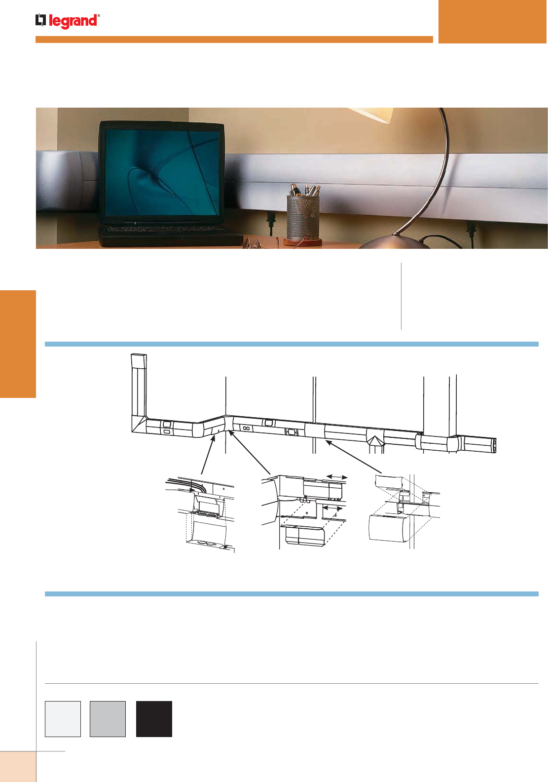
WWW.LEGRAND.US/WIREMOLD
58
STEEL RACEWAY
WIREMOLD
DS4000® SERIES RACEWAY
CODE REFERENCE
cULus Listed Raceway:
File E4376 Guide RJBT.
Fittings:
File E41751 Guide RJPR.
Meets Article 386 of NEC.
Meets Section 12-1600 of CEC.
Dual-channel raceway with increased capacity due to its unique
profile, integral divider and downward facing activations. Ideal
for any application that requires a high capacity metal raceway.
KEY
A. DS4010A Entrance End Fitting
B. DS4010B Blank End Fitting
C. DS4011 90° Flat Elbow Fitting
D. DS4015 Divided Tee Fitting
E. DS4017 Internal Elbow Fitting
F. DS4018 External Elbow Fitting
G. DS4047C Single-Channel
NEMA Device Plate
H. DS4047D Single-Channel
Duplex Device Plate
I. DS4047MAB Single-Channel
MAB Device Plate
J. DS4047R Single-Channel
Decorator Device Plate
K. DS4075 Small Obstacle
Transition Fitting
L. DS4075A Offset Fitting
M. DSDWND Downward Duplex
Device Plate
DSDWNR Downward
Decorator Device Plate
System Layout
DS4000® Raceway Part Numbers with a “DV” suffix have a fog white finish. Part
Numbers with a “DG” suffix have a gray finish. Part Numbers with a “BK” suffix have
an black finish.
Custom color options are also available. Consult the factory for more information.
COLOR OPTIONS
A
IF
E
G
K
DLB
CJH
M
Obstacle Avoidance Fitting
bypasses existing conduits
and small raceways mounted
on supporting wall.
Adjust-to-Fit™ Couplings
Allow up to 4" [102mm] of
lateral adjustment of Raceway
Base to minimize cutting.
2 1/4"
[57mm]
> 4" [102mm]
Bend Radius
Universal Downward Facing Device
Bracket accommodates industry
standard power and data devices
while allowing the industry’s largest
termination radius.
WWW.LEGRAND.US/WIREMOLD
59
STEEL RACEWAY
WIREMOLD
WIRE SIZE
THHN/THWN
O.D.
NUMBER OF CONDUCTORS 40% PER COMPARTMENT
WITHOUT
DEVICES
WITH DUPLEX
RECT. DEVICES
1.59in.2 [1025mm2]
WITH SURGE/
GFCI DEVICES
2.30in.2 [1485mm2]
WITH LARGE SINGLE
RECEPTACLES
3.00in.2 [1935mm2]
40% FILL
WITH DOWNWARD
ACTIVATION/CROSSOVERInches [mm}
14 AWG 0.111 [2.8] 206 141 111 83 46
12 AWG 0.130 [3.3] 150 103 81 60 33
10 AWG 0.164 [4.2] 95 64 51 38 21
8 AWG 0.216 [5.5] 54 37 29 22 12
6 AWG 0.254 [6.5] 39 27 21 15 8
DS4000 Series Raceway Wire Fill Capacities for Power
DS4000 Series Raceway Wire Fill Capacities for Communications
CABLE/WIRE SIZE
O.D. Approx. Dia.
40% FILL EACH
COMPARTMENT
40% FILL
WITH DOWNWARD
ACTIVATION/
CROSSOVERInches [mm]
UNSHIELDED
TWISTED
PAIR
4-pair, 24 AWG, Cat 3 0.190 [4.8] 70 28
4-pair, 24 AWG, Cat 5e 0.210 [5.3] 57 23
4-pair, 24 AWG, Cat 6 0.250 [6.3] 40 16
4-pair, 24 AWG, Cat 6a* 0.354 [9.0] 20 8
25-pair, 24 AWG 0.410 [10.4] 15 6
COAXIAL RG6/U 0.270 [6.9] 35 14
FIBER ZipCord 0.118 x
0.236
[3 x 6] 72 29
Round 4 Strand Fiber 0.187 [4.8] 73 29
Round 6 Strand Fiber 0.256 [6.5] 38 15
NOTE : For additional information, refer to the Technical Section.
* Category 6 augmented [6a] cable for 10 gigabit ethernet – max allowed cable diameter per addenda
No. 11 ANSI TIA/EIA 568-B.2.
DS4000 Series Raceway Fittings Wire Fill Capacities
WIRE SIZE/THHN
O.D. APPROX. DIA. DS4010A* DS4011 DS4015 DS4017** DS4018** DS4075 DS4075A**
Inches [mm] 40% 60% 40% 60% 40% 60% 40% 60% 40% 60% 40% 60% 40% 60%
THHN 14 0.111 [2.8] 125 187 171 256 62 93 160 238 142 213 106 160 142 213
12 0.130 [3.3] 91 137 125 187 45 68 116 175 104 156 78 116 104 156
10 0.164 [4.2] 57 86 78 118 28 43 73 110 65 98 49 73 65 98
8 0.216 [5.5] 33 50 45 68 16 25 42 63 38 57 28 42 38 57
6 0.254 [6.5] 24 36 33 49 12 18 31 46 27 41 20 31 27 41
UTP 4-pair, 24 AWG 0.150 [4.8] 68 103 94 140 49 74 87 131 78 117 58 87 78 117
4-pair, 24 AWG, Cat 3 0.190 [4.8] 43 64 58 87 31 46 55 82 49 73 36 55 49 73
4-pair, 24 AWG, Cat 5e 0.210 (5.3) 35 52 48 72 25 38 45 67 40 60 30 45 40 60
4-pair, 24 AWG, Cat 6 0.250 (6.3) 25 37 34 51 18 27 32 47 28 42 21 32 28 42
4-pair, 24 AWG, Cat 6a* 0.354 (9.0) 12 18 17 25 9 13 16 24 14 21 10 16 14 21
25-pair, 24 AWG 0.410 (10.4) 12 18 16 24 9 13 15 23 14 20 10 15 14 20
COAXIAL RG6/U 0.270 [6.9] 21 32 29 43 15 23 27 41 24 36 18 27 24 36
FIBER ZipCord 0.118 x
0.236
[3 x 6] 44 65 59 89 31 47 56 83 50 74 37 56 50 74
Round 4 Strand Fiber 0.187 [4.8] 44 66 60 90 32 48 56 85 50 75 38 56 50 75
Round 6 Strand Fiber 0.256 [6.5] 24 35 32 48 17 26 30 45 27 40 20 30 27 40
* Entrance end fitting fill rate is calculated using backfeed capability and radius inserts. Inserts are removable and fitting can obtain maximum raceway fill
from utilizing end fitting knockouts and removing radius control inserts.
** Calculated using radius control inserts. Inserts are factory installed and may be removed in order to obtain full raceway capacity if radius control is
not required.
WIRE SIZE
THHN/THWN
O.D. (Approx. Dia.) 40%
FILLInches [mm]
14 AWG 0.111 [2.8] 31
12 AWG 0.130 [3.3] 23
10 AWG 0.164 [4.2] 14
8 AWG 0.216 [5.5] 8
6 AWG 0.254 [6.5] 6
NOTE: Prewired downward facing covers are
punched in line for a sleek flush look.
Power conductors are provided in the
lower channel. Additional wires can be
added and should not exceed totals above.
Communications are to be installed in the
top channel refer to standard cable fill
chart for capacities.
Prewired DS4000 Raceway Cover Wire
Fill Capacities with Downward Facing
Power & Communication Devices
DS4000® SERIES RACEWAY
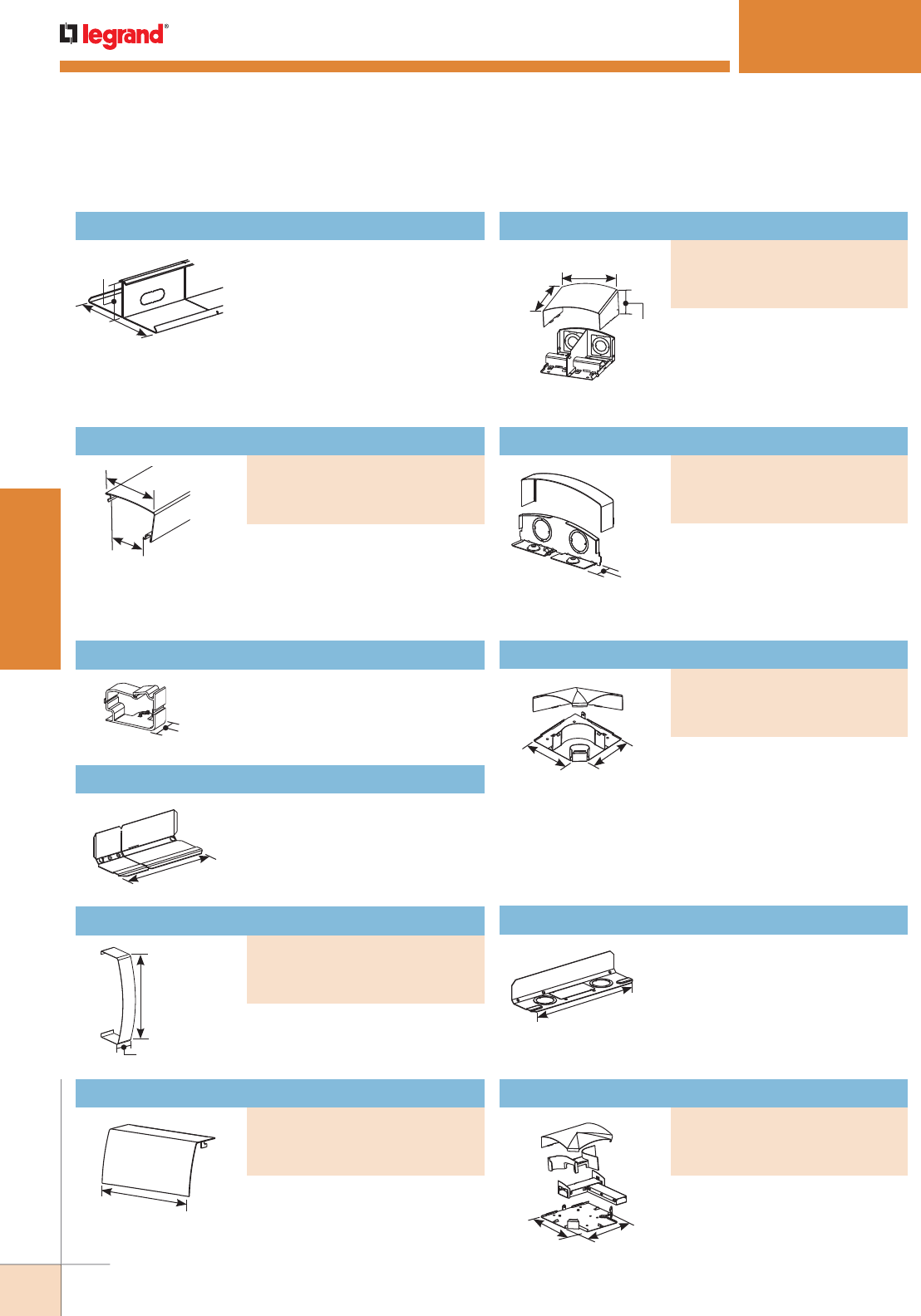
WWW.LEGRAND.US/WIREMOLD
60
STEEL RACEWAY
WIREMOLD
Raceway Cover
PART NUMBERS:
DS4010A-DV (Fog White)
DS4010A-DG (Gray)
DS4010A-BK (Black)
Covers seam where two sections
of DS4000C come together.
Half Seam Clip/Blank Faceplate
PART NUMBERS:
DS4006B-DV (Fog White)
DS4006B-DG (Gray)
DS4006B-BK (Black)
Seam Clip
PART NUMBERS:
DS4006-DV (Fog White)
DS4006-DG (Gray)
DS4006-BK (Black)
5 1/2"
[140mm]
2"
[51mm]
1 5/8"
[41mm]
6"
[152mm]
6"
[152mm]
1 1/16"
[27mm]
1"
[25mm]
5 3/4"
[146mm]
3"
[76mm]
5 5/8"
[143mm]
5 3/4"
[146mm]
2 7/8"
[73mm]
2 3/16"
[56mm]
DS4000® SERIES RACEWAY
.040" [1.0mm] galvanized steel.
Each base section has mounting
holes, two 9/32" [7.1mm] diameter,
located every 4" [102mm] and
pass through KOs located every
8" [203mm] along the entire
length. Packed four 10' [3.05m] sections of base per carton.
Two DS4001 Couplings included with each 10' section.
DS4000B Raceway Base
.040" [1.0mm] galvanized steel.
Packed eight 5' [1.5m] lengths
per carton. Four 5' [1.5m] cover
sections required for each 10'
[3.05m] section of base.
Holds conductors in place.
DS4000WC Wire Clip
Joins lengths of DS4000B together.
Sold in pairs.
DS4001 Adjust-to-Fit™ Coupling
Covers seams where two sections
of DS4000C Cover come together.
Can also be used as a blank
faceplate.
Full-capacity end fitting. Includes
four 3/4" and 1 1/4" concentric
trade size KOs and four 2 1/8"
large capacity KOs.
Closes off open end of DS4000B
Raceway Base Has two 3/4" and 1"
trade size KOs.
10"
[254mm]
Extra long coupling allows
attachment to a wall box or to back
feed DS4000 Series Raceway from
1" or 1 1/4" trade size conduit.
DS4014A Backfeed Coupling
Divided Tee
PART NUMBERS:
DS4015-DV (Fog White)
DS4015-DG (Gray)
DS4015-BK (Black)
8 1/2"
[216mm] 8 15/16"
[227mm]
For new lay-in or pull-through
installations. Two pair of DS4001
Couplings included. Two pair of
DS4001 Couplings included.
DS4000 Series Raceway Ordering Information (continued)
Raceway Cover
PART NUMBERS:
DS4000C-DV (Fog White)
DS4000C-DG (Gray)
DS4000C-BK (Black)
Blank End Fitting
PART NUMBERS:
DS4010B-DV (Fog White)
DS4010B-DG (Gray)
DS4010B-BK (Black)
7"
[178mm]
7"
[178mm] 90° flat corner for new lay-in or
pull-through installations. One pair
of DS4001 Couplings included.
Flat Elbow
PART NUMBERS:
DS4011-DV (Fog White)
DS4011-DG (Gray)
DS4011-BK (Black)
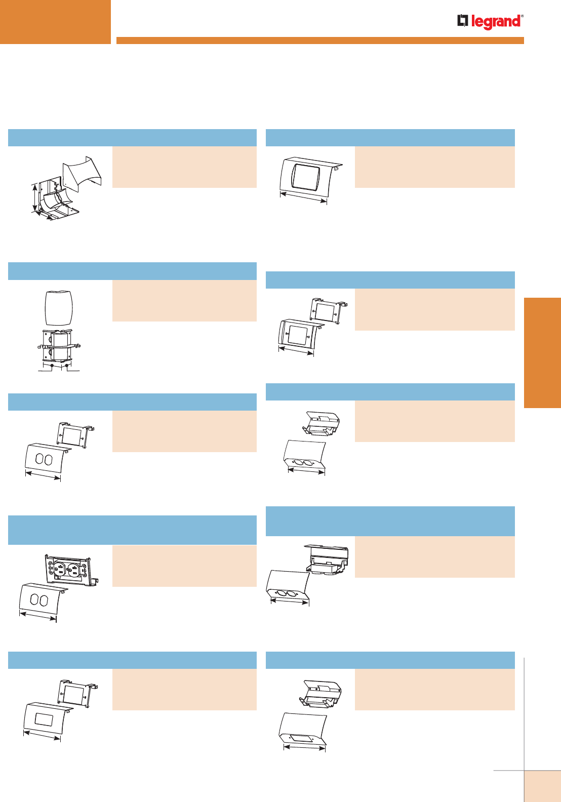
WWW.LEGRAND.US/WIREMOLD
61
STEEL RACEWAY
WIREMOLD
Downward Decorator Device Plate
PART NUMBERS:
DSDWNR-DV (Fog White)
DSDWNR-DG (Gray)
DSDWNR-BK (Black)
5 3/4"
[146mm]
5 3/4"
[146mm]
90° Full capacity divided internal
elbow that provides a 2" [51mm]
cable bend radius for fiber optic/
UTP/STP installations. One pair of
DS4001 Couplings included.
DS4000® SERIES RACEWAY
Installs 15A or 20A duplex
receptacles or 106 style data
frames into DS4000 Series
Raceway.
6"
[152mm]
6"
[152mm]
6"
[152mm]
Single-Channel Decorator Device Plate
PART NUMBERS:
DS4047R-DV (Fog White)
DS4047R-DG (Gray)
DS4047R-BK (Black)
6"
[152mm]
Installs 15A or 20A decorator style
receptacles, GFCI and surge
devices into DS4000 Series
Raceway.
Single-Channel MAB Device Plate
PART NUMBERS:
DS4047MAB-DV (Fog White)
DS4047MAB-DG (Gray)
DS4047MAB-BK (Black)
6"
[152mm] Installs communication devices into
DS4000 Series Raceway. Includes
CM-MAB Adapter for Wiremold Open System connectivity
modules and Pass & Seymour® Activate inserts. Also
includes MAB2S2 Adapter for Ortronics® Series II inserts
and MAB6TJ Adapter for Ortronics® TracJack connectors.
6"
[152mm]
Installs 15A and 20A duplex
receptacles or 106 style data frames
into DS4000 Series Raceway in a
downward facing, protected position.
Pass & Seymour® 20A duplex
receptacle with 6” [152mm] lead wires
pre-installed on a bracket into DS4000
Series Raceway in a downward facing,
protected position.
Installs 15A and 20A decorator style
recep tacles, GFCI and Surge devices
into DS4000 Series Raceway in a
downward facing, protected position.
DS4000 Series Raceway Ordering Information (continued)
Internal Elbow
PART NUMBERS:
DS4017-DV (Fog White)
DS4017-DG (Gray)
DS4017-BK (Black)
3 1/2"
[89mm]
3 1/2"
[89mm]
90° full capacity divided external
elbow provides a 2" [51mm] cable
bend radius for fiber optic/UTP/
STP installations. One pair of
DS4001 Couplings included.
External Elbow
PART NUMBERS:
DS4018-DV (Fog White)
DS4018-DG (Gray)
DS4018-BK (Black)
6"
[152mm]
For Turnlok® and most straight blade
devices up to 50 Amps. Use with
commercially available flush plates.
Single-Channel NEMA Device Plate
PART NUMBERS:
DS4047C-DV (Fog White)
DS4047C-DG (Gray)
DS4047C-BK (Black)
6"
[152mm]
Pass & Seymour® 20A duplex
receptacle with 6" [152mm] lead
wires pre-installed on a bracket
into DS4000 Series Raceway.
Single-Channel Duplex Device Plate with
One Duplex Installed
PART NUMBERS:
DS4047DQ-DV (Fog White)
DS4047DQ-DG (Gray)
DS4047DQ-BK (Black)
Single-Channel Duplex Device Plate
PART NUMBERS:
DS4047-DV (Fog White)
DS4047-DG (Gray)
DS4047-BK (Black)
Downward Duplex Device Plate with
One Duplex installed
PART NUMBERS:
DSDWNDQ-DV (Fog White)
DSDWNDQ-DG (Gray)
DSDWNDQ-BK (Black)
Downward Duplex Device Plate
PART NUMBERS:
DSDWND-DV (Fog White)
DSDWND-DG (Gray)
DSDWND-BK (Black)
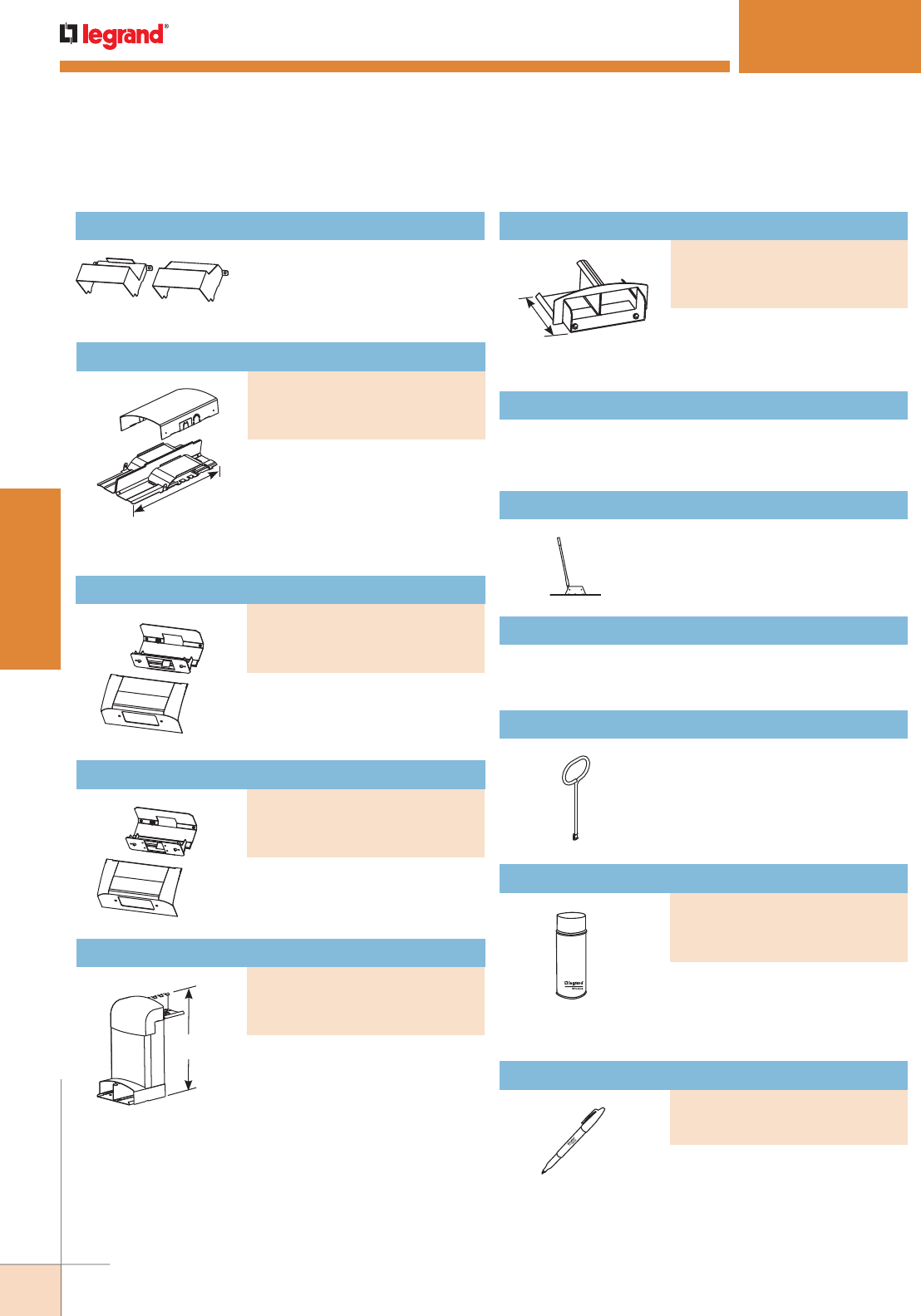
WWW.LEGRAND.US/WIREMOLD
62
STEEL RACEWAY
WIREMOLD
DS4000® SERIES RACEWAY
Ordering Information
Accepts two Extron® Electronics
MAAP single space modules.
11 1/2"
[292mm] Mounts DS4000 Series Raceway
around wall offsets and columns
with maximum offset depth of 9"
[229mm]. Minimum Offset: 3"
[76mm]. Maximum Offset: 9 3/4"
[235mm].
Kit includes 25 screws and special bit to secure covers for
fittings and raceway to DS4000B Raceway Base.
DSTRK Tamper-Resistant Kit
Portable cutter provides clean
square cuts for DS4000C
Raceway Cover.
640DS DS4000 Series Raceway Cutter
Case hard steel replacement blades and die set for 640DS
Cutter.
640DSBDK Replacement Blade Kit
Easy removal of installed DS4000
Series raceway and fittings’ covers
without scratching or damaging
their finish.
650RT Fitting Cover Removal Tool
Adapter to 4000 Series Raceway
PART NUMBERS:
DS4089-DV (Fog White)
DS4089-DG (Gray)
DS4089-BK (Black)
5 3/4"
[146mm] In-line transition from DS4000
Series Raceway to 4000 Series
Raceway.
13 7/8"
[352mm]
Provides shielding when using
downward-facing activations.
Includes enclosures for power or
data crossover.
DSDWNX Crossover Kit
Passes DS4000 Series Raceway
over previously installed conduit or
raceways as large as 2400 Series
Raceway. Also creates transition to
500, 700 or 2400D Series Raceway
from DS4000 Series Raceway.
Accepts one Ortronics® Series II
module, 2 TracJacks or 1 CM
Series insert.
Downward Ortronics® Series II Device Plate
DS4000 Series Raceway Ordering Information (continued)
Used for touching up large areas.
Contains 12 oz. of paint.
NOTE:
Can only be shipped via ground
transportation.
Spray Paint
PART NUMBERS:
DVWE-S (Ivory)
DGWE-S (Gray)
BKWE-S (Black)
Used for touching up small areas.
Contains 0.3 oz. of paint.
Touch-Up Paint Pen
PART NUMBERS:
DVWE-P (Ivory)
BKWE-P (Black)
Downward Ortronics® Series II Device Plate
PART NUMBERS:
DSDWNS-DV (Fog White)
DSDWNS-DG (Gray)
DSDWNS-BK (Black)
Small Obstacle/Transition Fitting
PART NUMBERS:
DS4075-DV (Fog White)
DS4075-DG (Gray)
DS4075-BK (Black)
Downward Device Plate
PART NUMBERS:
DSDWNU-DV (Fog White)
DSDWNU-DG (Gray)
DSDWNU-BK (Black)
Offset Fitting
PART NUMBERS:
DS4075A-DV (Fog White)
DS4075A-DG (Gray)
DS4075A-BK (Black)
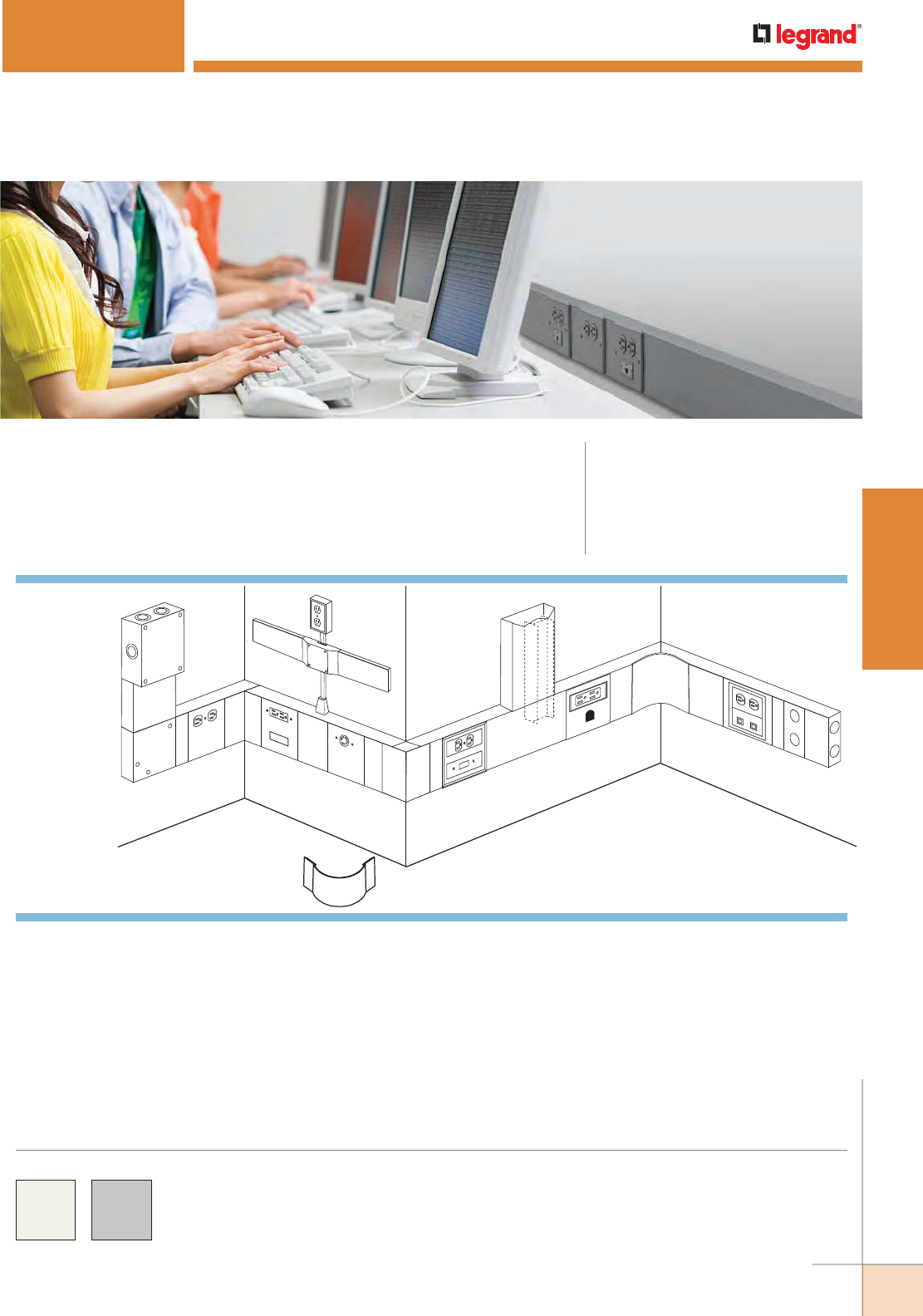
WWW.LEGRAND.US/WIREMOLD
63
STEEL RACEWAY
WIREMOLD
B
C
I
E
K
J
Q
O
G
H
M
D
LR
P
A
F
N
4000® SERIES RACEWAY
CODE REFERENCE
cULus Listed Raceway:
File E4376 Guide RJBT.
Fittings:
File E41751 Guide RJPR.
Meets Article 386 of NEC.
Meets Section 12-1600 of CEC.
Single- and Dual-Channel, Steel Raceway. Easy-to-install and ideal for
basic power or communication/low voltage installations.
KEY
A. 4010B Blank End Fitting
B. 4010DFO Entrance End Fitting
C. 4011 Flat Elbow
D. 4015D Divided Tee
E. 4017 Internal Elbow
F. 4017FO Radiused Full
Capacity Internal Elbow
G. 4018 External Elbow
H. 4018FO Radiused Full
Capacity External Elbow
I. 4047BX Duplex Receptacle
Device Plate
J. 4047JX Single Receptacle &
Device Plate
K. 4047RF Rectangular
Receptacles and Modular
Furniture Device Plate
L. 4047RH Device Plate for
Rectangular Receptacle and
Mousehole
M. 4050 Device Mounting Plate
with 5507 Series Faceplates
N. 4075DA Bridge Fitting
O. 500 Series Raceway
P. 5507D Duplex Faceplate
Q. 5785 Combination Connector
R. 5507RJ Device Plate with two
RJ ports
System Layout
COLOR OPTIONS
4000® Series Raceway Part Numbers with a “V” prefix have an
ivory finish. Part Numbers with a “G” prefix have a gray finish.
Custom color options are also available. Consult the factory
for more information.
NOTE: Illustration is for showing product applications only.

WWW.LEGRAND.US/WIREMOLD
64
STEEL RACEWAY
WIREMOLD
4000® SERIES RACEWAY
4000 Series Raceway Wire Fill Capacities for Communications
CABLE/WIRE SIZE
O.D. APPROX. DIA. DIVIDED
40% FILL
UNDIVIDED
40% FILLInches [mm]
UNSHIELDED
TWISTED
PAIR
4-pair, 24 AWG, Cat 3 0.190 [4.8] 49 101
4-pair, 24 AWG, Cat 5e 0.210 (5.3) 40 83
4-pair, 24 AWG, Cat 6 0.250 (6.3) 28 58
4-pair, 24 AWG, Cat 6a* 0.354 (9.0) 14 29
25-pair, 24 AWG 0.410 (10.4) 10 21
COAXIAL RG6/U 0.270 [6.9] 24 50
FIBER ZipCord 0.118 x
0.236
[3 x 6] 50 103
Round 4 Strand Fiber 0.187 [4.8] 51 104
Round 6 Strand Fiber 0.256 [6.5] 27 55
4000 Series Raceway Fittings Wire Fill Capacities When using 4000 Radius Inserts
CABLE/WIRE SIZE
O.D.
4011 FLAT ELBOW
40% FILL
4017 & 4018 ELBOWS
40% FILL
4015D & 4015 TEE FITTING
40% FILL
Inches [mm]
4011DRI
DIV.
4011/15RI
UNDIV.
4017/18RI
DIV.
4017/18RI
UNDIV.
4015DRI
DIV.
4011/15RI
UNDIV.
POWER
WIRING
THHN/THWN
2 0.384 [9.8] 11 21 6 11 6 16
4 0.324 [8.2] 15 30 8 15 9 23
6 0.254 [6.5] 24 48 13 25 14 37
8 0.216 [5.5] 34 67 18 35 20 51
10 0.164 [4.2] 68 136 36 71 40 104
12 0.130 [3.3] 107 214 56 112 63 163
14 0.111 [2.8] 145 288 75 151 85 220
UNSHIELDED
TWISTED
PAIR
Cat. 3 UTP 0.190 [4.8] 44 88 23 46 26 67
Cat 5e UTP 0.210 [5.3] 36 72 19 38 21 55
Cat 6 UTP 0.250 [6.3] 23 47 12 24 13 36
Cat 6a UTP 0.354 [9.0] 16 31 9 15 10 24
25-pair 0.410 [10.4] 9 19 5 10 6 14
COAXIAL RG6/U 0.270 [6.9] 22 44 22 23 13 33
FIBER ZipCord 0.118 x 0.236 [3 x 6] 132 263 69 137 78 201
Round 4 Strand Fiber 0.187 [4.8] 44 88 23 46 26 67
Round 6 Strand Fiber 0.256 [6.5] 36 72 19 38 21 55
NOTE: For additional information, refer to the Technical Section.
* Category 6 augmented (6a) cable for 10 gigabit ethernet max allowed cable diameter per addenda No. 11 ANSI TIA/EIA 568-B.2.
4000 Series Raceway Wire Fill Capacities for Power
WIRE SIZE
THHN/THWN
O.D.
NUMBER OF CONDUCTORS 40% FILL
WITHOUT
DEVICES
WITH DUPLEX
RECT. DEVICES
1.59in.2 [1025mm2]
WITH SURGE/
GFCI DEVICES
2.30in.2 [1485mm2]
LARGE SINGLE
RECEPTACLES
3.00in.2 [1935mm2]Inches [mm}
Undiv. Divided Undiv. Divided Undiv. Divided Undiv. Divided
14 AWG 0.111 [2.8] 296 127 165 78 107 49 49 20
12 AWG 0.130 [3.3] 216 93 120 57 78 36 36 15
10 AWG 0.164 [4.2] 136 58 76 36 49 22 22 9
8 AWG 0.216 [5.5] 78 33 43 20 28 13 13 5
6 AWG 0.254 [6.5] 56 24 31 15 20 9 9 3
4 AWG 0.324 [8.2] 34 15 000000
3 AWG 0.352 [8.9] 29 12 000000
2 AWG 0.384 [9.8] 24 10 000000
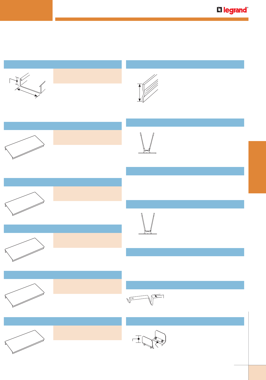
WWW.LEGRAND.US/WIREMOLD
65
STEEL RACEWAY
WIREMOLD
4000® SERIES RACEWAY
1 3/4"
[44mm]
4 3/4"
[121mm]
.054" [13.7mm] galvanized steel.
Packed five 10' [3m] lengths per
carton. Base has two 9/32" [7.1mm]
diameter KOs every 18" [457mm]
throughout length. No KOs 1 1/4"
[32mm] from each end.
Raceway Base
1 17/32"
[39mm]
.040" [1.0mm] galvanized steel.
Painted on one side only to provide
compartment identification. Packed
ten 5' [1.5m] lengths (50' [15.2m]) per
carton.
NOTE: Not for use with stainless steel
S4000 Series Raceway.
G4000D Divider
Portable cutter for 4000 Series
Raceway Base. Provides clean and
square end cuts.
NOTE: Not for use with stainless steel
S4000 Series Raceway.
640B Base Cutter
Case hard steel replacement blade and die set for
640B Cutter
640BDK Replacement Blade Kit
Portable cutter for 4000 and 6000
Series Raceway Cover. Provides clean
and square end cuts.
NOTE: Not for use with stainless steel
S4000 Series Raceway.
640C Cover Cutter
Case hard steel replacement blade and die set for
640C Cutter.
640CDK Replacement Blade Kit
1"
[25mm]
Holds conductors in place.
G4000WC Wire Clip (Galvanized)
1 1/2"
[38mm]
2 1/2"
[64mm]
Joins lengths of 4000B Raceway
Base. Sold in pairs.
4001A Coupling (Galvanized)
4000 Series Raceway Ordering Information
PART NUMBERS:
V4000B-10 (Ivory)
G4000B-10 (Gray)
.040" [1.0mm] galvanized steel.
Packed ten 5' [1.5m] lengths
per carton. 4000C Cover is also
compatible with 6000B, 6000
Series Raceway Base.
Raceway Cover
PART NUMBERS:
V4000C (Ivory)
G4000C (Gray)
Mounts devices spaced 12"
[305mm] on center using 4047
Series device plates.
7.5" [191mm] Precut Raceway Cover
PART NUMBERS:
V4000C075 (Ivory)
G4000C075 (Gray)
Mounts devices spaced 18"
[457mm] on center using 4047
Series device plates.
13.5" [343 mm] Precut Raceway Cover
PART NUMBERS:
V4000C135 (Ivory)
G4000C135 (Gray)
Mounts devices spaced 24"
[610mm] on center using 4047
Series device plates.
19.5" [495 mm] Precut Raceway Cover
PART NUMBERS:
V4000C195 (Ivory)
G4000C195 (Gray)
Mounts devices spaced 36"
[915mm] on center using 4047
Series device plates.
31.5" [800 mm] Precut Raceway Cover
PART NUMBERS:
V4000C315 (Ivory)
G4000C315 (Gray)
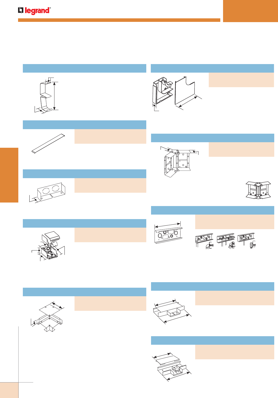
WWW.LEGRAND.US/WIREMOLD
66
STEEL RACEWAY
WIREMOLD
4000® SERIES RACEWAY
2 3/4"
[70mm]
4 3/4"
[121mm]
5 1/4"
[133mm]
6 1/2"
[165mm]
Full capacity entrance end fitting.
Has concentric 3/4", 1", and 1 1/4"
trade size KOs on end and bottom
for feeding 4000 Series Raceway.
Includes removable divider and
1 1/4" [32mm] bend radius control insert for UTP/STP and
fiber optic cable installations.
Entrance End Fitting
1 3/4"
[44mm]
4 3/4"
[121mm]
8 3/4"
[222mm]
1 3/4"
[44mm]
12"
[305mm]
Direct feeding. Feeding from
wall box.
Direct feeding
with divider.
10"
[254mm]
12"
[305mm]
10"
[254mm]
12"
[305mm]
Right angle turns on the same
surface.
Flat Elbow
Full capacity 90° flat corner
used in divided or undivided
applications. 2" [51mm] bend
radius control for UTP, STP
and fiber optic installations.
Ideal for new installations when the cable is lay-in or
pull-through.
1 1/2"
[38mm]
1 1/8"
[29mm]
Assembled as an
internal elbow.
Assembled as an
external elbow.
Internal or external 45° turns in
a run of 4000 Series Raceway.
Can also be assembled as an
inverted 45° elbow.
Internal or External 45° Elbow
Base has two concentric 1", 3/4", and 1/2" trade size KOs,
two concentric 1 1/4", and 1" KOs (undivided only), and two
rectangular 2 9/16" x 1 11/16" KOs.
Wall Box Connector
For branching raceway at right angles.
Use with undivided raceway only. Join
to raceway run with two pair of 4001A
Couplings (not included).
Tee
For branching raceway at right angles.
Use with divided raceway only. Join
to raceway run with two pair of 4001A
Couplings (not included).
Divided Tee
1"
[25mm]
4 1/2"
[114mm]
1 1/2"
[38mm]
1 1/4"
[32mm]
Required for holding G4000D
Divider in place. Use one every 2
1/2' [.762m].
4001DA Divider Clip (Galvanized)
Covers seams where two sections
of 4000 Series Raceway covers
come together.
Seam Clip
Closes off open end of 4000 Series
Raceway. Has two 1/2” trade size
KOs to facilitate end feeding.
Blank End Fitting
4000 Series Raceway Ordering Information (continued)
PART NUMBERS:
V4006 (Ivory)
G4006 (Gray)
PART NUMBERS:
V4010B (Ivory)
G4010B (Gray)
PART NUMBERS:
V4010DFO (Ivory)
G4010DFO (Gray)
PART NUMBERS:
V4011 (Ivory)
G4011 (Gray)
Radiused Full Capacity Flat Elbow
PART NUMBERS:
V4011FO (Ivory)
G4011FO (Gray)
PART NUMBERS:
V4012TX (Ivory)
G4012TX (Gray)
PART NUMBERS:
V4014A (Ivory)
G4014A (Gray)
PART NUMBERS:
V4015 (Ivory)
G4015 (Gray)
PART NUMBERS:
V4015D (Ivory)
G4015D (Gray)
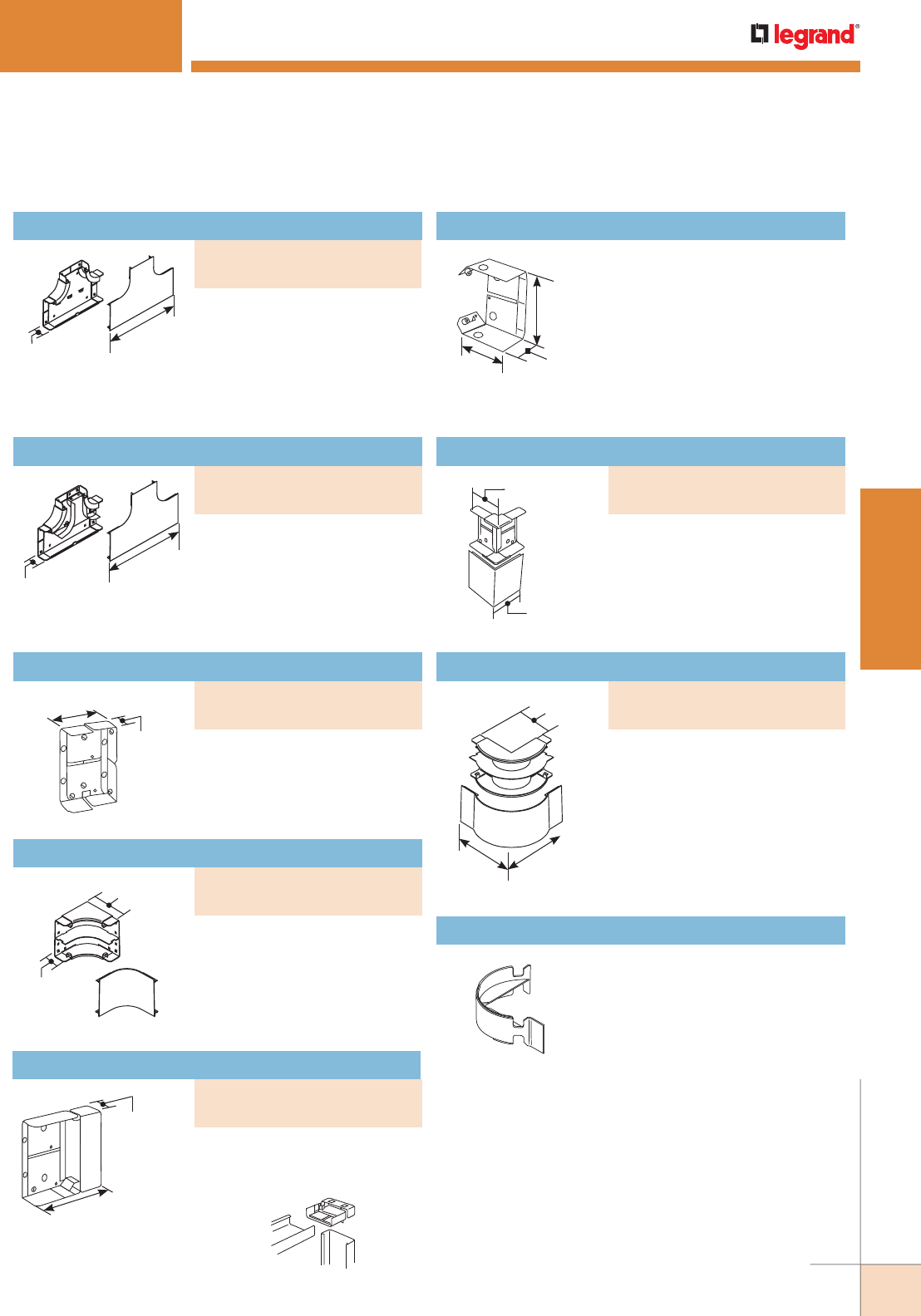
WWW.LEGRAND.US/WIREMOLD
67
STEEL RACEWAY
WIREMOLD
Full capacity, divided internal
elbow. Provides 2" [51mm] cable
bend radius control for UTP, STP
and fiber optic installations. Ideal
for new installations whether the
cable is lay-in or pull-through.
4000® SERIES RACEWAY
2 3/4"
[70mm] 1 1/2"
[38mm]
4 1/2"
[114mm]
Makes an internal corner while
continuing original run in a
straight line. May be used with
or without divider. Fiber bushing
included.
G4017TCA Internal Corner Coupling (Plated)
4 1/8"
[105mm]
4 11/16"
[119mm]
3 3/4"
[95mm]
6 1/2"
[165mm]
6 1/2"
[165mm]
Two required for
use with 4015.
90° external corners.
External Elbow
Full capacity 90° external corner.
Used in both divided and undivided
applications. Provides 2" [51mm]
cable bend radius control for UTP,
STP and fiber optic installations.
Ideal for new installations whether
the cable is lay-in or pull-through.
Radiused Full Capacity External Elbow
Radiused insert for 4011 Flat
Elbow and for 4015 Undivided Tee.
Provides 2" [51mm] cable bend
radius control for UTP, STP and
fiber optic cable installations. Ideal
for new and retrofit applications
whether the cable installation is
lay-in or pull-through.
4011/15RI Radiused Corner Insert
12 3/4"
[324mm]
1 3/4"
[44mm]
12 3/4"
[324mm]
1 3/4"
[44mm]
3 1/8"
[79mm]
1 1/2"
[38mm]
3 3/4"
[95mm]
1 3/4"
[44mm]
1 1/4"
[32mm]
4 21/32"
[118mm]
4000 Base
4017N
Full capacity, undivided tee
fitting. Provides 2" [51mm]
cable bend radius control
for UTP, STP and fiber optic
installations. Ideal for new
installations whether the cable
is lay-in or pull-through.
Full capacity, divided tee fitting.
Provides 2" [51mm] cable bend
radius control for UTP, STP and
fiber optic installations. Ideal for
new installations whether the
cable is lay-in or pull-through.
Radiused Full Capacity Divided Tee
90° internal corners. Fiber
bushing included.
Internal Elbow
Internal Full Capacity Elbow
Connects a vertical run of 4000
Series Raceway with a horizontal
overhead run with its cover
facing up.
Inverted Internal Elbow
4000 Series Raceway Ordering Information (continued)
Radiused Full Capacity Tee
PART NUMBERS:
V4015FO (Ivory)
G4015FO (Gray)
PART NUMBERS:
V4015DFO (Ivory)
G4015DFO (Gray)
PART NUMBERS:
V4017 (Ivory)
G4017 (Gray)
PART NUMBERS:
V4017FO (Ivory)
G4017FO (Gray)
PART NUMBERS:
V4017N (Ivory)
G4017N (Gray)
PART NUMBERS:
V4018 (Ivory)
G4018 (Gray)
PART NUMBERS:
V4018FO (Ivory)
G4018FO (Gray)
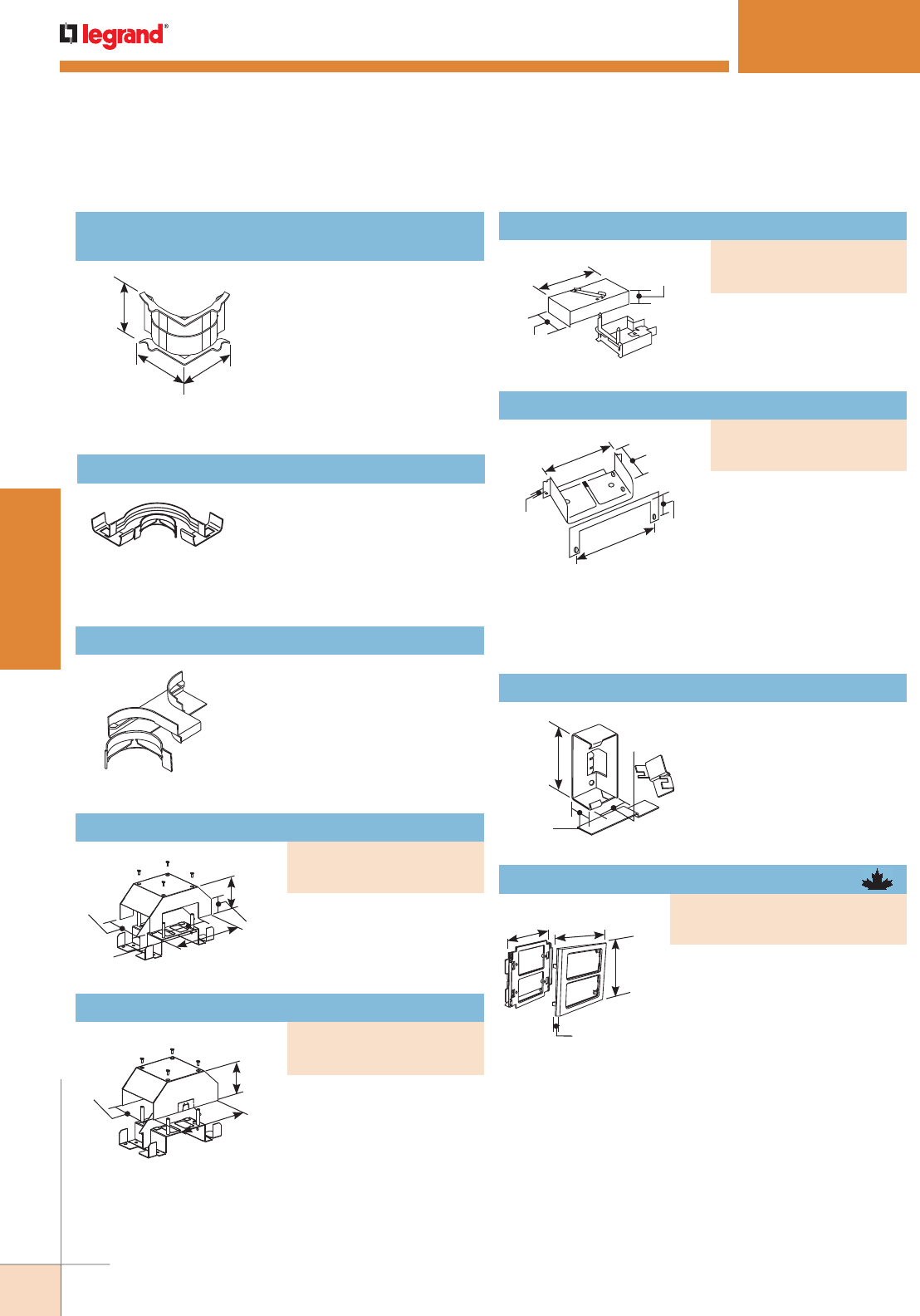
WWW.LEGRAND.US/WIREMOLD
68
STEEL RACEWAY
WIREMOLD
4000® SERIES RACEWAY
8 1/8"
[206mm]
1 3/4"
[44mm]
4 3/4"
[121mm]
4 13/16"
[122mm]
3 9/16"
[90mm]
9 1/2"
[242mm]
4 7/8"
[124mm]
1 5/8"
[41mm]
7/32"
[5.6mm] 1 1/2"
[38mm]
5 5/32"
[131mm]
5"
[127mm]
3"
[76mm]
NOTE: CM-EPLA End Plates are required when using Wiremold CM2
communication modules and Pass & Seymour® Activate inserts.
S2-EPL End Plates are required when using Ortronics® Series
II inserts. To mount TracJack modules, use 55074TJ or 55076TJ
Faceplates.
Radiused insert for 4017 Internal
Elbow and 4018 External Elbow in
divided or undivided applications.
Provides 2" [51mm] cable bend
radius control for UTP, STP and
fiber optic cable installations. Ideal
for new and retrofit applications
whether the cable installation is
lay-in or pull-through.
4017/18RI
Radiused Insert for Internal/External Elbow
Bend radius control insert for
4011 Divided Flat Elbow. Provides
2" [51mm] cable bend radius
control for UTP, STP and fiber
optic cable installations. Ideal for new or retrofit applications
where cable installation is lay-in or pull-through.
4011DRI Radiused Insert for Divided Flat Elbow
Radiused insert for 4015D Divided
Tee. Provides 2" [51mm] cable bend
radius control for UTP/STP or fiber
optic installations. Ideal for new
and retrofit applications whether
the cable installation is lay-in or
pull-through.
4015DRI Radiused Insert for Divided Tee
Allows 4000 Series Raceway
to cross over existing
installations of 4000 Series
Raceway.
Bridge Fitting
90° tee connection at any
point along a run of 4000
Series Raceway.
Take-Off Connector (4000 to 3000 Series Raceway)
Connects 4000 Series
Raceway to surface type
panel boxes. Maintains
maximum wire capacity
of 4000 Series Raceway.
Separate C-shaped flange
fits around raceway to hide
irregularities made during
cutting into box.
Panel Connector
4 1/2"
[114mm]
1 5/8"
[41mm]
2"
[51mm]
Reduces 4000 Series
Raceway to either 2400 or
2400BD Series Raceway.
V4089 Reducing Connector
4000 Series Raceway Ordering Information (continued)
6"
[152mm]
4 3/4"
[121mm]
6"
[152mm]
8 1/8"
[206mm]
4 3/4"
[121mm]
3 9/16"
[90mm]
Allows 4000 Series Raceway
to cross over existing
installations of 2400, 700, or
500 Series Raceway
Bridge Fitting
PART NUMBERS:
V4075DA (Ivory)
G4075DA (Gray)
PART NUMBERS:
V4074DA (Ivory)
G4074DA (Gray)
PART NUMBERS:
V4086A (Ivory)
G4086A (Gray)
4 11/16"
[116mm] 6"
[152mm]
7/16"
[11.1mm]
4 3/4"
[121mm] High impact plastic mounting
bracket and trim plate. Overlaps
raceway cover for a seamless
transition with cover fittings.
Accepts 5507 Faceplates, as
well as, Wiremold Open System
communication modules,
Ortronics® TracJack and Series
II inserts, and Pass & Seymour®
Activate Series inserts.
For faceplate options, see 5507 Series™
Faceplates.
Device Mounting Bracket
PART NUMBERS:
V4050 (Ivory)
G4050 (Gray)
PART NUMBERS:
V4075D (Ivory)
G4075D (Gray)
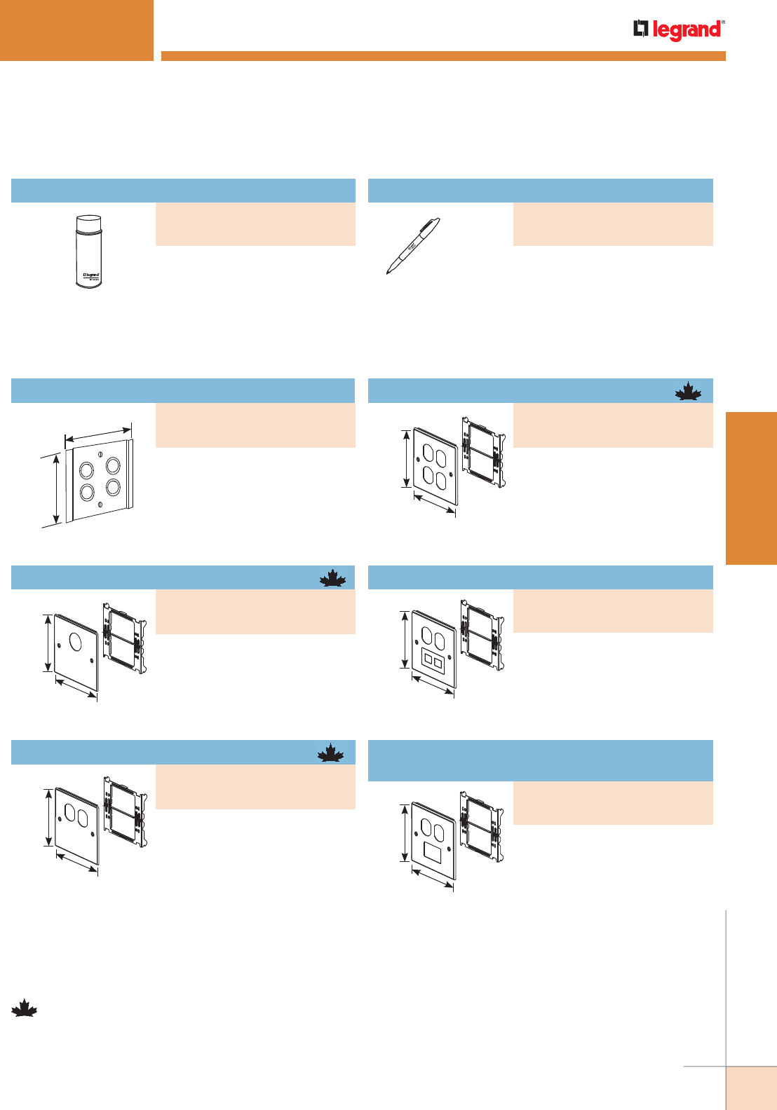
WWW.LEGRAND.US/WIREMOLD
69
STEEL RACEWAY
WIREMOLD
4000® SERIES RACEWAY
NOTE: All 4047 Series Faceplates provide 1/4" [6.4mm] of overlap on each
side of plate.
4 3/4"
[121mm]
4 17/32"
[115mm]
NOTE: Parts identified with this symbol are Certified to Canadian Safety
Standards for sale in Canada. When ordering these products, change
the “V” color prefix to “CV” or the “G” color prefix to “CG” to denote
the Canadian versions.
Used for touching up large areas.
Contains 12 oz. of paint.
NOTE: Can only be shipped via ground
transportation.
Spray Paint
Used for touching up small areas.
Contains 0.3 oz. of paint.
4047 Series Faceplates Ordering Information
Four concentric 1/2" and 3/4" trade
size KOs.
5 1/8"
[130mm]
4 3/4"
[121mm] Accepts 15A or 20A duplex
receptacles and 106 style frames.
Two-Gang Cover Two Duplex Receptacles
PART NUMBERS:
V4047BB (Ivory)
G4047BB (Gray)
4000 Series Raceway Ordering Information (continued)
PART NUMBERS:
IWE-S (Ivory)
GWE-S (Gray)
Tap-Off Fitting
PART NUMBERS:
V4046H-2 (Ivory)
G4046H-2 (Gray)
5 1/8"
[130mm]
4 3/4"
[121mm]
Accepts straight blade and locking
single receptacles with face
diameters of 1.38" to 1.39" [35mm
to 36mm].
Two-Gang Cover Single Round Opening
PART NUMBERS:
V4047AX (Ivory)
G4047AX (Gray)
5 1/8"
[130mm]
4 3/4"
[121mm] Accepts 15A or 20A duplex
receptacles and 106 style frames
when used for communications
outlets.
Two-Gang Cover One Duplex Receptacle
PART NUMBERS:
V4047BX (Ivory)
G4047BX (Gray)
Touch-Up Paint Pen
PART NUMBERS:
IWE-P (Ivory)
GWE-P (Gray)
5 1/8"
[130mm]
4 3/4"
[121mm] Accepts 15A or 20A duplex
receptacles. Includes combination
twistout that can accept either
one Modular Furniture adapter,
106 style frame, or two Keystone
RJ45s.
Two-Gang Cover Duplex & Modular Furniture
PART NUMBERS:
V4047BF (Ivory)
G4047BF (Gray)
5 1/8"
[130mm]
4 3/4"
[121mm] Accepts15A or 20A duplex
receptacles and 106 style frames.
Includes Mini adapter that will
accept Activate Series inserts
and Wiremold Open System
communication modules.
Two-Gang Cover & Pass & Seymour®
Activate 2A Mini Adapter
PART NUMBERS:
V4047BM (Ivory)
G4047BM (Gray)
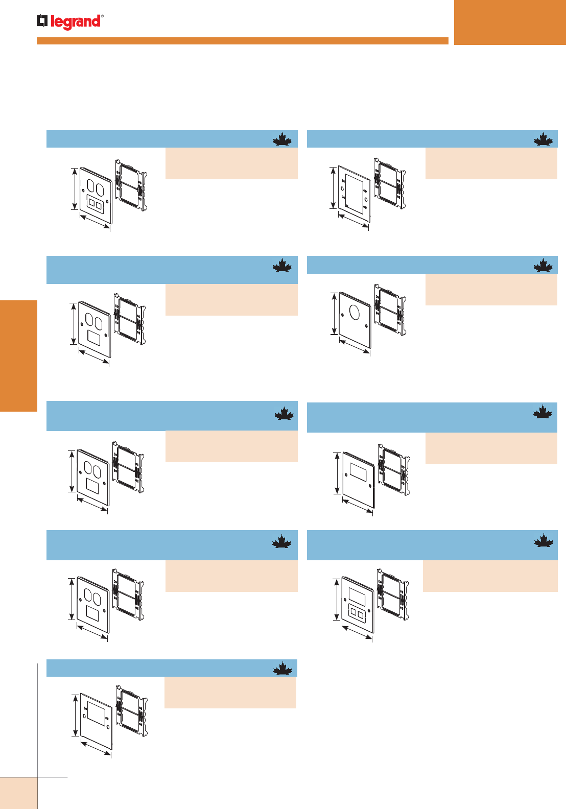
WWW.LEGRAND.US/WIREMOLD
70
STEEL RACEWAY
WIREMOLD
5 1/8"
[130mm]
4 3/4"
[121mm]
5 1/8"
[130mm]
4 3/4"
[121mm]
Accepts commercially available
flush plates (not included).
Accepts straight blade and
single locking receptacles with
face diameters of 1.56" - 1.58"
[39mm - 40mm].
Two-Gang Cover Single Round Opening
5 1/8"
[130mm]
4 3/4"
[121mm] Accepts rectangular GFCI,
Surge and Decorator Style
devices. Does not accept 5507
Series Faceplates.
4000® SERIES RACEWAY
4047 Series Faceplates Ordering Information (continued)
5 1/8"
[130mm]
4 3/4"
[121mm]
5 1/8"
[130mm]
4 3/4"
[121mm]
5 1/8"
[130mm]
4 3/4"
[121mm]
5 1/8"
[130mm]
4 3/4"
[121mm]
Accepts 15A or 20A duplex
receptacles. Includes
combination twistout that can
accept either one Modular
Furniture adapter, 106 style
frame, or two Keystone RJ45s.
Accepts 15A or 20A duplex
receptacles and 106 style
frames. Includes Mini adapter
that will accept Activate
Series inserts and Wiremold
Open System communication
modules.
Accepts 15A or 20A duplex
receptacles and 106 style
frames. Includes Mini adapter
that will accept one Ortronics®
Series II insert.
Accepts 15A or 20A duplex
receptacles and 106 style
frames. Includes Mini adapter
that will accept two Ortronics®
TracJack inserts.
Two-Gang Cover & Pass & Seymour®
Activate 2A Mini Adapter
Two-Gang Cover & Ortronics® Trac Jack
Mini Adapter
Two-Gang Cover Duplex & Modular Furniture
PART NUMBERS:
V4047BF (Ivory)
G4047BF (Gray)
5 1/8"
[130mm]
4 3/4"
[121mm] Accepts commercially available
flush plates (not included).
One-Gang Device Plate
PART NUMBERS:
V4047C-1 (Ivory)
G4047C-1 (Gray)
PART NUMBERS:
V4047BM (Ivory)
G4047BM (Gray)
Two-Gang Device Plate
PART NUMBERS:
V4047C-2 (Ivory)
G4047C-2 (Gray)
Two-Gang Cover & Ortronics® Series II
Mini Adapter
PART NUMBERS:
V4047BS (Ivory)
G4047BS (Gray)
PART NUMBERS:
V4047JX (Ivory)
G4047JX (Gray)
Two-Gang Cover with
One Rectangular Opening
PART NUMBERS:
V4047RX (Ivory)
G4047RX (Gray)
PART NUMBERS:
V4047BT (Ivory)
G4047BT (Gray)
5 1/8"
[130mm]
4 3/4"
[121mm] Accepts rectangular GFCI, Surge
and Decorator Style devices,
modular furniture adapters and
RJ45s. Does not accept 5507
Series Faceplates.
Two-Gang Cover Rectangular Opening
& Modular Furniture
PART NUMBERS:
V4047RF (Ivory)
G4047RF (Gray)
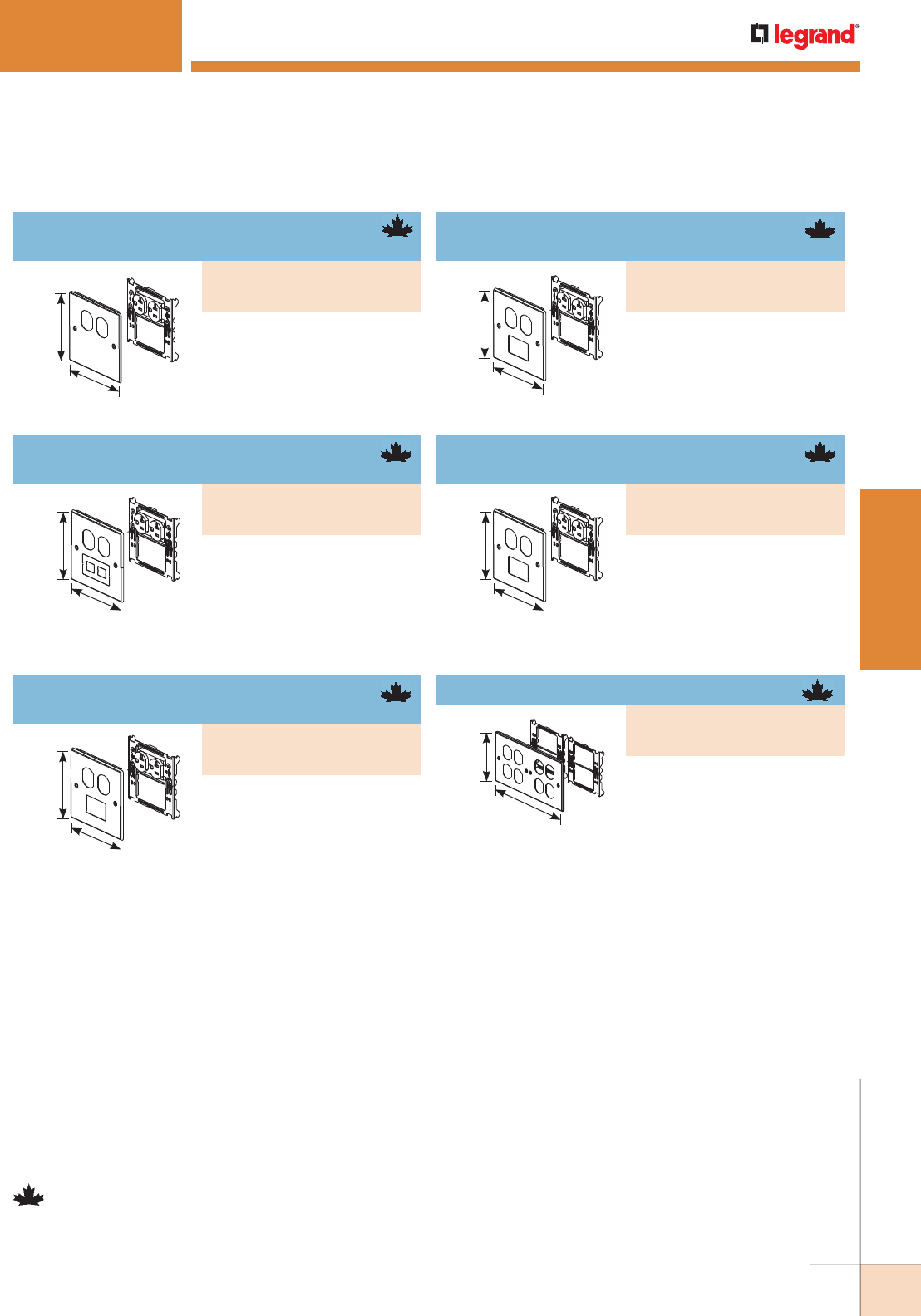
WWW.LEGRAND.US/WIREMOLD
71
STEEL RACEWAY
WIREMOLD
5 1/8"
[130mm]
4 3/4"
[121mm]
5 1/8"
[130mm]
4 3/4"
[121mm]
5 1/8"
[130mm]
4 3/4"
[121mm]
5 1/8"
[130mm]
4 3/4"
[121mm]
5 1/8"
[130mm]
4 3/4"
[121mm]
9 1/2"
[241mm]
4 3/4"
[121mm]
NOTE: Parts identified with this symbol are Certified to Canadian Safety
Standards for sale in Canada. When ordering these products, change
the “V” color prefix to “CV” or the “G” color prefix to “CG” to denote
the Canadian versions.
NOTE: All 4047 Series Faceplates provide 1/4" [6.4mm] of overlap on each
side of plate.
Includes one Pass & Seymour®
Duplex Receptacle with 12” wire
leads installed on bracket.
Includes one Pass & Seymour®
20A Duplex Receptacle with 12”
wire leads installed on bracket.
Has combination twistout that
can accept either one Modular
Furniture adapter or two
Keystone RJ45s.
Includes one Pass & Seymour®
20A Duplex Receptacle with
12" wire leads installed on
bracket. Includes Mini adapter
that accepts Pass & Seymour®
Activate inserts and Wiremold
Open System communication
modules.
Includes one Pass & Seymour®
20A Duplex Receptacle with 12"
wire leads installed on bracket.
Includes Mini adapter that will
accept one Ortronics® Series II
insert.
Includes one Pass & Seymour®
20A Duplex Receptacle with 12”
wire leads installed on bracket.
Includes Mini adapter that
accepts two Ortronics® TracJack
inserts.
Accepts 15A or 20A duplex
receptacles and 106 style
frames.
4000® SERIES RACEWAY
4047 Series Faceplates Ordering Information (continued)
Two-Gang Cover One Duplex
Receptacle Installed
PART NUMBERS:
V4047WX (Ivory)
G4047WX (Gray)
Two-Gang Cover One Duplex Receptacle
Installed & One Modular Furniture Opening
PART NUMBERS:
V4047WF (Ivory)
G4047WF (Gray)
Two-Gang Cover One Duplex Receptacle
Installed & Activate Mini Adapter
PART NUMBERS:
V4047WM (Ivory)
G4047WM (Gray)
Two-Gang Cover One Duplex Receptacle
Installed & Series II Mini Adapter
PART NUMBERS:
V4047WS (Ivory)
G4047WS (Gray)
Two-Gang Cover One Duplex Receptacle
Installed & TracJack Mini Adapter
PART NUMBERS:
V4047WT (Ivory)
G4047WT (Gray)
Four-Gang Cover Four Duplex Openings
PART NUMBERS:
V4047-2BBB (Ivory)
G4047-2BBB (Gray)
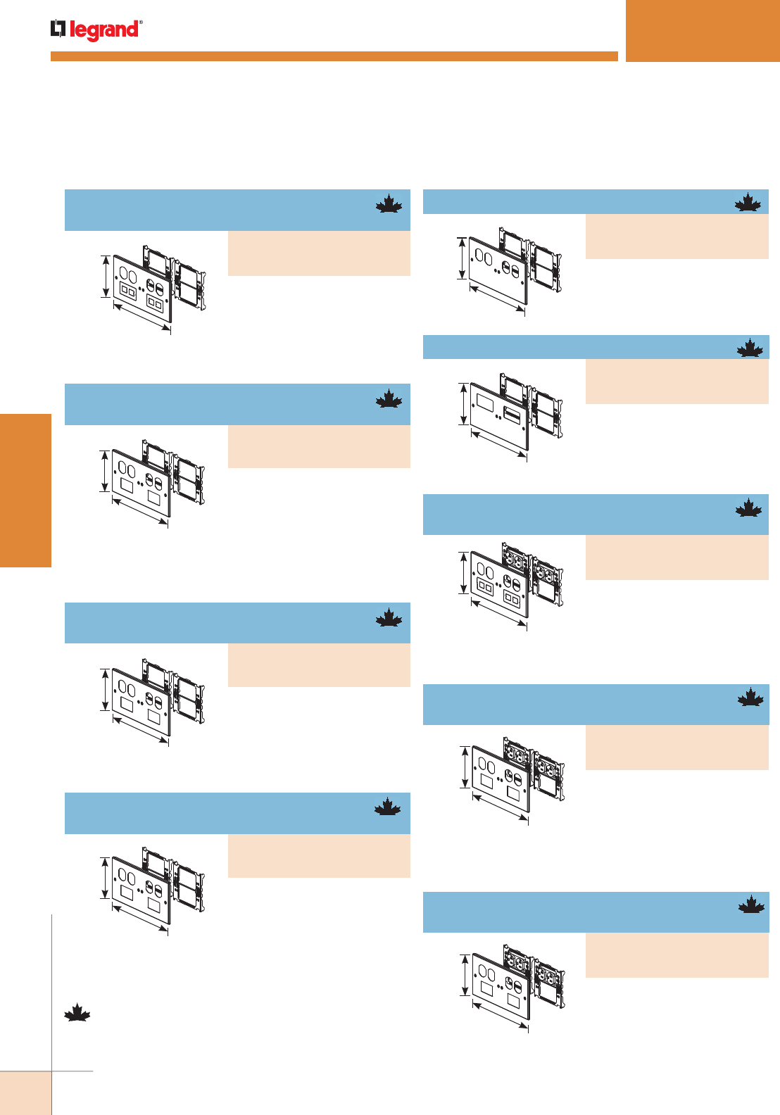
WWW.LEGRAND.US/WIREMOLD
72
STEEL RACEWAY
WIREMOLD
Includes two Pass & Seymour®
20A Duplex Receptacles with
12” wire leads installed on
bracket. Includes Mini adapter
that accepts one Ortronics® Series II insert.
Includes two Pass & Seymour®
20A Duplex Receptacles with
12" wire leads installed on
bracket. Includes Mini adapter
that accepts Pass & Seymour® Activate inserts & Wiremold
Open System communication modules.
Includes two Pass & Seymour®
20A Duplex Receptacles with
12” wire leads installed on
bracket. Two combination twistouts accept either modular
furniture adapters or Keystone RJ45s.
4000® SERIES RACEWAY
9 1/2"
[241mm]
4 3/4"
[121mm]
9 1/2"
[241mm]
4 3/4"
[121mm]
9 1/2"
[241mm]
4 3/4"
[121mm]
9 1/2"
[241mm]
4 3/4"
[121mm]
9 1/2"
[241mm]
4 3/4"
[121mm]
9 1/2"
[241mm]
4 3/4"
[121mm]
Accepts 15A or 20A duplex
receptacles and 106 style frame.
Includes combination twistouts
for either modular furniture
adapter or two keystone RJ45s.
Accepts 15A or 20A duplex
receptacles and 106 style
frame. Includes Mini adapter
that accepts Pass & Seymour®
Activate inserts, or Wiremold
Open System communication
modules.
Accepts 15A or 20A duplex
receptacles and 106 style
frame. Includes Mini adapter
that accepts one Ortronics®
Series II insert.
Accepts 15A or 20A duplex
receptacles and 106 style
frame. Includes Mini adapter
that accepts two Ortronics®
TracJack inserts.
Accepts 15A or 20A duplex
receptacles and 106 style
frames.
Accepts rectangular, GFCI,
Surge, and decorator style
devices. Does not accept 5507
Series Faceplates.
9 1/2"
[241mm]
4 3/4"
[121mm]
9 1/2"
[241mm]
4 3/4"
[121mm]
9 1/2"
[241mm]
4 3/4"
[121mm]
NOTE: Parts identified with this symbol are Certified to Canadian Safety
Standards for sale in Canada. When ordering these products, change
the “V” color prefix to “CV” or the “G” color prefix to “CG” to denote
the Canadian versions.
NOTE: All 4047 Series Faceplates provide 1/4" [6.4mm] of overlap on each
side of plate.
4047 Series Faceplates Ordering Information (continued)
Four-Gang Cover Two Duplex &
Two Modular Furniture Openings
PART NUMBERS:
V4047-2BBFF (Ivory)
G4047-2BBFF (Gray)
Four-Gang Cover with Two Duplex Openings
PART NUMBERS:
V4047-2BBXX (Ivory)
G4047-2BBXX (Gray)
Four-Gang Cover Two Duplex & Two
Mini Adapters
PART NUMBERS:
V4047-2BBMM (Ivory)
G4047-2BBMM (Gray)
Four-Gang Cover with Two Rectangular Openings
PART NUMBERS:
V4047-2RRXX (Ivory)
G4047-2RRXX (Gray)
Four-Gang Cover Two Duplex &
Two Series II Mini Adapters
PART NUMBERS:
V4047-2BBSS (Ivory)
G4047-2BBSS (Gray)
Four-Gang Cover with Two Duplex &
Two Modular Furniture Openings
PART NUMBERS:
V4047-2WWFF (Ivory)
G4047-2WWFF (Gray)
Four-Gang Cover Two Duplex &
Two TracJack Mini Adapters
PART NUMBERS:
V4047-2BBTT (Ivory)
G4047-2BBTT (Gray)
Four-Gang Cover with Two Activate
Mini Adapters
PART NUMBERS:
V4047-2WWMM (Ivory)
G4047-2WWMM (Gray)
Four-Gang Cover with Two Series II
Mini Adapters
PART NUMBERS:
V4047-2WWSS (Ivory)
G4047-2WWSS (Gray)
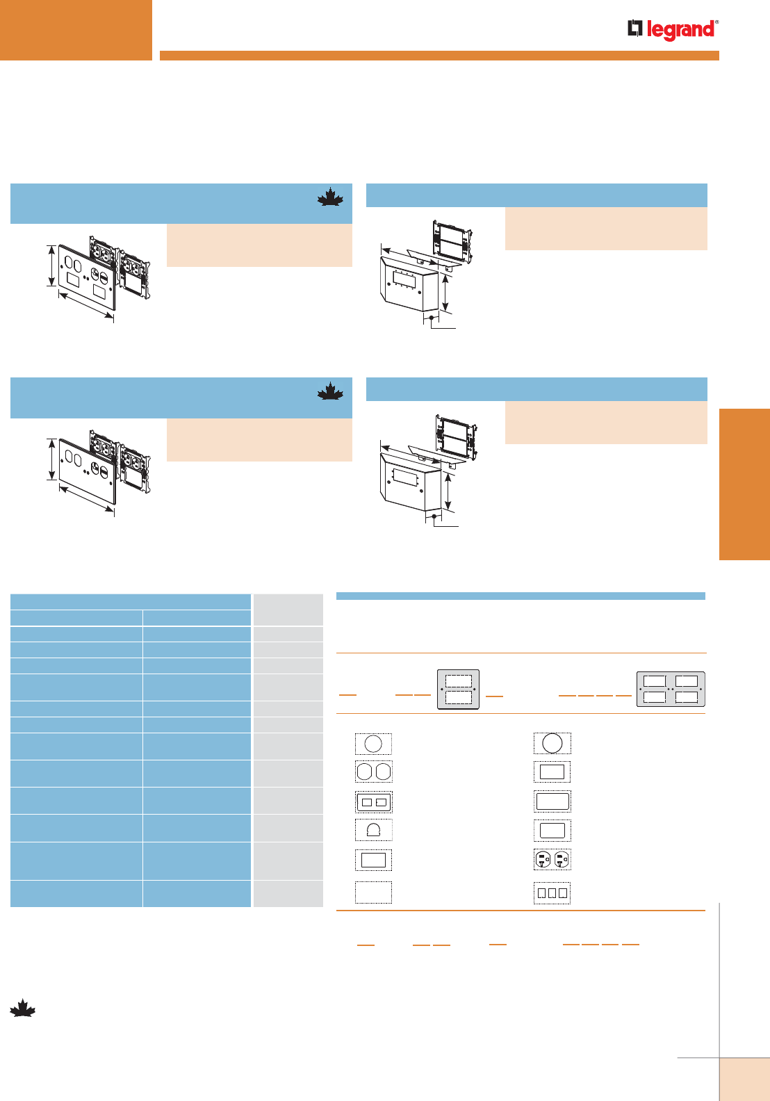
WWW.LEGRAND.US/WIREMOLD
73
STEEL RACEWAY
WIREMOLD
9 1/2"
[241mm]
4 3/4"
[121mm]
9 1/2"
[241mm]
4 3/4"
[121mm]
7 5/16"
[185mm]
4 3/16"
[122mm]
1 13/32"
[36mm]
7 5/16"
[185mm]
4 3/16"
[122mm]
1 13/32"
[36mm]
NOTE: Parts identified with this symbol are Certified to Canadian
Safety Standards for sale in Canada. When ordering these
products, change the “V” color prefix to “CV” or the “G” color
prefix to “CG” to denote the Canadian versions.
NOTE: All 4047 Series Faceplates provide 1/4" [6.4mm]
of overlap on each side of plate.
Accepts four Extron® Electronics
MAAP single space modules.
Bump-Up Device Plate
Accepts two Extron® Electronics
AAP single space modules.
Bump-Up Extron® AAP Device Plate
CONNECTION REQUIRED USE CATALOG
NUMBER
FROM TO
4000 Series Raceway DS4000 Series Raceway DS4089
4000 Series Raceway 3000 (Tee Connection) G4074A
4000 Series Raceway 4000 (Tee Connection) 4015/4015FO
4000 Series Raceway
w/Divider
4000 w/Divider
(Tee Connection)
4015D
4000 Series Raceway 500 Series Raceway V5785
6000 Series Raceway 4000 (Tee Connection) 6074A
1/2" or 3/4" trade size
Conduit or Armored Cable
Cover of 4000 Series
Raceway
4064H-2
1/2" trade size Conduit or
Armored Cable
End of 4000 Series
Raceway
4010B
3/4", 1", or 1 1/4" trade size
Conduit or Armored Cable
Back, Side or End of
4000 Series Raceway
4010DFO
1" or 1 1/4" trade size
Conduit or Armored Cable
Back or End of
4000 Series Raceway
4010DFC
1/2", 3/4", 1", or 1 1/4"
trade size Conduit or
Armored Cable
Back of 4000 Series
Raceway
4014A
Flush Mounted
Wall Box
Back of 4000 Series
Raceway
4014A
4000 Series Raceway Interconnectivity Fittings
2. Choose a Plate Configuration:
1. For “X”, Choose one of the following options:
4. Finished Part Number:
V
Ivory & UL Listed
CV
Ivory & cULus Listed (Canada only)
G
Gray & UL Listed
CG
Gray & cULus Listed (Canada only)
3.
For “Y”, Choose any combination of configurations from the options listed below:
Two-Gang Plate:
4047
XYY
12
1
2
Four-Gang Plate:
4047-2
XYYYY
123 4
12
34
1.41" [35.8mm] Diameter,
Single Round Receptacle
Duplex Receptacle Opening
Combination Modular Furniture &
2 Keystone Twist Out
Mouse Hole Twist Out & Grommet
Ortronics TracJack 2A Mini Adapter
Opening with Adapter
Blank
A.
B.
F.
H.
T.
X.
1.59" [40mm] Diameter,
Single Round Receptacle
Pass & Seymour Activate 2A Mini
Adapter Opening with Adapter
Rectangular Receptacle
Ortronics® Series II 2A Mini Adapter
Opening with Adapter
P&S Light Almond 20 Amp Receptacle
pre-pigtailed with 12" wire leads
installed on Bracket
3 Keystone Twist Out
J.
M.
R.
S.
W.
Z.
4047 4047-2
NOTE: JJ combination not available.
For additional colors or configurations, call 1-800-621-0049, option 2.
4047 Configurable Cover Plates Number Logic
4000® SERIES RACEWAY
Includes two Pass & Seymour®
20A Duplex Receptacles with
12" wire leads installed on
bracket. Includes Mini adapter
that accepts two Ortronics®
TracJack inserts.
Four-Gang Cover with Two TracJack
Mini Adapters
Includes two Pass & Seymour®
20A Duplex Receptacles with 12"
wire leads installed on bracket.
Four-Gang Cover with Two Duplex
Receptacles Installed
4047 Series Faceplates Ordering Information (continued)
PART NUMBERS:
V4047-2WWTT (Ivory)
G4047-2WWTT (Gray)
PART NUMBERS:
V4047UX (Ivory)
G4047UX (Gray)
PART NUMBERS:
V4047VX (Ivory)
G4047VX (Gray)
PART NUMBERS:
V4047-2WWXX (Ivory)
G4047-2WWXX (Gray)
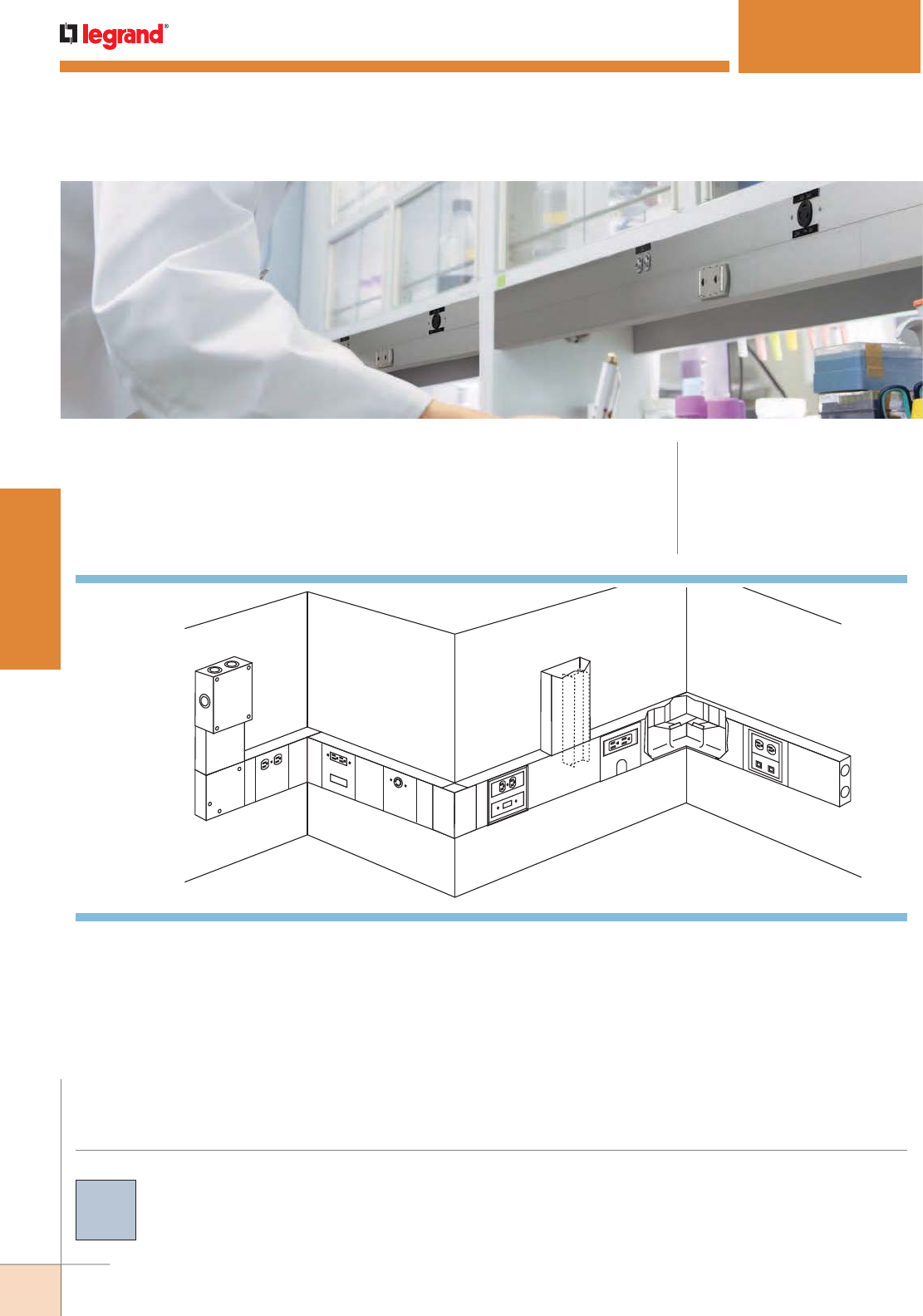
WWW.LEGRAND.US/WIREMOLD
74
STEEL RACEWAY
WIREMOLD
E
F
J
H
L
K
I
M
GB
A
C
D
CODE REFERENCE
cULus Listed Raceway:
File E4376 Guide RJBT.
Fittings:
File E41751 Guide RJPR.
Meets Article 386 of NEC.
Meets Section 12-1600 of CEC.
Easy-to-install and ideal for specialized power or
communication/low voltage installations.
KEY
A. G4017TC Internal Corner Coupling (Plated)
B. S4007C-1R Single Device Fitting
C. S4007C-2 Two-Gang Device Plate with
Wallplates
D. S4010B2 Blank End Fitting
E. S4010D Entrance End Fitting
F. S4011 Flat Elbow Fitting
G. S4015D Divided Tee Fitting
H. S4017 Internal Elbow Fitting
I. S4018 External Elbow Fitting
J. S4048B Duplex Receptacle Device Plate
K. S4048J Single Twistlock Receptacle Cover
L. S4048RF Rectangular Receptacles & AMP
Flexmode or ACO
M. V4050 Device Mounting Plate (Inserts
included)
System Layout
COLOR OPTIONS
S4000® Series Raceway Part Numbers are available with a
brushed stainless steel finish unless otherwise indicated in the
part number description.
Custom color options are also available. Consult the factory
for more information.
NOTE: Illustration is for showing product applications only.
S4000® SERIES RACEWAY
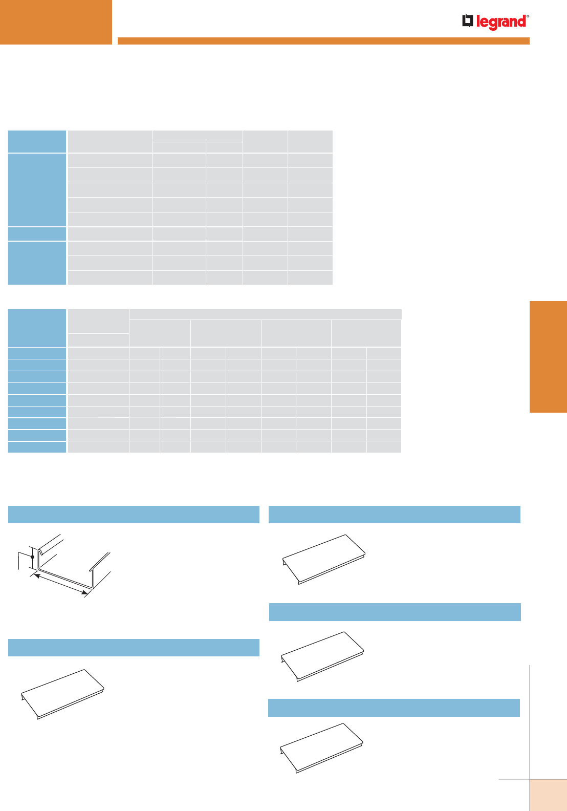
WWW.LEGRAND.US/WIREMOLD
75
STEEL RACEWAY
WIREMOLD
1 3/4"
[44mm]
4 3/4"
[121mm]
CABLE/WIRE SIZE
O.D. APPROX. DIA. DIVIDED
40% FILL
UNDIVIDED
40% FILLInches [mm]
UNSHIELDED
TWISTED
PAIR
4-pair, 24 AWG, Cat 3 0.190 [4.8] 49 101
4-pair, 24 AWG, Cat 5e 0.210 (5.3) 40 83
4-pair, 24 AWG, Cat 6 0.250 (6.3) 28 58
4-pair, 24 AWG, Cat 6a* 0.354 (9.0) 14 29
25-pair, 24 AWG 0.410 (10.4) 10 21
COAXIAL RG6/U 0.270 [6.9] 24 50
FIBER ZipCord 0.118 x 0.236 [3 x 6] 50 103
Round 4 Strand Fiber 0.187 [4.8] 51 104
Round 6 Strand Fiber 0.256 [6.5] 27 55
S4000 Series Raceway Wire Fill Capacities for Communications
S4000 Series Raceway Wire Fill Capacities for Power
WIRE SIZE
THHN/THWN
O.D.
NUMBER OF CONDUCTORS 40% FILL
WITHOUT
DEVICES
WITH DUPLEX
RECT. DEVICES
1.59in.2 [1025mm2]
WITH SURGE/
GFCI DEVICES
2.30in.2 [1485mm2]
LARGE SINGLE
RECEPTACLES
3.00in.2 [1935mm2]Inches [mm}
Undiv. Divided Undiv. Divided Undiv. Divided Undiv. Divided
14 AWG 0.111 [2.8] 296 127 165 78 107 49 49 20
12 AWG 0.130 [3.3] 216 93 120 57 78 36 36 15
10 AWG 0.164 [4.2] 136 58 76 36 49 22 22 9
8 AWG 0.216 [5.5] 78 33 43 20 28 13 13 5
6 AWG 0.254 [6.5] 56 24 31 15 20 9 9 3
4 AWG 0.324 [8.2] 34 15 000000
3 AWG 0.352 [8.9] 29 12 000000
2 AWG 0.384 [9.8] 24 10 000000
S4000® SERIES RACEWAY
S4000B Raceway Base
.050" [1.3mm] stainless steel.
Base has two 9/32" [7.1mm]
diameter KOs 1 1/4" [32mm]
from each end and every 18"
[457mm] on center throughout.
S4000B is available in 10'
[3m] lengths. Also available
in lengths precut to customer
specifications.
S4000C-5 Raceway Cover
.040" [1.0mm] stainless steel.
S4000C-5 is available in 5' [1.5m]
lengths, packed ten 5' [1.5m]
lengths per carton. Also available
in lengths precut to customer
specifications. Max. 5' [1.5m)
length.
S4000C075 7.5" [191mm] Precut Raceway Cover
.040" [1.0mm] stainless steel.
Snap-on cover for mounting
4 1/2" [114mm] device plates on
12" [305mm] centers.
S4000C090 9" [229mm] Precut Raceway Cover
.040" [1.0mm] stainless steel.
Snap-on cover for mounting
9" [229mm] device plates on
18" [457mm] centers.
S4000C135 13.5" [343mm] Precut Raceway Cover
.040" [1.0mm] stainless steel.
Snap-on cover for mounting
4 1/2" [114mm] device plates on
18" [457mm] centers.
S4000 Series Raceway Wire Fill Capacities for Communications
NOTE: For additional information, refer to the Technical Section.
* Category 6 augmented (6a) cable for 10 gigabit ethernet – max allowed cable diameter per addenda No. 11 ANSI TIA/EIA 568-B.2.
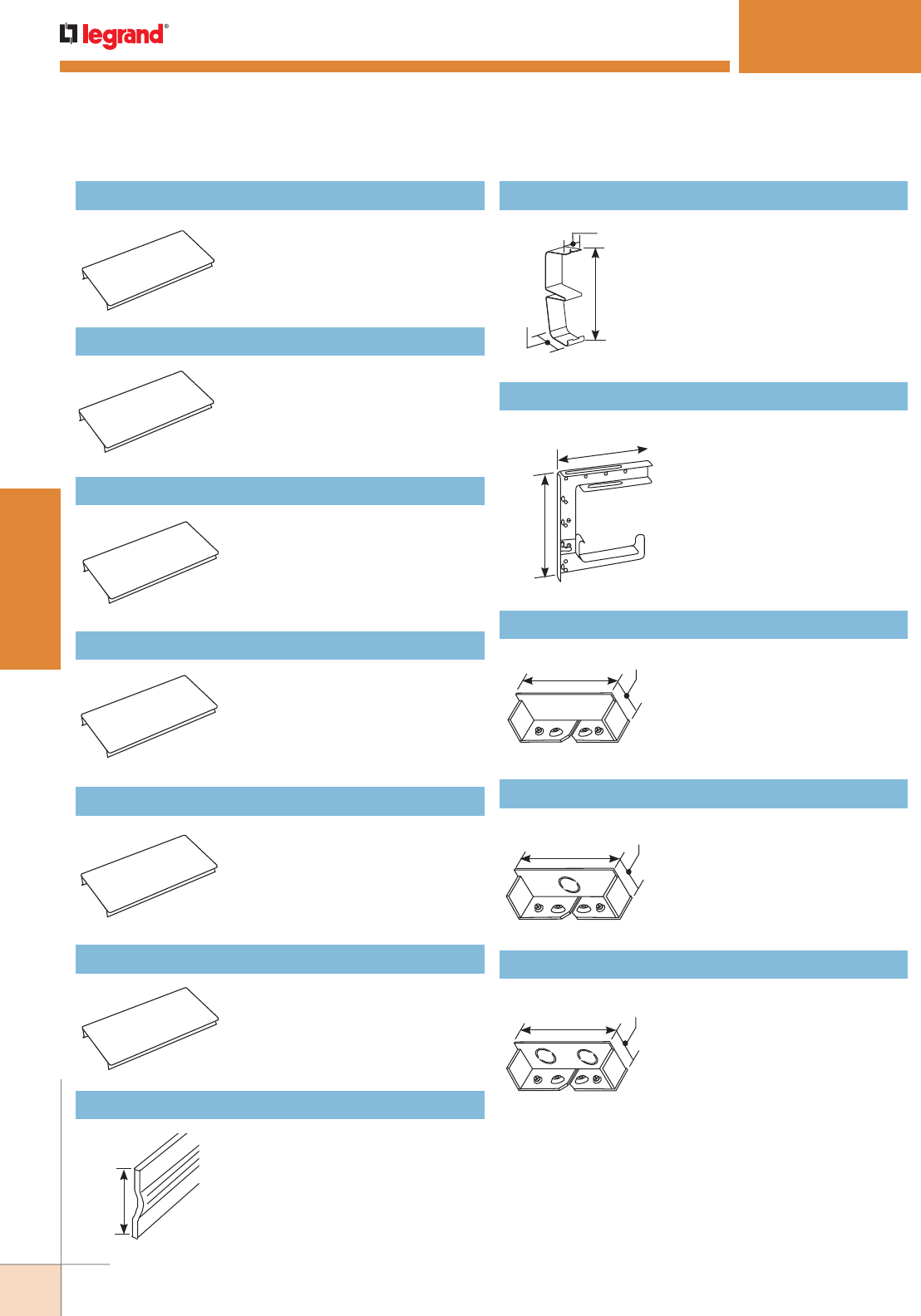
WWW.LEGRAND.US/WIREMOLD
76
STEEL RACEWAY
WIREMOLD
S4000® SERIES RACEWAY
S4000C150 15" [381mm] Precut Raceway Cover
.040" [1.0mm] stainless steel.
Snap-on cover for mounting
9" [229mm] device plates on
24" [610mm] centers.
S4000C195 19.5" [495mm] Precut Raceway Cover
.040" [1.0mm] stainless steel.
Snap-on cover for mounting
4 1/2" [114mm] device plates on 24"
[610mm] centers.
S4000C270 27" [686mm] Precut Raceway Cover
.040" [1.0mm] stainless steel.
Snap-on cover for mounting
9" [229mm] device plates on
36" [915mm] centers.
4 3/4"
[121mm]
1 3/4"
[44mm]
1 17/32"
[39mm]
7 7/8"
[200mm]
6 7/8"
[175mm]
1 3/4"
[44mm]
4 3/4"
[121mm]
1 3/4"
[44mm]
1"
[25mm]
4 1/2"
[114mm]
1 1/2"
[38mm]
S4000C315 31.5" [800mm] Precut Raceway Cover
.040" [1.0mm] stainless steel.
Snap-on cover for mounting 4 1/2"
[114mm] device plates on 36"
[915mm] centers.
S4000C390 39" [990mm] Precut Raceway Cover
.040" [1.0mm] stainless steel. Snap-
on cover for mounting 9" [229mm]
device plates on 48” [1220mm]
centers.
S4000C435 43.5" [1105mm] Precut Raceway Cover
.040" [1.0mm] stainless steel.
Snap-on cover for mounting 4 1/2"
[114mm] device plates on
48" [1220mm] centers.
G4000D Divider
.040" [1.0mm] galvanized steel. Packed
ten 5’ [1.5m] lengths (50' [15.20m])
per carton. Painted buff on one side
to provide compartment identification.
4001DA Divider Clips (not included) are
required to hold divider in place.
4001DA Divider Clip (Galvanized)
Required for holding G4000D
Divider in place. Use one every
2 1/2' [.762m].
S6008A C-Hanger
Suspends S4000, 4000 or 6000
Series Raceway from a structural
ceiling. Designed for use with 3/8"
[9.5mm] rod. Hangers should be
installed no more than 5' [1.5m]
apart along raceway run. Can
be bolted back-to-back for dual
runs of 3000, 4000 or 6000 Series
Raceway.
S4010B0 Blank End Fitting
Closes off open end of S4000
Base. Use when no end feeding is
required. Includes two No. 10-32
ground terminals.
S4010B1 Blank End Fitting
Closes off open end of S4000 Base.
Use when one end feed is required
in an undivided installation.
Includes one 1/2" - 3/4" trade
size KO and two No. 10-32 ground
terminals.
S4010B2 Blank End Fitting
Closes off open end of S4000 Base.
Use when end feeds are required
for an installation. Includes two
1/2" - 3/4" trade size KOs and two
No. 10-32 ground terminals.
S4000 Series Raceway Wire Fill Capacities for Communications (continued)
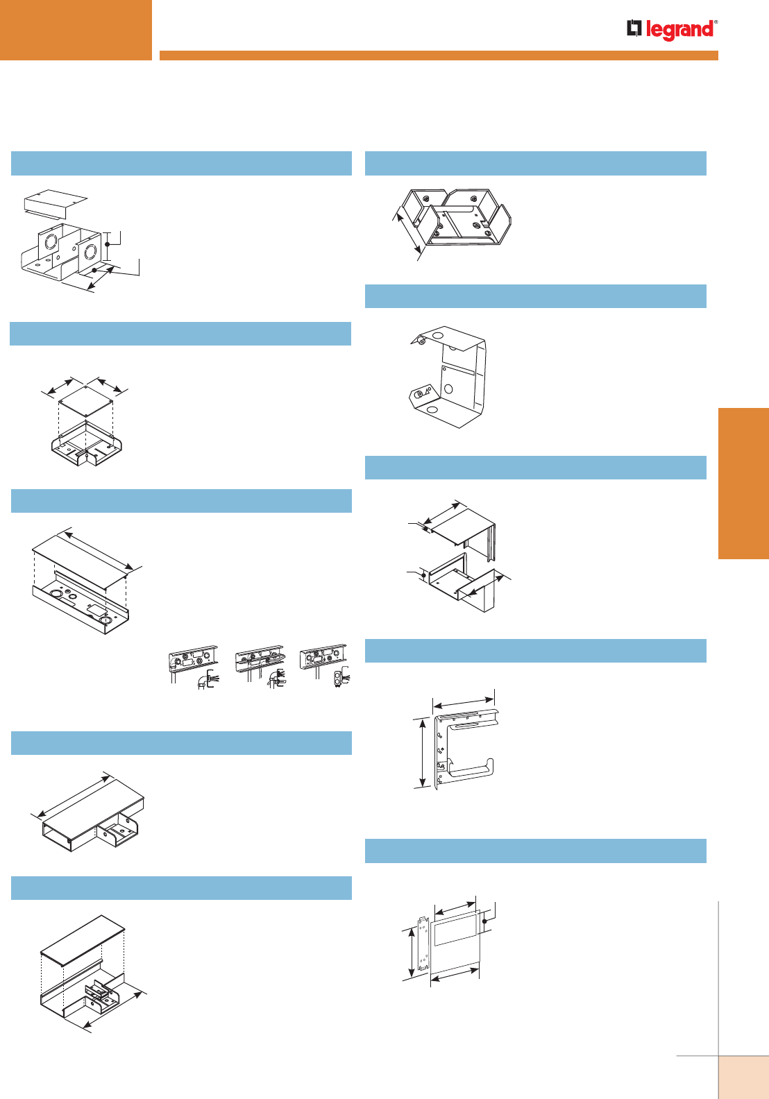
WWW.LEGRAND.US/WIREMOLD
77
STEEL RACEWAY
WIREMOLD
S4000® SERIES RACEWAY
4 3/4"
[121mm]
4 3/4"
[121mm]
14"
[356mm]
Direct feeding. Feeding from
wall box.
Direct feeding
with divider.
12"
[305mm]
12"
[305mm]
3 1/8"
[79mm]
6 3/8"
[162mm]
2 3/4"
[70mm]
3 3/4"
[95mm]
S4010D Entrance End Fitting
Has concentric 1/2" and 3/4"
trade size KOs on end, sides,
and bottom for feeding S4000
Series Raceway. Use punch kit
to increase KO size up to
1 1/4". Removable divider and
two No. 10-32 ground terminals
included.
S4011 Flat Elbow
Right angle turns on the same
surface. No couplings required.
S4014A Wall Box Connector
S4015 Tee
Divides S4000 Series Raceway
at right angles. Only for use
with undivided raceway. Use
two pair of G4001 Couplings
to attach to raceway (not
included).
S4015D Divided Tee
Divides S4000 Series Raceway
at right angles. Only for use
with divided raceway. Use
two pair of G4001 Couplings
to attach to raceway (not
included).
S4017 Internal Elbow
90° internal corners. No
couplings required.
7 7/8"
[200mm]
6 7/8"
[175mm]
3 3/4"
[95mm]
4 3/4"
[121mm]
4 1/2"
[114mm]
1 9/16"
[40mm]
5 5/8"
[143mm]
3 1/4"
[83mm]
1 9/16"
[39mm]
5 1/2"
[140mm]
G4017TCA Internal Corner Coupling
Creates internal corner while
continuing original run in
a straight line. Galvanized
finish. Use with or without
divider. Fiber bushing
included. 4010B Blank
End Fitting required for
installation (not included).
S4018 External Elbow
90° external corners.
Connect to raceway with
G4001 Couplings (not
included).
S6008A C-Hanger (Galvanized)
Suspends S4000, 4000 or
6000 Series Raceway from a
structural ceiling. Designed
for use with 3/8" [9.5mm]
rod. Hangers should be
installed no more than 5'
[1.5m] apart along raceway
run. Can be bolted back-to-
back for dual runs of 3000,
4000 or 6000 Series Raceway.
S4007C-1 One-Gang Device Plate
For horizontal mounting of
standard single-gang devices.
Accepts industry standard
single-gang faceplates for
electrical and communication
devices.
S4000 Series Raceway Wire Fill Capacities for Communications (continued)
Base has two concentric 3/4",
and 1/2" trade size KOs, two
concentric 1 1/4" and 1" trade
size KOs (undivided only), and
two rectangular 2 9/16" x 1
11/16" [65mm x 43mm] KOs.
Includes cover and two No.
10-32 ground terminals.
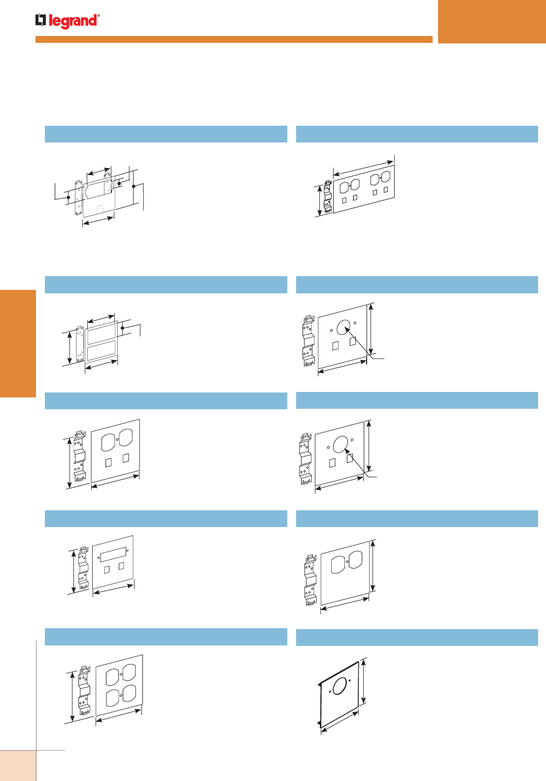
WWW.LEGRAND.US/WIREMOLD
78
STEEL RACEWAY
WIREMOLD
S4000® SERIES RACEWAY
3"
[76mm]
4 1/2"
[114mm]
1"
[25mm]
4 3/4"
[121mm]
1 25/32"
[45mm]
4 1/2"
[115mm]
3 3/4"
[95mm]
4 3/4"
[121mm]
1 9/16"
[39mm]
4 1/2"
[115mm]
4 3/4"
[121mm]
4 1/2"
[115mm]
4 3/4"
[121mm]
9"
[229mm]
4 3/4"
[121mm]
1.4"
[36mm]
Dia.
4 1/2"
[115mm]
4 3/4"
[121mm]
4 1/2"
[115mm]
4 3/4"
[121mm]
S4007C-1R Single Device Plate
For horizontal mounting
of surge suppression
receptacles in S4000 Divided
or Undivided Raceway. Also
accepts most manufacturers’
GFCI, large twistlock, and
rectangular faced single-gang
wiring devices and two-port
ACO. Use with commercially
available flush plate (not
furnished).
S4007C-2 Two-Gang Device Plate
For horizontal mounting of
two devices. Accepts industry
standard double-gang
faceplates for electrical and
communication devices.
S4046DRJ Combination Device Cover
For installation of one duplex
receptacle and two RJ11/45
type modular connectors.
Complete with necessary
bridges.
S4046RRJ Combination Device Cover
For installation of one
rectangular style device and
two RJ11/45 type modular
connectors. Complete with
necessary bridges.
S4046B-2 Double Duplex Device Cover
For installation of two duplex
style receptacles. Complete
with necessary bridges.
S4046DRJ-2 Double In-Line Device Cover
For installation of two
duplex style receptacles and
four RJ11/45 type modular
connectors. Complete with
necessary bridges.
S4046ARJ Combination Device Cover
For installation of straight blade
and single locking receptacles
and two RJ11/45 type modular
connectors. Complete with
necessary bridges.
1.6"
[41mm]
Dia.
4 1/2"
[115mm]
4 3/4"
[121mm]
4 1/2"
[115mm]
4 3/4"
[121mm]
4 1/2"
[115mm]
4 3/4"
[121mm]
S4046JRJ Combination Device Cover
For installation of one twistlock
receptacle and two RJ11/45
type telephone connectors.
Complete with necessary
bridges.
S4048B Duplex Receptacle Device Cover
For installation of one duplex
receptacle cover. Complete with
necessary bridges.
S4048J TwistLock Receptacle Device Cover
For installation of one twistlock
receptacle.
S4000 Series Raceway Wire Fill Capacities for Communications (continued)
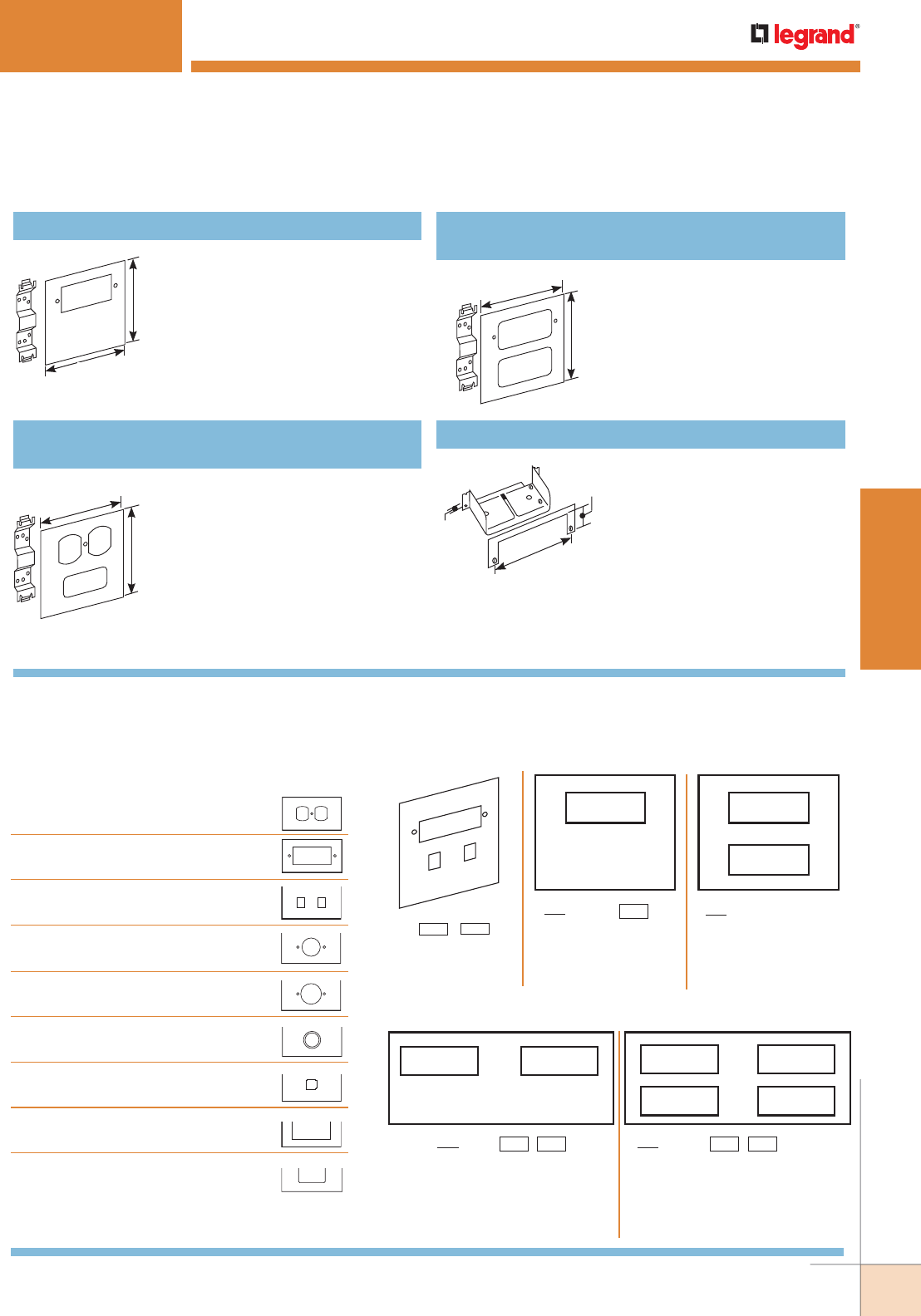
WWW.LEGRAND.US/WIREMOLD
79
STEEL RACEWAY
WIREMOLD
S4000® SERIES RACEWAY
4 1/2"
[115mm]
4 3/4"
[121mm]
4 1/2"
[115mm]
4 3/4"
[121mm]
4 1/2"
[115mm]
4 3/4"
[121mm]
7/32"
[5.6mm]
1 1/2"
[38mm]
5 5/32"
[131mm]
S4048R Rectangular Receptacle Device Cover
For installation of one
rectangular receptacle.
Complete with necessary
bridges.
For installing a duplex style
device and one modular
furniture adapter for
communications.
S4048BF Duplex Receptacle Cover with Modular
Furniture Opening
S4086A Panel Connector
To connect S4000 Series
Raceway with surface type panel
boxes.
Accommodates
maximum
wire capacity of S4000 Series
Raceway. Separate C-shaped
flange fits around raceway,
covering any irregularities from
cutting into box. Cut 4 3/4" x
1 3/4" [121mm x 44mm] hole in
panel box.
For installing a rectangular style
device and a modular furniture
adapter for communications.
S4048RF Rectangular Receptacle Cover with
Modular Furniture Opening
S4000 Series Raceway Made-to-Order Stainless Steel Device Plates
To keep pace with changing power and communication technology, Wiremold offers a variety of openings available on a made-to-order basis.
Choose from the assortment of openings shown below to design your own device plates. Consult the factory if a special opening is desired.
To make ordering easier, a catalog number suffix has been included beside the description. Please send a sketch with your order
indicating the letter of the desired opening.
Cat. No.
Suffix Description of Device Opening
D Standard Duplex Receptacle
R Decorator Style Duplex Receptacle
RJ Two RJ11/45 Modular Connectors
A Single Receptacle
(1.4" [35.6mm] Dia.)
J Single Receptacle
(1.6" [40.6mm] Dia.)
K One 1/2-3/4" [12.7-19.1mm] KO
with 1/2" [12.7mm] I.D. Grommet
M One IBM style connector
MFB One Modular Furniture Adapter
2A One 2A Mini Adapter
NOTE: Necessary device brackets are supplied with all device plates.
1
Qty.
____ S4048 _____
____ S4048 _____
____ S4048 _____
____ S4048 _____
1
Qty.
____ S4046 ____ _____
____ S4046 ____ _____
____ S4046 ____ _____
____ S4046 ____ _____
1
2
4 1/2" [115mm] Device PlatesExample: S4046RRJ
R RJ
1 2
1 2 1 2
3 4
9" [229mm] Device Plates
Qty.
____ S4048 ____ _____
____ S4048 ____ _____
____ S4048 ____ _____
____ S4048 ____ _____
1 2
Qty.
____ S4046 _____ _____ ____ ____
____ S4046 _____ _____ ____ ____
____ S4046 _____ _____ ____ ____
____ S4046 _____ _____ ____ ____
1 2
S4000 Series Raceway Wire Fill Capacities for Communications (continued)
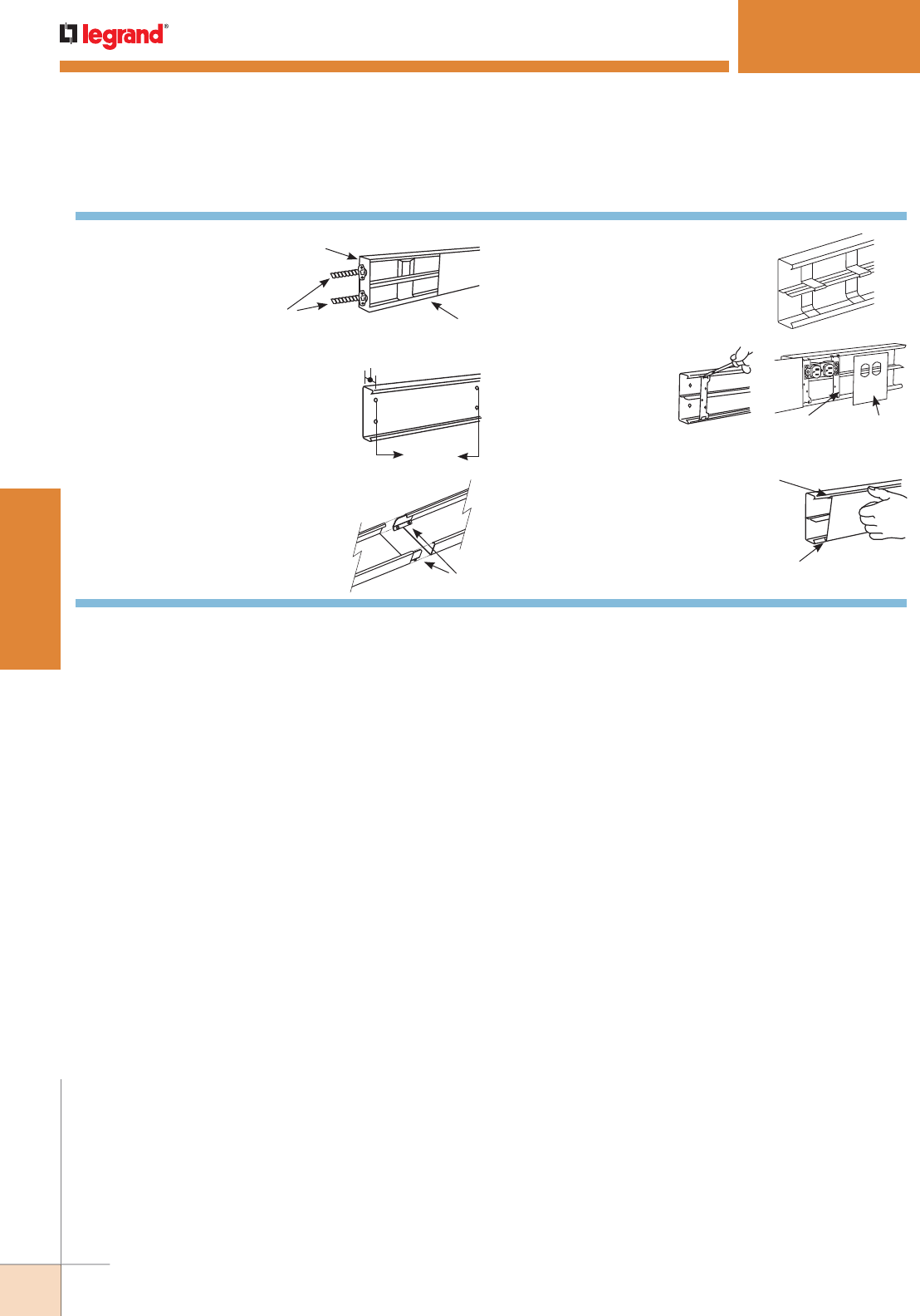
WWW.LEGRAND.US/WIREMOLD
80
STEEL RACEWAY
WIREMOLD
S4000® SERIES RACEWAY
S4000 Series Raceway Installation Details
For divided installations, place
divider into the strut on the
4001DA and snap into raceway.
Clips must be used every 30"
[762mm].
S4000B Sections
Divider Clips
Determine method of feeding
raceway: S4014A for back feed,
S4010D, S4010BO, S4010B1 or
S4010B2 for end feed.
S4010B
S4000 Base
1/2" [12.7mm] Flexible
Metal Conduit
To mount S4000B Base to surface,
remove mounting screw KOs (approx.
18" [457mm] centers along base) as
required. Mount base with No. 8 flat
head fasteners.
1 3/4" [44mm]
18"
[457mm]
Approx.
Cut S4000C Cover to fit
between device plates. Snap
in place as shown. Continue
along entire run.
Snap Cover
Onto Base
Engage One Leg
of Cover on Base
To install device covers,
snap device straps into
base as shown. Wire
device and assemble to
straps. Snap device plate
over base and device. Bottom
Inserts First
Device
Mounting Straps S4046B
To join lengths of S4000B, insert the
pair of 4001A Couplings into one side
of each base. Slide bases together
and tighten locking screws.
S4000B Sections
4001A Couplings
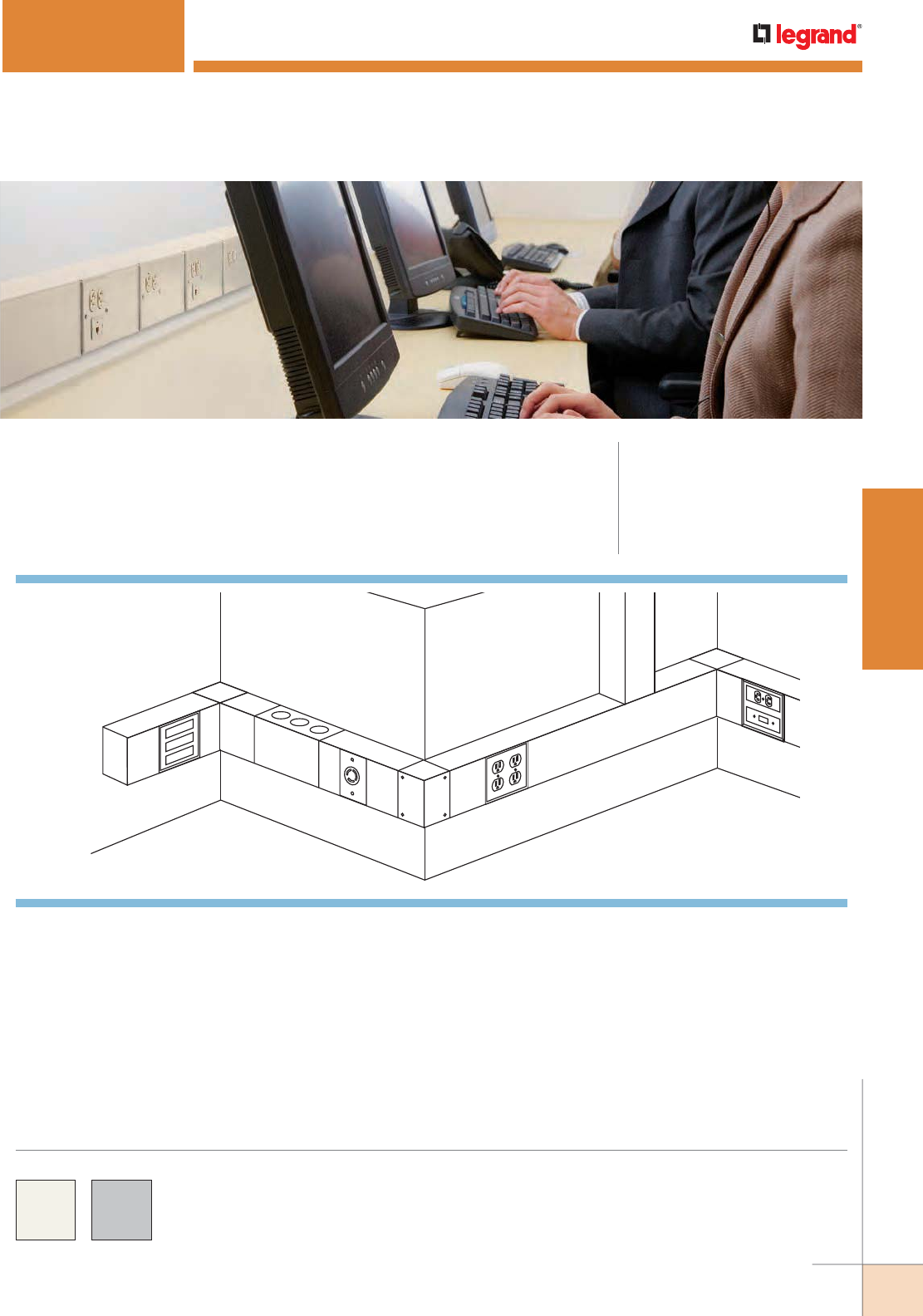
WWW.LEGRAND.US/WIREMOLD
81
STEEL RACEWAY
WIREMOLD
F
K
I
H
D
J
E
GA
C
B
6000® SERIES RACEWAY
CODE REFERENCE
cULus Listed Raceway:
File E4376 Guide RJBT.
Fittings:
File E41751 Guide RJPR.
Meets Article 386 of NEC.
Meets Section 12-1600 of CEC.
6000 Series Raceway is ideal for all applications requiring
high cable capacity.
KEY
A. 4050 Device Mounting Plate
Inserts included
B. 5507D Duplex Receptacle Faceplate
C. 5507SW Switch Faceplate
D. 6007C-1 Single-Gang Device Plate
E. 6007C-2 Two-Gang Device Plate
F. 6010B Blank End Fitting
G. 6011TX Combination Flat Elbow
H. 6014A Connector Fitting
I. 6017TX Combination Internal External
Elbow
J. 6017TX Inverted to External Elbow
K. 6046KD Circuit Breaker Housing
System Layout
COLOR OPTIONS
6000® Series Raceway Part Numbers with a “V” prefix have an
ivory finish. Part Numbers with a “G” prefix have an gray finish.
Custom color options are also available. Consult the factory
for more information.
NOTE: Illustration is for showing product applications only.
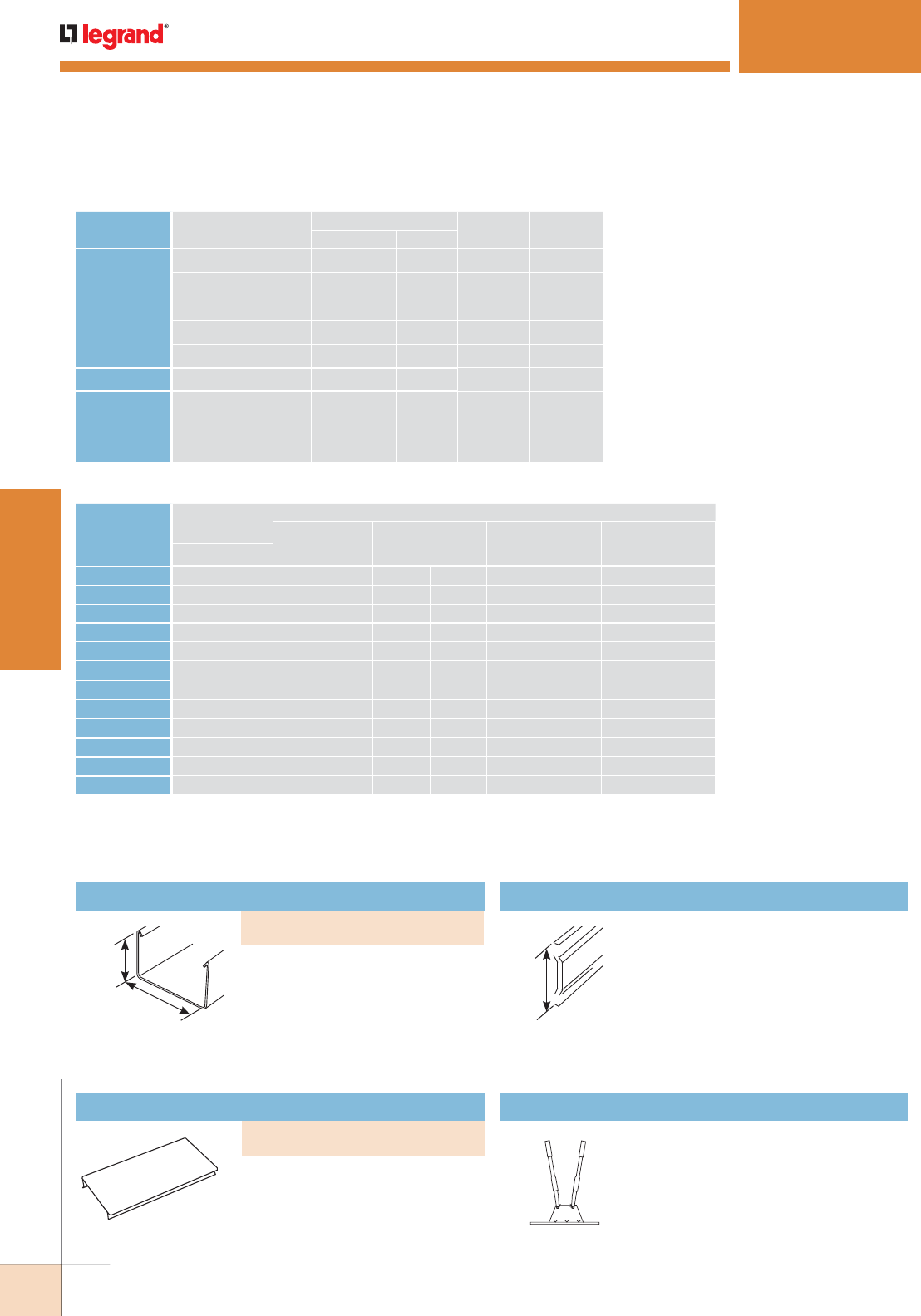
WWW.LEGRAND.US/WIREMOLD
82
STEEL RACEWAY
WIREMOLD
3 9/16"
[90mm]
4 3/4"
[121mm]
3 1/4"
[83mm]
6000® SERIES RACEWAY
Raceway Cover
.040" [1.0mm] galvanized steel.
Packed four 5' [1.5m] lengths per
carton. 4000 Series Raceway Cover
is also compatible with 6000 Series
Raceway Base.
.054" [1.4mm] galvanized steel.
Base has two 9/32" dia. trade size
KOs, 1 1/4" [32mm] from each end
and on centers of approximately 18"
[457mm] throughout. Packed 20'
[6.1m] per carton. 6000B-10 packed
two 10' [3m] lengths.
G6000DA Raceway Divider
.040" [1.0mm] galvanized steel. One
side painted buff primer to provide
identification of compartments. Packed
four 5' [1.5m] lengths per carton.
660B Raceway Base Cutter
Portable cutter for 6000 Series Raceway
Base. Provides clean and easy square
cuts.
6000 Series Raceway Ordering Information
CABLE/WIRE SIZE
O.D. APPROX. DIA. DIVIDED
40% FILL
UNDIVIDED
40% FILLInches [mm]
UNSHIELDED
TWISTED
PAIR
4-pair, 24 AWG, Cat 3 0.190 [4.8] 101 225
4-pair, 24 AWG, Cat 5e 0.210 (5.3) 83 184
4-pair, 24 AWG, Cat 6 0.250 (6.3) 58 130
4-pair, 24 AWG, Cat 6a* 0.354 (9.0) 29 65
25-pair, 24 AWG 0.410 (10.4) 21 48
COAXIAL RG6/U 0.270 [6.9] 50 111
FIBER ZipCord 0.118 x 0.236 [3 x 6] 103 230
Round 4 Strand Fiber 0.187 [4.8] 104 233
Round 6 Strand Fiber 0.256 [6.5] 55 124
6000 Series Raceway Wire Fill Capacities for Communications
6000 Series Raceway Wire Fill Capacities for Power
WIRE SIZE
THHN/THWN
O.D.
NUMBER OF CONDUCTORS 40% FILL
WITHOUT
DEVICES
WITH DUPLEX
RECT. DEVICES
1.59in.2 [1025mm2]
WITH SURGE/
GFCI DEVICES
2.30in.2 [1485mm2]
LARGE SINGLE
RECEPTACLES
3.00in.2 [1935mm2]Inches [mm}
Undiv. Divided Undiv. Divided Undiv. Divided Undiv. Divided
14 AWG 0.111 [2.8] 659 296 528 231 470 202 412 173
12 AWG 0.130 [3.3] 481 216 395 168 342 147 300 126
10 AWG 0.164 [4.2] 303 136 243 106 216 92 189 79
8 AWG 0.216 [5.5] 174 78 140 61 124 53 109 45
6 AWG 0.254 [6.5] 126 56 101 44 89 38 78 33
4 AWG 0.324 [8.2] 77 34 000000
3 AWG 0.352 [8.9] 65 29 000000
2 AWG 0.384 [9.8] 55 24 000000
1 AWG 0.446 [11.3] 40 18 000000
1/0 AWG 0.496 [12.3] 34 15 000000
2/0 AWG 0.532 (13.5) 28 12 000000
NOTE: For additional information, refer to the Technical Section.
* Category 6 augmented (6a) cable for 10 gigabit ethernet – max allowed cable diameter per addenda
No. 11 ANSI TIA/EIA 568-B.2.
Raceway Base
PART NUMBERS:
V6000B-10 (Ivory), G6000B-10 (Gray)
PART NUMBERS:
V6000C (Ivory), G6000C (Gray)
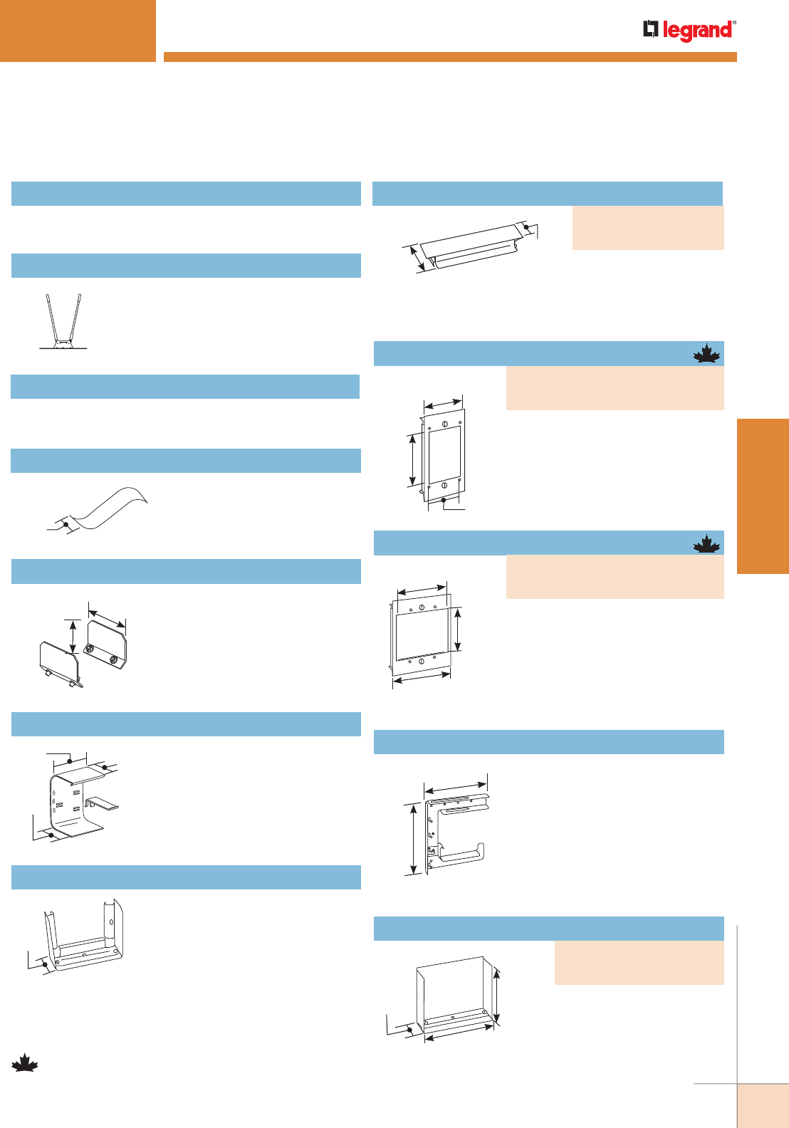
WWW.LEGRAND.US/WIREMOLD
83
STEEL RACEWAY
WIREMOLD
660BDK Replacement Blade Kit
Replacement blades and die set for 660B Cutter.
6000® SERIES RACEWAY
640C Raceway Cover Cutter
Portable cutter for 4000 and 6000
Series Raceway Cover. Provides
clean and easy square cuts.
640CDK Replacement Blade Kit
Replacement blades and die set for 640C Cutter.
1 1/2"
[38mm]
G6000WC Wire Clip (Galvanized)
For holding conductors in place.
For undivided raceways only.
2 1/2"
[64mm]
3 5/16"
[84mm]
6001A Coupling (Galvanized)
For joining lengths of 6000B.
2 1/2"
[64mm]
1 7/8"
[48mm]
2 7/8"
[73mm]
3 7/8"
[98mm]
2 7/8"
[73mm]
4 5/16"
[110mm]
7 7/8"
[200mm]
6 7/8"
[175mm]
1 1/2"
[38mm]
4 3/4"
[121mm]
3 1/2"
[89mm]
2 3/8"
[60mm]
3"
[76mm]
2 7/8"
[73mm]
G6001DA Divider Clip
Use for holding G6000DA Divider
in place to divide raceway into
1/3, 1/2, or 2/3 compartments.
NOTE: 6000 Series Raceway divided into
1/3 compartments will not accept
devices.
3"
[76mm]
G6001TX Converter Coupling
Use this coupling to convert
G6011TX or G6017TX into a tee or
cross. For tee, one required; for
cross, two required.
Single-Gang Device Plate
For vertical mounting of single-
gang devices. Use with industry
standard faceplates for electrical and
communication devices. Can also be
used with 4000B Base.
For installation of two-gang devices
or two vertically mounted single-
gang devices on undivided raceway.
Use with industry standard double-
gang faceplates for electrical and
communication devices. Can also be
used with 4000B Base.
G6008A C-Hanger (Galvanized)
For suspending 6000 or 4000 Series
Raceway from structural ceiling.
Designed for use with 3/8" [9.5mm]
rod. Hangers should be installed
no more than 5' [1.5m] apart along
raceway run. Can be bolted back-to-
back for dual runs of 4000, 6000 or
3008C or for combined runs with 3000
Series Raceway.
Blank End Fitting
For closing open end of 6000
Series Raceway.
NOTE: Parts identified with this symbol are Certified to Canadian Safety
Standards for sale in Canada. When ordering these products, change
the “V” color prefix to “CV” or the “G” color prefix to “CG” to denote
the Canadian versions.
6000 Series Raceway Ordering Information (continued)
PART NUMBERS:
V6007C-1 (Ivory)
G6007C-1 (Gray)
Two-Gang Device Plate
PART NUMBERS:
V6007C-2 (Ivory)
G6007C-2 (Gray)
PART NUMBERS:
V6010B (Ivory)
G6010B (Gray)
1 3/4"
[44mm]
1"
[25mm]
Connection Cover
Use where two sections
of 4000C or 6000C Cover,
not squarely cut, come
together.
PART NUMBERS:
V6006 (Ivory)
G6006 (Gray)
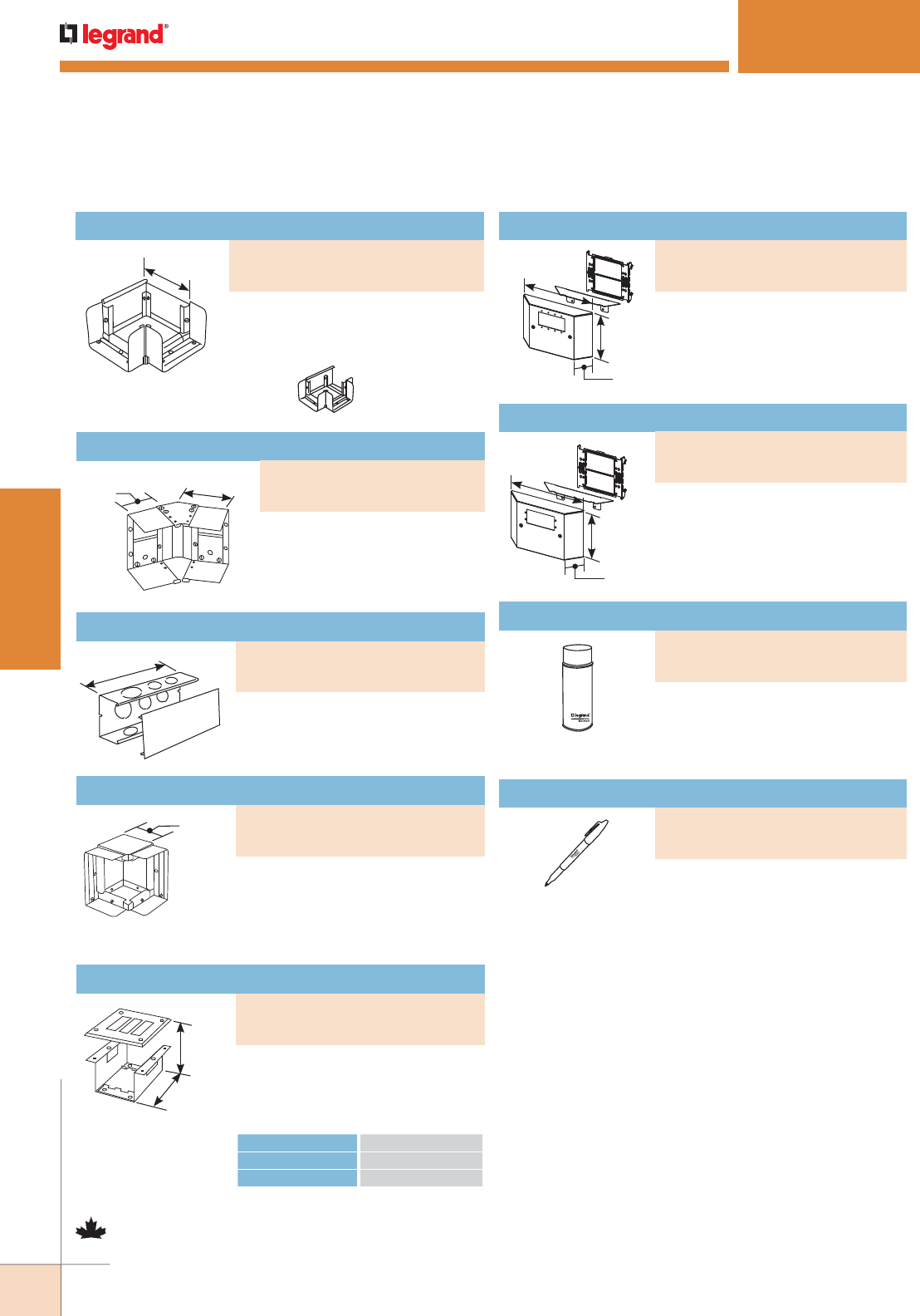
WWW.LEGRAND.US/WIREMOLD
84
STEEL RACEWAY
WIREMOLD
6000® SERIES RACEWAY
2 1/2"
[64mm]
4 1/4"
[108mm]
12"
[305mm]
3 1/2"
[89mm]
2 3/8"
[60mm]
4 9/16"
[116mm]
7 5/16"
[185mm]
4 3/16"
[122mm]
1 13/32"
[36mm]
MANUFACTURER SERIES
General Electric THQC, THHQC
Westinghouse Quicklag, C, QCH
Internal or External Elbow
For making internal or external
45° turns in a run of 6000 Series
Raceway. Can also be assembled
as an inverted 45° elbow.
Connector Fitting
Has 1 1/4", 1 1/2" and 2" trade size
KOs in back and on each side.
For use as internal or external
elbow, straight-through fitting, tee,
or cross (one G6001TX required for
tee or straight through fitting; two
for cross; not included).
Combination Internal/External Elbow
Circuit Breaker Housing
KOs in cover can be removed for
installation of three single-pole
breakers. For use with the following
breakers rated 100A maximum.
Accepts two Extron® Electronics AAP
single space modules.
NOTE: When ordering to use with 6000 Series Raceway in Canada specify
CV6050 (ivory) or CG6050 (gray) as the grounding bracket provided
is larger than the one provided when using with 4000 Series
Raceway. CM-EPLA End Plates are required when using Wiremold
CM2 communication modules and Pass & Seymour® Activate inserts.
S2-EPL End Plates are required when using Ortronics® Series
II inserts. To mount TracJack modules, use 55074TJ or 55076TJ
Faceplates.
NOTE: Parts identified with this symbol are Certified to Canadian Safety
Standards for sale in Canada. When ordering these products, change
the “V” color prefix to “CV” or the “G” color prefix to “CG” to denote
the Canadian versions.
6000 Series Raceway Ordering Information (continued)
PART NUMBERS:
V6012TX (Ivory)
G6012TX (Gray)
Bump-Up Extron® AAP Device Plate
PART NUMBERS:
V4047VX (Ivory)
G4047VX (Gray)
PART NUMBERS:
V6014A (Ivory)
G6014A (Gray)
Used for touching up large areas.
Contains 12 oz.of paint.
NOTE:
Can only be shipped via ground
transportation.
Spray Paint
PART NUMBERS:
IWE-S (Ivory)
GWE-S (Gray)
Used for touching up small areas.
Contains 0.3 oz.of paint.
Touch-Up Paint Pen
PART NUMBERS:
IWE-P (Ivory)
GWE-P (Gray)
PART NUMBERS:
V6017TX (Ivory)
G6017TX (Gray)
PART NUMBERS:
V6046KD (Ivory)
G6046KD (Gray)
7 5/16"
[185mm]
4 3/16"
[122mm]
1 13/32"
[36mm]
Accepts four Extron® Electronics
MAAP single space modules.
Bump-Up Device Plate
PART NUMBERS:
V4047UX (Ivory)
G4047UX (Gray)
Combination Flat Elbow
For use as a flat elbow. Can also be
used as a tee or cross (one G6001TX
required for tee; two for cross; not
included).
4 3/4"
[121mm]
Shown 6011TX with
6001TX to make tee.
PART NUMBERS:
V6011TX (Ivory)
G6011TX (Gray)
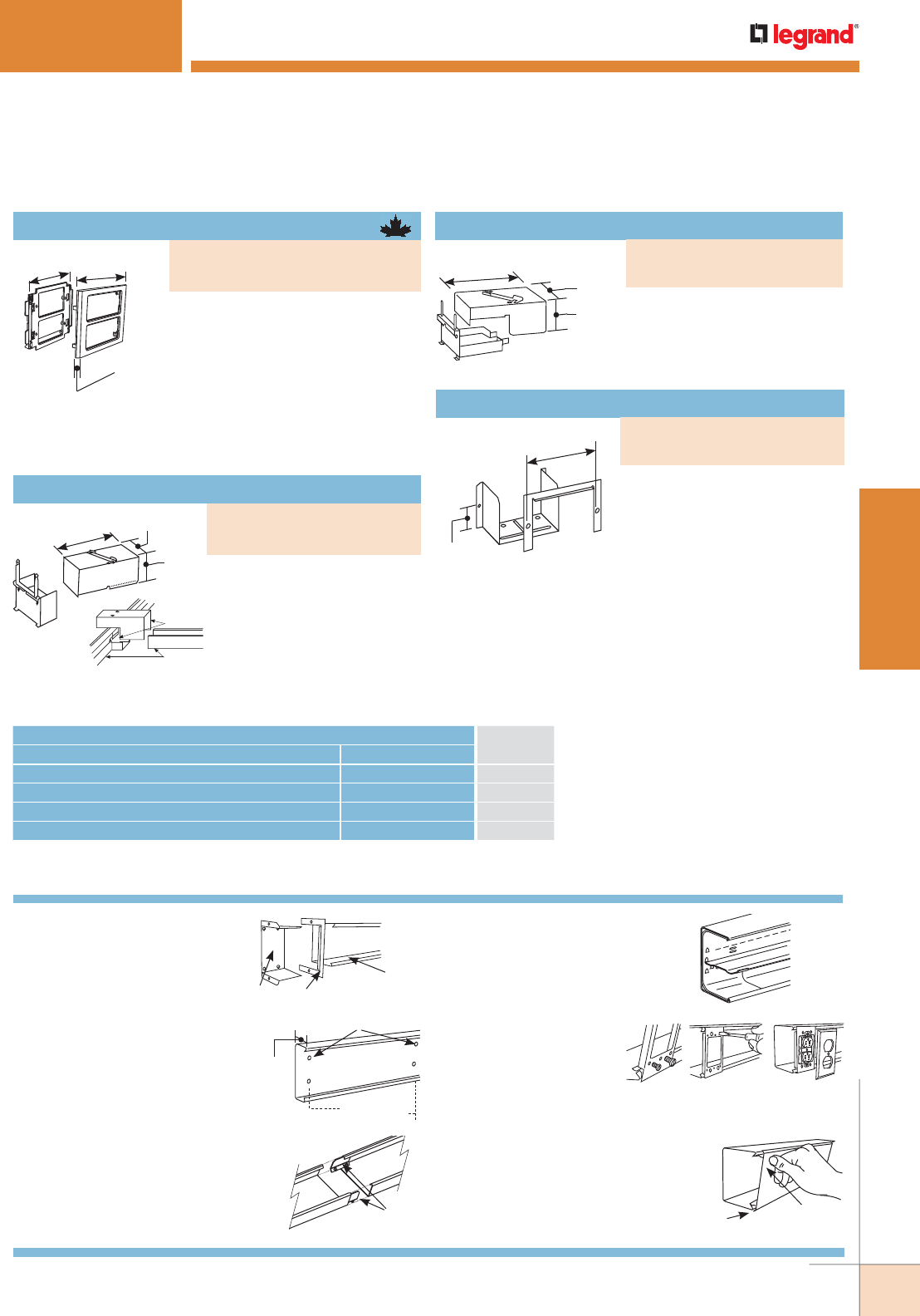
WWW.LEGRAND.US/WIREMOLD
85
STEEL RACEWAY
WIREMOLD
6000® SERIES RACEWAY
6000 Series Raceway Installation Details
5. To install G6007C-1 or
G6007C-2 Device
Plates: Snap into base
and tighten clamps as
shown. Wire device and
assemble to bracket. Install flush plate (not furnished).
6086 6086 C-Flange
6000 Base
1. Determine method of
feeding raceway: 6014A for
backfeed, 6086 (shown) for
panel feed.
2. To mount 6000 Base to
surface: Remove mounting
screw KOs (approx. 18"
[457mm] O.C. along base) as
required. Mount base with
No. 8 flathead fasteners.
Mounting Screw KO
3 9/16"
[40mm]
18" [457mm]
Approx.
3. To join lengths of 6000B,
insert the pair of 6001A
Couplings into one side
of each base. Slide bases
together and tighten locking
screws.
6000B Sections
6001A Couplings
G6000DA
G6001DA
4. For divided installations:
Install G6001DA Divider Clips
at 30" [762mm] intervals. Snap
G6000DA Divider into place.
Clamp G6007C-1
Engage One
Leg of Cover
on Base
Snap Cover
onto Base
6. Cut 6000C Cover to fit between
device brackets. Snap in place as
shown. Continue along entire run.
CONNECTION REQUIRED USE CATALOG
NUMBER
FROM TO
6000 Series Raceway 4000 (Tee Connection) G6074A
6000 Series Raceway 6000 (Tee Connection) G6074
1/2", 3/4", 1" or 1 1/4" trade size Conduit or Armored Cable Cover of 6000 G4046H-2
1 1/4", 1 1/2", or 2" trade size Conduit or Armored Cable Back and/or Side of 6000 G6014A
6000 Series Interconnectivity Fittings
6000 Series Raceway Ordering Information (continued)
3 9/16"
[90mm]
4 7/8"
[124mm]
9 1/2"
[241mm]
G6074
6000 Base
Take-Off Connector (6000-6000)
For 90° tee connection at any
point along a run of 6000 Series
Raceway.
PART NUMBERS:
V6074 (Ivory)
G6074 (Gray)
3 9/16"
[90mm]
4 7/8"
[124mm]
9 1/2"
[241mm]
For 90° tee connection at any
point along a run of 6000 Series
Raceway.
Take-Off Connector (6000-4000)
PART NUMBERS:
V6074A (Ivory)
G6074A (Gray)
5 3/16"
[132mm]
1 3/4"
[44mm]
Panel Connector Fitting
For connecting 6000 Series
Raceway with surface type
panel boxes. Accommodates
maximum wire capacity of 6000
system. Separate C-flange fits
around raceway, covering any
irregularities made when
cutting into box. Cut 4 3/4" x
3 9/16" [121mm x 90mm] hole
in panel box.
PART NUMBERS:
V6086 (Ivory)
G6086 (Gray)
4 3/4"
[121mm]
6"
[152mm]
7/16"
[11.1mm]
High impact plastic mounting bracket
and trim plate. Trim plate overlaps
raceway cover providing a seamless
transition between cover fittings.
Utilizes 5507 Faceplates, as
well as Wiremold Open System
communication modules, Ortronics® TracJack and Series II
inserts, and Pass & Seymour® Activate Series inserts. For
faceplate options, see 5507 Series Faceplates.
Device Mounting Bracket
PART NUMBERS:
V4050 (Ivory)
G4050 (Gray)
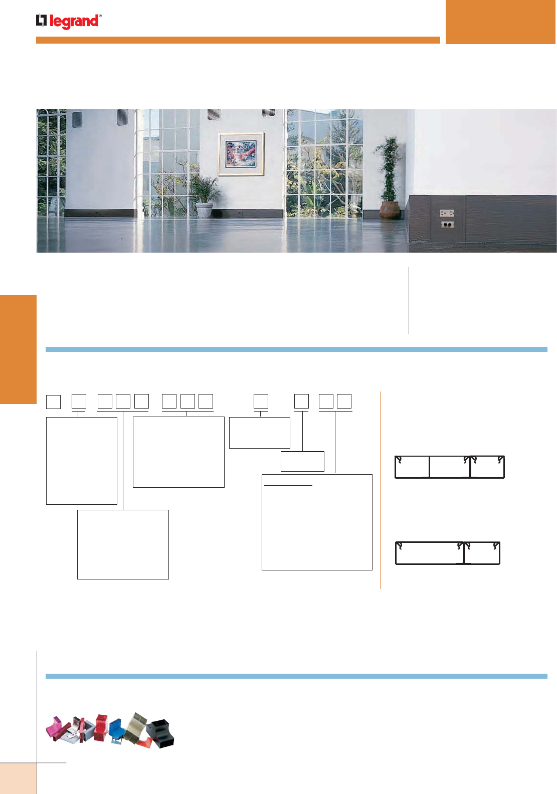
WWW.LEGRAND.US/WIREMOLD
86
STEEL RACEWAY
WIREMOLD
ANYSIZE™ SERIES RACEWAY
CODE REFERENCE
cULus Listed Raceway:
File E4376 Guide RJBT.
Fittings:
File E41751 Guide RJPR.
Meets Article 386 of NEC.
Meets Section 12-1600 of CEC.
AnySize™ Raceway is the ideal solution for applications
that require a specific size raceway. Available in a variety of
compartment sizes and finishes.
Where special lengths are required, provide a detailed bill of material, indicating the
various quantities, lengths and type of covers. Raceway must have a width greater than its
depth.
AnySize Base
EXAMPLE 1: N1 834 212 3 2 WI
This is a 8 3/4" [222mm] wide by 2
1/2" [63mm] deep raceway, with three
compartments and two covers, painted
“Weathered Iron.”
EXAMPLE 2: N1 612 300 2 2 IV
This is a 6 1/2" [165mm] wide by 3" [76mm]
deep raceway, with two compartments and
two covers, painted ivory.
COVER
NE1C = Standard Cover
NE1CW = Cover for use when wire clips are used. Wire clips are spaced 30" [762mm] on center only.
NE1CT* = Tamper-Resistant Cover
NE1CTW* = Tamper-Resistant Cover for use when wire clips are used.
Wire clips are spaced 30" [76mm] on center only.
*Supplied with one tamper-resistant bracket.
N
WIDTH
2 1/2" [63mm] = 212
2 5/8" [66mm] = 258
2 3/4" [69mm] = 234
2 7/8" [73mm] = 278
3" [76mm] = 300
10" [254mm] = 999
MATERIAL
1 Painted Steel
2 Unpainted
Satin Coat
3 Unpainted
Galv. (G90)
4 Stainless Steel
5 Anodized Alum
6 Painted Alum
Color Code**
BK Gloss Black (RAL 9005)
WH White (RAL 9003)
GY Gray (Wiremold Gray)
IV Ivory (Wiremold Ivory)
WI Weathered Iron
WB Weathered Bronze
CC Custom Color
(Provide paint chip
or number)
DEPTH
1" [25mm] = 100
1 1/8" [29mm] = 118
1 1/4" [32mm] = 114
1 3/8" [35mm] = 138
1 1/2" [38mm] = 112
5" [127mm] = 500
# of
Compartments
MAX 4
# of Covers
MAX
** All colors are gloss finish
unless otherwise specified.
AnySize Series Raceway Base Specifier
COLOR OPTIONS
AnySize Raceway and components are available in a wide
range of sizes, colors and options.
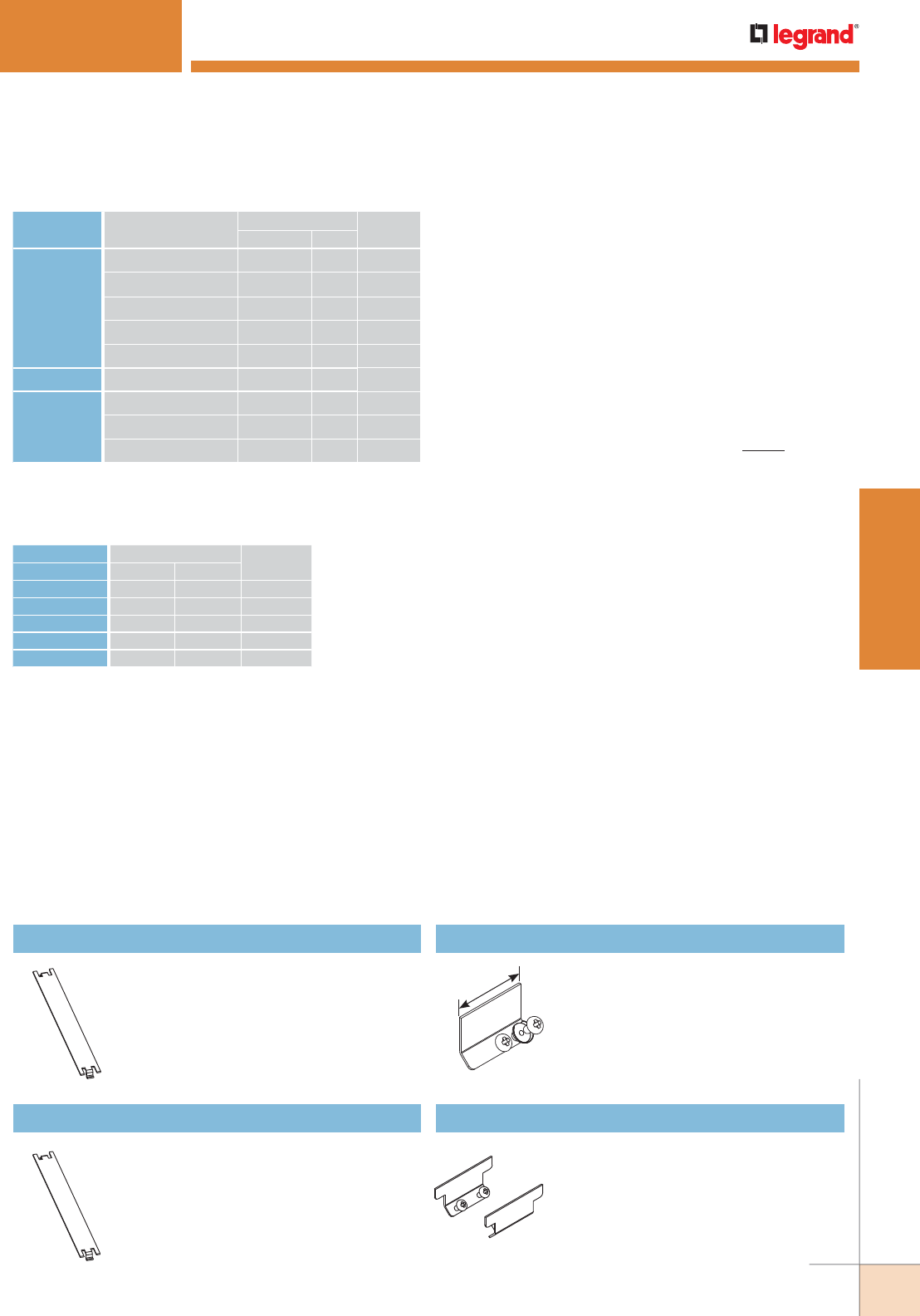
WWW.LEGRAND.US/WIREMOLD
87
STEEL RACEWAY
WIREMOLD
ANYSIZE™ SERIES RACEWAY
2"
[51mm]
Wire Fill Calculation: “Depth” and “Width” refer to the measurements
of the compartment with the cover on and are measured from the
outside of the material. All measurements are in inches. Due to
loading issues, use maximum wire fill of 4" [102mm] deep raceway
for all raceways greater than 4" [102mm] deep.
1. Determine usable area of compartment.
Usable area in square inches with no devices =
[Width x (Depth -0.2)] - 0.6
Usable area in square inches with standard 15A/20A devices =
[Width x (Depth -0.7)] - 0.3
2. Determine wire fill for compartment.
Multiply the compartment area (from Step 1) by the number of
wires per square inch, from the chart above Wire Fill = Area (sq.
in.) x No. Wires per sq. in. (Chart above)
3. Reduce fill by 20% if 2" [51mm] radiused fittings are not being
used. Wire Fill for standard fittings = .8 x wire fill from Step 2
4. Calculate fill for multi-compartment tees.
a) Standard Tee Wire Fill = (Wire fill from Step 2 or 3) / 2
Standard Full Capacity Tee Wire Fill = (Wire fill from Step 2 or
3) x 0.75
b) Radiused 2" Tee Wire Fill = (Wire fill from Step 2 or 3) / (No. of
compartments) Radiused 2" Full Capacity Tee Wire Fill = 1.5 x
(Wire fill from Step 2 or 3) / (No. of compartments)
Sample Wire Fill Calculation: Determine the number of Cat. 6
cables that will fit in a 2" [51mm] deep by 2.75" [70mm] wide
compartment for 40% fill. Fittings in the system have a 2" [51mm]
radius.
1 Useful area = 2.75 x (2.0 - 0.2) -0.6 = 4.35 in2
2 Wire Fill = 4.35 in2 x 8.15 cables / in2 (from chart) = 35 Cat.
6 cables
All Wiremold electrical products, unless specifically noted, are
listed by Underwriters Laboratories Inc. and conform to U.S.
Federal Specification W-C-582. They comply with the National
Electrical Code. Products designed primarily for use in telephone
or communications wiring and tools normally do not require UL
or cUL Listing. Most products are cUL Listed in compliance with
the Canadian Electrical Code. All products must be installed in
a manner consistent with applicable electrical codes. Wiremold
Surface Raceway is UL and cUL Listed by Underwriters
Laboratories Inc. (File #E4376 [Raceway] & #E41751 [Fittings]). This
product is in compliance with the National Electrical Code and the
Canadian Electrical Code.
WIRE SIZE O.D.
40% FILLTHHN/THWN Inches [mm]
14 AWG 0.111 [2.8] 41.24
12 AWG 0.130 [3.3] 30.08
10 AWG 0.164 [4.2] 18.96
8 AWG 0.216 [5.5] 10.93
6 AWG 0.254 [6.5] 7.89
AnySize Series Raceway Wire Fill Capacities for Power
CABLE/WIRE SIZE
O.D. APPROX. DIA.
40% FILLInches [mm]
UNSHIELDED
TWISTED
PAIR
4-pair, 24 AWG, Cat 3 0.190 [4.8] 14.11
4-pair, 24 AWG, Cat 5e 0.210 (5.3) 11.55
4-pair, 24 AWG, Cat 6 0.250 (6.3) 8.15
4-pair, 24 AWG, Cat 6a* 0.354 (9.0) 4.06
25-pair, 24 AWG 0.410 (10.4) 3.03
COAXIAL RG6/U 0.270 [6.9] 6.98
FIBER ZipCord 0.118 x 0.236 [3 x 6] 14.38
Round 4 Strand Fiber 0.187 [4.8] 14.57
Round 6 Strand Fiber 0.256 [6.5] 7.77
AnySize Series Raceway Wire Fill Capacities for Communications
NE1000TB Tamper-Resistant Retaining Bracket
For retaining cover in enhanced tamper-
resistant systems. Order additional brackets
if field cutting cover for enhanced tamper-
resistant system.
NE1000WC Wire Clip
For holding conductors in place.
NE1000GC Ground Clamp
For connection of equipment grounding
conductor to provide additional ground
to raceway.
NE1001 Coupling
For joining lengths of AnySize Raceway.
(Unpainted galvanized steel).
NOTE: Values are per square inch of inside area. See
above to determine useful area of compartment.
Capacity range is calculated at 20% to 40% of
raceway area as stated in a proposed revision
to the Commercial Building Standard for
Telecommunications Pathways & Spaces, TIA/
EIA-569.
AnySize Series Raceway Ordering Information
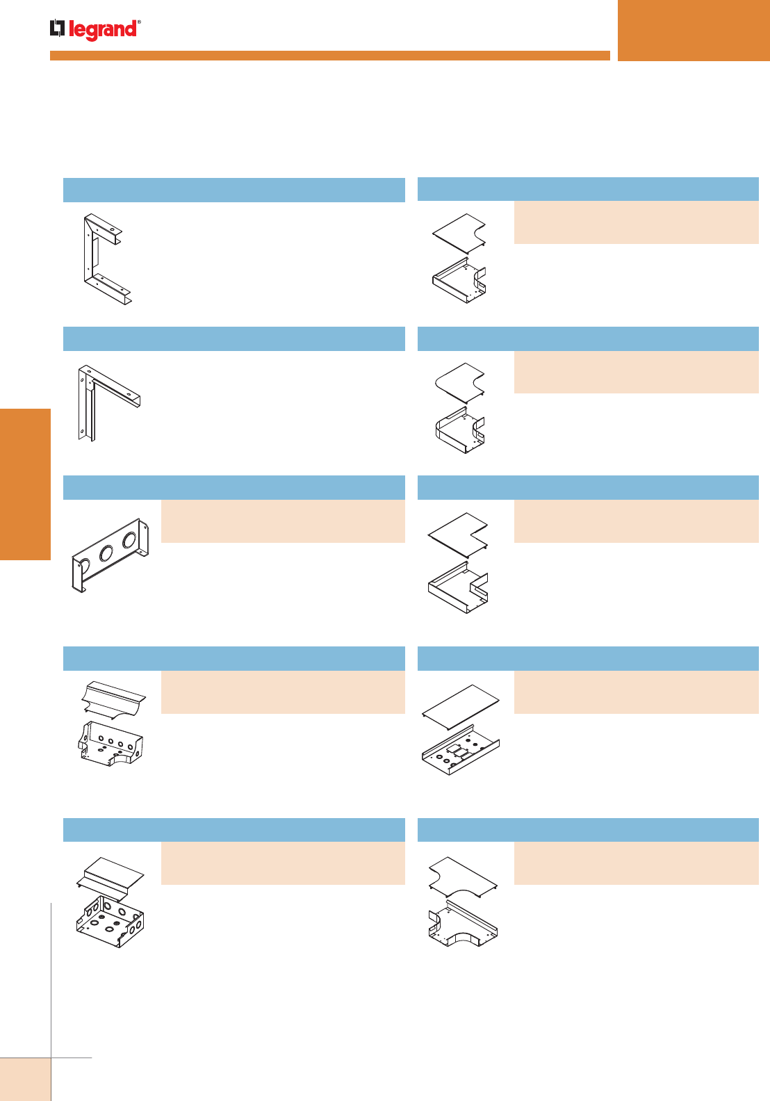
WWW.LEGRAND.US/WIREMOLD
88
STEEL RACEWAY
WIREMOLD
Has concentric conduit trade size KOs on
sides, end and bottom for feeding raceway.
Useful where large conduits feed the
raceway. Size of knockouts to be specified
by end user.
Radiused Large Capacity Entrance End Fitting
NE1008A C-Hanger
For supporting raceway from structural
ceiling. Designed for use with 3/8"
[9.5mm] threaded rod. Hangers should
be installed no more than 5' [1.5m] apart
along raceway run.
NE1008AW Wall Bracket Hanger
For supporting raceway from structural
wall. Use hardware capable of supporting
loaded raceway. Hangers should be
installed no more than 5' [1.5m] apart
along raceway run.
NOTE: “T” at the end of part number indicates it is for use in an enhanced
tamper-resistant system.
Blank End Fitting
For closing open end of AnySize Base.
NE1010BK has knockouts available for
connection to adjacent wiring systems. Size
and quantity of knockouts to be specified
by end user.
Entrance End Fitting
Has concentric conduit trade size KOs
on sides, ends and bottom for feeding
raceway. Size of knockouts to be specified
by end user.
Flat Elbow
For right angle turns on the same surface.
Used in divided and undivided applications
to provide a 2" [51mm] cable bend radius
for new lay-in or pull-through installations.
Radiused Full Capacity Flat Elbow
Same as NE1011FO but outside corner is
curved to a 2" [51mm] radius.
Radiused Full Capacity Flat Elbow
Wall Box Connector
Base is provided with ground terminal for
10-32 screw and user specified conduit
knockouts and/or wall box rectangular
knockouts (2 9/16” x 1 11/16” [65mm x
43mm]).
Provides a 2” [51mm] cable bend radius for
new lay-in or pull-through installations.
Dual cover version not available. Single
cover can be used in all applications.
Capacity is reduced in multi-compartment
applications.
Radiused Full Capacity Tee
ANYSIZE™ SERIES RACEWAY
AnySize Series Raceway Ordering Information (continued)
PART NUMBERS:
NE1011RFO
NE1011RFOT (For tamper-resistant systems)
PART NUMBERS:
NE1011
NE1011T (For tamper-resistant systems)
PART NUMBERS:
NE1014
NE1014T (For tamper-resistant systems)
PART NUMBERS:
NE1015FO
NE1015FOT (For tamper-resistant systems)
PART NUMBERS:
NE1010B (Blank end fitting)
NE1010BK (Includes knockout for adjacent systems)
PART NUMBERS:
NE1010DFO
NE1010DFOT (For tamper-resistant systems)
PART NUMBERS:
NE1010D
NE1010DT (For tamper-resistant systems)
PART NUMBERS:
NE1010FO
NE1010FOT (For tamper-resistant systems)
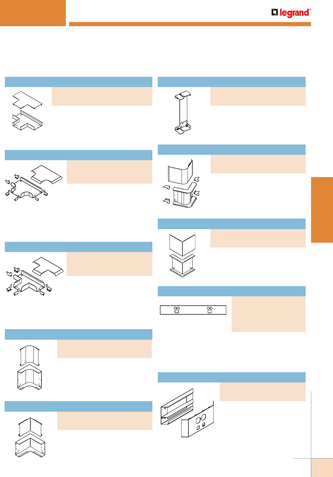
WWW.LEGRAND.US/WIREMOLD
89
STEEL RACEWAY
WIREMOLD
Tee
For branches at right angles. Dual cover
version not available. Single cover can
be used in all applications. Capacity
is reduced in multi-compartment
applications.
Provides a 2” [51mm] cable bend
radius new lay-in or pull-through
installations. Deeper fitting
provides 50% more fill than the standard tee fitting. Useful
for multi-compartment installations. Supplied with special
couplings. Dual cover version not available. Single cover can
be used in all applications.
Radiused Large Capacity Tee
Provides a 2” [51mm] cable bend
radius for new lay-in or pull-through
installations.
Radiused Full Capacity Internal Elbow
Large Capacity Tee
For branches at right angles.
Deeper fitting provides 50% more
fill than the standard tee fitting.
Useful for multi-compartment installations. Supplied with
special couplings. Dual cover version not available. Single
cover can be used in all applications.
Internal Elbow
For 90° internal corners.
Compact Internal Elbow
For 90° internal corners. Compact size
is useful when going around columns.
NOTE:“T” at the end of part number indicates
it is for use in an enhanced tamper-resistant
system.
A full capacity 90° external elbow
to provide a 2" [51mm] cable bend
radius for new lay-in or pull-through
installations. Supplied with special
couplings.
Radiused Full Capacity External Elbow
External Elbow
For 90° external corners.
Variable length from 6" to 60" [152mm to 1.5m] long. Specify
cutout type and location. Eliminates frequent seams when
devices are located close together along the raceway.
Supplied with appropriate brackets.
Device Cover
ANYSIZE™ SERIES RACEWAY
AnySize Series Raceway Ordering Information (continued)
PART NUMBERS:
NE1015
NE1015T (For tamper-resistant systems)
PART NUMBERS:
NE1015LFO
NE1015LFOT (For tamper-resistant
systems)
PART NUMBERS:
NE1015L
NE1015LT (For tamper-resistant
systems)
PART NUMBERS:
NE1017FO
NE1017FOT (For tamper-resistant systems)
PART NUMBERS:
NE1017
NE1017T (For tamper-resistant systems)
PART NUMBERS:
NE1017P
NE1017PT (For tamper-resistant systems)
PART NUMBERS:
NE1047
NE1047WC (Wire cover)
NE1017T
NE1017WCT (Wire cover for
tamper-resistant systems)
PART NUMBERS:
NE1018
NE1018T (For tamper-resistant systems)
PART NUMBERS:
NE1018FO
NE1018FOT (For tamper-resistant systems)
Deep Device Plate
Used to minimize or eliminate fill
reduction at activations. Mounts on
top of raceway and helps maintain
recommended bend radii at
activation. Specify depth required
between 5/8" [15.9mm] and 3"
[76mm]. Supplied with appropriate
brackets.
PART NUMBERS:
NE1407
NE1407T (For tamper-resistant systems)
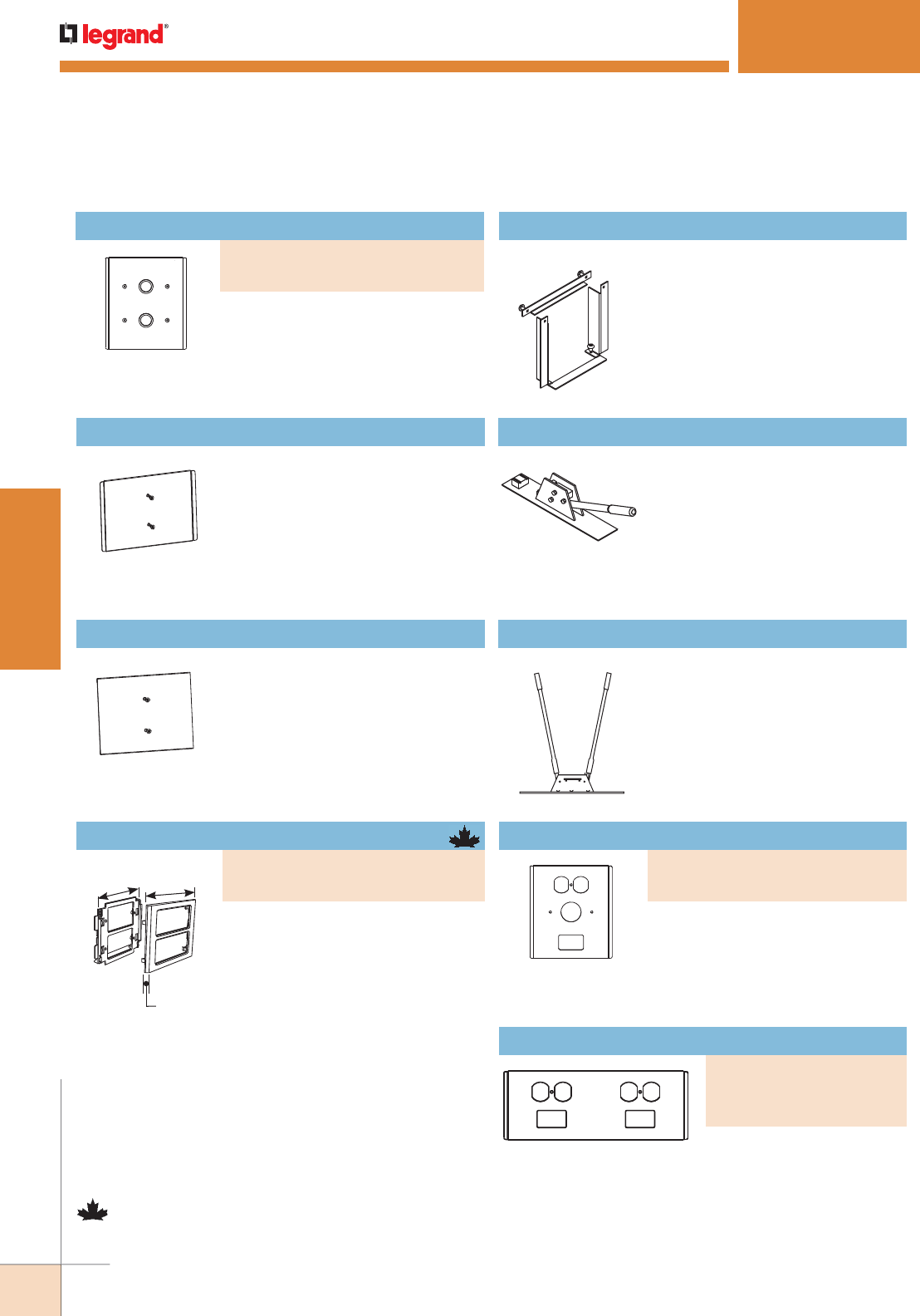
WWW.LEGRAND.US/WIREMOLD
90
STEEL RACEWAY
WIREMOLD
4 11/16"
[116mm]
6"
[152mm]
7/16"
[11.1mm]
NOTE: Parts identified with this symbol are Certified to Canadian Safety
Standards for sale in Canada. When ordering these products, change
the “V” color prefix to “CV” or the “G” color prefix to “CG” to denote
the Canadian versions.
NE1046AP Tamper–Resistant Access Plate
Required on an entrance point to allow
cover removal on tamper-resistant
systems. One plate is required on
every run between opposing walls.
Provides 1/4" [6.4mm] overlap flange
for improved aesthetics at cover edge.
Supplied with appropriate brackets.
NE1046APN Tamper–Resistant Access Plate
Required on an entrance point to allow
cover removal on tamper-resistant
systems. One plate is required on
every run between opposing walls.
NE1046APN does not have a flange to
overlap adjacent covers. Use for access
at end of run.
Device Mounting Bracket
High impact plastic mounting bracket
and trim plate which overlap raceway
cover providing a seamless transition
between cover fittings. For use with:
5507 Series™ Faceplates, Ortronics®
TracJack and Series II modules,
Pass & Seymour® Activate Series
inserts, and Wiremold Open System
communication modules.
NOTE: For use only with 4 3/4" [121mm] wide
raceway.
Three Compartment
Plate Shown.
Two Compartment Plate Shown.
NE1086A Panel Connector
To connect AnySize Raceway
with surface type panel boxes.
Accommodates maximum wire
capacity of AnySize system used.
Separate C-shaped flange fits around
raceway, covering any irregularities
made when cutting into box.
NE610 Tamper-Resistant Notch Tool
Required to create tamper-resistant
notches in raceway covers that are
field cut during installation.
NE610C Raceway Cover Cutter
Portable Cutter for AnySize Raceway
Covers for clean and easy square
cuts every time.
Allows high density activations. Provides 1/4" [6.4mm]
overlap flange for improved aesthetics at cover edge.
Supplied with appropriate brackets.
NOTE: For use only with 4 3/4" [121mm] wide raceway.
12" [305mm] Device Plate
Provides 1/4” [6mm] overlap flange
for improved aesthetics at cover edge.
Supplied with appropriate brackets.
NOTE: For use only with 4 3/4” [121mm] wide
raceway.
ANYSIZE™ SERIES RACEWAY
AnySize Series Raceway Ordering Information (continued)
PART NUMBERS:
V4050 (Ivory)
G4050 (Gray)
6' [152mm] Device Plate
PART NUMBERS:
NE1046
NE1046T (For tamper-resistant systems)
PART NUMBERS:
NE1046-2
NE1046T-2T (For tamper-
resistant systems)
Custom Tap-Off Fitting
Provided with user-specified trade
size KOs. Supplied with appropriate
brackets.
PART NUMBERS:
NE1406H
NE1406HT (For tamper-resistant systems)
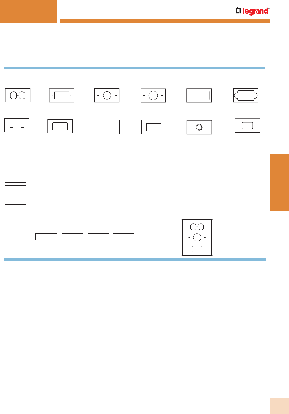
WWW.LEGRAND.US/WIREMOLD
91
STEEL RACEWAY
WIREMOLD
ANYSIZE™ SERIES RACEWAY
The following represent various cutouts available for AnySize Raceway.
The corresponding letter designations used to create the device plate part number are also shown.
To specify type of device plate, and cutout locations:
1) Specify device plate type above.
2) Add the suffix(es) (in parentheses above) that corresponds to the cutout type
required, beginning from the top compartment. For 12" [305mm] device plates,
indicate if the second column of cutouts is the same as the first. If it is not, please
send sketch. For NE1047 Covers sketch to indicate quantity and spacing of devices.
For other special cutouts, contact factory.
1
2
3
4
Device Plate Design and Part Numbers
Standard Duplex
(D) Decorator Duplex
(R) 1.6" [40.6mm] Dia.
Single (J) 4007C-1 Cutout *
(C1)
2 RJ11/45
(RJ)
4007C-1R Cutout *
(CIR)
Accommodates:
Wiremold Open System
communications, Ortronics
TracJack & Series II (LV2)
1.4" [35.5mm] Dia.
Single (A)
Accommodates:
Wiremold Open System
communications, Ortronics
TracJack & Series II (LV6)
Accommodates:
Wiremold Open System
communications (MFB)
AMP Flex/single
ACO (F) 1/2" – 3/4"
[12.7mm – 19.1mm]
KO & Grommet (K)
Sample Plate: NE1046DJLV2
Sample Part Number:
NE1046 D J LV2 ______ N/A
1 2 3 4
Prefix
2nd. col.
(yes/no or N/A)
* These openings also require the use of commercially available faceplates.
AnySize Series Raceway Device Plate Configurator
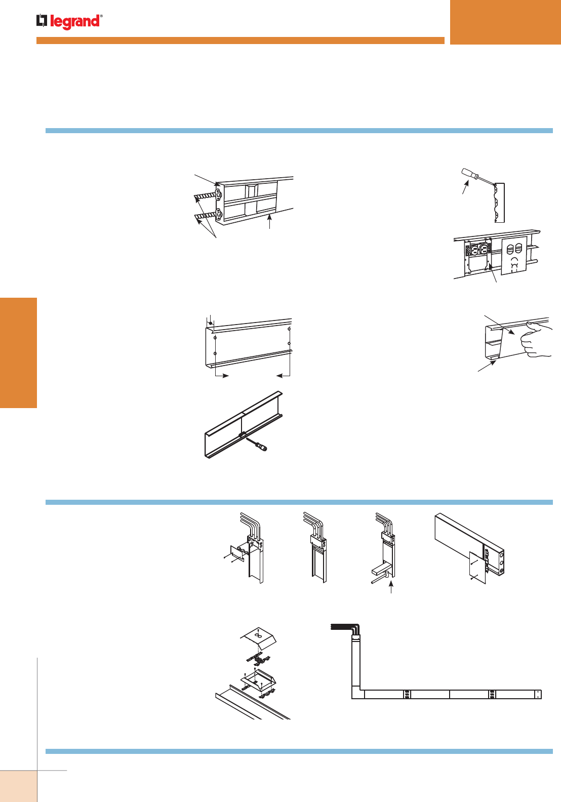
WWW.LEGRAND.US/WIREMOLD
92
STEEL RACEWAY
WIREMOLD
See the typical basic system (illustrated below) for installation details.
In general, the following procedure for installing AnySize Raceway is recommended.
1. Starting at feed connection,
install base sections over
entire run. Butt ends of
sections and install couplings
as shown below. Cut base
sections to length as required
for connection of bases
of fittings. Determine the
method of feeding raceway:
raceway base or wall box
connector for back feed, end blanks (shown), entrance
end fittings, or panel connector for end feed.
End Blank
Conduit
Base
3. Install wiring in base and wire
devices. To couple lengths of base
or fittings, butt the adjacent base
sections together and insert one
coupling centered over the splice.
Tighten the set screws. Repeat the
process on the other side of the
base.
2. To mount base to surface:
Remove mounting knockouts as
required. Mount base with No. 8
flathead fasteners.
Depth
24" [610mm]
(approx.)
4. Assemble devices and
device covers in base.
To install device plates,
snap device straps in
base as shown. Wire
device and assemble
to straps. Snap device
plate over base and
device. For deep device
plates or offset
device plates fasten to raceway
base by screwing into device
brackets in raceway base. Device Mounting Straps
Bottom
Inserts
First
5. Cut cover sections to length as
necessary and snap onto base.
It is recommended that covers
overlap base joint. Use pre-cut
cover, or cut cover to fit between
device plates. Snap in place as
shown. Continue along entire run.
Snap Cover onto Base
Engage One Leg of
Cover on Base
ANYSIZE™ SERIES RACEWAY
AnySize Raceway Installation Details
A. Complete instructions 1 to 3.
B. Add covers progressively from
access point to other end, utilizing
instructions 4 and 5 as needed. See
Illustrations below.
C. Repeat (ii) and (iii) as required.
D. Any cut covers will require
replacement of the tamper-resistant
notch using NE610 tool.
E. Tighten all screws securely.
NE1407 Deep Device
Plate Installation
(i) (ii) (iii) (iv)
AnySize Raceway – Typical Tamper-Resistant Installation
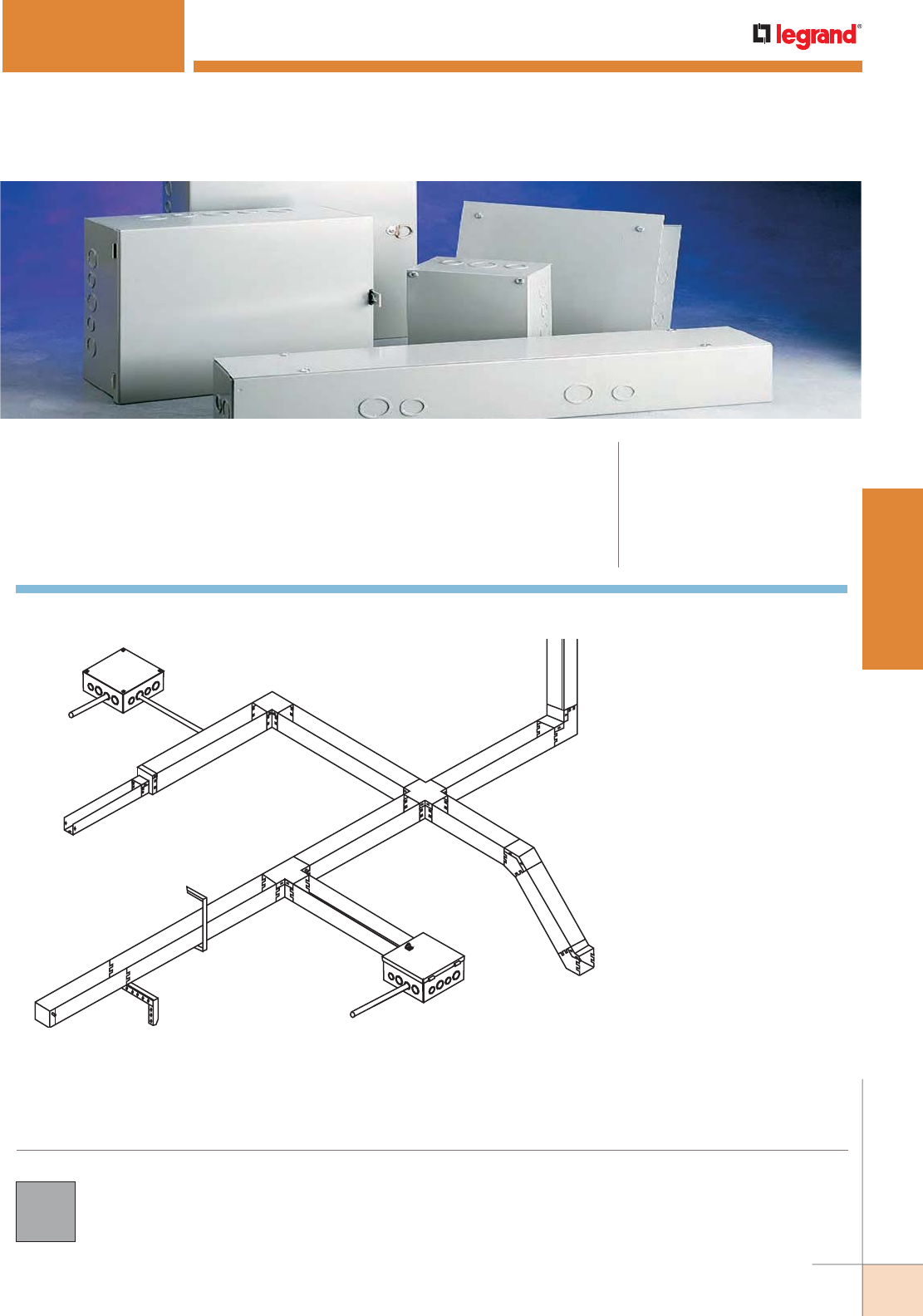
WWW.LEGRAND.US/WIREMOLD
93
STEEL RACEWAY
WIREMOLD
SPECMATE™ WIREWAY & ENCLOSURES
Wiremold® SpecMate™ Type 1 Wireway and Enclosures are available in a broad
range of enclosure and trough sizes to accommodate specific wire fill and bend
radii requirements.
COLOR OPTIONS
CODE REFERENCE
UL Listed Wireway, Auxiliary Gutters &
Associated Fittings:
File E137690 Guide ZDYX.
Meets Article 376 of NEC.
CSA File: 59760.
Meets Section 12-2200 of CEC.
SpecMate™ Wireway is available with a gray baked enamel finish.
Custom color options are also available. Consult the
factory for more information.
NOTE: Illustration is for showing
product applications only.
AD
B
E
C
F
G
H
JI
L
K
KEY
A. C14R25 Reducer
B. C14E 90º Flat Elbow
C. C14X Cross
D. C14EVI 90º Inside Elbow
E. C14E45VO 45º Outside Elbow
F. C14E45VI 45º Inside Elbow
G. C14T Tee
H. C14H Hanger
I. C14BH Bracket Hanger
J. C14EB End Blank
K. SPMJP-8-8-6 Hinged Cover
Junction Box
L. SPMJ-8-8-6 Screw Cover
Junction Box
SpecMate Type 1 Wireway System Layout

WWW.LEGRAND.US/WIREMOLD
94
STEEL RACEWAY
WIREMOLD
Wireway Capacity
The following charts show the wireway size and number of conductors allowed.
To apply these numbers correctly to your application, observe the rules outlined below, which are taken from the applicable Electrical
Code or UL/CSA standard.
National Electrical Code (NEC):
Article 376-22 of the NEC (2002) states that “The sum of cross-sectional areas of all contained conductors at any cross section of the
wireway shall not exceed 20 percent of the interior cross-sectional area of the wireway”.
Further to this “The derating factors in 310.15(B)(2)(a) shall be applied only when the number of current carrying conductors, including
neutral conductors classified as current-carrying under the provisions of 310.15(B)(4), exceeds 30.”
Where the conductors enter the wireway through the bottom or the sides, the maximum conductor size is limited due to the need to
control the bend radius of the conductor. Please see Article 376 of the NEC (2002) for more details.
Canadian Electrical Code (CEC):
The rules in CEC 12-2104 regarding conductors in wireways are as follows:
(1) Conductors used in wireways shall be the insulated types indicated in Table 19 (CEC) as being suitable for use in raceways.
(2) Except as permitted in Subrule (4) wireways shall contain not more than 200 conductors and the aggregate cross-sectional area of
the conductors and their insulation shall not exceed 20% of the interior cross-sectional area of the wireway.
(3) No conductor larger than 500 kcmil (MCM) copper of 750 kcmil (MCM) aluminum shall be installed in any wireway.
(4) Wireways containing only signal and control conductors may contain any number of conductors but the aggregate cross-sectional
area of the conductors and their insulation shall not exceed 40% of the interior cross-sectional area of the wireway.
(5) The cross-sectional area for conductors in Subrules (2) and (4) shall be determined in accordance with Rule 12-1014(4).
NOTE: See Section 12-2100 of the CEC for more details if required. For divided wireway (two equal compartments), add suffix “D” (i.e. C1800D). Consult
factory to order unequal compartments.
SpecMate Wireway Wire Fill Capacities for Power & Communications
SPECMATE™ WIREWAY & ENCLOSURES
Technical Data
SpecMate Wireway Wire Fill Capacities for Power & Communications
Wire Fill Calculation:
1. Determine useable area
of compartment. Useable
area in square inches =
[Width x Depth].
2. Determine wire fill for
compartment. Multiply the
compartment area (from
Step 1) by the number of
wires per square inch, from
the chart above. Wire Fill
= Area (sq. in.) x No. Wires
per sq. in. (Chart above).
3. Calculate fill for multi-
compartment tees or
crosses. Wire Fill = (Wire
Fill from Step 2) / No. of
compartments.)
Sample Wire Fill Calculation:
Determine the number
of 12 gauge wires that
will fit in a 4" [102mm]
deep by 4" [102mm] wide
compartment.
1) Useful area =
4" x 4"=16 in2
2) Wire Fill = 16" x 17.11"
wires/in2 (from chart) =
273 #12 THHN wires
CABLE/WIRE TYPE CATEGORY/WIRE SIZE
O.D 20% FILL 40% FILL
Inches [mm] (per sq. inch of area) (per sq. inch of area)
POWER WIRING
(THHN/THWN)
6 AWG 0.257 [6.5] 3.35 -
6 AWG 0.218 [5.5] 5.36 -
6 AWG 0.153 [3.9] 10.88 -
6 AWG 0.122 [3.1] 17.11 -
6 AWG 0.105 [2.7] 23.09 -
UNSHIELDED
TWISTED PAIR
4-pair, 24 AWG Cat. 5 UTP 0.220 [5.6] 5.26 10.52
4-pair, 24 AWG Cat. 3 UTP 0.190 [4.8] 7.05 14.11
TELEPHONE 2-pair, 24 AWG 0.140 [3.5] 12.99 25.98
3-pair, 24 AWG 0.150 [3.8] 11.32 22.64
4-pair, 24 AWG 0.190 [4.8] 7.05 14.1
25-pair, 24 AWG 0.410 [10.3] 1.51 3.03
COAXIAL CABLES RG58/U 0.195 [4.7] 6.70 13.39
RG59/U 0.242 [6.1] 4.35 8.70
RG62/U 0.242 [6.1] 4.35 8.70
RG6/U 0.270 [6.8] 3.49 6.99
TWINAXIAL 100 Ohm 0.330 [8.4] 2.34 4.68
SHIELDED
TWISTED PAIR
TYPE 1 0.390 [9.6] 1.67 3.35
TYPE 2 0.465 [11.8] 1.18 2.36
TYPE 3 0.275 [6.9] 4.24 8.48
FIBER OPTIC Two Strand [Duplex]
Multimode 62.5/125m
0.190 [4.8] 7.05 14.11

WWW.LEGRAND.US/WIREMOLD
95
STEEL RACEWAY
WIREMOLD
* Dimensions of RHH and RHW without outer covering are the same as THW No. 18 through No. 10, solid, as well as No. 8 and larger, stranded.
** Dimensions of THW in sizes No. 14 through No. 8. No. 6 THW and larger are the same dimensions as TW.
† No. 14 through No. 2.
SPECMATE™ WIREWAY & ENCLOSURES
Technical Data
CONDUCTOR SIZE
A
RFH-2, RH, RHH, RHW*, SF-2*
B
TF, TH, THW, TW**
C
TFN, THHN, T90, THWN
D
XHHW, ZW†
AWG-MCM [mm2] sq. inch [mm2] sq. inch [mm2] sq. inch [mm2] sq. inch [mm2]
18 [0.8] .0167 [11] .0088 [6] .0062 [4] – –
16 [1.3] .0196 [13] .0109 [7] .0079 [5] – –
14 [2.1] .0230 [15] .0135 [9] .0087 [6] – –
14 [2.1] .0327* – – – – – – –
14 [2.1] – – .0206†[13] – – .0131 [8]
12 [3.3] .0278 [18] .0172 [11] .0117 [8] – –
12 [3.3] .0384* – – – – – – –
12 [3.3] – – .0252†[16] – – .0167 [11]
10 [5.3] .0460 [30] .0222 [14] .0184 [12] – –
10 [5.3] – – .0311 [20] – – .0216 [14]
8 [8.4] .0845 [55] .0471 [30] .0373 [24] – –
8 [8.4] – – .0598†[39] – – .0456 [29]
6 [13.3] .1238 [80] .0819 [53] .0519 [33] .0625 [40]
4 [21.2] .1605 [104] .1087 [70] .0845 [55] .0845 [55]
3 [26.7] .1817 [117] .1263 [81] .0995 [64] .0995 [64]
2 [33.6] .2067 [133] .1473 [95] .1182 [76] .1182 [76]
1 [42.4] .2715 [175] .2027 [131] .1590 [103] .1590 [103]
1/0 [53.5] .3107 [200] .2367 [153] .1893 [122] .1893 [122]
2/0 [67.4] .3578 [231] .2781 [179] .2265 [146] .2265 [146]
3/0 [85.1] .4151 [268] .3288 [212] .2715 [175] .2715 [175]
4/0 [107.2] .4840 [312] .3904 [252] .3278 [211] .3278 [211]
250 [127.0] .5917 [382] .4877 [315] .4026 [260] .4026 [260]
300 [152.0] .6837 [441] .5581 [360] .4669 [301] .4669 [301]
350 [177.0] .7620 [492] .6291 [406] .5307 [342] .5307 [342]
400 [203.0] .8365 [540] .6969 [450] .5931 [383] .5931 [383]
500 [253.0] .9834 [634] .8316 [537] .7163 [462] .7163 [462]
600 [304.0] 1.1940 [770] 1.0261 [662] .8791 [567] .9043 [583]
700 [355.0] 1.3355 [862] 1.1575 [747] 1.0011 [646] 1.0297 [664]
750 [380.0] 1.4082 [909] 1.2252 [790] 1.0623 [685] 1.0936 [706]
800 [405.0] 1.4784 [954] 1.2908 [833] 1.1234 [725] 1.1499 [742]
900 [456.0] 1.6173 [1043] 1.4208 [917] 1.2449 [803] 1.2668 [817]
1000 [507.0] 1.7530 [1131] 1.5482 [999] 1.3623 [879] 1.3893 [896]
1250 [633.0] 2.2062 [1423] 1.9532 [1260] – – 1.7671 [1140]
1500 [760.0] 2.5475 [1644] 2.2751 [1468] – – 2.0612 [1330]
1750 [887.0] 2.8832 [1860] 2.5930 [1673] – – 2.3779 [1534]
2000 [1013.0] 3.2079 [2070] 2.9013 [1872] – – 2.6590 [1715]
Area of Conductor (Sq. In.)

WWW.LEGRAND.US/WIREMOLD
96
STEEL RACEWAY
WIREMOLD
CONDUCTOR SIZE
2.5" x 2.5" [64mm x 64mm]
(1.25 sq. inch [808mm2 ])
4" x 4" [102mm x 102mm]
(3.20 sq. inch [2068mm2])
6" x 6" [152mm x 152mm]
(7.20 sq. inch [4652mm2])
8" x 8" [203mm x 203mm]
(12.80 sq. inch [8271mm2])
AWG-MCM [mm2]ABCDABCDABCDABCD
18 [0.8] 74 142 201 – 191 363 516 – 431 818 1161 – 766 1454 2064 –
16 [1.3] 63 114 158 – 163 293 405 – 367 660 911 – 653 1174 1620 –
14 [2.1] 54 92 143 – 139 237 367 – 313 533 827 – 556 948 1471 –
14 [2.1] 38 – – – 97 – – – 220 – – – 391 – –
14 [2.1] – 60 – 95 – 155 – 244 – 349 – 549 – 621 – 977
12 [3.3] 44 72 106 – 115 186 273 – 258 418 615 – 460 744 1094 –
12 [3.3] 32 – – – 83 – – – 187 – – – 333 – – –
12 [3.3] – 49 – 74 – 126 – 191 – 285 – 431 – 507 – 766
10 [5.3] 27 56 67 – 69 144 173 – 156 324 391 – 278 576 695 –
10 [5.3] – 40 – 57 – 102 – 148 – 231 – 333 – 411 – 592
8 [8.4] 14 26 33 – 37 67 85 – 85 152 193 – 151 271 343 –
8 [8.4] – 20 – 27 – 53 – 70 – 120 – 157 – 214 – 280
6 [13.3] 10 15 24 20 25 39 61 51 58 87 138 115 103 156 246 204
4 [21.2] 7 11 14 14 19 29 37 37 44 66 85 85 79 117 151 151
3 [26.7] 6 9 12 12 17 25 32 32 39 57 72 72 70 101 128 128
2 [33.6] 6 8 10 10 15 21 27 27 34 48 60 60 61 86 108 108
1 [42.4] 4 6 7 7 11 15 20 20 26 35 45 45 47 63 80 80
1/0 [53.5] 4 5 6 6 10 13 16 16 23 30 38 38 41 54 67 67
2/0 [67.4] 3 45581114142025313135465656
3/0 [85.1] 3 3447911111721262630384747
4/0 [107.2] 2 33368991418212126323939
250 [127.0] 2 23356771214171721263131
300 [152.0] 1 22245661012151518222727
350 [177.0] 1 1224566911131316202424
400 [203.0] 1 1223455810121215182121
500 [253.0] 1 11133447 8 101013151717
600 [304.0] 1 1112333678710121414
700 [355.0] – 111223356769111212
750 [380.0] – 111223255669101211
800 [405.0] – –1122224566891111
900 [456.0] – –1–12224555791010
1000 [507.0] – –––122244557899
1250 [633.0] – –––11–133–456–7
1500 [760.0] – –––11–123–355–6
1750 [887.0] – –––11–122–344–5
2000 [1013.0] – ––––1–122–234–4
SPECMATE™ WIREWAY & ENCLOSURES
Technical Data (continued)
SpecMate Wireway Capacity Chart
SpecMate Wireway size and maximum number of conductors allowed. (Areas shown are 20% of the wireway’s full
interior cross sectional area.) This data is valid where conductors enter the wireway only at the end of the run; when
this is not the case, use the “Conductor Size Based on Bending Space” chart.
NOTE: Letters “A,” “B,” “C”, and “D” refer to conductor insulation types specified in the Area of Conductor Chart found earlier in this section.

WWW.LEGRAND.US/WIREMOLD
97
STEEL RACEWAY
WIREMOLD
CONDUCTOR SIZE
12" x 12" [305mm x 305mm]
(28.80 sq. inch [18609mm2])
10" x 4" [254mm x 102mm]
(8.00 sq. inch [5169mm2])
AWG-MCM [mm2]ABCDABCD
18 [0.8] 1724 3272 4645 – 479 909 1290 –
16 [1.3] 1469 2642 3645 – 408 773 1012 –
14 [2.1] 1252 2133 3310 – 347 592 919 –
14 [2.1] 880 – – – 244 – – –
14 [2.1] – 1398 – 2198 – 388 – 610
12 [3.3] 1035 1674 2461 – 287 465 683 –
12 [3.3] 750 – – – 208 – – –
12 [3.3] – 1142 – 1724 – 317 – 479
10 [5.3] 626 1297 1565 – 173 360 434 –
10 [5.3] – 926 – 1333 – 257 – 370
8 [8.4] 340 611 772 – 94 169 214 –
8 [8.4] – 481 – 631 – 133 – 175
6 [13.3] 232 351 554 460 64 97 154 128
4 [21.2] 179 264 340 340 49 73 94 94
3 [26.7] 158 228 289 289 44 63 80 80
2 [33.6] 139 195 243 243 38 54 67 67
1 [42.4] 106 142 181 181 29 39 50 50
1/0 [53.5] 92 121 152 152 25 33 42 42
2/0 [67.4] 80 103 127 127 22 28 35 35
3/0 [85.1] 69 87 106 106 19 24 29 29
4/0 [107.2] 59 73 87 87 16 20 24 24
250 [127.0] 48 59 71 71 13 16 19 19
300 [152.0] 42 51 61 61 11 14 17 17
350 [177.0] 37 45 54 54 10 12 15 15
400 [203.0] 34 41 48 48 9 11 13 13
500 [253.0] 29 34 40 40 8 9 11 11
600 [304.0] 24 28 32 31 6798
700 [355.0] 21 24 28 27 5677
750 [380.0] 20 23 27 26 5677
800 [405.0] 19 22 25 25 5676
900 [456.0] 17 20 23 22 4566
1000 [507.0] 16 18 21 20 4555
1250 [633.0] 13 14 – 16 34–4
1500 [760.0] 11 12 – 13 33–3
1750 [887.0] 9 11 – 12 23–3
2000 [1013.0] 8 9 – 10 22–3
SPECMATE™ WIREWAY & ENCLOSURES
Technical Data (continued)
SpecMate Wireway Capacity Chart (continued)
NOTE: Letters “A,” “B,” “C”, and “D” refer to conductor insulation types specified in the Area
of Conductor Chart found earlier in this section.
SpecMate Type 1 Wireway offers custom and
configurable options to meet wide range of
installation requirements.

WWW.LEGRAND.US/WIREMOLD
98
STEEL RACEWAY
WIREMOLD
SMALLER INSIDE
DIMENSION OF WIREWAY
MAXIMUM
CONDUCTOR SIZE
In. [mm2] AWG-MCM [mm2]
1 1/4 [32] 6 AWG [13]
2 [51] 3 AWG [27]
2 1/2 [64] 2 AWG [34]
3 [75] 1 AWG [42]
3 1/2 [89] 2/0 AWG [67]
4 [102] 4/0 AWG [107]
4 1/2 [114] 250 MCM [127]
5 [127] 350 MCM [177]
6 [152] 500 MCM [253]
8 [203] 900 MCM [456]
10 [254] 1250 MCM [633]
12 [305] 2000 MCM [1013]
Wireway size and maximum number of conductors allowed. (Areas shown are 20% of the wireway’s full interior cross
sectional area.) This data is valid where conductors enter the wireway only at the end of the run; when this is not the
case, use the “Conductor Size Based on Bending Space” chart.
NOTE: Letters “A,” “B,” “C”, and “D” refer to conductor insulation types specified in the Area of Conductor
Chart found earlier in this section.
NOTE: The above chart limits the maximum
conductor size when conductors are entering
through the side.
SpecMate Type 1 Wireway is also available in a
wide range of color and finish options. Consult
the factory for more information.
SPECMATE™ WIREWAY & ENCLOSURES
Technical Data (continued)
SpecMate Wireway Capacity Chart (continued)
CONDUCTOR SIZE
12" x 6" [305mm x 152mm]
(14.4 sq. inch [9305mm2
])
18" x 6" [457mm x 152mm]
(21.6 sq. inch [13957mm2])
24" x 6" [610mm x 152mm]
(28.8 sq. inch [18609mm2])
AWG-MCM [mm2]A B C D ABC D AB C D
18 [0.8]
862 1636 2322 – 1293 2454 3483 – 1724 3272 4645 –
16 [1.3]
734 1321 1822 – 1102 1981 2734 – 1469 2642 3645 –
14 [2.1]
626 1066 1655 – 939 1600 2482 – 1252 2133 3310 –
14 [2.1]
440 – –
–
660 – – – 880 – – –
14 [2.1]
– 699 – 1099 – 1048 – 1648 – 1398 – 2198
12 [3.3]
517 837 1230 – 776 1255 1846 – 1035 1674 2461 –
12 [3.3]
375 – – – 562 – – – 750 – – –
12 [3.3]
– 571 – 862 – 857 – 1293 – 1142 – 1724
10 [5.3]
313 648 782 – 469 972 1173 – 626 1297 1565 –
10 [5.3]
– 463 – 666 – 694 – 1000 – 926 – 1330
8 [8.4]
170 305 386 – 255 458 579 – 340 611 772 –
8 [8.4]
– 240 – 315 – 361 – 473 – 481 – 631
6 [13.3]
116 175 277 230 174 263 416 345 232 351 554 460
4 [21.2]
89 132 170 170 134 198 255 255 179 264 340 340
3 [26.7]
79 114 144 144 118 171 217 217 158 228 289 289
2 [33.6]
69 97 121 121 104 146 182 182 139 195 243 243
1 [42.4]
53 71 90 90 79 106 135 135 106 142 181 181
1/0 [53.5]
46 60 76 76 69 91 114 114 92 121 152 152
2/0 [67.4]
40 51 63 63 60 77 95 95 80 103 127 127
3/0 [85.1]
34 43 53 53 52 65 79 79 69 87 106 106
4/0 [107.2]
29 36 43 43 44 55 65 65 59 73 87 87
250 [127.0]
24 29 35 35 36 44 53 53 48 59 71 71
300 [152.0]
21 25 30 30 31 38 46 46 42 51 61 61
350 [177.0]
18 22 27 27 28 34 40 40 37 45 54 54
400 [203.0]
17 20 24 24 25 30 36 36 34 41 48 48
500 [253.0]
14 17 20 20 21 25 30 30 29 34 40 40
600 [304.0]
12 14 16 15 18 21 24 23 24 28 32 31
700 [355.0]
10 12 14 13 16 18 21 20 21 24 28 27
750 [380.0]
10 11 13 13 15 17 20 19 20 23 27 26
800 [405.0]
9111212141619 18192225 25
900 [456.0]
8101111131517 17172023 22
1000 [507.0]
8 9 10 10 12 13 15 15 16 18 21 20
1250 [633.0]
6 7 – 8 9 11 – 12 13 14 – 16
1500 [760.0]
56 –689– 101112– 13
1750 [887.0]
45 –678– 9 911– 12
2000 [1013.0]
44 –567– 8 89– 10

WWW.LEGRAND.US/WIREMOLD
99
STEEL RACEWAY
WIREMOLD
SPECMATE™ WIREWAY & ENCLOSURES
Technical Data (continued)
SpecMate Wireway Dimension Reference Chart
SIZE: 2 1/2 x 2 1/2 4 x 4 6 x 6 8 x 8 12 x 12
DIMENSION: Inches [mm] Inches [mm] Inches [mm] Inches [mm] Inches [mm]
A x B 2 1/2 x 2 1/2 [64 x 64] 4 x 4 [102 x 102] 6 x 6 [152 x 152] 8 x 8 [203 x 203] 12 x 12 [305 x 305]
C2 [51] 2 [51] 2 [51] 2 [51] 2 [51]
D1 2 7/16 [62] 3 15/16 [100] 5 15/16 [150] 7 15/16 [201] 11 15/16 [303]
D2 2 7/16 [62] 3 15/16 [100] 5 15/16 [150] 7 15/16 [201] 11 15/16 [303]
E 4 5/8 [118] 6 1/8 [156] 8 1/8 [206] 10 1/8 [257] 14 1/8 [359]
F 4 5/8 [118] 6 1/8 [156] 8 1/8 [206] 10 1/8 [257] 14 1/8 [359]
H1 3 1/16 [78] 3 3/4 [95] 4 9/16 [116] 5 3/8 [137] 7 [178]
H2 3 1/16 [78] 3 3/4 [95] 4 9/16 [116] 5 3/8 [137] 7 [178]
J 2 1/2 [64] 2 7/8 [73] 3 5/16 [84] 3 11/16 [94] 4 1/2 [114]
K 3 5/16 [84] 4 1/16 [103] 5 1/16 [128] 6 1/16 [154] 8 1/16 [205]
L 3 1/4 [83] 4 [102] 5 [127] 6 [153] 8 [204]
M 3 1/8 [79] 4 5/8 [118] 6 5/8 [168] 8 5/8 [219] 12 5/8 [321]
N 7 [177] 10 [254] 14 [356] 18 [457] 26 [660]
P 2 5/16 [59] 3 13/16 [97] 5 3/4 [146] 7 3/4 [197] 11 3/4 [298]
R 1 5/8 [41] 3 1/2 [89] 4 1/2 [114] 6 5/8 [168] 10 5/8 [270]
S 3 5/16 [84] 4 1/16 [103] 5 1/16 [129] 6 1/16 [154] 8 1/16 [205]
T 4 1/8 [105] 5 5/8 [143] 7 5/8 [194] 9 5/8 [245] 13 5/8 [346]
U 3 1/8 [79] 4 5/8 [118] 6 5/8 [168] 8 5/8 [219] 12 5/8 [321]
V 8 1/2 [216] 10 [254] 12 [305] 14 [356] 18 [457]
W 1 5/8 [41] 3 1/2 [89] 4 1/2 [114] 6 1/2 [165] 9 1/2 [241]
SIZE: 10 x 4 12 x 6 18 x 6 24 x 6
DIMENSION: Inches [mm] Inches [mm] Inches [mm] Inches [mm]
A x B 10 x 4 [254 x 102] 12 x 6 [305 x 152] 18 x 6 [457 x 152] 24 x 6 [610 x 152]
C2 [51] 2 [51] 2 [51] 2 [51]
D1 9 15/16 [252] 11 15/16 [303] 17 15/16 [455] 23 15/16 [608]
D2 3 15/16 [100] 5 15/16 [150] 5 15/16 [150] 5 15/16 [150]
E 12 1/8 [308] 14 1/8 [359] 20 1/8 [511] 26 1/8 [664]
F 6 1/8 [156] 8 1/8 [206] 8 1/8 [206] 8 1/8 [206]
H1 6 3/16 [157] 7 [178] 9 1/2 [241] 12 [305]
H2 3 3/4 [95] 4 9/16 [116] 4 9/16 [116] 4 9/16 [116]
J 4 3/32 [104] 4 1/2 [114] 5 3/4 [146] 7 [178]
K 7 1/16 [179] 8 1/16 [205] 11 1/16 [281] 14 1/16 [357]
L 7 [178] 8 [204] 11 [280] 14 [356]
M 10 5/8 [270] 12 5/8 [321] N/A N/A N/A N/A
N 16 [406] 20 [506] N/A N/A N/A N/A
P 9 3/4 [248] 11 3/4 [298] 17 3/4 [451] 23 3/4 [603]
R 3 1/2 [89] 4 1/2 [114] 4 1/2 [114] 4 1/2 [114]
S 7 1/16 [179] 8 1/16 [205] 11 1/16 [281] 14 1/16 [357]
T 11 5/8 [295] 13 5/8 [346] 19 5/8 [498] 25 5/8 [651]
U 10 5/8 [270] 12 5/8 [321] 18 5/8 [473] 24 5/8 [626]
V 16 [406] 18 [457] 24 [610] 30 [762]
W 3 1/2 [89] 4 1/2 [114] 4 1/2 [114] 4 1/2 [114]
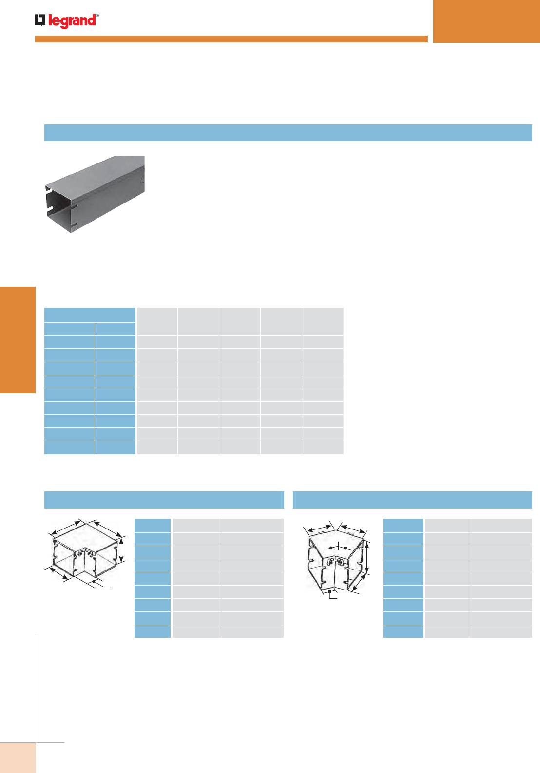
WWW.LEGRAND.US/WIREMOLD
100
STEEL RACEWAY
WIREMOLD
For divided wireway (two equal compartments), add suffix “-D”, i.e.: C1250-D. Wireway
can also be provided with divider(s) in specified locations. Consult factory to order.
Steel finished in ANSI61 gray powder coat paint.
One coupling required with each length of duct.
1/2" [12.7mm] and 3/4" [19.1mm] concentric trade size KOs 24" [610mm] on centers.
UL Listed and CSA Certified for support on 5' [1.5m] centers. (2 1/2", 4", and 6" [64mm,
102mm, 152mm] square profiles also UL Listed on 10' [3m] centers). Special sizes,
lengths, and colors available.
C1402
(shown)
C14E
(Shown)
E
E
A
B
C
One coupling required with each fitting.
C14E45
(Shown)
B
C
J
H1
H1
J
SPECMATE™ WIREWAY & ENCLOSURES
SpecMate Type 1 Wireway Ordering Information
SpecMate Wireway Type 1
STANDARD SIZES GAUGE 10' LENGTH
[3m]
5' LENGTH
[1.5m]
2' LENGTH
[.61m]
1' LENGTH
[.30m]
Inches [mm]
2 1/2" x 2 1/2" [64 x 64] 16 C1250 C1255 C1252 C1251
4" x 4" [102 x 102] 16 C1400 C1405 C1402 C1401
6" x 6" [152 x 152] 16 C1600 C1605 C1602 C1601
8" x 8" [203 x 203] 16 C1800 C1805 C1802 C1801
12" x 12" [305 x 305] 16 C11200 C11205 C11202 C11201
10" x 4" [254 x 102] 16 C110-40 C110-45 C110-42 C110-41
12" x 6" [305 x 152] 16 C112-60 C112-65 C112-62 C112-61
18" x 6" [457 x 152] 14 – C118-65 C118-62 C118-61
24" x 6" [610 x 152] 12 – C124-65 C124-62 C124-61
Ordering Data
90° Flat Elbow 45° Flat Elbow
C125E 2 1/2" x 2 1/2" [64mm x 64mm]
C14E 4" x 4" [102mm x 102mm]
C16E 6" x 6" [152mm x 152mm]
C18E 8" x 8" [203mm x 203mm]
C112E 12" x 12" [305mm x 305mm]
C110-4E 10" x 4" [254mm x 102mm]
C112-6E 12" x 6" [305mm x 152mm]
C118-6E 18" x 6" [457mm x 152mm]
C124-6E 24" x 6" [610mm x 152mm]
C125E45 2 1/2" x 2 1/2" [64mm x 64mm]
C14E45 4" x 4" [102mm x 102mm]
C16E45 6" x 6" [152mm x 152mm]
C18E45 8" x 8" [203mm x 203mm]
C112E45 12" x 12" [305mm x 305mm]
C110-4E45 10" x 4" [254mm x 102mm]
C112-6E45 12" x 6" [305mm x 152mm]
C118-6E45 18" x 6" [457mm x 152mm]
C124-6E45 24" x 6" [610mm x 152mm]
One coupling required with each fitting.
SpecMate Type 1 Wireway Ordering Information
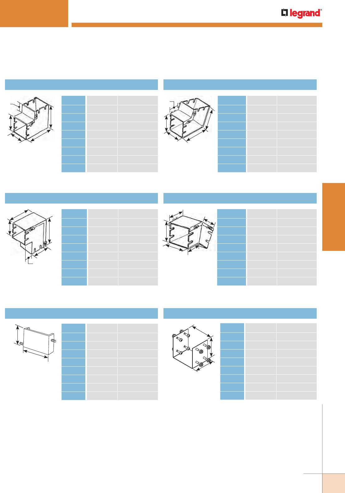
WWW.LEGRAND.US/WIREMOLD
101
STEEL RACEWAY
WIREMOLD
C14EVI
(Shown)
A
B
C
F
F
C14EVO
(Shown)
A
B
C
F
F
NOTE: Refer to “Dimension Reference Chart” shown previously in this section. For divided fittings (two equal compartments), add suffix “D” (i.e. C14ED).
Consult factory to order unequal compartments.
C14E45VI
(Shown)
A
B
C
H2
H2
C14E45VO
(Shown)
A
B
C
H2
H2
90° Vertical Inside Elbow
90° Vertical Outside Elbow
45° Vertical Inside Elbow
45° Vertical Outside Elbow
SPECMATE™ WIREWAY & ENCLOSURES
SpecMate Type 1 Wireway Ordering Information (continued)
C125EVI 2 1/2" x 2 1/2" [64mm x 64mm]
C14EVI 4" x 4" [102mm x 102mm]
C16EVI 6" x 6" [152mm x 152mm]
C18EVI 8" x 8" [203mm x 203mm]
C112EVI 12" x 12" [305mm x 305mm]
C110-4EVI 10" x 4" [254mm x 102mm]
C112-6EVI 12" x 6" [305mm x 152mm]
C118-6EVI 18" x 6" [457mm x 152mm]
C124-6EVI 24" x 6" [610mm x 152mm]
One coupling required with each fitting.
C125E45VI 2 1/2" x 2 1/2" [64mm x 64mm]
C14E45VI 4" x 4" [102mm x 102mm]
C16E45VI 6" x 6" [152mm x 152mm]
C18E45VI 8" x 8" [203mm x 203mm]
C112E45VI 12" x 12" [305mm x 305mm]
C110-4E45VI 10" x 4" [254mm x 102mm]
C112-6E45VI 12" x 6" [305mm x 152mm]
C118-6E45VI 18" x 6" [457mm x 152mm]
C124-6E45VI 24" x 6" [610mm x 152mm]
One coupling required with each fitting.
C125EVO 2 1/2" x 2 1/2" [64mm x 64mm]
C14EVO 4" x 4" [102mm x 102mm]
C16EVO 6" x 6" [152mm x 152mm]
C18EVO 8" x 8" [203mm x 203mm]
C112EVO 12" x 12" [305mm x 305mm]
C110-4EVO 10" x 4" [254mm x 102mm]
C112-6EVO 12" x 6" [305mm x 152mm]
C118-6EVO 18" x 6" [457mm x 152mm]
C124-6EVO 24" x 6" [610mm x 152mm]
One coupling required with each fitting.
C125E45VO 2 1/2" x 2 1/2" [64mm x 64mm]
C14E45VO 4" x 4" [102mm x 102mm]
C16E45VO 6" x 6" [152mm x 152mm]
C18E45VO 8" x 8" [203mm x 203mm]
C112E45VO 12" x 12" [305mm x 305mm]
C110-4E45VO 10" x 4" [254mm x 102mm]
C112-6E45VO 12" x 6" [305mm x 152mm]
C118-6E45VO 18" x 6" [457mm x 152mm]
C124-6E45VO 24" x 6" [610mm x 152mm]
One coupling required with each fitting.
C14EB
(Shown)
D2
D1
C14C
(Shown)
3"
W
A
End Blank Coupling
C125EB 2 1/2" x 2 1/2" [64mm x 64mm]
C14EB 4" x 4" [102mm x 102mm]
C16EB 6" x 6" [152mm x 152mm]
C18EB 8" x 8" [203mm x 203mm]
C112EB 12" x 12" [305mm x 305mm]
C110-4EB 10" x 4" [254mm x 102mm]
C112-6EB 12" x 6" [305mm x 152mm]
C118-6EB 18" x 6" [457mm x 152mm]
C124-6EB 24" x 6" [610mm x 152mm]
C125C 2 1/2" x 2 1/2" [64mm x 64mm]
C14C 4" x 4" [102mm x 102mm]
C16C 6" x 6" [152mm x 152mm]
C18C 8" x 8" [203mm x 203mm]
C112C 12" x 12" [305mm x 305mm]
C110-4C 10" x 4" [254mm x 102mm]
C112-6C 12" x 6" [305mm x 152mm]
C118-6C 18" x 6" [457mm x 152mm]
C124-6C 24" x 6" [610mm x 152mm]

WWW.LEGRAND.US/WIREMOLD
102
STEEL RACEWAY
WIREMOLD
C14T
(Shown)
B
L
K
K
U
T
C112BH
(Shown)
Tee Trapeze Hanger
SPECMATE™ WIREWAY & ENCLOSURES
SpecMate Type 1 Wireway Ordering Information (continued)
Two coupling required with each Tee.
C125T 2 1/2" x 2 1/2" [64mm x 64mm]
C14T 4" x 4" [102mm x 102mm]
C16T 6" x 6" [152mm x 152mm]
C18T 8" x 8" [203mm x 203mm]
C112T 12" x 12" [305mm x 305mm]
C110-4T 10" x 4" [254mm x 102mm]
C112-6T 12" x 6" [305mm x 152mm]
C118-6T 18" x 6" [457mm x 152mm]
C124-6T 24" x 6" [610mm x 152mm]
NOTE: Hanger recommended for use with
wireways more than 12 inches [305mm] wide.
Also available for smaller wireways.
C125TH 2 1/2" x 2 1/2" [64mm x 64mm]
C14TH 4" x 4" [102mm x 102mm]
C16TH 6" x 6" [152mm x 152mm]
C18TH 8" x 8" [203mm x 203mm]
C112TH 12" x 12" [305mm x 305mm]
C110-4TH 10" x 4" [254mm x 102mm]
C112-6TH 12" x 6" [305mm x 152mm]
C118-6TH 18" x 6" [457mm x 152mm]
C124-6TH 24" x 6" [610mm x 152mm]
Bracket Hanger
C14X
(Shown)
A
B
2"
[51mm]
S
S
S
S
Cross
Two coupling required with each Cross.
C125X 2 1/2" x 2 1/2" [64mm x 64mm]
C14X 4" x 4" [102mm x 102mm]
C16X 6" x 6" [152mm x 152mm]
C18X 8" x 8" [203mm x 203mm]
C112X 12" x 12" [305mm x 305mm]
C110-4X 10" x 4" [254mm x 102mm]
C112-6X 12" x 6" [305mm x 152mm]
C118-6X 18" x 6" [457mm x 152mm]
C124-6X 24" x 6" [610mm x 152mm]
NOTE: Gusset appears only on hangers for 12"
[305mm] wide or larger wireway.
C125BH 2 1/2" x 2 1/2" [64mm x 64mm]
C14BH 4" x 4" [102mm x 102mm]
C16BH 6" x 6" [152mm x 152mm]
C18BH 8" x 8" [203mm x 203mm]
C112BH 12" x 12" [305mm x 305mm]
C110-4BH 10" x 4" [254mm x 102mm]
C112-6BH 12" x 6" [305mm x 152mm]
C118-6BH 18" x 6" [457mm x 152mm]
C124-6BH 24" x 6" [610mm x 152mm]
A2"
[51mm]
4"
[102mm]
A
B
B
C14R25
(Shown)
C14F
(Shown)
P
R
Reducer Panel Flange
C125F 2 1/2" x 2 1/2" [64mm x 64mm]
C14F 4" x 4" [102mm x 102mm]
C16F 6" x 6" [152mm x 152mm]
C18F 8" x 8" [203mm x 203mm]
C112F 12" x 12" [305mm x 305mm]
C110-4F 10" x 4" [254mm x 102mm]
C112-6F 12" x 6" [305mm x 152mm]
C118-6F 18" x 6" [457mm x 152mm]
C124-6F 24" x 6" [610mm x 152mm]
C14R25 4" x 4" –2 1/2" x 2 1/2" [102mm x 102mm – 64mm x 64mm]
C16R4 6" x 6" – 4" x 4" [152mm x 152mm – 102mm x 102mm]
C18R6 8" x 8" – 6" x 6" [203mm x 203mm – 152mm x 152mm]
C112R8 12" x 12" – 8" x 8" [305mm x 305mm – 203mm x 203mm]
C112-6R6 12" x 6" – 6" x 6" [305mm x 152mm – 152mm x 152mm]
C118-6R12-6 18" x 6" – 12" x 6" [457mm x 152mm – 305mm x 152mm]
C124-6R18-6 24" x 6" – 18" x 6" [610mm x 152mm – 457mm x 152mm]
C118-6EB 18" x 6" [457mm x 152mm]
C124-6EB 24" x 6" [610mm x 152mm]
One coupling required with each fitting.
V
C112TH
(Shown)
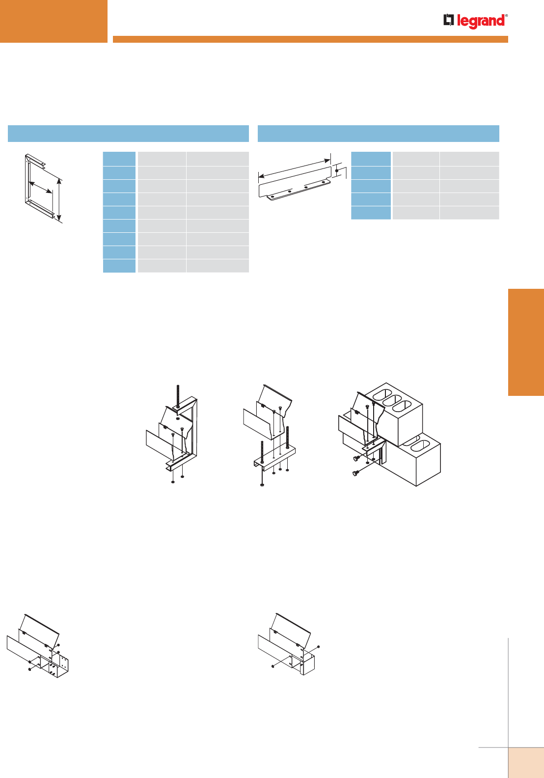
WWW.LEGRAND.US/WIREMOLD
103
STEEL RACEWAY
WIREMOLD
Typical Installation: The wireway should be installed as a complete system incorporating all fittings necessary to provide for directional
changes. All connections should be fastened securely with the fasteners provided by the manufacturer in order to ensure compliance with
UL and CSA bonding requirements. Conductors of appropriate types as outlined by the applicable Electrical Code may be used in wireway
following installation. Specific installation instructions are given below.
Installation:
For C-Hangers and Trapeze hangers, threaded rod should be cut to the appropriate length, and fastened to a structural member. The
hanger should then be bolted to the threaded rod through the holes provided, level and in line with the other hangers. Wall mounted
hangers should be fastened to structural members in the wall in a manner ensuring sufficient support strength. Once the wireway is in
place, it must be fastened to the hanger by any structurally sound method. Most installations use 1/4" [6.4mm] nuts and bolts fastened
through holes drilled in the wireway base. No sharp edges should be allowed in the wireway as a result of fastening. Fastening hardware
for hangers is not provided. UL Listed wireway with square cross sections of 2.5", 4", and 6" [64mm, 102mm, and 152mm] may be
supported on maximum spans of 10' [3m]. All other wireway shall be supported on spans of 5' [1.5m] or less.
C-Hanger: For widths
up to 12" [305mm].*
Trapeze Hanger: For
any size of wireway.*
Wall Bracket: For installations
along walls. For any size of
wireway.
Couplings are provided with necessary
hardware. Slide the coupling into the end
of the wireway and tighten the fasteners
with a wrench, ensuring they are secure.
Slide the end of the next length of wireway
over the other half of the coupling
and attach the fasteners. Repeat until
complete. Couplings are best located
at one-quarter of the distance between
supports (hangers).
Three styles of hangers may be
purchased with wireway.
Hanging Method
Installation of Couplings:
SPECMATE™ WIREWAY & ENCLOSURES
SpecMate Type 1 Wireway Installation Details
End Blanks provided with necessary
hardware. Slide the end blank into the end of
the wireway and tighten the fasteners with a
wrench, ensuring they are secure.
Installation of End Blanks
M
N
C110-4H
(Shown)
C14FB-10
(Shown)
B
10'
Changer Barrier – Field Installed
C125H 2 1/2" x 2 1/2" [64mm x 64mm]
C14H 4" x 4" [102mm x 102mm]
C16H 6" x 6" [152mm x 152mm]
C18H 8" x 8" [203mm x 203mm]
C112H 12" x 12" [305mm x 305mm]
C110-4H 10" x 4" [254mm x 102mm]
C112-6H 12" x 6" [305mm x 152mm]
C118-6T 18" x 6" [457mm x 152mm]
C124-6T 24" x 6" [610mm x 152mm]
C125FB 2 1/2" x 120" [64mm x 3m]
C14FB 4" x 120" [102mm x 3m]
C16FB 6" x 120" [152mm x 3m]
C18FB 8" x 120" [203mm x 3m]
C112FB 12" x 120" [305mm x 3m]
SpecMate Type 1 Wireway Ordering Information (continued)
NOTE: Refer to “Dimension Reference Chart” shown previously in this section. For divided fittings (two equal compartments), add suffix “D” (i.e. C14ED).
Consult factory to order unequal compartments.
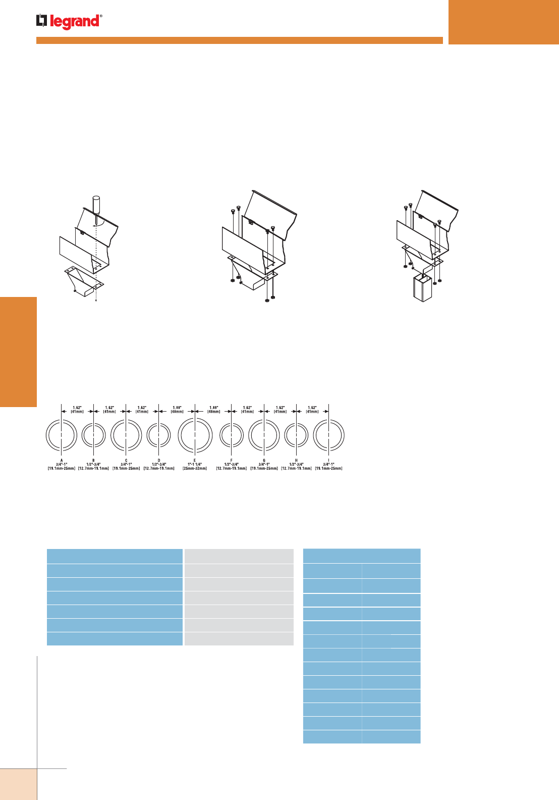
WWW.LEGRAND.US/WIREMOLD
104
STEEL RACEWAY
WIREMOLD
1. Locate the Pole Adapter on the wireway.
Drill holes in the appropriate locations to
match the holes in the Pole Adapter. Cut
and grommet hole to match pole adapter
entrance feed.
2. Bolt the Pole Adapter to the underside
of the wireway. No sharp edges should
remain in the wireway. (Bolts not
furnished.)
3. Insert the Wiremold NP600 Series Tele-
Power Pole into the underside of the
Pole Adapter. Tighten the two set screws
(furnished) onto the pole.
Installation of Tele-Power Pole Adapter:
SPECMATE™ WIREWAY & ENCLOSURES
SpecMate Type 1 Wireway Installation Details (continued)
“Type 1 Enclosures are intended for indoor use primarily to provide a degree of protection against contact with the
enclosed equipment and wiring.” – NEMA Standard / No. 250-1991
Standard Knockout Configuration
The knockout configuration shown below is referred to for each standard catalog number.
The following chart indicates the standard knockout pattern that can be accommodated according to the dimension
specified when custom sizes are ordered.
SpecMate Type 1 Wireway Enclosures Technical Data
Length of Side (L) Standard KO Configuration
4" [102mm] to less than 6" [152mm] B–C
6" [152mm] to less than 8" [203mm] B–C–D
8" [203mm] to less than 10" [254mm] F–G–H–I
10" [254mm] to less than 15" [381mm] C–D–E–F–G
15" [381mm] to less than 18" [457mm] B–C–D–E–F–G–H
18" [457mm] and up A–B–C–D–E–F–G–H–I
Standard Knockout Configuration for Custom Sizes
Metric Conversion
In. [mm]
4 [102]
6 [152]
8 [203]
10 [254]
12 [305]
15 [381]
18 [457]
20 [508]
24 [610]
30 [762]
36 [914]
48 [1220]
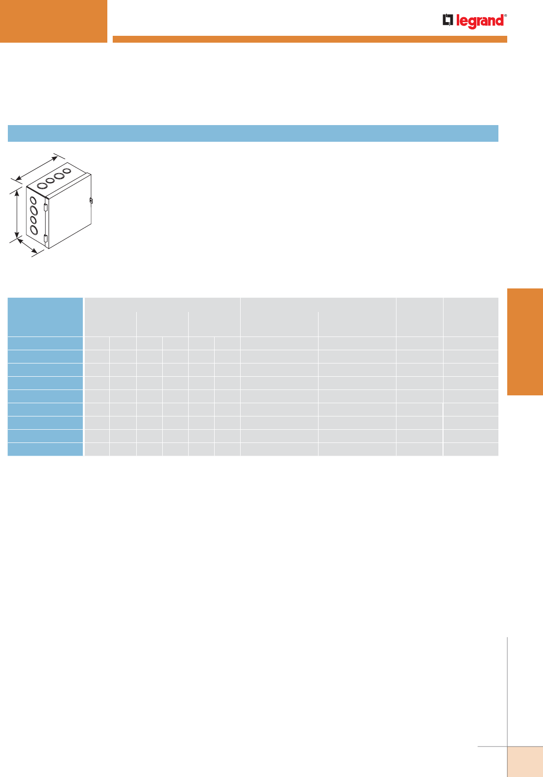
WWW.LEGRAND.US/WIREMOLD
105
STEEL RACEWAY
WIREMOLD
W
H
D
Hinged cover junction boxes for surface mounting. Formed steel hinges, friction catch and a
padlock hasp provide easy opening and secure closing.
Internal mounting holes and a ground terminal with ground screw provided.
Standard boxes are provided with concentric knockouts. Custom configurations and boxes without
knockouts are available on request. ANSI / ASA 61 gray finish inside and out.
SPECMATE™ WIREWAY & ENCLOSURES
SpecMate Type 1 Wireway Ordering Information
Hinged Cover Junction Box with Padlock Hasp
CATALOG NUMBER
BOX DIMENSIONS KNOCKOUT CONFIGURATION* INTERNAL
CU. IN.
(APPROX.)
STANDARD
HINGE TYPE
HEIGHT WIDTH DEPTH
FACE HEIGHT FACE WIDTHIn. [mm] In. [mm] In. [mm]
SPMJL-12-12-6 12 [305] 12 [305] 6 [152] C-D-E-F-G C-D-E-F-G 828 Formed
SPMJL-18-12-6 18 [457] 12 [305] 6 [152] A-B-C-D-E-F-G-H-I C-D-E-F-G 1247 Formed
SPMJL-18-18-6 18 [457] 18 [459] 6 [152] A-B-C-D-E-F-G-H-I A-B-C-D-E-F-G-H-I 1877 Formed
SPMJL-24-12-6 24 [610] 12 [305] 6 [152] A-B-C-D-E-F-G-H-I C-D-E-F-G 1666 Butt
SPMJL-24-18-6 24 [610] 18 [457] 6 [152] A-B-C-D-E-F-G-H-I A-B-C-D-E-F-G-H-I 2507 Butt
SPMJL-24-24-6 24 [610] 24 [610] 6 [152] A-B-C-D-E-F-G-H-I A-B-C-D-E-F-G-H-I 3349 Butt
SPMJL-20-20-10 20 [508] 20 [508] 10 [254] A-B-C-D-E-F-G-H-I A-B-C-D-E-F-G-H-I 3901 Butt
SPMJL-30-30-10 30 [762] 30 [762] 10 [254] A-B-C-D-E-F-G-H-I A-B-C-D-E-F-G-H-I 8814 Butt
SPMJL-36-24-10 36 [914] 24 [610] 10 [254] A-B-C-D-E-F-G-H-I A-B-C-D-E-F-G-H-I 8458 Continuous
Hinged Cover Junction Box with Padlock Hasp - Painted Steel
NOTE: Add "C" prefix to denote Canadian version -- Agency approved for sale in Canada.
*See standard knockout configuration diagram shown previously in this section.
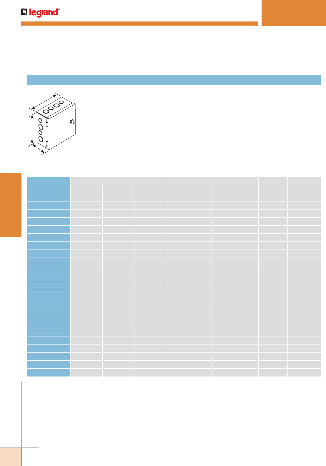
WWW.LEGRAND.US/WIREMOLD
106
STEEL RACEWAY
WIREMOLD
SPECMATE™ WIREWAY & ENCLOSURES
SpecMate Type 1 Wireway Ordering Information (continued)
Hinged cover junction boxes for surface mounting. Formed steel hinges, friction catch and a
“D” ring style handle provide easy opening and secure closing. Internal mounting holes and
a ground terminal with ground screw provided. Standard boxes are provided with concentric
knockouts. Custom configurations and boxes without knockouts are available on request.
ANSI/ASA 61 gray finish inside and out.
W
H
D
Hinged Cover Junction Box with Pull Ring
CATALOG NUMBER
BOX DIMENSIONS KNOCKOUT CONFIGURATION* INTERNAL
CU. IN.
(APPROX.)
STANDARD
HINGE TYPE
HEIGHT WIDTH DEPTH
FACE HEIGHT FACE WIDTHIn. [mm] In. [mm] In. [mm]
SPMJP-6-4-4 6 [152] 4 [102] 4 [102] B-C-D B-C 88 Formed
SPMJP-6-6-4 6 [152] 6 [152] 4 [102] B-C-D B-C-D 134 Formed
SPMJP-8-6-4 8 [203] 6 [152] 4 [102] F-G-H-I B-C-D 179 Formed
SPMJP-8-8-4 8 [203] 8 [203] 4 [102] F-G-H-I F-G-H-I 240 Formed
SPMJP-10-10-4 10 [254] 10 [254] 4 [102] C-D-E-F-G C-D-E-F-G 378 Formed
SPMJP-12-12-4 12 [305] 12 [305] 4 [102] C-D-E-F-G C-D-E-F-G 546 Formed
SPMJP-18-12-4 18 [457] 12 [305] 4 [102] A-B-C-D-E-F-G-H-I C-D-E-F-G 823 Formed
SPMJP-8-6-6 8 [203] 6 [152] 6 [152] F-G-H-I B-C-D 272 Formed
SPMJP-8-8-6 8 [203] 8 [203] 6 [152] F-G-H-I F-G-H-I 364 Formed
SPMJP-10-10-6 10 [254] 10 [254] 6 [152] C-D-E-F-G C-D-E-F-G 573 Formed
SPMJP-12-12-6 12 [305] 12 [305] 6 [152] C-D-E-F-G C-D-E-F-G 828 Formed
SPMJP-18-12-6 18 [457] 12 [305] 6 [152] A-B-C-D-E-F-G-H-I C-D-E-F-G 1247 Formed
SPMJP-18-18-6 18 [457] 18 [457] 6 [152] A-B-C-D-E-F-G-H-I A-B-C-D-E-F-G-H-I 1877 Formed
SPMJP-24-18-6 24 [610] 18 [457] 6 [152] A-B-C-D-E-F-G-H-I A-B-C-D-E-F-G-H-I 2507 Butt
SPMJP-24-24-6 24 [610] 24 [610] 6 [152] A-B-C-D-E-F-G-H-I A-B-C-D-E-F-G-H-I 3349 Butt
SPMJP-30-24-6 30 [762] 24 [610] 6 [152] A-B-C-D-E-F-G-H-I A-B-C-D-E-F-G-H-I 4190 Butt
SPMJP-18-12-8 18 [457] 12 [305] 8 [203] A-B-C-D-E-F-G-H-I C-D-E-F-G 1672 Formed
SPMJP-18-18-8 18 [457] 18 [457] 8 [203] A-B-C-D-E-F-G-H-I A-B-C-D-E-F-G-H-I 2516 Formed
SPMJP-24-18-8 24 [610] 18 [457] 8 [203] A-B-C-D-E-F-G-H-I A-B-C-D-E-F-G-H-I 3361 Butt
SPMJP-30-24-8 30 [762] 24 [610] 8 [203] A-B-C-D-E-F-G-H-I A-B-C-D-E-F-G-H-I 5617 Butt
SPMJP-36-24-8 36 [914] 24 [610] 8 [203] A-B-C-D-E-F-G-H-I A-B-C-D-E-F-G-H-I 6745 Continuous
SPMJP-36-24-12 36 [914] 24 [610] 12 [305] A-B-C-D-E-F-G-H-I A-B-C-D-E-F-G-H-I 10171 Continuous
Hinged Cover Junction Box with Pull Ring – Painted Steel
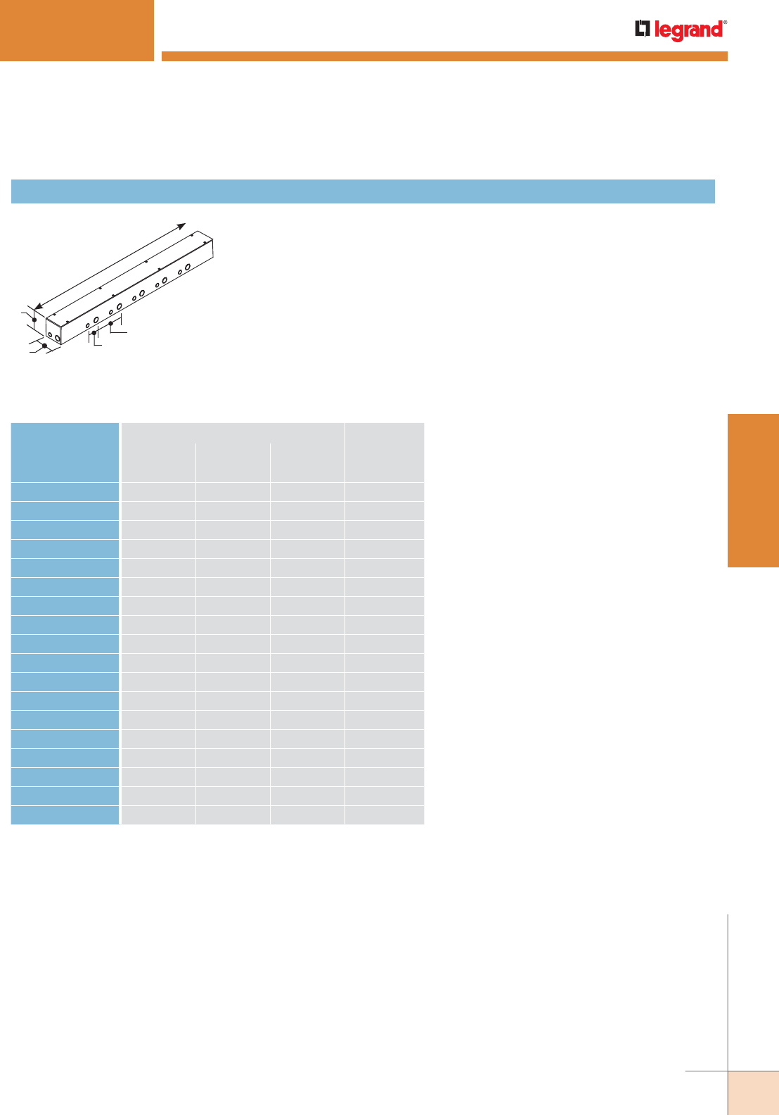
WWW.LEGRAND.US/WIREMOLD
107
STEEL RACEWAY
WIREMOLD
Screw-on cover wiring troughs are used as junction boxes or pull boxes for
surface mounting. Internal mounting holes and a ground terminal with ground
screw provided. Custom configurations of troughs up to 120" [3m] in length are
available with or without knockouts. ANSI/ASA 61 gray finish inside and out.
Clusters of 1/2" [12.7mm] – 3/4" [19.1mm] and 3/4" [19.1mm] – 1" [25mm] trade size knockouts are
spaced on 9" [229mm] centers along the trough. Other knockout sizes and spacings are available on
request.
H
D
W1 5/8"
[41mm]
9"
[229mm]
SPECMATE™ WIREWAY & ENCLOSURES
SpecMate Type 1 Wireway Ordering Information (continued)
Wiring Troughs
CATALOG NUMBER
BOX DIMENSIONS INTERNAL
CU. IN.
(APPROX.)
HEIGHT WIDTH DEPTH
In. [mm] In. [mm] In. [mm]
SPMJW-12-4-4 12 [305] 4 [102] 4 [102] 178
SPMJW-24-4-4 24 [610] 4 [102] 4 [102] 358
SPMJW-36-4-4 36 [914] 4 [102] 4 [102] 539
SPMJW-48-4-4 48 [1220] 4 [102] 4 [102] 719
SPMJW-60-4-4 60 [1525] 4 [102] 4 [102] 899
SPMJW-72-4-4 72 [1830] 4 [102] 4 [102] 1079
SPMJW-12-6-6 12 [305] 6 [152] 6 [152] 410
SPMJW-24-6-6 24 [610] 6 [152] 6 [152] 824
SPMJW-36-6-6 36 [914] 6 [152] 6 [152] 1238
SPMJW-48-6-6 48 [1220] 6 [152] 6 [152] 1652
SPMJW-60-6-6 60 [1525] 6 [152] 6 [152] 2067
SPMJW-72-6-6 72 [1830] 6 [152] 6 [152] 2481
SPMJW-18-8-8 12 [305] 8 [203] 8 [203] 736
SPMJW-24-8-8 24 [610] 8 [203] 8 [203] 1481
SPMJW-36-8-8 36 [914] 8 [203] 8 [203] 2225
SPMJW-48-8-8 48 [1220] 8 [203] 8 [203] 2969
SPMJW-60-8-8 60 [1525] 8 [203] 8 [203] 3713
SPMJW-72-8-8 72 [1830] 8 [203] 8 [203] 4457
Wiring Troughs - Painted Steel
NOTE: Add "C" prefix to denote Canadian version -- Agency approved for sale in Canada.
*See standard knockout configuration diagram shown previously in this section.
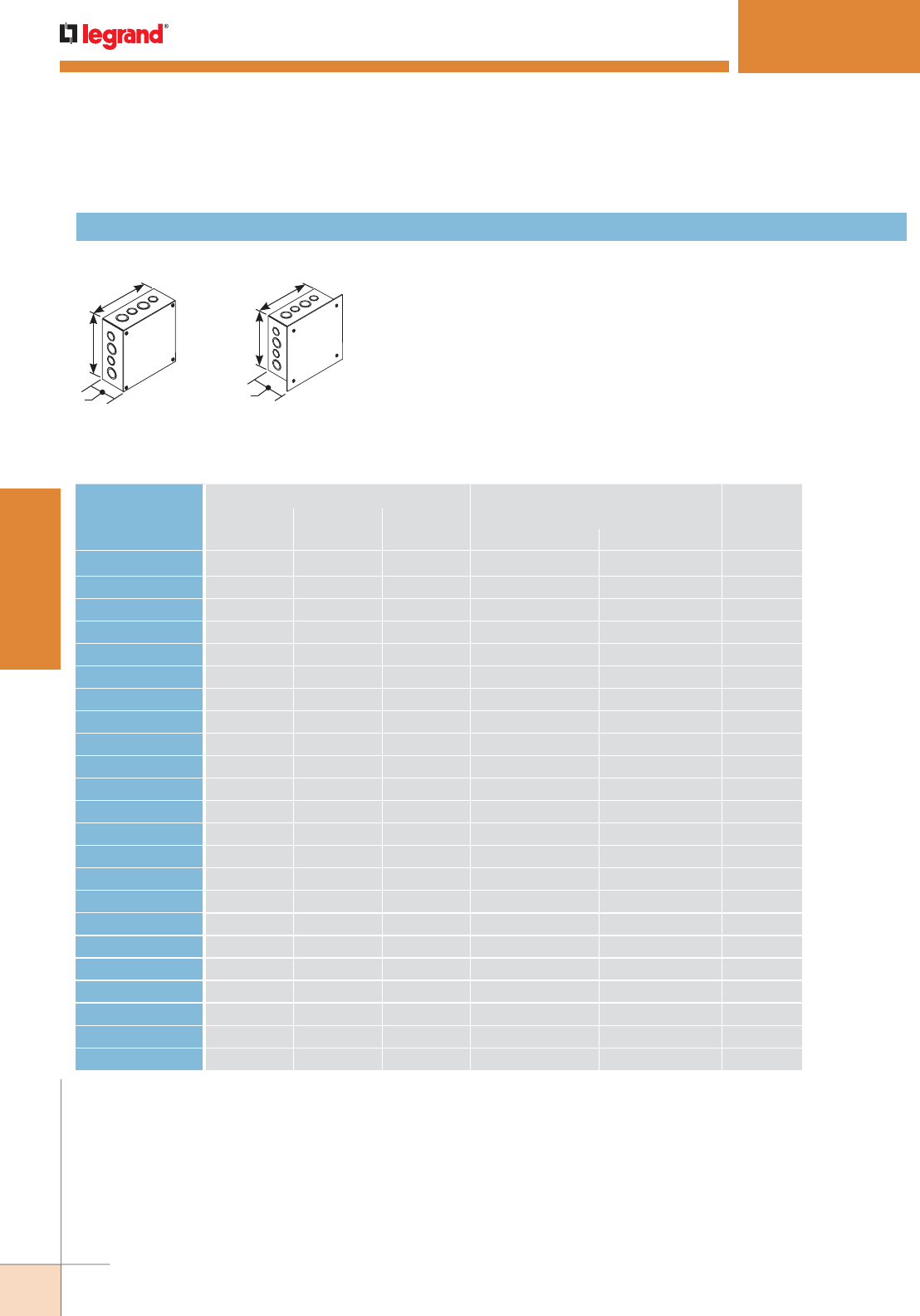
WWW.LEGRAND.US/WIREMOLD
108
STEEL RACEWAY
WIREMOLD
Screw-on cover junction boxes for surface or flush mounting. Internal
mounting holes and a ground terminal with ground screw provided. Standard
boxes are provided with concentric knockouts. Custom configurations and
boxes without knockouts are available on request. ANSI / ASA 61 Gray finish
inside and out.
Surface Mount
W
H
D
Flush Mount
W
H
D
SPECMATE™ WIREWAY & ENCLOSURES
SpecMate Type 1 Wireway Ordering Information (continued)
Surface Mount & Flush Mount Screw Cover Junction Boxes
CATALOG NUMBER
BOX DIMENSIONS
KNOCKOUT CONFIGURATION INTERNAL
CU. IN.
(APPROX.)
HEIGHT WIDTH DEPTH
In. [mm] In. [mm] In. [mm] HEIGHT FACE WIDTH
SPMJ-6-4-4 6 [152] 4 [102] 4 [102] B-C-D B-C- 88
SPMJ-6-6-4 6 [152] 6 [152] 4 [102] B-C-D B-C-D 134
SPMJ-8-6-4 8 [203] 6 [152] 4 [102] F-G-H-I B-C-D 179
SPMJ-8-8-4 8 [203] 8 [203] 4 [102] F-G-H-I F-G-H-I 240
SPMJ-10-10-4 10 [254] 10 [254] 4 [102] C-D-E-F-G C-D-E-F-G 378
SPMJ-12-12-4 12 [305] 12 [305] 4 [102] C-D-E-F-G C-D-E-F-G 546
SPMJ-18-12-4 18 [457] 12 [305] 4 [102] A-B-C-D-E-F-G-H-I C-D-E-F-G 823
SPMJ-18-18-4 18 [457] 18 [457] 4 [102] A-B-C-D-E-F-G-H-I A-B-C-D-E-F-G-H-I 1250
SPMJ-8-6-6 8 [203] 6 [152] 6 [152] F-G-H-I B-C-D 272
SPMJ-8-8-6 8 [203] 8 [203] 6 [152] F-G-H-I F-G-H-I 364
SPMJ-10-10-6 10 [254] 10 [254] 6 [152] C-D-E-F-G C-D-E-F-G 573
SPMJ-12-12-6 12 [305] 12 [305] 6 [152] C-D-E-F-G C-D-E-F-G 828
SPMJ-18-12-6 18 [457] 12 [305] 6 [152] A-B-C-D-E-F-G-H-I C-D-E-F-G 1247
SPMJ-18-18-6 18 [457] 18 [457] 6 [152] A-B-C-D-E-F-G-H-I A-B-C-D-E-F-G-H-I 1877
SPMJ-24-18-6 24 [610] 18 [457] 6 [152] A-B-C-D-E-F-G-H-I A-B-C-D-E-F-G-H-I 2507
SPMJ-24-24-6 24 [610] 24 [610] 6 [152] A-B-C-D-E-F-G-H-I A-B-C-D-E-F-G-H-I 3349
SPMJ-30-24-6 30 [762] 24 [610] 6 [152] A-B-C-D-E-F-G-H-I A-B-C-D-E-F-G-H-I 4190
SPMJ-18-12-8 18 [457] 12 [305] 8 [203] A-B-C-D-E-F-G-H-I C-D-E-F-G 1672
SPMJ-18-18-8 18 [457] 18 [457] 8 [203] A-B-C-D-E-F-G-H-I A-B-C-D-E-F-G-H-I 2516
SPMJ-24-18-8 24 [610] 18 [457] 8 [203] A-B-C-D-E-F-G-H-I A-B-C-D-E-F-G-H-I 3361
SPMJ-30-24-8 30 [762] 24 [610] 8 [203] A-B-C-D-E-F-G-H-I A-B-C-D-E-F-G-H-I 5617
SPMJ-36-24-8 36 [914] 24 [610] 8 [203] A-B-C-D-E-F-G-H-I A-B-C-D-E-F-G-H-I 6745
SPMJ-36-24-12 36 [914] 24 [610] 12 [305] A-B-C-D-E-F-G-H-I A-B-C-D-E-F-G-H-I 10171
Screw Cover Junction Boxes – Surface Mount – Painted Steel

WWW.LEGRAND.US/WIREMOLD
109
STEEL RACEWAY
WIREMOLD
CATALOG
NUMBER
BOX DIMENSIONS
KNOCKOUT CONFIGURATION* INTERNAL
CU. IN.
(APPROX.)
COVER DIMENSION
HEIGHT WIDTH DEPTH HEIGHT WIDTH
In. [mm] In. [mm] In. [mm] FACE HEIGHT FACE WIDTH In. [mm] In. [mm]
SPMJF-6-6-4 6 [152] 6 [152] 4 [102] B-C-D B-C-D 134 7.5 [191] 7.5 [191]
SPMJF-8-6-4 8 [203] 6 [152] 4 [102] F-G-H-I B-C-D 179 9.5 [242] 7.5 [191]
SPMJF-8-8-4 8 [203] 8 [203] 4 [102] F-G-H-I F-G-H-I 240 9.5 [242] 9.5 [242]
SPMJF-10-10-4 10 [254] 10 [254] 4 [102] C-D-E-F-G C-D-E-F-G 378 11.5 [292] 11.5 [292]
SPMJF-12-12-4 12 [305] 12 [305] 4 [102] C-D-E-F-G C-D-E-F-G 546 13.5 [343] 13.5 [343]
SPMJF-18-12-4 18 [457] 12 [305] 4 [102] A-B-C-D-E-F-G-H-I C-D-E-F-G 823 19.5 [534] 13.5 [343]
SPMJF-18-18-4 18 [457] 18 [457] 4 [102] A-B-C-D-E-F-G-H-I A-B-C-D-E-F-G-H-I 1250 19.5 [534] 19.5 [534]
SPMJF-8-6-6 8 [203] 6 [152] 6 [152] F-G-H-I B-C-D 272 9.5 [242] 7.5 [191]
SPMJF-8-8-6 8 [203] 8 [203] 6 [152] F-G-H-I F-G-H-I 364 9.5 [242] 9.5 [242]
SPMJF-10-10-6 10 [254] 10 [254] 6 [152] C-D-E-F-G C-D-E-F-G 573 11.5 [292] 11.5 [252]
SPMJF-12-12-6 12 [305] 12 [305] 6 [152] C-D-E-F-G C-D-E-F-G 828 13.5 [343] 13.5 [343]
SPMJF-18-12-6 18 [457] 12 [305] 6 [152] A-B-C-D-E-F-G-H-I C-D-E-F-G 1247 19.5 [534] 13.5 [343]
SPMJF-18-18-6 18 [457] 18 [457] 6 [152] A-B-C-D-E-F-G-H-I A-B-C-D-E-F-G-H-I 1877 19.5 [534] 19.5 [534]
SPMJF-24-18-6 24 [610] 18 [457] 6 [152] A-B-C-D-E-F-G-H-I A-B-C-D-E-F-G-H-I 2507 25.5 [649] 19.5 [534]
SPMJF-24-24-6 24 [610] 24 [610] 6 [152] A-B-C-D-E-F-G-H-I A-B-C-D-E-F-G-H-I 3349 25.5 [649] 25.5 [648]
SPMJF-30-24-6 30 [762] 24 [610] 6 [152] A-B-C-D-E-F-G-H-I A-B-C-D-E-F-G-H-I 4190 31.5 [775] 25.5 [648]
SPECMATE™ WIREWAY & ENCLOSURES
Screw Cover Junction Boxes - Flush Mount - Painted Steel
NOTE: Add “C” prefix to denote Canadian version — Agency approved for sale in Canada.
*See standard knockout configuration diagram shown previously in this section.

WWW.LEGRAND.US/WIREMOLD
110
STEEL RACEWAY
WIREMOLD
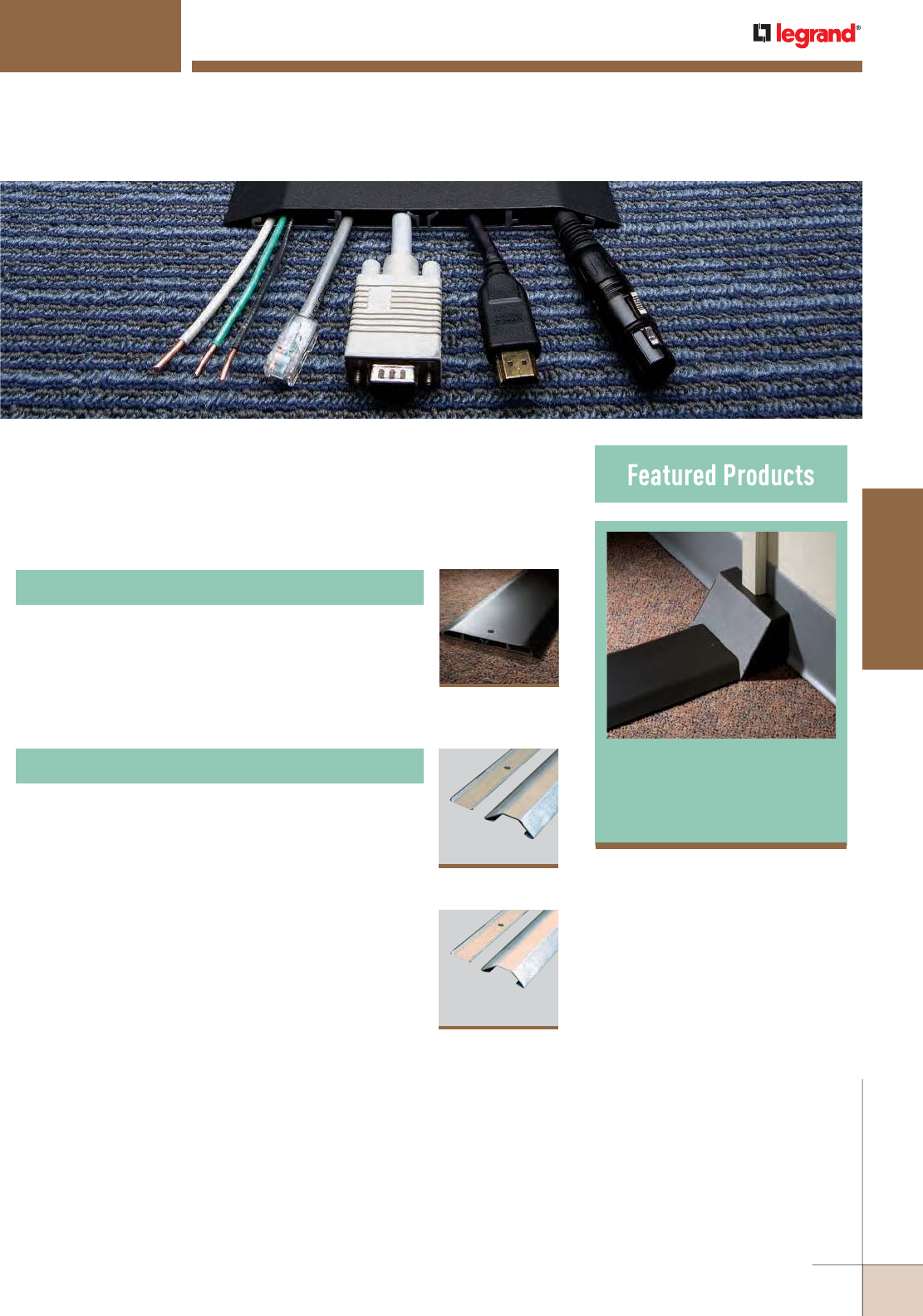
OFR Series
Overfloor
Raceway 113
OVERFLOOR RACEWAY
Wiremold® Overfloor Raceway Systems provide unique solutions to solve
specific installation issues when access to floors and ceilings is not an option
for installers, building owners, and designers.
Multiple-Channel Overfloor Raceway Systems
Steel Pancake Overfloor Raceway Systems
122
2600 Series™
Raceway
118
1500 Series™
Raceway
113
OFR Series
Overfloor Raceway
System
Table of Contents
WWW.LEGRAND.US/WIREMOLD
111
OVERFLOOR RACEWAY
WIREMOLD
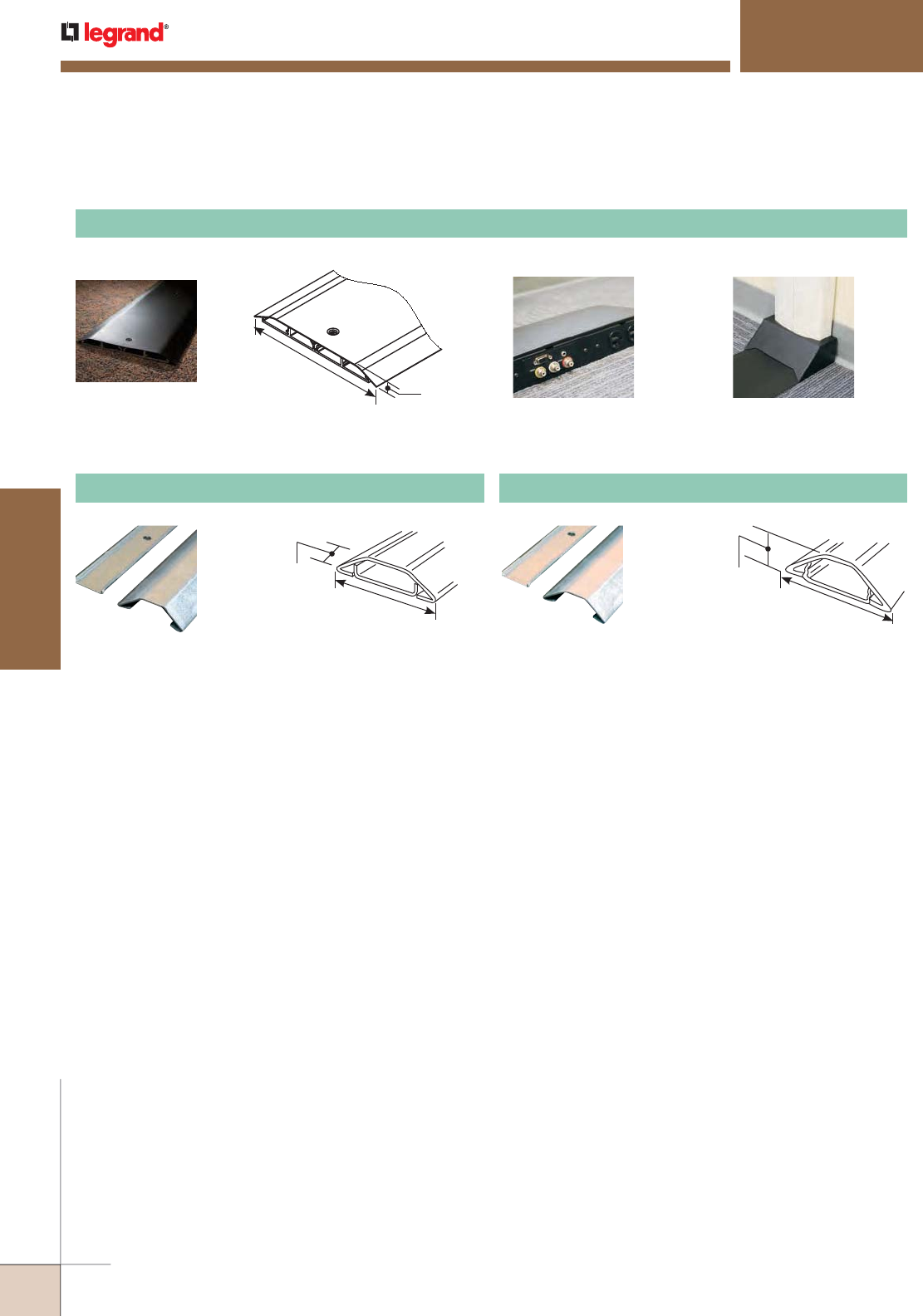
OVERFLOOR RACEWAY
Quick Selection Guide
OFR Series Overfloor Raceway Device Boxes Transition Fittings
6 7/8"
[175mm] 1/2"
[12.7mm]
Multiple-Channel Overfloor Raceway Systems
OFRB-8 & OFRC-8 OFR48-4 OFR89-DS4000
11/32"
[8.8mm]
1 9/16"
39mm]
23/32"
[18.3mm]
2 7/32"
[56.6mm]
1500 Series™ Raceway
Two-Piece Steel Single-Channel Overfloor Raceway Systems
2600 Series™ Raceway
WIREMOLD
WWW.LEGRAND.US/WIREMOLD
112
OVERFLOOR RACEWAY
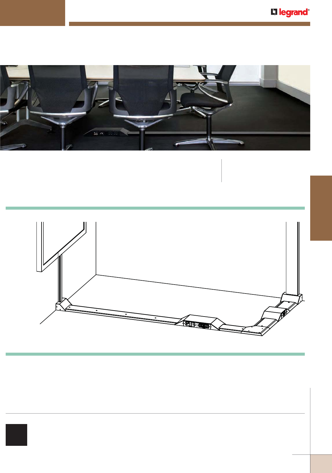
OFR SERIES OVERFLOOR RACEWAY
CODE REFERENCE
OFR Series Overfloor Raceway
System is cETLus Listed.
Wiremold® OFR Series Overfloor Raceway System provides four-channels
of capacity and access to a wide range of data and A/V connectivity
options in the smallest, lowest, narrowest, ADA compliant profile
available in over floor raceway systems.
COLOR OPTIONS
OFR Series Overfloor Raceway System is available with a
black powder coat finish that is also paintable.
OFR Series Overfloor Raceway System Layout
G
A
E
D
B
C
F
H
KEY
A. OFRBC-8 Overfloor Raceway Base & Cover
B. OFR11 90° Flat Elbow
C. OFR48-2 Two-Gang Device Box
D. OFR48-4 Four-Gang Device Box
E. OFR89-2400 Series Raceway Transition Fitting
F. OFR89-4000 Series Raceway Transition Fitting
G. 2400D Series Divided Raceway
H. 4000 Series Raceway
NOTE: Illustration is for showing product applications only.
WWW.LEGRAND.US/WIREMOLD
113
OVERFLOOR RACEWAY
WIREMOLD
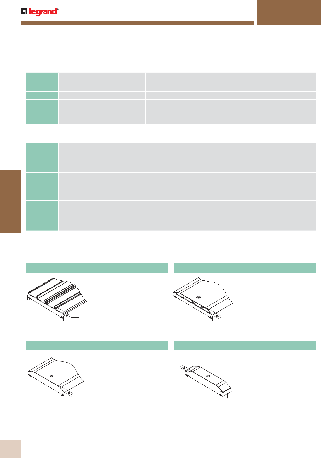
OFRB-8 Overfloor Raceway Base
OFR SERIES OVERFLOOR RACEWAY
Ordering Information
NOTE: For additional information, refer to the Technical Section.
* Category 6 augmented (6a) cable for 10 gigabit ethernet – max allowed cable diameter per addenda No. 11 ANSI TIA/EIA 568-B.2.
NOTE: Not recommended for use in high
traffic areas.
Base: 0.080” [2.0mm] aluminum.
Divided into four channels.
Packed four (4) 8’ [2.4m] lengths
per carton.
6"
[152mm] 7/16"
[11.1mm]
6 7/8"
[175mm] 1/2"
[12.7mm]
NOTE: Not recommended for use in high
traffic areas.
Cover: 0.040” [1.0mm] steel.
Durable black powder coat
finish. Packed four (4) 8’ [2.4m]
lengths of cover per carton.
OFR Series Raceway Wire Fill Capacities for Power
WIRE SIZE
THHN/THWN
O.D.
WIRE
CROSS-SECTIONAL
AREA
# OF WIRES PER
OUTER CHANNEL
(40% FILL)
# OF WIRES PER
OUTER CHANNEL
w/OFR1 (40% FILL)
# OF WIRES PER
OUTER CHANNEL
w/OFR9 (40% FILL)
# OF WIRES PER
INNER CHANNEL
(40% FILL)Inches [mm]
14 AWG 0.111 [2.8] 0.010 18 13 10 19
12 AWG 0.130 [3.3] 0.013 13 10 7 14
10 AWG 0.164 [4.2] 0.021 8 3 2 9
8 AWG 0.216 [5.5] 0.037 4 4 3 5
OFR Series Raceway Wire Fill Capacities for Communications
CABLE/WIRE SIZE
O.D.
APPROX. DIA.
WIRE
CROSS-
SECTIONAL
AREA
# OF WIRES
PER OUTER
CHANNEL
(40% FILL)
# OF WIRES
PER OUTER
CHANNEL
with OFR1
(40% FILL)
# OF WIRES
PER OUTER
CHANNEL
with OFR9
(40% FILL)
# OF WIRES
PER INNER
CHANNEL
(40% FILL)Inches [mm]
UNSHIELDED
TWISTED
PAIR
4-pair, 24 AWG, Cat 3
4-pair, 24 AWG, Cat 5e
4-pair, 24 AWG, Cat 6
4-pair, 24 AWG, Cat 6a*
0.190
0.210
0.250
0.354
[4.8]
[5.3]
[6.3]
[9.0]
0.028
0.035
0.049
0.098
6
5
3
1
4
3
2
1
3
2
2
1
6
5
3
2
COAXIAL RG6/U 0.270 [6.9] 0.057 3 2 1 3
FIBER ZipCord
Round 4 Strand Fiber
Round 6 Strand Fiber
0.118 x 0.236
0.187
0.256
[3 x 6]
[4.8]
[6.5]
0.025
0.027
0.051
7
6
3
5
4
2
3
3
1
7
6
3
OFRC-8 Overfloor Raceway Cover
NOTE: Not recommended for use in high
traffic areas.
Cover: 0.040" [1.0mm]
steel. Base: 0.080" [2.0mm]
aluminum. Durable black
powder coat finish. Divided into
four channels. Packed one (1) 8'
[2.4m] length of base and cover
per carton.
OFR6 Overfloor Raceway Seam Clip
Covers seam where two sections
of OFR Series Overfloor Raceway
cover come together.
6 7/8"
[175mm]
1/2"
[12.7mm]
OFRBC-8 Overfloor Raceway Base & Cover
7 5/32"
[182mm]
19/32"
[15.1mm]
1 1/2"
[38mm]
WIREMOLD
WWW.LEGRAND.US/WIREMOLD
114
OVERFLOOR RACEWAY
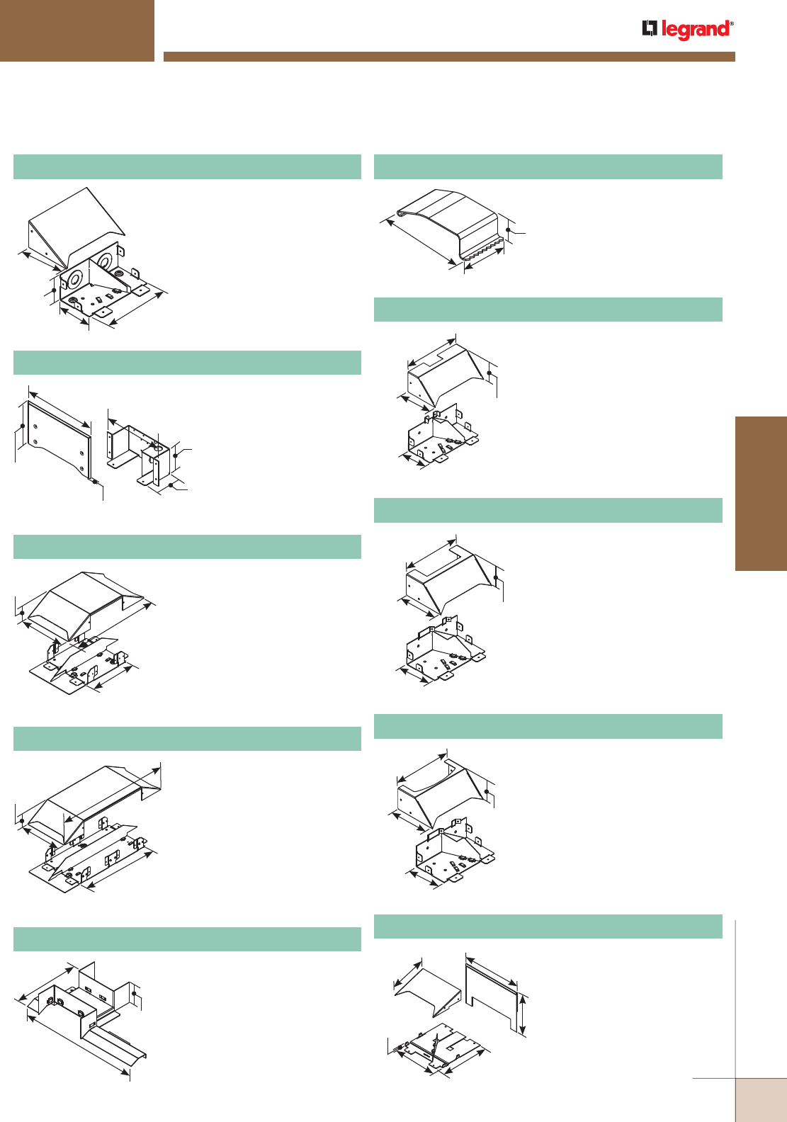
OFR SERIES OVERFLOOR RACEWAY
Ordering Information
1 13/32"
[36mm]
3/8"
[9.5mm]
3/4"
[19.1mm]
7"
[178mm]
6 15/16"
[176mm]
2 1/4"
[57mm]
13"
[330mm]
4"
[102mm]
2 9/16"
[65mm]
7 3/16"
[183mm]
3 1/4"
[83mm]
Divided two-gang device box.
Allows multiple services (power,
data, A/V) at a single point-of-
use. Side facing device mounting
provides low profile, with space
for large cable bend radius.
Accepts OFR Series device plates.
Removable divider can be aligned
with any of the raceway channels.
For holding conductors in place.
Packed twelve (12) per pack.
OFRWC Overfloor Raceway Wire Clips
Divided four-gang device box.
Allows multiple services (power,
data, A/V) at a single point-of-
use. Side facing device mounting
provides low profile, with space
for large cable bend radius.
Accepts OFR Series device
plates. Removable divider can be
aligned with any of the raceway
channels.
7"
[178mm]
12 1/2"
[318mm]
2 1/4"
[57mm]
18"
[457mm]
Allows access to power and
data on both sides of OFR48-4
4-Gang Device Box.
12 1/2"
[318mm]
2 1/8"
[54mm]
6 3/4"
[171mm]
OFR48-4 Overfloor Raceway 4-Gang Box
OFR48-4GX OFR Crossover Kit
OFR48-2 Overfloor Raceway 2-Gang Box
For connecting vertical runs of
2400 & 2400D Series Raceway
with OFR Series Raceway.
Includes removable divider than
can be positioned to feed any
raceway channel.
OFR89-2400 OFR 2400 Raceway Transition
OFR10IW OFR In-Wall Entrance End Fitting
Feeds OFR Series
Overfloor Raceway
from behind wall.
Configurable to provide
one or two channels
of power. Has 1/2"
trade size KO for single
channel and 3/4" trade
KO for two channel.
OFR10A Overfloor Raceway Entrance End Fitting
Feeds OFR Series Raceway,
Has two (2) concentric 1/2” and
1 1/4” trade size KOs on end.
Includes removable divider that
can be positioned to feed any
raceway channel. Can be used
to feed raceway from wall or
into furniture.
4 1/2"
[114mm]
6 15/16"
[176mm]
2 5/8"
[67mm]
3 1/2"
[89mm]
9 15/32"
[241mm]
3 15/32"
[88mm]
7 23/32"
[196mm]
5/32"
[4mm]
3 1/4"
[83mm]
5 7/16"
[138mm]
4 7/8"
[124mm]
2 9/16"
[65mm]
7 3/16"
[183mm]
3 15/16"
[100mm]
9 3/16"
[233mm]
6 1/4"
[159mm]
5 1/16"
[129mm]
6 15/16"
[176mm]
1/4"
[6.4mm]
7 9/16"
[192mm]
For connecting OFR Series
Raceway to Vista Point5
Architectural Columns.
OFR89-VIS Overfloor Vista Point5 Transition
For connecting vertical runs of
DS4000 Series Raceway with
OFR Series Raceway. Includes
removable divider than can be
positioned to feed any raceway
channel
OFR89-DS4000 OFR DS4000 Raceway Transition
4 7/8"
[124mm]
2 9/16"
[65mm]
7 3/16"
[183mm]
3 15/16"
[100mm]
For connecting vertical runs
of 4000 Series Raceway with
OFR Series Raceway. Includes
removable divider than can be
positioned to feed any raceway
channel.
OFR89-4000 OFR 4000 Raceway Transition
WWW.LEGRAND.US/WIREMOLD
115
OVERFLOOR RACEWAY
WIREMOLD
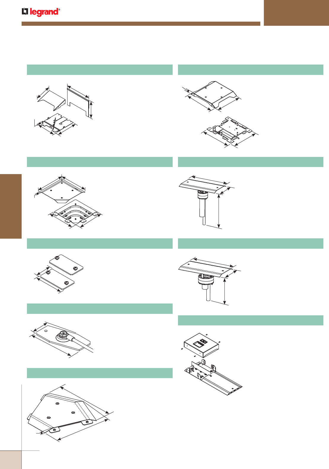
OFR SERIES OVERFLOOR RACEWAY
Ordering Information
2 1/2"
[64mm]
1 3/8"
[35mm]
2 1/2"
[64mm]
1 3/8"
[35mm] Connects equipment grounding
conductor to provide ground to
OFR Series Raceway. No. 10
ground screw provided.
OFR9 OFR Grounding Clip
Joins lengths of OFRB-8 OFR
Series Raceway Base together.
Sold in pairs.
OFR1 OFR Coupling
8 1/16"
[205mm]
1/2"
[12.7mm]
8 11/16"
[221mm]
8 11/16"
[221mm]
8 1/16"
[205mm]
For making right angle turns on
the same surface.
OFR11 OFR Flat Elbow
9 3/16"
[233mm]
6 1/4"
[159mm]
5 1/16"
[129mm]
6 15/16"
[176mm]
1/4"
[6.4mm]
7 9/16"
[192mm]
For connecting OFR Series
Raceway to Vista Architectural
Columns.
OFR89-VFL Overfloor Large Vista Transition
11 3/8"
[289mm]
1"
[25mm]
9 27/32"
[250mm]
11 1/8"
[283mm] 9 23/32"
[247mm]
8 1/2"
[216mm]
9/16"
[14.3mm]
8 1/4"
[210mm]
12 3/16"
[310mm]
7 1/16"
[179mm]
12 15/16"
[329mm]
12 3/16"
[310mm]
7 1/16"
[179mm]
9 7/16"
[240mm]
For making diagonal 45° turns
on the same surface.
OFR12 OFR 45° Flat Elbow
For branching OFR Series
Raceway at right angles.
Remove twistout on cover to
make a cross.
OFR15 OFR Tee/Cross
For bringing power, A/V, and
data through abandoned
Poke-Thru openings to open
spaces. Will replace any
3" poke-thru.
OFRPT3 OFR 3 Inch Poke-Thru Transition
For bringing power, A/V, and
data through abandoned
Poke-Thru openings to open
spaces. Will replace any 4"
poke-thru.
OFRPT4 OFR 4 Inch Poke-Thru Transition
Allows cords and cables to make a
smooth concealed transition to the
underside of the table when used
with the InteGreat™ Transition
Channel (MRTC).
OFR48-2MRTC OFR Transition Box
WIREMOLD
WWW.LEGRAND.US/WIREMOLD
116
OVERFLOOR RACEWAY
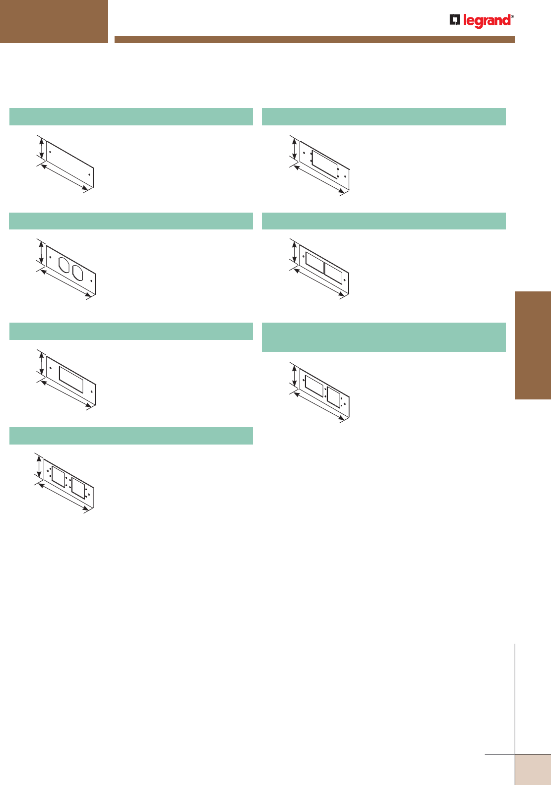
5 1/2"
[140mm]
2"
[51mm]
5 1/2"
[140mm]
2"
[51mm]
OFR47-U OFR Extron® MAAP-2A Device Plate
Device plate that will accept up
to four (4) Extron® Electronics
MAAP style plates in OFR48-2 and
OFR48-4 Device Boxes.
5 1/2"
[140mm]
2"
[51mm]
For covering unused
compartments in OFR48-2 and
OFR48-4 Device Boxes.
OFR47-B OFR Duplex Device Plate
5 1/2"
[140mm]
2"
[51mm]
For covering duplex style
devices in OFR48-2 and
OFR48-4 Device Boxes. Accepts
106 Frame.
OFR47-D OFR Duplex Device Plate
5 1/2"
[140mm]
2"
[51mm]
Device plate that will accept up to
four (4) ports of communications
devices. Includes adapters for
Ortronics® TracJack, Series II,
Pass & Seymour® Activate inserts
and Wiremold Open System
communication modules.
OFR47-2A OFR Communications Device Plate
5 1/2"
[140mm]
2"
[51mm] Device plate that will accept two
(2) Extron® Electronics AAP single
space modules.
OFR47-V OFR Extron® AAP Device Plate
For covering rectangular
decorator style devices in
OFR48-2 and OFR48-4 Device
Boxes.
OFR47-R OFR Decorator Device Plate
5 1/2"
[140mm]
2"
[51mm]
Combination device plate that
will accept up to two (2) Extron®
Electronics MAAP style plates
and up to two (2) ports of
communications devices. Includes
adapters for Ortronics® TracJack,
Series II, Pass & Seymour® Activate
inserts and Wiremold Open System
communication modules.
OFR47-U2A
OFR Extron® MAAP-2A Combo Device Plate
OFR SERIES OVERFLOOR RACEWAY
Ordering Information
WWW.LEGRAND.US/WIREMOLD
117
OVERFLOOR RACEWAY
WIREMOLD
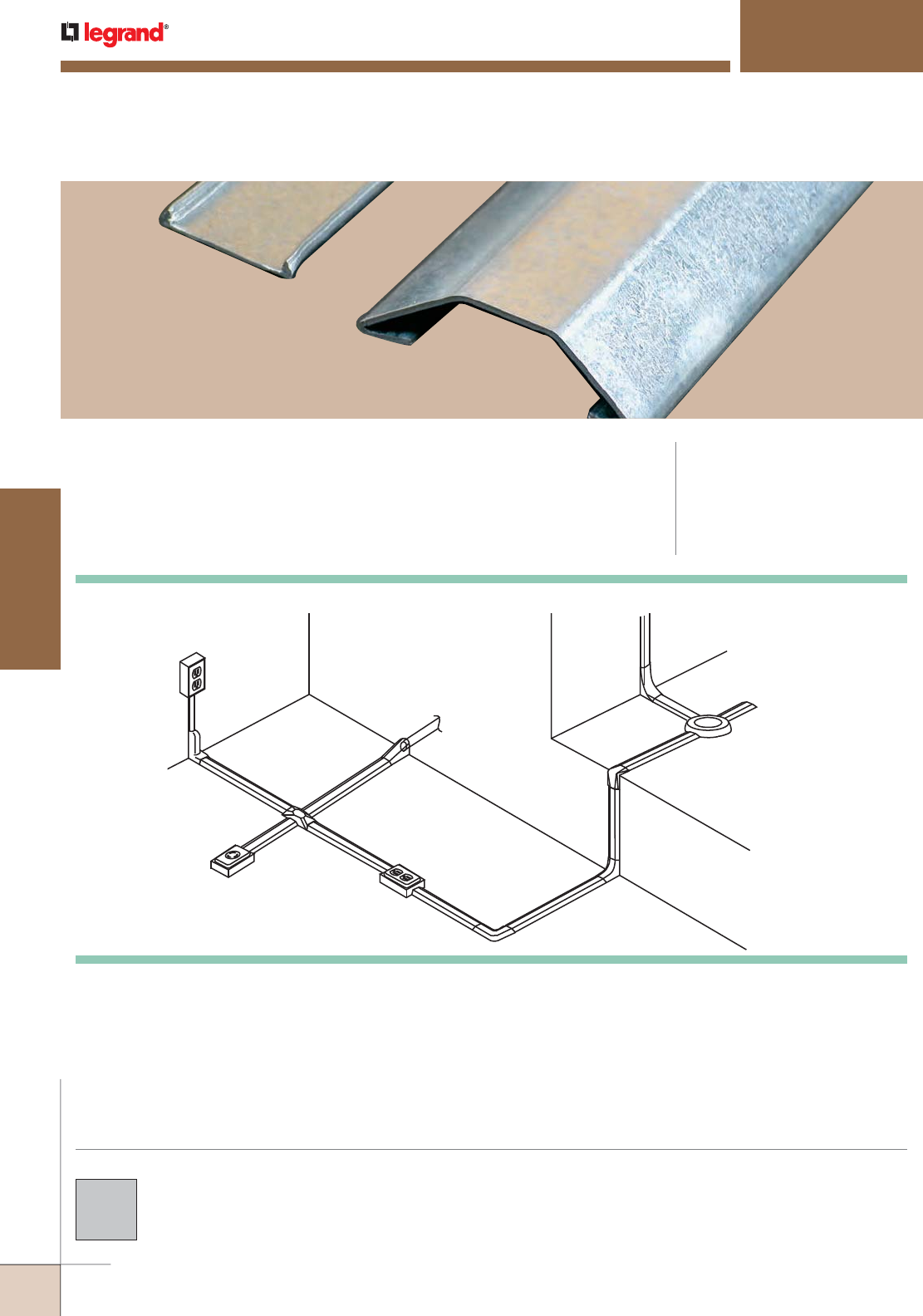
A
N
M
DBE
C
O
F
G
H
J
L
K
I
N
N
N
1500 SERIES™ OVERFLOOR RACEWAY
CODE REFERENCE
cULus Listed Underfloor Raceways:
File E4376 Guide RJBT.
Fittings: File E41751 Guide RJPR.
Meets Article 386 of NEC.
Meets Section 12-1600 of CEC.
Wiremold® 1500 Series™ Steel Pancake Raceway provides permanent
protection for overfloor cabling in high traffic areas.
KEY
A. V1517B Adapter Fitting
B. 1528 Utility Box
C. 1585 Combination Connector
D. 1546A Single Receptacle Box
E. 1546B Duplex Receptacle Box
F. 1511 90° Flat Elbow
G. 1517 Internal Elbow
H. 1518 External Elbow
I. 2642D Junction Box
J. 2686FO Transition Feed Fitting
K. 2600 Series Pancake Overfloor
Steel Raceway
L. 2400 Series Raceway
M. V500 500/700 Series Raceway
N. 1500 Raceway Base & Cover
O. 1/2" Conduit or Armored Cable
COLOR OPTIONS
1500 Series™ Raceway components are available in
galvanized steel unless otherwise indicated in the part
number description.
1500 Series Raceway System Layout
NOTE: Illustration is for showing product applications only.
WIREMOLD
WWW.LEGRAND.US/WIREMOLD
118
OVERFLOOR RACEWAY
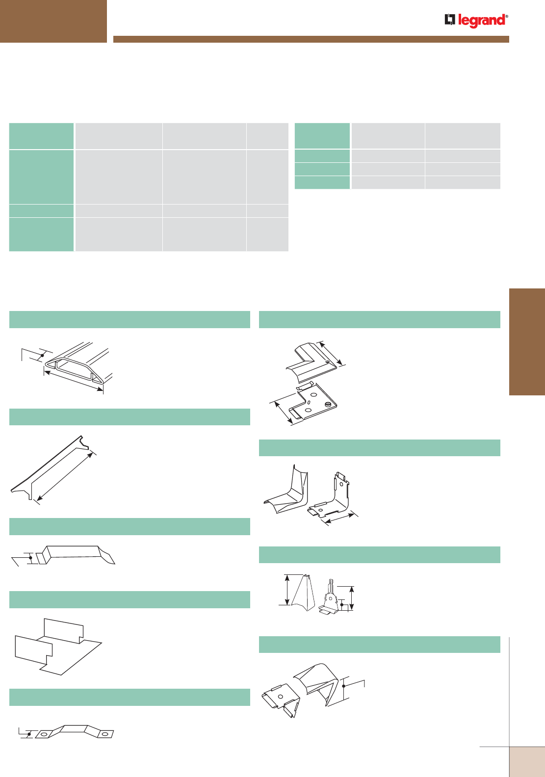
1500 SERIES™ OVERFLOOR RACEWAY
Ordering Information
3/8"
[9.5mm]
.040” [1.0mm] galvanized steel.
Packed ten 10’ [3m] lengths per
carton. Base has 9/32” [7.1mm]
diameter mounting holes on
centers of approximately 8”
[203mm].
11/32"
[8.8mm]
1 9/16"
39mm]
8 1/4"
209mm]
1500 Series Raceway Wire Fill Capacities for Power
WIRE SIZE
THHN/THWN
O.D. Approx. dia.) NO. OF CONDUCTORS
40% FILLInches [mm]
14 AWG 0.111 [2.8] 9
12 AWG 0.130 [3.3] 6
10 AWG 0.164 [4.2] 4
1500 Series Raceway Wire Fill Capacities for Communications
CABLE/WIRE SIZE
O.D. Approx. dia.)
40% FILLInches [mm]
UNSHIELDED
TWISTED PAIR
4-pair, 24 AWG, Cat 3
4-pair, 24 AWG, Cat 5e
4-pair, 24 AWG, Cat 6
4-pair, 24 AWG, Cat 6a*
25-pair, 24 AWG
0.190
0.210
0.250
0.354
0.410
[4.8]
[5.3]
[6.3]
[9.0]
[10.4]
3
2
1
0
0
COAXIAL RG6/U 0.270 [6.9] 1
FIBER ZipCord
Round 4 Strand Fiber
Round 6 Strand Fiber
0.118 x 0.236
0.187
0.256
[3 x 6]
[4.8]
[6.5]
3
3
1
NOTE: For additional information, refer to the Technical Section.
* Category 6 augmented (6a) cable for 10 gigabit ethernet – max allowed cable
diameter per addenda No. 11 ANSI TIA/EIA 568-B.2.
1500-10 Raceway Base & Cover
Protects wires from abrasion.
Slips into open end of 1500
Series Raceway where it enters
a fitting.
1502 Fiber Bushing
For holding conductors in place.
Not UL Listed.
1500WC Wire Clip
For removing cover of 1500
and 2600 Series Overfloor
Raceways.
656 Cover Removal Tool
2 1/2"
[64mm]
Ea. Leg
2 1/2"
[64mm]
2 15/16"
[75mm] 2 11/16"
[68mm]
2 1/8"
[54mm]
For external 90° corners.
1518 External Elbow
To feed to or from 500 or
700 Series Raceway on wall
to 1500 Series Raceway on
floor. Ivory finish.
V1517B Adapter Fitting
For internal 90° corners.
1517 Internal Elbow
1/2"
[12.7mm]
2 5/8"
[6.7mm]
Ea. Leg
1 3/4"
[44mm]
Ea. Leg
For right angle turns on the
same surface.
1511 90° Flat Elbow
Two-hole strap. Use to fasten
1500 Series Raceway to
surfaces at any point desired.
1504 Strap
WWW.LEGRAND.US/WIREMOLD
119
OVERFLOOR RACEWAY
WIREMOLD
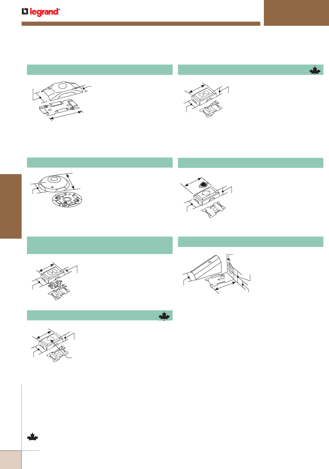
1 5/16"
[33mm]
5 1/16"
[129mm]
3 1/16"
[78mm]
1500 SERIES™ OVERFLOOR RACEWAY
Ordering Information
4"
[102mm]
Dia.
23/32"
[18.3mm]
1 5/16"
[33mm]
5 1/16"
[129mm]
3 1/16"
[78mm]
1 5/16"
[33mm]
1.405"
[36mm]
Dia.
5 1/16"
[129mm]
3 1/16"
[78mm]
1 5/16"
[33mm]
5 1/16"
[129mm]
3 1/16"
[78mm]
1 21/32"
[42mm]
3 1/4"
[83mm]
27/32"
[21.4mm]
3/4"
[19.1mm]
1 5/8"
[41mm]
May be used as a cross, tee or
elbow. Cover has 1/2" trade
size KO. Base has 1/2" and
3/4" concentric trade size KOs
to enable connection to floor
outlet boxes or underfloor duct
systems (use Chase nipple – not
included). Two 1500WC Wire
Clips included.
1542D Junction Box
Cover has twistouts for 1500 and
2600 Series Raceway on all four
sides. Base has 1/2" and 3/4"
trade size concentric KOs. Two
1500WC Wire Clips included.
Gray finish.
1543GL Grounding Duplex Receptacle 15A-125V
NEMA 5-15R & Cover
Furnished with 1/2" [12.7mm]
rubber stem. Designed to accept
modular connecting blocks
within the fitting. Nonmetallic
cover has 1500 and 2600 Series
Raceway twistouts on both ends
and both sides. Two 1500WC
Wire Clips included. Not UL
Listed. Gray finish.
1546T Telephone Outlet Box
For connecting 1/2"
trade size conduit or
armored cable to 1500
Series Raceway.
1585 Combination Connector
3 1/4"
[83mm]
1 21/32"
[42mm] 5/8"
[15.9mm]
Base and cover each
have 1/2" trade size KO.
May be used as a cross,
tee, straight through
or to terminate run.
Two 1500WC Wire Clips
included.
1528 Utility Box
Will accommodate commercially
available straight blade and
locking single receptacles with
face diameters of 1.38-1.40"
[35-36mm]. Base has 1/2" and
3/4" trade size concentric KOs.
Nonmetallic cover has 1500 and
2600 Series Raceway twistouts
on all four sides. Two 1500WC
Wire Clips included. Gray finish.
1546A Single Receptacle Box
NOTE: Box covers are manufactured of UL Listed Noryl plastic, gray
textured finish.
Will accommodate commercially
available 15A or 20A duplex
receptacles. Base has 1/2" and
3/4" concentric trade size KOs.
Nonmetallic cover has 1500 and
2600 Series Raceway twistouts
on all four sides. Two 1500WC
Wire Clips included. Side wiring
recommended. Gray finish.
1546B Duplex Receptacle Box
NOTE: Parts identified with this symbol are Certified to Canadian Safety
Standards for sale in Canada. When ordering these products, add “C”
prefix to part number to denote the Canadian version, i.e “C1546A”.
WIREMOLD
WWW.LEGRAND.US/WIREMOLD
120
OVERFLOOR RACEWAY
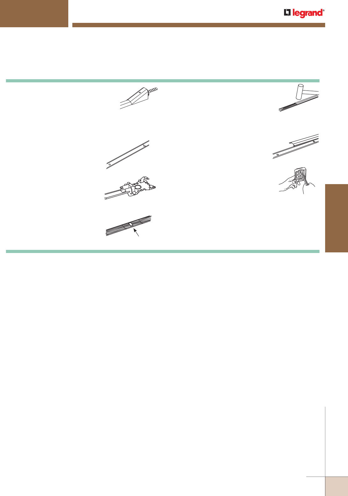
1500 SERIES™ OVERFLOOR RACEWAY
Ordering Information
500 & 700 Series Raceways Installation Details
2600 or 1500 Base
1. Determine method of feeding raceway
with 1517B, 1585 (shown), 2186 or
through a junction box or receptacle
box (i.e., 1542, 1546B).
2. Determine length of raceway base
to first fitting location. Cut base to
desired length.
4. Slip fitting tongue over raceway
base and fasten fitting base to
surface. Repeat steps 2-4 until
fitting and raceway bases are
installed along entire run.
5. Lay conductors in raceway base
using 1500WC or 2600WC Wire
Clips to hold conductors in place.
Wire and install devices along run.
3. Mount raceway base to surface using
No. 8 flathead fasteners through all
mounting holes provided.
6. Cut lengths of cover to fit between
fittings. (Cover must be shorter than
mating base: 3/8" [9.5mm] shorter
for 1500, 9/16" [14.3mm] shorter for
2600.) Snap covers onto base, latching
one side under the base bead and
striking cover with a rubber mallet.
7. When raceway bases are butted,
cover must be installed so that it
overlaps joint.
8. Remove proper twistouts in fitting
cover making sure that mounting
holes line up with fitting base.
Install cover with screws furnished.
2602 or 1502 Bushing
Wire clip
WWW.LEGRAND.US/WIREMOLD
121
OVERFLOOR RACEWAY
WIREMOLD

A
A
H
GK
D
B
CE
F
L
J
I
I
2600 SERIES™ OVERFLOOR RACEWAY
CODE REFERENCE
cULus Listed Underfloor Raceways:
File E4376 Guide RJBT.
Fittings: File E41751 Guide RJPR.
Meets Article 386 of NEC.
Meets Section 12-1600 of CEC.
2600 Series™ Raceway UL Code Reference, Color Options, System Layout,
Wire Fill Capacity Charts, Ordering Information, Installation Details and
Interconnectivity Options.
KEY
A. 2642D Junction Box
B. 1543GL Grounding Duplex Receptacle & Cover
C. 1546A Single Receptacle Box
D. 2611 90° Flat Elbow
E. 2686FO Transition Feed Fitting
F. 2400 Wiremold 2400 Series Raceway
G. 1500 Wiremold 1500 Series Raceway
H. V1517B Adapter Fitting
I. 2600 Wiremold 2600 Series Overfloor Steel Raceway
J. 500 Wiremold 200, 500 or 700 Series Raceway
K. Conduit 1/2" [12.7mm] Flexible Conduit
L. Conduit 1/2" or 3/4" Conduit to Underfloor Duct System
COLOR OPTIONS
2600 Series™ Raceway components are available in galvanized
steel unless otherwise indicated in the part number
description.
2600 Series Raceway System Layout
NOTE: Illustration is for showing product applications only.
WIREMOLD
WWW.LEGRAND.US/WIREMOLD
122
OVERFLOOR RACEWAY
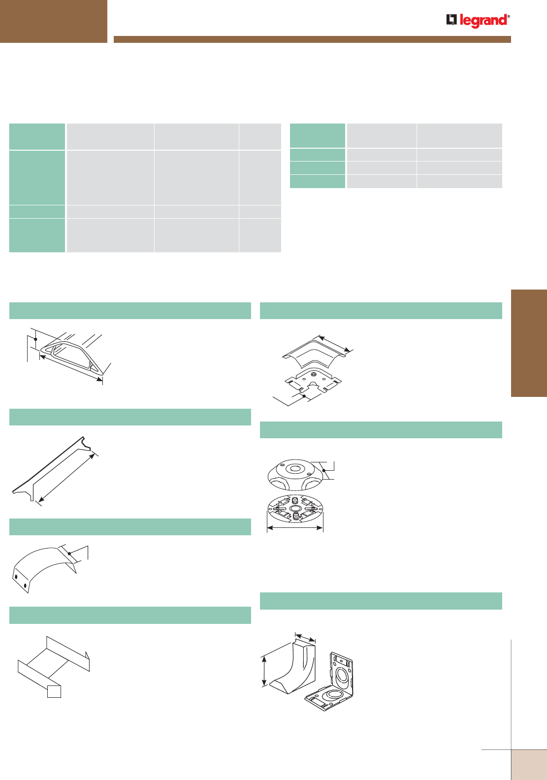
2600 SERIES™ OVERFLOOR RACEWAY
Ordering Information
Cover: .050" galvanized steel.
Base: .040" [1.0mm] galvanized
steel. Packed five 10' [3m]
lengths per carton. Base
has 9/32" [7.1mm] diameter
mounting holes on centers of
approximately 8" [203mm].
23/32"
[18.3mm] 2 7/32"
[56.6mm]
NOTE: For additional information, refer to the Technical Section.
* Category 6 augmented (6a) cable for 10 gigabit ethernet – max allowed cable
diameter per addenda No. 11 ANSI TIA/EIA 568-B.2.
2600 Series Raceway Wire Fill Capacities for Communications
CABLE/WIRE SIZE
O.D. Approx. dia.)
40% FILLInches [mm]
UNSHIELDED
TWISTED
PAIR
4-pair, 24 AWG, Cat 3
4-pair, 24 AWG, Cat 5e
4-pair, 24 AWG, Cat 6
4-pair, 24 AWG, Cat 6a*
25-pair, 24 AWG
0.190
0.210
0.250
0.354
0.410
[4.8]
[5.3]
[6.3]
[9.0]
[10.4]
10
8
5
2
2
COAXIAL RG6/U 0.270 [6.9] 5
FIBER ZipCord
Round 4 Strand Fiber
Round 6 Strand Fiber
0.118 x 0.236
0.187
0.256
[3 x 6]
[4.8]
[6.5]
10
10
5
2600 Series Raceway Wire Fill Capacities for Power
WIRE SIZE
THHN/THWN
O.D. Approx. dia.) NO. OF CONDUCTORS
40% FILLInches [mm]
14 AWG 0.111 [2.8] 29
12 AWG 0.130 [3.3] 21
10 AWG 0.164 [4.2] 13
For holding conductors in place.
2600WC Wire Clip
For removing cover of 1500 and
2600 Series Overfloor Raceways.
656 Cover Removal Tool
2600-10 Raceway Base & Cover
NOTE: Box covers are manufactured of UL Listed Noryl plastic, gray
textured finish.
3 5/8"
[92mm]
2 1/2"
[64mm]
Eliminates offsetting 2400 Series
Raceway in connecting with
surface panel boxes. Has 3/4"
and 1" concentric trade size KOs
with 1" trade size KO elongated
so adjustment from surface to
center of bushing is 1" [25mm]
to 1 5/8" [41mm] maximum. Has
twistouts for transition to 1500
and 2600 Series Raceway.
2686FO Transition Feed Fitting
4"
[102mm]
2 5/8"
[67mm]
2602 Fiber Bushing
Protects wires from abrasion.
Slips into open end of 2600
Series Raceway where it enters
a fitting.
For right angle turns on the
same surface.
2611 90° Flat Elbow
1"
[25mm]
5"
[127mm] Dia.
NOTE: Box covers are manufactured
of UL Listed Noryl plastic, gray
textured finish.
May be used with 1500 and/
or 2600 Series Raceway as a
cross, tee, or elbow. Cover has
1/2" trade size KO. Base has
1/2" and 3/4" concentric KO
to enable connection to floor,
outlet boxes or under floor duct
systems (use Chase nipple – not
included). Two 2600WC Wire
Clips included.
2642D Junction Box
8 1/4"
209mm]
3/4"
[19.1mm]
WWW.LEGRAND.US/WIREMOLD
123
OVERFLOOR RACEWAY
WIREMOLD
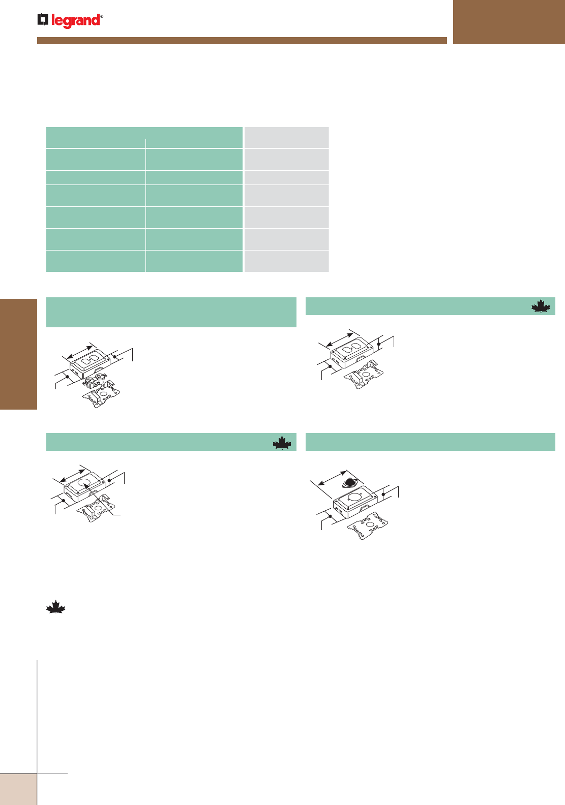
1 5/16"
[33mm]
5 1/16"
[129mm]
3 1/16"
[78mm]
1 5/16"
[33mm]
5 1/16"
[129mm]
3 1/16"
[78mm]
2600 SERIES™ OVERFLOOR RACEWAY
Ordering Information
Will accommodate commercially
available 15A or 20A duplex
receptacles. Base has 1/2" and
3/4" concentric trade size KOs.
Nonmetallic cover has 1500 and
2600 Series Raceway twistouts
on all four sides. Two 1500WC
Wire Clips included. Side wiring
recommended. Gray finish.
CONNECTION REQUIRED
USE CATALOG NUMBER
FROM TO
2600 Series Raceway 1500 Series Raceway 2642D, 1543GL, 1546A,
1546B, 1546T
2600 Series Raceway 2400 Series Raceway 2686FO
1/2" trade size Conduit or
Armored Cable
End of 1500 Series Raceway 1585
1/2" trade size Conduit or
Armored Cable
Bottom of 1500 Series
Raceway
1528
1/2" or 3/4" trade size
Conduit or Armored Cable
Bottom of 1500 or 2600
Series Raceway
2642D
1/2" or 3/4" trade size
Conduit or Armored Cable
Bottom of 1500 Series
Raceway
1542D
2600 Series Raceway Interconnectivity Fittings
1 5/16"
[33mm]
1.405"
[36mm]
Dia.
5 1/16"
[129mm]
3 1/16"
[78mm]
Will accommodate commercially
available straight blade and
locking single receptacles with
face diameters of 1.38-1.40"
[35-36mm]. Base has 1/2" and
3/4" trade size concentric KOs.
Nonmetallic cover has 1500 and
2600 Series Raceway twistouts
on all four sides. Two 1500WC
Wire Clips included. Gray finish.
1546A Single Receptacle Box
Furnished with 1/2" [12.7mm]
rubber stem. Designed to accept
modular connecting blocks
within the fitting. Nonmetallic
cover has 1500 and 2600 Series
Raceway twistouts on both ends
and both sides. Two 1500WC
Wire Clips included. Not UL
Listed. Gray finish.
1546T Telephone Outlet Box
1 5/16"
[33mm]
5 1/16"
[129mm]
3 1/16"
[78mm]
Cover has twistouts for 1500 and
2600 Series Raceway on all four
sides. Base has 1/2" and 3/4"
trade size concentric KOs. Two
1500WC Wire Clips included.
Gray finish.
1543GL Grounding Duplex Receptacle 15A-125V
NEMA 5-15R & Cover
NOTE: Parts identified with this symbol are Certified to Canadian Safety
Standards for sale in Canada. When ordering these products, add “C”
prefix to part number to denote the Canadian version, i.e “C1546A”.
1546B Duplex Receptacle Box
WIREMOLD
WWW.LEGRAND.US/WIREMOLD
124
OVERFLOOR RACEWAY
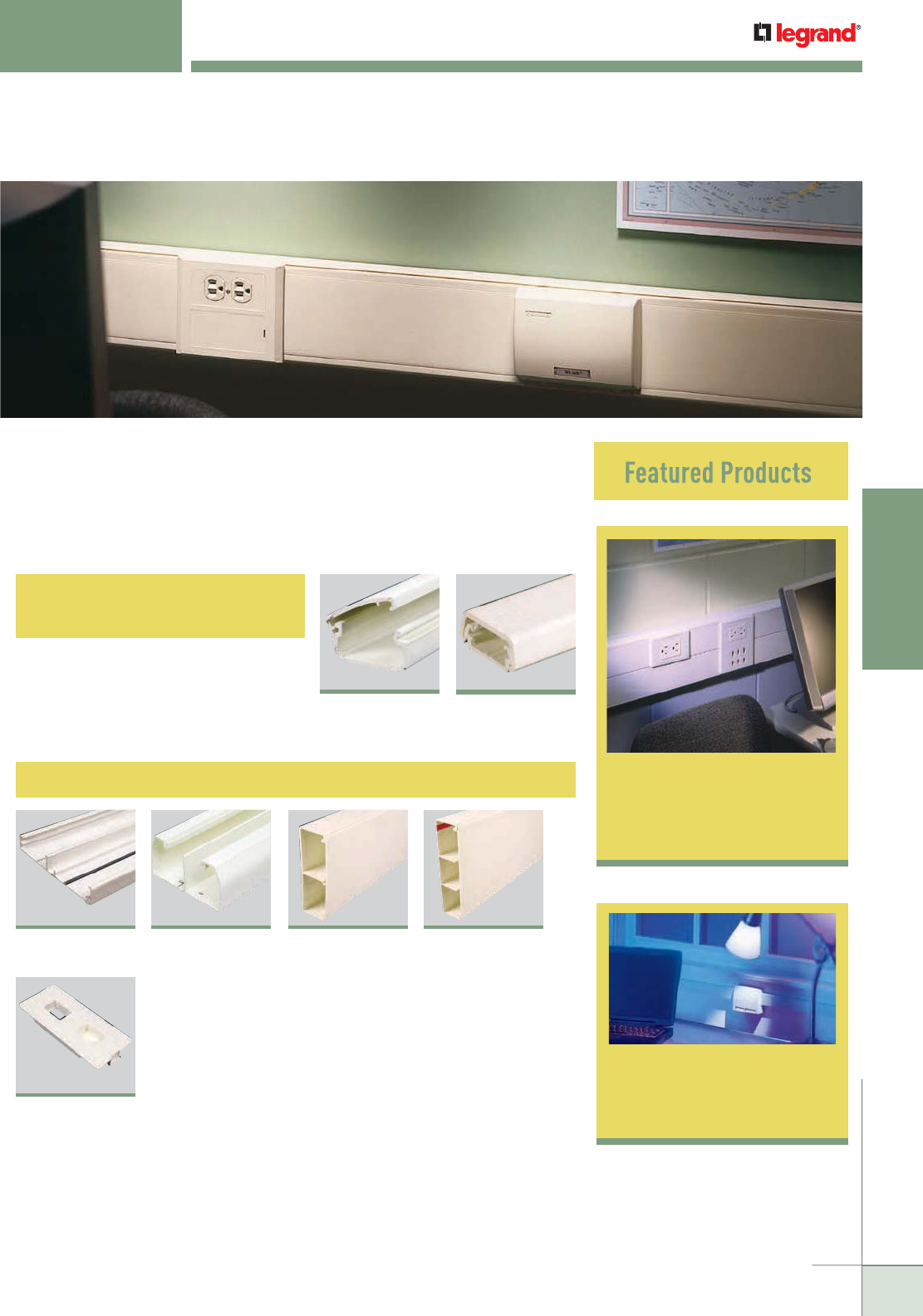
WWW.LEGRAND.US/WIREMOLD
125
NONMETALLIC RACEWAY
WIREMOLD
CableSmart™ 40N2
Series Raceway
NONMETALLIC RACEWAY
Wiremold® Nonmetallic Raceway is the industry leaders in quality, ease of
installation, and for providing pathway solutions for all types of installations.
For over 50 years, Wiremold Nonmetallic Surface Raceway Systems have
provided the highest quality, most dependable solutions for installers,
building owners, and designers.
Eclipse™ Series
Raceway 128
Large Capacity Multiple-Channel Raceways
142
Access® 5000
Series Raceway
158
5500 Series™
Raceway
148
CableSmart™ 40N2
Series Raceway
163
5507 Series™
Faceplates
151
5400 Series™
Raceway
Power-Rated Single-
and Dual-Channel Raceways
128
Eclipse™ PN03,
PN05, PN10
Series Raceway
133
400, 800,
2300/2300D
Series™ Raceway
148
Note: Uniduct is now in the Cord Management Section
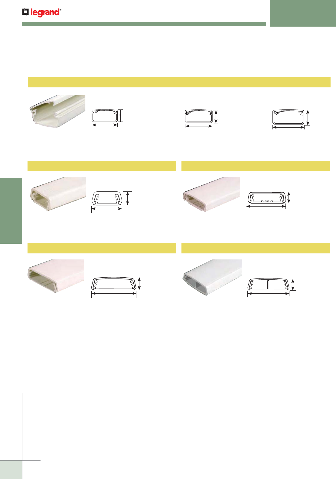
WWW.LEGRAND.US/WIREMOLD
126
NONMETALLIC RACEWAY
WIREMOLD
NONMETALLIC RACEWAY
Quick Selection Guide
Eclipse™ Series Raceway*
Power-Rated Single- & Dual-Channel Raceway Profiles
PN05L08 Raceway
7/8"
[22.2mm]
7/16"
[11.1mm]
400BAC Raceway
Capacity: 0.130 in.2 [83.9mm2]
800BAC Raceway
Capacity: 0.272 in.2 [175mm2]
7/16"
[11.1mm]
1 5/16"
[33mm]
2 1/4"
[57mm]
11/16"
[17.5mm]
11/16"
[17.5mm]
2 1/4"
[57mm]
Eclipse PN05*
Capacity: 0.538 in.2 [347mm2]
1 1/8"
[29mm]
5/8"
[15.9mm]
Eclipse PN10*
Capacity: 0.99 in.2 [638.7mm2]
1 11/16"
[43mm]
13/16"
[20.6mm]
Eclipse PN03*
Capacity: 0.285 in.2 [184mm2]
13/16"
[20.6mm]
1/2"
[12.7mm]
* UL Listed for up to 600V.
400 Series™ Raceway* 800 Series™ Raceway*
2300BAC Raceway
Capacity: 0.852 in.2 [550mm2]
2300BACD Raceway
Capacity: 0.426 in.2 [275mm2]
Each Compartment
2300 Series™ Raceway* 2300D Series™ Raceway*
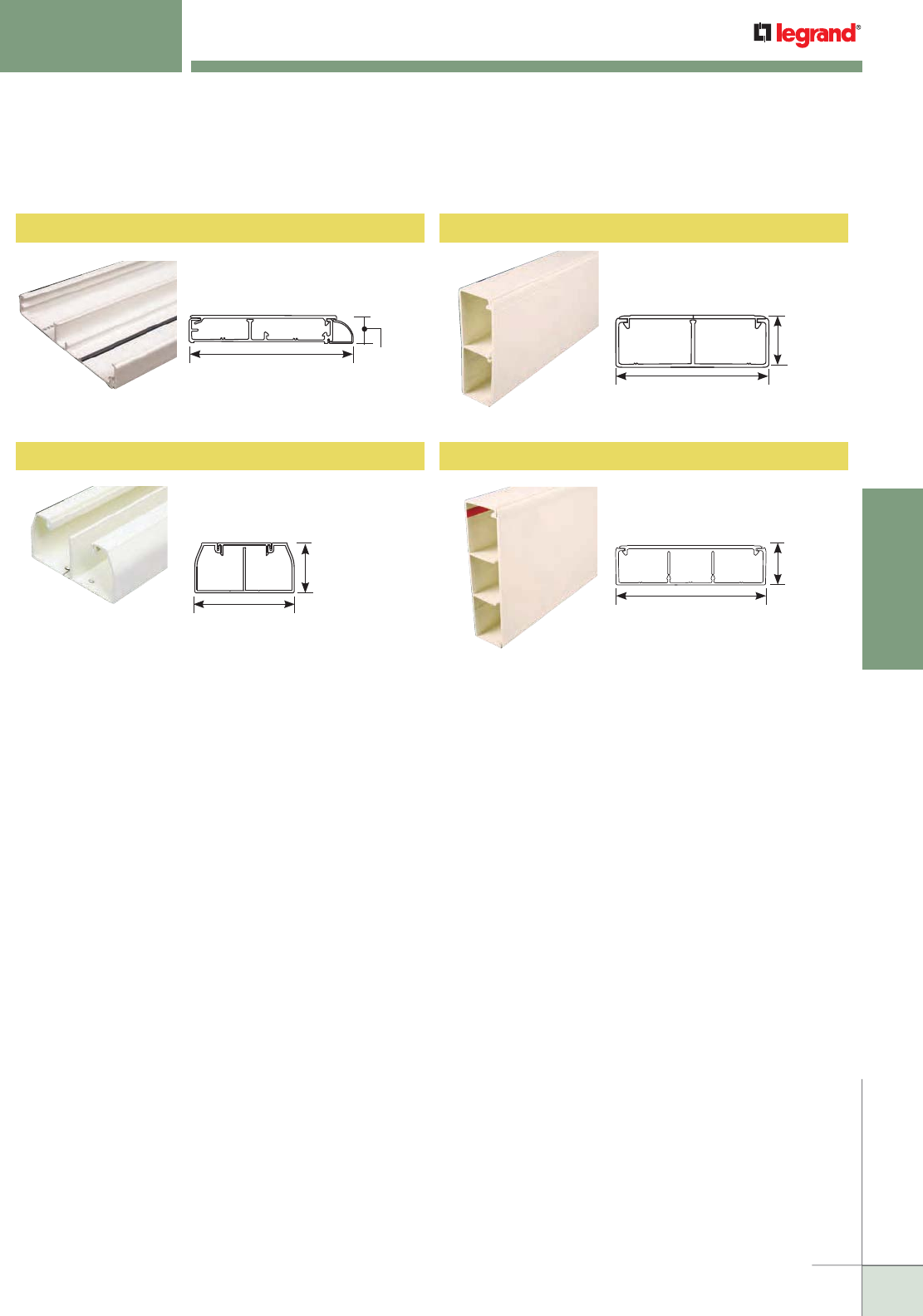
WWW.LEGRAND.US/WIREMOLD
127
NONMETALLIC RACEWAY
WIREMOLD
5400 Series™ Raceway
1 3/4"
[44mm]
5 1/4"
[133mm]
5400TB Raceway
Capacity: Each Compartment:
3.72 in.2 [2400mm2]
Access® 5000 Series Raceway
High Capacity Multiple Channel Raceway Profiles
NONMETALLIC RACEWAY
Quick Selection Guide
1 3/4"
[44mm]
6 11/16"
[170mm]
1"
[25mm]
5 3/4"
[146mm]
AB
5000B Raceway Base
Capacity: Compartment A: 1.39 in.2 [849mm2]
Compartment B: 1.94 in.2 [1250mm2]
5500 Series™ Raceway
5500BD3 Raceway
Capacity: Each Compartment:
2.64 in.2 [67mm2]
CableSmart® 40N2 Series Raceway
2"
[51mm]
4"
[102mm]
40N2B08 Raceway Base
Capacity: Each Compartment:
3.22 in.2 [2080mm2]
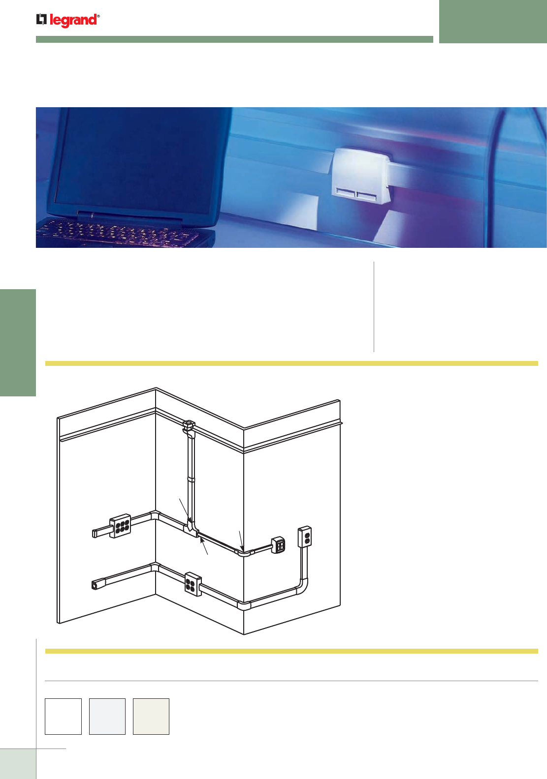
WWW.LEGRAND.US/WIREMOLD
128
NONMETALLIC RACEWAY
WIREMOLD
ECLIPSE™ SERIES RACEWAYS
Single Channel
CODE REFERENCE
cULus Listed Raceway:
File E90378 Guide RJTX.
Complies with flammability requirements of
UL-5A.
Fittings:
File E90377 Guide RJYT.
Meets Article 388 of NEC.
UL Listed for up to 600V.
Meets Section 12-1600 of CEC.
One-piece, latching, single-channel raceway available in three profiles.
Easy-to-install and ideal for demanding communication designs.
Accommodates communication or power wiring.
COLOR OPTIONS
Eclipse™ Series Raceway Part Numbers with a “-WH” suffix
have a white finish. Part Numbers with a “-FW” suffix have a
fog white finish. Part Numbers with a “-V” suffix have an ivory
finish. Eclipse Series Raceways are paintable using latex paint.
NOTE: Illustration is for showing product applications only.
I
N
H
M
E
E
D
K
GO
L
F
J
B
A
C
Eclipse Series PN03, PN05, PN10 Raceways System Layout KEY
A. PN03L08, PN03L10, PN05L08, PN05L10,
PN10L08, PN10L10 Latching Raceway
B. PN03F06, PN05F06, PN10F06 Cover Clip
C. PN03F11, PN05F11, PN10F11
90° Flat Elbow Fitting
D. PN03F15, PN05F15, PN10F15 Tee Fitting
E. PN03F17, PN05F17, PN10F17
Internal Elbow Fitting
F. PN03F18, PN05F18, PN10F18
External Elbow Fitting
G. PN03F19, PN05F19, PN10F19
Bend Radius External Elbow Fitting
H. PN03F20, PN05F20, PN10F20
Blank End Fitting
I. PN10F21 Entrance End Fitting
J. PN05F86, PN10F86 Drop Ceiling Connector
K. PN153R Reducer Adapter
L. PSB1 One-Gang Device Box
M. PSB2 Two-Gang Device Box
N. PSB3 Three-Gang Device Box
O. PBB2S2, PBB4TJ, PDB1CM, PDB1S2,
PDB2CM, PDB2S2, PDB4TJ
Communication Box
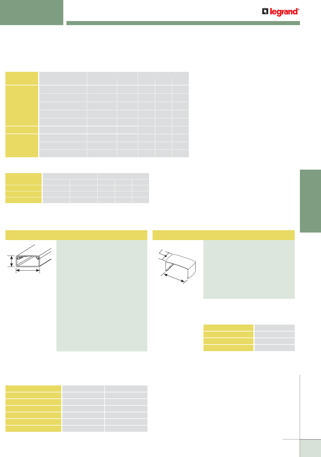
WWW.LEGRAND.US/WIREMOLD
129
NONMETALLIC RACEWAY
WIREMOLD
ECLIPSE™ SERIES RACEWAYS
Ordering Information
A
B
Latching Raceway
PART NUMBERS:
PN03L08FW (Fog White)
PN03L08V (Ivory)
PN03L08WH (White)
PN03L10FW (Fog White)
PN03L10V (White)
PN03L10WH (Ivory)
PN05L08FW (Fog White)
PN05L08V (Ivory)
PN05L08WH (White)
PN05L10FW (Fog White)
PN05L10V (Ivory)
PN05L10WH (White)
PN10L08FW (Fog White)
PN10L08V (Ivory)
PN10L08WH (White)
PN10L10FW (Fog White)
PN10L10V (Ivory)
PN10L10WH (White)
One-piece latching raceway with
co-extruded hinge and adhesive
backing. Available in 8' [2.44m] and
10' [3.0m] lengths.
CAT. NO. A B
PN03L08FW, V, WH 1/2" [12.7mm] 13/16" [20.6mm]
PN03L10FW, V, WH 1/2" [12.7mm] 13/16" [20.6mm]
PN05L08FW, V, WH 5/8" [15.9mm] 1 1/8" [29mm]
PN05L10FW, V, WH 5/8" [15.9mm] 1 1/8" [29mm]
PN10L08FW, V, WH 13/16" [20.6mm] 1 11/16" [43mm]
PN10L10FW, V, WH 13/16" [20.6mm] 1 11/16" [43mm]
CABLE/WIRE SIZE
O.D. APPROX. DIA. 40% FILL
Inches [mm] PN03 PN05 PN10
UNSHIELDED
TWISTED
PAIR
4-pair, 24 AWG, Cat 3 0.190 [4.8] 3 5 13
4-pair, 24 AWG, Cat 5e 0.210 (5.3) 2 5 11
4-pair, 24 AWG, Cat 6 0.250 (6.3) 1 3 8
4-pair, 24 AWG, Cat 6a* 0.354 (9.0) 0 1 4
25-pair, 24 AWG 0.410 (10.4) 0 1 3
COAXIAL RG6/U 0.270 [6.9] 1 3 6
FIBER ZipCord 0.118 x 0.236 [3 x 6] 3 6 14
Round 4 Strand Fiber 0.187 [4.8] 3 6 14
Round 6 Strand Fiber 0.256 [6.5] 1 3 7
Eclipse Series Raceway Wire Fill Capacities for Communications
WIRE SIZE
THHN/THWN
O.D. NO. OF CONDUCTORS
Inches [mm] PN03 PN05 PN10
14 AWG 0.111 [2.8] 8 16 15
12 AWG 0.130 [3.3] 7 14 20
10 AWG 0.164 [4.2] 0 0 19
NOTE: For additional information, refer to the Technical Section.
* Category 6 augmented (6a) cable for 10 gigabit ethernet – max allowed
cable diameter per addenda No. 11 ANSI TIA/EIA 568-B.2.
Eclipse Series Raceway Wire Fill Capacities for Power
For covering joint where two pieces of
Eclipse PN03, PN05, or PN10 Series
Raceway Cover come together.
Cover Clip
PART NUMBERS:
PN03F06FW (Fog White)
PN03F06V (Ivory)
PN03F06WH (White)
PN05F06FW (Fog White)
PN05F06V (White)
PN05F06WH (Ivory)
PN10F06FW (Fog White)
PN10F06V (Ivory)
PN10F06WH (White)
CAT. NO. A
PN03F06FW, V, WH 2 11/16" [68mm]
PN05F06FW, V, WH 2 15/16" [75mm]
PN10F06FW, V, WH 3 11/16" [94mm]
1"
[12.7mm]
A
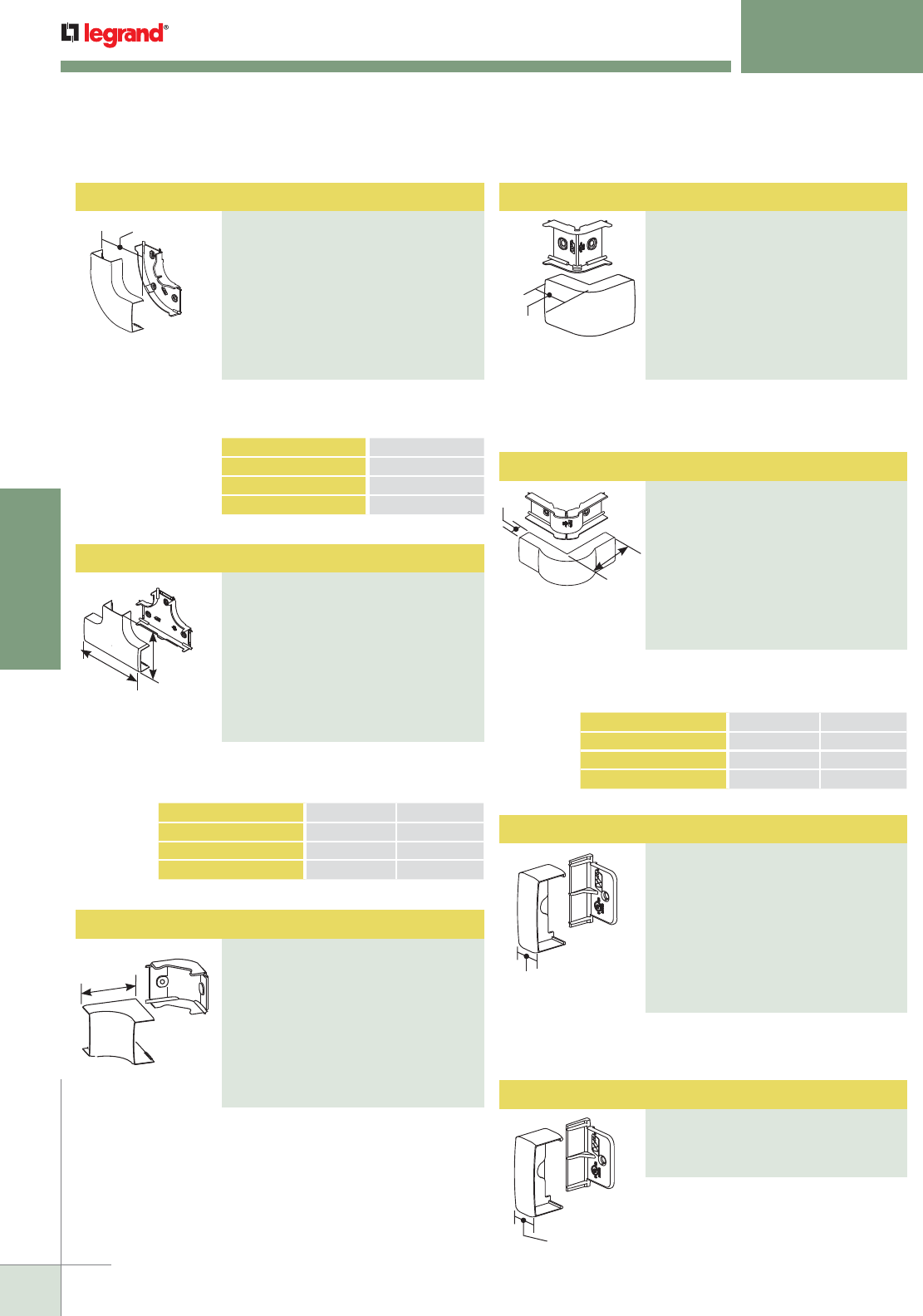
WWW.LEGRAND.US/WIREMOLD
130
NONMETALLIC RACEWAY
WIREMOLD
Tee
PART NUMBERS:
PN03F15FW (Fog White)
PN03F15WH (White)
PN03F15V (Ivory)
PN05F15FW (Fog White)
PN05F15WH (White)
PN05F15V (Ivory)
PN10F15FW (Fog White)
PN10F15WH (White)
PN10F15V (Ivory)
For branches of raceway running at
right angles. 1" [25mm] bend radius.
B
A
External Elbow
PART NUMBERS:
PN03F18FW (Fog White)
PN03F18WH (White)
PN03F18V (Ivory)
PN05F18FW (Fog White)
PN05F18WH (White)
PN05F18V (Ivory)
PN10F18FW (Fog White)
PN10F18WH (White)
PN10F18V (Ivory)
For right angle turns around external
corners.
1 5/8"
[41mm]
Each Leg
Reducer Adapter Fitting
PART NUMBERS:
PN153RFW (Fog White)
PN153RWH (White),
PN153RV (Ivory)
11/16"
[17.5mm
For adapting PN03 or PN05 Series
Raceway to a PN10 Series Raceway
trunking through the PN10F15 Tee
Fitting.
CAT. NO. A B
PN03F15FW, WH, V
2 11/16" [68mm] 4 5/16" [110mm]
PN05F15FW, WH, V 2 1
5/16" [75mm] 4 3/4" [121mm]
PN10F15FW, WH, V 3
11/16" [94mm] 5 5/16" [135mm]
Radiused Extruded Elbow
PART NUMBERS:
PN03F19FW (Fog White)
PN03F19WH (White)
PN03F19V (Ivory)
PN05F19FW (Fog White)
PN05F19WH (White)
PN05F19V (Ivory)
PN10F19FW (Fog White)
PN10F19WH (White)
PN10F19V (Ivory)
For right angle turns around external
corners. 1" [25mm] bend radius.
B
Each
Leg
A
CAT. NO. A B
PN03F19FW, WH, V
15/16" [23.8mm] 3 1/8" [79mm]
PN05F19FW, WH, V 1 3
/16" [30mm] 3 1/8" [79mm]
PN10F19FW, WH, V 1
3/16" [30mm] 3 3/8" [116mm]
ECLIPSE™ SERIES RACEWAYS
Ordering Information
PART NUMBERS:
PN03F20FW (Fog White)
PN03F20WH (White)
PN03F20V (Ivory)
PN05F20FW (Fog White)
PN05F20WH (White)
PN05F20V (Ivory)
PN10F20FW (Fog White)
PN10F20WH (White)
PN10F20V (Ivory)
Blank End Fitting
11/16"
[17.5mm
For closing open end of Eclipse PN03,
PN05, or PN10 series Raceway.
Internal Elbow
PART NUMBERS:
PN03F17FW (Fog White)
PN03F17WH (White)
PN03F17V (Ivory)
PN05F17FW (Fog White)
PN05F17WH (White)
PN05F17V (Ivory)
PN10F17FW (Fog White)
PN10F17WH (White)
PN10F17V (Ivory)
2 1/8"
[54mm]
Each Leg
For right angle turns around internal
corners. 1" [25mm] bend radius.
A
Flat Elbow
PART NUMBERS:
PN03F11FW (Fog White)
PN03F11V (Ivory)
PN03F11WH (White)
PN05F11FW (Fog White)
PN05F11V (Ivory)
PN05F11WH (White)
PN10F11FW (Fog White)
PN10F11V (Ivory)
PN10F11WH (White)
CAT. NO. A
PN03F11FW, V, WH 2 11/16" [68mm]
PN05F11FW, V, WH 2 15/16" [75mm]
PN10F11FW, V, WH 3 11/16" [94mm]
For right angle turns on the same
surface. 1" [25mm] bend radius.
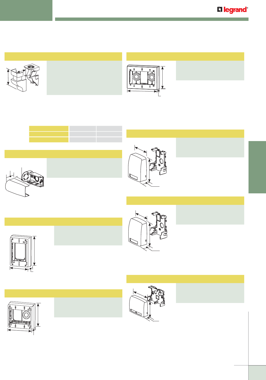
WWW.LEGRAND.US/WIREMOLD
131
NONMETALLIC RACEWAY
WIREMOLD
ECLIPSE™ SERIES RACEWAYS
Ordering Information
One-Gang Device Box
PART NUMBERS:
PSB1FW (Fog White)
PSB1WH (White)
PSB1V (Ivory)
Accepts all standard single-gang
NEMA faceplates and keystone
jacks. Twistouts on all four sides
for PN03, PN05, and PN10 Series
Raceways. Designed for use with
Ortronics® WiJack™ Wireless
Access Point.
4 3/4"
[121mm]
3"
[76mm]
1 3/4"
[44mm]
B
A
CAT. NO. A B
PN05F86FW, WH, V
1 5/16" [33mm] 4 3/8" [111mm]
PN10F86FW, WH, V 2 1
/2" [64mm] 4 3/8" [111mm]
For dropping cables from ceiling
into the raceway. Has 1/2" and 3/4"
concentric trade size KOs.Includes
PN153R Reducer Adapter
for use with PN03 Series Raceway.
Drop Ceiling Connector
PART NUMBERS:
PN05F86FW (Fog White)
PN05F86WH (White)
PN05F86V (Ivory)
PN10F86FW (Fog White)
PN10F86WH (White),
PN10F86V (Ivory)
For feeding raceway with 1/2" and 3/4"
trade size conduit or armored cable.
Has 1/2 and 3/4" concentric trade
size KOs. Includes PN153R Reducer
Adapter for use with PN03 and PN05
Series Raceway.
Entrance End Fitting
PART NUMBERS:
PN10F21FW (Fog White)
PN10F21WH (White),
PN10F21V (Ivory)
3 7/8"
[98mm]
7/8"
[22mm]
Surface mount box for use with
Eclipse Raceway or standalone
application. Accepts one front-
loaded downward facing
Ortronics® Series II insert.
2 7/8"
[73mm]
3 5/8"
[92mm]
1 7/16"
[36mm]
Series II Data Box
PART NUMBERS:
PDB1S2FW (Fog White)
PDB1S2WH (White)
PDB1S2V (Ivory)
Accepts all standard three-gang
NEMA faceplates and keystone
jacks. Twistouts on all four sides
for PN03, PN05, and PN10 Series
Raceways. Has 1/2" and 3/4"
concentric trade size KOs.
Designed for use with Ortronics®
WiJack™ Wireless Access Point.
7"
[178mm]
4 3/4"
[121mm]
1 3/4"
[44mm]
Three-Gang Device Box
PART NUMBERS:
PSB3FW (Fog White)
PSB3WH (White),
PSB3V (Ivory)
Accepts all standard two-gang
NEMA faceplates and keystone
jacks. Twistouts on all four sides
for PN03, PN05, and PN10 Series
Raceways. Has 1/2" and 3/4"
concentric trade size KOs, as well
as rectangular KO for wall box
mounting. Designed for use with
Ortronics® WiJack™ Wireless
Access Point.
4 7/8"
[124mm]
4 3/4"
[121mm]
1 3/4"
[44mm]
Two-Gang Device Box
PART NUMBERS:
PSB2FW (Fog White)
PSB2WH (White),
PSB2V (Ivory)
Surface mount box for use with
Eclipse Raceway or standalone
application. Has one 1/2" trade
size KO. Accepts one front-loaded
downward facing Pass &
Seymour® Activate or Wiremold®
Open System communication
module.
2 7/8"
[73mm]
3 5/8"
[92mm]
1 7/16"
[36mm]
Surface mount box for use with
Eclipse Raceway or standalone
application. Has two 1/2" trade
size KOs. Accepts two front-loaded
downward facing Ortronics® Series
II inserts.
5"
[127mm]
3 3/4"
[95mm]
1 7/16"
[36mm]
CM Data Box
PART NUMBERS:
PDB1CMFW (Fog White)
PDB1CMWH (White)
PDB1CMV (Ivory)
Series II Data Box
PART NUMBERS:
PDB2S2FW (Fog White)
PDB2S2WH (White)
PDB2S2V (Ivory)
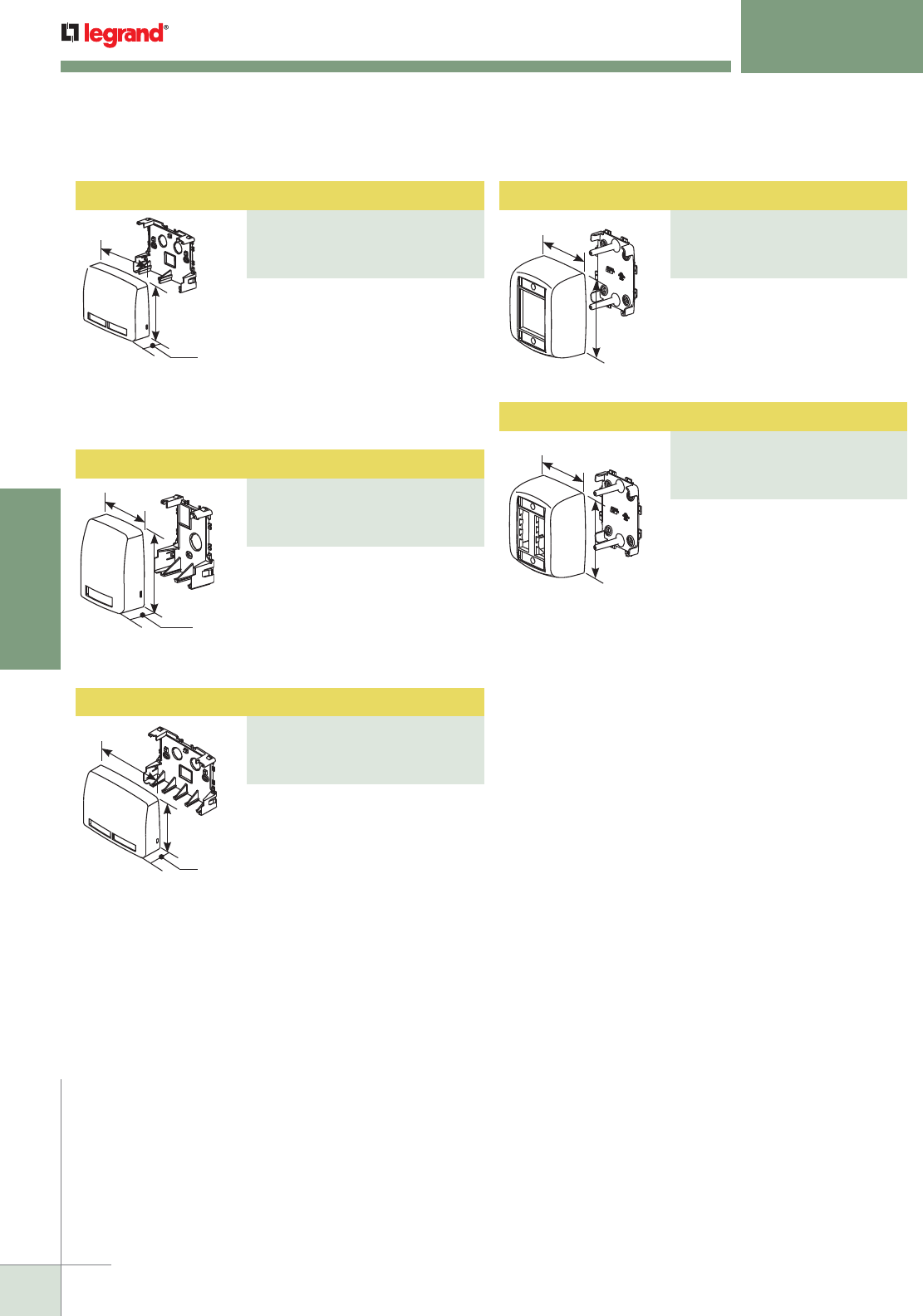
WWW.LEGRAND.US/WIREMOLD
132
NONMETALLIC RACEWAY
WIREMOLD
Surface mount box for use with
Eclipse Raceway or standalone
application. Accepts two front-
loaded outward facing Ortronics®
Series II inserts.
2 7/8"
[73mm]
3 5/8"
[92mm]
ECLIPSE™ SERIES RACEWAYS
Ordering Information
Surface mount box for use with
Eclipse Raceway or standalone
application. Has two 1/2" trade
size KOs. Accepts four front-
loaded downward facing
Ortronics® TracJack inserts.
5"
[127mm]
3 3/4"
[95mm]
1 7/16"
[36mm]
TracJack Data Box
PART NUMBERS:
PDB4TJFW (Fog White)
PDB4TJWH (White)
PDB4TJV (Ivory)
Bezel Box
PART NUMBERS:
PBB2S2FW (Fog White)
PBB2S2WH (White)
PBB2S2V (Ivory)
Surface mount box for use with
Eclipse Raceway or standalone
application. Accepts four front-
loaded outward facing Ortronics®
TracJack inserts.
3"
[76mm]
3 1/4"
[83mm]
Bezel Box
PART NUMBERS:
PBB4TJFW (Fog White)
PBB4TJWH (White)
PBB4TJV (Ivory)
Surface mount box for use with
Eclipse Raceway or standalone
application. Has two 1/2" trade
size KOs. Accepts two front-loaded
downward-facing Pass &
Seymour® Activate or Wiremold®
Open System communication
modules.
5"
[127mm]
3 3/4"
[95mm]
1 7/16"
[36mm]
Surface mount box for use with
Eclipse Raceway or standalone
application. Has one 1/2" trade
size KO. Accepts two front-loaded
downward facing Ortronics®
TracJack inserts.
2 7/8"
[73mm]
3 11/16"
[94mm]
1 7/16"
[36mm]
TracJack Data Box
PART NUMBERS:
PDB2TJFW (Fog White)
PDB2TJWH (White)
PDB2TJV (Ivory)
CM Data Box
PART NUMBERS:
PDB2CMFW (Fog White)
PDB2CMWH (White)
PDB2CMV (Ivory)
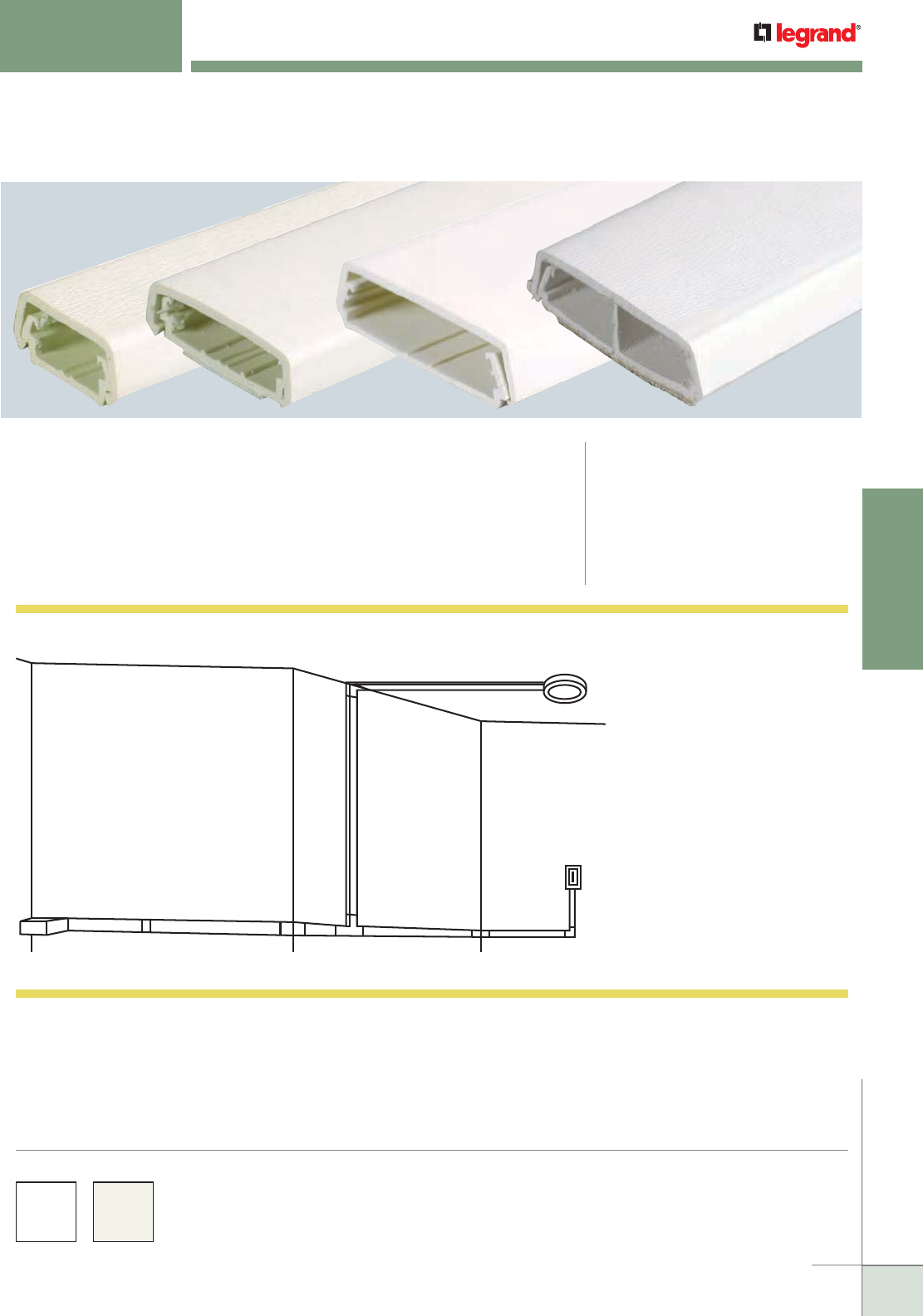
WWW.LEGRAND.US/WIREMOLD
133
NONMETALLIC RACEWAY
WIREMOLD
400, 800, 2300 & 2300D SERIES™ RACEWAYS
Two-Piece, Single- and Dual-Channel, Low Profile
CODE REFERENCE
cULus Listed Raceway:
File E90378 Guide RJTX.
Complies with flammability
requirements of UL-5A.
Fittings:
File E90377 Guide RJYT.
Meets Article 388 of NEC.
UL Listed for up to 600V.
Meets Section 12-1600 of CEC.
Two-piece, single- and dual-channel, low profile raceway. Easy-to-
install and ideal for power or communication installations.
COLOR OPTIONS
400, 800, 2300 Series Raceway Part Numbers with a “-WH” suffix
have a white finish. Part Numbers without a suffix have an ivory finish.
400, 800, 2300 Series Raceways are paintable using latex paint.
Custom color options are also available. Consult the factory for
more information.
400, 800, 2300 & 2300D Series Raceways System Layout
CAF
E
E
D
G
B
H
KEY
A. 406, 806, 2306 Cover Clip
B. 411, 811, 2311, 2311DFO Flat Elbow Fitting
C. 810A2, 2310A, 2310DFO Entrance End Fitting
D. 415, 815, 2315 Tee
E. 417, 817, 2317, 2317DFO Internal Elbow
F. 418, 818, 2318, 2318DFO External Elbow
G. 2337A, 2338A Round Device Boxes
H. 2344, 2347, 2348 Sure-Snap Device Boxes
NOTE: Illustration is for showing product applications only.
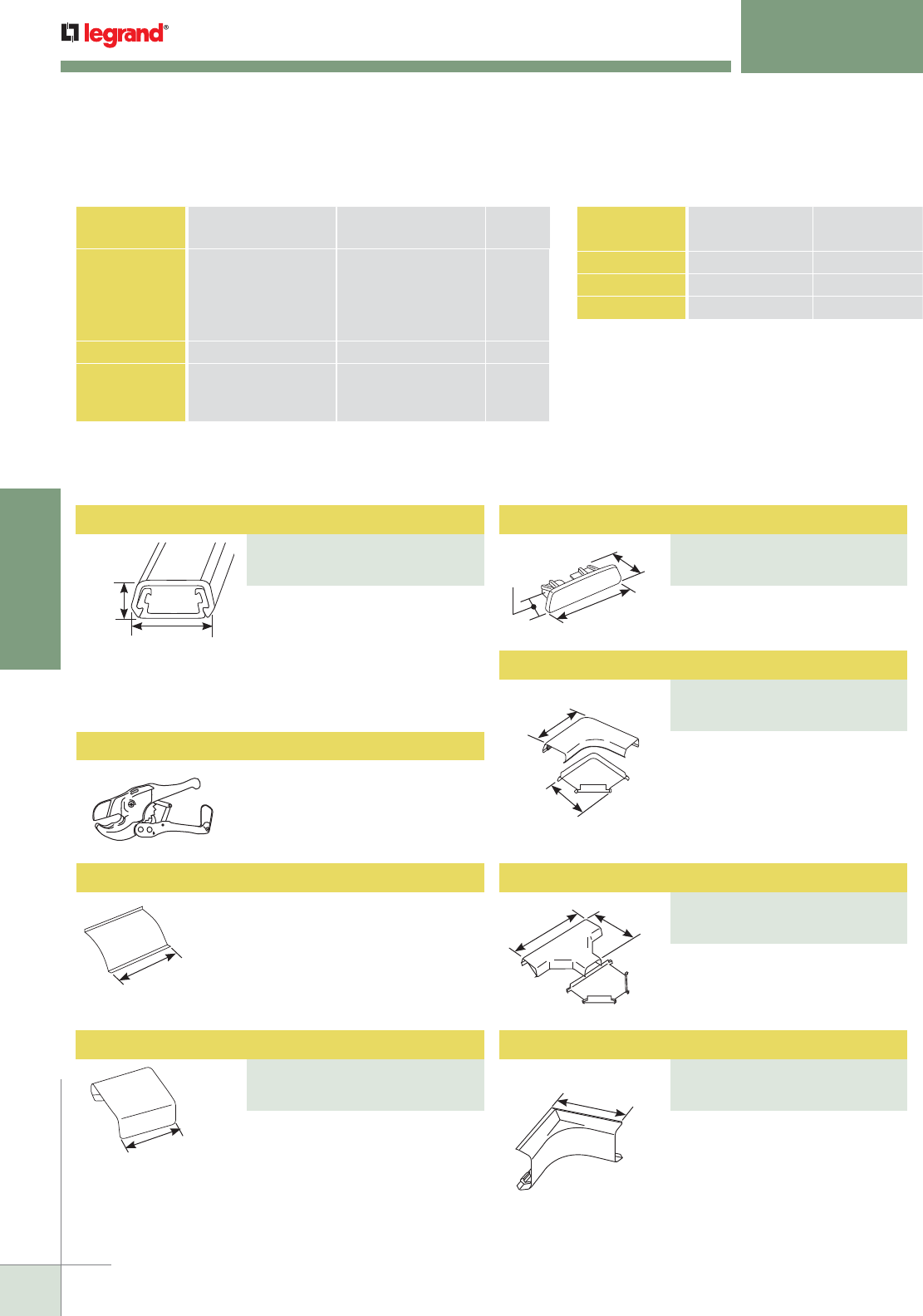
WWW.LEGRAND.US/WIREMOLD
134
NONMETALLIC RACEWAY
WIREMOLD
400, 800, 2300 & 2300D SERIES™ RACEWAYS
Ordering Information
Low-profile, two-piece raceway
with durable, textured PVC ivory
or white finishes. Available in
5' [1.52m] lengths. Packed 100'
[30.5m] per carton. Supplied with
wide adhesive tape along its entire
length.
Regular duty cutter. Ideal for use
with small nonmetallic raceways.
For covering joint where two
pieces of 400BAC Series Raceway
Cover come together.
400 Series Raceway Wire Fill Capacities for Communications
CABLE/WIRE SIZE
O.D. Approx. Dia.)
40% FILL Inches [mm]
UNSHIELDED
TWISTED PAIR
4-pair, 24 AWG, Cat 3
4-pair, 24 AWG, Cat 5e
4-pair, 24 AWG, Cat 6
4-pair, 24 AWG, Cat 6a*
25-pair, 24 AWG
0.190
0.210
0.250
0.354
0.410
[4.8]
[5.3]
[6.3]
[9.0]
[10.4]
1
1
1
0
0
COAXIAL RG6/U 0.270 [6.9] 0
FIBER ZipCord
Round 4 Strand Fiber
Round 6 Strand Fiber
0.118 x 0.236
0.187
0.256
[3 x 6]
[4.8]
[6.5]
1
1
1
NOTE: For additional information, refer to the Technical Section.
* Category 6 augmented (6a) cable for 10 gigabit ethernet – max allowed cable diameter
per addenda No. 11 ANSI TIA/EIA 568-B.2.
400 Series Raceway Wire Fill Capacities for Power
WIRE SIZE
THHN/THWN
O.D. NO. OF
CONDUCTORSInches [mm]
14 AWG 0.111 [2.8] 5
12 AWG 0.130 [3.3] 3
10 AWG 0.164 [4.2] 0
7/8"
[22.2mm]
7/16"
[11.1mm]
For holding conductors in place.
1/2"
[12.7mm]
13/16"
[20.6mm]
For closing open end of 400BAC
Series Raceway.
13/16"
[20.6mm]
3/8"
[9.5mm]
1/2"
[12.7mm]
For right angle turns on same
surface.
2 1/16"
[52mm] Ea.
Leg
1 3/8"
[35mm]
Ea. Leg
PVC-1 PVC Raceway Cutter
400WC Wire Clip
For branching of raceway running
at right angles.
3 3/16"
[81mm]
2"
[51mm]
1 1/2"
[38mm]
Ea. Leg
For right angle turns around
internal corners.
Raceway Base and Cover
PART NUMBERS:
400BAC (Ivory)
400BAC-WH (White)
Blank End Fitting
PART NUMBERS:
410B (Ivory)
410B-WH (White)
Cover Clip
PART NUMBERS:
406 (Ivory),
406-WH (White)
Flat Elbow
PART NUMBERS:
411 (Ivory)
411-WH (White)
Tee
PART NUMBERS:
415 (Ivory)
415-WH (White)
Internal Elbow
PART NUMBERS:
417 (Ivory)
417-WH (White)
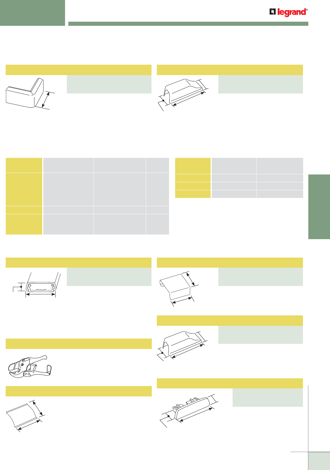
WWW.LEGRAND.US/WIREMOLD
135
NONMETALLIC RACEWAY
WIREMOLD
Raceway Base & Cover
PART NUMBERS:
800BAC (Ivory)
800BAC-WH (White)
Cover Clip
PART NUMBERS:
806 (Ivory)
806-WH (White)
1 1/2"
[38mm]
Ea. Leg For right angle turns around
external corners.
NOTE: Device Boxes for 400 Series Raceway can be found on pages located
at the end of this product section.
400, 800, 2300 & 2300D SERIES™ RACEWAYS
Ordering Information (continued)
For connecting 400 or 800 Series
Raceway with 1/2" trade size
conduit or armored cable. 1/2"
trade size KO on end and bottom.
1 1/2"
[38mm]
1 7/16"
[37mm]
4 1/4"
[108mm]
Low-profile, two-piece raceway
with durable, textured PVC ivory
or white finishes. Available in
5' [1.52m] lengths. Packed 100'
[3.05m] per carton. Supplied with
wide adhesive tape along its entire
length.
Regular duty cutter. Ideal for use
with small nonmetallic raceways.
For holding conductors in place.
For covering joint where two
pieces of 800BAC Series Raceway
Cover come together.
For connecting 400 or 800 Series
Raceway with 1/2" trade size
conduit or armored cable. 1/2"
trade size KO on end and bottom.
For closing open end of
800BAC Series Raceway.
7/16"
[11.1mm] 1 5/16"
[33mm]
1 3/8"
[35mm]
1"
[25mm]
1 1/4"
[32mm]
3/8"
[9.5mm]
1/2"
[12.7mm]
1"
[25mm]
1"
[25mm]
1 1/2"
[38mm]
1 7/16"
[37mm]
4 1/4"
[108mm]
800 Series Raceway Wire Fill Capacities for Communications
NOTE: For additional information, refer to the Technical Section.
* Category 6 augmented (6a) cable for 10 gigabit ethernet – max allowed cable
diameter per addenda No. 11 ANSI TIA/EIA 568-B.2.
CABLE/WIRE SIZE
O.D. Approx. Dia.)
40% FILL Inches [mm]
UNSHIELDED
TWISTED PAIR
4-pair, 24 AWG, Cat 3
4-pair, 24 AWG, Cat 5e
4-pair, 24 AWG, Cat 6
4-pair, 24 AWG, Cat 6a*
25-pair, 24 AWG
0.190
0.210
0.250
0.354
0.410
[4.8]
[5.3]
[6.3]
[9.0]
[10.4]
3
3
2
1
0
COAXIAL RG6/U 0.270 [6.9] 1
FIBER ZipCord
Round 4 Strand Fiber
Round 6 Strand Fiber
0.118 x 0.236
0.187
0.256
[3 x 6]
[4.8]
[6.5]
3
3
2
800 Series Raceway Wire Fill Capacities for Power
WIRE SIZE
THHN/THWN
O.D. NO. OF
CONDUCTORSInches [mm]
14 AWG 0.111 [2.8] 6
12 AWG 0.130 [3.3] 5
10 AWG 0.164 [4.2] 4
PVC-1 PVC Raceway Cutter
800WC Wire Clip
NOTE: Device Boxes for 800 Series Raceway can be found on pages located
at the end of this product section.
External Elbow
PART NUMBERS:
418 (Ivory),
418-WH (White)
Entrance End Fitting
PART NUMBERS:
810A2 (Ivory)
810A2-WH (White)
Entrance End Fitting
PART NUMBERS:
810A2 (Ivory)
810A2-WH (White)
Blank End Fitting
PART NUMBERS:
810B (Ivory),
810B-WH (White)
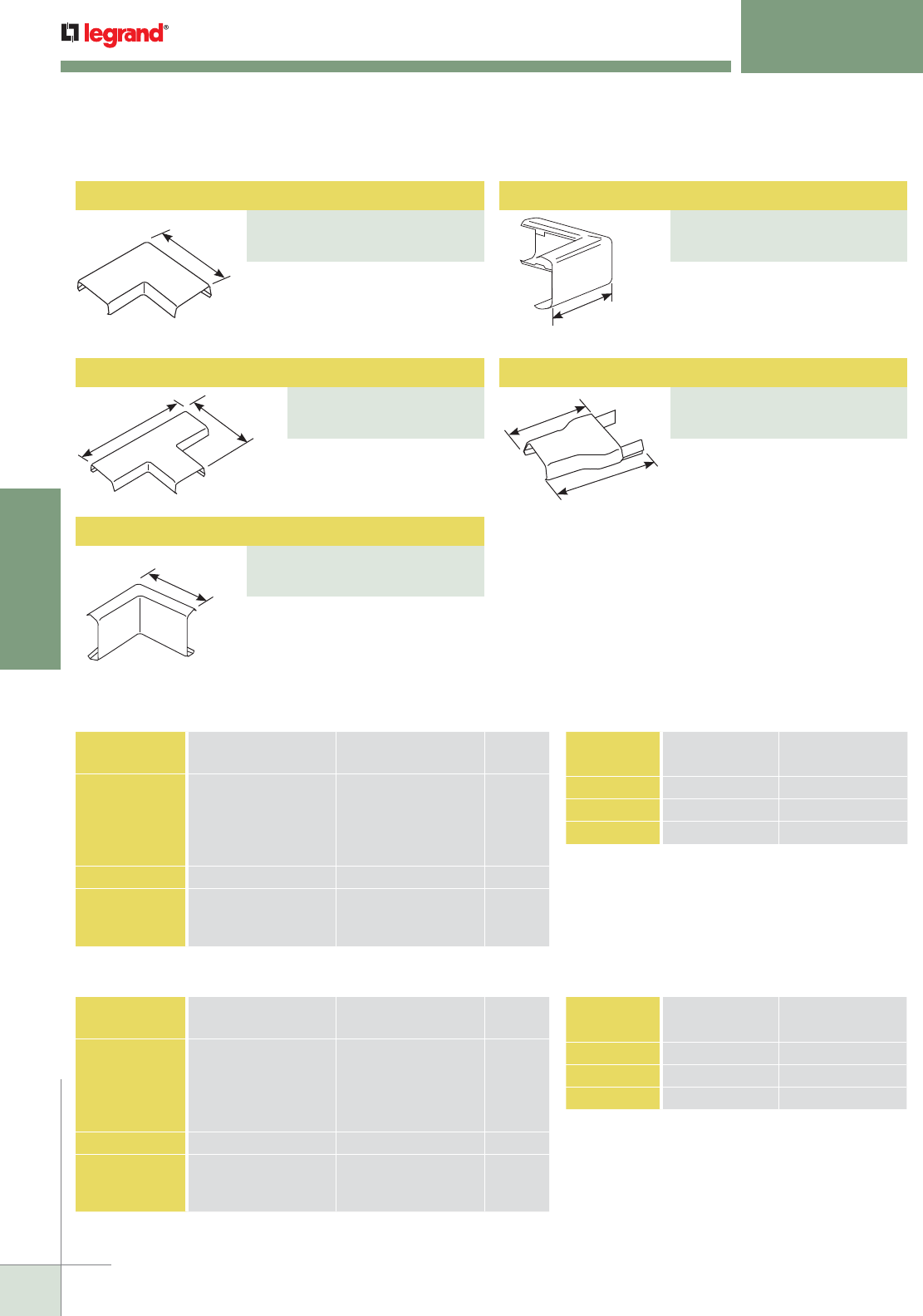
WWW.LEGRAND.US/WIREMOLD
136
NONMETALLIC RACEWAY
WIREMOLD
400, 800, 2300 & 2300D SERIES™ RACEWAYS
Ordering Information
2 1/2"
[64mm]
(Each leg)
4 1/8"
[105mm]
2 3/4"
[70mm]
2"
[51mm]
Ea. Leg
2"
[51mm]
Ea. Leg
1 1/2"
[38mm]
2"
[51mm]
NOTE: Device Boxes for 800 Series Raceway can be found on pages located
at the end of this product section.
For right angle turns on same
surface.
For branching of raceway
running at right angles.
For right angle turns around
internal corners.
For right angle turns around
external corners.
For transitioning from 800 Series
Raceway to 400 Series Raceway.
2300 Series Raceway Wire Fill Capacities for Communications
NOTE: For additional information, refer to the Technical
Section.
* Category 6 augmented (6a) cable for 10 gigabit ethernet –
max allowed cable diameter per addenda No. 11 ANSI TIA/
EIA 568-B.2.
CABLE/WIRE SIZE
O.D. Approx. Dia.)
40% FILL Inches [mm]
UNSHIELDED
TWISTED PAIR
4-pair, 24 AWG, Cat 3
4-pair, 24 AWG, Cat 5e
4-pair, 24 AWG, Cat 6
4-pair, 24 AWG, Cat 6a*
25-pair, 24 AWG
0.190
0.210
0.250
0.354
0.410
[4.8]
[5.3]
[6.3]
[9.0]
[10.4]
11
9
6
3
2
COAXIAL RG6/U 0.270 [6.9] 5
FIBER ZipCord
Round 4 Strand Fiber
Round 6 Strand Fiber
0.118 x 0.236
0.187
0.256
[3 x 6]
[4.8]
[6.5]
12
12
6
2300 Series Raceway Wire Fill Capacities for Power
WIRE SIZE
THHN/THWN
O.D.
NO. OF CONDUCTORSInches [mm]
14 AWG 0.111 [2.8] 15
12 AWG 0.130 [3.3] 12
10 AWG 0.164 [4.2] 12
2300D Series Raceway Wire Fill Capacities for Communications
CABLE/WIRE SIZE
O.D. Approx. Dia.) 40% FILL
(Ea. Comp.) Inches [mm]
UNSHIELDED
TWISTED PAIR
4-pair, 24 AWG, Cat 3
4-pair, 24 AWG, Cat 5e
4-pair, 24 AWG, Cat 6
4-pair, 24 AWG, Cat 6a*
25-pair, 24 AWG
0.190
0.210
0.250
0.354
0.410
[4.8]
[5.3]
[6.3]
[9.0]
[10.4]
5
4
3
1
1
COAXIAL RG6/U 0.270 [6.9] 2
FIBER ZipCord
Round 4 Strand Fiber
Round 6 Strand Fiber
0.118 x 0.236
0.187
0.256
[3 x 6]
[4.8]
[6.5]
6
6
3
2300D Series Raceway Wire Fill Capacities for Power
WIRE SIZE
THHN/THWN
O.D. NO. OF CONDUCTORS
(Each Compartment)Inches [mm]
14 AWG 0.111 [2.8] 12
12 AWG 0.130 [3.3] 8
10 AWG 0.164 [4.2] 5
Flat Elbow
PART NUMBERS:
811 (Ivory)
811-WH (White)
External Elbow
PART NUMBERS:
818 (Ivory)
818-WH (White)
Tee
PART NUMBERS:
815 (Ivory)
815-WH (White)
Reducing Connector
PART NUMBERS:
889A (Ivory)
889A-WH (White)
Internal Elbow
PART NUMBERS:
817 (Ivory)
817-WH (White)
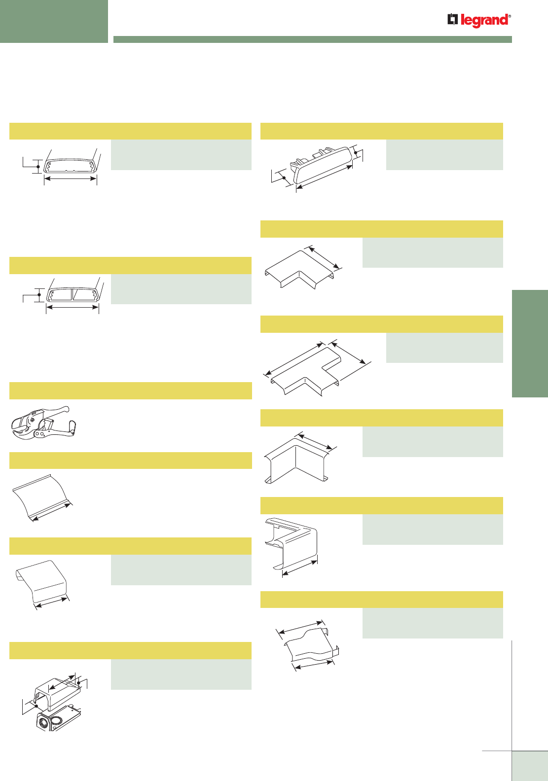
WWW.LEGRAND.US/WIREMOLD
137
NONMETALLIC RACEWAY
WIREMOLD
Low-profile, two-piece raceway
with durable, textured PVC ivory
or white finishes. Available in
5' [1.52m] lengths. Packed 50'
[15.2m] per carton. Supplied
with wide adhesive tape along its
entire length.
2300/2300D Series Raceway Ordering Information
2 1/4"
[57mm]
11/16"
[17.5mm]
2 1/4"
[57mm]
11/16"
[17.5mm]
1"
[25mm]
2"
[51mm]
1 15/16"
[49mm]
2 7/16"
[62mm]
4 1/2"
[114mm]
4 3/16"
[106mm]
Ea. Leg
1"
[25mm]
2 1/4"
[57mm]
27/32"
[21mm]
400, 800, 2300 & 2300D SERIES™ RACEWAYS
Ordering Information
Low-profile, two-piece raceway
with durable, textured PVC ivory
or white finishes. Available in
5' [1.52m] lengths. Supplied with
wide adhesive tape along its
entire length.
PVC-1 PVC Raceway Cutter
Regular duty cutter. Ideal for use
with small nonmetallic raceways.
6"
[152mm]
4 1/8"
[105mm]
2 1/2" [64mm]
Ea. Leg
2 1/2"
[64mm]
Ea. Leg
3"
[76mm]
2 1/2"
[64mm]
NOTE: Device Boxes for 2300 and 2300D Series Raceway can be found on
the next page of this product section.
2300WC Wire Clip
For holding conductors in place.
For covering joint where two
pieces of 2300BAC and 2300BACD
Series Raceway Cover come
together.
For connecting 2300 Series
Raceway with 1/2", 3/4", or 1"
trade size conduit or armored
cable. 1/2" and 3/4" trade size KO
on end, 1/2", 3/4", and 1" trade
size KOs on bottom.
For closing open end of
2300BAC and 2300BACD
Series Raceways.
For right angle turns on same
surface.
For branching of raceway
running at right angles.
For right angle turns around
internal corners.
For right angle turns around
external corners.
For transitioning from 2300 Series
Raceway to 800 Series Raceway.
Blank End Fitting
PART NUMBERS:
2310B (Ivory)
2310B-WH (White)
Raceway Base and Cover
PART NUMBERS:
2300BAC (Ivory)
2300BAC-WH (White)
Flat Elbow
PART NUMBERS:
2311 (Ivory)
2311-WH (White)
Divided Raceway Base and Cover
PART NUMBERS:
2300BACD (Ivory)
2300BACD-WH (White)
Tee
PART NUMBERS:
2315 (Ivory),
2315-WH (White)
Internal Elbow
PART NUMBERS:
2317 (Ivory),
2317-WH (White)
External Elbow
PART NUMBERS:
2318 (Ivory),
2318-WH (White)
Reducing Connector
PART NUMBERS:
2389 (Ivory)
2389-WH (White)
Cover Clip
PART NUMBERS:
2306 (Ivory),
2306-WH (White)
Entrance End Fitting
PART NUMBERS:
2310A (Ivory)
2310A-WH (White)
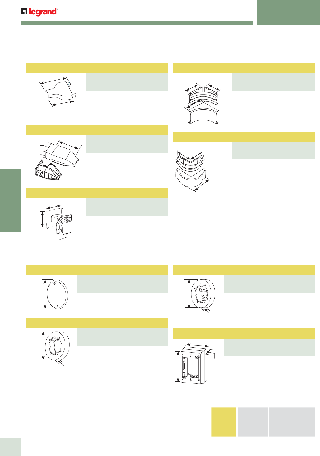
WWW.LEGRAND.US/WIREMOLD
138
NONMETALLIC RACEWAY
WIREMOLD
400, 800, 2300 & 2300D SERIES™ RACEWAYS
Ordering Information
3"
[76mm]
2 1/2"
[64mm]
•
•
6.5"
[165mm]
4.0"
[102mm]
2.2"
[56mm]
3 1/4"
[83mm]
Ea. Leg
3 1/2"
[89mm]
3 3/4"
[95mm]
Ea. Leg
5"
[127mm]
For transitioning from 2300 Series
Raceway to 400 Series Raceway.
Divided fitting to feed 2300 and
2300 Divided Series Raceway.
Includes 1/2", 3/4", and 1" trade
size KOs on back and top.
A 90° flat corner with integral
dividers provide 2" [51mm] cable
bend radius for UTP and fiber optic
installations.
A 90° internal corner with integral
dividers provide 2" [51mm] cable
bend radius for UTP and fiber optic
installations.
A 90° external corner with integral
dividers provide 2" [51mm] cable
bend radius for UTP and fiber optic
installations.
5 1/2"
[140mm]
5 1/2"
[140mm]
3 1/4
[83mm]
400/800/2300/2300D Series Raceway Device Box Ordering Information
4 1/2"
[114mm]
Dia.
5 1/2"
[140mm]
Dia.
1"
[25mm] L
2 3/4"
[70mm]
W
CAT. NO. L W GANG
2344
2344-WH
4 3/4" [121mm]
4 3/4” [121mm]
3" [76mm]
3” [76mm]
1
1
2344-2
2344-2-WH
4 3/4" [121mm]
4 3/4” [121mm]
4 7/8" [124mm]
4 7/8” [124mm]
2
2
Use with any nonmetallic round device
box to convert into a junction box.
For hanging fixtures, smoke/fire
alarms and other security devices with
3 1/2" [89mm] or 4 1/16" [103mm]
mounting centers. 5 1/2" [140mm]
diameter with open base. Not for use
with fans.
2344 one-gang, 2344-2 two-gang.
Two-gang base has rectangular KO to
enable extension from existing single-
gang flush wallbox and 1/2" and 1"
trade size concentric KOs. Accepts
industry standard faceplates for
switch and communication devices.
Reducing Connector
PART NUMBERS:
2389A (Ivory)
2389A-WH (White)
Radiused Divided Internal Elbow
PART NUMBERS:
2317DFO (Ivory)
2317DFO-WH (White)
Radiused Divided External Elbow
PART NUMBERS:
2318DFO (Ivory)
2318DFO-WH (White)
Radiused Divided Entrance End Fitting
PART NUMBERS:
2310DFO (Ivory)
2310DFO-WH (White)
Radiused Divided Flat Elbow
PART NUMBERS:
2311DFO (Ivory)
2311DFO-WH (White)
Blank Cover
PART NUMBERS:
2336 (Ivory)
2336-WH (White) 5 1/2"
[140mm]
Dia.
1" [25mm]
For hanging fixtures, smoke/fire
alarms and other security devices with
3 1/2" [89mm] or 4 1/16" [103mm]
mounting centers. Has 1/2" trade size
KO. Not for use with fans.
Fixture Box
PART NUMBERS:
2338A (Ivory)
2338A-WH (White)
Round Box Extension
PART NUMBERS:
2337A (Ivory)
2337A-WH (White)
Extra Deep Device Box
PART NUMBERS:
2344 (Ivory), 2344-WH (White)
2344-2 (Ivory), 2344-2-WH (White)
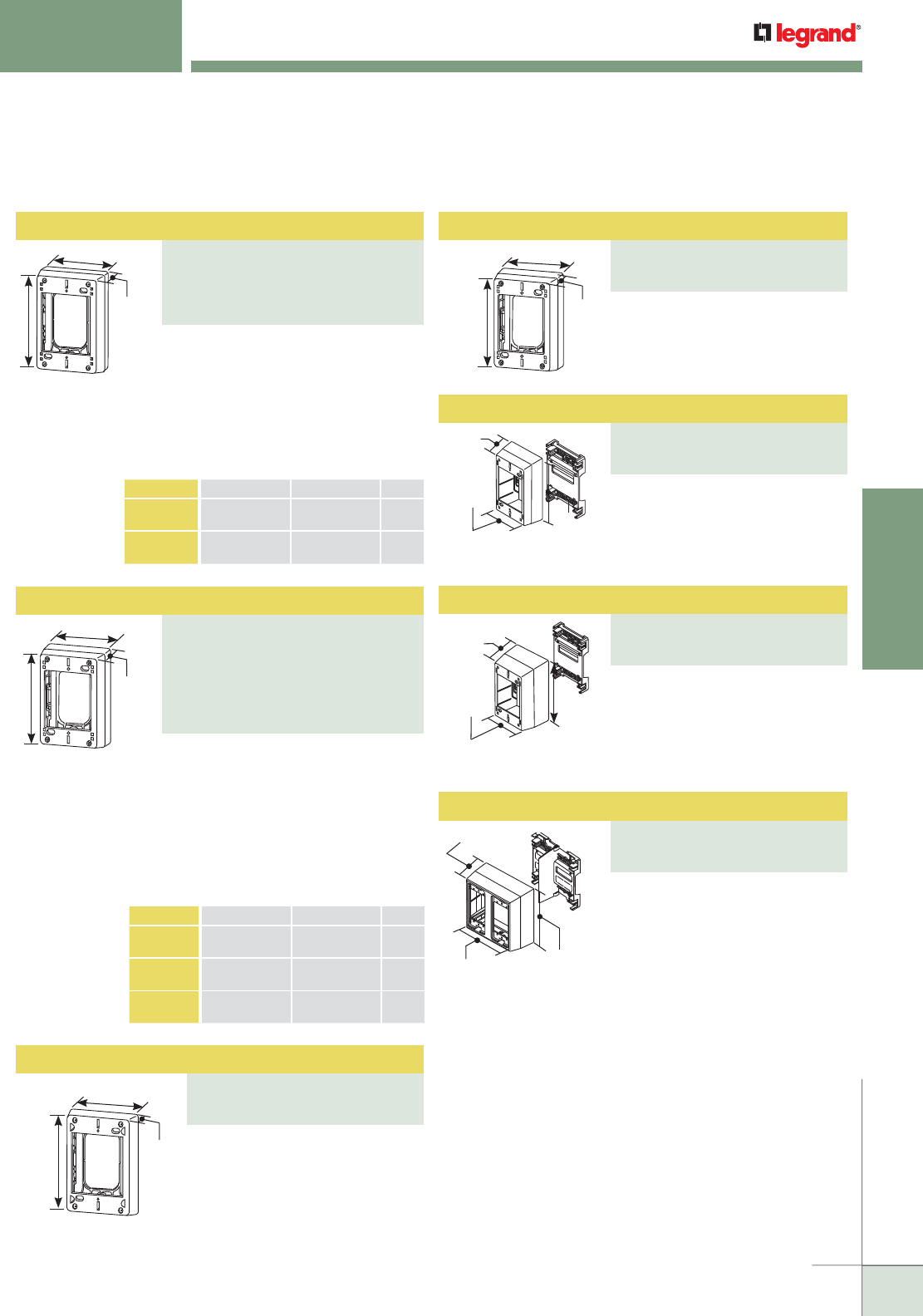
WWW.LEGRAND.US/WIREMOLD
139
NONMETALLIC RACEWAY
WIREMOLD
Device Box
PART NUMBERS:
2347 (Ivory)
2347-WH (White)
2347-2 (Ivory)
2347-2-WH (White)
400, 800, 2300 & 2300D SERIES™ RACEWAYS
Ordering Information
400/800/2300/2300D Series Raceway Device Box Ordering Information (continued)
1 3/4"
[44mm]
L
W
1"
[25mm]
4 3/4"
[121mm]
3"
[76mm]
1 3/4"
[44mm]
4 3/4"
[121mm]
3"
[76mm]
2 1/4"
[57mm]
4 3/4"
[121mm]
4 7/8"
[124mm]
NOTE: CM-EPLA End Plates are required when using Wiremold CM2
communication modules and Pass & Seymour® Activate inserts.
S2-EPL End Plates are required when using Ortronics® Series
II inserts. To mount TracJack modules, use 55074TJ or 55076TJ
Faceplates.
2348 one-gang, 2348-2 two-gang,
2348-3 three-gang. For deeper
switches and devices. 2348 Base has
rectangular KO. 2348-2 and 2348-3
Bases have rectangular KO to enable
extension from existing flush wall
box and 1/2" and 1" concentric KOs.
Accepts industry standard faceplates
for switch and communication devices.
CAT. NO. L W GANG
2348
2348-WH
4 3/4" [121mm]
4 3/4” [121mm]
3" [76mm]
3” [76mm]
1
1
2348-2
2348-2-WH
4 3/4" [121mm]
4 3/4” [121mm]
4 7/8" [124mm]
4 7/8” [124mm]
2
2
2348-3
2348-3-WH
4 3/4" [121mm]
4 3/4” [121mm]
7" [178mm]
7” [178mm]
3
3
For shallow switches and
receptacles. Base has rectangular
KO.
For deeper switches and devices,
and has magnetic backing. Base
has rectangular KO.
1 3/4"
[44mm]
4 3/4"
[121mm]
3"
[76mm]
2 3/4"
[70mm]
4 3/4"
[121mm]
3"
[76mm]
For use with 2300D Series Divided
Raceway. For mounting standard
switches, receptacles, and industry
standard faceplates for
communication devices.
For use with 2300D Series Divided
Raceway when additional depth is
required. For mounting standard
switches, receptacles and industry
standard faceplates for
communication devices.
Divided two-gang box for use with
2300D Series Divided Raceway.
Provides the ability to have both
power and low voltage at a single
point of use. Utilizes 5507 Series™
faceplates, as well as Wiremold
Open System communication
modules, Ortronics® TracJack,
Series II, and Pass & Seymour®
Activate Series inserts. For
faceplate options, see 5507
Series™ Faceplates.
1 3/8"
[35mm]
L
W
2347 one-gang, 2347-2 two-gang. For
standard switches and devices. 2347
Base has rectangular KO. 2347-2
Base has rectangular KO to enable
extension from existing flush wall
box and 1/2" and 1" concentric KOs.
Accepts industry standard faceplates
for switch and communication devices.
CAT. NO. L W GANG
2347
2347-WH
4 3/4" [121mm]
4 3/4” [121mm]
3" [76mm]
3” [76mm]
1
1
2347-2
2347-2-WH
4 3/4" [121mm]
4 3/4” [121mm]
4 7/8 [124mm]
4 7/8 [124mm]
2
2
Shallow Device Box/Extension Box
PART NUMBERS:
2348S/51 (Ivory)
2348S/51-WH (White)
Magnetic Deep Device Box (with Grommet)
PART NUMBERS:
2348AMP (Ivory)
2348AMP-WH (White)
Device Box
PART NUMBERS:
2348D (Ivory)
2348D-WH (White)
Extra Deep Device Box
PART NUMBERS:
2344D (Ivory),
2344D-WH (White)
Two-Gang Deep Divided Device Box
PART NUMBERS:
2344SD-2A (Ivory)
2344SD-2A-WH (White)
Deep Device Box
PART NUMBERS:
2348 (Ivory)
2348-WH (White)
2348-2 (Ivory)
2348-2-WH (White)
2348-3 (Ivory)
2348-3-WH (White)
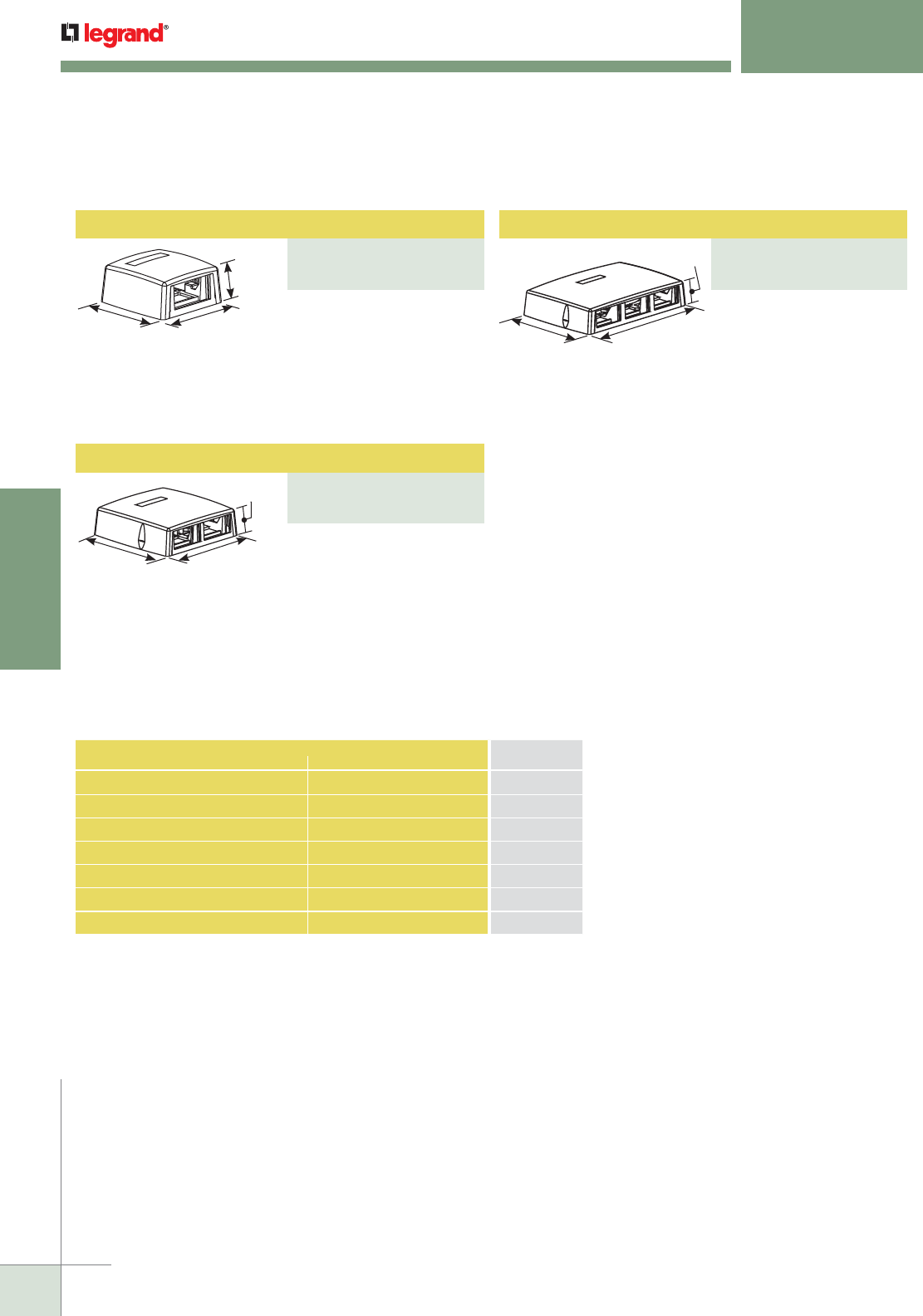
WWW.LEGRAND.US/WIREMOLD
140
NONMETALLIC RACEWAY
WIREMOLD
400, 800, 2300 & 2300D SERIES™ RACEWAYS
Ordering Information
1 1/2"
[38mm]
3 1/4"
[83mm]
3 1/4"
[83mm]
Accepts one CM2 size
Wiremold Open System
communication module or
Pass & Seymour® Activate
Series insert. Compatible
with Wiremold 400 and 800
Series Raceways.
Fiber storage loop. Accepts
three CM2 size Wiremold
Open System communication
modules or Pass &
Seymour® Activate Series
inserts. Compatible with
Wiremold 400, 800, and 2300
Series Raceways.
Fiber storage loop. Accepts
two CM2 size Wiremold
Open System communication
modules or Pass &
Seymour® Activate Series
inserts. Compatible with
Wiremold 400, 800, and 2300
Series Raceways.
5 3/16"
[132mm]
5 3/16"
[132mm]
1 1/2"
[38mm]
7 3/4"
[197mm]
5 3/16"
[132mm]
1 1/2"
[38mm]
CONNECTION REQUIRED USE CATALOG
NUMBER
FROM TO
800 Series Raceway 400 Series Raceway 889A
2300 Series Raceway 400 Series Raceway 2389A
2300 Series Raceway 800 Series Raceway 2389
Existing Outlet 400, 800, 2300 Series Raceways 2348S/51
1/2" Trade Size Conduit 400, 800 Series Raceways 810A2
1/2" or 3/4" Trade Size Conduit 2300 Series Raceway 2310A
3" [76mm] or 4" [102mm] Ceiling Boxes 400, 800, 2300 Series Raceways 2337A
400/800/2300 Series Raceway Interconnectivity Fittings
400/800/2300 Series Raceway Device Box Ordering Information
One Insert Multimedia Box
PART NUMBERS:
CM-MMB-231 (Ivory)
CM-MMB-231-WH (White)
Three Insert Multimedia Box
PART NUMBERS:
CM-MMB-233 (Ivory)
CM-MMB-233-WH (White)
Two Insert Multimedia Box
PART NUMBERS:
CM-MMB-232 (Ivory)
CM-MMB-232-WH (White)
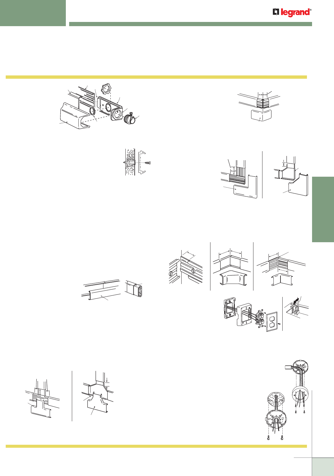
WWW.LEGRAND.US/WIREMOLD
141
NONMETALLIC RACEWAY
WIREMOLD
Raceway
Cover
1/2" & 3/4"
trade size KOs
Fitting
Cover Use Washer for
1/2" trade size KO
Bottom Side Only
Conduit
Attachment
Tap Fitting
Base
Raceway Base
1. Bring in and
connect feed
wires using
approved
connection
method.
Assemble
raceway cover
to butt against
the fitting base. Snap fitting cover onto base.
Install Base:
400BAC, 800BAC, 2300BAC
The adhesive on the 400BAC, 800BAC,
2300BAC and 2300BACD is intended to be
used as an installation aid for positioning the
product. Applications with power wire, screw fasteners
must be used in addition to the adhesive. Applications
with communication cable only, screw fasteners are
recommended in addition to the adhesive.
For low-voltage applications – 400BAC can be mounted
with adhesive only (screw fasteners may be required
depending on the cable quantity and size); 800BAC and
2300BAC require screw fasteners at 18" [457mm] intervals
in addition to the adhesive.
Peel release paper from adhesive strip and mount
immediately to surface. Adhesive-backed raceway should
be mounted to a clean, dry, grease-free, smooth surface.
Apply pressure along entire raceway base to insure proper
adhesion.
2. To install runs of raceway cover:
Measure distance from
fitting to fitting. Cut
required length of cover.
When two raceway sections
butt together, cover sections
should span base joints for maximum rigidity. When two
raceway cover sections butt together, use cover clip as
shown (406/806/2306).
3. Notching for Tee:
A. Make two cuts on side of base to be notched. Notch to
equal width of base. Break clean with pliers.
B. Butt 400BAC Raceway Base to base of 415 Tee. Screw
tee fitting base to wall. Cut 400BAC Raceway Cover 3/8"
[95mm] shorter than base. Snap on 415 Tee.
4. Notching for External Elbow:
A. Cut side of base to be
notched.
B. Break clean with pliers.
Raceway Cover
Cover
Clip
Base
3/8"
[9.5mm]
415 Tee Cover
B.
A. (800) 1 3/8" [35mm]
(2300) 1 1/2" [38mm]
815 Tee
2315 Tee
418/818/2318
External Elbow Cover
(400) 7/8" [22.2mm]
(800) 1 3/8" [35mm]
(2300) 1 1/2" [38mm]
5. Notching for Flat Elbow:
A. Cut side of base to be notched. Notch to equal width of
base. Break clean with pliers.
B. Butt 400BAC
Raceway
Base to base
of 411 Flat
Elbow. Screw
flat elbow
base to wall.
Cut 400BAC
Raceway
Cover 3/8" [9.5mm] shorter than base. Snap on 411 Flat
Elbow Cover.
811/2311
Flat Elbow
Cover
A. (800) 1 1/16" [27mm]
(2300) 1 1/2" [38mm]
411
90º Flat
Elbow Cover
B. 3/4" [19.1mm]
Base
6. Notching for Internal Elbow:
A. Cut side of base to be notched.
B. Break clean with pliers.
817/2317 Internal Elbow Cover
Butt or
Notch
(800) 1 3/8" [35mm]
(2300) 1 3/8" [35mm]
417 Internal Elbow Cover
1/2"
[12.7mm]
Butt or Notch
1"
[25mm]
1"
[25mm]
400, 800, 2300 Series Raceways Installation Details
7. All Sure-Snap® device
boxes are packaged
unassembled for easy
installation. During
shipment the base and
cover pieces may snap
together. To unsnap the cover from
base, place the blade of a screwdriver into the locking tab
(Figure 1). Push downward and gently pry the cover from
the base. Repeat at each corner if necessary.
8. Mount the cover to the base by
aligning key on the inside of the cover
with one of the grooves on the base.
Assemble with four screws. (Tap
screws to seat.)
9. Pull wiring through the center
knockout and attach the base
directly to in-ceiling box.
2338A Round
Device Box
2337A Round
Device Box
Figure 1
Sure-Snap Device Boxes
400, 800, 2300 & 2300D SERIES™ RACEWAYS
Installation Details
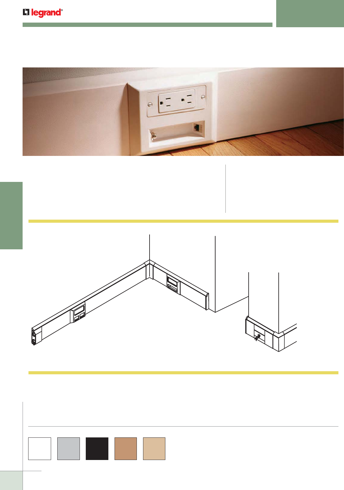
WWW.LEGRAND.US/WIREMOLD
142
NONMETALLIC RACEWAY
WIREMOLD
ACCESS® 5000 RACEWAY
Baseboard Molding
CODE REFERENCE
cULus Listed Raceway:
File E90378 Guide RJTX.
Complies with flammability requirements of UL-5A.
Fittings: File E90377 Guide RJYT.
Meets Article 388 of NEC.
UL Listed for up to 600V.
Meets Section 12-1600 of CEC.
Attractive baseboard molding that organizes and conceals electrical
wiring and communications cabling.
Access® 5000 Series Raceway Part Numbers with a “WH” suffix are available with
a white PVC finish. Part Numbers with a “BK” suffix are available with a black PVC
finish. Part Numbers with a “GY” suffix are available with a gray PVC finish. Part
Numbers with a “W” suffix are available in a real maple veneer finish. Part Numbers
with a “OA” suffix are available with a real oak veneer finish.
Custom color options are also available. Consult the factory for more information.
COLOR OPTIONS
Access 5000 Series Raceway System Layout
NOTE: Illustration is for showing product applications only.
KEY
A. 5007C-1A Device Bracket
B. 5007C-2AB/5007C-2RT
Deep Device Bracket
C. 5010A Entrance End Feed
D. 5010L Left End Cap
E. 5010R Right End Cap
F. 5017B Internal Base Elbow
G. 5017C Internal Cover Elbow
H. 5018B External Base Elbow
I. 5018C External Cover Elbow
J. CM2, Series II, TracJack
Communication Devices
K. Back Feed Position
C
K
F, G
A
E
D
B
J
H, I
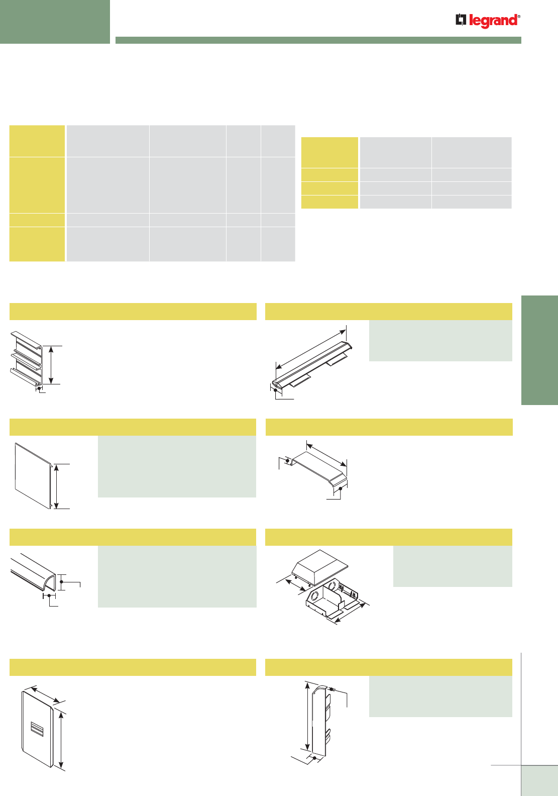
WWW.LEGRAND.US/WIREMOLD
143
NONMETALLIC RACEWAY
WIREMOLD
Raceway Cover
PART NUMBERS:
5000CWH (White PVC)
5000CBK (Black PVC),
5000CGY (Gray PVC)
5000CW (Maple Veneer)
5000COA (Oak Veneer)
ACCESS® 5000 RACEWAY
Ordering Information
5"
[127mm]
7/8"
[22mm]
5 1/4"
[133mm]
2 13/16"
[71mm]
4 9/16"
[116mm]
5 13/32"
[137mm]
3/4"
[19.1mm]
23/32"
[18.3mm]
4 19/32"
[117mm]
1 1/2"
[38mm]
Overall Assembled Depth is
1 15/16" [49mm].
3 9/16"
[90mm]
5 1/16"
[129mm]
3/4"
[19.1mm]
15/16"
[24mm]
NOTE: For additional information, refer to the Technical Section.
* Category 6 augmented (6a) cable for 10 gigabit ethernet – max allowed cable diameter
per addenda No. 11 ANSI TIA/EIA 568-B.2.
Access 5000 Series Raceway Wire Fill Capacities for Communications
CABLE/WIRE SIZE
O.D. Approx. Dia.) TOP
COMP.
40% FILL
BOTTOM
COMP.
40% FILL
Inches [mm]
UNSHIELDED
TWISTED PAIR
4-pair, 24 AWG, Cat 3
4-pair, 24 AWG, Cat 5e
4-pair, 24 AWG, Cat 6
4-pair, 24 AWG, Cat 6a*
25-pair, 24 AWG
0.190
0.210
0.250
0.354
0.410
[4.8]
[5.3]
[6.3]
[9.0]
[10.4]
27
22
15
7
5
19
16
11
5
4
COAXIAL RG6/U 0.270 [6.9] 13 9
FIBER ZipCord
Round 4 Strand Fiber
Round 6 Strand Fiber
0.118 x 0.236
0.187
0.256
[3 x 6]
[4.8]
[6.5]
27
28
15
20
20
10
Access 5000 Series Raceway Wire Fill Capacities
for Power
WIRE SIZE
THHN/THWN
O.D. NO. OF CONDUCTORS
TOP COMPARTMENTInches [mm]
14 AWG 0.111 [2.8] 24
12 AWG 0.130 [3.3] 20
10 AWG 0.164 [4.2] 12
5000B Raceway Base
5000B Base has an integral divider
forming two channels for power and
low-voltage separation. Base supplied
in 8' [2.44m] lengths, packed 80'
[24.4m] per carton. (Base is not visible
in a typical finished installation.)
Covers supplied in 8' [2.44m] lengths.
Trim covers supplied in 8' [2.44m]
lengths.
5001 Base Coupling
Use for aligning base sections.
For covering joint where two
pieces of Access 5000 Series
Raceway Cover come together.
5006A Internal Wire Guard
Use inside the base. Protects
inside wires and cables from gap
behind butted cover sections.
Installed when the 5006 Cover
Clips are not used.
Used to connect Access 5000
to 1/2" or 3/4" trade size
conduit. Has one 1/2" or 3/4"
concentric KO for both
channels in end only.
Cover Clip
PART NUMBERS:
5006WH (White PVC)
5006BK (Black PVC)
5006GY (Gray PVC)
Quarter-Round Trim
PART NUMBERS:
5000TWH (White PVC)
5000TBK (Black PVC),
5000TGY (Gray PVC)
5000TW (Maple Veneer)
5000TOA (Oak Veneer)
Entrance End Fitting
PART NUMBERS:
5010AWH (White PVC)
5010ABK (Black PVC)
5010AGY (Gray PVC)
5 29/32"
[150mm]
5/16"
[7.9mm]
1 3/16"
[30mm]
For closing right end of Access
5000 Series Raceway Base.
Right End Cap
PART NUMBERS:
5010RWH (White PVC)
5010RBK (Black PVC)
5010RGY (Gray PVC)
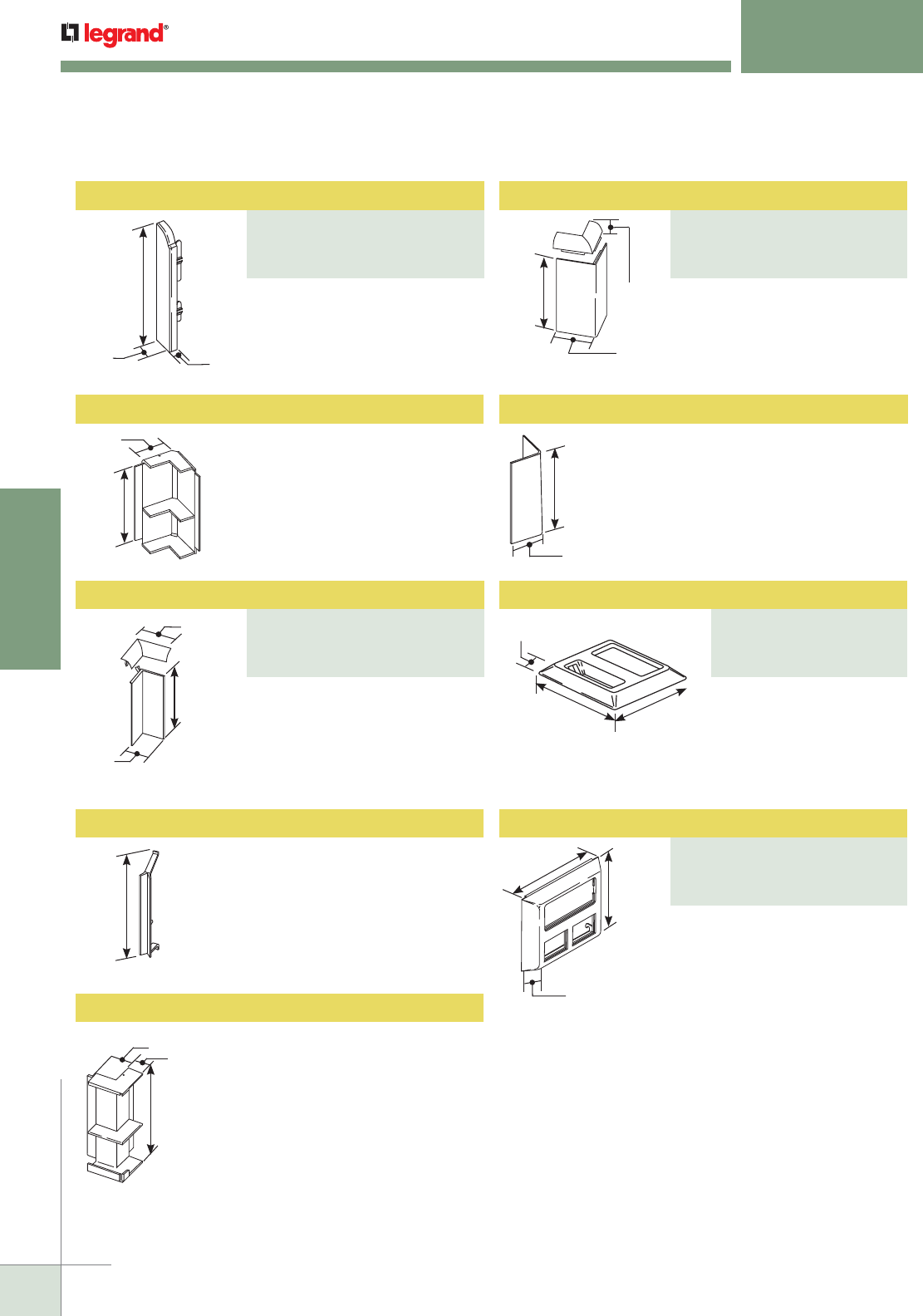
WWW.LEGRAND.US/WIREMOLD
144
NONMETALLIC RACEWAY
WIREMOLD
Internal Elbow Cover
PART NUMBERS:
5017CWH (White PVC)
5017CBK (Black PVC)
5017CGY (Gray PVC)
External Cover Elbow
PART NUMBERS:
5018CWH (White PVC)
5018CBK (Black PVC)
5018CGY (Gray PVC)
ACCESS® 5000 RACEWAY
Ordering Information
1 5/16"
[33mm]
5 1/16"
[129mm]
2 21/32"
[67mm]
5 5/16"
[135mm]
1 5/8"
[41mm]
4 3/4"
[121mm]
1"
[25mm]
7/8"
[22.2mm]
5 1/16"
[129mm]
15/16"
[23.8mm]
6 3/8"
[162mm]
5 3/16"
[132mm]
1 3/16"
[30mm] 5/16"
[7.9mm]
5 29/32"
[150mm]
9/16"
[14.3mm]
6 3/8"
[162mm]
5 3/16"
[132mm]
11/16"
[17.5mm]
5 1/4"
[133mm]
2 1/2"
[64mm]
4 3/16"
[106mm]
1 1/2"
[38mm]
For closing left end of Access 5000
Series Raceway Base.
5017B Internal Elbow Base
For mounting base at 90° internal
corners.
For mounting cover and trim cover
at 90° internal corners.
5017WG Internal Elbow Wire Guard
Protects wiring at mitered internal
cover; snaps into 5017B Base Elbow.
Not needed when 5017C Internal
Cover Elbow is used.
5018B External Base Elbow
For mounting base at 90° external
corners.
For mounting cover and trim
cover at 90° external corners.
5018WG External Elbow Wire Guard
Installs at a mitered external elbow
joint behind the covers to protect
sharp objects from being inserted.
Not needed when the external cover
elbow is used.
External device cover; for
mounting one standard
device and up to two
communication connections.
For faceplate options, see 5507 Series™ Faceplates. (For power side only.)
For mounting deeper devices such
as TVSS receptacles, GFCI devices,
and Pass & Seymour® Activate
inserts. Accepts 5507 Series™
Faceplates, 2A size Activate
inserts, and Open System
communication modules.
Bezels included.
For faceplate options, see
5507 Series™ Faceplates.
Left End Cap
PART NUMBERS:
5010LWH (White PVC)
5010LBK (Black PVC)
5010LGY (Gray PVC)
Device Plate
PART NUMBERS:
5007C-1AWH (White PVC)
5007C-1ABK (Black PVC)
5007C-1AGY (Gray PVC)
Deep Device Plate
PART NUMBERS:
5007C-2ABWH (White PVC)
5007C-2ABBK (Black PVC)
5007C-2ABGY (Gray PVC)
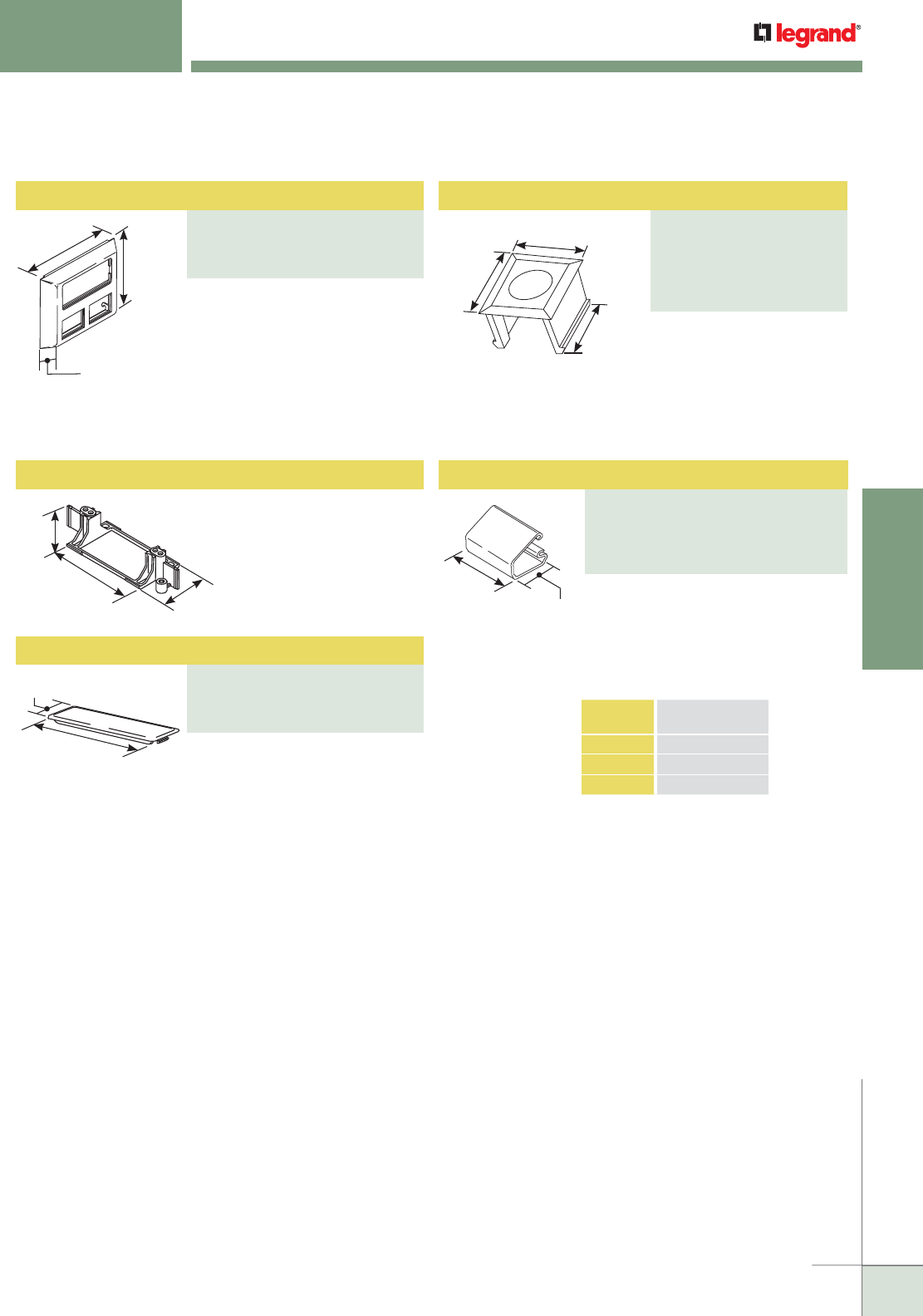
WWW.LEGRAND.US/WIREMOLD
145
NONMETALLIC RACEWAY
WIREMOLD
Low-Voltage Blank Plate
PART NUMBERS:
5005WH (White PVC)
5005BK (Black PVC)
5005GY (Gray PVC)
Wire Clip
PART NUMBERS:
2700WC (For Small Bundles)
2800WC (For Bigger Bundles)
2900WC (For Larger Bundles in
Top Section Only)
ACCESS® 5000 RACEWAY
Ordering Information
For mounting deeper devices such
as TVSS receptacles, GFCI devices,
and Pass & Seymour® Activate
inserts. Accepts 5507 Series™
Faceplates, Ortronics® TracJack,
and Series II Inserts. Bezels
included.
For use as a blank; has KO
to accept an “F” type coax
connector. Snaps into low-
voltage slots on device
plates. For use with
5007C-1AXX only.
15/16"
[23.8mm]
6 3/8"
[162mm]
5 3/16"
[132mm]
1 1/8"
[29mm]
3 11/16"
[94mm] 2"
[51mm]
5007C Electrical Device Bracket
For mounting standard devices.
Snaps into top section of base
wherever an outlet is needed.
1 1/2"
[38mm]
4 7/32"
[107mm]
3/4"
[19.1mm]
1/2"
[12.7mm]
21/32"
[16.7mm]
1 1/2"
[38mm]
W
Blanks entire low-voltage recess
in device plate. For use with
5007C-1AXX only.
Wire Clip
Holds and secures wiring and cabling
inside raceway. Mounts with adhesive
backing. 2700WC is used for small
bundles. 2800WC is used for bigger
bundles. 2900WC is used for larger
bundles in the top section only.
WIDTH
CAT. NO. Inches mm
2700WC 3/4" 19.1
2800WC 1" 25
2900WC 1 1/2" 38
Deep Device Plate
PART NUMBERS:
5007C-2RTWH (White PVC)
5007C-2RTBK (Black PVC)
5007C-2RTGY (Gray PVC)
Blank/Coax Adapter
PART NUMBERS:
5004WH (White PVC)
5004BK (Black PVC)
5004GY (Gray PVC)
5004W (Maple Veneer)
5004OA (Oak Veneer)
For faceplate options, see 5507 Series™ Faceplates.
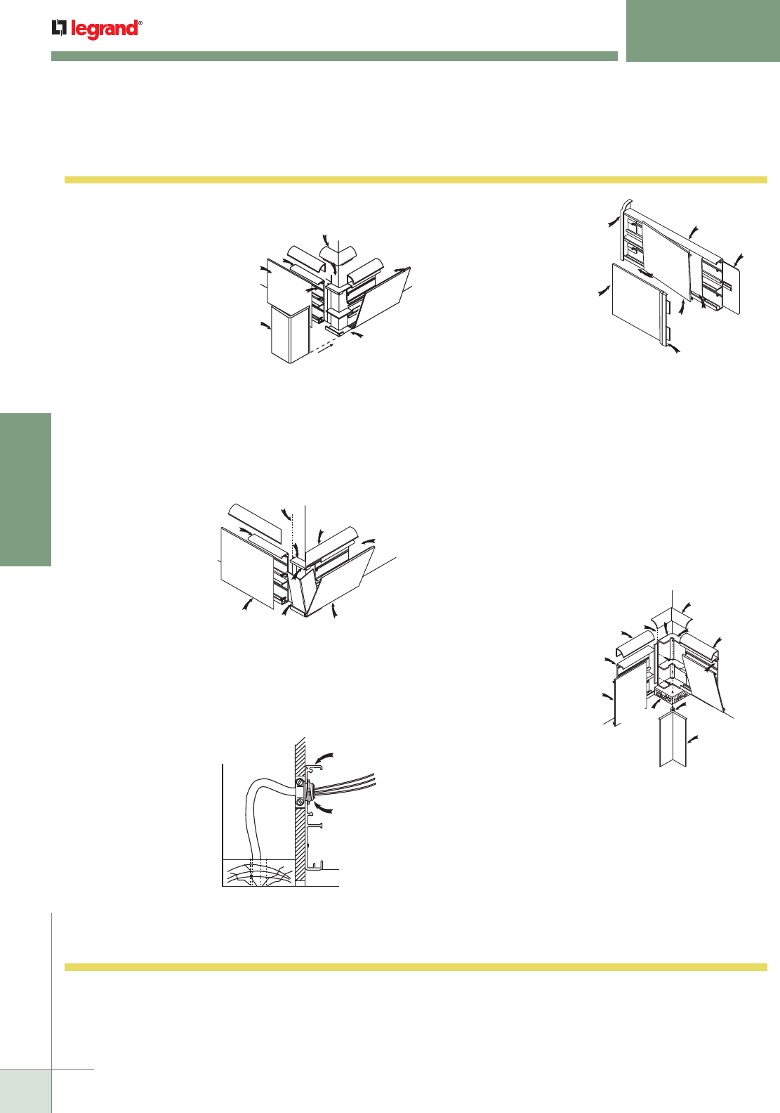
WWW.LEGRAND.US/WIREMOLD
146
NONMETALLIC RACEWAY
WIREMOLD
5. For Corners Using Molded Fittings:
Corners must be 90° to ensure
proper installation. The 5017B
Internal Base Elbow is
installed as shown, using
a spacing shim to allow
for the finished floor. The
5000B Base butts up to
the 5017B Base Elbow at
shoulder before mounting.
The 5000T Trim Cover is
installed first, then the 5000C
Cover is snapped in place aligning
both with the 5017B Base Elbow. The
5017C Internal Elbow Cover Trim is snapped in place, overlapping
the 5000T Trim Cover pieces. The 5017C Internal Elbow Cover is
then snapped onto the 5017B Base Elbow, overlapping the 5000C
Cover pieces. The locking tab on the 5017C Cover Elbow will snap
into slots in the back of the 5017B Base Elbow.
Internal Cover
Elbow 5017C*
Snap-on
Cover
Locking
Tab
Internal Elbow
Cover 5017C*
Spacing
Shim
Cover
5000C
Base
5000B
Trim Cover
5000T*
Fitting
Shoulder Internal Elbow
Base 5017B
Trim Cover
5000T
1. For Corners Using Molded Fittings:
Corners must be 90 degrees to
ensure proper installation. The
5018B External Base Elbow
and 5018C External Cover
Elbow are installed as
shown. Butt the 5000B
Base against the 5018B
Fitting Shoulder before
mounting. The 5000T Trim
Cover is installed first, then
the 5000C is snapped in place,
aligning both with the 5018B fitting shoulder. The 5018C External
Cover Elbow is installed by engaging the right-hand side of the
cover with the 5018B Base and sliding until the left side top and
bottom snap in. The 5018C External Cover Elbow is then snapped
in place overlapping the 5000T Trim Covers and interlocking
under the 5018C External Cover.
Trim Cover
5018C*
Fitting
Shoulder
Snap-on
Cover
External Elbow
Base 5018B
External Cover
Elbow 5018C*
Cover
5000C
Base
5000B
Mounting
Grooves
Trim
Cover
5000T*
Access 5000 Series Raceways Installation Details
2. For Mitered Corners:
The 5018WG External
Elbow Wire Guard is
installed as shown
inside the 5018B
External Base Elbow
when the covers are
mitered instead of
using the 5018C
External Cover Elbow.
It is recommended
that the covers be mitered
first and fitted before cutting to proper length to minimize waste.
For ease of installation, the covers should be installed starting at
the mitered corners. As with the corner fittings, install the 5000T
Trim Cover first, then snap the 5000C Covers in place.
Base 5000B
External
Base Elbow
5018B
Mitered Trim
Cover 5000T
Snap-on
Cover
Mitered Cover
5000C
External Elbow Wire Guard
5018WG (Slide Wire Guard into
Cover/Base Assembly)
Mitered
Cover 5000C
3. This illustration shows
an example of a back
feed using a nonmetallic
sheathed cable. Punch
or drill up to 3/4" trade
size hole in the top
compartment for feeding
power or communication
wiring. Make sure to allow
space between the bottom
of the 5000B Base if on a
subfloor to allow for the
finished floor or carpeting.
5000B Base
Strain Relief
Fitting
(Strip Sheathed Cable
Back to Connector)
Spaced for
Carpeting
NOTE: If baseboard 5000 is to be used without trim covers (5000T), cover
(5000C) should be mitered.
4. The 5006 Cover Clip is
installed between two
covers to hide an uneven
joint. Snap one cover onto
the Base, slide the 5006
Cover Clip over the end
of the other cover, butt
up against the installed
cover and snap into place.
The 5006A Internal Wire Guard is
used behind the covers as shown where
two pieces of cover butt together instead
of using the 5006 Cover Clip. This option is primarily used when a
wood veneer finish is used and the look of an exposed cover clip is
not wanted.
A 5010L or 5010R Left or Right End Cap is installed as shown at
the end of a base run before mounting. The 5000T Trim Cover and
the 5000C Cover are installed by partially snapping them in place
onto the 5000B Base, installing the 5000T first, and sliding them
to the end of the end caps. The rest of the cover is then snapped
progressively onto the base.
An optional 5001 Base Coupling can be installed as shown to assist
alignment when butting two 5000B Bases together.
Slide Cover
into End
Cap
Left
End Cap
5010L
Base
5000B
Base Coupling
5001
Internal Wire
Guard 5006A
Cover Clip
5006
Cover
5000C
Cover
5000C
ACCESS® 5000 RACEWAY
Installation Details
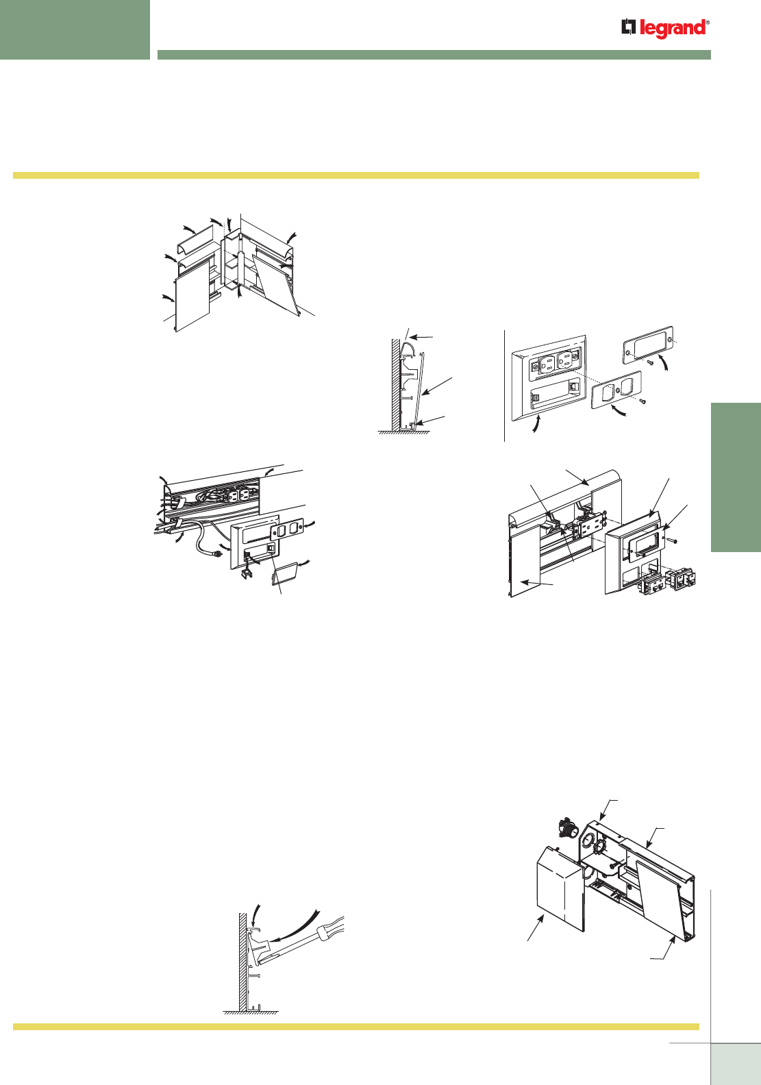
WWW.LEGRAND.US/WIREMOLD
147
NONMETALLIC RACEWAY
WIREMOLD
ACCESS® 5000 RACEWAY
Installation Details
Access 5000 Series Raceways Installation Details (continued)
6. For Mitered
Corners:
The 5017WG
Internal Elbow Wire
Guard is snapped
into the 5017B Base
Elbow when the
covers are mitered
instead of using the
5017C Cover Elbow.
It is recommended that the covers be mitered and fitted first
before cutting to proper length to minimize waste. For ease of
installation the covers should be installed starting at the mitered
corners. As with the corner fittings, install the 5000T Trim
Covers first and then snap the 5000C Covers in place.
NOTE: If baseboard 5000 is to be used without trim covers (5000T),
cover (5000C) should be mitered and assembled as shown.
7.
The illustration
shows a typical
installation of a
duplex outlet in the
top compartment
and a telephone
and coax
connection in the
lower compartment.
To install an outlet in the top
compartment, a 5007C Device Bracket
must be installed. The raceway will
accommodate a device up to 1 1/16" [27mm] in depth. A 5507R
Rectangular Faceplate can be used instead of the 5507D Faceplate to
accommodate decorative type devices.
The 2900WC, 2800WC, and 2700WC Wire Clips are used to hold wires
and cables within the raceway. Remove the adhesive and mount to the
5000B Base. Suggested spacing between wire clips is 48" [14.6m].
The 5000C Cover is to butt up against the tabs on the 5007C Device
Brackets as shown.
The 5007C-1A Device Plate accommodates up to two RJ11 or RJ45
voice or data connectors in the lower compartment. The 5004 Blank/
Coax Adapter is used as a blank when only one opening is needed
or to adapt an “F” type coax connector. This is done by knocking out
the center of the adapter which accepts the “F” connector. The wires
are then connected to the 5007C-1A assembly. If no low-voltage
connections are needed, the 5005 Blank Plate is used to cover the
openings. The 5007C-1A assembly is then mounted to the 5000B
Base.
Fitting
Shoulder
Internal Elbow
Base 5017B
Mitered Trim
Cover 5000T
Snap-on
Mitered
Cover
Snap-on Internal
Wire Guard
5017WG
Mitered
Cover
5000C
Base
5000B
Mitered Trim
Cover 5000T
Trim Cover 5000T
Baseboard Cover 5000C
Duplex
Faceplate
5507D
Telephone/Data
Connections
Blank
Plate
5005
Coax
Adapter
5004
Device Plate
5007C-1A
Baseboard Base
5000B
2900WC
2800WC
Wire Clips
8. The 5007C Device Bracket is installed
as shown. Insert the bracket in the
top compartment, place the blade
of a screwdriver on the left bottom
tab of the bracket and strike with a
hammer. Repeat on the right side.
5007C Device Brackets are mounted
anywhere a device is needed, in upper
compartment only.
9. The 5007C-1A Device Plate assembles by engaging the hooks
on back side of device plate to the bottom lip on the 5000B
Base and rotating toward wall. Secure to base using 5507D
or 5507R Faceplate. This illustration shows the procedure for
installing the 5000T Trim Cover. For deep devices such as GFCI
and surge receptacles, or the use of Wiremold Open System
communication modules and Pass & Seymour® Activate Series
inserts, the 5007C-2A should be used. For Ortronics® Series II or
Ortronics® TracJack inserts, the 5507C-2R7 should be used.
10. Use 5007C-2AB/5007C-
2RT for deep devices
such as Ground Fault
Circuit Interrupters,
Surge Protection Outlets
and/or communication
devices, and may be
utilized in the Wiremold
Access 5000 Raceway
System using this
5007C-2AB/5007C-2RT
Deep Device Plate.
Twist off the two spacers attached to the 5007C Device Bracket.
Snap the 5007C Device Bracket into the base channel provided.
Assemble the device to the device bracket, utilizing the spacers.
Assemble the deep device plate to the raceway base. Engage the
hooks, located next to the double window opening, to the lower
(large) lip of the raceway base. Rotate the device plate toward the
wall snapping it into place. Assemble the desired 5507 Faceplate
with Wiremold Open System communication modules, Ortronics®
TracJack and Series II inserts, or Pass & Seymour® Activate
Series inserts.
11. The 5010A Entrance End Feed
provides an end feed to Access
5000 Raceway with 1/2" or 3/4"
trade size conduit. Install with
side walls of the fitting base
and raceway base aligned.
Access 5000 Raceway
installed at baseboard
level should be spaced a
minimum of 1/8" [3.2mm]
above the floor level.
This will facilitate the
assembly/disassembly of
the end fitting cover.
Trim Cover,
Rotate into
Position
Device
Plate
Device Plate –
Hook to Lip
of Base
Base 5000B Device Bracket
5007C
Raceway
Base
Raceway Cover
Entrance End
Feed (Cover)
5010A
Entrance End
Feed (Base)
5010A
5007C-1A
5507D
5507R
5000T
5007C
5000C
Spacer
5007C-2AB
5507R
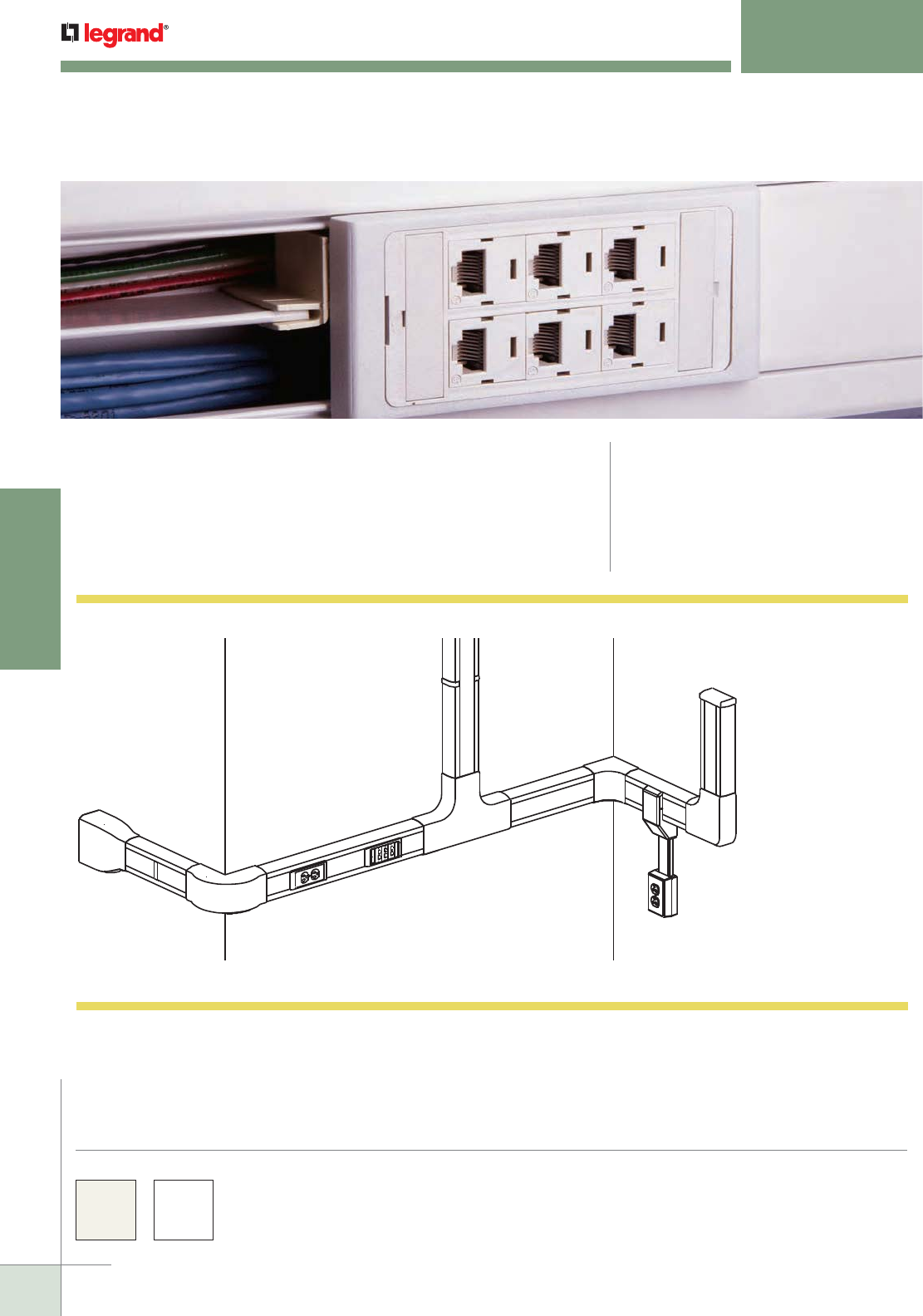
WWW.LEGRAND.US/WIREMOLD
148
NONMETALLIC RACEWAY
WIREMOLD
CABLESMART® 40N2 SERIES RACEWAY
Two-Piece, Dual-Channel, Large
CODE REFERENCE
cULus Listed Raceway:
File E90378 Guide RJTX.
Complies with flammability requirements of UL-5A.
Fittings: File E90377 Guide RJYT.
Meets Article 388 of NEC.
UL Listed for up to 600V.
Meets Section 12-1600 of CEC.
Two-piece, dual-channel, large raceway. Lightweight and easy-to-install.
Ideal for both power and communication installations.
Cablesmart® 40N2 Series Raceway Part Numbers with a “V” suffix are available in an
ivory finish. Part Numbers with a “WH” suffix have a white finish. 40N2 Series Raceway
is paintable using latex paint or stain.
Custom color options are also available. Consult the factory for more information.
COLOR OPTIONS
CableSmart 40N2 Series Raceway System Layout
NOTE: Illustration is for showing product applications only.
KEY
A. 40N2B08 Raceway Base
B. 40N2C08 Raceway Cover
C. 40N2F05 Base Clip
D. 40N2F06 Cover Clip
E. 40N2F11 Bend Radius Flat Elbow
F. 40N2F15 Bend Radius Tee
G. 40N2F17 Bend Radius Internal Elbow
H. 40N2F19 Bend Radius External Elbow
I. 40N2F20 Blank End Fitting
J. 40N2F21 Divided Entrance End Fitting
K. 40N2F31 Twin Cover Device Bracket
L. 40N2F74 Divided Transition Fitting
M. PSB1 One-Gang Device Box
M
A
K
I
H
B
G
C
K
L
D
J
FE
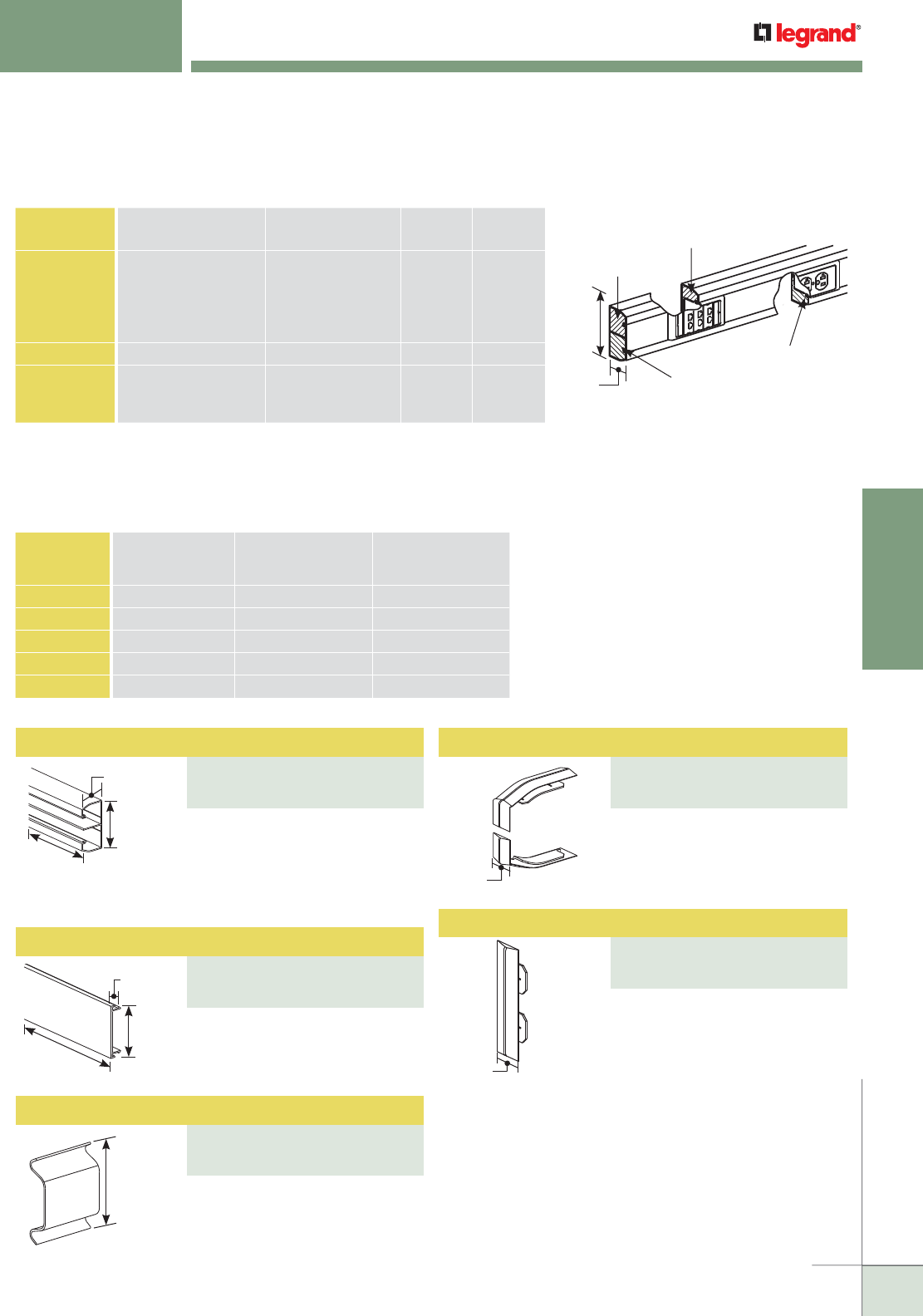
WWW.LEGRAND.US/WIREMOLD
149
NONMETALLIC RACEWAY
WIREMOLD
Wire Clip
PART NUMBERS:
40N2FWC (Ivory)
40N2FWCWH (White)
Full Width Raceway Cover
PART NUMBERS:
40N2C08V (Ivory)
40N2C08WH (White)
CABLESMART® 40N2 SERIES RACEWAY
Ordering Information
2"
[51mm]
4"
[102mm]
8'
[2.45m]
1/2"
[12.7mm]
2 3/16"
[56mm]
8'
[2.45m]
2 5/8"
[67mm]
5/8"
[15.9mm]
5/8"
[15.9mm]
Section A
3.22 in.2
[2080mm2]
Section B
1.71 in.2
[1100mm2]
Section C
3.22 in.2
[2080mm2]
Section D
1.71 in.2
[1100mm2]
4.0"
[102mm]
2.0"
[51mm]
40N2 Series Raceway Wire Fill Capacities for Communications
NOTE: For additional information, refer to the Technical Section.
* 40% fill is the maximum designed cable fill based on TIA/EIA 569-A.
** Category 6 augmented (6a) cable for 10 gigabit ethernet – max allowed cable diameter
per addenda No. 11 ANSI TIA/EIA 568-B.2.
CABLE/WIRE SIZE
O.D. Approx. Dia.) SECTION C
40% FILL
SECTION D
40% FILL
Inches [mm]
UNSHIELDED
TWISTED PAIR
4-pair, 24 AWG, Cat 3
4-pair, 24 AWG, Cat 5e
4-pair, 24 AWG, Cat 6
4-pair, 24 AWG, Cat 6a**
25-pair, 24 AWG
0.190
0.210
0.250
0.354
0.410
[4.8]
[5.3]
[6.3]
[9.0]
[10.4]
45
37
26
13
9
24
19
13
6
5
COAXIAL RG6/U 0.270 [6.9] 22 11
FIBER ZipCord
Round 4 Strand Fiber
Round 6 Strand Fiber
0.118 x 0.236
0.187
0.256
[3 x 6]
[4.8]
[6.5]
103
46
25
55
24
13
40N2 Series Raceway Wire Fill Capacities for Power
WIRE SIZE
THHN/THWN
O.D. Approx. Dia.)
NUMBER OF
COMPARTMENTS MAX NUMBER OF
CONDUCTORS
BOTH COMPARTMENTSInches [ ] COMP. A COMP. B
14 AWG 0.111 [2.8] 20 20 28
12 AWG 0.130 [3.3] 18 18 36
10 AWG 0.164 [4.2] 17 17 24
8 AWG 0.216 [5.5] 5 15 20
6 AWG 0.254 [6.5] 5 5 10
Two equal compartments. Use
with 40N2 Cover only. Available in
8' [2.4m] lengths with pre-punched
mounting holes, packed 48'
[14.6m] per carton.
Covers seams between sections of
40N2B08 Raceway Base.
Use with 40N2B08 Base. Available
in 8' [2.4m] lengths, packed 48'
[14.6m] per carton.
Used to retain cables in raceway
during installation.
Covers seams between sections of
40N2C08 Raceway Cover.
Two-Compartment Raceway Base
PART NUMBERS:
40N2B08V (Ivory)
40N2B08WH (White)
Base Clip
PART NUMBERS:
40N2F05V (Ivory)
40N2F05WH (White)
Cover Clip
PART NUMBERS:
40N2F06V (Ivory)
40N2F06WH (White)
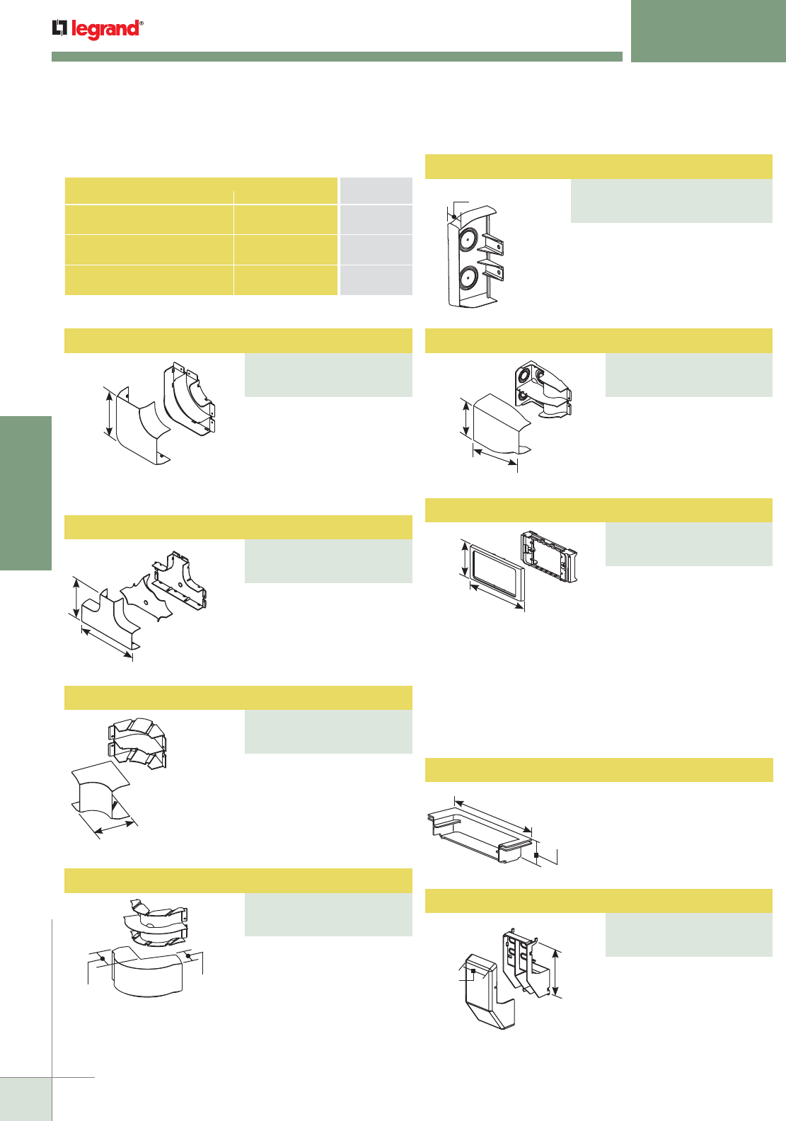
WWW.LEGRAND.US/WIREMOLD
150
NONMETALLIC RACEWAY
WIREMOLD
Radiused Full Capacity Flat Elbow
PART NUMBERS:
40N2F11V (Ivory)
40N2F11WH (White)
Used for power or
communica tions devices in a
single compartment. Accepts
5507 Series™ Faceplates.
For use with Ortronics® TracJack Individual Jack System,
Ortronics® Series II Front-Loading, Module System
Wiremold Open System Communication Modules.
CABLESMART® 40N2 SERIES RACEWAY
Ordering Information
6 5/8"
[168mm]
(Each leg) A 90° flat corner with
integral dividers to provide
2" [51mm] cable bend radius
for UTP and fiber optic
installations. Ideal for lay-in
or pull-through installations.
12 15/16"
[329mm]
8 9/16"
[217mm]
4 1/2" [114mm]
(Each leg)
2 11/16"
[68mm]
4 1/2"
[114mm]
(Each leg)
6"
[152mm]
7 5/16"
[186mm]
5 1/4"
[133mm]
2 3/16"
[56mm]
1 3/16"
[30mm]
6 3/8"
[162mm]
2 15/16"
[74mm]
6 1/8"
[156mm]
CONNECTION REQUIRED USE CATALOG
NUMBERFROM TO
1/2" or 3/4" trade size Conduit 40N2 Series
Raceway
40N2F20
3/4", 1", 1 1/4" & 1 1/2" trade
size conduit or armored cable
40N2 Series
Raceway
40N2F21
40N2 Series Raceway PN03, PN05, PN10
Series Raceways
40N2F74
Cablesmart 40N2 Series Raceway Interconnectivity Fittings
For branches at right angles.
A full capacity tee fitting that
provides separation of
services and 2" [51mm]
cable bend radius for UTP
and fiber optic installations.
A 90° internal corner with
integral dividers to provide
2" [51mm] cable bend radius
for UTP and fiber optic
installations. Ideal for lay-in
or pull-through installations.
A 90° external corner with
integral dividers to provide
2" [51mm] cable bend radius
for UTP and fiber optic
installations. Ideal for lay-in
or pull-through installations.
11/16"
[17.5mm]
Closes off raceway end runs. Can
be used to feed raceway using 1/2"
or 3/4" trade size conduit. Holes
for conduit must be drilled. Use a
step drill or other means.
FiberReady divided fitting to
feed 40N2 Series Raceway.
Includes 3/4", 1", 1 1/4", and
1 1/2" trade size KOs on
back and top.
40N2F55 High Capacity Device Box
Required for mounting power
or datacom devices into a
divided raceway application.
One used per device location.
Makes transition from 40N2
Series Raceway to PN03,
PN05, and PN10 Series
Raceways.
Blank End Fitting
PART NUMBERS:
40N2F20V (Ivory)
40N2F20WH (White)
Divided Entrance End Fitting
PART NUMBERS:
40N2F21V (Ivory)
40N2F21WH (White)
Radiused Full Capacity Tee
PART NUMBERS:
40N2F15V (Ivory)
40N2F15WH (White)
Twin Cover Device Bracket
PART NUMBERS:
40N2F31V (Ivory)
40N2F31WH (White)
NOTE: CM-EPLA End Plates are required when using Wiremold
communication modules and Pass & Seymour® inserts. S2-EPL End
Plates are required when using Ortronics® Series II inserts. To
mount TracJack inserts, use 5507-4TJ or 5507-6TJ Faceplates.
Radiused Full Capacity Internal Elbow
PART NUMBERS:
40N2F17V (Ivory)
40N2F17WH (White)
Divided Transition Fitting
PART NUMBERS:
40N2F74V (Ivory)
40N2F74WH (White)
Radiused Full Capacity External Elbow
PART NUMBERS:
40N2F19V (Ivory)
40N2F19WH (White)
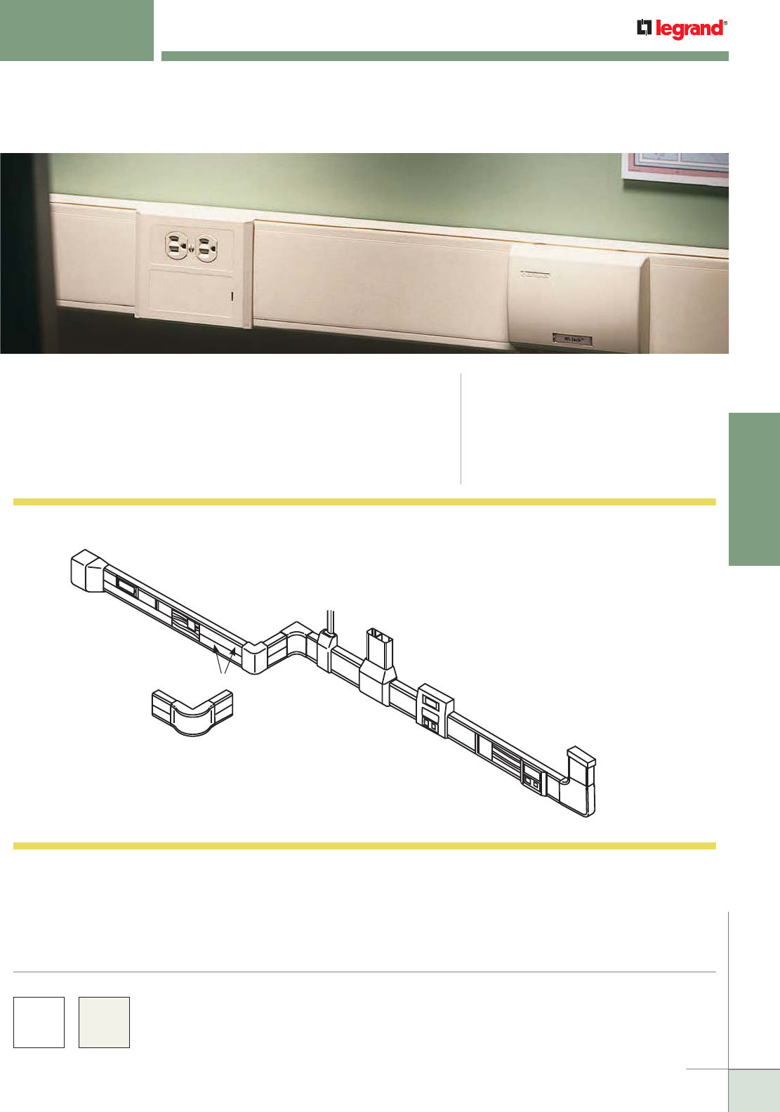
WWW.LEGRAND.US/WIREMOLD
151
NONMETALLIC RACEWAY
WIREMOLD
5400 SERIES™ RACEWAY
Large Capacity, Multiple Channel
CODE REFERENCE
Listed Raceway:
File E90378 Guide RJTX.
Complies with flammability requirements of UL-5A.
Fittings: File E90377 Guide RJYT.
Meets Article 388 of NEC.
UL Listed for up to 600V.
Meets Section 12-1600 of CEC.
Large capacity, multiple channel raceway. Lightweight and
easy-to-cut. Ideal for power or communication installations that
require multiple services.
H
F
P
CK
DL
M
QJ
A
R
O
G
B
I
E
N
5400 Series Raceway System Layout
NOTE: Illustration is for showing product applications only.
KEY
A. 5400C Raceway Cover
B. 5400TWC Twin Cover Wire Clip
C. 5400TB Two Compartment Base
D . 5400TC Twin Snap Cover
E. 5406A Cover Clip
F. 5406T Twin Cover Seam Clip
G. 5410 Entrance End Fitting
H. 5410DFO Entrance End Feed
I. 5411FO Flat Elbow
J. 5415 Tee
K. 5417FO Radiused Internal Elbow
L. 5418 Standard External Elbow
M. 5418FO Radiused External Elbow
N. 5450 In-Line Device Bracket
O. 5450A3 Multiple Device Bracket
P. 5450T Twin Snap Device Bracket
Q. 5474 Transition Fitting
R. Communication Device
5400 Series™ Raceway Part Numbers with a “-WH” suffix have a white finish. Part
Numbers without a suffix are only available in an ivory finish. 5400 Series Raceway is
paintable using latex paint or stain.
Custom color options are also available. Consult the factory for more information.
COLOR OPTIONS
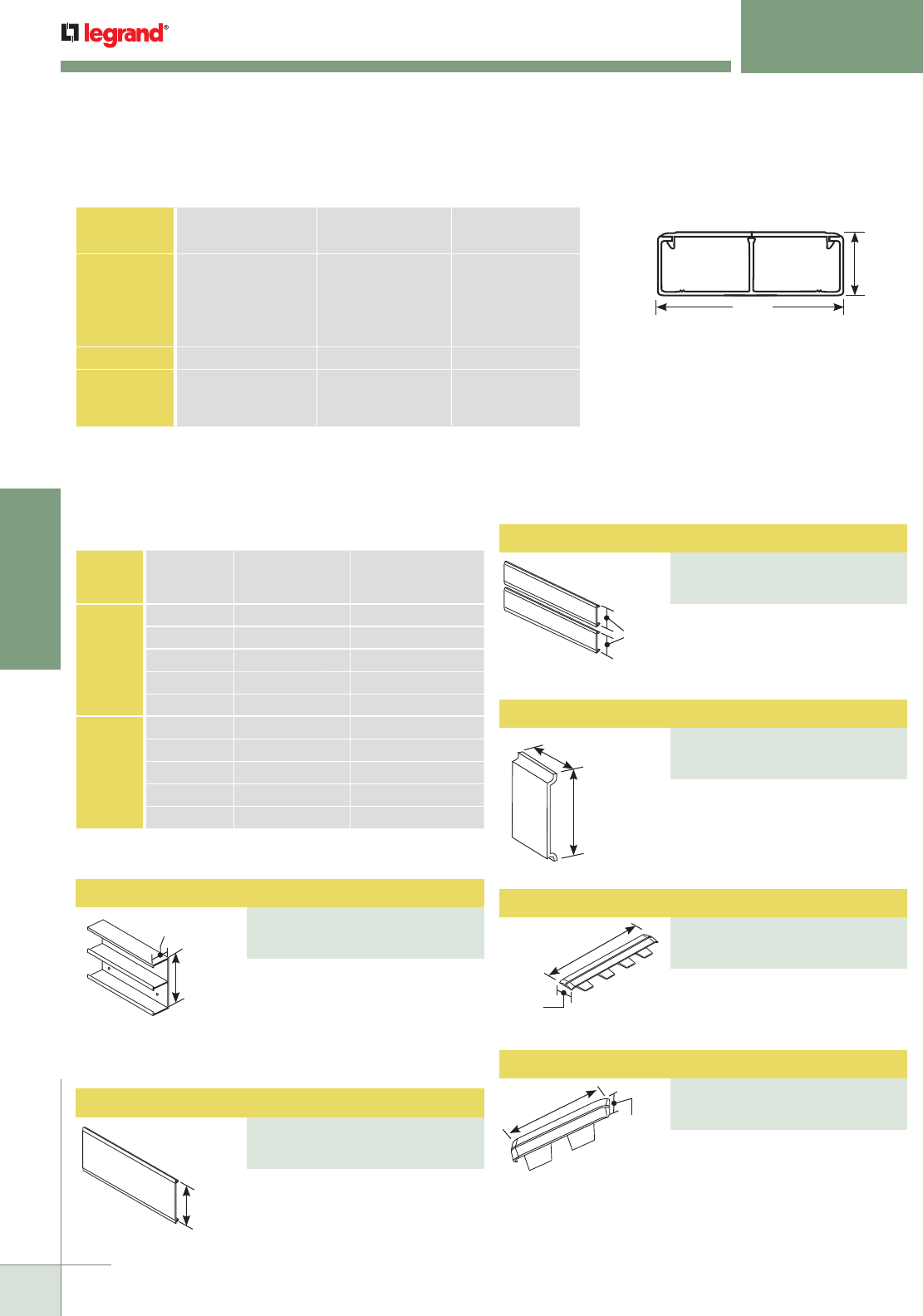
WWW.LEGRAND.US/WIREMOLD
152
NONMETALLIC RACEWAY
WIREMOLD
Twin Snap Cover Wire Clip
PART NUMBERS:
5400TWC (Ivory)
5400TWC-WH (White)
5 1/4"
[133mm]
3.72 sq. in.
[2400mm2]
3.72 sq. in.
[2400mm2]
1 3/4"
[44mm]
Total Raceway Capacity:
7.44 sq. in. [4800mm2]
1 11/16"
[43mm]
5 1/4"
[133mm]
5"
[127mm]
2 9/16"
[116mm]
Each
2 5/8"
[67mm]
1"
[25mm]
5400 SERIES™ RACEWAY
Ordering Information
NOTE: For additional information, refer to the Technical Section.
* Wire capacity is reduced to allow for proper conductor bend radius and maximum
permissible heat rise.
**
Category 6 augmented (6a) cable for 10 gigabit ethernet – max allowed cable diameter
per addenda No. 11 ANSI TIA/EIA 568-B.2.
5400 Series Raceway Wire Fill Capacities for Communications
CABLE/WIRE SIZE
O.D. Approx. Dia.) SECTION
EACH COMPARTMENT
40% FILL*
Inches [ ]
UNSHIELDED
TWISTED
PAIR
4-pair, 24 AWG, Cat 3
4-pair, 24 AWG, Cat 5e
4-pair, 24 AWG, Cat 6
4-pair, 24 AWG, Cat 6a*
25-pair, 24 AWG
0.190
0.210
0.250
0.354
0.410
[4.8]
[5.3]
[6.3]
[9.0]
[10.4]
52
42
30
15
11
COAXIAL RG6/U 0.270 [6.9] 26
FIBER ZipCord
Round 4 Strand Fiber
Round 6 Strand Fiber
0.118 x 0.236
0.187
0.256
[3 x 6]
[4.8]
[6.5]
53
54
28
5400 Series Raceway Wire Fill Capacities for Power
WIRE SIZE
THHN/THWN
O.D. Approx. Dia.)
NUMBER OF
CONDUCTORS
EACH COMPARTMENTInches [ ]
POWER
WIRING
WITHOUT
DEVICES
14 AWG 0.111 [2.8] 50
12 AWG 0.130 [3.3] 34
10 AWG 0.164 [4.2] 60
8 AWG 0.216 [5.5] 21
6 AWG 0.254 [6.5] 19
POWER
WIRING
WITH
DEVICES
14 AWG 0.111 [2.8] 50
12 AWG 0.130 [3.3] 34
10 AWG 0.164 [4.2] 60
8 AWG 0.216 [5.5] 21
6 AWG 0.254 [6.5] 19
* Total raceway capacity not to exceed capacity specified in Compartment.
Two equal compartments – Base
accepts single or Twin Snap Cover.
5400 Series raceway is available in
8' [2.4m] lengths with pre-punched
mounting holes, packed 48'
[14.6m] per carton.
Use with 5400 Series Raceway.
Available in 8' [2.4m] lengths,
packed 48' [14.6m] per carton.
Use with 5400 Series Raceway in
Twin Snap applications. Order
cover for each compartment.
Available in 8' [2.4m] lengths.
2 5/8"
[67mm]
2"
[51mm]
Retains wires in raceway.
5 3/32"
[129mm]
3/4"
[19.1mm]
For covering joint where two
pieces of 5400C Raceway Cover
come together.
For covering joint where two
pieces of 5400TC Cover come
together.
Twin Snap Raceway Cover
PART NUMBERS:
5400TC (Ivory)
5400TC-WH (White)
Cover Clip
PART NUMBERS:
5406A (Ivory)
5406A-WH (White)
Twin Cover Clip
PART NUMBERS:
5406T (Ivory)
5406T-WH (White)
Two-Compartment Raceway Base
PART NUMBERS:
5400TB (Ivory)
5400TB-WH (White)
Full-Width Raceway Cover
PART NUMBERS:
5400C (Ivory)
5400C-WH (White)
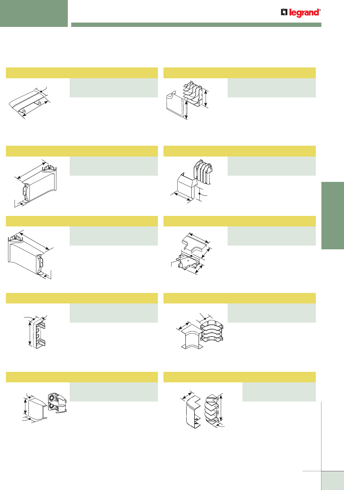
WWW.LEGRAND.US/WIREMOLD
153
NONMETALLIC RACEWAY
WIREMOLD
1 3/4"
[44mm]
7/8"
[22mm]
1 25/32"
[45mm]
5 15/32"
[139mm]
1 7/8"
[48mm]
7 1/8"
[181mm]
3 1/2"
[89mm]
7 1/2"
[191mm]
7 3/16"
[183mm]
7 25/32"
[198mm]
(Each leg)
4 27/32"
[123mm]
6 9/16"
[167mm]
14 1/4"
[362mm]
9 7/8"
[251mm]
9 1/8"
[232mm]
13"
[330mm]
4"
[102mm]
4 1/2"
[114mm]
(Each leg)
5 9/32"
[134mm]
1 13/16"
[46mm]
3 1/2"
[89mm]
(Each leg)
10"
[254mm]
1 3/4"
[44mm]
10"
[254mm]
1 3/4"
[44mm]
5400 SERIES™ RACEWAY
Ordering Information
For covering joint where two
pieces of 5400TB Base come
together. One clip per package.
For transitioning from MXN2A08
Corner Drop to a horizontal run of
5400TB Series Raceway to the left.
For transitioning from MXN2A08
Corner Drop to a horizontal run of
5400TB Series Raceway to the
right.
For closing open end of 5400
Series Raceway. Has four 1/2"
trade size KOs for end feed.
FiberReady divided fitting to feed
5400 Series Raceway. Includes 1",
1 1/4", 1 1/2", and 2" trade size
KOs on back and top.
For right angle turns on the same
surface. Integral dividers provide
2" [51mm] cable bend radius for
UTP and fiber optic installations.
Ideal for lay-in or pull-through
installations.
For branching raceway at right
angles.
A full capacity tee fitting for
branching raceway at right angles.
Provides separation of services
and 2" [51mm] cable bend radius
for UTP and fiber optic
installations.
For right angle turns around
internal corners. Integral dividers
provide 2" [51mm] cable bend
radius for UTP and fiber optic
installations. Ideal for lay-in or
pull-through installations.
For right angle turns around
external corners.
Radiused Full Capacity Flat Elbow
PART NUMBERS:
5411FO (Ivory)
5411FO-WH (White)
Base Seam Clip
PART NUMBERS:
5406TB (Ivory)
5406TB-WH (White)
Tee
PART NUMBERS:
5415 (Ivory)
5415-WH (White)
Transition Fitting
PART NUMBERS:
5408L (Ivory)
5408L-WH (White)
Tee
PART NUMBERS:
5415FO (Ivory)
5415FO-WH (White)
Transition Fitting
PART NUMBERS:
5408R (Ivory)
5408R-WH (White)
Radiused Full Capacity Internal Elbow
PART NUMBERS:
5417FO (Ivory)
5417FO-WH (White)
Blank End Fitting
PART NUMBERS:
5410 (Ivory)
5410-WH (White)
Radiused Divided Entrance End Cap
PART NUMBERS:
5410DFO (Ivory)
5410DFO-WH (White)
External Elbow
PART NUMBERS:
5418 (Ivory)
5418-WH (White)
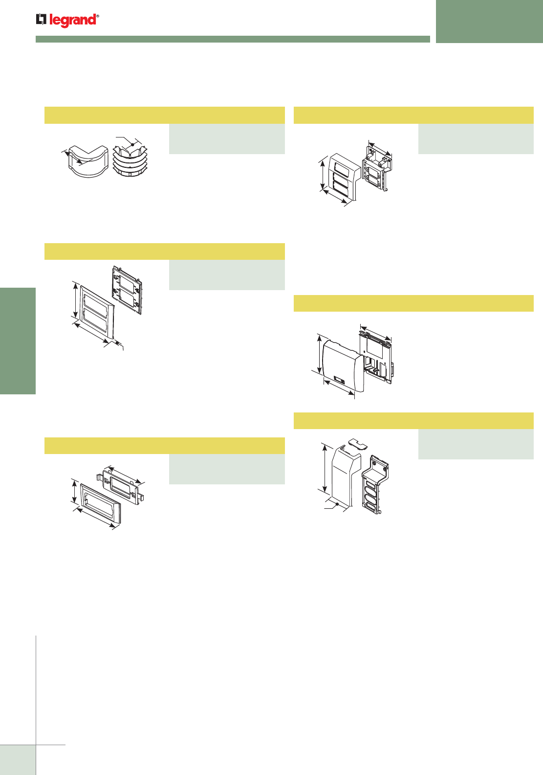
WWW.LEGRAND.US/WIREMOLD
154
NONMETALLIC RACEWAY
WIREMOLD
5 5/32"
[131mm]
6"
[152mm]
7/16"
[11.1mm]
4"
[102mm]
6 7/8"
[175mm]
(Each leg)
5400 SERIES™ RACEWAY
Ordering Information
For right angle turns around
external corners. Integral
dividers provide 2" [51mm]
cable bend radius for UTP
and fiber optic installations.
Use the 5418FO for a
alternative to 5418.
For mounting power and
communication devices
in-line with 5400 Series
Raceway. Utilizes 5507
Series™ Faceplates, as well
as Wiremold Open System
communication modules,
Ortronics® TracJack and
Series II inserts, and Pass &
Seymour® Activate Series
inserts. For faceplate
options, see 5507 Series™
Faceplates.
NOTE: CM-EPLA End Plates are required when using Wiremold
communication modules. S2-EPL End Plates are required when using
Ortronics® Series II inserts. To mount TracJack inserts, use 5507-4TJ
or 5507-6TJ Faceplates.
7 19/32"
[193mm]
7 1/2"
[191mm]
7 5/16"
[185mm]
2 1/2"
[64mm]
4 7/8"
[124mm]
4 5/8"
[117mm]
NOTE: CM-EPLA End Plates are required when using Wiremold
communication modules and Pass & Seymour® Activate inserts.
S2-EPL End Plates are required when using Ortronics® Series II
inserts. To mount TracJack inserts, use 5507-4TJ or 5507-6TJ
Faceplates.
For power or communication
devices in a single
compartment. For use with
5507 Series™ Faceplates,
Ortronics® TracJack &
Series II Modules, Pass &
Seymour® Activate Series
Inserts, and Wiremold Open
System Communication
Modules.
For mounting up to three
power or communication
devices at one location inline
and offset from 5400 Series
Raceway. For use with 5507
Series™ Faceplates, Ortronics® TracJack & Series II
Modules, Pass & Seymour® Activate Series Inserts, and
Wiremold Open System Communication Modules.
Radiused Full Capacity External Elbow
PART NUMBERS:
5418FO (Ivory)
5418FO-WH (White)
Three Device Mounting Bracket
PART NUMBERS:
5450A3 (Ivory)
5450A3-WH (White)
Device Bracket
PART NUMBERS:
5450 (Ivory)
5450-WH (White)
Twin Snap Device Bracket
PART NUMBERS:
5450T (Ivory)
5450T-WH (White)
Transition Fitting
PART NUMBERS:
5474 (Ivory),
5474-WH (White)
7 9/16"
[192mm]
3 3/16"
[81mm]
5 1/2"
[140mm]
6 1/2"
[165mm]
4 1/2"
[114mm]
Used to mount Ortronics®
Wi-Jack™ Wireless Access
Points to 5400 Series
Raceway.
Makes transition from 5400
Series Raceway to the
400/800/2300, or PN03,
PN05, and PN10 Series
Latching Raceways.
5450-ORAP Wireless Bracket
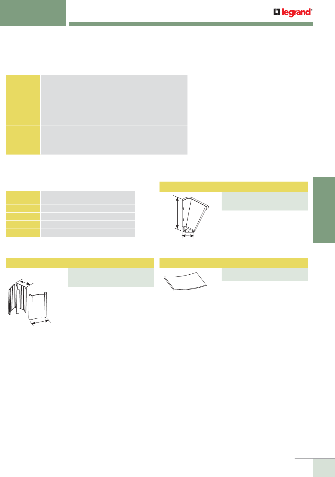
WWW.LEGRAND.US/WIREMOLD
155
NONMETALLIC RACEWAY
WIREMOLD
Entrance End Fitting
PART NUMBERS:
MXN2F21 (Ivory)
MXN2F21-WH (White)
Corner Drop Raceway Base and Cover
PART NUMBERS:
MXN2A08 (Ivory)
MXN2A08-WH (White)
NOTE: For additional information, refer to the Technical Section.
* Category 6 augmented (6a) cable for 10 gigabit ethernet – max allowed cable diameter per
addenda No. 11 ANSI TIA/EIA 568-B.2.
MXN Series RACEWAY Wire Fill Capacities for Communications
CABLE/WIRE SIZE
O.D. Approx. Dia.) SECTION
EACH COMPARTMENT
40% FILL*
Inches [ ]
UNSHIELDED
TWISTED
PAIR
4-pair, 24 AWG, Cat 3
4-pair, 24 AWG, Cat 5e
4-pair, 24 AWG, Cat 6
4-pair, 24 AWG, Cat 6a*
25-pair, 24 AWG
0.190
0.210
0.250
0.354
0.410
[4.8]
[5.3]
[6.3]
[9.0]
[10.4]
19
16
11
5
4
COAXIAL RG6/U 0.270 [6.9] 9
FIBER ZipCord
Round 4 Strand Fiber
Round 6 Strand Fiber
0.118 x 0.236
0.187
0.256
[3 x 6]
[4.8]
[6.5]
20
20
10
MXN Series Raceway Wire Fill Capacities for Power
WIRE SIZE
THHN/THWN
O.D. Approx. Dia.) NO. OF CONDUCTORS
EACH COMPARTMENTInches [ ]
14 AWG 0.111 [2.8] 50
12 AWG 0.130 [3.3] 34
10 AWG 0.164 [4.2] 60
8 AWG 0.216 [5.5] 21
6 1/8"
[156mm]
3 5/8"
[92mm]
2"
[51mm]
3 5/16"
[84mm]
Used as a vertical corner feed drop
to horizontal runs of 5400 Series
Raceway. Two compartments.
Packaged with base and cover.
MXN2A08 available in 8' [2.44m]
lengths. Use 5408L or 5408R to
transition to 5400 Series Raceway.
For feeding corner drop raceway
from large conduits. Has
concentric 3/4", 1", and 1 1/2"
trade size KOs.
Retains wires in MXN2A08 Corner
Drop Raceway.
5400 SERIES™ RACEWAY
Ordering Information
Wire Clip
PART NUMBERS:
MXN2FWC (Ivory)
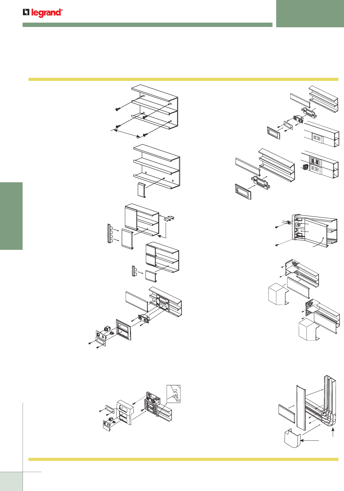
WWW.LEGRAND.US/WIREMOLD
156
NONMETALLIC RACEWAY
WIREMOLD
5400 SERIES™ RACEWAY
Installation Details
1. Mount raceway base to wall by
using appropriate screws. Use
two screws every 18" [457mm]
using the ribs on the outermost
compartments of the raceway as
guides.
2. Place the 5400TWC Wire Clips
in base as shown to contain the
wires in place while installing.
3. Slide the 5406A and 5406T Seam
Covers on the uninstalled section
of raceway cover as shown; snap
cover to the base overlapping
the seam cover over the
installed section. 5406TB
Base Seam Clip used for
base seams.
5400TWC
5406A
5400C
5406TB
5406T
5400TC
5450T
5450T
7. End cap may be used as a blank
to cap off the raceway at the
end-of-run, or to feed wires
from a 1/2" trade size pipe;
punch out the proper KO. Mount
endcap to raceway base
using appropriate screws.
NOTE: The 5400TB Base can
be rotated 90° to allow
feed from back instead
of side.
8. Feeding raceway from conduit.
1. Line up base of the fitting with
the raceway base using the
tongues as guides.
2. Fasten the base of the fitting
to the wall using screws.
3. Remove the proper KO.
4. Attach conduit using proper
fitting.
5. Feed the necessary cables.
6. Slide the dividers (two provided)
into the mounting guides if
needed.
7. Snap the raceway cover on
the base.
8. Snap fitting cover onto the
base using guiding keyslots
in base.
5410
9. Mount flat elbow as shown; assemble
raceway covers first, then elbow cover.
5411FO
Access 5400 Series Raceways Installation Details
6. Snap 5450T Bracket to raceway
base, engage sidewall first then
divider side. Install Wiremold
Open System communication
modules, Ortronics® TracJack
or Series II inserts, or Pass
& Seymour® Activate Series
inserts, or 5507 Faceplates.
Snap raceway cover to base
and finish with 5450T Trim
Plate (engaging raceway
sidewall first then
divider side).
4. Sequence for installing devices:
1. Snap bracket in raceway base.
2. Fasten devices to bracket.
Communication devices snap
onto bracket.
3. Snap raceway covers to
base, butting against
bracket.
4. Assemble trim ring.
5. Insert CM-EPLA or
S2-EPL, if required.
6. Install Wiremold
Open System communication modules,
Ortronics® TracJack or Series II inserts, or Pass & Seymour®
Activate Series inserts required.
7. Or install 5507 Faceplates, if required.
5. Install bracket to raceway base first,
mount to the wall with screws,
and mount device. After
installing raceway cover,
snap box cover to bracket
and assemble faceplates.
Install Wiremold Open
System Communication
Modules, Ortronics® TracJack
or Series II inserts, or Pass &
Seymour® Activate Series Inserts, or 5507 Faceplates. Use
5407A3 with 5400TB to install three devices at one location.
5450A3
5450
NOTE: Use blank plates to cover
any unused slots in bracket.
18"
[457mm]
5400TB
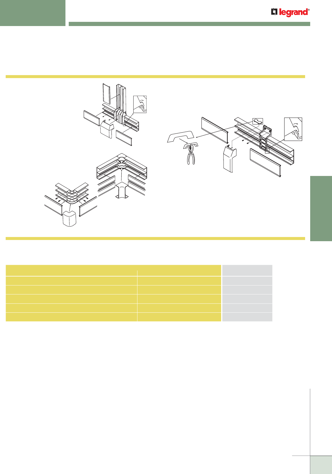
WWW.LEGRAND.US/WIREMOLD
157
NONMETALLIC RACEWAY
WIREMOLD
5400 SERIES™ RACEWAY
Installation Details
5400 Series Raceways Installation Details
5474
10. Punch out appropriate hole in
the tee fitting base and snap to
raceway base; screw down to
wall. Assemble raceway covers
to base and then snap tee cover,
overlapping raceway covers.
5417FO
5418 or 5418FO
11. Install one corner base first,
then measure to other corner
(measure from edges of fittings).
Mount raceway base and
cover; assemble fitting
cover last.
12. Punch out appropriate hole in fitting base and snap to the
raceway base; screw down to the wall. Remove proper twistout
from the insert by first scoring with a knife. Slide the insert onto
fitting cover. Assemble raceway covers to base and then snap
fitting cover, overlapping raceway covers.
5415
CONNECTION REQUIRED
USE CATALOG NUMBERFROM TO
5400 Series Raceway 400, 800, 2300 Series Raceways 5474
5400 Series Raceway PN03, PN05, PN10 Series Raceways 5474
5400 Series Raceway MXN2A08 5408L/5408R
1/2" Trade size Conduit or Armored Cable Side of 5400 Series Raceway 5410 or 5410DFO
3/4", 1", 1 1/2" & 2" Trade size Conduit or Armored Cable Back or Side of 5400TB 5410DFO
5400 Series Raceway Interconnectivity Fittings
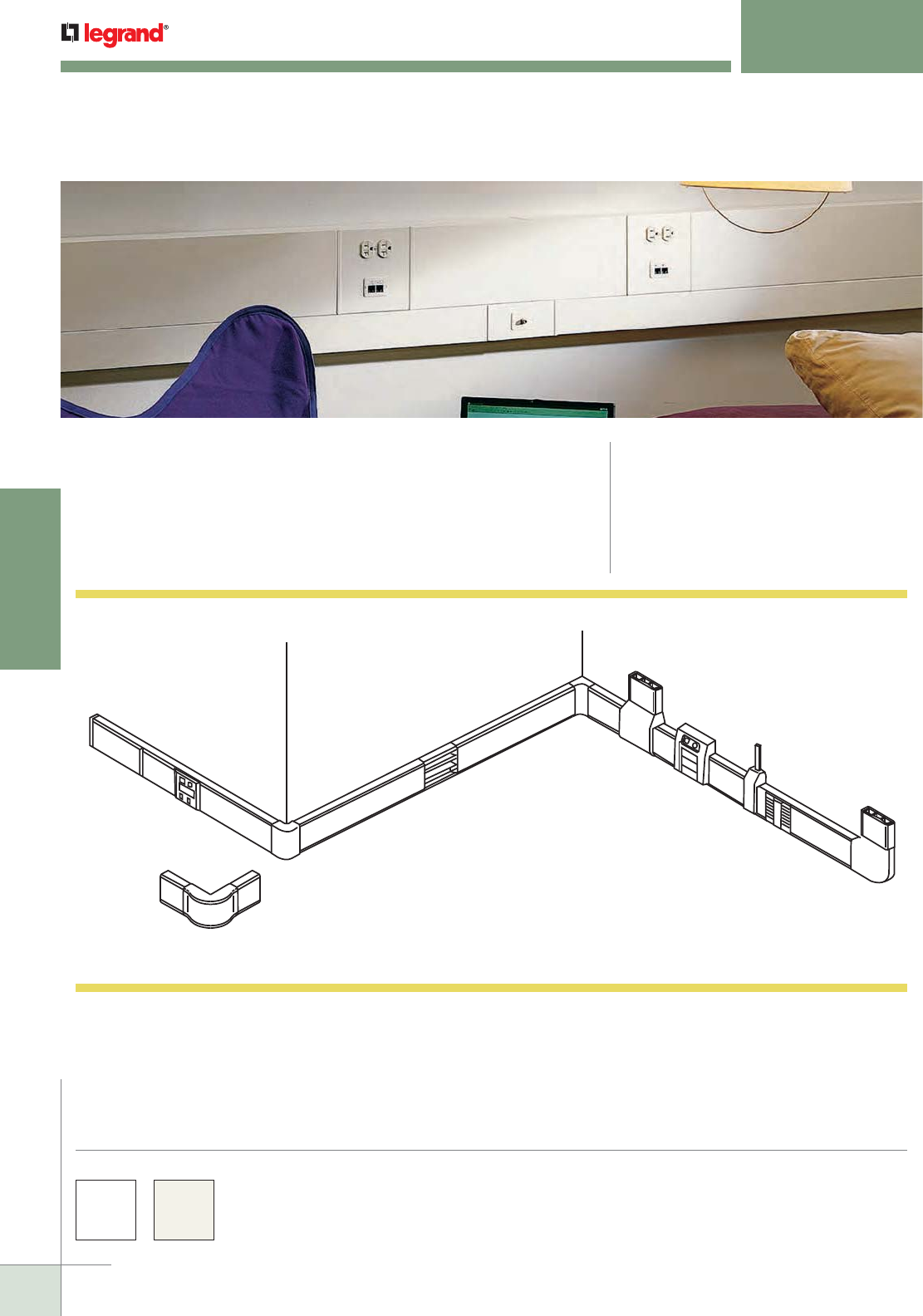
WWW.LEGRAND.US/WIREMOLD
158
NONMETALLIC RACEWAY
WIREMOLD
5500 SERIES™ RACEWAY
Large Capacity, Multiple Channel
CODE REFERENCE
Listed Raceway:
File E90378 Guide RJTX.
Complies with flammability requirements of UL-5A.
Fittings: File E90377 Guide RJYT.
Meets Article 388 of NEC.
UL Listed for up to 600V.
Meets Section 12-1600 of CEC.
Large capacity, multiple channel raceway. Lightweight and easy to cut.
Ideal for power or communication installations where flexibility for future
moves and changes is important.
B
C
D
E
F
GH
I
J
K
L
A
M
N
5500 Series Raceway System Layout
NOTE: Illustration is for showing product applications only.
KEY
A. 5510 End Cap/Entrance End Fitting
B. 5510D Entrance End Fitting
C. 5506 Cover Clip
D. 5550 In-Line Device Bracket
E. 5518 External Elbow
F. 5514A Back Connector Feed
G. 5517FO Radiused Full Capacity
Internal Elbow
H. 5515 Tee Fitting/Take-Off Connector
I. 5550A4 Multiple Device Bracket
J. 5574 or 5574A Inline Transition Fitting
K. 5500WCA Wire Clip
L. 5511FO Radiused Full Capacity
Flat Elbow
M. 5518FO Radiused Full Capacity
External Elbow
N. Communication Devices
5500 Series™ Raceway Part Numbers with a “-WH” suffix have a white finish. Part
Numbers without a suffix are only available in an ivory finish. 5500 Series Raceway is
paintable using latex paint.
Custom color options are also available. Consult the factory for more information.
COLOR OPTIONS
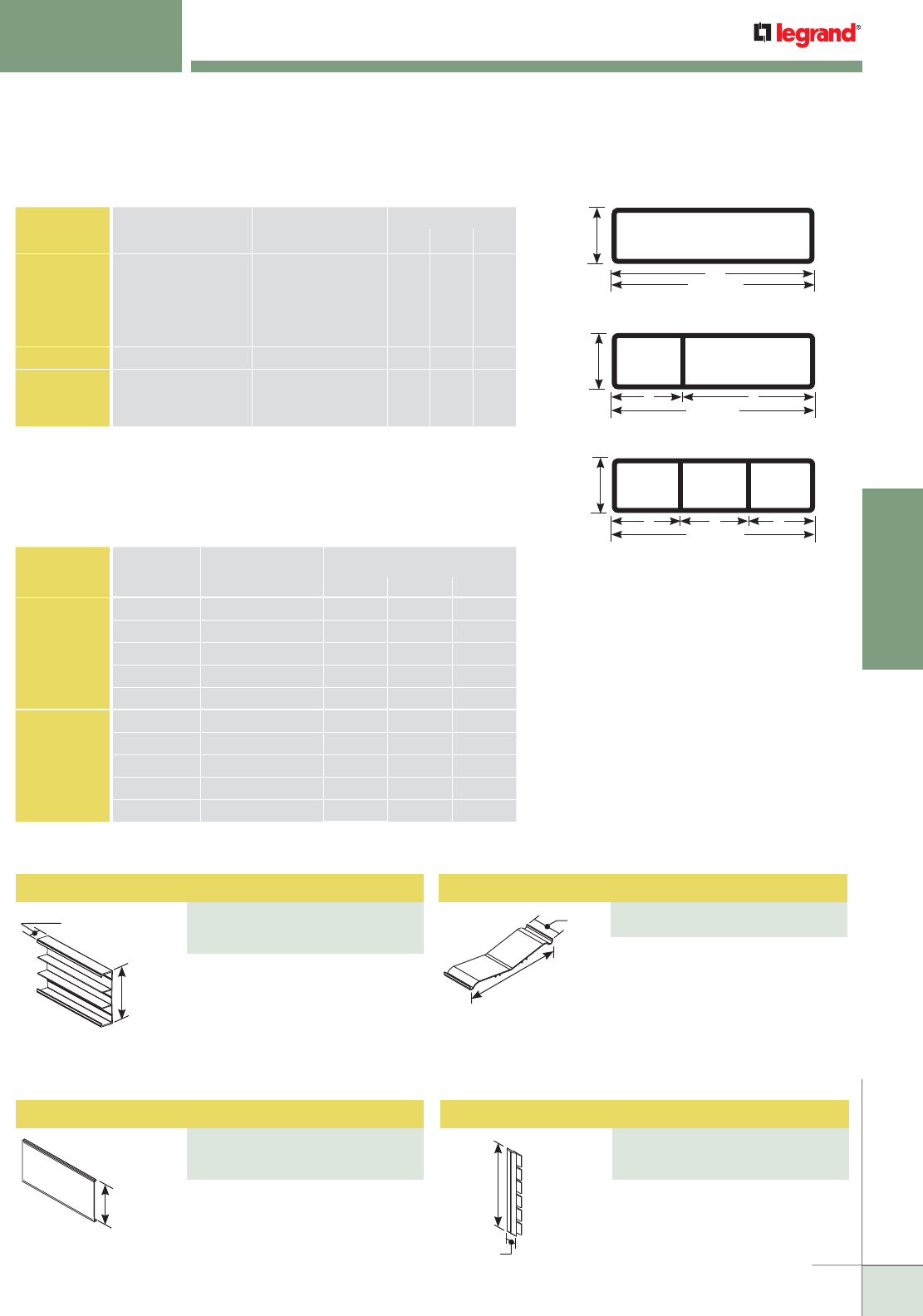
WWW.LEGRAND.US/WIREMOLD
159
NONMETALLIC RACEWAY
WIREMOLD
Divided Raceway Base
PART NUMBERS:
5500BD3 (Ivory)
5500BD3-WH (White)
5500 SERIES™ RACEWAY
Ordering Information
5500 Series Raceway Ordering Information
8.14 Sq. In.
[5252mm2]
6 11/16"
[170mm]
A
1 3/4"
[44mm]
2.64
Sq. In.
[1703mm2]
5.29 Sq. In.
[3413mm2]
6 11/16"
[170mm]
B C
1 3/4"
[44mm]
2.64
Sq. In.
[1703mm2]
2.64
Sq. In.
[1703mm2]
2.64
Sq. In.
[1703mm2]
6 11/16"
[170mm]
B B B
1 3/4"
[44mm]
1 11/16"
[43mm]
6 11/16"
[170mm]
6 3/8"
[162mm]
2"
[51mm]
6 1/16"
[154mm]
NOTE: For additional information, refer to the Technical Section.
* Wire capacity is reduced to allow for proper conductor bend radius and maximum
permissible heat rise.
** Category 6 augmented (6a) cable for 10 gigabit ethernet – max allowed cable diameter
per addenda No. 11 ANSI TIA/EIA 568-B.2.
5500 Series Raceway Wire Fill Capacities for Communications
CABLE/WIRE SIZE
O.D. Approx. Dia.) SECTION 40% FILL*
Inches [ ] ABC
UNSHIELDED
TWISTED
PAIR
4-pair, 24 AWG, Cat 3
4-pair, 24 AWG, Cat 5e
4-pair, 24 AWG, Cat 6
4-pair, 24 AWG, Cat 6a**
25-pair, 24 AWG
0.190
0.210
0.250
0.354
0.410
[4.8]
[5.3]
[6.3]
[8.9]
[10.4]
114
94
66
33
24
37
30
21
10
8
71
58
41
20
15
COAXIAL RG6/U 0.270 [6.9]
56
18 35
FIBER ZipCord
Round 4 Strand Fiber
Round 6 Strand Fiber
0.118 x 0.236
0.187
0.256
[3 x 6]
[4.8]
[6.5]
117
118
63
37
38
20
72
73
39
5500 Series Raceway Wire Fill Capacities for Power
WIRE SIZE
THHN/THWN
O.D. Approx. Dia.) NUMBER OF CONDUCTORS
Inches [ ] COMP A COMP B COMP C
POWER
WIRING
WITHOUT
DEVICES
14 AWG 0.111 [2.8] 64 41 50
12 AWG 0.130 [3.3] 60 25 44
10 AWG 0.164 [4.2] 90 46 70
8 AWG 0.216 [5.5] 65 18 40
6 AWG 0.254 [6.5] 45 15 34
POWER
WIRING WITH
DEVICES
14 AWG 0.111 [2.8] 64 35 50
12 AWG 0.130 [3.3] 60 25 44
10 AWG 0.164 [4.2] 90 16 70
8 AWG 0.216 [5.5] 65 8 36
6 AWG 0.254 [6.5] 45 5 25
Three equal compartments –
use for separate services in one
raceway. Breakaway dividers
enable compartment
configurations. Available in 8'
[2.4m] lengths. Packed 48' [14.6m]
per carton.
Use with 5500BD3. Available in 8'
[2.4m] lengths. Packed 48' [14.6m]
per carton.
Retains wires in raceway.
Wire Clip
PART NUMBERS:
5500WCA (Ivory)
Raceway Cover
PART NUMBERS:
5500C (Ivory)
5500C-WH (White)
6 1/2"
[165mm]
3/4"
[19.1mm]
For covering seam where two
pieces of 5500C Cover come
together.
Cover Clip
PART NUMBERS:
5506 (Ivory)
5506-WH (White)
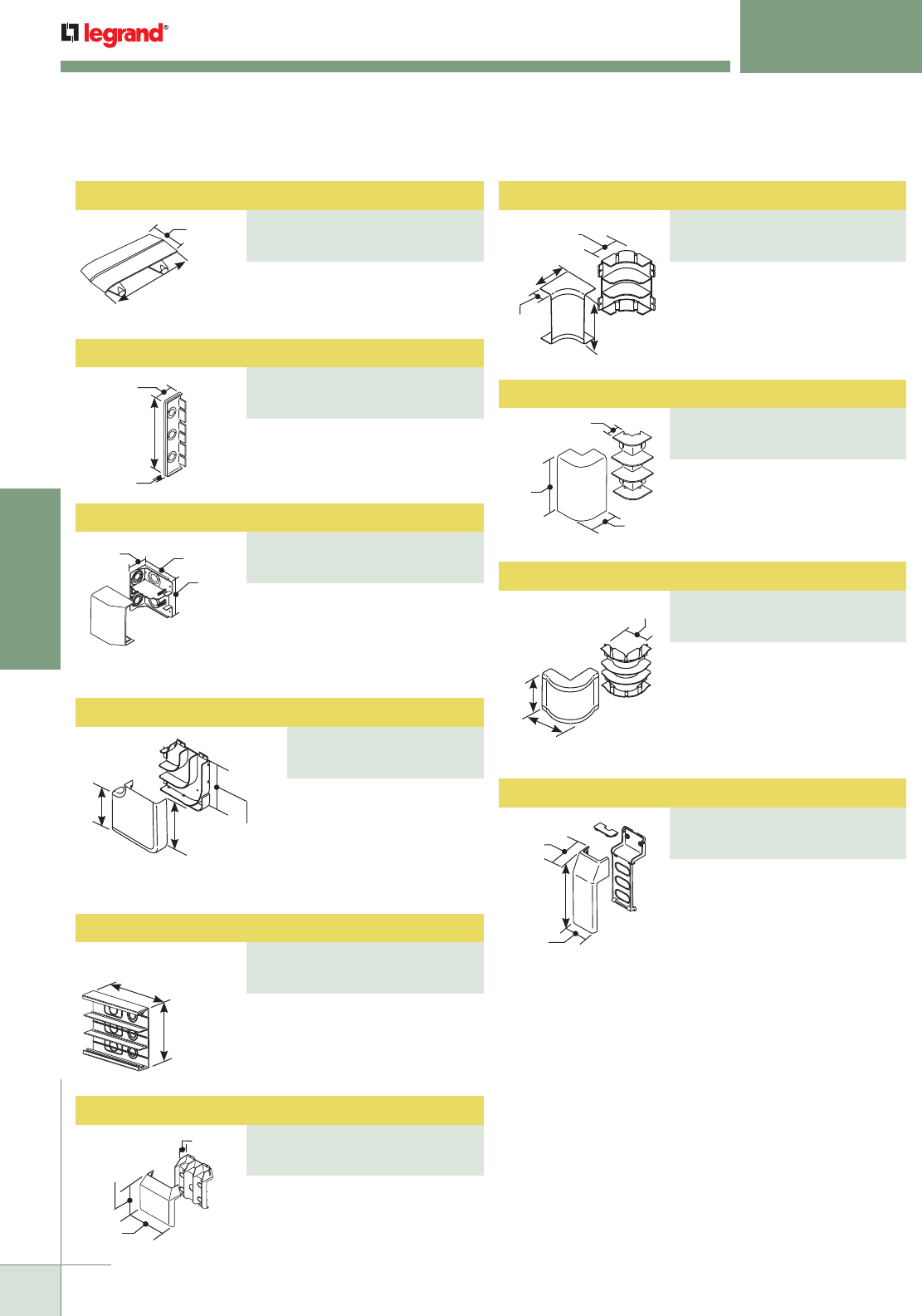
WWW.LEGRAND.US/WIREMOLD
160
NONMETALLIC RACEWAY
WIREMOLD
5500 SERIES™ RACEWAY
Ordering Information
1 3/4"
[44mm]
7/8"
[22.2mm]
1 13/16"
[46mm]
6 7/8"
[175mm]
3/8"
[9.5mm]
3 1/4"
[83mm]
6 7/8"
[175mm]
5 13/16"
[148mm]
9 3/16"
[233mm]
Each Leg
8 9/16"
[217mm]
6 7/8"
[175mm]
8"
[203mm]
6 11/16"
[170mm]
3 1/16"
[78mm]
9 1/8"
[232mm]
8 3/16"
[208mm]
4"
[102mm]
Each Leg
4 1/2"
[114mm]
1 13/16"
[46mm]
6 7/8"
[175mm]
3 1/2"
[89mm]
Each Leg
6 7/8"
[175mm]
1 1/4"
[32mm]
3 1/2"
[89mm]
Each Leg
6 7/8"
[175mm]
4"
[102mm]
2 3/8"
[60mm]
9"
[229mm]
3 3/16"
[81mm]
For covering seam where two
pieces of 5500BD3 Base come
together.
For closing open end of 5500BD3
Raceway. Three 1/2" trade size
KOs for end feed.
For feeding raceway from larger
conduits. Has concentric 3/4", 1",
1 1/2", and 2" trade size KOs on
end and back. Two removable
dividers are included.
90° flat corner with integral
dividers that provides a 2"
[51mm] cable bend radius
for UTP and fiber optic
installations. Ideal for lay-in
or pull-through installations.
Use when a is needed. Has three
rectangular KOs for use with
existing wall box and three 1/2",
3/4", and 1" trade size KOs.
For branching raceway at right
angles.
90° internal corner with integral
dividers that provides a 2" [51mm]
cable bend radius for UTP and
fiber optic installations. Ideal for
lay-in or pull-through installations.
For right angle turns around
external corners.
90° external corner with integral
dividers that provide a 2" [51mm]
cable bend radius for UTP and
fiber optic installations. Use
the 5518FO for a alternative to
the 5518.
Makes transition from 5500 Series
Raceway to the 400, 800, 2300,
PN03, PN05 and PN10 Latching
Series Raceways.
Bend Radius Full Capacity Internal Elbow
PART NUMBERS:
5517FO (Ivory)
5517FO-WH (White)
Base Seam Clip
PART NUMBERS:
5506B (Ivory)
5506B-WH (White)
External Elbow
PART NUMBERS:
5518 (Ivory)
5518-WH (White)
Blank End Fitting
PART NUMBERS:
5510 (Ivory)
5510-WH (White)
Bend Radius Full Capacity External Elbow
PART NUMBERS:
5518FO (Ivory)
5518FO-WH (White)
Entrance End Fitting
PART NUMBERS:
5510D (Ivory)
5510D-WH (White)
Transition Fitting
PART NUMBERS:
5574 (Ivory)
5574-WH (White)
Radiused Full Capacity Flat Elbow
PART NUMBERS:
5511 (Ivory)
5511-WH (White)
Backfeed Connector
PART NUMBERS:
5514A (Ivory)
5514A-WH (White)
Tee/Take-Off Connector
PART NUMBERS:
5515 (Ivory)
5515-WH (White)
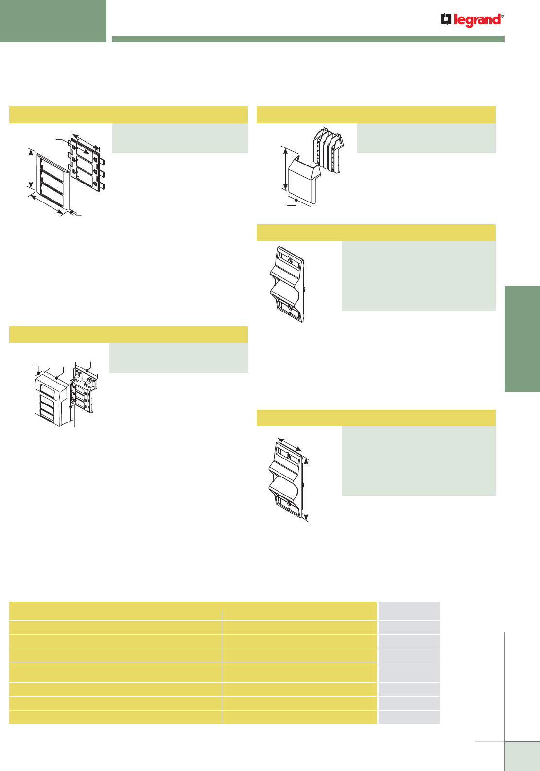
WWW.LEGRAND.US/WIREMOLD
161
NONMETALLIC RACEWAY
WIREMOLD
Angled Raceway Adapter
PART NUMBERS:
CM-ARA-V (Ivory)
CM-ARA-WH (White)
CM-ARA-FW (Fog White)
CM-ARA-BK (Black)
CM-ARA-G (Gray)
CM-ARA-GY (Light Gray)
5500 SERIES™ RACEWAY
Ordering Information
6 9/16"
[167mm]
9 1/8"
[231mm]
NOTE: CM-EPLA End Plates are required when using Wiremold
communication modules and Pass & Seymour® Activate inserts.
S2-EPL End Plates are required when using Ortronics® Series II
inserts. To mount TracJack inserts, use 5507-4TJ or 5507-6TJ
Faceplates.
9 5/8"
[244mm]
7 1/2"
[191mm]
7 5/16"
[186mm]
2 1/2"
[64mm]
6 5/8"
[168mm]
5"
[127mm]
2 7/8" x 1 3/4"
[73mm x 44mm]
cutout
6"
[152mm] 7/16"
[11.1mm]
NOTE: CM-EPLA End Plates are required when using Wiremold
communication modules and Pass & Seymour® Activate inserts.
S2-EPL End Plates are required when using Ortronics® Series II
inserts. To mount TracJack inserts, use 5507-4TJ or
5507-6TJ Faceplates.
For mounting up to three power
and communication devices
with the 5500 Series Raceway.
Utilizes 5507 Series™ Faceplates,
Wiremold Open System
communication modules,
Ortronics® TracJack and Series II
inserts, and Pass & Seymour®
Activate Series inserts. For
faceplate options, see 5507
Series™ Faceplates.
For mounting up to four power and
communication devices at one
location. Utilizes 5507 Series™
Faceplates, Wiremold Open
System communication modules,
Ortronics® TracJack and Series II
inserts, and Pass & Seymour®
Activate Series inserts. For
faceplate options, see 5507
Series™ Faceplates.
Makes transition from 5500 Series
Raceway to 5400 Series Raceway.
2"
[51mm]
4 5/16"
[110mm]
Provides angled exit in multi-channel
raceway systems. Snaps into standard
4050, 5450, 5450T, 5550, 40N2F31 and WallSource Device
Brackets. Angled exit provides additional mounting depth
required for A/V connections as well as ensuring the
required bend radius for UTP and fiber optic cabling.
Holds two Ortronics® Series II modules. Fits 5507 Series
Faceplate opening.
Provides angled exit in multi-channel
raceway systems. Snaps into standard
4050, 5450, 5450T, 5550, 40N2F31 and
WallSource Device Brackets. No CM-EPLA End Plates
required. Accepts two CM2 Series Wiremold Open System
communication modules or Pass & Seymour® Activate
Series inserts.
CONNECTION REQUIRED USE CATALOG
NUMBERFROM TO
5500BD3 Series Raceway 400BAC, 800BAC, 2300BAC 5574
5500BD3 Series Raceway PN03, PN05, PN10 Series Raceway 5574
5500BD3 Series Raceway 5400TB Series Raceway 5574A
Existing Outlet 5500BD3 Series Raceway 5514A
1/2", 3/4", & 1" Trade Size Conduit or Armored Cable Back of 5500BD3 Series Raceway 5514A or 5510D
1/2" Trade Size Conduit or Armored Cable Side of 5500BD3 Series Raceway 5510 or 5510D
3/4", 1", 1 1/2" & 2" Trade Size Conduit or Armored Cable Back or Side of 5500BD3 Series Raceway 5510D
5500 Series Raceway Interconnectivity Fittings
Transition Fitting
PART NUMBERS:
5574A (Ivory)
5574A-WH (White)
Device Inline Bracket
PART NUMBERS:
5550 (Ivory)
5550-WH (White)
Offset Mounting Device Bracket
PART NUMBERS:
5550A4 (Ivory)
5550A4-WH (White)
Angled Raceway Adapter
PART NUMBERS:
ARA-S2-V (Ivory)
ARA-S2-WH (White)
ARA-S2-FW (Fog White)
ARA-S2-BK (Black)
ARA-S2-G (Gray)
ARA-S2-GY (Light Gray)
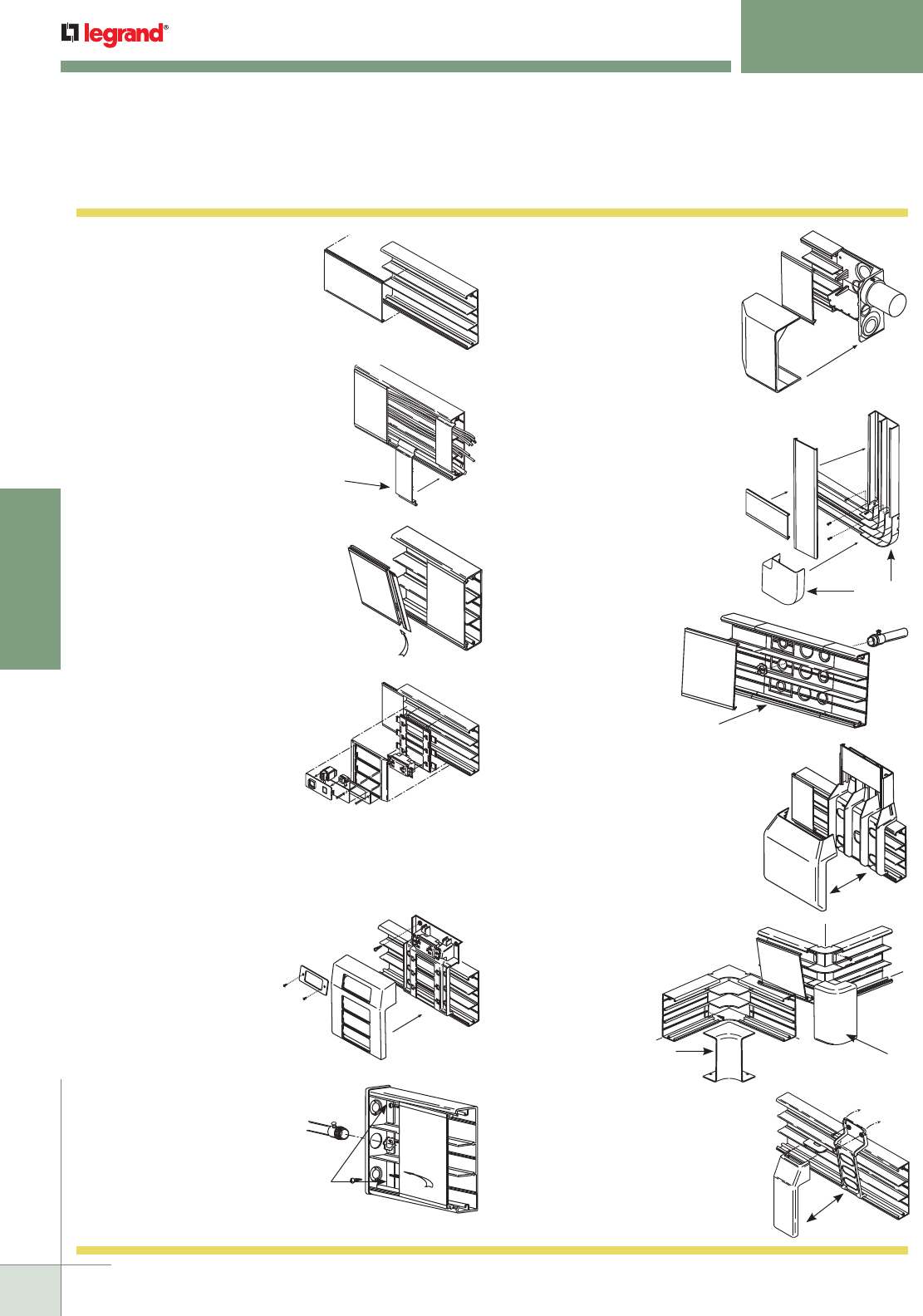
WWW.LEGRAND.US/WIREMOLD
162
NONMETALLIC RACEWAY
WIREMOLD
4. Sequence for installing devices:
1. Snap bracket in raceway base.
2. Fasten devices to bracket.
Communication devices snap
onto bracket (see Communication
Connectivity Section).
3. Snap raceway covers to base,
butting against bracket.
4. Assemble trim ring.
5. Insert CM-EPLA or S2-EPL,
if required.
6. Install Wiremold Open System
communication modules, Ortronics
®
TracJack or Series II
inserts, or Pass & Seymour
®
Activate Series inserts required.
7. Or install 5507 faceplates, if required.
5500 SERIES™ RACEWAY
Installation Details
1.
Integral dividers of the 5500BD3 may
be removed by tearing off at the score
mark. Mount raceway base to wall by
using appropriate screws. Use two
screws every 18" [457mm], using the
ribs on the outermost compartments of
the raceway as guides.
2. Place the 5500WCA Wire Clips in base
as shown to contain the wires in place
while installing.
3. Slide the 5506 Cover Clip on the
uninstalled section of raceway cover as
shown; snap cover to the base overlapping
the seam cover over the installed section.
5500C
5500BD3
5500WCA
5506
5550
Note: Use blank plates to cover
any unused slots in bracket.
5500 Series Raceway Installation Details
5550A4
5.
Install bracket to raceway base first,
mount to the wall with screws,
and mount device. After installing
raceway cover, snap box cover
to bracket and
assemble
device plate.
6. End cap may be used as a blank
to cap off the raceway at the end-
of-run, or to feed wires from a
1/2" trade size pipe (punch out
the proper KO). Mount endcap to
raceway base using appropriate
screws. Slide raceway cover
under the upper lip of the end
cap as shown, before snapping
to base.
5510
Screw
Locations
5510D
10. Punch out appropriate hole in the
tee fitting base, and snap to raceway
base; screw down to wall. Assemble
raceway covers to base and then
snap to tee cover overlapping
raceway covers.
5511FO
5515
12. Punch out appropriate hole in fitting base
and snap to the raceway base; screw down
to the wall. Remove proper twistout from
the insert by first scoring with a knife and
then twisting. Slide the insert onto fitting
cover. Assemble raceway covers to base
and then snap fitting cover, overlapping
raceway covers.
5574
5518 or
5518FO
5517FO
5514A
7. Feed raceway from larger conduit.
1. Line up base of the fitting with
the raceway base using the tongues
as guides.
2. Fasten the base of the fitting to
the wall using screws.
3. Remove the proper KO.
4. Attach conduit using proper fitting.
5. Feed the necessary cables.
6. Slide the dividers (two provided)
into the mounting guides if needed.
7. Snap the raceway cover on the base.
8. Snap fitting cover onto the base
using guiding keyslots in base.
8. Mount flat elbow as shown; assemble
raceway covers first, then elbow cover.
9. Use this fitting to back
feed from existing wall
box, or to feed from 1/2",
3/4" and 1" trade size
conduit: score KO with
knife, then punch out.
11. Install one corner base first, then
measure to other corner (measure
from edges of fittings). Mount
raceway base, and cover;
assemble fitting
cover last.
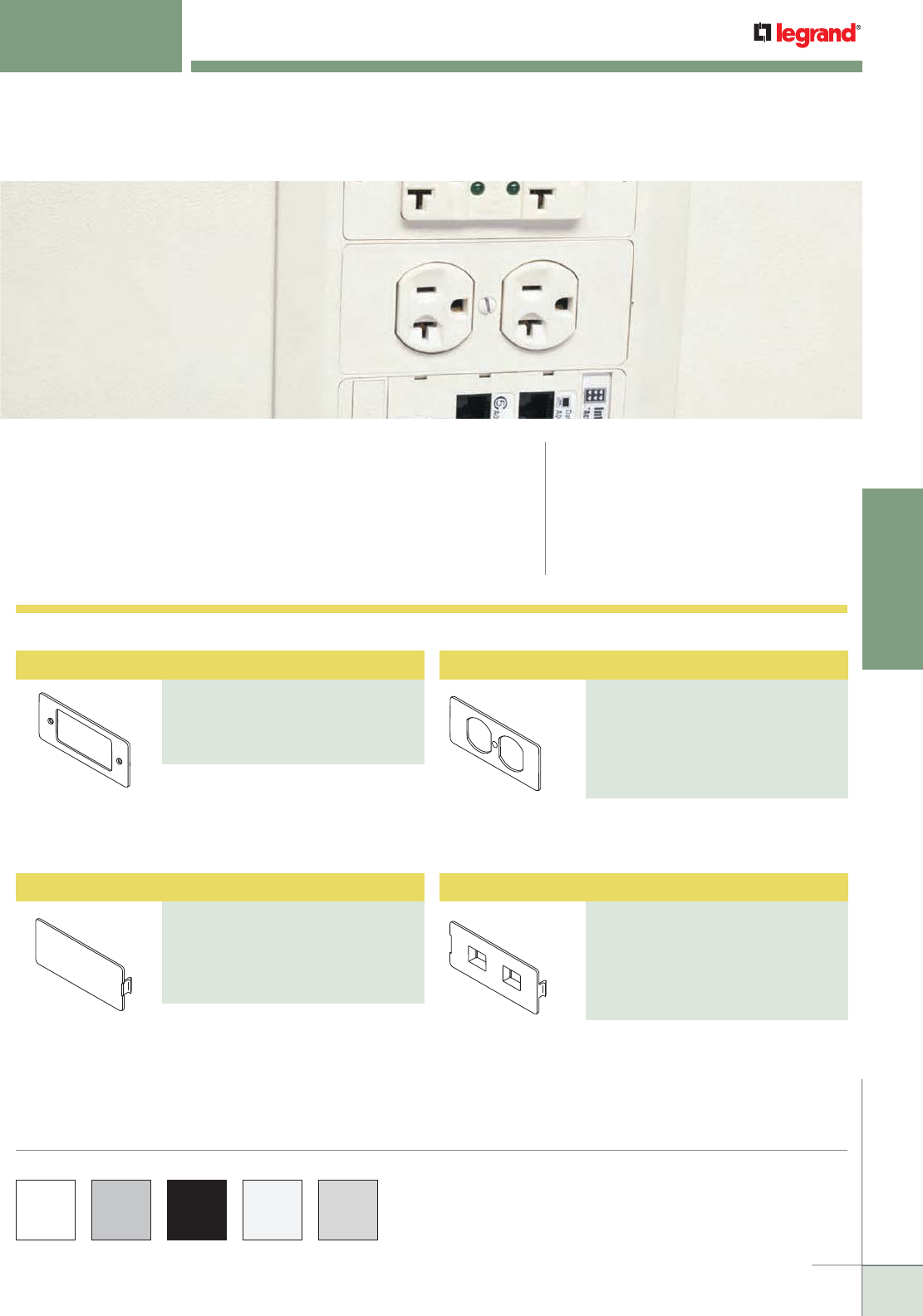
WWW.LEGRAND.US/WIREMOLD
163
NONMETALLIC RACEWAY
WIREMOLD
Duplex Receptacle Faceplate
PART NUMBERS:
5507D (Ivory)
5507D-WH (White)
5507D-G (Gray)
5507D-GY (Light Gray)
5507D-BK (Black)
5507D-FW (Fog White)
5507 SERIES™ FACEPLATES
Ordering Information
CODE REFERENCE
Listed Raceway:
File E90378 Guide RJTX.
Complies with flammability requirements of UL-5A.
Fittings: File E90377 Guide RJYT.
Meets Article 388 of NEC.
UL Listed for up to 600V.
Meets Section 12-1600 of CEC.
5507 Series™ Faceplates accept a wide assortment of power, A/V
and datacom devices from leading manufacturers. Faceplates can
be used in nonmetallic device brackets for 2300BACD, 400BAC, 5000,
5400TB, 5500BD3, 40N2 Series Raceways, 4050 Device Bracket for Steel
Raceways, and WallSource™ Boxes.
NOTE: All 5507 Series™ Faceplates have a standard measurement of
4 1/4" x 1 7/8" [108mm x 34mm].
COLOR OPTIONS
5507 Series™ faceplate Part Numbers without a suffix are available in an
ivory finish. Part Numbers with a “-WH” suffix have a white finish. Part
Numbers with a “-G” suffix have a gray finish. Part Numbers with a “-BK”
suffix have a black finish. Part Numbers with a “-FW” suffix have a fog
white finish. Part numbers with a “-GY” suffix have a light gray finish.
For mounting Activate and other
modular furniture bezels and other
modular furniture adapters. Not
for use with rectangular (decorator)
style devices.
5507 Series Faceplates Ordering Information
For covering unused compartments in
the device bracket.
For covering duplex style devices.
Accepts 106 Frame.
For mounting one or two keystone
device modules, recessed to provide
a flush installation. Has one opening
and one KO.
Modular Furniture Adapter
PART NUMBERS:
5507AD (Ivory)
5507AD-WH (White)
5507AD-GY (Gray)
5507AD-FW (Fog White)
Blank Faceplate
PART NUMBERS:
5507B (Ivory)
5507B-WH (White)
5507B-G (Gray)
5507B-GY (Light Gray)
5507B-FW (Fog White)
Flush Dual RJ Connector Faceplate
PART NUMBERS:
5507FRJ (Ivory)
5507FRJ-WH (White)
5507FRJ-G (Gray)
5507FRJ-GY (Light Gray)
5507FRJ-BK (Black)
5507FRJ-FW (Fog White)
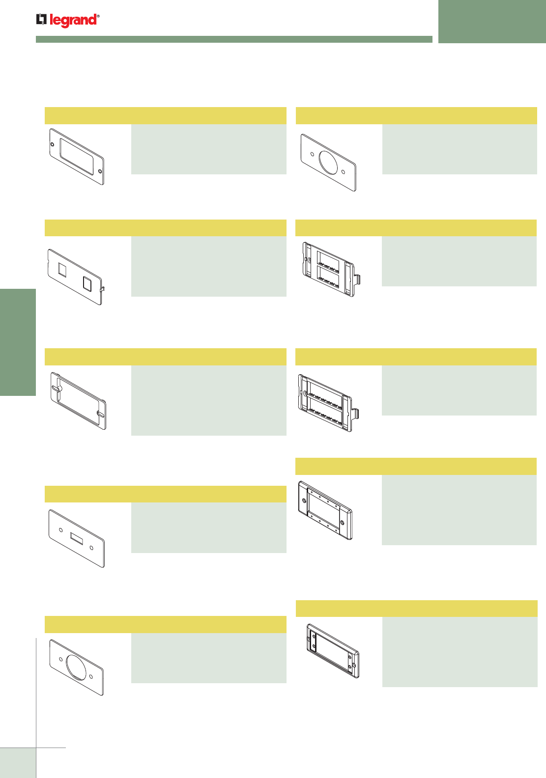
WWW.LEGRAND.US/WIREMOLD
164
NONMETALLIC RACEWAY
WIREMOLD
Rectangular Receptacle Faceplate
PART NUMBERS:
5507R (Ivory)
5507R-WH (White)
5507R-G (Gray)
5507R-FW (Fog White)
Extron® AAP Faceplate
PART NUMBERS:
5507AAP (Ivory)
5507AAP-WH (White)
5507AAP-G (Gray)
5507AAP-GY (Light Gray)
5507AAP-BK (Black)
5507AAP-FW (Fog White)
For covering rectangular decorator
style devices.
For mounting one or two keystone
device modules. Has one opening and
one KO.
5507 SERIES™ FACEPLATES
Ordering Information
For mounting commercial device
plates. Installs between the device
bracket and a device.
Accepts four AVIP and Extron®
Electronics MAAP single space
modules.
For covering standard toggle switches.
For covering single receptacles 1.59"
[40mm] diameter.
For covering single receptacles 1.41"
[36mm] diameter.
For mounting Ortronics® datacom
inserts. Accepts four TracJack
devices.
For mounting Ortronics® datacom
inserts. Accepts six TracJack devices.
Accepts two Extron® Electronics AAP
single space modules.
Ortronics® Faceplate
PART NUMBERS:
5507-4TJ (Ivory)
5507-4TJ-WH (White)
5507-4TJ-G (Gray)
5507-4TJ-FW (Fog White)
Rectangular Spacer
PART NUMBERS:
5507S (Ivory)
5507S-WH (White)
5507S-G (Gray)
5507S-GY (Light Gray)
5507S-BK (Black)
5507S-FW (Fog White)
Ortronics® Faceplate
PART NUMBERS:
5507-6TJ (Ivory)
5507-6TJ-WH (White)
5507-6TJ-G (Gray)
5507-6TJ-FW (Fog White)
Switch Faceplate
PART NUMBERS:
5507SW (Ivory)
5507SW-WH (White)
5507SW-G (Gray)
5507SW-FW (Fog White)
Single Receptacle Faceplate
PART NUMBERS:
5507T1 (Ivory)
5507T1-WH (White)
5507T1-G (Gray)
5507T1-FW (Fog White)
Single Receptacle Faceplate
PART NUMBERS:
5507T2 (Ivory)
5507T2-WH (White)
5507T2-G (Gray)
5507T2-FW (Fog White)
Dual RJ11/RJ45 Connector Faceplate
PART NUMBERS:
5507RJ (Ivory)
5507RJ-WH (White)
5507RJ-G (Gray)
5507RJ-GY (Light Gray)
5507RJ-FW (Fog White)
Extron® MAAP Faceplate
PART NUMBERS:
5507MAAP (Ivory)
5507MAAP-WH (White)
5507MAAP-G (Gray)
5507MAAP-GY (Light Gray)
5507MAAP-BK (Black),
5507MAAP-FW (Fog White)
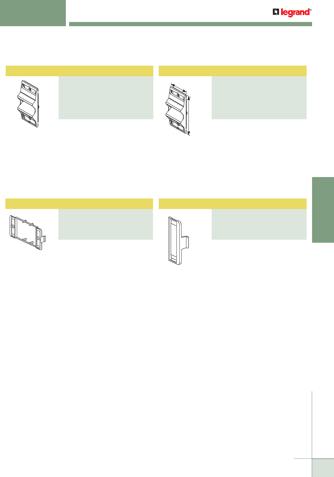
WWW.LEGRAND.US/WIREMOLD
165
NONMETALLIC RACEWAY
WIREMOLD
For mounting Ortronics® Series II
modules into 5507 opening. Includes
two outlet identification labels with
clear covers and two matching screw
covers.
5507 SERIES™ FACEPLATES
Ordering Information
For mounting Pass & Seymour®
Activate and Wiremold Open System
communication modules into 5507
openings. Includes two outlet
identification labels with clear covers
and two matching screw covers.
Angled Raceway Adapter
PART NUMBERS:
CM-ARA-V (Ivory),
CM-ARA-WH (White)
CM-ARA-FW (Fog White)
CM-ARA-BK (Black)
CM-ARA-G (Gray)
CM-ARA-GY (Light Gray)
2"
[51mm]
4 5/16"
[110mm]
Provides angled exit in multi-channel
raceway systems. Snaps into standard
4050, 5450, 5450T, 5550, 40N2F31 and
WallSource Device Brackets. Angled
exit provides additional mounting
depth required for A/V connections
as well as ensuring the required
bend radius for UTP and fiber optic
cabling. Holds two Ortronics® Series
II modules. Fits 5507 Series Faceplate
opening.
Provides angled exit in multi-channel
raceway systems. Snaps into standard
4050, 5450, 5450T, 5550, 40N2F31 and
WallSource Device Brackets. No
CM-EPLA End Plates required.
Accepts two CM2 Series Wiremold
Open System communication modules
or Pass & Seymour® Activate Series
inserts.
Angled Raceway Adapter
PART NUMBERS:
ARA-S2-V (Ivory)
ARA-S2-WH (White)
ARA-S2-FW (Fog White)
ARA-S2-BK (Black)
ARA-S2-G (Gray)
ARA-S2-GY (Light Gray)
End Plate
PART NUMBERS:
CM-EPLA (Ivory)
CM-EPLA-WH (White)
CM-EPLAG (Gray)
CM-EPLA-FW (Fog White)
End Plate
PART NUMBERS:
S2-EPL (Ivory)
S2-EPL-WH (White)
S2-EPLG (Gray)
S2-EPL-FW (Fog White)

WWW.LEGRAND.US/WIREMOLD
166
NONMETALLIC RACEWAY
WIREMOLD

WWW.LEGRAND.US/WIREMOLD
167
WIREMOLD
ALUMINUM RACEWAY
Wiremold® Aluminum Surface Raceway Systems are the industry leaders in quality, ease of installation, and for
providing pathway solutions for all types of installations. For over 50 years, Wiremold Surface Raceway Systems have
provided the highest quality, most dependable solutions for installers, building owners, and designers.
With the introduction of ALDS4000 Series Raceway System, we’re again pushing the envelope and expanding the
capacity, capabilities, and aesthetics of surface raceway systems.
ALUMINUM RACEWAY
Table of Contents
ALDS4000 Series
Raceway 181
Small Single- & Dual-Channel Raceways
ALDS400 Series Raceway
Large Single- & Dual-Channel Raceways
AL2000 Series
170
181
ALA3800 Series
185
ALA4800 Series
189
AL5200 Series
193
AL2400 Series
174
AL3300 Series
177
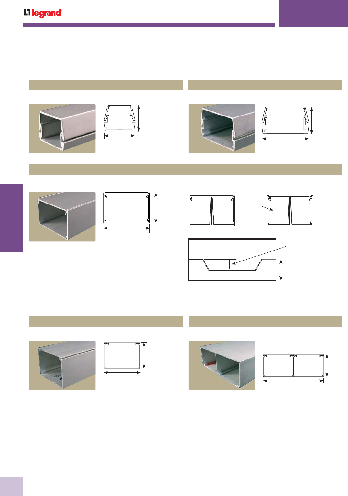
WWW.LEGRAND.US/WIREMOLD
168
WIREMOLD
ALUMINUM RACEWAY
ALUMINUM RACEWAY
Quick Selection Guide
Two-Piece Small Single- & Dual-Channel Raceway Profiles
Two-Piece Large Single- & Dual-Channel Raceway Profiles
AL2000 Series™ Raceway
ALA3800 Series™ Raceway
AL3300 Series™ Raceway
AL2400 Series™ Raceway
AL2000B & AL2000C
1 1/8"
[29mm]
1 7/16"
[37mm]
CAPACITY: 1.1 in.2 [710mm2]AL2400B & AL2400C CAPACITY: 1.7 in.2 [1097mm2]
1 9/32"
[33mm]
2"
[51mm]
2 7/8"
[73mm]
1 7/8"
[48mm]
Capacity with Offset Divider –
1.35 sq. in. [871mm2]
Capacity with 1/2 Divider –
2.2 sq. in. [1419mm2]
Capacity Undivided –
4.4 sq. in. [2839mm2]
2.20 in2
[1419mm2]
AL3300 w/Offset Divider
1.35 in2
[871mm2]
2.20 in2
[1419mm2]
2.20 in2
[1419mm2]
AL3300 w/Half Divider
AL3300 with Offset Divider
3/4"
[19.1mm]
1 7/16"
[36.5mm]
AL3300B & AL3300C CAPACITY: 4.40 in.2 [2389mm2]
ALA3800B & ALA3800C
2 1/4"
[57mm]
3"
[76mm]
CAPACITY: 5.96 in.2 [3842mm2]
ALA4800 Series™ Raceway
ALA4800B & ALA4800C CAPACITY:
Each Compartment
5.93 in.2 [3826mm2]
6"
[152mm]
2 1/4"
[57mm]
Capacity as Shown –
3.90 sq. in./4.5 sq. in.
[2526mm2/2903mm2]
Capacity Three Compartments –
2.85 sq. in./2.40 sq. in./2.85 sq. in.
[1839mm2/1548mm2/1839mm2]
Capacity Undivided –
8.5 sq. in. [5484mm2]
NOTE: See the AL5200
Series Raceway
section for additional
raceway compartment
configurations.
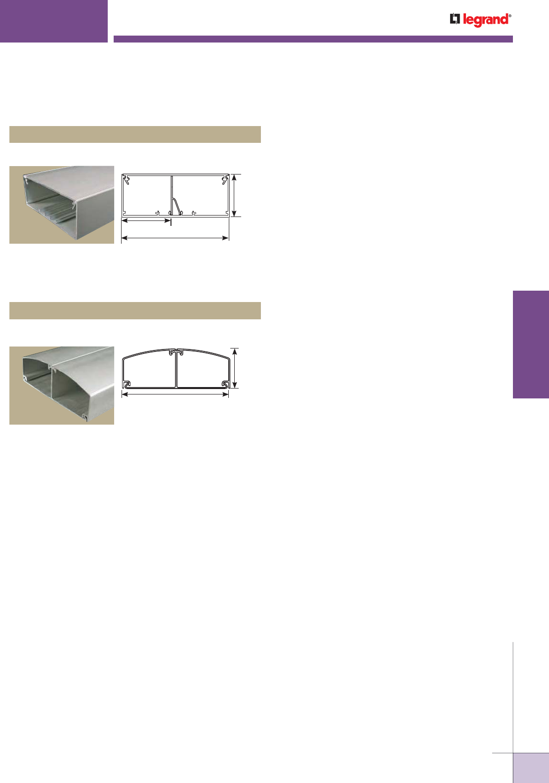
WWW.LEGRAND.US/WIREMOLD
169
WIREMOLD
ALUMINUM RACEWAY
AL5200 Series™ Raceway
AL5200B & AL5200C CAPACITY:
Each Compartment: 8.5 in.2 [5484mm2]
2 3/16"
[56mm]
2"
[51mm]
5"
[127mm]
Large Dual-Channel Raceway Profile
ALDS4000® Series Raceway
ALDS4000B & ALDS4000C
5 3/4"
[146mm]
2 1/8"
[54mm]
ALUMINUM RACEWAY
Quick Selection Guide
CAPACITY:
Each Compartment: 4.85 in2 (3192 mm2)
Two-Piece Large Single- & Dual-Channel Raceway Profiles (continued)
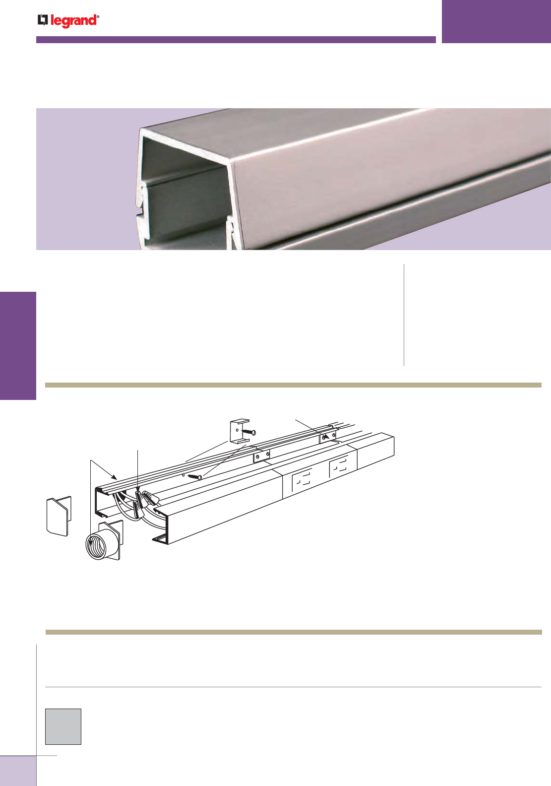
WWW.LEGRAND.US/WIREMOLD
170
WIREMOLD
ALUMINUM RACEWAY
Two-piece, single-channel raceway. Satin anodized finish complements decor in
commercial offices, laboratories, and health care facilities. CODE REFERENCE
cULus Listed Raceway:
File E4376 Guide RJPR.
Fittings:
File E41751 Guide RJPR.
Raceway & Fittings:
Meet Article 386 of NEC.
Multioutlet Assemblies:
Meet Article 380 of NEC.
AL2000
™
SERIES RACEWAY
NOTE: Illustration is for showing product applications only.
C
A
B
D
E
G
F
KEY
A. Supply conductors may be fed
through AL2010A Feed End Fitting.
This system is designed with
capacity for additional feed or
circuitry conductors.
B. Attach base section to mounting
surface with AL2003 Spring
Mounting Clips, or by drilling 9/32"
[7.1mm] holes in the base and use
#8 flathead screws.
C. Connect circuit wires with
connectors.
D. Additional multiple outlet sections
or AL2000 Raceway sections may
be attached at ends with AL2001
Coupling.
E. Close ends with blank end fitting
(AL2010B), or with feed end fittings
(AL2010A).
F. Snap in cover section.
G. In-line receptacle AL2043.
AL2000 Series Raceway System Layout
COLOR OPTIONS
AL2000 Series™ Raceway is available with a
satin anodized finish.
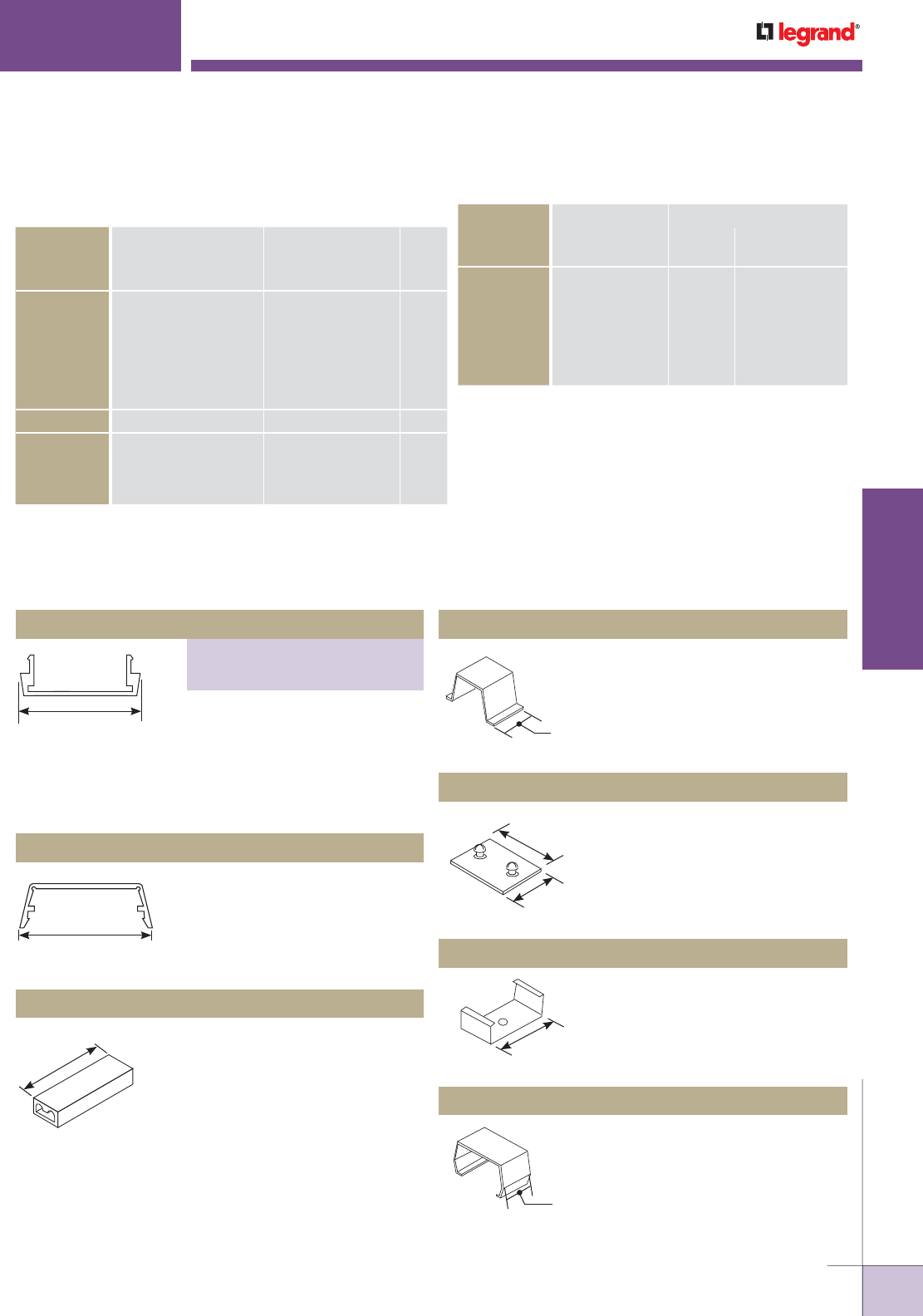
WWW.LEGRAND.US/WIREMOLD
171
WIREMOLD
ALUMINUM RACEWAY
AL2000 Series Raceway Wire
Fill Capacities for Communications
O.D. (Approx Dia.)
CABLE/WIRE SIZE Inches [mm]
40%
FILL
UNSHIELDED
TWISTED
PAIR
4-pair, 24 AWG, Cat 3 0.190 [4.8] 3
4-pair, 24 AWG, Cat 5e 0.210 [5.3] 3
4-pair, 24 AWG, Cat 6 0.250 [6.3] 2
4-pair, 24 AWG, Cat 6a* 0.354 [9.0] 1
25-pair, 24 AWG 0.410 [10.4] 0
COAXIAL RG6/U 0.270 [6.9] 17
FIBER ZipCord 0.118 x 0.236 [3 x 6] 3
Round 4 Strand Fiber 0.187 [4.8] 2
Round 6 Strand Fiber 0.256 [6.5] 2
NOTE: For additional information, refer to the Technical Section.
* Category 6 augmented (6a) cable for 10 gigabit ethernet – max allowed
cable diameter per addenda No. 11 ANSI TIA/EIA 568-B.2.
6063-T5 extruded aluminum, satin
anodized finish, .060" [1.5mm]
nominal thickness. Packed (12)
5’ [1.5m] lengths (AL2000B-5) or
six 10’ [3m] lengths (AL2000B10)
per carton.
6063-T5 extruded aluminum, satin
anodized finish, .060" [1.5mm]
nominal thickness. Packed (12)
5’ [1.5m] lengths per carton.
AL2000C-5 Raceway Cover
1 7/16"
[37mm]
1 7/16"
[37mm]
1 5/16"
[33mm] W30 – For common connection of
two, three, or four No. 12 or No.14
solid copper conductors. Packed
24 pieces per carton (16 W30 and
8 W30G). W30G – For connection of
equipment grounding of 2, 3, or 4
solid conductors No. 14 or No. 12
AWG. 300V maximum; 20A 105° C
maximum.
Joins lengths of AL2000B Base.
Supports lengths of AL2000
Raceway at any point desired.
Mount to surface with No. 8
flathead screw.
Covers seam where lengths of
cover or base come together.
Holds conductors in place in
raceway base.
W30/W30G Pressure-Type Wire Connectors
AL2000WC Wire Retainer (Plastic)
AL2001 Coupling (Galvanized Steel)
AL2003 Mounting Clip (Spring Steel)
AL2006 Cover Clip (Spring Steel)
NOTE:
Not for use with
aluminum conductors.
3/4"
[19.1mm]
1 3/16"
[30mm]
1 1/2"
[38mm]
AL2000
™
SERIES RACEWAY
1 7/16"
[37mm]
1"
[25mm]
AL2000 Series Raceway Wire Fill Capacities for Power
NUMBER OF CONDUCTORS
WIRE SIZE
THHN/THWN Inches [mm]
WITHOUT
DEVICES
WITH PLUGMOLD
RECEPTACLES
14 AWG 0.111 [2.8] 51 8
12 AWG 0.130 [3.3] 38 6
10 AWG 0.164 [4.2] 24 3
8 AWG 0.216 [5.5] 12
6 AWG 0.254 [6.5] 8
O.D.
AL2000 Series Raceway Ordering Information
Raceway Base
PART NUMBERS:
AL2000B-5 (5' Length)
AL2000B10 (10' Length)
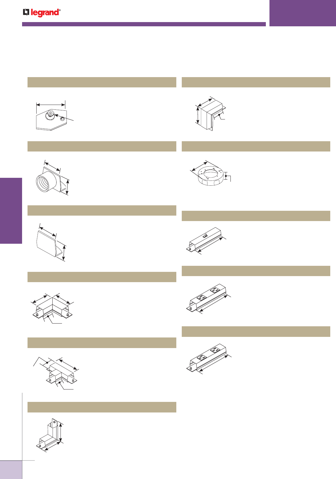
WWW.LEGRAND.US/WIREMOLD
172
WIREMOLD
ALUMINUM RACEWAY
Connects of equipment grounding
conductor to provide an additional
ground to raceway.
Designed for use in hanging
fixtures. Cover takes any device
with mounting screw centers
of 2 3/4", 3 1/2" and 4 1/16"
[70mm, 89mm, 103mm]. Base has
concentric 1/2" and 3/4" trade size
KOs.
Single-pole 120V switch. Two
couplings furnished.
Two 15A, 120V U-ground factory
wired receptacles. Two couplings
furnished.
Two 15A, 120V factory wired,
isolated ground, orange
receptacles. Two couplings
furnished.
End fitting with 1/2" [12.7mm] hub
adapter.
Closes off end of raceway.
Right angle turn on same surface.
Two AL2001 Couplings included.
Branch connection of two runs of
AL2000 Series Raceway. Three
AL2001 Couplings included
AL2009 Ground Clamp (Galvanized Steel)
AL2038 Round Fixture Box (Solid Base)
AL2040A In-Line Single Pole Switch
AL2043 In-Line Receptacle
AL2043IG In-Line Isolated Ground Receptacle
AL2010A Feed Fitting
AL2010B Blank End Fitting
AL2011 Flat Elbow
AL2015 Tee
AL2000
™
SERIES RACEWAY
#10 Ground Stud
with Cup Washer.
1 1/2"
[38mm]
1 3/16"
[30mm]
1 1/6"
[27mm]
1 1/16"
[27mm]
1 3/16"
[30mm]
3"
[76mm]
3"
[76mm]
1 9/16"
[40mm]
4"
[102mm]
1 7/16"
[37mm]
1 5/16"
[33mm]
Makes 90° internal corners. Two
AL2001 Couplings included
AL2017 Internal Elbow
3"
[76mm]
3"
[76mm]
Makes 90° external corners. Two
AL2001 Couplings included
AL2018 External Elbow
1 7/8"
[48mm]
3"
[76mm]
3"
[76mm]
4 13/16"
[122mm]
1 3/8"
[35mm]
6"
[152mm]
6"
[152mm]
6"
[152mm]
AL2000 Series Raceway Ordering Information (continued)
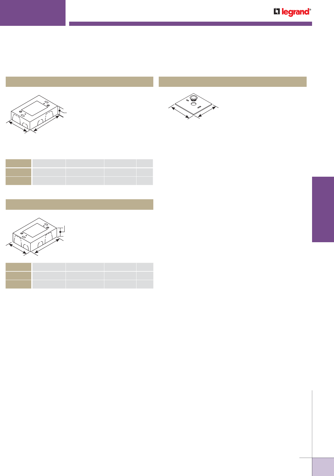
WWW.LEGRAND.US/WIREMOLD
173
WIREMOLD
ALUMINUM RACEWAY
For larger receptacles and deep
devices such as those of signal
and alarm systems. Base has
open back plate for mounting to
existing wall box and solid back
plate insert with 1/2" and 3/4"
trade size KOs to close opening.
Accepts industry standard
faceplates for communication
devices.
Designed for standard shallow
switches and receptacles.
Base has open back plate for
mounting to existing wall box
and solid back plate insert with
1/2" and 3/4" trade size KOs to
close opening.
Deep Device Box
Shallow Switch & Receptacle Box
CAT NO. L W D GANG
AL2044
4 5/8" [117mm] 3 1/16" [78mm] 2 1/4" [57mm] 1
AL2044-2
4 5/8" [117mm] 4 27/32" [123mm] 2 1/2" [64mm] 2
CAT NO. L W D GANG
AL2047
4 5/8" [117mm] 3 1/16" [78mm] 1 3/8" [35mm] 1
AL2047-2
4 5/8" [117mm] 4 27/32" [123mm] 1 3/8" [35mm] 2
AL2000
™
SERIES RACEWAY
L
W
D
Used to feed raceway from
existing wall outlet box.
AL2051H Box Adapter
4 1/2"
[114mm]
4 1/2"
[114mm]
AL2000 Series Raceway Ordering Information (continued)
WL
D
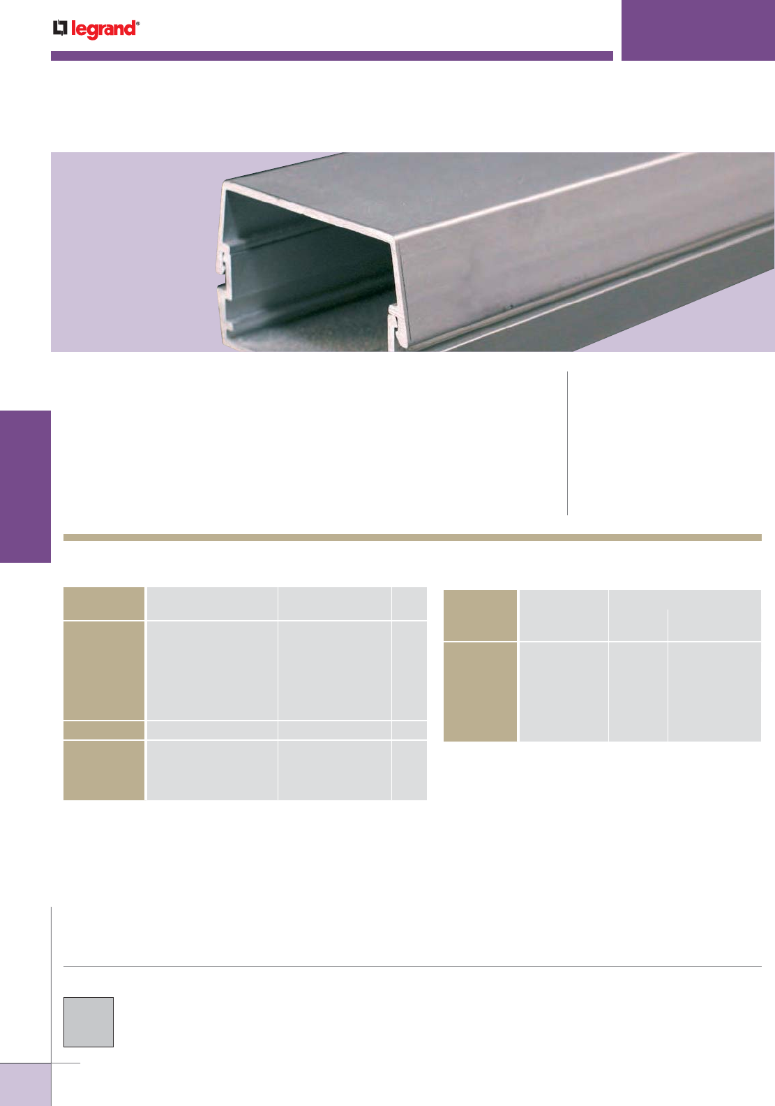
WWW.LEGRAND.US/WIREMOLD
174
WIREMOLD
ALUMINUM RACEWAY
Two-piece, single-channel raceway. Satin anodized finish complements decor in
commercial offices, laboratories, and health care facilities. CODE REFERENCE
cULus Listed Raceway:
File E4376 Guide RJPR.
Fittings:
File E41751 Guide RJPR.
Raceway & Fittings:
Meet Article 386 of NEC.
Multioutlet Assemblies:
Meet Article 380 of NEC.
AL2400
™
SERIES RACEWAY
AL2400 Series Raceway Wire
Fill Capacities for Communications
CABLE/WIRE SIZE Inches [mm]
40%
FILL
UNSHIELDED
TWISTED
PAIR
4-pair, 24 AWG, Cat 3 0.190 [4.8] 23
4-pair, 24 AWG, Cat 5e 0.210 [5.3] 19
4-pair, 24 AWG, Cat 6 0.250 [6.3] 13
4-pair, 24 AWG, Cat 6a* 0.354 [9.0] 6
25-pair, 24 AWG 0.410 [10.4] 5
COAXIAL RG6/U 0.270 [6.9] 11
FIBER ZipCord 0.118 x 0.236 [3 x 6] 24
Round 4 Strand Fiber 0.187 [4.8] 24
Round 6 Strand Fiber 0.256 [6.5] 13
NOTE: For additional information, refer to the Technical Section.
* Category 6 augmented (6a) cable for 10 gigabit ethernet – max allowed
cable diameter per addenda No. 11 ANSI TIA/EIA 568-B.2.
COLOR OPTIONS
AL2400 Series™ Raceway is available with a
satin anodized finish.
AL2400 Series Raceway Wire Fill Capacities for Power
NUMBER OF CONDUCTORS
WIRE SIZE
THHN/THWN Inches [mm]
WITHOUT
DEVICES
WITH PLUGMOLD
RECEPTACLES
14 AWG 0.111 [2.8] 78 16
12 AWG 0.130 [3.3] 58 12
10 AWG 0.164 [4.2] 37 8
8 AWG 0.216 [5.5] 18 4
6 AWG 0.254 [6.5] 13 3
O.D.
O.D. (Approx. Dia.)
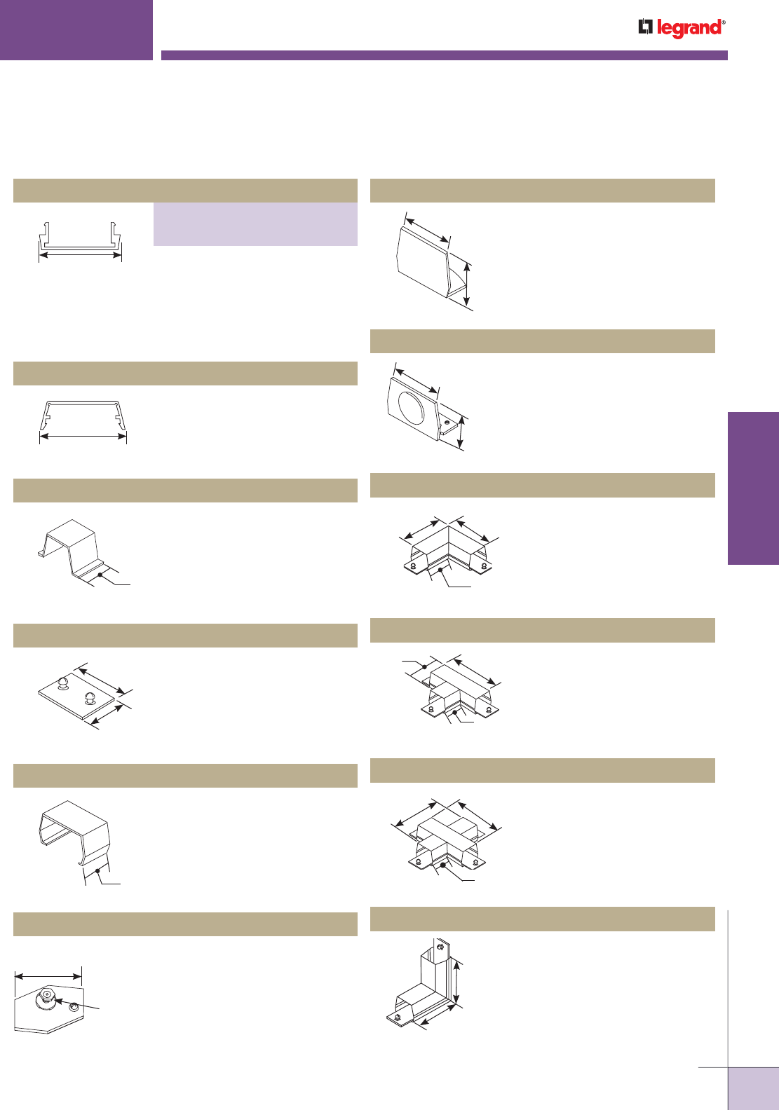
WWW.LEGRAND.US/WIREMOLD
175
WIREMOLD
ALUMINUM RACEWAY
6063-T5 extruded aluminum, satin
anodized finish, .060" [1.5mm]
nominal thickness. Packed (12) 5’
[1.5m] lengths (AL2400B-5) or six
10’ [3m] lengths (AL2400B10) per
carton.
Closes off open end of raceway.
End fitting with plastic 1/2" trade
size KO.
Right angle turn on same
surface. Two AL2401 Couplings
included.
Branch connection of two runs
of AL2400 Series Raceway.
Three AL2401 Couplings
included.
Cross connection of two runs of
AL2400 Series Raceway. Four
AL2401 Couplings included.
Makes 90° internal corners. Two
AL2401 Couplings included.
6063-T5 extruded aluminum, satin
anodized finish, .060" [1.5mm]
nominal thickness. Packed (12) 5’
[1.5m] lengths per carton.
Holds conductors in place in
raceway base.
Joins lengths of AL2400B Base.
Covers seam where lengths of
cover or base come together.
Connects of equipment grounding
conductor to provide an additional
ground to raceway.
AL2410B Blank End Fitting
AL2410B2 Feed Fitting
AL2411 Flat Elbow
AL2415 Tee
AL2416 Cross Fitting
AL2417 Internal Elbow
AL2400C Raceway Cover
AL2400WC Wire Retainer (Plastic)
AL2401 Coupling (Galvanized Steel)
AL2406 Cover Clip (Spring Steel)
AL2409 Ground Clamp (Galvanized Steel)
AL2400 SERIES
™
RACEWAY
2"
[51mm]
2"
[51mm]
1 1/2"
[38mm]
1 3/4"
[44mm]
2 3/4"
[70mm]
1"
[25mm]
#10 Ground Stud
with Cup Washer
1 1/2"
[38mm]
2"
[51mm]
1 1/4"
[32mm]
2"
[51mm]
1 1/4"
[32mm]
4"
[102mm]
4"
[102mm]
2"
[51mm]
6"
[152mm]
4"
[102mm]
2"
[51mm]
6"
[152mm] 6"
[152mm]
2"
[51mm]
4"
[102mm]
4"
[102mm]
AL2000 Series Raceway Ordering Information
Raceway Base
PART NUMBERS:
AL2400B-5 (5' Length)
AL2400B-10 (10' Length)
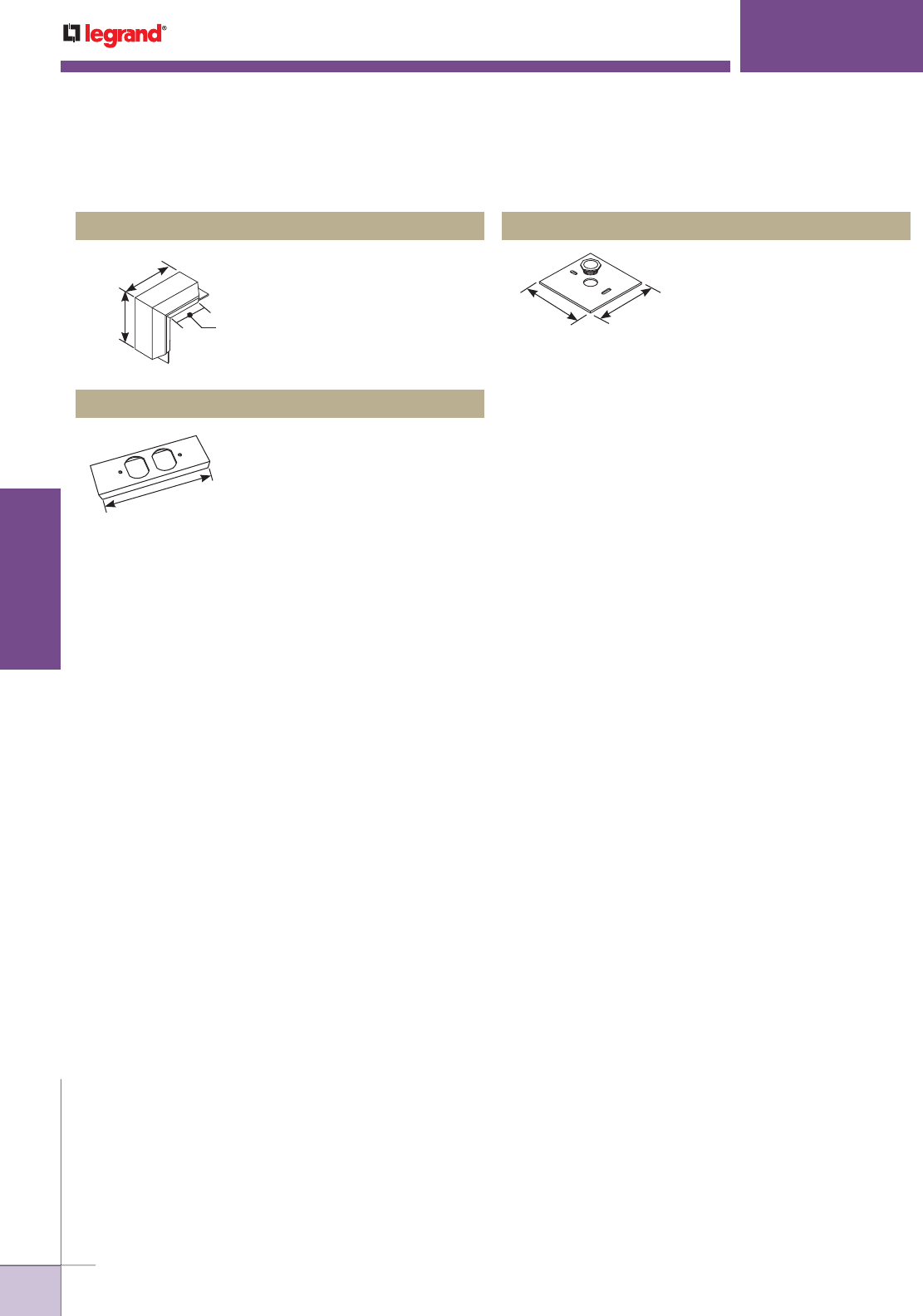
WWW.LEGRAND.US/WIREMOLD
176
WIREMOLD
ALUMINUM RACEWAY
Makes 90° external corners. Two
AL2401 Couplings included.
For in-line mounting of
commercially available duplex
receptacle.
AL2418 External Elbow
AL2446P-D Duplex Receptacle Cover Plate
AL2400
™
SERIES RACEWAY
3"
[76mm]
5"
[127mm]
5"
[127mm]
6"
[152mm]
Feeds raceway from existing wall
outlet box.
AL2451H Box Adapter
4 1/2"
[114mm]
4 1/2"
[114mm]
AL2400 Series Raceway Ordering Information (continued)
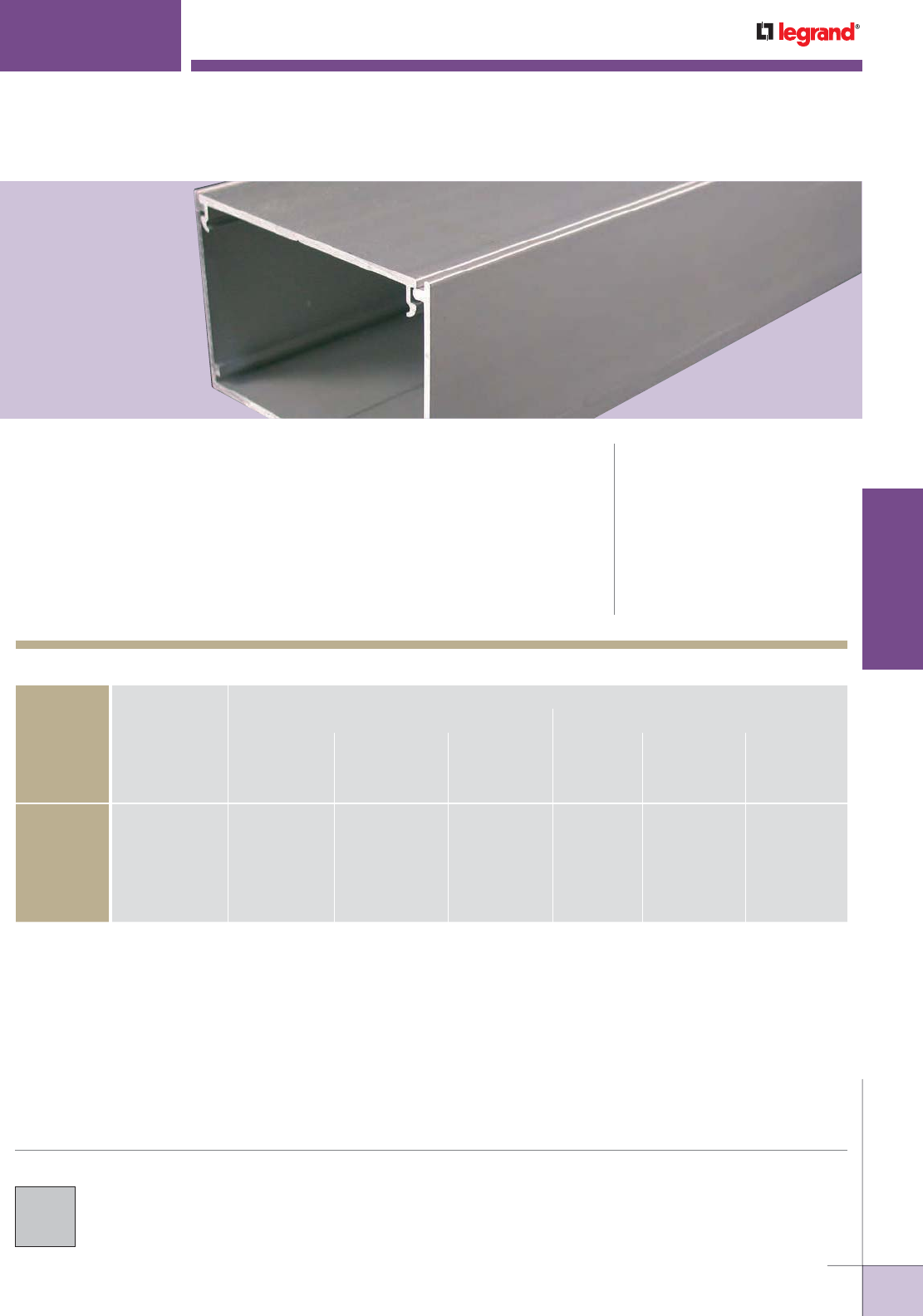
WWW.LEGRAND.US/WIREMOLD
177
WIREMOLD
ALUMINUM RACEWAY
Two-piece, single-channel raceway. Satin anodized finish complements decor in
commercial offices, laboratories, and health care facilities. CODE REFERENCE
cULus Listed Raceway:
File E4376 Guide RJPR.
Fittings:
File E41751 Guide RJPR.
Raceway & Fittings:
Meet Article 386 of NEC.
Multioutlet Assemblies:
Meet Article 380 of NEC.
AL3300
™
SERIES RACEWAY
AL3300 Series Raceway Wire Fill Capacities for Communications
CAPACITY OF CROSS SECTIONAL AREA
WITH DUPLEX DEVICE WITHOUT DEVICE
O.D.
WITH OFFSET
DIVIDER
WITHOUT
DIVIDER
WITH HALF
DIVIDER
WITH OFFSET
DIVIDER
WITHOUT
DIVIDER
WITH HALF
DIVIDER
WIRE SIZE
THHN/THWN Inches [mm]
1.35 in
2
[871mm
2
]
4.40 in
2
[2839mm
2
]
2.20 in
2
[1419mm
2
]
1.35 in
2
[871mm
2
]
4.40 in
2
[2839mm
2
]
2.20 in
2
[1419mm
2
]
14 AWG 0.111 [2.8] 59 136 39 59 193 96
12 AWG 0.130 [3.3] 40 93 27 40 132 66
10 AWG 0.164 [4.2] 25 58 17 25 83 41
8 AWG 0.216 [5.5] 14 33 9 14 48 24
6 AWG 0.254 [6.5] 10 24 7 10 34 17
COLOR OPTIONS
AL3300 Series™ Raceway is available with a
satin anodized finish.
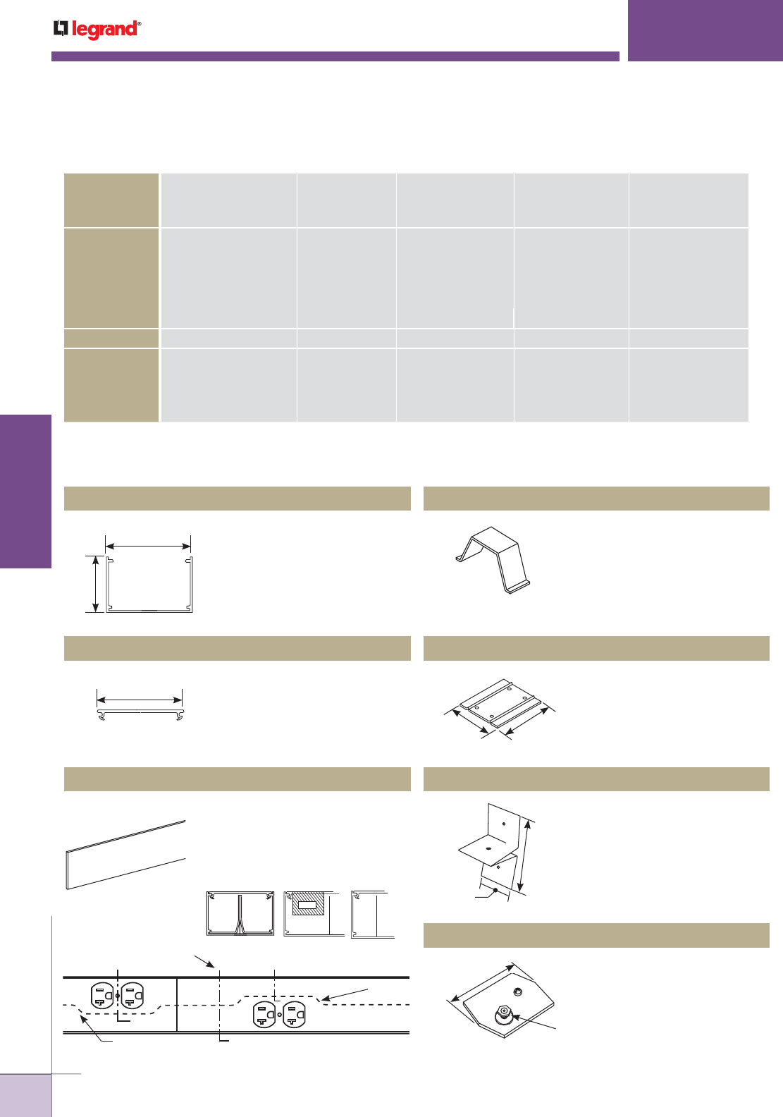
WWW.LEGRAND.US/WIREMOLD
178
WIREMOLD
ALUMINUM RACEWAY
AL3300
™
SERIES RACEWAY
AL3300 Series Raceway Wire Fill Capacities for Power
O.D. WITHOUT DIVIDER WITH OFFSET DIVIDER WITH HALF DIVIDER
(Approx. Dia.) 1.35in
2
[871mm
2
] 4.40 in
2
[2839mm
2
] 2.20 in
2
[1419mm
2
]
CABLE TYPE CABLE/WIRE SIZE Inches [mm] 20% FILL 40% FILL 20% FILL 40% FILL 20% FILL 40% FILL
UNSHIELDED
TWISTED PAIR
4-pair, 24 AWG, Cat 3 0.190 [4.8] 30 61 9 19 15 30
4-pair, 24 AWG, Cat 5e 0.210 [5.3] 25 50 7 15 12 35
4-pair, 24 AWG, Cat 6 0.250 [6.3] 17 35 5 10 8 17
4-pair, 24, AWG, Cat 6a* 0.354 [9.0] 8 17 2 5 4 8
25-pair, 24 AWG 0.410 [10.4] 6 13 2 4 3 6
COAXIAL RG6/U 20 Gage 0.270 [6.9] 15 30 4 9 7 15
FIBER 2 Stranded ZipCord 0.118 x
0.236
[3 x 6] 31 63 9 19 15 31
Round 4 Strand Fiber 0.187 [4.8] 32 64 9 19 16 32
Round 6 Strand Fiber 0.256 [6.5] 17 34 5 10 8 17
NOTE: For additional information, refer to the Technical Section.
* Category 6 augmented (6a) cable for 10 gigabit ethernet – max allowed cable diameter per addenda No. 11 ANSI TIA/EIA 568-B.2.
6063-T5 extruded aluminum,
satin anodized finish. Nominal
wall thickness .060" [1.5mm].
Packed four 10’ [3m] lengths
per carton.
Holds wires and cables in
raceway base. Use with
undivided raceway, snaps into
grooves in base.
Set screw coupling used for
attaching in-line raceway
sections.
Required for holding AL3300D5
Divider in place. Use one every
30" [762mm].
Connects equipment grounding
conductor to raceway.
6063-T5 extruded aluminum,
satin anodized finish. Nominal
wall thickness .060" [1.5mm].
Packed eight 5’ [1.5m] lengths
per carton.
Divider is 0.040" [1.0mm]
galvanized steel. Packed eight
5’ [1.5m] lengths per carton.
AL3301D Divider Clip sold
separately.
AL3300B10 Raceway Base AL3300WC Wire Clip (Spring Steel)
AL3301 Base Coupling (Galvanized Steel)
AL3301D Divider Clip (Galvanized Steel)
AL3309 Ground Clamp (Galvanized Steel)
AL3300C5 Raceway Cover
AL3300D5 Divider
2 7/8"
[73mm]
1 7/8"
[48mm]
2 3/4"
[70mm]
Section A-A Section B-B Section C-C
A
A
B
B
C
C
Device Plate
Optional
Divider
2 3/4"
[70mm]
2 3/4"
[70mm]
1 1/2"
[38mm]
3"
[76mm]
2 3/4"
[70mm]
#10 Ground Stud
with Cup Washer
AL3300 Series Raceway Ordering Information
NOTE: Offset plates cannot
abut. Short section of
cover must be used
between offset plates.
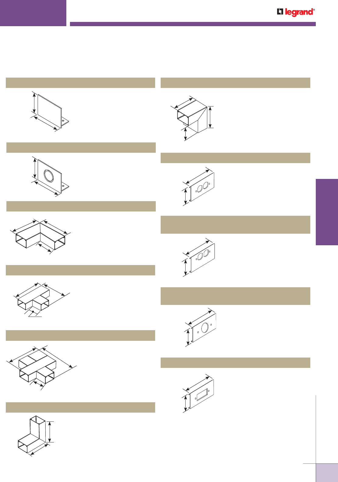
WWW.LEGRAND.US/WIREMOLD
179
WIREMOLD
ALUMINUM RACEWAY
AL3300
™
SERIES RACEWAY
Closes off open end of AL3300
Series Raceway.
End feeds raceway with 1/2"
or 3/4" trade size conduit or
armored cable.
Right angle turns on same
surface. Two AL3301Couplings
included.
90° tee connection of two runs
of AL3300 Series Raceway.
Three AL3301Couplings
included.
90° cross-through connection
of two runs of raceway. Four
AL3301Couplings included.
For making 90° internal
corners. Two AL3301 Couplings
included.
For making external corners.
Two AL3301 Couplings
included.
Mounts standard duplex
devices to cover. Can also be
used with 106 communication
frames.
Installs duplex devices in
divided aluminum raceway.
6" [152mm] offset divider
included. Can also be used with
106 communication frames.
Provided with offset divider.
Installs straight blade and
locking single receptacles with
face diameters of 1.38"-1.39"
[35mm-36mm].
Installs rectangular devices
including surge receptacles,
GFCI, and other rectangular
faced single-gang wiring
devices. Can also be used with
106 communication frames.
AL3310B Blank End Fitting
AL3310B1 End Fitting
AL3311 90° Flat Elbow
AL3315 Tee
AL3316 Cross Fitting
AL3317 Internal Elbow
AL3318 External Elbow
AL3346D Duplex Receptacle Cover
AL3346DO Offset Duplex Receptacle Cover Plate
(For Divided Raceway)
AL3346E Single Receptacle Cover Plate
(1.40" diameter)
AL3346G Rectangular Device Cover Plate
2 7/8"
[73mm]
1 13/16"
[46mm]
2 7/8"
[73mm]
1 13/16"
[46mm]
6"
[152mm]
6"
[152mm]
3 1/8"
[79mm]
9"
[229mm]
3 1/16"
[78mm]
6"
[152mm]
3 1/16"
[78mm]
9"
[229mm] 9"
[229mm]
6"
[152mm]
6"
[152mm]
4 7/8"
[124mm]
3"
[76mm]
4 7/8"
[124mm]
2 3/4"
[70mm]
6"
[152mm]
2 3/4"
[70mm]
6"
[152mm]
2 3/4"
[70mm]
6"
[152mm]
2 3/4"
[70mm]
6"
[152mm]
AL3300 Series Raceway Ordering Information (continued)
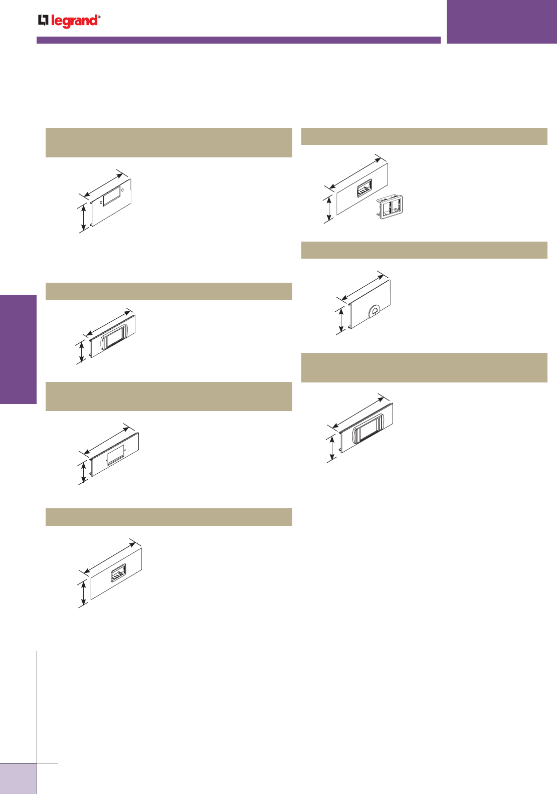
WWW.LEGRAND.US/WIREMOLD
180
WIREMOLD
ALUMINUM RACEWAY
AL3300
™
SERIES RACEWAY
Installs communication
connectivity devices. Includes
cover and low profile adapter
cover (6A opening).
Installs communication
connectivity devices utilizing
the industry standard single-
gang faceplates. Hole cut is
2" x 2 7/8" [51mm x 73mm].
Faceplates must be ordered
separately.
Installs a single 2A size
communication connectivity
device (2A opening). Includes
cover and 2A mini adapter.
Accepts only Ortronics®
datacom inserts. Supplied with
both adapters to accommodate
two TracJack™ devices or one
Series II device.
For exiting of communication
cable. Grommet furnished.
Accepts only Ortronics®
datacom inserts, three Series
II devices. Low profile adapter
included.
Installs rectangular devices
including surge receptacles,
GFCI and other rectangular
faced single-gang wiring
devices in divided aluminum
raceway. 6" [152mm] offset
divider included. Can also be
used with 106 communication
frames. Provided with
offset divider.
AL3356-ACTLPB Low Profile Adapter Cover Plate
AL3356R Cover Plate (with 2" x 2 7/8"
[51mm x 73mm] Hole cut)
AL33562A* 2A Mini Adapter Cover Plate
AL3356ABRT Ortronics® Cover Plate
AL3356Z Grommeted Cover Plate
AL3356-LPB3S2
Ortronics® Low Profile Adapter Cover Plate
AL3346GO Offset GFCI Receptacle Cover Plate
(For Divided Raceway)
2 3/4"
[70mm]
6"
[152mm]
2 3/4"
[70mm]
6"
[152mm]
2 3/4"
[70mm]
6"
[152mm]
2 3/4"
[70mm]
6"
[152mm]
2 3/4"
[70mm]
6"
[152mm]
2 3/4"
[70mm]
6"
[152mm]
2 3/4"
[70mm]
6"
[152mm]
* Refer to the Communications Connectivity section of this Product Guide for
information on CM2 Series modules.
AL3300 Series Raceway Ordering Information (continued)
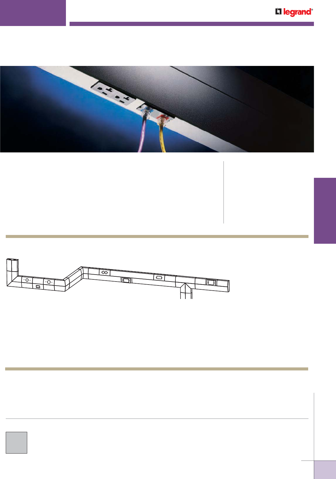
WWW.LEGRAND.US/WIREMOLD
181
WIREMOLD
ALUMINUM RACEWAY
B
CE
G
HJKL
ADF
I
M
Dual-channel raceway. Provides 1/3 more capacity in sleek, innovative design.
Meets or exceeds industry standards. CODE REFERENCE
cULus Listed Raceway:
File E4376 Guide RJPR.
Fittings:
File E41751 Guide RJPR.
Raceway & Fittings:
Meet Article 386 of NEC.
Multioutlet Assemblies:
Meet Article 380 of NEC.
ALDS4000
®
SERIES RACEWAY
NOTE: Illustration is for showing product applications only.
KEY
A. ALDS4011 Flat Elbow
B. ALDS4010A Entrance End Fitting
C. ALDS4047E 1.41 Dia. Device Plate
D. ALDS4047-2A Mini adapter Device Plate
E. ALDS4047F 1.59 Dia. Device Plate
F. ALDS4018 External Elbow
G. ALDS4017 Internal Elbow
H. ALDS4047D Duplex Device Plate
I. ALDS4047MAB MAB Device Plate
J. ALDS4047R Decorator Device Plate
K. ALDS4015 Tee
L. ALDS4047C One-Gang Device Plate
M. ALDS4010B Blank End Fitting
ALDS4000 Raceway System Layout
COLOR OPTIONS
ALDS4000® Series Raceway is available
with a satin anodized finish.
NOTE: Downward activations only available prewired.

WWW.LEGRAND.US/WIREMOLD
182
WIREMOLD
ALUMINUM RACEWAY
O.D. (Approx. Dia.) ALDS4011 ALDS4015 ALDS4017 ALDS4018
WIRE SIZE/THWN
40% 60% 40% 60% 40% 60% 40% 60%
Inches (mm)
THHN 14 AWG 0.111 [2.8] 122 182 49 73 75 112 133 199
12 AWG 0.130 [3.3] 89 133 35 53 54 82 97 145
10 AWG 0.164 [4.2] 56 84 22 34 34 51 61 92
8 AWG 0.216 [5.5] 32 48 13 19 20 30 35 53
6 AWG 0.254 [6.5] 23 35 9 14 14 21 25 38
UTP 4-pair, 24 AWG 0.150 [4.8] 67 100 27 40 41 61 73 109
4-pair, 24 AWG, Cat 3 0.190 [4.8] 42 62 17 25 25 38 45 68
4-pair, 24 AWG, Cat 5e 0.210 [5.3] 34 51 14 20 21 31 37 56
4-pair, 24 AWG, Cat 6 0.250 [6.3] 24 36 10 14 15 22 26 39
4-pair, 24 AWG, Cat 6a* 0.354 [9.0] 13 20 6 8 8 12 15 22
25-pair, 24 AWG 0.410 [10.4] 12 17 6 7 7 11 13 19
COAXIAL RG6/U 0.270 [6.9] 21 31 8 12 13 19 22 34
FIBER ZipCord 0.118 x 0.236 [3 x 6] 42 64 17 25 26 39 46 69
Round 4 Strand Fiber 0.187 [4.8] 43 64 17 26 26 40 47 70
Round 6 Strand Fiber 0.256 [6.5] 23 34 9 14 14 21 25 38
NOTE: 40% and 60% Wire fill capacities are calculated using radius control inserts. Inserts are factory installed and may be removed
if not required to obtain full raceway capacity.
* Entrance end fitting fill rate is calculated using backfeed capability and radius inserts. Inserts are removable and fitting can obtain
maximum raceway fill from utilizing end fitting knockouts and removing radius control inserts.
ALDS4000
®
SERIES RACEWAY
O.D. (Approx Dia.) 40% FILL
CABLE/WIRE SIZE Inches [mm] 1/2 COMPARTMENT
UNSHIELDED
TWISTED PAIR
4-pair, 24 AWG, Cat 3 0.190 [4.8] 68
4-pair, 24 AWG, Cat 5e 0.210 [5.3] 56
4-pair, 24 AWG, Cat 6 0.250 [6.3] 40
4-pair, 24 AWG, Cat 6a* 0.354 [9.0] 22
25-pair, 24 AWG 0.410 [10.4] 19
COAXIAL RG6/U 0.270 [6.9] 34
FIBER ZipCord 0.118 x 0.236 [3 x 6] 70
Round 4 Strand Fiber 0.187 [4.8] 71
Round 6 Strand Fiber 0.256 [6.5] 38
NOTE: For additional information, refer to the Technical Section.
* Category 6 augmented (6a) cable for 10 gigabit ethernet – max allowed cable diameter per
addenda No. 11 ANSI TIA/EIA 568-B.2.
WIRE SIZE
THHN/THWN Inches [mm]
NO. OF
CONDUCTORS
40%
W/DUPLEX
RECT. DEVICES
W/SURGE
GFCI DEVICES
LARGE SINGLE
RECEPTACLE
14 AWG 0.111 [2.8] 200 134 105 76
12 AWG 0.130 [3.3] 146 98 77 56
10 AWG 0.164 [4.2] 92 62 48 35
8 AWG 0.216 [5.5] 53 36 28 20
6 AWG 0.254 [6.5] 38 26 20 158
O.D.
ALDS4000 Series Raceway Wire Fill Capacities for Communications
ALDS4000 Series Raceway Wire Fill Capacities for Power
ALDS4000 Designer Series Raceway Fittings Wire Fill Capacities
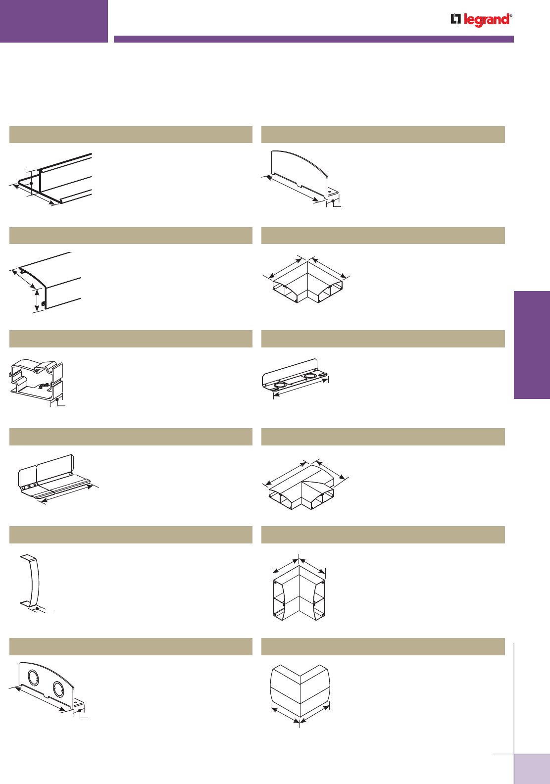
WWW.LEGRAND.US/WIREMOLD
183
WIREMOLD
ALUMINUM RACEWAY
ALDS4000
®
SERIES RACEWAY
.060" [1.52mm] satin anodized
finish. Packed four 10’ [3.05m]
lengths per carton.
Closes off open end of
ALDS4000B Base.
Flat corner for new lay-in or pull-
through applications. Includes
one pair of DS4001 Couplings.
Extra long coupling allows
attachment to wall box or back
fed to 1" or 1 1/4" trade size
conduit.
Divided Tee fitting. For new lay-
in or pull-through installations.
Includes two pairs of DS4001
Couplings.
Internal corner for new lay-in
or pull-through installations.
Includes one pair of DS4001
Couplings.
External corner for new lay-in
or pull-through installations.
Includes one pair of DS4001
Couplings.
.060 [1.52mm] satin anodized finish.
Packed eight 5’ [1.5m] lengths per
carton. Two covers per base.
Holds conductors in place.
Joins lengths of ALDS4000B
together. Sold in pairs.
Covers seam where two sections of
ALDS4000C come together.
Full capacity End Fitting. Has two
1/2" & 3/4" concentric trade size
KOs.
ALDS4000B Raceway Base ALDS4010B Blank End Fitting
ALDS4011 Flat Elbow
DS4014A Backfeed Coupling
ALDS4015 Divided Tee
ALDS4017 Internal Elbow
ALDS4018 External Elbow
ALDS4000C Raceway Cover
DS4000WC Wire Clip
DS4001 Adjust-to-Fit™ Coupling
ALDS4006 Seam Clip
5 1/2"
[140mm]
2 1/16"
[52mm]
2 7/8"
[73mm]
2 1/8"
[54mm]
1 5/8"
[41mm]
6"
[152mm]
ALDS4010A Entrance End Fitting
1"
[25mm]
2 1/8"
[54mm]
5 3/4"
[146mm]
2 1/8"
[54mm]
5 3/4"
[146mm]
8 1/4"
[210mm] 8 1/4"
[210mm]
10"
[254mm]
10 3/4"
[273mm]
8 3/4"
[222mm]
6"
[152mm] 6"
[152mm]
6"
[152mm]
6"
[152mm]
ALDS4000 Series Raceway Ordering Information
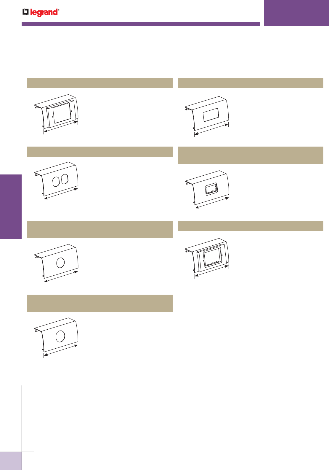
WWW.LEGRAND.US/WIREMOLD
184
WIREMOLD
ALUMINUM RACEWAY
ALDS4000
®
SERIES RACEWAY
Use with commercially-available
single-gang flush plate.
For 15A and 20A duplex
receptacles, or 106 style data
frames.
For straight blade and locking
receptacles.
For straight blade and locking
receptacles.
ALDS4047C Single-Channel One-Gang Device Plate
ALDS4047D Single-Channel Duplex Device Plate
ALDS4047E
Single-Channel 1.41" Diameter Device Plate
ALDS4047F
Single-Channel 1.59" Diameter Device Plate
6"
[152mm]
6"
[152mm]
6"
[152mm]
6"
[152mm]
For 15A and 20A decorator
receptacles.
ALDS4047R Single-Channel Decorator Device Plate
6"
[152mm]
2A opening. Includes adapters
for Ortronics TracJack, Series
II, Wiremold CM2 Series inserts,
Pass & Seymour Activate and
other manufacturers.
ALDS4047-2A*
Single-Channel 2A Mini Adapter Device Plate
6"
[152mm]
For installing Wiremold CM2
Series inserts and Activate
connectivity inserts. Provides
flush installation. Includes 6A
CM-MAB adapter and Ortronics®
MAB3S2 and MAB6TJ adapters.
ALDS4047MAB* Single-Channel MAB Device Plate
6"
[152mm]
* Refer to the Communications Connectivity section of this Product Guide for information on CM2 Series modules.
ALDS4000 Series Raceway Ordering Information (continued)

WWW.LEGRAND.US/WIREMOLD
185
WIREMOLD
ALUMINUM RACEWAY
Single-channel raceway. Satin anodized finish complements decor in commercial
offices, laboratories, and health care facilities.
CODE REFERENCE
cULus Listed Raceway:
File E4376 Guide RJPR.
Fittings:
File E41751 Guide RJPR.
Raceway & Fittings:
Meet Article 386 of NEC.
Multioutlet Assemblies:
Meet Article 380 of NEC.
ALA3800 SERIES
™
RACEWAY
COLOR OPTIONS
AL3800 Series™ Raceway is available with a
satin anodized finish.
AL3800 Series Raceway Wire Fill Capacities
for Communications
CABLE/WIRE SIZE Inches [mm]
40%
FILL
UNSHIELDED
TWISTED PAIR
4-pair, 24 AWG, Cat 3 0.190 [4.8] 86
4 -pair, 24 AWG, Cat 5e 0.210 [5.3] 70
4-pair, 24 AWG, Cat 6 0.250 [6.3] 50
4-pair, 24 AWG, Cat 6a* 0.354 [9.0] 25
25-pair, 24 AWG 0.410 [10.4] 24
COAXIAL RG6/U 0.270 [6.9] 43
FIBER ZipCord 0.118 x 0.236 [3 x 6] 88
Round 4 Strand Fiber 0.187 [4.8] 89
Round 6 Strand Fiber 0.256 [6.5] 47
NOTE: For additional information, refer to the Technical Section.
* Category 6 augmented (6a) cable for 10 gigabit ethernet – max allowed
cable diameter per addenda No. 11 ANSI TIA/EIA 568-B.2.
O.D. (Approx Dia.)
AL3800 Series Raceway Wire Fill Capacities for Power
WIRE SIZE
THHN/THWN Inches [mm]
40%
FILL
POWER WIRING
WITHOUT
DEVICES
14 AWG 0.111 [2.8] 214
12 AWG 0.130 [3.3] 156
10 AWG 0.164 [4.2] 98
8 AWG 0.216 [5.5] 56
6 AWG 0.254 [6.5] 41
POWER WIRING
WITH DEVICES
2.04 Sq. In.
[51.82mm]
14 AWG 0.111 [2.8] 159
12 AWG 0.130 [3.3] 116
10 AWG 0.164 [4.2] 73
8 AWG 0.216 [5.5] 42
6 AWG 0.254 [6.5] 30
O.D.
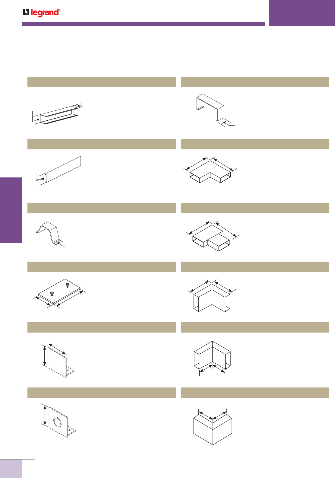
WWW.LEGRAND.US/WIREMOLD
186
WIREMOLD
ALUMINUM RACEWAY
ALA3800 SERIES
™
RACEWAY
Satin Anodized finish. Nominal
wall thickness of .078" [1.99mm].
Packed four 10’ [3m] lengths per
carton.
Satin Anodized finish. Nominal
wall thickness of .078" [1.99mm].
Packed eight 5’ [1.50m] lengths
per carton. ALAC-5 is compatible
with ALA3800 and ALA4800 Series
Raceways.
Covers seam where lengths of
raceway come together.
For making a 90° flat turn in a
raceway run. Includes two ALA01
Couplings.
For branch connections of two
runs of ALA3800 Series Raceway.
Includes three ALA01 Couplings.
For making a 90° internal turn
in a raceway run. Includes two
ALA01 Couplings.
For connecting a vertical run of
ALA3800 Series Raceway with
a horizontal run with its cover
facing up. Includes two ALA01
Couplings.
For making a 90° external turn
in a raceway run. Includes two
ALA01 Couplings.
Holds conductors in place in long
raceway runs. Snaps into grooves
on base.
Joins lengths of inline
ALA3800B-10 Raceway Base
together.
Closes off open end of raceway.
For feeding raceway, has
concentric 1/2" and 3/4" trade
size knockouts.
ALA3800B-10 Single Compartment Raceway Base
ALAC-5 Raceway Cover
ALA3806 Cover Clip
ALA3811 Flat Elbow
ALA3815 Tee
ALA3817 Internal Elbow
ALA3817N Inverted Internal Elbow
ALA3818 External Elbow
ALAWC Wire Clip
ALA01 Couplings
ALA3810B Blank End Fitting
ALA3810B1 Entrance End Fitting
3"
[76mm]
2 1/4"
[57mm]
3"
[76mm]
1"
[25mm]
2 13/16"
[71mm]
4"
[102mm]
2 1/4"
[57mm]
3"
[76mm]
2 1/4"
[57mm]
1 3/8"
[35mm]
6"
[152mm]
6"
[152mm]
6"
[152mm] 6"
[152mm]
6"
[152mm] 6"
[152mm]
6"
[152mm]
6"
[152mm]
ALA3800 Series Raceway Ordering Information
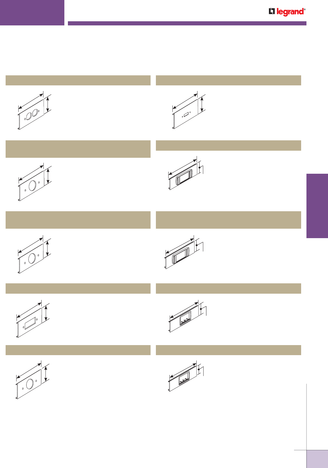
WWW.LEGRAND.US/WIREMOLD
187
WIREMOLD
ALUMINUM RACEWAY
ALA3800 SERIES
™
RACEWAY
Mounts standard duplex device
to the cover.
Installs commercially available
straight blade and locking
single receptacle with face
diameters of 1.38"-1.39"
[36mm-37mm].
Installs commercially available
straight blade and locking
single receptacle with face
diameters of 1.56"-1.58"
[38mm-39mm].
Mounts commercially available
GFCI or surge suppression
receptacles.
Mounts commercially available
straight blade or locking
single receptacles with face
diameters of 2.13" [52mm].
ALA-DR Duplex Receptacle Cover Plate
Accepts three (3) Wiremold
CM2 Series communication
connectivity inserts. Provides
a flush installation. Includes
cover and 6A mini adapter,
(6A-opening).
ALA-MAB* 6A Mini Adapter Cover Plate
ALA-E Single Receptacle Cover Plate
(1.40" [35.40mm])
ALA-F Single Receptacle Cover Plate
(1.59" [38.90mm])
ALA-G GFCI/Surge/Decorator Cover Plate
ALA-J Single Receptacle Cover Plate
NOTE: All device plates are 3" x 12" [76mm x 305mm]. These parts are compatible with both ALA4800 and ALA3800 Series Raceways.
* Refer to the Communications Connectivity section of this Product Guide for information on CM2 Series modules.
3"
[76mm]
12"
[305mm]
3"
[76mm]
12"
[305mm]
3"
[76mm]
12"
[305mm]
3"
[76mm]
12"
[305mm]
3"
[76mm]
12"
[305mm]
Mounts toggle switch in line.
ALA-N Toggle Switch Cover Plate
3"
[76mm]
12"
[305mm]
Accepts three (3) Wiremold
CM2 Series communication
connectivity inserts. Includes
cover and low profile adapter,
(6A-opening).
ALA-LPB* Low Profile Adapter Cover Plate
3"
[76mm]
12"
[305mm]
Accepts three Ortronics® Series
II datacom inserts. Low profile
adapter included.
ALA-LPB3S2
Ortronics® Low Profile Adapter Cover Plate
3"
[76mm]
12"
[305mm]
3"
[76mm]
12"
[305mm]
Accepts six Ortronics®
TracJack or three Series II
datacom inserts. Both adapters
included.
ALA-MABRT Ortronics® Cover Plate
3"
[76mm]
12"
[305mm]
ALA3800 Series Raceway Ordering Information (continued)
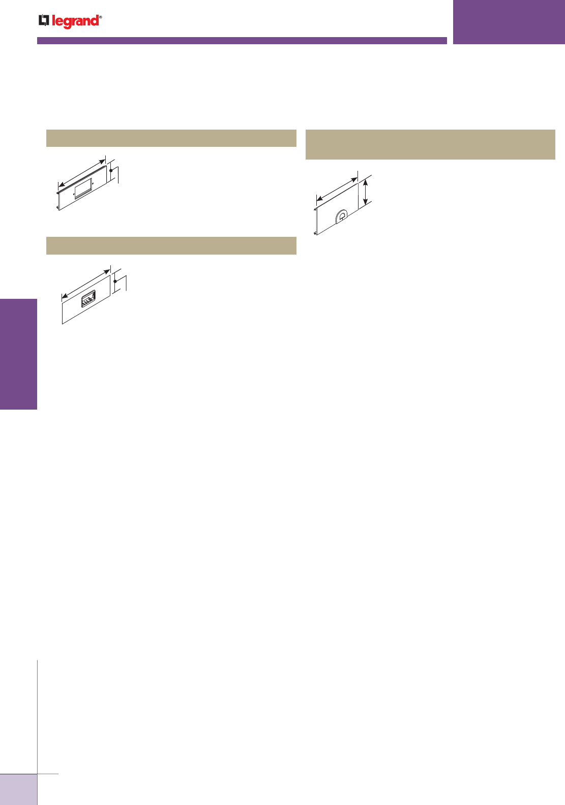
WWW.LEGRAND.US/WIREMOLD
188
WIREMOLD
ALUMINUM RACEWAY
ALA3800 SERIES
™
RACEWAY
NOTE: All device plates are 3" x 12" [76mm x 305mm]. These parts are compatible with both ALA4800 and ALA3800 Series Raceways.
* Refer to the Communications Connectivity section of this Product Guide for information on CM2 Series modules.
Installs communication connectivity
devices utilizing industry standard
single-gang faceplates. Hole cut is
1 3/4" x 2 15/16" [44mm x 75mm].
Faceplates must be ordered
separately.
ALA-SG Cover Plate with 1 3/4" x 2 15/16" Opening
3"
[76mm]
12"
[305mm]
Accepts one (1) Wiremold CM2
Series communication connectivity
device. Includes cover and 2A mini
adapter, (2A-opening).
ALA-2A* 2A Mini Adapter Cover Plate
3"
[76mm]
12"
[305mm]
Facilitates the exit of communication
cabling. Grommet included.
ALA-Z 3/4" [19.1mm] Grommet/Mouse Hole Device
Cover Plate
3"
[76mm]
12"
[305mm]
ALA3800 Series Raceway Ordering Information (continued)

WWW.LEGRAND.US/WIREMOLD
189
WIREMOLD
ALUMINUM RACEWAY
Dual-channel raceway. Satin anodized finish complements decor in commercial
offices, laboratories, and health care facilities. CODE REFERENCE
cULus Listed Raceway:
File E4376 Guide RJPR.
Fittings:
File E41751 Guide RJPR.
Raceway & Fittings:
Meet Article 386 of NEC.
Multioutlet Assemblies:
Meet Article 380 of NEC.
COLOR OPTIONS
ALA4800 Series™ Raceway is available with
a satin anodized finish.
AL4800 Series Raceway Wire Fill Capacities
for Communications
CABLE/WIRE SIZE Inches [mm]
40%
FILL
UNSHIELDED
TWISTED PAIR
4-pair, 24 AWG, Cat 3 0.190 [4.8] 86
4-pair, 24 AWG, Cat 5e 0.210 [5.3] 70
4-pair, 24 AWG, Cat 6 0.250 [6.3] 50
4-pair, 24 AWG, Cat 6a* 0.354 [9.0] 25
25-pair, 24 AWG 0.410 [10.4] 24
COAXIAL RG6/U 0.270 [6.9] 43
FIBER
(Each
Compartment)
ZipCord 0.118 x 0.236 [3 x 6] 88
Round 4 Strand Fiber 0.187 [4.8] 89
Round 6 Strand Fiber 0.256 [6.5] 47
NOTE: For additional information, refer to the Technical Section.
* Category 6 augmented (6a) cable for 10 gigabit ethernet – max allowed
cable diameter per addenda No. 11 ANSI TIA/EIA 568-B.2.
ALA4800 SERIES
™
RACEWAY
ALA4800 Series Raceway Wire Fill Capacities for Power
WIRE SIZE
THHN/THWN Inches [mm]
40%
FILL
POWER WIRING
WITHOUT DEVICES
14 AWG 0.111 [2.8] 214
12 AWG 0.130 [3.3] 156
10 AWG 0.164 [4.2] 98
8 AWG 0.216 [5.5] 56
6 AWG 0.254 [6.5] 41
POWER WIRING
WITH DEVICES
(2.04 Sq. In.
[51.82mm])
(Each
Compartment)
14 AWG 0.111 [2.8] 159
12 AWG 0.130 [3.3] 116
10 AWG 0.164 [4.2] 73
8 AWG 0.216 [5.5] 42
6 AWG 0.254 [6.5] 30
O.D. (Approx Dia.) O.D.
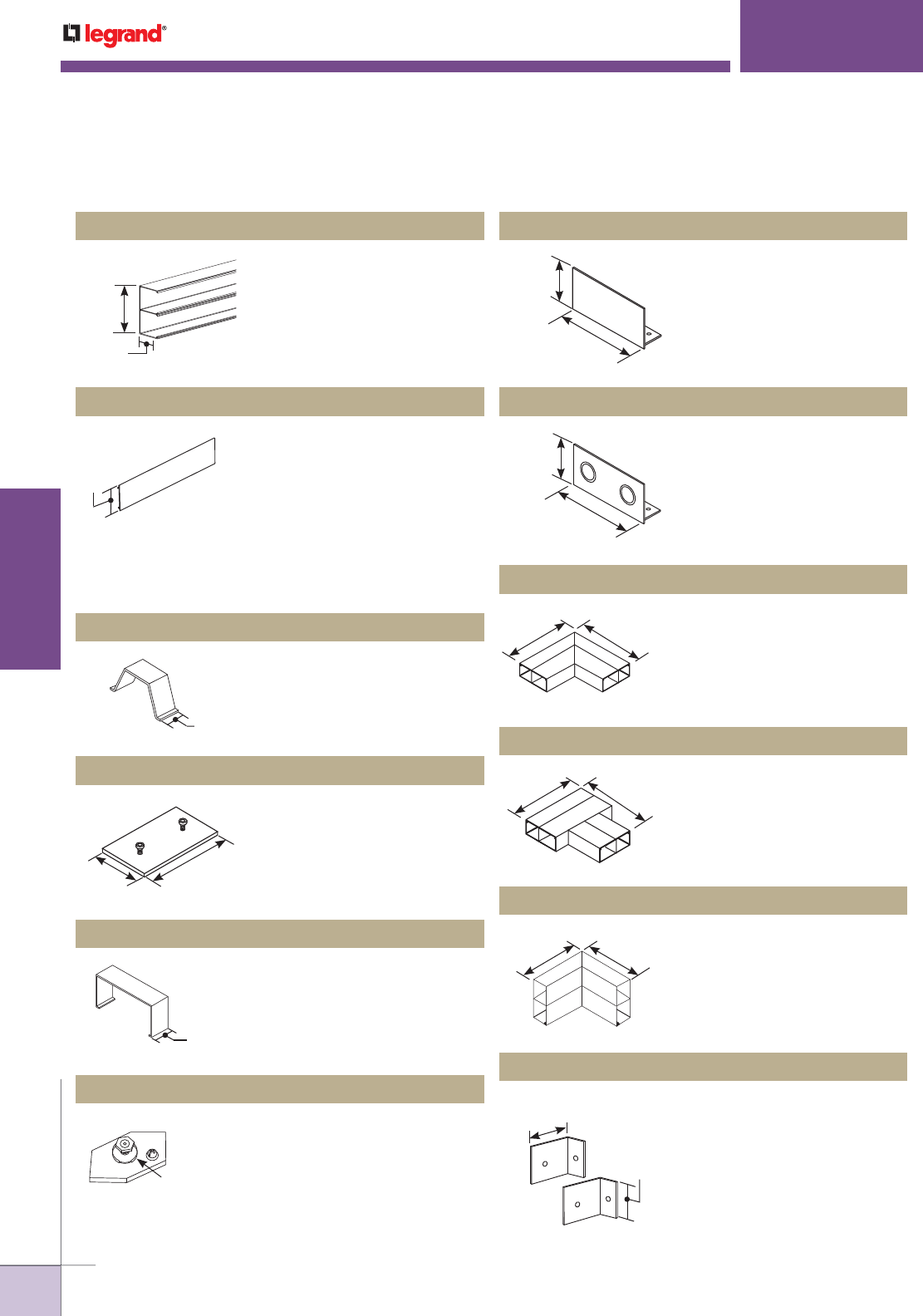
WWW.LEGRAND.US/WIREMOLD
190
WIREMOLD
ALUMINUM RACEWAY
ALA4800 SERIES
™
RACEWAY
6063-T5 extruded aluminum,
satin anodized finish, .078"
[1.98mm] wall thickness. Base
has integral divider for separation
of service. Packed 40' [12m] per
carton.
For covering ends of raceway.
For feeding raceway, has two
concentric 1/2" and 3/4" trade
size KOs.
Makes 90° flat turn in a raceway
run. Includes four ALA01
Couplings.
For branch connections of two
runs of ALA4800 Series Raceway.
Includes six ALA01 Couplings.
To make an internal turn in a
raceway run. Includes four ALA01
Couplings.
For butting two raceway sections
to form an internal 90° turn in a
raceway run.
6063-T5 extruded aluminum,
satin anodized finish, .078"
[1.98mm] wall thickness. Two
covers per base. Allows only one
compartment to be accessed
at a time. Packed 40' [12m] per
carton. ALAC-5 is compatible with
ALA4800 Series and ALA3800
Series Raceways.
For holding conductors in place
in long raceway runs. Snaps into
grooves in base.
Joins lengths of inline
ALA4800B-10 Raceway Base
together. Two required per
section of base.
Stainless steel clip to cover
joint where lengths of cover or
base come together.
For connection of equipment
grounding conductor to provide
additional ground to raceway.
ALA4800B-10 Dual Compartment Raceway Base ALA4810B Blank End Fitting
ALA4810B2 Entrance End Fitting
ALA4811 Flat Elbow
ALA4815 Tee
ALA4817 Internal Elbow
ALA17A Internal Corner Coupling
ALAC-5 Raceway Cover
ALAWC Wire Clip
ALA01 Couplings
ALA4806 Cover Clip
ALA09 Grounding Adapter
2 1/4"
[57mm]
6"
[152mm]
3"
[76mm]
1"
[25mm]
2 13/16"
[71mm]
4"
[102mm]
1 3/8"
[35mm]
#10 Ground Stud
with Cup Washer
2 3/16"
[56mm]
6"
[152mm]
2 3/16"
[56mm]
6"
[152mm]
9"
[229mm] 9"
[229mm]
9"
[229mm] 9"
[229mm]
6"
[152mm]
6"
[152mm]
4"
[102mm]
2"
[51mm]
NOTE: These parts are compatible with both ALA4800 and ALA3800 Series Raceways.
ALA4800 Series Raceway Ordering Information
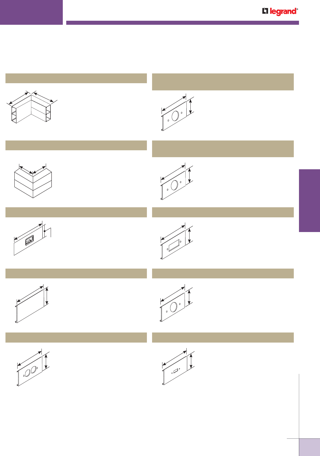
WWW.LEGRAND.US/WIREMOLD
191
WIREMOLD
ALUMINUM RACEWAY
ALA4800 SERIES
™
RACEWAY
6"
[152mm]
6"
[152mm]
For making a 90° external turn in a
raceway run. Includes four ALA01
Couplings.
For connecting a vertical run of
ALA4800 Series Raceway with a
horizontal run with its cover facing
up. Includes four ALA01 Couplings.
ALA4818 External Elbow
ALA4817N Inverted Internal Elbow
6"
[152mm]
6"
[152mm]
For two Ortronics® TracJack or
one Series II datacom insert. Both
adapters included.
ALA-ABRT Ortronics® Cover Plate
3"
[76mm]
12"
[305mm]
To cover a 12" [305mm] section of
raceway.
ALA-BL Blank Cover Plate
3"
[76mm]
12"
[305mm]
Mounts standard duplex device to
the cover.
ALA-DR Duplex Receptacle Cover Plate
3"
[76mm]
12"
[305mm]
Installs commercially available
straight blade and locking single
receptacle with face diameters of
1.56"-1.58" [38mm-39mm].
ALA-F Single Receptacle Cover Plate
(1.59" [38.90mm])
3"
[76mm]
12"
[305mm]
Installs commercially available
straight blade and locking single
receptacle with face diameters of
1.38"-1.39" [36mm-37mm].
ALA-E Single Receptacle Cover Plate
(1.40" [35.40mm])
3"
[76mm]
12"
[305mm]
Mounts commercially available GFCI
or surge suppression receptacles.
ALA-G GFCI/Surge/Decorator Cover Plate
3"
[76mm]
12"
[305mm]
Mounts commercially available
straight blade or locking single
receptacles with face diameters of
2.13" [52mm].
ALA-J Single Receptacle Cover Plate
3"
[76mm]
12"
[305mm]
Mounts toggle switch in line.
ALA-N Toggle Switch Cover Plate
3"
[76mm]
12"
[305mm]
NOTE: All device plates are 3" x 12" [76mm x 305mm]. These parts are compatible with both ALA4800 and ALA3800 Series Raceways.
*Refer to the Communications Connectivity section of this Product Guide for information on CM2 Series modules.
ALA4800 Series Raceway Ordering Information (continued)
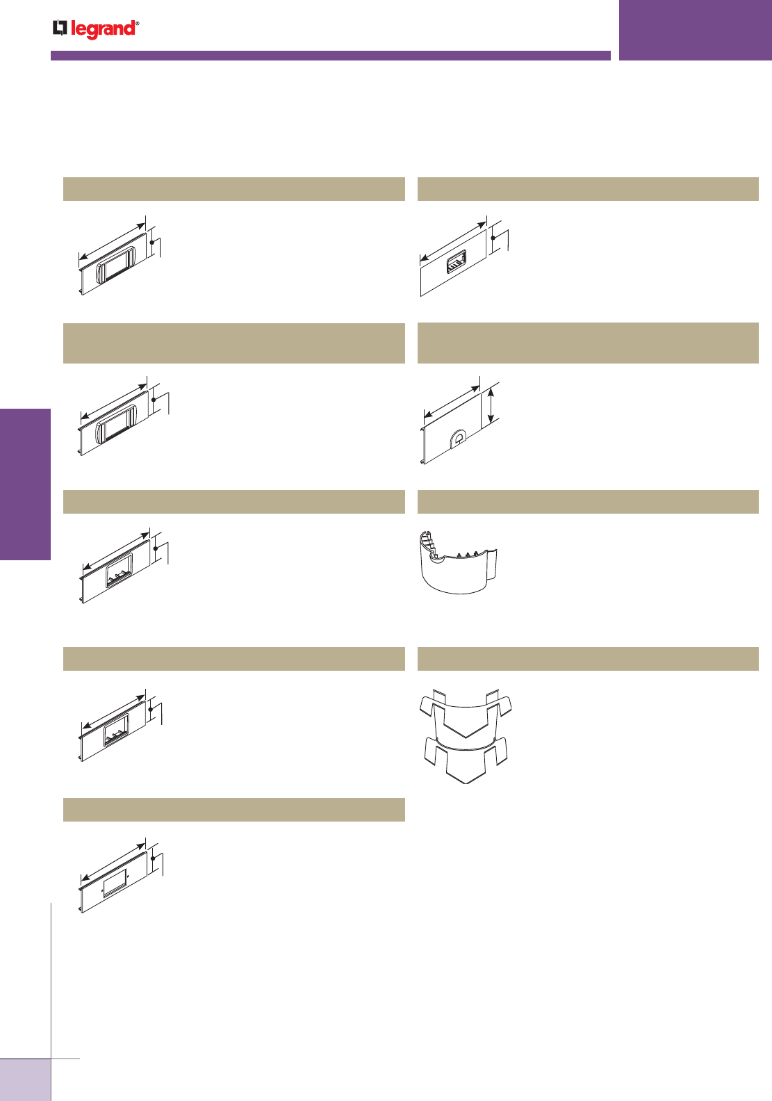
WWW.LEGRAND.US/WIREMOLD
192
WIREMOLD
ALUMINUM RACEWAY
ALA4800 SERIES
™
RACEWAY
Accepts three (3) Wiremold CM2
Series communication connectivity
inserts. Includes cover and low profile
adapter, (6A-opening).
ALA-LPB* Low Profile Adapter Cover Plate
3"
[76mm]
12"
[305mm]
Accepts three Ortronics® datacom
inserts for three Series II devices.
Low profile adapter included.
ALA-LPB3S2
Ortronics® Low Profile Adapter Cover Plate
3"
[76mm]
12"
[305mm]
Accepts three (3) Wiremold CM2
Series communication connectivity
inserts. Provides a flush installation.
Includes cover and 6A mini adapter,
(6A-opening).
ALA-MAB* 6A Mini adapter Cover Plate
3"
[76mm]
12"
[305mm]
Accepts six Ortronics® TracJack or
three Series II datacom inserts. Both
adapters included.
ALA-MABRT Ortronics® Cover Plate
3"
[76mm]
12"
[305mm]
Installs communication connectivity
devices utilizing industry standard
single-gang faceplates. Hole cut is
1 3/4" x 2 15/16" [44mm x 75mm].
Faceplates must be ordered
separately.
ALA-SG Cover Plate with 1 3/4" x 2 15/16" Opening
3"
[76mm]
12"
[305mm]
Accepts three (3) Wiremold CM2 Series
communication connectivity devices.
Includes cover and 2A mini adapter,
(2A-opening).
ALA-2A* 2A Mini Adapter Cover Plate
3"
[76mm]
12"
[305mm]
Facilitates the exit of communication
cabling. Grommet included.
ALA-Z 3/4" [19.1mm] Grommet/Mouse Hole Device
Cover Plate
3"
[76mm]
12"
[305mm]
A radiused insert for the ALA3811 and
ALA4811 flat elbow to provide a bend
radius of 2" [51mm] for Fiber Optic/
Category 5e installations. The insert is
ideal for new and retrofit applications
whether the cable installation is lay-in
or pull-through.
ALA11RI Radiused Insert
A radiused insert for ALA3817, ALA4817,
ALA3817N, ALA4817N, ALA3818, and
ALA4818 fittings to provide a bend
radius of 2" [51mm] for Fiber Optic/
Category 5e installations. The insert is
ideal for new and retrofit applications
whether the cable installation is lay-in
or pull-through.
ALA17/18RI Radiused Insert
NOTE: All device plates are 3" x 12" [76mm x 305mm]. These parts are compatible with both ALA4800 and ALA3800 Series Raceways.
*Refer to the Communications Connectivity section of this Product Guide for information on CM2 Series modules.
ALA4800 Series Raceway Ordering Information (continued)
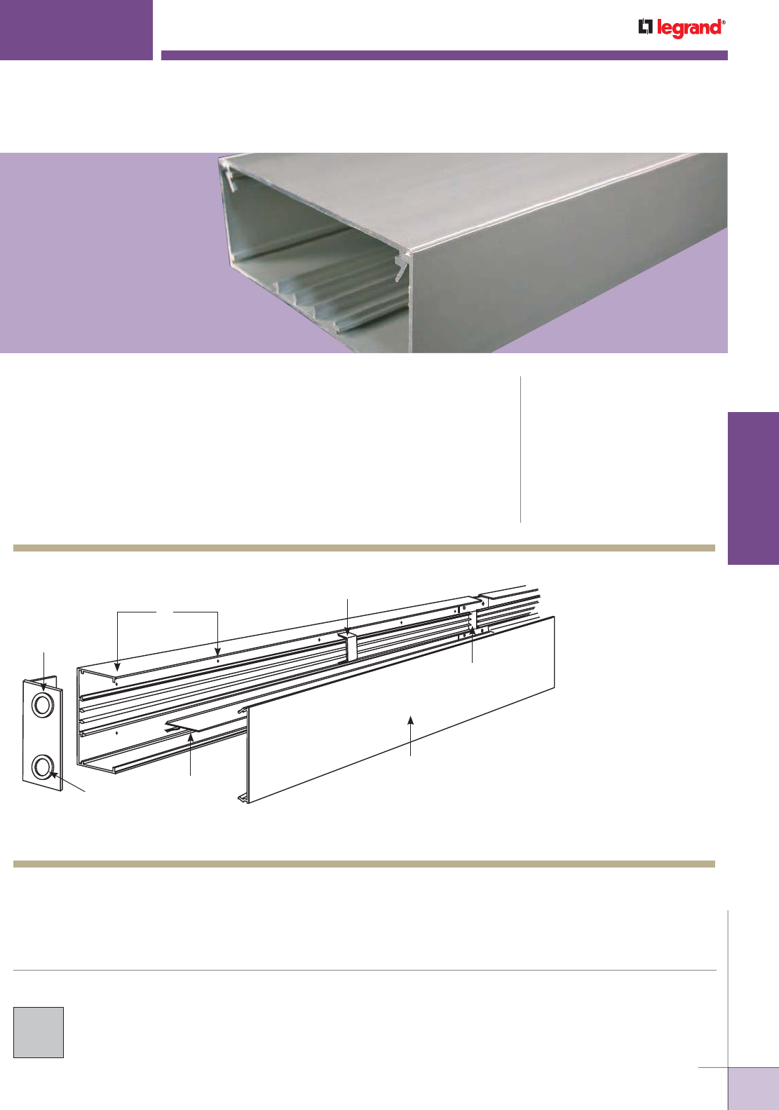
WWW.LEGRAND.US/WIREMOLD
193
WIREMOLD
ALUMINUM RACEWAY
Two-piece raceway. Field-installed divider provides for numerous raceway channel
configurations. Satin anodized finish complements decor in commercial offices,
laboratories, and health care facilities.
CODE REFERENCE
cULus Listed Raceway:
File E4376 Guide RJPR.
Fittings:
File E41751 Guide RJPR.
Raceway & Fittings:
Meet Article 386 of NEC.
Multioutlet Assemblies:
Meet Article 380 of NEC.
COLOR OPTIONS
AL5200 Series™ Raceway is available
with a satin anodized finish.
AL5200 SERIES
™
RACEWAY
KEY
A. Provide electrical feed
through 1/2" or 3/4"
[12.7mm or 19.1mm] KOs
in AL5210B2 End Cap.
B. Attach base section to
mounting surface by drilling
9/32" [7.1mm] holes in the
base, and using #8 flathead
screws.
C. Secure conductors in place
with AL5200WC Wire Clip.
D. Join additional raceway
sections with two AL5201
Couplings.
E. Close ends with AL5210B2
Blank End Fittings.
F. Snap cover into base to
complete installation.
AL5200 Raceway System Layout
NOTE: Illustration is for showing product applications only.
C
B
A
F
E
D
Snap-in Divider
(Optional)

WWW.LEGRAND.US/WIREMOLD
194
WIREMOLD
ALUMINUM RACEWAY
AL5200 SERIES
™
RACEWAY
AL5200 Series Raceway Wire Fill Capacities for Power
WIRE SIZE
THHN/THWN
NUMBER OF CONDUCTORS 40% FILL
WITHOUT DEVICES
Inches [mm]
2.40in.
2
[1550mm
2
]
2.85in
2
1840[mm
2
]
3.50 in.
2
[2260mm
2
]
3.90 in.
2
[2520mm
2
]
4.50 in.
2
[2900mm
2
]
4.80 in.
2
[3100mm
2
]
5.50 in.
2
[3550mm
2
]
8.50 in.
2
[5480mm
2
]
14 AWG 0.111 [2.8] 98 117 144 160 185 197 226 350
12 AWG 0.130 [3.3] 72 85 105 117 135 144 165 255
10 AWG 0.164 [4.2] 45 54 66 73 85 90 104 161
8 AWG 0.216 [5.5] 26 31 38 42 49 52 60 92
6 AWG 0.254 [6.5] 18 22 27 30 35 37 43 67
WITH DUPLEX RECTANGULAR DEVICES
1.59IN.
2
1025MM
2
WIRE SIZE
THHN/THWN Inches [mm]
2.85in
2
1840[mm
2
]
3.50 in.
2
[2260mm
2
]
3.90 in.
2
[2520mm
2
]
4.50 in.
2
[2900mm
2
]
4.80 in.
2
[3100mm
2
]
5.50 in.
2
[3550mm
2
]
8.50 in.
2
[5480mm
2
]
14 AWG 0.111 [2.8] 54 78 95 120 132 161 284
12 AWG 0.130 [3.3] 39 57 69 87 96 117 207
10 AWG 0.164 [4.2] 24 36 43 55 60 74 130
8 AWG 0.216 [5.5] 14 20 25 31 35 42 75
6 AWG 0.254 [6.5] 10 15 18 22 25 30 54
AL5200 Series Raceway Wire Fill Capacities for Communications
40% FILL CAPACITY CROSS SECTIONAL AREA
CABLE/WIRE SIZE Inches [mm]
2.40in.
2
[1550mm
2
]
2.85in
2
1840[mm
2
]
3.50 in.
2
[2260mm
2
]
3.90 in.
2
[2520mm
2
]
4.50 in.
2
[2900mm
2
]
4.80 in.
2
[3100mm
2
]
5.50 in.
2
[3550mm
2
]
8.50 in.
2
[5480mm
2
]
UNSHIELDED
TWISTED
PAIR
4-pair, 24 AWG, Cat 3 0.190 [4.8] 33 40 49 55 63 67 77 119
4-pair, 24 AWG, Cat 5e 0.210 [5.3] 27 32 40 45 51 55 63 98
4-pair, 24 AWG, Cat 6 0.250 [6.3] 19 23 28 31 36 39 44 69
4-pair, 24 AWG, Cat 6a* 0.354 [9.0] 9 11 14 15 18 19 22 34
25-pair, 24 AWG 0.410 [10.4] 7 8 10 11 13 14 16 25
COAXIAL RG6/U 0.270 [6.9] 16 19 24 27 31 33 38 59
FIBER ZipCord 0.118 x 0.236 [3 x 6] 34 41 50 56 64 69 79 122
Round 4 Strand Fiber 0.187 [4.8] 34 41 51 56 65 69 80 123
Round 6 Strand Fiber 0.256 [6.5] 18 22 27 30 34 37 42 66
NOTE: For additional information, refer to the Technical Section.
* Category 6 augmented (6a) cable for 10 gigabit ethernet – max allowed cable diameter per addenda No. 11 ANSI TIA/EIA 568-B.2.
O.D
O.D
O.D
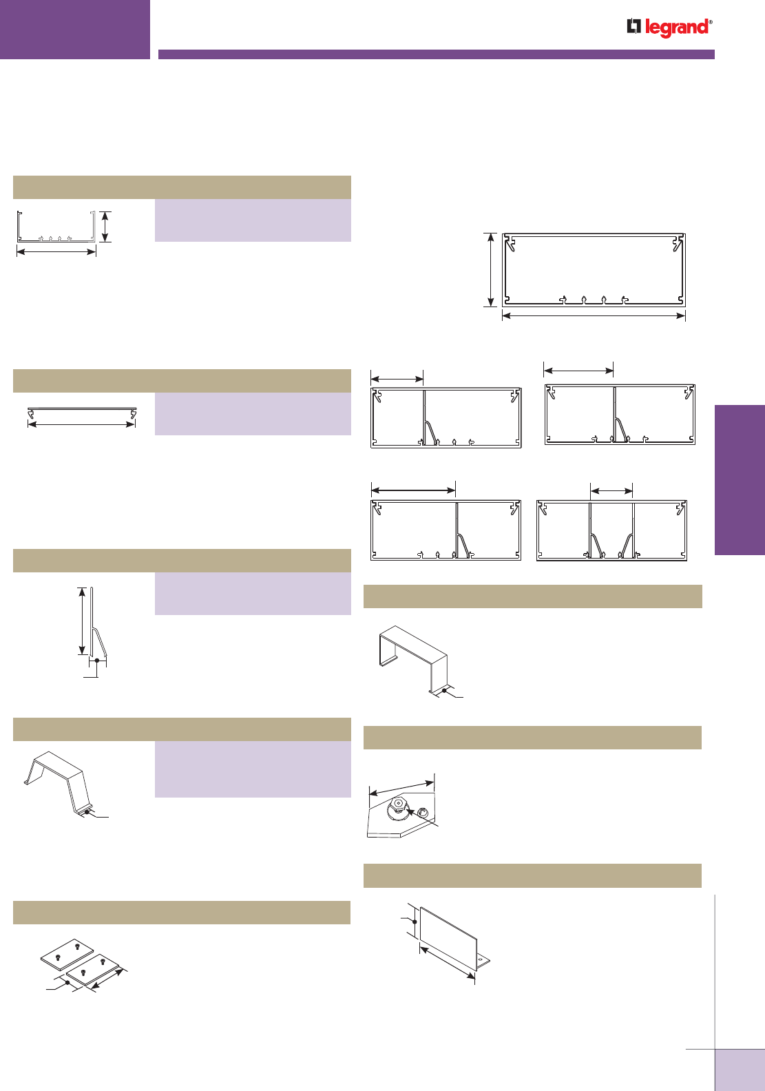
WWW.LEGRAND.US/WIREMOLD
195
WIREMOLD
ALUMINUM RACEWAY
AL5200 SERIES
™
RACEWAY
6063-T5 extruded aluminum, satin
anodized finish, .080" [2.03mm]
wall thickness. Base has four ribs
for snap-in divider. AL5200B-5 is
packed eight 5' [1.5m] lengths and
AL5200B-10 is packed four 10'
[3m] lengths per carton.
6063-T5 extruded aluminum, satin
anodized finish, .075" [1.9mm]
wall thickness. AL5200C-5 is
packed eight 5' [1.5m] lengths and
AL5200C-10 is packed four 10'
[3m] lengths per carton.
Extruded .050" [1.8mm] thick
aluminum. AL5200D-5 is packed
eight 5' [1.5m] lengths and
AL5200D-10 is packed four 10'
[3m] lengths per carton.
Covers seam where lengths of cover
or base come together.
Connects equipment grounding
conductor to provide an additional
ground to raceway.
Closes off open ends of raceway.
AL5206 Cover Clip (Spring Steel)
AL5209 Grounding Adapter
AL5210B Blank End Fitting
5"
[127mm]
2"
[51mm]
4 7/8"
[124mm]
1 13/16"
[46mm]
1/2"
[12.7mm]
Raceway may be configured in single or multiple channels
in several versatile ways to accommodate power or
communications wiring.
5.50 in.2
[3550mm2]
2.85 in.2
[1840mm2]
1 5/8"
[42mm]
2 3/16"
[56mm]
3.90 in.2
[2520mm2]
4.50 in.2
[2900mm2]
2"
[51mm]
5"
[127mm]
8.5 in.2
[5840mm2]
NOTE: Cross-sectional
area of each
compartment
indicated.
3.50 in.2
[2260mm2]
4.80 in.2
[3100mm2]
2 7/8"
[73mm]
1 7/16"
[37mm]
2.85 in.2
[1840mm2]
2.85 in.2
[1840mm2]
2.40 in.2
[1550mm2]
1 1/2"
[38mm] For holding conductors in place
in long raceway runs. Snaps into
grooves in raceway. AL5200WC
Full, AL5200WC2 3/4, and
AL5200WC3 1/2.
Set screw couplings. Use two for
attaching in-line raceway sections.
AL5201 Coupling
1 9/16"
[40mm] 3"
[76mm]
1 1/2"
[38mm]
#10 Ground
Stud with
Cup Washer
1 1/2"
[38mm]
1 9/16"
[49mm]
5"
[127mm]
AL5200 Series Raceway Ordering Information
Raceway Base
PART NUMBERS:
AL5200B-5 (5' Length)
AL5200B-10 (10' Length)
Raceway Base
PART NUMBERS:
AL5200C-5 (5' Length)
AL5200C-10 (10' Length)
Divider
PART NUMBERS:
AL5200D-5 (5' Length)
AL5200D-10 (10' Length)
Wire Clip
PART NUMBERS:
AL5200WC (Full)
AL5200D-10 (3/4)
AL5200WC3 (1/2)
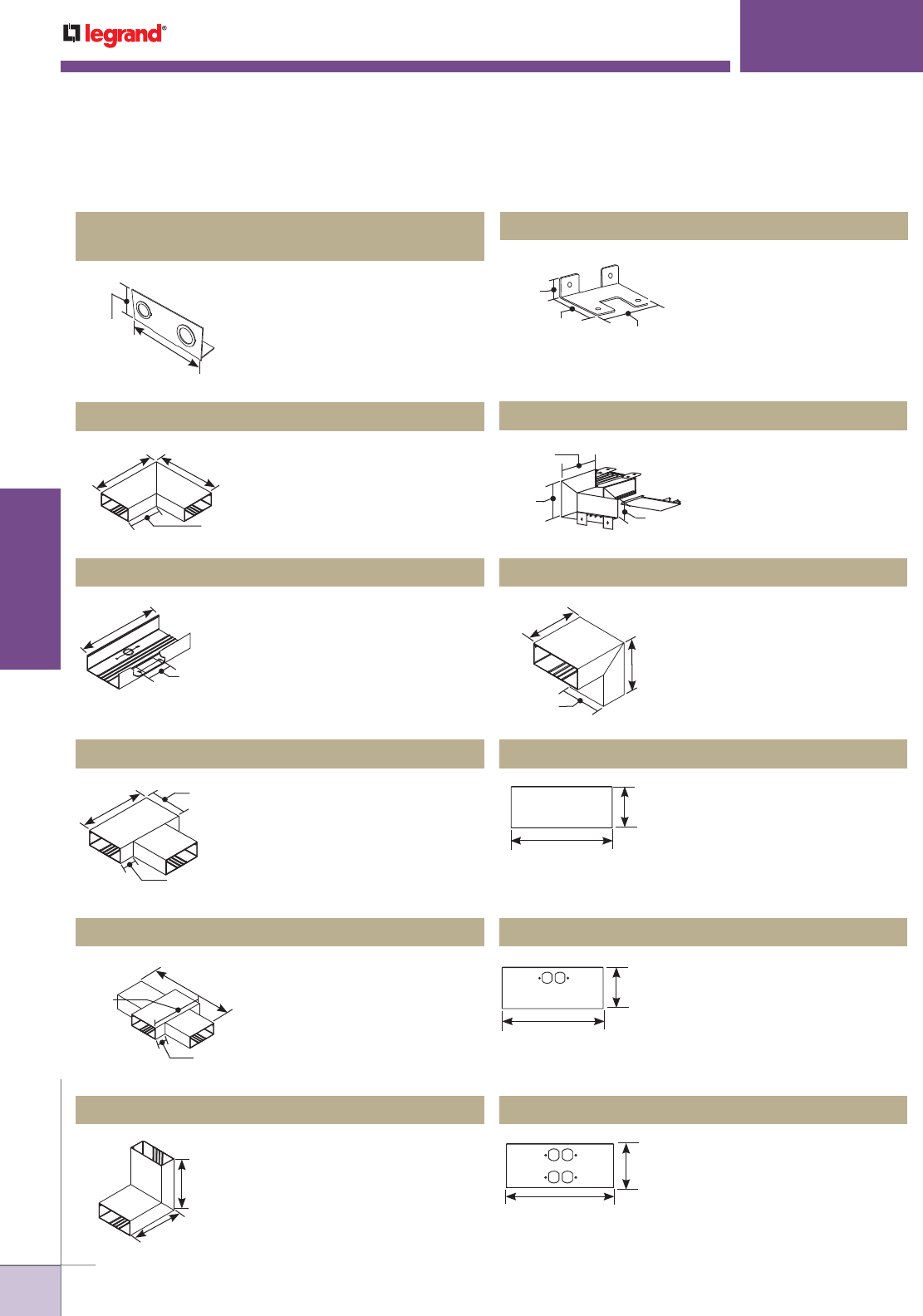
WWW.LEGRAND.US/WIREMOLD
196
WIREMOLD
ALUMINUM RACEWAY
AL5200 SERIES
™
RACEWAY
With single or multiple concentric
1/2" and 3/4" trade size KOs for
conduit connections. (AL5210B1
and AL5210B3, not shown,have
one and three double KOs
respectively.)
Makes a 90° flat turn in a raceway
run. Includes two pairs of AL5201
Couplings.
Connects two raceway sections
to form an internal 90° turn in a
raceway run.
Connects a vertical run of
AL5200 Series Raceway with a
horizontal overhead run with its
cover facing up.
Makes a 90° external turn in a
raceway run. Includes two pair
of AL5201 Couplings.
Covers a 12" [305mm] section of
raceway.
Mounts standard duplex devices
to cover.
Installs I5A and 2OA duplex
receptacles or duplex style
communication devices.
Feeds raceway from a wall-
mounted outlet box. Rectangular
hole cut or concentric 1/2" and
3/4" trade size KOs. Couplings
included.
Branch connection of two runs of
AL5200 Series Raceway. Includes
three pairs of AL5201 Couplings.
Cross through connection in a
raceway run. Includes four pairs of
AL5201 Couplings.
AL5210B1, AL5210B2, AL5210B3
Entrance End Fitting
AL5211 Flat Elbow
AL5217A Internal Corner Coupling
AL5217N Inverted Internal Elbow
AL5218 External Elbow
AL5246-B Blank Cover
AL5246-D Duplex Receptacle Cover Plate
AL5246-DD Double Duplex Cover Plate
AL5214 Wall Box Connector
AL5215 Tee
AL5216 Cross Fitting
1 9/16"
[49mm]
5"
[127mm]
5"
[127mm]
10"
[254mm]
10"
[254mm]
12"
[305mm]
3 3/8"
[86mm]
9"
[229mm]
10"
[254mm]
2"
[51mm]
15"
[381mm]
9"
[229mm]
2"
[51mm]
Makes 90° internal corner in a
raceway run. Includes two pairs of
AL5201 Couplings.
AL5217 Internal Elbow
7"
[178mm]
7"
[178mm]
5"
[127mm]
1 1/2"
[38mm]
3 5/16"
[84mm] 4 13/16"
[122mm]
3"
[76mm]
5"
[127mm]
5"
[127mm]
8"
[203mm]
8"
[203mm]
6"
[152mm]
4 7/8"
[124mm]
12"
[305mm]
12"
[305mm]
4 7/8"
[124mm]
12"
[305mm]
4 7/8"
[124mm]
AL5200 Series Raceway Ordering Information (continued)
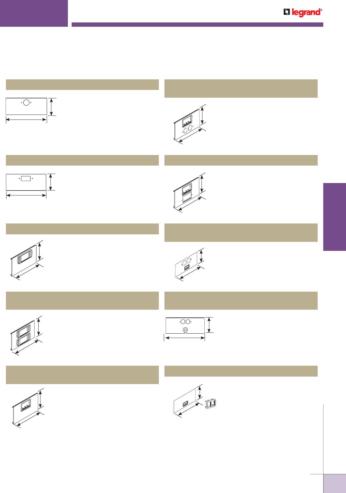
WWW.LEGRAND.US/WIREMOLD
197
WIREMOLD
ALUMINUM RACEWAY
AL5200 SERIES
™
RACEWAY
Installs commercially available
straight blade and locking
single receptacles with face
diameters of 1.56"-1.58"
[39.2mm-39.3mm].
Mounts commercially available
GFCI or surge suppression
receptacles.
Accepts three (3) Wiremold
CM2 Series communication
connectivity devices. Includes
cover and low profile adapter
(6A-opening).
For installation requiring a 15A
or 20A duplex receptacle and
accepts three (3) Wiremold CM2
Series communication connectivity
devices. Cover includes 6A mini
adapter (6A-opening).
For installation requiring a GFCI or
surge suppression receptacle and
accepts three (3) Wiremold CM2
Series communication connectivity
devices. Cover includes 6A mini
adapter (6A-opening).
Duplex receptacle cover accepts
one (1) Wiremold CM2 Series and
2A mini adapter (2A opening).
Grommeted cable access at duplex
receptacle location (2A opening).
Accepts only Ortronics® datacom
inserts. Supplied with both
adapters to accommodate two
TracJack devices or one Series II
device.
Accepts three (3) Wiremold
CM2 Series communication
connectivity devices. Includes
cover and two low profile
adapters (6A-openings).
Installs communication
connectivity devices. Includes
cover and 6A mini adapter
(6A-opening).
AL5246-F Single Receptacle Device Cover Plate
AL5246-G GFCI Device Cover Plate
AL5256-ACTLPB* Low Profile Adapter Cover Plate
AL5256-DACT*
Duplex & 6A Mini Adapter Cover Plate
AL5256-GACT* GFCI & 6A Mini Adapter Cover Plate
AL5256-D2A*
Duplex Receptacle & 2A Mini Adapter Cover Plate
AL5256-DZ
Duplex Receptacle & Mouse Hole Device Cover Plate
AL5256-ABRT Ortronics® Cover Plate
AL5256-ACT2LP*
Device Cover Plate with Two Low Profile Adapters
AL5256-ACTMAB
Device Cover Plate with 6A Mini Adapter
12"
[305mm]
4 7/8"
[124mm]
4 7/8"
[124mm]
12"
[305mm]
12"
[305mm]
4 7/8"
[124mm]
12"
[305mm]
4 7/8"
[124mm]
12"
[305mm]
4 7/8"
[124mm]
12"
[305mm]
4 7/8"
[124mm]
12"
[305mm]
4 7/8"
[124mm]
12"
[305mm]
4 7/8"
[124mm]
12"
[305mm]
4 7/8"
[124mm]
* Refer to the Communications Connectivity section of this Product Guide for information on CM2 Series modules.
AL5200 Series Raceway Ordering Information (continued)
4 7/8"
[124mm]
12"
[305mm]
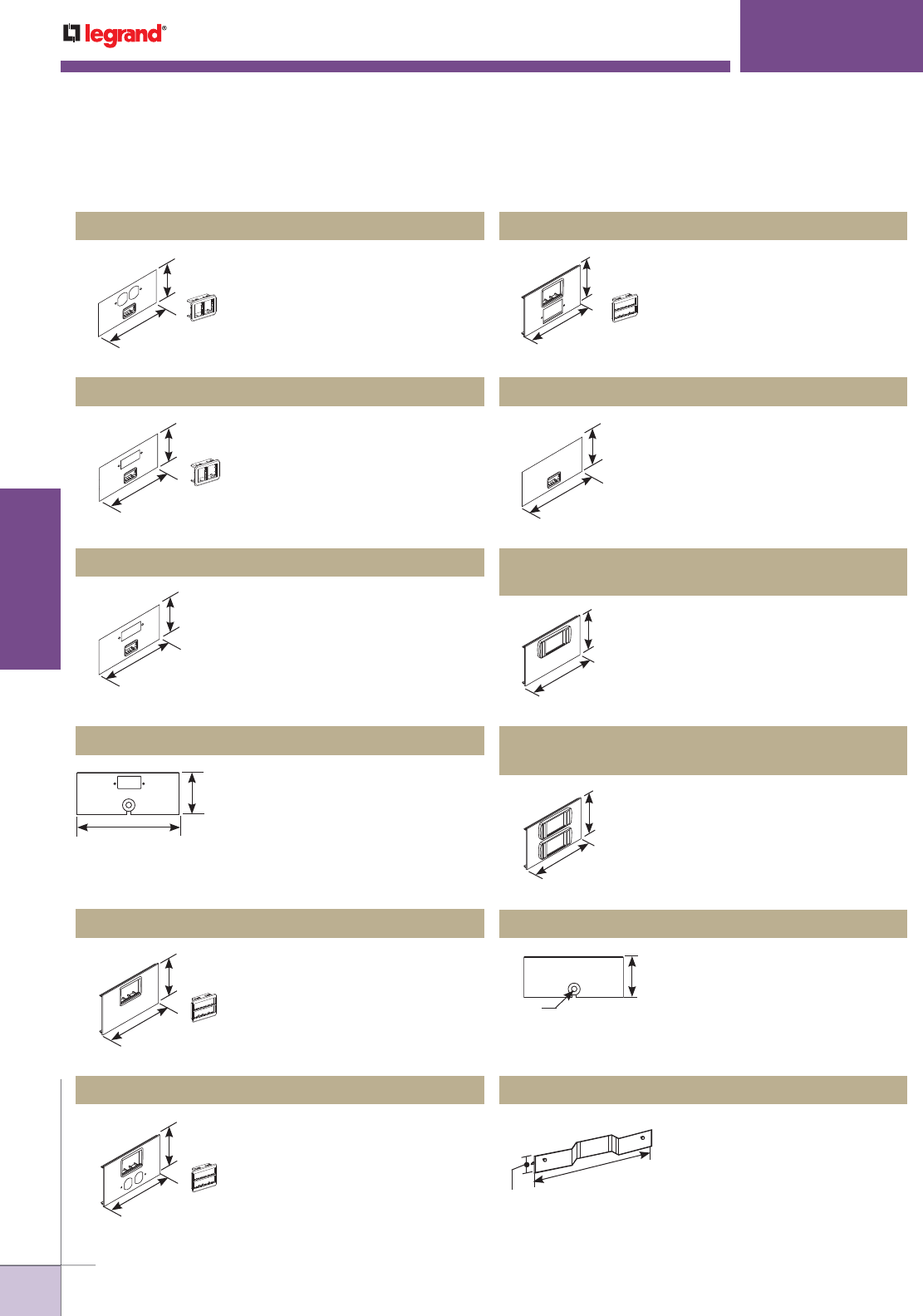
WWW.LEGRAND.US/WIREMOLD
198
WIREMOLD
ALUMINUM RACEWAY
AL5200 SERIES
™
RACEWAY
Accepts only Ortronics® datacom
inserts. Supplied with both
adapters to accommodate two
TracJack devices or one Series II
device.
GFCI sized hole cut accepts one (1)
Wiremold CM2 Series and 2A mini
adapter (2A opening).
Grommeted cable opening at GFCI
receptacle location.
Accepts only Ortronics® datacom
inserts. Supplied with both
adapters to accommodate two
TracJack devices or one Series II
device.
Accepts Ortronics® datacom
inserts. Supplied with both
adapters to accommodate six
TracJack devices or three Series II
devices.
Accepts Ortronics® datacom
inserts. Accepts three Series
II devices. Low profile adapter
included.
Accepts Ortronics® datacom
inserts. Accepts six Series II
devices. Two low profile adapters
included.
Accepts one (1) Wiremold
CM2 Series 2A communication
connectivity device. Includes cover
and 2A mini adapter (2A opening).
Facilitates exit of voice or data
communication cabling. Grommet
furnished.
Used to allow device offsets and
to extend over ribs in the raceway
base. Snap fits into base.
Accepts Ortronics® datacom
inserts. Supplied with both
adapters to accommodate six
TracJack devices or three Series II
devices.
Accepts Ortronics® datacom
inserts. Supplied with both
adapters to accommodate six
TracJack devices or three Series
II devices.
AL5256-DABRT Duplex & Ortronics® Cover Plate
AL5256-G2A* GFCI & 2A Mini Adapter Cover Plate
AL5256-GZ GFCI & Mouse Hole Device Cover Plate
AL5256-GABRT GFCI & Ortronics® Cover Plate
AL5256-GMABRT GFCI & Ortronics® Cover Plate
AL5256-LPB3S2
Ortronics® Low Profile Adapter Cover Plate
AL5256-2LPB3S2
Ortronics® Low Profile Adapter Cover Plate
AL5256-2A* 2A Mini adapter Cover Plate
AL5256-Z Mouse Hole Device Cover Plate
AL5260 Offset Divider
AL5256-MABRT Ortronics® Cover Plate
AL5256-DMABRT Duplex & Ortronics® Cover Plate
12"
[305mm]
4 7/8"
[124mm]
12"
[305mm]
4 7/8"
[124mm]
12"
[305mm]
4 7/8"
[124mm]
4 7/8"
[124mm]
12"
[305mm]
12"
[305mm]
4 7/8"
[124mm]
12"
[305mm]
4 7/8"
[124mm]
12"
[305mm]
4 7/8"
[124mm]
12"
[305mm]
4 7/8"
[124mm]
12"
[305mm]
4 7/8"
[124mm]
12"
[305mm]
4 7/8"
[124mm]
4 7/8"
[124mm]
1 1/4"
[32mm] Dia.
9 9/16"
[243mm]
1 9/16"
[40mm]
* Refer to the Communications Connectivity section of this Product Guide for
information on CM2 Series modules.
AL5200 Series Raceway Ordering Information (continued)
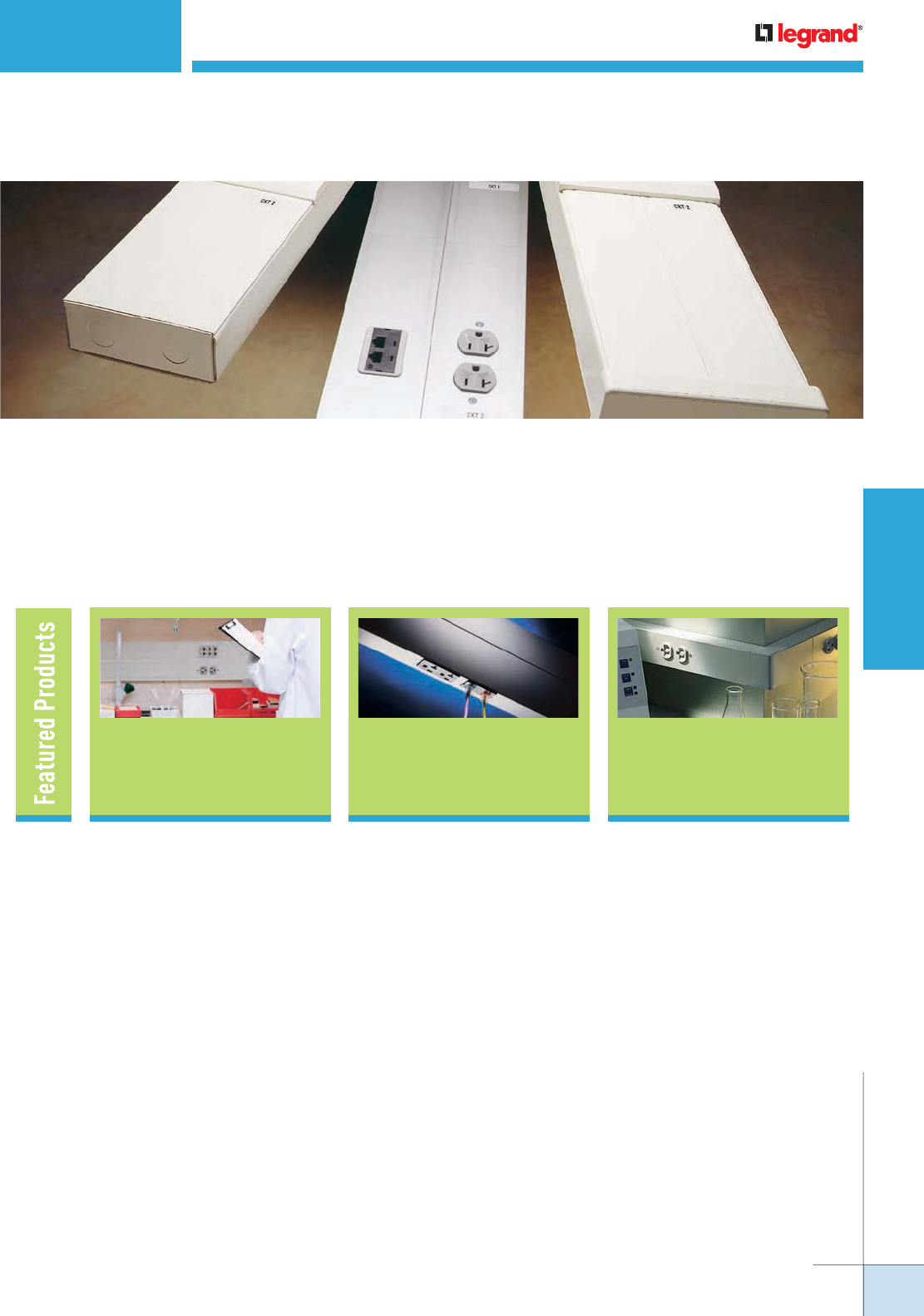
WWW.LEGRAND.US/WIREMOLD
199
WIREMOLD
PREWIRED RACEWAY
PREWIRED RACEWAY
When time is an issue, Wiremold® Prewired Raceway gives you the option of
letting our experts do the work for you. Wiring is labeled, wrapped and ready for
termination at the job site. All you need to do is mount the raceway on the wall
and connect the feed wires. Use our new Prewired Connectors, and you’ll get off
the job even faster. Save installation time, labor and money with raceway that’s
ready for work before it even gets on the job.
ALA4800 Series
Raceway 225
ALDS4000 Series
Raceway 227 233
Prewired Steel
Raceways
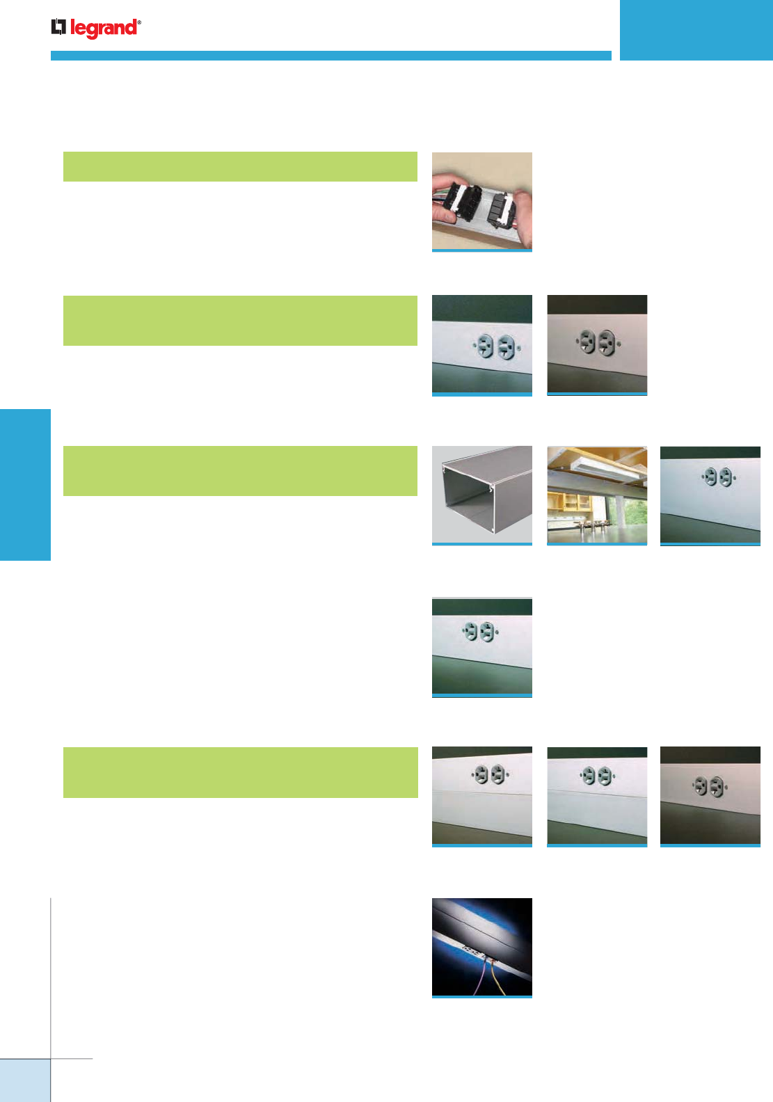
WWW.LEGRAND.US/WIREMOLD
200
WIREMOLD
PREWIRED RACEWAY
Dual Channel, Dual Cover Aluminum
Raceway Systems
Why Prewired?
203
Single Channel, Single Cover Aluminum
Raceway Systems
Single/Dual Channel, Single Cover Aluminum
Raceway Systems
210
AL3000 Series
Raceway
211
ALA3800 Series
Raceway
213
AL3300 Series
Raceway
AL4750 Series
Raceway
215
AL4000 Series
Raceway
217
219
AL4400 Series
Raceway
221
AL4320 Series
Raceway
XX
ALDS4000 Series
Raceway
223
AL4520 Series
Raceway
225
ALA4800 Series
Raceway
227
PREWIRED RACEWAY
Table of Contents
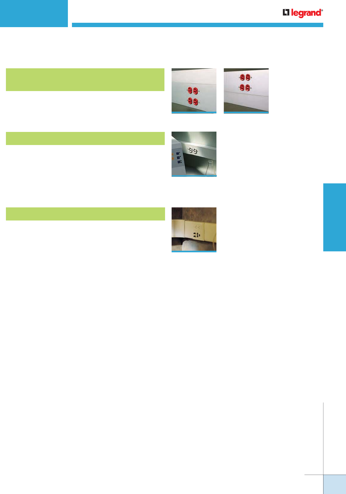
WWW.LEGRAND.US/WIREMOLD
201
WIREMOLD
PREWIRED RACEWAY
Three Channel, Dual Cover Aluminum
Raceway Systems
Prewired Steel Raceway Systems
Prewired Nonmetallic Raceway Systems
235
5400 Series™,
5500 Series™
& CableSmart™
40N2 Series Raceways
229
AL7320 Series
Raceway
231
AL7450 Series
Raceway
PREWIRED RACEWAY
Table of Contents
3000® Series,
4000® Series,
DS4000® & 6000®
Series Raceways
233
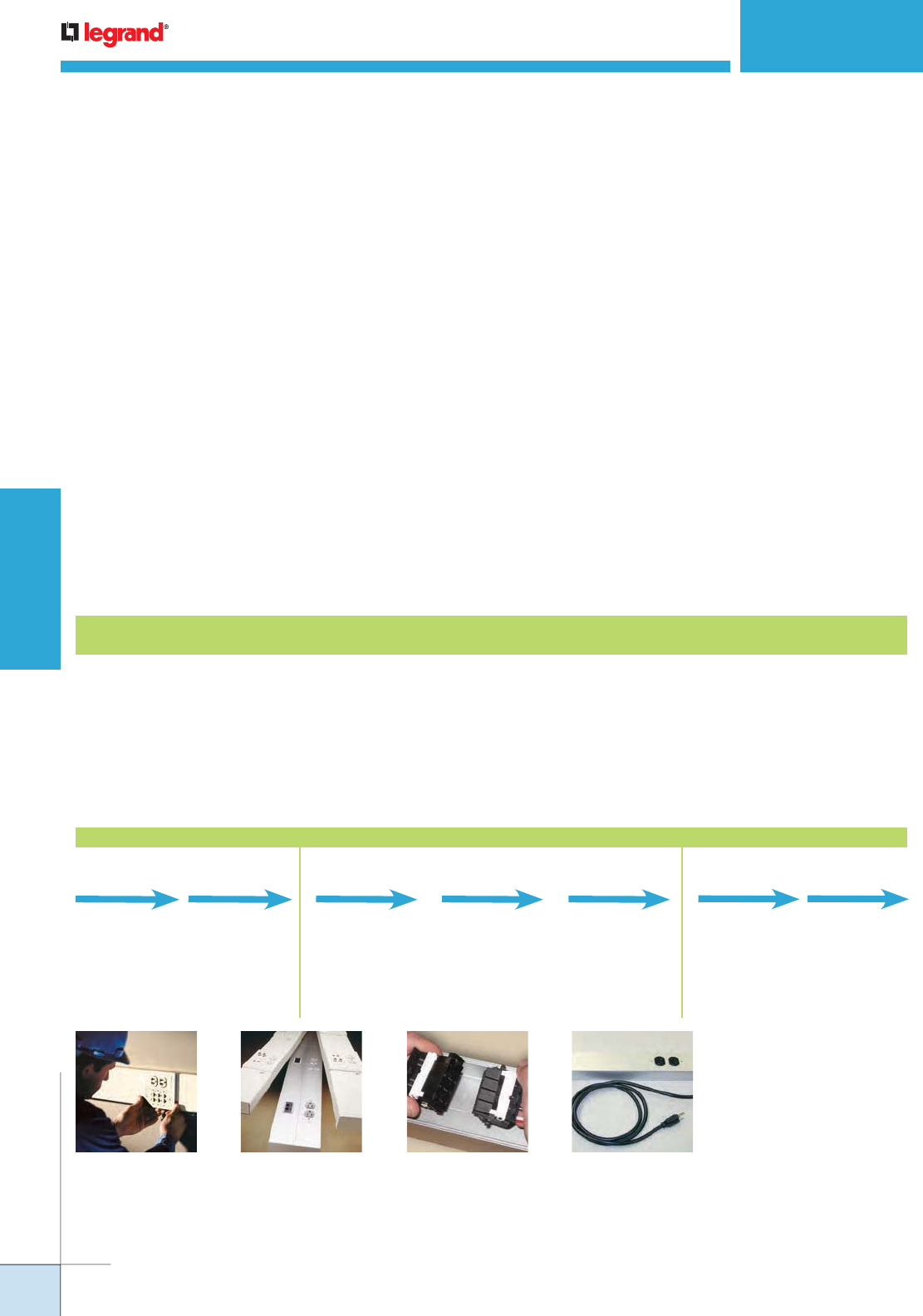
WWW.LEGRAND.US/WIREMOLD
202
WIREMOLD
PREWIRED RACEWAY
PREWIRED RACEWAY
At Wiremold®, our goal for Prewired Raceway is to enhance
the value to the end user and installer by providing
value-added services to their projects, i.e. specific wiring
configurations, labeling and special services.
Wiremold® has been setting the standard in the engineering
and manufacturing of Prewired Raceway solutions over
the last 20 years. Wiremold has the knowledgeable sales,
project management and engineering resources to provide
you with assistance in:
• Defining bills of material and project quotes.
• Interpreting project specifications, electrical drawings
and elevation plans to produce detailed submittal and
installation drawings.
• Coordinating production, packaging and shipping
schedules to meet your job site requirements.
As a leader in the electrical industry Wiremold continues to
look for new and innovative ways to simplify the installation
of our Prewired Raceway systems. Over the last 5 years
Wiremold has:
• Redesigned our submittal and installation documentation
to more clearly depict design intent and ease installation.
• Introduced Wiremold “Prewired Connectors”. The
only UL and cUL listed modular connector for Prewired
Raceway systems available on the market. “Prewired
Connectors” have been shown to decrease installation
time and eliminate miswiring in the field that can lead to
costly callbacks.
• Introduced UL and cUL listed Commercial Outlet Centers
(Cord-Ended) that are optimal for mounting to semi-
permanent structures such as shelving and rack displays
found in many Lab applications.
When deadlines are looming and skilled labor is in short
supply Wiremold has the expertise and quality solutions to
help you complete your project on time. Wiremold Prewired
Raceway solutions will:
• Save up to 67% of the installation time needed for field
install of component raceway parts.
• Provide maximum flexibility for adding or relocating
power and communication requirements during
renovations or equipment changes.
• Provide you with an established project team who has the
knowledge and experience from successfully completing
work on thousands of projects for the educational,
pharmaceutical, hospital, retail and military markets.
Detailed Submittal
The detailed submittal shows exactly how each raceway run will be built (lengths, number and type of receptacles,
wiring schematics, circuiting information, etc.). The contractor and/or distributor must review and correct any
information not clearly indicated on the drawings or specs, approve and return before production can be scheduled.
Submittal Free
The Prewired Express Building Plan Checklist is filled out by the contractor or distributor and sent along with plans,
casework, and specs. No submittal is required and the project is scheduled for production upon receipt of all
information.
Ordering Process for Prewired Applications
Prewired Raceway gets
installers off the job in 1/3
less time than conventional
raceway installations.
Wiremold Prewired Raceway
is available in a wide range
of capacity and configuration
options.
PHASE 1 PHASE 2 PHASE 3
• Place contractor
order with
authorized Prewired
Distributor.
• All bid and order
documents to
Wiremold Project
Services.
• Wiremold
Project Manager
assigned and PO
acknowledged.
• Documents
reviewed for
completeness.
Within 24 Hours Within 2 Weeks
Purchase Order Project Launch
• Includes Material
Product Sheets,
material list,
Engineered
raceway details,
product placement
drawings and
release forms.
Submittals
Within 2-4 Weeks
• Return approved
submittal package
with required
revisions and
requested on
site date.
• Drawings revised.
Approval & Release
• Material
packaged &
marked per
area, and
shipped with
“as built”
drawings and
documents.
Shipment
Commercial Outlet Centers
(Cord-Ended) that are
optimal for mounting to
semi-permanent structures
such as shelving and rack
displays found in many Lab
applications.
Prewired Connectors provide
contractors with peace-
of-mind. Connectors are
factory wired and tested so
errors, backtracking and
troubleshooting are virtually
eliminated.
• Electrical Plans
• Data Plans
• Legends &
Schedules
• Specifications
• Take-Off
Completed
• Quote Delivered
Within 48 Hours*
Documents to Rep Quote
* Based on
Complexity

WWW.LEGRAND.US/WIREMOLD
203
WIREMOLD
PREWIRED RACEWAY
5-15R
5-20R
5-30R
L5-15R
L5-20R
L5-30R
6-15R
6-20R
6-30R
L6-15R
L6-20R
L6-30R
Supports following NEMA NEMA configurations:
PREWIRED RACEWAY
Prewired Connectors
Introducing Faster, More Reliable Connections for
Prewired Raceway Systems
New Wiremold Prewired Connectors offer the fastest, most reliable
connectivity solution available for prewired raceway system installations.
Independent testing has shown that when using new Prewired Connectors
in prewired raceway installations, installers can get off the job up
to eighteen times faster than when using conventional installation
methods… while virtually eliminating any callbacks for wiring errors.
Prewired Connectors provide fast and
reliable connectivity and are available
in 3-, 6- and 8-wire configurations.
Prewired Connector Applications:
Current Rating: 30A maximum
Voltage Rating: 250V maximum
Wire Gauge: 10AWG maximum
Wire Type: Stranded Copper
Specification Guidelines:
• Maximum of one (1) device per foot of raceway.
• Harnesses from multiple feeds may not cross in duct
when feeding from different directions.
• Maximum base segment length of ten (10) feet.
• No downstream protection on GFCI or Surge devices.
3-Wire 6-Wire 8-Wire
The Process
1. Raceway is wired and assembled per customer
specifications.
2 Finished raceway is quality tested to insure
performance and accuracy of wiring
3. Raceway is labelled and packed per job and job
site requirements.
4. Detailed project drawings are included with
every project.
5. Raceway is shipped to arrive at job site per
production schedule and project specifications.
For the Contractor:
Getting a complete
package of detailed
drawings helps my
guys know where
every carton and piece
of raceway go.
For the Lab:
Cord-ended Prewired
gives me the flexibility
I need to reconfigure
my lab.
For the Contractor:
Prewired Connectors
increase my productivity.
Installs are ultra fast and
there are no miswiring or
troubleshooting issues.
Prewired Testimonials
NOTE: Consult factory for other configurations.
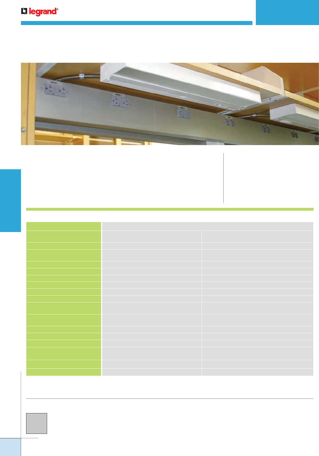
WWW.LEGRAND.US/WIREMOLD
204
WIREMOLD
PREWIRED RACEWAY
PREWIRED RACEWAY
Aluminum
Isoduct® Aluminum Prewired Raceway Systems are manufactured to specific job
lengths, completely assembled and shipped to the jobsite ready to install.
COLOR OPTIONS
CODE REFERENCE
cULus Listed Multioutlet Assemblies:
File E15191 Guide PVGT.
Surface Metal Raceway:
File E4376 Guide RJBT.
Fittings: File E41751 Guide RJPR.
Meet Article 380 of NEC.
Aluminum Prewired Raceway Systems are available with an
anodized aluminum finish.
Custom color options are also available.
Consult the factory for more information.
Prewired Aluminum Raceway Features
FEATURES STANDARD OPTIONS
Communication Devices Ortronics & Activate Connectivity
System Devices
Other manufacturers
Electrical Devices Pass & Seymour Other manufacturers
Cover Length 12" [305mm], 18" [457mm]
24” [610mm] or 36” [914mm]
Custom – consult factory
Body Length Longest = 10' [3.05m], shortest = 1' [305mm]
Installation Surface mounted Flush mounted (recessed)
Finish Architectural Class II Clear Anodized Custom colors available, consult factory*
Fittings Mitered Butt joints or custom
Wire Type THHN Stranded Options per specification
Wiring Splices Insulation displacement connectors Continuous wiring or twist-on wire connector
Grounding Conductors Wire gauge per National Electrical Oversized and/or separate grounding wires
Code (NEC) and shared grounding wires
Device Identification Gray self-adhesive polyester label
with black letters
Engraved covers, self-adhesive engraved
nameplate, engraved nameplate
Neutrals Shared neutral Oversized and/or separate neutral wires
Pigtails 12" [305mm] feeds and receptacle leads Per specification
Conduit Feeds Raceway drilled at job site with hole saw Entrance end cap
Device Mounting Mounted to cover with 2 counter-sunk
#6-32 screws
Device mounting brackets
Record Drawings 3 sets and 2 copies of marked-up blueprints Per job requirements
Submittal Services Detailed Submittal Express Submittal or Submittal Free
* Paint chip required for custom colors.
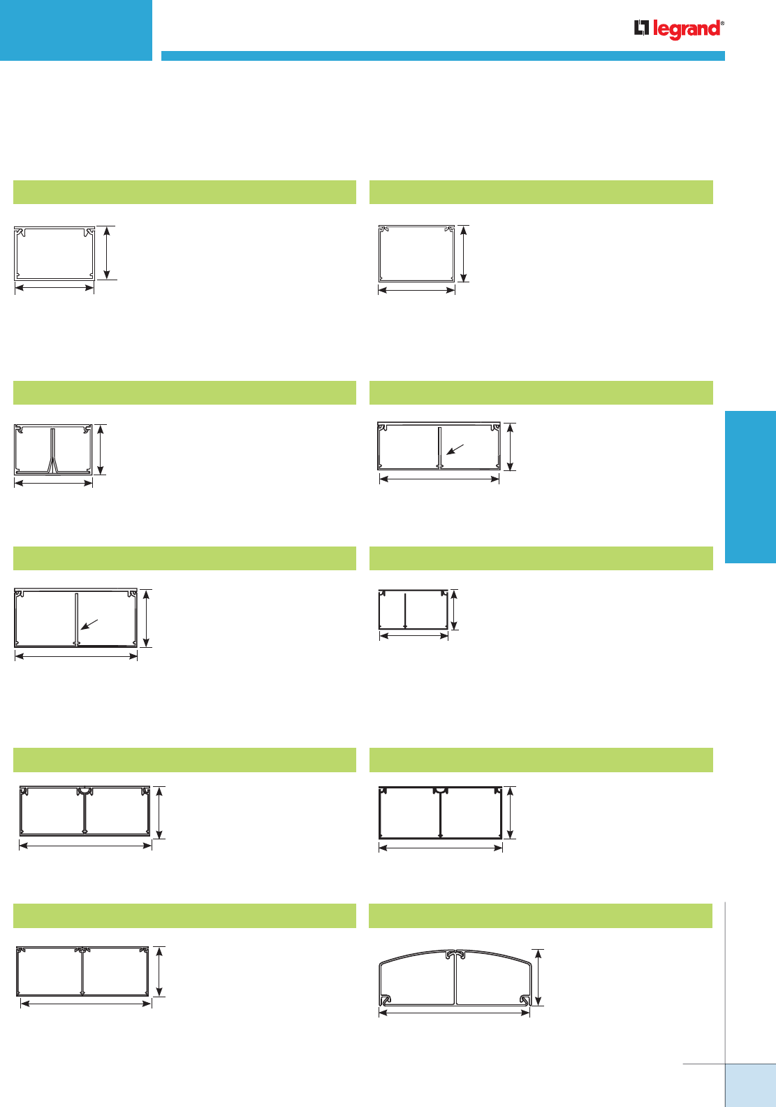
WWW.LEGRAND.US/WIREMOLD
205
WIREMOLD
PREWIRED RACEWAY
PREWIRED RACEWAY
Quick Selection Guide
1 3/4"
[44mm]
5 1/4"
[133mm]
2 1/4"
[57mm]
5 1/4"
[133mm]
6"
[152mm]
2 1/4"
[57mm]
5 3/4"
[146mm]
2 1/8"
[54mm]
1 25/32"
[45mm]
2 5/8"
[67mm]
2 1/4"
[57mm]
3"
[76mm]
Single Channel – Single Cover Raceway Profiles
Capacity: 1.1 in2 [710mm2]
Cover Options: AL3000C
Capacity: 6.10 in2 [3963mm2]
Cover Options: ALA-C
AL3000 Series Raceway ALA3800 Series Raceway
NOTE: These profiles are available as either a single channel raceway or as a divided dual channel raceway.
Single/Dual Channel – Single Cover Raceway Systems
1 7/8"
[36mm]
2 7/8"
[73mm]
1 3/4"
[44mm]
4 3/4"
[121mm]
Barrier
Available with Barrier removed.
Capacity:
1/2 Divided: 2.20 in2 [1419mm2]
Offset Divided: 1.35 in2 [871mm2]
Undivided: 4.40 in2 [2389mm2]
Cover Options: AL3300C
AL3300 Series Raceway
Capacity:
Divided: 3.10 in2 [2000mm2]
Undivided: 7.20 in2
[4645mm2]
Cover Options: AL4000C
AL4000 Series Raceway
2 1/4"
[57mm]
4 3/4"
[121mm]
Barrier
Available with Barrier removed.
3 1/4"
[83mm]
1 7/8"
[48mm]
Capacity:
Per Compartment:
4.72 in2 [3045mm2]
Cover Options: AL4000C
AL4400 Series Raceway
Capacity:
Small: 2.22 in2 [1536mm2]
Large: 3.75 in2 [2950mm2]
Cover Options: AL4750C
AL4750 Series Raceway
Dual Channel – Dual Cover Raceway Systems
Capacity:
Per Compartment:
4.45 in2 [2970mm2]
Cover Options: AL3000C
AL4320 Series Raceway
Capacity:
Per Compartment:
5.90 in2 [3818mm2]
Cover Options: AL3000C
AL4520 Series Raceway
Capacity:
Per Compartment:
5.93 in2 [3026mm2]
Cover Options: ALA-C
ALA4800 Series Raceway
Capacity:
Per Compartment:
4.85 in2 [3129mm2]
Cover
Options: ALDS4000C
ALDS4000 Series Raceway
Available with Barrier removed.
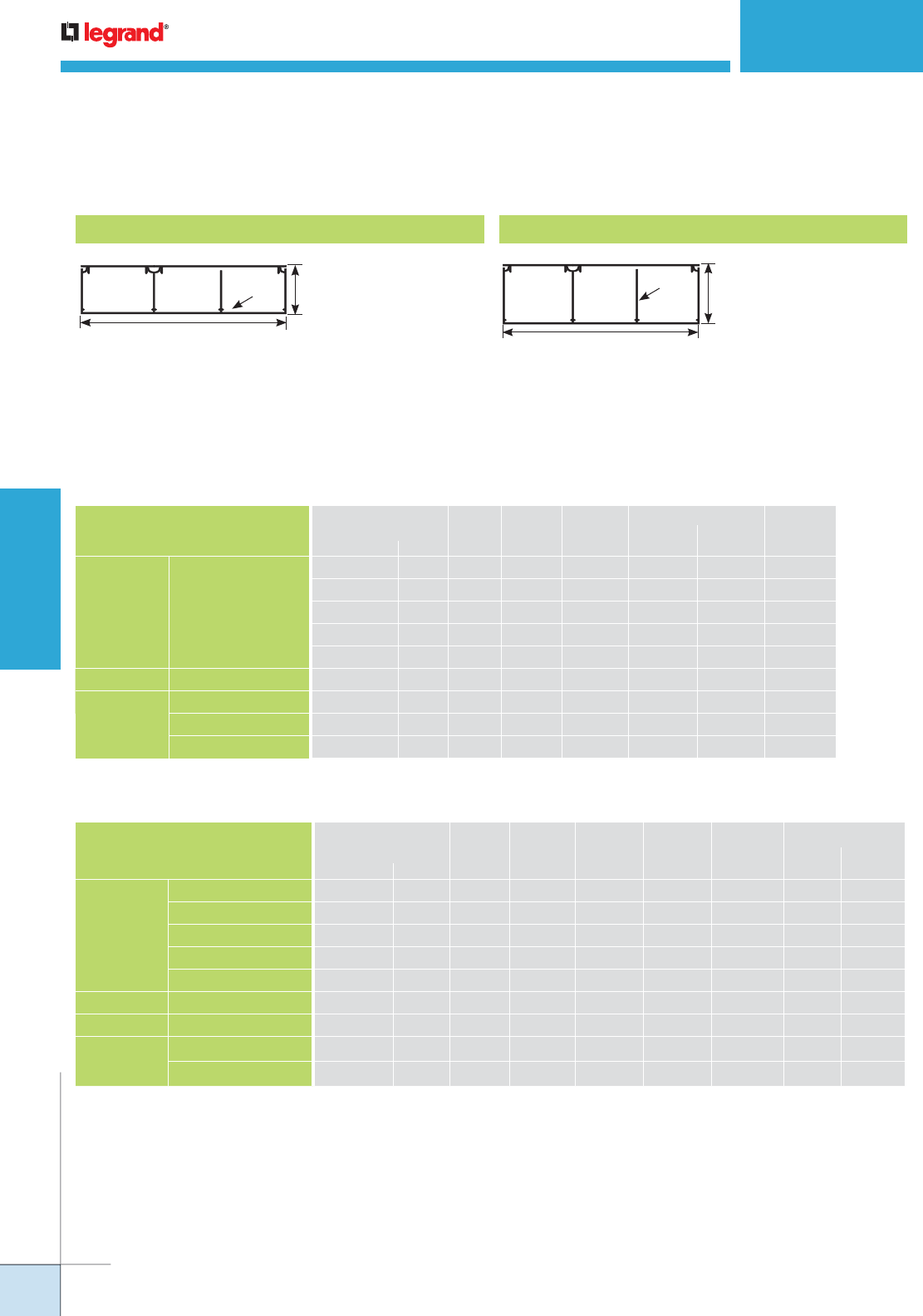
WWW.LEGRAND.US/WIREMOLD
206
WIREMOLD
PREWIRED RACEWAY
PREWIRED RACEWAY
Quick Selection Guide
Capacity:
Per Compartment:
4.31 in2 [2797mm2]
Cover Options:
AL3000C, AL4000C
AL7320 Series Raceway
Capacity:
Single: 5.02 in2
[3239mm2]
Dual: 4.72 in2
[3045mm2]
Cover Options:
AL3000C, AL4000C
AL7450 Series Raceway
Three Channel – Dual Cover Raceway Systems
1 3/4"
[44mm]
7 3/8"
[187mm]
Barrier
Available with Barrier removed.
7 3/8"
[187mm]
2 1/4"
[57mm]
Barrier
Available with Barrier removed.
NOTE: For additional information, refer to the Technical Section.
* Category 6 augmented (6a) cable for 10 gigabit ethernet – max allowed cable diameter per addenda No. 11 ANSI TIA/EIA 568-B.2.
** Each compartment.
Aluminum Prewired Raceway Systems Wire Fill Capacities for Data/Communications
AL3000 AL4000 AL4320** AL7320 ALDS4000
O.D. No Barrier Single
CABLE/WIRE TYPE Inches [mm] 40% 40% 40% 40% 40% 40%
UNSHIELDED
TWISTED
PAIR
4-pair, 24 AWG Cat 3 0.190 [4.8] 53 48 53 81 43 68
4-pair, 24 AWG Cat 5e 0.210 [5.3] 43 39 43 66 35 56
4-pair, 24 AWG Cat 6 0.250 [6.4] 31 28 31 47 25 40
4-pair, 24 AWG Cat 6a* 0.354 [9.0] 15 14 15 23 12 20
25-pair, 24 AWG 0.360 [9.1] 15 13 15 23 12 19
COAXIAL RG6/U
0.270 [6.9] 26 24 26 40 21 34
FIBER OPTIC ZipCord
0.118 x 0.236 [3 x 6] 54 48 54 83 44 70
Round 4 Strand Fiber 0.187 [4.7] 55 49 55 84 44 71
Round 6 Strand Fiber 0.256 [6.5] 29 26 29 45 24 38
Aluminum Prewired Raceway Systems Wire Fill Capacities for Data/Communications (continued)
AL4400 AL4520** ALA4750 ALA3800 ALA4800** AL7450
O.D Top Bottom
CABLE/WIRE TYPE Inches [mm] 40% 40% 40% 40% 40% 40% 40%
UNSHIELDED
TWISTED
PAIR
4-pair, 24 AWG Cat 3 0.190 [4.8] 66 84 69 86 86 71 66
4-pair, 24 AWG Cat 5e 0.210 [5.3] 55 69 57 70 70 58 55
4-pair, 24 AWG Cat 6 0.250 [6.4] 38 48 40 50 50 41 38
4-pair, 24 AWG Cat 6a* 0.354 [9.0] 19 24 20 25 25 20 19
25-pair, 24 AWG 0.360 [9.1] 19 23 19 24 24 20 19
COAXIAL RG6/U
0.270 [6.9] 33 41 34 43 43 35 33
FIBER OPTIC Zi
pCord 0.118 x 0.236 [3 x 6] 68 85 70 88 88 72 68
Round 4 Strand Fiber 0.187 [4.7] 69 87 71 89 89 73 69
Round 6 Strand Fiber 0.256 [6.5] 37 46 38 47 47 39 37

WWW.LEGRAND.US/WIREMOLD
207
WIREMOLD
PREWIRED RACEWAY
Aluminum Prewired Raceway Systems Wire Fill Capacities for Power (40% fill factor)
THHN/THWN
STRANDED
AL7320
AL3000 AL4000* AL4320* Single Dual* ALDS4000*
POWER WIRING
WITHOUT DEVICES
6 AWG 30 27 30 31 56 –
8 AWG 41 37 42 42 78 53
10 AWG 72 64 73 74 135 92
12 AWG 114 102 115 117 214 146
14 AWG 156 140 158 161 294 200
POWER WIRING
WITH GFCI
DEVICES
(2.04 SQ.IN.)
6 AWG 14 10 14 14 40 –
8 AWG 19 15 19 20 55 27
10 AWG 33 25 34 35 96 47
12 AWG 53 41 54 56 153 75
14 AWG 72 56 74 77 210 102
PREWIRED RACEWAY
Quick Selection Guide
Aluminum Prewired Raceway Systems Wire Fill Capacities for Power (40% fill factor) (continued)
THHN/THWN
STRANDED
AL7450
ALA3800* AL4400* AL4520* AL4750* Single Dual* ALA4800
POWER WIRING
WITHOUT DEVICES
8 AWG 41 50 54 35 53 49 41
10 AWG 56 87 110 61 108 101 56
12 AWG 98 139 172 97 170 159 98
14 AWG 156 190 232 133 229 215 156
POWER WIRING
WITH GFCI
DEVICES
(2.04 SQ.IN.)
8 AWG 30 28 32 13 31 27 30
10 AWG 42 49 65 22 64 57 42
12 AWG 73 77 102 35 100 89 73
14 AWG 116 106 137 49 135 121 116
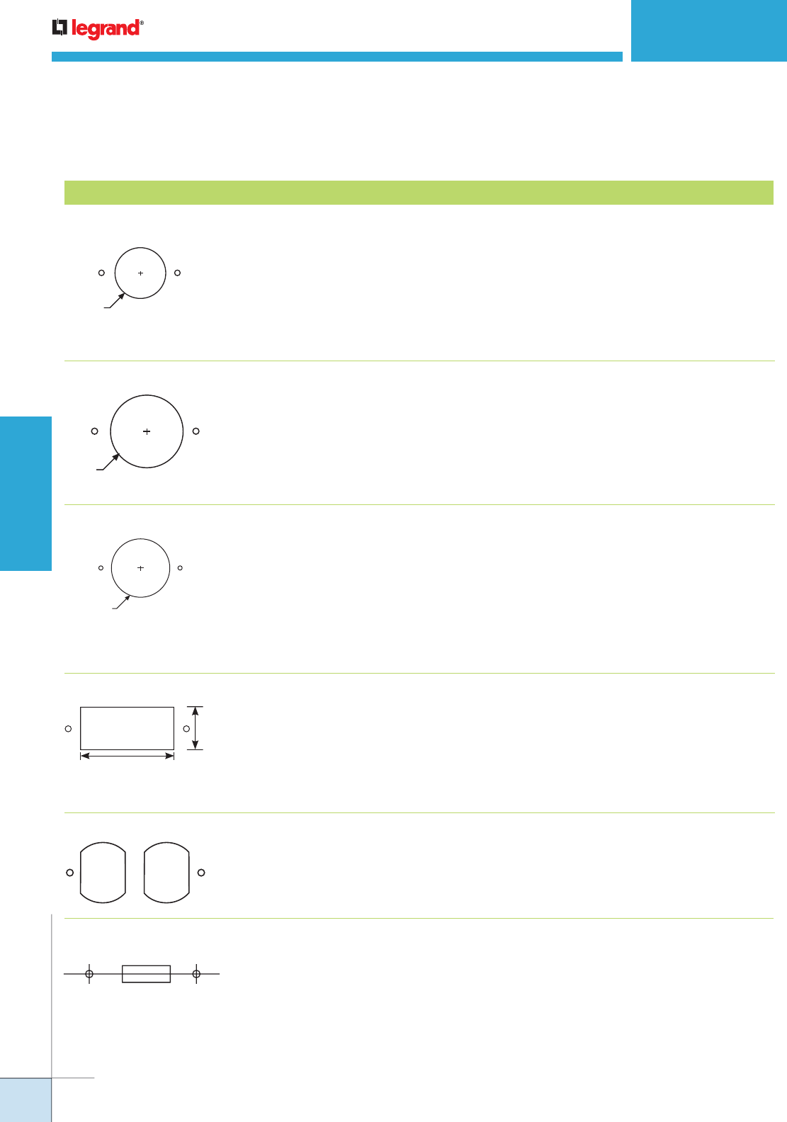
WWW.LEGRAND.US/WIREMOLD
208
WIREMOLD
PREWIRED RACEWAY
PREWIRED RACEWAY
Quick Selection Guide
5-30R
5-50R
6-30R
6-50R
7-30R
7-50R
10-30R
10-50R
1.3"
[33mm]
2.62"
[64mm]
2.13" [52mm]
5-15R
5-20R
6-15R
6-20R
L5-15R
L6-15R
L7-15R
NOTE: Custom openings are also available –
consult factory for more information.
30A and 50A Straight Blade
Rectangular Openings Decorator Style, Rectangular GFCIs,
and Rectangular Surge Protection
Receptacles
Duplex
Single-Gang Switch
Prewired Aluminum Raceway Systems Device Opening
Opening Device Compatibility Raceway Profile Compatibility
1.40"
[35.6mm]
5-15R
5-20R
6-15R
6-20R
10-20R
14-20R
Single Receptacle 15A and 20A Straight Blade and Locking
15-20R
18-20R
L5-15R
L6-15R
L7-15R
1.59"
[40mm]
Single Receptacle NEMA Locking Devices.
Accommodates all NEMA
Locking Devices except
L5-15R, L6-15R and L7-15R.
* Raceway profile will accommodate opening
and device when undivided.
Single Receptacle
Additional 4 & 5 wire straight blade
device may be compatible.
Consult factory.
AL3000
AL3300
ALA3800
AL4000
AL4400
AL4750
AL4320
AL4520
ALA4800
ALDS4000
AL7320
AL7450
AL3000
AL3300*
ALA3800
AL4000
AL4400
AL4750*
AL4320
AL4520
ALA4800
ALDS4000
AL7320
AL7450
* Raceway profile requires installation of an
adapter box to accommodate device.
** Raceway profile requires removal of
barrier and installation of an adapter box to
accommodate device.
AL3000*
AL3300**
ALA3800
AL4000*
AL4400*
AL4750**
AL4320*
AL4520*
ALA4800
ALDS4000*
AL7320*
AL7450*
* Raceway profile will accommodate opening
and device when undivided.
AL3000
AL3300
ALA3800
AL4000
AL4400
AL4750*
AL4320
AL4520
ALA4800
ALDS4000
AL7320
AL7450
AL3000
AL3300
ALA3800
AL4000
AL4400
AL4750
AL4320
AL4520
ALA4800
ALDS4000
AL7320
AL7450
AL3000
AL3300
ALA3800
AL4000
AL4400
AL4750
AL4320
AL4520
ALA4800
ALDS4000
AL7320
AL7450
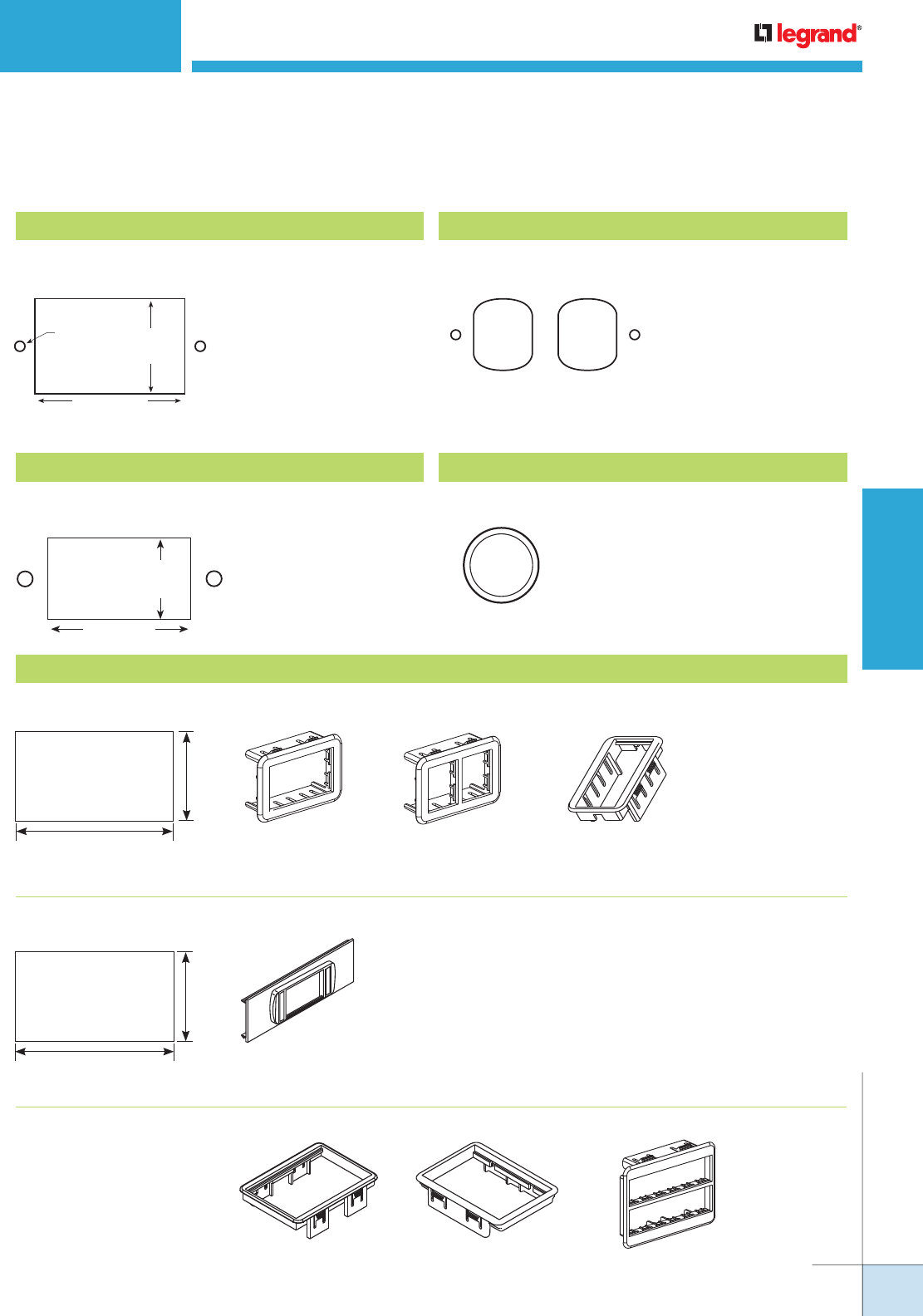
WWW.LEGRAND.US/WIREMOLD
209
WIREMOLD
PREWIRED RACEWAY
Duplex for Data Accommodates Standard
Duplex 106 Style
Frames.
1.3"
[33mm]
2.62"
[64mm]
Rectangular Openings Accommodates Standard
Decorator Style Frames.
PREWIRED RACEWAY
Quick Selection Guide
1/4" [6.4mm] Inner Diameter
1/2" [12.7mm] Inner Diameter
3/4" [19.1mm] Inner Diameter
Standard
1" [25mm] Inner Diameter
1.98"
[50mm]
1.18"
[30mm]
3 3/8"
[86mm]
1 13/16"
[46mm]
CM-2AB – Accepts
One Series II Module
ABS2 – Accepts Two
TracJack Modules
LPB – Accepts 3 Pass & Seymour Activate Inserts
LPB3S2 – Accepts 3 Ortronics Series II Inserts
AB2TJ – Accepts One
Activate 2A Module
MAB6TJMAB3S2MAB
NOTE: Custom openings are also
available – consult factory
for more information.
NOTE: Only available in 3800,
4800, ALDS4000 and
DS4000 series.
AB Adapter Openings Accommodates 2A size Activate and Ortronics® Bezels.
Low or High Profile Adapter
Openings
Modular Adapter Opening
Accommodates Activate and Ortronics® Low Profile Adapters.
Low Profile Adapter (LPB)
Grommet Openings
Accommodates MAB Activate and Ortronics® Adapters.
Prewired Aluminum Raceway Systems Data/Communications Opening
Wallplate Openings Accommodates a wide
range of standard size
commercially available
wall plates.
6-32
Tapped Hole
1.75"
[44mm]
2.75"
[70mm]
Opening Device Compatibility Opening Device Compatibility
Opening Device Compatibility Opening Device Compatibility
Opening Device Compatibility
Accommodates
commercially available
Grommets
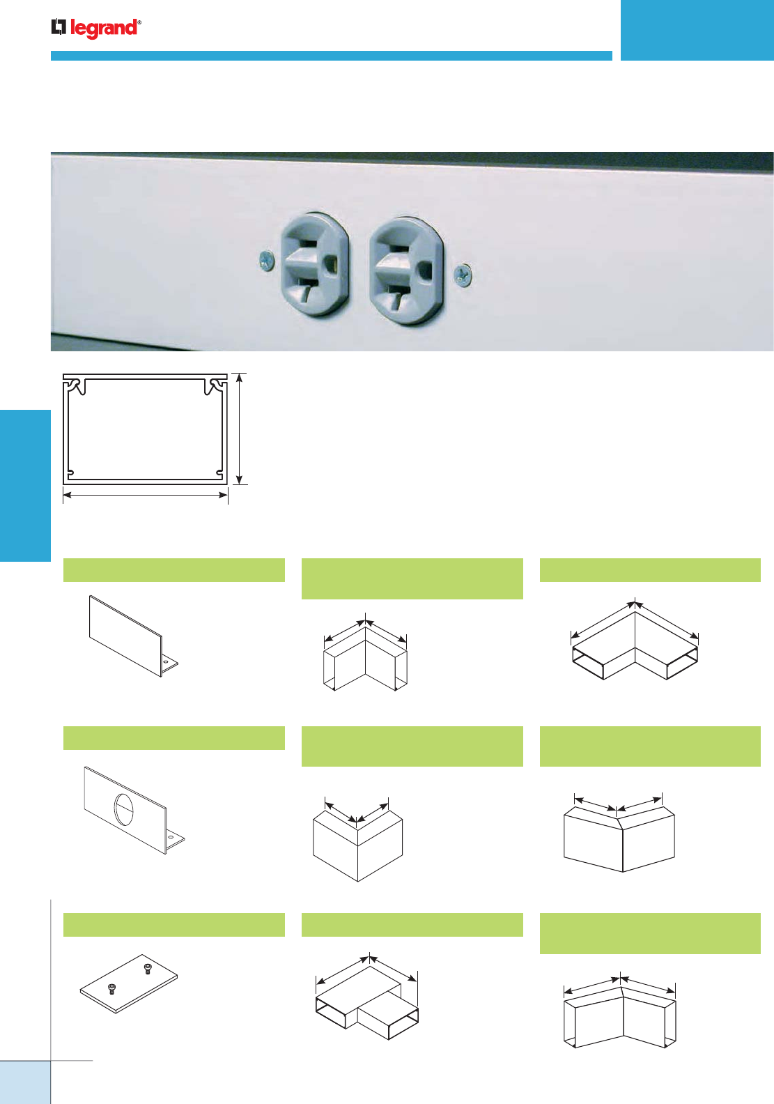
WWW.LEGRAND.US/WIREMOLD
210
WIREMOLD
PREWIRED RACEWAY
AL3000 SERIES RACEWAY
Ordering Information
90°
5 5/8""
[143mm]
5 5/8""
[143mm]
6"
[152mm]
6"
[152mm]
6"
[152mm]
6"
[152mm]
5 5/8"
[143mm]
5 5/8"
[143mm]
6"
[152mm]
6"
[152mm]
6"
[152mm]
6"
[152mm]
AL3000 Series Raceway is a single-channel, single-cover raceway that is a cost
effective, highly aesthetic solution to provide access to communication cabling
or electrical wiring systems. The raceway is designed to meet most installation
requirements for UTP, fiber optic and electrical wiring.
2 5/8"
[67mm]
1 25/32"
[45mm]
4 19/32 sq. in.
[289 sq. cm]
Material: 6063 T6 Aluminum Alloy
Wall Thic ess: 0.078" [1.99mm]
Anodized Finish Thickness: 0.004" [0.004mm]
AL3010B Blank End Cap AL3011 90° Flat ElbowAL3017 Internal Elbow with
Coupling
AL3010B1 Entrance End Cap AL3012B 45° External Elbow
with Coupling
AL3001 Slide Coupling AL3015 Flat Tee AL3012A 45° Internal Elbow
with Coupling
For 3/4" [19.1mm]
conduit connector
AL3018 External Elbow with
Coupling
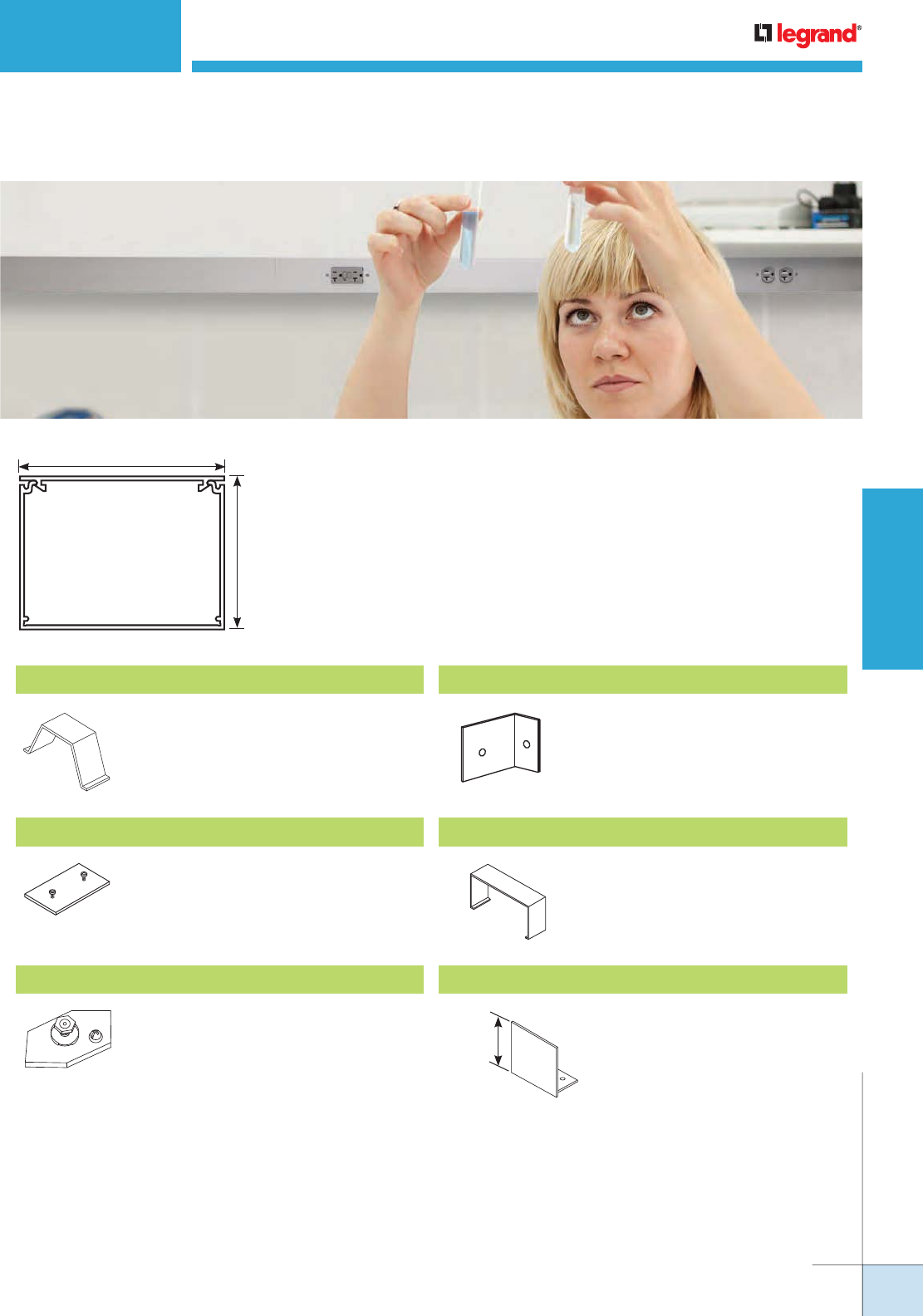
WWW.LEGRAND.US/WIREMOLD
211
WIREMOLD
PREWIRED RACEWAY
ALA3800 SERIES RACEWAY
Ordering Information
ALA3800 Series Aluminum Raceway System meets the demands of commercial
spaces, directing power or communications services where required. The low-
profile surface mounted raceway is easy to install and because of its two-piece
design, wiring is always accessible.
2 1/4"
[57mm]
3"
[76mm]
CAPACITY:
5.96 i n.2 [3842mm2] Material: 6063 T6 Aluminum Alloy
Wall Thickness: 0.078" [1.99mm]
Anodized Finish Thickness: 0.004" [0.004mm]
ALAWC Wire Clip
ALA01 Slide Coupling
Connects adjoining sections of ALA3800
Series Raceway base.
ALA09 Grounding Adapter
Connects equipment grounding conductor
to ALA3800 Series Raceway.
ALA17A Internal Corner Coupling
Forms an internal 90° turn in a run of
ALA3800 Series Raceway.
ALA3806 Cover Clip
2 1/4"
[57mm]
ALA3810B Entrance End Cap
Closes off open ends of ALA3800 Series
Raceway
Holds conductors in place in long runs
of ALA3800 Series Raceway. Snaps into
grooves on base.
Covers seams where sections of ALAC-5
Cover come together.
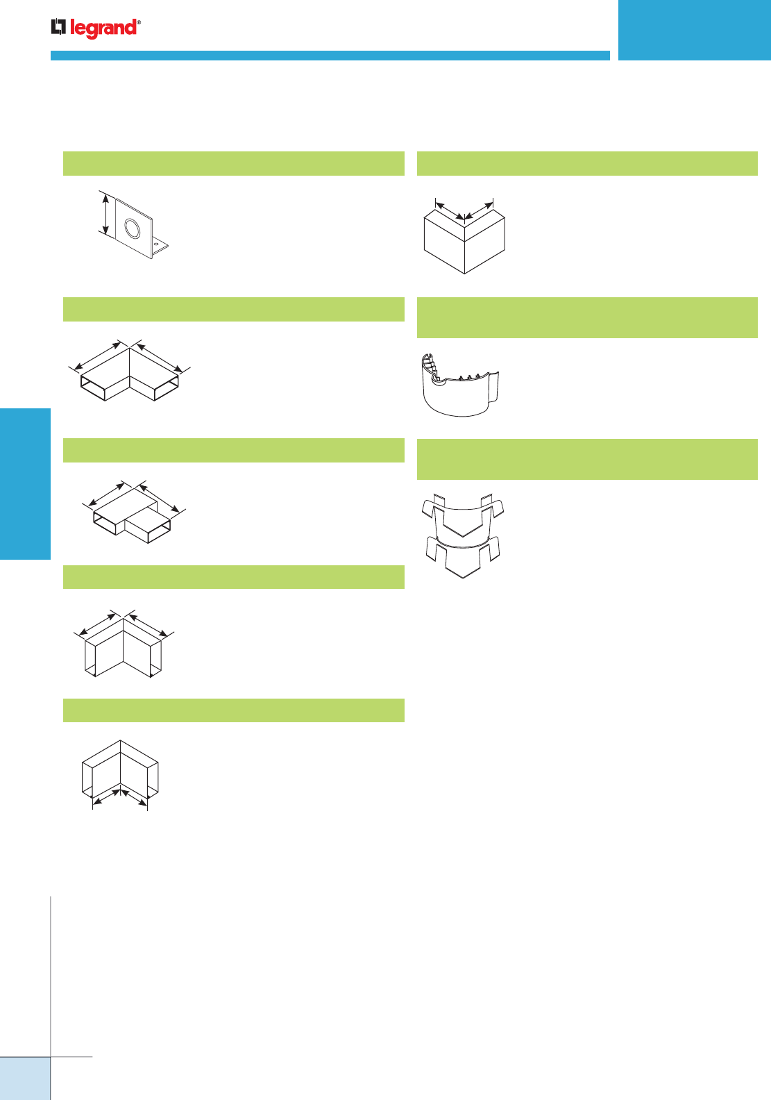
WWW.LEGRAND.US/WIREMOLD
212
WIREMOLD
PREWIRED RACEWAY
ALA3800 SERIES RACEWAY
Ordering Information
Makes 90° turns in runs of ALA3800
Series Raceway. Includes two (2)
ALA01 Couplings.
ALA3811 90° Flat Mitered Elbow with Coupling
6"
[152mm]
6"
[152mm]
6"
[152mm]
6"
[152mm] Makes branch connections of two
runs of ALA3800 Series Raceway.
Includes three (3) ALA01 Couplings.
ALA3815 Flat Tee with Coupling
6"
[152mm]
6"
[152mm] Makes 90° internal turns in runs of
ALA3800 Series Raceway. Includes
two (2) ALA01 Couplings.
ALA3817 Internal Mitered Elbow with Coupling
6"
[152mm]
Connects vertical runs with
horizontal runs of ALA3800 Series
Raceway with its cover facing up.
Includes two ALA01 Couplings.
ALA3817N Inverted Internal Elbow
6"
[152mm] Makes 90° external turns in runs of
ALA3800 Series Raceway. Includes
two (2) ALA01 Couplings.
ALA3818 External Mitered Elbow with Coupling
Installs in ALA3811 Flat Elbow. For
new and retrofit applications whether
the cable installation is lay-in or pull-
through.
ALA11R1 2" [51mm] Bend Radius Control Insert
for Flat Elbow
Inserts into ALA3817, ALA3817N,
and ALA3818 fittings. For new and
retrofit applications whether the cable
installation is lay-in or pull-through.
ALA17/18R1 2" [51mm] Bend Radius Control Insert
for Internal and External Elbows
For feeding raceway, has concentric
1/2" and 3/4" knockouts.
ALA3810B1 Entrance End Cap
2 1/4"
[57mm]
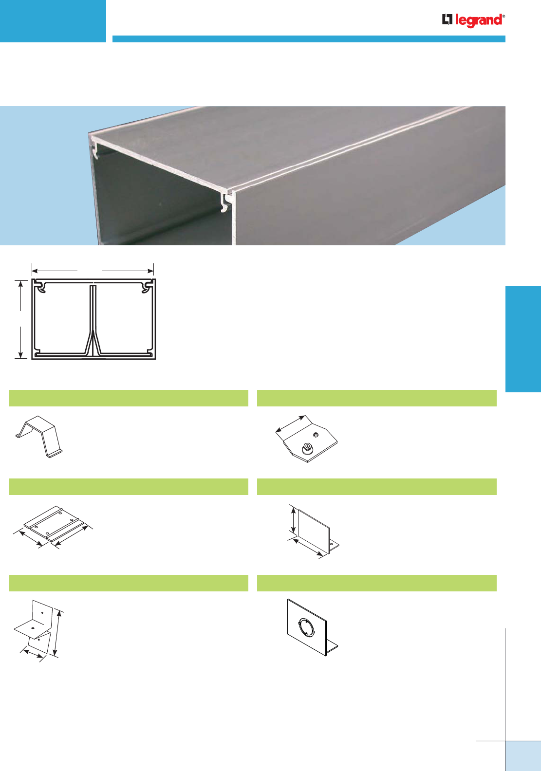
WWW.LEGRAND.US/WIREMOLD
213
WIREMOLD
PREWIRED RACEWAY
AL3300 SERIES RACEWAY
Ordering Information
AL3300 Series Raceway’s low profile, divided aluminum raceway meets the
demands of today's laboratories, healthcare facilities and upscale office
locations, providing a compact and effective method of consolidating power and
communication cabling.
Material: 6063 T6 Aluminum Alloy
Wall Thickness: 0.078" [1.99mm]
Anodized Finish Thickness: 0.004" [0.004mm]
2 7/8"
[73mm]
1 7/8"
[36mm]
AL3301 Coupling
2 3/4"
[70mm]
3"
[76mm]
Set screw coupling used for
attaching in-line raceway sections.
AL3300WC Wire Clip
AL3301D Divider Clip
1 1/2"
[38mm]
3"
[76mm]
Required for holding AL3300D5
divider in place. Use one every 30"
[76.2m].
AL3309 Ground Clamp
2 3/4"
[70mm]
AL3310B Blank End
2 7/8"
[73mm]
1 7/8"
[48mm]
For closing open end of AL3300
Series Raceway.
AL3310B1 End
For end feeding raceway with 1/2"
[12.7mm] or 3/4" [19.1mm] trade
size conduit or armored cable.
For holding wires and cables in
raceway base. Use with undivided
raceway, snap into grooves of base.
For connection of equipment
grounding conductor to provide
additional ground to raceway.
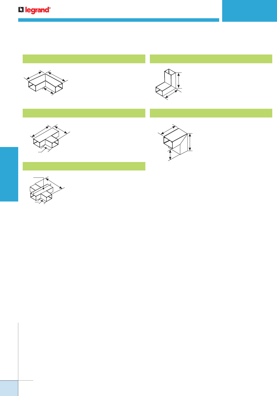
WWW.LEGRAND.US/WIREMOLD
214
WIREMOLD
PREWIRED RACEWAY
AL3300 SERIES RACEWAY
Ordering Information
AL3311 90° Flat Elbow
For right angle turns on same
surface. Two (2) couplings
included.
6"
[152mm]
6"
[152mm]
3 1/8"
[79mm]
AL3315 Tee
For 90° tee connection of two runs
of AL3300 Series Raceway. Three
(3) couplings included.
9"
[229mm]
3 1/8"
[79mm]
6"
[152mm]
AL3316 Cross
For 90° cross-through connection
of two runs of raceway. Couplings
included.
3"
[76mm]
9"
[229mm]
9"
[229mm]
AL3317 Internal Elbow
For making 90° internal corners.
Couplings included.
6"
[152mm]
6"
[152mm]
AL3318 External Elbow
For making external corners.
Couplings included.
4 7/8"
[124mm]
3"
[76mm]
4 7/8"
[124mm]
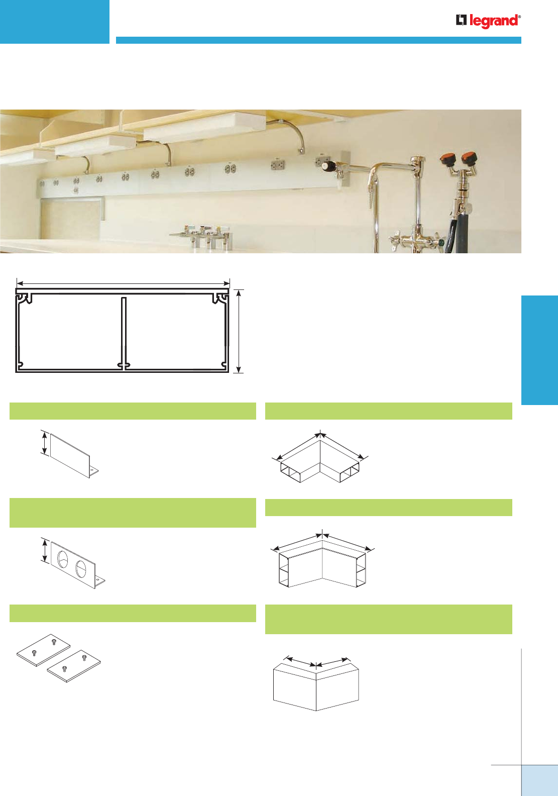
WWW.LEGRAND.US/WIREMOLD
215
WIREMOLD
PREWIRED RACEWAY
AL4000 SERIES
™
RACEWAY
Ordering Information
AL4000 Series Raceway is a two-channel, single-cover,
highly aesthetic, raceway solution designed to provide
access to communication cabling and electrical wiring
systems.
Material: 6063 T6 Aluminum Alloy
Wall Thickness: 0.078" [1.99mm]
Anodized Finish Thickness: 0.004" [0.004mm]
4 3/4"
[121mm]
1 3/4"
[44mm]
3.61 sq. in
[2330mm2]
3.61 sq. in
[2330mm2]
AL4010B Blank End Cap
1 3/4"
[44mm]
Closes off open end of raceway.
AL4010B2
Entrance End Cap with two 1 1/16" Provisions
1 3/4"
[44mm] End Cap with two connections for
3/4" conduit.
AL4001 Slide Coupling
Connects adjoining sections of
AL4000 Series Raceway base.
Includes two (2) couplings
AL4011 90° Flat Mitered Elbow with Coupling
7 3/4"
[197mm]
7 3/4"
[197mm] Makes 90° turns in runs of
AL4000 Series Raceway.
Includes two (2) sets of two (2)
AL4001 Couplings.
AL4012A 45° Internal Mitered Elbow with Coupling
6"
[152mm]
6"
[152mm] Makes 45° internal turns in
runs of AL4000 Series Raceway.
Includes two (2) sets of two (2)
AL4001 Couplings.
AL4012B
45° External Mitered Elbow with Coupling
6"
[152mm]
6"
[152mm] Makes 45° external turns in
runs of AL4000 Series Raceway.
Includes two (2) sets of two (2)
AL4001 Couplings.
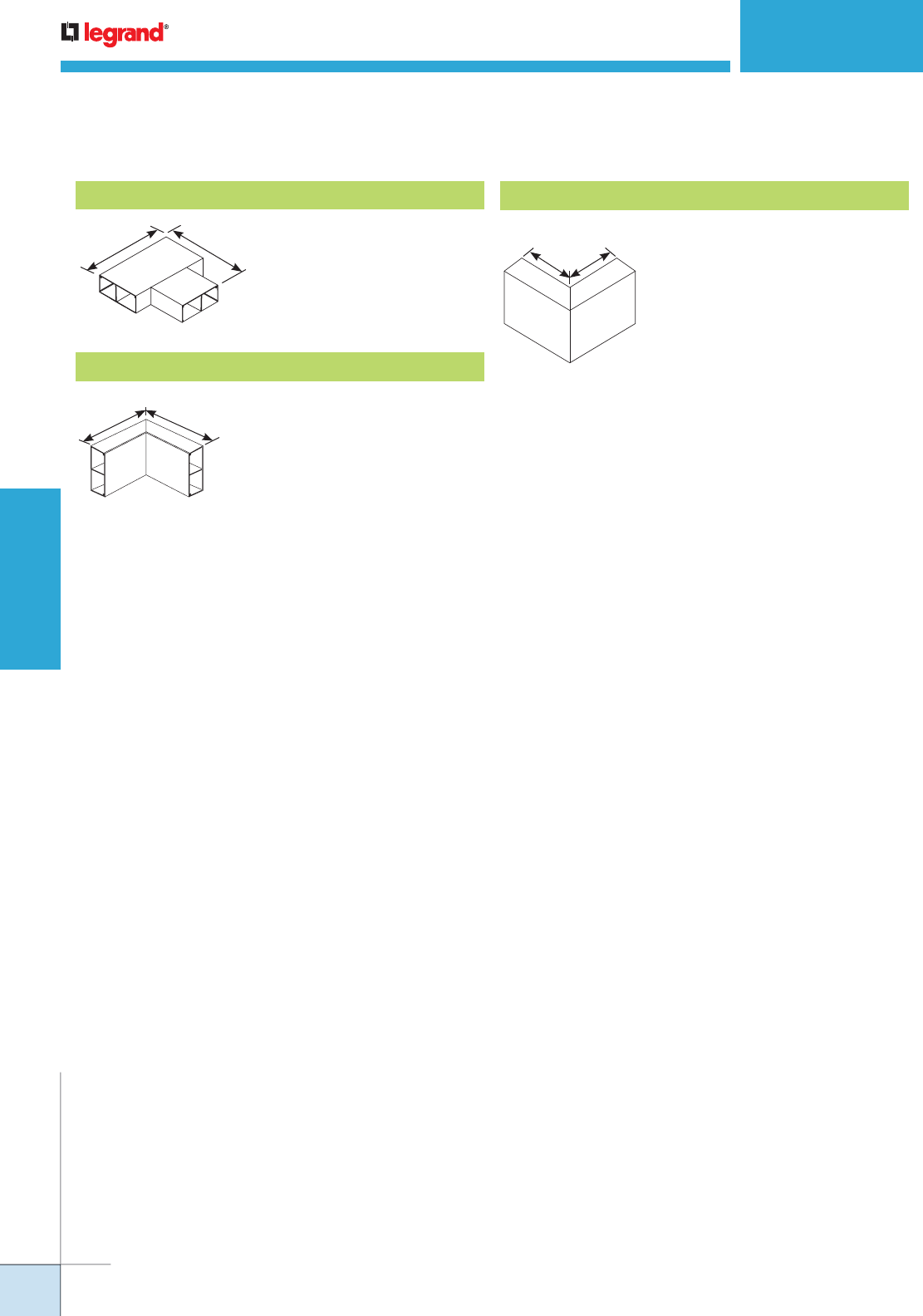
WWW.LEGRAND.US/WIREMOLD
216
WIREMOLD
PREWIRED RACEWAY
AL4000 SERIES RACEWAY
Ordering Information
AL4015 Flat Tee with Coupling
Makes branch connections of two
runs of AL4000 Series Raceway.
Includes three (3) sets of two (2)
AL4001 Couplings.
7 3/4"
[197mm]
7 3/4"
[197mm]
AL4017 Internal Mitered Elbow with Coupling
Makes 90° internal turns in runs of
AL4000 Series Raceway. Includes
two (2) sets of two (2) AL4001
Couplings.
6"
[152mm]
6"
[152mm]
AL4018 External Mitered Elbow with Coupling
Makes 90° external turns in
runs of AL4000 Series Raceway.
Includes two (2) sets of two (2)
AL4001 Couplings.
6"
[152mm]
6"
[152mm]
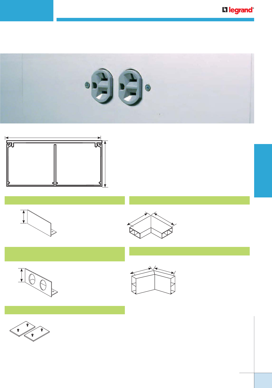
WWW.LEGRAND.US/WIREMOLD
217
WIREMOLD
PREWIRED RACEWAY
AL4400 SERIES RACEWAY
Ordering Information
AL4400 Series Raceway is a two-channel, single-cover, cost
effective solution for providing access to communication
cabling and electrical wiring systems.
Material: 6063 T6 Aluminum Alloy
Wall Thickness: 0.078" [1.99mm]
Anodized Finish Thickness: 0.004" [0.004mm]
AL4410B Blank End Cap AL4411 90° Flat Mitered Elbow with Coupling
2 1/4"
[57mm]
AL4410B2
Entrance End Cap with Two 1 1/16" Provisions
2 1/4"
[57mm]
End Cap with two
connections for 3/4" conduit.
AL4401 Slide Coupling
Connects adjoining sections
of AL4400 Series Raceway
base. Includes two (2)
couplings.
90°
7 3/4"
[197mm]
7 3/4"
[197mm]
AL4012A 45° Internal Mitered Elbow with Coupling
Makes 45° internal turns
in runs of AL4400 Series
Raceway. Includes two (2) sets
of two (2) AL4401 Couplings.
135°
6"
[152mm]
6"
[152mm]
4.75 in.2
[3061mm2]
4.75 in.2
[3061mm2]
2 1/4"
[57mm]
4 3/4"
[121mm]
Closes off open end of
raceway.
Makes 90° turns in runs of
AL4400 Series Raceway.
Includes two (2) sets of two
(2) AL4401 Couplings.
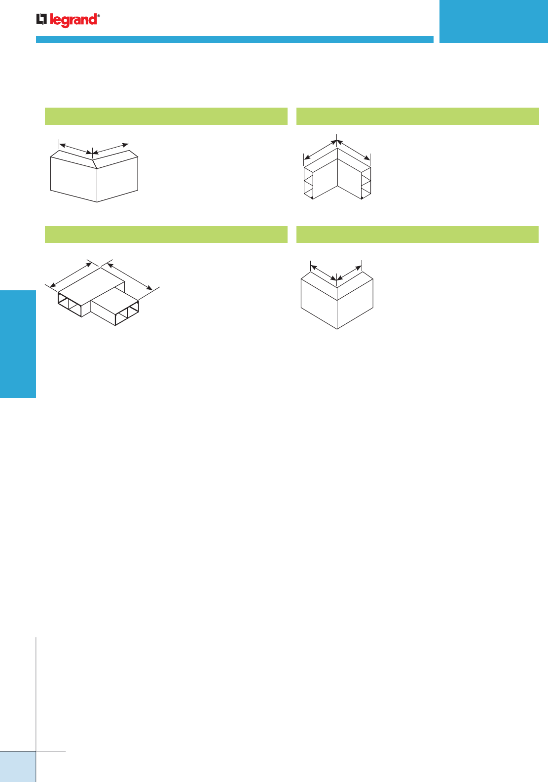
WWW.LEGRAND.US/WIREMOLD
218
WIREMOLD
PREWIRED RACEWAY
AL4400 SERIES RACEWAY
Ordering Information
AL4412B 45° External Mitered Elbow with Coupling
Makes 45° external turns
in runs of AL4400 Series
Raceway. Includes two
(2) sets of two (2) AL4401
Couplings.
AL4415 Flat Tee with Coupling
Makes branch
connections of two runs of
AL4400 Series Raceway.
Includes three (3) sets of
two (2) AL4401 Couplings.
7 3/4"
[197mm] 7 3/4"
[197mm]
AL4417 Internal Mitered Elbow with Coupling
Makes 90° internal turns in
runs of AL4400 Series Raceway.
Includes two (2) sets of two (2)
AL4401 Couplings.
6"
[152mm]
6"
[152mm]
90°
AL4418 External Mitered Elbow with Coupling
Makes 90° external turns in
runs of AL4400 Series Raceway.
Includes two (2) sets of two (2)
AL4401 Couplings.
6"
[152mm]
6"
[152mm]
135°
6"
[152mm]
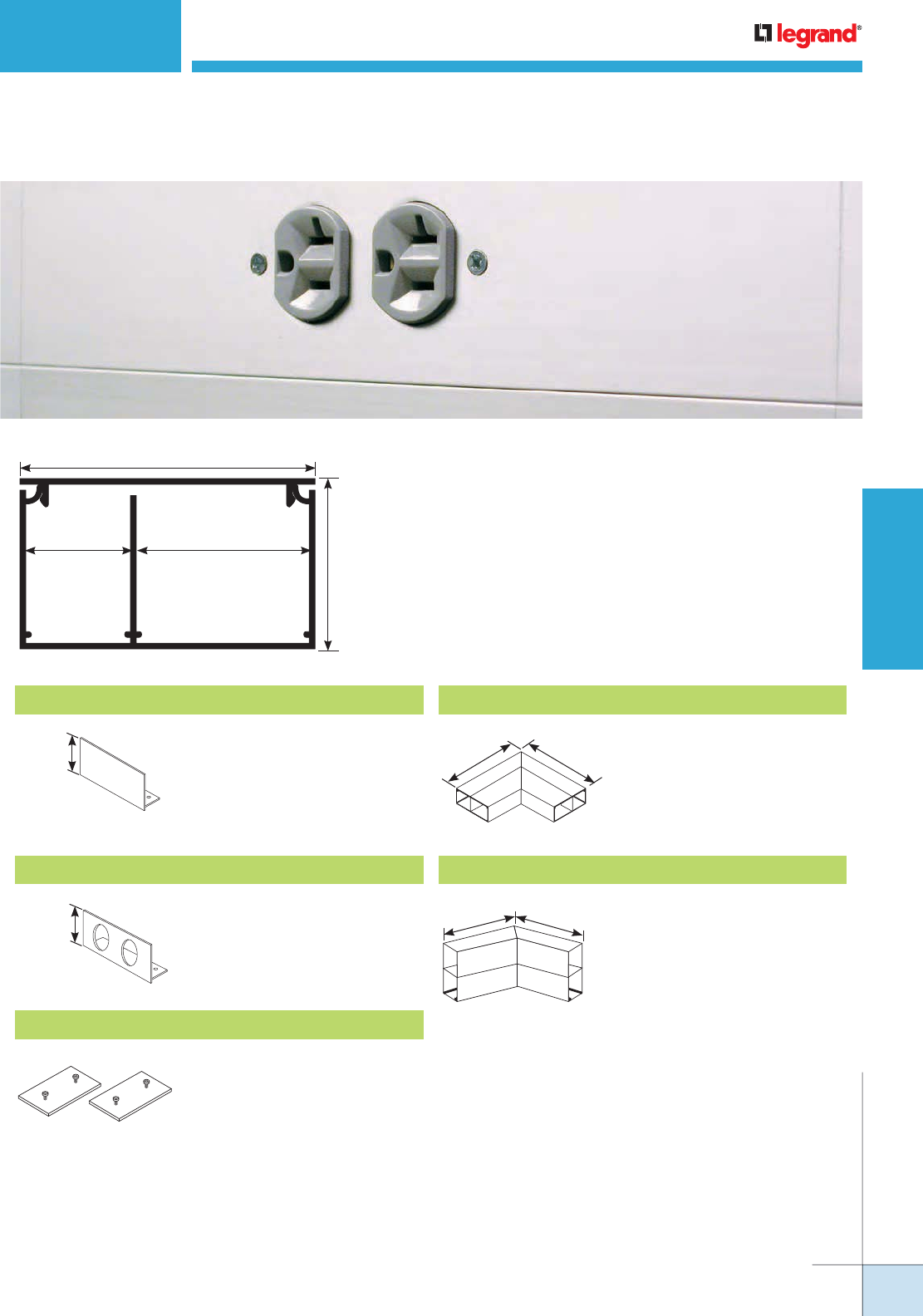
WWW.LEGRAND.US/WIREMOLD
219
WIREMOLD
PREWIRED RACEWAY
AL4750 SERIES RACEWAY
Ordering Information
AL4750 Series Raceway is a cost effective, highly aesthetic
two-channel, single cover raceway solution to provide access
for communication cabling and electrical wiring systems.
Material: 6063 T6 Aluminum Alloy
Wall Thickness: 0.078" [1.99mm]
Anodized Finish Thickness: 0.004" [0.004mm]
AL4710B Blank End Cap
Closes off open end of raceway.
1 3/4"
[44mm]
AL4710B2 Entrance End Cap
End Cap with two connections
for 1/2" conduit.
1 3/4"
[44mm]
AL4701 Slide Coupling
Connects adjoining sections of
AL4750 Series Raceway base.
Includes two (2) Couplings.
AL4711 90° Flat Mitered Elbow with Coupling
Makes 90° turns in runs of
AL4750 Series Raceway.
Includes two (2) sets of two
(2) AL4701 Couplings.
8 1/4"
[210mm]
8 1/4"
[210mm]
90°
AL4712A 45° Internal Mitered Elbow with Coupling
Makes 45° internal turns
in runs of AL4750 Series
Raceway. Includes two
(2) sets of two (2) AL4701
Couplings.
135°
6"
[152mm]
6"
[152mm]
3 1/4"
[83mm]
1 7/8"
[48mm]
2"
[51mm]
1 1/4"
[32mm]
15.36 sq. cm
2.22 sq. in. 24.5 sq. cm
3.75 sq. in.
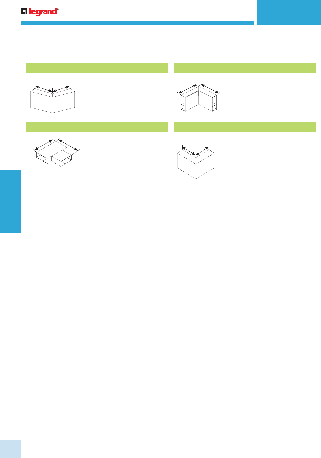
WWW.LEGRAND.US/WIREMOLD
220
WIREMOLD
PREWIRED RACEWAY
AL4750 SERIES RACEWAY
Ordering Information
AL4712B 45° External Mitered Elbow with Coupling
Makes 45° external turns
in runs of AL4750 Series
Raceway. Includes two
(2) sets of two (2) AL4701
Couplings.
AL4715 Flat Tee with Coupling
Makes branch connections
of two runs of AL4750 Series
Raceway. Includes three
(3) sets of two (2) AL4701
Couplings.
AL4717 Internal Mitered Elbow with Coupling
Makes 90° internal turns in
runs of AL4750 Series Raceway.
Includes two (2) sets of two (2)
AL4701 Couplings.
AL4718 External Mitered Elbow with Coupling
Makes 90° external turns in
runs of AL4750 Series Raceway.
Includes two (2) sets of two (2)
AL4701 Couplings.
6"
[152mm]
6"
[152mm]
6 1/4"
[159mm]
6 1/4"
[159mm]
6"
[152mm]
6"
[152mm]
6"
[152mm]
6"
[152mm]
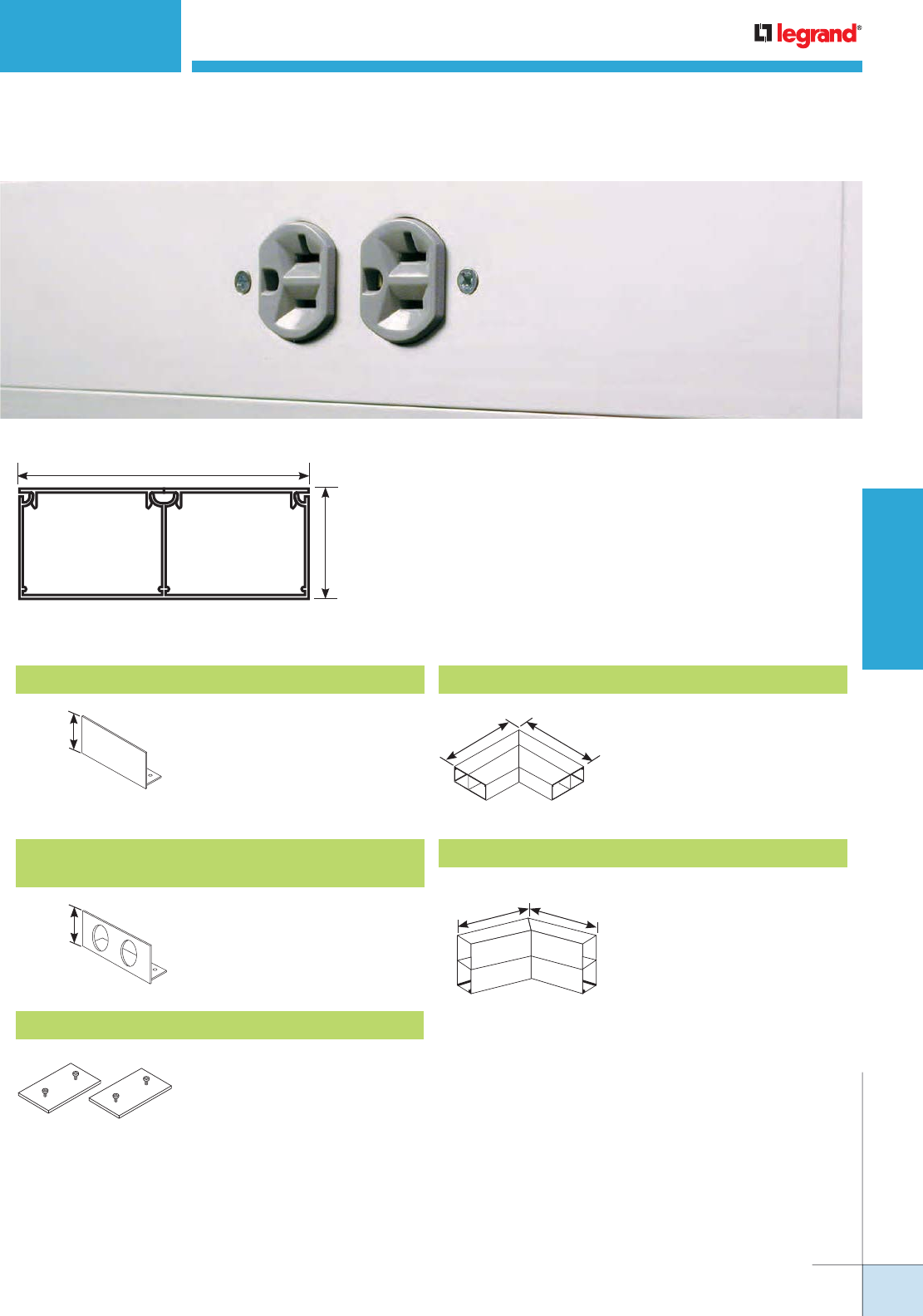
WWW.LEGRAND.US/WIREMOLD
221
WIREMOLD
PREWIRED RACEWAY
AL4320 SERIES RACEWAY
Ordering Information
AL4320 Series Raceway is a two-channel, dual-cover, highly
aesthetic, raceway solution designed to provide access to
communication cabling and electrical wiring systems.
Material: 6063 T6 Aluminum Alloy
Wall Thickness: 0.078" [1.99mm]
Anodized Finish Thickness: 0.004" [0.004mm]
5 1/4"
[133mm]
3.99 in.2
[2579mm2]
1 3/4"
[44mm]
3.99 in.2
[2579mm2]
AL4310B Blank End Cap
Closes off open end of AL4320
Series Raceway.
1 3/4"
[44mm]
AL4310B2
Entrance End Cap with Two 1 1/16" Provisions
End Cap with two connections
for 3/4" conduit.
1 3/4"
[44mm]
AL4301 Slide Coupling
Connects adjoining sections of
AL4320 Series Raceway base.
Includes two (2) couplings.
AL4311 90° Flat Mitered Elbow with Coupling
Makes 90° turns in runs of
AL4320 Series Raceway.
Includes two (2) sets of two
(2) AL4301 Couplings.
90°
8 1/4"
[210mm]
8 1/4"
[210mm]
AL4312A 45° Internal Mitered Elbow with Coupling
Makes 45° internal turns
in runs of AL4320 Series
Raceway. Includes two
(2) sets of two (2) AL4301
Couplings.
135°
6"
[152mm] 6"
[152mm]
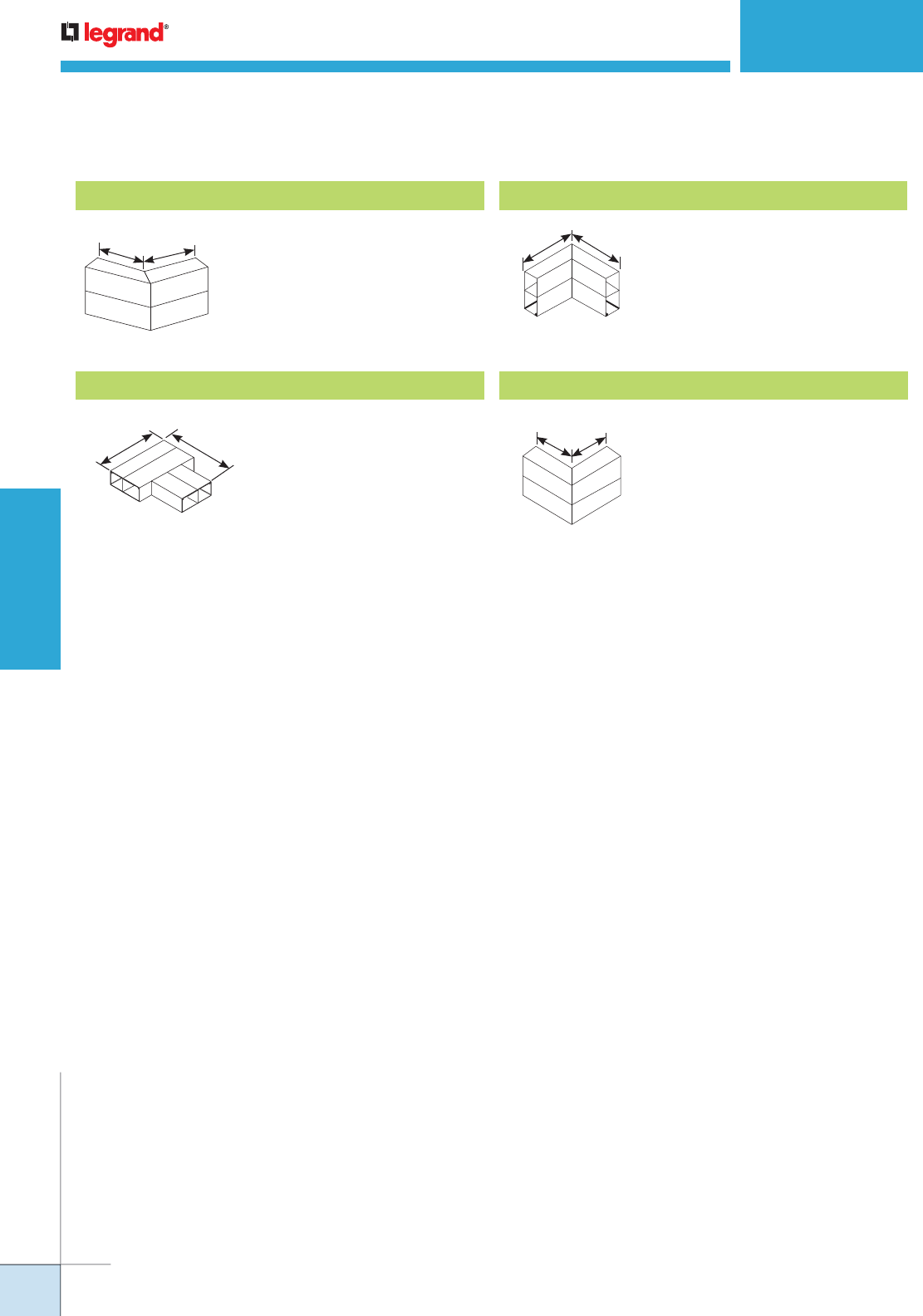
WWW.LEGRAND.US/WIREMOLD
222
WIREMOLD
PREWIRED RACEWAY
AL4320 SERIES RACEWAY
Ordering Information
AL4312B 45° External Mitered Elbow with Coupling
Makes 45° external turns in
runs of AL4320 Series Raceway.
Includes two (2) sets of two (2)
AL4301 Couplings.
AL4315 Flat Tee with Coupling
Makes branch connections
of two runs of AL4320 Series
Raceway. Includes three (3) sets
of two (2) AL4301 Couplings.
8 1/4"
[210mm]
8 1/4"
[210mm]
AL4317 Internal Mitered Elbow with Coupling
Makes 90° internal turns in
runs of AL4320 Series Raceway.
Includes two (2) sets of two (2)
AL4301 Couplings.
6"
[152mm]
90°
6"
[152mm]
AL4318 External Mitered Elbow with Coupling
Makes 90° external turns in
runs of AL4320 Series Raceway.
Includes two (2) sets of two (2)
AL4301 Couplings.
6"
[152mm]
6"
[152mm]
135°
6"
[152mm]
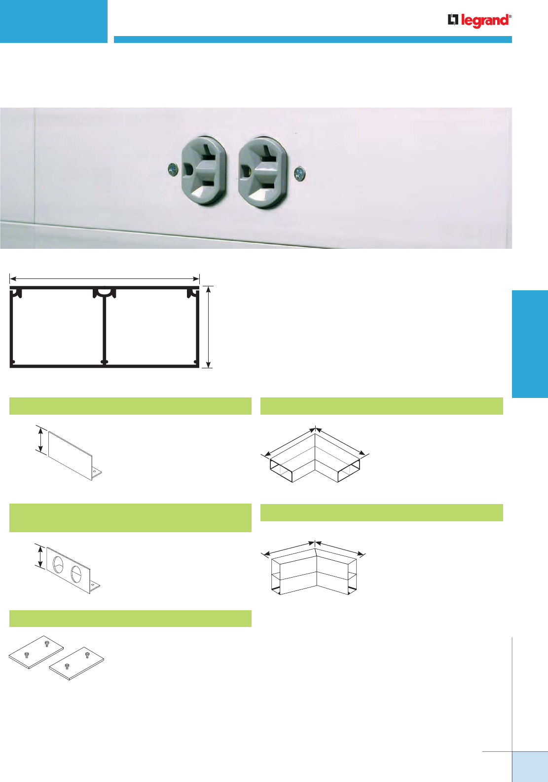
WWW.LEGRAND.US/WIREMOLD
223
WIREMOLD
PREWIRED RACEWAY
AL4520 SERIES RACEWAY
Ordering Information
AL4520 Series Raceway is a two-channel, dual-cover, highly
aesthetic, raceway solution designed to provide access to
communication cabling and electrical wiring systems.
Material: 6063 T6 Aluminum Alloy
Wall Thickness: 0.078" [1.99mm]
Anodized Finish Thickness: 0.004" [0.004mm]
AL4510B Blank End Cap AL4511 90° Flat Mitered Elbow with Coupling
AL4501 Slide Coupling
Makes 90° turns in runs of
AL4520 Series Raceway.
Includes two (2) sets of two
(2) AL4501 Couplings.
Connects adjoining sections of
AL4320 Series Raceway base.
Includes two (2) couplings
5 1/4"
[135mm]
2 1/4"
[58mm]
5.25 in.2
[3888mm2]
5.25 in.2
[3888mm2]
2 1/4"
[58mm]
AL4510B2
Entrance End Cap with Two 1 1/16" Provisions
End Cap with two connections
for 3/4" conduit.
2 1/4"
[58mm]
AL4512A 45° Internal Mitered Elbow with Coupling
Makes 45° internal turns
in runs of AL4520 Series
Raceway. Includes two
(2) sets of two (2) AL4501
Couplings
135°
6"
[152mm]
6"
[152mm]
Closes off open end of AL4520
Series Raceway.
90°
8 1/4"
[210mm]
8 1/4"
[210mm]
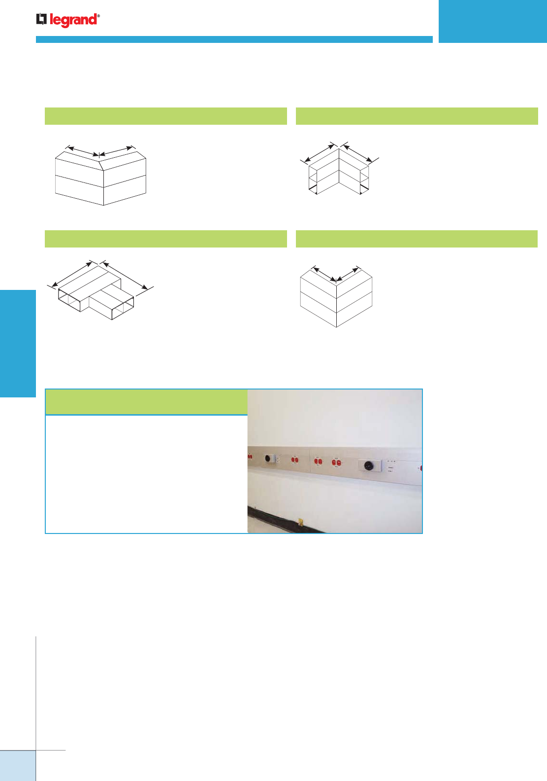
WWW.LEGRAND.US/WIREMOLD
224
WIREMOLD
PREWIRED RACEWAY
AL4512B
45° External Mitered Elbow with Coupling
Makes 45° external turns
in runs of AL4520 Series
Raceway. Includes two
(2) sets of two (2) AL4501
Couplings.
AL4515 Flat Tee with Coupling
Makes branch connections
of two runs of AL4520 Series
Raceway. Includes three
(3) sets of two (2) AL4501
Couplings.
8 1/4"
[211mm]
8 1/4"
[211mm]
AL4517 Internal Mitered Elbow with Coupling
Makes 90° internal turns in
runs of AL4520 Series Raceway.
Includes two (2) sets of two (2)
AL4501 Couplings.
6"
[152mm]
6"
[152mm]
AL4518 External Mitered Elbow with Coupling
Makes 90° external turns in
runs of AL4520 Series Raceway.
Includes two (2) sets of two (2)
AL4501 Couplings.
6"
[152mm]
AL4520 SERIES RACEWAY
Ordering Information
Why Wiremold…
It took planning and coordination to fit out new lab
space with flexible power and data for the University
Health Network in Toronto. What's more, everyone
was under a tight timetable. That's why the team
specified Wiremold Prewired Aluminum Raceway.
Prewired raceway is manufactured to exact job
specifications with all circuits and devices exactly
as shown on the drawings. Numerous projects have
shown that prewired raceway installs significantly
faster and saves cost.
6"
[152mm]
135°
6"
[152mm]
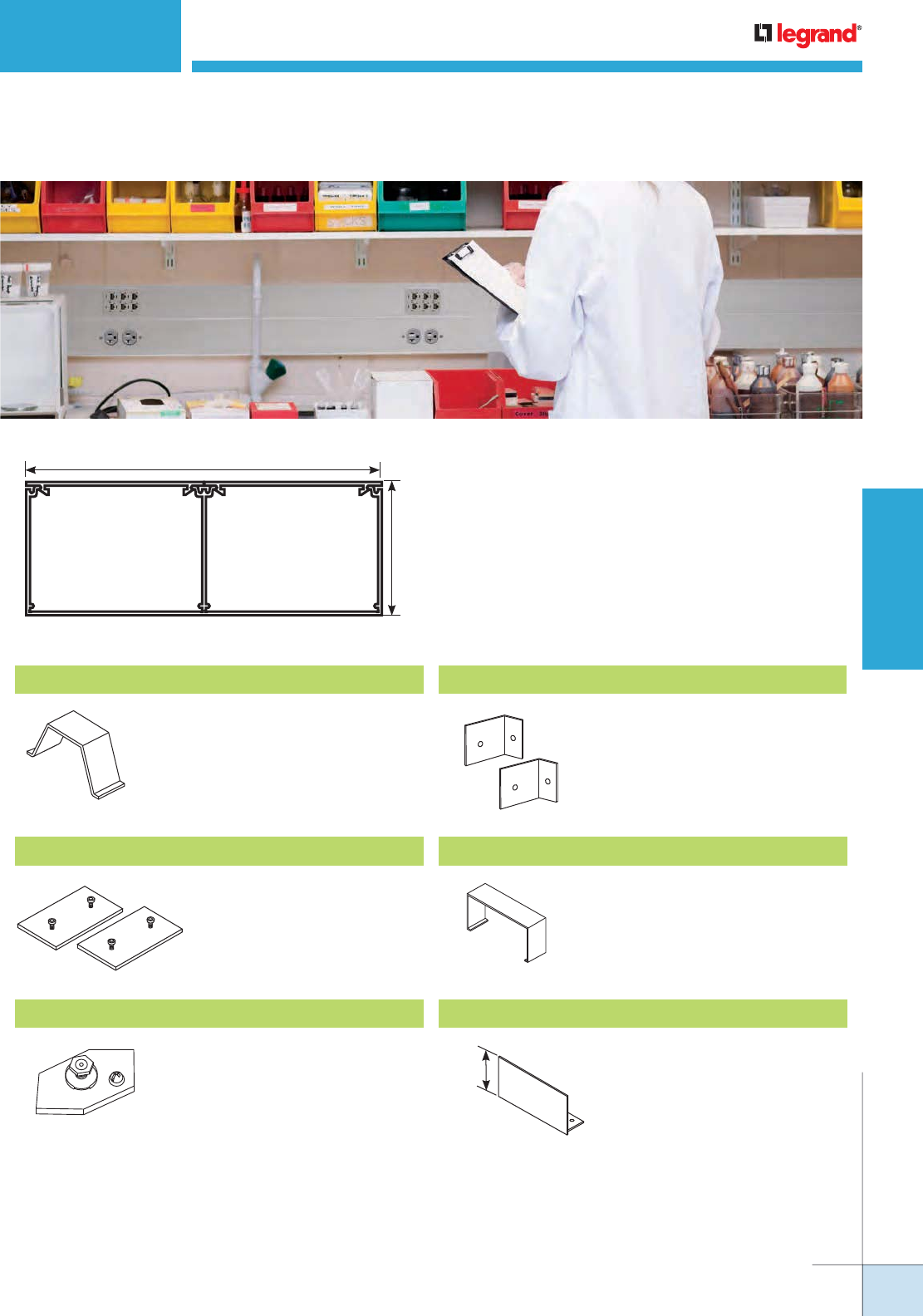
WWW.LEGRAND.US/WIREMOLD
225
WIREMOLD
PREWIRED RACEWAY
ALA4800 SERIES RACEWAY
Ordering Information
ALA4800 Series Aluminum Raceway’s two-channel,
dual-cover aluminum raceway meets the demands of
laboratories, healthcare facilities and upscale office
locations by providing an effective method of consolidating
power and communications cabling.
Material: 6063 T6 Aluminum Alloy
Wall Thickness: 0.078" [1.99mm]
Anodized Finish Thickness: 0.004" [0.004mm]
ALA01 Slide Coupling
ALA09 Grounding Adapter
ALA4806 Cover Clip
ALA4810B Blank End Cap
Connects adjoining sections of
ALA4800 Series Raceway base.
Includes two (2) couplings.
Connects to equipment
grounding conductor.
Covers seam where two
sections of ALAC-5 Cover come
together.
Closes off open end of ALA4800
Series Raceway.
6.04in2
[3895mm2]
6.04in2
[3895mm2]
6"
[152mm]
2 1/4"
[57mm]
ALAWC Wire Clip
Holds conductors in place
along raceway. Snaps into
grooves on base.
2 1/4"
[57mm]
ALA17A Internal Corner Coupling
Makes internal 90° turn in a
raceway run.
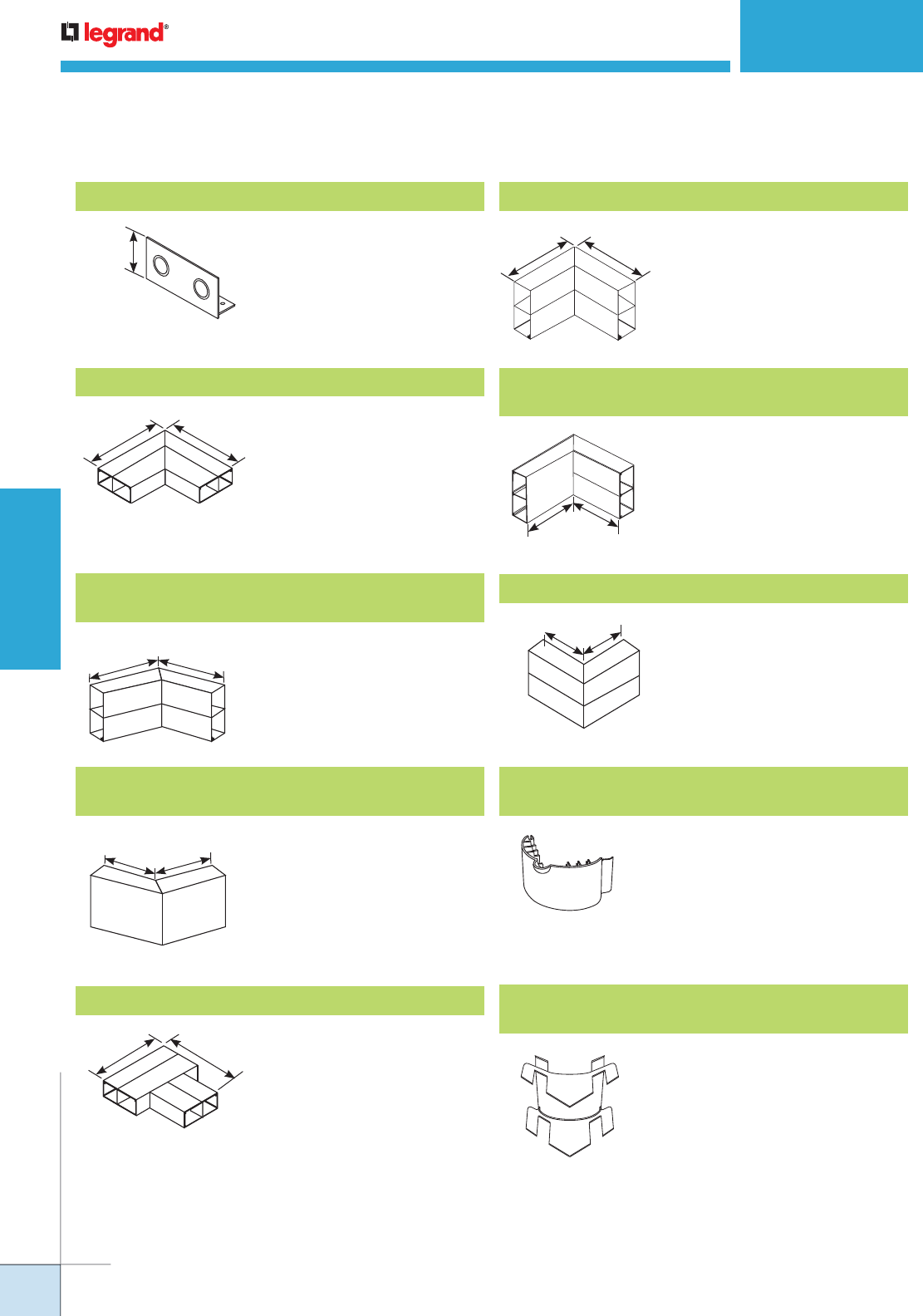
WWW.LEGRAND.US/WIREMOLD
226
WIREMOLD
PREWIRED RACEWAY
ALA4800 SERIES RACEWAY
Ordering Information
ALA4810B2 Entrance End Cap
For feeding raceway. Has
two concentric 1/2" and 3/4"
knockouts.
2 1/4"
[57mm]
ALA4811 90° Flat Mitered Elbow with Coupling
Makes 90° turns in runs of
ALA4800 Series Raceway.
Includes two (2) sets of two (2)
ALA01 Couplings.
9"
[229mm]
9"
[229mm]
ALA4812A
45° Internal Mitered Elbow with Coupling
Makes 45° internal turns in
runs of ALA4800 Series
Raceway. Includes two (2) sets
of two (2) ALA01 Couplings.
6"
[152mm]
6"
[152mm]
135°
ALA4812B
45° External Mitered Elbow with Coupling
Makes 45° external turns
in runs of ALA4800 Series
Raceway. Includes two (2) sets
of two (2) ALA01 Couplings.
ALA4815 Flat Tee with Coupling
Makes branch connections of
two runs of ALA4800 Series
Raceway. Includes three
(3) sets of two (2) ALA01
Couplings.
9"
[229mm]
9"
[229mm]
ALA4817 Internal Mitered Elbow with Coupling
Makes 90° internal turns in runs
of ALA4800 Series Raceway.
Includes two (2) sets of two (2)
ALA01 Couplings.
6"
[152mm]
6"
[152mm]
ALA4817N
Inverted Internal Mitered Elbow with Coupling
For connecting a vertical run of
ALA4800 Series Raceway with a
horizontal run of ALA4800 Series
Raceway with its cover facing up.
Includes four (4) ALA01 Couplings.
ALA4818 External Mitered Elbow with Coupling
Makes 90° external turns in runs
of ALA4800 Series Raceway.
Includes four (4) ALA01 Couplings.
ALA11R 12" [51mm] Bend Radius Control Insert
for Flat Elbow
Installs in ALA3811 Flat Elbow.
For new and retrofit applications
whether the cable installation is
lay-in or pull-through.
ALA17/18R 12" [51mm] Bend Radius Control
Insert for Internal & External Elbows
Inserts into ALA3817, ALA3817N,
and ALA3818 fittings. For new and
retrofit applications whether the
cable installation is lay-in or pull-
through.
6"
[152mm]
135°
6"
[152mm]
6"
[152mm]
90°
6"
[152mm]
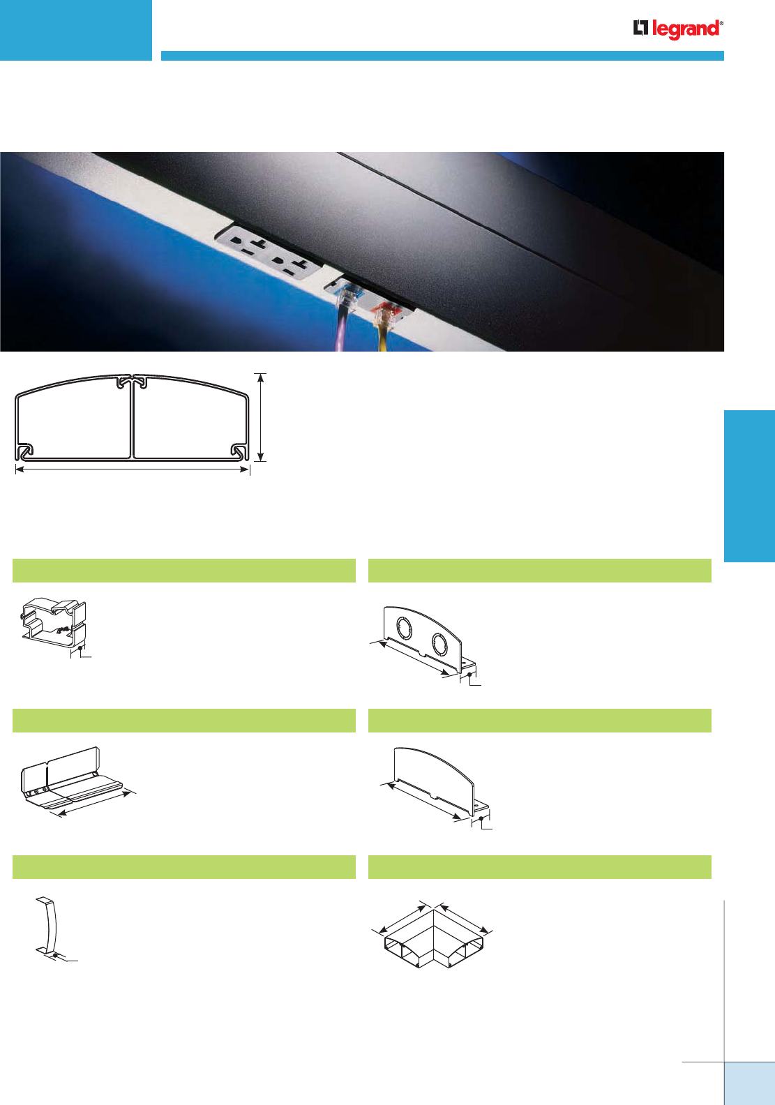
WWW.LEGRAND.US/WIREMOLD
227
WIREMOLD
PREWIRED RACEWAY
ALDS4000 SERIES RACEWAY
Ordering Information
ALDS4000 Series Raceway offers a variety of innovative features and
fittings that save installation time, cost less to specify, and provide
1/3 more wiring capacity than conventional box-style raceway
profiles.
Material: 6063 T6 Aluminum Alloy
Wall Thickness: 0.078" [1.99mm]
Anodized Finish Thickness: 0.004" [0.004mm]
DS4000WC Wire Clip ALDS4010A Entrance End Fitting
ALDS4010B Blank End Fitting
ALDS4011 Flat Elbow
DS4001 Adjust-to-fit™ Coupling
ALDS4006 Seam Clip
For holding conductors in place. Full-capacity end fitting.
Includes two 1/2" and 3/4"
trade size KOs.
For closing open end of
ALDS4000B Raceway Base.
90° flat corner for new lay-in or
pull-through installations.
For joining lengths of ALDS4000B
together. Sold in pairs.
For covering seams where two
sections of ALDS4000C come
together.
5 3/4"
[146mm]
2 1/8"
[54mm]
4.85"
[3129mm2]
4.85"
[3129mm2]
1 5/8"
[41mm]
6"
[152mm]
1"
[25mm]
1 1/8"
[29mm]
5 3/4"
[146mm]
1 1/8"
[29mm]
5 3/4"
[146mm]
8 1/4"
[210mm] 8 1/4"
[210mm]
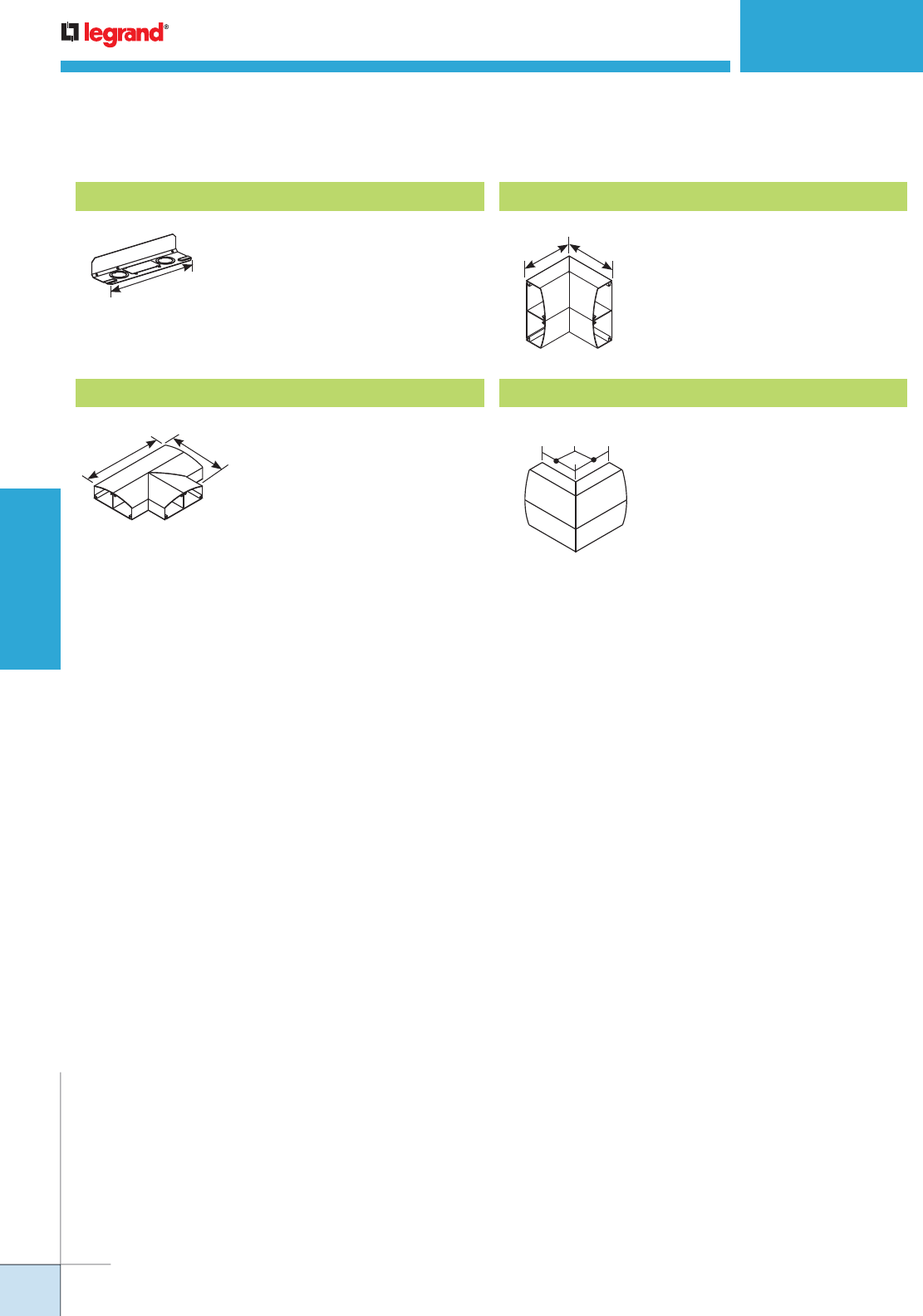
WWW.LEGRAND.US/WIREMOLD
228
WIREMOLD
PREWIRED RACEWAY
ALDS4000 SERIES RACEWAY
Ordering Information
DS4014A Backfeed Fitting
Extra long coupling allows
attachment to wall box or
back fed 1" or 1 1/4" trade size
conduit.
10"
[254mm]
ALDS4015 Divided Tee Fitting
For new lay-in or pull-through
installations.
10 3/4"
[273mm]
8 3/4"
[222mm]
ALDS4018 90° External Elbow
External corner for new lay-in or
pull-through installations.
6"
[152mm]
ALDS4017 90° Internal Elbow
Internal corner for new lay-in or
pull-through installations.
6"
[152mm]
6"
[152mm]
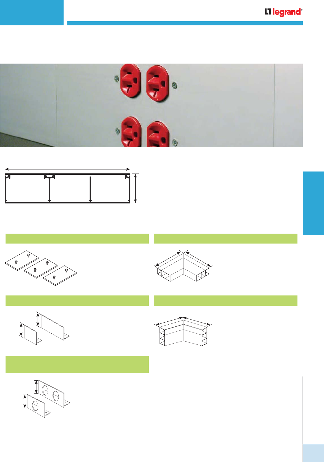
WWW.LEGRAND.US/WIREMOLD
229
WIREMOLD
PREWIRED RACEWAY
AL7320 SERIES RACEWAY
Ordering Information
AL7320 Series Raceway’s three-channel, dual-cover
profile is a cost-effective, highly aesthetic solution to
provide access to your communication cabling and
electrical wiring systems.
Material: 6063 T6 Aluminum Alloy
Wall Thickness: 0.078" [1.99mm]
Anodized Finish Thickness: 0.004" [0.004mm]
AL7301 Slide Coupling
AL7312A 45° Internal Mitered Elbow with CouplingAL7310B Blank End Cap
AL7310B3
Entrance End Cap with Two 1 1/16" Provisions
45° internal turns in runs
of AL7320 Series Raceway.
Includes six (6) AL7301
Couplings.
Closes off open end of
AL7320 Series Raceway.
End Cap with three
connections for 3/4"
conduit.
7 3/8"
[187mm]
1 3/4"
[44mm]
3.67 in.2
[2370mm2]
3.61 in.2
[2330mm2]
3.99 in.2
[2579mm2]
1 3/4"
[44mm]
1 3/4"
[44mm]
1 3/4"
[44mm]
1 3/4"
[44mm]
AL7311 90° Flat Mitered Elbow with Coupling
Makes 90° turns in runs of
AL7320 Series Raceway.
Includes six (6) AL7301
Couplings.
10 3/8"
[266mm]
10 3/8"
[266mm]
6"
[152mm]
6"
[152mm]
Connects adjoining
sections of AL7320 Series
Raceway base. Includes
three (3) couplings.
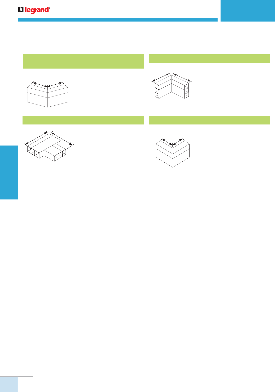
WWW.LEGRAND.US/WIREMOLD
230
WIREMOLD
PREWIRED RACEWAY
AL7320 SERIES RACEWAY
Ordering Information
AL7312B
45° External Mitered Elbow with Coupling
AL7315 Flat Tee with Coupling
AL7317 Internal Mitered Elbow with Coupling
AL7318 External Mitered Elbow with Coupling
Makes 45° external turns
in runs of AL7320 Series
Raceway. Includes six (6)
AL7301 Couplings.
Makes branch connections
of two runs of AL7320 Series
Raceway. Includes nine (9)
AL7301 Couplings.
Makes 90° internal turns
in runs of AL7320 Series
Raceway. Includes six (6)
AL7301 Couplings.
Makes 90° external turns
in runs of AL7320 Series
Raceway. Includes six (6)
AL7301 Couplings.
6"
[152mm]
6"
[152mm]
10 3/8"
[266mm]
10 3/8"
[266mm]
6"
[152mm]
6"
[152mm]
6"
[152mm]
6"
[152mm]
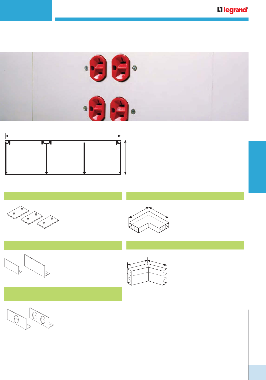
WWW.LEGRAND.US/WIREMOLD
231
WIREMOLD
PREWIRED RACEWAY
AL7450 SERIES RACEWAY
Ordering Information
AL7450 Series Raceway’s three-channel, dual-cover
profile is a cost-effective, highly aesthetic solution
for providing access to communication cabling and
electrical wiring systems.
Material: 6063 T6 Aluminum Alloy
Wall Thickness: 0.078" [1.99mm]
Anodized Finish Thickness: 0.004" [0.004mm]
AL7401 Slide Coupling
AL7410B Blank End Cap
AL7411 90° Flat Mitered Elbow with Coupling
AL7412A 45° Internal Mitered Elbow with Coupling
AL7410B3
Entrance End Cap with Two 1 1/16" Provisions
Connects adjoining sections of
AL7450 Series Raceway base.
Includes three (3) couplings.
Closes off open end of AL7450
Series Raceway.
Makes 90° turns in runs of
AL7450 Series Raceway.
Includes six (6) AL7401
Couplings.
Makes 45° internal turns
in runs of AL7450 Series
Raceway. Includes six (6)
AL7401 Couplings.
End Cap with three
connections for 3/4" conduit.
7 3/8"
[187mm]
2 1/4"
[57mm]
5.25 in2
[3388m2]
4.83 in2
[3114m2]
4.75 in2
[3061m2]
10 3/8"
[263.5mm]
10 3/8"
[263.5mm]
6"
[152mm]
6"
[152mm]
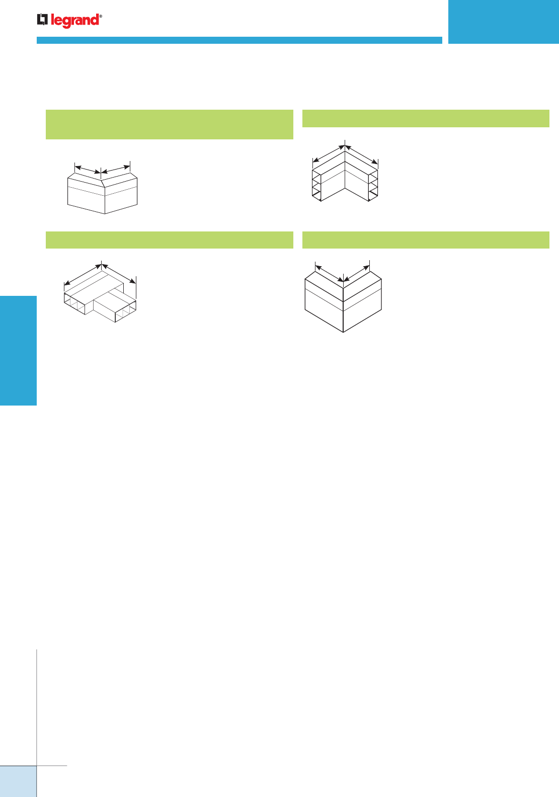
WWW.LEGRAND.US/WIREMOLD
232
WIREMOLD
PREWIRED RACEWAY
AL7450 SERIES RACEWAY
Ordering Information
AL7412B
45° External Mitered Elbow with Coupling
AL7415 Flat Tee with Coupling
AL7417 Internal Mitered Elbow with Coupling
AL7418 External Mitered Elbow with Coupling
Makes 45° external turns
in runs of AL7450 Series
Raceway. Includes six (6)
AL7401 Couplings.
Makes branch connections
of two runs of AL7450 Series
Raceway. Includes nine (9)
AL7401 Couplings.
Makes 90° internal turns
in runs of AL7450 Series
Raceway. Includes six (6)
AL7401 Couplings.
Makes 90° external turns
in runs of AL7450 Series
Raceway. Includes six (6)
AL7401 Couplings.
6"
[152mm]
6"
[152mm]
6"
[152mm]
6"
[152mm]
6"
[152mm]
10 3/8"
[263.5mm]
10 3/8"
[263.5mm]

WWW.LEGRAND.US/WIREMOLD
233
WIREMOLD
PREWIRED RACEWAY
PREWIRED RACEWAY
Steel
CODE REFERENCE
cULus Listed Multioutlet Assemblies:
File E15191 Guide PVGT.
Surface Metal Raceway:
File E4376 Guide RJBT.
Fittings: File E41751 Guide RJPR.
Meet Article 380 of NEC.
Steel Prewired Raceway Systems offer the lowest installed cost for
communications cabling or electrical wiring. Raceways come completely
assembled and ready to install, significantly reducing on-site labor costs.
COLOR OPTIONS
Steel Prewired Raceways are available with an ivory ScuffCoat™ finish or a gray enamel finish.
DS4000® Series Raceway available in Designer Ivory, Designer Gray, Designer Black, and Designer Bronze.
Custom color options are also available. Consult the factory for more information.
• Prewired raceway offers the lowest
installed cost. Manufactured to specified
job site lengths, electrically prewired and
assembled – ready to install. Reduces
on-site installation time and costs. For
lowest installed cost, specify factory
mounted and labeled communication
connectivity devices.
• Accommodates high-density
communication cabling for networks and
phone systems. Features communication
connectivity devices. Raceway is
compatible with other manufacturers’
activation devices. Blank openings also
available.
• Accommodates most electrical wiring
devices or communication faceplates
including single outlets, duplex outlets,
NEMA-locking outlets, GFCI outlets, and
surge protected outlets. (Refer to the
raceway device compatibility chart in the
3000, 4000, and 4000 Designer Series
Raceway sections of this catalog.)
Broad range of standard fittings available
Accommodates every possible site
situation, from internal and external
elbows to flat tees. All fittings are
made from galvanized steel to ensure
continuity.
• Removable cover. Provides maximum
flexibility for adding or relocating
circuits, data openings or electrical
devices.
• Ivory ScuffCoat™ finish and gray baked
enamel finish. Assures durability. Can be
overpainted to complement decor.
• Communication and electrical device
identification with self-adhesive
polyester or self-adhesive phenolic
labels are available as options. No
guesswork or time-consuming tracing
of circuits. Speeds circuit additions and
renovations.
• Jobs can be packaged by room, area,
floor or building, and shipped per your
job site requirements.
• Datacom Connectivity Options. Accepts
industry standard and proprietary devices
from a wide range of manufacturers to
provide a seamless and aesthetically
pleasing interface for voice, data, audio,
and video applications at the point of use.
• UL Listed commercial outlet centers.
File E317375 Multioutlet assemblies
rated to 20A maximum can be provided
with listed cord and plug assemblies.
These assemblies are optimal for
mounting to semi-permanent structures
such as shelving and rack displays found
in many lab applications.
Steel Prewired Raceway Features and Benefits
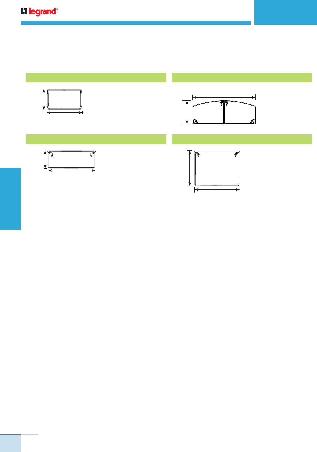
WWW.LEGRAND.US/WIREMOLD
234
WIREMOLD
PREWIRED RACEWAY
STEEL PREWIRED RACEWAY
Ordering Information
2 3/4"
[70mm]
1 17/32"
[31mm]
Steel Prewired Raceway Profiles
3.51 sq. in.
[89.15mm2]
3000 Series Raceway
1 3/4"
[44mm]
4 3/4"
[121mm]
Divided:
3.7 sq. in. [93.98mm2]
Undivided:
7.5 sq. in. [190.5mm2]
4000 Series Raceway
2 1/8"
[54mm]
5 3/4"
[146mm] Each Compartment –
5.01 in.2 [3235mm2]
DS4000® Series Raceway
3 9/16"
[90mm]
4 3/4"
[121mm]
Divided:
7.20 in.2 [4645mm2]
Undivided:
16.00 in.2 [10320mm2]
6000® Series Raceway

WWW.LEGRAND.US/WIREMOLD
235
WIREMOLD
PREWIRED RACEWAY
CODE REFERENCE
cULus Listed Multioutlet Assemblies:
File E15191 Guide PVGT.
Surface Metal Raceway:
File E4376 Guide RJBT.
Fittings: File E41751 Guide RJPR.
Meet Article 380 of NEC.
Nonmetallic Prewired Raceway Systems offer the lowest installed cost for
communications cabling or electrical wiring. Raceways come completely
assembled and ready to install, significantly reducing on-site labor costs.
• Prewired raceway offers the lowest
installed cost. Manufactured to specified
job site lengths, electrically prewired and
assembled – ready to install. Reduces
on-site installation time and costs. For
lowest installed cost, specify factory
mounted and labeled communication
connectivity devices.
• Accommodates high-density
communication cabling for networks and
phone systems. Features communication
connectivity devices. Raceway is
compatible with other manufacturers’
activation devices. Blank openings also
available.
• Accommodates most electrical wiring
devices or communication faceplates
including single outlets, duplex outlets,
NEMA-locking outlets, GFCI outlets, and
surge protected outlets. (Refer to the
raceway device compatibility chart in the
5400 and 5500 Series Raceway sections
of this catalog.)
• Broad range of standard fittings
available. Accommodates every possible
site situation, from internal and external
elbows to flat tees. All fittings are
made from galvanized steel to ensure
continuity.
• Removable cover. Provides maximum
flexibility for adding or relocating
circuits, data openings or electrical
devices.
• Communication and electrical device
identification with self-adhesive
polyester or self-adhesive phenolic
labels are available as options. No
guesswork or time-consuming tracing
of circuits. Speeds circuit additions and
renovations.
• Jobs can be packaged by room, area,
floor or building, and shipped per your
job site requirements.
• Datacom Connectivity Options. Accepts
industry standard and proprietary devices
from a wide range of manufacturers to
provide a seamless and aesthetically
pleasing interface for voice, data, audio,
and video applications at the point of use.
COLOR OPTIONS
Nonmetallic Prewired Raceways are available with
an ivory finish.
Custom color options are also available.
Consult the factory for more information.
PREWIRED RACEWAY
Nonmetallic
Nonmetallic Prewired Raceway Features and Benefits
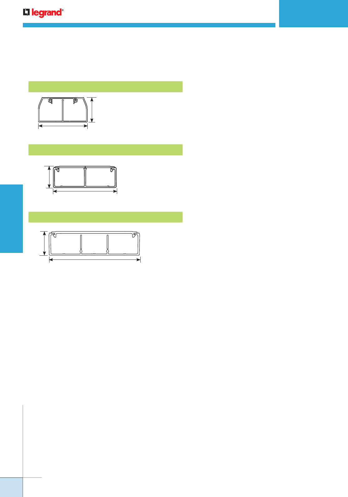
WWW.LEGRAND.US/WIREMOLD
236
WIREMOLD
PREWIRED RACEWAY
Each Compartment:
3.22 in.2 [2080mm2]
Each Compartment:
3.72 sq. in. [2400mm2]
Full:
7.31 sq. in. [4716mm2]
Each
Compartment:
2.64 sq. in.
[1703mm2]
CableSmart 40N2 Series Raceway
5400 Series Raceway
5500 Series Raceway
2"
[51mm]
4"
[102mm]
1 3/4"
[44mm]
5 1/4"
[133mm]
1 3/4"
[44mm]
6 11/16"
[170mm]
Nonmetallic Prewired Raceway Profiles
NONMETALLIC PREWIRED RACEWAY
Ordering Information
Consult your local Wiremold representative for price, quotation and
delivery information.
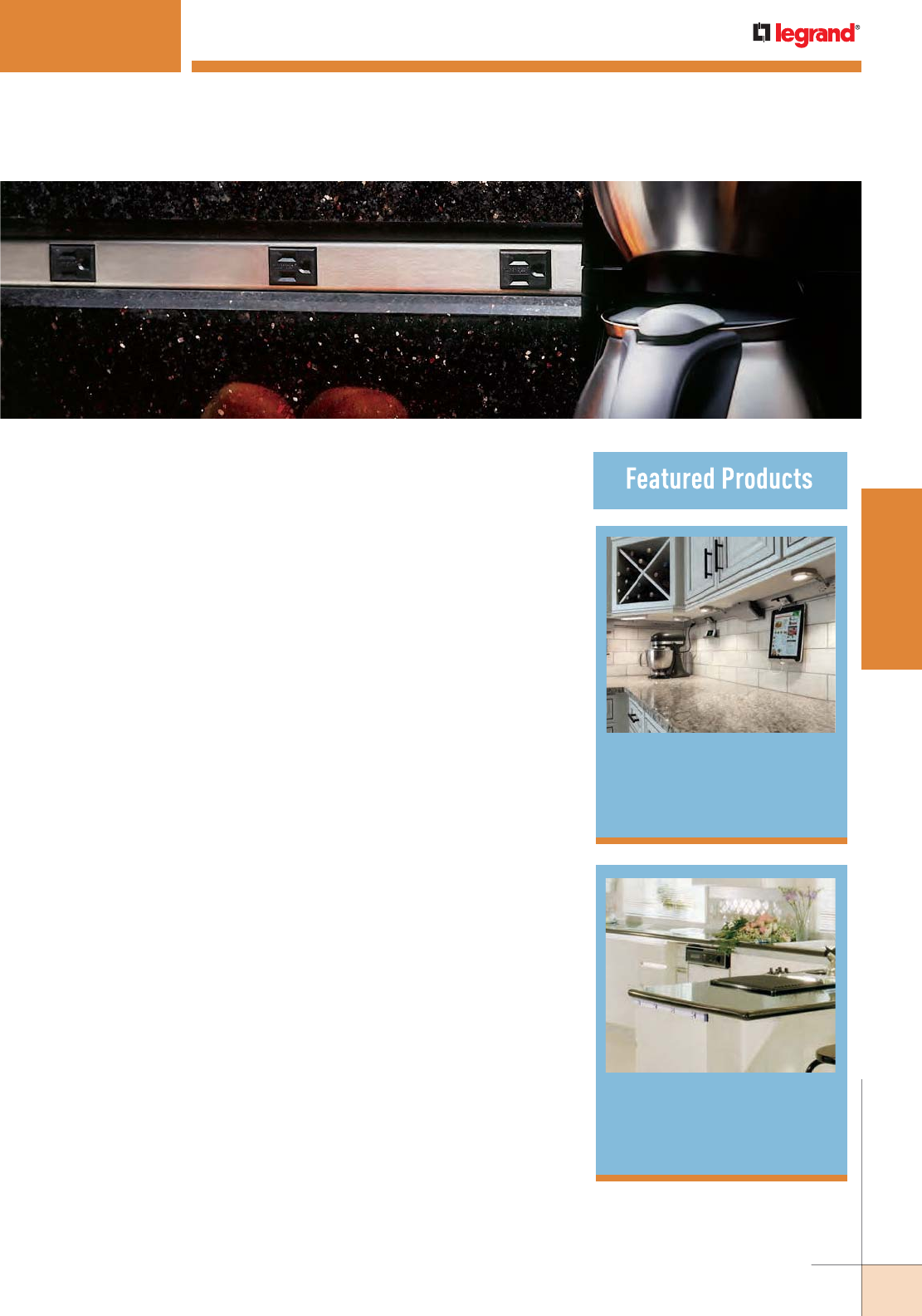
237
WWW.LEGRAND.US/WIREMOLD
WIREMOLD
PLUGMOLD SYSTEMS
PLUGMOLD
®
SYSTEMS
Wiremold® Plugmold® Multi-outlet Systems are an excellent choice
for applications where space is minimal but multiple outlets for
power are required.
adorne
™
Under-Cabinet
Lighting System
265
Tamper-Resistant
Plugmold®
260
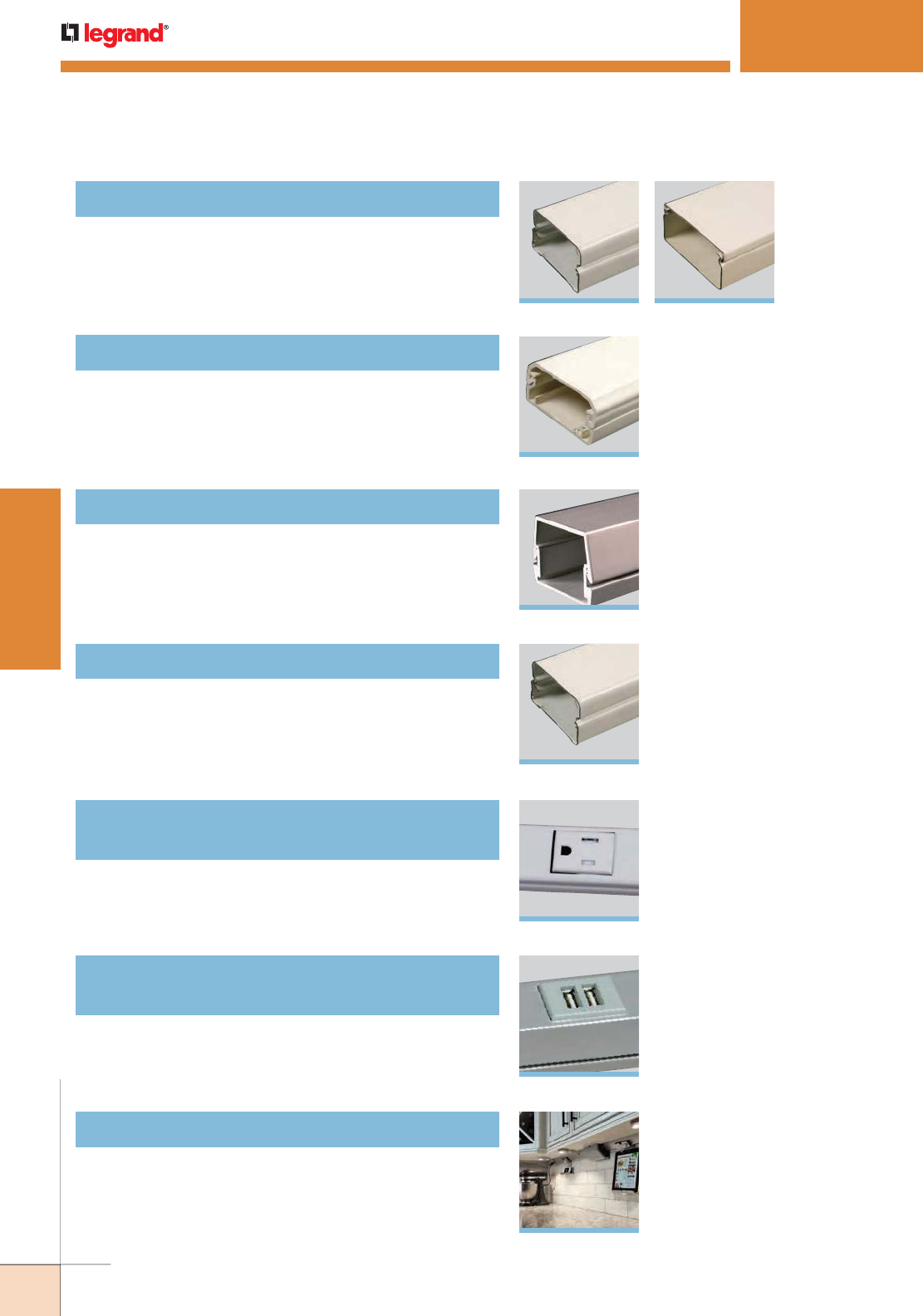
238
WWW.LEGRAND.US/WIREMOLD
WIREMOLD
PLUGMOLD SYSTEMS
Plugmold® Steel Multi-outlet Systems
Plugmold® Plus Nonmetallic Multi-outlet Systems
Plugmold® Aluminum Multi-outlet Systems
Plugmold® Tamper-Resistant Multi-outlet Systems
Plugmold® Tamper-Resistant GFCI
Multi-outlet Systems
2000 Series™
NM2000 Series™
AL2000 Series™
2000TR Series™
2400 Series™
240
251
256
260
263
246
PLUGMOLD
®
SYSTEMS
Table of Contents
Plugmold® Tamper-Resistant USB Charging
Multi-outlet System
264
adorne Under-Cabinet Lighting System
265
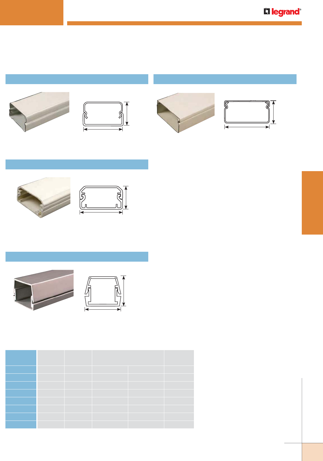
239
WWW.LEGRAND.US/WIREMOLD
WIREMOLD
PLUGMOLD SYSTEMS
Plugmold Multi-outlet Systems and Raceways
SERIES MATERIAL AMPERAGE
PROFILE DIMENSIONS RECEPTACLE
TYPEInches [mm]
2000 Steel 15 Amp 3/4" x 1 9/32" [19.1mm x 33mm] Simplex
2000TR Steel 15 Amp 3/4" x 1 9/32" [19.1mm x 33mm] Simplex
V2400 Steel 20 Amp 7/8" x 1 29/32" [22.2mm x 48mm] Simplex
24R Steel 15 Amp 7/8" x 1 29/32" [22.2mm x 48mm] TR Duplex
24S Steel 20 Amp 7/8" x 1 29/32" [22.2mm x 48mm] Duplex
NM2000 Nonmetallic 15 Amp 1" x 1 3/4" [25mm x 44mm] Duplex
AL2000 Aluminum 15 Amp 1 1/8" x 1 7/16" [29mm x 37mm] Simplex
AL2000TR Aluminum 15 Amp 1 1/8" x 1 7/16" [29mm x 37mm] Simplex
NOTE: All systems can be custom configured to suit specific job requirements.
PLUGMOLD
®
SYSTEMS
Quick Selection Guide
Plugmold® 2400, 24S, 24R™ Series
1 29/32"
[48mm]
7/8"
[22.2mm]
CAPACITY: 1.39 in.2 [897mm2]
Plugmold® Multi-outlet Systems – Steel Profiles
Plugmold® 2000 Series™
1 9/32"
[32mm]
3/4"
[19.1mm]
CAPACITY: 0.80 in.2 [516mm2]
Plugmold® Plus NM2000 Series™
Plugmold® Multi-outlet Systems – Nonmetallic Profiles
1 3/4"
[44mm]
1"
[25mm]
CAPACITY: 0.114 in.2 [735mm2]
Plugmold® AL2000 Series™
Plugmold®Multi-outlet Systems – Aluminum Profiles
1 7/16"
[37mm]
1 1/8"
[29mm]
CAPACITY: 1.10 in.2 [710mm2]
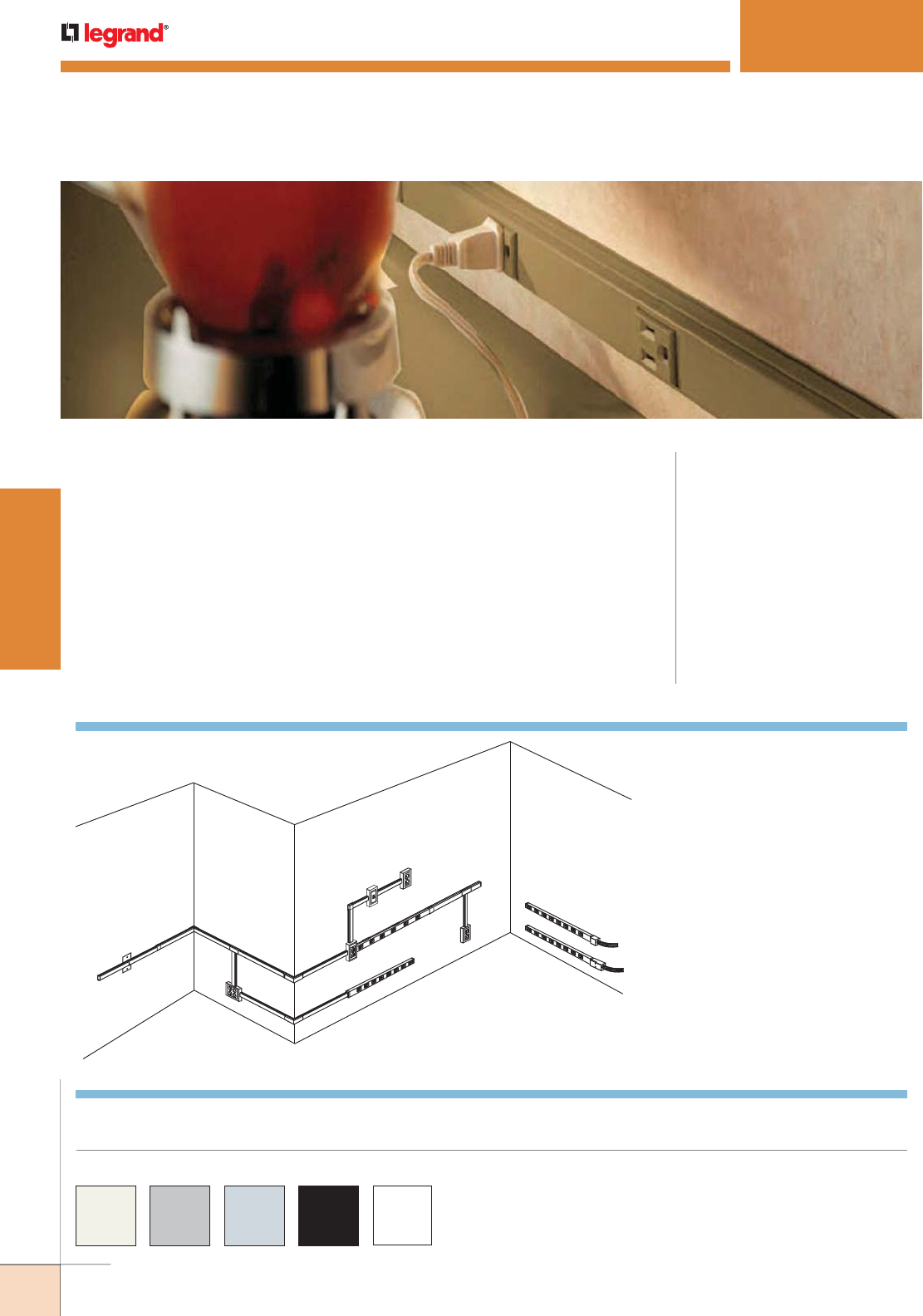
240
WWW.LEGRAND.US/WIREMOLD
WIREMOLD
PLUGMOLD SYSTEMS
PLUGMOLD
®
2000 SERIES
™
CODE REFERENCE
cULus Listed Base & Blank Cover:
File E4376 Guide RJBT.
Multi-outlet Assemblies:
File E15191 Guide PVGT.
Fittings:
File E41751 Guide RJPR.
Base & Blank Cover& Plugmold Series
with Snapicoil Harness:
Meets Article 386 of NEC.
Meets Section 12-3032 of CEC.
Plugmold Wired Sections:
Meets Article 380 of NEC.
Meets Section 12-3032 of CEC.
COLOR OPTIONS
Plugmold® 2000 Series™ Part Numbers with a “V” prefix have an ivory finish. Part
Numbers with a “G” prefix have a gray finish. Part Numbers with a “S” prefix have a
stainless finish. Part Numbers with a “WH” prefix have a white finish. Part Numbers
with a “BK” prefix have a black finish. Part Numbers without a prefix have a galvanized
steel finish unless otherwise specified.
Custom color options are also available. Consult the factory for more information.
AF
E
G
H
I
JO
L
Q
P
M
M
N
K
BC
D
NOTE: Illustration is for showing product applications only.
KEY
A. V2010B Blank End Fitting
B. V2051H Flush Plate Adapter
C. V2006 Cover Clip
D. 2017TC Internal Corner Coupling
E. V2015 Tee Fitting
F. V2048-2 Two-Gang Device Box
G. V2018C Extern Elbow Cover
H. V2048 Single-Gang Device Box
I. V2011 90° Flat Elbow
J. V20GB506 Plugmold Strip
K. V2089 Side-Reducing Fitting
L. V5748 Single-Gang Device Box
M. V500 500 Series Raceway
N. V2010A2 Entrance End Fitting
O. V2010A3 Entrance End Fitting
P. V518 External Elbow
Q. V2089E End-Reducing Connector
Plugmold 2000 Series System Layout
Two-piece, low profile multiple outlet raceway. Low profile requires
minimal space.
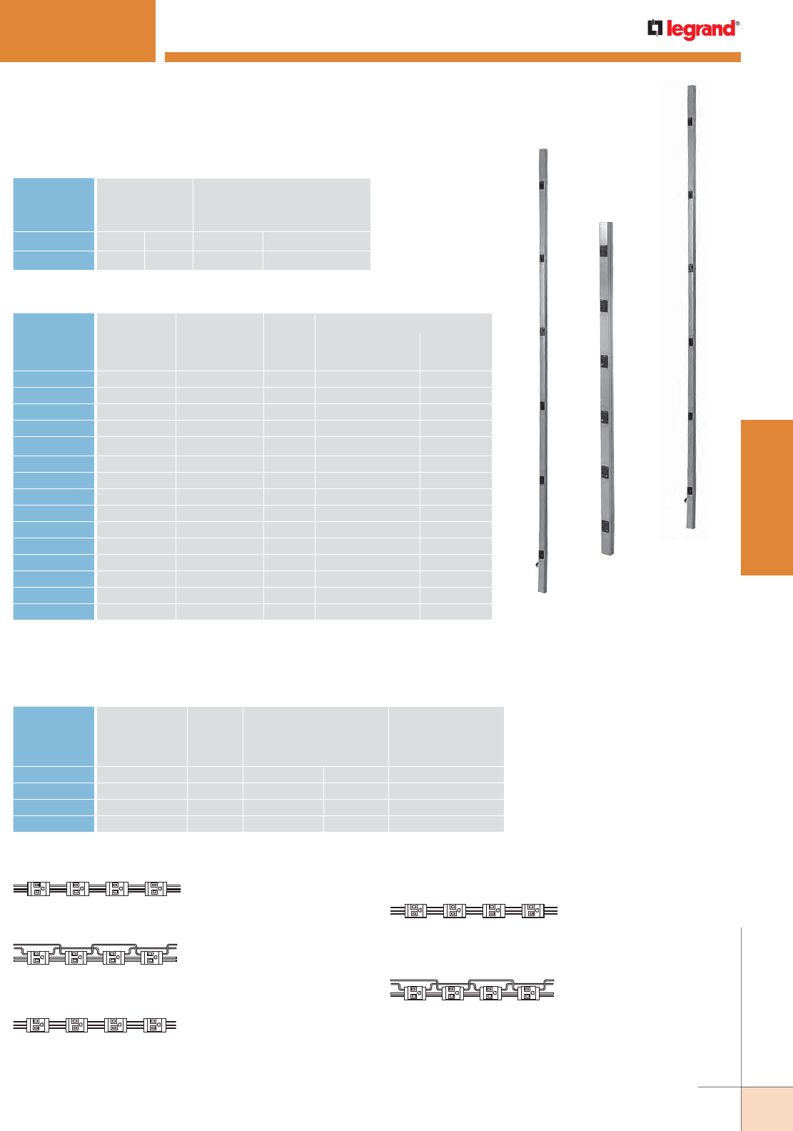
241
WWW.LEGRAND.US/WIREMOLD
WIREMOLD
PLUGMOLD SYSTEMS
PLUGMOLD
®
2000 SERIES
™
Plugmold 2000 Series Wire Fill Capacities for Power
WIRE SIZE
THHN/THWN
NUMBER OF CONDUCTORS
O.D. WITHOUT
DEVICES
WITH PLUGMOLD
RECEPTACLESInches [mm]
12 AWG 0.111 [2.8] 7 5
14 AWG 0.130 [3.3] 7 5
Plugmold 2000 Series Product Configuration Matrix
CAT. NO FINISH
LENGTH WIRING
CONFIG.
OUTLETS (15A 125V NEMA 5-15R)
CENTER DISTANCE OUTLET
Feet [mm] Inches [mm] QTY.
20GB206 S 2 [610mm] GB 6 [152mm] 4 Single
20GB306 V, G, BK, WH, S 3 [915mm] GB 6 [152mm] 6 Single
20IG306 V, G 3 [915mm] IG 6 [152mm] 6 Single
20GB506 V, G, BK, WH, S 5 [1.5m] GB 6 [152mm] 10 Single
20GB512 V, G, BK, WH, S 5 [1.5m] GB 12 [305mm] 5 Single
20GBA512 V, G 5 [1.5m] GBA 12 [305mm] 5 Single
20IG512 V, G 5 [1.5m] IG 12 [305mm] 5 Single
20GB606 V, G, BK, WH, S 6 [1.8m] GB 6 [152mm] 12 Single
20GB609 V, G 6 [1.8m] GB 9 [229mm] 8 Single
20GB612 V, G, BK, WH, S 6 [1.8m] GB 12 [305mm] 6 Single
20GB618 V, G 6 [1.8m] GB 18 [457mm] 4 Single
20GBA609 V, G 6 [1.8m] GBA 9 [229mm] 8 Single
20GBA612 V, G 6 [1.8m] GBA 12 [305mm] 6 Single
20GBA618 V, G 6 [1.8m] GBA 18 [457mm] 4 Single
20IG606 V, G 6 [1.8m] IG 6 [152mm] 12 Single
NOTE: Ivory, gray, white, and black Plugmold Series in GB and GBA wiring have matching color receptacles.
Stainless steel Plugmold Series has black receptacles and Plugmold Series with IG wiring has orange receptacles.
Plugmold 2000 Series 48' and 50' [14.6m & 15.2m] Lengths – Ivory, Gray Finish
CAT. NO
LENGTH WIRING
CONFIG.
OUTLETS 15A 125V
NEMA 5-15R)
CENTER DISTANCE
2000B AND 2000C
HOLE CUT COVER
LENGTH
Feet [mm] Inches [mm] QTY. QTY. Feet [mm]
20GB12 48 [14.6] GB 12 [305] 48 Single 8 6 [1.830]
20GB18 48 [14.6] GB 18 [457] 32 Single 8 6 [1.830]
20GB30 50 [15.2] GB 30 [760] 20 Single 10 5 [1.525]
20GBA12 48 [14.6] GBA 12 [305] 48 Single 8 6 [1.830]
V20GB306
V20GB612
V20GB12
NOTE:
Snapicoil Reels on custom order. Snapicoil
Harness is available on reels if lengths
greater than 50' are needed, or if multiple
lengths are required for production-type
jobs. The maximum length per reel is 240’
for Snapicoil Harness with outlets 12" and
18" on centers; 500' with outlets 30" on
center. Packaging includes the necessary
number of lengths of base, holecut cover,
wire clips, and couplings for complete
installation. Price and delivery information
should be obtained prior to specifying or
ordering. To specify or order, add R to the
Snapicoil Harness number. Ex: V20GB12R.
Other outlet spacings available on custom
order.
Receptacles are made from high impact
thermoplastic. Plugmold 2000 Series is
supplied with two (2) 2010B Blank End
Fittings and (1) 2001 Base Coupling.
GB SERIES:
3-wire #12 THHN solid (1 hot, 1
neutral, and 1 ground), 1-circuit;
has insulated grounding conductor.
GBA SERIES:
4-wire #12 THHN solid (2 hot, 1
neutral, and 1 ground), 2-circuits;
outlets wired alternately; has
insulated grounding conductor.
IG SERIES:
3-wire #12 THHN solid (1 hot, 1
neutral, and 1 ground), 1 circuit;
has insulated-isolated grounding
conductor, orange receptacle.
GB SERIES:
3-wire #12 THHN solid (1
hot, 1 neutral, and 1 ground),
1-circuit; has insulated
grounding conductor.
GBA SERIES:
4-wire #12 THHN solid (2
hot, 1 neutral, and 1 ground),
2-circuits; outlets wired
alternately; has insulated
grounding conductor.
WITH SNAPICOIL HARNESS
Plugmold 2000 Series Wiring Configuration
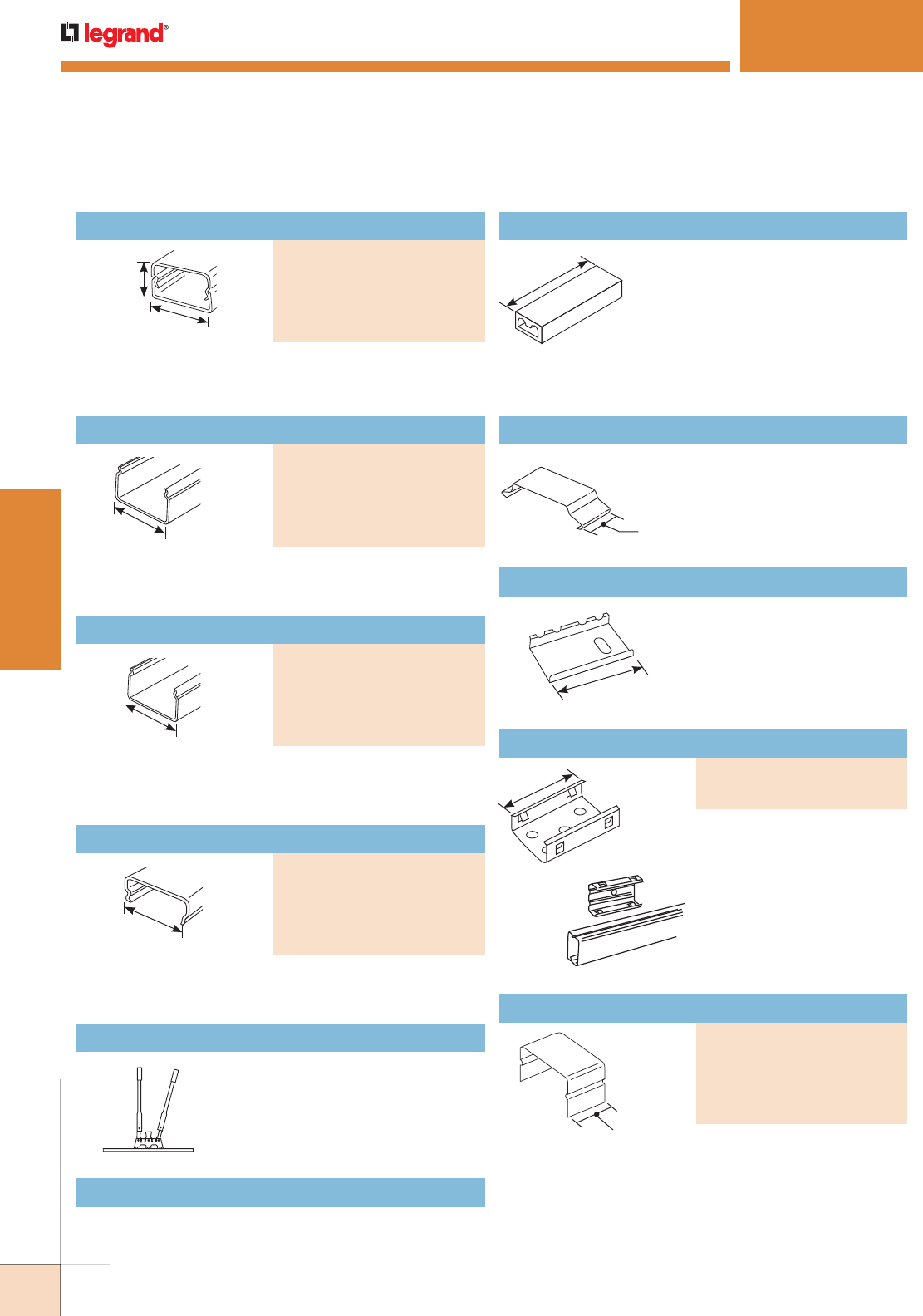
242
WWW.LEGRAND.US/WIREMOLD
WIREMOLD
PLUGMOLD SYSTEMS
PLUGMOLD
®
2000 SERIES
™
620BCK Replacement Blade Kit
Replacement blades and die set for 620 Cutter.
620 Raceway Base and Cover Cutter
Portable cutter for both 2000
Base and Cover.
2000WC Wire Clip (Plated)
Use when conductors bypass
receptacles. Not UL Listed.
1/2"
[12.7mm]
2001 Coupling (Galvanized Steel)
Joins lengths of 2000 Series
Raceway Base.
2"
[51mm]
W30/W30G Pressure-Type Wire Connectors
1 5/16"
[33mm] W30 – For common connection of two,
three, or four No. 12 or No.14 solid
copper conductors.
W30G – For connection of equipment
grounding of 2, 3, or 4 solid conductors
No. 14 or No. 12 AWG. 300V maximum;
20A 105° C maximum.
NOTE: Not for use with
aluminum
conductors.
Plugmold 2000 Series Ordering Information
Base and Cover
3/4"
[19.1mm]
1 9/32"
[33mm]
2000B Base: .040" [1.0mm] steel; 2000C Cover: .025" [.6mm]
steel. Packed ten 5' [1.5m] lengths of each per carton.
PART NUMBERS:
V2000BC (Ivory)
WH2000BC (White)
G2000BC (Gray)
BK2000BC (Black)
S2000BC (Stainless Steel)
Raceway Base
.040" [1.0mm] steel. Packed twenty 5' [1.5m] lengths
per carton.
1 9/32"
[33mm]
PART NUMBERS:
V2000B-5 (Ivory)
WH2000B-5 (White),
G2000B-5 (Gray)
BK2000B-5 (Black)
S2000B-5 (Stainless Steel)
Raceway Base
1 9/32"
[33mm]
.040" [1.0mm] steel. Packed ten 10' [3.05m] lengths
per carton.
PART NUMBERS:
V2000B-10 (Ivory)
WH2000B-10 (White)
G2000B-10 (Gray)
BK2000B-10 (Black)
S2000B-10 (Stainless Steel)
Raceway Base
1 9/32"
[33mm]
.025" [.6mm] steel. Packed twenty 5' [1.5m] lengths per
carton. Has no receptacle hole cuts.
PART NUMBERS:
V2000C (Ivory)
WH2000C (White)
G2000C (Gray)
BK2000C (Black)
S2000C (Stainless Steel)
2006 Cover Clip
Covers seam where lengths of
cover or base meet.
3/4"
[19.1mm]
PART NUMBERS:
V2006 (Ivory)
WH2006 (White)
G2006 (Gray)
BK2006 (Black)
S2006 (Stainless Steel)
2"
[51mm]
2003 Supporting Clip
Temporary support, while
positioning lengths of raceway
base. Use with 2000 Series
Raceway.
1. 2003 mounted on surface with No. 6
flathead screw.
2. Plugmold 2000 or 2100 snaps into
2003 Supporting Clip.
1
2
PART NUMBERS:
V2003 (Ivory)
2003 (Plated Finish)
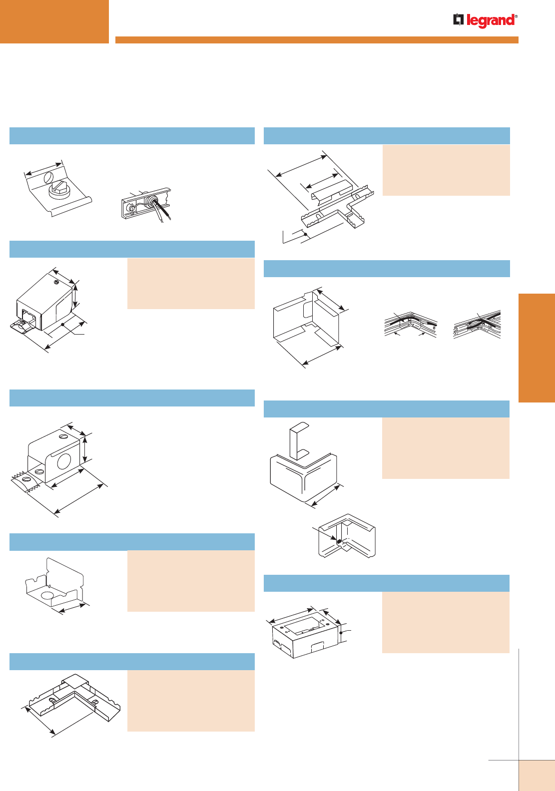
243
WWW.LEGRAND.US/WIREMOLD
WIREMOLD
PLUGMOLD SYSTEMS
2009 Ground Clamp (Galvanzied)
Connects equipment grounding
conductor to provide an
additional ground to raceway.
1 13/64"
[30mm]
How 2009 is used.
2010A2 Entrance End Fitting
Connects 2000 Series Raceway
with 1/2" trade size conduit
and armored cable connectors.
1/2" trade size KOs on end,
each side and bottom. Includes
ground screw.
3"
[76mm]
1 9/32"
[33mm]
1 1/2"
[38mm]
2 1/8"
[54mm]
2017TC Internal Corner Coupling
Furnished with one fiber
bushing.
1 1/2"
[38mm]
1 1/2"
[38mm]
1. 2017TC used as a
corner coupling.
2017TC
2000B
2. 2017TC used
as a corner
coupling and
a straight-
through fitting.
2017TC
2000B
PLUGMOLD
®
2000 SERIES
™
Plugmold 2000 Series Ordering Information (continued)
Entrance End Fitting
Offers larger capacity than
V2010A2. 1/2" trade size KOs
on end, each side and bottom.
3/4" trade size KOs on bottom
and rear. Includes ground
screw.
2 1/8"
[54mm]
3"
[76mm]
2 11/16"
[67mm]
2 7/64"
[53mm]
PART NUMBERS:
V2010A3 (Ivory)
WH2010A3 (White)
G2010A3 (Gray)
BK2010A3 (Black)
External Elbow Cover
Continues raceway runs
around outside corner. Fills
the gap when external corner
is made by notching and
bending the 2000 Base.
1 7/8"
[48mm]
Corner Gap
Filler snapped
into place in
2018C.
PART NUMBERS:
V2018C (Ivory)
WH2018C (White)
G2018C (Gray)
BK2018C (Black)
S2018C (Stainless Steel)
Single-Gang Device Box
Cover has twistouts for 2000, 500 and 700 Series Raceways.
Base has 1/2" trade size KO and rectangular KO for
extension to wall box. Base has No. 10 threaded hole for
ground connection.
2 7/8"
[73mm]
1 3/4"
[44mm]
4 5/8"
[118mm]
PART NUMBERS:
V2048 (Ivory)
WH2048 (White)
G2048 (Gray)
BK2048 (Black)
S2048 (Stainless Steel)
Blank End
Closes off open end of 2000
Series Raceway.
3/4"
[19.1mm]
PART NUMBERS:
V2010B (Ivory)
WH22010B (White)
G2010B (Gray)
BK2010B (Black)
S2010B (Stainless Steel)
90° Flat Elbow
Right angle turns on same surface. Cover stop permits neat
butting of 2000C Cover. Two couplings furnished.
2 1/2"
[64mm]
Each Leg
PART NUMBERS:
V2011 (Ivory)
WH2011 (White)
G2011 (Gray)
BK2011 (Black)
S2011 (Stainless Steel)
Tee
Branches raceway at right
angles. Couplings furnished.
1 1/2"
[38mm]
4"
[102mm]
6"
[152mm]
PART NUMBERS:
V2015 (Ivory)
WH2015 (White)
G2015 (Gray)
BK2015 (Black)
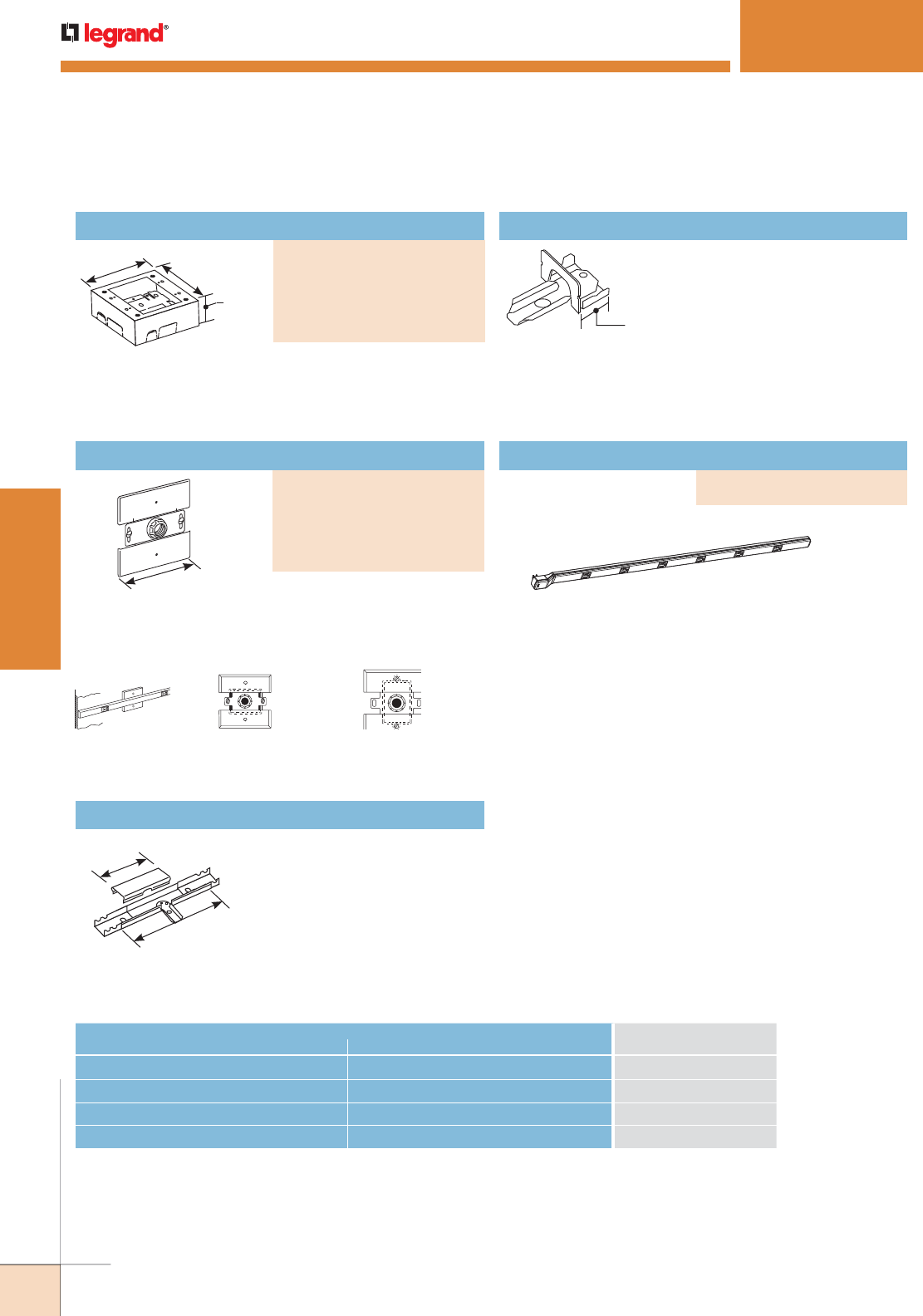
244
WWW.LEGRAND.US/WIREMOLD
WIREMOLD
PLUGMOLD SYSTEMS
Feeds 2000 Series Plugmold from an existing wall outlet.
Equipped with 1/2" [12.7mm] threaded stud, toothed lock
washer for grounding, threaded hole for and conduit
bushing.
3/4"
[19.1mm]
V2089E End Reducing Connector
Connects 2000 Series
Plugmold with 500 Series
Raceway through the end of
2000 Series Plugmold.
4 1/2"
[114mm]
Plugmold 2000
extended from wall
outlet using 2051H.
2051H fastened to
horizontally mounted
wall box.
2051H fastened to
vertically mounted
wall box.
V2089 Side Reducing Connector
Connects 2000 Series
Plugmold with 500 Series
Raceway through the side of
2000 Series Plugmold.
6"
[152mm]
3 1/4"
[83mm]
PLUGMOLD 2000
®
SERIES
™
2000 Series Interconnectivity Fittings
CONNECTION REQUIRED
USE CATALOG NUMBERFROM TO
500 Series Raceway Side of Plugmold 2000 Series V2089, V2048, V2048-2
500 Series Raceway End of Plugmold 2000 Series V2089E, V2048, V2048-2
Existing Outlet Plugmold 2000 Series V2051H
1/2" trade size Conduit or Armored Cable End of Plugmold 2000 Series V2010A2, V2010A3
Plugmold 2000 Series Ordering Information (continued)
Two-Gang Device Box
Cover has twistouts for 2000, 500 and 700 Series Raceways.
Base has 1/2" trade size KO and rectangular KO for
extension to wall box. Base has No.10 threaded hole for
ground connection.
4 3/4"
[121mm] 4 3/4"
[121mm]
1 3/4"
[44mm]
PART NUMBERS:
V2048-2 (Ivory)
WH2048-2 (White)
G2048-2 (Gray)
BK2048-2 (Black)
S2048-2 (Stainless Steel)
Flush Plate Adapter
PART NUMBERS:
V2051H (Ivory)
WH2051H (White)
G2051H (Gray)
BK2051H (Black)
S2051H (Stainless Steel)
Plug-in Plugmold
Available in 3' [915mm]
with six single receptacles
and two (2) mounting clips.
PART NUMBER:
PIP36BK (Black)
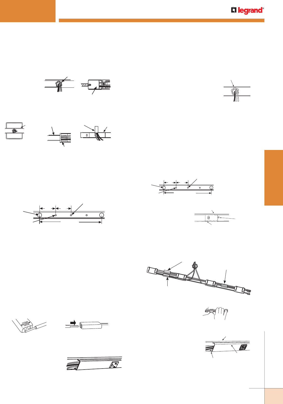
245
WWW.LEGRAND.US/WIREMOLD
WIREMOLD
PLUGMOLD SYSTEMS
PLUGMOLD
®
2000 SERIES
™
1. Determine the method of feeding and bring feed
conductors into base section.
2. Install 2000B Base on surface, starting with feed section.
Mount base section with No. 8 flathead screws, through
mounting screw knockouts and piercings, or mount with
2003 Support Clips. Random piercing and knockout pattern
does not start and end at same point on bases of Plugmold.
Attaching Lock Nut
Lock nut run onto
Connector as spacer.
CAUTION: Be sure
lock nut and feed
do not fall behind
receptacle.
V2010A2 Entrance
End Fitting (typical)
end feeding from
conduit or armored
cable.
Back feeding from
wall box.
V2051H
Flush
Plate
Adapter
V500
2089E
End feeding
from 500 Series
Raceway.
V2089
for
V500
V500
Side-feeding from
500 Series Raceway.
Mounting
Screw KO
2000B Base
2"
[51mm]
2"
[51mm]
8"
[203mm]
Approx.
Approx.
Mounting
Screw
Piercing
1/2"
[12.7mm]
Feed KO
3. Connect feed to prewired cover section. Use approved
connection method for ground conductor. Use only
W30G (green) wire connectors on equipment grounding
conductors, not W30.
W30 and W30G CONNECTORS
W30 – Common connection of 2, 3 or 4 solid conductors
No.14 or No.12 AWG.
W30G – For connection of equipment grounding of 2, 3, or 4
solid conductors No.14 or No.12 AWG.
Rating – 300 volts maximum, 20 AMP. 105° C maximum.
Note: W30 Connector has a white finish, W30G Connector has a
green finish.
A. Strip wire ends to width of
product (1/2" [12.7mm]).
B. Insert wire ends the
full stripped distance.
4. Engage lower bead of cover in base. Starting at one end, snap
in top bead. Be careful not to pinch wires.
To snap cover in, work from one
end to the other, striking sharply
with heel of hand.
Plugmold Multi-outlet Systems Installation Details
4. Lay out Snapicoil Harness along entire run of base so that
receptacles are not located over feed or in corners. Connect
harness to feed. Use approved connection method for ground
conductor.
6. Engage lower bead of cover
in base and starting at
one end, snap in top bead.
be careful not to pinch
wires. Continue snapping
receptacles into covers,
and covers into base along
entire run.
1. Determine method of feeding. Bring feed
conductors into base.
A. Stub-in feed at beginning of run,
half the distance or less from first
receptacle. Cut off base so 1/2"
[12.7mm] entrance KO aligns with
feed (also provides for cover to
overlap base joint). Save base section
cut-off for opposite end of run.
B. Remove appropriate entrance KO and
install 1/2" [12.7mm] connector as
shown.
Feed Stubbed In
CAUTION: Be sure lock
nut and feed do not fall
behind receptacle.
3. Snap in 2001 Coupling
where base sections abut.
Base Joint No. 8
Flathead
Screw
5. Starting at feed, snap
receptacles completely into
first cover section.
2000B Base
Snap in
Upper Bead
of Cover
Lower Bead
Engaged
W30 Connector on
Black Hot Wire
W30 Connector on
White Neutral Wire
W30G Connector on
Green Ground Wire
2. Install 2000B Raceway Base on surface, starting with feed
section. Mount entire run with No. 8 flat head screws,
through mounting screw knockouts and piercings. Cut base
to length at corners and end of run. Random piercing and
knockout pattern does not start and end at same point on
bases of Plugmold.
Mounting
Screw KO
2"
[51mm]
2"
[51mm]
8" [203mm]
approx.
approx.
Mounting Screw
Piercing 2000B Base
1/2" [12.7mm]
Feed KO
Snapicoil Harness Installation Details
2001 Coupling
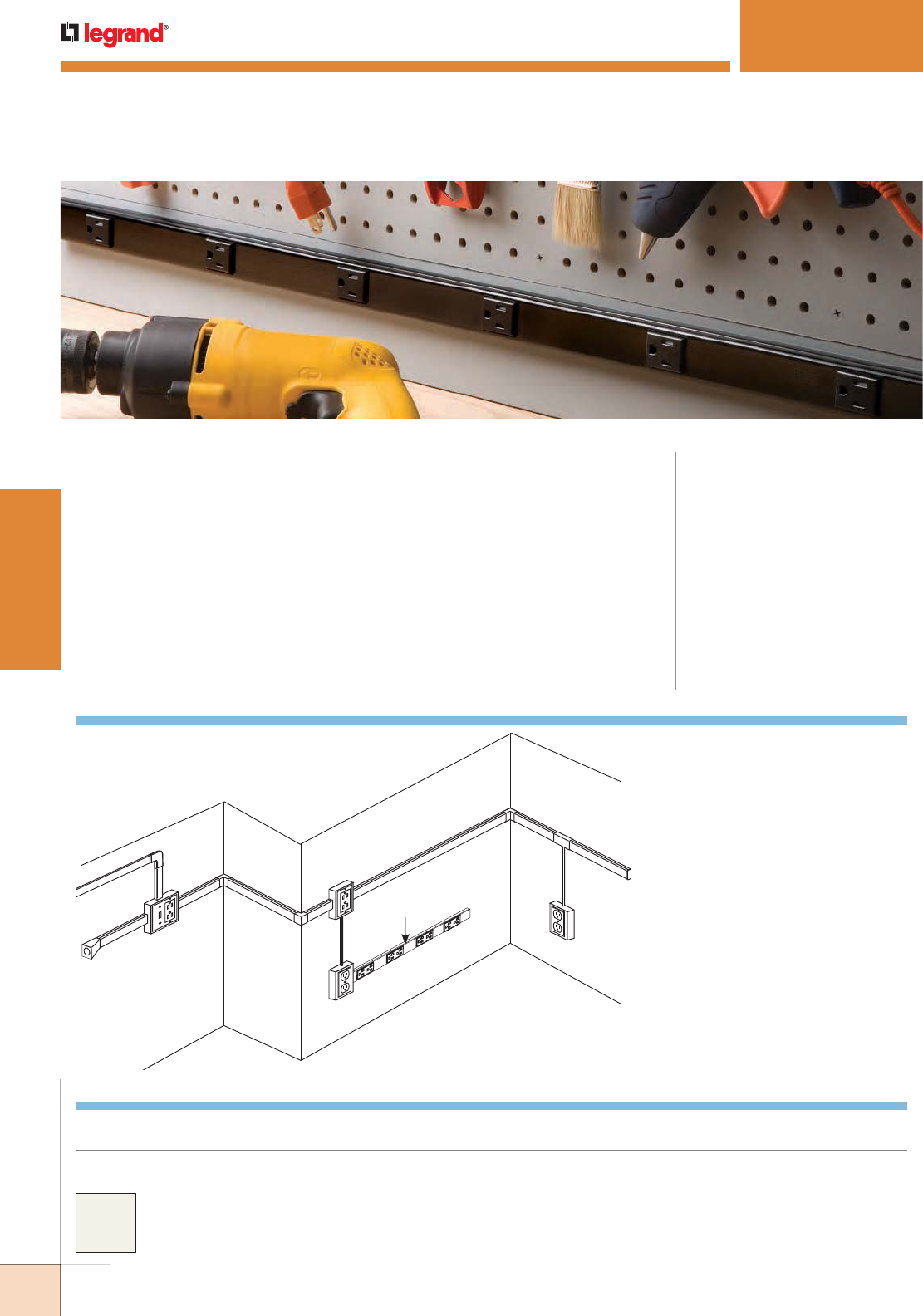
246
WWW.LEGRAND.US/WIREMOLD
WIREMOLD
PLUGMOLD SYSTEMS
PLUGMOLD
®
2400 SERIES
™
KEY
A. V2410A Entrance End Fitting
B. V2448-2 Two-Gang Device Box
C. V2417 Internal Elbow
D. V2418 External Elbow
E. V2448 Single-Gang Device Box
F. 24S7218GBX99IV Plugmold
Multi-outlet System
G. V2489 Side Reducing Connector
H. V2410B Blank End Fitting
I. 500 500 Series Raceway
J. V5747 Single-Gang Device Box
K. V2411 Flat Elbow
CODE REFERENCE
cULus Listed Base and Blank Cover:
File E4376 Guide RJBT.
Multi-outlet Assemblies:
File E15191 Guide PVGT.
Fittings:
File E41751 Guide RJPR.
Base and Blank Cover and Plugmold
Series with Snapicoil Harness:
Meets Article 386 of NEC.
Meets Section 12-3032 of CEC.
Plugmold Wired Sections:
Meets Article 380 of NEC.
Meets Section 12-3032 of CEC.
Two-piece, single channel raceway. Easy-to-install and ideal for basic power or
communication installations
Plugmold® 2400 Series™ Part Numbers with a “V” prefix have an ivory finish. Part
Numbers without a prefix have a galvanized steel finish unless otherwise specified.
Custom color options are also available. Consult the factory for more information.
A
B
C
K
E
F
G
I
J
C
H
D
NOTE: Illustration is for showing product applications only.
COLOR OPTIONS
Plugmold 2400 Series System Layout
E
I
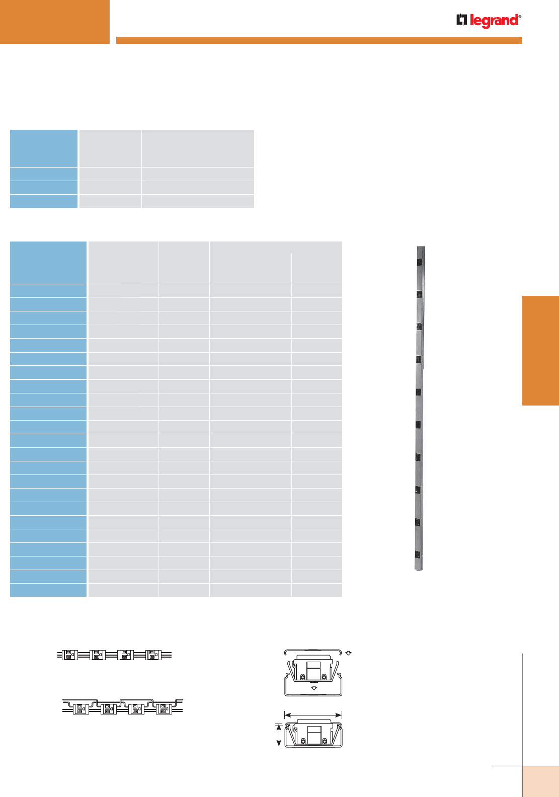
247
WWW.LEGRAND.US/WIREMOLD
WIREMOLD
PLUGMOLD SYSTEMS
PLUGMOLD
®
2400 SERIES
™
Plugmold 2400 Series Wire Fill Capacities for Power
WIRE SIZE
THHN/THWN
NUMBER OF CONDUCTORS
O.D. WITHOUT
DEVICES
WITH PLUGMOLD
RECEPTACLESInches [mm]
14 AWG 0.111 [2.8] 57 12
12 AWG 0.130 [3.3] 41 9
10 AWG 0.164 [4.2] 26 0
Plugmold 2400 Series Product Configuration Matrix
CAT NO. LENGTH WIRING
CONFIG.
OUTLETS 20A 125V NEMA 520R
CENTER
DIS
TANCE OUTLET
QTY.Feet [mm] Inches [mm]
V24GB306 3 [915mm] GB 6 [152] 6 Single
V24GB506 5 [1.5m] GB 6 [152] 10 Single
V24GB512 5 [1.5m] GB 12 [305] 5 Single
V24GBA512 5 [1.5m] GBA 12 [305] 5 Single
V24GB606 6 [1.8m] GB 6 [152] 12 Single
V24GB612 6 [1.8m] GB 12 [305] 6 Single
V24GB618 6 [1.8m] GB 18 [457] 4 Single
V24GBA612 6 [1.8m] GBA 12 [305] 5 Single
V24GBA618 6 [1.8m] GBA 18 [457] 4 Single
24S3612GBX99IV 3 [915mm] GB 12 [305] 3 Duplex
24S3612GBA99IV 3 [915mm] GBA 12 [305] 3 Duplex
24S6012GBX99IV 5 [1.5m] GB 12 [305] 5 Duplex
24S6012IGX99IV 5 [1.5m] IG 12 [305] 5 Duplex
24S6012GBA99IV 5 [1.5m] GBA 12 [305] 5 Duplex
24S7212GBX99IV 6 [1.8m] GB 12 [305] 6 Duplex
24S7224GBA99IV 6 [1.8m] GBA 24 [608] 3 Duplex
24S7218GBX99IV 6 [1.8m] GB 18 [457] 4 Duplex
24S7224GBX99IV 6 [1.8m] GB 24 [608] 3 Duplex
24S7218IGX99IV 6 [1.8m] IG 18 [457] 4 Duplex
24S7212IGX99IV 6 [1.8m] IG 12 [305] 6 Duplex
24S7224IGX99IV 6 [1.8m] IG 24 [608] 3 Duplex
24S7212GBA99IV 6 [1.8m] GBA 12 [305] 6 Duplex
24S7218GBA99IV 6 [1.8m] GBA 18 [457] 4 Duplex
NOTE: One Coupling and two End Clips included.
Wiring Configuration
GB SERIES:
3 wire, #12 THHN solid (1 hot, 1 neutral and 1
ground) 1 circuit; has grounding conductor.
GBA SERIES:
4-wire, #12 THHN solid (2 hot, 1 neutral, and 1
ground) 2 circuits; outlets wired alternately; has
grounding conductor.
Cross Section
Cover
Receptacle
Base
7/8"
[22.2mm]
1 29/32"
[48mm]
V24GB506
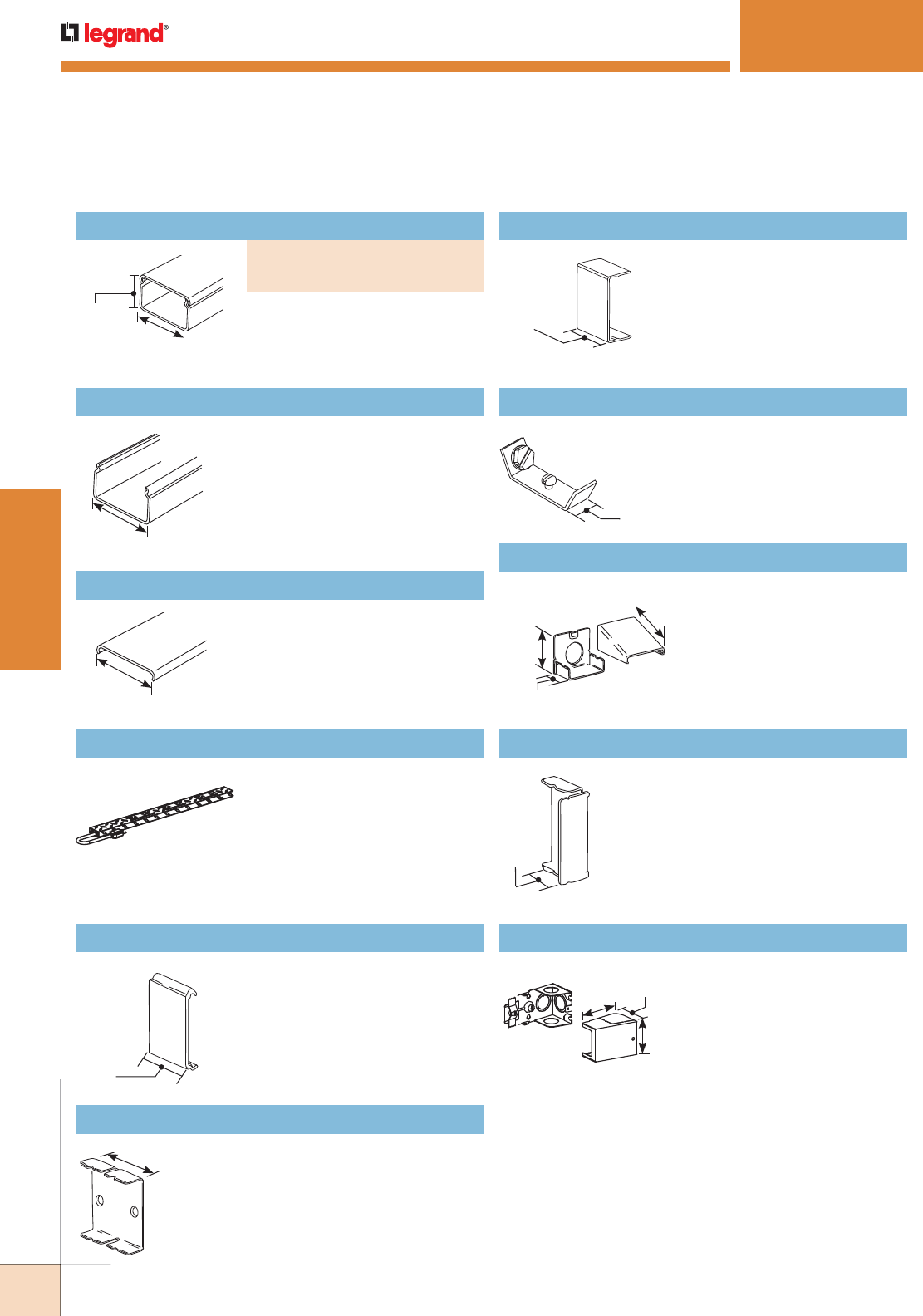
248
WWW.LEGRAND.US/WIREMOLD
WIREMOLD
PLUGMOLD SYSTEMS
V2406 Cover Clip
2409 Ground Clamp
V2410A Entrance End Fitting
V2410B Blank End Fitting
V2410C Entrance End Fitting
V2400C Raceway Cover
PM48T Multiple Outlet Strip (Diamond Plate Finish)
2400WC Wire Clip
V2400B Raceway Base
Packed ten 5' [1.5m] lengths of
each per carton.
Covers seam where lengths
of cover or base meet. Use
with Plugmold® 2400 Series.
(Nonmetallic.)
No. 10 ground screw provided.
Use with Plugmold® 2400
Series.
Connects Plugmold® 2400
Series with 1/2" trade size
conduit and armored cable.
Closes off open end of
Plugmold® 2400 Series.
Has 1/2" and 3/4" trade size
KOs on end and bottom.
Additional 1/2" trade size KO
on sides.
.040" [1.0mm] steel 5' [1.5m]
lengths. Packed (20) 5' [1.5m]
lengths per carton. V2400C Cover
has no receptacle hole cuts.
Diamond plate finish base
.040" [1.0mm] steel. Cover
.040" [1.0mm] steel. 48" [1.2m]
length. Provides five duplex 15A
receptacles. Packed three per
carton. PM48T Merchandiser available – 10 cartons of
PM48T packed in a merchandising display.Order as PM48
Holds conductors in place in
raceway.
.040" [1.0mm] steel. Packed twenty
5' [1.5m] lengths per carton.
7/8"
[22.2mm]
1 29/32"
[48mm]
1 29/32"
[48mm]
1 29/32"
[48mm]
1"
[25mm]
2401 Coupling
Joins lengths of raceway. Use with
Plugmold® 2400 Series.
2" [51mm]
1 1/2"
[38mm]
1/2"
[12.7mm]
2"
[51mm]
1 5/8"
[41mm]
1 3/16"
[46mm]
1 3/16"
[30mm]
2 11/16"
[68mm]
1 7/8"
[48mm]
2 1/8"
[54mm]
PLUGMOLD
®
2400 SERIES
™
Plugmold 2400 Series Ordering Information
Base and Cover
PART NUMBERS:
V2400B Base (.040" [1.0mm] steel)
V2400C Cover (.025" [.6mm] steel)
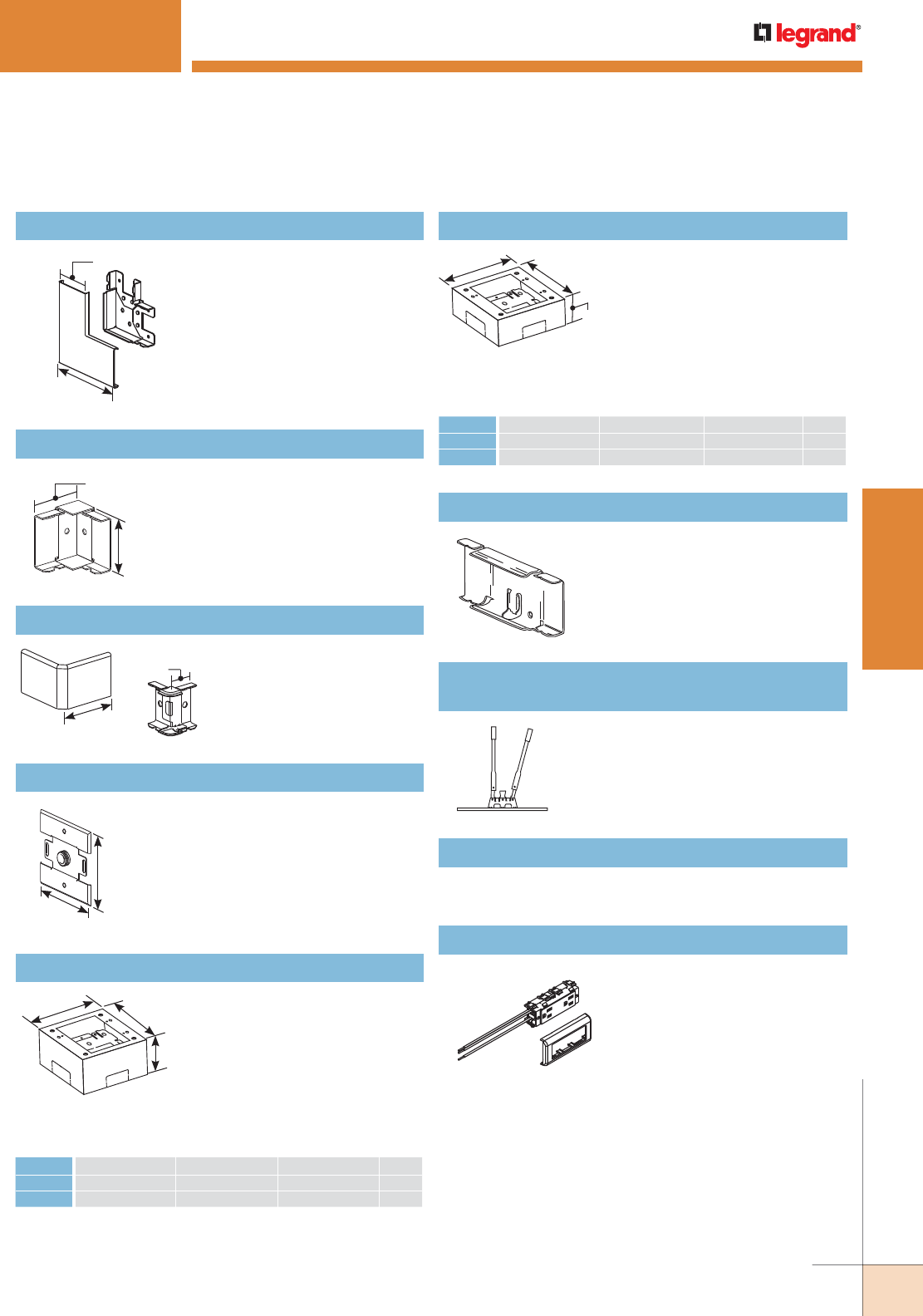
249
WWW.LEGRAND.US/WIREMOLD
WIREMOLD
PLUGMOLD SYSTEMS
V2411M Flat Elbow
Right angle turns on the same
surface.
3 15/16" [100mm]
Each Leg
1 29/32" [49mm]
V2417M Internal Elbow
Makes internal 90° corners.
All steel construction.
1 3/4"
[45mm]
1 29/32"
[49mm]
V2418M External Elbow
Covers outside corners.
(Nonmetallic Cover.)
3"
[76mm]
1 1/4"
[32mm]
V2451H Back Feed Fitting
Feeds Plugmold 2400 Series
Raceway from an existing
outlet box. Equipped with 1/2"
trade size male bushing and
locknut washer for grounding.
4 1/2"
[114mm]
4 1/2"
[114mm]
624BCK Replacement Blade Kit
Replacement blades and die set for 624 Cutter.
V2489 Side Reducing Connector
Connects Plugmold 2400
Series with 500 Series
Raceway.
Extra Deep Device Boxes
Base has rectangular
knockout to enable extension
from existing single-gang
flush wall box and 1/2" and 1"
concentric KOs. V2444 Cover
has two twistouts for 500 and
700 Series Raceway, and
two twistouts for 2400 Series Raceway. V2444-2 Cover has
four 2400 Series Raceway Series twistouts.
D
LW
CAT NO. L W D GANG
V2444 4 5/8" [117mm] 2 7/8" [73mm] 2 3/4" [44mm] 1
V2444-2 4 3/4" [121mm] 4 3/4" [121mm] 2 3/4" [44mm] 2
W
L
D
Base has 1/2" trade size
KO and rectangular KO for
extension to wall box. Has
#10 threaded hole for ground
connection. V2448 Cover
has two twistouts for 500
and 700 Series Raceway, and two twistouts for 2400 Series
Raceway. V2448-2 Cover has four 2400 Series Raceway
twistouts.
Device Boxes
CAT NO. L W D GANG
V2448 4 5/8" [117mm] 2 7/8" [73mm] 1 3/4" [44mm] 1
V2448-2 4 3/4" [121mm] 4 3/4" [121mm] 1 3/4" [44mm] 2
624 2400 and 2400D
Raceway Base and Cover Cutter
Portable cutter for 2400B and
2400BD Series Raceway.
V2427GA Duplex Receptacle
3-wire, 15A, 125V, NEMA
5-15R. Provided with 10 1/2"
[267mm] pigtails and inline
splice connectors. Ivory
receptacle with ivory trim
plate.
PLUGMOLD
®
2400 SERIES
™
Plugmold 2400 Series Ordering Information (continued)
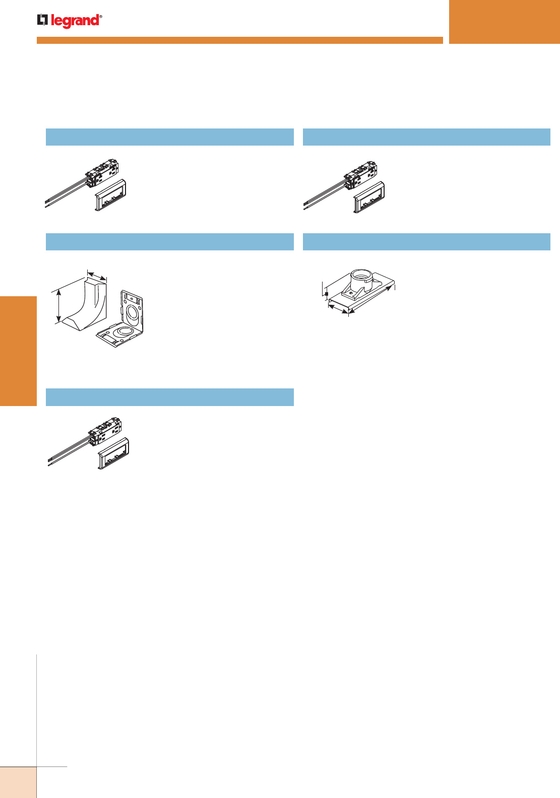
250
WWW.LEGRAND.US/WIREMOLD
WIREMOLD
PLUGMOLD SYSTEMS
V2427GT Duplex Receptacle
3-wire, 20A, 125V, NEMA 5-20R.
Provided with 10 1/2" [267mm]
pigtails and inline splice
connectors. Ivory receptacle
with ivory trim plate.
2686FO Transition Feed Fitting
Eliminates offsetting V2400
in connecting with surface
panel boxes. Has 3/4" and 1"
concentric trade size KOs with
1" trade size KO elongated so
adjustment from surface to
center of bushing is 1" [25mm]
minimum to 1 5/8" [41mm]
maximum. Has twistouts for
transition to Pancake 1500 and
2600 Series Raceway.
2 1/2"
[63mm]
3 5/8"
[92mm]
IG2427GA Isolated Ground Duplex Receptacle
3-wire, 15A, 125V NEMA 5-15R.
Provided with 10 1/2" [267mm]
pigtails and inline splice
connectors. Orange receptacle
with ivory trim plate.
IG2427GT Isolated Ground Duplex Receptacle
3-wire, 20A, 125V NEMA 5-20R.
Provided with 10 1/2" [267mm]
pigtails and inline splice
connectors. Orange receptacle
with ivory trim plate.
V2426 Lamp Holder
Medium base lamp holder
660W, 250V. Black, general
purpose phenolic.
5"
[127mm]
1 29/32"
[49mm]
1 9/16"
[40mm]
PLUGMOLD
®
2400 SERIES
™
Plugmold 2400 Series Ordering Information (continued)
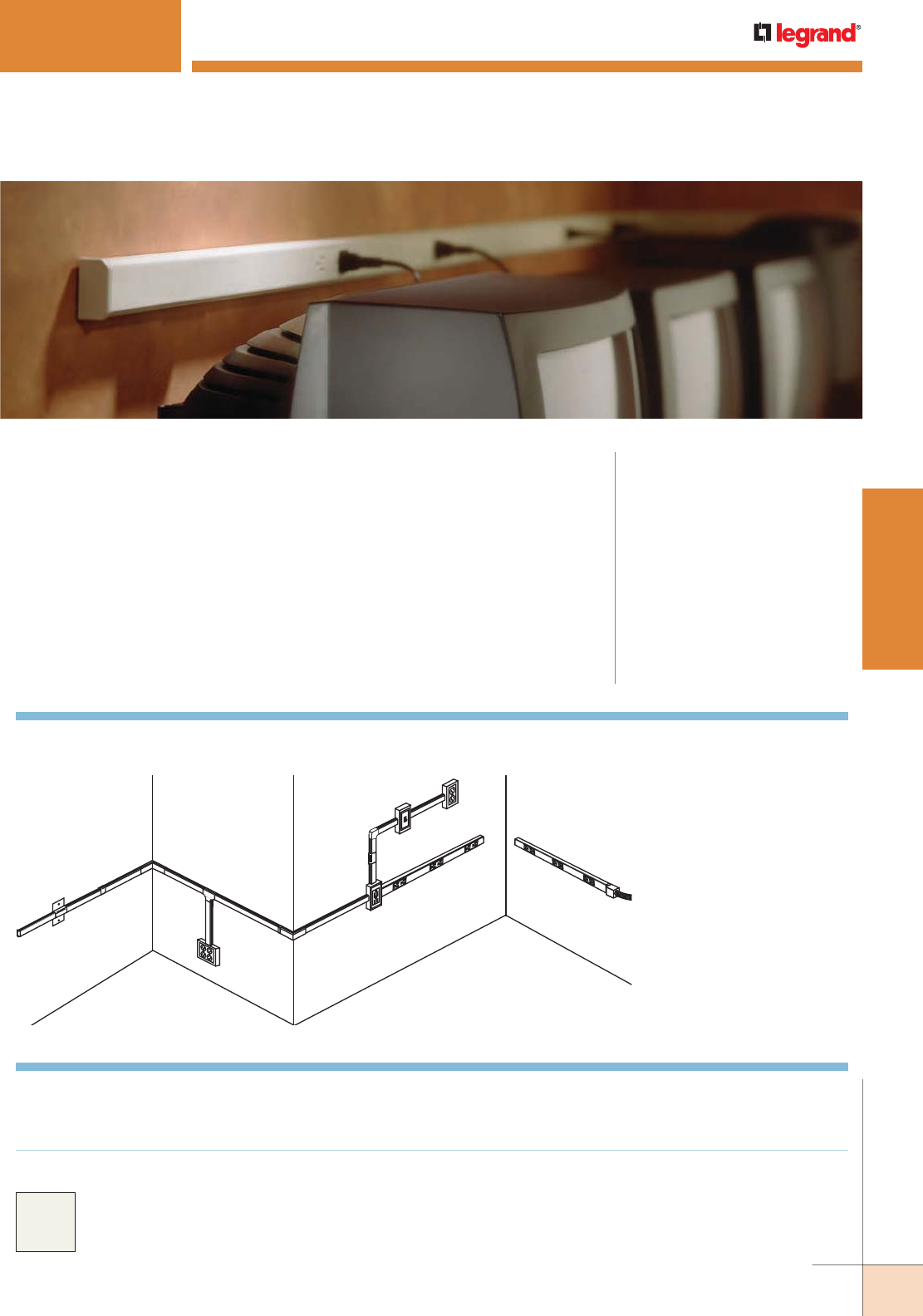
251
WWW.LEGRAND.US/WIREMOLD
WIREMOLD
PLUGMOLD SYSTEMS
PLUGMOLD
®
NM2000 SERIES
™
Two-piece, single channel raceway. Easy-to-install and ideal for basic power or
communication installations. CODE REFERENCE
cULus Listed Base & Blank Cover:
File E4376 Guide RJBT.
Multi-outlet Assemblies:
File E15191 Guide PVGT.
Fittings:
File E41751 Guide RJPR.
Base and Blank Cover and Plugmold
Series with Snapicoil Harness:
Meets Article 386 of NEC.
Meets Section 12-3032 of CEC.
Plugmold Wired Sections:
Meets Article 380 of NEC.
Meets Section 12-3032 of CEC.
BG
F
L
I
J
A,K
NM2010A Plugmold
C
D
E
NOTE: Illustration is for showing product applications only.
Plugmold NM2000 Series System Layout
Plugmold® Plus NM2000 Series™ Part Numbers without a
prefix have an ivory finish unless otherwise specified.
Custom color options are also available. Consult the factory
for more information.
COLOR OPTIONS
KEY
A. NM2010A Entrance End Fitting
B. NM2010B Blank End Fitting
C. NM2051H Horizontal Wall Box
Adapter
D. NM2006 Cover Clip
E. NM2017 Internal Elbow
F. NM2015 Tee Fitting
G. NM2048-2 Two-Gang Device Box
H. NM2018 External Elbow
I. NM2048 Single-Gang Device Box
J. NM2011 Flat Elbow
K. NM2010A Entrance End Fitting
L. NM2051V Vertical Wall Box
Adapter Plugmold Plus
Multi-outlet System
H
Plugmold
Plugmold

252
WWW.LEGRAND.US/WIREMOLD
WIREMOLD
PLUGMOLD SYSTEMS
Plugmold NM2000 Multi-outlet Strips
CAT NO. WIRING
CONFIG
Duplex Outlets
(15A 120V NEMA 5-15R)
LENGTH CENTER DISTANCE
Feet [mm] Inches [mm] QTY.
NM20GB412 GB 12 [305] 4
NM20GBA412 4 [1220] GBA 12 [305] 4
NM20IG412 IG 12 [305] 4
NM20GB512 GB 12 [305] 5
NM20GB515 GB 15 [381] 4
NM20GB530 5 [1525] GB 30 [762] 2
NM20GBA512 GBA 12 [305] 5
NM20IG512 IG 12 [305] 5
NM20GB609 GB 9 [229] 8
NM20GB612 GB 12 [305] 6
NM20GB618 GB 18 [457] 4
NM20GBA609 6 [1830] GBA 9 [229] 8
NM20GBA612 GBA 12 [305] 6
NM20IG612 IG 12 [305] 6
Plugmold NM2000 Series Wire Fill Capacities for Communications
CABLE/WIRE SIZE
O.D. Approx. Dia. 40%
FILLIn [mm]
UNSHIELDED
TWISTED PAIR
4-pair, 24 AWG, Cat 3 0.190 [4.8] 16
4-pair, 24 AWG, Cat 5e 0.210 [5.3] 13
4-pair, 24 AWG, Cat 6 0.250 [6.3] 9
4-pair, 24 AWG, Cat 6a* 0.354 [9.0] 4
25-pair, 24 AWG 0.410 [10.4] 3
COAXIAL RG6/U 0.270 [6.9] 7
Fiber ZipCord 0.118 x 0.236 [3 x 6] 16
Round 4 Strand Fiber 0.187 [4.8] 16
Round 6 Strand Fiber 0.256 [6.5] 8
NOTE: For additional information, refer to the Technical Section.
* Category 6 augmented (6a) cable for 10 gigabit ethernet – max allowed
cable diameter per addenda No. 11 ANSI TIA/EIA 568-B.2.
Plugmold NM2400 Multi-outlet Strips
CAT NO.
LENGTH WIRING
CONFIG
DUPLEX OUTLETS
(20A 120V NEMA 5-20R)
CENTER DISTANCE
Feet [mm] Inches [mm] QTY.
NM24GB412 GB 12 [305] 4
NM24GBA412 4 [1220] GBA 12 [305] 4
NM24GB512 GB 12 [305] 5
NM24GB530 5 [1525] GB 30 [762] 2
NM24GBA512 GBA 12 [305] 5
NM24GB612 GB 12 [305] 6
NM24GB618 6 [1830] GB 18 [457] 4
NM24GBA612 GBA 12 [305] 6
NOTE: Fed. Spec. duplex receptacles are made from high impact nylon and colored
to match the raceway
Plugmold NM2000 Series Wire
Fill Capacities for Power
WIRE SIZE
THHN/THWN
NUMBER OF
CONDUCTORSInches [mm]
14 AWG 0.111 [2.8] 45
12 AWG 0.130 [3.3] 31
10 AWG 0.164 [4.2] 15
Plugmold NM2000 with Snapicoil Harness
CAT NO.
LENGTH WIRING
CONFIG
DUPLEX OUTLETS
(15A 120V NEMA 5-15R) NM2000B & NM2000C
CENTER DISTANCE LENGTH
Feet [mm] Inches [mm] QTY. QTY. Feet [m]
NM20GB12 48 [14.6] GB 12 [305] 48 8 6 [1.830]
NM20GBA12 48 [14.6] GBA 12 [305] 48 8 6 [1.830]
PLUGMOLD
®
NM2000 SERIES
™
O.D.
GB SERIES:
3-wire #12 THHN solid (1 hot, 1 neutral, and 1 ground),
1-circuit; has insulated grounding conductor.
GBA SERIES:
4-wire #12 THHN solid (2 hot, 1 neutral, and 1 ground),
2-circuits; outlets wired alternately; has insulated
grounding conductor.
IG SERIES:
3-wire #12 THHN solid (1 hot, 1 neutral, and 1 ground),
1 circuit; has insulated-isolated grounding conductor,
orange receptacle.
REELS: Reels available as follows:
• Lengths greater than 50' [15.2m]
• Multiple lengths
• For outlet spacing of 12" and 18" [305mm and 457mm],
the maximum length is 240' [73m] per reel.
• For outlet spacing of 30" [762mm], the
maximum length is 500' [152m] per reel.
Packaging includes the necessary lengths of NM2000B
Base, NM2000C Hole Cut Cover, NM2000WC Wire Clips,
and 2001 Couplings for complete installation. Price and
delivery information should be obtained prior to specifying
or ordering. To specify or order, add R to the Snapicoil
Harness number. Ex: NM20GB12. Other outlet spacings
available on custom order, contact your field sales
representative or Specialized Products at 1-800-621-0049.
Plugmold NM2000 Wiring Configuration
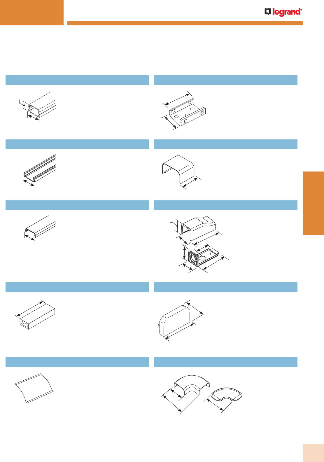
253
WWW.LEGRAND.US/WIREMOLD
WIREMOLD
PLUGMOLD SYSTEMS
PLUGMOLD
®
NM2000 SERIES
™
Ordering Information
NM2000BC Base and Cover
NM2000B and NM2000C packed
ten 5' [1.5m] lengths of each per
carton.
1 3/4"
[44mm]
1"
[25mm]
NM2000B Raceway Base
Single channel plastic base,
ivory finish. Packed ten 8' [2.4m]
lengths per carton.
1 3/4"
[44mm]
NM2000C Raceway Cover
Tapered snap-on cover.
Textured ivory finish. Packed
ten 8' [2.4m] lengths per carton.
1 3/4"
[44mm]
Pressure-Type Wire Connectors
W30 – For common connection
of two, three, or four No. 12 or
No.14 solid copper conductors.
W30G – For connection of
equipment grounding of 2, 3, or
4 solid conductors No. 14 or No.
12 AWG. 300V maximum; 20A
105° C maximum.
1 5/16"
[33mm]
NOTE: Not for use with
aluminum conductors.
NM2000WC Wire Clip
Holds wire or cable in place or
for use when conductors bypass
receptacles.
NM2003 Supporting Clip
Supports lengths of raceway
at any point desired. Mount
to surface with No. 8 flathead
screw.
1 3/4"
[44mm]
2"
[51mm]
NM2006 Cover Clip
Covers seam where lengths of
cover or base meet.
1 1/2"
[38mm]
NM2010A Entrance End Fitting
1 9/16"
[40mm]
1 3/4"
[44mm]
1 3/4"
[44mm]
1 1/2"
[38mm]
1 3/4"
[44mm]
3 13/16"
[97mm]
3 3/8"
[86mm]
To end feed raceway
or Plugmold strip. Has
1/2" trade size KO on
end and bottom.
NM2010B Blank End Fitting
Closes off open end of NM2000
Series Raceway.
1 15/16"
[49mm]
1 1/16"
[27mm]
NM2011 Flat Elbow
Right angle turns on same
surface.
2 11/16"
[68mm]
1 7/8"
[48mm]
3 3/16"
[81mm]
Plugmold NM2000 Series Ordering Information (continued)
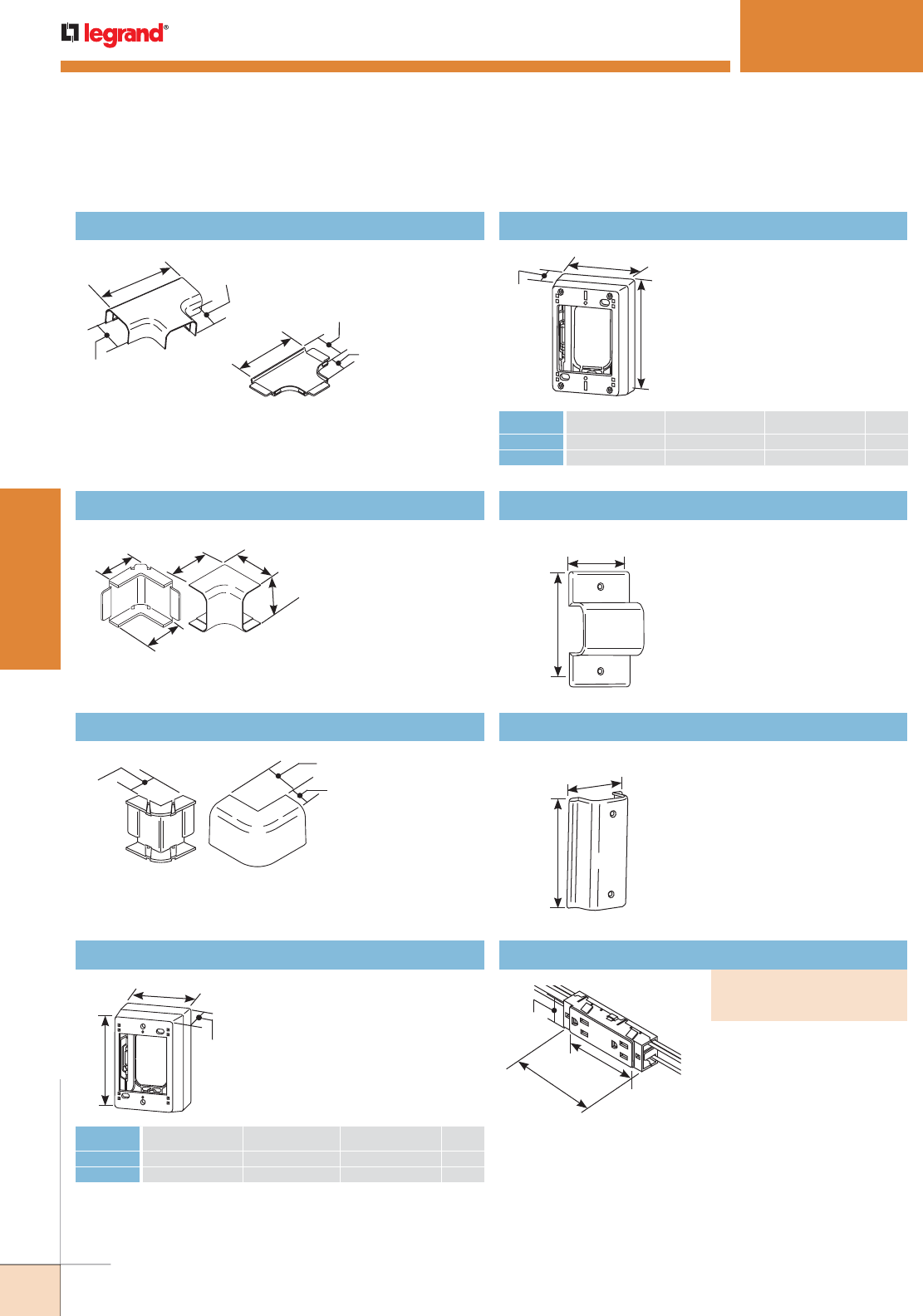
254
WWW.LEGRAND.US/WIREMOLD
WIREMOLD
PLUGMOLD SYSTEMS
Replacement Receptacles
PART NUMBERS:
NM2027-15 (15 Amp)
NM2027-20 (20 Amp)
PLUGMOLD
®
NM2000 SERIES
™
NM2015 Tee
Branches NM2000 Series
Raceway at right angles.
4 1/2"
[114mm]
1 7/8"
[48mm]
1 5/16"
[33mm]
3 11/16"
[94mm] 1"
[25mm]
1 5/8"
[41mm]
NM2017 Internal Elbow
Right angle turns at
inside corners.
2"
[51mm] 2"
[51mm]
1 7/8"
[48mm]
1 5/8"
[41mm]
1 5/8"
[41mm]
NM2018 External Elbow
Used for making
90° turns at outside
corners.
1 3/8"
[35mm]
1"
[25mm]
1"
[25mm]
Extra Deep Device Boxes
Mounts power/communications
devices when additional depth
is required. Has combination
twistouts for 2700, 2800, 2900,
and NM2000 Series Raceways.
L
D
W
CAT NO. L W D GANG
NM2044
4 3/4" [121mm] 3" [76mm] 2 3/4" [70mm] 1
NM2044-2
4 3/4" [121mm] 4 7/8" [124mm] 2 3/4" [70mm] 2
Sure-Snap® Deep Device Box
Cover snaps onto base – no
screws required. Cover
has twistouts on all sides.
Rectangular KO in base for
extension to wall box.
CAT NO. L W D GANG
NM2048
4 3/4" [121mm] 3" [76mm] 1 3/4" [44mm] 1
NM2048-2
4 3/4" [121mm] 4 7/8" [124mm] 1 3/4" [44mm] 2
D
L
W
NM2051H Horizontal Wall Box Adapter
Feeds NM2000 Series Raceway
from an existing wall outlet
for horizontal applications.
Provides complete access to
wall box for connections.
2 3/4"
[70mm]
4 1/2"
[114mm]
NM2051V Vertical Wall Box Adapter
Feeds NM2000 Series Raceway
from an existing wall outlet for
vertical applications. Provides
complete access to wall box for
connections.
2 3/4"
[70mm]
4 1/2"
[114mm]
15 and 20A replacement
devices. 6" [152mm] wire
leads each side.
3 3/16"
[81mm]
1 1/8"
[29mm]
4"
[102mm]
Plugmold NM2000 Series Ordering Information (continued)
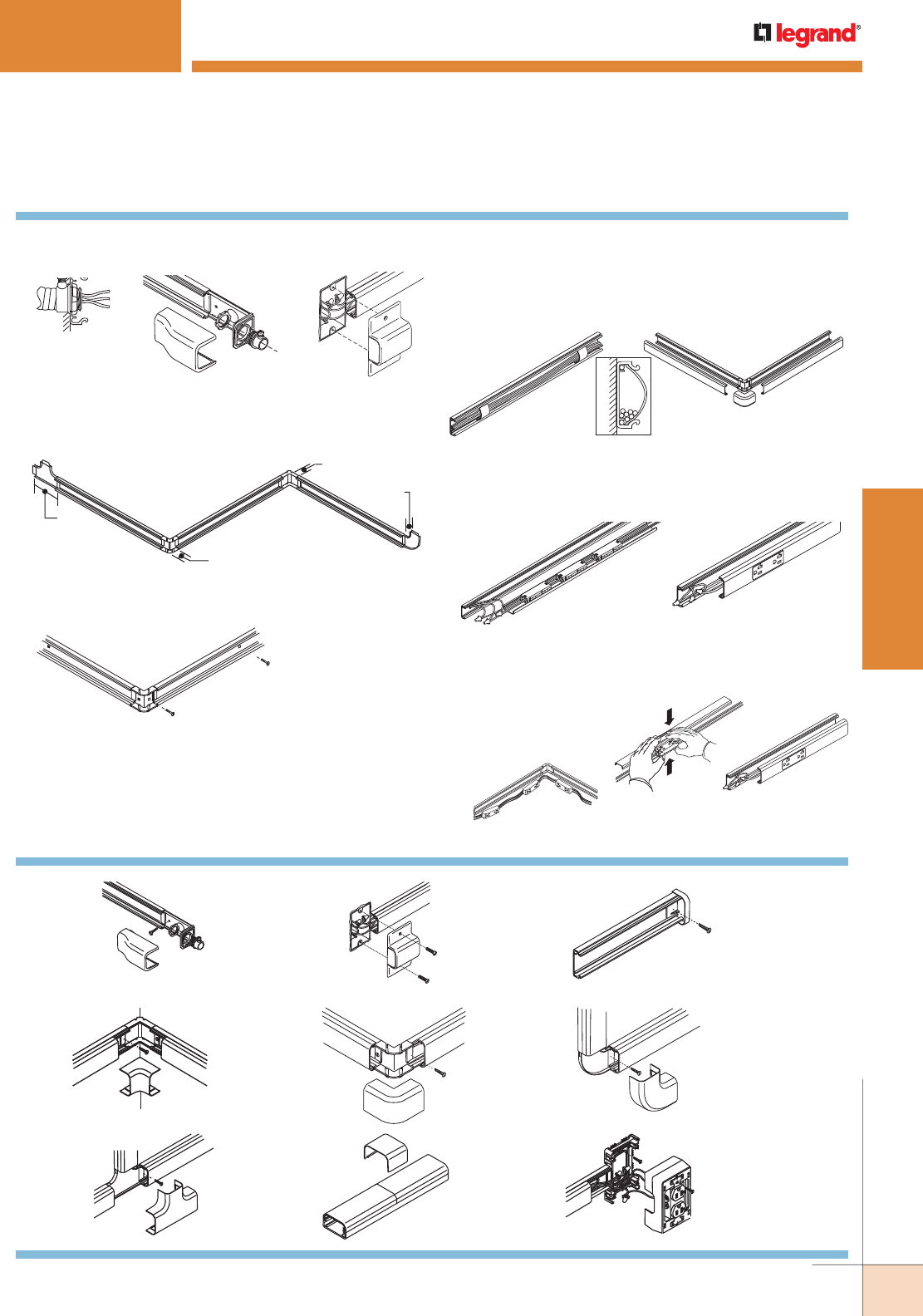
255
WWW.LEGRAND.US/WIREMOLD
WIREMOLD
PLUGMOLD SYSTEMS
PLUGMOLD
®
NM2000 SERIES
™
Installation Details
1. Lay out raceway path. Determine feed method and
location from figures A, B, and C below.
2. Measure and cut raceway base and cover. See common
fitting dimensions below.
Fig. A
Fig. B Fig. C
3. Install raceway and fitting bases using No.8 flathead
screws.
4. Wiring Method – Refer to Instructions A through E
according to your application
A FIELD WIRED RACEWAY
A1 Install wire in raceway A2 Snap on raceway and install
wire clips fitting covers.
as needed.
1 3/4"
[44mm]
1 5/8" [41mm] from
Edge of Wall
1" [25mm] from
Edge of Wall
1 1/16"
[27mm]
B WIRED COVER SECTIONS
B1 Connect receptacle B2 Snap cover/harness
harness to feed point, assembly onto base and
using approved methods. snap on fitting covers.
Plugmold NM2000 Series Installation Details
NM2010B
Blank End Fitting
NM2010A
Entrance
End Fitting
NM2051H
(Shown)
Wall Box
Adapter
NM2011
Flat Elbow
NM2017
Internal
Elbow
NM2018
External
Elbow
NM2048
Device Box
NM2015
Tee Fitting
NM2006
Cover Clip
Plugmold NM2000/NM2400 Series Installation Details
C SNAPICOIL HARNESS
C1 Lay out Snapicoil C2 Snap receptacles C3 Snap wired
Harness so that into NM2000 cover section
receptacles are not Cover. onto base.
located over feed
point or at corners.
Connect harness
to feed point.
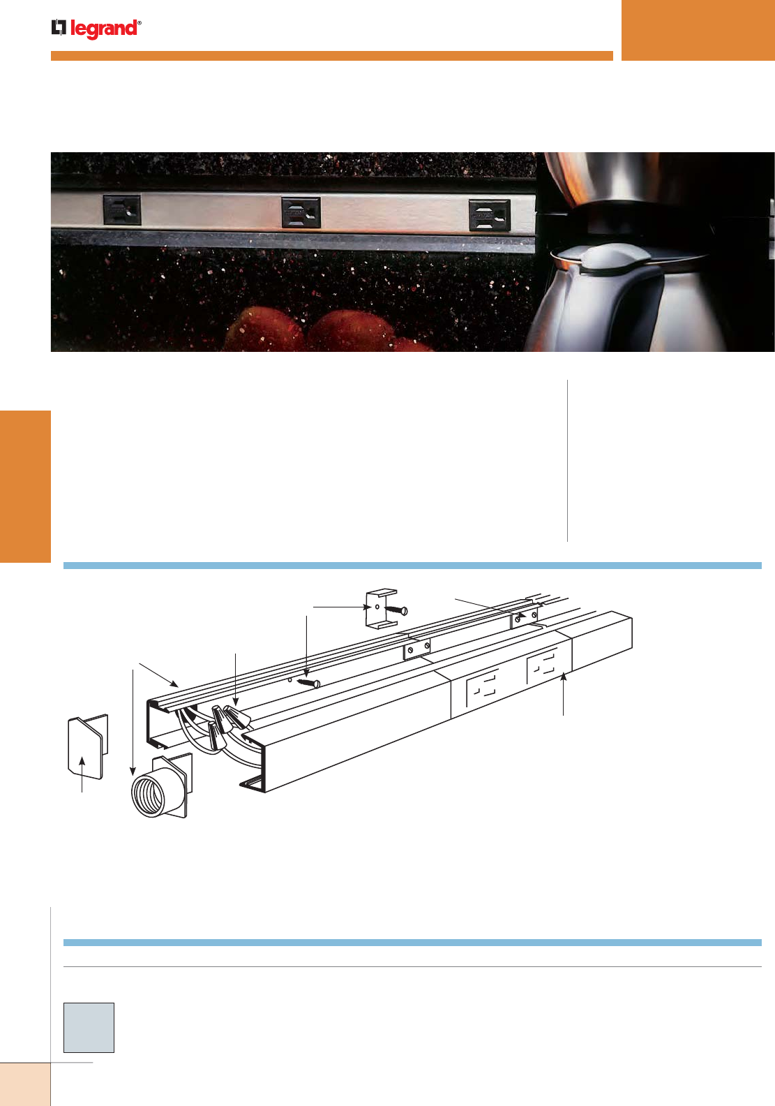
256
WWW.LEGRAND.US/WIREMOLD
WIREMOLD
PLUGMOLD SYSTEMS
C
A
B
D
E
F
KEY
A Supply conductors may be fed from 1/2"
[12.7mm] KO in base, or through AL2010A
Feed Fitting. This system is designed with
capacity for additional feed or circuitry
conductors.
B Attach base section to mounting surface
with AL2003 Spring Mounting Clips or by
drilling 9/32" [7.1mm] holes in the base
and using #8 flathead screws.
C Connect circuit wires with connectors.
D Additional multiple outlet sections or
AL2000 Raceway sections may be attached
at ends with AL2001 Coupling.
E Close ends with blank end fitting
(AL2010B), or with feed fittings (AL2010A).
F Snap in cover section.
PLUGMOLD
®
AL2000 SERIES
™
Low profile multiple outlet system with an aesthetic finish. CODE REFERENCE
cULus Listed Base & Blank Cover:
File E4376 Guide RJBT.
Multi-outlet Assemblies:
File E15191 Guide PVGT.
Fittings:
File E41751 Guide RJPR.
Base & Blank Cover:
Meets Article 386 of NEC.
Plugmold Strips:
Meets Article 380 of NEC.
IMPORTANT:
All mounting methods
must result in a flush
interior surface. Special
outlet assemblies
manufactured to
specifications. Consult
factory.
NOTE: Illustration is for showing
product applications only.
NOTE:
To remove cover, insert
screwdriver into groove,
push down and twist.
Plugmold AL2000 Series System Layout
Plugmold® AL2000 Series™ Part Numbers without a prefix have
an satin anodized finish unless otherwise specified.
Custom color options are also available. Consult the
factory for more information.
COLOR OPTIONS
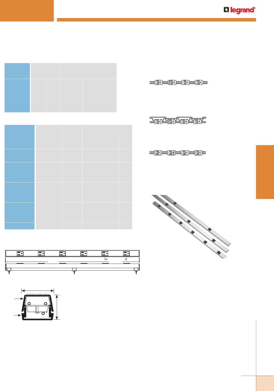
257
WWW.LEGRAND.US/WIREMOLD
WIREMOLD
PLUGMOLD SYSTEMS
PLUGMOLD
®
AL2000 SERIES
™
WIRE SIZE
THHN/THWN
NUMBER OF CONDUCTORS
Inches [mm]
WITHOUT
DEVICES
WITH PLUGMOLD
RECEPTACLE
14 AWG 0.111 [2.8] 51 8
12 AWG 0.130 [3.3] 38 6
10 AWG 0.164 [4.2] 24 3
8 AWG 0.216 [5.5] 12
6 AWG 0.254 [6.5] 8
Plugmold AL2000 Series Multi-outlet Strips
Length WIRING
CONFIG.
SINGLE OUTLETS
(15A 120V NEMA 5-15R)
CENTER DISTANCE
CAT. NO.* Feet [mm] Inches [mm] QTY.
AL20GB306 3 [915] GB 6 [152] 6
AL20IG306 IG 6 [152] 6
AL20GB506 GB 6 [152] 10
AL20GB512 5 [1525] GB 12 [305] 5
AL20IG506 IG 6 [457] 10
AL20GB606 GB 6 [152] 12
AL20GB612 GB 12 [305] 6
AL20GB618 GB 18 [457] 4
AL20GBA606 6 [1830] GBA 6 [152] 12
AL20GBA612 GBA 12 [305] 6
AL20GBA618 GBA 18 [457] 4
AL20IG606 IG 6 [152] 12
* AL2000 Series Plugmold has gray outlets. Each AL2000 Plugmold strip is supplied
with two AL2010B Blank End Fittings and one AL2001 Coupling.
Center
Distance
Length
1 7/16"
[37mm]
1 1/8"
[29mm]
Cover
Base
GB SERIES:
3-wire #12 THHN solid, 1-circuit; has insulated
grounding conductor. Gray receptacles.
GBA SERIES:
4-wire #12 THHN solid, 2-circuit; outlets wired
alternately; has insulated grounding conductor.
Gray receptacles.
IG SERIES:
3-wire #12 THHN solid, 1 circuit; has insulated-isolated
grounding conductor. Orange receptacles.
AL20GB306
AL20GB612
AL20GB618
Plugmold AL2000 Series Wiring Configuration
O.D.
Plugmold AL2000 Series Wire Fill Capacities for Power
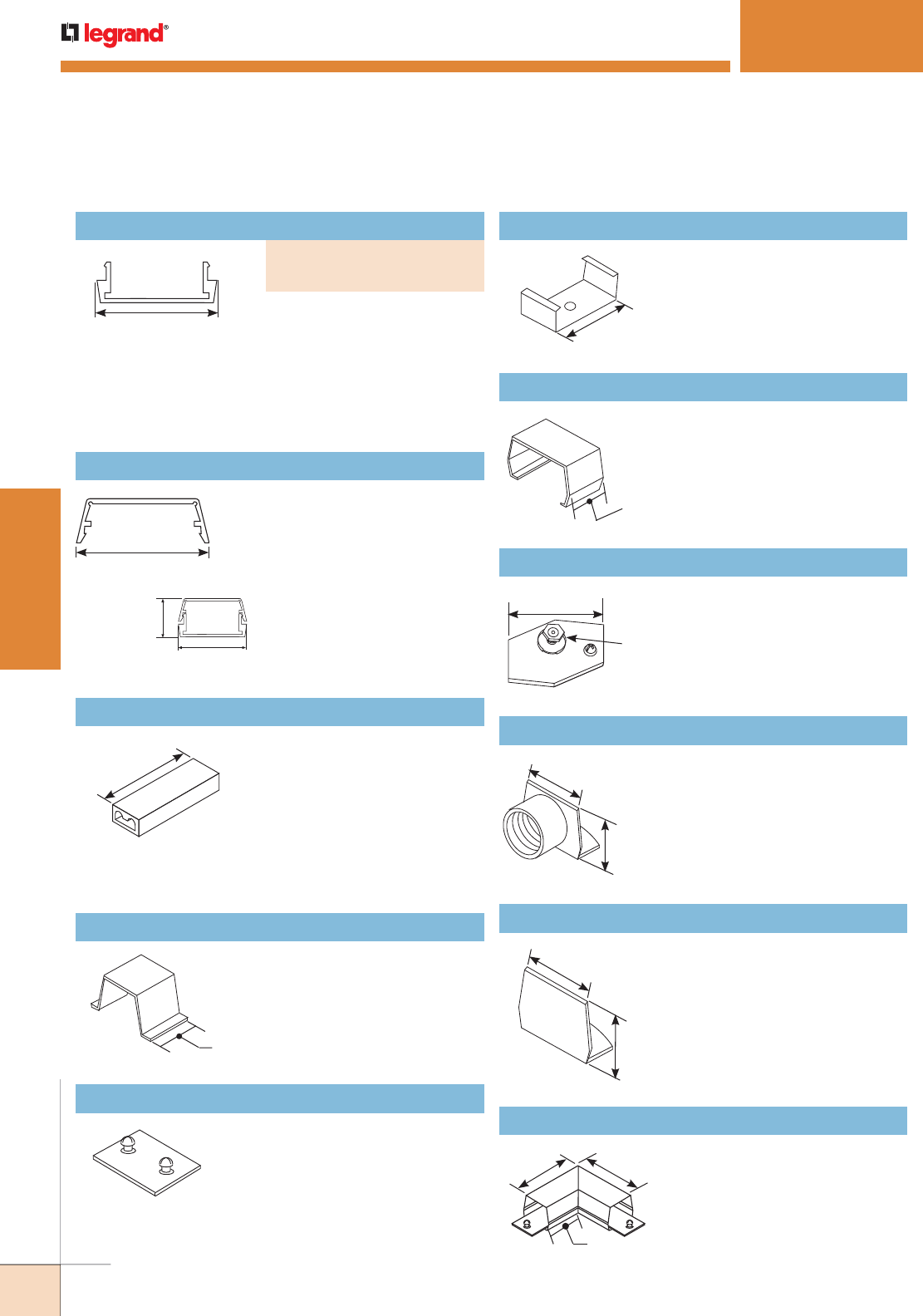
258
WWW.LEGRAND.US/WIREMOLD
WIREMOLD
PLUGMOLD SYSTEMS
PLUGMOLD
®
AL2000 SERIES
™
6063-T5 extruded aluminum,
satin anodized finish, .060"
[1.5mm] nominal thickness.
Packed (12) 5' [1.5m] lengths
(AL2000B-5) or six 10' [3m]
lengths (AL2000B-10) per
carton.
1 7/16"
[37mm]
AL2000C-5 Raceway Cover
6063-T5 extruded aluminum,
satin anodized finish, .060"
[1.5mm] nominal thickness.
Packed (12) 5' [1.5m] lengths
per carton.
1 7/16"
[37mm]
AL2000 Base and Cover shown
assembled. Cross sectional area 1in.2
[1037mm2].
1 1/8"
[29mm]
1 7/16"
[37mm]
Pressure-Type Wire Connectors
W30 – For common connection
of two, three, or four No. 12 or
No.14 solid copper conductors.
W30G – For connection of
equipment grounding of 2, 3, or
4 solid conductors No. 14 or No.
12 AWG. 300V maximum; 20A
105° C maximum.
1 5/16"
[33mm]
NOTE: Not for use with
aluminum conductors.
AL2000WC Wire Retainer (Nonmetallic)
Holds conductors in place in
raceway base.
3/4"
[19.1mm]
AL2001 Slide Coupling
Connects adjoining sections of
AL2000 Series Raceway base.
AL2003 Mounting Clip (Spring Steel)
Supports lengths of AL2000
Series Raceway at any point
desired. Mount to surface with
No. 8 flathead screw.
1 7/16"
[37mm]
AL2006 Cover Clip (Spring Steel)
Covers seam where lengths of
cover or base come together.
1"
[25mm]
AL2009 Ground Clamp (Galvanized Steel)
Connects equipment grounding
conductor to provide additional
ground to raceway.
Ground Stud
1 1/2"
[38mm]
AL2010A Feed Fitting
End fitting with 1/2" [12.7mm]
hub adapter.
1 3/8"
[35mm]
1"
[25mm]
AL2010B Blank End Fitting
Closes off end of AL2000 Series
Raceway.
1"
[25mm]
1 3/8"
[35mm]
AL2011 Flat Elbow
Right angle turn on same
surface. Comes with two
couplings.
3"
[76mm]
3"
[76mm]
1 9/16"
[40mm]
Plugmold AL2000 Series Ordering Information
Raceway Base
PART NUMBERS:
AL2000B-5 (5' Length)
AL2000B-10 (10' Length)
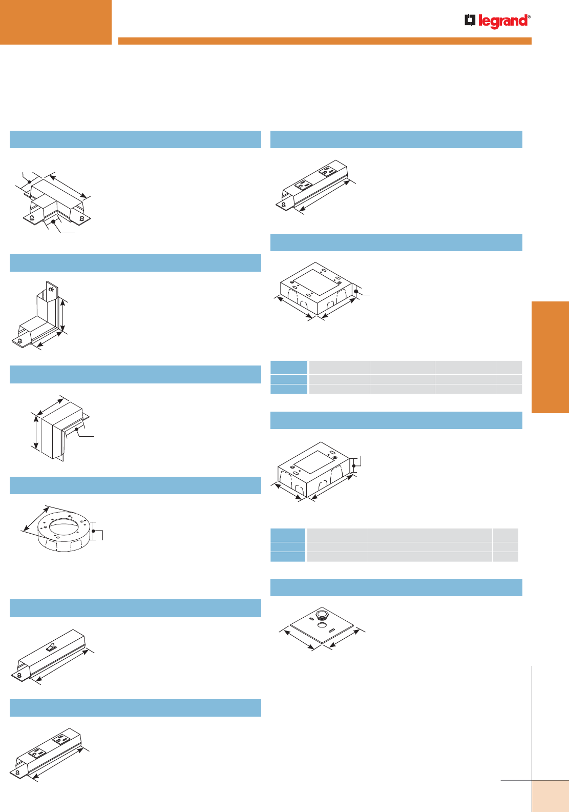
259
WWW.LEGRAND.US/WIREMOLD
WIREMOLD
PLUGMOLD SYSTEMS
PLUGMOLD
®
AL2000 SERIES
™
AL2015 Tee
Branch connection of two runs
of AL2000 Series Raceway.
Comes with three couplings.
4"
[102mm]
1 7/16"
[37mm]
1 9/16"
[40mm]
AL2017 Internal Elbow
Makes 90° internal corners.
Two couplings furnished.
3"
[76mm]
3"
[76mm]
AL2018 External Elbow
Makes 90° external corners.
Two couplings furnished.
1 7/8"
[48mm]
3"
[76mm]
3"
[76mm]
AL2038 Round Fixture Box (Solid Base)
Designed for use in hanging
fixtures. Cover takes any device
with mounting screw centers
of 2 3/4", 3 1/2" and 4 1/16"
[70mm, 89mm and 103mm].
Base has concentric 1/2" and
3/4" trade size KOs. Not rated
for fan use.
4 13/16"
[122mm]
1 3/8"
[35mm]
AL2040A In-Line Single Pole Switch
Single pole 120V Black switch.
Two couplings furnished.
6"
[152mm]
AL2043 In-Line Receptacle
Two 15A, 120V U-ground factory
wired receptacles.
Two couplings furnished.
6"
[152mm]
AL2043IG In-Line Isolated Ground Receptacle
Two 15A, 120V factory wired
isolated ground orange
receptacles. Two couplings
furnished.
6"
[152mm]
AL2051H Box Adapter
Used to feed raceway from
existing wall outlet box. Accepts
up to 5/8" trade size conduit.
4 1/2"
[114mm]
4 1/2"
[114mm]
Deep Device Box
For larger receptacles and deep
devices such as those of signal
and alarm systems. Base has
open back plate for mounting to
existing wall box and solid back
plate insert with 1/2" and 3/4"
trade size KOs to close opening.
Not for use on AL2400 Series
Raceway.
WL
D
CAT NO. L W D GANG
AL2044
4 5/8" [117mm] 3 1/16" [78mm] 2 1/4" [57mm] 1
AL2044-2
4 5/8" [117mm] 4 27/32" [123mm] 2 1/2" [64mm] 2
Shallow Switch Receptacle Boxes
Designed for standard shallow
switches and receptacles.
Base has open back plate for
mounting to existing wall box
and solid back plate insert with
1/2" and 3/4" trade size KOs to
close opening. Not for use on
AL2400 Series Raceway.
L
W
D
CAT NO. L W D GANG
AL2047
4 5/8" [117mm] 3 1/16" [78mm] 1 3/8" [35mm] 1
AL2047-2
4 5/8" [117mm] 4 27/32" [123mm] 1 3/8" [35mm] 2
Plugmold AL2000 Series Ordering Information (continued)
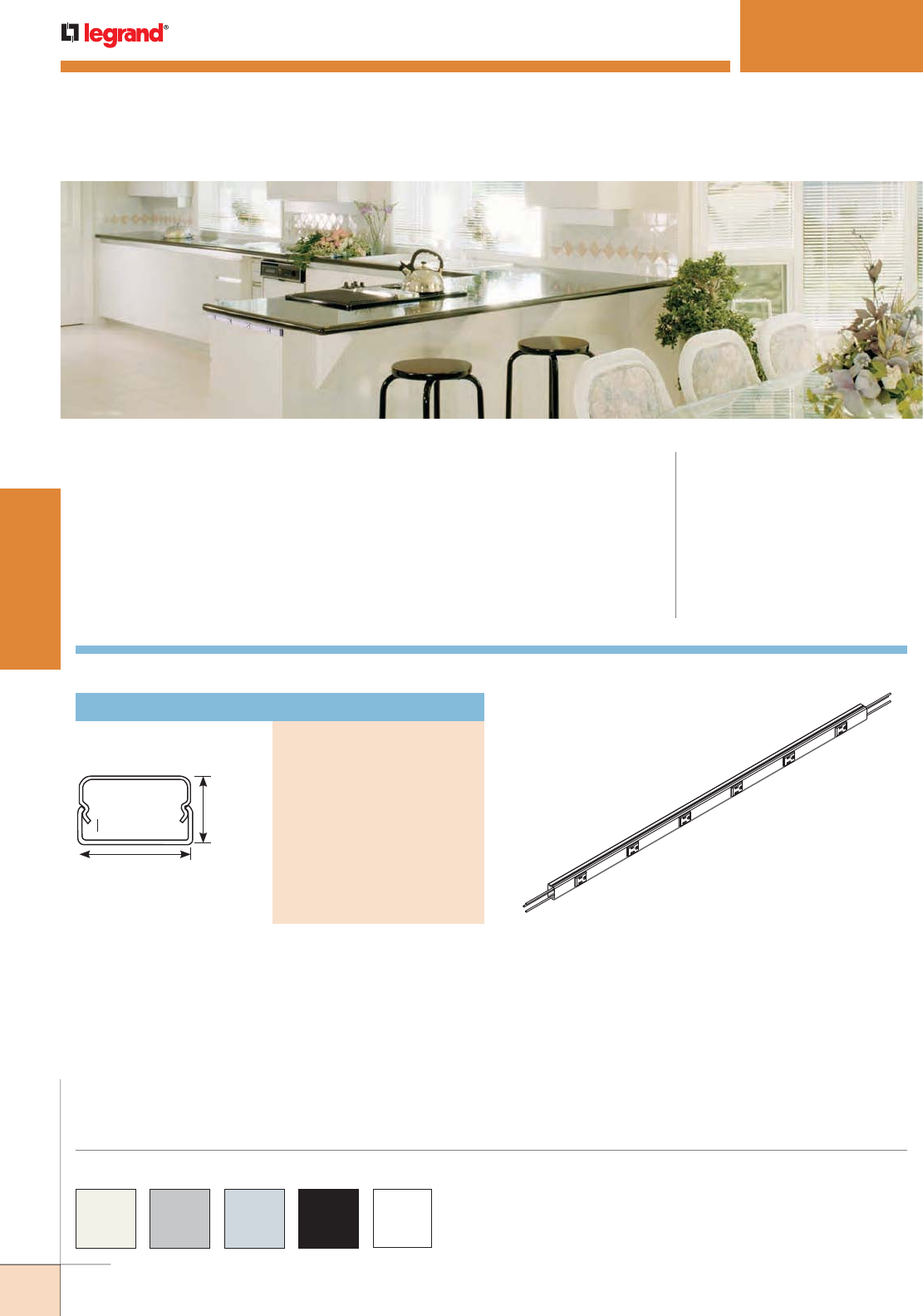
260
WWW.LEGRAND.US/WIREMOLD
WIREMOLD
PLUGMOLD SYSTEMS
2000 Series Plugmold is available in an Ivory, Gray, Black, or White baked enamel finish
or in durable stainless steel or satin anodized aluminum unless otherwise specified in
the part number description.
Custom color options are also available. Consult the factory for more information.
V20GB306TR
PLUGMOLD
®
2000TR SERIES
™
Plugmold® 2000TR Series™ Tamper-Resistant Multi-outlet Systems meet
the 2008 NEC requirement 406.11 for Tamper Resistant receptacles in
dwelling units.
CODE REFERENCE
cULus Listed Base & Blank Cover:
File E4376 Guide RJBT.
Multi-outlet Assemblies:
File E15191 Guide PVGT.
Fittings:
File E41751 Guide RJPR.
Base & Blank Cover
Meets Article 386 of NEC.
Plugmold Strips:
Meets Article 380 of NEC.
Available in 3' [914mm] and 5' [1.5m] lengths with 6"
[152mm] receptacle spacing. 15A tamper-resistant
receptacles. 3-wire, #12 THHN (1 hot, 1 neutral, and
insulated ground conductor). .040" [1.0mm] steel housing.
Packed 2 per carton. Each unit supplied with one (1)
Coupling and two (2) Blank End Fittings.
1 9/32"
[32mm]
3/4"
[19.1mm]
Plugmold 2000TR Series
Cross Section
Steel Plugmold 2000TR Series Ordering Information
COLOR OPTIONS
Tamper-Resistant Plugmold
PART NUMBERS:
V20GB306TR
V20GB506TR (Ivory)
WH20GB306TR
WH20GB506TR (White)
G20GB306TR
G20GB506TR (Gray)
BK20GB306TR
BK20GB506TR (Black)
S20GB306TR
S20GB506TR
S20GB606TR (Stainless Steel)
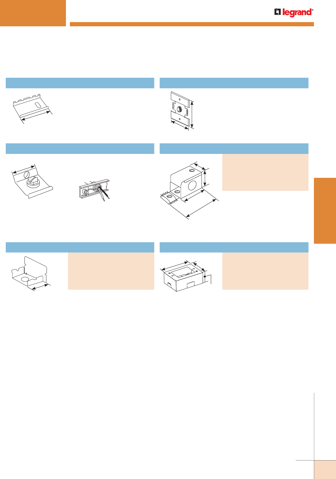
261
WWW.LEGRAND.US/WIREMOLD
WIREMOLD
PLUGMOLD SYSTEMS
PLUGMOLD
®
2000TR SERIES
™
2001 Coupling
Joins lengths of Plugmold 2000TR
Series together.
2"
[51mm]
2009 Ground Clamp
Connects equipment grounding
conductor to Plugmold 2000TR
Series.
1 13/64"
[30mm]
How 2009 is used.
Blank End Fitting
PART NUMBERS:
V2010B (Ivory)
WH2010B (White)
G2010B (Gray)
BK2010B (Black)
S2010B (Stainless Steel)
Closes off open end of sections of
Plugmold 2000TR Series.
3/4"
[19.1mm]
V2051H Back Feed Fitting
Feeds Plugmold 2000TR Series
from an existing outlet box.
Equipped with 1/2" trade size male
bushing and lock nut washer for
grounding.
4 1/2"
[114mm]
4 1/2"
[114mm]
Entrance End Fitting
PART NUMBERS:
V2010A2 (Ivory)
WH2010A2 (White)
G2010A2 (Gray)
BK2010A2 (Black)
S2010A2 (Stainless Steel)
Connects Plugmold 2000TR Series
with 1/2" trade size conduit and
armored cable connectors. 1/2"
trade size KOs on end, each side
and bottom. Includes ground
screw.
3"
[76mm]
1 9/32"
[33mm]
1 1/2"
[38mm]
2 1/8"
[54mm]
Steel Plugmold 2000TR Series Ordering Information (continued)
One-gang device box. Cover has one twistout for 2000 Series
Plugmold on two sides and one twistout for 500® and 700®
Series Raceway on the top and bottom. Base includes
knockout to enable extension from existing single-gang
flush wall box and 1/2" trade size KOs. Accepts industry
standard faceplates for electrical and communication
devices.
4 5/8"
[117mm] 2 7/8"
[73mm]
1 3/4"
[44mm]
Entrance End Fitting
PART NUMBERS:
V2040B (Ivory)
WH2040B (White)
G2040B (Gray)
BK2040B (Black)
S2040B (Stainless Steel)
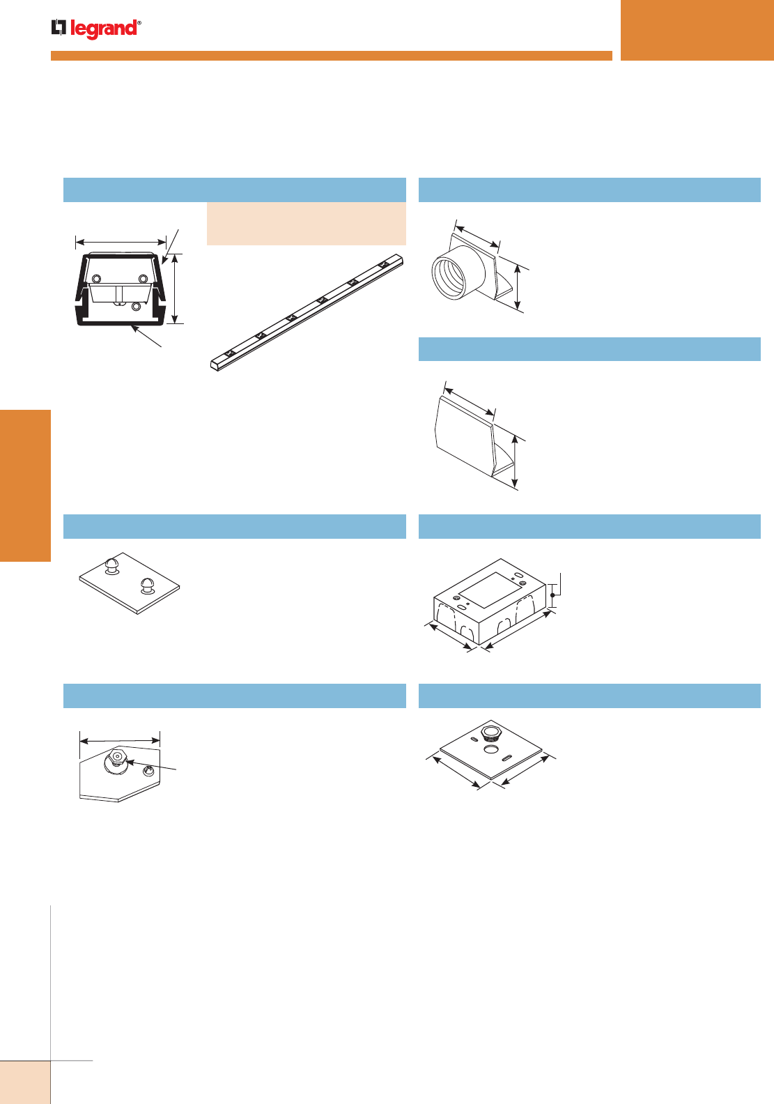
262
WWW.LEGRAND.US/WIREMOLD
WIREMOLD
PLUGMOLD SYSTEMS
Tamper-Resistant Plugmold
PART NUMBERS:
AL20GB306TR (3' [914mm] Length)
AL0GB506TR (5' [1.5m] Length)
Aluminum Plugmold 2000TR Series Ordering Information
PLUGMOLD
®
2000TR SERIES
™
Available in 3' [914mm] and 5' [1.5m] lengths with 6"
[152mm] receptacle spacing. 15A tamper-resistant
receptacles. 3-wire, #12 THHN (1 hot, 1 neutral, and
insulated ground conductor). .060" [1.5mm] 6063-T5
extruded aluminum housing with satin anodized finish.
Packed 2 per carton. Each unit supplied with one (1)
Coupling and two (2) Blank End Fittings.
1 7/16"
[37mm]
1 1/8"
[29mm]
Cover
Base
AL20GB306TR
AL2001 Coupling
Connects adjoining sections of
AL2000 Series Raceway base.
AL2009 Ground Clamp
(Galvanized Steel) Connects
equipment grounding conductor
to provide additional ground to
raceway.
Ground
Stud
1 1/2"
[38mm]
AL2010A Feed Fitting
End fitting with 1/2" [12.7mm]
hub adapter.
1 3/8"
[35mm]
1"
[25mm]
AL2010B Blank End Fitting
Closes off open end of sections
of AL2000 Series Raceway.
1"
[25mm]
1 3/8"
[35mm]
AL2047 Shallow Switch and Receptacle Box
Designed for standard shallow
switches and receptacles.
Base has open back plate for
mounting to existing wall box
and solid back plate insert with
1/2" and 3/4" trade size KOs to
close opening. Not for use with
AL2400 Series Raceway.
3 1/16"
[78mm]
4 5/8""
[117mm]
1 3/8""
[35mm]
AL2051H Box Adapter
Used to feed raceway from
existing wall outlet box. Accepts
up to 5/8" trade size conduit.
4 1/2"
[114mm]
4 1/2"
[114mm]
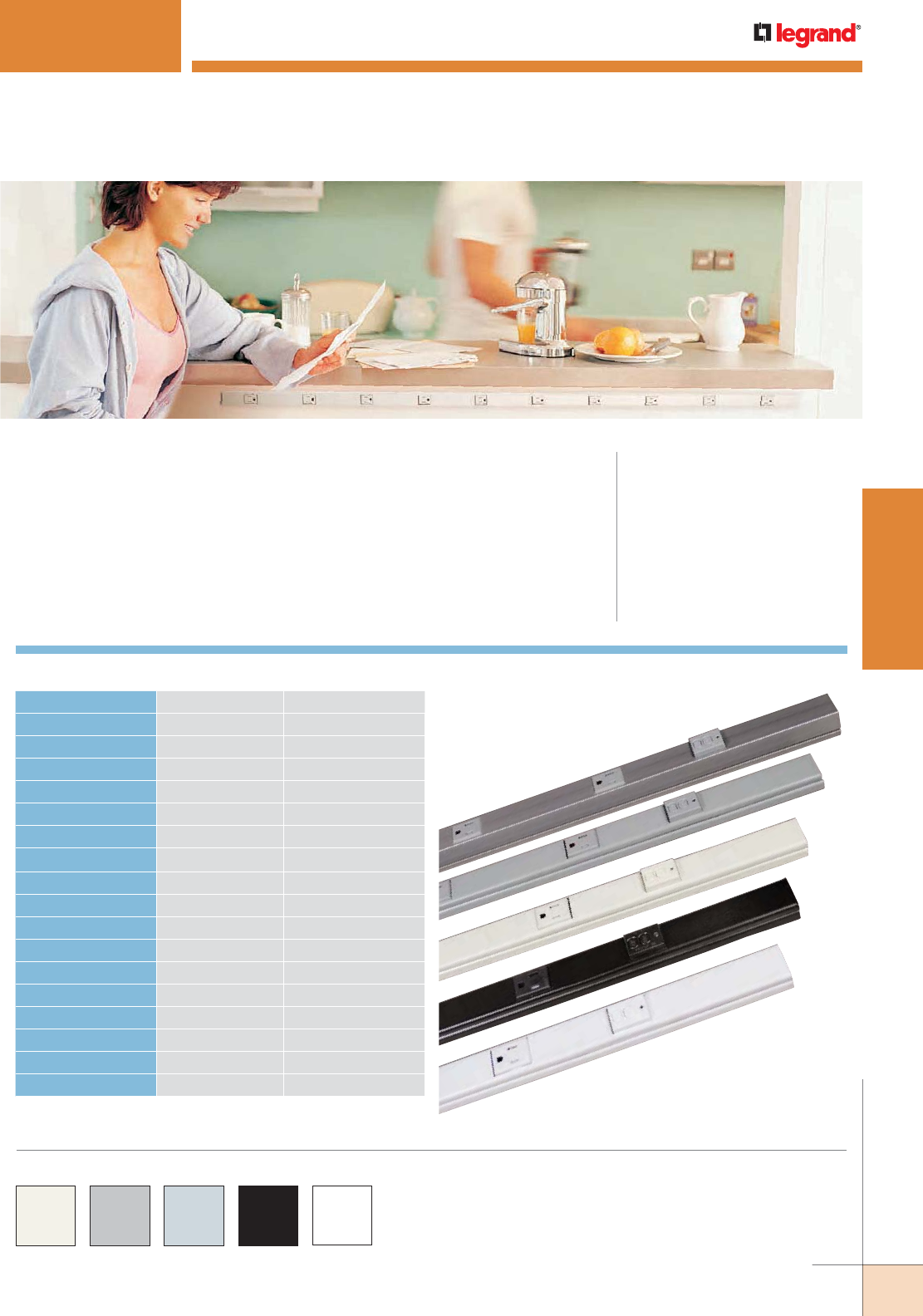
263
WWW.LEGRAND.US/WIREMOLD
WIREMOLD
PLUGMOLD SYSTEMS
PLUGMOLD
®
MULTIOUTLET GFCI PROTECTION
CODE REFERENCE
cULus Listed Base & Blank Cover:
File E4376 Guide RJBT.
Multi-outlet Assemblies:
File E15191 Guide PVGT.
Fittings:
File E41751 Guide RJPR.
Base & Blank Cover
Meets Article 386 of NEC.
Plugmold Strips:
Meets Article 380 of NEC.
Wiremold® Plugmold® Multi-outlet Systems are now available in a tamper-
resistant GFCI version that is a great solution for adding GFCI protection
to multiple outlets without having to install multiple outlets. The tamper-
resistant feature also provides safety for multi-user facilities, residential
living spaces and kitchens. Designed to mount on wall surfaces, the low
profile, aesthetically-pleasing design is available in 3', 5' and 6' [915mm,
1.52m and1.8m] lengths in a variety of colors and finishes.
Plugmold Multi-outlet GFCIs are available in a Black, Gray, Ivory
or White painted finish or in stainless steel or anodized aluminum
unless otherwise specified in the part number description
Custom color options are also available. Consult the factory for
more information.
Available Options
PART NUMBERS LENGTH FINISH
AL20GB306TRGFI 36" [914mm] Anodized Aluminum
AL20GB506TRGFI 60" [1.5m] Anodized Aluminum
BK20GB306TRGFI 36" [914mm] Painted Black
BK20GB506TRGFI 60" [1.5m] Painted Black
BK20GB606TRGFI 72" [1.8m] Painted Black
G20GB306TRGFI 36" [914mm] Painted Gray
G20GB506TRGFI 60" [1.5m] Painted Gray
G20GB606TRGFI 72" [1.8m] Painted Gray
S20GB306TRGFI 36" [914mm] Stainless Steel
S20GB506TRUGFI 60" [1.5m] Stainless Steel
S20GB606TRUGFI 72" [1.8m] Stainless Steel
V20GB306TRGFI 36" [914mm] Painted Ivory
V20GB506TRGFI 60" [1.5m] Painted Ivory
V20GB606TRGFI 72" [1.8m] Painted Ivory
WH20GB306TRGFI 36" [914mm] Painted White
WH20GB506TRGFI 60" [1.5m] Painted White
WH20GB606TRGFI 72" [1.8m] Painted White
NOTE: For available custom options, consult factory.
COLOR OPTIONS
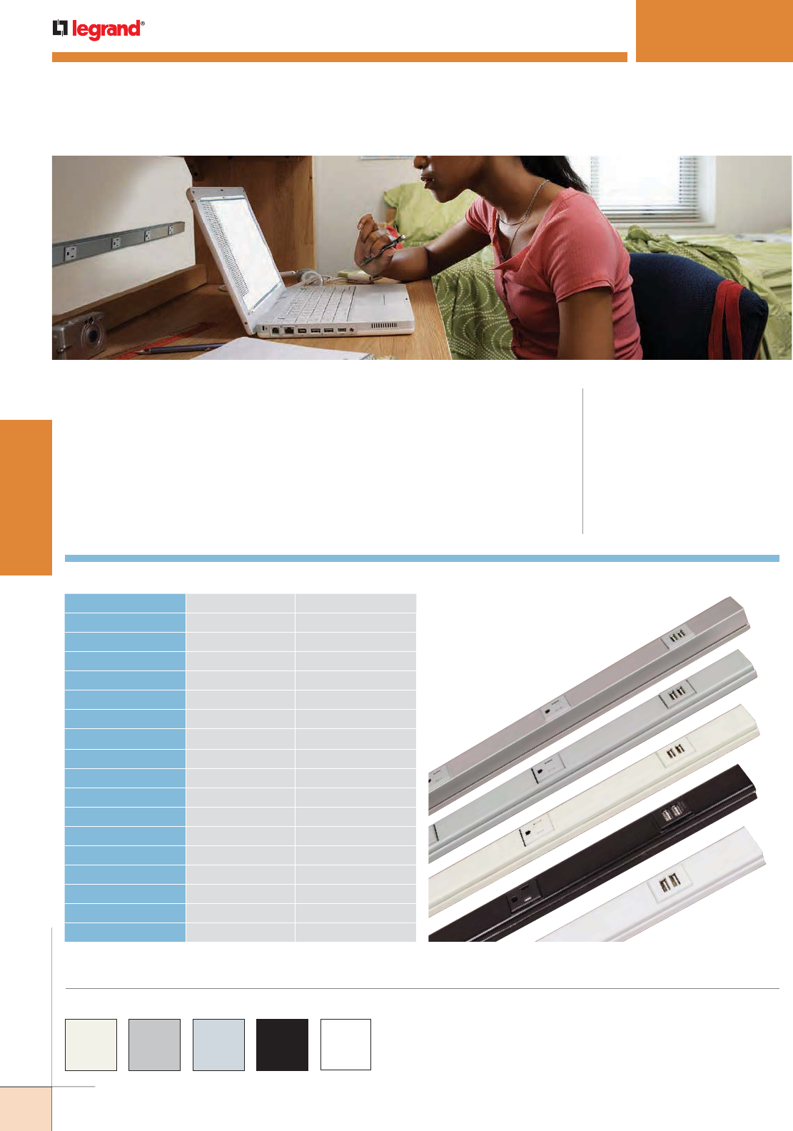
264
WWW.LEGRAND.US/WIREMOLD
WIREMOLD
PLUGMOLD SYSTEMS
PLUGMOLD
®
MULTIOUTLET USB CHARGING SYSTEM
CODE REFERENCE
cULus Listed Base & Blank Cover:
File E4376 Guide RJBT.
Multi-outlet Assemblies:
File E15191 Guide PVGT.
Fittings:
File E41751 Guide RJPR.
Base & Blank Cover
Meets Article 386 of NEC.
Plugmold Strips:
Meets Article 380 of NEC.
Wiremold® Plugmold® Multi-outlet Systems are now available in a tamper-
resistant version with USB charging that is a great solution for adding the
convenience of multiple outlets and USB charging to work or living spaces
without the work required to install multiple outlets. The tamper-resistant
feature provides safety for multi-user facilities, residential living spaces
and kitchens. Designed to mount on wall surfaces, the low profile design is
aesthetically pleasing and is available in 3', 5' and 6' lengths in a variety of
colors and finishes.
Available Options
PART NUMBERS LENGTH FINISH
AL20GB306TRUSB 36" [914mm] Anodized Aluminum
AL20GB506TRUSB 60" [1.5m] Anodized Aluminum
BK20GB306TRUSB 36" [914mm] Painted Black
BK20GB506TRUSB 60" [1.5m] Painted Black
BK20GB606TRUSB 72" [1.8m] Painted Black
G20GB306TRUSB 36" [914mm] Painted Gray
G20GB506TRUSB 60" [1.5m] Painted Gray
G20GB606TRUSB 72" [1.8m] Painted Gray
S20GB306TRUSB 36" [914mm] Stainless Steel
S20GB506TRUSB 60" [1.5m] Stainless Steel
S20GB606TRUSB 72" [1.8m] Stainless Steel
V20GB306TRUSB 36" [914mm] Painted Ivory
V20GB506TRUSB 60" [1.5m] Painted Ivory
V20GB606TRUSB 72" [1.8m] Painted Ivory
WH20GB306TRUSB 36" [914mm] Painted White
WH20GB506TRUSB 60" [1.5m] Painted White
WH20GB606TRUSB 72" [1.8m] Painted White
NOTE: For available custom options, consult factory.
Plugmold Multi-outlet GFCIs are available in a Black, Gray, Ivory
or White painted finish or in stainless steel or anodized aluminum
unless otherwise specified in the part number description
Custom color options are also available. Consult the factory for
more information.
COLOR OPTIONS
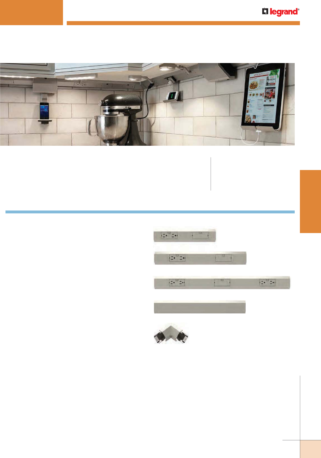
265
WWW.LEGRAND.US/WIREMOLD
WIREMOLD
PLUGMOLD SYSTEMS
ADORNE
™
UNDERCABINET LIGHTING SYSTEM
The adorne Under-Cabinet Lighting System is a fully customizable and modular
solution for eliminating kitchen clutter. It is compatible with any kitchen layout,
such as a galley, L-shaped, or U-shaped, as well as with any home wiring.
Visit www.adornemyhome.com to use the Under-Cabinet System Planning and
Configuration Tool.
How to Specify the System
1. Planning Your System Layout
• First, determine where you want to install the
system. Then measure your cabinets to determine
the length of Modular Track required:
• Measure each cabinet length at back of cabinet.
• For installations with a corner, allow 3" on each
side for Corner Connector.
• When totaling up the length of required Modular
Track, be sure to include the length of the desired
Control Box or Direct Wire Connector. For a 1-gang
box, allow 5". For a 2-gang box, allow 5.25". For
Direct Wire Connector, allow 6". For more detail on
Control Box options, see page 58.
• If your selection of Modular Tracks does not match
the exact length of your cabinets, you can use a
Modular Track Extender to complete the track. This
piece can be cut down to 6". Standard 12", 18", and
27" Modular Tracks cannot be shortened.
12” Modular Track
18” Modular Track
18” Modular Track Extender
Modular Track Corner Connector
27” Modular Track
CODE REFERENCE
adorne Under-Cabinet Lighting System is
cETLus Listed
ETL Listed System:
100477147
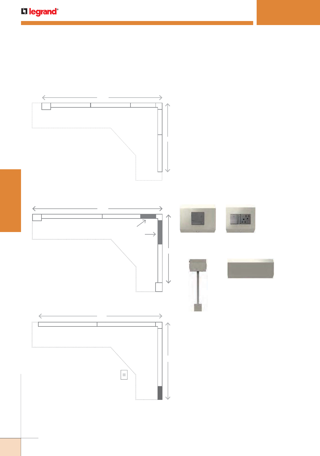
266
WWW.LEGRAND.US/WIREMOLD
WIREMOLD
PLUGMOLD SYSTEMS
ADORNE
™
UNDERCABINET LIGHTING SYSTEM
How to Specify the System
Sample Installation: Length of cabinets is greater than
combined length of standard Modular Tracks
• One 2-Gang Control Box is placed
at one end of system for hardwired
power connection and lighting control
• Total length of cabinets can be exactly
matched with combination of standard
Modular Tracks
• As needed, Control Boxes can be placed
anywhere in system
Sample Installation: Length of cabinets is equal to combined
length of standard Modular Tracks
2G 18 18 12
12 27
c
56”
33”
Sample Installation: Direct wire with system controls in a
remote location
2. Selecting the Control Box and Power Options
Next, select the type of lighting and power connection
you’d like to include. For a simple install, the Plug-
In Control Box provides the easiest solution. For a
hardwired installation, there are three options to
choose from which enable expanded lighting control
options such as dimming:
• Control Box with Paddle Dimmer
• Control Box with Paddle Dimmer and GFCI protection
• Direct Wire Connector
For hardwired installations, there must be three
separate circuits from the electrical panel:
• Receptacle Circuit: 20 Amps; GFCI-protected;
266Use #12 wire
• Lighting Circuit: 15 Amps; Use #12 or #15 wire
• Accessory Circuit: 15 Amps; Use #12 or #14 wire
1-Gang Control Box
with Paddle Dimmer
2-Gang Control Box
with Paddle Dimmer
and 15A GFCI
Plug-In
Control Box
Direct Wire Connector
Hardwired Control Boxes
1. Planning Your System Layout (continued)
NOTE: Compatible with all adorne 2-module devices. The CFL/LED
Paddle Dimmer (ADPD453LM2) is recommended for use with the
adorne system.
• 1-Gang Control Boxes are placed at
both ends of the system for hardwired
power connection and lighting control
• Modular Track Extender is custom-cut
to match exact length of cabinets
1G
1G
27 18 EX
EX 18
c
(cut to 6.75”)
(cut to 9.75”)
*
60”
36”
• Direct Wire Connector is placed at
one end of system for hardwired
power connection
• Light control located in nearby wallbox
• GFCI circuit breaker located in
electrical panel
27 27
DWC27
c
57”
36”
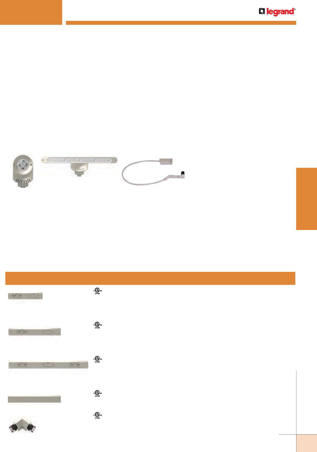
267
WWW.LEGRAND.US/WIREMOLD
WIREMOLD
PLUGMOLD SYSTEMS
ADORNE
™
UNDERCABINET LIGHTING SYSTEM
How to Specify the System
3. Selecting the LED Lights
The adorne Under-Cabinet Lighting System is only
compatible with adorne LED lights. These are available in
Puck and Linear versions. Recommended placement for
lights is every 18” along Modular Track.
You can select any combination of Puck and Linear lights
to complete your system. In addition, if you are mounting
a light under the cabinet and wish to move it further
to the front of the counter, you can use the LED Light
Extender. This enables you to increase the length of any
light from the Modular Track from a standard 11” to up
to 22”. This is especially useful in corner installations.
4. Choosing Accessories to Complete the System
The final step is to select the accessories to perfectly
complement your system. adorne offers a range
of options, including USB charging ports, mobile
and tablet cradles, and a Digital Music Kit. Each of
these accessories provides flexibility in that it can be
added or removed at any time – simply swap it with
an existing outlet or blank module to increase your
system capabilities. For more detail on accessories,
see page 60.
LED Puck Light
LED Linear Light
Light Extender
Name Compliance Specifications Part Number
12" Modular Track Includes one Outlet Module and one Blank Module.
Can support up to two LED lights.
Provides 120V power via 15A outlet modules and 20A
pass-through.
Module openings are 6” on-center.
APMT12TM2
18" Modular Track Includes one Outlet Module and one Blank Module.
Can support up to two LED lights.
Provides 120V power via 15A outlet modules and 20A
pass-through.
Module openings are 9” on-center.
APMT18TM4
27" Modular Track Includes two Outlet Modules and one Blank Module.
Can support up to three LED lights.
Provides 120V power via 15A outlet modules and 20A
pass-through.
Module openings are 9” on-center.
APMT27TM2
18" Modular Track Extender Enables a perfect fit for any kitchen. Simply cut to length
(minimum of 6”) and attach to end of Modular Track.
Does not include any module openings.
APME18TM2
Modular Track Corner Connector Use with installations that include a right-angle corner
to connect two Modular Tracks.
Allow 3” on each side for installations with Corner
Connectors.
APCCTM4
Modular Tracks
The adorne system is a flexible and modular solution
designed to eliminate kitchen clutter. Fully customizable,
you can select from several types of modules and modify
your system in minutes. Simply pop out an existing
module and replace it with a new module at any time.
The Modular Tracks listed below simply plug together
to create a full system custom-designed for any kitchen.
They form the base of the system, housing all of the wiring
that connects the modules.
Each system must include a Control Box or Direct Wire
Connector that is hardwired to existing wiring or plugged
into an outlet on the backsplash.
Visit www.adornemyhome.com for more information.
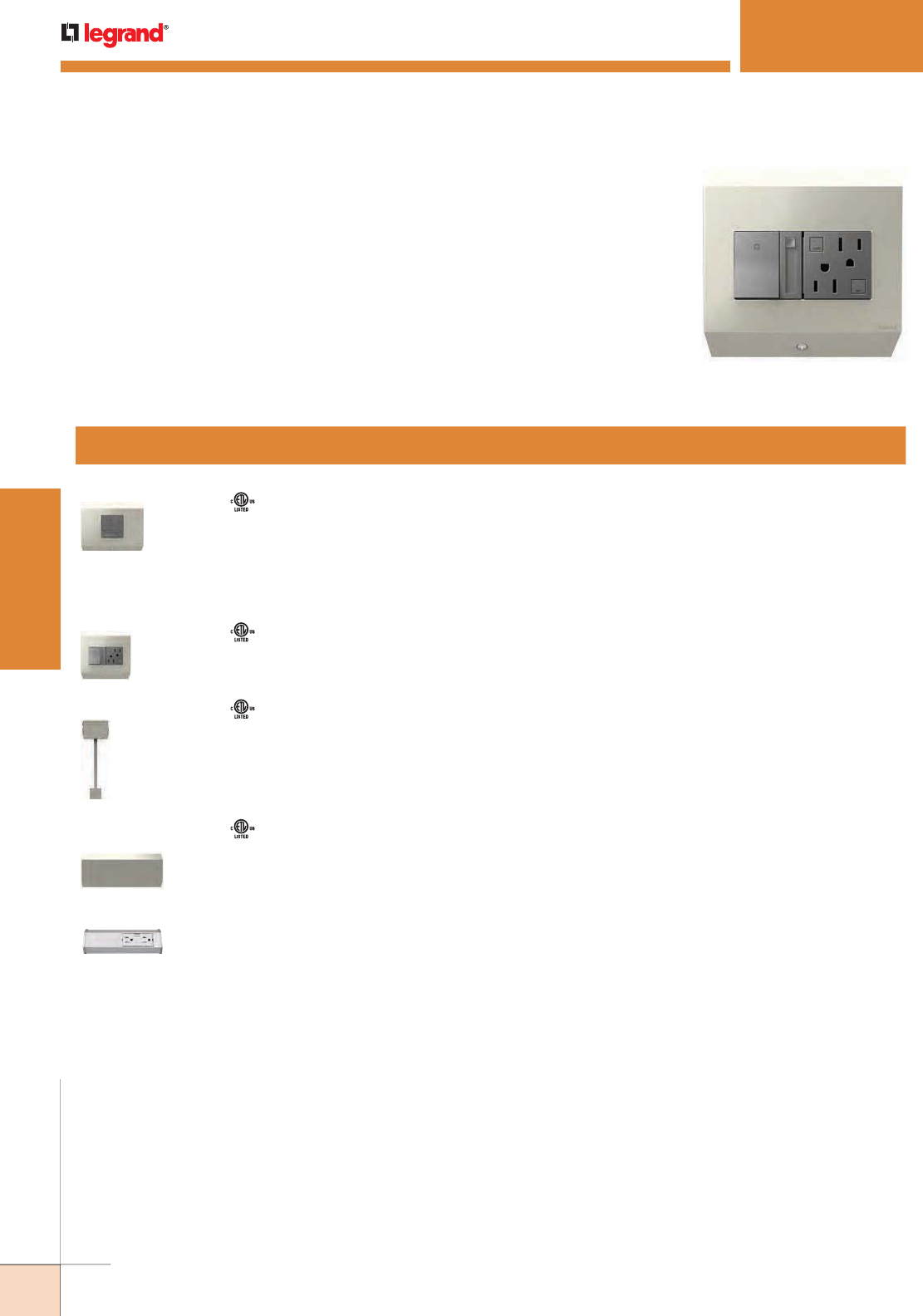
268
WWW.LEGRAND.US/WIREMOLD
WIREMOLD
PLUGMOLD SYSTEMS
Name Compliance Specifications Part Number
Control Box
with Paddle Dimmer
450W Connects to existing in-wall wiring. Fits onto end of Modular Track, adding 5"
onto system length.
Includes adorne 450W CFL/LED Paddle Dimmer ( ADPD453LM2).
GFCI protection must be provided at the electrical panel
APCB1TM4
Control Box with
Paddle Dimmer
and 15A GFCI
450W
15A
Connects to existing in-wall wiring. Fits onto end of Modular Track, adding
5.25" onto system length.
Includes adorne 450W CFL/LED Paddle Dimmer (ADPD453LM2) and 15A
Tamper-Resistant GFCI Outlet (AGFTR153M4).
APCB2TM2
Plug-In Control Box Snaps into any module opening on the track and plugs into an existing outlet
to provide system power. Cord length of 11" can easily be shortened to match
the distance from outlet to Modular Track.
APCB3TM4
Direct Wire
Connector
Enables direct wire feed of power from in-wall wiring, eliminating need for a
Control Box. Connector is 6" in length.
APDWCTM1
Short Modular Track Designed for use with shorter cabinet sections to extend the under-cabinet
system throughout your kitchen.
APST9TM1
Control Boxes
Every Under-Cabinet Lighting System must include one of the below Control Boxes or
Direct Wire Connector. These boxes connect to existing in-wall wiring or plug into an
outlet on the backsplash to provide system power.
Control Boxes include system end caps, ensuring a clean finish on the left and right
edges of the installed system.
ADORNE
™
UNDERCABINET LIGHTING SYSTEM
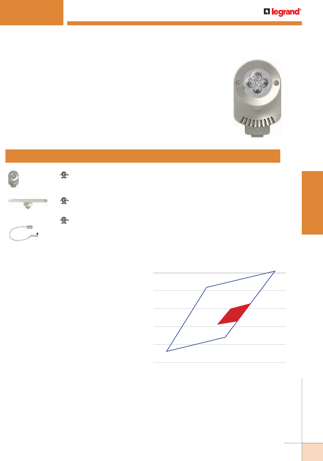
269
WWW.LEGRAND.US/WIREMOLD
WIREMOLD
PLUGMOLD SYSTEMS
ADORNE
™
UNDERCABINET LIGHTING SYSTEM
Name Compliance Specifications Part Number
LED Puck Light • 8W
• 240 lumens
• correlated color temperature: 3000 kelvin color rendering index: 95
ALPKLEDTM4
LED Linear Light • 8W
• 280 lumens
• correlated color temperature: 3000 kelvin color rendering index: 95
ALLNLEDTM4
Light Extender Enables adorne LED lights to be mounted up to 22” from backsplash
by extending cord length beyond default 11”. Ideal for corner cabinet
installations.
ALEXTLEDTM4
Lighting
adorne Puck and Linear LED Lights are designed for use with the adorne system only.
They can be paired with the adorne CFL/LED Paddle Dimmer (ADPD453L) to enable
dimming.
Lights easily plug into a connection port on any system module. Optimal positioning is
one light for every 18” of Modular Track. Lights can be added or removed as needed.
The adorne system is optimized to provide a premium under-cabinet lighting solution
by utilizing the latest innovations in lighting research and LED technologies.
System specifications:
• OSRAM OSLON® Color Champ LED
• Nominal 3000K Correlated Color Temperature (CCT)
warm light output
• Color Rendering Index (CRI) of 95
• Excellent range of color differentiation and rendering
of the important red color (think red meat and
apples) and skin tones
• A bright lumen light output (Puck = 240 lumens/
Linear = 280 lumens) provides optimized lighting for
the under-cabinet environment
• Efficient driver design integrated in each fixture
results in:
- Reliable and smooth dimming
- Rated for 40,000 hours of high performance
• LED quality control uses a “fine bin system” based
on a three-step MacAdams ellipse to ensure color
consistency
NOTE: adorne individual LEDs are specifically selected to ensure fixture output
CCT uniformity within a range of less than 100. This tight manufacturing
assurance process ensures that variations inherent in the LED chip
manufacturing process do not compromise reliable light quality.
.425
.415
.405
.395
.385
.375
ANSI Chromaticy
Color Bin for 3000K
Legrand adorne LED
Fixture Chromaticy Color
Bin for 3000K
.41 .415 .42 .425 .43 .435 .44 .445 .45 .455 .46
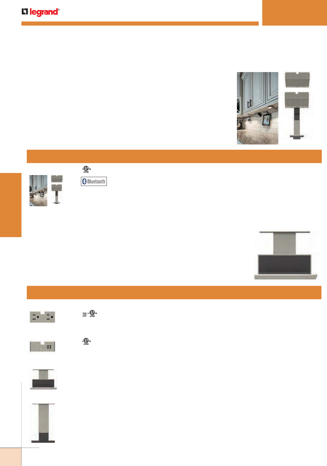
270
WWW.LEGRAND.US/WIREMOLD
WIREMOLD
PLUGMOLD SYSTEMS
Compliance Specifications Part Number
15A Outlet Module 15A, 120V
Provides two power outlets by snapping into any module opening.
Tamper-resistant outlet is designed with a patented shutter system.
Included with 12", 18", and 27" Modular Tracks.
APTR15TM4
USB Outlet Module 2.1A, 5V Provides two USB charging ports for devices such as mobile phones and
tablets by snapping into any module opening.
Charging cable not included.
APUSB2TM4
Mobile Phone Cradle Attaches anywhere along track to hold a mobile phone. Perfect for use
with USB Outlet Module while charging devices.
AAPCTM4
Tablet Cradle Attaches anywhere along track to hold a tablet. Perfect for use with USB
Outlet Module while charging devices.
AATCTM4
Modules and Accessories
adorne system modules are designed to fit in any module opening, and can be easily
added or removed by using the included module tool. Simply fit the tool into either end
of the module and pop it out of the track.
Cradles do not occupy a module opening. Instead, they save space by resting on the
back edge of the track.
Digital Music Kit
The Digital Music Kit adds high performance sound to your adorne Under-Cabinet
Lighting System. It includes two speakers and a detachable dock for smart phones
or MP3 players. Simply fit the main speaker into one module opening and then place
the second speaker in any other module location. Speakers can be easily removed
and relocated at any time by simply pushing on the sides of the modules and popping
them out of the track.
The system features BLUETOOTH® wireless technology to enable streaming of music
from your devices. It also includes a 3.5mm cable to manually connect devices.
ADORNE
™
UNDERCABINET LIGHTING SYSTEM
Name Compliance Specifications Part Number
Digital Music Kit 2" (50mm) full range drivers
Digital signal processing for full, rich sound
BLUETOOTH wireless technology is A2DP compatible
Includes USB charging capability
AUDMTM1
NOTE: Bluetooth® is a registered trademark of Bluetooth SIG, Inc. The Bluetooth word mark and logos are owned by the Bluetooth SIG, Inc. and any use of such
marks (licensee name) is under license. Other trademarks and trade names are those of their respective owners.
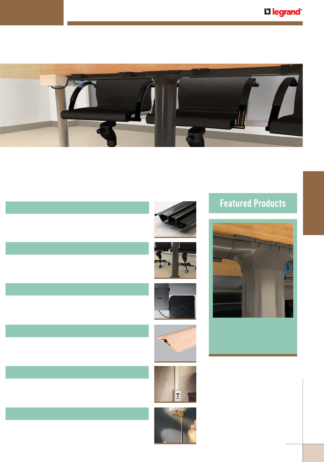
CORD MANAGEMENT
Wiremold® provides unique solutions to organize and secure cords and
cables, but allowing for easy access for future changes and upgrades.
Cord Management solutions are an economical option for situations where
a UL Listed Raceway is not required.
Table of Contents
InteGreat™ Under
Table Cable
Management 273
1200/1400/1600 Series™ Raceways
276
InteGreat™ Under Table Cable Management
273
InteGreat™ Cable Retractors
275
InteGreat™ Transition Channel
274
UniDuct® Series Raceways
278
300 Series™ Duct
286
WWW.LEGRAND.US/WIREMOLD
271
CORD MANAGEMENT
WIREMOLD
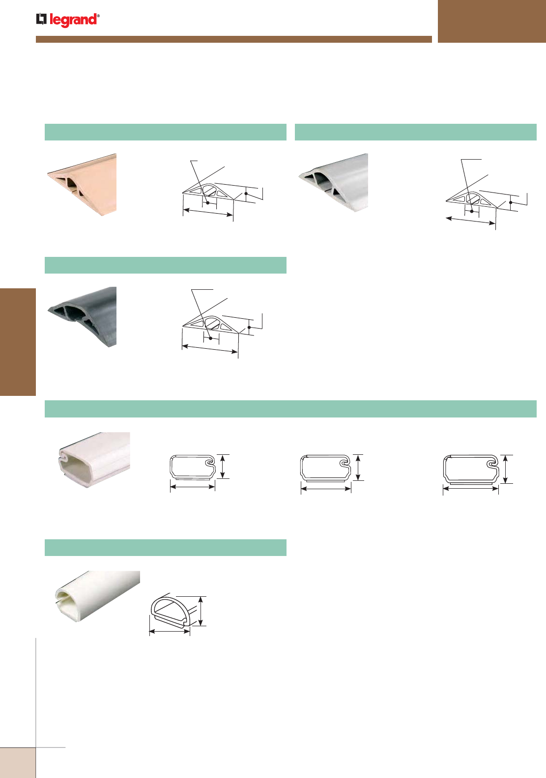
CORD MANAGEMENT
Quick Selection Guide
1/2"
[12.7mm]
2 1/2"
[64mm]
14/32"
[11.4mm]
3"
[76mm]
26/32"
[20.1mm]
20/32"
[16.5mm]
30/32"
[23.4mm]
1 1/32"
[26mm]
3 11/32"
[85mm]
1200 Series™ Raceway
One-Piece Nonmetallic Single-Channel Overfloor Raceway Systems
1400 Series™ Raceway
1600 Series™ Raceway
Uniduct® Raceway
Low Voltage Single-Channel Raceway Profiles
Uniduct 2700 Raceway
2700 Series
Capacity: 0.163 in.2 [105mm2]
3/8"
[9.5mm]
3/4"
[19.1mm]
2800 Series
Capacity: 0.337 in.2 [217mm2]
1/2"
[12.7mm]
1"
[25mm]
2900 Series
Capacity: 0.869 in.2 [530mm2]
3/4"
[19.1mm]
1 1/2"
[38mm]
300 Series™ Duct
Hide Cord Raceway Profiles
12/32"
[8.9mm]
1/2"
[12.7mm]
300 Duct
Capacity: .900 in.2 [581mm2]
WIREMOLD
WWW.LEGRAND.US/WIREMOLD
272
CORD MANAGEMENT
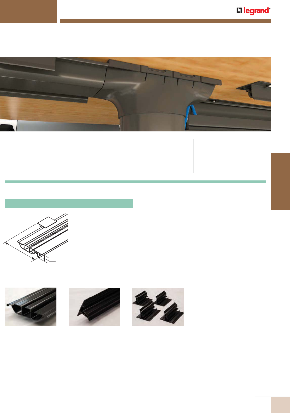
INTEGREAT™ UNDER TABLE CABLE MANAGEMENT
Ordering Information
UTCM5 Under Table Cable Management Kit
Consists of a 5' [1.524mm]
length of divided base,
5' [1.524mm] length of
mounting hinge rail and
four (4) latching clips.
Black, nonmetallic
construction. Base width
without Rail & Clips: 5"
[127mm]. Base width with
Rail & Clips: 6 13/16"
[173mm].
WWW.LEGRAND.US/WIREMOLD
273
CORD MANAGEMENT
WIREMOLD
KIT CONTENTS:
Base Hinge Rail Latching Clips
CODE REFERENCE
InteGreat™ UTCM is not UL
listed because it is designed to
protect and organize cords and
cables that are not required to
be enclosed by the National
Electric Code.
InteGreat™ Under Table Cable Management provides clean cord management for
power, communication and A/V cables on the horizontal underside of the table.
The simple hinge mechanism allows for easy access for future technology
upgrades. InteGreat Under Table Cable Management mates with the InteGreat
Transition Channel for a true cable management solution.
InteGreat™ Cable Management Ordering Information
6 13/16
[173mm] 1 1/16
[27mm]
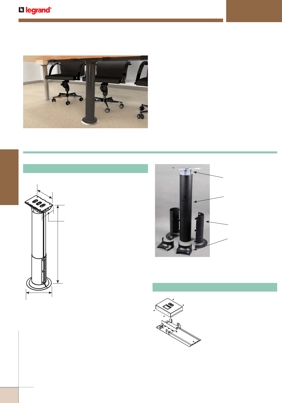
INTEGREAT™ TRANSITION CHANNEL
Ordering Information
InteGreat Transition Channel continues the cord
management and protection from the underside of the
table to the floor, where cables can gain access to the
building infrastructure. The Transition Channel fits
directly into InteGreat Under Table Cable Management
on the underside of the table and mates with Wiremold®
Poke-Thru Devices or OFR Series Overfloor Raceway
for a smooth transition to the building infrastructure.
InteGreat Transition Channel provides a protected pathway for
cables to the building infrastructure. It is designed to work with
Wiremold® Poke-Thru Devices and OFR Series Raceway.
Allows cords and cables to make
a smooth concealed transition to
the underside of the table when
used with the InteGreat™ Transition
Channel (MRTC).
OFR48-2MRTC OFR Transition Box
WIREMOLD
WWW.LEGRAND.US/WIREMOLD
274
CORD MANAGEMENT
Center Spine with
Mounting Plate
Side Channel
Bottom Boot
Transition Cover
26" – 30"
[660mm – 762mm]
7"
[178mm]
6.8"
[172mm]
4.7"
[119mm]
MRTC Transition Channel Kit
Consists of aluminum center
spine with steel mounting
plate and four (4)screws,
black aluminum side
channels, black nonmetallic
bottom boot and two (2)
black nonmetallic transition
covers.
InteGreat™ Transition Channel Ordering Information
CODE REFERENCE
InteGreat™ Transition Channel
is not UL listed because it is
designed to protect and organize
cords and cables that are not
required to be enclosed by the
National Electric Code.
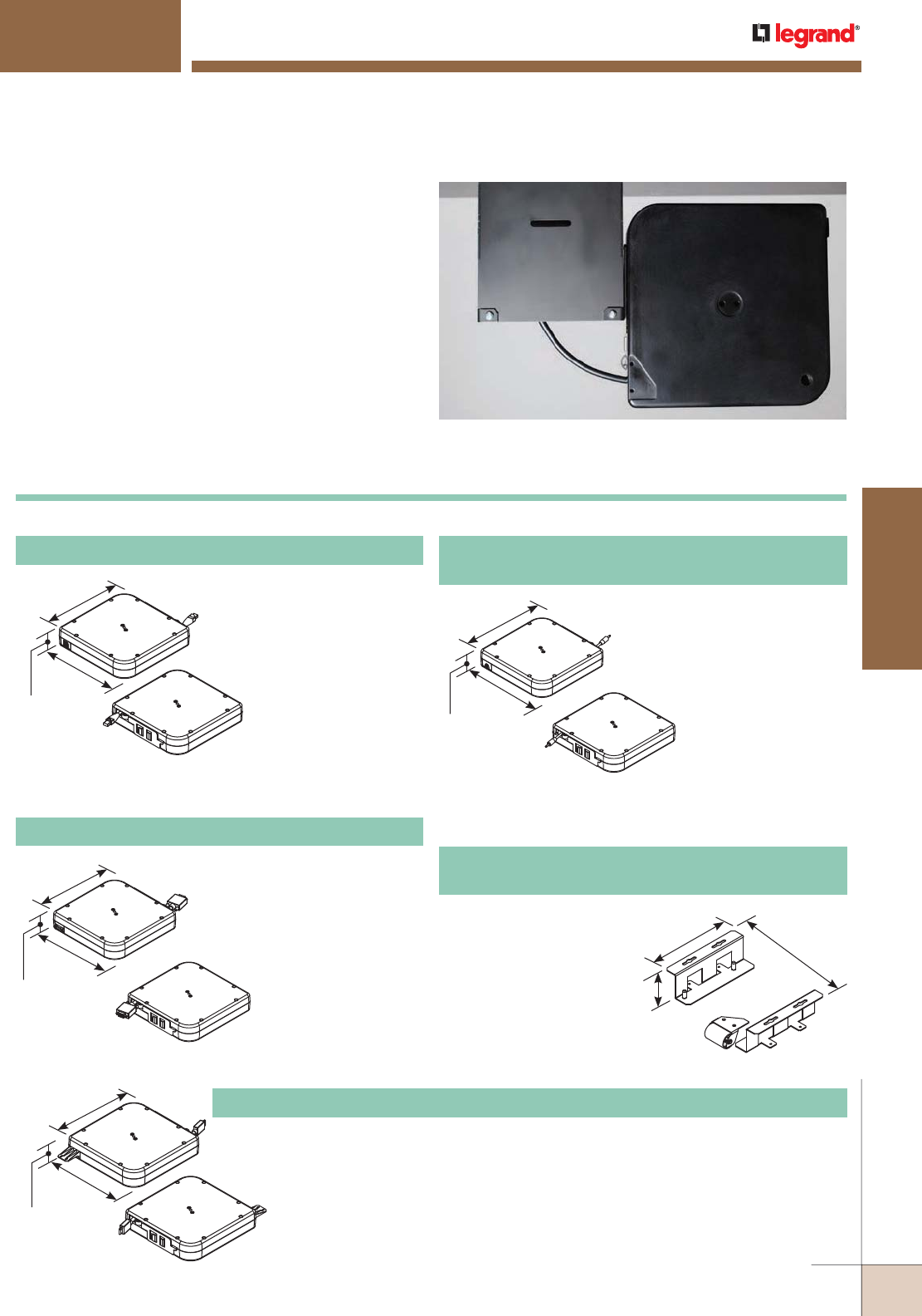
8 1/4"
[210mm]
8 1/4"
[210mm]
1 7/8"
[48mm]
INTEGREAT™ CABLE RETRACTORS
Ordering Information
InteGreat Cable Retractors attach easily to InteGreat A/V
Table Boxes, or can be mounted directly to the underside
of conference room tables. InteGreat Cable Retractors
have 5' [1.52m] of retractable cable that allows users to
have easy access to A/V and communication services. With
a simple pull, the cable locks into place or retracts back
into the table box, keeping the conference room table neat
and organized.
InteGreat Cable Retractors protect cables while keeping them
neat and organized.
Mounts directly to the InteGreat Series A/V Table Box or to the underside of the
conference room table using the TBCRHMK. Loaded with 12' [3.66m] of HDMI with
Ethernet cable that extends out 5' [1.52m] from the retractor. Retractor has a
female input from building infrastructure, and a male connector on the output side.
Input side has mounting tab that allows installer to cable tie HDMI to the retractor
to minimize chances of a loose connection.
8 1/4"
[210mm]
8 1/4"
[210mm]
1 7/8"
[48mm]
8 1/4"
[210mm]
10"
[254mm]
1 7/8"
[48mm]
InteGreat™ Cable Retractors Ordering Information
8 1/4"
[210mm]
8 1/4"
[210mm]
1 7/8"
[48mm]
TBCRCAT6 Cable Retractor with Category 6A Cable
Mounts directly to the
InteGreat Series A/V Table
Box or to the underside of the
conference room table using
the TBCRHMK. Loaded with
12' [3.66m] of Cat6A cable that
extends out 5' [1.52m]
from the retractor.
Retractor has a female
input from building
infrastructure, and a male
connector on the output side.
TBCRVGA Cable Retractor with VGA VESA Cable
TBCRHDMI Cable Retractor with HDMI w/Ethernet Cable
TBCR3.5MM
Cable Retractor with 3.5mm Audio Cable
10 5/16"
[262mm]
6 3/8"
[162mm]
1 15/16"
[49mm]
Allows retractor to mount
horizontally under a
conference room table,
so cable can be accessed
through a table grommet.
Multiple retractors can
be mounted to each other
by attaching the TBCRHMK
Mounting Brackets to each other.
TBCRHMK
Cable Retractor Horizontal Mounting Bracket
Cable Retractor with 3.5mm
audio cable. Mounts directly to
the InteGreat Series A/V Table
Box or to the underside of the
conference room table using
the TBCRHMK. Loaded with
12' [3.66m] of audio
cable that extends out
5' [1.52m] from the
retractor. Retractor has
a female input from building
infrastructure, and a male
connector on the output side.
Mounts directly to the InteGreat
Series A/V Table Box or to the
underside of the conference
room table using the TBCRHMK.
Loaded with 12' [3.66m] of VESA
Style VGA cable that extends
out 5' [1.52m] from the
retractor. Retractor has
a female input from
building infrastructure,
and a male connector on
the output side.
WWW.LEGRAND.US/WIREMOLD
275
CORD MANAGEMENT
WIREMOLD
CODE REFERENCE
InteGreat™ Cable Retractors are
not UL listed because they are
designed to protect and organize
cords and cables that are not
required to be enclosed by the
National Electric Code.
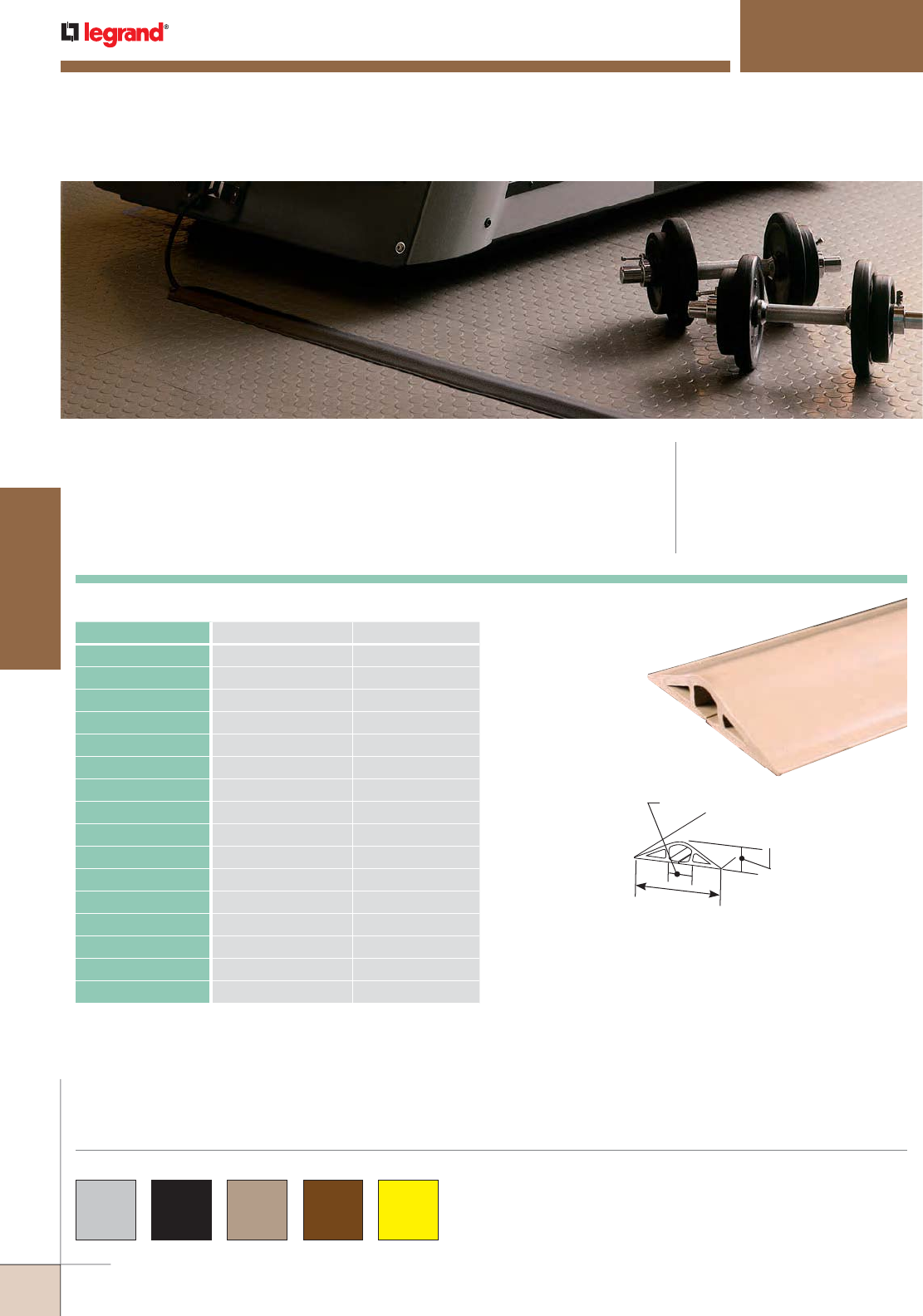
1200/1400/1600 SERIES™ OVERFLOOR RACEWAYS
CODE REFERENCE
1200, 1400, and 1600 Series
Raceway are not UL listed because
they are designed to protect and
organize cords and cables that are
not required to be enclosed by the
National Electric Code.
Wiremold® 1200/1400/1600 Series Overfloor Raceway Systems
provide permanent or temporary protection for overfloor cabling
in high traffic areas.
COLOR OPTIONS
1200/1400/1600 Series Raceways are available in gray, black,
beige, brown and high visibility yellow.
Custom color options are also available. Consult the factory
for more information.
1200 Series — Channel Capacity Up to 5/16" [7.9mm] Cable Diameter
1/2"
[12.7mm]
2 1/2"
[64mm]
14/32"
[11.4mm]
CATALOG NUMBER COLOR LENGTH
BE1200-5 Beige 5' [1.5m]
BE1200-5R Beige 5' [1.5m]
BE1200-10 Beige 10' [3.0m]
BE1200-50 Beige 50' [15.2m]
BK1200-5 Black 5' [1.5m]
BK1200-10 Black 10' [3.0m]
BK1200-50 Black 50' [15.2m]
BR1200-5R Brown 5' [1.5m]
BR1200-5 Brown 5' [1.5m]
BR1200-10 Brown 10' [3.0m]
BR1200-50 Brown 50' [15.2m]
GR1200-5 Gray 5' [1.5m]
GR1200-5R Gray 5' [1.5m]
GR1200-10 Gray 10' [3.0m]
GR1200-50 Gray 50' [15.2m]
YL1200-50 High Visibility Yellow 50' [15.2m]
WIREMOLD
WWW.LEGRAND.US/WIREMOLD
276
CORD MANAGEMENT
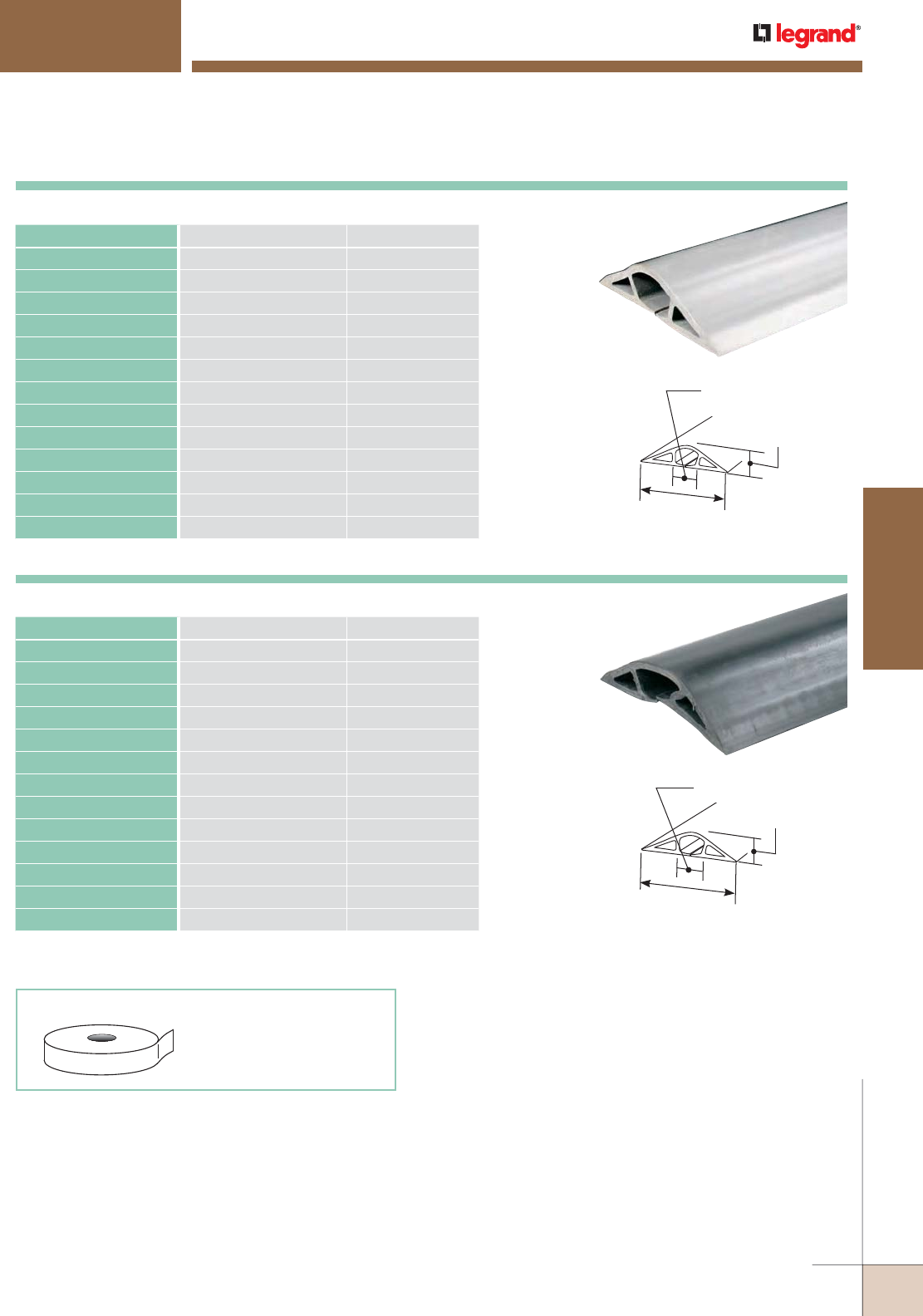
3"
[76mm]
26/32"
[20.1mm]
20/32"
[16.5mm]
30/32"
[23.4mm]
1 1/32"
[26mm]
3 11/32"
[85mm]
DST2 DOUBLESIDED TAPE
For long term installation.
2" wide x 17 yds.
1200/1400/1600 SERIES™ OVERFLOOR RACEWAYS
Ordering Information
1400 Series — Channel Capacity Up To 1/2" [12.7mm] Cable Diameter
CATALOG NUMBER COLOR LENGTH
BE1400-5 Beige 5' [1.5m]
BE1400-10 Beige 10' [3.0m]
BE1400-50 Beige 50' [15.2m]
BK1400-5 Black 5' [1.5m]
BK1400-10 Black 10' [3.0m]
BK1400-50 Black 50' [15.2m]
BR1400-5 Brown 5' [1.5m]
BR1400-10 Brown 10' [3.0m]
BR1400-50 Brown 50' [15.2m]
GR1400-5 Gray 5' [1.5m]
GR1400-10 Gray 10' [3.0m]
GR1400-50 Gray 50' [15.2m]
YL1400-50 High Visibility Yellow 50' [15.2m]
1600 Series — Channel Capacity Up To 3/4" [19.1mm] Cable Diameter
CATALOG NUMBER COLOR LENGTH
BE1600-5 Beige 5' [1.5m]
BE1600-10 Beige 10' [3.0m]
BE1600-25 Beige 25' [7.6m]
BK1600-5 Black 5' [1.5m]
BK1600-10 Black 10' [3.0m]
BK1600-25 Black 25' [7.6m]
BR1600-5 Brown 5' [1.5m]
BR1600-10 Brown 10' [3.0m]
BR1600-25 Brown 25' [7.6m]
GR1600-5 Gray 5' [1.5m]
GR1600-10 Gray 10' [3.0m]
GR1600-25 Gray 25' [7.6m]
YL1600-25 High Visibility Yellow 25' [7.6m]
WWW.LEGRAND.US/WIREMOLD
277
CORD MANAGEMENT
WIREMOLD
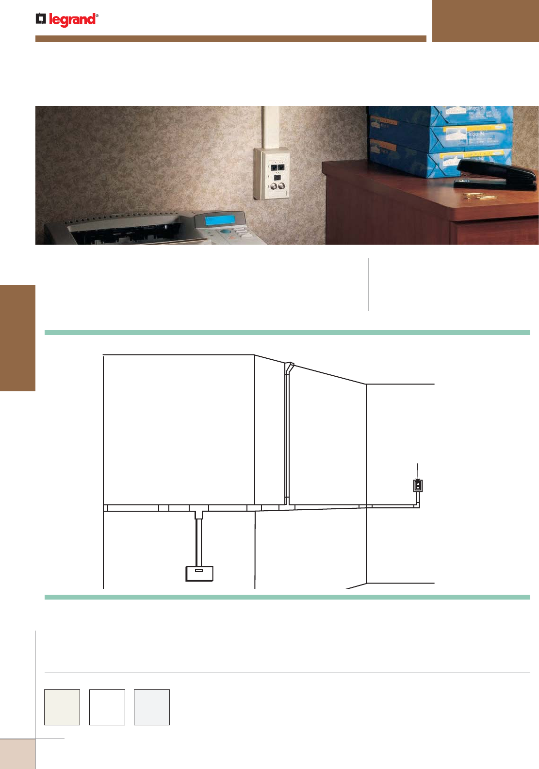
G
D
A
B
F
D
I
C
E
J
H
UNIDUCT® SERIES RACEWAYS
Single-Channel
CODE REFERENCE
Uniduct Series Raceway is not UL listed
because it is designed to protect and
organize cords and cables that are not
required to be enclosed by the National
Electric Code.
One-piece, latching single-channel raceway available in three profiles.
Easy-to-install and ideal for basic communication installations.
COLOR OPTIONS
Uniduct® Series Raceway Part Numbers with a “-WH” suffix
have a white finish. Part Numbers with a “-FW” suffix have a fog
white finish. Part Numbers without a suffix have an ivory finish.
Uniduct Raceway can also be painted using latex paint.
Uniduct 2700, 2800, 2900 Series Raceways System Layout
NOTE: Illustration is for
showing product
applications only.
KEY
A. 2706, 2806, 2906 Cover Clip
B. 2710B, 2810B, 2910B Blank End Fitting
C. 2711, 2811, 2911 Flat Elbow
D. 2715, 2815, 2915 Tee Fitting
E. 2717, 2817, 2917 Internal Elbow
F. 2718, 2818, 2918 External Elbow
G. 2786, 2886, 2986 Drop Ceiling Connector
H. CM2, Series II, TracJack
Communication Devices
I. CM-MMB-293 Multimedia Box
J. NM2048 Device Box
WIREMOLD
WWW.LEGRAND.US/WIREMOLD
278
CORD MANAGEMENT
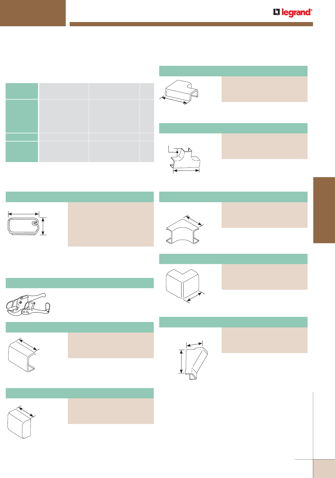
Co-extruded design, smooth plastic 2700L8 finish with
adhesive backing. Available in [1.8m] length, packed 120'
[36.6m] per carton. 2700L8 available in 8' [2.44m] length,
packed 160' [48.8m] per carton.
Covers seam where two pieces of
2700 Series Raceway Cover come
together.
Uniduct® 2700 Series Raceway Wire Fill Capacities
for Communications
CABLE/WIRE SIZE
O.D. Approx. Dia.) 40%
FILLInches [mm]
UNSHIELDED
TWISTED
PAIR
4-pair, 24 AWG, Cat 3
4-pair, 24 AWG, Cat 5e
4-pair, 24 AWG, Cat 6
4-pair, 24 AWG, Cat 6a*
25-pair, 24 AWG
0.190
0.210
0.250
0.354
0.410
[4.8]
[5.3]
[6.3]
[9.0]
[10.4]
2
1
1
0
0
COAXIAL RG6/U 0.270 [6.9] 1
FIBER ZipCord
Round 4 Strand Fiber
Round 6 Strand Fiber
0.118 x 0.236
0.187
0.256
[3 x 6]
[4.8]
[6.5]
2
2
1
NOTE: For additional information, refer to the Technical Section.
* Category 6 augmented (6a) cable for 10 gigabit ethernet – max allowed
cable diameter per addenda No. 11 ANSI TIA/EIA 568-B.2.
3/4"
[19.1mm]
3/8"
[9.5mm]
1"
[25mm]
For branching of raceway running
at right angles.
11/16"
[17.5mm]
2 3/16"
[56mm]
UNIDUCT® 2700 SERIES RACEWAYS
Ordering Information
1"
[25mm]
Closes off open end of 2700 Series
Raceway.
1 1/2"
[38mm]
Each Leg Makes right angle turns in 2700
Series Raceway on same surface.
Conceals cables dropped from
ceiling into the 2700 Series
Raceway.
1 7/16"
[37mm]
2 1/8"
[54mm]
NOTE: Device Boxes for Uniduct 2700 Series Raceway can be found on
pages located at the end of this product section.
Makes right angle turns around
internal corners.
1 1/4"
[32mm]
Each Leg
Makes right angle turns around
external corners.
1"
[25mm]
Each Leg
Regular duty cutter. Ideal for use
with small nonmetallic raceways.
PVC-1 PVC Raceway Cutter
One-Piece Latching Raceway Cover
PART NUMBERS:
2700 (Ivory)
2700-WH (White)
2700L8 (Ivory)
2700L8-WH (White)
2700-FW (Fog White)
2700L8-FW (Fog White)
Cover Clip
PART NUMBERS:
2706 (Ivory)
2706-WH (White)
2706-FW (Fog White)
Blank End Fitting
PART NUMBERS:
2710B (Ivory)
2710B-WH (White)
2710B-FW (Fog White)
One-Piece Latching Raceway Cover
PART NUMBERS:
2711 (Ivory)
2711-WH (White)
2711-FW (Fog White)
Tee
PART NUMBERS:
2715 (Ivory)
2715-WH (White)
2715-FW (Fog White)
Internal Elbow
PART NUMBERS:
2717 (Ivory)
2717-WH (White)
2717-FW (Fog White)
External Elbow
PART NUMBERS:
2718 (Ivory)
2718-WH (White)
2718-FW (Fog White)
Drop Ceiling Connector
PART NUMBERS:
2786 (Ivory)
2786-WH (White)
2786-FW (Fog White)
WWW.LEGRAND.US/WIREMOLD
279
CORD MANAGEMENT
WIREMOLD
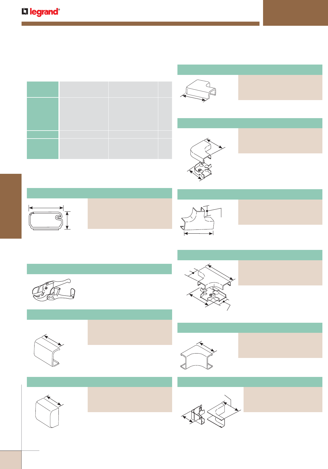
Cover Clip
PART NUMBERS:
2806 (Ivory)
2806-WH (White)
2806-FW (Fog White)
Blank End Fitting
PART NUMBERS:
2810B (Ivory)
2810B-WH (White)
2810B-FW (Fog White)
UNIDUCT® 2800 SERIES RACEWAYS
Ordering Information
1"
[25mm]
1/2"
[12.7mm]
1 1/2"
[38mm]
Co-extruded design, smooth ivory plastic finish with
adhesive backing. 2800 available in 6' [1.8m] lengths, packed
120' [36.6m] per carton. 2800L8 available in 8' [2.44m]
length, packed 160' [48.8m] per carton.
Regular duty cutter. Ideal for use
with small nonmetallic raceways.
Covers seam where two pieces of
2800 Series Raceway Cover
come together.
1 3/8"
[35mm]
Closes off end of 2800 Series
Raceway.
2"
[51mm]
Each leg Makes right angle turns in 2800
Series Raceway on same surface.
3"
[76mm]
(Each leg)
2 1/4"
[57mm]
Makes right angle turns in 2800
Series Raceway on same surface.
Maintains 1 1/4" [32mm] bend
radius when installing UTP and
fiber optic cable.
Uniduct® 2800 Series Raceway Wire Fill Capacities
for Communications
NOTE: For additional information, refer to the Technical Section.
* Category 6 augmented (6a) cable for 10 gigabit ethernet – max allowed
cable diameter per addenda No. 11 ANSI TIA/EIA 568-B.2.
Makes right angle turns around
internal corners of 2800 Series
Raceway. Maintains 1 1/4"
[32mm] bend radius when
installing UTP and fiber
optic cable.
7/8"
[22.2mm]
2 7/8"
[73mm]
For branching of 2800 Series
Raceway running at right angles.
5"
[127mm]
1 1/4"
[32mm]
3 1/2"
[89mm]
1 15/16"
[49mm]
For branching of 2800 Series
Raceway running at right angles.
Maintains 1 1/4" [32mm] cable
bend radius when installing UTP
and fiber optic cable.
1 1/2"
[38mm]
Each leg
For right angle turns around
internal corners.
NOTE: Device Boxes for Uniduct 2700 Series Raceway can be found on
pages located at the end of this product section.
PVC-1 PVC Raceway Cutter
CABLE/WIRE SIZE
O.D. Approx. Dia.) 40%
FILLInches [ ]
UNSHIELDED
TWISTED
PAIR
4-pair, 24 AWG, Cat 3
4-pair, 24 AWG, Cat 5e
4-pair, 24 AWG, Cat 6
4-pair, 24 AWG, Cat 6a*
25-pair, 24 AWG
0.190
0.210
0.250
0.354
0.410
[4.8]
[5.3]
[6.3]
[9.0]
[10.4]
4
3
2
1
1
COAXIAL RG6/U 0.270 [6.9] 2
FIBER ZipCord
Round 4 Strand Fiber
Round 6 Strand Fiber
0.118 x 0.236
0.187
0.256
[3 x 6]
[4.8]
[6.5]
4
4
2
Flat Elbow
PART NUMBERS:
2811 (Ivory)
2811-WH (White)
2811-FW (Fog White)
One-Piece Latching Raceway
PART NUMBERS:
2800 (Ivory), 2800-WH (White)
2800L8 (Ivory), 2800L8-WH (White)
2800-FW (Fog White)
2800L8-FW (Fog White)
Radiused Flat Elbow
PART NUMBERS:
2811FO (Ivory)
2811FO-WH (White)
2811FO-FW (Fog White)
Tee
PART NUMBERS:
2815 (Ivory)
2815-WH (White)
2815-FW (Fog White)
Radiused Tee
PART NUMBERS:
2815FO (Ivory)
2815FO-WH (White)
2815FO-FW (Fog White)
Internal Elbow
PART NUMBERS:
2817 (Ivory)
2817-WH (White)
2817-FW (Fog White)
Radiused Internal Elbow
PART NUMBERS:
2817FO (Ivory)
2817FO-WH (White)
2817FO-FW (Fog White)
2 1/2"
[64mm]
3 1/4" [83mm]
(Each leg)
WIREMOLD
WWW.LEGRAND.US/WIREMOLD
280
CORD MANAGEMENT
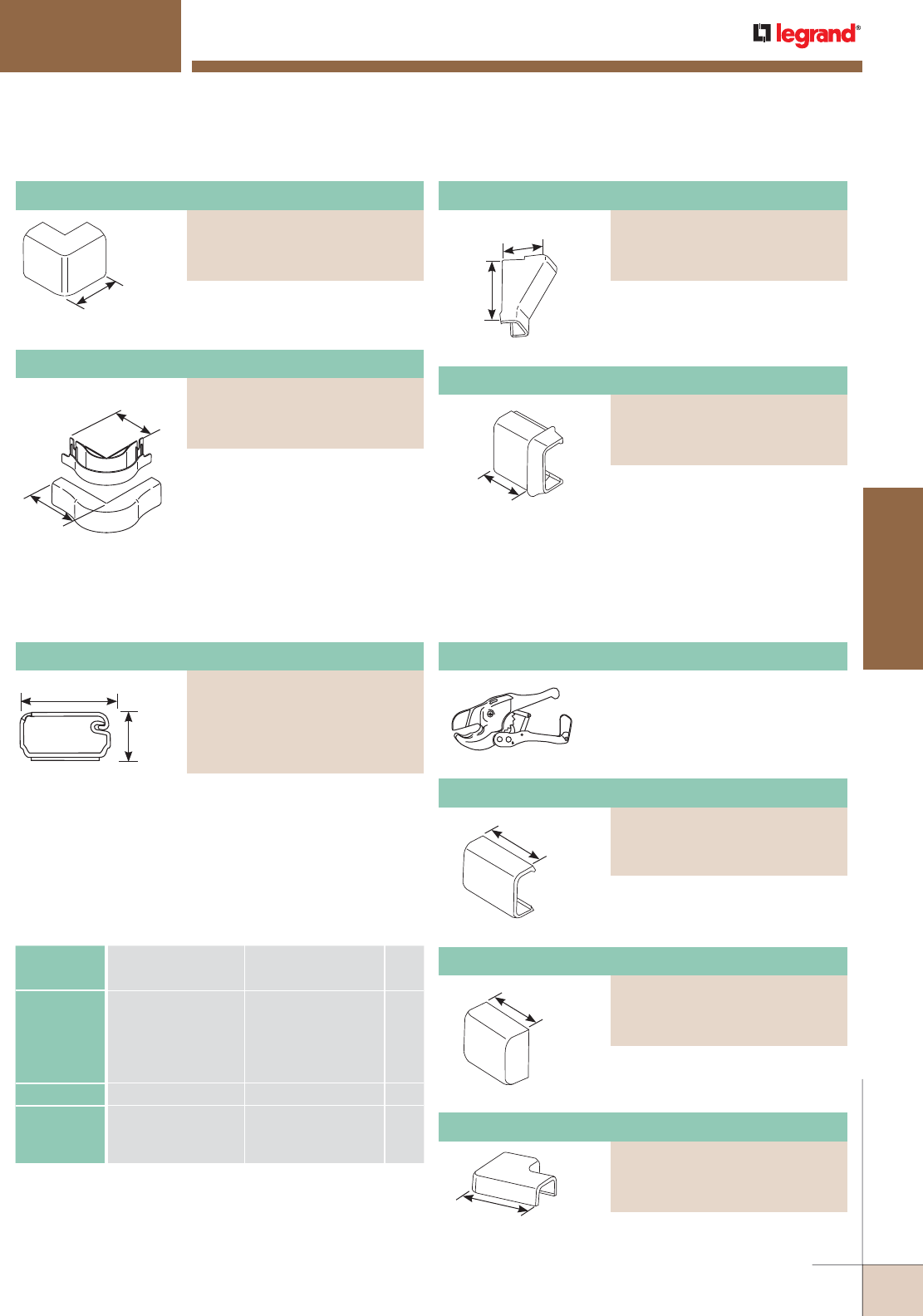
Flat Elbow
PART NUMBERS:
2911 (Ivory)
2911-WH (White)
2911-FW (Fog White)
Blank End Fitting
PART NUMBERS:
2910B (Ivory)
2910B-WH (White)
2910B-FW (Fog White)
Cover Clip
PART NUMBERS:
2906 (Ivory)
2906-WH (White)
2906-FW (Fog White)
NOTE: Device Boxes for Uniduct 2700 Series Raceway can be found on
pages located at the end of this product section.
UNIDUCT® 2800 & 2900 SERIES RACEWAYS
Ordering Information
1 1/8"
[29mm]
Each Leg
Makes right angle turns around
external corners.
Makes right angle turns around
external corners of 2800 Series
Raceway. Maintains 1 1/4" [32mm]
cable bend radius when installing
UTP and fiber optic cable.
3"
[76mm]
(Each leg)
3 3/4"
[95mm]
Conceals dropped cables from
ceiling into 2800 Series Raceway.
1 9/16"
[40mm]
2 3/8"
[60mm]
For transitioning from 2800 Series
Raceway to 2700 Series Raceway.
3/4"
[19.1mm]
1 1/2"
[38mm]
3/4"
[19.1mm]
2"
[51mm]
1 3/4"
[44mm]
2 3/4"
[70mm]
Each Leg
For closing open end of 2900
Series Raceway.
For right angle turns on same
surface.
Co-extruded design, smooth plastic finish with adhesive
backing. Available in 6' [1.8m] length, packed 120' [36.6m]
per carton. 2900L8 available in 8' [2.44m] length, packed
160' [48.8m] per carton.
For covering joint where two
pieces of 2900 Series Raceway
Cover come together.
Regular duty cutter. Ideal for use
with small nonmetallic raceways.
Uniduct® 2900 Series Raceway Wire Fill Capacities
for Communications
NOTE: For additional information, refer to the Technical Section.
* Category 6 augmented (6a) cable for 10 gigabit ethernet – max allowed
cable diameter per addenda No. 11 ANSI TIA/EIA 568-B.2.
Uniduct® 2900 Series Raceway Ordering Information
PVC-1 PVC Raceway Cutter
CABLE/WIRE SIZE
O.D. Approx. Dia.) 40%
FILLInches [ ]
UNSHIELDED
TWISTED
PAIR
4-pair, 24 AWG, Cat 3
4-pair, 24 AWG, Cat 5e
4-pair, 24 AWG, Cat 6
4-pair, 24 AWG, Cat 6a*
25-pair, 24 AWG
0.190
0.210
0.250
0.354
0.410
[4.8]
[5.3]
[6.3]
[8.9]
[10.4]
12
10
7
3
2
COAXIAL RG6/U 0.270 [6.9] 6
FIBER ZipCord
Round 4 Strand Fiber
Round 6 Strand Fiber
0.118 x 0.236
0.187
0.256
[3 x 6]
[4.8]
[6.5]
12
12
6
External Elbow
PART NUMBERS:
2818 (Ivory)
2818-WH (White)
2818-FW (Fog White)
Drop Ceiling Connector
PART NUMBERS:
2886 (Ivory)
2886-WH (White)
2886-FW (Fog White)
Radiused External Elbow
PART NUMBERS:
2818FO (Ivory)
2818FO-WH (White)
2818FO-FW (Fog White)
Reducing Connector (2800 – 2700)
PART NUMBERS:
2889 (Ivory)
2889-WH (White)
2889-FW (Fog White)
One-Piece Latching Raceway
PART NUMBERS:
2900 (Ivory)
2900-WH (White)
2900L8 (Ivory)
2900L8-WH (White)
2900-FW (Fog White)
WWW.LEGRAND.US/WIREMOLD
281
CORD MANAGEMENT
WIREMOLD
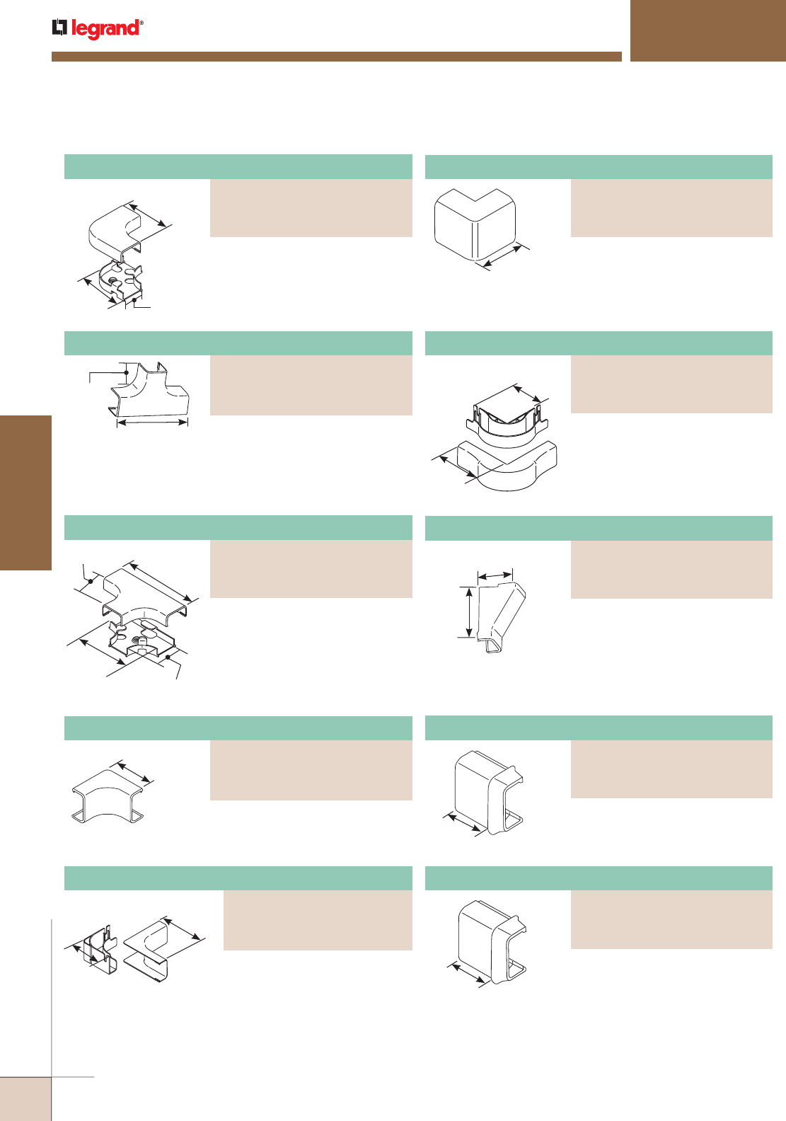
Radiused Internal Elbow
PART NUMBERS:
2917FO (Ivory)
2917FO-WH (White)
2917FO-FW (Fog White)
Internal Elbow
PART NUMBERS:
2917 (Ivory)
2917-WH (White)
2917-FW (Fog White)
3 1/2"
[89mm] (Each
leg)
2 3/4"
[70mm] 2 1/4"
[57mm]
UNIDUCT® 2900 SERIES RACEWAYS
Ordering Information
For right angle turns on same
surface. Maintains 1 1/4" [32mm]
bend radius when installing UTP
and fiber optic cable.
3"
[76mm]
(Each Leg)
3 3/4"
[95mm]
2"
[51mm]
2 7/8"
[73mm]
1 1/8"
[29mm]
3 7/8"
[98mm]
5 1/2"
[140mm]
1 1/4"
[32mm]
4"
[102mm]
1 15/16"
[49mm]
2 1/4"
[57mm]
Each Leg
2 1/2"
[64mm]
3 1/4"
[83mm]
(Each leg)
1 7/8"
[48mm]
Each Leg
15/16"
[24mm]
15/16"
[24mm]
For right angle turns around
external corners. Maintains
1 1/4" [32mm] bend radius
when installing UTP and fiber
optic cable.
For dropping cables from ceiling
into the raceway.
For transitioning from 2900 Series
Raceway to 2800 Series Raceway.
For transitioning from 2900 Series
Raceway to 2700 Series Raceway.
For branching of 2900 Series
Raceway running at right angles.
For branching of raceway running
at right angles. Maintains
1 1/4" [32mm] bend radius
when installing UTP and fiber
optic cable.
For right angle turns around
internal corners.
For right angle turns around
internal corners. Maintains
1 1/4" [32mm] bend radius
when installing UTP and fiber
optic cable.
For right angle turns around
external corners.
Radiused Flat Elbow
PART NUMBERS:
2911FO (Ivory)
2911FO-WH (White)
2911FO-FW (Fog White)
External Elbow
PART NUMBERS:
2918 (Ivory)
2918-WH (White)
2918-FW (Fog White)
Tee
PART NUMBERS:
2915 (Ivory)
2915-WH (White)
2915-FW (Fog White)
Radiused External Elbow
PART NUMBERS:
2918FO (Ivory)
2918FO-WH (White)
2918FO-FW (Fog White)
Radiused Tee
PART NUMBERS:
2915FO (Ivory)
2915FO-WH (White)
2915FO-FW (Fog White)
Drop Ceiling Connector
PART NUMBERS:
2986 (Ivory)
2986-WH (White)
2986-FW (Fog White)
Reducing Connector
PART NUMBERS:
2989 (Ivory)
2989-WH (White)
2989-FW (Fog White)
Reducing Connector
PART NUMBERS:
2989A (Ivory)
2989A-WH (White)
2989A-FW (Fog White)
WIREMOLD
WWW.LEGRAND.US/WIREMOLD
282
CORD MANAGEMENT
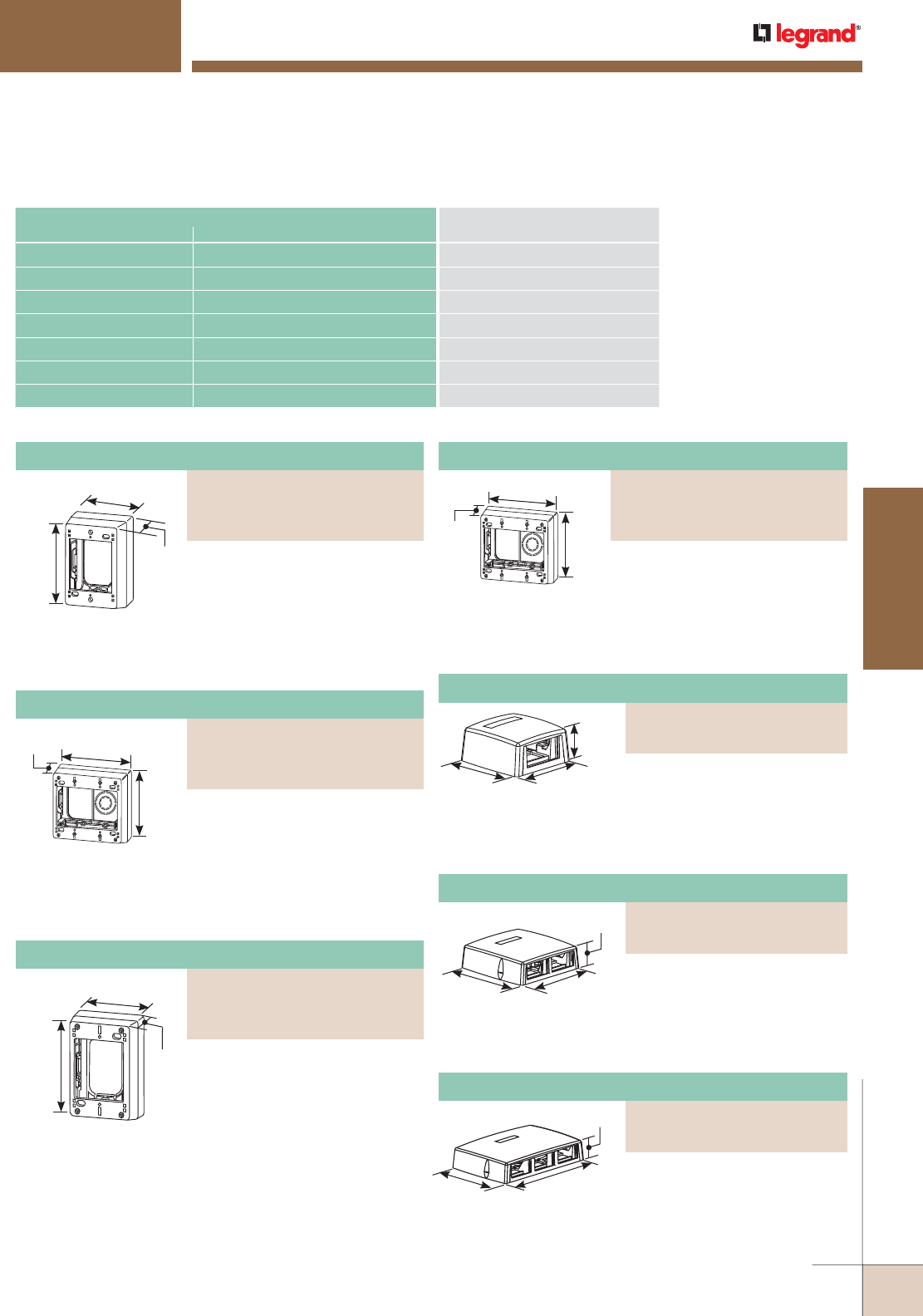
Deep Device Box
PART NUMBERS:
NM2048 (Ivory)
NM2048-WH (White)
NM2048-FW (Fog White)
Extra Deep Device Box
PART NUMBERS:
NM2044 (Ivory)
NM2044-WH (White)
NM2044-FW (Fog White)
CONNECTION REQUIRED
USE CATALOG NUMBER
FROM TO
Uniduct 2800 Series Raceway Uniduct 2700 Series Raceway 2889
Uniduct 2900 Series Raceway Uniduct 2700 Series Raceway 2989A
Uniduct 2900 Series Raceway Uniduct 2800 Series Raceway 2989
Drop Ceiling Uniduct 2800 Series Raceway 2786
Drop Ceiling Uniduct 2800 Series Raceway 2886
Drop Ceiling Uniduct 2900 Series Raceway 2986
NM2000 Uniduct 2700, 2800, or 2900 Series Raceway NM2044, NM2044-2, NM2048, NM2048-2
Uniduct 2700, 2800, 2900 Series Raceways Interconnectivity Fittings
4 3/4"
[121mm]
2 3/4"
[70mm]
3"
[76mm]
4 7/8"
[124mm]
4 3/4"
[121mm]
2 3/4"
[70mm]
4 3/4"
[121mm]
1 3/4"
[44mm]
3"
[76mm]
UNIDUCT® SERIES RACEWAY
Device Box Ordering Information
4 7/8"
[124mm]
4 3/4"
[121mm]
1 3/4"
[44mm]
For mounting multiple voice data
devices. Has combination twistouts
for Uniduct 2700, 2800, 2900,
and NM2000 Series Raceways.
Accepts industry standard NEMA
faceplates.
3 1/4"
[83mm]
3 1/4"
[83mm]
1 1/2"
[38mm]
Accepts one 2A size Wiremold
Open System Communication
Module or Pass & Seymour®
Activate Series Insert. Compatible with Uniduct 2700 and
2800 Series Raceways.
5 3/16"
[132mm]
5 3/16"
[132mm]
1 1/2"
[38mm]
Fiber storage loop. Accepts two
2A size Wiremold® Open System
Communication Modules
or Pass & Seymour® Activate Series Inserts. Compatible
with Uniduct 2700, 2800, and 2900 Series Raceways.
For mounting voice/data devices
when additional depth is required.
Has combination twistouts for
Uniduct 2700, 2800, 2900 and
NM2000 Series Raceways.
Accepts industry standard NEMA
faceplates.
For mounting multiple voice/data
devices when additional depth
is required. Has combination
twistouts for Uniduct 2700,
2800, 2900 and NM2000 Series
Raceways. Accepts industry
standard NEMA faceplates.
For mounting deep voice/data
devices. Has combination twistouts
for Uniduct 2700, 2800, 2900,and
NM2000 Series Raceways.
Accepts industry standard NEMA
faceplates.
5 3/16"
[132mm]
7 3/4"
[197mm]
1 1/2"
[38mm]
Fiber storage loop. Accepts
three 2A size Wiremold® Open
System Communication Modules
or Pass & Seymour® Activate Series Inserts. Compatible
with Uniduct 2700, 2800, and 2900 Series Raceways.
Two-Gang Extra Deep Device Box
PART NUMBERS:
NM2044-2 (Ivory)
NM2044-2WH (White)
NM2044-2FW (Fog White)
Two-Gang Deep Device Box
PART NUMBERS:
NM2048-2 (Ivory)
NM2048-2WH (White)
NM2048-2FW (Fog White)
One Insert Multimedia Box
PART NUMBERS:
CM-MMB-291 (Ivory)
CM-MMB-291-WH (White)
Two Insert Multimedia Box
PART NUMBERS:
CM-MMB-292 (Ivory)
CM-MMB-292-WH (White)
Three Insert Multimedia Box
PART NUMBERS:
CM-MMB-293 (Ivory)
CM-MMB-293-WH (White)
WWW.LEGRAND.US/WIREMOLD
283
CORD MANAGEMENT
WIREMOLD
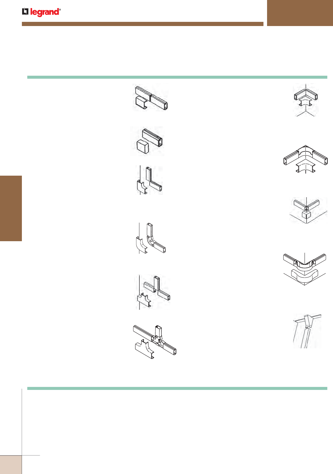
1. Cover Clip: 2706/2806/2906
To join two pieces of Uniduct Raceway
in line. Install the Uniduct Raceway
butted as shown. Snap the cover clip
(2706/2806/2906) onto the Uniduct
Raceway, leaving no gap.
2. Blank End Fitting: 2710B/2810B/2910B
To cover the open end of Uniduct
Raceway. Snap the blank end fitting
(2710B/2810B/2910B) onto the open
end of 2700, 2800, or 2900 Series
Uniduct Raceway.
4. Bend Radius 90° Flat Elbow:
2811FO/2911FO
To make right angle turn on same
surface and maintain 1 1/4" [32mm]
bend radius. Mount the fitting base
to the wall by using screws or the
adhesive strip supplied. Butt the
Uniduct Raceway as shown and snap
the fitting cover over the base after
the cabling has been completed.
5. Tee: 2715/2815/2915
For branching at right angles.
Install the Uniduct Raceway butted
as shown. Snap tee (2715/2815/2915)
onto the Uniduct Raceway, leaving
no gap.
6. Bend Radius Tee: 2815FO/2915FO
To branch at right angles and
maintain a 1 1/4" [32mm] bend
radius. Mount the fitting base to the
wall by using screws or the adhesive
strip supplied. Butt the Uniduct
Raceway as shown and snap the
fitting cover over the base after the
cabling has been completed.
3. 90° Flat Elbow: 2711/2811/2911
To make right angle turn on same
surface. Install the Uniduct Raceway
butted as shown. Snap 90° flat elbow
(2711/2811/2911) onto the Uniduct
Raceway, leaving no gap.
7. Internal Elbow: 2717/2817/2917
To go around internal corner. Install
Uniduct 2700, 2800, or 2900 Series
Raceway butted as shown. Snap
internal elbow (2717/2817/2917) onto
the Uniduct Raceway, leaving no gap.
8. Bend Radius Internal Elbow:
2817FO/2917FO
To make internal corner connection
and maintain 1 1/4" [32mm] bend
radius. Mount the fitting base to the
wall by using screws or the adhesive
strip supplied. Butt the Uniduct
Raceway as shown and snap the
fitting cover over the base after the
cabling has been completed.
9. External Elbow: 2718/2818/2918
To go around external corner. Install
Uniduct 2700, 2800, or 2900 Series
Raceway butted as shown. Snap
external elbow (2718/2818/2918)
onto the Uniduct Raceway, leaving
no gap.
10. Bend Radius External Elbow:
2818FO/2918FO
To make external corner connection
and maintain 1 1/4" [32mm] bend
radius. Mount the fitting base to the
wall by using screws or the adhesive
strip supplied. Butt the Uniduct
Raceway as shown and snap the
fitting cover over the base after the
cabling has been completed.
10. Drop Ceiling Connector:
2786/2886/2986
For bringing cables from ceiling to
raceway. Cut a hole in the ceiling tile
right next to metal grid. Drop the
cables from the ceiling into the Uniduct
Raceway. Push the drop ceiling
connector (2786/2886/2986) through
the hole so that the notch in the large
end of the connector butts with the
metal grid. Snap the drop ceiling
connector onto the Uniduct Raceway.
2700, 2800, 2900 Series Raceways Installation Details
UNIDUCT® 2700, 2800, 2900 SERIES RACEWAYS
Installation Details
WIREMOLD
WWW.LEGRAND.US/WIREMOLD
284
CORD MANAGEMENT
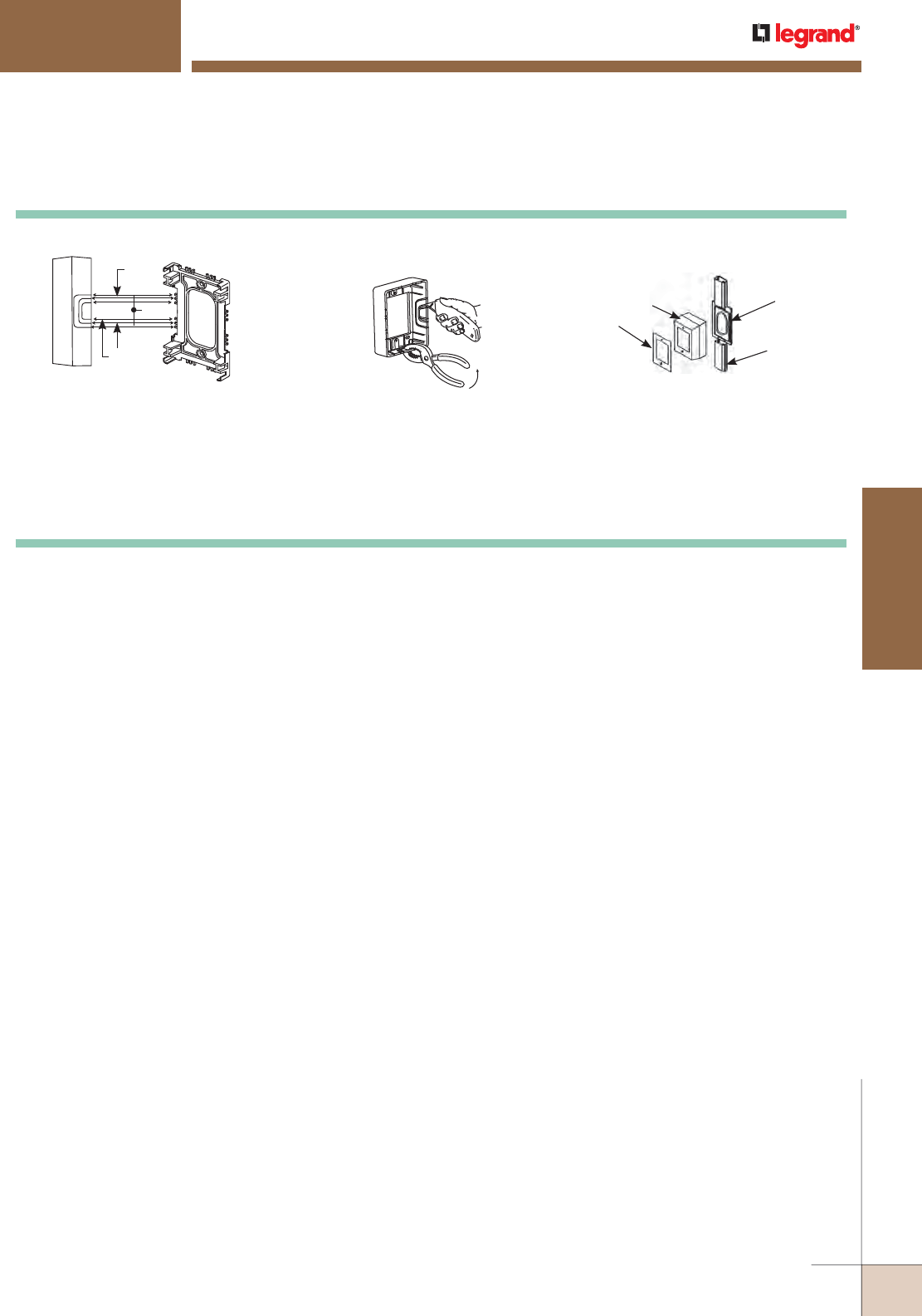
UNIDUCT® 2700, 2800, 2900 SERIES RACEWAYS
Installation Details
NM2048 Cover
Faceplate
NM2048 Base
2700, 2800, 2900
Uniduct Raceway
2700
2800
2900
Base Front View
Cover Side View
1. Remove proper tongue on the
device box (NM2048) base.
2. Notch proper knockout in cover
using knife. Use pliers to remove
knockout inward for cleaner edge.
(Trimming may be necessary.)
4. Mount raceway to box.
Install cables. 5. Snap device box cover onto base.
3 . Fasten device box base to wall
using screws (not provided).
2700, 2800, 2900 Series Raceways Device Box Installation Details
6. Mount device and faceplate.
WWW.LEGRAND.US/WIREMOLD
285
CORD MANAGEMENT
WIREMOLD
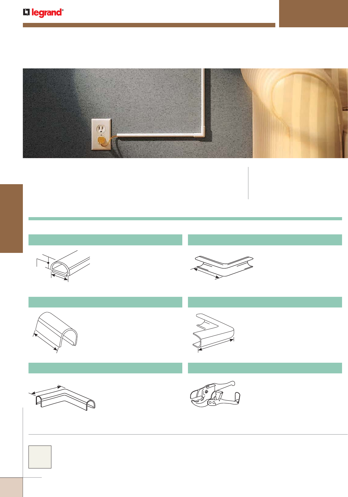
300 Duct
300 Series Faceplates Ordering Information
317 Internal Elbow
For right angle turns around
internal corners.
1/2"
[12.7mm]
12/32"
[8.9mm]
1"
[25mm]
1 5/8"
[41mm]
1 5/8"
[41mm]
1 5/8"
[41mm]
300 SERIES™ DUCT
CODE REFERENCE
300 Series Duct is not UL listed because it
is designed to protect and organize cords
and cables that are not required to be
enclosed by the National Electric Code.
300 Series™ Duct conceals electrical cords and low voltage wiring. With a
full complement of fittings and adhesive backing, 300 Series Duct is easy-
to-install and paintable so that it blends with any decor.
300 Series™ Duct is available in an ivory finish and is
paintable using latex paint.
COLOR OPTIONS
One-piece latching duct. 5' [1.5m]
strip extruded from rigid natural
PVC. Adhesive back. Smooth
texture ivory.
306 Coupling
For joining strips of 300 Series
duct.
311 Flat Elbow
For right angle turns on the same
surface.
318 External Elbow
For right angle turns around
external corners.
PVC-1 Raceway Cutter
Regular duty cutter. Ideal for use
with small nonmetallic raceways.
WIREMOLD
WWW.LEGRAND.US/WIREMOLD
286
CORD MANAGEMENT
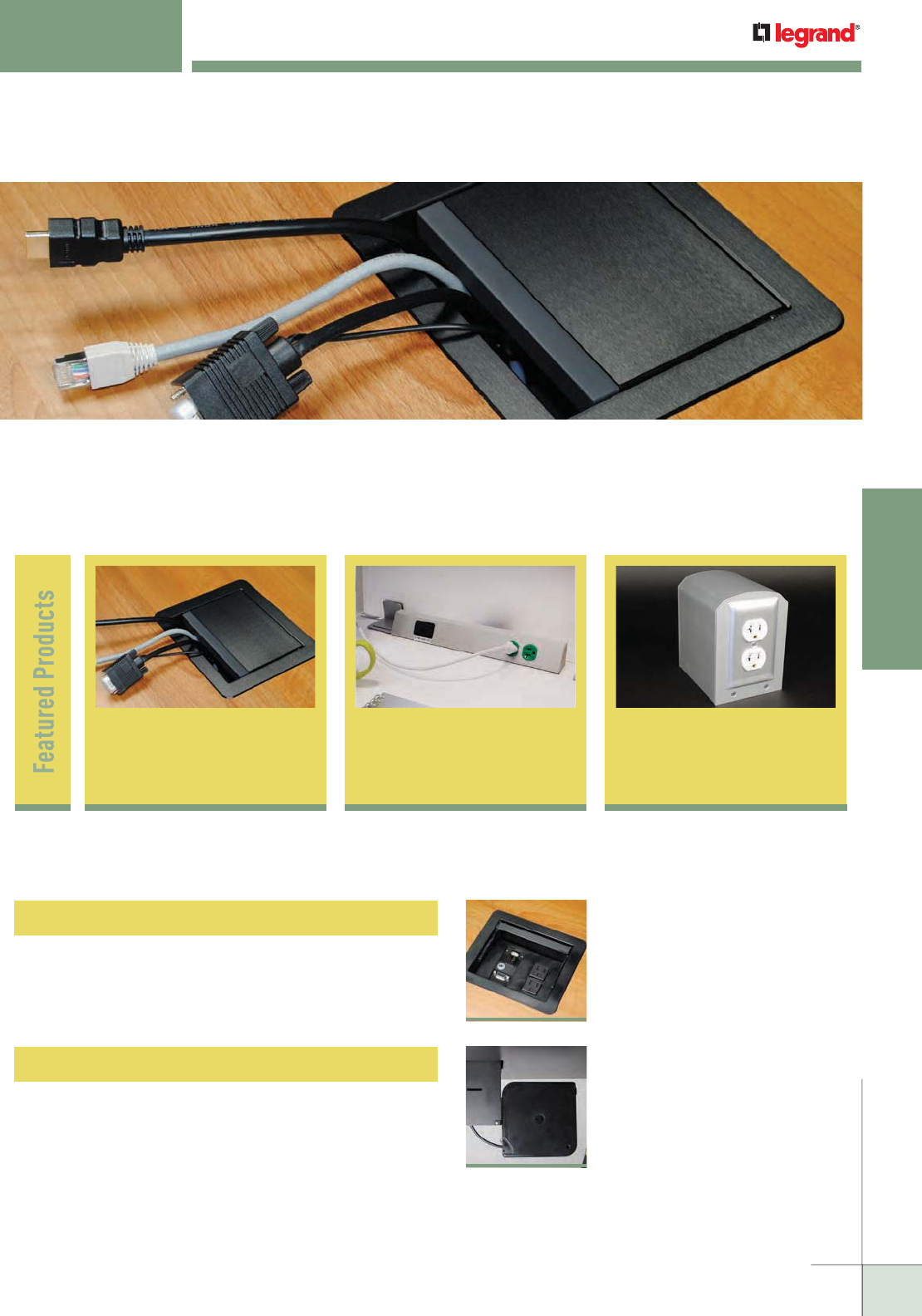
WWW.LEGRAND.US/WIREMOLD
287
TABLE BOXES
WIREMOLD
TABLE BOXES
Wiremold® Table boxes bring technology closer to the user’s work area.
The routing of power, communication and A/V connections is virtually
transparent and increasingly more accessible. Solutions offer flexibility in
meeting connectivity configurations and décor needs.
InteGreat A/V
Table Box 290
TableSource™
Table Boxes 297
Table of Contents
InteGreat AV Table Box
290
InteGreat Cable Retractors
291
Lab Bench
Pedestal
Table Box 303
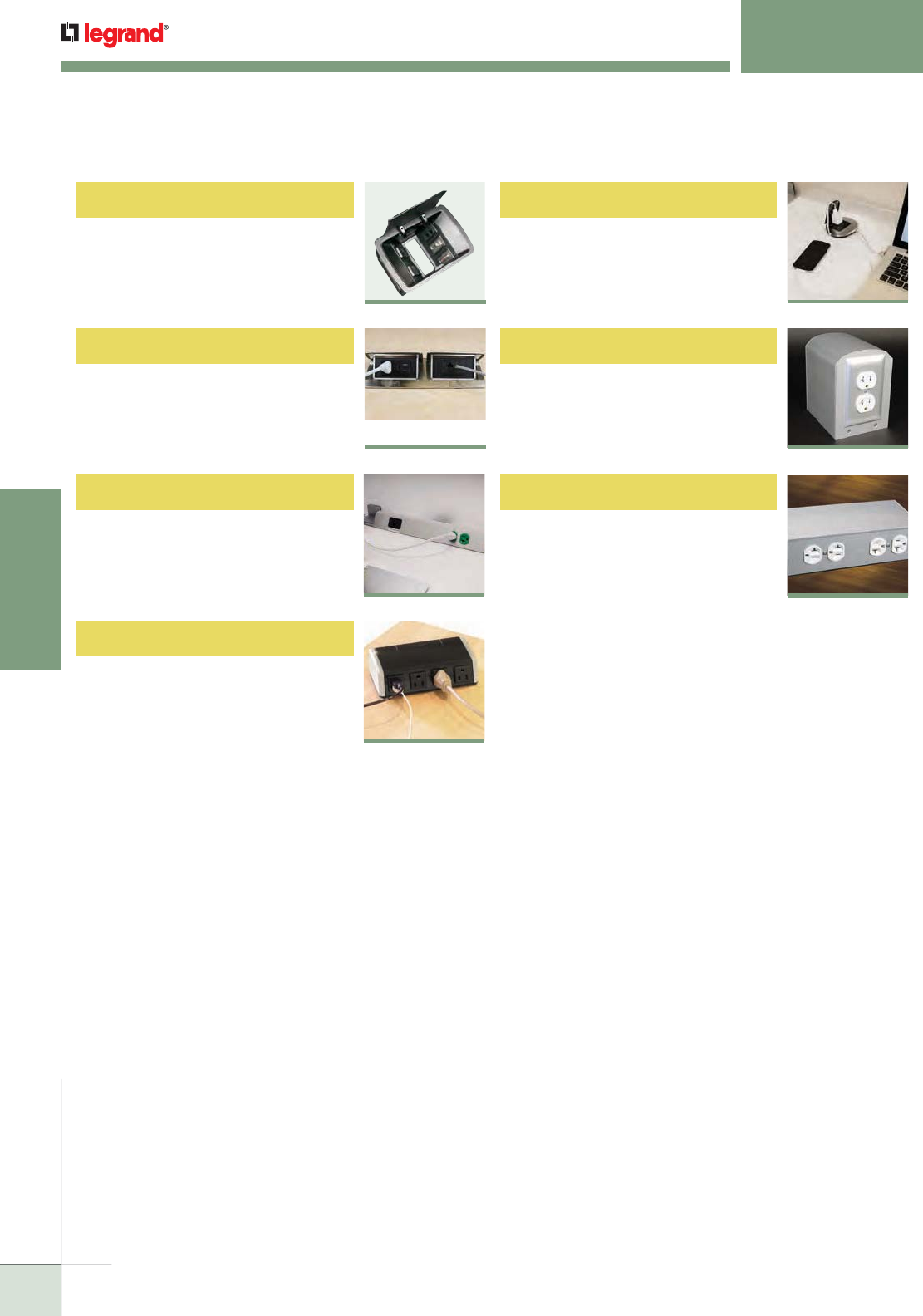
WWW.LEGRAND.US/WIREMOLD
288
TABLE BOXES
MEETING ROOM SOLUTIONS
Table of Contents
WIREMOLD
Desktop Power Center
Lab Bench Pedestal Table Box
303
4 Gang Lab Bench Table Box
305
300
Desk Module
301
TableSource™ Table Boxes
297
dequorum™ Recessed Table Boxes
dequorum™ Flip-Up Table Boxes
295
292
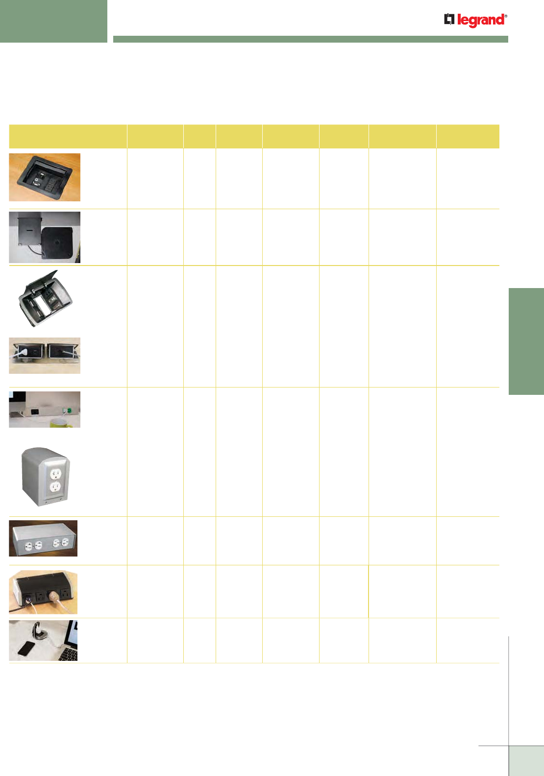
WWW.LEGRAND.US/WIREMOLD
289
TABLE BOXES
WIREMOLD
MEETING ROOM SOLUTIONS
Quick Selection Guide
Table Boxes
Table Box Model Svc. Location
@ Table Cord
Length Field Wired
Whip length Cover Color/
Material Electrical
Outlets Communication
Openings AV
Openings
InteGreat
A/V Table Box
Recessed 12' 6' Black,
Aluminum
Three 15A
receptacles,
two inside table
box, and one
underneath
Up to 5 available
using InteGreat Cable
Retractors
or Wiremold
AVIP plates
Up to five (5)
Wiremold AVIP
device plates or
five (5) Extron®
Electronics MAAP
device plates
InteGreat
Cable
Retractors
Underneath or
with InteGreat
A/V Table Box
5' N/A Black N/A N/A N/A
deQuorum
Recessed
Table Boxes
Recessed 12' 6' Gray, Black (2) 20A
Duplexes
Gasketed
Adapters for
Ortronics®
Series II, TracJack
or Wiremold Open
System
Cable Cord Keeper
or Wiremold AVIP
Plates or Extron®
Electronics
MAAP modules –
(6) single or
(3) double
deQuorum
Flip-Up
Table Boxes
Above 6' 6' Black,
Stainless
(1) 15A or
20A Duplex
Adapters for
Ortronics®
Series II or TracJack
and Wiremold Open
System
N/A
TableSource
Table Boxes
Above 6' N/A Clear Anodized
Aluminum
Black, White
and Ivory
(1) 15A
Duplex
2 Openings with
Adapters for
Ortronics®
Series II, TracJack
or Wiremold Open
System
N/A
Lab Bench
Pedestal
Table Box
Above N/A N/A Clear Anodized
Aluminum
Black, White
and Ivory
One or two
15A, 20A
simplex or
duplex,
GFCI or 30A
twist lock
receptacles
1-4 Openings
with Adapters for
Ortronics®
Series II, TracJack
or Wiremold Open
System
Up to five (5)
Wiremold AVIP
device plates or
five (5) Extron®
Electronics MAAP
device plates
4 Gang
Lab Bench
Table Box
Above N/A N/A Clear Anodized
Aluminum
Fits (1-4)
15A Duplexes
or Decorator
Style Outlets
See product
pages for
device plate
selection
See product
pages for
device plate
selection
Desktop
Power
Center
Above 6' N/A Black with
Magnesium
Side Panels
(
3) 15A Outlets
with (2) USB
Charging
Outlets or
(4) 15A Outlets
N/A N/A
Desk
Module
Flush 12' N/A Brushed Silver
with Black
Cover
(1) 15A
Duplex
RJ45
(Retractor
available)
USB Charging
(USB Retractor
available)
Extron® Electronics MAAP modules are sold separately.
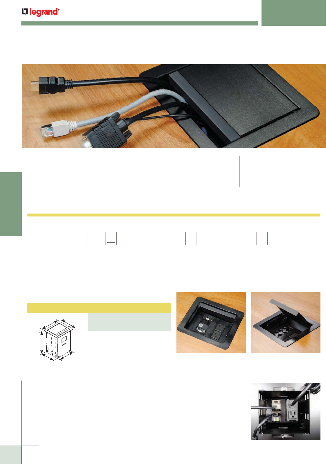
WWW.LEGRAND.US/WIREMOLD
290
TABLE BOXES
WIREMOLD
Table Box with 12' [3.66m] cord.
Unit comes with two (2) 15A
receptacles in the recessed
compartments and one 15A
receptacle on the underside of
the box. Hardware bag includes
Wiremold® AVIP Series Cable
Kit with eight (8) openings. Can
accept up to five (5) Wiremold AVIP
device plates or five (5) Extron®
Electronics MAAP device plates.
(Sold separately.)
A/V Table Box
PART NUMBERS:
TB672APBK (Black)
TB672APAL (Aluminum)
InteGreat A/V Table Box Ordering Information
InteGreat A/V Table Boxes
accept Wiremold AVIP Series
and Extron® Electronics MAAP
Device Plates.
A Wiremold® AVIP Series Cable
Kit is supplied with every
InteGreat A/V Table Box.
7"
[178mm]
6 15/16"
[176mm]
8 1/4"
[210mm]
6"
[152mm]
5 9/16"
[141mm]
Convenience receptacle on the
underside of the box is ideal for
powering small devices under
the table.
InteGreat A/V table boxes are an elegant solution for extending power,
communication and A/V to the meeting presenter’s point-of use. InteGreat A/V
table boxes provide the depth to mount devices, especially A/V devices, below
the table top. It has attractive finishes that can match any room décor. Combine
it with other InteGreat products, such as InteGreat Retractors, InteGreat Under
Table Cable Management and InteGreat Transition Channel for a comprehensive
solution to managing and delivering power, communication and A/V connectivity
for conference rooms.
INTEGREAT™ A/V TABLE BOXES
CODE REFERENCE
cETLus Listed Furniture
Power Distribution Unit:
Listed to US & Canadian
Safety Standards
InteGreat AV Table Box Part Number Configurator
NOTE: Part Number Configurator can be used both to identify stock product
configurations and also to request custom configurations from factory.
K
Color:
BK = Black
AL = Aluminum
Compartments:
2 = 2 Compartments
Compartment 1
A = A/V
P = Power
Size:
67 = 6" x 7" Flange
InteGreat Series:
TB = Table Box
TB 67 2 A P B F
Compartment 2
P = Power
Cord Type:
= 12' Cord
F = Field Wired
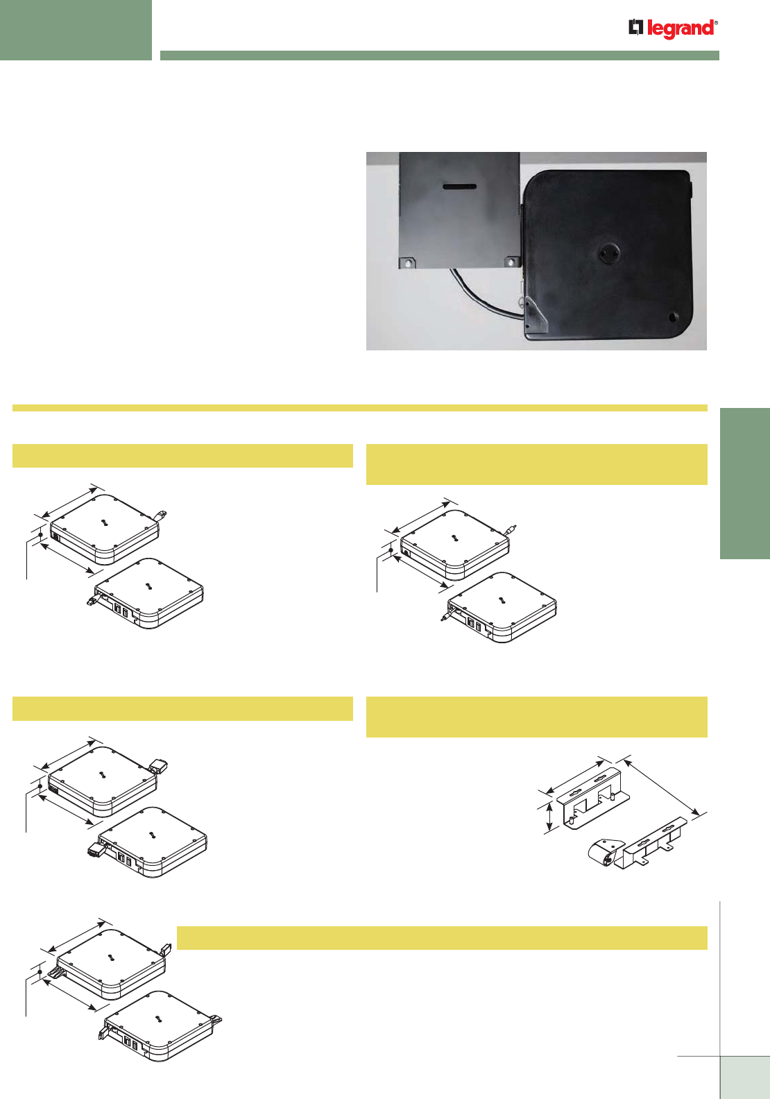
WWW.LEGRAND.US/WIREMOLD
291
TABLE BOXES
WIREMOLD
INTEGREAT™ CABLE RETRACTORS
InteGreat Cable Retractors attach easily to InteGreat A/V
Table Boxes, or can be mounted directly to the underside
of conference room tables. InteGreat Cable Retractors have
5' [1.52m] of retractable cable that allows users to have
easy access to A/V and communication services. With a
simple pull, the cable locks into place or retracts back into
the table box, keeping the conference room table neat and
organized.
InteGreat Cable Retractors protect cables while keeping them
neat and organized.
Mounts directly to the InteGreat Series A/V Table Box or to the underside of the
conference room table using the TBCRHMK. Loaded with 12' [3.66m] of HDMI with
Ethernet cable that extends out 5' [1.52m] from the retractor. Retractor has a
female input from building infrastructure, and a male connector on the output side.
Input side has mounting tab that allows installer to cable tie HDMI to the retractor
to minimize chances of a loose connection.
8 1/4"
[210mm]
8 1/4"
[210mm]
1 7/8"
[48mm]
8 1/4"
[210mm]
8 1/4"
[210mm]
1 7/8"
[48mm]
8 1/4"
[210mm]
10"
[254mm]
1 7/8"
[48mm]
InteGreat™ Cable Retractor Ordering Information
8 1/4"
[210mm]
8 1/4"
[210mm]
1 7/8"
[48mm]
TBCRCAT6 Cable Retractor with Category 6A Cable
Mounts directly to the
InteGreat Series A/V Table Box
or to the underside of the
conference room table using
the TBCRHMK. Loaded with
12' [3.66m] of Cat6A cable that
extends out 5' [1.52m]
from the retractor.
Retractor has a female
input from building infra-
structure, and a male
connector on the output side.
TBCRVGA Cable Retractor with VGA VESA Cable
Mounts directly to the
InteGreat Series A/V Table Box
or to the underside of the
conference room table using
the TBCRHMK. Loaded with
12' [3.66m] of VGA VESA
cable that extends out
5' [1.52m] from the
retractor. Retractor
has a female input from
building infrastructure, and
a male connector on the
output side.
TBCRHDMI High Speed HDMI with Ethernet Cable
TBCR3.5MM
Cable Retractor with 3.5mm Audio Cable
10 5/16"
[262mm]
6 3/8"
[162mm]
1 15/16"
[49mm]
Allows retractor to mount
horizontally under a
conference room table,
so cable can be accessed
through a table grommet.
Multiple retractors can
be mounted to each other
by attaching the TBCRHMK
Mounting Brackets to each other.
TBCRHMK
Cable Retractor Horizontal Mounting Bracket
Cable Retractor with 3.5mm
audio cable. Mounts directly
to the InteGreat Series A/V
Table Box or to the underside
of the conference room table
using the TBCRHMK. Loaded
with 12' [3.66m] of audio
cable that extends out
5' [1.52m] from the
retractor. Retractor has
a female input from building
infrastructure, and a male
connector on the output side.
CODE REFERENCE
InteGreat™ Cable Retractors are
not UL listed because they are
designed to protect and organize
cords and cables that are not
required to be enclosed by the
National Electric Code.
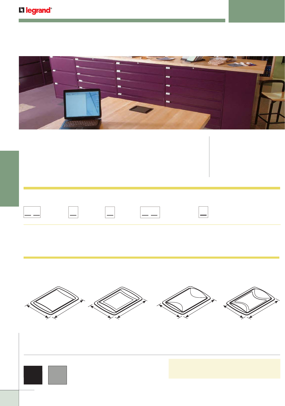
WWW.LEGRAND.US/WIREMOLD
292
TABLE BOXES
WIREMOLD
For information regarding communication inserts, go to:
www.legrand.us/wiremold
Cover Color:
Black = 0
Gray = 5
deQuorum Series:
KC = Cord Ended
KF = Field Installed
Cover Style:
Flush = 1
Contoured = 4
Top Style:
Recessed = 2
Blank = 8
Communication:
Ortronics = RT
Wiremold = CM Open System
5 7/8"
[149mm]
8 7/16"
[214mm]
Decorative Recess for
Table Laminate Insert
5 7/8"
[149mm]
8 7/16"
[214mm]
Decorative Recess for
Table Laminate Insert
Flush Covers - Available finishes: Black or Gray.
Shown with flange.
Contoured Covers - Available finishes: Black or Gray.
Shown with flange.
5 7/8"
[149mm]
8 7/16"
[214mm]
Blank Top
5 7/8"
[149mm]
8 7/16"
[214mm]
Blank Top
deQuorum™ Recessed Table Boxes provide flexibility in décor,
communication and A/V connectivity options, and installation to
meet specific functional and aesthetic needs.
deQUORUM™ RECESSED TABLE BOXES
CODE REFERENCE
cULus Listed Relocatable Power Tap:
File E66421 Guide XBYS
cULus Listed Multioutlet Assembly:
File E15191 Guide PVGT
Listed to US and Canadian Safety
Standards
Meets Article 380 of NEC.
COLOR OPTIONS
deQuorum Table Box Covers are available in
Black or Gray
deQuorum Recessed Table Box Part Number Configurator
deQuorum Recessed Table Box Cover Options
NOTE: Part Number Configurator can be used both to identify stock product configurations and also to request custom configurations from
the factory. Consult the factory for more information.
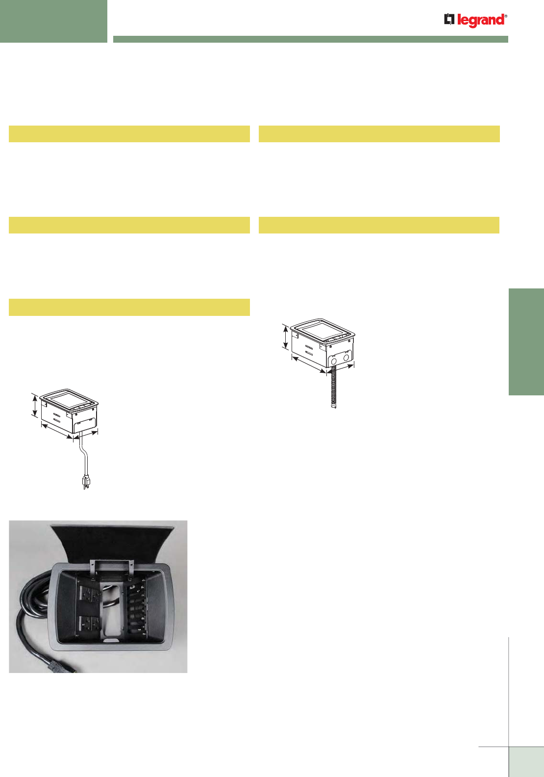
WWW.LEGRAND.US/WIREMOLD
293
TABLE BOXES
WIREMOLD
deQUORUM™ RECESSED TABLE BOXES
Ordering Information
deQuorum Recessed Table Box – In-Stock Configuration Ordering Information
3 3/8"
[86mm]
7 7/8"
[200mm] 5 1/8"
[130mm]
Cord-Ended Unit
3 3/8"
[86mm]
7 7/8"
[200mm] 5 1/8"
[130mm]
Field-Wired Unit
Cord-ended with black, flush cover with decorative recess.
Unit comes with two 20A gasketed prewired receptacles
with a 12' [3.65m] 14/3 SJT black cord. Includes adapter for
Wiremold CM Series Open System communications outlets.
Communication modules sold separately.
KC10CM2
Field-wired with black, flush cover. Unit comes with two
20A gasketed prewired receptacles with a 3/8" [9.5mm]
diameter 6' [1.83m] flexible whip. Includes adapter for
Wiremold CM Series Open System communications outlets.
Communication modules sold separately.
KF10CM8
Cord-ended with black, flush cover. Unit comes with two
20A gasketed prewired receptacles with a 12' [3.65m] 14/3
SJT black cord. Includes adapter for Ortronics® Series II and
TracJack inserts. Communication modules sold separately.
KC10RT8
Field-wired with gray, flush cover with decorative recess.
Unit comes with two 20A gasketed prewired receptacles
with a 3/8" [9.5mm] diameter 6' [1.83m] flexible whip.
Includes adapter for Ortronics® Series II and TracJack
inserts. Communication modules sold separately.
KF15RT2
Cord-ended with gray, flush cover. Unit comes with two 20A
gasketed prewired receptacles with a 12' [3.65m] 14/3 SJT
black cord. Includes adapter for Ortronics® Series II and
TracJack inserts. Communication modules sold separately.
KC15RT8
Above unit shown with KA700, 20A Gasketed
Receptacle Plate and KA305, Wiremold AVIP
Adapter Plate installed.
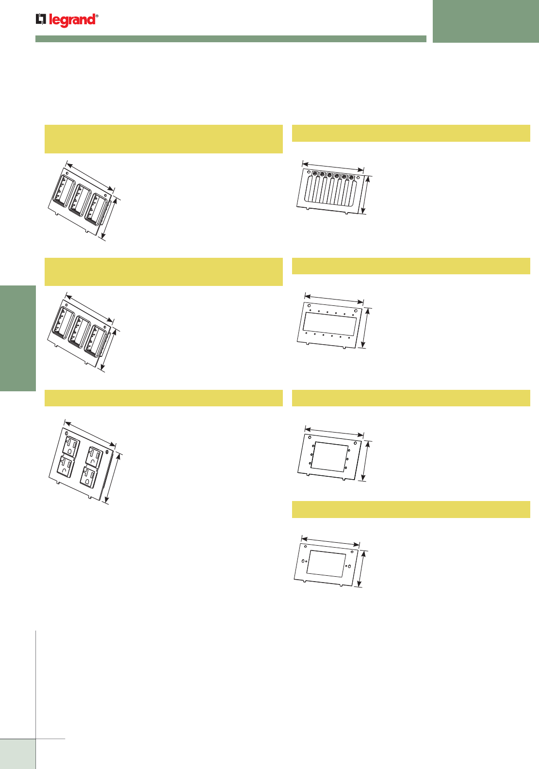
WWW.LEGRAND.US/WIREMOLD
294
TABLE BOXES
WIREMOLD
deQUORUM™ RECESSED TABLE BOXES
Ordering Information
4 3/4"
[120mm]
3 1/16"
[78mm]
4 3/4"
[120mm]
3 1/16"
[78mm]
deQuorum Recessed Table Box – Communication Plate Ordering Information
4 3/4"
[120mm]
3 1/16"
[78mm]
4 3/4"
[120mm]
3 1/16"
[78mm]
KA102RT
Replacement Ortronics Communications Plate
Installed adapters will
accommodate either Ortronics®
Series II front-loading module
system or the TracJack individual
jack system. Includes black plate
and three (3) Series II and three (3)
TracJack adapters.
4 3/4"
[120mm]
3 1/16"
[78mm]
KA104CM Replacement Wiremold Open System
Communications Plate
Installed adapters accept
Wiremold CM Series modules to
accommodate a wide range of
communications outlets. Includes
black plate and three (3) Wiremold
Open System CM2 adapters.
KA700 Replacement 20A Gasketed Receptacle Plate
Plate has factory-installed
receptacles ready to connect
with installed unit. Can be used
for field-installed or cord-ended
units.
KA302 Cable Cord keeper Plate
Holds cables captive for easy
access. Pull the cable out for
use. Keeper bars provide seven
adjustable openings for cables
ranging from .150" to .350"
[3.8mm to 8.9mm] in diameter.
4 3/4"
[120mm]
3 1/16"
[78mm]
4 3/4"
[120mm]
3 1/16"
[78mm]
KA305 Wiremold AVIP Adapter Plate
Accepts six (6) single size
Wiremold AVIP plates or Extron®
Electronics MAAP or three (3)
double size MAAP modules, or any
combination. Includes necessary
hardware.
KA305-AAP Extron® AAP Adapter Plate
Accepts three (3) AAP plates.
Includes necessary hardware.
KA301 Single-Gang Opening Plate
Use this plate to install any
communication and/or multimedia
connectivity that requires a single-
gang wallplate. Includes necessary
mounting hardware.
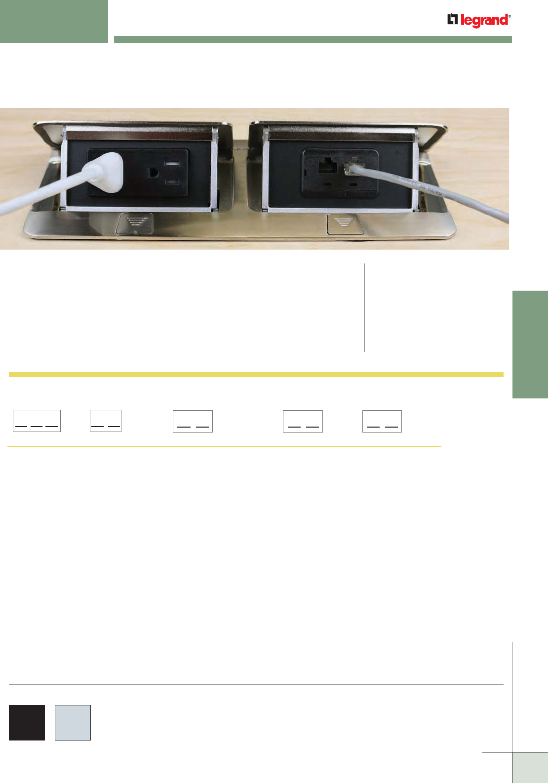
WWW.LEGRAND.US/WIREMOLD
295
TABLE BOXES
WIREMOLD
deQuorum™ Flip-Up Table Boxes provide flexibility in décor, communication
connectivity options, and installation to meet specific functional and aesthetic
needs.
CODE REFERENCE
cULus Listed Relocatable Power Tap:
File E66421 Guide XBYS
cULus Listed Multioutlet Assembly:
File E15191 Guide PVGT
Listed to US and Canadian Safety
Standards
Meets Article 380 of NEC.
deQUORUM™ FLIPUP TABLE BOXES
deQuorum Flip-Up Table Box Part Number Configurator
NOTE: Part Number Configurator can be used both to identify stock product configurations and also to request custom configurations
from the factory. Consult the factory for more information.
COLOR OPTIONS
deQuorum Flip-Up Table Box Covers are available in the
following finishes: Black and Stainless.
deQuorum Series:
DQF = deQuorum
Flip-Up
Wiring Option:
P = Cord Ended
F = Field Wired
Unit Color:
BK = Black
ST = Stainless
Receptacle Amperage:
15 = 15A
20 = 20A
Second Gang:
Communications = 2A
Only One Gang = Blank
D Q F
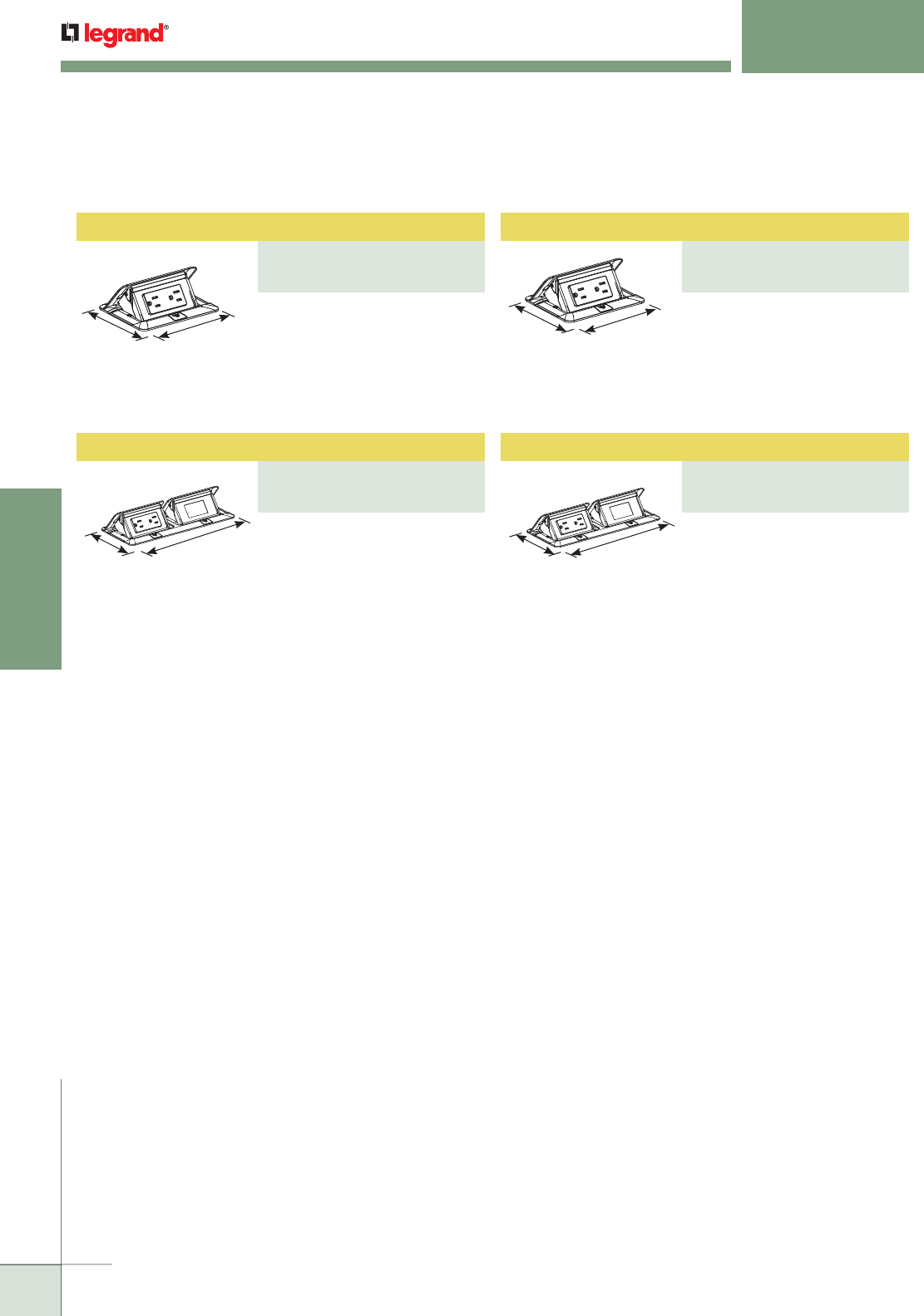
WWW.LEGRAND.US/WIREMOLD
296
TABLE BOXES
WIREMOLD
Dual Flip-Up Unit
PART NUMBERS:
DQFP20ST-2A (20 Amp)
DQFP15ST-2A (15 Amp)
Dual Flip-Up Unit
PART NUMBERS:
DQFP20BK-2A (20 Amp)
DQFP15BK-2A (15 Amp)
Single Flip-Up Unit
PART NUMBERS:
DQFP20ST (20 Amp)
DQFP15ST (15 Amp)
Single Flip-Up Unit
PART NUMBERS:
DQFP20BK (20 Amp)
DQFP15BK (15 Amp)
4 3/4"
[120mm]
9 1/4"
[235mm] 4 3/4"
[120mm]
9 1/4"
[235mm]
4 3/4"
[120mm]
4 7/8"
[124mm]
Black cover. DQFP20BK includes
one 20A black gasketed duplex
receptacle. DQFP15BK includes
one 15A black gasketed duplex
receptacle. Both units come with
a 6' [1.83m] cord.
4 3/4"
[120mm] 4 7/8"
[124mm]
Stainless finish cover. DQFP20ST
includes one 20A black gasketed
duplex receptacle. DQFP15ST
includes one 15A gasketed duplex
receptacle. Both units come with
a 6' [1.83m] cord.
Stainless finish cover.
DFQFP20ST-2A includes one
20A black gasketed duplex
receptacle. Second opening
will accept adapter for one
(1) Wiremold CM Series
Open System 2A module,
one (1) Ortronics Series II or
one (1) TracJack adapter to
accommodate a wide range of
communication outlets. Adapters
are included in hardware bag.
DQFP15ST-2A includes one
15A black gasketed duplex
receptacle. Both units come with
a 12' [3.66m] cord.
Black cover. DQFP20BK-2A
includes one 20A black gasketed
duplex receptacle. Second
opening will accept adapter for
one (1) Wiremold CM Series
Open System 2A module, one
(1) Ortronics Series II or one (1)
TracJack adapter to accommodate
a wide range of communication
outlets. Adapters are included
in hardware bag. DQFP15BK-2A
includes one 15A black gasketed
duplex receptacle. Both units
come with a 12' [3.66m] cord.
deQuorum™ Flip-Up Table Box Ordering Information
deQUORUM™ FLIPUP TABLE BOXES
Ordering Information
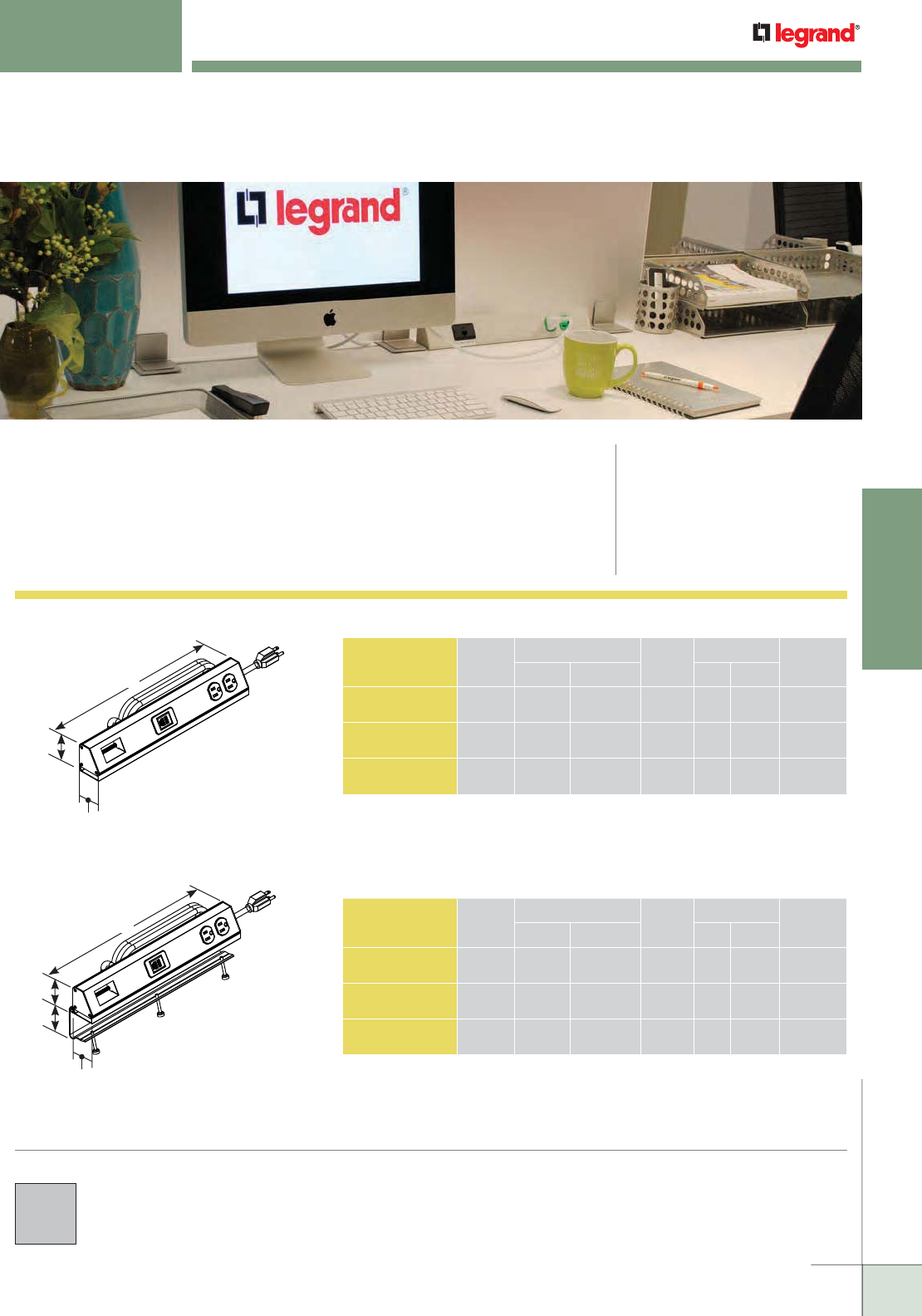
WWW.LEGRAND.US/WIREMOLD
297
TABLE BOXES
WIREMOLD
CATALOG
NUMBER FINISH
UNIT LENGTH 15A
DUPLEX
CORD LENGTH COMM.
OPENINGSInches [mm] Feet [mm]
TSAM1F0AL1U Clear
Anodized
13" [330.2mm] 1 12' [3.7m] 0
TSAM1F1AL1U Clear
Anodized
15 1/2" [393.7mm] 1 12' [3.7m] 1
TSAM1F2AL1U Clear
Anodized
18 3/32" [461.2mm] 1 12' [3.7m] 2
TABLESOURCE™ TABLE BOXES
TableSource™ Table Boxes provide flexibility in décor, datacom
connectivity options, and installation to meet specific functional and
aesthetic needs.
CODE REFERENCE
cULus Listed Relocatable Power Tap:
File E66421 Guide XBYS
cULus Listed Multioutlet Assembly:
File E15191 Guide PVGT
Listed to US and Canadian Safety
Standards
Meets Article 380 of NEC.
TableSource Activations in this chart
are packaged with a mounting clip that
attaches to the work surface and a
hardware bag of adapters that allows
the communication openings to accept
either Ortronics Series II, TracJack or
Wiremold Open System.
TableSource Activations in this chart
are packaged with a mounting clip that
attaches to the work surface and a
hardware bag of adapters that allows
the communication openings to accept
either Ortronics Series II, TracJack or
Wiremold Open System.
2 3/8"
[60.33mm]
Accommodates
Surface Thicknesses
from 0.7" to 1.9"
[18mm to 48mm]
COLOR OPTIONS
TableSource Table Box Covers
are available in a clear anodized finish.
TableSource Table Box Ordering Information
CATALOG
NUMBER FINISH
UNIT LENGTH 15A
DUPLEX
CORD LENGTH COMM.
OPENINGSInches [mm] Feet [mm]
TSAX1F0AL1U Clear
Anodized
13" [330.2mm] 1 12' [3.7m] 0
TSAX1F1AL1U Clear
Anodized
15 1/2" [393.7mm] 1 12' [3.7m] 1
TSAX1F2AL1U Clear
Anodized
18 5/32" [461.2mm] 1 12' [3.7m] 2
2 3/8"
[60.33mm]
2"
[50.8mm]
15 1/2"
[393.7mm]
2 3/8"
[60.33mm]
2"
[50.8mm]
15 1/2"
[393.7mm]
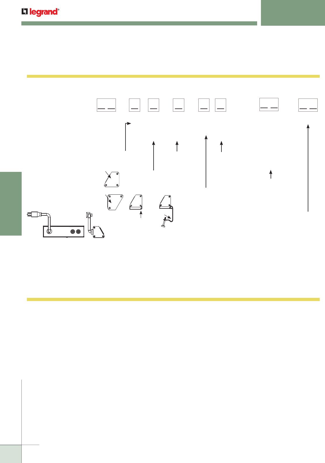
WWW.LEGRAND.US/WIREMOLD
298
TABLE BOXES
WIREMOLD
TABLESOURCE™ TABLE BOXES
Ordering Information
IMPORTANT
Use this chart to configure
your own custom TableSource
activation. Many of the
configurations are standard
offerings, and can be quoted and
delivered to you quickly with the
help of our Wiremold Customs
group. Just call in with your
TableSource part number, and they
will be able to supply you with a
quote, technical specifications and
a CAD Drawing. 1. Select face for
mounting device.
Input letter.
7. Choose number of
USB modules. Input
a number followed
by "U"
#U = Number of USB
Modules
2. Do you want optional
mounting bracket
for backsplash
application?
3. Number of
duplexes
(from 1-4).
Input number.
5. Choose
number of
communication
adapters (from
1-4). Input
number. 6. Choose color of
activation and
devices. Input
two-letter color
code.
A Face
B Face
Mounting
Clip
X
Backsplash
Bracket
M
Length Code
Feet [metric] Letter
2 [0.6m] B
3 [0.9m] C
4 [1.2m] D
5 [1.5m] E
6 [1.8m] F
7 [2.1m] G
8 [2.4m] H
9 [2.7m] I
10 [3.0m] J
11 [3.4m] K
12 [3.7m] L
NOTE: Cord color is
black.
Product
Group
1U, 2U, etc.
LL
Color of Product
WH- Painted White with
black devices
BK- Painted Black with
Black devices
IV- Painted Ivory with
black devices
AL- Anodized Aluminum
with gray devices
LL
Face
of
Unit
A,B
Mounting
Bracket
M, X
LL
No. of
Duplexes
1-4
#
Power
Cord
Length
No. of
Comm.
Adapters
1-4
L#
Design a Cord-Ended TableSource Solution Sample Part: TSAM2H1IV2U
4. Choose a length and
input the corresponding
letter for that length.
Data Cables egress out the back
(the side opposite the devices)
LL
TS
TableSource Work Surface Activations Configurator
NOTE: Part Number Configurator can be used both to identify stock product configurations and also
to request custom configurations from the factory. Consult the factory for more information.
NOTE: Wiremold Open System, Ortronics Series II and TracJack modules
provided with all assemblies.
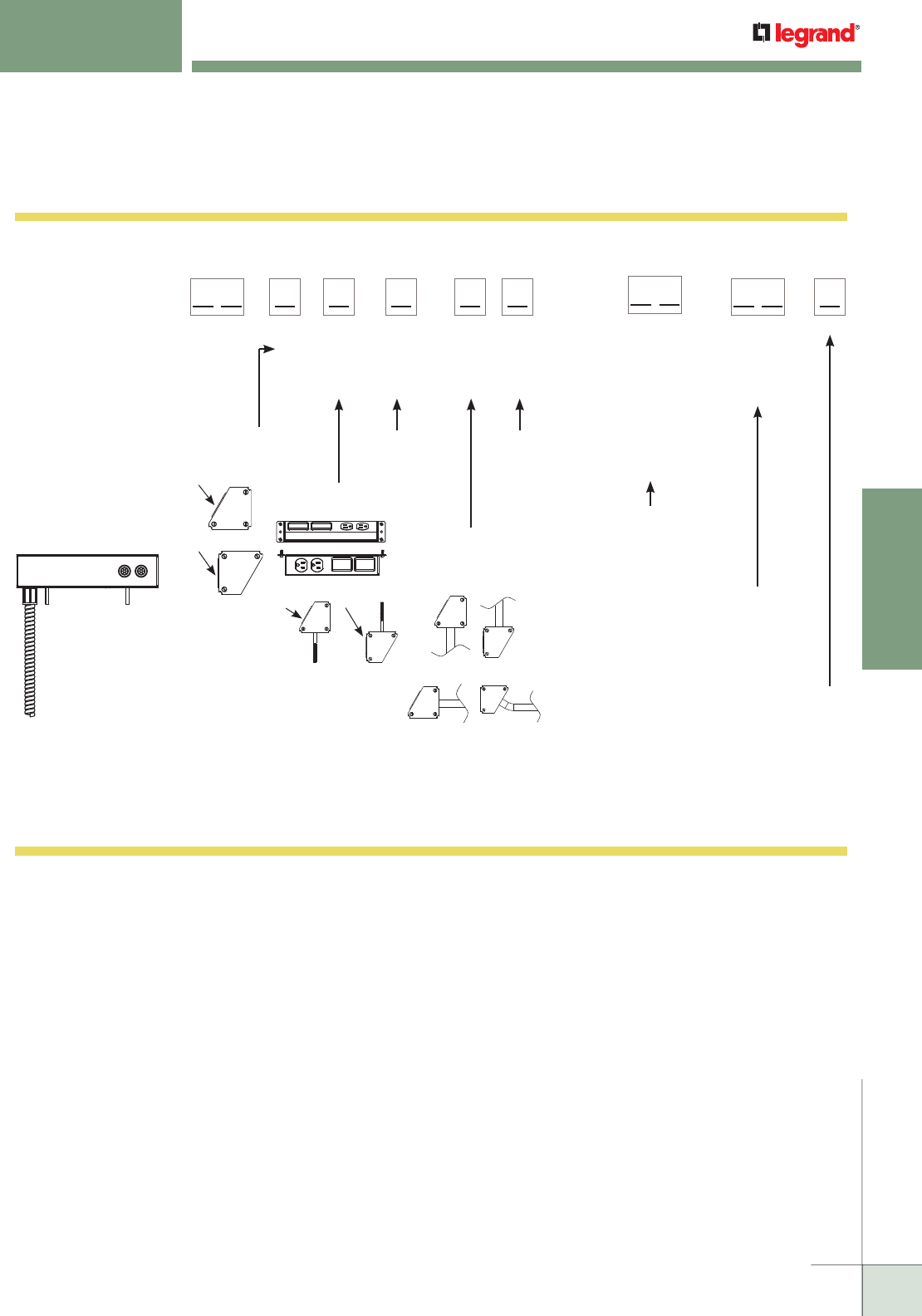
WWW.LEGRAND.US/WIREMOLD
299
TABLE BOXES
WIREMOLD
IMPORTANT
Use this chart to configure
your own custom TableSource
activation. Many of the
configurations are standard
offerings, and can be quoted
and delivered to you quickly
with the help of our Wiremold
Customs group. Just call in
with your TableSource part
number, and they will be able
to supply you with a quote,
technical specifications and a
CAD Drawing.
Design a Hard-Wired TableSource Solution Sample Part: TSAP2Z1BK2UG
Data Cables egress out
the back (the side opposite
the devices)
TABLESOURCE™ TABLE BOXES
Ordering Information
TableSource Work Surface Activations Configurator
NOTE: Part Number Configurator can be used both to identify stock product configurations and also
to request custom configurations from the factory. Consult the factory for more information.
NOTE: Wiremold Open System, Ortronics Series II and TracJack modules
provided with all assemblies.
1. Select face for
mounting device.
Input letter.
7. Choose number of
USB modules. Input
a number followed
by "U"
#U = Number of USB
Modules
3. Number of
duplexes
(from 1-4).
Input
number.
5. Choose
number of
communication
adapters (from
1-4). Input
number.
6. Choose color of
activation and
devices. Input
two-letter
color code.
A Face
B Face
1U, 2U, etc.
Number of USB
Module #
followed
by "U"
LL
Color of Product
WH- Painted White with
black devices
BK- Painted Black with
Black devices
IV-
Painted Ivory with
black devices
AL- Anodized Aluminum
with gray devices
LL
Face
of
Unit
A, B
L
Mounting
Syle
T, P
L
No. of
Duplexes
1-4
#
Whip
Exit
Y, Z
L
No. of
Comm.
Adapters
1-4
#
4. Choose face for 6'
[1.8m], three-wire
whip to exit.
2. Mounting styles
T MOUNTING EARS
P – MOUNTING STUD
A Face B Face
Y STYLE
Z STYLE
Product
Group
LL
TS
8. Choose if
Deadfront GFCI
Protection is
needed. If not,
leave blank.
G = Dead Front
GFCI Module
G
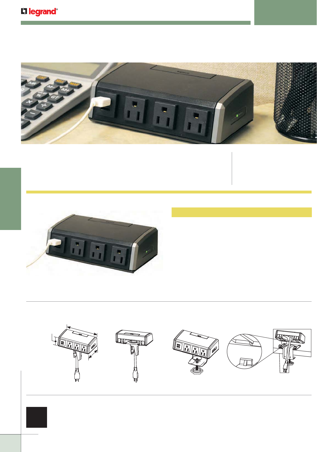
WWW.LEGRAND.US/WIREMOLD
300
TABLE BOXES
WIREMOLD
WSC320-S Table Box
Has three (3) surge-protected 15Amp power outlets, two
USB charging outlets and a 6' [1.83m] cord. Units come with
accessories for mounting into round cutouts in desk or edge
mounting on desks or other work surfaces.
NOTE: USB circuit is designed to the USB 2.0 standard and can provide
2.1 amps shared accross the two USB ports.
DESKTOP POWER CENTER TABLE BOXES
Desktop Power Center Table Boxes bring surge-protected power and USB
charging outlets up to the work surface by utilizing existing cord drop openings in
office desks and table tops or by mounting onto the edge of a desk or table top.
CODE REFERENCE
cETLus Listed
Furniture Power Distribution Unit:
Listed to US and Canadian Safety
Standards
COLOR OPTIONS
Desktop Power Center Table Box is available in black with
magnesium side panels.
Desktop Power Center Table Box Ordering Information
Mounting Options:
Installs through an existing cord drop opening.
Back View
6 11/16"
[170mm]
3 9/16"
[90mm]
2"
[52mm]
Front View
Installs on the edge of a work surface.
Front View Back View
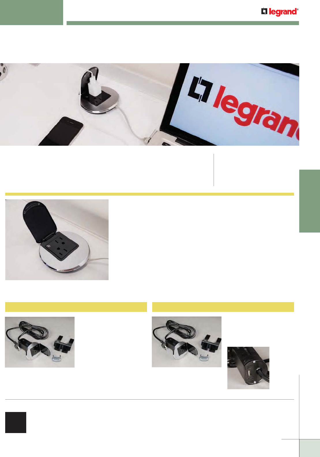
WWW.LEGRAND.US/WIREMOLD
301
TABLE BOXES
WIREMOLD
DESK MODULE
CODE REFERENCE
cETLus Listed :
Furniture Power Distribution Unit
Listed to US and Canadian Safety
Standards
Wiremold® Desk Module upgrades workstations to well connected spaces
so users can focus on the business at hand.
COLOR OPTIONS
Desk Modules are available in a black finish
with silver trim elements
Desk Module Ordering Information
WSDM210BK Desk Module
Desk module, black/silver,
with two (2) 15A outlets and
12' cord.
WSDM211BK Desk Module
Desk module, black/silver,
with two (2) 15A outlets, one
UB charging outlet and 12'
cord.
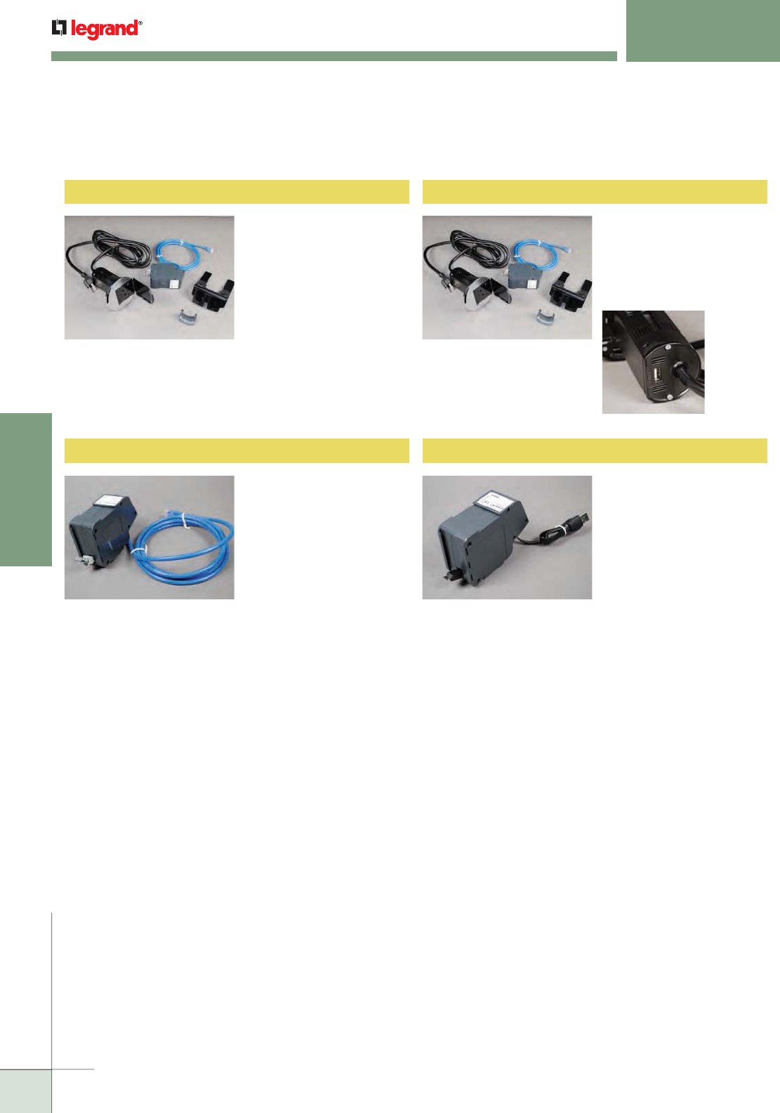
WWW.LEGRAND.US/WIREMOLD
302
TABLE BOXES
WIREMOLD
Desk Module Ordering Information
DESK MODULE
Ordering Information
WSDM210BKR Desk Module
Desk module, black/silver,
with two (2) 15A outlets
and 12' cord. Includes
RJ45 retractor cassette.
WSDM211BKR Desk Module
Desk module, black/silver,
with two (2) 15A outlets,
one USB charging outlet
and 12' cord. Includes RJ45
retractor cassette.
WSDMDC RJ45 Retractor Cassette WSDMUC USB Retractor Cassette
Retractor with Category
6 cable extending to 4.4'
[1.35m]
Retractor with USB
charging cable extending
to 4.4' [1.35m]
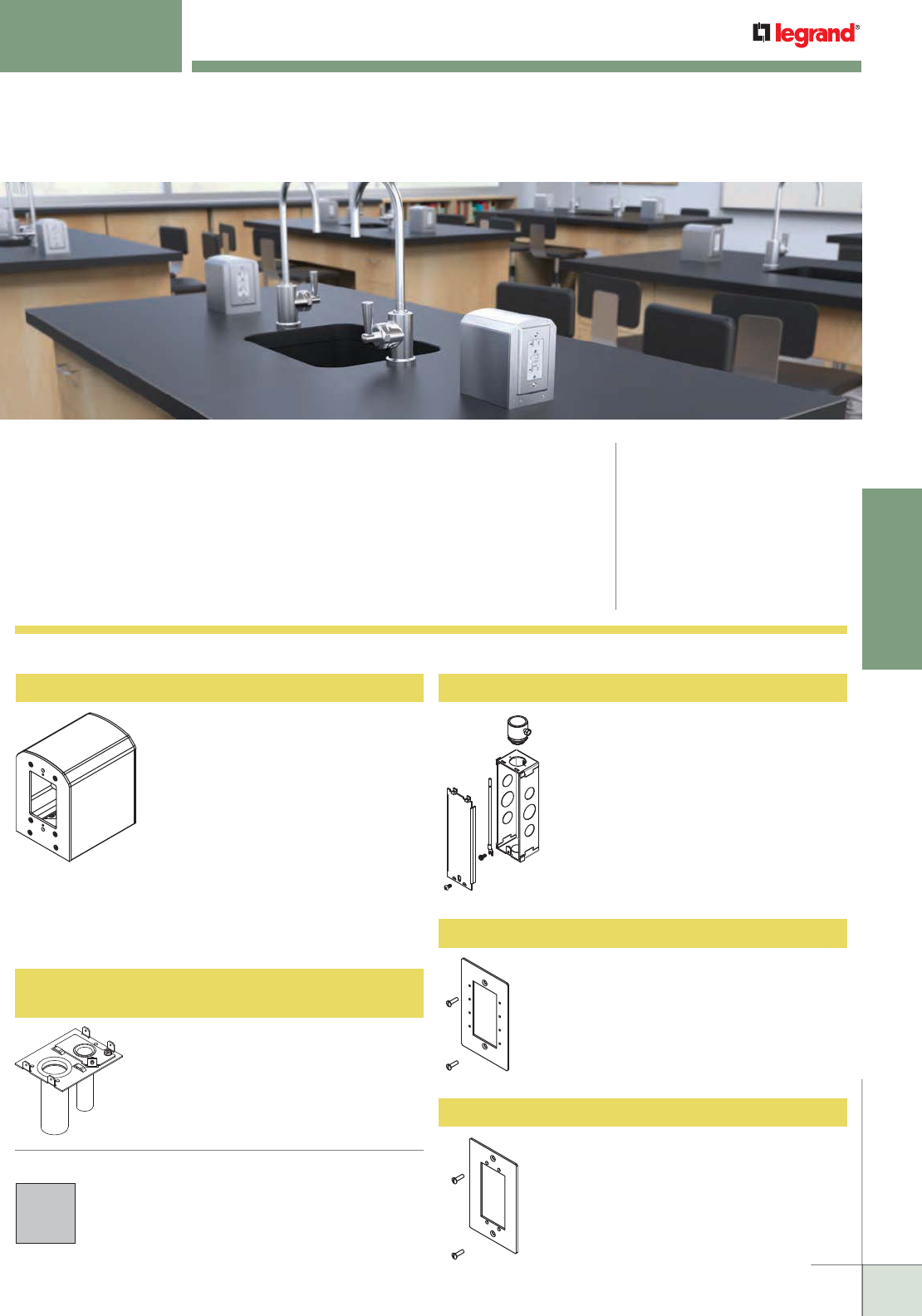
WWW.LEGRAND.US/WIREMOLD
303
TABLE BOXES
WIREMOLD
LAB BENCH PEDESTAL TABLE BOX
The new Wiremold® Lab Bench Pedestal Table Boxes provide increased capacity
and access to multiple services in a variety of configurations to meet the demanding
needs of laboratory activity. These field-wired units can be added to existing benches
or designed into new lab construction. UL has evaluated these boxes for use on
laboratory bench work surfaces. Pass & Seymour® receptacles were installed in the
box and subjected to spill testing outlined in UL 111. The test results showed that
there was no risk of fire or electrical shock as a result of the spill.
CODE REFERENCE
cULus Listed Metallic Outlet Boxes:
File E2961, Guide QCIT
Meets Article 314.27(C) of NEC
cULus Listed Multioutlet Assembly:
File E15191, Guide PVGT
Meets Article 380 of NEC
Meets Article 12-3032 of CEC
Evaluated for use on Laboratory
Bench work surfaces
LBP2 Lab Bench Pedestal
COLOR OPTIONS
Lab Bench Work Surface Portal Covers are available with a
clear anodized aluminum finish.
Lab Bench Table Boxes are available in a clear anodized
aluminum finish.
Lab Bench Pedestal Table Boxes Ordering Information
Aluminum housing and side plates,
with a steel base and divider,
measures 4" x 5" x 5 5/8" [102mm
x 127mm x 143mm]. Base is
configurable to have a combination
of two (2) 3/4" knockouts or two (2)
3/4" EMT stubs. Accommodates a
variety of power outlets (duplex,
decorator, GFCI and up to 30A twist
lock). Use Wiremold AVIP to provide
communications and A/V. Receptacles and wall plates are
sold separately. See chart on next page for list of Pass &
Seymour® receptacles that were evaluated by UL for use
with the box on laboratory bench work
One gang 3/4" trade size conduit housing
assembly. Assembly includes junction
box and 3/4" trade size fitting to attach
to 3/4" trade size conduit for power
connections. See chart on next page for
list of Pass & Seymour® receptacles that
were evaluated by UL for use with the box
on laboratory bench work surfaces.
LBPBHA Bottom Housing Unit
LBP-MAAP Lab Bench MAAP Plate
Plate is finished black to match
Wiremold AVIP devices. Used to provide
communication and A/V services.
LBP-AAP Lab Bench AAP Plate
Plate is finished black to match Extron®
Electronics AAP devices.
LBP2-114BASE Lab Bench Base Plate with
1 1/4" Conduit Stub
Base has attached 1 1/4" conduit to pull
pre-terminated communication cables.

WWW.LEGRAND.US/WIREMOLD
304
TABLE BOXES
WIREMOLD
LAB BENCH PEDESTAL TABLE BOX
Ordering Information
UL Approved Compatible Pass & Seymour® Devices
GFCI DEVICES
Straight Blade GFCI –
1595, 2095, 1595DSWR, 1595R, 1595S, 2095DSWR, 2095S, 2095TRWR
Tamper Resistant GFCI –
1595NTLTR,1595TR, 1595TRS, 1595TRWR, 1595NTLTR, 2095TR, 2095TRS
Plugtail GFCI PT –
1595, PT1595NTLTR, PT1595TR, PT2095, PT2095NTLTR, PT2095TR
Hospital Grade GFCI –
1595HG, 1595HGNTLTR, 1595HGTR, 2095HG, 2095HGNTLTR, 2095HGTR
Plugtail Hospital Grade GFCI –
PT1595HG, PT1595HGNTLTR, PT1595HGTR, PT2095HG, PT2095HGNTLTR, PT2095HGTR
Deadfront GFCI –
2085
HOSPITAL GRADE DEVICES
Hospital Grade GFCI –
1595HG, 1595HGNTLTR, 1595HGTR, 2095HG, 2095HGNTLTR, 2095HGTR
PlugTail Hospital Grade GFCI –
PT1595HG, PT1595HGNTLTR, PT1595HGTR, PT2095HG, PT2095HGNTLTR, PT2095HGTR
Plugtail Hospital Grade –
PT8200, PT8200IL, PT8300, P8300IL, PTTR62H, PTTR63H, TRIG26262HG, TRIG26362HG, TRIG8200, TRIG8300
Isolated Ground –
IG26262HG, IG26362HG, IG8200, IG8300, IG8310, IG8800, PS8200H, PS8200HS, TR26262HG, TR62H
15A Hospital Grade –
8200, 8201, 26222HG, 26262HG, 8200H, 8200IL, 8300IL, PS8300H, PS8300HS, TR26362HG, TR63H
20A Hospital Grade –
8300, 8301, 8800, 8801, 26322HG, 26362HG
STRAIGHT BLADE DEVICES
Tamper Resistant –
TR15, TR20, TR26261, TR26262, TR26361, TR26362, TR5251, TR5262, TR5351, TR5362, TR62, TR63, WR20TR, PS5262
15A Devices –
5251, 5261, P5262, 5290, 5651, 5662, 5671, 6207, 26252, 26652, 26661, 5262A, 5662A, 4862A, PS5362
20A Devices –
P5351, 5361, 5362, 5850, 5851, 5862, 5871,5890, 6307, 26352, 26852, 26861, 5362A
15A Weather & Corrosion Resistant –
CR15, CR6207, CRB5262, CRB5262S, WR5262, WR5662
10A Weather & Corrosion Resistant –
CR20, CR6307, CRB5362, CRB5362S, WR20TR, WR5362, WR5862
TR USB –
TM8-USB
ISOLATED GROUND DEVICES
Hospital Grade IG –
IG26262HG, IG26362HG, IG8200, IG8300, IG8301, IG8800, TRIG26262HG, TRIG26362HG, TRIG8200, TRIG8300, IGL2120R, IGL2130R
Locking IG –
IG4700, IG4710, IGL520R, IGL530R, IGL620R, IGL630R, IGL1420R, IGL1430R, IGL1520R, IGL1530R
15A Isolated Ground –
TRIG26262, TRIG5262, IG26262, IG5261, IG5262, IG5662
20A Isolated Ground –
TRIG26362, TRIG5362, IG26362, IG5361, IG5362, IG5862
PLUGTAIL™ RECEPTACLES
PlugTail GFCI –
PT1595, PT1595NTLTR, PT1595TR, PT2095, PT2095NTLTR, PT2095TR
PlugTail Hospital Grade –
PT1595HG, PT1595HGNTLTR, PT1595HGTR, PT2095HG, PT2095HGNTLTR, PT2095HGTR, PTTR2095HGTR, PTTR8200, PTTR8300
PlugTail Hospital Grade GFCI –
PT8200, PT8200IL, PT8300, PT8300IL, PTTR62H, PTTR63H
PlugTail TR Grade –
PTTR5262, PTTR5262SC, PTTR5362, PTTR5362SC, PTTR62, PTTR63
PlugTail 15A & 20A –
PT5262A, PT5362A
LOCKING RECEPTACLES
Turnlok IG –
IG4700, IG4710, IGL520R, IGL530R, IGL620R, IGL630R, IGL1420R, IGL1430R, IGL1520R, IGL1530R, IGL2120R, IGL2130R
20A Turnlok –
7310, 7410, CRL520R, L1020R, L1420R, L1530R, L1820R, L2120R, L520R, L620R, L630R
30A Turnlok –
3330, 3430, 3330G, CRL530R, L1030R, L1130R, L1430R, L1530R, L1830R, L2130R, L530R
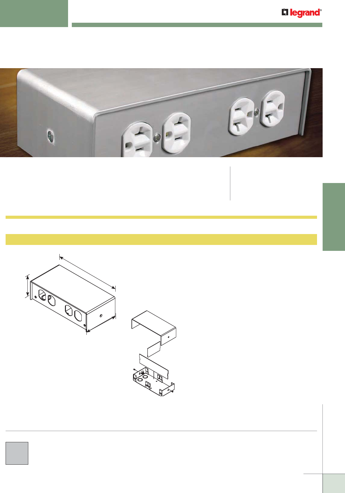
WWW.LEGRAND.US/WIREMOLD
305
TABLE BOXES
WIREMOLD
4 GANG LAB BENCH TABLE BOXES
4 Gang Lab Bench Table Boxes provide access to multiple services in a variety of
configurations to meet the demanding needs of laboratory activity. CODE REFERENCE
cULus Listed Outlet Box:
File E2961 Guide QCIT
Listed to US and Canadian
Safety Standards
AL241S-HB 4 Gang Lab Bench Table Box
9 1/4"
[235mm]
4 1/2"
[114mm]
2 1/2"
[64mm]
Aluminum housing and base 9 1/4" x 4 1/2" x 2 1/2" [235mm
x 114mm x 64mm] are provided with four (4) 1" trade size
knockouts in base for hardwiring unit and two dividers which
allow units to be divided on either the "X" or "Y" axis/plane.
Accommodates a variety of power (NEMA or decorator), and
supports Ortronics® and Wiremold Open Systems connectivity.
Portals are field configurable by ordering the corresponding
faceplates.
COLOR OPTIONS
Lab Bench Table Box covers are available with a clear anodized
aluminum finish.
4 Gang Lab Bench Table Box Ordering Information
AL241S-HB exploded view
showing dividers
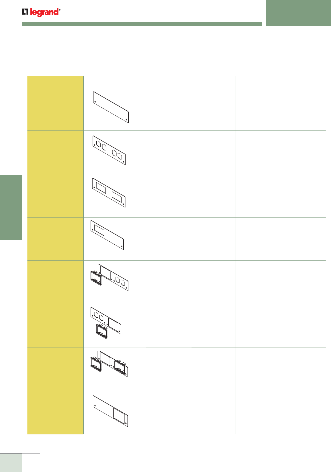
WWW.LEGRAND.US/WIREMOLD
306
TABLE BOXES
WIREMOLD
4 GANG LAB BENCH TABLE BOXES
Ordering Information
Faceplates for 4 Gang Lab Bench Table Box Ordering Information
PART NUMBER LEFT OPENING RIGHT OPENING
AL241FPB-B Blank Blank
AL241FPD-D Duplex Duplex
AL241FPDEC-DEC Decorator Decorator
AL241FPDEC-B Decorator Blank
AL241FP6A-D Ortronics® or Wiremold Open
System Communication 6A
Module. Adapters included.
Duplex
AL241FPD-6A Duplex Ortronics® or Wiremold Open
System Communication t6A
Module. Adapters included.
AL241FP6A-6A Ortronics® or Wiremold Open
System Communication 6A
Module. Adapters included.
Ortronics® or Wiremold Open
System Communication 6A
Module. Adapters included.
AL241FPB-6A Blank Ortronics® or Wiremold Open
System Communication
6AModule. Adapters included.
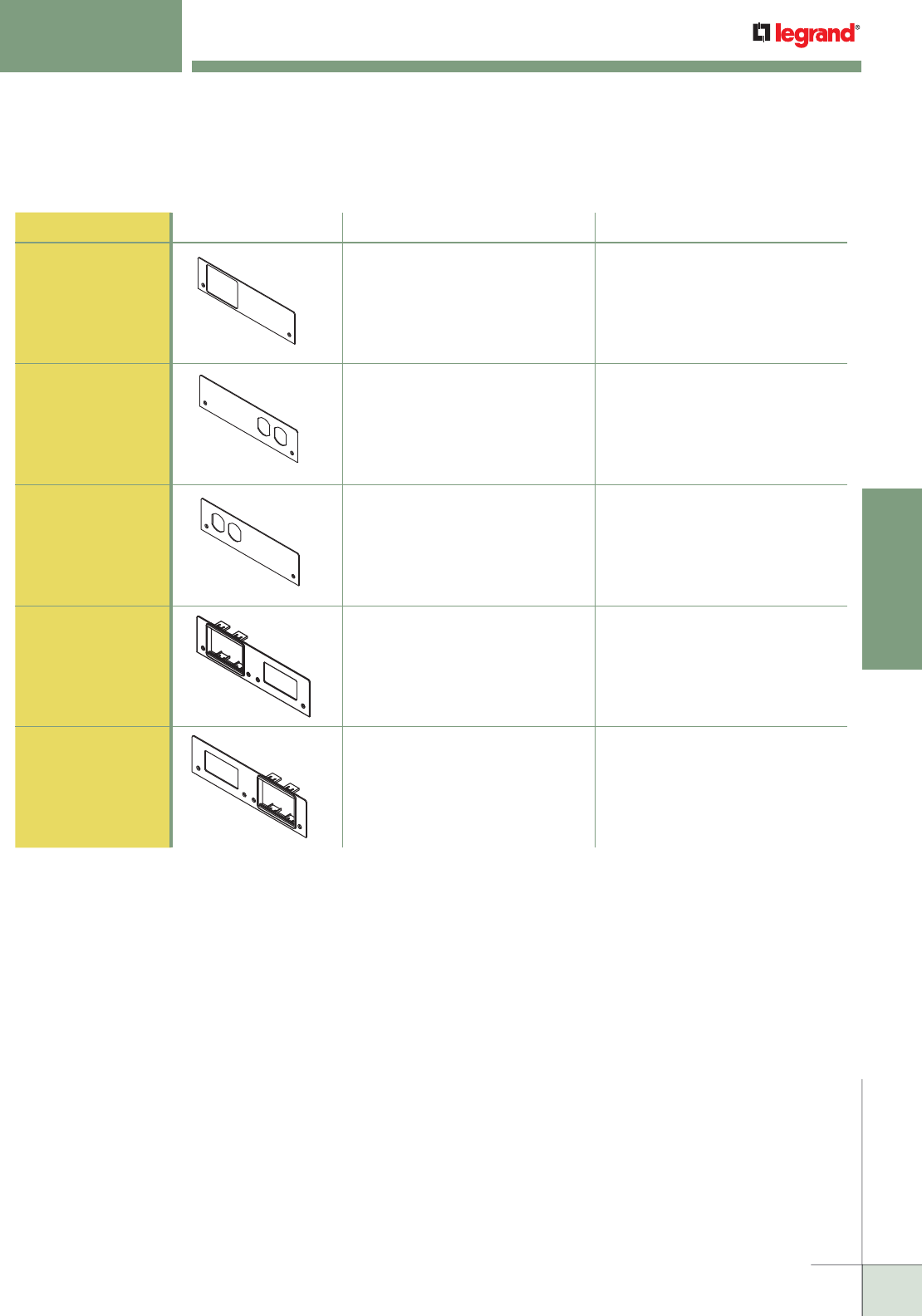
WWW.LEGRAND.US/WIREMOLD
307
TABLE BOXES
WIREMOLD
Faceplates for 4 Gang Lab Bench Table Box Ordering Information (continued)
4 GANG LAB BENCH TABLE BOXES
Ordering Information
PART NUMBER LEFT OPENING RIGHT OPENING
AL241FP6A-B Ortronics® or Wiremold Open
System Communication 6A
Module. Adapters included.
Blank
AL241FPB-D Blank Duplex
AL241FPD-B Duplex Blank
AL241FP6A-DEC Ortronics® or Wiremold Open
System Communication 6A
Module. Adapters included.
Decorator
AL241FPDEC-6A Decorator Ortronics® or Wiremold Open
System Communication t6A
Module. Adapters included.

WWW.LEGRAND.US/WIREMOLD
308
TABLE BOXES
WIREMOLD
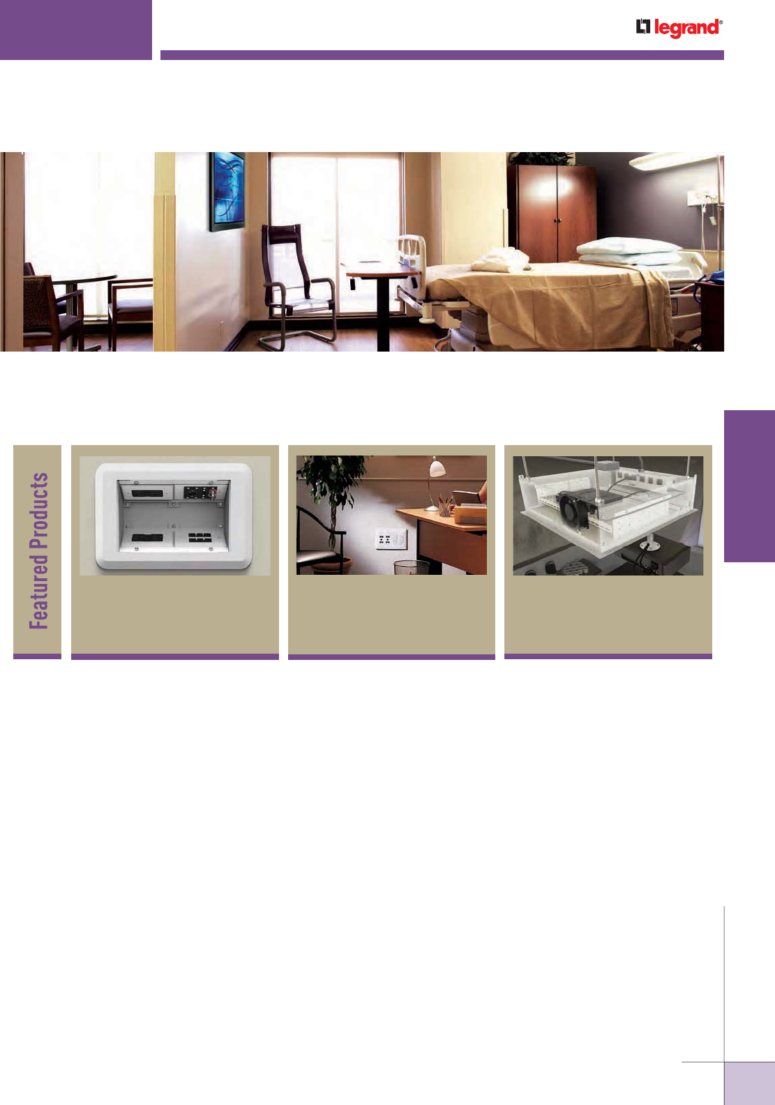
WWW.LEGRAND.US/WIREMOLD
309
WIREMOLD
WALL/CEILING BOXES
WALL/CEILING BOXES
Wiremold® Wall and ceiling boxes provide unique solutions to solve specific
installation issues or provide special capabilities for installers, building owners,
and designers.
WallSource™ Multiple
Service Boxes 313
Evolution™ Series
Wall Boxes 311
Evolution™ Series
Ceiling Boxes 316
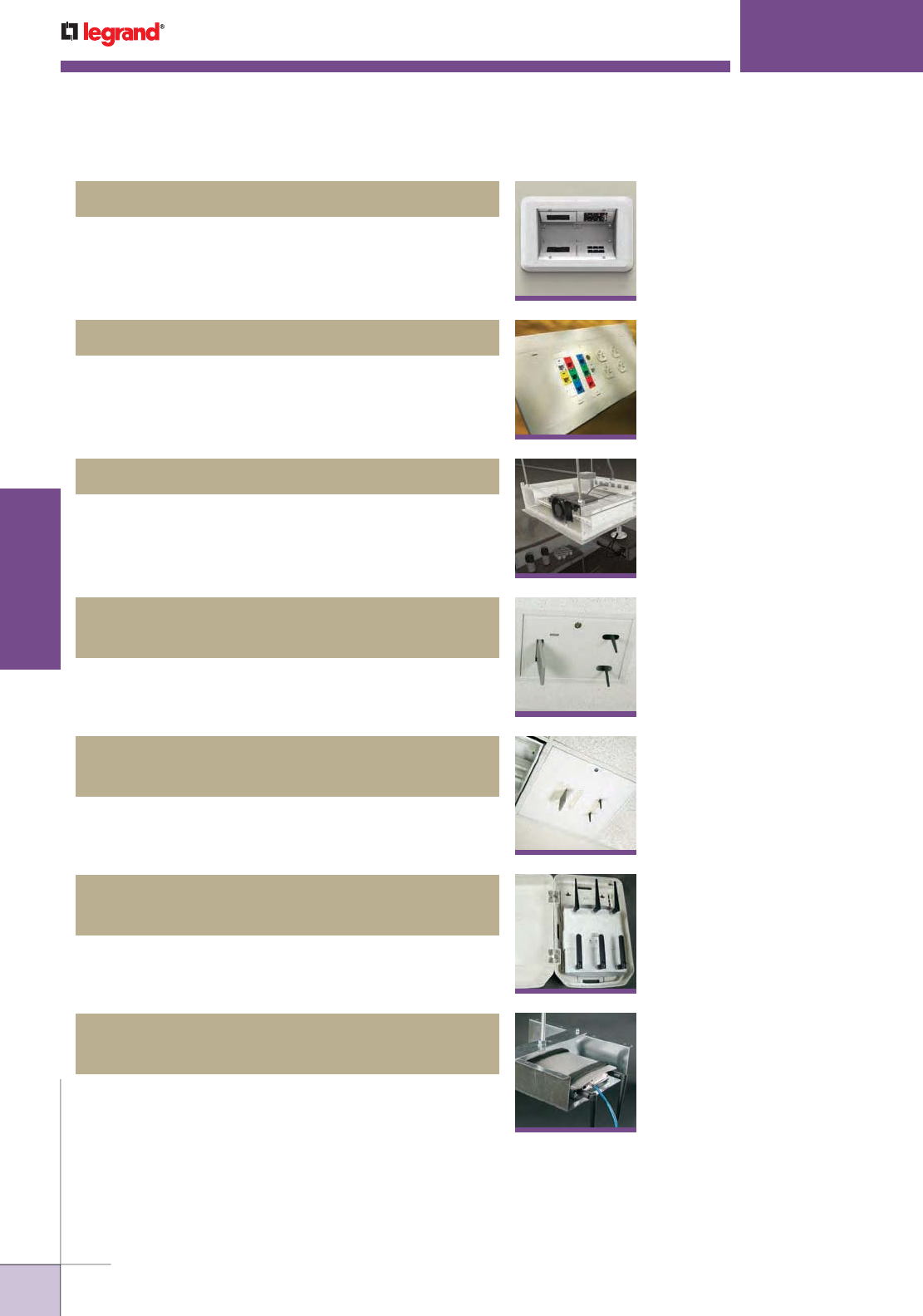
WWW.LEGRAND.US/WIREMOLD
310
WIREMOLD
WALL/CEILING BOXES
WALL/CEILING BOXES
Table of Contents
NME1250AP Nonmetallic Wireless
Access Point Enclosure
325
WAPBRKT Wireless Access Point
Mounting Bracket For Overhead Applications
326
Evolution™ Series Wall Boxes
311
Evolution™ Series Ceiling Boxes
316
WallSource™ Multiple Service Boxes
313
WAPE Series Wireless Access Point
Ceiling Enclosures
322
WAPENCL Series Wireless Access Point
Ceiling Enclosures
324
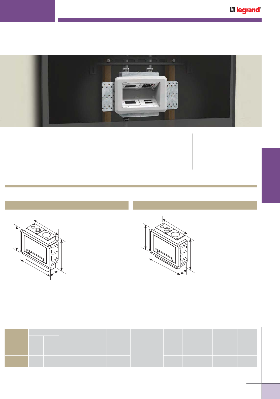
WWW.LEGRAND.US/WIREMOLD
311
WIREMOLD
WALL/CEILING BOXES
Evolution™ Series Wall Boxes are the latest advancement in the most innovative line
of pathways in the industry. These wall boxes are designed for new work and old
work applications while offering a sleek, clean look that architects will love and the
functionality engineers and contractors require. Offered in a 2-gang version with a
storage module for active A/V equipment and a 4-gang version when more power,
communications, and A/V capacities are required, Evolution Series Wall Boxes are ideal
for areas with large or small capacity needs or where a flat screen is required, such as
conference rooms, airports, entertainment venues, college campuses, and hospitals.
CODE REFERENCE
cULus Listed
Metallic Outlet Boxes:
File E2961 Guide QCIT
Evolution Series EFSB2 Wall Box Ordering Information
EFSB2 2-Gang Wall Box EFSB4 4-Gang Wall Box
Designed to fit and be
concealed behind 42"
[1.067m] or larger flat
screen displays. Can
be installed in both
new work and old work
applications. Has 2
NEMA size openings for
power, communication,
or A/V devices. Box is
also equipped with a
storage module that
will accept active A/V
equipment up to 6 7/8" x
9 1/8" [175mm x 232mm]
(dimensions include wire
and cables) in size.
EVOLUTION
™
SERIES WALL BOXES
Designed to fit and be
concealed behind 42"
[1.067m] or larger flat
screen displays. Can
be installed in both
new work and old work
applications. Has 4
NEMA size openings for
power, communication,
or A/V devices.
11 5/8"
[296mm]
8 3/4"
[222mm]
13"
[330mm]
3 7/8"
[98mm]
11 1/4"
[287mm]
10 7/8"
[275mm]
8 3/4"
[222mm]
13"
[330mm]
3 7/8"
[92mm]
11 1/4"
[287mm]
Evolution Series Wall Box Model Selection Guide
EVOLUTION
WALL BOX
MODEL
INSTALL TYPE
BOX
CAPACITY
DEPTH
BEHIND
PLATES
REMOVABLE
MODULES
DEVICE
PLATE SIZE
COVER
COLORS
COMPARTMENT
VOLUMES
KO SIZE
RANGE
Trade Size TUNNELS
New
Work
Old
Work
EFSB2 Yes Yes 2-Gangs 3-5/8" (92mm) Yes Use Standard Size
Device Plates:
Single-Gang
(2 3/4" x 4 1/2")
[70mm x 114mm]
White 43 cu. in. (705ml) 3/4" to 2" Yes
EFSB4 Yes Yes 4-Gangs 3-5/8" (92mm) Yes White 43 cu. in. (705ml) 3/4" to 2" Yes
NOTE: Trim flange and decorative cover are paintable.
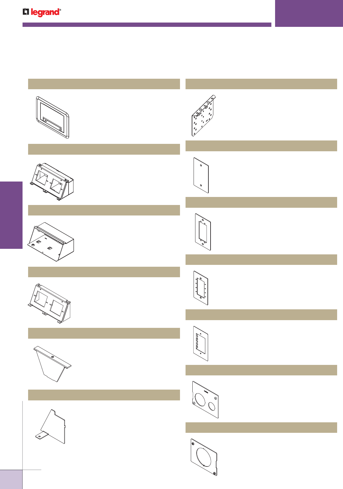
WWW.LEGRAND.US/WIREMOLD
312
WIREMOLD
WALL/CEILING BOXES
EFSC Replacement Trim Flange & Cover Assembly
Evolution Series Wall Box Replacement Parts & Accessories Ordering Information
EVOLUTION
™
SERIES WALL BOXES
Replacement trim flange and decorative
cover assembly for the EFSB2 and
EFSB4 wall boxes. Trim flange and
cover are finished in a decorative white
color, with a paintable surface to match
any room decor.
EFS-DM Replacement Device Module
Comes complete with module base,
2" trade size knockout plate, 3/4" and
3/4" / 1-1/4" concentric knockout plate,
and a removable divider. Finished in a
decorative white color.
EFS-SM Replacement Storage Module
Used to store active A/V equipment.
Comes complete with tie-down
locations to secure devices in place.
Decorative white finish. Includes one (1)
storage module.
EFS-DB Replacement 2-Gang Device Bracket
Each location is sized to accept NEMA
standard devices. Device bracket will fit
both the EFSB2 and EFSB4 wall boxes.
Includes one (1) bracket.
EFS-TUN Replacement Tunnel
Allows cables to be wrapped around
from one module to another without
having to run another dedicated line.
Tunnels fits EFSB2 and EFSB4 wall
boxes. Includes two (2) tunnel pieces.
EFS-DIV Replacement Divider
Provides separation of services.
Includes one (1) divider.
EFS-MB Replacement Mounting Bracket
Allows wall box to be secured to
wall in both new work and old work
applications. Includes 2 brackets.
EFB-B Blank Device Plate
Device plate dimensions: 2 3/4" x
4 1/2" [69mm x 114mm].
EFB-AAP Device Plate
Holds two (2) Extron® Electronics AAP
devices. Device plate dimensions:
2 3/4" x 4 1/2" [69mm x 114mm].
EFB-MAAP Device Plate
Holds four (4) Wiremold AVIP or
Extron Electronics MAAP Devices.
Device plate dimensions: 2 3/4" x 4
1/2" [69mm x 114mm].
EFB-MOS Device Plate
European device plate accepts up
to [45mm x 67.5mm] Arteor device.
Device plate dimensions: 2 3/4" x
4 1/2" [69mm x 114mm].
EFB810-3/4-1 1/4 Knockout Plate
Has one 3/4" and one 3/4"/1 1/4"
concentric trade size knockout.
EFB810-2 Knockout Plate
Has one 2" trade size knockout.
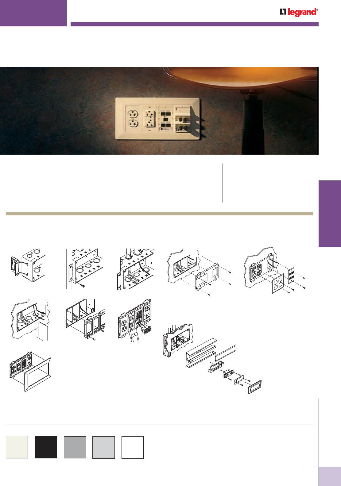
WWW.LEGRAND.US/WIREMOLD
313
WIREMOLD
WALL/CEILING BOXES
1. 2. 3.
4. 5. 6.
7.
1. 2.
A four-gang WallSource Box (WSA42-4) installed during
construction can easily accommodates the wire and cabling
required to feed a divided surface raceway system.
1.
WALLSOURCE
™
SERVICE BOXES
Wiremold® WallSource™ Multiple Service Boxes are six-gang boxes that can
accommodate multiple services including power and communications eliminating
multiple drops and uneven wall faceplates.
CODE REFERENCE
UL Listed Wireway, Auxiliary Gutters &
Associated Fittings:
File E2961 Guide QCIT.
Meets Article 314 of NEC.
Wallsource Multiple Service Boxes and components are available in
ivory, black, gray, light gray or white as indicated in the part number
descriptions.
Custom color options are also available. Consult the
factory for more information.
COLOR OPTIONS
WSA42-4 Box Installation Shown
WallSource Box Installation Details
Installing WSA00-4 on WSA42-4
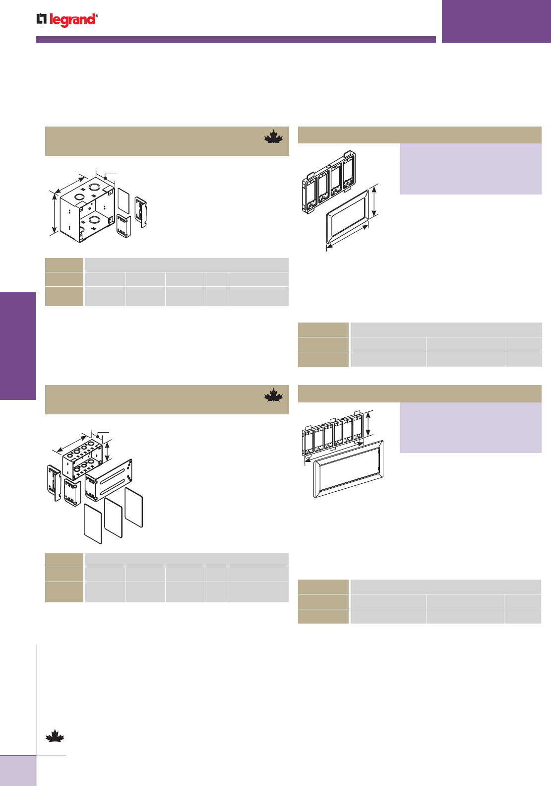
WWW.LEGRAND.US/WIREMOLD
314
WIREMOLD
WALL/CEILING BOXES
ORDERING DATA
CAT. NO. L W D Gang Trade Size KOs
WSA42-4 9 3/16"
[233mm]
5"
[127mm]
3 1/4"
[83mm]
4 1/2", 3/4",
1", 1 1/2"
Device Mounting Bracket & Trim Ring
PART NUMBERS:
WSC07-6AWH (White)
WSC07-6ABK (Black)
WSC07-6AG (Gray)
WSC07-6AGY (Gray)
L
D
W
L
D
W
L
W
L
W
WALLSOURCE
™
SERVICE BOXES
WSB42-2
WallSource Box, Divider & Mounting Bracket
Slide-in dividers separate
the box for power and
communication services.
Adjustable mounting brackets
offer flexibility to flush mount
box in 1/2", 5/8", 1", and 1/4"
[12.7mm, 15.9mm, 25mm, and
32mm] wall thicknesses.
ORDERING DATA
CAT. NO. L W D Gang Trade Size KOs
WSB42-2 4 3/4"
[121mm]
5"
[127mm]
3 1/4"
[83mm]
2 1/2", 3/4", 1"
ORDERING DATA
CAT. NO. L W Gang
WSA07-4A 11 1/4" [286mm] 7" [177mm] 4
Self-leveling bracket
accommodates a wide variety of
electrical and communications
devices. The trim ring hides the
holecut to give the box a finished
look. For use with: 5507 Series
Faceplates, Ortronics® TracJack &
Series II Modules, Pass & Seymour
Activate Series Inserts and
Wiremold Open System
Communication Modules.
WSA42-4
Wallsource Box, Divider & Mounting Brackets
Slide-in dividers separate
the box for power and
communication services.
Adjustable mounting brackets
offer flexibility to flush mount
box in 1/2", 5/8", 1", and 1 1/4"
[12.7mm, 15.9mm, 25mm, and
32mm] wall thicknesses.
ORDERING DATA
CAT. NO. L W Gang
WSC07-6A 15 13/16" [402mm] 7" [177mm] 6
Self-leveling bracket
accommodates a wide variety of
electrical and communications
devices. The trim ring hides the
holecut to give the box a finished
look. For use with: 5507 Series
Faceplates, Ortronics® TracJack &
Series II Modules, Pass & Seymour
Activate Series Inserts and
Wiremold Open System
Communication Modules.
WallSource Service Boxes Ordering Information
Parts identified with this symbol are Certified to Canadian Safety Standards
for sale in Canada. When ordering these products, add “C” suffix to part
number to denote the Canadian version, i.e “WSB42-2C”.
Device Mounting Bracket & Trim Ring
PART NUMBERS:
WSA07-4AWH (White)
WSA07-4ABK (Black)
WSA07-4AG (Gray)
WSA07-4AGY (Gray)
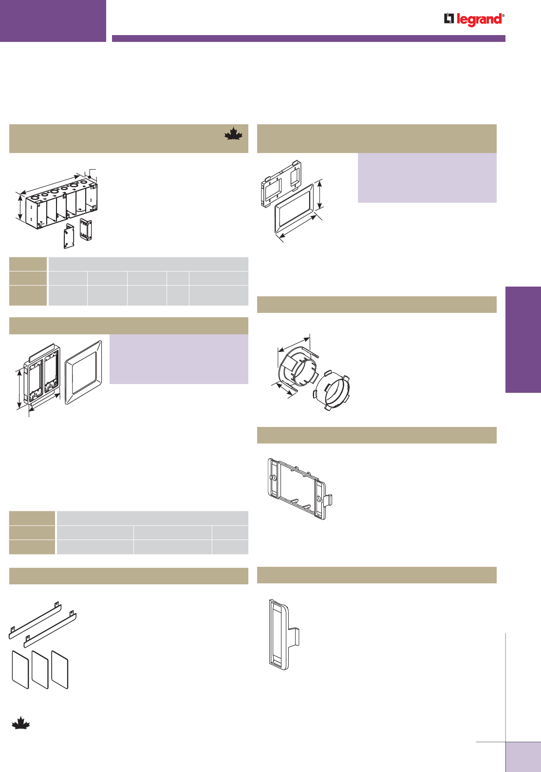
WWW.LEGRAND.US/WIREMOLD
315
WIREMOLD
WALL/CEILING BOXES
ORDERING DATA
CAT. NO. L W D Gang Trade Size KOs
WSA42-6 13 3/4"
[350mm]
5"
[127mm]
3 1/4"
[83mm]
6 1/2", 3/4",
1", 1 1/2"
Self-leveling bracket
accommodates a wide variety of
electrical and communications
devices. The trim ring hides the
holecut to give the box a finished
look. For use with: 5507 Series
Faceplates, Ortronics® TracJack &
Series II Modules, Pass & Seymour
Activate Series Inserts and
Wiremold Open System
Communication Modules.
2.5/8"
[67mm]
1"
[25mm]
FSS-18 Fiber Storage Loop
S2-EPL End Plates
Use this loop to store 18" [457mm]
of cable with a controlled 1"
[25mm] bend radius.
Includes two outlet identification
labels with clear covers and two
matching screw covers. Required
for mounting Ortronics® Series II
modules into the WSX07-X Series
device brackets.
CM-EPLA End Plates
Includes two outlet identification
labels with clear covers and two
matching screw covers. Required
for mounting Pass & Seymour
Activate™ and Wiremold Open
System communication modules
into the WSX07-X Series device
brackets.
11 1/4"
[286mm]
7"
[177mm]
L
D
W
L
W
WSC42-6
Wallsource Box, Divider & Mounting Brackets
WSA86 Backfeed Kit
Slide-in dividers separate
the box for power and
communication services.
Adjustable mounting brackets
offer flexibility to flush mount
box in 1/2", 5/8", 1", and 1 1/4"
[12.7mm, 15.9mm, 25mm, and
32mm] wall thicknesses.
For backfeeding 4000, 6000,
5400, 5500 and ALA4800 Series
Raceways. Use included templates
to easily cut entrances into
raceway. Use the dividers for
UL Listed separation. Use the
backfeed plate with 4000 and 6000
Series Raceway to completely
cover wall hole cut. Includes ivory
and gray pieces.
WALLSOURCE
™
SERVICE BOXES
WallSource Service Boxes Ordering Information
ORDERING DATA
CAT. NO. L W GANG
WSB07-2A 6 13/16" [173mm] 7" [177mm] 2
Self-leveling bracket accommo-
dates a wide variety of electrical
and communications devices. This
bracket accommodates a standard
single- and dual-gang faceplate.
The trim ring hides the holecut to
give the box a finished look.
Parts identified with this symbol are Certified to Canadian Safety Standards
for sale in Canada. When ordering these products, add “C” suffix to part
number to denote the Canadian version, i.e “WSB42-2C”.
Device Mounting Bracket & Trim Ring
PART NUMBERS:
WSB07-2AWH (White)
WBC07-2ABK (Black)
WBC07-2AG (Gray)
WBC07-2AGY (Gray)
Open Architecture Device Mounting Bracket
& Trim Ring
PART NUMBERS:
WSA00-4 (Ivory)
WSA00-4WH (White)
WSA00-4BK (Black)
WSA00-4GY (Gray)
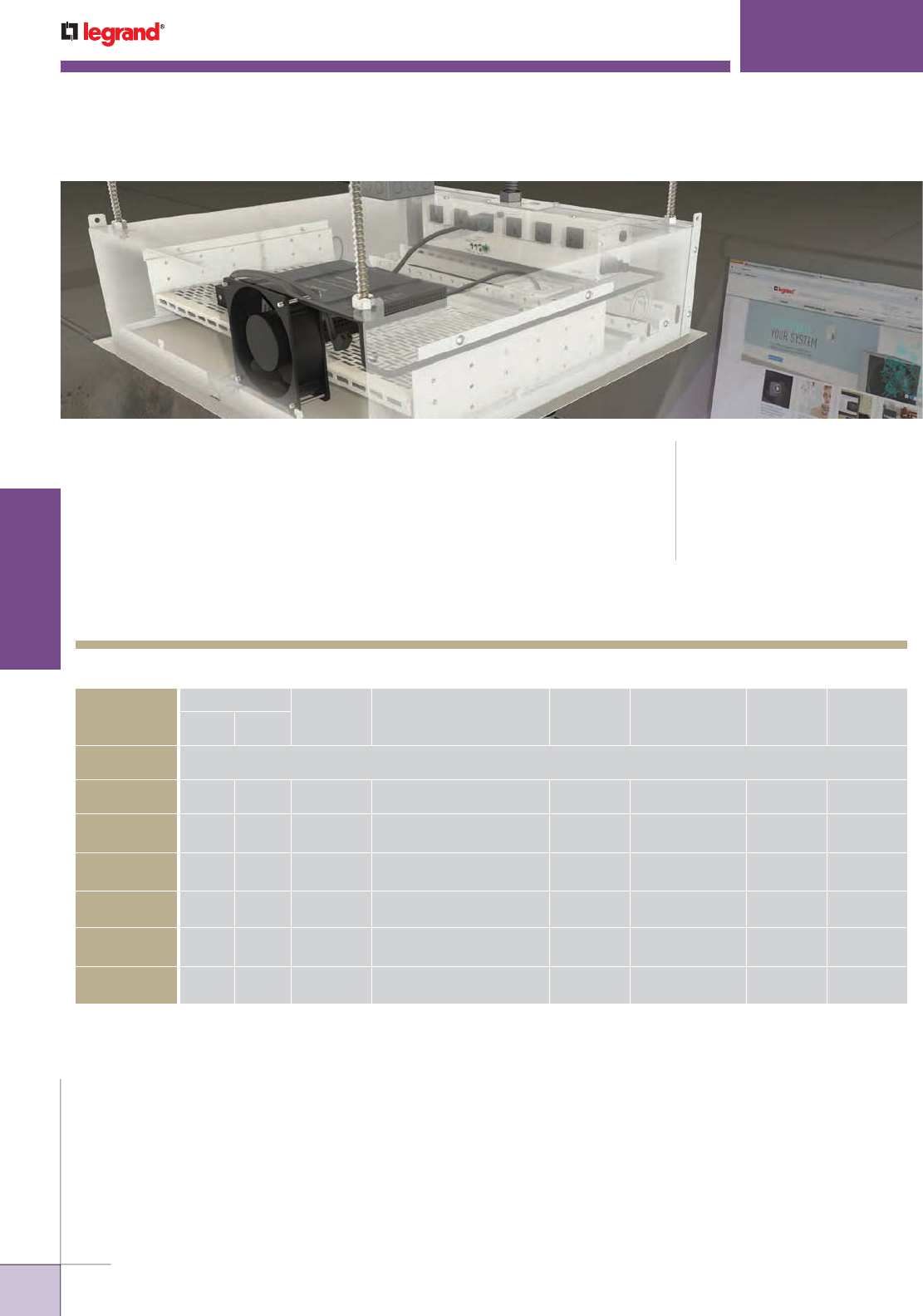
WWW.LEGRAND.US/WIREMOLD
316
WIREMOLD
WALL/CEILING BOXES
EVOLUTION
™
SERIES CEILING BOXES
Evolution™ Series products just keep on growing. The Evolution Series Ceiling
Box is the newest member of the most innovative family of product on the market.
These boxes are designed to go above a false or permanent ceiling structure while
maintaining the aesthetics of the room. They provide both storage capacity and
the ability to support a projector at the same time. Evolution Series Ceiling Boxes
are offered in six different versions from a base model to the high end RackLink™
version where the product can monitor and connect with building automation
systems. Evolution Series Ceiling boxes are perfect for conference rooms,
educational classrooms, training facilities, airports, or anywhere a projector and/
or A/V equipment is required.
CODE REFERENCE
cETLus Listed
Information Technology Equipment:
Meets Article 300.22(c) of the NEC
EVOLUTION
CEILING BOX
MODEL
INSTALL TYPE
SHELF
CAPACITY RECEPTACLES
REMOVABLE
SHELVES PROJECTOR MOUNT
COVER
COLORS
KO SIZE
RANGE
Trade Size
False
Ceiling
Hard
Ceiling
BOX SIZE 23 3/4" x 23 3/4" x 6 3/4" [603mm x 603mm x 171mm]
ECB2S Yes Yes 2RU 6 Yes No White 1/2" to 2"
ECB2SP Yes Yes 2RU 7 Yes Yes, Up to 50 Lbs. White 1/2" to 2"
ECB2S-CR Yes Yes 2RU 4 Controlled, 2 Uncontrolled Yes No White 1/2" to 2"
ECB2SP-CR Yes Yes 2RU 4 Controlled, 3 Uncontrolled Yes Yes, Up to 50 Lbs. White 1/2" to 2"
ECB2S-RLNK Yes Yes 2RU 4 Controlled, 2 Uncontrolled Yes No White 1/2" to 2"
ECB2SP-RLNK Yes Yes 2RU 4 Controlled, 3 Uncontrolled Yes Yes, Up to 50 Lbs. White 1/2" to 2"
NOTE: Trim flange and decorative cover are paintable.
Evolution Series Ceiling Box Model Selection Guide
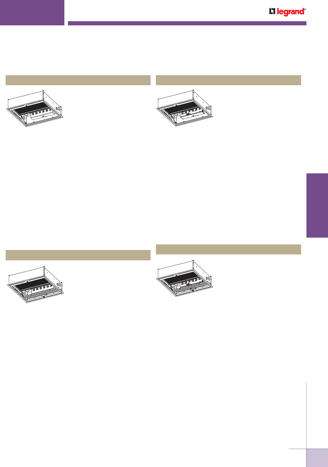
WWW.LEGRAND.US/WIREMOLD
317
WIREMOLD
WALL/CEILING BOXES
EVOLUTION
™
SERIES CEILING BOXES
Ordering Information
Fully finished enclosure
designed to manage and store
A/V equipment in an air handling
plenum space above a false
ceiling. Box comes equipped
with:
• four (4) mounting tabs for
securing the box via braided
cable (not included)
• four (4) 3/8" knockout locations for threaded rod supports
• six (6) 20A receptacles, evenly spaced and rotated for
large plugs (i.e. wall warts)
• one (1) easy to remove and reposition shelf
• one (1) easy to remove door that utilizes the ceiling tile
or drywall for better aesthetics
• knockouts ranging from 1/2" to 2" trade size
• two (2) single-gang locations for additional receptacles,
communication or A/V devices
• one (1) cover tether cord
Evolution Series Ceiling Box Ordering Information
ECB2S Evolution Series Ceiling Box
Fully finished enclosure designed
to manage and store A/V
equipment in an air handling
plenum space above a false
ceiling. ECB2SP has a built in
projector mount that utilizes a
1 1/2" standard NPS fitting and
is rated to support a load up to
50 lbs. The projector mount can
move laterally and be positioned
anywhere along the track. Box
comes equipped with:
• one (1) movable projector mount
• four (4) mounting tabs for securing the box via braided
cable (not included)
• four (4) 3/8" knockout locations for threaded rod supports
• seven (7) 20A receptacles, evenly spaced and rotated for
large plugs (i.e. wall warts) (one receptacle located on
exterior of box to supply power to the projector)
• one (1) easy to remove and reposition shelf
• one (1) easy to remove door that utilizes the ceiling tile
or drywall ceiling materials for better aesthetics
• knockouts ranging from 1/2" to 2" trade size
• two (2) single-gang locations for additional receptacles,
communication or A/V devices
• one (1) cover tether cord
ECB2SP Evolution Series Ceiling Box
Fully finished enclosure designed
to manage and store A/V
equipment in an air handling
plenum space above a false
ceiling. ECB2S-CR is equipped
with dry contact controlled
receptacles that can be switched
off when not in use and has a built
in fan to keep the temperature of
the equipment cool. The Box
comes equipped with:
• four (4) mounting tabs for securing the box via braided
cable (not included)
• four (4) 3/8" knockout locations for threaded rod supports
• four (4) dry contact controlled 20A receptacles, evenly
spaced and rotated for large plugs (i.e. wall warts)
• two (2) uncontrolled 20A receptacles
• one (1) 120mm x 120mm, 120VAC, 49 CFM/28 dBA AC fan
• one (1) easy to remove and reposition shelf
• one (1) easy to remove door that utilizes the ceiling tile for
better aesthetics
• knockouts ranging from 1/2" to 2" trade size
• two (2) single-gang locations for additional receptacles,
communication or A/V devices
• one (1) cover tether cord
ECB2S-CR Evolution Series Ceiling Box
Fully finished enclosure
designed to manage and store
A/V equipment in an air handling
plenum space above a false
ceiling. ECB2SP-CR is equipped
with dry contact controlled
receptacles that can be switched
off when not in use and has
a built in fan to keep the
temperature of the equipment cool. The ECB2SP-CR has a
built in projector mount that utilizes a 1 1/2" standard NPS
fitting and is rated to support a load up to 50 lbs. The
projector mount can move laterally and be positioned
anywhere along the track. Box comes equipped with:
• one (1) projector mount that is movable and can support
up to a 50lb load
• four (4) mounting tabs for securing the box via braided
cable (not included)
• four (4) 3/8" knockout locations for threaded rod supports
• four (4) 20A dry contact controlled receptacles, evenly
spaced and rotated for large plugs (i.e. wall warts)
• two (2) 20A uncontrolled receptacles, evenly spaced and
rotated for wall warts
• one (1) 120mm x 120mm, 120VAC, 49 CFM/28 dBA AC fan
• one (1) 20A external receptacle for the projector
• one (1) easy to remove and reposition shelf
• one (1) easy to remove door that utilizes the ceiling tile
for better aesthetics
• knockouts ranging from 1/2" to 2" trade size
• two (2) single-gang locations for additional receptacles,
communication or A/V devices
• one (1) cover tether cord
ECB2SP-CR Evolution Series Ceiling Box
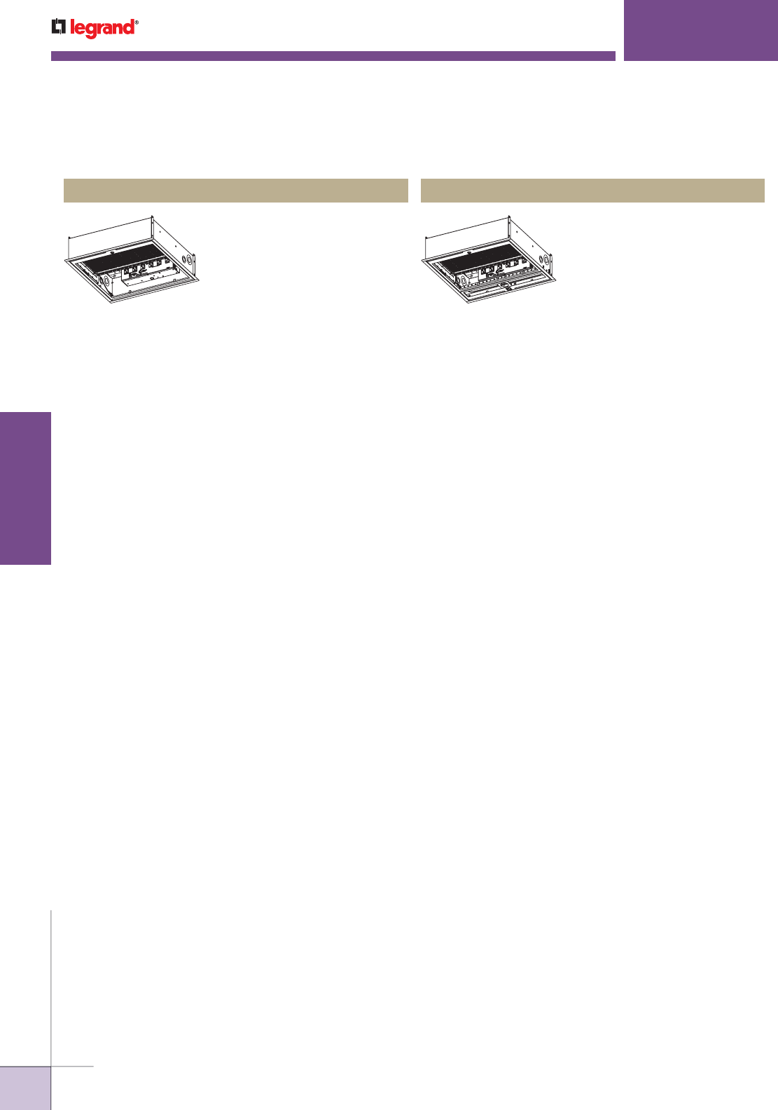
WWW.LEGRAND.US/WIREMOLD
318
WIREMOLD
WALL/CEILING BOXES
Fully finished enclosure designed
to manage and store A/V
equipment in an air handling
plenum space above a false or
hard ceiling. These boxes are
also equipped with the RackLink
system, by Middle Atlantic
Products. Box comes
equipped with:
• four (4) mounting tabs for securing the box via braided
cable (not included)
• four (4) 3/8" knockout locations for threaded rod supports
• one (1) RackLink controlled power module that allows for
the ceiling box and all of the A/V contents to be monitored
and controlled locally or from a remote location
• four (4) 20A controlled receptacles evenly spaced and
rotated for large plugs (i.e. wall warts)
• two (2) 20A uncontrolled receptacles evenly spaced and
rotated for large plugs (i.e. wall warts)
• one (1) 120mm x 120mm, 120VAC, 49 CFM/28 dBA AC fan
• one (1) easy to remove, pivotable and repositionable shelf
• one (1) easy to remove door that utilizes the ceiling tile for
better aesthetics
• knockouts ranging from 1/2" to 2" trade size
• two (2) single-gang locations for additional receptacles,
communication or A/V devices
• one (1) cover tether cord
Fully finished enclosure designed
to manage and store A/V
equipment in an air handling
plenum space above a false or
hard ceiling. These boxes are
also equipped with the RackLink
system, by Middle Atlantic
Products. The ECB2SP-RLNK has
a built in projector mount that
utilizes a 1 1/2" standard NPS
fitting and is rated to support a
load up to 50 lbs. The projector
mount can move laterally and be
positioned anywhere along the
track. The Box comes equipped
with:
• one (1) projector mount
• four (4) mounting tabs for securing the box via braided
cable (not included)
• four (4) 3/8" knockout locations for threaded rod supports
• one (1) RackLink controlled power module that allows the
ceiling box and all of the A/V contents to be monitored and
controlled from a remote location
• four (4) 20A controlled receptacles evenly spaced and
rotated for large plugs (i.e. wall warts)
• two (2) 20A uncontrolled receptacles evenly spaced and
rotated for large plugs (i.e. wall warts)
• one (1) 20A external receptacle for the projector
• one (1) 120mm x 120mm, 120VAC, 49 CFM/28 dBA AC fan
• one (1) easy to remove, pivot and reposition shelf
• one (1) easy to remove door that utilizes the ceiling tile for
better aesthetics
• knockouts ranging from 1/2" to 2" trade size
• two (2) single gang locations for additional receptacles,
communication or A/V devices
• one (1) cover tether cord
Evolution Series Ceiling Box Ordering Information (continued)
ECB2S-RLNK Evolution Series Ceiling Box ECB2SP-RLNK Evolution Series Ceiling Box
EVOLUTION
™
SERIES CEILING BOXES
Ordering Information
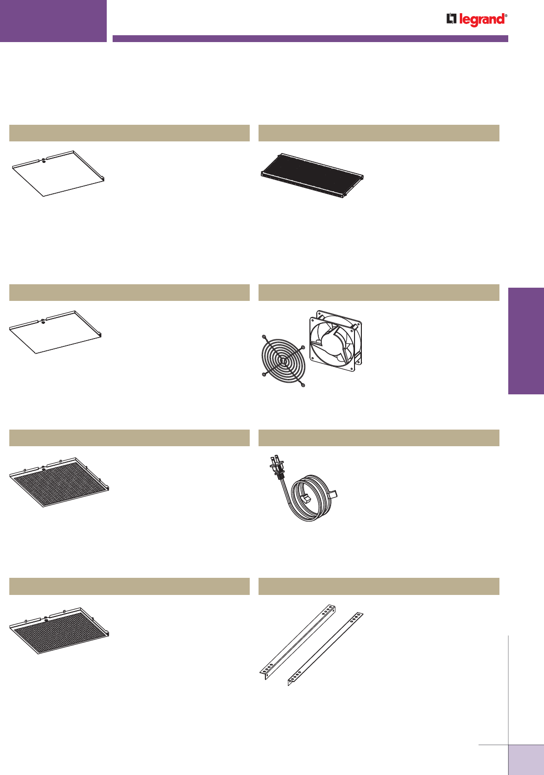
WWW.LEGRAND.US/WIREMOLD
319
WIREMOLD
WALL/CEILING BOXES
Designed to provide a solid secure
panel to protect the audio/video
equipment loaded within the
enclosure. Panel is designed to
work with the ECB2S, ECB2S-CR,
and ECB2S-RLNK boxes and is
powder coated white to match
the enclosure. The panels are
field paintable to match the room
decor. Includes a lock and key.
EVOLUTION
™
SERIES CEILING BOXES
Ordering Information
Evolution Series Ceiling Box Parts & Accessories Ordering Information
ECB-SD Solid Panel ECB-SHELF Additional Shelving
Designed to provide a solid
secure panel to protect the audio/
video equipment loaded within
the enclosure. Panel is designed
to work with the ECB2SP,
ECB2SP-CR, and ECB2SP-RLNK
boxes and is powder coated
white to match the enclosure.
The panels are field paintable to
match the room decor. Includes
a lock and key.
ECB-SPD Solid Panel
Designed to provide extra air flow
into and out of the box allowing
the audio/video equipment to
remain as cool as possible.
Panel is designed to work with
the ECB2S, ECB2S-CR, and
ECB2S-RLNK boxes and is
powder coated white to match
the enclosure. The panels are
field paintable to match the room
decor. Includes a lock and key.
ECB-PD Perforated Panel
Designed to provide extra air flow
into and out of the box allowing
the audio/video equipment to
remain cool. Panel is designed
to work with the ECB2SP,
ECB2SP-CR, and ECB2SP-RLNK
boxes and is powder coated
white to match the enclosure.
The panels are field paintable to
match the room decor. Includes
a lock and key.
ECB-PPD Perforated Panel
When more capacity is
required an additional shelf
can be purchased. The shelf
is made of steel and has a
unique pattern that has been
specifically designed to accept
most audio/video devices.
The shelf is powder coated
white and equipped with quick
release tabs which allow the
shelf to pivot both forward and
backward, and be easily and
quickly installed or removed.
ECB-FAN Additional AC Fan
120mm x 120mm 120 VAC,
49 CFM/28 dBA fan for use
when additional air flow is
required. Includes fan guard.
ECB-FC Replacement Fan Cord
Replacement fan cord,
designed to fit into ECB-FAN.
ECB-EMB External Mounting Brackets
Steel mounts designed to be
attached to the outside of the
ceiling box and support the box
with threaded 3/8" [9.5mm]
diameter threaded rod. Two (2)
brackets included.
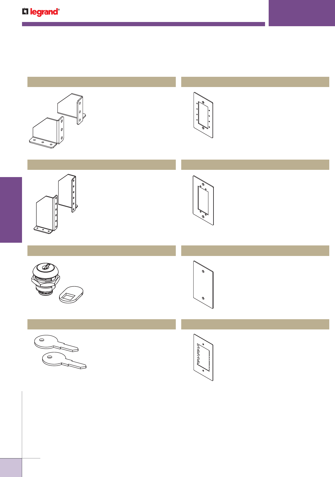
WWW.LEGRAND.US/WIREMOLD
320
WIREMOLD
WALL/CEILING BOXES
EVOLUTION
™
SERIES CEILING BOXES
Ordering Information
Evolution Series Ceiling Box Parts & Accessories Ordering Information (continued)
Steel Brackets for securing a
1RU device. Includes 2 brackets.
ECB-1RUMB Rack Mount Brackets
Steel Brackets for securing a
1RU or 2RU device. Includes
2 brackets.
ECB-2RUMB Rack Mount Brackets
Standard quarter turn lock and
key set, allows a standard ceiling
enclosure to be retrofitted from
the quarter turn latch to a locking
option. Works with the ECB2S,
ECB2SP, ECB2S-CR, ECB2SP-CR,
ECB2S-RLNK and ECB2SP-RLNK
enclosures.
ECB-CLK Lock & Key Set
Replacement or additional keys
for the lock sets. All keys are the
same for all boxes.
ECB-KEY Replacement Keys
Holds four (4) Wiremold AVIP device
plates or Extron® Electronics MAAP
devices. Device plate dimensions:
2 3/4" x 4 1/2" [69mm x 114mm].
EFB-MAAP Device Plate
Holds two (2) Extron® Electronics
AAP devices. Device plate dimensions:
2 3/4" x 4 1/2" [69mm x 114mm].
EFB-AAP Device Plate
Device plate dimensions: 2 3/4" x
4 1/2" [69mm x 114mm].
EFB-B Blank Device Plate
European device plate accepts up
to [45mm x 67.5mm] Arteor device.
Device plate dimensions: 2 3/4" x
4 1/2" [69mm x 114mm].
EFB-MOS Device Plate
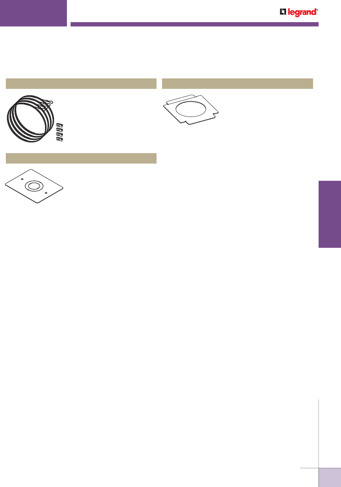
WWW.LEGRAND.US/WIREMOLD
321
WIREMOLD
WALL/CEILING BOXES
EVOLUTION
™
SERIES CEILING BOXES
Ordering Information
Evolution Series Ceiling Box Parts & Accessories Ordering Information (continued)
Used to support Evolution Series
Ceiling box to building structure.
ECB-CBKIT Cable Kits
Interchangeable plate with a 3/4"
& 1 1/4" concentric trade size
knockouts.
ECB-KO Knockout Plate
Cleans up projector installation
leaving a more aesthetic finished look.
ECB-PTP Projector Trim Plate
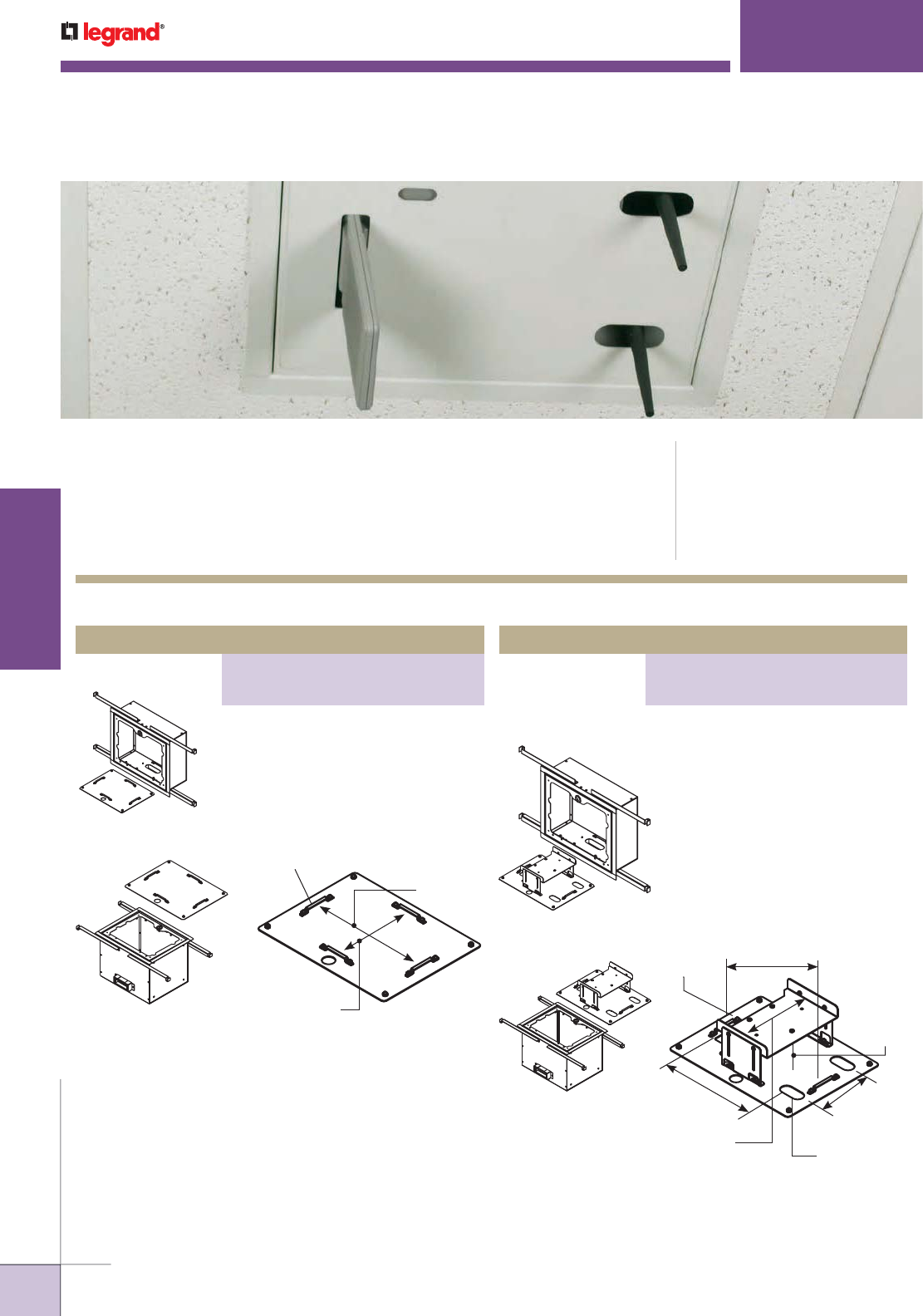
WWW.LEGRAND.US/WIREMOLD
322
WIREMOLD
WALL/CEILING BOXES
WAPE SERIES WIRELESS ACCESS POINT CEILING ENCLOSURES
Wiremold® WAPE Series Ceiling Enclosures provide a secure enclosure to house
a wide selection of wireless access points. These ceiling enclosures are plenum
rated by UL and may be used in environmental air spaces.
CODE REFERENCE
cULus Listed Communication
Circuit Accessories:
File E145222 Guide DUXR
Meets Article 800 of NEC.
Meets Article 60-308 of CEC.
WAPE5-BLKIT
WAPE10-BLKIT
10 1/8"
[257mm]
Securing Tab
6 7/8"
[174mm]
COVER
WAPE10-1200KIT
8 1/2"
[216mm]
3/4 x 3 3/4"
[19mm x 95mmm]
10 1/2"
[267mm]
Adjustable
1" – 3"
[25mm – 76mm]
5 5/8"
[143mm]
Slot
2" x 1"
[51mm x 25mm]
7 1/2"
[190mm]
COVER
WAPE5-1200KIT
WAPE Series Wireless Access Point Ceiling Enclosures Ordering Information
5" ( WAPE5-BLKIT) or 10" (WAPE10-
BLKIT) deep enclosure for 2' x 2' drop
ceiling tile with blank mounting cover,
12"W x 14"L [305mm x 356mm].
5" (WAPE5-1200KIT) or 10" (WAPE10-
1200KIT) deep enclosure for 2'x 2'
drop ceiling tile with faceplate for
mounting CISCO Aironet 1200, 12"W x
14"L [305mm x 356mm].
Wireless Access Point Enclosure
PART NUMBERS:
WAPE5-BLKIT (5" Deep Enclosure)
WAPE10-BLKIT (10" Deep Enclosure)
Wireless Access Point Enclosure
PART NUMBERS:
WAPE5-1200KIT (5" Deep Enclosure)
WAPE10-1200KIT (10" Deep Enclosure)
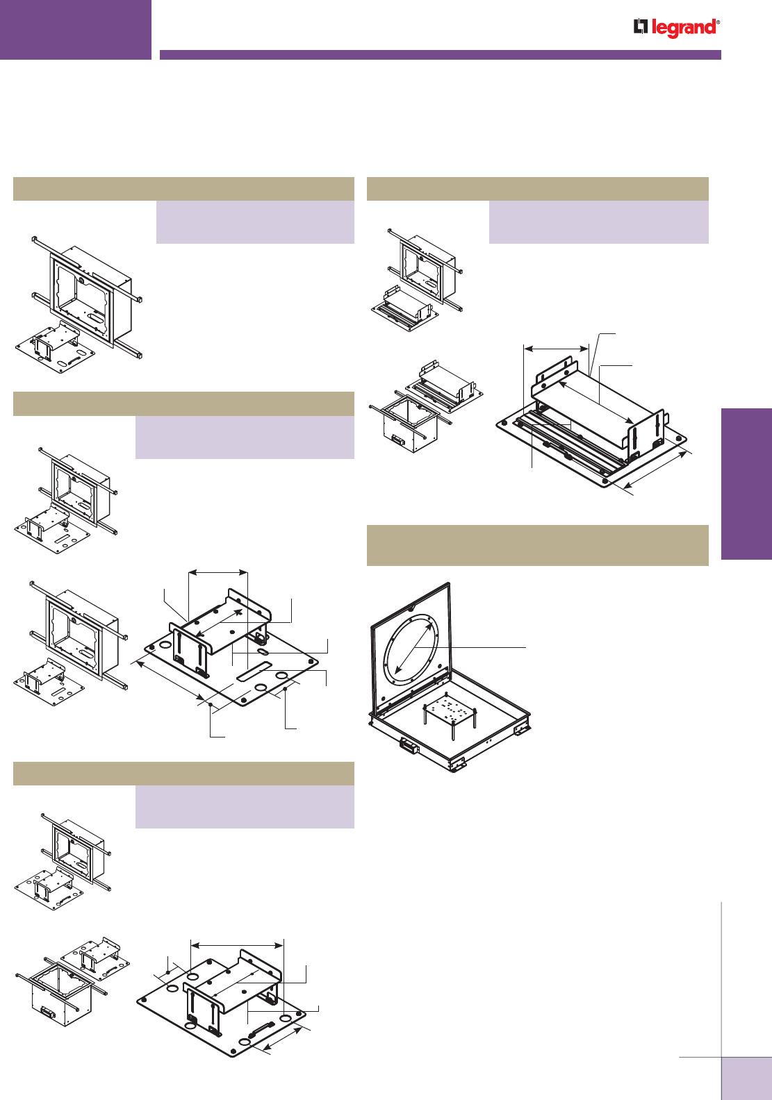
WWW.LEGRAND.US/WIREMOLD
323
WIREMOLD
WALL/CEILING BOXES
Wireless Access Point Enclosure
PART NUMBERS:
WAPE5-1232KIT (5" Deep Enclosure)
WAPE10-1232KIT (10" Deep Enclosure)
WAPE SERIES WIRELESS ACCESS POINT CEILING ENCLOSURES
Ordering Information
WAPE5-1250KITD
WAPE Series Wireless Access Point Ceiling Enclosures Ordering Information (continued)
5" deep enclosure for 2'x 2' drop
ceiling tile with faceplate for
mounting Cisco® Aironet 1250 and
3500 Series using dipole antennas
(WAPE5-1250KITD) or remote
antennas (WAPE5-1250KITR),
13"W x 14"L [330mm x 356mm].
WAPE10-1232KIT
WAPE5-1232KIT
WAPE10-UNIKIT
WAPE5-UNIKIT
14" Diameter
[355mm]
6 1/2" Deep
[165mm]
5" (WAPE5-1232KIT) or 10" (WAPE10-
1232KIT) deep enclosure for 2'x 2'
drop ceiling tile with faceplate for
mounting CISCO® Aironet 1232,
12"W x 14"L [305mm x 356mm].
5" (WAPE5-UNIKIT) or 10" (WAPE10-
UNIKIT) deep enclosure for 2'x 2' drop
ceiling tile with universal faceplate,
12"W x 14"L [305mm x 356mm].
WAPE10-DOME
Wireless Access Point Enclosure – with Dome Cover
3" deep enclosure for 2'x 2' drop
ceiling tile. 14" diameter by 6 1/2"
deep transmission dome.
10 3/8"
[263mm]
Between
Securing Tabs
6 3/4"
[171mm]
5 5/8"
[143mm]
Securing
Tab
Adjustable
1" – 3"
[25mm – 76mm]
COVER
COVER
Adjustable
1" – 3"
[25mm – 76mm]
Antenna Opening
3/4" x 3 3/4"
[19mm x 95mm]
7 1/2"
[190mm]
2 5/8"
[67mm]
2 1/4"
[57mm]
8 1/2"
[216mm]
8 1/2"
[216mm]
Securing
Tab
Wireless Access Point Enclosure
PART NUMBERS:
WAPE5-1250KITD (Dipole Antennas)
WAPE5-1250KITR (Remote Antennas)
Wireless Access Point Enclosure
PART NUMBERS:
WAPE5-UNIKIT (5" Deep Enclosure)
WAPE5-1250KITR (10" Deep Enclosure)
WAPE10-1242KIT
WAPE5-1242KIT
5" (WAPE5-1242KIT) or 10" (WAPE10-
1242KIT) deep enclosure for 2'x 2'
drop ceiling tile with faceplate for
mounting CISCO® Aironet 1242,
12"W x 14"L [305mm x 356mm].
Adjustable
1" – 3"
[25mm – 76mm]
7 1/2"
[190mm]
5 3/8"
[136mm]
10 3/4"
[273mm]
2 5/8"
[67mm]
COVER
Wireless Access Point Enclosure
PART NUMBERS:
WAPE5-1242KIT (5" Deep Enclosure)
WAPE10-1242KIT (10" Deep Enclosure)
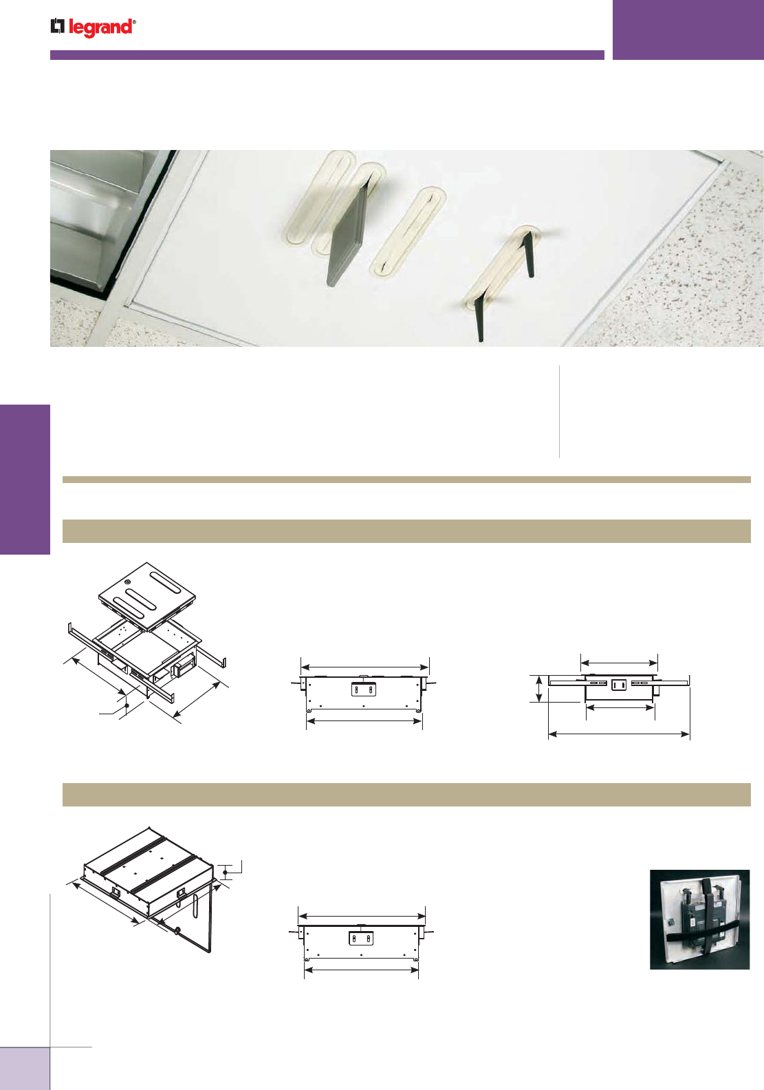
WWW.LEGRAND.US/WIREMOLD
324
WIREMOLD
WALL/CEILING BOXES
WAPENCL SERIES WIRELESS ACCESS POINT CEILING ENCLOSURES
Wiremold® WAPENCL Series Ceiling Enclosures provide a secure enclosure to
house a wide selection of wireless access points including the Cisco® Aironet 1250
and 3500 Series. These ceiling enclosures are plenum rated by UL and may be
used in environmental air spaces.
CODE REFERENCE
cULus Listed Communication Circuit
Accessories:
File E145222 Guide DUXR
Meets Article 800 of NEC.
Meets Article 60-308 of CEC.
WAPENCL Series Wireless Access Point Ceiling Enclosures Ordering Information
WAPENCL Wireless Access Point Ceiling Enclosure for Drop Ceilings
Provides a permanent and secure location for mounting wireless access points
into a grid ceiling system.
NOTE: Internal dimensions shown.
11 7/8"
[302mm]
12"
[305mm]
3 7/8"
[99mm]
13 3/8"
[340mm]
12"
[305mm]
Front Exterior Dimensions
13 1/2"
[343mm]
4"
[102mm]
12 1/8"
[308mm]
25 1/4"
[641mm]
Side Exterior Dimensions
4 1/2"
[114mm]
23 29/32"
[760mm]
23 29/32"
[760mm]
23 29/32"
[760mm]
22 1/2"
[572mm]
Side Exterior Dimensions WAPENCL’s innovative
device mounting system is
designed to securely retain
most wireless devices.
WAPENCL-24-24-4 Wireless Access Point Ceiling Enclosure for Drop Ceilings
Provides a permanent and secure location for mounting wireless access points
into a grid ceiling system.
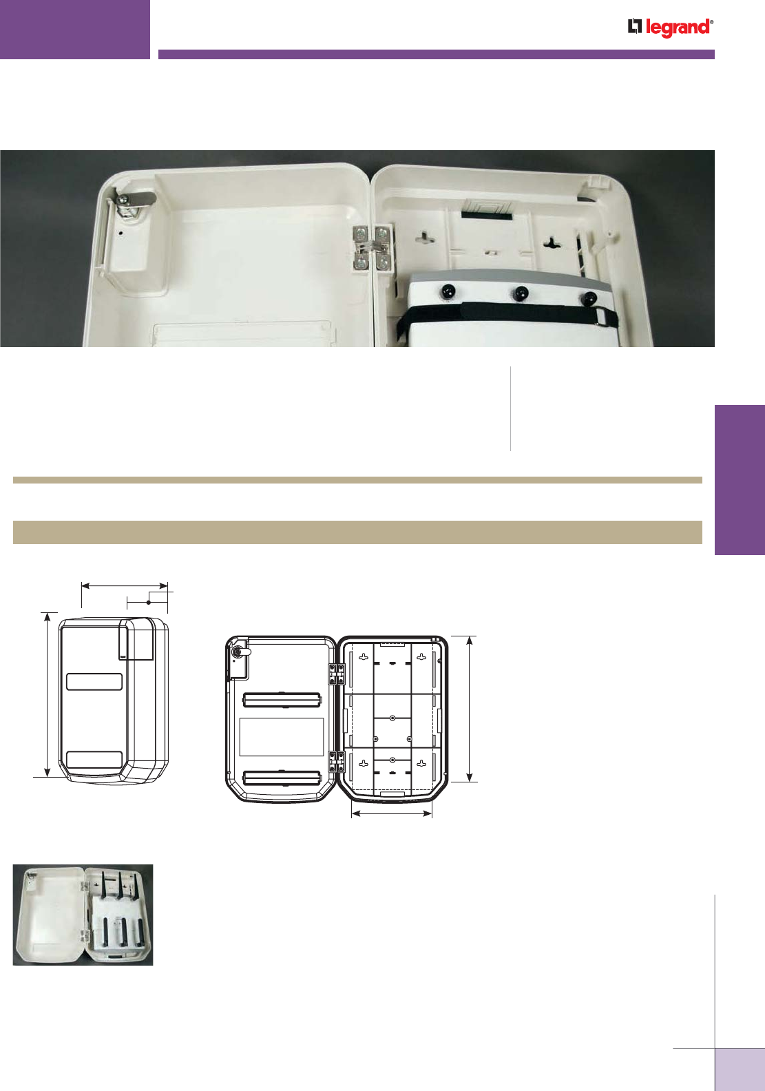
WWW.LEGRAND.US/WIREMOLD
325
WIREMOLD
WALL/CEILING BOXES
NME1250AP WALLMOUNTED NONMETALLIC
WIRELESS ACCESS POINT ENCLOSURE
Nonmetallic Wireless Access
Point Mounting Enclosure
(NME1250AP), loaded with
a wireless access point, for
vertical applications.
7 6/16"
[192mm]
13 3/4"
[349mm]
5 1/8"
[131mm]
Inside:
4 5/8"
[117mm]
10 7/16"
[265mm]
15 3/4"
[400mm]
Wiremold® NME1250AP Wireless Access Point Enclosure conceals wireless
access points in a durable thermoplastic listed enclosure. CODE REFERENCE
cETLus Listed Communication Circuit
Accessories:
Meets Article 800 of NEC.
Meets Article 60-308 of CEC.
NME1250AP Nonmetallic Wireless Access Point Mounting Enclosure Ordering Information
NME1250AP Nonmetallic Wireless Access Point Mounting Enclosure
Wall-mounted access point enclosure constructed of durable thermoplastic.
Supports a wide variety of access point configurations for most leading
manufacturers of access point products including the Cisco® Aironet 1250 and
3500 Series.
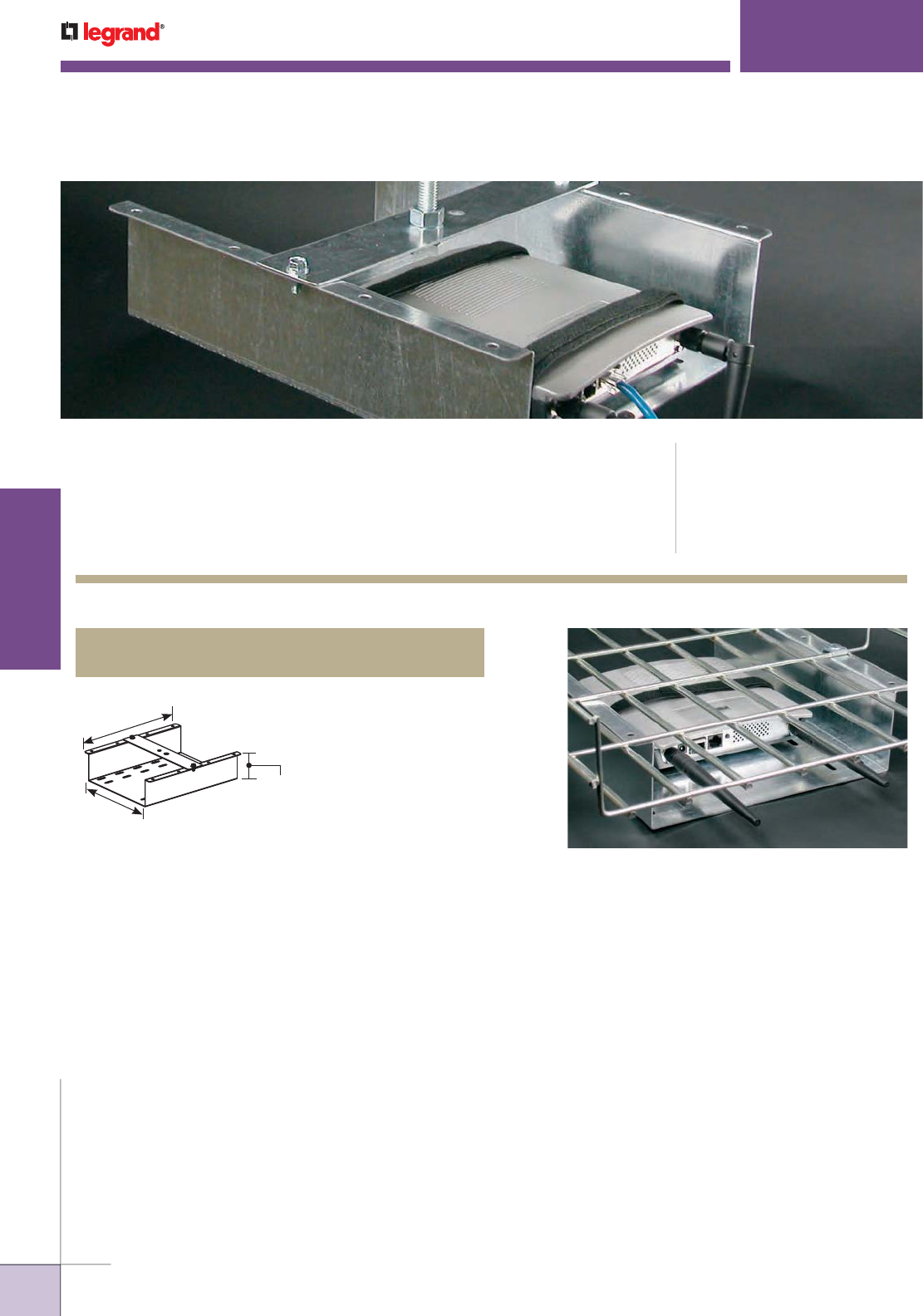
WWW.LEGRAND.US/WIREMOLD
326
WIREMOLD
WALL/CEILING BOXES
Provides secure support for
mounting wireless access
points in overhead applications.
WAPBRKT WIRELESS ACCESS POINT
MOUNTING BRACKET FOR OVERHEAD APPLICATIONS
Wiremold® WAPBRKT Wireless Access Point Mounting Bracket
provides a secure support for mounting wireless access points
in overhead applications.
CODE REFERENCE
cULus Listed Communication Circuit
Accessories:
File E145222 Guide DUXR
Meets Article 800 of NEC.
Meets Article 60-308 of CEC.
WAPBRKET Overhead Wireless Access Point Mounting Bracket Ordering Information
WAPBRKT
Overhead System Wireless Access Point Bracket
The WAPBRKT is designed to work with most tray
and basket overhead systems.
11 3/16"
[284mm]
12 3/4"
[324mm]
3 1/8"
[79mm]
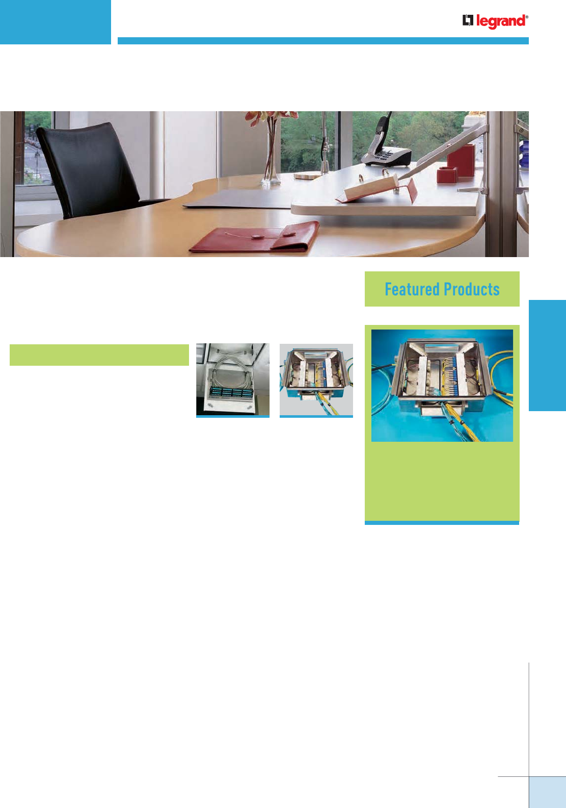
ZONE CABLING ENCLOSURES
Wiremold® Zone Cabling Enclosures provide a range of alternatives to meet
a variety of wireless connectivity strategies.
CZE Series Zone
Cabling Enclosures
328
Zone Cabling Enclosures
328
CZE Series Zone
Cabling Enclosures
329
RFE Series Zone
Cabling Enclosures
Table of Contents
WWW.LEGRAND.US/WIREMOLD
327
WIREMOLD
ZONE CABLING ENCLOSURES
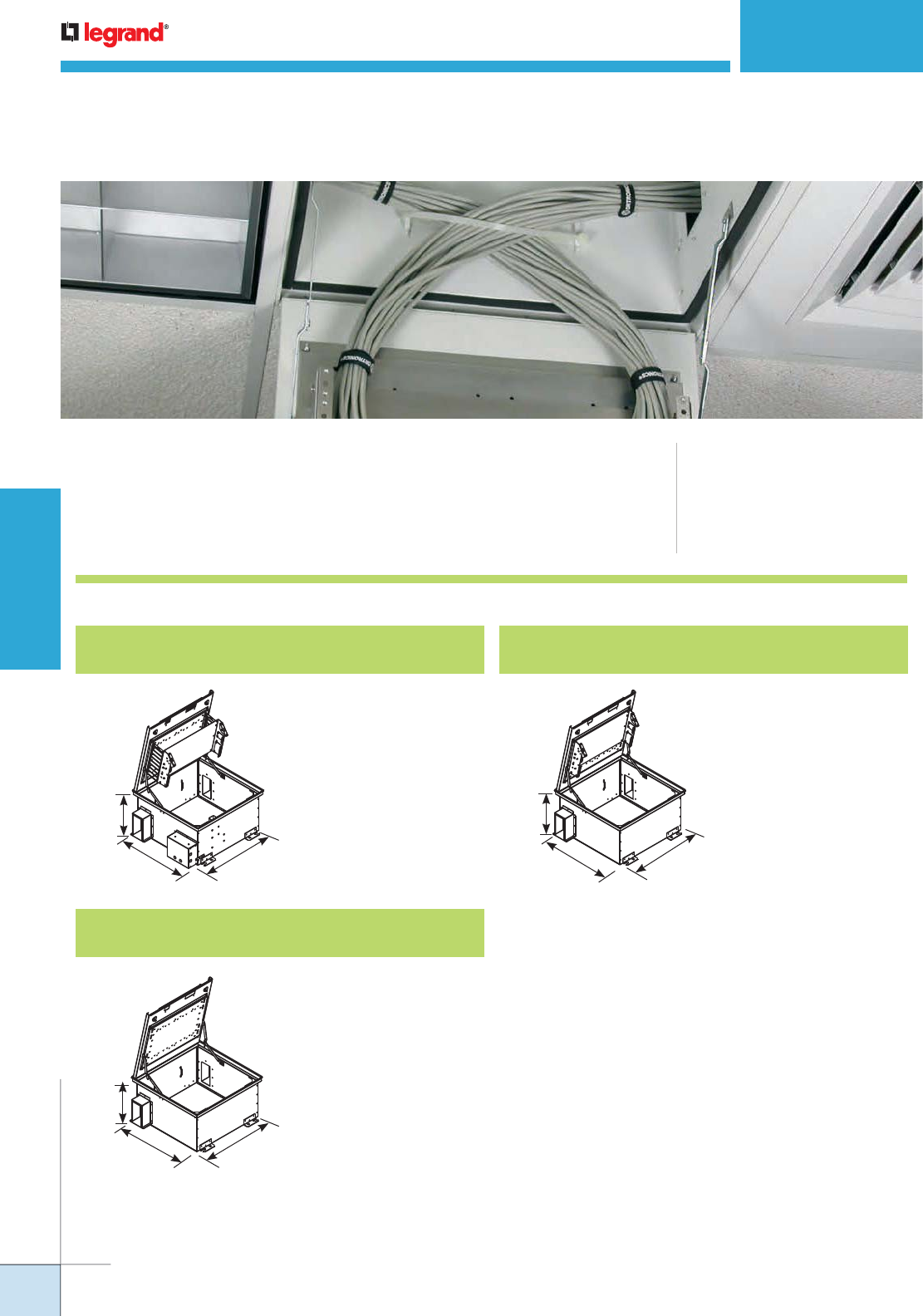
CZE SERIES ZONE CABLING ENCLOSURES
Wiremold® CZE Series Ceiling Zone Cabling Enclosures create an intermediate or
remote consolidation point that may be tested and secured prior to adding drops
for voice and data outlets.
CODE REFERENCE
cULus Listed Communication Circuit
Accessories:
File E145222 Guide DUXR
Meets Article 800 of NEC.
Meets Article 60-308 of CEC.
CZE Series Ceiling Zone Cabling Enclosures Ordering Information
CZE-242412A Ceiling Zone Cabling Enclosure
for Active Equipment
12" deep telecommunications
enclosure for 2' x 2' drop
ceiling tile. One removable
7 RMU bracket for 19" patch
panels and equipment.
Includes junction box and fan.
21 1/2"
[546mm]
21 1/2"
[546mm]
12"
[305mm]
21 1/2"
[546mm]
21 1/2"
[546mm]
12"
[305mm]
21 1/2"
[546mm]
21 1/2"
[546mm]
12"
[305mm]
CZE-242412WB Ceiling Zone Cabling Enclosure
with Wiring Blocks
12" deep termination block
enclosure for 2' x 2' drop
ceiling tile. One removable
mounting plate for two 300
pair 1100 style termination
blocks (without legs).
CZE-242412PP Ceiling Zone Cabling Enclosure for
Mounting Patch Panels
12' deep patch panel
enclosure for 2' x 2' drop
ceiling tile. One bracket for
19" patch panels. Bracket
supports 5 RMU.
WWW.LEGRAND.US/WIREMOLD
328
WIREMOLD
ZONE CABLING ENCLOSURES
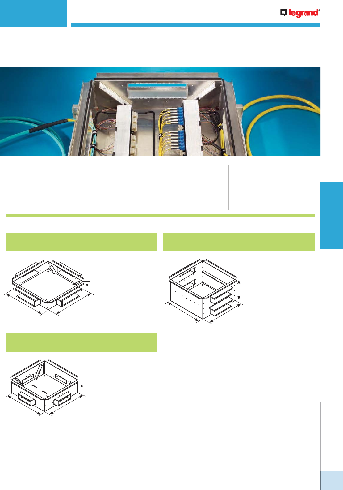
CODE REFERENCE
cULus Listed Communication
Circuit Accessories:
File E145222 Guide DUXR
Meets Article 800 of NEC.
Meets Article 60-308 of CEC.
RFE SERIES ZONE CABLING ENCLOSURES
Wiremold® RFE Series Raised Floor Zone Cabling Enclosures create an
intermediate or remote consolidation point that may be tested and secured prior
to adding drops for voice and data outlets.
RFE Series Raised Floor Zone Cabling Enclosures Ordering Information
RFE-25256 Raised Floor Enclosure for
Zone Cabling
Enclosure for 6" deep
floor. Two pairs of
pivoting mounting
rails for 19" patch
panels. Rails support
2 RMU each.
RFE-242412 Raised Floor Enclosure for
Zone Cabling
Enclosure for 14"
deep floor. A single
mounting rail for 19"
patch panels. Rail
supports 11 RMU.
21"
[533mm]
21"
[533mm]
6"
[152mm]
RFE-25257RB Raised Floor Enclosure for
Zone Cabling
Enclosure for 8" deep
floor. Two pairs of
pivoting mounting
rails for 19" patch
panels. Rails support
4 RMU each.
21"
[533mm]
21"
[533mm]
7"
[178mm]
21"
[533mm] 21"
[533mm]
12"
[305mm]
WWW.LEGRAND.US/WIREMOLD
329
WIREMOLD
ZONE CABLING ENCLOSURES

WWW.LEGRAND.US/WIREMOLD
330
WIREMOLD
ZONE CABLING ENCLOSURES
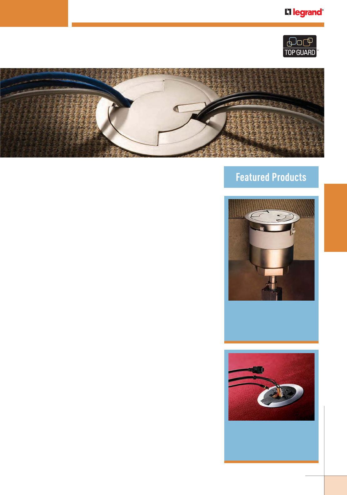
WWW.LEGRAND.US/WIREMOLD
331
WIREMOLD
POKE-THRU DEVICES
POKETHRU DEVICES
Evolution Series™
Poke-Thru Devices
337
With the introduction of our new Evolution™ Series of Poke-Thru Devices,
Wiremold® is again pushing the envelope by expanding the capacity,
capabilities, and aesthetics of Infloor power and communication delivery
systems for open spaces.
Wiremold® Poke-Thru Devices are TopGuard
protected to meet and exceed the UL scrub
water exclusion requirement.
AV3 Series™
Poke-Thru Devices
360
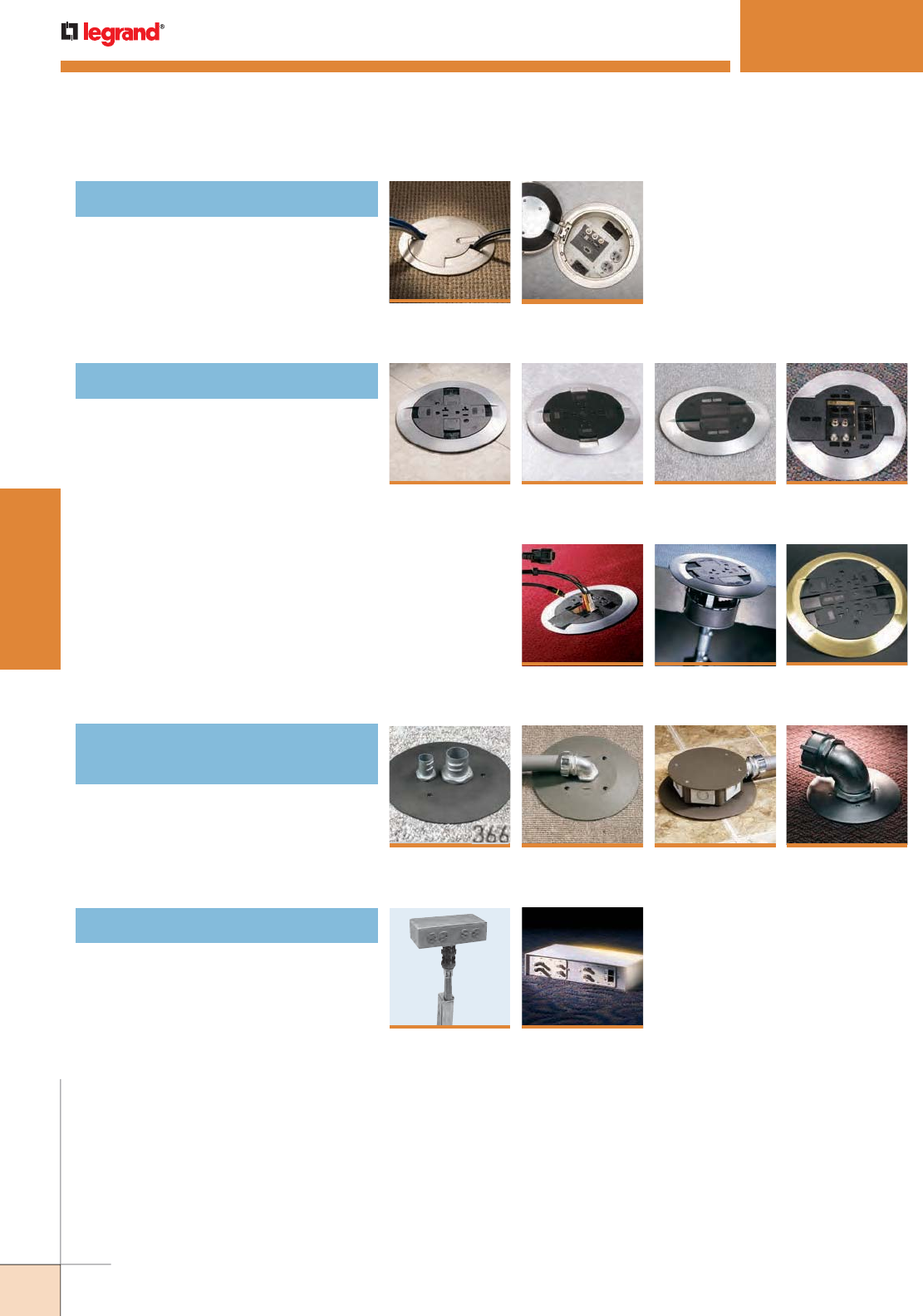
WWW.LEGRAND.US/WIREMOLD
332
WIREMOLD
POKE-THRU DEVICES
Recessed Style Poke-Thru Devices
POKETHRU DEVICES
Table of Contents
Evolution™ 6AT
Series
337
352
RC7 Series™
358
AMD8 Series™
356
RC9AMD
Series™
364
RC4 Series™
Evolution™ 8AT
Series
345
354
RC9 Series™
360
AV3 Series™
Surface Style Poke-Thru Devices
362
RC3 Series™
4FFATC
Series™
370
RC9AFFTC
Series™
368
RC7AFFTC
Series™
Furniture Feed Style Poke-Thru
Devices
372
RC9AM2TC
Series™
374
FIT Series™
377
RC91GHBTC &
RC92GHBTC
Series™
Pedestal Style Poke-Thru Devices
366

WWW.LEGRAND.US/WIREMOLD
333
WIREMOLD
POKE-THRU DEVICES
POKETHRU DEVICES
Quick Selection Guide
Recessed Poke-Thru Devices
6" & 8" DIAMETER HOLE
POKE-THRU SERIES EVOLUTION
™
6ATC SERIES EVOLUTION
™
6AT SERIES EVOLUTION
™
6ATCFF SERIES EVOLUTION
™
8AT SERIES
HOLE SIZE – COVER FLOORS Minimum: 6" [152mm]
Maximum: 6 1/8" [156mm]
Minimum: 6" [152mm]
Maximum: 6 1/8" [156mm]
Minimum: 6" [152mm]
Maximum: 6 1/8" [156mm]
Minimum: 8" [203mm]
Maximum: 8 1/8" [206mm]
HOLE SIZE –
BARE CONCRETE
&
TERRAZZO FLOORS
Minimum: 6 1/16" [154mm]
Maximum: 6 1/8" [156mm]
Minimum: 6 1/16" [154mm]
Maximum: 6 1/8" [156mm]
Minimum: 6 1/16" [154mm]
Maximum: 6 1/8" [156mm]
Minimum: 8 1/16" [205mm]
Maximum: 8 1/8" [206mm]
UL FIRE CLASSIFICATION
1-, 1 1/2- & 2-Hours 1-, 1 1/2- & 2-Hours 1-, 1 1/2- & 2-Hours 1-, 1 1/2- & 2-Hours
UL SCRUBWATER PROTECTION
TopGuard™TopGuard™TopGuard™TopGuard™
CAPACITY
2 1/2 Gangs
3 Duplex Receptacles or
12 Communication Ports or
10 Wiremold AVIP or Extron
®
MAAP or 2 AAP Plates or any
combination of the above
2 1/2 Gangs
3 Duplex Receptacles or
12 Communication Ports or
10 Wiremold AVIP or Extron
®
MAAP or 2 AAP Plates or any
combination of the above
N/A 4 Gangs
5 Duplex Receptacles or
22 Communication Ports or
16 Wiremold AVIP or Extron
®
MAAP or 4 AAP Plates or any
combination of the above
MAXIMUM COPPER
CROSS SECTION*
OUTER CHANNELS
.0154 sq. in. [9.9mm
2
] .0154 sq. in. [9.9mm
2
] Data Channel .0187 in
2
[12.1mm
2
]
Power: 0.0815 [52.6mm
2
]
.0154 sq. in. [9.9mm
2
]
CENTER
CHANNEL(S)
.0387 sq. in. [24.97mm
2
] .0387 sq. in. [24.97mm
2
] .0686 in
2
[44.3mm
2
] .0775 sq. in. [16.60mm
2
]
POWER
OUTER CHANNELS
Three (3) #12 AWG Three (3) #12 AWG Fifteen (15) #12 AWG Three (3) #12 AWG
CENTER
CHANNEL(S)
Seven (7) #12 AWG Seven (7) #12 AWG N/A Fifteen (15) #12 AWG
COMMUNICATIONS
OUTER CHANNELS
Four (4) Cat 6A Four (4) Cat 6A Five (5) Cat 6A Four (4) Cat 6A
CENTER
CHANNEL(S)
Twelve (12) Cat 6A Twelve (12) Cat 6A Twenty-One (21) Cat 6A Twenty-Four (24) Cat 6A
CONDUIT FEEDS
3/4" Conduit for Outer
Channel, Maximum
1 1/4" Conduit for Center Channel
or 2" Conduit which takes up the
Center Channel and one Outer
Channel
3/4" Conduit for Outer
Channel, Maximum
1 1/4" Conduit for Center Channel
or 2" Conduit which takes up the
Center Channel and one Outer
Channel
3/4" Conduit for Outer
Channel, Maximum
1 1/4" Conduit for Center Channel
or 2" Conduit which takes up the
Center Channel and one Outer
Channel
3/4" Conduit for Outer
Channel, Maximum
1 1/4" Conduit for Center Channel
or 2" Conduit which takes up the
Center Channel and one Outer
Channel
COVER SIZE
7 1/4” [184mm] 7 1/4” [184mm] 7 3/4” [197mm] 9 1/4” [235mm]
COVER COLORS
Black, Gray, Nickel,
Bronze, Brass
Black, Gray, Nickel,
Bronze, Brass
Black, Gray, Nickel,
Bronze, Brass
Black, Gray, Nickel,
Bronze, Brass
APPROVED CONCRETE FLOOR
COVERINGS
Carpet, Tile,
Concrete/Terrazzo & Wood
Carpet, Tile,
Concrete/Terrazzo & Wood
Carpet, Tile,
Concrete/Terrazzo & Wood
Carpet, Tile,
Concrete/Terrazzo & Wood
FLOOR COVERING THICKNESS Minimum: 0" [0mm]
Maximum: 1 1/4" [32mm]
Minimum: 0" [0mm]
Maximum: 1 1/4" [32mm
Minimum: 0" [0mm]
Maximum: 1 1/4" [32mm]
Minimum: 0" [0mm]
Maximum: 1 1/4" [32mm]
NOTE: For modular prewired Walkerflex® versions, see the Walkerflex® product section.
* The above maximum copper fill values are the maximum amount of copper to maintain fire
classification and are for each individual power and communication compartments. Do not
add values together for any one compartment.
NOTE: Pre-Pour Sleeves for 6" (6PPS) and 8" (8PPS) Evolution Series Poke-Thru Devices
speed installation and insure accurate location of devices.
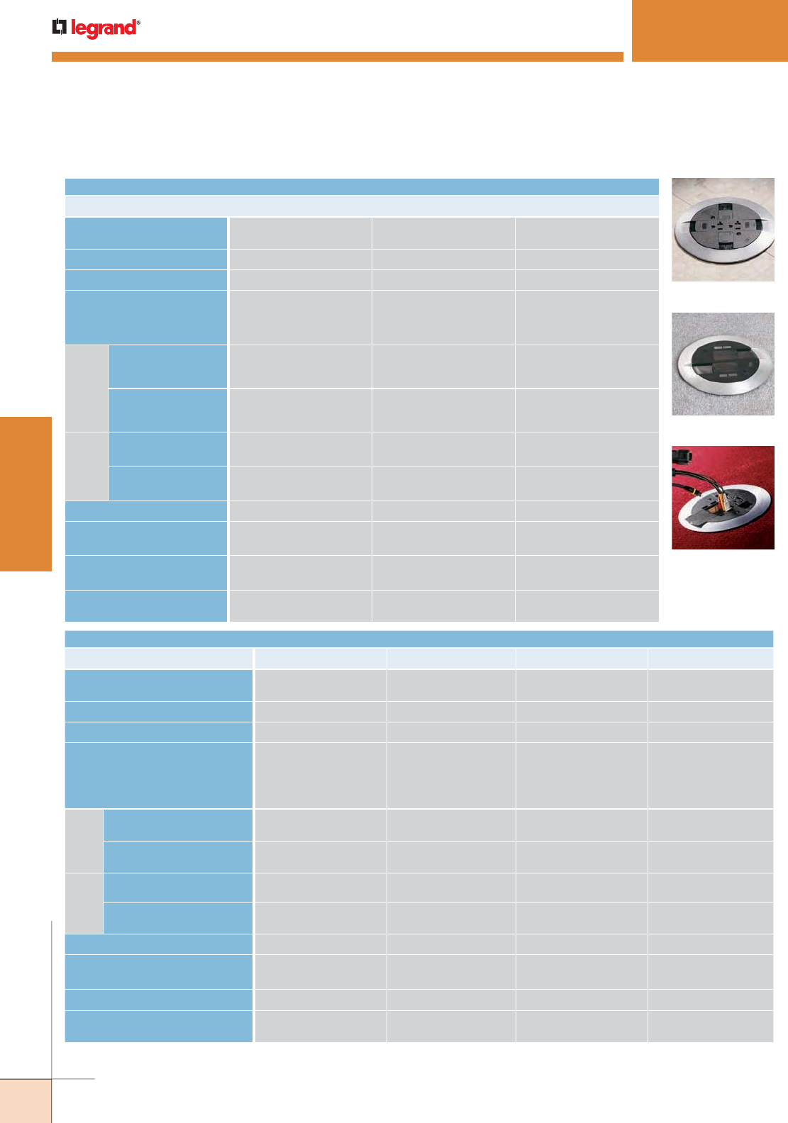
WWW.LEGRAND.US/WIREMOLD
334
WIREMOLD
POKE-THRU DEVICES
POKETHRU DEVICES
Quick Selection Guide
Surface Style Poke-Thru Devices
3" DIAMETER HOLE
POKE-THRU SERIES RC7 SERIES RC9 SERIES RC9AMD SERIES
HOLE SIZE Minimum: 3 1/16" [78mm]
Maximum: 3 1/8" [79mm]
Minimum: 3 1/16" [78mm]
Maximum: 3 1/8" [79mm]
Minimum: 3" [76mm]
Maximum: 3 1/8" [79mm]
UL FIRE CLASSIFICATION
1-, 1 1/2- & 2-Hours 1-, 1 1/2- & 2-Hours 1-, 1 1/2- & 2-Hours
UL SCRUBWATER PROTECTION
TopGuard™TopGuard™TopGuard™
CAPACITY
2 Gangs
(1) 20A Duplex Receptacle,
(2) Ports of Communication
Devices
2 Gangs
(1) 15A Quad Receptacle,
(2) Openings for Communication
Pass-Through
1 Gang
(4) Ports of
Communication Devices
MAXIMUM
COPPER FILL
POWER* (3) #12 AWG
.01536 sq. in. [9.91 sq. mm]
(3) #12 AWG
.01536 sq. in. [9.91 sq. mm]
N/A
COMMUNICATIONS* (1) Cat 6/Channel
.004 sq. in. [2.58 sq. mm]
(1) Cat 6/Channel
.004 sq. in. [2.58 sq. mm]
(4) Cat 6/Channel
.01600 sq. in. [10.324 sq. mm]
FEED
CHANNELS
POWER 3/4" Trade Size 3/4" Trade Size N/A
COMMUNICATIONS 1/2" Trade Size/Channel
(2) Channels per unit
1/2" Trade Size/Channel
(2) Channels per unit
2" Trade Size
COVER SIZE
7” [178mm] 7” [178mm] 7” [178mm]
COVER COLORS
Black, Brass,
Aluminum, Gray
Black, Brass,
Aluminum, Gray
Black, Brass,
Aluminum, Gray
APPROVED CONCRETE FLOOR
COVERINGS
Carpet, Tile & Wood Carpet, Tile & Wood Carpet, Tile & Wood
FLOOR COVERING THICKNESS
Minimum: 1/8" [3.2mm]
Maximum: 3/4" [19.1mm]
Minimum: 1/8" [3.2mm]
Maximum: 3/4" [19.1mm]
Minimum: 1/8" [3.2mm]
Maximum: 3/4" [19.1mm]
RC7 Series
RC9AMD Series
AV3 Series
4" DIAMETER HOLE
POKE-THRU SERIES
AV3 SERIES AMD8 SERIES RC4 SERIES RC3 SERIES
HOLE SIZE Minimum: 4" [102mm]
Maximum:4 1/8" [105mm]
Minimum: 4 [102mm]
Maximum: 4 1/8" [105mm]
Minimum:4" [102mm]
Maximum:4 1/8" [105mm]
Minimum:4" [102mm]
Maximum:4 1/8" [105mm]
UL FIRE CLASSIFICATION
1-, 1 1/2- & 2-Hours 1-, 1 1/2- & 2-Hours 1-, 1 1/2- & 2-Hours 1-, 1 1/2- & 2-Hours
UL SCRUBWATER PROTECTION
TopGuard™TopGuard™TopGuard™TopGuard™
CAPACITY
2 Gangs (1) 20A Duplex
Receptacle, (3) Single Width
Wiremold AVIP or Extron
®
MAAP Devices or
(4) Ports of Communications
1 Gang All Communications
(8) Ports for
Communication Devices
2 Gangs (2) 20A Duplex
Receptacles
(4) Ports for
Communication Devices
2 Gangs (1) Duplex Receptacle
(4) Ports for
Communication Devices
MAXIMUM
COPPER FILL
POWER* (3) #12 AWG
.01536 sq. in. [9.91 sq. mm]
N/A (6) #12 AWG
.03072 sq. in. [19.82 sq. mm]
(3) #12 AWG
.01536 sq. in. [9.91 sq. mm]
COMMUNICATIONS* (4) Cat 6
.01938 sq. in. [12.503 sq. mm]
(8) Cat 6
.03474 sq. in. [22.412 sq. mm]
(4) Cat 6/Channel
.016 sq. in. [10.3 sq. mm]
(4) Cat 6/Channel
.016 sq. in. [10.3 sq. mm]
FEED
CHANNELS
POWER 3/4" Trade Size 3/4" Trade Size 3/4" Trade Size 3/4" Trade Size
COMMUNICATIONS 1 1/4" Trade Size/Channel 1 1/4" Trade Size/Channel 3/4" Trade Size (Equivalent)
Oval Shaped Opening
3/4" Trade Size (Equivalent)
Oval Shaped Opening
COVER SIZE
8 1/4" [210mm] 7 1/2" [191mm] 8 1/4" [210mm] 7 1/2" [191mm]
COVER COLORS
Black, Brass,
Aluminum, Gray
Black, Brass,
Aluminum, Gray
Black, Brass,
Aluminum, Gray
Black, Brass,
Aluminum, Gray
APPROVED CONCRETE FLOOR COVERINGS
Carpet, Tile & Wood Carpet, Tile & Wood Carpet, Tile & Wood Carpet, Tile & Wood
FLOOR COVERING THICKNESS
Minimum: 1/8" [3.2mm]
Maximum: 3/4" [19.1mm]
Minimum: 1/8" [3.2mm]
Maximum: 3/4" [19.1mm]
Minimum: 1/8" [3.2mm]
Maximum: 3/4" [19.1mm]
Minimum: 1/8" [3.2mm]
Maximum: 3/4" [19.1mm]
* The above maximum copper fill values are the maximum amount of copper to maintain fire classification and are for each individual power and
communication compartments. Do not add values together for any one compartment.
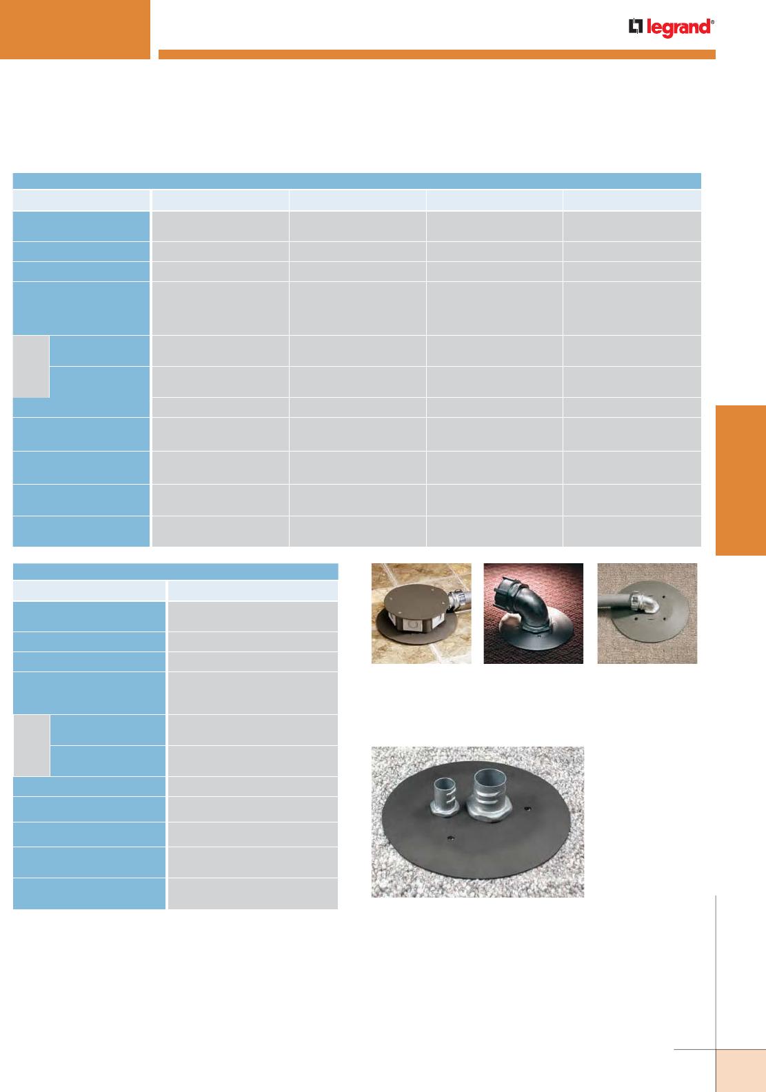
WWW.LEGRAND.US/WIREMOLD
335
WIREMOLD
POKE-THRU DEVICES
POKETHRU DEVICES
Quick Selection Guide
3" DIAMETER HOLE
POKE-THRU SERIES RC7AFFTC SERIES RC7AM2TC SERIES RC9FFTC SERIES RC9AM2TC SERIES
HOLE SIZE Minimum: 3 1/16” [78mm]
Maximum: 3 1/8” [79mm]
Minimum: 3” [76mm]
Maximum: 3 1/8” [79mm]
Minimum: 3” [76mm]
Maximum: 3 1/8” [79mm]
Minimum: 3” [76mm]
Maximum: 3 1/8” [79mm]
UL FIRE CLASSIFICATION
1-, 1 1/2- & 2-Hours 1-, 1 1/2- & 2-Hours 1-, 1 1/2- & 2-Hours 1-, 1 1/2- & 2-Hours
UL SCRUBWATER PROTECTION
TopGuard™TopGuard™TopGuard™TopGuard™
CAPACITY
2 Gangs
Two (2) 1/2” & one (1) 3/4”
Trade Size Screw Plug Openings
1 Gang Two (2) 1/2” &
one (1) 3/4” Trade Size
Screw Plug Openings
2 Gangs Hexagonal Service
Head with one (1) 3/4” Trade
Size Conduit & five (5)
Communication Openings
1 Gang One (1) 1 1/4”/2"
Concentric Screw Plug
MAXIMUM
COPPER FILL
POWER* (10) #12 AWG
.05214 sq. in. [33.64mm
2
]
(20) #12 AWG
.09216 sq. in. [59.46mm
2
]
(3) #12 AWG
.05726 sq. in. [36.94mm
2
]
(20) #12 AWG
.09216 sq. in. [59.46mm
2
]
COMMUNICATIONS* (7) Cat 6/Channel
.05000 sq. in. [32.26mm
2
]
(7) Cat 6/Channel
.09216 sq. in. [59.46mm
2
]
(15) Cat 6/Channel
.06425 sq. in. [41.45mm
2
]
(32) Cat 6/Channel
.09216 sq. in. [59.46mm
2
]
COVER SIZE
7” [178mm] 7” [178mm] 7” [178mm] 7” [178mm]
COVER COLORS
Black, Brass, Aluminum,
Gray
Black, Brass, Aluminum,
Gray
Black, Brass, Aluminum,
Gray
Black, Brass, Aluminum,
Gray
COVER CONSTRUCTION Die-Cast Die-Cast Die-Cast Die-Cast
CONDUIT/STEM DIAMETER One (1) 3/4” & two (2) 1/2”
Trade Size Conduit
One (1) 2”
Trade Size Conduit
One (1) 3/4” & one 1 1/4”
Trade Size Conduit
One (1) 2”
Trade Size Conduit
FLOOR COVERING THICKNESS
Minimum: 1/8" [3.2mm]
Maximum: 3/4" [19.1mm]
Minimum: 1/8" [3.2mm]
Maximum: 3/4" [19.1mm]
Minimum: 1/8" [3.2mm]
Maximum: 3/4" [19.1mm]
Minimum: 1/8" [3.2mm]
Maximum: 3/4" [19.1mm]
Furniture Feed Style Poke-Thru Devices
RC9FF Series RC9AM2 Series RC7AFF Series
4FFATC Series
4" DIAMETER HOLE
POKE-THRU SERIES
4FFATC SERIES
HOLE SIZE Minimum: 4" [76mm]
Maximum: 4 1/8" [78mm]
UL FIRE CLASSIFICATION
1-, 1 1/2- & 2-Hours
UL SCRUBWATER PROTECTION
TopGuard™
CAPACITY
2 Gangs
One (1) 3/4" & one (1) 1 1/4" Trade Size
Screw Plug Openings
MAXIMUM
COPPER FILL
POWER* (16) #12 AWG or (10) #10 AWG
.08192 sq. in. [52.851mm
2
]
COMMUNICATIONS* (18) Cat 6/Channel
.072 sq. in. [46.45mm
2
]
COVER SIZE
7 1/2" [191mm]
COVER COLORS
Black, Brass, Aluminum, Gray
COVER CONSTRUCTION Die-Cast
CONDUIT/STEM DIAMETER One (1) 3/4" & one (1) 1 1/4"
Trade Size Conduit
FLOOR COVERING THICKNESS
Minimum: 1/8" [3.2mm]
Maximum: 3/4" [19.1mm]
* The above maximum copper fill values are the maximum amount of
copper to maintain fire classification and are for each individual power
and communication compartments. Do not add values together for any
one compartment.
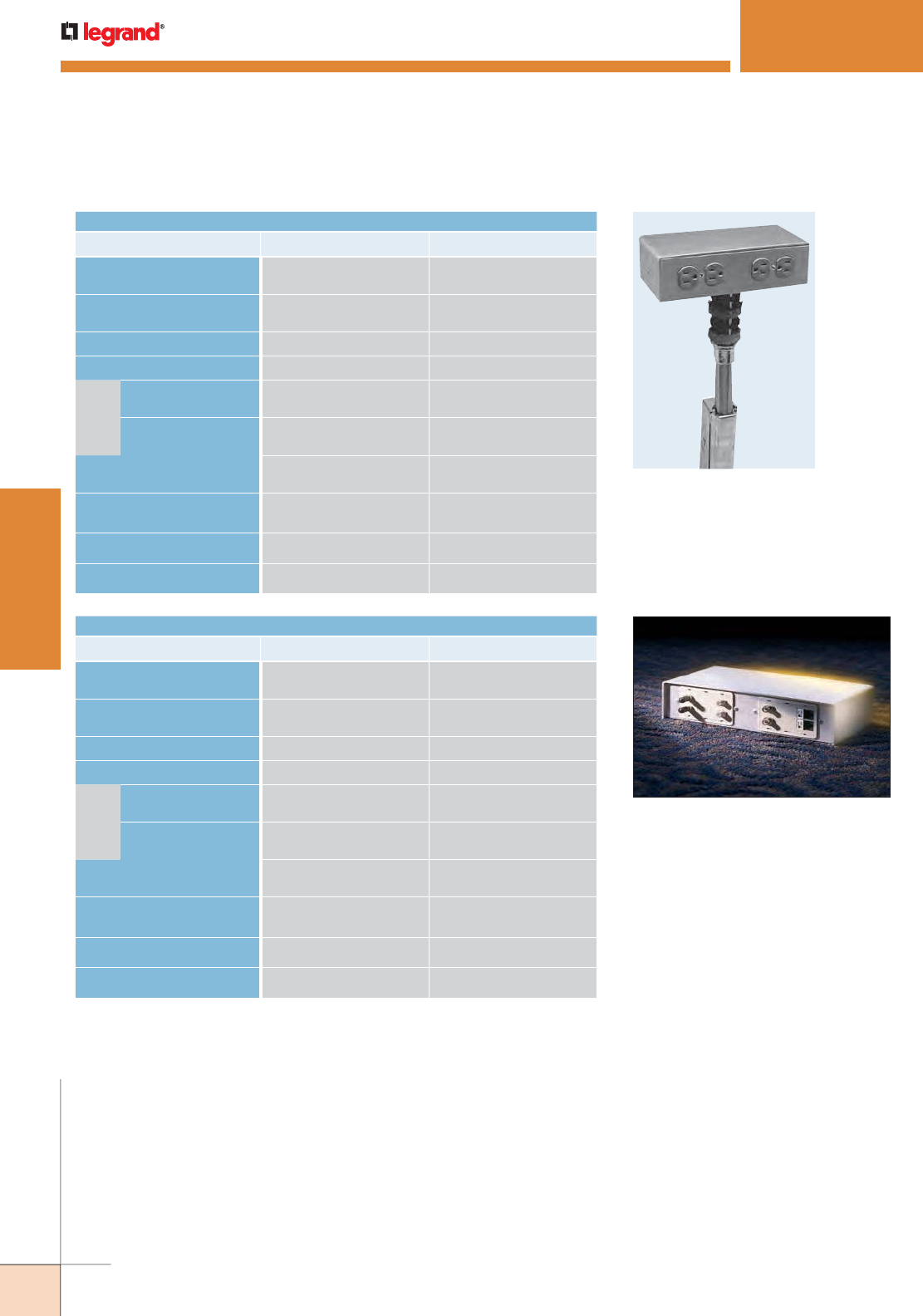
WWW.LEGRAND.US/WIREMOLD
336
WIREMOLD
POKE-THRU DEVICES
2" DIAMETER HOLE
POKE-THRU SERIES
FIT SERIES FIT SERIES
HOLE SIZE
Minimum: 2 1/32" [52mm]
Maximum: 2 1/8" [54mm]
Minimum: 2 1/32" [52mm]
Maximum: 2 1/8" [54mm]
CAPACITY
Single Width
200-H/BTC Service Head
Double Width
241-H/BTC Service Head
UL FIRE CLASSIFICATION
1-, 1 1/2-, 2-, 3-& 4-hrs 1-, 1 1/2-, 2-, 3-& 4-hrs
UL SCRUBWATER PROTECTION
TopGuard™TopGuard™
MAXIMUM
COPPER FILL
POWER*
(3) #12 AWG
.01536 sq. in. [9.91 mm2]
(7) #12 AWG
.03584 sq. in. [23.12 mm2]
COMMUNICATIONS*
(6) Cat 6/Channel
.05020 sq. in. [32.39 mm2]
(6) Cat 6A/Channel
.05020 sq. in. [32.39 mm2]
FLANGE/COVER DIAMETER
4 5/8" x 4" x 2 5/8"
[118mm x 102mm x 69mm]
4 5/8" x 9 1/4" x 2 5/8"
[118mm x 235mm x 69mm]
CONDUIT/STEM DIAMETER
One 1"
Trade Size Conduit
One 1"
Trade Size Conduit
SERVICE HEAD CONSTRUCTION
Aluminum Aluminum
COVER COLORS
Brushed Aluminum Brushed Aluminum
Pedestal Style Poke-Thru Devices
POKETHRU DEVICES
Quick Selection Guide
FIT Series
RC92GHBTC Series
3" DIAMETER HOLE
POKE-THRU SERIES
RC91GHBTC SERIES RC92GHBTC SERIES
HOLE SIZE
Minimum: 3 1/16" [78mm]
Maximum: 3 1/8" [79mm]
Minimum: 3 1/16" [78mm]
Maximum: 3 1/8" [79mm]
CAPACITY
Single Width
Service Head
Double Width
Service Head
UL FIRE CLASSIFICATION
1-, 1 1/2-, 2-hrs 1-, 1 1/2-, 2-hrs
UL SCRUBWATER PROTECTION
TopGuard™TopGuard™
MAXIMUM
COPPER FILL
POWER*
(3) #12 AWG
.01536 sq. in. [9.91 mm2]
(10) #12 AWG
.05120 sq. in. [33.03 mm2]
COMMUNICATIONS*
(15) Cat 6/Channel
.05020 sq. in. [23.39 mm2]
(31) Cat 6A/Channel
.05020 sq. in. [23.39 mm2]
FLANGE/COVER DIAMETER
4 5/8" x 4" x 2 5/8"
[118mm x 102mm x 69mm]
4 5/8" x 9 1/4" x 2 5/8"
[118mm x 235mm x 69mm]
CONDUIT/STEM DIAMETER
One (1) 1/2" & one (1) 1 1/4"
Trade Size Conduit
One (1) 1/2" & one (1) 1 1/4"
Trade Size Conduit
SERVICE HEAD CONSTRUCTION
Aluminum Aluminum
COVER COLORS
Brushed Aluminum Brushed Aluminum
NOTE: For modular prewired Walkerflex® versions, see the Walkerflex® product section.
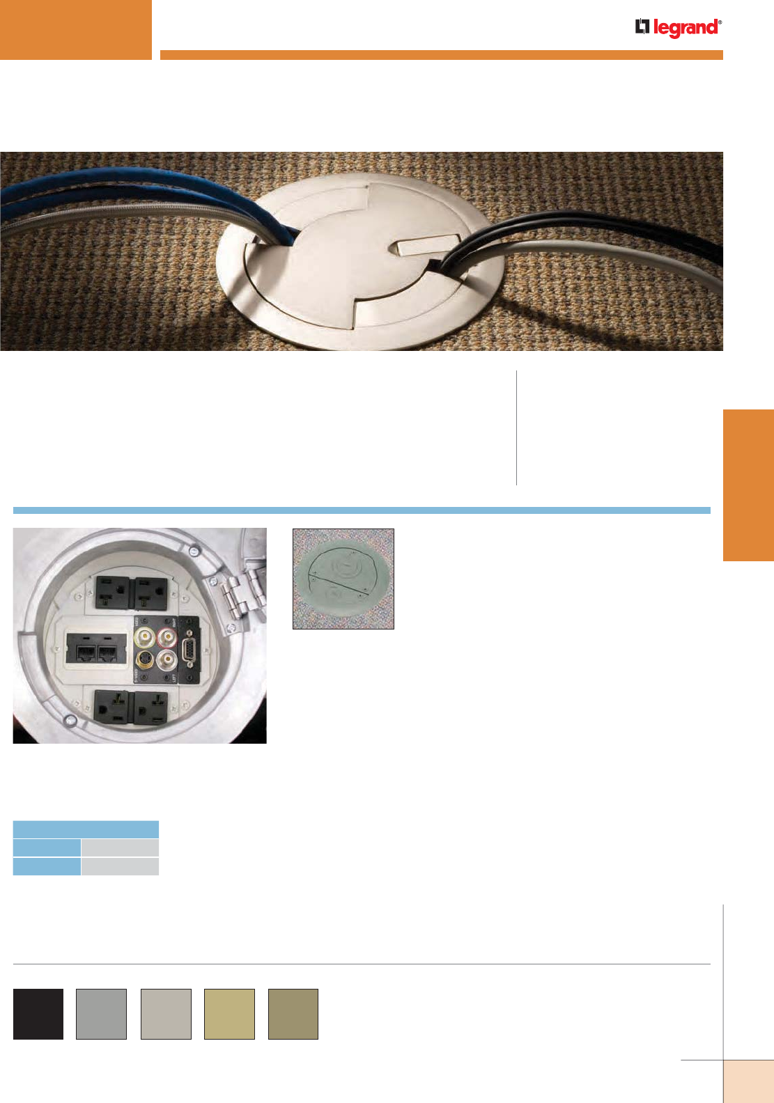
WWW.LEGRAND.US/WIREMOLD
337
WIREMOLD
POKE-THRU DEVICES
Evolution Series Poke-Thru Devices feature
loads of capacity and a flush to the floor
surface cover and flange configuration.
Cover Assemblies for
the 6AT Series Poke-
Thru Devices are
available in a variety of
service configurations
for installation in carpet
or tile floors.
EVOLUTION™ 6AT SERIES POKETHRU DEVICES
CODE REFERENCE
cULus Listed Metallic Outlet Boxes:
File E2961 Guide QCIT.
cULus Listed Nonmetallic Outlet Boxes
& Fittings Classified for Fire Resistance:
File R8209 Guide CEYY.
Meets Article 300.21, 300.22(C) & 314
of NEC.
Evolution™ 6AT Series Poke-Thru Devices allow all power and
communication devices to be recessed 3 1/4” below floor level, and
provide 2 1/2-gang capacity for power, communication, or A/V devices.
COLOR OPTIONS
Evolution 6AT Series parts are available in the following
powder coated finishes: “BK” black, “GY” gray,
“NK” nickel, “BS” brass, and “BZ” bronze.
Custom color options are also available. Consult the
factory for more information.
HOLE DIAMETER
Minimum: 6" [152mm]
Maximum: 6 1/8" [156mm]
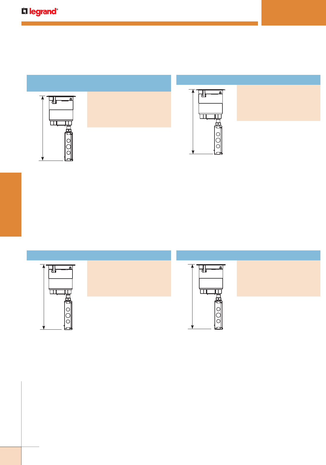
WWW.LEGRAND.US/WIREMOLD
338
WIREMOLD
POKE-THRU DEVICES
EVOLUTION™ 6AT SERIES POKETHRU DEVICES
NOTE: UL Fire
Classified
for up to 2 hour
rated floors.
NOTE: Receptacles
can be wired as
a standard or
isolated ground
device.
16 3/4"
[425 mm]
16 3/4"
[425 mm]
NOTE: UL Fire Classified
for up to 2 hour
rated floors.
NOTE: Receptacles
can be wired as
a standard or
isolated ground
device.
NOTE: Includes one (1)
6TS Tile Shim.
NOTE: UL Fire
Classified for up
to 2 hour rated
floors.
16 3/4"
[425 mm]
NOTE: UL Fire Classified
for up to 2 hour
rated floors.
NOTE: Includes one (1)
6TS Tile Shim.
NOTE: For more information on Device Plates and Bottom Feed Plates and
on the additional options available, see the Device Plates and Bottom
Feed Plates sections found later in this document.
* Tunneling extends from the 5BLH to 575CHA so that power cables from the
20A duplex receptacle mounted on the left side of the poke-thru device are
run into the junction box attached to the 575CHA.
** Also includes junction box attached to the 3/4" conduit.
For carpet, tile, wood and laminate
floors. For use in 6" [152mm]
diameter cored hole. Devices are
recessed 3 1/4" [83mm] below floor
surface. Die-cast aluminum cover
available in finishes shown.
INCLUDED
For Side Compartments:
• Two (2) proprietary 20AMP Duplex
Receptacles installed
For Center Compartment:
• One (1) 6ACT8A Mounting Plate
• One (1) 6TRAC Mounting Plate
• One (1) 6SER Mounting Plate
For Bottom Feed Compartment:
• One (1) 5BLH 1/2-Gang Blank Housing*
• One (1) 1PTHA 1-Gang Pass-Through
Housing Assembly
• One (1) 575CHA 1/2-Gang 3/4"
Conduit Housing Assembly**
For tile, wood and laminate floors.
For use in 6" [152mm] diameter
cored hole. Devices are recessed
3 1/4" [83mm] below floor surface.
Die-cast aluminum cover available
in finishes shown.
INCLUDED
For Side Compartments:
• Two (2) proprietary 20AMP Duplex
Receptacles installed
For Center Compartment:
• One (1) 6ACT8A Mounting Plate
• One (1) 6TRAC Mounting Plate
• One (1) 6SER Mounting Plate
For Bottom Feed Compartments:
• One (1) 5BLH 1/2-Gang Blank
Housing*
• One (1) 1PTHA 1-Gang Pass-Through
Housing Assembly
• One (1) 575CHA 1/2-Gang 3/4” Conduit
Housing Assembly**
For carpet, tile, wood and laminate
floors. For use in 6" [152mm]
diameter cored hole. Devices are
recessed 3 1/4" [83mm] below
floor surface. Die-cast aluminum
cover available in finishes shown.
INCLUDED
For Side Compartments:
• No Device Plates are provided.
For Center Compartment:
• No Device Plates are provided.
For Bottom Feed Compartment:
• One (1) 5PTHA 1/2-Gang
Pass-Through Housing Assembly
• One (1) 1PTHA 1-Gang
Pass-Through Housing Assembly
• One (1) 575CHA 1/2-Gang 3/4”
Conduit Housing Assembly**
For tile, wood or laminate floors.
For use in 6" [152mm] diameter
cored hole. Devices are recessed
3 1/4" [83mm] below floor surface.
Die-cast aluminum cover available
in finishes shown.
INCLUDED
For Side Compartments:
• No Device Plates are provided.
For Center Compartment:
• No Device Plates are provided.
For Bottom Feed Compartment:
• One (1) 5PTHA 1/2-Gang
Pass-Through Housing Assembly
• One (1) 1PTHA 1-Gang
Pass-Through Housing Assembly
• One (1) 575CHA 1/2-Gang 3/4”
Conduit Housing Assembly**
16 3/4"
[425 mm]
Evolution 6AT Series Poke-Thru Devices Ordering Information
Recessed Assembly with Surface Style Cover
PART NUMBERS:
6ATCGY (Painted Gray)
6ATCBK (Painted Black)
6ATCNK (Nickel)
6ATCBS (Brass)
6ATCBZ (Bronze)
Recessed Assembly With Flush Style Cover
PART NUMBERS:
6ATGY (Gray)
6ATBK (Black)
6ATNK (Nickel)
6ATBS (Brass)
6ATBZ (Bronze)
Recessed Prewired Assembly with Flush Style Cover
PART NUMBERS:
6ATPGY (Gray)
6ATPBK (Black)
6ATPNK (Nickel)
6ATPBS (Brass)
6ATPBZ (Bronze)
Recessed Prewired Assembly with
Surface Style Cover
PART NUMBERS:
6ATCPGY (Gray)
6ATCPBK (Black)
6ATCPNK (Nickel)
6ATCPBS (Brass)
6ATCPBZ (Bronze)
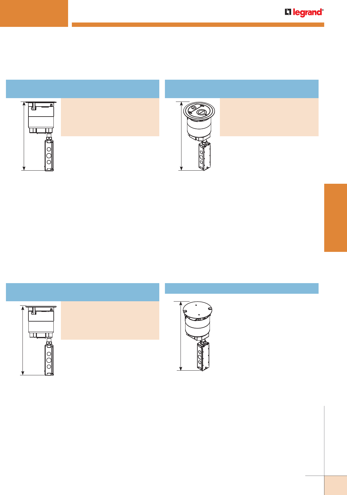
WWW.LEGRAND.US/WIREMOLD
339
WIREMOLD
POKE-THRU DEVICES
PART NUMBERS:
6ATCPAVGY (Gray)
6ATCPAVBK (Black)
6ATCPAVNK (Nickel)
6ATCPAVBS (Brass)
6ATCPAVBZ (Bronze)
Recessed Prewired Audio/ Video Assembly with
Surface Style Cover
EVOLUTION™ 6AT SERIES POKETHRU DEVICES
16 3/4"
[425 mm]
16 3/4"
[425 mm]
16 3/4"
[425 mm]
NOTE: UL Fire
Classified
for up to 2 hour
rated floors.
NOTE: Receptacles
can be wired as
a standard or
isolated ground
device.
NOTE: UL Fire Classified
for up to 2 hour
rated floors.
NOTE: Receptacles
can be wired as
a standard or
isolated ground
device.
NOTE: Includes one (1)
6TS Tile Shim.
NOTE: UL Fire
Classified for up
to 2 hour rated
floors.
NOTE: For more information on Device Plates and Bottom Feed Plates and on
the additional options available, see the Device Plates and Bottom Feed
Plates sections found later in this document.
** Also includes junction box attached to the 3/4" conduit.
For carpet, tile, wood and laminate
floors. For use in 6" [152mm] diameter
cored hole. Devices are recessed
3 1/4" [83mm] below floor surface.
Die-cast aluminum cover available
in finishes shown.
INCLUDED
For Side Compartments:
• One (1) Proprietary 20AMP Duplex Power
Receptacle installed
• One (1) 682A Device Plate
• One (1) 68MAAP Device Plate
For Center Device Compartment:
• One (1) 6DEC Mounting Plate
• One (1) 6AAP Mounting Plate
• One (1) 6MAAP Device Plate
For Bottom Feed Compartment:
• One (1) 5PTHA 1/2-Gang Pass-Through
Housing Assembly
• One (1) 1PTHA 1-Gang Pass-Through
Housing Assembly
• One (1) 575CHA 1/2-gang 3/4” Conduit
Housing Assembly**
For tile, wood and laminate floors. For
use in 6" [152mm] diameter cored hole.
Devices are recessed 3 1/4" [83mm]
below floor surface. Die-cast aluminum
cover available in finishes shown.
INCLUDED
For Side Compartments:
• One (1) Proprietary 20AMP Duplex Power
Receptacle installed
• One (1) 682A Device Plate
• One (1) 68MAAP Device Plate
For Center Device Compartment:
• One (1) 6DEC Mounting Plate
• One (1) 6AAP Mounting Plate
• One (1) 6MAAP Device Plate
For Bottom Feed Compartments:
• One (1) 5PTHA 1/2-Gang
Pass-Through Housing Assembly
• One (1) 1PTHA 1-Gang
Pass-Through Housing Assembly
• One (1) 575CHA 1/2-gang 3/4” Conduit
Housing Assembly**
For carpet, tile, wood and laminate
floors. For use in 6" [152mm] diameter
cored hole. Devices are recessed
3 1/4" [83mm] below floor surface.
Die-cast aluminum cover available in
finishes shown.
INCLUDED
For Side Compartments:
• No Device Plates are provided.
For Center Compartment:
• No Device Plates are provided.
For Bottom Feed Compartment:
• One (1) 5PTHA 1/2-Gang
Pass-Through Housing Assembly
• One (1) 15FFHA 1 1/2-Gang
Pass-Through Housing Assembly
• One (1) 575CHA 1/2-Gang 3/4"
Conduit Housing Assembly**
16 3/4"
[425 mm]
NOTE: UL Fire Classified
for up to 2 hour
rated floors.
Includes 6" core hole poke-thru
stem assembly with a disposable
plate. Devices are recessed 3 1/4"
[83mm] below floor surface. No
cover assembly is included. No
device plates are included. For use
with the following cover assemblies
(purchased separately): 6CTC, 6CT,
and 6CFFTC Series.
INCLUDED
For Side Compartments:
• No Device Plates are provided.
For Center Compartment:
• No Device Plates are provided.
For Bottom Feed Compartments:
• One (1) 5PTHA 1/2-Gang Pass- Through
Housing Assembly
• One (1) 1PTHA 1-Gang Pass-Through
Housing Assembly
• One (1) 575CHA 1/2-gang 3/4" Conduit
Housing Assembly**
6STC Recessed Assembly with Disposable Plate
Evolution 6AT Series Poke-Thru Devices Ordering Information (continued)
PART NUMBERS:
6ATCGY (Gray)
6ATCBK (Black)
6ATCNK (Nickel)
6ATCBS (Brass)
6ATCBZ (Bronze)
Recessed Furniture Feed Assembly with
Surface Style Cover
PART NUMBERS:
6ATPAVGY (Gray)
6ATPAVBK (Black)
6ATPAVNK (Nickel)
6ATPAVBS (Brass)
6ATPAVBZ (Bronze)
Recessed Prewired Audio/Video Assembly with
Flush Style Cover
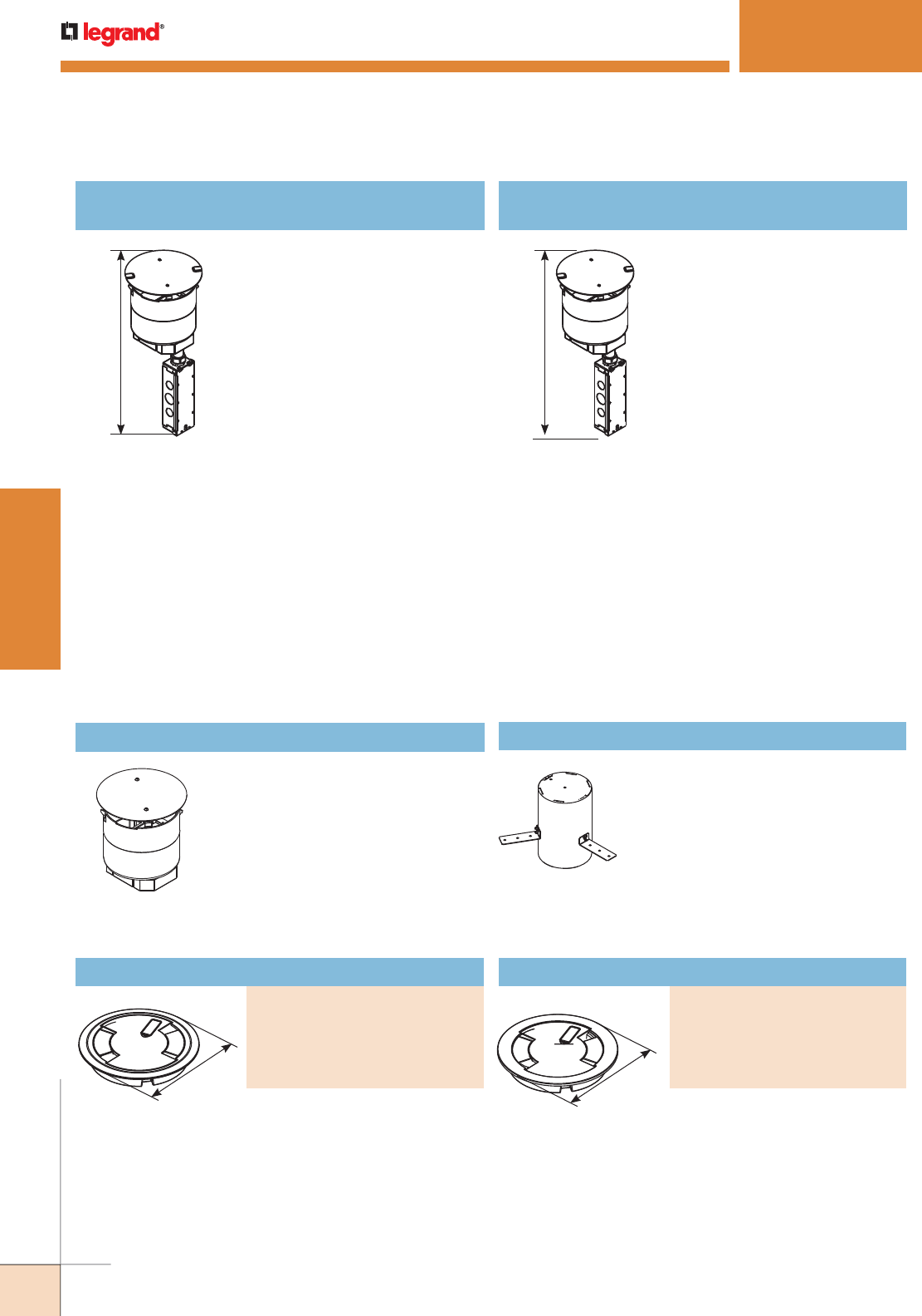
WWW.LEGRAND.US/WIREMOLD
340
WIREMOLD
POKE-THRU DEVICES
Flush Style Cover Assembly
PART NUMBERS:
6CTGY* (Gray)
6CTBK* (Black)
6CTNK* (Nickel)
6CTBS* (Brass)
6CTBZ* (Bronze)
Surface Style Cover Assembly
PART NUMBERS:
6CTCGY* (Gray)
6CTCBK* (Black)
6CTCNK* (NIckel)
6CTCBS* (Brass)
6CTCBZ* (Bronze)
Die-cast aluminum cover assembly.
Cover assembly is available in
finishes shown. 6CTC Series cover
assemblies designed for use with
6STC, 6STCP, and 6STCPAV Poke-
Thru Stem Assemblies.
EVOLUTION™ 6AT SERIES POKETHRU DEVICES
Evolution 6AT Series Cover Assemblies Ordering Information
16 3/4"
[425 mm] 16 3/4"
[425 mm]
* Tunneling extends from the 5BLH to 575CHA so that power cables from the
20A duplex receptacle mounted on the left side of the poke-thru device are
run into the junction box attached to the 575CHA.
** Also includes junction box attached to the 3/4" conduit.
6STCPAV Recessed Prewired Audio/Video
Assembly with Disposable Plate
6STCP Recessed Prewired Assembly with
Disposable Plate
NOTE: UL Fire Classified
for up to 2 hour
rated floors.
NOTE: Receptacles can be
wired as a standard
or isolated ground
device.
NOTE: UL Fire Classified
for up to 2 hour
rated floors.
NOTE: Receptacles can be
wired as a standard
or isolated ground
device.
6PPS 6” Pre-Pour Poke-Thru Sleeve
Nonmetallic sleeve attaches to
structural decking and maintains 6"-6
1/8" diameter cast in core hole. Unit
includes three (3) attachment legs,
two (2) end caps and three (3) thumb
screws.
7 1/4"
[184mm] 7 1/4"
[184mm]
Die-cast aluminum cover
assembly. Cover assembly is
available in finishes shown. 6CT
Series cover assemblies designed
for use with 6STC, 6STCP and
6STCPAV Poke-Thru Stem
Assemblies. Includes one (1) 6TS
Tile Shim.
* Add suffix “TR” to the end of the part number to indicate tamper-resistant
cover assembly. Tamper-resistant versions are secured with a single
tamper-resistant screw.
Includes 6" diameter poke-thru
stem assembly with a disposable
plate. Devices are recessed 3 1/4"
[83mm] below floor surface. No cover
assembly is included. For use with the
following cover assemblies (purchased
separately): 6CTC and 6CT Series.
INCLUDED
For Side Compartments:
• One (1) Proprietary 20AMP Duplex Power
Receptacle installed
• One (1) 682A Device Plate
• One (1) 68MAAP Device Plate
For Center Compartment:
• One (1) 6DEC Mounting Plate
• One (1) 6AAP Mounting Plate
• One (1) 6MAAP Device Plate
For Bottom Feed Compartments:
• One (1) 5PTHA 1/2-Gang
Pass-Through Housing Assembly
• One (1) 1PTHA 1-Gang Pass-Through
Housing Assembly
• One (1) 575CHA 1/2-gang 3/4" Conduit
Housing Assembly**
Includes 6" diameter poke-thru
stem assembly with a disposable
plate. Devices are recessed 3 1/4"
[83mm] below floor surface. No
cover assembly is included. For use
with the following cover assemblies
(purchased separately): 6CTC and
6CT Series.
INCLUDED
For Side Compartments:
• Two (2) Proprietary 20AMP Duplex Power
Receptacles installed
For Center Compartment:
• One (1) 6ACT8A Mounting Plate
• One (1) 6TRAC Mounting Plate
• One (1) 6SER Mounting Plate
For Bottom Feed Compartment:
• One (1) 5BLH 1/2-Gang Blank Housing*
• One (1) 1PTHA 1-Gang Pass-Through
Housing Assembly
•
One (1) 575CHA 1/2-Gang 3/4" Conduit
Housing Assembly**
Evolution 6AT Series Poke-Thru Devices Ordering Information (continued)
Complete abandonment plug
assembly for 6" opening. Assembly
includes intumescent fire stop
material to maintain a 2 hour fire
rating of the floor
ABPLUG6 Abandonment Plug Assembly
NOTE: For more information on Device Plates and Bottom Feed Plates and
on the additional options available, see the Device Plates and Bottom
Feed Plates sections found later in this document.
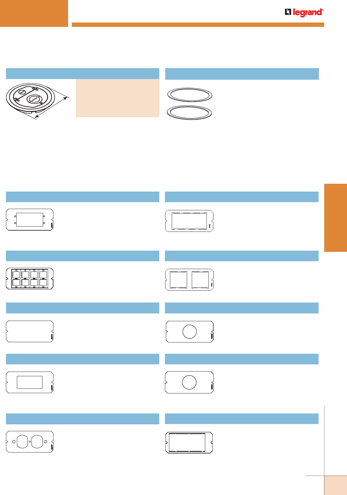
WWW.LEGRAND.US/WIREMOLD
341
WIREMOLD
POKE-THRU DEVICES
EVOLUTION™ 6AT SERIES POKETHRU DEVICES
Device plate will accept two (2)
standard [45mm x 45mm] or one (1)
standard [45mm x 90mm] Mosaic style
device(s). Devices supplied by others.
6MOS Mosaic Device Plate6AAP Device Plate
Device plate that will accept up to
two (2) Extron® Electronics AAP
style plates. For use in the center
compartment only. Devices supplied
by others.
6ACT8A Device Plate
Device plate that will accept up to eight
(8) ports of communication devices.
For use in the center compartment
only. Devices supplied by others.
6B Device Plate
Device plate used to blank off center
compartment, when no devices are
used.
6DEC Device Plate
Device plate that will accept Decorator
style devices such as 20A receptacles,
GFCIs, 106 adapters or A/V devices.
For use in the center compartment
only. Devices supplied by others.
6DP Device Plate
Device plate that will accept standard
20A duplex receptacle or duplex
Turnlok receptacle. For use in the
center compartment only. Devices
supplied by others.
6MOSBS Mosaic British Standard Device Plate
Device plate will accept two (2) Mosaic
British standard devices [45mm x
45mm]. Devices supplied by others.
6S1 Device Plate
Receptacle opening 1 3/8" [35mm].
For 6" poke-thru units only.
6S2 Device Plate
Receptacle opening 1 9/16" [40mm].
For 6" poke-thru units only.
6SER Device Plate
Device plate that will accept up to
four (4) Ortronics® Series II dual
modular inserts. For use in the center
compartment only. Devices supplied
by others.
Evolution 6AT Series Center Mount Device Plates Ordering Information
6TS Tile Shim
Used for floor coverings greater than
5/16" [7.9mm]. The 6TS will allow the
top surface of the cover to be flush
with the finished floor. Includes: two
(2) 1/8" [3.2mm] thick shims and two
(2) 1/16" [1.6mm] thick shims. Up to
a total of 3/8" [9.5mm] of adjustment.
7 3/4"
[197mm]
Surface style, die-cast aluminum cover assembly, with
one (1) 3/4" trade size screw plug opening, and one (1)
concentric 2"-1 1/4" trade size screw plug opening. Cover
assembly available in finishes shown. 6CFFTC Series Cover
Assemblies designed for use with 6STC Poke-Thru Stem
Assembly. Includes one (1) 3/4" and one (1) 2" trade size
conduit fittings and one (1) divider to separate services.
Evolution 6AT Series Cover Assemblies Ordering Information (continued)
Furniture Feed Cover Assembly
PART NUMBERS:
6CFFTCGY (Gray)
6CFFTCBK (Black)
6CFFTCNK (Nickel)
6CFFTCBS (Brass)
6CFFTCBZ (Bronze)
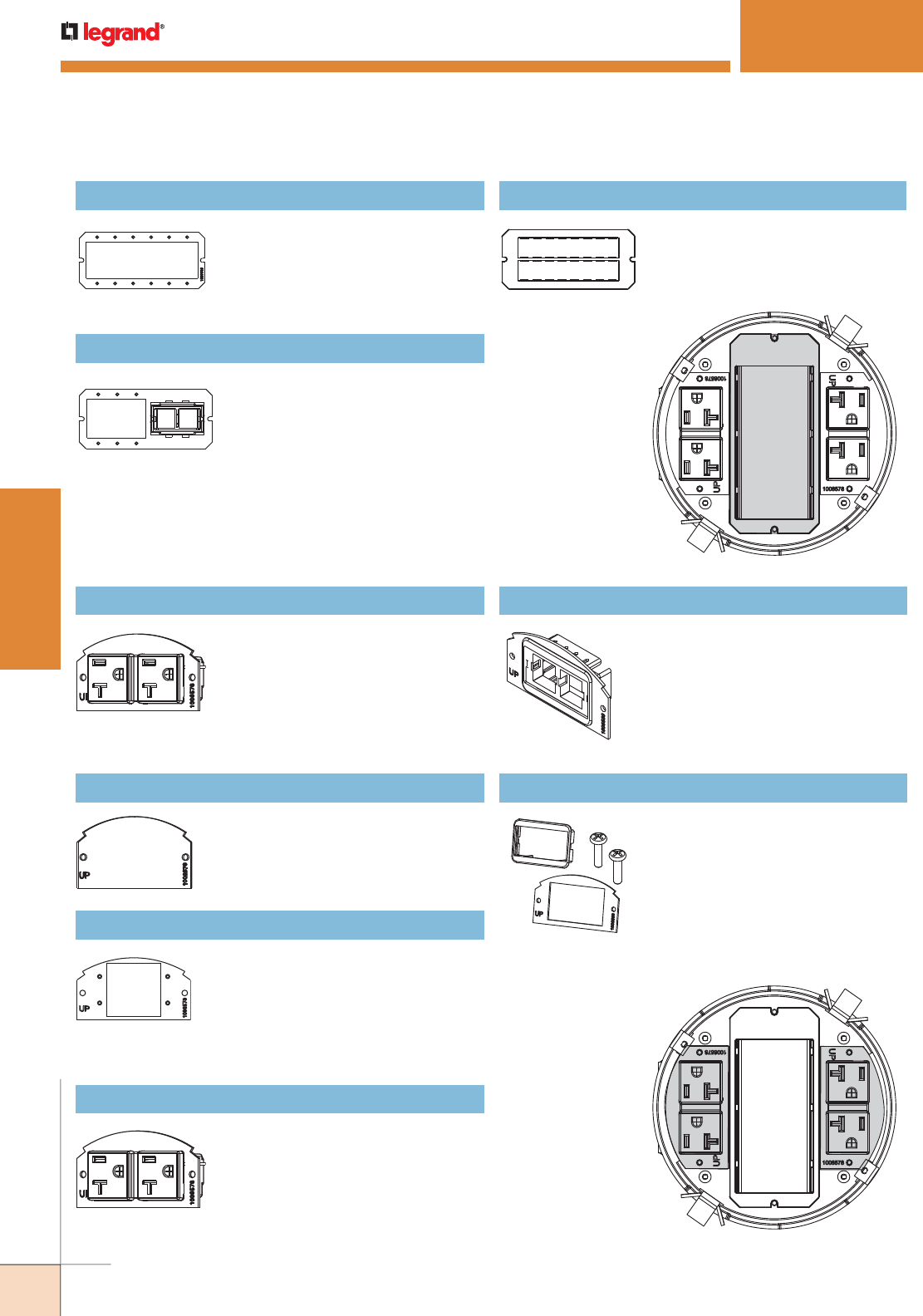
WWW.LEGRAND.US/WIREMOLD
342
WIREMOLD
POKE-THRU DEVICES
EVOLUTION™ 6AT SERIES POKETHRU DEVICES
6AT Side Mount
Device Plates
Mounting Locations
Device Plates in this
section can be installed
in the shaded locations
indicated in this
illustration.
Two (2) proprietary 20AMP duplex
power receptacles with mounting
plates. Designed to fit in either of the
two side compartments in both the
6ATC and the 8ATC Series Poke-Thru
Devices. Receptacle can be wired as a
standard or isolated ground device.
68REC 20AMP Duplex Receptacles
68B Device Plate
Blank plate. Used to blank off either
of the side compartments when no
devices or cabling are to be used.
68MAAP Device Plate
Device plate that will accept up to
two (2) Wiremold AVIP or Extron®
Electronics MAAP device plates.
For use in either of the two side
compartments only. Not for use in the
center compartment. Extron® Devices
supplied by others.
68REC-25 20AMP Duplex Receptacles
Two (2) proprietary 20AMP duplex power
receptacles with mounting plates and
25’ leads. Designed to fit in either of the
two side compartments in both the 6ATC
and the 8ATC Series Poke-Thru Devices.
Receptacle can be wired as a standard
or isolated ground device.
Device plate that will accept up to two
(2) ports of communication devices.
For use in either of the two side
compartments only. Not for use in the
center compart ment. Communication
devices supplied by others.
682A Device Plate
682A-PT Device Plate
Device plate that allows for
communica tion cabling to pass
through. Includes one (1) rectangular
adapter ring.
Evolution 6AT Series Side Mount Device Plates Ordering Information
6AT Center Mount
Device Plate
Mounting Location
Device Plates on this
page can be installed
in the shaded location
indicated in this
illustration.
6MAAP Device Plate
Device plate that will accept up to
six (6) Wiremold AVIP or Extron®
Electronics MAAP style plates. For
use in the center compartment only.
Devices supplied by others.
6MAAP2A Device Plate
Combination device plate that will
accept up to three (3) Wiremold
AVIP or Extron® Electronics MAAP
style plates, and up to two (2) ports
of communication devices. For use
in the center compartment only.
Devices supplied by others.
6TRAC Device Plate
Device plate that will accept up to eight
(8) Ortronics® TracJack devices. For
use in the center compartment only.
Devices supplied by others.
Evolution 6AT Series Center Mount Device Plates Ordering Information (continued)
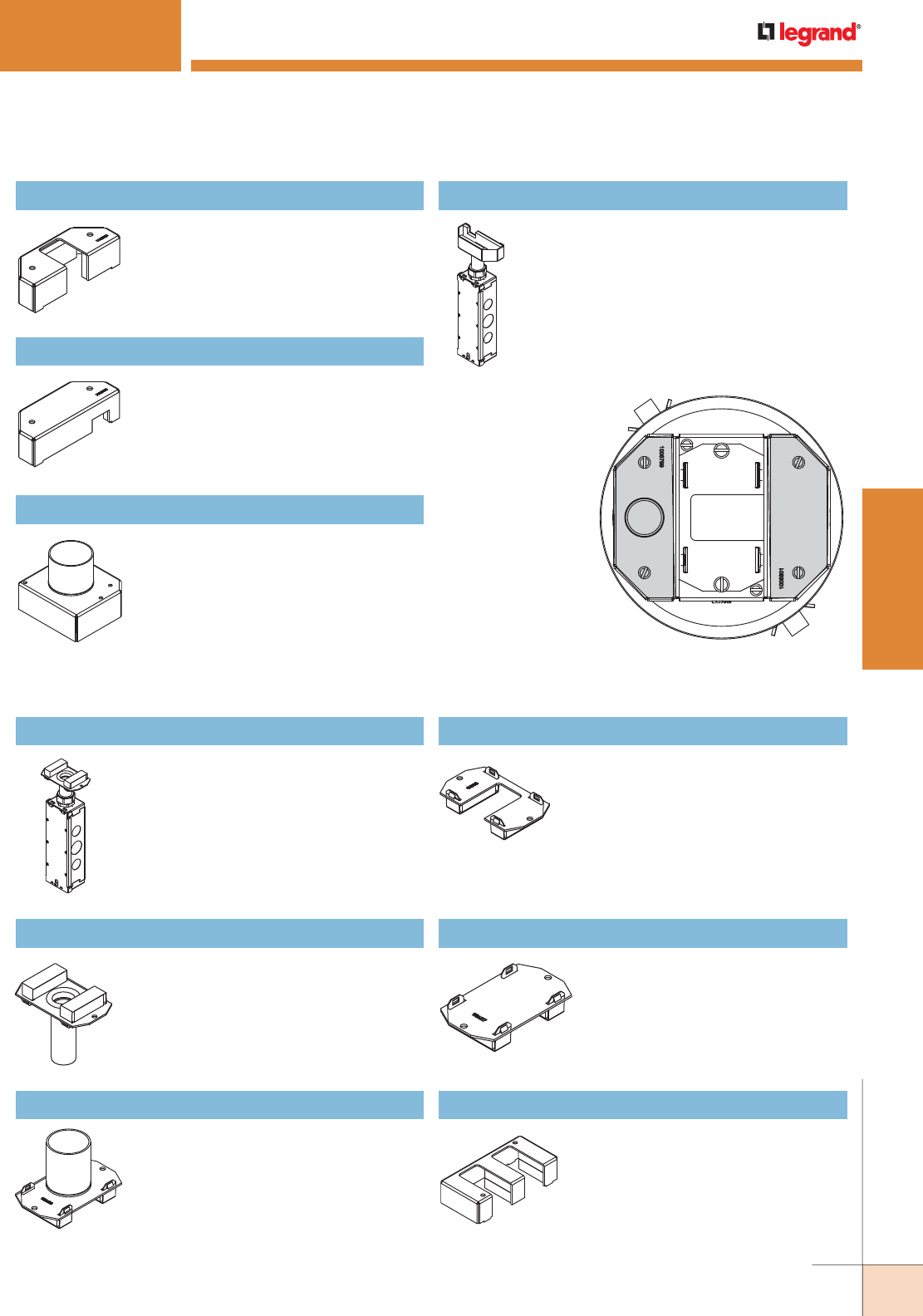
WWW.LEGRAND.US/WIREMOLD
343
WIREMOLD
POKE-THRU DEVICES
6AT Bottom Feed Side
Mount Device Plate
Mounting Locations
Device Plates in this section
can be installed in the
shaded locations indicated
in this illustration.
5PTHA Bottom Housing Assembly
Half-gang pass through housing
assembly. Designed to allow pass
through of communication cables when
no conduit is required. For use on side
compartments only.
5BLH Bottom Housing Assembly
Half-gang blank housing assembly.
Designed to blank off compartment when
no devices are used. Includes tunnel for
6AT and 8AT Series Poke-Thru Devices.
For use on side compartments only.
152CHA Bottom Housing Assembly
One and a half-gang 2" trade size conduit
housing assembly. Recommended for
use with furniture feed devices (6ATCFF).
Covers the center compartment and one of
the side compartments.
575CHA Bottom Housing Assembly
Half-gang 3/4" trade size conduit housing
assembly. Includes junction box attached to
3/4" trade size conduit for electrical power
connections. For use on side compartments
only.
EVOLUTION™ 6AT SERIES POKETHRU DEVICES
175CHA Bottom Housing Assembly
One-gang 3/4” trade size conduit housing
assembly. Includes junction box attached
to 3/4” trade size conduit for electrical
power connections.
NOTE: When using on a 6ATCFF Furniture Feed unit,
1BHA (sold separately) is required.
175CHA-LJB Bottom Housing Assembly
One-gang 3/4” trade size conduit housing
assembly. Junction box not included.
NOTE: When using on a 6ATCFF Furniture Feed unit,
1BHA (sold separately) is required.
1125CHA Bottom Housing Assembly
One-gang 1 1/4” conduit housing
assembly.
NOTE: When using on a 6ATCFF Furniture Feed unit,
1BHA (sold separately) is required.
1PTHA Bottom Housing Assembly
One-gang pass through housing
assembly. Designed to allow pass
through of communication cables
when no conduit is required.
NOTE: When using on a 6ATCFF Furniture Feed
unit, 1BHA (sold separately) is required.
1BLH Bottom Housing Assembly
One-gang blank housing assembly.
Designed to blank off compartment
when no devices are used.
NOTE: When using on a 6ATCFF Furniture Feed
unit, 1BHA (sold separately) is required.
15FFHA Bottom Housing Assembly
One and a half-gang pass through
conduit housing assembly. Used for
furniture feed applications on the
center compartment only. Only for use
with 6AT Series units.
Evolution 6AT Series Bottom Feed Center Mount Device Plates Ordering Information
Evolution 6AT Series Bottom Feed Side Mount Device Plates Ordering Information
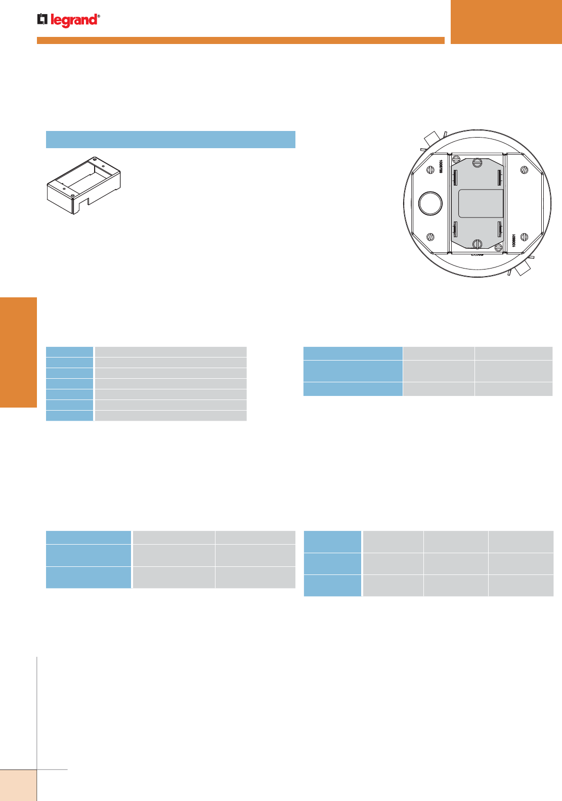
WWW.LEGRAND.US/WIREMOLD
344
WIREMOLD
POKE-THRU DEVICES
FLOOR TYPE HOLE SIZE (Min.) HOLE SIZE (Max.)
Covered Floors (Carpet,
Tile or Wood)
6" [152mm] 6 1/8" [156mm]
Bare Concrete or Terrazzo 6 1/16" [154mm] 6 1/8" [156mm]
6AT Hole Sizes
6ATCFF Copper Cross-Section –
Furniture Feed Poke-Thru Devices
NOTE: When using conductor sizes other than listed above, the aggregate cross-sectional area of the copper conductors
shall not exceed the cross-sectional areas listed.
SIZE SOLID
#24 0.00032 sq. in. [0.20645mm2]
#22 0.00050 sq. in. [0.32258mm2]
#14 0.00323 sq. in. [2.08386mm2]
#12 0.00512 sq. in. [3.30321mm2]
#10 0.00815 sq. in. [5.25805mm2]
#8 0.01296 sq. in. [8.36127mm2]
Copper Cross Sectional Area of
Commonly Used Conductors
6AT Copper Cross-Section
OUTER CHANNELS CENTER CHANNEL
Max Copper X Section 0.0154 sq. in.
[9.9mm2]
0.0387 sq. in.
[24.97mm2]
Max # Conductors (3) 12 AWG
or (4) Cat 6A
(12) 14 AWG
or (12) Cat 6A
POWER
CHANNEL
DATA CHANNEL
CENTER
DATA CHANNEL
OUTSIDE
Max Copper
X Section
.0815 sq. in.
[52.6mm2]
0.0686 sq. in.
[44.3mm2]
0.0187
[12.1mm2]
Max #
Conductors
(10) 10 AWG (22) Cat 6a (5) Cat. 6a
EVOLUTION™ 6AT SERIES POKETHRU DEVICES
6AT Bottom Feed
Center Mount Device
Plate Location
All Bottom Housing
Assemblies on this page can
be installed in the shaded
locations indicated in this
illustration.
1BHA Bottom Housing Assembly
One-gang bottom housing assembly.
Designed to accept 175CHA, 175CHA-
LJB, 1125CHA, 1PTHA, and 1BLH
plates.
NOTE: Use above values for solid or stranded conductors.
CAUTION: Receptacle supplied with this Poke-Thru is not suitable for direct field wiring. Contact manu facturer for
replacement. Field modifications will void UL Listing and Classification. Replacement receptacle is limited to
this manufacturers’ Catalog No 68REC.
Evolution 6AT Series Bottom Feed Center Mount Device Plates Ordering Information
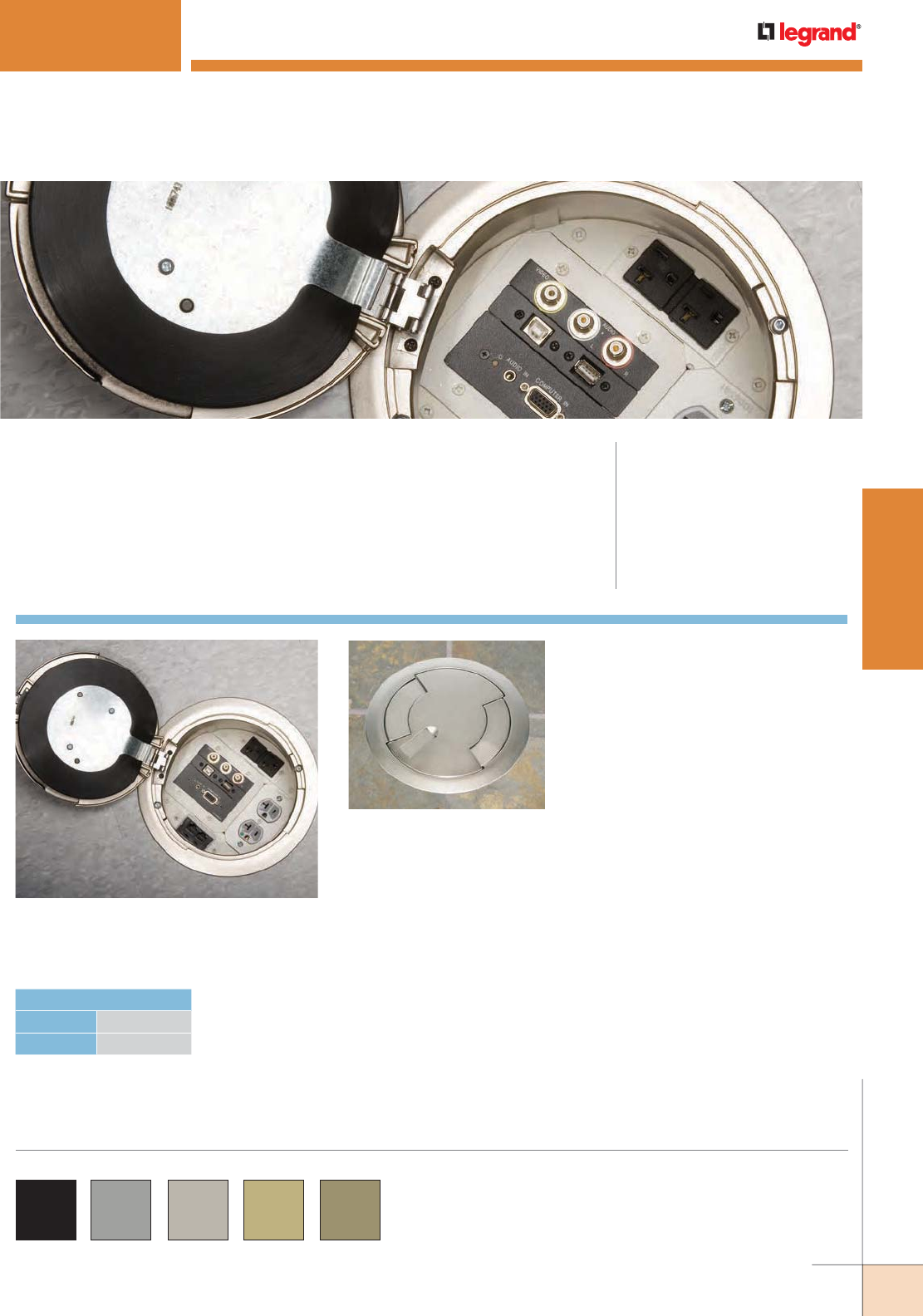
WWW.LEGRAND.US/WIREMOLD
345
WIREMOLD
POKE-THRU DEVICES
EVOLUTION™ 8AT SERIES POKETHRU DEVICES
CODE REFERENCE
cULus Listed Metallic Outlet Boxes:
File E2961 Guide QCIT.
cULus Listed Nonmetallic Outlet
Boxes and Fittings Classified for Fire
Resistance:
File R8209 Guide CEYY.
Meets Article 300.21, 300.22(C) & 314
of NEC.
Evolution™ 8AT Series Poke-Thru Devices allow all power and
communication devices to be recessed below floor level, and provide
4-gang capacity for power, communication, and A/V devices.
COLOR OPTIONS
Evolution 8AT Series parts are available in the following
powder coated finishes: “BK” black, “GY” gray, “NK”
nickel, “BS” brass, and “BZ” bronze.
Custom color options are also available. Consult the
factory for more information.
Evolution Series 8CTC Cover Assembly Lids
open a full 180° to reduce the risk of damage
when plugging in devices.
Cover Assemblies for the 8AT
Series Poke-Thru Devices are
available in a variety of finishes
and service configurations for
carpet or tile floor installations.
HOLE DIAMETER
Minimum: 8" [203mm]
Maximum: 8 1/8" [206mm]
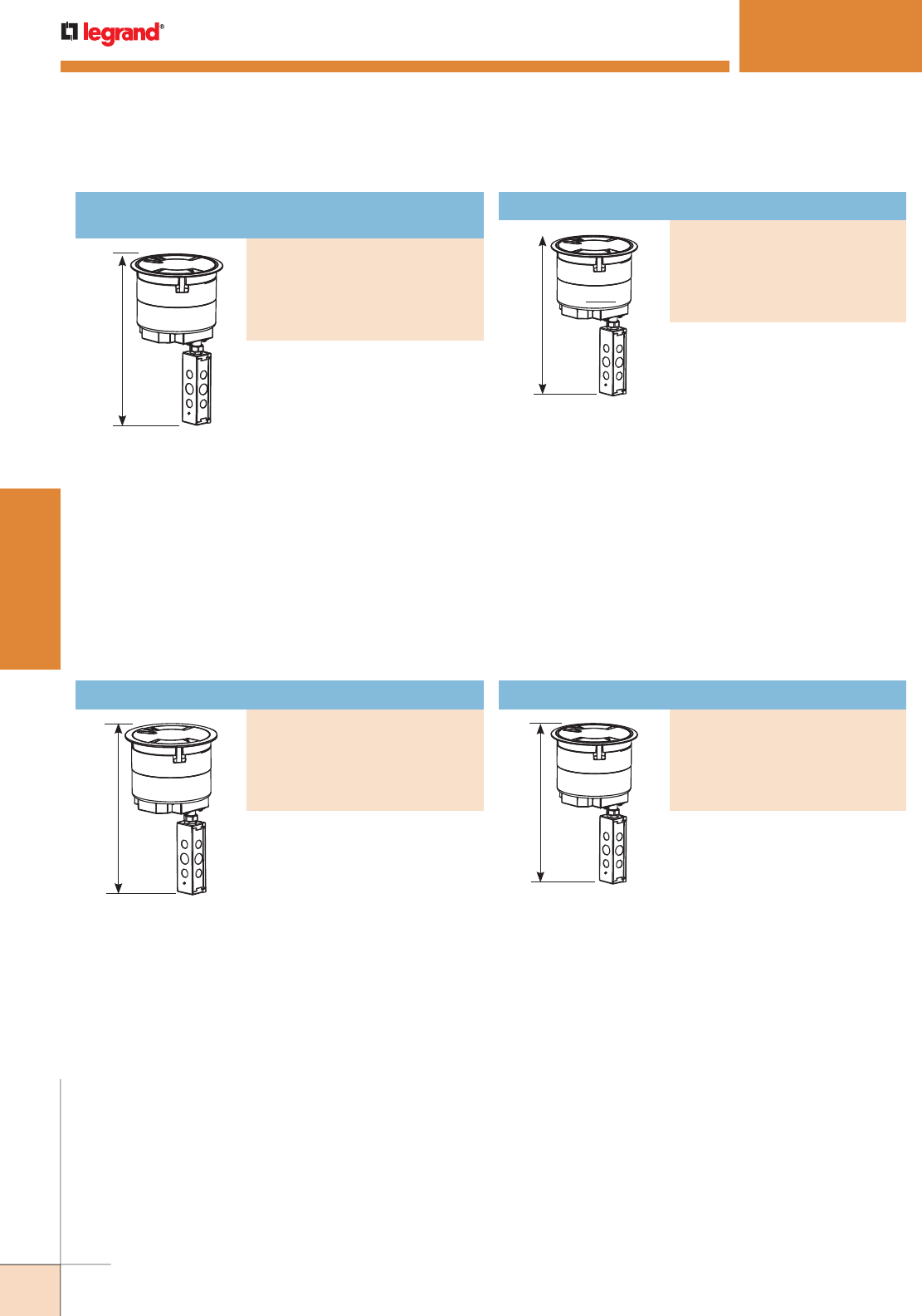
WWW.LEGRAND.US/WIREMOLD
346
WIREMOLD
POKE-THRU DEVICES
Recessed Prewired Assembly with
Surface Style Cover
PART NUMBERS:
8ATCPGY (Gray)
8ATCPBK (Black)
8ATCPNK (Nickel)
8ATCPBS (Brass)
8ATCPBZ (Bronze)
EVOLUTION™ 8AT SERIES POKETHRU DEVICES
16 3/4"
[425 mm]
16 3/4"
[425 mm]
NOTE: UL Fire Classified
for up to 2 hour
rated floors.
NOTE: Receptacles
can be wired as
a standard or
isolated ground
device.
16 3/4"
[425 mm]
16 3/4"
[425 mm]
NOTE: UL Fire Classified
for up to 2 hour
rated floors.
NOTE: Receptacles can be
wired as a standard
or isolated ground
device.
For carpet, tile, wood and laminate
floors. For use in 8" [203mm]
diameter cored hole. Devices are
recessed 3 1/4" [83mm] below floor
surface. Die-cast aluminum cover
available in finishes shown.
INCLUDED
For Side Compartments:
• Two (2) proprietary 20AMP Duplex
Receptacles installed
For Center Compartments:
• No Device Plates are provided
For Bottom Feed Compartments:
• One (1) 5BLH 1/2-Gang Blank Housing*
• Three (3) 1PTHA 1-Gang
Pass-Through Housing Assembly
• One (1) 575CHA 1/2-Gang 3/4"
Conduit Housing Assembly**
• One (1) 8DIV 8" Divider
For carpet, tile, wood and laminate
floors. For use in 8" [203mm]
diameter cored hole. Devices are
recessed 3 1/4" [83mm] below
floor surface. Die-cast aluminum
cover assembly available in
finishes shown.
INCLUDED
For Side Compartments:
• Two (2) proprietary 20 Amp Duplex
Receptacles installed
For Center Compartments:
• No Device Plates are provided
For Bottom Feed Compartments:
• One (1) 5BLH 1/2-Gang Blank
Housing*
• Three (3) 1PTHA 1-Gang
Pass-Through Housing Assembly
• One (1) 575CHA 1/2-Gang 3/4"
Conduit Housing Assembly**
• One (1) 8DIV 8" Divider
• One (1) 8TS Tile Shim
NOTE: For more information on Device Plates and Bottom Feed Plates and
on the additional options available, see the Device Plates and Bottom
Feed Plates sections found later in this document.
* Tunneling extends from the 5BLH to 575CHA so that power cables from the
20A duplex receptacle mounted on the left side of the poke-thru device are
run into the junction box attached to the 575CHA.
** Also includes junction box attached to the 3/4" conduit.
NOTE: UL Fire Classified
for up to 2 hour
rated floors.
NOTE: UL Fire Classified
for up to 2 hour
rated floors.
For carpet, tile, wood and laminate
floors. For use in 8" [203mm]
diameter cored hole. Devices are
recessed 3 1/4" [83mm] below
floor surface. Die-cast aluminum
cover assembly available in
finishes shown.
INCLUDED
For Side Compartments:
• No Device Plates are provided
For Center Compartments:
• No Device Plates are provided
For Bottom Feed Compartments:
• One (1) 5PTHA 1/2-Gang
Pass-Through Housing Assembly
• Three (3) 1PTHA 1-Gang
Pass-Through Housing Assembly
• One (1) 575CHA 1/2-gang 3/4"
Conduit Housing Assembly**
• One (1) 8DIV 8" Divider
For carpet, tile, wood and laminate
floors. For use in 8" [203mm]
diameter cored hole. Devices are
recessed 3 1/4" [83mm] below
floor surface. Die-cast aluminum
cover assembly available in
finishes shown.
INCLUDED
For Side Compartments:
• No Device Plates are provided
For Center Compartments:
• No Device Plates are provided
For Bottom Feed Compartments:
• One (1) 5PTHA 1/2-Gang
Pass-Through Housing Assembly*
• Three (3) 1PTHA 1-Gang
Pass-Through Housing Assembly
• One (1) 575CHA 1/2-gang 3/4"
Conduit Housing Assembly**
• One (1) 8DIV 8" Divider
• One (1) 8TS Tile Shim
Evolution 8AT Series Poke-Thru Devices Ordering Information
Recessed Assembly with Surface Style Cover
PART NUMBERS:
8ATCGY (Gray)
8ATCBK (Black)
8ATCNK (Nickel)
8ATCBS (Brass)
8ATCBZ (Bronze)
Recessed Prewired Assembly with Flush Style Cover
PART NUMBERS:
8ATPGY (Gray)
8ATPBK (Black)
8ATPNK (Nickel)
8ATPBS (Brass)
8ATPBZ (Bronze)
Recessed Assembly with Flush Style Cover
PART NUMBERS:
8ATGY (Gray)
8ATBK (Black)
8ATNK (Nickel)
8ATBS (Brass)
8ATBZ (Bronze)
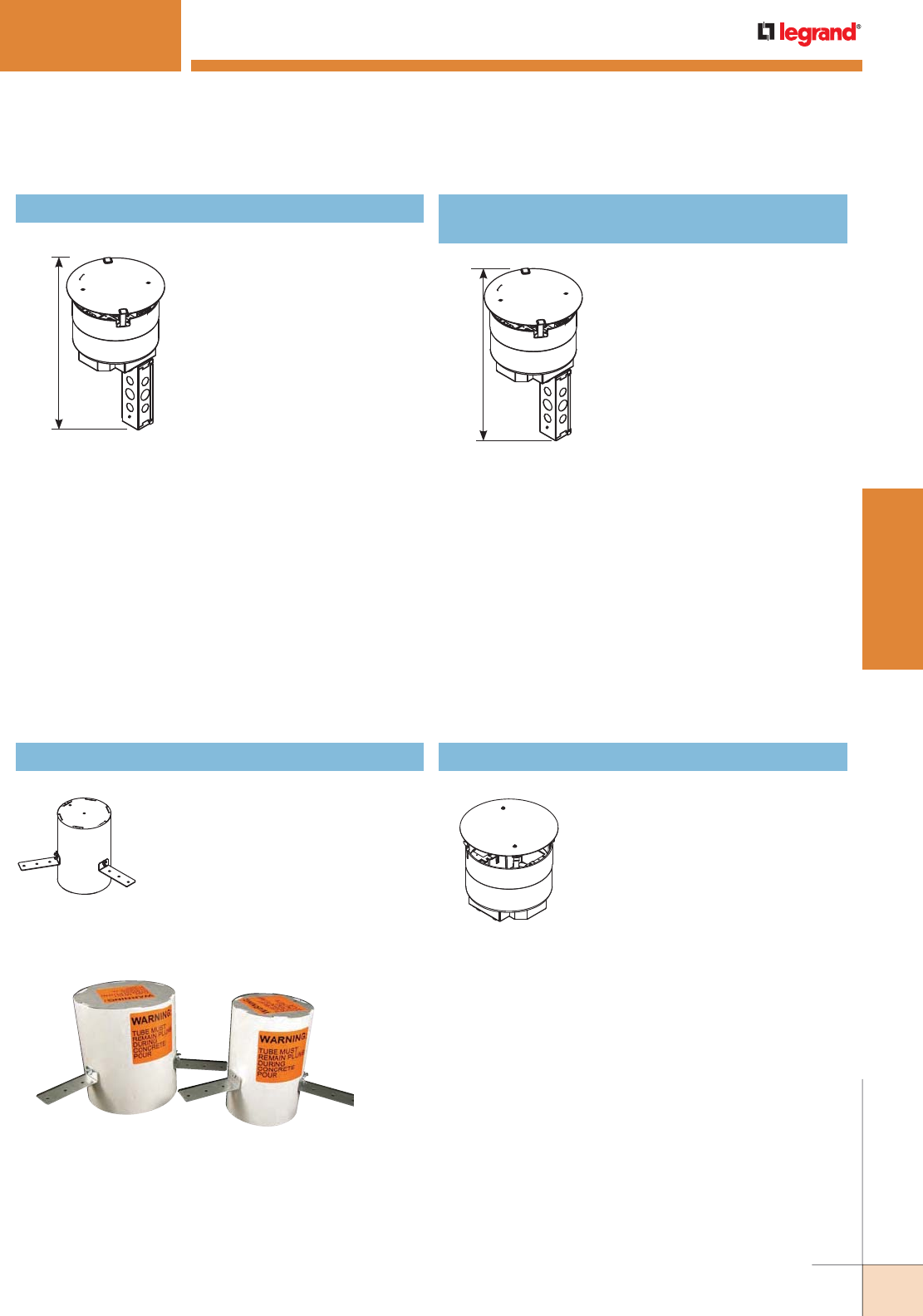
WWW.LEGRAND.US/WIREMOLD
347
WIREMOLD
POKE-THRU DEVICES
NOTE: For more information on Device Plates and Bottom Feed Plates and
on the additional options available, see the Device Plates and Bottom
Feed Plates sections found later in this document.
* Tunneling extends from the 5BLH to 575CHA so that power cables from the
20A duplex receptacle mounted on the left side of the poke-thru device are
run into the junction box attached to the 575CHA.
** Also includes junction box attached to the 3/4" conduit.
Includes 8" diameter poke-thru
stem assembly with a disposable
plate. Devices are recessed 3 1/4"
[83mm] below floor surface. No
cover assembly is included. For use
with the following cover assemblies
(purchased separately): 8CTC and
8CT Series.
INCLUDED
For Side Compartments:
• No Device Plates are provided
For Center Compartments:
• No Device Plates are provided
For Bottom Feed Compartments:
• One (1) 5PTHA 1/2-Gang
Pass-Through Housing Assembly
• Three (3) 1PTHA 1-Gang
Pass-Through Housing Assembly
• One (1) 575CHA 1/2-gang 3/4" Conduit
Housing Assembly**
• One (1) 8DIV 8" Divider
8STC Recessed Assembly with Disposable Plate 8STCP Recessed Prewired Assembly with
Disposable Plate
16 3/4"
[425 mm] 16 3/4"
[425 mm]
EVOLUTION™ 8AT SERIES POKETHRU DEVICE
NOTE: UL Fire Classified
for up to 2 hour
rated floors.
NOTE: Receptacles
can be wired as
a standard or
isolated ground
device.
NOTE: UL Fire Classified
for up to 2 hour
rated floors.
8PPS 8" Pre-Pour Poke-Thru Sleeve
Nonmetallic sleeve attaches to
structural decking and plywood
decking designs while maintaining
a 8"-8 1/8" diameter cast in hole.
Unit includes three (3) attach ment
legs, two (2) end caps and three (3)
thumb screws.
Includes 8" diameter poke-thru
stem assembly with a disposable
plate. Devices are recessed 3 1/4"
[83mm] below floor surface. No
cover assembly is included. For use
with the following cover assemblies
(purchased separately): 8CTC and
8CT Series.
INCLUDED
For Side Compartments:
• Two (2) proprietary 20 Amp Duplex
Receptacles installed
• No Device Plates are provided
For Center Compartments:
• No Device Plates are provided
For Bottom Feed Compartments:
• One (1) 5BLH - 1/2-Gang Blank
Housing*
• Three (3) 1PTHA - 1-Gang
Pass-Through Housing Assembly
• One (1) 575CHA - 1/2-gang 3/4" Conduit
Housing Assembly**
• One (1) 8DIV 8" Divider
Evolution 8AT Series Poke-Thru Devices Ordering Information (continued)
ABPLUG8 Abandonment Plug
Complete abandonment plug
assembly for 8" diameter hole.
Assembly comes complete with
intumescent material to maintain a
2-hour fire classification of the floor.
NOTE: Pre-Pour Sleeves for 6" (6PPS) and 8" (8PPS) Evolution Series Poke-
Thru Devices speed installation and insure accurate location of devices.
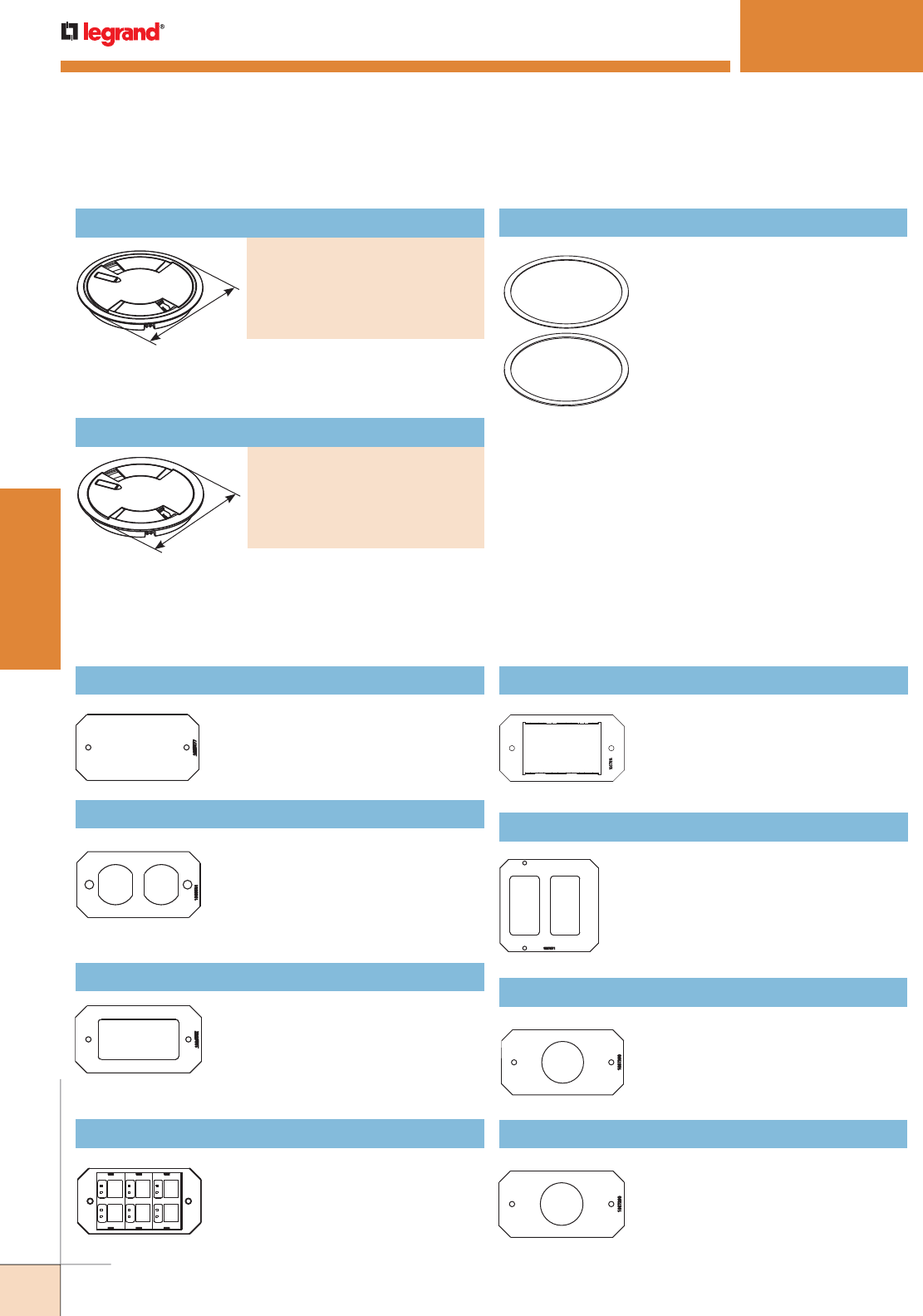
WWW.LEGRAND.US/WIREMOLD
348
WIREMOLD
POKE-THRU DEVICES
* Add suffix “TR” to the end of the part number to indicate tamper-resistant
cover assembly. Tamper-resistant versions are secured with a single
tamper-resistant screw.
9 1/4"
[235mm]
9 1/4"
[235mm]
Die-cast aluminum cover assembly. Cover assembly is
available in finishes shown. 8CTC Series Cover Assemblies
designed for use with 8STC and 8STCP Poke-Thru Stem
Assemblies.
Die-cast aluminum cover assembly. Cover assembly is
available in finishes shown. 8CTC Series Cover Assemblies
designed for use with 8STC and 8STCP Poke-Thru Stem
Assemblies. Includes one (1) 8TS Tile Shim.
8TS Tile Shim
Used for floor coverings greater than
5/16" [7.9mm]. The 8TS will allow the
top surface of the cover to be flush
with the finished floor. Includes: two
(2) 1/8" [3.2mm] thick shims and two
(2) 1/16" [1.6mm] thick shims. Up to
a total of 3/8" [9.5mm] of adjustment.
Evolution 8AT Series Poke-Thru Devices Cover Assemblies Ordering Information
EVOLUTION™ 8AT SERIES POKETHRU DEVICES
8B Device Plate
Single-gang device plate used to blank
off any one (1) of the three (3) gangs
in the center compartment, when no
devices are used.
8DP Device Plate
Single-gang device plate that accepts
standard 20A duplex receptacle or
duplex Turnlok receptacle. Fits in any
one (1) of the three (3) gangs in the
center compartment. Devices supplied
by others.
8DEC Device Plate
Single-gang device plate that will accept
Decorator style devices such as 20A
receptacles, GGCIs, 106 adapters or A/V
devices. Fits in any one (1) of the three
(3) gangs in the center compartment.
Devices supplied by others.
Evolution 8AT Series Center Mount Device Plates Ordering Information
8ACT6A Device Plate
Single-gang device plate that will accept
up to six (6) ports of communication
devices. Fits in any one (1) of the three
(3) gangs in the center compartment.
Devices supplied by others.
8MOS Mosaic Device Plate
Device plate accepts three (3) standard
Mosaic devices [45mm x 22.5mm].
Devices supplied by others.
8CREST Crestron Double Gang Plate
Device plate accepts Crestron double-
gang decorator style devices.
8S1 Device Plate
Receptacle opening 1 3/8" [35mm]. For
8" poke-thru units only.
8S2 Device Plate
Receptacle opening 1 9/16" [40mm]. For
8" poke-thru units only.
Surface Style Cover Assembly
PART NUMBERS:
8CTCBK* (Black)
8CTCGY* (Gray)
8CTCNK* (NIckel)
8CTCBS* (Brass)
8CTCBZ* (Bronze)
Flush Style Cover Assembly
PART NUMBERS:
8CTBK* (Black)
8CTGY* (Gray)
8CTNK* (NIckel)
8CTBS* (Brass)
8CTBZ* (Bronze)
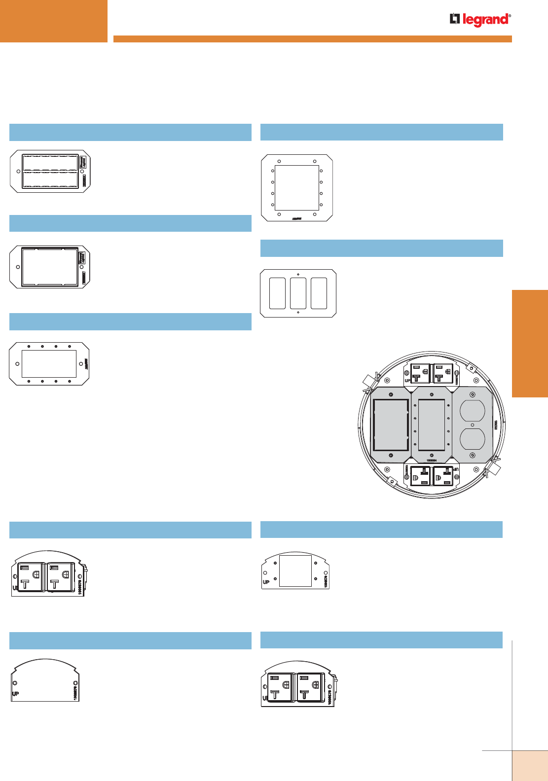
WWW.LEGRAND.US/WIREMOLD
349
WIREMOLD
POKE-THRU DEVICES
Evolution 8AT Series Center Mount Device Plates Ordering Information (continued)
8TRAC Device Plate
Single-gang device plate that will
accept up to six (6) Ortronics® TracJack
devices. Fits in any one (1) of the three
(3) gangs in the center compartment.
Devices supplied by others.
8SER Device Plate
Single-gang device plate that will
accept up to three (3) Ortronics® Series
II dual modular inserts. Fits in any one
(1) of the three (3) gangs in the center
compartment. Devices supplied by
others.
8MAAP Device Plate
Single-gang device plate that
will accept up to four (4) Extron®
Electronics MAAP style plates. Fits
in any one (1) of the three (3) gangs
in the center compartment. Devices
supplied by others.
8AAP Device Plate
Two-gang device plate that will
accept up to four (4) Extron®
Electronics AAP style plates. 8AAP
takes up 2 of the 3 gangs in the
center compartment. Devices
supplied by others.
8AT Center Mount Device
Plate Mounting Locations
Device Plates on this page can
be installed in the shaded
location indicated in this
illustration.
8CREST3G Device Plate
Three-gang device plate that
will accept Crestron® or Extron®
Electronics triple-gang decorator
style devices. Takes up all 3 gangs
in the center compartment. Devices
supplied by others.
68REC 20AMP Duplex Receptacles
Two proprietary 20AMP duplex power
receptacles with mounting plates.
Designed to fit in either of the two side
compartments in both the 6ATC and
the 8ATC Series Poke-Thru Devices.
Receptacle can be wired as a standard
or isolated ground device.
68B Device Plate
Blank plate. Used to blank off either
of the side compartments when no
devices or cabling are to be used.
68MAAP Device Plate
Device plate that will accept up to
two (2) Wiremold AVIP or Extron®
Electronics MAAP device plates.
For use in either of the two side
compartments only. Not for use in
the center compartment. Extron
Devices supplied by others.
68REC-25 20AMP Duplex Receptacles
Two (2) proprietary 20AMP duplex
power receptacles with mounting
plates and 25' leads. Designed to fit in
either of the two side compartments
in both the 6ATC and the 8ATC Series
Poke-Thru Devices. Receptacle can
be wired as a standard or isolated
ground device.
Evolution 8AT Series Side Mount Device Plates Ordering Information
EVOLUTION™ 8AT SERIES POKETHRU DEVICES
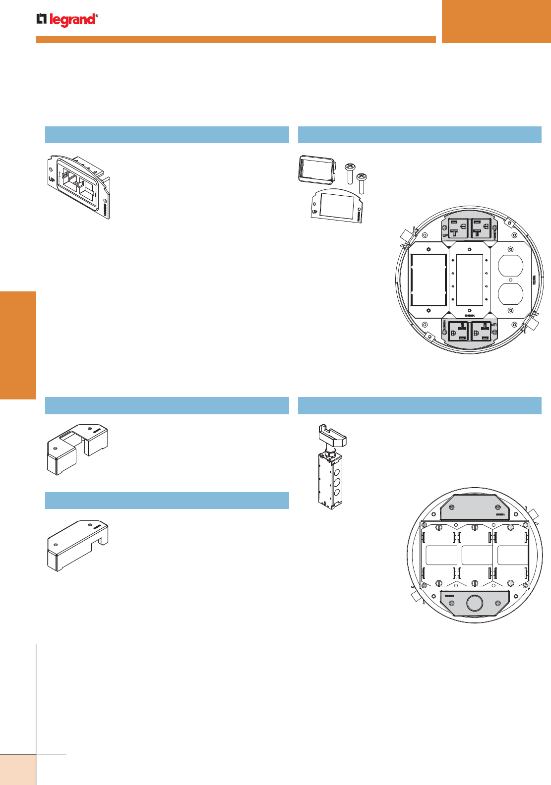
WWW.LEGRAND.US/WIREMOLD
350
WIREMOLD
POKE-THRU DEVICES
8AT Bottom Feed Side
Mount Device Plate
Mounting Locations
Device Plates in this section
can be installed in the shaded
locations indicated in this
illustration.
8AT Side Mount
Device Plates
Mounting Locations
Device Plates in this section
can be installed in the
shaded locations indicated
in this illustration.
682A Device Plate
Device plate that will accept up to two
(2) ports of communication devices.
For use in either of the two side
compartments only. Not for use in the
center compartment. Communication
devices supplied by others.
682A-PT Device Plate
Device plate that allows for
communication cabling to pass
through. Includes one (1) rectangular
adapter ring.
5PTHA Bottom Housing Assembly
Half-gang pass through housing
assembly. Designed to allow pass
through of communication cables when
no conduit is required. For use on side
compartments only.
5BLH Bottom Housing Assembly
Half-gang blank housing assembly.
Designed to blank off compartment
when no cable pass through is required.
For use on side compartments only.
Includes tunnels for 6" 152mm] and 8"
[203mm] Poke-Thru devices.
575CHA Bottom Housing Assembly
Half-gang 3/4" trade size conduit
housing assembly. Includes junction box
attached to 3/4" trade size conduit for
electrical power connections. For use on
side compartments only.
Evolution 8AT Series Bottom Feed Side Mount Device Plates Ordering Information
Evolution 8AT Series Side Mount Device Plates Ordering Information (coninued)
EVOLUTION™ 8AT SERIES POKETHRU DEVICES
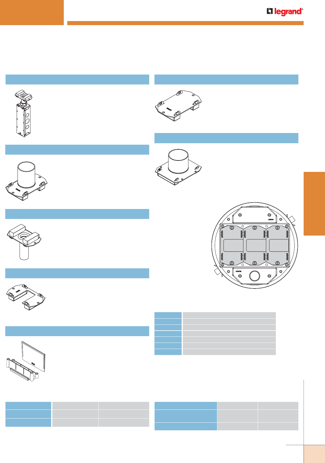
WWW.LEGRAND.US/WIREMOLD
351
WIREMOLD
POKE-THRU DEVICES
8AT Bottom Feed Center Mount
Device Plate Locations
All Bottom Housing Assemblies
on this page can be installed in
the shaded locations indicated
in this illustration.
175CHA Bottom Housing Assembly
One-gang 3/4" trade size conduit
housing assembly. Includes junction box
attached to 3/4" trade size conduit for
electrical power connec tions. For use on
any one (1) of the three (3) gangs in the
center compartment.
1BLH Bottom Housing Assembly
One-gang blank housing assembly.
Designed to blank off compartment
when no cable pass through is required.
For use on any one (1) of the three (3)
gangs in the center compartment.
1125CHA Bottom Housing Assembly
One-gang 1 1/4" trade size conduit
housing assembly. For use on any one
(1) of the three (3) gangs in the center
compartment.
22CHA Bottom Housing Assembly
Two-gang 2" trade size conduit housing
assembly. Used on 8AT Series devices.
Covers two (2) of the three (3) gangs in
the center compartment. Only for use
with 8AT Series units.
175CHA-LJB Bottom Housing Assembly
One-gang 3/4" trade size conduit housing
assembly. Junction box not included.
1PTHA Bottom Housing Assembly
One-gang pass through housing
assembly. Designed to allow pass
through of communication cables when
no conduit is required. For use on any
one (1) of the three (3) gangs in the
center.
8DIV 8" [203mm] Divider
Divider allows for separation of services
when required.
FLOOR TYPE HOLE SIZE (MIN.) HOLE SIZE (MAX.)
Covered Floors
(Carpet, Tile or Wood)
8" [203mm] 8 1/8" [206mm]
Bare Concrete or Terrazzo 8 1/16" [205mm] 8 1/8" [266mm]
8AT Hole Sizes8AT Copper Cross-Section
OUTER CHANNELS CENTER CHANNEL
Max Copper X-Section 0.0154 sq. in. [9.9mm2] 0.0775 sq. in. [16.60mm2]
Max # Conductors (3) 12 AWG or (4) Cat 6A (24) 14 AWG or (24) Cat 6A
NOTE: When using conductor sizes other than listed above, the aggregate
cross-sectional area of the copper conductors shall not exceed
the cross-sectional areas listed.
SIZE SOLID
#24 0.00032 sq. in. [0.20645mm2]
#22 0.00050 sq. in. [0.32258mm2]
#14 0.00323 sq. in. [2.08386mm2]
#12 0.00512 sq. in. [3.30321mm2]
#10 0.00815 sq. in. [5.25805mm2]
#8 0.01296 sq. in. [8.36127mm2]
Copper Cross Sectional Area of
Commonly Used Conductors
NOTE: Use above values for solid or stranded conductors.
CAUTION: Receptacle supplied with this Poke-Thru is not suitable for
direct field wiring. Contact manu facturer for replacement. Field
modifications will void UL Listing and Classification. Replacement
receptacle is limited to this manufacturers’ Catalog No 68REC.
Evolution 8AT Series Bottom Feed Center Mount Device Plates Ordering Information
EVOLUTION™ 8AT SERIES POKETHRU DEVICES
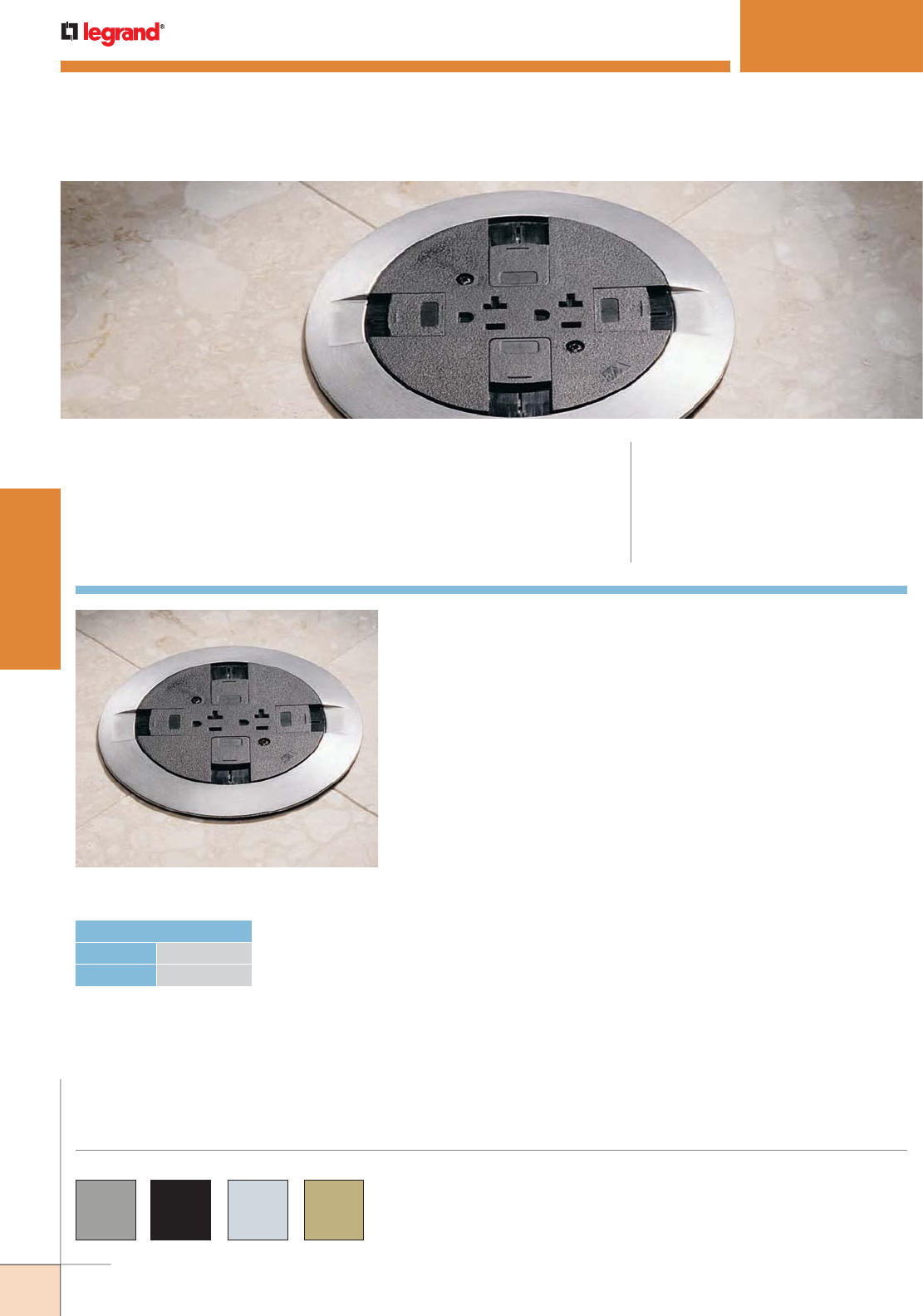
WWW.LEGRAND.US/WIREMOLD
352
WIREMOLD
POKE-THRU DEVICES
RC7 SERIES™ POKETHRU DEVICES
CODE REFERENCE
cULus Listed Metallic Outlet Boxes:
File E2961 Guide QCIT.
cULus Listed Nonmetallic Outlet Boxes &
Fittings Classified for Fire Resistance:
File R8209 Guide CEYY.
Meets Article 300.21, 300.22(C) & 314 of NEC.
RC7 Series™ Surface Style Poke-Thru Devices provide one (1) 20A
duplex power device and up to two (2) ports of communication.
COLOR OPTIONS
RC7 Series parts are available in gray “GY”, black “BK”,
brushed aluminum “AL”, brass “BS”, brass-colored
finish “AB” and an aluminum-colored finish “AA”.
Custom color options are also available. Consult the
factory for more information.
RC7 Series Poke-Thru Device.
HOLE DIAMETER
Minimum: 3 1/16" [78mm]
Maximum: 3 1/8" [79mm]
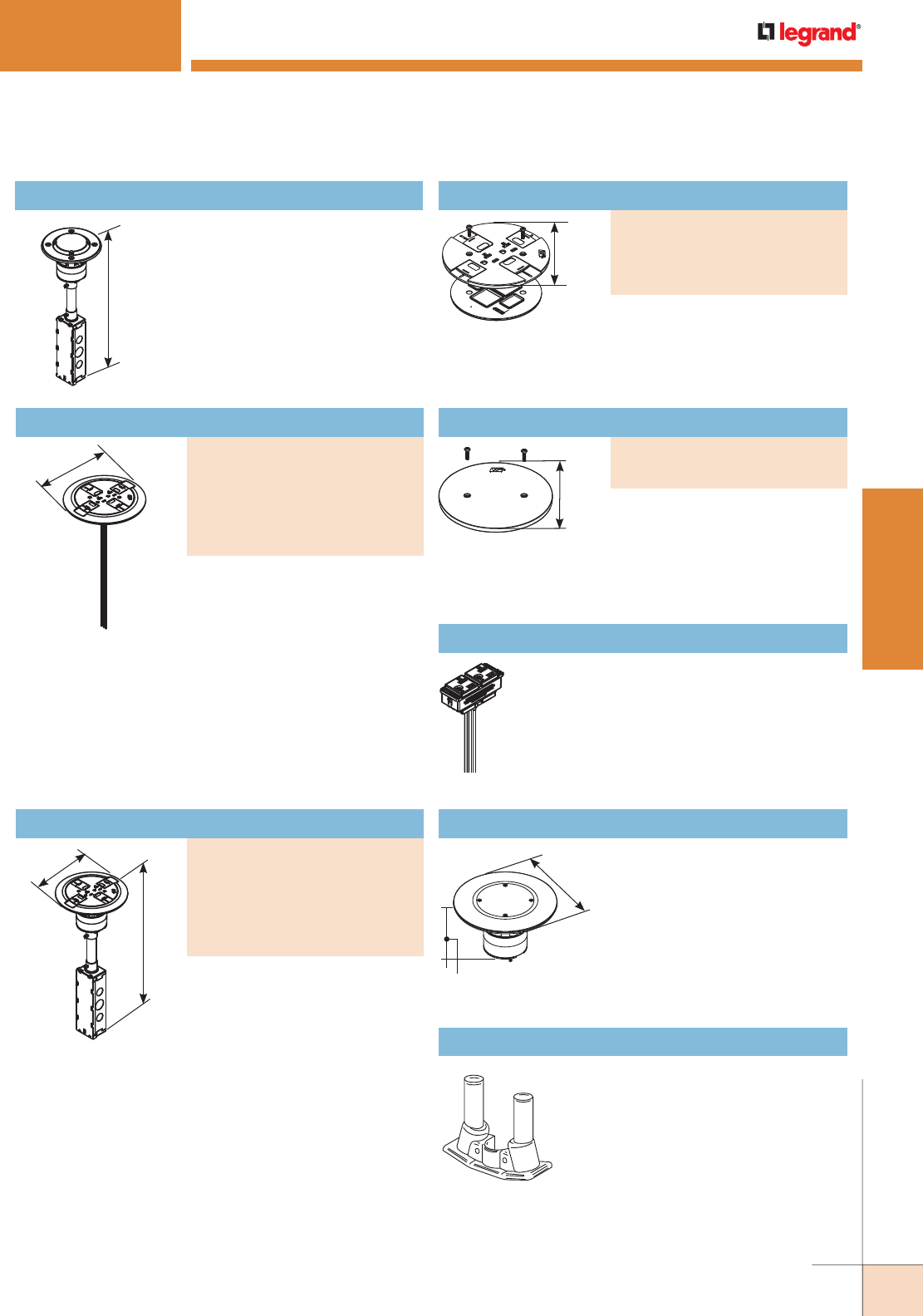
WWW.LEGRAND.US/WIREMOLD
353
WIREMOLD
POKE-THRU DEVICES
Abandonment Plate
PART NUMBERS:
RC7APTCGY (Gray)
RC9APTCBK (Black)
Prewired 20A duplex receptacle
can be wired as standard duplex
or isolated ground. Aluminum and
brass flanges shipped with black
slide cover. Includes Wiremold
Open System unloaded inserts.
NOTE: Assembled with scrub water gasket. For use on tile or carpet floors.
NOTE: RC7 Series Poke-Thru Devices require a 3 1/16" [78mm] diameter
hole. Not designed to work with bare concrete or terrazzo. Floor
covering thickness 1/8" minimum.
Prewired 20A duplex receptacle
can be wired as standard duplex or
isolated ground. Aluminum and
brass flanges shipped with black
slide cover. Includes Wiremold
Open System unloaded inserts.
NOTE: Includes two Cat 6 TechChoice discrete keystone connectors, two
Ortronics TracJack adapters, and two Wiremold Open System
adapters.
Slide Holder Assembly
PART NUMBERS:
RC7SHTCGY (Gray)
RC7SHTCBK (Black)
RC7SHTCAA (Aluminum)
RC7SHTCBS (Brass)
RC7 SERIES™ POKETHRU DEVICES
NOTE: RC7 Series Poke-Thru Devices require a 3
1/16" [78mm] diameter hole. Not designed
to work with bare concrete or terrazzo. Floor
covering thickness 1/8" minimum.
16 1/2"
[419mm]
RC7STC Insert Assembly with Disposable Plate
Used with RC7CTC Series Covers to
complete installation.
7"
[178mm]
5"
[127mm]
7"
[178mm]
3 3/16"
[97mm]
7"
[178mm]
16 1/2"
[419mm]
5"
[127mm]
Nonmetallic slide holder assembly.
Assembled with scrub water
gasket. For use on tile or carpet
floors.
RC37REC, RC37REC-25 Replacement Receptacle
Prewired snap-in 20A receptacle can be wired
as standard duplex or isolated ground. Available
only in black. See installation instructions with
replacement receptacle for complete installation
details. The RC37REC-25 is available with 25
foot leads and can be wired as standard duplex
or isolated ground.
ABPLUG3 Abandonment Plug Assembly
Complete plug assembly for
abandoning an open 3" [76mm]
diameter hole. Assembly includes
intumescent fire-stop material to
maintain the fire-classification of
the floor, inte gral retainer ring to
prevent the unit from pulling up
through the floor, and a black die-
cast aluminum cover.
COM75 Communication Adapter
For two 3/4" trade size conduit
connections (COM75). No additional
capacity with COM75.
NOTE: To abandon the RC7 Series Poke-Thru Device, the internal gasket,
duplex receptacle, and communication modules must not be removed
in order to maintain UL Classification. Also the stem must remain in
the hole.
RC7 Series Poke-Thru Devices Ordering Information
Assembled Poke-Thru Device
PART NUMBERS:
RC7ATCAA (All Aluminum)
RC7ATCAB (All Brass)
RC7ATCGY (Gray)
RC7ATCBK (Black)
RC7ATCAL (Aluminum)
RC7ATCBS (Brass)
Assembled Poke-Thru Device
PART NUMBERS:
RC7CTCAA (All Aluminum)
RC7CTCAB (All Brass)
RC7CTCGY (Gray)
RC7CTCBK (Black)
RC7CTCAL (Aluminum)
RC7CTCBS (Brass)
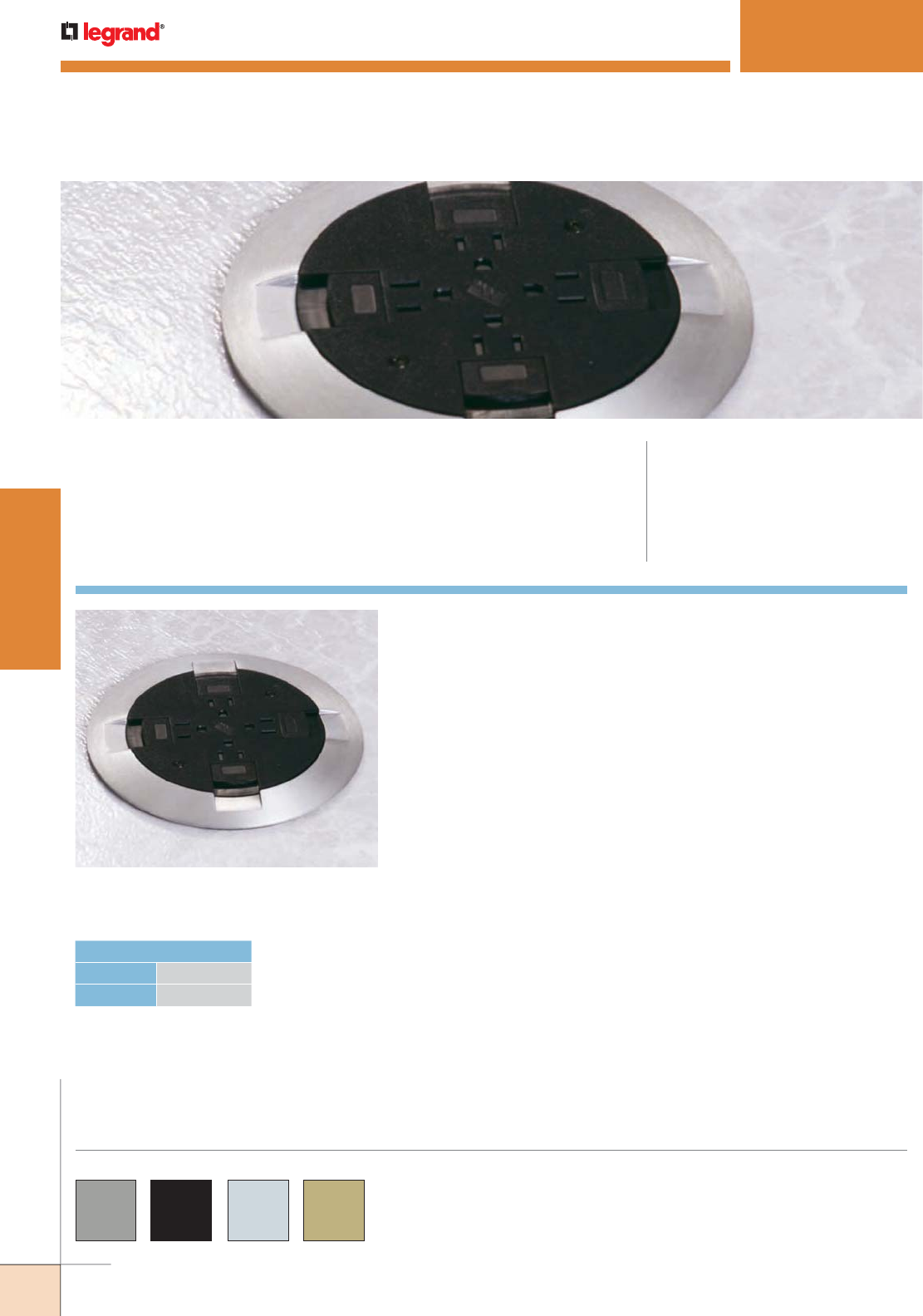
WWW.LEGRAND.US/WIREMOLD
354
WIREMOLD
POKE-THRU DEVICES
RC9 SERIES™ POKETHRU DEVICES
CODE REFERENCE
cULus Listed Metallic Outlet Boxes:
File E2961 Guide QCIT.
cULus Listed Nonmetallic Outlet Boxes &
Fittings Classified for Fire Resistance:
File R8209 Guide CEYY.
Meets Article 300.21, 300.22(C) & 314 of NEC.
RC9 Series™ Surface Style Poke-Thru Devices provide a 15 Amp quad
power device and two (2) openings for communication pass-through.
RC9 Series parts are available in gray “GY”, black “BK”,
brushed aluminum “AL”, brass “BS”, brass-colored finish
“AB” and an aluminum-colored finish “AA”.
Custom color options are also available. Consult the
factory for more information.
COLOR OPTIONS
RC9 Series Poke-Thru Device
(RC9A15TCAL) installed in a tile floor.
HOLE DIAMETER
Minimum: 3 1/16" [78mm]
Maximum: 3 1/8" [79mm]
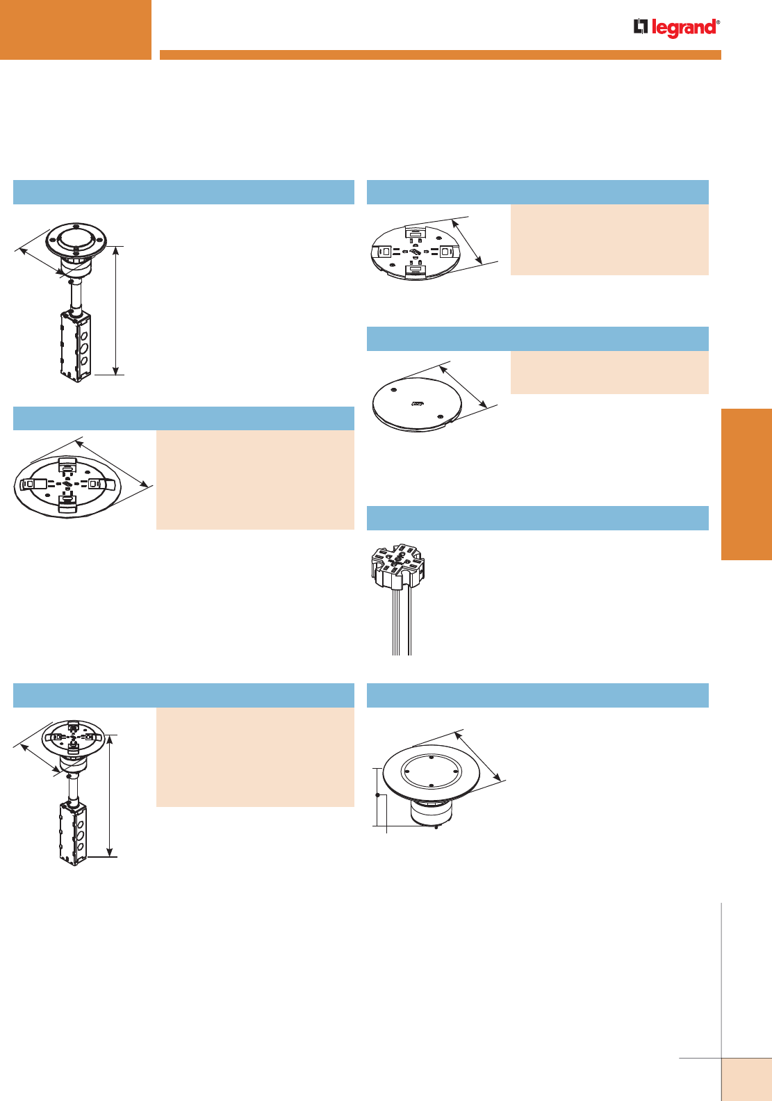
WWW.LEGRAND.US/WIREMOLD
355
WIREMOLD
POKE-THRU DEVICES
Abandonment Plate
PART NUMBERS:
RC9APTC (Gray)
RC9APTCBK (Black)
Nonmetallic Slide Holder Assembly
PART NUMBERS:
RC9SHTCGY (Gray)
RC9SHTCBK (Black)
RC9SHTCBS (Brass)
RC9SHTCAA (Aluminum)
16 1/2"
[419mm]
7"
[178mm]
Prewired 15A quad receptacle can
be wired as standard quad
receptacle or isolated ground.
Unit also includes two openings for
pass-through capability for one
4-pair Category 5e or Category 6
cable per opening.
RC9 SERIES™ POKETHRU DEVICES
7"
[178mm]
16 1/2"
[419mm]
6"
[152mm]
RC9STC Insert Assembly with Disposable Plate
Includes prewired 15A quad
receptacle. Use with RC9C Series
Covers to complete installation.
Aluminum and brass flanges shipped with black cover.
Cover assembly also includes two openings for pass-
through capability for one 4-pair Category 5e or Category 6
cable per opening.
NOTE: Assembled with scrub water gasket. For use on tile or carpet floors.
5"
[127mm]
7"
[178mm]
3 3/16"
[97mm]
5"
[127mm]
NOTE: Assembled with scrub water gasket.
For use on tile or carpet floors.
NOTE: To abandon the RC9 Series Poke-Thru Device, the internal gasket
and quad receptacle must not be removed in order to maintain UL
Classification. Also, the stem must remain in the hole.
RC9REC, RC9REC-25 Replacement Receptacle
Prewired 15A quad receptacle can be wired
as standard receptacle or isolated ground.
Available only in black. See installation
instructions with replacement receptacle for
complete installation details. Receptacle also
available with 25' leads (RC9REC-25).
ABPLUG3 Abandonment Plug Assembly
Complete plug assembly for
abandoning an open 3" [76mm]
diameter hole. Assembly
includes intumescent fire-
stop material to maintain the
fire-classification of the floor,
integral retainer ring to prevent
the unit from pulling up through
the floor, and a black die-cast
aluminum cover.
NOTE: Assembled with scrub water gasket. For use on tile or carpet floors.
NOTE: RC9 Series Poke-Thru Devices require a 3 1/16" [78mm] diameter
hole. Not designed to work with bare concrete or terrazzo. Floor
covering thickness 1/8" minimum.
RC9 Series Poke-Thru Devices Ordering Information
Finish Flange & Slide Holder Assembly
PART NUMBERS:
RC9CTCAA (All Aluminum)
RC9CTCGY (Gray)
RC9CTCAB (All Brass)
RC9CTCBK (Black)
RC9CTCAL (Aluminum)
RC9CTCBS (Brass)
Assembled Poke-Thru Device
PART NUMBERS:
RC9A15TCAA (All Aluminum)
RC9A15TCAB (All Brass)
RC9A15TCGY (Gray)
RC9A15TCBK (Black)
RC9A15TCAL (Aluminum)
RC9A15TCBS (Brass)
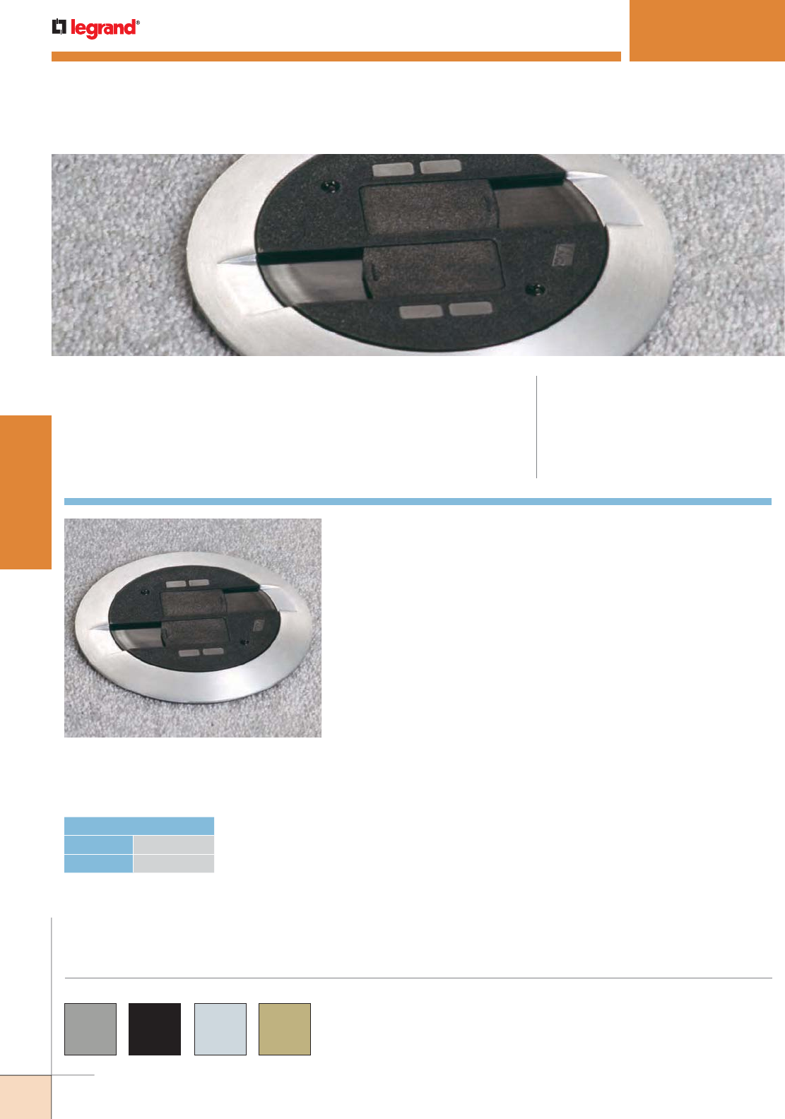
WWW.LEGRAND.US/WIREMOLD
356
WIREMOLD
POKE-THRU DEVICES
RC9AMD Series parts are available in gray “GY”, black “BK”,
brushed aluminum “AL”, brass “BS”, brass-colored finish
“AB” and an aluminum-colored finish “AA”.
Custom color options are also available. Consult the
factory for more information.
RC9AMD Series Poke-Thru Device
(RC9AMDTCAL) installed in a
carpeted floor.
RC9AMD SERIES™ POKETHRU DEVICES
CODE REFERENCE
cULus Listed Metallic Outlet Boxes:
File E2961 Guide QCIT.
cULus Listed Nonmetallic Outlet Boxes &
Fittings Classified for Fire Resistance:
File R8209 Guide CEYY.
Meets Article 300.21, 300.22(C) & 314 of NEC.
RC9AMD Series™ Surface Style Poke-Thru Devices provide up to four
(4) ports of communication.
COLOR OPTIONS
HOLE DIAMETER
Minimum: 3" [76mm]
Maximum: 3 1/8" [79mm]
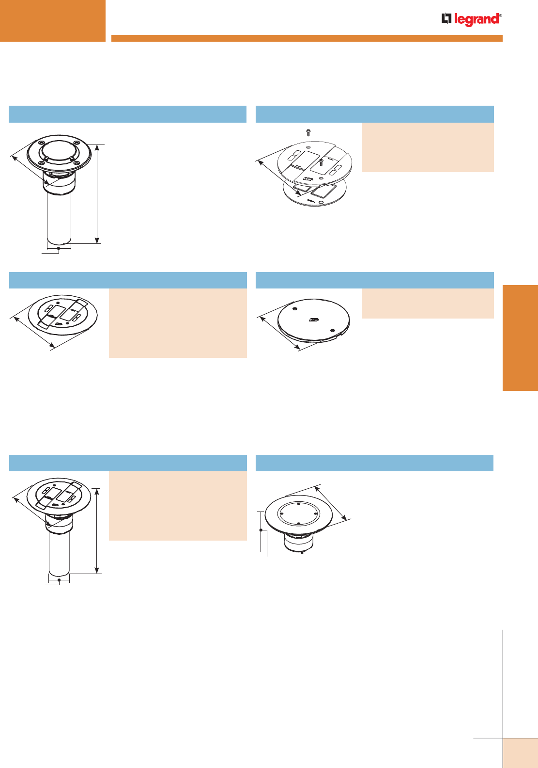
WWW.LEGRAND.US/WIREMOLD
357
WIREMOLD
POKE-THRU DEVICES
Abandonment Plate
PART NUMBERS:
RC9APTC (Gray)
RC9APTCBK (Black)
All communication device accepts
up to four UTP connectors. Unit
includes two (2) Ortronics TracJack
adapters, two (2) Ortronics Series
II adapters, and two (2) Wiremold
Open System inserts. Modular
jacks sold separately.
NOTE: Assembled with scrub water gasket. For use on tile or carpet floors.
NOTE: RC9 Series Poke-Thru Devices require a 3" [76mm] diameter hole.
Not designed to work with bare concrete or terrazzo. Floor covering
thickness 1/8" minimum.
5"
[127mm]
10"
[254mm]
6"
[152mm]
2" Trade
Size Conduit
Stem
RC9AMD SERIES™ POKETHRU DEVICES
RC9AM2STC Insert Assembly with Disposable Plate
Use with RC9CMD Series Covers
to complete installation.
Includes two (2) Ortronics TracJack adapters, two (2)
Ortronics Series II adapters, and two (2) Wiremold Open
System adapters. Modular jacks sold separately.
NOTE: Assembled with scrub water gasket. For use on tile or carpet floors.
ABPLUG3 Abandonment Plug Assembly
Complete plug assembly for
abandoning an open 3" [76mm]
diameter hole. Assembly
includes intumescent fire-
stop material to maintain the
fire-classification of the floor,
integral retainer ring to prevent
the unit from pulling up through
the floor, and a black die-cast
aluminum cover.
7"
[178mm] 5"
[127mm]
7"
[178mm]
3 3/16"
[97mm]
10"
[254mm]
7"
[178mm]
2" Trade Size
Conduit Stem
RC9AMD Series Poke-Thru Devices Ordering Information
Finish Flange & Slide Holder Assembly
PART NUMBERS:
RC9CMDTCAA (All Aluminum)
RC9CMDTCAB (All Brass)
RC9CMDTCGY (Gray)
RC9CMDTCBK (Black)
RC9CMDTCAL (Aluminum)
RC9CMDTCBS (Brass)
Assembled Poke-Thru Device
PART NUMBERS:
RC9AMDTCAA (All Aluminum)
RC9AMDTCAB (All Brass)
RC9AMDTCGY (Gray)
RC9AMDTCBK (Black)
RC9AMDTCAL (Aluminum)
RC9AMDTCBS (Brass)
Nonmetallic Slide Holder Assembly
PART NUMBERS:
RC9SHMDTCGY (Gray)
RC9SHMDTCBK (Black)
RC9SHMDTCAL (Aluminum)
RC9SHMDTCBS (Finish)
NOTE: To abandon the RC9 Series Poke-
Thru Device, the internal gasket
and quad receptacle must not be
removed in order to maintain UL
Classification. Also, the stem must
remain in the hole.
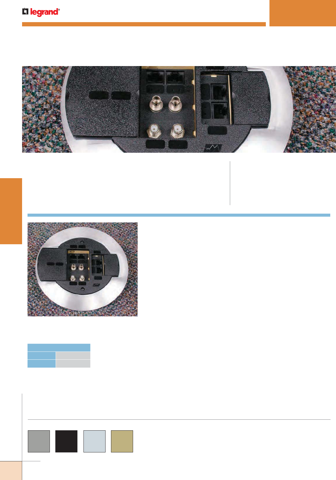
WWW.LEGRAND.US/WIREMOLD
358
WIREMOLD
POKE-THRU DEVICES
AMD8 Series Poke-Thru Device installed
in a carpeted floor.
AMD8 SERIES™ POKETHRU DEVICES
CODE REFERENCE
cULus Listed Metallic Outlet Boxes:
File E2961 Guide QCIT.
cULus Listed Nonmetallic Outlet Boxes &
Fittings Classified for Fire Resistance:
File R8209 Guide CEYY.
Meets Article 300.21, 300.22(C) & 314 of NEC.
AMD8 Series™ All Communication Surface Style Poke-Thru Devices
provide up to eight (8) ports of communication.
AMD8 Series parts are available in gray “GY”, black “BK”,
brushed aluminum “AL”, brass “BS”, brass-colored finish
“AB” and an aluminum-colored finish “AA”.
Custom color options are also available. Consult the
factory for more information.
COLOR OPTIONS
HOLE DIAMETER
Minimum: 4" [102mm]
Maximum: 4 1/8" [105mm]
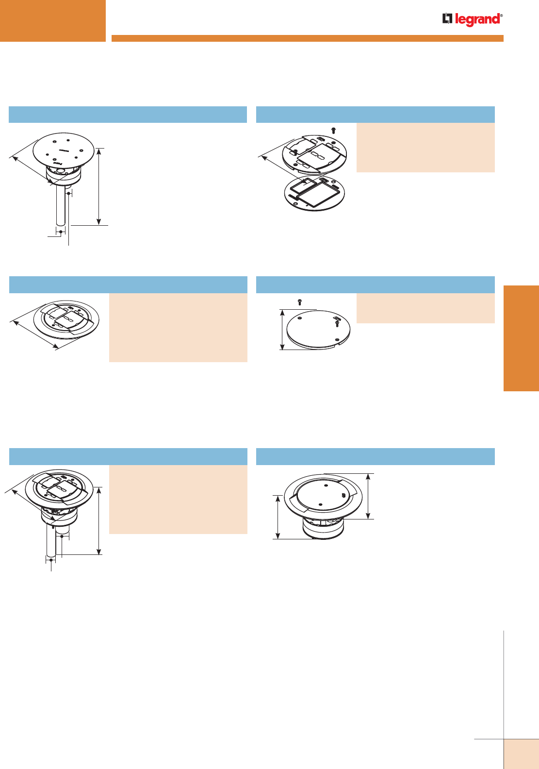
WWW.LEGRAND.US/WIREMOLD
359
WIREMOLD
POKE-THRU DEVICES
Abandonment Plate
PART NUMBERS:
AMD8APTCGY (Gray)
AMD8APTCBK (Black)
Slide Holder
PART NUMBERS:
AMD8SHTCGY (Gray)
AMD8SHTCBK (Black)
AMD8SHTCAL (Aluminum)
AMD8SHTCBS (Brass)
7 1/2"
[191mm]
3 7/8"
[98mm]
AMD8 SERIES™ POKETHRU DEVICES
NOTE: Assembled with scrub water gasket. For use on tile or carpet floors.
NOTE: AMD8 Series Poke-Thru Devices require a 4" [102mm] diameter hole.
Not designed to work with bare concrete or terrazzo. Floor covering
thickness 1/8" minimum.
AMD8STC Insert Assembly with Disposable Plate
Use with AMD8C Series Covers to
complete installation.
Includes adapters to accept eight (8) Ortronics TracJack
modular jacks, four (4) Ortronics Series II modular jacks,
or Wiremold Open System adapters. Modular jacks sold
separately.
NOTE: Assembled with scrub water gasket. For use on tile or carpet floors.
All communication device accepts
up to eight UTP, fiber optic, audio,
or video connectors. Includes
adapters to accept eight (8)
Ortronics TracJack modular jacks,
four (4) Ortronics Series II modular
jacks, or Wiremold Open System
adapters. Modular jacks sold
separately.
Nonmetallic slide holder assembly.
NOTE: Assembled with scrub water gasket.
For use on tile or carpet floors.
ABPLUG4 Abandonment Plug Assembly
Complete plug assembly
for abandoning an open
4" [102mm] diameter
hole. Assembly includes
intumescent fire-stop
material to maintain the
fire classification of the
floor, integral retainer
ring to prevent the unit
from pulling up through
the floor, and a black
die-cast aluminum cover.
7 1/2"
[191mm]
9 7/16"
[240mm]
7"
[178mm]
3/4" Trade Size
Conduit Stem
1 1/4" Trade Size
Conduit Stem
5"
[127mm]
5"
[127mm]
9 3/4"
[248mm]
7 1/2"
[191mm]
3/4" Trade Size
Conduit Stem
1 1/4" Trade Size
Conduit Stem
AMD8 Series Poke-Thru Devices Ordering Information
Finish Flange & Slide Holder
PART NUMBERS:
AMD8CTCAA (All Aluminum)
AMD8CTCAB (All Brass)
AMD8CTCGY (Gray),
AMD8CTCBK (Black)
AMD8CTCAL (Aluminum)
AMD8CTCBS (Brass)
Assembled Poke-Thru Device
PART NUMBERS:
AMD8ATCAA (All Aluminum)
AMD8ATCAB (All Brass)
AMD8ATCGY (Gray)
AMD8ATCBK (Black)
AMD8ATCAL (Aluminum)
AMD8ATCBS (Brass)
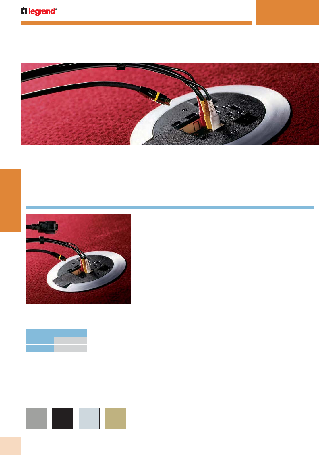
WWW.LEGRAND.US/WIREMOLD
360
WIREMOLD
POKE-THRU DEVICES
AV3 Series Poke-Thru Device installed
in a carpeted floor.
AV3 SERIES™ POKETHRU DEVICES
CODE REFERENCE
cULus Listed Metallic Outlet Boxes:
File E2961 Guide QCIT.
cULus Listed Nonmetallic Outlet Boxes
& Fittings Classified for Fire Resistance:
File R8209 Guide CEYY.
Meets Article 300.21, 300.22(C) & 314 of
NEC.
AV3 Series™ Surface Style Poke-Thru Devices provide one (1) 20 Amp
duplex power device and accepts up to three (3) Extron® Electronics
MAAP Series device plates.
AV3 Series parts are available in gray “GY”, black “BK”,
brushed aluminum “AL”, brass “BS”, brass-colored finish
“AB” and an aluminum-colored finish “AA”.
Custom color options are also available. Consult the
factory for more information.
COLOR OPTIONS
HOLE DIAMETER
Minimum: 4" [102mm]
Maximum: 4 1/8" [105mm]
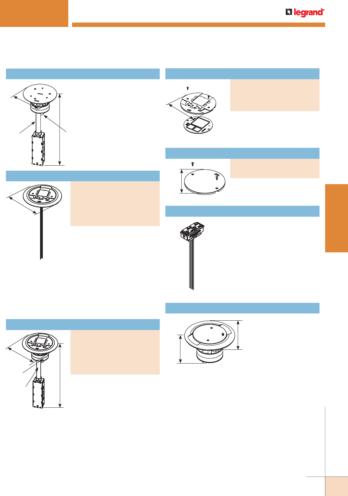
WWW.LEGRAND.US/WIREMOLD
361
WIREMOLD
POKE-THRU DEVICES
Abandonment Plate
PART NUMBERS:
AV3APTCGY (Gray)
AV3APTCBK (Black)
Complete plug assembly
for abandoning an open
4" [102mm] diameter
hole. Assembly includes
intumescent fire-stop
material to maintain the
fire classification of the
floor, integral retainer
ring to prevent the unit from pulling up through the floor,
and a black die-cast aluminum cover.
7 1/2"
[191mm]
3 7/8"
[98mm]
16 5/8"
[422mm]
7"
[178mm]
3/4" Trade Size
Conduit Stem
1 1/4"
Trade Size
Conduit Stem
AV3 SERIES™ POKETHRU DEVICES
NOTE: AV3 Series Poke-Thru Devices require a 4" [102mm] diameter hole.
Not designed to work with bare concrete or terrazzo. Floor covering
thickness 1/8" minimum.
AV3STC Insert Assembly with Disposable Plate
Use with AV3CTC Series
Covers to complete
installation.
Nonmetallic slide holder assembly.
NOTE: Assembled with scrub water gasket.
For use on tile or carpet floors.
RC37REC, RC37REC-25 Replacement Receptacles
Prewired snap-in 20A receptacle
can be wired as standard duplex
or isolated ground. Available
only in black. See installation
instructions with replacement
receptacle for complete installation
details. The RC37REC-25 is
available with 25 foot
[7.62m]
leads
and can be wired as standard
duplex or isolated ground.
5 3/4"
[146mm]
5 3/4"
[146mm]
ABPLUG4 Abandonment Plug Assembly
AV3 Series Poke-Thru Devices Ordering Information
Slide Holder
PART NUMBERS:
AV3SHTCGY (Gray)
AV3SHTCBK (Black)
AV3SHTCAL (Aluminum)
AV3SHTCBS (Brass)
8 1/4"
[210mm]
Finish Flange & Slide Holder
PART NUMBERS:
AV3CTCAA (All Aluminum)
AV3CTCAB (All Brass)
AV3CTCGY (Gray)
AV3CTCBK (Black)
AV3CTCAL (Aluminum)
AV3CTCBS (Brass)
Incudes one prewired 20A duplex
receptacle which can be wired as
a standard receptacle or isolated
ground. Includes one adapter to
accept Wiremold AVIP or Extron®
Electronics MAAP mini
architectural adapter plates,
Wiremold Open System adapters,
and Ortronics TracJack and Series
II mounting adapters. Modular
Jacks sold separately.
NOTE: Assembled with scrub water gasket. For use on tile or carpet floors.
A/V device incudes one prewired
20A duplex receptacle which can
be wired as a standard receptacle
or isolated ground. Includes one
adapter to accept Wiremold AVIP
or Extron® Electronics MAAP mini
architectural adapter plates,
Wiremold Open System adapters,
and Ortronics TracJack and Series
II mounting adapters. Modular
Jacks sold separately.
NOTE: Assembled with scrub water gasket. For use on tile or carpet floors.
NOTE: AV3 Series Poke-Thru Devices require a 4" [102mm] diameter hole.
Not designed to work with bare concrete or terrazzo. Floor covering
thickness 1/8" minimum.
17"
[432mm]
8 1/4"
[210mm]
3/4" Trade
Size Conduit
Stem
1 1/4"
Trade Size
Conduit
Stem
Assembled Poke-Thru Device
PART NUMBERS:
AV3ATCAA (All Aluminum)
AV3ATCAB (All Brass)
AV3ATCGY (Gray)
AV3ATCBK (Black)
AV3ATCAL (Aluminum)
AV3ATCBS (Brass)

WWW.LEGRAND.US/WIREMOLD
362
WIREMOLD
POKE-THRU DEVICES
RC3 Series Poke-Thru Device installed in
a carpeted floor.
RC3 SERIES™ POKETHRU DEVICES
CODE REFERENCE
cULus Listed Metallic Outlet Boxes:
File E2961 Guide QCIT.
cULus Listed Nonmetallic Outlet Boxes &
Fittings Classified for Fire Resistance:
File R8209 Guide CEYY.
Meets Article 300.21, 300.22(C) & 314 of NEC.
RC3 Series™ Surface Style Poke-Thru Devices provide one (1) 20 Amp
power device and four (4) ports of communication.
RC3 Series parts are available in gray “GY”, black “BK”,
brushed aluminum “AL”, brass “BS”, a brass-colored finish
“AB” and an aluminum-colored finish “AA”.
Custom color options are also available. Consult the
factory for more information.
COLOR OPTIONS
HOLE DIAMETER
Minimum: 4" [102mm]
Maximum: 4 1/8" [105mm]
NOTE: To abandon the RC3 Series Poke-Thru Device, the duplex receptacle
must be left installed in the unit in order to maintain scrub water
compliance. Also the stem must remain in the hole.
16 11/16"
[424mm]
RC3STC Insert Assembly with Disposable Plate
Use with RC3C Series Covers to
complete installation.
RC3 Series Poke-Thru Devices Ordering Information
Abandonment Plate
PART NUMBERS:
RC3APTCBK (Black)
RC3APTCGY (Gray)
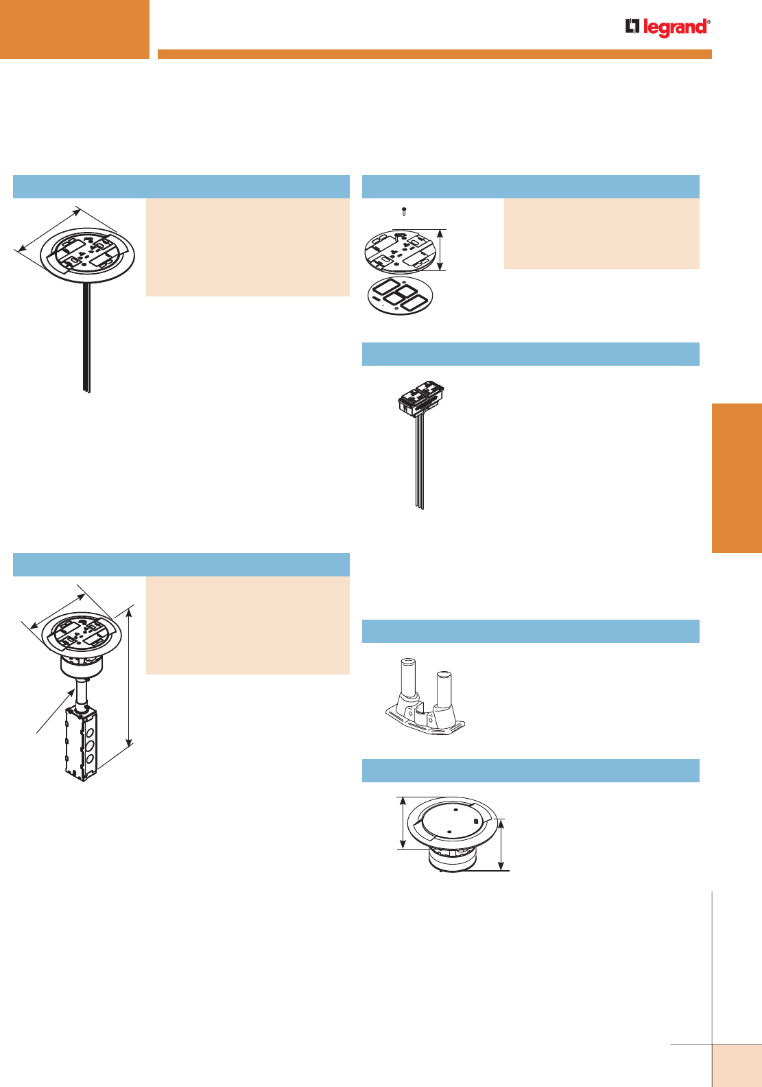
WWW.LEGRAND.US/WIREMOLD
363
WIREMOLD
POKE-THRU DEVICES
COM75 Communication Adapter
Finish Flange & Slide Holder
PART NUMBERS:
RC3CTCAA (All Aluminum)
RC3CTCAB (All Brass)
RC3CTCGY (Gray)
RC3CTCBK (Black)
RC3CTCAL ( Aluminum)
RC3CTCBS (Brass)
Finish flange and slide holder.
Prewired 20A duplex receptacle
can be wired as standard duplex or
isolated ground. Includes Wiremold
Open System unloaded adapters
to accept four (4) discrete
keystone connectors from most
manufacturers. Unit also includes
two (2) Ortronics TracJack adapters
and two (2) Ortronics Series II
adapters. Modular Jacks sold
separately.
NOTE: Assembled with scrub water gasket. For use on tile or carpet floors.
Assembled unit. Prewired 20A
duplex receptacle can be wired as
standard duplex or isolated ground.
Includes Wiremold Open System
unloaded adapters to accept four (4)
discrete keystone connectors from
most manufacturers. Unit also
includes two (2) Ortronics TracJack
adapters and two (2) Ortronics
Series II adapters. Modular Jacks
sold separately.
NOTE: Assembled with scrub water gasket. For use on tile or carpet floors.
NOTE: RC3 Series Poke-Thru Devices require a 4" [102mm] diameter
hole. Not designed to work with bare concrete or terrazzo. Floor covering
thickness 1/8" minimum.
7 1/2"
[191mm]
Nonmetallic slide holder assembly.
NOTE: Assembled with scrub water gasket.
For use on tile or carpet floors.
5"
[127mm]
7 1/2"
[191mm]
16"
[406mm]
3/4" Trade Size
Conduit Stem
RC3 SERIES™ POKETHRU DEVICES
RC3 Series Poke-Thru Devices Ordering Information
RC37REC, RC37REC-25 Replacement Receptacles
Prewired snap-in 20A receptacle
can be wired as standard duplex or
isolated ground. Available only in
black. See installation instructions with
replacement receptacle for complete
installation details. The RC37REC-25
is available with 25 foot
[7.62m]
leads
and can be wired as standard duplex or
isolated ground.
NOTE: RC3 Series Poke-Thru Devices require a 4" [102mm] diameter hole.
Not designed to work with bare concrete or terrazzo. Floor covering
thickness 1/8" minimum.
NOTE: The 20A duplex receptacle supplied with the new scrub water version
RC3 Poke-Thru Device is proprietary and can only be replaced with the
RC37REC.
For two 3/4" trade size conduit
connections. No additional capacity
with COM75.
7 1/2"
[191mm]
3 7/8"
[98mm]
ABPLUG4 Abandonment Plug Assembly
Complete plug assembly
for abandoning an open
4" [102mm] diameter
hole. Assembly includes
intumescent fire-stop
material to maintain the
fire classification of the
floor, integral retainer ring to prevent the unit from pulling
up through the floor, and a black die-cast aluminum cover.
Slide Holder
PART NUMBERS:
RC3SHTCGY (Gray)
RC3SHTCBK (Black)
RC3SHTCBS (Brass)
RC3SHTCAA (Aluminum)
Assembled Poke-Thru Device
PART NUMBERS:
RC3ATCAA (All Aluminum)
RC3ATCAB (All Brass)
RC3ATCGY (Gray)
RC3ATCBK (Black)
RC3ATCAL (Aluminum)
RC3ATCBS (Brass)
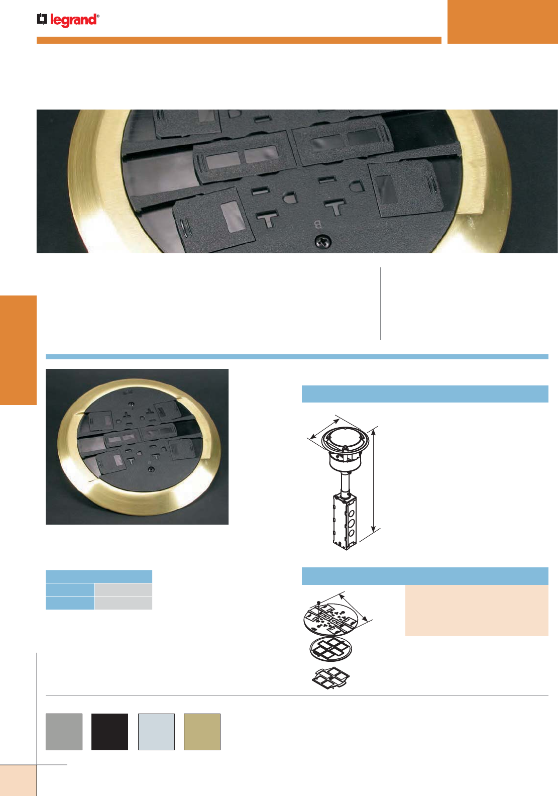
WWW.LEGRAND.US/WIREMOLD
364
WIREMOLD
POKE-THRU DEVICES
RC4 Series Poke-Thru Device
(RC4CTCBS).
RC4 SERIES™ POKETHRU DEVICES
CODE REFERENCE
cULus Listed Metallic Outlet Boxes:
File E2961 Guide QCIT.
cULus Listed Nonmetallic Outlet Boxes &
Fittings Classified for Fire Resistance:
File R8209 Guide CEYY.
Meets Article 300.21, 300.22(C) & 314 of NEC.
RC4 Series™ Surface Style Poke-Thru Devices provide two (2) 20 Amp
duplex power devices and four (4) ports of communication.
RC4 Series parts are available in gray “GY”, black “BK”,
brushed aluminum “AL”, brass “BS”, brass-colored finish
“AB” and an aluminum-colored finish “AA”.
COLOR OPTIONS
HOLE DIAMETER
Minimum: 4" [102mm]
Maximum: 4 1/8" [105mm]
RC4STC Insert Assembly with Disposable Plate
Comes complete with four prewired
20A receptacles. Use RC4STC with
RC4C Series Covers.
NOTE: If wiring for Isolated Ground, attach
orange IG label (supplied).
6"
[152mm]
16 3/8"
[416mm]
RC4 Series Poke-Thru Devices Ordering Information
Nonmetallic slide holder assembly.
NOTE: Assembled with scrub water gasket.
For use on tile or carpet floors.
6 1/4"
[159mm]
Slide Holder
PART NUMBERS:
RC4SHTCGY (Gray)
RC4SHTCBK (Black)
RC4SHTCBS (Brass)
RC4SHTCAL (Aluminum)
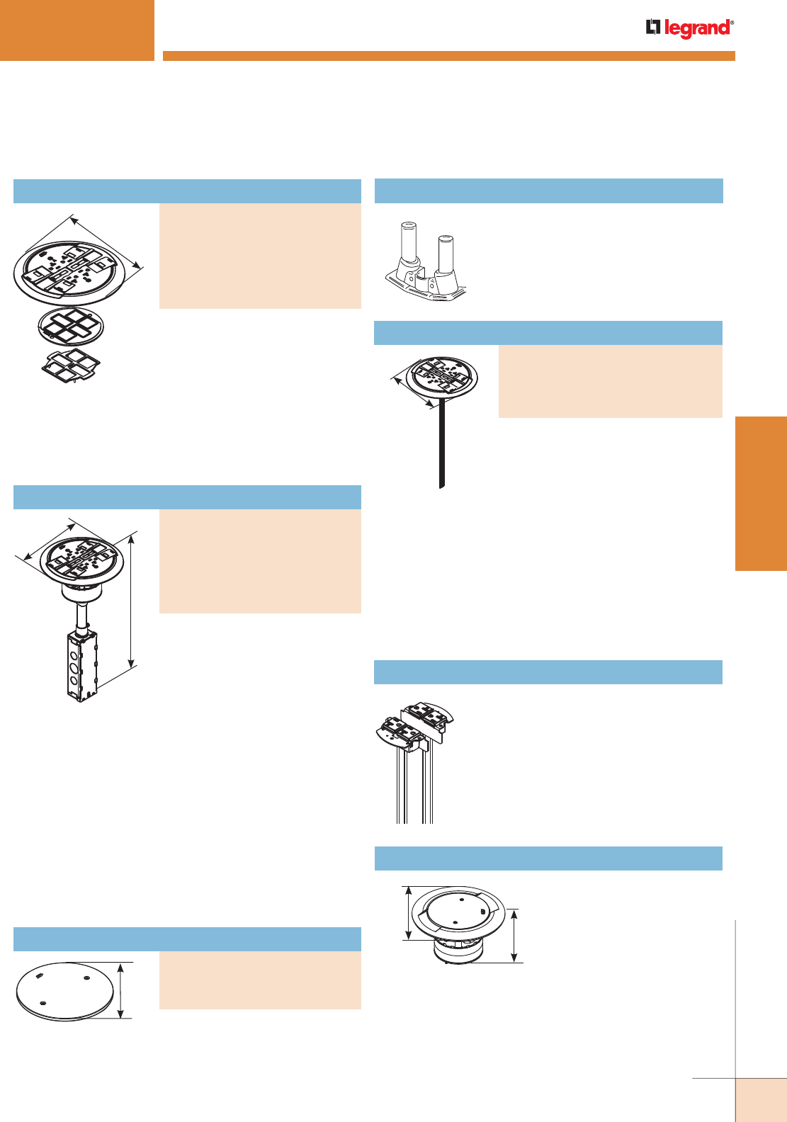
WWW.LEGRAND.US/WIREMOLD
365
WIREMOLD
POKE-THRU DEVICES
Complete plug assembly
for abandoning an open
4" [102mm] diameter
hole. Assembly includes
intumescent fire-stop
material to maintain the fire
classification of the floor,
integral retainer ring to prevent the unit from pulling up
through the floor, and a black die-cast aluminum cover.
NOTE: To abandon the RC4 Series Poke-Thru Device, the internal gasket,
duplex receptacle, and communication modules must not be removed
in order to maintain UL Classification. Also the stem must remain in
the core-drilled hole.
Abandonment Plate
PART NUMBERS:
RC4APTCGY (Gray)
RC4APTCBK (Black)
RC4APTCBS (Brass)
RC4 SERIES™ POKETHRU DEVICES
Used to upgrade existing installations
of RC4 Poke-Thru Devices on
carpet floors to meet scrub water
requirements. Includes two 20A duplex
receptacles that can be wired as a
standard duplex or isolated ground. Also includes scrub
water finish flange and slide holder assembly. See
installation instructions with retrofit kit for complete
installation details.
NOTE: Existing installations of RC4 Poke-Thru Devices are not required to be
upgraded to meet carpet scrub water requirements, if manufactured
prior to June 2003.
NOTE: RC4 Series Poke-Thru Devices require a 4" [102mm] diameter hole.
Not designed to work with bare concrete or terrazzo. Floor covering
thickness 1/8" minimum.
Includes Wiremold Open System
unloaded adapters to accept four
discrete keystone connectors from
most manufacturers. Unit also
includes Ortronics TracJack
Mounting adapters and Ortronics
Series II Communication Housing.
Modular jacks sold separately.
NOTE: Assembled with scrub water gasket. For use on tile or carpet floors.
8 1/4"
[210mm]
6 1/4"
[159mm]
COM75 Communication Adapter
Provides two 3/4" trade size threaded
openings to accommodate conduit
connections.
8 1/4"
[210mm]
RC4 Series Poke-Thru Devices Ordering Information
RC4REC2, RC4REC2-25 Replacement Receptacles
Two prewired 20A duplex receptacles can
be wired as standard duplex or isolated
ground. Available only in black. See
installation instructions with replacement
receptacle for complete installation details.
RC4REC2-25 is available with 25 foot
[7.62m] leads.
7 1/2"
[191mm]
3 7/8"
[98mm]
ABPLUG4 Abandonment Plug Assembly
Finish Flange & Slide Holder Assembly
PART NUMBERS:
RC4CTCAA (All Aluminum)
RC4CTCAB (All Brass)
RC4CTCGY (Gray)
RC4CTCBK (Black)
RC4CTCAL ( Aluminum)
RC4CTCBS (Brass)
Unit includes four prewired 20A
receptacles. Each duplex
receptacle is wired as a separate
circuit. The duplex can be wired as
a standard receptacle or isolated
ground. Includes Wiremold Open
System unloaded adapters to
accept four discrete keystone
connectors from most
manufacturers. Unit also includes
Ortronics TracJack Mounting
adapters and Ortronics Series II
Communication Housing. Modular
jacks sold separately.
NOTE: Assembled with scrub water gasket. For use on tile or carpet floors.
NOTE: If wiring for Isolated Ground, attach orange IG label (supplied).
NOTE: RC4 Series Poke-Thru Devices require a 4" [102mm] diameter hole.
Not designed to work with bare concrete or terrazzo. Floor covering
thickness 1/8" minimum.
8 1/4"
[210mm]
16 3/8"
[416mm]
Assembled Poke-Thru Device
PART NUMBERS:
RC4ATCAA (All Aluminum)
RC4ATCAB (All Brass)
RC4ATCGY (Gray)
RC4ATCBK (Black)
RC4ATCAL ( Aluminum)
RC4ATCBS (Brass)
Retrofit Kit
PART NUMBERS:
RC4KTCBK (Black)
RC4KTCGY (Gray)
RC4KTCAL (Aluminum)
RC4KTCBS (Brass)
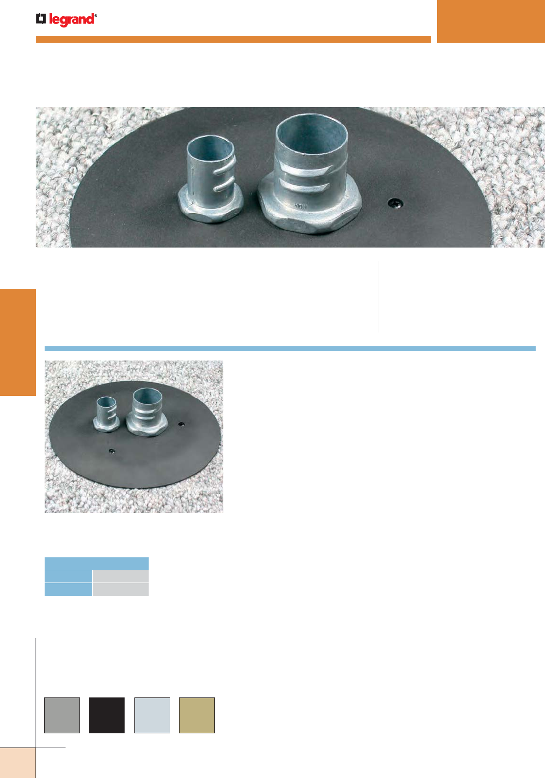
WWW.LEGRAND.US/WIREMOLD
366
WIREMOLD
POKE-THRU DEVICES
4FFATC Series Furniture Feed Style
Poke-Thru Device (4FFATCBK).
4FFATC SERIES™ POKETHRU DEVICES
CODE REFERENCE
cULus Listed Metallic Outlet Boxes:
File E2961 Guide QCIT.
cULus Listed Nonmetallic Outlet Boxes &
Fittings Classified for Fire Resistance:
File R8209 Guide CEYY.
Meets Article 300.21, 300.22(C) & 314 of NEC.
4FFATC Series™ Furniture Feed Style Poke-Thru Devices provide
one (1) 3/4" trade size opening for power and one (1) 1 1/4" trade size
opening for communication.
COLOR OPTIONS
4FFATC Series flanges are available in gray “GY”, black
“BK”, brushed aluminum “AL”, and plated brass “BS”.
HOLE DIAMETER
Minimum: 4" [102mm]
Maximum: 4 1/8" [105mm]
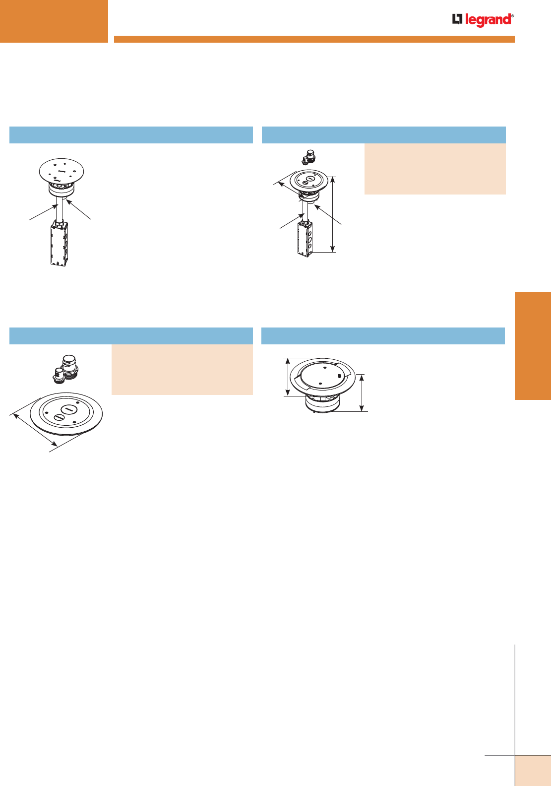
WWW.LEGRAND.US/WIREMOLD
367
WIREMOLD
POKE-THRU DEVICES
Furniture Feed Poke-Thru Assembly
PART NUMBERS:
4FFATCGY (Gray)
4FFATCBK (Black)
4FFATCAL (Aluminum)
4FFATCBS (Brass)
7 1/2"
[191mm]
1 1/4"
Trade Size
Conduit Stem
3/4"
Trade Size
Conduit Stem
7 1/2"
[191mm]
3 7/8"
[98mm]
NOTE: 4FFATC Series Poke-Thru Devices require a 4" [102mm] diameter
hole. Not designed to work with bare concrete or terrazzo. Floor
covering thickness 1/8" minimum.
7 1/2"
[191mm] 16 15/16"
[430mm]
1 1/4"
Trade
Size
Conduit
Stem
3/4"
Trade Size
Conduit Stem
AV3STC Insert Stem with Disposable Plate
Use with 4FFCTC Series covers
to form a complete poke-thru
assembly.
Complete with one-piece finish
flange and conduit assembly.
Conduit assembly consists of one
3/4" and one 1 1/4" trade size
conduit. Finish cover flange
provided with one 3/4" and one
1 1/4" trade size screw plug
opening.
NOTE: Assembled with scrub water gasket.
For use on tile or carpet covered
concrete floors.
Complete with one 3/4" and one
1 1/4" trade size conduit adapters
and closure plugs. Use with the
AV3STC Insert to form a complete
poke-thru assembly.
NOTE: Assembled with scrub water gasket.
For use on tile or carpet floors.
ABPLUG4 Abandonment Plug Assembly
Complete plug assembly
for abandoning an open
4" [102mm] diameter
hole. Assembly includes
intumescent fire-stop
material to maintain the
fire classification of the
floor, integral retainer ring
to prevent the unit from
pulling up through the
floor, and a black die-cast
aluminum cover.
4FFATC SERIES™ POKETHRU DEVICES
4FFATC Series Poke-Thru Devices Ordering Information
Finish Flange & Conduit Adapter Assembly
PART NUMBERS:
4FFCTCBK (Black)
4FFCTCGY (Gray)
4FFCTCAL (Aluminum)
4FFCTCBS (Brass)
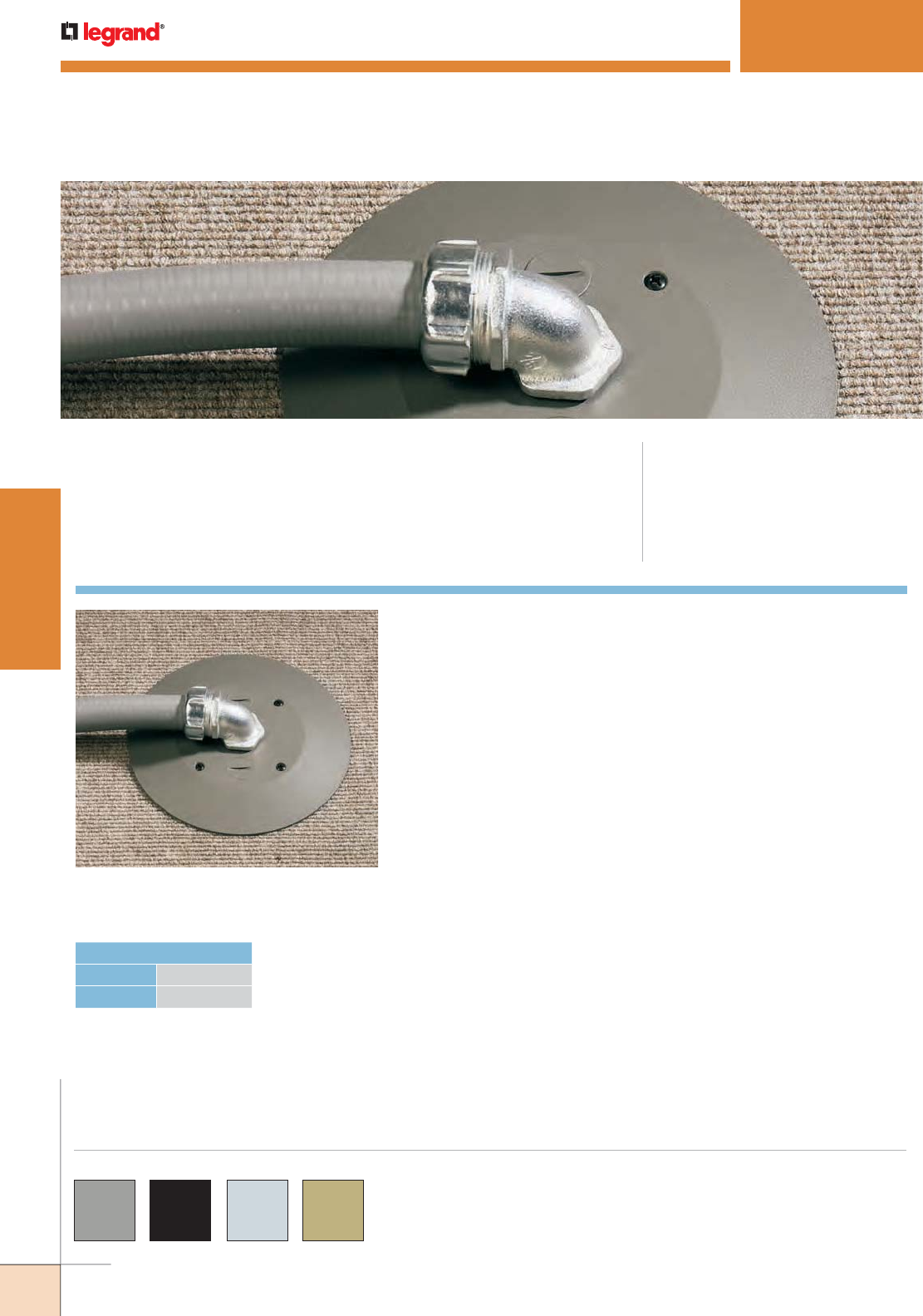
WWW.LEGRAND.US/WIREMOLD
368
WIREMOLD
POKE-THRU DEVICES
RC7AFFTC Series Furniture Feed Style
Poke-Thru Device installed in a tiled floor.
RC7AFFTC SERIES™ POKETHRU DEVICES
CODE REFERENCE
cULus Listed Metallic Outlet Boxes:
File E2961 Guide QCIT.
cULus Listed Nonmetallic Outlet Boxes &
Fittings Classified for Fire Resistance:
File R8209 Guide CEYY.
Meets Article 300.21, 300.22(C) & 314 of NEC.
RC7AFFTC Series™ Furniture Feed Style Poke-Thru Devices provide one (1)
3/4" trade size opening for power and two (2) 1/2" trade size openings for
communication.
COLOR OPTIONS
RC7AFFTC Series flanges are available in gray “GY”, black
“BK”, brushed aluminum “AL” and brass “BS”.
HOLE DIAMETER
Minimum: 3 1/16" [78mm]
Maximum: 3 1/8" [79mm]
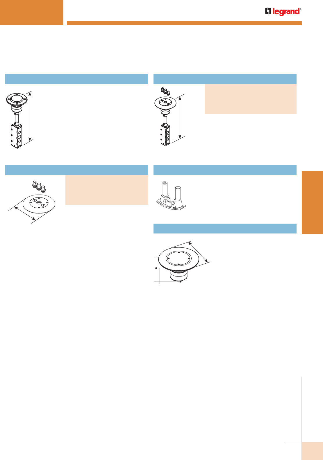
WWW.LEGRAND.US/WIREMOLD
369
WIREMOLD
POKE-THRU DEVICES
NOTE: RC7AFFTC Series Poke-Thru Devices require a 3 1/16" [78mm]
diameter hole. Not designed to work with bare concrete or terrazzo.
Floor covering thickness 1/8" minimum.
RC7STC Insert Stem with Disposable Plate
Use with RC7CFF Series covers to form a
complete poke-thru assembly.
Complete with one 3/4" [19.1mm]
conduit and two 1/2" trade size
adapters and closure plugs. Use
with the RC7STC Insert to form a
complete poke-thru assembly.
NOTE: Assembled with scrub water gasket.
For use on tile or carpet floors.
7" [178mm]
16 1/2"
[419mm]
7"
[178mm]
3 3/16"
[97mm]
16 1/2"
[419mm]
RC7AFFTC SERIES™ POKETHRU DEVICES
ABPLUG3 Abandonment Plug Assembly
Complete plug assembly for
abandoning an open 3" [76mm]
diameter hole. Assembly includes
intumescent fire-stop material to
maintain the fire classification of
the floor, integral retainer ring to
prevent the unit from pulling up
through the floor, and a black
die-cast aluminum cover.
RC7AFFTC Series Poke-Thru Devices Ordering Information
Complete with one-piece finish flange
and conduit assembly with one 3/4"
and two 1/2" trade size conduit
adapters and closure plugs
NOTE: Assembled with scrub water gasket. For
use on tile or carpet floors.
Flush Furniture Feed Poke-Thru Assembly
PART NUMBERS:
RC7AFFTCBK (Black)
RC7AFFTCGY (Gray)
RC7AFFTCAL (Aluminum)
RC7AFFTCBS (Brass)
Finish Flange & Conduit Adapter Assembly
PART NUMBERS:
RC7CFFTCBK (Black)
RC7CFFTCGY (Gray)
RC7CFFTCAL (Aluminum)
RC7CFFTCBS (Brass)
COM75 Communication Adapter
Provides two 3/4" trade size threaded
openings to accommodate conduit
connections.
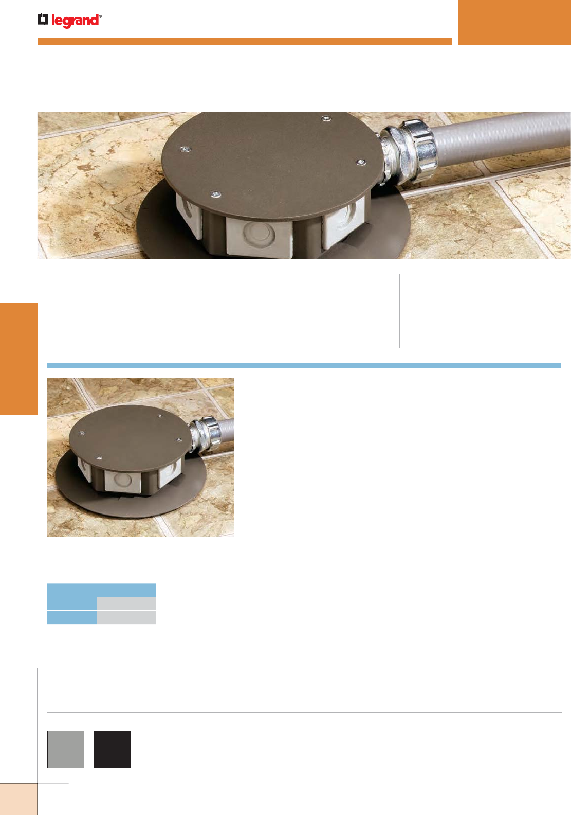
WWW.LEGRAND.US/WIREMOLD
370
WIREMOLD
POKE-THRU DEVICES
RC9AFFTC Series Furniture Feed Style
Poke-Thru Device (RC9AFFTCBK).
RC9AFFTC SERIES™ POKETHRU DEVICES
CODE REFERENCE
cULus Listed Metallic Outlet Boxes:
File E2961 Guide QCIT.
cULus Listed Nonmetallic Outlet Boxes &
Fittings Classified for Fire Resistance:
File R8209 Guide CEYY.
Meets Article 300.21, 300.22(C) & 314 of NEC.
RC9AFFTC Series™ Furniture Feed Style Poke-Thru Devices provide a
hexagonal housing to allow for multi-directional feeds.
RC9AFFTC Series flanges are available in gray “GY”
or black “BK” finishes.
COLOR OPTIONS
HOLE DIAMETER
Minimum: 3 1/16" [78mm]
Maximum: 3 1/8" [79mm]
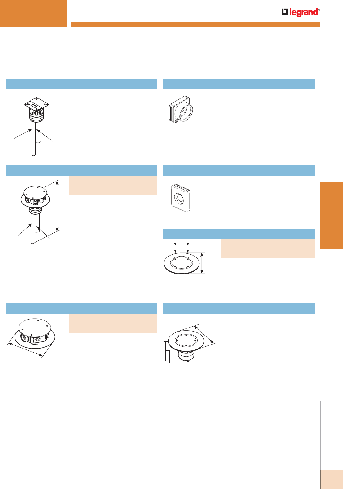
WWW.LEGRAND.US/WIREMOLD
371
WIREMOLD
POKE-THRU DEVICES
NOTE: RC9AFFTC Series Poke-Thru Devices require a 3" [76mm]
diameter hole. Not designed to work with bare concrete or
terrazzo. Floor covering thickness 1/8" minimum.
RC9FFS Insert Stem with Disposable Plate
Furniture feed insert with one
1 1/4" and one 1/2" trade size
conduit to feed power and
communication services. Use with
RC9CFFTC Series Covers to form a
complete poke-thru assembly.
FFD-P Drop-In Hub
3/4" trade size threaded drop-in hub.
Used to make conduit connections to
the service head.
Complete with hexagonal service
head. Service head has one 3/4"
trade size threaded conduit hub
and five rubber grommets. The
service head includes scrub water
gasket. Unit is supplied with one
1 1/4" and one 1/2" trade size
conduit stem to feed power and
communication services. Service
head is not to be used as a junction
box. All power connections must
be made in a junction box below
(not supplied).
NOTE: Assembled with scrub water gasket.
For use on tile or carpet floors.
Used to abandon fitting by removing
hexagonal housing and placing plate
inside the flange. Insert stem must
remain in the place.
RC9AFFTC SERIES™ POKETHRU DEVICES
7"
[178mm]
7"
[178mm]
3 3/16"
[97mm]
7"
[178mm]
14 7/16"
[367mm]
1 1/4"
Trade Size
Conduit Stem
1/2"
Trade Size
Conduit Stem
1 1/4"
Trade Size
Conduit Stem
1/2"
Trade Size
Conduit Stem
Complete with gray or black carpet
flange, gray hexagonal housing,
five black rubber grommets, and
one 3/4" trade size threaded drop-
in hub. The service head includes
scrub water gasket. Use with
RC9FFS Insert to form a complete
poke-thru assembly.
TG-1 Communication Grommet
Drop-in rubber grommet for
pass-through cabling. Set of two
grommets (one grommet shown)
black.
ABPLUG3 Abandonment Plug Assembly
Complete plug assembly for
abandoning an open 3" [76mm]
diameter hole. Assembly includes
intumescent fire-stop material to
maintain the fire-classification of the
floor, integral retainer ring to prevent
the unit from pulling up through the
floor, and a black die-cast aluminum
cover.
RC9AFFTC Series Poke-Thru Devices Ordering Information
Assembled Furniture Feed Poke-Thru Device
PART NUMBERS:
RC9AFFTCGY (Gray)
RC9AFFTCBK (Black)
Finish Flange & Service Head Assembly
PART NUMBERS:
RC9CFFTCGY (Gray)
RC9CFFTCBK (Black)
Abandonment Plate
PART NUMBERS:
RCAPFFTC (Gray)
RCAPFFTCBK (Black)
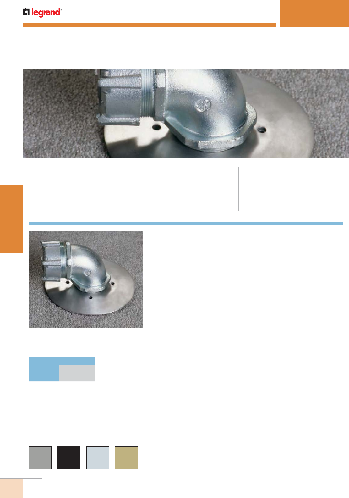
WWW.LEGRAND.US/WIREMOLD
372
WIREMOLD
POKE-THRU DEVICES
RC9AM2TC Series Furniture Feed Style
Poke-Thru Device (RC9AM2STC).
RC9AM2TC SERIES™ POKETHRU DEVICES
CODE REFERENCE
cULus Listed Metallic Outlet Boxes:
File E2961 Guide QCIT.
cULus Listed Nonmetallic Outlet Boxes &
Fittings Classified for Fire Resistance:
File R8209 Guide CEYY.
Meets Article 300.21, 300.22(C) & 314 of NEC.
RC9AM2TC Series™ Furniture Feed Style Poke-Thru Devices provide
one (1) 1 1/4" and 2" trade size concentric openings for single service
pass-through.
RC9AM2TC Series flanges are available in gray “GY”, black “BK”,
brushed brass “BS” and brushed aluminum “AL” finishes.
Custom color options are also available. Consult the factory for
more information.
COLOR OPTIONS
HOLE DIAMETER
Minimum: 3" [76mm]
Maximum: 3 1/8" [79mm]
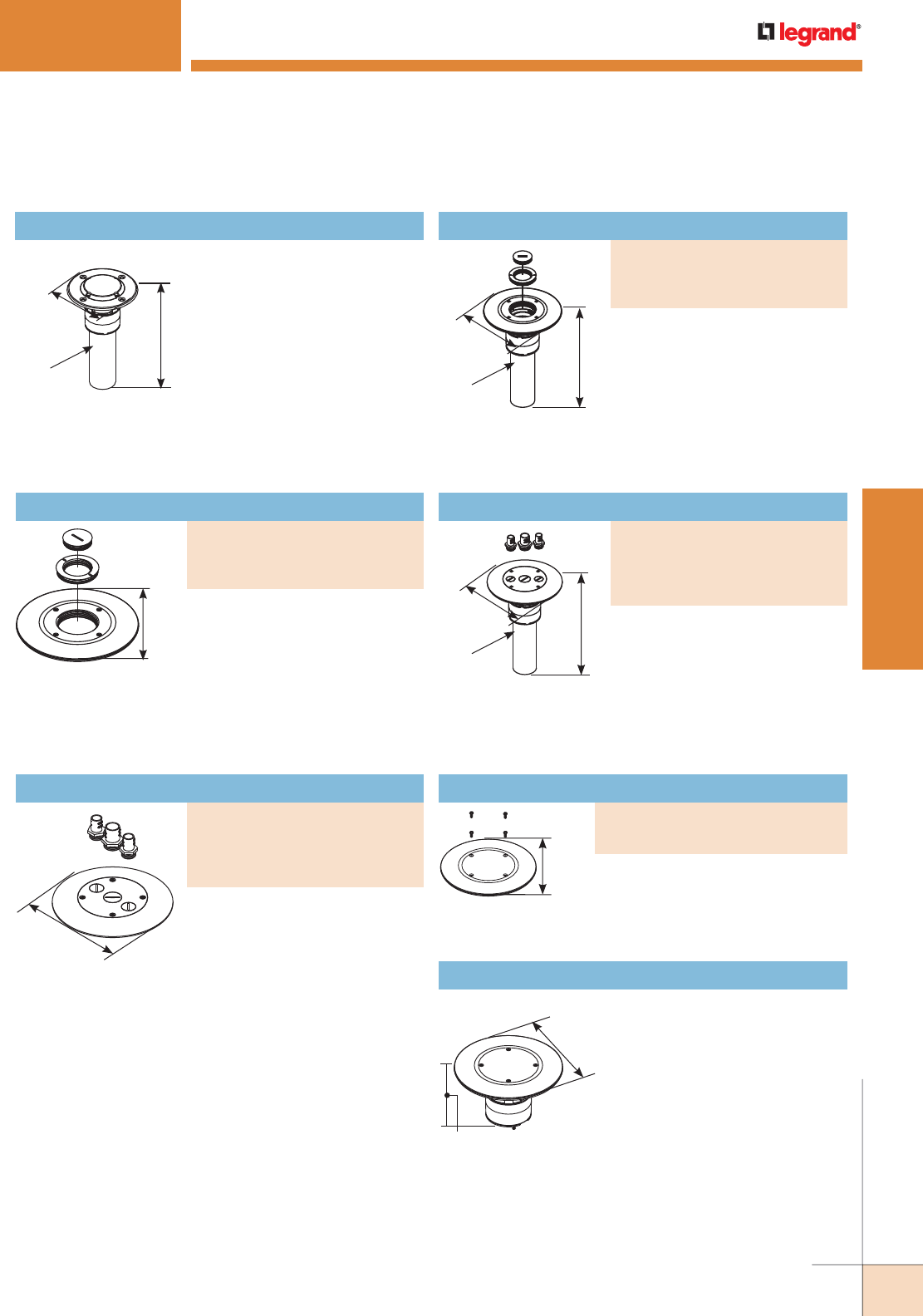
WWW.LEGRAND.US/WIREMOLD
373
WIREMOLD
POKE-THRU DEVICES
7" [178mm]
Complete with one 3/4" trade size
conduit and two 1/2" trade size
adapters and closure plugs. Use
with RC9AM2STC Insert Stem to
form a complete poke-thru
assembly.
NOTE: RC9AM2TC Series Poke-Thru Devices Poke-Thru Devices require a 3"
[76mm] diameter hole. Not designed to work with bare concrete or
terrazzo. Floor covering thickness 1/8" minimum.
RC9AM2STC Insert Stem with Disposable Plate
Use with RC9CM2TC Series cover
to complete installation.
Complete with combination
1 1/4" and 2" trade size threaded
conduit openings and closure
plugs. Must be used with a conduit
connector (not included) at the
adapter assembly plate to maintain
fire classification.
NOTE: Assembled with scrub water gasket.
For use on tile or carpet floors.
Complete with combination
1 1/4" and 2" trade size threaded
conduit openings and closure
plugs. Must be used with a conduit
connector (not included) at the
adapter assembly plate to maintain
fire classification.
NOTE: Assembled with scrub water gasket.
For use on tile or carpet floors.
RC9AM2TC SERIES™ POKETHRU DEVICES
2" trade size conduit stem,
complete with one 3/4" trade size
conduit and two 1/2" trade size
adapters and closure plugs.
NOTE: Assembled with scrub water gasket.
For use on tile or carpet floors.
ABPLUG3 Abandonment Plug Assembly
Complete plug assembly for
abandoning an open 3" [76mm]
diameter hole. Assembly includes
intumescent fire-stop material
to maintain the fire-classification
of the floor, integral retainer ring
to prevent the unit from pulling
up through the floor, and a black
die-cast aluminum cover.
7"
[178mm]
7"
[178mm]
3 3/16"
[97mm]
10"
[254mm]
7"
[178mm]
2" Trade Size
Conduit Stem
10"
[254mm]
7"
[178mm]
2" Trade Size
Conduit Stem
10 1/4"
[260mm]
7"
[178mm]
2" Trade Size
Conduit Stem
RC9AM2TC Series Poke-Thru Devices Ordering Information
Assembled Furniture Feed Poke-Thru Device
PART NUMBERS:
RC9AM2TCGY (Gray)
RC9AM2TCBK (Black)
RC9AM2TCAL (Aluminum)
Assembled Furniture Feed Poke-Thru Device
PART NUMBERS:
RC7AM2TCGY (Gray)
RC7AM2TCBK (Black)
RC7AM2TCBS (Brass)
RC7AM2TCAL (Aluminum)
Furniture Feed Poke-Thru Device Cover Assembly
PART NUMBERS:
RC9CM2TCGY (Gray)
RC9CM2TCBK (Black)
RC9CM2TCAL (Aluminum)
Furniture Feed Poke-Thru Device Cover Assembly
PART NUMBERS:
RC7CFFTCGY (Gray)
RC7CFFTCBK (Black)
RC7CFFTCBS (Brass)
RC7CFFTCAL (Aluminum) Used to abandon fitting by removing
hexagonal housing and placing plate
inside the flange. Insert stem must
remain in the place.
7"
[178mm]
Abandonment Plate
PART NUMBERS:
RCAPFFTC (Gray)
RCAPFFTCBK (Black)
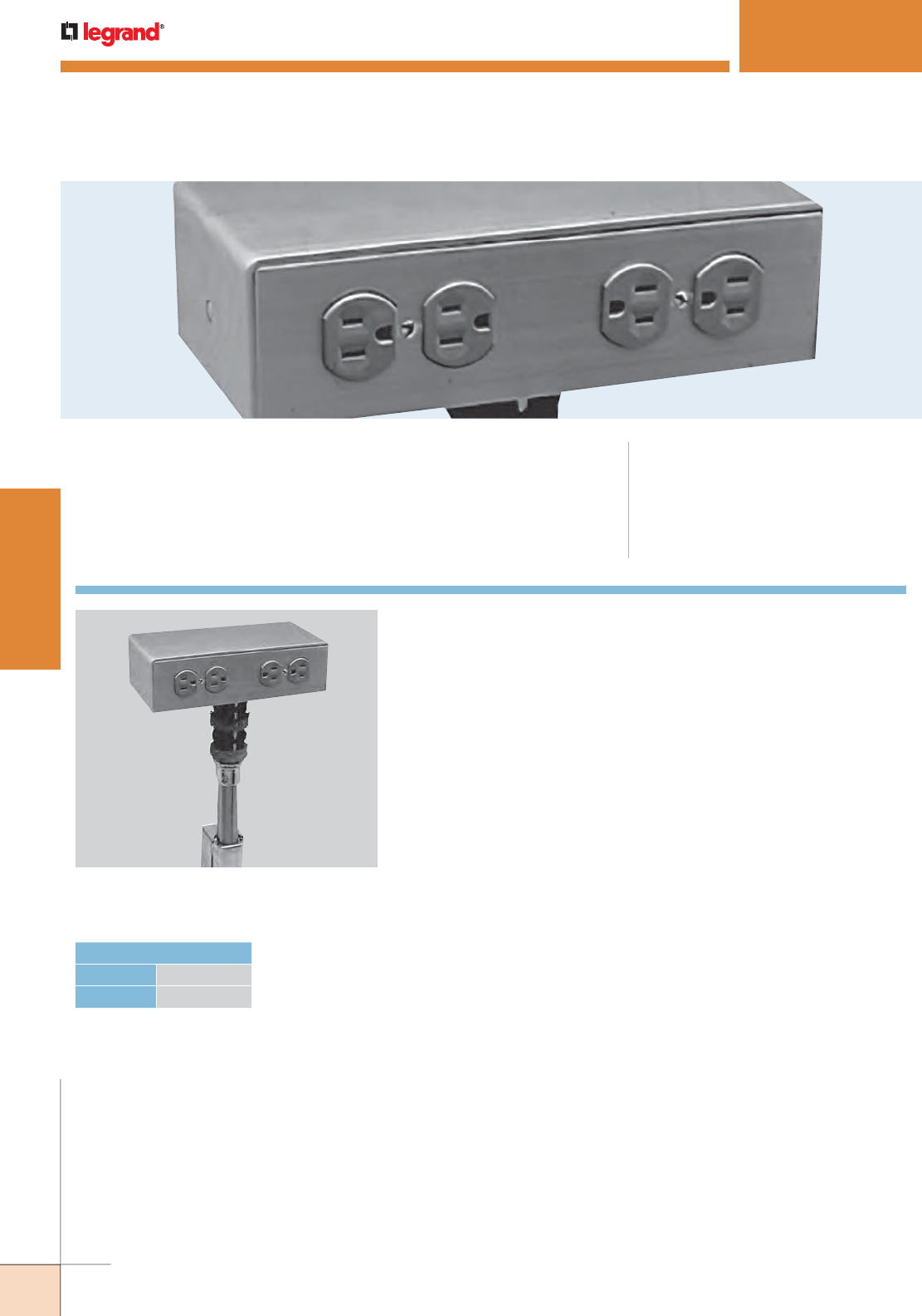
WWW.LEGRAND.US/WIREMOLD
374
WIREMOLD
POKE-THRU DEVICES
FIT Series Pedestal Style Poke-Thru
Device with 241 Service Head.
FIT SERIES™ POKETHRU DEVICES
CODE REFERENCE
cULus Listed Metallic Outlet Boxes:
File E2961 Guide QCIT.
cULus Listed Nonmetallic Outlet Boxes &
Fittings Classified for Fire Resistance:
File R8209 Guide CEYY.
Meets Article 300.21, 300.22(C) & 314 of NEC.
FIT Series™ Pedestal Style Poke-Thru Devices provide dual service
capability in either a single- or dual-width service head.
CORE HOLE DIAMETER
Minimum: 2 1/32" [52mm]
Maximum: 2 1/8" [54mm]
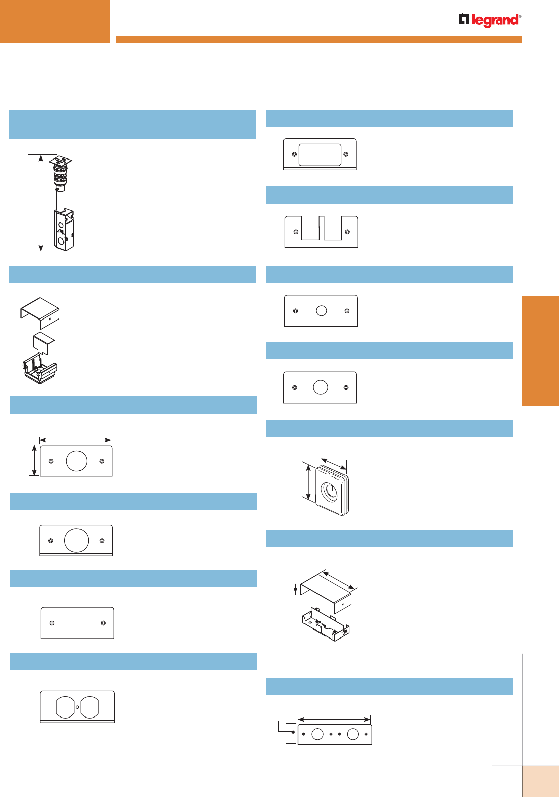
WWW.LEGRAND.US/WIREMOLD
375
WIREMOLD
POKE-THRU DEVICES
NOTE: FIT Series Poke-Thru Devices require a
minimum 2 1/32" [52mm],
2 1/8" [54mm] maximum diameter hole.
200-H/BTC Housing & Base
Single width. For 200 Series Service
Head. Barrier included (may not be
needed on single service applications).
Base has a 3/4" trade size knockout for
connection to FIT insert. Also includes
scrub water gasket.
NOTE: Assembled with scrub water gasket. For
use on tile or carpet floors.
FIT 2" [51mm] Poke-Thru Insert with
Junction Box Assembly
1" trade size barriered conduit. Also
includes BX/MC cable connector. Must
be activated with 200 Series or 241
Series Service Head and FIFP or FP
Series Faceplates (sold separately)
to maintain UL Listing and/or
Classification.
FIFP-1.390 Faceplate
Single-gang with one 1.390"
[35.3mm] receptacle opening.
FIT SERIES™ POKETHRU DEVICES
15 1/2"
[394mm]
4 5/8" [118mm]
1 7/8"
[48mm]
FIFP-1.562 Faceplate
Single-gang with one
1.562" [39.7mm] receptacle
opening.
FIFP-B Faceplate
Single-gang, blank.
FIFP-R Faceplate
Single-gang with one duplex
receptacle opening.
FIFP-SS Faceplate
Single-gang with one surge
suppression receptacle opening.
FIFP-T Faceplate
Single-gang faceplate with
one telephone opening.
Communication grommets
included.
FIFP50 Faceplate
Single-gang with one 1/2" trade
size knockout.
FIFP75 Faceplate
Single-gang with one 3/4" trade
size knockout.
1 3/8"
[35mm]
1 5/8"
[41mm]
9 1/4"
[235mm]
2 5/8"
[67mm]
9" [229mm]
2 1/2"
[64mm]
TG-1 Communications Grommet
One set of two grommets.
241-H/BTC Assembly & Base
Double width housing for 241
Series Service Head. Barrier
included (may not be needed
for single service applications).
Base has a 3/4" trade size KO
for connection to FIT insert. See
faceplates on this page. Order
two plates to complete service
head assembly.
FP1.390-1.390 Faceplate
Two-gang with two 1.390"
[35.3mm] receptacle openings.
NOTE: Assembled with scrub water gasket. For use on tile or carpet floors.
FIT Series Poke-Thru Devices Ordering information
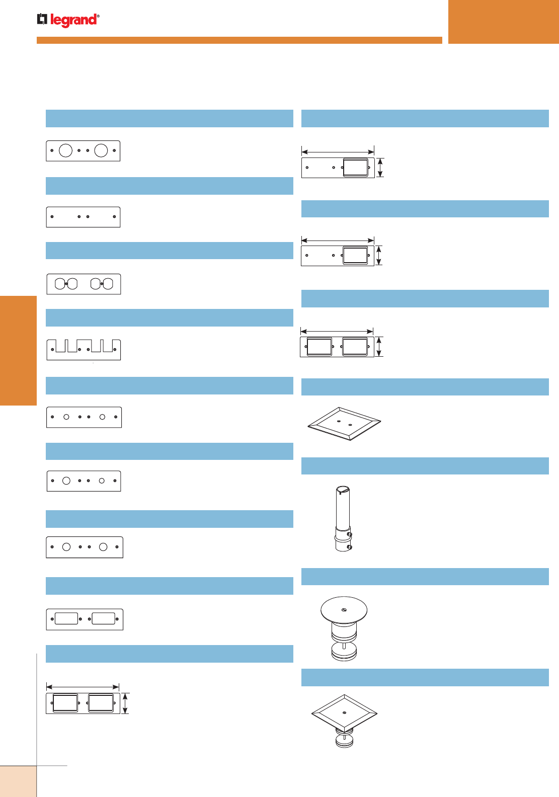
WWW.LEGRAND.US/WIREMOLD
376
WIREMOLD
POKE-THRU DEVICES
NOTE: FIT Series Poke-Thru Devices require a 2" [51mm] diameter hole.
FP1.562-1.562 Faceplate
Two-gang with two 1.562" [39.7mm]
receptacle openings.
9"
[229mm]
2 1/2"
[64mm]
9"
[229mm]
2 1/2"
[64mm]
9"
[229mm]
2 1/2"
[64mm]
9"
[229mm]
2 1/2"
[64mm]
FIT SERIES™ POKETHRU DEVICES
FPB-B Faceplate
Two-gang faceplate – blank.
FP2R Faceplate
Two-gang faceplate with two
duplex receptacle openings.
FP2T Faceplate
Two-gang faceplate with two
communications openings.
FP50-50 Faceplate
Two-gang with two 1/2" trade size
knockouts.
FP75-50 Faceplate
Two-gang with one 3/4" and one
1/2" trade size knockout.
FP75-75 Faceplate
Two-gang with two 3/4" trade size
knockouts.
FPSS-SS Faceplate
Two-gang with two surge
suppression device openings.
FPACT-ACT Faceplate
Two-gang faceplate with two
6A mini adapters openings.
Two adapters included. Accepts
Wiremold Open System
communication modules.
FPB-ACT Faceplate
Two-gang faceplate with one
6A mini adapter opening. One
adapter included. Accepts
Wiremold Open System
communication modules.
FPB-RT Faceplate
Two-gang plate with one
Ortronics® TracJack adapter
included and one Ortronics®
Series II adapter included.
Flat connector only.
FPB-2RT Faceplate
Two-gang plate with two
Ortronics® TracJack adapters
included and two Ortronics®
Series II adapters included.
Flat connector only.
AP-FITTC Poke-Thru Abandonment Plate
2" [51mm]. Stem must remain in
cored hole.
FIT-EXT Assembled Extension
4 5/8" [118mm]. Includes 1"
trade size barriered conduit and
coupling. For use with slabs
greater than 8" [203mm].
221-21 Carpet Fire-Rated Plug
For carpet applications.
221-21 Tile Fire-Rated Plug
For tile applications.
FIT Series Poke-Thru Devices Ordering information (continued)
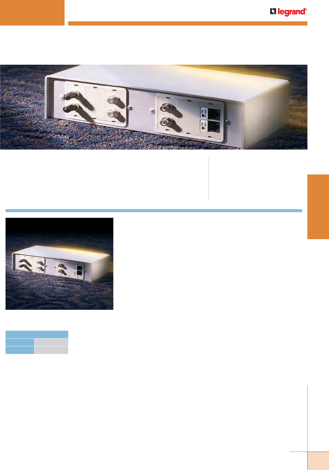
WWW.LEGRAND.US/WIREMOLD
377
WIREMOLD
POKE-THRU DEVICES
RC91GHBTC & RC92GHBTC SERIES™ POKETHRU DEVICES
RC92GHBTC Series Poke-Thru Device.
CODE REFERENCE
cULus Listed Metallic Outlet Boxes:
File E2961 Guide QCIT.
cULus Listed Nonmetallic Outlet Boxes &
Fittings Classified for Fire Resistance:
File R8209 Guide CEYY.
Meets Article 300.21, 300.22(C) & 314 of NEC.
RC91GHBTC & RC92GHBTC Series™ Pedestal Style Poke-Thru
Devices provide dual service capability in either a single- or dual-width
service head.
HOLE DIAMETER
Minimum: 3 1/16" [78mm]
Maximum: 3 1/8" [79mm]
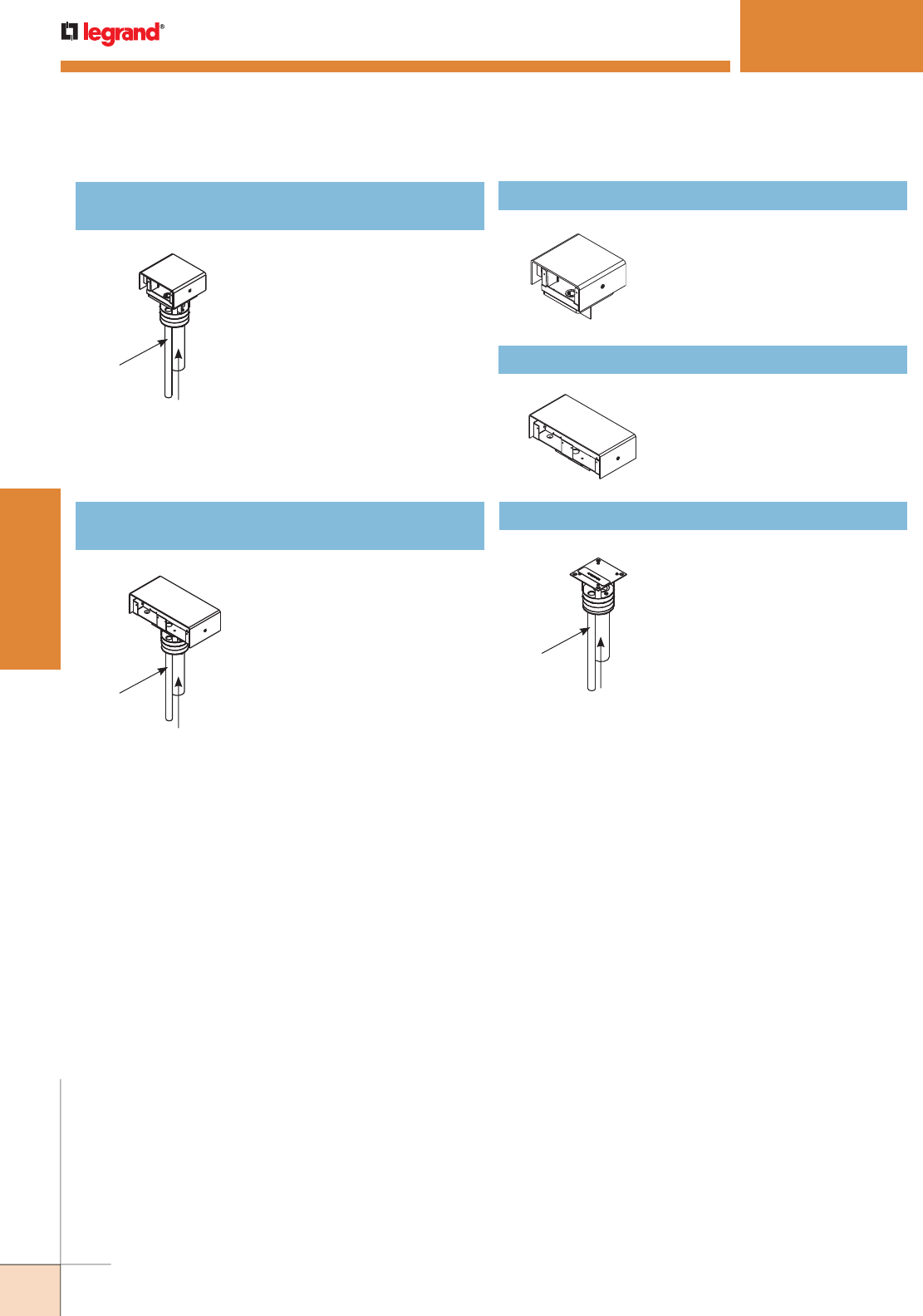
WWW.LEGRAND.US/WIREMOLD
378
WIREMOLD
POKE-THRU DEVICES
1/2" Trade Size
Conduit Stem
1 1/4" Trade Size
Conduit Stem
1/2" Trade Size
Conduit Stem
1 1/4" Trade Size
Conduit Stem
1/2" Trade Size
Conduit Stem
1 1/4" Trade Size
Conduit Stem
NOTE: RC91GHBTC and RC92GHBTC Series Poke-Thru Devices require a
minimum 31/16" [78mm] diameter hole.
RC91GHBTC & RC92GHBTC SERIES™ POKETHRU DEVICES
Ordering Information
291-H/BTC Single Width Service Head
Includes housing, base, scrub
water gasket, and barrier. Use
with Insert Assembly RC9FFS.
RC91GHBTC Poke-thru Insert with Single Width
Service Head
Includes insert stem with
disposable plate and service
head with housing, base, scrub
water gasket, and barrier. Service
head and insert install together
to make a poke-thru assembly.
Combine with faceplates
(sold separately) to complete
service head assembly. Shown
assembled. Service head is
shipped unassembled with the
insert stem.
NOTE: Assembled with scrub water gasket.
For use on tile or carpet floors.
RC92GHBTC Poke-thru Insert with Double Width
Service Head
Includes insert stem with
disposable plate and service
head with housing, base, scrub
water gasket, and barrier. Service
head and insert install together
to make a poke-thru assembly.
Combine with faceplates
(sold separately) to complete
service head assembly. Shown
assembled. Service head is
shipped unassembled with the
insert stem.
NOTE: Assembled with scrub water gasket.
For use on tile or carpet floors.
292-H/BTC Double Width Service Head
Includes housing, base, scrub
water gasket, and barrier. Use
with Insert Assembly RC9FFS.
RC9FFS Insert Stem With Disposable Plate
Furniture feed insert with one
1 1/4" and one 1/2" trade size
conduit to feed power and
communication services.
Use with either 291-H/BTC
or 292-H/BTC Service Head to
form complete unit.
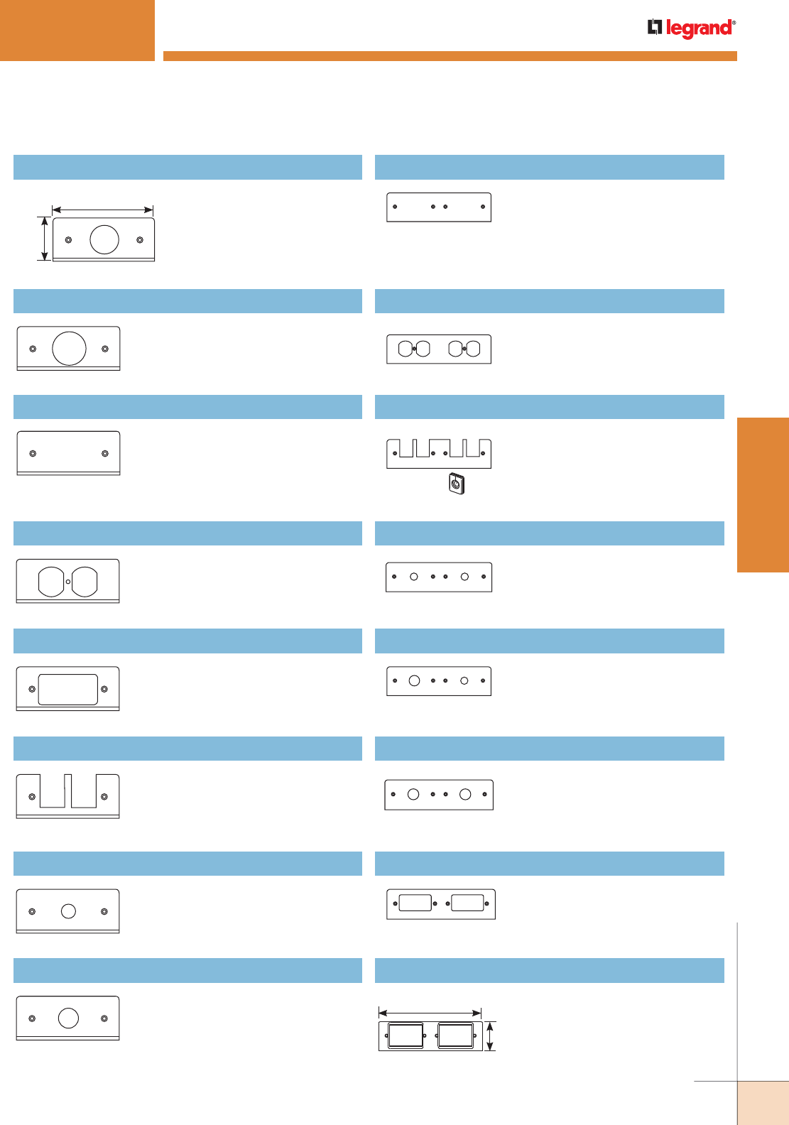
WWW.LEGRAND.US/WIREMOLD
379
WIREMOLD
POKE-THRU DEVICES
FPB-B Faceplate
Two-gang faceplate – blank.
FP2R Faceplate
Two-gang faceplate with two
duplex receptacle openings.
FP2T Faceplate
Two-gang faceplate with two
communications openings.
FP50-50 Faceplate
Two-gang with two 1/2" trade
size knockouts.
4 5/8"
[118mm]
1 7/8"
[48mm]
FIFP-1.390 Faceplate
Single-gang with one 1.390"
[35.3mm] receptacle opening.
9"
[229mm]
2 1/2"
[64mm]
FIFP-1.562 Faceplate
Single-gang with one 1.562"
[39.7mm] receptacle opening.
FIFP-B Faceplate
Single-gang, blank.
FIFP-R Faceplate
Single-gang with one duplex
receptacle opening.
FIFP-SS Faceplate
Single-gang with one surge
suppression receptacle opening.
FIFP-T Faceplate
Single-gang faceplate with
one telephone opening.
Communication grommets
included.
RC91GHBTC & RC92GHBTC SERIES™ POKETHRU DEVICES
Ordering Information
FIFP50 Faceplate
Single-gang with one 1/2" trade
size knockout.
FIFP75 Faceplate
Single-gang with one 3/4" trade
size knockout.
FP75-50 Faceplate
Two-gang with one 3/4" and one
1/2" trade size knockout.
FP75-75 Faceplate
Two-gang with two 3/4" trade
size knockouts.
FPSS-SS Faceplate
Two-gang with two surge
suppression device openings.
FPACT-ACT Faceplate
Two-gang faceplate with two
6A mini adapter openings. Two
adapters included. Accepts
Wiremold Open System
communication modules.
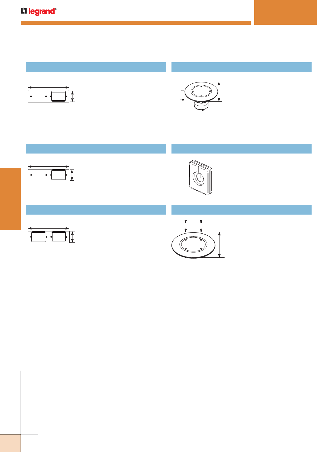
WWW.LEGRAND.US/WIREMOLD
380
WIREMOLD
POKE-THRU DEVICES
RC91GHBTC & RC92GHBTC SERIES™ POKETHRU DEVICES
Ordering Information
9"
[229mm]
2 1/2"
[64mm]
9"
[229mm]
2 1/2"
[64mm]
9"
[229mm]
2 1/2"
[64mm]
7"
[178mm]
3 3/16"
[97mm]
7" [178mm]
FPB-ACT Faceplate
Two-gang faceplate with one
6A mini adapter opening. One
adapter included. Accepts
Wiremold Open System
communication modules.
FPB-RT Faceplate
Two-gang plate with one
Ortronics® TracJack adapter
included and one Ortronics®
Series II adapter included.Flat
connector only.
FPB-2RT Faceplate
Two-gang plate with two
Ortronics® TracJack adapters
included and two Ortronics®
Series II adapters included. Flat
connector only.
ABPLUG3 Abandonment Plug Assembly
Complete plug assembly for
abandoning an open 3" [76mm]
diameter hole. Assembly
includes intumescent fire-
stop material to maintain
the fire classification of the
floor, integral retainer ring to
prevent the unit from pulling
up through the floor, and a
black die-cast aluminum cover.
TG-1 Communication Grommet
One set of two grommets (one
grommet shown) black.
RCAPFFTCBK Abandonment Plate
Used to abandon fitting by
removing hexagonal housing
and placing plate inside the
flange. Insert stem must
remain in the place. Available
in black (BK).
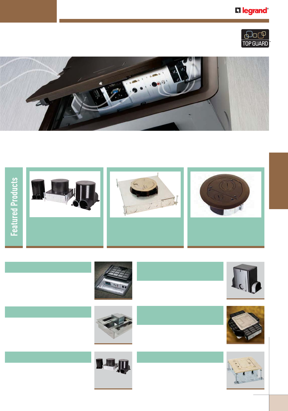
WWW.LEGRAND.US/WIREMOLD
381
FLOOR BOXES
WIREMOLD
437
Resource RFB® Series
Floor Boxes
FLOOR BOXES
Wiremold® offers one of the most complete lines of both commercial and
residential floor box solutions in the industry. From small, single service
boxes to large multi-utility convention center versions, there is a Wiremold
floor box to meet any need.
Ratchet-Pro Series
Floor Box 423
Wiremold® Floor Boxes are TopGuard protected
to meet and exceed the UL scrub water
exclusion requirement.
RFB4E Series
Floor Box 450
405
Fire Classified Floor Boxes
430
Modulink™ 880MP Series
Floor Boxes
Table of Contents
Evolution™ Series Floor Boxes
XX
389
423
Ratchet-Pro™ Series Floor Boxes
FloorSource™
Series Round
FF Floor Box 518
OmniBox™ Series Floor Boxes
463
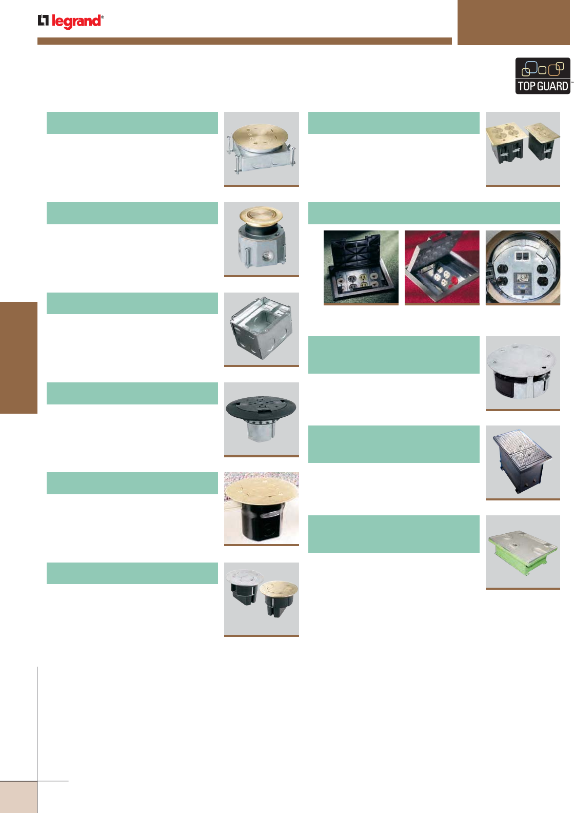
WWW.LEGRAND.US/WIREMOLD
382
FLOOR BOXES
WIREMOLD
FLOOR BOXES
Table of Contents
476
880 Series™ Floor Boxes
480
800 Series™ Floor Boxes
482
880W Series™ Floor Boxes
490
861 Series™ Floor Boxes
493
862 Series™ Floor Boxes
863 Series™ Floor Boxes
496
Wiremold® Floor Boxes are TopGuard protected
to meet and exceed the UL scrub water
exclusion requirement.
498
WMFB Series™ Floor Boxes
523
CCBB Series™ Ballroom
Floor Boxes
FloorSource Series™ Raised Floor Boxes
AC Series™ Raised
Floor Boxes
508 513
CRFB Series™
Raised Floor Boxes
501
AF Series™ Raised
Floor Boxes
519
CCFB Series™
Convention Center Products
518
FloorSource™ Series Round
Furniture Feed Floor Boxes

WWW.LEGRAND.US/WIREMOLD
383
FLOOR BOXES
WIREMOLD
Box Model Box Type
Service
Capability
Box
Capacity
Box
Construction
Depth Behind
Device Plates KO Sizes Cover Model
Cover
Construction
Cover & Flange
Part Nos. Notes
Ratchet-Pro
RPSFB-OG
Round Dual 2 Gangs Steel & PVC 3 1/2"
[89mm]
3/4" – 2" Die-Cast
Aluminum
Tile, Carpet RPAV3CTC,
RP7CTC,
RPAMD4CTC,
RPAMD8CTC,
RP4FFCTC,
RP9AM2CTC
Surface Devices,
On-Grade
or Above-Grade
RFB Series
RFB2-OG Rectangular Triple 2 Gangs Steel 3"
[76mm]
3/4" – 1 1/4"
Trade Size
FloorPort™
Die-Cast
Aluminum
Tile, Carpet,
Wood,
Terrazzo
FPCT, FPBT,
FPFFT Series
Recessed
Devices, Fully
Adjustable
RFB Series
RFB4-C1 Rectangular Dual 4 Gangs Cast Iron 2"
[51mm]
1" – 1 1/4"
Trade Size
FloorPort™
Die-Cast
Aluminum
Tile,
Carpet
FPCT, FPBT,
FPFFT Series
Recessed
Devices, Fully
Adjustable
RFB Series
RFB4E-OG Rectangular Triple 4 Gangs Steel 3 1/2"
[89mm]
3/4" – 2"
Trade Size
Evolution
Round
Poke-Thru
Cover
Tile, Carpet,
Wood,
Terrazzo, Bare
Concrete
6CT Series Recessed
Devices, Fully
Adjustable
RFB Series
RFB6-OG Rectangular Triple 6 Gangs Steel 3 1/4"
[83mm]
3/4" – 1 1/4"
Trade Size
FloorPort™
Die-Cast
Aluminum
Tile, Carpet,
Wood,
Terrazzo
FPCT, FPBT,
FPFFT Series
Recessed
Devices, Fully
Adjustable
RFB Series
RFB6E-OG Rectangular Triple 6 Gangs Steel 3 1/4"
[83mm]
3/4" – 1 1/4"
Trade Size
Evolution™
Round
Poke-Thru
Cover
Tile, Carpet,
Wood,
Terrazzo, Bare
Concrete
8CT Series Recessed
Devices, Fully
Adjustable
RFB Series
RFB9-OG Rectangular Triple 9 Gangs Steel 2 1/2"
[64mm]
3/4" – 1 1/4"
Trade Size
Die-Cast
Aluminum
Tile, Carpet,
Wood,
Terrazzo
RFB119CTC,
RFB119BTC
Recessed
Devices, Fully
Adjustable
RFB Series
RFB11-OG Rectangular Triple 11 Gangs Steel 2 1/2"
[64mm]
3/4" – 2"
Trade Size
Die-Cast
Aluminum
Tile, Carpet,
Wood,
Terrazzo
RFB119CTC,
RFB119BTC
Recessed
Devices, Fully
Adjustable
Evolution
Series
EFB6S-OG
Rectangular Triple 6 Gangs Steel 3 7/8"
[98mm]
3/4" – 2"
Trade Size
Evolution
Rectangular
Die-Cast
Alumuinum
Tile, Carpet,
Wood, Terrazzo,
Polished
Concrete
EFB610CTC,
EFB610BTC,
EFB610BT,
EFB610CT
Removable
Modules,
Standard Size
Device Plates
EPOXY PAINTED METAL & CAST IRON BOXES
FLOOR BOX SYSTEMS
Quick Selection Guide
On-Grade Floor Boxes for Concrete Floors
Box Model Box Type
Service
Capability
Box
Capacity
Box
Construction
Depth Behind
Device Plates KO Sizes Cover Model
Cover
Construction
Cover & Flange
Part Nos. Notes
Ratchet-Pro
881
Round Single 1 Gang PVC 1 3/4"
[44mm]
1"
Trade Size
Metal,
Polycarbonate
Tile, Carpet 895, 896 Flush Devices,
On-Grade
or Above-Grade
Ratchet-Pro
RPNFB
Round Dual 2 Gangs PVC 3 1/2"
[89mm]
3/4" – 2" Die-Cast
Aluminum
Tile, Carpet RPAV3CTC,
RP7CTC,
RPAMD4CTC,
RPAMD8CTC,
RP4FFCTC,
RP9AM2CTC
Surface Devices,
On-Grade
or Above-Grade
Modulink
880MP
880MP2
Rectangular Single 1 Gang PVC 1 3/4"
[44mm]
1/2" – 2"
Trade Size
Metal,
Polycarbonate
Tile, Carpet 817, 818, 828, 829,
830 Series
Flush Devices,
On-Grade
or Above-Grade
Modulink
880MP
880MP2
Rectangular Single 2 or 3
Gangs
PVC 1 3/4"
[44mm]
1/2" – 2"
Trade Size
Metal,
Polycarbonate
Tile, Carpet 827, 828, 829, 830,
837, 838 Series
Flush Devices,
On-Grade
or Above-Grade
PVC BOXES
Wiremold® Floor Boxes are TopGuard protected
to meet and exceed the UL scrub water
exclusion requirement.
NOTE: Most Wiremold floor boxes and accessories are listed by Underwriters Laboratories Inc., and comply with
Federal Specifications W-C-583b in one of the following types and classes: Type 1-Fully adjustable, Type II-Semi-adjustable,
Type III-Non-adjustable, Class 1-Watertight, Class 2-Concrete-tight.

WWW.LEGRAND.US/WIREMOLD
384
FLOOR BOXES
WIREMOLD
Box Model Box Type
Service
Capability
Box
Capacity
Box
Construction
Depth Behind
Device Plates KO Sizes Cover Model
Cover
Construction
Cover & Flange
Part Nos. Notes
Evolution
Series
EFB8S-OG
Rectangular Triple 8 Gangs Steel 3 1/2"
[89mm]
3/4" – 2"
Trade Size
Evolution
Rectangular
Tile, Carpet,
Wood,
Terrazzo,
Polished
Concrete
EFB610CTC,
EFB610BTC,
EFB610BT,
EFB610CT
Removable
Modules,
Standard size
Device Plates
Evolution
Series
EFB10S-OG
Rectangular Triple 10 Gangs Steel 3 1/2"
[89mm]
3/4" – 2"
Trade Size
Evolution
Rectangular
Tile, Carpet,
Wood,
Terrazzo,
Polished
Concrete
EFB610CTC,
EFB610BTC,
EFB610BT,
EFB610CT
Removable
Modules,
Finished
Interior
800 Series
800CILCK Round Single 1 Gang Cast Iron N/A 1/2" – 3/4"
Trade Size
Brass Tile,
Carpet
825 Series Flush
Devices, Fully
Adjustable
OmniBox
880CS1,
880CM1
Rectangular Single 1 Gang Cast Iron 880CS1:
2 3/4" [70mm]
880CM1:
1 3/4" [44mm]
1"
Trade Size
Metal,
Polycarbonate
Tile,
Carpet
817, 818, 828,
829, 830 Series
Flush
Devices, Fully
Adjustable
OmniBox
880CS2,
880CM2
Rectangular Dual 2 Gangs Cast Iron 880CS2:
2 3/4" [70mm]
880CM2:
1 3/4" [44mm]
1"
Trade Size
Metal,
Polycarbonate
Tile,
Carpet
827, 828, 829,
830 Series
Flush
Devices, Fully
Adjustable
OmniBox
880CS3,
880CM3
Rectangular Triple 3 Gangs Cast Iron 880CS3:
2 3/4" [70mm]
880CM3:
1 3/4" [44mm]
1"
Trade Size
Metal,
Polycarbonate
Tile,
Carpet
828, 829, 830,
837, 838 Series
Flush
Devices, Fully
Adjustable
880 Series
887B/889B Round Single 1 Gang Cast Iron 887B:
2" [51mm]
889B:
3" [76mm]
887B:
1/2" – 3/4"
889B:
1" – 1 1/4"
Trade Size
Metal,
Polycarbonate
Tile,
Carpet
895, 896 Series Flush
Devices, Fully
Adjustable
CCBB Series
CCBBS-OG
CCBBL-OG
Rectangular Triple 12 Gangs Steel CCBBS-OG:
3 3/4" [95mm]
CCBBl-OG:
Custom
CCBBS:
3/4" – 2"
Trade Size
CCBBL:
Field
Punched
Cast
Aluminum
Carpet CCBBSCTCAL,
CCBBLCTCAL
Recessed
Devices,
Adjustable
Pre-pour
CCFB Series Rectangular Multi Customs Steel Custom Field
Punched
Cast
Aluminum
Tile, Carpet,
Bare Concrete
CCFBCTC Power, A/V,
Comm.,
Water, Air
EPOXY PAINTED METAL & CAST IRON BOXES
FLOOR BOX SYSTEMS
Quick Selection Guide
On-Grade Floor Boxes for Concrete Floors (continued)
Fire Classified Floor Boxes – Add “FC” Suffix to part number for fire classified version. All fire classified boxes feed with 1 1/4" conduit feeds.
Box Model Box Type
Service
Capability
Box
Capacity
Box
Construction
Depth Behind
Device Plates KO Sizes Cover Model
Cover
Construction
Cover & Flange
Part Nos. Notes
Ratchet-Pro
881 Round Single (4) #12
AWG or
(6) Cat 6A
PVC 1 3/4"
[44mm]
1"
Trade Size
Metal,
Polycarbonate
Tile,
Carpet
895, 896
Series
Flush Devices,
On-Grade
or Above-Grade
Ratchet-Pro
RPNFB Round Dual 2 Gang PVC 3 1/2"
[89mm]
3/4" – 2"
Trade Size
Metal,
Polycarbonate
Tile,
Carpet
RPAMD4CTC,
RPAMD8CTC,
RF4FFCTC, RPAV3CTC,
RP9AM2CTC, RP7CTC
Flush Devices,
On-Grade
or Above-Grade
Modulink
880MPFC
Rectangular Single (4) #12
AWG or
(6) Cat 6A
PVC 1 3/4"
[44mm]
1"
Trade Size
Metal,
Polycarbonate
Tile,
Carpet
817, 818,
828, 829,
830 Series
Flush Devices,
On-Grade
or Above-Grade
Modulink
880MP, 880MP2 Rectangular Single (4) #12
AWG or
(6) Cat 6A
PVC 1 3/4"
[44mm]
1/2" – 2"
Trade Size
Metal,
Polycarbonate
Tile,
Carpet
817, 818,
828, 829,
830 Series
Flush Devices,
On-Grade
or Above-Grade
Modulink
880MP, 880MP2 Rectangular Dual PVC 1 3/4"
[44mm]
1/2" – 2"
Trade Size
Metal,
Polycarbonate
Tile,
Carpet
827, 828, 829,
830, 837,
838 Series
Flush Devices,
On-Grade
or Above-Grade
PVC BOXES
Above-Grade Floor Boxes for Concrete Floors
Wiremold® Floor Boxes are TopGuard protected
to meet and exceed the UL scrub water
exclusion requirement.
NOTE: Most Wiremold floor boxes and accessories are listed by Underwriters Laboratories Inc., and comply with
Federal Specifications W-C-583b in one of the following types and classes: Type 1-Fully adjustable, Type II-Semi-adjustable,
Type III-Non-adjustable, Class 1-Watertight, Class 2-Concrete-tight.

WWW.LEGRAND.US/WIREMOLD
385
FLOOR BOXES
WIREMOLD
FLOOR BOX SYSTEMS
Quick Selection Guide
Fire Classified Floor Boxes – Add “FC” Suffix to part number for fire classified version. All fire classified boxes feed with 1 1/4" conduit feeds.
Box Model Box Type
Service
Capability
Box
Capacity
Box
Construction
Depth Behind
Device Plates KO Sizes Cover Model
Cover
Construction
Cover &
Flange
Part Nos. Notes
800 Series
800LCK Round Single 1 Gang Steel N/A 1/2 – 3/4"
Trade Size
Brass Tile,
Carpet
825 Series Flush
Devices, Fully
Adjustable
880 Series
885B/886B Round Single 1 Gang Steel 885B:
2" [51mm]
886B:
2 1/4"
[57mm]
885B:
1/2" – 3/4"
886B:
1/2" – 1"
Trade Size
Metal,
Polycarbonate
Tile,
Carpet
895, 896
Series
Flush
Devices,
Fully
Adjustable
OmniBox
880S1, 880M1
8801S-FC
Rectangular Single 1 Gang
(4) #12 AWG/
Gang or (6)
Cat 6A/Gang
Steel 880S1:
2 3/4"
[70mm]
880M1:
1 3/4" [44mm]
880S1:
1/2" – 1"
880M1:
1/2" – 3/4"
Trade Size
Metal,
Polycarbonate
Tile,
Carpet
817, 818,
827, 828,
829,
830 Series
Flush
Devices,
Fully
Adjustable
OmniBox
880S2, 880M2
8802S-FC
Rectangular Dual 2 Gangs
(4) #12 AWG/
Gang or (6)
Cat 6A/Gang
Steel 880S2:
2 3/4"
[70mm]
880M2:
1 3/4" [44mm]
880S2:
1/2" – 1"
880M2:
1/2" – 3/4"
Trade Size
Metal,
Polycarbonate
Tile,
Carpet
827, 828,
829,
830 Series
Flush
Devices,
Fully
Adjustable
OmniBox
880S3, 880M3
8803S-FC
Rectangular Triple 1 Gang
(4) #12 AWG/
Gang or (6)
Cat 6A/Gang
Steel 880S3:
2 3/4"
[70mm]
880M3:
1 3/4" [44mm]
880S3:
1/2" – 1"
880M3:
1/2" – 3/4"
Trade Size
Metal,
Polycarbonate
Tile,
Carpet
828, 829,
830, 837,
838
Series
Flush
Devices,
On-Grade or
Above-Grade
Ratchet-Pro
RPSFB Round Dual 2 Gangs PVC 3 1/2"
[89mm]
3/4" – 2" Die-Cast
Aluminum
Tile, Carpet RPAV3CTC,
RP7CTC,
RPAMD4CTC,
RPAMD8CTC,
RP4FFCTC,
RPAM2CTC,
RP9AM2CTC
Surface
Devices,
On-Grade
or Above-
Grade
RFB Series
RFB2 Rectangular Triple 1 Gang
(4) #12 AWG/
Gang or (6)
Cat 6A/Gang
Steel 3"
[76mm]
3/4" – 1 1/4"
Trade Size
FloorPort
Die-Cast
Aluminum
Tile, Carpet,
Wood,
Terrazzo
FPCT,
FPBT,
FPFFT
Series
Recessed
Devices,
On-Grade or
Above-Grade
RFB Series
RFB4 Rectangular Triple 1 Gang
(4) #12 AWG/
Gang or (6)
Cat 6A/Gang
Steel 2"
[51mm]
3/4" – 1 1/4"
Trade Size
FloorPort
Die-Cast
Aluminum
Tile, Carpet,
Wood,
Terrazzo
FPCT,
FPBT,
FPFFT
Series
Recessed
Devices,
On-Grade or
Above-Grade
RFB Series
RFB4E Rectangular Triple 4 Gangs Steel 3 1/2"
[89mm]
3/4" – 2"
Trade Size
Evolution
Series
Poke-Thru
Covers
Tile, Carpet,
Wood,
Terrazzo,
Bare
Concrete
6CT & 6CTC
Series
Recessed
Devices,
Fully
Adjustable
RFB Series
RFB6 Rectangular Triple 6 Gangs Steel 3 1/4"
[83mm]
3/4" – 1 1/4"
Trade Size
FloorPort
Die-Cast
Aluminum
Tile, Carpet,
Wood,
Terrazzo
FPCT,
FPBT,
FPFFT
Series
Recessed
Devices,
On-Grade or
Above-Grade
RFB Series
RFB6E Rectangular Triple 6 Gangs Steel 3 1/4"
[83mm]
3/4" – 1 1/4"
Trade Size
Evolution
Series
Poke-Thru
Covers
Tile, Carpet,
Wood,
Terrazzo,
Bare
Concrete
8CT & 8CTC
Series
Recessed
Devices,
Fully
Adjustable
RFB Series
RFB9 Rectangular Triple 9 Gangs Steel 2 1/2"
[64mm]
3/4" – 1 1/4"
Trade Size
Die-Cast
Aluminum
Tile, Carpet,
Wood,
Terrazzo
RFB119TC Recessed
Devices,
On-Grade or
Above-Grade
RFB Series
RFB11 Rectangular Triple 11 Gangs Steel 2 1/2"
[64mm]
3/4" – 2"
Trade Size
Die-Cast
Aluminum
Tile, Carpet,
Wood,
Terrazzo
RFB119TC Recessed
Devices,
On-Grade or
Above-Grade
STEEL BOXES
Above-Grade Floor Boxes for Concrete Floors (continued)
Wiremold® Floor Boxes are TopGuard protected
to meet and exceed the UL scrub water
exclusion requirement.
NOTE: Most Wiremold floor boxes and accessories are listed by Underwriters Laboratories Inc., and comply with
Federal Specifications W-C-583b in one of the following types and classes: Type 1-Fully adjustable, Type II-Semi-adjustable,
Type III-Non-adjustable, Class 1-Watertight, Class 2-Concrete-tight.

WWW.LEGRAND.US/WIREMOLD
386
FLOOR BOXES
WIREMOLD
FLOOR BOX SYSTEMS
Quick Selection Guide
Box Model Box Type
Service
Capability
Box
Capacity
Box
Construction
Depth Behind
Device Plates KO Sizes Cover Model
Cover
Construction
Cover &
Flange
Part Nos. Notes
Evolution
Series
EFB6S
Rectangular Triple 6 Gangs Steel 3 7/8"
[98mm]
3/4" – 2"
Trade Size
Die-Cast
Aluminum
Tile, Carpet,
Wood, Terrazzo,
Polished Concrete
EFB610CTC,
EFB610BTC,
EFB610BT,
EFB610CT
Removable
Modules,
Standard size
Device Plates
Evolution
Series
EFB8S
Rectangular Triple 8 Gangs Steel 3 1/2"
[89mm]
3/4" – 2"
Trade Size
Die-Cast
Aluminum
Tile, Carpet,
Wood, Terrazzo,
Polished Concrete
EFB610CTC,
EFB610BTC,
EFB610BT
EFB610CT
Removable
Modules,
Standard size
Device Plates
Evolution
Series
EFB10S
Rectangular Triple 10 Gangs Steel 3 1/4"
[83mm]
3/4" – 2"
Trade Size
Die-Cast
Aluminum
Tile, Carpet,
Wood, Terrazzo,
Polished Concrete
EFB610CTC,
EFB610BTC,
EFB610BT,
EFB610CT
Removable
Modules,
Finished
Interior
CCBB Series
CCBBS
CCBBL
Rectangular Triple 12 Gangs Steel CCBBS:
3 3/4" [95mm]
CCBBL:
Custom
CCBBS: 3/4" –
2" Trade Size
CCBBL: Field
Punched
Cast
Aluminum
Carpet CCBBSCTCAL,
CCBBLCTCAL
Recessed
Devices,
Adjustable
Pre-pour
CCFB Series Rectangular Multi Custom Steel Custom Field
Punched
Cast
Aluminum
Tile, Carpet,
Bare
Concrete
CCFBCTC Power, A/V,
Comm.,
Water, Air
STEEL BOXES (continued)
Above-Grade Floor Boxes for Concrete Floors (continued)
NOTE: Most Wiremold floor boxes and accessories are listed by Underwriters Laboratories Inc., and comply with
Federal Specifications W-C-583b in one of the following types and classes: Type 1-Fully adjustable, Type II-Semi-adjustable,
Type III-Non-adjustable, Class 1-Watertight, Class 2-Concrete-tight.
Wiremold® Floor Boxes are TopGuard protected
to meet and exceed the UL scrub water
exclusion requirement.
862 Series
862 Round Single 1 Gang PVC N/A 3/4"
Trade Size
Brass, Brushed
Aluminum
Tile,
Carpet
Included with Kit
or 895, 896 Series
WMFB Series
WMFB1 Square Single 1 Gang PVC N/A 1/2" & 3/4"
Trade Size
Brass,
Brushed Nickel
Tile,
Carpet
Included with Kit
WMFB Series
WMFB2 Square Dual 2 Gangs PVC N/A 1/2" & 3/4"
Trade Size
Brass,
Brushed Nickel
Tile,
Carpet
Included with Kit
863 Series
863 Round Dual 2 Gangs PVC N/A 1/2"
Trade Size
Romex strain relief
pass-though opening
for communications
Brass, Brushed
Aluminum
Carpet Included with Kit
RESIDENTIAL BOXES
Box Model Box Type
Service
Capability
Box
Capacity
Box
Construction
Depth Behind
Device Plates KO Sizes
Cover
Construction
Cover
Type
Cover & Flange
Part Nos.
861 Series
861 Round Single 1 Gang Die-Cast
Aluminum
N/A 1/2" Trade Size Brass,
Brushed Aluminum
Tile,
Carpet
895 Series &
Poke-Thru Covers
862 Series
862 Round Single 1 Gang PVC N/A 3/4" Trade Size Brass Tile,
Carpet
Included with Kit
or 895, 896 Series
863 Series
863 Round Dual 2 Gangs PVC N/A 1/2" Trade Size
Romex strain relief
pass-though opening
for communications.
Brass,
Brushed Aluminum
Carpet Included
with Kits
880W Series,
880W1 Rectangular Single 1 Gang Steel 2 3/4"
[70mm]
1/2" & 3/4"
Trade Size
Brass,
Brushed Aluminum,
Nonmetallic
Tile,
Carpet
817, 818, 828, 829,
830 Series
880W Series,
880W2 Rectangular Dual 2 Gangs Steel 2 3/4"
[70mm]
1/2" & 3/4"
Trade Size
Brass,
Brushed Aluminum,
Nonmetallic
Tile,
Carpet
827, 828, 829,
830 Series
880W Series,
880W3 Rectangular Triple 3 Gangs Steel 2 1/4"
[57mm]
1/2" & 3/4"
Trade Size
Brass,
Brushed Aluminum,
Nonmetallic
Tile,
Carpet
828, 829, 830, 837,
838 Series
CRFB Series
CRFB4 Round Triple 4 Gangs Die-Cast
Aluminum
2 1/4"
[57mm]
1/2, 3/4", 1",
1 1/4" & 2"
Trade Size
CRFB & Evolution
Die-Cast Aluminum
Tile,
Carpet
CRFBCTC,
CRFBBTC,
8AT Series
COMMERCIAL BOXES
Floor Boxes for Wood Floor

WWW.LEGRAND.US/WIREMOLD
387
FLOOR BOXES
WIREMOLD
FLOOR BOX SYSTEMS
Quick Selection Guide
AF Series
SAF 2 1/2 Square Triple 3 Gangs Steel 1 3/4"
[44mm]
1/2" & 3/4"
Trade Size
Polycarbonate Tile,
Carpet
Included
with Box
AC Series
AC8840 Square Single 2 Gangs Steel 1 1/2"
[38mm]
1/2" & 3/4"
Trade Size
Die-Cast
Zinc
Carpet Included
with Box
AC Series
AC8104 Square Dual 4 Gangs Steel 1 5/8"
[41mm]
1/2" & 3/4"
Trade Size
Die-Cast
Zinc
Carpet Included
with Box
6FF Series
6FF-AFB Round Dual 2 Gangs Die Cast N/A 1/2" to 1 1/2" Die Cast
Aluminum
Carpet Cover Sold
Separately
Evolution Series
EFB6S
Rectangular Triple 6 Gangs Steel 3 7/8"
[98mm]
3/4" – 2"
Trade Size
Die-Cast
Aluminum
Tile, Carpet,
Wood, Terrazzo,
Polished Concrete
EFB610CTC,
EFB610BTC,
EFB610BT,
EFB610CT
Evolution Series
EFBFF Rectangular Dual 2 Gangs Steel NA 1/2" - 2"
Trade Size
Die-Cast
Aluminum
Tile, Carpet, Wood FPFFTC
Series
ACCESS FLOOR DEPTH: 4"
Box Model Box Type
Service
Capability
Box
Capacity
Box
Construction
Depth Behind
Device Plates KO Sizes
Cover
Construction
Cover
Type
Cover & Flange
Part Nos.
AF Series
SAF 2 1/2 Square Triple 3 Gangs Steel 1 3/4"
[44mm]
1/2" & 3/4"
Trade Size
Polycarbonate Tile,
Carpet
Included
with Box
6FF Series
6FF-AFB Round Dual 2 Gangs Die Cast N/A 1/2" to 1 1/2" Die Cast
Aluminum
Carpet Cover Sold
Separately
ACCESS FLOOR DEPTH: 3"
Raised Floor Boxes
Wiremold® Floor Boxes are TopGuard protected
to meet and exceed the UL scrub water
exclusion requirement.
NOTE: Most Wiremold floor boxes and accessories are listed by Underwriters Laboratories Inc., and comply with
Federal Specifications W-C-583b in one of the following types and classes: Type 1-Fully adjustable, Type II-Semi-adjustable,
Type III-Non-adjustable, Class 1-Watertight, Class 2-Concrete-tight.
Box Model Box Type
Service
Capability
Box
Capacity
Box
Construction
Depth Behind
Device Plates KO Sizes
Cover
Construction
Cover
Type
Cover & Flange
Part Nos.
AF Series
SAF 2 1/2 Square Triple 3 Gangs Steel 1 3/4"
[44mm]
1/2" & 3/4"
Trade Size
Polycarbonate Tile,
Carpet
Included
with Box
AF Series
AF1 Square Triple 4 Gangs Die-Cast
Aluminum
2 3/4"
[70mm]
1/2" & 3/4"
Trade Size
Polycarbonate Tile,
Carpet
Included
with Box
AF Series
AF3 Square Triple 8 Gangs Die-Cast
Aluminum
2 3/4"
[70mm]
1/2" & 3/4"
Trade Size
Polycarbonate Tile,
Carpet
Included
with Box
AC Series
AC8840 Square Single 2 Gangs Steel 1 1/2"
[38mm]
1/2" & 3/4"
Trade Size
Die-Cast
Zinc
Carpet Included
with Box
AC Series
AC8850 Square Single 4 Gangs Steel 2"
[51mm]
1/2" & 3/4"
Trade Size
Die-Cast
Zinc
Carpet Included
with Box
AC Series
AC8104 Square Dual 4 Gangs Steel 1 5/8"
[41mm]
1/2" & 3/4"
Trade Size
Die-Cast
Zinc
Carpet Included
with Box
AC Series
AC8105 Square Triple 6 Gangs Steel 2"
[51mm]
1/2" & 3/4"
Trade Size
Die-Cast
Zinc
Carpet Included
with Box
AC Series
AC10105 Square Triple 8 Gangs Steel 2"
[51mm]
1/2" & 3/4"
Trade Size
Die-Cast
Zinc
Carpet Included
with Box
6FF Series
6FF-AFB Round Dual 2 Gangs Die Cast N/A 1/2" to 1 1/2" Die Cast
Aluminum
Tile, Carpet Cover Sold
Separately
Evolution Series
EFB6S
Rectangular Triple 6 Gangs Steel 3 7/8"
[98mm]
3/4" – 2"
Trade Size
Die-Cast
Aluminum
Tile, Carpet,
Wood, Terrazzo,
Polished Concrete
EFB610CTC,
EFB610BTC,
EFB610BT,
EFB610CT
Evolution Series
EFBFF Rectangular Dual 2 Gangs Steel NA 1/2" - 2"
Trade Size
Die-Cast
Aluminum
Tile, Carpet,
Wood
FPFFTC
Series
ACCESS FLOOR DEPTH: 5"

WWW.LEGRAND.US/WIREMOLD
388
FLOOR BOXES
WIREMOLD
FLOOR BOX SYSTEMS
Quick Selection Guide
Raised Floor Boxes (continued)
Wiremold® Floor Boxes are TopGuard protected
to meet and exceed the UL scrub water
exclusion requirement.
Box Model Box Type
Service
Capability
Box
Capacity
Box
Construction
Depth Behind
Device Plates KO Sizes
Cover
Construction
Cover
Type
Cover & Flange
Part Nos. Notes
AF Series
SAF 2 1/2 Square Triple 3 Gangs Steel 1 3/4"
[44mm]
1/2" & 3/4"
Trade Size
Polycarbonate Tile,
Carpet
Included
with Box
AF Series
AF1 Square Triple 4 Gangs Die-Cast
Aluminum
2 3/4"
[70mm]
1/2" & 3/4"
Trade Size
Polycarbonate Tile,
Carpet
Included
with Box
AF Series
AF3 Square Triple 8 Gangs Die-Cast
Aluminum
2 3/4"
[70mm]
1/2" & 3/4"
Trade Size
Polycarbonate Tile,
Carpet
Included
with Box
AC Series
AC8840 Square Single 2 Gangs Steel 1 1/2"
[38mm]
1/2" & 3/4"
Trade Size
Die-Cast
Zinc
Carpet Included
with Box
AC Series
AC8850 Square Single 4 Gangs Steel 2"
[51mm]
1/2" & 3/4"
Trade Size
Die-Cast
Zinc
Carpet Included
with Box
AC Series
AC8104 Square Dual 4 Gangs Steel 1 5/8"
[41mm]
1/2" & 3/4"
Trade Size
Die-Cast
Zinc
Carpet Included
with Box
AC Series
AC8105 Square Triple 6 Gangs Steel 2"
[51mm]
1/2" & 3/4"
Trade Size
Die-Cast
Zinc
Carpet Included
with Box
AC Series
AC10105 Square Triple 8 Gangs Steel 2"
[51mm]
1/2" & 3/4"
Trade Size
Die-Cast
Zinc
Carpet Included
with Box
CRFB Series
CRFB4 Round Triple 4 Gangs Die-Cast
Aluminum
2 1/4"
[57mm]
1/2", 3/4", 1",
1-1/4" & 2"
Trade Size
CRFB &
Evolution
Die-Cast
Aluminum
Tile,
Carpet
CRFBCTC,
CRFBBTC,
8AT Series
Evolution
Series
EFB6S
Rectangular Triple 6 Gangs Steel 3 7/8"
[98mm]
3/4"– 2"
Trade Size
Die-Cast
Aluminum
Tile, Carpet,
Wood,
Terrazzo,
Polished
Concrete
EFB610CTC,
EFB610BTC,
EFB610BT,
EFB610CT
Removable
Modules,
Standard Size
Device Plates
Evolution
Series
EFB8S
Rectangular Triple 8 Gangs Steel 3 1/2"
[89mm]
3/4"– 2"
Trade Size
Die-Cast
Aluminum
Tile, Carpet,
Wood,
Terrazzo,
Polished
Concrete
EFB610CTC,
EFB610BTC,
EFB610BT,
EFB610CT
Removable
Modules,
Standard Size
Device Plates
Evolution
Series
EFB10S
Rectangular Triple 10 Gangs Steel 3 1/4"
[83mm]
3/4"– 2"
Trade Size
Die-Cast
Aluminum
Tile, Carpet,
Wood,
Terrazzo,
Polished
Concrete
EFB610CTC,
EFB610BTC,
EFB610BT,
EFB610CT
Removable
Modules,
Finished
Interior
6FF Series
6FF-AFB Round Dual 2 Gangs Die Cast N/A 1/2" to 1 1/2" Die Cast
Aluminum
Carpet Cover Sold
Separately
Evolution
Series
EFBFF
Rectangular Dual 2 Gangs Steel NA 1/2" - 2"
Trade Size
Die-Cast
Aluminum
Tile, Carpet,
Wood
FPFFTC
Series
ACCESS FLOOR DEPTH: 6"
NOTE: Most Wiremold floor boxes and accessories are listed by Underwriters Laboratories Inc., and comply with
Federal Specifications W-C-583b in one of the following types and classes: Type 1-Fully adjustable,
Type II-Semi-adjustable, Type III-Non-adjustable, Class 1-Watertight, Class 2-Concrete-tight.
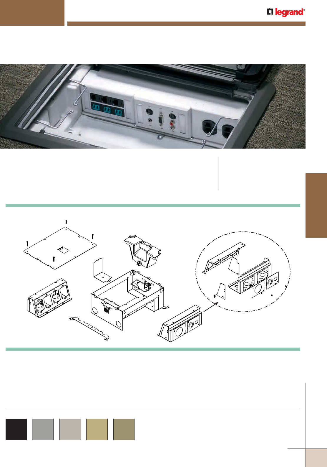
WWW.LEGRAND.US/WIREMOLD
389
FLOOR BOXES
WIREMOLD
A
F
E
D
C
K
G
H
J
I
Each Removable Module consists of
the above components
B
Wiremold® Evolution™ Series Floor Boxes are the latest advancement in the
most complete and innovative line of floor solutions in the industry.
EVOLUTION™ SERIES FLOOR BOXES
CODE REFERENCE
cULus Listed
Metallic Outlet Boxes:
File E2961 Guide QCIT.
Meet Article 300.22(c) of NEC
COLOR OPTIONS
Evolution Series Floor Box Covers are available in the following
powder coated finishes: “BK” black, “GY” gray, “NK” nickel, “BS”
brass, and “BZ” bronze.
Custom color options are also available. Consult the factory for more
information.
KEY
A. Mud Cap (temporary construction cover)
B. Removable Module
C. Toggle Clamp
D. Box
E. Cable Guide
F. Tunnel
G. Mounting Bracket
H. Divider (removable repositionable)
I. End Cap
J. Back Knockout Plate
K. Concrete Level Leg
L. “L” Bracket
Evolution™ Series Floor Box Components
L
B
All items shown above are included
with Evolution Series floor boxes.
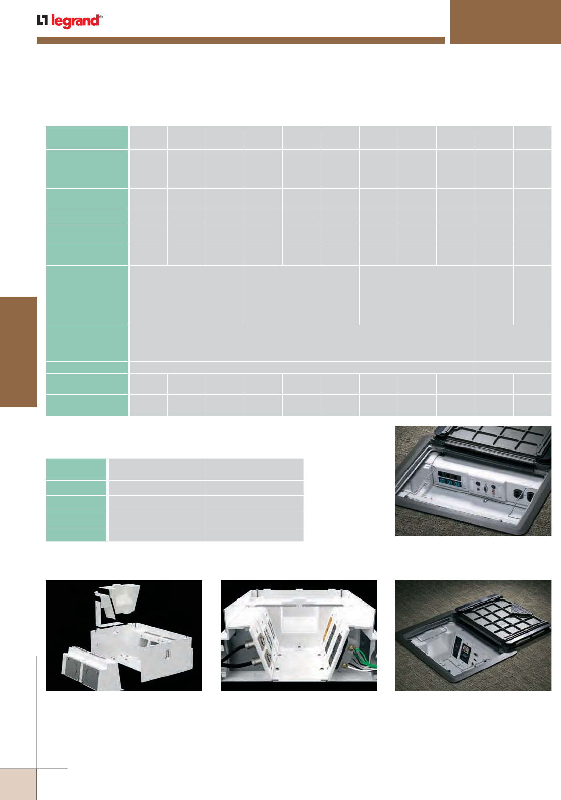
WWW.LEGRAND.US/WIREMOLD
390
FLOOR BOXES
WIREMOLD
EVOLUTION™ SERIES FLOOR BOXES
Configurable with Removable Modules
In addition to having removable dividers and a
tunnel feature that allows all compartments
to be connected, the modules are removable
through the top or back of the floor box. This
allows for easier installations and facilitates
moves, adds and changes without having to
disconnect services, saving time and money.
Audio/Video Design
Evolution Series Floor Boxes have been
developed specifically with the A/V industry in
mind. With 3 1/2" – 3 7/8" [89mm x 98mm] of
wiring capacity behind each device plate, these
boxes will accept devices from leading A/V
manufacturers including Extron® Electronics
and Crestron®.
Durable 180° Articulating Hinge
Hinge design enables covers to open a full
180° and lie flat on the floor surface with the
durability to support a large cover. Provides easy
access to all interior modules and activations
while reducing tripping hazards.
Finished Interior
Fully finished interior removes the unfinished
industrial look while increasing visibility, making
it easier to see where to plug in devices.
EVOLUTION
FLOOR BOX MODEL EFB6S EFB6S-OG EFB6S-FC EFB8S EFB8S-OG EFB8S-FC EFB10S EFB10S-OG EFB10S-FC EFBFF EFBFF-OG
INSTALL FLOOR TYPE:
Concrete Floor
Raised Floor
Wood Floor
YES
YES
YES
YES YES YES
YES
YES
YES YES YES
YES
YES
YES YES YES
YES
YES
YES
BOX TYPE: Standard On-Grade Fire
Classified
Standard On-Grade Fire
Classified
Standard On-Grade Fire
Classified
Furniture
Feed
Furniture
Feed
BOX CAPACITY: 6-Gangs 6-Gangs 6-Gangs 8-Gangs 8-Gangs 8-Gangs 10-Gangs 10-Gangs 10-Gangs 2-Gangs 2-Gangs
DEPTH BEHIND
PLATES: 3 7/8"
[98mm]
3 7/8"
[98mm]
3 7/8"
[98mm]
3 1/2"
[89mm]
3 1/2"
[89mm]
3 1/2"
[89mm]
3 1/2"
[89mm]
3 1/2"
[89mm]
3 1/2"
[89mm]
N/A N/A
REMOVABLE
MODULES: YES YES YES YES YES YES YES YES YES
DEVICE PLATE SIZE: Uses Standard Size Device Plates:
Single-Gang (2 3/4" x 4 1/2")
[70mm x 114mm]
Uses Standard Size Device Plates:
Single-Gang (2 3/4" x 4 1/2")
Double-Gang (4 9/16" x 4 1/2")
Triple-Gang (6 3/8" x 4 1/2")
Four-Gang (8 1/8" x 4 1/2")
Non-Standard Size Device Plates
(4.652" x 2.302")
[117mm x 58mm]
Standard Size Device Plates
Double-Gang (4 9/16 X 4 1/2")
Triple-Gang (6 3/8" X 4 1/2")
Five-Gang (10" x 4 1/2")
COVERS:
COLORS:
EFB610CTC Series, EFB610BTC Series, EFB610CT Series, EFB610BT Series
Black, Gray, Brass, Nickel, Bronze
FPFFTC Series
Black, Gray, Brass,
Nickel, Bronze,
Brushed Aluminum
FLOOR SURFACE: Carpet, Tile, Wood, Bare (Polished) Concrete & Terrazzo Carpet, Tile & Wood
KO SIZE RANGE:
(TRADE SIZE) 3/4" to 2" 3/4" to 2" 1 1/4" 3/4" to 2" 3/4" to 2" 1 1/4" 3/4" to 2" 3/4" to 2" 1 1/4" 1/2" to 2" 1/2" to 2"
FIRE RATING:
(HOURS) Up to
2 Hours
Up to
2 Hours
Up to
2 Hours
NOTE: Covers open full 180°, slide cable egress doors, painted interior.
Evolution™ Series Floor Box Model Selection Guide
MODEL OUTER COMPARTMENTS
(EACH)
CENTER COMPARTMENTS
(EACH)
EFB6 SERIES 32 in.3 [524ml] 38.5 in.3 [630ml]
EFB8 SERIES 27.5 in.3 [450ml] 34 in.3 [557ml]
EFB10 SERIES 23.5 in.3 [385ml] 27.5 in.3 [450ml]
EFBFF SERIES 64.5 in.3 [1056ml] 64.5 in.3 [1056ml]
Evolution Series Floor Box Compartment Volumes
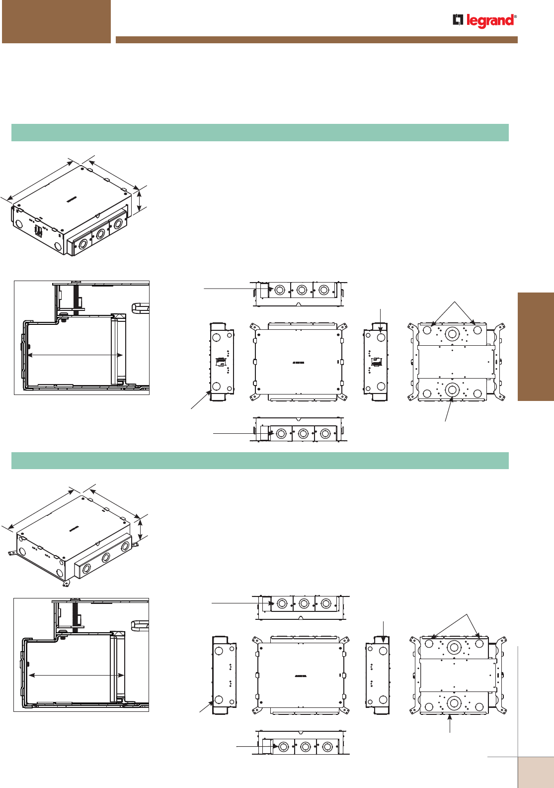
WWW.LEGRAND.US/WIREMOLD
391
FLOOR BOXES
WIREMOLD
Designed to be installed in concrete floors, raised floors, and wood floor applica tions.
Box has a fully finished interior to assist plugging and unplugging of devices.
Designed to work with standard size wall plates. Box comes complete with all
components needed for initial installation. Included components are: Protective/
Disposable cover, tunnel system for connecting the two modules of compartments,
two (2) removable modules, two (2) toggle clamps to secure box to raised and wood
floors, two (2) cable management guides, two (2) leveling support legs for concrete
applications and trade size knockouts ranging in size from 3/4" to 2" trade size.
Items not included with the box and sold separately are: receptacles, communica-
tion jacks, and A/V devices and device plates. Box is compatible with Wiremold®
Walkerflex Modular Wiring System. Custom options are available upon request.
NOTE: For use on bare (polished) concrete or terrazzo floors EFB610-CTR must be used, sold separately.
EFB6S Six-Gang Floor Box
EVOLUTION™ SERIES FLOOR BOXES
Three (3) KOs:
Outer: 1 1/4" Trade Size KO
Inner: 3/4" Trade Size KO
Two (2) KOs:
Outer: 2" Trade Size KO
Inner: 1" Trade Size KO
Two (2) KOs:
1" Trade Size KO
Two (2) KOs:
1" Trade Size KO
Four (4) 1" Trade Size KOs
Three (3) KOs:
Outer: 1 1/4" Trade Size KO
Inner: 3/4" Trade Size KO
3.7/8" [99mm]
EFB6 Depth Behind Plates
3 7/8" [99mm]
EFB6-OG Depth Behind Plates
11 3/16"
[284mm]
15 1/8"
[384mm]
4 1/16"
[103mm]
11 3/16"
[284mm]
15 1/8"
[384mm]
4 1/16"
[103mm]
Designed to be installed in both on-grade and above grade concrete floor applica-
tions. Box has an epoxy coating that allows the box to be placed in on-grade
applications without the need for additional vapor barriers. Designed to work with
standard size wall plates. Box comes complete with all components needed for
initial installation. Included components are: protective/disposable cover, tunnel
system for connecting the two modules of compartments, two (2) removable
modules, two (2) cable manage ment guides, two (2) leveling support legs for con-
crete applications and trade size knockouts ranging in size from 3/4" to 1 1/4". Items
not included with the box and sold separately are: receptacles, communication
jacks, and A/V devices and device plates. Custom options are available upon request.
NOTE: For use on bare (polished) concrete or terrazzo floors EFB610-CTR must be used, sold separately.
EFB6S-OG Six-Gang Floor Box
Evolution™ Series 6-Gang Floor Boxes Ordering Information
Three (3) KOs:
Outer: 1 1/4" Trade Size KO
Inner: 3/4" Trade Size KO Two (2) KOs:
1" Trade Size KO
Two (2) KOs:
1" Trade Size KO
Four (4) 1" Trade Size KOs
Three (3) KOs:
Outer: 1 1/4" Trade Size KO
Inner: 3/4" Trade Size KO
Two (2) KOs:
Outer: 2" Trade Size KO
Inner: 1" Trade Size KO
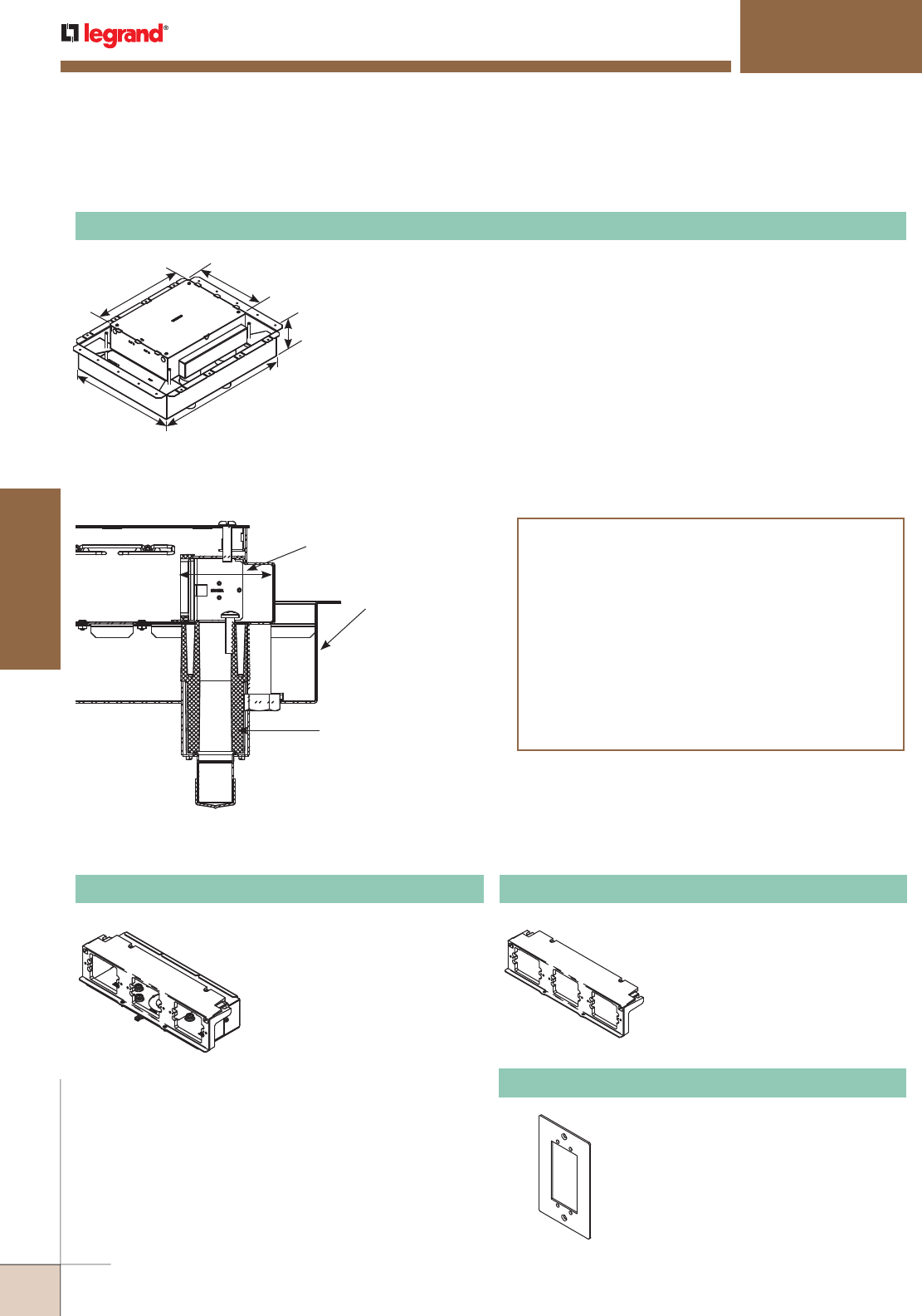
WWW.LEGRAND.US/WIREMOLD
392
FLOOR BOXES
WIREMOLD
Designed to be installed in above grade concrete floors while maintaining the
fire classification of the floor. This box is classified to be used in 2-hour fire rated
floors. Designed to accept standard size wall plates. Box comes complete with all
components needed for initial installation. Included components are: protective/
disposable cover, tunnel system for connecting the two modules of compartments,
fire classified pan, two (2) removable modules, four (4) 1 1/4 intumescent conduit
feeds and two (2) cable management guides. Items not included with the box
and sold separately are: receptacles, communication jacks, and A/V devices and
device plates
NOTE: For use on bare (polished) concrete or terrazzo floors EFB610-CTR must be used, sold
separately.
NOTE: Designed for new construction applications.
NOTE: Consult structural engineer before making cuts into decking. Add additional supports as
instructed by the structural engineer.
EFB6S-FC Six-Gang Fire-Classified Floor Box
EFB6M Module
11 3/16"
[284mm]
15 1/8"
[384mm]
7 1/2"
[191mm]
21 3/4"
[552mm]
17 1/4"
[438mm]
Fire Classified Pan
(Insures 3 1/4" [83mm] of
concrete around box at all times)
1 1/4" [35] Intumescent
Service Feed (Four (4) per box)
3 7/8" [98mm]
Depth Behind Device Plate
Outlet Boxes and Fittings Classified for
Fire Resistance Legrand/Wiremold (R8209)
Type EFB6S-FC, EFB8S-FC and EFB10S-FC preset electrical
insert for use in 2-hour fire rated D900 Series Floor-Ceiling
designs constructed with nominal 2" or 3" deep fluted steel
floor units having a nominal 5" wide valley and crests spaced
12" OC, with a minimum 3 1/4" [83mm] thickness of structural
concrete topping. The assembly preset electrical insert with
floor plate kit and service activations fitting will not reduce
the 2-hour fire rating of the floor assembly when installed in
accordance with the installation instructions accompanying
the preset electrical insert and when the preset electrical
insert are spaced 2' [0.61m] OC with not more than one unit
per 4 square feet [0.37m2] of floor area in each span.
Bank of three (3) compartments
that accept power,
communications and audio/
video devices. Accepts standard
size (2 3/4" x 4 1/2" [70mm x
114mm]) device plates. Includes
device bracket, back plate, three
(3) knockout plates (3/4"/1 1/4"
concentric), two (2) end caps and
one (1) divider.
NOTE: Module will fit on either side of the
floor box.
EFB-AAP Device Plate
Holds two (2) Extron® Electronics
AAP devices. Device plate
dimensions: 2 3/4" x 4 1/2"
[69mm x 114mm].
EFB6-MB Mounting Bracket
Holds up to three (3) devices of
power, communications or audio/
video devices. Bracket accepts
standard size (2 3/4" x 4 1/2"
[70mm x 114mm]) device plates
sold separately by others.
EVOLUTION™ SERIES FLOOR BOXES
Evolution™ Series 6-Gang Floor Boxes Ordering Information (continued)
Evolution™ Series 6-Gang Floor Box Accessories Ordering Information
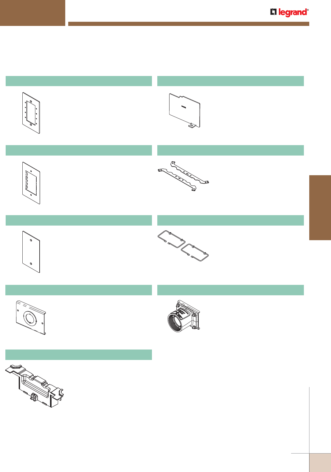
WWW.LEGRAND.US/WIREMOLD
393
FLOOR BOXES
WIREMOLD
EFB-MAAP Device Plate
Holds four (4) Wiremold AVIP or
Extron® Electronics MAAP devices.
Device plate dimensions: 2 3/4" x
4 1/2" [69mm x 114mm].
EFB-MOS Device Plate
European device plate accepts up
to [45mm x 67.5mm] Arteor device.
Device plate dimensions: 2 3/4" x 4
1/2" [69mm x 114mm].
EFB-B Blank Device Plate
Device plate dimensions: 2 3/4" x
41/2" [69mm x 114mm].
EFB6-3/4-11/4 Knockout Plate
Has one (1) 1 1/4" concentric trade
size knockout opening.
EFB6-TUN Tunnel
6 gang tunnel allows for cables to be
wrapped around box from one module
to the other.
EFB6-DIV Relocatable Divider
Provides separation of services.
Includes one (1) divider plate.
EFBCLL Concrete Leveling Legs
Provide floor box adjustment up or
down to match the desired pour
height of the concrete. Included two
(2) leveling legs, threaded rod not
supplied.
EFBCMG Cable Management Guides
Guides help organize and maintain
cable position when opening and
closing the cover.
EFB6S-2HUB 2" Conduit Hub
Hub allows 2" conduit to be fed into
the back of EFB6S and EFB6S-OG
Floor Boxes. Maximum of six (6) hubs
per box.
EVOLUTION™ SERIES FLOOR BOXES
Evolution™ Series 6-Gang Floor Box Accessories Ordering Information (continued)
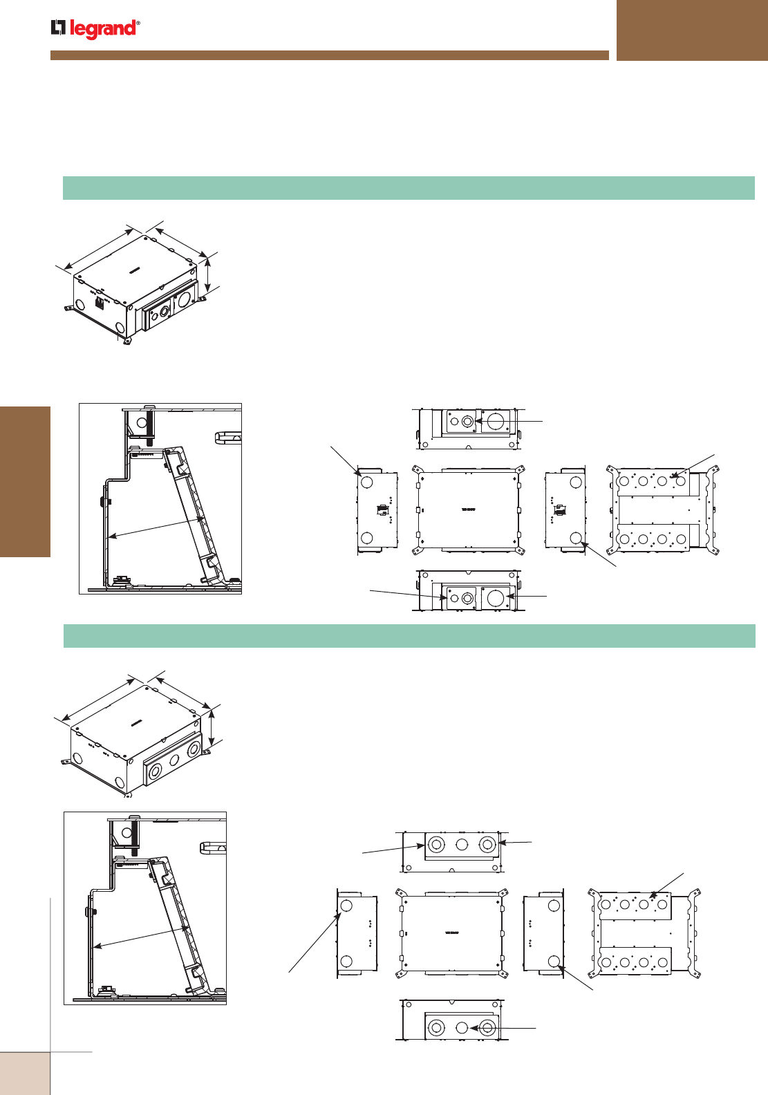
WWW.LEGRAND.US/WIREMOLD
394
FLOOR BOXES
WIREMOLD
3 1/2" [89mm]
EFB8-OG Depth Behind Plates
Each Side:
Outer: 2" Trade Size KO
Inner: 1" Trade Size KO
Two (2) KOs:
1 1/4" Trade Size KO
Two (2) KOs:
1 1/4" Trade Size KO
Eight (8) KOs:
1" Trade Size KO
Each Side:
1 1/4" Trade Size KO
Each Side:
Outer: 2" Trade Size KO
Inner: 1" Trade Size KO
EFB8S-OG Eight-Gang Floor Box
Designed to be installed in both on-grade and above grade concrete floor applications.
Box has an epoxy coating that allows the box to be placed in on-grade applications
without the need for additional vapor barriers. Designed to work with standard size
wall plates. Box comes complete with all components needed for initial installation.
Included components are: protective/disposable cover, tunnel system for connecting the
two modules of compartments, two (2) removable modules, two (2) cable management
guides, two (2) leveling support legs for concrete applications, trade size knockouts
ranging in size from 3/4" to 2". Items not included with the box and sold separately are:
receptacles, communication jacks, and A/V devices and device plates. Custom options are
available upon request.
NOTE: For use on bare (polished) concrete or terrazzo floors EFB610-CTR must be used, sold separately.
EVOLUTION™ SERIES FLOOR BOXES
3 1/2" [89mm]
EFB8 Depth Behind Plates
Each Side:
Outer: 1 1/4" Trade Size KO
Inner: 3/4" Trade Size KO
Two (2) KOs:
1 1/4" Trade Size KO
Two (2) KOs:
1 1/4" Trade Size KO Eight (8) KOs:
1" Trade Size KO
Each Side:
2" Trade Size KO
Each Side:
3/4" Trade Size KO
11 3/16"
[284mm]
15 1/8"
[384mm]
6"
[152mm]
EFB8S Eight-Gang Floor Box
Designed to be installed in concrete floors, raised floors, and wood floor applications.
Box has a fully finished interior to assist plugging and unplugging of devices. Designed to
work with standard size wall plates. Box comes complete with all components needed
for initial installation. Included components are: protective/disposable cover, tunnel
system for connecting the two modules of compartments, two (2) removable modules,
two (2) toggle clamps to secure box to raised and wood floors, two (2) cable management
guides, two (2) leveling support legs for concrete applications and trade size knockouts
ranging in size from 3/4" to 2". Items not included with the box and sold separately are:
receptacles, communication jacks, and A/V devices and device plates. Box is compatible
with Wiremold® Walkerflex Modular Wiring System. Custom options are available upon
request.
NOTE: For use on bare (polished) concrete or terrazzo floors EFB610-CTR must be used, sold separately.
Evolution™ Series 8-Gang Floor Boxes Ordering Information
11 3/16"
[284mm]
15 1/8"
[384mm]
6"
[152mm]
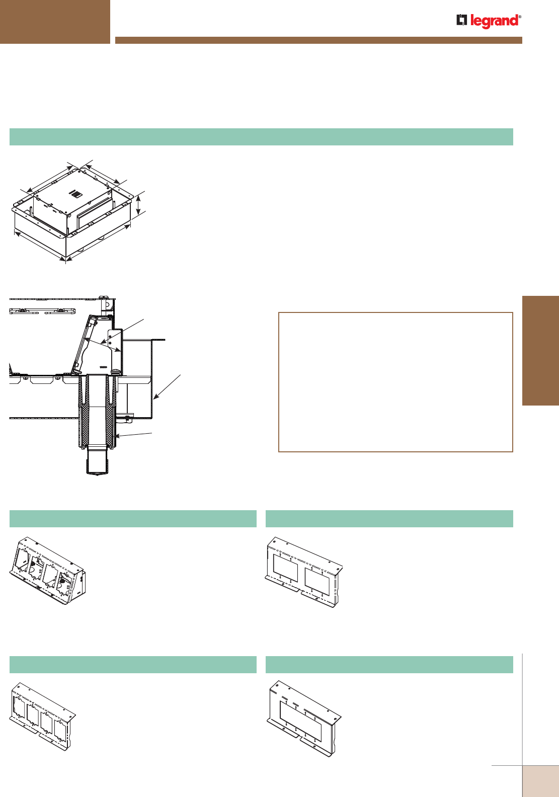
WWW.LEGRAND.US/WIREMOLD
395
FLOOR BOXES
WIREMOLD
11 3/16"
[284mm]
15 1/8"
[384mm]
7 1/2"
[191mm]
21 3/4"
[552mm]
17 1/4"
[438mm]
Designed to be installed in above grade concrete floors while maintaining the fire
classification of the floor. This box is classified for use in 2-hour fire rated floors.
Designed to work with standard size wall plates. Box comes complete with all
components needed for initial installation. Included components are: protective/
disposable cover, tunnel system for connecting the two modules of compartments,
fire classified pan, two (2) removable modules, four (4) 1 1/4 intumescent conduit
feeds and two (2) cable management guides. Items not included with the box and
sold separately are: receptacles, communication jacks, and A/V devices and device
plates.
NOTE: For use on bare (polished) concrete or terrazzo floors EFB610-CTR must be used,
sold separately.
NOTE: Designed for new construction applications.
NOTE: Consult structural engineer before making cuts into decking. Add additional supports as
instructed by the structural engineer.
EFB8S-FC Eight-Gang Fire-Classified Floor Box
Outlet Boxes and Fittings Classified for
Fire Resistance Legrand/Wiremold (R8209)
Type EFB6S-FC, EFB8S-FC and EFB10S-FC preset electrical
insert for use in 2-hour fire rated D900 Series Floor-Ceiling
designs constructed with nominal 2" or 3" deep fluted steel
floor units having a nominal 5" wide valley and crests spaced
12" OC, with a minimum 3 1/4" [83mm] thickness of structural
concrete topping. The assembly preset electrical insert with
floor plate kit and service activations fitting will not reduce
the 2-hour fire rating of the floor assembly when installed in
accordance with the installation instructions accompanying
the preset electrical insert and when the preset electrical
insert are spaced 2' [0.61m] OC with not more than one unit
per 4 square feet [0.37m2] of floor area in each span.
Fire Classified Pan
(Insures 3 1/4" [83mm] of
concrete around box at all times)
1 1/4" [35] Intumescent Service Feed
(Four (4) per box)
3 1/2" [89mm]
Depth Behind Device Plate
EFB8M Module
Bank of four (4) compartments that
accept power, communications and
audio/video devices. Accepts standard
size (2 3/4" x 4 1/2") [70mm x 114mm]
device plates. Includes one device
bracket, one back plate, two (2)
knockout plates, two (2) end caps and
one divider.
NOTE: Module will fit on either side of the
floor box.
EFB8-22GMB Mounting Bracket
Equipped with two (2) 2-gang standard
size device openings for a standard
2-gang (4 9/16" x 4 1/2" [116mm x
114mm]). Ideal for 2-gang A/V devices
such as Crestron® 2-gang digital
media devices. Device plates and
devices supplied by others.
Evolution™ Series 8-Gang Floor Box Accessories Ordering Information
EFB8-MB Mounting Bracket
Holds up to four (4) devices for power,
communications or audio/video.
Bracket accepts standard size (2 3/4" x
4 1/2" [70mm x 114mm]) device plates
sold separately by others.
EFB8-4GMB Mounting Bracket
Holds a standard 4 gange device plate.
Device plate dimensions: 81/8" x 4
1/4" [206mm x 116mm].
EVOLUTION™ SERIES FLOOR BOXES
Evolution™ Series 8-Gang Floor Boxes Ordering Information (continued)
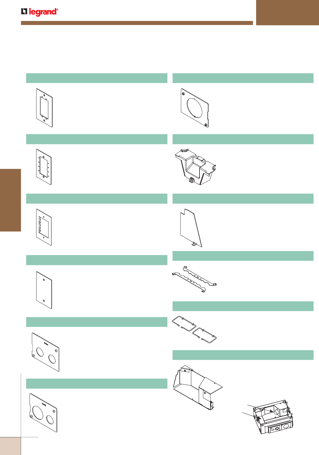
WWW.LEGRAND.US/WIREMOLD
396
FLOOR BOXES
WIREMOLD
50A Device
Tunnel
EFB-AAP Device Plate
Holds two (2) Extron® Electronics AAP
devices. Device plate dimensions: 2 3/4" x
4 1/2" [69mm x 114mm].
EFB-MAAP Device Plate
Holds four (4) Wiremold AVIP or Extron®
Electronics MAAP devices. Device plate
dimensions: 2 3/4" x 41/2" [69mm x
114mm].
EFB-MOS Device Plate
EFB-B Blank Device Plate
European device plate accepts up to
[45mm x 67.5mm] Arteor device. Device
plate dimensions: 2 3/4" x 4 1/2" [69mm x
114mm].
Device plate dimensions: 2 3/4" x 4 1/2"
[69mm x 114mm].
EFB810-3/4 - 3/4 Knockout Plate
Has two (2) 3/4" trade size knockouts.
EFB810-3/4 -1 1/4 Knockout Plate
Has one 3/4" and one 3/4"/1 1/4"
concentric trade size knockout.
EFB810-2 Knockout Plate
Has one 2" trade size knockout.
EFB810-TUN Tunnel
For EFB8 Series and EFB10 Series
boxes. Tunnel allows cables to be
wrapped around box from one module
to the other.
EFB810-DIV Relocatable Divider
Provides separation of services.
Includes one (1) divider plate.
EFB-CLL Concrete Leveling Legs
Concrete Leveling Legs – Legs allow
floor box to be adjusted up or down to
match the desired pour height of the
concrete. Includes two (2) leveling legs.
Threaded rod not supplied.
EFBCMG Cable Management Guides
Guides help organize and
maintain cable position when
opening and closing the cover.
EFB-50A 50A Adapter
Allows for a 50A device to be
installed on the 8-gang and
10-gang series boxes.
NOTE: Only fits on the side of the floor
box where the device is facing
the tunnel.
EVOLUTION™ SERIES FLOOR BOXES
Evolution™ Series 8-Gang Floor Box Accessories Ordering Information (continued)
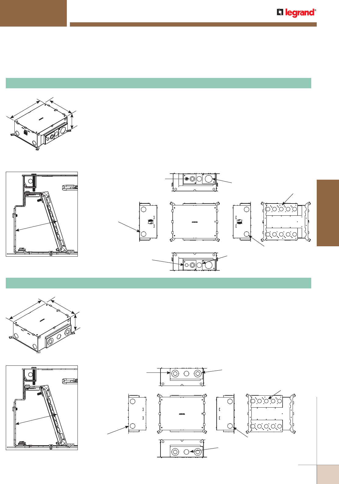
WWW.LEGRAND.US/WIREMOLD
397
FLOOR BOXES
WIREMOLD
3 1/2" [89mm]
EFB10 Depth Behind Plates
Each Side:
Outer: 1 1/4" Trade Size KO
Inner: 3/4" Trade Size KO
Two (2) KOs:
1 1/4" Trade Size KO
Two (2) KOs:
1 1/4" Trade Size KO
Ten (10) KOs:
1" Trade Size KO
Each Side:
1 1/4" Trade Size KO
Each Side:
3/4" Trade Size KO
Each Side:
2" Trade Size KO
11 3/16"
[284mm]
15 1/8"
[384mm]
6"
[152mm]
3 1/2" [89mm]
EFB10 Depth Behind Plates
Each Side:
Outer: 2" Trade Size KO
Inner: 1" Trade Size KO
Two (2) KOs:
1 1/4" Trade Size KO
Two (2) KOs:
1 1/4" Trade Size KO
Ten (10) KOs:
1" Trade Size KO
Each Side:
1 1/4" Trade Size KO
Each Side:
Outer: 2" Trade Size KO
Inner: 1" Trade Size KO
11 3/16"
[284mm]
15 1/8"
[384mm]
6"
[152mm]
Designed to be installed in concrete floors, raised floors, and wood floor applications.
Box has a fully finished interior to assist plugging and unplugging of devices. Box comes
complete with all components needed for initial installation. Included components
are: protective/disposable cover, tunnel system for connecting the two modules of
compartments, two (2) removable modules, two (2) toggle clamps to secure box to
raised and wood floors, two (2) cable management guides, two (2) leveling support legs
for concrete applications, trade size knockouts ranging in size from 3/4" to 2". Items not
included with the box and sold separately are: receptacles, communication jacks, and
A/V devices and device plates. Box is compatible with Wiremold® Walkerflex Modular
Wiring System. Custom options are available upon request.
NOTE: For use on bare (polished) concrete or terrazzo floors EFB610-CTR must be used, sold separately.
EFB10S Ten-Gang Floor Box
Designed to be installed in both on-grade and above grade concrete floor applications.
Box has an epoxy coating that allows the box to be placed in on-grade applications
without the need for additional vapor barriers. Box comes complete with all
components needed for initial installation. Included components are: protective/
disposable cover, tunnel system for connecting the two modules of compartments, two
(2) removable modules, two (2) cable management guides, two (2) leveling support legs
for concrete applications and trade size knockouts ranging in size from 3/4" to 1 1/4".
Items not included with the box and sold separately are: receptacles, communication
jacks, and A/V devices and device plates. Custom options are available upon request.
NOTE: For use on bare (polished) concrete or terrazzo floors EFB610-CTR must be used, sold separately.
EFB10S-OG Ten-Gang Floor Box
EVOLUTION™ SERIES FLOOR BOXES
Evolution™ Series Ten-Gang Floor Box Ordering Information
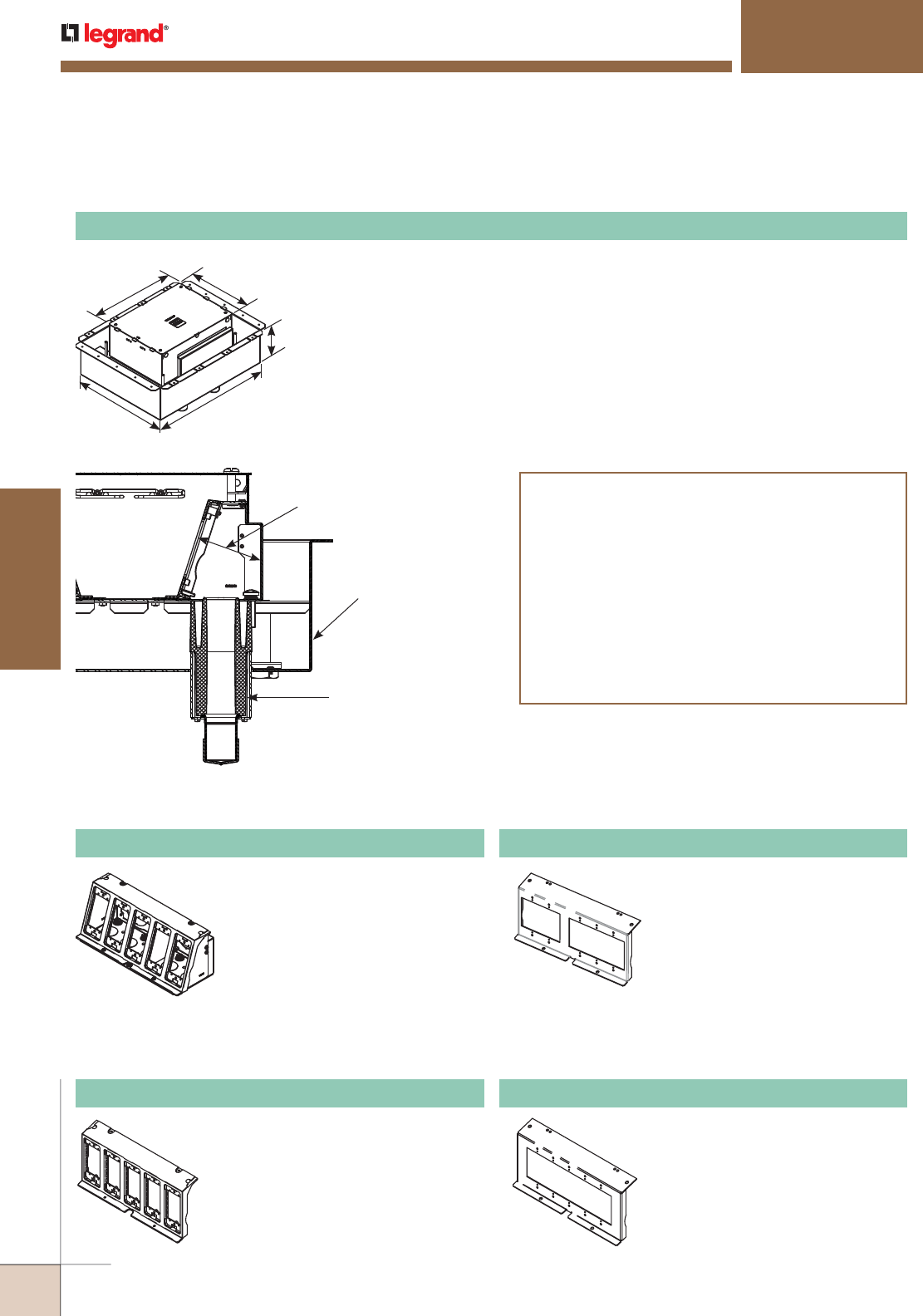
WWW.LEGRAND.US/WIREMOLD
398
FLOOR BOXES
WIREMOLD
Fire Classified Pan
(Insures 3 1/4" [83mm]
of concrete around box at
all times)
1 1/4" [35] Intumescent
Service Feed (Four (4) per box)
3 1/2" [89mm]
Depth Behind Device Plate
Designed to be installed in above grade concrete floors while maintaining the fire
classification of the floor. This box is classified for use in 2-hour fire rated floors.
Box comes complete with all components needed for initial installation. Included
components are: protective/disposable cover, tunnel system for connecting the two
modules of compartments, fire classified pan, two (2) removable modules, four (4) 1
1/4" trade size intumescent conduit feeds and two (2) cable management guides.
Items not included with the box and sold separately are: receptacles, communication
jacks, and A/V devices and device plates.
NOTE: For use on bare (polished) concrete or terrazzo floors EFB610-CTR must be used, sold separately.
NOTE: Designed for new construction applications.
NOTE: Consult structural engineer before making cuts into decking. Add additional supports as instructed by
the structural engineer.
EFB10S-FC Ten-Gang Fire-Classified Floor Box
Outlet Boxes and Fittings Classified for
Fire Resistance Legrand/Wiremold (R8209)
Type EFB6S-FC, EFB8S-FC and EFB10S-FC preset electrical
insert for use in 2-hour fire rated D900 Series Floor-Ceiling
designs constructed with nominal 2" or 3" deep fluted steel
floor units having a nominal 5" wide valley and crests spaced
12" OC, with a minimum 3 1/4" [83mm] thickness of structural
concrete topping. The assembly preset electrical insert with
floor plate kit and service activations fitting will not reduce
the 2-hour fire rating of the floor assembly when installed in
accordance with the installation instructions accompanying
the preset electrical insert and when the preset electrical
insert are spaced 2' [0.61m] OC with not more than one unit
per 4 square feet [0.37m
2
] of floor area in each span.
11 3/16"
[284mm]
15 1/8"
[384mm]
7 1/2"
[191mm]
21 3/4"
[552mm]
17 1/4"
[438mm]
EFB10M Module EFB10-23GMB Mounting Bracket
EFB10-5GMB Mounting Bracket
Bank of five (5) compartments that
accept power, communications and
audio/video devices. Accepts EFB10
Series device plates (2 1/32" x
4 5/8") [58mm x 117mm]. Includes
one mounting bracket, one back plate,
one divider, two (2) end caps and two
(2) knockout plates. Device plates
sold separately.
NOTE: Module will fit on either side of the
floor box.
Equipped with one (1) 2-gang
standard size device opening
and one (1) 3-gang standard size
device opening. Accepts a standard
2-gang (4 9/16" x 4 1/2" [116mm x
114mm]) and a 3-gang (6 3/8" x 4
1/2" [162mm x 114mm]) device plate.
Ideal for 2-gang A/V devices such as
Crestron® 2-gang and 3-gang digital
media devices. Device plates and
devices supplied by others.
Holds a standard 5 gang device plate
Device plate dimensions: 10" x 4 1/2"
[254mm x 116mm].
Evolution™ Series Ten-Gang Floor Box Accessories Ordering Information
EFB10-MB Mounting Bracket
Holds up to five (5) devices for power,
communications or audio/video.
Bracket accepts EFB10 Series device
plates (2 1/32" x 4 5/8") [58mm x
117mm] device plates sold separately.
EVOLUTION™ SERIES FLOOR BOXES
Evolution™ Series Ten-Gang Floor Box Ordering Information (continued)
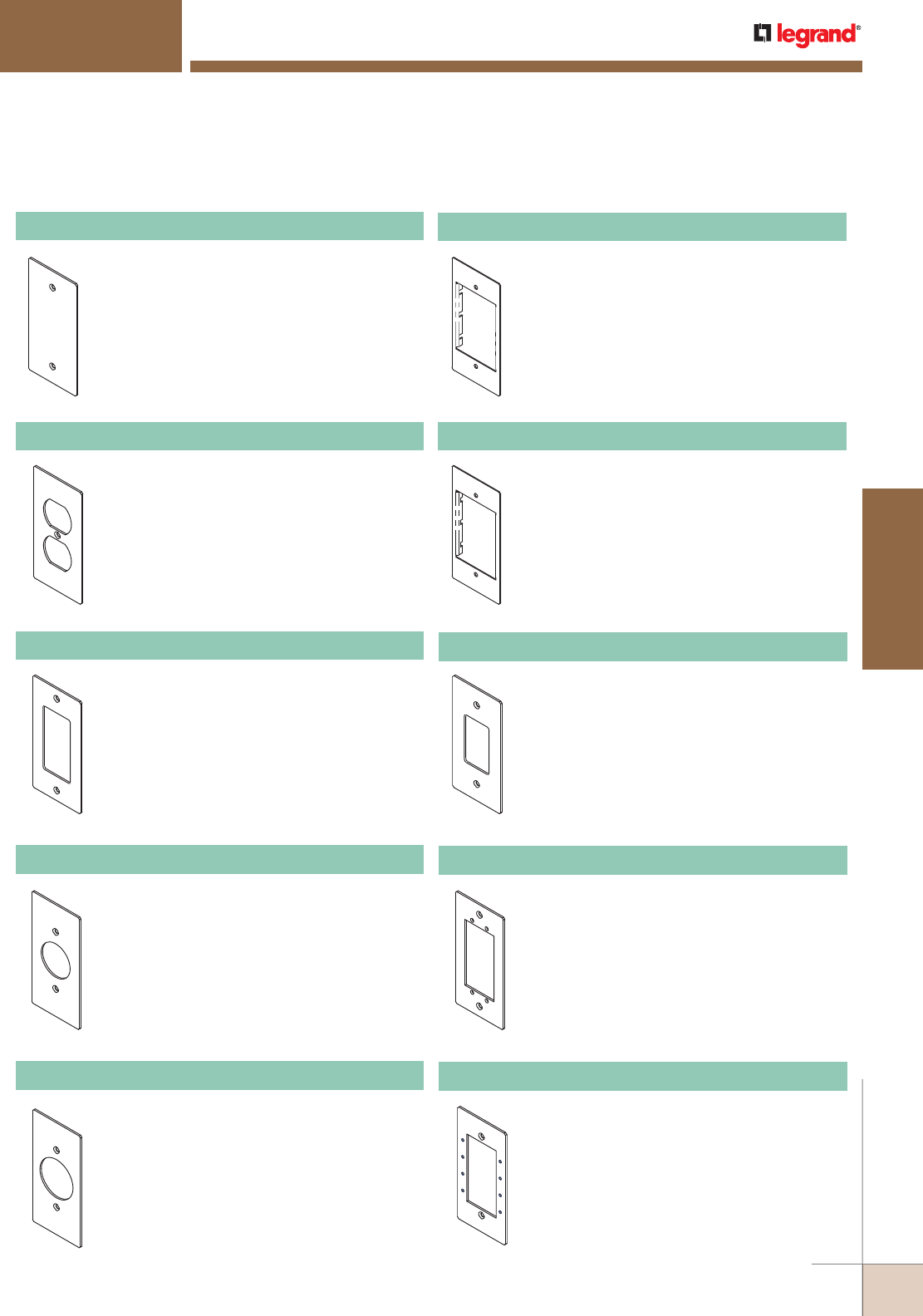
WWW.LEGRAND.US/WIREMOLD
399
FLOOR BOXES
WIREMOLD
EFB10-B Device Plate
Blank device plate. Device plate dimensions:
2.3" x 4.652" [58mm x 118mm].
EFB10-DP Device Plate
Duplex device plate. Device plate dimensions:
2.3" x 4.652" [58mm x 118mm]. Includes
receptacle spacers.
EFB10-DEC Decorator Style Device Plate
For use with decorator style receptacles, GFCI
receptacle, and decorator style audio/ video
devices. Device plate dimensions: 2.3" x 4.652"
[58mm x 118mm]. Includes receptacle spacers.
EFB10-S1 Knockout Plate
Single receptacle 1.39" [35mm]. diameter.
Device plate dimensions: 2.3" x 4.652" [58mm x
118mm]. Includes receptacle spacers.
EFB10-S2 Knockout Plate
Single receptacle 1.59" [40mm] diameter. Device
plate dimensions: 2.3" x 4.652" [58mm x 118mm].
Includes receptacle spacers.
EFB10-6AB Device Plate
Accepts up to three (3) dual Wiremold Open
System communication adapters. Adapters sold
separately. Device plate dimensions: 2.3" x 4.652"
[58mm x 118mm].
EFB10-3S2 Device Plate
Accepts up to three (3) Ortronics® Series II
devices. Ortronics® devices sold separately.
Device plate dimensions: 2.3" x 4.652"
[58mm x 118mm].
EFB10-2C Device Plate
Accepts one dual Wiremold Open System
adapter, or one Ortronics® Series II adapter, or
one Ortronics® TracJack adapter. Adapters sold
separately. Device plate dimensions: 2.3" x 4.652"
[58mm x 118mm].
EFB10-AAP Device Plate
Holds two (2) Extron® Electronics AAP devices.
Device plate dimensions: 2.3" x 4.652" [58mm x
118mm].
EFB10-MAAP Device Plate
Holds four (4) Wiremold AVIP or Extron®
Electronics MAAP devices. Device plate
dimensions: 2.3" x 4.652" [58mm x 118mm].
EVOLUTION™ SERIES FLOOR BOXES
Evolution™ Series Ten-Gang Floor Box Accessories Ordering Information (continued)
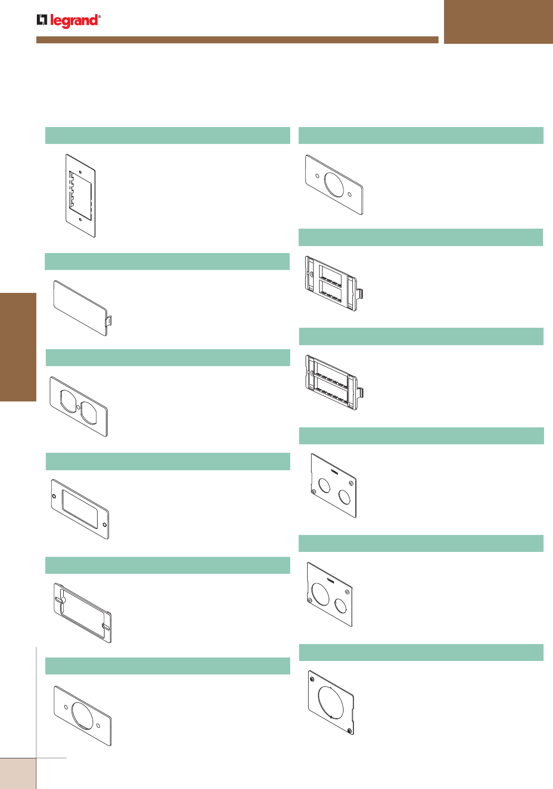
WWW.LEGRAND.US/WIREMOLD
400
FLOOR BOXES
WIREMOLD
EFB810-3/4-11/4 Knockout Plate
Has one 3/4" and one 3/4"/1 1/4"
concentric trade size knockout.
EFB810-2 Knockout Plate
Has one 2" trade size knockout.
EVOLUTION™ SERIES FLOOR BOXES
Evolution™ Series Ten-Gang Floor Box Accessories Ordering Information (continued)
EFB810-3/4-3/4 Knockout Plate
Has two 3/4" trade size knockout.
EFB10-MOS Device Plate
[45mm x 67.5mm] device plate. Device plate
dimensions: 2.3" x 4.652" [58mm x 118mm].
5507D-WH Duplex Receptacle Faceplate
For covering duplex style devices. Accepts
106 frame.
5507R-WH Rectangular Receptacle Faceplate
For covering rectangular decorator style
devices.
5507B-WH Blank Faceplate
For covering unused compartments in the
device bracket.
5507S-WH Rectangular Spacer
For mounting commercial device plates.
Installs between the device bracket and
a device.
5507T1-WH Single Receptacle Faceplate
For covering single receptacles – 1.59"
[40mm] in diameter.
5507T2-WH Single Receptacle Faceplate
For covering single receptacles – 1.41"
[36mm] in diameter.
55074TJ-WH Ortronics® Faceplate
For mounting Ortronics® datacom inserts.
Accepts four (4) TracJack devices.
55076TJ-WH Ortronics® Faceplate
For mounting Ortronics® datacom inserts.
Accepts six (6) TracJack devices.
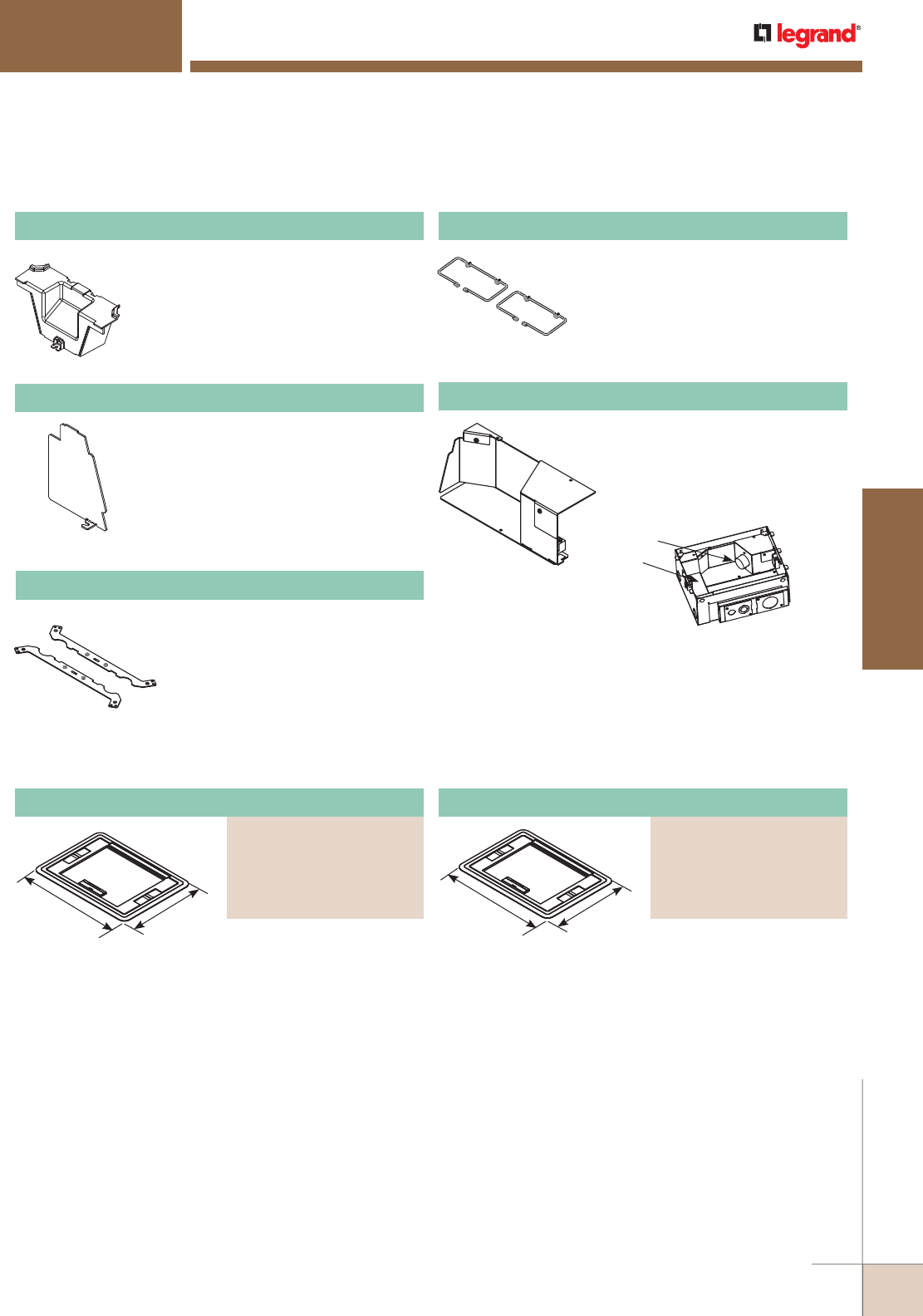
WWW.LEGRAND.US/WIREMOLD
401
FLOOR BOXES
WIREMOLD
Flush Style Cover with Carpet Insert
PART NUMBERS:
EFB610CTBK (Black)
(Gray)
EFB610CTNK (Nickel)
EFB610CTBS (Brass)
EFB610CTBZ (Bronze)
EVOLUTION™ SERIES FLOOR BOXES
Evolution™ Series Ten-Gang Floor Box Accessories Ordering Information (continued)
Evolution™ Series Floor Box Cover Plates and Accessories Ordering Information
16 3/8"
[416mm] 12 1/2"
[318mm]
Die cast aluminum cover
assembly designed to be
used on top of the floor
covering. Available in five
powder coated finishes.
For use on Evolution™
Series 6-, 8- and 10-gang
floor boxes (EFB6S, EFB8S
and EFB10S).
NOTE: Depth of recess area in plate
is 1/4" [6.35mm].
16 3/8"
[416mm] 12 1/2"
[318mm]
Die cast aluminum cover
assembly designed to be
used level (flush) with finish
floor covering. Available in
five powder coated finishes.
For use on Evolution™
Series 6-, 8- and 10-gang
floor boxes (EFB6S, EFB8S,
and EFB10S).
NOTE: Depth of recess area in plate
is 1/4" [6.35mm].
50A Device
Tunnel
EFB-50A 50A Adapter
Allows for a 50A device to be
installed on the 8-gang and
10-gang series boxes.
NOTE: Only fits on the side of the floor box
where the device is facing the tunnel.
EFB810-TUN Tunnel
For EFB8 Series and EFB10 Series boxes.
Tunnel allows cables to be wrapped
around box from one module to the other.
EFB810-DIV Relocatable Divider
Provides separation of services. Includes
one (1) divider plate.
EFB-CLL Concrete Leveling Legs
Legs allow floor box to be adjusted
up or down to match the desired
pour height of the concrete. Includes
two (2) leveling legs. Threaded rod
not supplied.
EFBCMG Cable Management Guides
Guides help organize and maintain
cable position when opening and
closing the cover.
Surface Style Cover with Carpet Insert
PART NUMBERS:
EFB610CTCBK (Black)
EFB610CTCGY (Gray)
EFB610CTCNK (Nickel)
EFB610CTCBS (Brass)
EFB610CTCBZ (Bronze)
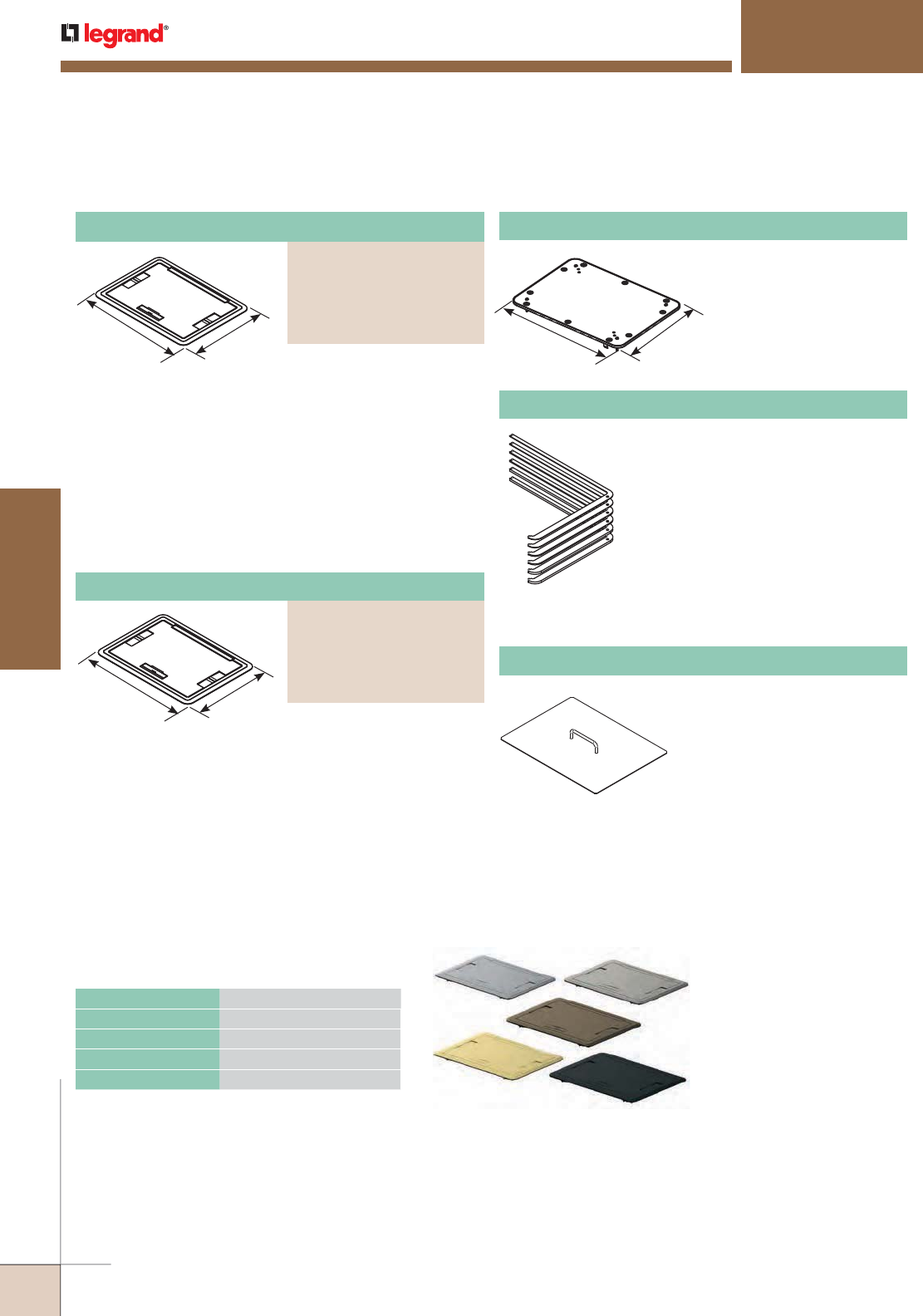
WWW.LEGRAND.US/WIREMOLD
402
FLOOR BOXES
WIREMOLD
Die cast aluminum cover
assembly designed to be
used level (flush) with finish
floor covering. Available in
five powder coated finishes.
For use on Evolution™
Series 6-, 8- and 10-gang
floor boxes (EFB6S, EFB8S
and EFB10S).
NOTE: Depth of recess area in plate
is 1/4" [6.35mm].
16 3/8"
[416mm] 12 1/2"
[318mm]
Used for floor coverings
greater than 3/16" [4.7mm].
The EFB610-TS allows the
finished cover assembly to
be flush with the finished
floor. Includes one (1)
1/16" [1.6mm], one (1)
1/8" [3.2mm] and one 1/4"
[6.4mm] tile shims for
9/16" [14.3mm] of upward
adjustment.
EFB610-TS Tile Shim
Designed to help mark out
floor to insure a proper fit.
EFB-Template Floor Box Template
EVOLUTION™ SERIES FLOOR BOXES
Evolution™ Series Floor Box Cover Plates and Accessories Ordering Information (continued)
Evolution Series Floor Box Covers are
available in powder coated finishes
of (L to R) gray, nickel, bronze, brass
and black.
CATALOG NUMBERS MAXIMUM LOAD IN POUNDS
EFB610BTC Series 1800
EFB610CTC Series 1800
EFB610BT Series 1800
EFB610CT Series 1800
NOTE: Load applied through a 3" [76mm] mandrel in center
of the cover. Loads above are static loads only and do
not pertain to rolling loads.
Load Capacities for Evolution™ Series
Floor Box Cover Assemblies
16 3/8"
[416mm]
12 1/2"
[318mm]
Nonmetallic ring for use with
bare concrete and terrazzo
floor applications.
NOTE: Ring must be attached to
the floor box before pouring
concrete or terrazzo.
EFB610CTR Bare Concrete/Terrazzo Trim Ring
16 3/8"
[416mm] 12 1/2"
[318mm]
Die cast aluminum cover
assembly designed to be
used on top of the floor
covering. Available in the
following powder coated
finishes: black, gray, brass,
nickel and bronze. For use
on Evolution™ Series 6-,
8- and 10-gang floor boxes
(EFB6S, EFB8S and EFB10S).
Surface Style Cover Assembly
PART NUMBERS:
EFB610BTCBK (Black)
EFB610BTCGY (Gray)
EFB610BTCNK (Nickel)
EFB610BTCBS (Brass)
EFB610BTCBZ (Bronze)
PART NUMBERS:
EFB610BTCBK (Black)
EFB610BTCGY (Gray)
EFB610BTCNK (Nickel)
EFB610BTCBS (Brass)
EFB610BTCBZ (Bronze)
Surface Style Cover with Solid Lid
Flush Style Cover with Solid Lid
PART NUMBERS:
EFB610BTBK (Black)
EFB610BTGY (Gray)
EFB610BTNK (Nickel)
EFB610BTBS (Brass)
EFB610BTBZ (Bronze)
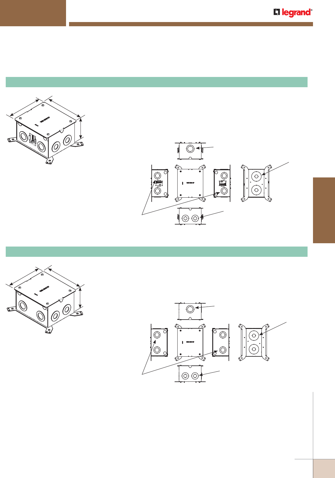
WWW.LEGRAND.US/WIREMOLD
403
FLOOR BOXES
WIREMOLD
Evolution™ Series EFBFF Furniture Floor Boxes Ordering Information
Outer: 1 1/2" Trade Size KO
Inner: 1" Trade Size KO
Two (2) KOs:
Outer: 2" Trade Size KO
Inner: 1/2" Trade Size KO
Two (2) KOs:
Outer: 1 1/4" Trade Size KO
Inner: 1/2" Trade Size KO
Each Side, Two KOs:
Inner: 3/4" Trade Size KO
Outer: 1 1/4" Trade Size KO
7 1/16"
[179mm]
6 5/8"
[168mm]
4 1/8"
[105mm]
Outer: 1 1/2" Trade Size KO
Inner: 1" Trade Size KO
Two (2) KOs:
Outer: 1 1/4" Trade Size KO
Inner: 1/2" Trade Size KO
Two (2) KOs:
Outer: 2" Trade Size KO
Inner: 1/2" Trade Size KO
Each Side, Two KOs:
Inner: 3/4" Trade Size KO
Outer: 1 1/4" Trade Size KO
7 1/16"
[179mm]
6 5/8"
[168mm]
4 1/8"
[105mm]
For carpet, tile and wood covered floors. For use in concrete, raised and wood
floor applications. Box is provided with a protective, disposable cover that allows
the box to be installed at any point in the construction process. Box is available
in a standard version for use in above grade concrete, raised, and wood floor
applications. Boxes are also compatible with Wiremold® Walkerflex Modular
Wiring System. Custom options are available upon request.
EFBFF Two-Gang Furniture Feed Floor Box Assembly
For carpet, tile and wood covered floors. For use in on-grade and above grade
concrete floor applications. Box is provided with a protective, disposable cover
that allows the box to be installed at any point in the construction process. Box
is available with an epoxy coating for on-grade applications. Custom options are
available upon request.
EFBFF-OG Two-Gang Furniture Feed Floor Box Assembly
NOTE: For use with bare concrete or terrazzo floors.
Use FP-CTR Trim Ring.
NOTE: Box is divided down center to allow for
separation between power and communication
or A/V services.
W For use with bare concrete or terrazzo floors.
Use FP-CTR Trim Ring.
NOTE: Box is divided down center to allow
for separation between power and
communication or A/V services.
EVOLUTION™ SERIES FLOOR BOXES
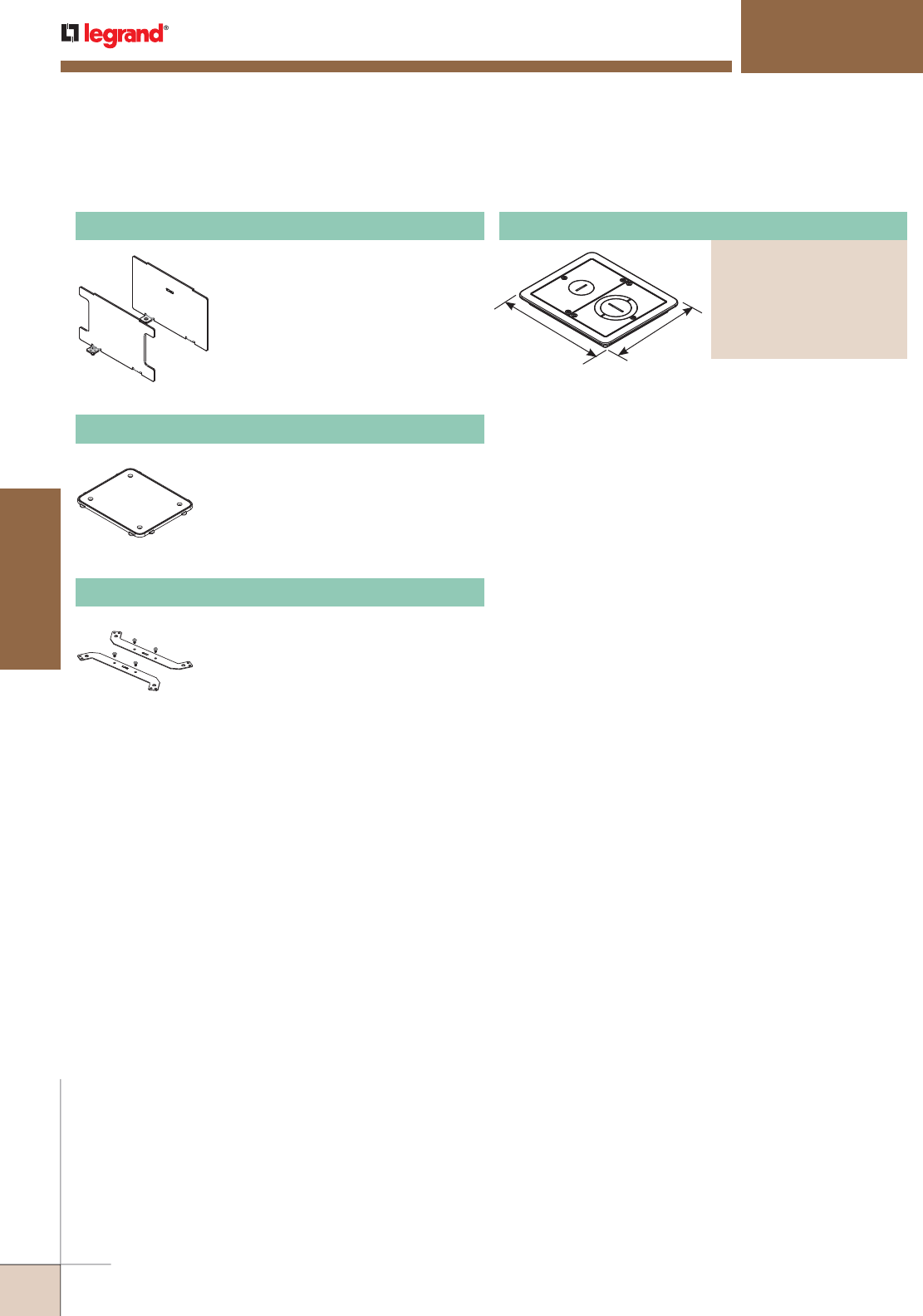
WWW.LEGRAND.US/WIREMOLD
404
FLOOR BOXES
WIREMOLD
EFBFF-DIV Divider
Provides separation of services.
7 3/4"
[197mm] 6 1/2"
[165mm]
Flanged cover for use in tile or carpet or wood floor
installa tions. Die-cast aluminum assembly available in
powder coat finishes of black, bronze, brass, nickel, gray
or brushed aluminum. Provided with one (1) 1" trade size
screw plug for power or communication type cabling and
one (1) combination 1 1/4" and 2" trade size screw plug for
communication and A/V type cabling. Allows for feeding both
power and communication cabling.
NOTE: Flangeless FloorPort Series (FPFFT) covers are not designed to
work with Evolution Series Furniture Feed Floor Boxes.
Evolution™ Series EFBFF Furniture Floor Box Accessories Ordering Information
EVOLUTION™ SERIES FLOOR BOXES
Nonmetallic ring for use on bare
polished concrete and terrazzo floor
applications.
NOTE: Ring must be attached to the floor box before
pouring concrete or terrazzo.
FP-CTR Bare Concrete and Terrazzo Ring
Legs allow floor box to be adjusted up or
down to match the desired pour height
of the concrete. Includes two (2) leveling
legs. Threaded rod not supplied.
EFBFF-CLL Concrete Leveling legs
Surface Style Cover Assembly
PART NUMBERS:
FPFFTCBK (Black)
FPFFTCGY (Gray)
FPFFTCNK (Nickel)
FPFFTCBS (Brass)
FPFFTCBZ (Bronze)
FPFFTCAL (Aluminum)
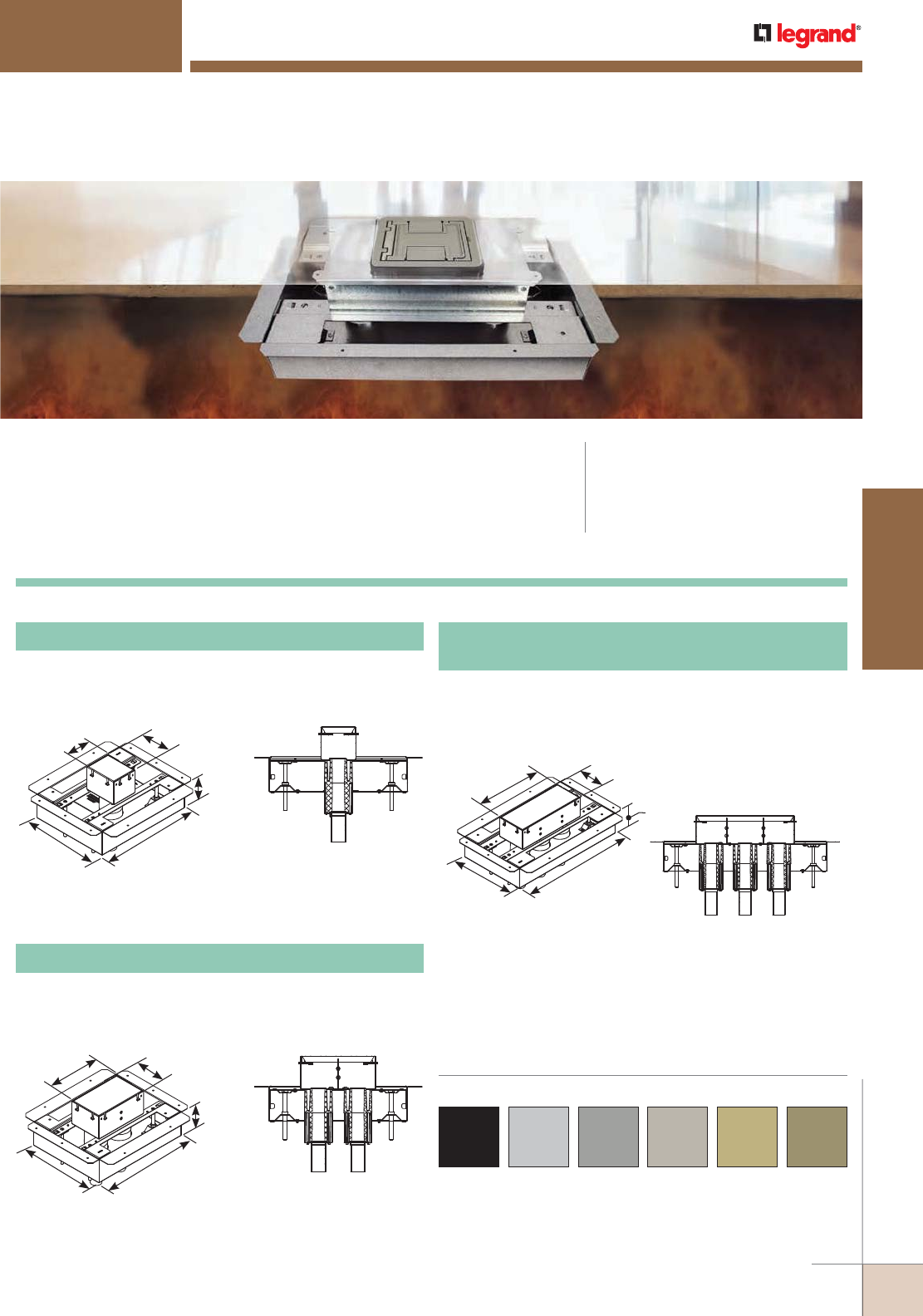
WWW.LEGRAND.US/WIREMOLD
405
FLOOR BOXES
WIREMOLD
Legrand® takes Wiremold floor boxes to the next level with the introduction
of seven recessed and flush style floor box models that meet or exceed
UL Fire Classification requirements. Available in both single- and multiple-
gang versions, in both steel and nonmetallic fabrications, these floor boxes
preserve the two-hour fire rating of floors in which they have been installed
and are a favored industry solution for getting power, communication and
audio video services into open spaces.
FIRE CLASSIFIED FLOOR BOXES
CODE REFERENCE
cULus Listed
Metallic Outlet Boxes:
File E2961 Guide QCIT.
Meets Article 300.22(c) of NEC.
Cover Plates and Flanges for Fire Classified OmniBox Series™ Floor Boxes
are available in black, aluminum, gray, nickel, brass and bronze.
Custom color options are also available. Consult the factory for
more information.
Standard Depth Steel OmniBox Floor Box Ordering Information
NOTE: Floor Box spacing 2' on center and one for every 4 square feet in a
span. Four (4) #12 AWG Type THHN Power Conductors or 48 #23
AWG (6 Cat. 6) Tele Data Conductors per gang.
8801S-FC One-Gang Fire Classified Steel Floor Box
Adjustment range over deck of 2" [51mm] minimum to
5" [127mm] maximum. One 1 1/4" [32mm] conduit feed
opening. Box Capacity – 53 cubic inches.
3 3/4"
[94mm]
3 1/2"
[90mm]
11 3/8"
[289mm]
14 1/2"
[367mm]
4 13/16"
[122mm]
8802S-FC Two-Gang Fire Classified Steel Floor Box
Adjustment range over deck of 2" [51mm] minimum to
5" [127mm] maximum. Two 1 1/4" [32mm] conduit feed
openings. Box Capacity – 58.5 cubic inches each gang.
7 1/8"
[199mm]
3 1/2"
[90mm]
11 3/8"
[289mm]
14 1/2"
[367mm]
4 13/16"
[122mm]
8803S-FC
Three-Gang Fire Classified Steel Floor Box
Adjustment range over deck of 2" [51mm] minimum to
5" [127mm] maximum. Three 1 1/4" [32mm] conduit feed
openings. Inside Gang Capacity – 67.5 cubic inches. Outside
Gang Capacity – 54 cubic inches each gang.
12"
[304mm]
3 1/2"
[90mm]
11 3/8"
[289mm]
20"
[507mm]
4 13/16"
[122mm]
NOTE: Floor Box spacing 2' on center and one for every 4 square feet in a
span. Four (4) #12 AWG Type THHN Power Conductors or 48 #23
AWG (6 Cat. 6) Tele Data Conductors per gang.
NOTE: Floor Box spacing 2' on center and one for every 4 square feet in a
span. Four (4) #12 AWG Type THHN Power Conductors or 48 #23
AWG (6 Cat. 6) Tele Data Conductors per gang.
COLOR OPTIONS
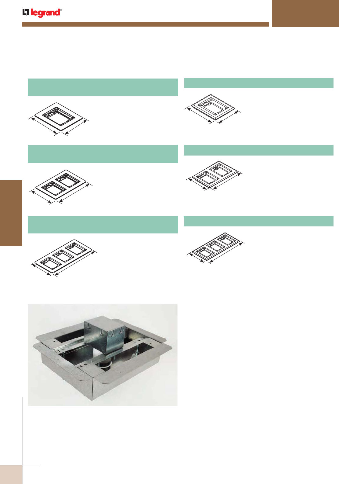
WWW.LEGRAND.US/WIREMOLD
406
FLOOR BOXES
WIREMOLD
For use on 880S2, 880M2,
880CS2-1 and 880CM2-1
Floor Boxes.
817C One-Gang Brass Carpet Flange
For use on 880S1, 880M1,
880CS1-1 and 880CM1-1
Floor Boxes.
827B Two-Gang Brass Combination
Carpet and Tile Flange
Accepts Ortronics® MAB6TJ
TracJack and MAB3S2 Series II
adapters and Wiremold CM
Series inserts, sold separately.
817B One-Gang Brass Combination
Carpet and Tile Flange
Accepts Ortronics® MAB6TJ
TracJack and MAB3S2 Series II
adapters and Wiremold CM
Series inserts, sold separately.
837B Three-Gang Brass Combination
Carpet and Tile Flange
Accepts Ortronics® MAB6TJ
TracJack and MAB3S2 Series II
adapters and Wiremold CM
Series inserts, sold separately.
FIRE CLASSIFIED FLOOR BOXES
Omnibox Series Floor Boxes
OmniBox Series Floor Boxes Solid Brass Cover Plate Flanges Ordering Information
Fire-Classified
OmniBox Series
Floor Box
5 3/4"
[146mm] 4 3/4"
[121mm]
5 3/4"
[146mm]
8 7/8"
[225mm]
5 3/4"
[146mm]
13"
[330mm]
6 1/16"
[154.4mm]
5 1/16"
[128.5mm]
6 1/16"
[154.4mm]
9 3/16"
[233mm]
6 1/16"
[154.4mm]
13 5/16"
[338mm]
NOTE: UL Listed for tile, terrazzo, polished concrete, wood and carpet floors.
Brass covers and flanges are not interchangeable with aluminum or nonmetallic covers and flanges.
Nonmetallic covers are interchangeable with aluminum flanges.
827C Two-Gang Brass Carpet Flange
837C Three-Gang Brass Carpet Flange
For use on 880S3, 880M3,
880CS3-1 and 880CM3-1
Floor Boxes.
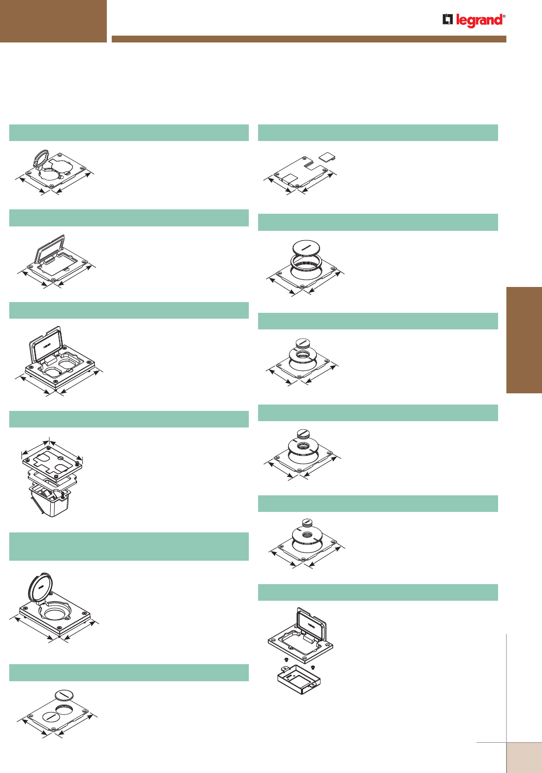
WWW.LEGRAND.US/WIREMOLD
407
FLOOR BOXES
WIREMOLD
FIRE CLASSIFIED FLOOR BOXES
Omnibox Series Floor Boxes
OmniBox Series Floor Boxes Metal Cover Plates Ordering Information
828SPTC Brass Duplex Cover Plate
828R Brass Duplex Cover Plate
828GFITC Brass GFI Cover Plate
Flip lids. Can also be used with a
106 type communication adapter.
Screw plugs. Screw plugs are
1 1/2" [38mm] in diameter.
May be used with Activate and
Ortronics® Connectivity Systems
in conjunction with 817B, 827B,
and 837B Flanges.
3 1/8"
[80.2mm]
4 3/16"
[106.2mm]
3 1/8"
[80.2mm]
4 3/16"
[106.2mm]
3 1/8"
[80.2mm]
4 3/16"
[106.2mm]
NOTE: For use with 880S and 880CS
Series Boxes only.
3 1/8"
[80.2mm] 4 3/16"
[106.2mm]
3 1/8"
[80.2mm]
4 3/16"
[106.2mm]
3 1/8"
[80.2mm]
4 3/16"
[106.2mm]
3 1/8"
[80.2mm]
4 3/16"
[106.2mm]
3 1/8"
[80.2mm]
4 3/16"
[106.2mm]
3 1/8"
[80.2mm]
4 3/16"
[106.2mm]
3 1/8"
[80.2mm]
4 3/16"
[106.2mm]
NOTE: UL Listed for tile, terrazzo, polished concrete, wood and carpet floors.
Brass covers and flanges are not interchangeable with aluminum
or nonmetallic covers and flanges. Nonmetallic covers are
interchangeable with aluminum flanges.
4 3/16"
[106.2mm]
3 1/8"
[80.2mm]
828DPGFITC Brass Rectangular Cover Plate
Allows for mounting of a
duplex-style receptacle with a
rectangular-style flip lid cover.
828COMTC Brass Communication Cover Plate
Allows for up to four communica-
tion devices to be mounted in a
recessed position within the 880
Floor Box. The 828COM Cover
Plate has removable slides for
cable egress.
828DLR
Brass Single Locking Receptacle Cover Plate
Single flip lid cover for 20A or 30A
single locking receptacles. Device
opening is 2 5/8" [67mm]. For use
with maximum female locking
device of 1.58" diameter, and
maximum male plug face of
2.25" diameter.
829STC Brass Communication Cover Plate
Data slides. Feed through only,
not for use with a mounting plate
for communication jacks.
829CK Brass Communication Cover Plate
2 5/8" and 2 1/4" [67mm and
57mm] plugs.
829CK-1 Brass Communication Cover Plate
2 5/8" and 1" [67mm and 25mm]
plugs.
829CK-3/4 Brass Communication Cover Plate
2 5/8" and 3/4" [67mm and
19.1mm] plugs.
829CK-1/2 Brass Communication Cover Plate
2 5/8" and 1/2" [67mm and
12.7mm] plugs.
828MAAP A/V Adapter Plate
Sheet metal adapter plate that
accepts two (2) Wiremold AVIP or
Extron® Electronics MAAP style
device plates, sold separately. For
use with 828GFITC or 828GFITCAL
cover plates, sold separately.
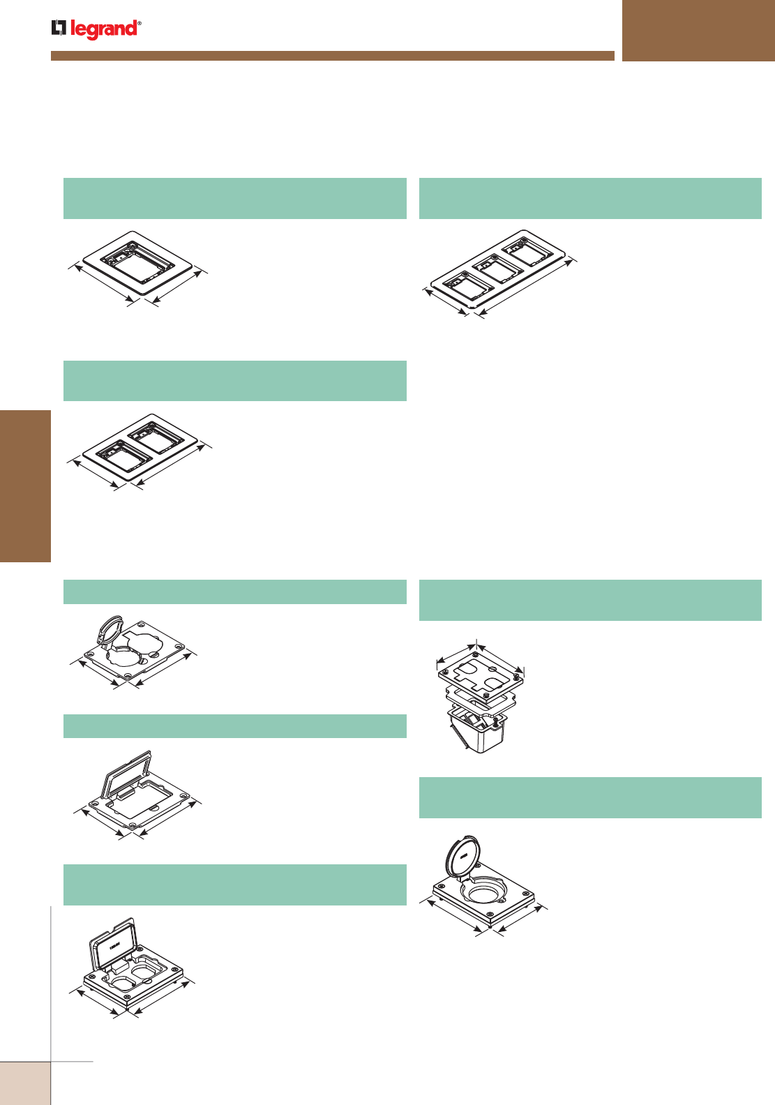
WWW.LEGRAND.US/WIREMOLD
408
FLOOR BOXES
WIREMOLD
FIRE CLASSIFIED FLOOR BOXES
Omnibox Series Floor Boxes
818TCAL One-Gang Brushed Aluminum
Combination Carpet and Tile Flange
Accepts Ortronics® MAB6TJ
TracJack and MAB3S2
Series II adapters and
Wiremold CM Series
inserts, sold separately.
828R-TCAL Brushed Aluminum Duplex Cover Plate
Flip lids. Can also be
used with a 106 type
communication adapter.
828TCAL Two-Gang Brushed Aluminum
Combination Carpet and Tile Flange
Accepts Ortronics® MAB6TJ
TracJack and MAB3S2
Series II adapters and
Wiremold CM Series
inserts, sold separately.
828DPGFITCAL
Brushed Aluminum Rectangular Cover Plate
Allows for mounting of a
duplex-style receptacle with
a rectangular-style flip lid
cover.
Single flip lid cover for 20A or 30A
single locking receptacles. Device
opening is 2 5/8" [67mm]. For use
with maximum female locking
device of 1.58" diameter, and
maximum male plug face of
2.25" diameter.
828DLRAL Brushed Aluminum Single Locking
Receptacle Cover Plate
Omnibox Series Floor Boxes Brushed Aluminum Cover Plate Flanges Ordering Information
6 1/16"
[154mm] 5 1/16"
[128.5mm]
6 1/16"
[154mm]
9 1/16"
[229.7mm]
NOTE: Brushed aluminum flanges come with beveled edges.
NOTE: Brushed aluminum flanges come with beveled edges.
838TCAL Three-Gang Brushed Aluminum
Combination Carpet and Tile Flange
Accepts Ortronics® MAB6TJ
TracJack and MAB3S2
Series II adapters and
Wiremold CM Series
inserts, sold separately.
6 1/16"
[154mm]
13 3/16"
[334.5mm]
NOTE: Brushed aluminum flanges come with beveled edges.
3 3/16"
[83.6mm]
4 5/16"
[109.5mm]
3 3/16"
[83.6mm]
4 5/16"
[109.5mm]
3 3/16"
[83.6mm]
4 5/16"
[109.5mm]
Allows for up to four
communication devices to be
mounted in a recessed position
within the 880 Floor Box. The
828COMTCAL Cover Plate has
removable slides for cable egress.
828COMTCAL
Brushed Aluminum Communication Cover Plate
NOTE: For use with 880S and 880CS Series Boxes only.
3 3/16"
[83.6mm] 4 5/16"
[109.5mm]
4 5/16"
[109.5mm]
3 3/16"
[83.6mm]
NOTE: UL Listed for tile, terrazzo, polished concrete, wood and
carpet floors.
Brass covers and flanges are not interchangeable with aluminum
or nonmetallic covers and flanges. Nonmetallic covers are
interchangeable with aluminum flanges.
828GFITCAL Brushed Aluminum GFI Cover Plate
May be used with Activate
and Ortronics® Connectivity
Systems in conjunction
with 817B, 827B, and 837B
Flanges.
OmniBox Series Floor Boxes Metal Cover Plates Ordering Information
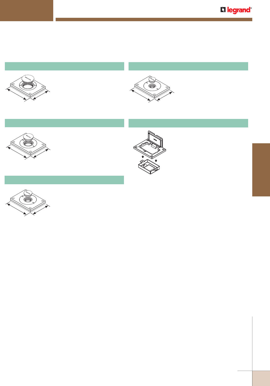
WWW.LEGRAND.US/WIREMOLD
409
FLOOR BOXES
WIREMOLD
FIRE CLASSIFIED FLOOR BOXES
Omnibox Series Floor Boxes
OmniBox Series Floor Boxes Metal Cover Plates Ordering Information (continued)
NOTE: UL Listed for tile, terrazzo, polished concrete, wood and carpet floors.
Brass covers and flanges are not interchangeable with aluminum or nonmetallic covers and flanges.
Nonmetallic covers are interchangeable with aluminum flanges.
Power or communication plate
with 2" [51mm] and 1 1/4" [32mm]
plugs.
830CKTCAL Brushed Aluminum Cover Plate
Power or communication plate
with 2" [51mm] and 1/2" [12.7mm]
plugs.
NOTE: Acceptable for use with threaded
conduit when passing through
power cables.
830CKTCAL-1/2 Brushed Aluminum Cover Plate
Power or communication plate
with 2" [51mm] and 3/4" [19.1mm]
plugs.
NOTE: Acceptable for use with threaded
conduit when passing through
power cables.
830CKTCAL-3/4 Brushed Aluminum Cover Plate
NOTE: Acceptable for use with threaded
conduit when passing through
power cables.
4 5/16"
[109.5mm]
3 3/16"
[83.6mm]
4 5/16"
[109.5mm]
3 3/16"
[83.6mm]
4 5/16"
[109.5mm]
3 3/16"
[83.6mm]
4 5/16"
[109.5mm] 3 3/16"
[83.6mm]
Power or communication plate
with 2" [51mm] and 1" [25mm]
plugs.
NOTE: Acceptable for use with threaded
conduit when passing through
power cables.
830CKTCAL-1 Brushed Aluminum Cover Plate 828MAAP A/V Adapter Plate
Sheet metal adapter plate that
accepts two (2) Wiremold AVIP or
Extron® Electronics MAAP style
device plates, sold separately. For
use with 828GFITC or 828GFITCAL
cover plates, sold separately.
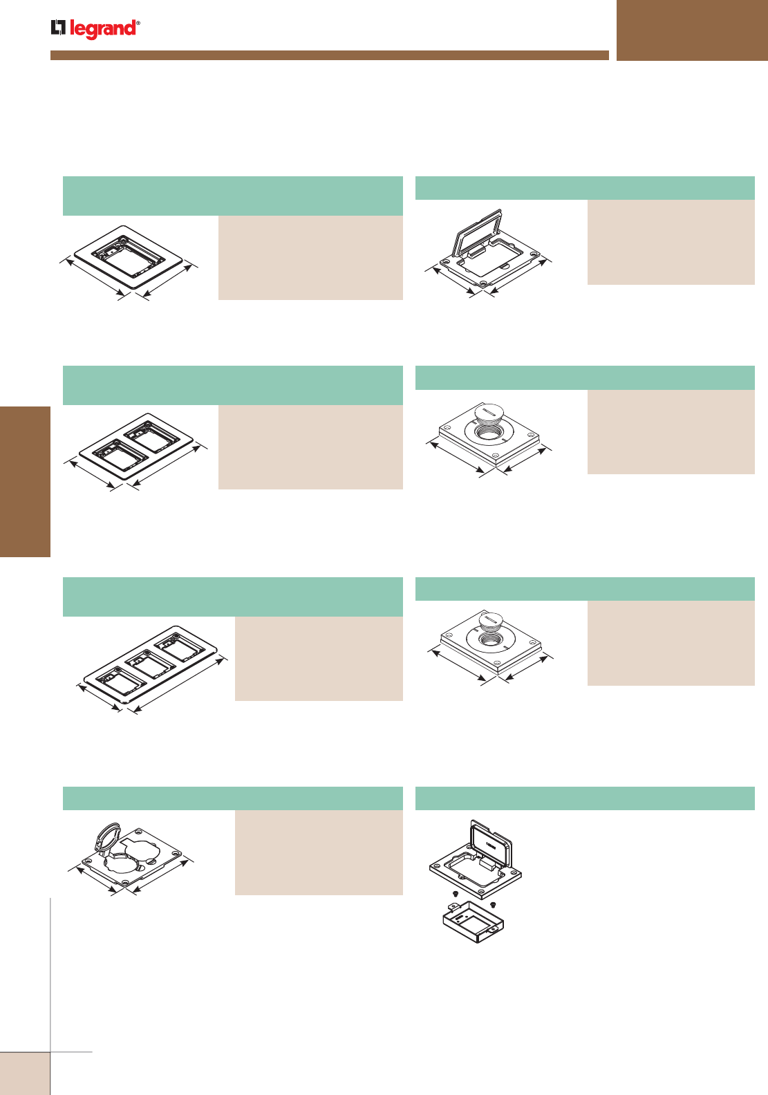
WWW.LEGRAND.US/WIREMOLD
410
FLOOR BOXES
WIREMOLD
FIRE CLASSIFIED FLOOR BOXES
Omnibox Series Floor Boxes
OmniBox Series Floor Boxes Powder-Coated Aluminum Cover Plate Flanges Ordering Information
NOTE: UL Listed for tile, terrazzo, polished concrete, wood and carpet floors.
Brass covers and flanges are not interchangeable with aluminum or nonmetallic covers and flanges.
Nonmetallic covers are interchangeable with aluminum flanges.
Allows for mounting a duplex receptacle (Decorator or GFCI
style) with a rectangular flip cover.
3 3/16"
[83.6mm]
4 5/16"
[109.5mm]
Powder-Coated Aluminum Rectangular Cover Plate
PART NUMBERS:
828GFITCAL-BK (Black)
828GFITCAL-GY (Gray)
828GFITCAL-BS (Brass)
828GFITCAL-NK (Nickel)
828GFITCAL-BZ (Bronze)
4 5/16"
[109.5mm]
3 3/16"
[83.6mm]
Power or communication plate with 2" [51mm] and
1" [25mm] plugs.
NOTE: Acceptable for use with threaded conduit when passing through
power cables.
Powder-Coated Aluminum Cover Plate
PART NUMBERS:
829CKAL-1BK (Black)
829CKAL-1GY (Gray)
829CKAL-1BS (Brass)
829CKAL-1NK (Nickel)
829CKAL-1BZ (Bronze)
828MAAP A/V Adapter Plate
Sheet metal adapter plate that
accepts two (2) Wiremold AVIP or
Extron® Electronics MAAP style
device plates, sold separately. For
use with 828GFITC or 828GFITCAL
cover plates, sold separately.
Power or communication plate with 2" [51mm] and 3/4"
[19.1mm] plugs.
NOTE: Acceptable for use with threaded conduit when passing through
power cables.
4 5/16"
[109.5mm]
3 3/16"
[83.6mm]
Powder-Coated Aluminum Cover Plate
PART NUMBERS:
829CKAL-3/4BK (Black)
829CKAL-3/4GY (Gray)
829CKAL-3/4BS (Brass)
829CKAL-3/4NK (Nickel)
829CKAL-3/4BZ (Bronze)
Accepts Ortronics® MAB6TJ TracJack and MAB3S2 Series II
adapters and Wiremold CM Series inserts, sold separately.
6 1/16"
[154.4mm]
5 1/16"
[128.5mm]
Accepts Ortronics® MAB6TJ TracJack and MAB3S2 Series II
adapters and Wiremold CM Series inserts, sold separately.
6 1/16"
[154.4mm]
9 1/16"
[230mm]
Two-Gang Powder-Coated Aluminum
Combination Carpet and Tile Flange
PART NUMBERS:
827TCAL-BK (Black)
827TCAL-GY (Gray)
827TCAL-BS (Brass)
827TCAL-NK (Nickel)
827TCAL-BZ (Bronze)
One-Gang Powder-Coated Aluminum
Combination Carpet and Tile Flange
PART NUMBERS:
817TCAL-BK (Black)
817TCAL-GY (Gray)
817TCAL-BS (Brass)
817TCAL-NK (Nickel)
817TCAL-BZ (Bronze)
6 1/16"
[154.4mm]
13 3/16"
[335mm]
Three-Gang Powder-Coated Aluminum
Combination Carpet and Tile Flange
PART NUMBERS:
837TCAL-BK (Black)
837TCAL-GY (Gray)
837TCAL-BS (Brass)
837TCAL-NK (Nickel)
837TCAL-BZ (Bronze)
Accepts Ortronics® MAB6TJ TracJack and MAB3S2 Series II
adapters and Wiremold CM Series inserts, sold separately.
Flip lids. Can also be used with a 106 type communication
adapter.
3 3/16"
[83.6mm]
4 5/16"
[109.5mm]
Powder-Coated Aluminum Duplex Cover Plate
PART NUMBERS:
828R-TCAL-BK (Black)
828R-TCAL-GY (Gray)
828R-TCAL-BS (Brass)
828R-TCAL-NK (Nickel)
828R-TCAL-BZ (Bronze)
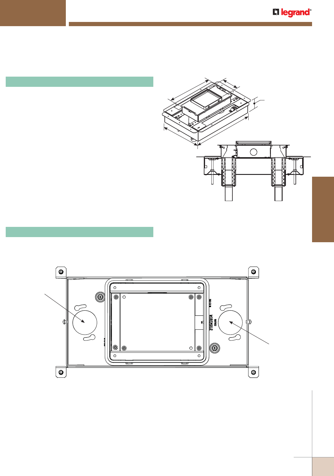
WWW.LEGRAND.US/WIREMOLD
411
FLOOR BOXES
WIREMOLD
FIRE CLASSIFIED FLOOR BOXES
RFB Series Floor Boxes
NOTE: For use in concrete pours ranging from 2" [51mm] to 5" [127mm]
maximum pour depth.
NOTE: Floor Box spacing 2' on center and one for every 4 square feet
in a span.
Four (4) #12 AWG Type THHN Power Conductors or 48 #23 AWG
(6 Cat. 6) Tele Data Conductors per gang.
14 1/2"
[367mm]
13 3/8"
[339mm]
3 1/2"
[89mm]
6 1/2"
[166mm]
20"
[507mm]
Conduit Feed
Opening –
1 1/4" [32mm]
Conduit Feed
Opening –
1 1/4" [32mm]
Top View
NOTE: UL Listed for tile, terrazzo, polished concrete, wood and carpet floors.
Fire Classified RFB2 Series Multi-Service Steel Recessed Floor Box Ordering Information
RFB2S-FC Fire Classified Two-Compartment Box
For use in either concrete or wood floors. Fully adjustable
with tunnel compartment. Supplied with one (1) duplex
receptacle, mounting plate, and one (1) communication
mounting plate (RFB22AB). Other device plates sold
separately.
Fire Classified RFB2S-FC Series Floor Box Compartment Capacities, Knockout Locations and Sizes
RFB2S-FC
Power or Data
50.2 cu. in. [822.6 ml]
Each Side
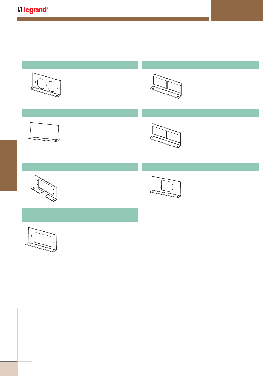
WWW.LEGRAND.US/WIREMOLD
412
FLOOR BOXES
WIREMOLD
FIRE CLASSIFIED FLOOR BOXES
RFB Series Floor Boxes
Fire Classified RFB2 Series Multi-Service Steel Recessed Floor Box Accessories
RFB2DP Internal Duplex Receptacle Bracket
Accepts standard 15A and
20A duplex receptacles.
NOTE: For RFB2 Series
Floor Boxes only.
RFB22AB Internal Communication Bracket
Includes two (2) adapters
to accept Wiremold Open
System communication
inserts, sold separately.
NOTE: For RFB2 Series
Floor Boxes only.
RFB2B Internal Blank Bracket
Plate used to close off
unused gangs.
NOTE: For RFB2 Series
Floor Boxes only.
RFB2RT Internal Communication Bracket
Includes two (2) adapters to
accept Ortronics® TracJack
devices, and two (2) adapters
to accept Ortronics Series II
devices, sold separately.
NOTE: For RFB2 Series
Floor Boxes only.
RFB2-AAP Internal Audio/Video Bracket
Accepts Extron® Electronics
AAP Series Devices, sold
separately.
NOTE: For RFB2 Series
Floor Boxes only.
RFB2EXT Internal Audio Video Bracket
Accepts two (2) Wiremold
AVIP or Extron® Electronics
MAAP Series devices, sold
separately.
NOTE: For RFB2 Series
Floor Boxes only.
RFB2GFI
Internal GFI or Decorator Style Receptacle Opening
Accepts standard GFCI or
Decorator Style Receptacles,
Communication or Audio/
Video Devices.
NOTE: For RFB2 Series
Floor Boxes only.
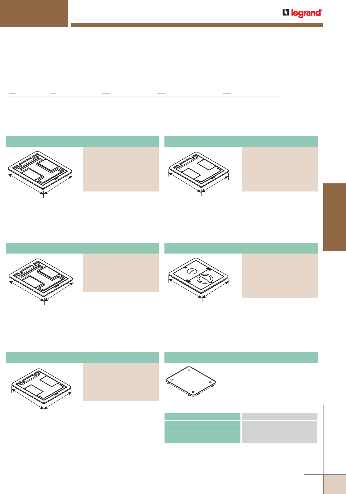
WWW.LEGRAND.US/WIREMOLD
413
FLOOR BOXES
WIREMOLD
Flanged cover for use in tile or carpet installation. Die-cast
aluminum assembly. Lid area is flush with the finished floor,
no cutouts provided.
FIRE CLASSIFIED FLOOR BOXES
RFB Series Floor Boxes
FloorPort™ Series Flanged Cover Assemblies Ordering Information
Flanged cover for use in tile or carpet installation. Die-cast
aluminum assembly. Lid area is flush with the finished floor,
no cutouts provided.
Flanged cover for use in tile or carpet installation. Die-cast
aluminum assembly. Insert in lid allows for carpet or tile
cutouts to match finished floor.
Flanged cover for use in tile or carpet installation. Die-
cast aluminum assembly. Provided with one 1" trade size
screw plug for power or communication type cabling and
one combination 1 1/4" and 2" trade size screw plug for
communication type cabling. Allows for feeding both power
and communication cabling.
North American Made FloorPort Series Flanged Cover Assemblies Ordering Information
NOTE: Pricing varies depending on country of origin. Consult your local
sales representative for more information.
NOTE: UL Listed for tile, terrazzo, polished concrete, wood and carpet floors.
7 3/4"
[197mm]
6 1/2"
[165mm]
7 3/4"
[197mm] 6 1/2"
[165mm]
7 3/4"
[197mm]
6 1/2"
[165mm]
7 3/4"
[197mm]
6 1/2"
[165mm]
7 3/4"
[197mm]
6 1/2"
[165mm]
FloorPort Part Number Configurator
B
FP TC NK
Blank Top = B
Cutout Top = C
Furniture Feed = FF
FloorPort Cover Nickel = NK
Brass = BS
Black = BK
Bronze = BZ
Gray = GY
Brushed Aluminum = AL
Tile (Flangeless) = T
Tile/Carpet = TC
(Flanged)
North American Made = NA
(Optional)
NA
Cutout Cover Assembly
PART NUMBERS:
FPCTCBK (Black)
FPCTCBZ (Bronze)
FPCTCBS (Brass)
FPCTCNK (Nickel)
FPCTCAL (Brushed Aluminum)
FPCTCGY (Gray)
CATALOG NUMBERS MAXIMUM LOAD IN POUNDS
FPCTC 1000
FPBTC 750
FPFFTC 1000
NOTE: Load applied through a 2" [51mm] mandrel in center of
service fitting.
Loads above are static loads only and do not pertain to rolling loads.
Load Capacities for FloorPort Cover Assemblies
Blank Cover Assembly
PART NUMBERS:
FPBTCBK (Black)
FPBTCBZ (Bronze)
FPBTCBS (Brass)
FPBTCNK (NIckel)
FPBTCAL (Brushed Aluminum)
FPBTCGY (Gray)
Cutout Cover Assembly
PART NUMBERS:
FPCTCBK-NA (Black)
FPCTCBZ-NA (Bronze)
FPCTCBS-NA (Brass)
FPCTCNK-NA (Nickel)
FPCTCGY-NA (Gray)
Furniture Feed Cover Assembly
PART NUMBERS:
FPFFTCBK (Black)
FPFFTCBZ (Bronze)
FPFFTCBS (Brass)
FPFFTCNK (Nickel)
FPFFTCAL (Brushed Aluminum)
FPFFTCGY (Gray)
Blank Cover Assembly
PART NUMBERS:
FPBTCBK-NA (Black)
FPBTCBZ-NA (Bronze)
FPBTCBS-NA (Brass)
FPBTCNK-NA (Nickel)
FPBTCGY-NA (Gray)
Nonmetallic ring for use on
bare polished concrete and
terrazzo floor applications.
FP-CTR Bare Concrete and Terrazzo Ring
Flanged cover for use in tile or carpet installation. Die-cast
aluminum assembly. Insert in lid allows for carpet or tile
cutouts to match finished floor.
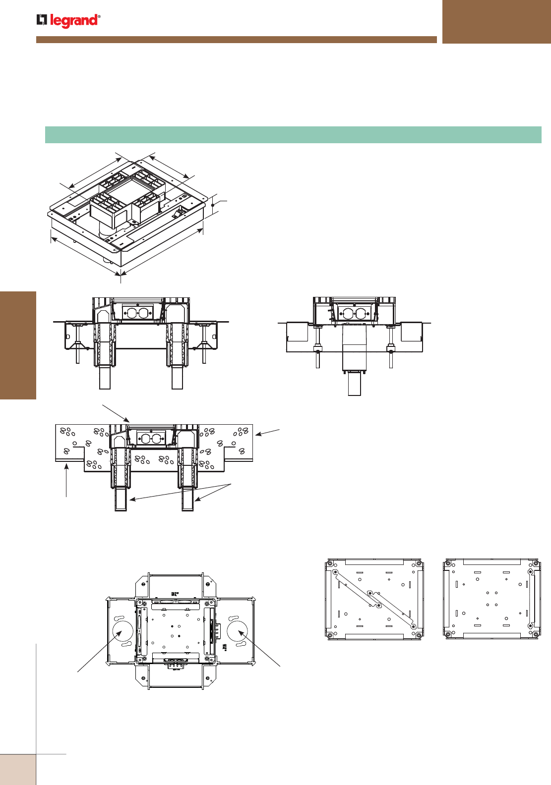
WWW.LEGRAND.US/WIREMOLD
414
FLOOR BOXES
WIREMOLD
RFB4S-FC Fire Classified Four-Compartment Box
Includes four duplex receptacle brackets. 12 3/4" L x 10" W x 3 7/16" D
[324mm x 254mm x 87mm]. Fully adjustable. Tunneling from adjacent
compartments only (not cross compartments). Tunneling can be set
to feed all four compartments from one conduit in a single-service
application.
NOTES: For use in concrete pours ranging from 2" [51mm] to 5" [127mm] maximum
pour depth.
Floor Box spacing 2' on center and one for every 4 square feet in a span.
Four (4) #12 AWG Type THHN Power Conductors or 48 #23 AWG (6 Cat. 6) Tele
Data Conductors per gang.
All boxes and activations are sold separately.
FIRE CLASSIFIED FLOOR BOXES
RFB Series Floor Boxes
Fire Classified RFB4 Series Multi-Service Steel Recessed Floor Box Ordering Information
Fire Classified RFB4S-FC Series Compartment Capacities, Knockout Locations and Sizes
RFB4S-FC
Power or Data 25.5
cu. in. [418ml]
Power or Data
22.5 cu. in. [369ml]
Power or Data
22.5 cu. in. [369ml]
Power or Data 43.5
cu. in. [713ml]
Conduit Feed
Opening –
1 1/4" [32mm]
Conduit Feed
Opening –
1 1/4" [32mm]
12 3/4"
[324mm]
10"
[254mm]
16 5/8"
[422mm]
3 7/16"
[87mm]
20"
[507mm]
NOTE: UL Listed for tile, terrazzo, polished concrete, wood and carpet floors.
RFB4S-FC
Steel Deck
Concrete:
3 1/4" [83mm] Light Weight
4 1/2" [114mm] Heavy Weight
1 1/4" [32mm] Intumescent
Stem Assemblies
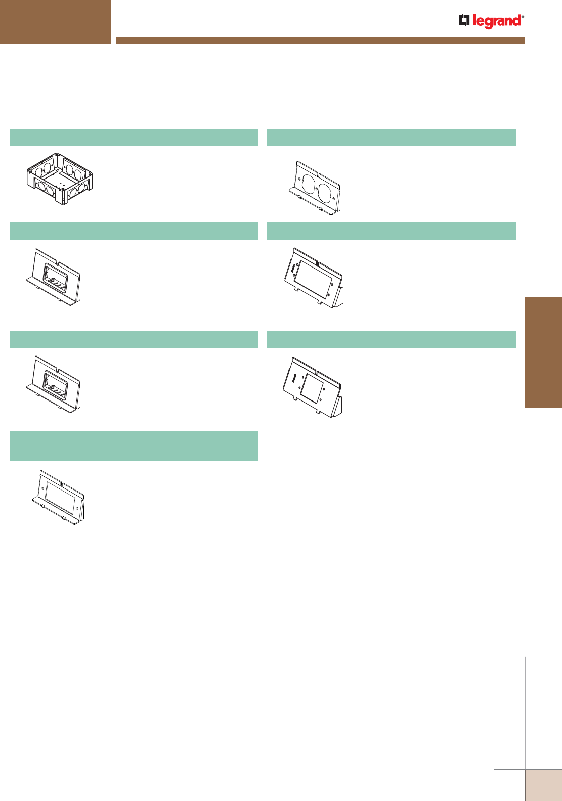
WWW.LEGRAND.US/WIREMOLD
415
FLOOR BOXES
WIREMOLD
FIRE CLASSIFIED FLOOR BOXES
RFB Series Floor Boxes
Additional configurations are available. Please consult your Wiremold Field
Sales Representative for more information.
Fire Classified RFB4 Series Multi-Service Steel Recessed Floor Box Accessories
RFB-WTB Conversion Kit
Converts RFB4 Box to a
RFB4-4DB Box.
RFB-DR-4DB Internal Duplex Receptacle Bracket
Accepts 15A and 20A duplex
receptacles.
NOTE: For use with RFB4-4DB.
WTB-2-AB Communication Bracket
One 2A size Pass & Seymour®
Activate adapter included.
Wiremold Open System inserts
sold separately.
NOTE: For use with RFB4-4DB.
WTB-2-RT Communication Bracket
Ortronics® AB2TJ TracJack and
ABS2 Series II adapters included.
NOTE: For use with RFB4-4DB.
RFB-GFI-4DB
Internal GFCI or Decorator Style Receptacle Opening
Accepts standard GFCI or
Decorator Style Receptacles,
Communication or Audio/Video
Devices.
NOTE: For use with RFB4-4DB.
WTB-AAP Internal Audio/Video Bracket
Accepts two (2) Wiremold AVIP
device plates or Extron®
Electronics AAP Series devices,
sold separately.
NOTE: For use with RFB4-4DB.
WTB-MAAP Internal Audio/Video Bracket
Accepts two (2) Wiremold AVIP
device plates or Extron®
Electronics MAAP Series devices,
sold separately.
NOTE: For use with RFB4-4DB.
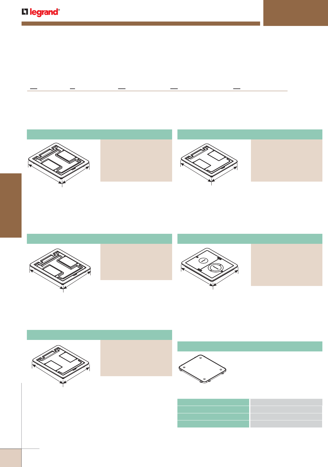
WWW.LEGRAND.US/WIREMOLD
416
FLOOR BOXES
WIREMOLD
FloorPort™ Series Flanged Cover Assemblies Ordering Information
FIRE CLASSIFIED FLOOR BOXES
RFB Series Floor Boxes
FloorPort Part Number Configurator
B
FP TC NK
Blank Top = B
Cutout Top = C
Furniture Feed = FF
FloorPort Cover Nickel = NK
Brass = BS
Black = BK
Bronze = BZ
Gray = GY
Brushed Aluminum = AL
Tile (Flangeless) = T
Tile/Carpet = TC
(Flanged)
North American Made = NA
(Optional)
NA
Flanged cover for use in tile or carpet installation. Die-cast
aluminum assembly. Lid area is flush with the finished floor,
no cutouts provided.
Flanged cover for use in tile or carpet installation. Die-cast
aluminum assembly. Insert in lid allows for carpet or tile
cutouts to match finished floor.
Cutout Cover Assembly
PART NUMBERS:
FPCTCBK (Black)
FPCTCBZ (Bronze)
FPCTCBS (Brass)
FPCTCNK (Nickel)
FPCTCAL (Brushed Aluminum)
FPCTCGY (Gray)
Blank Cover Assembly
PART NUMBERS:
FPBTCBK (Black)
FPBTCBZ (Bronze)
FPBTCBS (Brass)
FPBTCNK (Nickel)
FPBTCAL (Brushed Aluminum)
FPBTCGY (Gray)
7 3/4"
[197mm]
6 1/2"
[165mm]
7 3/4"
[197mm] 6 1/2"
[165mm]
Flanged cover for use in tile or carpet installation. Lid area
is flush with the finished floor, no cutouts provided.
Flanged cover for use in tile or carpet installation. Die-
cast aluminum assembly. Provided with one 1" trade size
screw plug for power or communication type cabling and
one combination 1 1/4" and 2" trade size screw plug for
communication type cabling. Allows for feeding both power
and communication cabling.
North American Made FloorPort Series Flanged Cover Assemblies Ordering Information
NOTE: Pricing varies depending on country of origin. Consult your local
sales representative for more information.
NOTE: UL Listed for tile, terrazzo, polished concrete, wood and carpet floors.
7 3/4"
[197mm]
6 1/2"
[165mm]
7 3/4"
[197mm]
6 1/2"
[165mm]
7 3/4"
[197mm]
6 1/2"
[165mm]
CATALOG NUMBERS MAXIMUM LOAD IN POUNDS
FPCTC 1000
FPBTC 750
FPFFTC 1000
NOTE: Load applied through a 2" [51mm] mandrel in center of
service fitting.
Loads above are static loads only and do not pertain to rolling loads.
Load Capacities for FloorPort Cover Assemblies
Cutout Cover Assembly
PART NUMBERS:
FPCTCBK-NA (Black)
FPCTCBZ-NA (Bronze)
FPCTCBS-NA (Brass)
FPCTCNK-NA (Nickel)
FPCTCGY-NA (Gray)
Furniture Feed Cover Assembly
PART NUMBERS:
FPFFTCBK (Black)
FPFFTCBZ (Bronze)
FPFFTCBS (Brass)
FPFFTCNK (Nickel)
FPFFTCAL (Brushed Aluminum)
FPFFTCGY (Gray)
Blank Cover Assembly
PART NUMBERS:
FPBTCBK-NA (Black)
FPBTCBZ-NA (Bronze)
FPBTCBS-NA (Brass)
FPBTCNK-NA (Nickel)
FPBTCGY-NA (Gray)
Nonmetallic ring for use on
bare polished concrete and
terrazzo floor applications.
FP-CTR Bare Concrete and Terrazzo Ring
Flanged cover for use in tile or carpet installation. Die-cast
aluminum assembly. Insert in lid allows for carpet or tile
cutouts to match finished floor.
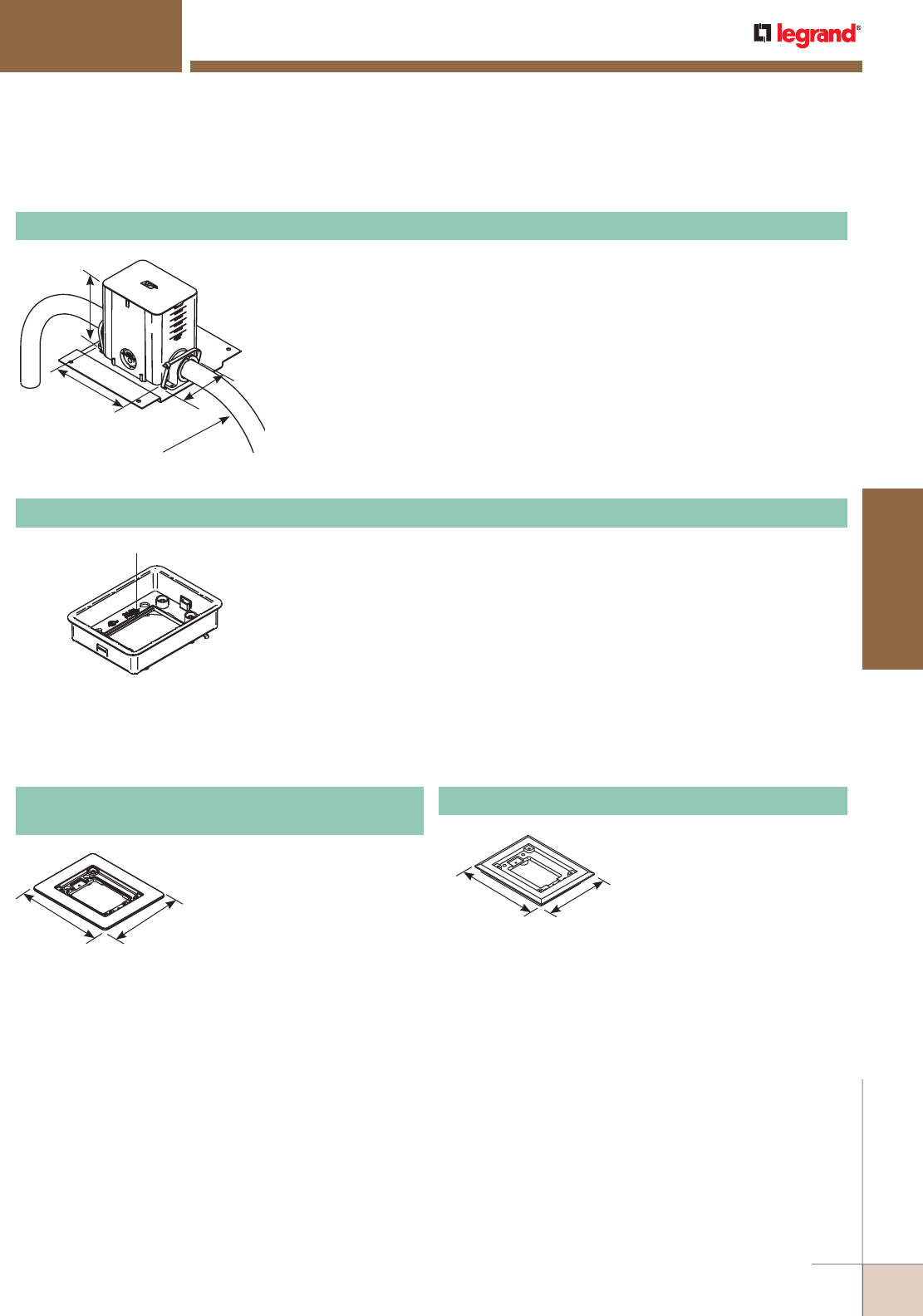
WWW.LEGRAND.US/WIREMOLD
417
FLOOR BOXES
WIREMOLD
FIRE CLASSIFIED FLOOR BOXES
880MP Series Floor Boxes
Fire Classified 880MP Floor Box Ordering Information
Comes with fiber storage loop. Also includes brass inserts for flange
connection and green ground wire for ground connection. Activate modular
inserts snap directly into the adjusting ring without the need for an adapter.
Also includes mounting screws to attach flange to box body. Ortronics®
connectivity inserts do not snap directly into the adjusting ring. For Ortronics
inserts use the 828GFITC or 829PFLRT.
NOTE: One 880MPA is needed for each 880MPFC used.
Activate Inserts Snap Here
880MP Series Floor Boxes Solid Brass Cover Plate Flanges Ordering Information
5 3/4"
[146mm] 4 3/4"
[121mm]
6 1/16"
[154.4mm] 5 1/16"
[128.5mm]
1" Trade Size
Maximum Conduit Size
7 1/8"
[181mm]
4 1/8"
[105mm]
6"
[152mm]
NOTE: UL Listed for tile, terrazzo, polished concrete, wood and carpet floors.
Brass covers and flanges are not interchangeable with aluminum or nonmetallic covers and flanges.
Nonmetallic covers are interchangeable with aluminum flanges.
880MPFC Fire Classified Nonmetallic Rectangular Floor Box
Box comes complete with reusable mudcap, insert spacer, conduit plugs and
reducers. Reducers provided for reduction to 1", 3/4" and 1/2" [25mm, 19.1mm
and 12.7mm] conduit. Minimum concrete depth is 3 1/2" [89mm] and maximum
concrete depth is 6" [152mm]. Minimum capacity is 50 cu. in. [819ml] and
maximum capacity is 100 cu. in. [1639ml]. Box dimensions are
4 1/8" W x 5 1/2" L x 6" D [105mm x 140mm x 152mm].
NOTES: Insert spacer should not be removed until after concrete pour.
880MPFC is a single-gang offering. Can not gang boxes together and maintain Fire
Classification.
Floor Box spacing 2' on center and one for every 65 square feet in a span.
Maximum Copper Cross Section per Insert: Four (4) #12 AWG Type THHN Power Conductor
or 48 #23 AWG (6 Cat. 6) Tele Data conductors.
880MPA Nonmetallic Floor Box Adjusting Ring
817B
One-Gang Brass Combination Carpet and Tile Flange
Accepts Ortronics® MAB6TJ
TracJack and MAB3S2 Series
II adapters and Wiremold CM
Series inserts, sold separately.
817C One-Gang Brass Carpet Flange
For use on 880S1, 880M1,
880CS1-1, and 880CM1-1
Floor Boxes.
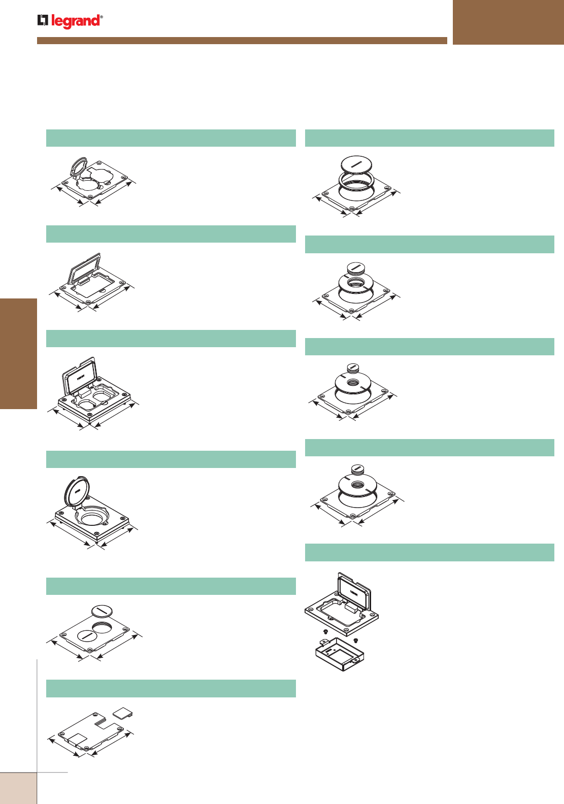
WWW.LEGRAND.US/WIREMOLD
418
FLOOR BOXES
WIREMOLD
FIRE CLASSIFIED FLOOR BOXES
880MP Series Floor Boxes
NOTE: UL Listed for tile, terrazzo, polished concrete, wood and
carpet floors.
Brass covers and flanges are not interchangeable with aluminum
or nonmetallic covers and flanges. Nonmetallic covers are
interchangeable with aluminum flanges.
880MP Series Floor Boxes Metal Cover Plates Ordering Information
828R Brass Duplex Cover Plate
Flip lids. Can also be used with a
106 type communication adapter.
3 1/8"
[80.2mm]
4 3/16"
[106.2mm]
828GFITC Brass GFI Cover Plate
May be used with Activate and
Ortronics® Connectivity Systems in
conjunction with 817B, 827B, and
837B Flanges.
3 1/8"
[80.2mm]
4 3/16"
[106.2mm]
828DPGFITC Brass Rectangular Cover Plate
Allows for mounting of a duplex-
style receptacle with a rectangular-
style flip lid cover.
3 1/8"
[80.2mm]
4 3/16"
[106.2mm]
828DLR Brass Single Locking Receptacle Cover Plate
Single flip lid cover for 20A or 30A
single locking receptacles. Device
opening is 2 5/8" [67mm]. For use
with maximum female locking
device of 1.58" diameter and
maximum male plug face of 2.25"
diameter.
3 1/8"
[80.2mm] 4 3/16"
[106.2mm]
3 1/8"
[80.2mm]
4 3/16"
[106.2mm]
Screw plugs. Screw plugs are 11/2"
[38mm] in diameter.
828SPTC Brass Duplex Cover Plate
3 1/8"
[80.2mm]
4 3/16"
[106.2mm]
Data slides. Feed through only, not
for use with a mounting plate for
communication jacks.
829STC Brass Communication Cover Plate
3 1/8"
[80.2mm]
4 3/16"
[106.2mm]
2 5/8" and 2 1/4" [67mm and
57mm] plugs.
829CK Brass Communication Cover Plate
3 1/8"
[80.2mm]
4 3/16"
[106.2mm]
2 5/8" and 1" [67mm and 25mm]
plugs.
829CK-1 Brass Communications Cover Plate
3 1/8"
[80.2mm]
4 3/16"
[106.2mm]
2 5/8" and 3/4" [67mm and
19.1mm] plugs.
829CK-3/4 Brass Communications Cover Plate
3 1/8"
[80.2mm]
4 3/16"
[106.2mm]
2 5/8" and 1/2" [67mm and
12.7mm] plugs.
829CK-1/2 Brass Communications Cover Plate
828MAAP AV Adapter Plate
Sheet metal adapter plate that
accepts two (2) Wiremold AVIP or
Extron® Electronics MAAP style
device plates, sold separately. For
use with 828GFITC or 828GFITCAL
cover plates, sold separately.
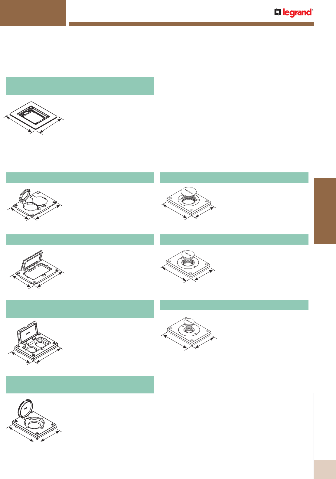
WWW.LEGRAND.US/WIREMOLD
419
FLOOR BOXES
WIREMOLD
FIRE CLASSIFIED FLOOR BOXES
880MP Series Floor Boxes
818TCAL One-Gang Brushed Aluminum
Combination Carpet and Tile Flange
Accepts Ortronics® MAB6TJ
TracJack and MAB3S2 Series II
adapters and Wiremold CM Series
inserts, sold separately.
NOTE: Brushed alumnum flanges come
with beveled edges.
880MP Series Floor Boxes Brushed Aluminum Cover Plate Flanges Ordering Information
6 1/16"
[154mm] 5 1/16"
[128.5mm]
4 5/16"
[109.5mm] 3 3/16"
[83.6mm]
4 5/16"
[109.5mm]
3 3/16"
[83.6mm]
880MP Series Floor Boxes Metal Cover Plates Ordering Information
3 3/16"
[83.6mm]
4 5/16"
[109.5mm]
3 3/16"
[83.6mm]
4 5/16"
[109.5mm]
3 3/16"
[83.6mm]
4 5/16"
[109.5mm]
4 5/16"
[109.5mm] 3 3/16"
[83.6mm]
NOTE: UL Listed for tile, terrazzo, polished concrete, wood and carpet
floors.
Brass covers and flanges are not interchangeable with aluminum
or nonmetallic covers and flanges. Nonmetallic covers are
interchangeable with aluminum flanges.
828DPGFITCAL
Brushed Aluminum Rectangular Cover Plate
Allows for mounting of a
duplex-style receptacle with a
rectangular-style flip lid cover.
828DLRAL Brushed Aluminum Single Locking
Receptacle Cover Plate
Single flip lid cover for 20A or 30A
single locking receptacles. Device
opening is 2 5/8" [67mm]. For use
with maximum female locking
device of 1.58" diameter, and
maximum male plug face of
2.25" diameter
828R-TCAL Brushed Aluminum Duplex Cover Plate
Flip lids. Can also be used with a
106 type communication adapter.
828GFITCAL Brushed Aluminum GFI Cover Plate
May be used with Activate and
Ortronics® Connectivity Systems in
conjunction with 817B, 827B, and
837B Flanges.
830CKTCAL Brushed Aluminum Cover Plate
Power or communication plate
with 2" [51mm] and 1 1/4" [32mm]
plugs.
NOTE: Acceptable for use with threaded
conduit when passing through
power cables.
4 5/16"
[109.5mm] 3 3/16"
[83.6mm]
830CKTCAL-3/4 Brushed Aluminum Cover Plate
Power or communication plate
with 2" [51mm] and 3/4" [19.1mm]
plugs.
NOTE: Acceptable for use with threaded
conduit when passing through
power cables.
830CKTCAL-1 Brushed Aluminum Cover Plate
Power or communication plate
with 2" [51mm] and 1" [25mm]
plugs.
NOTE: Acceptable for use with threaded
conduit when passing through
power cables.
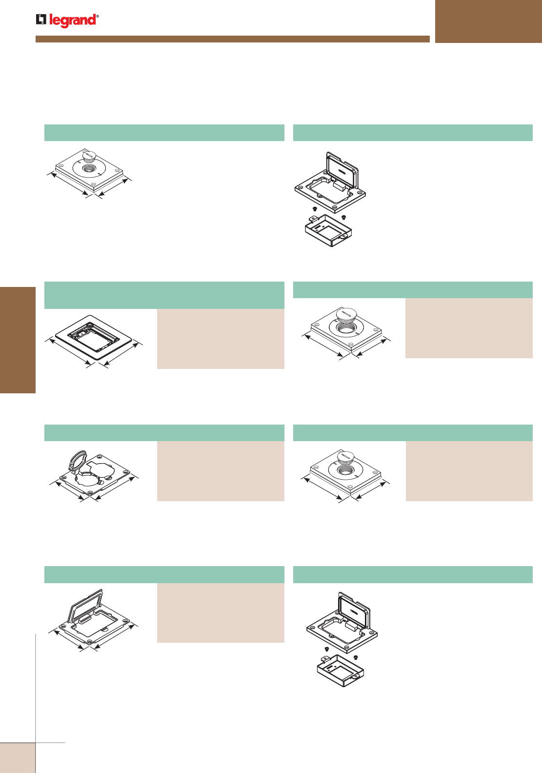
WWW.LEGRAND.US/WIREMOLD
420
FLOOR BOXES
WIREMOLD
FIRE CLASSIFIED FLOOR BOXES
880MP Series Floor Boxes
828MAAP AV Adapter Plate
Sheet metal adapter plate that
accepts two (2) Wiremold AVIP or
Extron® Electronics MAAP style
device plates, sold separately. For
use with 828GFITC or 828GFITCAL
cover plates, sold separately.
830CKTCAL-1/2 Brushed Aluminum Cover Plate
Power or communication plate
with 2" [51mm] and 1/2"
[12.7mm] plugs.
NOTE: Acceptable for use with threaded
conduit when passing through
power cables.
4 5/16"
[109.5mm] 3 3/16"
[83.6mm]
880MP Series Floor Boxes Powder-Coated Aluminum Cover Plate Flanges Ordering Information
6 1/16"
[154.4mm]
5 1/16"
[128.5mm]
4 5/16"
[109.5mm]
3 3/16"
[83.6mm]
3 3/16"
[83.6mm]
4 5/16"
[109.5mm]
3 3/16"
[83.6mm]
4 5/16"
[109.5mm]
NOTE: UL Listed for tile, terrazzo, polished concrete, wood and carpet floors.
Brass covers and flanges are not interchangeable with aluminum or
nonmetallic covers and flanges. Nonmetallic covers are interchangeable
with aluminum flanges.
828MAAP AV Adapter Plate
Sheet metal adapter plate
that accepts two (2) Wiremold
AVIP or Extron® Electronics
MAAP style device plates,
sold separately. For use with
828GFITC or 828GFITCAL cover
plates, sold separately.
Powder-Coated Aluminum Duplex Cover Plate
PART NUMBERS:
828R-TCAL-BK (Black)
828R-TCAL-GY (Gray)
828R-TCAL-BS (Brass)
828R-TCAL-NK (Nickel)
828R-TCAL-BZ (Bronze)
Flip lids. Can also be used with a 106 type communication
adapter.
4 5/16"
[109.5mm]
3 3/16"
[83.6mm]
Power or communication plate with 2" [51mm] and 3/4"
[19.1mm] plugs.
NOTE: Acceptable for use with threaded conduit when passing through
power cables.
Powder-Coated Aluminum Cover Plate
PART NUMBERS:
829CKAL-3/4BK (Black)
829CKAL-3/4GY (Gray)
829CKAL-3/4BS (Brass)
829CKAL-3/4NK (Nickel)
829CKAL-3/4BZ (Bronze)
Allows for mounting a duplex receptacle (Decorator or GFCI
style) with a rectangular flip cover.
Powder-Coated Aluminum Rectangular Cover Plate
PART NUMBERS:
828GFITCAL-BK (Black)
828GFITCAL-GY (Gray)
828GFITCAL-BS (Brass)
828GFITCAL-NK (Nickel)
828GFITCAL-BZ (Bronze)
Power or communication plate with 2" [51mm] and
1" [25mm] plugs.
NOTE: Acceptable for use with threaded conduit when passing through
power cables.
Powder-Coated Aluminum Cover Plate
PART NUMBERS:
829CKAL-1BK (Black)
829CKAL-1GY (Gray)
829CKAL-1BS (Brass)
829CKAL-1NK (Nickel)
829CKAL-1BZ (Bronze)
Accepts Ortronics® MAB6TJ TracJack and MAB3S2 Series II
adapters and Wiremold CM Series inserts, sold separately.
One-Gang Powder-Coated Aluminum
Combination Carpet and Tile Flange
PART NUMBERS:
817TCAL-BK (Black)
817TCAL-GY (Gray)
817TCAL-BS (Brass)
817TCAL-NK (Nickel)
817TCAL-BZ (Bronze)
880MP Series Floor Boxes Brushed Aluminum Cover Plate Flange Ordering Information
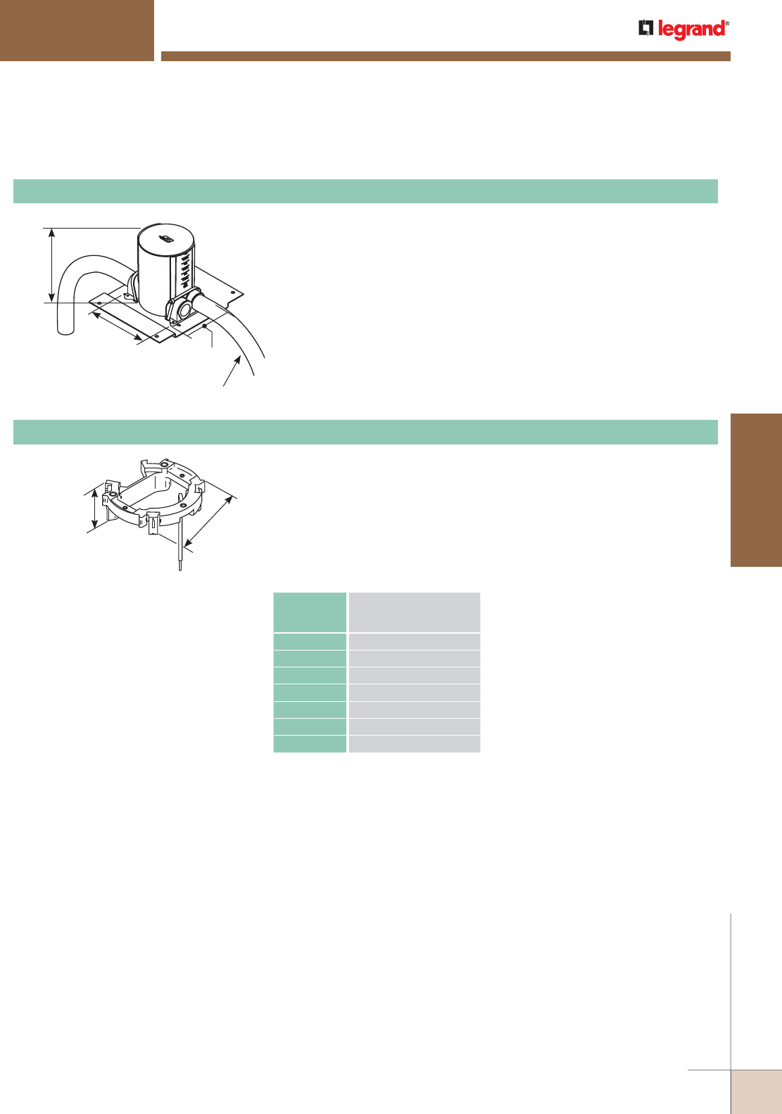
WWW.LEGRAND.US/WIREMOLD
421
FLOOR BOXES
WIREMOLD
FIRE CLASSIFIED FLOOR BOXES
880MP Series Floor Boxes
Used to attach wiring devices and cover plates to PVC Box. Locks into place
without using glue or mechanical fasteners. Compensates for up to 10˚ of
tilt if box is not level. Ground wire is factory attached to the adjusting ring.
NOTE: One ring required per box, single- or dual-service.
4"
[102mm]
1 1/8"
[29mm]
Fire Classified Ratchet-Pro PVC Floor Box Ordering Information
6"
[152mm]
5 1/2"
[140mm]
4 1/4"
[108mm]
1" Trade Size
Maximum Conduit Size
NOTE: UL Listed for tile, terrazzo, polished
concrete, wood and carpet floors.
881FC Round PVC Floor Box
Supplied with reusable concrete cap, adapter ring (881ADP), conduit reducers
and conduit hub plugs. Available for single service only. Graduated cubic
inch markings inside the box indicate volume capacity at any depth. Box has
parallel conduit hubs eliminating the need for 90˚ sweeps in installation. One-
piece reduction from 1" to 1/2" [25mm to 12.7mm] conduit. Reducers and
plugs located on a mounting bar for easier selection. For concrete pours of 2
1/4" to 6" [57mm to 152mm].
NOTES: Floor Box spacing 2' on center and one for every 65 square feet in a span.
Maximum Copper Cross Section per Insert: Four (4) #12 AWG Type THHN Power
Conductor or 48 #23 AWG (6 Cat. 6) Tele Data conductors.
881ADP PVC Floor Box Ratchet Adjusting Ring
Volume Capacities for Ratchet-Pro PVC Floor Box
BOX HEIGHT Single Service 895 Activation
WIRING VOLUME
In. mm Cu. In. ml
6 152.0 56.0 917.0
5 1/2 140.0 49.0 803.0
5 127.0 42.0 688.0
4 1/2 114.0 35.0 574.0
4 102.0 28.0 459.0
3 1/2 89.0 21.0 344.0
3 1/4 76.0 17.0 278.0
NOTE: To calculate total box volume, use the displacement
of the largest uncut section remaining.
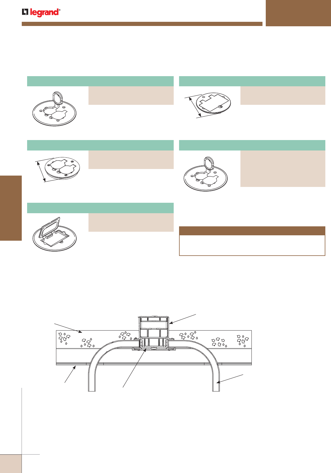
WWW.LEGRAND.US/WIREMOLD
422
FLOOR BOXES
WIREMOLD
Aluminum Duplex Cover Plate
PART NUMBERS:
895TCAL-BK (Black)
895TCAL-GY (Gray)
895TCAL-BS (Brass)
895TCAL-NK (Nickel)
895TCAL-BZ (Bronze)
FIRE CLASSIFIED FLOOR BOXES
880MP Series Floor Boxes
Ratchet-Pro Fire Classified Floor Boxes Installation Cross Section
4 1/4"
[108mm] With flip lids, 4 1/4" [108mm]
for tile.
Duplex Cover Plate
PART NUMBERS:
895T (Brass)
895TAL (Brushed Aluminum)
Cover Plates for 881FC Floor Box
CAUTION
Installation must comply with NEC and local code conductor
volume requirements. Not for use when concrete is the finished
floor. Use only for tile, carpet or wood covered floors.
With flip lids, 5 1/2" [140mm]
diameter for carpet.
With flip lids, 5 1/2" [140mm]
diameter for carpet.
Duplex Cover Plate
PART NUMBERS:
895 (Brass)
895TCAL (Brushed Aluminum)
5 1/2" [140mm] diameter for
carpet.
GFI Receptacle Cover Plate
PART NUMBERS:
895GFI (Brass)
895GFICAL (Brushed Aluminum)
4 1/4"
[108mm] 4 1/4" [108mm] for tile.
GFI Receptacle Cover Plate
PART NUMBERS:
895TGFI (Brass)
895TGFIAL (Brushed Aluminum)
Intumescent Material
Steel Deck
Concrete:
3 1/4" [83mm] Light Weight
4 1/2" [114mm] Normal Weight
880MPFC Floor Box
1" (Maximum)
Trade Size PVC Elbow
NOTE: 1. All cover plates are furnished with gasket and three screws.
2. Polycarbonate cover plates cannot be used on the 881FC Fire
Classified Floor Box.
NOTE: UL Listed for tile, terrazzo, polished concrete, wood and carpet floors.
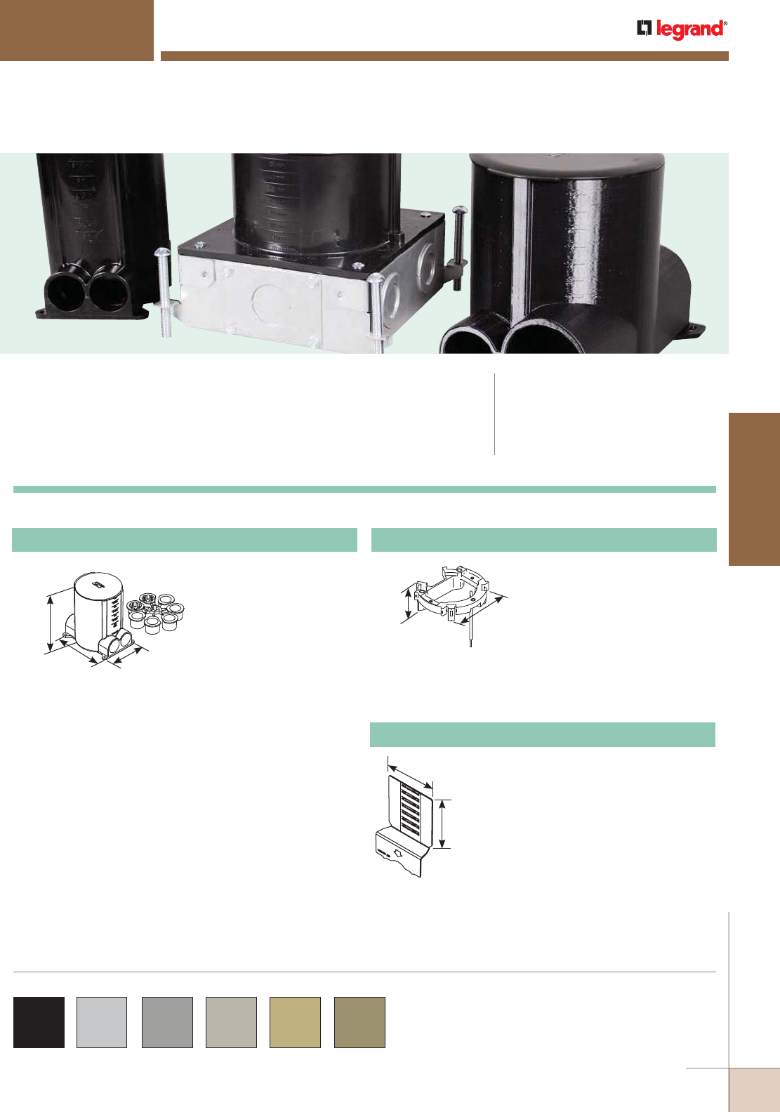
WWW.LEGRAND.US/WIREMOLD
423
FLOOR BOXES
WIREMOLD
Ratchet-Pro™ Series Floor Boxes provide dual-service capability in a single,
easy-to-install round floor box.
RATCHETPRO™ SERIES FLOOR BOXES
CODE REFERENCE
cULus Listed
Nonmetallic Outlet Boxes:
File E110748 Guide QCMZ.
5 1/2"
[140mm]
4 1/4"
[108mm]
6"
[152mm]
4"
[102mm]
1 1/8"
[28mm]
Supplied with reusable
concrete cap, adjusting
ring, conduit reducers and
conduit hub plugs. Available
for both single and dual
service (895DCC required
for dual service brass
activation). Graduated cubic
inch markings inside the box
indicate volume capacity at
any depth. Box has parallel
conduit hubs eliminating
need for 90° sweeps in
installation. One-piece
reduction from 1" to 1/2"
[25mm to12.7mm] conduit.
Reducers and plugs located
on a mounting bar for easier
selection. For concrete pours
of 2 1/4" to 6" [57mm to
152mm].
881 Round PVC Floor Box
Used to attach wiring devices
and cover plates to PVC box.
Locks into place without using
glue or mechanical fasteners.
Compensates for up to 10° of tilt
if box is not level.
NOTE: Ground wire is factory attached
to the adjusting ring. One ring
required per box, single- or dual-
service, ordered separately.
881-ADP PVC Floor Box Ratchet Adjusting Ring
5 1/2"
[140mm]
3 11/16"
[94mm] Used to isolate power and
communication compartments.
Graduated cubic inch markings are
marked clearly on the divider and
correspond directly to the cubic
inch markings on the interior of the
box. Cuts easily with a utility knife.
Supplied with a receptacle plate that
completes separation of power and
communication services. One divider
required for dual-service activation.
881-DIV PVC Floor Box Divider Plate
Ratchet-Pro 881 Series Floor Boxes Ordering Information
NOTE: 881-ADP adjusting
ring is included with
the 881 floor box.
895 and 896 Series Cover Plates are compatible with Ratchet-Pro 881
Series Floor Boxes and are available in black, aluminum, gray, nickel,
brass and bronze.
Custom color options are also available. Consult the factory for more
information.
COLOR OPTIONS

WWW.LEGRAND.US/WIREMOLD
424
FLOOR BOXES
WIREMOLD
RATCHETPRO™ SERIES FLOOR BOXES
Ratchet-Pro 881 Series Floor Boxes Cover Plates Ordering Information
NOTE: All cover plates are furnished with gasket and three screws.
The 895P Polycarbonate Series Cover Plates must be field modified for dual service.
5 1/2"
[140mm]
895DCC Dual Service Brass Duplex Cover Plate
With flip lids. Supplied with 1/2"
[12.7mm] screw plug for accessing
communication cables. 5 1/2" [140mm]
diameter for carpet applications only.
Used in conjunction with the 881DIV to
complete dual-service activation.
GFI Receptacle Cover Plate
PART NUMBERS:
895 (Brass)
895GTCAL (Brushed Aluminum)
5 1/2"
[140mm] With flip lids. Duplex cover plate
with flip lids, 5 1/2" [140mm]
diameter for carpet.
4 1/4"
[108mm]
Brass cover plate with two screw
plug openings, 4 1/4" [108mm]
diameter for tile.
NOTE: Screw plug openings are 1 1/2" [38mm]
tapped openings.
895TSP Cover Plate
GFI Receptacle Cover Plate
PART NUMBERS:
895GFI (Brass)
895GFICAL (Brushed Aluminum)
5 1/2"
[140mm] GFI receptacle cover plate, 5 1/2"
[140mm] diameter for carpet.
Cover Plate
PART NUMBERS:
895TGFI (Brass)
895TGFIAL (Brushed Aluminum)
4 1/4"
[108mm] GFI receptacle cover plate, 4 1/4"
[108mm] diameter for tile.
5 1/2"
[140mm]
Brass communication or power
cover plate with 2 5/8" [67mm]
threaded opening, 5 1/2" [140mm]
diameter for carpet.
NOTE: Sold without abandon plug.
896 Communication or Power Cover Plate
4 1/4"
[108mm]
Brass communication or power
cover plate with 2 5/8" [67mm]
threaded opening, 4 1/4" [108mm]
diameter for tile.
NOTE: Sold without abandon plug.
896T Communication or Power Cover Plate
5 1/2"
[140mm]
Brass communication or power
cover plate with 2 1/4" [57mm]
threaded opening, 5 1/2" [140mm]
diameter for carpet.
896CK Communication or Power Cover Plate
4 1/4"
[108mm]
Brass communication or power
cover plate with 2 1/4" [57mm]
threaded opening, 5 1/2" [140mm]
diameter for tile.
896TCK Communication or Power Cover Plate
Cover Plate
PART NUMBERS:
896CK-1/2 (Brass)
896CKAL-1/2 (Brushed Aluminum)
Cover plate with 1/2" [12.7mm]
threaded opening, 5 1/2" [140mm]
diameter for carpet.
5 1/2"
[140mm]
5 1/2"
[140mm] Cover plate with two screw plug
openings, 5 1/2" [140mm] diameter
for carpet.
GFI Receptacle Cover Plate
PART NUMBERS:
895SP (Brass)
895SPAL (Brushed Aluminum)
4 1/4"
[108mm] Duplex cover plate with flip lids,
4 1/4" [108mm] diameter for tile.
Duplex Cover Plate with Flip Lids
PART NUMBERS:
895T (Brass)
895TAL (Brushed Aluminum)
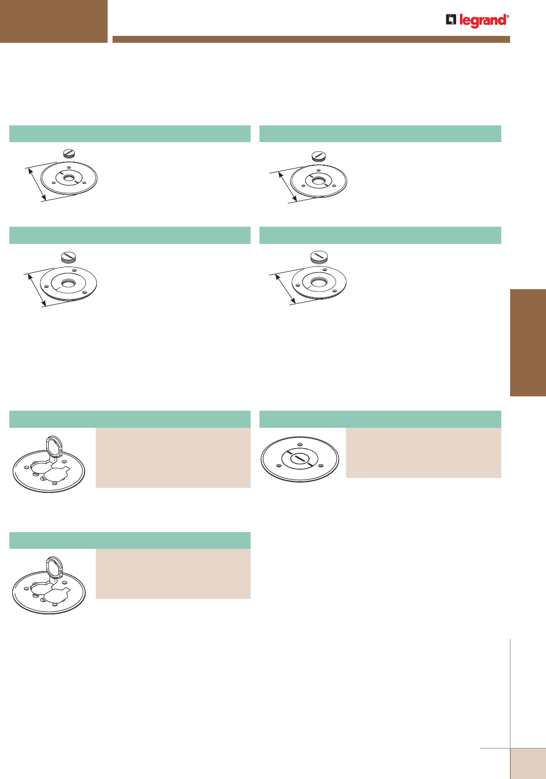
WWW.LEGRAND.US/WIREMOLD
425
FLOOR BOXES
WIREMOLD
Polycarbonate Duplex Cover Plate
PART NUMBERS:
895P-BLK (Black)
895P-BRN (Brown)
895P-BRZ (Bronze)
895P-AL (Aluminum)
NOTE: All cover plates are furnished with gasket and three screws. The 895P Polycarbonate Series Cover Plates must be field modified for dual service.
5 1/2"
[140mm]
Brass cover plate with 3/4"
[19.1mm] threaded opening, 5 1/2"
[140mm] diameter for carpet.
896CK-3/4 Cover Plate
4 1/4"
[108mm]
Brass cover plate with 3/4"
[19.1mm] threaded opening, 5 1/2"
[140mm] diameter for tile.
896TCK-3/4 Cover Plate
5 1/2"
[140mm]
Brass cover plate with 1" [25mm]
threaded opening, 5 1/2" [140mm]
diameter for carpet.
896CK-1 Cover Plate
4 1/4"
[108mm]
Brass cover plate with 1" [25mm]
threaded opening, 5 1/2" [140mm]
diameter for tile.
896TCK-1 Cover Plate
Ratchet-Pro 881 Series Floor Boxes Cover Plates Ordering Information (continued)
RATCHETPRO™ SERIES FLOOR BOXES
Aluminum Duplex Cover Plate
PART NUMBERS:
895TCAL-BK (Black)
895TCAL-GY (Gray)
895TCAL-NK (Nickel)
895TCAL-BS (Brass)
895TCAL-BZ (Bronze)
With flip lids, 5 1/2" [140mm] diameter
for carpet.
With flip lids, 5 1/2" [140mm] diameter
for carpet.
5 1/2" [140mm] diameter.
North American Made Ratchet-Pro 881 Series Floor Boxes Cover Plates Ordering Information
Communications Cover Plate
PART NUMBERS:
896PCK-BLK (Black)
896PCK-BRN (Brown)
896PCK-BRZ (Bronze)
896PCK-AL (Aluminum)
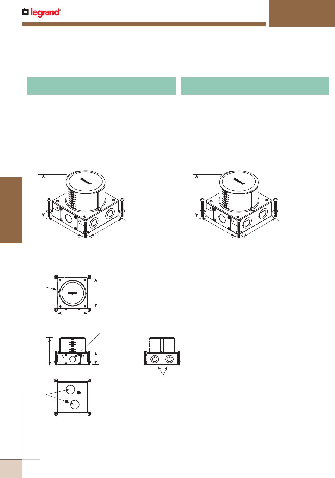
WWW.LEGRAND.US/WIREMOLD
426
FLOOR BOXES
WIREMOLD
Ratchet-Pro RPSFB and RPSFB-OG Series Floor Boxes Ordering Information
RATCHETPRO™ SERIES FLOOR BOXES
Rectangular dual service metal concrete floor box with a
nonmetallic top that allows for concrete pours between
4" thick to 6" thick. Graduated markings on the inside and
outside of the box indicating volume capacity, as well as
the depth of concrete pour. Box accepts 2HUB to allow 2"
conduit feeds (sold separately) while maintaining a 4" deep
concrete pour.
Box includes (1) Reusable concrete cap, (2) Removable
knockout plates to allow the 2HUB to be attached. 2HUB
sold separately.
RPSFB Rectangular Dual Service Metal Concrete
Floor Box
6 1/16"
[152mm]
7"
[178mm]
6 13/16"
[173mm]
Rectangular dual service metal concrete floor box with a
nonmetallic top that allows for concrete pours between
4" thick to 6" thick. Graduated markings on the inside and
outside of the box indicating volume capacity, as well as
the depth of concrete pour. Box accepts 2HUB to allow 2"
conduit feeds (sold separately) while maintaining a 4" deep
concrete pour.
Box includes (1) Reusable concrete cap, (2) Removable
knockout plates to allow the 2HUB to be attached. 2HUB
sold separately.
RPSFB-OG On-Grade Rectangular Dual Service
Metal Concrete Floor Box
6 1/16"
[152mm]
7"
[178mm]
6 13/16"
[173mm]
Ratchet-Pro RPSFB and RPSFB-OG Dimensions and Knockout Locations
5 15/16"
[151mm]
6 13/16"
[173mm]
2 SIDES
1" trade size KO inside
a removable plate
2 SIDES:
3/4" & 1 1/4" trade size
concentric KOs
BOTTOM:
1 1/2" trade
size KOs
7"
[178mm]
6 1/16"
[154mm]
2 13/16"
[71mm]
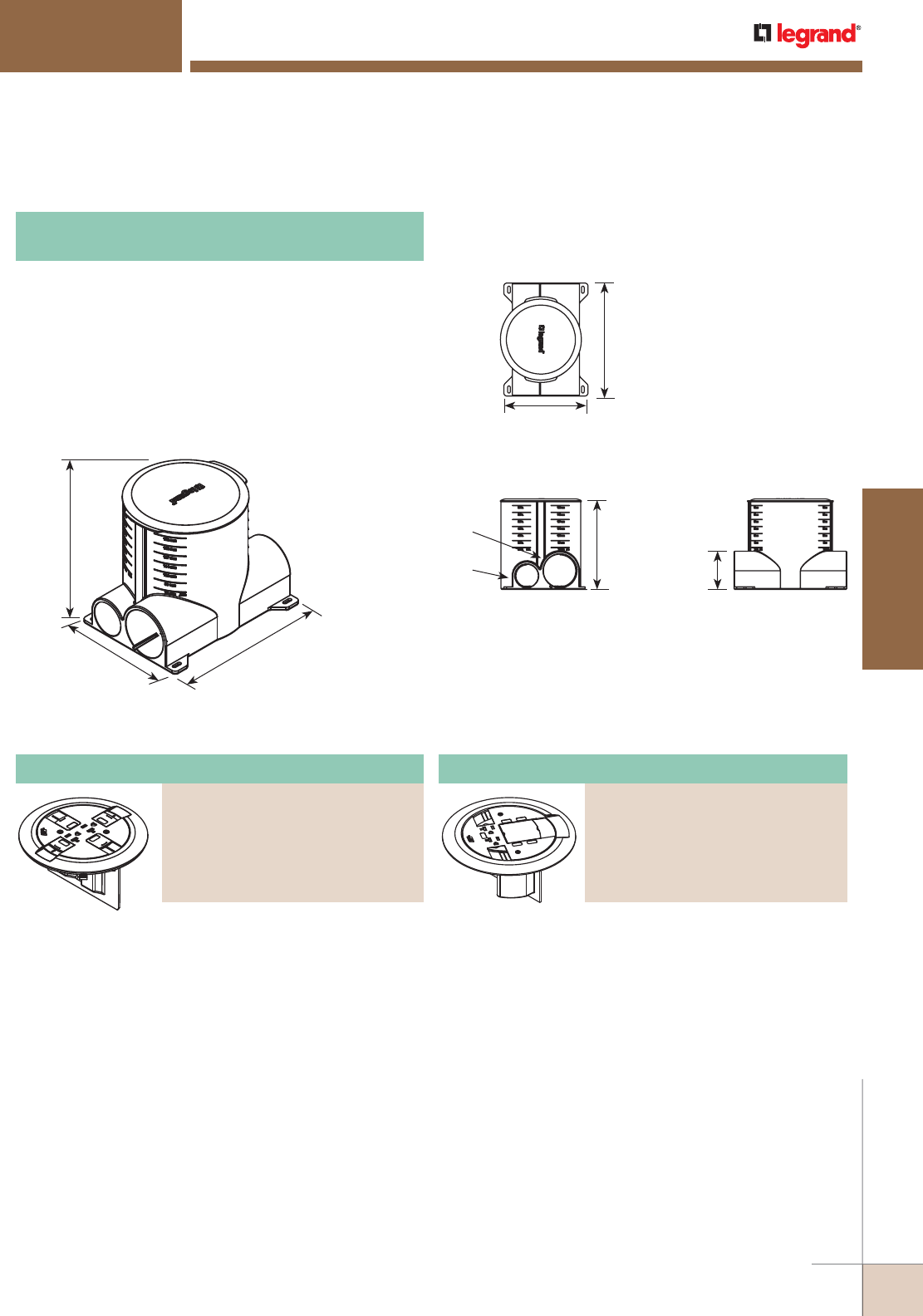
WWW.LEGRAND.US/WIREMOLD
427
FLOOR BOXES
WIREMOLD
Multiple Service Floor Box Cover Kit
PART NUMBERS:
RPAV3CTCGY (Gray)
RPAV3CTCBK (Black)
RPAV3CTCAL (Aluminum)
RPAV3CTCBS (Brass)
RPAV3CTCAA (All Aluminum)
RPAV3CTCAB (All Brass)
Multiple Service Floor Box Cover Kit
PART NUMBERS:
RP7CTCGY (Gray)
RP7CTCBK (Black)
RP7CTCAL (Aluminum)
RP7CTCBS (Brass)
RP7CTCAA (All Aluminum)
RP7CTCAB (All Brass)
Ratchet-Pro RPNFB
Dimensions & Knockout Locations
Ratchet-Pro RPNFB Series Floor Boxes Ordering Information
RATCHETPRO™ SERIES FLOOR BOXES
Round dual service nonmetallic concrete floor box. Floor box
has two 1 1/4" trade size conduit hubs for power and two 2"
trade size conduit hubs for communications and audio/video
services.
Box Includes: (1) Reusable concrete cap, (1) Reducing ring
for the 2" hubs that can be reduced down to 1 1/2 Trade size,
and 1 1/4" trade size openings, (1) Reducing ring for the
1 1/4" hubs that allow to be reduced to 1" trade size opening
or 3/4" trade size opening.
RPNFB Round Dual Service Nonmetallic Concrete
Floor Box
6 7/16"
[164mm]
6"
[152mm]
8 1/16"
204mm]
6"
[152mm]
2 SIDES:
2" trade size
Conduit Hub
2 SIDES:
1 1/4" trade size
Conduit Hub
8 1/16"
[204mm]
6 7/16"
[164mm]
2 3/4"
[69mm]
Ratchet-Pro RPNFB, RPSFB and RPSFB-OG Series Floor Box Kits Ordering Information
Kit comes complete with (1) prewired
20A duplex receptacle, (receptacle can
be wired as a standard receptacle,
or isolated ground), flange and slide
holder, adapter ring to secure into
the boxes, divider (RP-DIV), Wiremold
CM series open system adapters
(unloaded), Ortronics® Series II, and
TracJack adapters. Modular jacks and
A/V connectors sold separately.
Flange Color Slide Holder Color
Gray Gray
Black Black
Aluminum Black
Brass Black
All Aluminum Aluminum
All Brass Brass
Kit comes complete with (1) prewired
20A duplex receptacle, (receptacle
can be wired as standard receptacle,
or isolated ground), flange and slide
holder, adapter ring to secure into
the boxes, divider (RP-DIV), Wiremold
CM series open system adapters
(unloaded), Ortronics® Series II,
TracJack adapters and adapter to
accept AVIP or Extron® Electronics
MAAP devices. Modular jacks and A/V
connectors sold separately.
Flange Color Slide Holder Color
Gray Gray
Black Black
Aluminum Black
Brass Black
All Aluminum Aluminum
All Brass Brass
CAUTION: See cut sheet for depth limits.
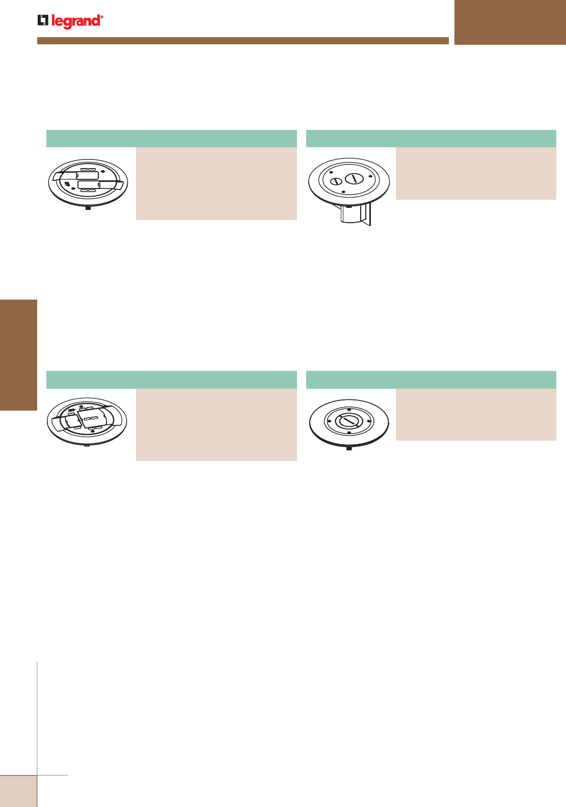
WWW.LEGRAND.US/WIREMOLD
428
FLOOR BOXES
WIREMOLD
Multiple Service Furniture Feed Floor Box Cover Kit
PART NUMBERS:
RP4FFCTCGY (Gray)
RP4FFCTCBK (Black)
RP4FFCTCAL (Aluminum)
RP4FFCTCBS (Brass)
Ratchet-Pro RPNFB, RPSFB and RPSFB-OG Series Floor Box Kits Ordering Information (continued)
RATCHETPRO™ SERIES FLOOR BOXES
Kit comes complete with adapter ring
to secure into the boxes, Wiremold
CM series open system adapters
(unloaded), Ortronics® Series II, and
TracJack adapters. Modular jacks and
A/V connectors sold separately.
Flange Color Slide Holder Color
Gray Gray
Black Black
Aluminum Black
Brass Black
All Aluminum Aluminum
All Brass Brass
Kit comes complete with adapter ring
to secure into the boxes, (1) 3/4" trade
size screw plug and conduit fitting for
power, 1-1/4" trade size screw plug
and conduit fitting for low voltage
(communications or Audio/Video)
services.
Flange Color
Gray
Black
Aluminum
Brass
Kit comes complete with adapter ring
to secure into the boxes, (1) 1 1/4/2"
concentric screw plug closure plug.
Conduit fittings sold separately by
others.
Flange Color
Gray
Black
Aluminum
Brass
CAUTION: See cut sheet for depth limits.
Single Service 4 Port Floor Box Cover Kit
PART NUMBERS:
RPAMD4CTCGY (Gray)
RPAMD4CTCBK (Black)
RPAMD4CTCAL (Aluminum)
RPAMD4CTCBS (Brass)
RPAMD4CTCAA (All Aluminum)
RPAMD4CTCAB (All Brass)
Single Service 8 Port Floor Box Cover Kit
PART NUMBERS:
RPAMD8CTCGY (Gray)
RPAMD8CTCBK (Black)
RPAMD8CTCAL (Aluminum)
RPAMD8CTCBS (Brass)
RPAMD8CTCAA (All Aluminum)
RPAMD8CTCAB (All Brass)
Single Service Furniture Feed Floor Box Cover Kit
PART NUMBERS:
RP9AM2CTCGY (Gray)
RP9AM2CTCBK (Black)
RP9AM2CTCAL (Aluminum)
RP9AM2CTCBS (Brass)
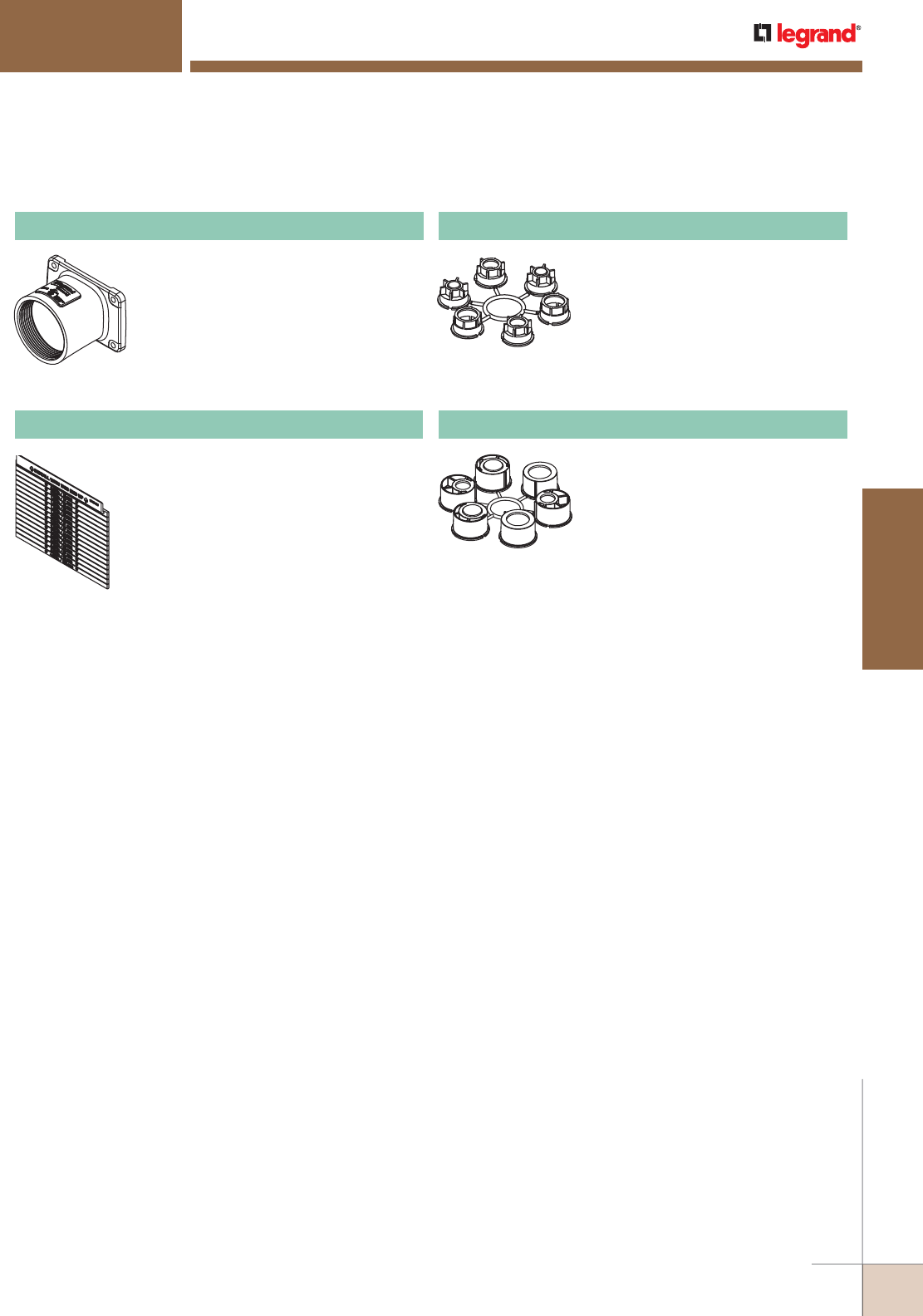
WWW.LEGRAND.US/WIREMOLD
429
FLOOR BOXES
WIREMOLD
Ratchet-Pro RPNFB, RPSFB and RPSFB-OG Series Floor Box Kits Ordering Information (continued)
RATCHETPRO™ SERIES FLOOR BOXES
2HUB 2" Conduit Transition Hub
Trade size 2" die cast zinc conduit
fitting allows for 2" conduit to transition
into a shallow box design. Includes: die
cast fitting gasket. Accepts standard 2"
threaded conduit or trade size EMT and
PVC conduit fittings.
NOTE: For use with RPSFB and RFSFB-OG Series
floor boxes.
RP-DIV Divider
Used to isolate power and low voltage
(communications and audio/video)
compartments. Graduated markings
indicating location to cut divider to, in
order to match concrete pour.
125CRR Conduit Reducing Ring
Conduit reducing ring allows for 1
1/4" conduit hub (for RPNFB only) to
allow for smaller conduit feeds where
needed. Ring includes: (2) blanking
plug, (2) 3/4" trade size plugs, and (2)
1" trade size plugs.
2CRR Conduit Reducing Ring
Conduit reducing ring allows for
2" conduit hub (for RPNFB only) to
allow for smaller conduit feeds where
needed. Ring includes: (2) blanking
plug, (2) 11/2" trade size plugs, and
(2) 11/4" trade size plugs, and (2)
blank plugs.
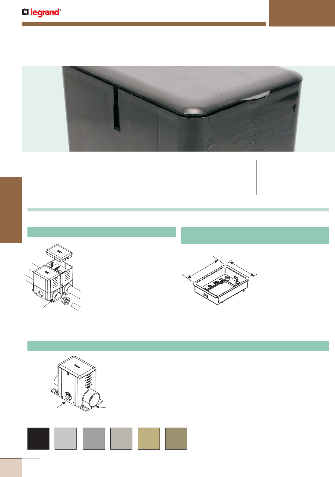
WWW.LEGRAND.US/WIREMOLD
430
FLOOR BOXES
WIREMOLD
Modulink™ Nonmetallic Floor Boxes provide power and communication services
directly to the workstation or to any open space location.
MODULINK™ 880MP SERIES FLOOR BOXES
CODE REFERENCE
cULus Listed
Nonmetallic Outlet Boxes:
File E110748 Guide QCMZ.
Box comes complete with reusable
mudcap, insert spacer, conduit
plugs and reducers. Reducers
provided for reduction to 1 1/2",
1 1/4", 1", 3/4" and 1/2" [25mm,
19.1mm, and 12.7mm] conduit.
Minimum concrete depth is 4"
[102mm] and maximum concrete
depth is 6" [152mm]. Minimum
capacity is 50 cu. in. [819ml] and
maximum capacity is 100 cu. in.
[1693ml]. Box dimensions are
4 1/8" W x 5 1/2" L x 6" H [105mm
W x 140mm L x 152mm H].
880MP Nonmetallic Rectangular Floor Box
NOTE: One 880MPA is needed for each
880MP and 880MP2 box used.
For example, a three-gang
box will require three 880MPA
Adjusting Rings, ordered
separately.
Comes with fiber storage
loop. Also includes
brass inserts for flange
connection and green
ground wire for ground
connection. Wiremold
CM Series Open System
adapters that snap directly
into the adjusting ring
without the need for an
adapter. Also includes
mounting screws to attach
flange to box body.
880MPA
Nonmetallic Rectangular Floor Box Adjusting Ring
Modulink 880MP Series Floor Boxes Ordering Information
5 3/8"
[136mm]
3 15/16"
[100mm]
Activate inserts snap here.
1 1/4" Trade Size
Conduit Hub
Box comes complete with reusable mudcap, insert spacer, conduit plugs and
reducers. Reducers provided for reduction to 1 1/2", 1 1/4", 1", 3/4", and 1/2"
[38mm, 32mm, 25mm, 19.1mm, and 12.7mm] conduit. Minimum concrete depth is
4" [102mm] and maximum concrete depth is 6" [152mm]. Minimum capacity is 50
cu. in. [819ml] and maximum capacity is 100 cu. in. [1639ml]. Box dimensions are
4 1/8" W x 8 1/4" L x 6 3/16" [105mm x 210mm x 157mm].
NOTE: Insert spacer should not be removed until after concrete pour.
Box can be connected together to create a two- or three-gang option.
1 1/4" trade size
knockout opening
(both sides)
2" trade size
opening
(both ends)
880MP2 Nonmetallic Rectangular Floor Box
817, 828, 829, 830, 837 and 838 Series Cover Plates are designed for
use with Modulink™ 880MP Series Floor Boxes and are available in
black, aluminum, gray, nickel, brass and bronze.
Custom color options are also available. Consult the factory for
more information.
COLOR OPTIONS
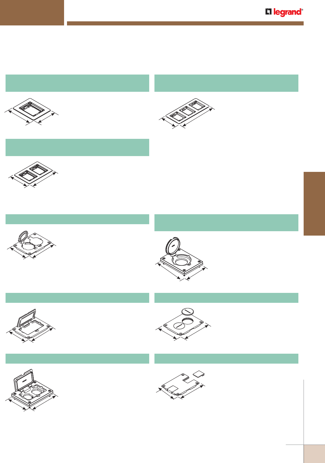
WWW.LEGRAND.US/WIREMOLD
431
FLOOR BOXES
WIREMOLD
MODULINK™ 880MP SERIES FLOOR BOXES
Modulink 880MP Series Floor Boxes Solid Brass Cover Plate Flanges Ordering Information
Modulink 880MP Series Floor Boxes Metal Cover Plates Ordering Information
NOTE: Brass covers and flanges are not interchangeable with aluminum or nonmetallic covers and flanges.
Nonmetallic covers are interchangeable with aluminum flanges.
Accepts Ortronics® MAB6TJ
TracJack and MAB3S2 Series II
adapters and Wiremold CM Series
inserts, sold separately.
817B One-Gang Brass Combination
Carpet and Tile Flange
6.080"
[154.4mm]
5.060"
[128.5mm]
Accepts Ortronics® MAB6TJ
TracJack and MAB3S2 Series II
adapters and Wiremold CM Series
inserts, sold separately.
827B Two-Gang Brass Combination
Carpet and Tile Flange
6.080"
[154.4mm]
5.060"
[128.5mm]
Accepts Ortronics® MAB6TJ
TracJack and MAB3S2 Series II
adapters and Wiremold CM Series
inserts, sold separately.
837B Three-Gang Brass Combination
Carpet and Tile Flange
6.080"
[154.4mm]
5.060"
[128.5mm]
828GFITC Brass GFI Cover Plate
May be used with Activate and
Ortronics® Connectivity Systems in
conjunction with 817B, 827B, and
837B Flanges.
3 1/8"
[80.2mm]
4 3/16"
[106.2mm]
828R Brass Duplex Cover Plate
Flip lids. Can also be used with a 106
type communication adapter.
3 1/8"
[80.2mm]
4 3/16"
[106.2mm]
828DPGFITC Brass Rectangular Cover Plate
Allows for mounting of a duplex style
receptacle with a rectangular style
flip lid cover.
4 3/16"
[106.2mm]
3 1/8"
[80.2mm]
828DLR
Brass Single Locking Receptacle Cover Plate
Single flip lid cover for 20A or 30A
single locking receptacles. Device
opening is 2 5/8" [67mm]. For use
with maximum female locking
device of 1.58" diameter, and
maximum male plug face of
2.25" diameter.
3 1/8"
[79mm]
4 1/8"
[105mm]
Screw plugs are 1 1/2" [38mm]
in diameter.
828SPTC Brass Duplex Cover Plate
3 1/8"
[79mm]
4 1/8"
[105mm]
Brass communications cover
plate, data slides. Feed through
only, not for use with a mounting
plate for flush mounted
communication adapter.
829STC Brass Communications Cover Plate
3 1/8"
[79mm]
4 1/8"
[105mm]
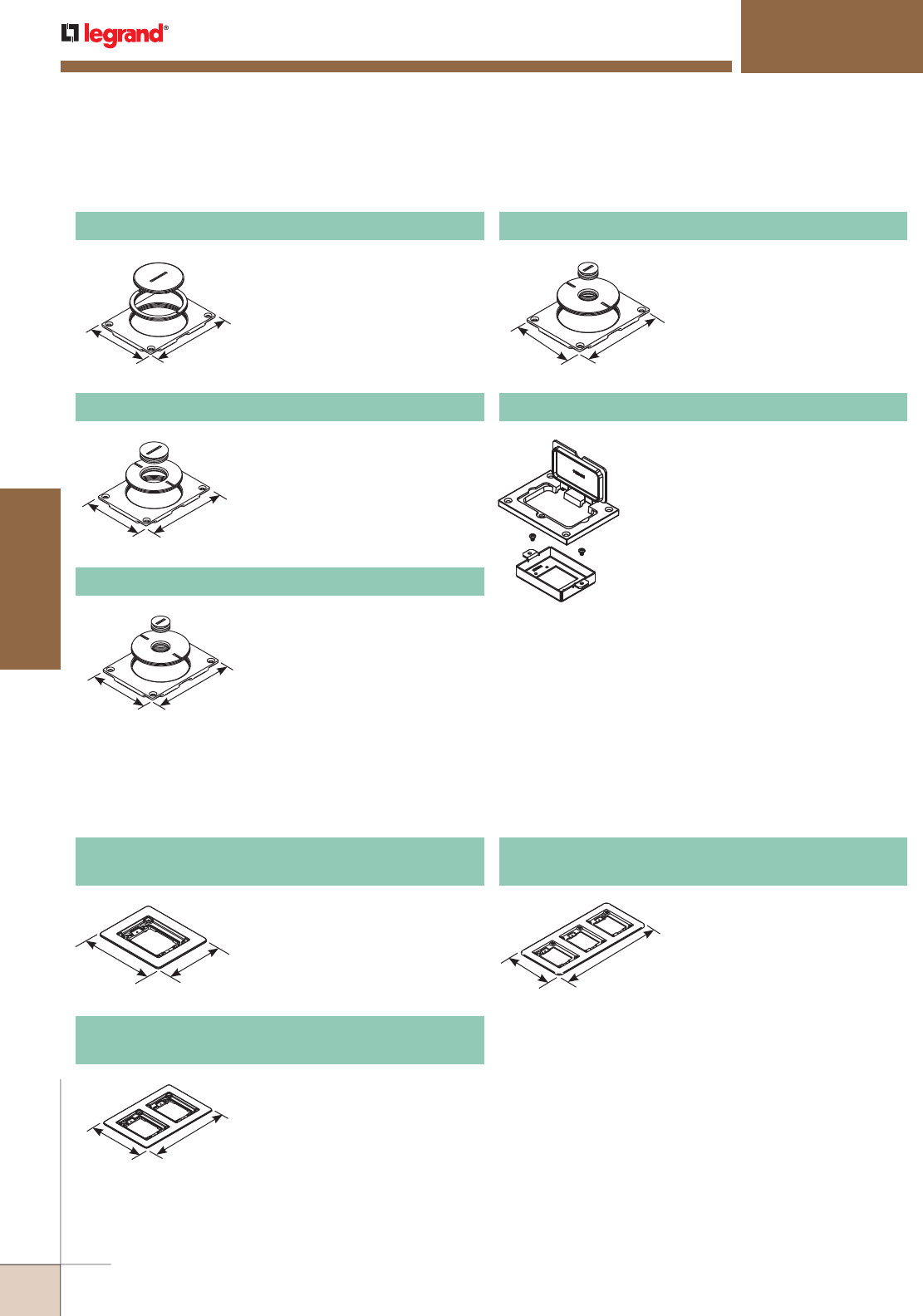
WWW.LEGRAND.US/WIREMOLD
432
FLOOR BOXES
WIREMOLD
MODULINK™ 880MP SERIES FLOOR BOXES
Modulink 880MP Series Floor Boxes Metal Cover Plates Ordering Information (continued0
NOTE: Brass covers and flanges are not interchangeable with aluminum or nonmetallic covers and flanges. Nonmetallic covers are interchangeable with
aluminum flanges.
3 1/8"
[80.2mm]
4 3/16"
[106.2mm]
2 5/8" and 2 1/4" [67mm and
57mm] plugs. Not for use with
threaded conduit.
829CK Brass Communications Cover Plate
3 1/8"
[80.2mm]
4 3/16"
[106.2mm]
2 5/8" and 1" [67mm and 25mm]
plugs. Not for use with threaded
conduit.
829CK-1 Brass Communications Cover Plate
3 1/8"
[83.60mm]
4 3/16"
[106.2mm]
Brass communications cover
plate, 2 5/8" and 1/2" [67mm and
12.7mm] plugs. For carpet or tile
installations. Not for use with
threaded conduit.
829CK-1/2 Brass Communications Cover Plate
3 1/8"
[80.2mm]
4 3/16"
[106.2mm]
2 5/8" and 3/4" [67mm and
19.1mm] plugs. Not for use with
threaded conduit.
829CK-3/4 Brass Communications Cover Plate
828MAAP AV Adapter Plate
Sheet metal adapter plate that accepts
two (2) Wiremold AVIP or Extron®
Electronics MAAP style device plates,
sold separately. For use with 828GFITC
or 828GFITCAL cover plates, sold
separately.
Modulink 880MP Series Floor Boxes Brushed Aluminum Cover Plate Flanges Ordering Information
818TCAL One-Gang Brushed Aluminum
Combination Carpet and Tile Flange
Accepts Ortronics® MAB6TJ
TracJack and MAB3S2 Series II
adapters and Wiremold CM Series
inserts, sold separately.
5.940"
[150.9mm]
4.920"
[125.0mm]
838TCAL Three-Gang Brushed Aluminum
Combination Carpet and Tile Flange
Accepts Ortronics® MAB6TJ
TracJack and MAB3S2 Series II
adapters and Wiremold CM Series
inserts, sold separately.
9.045"
[229.7mm]
5.940"
[150.9mm]
828TCAL Two-Gang Brushed Aluminum
Combination Carpet and Tile Flange
Accepts Ortronics® MAB6TJ
TracJack and MAB3S2 Series II
adapters and Wiremold CM Series
inserts, sold separately.
5.940"
[150.9mm]
13.170"
[334.5mm]
NOTE: Brushed aluminum flanges come with beveled edges.
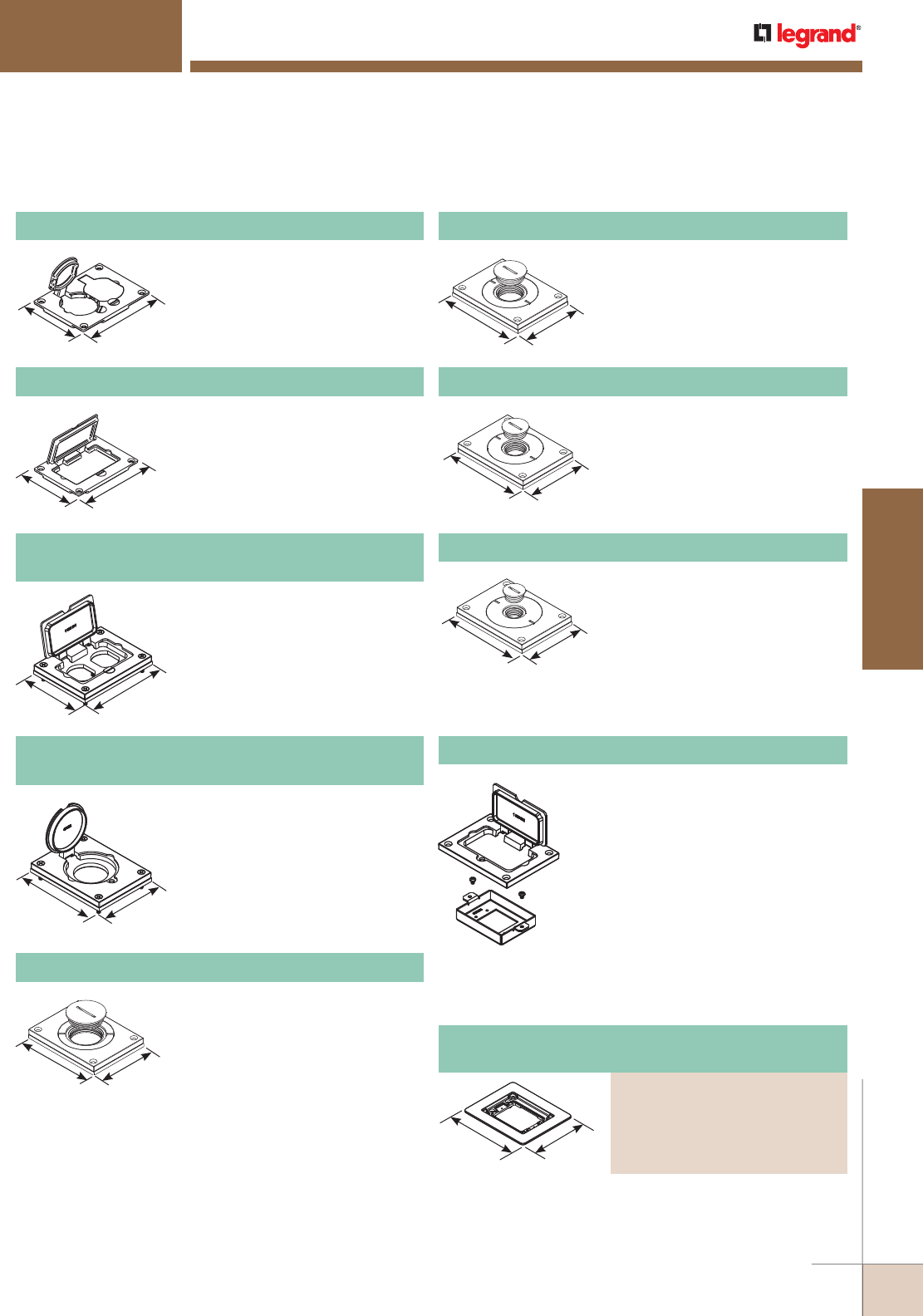
WWW.LEGRAND.US/WIREMOLD
433
FLOOR BOXES
WIREMOLD
NOTE: Brass covers and flanges are not interchangeable with aluminum
or nonmetallic covers and flanges. Nonmetallic covers are
interchangeable with aluminum flanges.
MODULINK™ 880MP SERIES FLOOR BOXES
Modulink 880MP Series Floor Boxes Brushed Aluminum Cover Plates Ordering Information
828R-TCAL Brushed Aluminum Duplex Cover Plate
Flip lids. Can also be used with a 106
type communication adapter.
3.290"
[83.6mm]
4.310"
[109.5mm]
828GFITCAL Brushed Aluminum GFI Cover Plate
May be used with Activate and
Ortronics® Connectivity Systems in
conjunction with 817B, 827B, and
837B Flanges.
3.290"
[83.6mm]
4.310"
[109.5mm]
828DPGFITCAL Brushed Aluminum Rectangular
Cover Plate
Allows for mounting of a duplex style
receptacle with a rectangular style
flip lid cover.
4.310"
[109.5mm]
3.290"
[83.6mm]
828DLRAL Brushed Aluminum Single Locking
Receptacle Cover Plate
Single flip lid cover for 20A or 30A
single locking receptacles. Device
opening is 2 5/8" [67mm]. For use
with maximum female locking device
of 1.58" diameter, and maximum
male plug face of 2.25" diameter.
4.310"
[109.5mm] 3.290"
[83.6mm]
830CKTCAL Brushed Aluminum Cover Plate
Power or communication plate with
2" [51mm] and 1 1/4" [32mm] plugs.
NOTE: Acceptable for use with threaded
conduit when passing through
power cables.
4.310"
[109.5mm] 3.290"
[83.6mm]
830CKTCAL-1 Brushed Aluminum Cover Plate
Power or communication plate with
2" [51mm] and 1" [25mm] plugs.
NOTE: Acceptable for use with threaded
conduit when passing through
power cables.
828MAAP AV Adapter Plate
Sheet metal adapter plate that accepts
two (2) Wiremold AVIP or Extron®
Electronics MAAP style device plates,
sold separately. For use with 828GFITC
or 828GFITCAL cover plates, sold
separately.
830CKTCAL-3/4 Brushed Aluminum Cover Plate
Power or communication plate with
2" [51mm] and 3/4" [19.1mm] plugs.
NOTE: Acceptable for use with threaded
conduit when passing through
power cables.
830CKTCAL-1/2 Brushed Aluminum Cover Plate
Power or communication plate with
2" [51mm] and 1/2" [12.7mm] plugs.
NOTE: Acceptable for use with threaded
conduit when passing through
power cables.
4.310"
[109.5mm] 3.290"
[83.6mm]
4.310"
[109.5mm] 3.290"
[83.6mm]
4.310"
[109.5mm] 3.290"
[83.6mm]
Modulink 880MP Series Floor Boxes Powder-Coated
Aluminum Cover Plate Flanges Ordering Information
Accepts Ortronics® MAB6TJ TracJack and MAB3S2 Series II
adapters and Wiremold CM Series inserts, sold separately.
6.080"
[154.4mm]
5.060"
[128.5mm]
One-Gang Powder-Coated Aluminum Combination
Carpet and Tile Flange
PART NUMBERS:
817TCAL-BK (Black)
817TCAL-GY (Gray)
817TCAL-NK (Nickel)
817TCAL-BS Brass)
(Bronze)
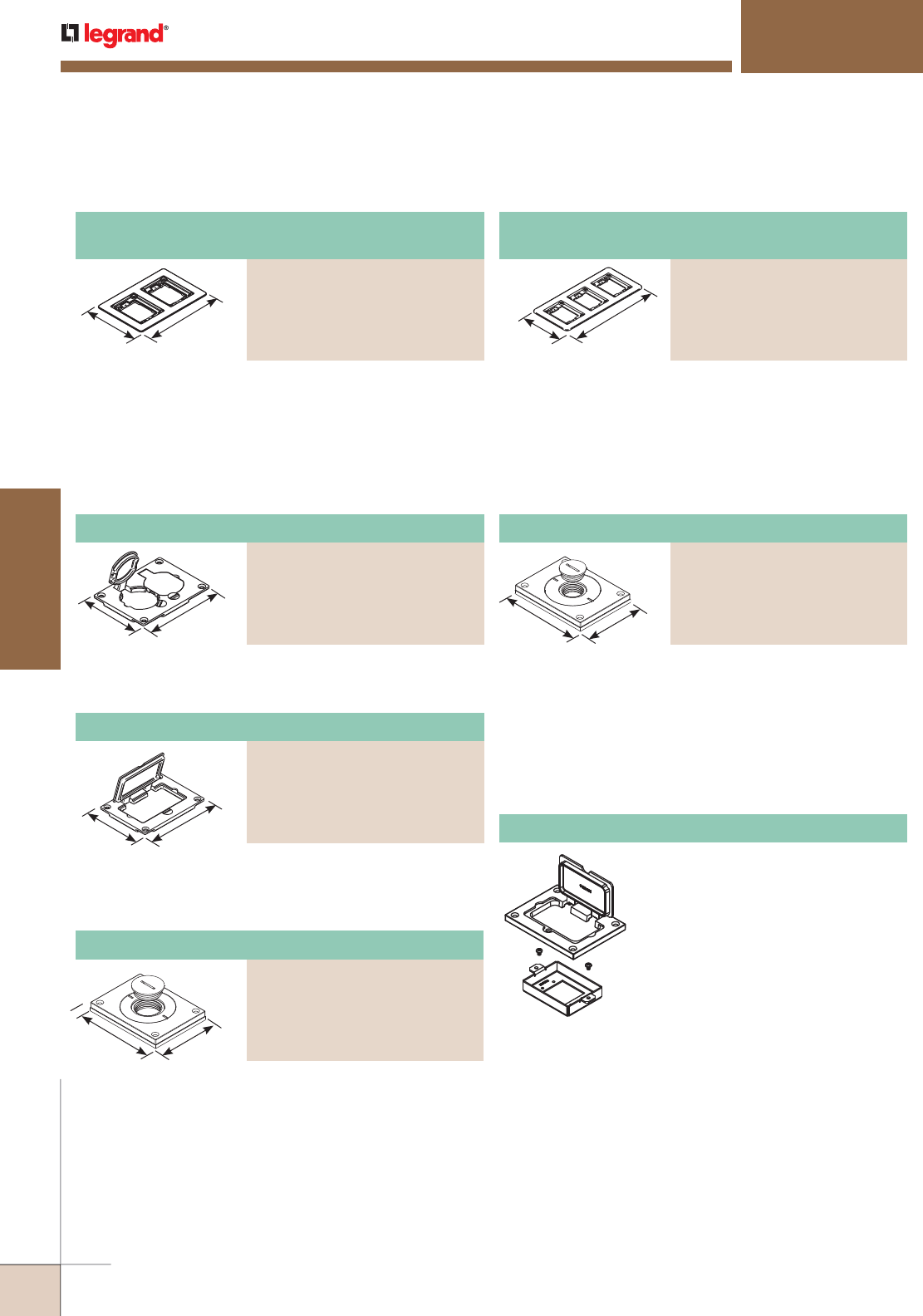
WWW.LEGRAND.US/WIREMOLD
434
FLOOR BOXES
WIREMOLD
MODULINK™ 880MP SERIES FLOOR BOXES
Modulink 880MP Series Floor Boxes Powder-Coated Aluminum Cover Plate Flanges Ordering Information (continued)
Modulink 880MP Series Floor Boxes Powder-Coated Aluminum Cover Plates Ordering Information
NOTE: Brass covers and flanges are not interchangeable with aluminum or nonmetallic covers and flanges.
Nonmetallic covers are interchangeable with aluminum flanges.
Powder-Coated Aluminum Duplex Cover Plate
PART NUMBERS:
828R-TCAL-BK (Black)
828R-TCAL-GY (Gray)
828R-TCAL-NK (Nickel)
828R-TCAL-BS (Brass)
828R-TCAL-BZ (Bronze)
Flip lids. Can also be used with a
106 type communication adapter.
3.290"
[83.6mm]
4.310"
[109.5mm]
Allows for mounting a duplex
receptacle (Decorator or GFCI
style) with a rectangular flip cover.
3.290"
[83.6mm]
4.310"
[109.5mm]
Power or communication plate
with 2" [51mm] and 3/4" [19.1mm]
plugs. Covers are available in five
decorative colors: black, gray,
brass, nickel and bronze.
NOTE: Acceptable for use with threaded
conduit when passing through
power cables.
828MAAP AV Adapter Plate
Sheet metal adapter plate that
accepts two (2) Wiremold AVIP or
Extron® Electronics MAAP style
device plates, sold separately. For
use with 828GFITC or 828GFITCAL
cover plates, sold separately.
Powder-Coated Aluminum Cover Plate
PART NUMBERS:
829CKAL-3/4BK (Black)
829CKAL-3/4GY (Gray)
829CKAL-3/4NK (Nickel)
829CKAL-3/4BS (Brass)
829CKAL-3/4BZ (Bronze)
Powder-Coated Aluminum GFI Cover Plate
PART NUMBERS:
828GFITCAL-BK (Black)
828GFITCAL-GY (Gray)
828GFITCAL-NK (Nickel)
828GFITCAL-BS (Brass)
828GFITCAL-BZ (Bronze)
Power or communication plate
with 2" [51mm] and 1" [25mm]
plugs.
NOTE: Acceptable for use with threaded
conduit when passing through
power cables.
3.290"
[83.6mm] 4.310"
[109.5mm]
Powder-Coated Aluminum Cover Plate
PART NUMBERS:
829CKAL-1BK (Black)
829CKAL-1GY (Gray)
829CKAL-1NK (Nickel)
829CKAL-1BS (Brass)
829CKAL-1BZ (Bronze)
Accepts Ortronics® MAB6TJ
TracJack and MAB3S2 Series II
adapters and Wiremold CM Series
inserts, sold separately.
6.080"
[154.4mm]
13.17"
[335mm]
Three-Gang Powder-Coated Aluminum Combination
Carpet and Tile Flange
PART NUMBERS:
837TCAL-BK (Black)
837TCAL-GY (Gray)
837TCAL-NK (Nickel)
837TCAL-BS (Brass)
837TCAL-BZ (Bronze)
Accepts Ortronics® MAB6TJ
TracJack and MAB3S2 Series II
adapters and Wiremold CM Series
inserts, sold separately.
6.080"
[154.4mm]
9.02"
[229mm]
Two-Gang Powder-Coated Aluminum Combination
Carpet and Tile Flange
PART NUMBERS:
827TCAL-BK (Black)
827TCAL-GY (Gray)
827TCAL-NK (Nickel)
827TCAL-BS (Brass)
827TCAL-BZ (Bronze)
3 1/4"
[83mm]
4 5/32"
[110mm]
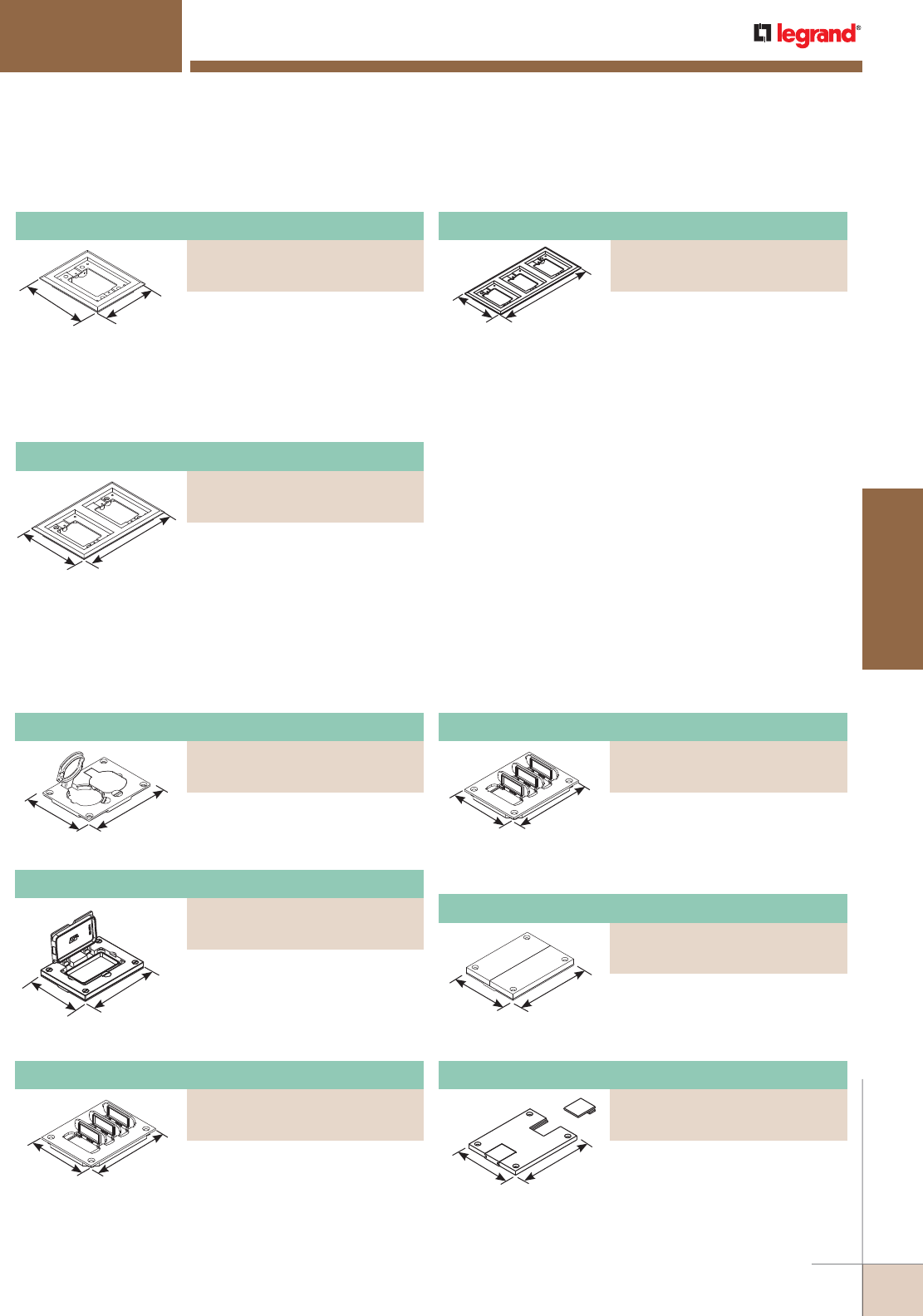
WWW.LEGRAND.US/WIREMOLD
435
FLOOR BOXES
WIREMOLD
MODULINK™ 880MP SERIES FLOOR BOXES
Modulink 880MP Series Floor Boxes Nonmetallic Cover Plates Flanges Ordering Information
* Replacement flip lids can be ordered under Cat. No. PFL-BLK and PFL-BRN. Each Cat. No. comes with three flip lids.
The above cover plates are listed for tile and carpet applications.
Modulink 880MP Series Floor Boxes Nonmetallic Cover Plates Ordering Information
NOTE: Brass covers and flanges are not interchangeable with aluminum
or nonmetallic covers and flanges. Nonmetallic covers are
interchangeable with aluminum flanges.
One-Gang Nonmetallic Carpet Flange
PART NUMBERS:
817PCC-BLK (Black)
817PCC-BRN (Brown)
5 3/4"
[146mm]
4 3/4"
[121mm] For Ortronics® connectivity use
with 829PFLRT Cover. For Activate™
connectivity use with 829PFL
Cover. Accepts Ortronics® MAB6TJ
TracJack and MAB3S2 Series II
adapters and Wiremold CM Series
inserts, sold separately.
5 3/4"
[146mm]
8 7/8"
[225mm] For Ortronics® connectivity use
with 829PFLRT Cover. For Activate™
connectivity use with 829PFL
Cover. Accepts Ortronics® MAB6TJ
TracJack and MAB3S2 Series II
adapters and Wiremold CM Series
inserts, sold separately.
13"
[330mm]
5 3/4"
[146mm] For Ortronics® connectivity use
with 829PFLRT Cover. For Activate™
connectivity use with 829PFL
Cover. Accepts Ortronics® MAB6TJ
TracJack and MAB3S2 Series II
adapters and Wiremold CM Series
inserts, sold separately.
Nonmetallic Communications Cover Plate
PART NUMBERS:
829PCK-BLK (Black)
(Brown)
Nonmetallic Communications Cover Plate
PART NUMBERS:
829PFLRT-BLK* (Black)
829PFLRT-BRN* (Brown)
Nonmetallic Duplex Cover Plate
PART NUMBERS:
828PR-BLK (Black)
828PR-BRN (Brown)
3 3/16"
[81mm]
4 1/8"
[105mm] Flip lids. Can also be used with a
106 type communication adapter.
Nonmetallic GFI Cover Plate
PART NUMBERS:
828PRGFI-BLK (Black)
828PRGFI-BRN (Brown)
3 3/16"
[81mm]
4 1/8"
[105mm]
May be used with Ortronics®
Connectivity systems in
conjunction with 817, 827 and
837PCC Series flanges.
Nonmetallic Communication Cover Plate
PART NUMBERS:
829PFL-BLK* (Black)
829PFL-BRN*(Brown)
3 3/16"
[81mm]
4 1/8"
[105mm] Individual flip lids. Gasket
included. Wiremold CM Series
inserts included.
3 3/16"
[81mm]
3 3/16"
[81mm] Individual flip lids. Gasket
included. Ortronics® MAB6TJ
TracJack and MAB3S2 Series II
adapters included.
Breakouts. Feed through only, not
for use with a mounting plate for
communication jacks.
3 3/16"
[81mm]
4 1/8"
[105mm]
Nonmetallic Communications Cover Plate
PART NUMBERS:
829PSTC-BLK (Black)
829PSTC-BRN (Brown)
3 3/16"
[81mm]
4 1/8"
[105mm]
Data slides. Feed through only, not
for use with a mounting plate for
communication jacks.
Three-Gang Nonmetallic Carpet Flange
PART NUMBERS:
837PCC-BLK (Black)
837PCC-BRN (Brown)
Two-Gang Nonmetallic Carpet Flange
PART NUMBERS:
827PCC-BLK (Black)
827PCC-BRN (Brown)
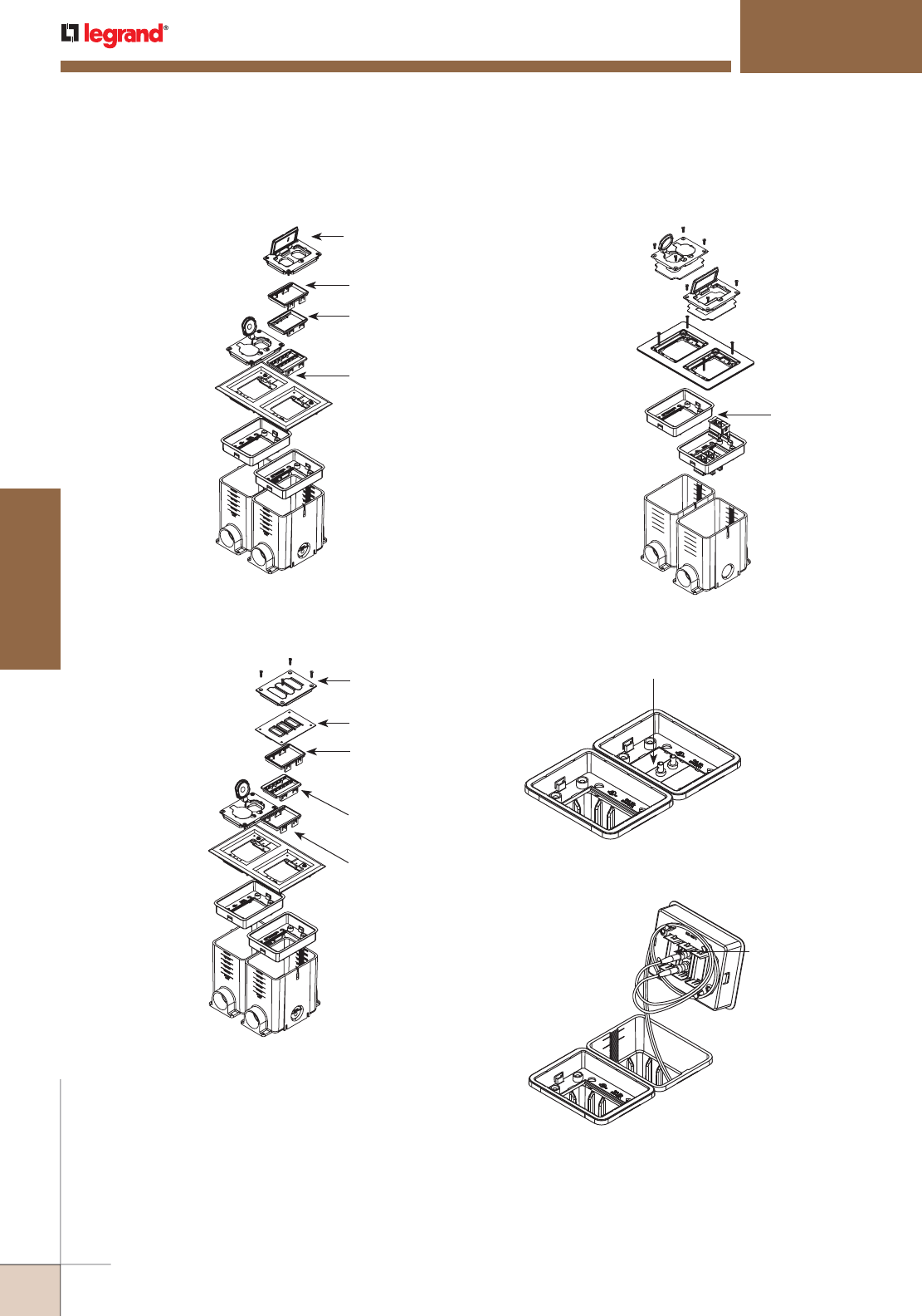
WWW.LEGRAND.US/WIREMOLD
436
FLOOR BOXES
WIREMOLD
MODULINK™ 880MP SERIES FLOOR BOXES
Modulink 880MP Series Floor Boxes Mounting Options for Connectivity Insets
Flush installation with
Activate installed using the
Activate bezel, or Ortronics
installed using the Ortronics
bezels.
Recessed installation with
Activate installed directly
into the 880MPA Adjusting
Ring. Ortronics inserts
cannot be inserted directly
into 880MPA, see below for
Ortronics solution.
828GFITC
Cover
CM-MAB Bezel
(Sold Separately, Not
Included with 828GFITC)
MAB3S2 Bezel
(Ortronics Series II Bezel
Sold Separately)
MAB6TJ Bezel
(Ortronics TracJack
Bezel Sold Separately)
Activate Inserts Sold
Separately
Flush installation with
Ortronics installed using
829PFLRT Cover or
Activate installed using
829PFL Cover.
NOTE: Part is approved
for scrub water
applications only
with inserts in the
flush position.
829PFL or 829PFLRT
Cover
Scrub Water Gasket
Included
CM-MAB Activate Bezel
(Included with 829PFL
Cover)
MAB6TJ (Ortronics
TracJack Bezel Included
with 829PFLRT)
MAB3S2 Bezel
(Ortronics Series II Bezel
Included with 829PFLRT)
Fiber Optic Insert, sold separately
Fiber Storage Loop
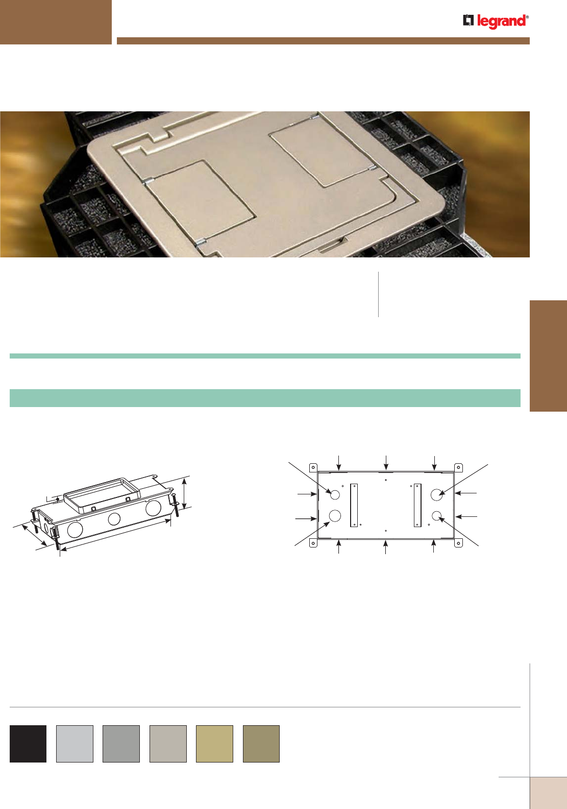
WWW.LEGRAND.US/WIREMOLD
437
FLOOR BOXES
WIREMOLD
Resource RFB® Series Floor Boxes are a versatile solution that provides
power and/or communication services to open space areas.
RESOURCE RFB® SERIES FLOOR BOXES
CODE REFERENCE
cULus Listed
Metallic Outlet Boxes:
File E2961 Guide QCIT.
6 1/2"
[165mm] 13 1/8"
[333mm]
2 5/8"
[67mm]
9/16"
[14mm]
For use in either concrete or wood floors. Fully adjustable
with tunnel compartment. Supplied with one (1) duplex
receptacle mounting plate, and one (1) communication
mounting plate (RFB22AB). Other device plates sold
separately.
RFB2-SS Two-Compartment Shallow Stamped Steel Box
RFB2 Series Multiservice Steel Recessed Floor Boxes Ordering Information
Top View
Power or Data
38.0 cu. in. [622.7 ml] Each Side
Side KO
3/4"
[19.1mm]
Side KO
3/4"
[19.1mm]
Bottom KO
1/2"
[12.7mm]
Bottom KO
3/4"
[19.1mm]
Side KO
3/4"
[19.1mm]
Side KO
3/4"
[19.1mm]
Side KO
3/4"
[19.1mm]
Side KO
3/4"
[19.1mm]
Side KO
3/4"
[19.1mm]
Side KO
3/4"
[19.1mm]
Bottom KO
1/2"
[12.7mm]
Bottom KO
3/4"
[19.1mm]
Side KO
3/4"
[19.1mm]
Side KO
3/4"
[19.1mm]
COLOR OPTIONS
Evolution Series Floor Box Covers are available in the following
powder coated finishes: “BK” black, "AL" aluminum, “GY” gray, “NK”
nickel, “BS” brass and “BZ” bronze.
Custom color options are also available. Consult the factory for
more information.
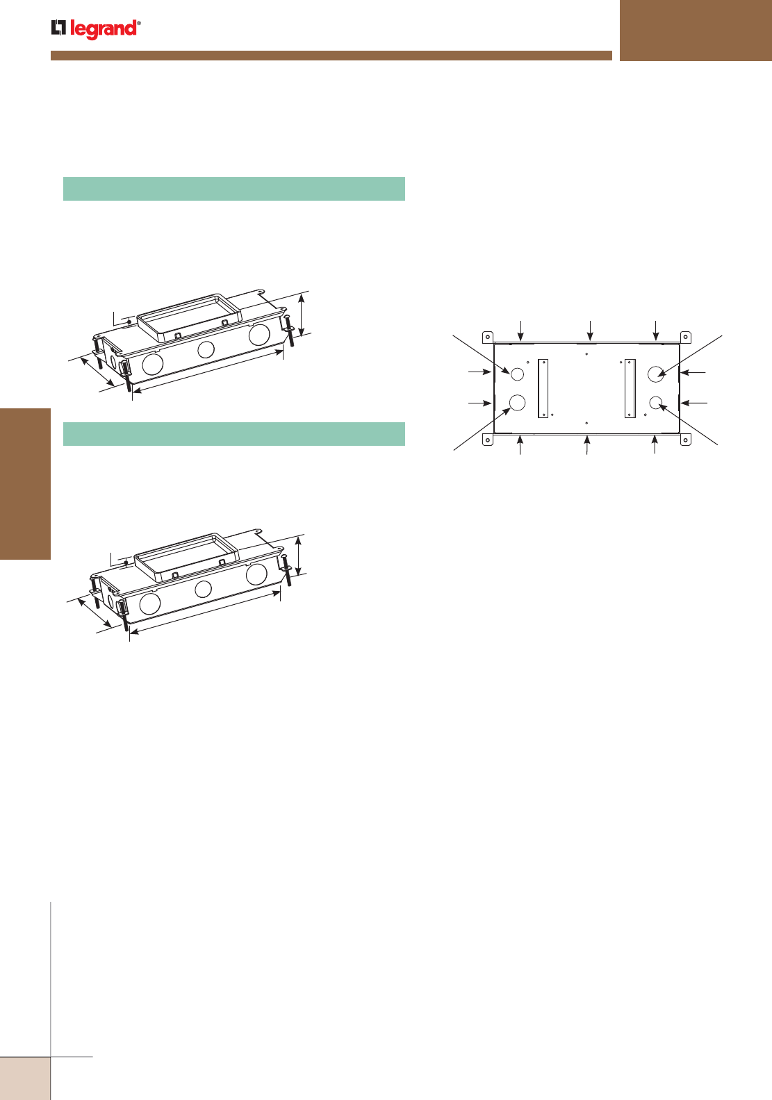
WWW.LEGRAND.US/WIREMOLD
438
FLOOR BOXES
WIREMOLD
RESOURCE RFB® SERIES FLOOR BOXES
RFB2 Series
Top View
Power or Data
50.2 cu. in. [822.6 ml] Each Side
Side KO
1 1/4"
[32mm]
Side KO
1"
[25mm]
Side KO
1 1/4"
[32mm]
Side KO
3/4"
[19.1mm]
Bottom KO
1/2"
[12.7mm]
Bottom KO
3/4"
[19.1mm]
Bottom KO
1/2"
[12.7mm]
Bottom KO
3/4"
[19.1mm]
Side KO
3/4"
[19.1mm]
Side KO
1 1/4"
[32mm]
Side KO
1"
[25mm]
Side KO
1 1/4"
[32mm]
Side KO
3/4"
[19.1mm]
Side KO
3/4"
[19.1mm]
RFB2 Series Multiservice Steel Recessed Floor Boxes Ordering Information (continued)
6 1/2"
[165mm]
13 1/8"
[333mm]
3 7/16"
[87mm]
3/4"
[19.1mm]
For use in either concrete or wood floors. Fully adjustable
with tunnel compartment. Supplied with one (1) duplex
receptacle mounting plate, and one (1) communication
mounting plate (RFB22AB). Other device plates
sold separately.
RFB2 Two-Compartment Box
6 1/2"
[165mm]
13 1/8"
[333mm]
3 7/16"
[87mm]
3/4"
[19.1mm]
For use On Grade. Fully adjustable with tunnel
compartment. Supplied with one (1) duplex receptacle
mounting plate, and one (1) communication mounting plate
(RFB22AB). Other device plates sold separately.
RFB2-OG Two-Compartment Box
NOTE: RFB2-OG for on-grade applications is painted with a fusion-bonded
epoxy designed for use on metal reinforcement bar and related
accessories before encapsulating in concrete.
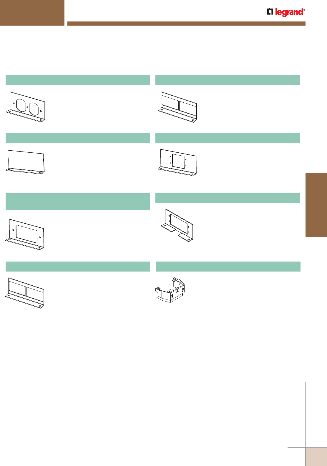
WWW.LEGRAND.US/WIREMOLD
439
FLOOR BOXES
WIREMOLD
RESOURCE RFB® SERIES FLOOR BOXES
RFB2 Series
Accepts standard 15A and 20A duplex
receptacles.
NOTE: For RFB2 Series Floor Boxes only..
RFB2DP Internal Duplex Receptacle Bracket
Plate used to close off unused gangs.
NOTE: For RFB2 Series Floor Boxes only.
RFB2B Internal Blank Bracket
Accepts standard GFCI or Decorator
Style Receptacles, Communication or A/V
Devices.
NOTE: For RFB2 Series Floor Boxes only.
RFB2GFI
Internal GFI or Decorator Style Receptacle Bracket
Includes two (2) adapters to accept
Wiremold CM2 Series Open System
communication inserts, sold separately.
NOTE: For RFB2 Series Floor Boxes only.
RFB22AB Internal Communication Bracket
Includes two (2) adapters to accept
Ortronics® TracJack devices, and two (2)
adapters to accept Ortronics® Series II
devices, sold separately.
NOTE: For RFB2 Series Floor Boxes only.
RFB2RT Internal Communication Bracket
Accepts two (2) Wiremold AVIP or Extron®
Electronics MAAP Series devices, sold
separately.
NOTE: For RFB2 Series Floor Boxes only.
RFB2EXT Internal A/V Bracket
Accepts two (2) Extron® Electronics AAP
Series devices, sold separately.
NOTE: For RFB2 Series Floor Boxes only.
RFB2-AAP Internal A/V Bracket
RFB2 Series Multiservice Steel Recessed Floor Box Accessories Ordering Information
Barrier kit used to separate power and
communication wires in partition feed
covers. Supplied with base and three
extensions to adjust to cover height.
Kit should be used on RFB2, RFB2-OG,
RFB2-SS, RFB4 and RFB4-SS Floor
Boxes. Kits are sold separately.
RFBKIT Barrier Kit
NOTE: All device plates and accessories shown on this page are made in
the United States of America.
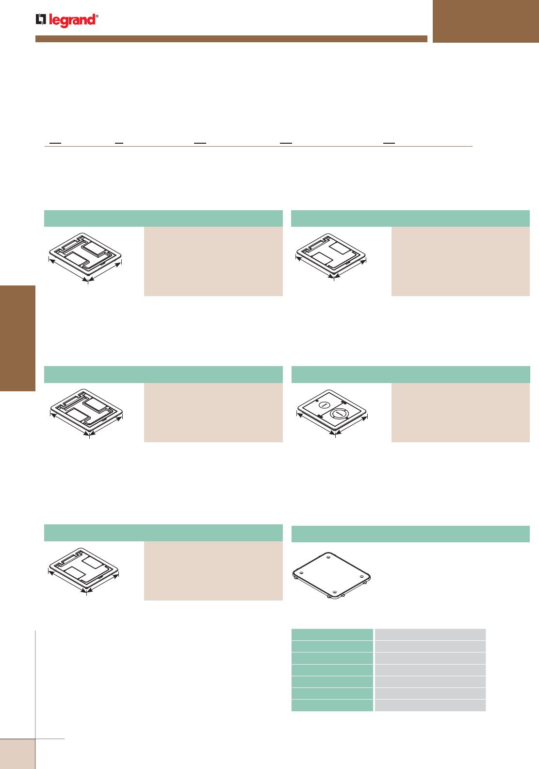
WWW.LEGRAND.US/WIREMOLD
440
FLOOR BOXES
WIREMOLD
RESOURCE RFB® SERIES FLOOR BOXES
RFB2 Series
FloorPort™ Series Flanged Cover Plates Ordering Information
7 3/4"
[197mm] 6 1/2"
[165mm]
Flanged cover for use in tile or carpet installation. Die-cast
aluminum assembly. Insert in lid allows for carpet or tile
cutouts to match finished.
Cutout Cover Assembly
PART NUMBERS:
FPCTCBK (Black)
FPCTCBZ (Bronze)
FPCTCBS (Brass)
FPCTCNK (Nickel)
FPCTCGY (Gray)
FPCTCAL (Brushed Aluminum)
7 3/4"
[197mm]
6 1/2"
[165mm]
Flanged cover for use in tile or carpet installation. Die-cast
aluminum assembly. Lid area is flush with the finished floor,
no cutouts provided.
Blank Cover Assembly
PART NUMBERS:
FPBTCBK (Black)
FPBTCBZ (Bronze)
FPBTCBS (Brass)
FPBTCNK (Nickel)
FPBTCGY (Gray)
FPBTCAL (Brushed Aluminum)
Blank Cover Assembly
PART NUMBERS:
FPBTCBK-NA (Black)
FPBTCBZ-NA (Bronze)
FPBTCBS-NA (Brass)
FPBTCNK-NA (Nickel)
FPBTCGY-NA (Gray)
Cutout Cover Assembly
PART NUMBERS:
FPCTCBK-NA (Black)
FPCTCBZ-NA (Bronze)
FPCTCBS-NA (Brass)
FPCTCNK-NA (Nickel)
FPCTCGY-NA (Gray)
7 3/4"
[197mm] 6 1/2"
[165mm]
Flanged cover for use in tile or carpet installation. Die-cast
aluminum assembly. Insert in lid allows for carpet or tile
cutouts to match finished floor.
7 3/4"
[197mm]
6 1/2"
[165mm]
Flanged cover for use in tile or carpet installation. Die-cast
aluminum assembly. Lid area is flush with the finished floor,
no cutouts provided.
Load Capacities for FloorPort™ Cover Assemblies
CATALOG NUMBERS MAXIMUM LOAD IN POUNDS
FPCTC 1000
FPBTC 750
FPFFT 1000
FPBT 750
FPCT 1000
FPFF 1000
NOTE: Load applied through a 2" [51mm] mandrel in center of service fitting.
Loads above are static loads only and do not pertain to rolling loads.
7 3/4"
[197mm] 6 1/2"
[165mm]
Flanged cover for use in tile or carpet installation. Die-cast
aluminum assembly. Provided with one 1" trade size screw
plug for power or communication type cabling and one
combination 1 1/4" and 2" trade size screw plug for
communication type cabling. Allows for feeding both power
and communication cabling.
Furniture Feed Cover Assembly
PART NUMBERS:
FPFFTCBK (Black)
FPFFTCBZ (Bronze)
FPFFTCBS (Brass)
FPFFTCNK (Nickel)
FPFFTCGY (Gray)
Nonmetallic ring for use on bare
polished concrete and terrazzo
floor applications.
NOTE: FP-CTR is designed to work with flanged
covers only.
FP-CTR Bare Concrete and Terrazzo Ring
FloorPort Part Number Configurator
B
FP TC NK
Blank Top = B
Cutout Top = C
Furniture Feed = FF
FloorPort Cover Nickel = NK
Brass = BS
Black = BK
Bronze = BZ
Gray = GY
Brushed Aluminum = AL
Tile (Flangeless) = T
Tile/Carpet = TC
(Flanged)
North American Made = NA
(Optional)
NA
North American Made FloorPort™ Series Flanged Cover Plates Ordering Information
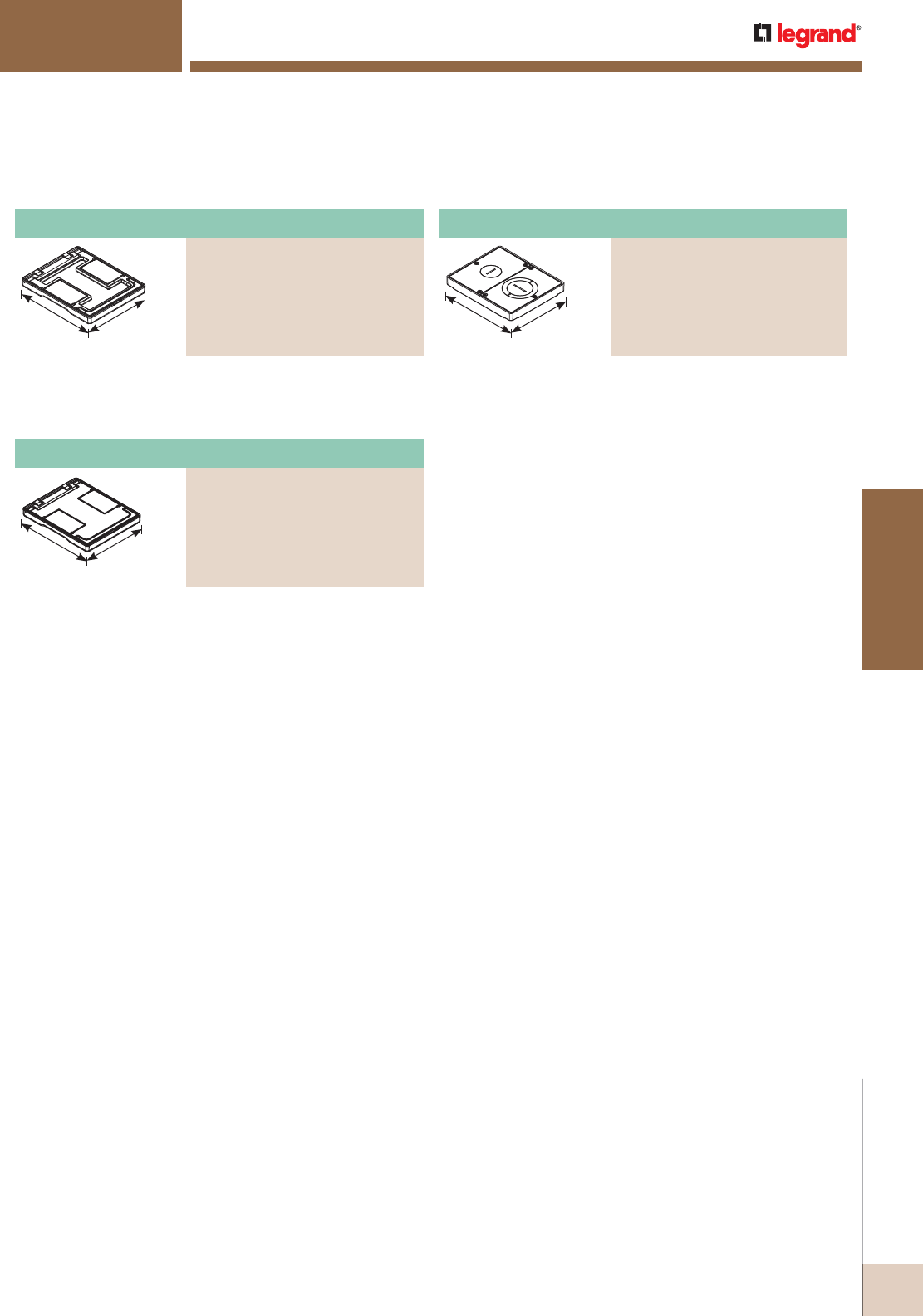
WWW.LEGRAND.US/WIREMOLD
441
FLOOR BOXES
WIREMOLD
RESOURCE RFB® SERIES FLOOR BOXES
RFB2 Series
Furniture Feed Cover Assembly
PART NUMBERS:
FPFFTBK (Black)
FPFFTBZ (Bronze)
FPFFTBS (Brass)
FPFFTNK (Nickel)
FPFFTGY (Gray)
(Brushed Aluminum)
Cutout Cover Assembly
PART NUMBERS:
FPCTBK (Black)
FPCTBZ (Bronze)
FPCTBS (Brass)
FPCTNK (Nickel)
FPCTGY (Gray)
FPCTAL (Brushed Aluminum)
FloorPort™ Series Flangeless Cover Assemblies Ordering Information
6 3/4"
[197mm] 5 1/2"
[165mm]
Flangeless cover for use in tile or carpet installations.
Die-cast aluminum assembly. Insert in lid allows for carpet
or tile cutouts to match finished floor.
6 3/4"
[197mm]
5 1/2"
[165mm]
Flangeless cover for use in tile or carpet installation.
Die-cast aluminum assembly. Lid area is flush with the
finished floor, no cutouts provided.
6 3/4"
[197mm] 5 1/2"
[165mm]
Flangeless cover for use in tile or carpet installation.
Die-cast aluminum assembly. Provided with one 1" trade
size screw plug for power or communication type cabling
and one combination 1 1/4" and 2" trade size screw plug for
communication type cabling. Allows for feeding both power
and communication cabling.
Blank Cover Assembly
PART NUMBERS:
FPBTBK (Black)
FPBTBZ (Bronze)
FPBTBS (Brass)
FPBTNK (Nickel)
FPBTGY (Gray)
FPBTAL (Brushed Aluminum)
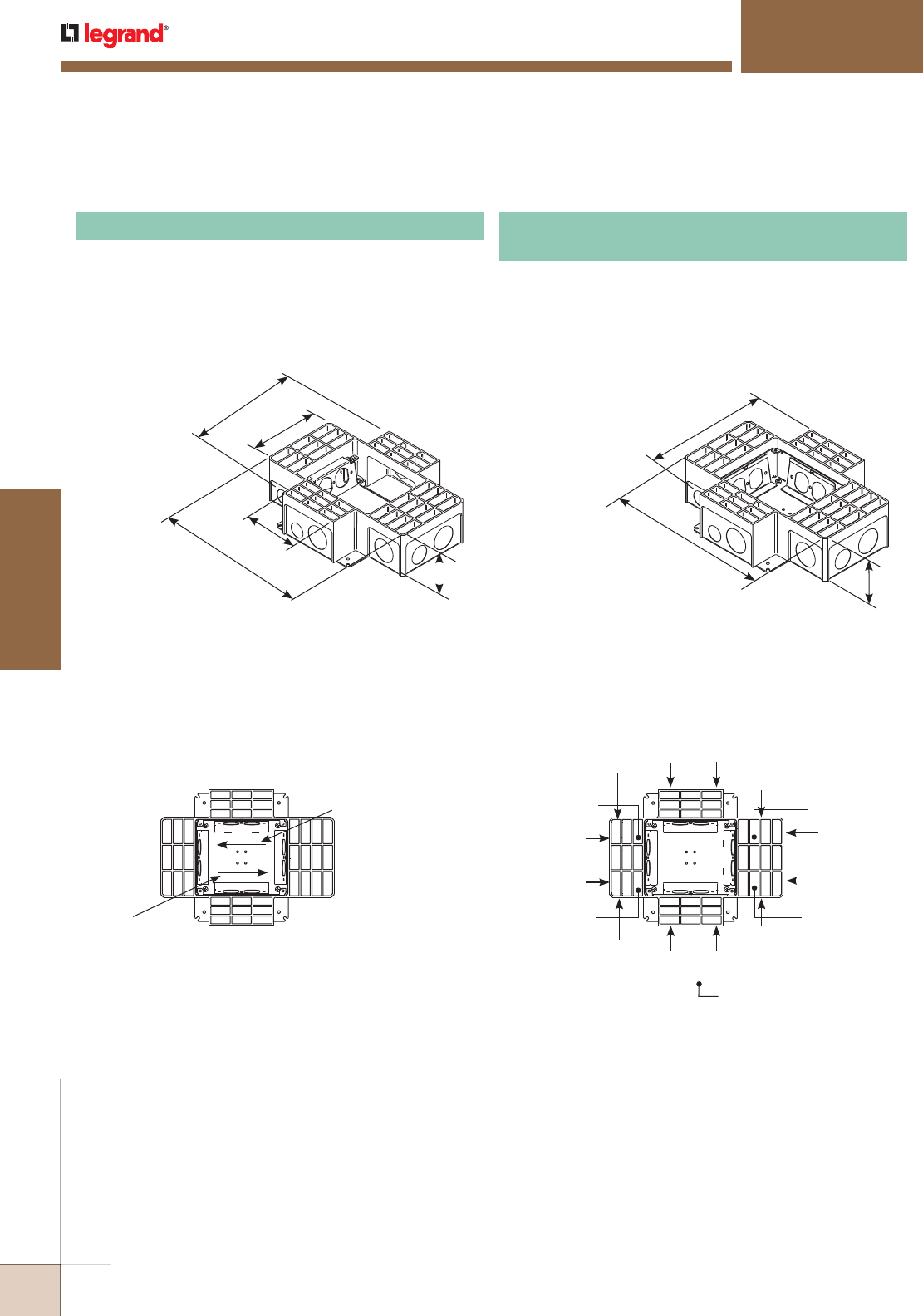
WWW.LEGRAND.US/WIREMOLD
442
FLOOR BOXES
WIREMOLD
RESOURCE RFB® SERIES FLOOR BOXES
RFB4 Series
No feed through to opposite data compartment on RFB4.
Power or Data
32.3 cu. in.
[529 ml]
Power or Data
(RFB4* Data Only)
16.4 cu. in. [269 ml]
Power or Data
(RFB4* Data Only)
16.4 cu. in. [269 ml]
Feed Through
Direction
Power or Data
50.0 cu. in.
[820 ml]
Compartment Capacities
1"
[25mm]
1"
[25mm]
1"
[25mm]
1 1/4"
[32mm]
1 1/4"
[32mm]
1 1/4"
[32mm]
1 1/4"
[32mm]
1 1/4"
[32mm]
1/2"
[12.7mm]
3/4"
[19.1mm]
3/4"
[19.1mm]
3/4"
[19.1mm]
3/4"
[19.1mm]
3/4"
[19.1mm]
3/4"
[19.1mm]
1 1/4"
[32mm]
Indicates Bottom KO.
Knockout Locations and Sizes
Resource RFB4 and RFB4-4DB Series Floor Boxes Compartment Capacities, Knockout Locations and Sizes
Feed Through
Direction
10"
[254mm]
5 7/8"
[149mm]
4 3/4"
[121mm]
12 3/4"
[254mm] 3 7/16"
[87mm]
12 3/4" x 10" x 3 7/16" [324mm x 254mm x 87mm]
. Fully
adjustable with tunnel compartment and two receptacle
brackets. Tunneling from end power compartment to end
power compartment only. Communication brackets not
included.
All boxes and covers are sold separately.
NOTE: Only for use in concrete floors.
RFB4 Four-Compartment Combination Box
3 7/16"
[87mm]
12 3/4"
[324mm]
10"
[254mm]
Includes four duplex receptacle brackets. 12 3/4" x 10" x
37/16" [324mm x 254mm x 87mm]. Fully adjustable.
Tunneling from adjacent or opposite compart ments only,
(not cross compartments). Tunneling can be set to feed all
four compartments from one conduit in a single-service
application. All boxes and covers are sold separately.
NOTE: Only for use in concrete floors.
RFB4-4DB Four-Compartment Box
With Four Duplex Receptacle Brackets
RFB4 and RFB4-4DB Series Multiservice Steel Recessed Floor Boxes Ordering Information
NOTE: All boxes and activations are sold separately.
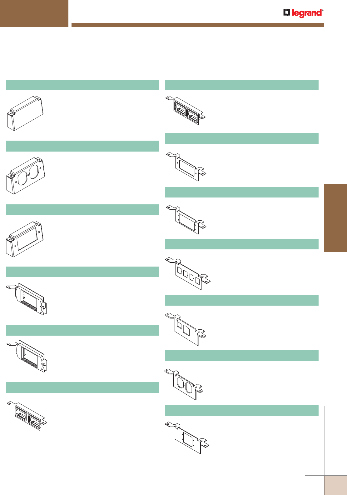
WWW.LEGRAND.US/WIREMOLD
443
FLOOR BOXES
WIREMOLD
Resource RFB4 and RFB4-4DB Series Multiservice Steel Recessed Floor Box Accessories Ordering Information
Accepts standard 15A and 20A duplex
receptacles.
NOTE: For RFB4 only.
RFB-DR Internal Duplex Bracket
Accepts standard GFCI or Decorator
Style receptacles, Communication or A/V
Devices.
NOTE: For RFB4 only.
RFB-GFI Internal GFI Bracket
Activate™ low profile adapter included.
Wiremold CM Series Open System
inserts sold separately.
NOTE: For RFB4 only.
RFB4-LPB Communication Bracket
Ortronics® Series II low profile adapter
included.
NOTE: For RFB4 only.
RFB4-LPBS2 Communication Bracket
Two (2) 2A size adapters included.
Wiremold CM2 Series Open System
inserts, sold separately.
NOTE: For RFB4 only.
DTB-2-2AB Communication Bracket
Decorator style opening for decorator
style 106 adapter.
NOTE: For RFB4 only.
DTB-2-DECORA Communication Bracket
Accepts two (2) Extron® Electronics AAP
devices, sold separately.
NOTE: For RFB4 only.
DTB-2-AAP Internal A/V Bracket
Power compartments only. Used to
close off unused gangs.
NOTE: For RFB4 only.
RFB-B Internal Blank Bracket
Ortronics® AB2TJ TracJack and ABS2
Series II adapters included.
NOTE: For RFB4 only.
DTB-2-2RT Communication Bracket
RESOURCE RFB® SERIES FLOOR BOXES
RFB4 Series
With one (1) IBM Type II opening and
one (1) keystone opening (devices not
included).
NOTE: For RFB4 only.
DTB-2-DT Communication Bracket
With duplex opening for use with 106
adapter (sold separately, devices not
included).
NOTE: For RFB4 only.
DTB-2-SD Communication Bracket
Accepts two (2) Wiremold AVIP or
Extron® Electronics MAAP devices, sold
separately.
NOTE: For RFB4 only.
DTB-2-EXT Internal A/V Bracket
Four (4) RJ keystone opening knockouts.
Use as blank plate or for up to four (4)
RJ openings.
NOTE: For RFB4 only. Opening dimension is 9/16"
x 3/4" [ 14.3mm x 19.1mm].
DTB-2-4TKO Communication Bracket
NOTE: Additional configurations available. Please consult your local Sales
Representative for more information.
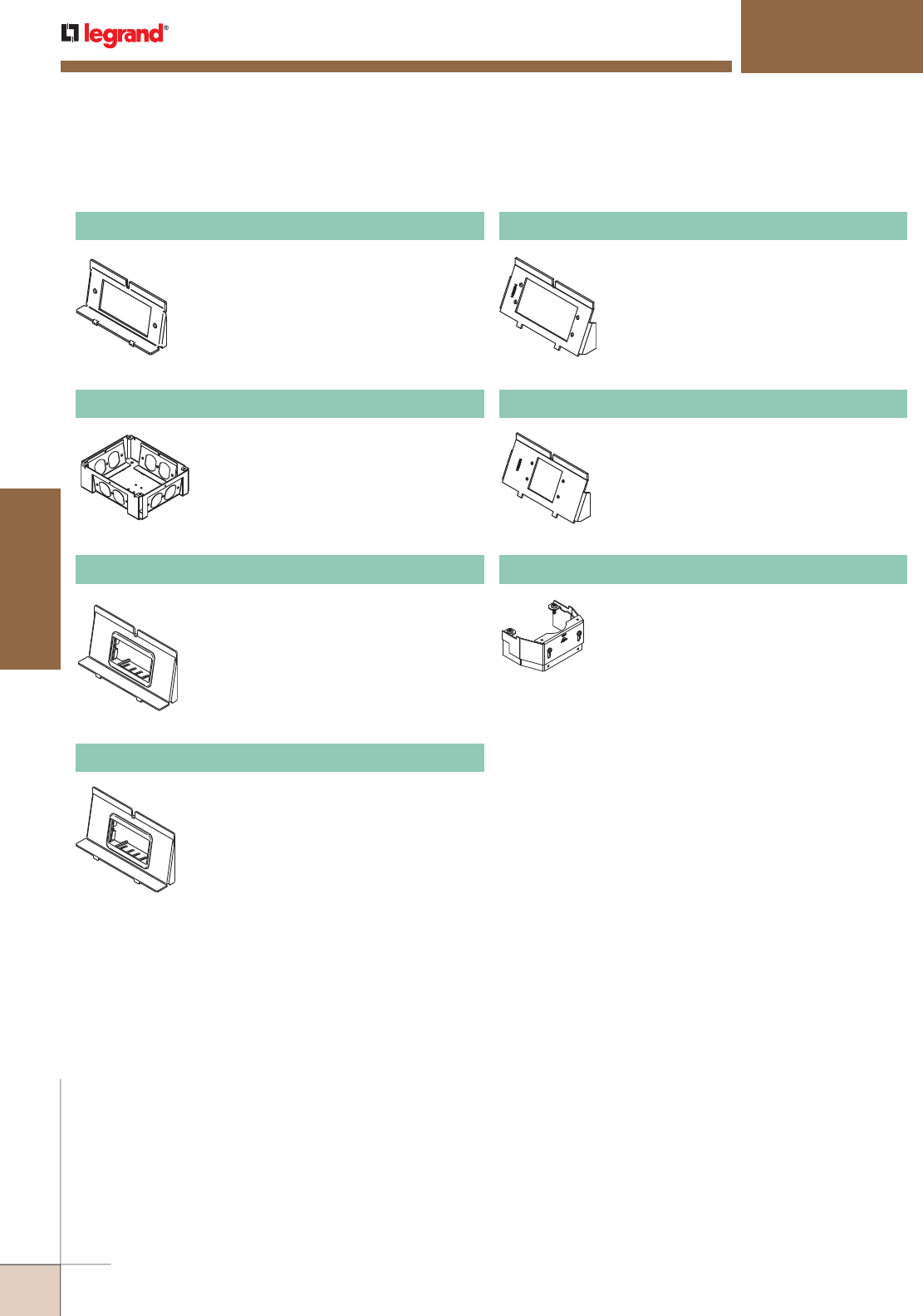
WWW.LEGRAND.US/WIREMOLD
444
FLOOR BOXES
WIREMOLD
RESOURCE RFB® SERIES FLOOR BOXES
RFB4 Series
To convert RFB4 Box to an RFB4-4DB
Box.
NOTE: For RFB4-4DB only.
RFB-WTB Conversion Kit
One (1) 2A adapter included. Wiremold
CM2 Series Open System inserts sold
separately.
NOTE: For RFB4-4DB only.
WTB-2-AB Communication Bracket
Ortronics® AB2TJ TracJack and ABS2
Series II adapters included.
NOTE: For RFB4-4DB only.
WTB-2-RT Communication Bracket
Accepts two (2) Extron® Electronics AAP
Series devices, sold separately.
NOTE: For RFB4-4DB only.
WTB-AAP Internal A/V Bracket
Accepts standard GFCI or Decorator style
receptacles, communications or A/V
devices.
NOTE: For RFB4-4DB only.
RFB-GFI-4DB Internal GFCI Bracket
Accepts two (2) Wiremold AVIP or
Extron® Electronics MAAP Series
devices, sold separately.
NOTE: For RFB4-4DB only.
WTB-MAAP Internal A/V Bracket
NOTE: Additional configurations available. Please consult your local Sales
Representative for more information.
RFB4 and RFB4-4DB Series Multiservice Steel Recessed Floor Box Accessories Ordering Information
Barrier kit used to separate power and
communication wires in partition feed
covers. Supplied with base and three
extensions to adjust to cover height.
Kit should be used on RFB2, RFB2-OG,
RFB2-SS, RFB4 and RFB4-SS Floor
Boxes. Kits are sold separately.
RFBKIT Barrier Kit
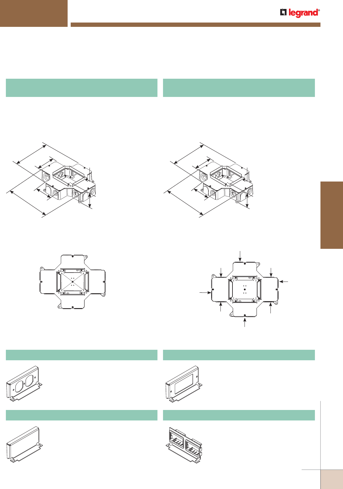
WWW.LEGRAND.US/WIREMOLD
445
FLOOR BOXES
WIREMOLD
RESOURCE RFB® SERIES FLOOR BOXES
RFB4 Series
11 7/8"
[302mm]
5 1/8"
[130mm]
14 1/2"
[368mm]
5 1/8"
[130mm] 3 7/16"
[87mm]
5/8"
[17mm]
11 7/8"
[302mm]
5 1/8"
[130mm]
14 1/2"
[368mm]
5 1/8"
[130mm] 3 7/16"
[87mm]
5/8"
[17mm]
RFB4-CI-1 Series Multiservice Cast Iron Recessed Floor Boxes Compartment Capacities, Knockout Locations and Sizes
Power or Data
36.0 cu. in. [590 ml]
Power or Data
36.0 cu. in. [590 ml]
Power or Data
27.0 cu. in. [443 ml]
Power or Data
27.0 cu. in. [443 ml]
Compartment Capacities Knockout Locations and Sizes
1"
[25mm]
1"
[25mm]
1"
[25mm]
1 1/4"
[32mm]
1 1/4"
[32mm]
1 1/4"
[32mm]
1"
[25mm]
1 1/4"
[32mm]
Accepts standard 15 Amp and 20 Amp
Duplex Receptacles.
CIHT-D Internal Duplex Receptacle Bracket
14 1/2" L x 11 7/8" W x 3 7/16" D [368mm x 302mm x
87mm]. Fully adjustable with tunnel compartment and
two receptacle brackets. Feed through from adjacent or
opposite compart ments only, (not cross compartments).
Communica tion brackets not included. All boxes and
activations are sold separately.
14 1/2" L x 11 7/8" W x 3 7/16" D [368mm x 302mm x
87mm]. Fully adjustable with tunnel compartment and
two receptacle brackets. Feed through from adjacent or
opposite compart ments only, (not cross compartments).
Communica tion brackets not included. All boxes and
activations are sold separately.
RFB4-CI-1
Four-Compartment Cast Iron Combination Box
RFB4-CI-NA North American Made
Four-Compartment Cast Iron Combination Box
Used to close off unused gangs.
CIH/LT-B Internal Blank Bracket
Communication bracket with two (2) 2A
size Activate™ adapters included. Accepts
Wiremold CM2 Series Open System
communication modules, sold separately.
CILT-2AB Communication Bracket
Accepts standard GFCI or Decorator
Style Receptacles, Communication or
A/V Devices.
CIHT-GFI Internal GFI Bracket
RFB4-CI-1 Series Multiservice Cast Iron Recessed Floor Boxes Ordering Information
RFB4-C1-1 Series Multiservice Cast Iron Recessed Floor Box Accessories Ordering Information
NOTE: Only for use in concrete
floors. All boxes and
activations are sold
separately.
NOTE: Only for use in concrete
floors. All boxes and
activations are sold
separately.
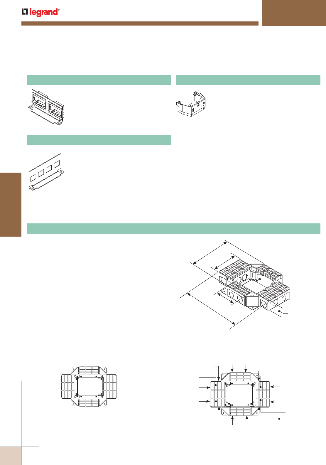
WWW.LEGRAND.US/WIREMOLD
446
FLOOR BOXES
WIREMOLD
RFB4-SS Series Multiservice Shallow Steel Recessed Floor Boxes Compartment Capacities, Knockout Locations and Sizes
Compartment Capacities
Power or Data
15.7 cu. in. [257 ml]
Power or Data
31.2 cu. in. [511 ml]
Power or Data
31.2 cu. in. [511 ml]
Power or Data
15.7 cu. in. [257 ml]
Knockout Locations and Sizes
1"
[25mm]
1"
[25mm]
1"
[25mm]
1"
[25mm]
1/2"
[12.7mm] 1/2"
[12.7mm]
3/4"
[19.1mm]
3/4"
[19.1mm]
3/4"
[19.1mm]
3/4"
[19.1mm]
3/4"
[19.1mm]
3/4"
[19.1mm]
1"
[25mm]
1"
[25mm]
1"
[25mm]
1"
[25mm]
Indicates
Bottom KO
10"
[254mm]
13 5/8"
[346mm]
5 7/8"
[149mm]
4 3/4"
[121mm]
2 7/16"
[62mm]
13 5/8" L x 10" W x 2 7/16" D [346mm x 254mm x 62mm].
Fully adjustable with tunnel compartment and two (2)
receptacle brackets. Feed through tunneling to adjacent
compartments only. Tunneling can be set to feed all
four compartments from one conduit in a single-service
application. Communication brackets not included. All boxes
and activations are sold separately.
NOTE: Only for use in concrete floors. All boxes and activations are sold
separately.
RFB4-SS Four-Compartment Shallow Stamped Steel Combination Box
RF4B-SS Multiservice Shallow Steel Recessed Floor Boxes Ordering Information
RFB4-C1-1 Series Multiservice Cast Iron Recessed Floor Box Accessories Ordering Information (continued)
RESOURCE RFB® SERIES FLOOR BOXES
RFB4 Series
Communication bracket with Ortronics®
AB2TJ TracJack and ABS2 Series II
adapters included. Accepts Ortronics®
workstation connectivity outlets and
modular inserts.
CILT-2-RT Communication Bracket
Communication bracket with four (4) RJ
opening knockouts. Use as blank plate or
for up to four RJ openings.
NOTE: Opening dimension is 9/16" x 3/4" [14.3mm x
19.1mm]
CILT-4TKO Communication Bracket
Barrier kit used with RFB4-CI floor
boxes. Kits are sold separately.
RFBCIKIT Barrier Kit
NOTE: Additional configurations available. Please consult your local Sales Representative for more information.
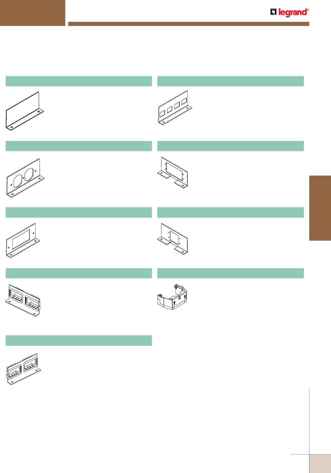
WWW.LEGRAND.US/WIREMOLD
447
FLOOR BOXES
WIREMOLD
Accepts two (2) Wiremold AVIP or
Extron® Electronics MAAP Series devices,
sold separately.
NOTE: For RFB4-SS Series Floor Boxes only.
RFB4-SS-MAAP Internal A/V Bracket
RESOURCE RFB® SERIES FLOOR BOXES
RFB4 Series
Accepts standard 15A and 20A duplex
receptacles.
RFB-RB-SS Internal Duplex Receptacle Bracket
Used to close off unused gangs.
RFB-B-SS Internal Blank Bracket
Accepts standard GFCI and Decorator
style receptacles, Communication or A/V
devices.
RFB-GFI-SS Internal GFI Bracket
Two Pass & Seymour® Activate™ adapters
included. Wiremold CM Series Open
System inserts, sold separately.
RFB-2AB-SS Internal Bracket
Ortronics® AB2TJ TracJack and ABS2
Series II adapters included.
RFB-2-SSRT Communication Bracket
Four (4) RJ keystone opening knockouts.
Use as blank plate or for up to four RJ
openings.
NOTE: Opening dimension is 9/16" x 3/4"
[14.3mm x 19.1mm]
RFB-4TKO-SS Internal Bracket
Accepts two (2) Extron® Electronics AAP
Series devices, sold separately.
NOTE: For RFB4-SS Series Floor Boxes only.
RFB4-SS-AAP Internal A/V Bracket
RFB4-SS Multiservice Shallow Steel Floor Box Accessories Ordering Information
Barrier kit used to separate power and
communication wires in partition feed
covers. Supplied with base and three
extensions to adjust to cover height.
Kit should be used on RFB2, RFB2-OG,
RFB2-SS, RFB4 and RFB4-SS Floor
Boxes. Kits are sold separately.
RFBKIT Barrier Kit
NOTE: Additional configurations available. Please consult your local Sales
Representative for more information.

WWW.LEGRAND.US/WIREMOLD
448
FLOOR BOXES
WIREMOLD
RESOURCE RFB® SERIES FLOOR BOXES
RFB2 Series
FloorPort™ Series Flanged Cover Plates Ordering Information
7 3/4"
[197mm] 6 1/2"
[165mm]
Flanged cover for use in tile or carpet installation. Die-cast
aluminum assembly. Insert in lid allows for carpet or tile
cutouts to match finished.
Cutout Cover Assembly
PART NUMBERS:
FPCTCBK (Black)
FPCTCBZ (Bronze)
FPCTCBS (Brass)
FPCTCNK (Nickel)
FPCTCGY (Gray)
FPCTCAL (Brushed Aluminum)
7 3/4"
[197mm]
6 1/2"
[165mm]
Flanged cover for use in tile or carpet installation. Die-cast
aluminum assembly. Lid area is flush with the finished floor,
no cutouts provided.
Blank Cover Assembly
PART NUMBERS:
FPBTCBK (Black)
FPBTCBZ (Bronze)
FPBTCBS (Brass)
FPBTCNK (Nickel)
FPBTCGY (Gray)
FPBTCAL (Brushed Aluminum)
Blank Cover Assembly
PART NUMBERS:
FPBTCBK-NA (Black)
FPBTCBZ-NA (Bronze)
FPBTCBS-NA (Brass)
FPBTCNK-NA (Nickel)
FPBTCGY-NA (Gray)
Cutout Cover Assembly
PART NUMBERS:
FPCTCBK-NA (Black)
FPCTCBZ-NA (Bronze)
FPCTCBS-NA (Brass)
FPCTCNK-NA (Nickel)
FPCTCGY-NA (Gray)
7 3/4"
[197mm] 6 1/2"
[165mm]
Flanged cover for use in tile or carpet installation. Die-cast
aluminum assembly. Insert in lid allows for carpet or tile
cutouts to match finished floor.
7 3/4"
[197mm]
6 1/2"
[165mm]
Flanged cover for use in tile or carpet installation. Die-cast
aluminum assembly. Lid area is flush with the finished floor,
no cutouts provided.
Load Capacities for FloorPort™ Cover Assemblies
CATALOG NUMBERS MAXIMUM LOAD IN POUNDS
FPCTC 1000
FPBTC 750
FPFFT 1000
FPBT 750
FPCT 1000
FPFF 1000
NOTE: Load applied through a 2" [51mm] mandrel in center of service fitting.
Loads above are static loads only and do not pertain to rolling loads.
7 3/4"
[197mm] 6 1/2"
[165mm]
Flanged cover for use in tile or carpet installation. Die-cast
aluminum assembly. Provided with one 1" trade size screw
plug for power or communication type cabling and one
combination 1 1/4" and 2" trade size screw plug for
communication type cabling. Allows for feeding both power
and communication cabling.
Furniture Feed Cover Assembly
PART NUMBERS:
FPFFTCBK (Black)
FPFFTCBZ (Bronze)
FPFFTCBS (Brass)
FPFFTCNK (Nickel)
FPFFTCGY (Gray)
Nonmetallic ring for use on bare
polished concrete and terrazzo
floor applications.
NOTE: FP-CTR is designed to work with flanged
covers only.
FP-CTR Bare Concrete and Terrazzo Ring
FloorPort Part Number Configurator
B
FP TC NK
Blank Top = B
Cutout Top = C
Furniture Feed = FF
FloorPort Cover Nickel = NK
Brass = BS
Black = BK
Bronze = BZ
Gray = GY
Brushed Aluminum = AL
Tile (Flangeless) = T
Tile/Carpet = TC
(Flanged)
North American Made = NA
(Optional)
NA
North American Made FloorPort™ Series Flanged Cover Plates Ordering Information

WWW.LEGRAND.US/WIREMOLD
449
FLOOR BOXES
WIREMOLD
RESOURCE RFB® SERIES FLOOR BOXES
RFB2 Series
Furniture Feed Cover Assembly
PART NUMBERS:
FPFFTBK (Black)
FPFFTBZ (Bronze)
FPFFTBS (Brass)
FPFFTNK (Nickel)
FPFFTGY (Gray)
FPFFTAL (Brushed Aluminum)
Cutout Cover Assembly
PART NUMBERS:
FPCTBK (Black)
FPCTBZ (Bronze)
FPCTBS (Brass)
FPCTNK (Nickel)
FPCTGY (Gray)
FPCTAL (Brushed Aluminum)
FloorPort™ Series Flangeless Cover Assemblies Ordering Information
6 3/4"
[197mm] 5 1/2"
[165mm]
Flangeless cover for use in tile or carpet installations.
Die-cast aluminum assembly. Insert in lid allows for carpet
or tile cutouts to match finished floor.
6 3/4"
[197mm]
5 1/2"
[165mm]
Flangeless cover for use in tile or carpet installation.
Die-cast aluminum assembly. Lid area is flush with the
finished floor, no cutouts provided.
6 3/4"
[197mm] 5 1/2"
[165mm]
Flangeless cover for use in tile or carpet installation.
Die-cast aluminum assembly. Provided with one 1" trade
size screw plug for power or communication type cabling
and one combination 1 1/4" and 2" trade size screw plug for
communication type cabling. Allows for feeding both power
and communication cabling.
Blank Cover Assembly
PART NUMBERS:
FPBTBK (Black)
FPBTBZ (Bronze)
FPBTBS (Brass)
FPBTNK (Nickel)
FPBTGY (Gray)
FPBTAL (Brushed Aluminum)
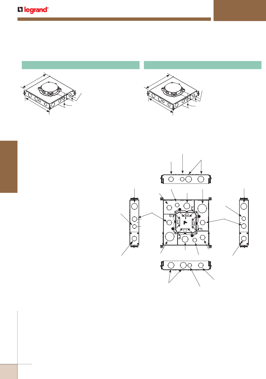
WWW.LEGRAND.US/WIREMOLD
450
FLOOR BOXES
WIREMOLD
Knockout Locations and SizesCompartment Capacities
Four Compartments: (A, B, C, D)
Each Compartment Capacity:
75.0in3 [1230ml]
13 1/8"
[334mm]
13 1/8"
[334mm]
1 13/32"
[36mm]
4 1/16"
[103mm]
13 1/8"
[334mm]
13 1/8"
[334mm]
1 13/32"
[36mm]
4 1/16"
[103mm]
RESOURCE RFB® SERIES FLOOR BOXES
RFB4 Series
For use in concrete
floors. For use with
round Evolution
Series™ covers. Fully
adjustable with tunnel
compartments. Device
plates sold separately.
RFB4E Four-Compartment Box
For use in concrete floors.
For use in on-grade
concrete floors. For use
with round Evolution
Series™ covers. Fully
adjustable with tunnel
compartments. Device
plates sold separately.
RFB4E-OG Four-Compartment On-Grade Box
RFB4E Series Multiservice Steel Recessed Floor Boxes Compartment Capacities, Knockout Locations and Sizes
Removable Plate with
1" trade Size KO
1 1/4" Trade Size
3/4" Trade Size
1 1/4" Trade Size
2" Trade Size
1" Trade Size
1" Trade Size
1 1/4" Trade Size 1 1/4" Trade Size
1" Trade Size
1" Trade Size
3/4" Trade Size
3/4" Trade Size
3/4" Trade Size
1 1/4" Trade Size
2" Trade Size
1" Trade Size
Removable Plate with
1" trade Size KO
3/4" Trade Size
1 1/4" Trade Size
1" Trade Size
AB
C
D
3/4" Trade Size
RFB4E Series Multiservice Steel Recessed Floor Boxes Ordering Information
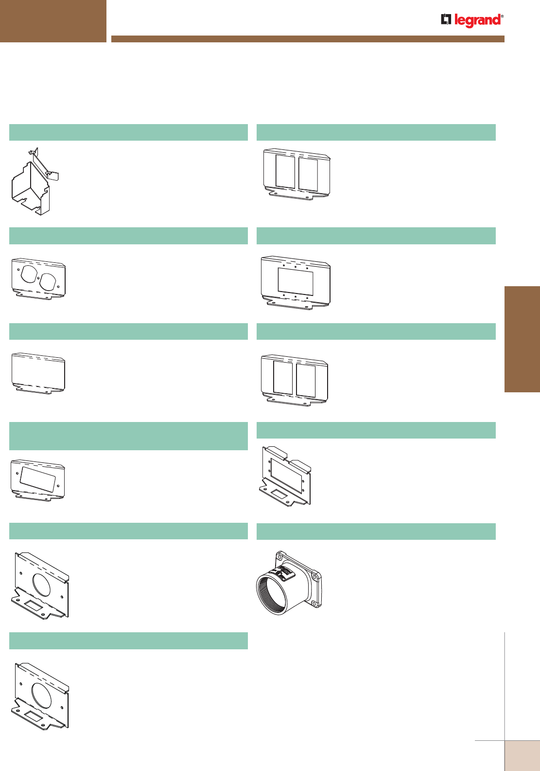
WWW.LEGRAND.US/WIREMOLD
451
FLOOR BOXES
WIREMOLD
RESOURCE RFB® SERIES FLOOR BOXES
RFB4 Series
Accepts standard 15A and 20A duplex
receptacles.
NOTE: For RFB4E, RFB6 and RFB6E Series Floor
Boxes only.
RFB6DP Internal Duplex Receptacle Bracket
Used to separate power and communication
services in combination with a 6CFFTC
Furniture Feed Cover, sold separately.
RFB4EKIT Barrier Kit
Closed off unused gangs.
NOTE: For RFB4E, RFB6 and RFB6E Series Floor
Boxes only.
RFB6B Internal Blank Bracket
Accepts standard GFCI and Decorator
Style receptacles, communication or
A/V devices.
NOTE: For RFB4E, RFB6 and RFB6E Series Floor
Boxes only.
RFB6GFI
Internal GFI or Decorator Style Receptacle Bracket
Receptacle opening 1 3/8" [35mm].
NOTE: For RFB4E, RFB6 and RFB6E Series Floor
Boxes only.
RFB6S1 Internal Single Receptacle Bracket
Receptacle opening 1 9/16" [40mm].
NOTE: For RFB4E, RFB6 and RFB6E Series Floor
Boxes only.
RFB6S2 Internal Single Receptacle Bracket
Includes one (1) adapter to accept
Ortronics® TracJack devices, and one
(1) adapter to accept Ortronics Series II
devices, sold separately.
NOTE: For RFB4E, RFB6 and RFB6E Series
Floor Boxes only.
RFB6RT Internal Communication Bracket
RFB6EXT Internal A/V Bracket
Accepts three (3) Wiremold AVIP or
Extron® Electronics MAAP Series
devices, sold separately.
NOTE: For RFB4E, RFB6 and RFB6E Series
Floor Boxes only.
RFB62A Internal Communication Bracket
Included two (2) adapter to accept
Wiremold CM2 Series Open System
communication inserts, sold separately.
NOTE: For RFB4E, RFB6 and RFB6E Series
Floor Boxes only.
RFB6-AAP Internal A/V Bracket
Accepts two (2) Extron® Electronics
AAP Series devices, sold separately.
NOTE: For RFB4E, RFB6 and RFB6E Series
Floor Boxes only.
2HUB 2" Conduit Transition Hub
Trade size 2" die cast zinc conduit fitting
allows for 2" conduit to transition into a
shallow box design. Includes: die cast
fitting, gasket, and mounting screws.
RFB4E and RB6 Series Multiservice Steel Recessed Floor Box Accessories Ordering Information
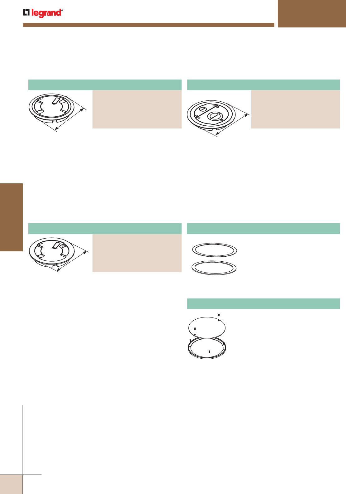
WWW.LEGRAND.US/WIREMOLD
452
FLOOR BOXES
WIREMOLD
Flush Style Cover Assembly
PART NUMBERS:
6CFFTCBK (Black)
6CFFTCGY (Gray)
6CFFTCNK (Nickel)
6CFFTCBS (Brass)
6CFFTCBZ (Bronze)
Flush Style Cover Assembly
PART NUMBERS:
6CTBK* (Painted Black)
6CTGY* (Painted Gray)
6CTCNK* (Nickel)
6CTCBS* (Brass)
6CTCBZ* (Bronze)
RESOURCE RFB® SERIES FLOOR BOXES
RFB4 Series
Die-cast aluminum cover
assembly. Cover assembly is
available in five finishes. 6CTC
Series cover assemblies designed
for use with 6STCP, 6STC, and
6STCPAV Poke-Thru Stem
Assemblies.
7 1/4"
[184mm]
7 1/4"
[184mm]
Die-cast aluminum cover
assembly. Cover assembly is
available in five finishes. 6CT
Series cover assemblies designed
for use with 6STCP, 6STC, and
6STCPAV Poke-Thru Stem
Assemblies. Includes one (1) 6TS
Tile Shim.
7 3/4"
[197mm]
Surface style, die-cast aluminum
cover assembly, with one (1) 3/4"
trade size screw plug opening, and
one (1) concentric 2"-1 1/4" trade
size screw plug opening. Cover
assembly is available in five
powder coated finishes. 6CFFTC
Series Cover Assemblies designed
for use with 6STC Poke-Thru Stem
Assembly. Includes one (1) 3/4"
and one (1) 1" trade size conduit
fittings and one (1) divider to
separate devices.
Used for floor coverings greater
than 5/16" [7.9mm]. The 6TS will
allow the top surface of the cover
to be flush with the finished floor.
Includes: six (6) 1/16" [1.6mm]
thick shims. Up to a total of 3/8"
[9.5mm] of adjustment.
6TS Tile Shim
Evolution Series Cover Assemblies for RFB4E and RFB4E-0G Floor Boxes Ordering Information
* Add suffix “TR” to the end of the part number to indicate tamper-resistant
cover assembly. Tamper-resistant versions are secured with a single
tamper-resistant screw.
Surface Style Cover Assembly
PART NUMBERS:
6CTCBK* (Painted Black)
6CTCGY* (Painted Gray)
6CTCNK* (Nickel)
6CTCBS* (Brass)
6CTCBZ* (Bronze)
Nonmetallic ring for use with bare
concrete and terrazzo floor applications.
NOTE: Only for use on RFB4E and RFB4E-OG Floor
Boxes. Designed to work with 6CT Series
Covers only.
RFB4E-CTR Bare Concrete and Terrazzo Ring
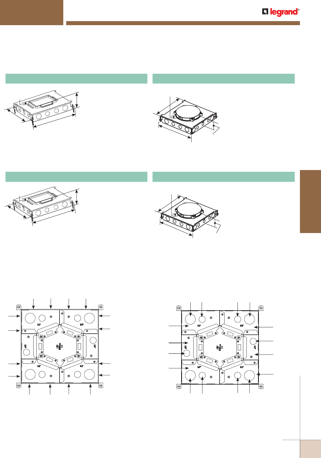
WWW.LEGRAND.US/WIREMOLD
453
FLOOR BOXES
WIREMOLD
RESOURCE RFB® SERIES FLOOR BOXES
RFB6 Series
For use in either concrete or wood floors. Fully adjustable
with tunnel compartment. Supplied with two (2) duplex
mounting plates, two (2) communication mounting plates
(RFB62A), and (2) blank mounting plates. Other plates
sold separately.
RFB6 Six-Compartment Box
For use in concrete floors.
For use with round Evolution™
Series covers. Fully adjustable
with tunnel compartments.
Supplied with two (2) duplex
mounting plates. Other plates
sold separately.
RFB6E Six-Compartment Box
14"
[355mm] 14 5/8"
[371mm]
3 1/4"
[83mm]
3/4"
[19.1mm]
14"
[355mm]
14 5/8"
[371mm]
4"
[102mm]
1 1/8"
[28mm]
A = Side KO 1 1/4" [32mm]
B = Side KO 1" [25mm]
C = Side KO 3/4" [19.1mm]
ABAB
A
C
C
A
ABAB
A
C
C
A
Feed through is accomplished through removable plugs.
Side Knockout Locations
KNOCKOUTS
RFB6 and RFB6E Series Multiservice Steel Recessed Floor Boxes Compartment Capacities, Knockout Locations and Sizes
Bottom Knockout Locations
Compartment Wire and Communication Compacities
A = Bottom KO 1 1/4" [32mm]
B = Bottom KO 3/4" [19.1mm]
KNOCKOUTS
C = Power or Data 52 in
3
[852ml]
D = Power or Data 23 in
3
[376ml]
COMPARTMENT CAPACITIES
ABAB
Compartment
C
B
Compartment
C
ABAB
Compartment
C
Compartment
D
B
Compartment
C
Compartment
D
14"
[355mm] 14 5/8"
[371mm]
3 1/4"
[83mm]
3/4"
[19.1mm]
For use in either concrete or wood floors. Fully adjustable with
tunnel compartment. Supplied with two (2) duplex mounting
plates, two (2) communication mounting plates (RFB62A), and
(2) blank mounting plates. Other plates sold separately.
RFB6-OG Six-Compartment On-Grade Box
14"
[355mm]
14 5/8"
[371mm] 4"
[102mm]
1 1/8"
[28mm] For use in concrete floors.
For use with round Evolution™
Series covers. Fully adjustable
with tunnel compartments.
Supplied with two (2) duplex
mounting plates. Other plates
sold separately.
RFB6E-OG Six-Compartment On-Grade Box
RFB6 and RFB6E Multiservice Steel Recessed Floor Boxes Ordering Information
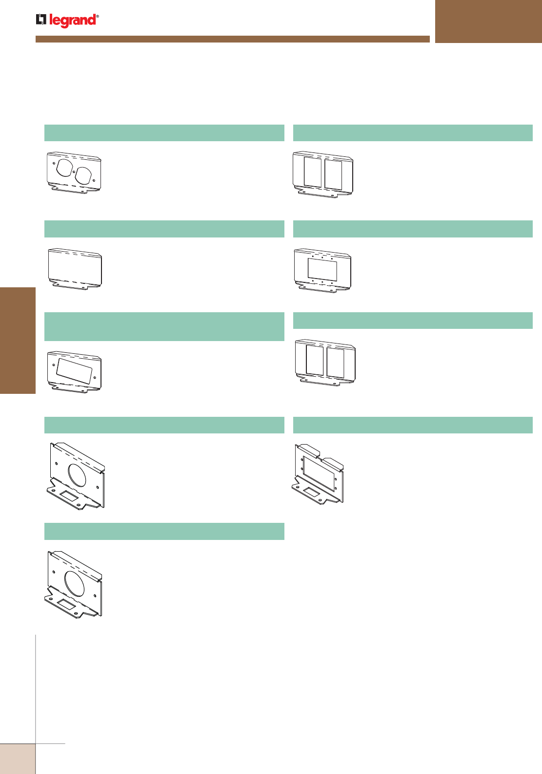
WWW.LEGRAND.US/WIREMOLD
454
FLOOR BOXES
WIREMOLD
RESOURCE RFB® SERIES FLOOR BOXES
RFB6 Series
Accepts standard 15A and 20A
duplex receptacles.
NOTE: For RFB4E, RFB6 and RFB6E Series
Floor Boxes.
RFB6DP Internal Duplex Receptacle Bracket
Receptacle opening 1 9/16" [40mm].
NOTE: For RFB4E, RFB6 and RFB6E Series
Floor Boxes.
RFB6S2 Internal Single Receptacle Bracket
Closes off unused gangs.
NOTE: For RFB4E, RFB6 and RFB6E Series
Floor Boxes.
RFB6B Internal Blank Bracket
Accepts standard GFCI and Decorator
Style receptacles, communication or
A/V devices.
NOTE: For RFB4E, RFB6 and RFB6E Series
Floor Boxes.
RFB6GFI
Internal GFI or Decorator Style Receptacle Bracket
Receptacle opening 1 3/8" [35mm].
NOTE: For RFB4E, RFB6 and RFB6E Series
Floor Boxes.
RFB6S1 Internal Single Receptacle Bracket
Includes one (1) adapter to accept
Ortronics® TracJack devices, and one
(1) adapter to accept Ortronics Series II
devices, sold separately.
NOTE: For RFB4E, RFB6 and RFB6E Series Floor
Boxes.
RFB6RT Internal Communication Bracket
Accepts three (3) Wiremold AVIP or
Extron® Electronics MAAP Series devices,
sold separately.
NOTE: For RFB4E, RFB6 and RFB6E Series Floor
Boxes.
RFB6EXT Internal A/V Bracket
Includes two (2) adapters to accept
Wiremold CM2 Series Open System
communication inserts, sold separately.
NOTE: For RFB4E, RFB6 and RFB6E Series
Floor Boxes
RFB62A Internal Communication Bracket
Accepts two (2) Extron® Electronics AAP
Series devices, sold separately.
NOTE: For RFB4E, RFB6 and RFB6E Series
Floor Boxes.
RFB6-AAP Internal A/V Bracket
RFB6 and RFB6E Series Steel Recessed Floor Boxes Ordering Information
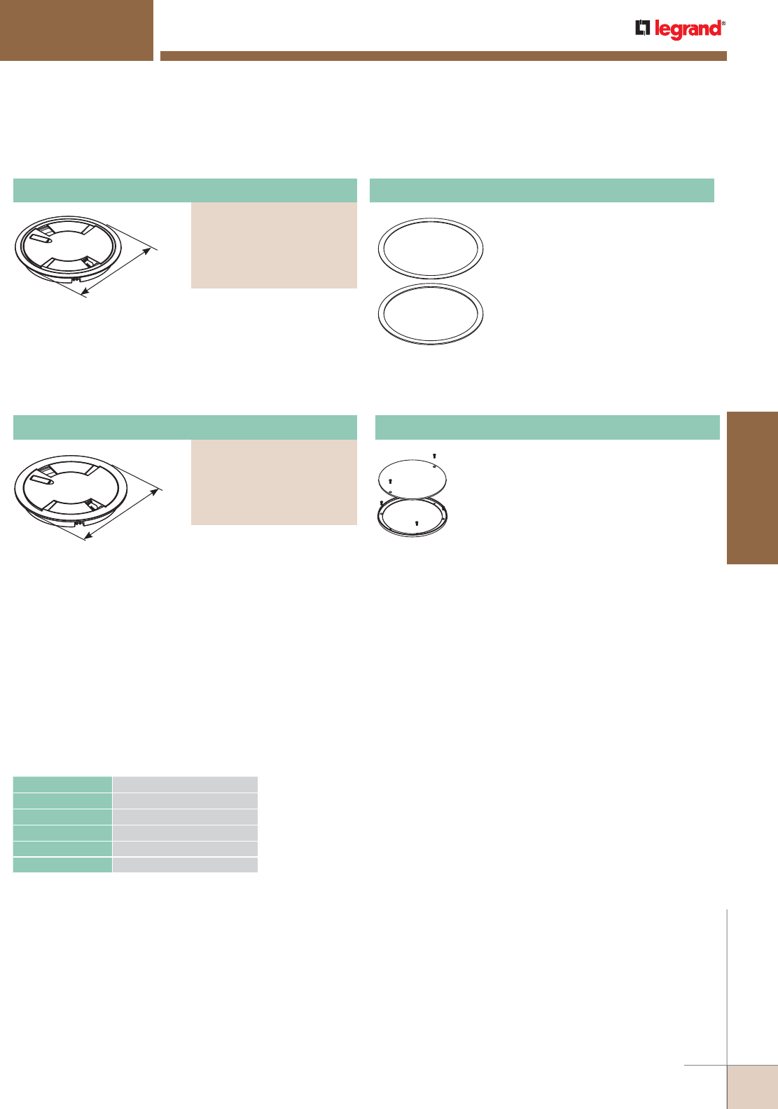
WWW.LEGRAND.US/WIREMOLD
455
FLOOR BOXES
WIREMOLD
Nonmetallic ring for use with bare concrete
and terrazzo floor applications.
NOTE: For RFB4E, RFB6 and RFB6E Series Floor
Boxes. Designed to work with 8CTC and 8CT
Series Covers only.
RFB6E-CTR Bare Concrete and Terrazzo Ring
Die-cast aluminum cover
assembly. Cover assembly
is available in five finishes.
8CTC Series Cover
Assemblies designed for
use with 8STC and 8STCP
Poke-Thru Stem Assemblies.
Includes one (1) 8TS Tile
Shim.
RESOURCE RFB® SERIES FLOOR BOXES
RFB6 Series
Evolution Series Cover Assemblies for RFB6E and RFB6E-OG Floor Boxes Ordering Information
* Add suffix “TR” to the end of the part number to indicate tamper-
resistant cover assembly. Tamper-resistant versions are secured with a
single tamper-resistant screw.
Die-cast aluminum cover
assembly. Cover assembly
is available in five finishes.
8CTC Series Cover
Assemblies designed for use
with 8STC and 8STCP Poke-
Thru Stem Assemblies.
9 1/4"
[235mm]
9 1/4"
[235mm]
Used for floor coverings greater
than 5/16" [7.9mm]. The
8TS will allow the top surface
of the cover to be flush with the
finished floor. Includes: two (2)
1/8" [3.2mm] thick shims and two
(2) 1/16" [1.6mm] thick shims.
Up to a total of 3/8" [9.5mm] of
adjustment.
8TS Tile Shim
Catalog Numbers Maximum Load in Pounds
6CT 1000
6CTC 1000
6CFFTC 1000
8CT 1000
8CTC 1000
NOTE: Load applied through a 1" mandrel in the
center of cover assembly.
NOTE: Loads above are static loads only and do not
pertain to rolling loads.
Load Capacities for Evolution™ Series
Cover Assemblies
Surface Style Cover Assembly
PART NUMBERS:
8CTCBK* (Painted Black)
8CTCGY* (Painted Gray)
8CTCNK* (Nickel)
8CTCBS* (Brass)
8CTCBZ* (Bronze)
Surface Style Cover Assembly
PART NUMBERS:
8CTBK* (Painted Black)
8CTGY* (Painted Gray)
8CTNK* (Nickel)
8CTBS* (Brass)
8CTBZ* (Bronze)

WWW.LEGRAND.US/WIREMOLD
456
FLOOR BOXES
WIREMOLD
RESOURCE RFB® SERIES FLOOR BOXES
RFB2 Series
FloorPort™ Series Flanged Cover Plates Ordering Information
7 3/4"
[197mm] 6 1/2"
[165mm]
Flanged cover for use in tile or carpet installation. Die-cast
aluminum assembly. Insert in lid allows for carpet or tile
cutouts to match finished.
Cutout Cover Assembly
PART NUMBERS:
FPCTCBK (Black)
FPCTCBZ (Bronze)
FPCTCBS (Brass)
FPCTCNK (Nickel)
FPCTCGY (Gray)
FPCTCAL (Brushed Aluminum)
7 3/4"
[197mm]
6 1/2"
[165mm]
Flanged cover for use in tile or carpet installation. Die-cast
aluminum assembly. Lid area is flush with the finished floor,
no cutouts provided.
Blank Cover Assembly
PART NUMBERS:
FPBTCBK (Black)
FPBTCBZ (Bronze)
FPBTCBS (Brass)
FPBTCNK (Nickel)
FPBTCGY (Gray)
FPBTCAL (Brushed Aluminum)
Blank Cover Assembly
PART NUMBERS:
FPBTCBK-NA (Black)
FPBTCBZ-NA (Bronze)
FPBTCBS-NA (Brass)
FPBTCNK-NA (Nickel)
FPBTCGY-NA (Gray)
Cutout Cover Assembly
PART NUMBERS:
FPCTCBK-NA (Black)
FPCTCBZ-NA (Bronze)
FPCTCBS-NA (Brass)
FPCTCNK-NA (Nickel)
FPCTCGY-NA (Gray)
7 3/4"
[197mm] 6 1/2"
[165mm]
Flanged cover for use in tile or carpet installation. Die-cast
aluminum assembly. Insert in lid allows for carpet or tile
cutouts to match finished floor.
7 3/4"
[197mm]
6 1/2"
[165mm]
Flanged cover for use in tile or carpet installation. Die-cast
aluminum assembly. Lid area is flush with the finished floor,
no cutouts provided.
Load Capacities for FloorPort™ Cover Assemblies
CATALOG NUMBERS MAXIMUM LOAD IN POUNDS
FPCTC 1000
FPBTC 750
FPFFT 1000
FPBT 750
FPCT 1000
FPFF 1000
NOTE: Load applied through a 2" [51mm] mandrel in center of service fitting.
Loads above are static loads only and do not pertain to rolling loads.
7 3/4"
[197mm] 6 1/2"
[165mm]
Flanged cover for use in tile or carpet installation. Die-cast
aluminum assembly. Provided with one 1" trade size screw
plug for power or communication type cabling and one
combination 1 1/4" and 2" trade size screw plug for
communication type cabling. Allows for feeding both power
and communication cabling.
Furniture Feed Cover Assembly
PART NUMBERS:
FPFFTCBK (Black)
FPFFTCBZ (Bronze)
FPFFTCBS (Brass)
FPFFTCNK (Nickel)
FPFFTCGY (Gray)
Nonmetallic ring for use on bare
polished concrete and terrazzo
floor applications.
NOTE: FP-CTR is designed to work with flanged
covers only.
FP-CTR Bare Concrete and Terrazzo Ring
FloorPort Part Number Configurator
B
FP TC NK
Blank Top = B
Cutout Top = C
Furniture Feed = FF
FloorPort Cover Nickel = NK
Brass = BS
Black = BK
Bronze = BZ
Gray = GY
Brushed Aluminum = AL
Tile (Flangeless) = T
Tile/Carpet = TC
(Flanged)
North American Made = NA
(Optional)
NA
North American Made FloorPort™ Series Flanged Cover Plates Ordering Information

WWW.LEGRAND.US/WIREMOLD
457
FLOOR BOXES
WIREMOLD
RESOURCE RFB® SERIES FLOOR BOXES
RFB2 Series
Furniture Feed Cover Assembly
PART NUMBERS:
FPFFTBK (Black)
FPFFTBZ (Bronze)
FPFFTBS (Brass)
FPFFTNK (Nickel)
FPFFTGY (Gray)
FPFFTAL (Brushed Aluminum)
Cutout Cover Assembly
PART NUMBERS:
FPCTBK (Black)
FPCTBZ (Bronze)
FPCTBS (Brass)
FPCTNK (Nickel)
FPCTGY (Gray)
FPCTAL (Brushed Aluminum)
FloorPort™ Series Flangeless Cover Assemblies Ordering Information
6 3/4"
[197mm] 5 1/2"
[165mm]
Flangeless cover for use in tile or carpet installations.
Die-cast aluminum assembly. Insert in lid allows for carpet
or tile cutouts to match finished floor.
6 3/4"
[197mm]
5 1/2"
[165mm]
Flangeless cover for use in tile or carpet installation.
Die-cast aluminum assembly. Lid area is flush with the
finished floor, no cutouts provided.
6 3/4"
[197mm] 5 1/2"
[165mm]
Flangeless cover for use in tile or carpet installation.
Die-cast aluminum assembly. Provided with one 1" trade
size screw plug for power or communication type cabling
and one combination 1 1/4" and 2" trade size screw plug for
communication type cabling. Allows for feeding both power
and communication cabling.
Blank Cover Assembly
PART NUMBERS:
FPBTBK (Black)
FPBTBZ (Bronze)
FPBTBS (Brass)
FPBTNK (Nickel)
FPBTGY (Gray)
FPBTAL (Brushed Aluminum)
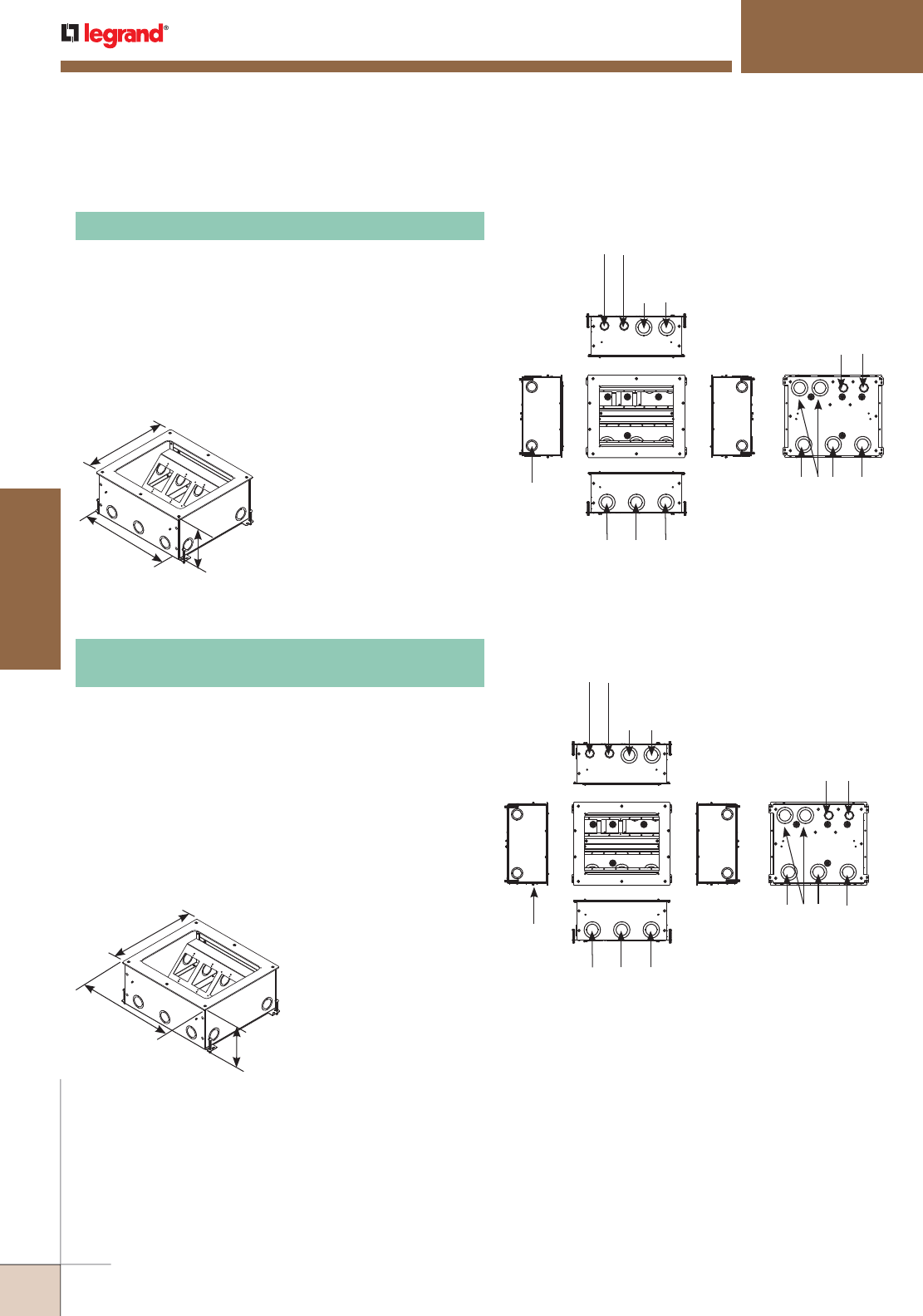
WWW.LEGRAND.US/WIREMOLD
458
FLOOR BOXES
WIREMOLD
RESOURCE RFB® SERIES FLOOR BOXES
RFB9/RFB11 Series
12 5/8"
[321mm]
14 3/4"
[356mm]
6 1/8"
[156mm]
Combination
(2) 1" & 1 1/4"
concentric
trade size KO
Combination (2) 1 1/4"
& 2" concentric
trade size KO 3-gang
84 cu. in. [1377ml]
Combination
3/4" & 1" concentric
trade size KO 1-gang
35 cu. in. [574ml]
Combination (5) 1 1/4" &
2" concentric
trade size KO
Combination (3) 1 1/4" & 2"
concentric
trade size KO 6-gang
132 cu. in. [2163ml]
Combination (2) 3/4" &
1" concentric
trade size KO
Combination
(2) 1" & 1 1/4"
concentric
trade size KO
Combination (2) 1 1/4"
& 2" concentric
trade size KO 3-gang
84 cu. in. [1377ml]
Combination
3/4" & 1" concentric
trade size KO 1-gang
35 cu. in. [574ml]
Combination (5) 1 1/4" &
2" concentric
trade size KO
Combination (3) 1 1/4" & 2"
concentric
trade size KO 6-gang
132 cu. in. [2163ml]
Combination (2) 3/4" &
1" concentric
trade size KO
NOTE: RFB11 and RFB9 will also accept industry standard and standard sectional
device plates from most manufacturers.
Adjustable before concrete pour. Provided with mudcap to
prevent entry of concrete during pour. Cover assembly and
device plates sold separately. For use on bare concrete, tile,
terrazzo, carpet and wood covered floors.
NOTE: When used on bare concrete floor applications, RFB119-PAN must be
installed before concrete pour. RFB119-PAN sold separately.
NOTE: RFB11-OG for on-grade applications is painted with fusion-bonded
epoxy designed for use on metal reinforcement bar and related
accessories before encapsulating in concrete.
Caution: When used on terrazzo covered floors with a thickness of 1/4"
[6.4mm] or greater, mudcap catalog number #RFB119-PAN must
be used and ordered separately.
RFB11-OG Four-Compartment Eleven-Gang
On-Grade Floor Box
Adjustable before concrete pour. Provided with mudcap to
prevent entry of concrete during pour. Cover assembly and
device plates sold separately. For use on bare concrete, tile,
terrazzo, carpet and wood covered floors.
NOTE: When used on bare concrete floor applications, RFB119-PAN must
be installed before concrete pour. RFB119-PAN sold separately.
Caution: When used on terrazzo covered floors with a thickness of 1/4"
[6.4mm] or greater, mudcap catalog number #RFB119-PAN must
be used and ordered separately.
RFB11 Four-Compartment Eleven-Gang Floor Box
12 5/8"
[321mm]
14 3/4"
[356mm] 6 1/8"
[156mm]
RFB9/RFB11 Series Floor Boxes Ordering Information
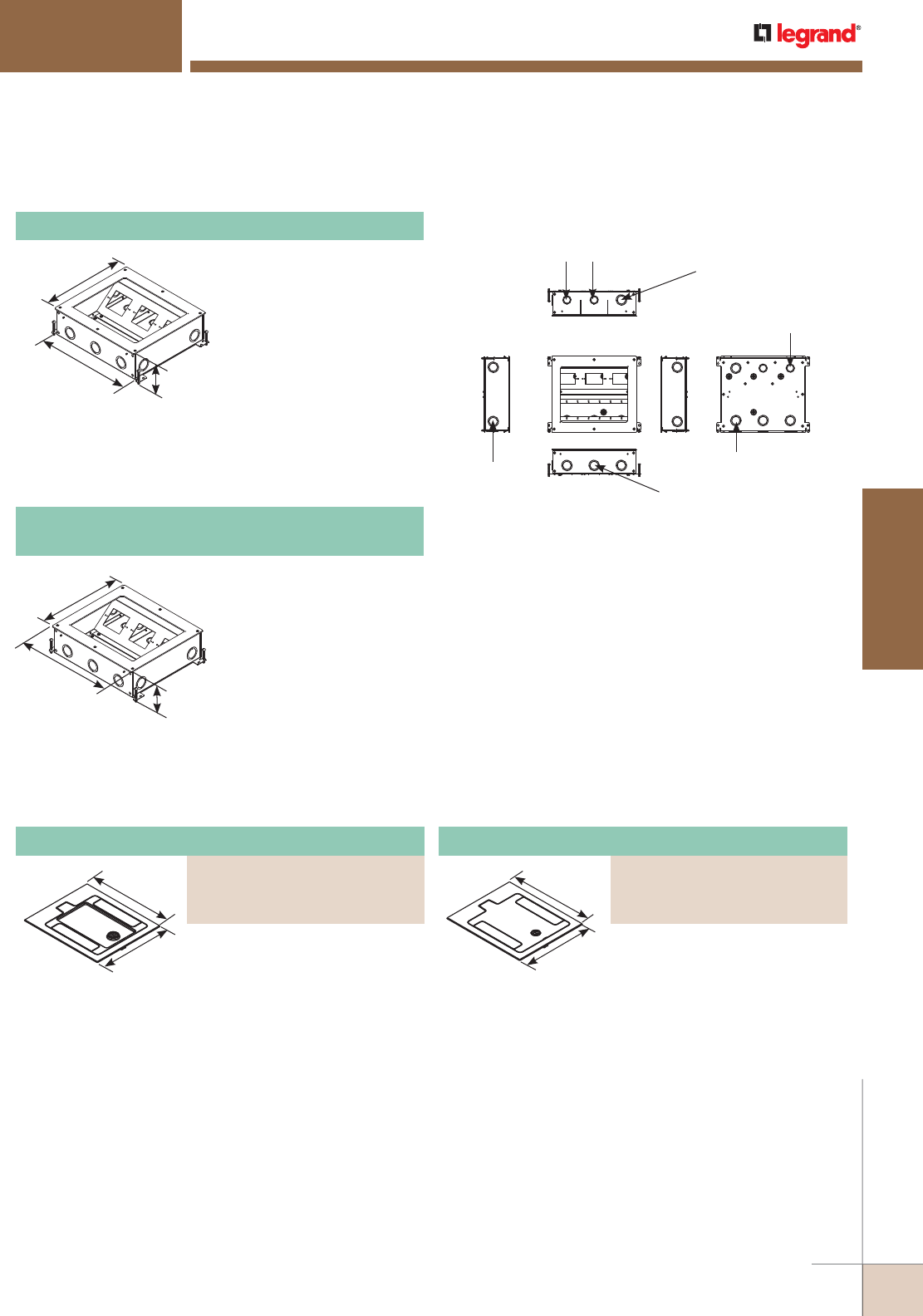
WWW.LEGRAND.US/WIREMOLD
459
FLOOR BOXES
WIREMOLD
12 5/8"
[321mm]
14 3/4"
[356mm] 4 1/8"
[105mm]
NOTE: RFB9-OG for on-grade applications is painted with fusion-bonded
epoxy designed for use on metal reinforcement bar and related
accessories before encapsulating in concrete.
NOTE: RFB11 and RFB9 will also accept industry standard and standard
sectional device plates from most manufacturers.
Caution: When used on terrazzo covered floors with a thickness of 1/4"
[6.4mm] or greater, mudcap catalog number #RFB119-PAN must
be used and ordered separately.
Combination
(2) 1" & 1 1/4"
concentric
trade size KO
Combination 1" & 1 1/4"
concentric trade size KO
1-gang
43 cu. in. [705ml]
Combination 3/4" & 1"
concentric trade size KO
1-gang
43 cu. in. [705ml]
Combination (4)
1" & 1 1/4" concentric
trade size KO
Combination (3)
1" & 1 1/4" concentric
trade size KO 6-gang
132 cu. in. [2163ml]
Combination (2)
3/4" & 1" concentric
trade size KO
Knockouts:
12 1/2"
[317mm]
10 11/16"
[272mm]
RFB9/RFB11 Series Floor Box Accessories Ordering Information
Adjustable before concrete
pour. Provided with mudcap
to prevent entry of concrete
during pour. Cover assembly
and device plates sold
separately. For use on bare
concrete, tile, terrazzo, carpet
and wood covered floors.
RFB9 Four-Compartment Nine-Gang Floor Box
Four-compartment, 9-gang
floor box. Adjustable before
concrete pour. Provided with
mudcap to prevent entry of
concrete during pour. Cover
assembly and device plates
sold separately. For use on
tile, terrazzo, carpet and
wood covered floors.
12 5/8"
[321mm]
14 3/4"
[356mm]
4 1/8"
[105mm]
RFB9-OG
Four-Compartment Nine-Gang On-Grade Floor Box
12 1/2"
[317mm]
10 11/16"
[272mm]
RFB9/RFB11 Series Floor Boxes Ordering Information (continued)
NOTE: When used on bare concrete floor applications, RFB119-PAN must
be installed before concrete pour. RFB119-PAN sold separately.
Caution: When used on terrazzo covered floors with a thickness of 1/4"
[6.4mm] or greater. RFB119-PAN must be used and ordered
separately.
NOTE: When used on bare concrete floor applications, RFB119-PAN must
be installed before concrete pour. RFB119-PAN sold separately.
NOTE: For bare concrete or terrazzo applications. Cover must be used in conjunction with
RB119-PAN. RFB119-PAN must be attached to the box prior to concrete or terrazzo pour.
RESOURCE RFB® SERIES FLOOR BOXES
RFB9/RFB11 Series
Cast aluminum cover assembly.
Provided with carpet cut-out area.
Maximum load capacity 1,500 lbs.
UL Listed to U.S. and Canadian
safety standards to meet UL
requirements under UL514A for
scrub water exclusion.
Flush with floor, cast aluminum
cover assembly. Maximum load
capacity 3,000 lbs. UL Listed to
U.S. and Canadian safety standards
to meet UL requirements under
UL514A for scrub water exclusion.
Carpet Cover Assembly
PART NUMBERS:
RFB119CTCAL (Brushed Aluminum)
RFB119CTCBK (Black)
RFB119CTCGY (Gray)
Flush Tile or Carpet Cover Assembly
PART NUMBERS:
RFB119BTCAL (Brushed Aluminum)
RFB119BTCBK (Black)
RFB119BTCGY (Gray)
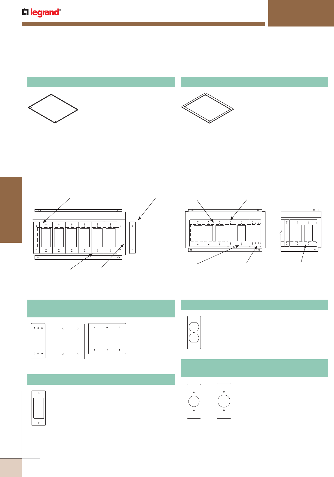
WWW.LEGRAND.US/WIREMOLD
460
FLOOR BOXES
WIREMOLD
RESOURCE RFB® SERIES FLOOR BOXES
RFB9/RFB11 Series
RFB9/RFB11 Series Floor Box Accessories Ordering Information (continued)
Used for floor coverings greater
than 1/4" [6.35mm]. Use one spacer
for 3/8" [9.53mm] thick tile. Use two
spacers for 1/2" [12.70mm] thick
tile. The RFB119-TS will allow the
top surface of the cover assembly to
be flush with 3/8" [9.53mm] to 1/2"
[12.70mm] floor coverings.
RFB119-TS Tile Spacer
When used on bare concrete and
terrazzo-covered floors with a
thickness of 1/4" [6.35mm] or
greater, this mudcap must be used.
The RFB119-PAN must be ordered
separately.
RFB119-PAN Mudcap for Terrazzo Floor Applications
NOTE: Must be used with RFB119-TS (Tile Spacer, see below) for terrazzo
heights greater than 1/4" [6.35mm]. Use one spacer for 3/8"
[9.54mm] thick tile Use two spacers for 1/2" [12.70mm] thick tile.
(6) 1-Gang Sectional Plates
1 13/16" x 4 1/2"
[46mm x 114mm]
Cat. No. RFB119-SPACER
Used to close gap on outside
sectional device plate
Existing opening when not
covered with Cat. No.
RFB119-SPACER
RFB119-SPACER
Multi-Gang Mounting Brackets Used with Sectional Device Plates Multi-Gang Mounting Brackets Used with Standard Device Plates
3-Gang Standard Plate
6 3/8" x 4 1/2"
[162mm x 114mm]
1-Gang Standard Plate
2 3/4" x 4 1/2"
[70mm x 114mm]
Cat. No. RFB119-SPACER
Used to close gap between standard single
and multi-gang plates
Cat. No. RFB119-SB
Single-gang sectional blank plate
(Mounted off-center)
2-gang standard plate
4 9/16" x 4 1/2"
[116mm x 114mm]
RFB9/RFB11 Series Floor Boxes Installation Ordering Information
RFB9/RFB11 Series Floor Boxes Steel Sectional Device Plates Ordering Information
RFB119-SB
RFB119-3SB
RFB119-2SB
One-, two-,
and three-gang
sectional width
device plates.
RFB119-SB, RFB119-2SB, RFB119-3SB
Blank Device Plate
Single-gang sectional (SGFI) width device plate.
RFB119-SGFI GFI Receptacle Device Plate
Single-gang sectional (SD) width device plate.
RFB119SD Duplex Receptacle Device Plate
RFB119-SSR1 RFB119-SSR2
Single-gang device plates in sectional
widths. SSR1 has an opening of 1.39"
and SSR2 has an opening of 1.59"
[40.39mm].
RFB119-SSR1, RFB119-SSR2
Single Receptacle Device Plate
NOTE: Sectional device plates allow for custom configuration of a multi-gang plate that conforms to the standard
NEMA 1.812" (1 13/16") [46.02mm] center-to-center spacing.
RFB11 and RFB9 will also accept industry standard and standard sectional device plates from most manufacturers.
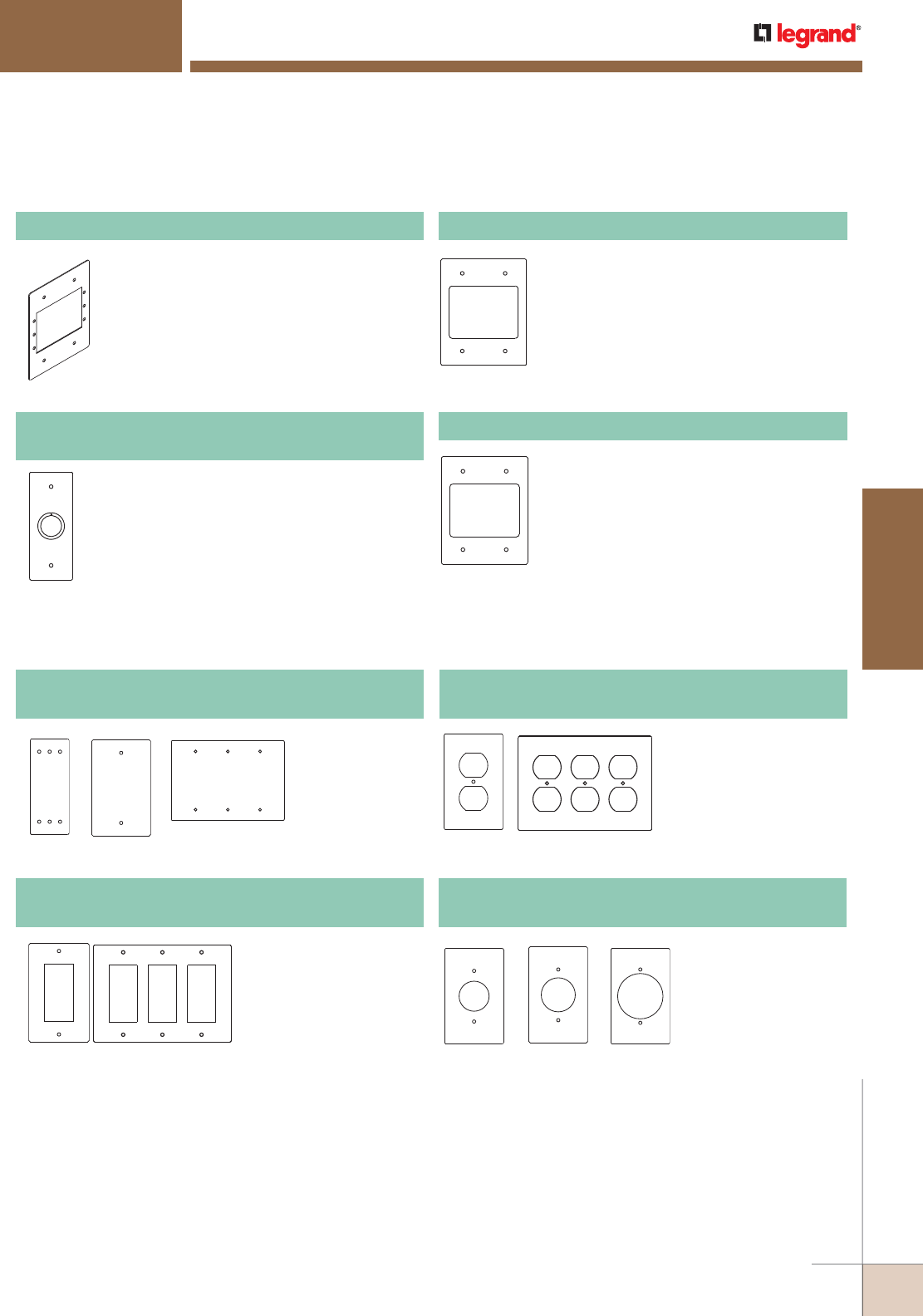
WWW.LEGRAND.US/WIREMOLD
461
FLOOR BOXES
WIREMOLD
RESOURCE RFB® SERIES FLOOR BOXES
RFB9/RFB11 Series
RFB9/RFB11 Series Floor Boxes Steel Sectional Device Plates Ordering Information (continued)
Available in sectional (SKO) width.
RFB119-SKO Combination 1/2" and 3/4" Trade Size
Knockout Device Plate
RFB119-2SAB Communication Device Plate
Available in two-gang sectional width.
Provided with bezel to accept up to three
(3) dual Wiremold CM Series Open System
communication modules or Pass & Seymour®
Activate Connectivity System inserts. Modular
inserts sold separately.
RFB119-AAP Device Plate
Two-gang sectional device plate. Holds three
(3) Extron® Electronics AAP devices.
RFB119-2SRT Communication Device Plate
Available in two-gang sectional width. Provided
with one opening to accept one Ortronics®
TracJack bezel and one Ortronics® Series II
bezel. Will accept up to six Ortronics® TracJack
devices or up to three dual Ortronics® Series II
modular inserts. Modules sold separately.
RFB119-B
RFB119-3B
RFB119-SB
One-, two- and
three-gang device
plates in standard
widths.
RFB119-B, RFB119-3B, RFB119-SB
Blank Device Plate
RFB119-GFI RFB119-3GFI
One- and three-gang
device plates in standard
(GFI) widths.
RFB119-GFI, RFB119-3GFI
GFI Receptacle Device Plates
RFB119-D RFB119-3D
One- and three-gang
device plates in standard
(D) widths.
RFB119-D, RFB119-3D
Duplex Receptacle Device Plates
RFB119-SR1 RFB119-SR2 RFB119-SR3
One-device plates in
standard (SR) widths.
SR1 has an opening of
1.39" [35.31mm]. SR2
has an opening of 1.59"
[40.39mm]. SR3 has a
2.14" [54.36mm] opening.
RFB119-SR1, RFB119-SR2, RFB119-SR3
Single Receptacle Device Plates
RFB9/RFB11 Series Floor Boxes Steel Standard Device Plates Ordering Information
NOTE: Sectional device plates allow for custom configuration of a multi-gang plate that conforms to the standard
NEMA 1.812" (1 13/16") [46.02mm] center-to-center spacing.
RFB11 and RFB9 will also accept industry standard and standard sectional device plates from most manufacturers.
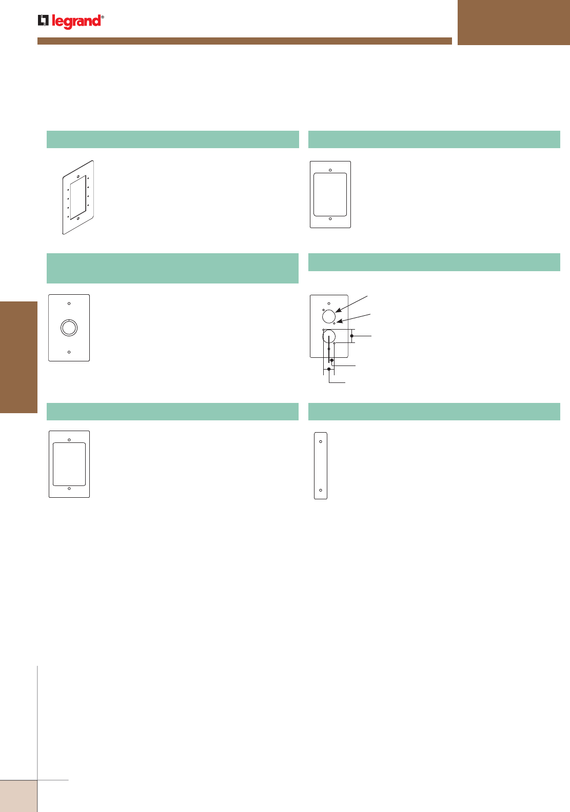
WWW.LEGRAND.US/WIREMOLD
462
FLOOR BOXES
WIREMOLD
RESOURCE RFB® SERIES FLOOR BOXES
RFB9/RFB11 Series
NOTE: Sectional device plates allow for custom configuration of a multi-gang plate that conforms to the standard
NEMA 1.812" (1 13/16") [46.02mm] center-to-center spacing.
RFB11 and RFB9 will also accept industry standard and standard sectional device plates from most manufacturers.
RFB119-MAAP Device Plate
One-gang standard device plate. Holds four
(4) Wiremold AVIP or Extron® Electronics
MAAP devices.
Available in standard (KO) widths.
RFB119-KO Combination 1/2" and 3/4" Trade Size
Knockout Device Plates
RFB119-AB Communication Device Plate
Available in standard width. Provided with
bezel to accept up to three (3) dual Wiremold
CM Series Open System communication
modules or Pass & Seymour® Activate
Connectivity System inserts. Modules and
inserts sold separately.
RFB119-RT Communication Device Plate
Available in standard width. Provided with one
opening to accept one Ortronics® TracJack
bezel and one Ortronics® Series II bezel. Will
accept up to six Ortronics® TracJack devices
or up to three dual Ortronics® Series II
modular inserts. Modular inserts and devices
sold separately.
Diameter 0.875"
[22.2mm]
Diameter 0.109"
[2.8mm]
1"
[25.4mm]
0.375"
[9.5mm]
0.750"
[19.1mm]
RFB119-XLR Microphone Device Plate
Available in standard widths.
Provided with double opening to
accept two microphone devices.
RFB119-Spacer Spacer Plate
Used to close off openings when certain
combinations of standard width device plates
leave open spaces. Four (4) spacer plates are
included with the RFB11 and two (2) with
the RFB9.
RFB9/RFB11 Series Floor Boxes Steel Standard Device Plates Ordering Information (continued)
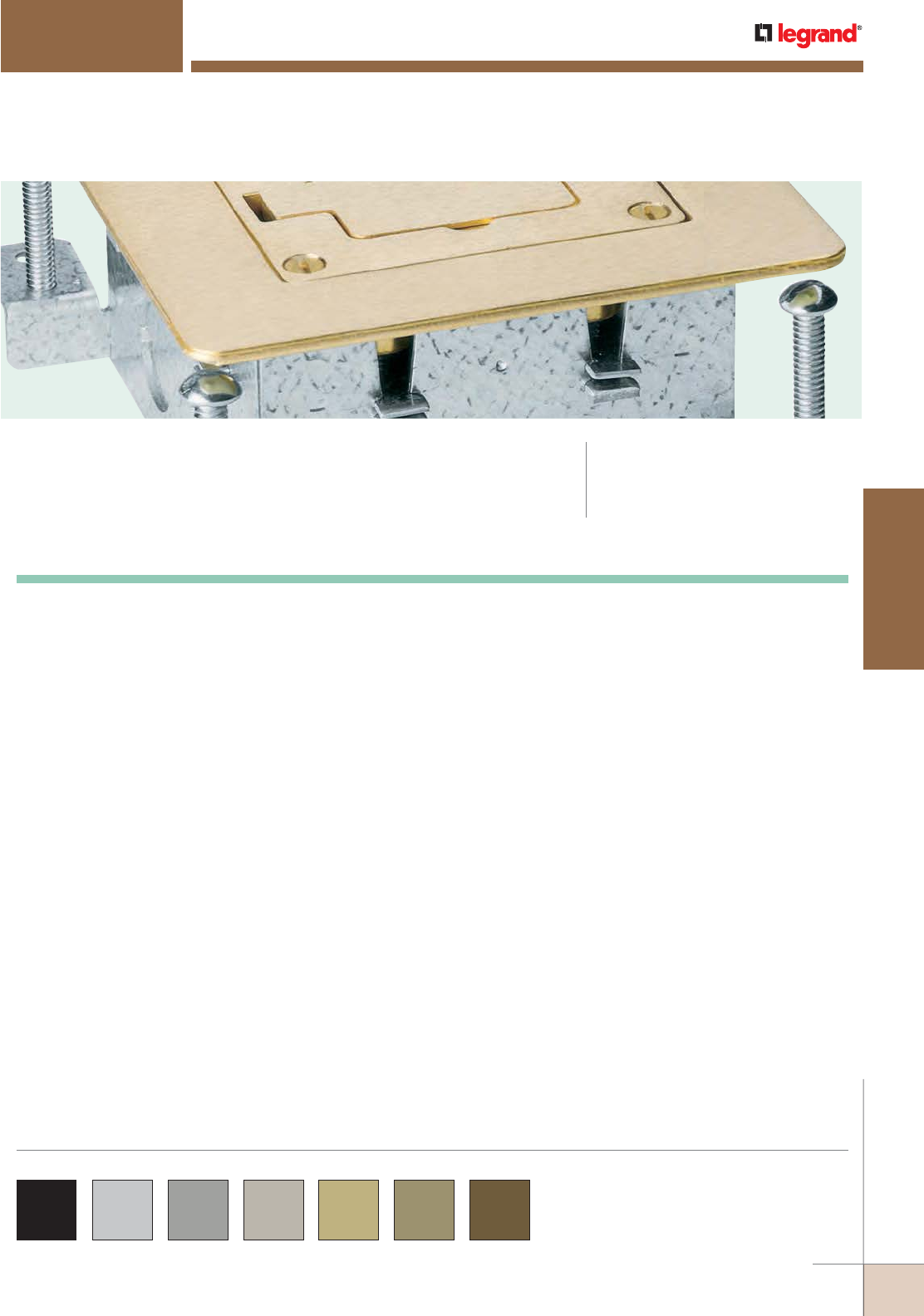
WWW.LEGRAND.US/WIREMOLD
463
FLOOR BOXES
WIREMOLD
OmniBox Series™ Floor Boxes provide an excellent activation solution when
multiple services are required in open space areas to meet the workstation
needs of today’s applications.
OMNIBOX™ SERIES FLOOR BOXES
CODE REFERENCE
cULus Listed
Metallic Outlet Boxes:
File E2961 Guide QCIT.
OmniBox Series™ Flanges Cover Plates are available in
black, aluminum, gray, nickel, brass, bronze and brown.
Custom color options are also available. Consult the
factory for more information.
COLOR OPTIONS
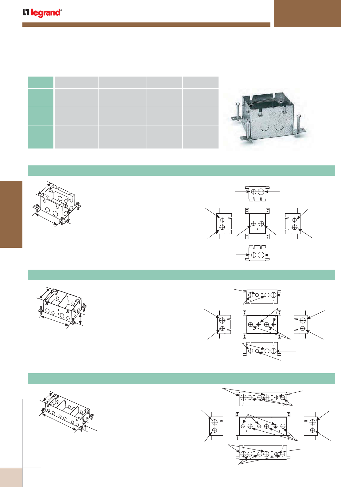
WWW.LEGRAND.US/WIREMOLD
464
FLOOR BOXES
WIREMOLD
Back
Side Side
Top
Front
1/2"
Trade Size
1/2"
Trade Size
3/4"
Trade Size
3/4"
Trade Size
3/4"
Trade Size
3/4"
Trade Size
1/2"
Trade Size
3/4"
Trade Size
1"
Trade Size
1"
Trade Size
3 23/32"
[94mm]
3 15/32"
[88mm]
4 13/16"
[122mm]
Knockouts:
OMNIBOX™ SERIES FLOOR BOXES
880S1 One-Gang Stamped Steel Floor Box
Fully adjustable.
Fully adjustable.
Fully adjustable.
CAT. NO.
CONDUIT
OPENINGS
COMPARTMENT
CAPACITY
ADJUSTMENT
BEFORE POUR
ADJUSTMENT
AFTER POUR
880S1 (3)-1/2" [12.7mm],
(5)-3/4" [19.1mm],
(2)-1" [25mm]
53 cu. in.
[869ml3]
1 3/4"
[44mm]
1/2"
[12.7mm]
880S2 (4)-1/2" [12.7mm],
(8)-3/4" [19.1mm],
(4)-1" [25mm]
117 cu. in.
58 cu. in.
59 cu. in.
[1918ml3]
[951ml3]
[967ml3]
1 3/4"
[44mm]
1/2"
[12.7mm]
880S3 (5)-1/2" [12.7mm],
(11)-3/4" [19.1mm],
(6)-1" [25mm]
180 cu. in.
58 cu. in.
68 cu. in.
56 cu. in.
[2950ml3]
[951ml3]
[1115ml3]
[918ml3]
1 3/4"
[44mm]
1/2"
[12.7mm]
Omnibox Series Stamped Steel Floor BoxesTechnical Specifications
4 13/16"
[122mm]
3 15/32"
[88mm]
7 15/16"
[202mm]
Knockouts:
4 13/16"
[122mm]
3 15/32"
[88mm]
12"
[305mm]
Knockouts: Back
Side Side
Top
Front
1"
Trade Size 1"
Trade Size
3/4"
Trade Size
3/4"
Trade Size
3/4"
Trade Size
3/4"
Trade Size
1/2"
Trade Size
3/4"
Trade Size
1/2"
Trade Size
1"
Trade Size
1/2"
Trade Size
1"
Trade Size
880S2 Two-Gang Stamped Steel Floor Box
880S3 Three-Gang Stamped Steel Floor Box
Back
Side Side
Top
Front
1"
Trade Size
1"
Trade Size
3/4"
Trade Size
3/4"
Trade Size
3/4"
Trade Size
3/4"
Trade Size
1/2"
Trade Size
3/4"
Trade Size
1"
Trade Size
1"
Trade Size
1/2"
Trade Size
1/2"
Trade Size
Omnibox Series Stamped Steel Floor Boxes Ordering Information
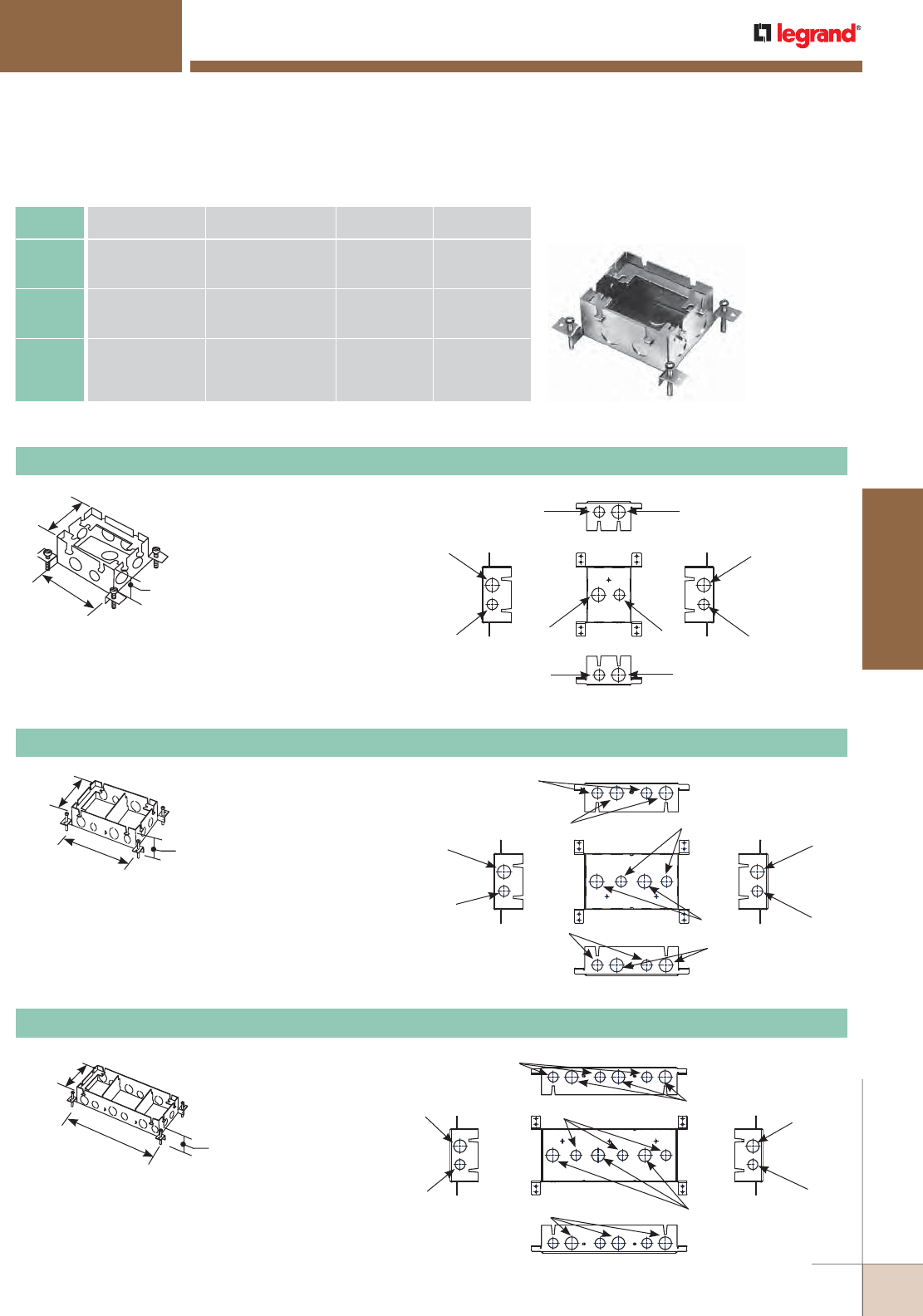
WWW.LEGRAND.US/WIREMOLD
465
FLOOR BOXES
WIREMOLD
OMNIBOX™ SERIES FLOOR BOXES
3 23/32"
[94mm]
2 15/32"
[63mm]
4 13/16"
[122mm]
880M1 One-Gang Shallow Stamped Steel Floor Box
Back
Side Side
Top
Front
3/4"
Trade Size 3/4"
Trade Size
1/2"
Trade Size
1/2"
Trade Size
1/2"
Trade Size
1/2"
Trade Size
3/4"
Trade Size
1/2"
Trade Size
3/4"
Trade Size
3/4"
Trade Size
Knockouts:
Fully adjustable.
CAT. NO.
CONDUIT
OPENINGS
COMPARTMENT
CAPACITY
ADJUSTMENT
BEFORE POUR
ADJUSTMENT
AFTER POUR
880M1 (5)-1/2" [12.7mm],
(5)-3/4" [19.1mm]
37 cu. in.
[606ml3]
1 3/4"
[44mm]
1/2"
[12.7mm]
880M2 (8)-1/2" [12.7mm],
(8)-3/4" [19.1mm]
80 cu. in.
40 cu. in.
40 cu. in.
[1311ml3]
[656ml3]
[656ml3]
1 3/4"
[44mm]
1/2"
[12.7mm]
880M3 (11)-1/2" [12.7mm],
(11)-3/4" [19.1mm]
126 cu. in.
39 cu. in.
48 cu. in.
39 cu. in.
[2065ml3]
[639ml3]
[787ml3]
[639ml3]
1 3/4"
[44mm]
1/2"
[12.7mm]
Omnibox Series Shallow Stamped Steel Floor Boxes Technical Specifications
4 13/16"
[122mm]
2 15/32"
[63mm]
7 15/16"
[202mm]
Knockouts: Back
Side Side
Top
Front
3/4"
Trade Size
3/4"
Trade Size
1/2"
Trade Size
1/2"
Trade Size
3/4"
Trade Size
3/4"
Trade Size
1/2"
Trade Size
3/4"
Trade Size
1/2"
Trade Size
1/2"
Trade Size
Fully adjustable.
880M2 Two-Gang Shallow Stamped Steel Floor Box
4 13/16"
[122mm]
2 15/32"
[63mm]
12"
[305mm]
Knockouts: Back
Side Side
Top
Front
3/4"
Trade Size 3/4"
Trade Size
1/2"
Trade Size
1/2"
Trade Size
3/4"
Trade Size
1/2"
Trade Size
3/4"
Trade Size
1/2"
Trade Size
3/4"
Trade Size
Fully adjustable.
880M3 Three-Gang Shallow Stamped Steel Floor Box
Omnibox Series Shallow Stamped Steel Floor Boxes Ordering Information
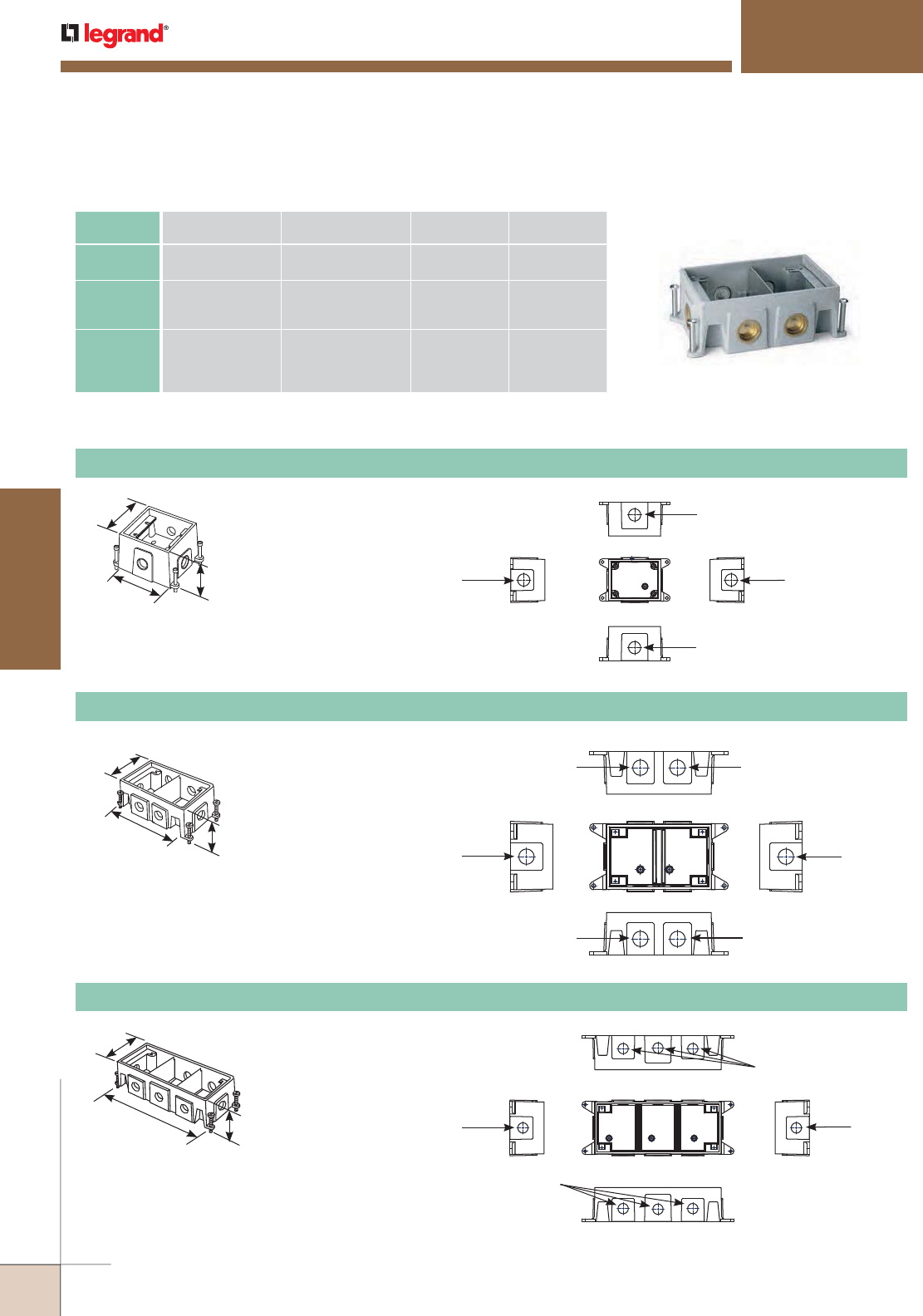
WWW.LEGRAND.US/WIREMOLD
466
FLOOR BOXES
WIREMOLD
CAT. NO.
CONDUIT
OPENINGS
COMPARTMENT
CAPACITY
ADJUSTMENT
BEFORE POUR
ADJUSTMENT
AFTER POUR
880CS11 (4)-1" [25mm] 48 cu. in.
[787ml3]
1 3/4"
[44mm]
1/2"
[12.7mm]
880CS21 (6)-1" [25mm] 94 cu. in.
45 cu. in.
49 cu. in.
[1541ml3]
[738ml3]
[803ml3]
1 3/4"
[44mm]
1/2"
[12.7mm]
880CS31 (8)-1" [25mm] 160 cu. in.
53 cu. in.
54 cu. in.
53 cu. in.
[2622ml3]
[869ml3]
[885ml3]
[869m l3]
1 3/4"
[44mm]
1/2"
[12.7mm]
OMNIBOX™ SERIES FLOOR BOXES
Omnibox Series Cast Iron Floor Boxes Technical Specifications
4 3/8"
[111mm]
3 7/16"
[87mm]
5 3/16"
[132mm]
Knockouts: Back
Side Side
Top
Front
1"
Conduit Thread
1"
Conduit Thread
1"
Conduit Thread
1"
Conduit Thread
880CS1-1 One-Gang Cast-Iron Floor Box
Fully adjustable.
Fully adjustable.
Fully adjustable.
5 3/16"
[132mm]
3 7/16"
[87mm]
8 1/2"
[216mm]
5 3/16"
[132mm]
3 7/16"
[87mm]
12 1/2"
[318mm]
Knockouts: Back
Side Side
Top
Front
1"
Conduit Thread
1"
Conduit Thread
1"
Conduit Thread
1"
Conduit Thread
1"
Conduit Thread
1"
Conduit Thread
Back
Knockouts:
Side Side
Top
Front
1"
Conduit Thread
1"
Conduit Thread
1"
Conduit Thread
1"
Conduit Thread
880CS2-1 Two-Gang Cast-Iron Floor Box
880CS3-1 Three-Gang Cast-Iron Floor Box
Omnibox Series Cast Iron Floor Boxes Ordering Information
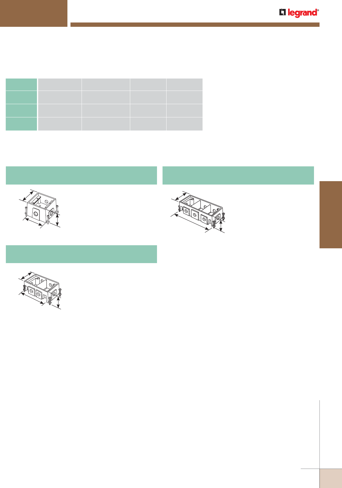
WWW.LEGRAND.US/WIREMOLD
467
FLOOR BOXES
WIREMOLD
4 3/8"
[111mm]
3 7/16"
[87mm]
5 3/16"
[132mm]
5 3/16"
[132mm]
3 7/16"
[87mm]
8 1/2"
[216mm]
5 3/16"
[132mm]
3 7/16"
[87mm]
12 1/2"
[318mm]
CAT. NO.
CONDUIT
OPENINGS
COMPARTMENT
CAPACITY
ADJUSTMENT
BEFORE POUR
ADJUSTMENT
AFTER POUR
880CS1NA (4)-1" [25mm] 48 cu. in. 1 3/4"
[44mm]
1/2"
[12.7mm]
880CS2NA 61" 25mm 94 cu. in.
45/49
1 3/4"
44mm
1/2"
12.7mm
880CS3NA 81" 25mm 160 cu. in.
53/54/53
1 3/4"
44mm
1/2"
12.7mm
Omnibox Series Cast Iron Floor Boxes Technical Specifications
Omnibox Series Cast Iron Floor Boxes Ordering Information (continued)
OMNIBOX™ SERIES FLOOR BOXES
880CS1-NA North American Made One-Gang
Cast Iron Floor Box
Fully adjustable.
880CS1-NA
North America Made One-Gang Cast Iron Floor Box
Fully adjustable.
880CS2-NA North American Made Two-Gang
Cast Iron Floor Box
880CS1-NA
North America Made One-Gang Cast Iron Floor Box
Fully adjustable.
880CS3-NA North American Made Three-Gang
Cast Iron Floor Box
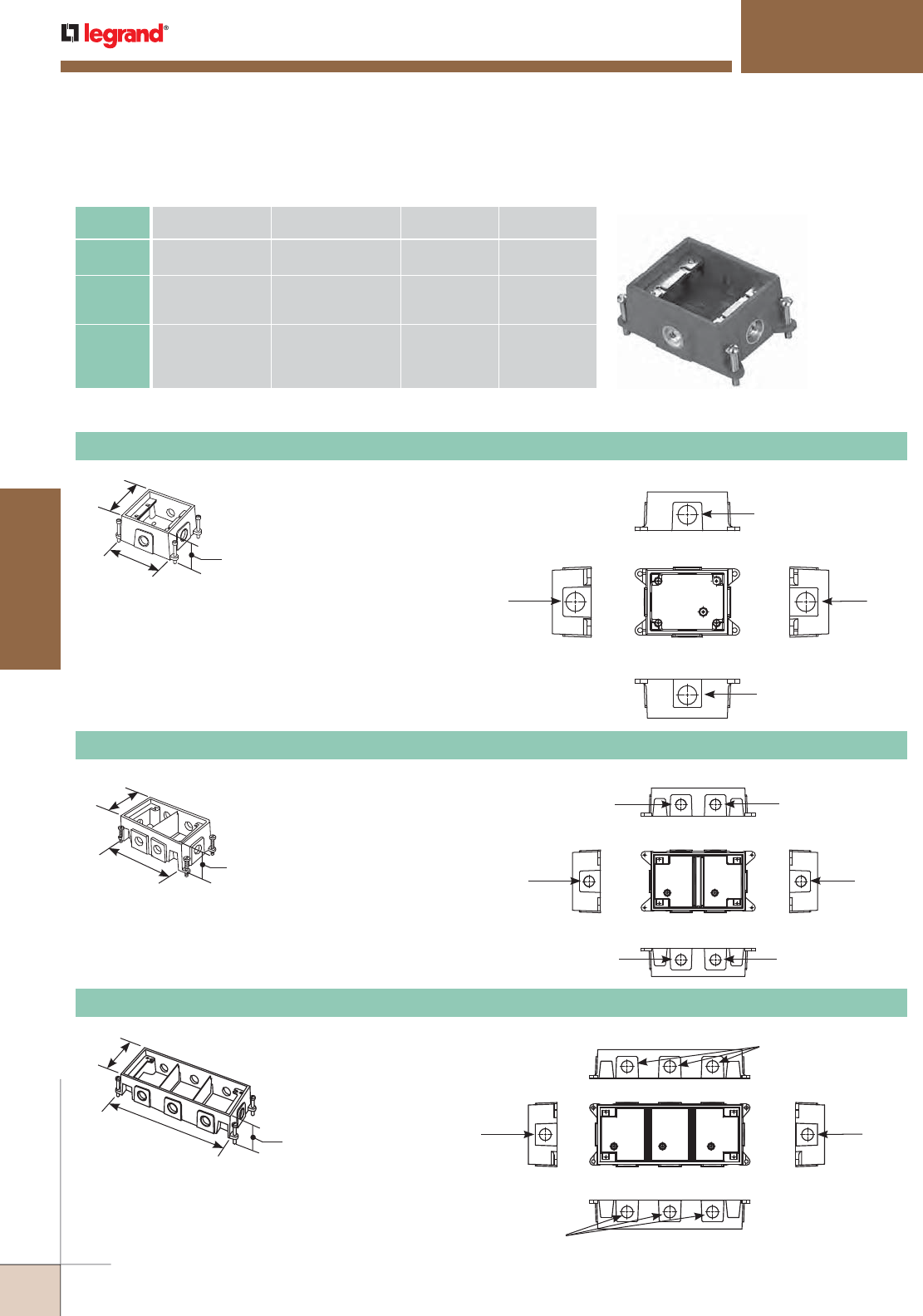
WWW.LEGRAND.US/WIREMOLD
468
FLOOR BOXES
WIREMOLD
Back
Side Side
Top
Front
1"
Conduit Thread
1"
Conduit Thread
1"
Conduit Thread
1"
Conduit Thread
Back
Side Side
Top
Front
1"
Conduit Thread
1"
Conduit Thread
1"
Conduit Thread
1"
Conduit Thread
1"
Conduit Thread
1"
Conduit Thread
Back
Side Side
Top
Front
1"
Conduit Thread
1"
Conduit Thread
1"
Conduit Thread
1"
Conduit Thread
5 3/16"
[132mm]
2 7/16"
[62mm]
8 1/2"
[216mm]
2 7/16"
[62mm]
5 3/16"
[132mm]
4 3/8"
[111mm] Knockouts:
OMNIBOX™ SERIES FLOOR BOXES
CAT. NO.
CONDUIT
OPENINGS
COMPARTMENT
CAPACITY
ADJUSTMENT
BEFORE POUR
ADJUSTMENT
AFTER POUR
880CM11 (4)-1" [25mm] 34 cu. in.
[557ml3]
1 3/4"
[44mm]
1/2"
[12.7mm]
880CM21 (6)-1" [25mm] 76 cu. in.
36 cu. in.
40 cu. in.
[1246ml3]
[595ml3]
[656ml3]
1 3/4"
[44mm]
1/2"
[12.7mm]
880CM31 (8)-1" [25mm] 118 cu. in.
39 cu. in.
40 cu. in.
39 cu. in.
[1934ml3]
[639ml3]
[656ml3]
[639ml3]
1 3/4"
[44mm]
1/2"
[12.7mm]
Omnibox Series Shallow Cast Iron Floor Boxes Technical Specifications
880CM1-1 One-Gang Shallow Cast Iron Floor Box
Fully adjustable.
Fully adjustable.
Fully adjustable.
Knockouts:
880CM2-1 Two-Gang Shallow Cast Iron Floor Box
880CM3-1 Three-Gang Shallow Cast Iron Floor Box
5 3/16"
[132mm]
2 7/16"
[62mm]
12 1/2"
[318mm]
Knockouts:
Omnibox Series Shallow Cast Iron Floor Boxes Ordering Information
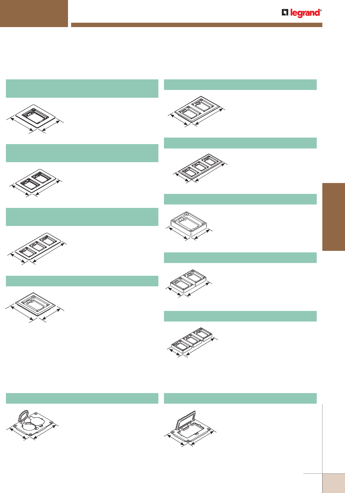
WWW.LEGRAND.US/WIREMOLD
469
FLOOR BOXES
WIREMOLD
OMNIBOX™ SERIES FLOOR BOXES
Omnibox Series Solid Brass Floor Boxes Cover Plate Flanges Ordering Information
5 3/4"
[146mm] 4 3/4"
[121mm]
817C One-Gang Brass Carpet Flange
For use on 880S1, 880M1,
880CS1-1, and 880CM1-1
Floor Boxes.
5 3/4"
[146mm]
8 7/8"
[225mm]
827C Two-Gang Brass Carpet Flange
For use on 880S2, 880M2,
880CS2-1, and 880CM2-1
Floor Boxes.
5 3/4"
[146mm]
13"
[330mm]
837C Three-Gang Brass Carpet Flange
For use on 880S3, 880M3,
880CS32-1, and 880CM3-1
Floor Boxes.
4 1/2"
[107mm]
3 1/2"
[88.4mm]
817T One-Gang Brass Tile Flange
For use on 880S1, 880M1,
880CS1-1, and 880CM1-1
Floor Boxes.
4 1/2"
[114.9mm]
7 5/8"
[193.7mm]
827T Two-Gang Brass Tile Flange
For use on 880S2, 880M2,
880CS2-1, and 880CM2-1
Floor Boxes.
4 1/2"
[114mm]
11 3/4"
[298mm]
837T Three-Gang Brass Tile Flange
For use on 880S3, 880M3,
880CS3-1, and 880CM3-1
Floor Boxes.
827B Two-Gang Brass Combination Carpet and
Tile Flange
Accepts Ortronics® MAB6TJ
TracJack and MAB3S2 Series II
adapters and Wiremold CM Series
inserts, sold separately.
6 1/16"
[154.4mm]
9 1/16"
[230.2mm]
817B One-Gang Brass Combination Carpet and
Tile Flange
Accepts Ortronics® MAB6TJ
TracJack and MAB3S2 Series II
adapters and Wiremold CM Series
inserts, sold separately.
6 1/16"
[154.4mm]
5 1/16"
[128.5mm]
837B Three-Gang Brass Combination Carpet and
Tile Flange
Accepts Ortronics® MAB6TJ
TracJack and MAB3S2 Series II
adapters and Wiremold CM Series
inserts, sold separately.
6 1/16"
[154.4mm]
13 5/16"
[338mm]
Omnibox Series Metal Cover Plates Ordering Information
828R Brass Duplex Cover Plate
Flip lids. Can also be used with a 106
type communication adapter.
3 1/8"
[80.2mm]
4 3/16"
[106.2mm]
828GFITC Brass GFI Cover Plate
May be used with Activate and
Ortronics® Connectivity Systems
in conjunction with 817B, 827B,
and 837B Flanges.
3 1/8"
[80.2mm]
4 3/16"
[106.2mm]
NOTE: UL Listed for tile, terrazzo, and carpet floors.
Brass covers and flanges are not interchangeable with aluminum or nonmetallic covers and flanges.
Nonmetallic covers are interchangeable with aluminum flanges.
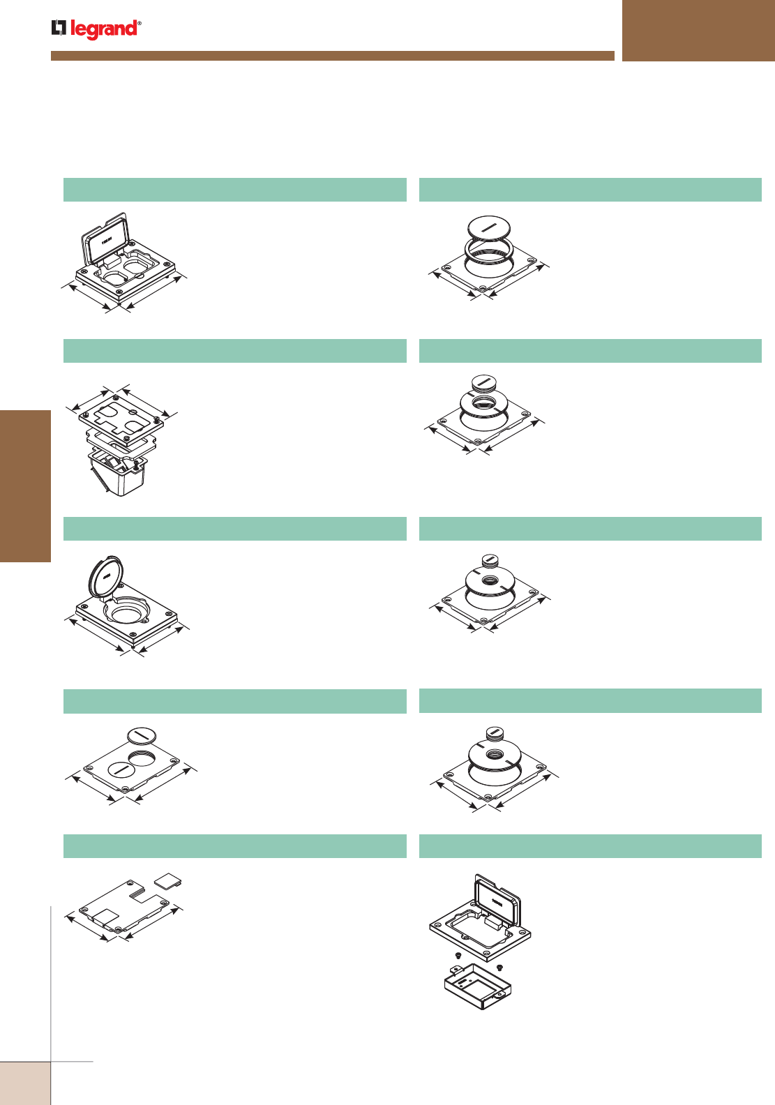
WWW.LEGRAND.US/WIREMOLD
470
FLOOR BOXES
WIREMOLD
OMNIBOX™ SERIES FLOOR BOXES
Omnibox Series Metal Cover Plates Ordering Information (continued)
828DPGFITC Brass Rectangular Cover Plate
Allows for mounting of a duplex style
receptacle with a rectangular style
flip lid cover.
3 1/8"
[80.2mm]
4 3/16"
[106.2mm]
Allows for up to four communication
devices to be mounted in a recessed
position within the 880 Floor Box. The
828COM Cover Plates has removable
slides for cable egress.
NOTE: For use with 880S and 880CS Series Boxes
only.
828COMTC Brass Communications Cover Plate
3 1/8"
[80.2mm] 4 3/16"
[106.2mm]
828DLR Brass Single Locking Receptacle Cover Plate
Single flip lid cover for 20A or 30A
single locking receptacles. Device
opening is 2 5/8" [67mm]. For use
with maximum female locking device
of 1.58" diameter, and maximum
male plug face of 2.25" diameter.
4 3/16"
[106.2mm] 3 1/8"
[80.2mm]
3 1/8"
[79mm]
4 1/8"
[105mm]
Screw plugs. Screw plugs are
11/2" [38mm] in diameter.
828SPTC Brass Duplex Cover Plate
3 1/8"
[79mm]
4 1/8"
[105mm]
Data slides. Feed through only, not
for use with a mounting plate for
communication adapter.
829STC Brass Communication Cover Plate
3 1/8"
[80.2mm]
4 3/16"
[106.2mm]
2 5/8" and 2 1/4" [67mm and
57mm] plugs.
829CK Brass Communication Cover Plate
3 1/8"
[80.2mm]
4 3/16"
[106.2mm]
2 5/8" and 1" [67mm and 25mm]
plugs.
829CK-1 Brass Communications Cover Plate
3 1/8"
[80.2mm]
4 3/16"
[106.2mm]
2 5/8" and 3/4" [67mm and
19.1mm] plugs.
829CK-3/4 Brass Communications Cover Plate
3 1/8"
[83.60mm]
4 3/16"
[106.2mm]
2 5/8" and 1/2" [67mm and
12.7mm] plugs.
829CK-1/2 Brass Communications Cover Plate
828MAAP AV Adapter Plate
Sheet metal adapter plate
that accepts two (2) Wiremold
AVIP or Extron® Electronics
MAAP style device plates,
sold separately. For use with
828GFITC or 828GFITCAL cover
plates, sold separately.
NOTE: UL Listed for tile, terrazzo, and carpet floors.
Brass covers and flanges are not interchangeable with aluminum or nonmetallic covers and flanges.
Nonmetallic covers are interchangeable with aluminum flanges.
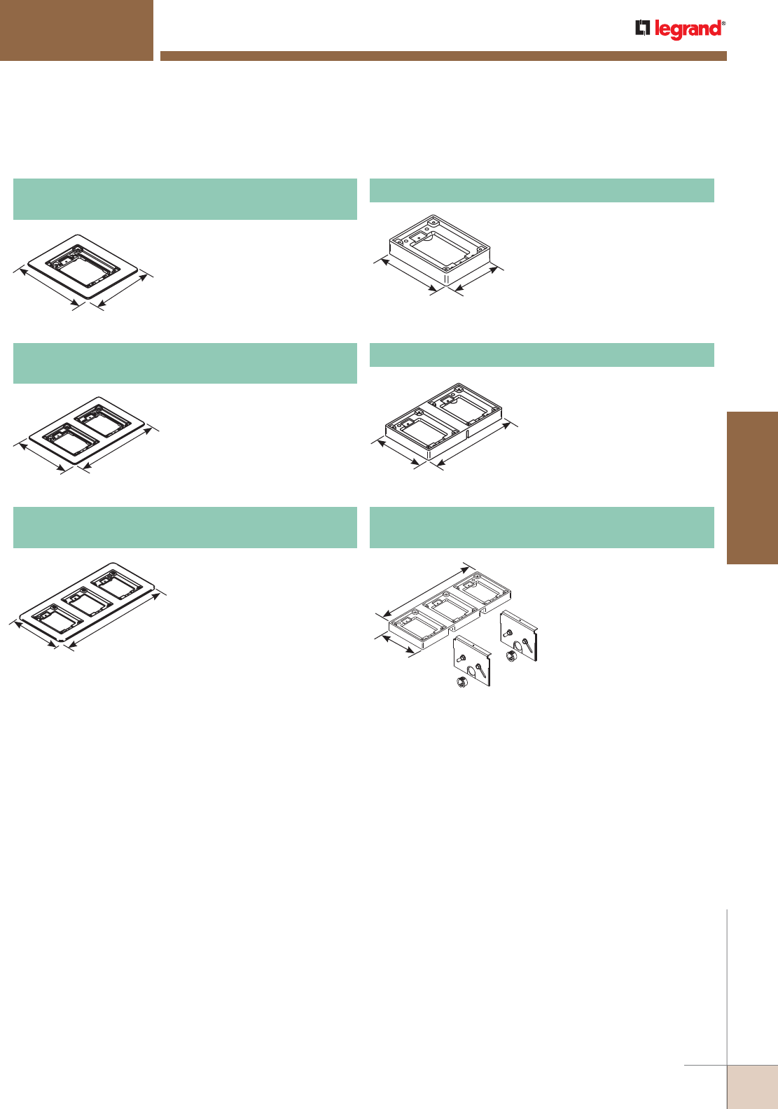
WWW.LEGRAND.US/WIREMOLD
471
FLOOR BOXES
WIREMOLD
6"
[152.4mm] 5"
[127mm]
OMNIBOX™ SERIES FLOOR BOXES
Omnibox Series Brushed Aluminum Cover Plate Flanges Ordering Information
818TCAL One-Gang Brushed Aluminum
Combination Carpet and Tile Flange
Accepts Ortronics® MAB6TJ
TracJack and MAB3S2 Series
II adapters and Wiremold CM
Series inserts, sold separately.
NOTE: Brushed aluminum flanges come
with beveled edges.
828TCAL Two-Gang Brushed Aluminum
Combination Carpet and Tile Flange
Accepts Ortronics® MAB6TJ
TracJack and MAB3S2 Series
II adapters and Wiremold CM
Series inserts, sold separately.
NOTE: Brushed aluminum flanges come
with beveled edges.
838TCAL Three-Gang Brushed Aluminum
Combination Carpet and Tile Flange
Accepts Ortronics® MAB6TJ
TracJack and MAB3S2 Series
II adapters and Wiremold CM
Series inserts, sold separately.
NOTE: Brushed aluminum flanges come
with beveled edges.
4 1/2"
[114mm]
11 3/4"
[298mm]
838TAL-880S3, 838TAL-880M3,
838TAL-880CS3, 838TAL-880CM3 Kit
The 838TAL-880 Series
flanges provide additional
load support for 3-gang tile
flanges. Kit includes 838TAL
Flange and two support
dividers.
NOTE: Order kit for specific box
type: 880S3, 880M3, 880CS3,
or 880CM3
818TAL One-Gang Brushed Aluminum Tile Flange
For use on 880S1, 880M1,
880CS1-1, and 880M1-1
Floor Boxes.
828TAL Two-Gang Brushed Aluminum Tile Flange
For use on 880S2, 880M2,
880CS2-1, and 880CM2-1
Floor Boxes.
6"
[152.4mm]
9"
[228.6mm]
6"
[152.4mm]
13 3/16"
[335mm]
4 1/2"
[114mm] 3 1/2"
[89mm]
4 1/2"
[114mm]
7 5/8"
[194mm]
NOTE: UL Listed for tile, terrazzo, and carpet floors.
Brass covers and flanges are not interchangeable with aluminum or nonmetallic covers and flanges.
Nonmetallic covers are interchangeable with aluminum flanges.
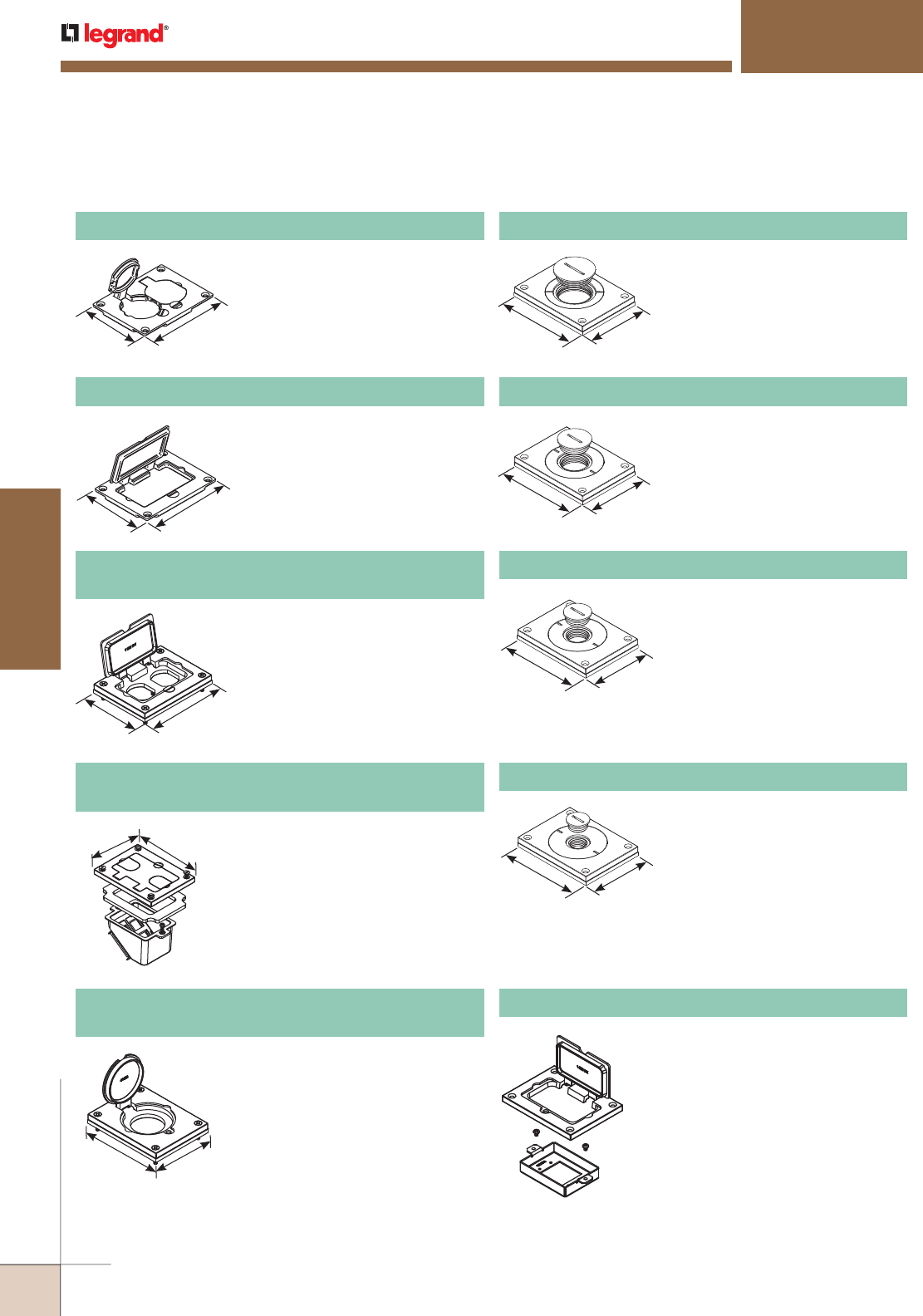
WWW.LEGRAND.US/WIREMOLD
472
FLOOR BOXES
WIREMOLD
828R-TCAL Brushed Aluminum Duplex Cover Plate
Flip lids. Can also be used with a
106 type communication adapter.
830CKTCAL Brushed Aluminum Cover Plate
Power or communication plate
with 2" [51mm] and 1 1/4" [32mm]
plugs.
NOTE: Acceptable for use with threaded
conduit when passing through
power cables.
830CKTCAL-1 Brushed Aluminum Cover Plate
Power or communication plate
with 2" [51mm] and 1" [25mm]
plugs.
NOTE: Acceptable for use with threaded
conduit when passing through
power cables.
828GFITCAL Brushed Aluminum GFI Cover Plate
May be used with Activate and
Ortronics® Connectivity Systems in
conjunction with 817B, 827B, and
837B Flanges.
828COMTCAL
Brushed Aluminum Communication Cover Plate
Allows for up to four communication
devices to be mounted in a recessed
position within the 880 Floor Box.
The 828COMTCAL Cover Plate has
removable slides for cable egress.
NOTE: For use with 880S and 880CS Series
Boxes only.
828DPGFITCAL
Brushed Aluminum Rectangular Cover Plate
Allows for mounting of a duplex
style receptacle with a rectangular
style flip lid cover.
828DLRAL Brushed Aluminum Single Locking
Receptacle Cover Plate
Single flip lid cover for 20A or 30A
single locking receptacles. Device
opening is 2 5/8" [67mm]. For use
with maximum female locking device
of 1.58" diameter, and maximum
male plug face of 2.25" diameter.
Omnibox Series Brushed Aluminum Cover Plates Ordering Information
828MAAP AV Adapter Plate
Sheet metal adapter plate that
accepts two (2) Wiremold AVIP or
Extron® Electronics MAAP style
device plates, sold separately. For
use with 828GFITC or 828GFITCAL
cover plates, sold separately.
830CKTCAL-3/4 Brushed Aluminum Cover Plate
Power or communication plate
with 2" [51mm] and 3/4" [19.1mm]
plugs.
NOTE: Acceptable for use with threaded
conduit when passing through
power cables.
830CKTCAL-1/2 Brushed Aluminum Cover Plate
Power or communication plate
with 2" [51mm] and 1/2" [12.7mm]
plugs.
NOTE: Acceptable for use with threaded
conduit when passing through
power cables.
OMNIBOX™ SERIES FLOOR BOXES
NOTE: UL Listed for tile, terrazzo, and carpet floors.
Brass covers and flanges are not interchangeable with aluminum or nonmetallic covers and flanges.
Nonmetallic covers are interchangeable with aluminum flanges.
3 3/16"
[83.6mm]
4 5/16"
[109.5mm]
4 5/16"
[110mm]
4 5/16"
[109.5mm]
4 5/16"
[109.5mm]
4 5/16"
[109.5mm]
4 5/16"
[109.5mm]
3 3/16"
[83.6mm]
3 3/16"
[83.6mm]
3 3/16"
[83.6mm]
3 3/16"
[83.6mm]
3 3/16"
[83.6mm]
3 3/16"
[83.6mm]
4 5/16"
[109.5mm]
3 3/16"
[83.6mm]
4 5/16"
[109.5mm]
3 3/16"
[83.6mm]
4 5/16"
[109.5mm]
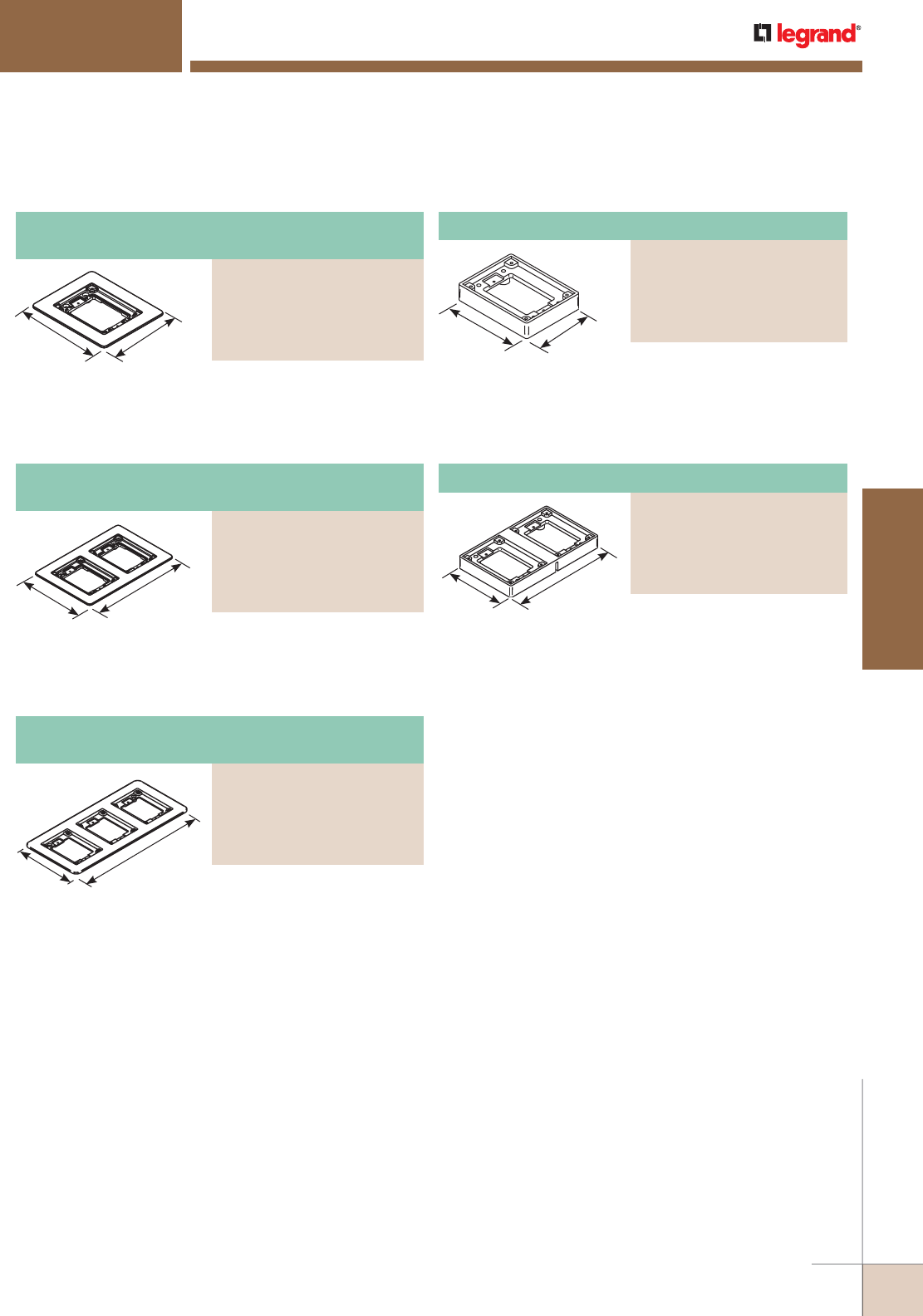
WWW.LEGRAND.US/WIREMOLD
473
FLOOR BOXES
WIREMOLD
Three-Gang Powder-Coated Aluminum
Combination Carpet and Tile Flange
PART NUMBERS:
837TCAL-BK (Black)
837TCAL-GY (Gray)
837TCAL-NK (Nickel)
837TCAL-BS (Brass)
(Bronze)
One-Gang Powder-Coated Aluminum
Combination Carpet and Tile Flange
PART NUMBERS:
817TCAL-BK (Black)
817TCAL-GY (Gray)
817TCAL-NK (Nickel)
817TCAL-BS (Brass)
817TCAL-BZ (Bronze)
Omnibox Series Powder-Coated Aluminum Cover Plate Flanges Ordering Information
Accepts Ortronics® MAB6TJ
TracJack and MAB3S2 Series II
adapters and Wiremold CM
Series inserts, sold separately.
Two-Gang Powder-Coated Aluminum
Combination Carpet and Tile Flange
PART NUMBERS:
827TCAL-BK (Black)
827TCAL-GY (Gray)
827TCAL-NK (Nickel)
827TCAL-BS (Brass)
827TCAL-BZ (Bronze)
Accepts Ortronics® MAB6TJ
TracJack and MAB3S2 Series II
adapters and Wiremold CM
Series inserts, sold separately.
Accepts Ortronics® MAB6TJ
TracJack and MAB3S2 Series II
adapters and Wiremold CM
Series inserts, sold separately.
For use on 880S1, 880M1,
880CS1-1, and 880M1-1
Floor Boxes.
OMNIBOX™ SERIES FLOOR BOXES
One-Gang Powder-Coated Aluminum Tile Flange
PART NUMBERS:
817TAL-BK (Black),
817TAL-GY (Gray),
817TAL-NK (Nickel),
817TAL-BS (Brass),
817TAL-BZ (Bronze)
For use on 880S2, 880M2,
880CS2-1, and 880M2-1
Floor Boxes.
Two-Gang Powder-Coated Aluminum Tile Flange
PART NUMBERS:
827TAL-BK (Black),
827TAL-GY (Gray),
827TAL-NK (Nickel)
827TAL-BS (Brass)
827TAL-BZ (Bronze)
4 1/2"
[114mm] 3 1/2"
[89mm]
4 1/2"
[114mm]
7 5/8"
[194mm]
6"
[152.4mm] 5"
[127mm]
6"
[152.4mm]
9"
[228.6mm]
6"
[152.4mm]
13 3/16"
[335mm]
NOTE: UL Listed for tile, terrazzo, and carpet floors.
Brass covers and flanges are not interchangeable with aluminum or nonmetallic covers and flanges.
Nonmetallic covers are interchangeable with aluminum flanges.
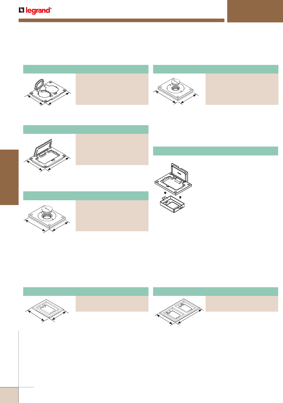
WWW.LEGRAND.US/WIREMOLD
474
FLOOR BOXES
WIREMOLD
Powder-Coated Aluminum Cover Plate
PART NUMBERS:
829CKAL-1BK (Black)
829CKAL-1GY (Gray)
829CKAL-1NK (Nickel),
829CKAL-1BS (Brass),
829CKAL-1BZ (Bronze)
Powder-Coated Aluminum Rectangular Cover Plate
PART NUMBERS:
828GFITCAL-BK (Black)
828GFITCAL-GY (Gray)
828GFITCAL-NK (Nickel)
828GFITCAL-BS (Brass)
828GFITCAL-BZ (Bronze)
Powder-Coated Aluminum Duplex Cover Plate
PART NUMBERS:
828R-TCAL-BK (Black)
828R-TCAL-GY (Gray)
828R-TCAL-NK (Nickel)
828R-TCAL-BS (Brass)
828R-TCAL-BZ (Bronze),
OMNIBOX™ SERIES FLOOR BOXES
Omnibox Series Powder-Coated Aluminum Cover Plates Ordering Information
Omnibox Series Nonmetallic Cover Plate Flanges Ordering Information
Power or communication plate
with 2" [51mm] and 3/4" [19.1mm]
plugs.
NOTE: Acceptable for use with threaded
conduit when passing through
power cables.
828MAAP AV Adapter Plate
Sheet metal adapter plate that
accepts two (2) Wiremold AVIP or
Extron® Electronics MAAP style
device plates, sold separately. For
use with 828GFITC or 828GFITCAL
cover plates, sold separately.
Allows for mounting of a duplex
receptacle (Duplex or GFCI style)
with a rectangular flip cover.
Power or communication plate
with 2" [51mm] and 1" [25mm]
plugs.
NOTE: Acceptable for use with threaded
conduit when passing through
power cables.
Flip lids. Can also be used with a
106 type communication adapter.
NOTE: UL Listed for tile, terrazzo, and carpet floors.
Brass covers and flanges are not interchangeable with aluminum or nonmetallic covers and flanges.
Nonmetallic covers are interchangeable with aluminum flanges.
5 3/4"
[146mm]
4 3/4"
[121mm] For Ortronics® connectivity use
with 829PFLRT Cover. For Activate™
connectivity use with 829PFL
Cover. Accepts Ortronics® MAB6TJ
TracJack and MAB3S2 Series II
adapters and Wiremold CM Series
inserts, sold separately.
5 3/4"
[146mm]
8 7/8"
[225mm] For Ortronics® connectivity use
with 829PFLRT Cover. For Activate™
connectivity use with 829PFL
Cover. Accepts Ortronics® MAB6TJ
TracJack and MAB3S2 Series II
adapters and Wiremold CM Series
inserts, sold separately.
Two-Gang Nonmetallic Carpet Flange
PART NUMBERS:
827PCC-BLK (Black)
827PCC-BRN (Brown)
One-Gang Nonmetallic Carpet Flange
PART NUMBERS:
817PCC-BLK (Black)
817PCC-BRN (Brown)
Powder-Coated Aluminum Cover Plate
PART NUMBERS:
829CKAL-3/4BK (Black)
829CKAL-3/4GY (Gray)
829CKAL-3/4NK (Nickel)
829CKAL-3/4BS (Brass)
829CKAL-3/4BZ (Bronze)
4 5/32"
[110mm]
3 1/4"
[83mm]
3 1/4"
[83mm]
4 5/32"
[110mm]
3 1/4"
[83mm]
4 5/32"
[110mm]
3 1/4"
[83mm]
4 5/32"
[110mm]
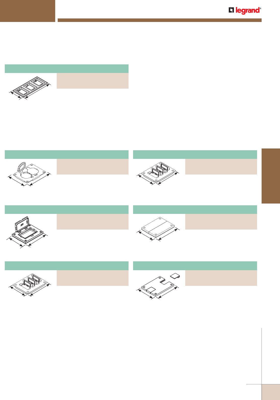
WWW.LEGRAND.US/WIREMOLD
475
FLOOR BOXES
WIREMOLD
Nonmetallic Duplex Cover Plate
PART NUMBERS:
828PR-BLK (Black)
828PR-BRN (Brown)
Omnibox Series Nonmetallic Cover Plate Flanges Ordering Information (continued)
OMNIBOX™ SERIES FLOOR BOXES
Omnibox Series Nonmetallic Cover Plates Ordering Information
3 3/16"
[81mm]
4 1/8"
[105mm] Flip lids. Can also be used with a
106 type communication adapter.
Nonmetallic Communication Cover Plate
PART NUMBERS:
829PFL-BLK (Black)
829PFL-BRN (Brown)
3 3/16"
[81mm]
4 1/8"
[105mm] Individual flip lids. Gasket
included. Wiremold CM Series
inserts included.
3 3/16"
[81mm]
4 1/8"
[105mm] Individual flip lids. Gasket
included. Ortronics® MAB6TJ
TracJack and MAB3S2 Series II
adapters included.
Nonmetallic Communications Cover Plate
PART NUMBERS:
829PCK-BLK (Black)
829PCK-BRN (Brown)
Breakouts. Feed through only, not
for use with a mounting plate for
communication jacks.
3 3/16"
[81mm]
4 1/8"
[105mm]
Nonmetallic Communications Cover Plate
PART NUMBERS:
829PSTC-BLK (Black)
829PSTC-BRN (Brown)
3 3/16"
[81mm]
4 1/8"
[105mm]
Data slides. Feed through only, not
for use with a mounting plate for
communication jacks.
Nonmetallic Communication Cover Plate
PART NUMBERS:
829PFLRT-BLK (Black)
829PFLRT-BRN (Brown)
13"
[330mm]
5 3/4"
[146mm]
For Ortronics® connectivity use
with 829PFLRT Cover. For Activate™
connectivity use with 829PFL
Cover. Accepts Ortronics® MAB6TJ
TracJack and MAB3S2 Series II
adapters and Wiremold CM Series
inserts, sold separately.
Three-Gang Nonmetallic Carpet Flange
PART NUMBERS:
837PCC-BLK (Black)
837PCC-BRN (Brown)
3 3/16"
[81mm]
4 1/8"
[105mm]
May be used with Ortronics®
Connectivity systems in
conjunction with 817, 827 and
837PCC Series flanges.
Nonmetallic GFI Cover Plate
PART NUMBERS:
828PRGFI-BLK (Black)
828PRGFI-BRN (Brown)
NOTE: UL Listed for tile, terrazzo, and carpet floors.
Brass covers and flanges are not interchangeable with aluminum or nonmetallic covers and flanges.
Nonmetallic covers are interchangeable with aluminum flanges.
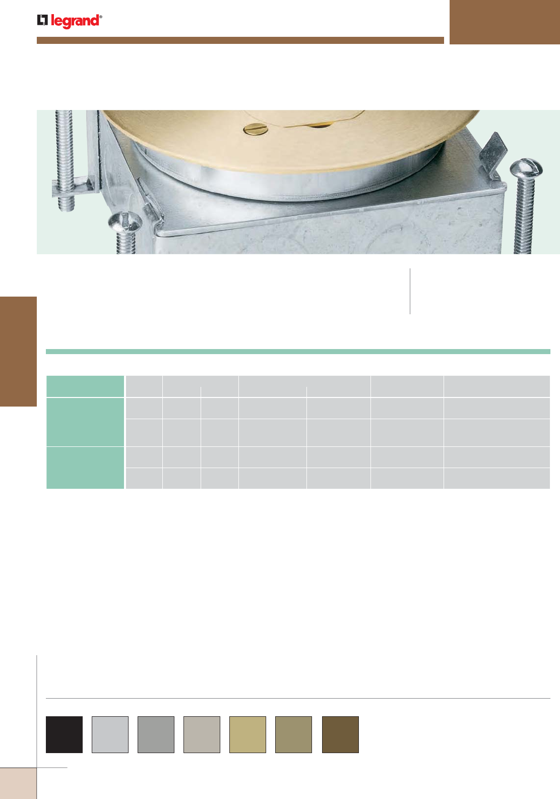
WWW.LEGRAND.US/WIREMOLD
476
FLOOR BOXES
WIREMOLD
880 Series™ Floor Boxes provide an excellent solution for low density
power or communication requirements in open space areas.
880 SERIES™ FLOOR BOXES
CODE REFERENCE
cULus Listed
Metallic Outlet Boxes:
File E2961 Guide QCIT.
880 Series™ Flanges and Cover Plates are available in
black, aluminum, gray, nickel, brass, bronze and brown.
Custom color options are also available. Consult the
factory for more information.
COLOR OPTIONS
• Can be used with all Wiremold 895/896 Series Cover Plates: brass or plastic, carpet, or tile application.
• All 880 Series Floor Boxes have 10° angular adjustment after the concrete pour.
• All 880 Series Floor Boxes can accommodate a duplex receptacle mounted flush with the floor.
CLASS CAT. NO.
DIMENSIONS ADJUSTMENT CAPACITY CUBIC IN.
[CM3]
KNOCKOUTS OR
CONDUIT OPENINGS* A B BEFORE THE POUR AFTER THE POUR
CONCRETETIGHT
STEEL
885B 4 13/16"
[122mm]
2 7/16"
[62mm]
1 3/4"
[44mm]
1/2"
[12.7mm]
29.5 in.3
[483.5cm3]
Four Sides –
Bottom –
(1)-1/2", (1)-3/4"
(2)-1/2", (2)-3/4"
886B
4 13/16"
[122mm]
2 3/4"
[70mm]
1 3/4"
[44mm]
1/2"
[12.7mm]
39 in.3
[639.2cm3]
Two Sides –
Two Sides –
Bottom –
(1)-1/2", (1)-3/4"
(1)-3/4", (1)-1"
(2)-1/2", (2)-3/4"
WATERTIGHT
CASTIRON
887B 4 13/16"
[122mm]
2 5/8"
[67mm]
2"
[51mm]
1/2"
[12.7mm]
24.7 in.3
[404.8cm3]
Two Sides –
Two Sides –
(1)-1/2"
(1)-3/4"
889B 4 13/16"
[122mm]
3 1/2"
[89mm]
2"
[51mm]
1/2"
[12.7mm]
40 in.3
[655.6cm3]
Two Sides –
Two Sides –
(1)-1"
(1)-1 1/4"
*1/2" = [12.7mm], 3/4" = [19.1mm], 1" = [25mm], 1 1/4" = [32mm].
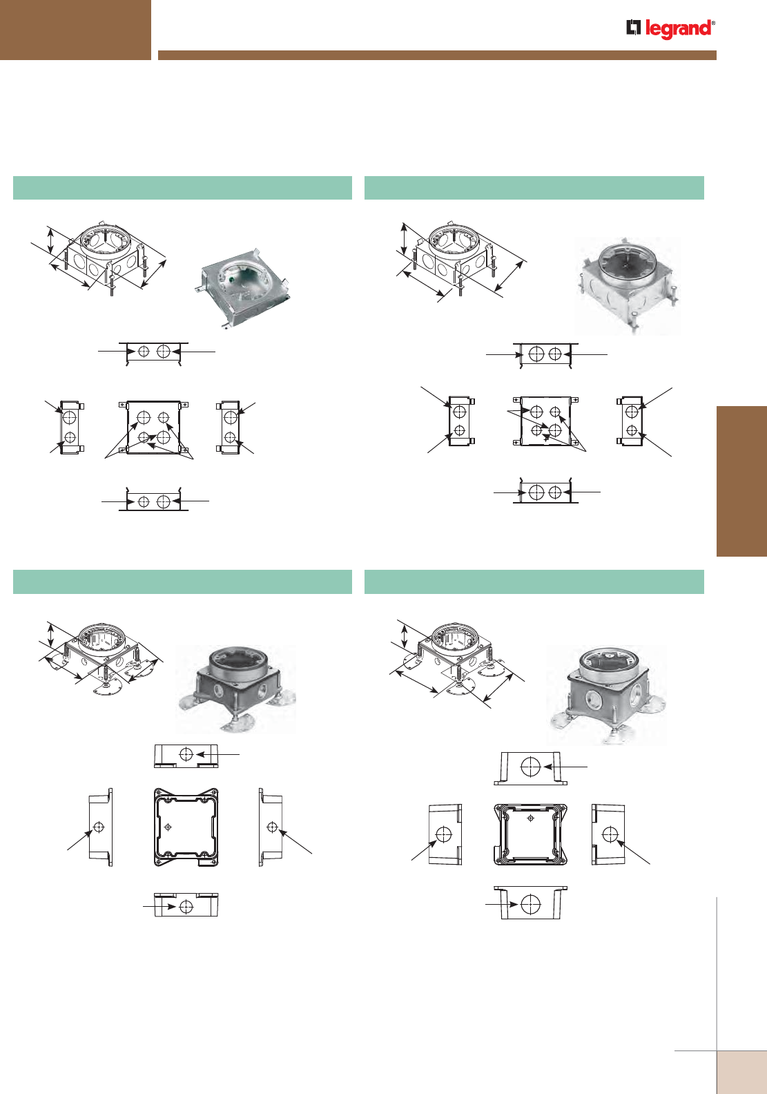
WWW.LEGRAND.US/WIREMOLD
477
FLOOR BOXES
WIREMOLD
880 SERIES™ FLOOR BOXES
Knockouts:
887B Cast-Iron Floor Box
Knockouts:
Side Side
Top
Front
1/2"
Conduit Thread
1/2"
Conduit Thread
3/4"
Conduit Thread
3/4"
Conduit Thread
Back
Knockouts:
Back
Side Side
Top
Front
3/4"
Trade Size
3/4"
Trade Size
1/2"
Trade Size
1/2"
Trade Size
1/2"
Trade Size
1/2"
Trade Size
3/4"
Trade Size
1/2"
Trade Size
3/4"
Trade Size
3/4"
Trade Size
885B Stamped Steel Floor Box
Knockouts: Back
Side Side
Top
Front
3/4"
Trade Size
3/4"
Trade Size
1/2"
Trade Size
1/2"
Trade Size
1"
Trade Size
1"
Trade Size
3/4"
Trade Size
1/2"
Trade Size
3/4"
Trade Size
1/2"
Trade Size
886B Stamped Steel Steel Floor Box
Side Side
Top
Front
1"
Conduit Thread
1"
Conduit Thread
1 1/4"
Conduit Thread
1 1/4"
Conduit Thread
Back
889B Cast-Iron Floor Box
880 Series Stamped Steel Floor Boxes Ordering Information
880 Series Cast-Iron Floor Boxes Ordering Information
Stamped steel, shallow
single-service.
Cast0iron, shallow single-
service. Cast0ironv, deep single-
service.
Stamped steel, deep single-
service.
4 3/16"
[122mm]
4 3/16"
[122mm]
2 3/4"
[122mm]
4 3/16"
[122mm]
4 3/16"
[122mm]
2 7/16"
[62mm]
2 5/8"
[67mm]
4 3/16"
[122mm]
4 3/16"
[122mm]
3 1/2"
[89mm]
4 3/16"
[122mm]
4 3/16"
[122mm]
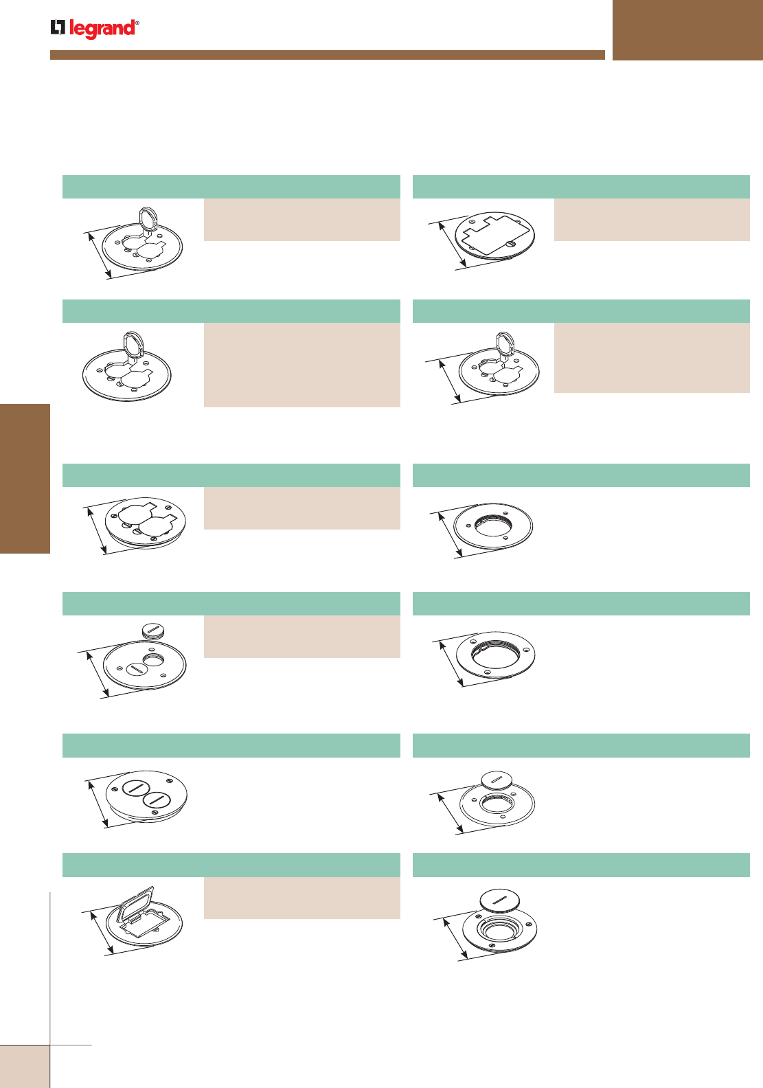
WWW.LEGRAND.US/WIREMOLD
478
FLOOR BOXES
WIREMOLD
Nonmetallic Duplex Power Plate
PART NUMBERS:
895P-BLK (Black)
895P-BRN (Brown)
895P-BRZ (Bronze)
895P-AL (Brass)
Aluminum Duplex Cover Plate
PART NUMBERS:
895TCAL-BK (Black)
895TCAL-GY (Gray)
895TCAL-NK (Nickel)
895TCAL-BS (Brass)
895TCAL-BZ (Bronze)
GFI Receptacle Cover Plate
PART NUMBERS:
895TGFI (Bronze)
895TGFIAL (Brushed Aluminum)
880 SERIES™ FLOOR BOXES
4 1/4"
[108mm]
895TSP Cover Plate With Two Screw Plug Openings
Brass cover plate with two 1 1/2"
[38mm] screw plug openings, 4 1/4"
[108mm] for tile.
GFI Receptacle Cover Plate
PART NUMBERS:
895GFI (Brass)
895SGFICAL (Brushed Aluminum)
5 1/2"
[140mm] GFI receptacle cover plate, 5 1/2"
[140mm] for carpet.
4 1/4"
[108mm] GFI receptacle cover plate, 4 1/4"
[108mm] for tile.
4 1/4"
[108mm]
896T Communications or Power Cover Plate
Brass communications or power
cover plate with 2 5/8" [67mm]
threaded opening for tile. Sold
without abandon plug.
5 1/2"
[140mm]
896CK Communications or Power Cover Plate
Brass communications or power
cover plate with 2 1/4" [57mm]
threaded opening for carpet.
880 Series Floor Box Cover Plates Ordering Information
4 1/4"
[108mm] Duplex cover plate with flip lids,
4 1/4" [108mm] for tile.
5 1/2"
[140mm] Duplex cover plate with flip lids,
5 1/2" [140mm] for carpet.
With flip lids, 5 1/2" [140mm]
diameter for carpet.
5 1/2"
[140mm]
Polycarbonate duplex cover plate
with flip lids for carpet.
5 1/2"
[140mm]
Brass communication or power
cover plate with 2 5/8" [67mm]
threaded opening for carpet. Sold
without abandon plug.
896 Communication or Power Cover Plate
Duplex Cover Plate with Flip Lid
PART NUMBERS:
895 (Brass)
895TCAL (Brushed Aluminum)
Aluminum Duplex Power Plate
PART NUMBERS:
895TGFI (Brass)
895TGFIAL (Brushed Aluminum)
Duplex Cover Plate with Flip Lids
PART NUMBERS:
895T (Brass)
895TAL (Brushed Aluminum)
5 1/2"
[140mm] Cover plate with two 1 1/2" [38mm]
screw plug openings, 5 1/2"
[140mm] for carpet.
Cover Plate With Two Screw Plug Openings
PART NUMBERS:
895SP (Brass)
895SPAL (Brushed Aluminum)
4 1/4"
[108mm]
896TCK Communications or Power Cover Plate
Brass communications or power
cover plate with 2 1/4" [57mm]
threaded opening for tile.
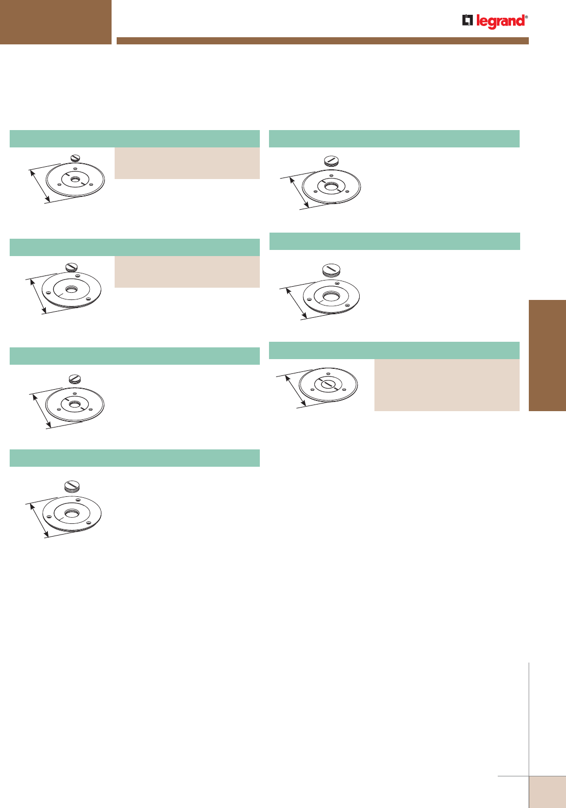
WWW.LEGRAND.US/WIREMOLD
479
FLOOR BOXES
WIREMOLD
880 SERIES™ FLOOR BOXES
4 1/4"
[108mm]
896TCK-3/4 Communications or Power Cover Plate
Brass cover plate with 3/4"
[19.1mm] threaded opening for tile.
5 1/2"
[140mm]
896CK-1 Communications or Power Cover Plate
Brass cover plate with 1" [25mm]
threaded opening for carpet.
4 1/4"
[108mm]
896TCK-1 Communications or Power Cover Plate
Brass cover plate with 1" [25mm]
threaded opening for tile.
880 Series Floor Box Cover Plates Ordering Information (continued)
5 1/2"
[140mm] Cover plate with 1/2" [12.7mm]
threaded opening 5 1/2" [140mm]
for carpet.
4 1/4"
[108mm] Cover plate with 1/2" [12.7mm]
threaded opening, 4 1/4" [108mm]
for tile.
5 1/2"
[140mm]
896CK-3/4 Communications or Power Cover Plate
Brass cover plate with 3/4"
[19.1mm] threaded opening
for carpet.
5 1/2"
[140mm]
Polycarbonate communications or
power cover plate. Includes one
plug with 3/4" [19mm] opening,
one plug with 1" [25mm] opening,
and one plug with 2 5/8" [67mm]
opening. For pass-through only.
Communications or Power Cover Plate
PART NUMBERS:
896PCK-BLK (Black)
896PCK-BRN (Brown)
896PCK-BRZ (Bronze)
896PCK-AL (Aluminum)
Communications or Power Cover Plate
PART NUMBERS:
896CK-1/2 (Brass)
896CKAL-1/2 (Brushed Aluminum)
Communications or Power Cover Plate
PART NUMBERS:
896TCK-1/2 (Brass)
896TCKAL-1/2 (Brushed Aluminum)
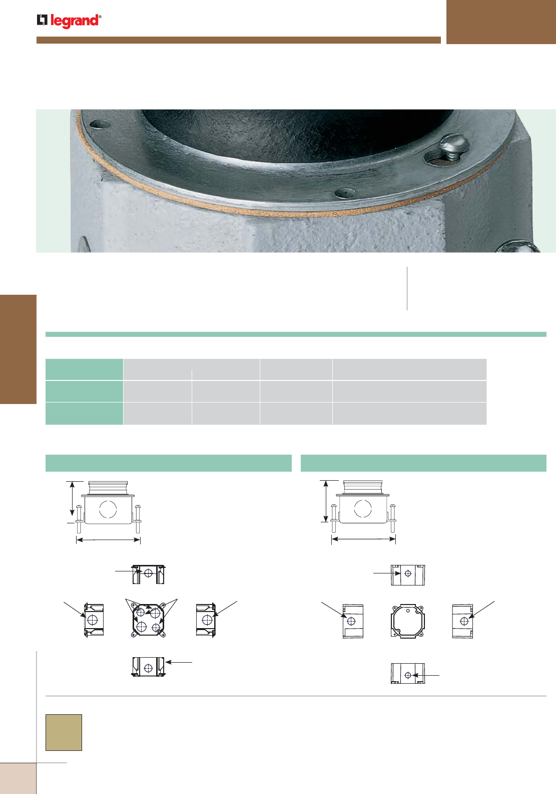
WWW.LEGRAND.US/WIREMOLD
480
FLOOR BOXES
WIREMOLD
800 Series™ Semi-Adjustable Floor Boxes provide an economical solution for
low density power or communication services in open space areas.
800 SERIES™ FLOOR BOXES
CODE REFERENCE
cULus Listed
Metallic Outlet Boxes:
File E2961 Guide QCIT.
800 Series™ Conversion Kits are
available in these colors.
COLOR OPTIONS
Adjustable before and after
the concrete pour. Sold less
conversion kit.
Adjustable before and after
the concrete pour. Sold less
conversion kit.
3 3/8"
[86mm]
4 3/16"
[106mm]
Back
Side Side
Top
Front
3/4"
Conduit Thread
3/4"
Conduit Thread
1/2"
Conduit Thread
1/2"
Conduit Thread
Knockouts:
CAT. NO.
ADJUSTMENT CAPACITY CUBIC IN.
[CM3]
KNOCKOUTS OR
CONDUIT OPENINGSBEFORE THE POUR AFTER THE POUR
800LCK 2 3/4" vertical
[70mm]
1/2" vertical
[12.7mm]
23.6 cu. in.
[357ml3]
Sides –
Bottom –
(2)-1/2" [12.7mm]; (2)-3/4" [19.1mm]
(2)-1/2" [12.7mm]; (2)-3/4" [19.1mm]
800CILCK 2 3/4" vertical
[70mm]
1/2" vertical
[12.7mm]
28.3 cu. in.
[463ml3]
Sides – (2)-1/2" [12.7mm] and
(2)-3/4" [19.1mm] threaded
800LCK Steel Floor Box 800CILCK Cast-Iron Floor Box
3"
[76mm]
4 3/16"
[106mm]
800 Series Floor Boxes Technical Specifications
Back
Side Side
Top
Front
3/4"
Trade Size
3/4"
Trade Size
1/2"
Trade Size
3/4"
Trade Size
1/2"
Trade Size
Knockouts:
1/2"
Trade Size
800 Series Semi-Adjustable Floor Boxes Ordering Information
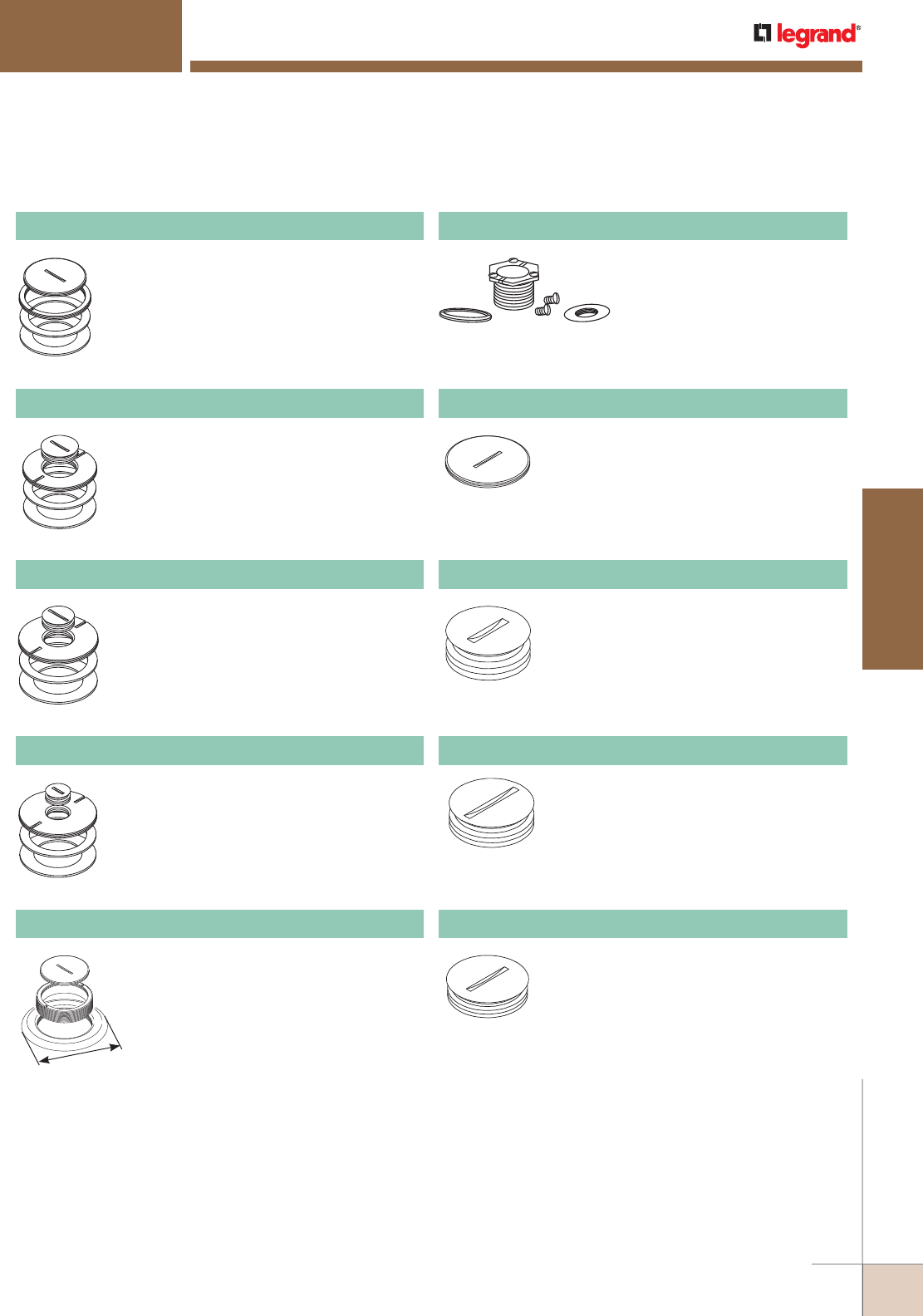
WWW.LEGRAND.US/WIREMOLD
481
FLOOR BOXES
WIREMOLD
800 SERIES™ FLOOR BOXES
Brass conversion kit which includes one
825A – 2 1/4" [57mm] diameter plug, one
825C, one 825L, and one 825N. For carpet or
tile installations.
825CK Conversion Kit
Brass conversion kit which includes one
825A-1 – 1" [25mm] diameter plug, one
825C-1, one 825L, and one 825N.For carpet
or tile installations.
825CK-1 Conversion Kit
Brass conversion kit which includes one
825A-3/4 – 3/4" [19.1mm] diameter plug,
one 825C-3/4, one 825L, and one 825N. For
carpet or tile installations.
825CK-3/4 Conversion Kit
Brass conversion kit which includes one
825A-1/2 – 1/2" [12.7mm] diameter plug,
one 825C-1/2, one 825L, and one 825N. For
carpet or tile installations.
825CK-1/2 Conversion Kit
4"
[102mm]
Includes the 825A. Total diameter is 2 5/8"
[67mm].
825CP Brass Carpet Plate Assembly
Conversion kit to fit 525 Series
service fitting on 800 Series
Boxes. Includes one 825C, one
825P-1, and one 1124L-1. For
carpet or tile installations.
825SFCK Conversion Kit
2 1/4" [57mm] diameter brass abandon plug.
Thread size is pipe thread size.
825A Abandon Plug
1/2" [12.7mm] diameter brass abandon plug.
Thread size is pipe thread size.
825A-1/2 Abandon Plug
3/4" [19.1mm] diameter brass abandon plug.
Thread size is pipe thread size.
825A-3/4 Abandon Plug
1" [25mm] diameter brass abandon plug.
Thread size is pipe thread size.
825A-1 Abandon Plug
800 Series Floor Box Conversion Kits Ordering Information
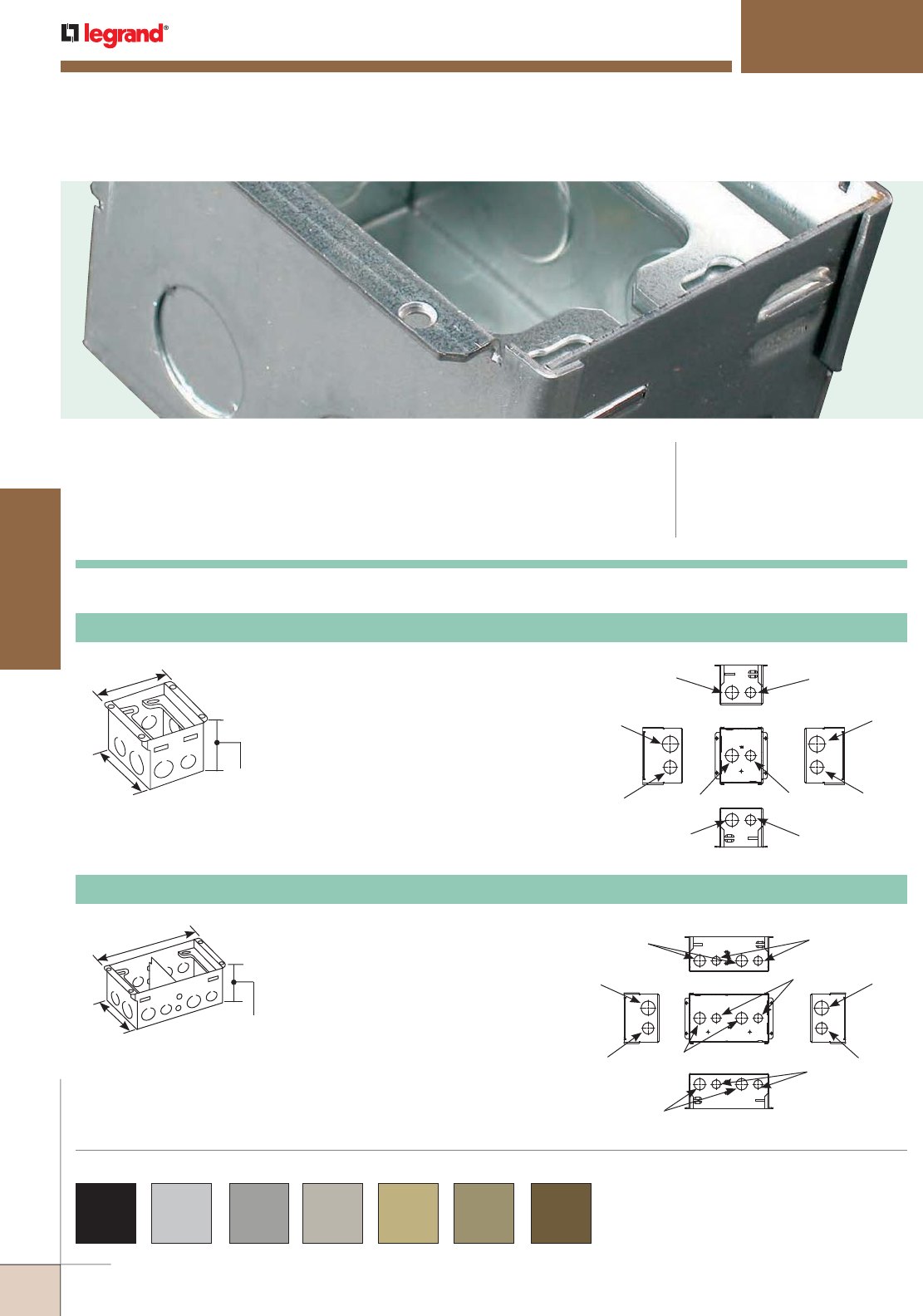
WWW.LEGRAND.US/WIREMOLD
482
FLOOR BOXES
WIREMOLD
880W Series™ Flanges and Cover Plates are available in
black, aluminum, gray, nickel, brass, bronze and brown.
Custom color options are also available. Consult the
factory for more information.
COLOR OPTIONS
880W Series™ Floor Boxes provide an excellent solution for wood floor
applications when both power and communication services are required
in open space areas.
880W SERIES™ FLOOR BOXES
CODE REFERENCE
cULus Listed
Metallic Outlet Boxes:
File E2961 Guide QCIT.
Meets Article 300.22(c) of NEC.
Back
Side Side
Top
Front
1"
Trade Size
3/4"
Trade Size
1/2"
Trade Size
3/4"
Trade Size
1/2"
Trade Size
1/2"
Trade Size
3/4"
Trade Size
1"
Trade Size
3/4"
Trade Size
3/4"
Trade Size
Knockouts:
3 3/4"
[95mm]
4 13/16"
[122mm]
3 7/16"
[87mm]
880W1 One-Gang Steel Floor Box for Wood Floors
Knockouts: Back
Side Side
Top
Front
1"
Trade Size
3/4"
Trade Size
1/2"
Trade Size
3/4"
Trade Size
1/2"
Trade Size
1/2"
Trade Size
3/4"
Trade Size
1"
Trade Size
3/4"
Trade Size
3/4"
Trade Size
7 7/8"
[200mm]
4 15/16"
[125mm]
3 7/16"
[87mm]
880W2 Two-Gang Steel Floor Box for Wood Floors
880W Series Floor Boxes Ordering Information
Knockouts for three (3) 1/2"
[12.7mm], five (5) 3/4"
[19.1mm], and two (2) 1"
[25mm] conduits. 53 cu. in.
[869ml] of capacity.
Knockouts for six (6) 1/2"
[12.7mm], eight (8) 3/4"
[19.1mm], and two (2) 1"
[25mm] conduits. 58 cu. in.
[951ml] of capacity in one
compartment. 59 cu. in.
[967ml] of capacity in second
compartment. Barrier is
removable for greater capacity
if needed.
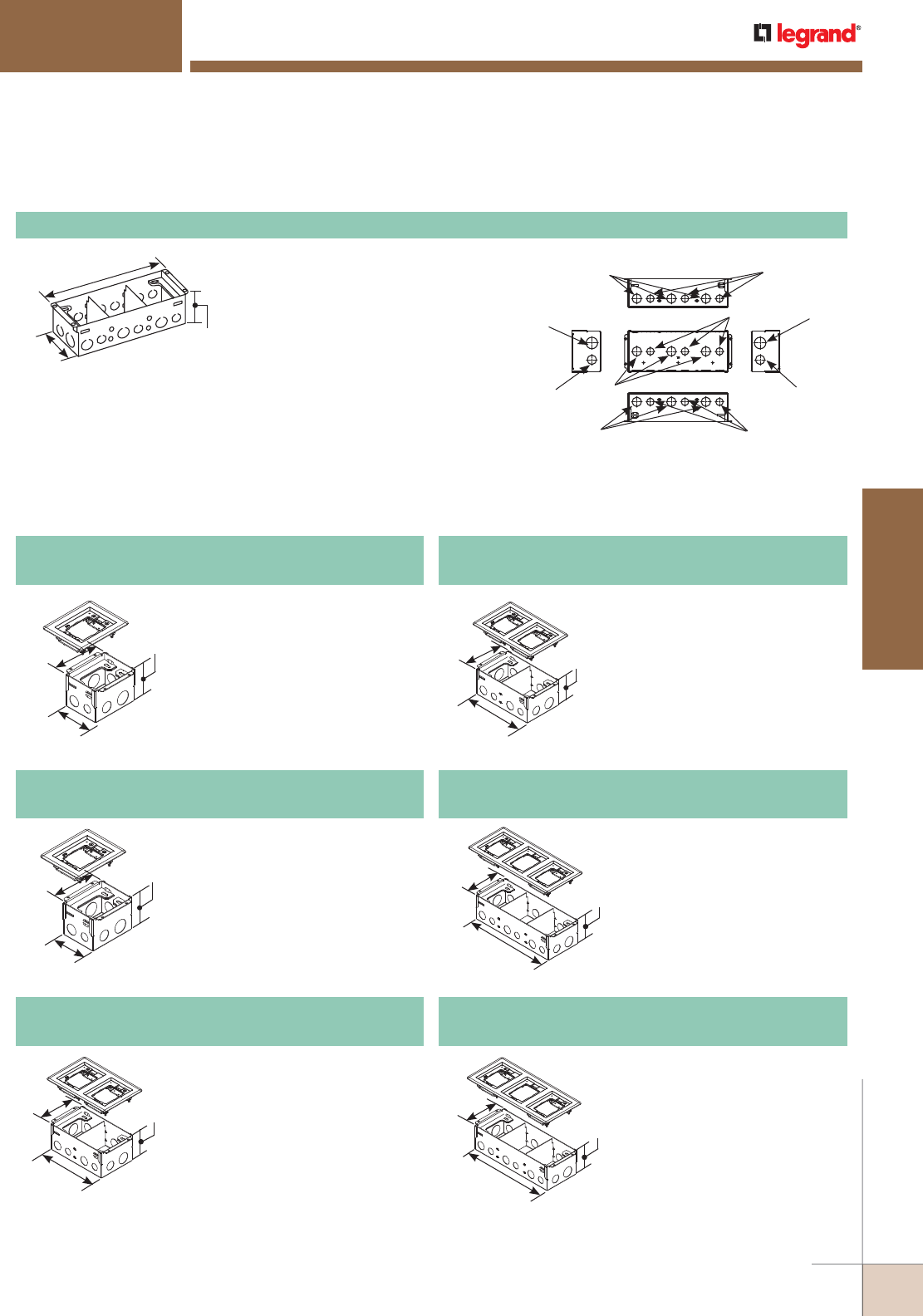
WWW.LEGRAND.US/WIREMOLD
483
FLOOR BOXES
WIREMOLD
880W SERIES™ FLOOR BOXES
Back
Side Side
Top
Front
1"
Trade Size
3/4"
Trade Size
1/2"
Trade Size
3/4"
Trade Size
1/2"
Trade Size
1/2"
Trade Size
3/4"
Trade Size
1"
Trade Size
3/4"
Trade Size
3/4"
Trade Size
Knockouts:
880W3 Three-Gang Steel Floor Box for Wood Floors
12"
[305mm]
4 15/16"
[125mm]
3 7/16"
[87mm]
Knockouts for nine (9) 1/2"
[12.7mm], eleven (11) 3/4"
[19.1mm], and two (2) 1"
[25mm] conduits. 56 cu. in.
[918ml] of capacity in each of
the outside compartments.
68 cu. in. [1115ml] of
capacity in center
compartment. Barrier is
removable for greater
capacity if needed.
4 15/16"
[125mm]
12"
[305mm]
3 7 1/6"
[87mm]
4 15/16"
[125mm]
7 7/8"
[200mm]
3 7 1/6"
[87mm]
4 15/16"
[125mm]
3 3/4"
[95mm]
3 7/16"
[87mm]
4 15/16"
[125mm]
3 3/4"
[95mm]
3 7/16"
[87mm]
880W1 Floor Box with 817B brass
flange included. Flange can be
used for tile or carpet applications.
NOTE: Order cover separately.
880W1817B
One-Gang Steel Floor Box for Wood Floors
880W1 Floor Box with 818TCAL
brushed aluminum flange
included. Flange can be used for
tile or carpet applications.
NOTE: Order cover separately.
880W1818TCAL
One-Gang Steel Floor Box for Wood Floors
880W2 Floor Box with 828TCAL
brushed aluminum flange
included. Flange can be used for
tile or carpet applications.
NOTE: Order cover separately.
880W2828TCAL
Two-Gang Steel Floor Box for Wood Floors
880W3 Floor Box with 837B
brass flange included. Flange
can be used for tile or carpet
applications.
NOTE: Order cover separately.
880W3837B
Three-Gang Steel Floor Box for Wood Floors
880W Series Floor Box Kits Ordering Information
4 15/16"
[125mm]
7 7/8"
[200mm]
3 7 1/6"
[87mm]
4 15/16"
[125mm]
12"
[305mm]
3 7 1/6"
[87mm]
880W2 Floor Box with 827B brass
flange included. Flange can be
used for tile or carpet applications.
NOTE: Order cover separately.
880W2827B
Two-Gang Steel Floor Box for Wood Floors
880W3 Floor Box with 838TCAL
brushed aluminum flange
included. Flange can be used for
tile or carpet applications.
NOTE: Order cover separately.
880W3838TCAL
Three-Gang Steel Floor Box for Wood Floors
880W Series Floor Boxes Ordering Information (continued)
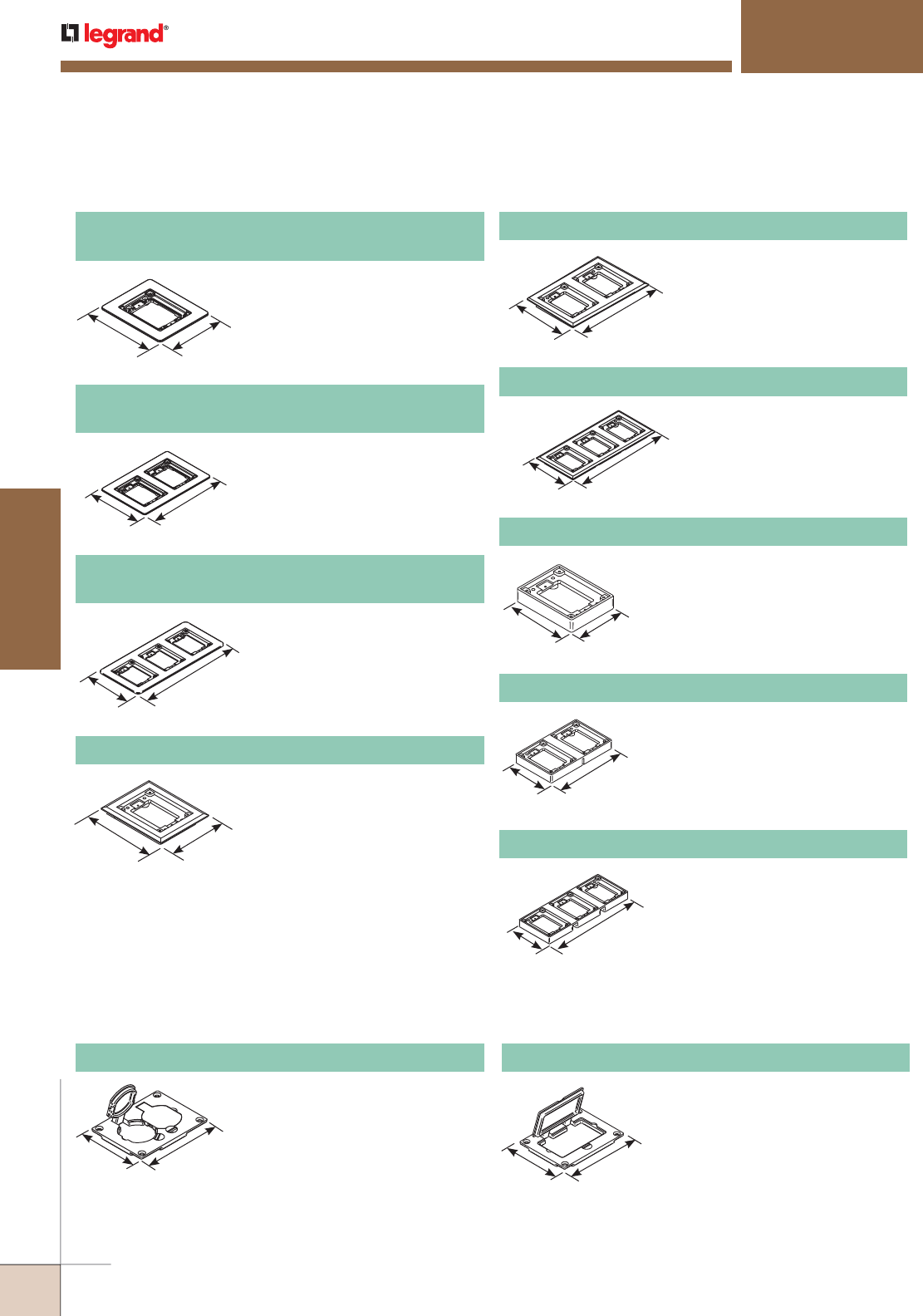
WWW.LEGRAND.US/WIREMOLD
484
FLOOR BOXES
WIREMOLD
880W SERIES™ FLOOR BOXES
880W Series Floor Boxes Solid Brass Cover Plate Flanges Ordering Information
880W Series Floor Boxes Metal Cover Plates Ordering Information
828R Brass Duplex Cover Plate
Flip lids. Can also be used with a
106 type communication adapter.
3 1/8"
[80.2mm]
4 3/16"
[106.2mm]
828GFITC Brass GFI Cover Plate
May be used with Activate and
Ortronics® Connectivity Systems in
conjunction with 817B, 827B, and
837B Flanges.v
3 1/8"
[80.2mm]
4 3/16"
[106.2mm]
NOTE: UL Listed for tile, terrazzo, and carpet floors.Brass covers and flanges are not interchangeable with aluminum or nonmetallic covers and flanges.
Nonmetallic covers are interchangeable with aluminum flanges.
5 3/4"
[146mm] 4 3/4"
[121mm]
817C One-Gang Brass Carpet Flange
For use on 880S1, 880M1,
880CS1-1, and 880CM1-1
Floor Boxes.
5 3/4"
[146mm]
8 7/8"
[225mm]
827C Two-Gang Brass Carpet Flange
For use on 880S2, 880M2,
880CS2-1, and 880CM2-1
Floor Boxes.
5 3/4"
[146mm]
13"
[330mm]
837C Three-Gang Brass Carpet Flange
For use on 880S3, 880M3,
880CS32-1, and 880CM3-1
Floor Boxes.
4 1/2"
[107mm]
3 1/2"
[88.4mm]
817T One-Gang Brass Tile Flange
For use on 880S1, 880M1,
880CS1-1, and 880CM1-1
Floor Boxes.
4 1/2"
[114.9mm]
7 5/8"
[193.7mm]
827T Two-Gang Brass Tile Flange
For use on 880S2, 880M2,
880CS2-1, and 880CM2-1
Floor Boxes.
4 1/2"
[114mm]
11 3/4"
[298mm]
837T Three-Gang Brass Tile Flange
For use on 880S3, 880M3,
880CS3-1, and 880CM3-1
Floor Boxes.
827B Two-Gang Brass Combination Carpet and
Tile Flange
Accepts Ortronics® MAB6TJ
TracJack and MAB3S2 Series II
adapters and Wiremold CM Series
inserts, sold separately.
6 1/16"
[154.4mm]
9 1/16"
[228.6mm]
817B One-Gang Brass Combination Carpet and
Tile Flange
Accepts Ortronics® MAB6TJ
TracJack and MAB3S2 Series II
adapters and Wiremold CM Series
inserts, sold separately.
6 1/16"
[154.4mm]
5 1/16"
[128.5mm]
837B Three-Gang Brass Combination Carpet and
Tile Flange
Accepts Ortronics® MAB6TJ
TracJack and MAB3S2 Series II
adapters and Wiremold CM Series
inserts, sold separately.
6 1/16"
[154.4mm]
13 1/16"
[338mm]
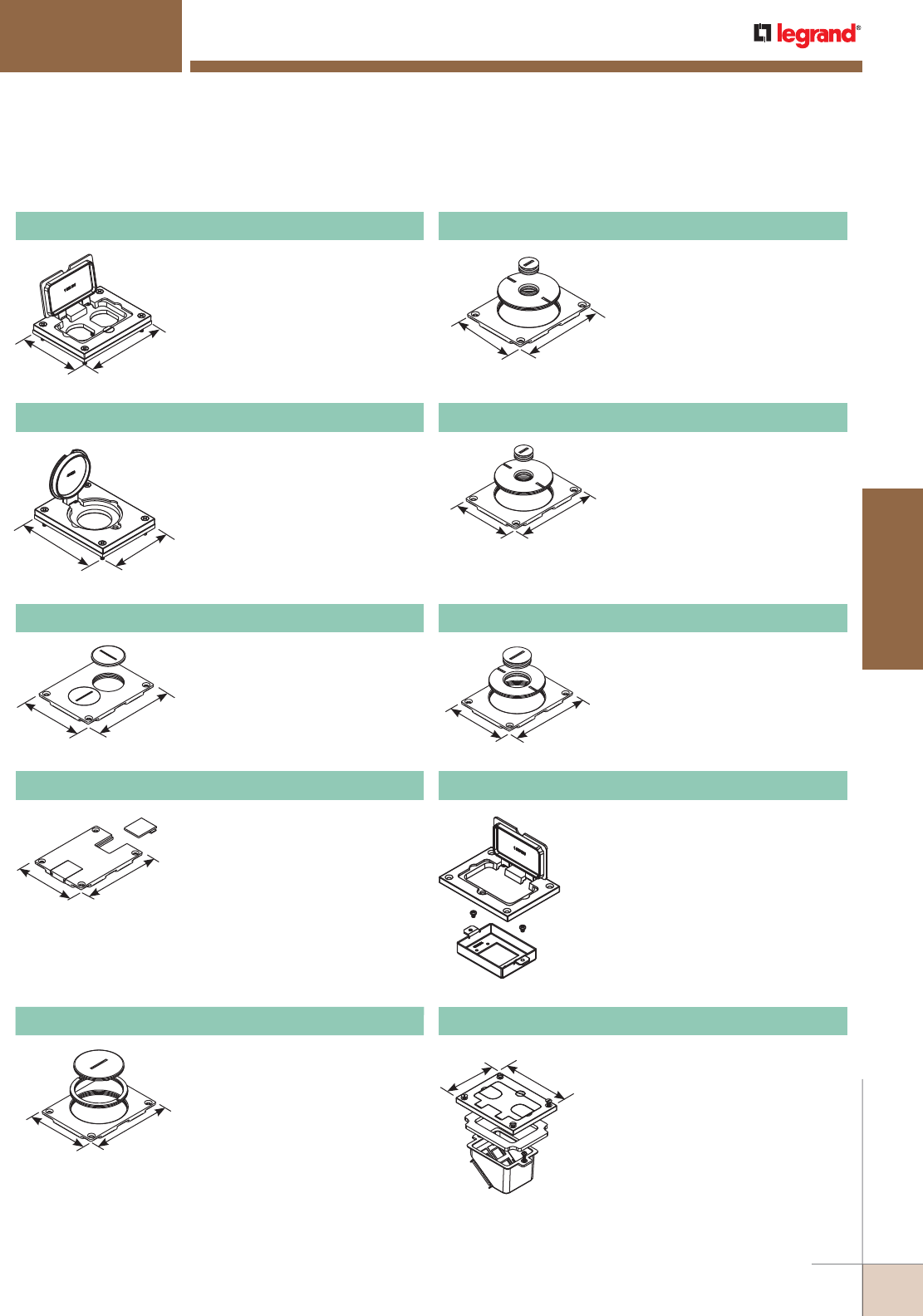
WWW.LEGRAND.US/WIREMOLD
485
FLOOR BOXES
WIREMOLD
880W Series Floor Boxes Metal Cover Plates Ordering Information (continued)
880W SERIES™ FLOOR BOXES
828DPGFITC Brass Rectangular Cover Plate
Allows for mounting of a duplex style
receptacle with a rectangular style
flip lid cover.
4 3/16"
[106.2mm]
3 1/8"
[80.2mm]
3 1/8"
[79mm]
4 1/8"
[105mm]
Screw plugs are 1 1/2" [38mm] in
diameter.
828SPTC Brass Duplex Cover Plate
3 1/8"
[79mm]
4 1/8"
[105mm]
Data slides. Feed through only,
not for use with a mounting plate
for flush mounted communication
adapter.
829STC Brass Communication Cover Plate
3 1/8"
[80.2mm]
4 3/16"
[106.2mm]
2 5/8" and 2 1/4" [67mm and
57mm] plugs.
829CK Brass Communication Cover Plate
3 1/8"
[80.2mm]
4 3/16"
[106.2mm]
2 5/8" and 1" [67mm and 25mm]
plugs.
829CK-1 Brass Communication Cover Plate
3 1/8"
[83.60mm]
4 3/16"
[106.2mm]
2 5/8" and 1/2" [67mm and
12.7mm] plugs. For carpet or tile
installations.
829CK-1/2 Brass Communication Cover Plate
3 1/8"
[80.2mm]
4 3/16"
[106.2mm]
2 5/8" and 3/4" [67mm and
19.1mm] plugs.
829CK-3/4 Brass Communication Cover Plate
828MAAP AV Adapter Plate
Sheet metal adapter plate that accepts
two (2) Wiremold AVIP or Extron®
Electronics MAAP style device plates,
sold separately. For use with 828GFITC
or 828GFITCAL cover plates, sold
separately.
NOTE: UL Listed for tile, terrazzo, and carpet floors.Brass covers and
flanges are not interchangeable with aluminum or nonmetallic
covers and flanges. Nonmetallic covers are interchangeable with
aluminum flanges.
828DLR Brass Single Locking Receptacle Cover Plate
Single flip lid cover for 20A or 30A
single locking receptacles. Device
opening is 2 5/8" [67mm]. For use
with maximum female locking
device of 1.58" diameter, and
maximum male plug face of
2.25" diameter.
4 3/16"
[106.2mm]
3 1/8"
[80.2mm]
828COMTC Brass Communication Cover Plate
Allows for up to four communication
devices to be mounted in a recessed
position within the 880 Floor Box. The
828COM Cover Plate has removable
slides for cable egress.
NOTE: For use with 880S and 880CS Series
Boxes only.
3 1/8"
[80.2mm] 4 3/16"
[106.2mm]
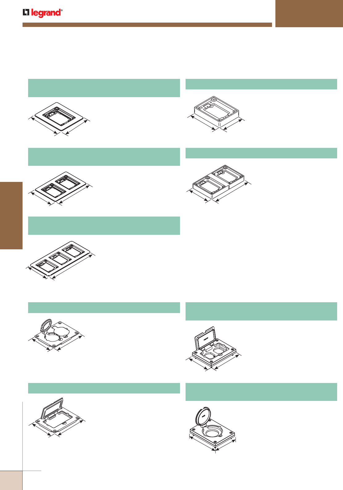
WWW.LEGRAND.US/WIREMOLD
486
FLOOR BOXES
WIREMOLD
880W SERIES™ FLOOR BOXES
880W Series Floor Boxes Metal Cover Plates Ordering Information
818TCAL One-Gang Brushed Aluminum
Combination Carpet and Tile Flange
Accepts Ortronics® MAB6TJ
TracJack and MAB3S2 Series
II adapters and Wiremold CM
Series inserts, sold separately.
NOTE: Brushed Aluminum flanges come
with beveled edges.
828TCAL Two-Gang Brushed Aluminum
Combination Carpet and Tile Flange
Accepts Ortronics® MAB6TJ
TracJack and MAB3S2 Series
II adapters and Wiremold CM
Series inserts, sold separately.
NOTE: Brushed Aluminum flanges come
with beveled edge
838TCAL Three-Gang Brushed Aluminum
Combination Carpet and Tile Flange
Accepts Ortronics® MAB6TJ
TracJack and MAB3S2 Series
II adapters and Wiremold CM
Series inserts, sold separately.
NOTE: Brushed Aluminum flanges come
with beveled edge
880W Series Floor Boxes Brushed Aluminum Cover Plate Flanges Ordering Information
818TAL One-Gang Brushed Aluminum Tile Flange
For use on 880S1, 880M1,
880CS1-1, and 880M1-1
Floor Boxes.
828TAL Two-Gang Brushed Aluminum Tile Flange
For use on 880S2, 880M2,
880CS2-1, and 880CM2-1
Floor Boxes.
828R-TCAL Brushed Aluminum Duplex Cover Plate
Flip lids. Can also be used with a
106 type communication adapter.
828GFITCAL Brushed Aluminum GFI Cover Plate
May be used with Activate and
Ortronics® Connectivity Systems in
conjunction with 817B, 827B, and
837B Flanges.
828DPGFITCAL
Brushed Aluminum Rectangular Cover Plate
Allows for mounting of a duplex
style receptacle with a rectangular
style flip lid cover.
828DLRAL Brushed Aluminum Single Locking
Receptacle Cover Plate
Single flip lid cover for 20A or 30A
single locking receptacles. Device
opening is 2 5/8" [67mm]. For use
with maximum female locking
device of 1.58" diameter, and
maximum male plug face of
2.25" diameter.
NOTE: UL Listed for tile, terrazzo, and carpet floors.
Brass covers and flanges are not interchangeable with aluminum
or nonmetallic covers and flanges. Nonmetallic covers are
interchangeable with aluminum flanges.
5"
[127mm]
6"
[152.4mm]
9"
[228.6mm]
6"
[152.4mm]
13 3/16"
[335mm]
4 1/2"
[114mm] 3 1/2"
[89mm]
4 1/2"
[114mm]
7 5/8"
[194mm]
3 1/4"
[83mm]
4 5/16"
[110mm]
3 1/4"
[83mm]
4 5/16"
[110mm]
3 1/4"
[83mm]
4 5/16"
[110mm]
3 1/4"
[83mm]
4 5/16"
[110mm]
6"
[152.4mm]
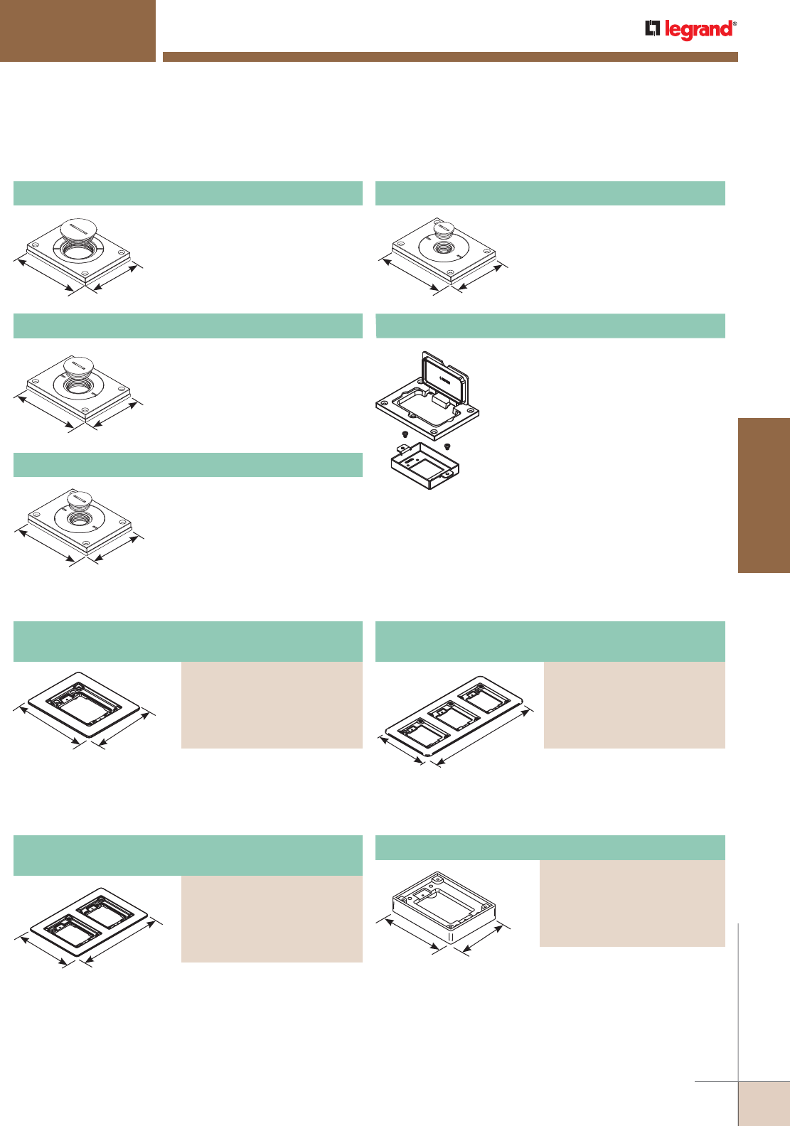
WWW.LEGRAND.US/WIREMOLD
487
FLOOR BOXES
WIREMOLD
880W SERIES™ FLOOR BOXES
880W Series Floor Boxes Metal Cover Plates Ordering Information (continued)
830CKTCAL Brushed Aluminum Cover Plate
Power or communication plate
with 2" [51mm] and 1 1/4" [32mm]
plugs.
NOTE: Acceptable for use with threaded
conduit when passing through
power cables.
830CKTCAL-1 Brushed Aluminum Cover Plate
Power or communication plate with
2" [51mm] and 1" [25mm] plugs.
NOTE: Acceptable for use with threaded
conduit when passing through p
ower cables.
828MAAP AV Adapter Plate
Sheet metal adapter plate that accepts
two (2) Wiremold AVIP or Extron®
Electronics MAAP style device plates,
sold separately. For use with 828GFITC
or 828GFITCAL cover plates, sold
separately.
830CKTCAL-3/4 Brushed Aluminum Cover Plate
Power or communication plate
with 2" [51mm] and 3/4" [19.1mm]
plugs.
NOTE: Acceptable for use with threaded
conduit when passing through
power cables.
830CKTCAL-1/2 Brushed Aluminum Cover Plate
Power or communication plate
with 2" [51mm] and 1/2" [12.7mm]
plugs.
NOTE: Acceptable for use with threaded
conduit when passing through
power cables.
NOTE: UL Listed for tile, terrazzo, and carpet floors.
Brass covers and flanges are not interchangeable with aluminum or nonmetallic covers and flanges.
Nonmetallic covers are interchangeable with aluminum flanges.
880W Series Floor Boxes Powder-Coated Aluminum Cover Plate Flanges Ordering Information
4 5/16"
[109.5mm]
3 3/16"
[83.6mm]
3 1/4"
[83mm]
4 5/16"
[109.5mm]
3 1/4"
[83mm]
Three-Gang Powder-Coated Aluminum
Combination Carpet and Tile Flange
PART NUMBERS:
837TCAL-BK (Black)
837TCAL-GY (Gray)
837TCAL-NK (Nickel)
837TCAL-BS (Brass)
837TCAL-BZ (Bronze)
One-Gang Powder-Coated Aluminum
Combination Carpet and Tile Flange
PART NUMBERS:
817TCAL-BK (Black)
817TCAL-GY (Gray)
817TCAL-NK (Nickel)
817TCAL-BS (Brass)
817TCAL-BZ (Bronze)
Accepts Ortronics® MAB6TJ
TracJack and MAB3S2 Series II
adapters and Wiremold CM
Series inserts, sold separately.
Two-Gang Powder-Coated Aluminum
Combination Carpet and Tile Flange
PART NUMBERS:
827TCAL-BK (Black)
827TCAL-GY (Gray)
827TCAL-NK (Nickel)
827TCAL-BS (Brass)
827TCAL-BZ (Bronze)
Accepts Ortronics® MAB6TJ
TracJack and MAB3S2 Series II
adapters and Wiremold CM
Series inserts, sold separately.
Accepts Ortronics® MAB6TJ
TracJack and MAB3S2 Series II
adapters and Wiremold CM
Series inserts, sold separately.
For use on 880S1, 880M1,
880CS1-1, and 880M1-1
Floor Boxes.
One-Gang Powder-Coated Aluminum Tile Flange
PART NUMBERS:
817TAL-BK (Black)
817TAL-GY (Gray)
817TAL-NK (Nickel)
817TAL-BS (Brass)
817TAL-BZ (Bronze)
4 1/2"
[114mm] 3 1/2"
[89mm]
6"
[152.4mm] 5"
[127mm]
6"
[157.4mm]
9"
[228.6mm]
6"
[152.4mm]
13 3/16"
[335mm]
4 5/16"
[109.5mm]
3 3/16"
[83.6mm]
4 5/16"
[109.5mm]
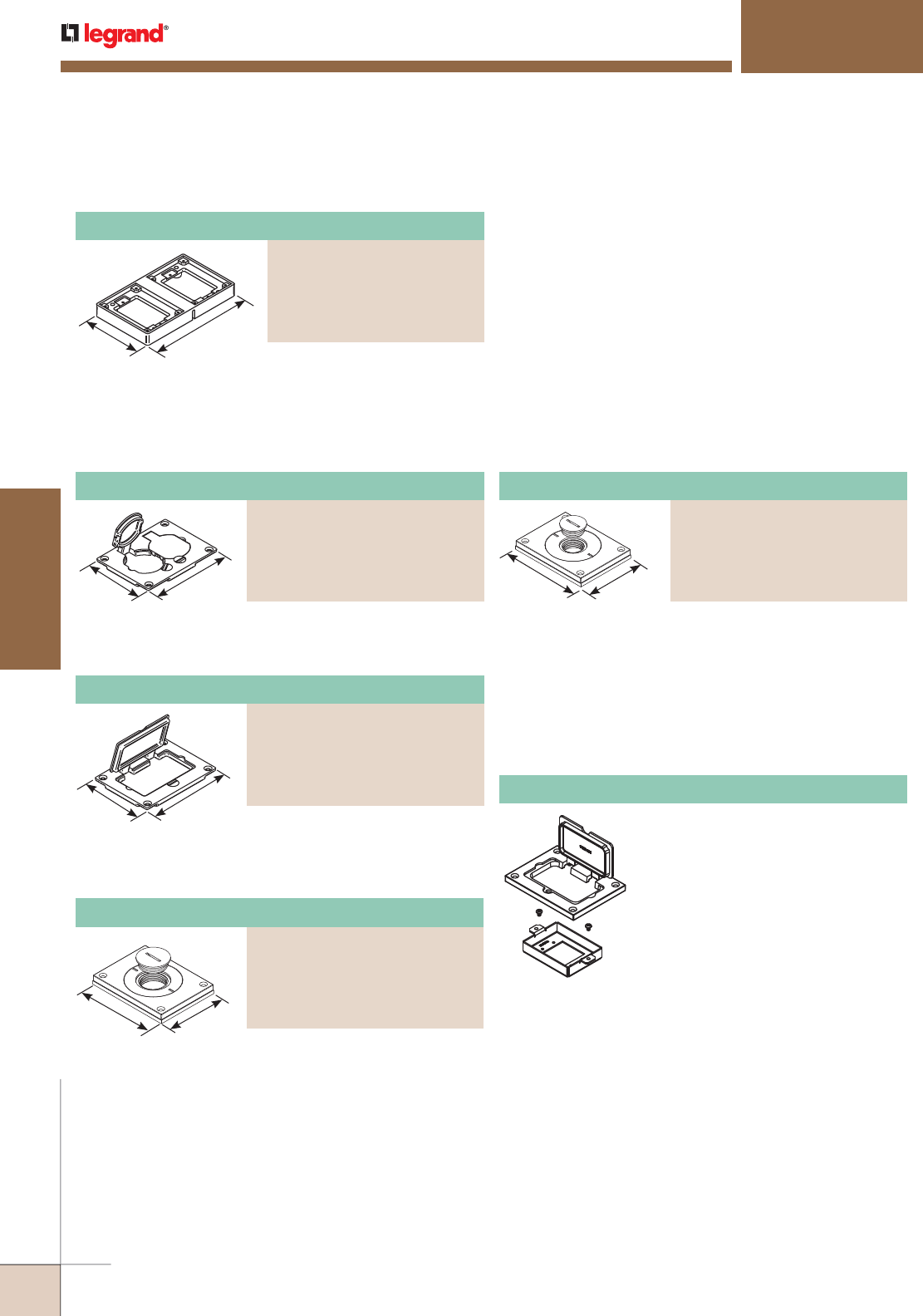
WWW.LEGRAND.US/WIREMOLD
488
FLOOR BOXES
WIREMOLD
880W SERIES™ FLOOR BOXES
880W Series Floor Boxes Powder-Coated Aluminum Cover Plate Flanges Ordering Information (continued)
Powder-Coated Aluminum Duplex Cover Plate
PART NUMBERS:
828R-TCAL-BK (Black)
828R-TCAL-GY (Gray)
828R-TCAL-NK (Nickel)
828R-TCAL-BS (Brass)
828R-TCAL-BZ (Bronze)
Flip lids. Can also be used with a
106 type communication adapter.
Allows for mounting a duplex
receptacle (Decorator or GFCI
style) with a rectangular flip cover.
Power or communication plate
with 2" [51mm] and 1" [25mm]
plugs.
NOTE: Acceptable for use with threaded
conduit when passing through
power cables.
Power or communication plate
with 2" [51mm] and 3/4" [19.1mm]
plugs. Covers are available in five
decorative colors: black, gray,
brass, nickel and bronze.
NOTE: Acceptable for use with threaded
conduit when passing through
power cables.
3 1/4"
[83mm]
4 5/16"
[109mm]
828MAAP AV Adapter Plate
Sheet metal adapter plate that
accepts two (2) Wiremold AVIP or
Extron® Electronics MAAP style
device plates, sold separately. For
use with 828GFITC or 828GFITCAL
cover plates, sold separately.
880W Series Floor Boxes Powder-Coated Aluminum Cover Plates Ordering Information
Powder-Coated Aluminum Cover Plate
PART NUMBERS:
829CKAL-3/4BK (Black)
829CKAL-3/4GY (Gray)
829CKAL-3/4NK (Nickel)
829CKAL-3/4BS (Brass)
829CKAL-3/4BZ (Bronze)
Powder-Coated Aluminum GFI Cover Plate
PART NUMBERS:
828GFITCAL-BK (Black)
828GFITCAL-GY (Gray)
828GFITCAL-NK (Nickel)
828GFITCAL-BS (Brass)
828GFITCAL-BZ (Bronze)
Powder-Coated Aluminum Cover Plate
PART NUMBERS:
829CKAL-1BK (Black)
829CKAL-1GY (Gray)
829CKAL-1NK (Nickel)
829CKAL-1BS (Brass)
829CKAL-1BZ (Bronze)
For use on 880S2, 880M2,
880CS2-1, and 880M2-1
Floor Boxes.
Two-Gang Powder-Coated Aluminum Tile Flange
PART NUMBERS:
827TAL-BK (Black),
827TAL-GY (Gray),
827TAL-NK (Nickel)
827TAL-BS (Brass)
827TAL-BZ (Bronze)
4 1/2"
[114mm]
7 5/8"
[194mm]
4 5/16"
[109mm]
3 1/4"
[83mm]
3 1/4"
[83mm]
4 5/16"
[109.5mm]
NOTE: UL Listed for tile, terrazzo, and carpet floors.
Brass covers and flanges are not interchangeable with aluminum or nonmetallic covers and flanges.
Nonmetallic covers are interchangeable with aluminum flanges.
3 1/4"
[83mm]
4 5/16"
[109.5mm]
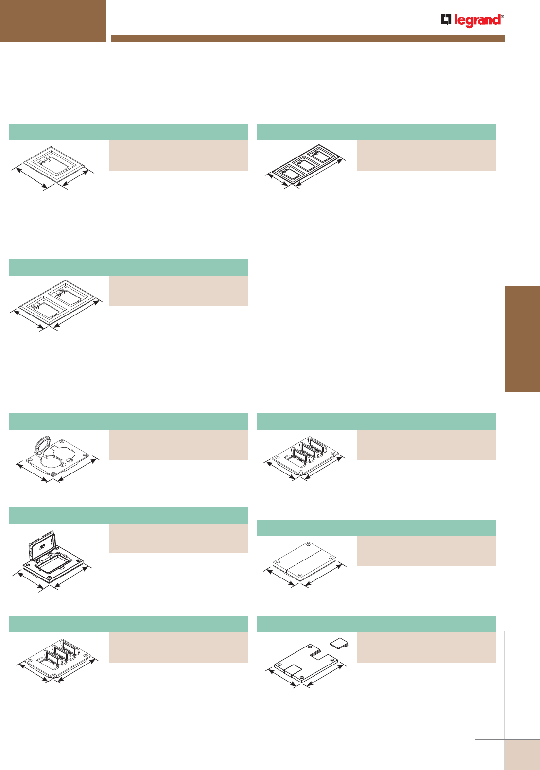
WWW.LEGRAND.US/WIREMOLD
489
FLOOR BOXES
WIREMOLD
880W SERIES™ FLOOR BOXES
Nonmetallic Communications Cover Plate
PART NUMBERS:
829PFLRT-BLK (Black)
829PFLRT-BRN (Brown)
Nonmetallic Duplex Cover Plate
PART NUMBERS:
828PR-BLK (Black)
828PR-BRN (Brown)
One-Gang Nonmetallic Carpet Flange
PART NUMBERS:
817PCC-BLK (Black)
817PCC-BRN (Brown)
5 3/4"
[146mm]
4 3/4"
[121mm] For Ortronics® connectivity use
with 829PFLRT Cover. For Activate™
connectivity use with 829PFL
Cover. Accepts Ortronics® MAB6TJ
TracJack and MAB3S2 Series II
adapters and Wiremold CM Series
inserts, sold separately.
5 3/4"
[146mm]
8 7/8"
[225mm] For Ortronics® connectivity use
with 829PFLRT Cover. For Activate™
connectivity use with 829PFL
Cover. Accepts Ortronics® MAB6TJ
TracJack and MAB3S2 Series II
adapters and Wiremold CM Series
inserts, sold separately.
880W Series Floor Boxes Nonmetallic Cover Plate Flanges Ordering Information
13"
[330mm]
5 3/4"
[146mm] For Ortronics® connectivity use
with 829PFLRT Cover. For Activate™
connectivity use with 829PFL
Cover. Accepts Ortronics® MAB6TJ
TracJack and MAB3S2 Series II
adapters and Wiremold CM Series
inserts, sold separately.
880W Series Floor Boxes Nonmetallic Cover Plates Ordering Information
3 3/16"
[81mm]
4 1/8"
[105mm] Flip lids. Can also be used with a
106 type communication adapter.
Nonmetallic GFI Cover Plate
PART NUMBERS:
828PRGFI-BLK (Black)
828PRGFI-BRN (Brown)
3 3/16"
[81mm]
4 1/8"
[105mm]
May be used with Ortronics®
Connectivity systems in
conjunction with 817, 827 and
837PCC Series flanges.
Nonmetallic Communication Cover Plate
PART NUMBERS:
829PFL-BLK (Black)
829PFL-BRN (Brown)
3 3/16"
[81mm]
4 1/8"
[105mm] Individual flip lids. Gasket
included. Wiremold CM Series
inserts included.
3 3/16"
[81mm]
4 1/8"
[105mm] Individual flip lids. Gasket
included. Ortronics® MAB6TJ
TracJack and MAB3S2 Series II
adapters included.
Nonmetallic Communications Cover Plate
PART NUMBERS:
829PCK-BLK (Black)
829PCK-BRN (Brown)
Breakouts. Feed through only, not
for use with a mounting plate for
communication jacks.
3 3/16"
[81mm]
4 1/8"
[105mm]
Nonmetallic Communications Cover Plate
PART NUMBERS:
829PSTC-BLK (Black)
829PSTC-BRN (Brown)
3 3/16"
[81mm]
4 1/8"
[105mm]
Data slides. Feed through only, not
for use with a mounting plate for
communication jacks.
Three-Gang Nonmetallic Carpet Flange
PART NUMBERS:
837PCC-BLK (Black)
837PCC-BRN (Brown)
Two-Gang Nonmetallic Carpet Flange
PART NUMBERS:
827PCC-BLK (Black)
827PCC-BRN (Brown)
NOTE: UL Listed for tile, terrazzo, and carpet floors.
Brass covers and flanges are not interchangeable with aluminum or nonmetallic covers and flanges.
Nonmetallic covers are interchangeable with aluminum flanges.
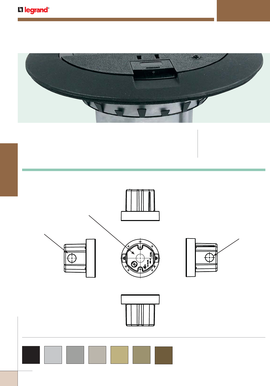
WWW.LEGRAND.US/WIREMOLD
490
FLOOR BOXES
WIREMOLD
861 SERIES™ FLOOR BOXES
861 Series™ Single Service Wood Floor Boxes bring power or communication
service directly to the open space. Available with poke-thru style covers. CODE REFERENCE
cULus Listed
Metallic Outlet Boxes:
File E2961 Guide QCIT.
Meets Article 300.22(c) of NEC
Back
Side Side
Top
Front
1/2"
Conduit Thread 1/2"
Conduit Thread
1/2"
Conduit Thread
Knockouts:
861 Series Floor Boxes Ordering Information
COLOR OPTIONS
861 Series™ Cover Plates are available in black, aluminum,
gray, nickel, brass, bronze and brown.
Custom color options are also available. Consult the factory
for more information.
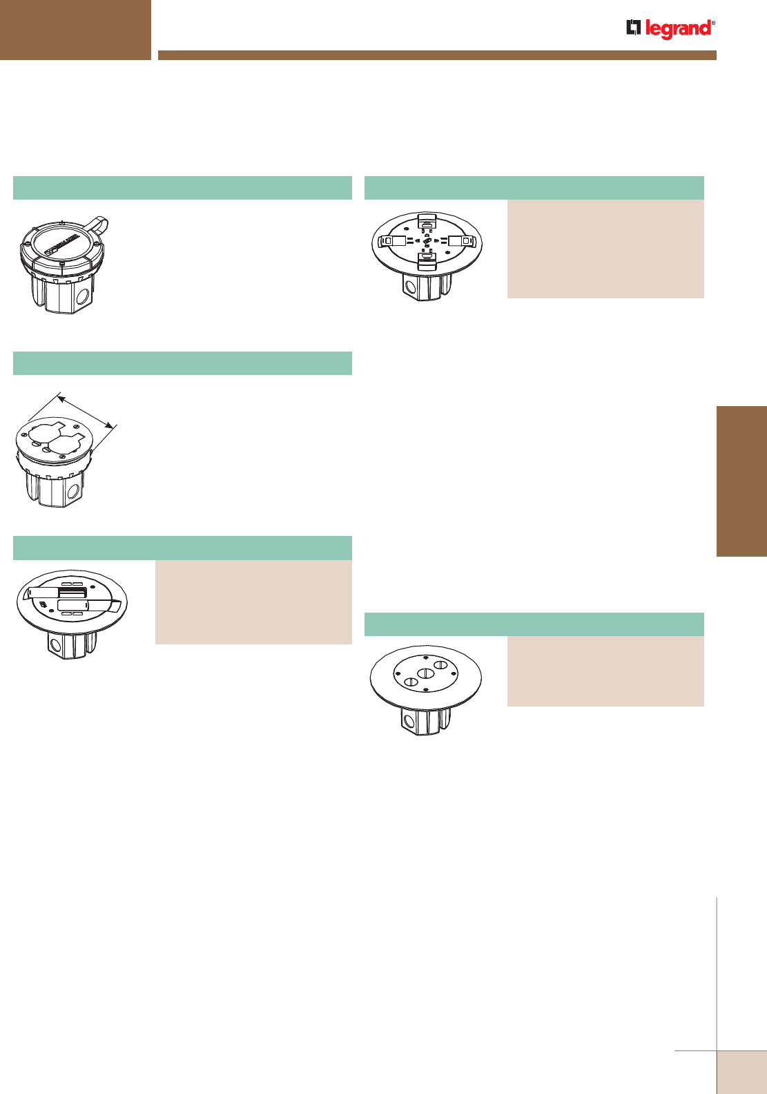
WWW.LEGRAND.US/WIREMOLD
491
FLOOR BOXES
WIREMOLD
861 SERIES™ FLOOR BOXES
4 1/4"
[108mm]
Die-cast aluminum construction
with three 1/2" [12.7mm] knockouts;
two on the sides and one on the
bottom. 18 cu. in. [295ml3] of
capacity. Requires a 4" [102mm]
diameter hole. Comes complete with
a disposable cover, receptacle and
cover sold separately.
861 Wood Floor Box
Complete with 20A duplex
receptacle and brass cover plate.
Die-cast aluminum construction
with three 1/2" [12.7mm] knockouts;
two on the sides and one on the
bottom. 18 cu. in. [295ml3] of
capacity. Requires a 4" [102mm]
diameter hole.
861DB Wood Floor Box Assembly
Complete with prewired 15A quad
receptacle can be wired as
standard or isolated ground. Flush
poke-thru-style cover is available
in painted or brushed metal
finishes. Slide covers match
painted flange colors. Aluminum
and brass covers shipped with
black slide covers. Brass flange
also available with nonmetallic
brass-color (AB) slide holder. Die-
cast aluminum construction with
three 1/2" trade size knockouts:
two on the sides and one on the
bottom. 18 cu. in. [295 cu.cm]
capacity. Requires a 4" [102mm]
diameter hole and overall floor
depth of 1" [25mm]. Assembled
with scrub water gasket. For use
on tile, wood, or carpet floors.
Cover has two 1/2" trade size
conduits and one 3/4" trade size
threaded conduit opening for
feeding cables and wires through
floor. Flush flanges available in
painted or brushed metal finishes.
Die-cast aluminum construction
with three 1/2" trade size
knockouts; two on the sides and
one on the bottom, 18 cu. in.
[295 cu. cm] capacity. Requires a
4" [102mm] diameter hole.
861 Series Floor Boxes Ordering Information (continued)
Wood Floor Box Assembly
PART NUMBERS:
861QTCBK (Painted Black)
861QTCGY (Painted Gray)
861QTCBS (Brushed Brass)
861QTCAL (Brushed Aluminum)
861QTCAB (All Brass)
861QTCAA (All Aluminum)
Furniture Feed Raised Floor Box Assembly
PART NUMBERS:
861FFTCBK (Painted Black)
861FFTCGY (Painted Gray)
861FFTCBS (Brushed Brass)
861FFTCAL (Brushed Aluminum)
All communication floor boxes
accept up to four UTP connectors.
Flush poke-thru-style flanges
available in painted or brushed
metal finishes. Slide covers match
painted flange colors. Aluminum
and brass flanges shipped with
black slide cover. Brass flange also
available with nonmetallic brass-
color (AB) slide holder. Die-cast
aluminum construction with three
1/2" trade size knockouts: two on
the sides and one on the bottom.
18 cu. in. [295 cu.cm] capacity.
Requires a 4" [102mm] diameter
hole and overall floor depth of 1"
[25mm]. Includes two (2) Ortronics
TracJack inserts, two (2) Ortronics
Series II adapters and two
Wiremold Open System adapters.
Assembled with scrub water
gasket. For use on tile, wood, or
carpet floors. Modular jacks sold
separately.
Wood Floor Box Assembly
PART NUMBERS:
861AMDTCBK (Painted Black)
861AMDTCGY (Painted Gray)
861AMDTCBS (Brushed Brass)
861AMDTCAL (Brushed Aluminum)
861AMDTCAB (All brass)

WWW.LEGRAND.US/WIREMOLD
492
FLOOR BOXES
WIREMOLD
Duplex Cover Plate
PART NUMBERS:
895P-BLK (Black)
895P-BRN (Brown)
895P-BRZ (Bronze)
895P-AL (Brushed Aluminum)
5 1/2"
[140mm]
5 1/2"
[140mm]
5 1/2"
[140mm]
5 1/2"
[140mm]
NOTE: All 895 Style Cover Plates are furnished with gasket and three screws.
All carpet cover plates are 5 1/2" [140mm] in diameter.
All tile cover plates are 4 1/4" [108mm] in diameter.
861 SERIES™ FLOOR BOXES
Duplex cover plate with flip lids,
5 1/2' [140mm] for carpet.
Cover plate with two screw plug
openings, 5 1/2" [140mm] for
carpet.
GFI receptacle cover plate, 5 1/2"
[140mm] for carpet.
Polycarbonate duplex cover plate
with flip lids for carpet.
861 Series Floor Box Cover Plate Ordering Information
GFI Receptacle Cover Plate
PART NUMBERS:
895GFI (Brass)
895GFICAL (Brushed Aluminum)
Duplex Cover Plate With Flip Lids
PART NUMBERS:
895 (Brass)
895TCAL (Brushed Aluminum)
4 1/4"
[108mm]
GFI receptacle cover plate, 4 1/4"
[108mm] for tile.
GFI Receptacle Cover Plate
PART NUMBERS:
895TGFI (Brass)
895TGFIAL (Brushed Aluminum)
4 1/4"
[108mm]
Duplex cover plate with flip lids,
4 1/4" [108mm] for tile.
Duplex Cover Plate With Flip Lids
PART NUMBERS:
895T (Brass)
895TAL (Brushed Aluminum)
Cover Plate With Two Screw Plug Openings
PART NUMBERS:
895SP (Brass)
895SPAL (Brushed Aluminum)
With flip lids, 5 1/2" [140mm]
diameter for carpet.
5 1/2"
[140mm]
Aluminum Duplex Cover Plate
PART NUMBERS:
895TCAL-BK (Black)
895TCAL-GY (Gray)
895TCAL-NK (Nickel)
895TCAL-BS (Brass)
895TCAL-BZ (Bronze)
Cover plate with two screw plug
openings, 4 1/4" [108mm] for tile.
4 1/4"
[108mm]
Cover Plate with Two Screw Plug Openings
PART NUMBERS:
895TSP (Brass)
895TSPAL (Brushed Aluminum)
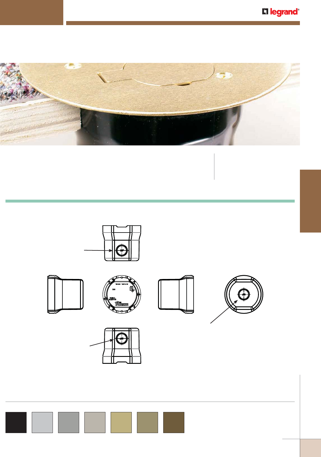
WWW.LEGRAND.US/WIREMOLD
493
FLOOR BOXES
WIREMOLD
862 SERIES™ FLOOR BOXES
862 Series™ Residential Floor Boxes provide an excellent solution for low
density power or communication requirements for both concrete or wood
floor applications.
CODE REFERENCE
cULus Listed
Nonmetallic Outlet Boxes:
File E110748 Guide QCMZ.
Back
Side Side
Top
Front
3/4"
Trade Size
3/4"
Trade Size
3/4"
Trade Size
Bottom
Knockouts:
862 Series Floor Box Kits Ordering Information
862 Series™ Floor Box Kits are available in black,
aluminum, gray, nickel, brass, bronze and brown.
Custom color options are also available. Consult the
factory for more information.
COLOR OPTIONS
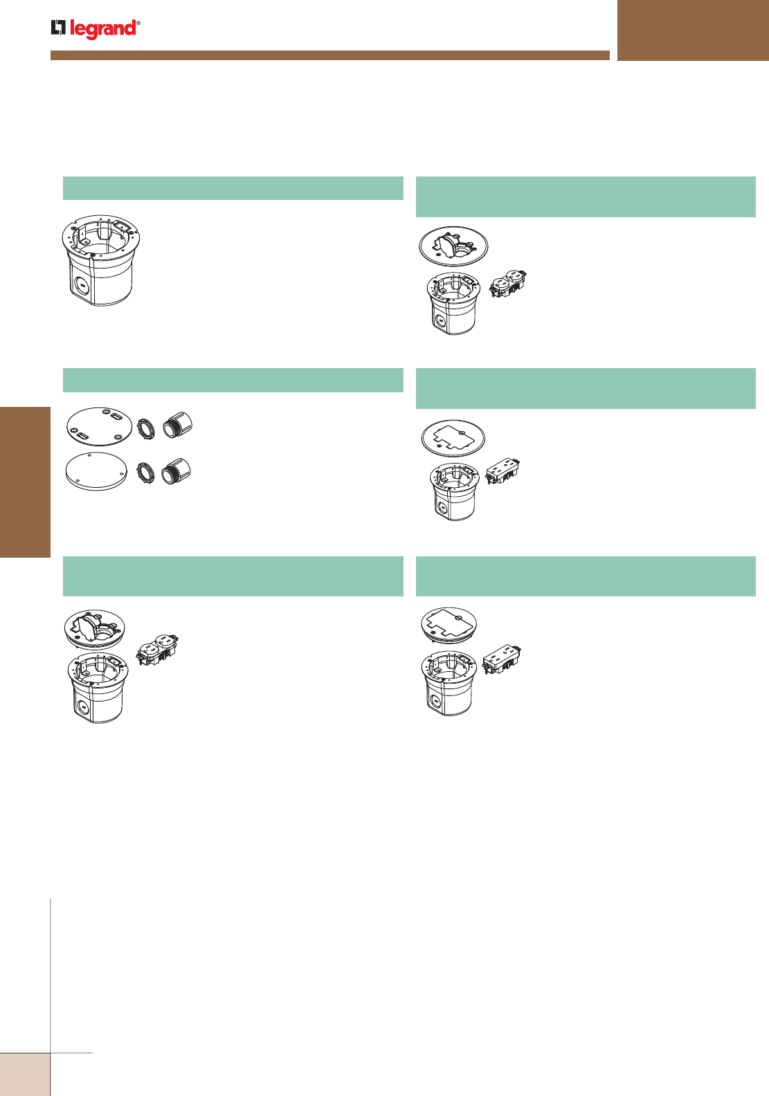
WWW.LEGRAND.US/WIREMOLD
494
FLOOR BOXES
WIREMOLD
862 SERIES™ FLOOR BOXES
Includes 862 Series Floor Box, one
15A, 125V tamper-resistant brown
duplex receptacle, and one 895T
brass duplex receptacle cover for
tile. Order 862KIT when using in
concrete floor.
862DB PVC Floor Box Assembly
For Wood or Concrete Floors
Box only, for wood or concrete
floors. When using in concrete floor,
order 862KIT with 862 Floor Box.
862 PVC Floor Box
When using any of the 862 Series
Floor Boxes in a concrete floor, the
862KIT will provide a mud cap for
the concrete pour, two 3/4" trade
size conduit hubs, and a scrub
water gasket. Not needed for wood
floor installations.
862KIT Concrete Floor Kit
Includes 862 Series Floor Box, one
15A, 125V tamper-resistant brown
duplex receptacle, and one 895
brass duplex receptacle cover for
carpet. Order 862KIT when using in
concrete floor.
862C PVC Floor Box Assembly
For Wood or Concrete Floors
Includes 862 Series Floor Box, one
Decorator style 15A, 125V tamper-
resistant brown receptacle, and one
895GFI brass cover for carpet. Order
862KIT when using in concrete floor.
862GFI PVC Floor Box Assembly
For Wood or Concrete Floors
Includes 862 Series Floor Box, one
Decorator style 15A, 125V tamper-
resistant brown receptacle, and one
895TGFI brass cover for tile. Order
862KIT when using in concrete floor.
862TGFI PVC Floor Box Assembly
For Wood or Concrete Floors
862 Series Floor Box Kits Ordering Information (continued)
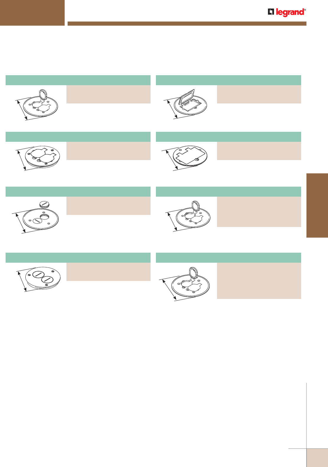
WWW.LEGRAND.US/WIREMOLD
495
FLOOR BOXES
WIREMOLD
Duplex Cover Plate
PART NUMBERS:
895P-BLK (Black)
895P-BRN (Brown)
895P-BRZ (Bronze)
895P-AL (Brushed Aluminum)
5 1/2"
[140mm]
5 1/2"
[140mm]
5 1/2"
[140mm]
5 1/2"
[140mm]
Duplex cover plate with flip lids,
5 1/2' [140mm] for carpet.
Cover plate with two screw plug
openings, 5 1/2" [140mm] for
carpet.
GFI receptacle cover plate, 5 1/2"
[140mm] for carpet.
Polycarbonate duplex cover plate
with flip lids for carpet.
861 Series Floor Box Cover Plate Ordering Information
GFI Receptacle Cover Plate
PART NUMBERS:
895GFI (Brass)
895GFICAL (Brushed Aluminum)
Duplex Cover Plate With Flip Lids
PART NUMBERS:
895 (Brass)
895TCAL (Brushed Aluminum)
4 1/4"
[108mm]
GFI receptacle cover plate, 4 1/4"
[108mm] for tile.
GFI Receptacle Cover Plate
PART NUMBERS:
895TGFI (Brass)
895TGFIAL (Brushed Aluminum)
4 1/4"
[108mm]
Duplex cover plate with flip lids,
4 1/4" [108mm] for tile.
Duplex Cover Plate With Flip Lids
PART NUMBERS:
895T (Brass)
895TAL (Brushed Aluminum)
Cover Plate With Two Screw Plug Openings
PART NUMBERS:
895SP (Brass)
895SPAL (Brushed Aluminum)
With flip lids, 5 1/2" [140mm]
diameter for carpet.
5 1/2"
[140mm]
Aluminum Duplex Cover Plate
PART NUMBERS:
895TCAL-BK (Black)
895TCAL-GY (Gray)
895TCAL-NK (Nickel)
895TCAL-BS (Brass)
(Bronze)
Cover plate with two screw plug
openings, 4 1/4" [108mm] for tile.
4 1/4"
[108mm]
Cover Plate with Two Screw Plug Openings
PART NUMBERS:
895TSP (Brass)
895TSPAL (Brushed Aluminum)
862 SERIES™ FLOOR BOXES
NOTE: All 895 Style Cover Plates are furnished with gasket and three screws.
All carpet cover plates are 5 1/2" [140mm] in diameter.
All tile cover plates are 4 1/4" [108mm] in diameter.
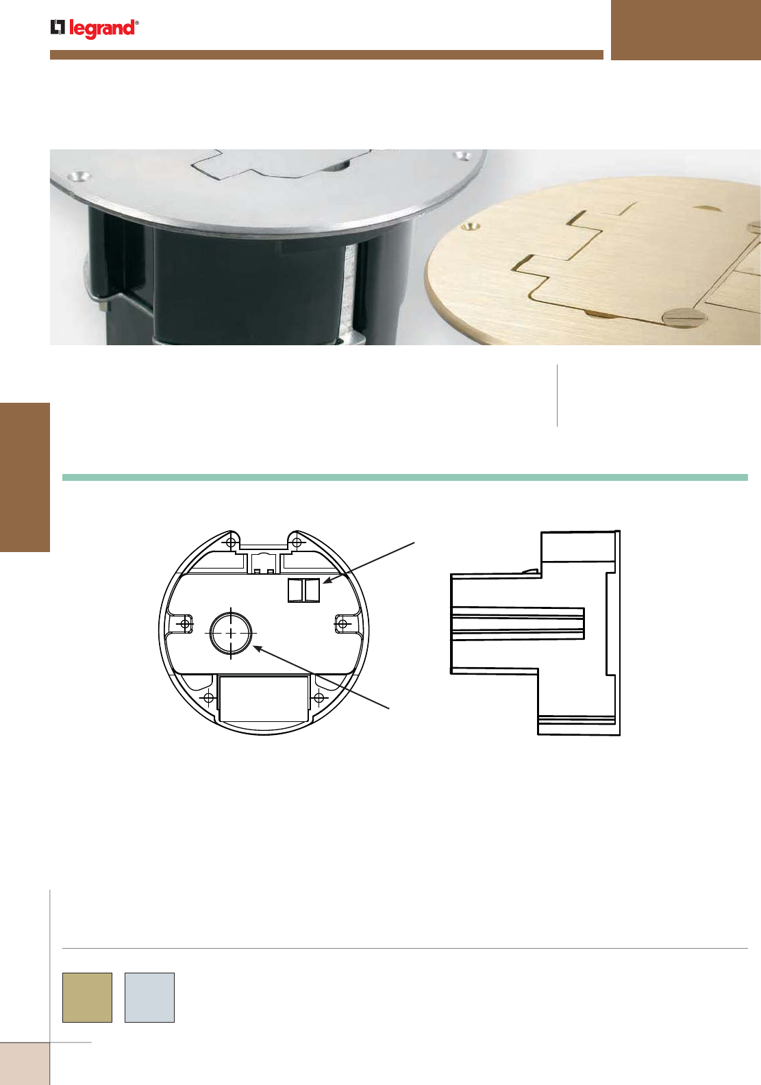
WWW.LEGRAND.US/WIREMOLD
496
FLOOR BOXES
WIREMOLD
863 SERIES™ FLOOR BOXES
863 Series™ Multi-Service Round Floor Box Assembly Kits for Wood
Floors for New and Retrofit Residential Applications. CODE REFERENCE
cULus Listed
Nonmetallic Outlet Boxes:
File E110748 Guide QCMZ.
863 Series™ Cover Plates are available in these colors as
indicated in the part number descriptions.
Custom color options are also available. Consult the factory
for more information.
COLOR OPTIONS
Knockouts:
Side
1/2"
Trade Size
Bottom
Romex Strain
Relief
863 Series Floor Box Assembly Kits Ordering Information
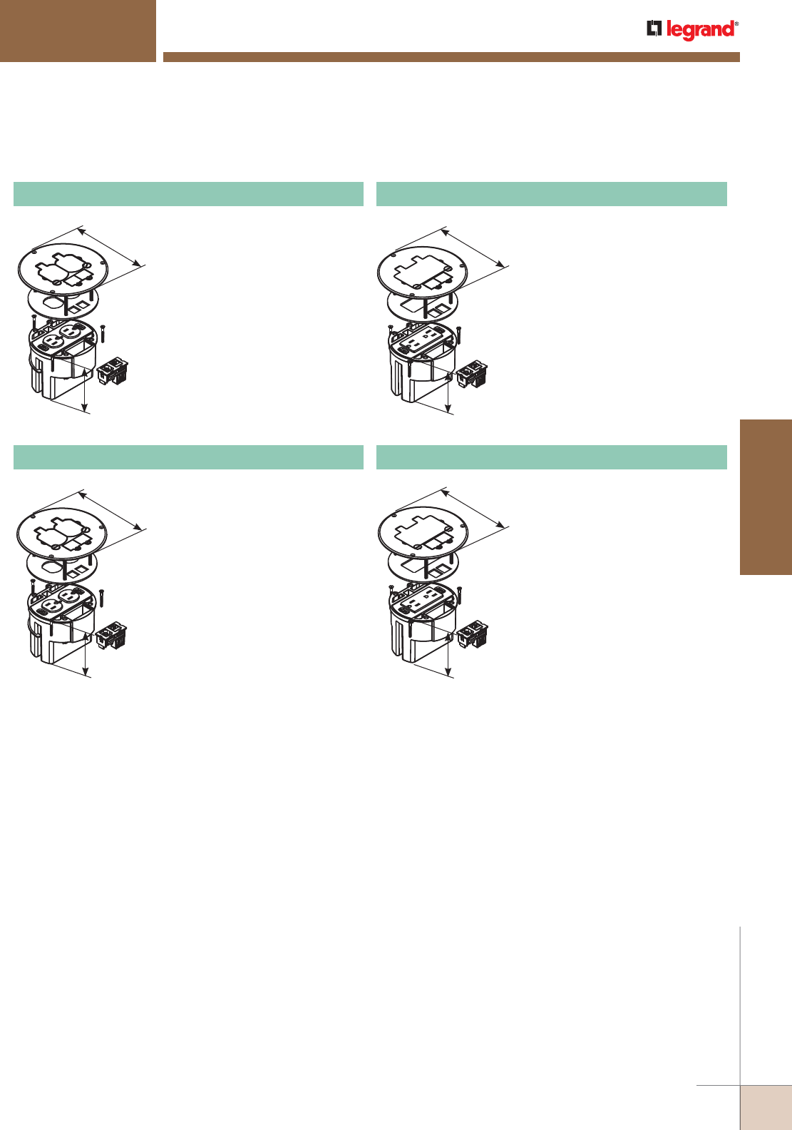
WWW.LEGRAND.US/WIREMOLD
497
FLOOR BOXES
WIREMOLD
3 1/2"
[89mm]
5 3/4"
[146mm]
3 1/2"
[89mm]
5 3/4"
[146mm]
3 1/2"
[89mm]
5 3/4"
[146mm]
3 1/2"
[89mm]
5 3/4"
[146mm]
863 SERIES™ FLOOR BOXES
Includes round PVC floor box, one
15A, 125V tamper-resistant duplex
receptacle, one coax F connector,
one RJ45 Category 5e connector,
and brass duplex opening cover
plate with two flip lids.
863DPCOM Dual-Service Floor Box Kit
Includes round PVC floor box, one
15A, 125V tamper-resistant duplex
receptacle, one coax F connector,
one RJ45 Category 5e connector,
and brushed aluminum duplex
opening cover plate with two
flip lids.
863DPCOMAL Dual-Service Floor Box Kit
Includes round PVC floor box,
one 15A, 125V tamper-resistant
decorator style duplex receptacle,
one coax F connector, one RJ45
Category 5e connector, and brass
duplex opening cover plate with
single flip lid.
863DRGFICOM Dual-Service Floor Box Kit
Includes round PVC floor box,
one 15A, 125V tamper-resistant
decorator style duplex receptacle,
one coax F connector, one RJ45
Category 5e connector, and brushed
aluminum duplex opening cover
plate with single flip lid.
863DRGFICOMAL Dual-Service Floor Box Kit
863 Series Floor Boxes Ordering Information
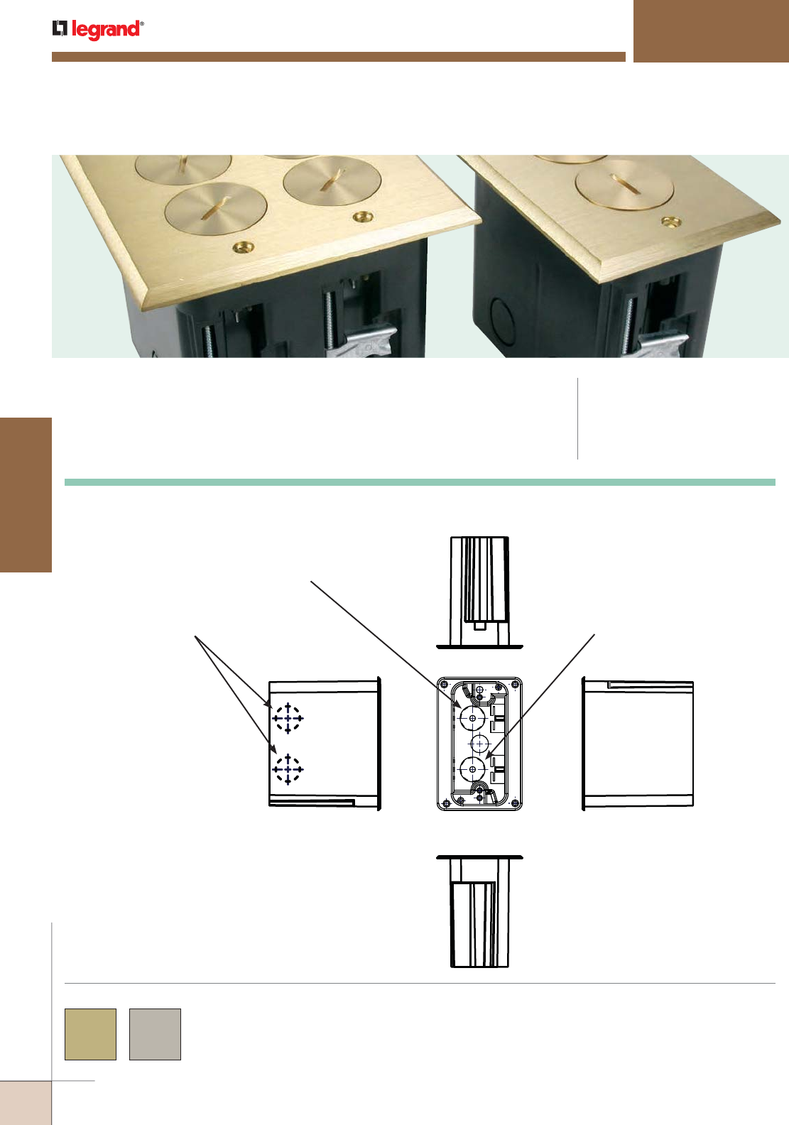
WWW.LEGRAND.US/WIREMOLD
498
FLOOR BOXES
WIREMOLD
WMFB SERIES™ FLOOR BOXES
Multi-Service Floor Box Assembly Kits for Wood Floors for New and Retrofit
Residential Applications. CODE REFERENCE
cULus Listed
Nonmetallic Outlet Boxes:
File E143222 Guide QCMZ.
WMFB Series™ Cover Plates are available in these colors as
indicated in the part number descriptions.
Custom color options are also available. Consult the factory
for more information.
COLOR OPTIONS
Knockouts: Back
Side Side
Top
Front
1/2"
Trade Size KO
1/2"
Trade Size KO
1/2"
Trade Size KO
WMFB Series Floor Boxes Ordering Information
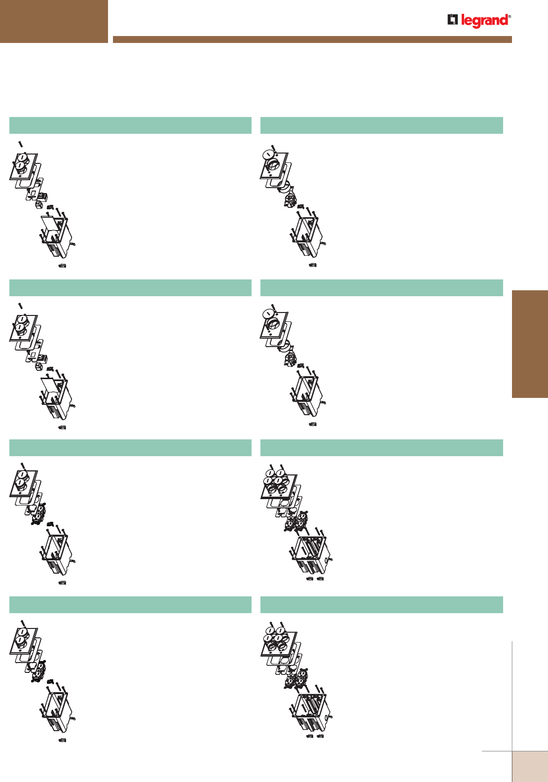
WWW.LEGRAND.US/WIREMOLD
499
FLOOR BOXES
WIREMOLD
WMFB SERIES™ FLOOR BOXES
Includes single-gang box, divider, one
15A, 125V receptacle, one opening for
communication device, and brass
cover with two screw plugs. For hole
cut dimensions, see installation
instructions sheet.
Box Dimensions:
2 1/8" W x 3 3/4" L x 3 7/8" D
[54mm W x 95mm L x 98mm D]
Device Plate:
3 1/8" W x 4 15/16" L
[79mm W x 125mm L]
WMFB1SRKS1B Single-Gang Floor Box Assembly
Includes single-gang box, divider, one
15A, 125V receptacle, one opening for
communication device, and nickel
cover with two screw plugs. For hole
cut dimensions, see installation
instructions sheet.
Box Dimensions:
2 1/8" W x 3 3/4" L x 3 7/8" D
[54mm W x 95mm L x 98mm D]
Device Plate:
3 1/8" W x 4 15/16" L
[79mm W x 125mm L]
WMFB1SRKS1N Single-Gang Floor Box Assembly
Includes single-gang box, one 15A, 125V
tamper-resistant receptacle, and brass
cover with two screw plugs. For hole
cut dimensions, see installation
instructions sheet.
Box Dimensions:
2 1/8" W x 3 3/4" L x 3 7/8" D
[54mm W x 95mm L x 98mm D]
Device Plate:
3 1/8" W x 4 15/16" L
[79mm W x 125mm L]
WMFB1DRB Single-Gang Floor Box Assembly
Includes single-gang box, one 15A
tamper-resistant receptacle, and brass
cover with one screw plug. For hole
cut dimensions, see installation
instructions sheet.
Box Dimensions:
2 1/8" W x 3 3/4" L x 3 7/8" D
[54mm W x 95mm L x 98mm D]
Device Plate:
3 1/8" W x 4 15/16" L
[79mm W x 125mm L]
WMFB1SRB Single-Gang Floor Box Assembly
Includes single-gang box, one 15A, 125V
tamper-resistant receptacle, and nickel
cover with two screw plugs. For hole
cut dimensions, see installation
instructions sheet.
Box Dimensions:
2 1/8" W x 3 3/4" L x 3 7/8" D
[54mm W x 95mm L x 98mm D]
Device Plate:
3 1/8" W x 4 15/16" L
[79mm W x 125mm L]
WMFB1DRN Single-Gang Floor Box Assembly
Includes single-gang box, one 15A
tamper-resistant receptacle, and nickel
cover with one screw plug. For hole
cut dimensions, see installation
instructions sheet.
Box Dimensions:
2 1/8" W x 3 3/4" L x 3 7/8" D
[54mm W x 95mm L x 98mm D]
Device Plate:
3 1/8" W x 4 15/16" L
[79mm W x 125mm L]
WMFB1SRN Single-Gang Floor Box Assembly
Includes dual-gang box, two 15A tamper-
resistant duplex receptacles, and brass
cover with four screw plugs. For hole
cut dimensions, see installation
instructions sheet.
Box Dimensions:
3 1/4" W x 3 3/4" L x 3 7/8" D
[83mm W x 95mm L x 98mm D]
Device Plate:
4 7/8" W x 5 1/16" L
[124mm W x 129mm L]
WMFB2DR2B Dual-Gang Floor Box Assembly
Includes dual-gang box, two 15A tamper-
resistant duplex receptacles, and nickel
cover with four screw plugs. For hole
cut dimensions, see installation
instructions sheet.
Box Dimensions:
3 1/4" W x 3 3/4" L x 3 7/8" D
[83mm W x 95mm L x 98mm D]
Device Plate:
4 7/8" W x 5 1/16" L
[124mm W x 129mm L]
WMFB2DR2N Dual-Gang Floor Box Assembly
WMFB Series Floor Boxes Ordering Information (continued)
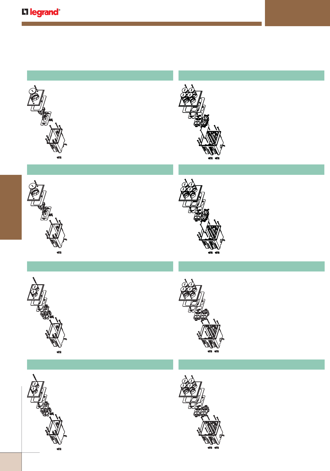
WWW.LEGRAND.US/WIREMOLD
500
FLOOR BOXES
WIREMOLD
WMFB SERIES™ FLOOR BOXES
Includes single-gang box, device plate
with two openings for communication
devices, and brass cover with one screw
plug. For hole cut dimensions, see
installation instructions sheet.
Box Dimensions:
2 1/8" W x 3 3/4" L x 3 7/8" D
[54mm W x 95mm L x 98mm D]
Device Plate:
3 1/8" W x 4 15/16" L
[79mm W x 125mm L]
WMFB1KS2B Single-Gang Floor Box Assembly
Includes single-gang box, device plate
with two openings for communication
devices, and nickel cover with one screw
plug. For hole cut dimensions, see
installation instructions sheet.
Box Dimensions:
2 1/8" W x 3 3/4" L x 3 7/8" D
[54mm W x 95mm L x 98mm D]
Device Plate:
3 1/8" W x 4 15/16" L
[79mm W x 125mm L]
WMFB1KS2N Single-Gang Floor Box Assembly
Includes single-gang box, 106 adapter
with four openings for communication
devices, and brass cover with two screw
plugs. For hole cut dimensions, see
installation instructions sheet.
Box Dimensions:
2 1/8" W x 3 3/4" L x 3 7/8" D
[54mm W x 95mm L x 98mm D]
Device Plate:
3 1/8" W x 4 15/16" L
[79mm W x 125mm L]
WMFB1KS4B Single-Gang Floor Box Assembly
Includes dual-gang box, one 15A tamper-
resistant duplex receptacle, 106 adapter
with four openings for communication
devices, and brass cover with four screw
plugs. For hole cut dimensions, see
installation instructions sheet.
Box Dimensions:
3 1/4" W x 3 3/4" L x 3 7/8" D
[83mm W x 95mm L x 98mm D]
Device Plate:
4 7/8" W x 5 1/16" L
[124mm W x 129mm L]
WMFB2DRKS4B Dual-Gang Floor Box Assembly
Includes single-gang box, 106 adapter
with four openings for communication
devices, and nickel cover with two screw
plugs. For hole cut dimensions,see
installation instructions sheet.
Box Dimensions:
2 1/8" W x 3 3/4" L x 3 7/8" D
[54mm W x 95mm L x 98mm D]
Device Plate:
3 1/8" W x 4 15/16" L
[79mm W x 125mm L]
WMFB1KS4N Single-Gang Floor Box Assembly
Includes dual-gang box, one 15A tamper-
resistant duplex receptacle, 106 adapter
with four openings for communication
devices, and nickel cover with four screw
plugs. For hole cut dimensions, see
installation instructions sheet.
Box Dimensions:
3 1/4" W x 3 3/4" L x 3 7/8" D
[83mm W x 95mm L x 98mm D]
Device Plate:
4 7/8" W x 5 1/16" L
[124mm W x 129mm L]
WMFB2DRKS4N Dual-Gang Floor Box Assembly
Includes dual-gang box, two 106 adapter
with eight openings for communication
devices, and brass cover with four screw
plugs. For hole cut dimensions, see
installation instructions sheet.
Box Dimensions:
3 1/4" W x 3 3/4" L x 3 7/8" D
[83mm W x 95mm L x 98mm D]
Device Plate:
4 7/8" W x 5 1/16" L
[124mm W x 129mm L]
WMFB2KS8B Dual-Gang Floor Box Assembly
Includes dual-gang box, two 106 adapter
with eight openings for communication
devices, and nickel cover with four screw
plugs. For hole cut dimensions, see
installation instructions sheet.
Box Dimensions:
3 1/4" W x 3 3/4" L x 3 7/8" D
[83mm W x 95mm L x 98mm D]
Device Plate:
4 7/8" W x 5 1/16" L
[124mm W x 129mm L]
WMFB2KS8N Dual-Gang Floor Box Assembly
WMFB Series Floor Boxes Ordering Information (continued)
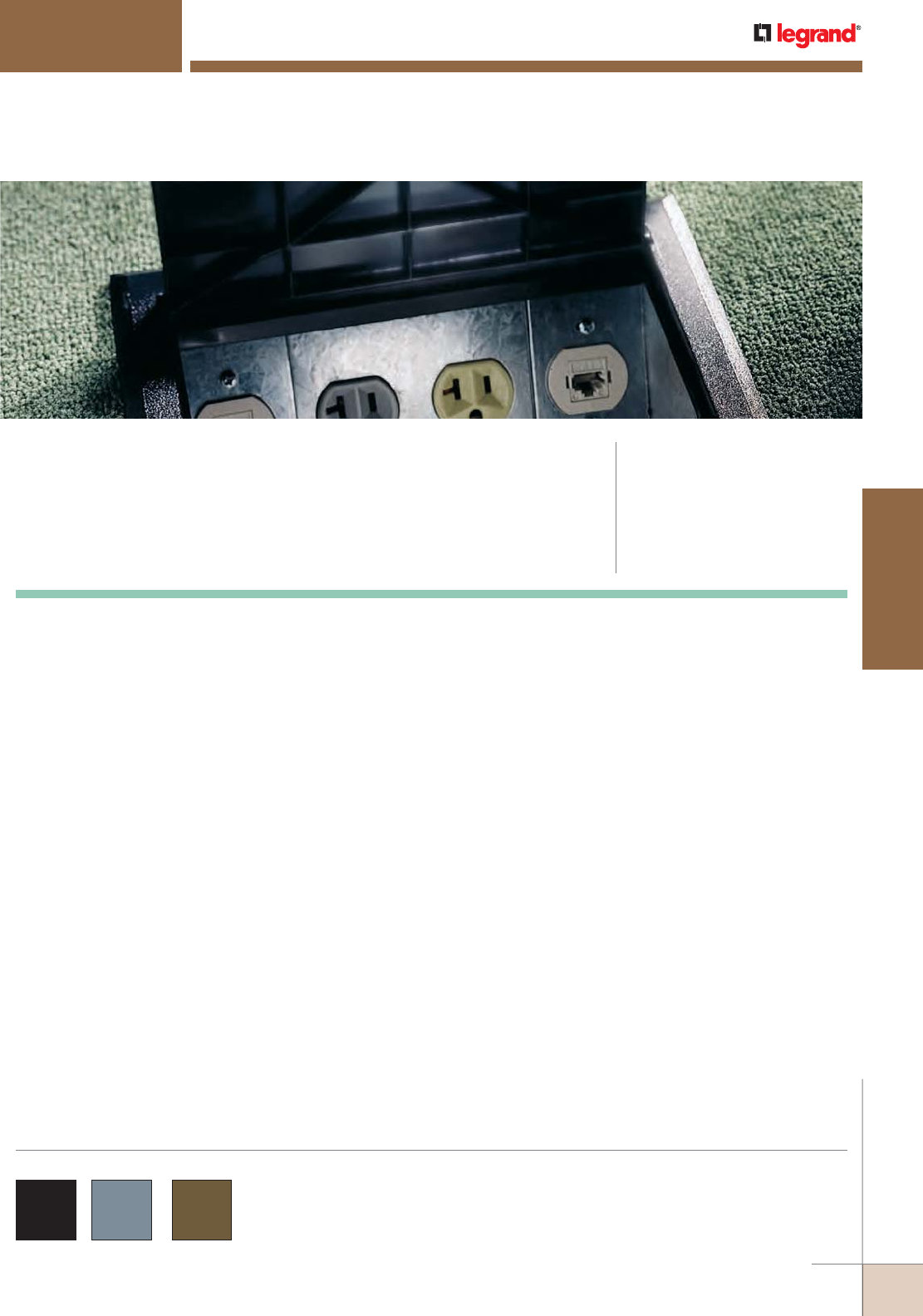
WWW.LEGRAND.US/WIREMOLD
501
FLOOR BOXES
WIREMOLD
AF™ SERIES FLOOR BOXES
FloorSource AF Series™ Raised Floor Boxes provide point-of-use
activations for multiple power and communications devices while offering
greater flexibility relating to adds, moves and changes within a standard
and shallow raised floor application.
CODE REFERENCE
UL Listed Classified Raised Floor Box:
File E2961, Guide QCIT.
UL Listed Classified Raised Floor Box
(prewired):
File E51105, Guide QQVX.
Meets Article 300.22(c) of NEC.
Meets Article 12-2500 of CEC.
AF Series™ Raised Floor Boxes are available in die-cast
aluminum with black, gray or brown covers and trim flanges
as indicated in the part number descriptions.
COLOR OPTIONS
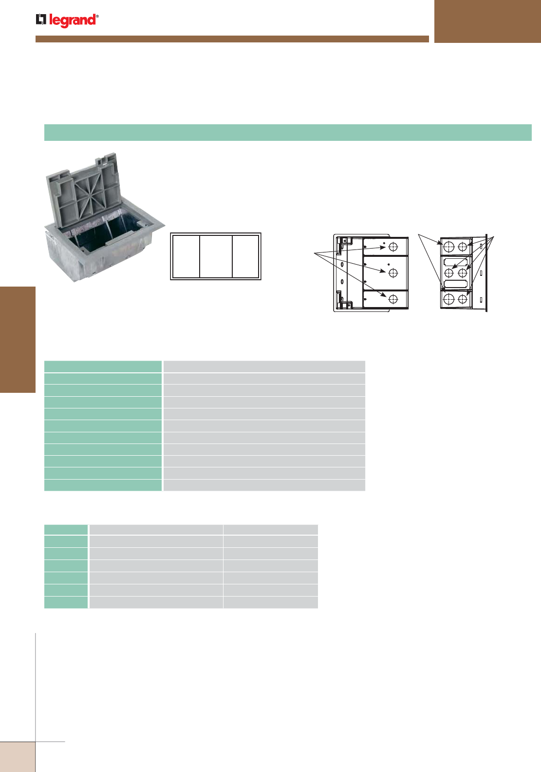
WWW.LEGRAND.US/WIREMOLD
502
FLOOR BOXES
WIREMOLD
SGT
SGT
DGT
Faceplate Locations Knockouts:
Side
1/2"
Trade Size KO
3/4"
Trade Size
Bottom
1/2"
Trade Size
AF™ SERIES FLOOR BOXES
The AF1 Raised Floor and Stage Floor Box provides three separate compartments that
accommodate a combination of power, communication and audio/video devices. This
combination is accomplished with the built-in service dividers. These dividers are arranged
in a single-double, single-gang configuration. Die-cast aluminum housing provides added
strength and reliability. Polycarbonate hinged lid and trim flange are available for carpet or
tile applications, as well as color choice of black, brown, or gray.
AF-1 Raised Floor Box
DESCRIPTION DIMENSIONS
OVERALL TRIM RING 8 3/4" x 6 3/4" [222mm x 171mm]
MODULE DEPTH OVERALL 5" [127mm]
PANEL OPENING 8" x 6" [203mm x 152mm]
COVER SIZE 7 1/2" x 5" [191mm x 127mm]
ACTIVATION CHAMBER VOLUME 130 cu. in. [2130ml]
USER VOLUME 78.6 cu. in. [1288ml]
TOTAL VOLUME 208.6 cu. in. [3418ml]
KNOCKOUT SIZES Seven (7) 1/2" and Two (2) 3/4" Trade Size KOs (Power Side only)
SERVICE Triple
MAXIMUM FLOOR THICKNESS 1 1/2" [38mm] (Includes floor covering)
Specifications
CAT. NO. DESCRIPTION BOX DIMENSION
AF1KC AF1 with Black Carpet Cover and Trim 8" x 6" [203mm x 152mm]
AF1KT AF1 with Black Tile Cover and Trim 8" x 6" [203mm x 152mm]
AF1NC AF1 with Brown Carpet Cover and Trim 8" x 6" [203mm x 152mm]
AF1NT AF1 with Brown Tile Cover and Trim 8" x 6" [203mm x 152mm]
AF1YC AF1 with Gray Carpet Cover and Trim 8" x 6" [203mm x 152mm]
AF1YT AF1 with Gray Tile Cover and Trim 8" x 6" [203mm x 152mm]
NOTE: AF1 and AF3 Floor Boxes are available in a prewired (power only) version.
Consult factory for ordering information. For information on prewired versions
with Walkerflex, see the Walkerflex Section of this Product Guide.
NOTE: All boxes and plates are sold separately.
Ordering Data
AF Series Raised Floor Boxes Ordering Information
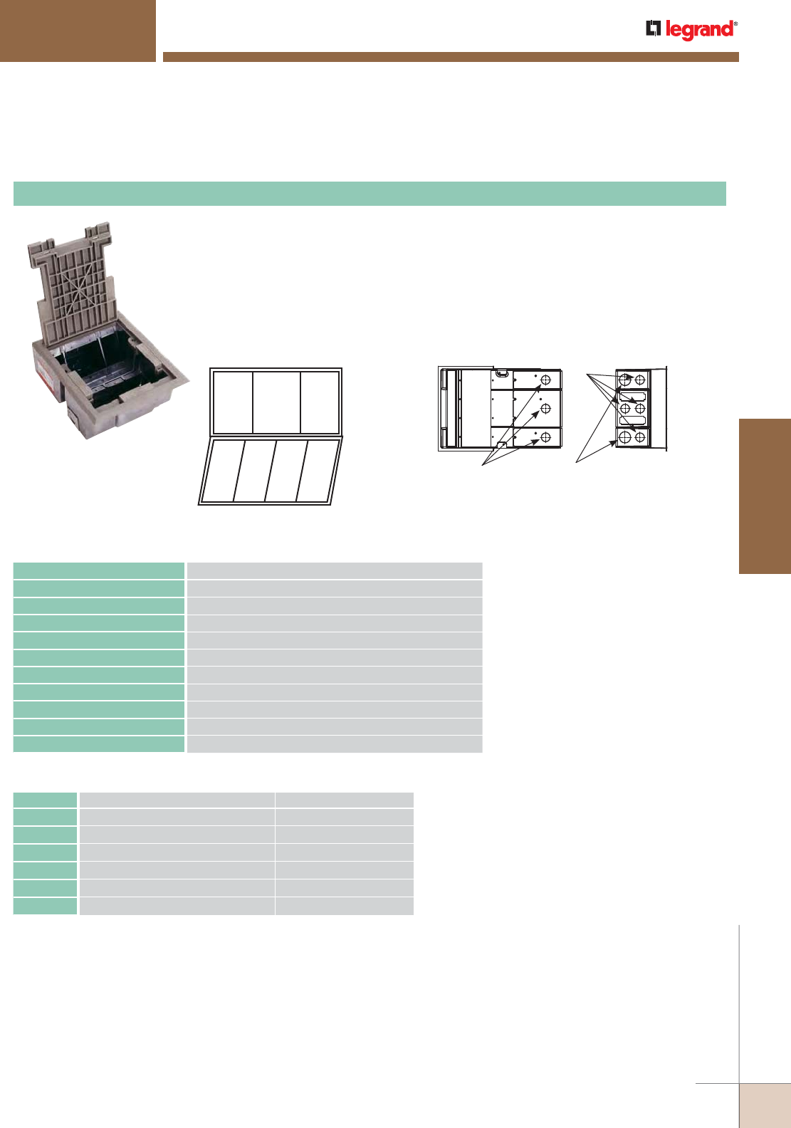
WWW.LEGRAND.US/WIREMOLD
503
FLOOR BOXES
WIREMOLD
The AF3 Raised Floor and Stage Floor Box provides four separate compartments that
accommodate up to eight gangs of communication, power and/or audio/ video devices.
The top panel has a unique built-in service divider that accommodates a combination power,
communication and audio/video devices. These dividers are arranged in a single-double,
single-gang configuration. The lower panel provides single-gang activation points in a single
service configuration. Die-cast aluminum housing provides added strength and reliability.
Polycarbonate hinged lid and trim flange are available for carpet or tile applications, as well
as a color choice of black, brown, or gray.
SGT
SGT
DGT
SGB
SGB
SGB
SGB
Faceplate Locations Knockouts: Side
1/2"
Trade Size
3/4"
Trade Size
Bottom 1/2"
Trade Size
AF-3 Raised Floor Box
DESCRIPTION DIMENSIONS
OVERALL TRIM RING 9 1/8" x 11" [232mm x 279mm]
MODULE DEPTH OVERALL 5" [127mm]
PANEL OPENING 8" x 10" [203mm x 254mm]
COVER SIZE 7 1/2" x 9 1/2" [191mm x 242mm]
ACTIVATION CHAMBER VOLUME 220 cu. in. [3604ml]
USER VOLUME 180 cu. in. [2948ml]
TOTAL VOLUME 300 cu. in. [4915ml]
KNOCKOUT SIZES Seven (7) 1/2" and Two (2) 3/4" Trade Size KOs (Power Side only)
SERVICE Triple
MAXIMUM FLOOR THICKNESS 1 1/2" [38mm] (Includes floor covering)
Specifications
CAT. NO. DESCRIPTION BOX DIMENSION
AF3KC AF3 with Black Carpet Cover and Trim 8" x 10" [203mm x 254mm]
AF3KT AF3 with Black Tile Cover and Trim 8" x 10" [203mm x 254mm]
AF3NC AF3 with Brown Carpet Cover and Trim 8" x 10" [203mm x 254mm]
AF3NT AF3 with Brown Tile Cover and Trim 8" x 10" [203mm x 254mm]
AF3YC AF3 with Gray Carpet Cover and Trim 8" x 10" [203mm x 254mm]
AF3YT AF3 with Gray Tile Cover and Trim 8" x 10" [203mm x 254mm]
NOTE: AF1 and AF3 Floor Boxes are available in a prewired (power only) version.
Consult factory for ordering information. For information on prewired versions
with Walkerflex, see the Walkerflex Section of this Product Guide.
NOTE: All boxes and plates are sold separately.
Ordering Data
AF™ SERIES FLOOR BOXES
AF Series Raised Floor Boxes Ordering Information
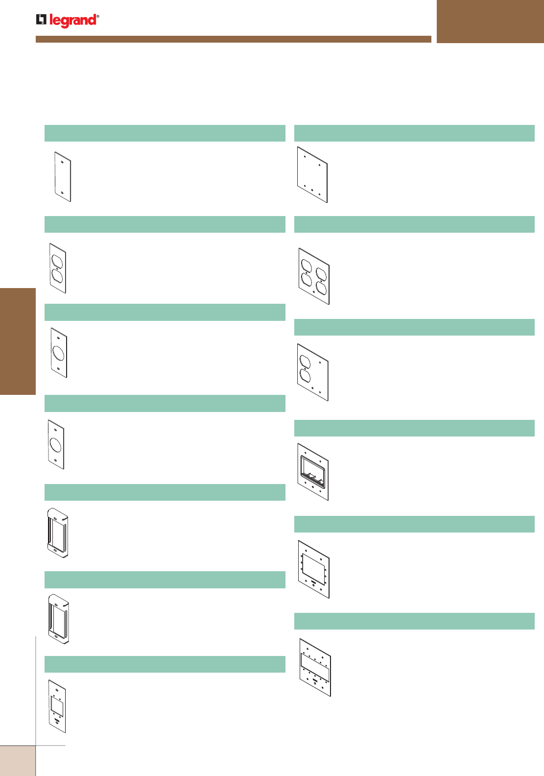
WWW.LEGRAND.US/WIREMOLD
504
FLOOR BOXES
WIREMOLD
Includes one (1) Wiremold Open System adapter.
Adapter accepts three (3) Wiremold CM Series
inserts or three (3) Wiremold CM2 Series
modules. Use in center compartment only.
AF™ SERIES FLOOR BOXES
Blank plate for field punching.
SGT-B Single-Gang Plate
One duplex opening.
SGT-DP Single-Gang Plate
For Heyco bushing opening or single receptacle
1.046" [35.7mm] diameter. Use in outer, side
compartments only.
SGT-H Single-Gang Plate
1" [25mm] knockout.
SGT-1KO Single-Gang Plate
Accepts three (3) Wiremold Open System inserts
or three (3) Wiremold CM Series Open System
modules.
SGT-ACT Single-Gang Plate
Accepts three (3) Ortronics® Series II inserts.
SGT-3S2 Single-Gang Plate
Accepts two (2) Wiremold AVIP or Extron®
Electronics MAAP Series Devices, sold separately.
SGT-MAAP Internal Audio/Video Plate
Blank plate. Use in center compartment only.
DGT-B Double-Gang Plate
Two duplex openings. Use in center
compartment only.
DGT-2DP Double-Gang Plate
One duplex opening and blank. Use in center
compartment only.
DGT-DP/B Double-Gang Plate
DGT-ACT Double-Gang Plate
Accepts three (3) Extron® Electronics AAP Series
Devices, sold separately.
DGT-AAP Internal Audio/Video Plate
Accepts five (5) Wiremold AVIP or Extron®
Electronics MAAP Series Devices, sold
separately.
DGT-MAAP Internal Audio/Video Plate
AF Series Upper (Top) Panel Device Plates for Raised Floor Boxes Ordering Information
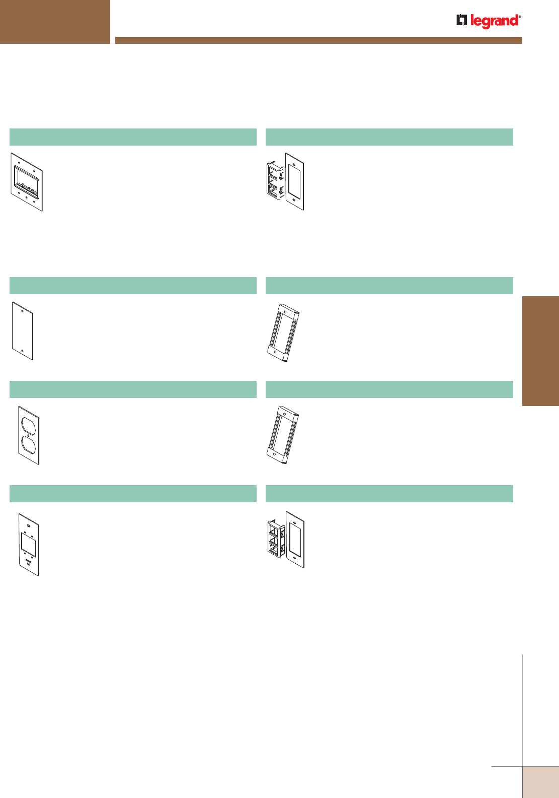
WWW.LEGRAND.US/WIREMOLD
505
FLOOR BOXES
WIREMOLD
Lower (Bottom) Panel Device Plates for AF3 Raised Floor Boxes Ordering Information
Includes one (1) Ortronics® Series II adapter
and one (1) TracJack adapter. Use in center
compartment only.
DGT-RT Double-Gang Plate
Accepts three (3) Ortronics® TracJack inserts.
SGT-3TJ Single-Gang Plate
Blank plate for field punching.
SGB-B Single-Gang Plate
One duplex opening.
SGB-DP Single-Gang Plate
Accepts two (2) Wiremold AVIP or Extron®
Electronics MAAP Series Devices, sold
separately.
SGB-MAAP Internal Audio/Video Plate
Accepts three (3) Wiremold Open System inserts
or three (3) CM2 Series Open System modules.
SGB-ACT Single-Gang Plate
Accepts three (3) Ortronics® Series II inserts.
SGB-3S2 Single-Gang Plate
Accepts three (3) Ortronics® Tracjack inserts.
SGB-3TJ Single-Gang Plate
AF™ SERIES FLOOR BOXES
AF Series Upper (Top) Panel Device Plates for Raised Floor Boxes Ordering Information (continued)
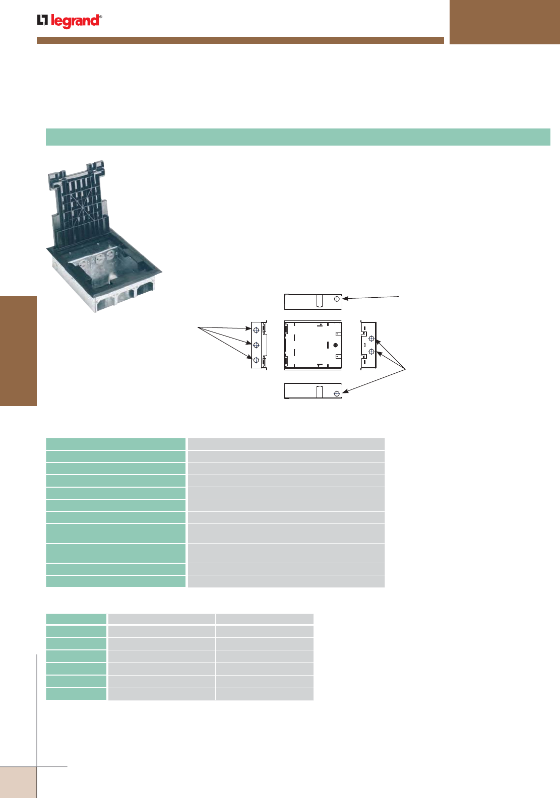
WWW.LEGRAND.US/WIREMOLD
506
FLOOR BOXES
WIREMOLD
Knockouts:
Side
1/2"
Trade Size KO
Front
1/2"
Trade Size
Side
Back
Top
1/2"
Trade Size
AF™ SERIES FLOOR BOXES
The SAF Shallow Raised Floor Box has been designed to fit into 2 1/2" floor depths and
provides two compartments that accommodate a combination of power, communication
and audio/video devices. The SAF21/2 can accommodate two duplex receptacles on one
side and up to six communication devices on the other side. The power and communication
compartments can only be used for designated services. Four 1/2" trade size KOs are in the
sides of the box to feed the power devices. The hinged polycarbonate lid and trim flange for
carpet or tile are available in black, brown, or gray. Two duplex receptacle power plates are
supplied with each box. Receptacles not included. Three blank communication plates are
included with each box. Box includes a communication compartment cover plate for use in
air handling spaces. SAF21/2 Box will accept up to two SG2 Power Plates, and up to three
SGC2 Communication Plates. Consult factory for custom plates.
SAF Raised Floor Box
DESCRIPTION DIMENSIONS
OVERALL TRIM RING 9 1/8" x 11" [232mm x 279mm]
MODULE DEPTH OVERALL 2 1/2" [64mm]
PANEL OPENING 8" x 10" [203mm x 254mm]
COVER SIZE 7 1/2" x 9 1/2" [191mm x 242mm]
ACTIVATION VOLUME 18.5 cubic inches [303ml]
POWER VOLUME 29 cubic inches [475ml]
MAXIMUM FLOOR PANEL THICKNESS
WITH FLOOR COVERING
1 3/16" [30mm]
KNOCKOUTS Power – Four (4) 1/2" Trade Size Concentric KOs
Communication – Three (3) 1/2" Trade Size Concentric KOs
SERVICE Triple
MAXIMUM FLOOR THICKNESS 1 3/8" [35mm] (includes floor covering)
Specifications
CAT. NO. DESCRIPTION BOX DIMENSION
SAF21/2KC Black Carpet Cover and Trim 8" x 10" [203mm x 254mm]
SAF21/2KT Black Tile Cover and Trim 8" x 10" [203mm x 254mm]
SAF21/2NC Brown Carpet Cover and Trim 8" x 10" [203mm x 254mm]
SAF21/2NT Brown Tile Cover and Trim 8" x 10" [203mm x 254mm]
SAF21/2YC Gray Carpet Cover and Trim 8" x 10" [203mm x 254mm]
SAF21/2YT Gray Tile Cover and Trim 8" x 10" [203mm x 254mm]
Ordering Data
AF Series Raised Floor Boxes Ordering Information
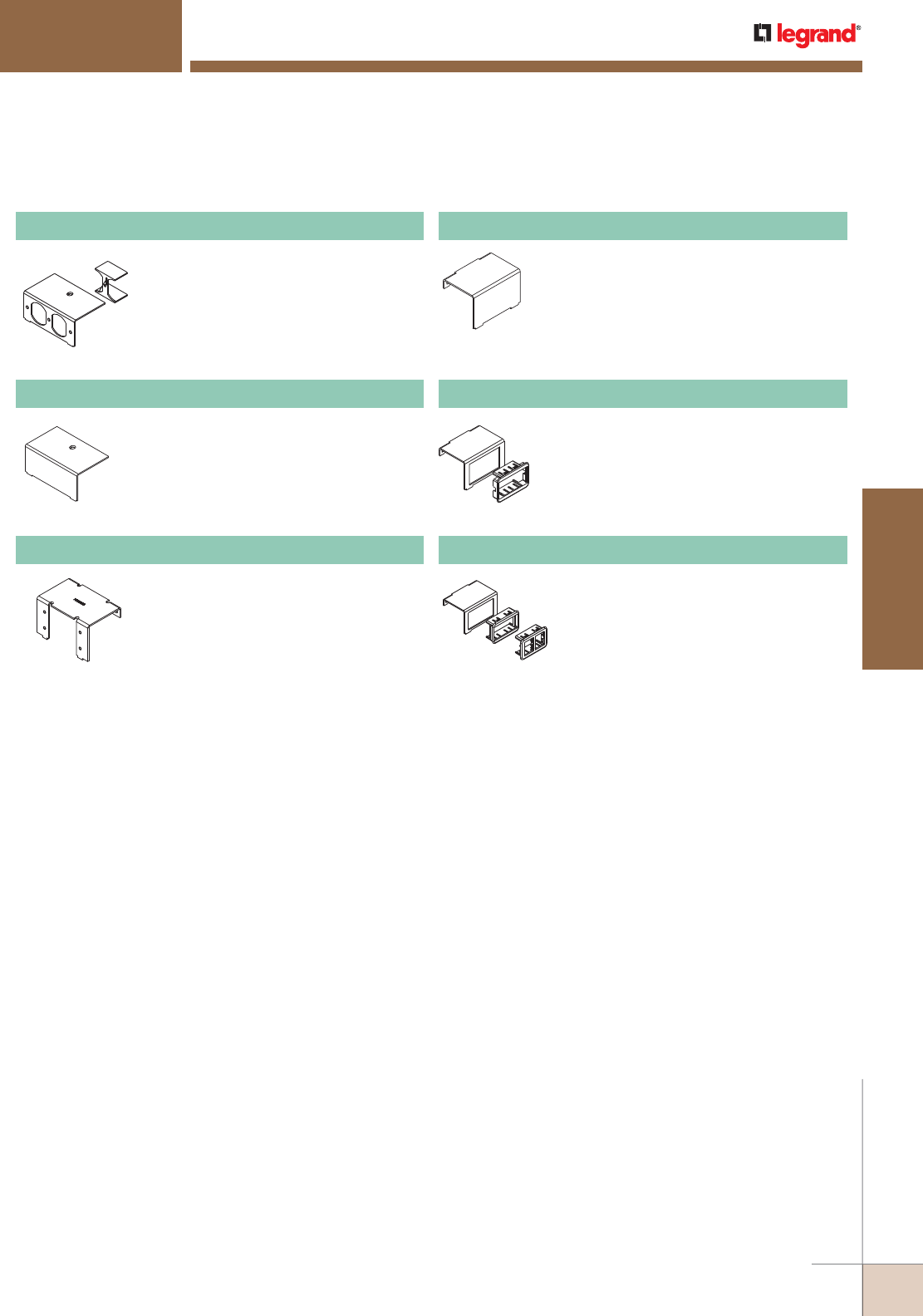
WWW.LEGRAND.US/WIREMOLD
507
FLOOR BOXES
WIREMOLD
AF™ SERIES FLOOR BOXES
Single-gang duplex receptacle.
SG2-DP Power Plate
Single-gang blank plate.
SG2-B Power Plate
Accepts two (2) Wiremold AVIP or
Extron® Electronics MAAP Series
Devices, sold separately.
SGC2-MAAP Communication Plate
Single-gang blank.
SGC2-B Communication Plate
Single-gang adapter. Includes one (1)
Wiremold Open System adapter.
SGC2-ACT Communication Plate
Includes one (1) Ortronics® Series II
adapter and one (1) TracJack adapter.
SGC2-RT Communication Plate
SAF21/2 Raised Floor Box Device Plates Ordering Information
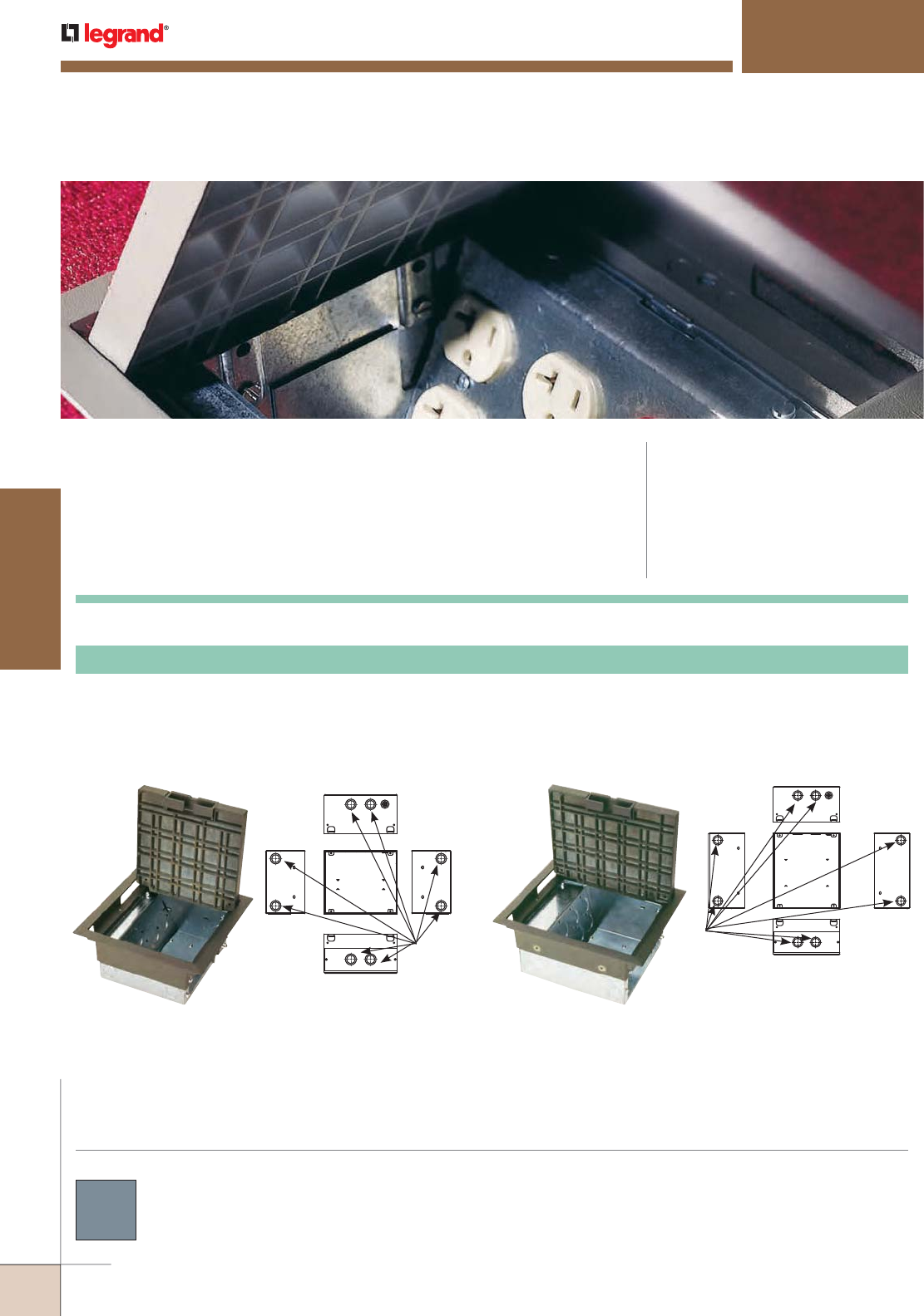
WWW.LEGRAND.US/WIREMOLD
508
FLOOR BOXES
WIREMOLD
Side
1/2" & 3/4"
Trade Size
Concentric KOs
Back
Side
Top
Front
Knockouts:
AC™ SERIES FLOOR BOXES
FloorSource AC Series™ Raised Floor Boxes provide point-of-use
activations for multiple power, communication and audio/video devices
while offering greater flexibility relating to adds, moves and changes
within the raised floor.
AC Series™ Raised Floor Boxes are available in die-
cast zinc construction with gray covers as indicated in
the part number descriptions.
COLOR OPTIONS
CODE REFERENCE
UL Listed Classified Raised Floor Box:
File E2961, Guide QCIT.
UL Listed Classified Raised Floor Box
(prewired):
File E51105, Guide QQVX.
Meets Article 300.22(c) of NEC.
Meets Article 12-2500 of CEC.
AC8850 AC8105Knockouts:
Side
Back
1/2" & 3/4"
Trade Size
Concentric KOs
Side
Front
Top
NOTE: Back plate is removable for greater depth capacity.
The AC8850 and AC8105 are boxes with a 5" [127mm] depth design, with the AC8105 providing an extra 2" [51mm] of width
for additional wiring capacity. These boxes can accommodate four duplex power receptacles on one side. Power plate with
duplex knockouts included with box. The communication plate will accept at least three communication adapters for up to
18 ports of activation. Lids rotate 180° for easy orientation. Gray lids are die-cast zinc construction.
AC8850, AC8105 Raised Floor Box
AC Series Raised Floor Boxes Ordering Information
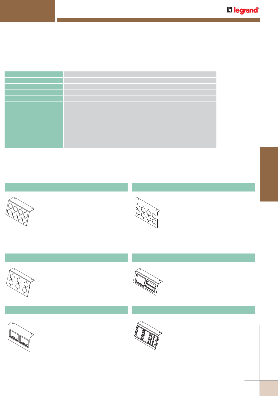
WWW.LEGRAND.US/WIREMOLD
509
FLOOR BOXES
WIREMOLD
AC™ SERIES FLOOR BOXES
Power Plates for AC8850 and AC8105 Raised Floor Boxes Ordering Information
Four (4) duplex KOs. One plate supplied
with AC8850 Box.
* AC8850 is a single-service box. Power plates cannot
be used in conjunction with communication plates.
P8850-4DP Power Plate
Four (4) duplex KOs. One plate supplied
with AC8105 Box.
P8105-4DP Double-Gang Power Plate
Three (3) duplex KOs for 106
communication style adapter. Fits both
AC8850 and AC8105 Boxes.
C8005P-3DBP* Communication Plate
For AC8850 Box. Includes one (1) (C8850P-
ACT) or two (2) (C8850P-2ACT) Wiremold
CM Series Open System adapter(s).
C8850P-ACT*, C8850P-2ACT* Communication Plate
For AC8850 Box. Includes one (1) or two
(2) Ortronics® Series II and one (1) or two
(2) TracJack adapter(s).
C8850P-RT*, C8850P-2RT* Communication Plate
For AC8850 and AC8105 Boxes. Includes
three (3) Ortronics® Series II and three (3)
TracJack adapters.
C8005P-3RT* Communication Plate
DESCRIPTION AC8850 DIMENSIONS AC8105 DIMENSIONS
BOX DIMENSIONS 8" x 8" x 5" [203mm x 203mm x 127mm] 8" x 10" x 5" [203mm x 254mm x 127mm]
OVERALL TRIM RING 9 1/4" x 9 1/4" [235mm x 235mm] 9 1/4" x 11 1/4" [235mm x 286mm]
MODULE DEPTH OVERALL 5" [127mm] 5" [127mm]
PANEL OPENING 8" x 8" [203mm x 203mm] 8" x 10" [203mm x 254mm]
COVER SIZE 7 11/16" x 7 11/16" [195mm x 195mm] 7 11/16" x 9 11/16" [195mm x 246mm]
ACTIVATION CHAMBER VOLUME 97.22 cubic inches [1593ml] 111.08 cubic inches [1820ml]
USER VOLUME 102.22 cubic inches [1674ml] 151.97 cubic inches [2490ml]
TOTAL VOLUME 199.22 cubic inches [3264ml] 262.97 cubic inches [4309ml]
KNOCKOUTS Power – Four (4) 1/2"-3/4" Trade Size Cocentric KOs
Communication – Four (4) 1/2”-3/4” Trade Size Concentric KOs
SERVICE Single Triple
MAXIMUM FLOOR THICKNESS 2" [51mm] (includes floor covering) 2" [51mm] (includes floor covering)
NOTE: For custom options, consult factory. All boxes are sold with one power plate: 4" [102mm] deep boxes have plate with
two power duplex receptacle KOs, 5" [127mm] deep boxes have plate with four power duplex receptacle KOs. All
communication plates sold separately.
Specifications
AC Series Raised Floor Boxes Ordering Information
Communication Plates for AC8850 and AC8105 Raised Floor Boxes Ordering Information
* AC8850 is a single-service box. Power plates cannot be used in conjunction
with communication plates.
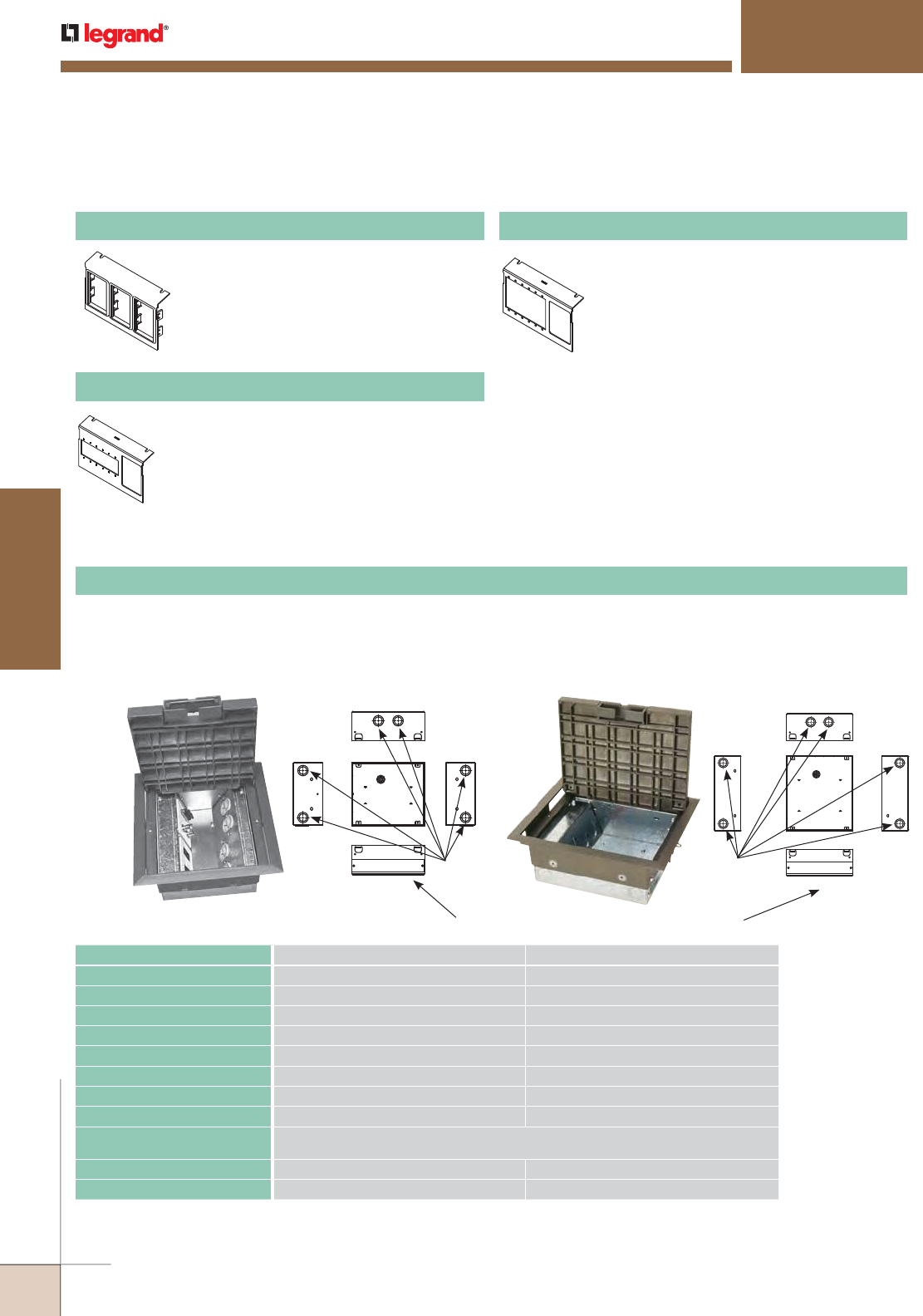
WWW.LEGRAND.US/WIREMOLD
510
FLOOR BOXES
WIREMOLD
* AC8850 is a single-service box. Power plates cannot be used in conjunction
with communication plates.
AC™ SERIES FLOOR BOXES
For AC8850 and AC8105 Boxes. Includes
three (3) 6A Wiremold CM Series Open
System adapters.
C8005P-3ACT* Communication Plate
Accepts six (6) Wiremold AVIP or Extron®
Electronics MAAP Series Devices, sold
separately, and one (1) CM communication
adapter.
NOTE: For use in AC8105 style box.
C8005P-MAAP-6A* Internal Audio/Video Plate
Accepts six (6) Extron® Electronics AAP
Series Devices, sold separately, and one (1)
CM communication adapter.
NOTE: For use in AC8105 style box.
C8005P-AAP-6A* Internal Audio/Video Plate
AC8104AC8840 Knockouts:
Side
1/2" & 3/4"
Trade Size
Concentric KOs
Back
Side
Top
Front
NOTE: Plate is removable for greater depth capacity.
The AC8840 and AC8104 are boxes with a 4" [102mm] depth design, with the AC8104 providing an extra 2" [51mm] of width
for added wiring capacity. These boxes can accommodate two duplex power receptacles on one side. Power plate with duplex
knockouts included with box. The communication plate will accept two communication adapters for up to 12 ports of activation.
Lids can be rotated 180° for easy orientation. Gray lids are die-cast zinc construction.
AC8840, AC8104 Raised Floor Boxes
DESCRIPTION AC8840 DIMENSIONS AC8104 DIMENSIONS
BOX DIMENSIONS 8" x 8" x 4” [203mm x 203mm x 102mm] 8" x 10" x 4” [203mm x 254mm x 102mm]
OVERALL TRIM RING 9 1/4" x 9 1/4" [235mm x 235mm] 9 1/4" x 11 1/4" [235mm x 286mm]
MODULE DEPTH OVERALL 4" [102mm] 4" [102mm]
PANEL OPENING 8" x 8" [203mm x 203mm] 8" x 10" [203mm x 254mm]
COVER SIZE 7 11/16" x 7 11/16" [195mm x 195mm] 7 11/16" x 9 11/16" [195mm x 246mm]
ACTIVATION CHAMBER VOLUME 63.92 cubic inches [1047ml] 76.87 cubic inches [1260ml]
USER VOLUME 84.34 cubic inches [1382ml] 130.09 cubic inches [2131ml]
TOTAL VOLUME 152.34 cubic inches [2496ml] 201.09 cubic inches [3295ml]
KNOCKOUTS Power – Four (4) 1/2"-3/4" Trade Size Concentric KOs
Communication – Two (2) 1/2"-3/4" Trade Size Concentric KOs
SERVICE Single Dual
MAXIMUM FLOOR THICKNESS 2" [51mm] (includes floor covering) 2" [51mm] (includes floor covering)
NOTE: For custom options, consult factory. All boxes are sold with one power plate: 4" [102mm] deep boxes have plate with
two power duplex receptacle KOs, 5" [127mm] deep boxes have plate with four power duplex receptacle KOs. All
communication plates sold separately.
Specifications
Side
Back
1/2" & 3/4"
Trade Size
Concentric KOs
Side
Front
Top
Knockouts:
Communication Plates for AC8850 and AC8105 Raised Floor Boxes Ordering Information
Communication Plates for AC8850 and AC8105 Raised Floor Boxes Ordering Information
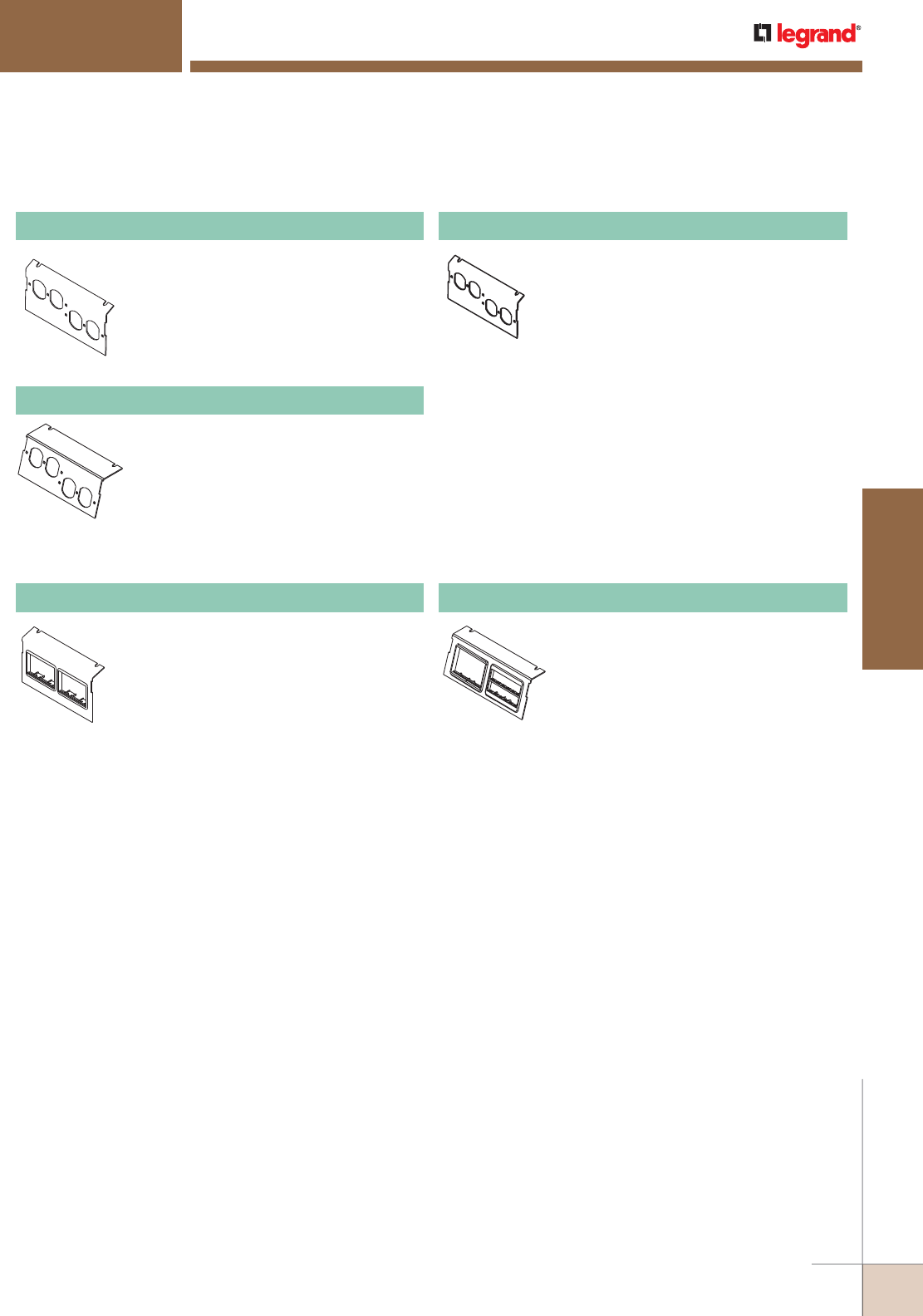
WWW.LEGRAND.US/WIREMOLD
511
FLOOR BOXES
WIREMOLD
AC™ SERIES FLOOR BOXES
NOTE: AC8840 is a single-service box. Power plates cannot be used in
conjunction with communication plates.
Two duplex KOs. One (1) plate supplied
with AC8840 Box.
P8840-2DP Power Plate
Power Plates for AC8840 and AC8104 Raised Floor Boxes Ordering Information
Two duplex KOs. For AC8840 and AC8104
Boxes.
C8004P-2DBP Communication Plate
Two duplex KOs. One (1) plate supplied
with AC8104 Box.
P8104-2DP Power Plate
NOTE: AC8840 is a single-service box. Power plates cannot be used in
conjunction with communication plates.
For AC8840 and AC8104 Boxes. Includes
two (2) Wiremold CM Series Open System
adapters.
C8004P-2ACT Communication Plate
For AC8840 and AC8104 Boxes. Includes
two (2) Ortronics® Series II adapters and
two (2) TracJack adapters.
C8004P-2RT Communication Plate
Communication Plates for AC8840 and AC8104 Raised Floor Boxes Ordering Information
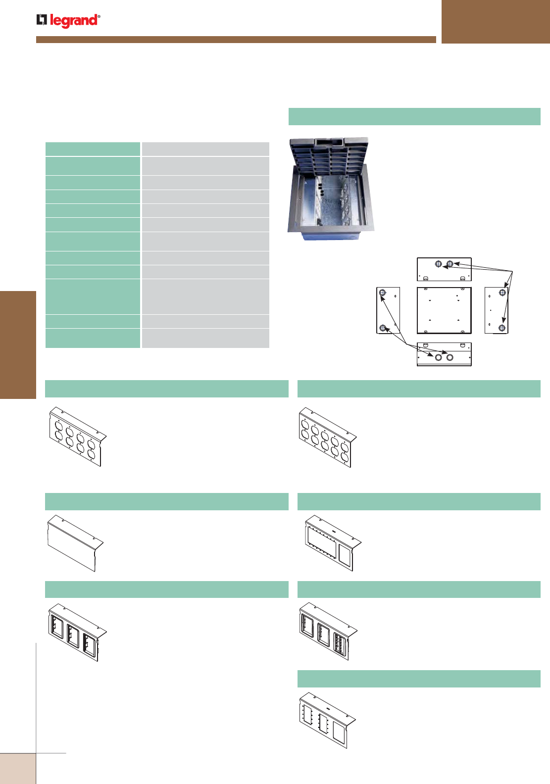
WWW.LEGRAND.US/WIREMOLD
512
FLOOR BOXES
WIREMOLD
AC™ SERIES FLOOR BOXES
AC10105-2 Raised Floor Box
Communication Plates for AC10105-2 Raised Floor Box Ordering Information
Knockouts:
Side
1/2" & 3/4"
Trade Size
Concentric KOs
Back
Side
Top
Front
1/2" & 3/4"
Trade Size
Concentric KOs
DESCRIPTION DIMENSIONS
BOX DIMENSIONS 10" x 10" x 5"
[254mm x 254mm x 127mm]
OVERALL TRIM RING 11 1/2" x 11 1/2" [292mm x 292mm]
MODULE DEPTH OVERALL 5" [127mm]
PANEL OPENING 10" x 10" [254mm x 254mm]
COVER SIZE 9 5/8" x 9 5/8" [245mm x 245mm]
ACTIVATION CHAMBER
VOLUME
115 cu. in. [1884ml]
USER VOLUME 243 cu. in. [3981ml]
TOTAL VOLUME 358 cu. in. [5865ml]
KNOCKOUT SIZES Power – Four (4) 1/2" Trade Size
Concentric KOs
Communication – Four (4) 1/2" Trade
Size Concentric KOs
SERVICE Triple
MAXIMUM FLOOR
THICKNESS
2" [51mm] (includes floor covering)
Specifications The AC10105-2 box with a 5" [127mm]
depth is a square profile box that
provides eight-gangs of power and/or
communication device capacity. Power
plate with duplex knockouts included
with box. The AC10105-2 also provides
increased plug-in volume which is ideal
for the additional space needed when
plugging in transformer type plugs. Lids
can be rotated 180° for easy orientation.
Gray lids are die-cast zinc construction.
Power Plates for AC10105-2 Raised Floor Box Ordering Information
Four duplex KOs. One supplied with
AC10105-2 Box.
P10105-4DP Double-Gang Power Plate
Five duplex KOs for AC10105-2 Box.
P10105-5DP Double-Gang Power Plate
Blank. For AC10105 Box.
C10105P-B Communication Plate
For AC10105 Box. Includes three (3)
Ortronics® Series II adapters and three (3)
TracJack adapters.
C10105P-3RT Communication Plate
For AC10105 Box. Includes three (3)
Wiremold CM Series Open System
adapters.
C10105P-3ACT Communication Plate
Accepts eight (8) Wiremold AVIP or
Extron® Electronics MAAP Series Devices,
sold separately, and one (1) CM Series
communication adapter.
C10105P-MAAP-6A Internal Audio/Video Plate
Accepts eight (8) Extron® Electronics AAP
Series Devices, sold separately, and one (1)
CM Series communication adapter.
C10105P-AAP-6A Internal Audio/Video Plate
AC Series Raised Floor Boxes Ordering Information
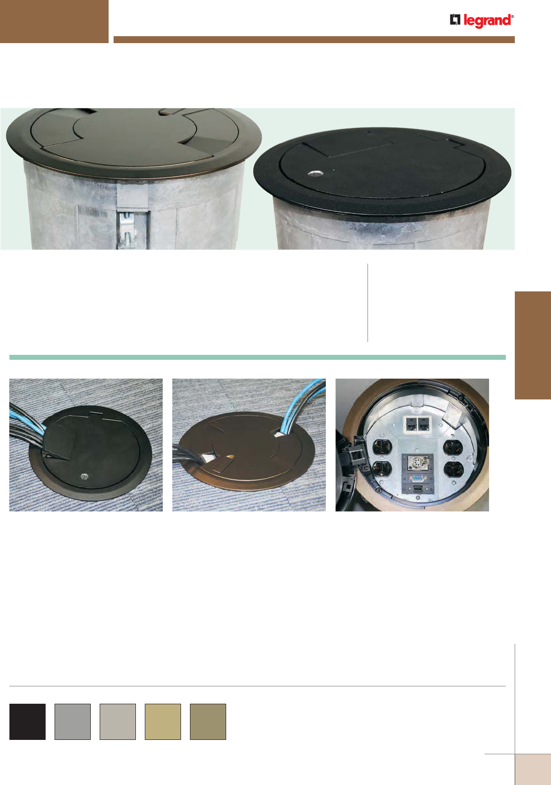
WWW.LEGRAND.US/WIREMOLD
513
FLOOR BOXES
WIREMOLD
CRFB SERIES™ FLOOR BOXES
CRFB Series Floor Boxes are round recessed floor boxes designed to meet the
functionality and flexibility requirements of the raised and wood floor markets.
New egress design for CRFB Series Floor Box
Covers offers larger wire/cable egress with
locking feature.
CODE REFERENCE
UL Listed Classified Raised Floor Box:
File E2961, Guide QCIT.
UL Listed Classified Raised Floor Box
(prewired):
File E51105, Guide QQVX.
Meets Article 300.22(c) of NEC
Meets Article 12-2500 of CEC.
CRFB Series Floor Boxes Cover and Evolution™ Series
Poke-Thru Covers are available in black, gray, nickel,
brass and bronze finishes.
COLOR OPTIONS
CRFB Series four-compartment configurable box.Cables egress from a CRFB Series Floor Box
with Evolution Series Poke-Thru Cover.
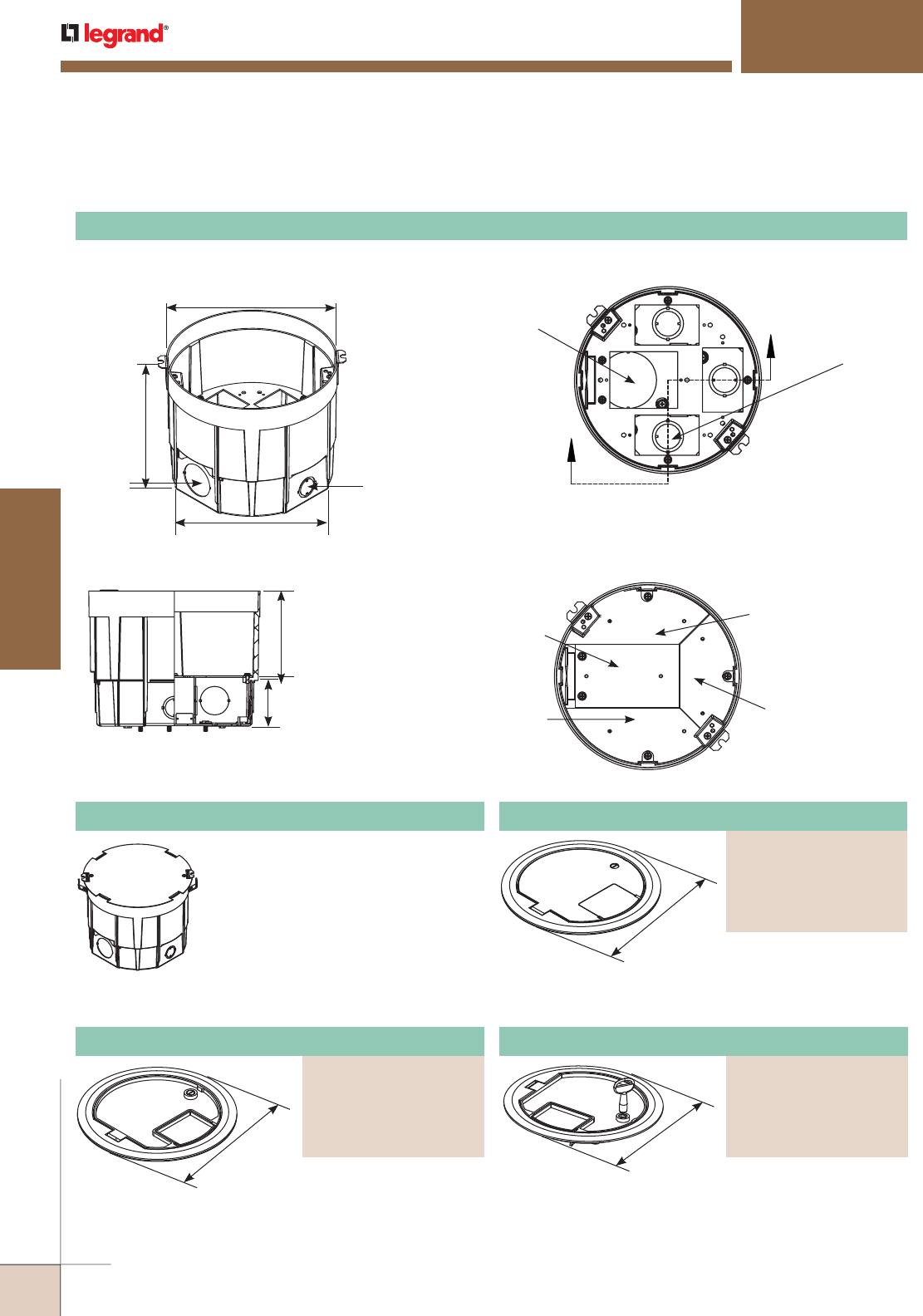
WWW.LEGRAND.US/WIREMOLD
514
FLOOR BOXES
WIREMOLD
Ø 8 1/4"
[210mm]
Ø 7.789"
[198mm]
6 5/8"
[168mm]
Combination 1/2" &
3/4" (3) concentric
trade size KOs
1 1/4" trade
size KO
2" Trade Size KO
Combination 3/4" & 1"
(3) concentric Trade
Size KOs
The housing is die-cast aluminum construction with stamped steel bottom plate.
COMPARTMENT DEPTH
23.5 in.3
[385ml]
17.5 in.3
[287ml]
32.8 in.3
[537ml]
23.5 in.3
[385ml]
COMPARTMENT VOLUMES
CRFB SERIES™ FLOOR BOXES
2 1/4"
[57mm]
3 3/4"
[95mm]
CRFB Series Round Raised Floor Boxes Ordering Information
9 3/16"
[233mm]
9 3/16"
[233mm]
Die-cast aluminum construction with
stamped steel bottom plate. Includes
3 duplex receptacle plates, 1 center
communication plate and 3 cable pass
through grommets for 1" trade size
tunnel.
NOTE: Floor thickness range (including floor
covering) 3/8" – 2" [9.5mm - 51mm].
CRFB4 CRFB Housing
Available in die cast aluminum with a painted finish.
No cutouts are provided for floor coverings.
Available in die cast aluminum with a painted finish.
Lid has built-in key locking feature for tamper resistance.
Insert areas allow for tile or carpet cutouts to match
finished floor.
CRFB Series Floor Boxes Assembly Details
CRFB-Housing
9 3/16"
[233mm]
Available in die cast aluminum with a painted finish. Insert
areas allow for tile or carpet cutouts to match finished floor.
Surface Style Cover Assembly
PART NUMBERS:
CRFBCTCBK (Black)
CRFBCTCGY (Gray)
CRFBCTCNK (Nickel)
CRFBCTCBS (Brass)
CRFBCTCBZ (Bronze)
Surface Style Cover Assembly
PART NUMBERS:
CRFBBTCBK (Black)
CRFBBTCGY (Gray)
CRFBBTCNK (Nickel)
CRFBBTCBS (Brass)
CRFBBTCBZ (Bronze)
Tamper Resistant Surface Style Cover Assembly
PART NUMBERS:
CRFBCTCBKTR (Black)
CRFBCTCGYTR (Gray)
CRFBCTCNKTR (Nickel)
CRFBCTCBSTR (Brass)
CRFBCTCBZTR (Bronze)
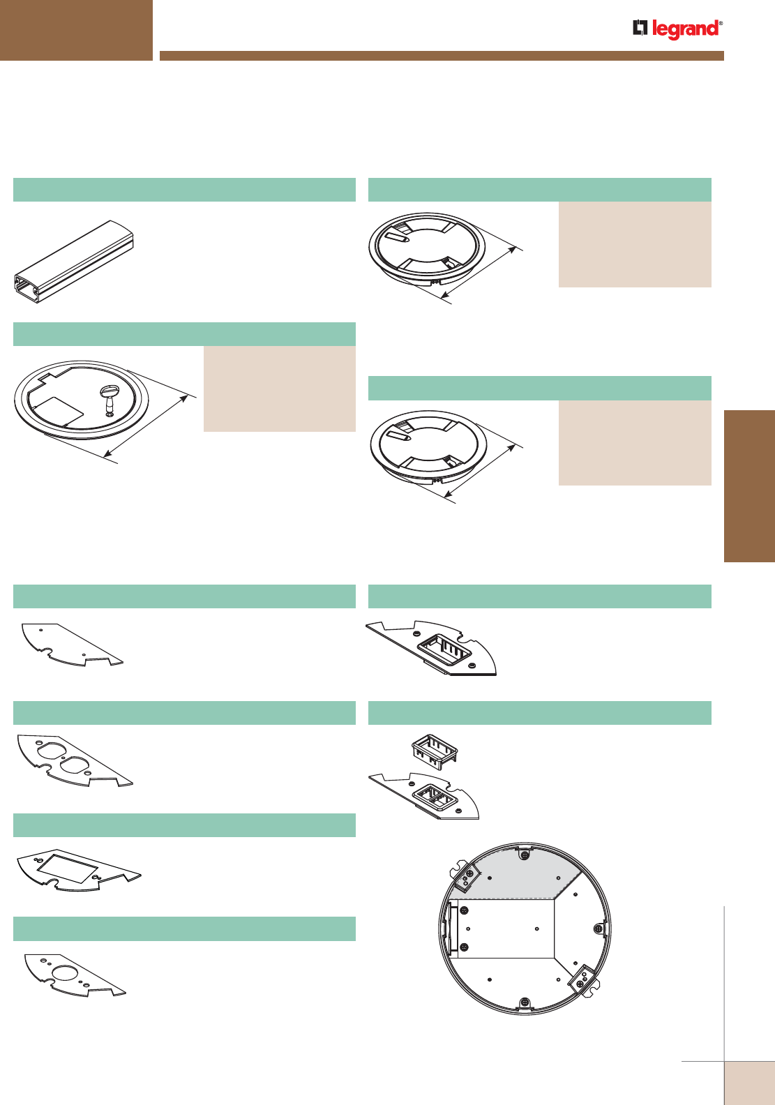
WWW.LEGRAND.US/WIREMOLD
515
FLOOR BOXES
WIREMOLD
9 3/16"
[233mm]
9 1/4"
[235mm]
CRFB SERIES™ FLOOR BOXES
Tunnel allows the two outer
compartments to be utilized for
one service while the center two
compartments are utilized for
other services.
CRFB-TUN Tunnel
Device Plate
Location #1
NOTE: Standard size for device plates for Plate Location 1
is 6 11/32" [161mm] x 2 3/4" [62mm].
CRFB Series Device Plates for Location 1 Ordering Information
Used to close off unused gang.
CRFB-B-1 Blank Device Plate #1
Accepts standard 15A and 20A
duplex receptacles.
CRFB-D-1 Duplex Device Plate
Accepts standard GFCI or Decorator
style receptacles.
CRFB-GFI-1 GFCI/Decorator Plate
Accepts single device 1.39" [35mm]
CRFB-SR1-1 1.39" [35mm] Device Plate
Accepts two (2) ports of
communication devices. Includes
one (1) Wiremold CM Series Open
System adapter and inserts.
CRFB-AB-1 Communication Device Plate
Accepts two (2) ports of
communication devices. Includes
one (1) Ortronics® Series II and one
(1) Tracjack adapter.
CRFB-RT-1 Communication Device Plate
CRFB Series Round Raised Floor Boxes Ordering Information
Die-cast aluminum cover
assembly with painted
finishes.
Surface Style Cover Assembly
PART NUMBERS:
8CTCBK (Black)
8CTCGY (Gray)
8CTCNK (Nickel)
8CTCBS (Brass)
8CTCBZ (Bronze)
NOTE: Add suffix “TR” to the end of the
part number to indicate tamper-
resistant cover assembly.
Available in die cast
aluminum with painted
finishes. No cutouts are
provided. Lid has built-in
key locking feature for
tamper resistance.
Tamper Resistant Surface Style Cover Assembly
PART NUMBERS:
CRFBBTCBKTR (Black)
CRFBBTCGYTR (Gray)
CRFBBTCNKTR (Nickel)
CRFBBTCBSTR (Brass)
CRFBBTCBZTR (Bronze)
9 1/4"
[235mm]
Die-cast aluminum cover
assembly with painted
finishes.
Flush Style Cover Assembly
PART NUMBERS:
8CTBK (Black)
8CTGY (Gray)
8CTNK (Nickel)
8CTBS (Brass)
8CTBZ (Bronze)
NOTE: Add suffix “TR” to the end of the
part number to indicate tamper-
resistant cover assembly.
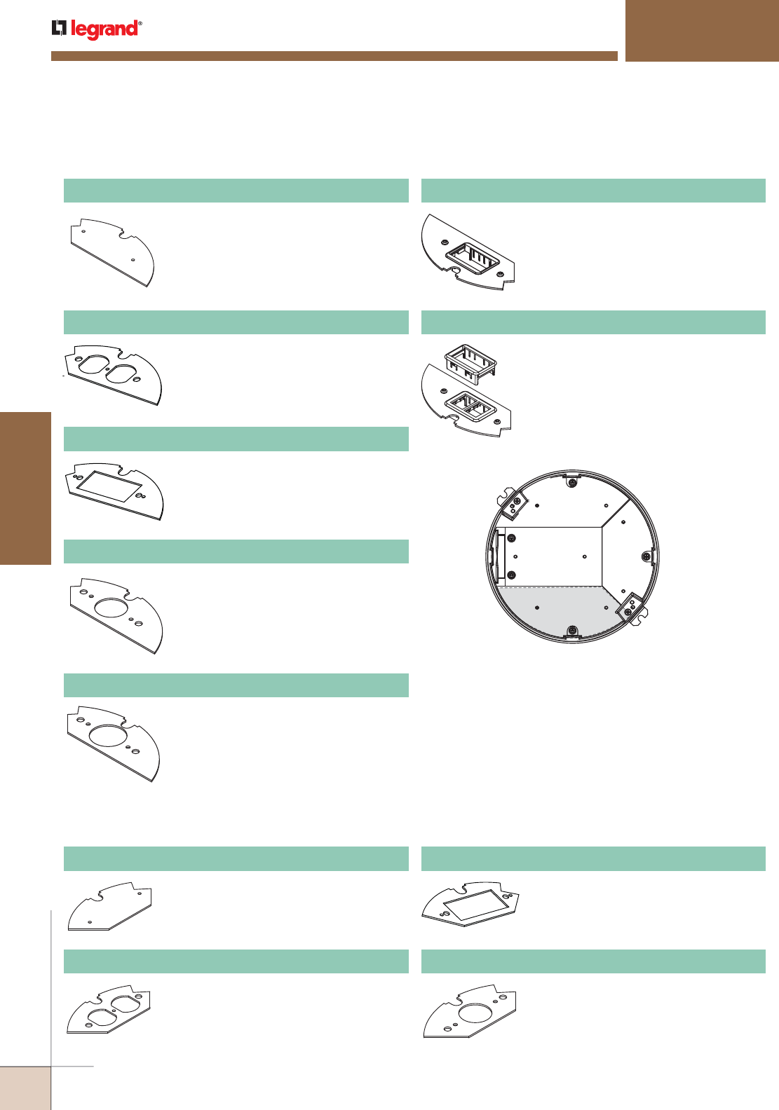
WWW.LEGRAND.US/WIREMOLD
516
FLOOR BOXES
WIREMOLD
Device Plate
Location #2
NOTE: Standard size for device plates for Plate Location 2
is 5 7/32" [132mm] x 2 3/4" [62mm].
CRFB SERIES™ FLOOR BOXES
CRFB Series Device Plates for Location 2 Ordering Information
Used to close off unused gang.
CRFB-B-2 Blank Device Plate #2
Accepts two (2) ports of
communication devices. Includes one
(1) Wiremold CM Series Open System
adapter and inserts.
CRFB-AB-2 Communication Device Plate
Accepts standard 15A and 20A duplex
receptacles.
CRFB-D-2 Duplex Device Plate
Accepts two (2) ports of
communication devices. Includes one
(1) Ortronics® Series II and one (1)
Tracjack adapter.
CRFB-RT-2 Communication Device Plate
Accepts standard GFCI or Decorator
style receptacles.
CRFB-GFI-2 GFCI/Decorator Plate
Accepts single device 1.39" [35mm]
CRFB-SR1-2 1.39" [35mm] Device Plate
Accepts single device 1.60" [41mm]
CRFB-SR2-2 1.60" [41mm] Device Plate
CRFB Series Device Plates for Location 3 Ordering Information
Used to close off unused gang.
CRFB-B-3 Blank Device Plate #3
Accepts standard 15A and 20A duplex
receptacles.
CRFB-D-3 Duplex Device Plate
Accepts standard GFCI or Decorator
style receptacles.
CRFB-GFI-3 GFCI/Decorator Plate
Accepts single device 1.39" [35mm].
CRFB-SR1-3 1.39" [35mm] Device Plate
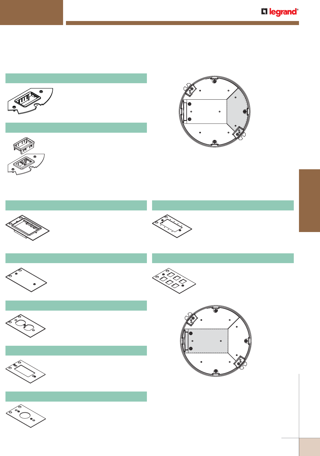
WWW.LEGRAND.US/WIREMOLD
517
FLOOR BOXES
WIREMOLD
Device Plate
Location #3
NOTE: Standard size for device plates for Plate Location 3
is 5 7/32" [132mm] x 2 3/4" [62mm].
CRFB Series Device Plates for Location 4 Ordering Information
Device Plate
Location #4
NOTE: Standard size for device plates for Plate Location 4
is 5 7/32" [132mm] x 2 3/4" [62mm].
CRFB SERIES™ FLOOR BOXES
Accepts two (2) ports of communication
devices. Includes one (1) Ortronics®
Series II and one (1) Tracjack adapter.
CRFB-RT-3 Communication Device Plate
Accepts two (2) ports of
communication devices. Includes one
(1) Wiremold CM Series Open System
adapter and inserts.
CRFB-AB-3 Communication Device Plate
CRFB Series Device Plates for Location 3 Ordering Information (continued)
Used to close off unused gang.
CRFB-B-4 Center Blank Plate
6A communications plate. Includes:
(1) 6A Wiremold Open System Adapter,
(1) Ortronics Series II Adapter, (1)
Ortronics TracJack Adapter. Modular
jacks sold separately.
CRFB-BEZ6A-4 Center 6A Comm Adapter
Accepts standard 15A and 20A Duplex
Receptacles.
CRFB-D-4 Center Duplex Plate
Accepts standard GFCI or Decorator
Style Receptacles.
CRFB-GFI-4 Center Decorator Style Plate
Accepts single device 1.39" [35mm].
CRFB-SR1-4 Center 1.39" [35mm] Device Plate
Holds four (4) Wiremold AVIP or Extron®
Electronics MAAP device plates.
CRFB-MAAP-4 Extron® MAAP Plate
Communication plate with six (6)
RJ knockouts. Modular jacks sold
separately.
CRFB-6COM-4 Center Communication Plate
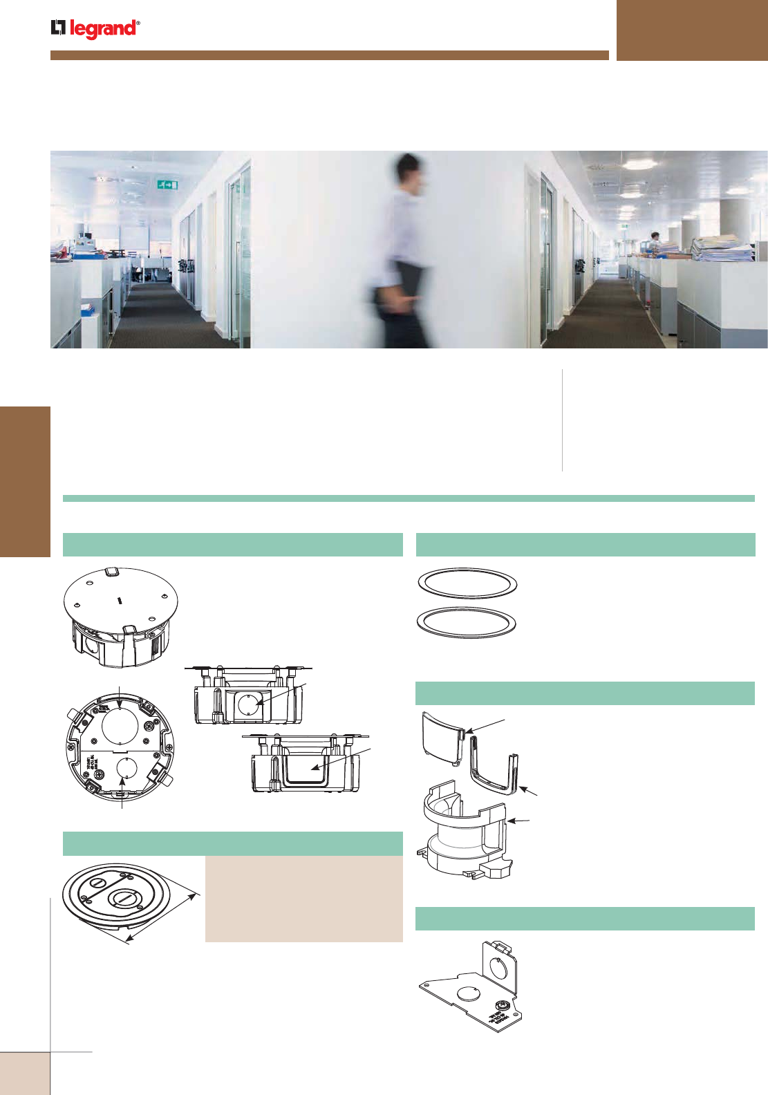
WWW.LEGRAND.US/WIREMOLD
518
FLOOR BOXES
WIREMOLD
Surface style, die-cast aluminum cover assembly, with
one (1) 3/4" trade size screw plug opening, and one (1)
concentric 2"-1 1/4" trade size screw plug opening. Includes
one (1) 3/4" and one (1) 2" trade size conduit fittings and
one (1) divider supplied to separate services. (Divider only
required for use with 6STC Poke-Thru stem assembly.)
CODE REFERENCE
UL Listed Classified Raised Floor Box:
File E2961, Guide QCIT
UL Listed Classified Raised Floor Box:
(prewired)
Meets article 300.22(c) of the NEC.
Meets article 12-2500 of the CEC.
FLOORSOURCE
™
SERIES ROUND FURNITURE FEED FLOOR BOXES
The new FloorSource™ Series Round Furniture Feed Floor Box is designed
to work in both wood and raised floor applications. Constructed of die cast
aluminum material, the furniture feed floor box can be divided for dual service.
Each 3" [76mm] tall box is provided with a durable sheet metal cover. This box
accepts the 6" [182mm] round Evolution™ Series furniture feed covers.
The FloorSource furniture feed box has many applications including: commercial
offices, financial insitutions, education and hospitality locations.
FloorSource™ Series Furniture Feed Floor Box Ordering Information
Die-cast aluminum body with stamped
steel knockout plates. Box includes
two (2) 3/4" trade size knockouts,
one (1) 1 1/2" trade size knockout, a
removable side feed plate, a divider
and a durable construction cap.
6TS Tile Shim
Used for floor coverings greater than
5/16" [7.9mm]. The 6TS will allow the
top surface of the cover to be flush
with the finished floor. Includes: two
(2) 1/8" [3.2mm] thick shims and two
(2) 1/16" [1.6mm] thick shims. Up to
a total of 3/8" [9.5mm] of adjustment.
6FF-AFB-HWB Replacement Part
Hardware bag includes one (1)
divider, one (1) side feed and one
(1) side feed plug grommet.
7 3/4"
[197mm]
Plug
Grommet
Divider
3/4" KO
Side
Feed
Plate
6CFF-AFB Round Furniture Feed Floor Box
3/4" KO
1 1/2" KO
6FFAFB-.5BP Accessory Knockout Plate
Stamped steel plate with 1/2"
trade size knockout.
6CFFTCGY Furniture Feed Cover Assembly
PART NUMBERS:
6CFFTCBK (Black)
6CFFTCGY (Gray)
6CFFTCNK (Nickel)
6CFFTCBS (Brass)
6CFFTCBZ (Bronze)
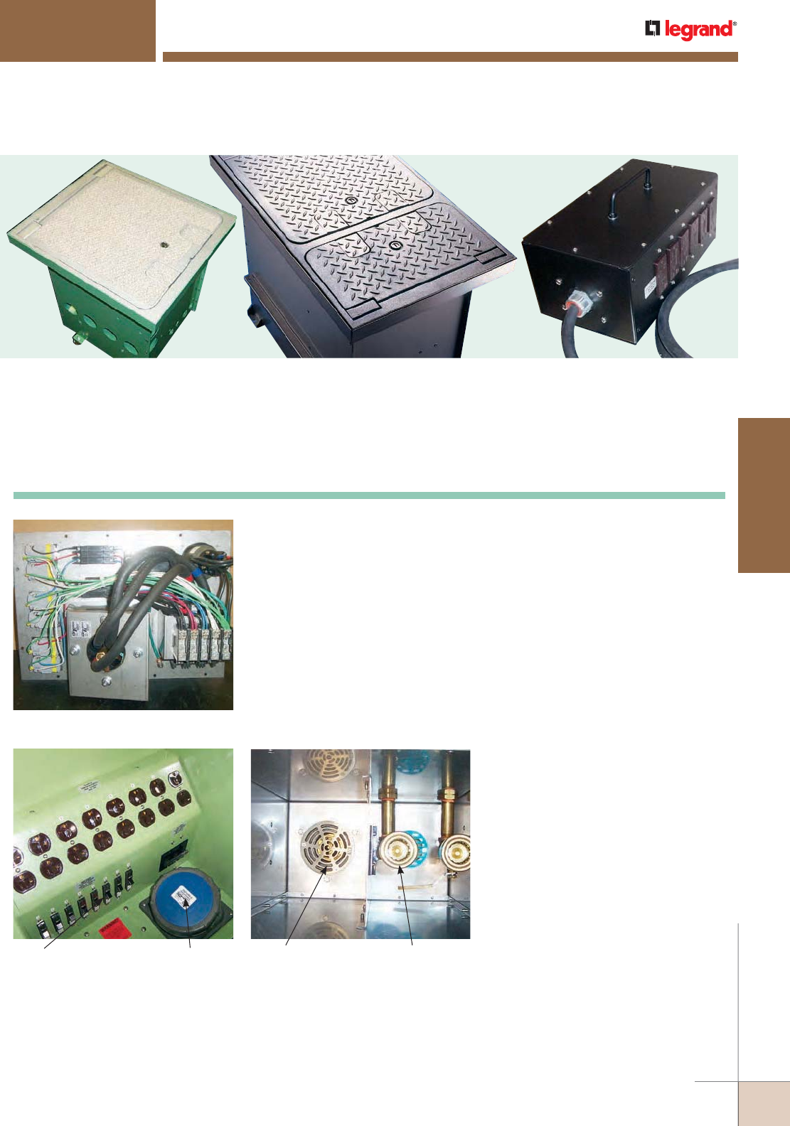
WWW.LEGRAND.US/WIREMOLD
519
FLOOR BOXES
WIREMOLD
Water and Compressed
Air Utilities
Drain Compartment
Water services (W) available. If water services
are required, a main divider is automatically
added to isolate the electrical/communications
compartments from the water compartment.
Compressed air services are also available.
Circuit Breakers
(Prewired to Receptacles)
100A Watertight Pin
and Sleeve Device
CCFB SERIES™ CONVENTION CENTER SERIES PRODUCTS
Convention Center Series™ Products are industry leading solutions for
providing multiple utilities services directly to the show room.
Available Prewired Electrical Sub-Assembly
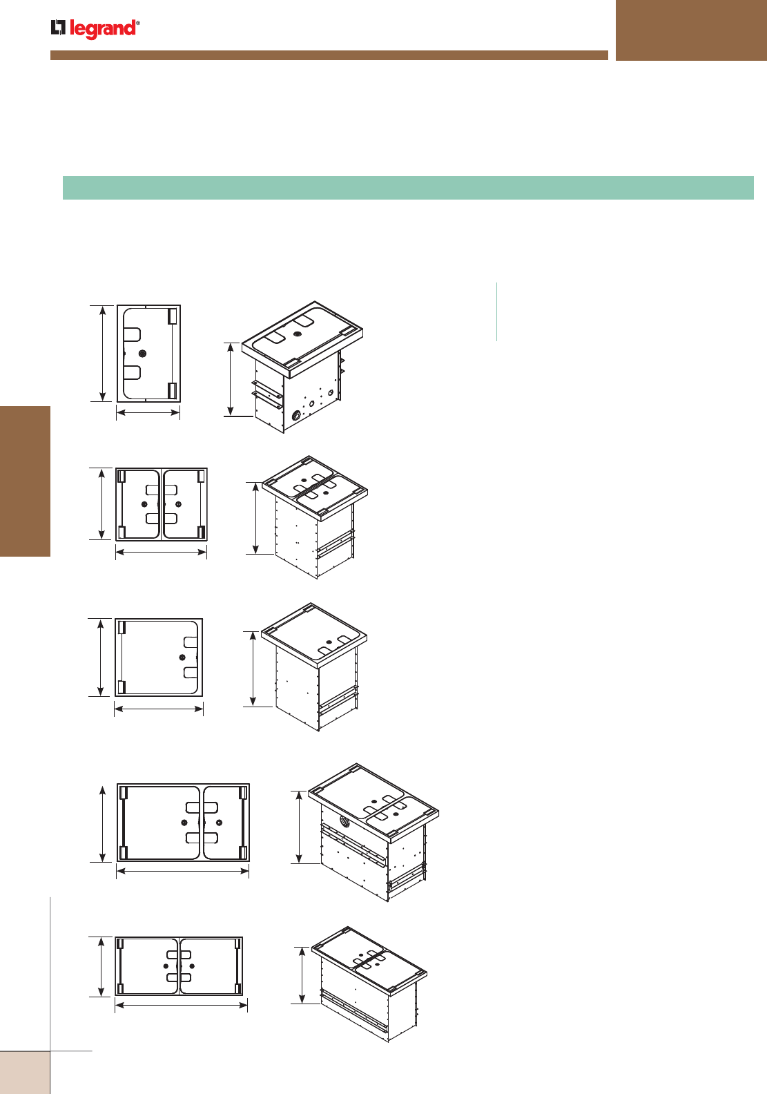
WWW.LEGRAND.US/WIREMOLD
520
FLOOR BOXES
WIREMOLD
CCFB SERIES™ CONVENTION CENTER SERIES PRODUCTS
NOTE: Boxes and Device Plates are custom made to order.
“-XXXX” in title denotes Project Number assigned by
Wiremold Project Services Team.
NOTE: Boxes and Covers are shipped separately.
NOTE: Load was applied in the center of the cover over a
1" x 16" rectangular bar.
NOTE: Service feed openings are field installed.
Power Capabilities
• One (1) 100A 120/208V Pin and Sleeve Receptacle
• One (1) 100A 277/480V Pin and Sleeve Receptacle
• 20A Receptacles
• 20A Panel Mounted Circuit Breakers
• 350A 600V Terminal Blocks
Maximum Electric Ratings
• 140A, 480V 3 Phase
• 140A, 120/208V 3 Phase into Terminal Blocks
• 100A, 277/480V 3 Phase for individually wired
Devices
Other Utilities
• Water
• Compressed Air
16 1/2"
[419mm]
12.1/2"
[317mm]
19.1/8"
[486mm]
TYPE S BOX
Cover Styles
CCFBC-NS-H-C1
CCFBC-CR-H-C1
Cover Styles
CCFBC-NS-H-C3
CCFBC-CR-H-C3
21"
[533mm]
24"
[610mm]
19.3/16"
[487mm]
TYPE SS BOX
25"
[635mm]
21 3/4"
[552mm]
19.3/16"
[487mm]
TYPE L BOX Cover Styles
CCFBC-NS-H-C2
CCFBC-CR-H-C2
Designed to accept power, communication and audio/video devices, water and compressed air. CCFB boxes are available in
four (4) different finishes: unpainted G90 galvanized steel (UGS), painted galvanized steel (PGS), stainless steel (USS) and
painted stainless steel (PSS). Cast aluminum cover assembly has a peened textured finish. Provided with a carpet cut-out
area and is designed to meet loads up to 64,000 lbs.
CCFB-XXXX Multi-Utility Recessed Floor Box
CODE REFERENCE
cULus Listed Metallic Outlet Boxes:
File E317375 Guide AUUZ, AUU27.
Meets Article 314 and 408 of NEC.
25"
[635mm]
33"
[838mm]
19.3/16"
[487mm]
TYPE LS BOX Cover Styles
CCFBC-NS-H-C4
CCFBC-CR-H-C4
25"
[635mm]
42"
[1067mm]
19.3/16"
[487mm]
TYPE LL BOX
Cover Styles
CCFBC-NS-H-C5
CCFBC-CR-H-C5
CCFB Ballroom Floor Boxes Ordering Information
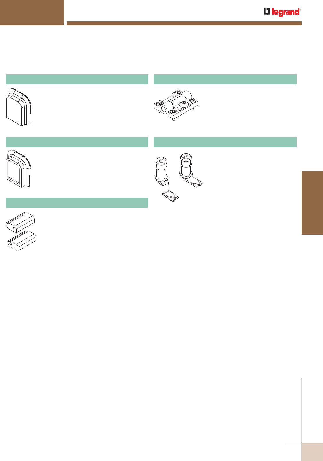
WWW.LEGRAND.US/WIREMOLD
521
FLOOR BOXES
WIREMOLD
CCFB SERIES™ CONVENTION CENTER SERIES PRODUCTS
CCFB-QT-001
CCFB-QT-002
Replacement egress blocks with a diamond
plate checkered pattern. Includes one egress
block and hinge.
CCFB-EBCH Checked Egress Block
Replacement egress blocks with carpet.
Includes one egress block and hinge.
CCFB-EBCI Carpet Insert Egress Block
Replacement cover hinges. Includes a left and
right hinge.
CCFB-HB Hinge Block Assembly
Replacement egress hinges. Includes
one (1) hinge.
CCFB-PH Egress Hinge
Quarter turn latch assembly allows
cover to be secured down when cover is
in closed position.
CCFB-QT Quarter Turn Latch
CCFB Series Floor Boxes Replacement Parts Ordering Information
NOTE: CCFB-QT-002 is used on the TYPE S and TYPE SS boxes.
CCFB-QT-001: used on TYPE L, TYPE LS, and TYPE LL boxes.
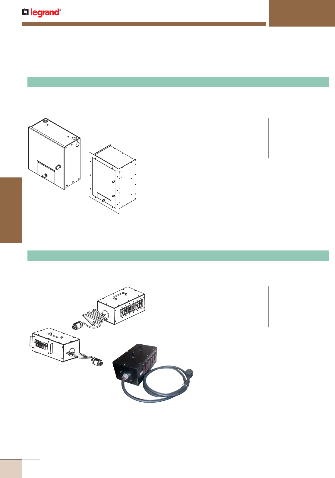
WWW.LEGRAND.US/WIREMOLD
522
FLOOR BOXES
WIREMOLD
PPDU-620 Power Distribution Unit
CCWB Series Wall Boxes Ordering Information
CCFB Series PPDU Portable Power Distribution Units Ordering Information
Surface Mounted Wall Box
Recessed Wall Box
CCFB SERIES™ CONVENTION CENTER SERIES PRODUCTS
Available in recessed and wall mount versions. Available with key locks for increased security and are designed for power,
communications and audio/video devices. Wall mount version available painted or in a paintable G60 material. Recessed
wall box is available in a G90 steel material and the recessed wall box covers are available in a paintable G60 material.
CCWB-XXXX Convention Center Wall Box
Power Capabilities
• One (1) 100A 120/208V Pin and Sleeve Receptacle
• One (1) 100A 277/480V Pin and Sleeve Receptacle
• 20A Receptacles
• 20A Panel Mounted Circuit Breakers
• 350A 600V Terminal Blocks
NOTE: Boxes and device plates are custom made to order.
“-XXXX” in part number denotes project number
assigned by Wiremold Project Services team.
Factory installed KOs per project requirements.
NOTE: The convention center wall boxes are not listed for
water and compressed air services.
CODE REFERENCE
cULus Listed Metallic
Outlet Boxes:
File E317375 Guide AUUZ,
AUU27.
Meets Article 314 and
408 of NEC.
Designed to supply power to an exhibition hall. Available in a painted steel enclosure with six (6) GFCI (20A/120V) duplex
receptacles, and six (6) single pole 20A, circuit breakers.
CODE REFERENCE
cULus Listed Portable
Power Units and Devices:
File E302114 Guide QPSH.
Meets Article(s) 518, 520,
525, 530 and 590 of NEC.
Electric Ratings
• Type 1
• Input: 30A, Three Phase 120/208V
• Output: 20A per Receptacle,
Single Phase 120VAC
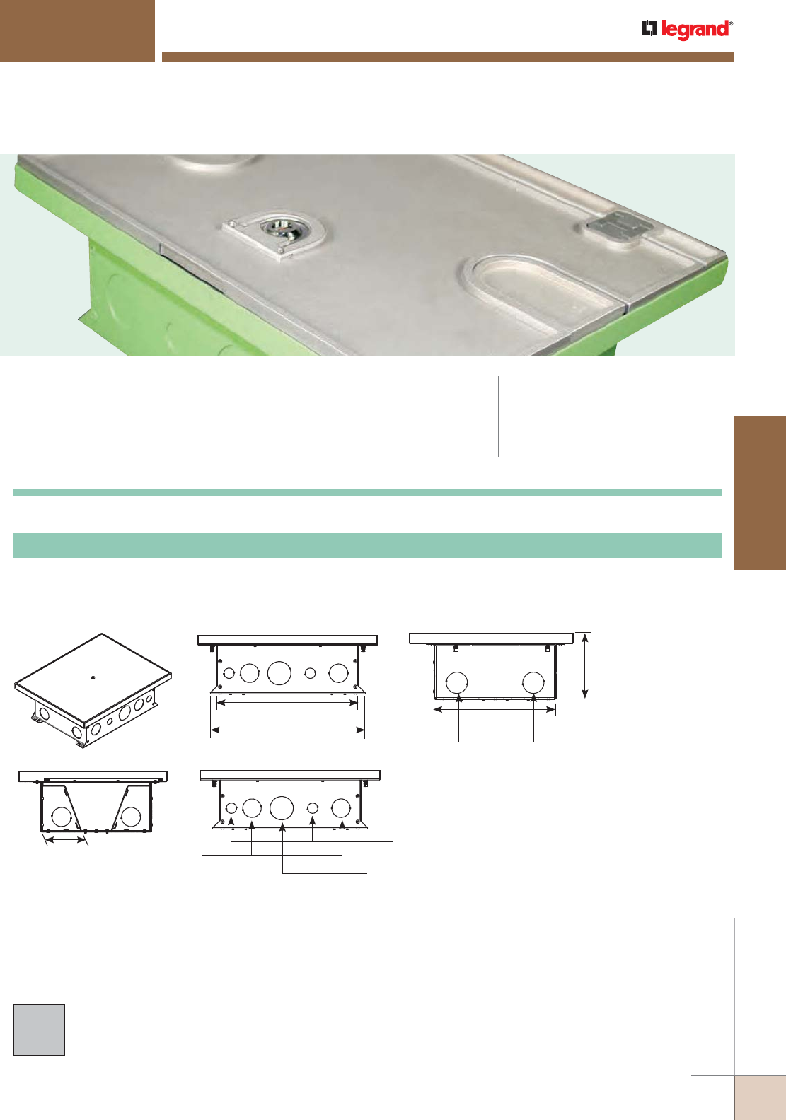
WWW.LEGRAND.US/WIREMOLD
523
FLOOR BOXES
WIREMOLD
CCBB SERIES™ BALLROOM FLOOR BOXES
CCBB Series™ Ballroom Floor Boxes are concrete floor boxes that have
been designed for above-grade and on-grade applications. CODE REFERENCE
UL Listed Commercial Appliance
and Outlet Centers:
File E237584. Guide AUUZ, AUU27.
CCFB Series Floor Box covers are cast aluminum and
available with a peened textured finish.
COLOR OPTIONS
CCBBS, CCBBS-OG 12-Gang Recessed Floor Box
Adjustable before concrete pour, provided with mudcap to prevent concrete entry during pour. Cover assembly and device
plates sold separately. Available in a standard model for above grade applications (CCBBS) or with a painted epoxy coating
for on grade applications (CCBBS-OG).
CCBB Series Ballroom Floor Boxes Ordering Information
Depth Behind Plate
3 3/4" [95mm]
NOTE: Custom options are available. Consult factory for more
information.
15 5/32"
[385mm]
16 19/32"
[421mm]
6 1/4"
[159mm]
11 1/2"
[292mm]
1 1/2"
Trade Size KOs
1 1/2"
Trade Size KOs
2"
Trade Size KOs
3/4"
Trade Size KOs
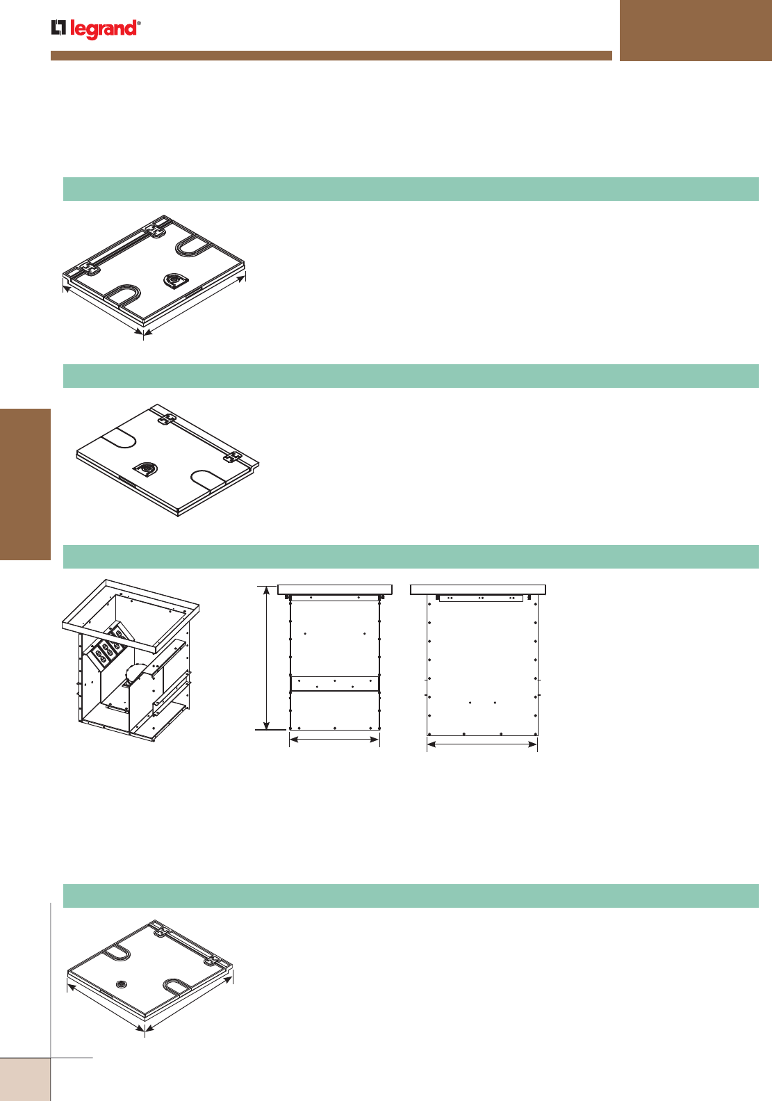
WWW.LEGRAND.US/WIREMOLD
524
FLOOR BOXES
WIREMOLD
19"
[483mm]
13 1/8"
[333mm]
NOTE: Load was applied in the center of the cover over a 1" x 14" rectangular bar. Covers are designed for
use in floors with a floor covering of 1/4" [6.4mm] minimum. (Not intended for bare concrete or
terrazzo applications.)
CCBB SERIES™ BALLROOM FLOOR BOXES
CCBBSCTCAL Carpet Cover Assembly
Cast aluminum cover assembly. Available in a peened textured finish. Provided with a
carpet cut-out area. Load tested over 25,000 lbs.
NOTE: Boxes and Device Plates are custom made to order. “-XXXX” in title denotes Project Number
assigned by Wiremold Project Services Team.
NOTE: Not intended for use on bare concrete or terrazzo floors.
NOTE: Service feed openings are field installed.
17 7/8"
[454mm]
15 1/16"
[383mm]
Box Depth:
25" [635mm]
Depth varies
based on
services included.
CCBBL-XXXX Recessed Floor Box
Designed to accept power,
communication and A/V device.
Power Capabilities
• One (1) 100A 120/208V Pin and Sleeve
Receptacle
• One (1) 100A 277/480V Pin and Sleeve
Receptacle
• 20A Receptacles
• 20A Panel Mounted Circuit Breakers
• 350A 600V Terminal Blocks
Maximum Electric Ratings
• 140A, 480V 3 Phase
• 140A, 120/208V 3 Phase into Terminal
Blocks
• 100A, 277/480V 3 Phase for
individually wired Devices
CCBB Series Ballroom Floor Boxes Ordering Information (continued)
NOTE: Load was applied in the center of the cover over a 1" x 14" rectangular bar. Covers are designed for
use in floors with a floor covering of 1/4" [6.4mm] minimum. (Not intended for bare concrete or
terrazzo applications.)
21 1/2"
[546mm]
19"
[483mm]
CCBBLCTCAL Carpet Cover Assembly
Cast aluminum cover assembly. Available in a peened textured finish. Provided with a
carpet cut-out area. Load tested over 30,000 lbs.
NOTE: Load was applied in the center of the cover over a 1" x 14" rectangular bar. Covers are designed for
use in floors with a floor covering of 1/4" [6.4mm] minimum. (Not intended for bare concrete or
terrazzo applications.)
CCBBSBTCAL Carpet Cover Assembly
Cast aluminum solid top cover assembly for polished concrete applications. Available
with a peened texture finish. Load tested over 25000 lbs.
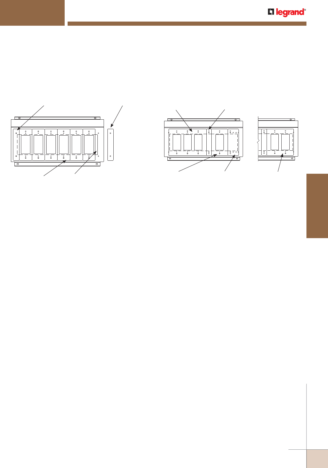
WWW.LEGRAND.US/WIREMOLD
525
FLOOR BOXES
WIREMOLD
CCBB SERIES™ BALLROOM FLOOR BOXES
Small Ballroom Floor Boxes Device Plate Installation information
CCBBS Small Ballroom Series Floor Boxes Device Plate Installation Information
(6) 1-Gang Sectional Plates
1 13/16" x 4 1/2"
[46mm x 114mm]
Cat. No. RFB119-SPACER
Used to close gap on outside sectional device plate
Existing opening when not
covered with Cat. No.
RFB119-SPACER
RFB119-SPACER
Multi-Gang Mounting Brackets Used
with Sectional Device Plates
Multi-Gang Mounting Brackets Used
with Standard Device Plates
3-Gang Standard Plate
6 3/8" x 4 1/2"
[162mm x 114mm]
1-Gang Standard Plate
2 3/4" x 4 1/2"
[70mm x 114mm]
Cat. No. RFB119-SPACER
Used to close gap between standard
single and multi-gang plates
Cat. No. RFB119-SB
Single-gang sectional blank plate
(Mounted off-center)
2-gang standard plate
4 9/16" x 4 1/2"
[116mm x 114mm]
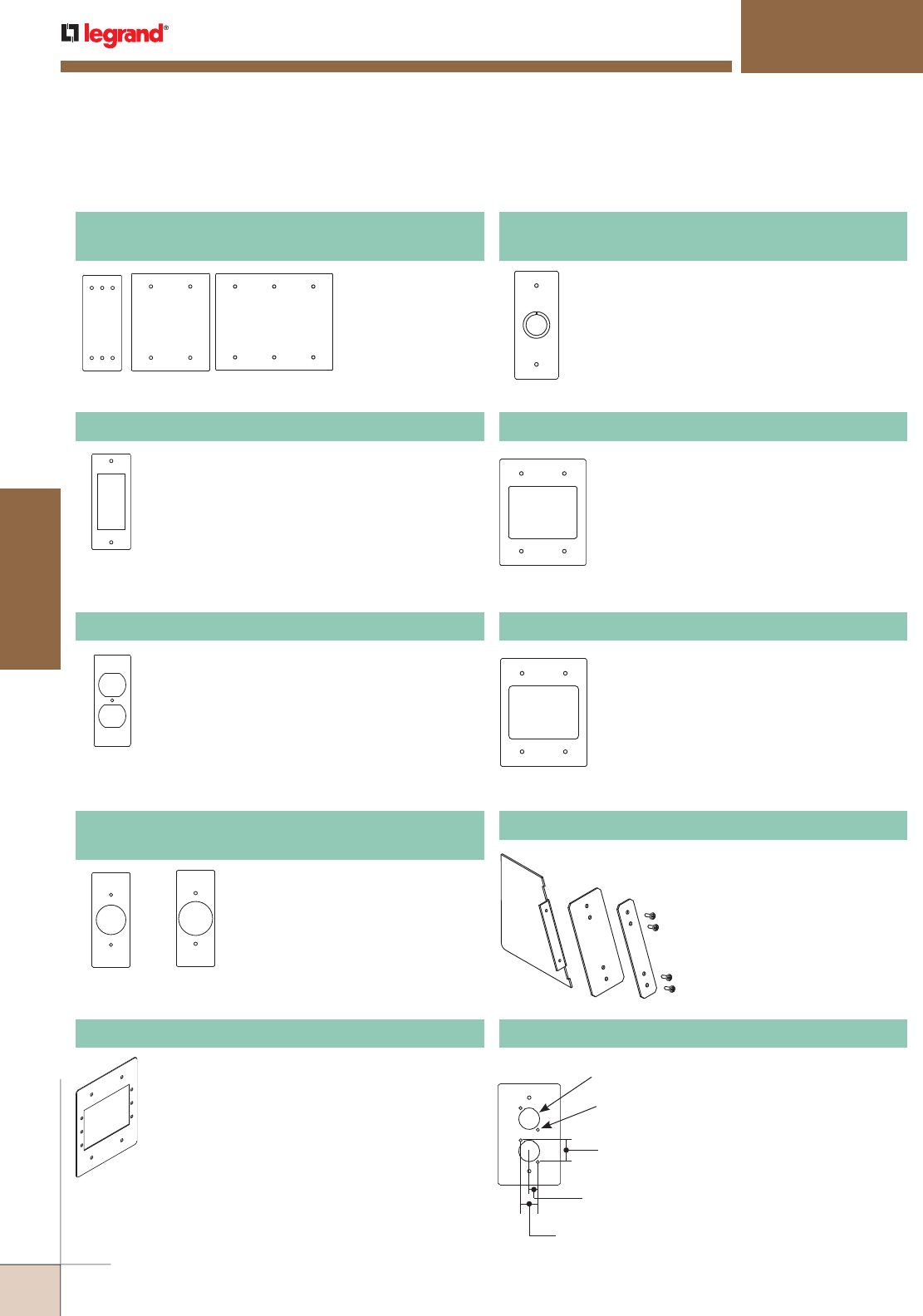
WWW.LEGRAND.US/WIREMOLD
526
FLOOR BOXES
WIREMOLD
CCBB SERIES™ BALLROOM FLOOR BOXES
RFB119-XLR Microphone Device Plate
Available in standard widths.
Provided with double opening to
accept two microphone devices.
RFB119-2SAB
RFB119-2SRT
RFB119-SGFI GFI Receptacle Device Plate
Single-gang sectional (SGFI) width device plate.
One-, two- and
three-gang device
plates in standard
widths.
RFB119-SB, RFB119-2SB, RFB119-3SB
Blank Device Plate
RFB119-SB RFB119-3SB
RFB119-2SB
Diameter 0.875"
[22.2mm]
Diameter 0.109"
[2.8mm]
1"
[25.4mm]
0.375"
[9.5mm]
0.750"
[19.1mm]
RFB119SD Duplex Receptacle Device Plate
Single-gang sectional (SD) width device plate.
RFB119-SSR1 RFB119-SSR2
RFB119-SSR1, RFB119-SSR2
Single Receptacle Device Plate
Single-gang device plates in
sectional widths. SSR1 has an
opening of 1.39" [35.31mm] and
SSR2 has an opening of 1.59"
[40.39mm].
RFB119-AAP Device Plate
Two-gang sectional device plate. Holds three (3)
Extron® Electronics AAP devices.
RFB119-2SAB Communication Device Plate
Available in two-gang sectional width.
Provided with bezel to accept up to
three (3) dual Wiremold CM Series Open
System communication modules or Pass
& Seymour® Activate Connectivity System
inserts. Modular inserts sold separately.
RFB119-2SRT Communication Device Plate
Available in two-gang sectional width.
Provided with one opening to accept
one Ortronics® TracJack bezel and one
Ortronics® Series II bezel. Will accept up
to six Ortronics® TracJack devices or up
to three dual Ortronics® Series II modular
inserts. Modules sold separately.
CCBBS-DIV Relocatable Divider
Provides separation for services.
Includes Divider and two (2)
detentes size plates.
RFB119-SKO Combination 1/2" and 3/4" Trade Size
Knockout Device Plate
Available in sectional (SKO) width.
CCBBS Series Floor Boxes Steel Sectional Device Plates Ordering Information
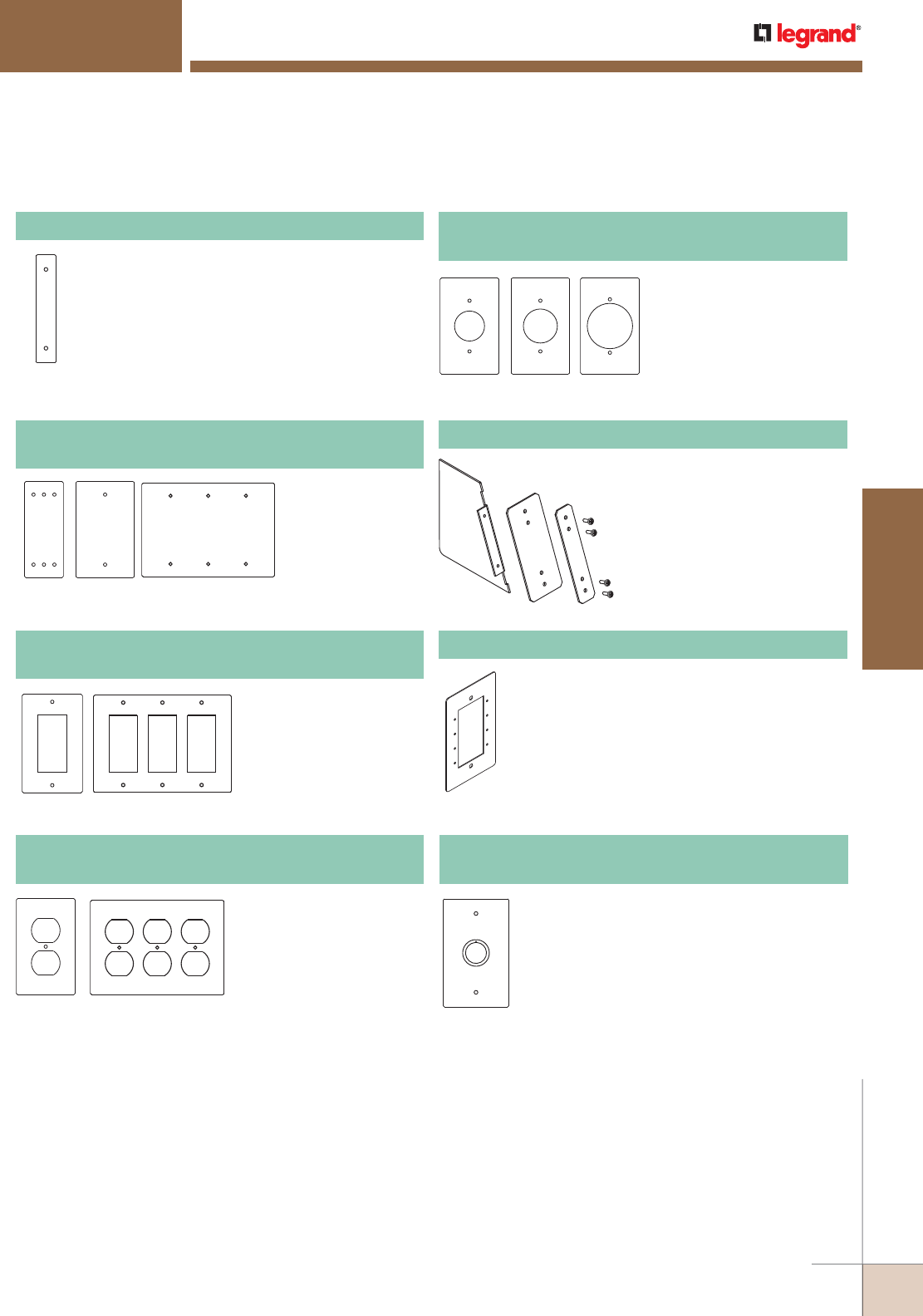
WWW.LEGRAND.US/WIREMOLD
527
FLOOR BOXES
WIREMOLD
RFB119-Spacer Spacer Plate
Used to close off openings when certain
combinations of standard width device
plates leave open spaces. Four (4) spacer
plates are included with the RFB11 and
two (2) with the RFB9.
CCBB SERIES™ BALLROOM FLOOR BOXES
NOTE: Sectional device plates allow for custom configuration of a multi-gang plate that conforms to the standard NEMA 1.812" (1 13/16") [46.02mm]
center-to-center spacing.
RFB11 and RFB9 will also accept industry standard and standard sectional device plates from most manufacturers.
RFB119-GFI RFB119-3GFI
RFB119-D RFB119-3D
RFB119-B RFB119-3BRFB119-SB
One-, two- and
three-gang blank
device plates in
sectional (SB)
widths
RFB119-B, RFB119-3B, RFB119-SB
Blank Device Plate
One- and three-gang
device plates in standard
(GFI) widths.
RFB119-GFI, RFB119-3GFI
GFI Receptacle Device Plates
One- and three-gang
device plates in standard
(D) widths.
RFB119-D, RFB119-3D
Duplex Receptacle Device Plates
RFB119-SR1 RFB119-SR2 RFB119-SR3
One-device plates in
standard (SR) widths.
SR1 has an opening of
1.39" [35.31mm]. SR2
has an opening of 1.59"
[40.39mm]. SR3 has a
2.14" [54.36mm] opening.
RFB119-SR1, RFB119-SR2, RFB119-SR3
Single Receptacle Device Plates
CCBBS-DIV Relocatable Divider
Provides separation for services.
Includes Divider and two (2)
different size plates.
RFB119-MAAP Device Plate
One-gang standard device plate. Holds
four (4) Wiremold AVIP or Extron® Electronics
MAAP devices.
Available in standard (KO) widths.
RFB119-KO Combination 1/2" and 3/4" Trade Size
Knockout Device Plates
CCBBS Floor Boxes Steel Standard Device Plates Ordering Information (continued)
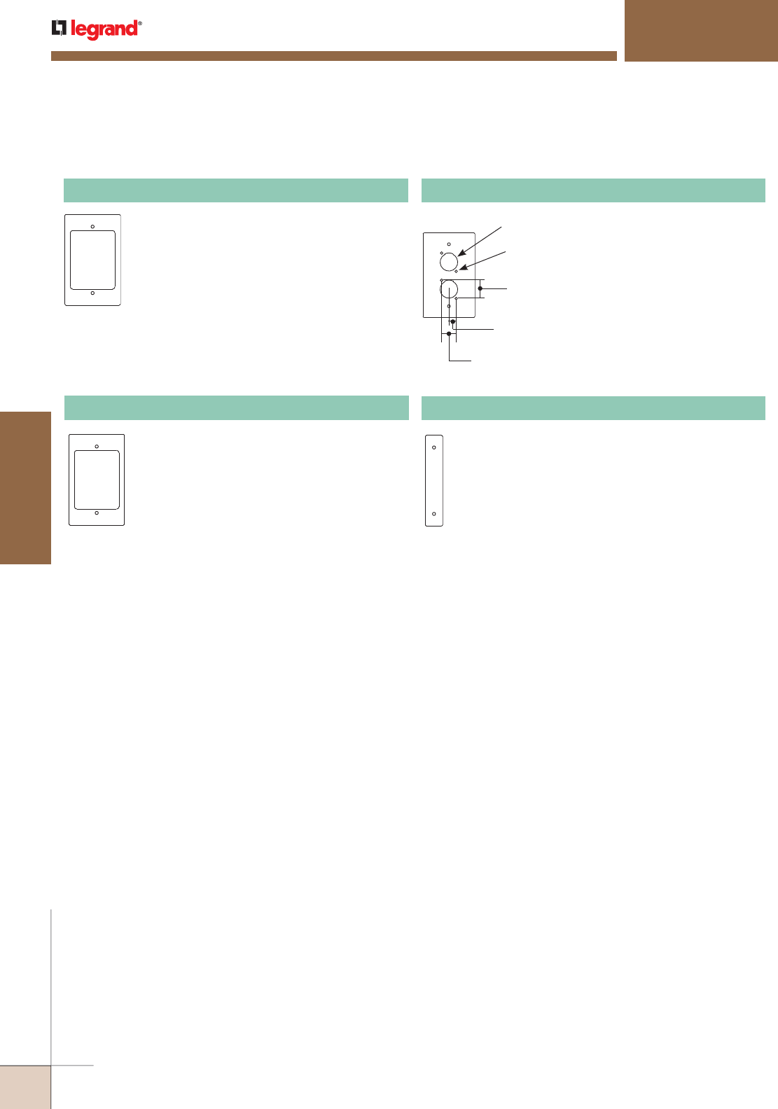
WWW.LEGRAND.US/WIREMOLD
528
FLOOR BOXES
WIREMOLD
RFB119-AB Communication Device Plate
Available in standard width. Provided with
bezel to accept up to three (3) dual Wiremold
CM Series Open System communication
modules or Pass & Seymour® Activate
Connectivity System inserts. Modules and
inserts sold separately.
RFB119-RT Communication Device Plate
Available in standard width. Provided with one
opening to accept one Ortronics® TracJack
bezel and oneOrtronics® Series II bezel. Will
accept up to six Ortronics® TracJack devices
or up to three dual Ortronics® Series II
modular inserts. Modular inserts and devices
sold separately.
Diameter 0.875"
[22.2mm]
Diameter 0.109"
[2.8mm]
1"
[25.4mm]
0.375"
[9.5mm]
0.750"
[19.1mm]
RFB119-XLR Microphone Device Plate
Available in standard widths.
Provided with double opening to
accept two microphone devices.
RFB119-Spacer Spacer Plate
Used to close off openings when certain
combinations of standard width device plates leave
open spaces. Four (4) spacer plates are included with
the RFB11 and two (2) with the RFB9.
CCBB SERIES™ BALLROOM FLOOR BOXES
CCBBS Floor Boxes Steel Standard Device Plates Ordering Information (continued)
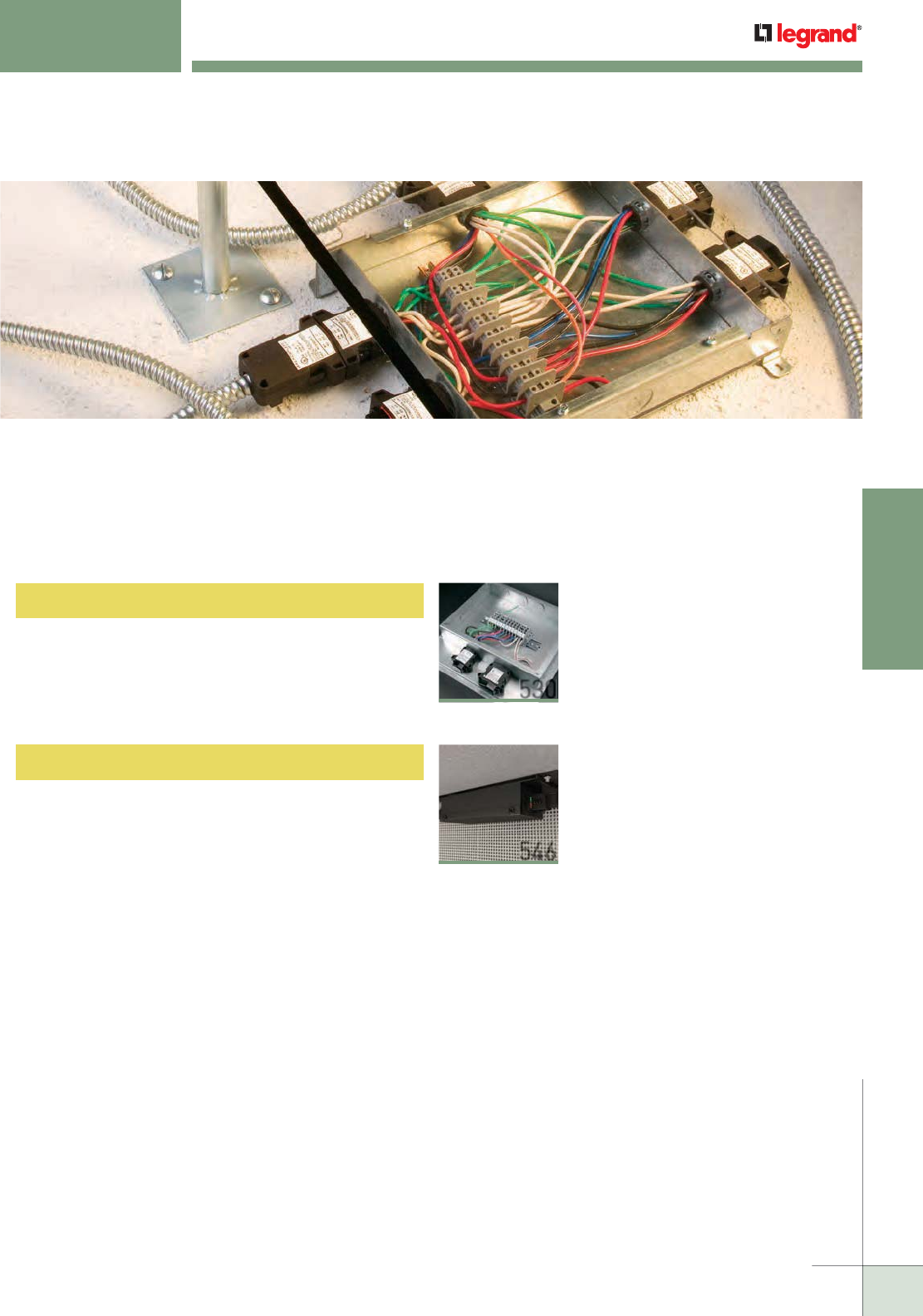
WIREMOLD
WWW.LEGRAND.US/WIREMOLD
529
MODULAR WIRING
MODULAR WIRING
Walkerflex® Modular Wiring Systems offer cost-effective wire management
capabilities for power distribution. This system can be utilized with a wide variety
of Wiremold® point-of-use products enabling maximum flexibility relating to
adds, moves and changes.
530
Walkerflex® Modular Wiring System
Table of Contents
546
Work Surface Modular Power
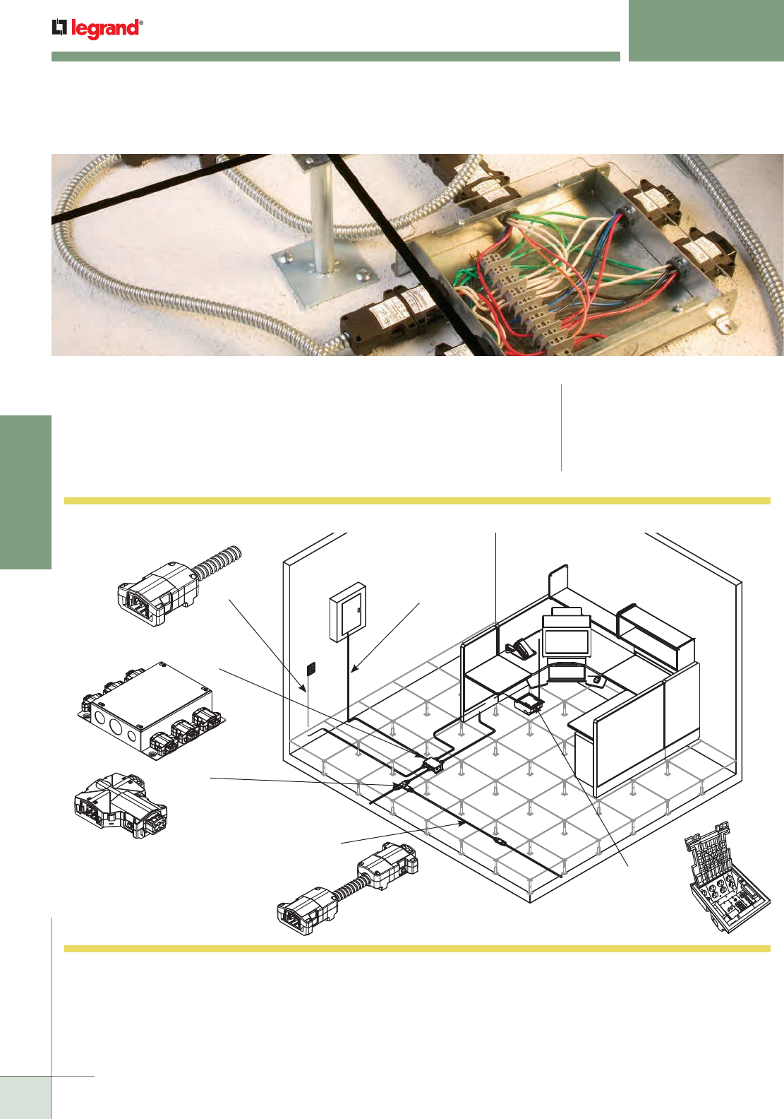
WIREMOLD
WWW.LEGRAND.US/WIREMOLD
530
MODULAR WIRING
NOTE: Illustration is for showing product applications only.
KEY
A typical workstation layout using
Walkerflex products to feed furniture
panel and AF Series Raised Floor
Box in a raised floor application.
AF Series
Raised Floor Box
NCBS
Cable Splitter
NCW
Cable Whip Homerun Cable
NDU
Distribution Unit
NCS
Cable Set
Walkerflex Modular Wiring System Layout
WALKERFLEX
®
MODULAR WIRING SYSTEM
Walkerflex® Modular Wiring Systems are designed to provide the highest level
of flexibility for power distribution as well as reducing the cost relating to future
adds, moves, and changes.
CODE REFERENCE
cULus Listed Manufactured Wiring
Systems:
File E51105 Guide QQVX
Meets Article 300.22(c), 314 & 604 of NEC.
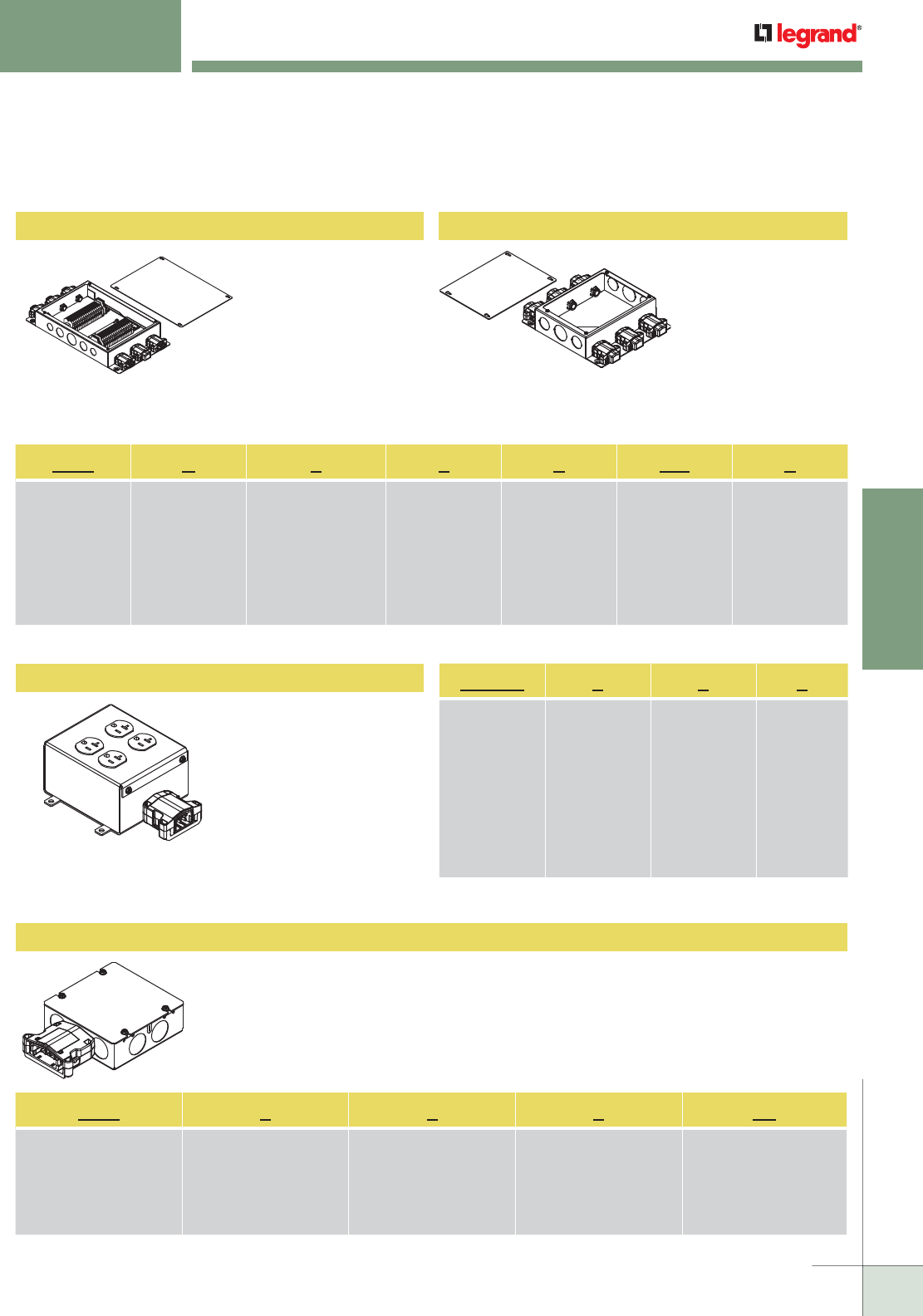
WIREMOLD
WWW.LEGRAND.US/WIREMOLD
531
MODULAR WIRING
WALKERFLEX
®
MODULAR WIRING SYSTEM
Prewired Distribution Unit
Receptacle Distribution Unit
Furniture Feed Distribution Unit
Unwired Distribution Unit
Conversion point from
electrical closet to the
Walkerflex System.
Unit can be prewired to
buss bar system or be
prewired with home run
cable. Consult factory
for prewiring home run
cable.
Example: NDUP222WC6
Prewired receptacle
unit that is fed with the
flex system.
Example: RECDU111
Conversion point from rigid EMT, BX, or other listed
manufactured wiring systems to the Walkerflex Modular
Wiring System.
Example: NDU332FF
Conversion point from
electrical closet to the
Walkerflex System. Unit
is for field wiring.
Example: NDU222WC6
NOTE: All distribution units are wired
with #10 AWG wire and a #12
Equipment ground.
NDU P 2 2 2 WC 6
Identifies the
Distribution Unit
NDU=120V
LDU=277V
Identifies how
unit is wired:
( ) Unwired – No
identifier needed
(see unwired
example above
(P) Prewired)
Number of Circuits,
also number of Hot
Conductors per
Connector. Insert "1"
for single circuit, "2"
for two-circuit, "3" for
three-circuit, "4" for
four-circuit, or "6" for
six-circuit.
Identifies Number
of Neutral
Conductors per
Connector, Four
(4) Conductors
maximum.
All Neutrals
#10 AWG.
Number of Ground
Conductors per
Connector. Insert
"1" for one System
Ground or "2" for
one System Ground
and one Isolated
Ground.
"WC" stands for
Wire Connector.
Remains constant.
Identifies Number
of Power "OUT"
Wire Connectors.
NOTE: For available wiring configuration options, see Wiring Configurations Chart in this section.
NDU 3 3 2 FF
Identifies the Furniture Feed
Distribution Unit.
NDU=120V
LDU=277V
Number of Circuits, also
number of Hot Conductors.
Insert “1” for single circuit,
“2” for two-circuit, “3” for
three-circuit, “4” for four-
circuit, or “6” for six-circuit.
Identifies number of Neutral
Conductors. Four (4)
Conductors maximum.
All Neutrals #10 AWG.
Number of Ground
Conductors. Insert “1” for
one System Ground or “2” for
one System Ground and one
Isolated Ground.
“FF” stands for Furniture
Feed. Remains constant.
NOTE: For available wiring configuration options, see Wiring Configurations Chart in this section.
RECDU 1 1 1
Identifies the
Receptacle
Distribution Unit.
Remains
constant.
Number of
Circuits, also
number of Hot
Conductors.
Insert “1” for
single circuit, “2”
for two-circuit,
“3” for three-
circuit, “4” for
four-circuit, or
“6” for six-circuit.
Identifies number
of Neutral
Conductors.
Four (4)
Conductors
maximum.
All Neutrals #10
AWG.
Number
of Ground
Conductors.
Insert “1” for
one System
Ground or “2”
for one System
Ground and
one Isolated
Ground.
NOTE: For available wiring configuration options, see Wiring Configurations
Chart in this section.
NOTE: Not suitable for use in air handling spaces.
NOTE: Units need to be field wired.
Walkerflex Modular Wiring System Components
NOTE: All distribution units are wired
with #10 AWG wire and a #12
Equipment ground.
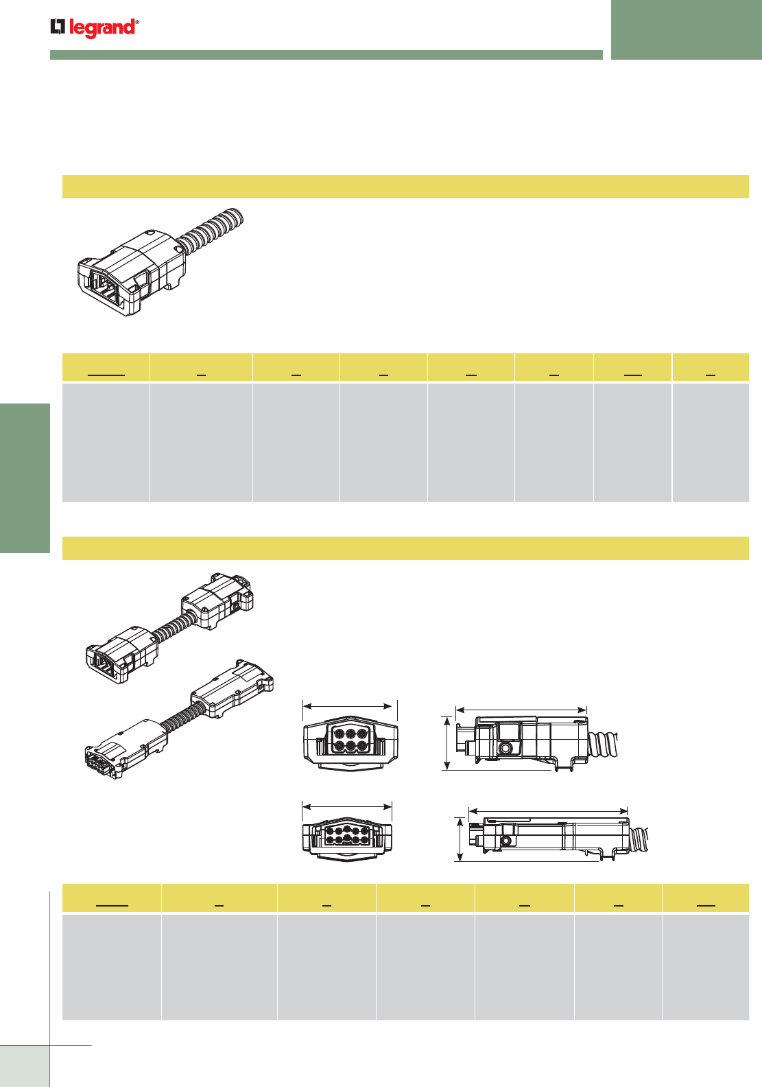
WIREMOLD
WWW.LEGRAND.US/WIREMOLD
532
MODULAR WIRING
WALKERFLEX
®
MODULAR WIRING SYSTEM
Cable Sets
Cable Whip
Carries Power from distribution unit to other components in flex system. Standard
lengths: 1, 5, 10, 15, 20, 25, 30, 40, and 50 ft. [305mm, 1.52m, 3.05m, 4.57m, 7.62m,
9.14m, 12.19m, and 15.24m]. Consult factory for all other lengths.
Cable Whips have a modular connector on one end and pigtails on the other end.
Coded “M” (male) for power “OUT” or “F” (female) for power “IN”.
Example: NCW111AL10F
Carries power from distribution unit to other components in flex system. Standard
lengths: 1, 5, 10, 15, 25, 30, 40, and 50 ft. [305mm, 1.52m, 3.05m, 4.57m, 7.62m,
9.14m, 12.19m,15.24m]. Consult factory for all other lengths.
Cable set will have a plug on both ends. Coded “M” (Male) on one end (“Power
Out”) and coded “F” (Female) on the other end (“Power In”) which allows proper
connections.
Example: NCS111AL10
NCW 1 1 1 A L 10 F
Identifies the
Cable Whip.
NCW=120V
LCW=277V
Number of Circuits,
also number of Hot
Conductors, insert
“1” for single circuit,
“2” for two-circuit,
“3” for three-circuit,
“4” for four-circuit,
or “6” for six-circuit.
Identifies Number
of Neutral
Conductors, Four
(4) Conductors
maximum.
All Neutrals
#10 AWG.
Number
of Ground
Conductors,
insert “1” for one
System Ground,
or “2” for one
System Ground
and one Isolated
Ground.
Identifies
Gage of Hot
and Ground
Conductors.
(A) = #12 AWG
(B) = #10 AWG
“L” stands
for Length,
remains
constant.
Length of MC
Cable in feet.
Insert “M”
for Power
Out or “F”
for Power In.
NOTE: For available wiring configuration options, see Wiring Configurations Chart in this section.
NCS 1 1 1 A L 10
Identifies the Cable
Whip.
NCW=120V
LCW=277V
Number of Circuits,
also number of Hot
Conductors, insert “1”
for single circuit, “2”
for two-circuit, “3” for
three-circuit, “4” for
four-circuit, or “6” for
six-circuit.
Identifies Number of
Neutral Conductors,
Four (4) Conductors
maximum.
All Neutrals
#10 AWG.
Number of Ground
Conductors, insert
“1” for one System
Ground, or “2” for
one System Ground
and one Isolated
Ground.
Identifies Gage of
Hot and Ground
Conductors.
(A) = #12 AWG
(B) = #10 AWG
“L” stands
for Length,
remains
constant.
Length of MC
Cable in feet.
NOTE: For available wiring configuration options, see Wiring Configurations Chart in this section.
Female (In)
Male (Out)
F
emal
e (In) Male (Out)
Walkerflex Modular Wiring System Components (continued)
2 1/2"
[64mm] 3 1/2"
[89mm]
1 7/16"
[37mm]
3 5/32"
[80mm] 5 11/16"
[145mm]
1 1/2"
[38mm]
Female (In)
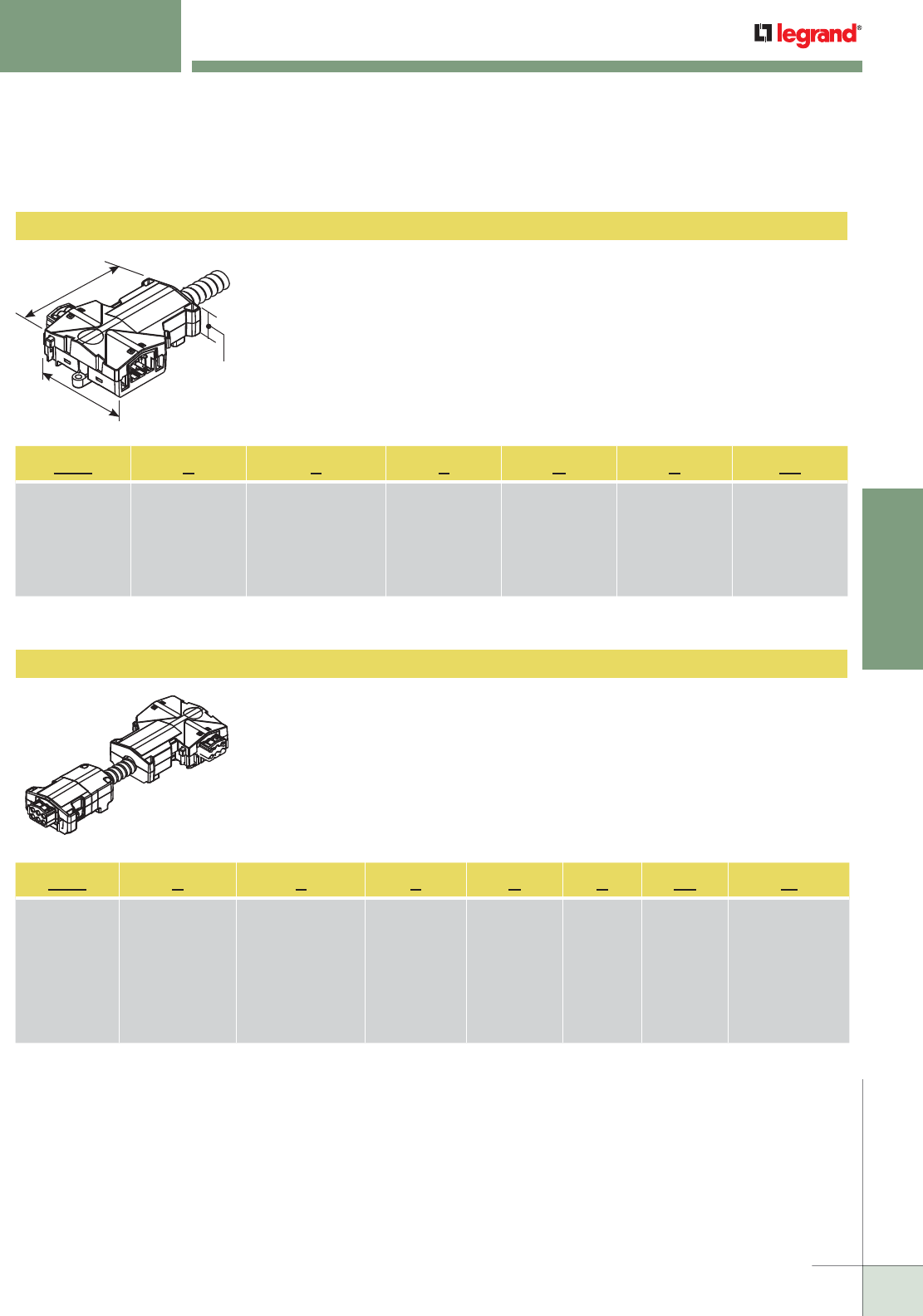
WIREMOLD
WWW.LEGRAND.US/WIREMOLD
533
MODULAR WIRING
WALKERFLEX
®
MODULAR WIRING SYSTEM
Modular Power Adapter
Power Adapters
All adapters are interface components that connect the flex system to an item that
is to be energized, such as raised floor boxes, power poles, convenience outlets
and various lighting fixtures. Power adapters are for 120V & 277V, 20A applications
with a standard 8' [2.4m] MC cable whip and 12" [305mm] leads on the end.
Not available in 8-10 wire.
Example: NPA222AL15
All adapters are interface components that connect the flex system to an item that
is to be energized, such as raised floor boxes, power poles, convenience outlets
and various lighting fixtures. Power adapters are for 120V & 277V, 20A applications
with a male "Power Out" head at one end and the power adapter at the other end.
NOTE: Only available in up to 6-wire configurations.
Example: NPA222AL10M
NPA 2 2 2 A L 15
Identifies the
Power Adapter
NPA=120V
LPA=277V
Number of Circuits,
Also Number of
Hot Conductors.
Insert “1” for single
circuit, “2” for
two-circuit.
Identifies Number of
Neutral Conductors,
Two (2) Conductors
maximum.
All Neutrals
#10 AWG.
Number of Ground
Conductors. Insert
“1” for one System
Ground, or “2” for
one System Ground
and one Isolated
Ground.
Identifies Gage of
Hot and Ground
Conductors.
(A) = #12 AWG
(B) = #10 AWG
“L” stands for
Length, remains
constant.
Length of MC
Cable in feet.
NOTE: For available wiring configuration options, see Wiring Configurations Chart in this section.
NPA 2 2 2 A L 10 M
Identifies the
Power Adapter
NPA = 120V
LPA = 277V
No. of Circuits,
also No. of Hot
Conductors.
Insert “1” for
single circuit, “2”
for two-circuit,
“3” for three-
circuit.
Identifies No. of
Neutral Conductors,
Two (2) Conductors
maximum.
All Neutrals
#10 AWG.
Number
of Ground
Conductors.
Insert “1” for
one System
Ground, or “2”
for one System
Ground and one
Isolated Ground.
Identifies
Gage of Hot
and Ground
Conductors.
(A) = #12 AWG
(B) = #10 AWG
“L”
stands for
Length,
remains
constant.
Length of
MC Cable in
feet.
M = Male
Power Out
NOTE: For available wiring configuration options, see Wiring Configurations Chart in this section.
4 3/32"
[104mm]
3 1/16"
[78mm]
1 11/32"
[34mm]
NOTE: Only available in up to 6-wire configurations.
Walkerflex Modular Wiring System Components
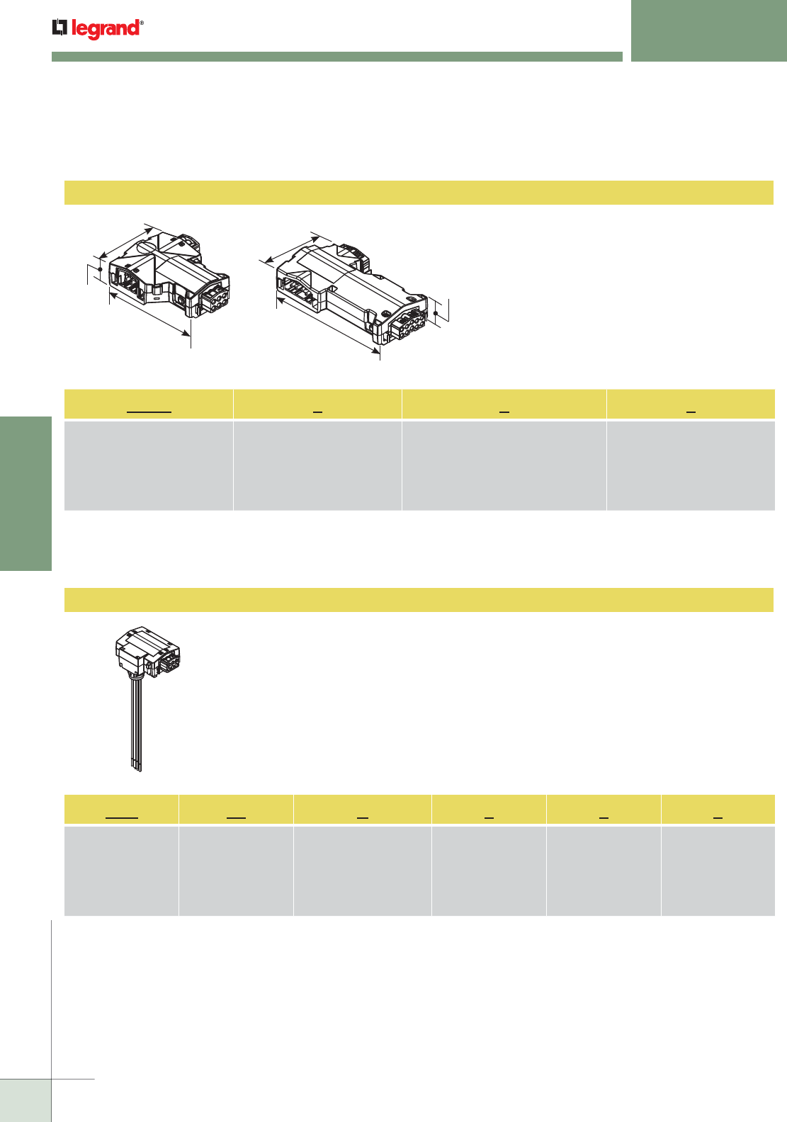
WIREMOLD
WWW.LEGRAND.US/WIREMOLD
534
MODULAR WIRING
WALKERFLEX
®
MODULAR WIRING SYSTEM
Cable Splitter
Power Tap
All taps are interface components that connect the flex system to an item that is to be
energized, such as raised floor boxes, power poles, and lighting fixtures. Power Taps
are for 120V & 277V applications with standard 8" leads on the end. Not available in
8-10 wire configurations.
Example: NPT18B111
NPT 18 B 1 1 1
Identifies the
Power Tap
NPT = 120V Unit
LPT = 277V Unit
Identifies Size of Wires
18 = #18AWG
12 = #12AWG
Egress Options
B = Bottom Egress
S = Side Egress
Identifies Number of
Hot Conductors
1 = Single Circuit
2 = Two Circuits
3 = Three Circuits
Identifies Number of
Neutral Conductors
Two (2) Conductors
maximum.
Identifies Number
of Grounds.
1 = 1 System Ground
2 = 2 System Ground &
Isolated Ground
Used to split one or more circuits so that it can be
used in more than one direction from a given point.
Example: NCBS111
NCBS 1 1 1
Identifies the Cable
Splitter Unit.
NCBS=120V
LCBS=277V
Number of Hot Conductors. Insert
“1” for single circuit,
“2” for two-circuit, “3” for three-
circuit, “4” for four-circuit,
or “6” for six-circuit.
Identifies Number of Neutral Conductors,
Four (4) Conductors maximum.
All Neutrals #10 AWG.
Number of Ground Conductors.
Insert “1” for one System Ground,
or “2” for one System Ground and
one Isolated Ground.
NOTE: For available wiring configuration options, see Wiring Configurations Chart in this section.
3 1/16"
[78mm]
4 3/32"
[104mm]
1 11/32"
[34mm]
3 1/16"
[78mm]
6 5/32"
[156mm]
1 19/32"
[40mm]
Walkerflex Modular Wiring System Components (continued)
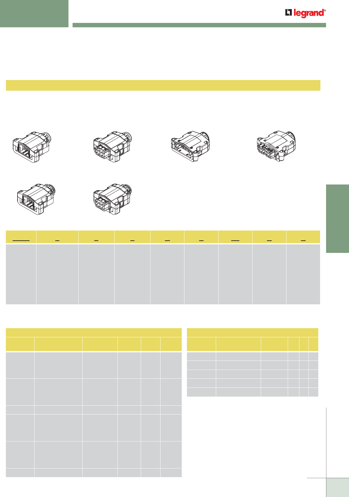
WIREMOLD
WWW.LEGRAND.US/WIREMOLD
535
MODULAR WIRING
WALKERFLEX
®
MODULAR WIRING SYSTEM
Wire Connectors
NWC 2 2 2 A L 12 F S
Identifies
the Wire
Connector.
NWC=120V
LWC=277V
Number of
Circuits, also
number of Hot
Conductors. Insert
“1” for single
circuit, “2” for
two-circuit, “3” for
three-circuit, “4”
for four-circuit, or
“6” for six-circuit.
Identifies
number
of Neutral
Conductors.
Four (4),
Conductors
maximum.
All Neutrals
#10 AWG.
Number
of Ground
Conductors.
Insert “1” for
one System
Ground or “2”
for one System
Ground and
one Isolated
Ground.
Identifies
Gage of Hot
and Ground
Conductors.
(A) = #12 AWG
(B) = #10AWG
Identifies
Length. “L”
remains
constant.
Identifies
Length of
Wires (in
inches)
protruding
out of back
side of the
Connector.
Identifies
Power
Direction
“F” (Female)
for Power
“IN”, “M”
(Male) for
Power
“OUT”.
Identifies
method of
securing in
device. “L”
for Lock
Nut, “S” for
Snap Ring.
NOTE: For available wiring configuration options, see Wiring Configurations Chart in this section.
Connectors are used to transition between the distribution units, cable sets, and end devices (floor boxes, poles, or
raceway). Standard wire lengths are 8", 12" and 18" [203mm, 305mm, and 457mm].
NOTE: Locking Ring style is only available up to 6 wire configurations.
Example: NWC222AL12FS Example: NWC222AL12MS Example: NWC332AL12FS Example: NWC332AL12MS
SNAP RING STYLE
Example: NWC222AL12FL Example: NWC222AL12ML
LOCKING RING STYLE
36 WIRE CONFIGURATION
KEY
COLOR
WIRING
CONFIGURATION
WIRING
VOLTAGE H N G
BLACK 111 120V 1 1 1
211 120V 2 1 1
311 120V 3 1 1
ORANGE 112 120V/IG 1 1 2
212 120V/IG 2 1 2
222 120V/IG 2 2 2
NATURAL 221 120V/2N 2 2 1
YELLOW 111 277V 1 1 1
211 277V 2 1 1
311 277V 3 1 1
GREEN 112 277V/IG 1 1 2
212 277V/IG 2 1 2
222 277V/IG 2 2 2
BLUE 221 277V/2N 2 2 1
Walkerflex Wiring Configurations
810 WIRING CONFIGURATION
KEY
COLOR
WIRING
CONFIGURATION
WIRING
VOLTAGE H N G
BLACK 422 120V 4 2 2
ORANGE 442 120V/IG 4 4 2
NATURAL 332 120V 3 3 2
BLUE 631 120V 6 3 1
IVORY 622 120V 6 2 2
Walkerflex Modular Wiring System Components (continued)
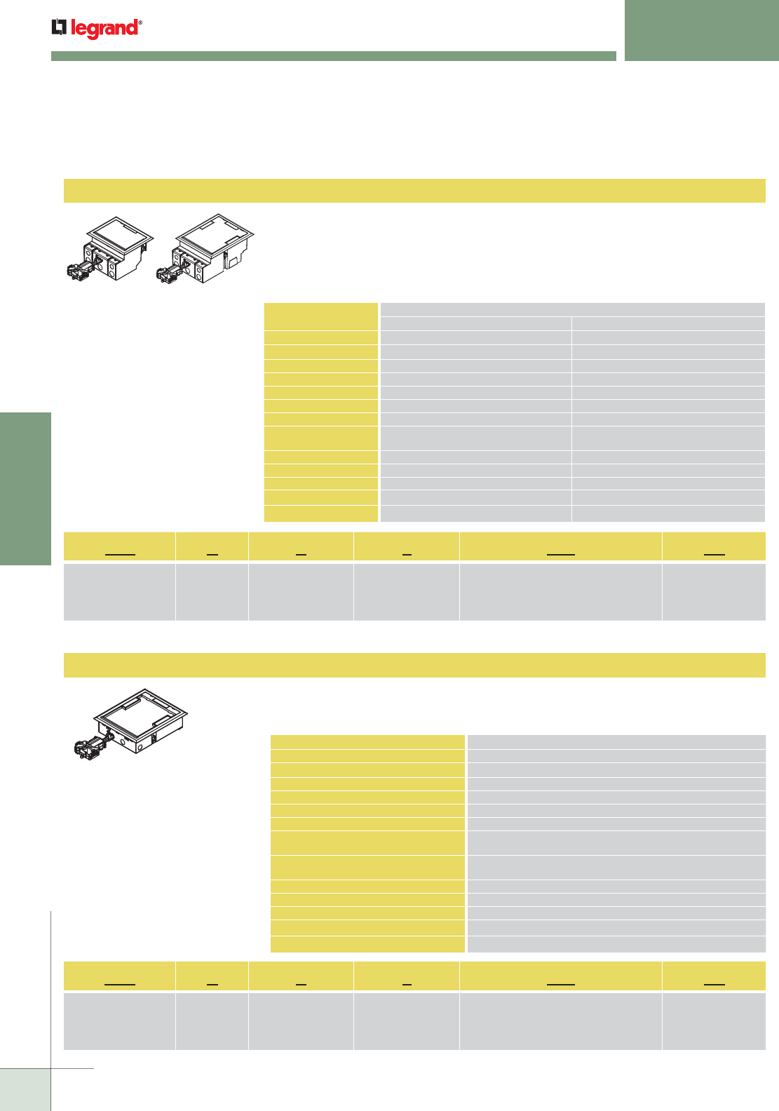
WIREMOLD
WWW.LEGRAND.US/WIREMOLD
536
MODULAR WIRING
WALKERFLEX
®
MODULAR WIRING SYSTEM
AF Series
AF2 K C 2 111 PA
AF Series:
AF2 or AF4
Cover Color:
K = Black
Y = Gray
N = Brown
Cover Insert:
C =Carpet Insert
T =Tile (No Insert)
No. of Receptacles:
2 = 2 Receptacles
4 = 4 Receptacles
Power Delivery System:
111 = 1 Circuit, 1 Neutral, System Ground
222 = 2 Circuits, 2 Neutrals, Isolated Ground
Style of Feed:
PA = Power Adapter
SAF K C 2 111 PA
SAF Series Cover Color:
K = Black
Y = Gray
N = Brown
Cover Insert:
C =Carpet Insert
T =Tile (No Insert)
No. of Receptacles:
2 = 2 Receptacles
4 = 4 Receptacles
Power Delivery System:
111 = 1 Circuit, 1 Neutral, System Ground
222 = 2 Circuits, 2 Neutrals, Isolated Ground
Style of Feed:
PA = Power Adapter
AF2 and AF4 prewired raised floor/raised stage boxes have been designed to work
with power, communications and AV devices. The housings are made from die-cast
aluminum material with a polycarbonate cover and flange assembly. Comes with a
1
ft. modular Walkerflex power adapter.
AF2 & AF4 Prewired Raised Floor Boxes
SAF prewired shallow raised floor/raised stage boxes have been designed to work with power,
communications and AV devices in a minimum 2 1/2" deep floor. The housings are made from
formed galvanized steel with a polycarbonate cover
Prewired Raised Floor Boxes
DESCRIPTION
DIMENSIONS
AF2 AF4
Overall Trim Ring 8 3/4" x 6 3/4" [222mm x 171mm] 9 1/8" x 11" [232mm x 279mm]
Module Depth 5" [127mm] 5" [127mm]
Panel Opening 8" x 6" [203mm x 152mm] 8" x 10" [203mm x 254mm]
Cover Size 7 1/2" x 5" [191mm x 127mm] 7 1/2" x 9 1/2" [191mm x 242mm]
Activation Chamber 130 cu in. [2130ml] 220 cu in. [3604ml]
User Volume 78.6 cu in. [1288ml] 180 cu in. [2948ml]
Total Volume 208.6 cu in. [3418ml] 300 cu in. [4915ml]
Knockout Sizes Seven (7) 1/2" & Two (2) 3/4"
Trade Size KOs (Power Side only)
Seven (7) 1/2" & Two (2) 3/4"
Trade Size KOs (Power Side only)
Depth Behind Plate 2 3/4" [69.8mm] 2 3/4" [69.8mm]
Service Triple Triple
Capacity 4 Gangs 8 Gangs
Connectivity 6 Ports Unloaded 12 Ports Unloaded
Max. Floor Thickness 1 1/2" [38mm] (Floor covering included) 1 1/2" [38mm] (Floor covering included)
DESCRIPTION DIMENSIONS
Overall Trim Ring 9 1/8" x 11" [232mm x 279mm]
Module Depth Overall 2.5" [64mm]
Panel Opening 8" x 10" [203mm x 254mm]
Cover Size 7 1/2" x 9 1/2" [191mm x 242mm]
Activation Volume 18.5 cu in. [303ml]
Power Volume 29 cu in. [475ml]
Maximum Floor Panel Thickness with
Floor Covering
1 3/16" [30mm]
Knockout Sizes Power – Four (4) 1/2"-3/4" Trade Size Concentric KOs
Communication – Two (2) 1/2"-3/4" Trade Size Concentric KOs
Depth Behind Plate 2" [51mm]
Service Triple
Capacity 3 Gangs
Connectivity 6 Ports Unloaded
Mx. Floor Thickness 1 3/8" [35mm] (Floor covering included)
Standard Product
Offerings: AF2
AF2KC2111PA
AF2YC2111PA
AF2NC2111PA
AF2KT2111PA
AF2YT2111PA
AF2NT2111PA
AF2KC2222PA
AF2YC2222PA
AF2NC2222PA
AF2KT2222PA
AF2YT2222PA
AF2NT2222PA
AF2KC4222PA
AF2YC4222PA
AF2NC4222PA
AF2KT4222PA
AF2YT4222PA
AF2NT4222PA
Standard Product
Offerings: AF4
AF4KC2111PA
AF4YC2111PA
AF4NC2111PA
AF4KT2111PA
AF4YT2111PA
AF4NT2111PA
AF4KC2222PA
AF4YC2222PA
AF4NC2222PA
AF4KT2222PA
AF4YT2222PA
AF4NT2222PA
AF4KC4222PA
AF4YC4222PA
AF4NC4222PA
AF4KT4222PA
AF4YT4222PA
AF4NT4222PA
SAF Series
Standard Product Offerings: SAF
SAFKC2111PA
SAFYC2111PA
SAFNC2111PA
SAFKT2111PA
SAFYT2111PA
SAFNT2111PA
SAFKC2222PA
SAFYC2222PA
SAFNC2222PA
SAFKT2222PA
SAFYT2222PA
SAFNT2222PA
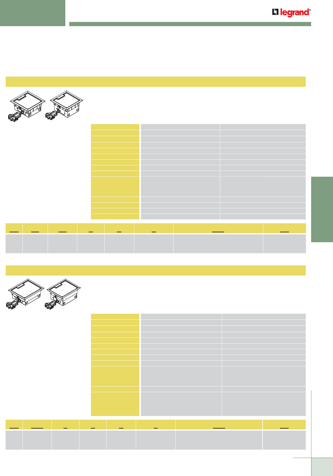
WIREMOLD
WWW.LEGRAND.US/WIREMOLD
537
MODULAR WIRING
WALKERFLEX
®
MODULAR WIRING SYSTEM
AC8X10 Series
AC8X8 Series
The AC Series Floor Box is an 8" x 8" [203mm x 203mm] single-service, prewired
raised floor/raised stage box designed to work with power devices in a minimum
4" [102mm] deep floor. The housings are made from formed galvanized steel with
a die-cast aluminum cover and flange assembly.
AC8840 & AC8850 Prewired Raised Floor Boxes
The AC810 Series Prewired Raised Floor/Raised Stage Boxes are designed to work
with power and communications devices in a minimum 4" [102mm] deep floor. The
housings are made from formed galvanized steel with a die-cast aluminum cover
and flange assembly. Comes with a 1 ft. modular Walkerflex power adapter.
AC8104 & AC8105 Prewired Raised Floor Boxes
Prewired Raised Floor Boxes (continued)
DESCRIPTION AC8840 DIMENSIONS AC8850 DIMENSIONS
Box Dimensions 8" x 8" x 4" [203mm x 203mm x 102mm] 8" x 8" x 5" [203mm x 203mm x 127mm]
Overall Trim Ring 9 1/4" x 9 1/4" [235mm x 235mm] 9 1/4" x 9 1/4" [235mm x 235mm]
Module Depth 4" [102mm] 5" [127mm]
Panel Opening 8" x 8" [203mm x 203mm] 8" x 8" [203mm x 203mm]
Cover Size 7 11/16" x 7 11/16" [195mm x 195mm] 7 11/16" x 7 11/16" [195mm x 195mm]
Activation Chamber 63.92 cu in. [1047ml] 97.22 cu in. [1593ml]
User Volume 84.34 cu in. [1382ml] 102.22 cu in. [1674ml]
Total Volume 152.34 cu in. [2496ml] 199.22 cu in. [3264ml]
Knockout Sizes Power – Four (4) 1/2"-3/4"
Trade Size Concentric KOs
Communication – Two (2) 1/2"-3/4"
Trade Size Concentric KOs
Power – Four (4) 1/2"-3/4"
Trade Size Concentric KOs
Communication – Four (4) 1/2"-3/4"
Trade Size Concentric KOs
Depth Behind Plate 2" [51mm] 2" [51mm]
Service Single Single
Capacity 4 Gangs 4 Gangs
Max. Floor Thickness 2" [51mm] (floor covering included) 2" [51mm] (floor covering included)
DESCRIPTION AC8104 DIMENSIONS AC8105W DIMENSIONS
Box Dimensions 8" x 10" x 4" [203mm x 254mm x 102mm] 8" x 10" x 5" [203mm x 254mm x 127mm]
Overall Trim Ring 9 1/4" x 11 1/4" [235mm x 286mm] 9 1/4" x 11 1/4" [235mm x 286mm]
Module Depth 4" [102mm] 5" [127mm]
Panel Opening 8" x 10" [203mm x 254mm] 8" x 10" [203mm x 254mm]
Cover Size 7 11/16" x 9 11/16" [195mm x 246mm] 7 11/16" x 9 11/16" [195mm x 246mm]
Activation Chamber 76.87 cu in. [1593ml] 111.08 cu in. [1820ml]
User Volume 130.09 cu in. [2131ml] 151.97 cu in. [2490ml]
Total Volume 201.09 cu in. [3295ml] 262.97 cu in. [4309ml]
Knockout Sizes Power – Four (4) 1/2"-3/4" Trade Size
Concentric KOs
Communication – Four (4) 1/2"-3/4"
Trade Size Concentric KOs
Power – Four (4) 1/2"-3/4" Trade Size
Concentric KOs
Communication – Four (4) 1/2"-3/4" Trade
Size Concentric KOs
Depth Behind Plate 1 3/4" [44mm] 2" [51mm]
Service Dual Triple
Capacity 6 Gangs 6 Gangs
Connectivity 12 Ports Unloaded 18 Ports Unloaded
Max. Floor Thickness 2" [51mm] (floor covering included) 2" [51mm] (floor covering included)
AC 88 50 Y C 2 111 PA
AC
Series
Cover Size:
88 = 8" x 8"
Box Depth:
40 = 4" Deep
50 = 5" Deep
Cover Color:
Y = Gray
Cover Insert:
C = Carpet
Insert
No. of Receptacles:
2 = 2 Receptacles
4 = 4 Receptacles
Power Delivery System:
111 = 1 Circuit, 1 Neutral, System Ground
222 = 2 Circuits, 2 Neutrals, Isolated Ground
Style of Feed:
PA = Power Adapter
AC 810 5 Y C 2 111 PA
AC
Series
Cover Size:
810 = 8" x 10"
Box Depth:
4" = 4" Deep
5" = 5" Deep
Cover Color:
Y = Gray
Cover Insert:
C = Carpet
Insert
No. of Receptacles:
2 = 2 Receptacles
4 = 4 Receptacles
Power Delivery System:
111 = 1 Circuit, 1 Neutral, System Ground
222 = 2 Circuits, 2 Neutrals, Isolated Ground
Style of Feed:
PA = Power Adapter
Standard Product
Offerings: AC8850
AC8850YC2111PA
AC8850YC2222PA
AC8850YC42222PA
Standard Product
Offerings: AC8105
AC8105YC2111PA
AC8105YC2222PA
AC8105YC42222PA
Standard Product
Offerings: AC8840
AC8840YC2111PA
AC8840YC2222PA
Standard Product
Offerings: AC8104
AC8104YC2111PA
AC8104YC2222PA
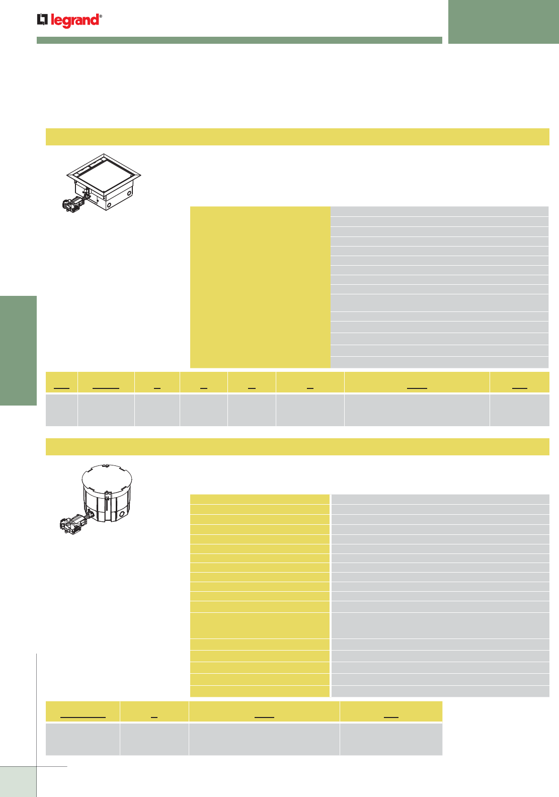
WIREMOLD
WWW.LEGRAND.US/WIREMOLD
538
MODULAR WIRING
WALKERFLEX
®
MODULAR WIRING SYSTEM
AC10105
CRFB
AC10105 prewired raised floor/raised stage boxes. The AC10105 is a 10" x 10"
[203mm x 254mm] box that has been designed to work with power, communica-
tions and audio visual devices in a minimum 5" [127mm] deep floor. The housings
are made from formed galvanized steel with a die-cast aluminum cover and flange
assembly. Comes with a 1 ft. modular Walkerflex power adapter.
Prewired round raised floor/wood floor stage boxes. Die-cast aluminum is
designed to work with power, communication, and A/V devices in a minimum 6 1/2"
[165mm] deep floor. Comes with a 1 foot modular Walkerflex power adapter.
Prewired Raised Floor Boxes (continued)
DESCRIPTION DIMENSIONS
Box Dimensions 10" x 10" x 5" [254mm x 254mm x 127mm]
Overall Trim Ring 11 1/2" x 11 1/2" [292mm x 292mm]
Module Depth 5" [127mm]
Panel Opening 10" x 10" [254mm x 254mm]
Cover Size 9 5/8" x 9 5/8" [245mm x 245mm]
Activation Chamber 115 cu in. [1884ml]
User Volume 243 cu in. [3981ml]
Total Volume 358 cu in. [5865ml]
Knockout Sizes Power – Four (4) 1/2" Trade Size Concentric KOs
Communication – Four (4) 1/2"-3/4" Trade Size Concentric KOs
Depth Behind Plate 2" [51mm]
Service Triple
Capacity 6 Gangs
Connectivity 18 Ports Unloaded
Max. Floor Thickness 2" [51mm] (Floor covering included)
DESCRIPTION DIMENSIONS
Box Dimensions 9 1/2" [241mm] Diameter x 6 5/8" [168mm] Tall
Overall Trim Ring 9 1/2" [241mm] Diameter
Module Depth 3 3/4" [95mm]
Panel Opening 9 1/2" [241mm]
Cover Size 9 1/4" [235mm] Diameter
Activation Chamber:
Chambers 1 and 2 23.5 cu in. [385ml]
Chamber 3 17.5 cu in. [287ml]
Chamber 4 32.8 cu in. [538ml]
User Volume 30 cu in. [762ml]
Total Volume 127.3 cu in. [3233ml]
Knockout Sizes Four (4) Concentric 1/2" - 3/4" Trade Size
Three (3) Concentric 3/4" - 1" Trade Size
One (1) 2" Trade Size
Depth Behind Plate 2 1/4" [57mm]
Service Triple
Capacity 4 Gangs
Communication Device 6 Ports Unloaded
Max. Floor Thickness 2" [51mm] (Floor covering included)
AC 1010 5 Y C 2 111 PA
AC
Series
Cover Size:
1010 =10" x 10"
Box Depth:
5 = 5" Deep
Cover Color:
Y = Gray
Cover Insert:
C = Carpet
Insert
No. of Receptacles:
2 = 2 Receptacles
4 = 4 Receptacles
Power Delivery System:
111 = 1 Circuit, 1 Neutral, System Ground
222 = 2 Circuits, 2 Neutrals, Isolated Ground
Style of Feed:
PA = Power
Adapter
CRFB4P 2 111 PA
Cover Size:
7 11/16" diameter
No. of Receptacles:
2 = 2 Receptacles
4 = 4 Receptacles
Power Delivery System:
111 = 1 Circuit, 1 Neutral, System Ground
222 = 2 Circuits, 2 Neutrals, Isolated Ground
Style of Feed:
PA = Power Adapter
Standard Product
Offerings: AC10105
AC10105YC2111PA
AC10105YC2222PA
AC10105YC42222PA
Standard Product
Offerings: CRFB
CRFB4P2111PA
CRFB4P2222PA
CRFB4P4222PA
NOTE: Covers are sold separately.
For more information on cover
options, see the next page.
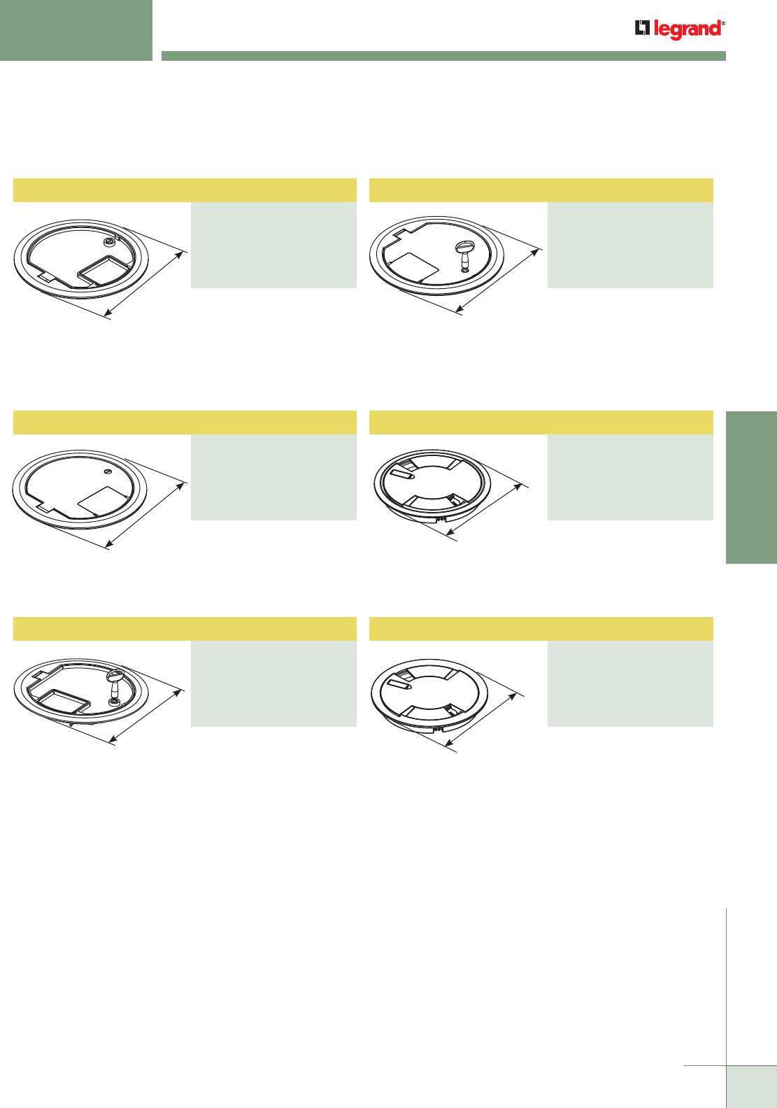
WIREMOLD
WWW.LEGRAND.US/WIREMOLD
539
MODULAR WIRING
Tamper Resistant Surface Style Cover Assembly
PART NUMBERS:
CRFBBTCBKTR (Black)
CRFBBTCGYTR (Gray)
CRFBBTCNKTR (Nickel)
CRFBBTCBSTR (Brass)
CRFBBTCBZTR (Bronze)
Surface Style Cover Assembly
PART NUMBERS:
8CTCBK* (Black)
8CTCGY* (Gray)
8CTCGY* (Nickel)
8CTCBS* (Brass)
8CTCBZ* (Bronze)
WALKERFLEX
®
MODULAR WIRING SYSTEM
Available in die cast
aluminum with five painted
finishes. Insert areas allow
for tile or carpet cutouts to
match finished floor.
Available in die cast
aluminum with five painted
finishes. No cutouts are
provided. Lid has built-in key
locking feature for tamper
resistance.
Available in die cast
aluminum with five painted
finishes. No cutouts are
provided for floor coverings.
Die-cast aluminum cover
assembly. Cover assembly
is available in five painted
finishes.
Die-cast aluminum cover
assembly. Cover assembly
is available in five painted
finishes.
Available in die cast
aluminum with five painted
finishes. Lid has built-in key
locking feature for tamper
resistance. Insert areas
allow for tile or carpet
cutouts to match finished
floor.
Prewired Raised Floor Boxes (continued)
9 3/16"
[233mm]
9 3/16"
[233mm]
9 3/16"
[233mm]
9 1/4"
[235mm]
9 1/4"
[235mm]
* Add suffix “TR” to the end of the part number to indicate tamper-resistant cover assembly.
Tamper-resistant versions are secured with a single tamper-resistant screw.
Flush Style Cover Assembly
PART NUMBERS:
8CTCBK* (Black)
8CTCGY* (Gray)
8CTCGY* (Nickel)
8CTCBS* (Brass)
8CTCBZ* (Bronze)
Surface Style Cover Assembly
PART NUMBERS:
CRFBBTCBK (Black)
CRFBBTCGY (Gray)
CRFBBTCNK (Nickel)
CRFBBTCBS (Brass)
CRFBBTCBZ (Bronze)
Tamper Resistant Surface Style Cover Assembly
PART NUMBERS:
CRFBCTCBKTR (Black)
CRFBCTCGYTR (Gray)
CRFBCTCNKTR (Nickel)
CRFBCTCBSTR (Brass)
CRFBCTCBZTR (Bronze)
9 3/16"
[233mm]
Surface Style Cover Assembly
PART NUMBERS:
CRFBCTCBK (Black)
CRFBCTCGY (Gray)
CRFBCTCNK (Nickel)
CRFBCTCBS (Brass)
CRFBCTCBZ (Bronze)
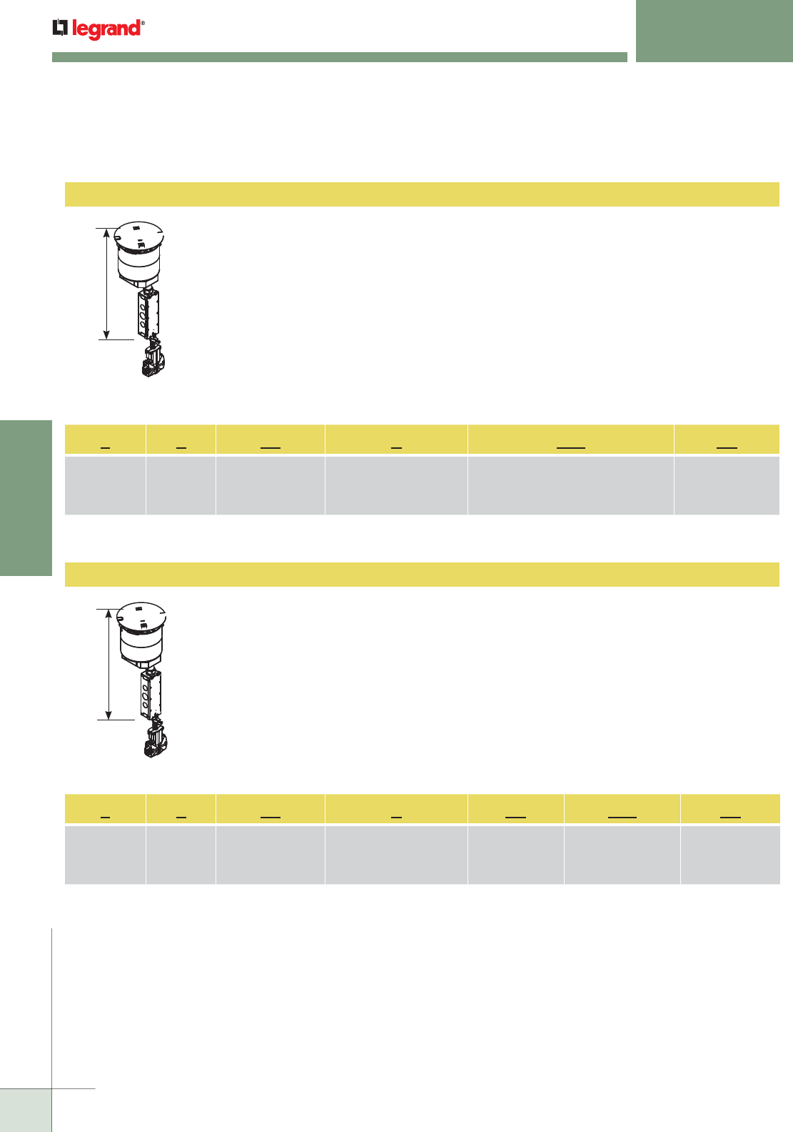
WIREMOLD
WWW.LEGRAND.US/WIREMOLD
540
MODULAR WIRING
WALKERFLEX
®
MODULAR WIRING SYSTEM
Evolution Series Poke-Thru Devices
6STCP
Recessed modular stem assembly – includes 6” [152mm] core hole poke-thru stem assembly
with a disposable plate and two proprietary 20A duplex receptacles. Devices are recessed 3 1/4”
[83mm] below the surface, no cover assembly included. For use with the following cover assemblies
(Purchased separately): 6CTC and 6CT series. Comes with 1 ft. modular Walkerflex power adapter.
Included: For Side Compartments: Two (2) proprietary 20 Amp duplex receptacles installed. For
Center Compartment: One (1) 6ACT8A Mounting Plate, One (1) 6TRAC Mounting Plate, and One (1)
6SER Mounting Plate. For Bottom Feed Compartment: One (1) 5BLH 1/2-Gang Blank Housing, One
(1) 1PTHA 1-Gang Pass-Through Housing Assembly, and One (1) 575CHA 1/2-Gang 3/4” Conduit
Housing Assembly.
NOTE: UL Fire Classified for up to 2 hour rated floors.
NOTE: Receptacles can be wired as a standard or isolated ground devices.
NOTE: Assembled with a scrub water gasket. For use on tile, wood or carpeted covered floors. Maximum floor covering thickness
range 1" [25mm], not designed for use on bare concrete or terrazzo finished floors.
16 3/4"
[425mm]
6STCPAV
Recessed modular stem assembly – includes 6" [152mm] core hole poke-thru stem assembly
with a disposable plate and one proprietary 20A duplex receptacle. Devices are recessed 3 1/4"
[83mm] below the surface, no cover assembly included. For use with the following cover assemblies
(Purchased separately): 6CTC and 6CT series. Comes with 1 ft. modular Walkerflex power adapter.
Included: For Side Compartments: One (1) proprietary 20 Amp duplex receptacle installed, 682A
Device Plate, and 68MAAP Device Plate. For Center Compartment: 6DEC Mounting Plate, 6AAP
Mounting Plate, and 6MAAP Mounting Plate. For Bottom Feed Compartment: One (1) 5PTHA 1/2-Gang
Pass-Through Housing Assembly, One (1) 1PTHA 1-Gang Pass-Through Housing Assembly, and One
(1) 575CHA 1/2-Gang 3/4" Conduit Housing Assembly.
NOTE: UL Fire Classified for up to 2 hour rated floors.
NOTE: Receptacles can be wired as a standard or isolated ground devices.
NOTE: Assembled with a scrub water gasket. For use on tile, wood or carpeted covered floors. Maximum floor covering thickness
range 1" [25mm], not designed for use on bare concrete or terrazzo finished floors.
6 S TC P 222 PA
Diameter of
Poke-Thru
Device:
6 = 6" [152mm]
S = Stem
Assembly
Unit is approved tile,
wood, and carpet
covered floors
Unit is prewired with 2
20A Duplex Receptacles
installed to a Walkeflex
connector
Power Delivery System:
111 = 1 Circuit, 1 Neutral, System Ground
222 = 2 Circuits, 2 Neutrals, Isolated Ground
Style of Feed:
PA = Power
Adapter
6 S TC PAV 111 PA
Diameter of
Poke-Thru
Device:
6 = 6" [152mm]
S = Stem
Assembly
Unit is approved tile,
wood, and carpet
covered floors
Unit is prewired with 1 20A
Duplex Receptacle installed
to a Walkerflex connector
AV = Audio/Visual
Power Delivery System:
111 = 1 Circuit,
1 Neutral,
System Ground
Style of Feed:
PA = Power
Adapter
16 3/4"
[425mm]
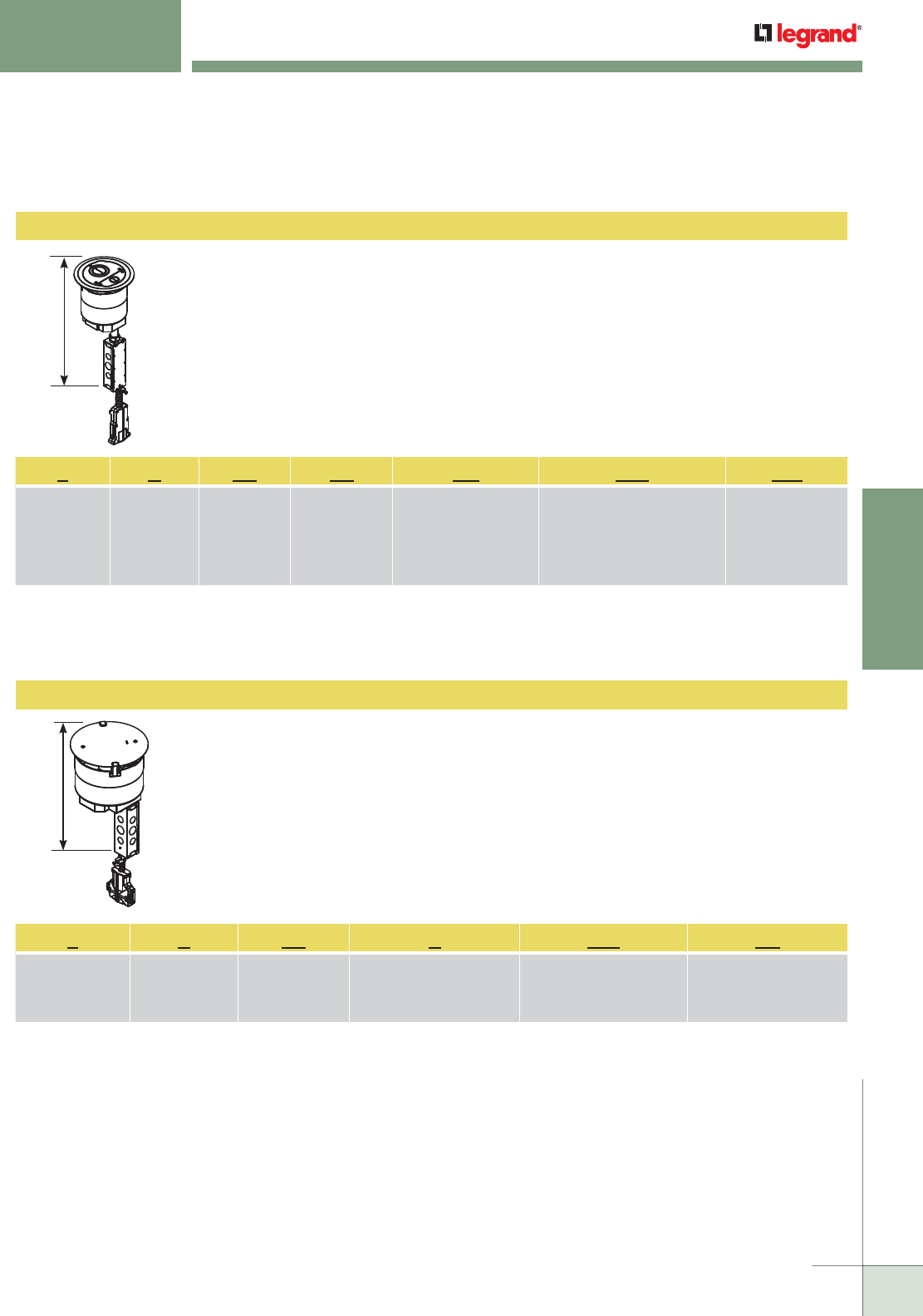
WIREMOLD
WWW.LEGRAND.US/WIREMOLD
541
MODULAR WIRING
6ATCFF
8STCP
Recessed modular stem assembly with disposable plate – includes 6" [152mm] core hole poke-thru
stem assembly with a disposable plate. Devices are recessed 3 1/4" [83mm] below the surface, no
cover assembly included. For use with the following cover assemblies (Purchased separately): 6CTC
and 6CT series. Comes with 1 ft. modular Walkerflex cable whip.
Included For Bottom Feed Compartment: One (1) 5PTHA 1/2-Gang Pass Through Housing Assembly,
One (1) 15FFHA 1 1/2-Gang Pass Through Housing Assembly, One (1) 575CHA 1/2-Gang 3/4" Conduit
Housing Assembly
NOTE: UL Fire Classified for up to 2 hour rated floors.
NOTE: Assembled with a scrub water gasket. For use on tile, wood or carpeted covered floors. Maximum floor covering thickness
range 1" [25mm], not designed for use on bare concrete or terrazzo finished floors.
Recessed modular stem assembly with disposable plate – includes 8" core hole poke-thru stem
assembly with a disposable plate. Devices are recessed 3 1/4" [83mm] below the surface, no cover
assembly included. For use with the following cover assemblies (Purchased separately): 8CTC and
8CT series. Comes with 1 ft. modular Walkerflex power adapter.
Included For Bottom Feed Compartments: One (1) 5PTHA 1/2-Gang Pass Through Housing Assembly,
One (1) 1PTHA 1-Gang Pass Through Housing Assembly, One (1) 575CHA 1/2-gang 3/4" Conduit
Housing Assembly.
NOTE: UL Fire Classified for up to 2 hour rated floors.
NOTE: Assembled with a scrub water gasket. For use on tile, wood or carpeted covered floors. Maximum floor covering thickness
range 1" [25mm], not designed for use on bare concrete or terrazzo finished floors.
WALKERFLEX
®
MODULAR WIRING SYSTEM
6 A TC FF BK 422 CW
Diameter of
Poke-Thru
Device:
6 = 6" [152mm]
A = Assembled
Unit
Unit is
approved tile,
wood, and
carpet covered
floors
Furniture Feed
Style Poke-Thru
Device
Color of Cover Assembly =
BK = Black
GY = Gray
BS = Brass
NK = Nickel
BE = Bronze
Power Delivery System:
422 = 4 Circuits, 2 Neutrals,
Isolated Ground
Style of Feed:
CW =Cable Whip
8 S TC P 222 PA
Diameter of Poke-
Thru Device:
8 = 8" [203mm]
S = Stem
Assembly
Unit is approved
tile, wood, and
carpet covered
floors
Unit is prewired with 2 20A
Duplex Receptacles installed to
a Walkerflex connector
Power Delivery System:
222 = 2 Circuits, 2 Neutrals,
Isolated Ground
Style of Feed:
PA =Power Adapter
16 3/4"
[425mm]
Evolution Series Poke-Thru Devices
Flush Poke-Thru Devices
16 3/4"
[425mm]
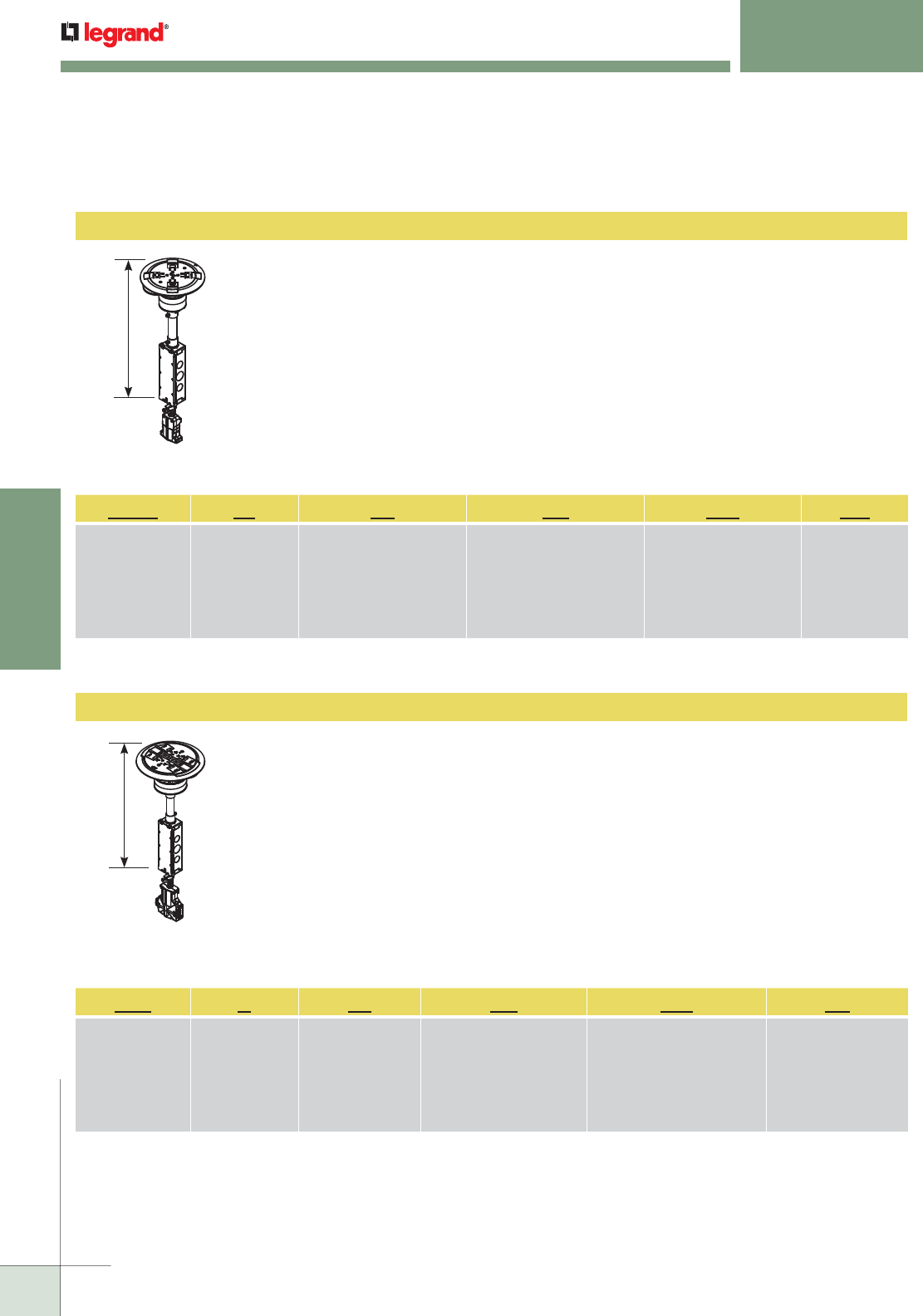
WIREMOLD
WWW.LEGRAND.US/WIREMOLD
542
MODULAR WIRING
RC9A15TC
RC4ATC
Surface style poke-thru assembly – Prewired 15A quad receptacle with a 1 ft. modular Walkerflex
cable whip. Poke-thru unit fits into a 3" [76.2 mm] diameter core hole. Unit also includes two
openings for pass through capability for one (1) 4-pair category 5e or category 6 cable per opening.
Comes with 1 ft. modular Walkerflex cable whip.
Standard Offerings: RC9A15TCBK111CW, RC9A15TCGY111CW, RC9A15TCBS111CW,
RC9A15TCAA111CW, RC9A15TCAL111CW, RC9A15TCAB111CW
NOTE: Assembled with a scrub water gasket. For use on tile, wood or carpeted covered floors. Floor covering thickness range
1/8" to 3/4", not designed for use on bare concrete or terrazzo finished floors.
Surface style poke-thru assembly – Two (2) prewired 20A proprietary receptacles with a 1 ft. modular
Walkerflex connector. The duplex receptacle on the “A” side is wired to the system ground and the
duplex receptacle on the “B” side is wired to isolated ground. The poke-thru unit fits into a 4" [101.6
mm] diameter core hole. Comes with 1 ft. modular Walkerflex power adapter.
Unit also includes:
• Open inserts unloaded to accept discrete keystone connectors from most manufacturers
• Ortronics Tracjacks mounting bezel
• Ortronics Series II communication housing
Standard Offerings: RC4ATCBK222PA, RC4ATCGY222PA, RC4ATCBS222PA, RC4ATCAL222PA,
RC4ATCAA222PA, RC4ATCAB222PA
NOTE: Assembled with a scrub water gasket. For use on tile, wood or carpeted covered floors. Floor covering thickness range 1/8"
to 3/4", not designed for use on bare concrete or terrazzo finished floors. Modular Jacks sold separately.
WALKERFLEX
®
MODULAR WIRING SYSTEM
RC9A 15 TC BK 111 CW
Surface Style Poke-
Thru, Model: RC9A
15 = 15A Quad
Power Receptacle
Unit is approved tile, wood,
and carpet covered floors
Color of Cover Assembly:
BK = Black
GY = Gray
AL = Aluminum
BS = Brass
AA = All Aluminum
AB = All Brass
Power Delivery System:
111 = 1 Circuit, 1 Neutral,
System Ground
Style of Feed:
CW = Cable Whip
RC4 A TC BK 222 PA
Surface Style
Poke-Thru,
Model: RC4
A = Assembled
Unit
Unit is approved tile,
wood, and carpet
covered floors
Color of Cover Assembly:
BK = Black
GY = Gray
AL = Aluminum
BS = Brass
AA = All Aluminum
AB = All Brass
Power Delivery System:
222 = 2 Circuits, 2 Neutrals,
Isolated Ground
Style of Feed:
PA = Power Adapter
Surface Style Poke-Thru Devices
16 3/4"
[425mm]
16 3/4"
[425mm]
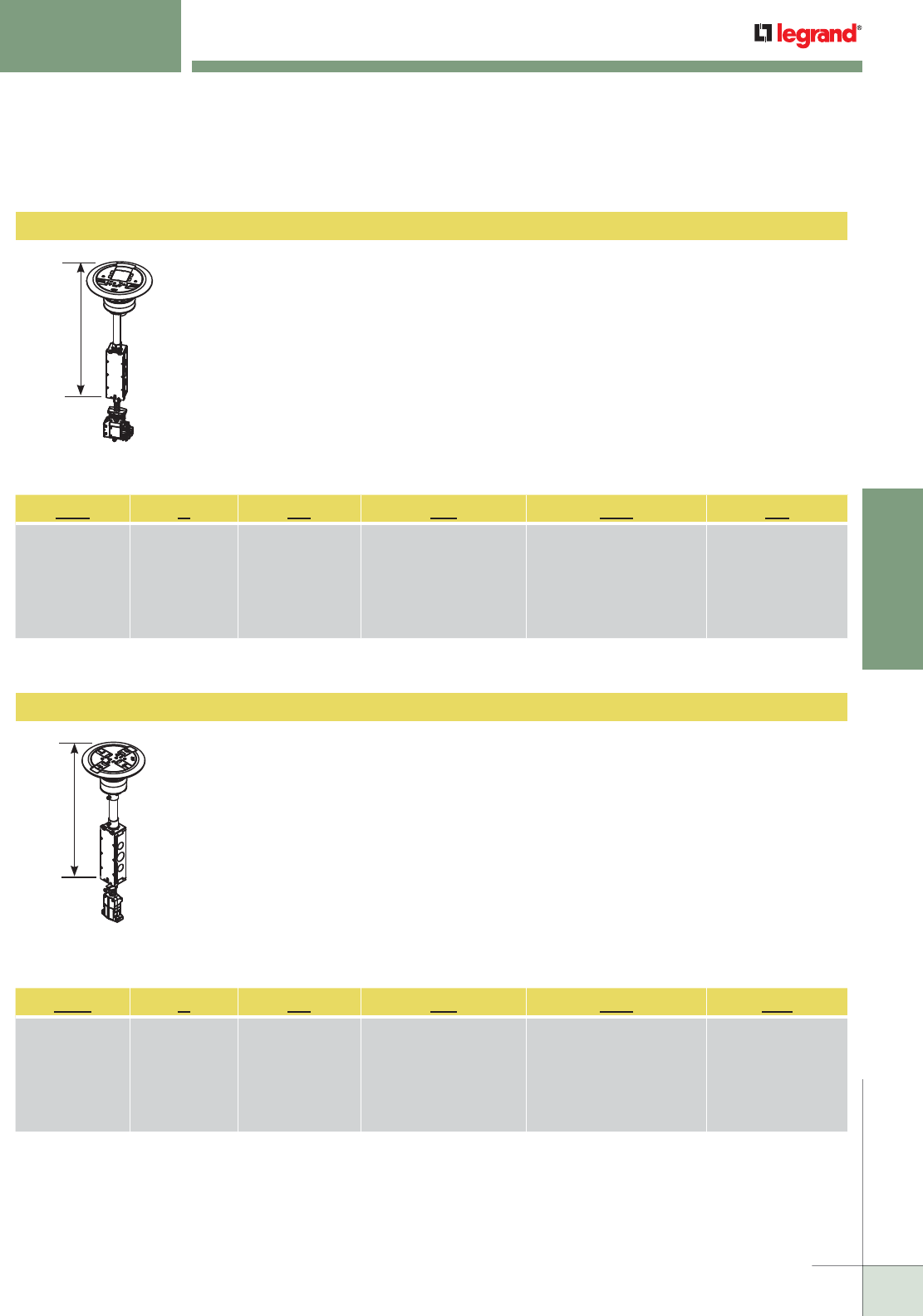
WIREMOLD
WWW.LEGRAND.US/WIREMOLD
543
MODULAR WIRING
AV3ATC
RC7ATC
Surface style AV poke-thru assembly – One (1) prewired 20A proprietary receptacle with a 1 ft.
modular Walkerflex power adapter. The poke-thru unit fits into a 4" [101.6mm] diameter core hole.
Unit also includes:
• One (1) Extron adapter to accept Extron MAAP mini architectural adapter plates.
(Extron devices sold separately, only through authorized Extron dealers).
• One (1) Wiremold open system adapter and inserts unloaded to accept discrete keystone
connectors from most manufacturers
• One (1) Ortronics Tracjacks adapter
• One (1) Ortronics Series II adapter
Standard Offerings: AVATCBK111PA, AV3ATCGY111PA, AV3ATCBS111PA, AV3ATCAL111PA,
AV3ATCAA111PA, AV3ATCAB111PA
NOTE: Assembled with a scrub water gasket. For use on tile, wood or carpeted covered floors. Floor covering thickness range
1/8" to 3/4", not designed for use on bare concrete or terrazzo finished floors. Modular Jacks sold separately.
Surface style poke-thru assembly – One (1) prewired 20A proprietary receptacle with a 1 ft. modular
Walkerflex cable whip. The Poke-thru unit fits into a 3" [76.2 mm] diameter core hole.
Unit also includes:
• One (1) Wiremold open system adapter and inserts unloaded to accept discrete keystone
connectors from most manufacturers
• Two (2) Cat. 6 TechChoice discrete keystone modular jacks
• One (1) Ortronics TracJack adapter
Standard Offerings: RC7ATCBK111CW, RC7ATCGY111CW, RC7ATCBS111CW, RC7ATCAL111CW,
RC7ATCAA111CW, RC7ATCAB111CW
NOTE: Assembled with a scrub water gasket. For use on tile, wood or carpeted covered floors. Floor covering thickness range 1/8"
to 3/4", not designed for use on bare concrete or terrazzo finished floors.
WALKERFLEX
®
MODULAR WIRING SYSTEM
AV3 ATC BK 111 PA
Surface Style
Poke-Thru,
Model: AV3
A = Assembled
Unit
Unit is approved tile,
wood, and carpet
covered floors
Color of Cover Assembly:
BK = Black
GY = Gray
AL = Aluminum
BS = Brass
AA = All Aluminum
AB = All Brass
Power Delivery System:
111 = 1 Circuit, 1 Neutral,
System Ground
Style of Feed:
PA = Power Adapter
RC7 A TC BK 111 CW
Surface Style
Poke-Thru,
Model: RC7
A = Assembled
Unit
Unit is approved tile,
wood, and carpet
covered floors
Color of Cover Assembly:
BK = Black
GY = Gray
AL = Aluminum
BS = Brass
AA = All Aluminum
AB = All Brass
Power Delivery System:
111 = 1 Circuit, 1 Neutral,
System Ground
Style of Feed:
CW = Cable Whip
Surface Style Poke-Thru Devices
16 3/4"
[425mm]
16 3/4"
[425mm]
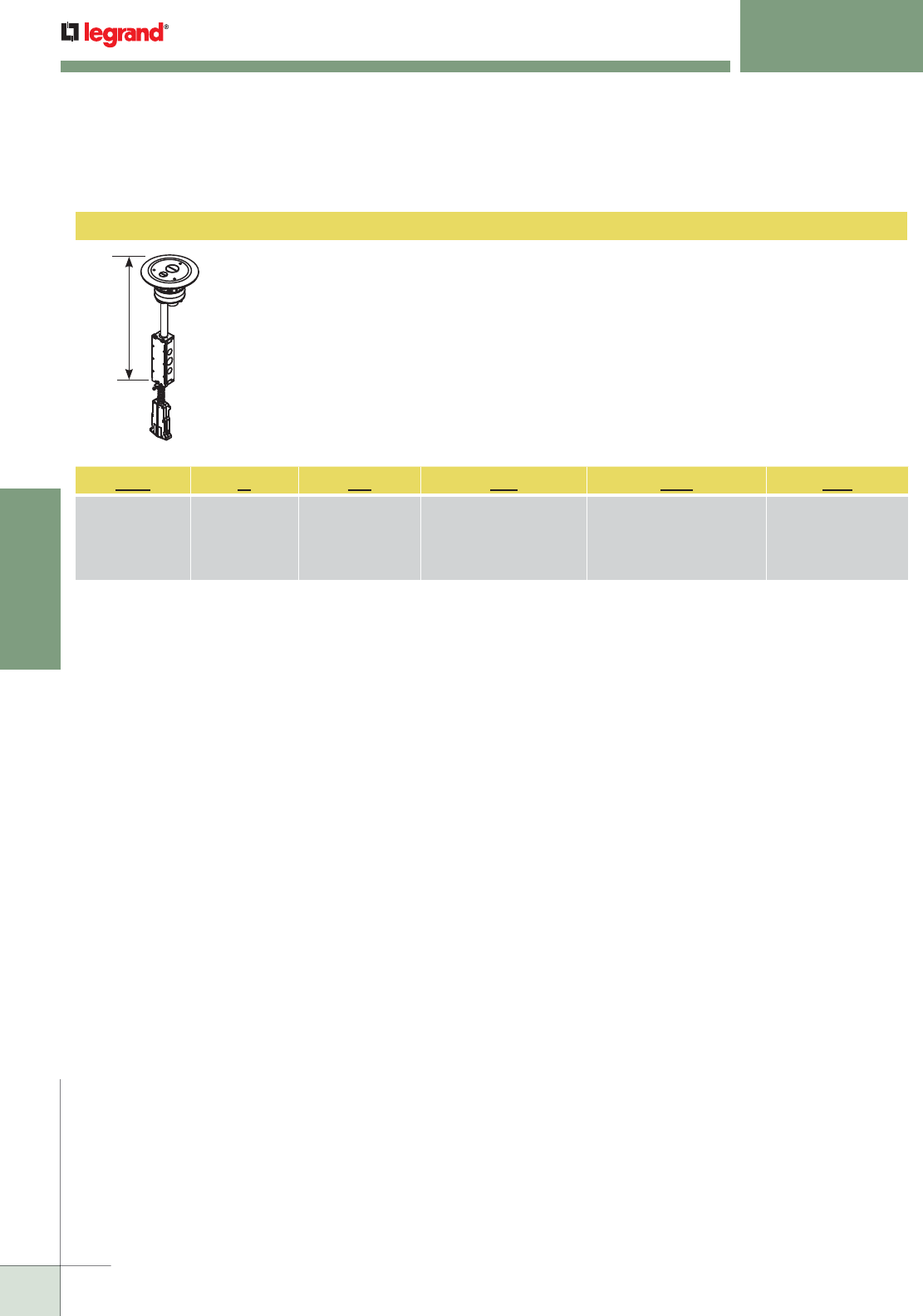
WIREMOLD
WWW.LEGRAND.US/WIREMOLD
544
MODULAR WIRING
4FFATC
Furniture feed style poke-thru assembly – Complete with one-piece finish flange and conduit
assembly. Finish covers flange provided with one (1) 3/4" trade size screw plug opening and one (1)
1 1/4" trade size screw plug opening. The poke-thru unit fits into a 4" [102 mm] diameter core hole.
Comes with 1 ft. modular Walkerflex cable whip.
Unit also includes:
• One (1) 3/4" trade size conduit adapter.
• One (1) 1 1/4" trade size conduit adapter.
Standard Offerings: 4FFATCBK422CW, 4FFATCGY422CW, 4FFATCBS422CW, 4FFATCAL422CW,
NOTE: Assembled with a scrub water gasket. For use on tile, wood or carpeted covered floors. Floor covering thickness range 1/8"
to 3/4", not designed for use on bare concrete or terrazzo finished floors.
WALKERFLEX
®
MODULAR WIRING SYSTEM
4FF A TC BK 422 CW
4FF = Furniture
Feed Style Poke-
Thru Device
A = Assembled
Unit
Unit is approved tile,
wood, and carpet
covered floors
Color of Cover Assembly:
BK = Black
GY = Gray
AL = Aluminum
BS = Brass
Power Delivery System:
422 = 4 Circuits, 2 Neutrals,
Isolated Ground
Style of Feed:
CW = Cable Whip
Furniture Feed Style Poke-Thru Devices
16 3/4"
[425mm]
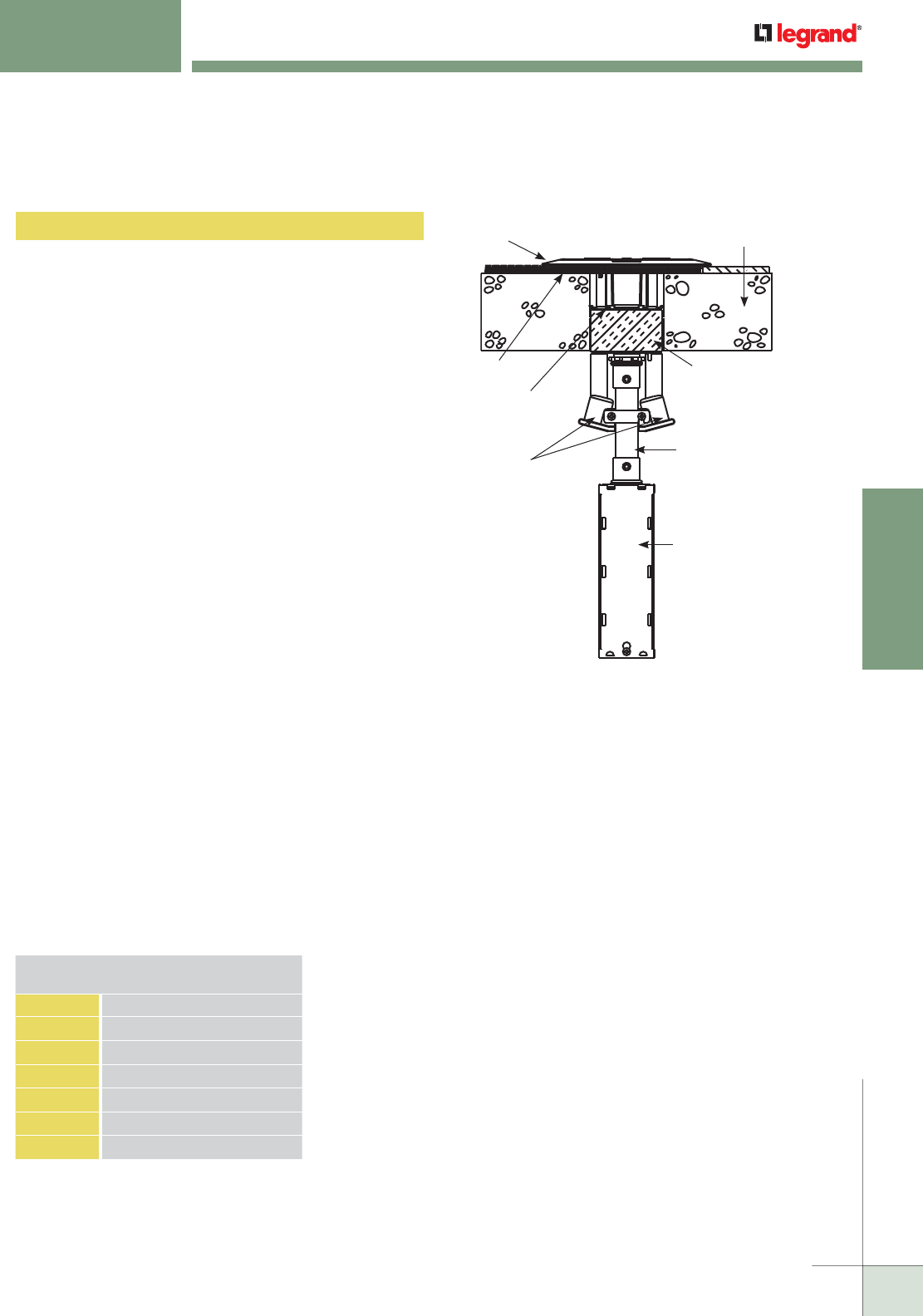
WIREMOLD
WWW.LEGRAND.US/WIREMOLD
545
MODULAR WIRING
WALKERFLEX
®
MODULAR WIRING SYSTEM
Surface Style Poke-Thru Devices Specifications
The copper cross-sectional area determines the amount
of wire fill capacity in a poke-thru device. Unlike other
wire and cable management systems that utilize wire
fill capacity, a poke-thru device is UL tested under fire
conditions to determine the maximum amount of copper
conductors that will pass through a poke-thru device, while
maintaining the fire-rating of the floor assembly. All Walker
Flush Style Devices are UL Classified to U.S. and Canadian
safety standards (see complete marking on product) to
accommodate at a maximum rating as follows:
RC7 SERIES
Maximum Allowable Copper Cross-Sectional Area:
RC7 Power Compartment Only = .01536 sq. in. [9.91mm2]
RC7 Each Communication Compartment Only = .0040 sq. in.
[2.58mm2]
NOTE: The RC7 Series requires a 3" [76mm] cored hole.
(American-made core bit having an outside diameter of 3 1/16" [78mm].)
RC9 SERIES
Maximum Allowable Copper Cross-Sectional Area:
RC9 Power Compartment Only = .01536 sq. in. [9.91mm2]
RC9 Each Communication Compartment Only = .0040 sq. in.
[2.58mm2]
NOTE: The RC9 Series requires a 3" [76mm] cored hole.
(American-made core bit having an outside diameter of 3 1/16" [78mm].)
AV3 SERIES
Maximum Allowable Copper Cross-Sectional Area:
AV3 Power Compartment Only = .01536 sq. in. [9.91mm2]
AV3 Communication Compartment Only = .01938 sq. in.
[12.503mm2]
NOTE: The AV3 Series requires a 4" [102mm] cored hole.
(American-made core bit having an outside diameter of 4 1/16" [103mm].)
RC4 SERIES
Maximum Allowable Copper Cross-Sectional Area:
RC4 Power Compartment Only = .03072 sq. in. [19.82mm2]
RC4 Each Communication Compartment Only = .008 sq. in.
[5.16mm2]
NOTE: The RC4 Series requires a 4" [102mm] cored hole.
(American-made core bit having an outside diameter of 4 1/16" [103mm].)
Copper Cross Section
COM50 1/2" Trade Size
Conduit Connections
(Sold Separately)
Intumescent
Material
3/4" Trade Size
EMT Conduit
Trim Flange for
Carpet or Tile Concrete Slab
Junction Box
24.5 cu in. [401ml]
Scrub Water
Gasket
Retaining Flange
IMPORTANT!
The above maximum copper cross sectional area values are for
each individual power and communication compartment.
DO NOT add values together for any one compartment.
CAUTION! Core bits vary in size from manufacturer to
manufacturer:
• Use a 3" [76mm] American made core bit having an outside
diameter of 3 1/16" [78mm]. Minimum hole diameter: 3 1/16"
[78mm].
• Use a 4" [102mm] American made core bit having an outside
diameter of 4 1/16" [103mm]. Minimum hole diameter: 4 1/16"
[103mm].
CAUTION! These devices are suitable for 1, 1 1/2, and 2 hour rated
floor assemblies as described in the UL Fire Resistance directory
for each service.
These devices meet all UL scrub water requirements, but are
not suitable for wet or damp locations, or other areas subject
to saturation with water or other liquids such as commercial
kitchens.
Concrete Thickness Min/Max:
1-Hour Rated Floor – 2 1/4" [57mm] min over top of deck (or 3"
[76mm] thick reinforced concrete slab) to a maximum of 7 1/2"
[191mm].
2-Hour Rated Floor – 3 1/4" [83mm] min over top of deck (or 4"
[102mm] thick reinforced concrete slab) to a maximum of 7 1/2"
[191mm].
Floor Coverings:
The poke-thru device is fire rated for carpet and wood covered
concrete floors, and tile floor coverings 1/8" to 3/4" [3.2mm to
19.1mm] thickness. For floor coverings not listed above, consult
factory.
Copper Cross Sectional Area
of Commonly Used Conductors
SIZE SOLID
#24 0.00032 sq. in. [0.206mm2]
#22 0.00050 sq. in. [0.322mm2]
#14 0.00323 sq. in. [2.083mm2]
#12 0.00512 sq. in. [3.303mm2]
#10 0.00815 sq. in. [5.258mm2]
#8 0.01296 sq. in. [8.361mm2]
NOTE: Use above values for solid or stranded conductors.
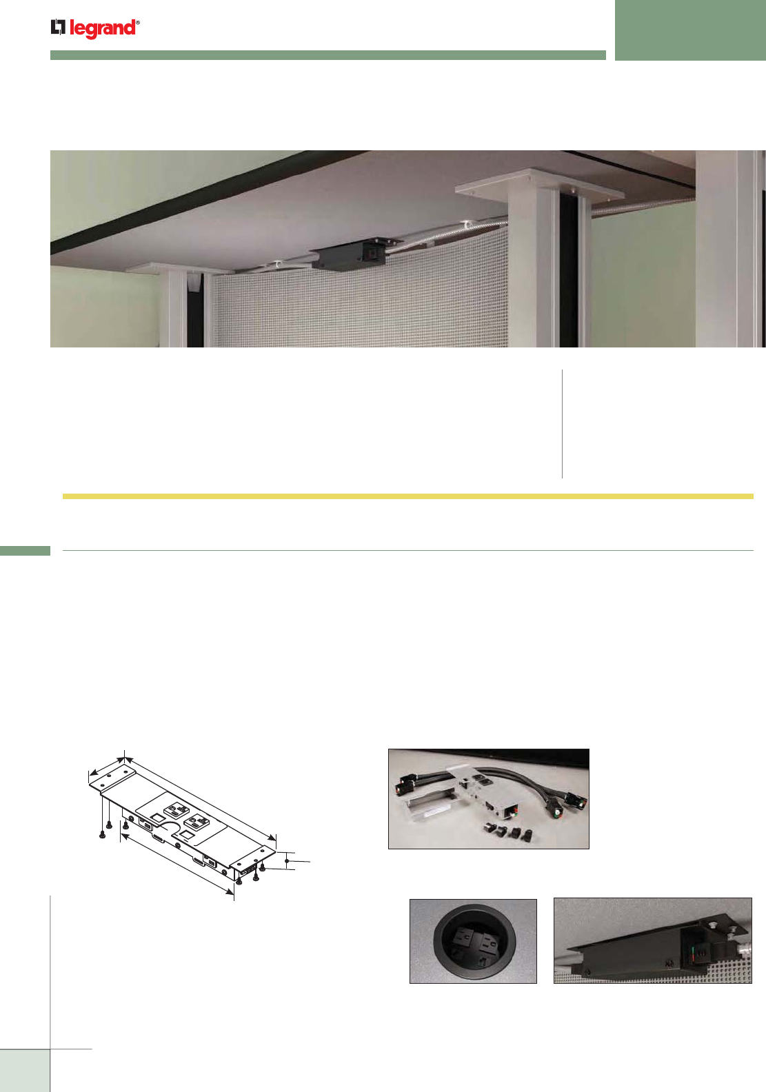
546
WWW.LEGRAND.US/WIREMOLD
546
MODULAR WIRING
WIREMOLD
WORK SURFACE MODULAR POWER
CODE REFERENCE
UL Listed :
Manufactured Wiring Systems
File E51105 Guide: QQVX
CSA Certified File 257563
Cord Ended Units are UL & cUL Listed
Furniture Feed Distribution Units
File: E349493 Guide: IYNC
Wiremold® Work Surface Modular Power Kits (WSMP) make rearranging
meeting rooms fast, easy, and safe by providing both under table power
and cable management in one package. It is a 4 wire system, with two hot
conductors, a neutral conductor and a ground. The dual circuit pathway
insures that one has all the power needed to satisfy any meeting or gathering.
Work Surface Modular Power Kits Ordering Information
12"
[305mm]
2 5/32"
[55mm]
3 5/32"
[80mm]
10"
[254mm]
NOTE: Kits include portal(s), flange(s) cables and
mounting clips. Enhanced Portal Kit shown.
NOTE: Kit configurations assume there is 1/2" of cabling on each side of the table to make the table-to-table connections.
Shown with existing table
grommet (supplied by others).
NOTE: Part Number Configurator can be used both to identify stock product configurations and also to request custom configurations
from the factory. Consult the factory for more information.
Work Surface Modular Power Part Number Configurator
Power:
Modular Power
Enhanced Portal = ME
Modular Power
Standard Unit = MP
Cord-ended Power
Enhanced Unit = CE
Work Surface
Series = WS
Style:
Under Table
(No Flange) = UT
Through Table
(Contour
Flange) = TC
Table Size:
72" = 72
60" = 60
Data:
2 Keystone
Openings = D
Portal Color:
Black = BK
Silver = SL
Kit Config.:
Single
Portal Kit = SL
Double
Portal Kit = DK
Wiring Config.:
Portals wired
for circuit 2 = 2
Portals wired
for circuit 1 =
Blank
WS ME D TC 72 SL SK -2
NOTE: Cable and Connectors are wired for two circuits. Portals are either Circuit 1 or Circuit 2. (They pass through the other circuit.)
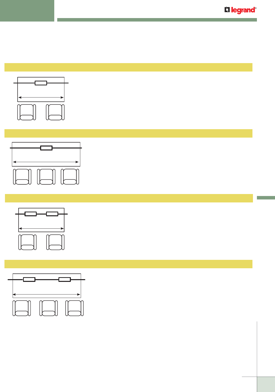
547
WWW.LEGRAND.US/WIREMOLD 547
MODULAR WIRING
WIREMOLD
Modular Power & Double Work Surface Portal Quick Kit for 5' Table – Kit contains
three 4 wire, 2 circuit connectorized cables; two 12" in length (one M/F and one F/F)
and one 17" (F/F), all with black cable covers and 8 cable clamps for mounting. Also
two work surface portals each with 2 power outlets accessible from table surface and
2 convenience power outlets accessible from under the table, 2 keystone openings for
communications and one silver flange cover. The 4 wire portal is typically wired to the
first circuit. If you want a kit with portals wired for the second circuit, please order the
“-2” suffixed part number.
WSMEDTC60SLDK, WSMEDTC60SLDK-2 Through Table Access – Double Enhanced Portal Kits
Modular Power & Double Work Surface Portal Quick Kit for 6' Table – Kit
contains three 4 wire, 2 circuit connectorized cables; two 12" in length (one
M/F and one F/F) and one 29" (F/F), all with black cable covers and 8 cable
clamps for mounting. Also two work surface portals each with 2 power outlets
accessible from table surface and 2 convenience power outlets accessible from
under the table, 2 keystone openings for communications and one silver flange
cover. The 4 wire portal is typically wired to the first circuit. If you want a kit with
portals wired for the second circuit, please order the “-2” suffixed part number.
WSMEDTC72SLDK, WSMEDTC72SLDK-2 Through Table Access – Double Enhanced Portal Kits
NOTE: Kit configurations assume there is 1/2" of cabling on each side of the table to make the table-to-table connections.
10"
12" MF 29" FF 12" FF
10"
Table Length 72"
Table Length 60"
10"
12" MF 17" FF 12" FF
10"
WORK SURFACE MODULAR POWER
Ordering Information
Modular Power & Work Surface Portal Quick Kit for 5' Table – Kit contains two 4 wire,
2 circuit connectorized cables each 25.5" in length (one M/F and one F/F) with black
cable covers and 4 cable clamps for mounting. Also one work surface portal with 2
power outlets accessible from table surface and 2 convenience power outlets accessible
from under the table, 2 keystone openings for communications and one silver flange
cover. The 4 wire portal is typically wired to the first circuit. If you want a kit with portals
wired for the second circuit, please order the “-2” suffixed part number.
WSMEDTC60SLSK, WSMEDTC60SLSK-2 Through Table Access – Single Enhanced Portal Kits
10"
25.5" MF 25.5" FF
Table Length 60"
Modular Power & Work Surface Portal Quick Kit for 6' Table – Kit contains two
4 wire, 2 circuit connectorized cables each 31.5" in length (one M/F and one F/F)
with black cable covers and 4 cable clamps for mounting. Also one work surface
portal with 2 power outlets accessible from table surface and 2 convenience
power outlets accessible from under the table, 2 keystone openings for
communications and one silver flange cover. The 4 wire portal is typically wired
to the first circuit. If you want a kit with portals wired for the second circuit,
please order the “-2” suffixed part number.
WSMEDTC72SLSK, WSMEDTC72SLSK-2 Through Table Access – Single Enhanced Portal Kits
10"
31.5" MF 31.5" FF
Table Length 72"
Work Surface Modular Power Kits Ordering Information

WIREMOLD
WWW.LEGRAND.US/WIREMOLD
548
MODULAR WIRING
Cord-Ended Enhanced Work Surface Portals – For Use at Workstations –
Cord-ended silver flange and portal (SL) or black flange and portal (BK), with
2 power outlets accessible from table surface and 3 convenience power outlets
accessible from under the table, 2 keystone openings, 4 cable clamps and 72"
power cord.
WSCEDTCSL, WSCEDTCBK Cord-Ended Enhanced Work Surface Portals – For Use at Workstations*
Cord-Ended Enhanced Work Surface Portals – For Use at Workstations Ordering Information
Portal Dimensions:
Top with Mounting Flange: 12" L x 3 13/100" W
Base: 9 63/100" L x 2 17/100" D
Flange: 5 68/100" L x 3 39/100" W
* Cord-Ended Units are UL and cUL Listed.
Modular Power & Work Surface Portal Quick Kit for 5' Table – Kit contains two 4 wire,
2 circuit connectorized cables each 27" in length (one M/F and one F/F) with black
cable covers and 4 cable clamps for mounting, one black work surface portal with 2
power and 2 keystone openings for communications. The 4 wire portal is typically wired
to the first circuit. If you want a kit with portals wired for the second circuit, please
order the “-2” suffixed part number. Kits can be used with existing grommeted table
openings or with portals rotated and edge mounted.
WSMPDUT60BKSK, WSMPDUT60BKSK-2 Under Table Access (No Flange) – Portal Kits
Modular Power & Work Surface Portal Quick Kit for 6' Table – Kit contains
two 4 wire, 2 circuit connectorized cables each 33" in length (one M/F and one
F/F) with black cable covers and 4 cable clamps for mounting, one black work
surface portal with 2 power and 2 keystone openings for communications.
The 4 wire portal is typically wired to the first circuit. If you want a kit with
portals wired for the second circuit, please order the “-2” suffixed part number.
Kits can be used with existing grommeted table openings or with portals
rotated and edge mounted.
WSMPDUT72BKSK, WSMPDUT72BKSK-2 Under Table Access (No Flange) – Portal Kits
6.5"
27" MF 27" FF
Table Length 60"
6.5"
33" MF 33" FF
Table Length 72"
Work Surface Modular Power Kits Ordering Information (continued)
WORK SURFACE MODULAR POWER
Ordering Information
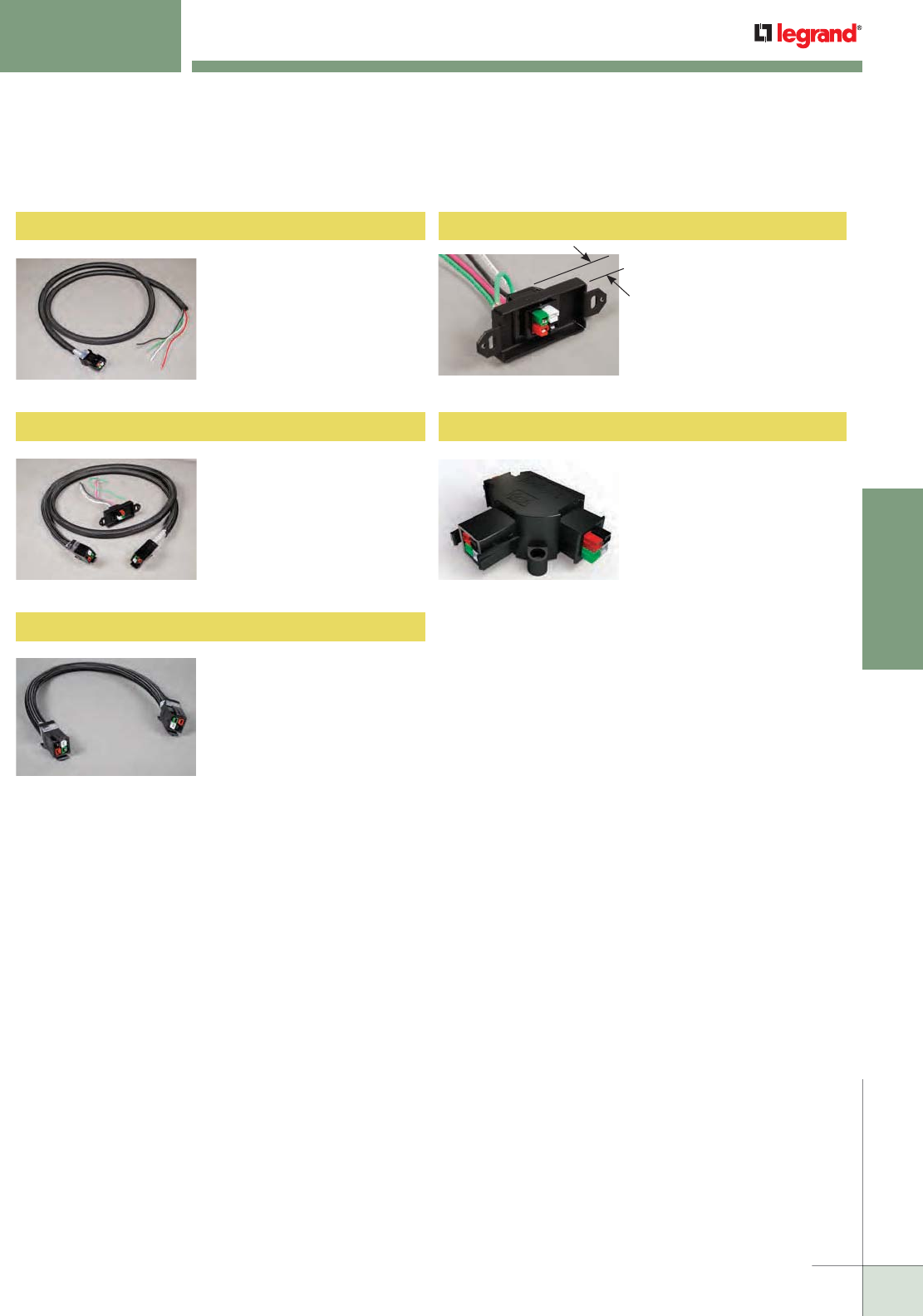
WIREMOLD
WWW.LEGRAND.US/WIREMOLD
549
MODULAR WIRING
Work Surface Modular Power Components Ordering Information
72", multi-circuit, black starter
cable with cover with 12"
leads on one end and a female
connector on the other.
WSMPHWSC72 Hardwire Starter Cable
Single connector with 18"
leads in decorator footprint for
wall or floor outlets with 72"
female/female interconnecting
cable and cable cover.
WSMPQDSFF Quick Disconnect Insert & Cable
12" MM connectorized cable to
accommodate “U” or cornered
runs.
WSMPCMM12 Connector Cable
Male connector in decorator
sized plate with 18" leads.
(Decorator faceplate not
included.)
WSMP-QD Quick Disconnect Connector
MFM connectors for starting
power runs from the center of
a table or auditorium seating
applications.
WSMP-T T Connector
WORK SURFACE MODULAR POWER
Ordering Information
1.15" Depth
(1.4" with wire leads)

WIREMOLD
WWW.LEGRAND.US/WIREMOLD
550
MODULAR WIRING
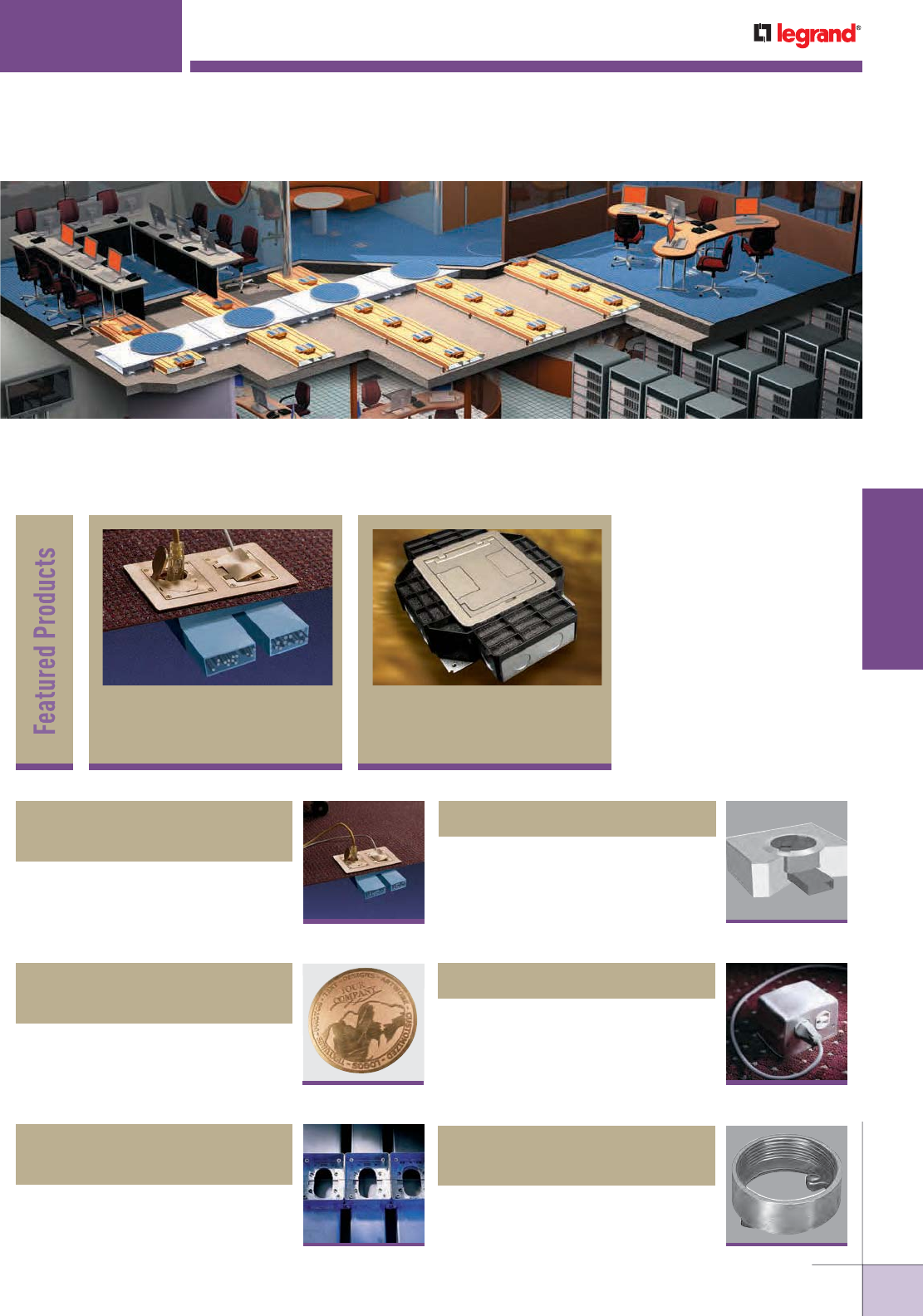
WWW.LEGRAND.US/WIREMOLD
551
INFLOOR DUCTS
WIREMOLD
INFLOOR DUCTS
Wiremold® Infloor Duct Systems are cost-effective and flexible solutions for
any wiring and communication needs throughout an open space environment
which will accommodate needs now and into the future.
Product
blurb
Floorport™ Series
Cover
Assemblies 609
Walkerduct
Underfloor
Duct Systems 557
Walkerduct® Carpet/Tile
Holders
569
Walkerduct® Underfloor
Duct Systems
557
572
Walkerduct® Pro Series
Service
Fittings
582
525 Series™ Service Fittings
580
PSRC9 Series™ Service Fittings
585
525 & Multiplex™ Series
Activation Accessories
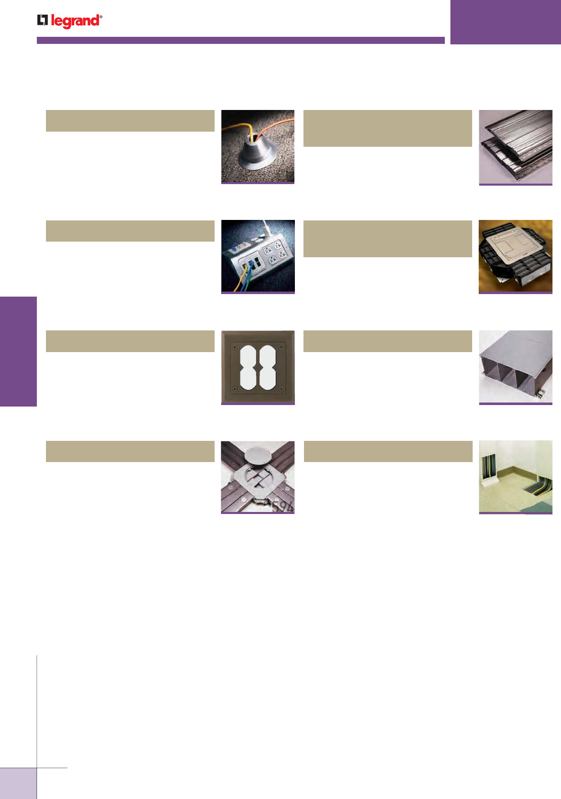
WWW.LEGRAND.US/WIREMOLD
552
INFLOOR DUCTS
WIREMOLD
INFLOOR DUCT SYSTEMS
Table of Contents
590
Source I® Service Fittings
Wallduct Raceway Systems
616
Trenchduct Feeder Systems
612
599
Walkercell® Cellular
Raceway Systems
Flushduct Infloor Duct Systems
594
609
Floorport™ Series
Cover Assemblies
588
Multiplex™ Series Service Fittings
587
1200 Series™ Service Fittings
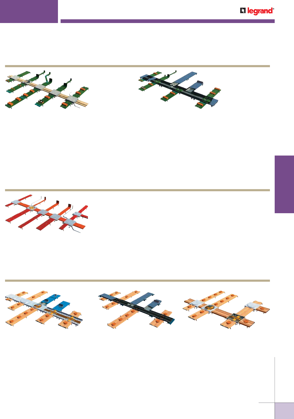
WWW.LEGRAND.US/WIREMOLD
553
INFLOOR DUCTS
WIREMOLD
INFLOOR DUCT SYSTEMS
Quick Selection Guide
Walkerduct Layout with Junction Boxes Walkerduct Layout with Trenchduct
Walkerduct with Junction Boxes offers
capacity and flexibility for casinos, retail,
libraries, light industrial, and small-to-
medium office space.
Walkerduct with Trenchduct provides
a high capacity of wire and cable
management. Perfect for an open space
setting, power and communications can be
easily rewired through steel access plates.
Features:
• Two Sizes of Underfloor Ducts
• Multiple Duct Combinations/
Configurations
• Quality Construction
• Ample Bend Radius throughout System
• Round or Square Junction Box Access
Openings
• Choice of Preset Shape or Size
• Wide Variety of Activations
Service Fitting/Activation Options:
• 817 Series™ Flush Fittings
• 525 Series™ Pedestal Fittings
• 1200 Series™ Pedestal Fittings
• PSRC9 Series™ Flush Fittings
• Trench Access Hood
• Multiplex™ Pedestal Fittings
Walkerduct Underfloor Duct
Features:
• Three-in-One Configuration Raceway
• Triple Service Preset with Recessed Activations
• Large Capacity Feeder System
• Flexible Trenchduct Design
• Custom Options Available
• Ample Bend Radius throughout System
Service Fitting/Activation Options:
• FloorPort™ Recessed Fittings
• Multiplex™ Pedestal Fittings
Walkercell Layout with Junction Box Header Walkercell Layout with Trenchduct Walkercell Feed & Distribution Layout
Walkercell with Junction Box Header provides fast installation and high flexibility
along with high capacity for commercial and educational facilities. Easy access to
cables and wires manage the changing business needs of commercial buildings.
Walkercell with Trenchduct provides fast installation and high flexibility along
with high capacity for commercial and educational facilities. Easy access to
cables and wires manage the changing business needs of commercial buildings.
Walkercell Feed and Distribution also provides fast installation and high flexibility
along with high capacity for commercial and educational facilities. Easy access to
cables and wires manage the changing business needs of commercial buildings.
Walkercell Cellular Raceway
Features:
• 1, 2, or 3 Duct Combinations
• Feed and Distribution Ducts Located
Flush with Finished Floor
• Easy Access to Ducts through Factory
Installed Screw Plugs
• Variety of Pedestal Activations
• 1 3/8" [35mm] Minimum System Depth
(2 5/8" when using a junction box)
• Trenchduct Feed Maximizes Capacity
Service Fitting/Activation Options:
• 525 Series™ Pedestal Fittings
• Multiplex™ Pedestal Fittings
Walker Flushduct with Junction Boxes lay level with
the concrete on the floor. It provides easy access
through the duct and simple installation of wires and
cables. It also offers an aesthetically pleasing option
for any open space application.
FlushDuct Infloor Duct Systems

WWW.LEGRAND.US/WIREMOLD
554
INFLOOR DUCTS
WIREMOLD
INFLOOR DUCT SYSTEMS
Quick Selection Guide
Activation/Service Fitting – The device access point at
which wires and cables egress from the infloor system.
These products come in a variety of styles and sizes and can
be recessed into the floor, flush with the floor or mounted
above the floor.
Afterset – A metal fitting installed between the infloor
raceway and the activation used to bring cables and wires
from the raceway to the activation. It is installed after core
drilling the concrete to reach the raceway buried in the
concrete.
Crossunder – A design option of intersecting infloor
raceways where one system drops down under the other
instead of intersecting on the same plane.
Distribution Raceway – Raceway that carries wires and
cables from the feeder system to the workstation area.
Typically has presets attached to the raceway, but can also
have aftersets.
Feeder System – Large capacity raceway used to carry
cables and wires from the communication and power
closets to the distribution raceway. Trenchduct, Headerduct,
and No. 4 duct are commonly used as feeder systems.
Junction Box – A location in the raceway system that allows
transition of pathways and access to cables.
Mudcap – A recessed lid installed on the top of a preset
or afterset to prevent concrete from entering it. Mudcap is
removed when access to the wires and cables is needed.
The concrete above it is chipped out, and the mudcap is
removed with a screwdriver.
Preset – A metal fitting is mounted on the infloor raceway
that is buried in the concrete, designed to provide an access
point to the cable and wires in the raceway. The concrete
above it (1/8" deep) and the mudcap are removed, and a
service fitting is mounted on it to provide cable and wire
egress from the raceway.
Slab Depth – Total depth of the concrete.
System Depth – Depth of Walker Infloor System from base
of duct/cell/trench to the top of the cover plates.
Infloor Systems Terminology
Frequently Ordered Catalog Numbers
SPACING PRESETS 12" [305mm] OC 24" [610mm] OC
1" [25mm] D21210 D22410
1 1/2" [38mm] D21215 D22415
2" [51mm] D21220 D22420
2 1/2" [64mm] D21225 D22425
3" [76mm] D21230 D22430
No. 2 Walkerduct Pro Series with Presets
SPACING PRESETS 12" [305mm] OC 24" [610mm] OC
1" [25mm] 2-12 x 2 x 7/8 2-24 x 2 x 7/8
1 1/2" [38mm] 2-12 x 2 x 1 1/2 2-24 x 2 x 11/2
2" [51mm] 2-12 x 2 x 2 2-24 x 2 x 2
2 1/2" [64mm] 2-12 x 2 x 2 1/2 2-24 x 2 x 2 1/2
3" [76mm] 2-12 x 2 x 3 2-24 x 2 x 3
No. 2 Walkerduct with 2" IPS Presets
SPACING PRESETS 12" [305mm] OC 24" [610mm] OC
1" [25mm] D41210 D42410
1 1/2" [38mm] D41215 D42415
2" [51mm] D41220 D42420
2 1/2" [64mm] D41225 D42425
3" [76mm] D41230 D42430
No. 4 Walkerduct Pro Series with Presets
SPACING PRESETS 12" [305mm] OC 24" [610mm] OC
1" [25mm] 4-12 x 2 x 7/8 4-24 x 2 x 7/8
1 1/2" [38mm] 4-12 x 2 x 1 1/2 4-24 x 2 x 1 1/2
2" [51mm] 4-12 x 2 x 2 4-24 x 2 x 2
2 1/2" [64mm] 4-12 x 2 x 2 1/2 4-24 x 2 x 2 1/2
3" [76mm] 4-12 x 2 x 3 4-24 x 2 x 3
No. 4 Walkerduct with 2" IPS Presets
JUNCTION BOXES* ROUND COVER PLATE SQUARE COVER PLATE ROUND HEAVY DUTY SQUARE HEAVY DUTY TWO-LEVEL
(1) No. 2 Duct 12JR- 12JS- 12HR- 12HS- 142L
(1) No. 4 Duct 14JR- 14JS- 14HR- 14HS- 142L
(2) No. 2 Ducts 222JR- 222JS- 222HR- 222HS-
(2) No. 4 Ducts 244JR- 244JS- 244HR- 244HS-
(1) No. 2 and (1) No. 4 Duct 224JR- 224JS- 224HR- 224HS-
(3) No. 2 Ducts 3222JR- 3222JS- 3222HR- 3222HS-
(2) No. 2 and (1) No. 4 Ducts 3224JR- 3224JS- 3224HR- 3224HS-
(1) No. 2 and (2) No. 4 Ducts 3244JR- 3244JS- 3244HR- 3244HS-
(1) No. 4, (1) No. 2, and (1) No. 4
Duct
3424JR- 3424JS- 3424HR- 3424HS-
(3) No. 4 Ducts 3444JR- 3444JS- 3444HR- 3444HS-
(4) No. 2 Ducts 42222JR- 42222JS- 42222HR- 42222HS-
(5) No. 2 Ducts 522222JR- 522222JS- 522222HR- 522222HS-
* Add suffix to indicate height of junction box.
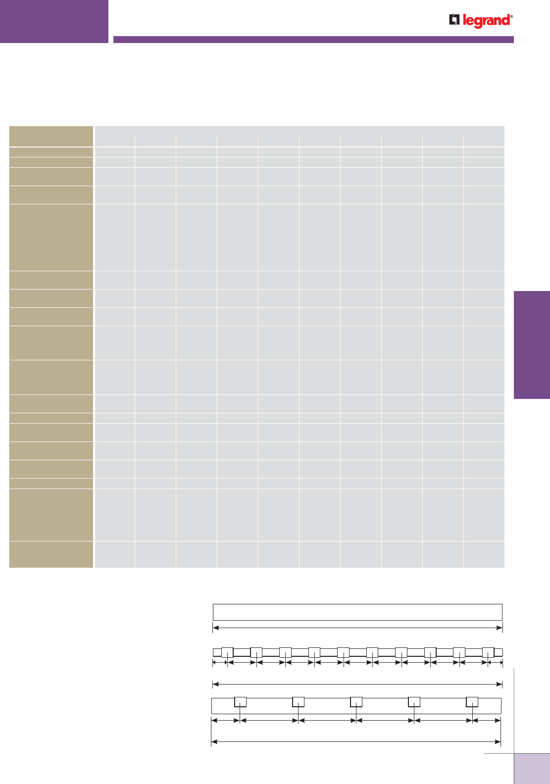
WWW.LEGRAND.US/WIREMOLD
555
INFLOOR DUCTS
WIREMOLD
Walkerduct Raceways provide wire management for open
space environments while maintaining aesthetics because they
are buried in the floor, out of sight, and safe from abuse. The
duct is designed to be used with Walkerduct Junction Boxes
or Walker® Trenchduct to create an infloor wire management
system. Duct runs provide a range of capacities to suit any
situation and to future proof the wire management system.
Duct can be used individually or combined with other duct to
deliver power and communication services to workstations.
Multiple duct runs may be all one size of duct or a mix of
sizes. Activations may be located anywhere along the length
of the duct to maximize flexibility and accessibility to wiring
workstations. Flexibility is only limited by the grid pattern.
Designed to be used with power and communications service
fittings shown in Service Fittings section of this Product Guide.
12"
[305mm]
12"
[305mm]
12"
[305mm]
12"
[305mm]
12"
[305mm]
12"
[305mm]
12"
[305mm]
12"
[305mm]
12"
[305mm]
6"
[152mm]
6"
[152mm]
10' [3m]
10' [3m]
24"
[610mm]
24"
[610mm]
24"
[610mm]
24"
[610mm]
12"
[305mm]
12"
[305mm]
10' [3m]
Walkerduct Pro Series Duct Systems
ACCESSORIES
SYSTEM
12 14 222 224 244 3222 3224 3244 3424 3444
Adjustable Supports* SC12- SC14- SC222- SC224- SC244- SC3222- SC3224- SC3244- SC3244- *
Hold-Down Strap HS12 HS14 HS222 HS224 HS244 HS3222 HS3224 HS3244 HS3244 *
Couplings 302 H302 302 302
H302
H302 302 302
H302
302
H302
302
H302
H302
Duct End Closures 304 H304 304 304
H304
H304 304 304
H304
304
H304
304
H304
H304
Conduit Adapters 312-
314-
317-
322-
324-
H312-
H317-
H322
312-
314-
317-
322-
324-
312-
314-
317-
322-
324-
H322-
H317-
H312-
H312-
H317-
H324-
312-
314-
317-
322-
324-
312-
H312-
314-
317-
H317-
322-
H322-
324-
312-
314-
317-
H317-
322-
H322-
324-
H312-
312-
314-
317-
H317-
322-
H322-
324-
H312-
H312-
H317-
H322
Box Corner
Conduit Adapter
255- 255- 255- 255- 255- 255- 255- 255- 255- 255-
Terminal Bushings 334UF H334 334UF 334UF
H332
H334 334UF 334UF
H334
334UF 334UF H334
Vertical Elbows 332UF H332 332UF 332UF
H332
H332 332UF 332UF
H332
332UF
H332
332UF
H332
H332
Horizontal Elbows
(90° & 45°)
338UF
342UF
H338
H342
338UF
342UF
338UF
H338
342UF
H342
H338
H342
338UF
342UF
338UF
H338
342UF
H342
338UF
H338
342UF
H342
338UF
H338
342UF
H342
H338
H342
Crossunder Offsets 372
375
H372
H375
372
375
372
H372
375
H375
H372
H375
372
375
372
H372
375
H375
372
H372
372
H372
H372
H375
Expansion Joints 382 H382 382 382
H382
H382 382 382
H382
382
H382
382
H382
H382
Mudcaps 421 421 421 421 421 421 421 421 421 421
Marker Caps 422GR
422RD
422GR
422RD
422GR
422RD
422GR
422RD
422GR
422RD
422GR
422RD
422GR
422RD
422GR
422RD
422GR
422RD
422GR
422RD
Box Opening Closures 203 H203 203 203
H203
H203 203 203
H203
203
H203
203
H203
H203
Box Closure Adapters —
275SR
275SL
275SR
—275SL
275SR
275SL
275SR
— 275SL
275SR
275SL
275SR
275SL
275SR
275SL
275SR
Sealant 290G 290G 290G 290G 290G 290G 290G 290G 290G 290G
Tile & Carpet
Trim/Holders
square
FT6-
CT6-
round
SFCS5-
SFCB5-
square
FT10-
CT10-
round
SFCS9-
SFCB9-
square
FT10-
CT10-
round
SFCS9-
SFCB9-
square
FT15-
CT15-
round
SFCS14-
SFCB14-
square
FT18-
CT18-
round
SFCS17-
SFCB17-
square
FT15-
FT15-
round
SFCS14-
SFCB14-
square
FT18-
FT18-
round
SFCS17-
SFCB17-
square
FT21-
FT21-
round
SFCS20-
SFCB20-
square
FT21-
FT21-
round
SFCS20-
SFCB20-
square
FT25-
FT25-
round
SFCS24-
SFCB24-
Junction Box
Conduct Adapters
212-
232-
H232- 212-
232-
212-
232-
H232-
H232 212
232
212
232
H232-
212
232
H232-
212
232
H232-
H232
* Supports include built-in Coupling.
NOTE: Part numbers ending in a dash need to have the height adjustment size suffix included when ordering.
Please see the individual support product descriptions for this information.
INFLOOR DUCT SYSTEMS
Quick Selection Guide
WWW.LEGRAND.US/WIREMOLD
556
INFLOOR DUCTS
WIREMOLD
PRODUCT FAMILY
CATALOG
NUMBER
SYSTEM
COMPATIBILITY
ACTIVATION
LOCATION
SERVICE
CAPACITY
SERVICE
COMPATIBILITY
MATERIAL/COLORS
WALKERDUCT
WALKERCELL
FLUSHDUCT
TRENCHDUCT
Flush
Recessed
Pedestal
Single Service
Dual Service
Triple Ser vice
Power
Communication
Audio/Visual
Polycarbonate
Alumi num
Brass
Gray
Black
Nickel
Bronze
FloorPort
FPCTC Series
• • •••• ••••••
FPBTC Series
• • •••• ••••••
FPFFTC Series
• • •••• ••••••
FPCT Series
• • •••• ••••••
FPBT Series
• • •••• ••••••
FPFFT Series
• • •••• ••••••
Pro
Series
Flanges
817B
••••••
827B
••••••
837B
•• ••••
817PCC
•••••••
827PCC
• • •••• •
837PCC
•• •••••
818TCAL
• •••••
828TCAL
••••••
838TCAL
•• ••••
Source I
S165B
•••• •
S165BLK/BRN
••• ••
S166B
•••••
S166BLK/BRN
••••••
S175BLK/BRN
• •••• •
PSRC9
Series
PSRC9TC
• • • • ••••
PSRC9AMDTC
• • • • ••••
PSRC9FFTC
• • • • ••••
1200
Series
1204BF •• •• • •
1204AL •• •• • •
1223BF •• •• • •
1223AL •• •• • •
Multiplex
MP4 ••• •• ••• •
MP8 • • • • ••• •
MP8-1 ••• • • ••• •
525
Series
525A ••• •• •• •
525B ••• •• •• •
525C ••• •• •• •
525D ••• •• •• •
525F ••• •• • •
525G ••• •• • •
525H ••• •• • •
525I ••• •• • •
525J ••• •• ••• •
525RT ••• •• • •
525ACT••• •• • • •
SERVICE FITTINGS & ACTIVATION ACCESSORIES
Quick Selection Guide
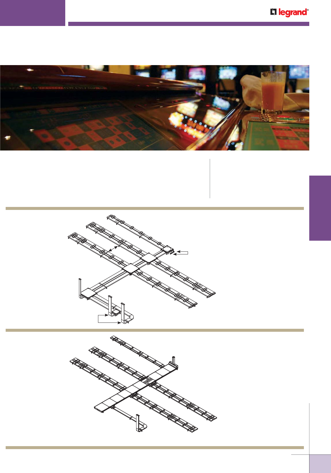
WWW.LEGRAND.US/WIREMOLD
557
INFLOOR DUCTS
WIREMOLD
D
B
B
EA
GG
F
F
B
D
A
C
H
E
C
D
B
J
E
A
GF
C
H
I
WALKERDUCT
®
UNDERFLOOR DUCT SYSTEMS
KEY
A. Duct
B. Pro Series Preset
C. Junction Box
D. Coupling
E. Duct Support
F. Conduit Adapter
G. Elbow
H. Junction Box Closure
Walkerduct® Underfloor Duct Systems offer maximum capacity and
configurability using two sizes of duct. CODE REFERENCE
ULus Listed Underfloor Raceway:
File E7020 Guide RKCZ
cULus Listed Underfloor Raceway Fittings:
File E11912 Guide RKQX.
Meets Article 390 of NEC.
Walkerduct Pro Series
System Layout with
Junction Boxes
KEY
A. Trenchduct
B. #2 2" IPS Duct
C. #4 2" IPS Duct
D. Cross Under
E. Couplings
F. End Closure
G. Duct Support
H. Horizontal Flat Elbow
I. Vertical Elbow
J. Blank #4 Duct
NOTE: Illustration is for showing product applications only.
Walkerduct 2" [51mm]
IPS Duct System Layout
with Trenchduct
NOTE: Illustration is for showing product applications only.
WWW.LEGRAND.US/WIREMOLD
558
INFLOOR DUCTS
WIREMOLD
WALKERDUCT
®
UNDERFLOOR DUCT SYSTEMS
PRODUCT FAMILY
CATALOG
NUMBER
ACTIVATION
LOCATION
SERVICE
CAPACITY
SERVICE
COMPATIBILITY
MATERIAL/COLORS
Flush
Pedestal
Single Service
Dual Service
Triple Ser vice
Power
Communication
Audio/Visual
Polycarbonate
Alumi num
Brass
Gray
Black
Pro
Series
Flanges
817B •• •• •
827B • • • • •
837B • • • • •
817PCC • • • • • •
827PCC • • • • • •
837PCC • • • • • •
818TCAL • • • • •
828TCAL • • • • •
838TCAL • • • • •
Source I
S165B • • • •
S165BLK/BRN • • • •
S166B • • • •
S166BLK/BRN • • • • •
S175BLK/BRN • • • • •
PSRC9
Series
PSRC9TC • • • ••••
PSRC9AMDTC • • • ••••
PSRC9FFTC • • • ••••
1200
Series
1204BF • • • •
1204AL • • • •
1223BF • • • •
1223AL • • • •
Multiplex
MP4 •• ••• •
MP8 • • ••• •
MP8-1 • • ••• •
525
Series
525A • • • • •
525B • • • • •
525C • • • • •
525D • • • • •
525F • • • •
25G • • • •
525H • • • •
525I • • • •
525J •• ••• •
525RT • • • •
525ACT •• • •
Walkerduct Underfloor Duct Systems Service Fitting Compatibility
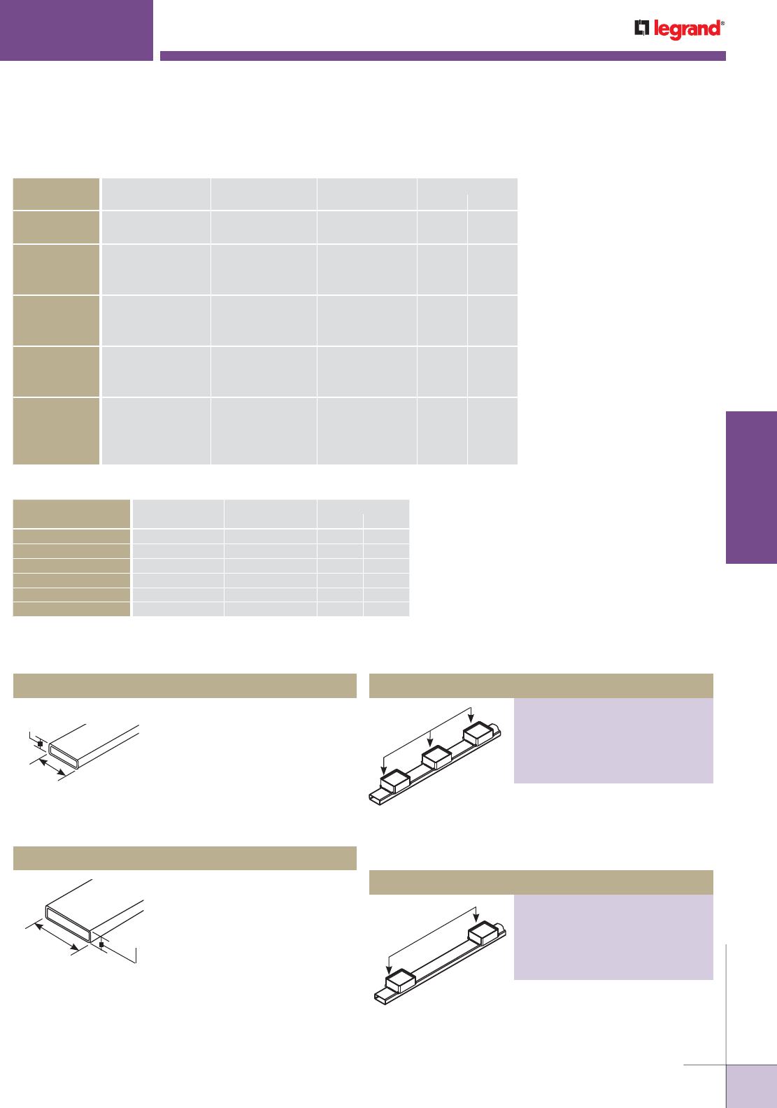
WWW.LEGRAND.US/WIREMOLD
559
INFLOOR DUCTS
WIREMOLD
Factory-installed preset duct.
Used for distribution runs. 10' [3m]
standard length, 16 gauge galvannealed construction with
continuous seam weld.
Pro Series No. 2 Duct, 12" [305mm] Spacing
PART NUMBERS:
D21210 (10" Preset Height)
D21215 (15" Preset Height)
D21220 (20" Preset Height)
D21225 (25" Preset Height)
D21230 (30" Preset Height)
WALKERDUCT
®
UNDERFLOOR DUCT SYSTEMS
Walkerduct Duct Configuration Options
3 1/8" x 1 1/4" [79mm x 32mm]
16 gauge galvannealed steel. One
piece, continuously seam welded
construction. 10' [3m] standard
length. Used primarily for afterset
applications or as a feeder run.
2-0 Blank No. 2 Duct
6 1/2" x 1 1/2" [165mm x 38mm]
16 gauge galvannealed steel. One
piece, continuously seam welded
construction. 10' [3m] standard
length. Used primarily for afterset
applications or as a feeder run.
4-0 Blank No. 4 Duct
Walkerduct Wire Size/Fill Chart
3 1/8"
[79mm]
1 1/4"
[32mm]
6 1/2"
[165mm]
1 1/2"
[38mm]
No. 2 Duct with 12"
[305mm] spacing
No. 2 Duct with 24"
[3610mm] spacing
WIRE SIZE
THHN/THWN/THWN-2
DIAMETER AREA (In2) 40% FILL
Inches [mm] Sq. In. [Sq. mm] NO. 2 NO. 4
14 AWG 0.111 [2.8] .0097 [6.3] 137 359
12 AWG 0.130 [3.3] .0133 [8.6] 100 262
10 AWG 0.164 [4.2] .0211 [13.6] 63 165
8 AWG 0.216 [5.5] .0366 [23.6] 36 95
6 AWG 0.254 [6.5] .0507 [32.7] 26 68
4 AWG 0.324 [8.2] .0824 [53.2] 16 42
CABLE/WIRE SIZE
DIAMETER Approx. AREA In240% FILL
Inches [mm] Sq. In. [Sq. mm] No. 2 No. 4
UNSHIELDED
TWISTED PAIR
4-pair, 24 AWG, Cat 5 0.220 [5.6] .038 [24.5] 35 91
4-pair, 24 AWG, Cat 6 0.250 [6.4] .049 [31.7] 27 71
TELEPHONE 2-pair, 24 AWG 0.140 [3.6] .015 [9.9] 89 232
4-pair, 24 AWG 0.190 [4.8] .028 [18.1] 47 124
25-pair, 24 AWG 0.410 [10.4] .132 [85.2] 10 26
COAXIAL RG58/U 0.195 [4.9] .030 [19.4] 44 116
RG59/U 0.242 [6.1] .046 [29.7] 29 75
RG6/U 0.270 [6.8] .057 [36.8] 23 61
SHIELDED
TWISTED PAIR
TYPE 1 0.390 [9.9] .119 [76.8] 11 29
TYPE 2 0.465 [11.8] .170 [109.7] 7 20
TYPE 3 0.245 [6.2] .047 [30.3] 28 74
FIBER 2 Strand 0.180 [4.6] .025 [16.1] 53 139
4 Strand 0.190 [4.8] .028 [18.1] 47 124
6 Strand 0.210 [5.3] .035 [22.6] 38 99
Fiber ZipCord 0.110 [2.8] .010 [6.5] 133 348
Factory-installed preset duct.
Used for distribution runs. 10' [3m]
standard length, 16 gauge galvannealed construction with
continuous seam weld.
Walkerduct Cable Size/Fill Chart
Pro Series No. 2 Duct, 24" [610mm] Spacing
PART NUMBERS:
D22410 (10" Preset Height)
D22415 (15" Preset Height)
D22420 (20" Preset Height)
D22425 (25" Preset Height)
D22430 (30" Preset Height)
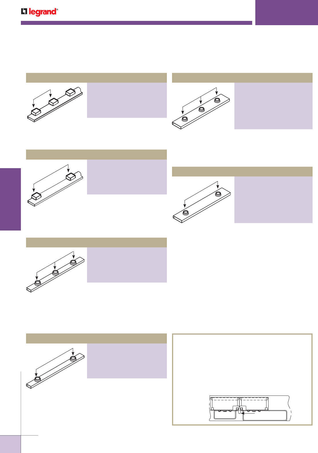
WWW.LEGRAND.US/WIREMOLD
560
INFLOOR DUCTS
WIREMOLD
2" [51mm] IPS No. 4 Duct, 12" [305mm] Spacing
PART NUMBERS:
4-12x2x7/8 (7/8" Preset Insert Height)
4-12x2x11/2 (1 1/2" Preset Insert
Height)
4-12x2x2 (2" Preset Insert Height)
4-12x2x21/2 (2 1/2" Preset Insert
Height)
4-12x2x3 (3" Preset Insert Height)
2" [51mm] IPS No. 2 Duct, 12" [305mm] Spacing
PART NUMBERS:
2-12x2x7/8 (7/8" Preset Insert Height)
2-12x2x11/2 (1 1/2" Preset Height)
2-12x2x2 (2" Preset Height)
2-12x2x21/2 (2 1/2" Preset Height)
2-12x2x3 (3" Preset Height)
Pro Series No. 4 Duct, 12" [305mm] Spacing
PART NUMBERS:
D41210 (10" Preset Height)
D41215 (15" Preset Height)
D41220 (20" Preset Height)
D41225 (25" Preset Height)
D41230 (30" Preset Height)
Pro Series No. 4 Duct, 24" [610mm] Spacing
PART NUMBERS:
D42410 (10" Preset Height)
D42415 (15" Preset Height)
D42420 (20" Preset Height)
D42425 (25" Preset Height)
D42430 (30" Preset Height)
WALKERDUCT
®
UNDERFLOOR DUCT SYSTEMS
Factory-installed preset duct. Used for distribution runs.
10' [3m] standard length, 16 gauge galvannealed
construction with continuous seam weld.
Factory-installed preset duct.
Used for distribution runs. 10'
[3m] standard length, 16 gauge galvannealed construction
with continuous seam weld. Last two digits of Catalog
Number indicates preset height.
Factory installed round preset
duct with internal threads to
accept standard connectors. 10' [3m] standard length,
16 gauge galvannealed steel construction with continuous
seam weld. Preset I.D. is 2" [51mm].
No. 4 Duct with 12"
[305mm] spacing
No. 2 Duct with 12"
[305mm] spacing
No. 4 Duct with 24"
[610mm] spacing
NOTE: 1 1/2" preset is minimum height required for power.
Walkerduct Duct Configuration Options (continued)
Factory installed round preset duct with internal threads
to accept standard connectors. 10' [3m] standard length,
16 gauge galvannealed steel construction with continuous
seam weld. Preset I.D. is threaded for 2" [51mm] conduit.
DUCT CONFIGURATION NOTES
• Custom insert heights, duct lengths, and preset
spacings are available. Contact factory for detailed
information.
• Multi-gang Pro Series Duct Systems use an alignment
clip to connect presets. One alignment clip is included
with each piece of duct and prevents movement of
presets during concrete pour.
Alignment Clip
End View with
Alignment Clip
in Place
IMPORTANT: Triple-gang flush activations are not compatible with 3222 and
3444 System layouts. Use combination of single- and two-gang
activations to access all three ducts at one point.
IMPORTANT: A minimum 1 1/2" [38mm] preset or afterset is required
on Pro Series Underfloor Duct to support standard duplex
receptacles when using flush activations. Most communication
devices will need a minimum of 2" preset or afterset on Pro
Series Underfloor Duct when using flush activations.
No. 4 Duct with 12"
[305mm] spacing
No. 4 Duct with 24"
[610mm] spacing
Factory installed round preset
duct with internal threads to
accept standard connectors. 10' [3m] standard length,
16 gauge galvannealed steel construction with continuous
seam weld. Preset I.D. is threaded for 2" [51mm] conduit.
No. 2 Duct with 24"
[610mm] spacing
Factory installed round preset duct with internal threads
to accept standard connectors. 10' [3m] standard length,
16 gauge galvannealed steel construction with continuous
seam weld. Preset I.D. is threaded for 2" [51mm] conduit.
2" [51mm] IPS No. 2 Duct, 24" [610mm] Spacing
PART NUMBERS:
2-24x2x7/8 (7/8" Preset Insert Height)
2-24x2x11/2 (1 1/2" Preset Height)
2-24x2x2 (2" Preset Height)
2-24x2x21/2 (2 1/2" Preset Height)
2-24x2x3 (3" Preset Height)
2" [51mm] IPS No. 4 Duct, 24" [610mm] Spacing
PART NUMBERS:
4-24x2x7/8 (7/8" Preset Insert Height)
4-24x2x11/2 (1 1/2" Preset Insert
Height)
4-24x2x2 (2" Preset Insert Height)
4-24x2x21/2 (2 1/2" Preset Insert
Height)
4-24x2x3 (3" Preset Insert Height)
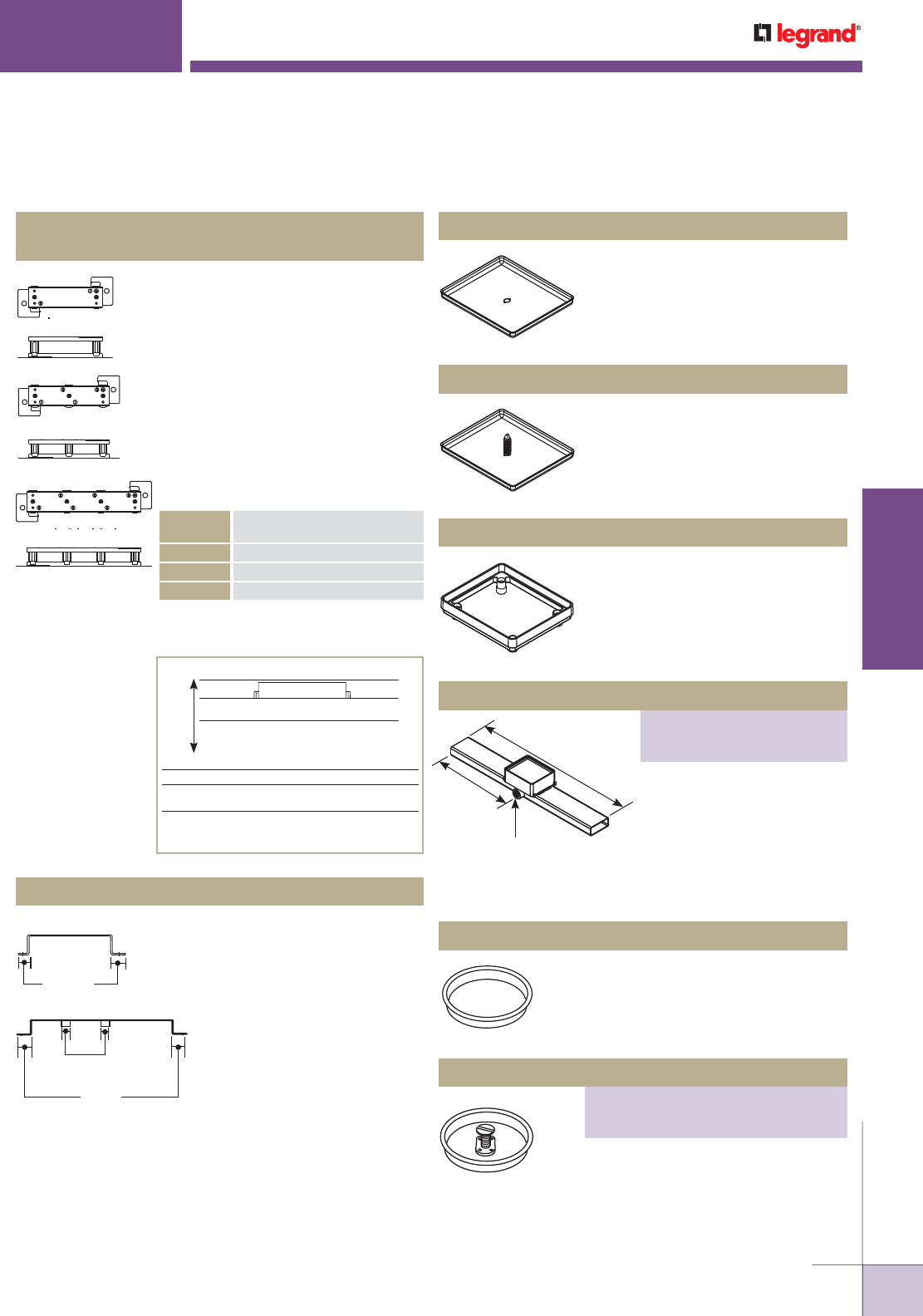
WWW.LEGRAND.US/WIREMOLD
561
INFLOOR DUCTS
WIREMOLD
2" [51mm] IPS Duct Marker Cap
PART NUMBERS:
415B (Brass)
415N (Steel)
WALKERDUCT
®
UNDERFLOOR DUCT SYSTEMS
SC14-*
SC222-*
SC3222-*
How to Determine Correct Support Heights
A Height of preset.
B Height of duct.
C Distance from bottom of duct to form or slab. This
dimension is the correct support height.
D Distance between finished concrete floor line and
floor slab. This dimension is the sum total of A, B,
and C. Support Height (C) = D - (A and B)
A
Preset
Duct
B
C
D
*CATALOG
NO. SUFFIX HEIGHT ADJUSTMENT
-18 1/2" [12.7mm] to 1 7/8" [48mm]
-33 1 1/2" [38mm] to 3 3/4" [95mm]
-48 3" [76mm] to 4 7/8" [124mm]
Duct supports for deeper pours are available
through the factory.
SC12 Adjustable Duct Supports with
Built-in Coupling
SC14, SC222, SC224, SC244, SC3222,
SC3224, SC3244, SC3424
To support, couple, and hold duct
in place before and during concrete
pour. Steel construction. Leveling
screws provide vertical adjustment.
Different leg heights available.
Supports may be fastened to form
or to slab through holes in the feet.
Top members maintain 1" [25mm]
spacing between ducts. Locate duct
supports on approximately 5' [1.5m]
intervals.
NOTE: Steel shims (Cat. # Duct Shims) should be placed under #2 Duct to
maintain proper preset height.
HS3224
1"
[25mm]
1 5/8"
[41mm]
HS14
3/4"
[19.1mm]
HS12 Hold-Down Straps
HS14, HS222, HS224, HS244,
HS3222, HS342, HS3244
To fasten ducts to the slab
in shallow concrete. Used in
place of duct supports. Straps
maintain 1" [25mm] spacing
between ducts on multiple duct
runs and prevent duct from
floating during concrete pour.
Attaches to slab with stakes
or drive pins (not included).
Locate Hold-Down Straps on
approximate 5' [1.5m] centers. Duct systems with both #2
and #4 ducts will require a 1/4" thick shim to bring the top
of the #2 duct level with the #4 duct. Consult factory for
additional information.
421 Pro Series Mudcap
Steel replacement cap for preset
or afterset. Recessed to hold 3/8"
[9.5mm] concrete.
422GR, 422RD Pro Series Marker Cap
Replaces mudcap on preset to
indicate location of the last insert
in each run. Select color for each
service.
6"
[152mm]
3/4" Hub
12"
[305mm]
425, 426 Preset Extensions
1/2" [12.7mm] (425) and 1" [25mm]
(426) Preset Extensions. Steel
replacement cap for preset or
afterset. Recessed to hold 3/8"
[9.5mm] concrete.
12" [305mm] section of Duct
with 1" [25mm] Preset. For
rigid or PVC conduit. Used
to provide feed to isolated
outlets; maintains 12"
[305mm] spacing of presets. Preset height is 1" [25mm].
Add extensions if higher preset needed.
404 2" [51mm] IPS Duct Mudcap
Steel replacement cap for 2" [51mm]
IPS preset. Recessed to hold 3/8"
[9.5mm] concrete.
Replaces mudcap on preset to indicate
location of run. NEC requires markers
to locate the last preset in each run.
Select color for each service.
Walkerduct Duct Accessories Ordering Information
Duct Conduit Hub
PART NUMBERS:
D2075 (For No. 2 Duct)
D4075 (For No. 4 Duct)
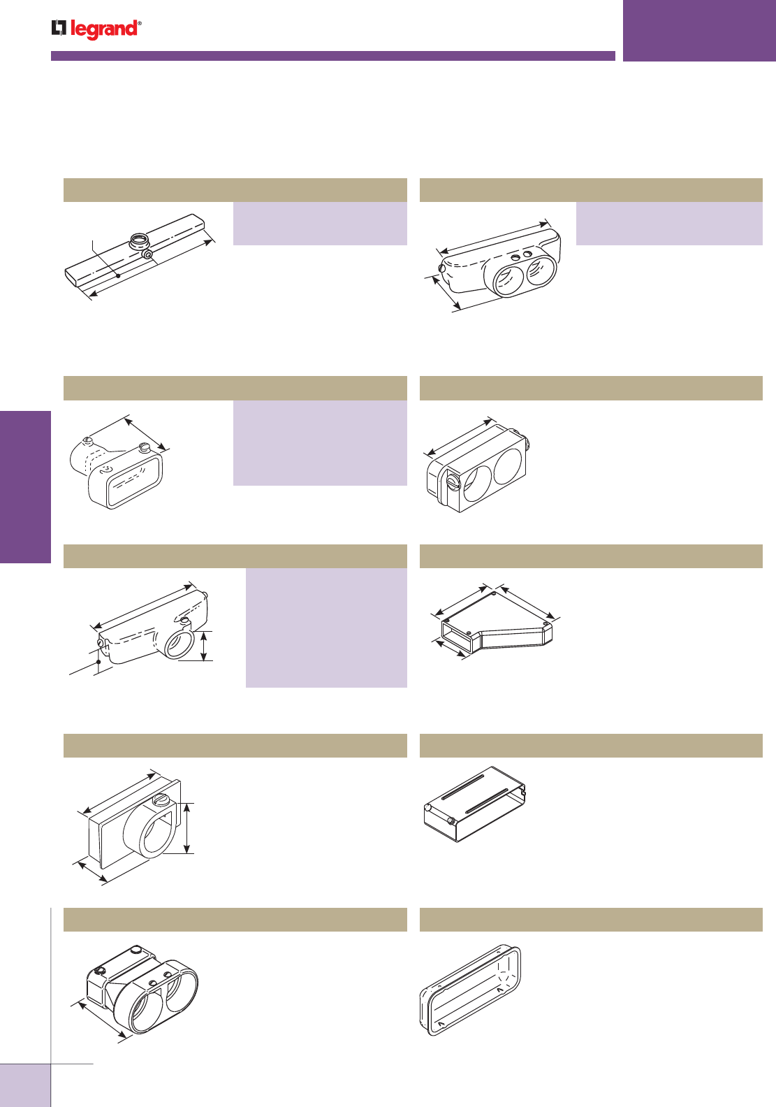
WWW.LEGRAND.US/WIREMOLD
562
INFLOOR DUCTS
WIREMOLD
Female Conduit Adapter
PART NUMBERS:
H312-3/4
(3/4" conduit trade size)
H312-1 (1" conduit trade size)
312-11/4
(1 1/4" conduit trade size)
H312-11/2
(1 1/2" conduit trade size)
H312-2 (2" conduit trade size)
Female Conduit Adapter
PART NUMBERS:
312-3/4 (3/4" conduit trade size)
312-1 (1" conduit trade size)
312-11/4 (1 1/4" conduit trade size)
312-11/2 (1 1/2" conduit trade size)
312-2 (2" conduit trade size)
WALKERDUCT
®
UNDERFLOOR DUCT SYSTEMS
12"
[305mm]
24"
[610mm]
3 1/2"
[89mm]
1 1/4"
[32mm]
7 1/8"
[181mm]
1 1/8"
[54mm]
1 1/4"
[32mm]
3" [76mm]
1 3/4"
[44mm]
3 1/2"
[89mm]
3"
[76mm]
7 1/8"
[181mm]
3"
[76mm]
6"
[152mm]
3 9/16"
[90mm]
6 15/16"
[176mm]
2' [610mm] Section of Duct
with IPS Preset and 3/4"
[19.1mm] Conduit Hub. For
rigid conduit. Used to provide
feed to isolated outlets; maintains 24" [610mm] spacing of
presets. Heights from 7/8" [22.2mm] to 3 1/2" [89mm].
*Specify preset height.
Fits on outside of No. 2 Duct.
For one rigid or PVC conduit.
Fits on outside of No. 4 Duct. For one rigid or PVC conduit.
314-3/4 Male Conduit Adapter
Fits into end of No. 2 Duct.
For one 3/4" trade size rigid
or PVC conduit.
322-11/4, 322-11/2 Female Conduit Adapter
Fits on the outside of No. 2
Duct. For two rigid or PVC
conduits. Suffix denotes
conduit trade size.
Fits on the outside of No. 4 Duct.
For two rigid or PVC conduits.
324-3/4 Male Conduit Adapter
Fits into the end of No. 2 Duct. For
two 3/4" trade size rigid or PVC
conduits.
300-4 Adapter Coupling
Couples No. 2 Duct to No. 4 Duct.
304, H304 Duct End Plug
304- To seal the end of No. 2
Duct. H304- To seal the end of No.
4 Duct.
302, H302 Coupling
302- To Couple two No. 2 Ducts.
H302- To Couple two No. 4 Ducts.
Walkerduct Duct Accessories Ordering Information (continued)
2" [51mm] IPS Duct Conduit Hub
PART NUMBERS:
317-3/4* (For No. 2 Duct)
H317-3/4* (For No. 4 Duct)
Female Conduit Adapter
PART NUMBERS:
H322-11/4 (1 1/4" conduit trade size)
H322-11/2 (1 1/2" conduit trade size)
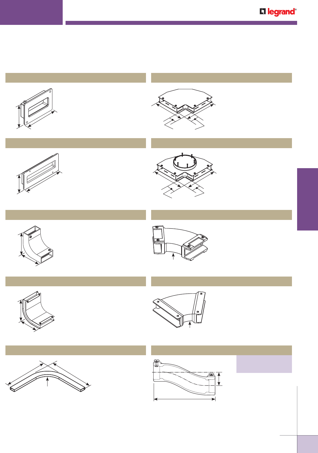
WWW.LEGRAND.US/WIREMOLD
563
INFLOOR DUCTS
WIREMOLD
4 1/8"
[105mm]
2 3/4"
[70mm]
334UF Panel connector
Secures No. 2 Duct to cabinet.
WALKERDUCT
®
UNDERFLOOR DUCT SYSTEMS
7 11/16"
[195mm]
3 5/16"
[84mm]
8 1/2"
[216mm]
2 5/16"
Radius
[59mm]
5 1/8"
[130mm]
8 1/2"
[216mm]
3" Radius
[76mm]
8 1/2"
[216mm]
21 7/8"
[556mm]
8 1/2" Radius
[216mm]
21 7/8"
[556mm]
2 13/16"
[71mm]
10 1/2"
[267mm]
10 1/2"
[267mm]
2 13/16"
[71mm]
10 1/2"
[267mm]
10 1/2"
[267mm]
6 3/8"
[162mm]
1 5/8"
[41mm]
3" Radius
[76mm]
3" Radius
[76mm]
H338AU-1 90° Horizontal Elbow with Access Unit
Used to make 90° horizontal
turn in No. 4 Duct. Access
cover can be removed to
facilitate wire pulling.
H334 Panel Connector
Secures No. 4 Duct to cabinet.
332UF 90° Vertical Elbow
Creates 90° vertical turn in
No. 2 Duct.
H332 90° Vertical Elbow
Creates 90° vertical turn in
No. 4 Duct.
338UF 90° Horizontal Elbow
Creates 90° horizontal
turn in No. 2 Duct.
H338 90° Horizontal Elbow
Creates 90° horizontal turn in
No. 4 Duct.
342UF Adjustable Horizontal Elbow
No. 2 Duct elbow angled for
45° turn. Angle may be varied
from 22 1/2° to 67 1/2° by
cutting duct ends at different
angles.
H342 Adjustable Horizontal Elbow
No. 4 Duct elbow angled for
45° turn. Angle may be varied
from 22 1/2° to 67 1/2° by
cutting duct ends at different
angles.
Used to raise or lower
a run of duct by 1 5/8"
[41mm]. Two required
for crossunders.
Walkerduct Duct Accessories Ordering Information (continued)
Offset
PART NUMBERS:
372 (For No. 2 Duct)
H372 (For No. 4 Duct)
WWW.LEGRAND.US/WIREMOLD
564
INFLOOR DUCTS
WIREMOLD
Variable Offset
PART NUMBERS:
375 (For No. 2 Duct)
H375 (For No. 4 Duct)
WALKERDUCT
®
UNDERFLOOR DUCT SYSTEMS
5/8"
[15.9mm]
Duct
10°
5/8"
[15.9mm]
Used to raise or
lower a run of duct
from 5/16 [7.9mm] to
3 1/2 [89mm]. Field
cut duct based on
chart below.
FOR OFFSET
DUCT CUT
LENGTH FOR OFFSET
DUCT CUT
LENGTH
5/16"
3/8"
7/16"
1/2"
9/16"
5/8"
11/16"
3/4"
13/16"
7/8"
15/16"
1 3/8"
1 3/4"
2 1/8"
2 1/2"
2 7/8"
3 1/4"
3 1/2"
3 7/8"
4 1/4"
4 5/8"
5"
[35mm]
[44mm]
[54mm]
[64mm]
[73mm]
[83mm]
[89mm]
[98mm]
[108mm]
[118mm]
[127mm]
1"
1 1/4"
1 1/2"
1 3/4"
2"
2 1/4"
2 1/2"
2 3/4"
3"
3 1/4"
3 1/2"
[25mm]
[32mm]
[38mm]
[45mm]
[51mm]
[57mm]
[64mm]
[70mm]
[76mm]
[83mm]
[89mm]
5 3/8"
6 13/16"
8 1.4"
9 11/16"
11 1/4"
12 9/16"
14"
15 7/16"
16 7/8"
18 5/16"
19 3/4"
[137mm]
[173mm]
[210mm]
[246mm]
[286mm]
[319mm]
[356mm]
[392mm]
[429mm]
[465mm]
[502mm]
[7.9mm]
[9.5mm]
[11.1mm]
[12.7mm]
[14.3mm]
[15.9mm]
[17.5mm]
[19.1mm]
[20.6mm]
[22.2mm]
[23.8mm]
Slip over two sections of duct. Outside
screws fasten and ground sleeves of
duct.
290C Waterproof Sealing Compound
Three tubes, 10.1 fluid ounces
each. Will seal approximately 100
couplings, (12) three-duct boxes, (25)
two-duct boxes, or (50) single-duct
boxes.
Walkerduct Aftersets & Accessories Ordering Information
4 13/16"
[123mm] 4 1/8"
[105mm]
Installed either before or after
concrete pour to create activation
from duct.
NOTE: Drill a 6 1/2" [165mm] hole in
concrete and a 2 1/2" [64mm] hole
in duct.
NOTE: Need minimum of 1 1/2" height
for power.
Installed either before or after concrete pour to create
activation from duct.
H14ABD Afterset Access Assembly
H14-BA Afterset Access Assembly Neoprene Boot
Used with H14ABD to protect cables coming out
of duct.
H14-AS Complete Access Activation
For access to large number of cables for
activation. Use 6ER- Extension Ring when
additional height is required.
Walkerduct Duct Accessories Ordering Information (continued)
12S-CVRPLT ø=5 23/32
Expansion Sleeve Joints
PART NUMBERS:
382 (For No. 2 Duct)
H382 (For No. 4 Duct)
Provides access to pull large number of cables
out of duct at one activation. Neoprene boot to
protect wires not included. Use 6ER- Extension
Ring when additional height is required.
Pro Series Afterset
PART NUMBERS:
4215 = 1 1/2" [38mm]
4220 = 2" [51mm]
4225 = 2 1/2" [64mm]
4230 = 3" [76mm]
2" [51mm] IPS Duct Round Afterset
PART NUMBERS:
436-2-7/8 = 7/8" [22.2mm]
436-2-1 1/2 = 1 1/2" [38mm]
436-2-2 = 2" [51mm]
436-2-23/8 = 2 3/8" [60mm]
436-2-3 = 3" [76mm]
NOTE: Drill a 2 1/2" [64mm] hole in concrete and a 2 1/4" [57mm] hole
in duct.
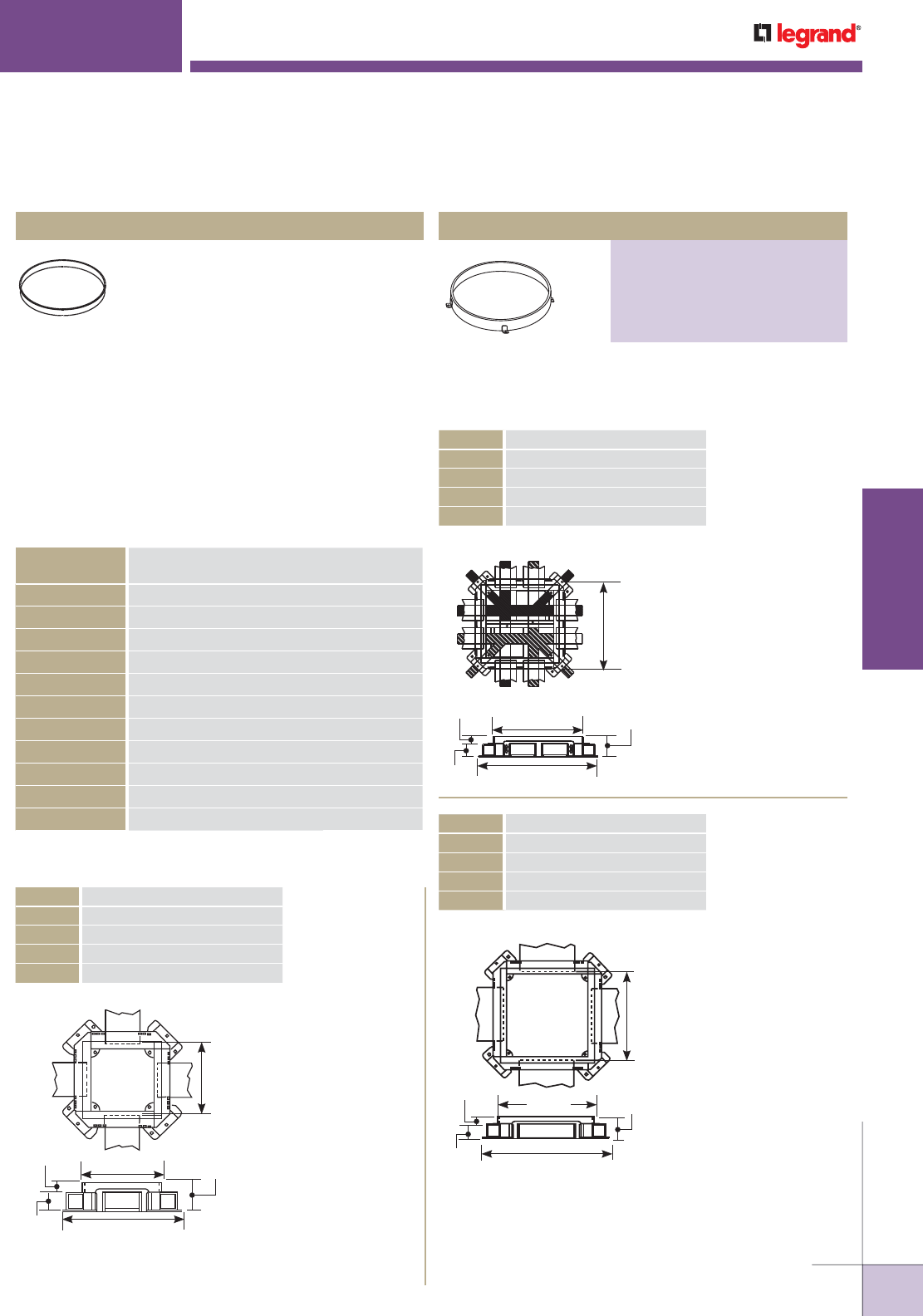
WWW.LEGRAND.US/WIREMOLD
565
INFLOOR DUCTS
WIREMOLD
WALKERDUCT
®
UNDERFLOOR DUCT SYSTEMS
H14BC Blanking Cap
Closes 5" [127mm] hole in duct.
Extension ring for H14ABD and
H14-AS Boxes.
Walkerduct Junction Boxes Ordering Information
One No. 2 Duct per
side. No interior
partitioning.
Square cover plate
measures 6 3/4"
x 6 3/4" [171mm x
171mm]. Diameter
of round cover plate
is 4.813" [122mm].
7" [178mm]
Duct Step to
Duct Step
6 3/4"
[172mm] 2 5/8"
[65mm]
1 5/8"
[41mm] 11 3/8"
[289mm]
15/16"
[23.8mm]
One No. 4 Duct per
side. No interior
partitioning.
Square cover plate
measures 10 7/8"
x 10 7/8" [276mm x
276mm]. Diameter of
round cover plate is
8.938" [227mm].
11 1/8"
[283mm]
Duct Step to
Duct Step
2 5/8"
[65mm]
1 5/8"
[41mm]
15/16"
[23.8mm]
15 1/2"
[394mm]
10 7/8"
[276mm]
This chart provides the information needed to select the
correct suffix for all of the Junction Box Catalog Numbers
listed in this section.
NOTE: Square Tile/Carpet Trims for heavy duty Junction Boxes – need to
increase depth of Pan by 1/8". Example: for 1/4" Carpet, use 3/8"
deep Carpet Holder.
NOTE: For all 3 Duct Boxes – Center compartment cannot be accessed
with Corner Conduit Adapter, part #255.
SUFFIX FOR
JUNCTION BOXES* DEPTH OF CONCRETE OVER DUCT
1 1" [25mm] min. to 1 1/2" [35mm] max.
1 1/2 1 1/2" [38mm] min. to 2" [51mm] max.
2 2" [51mm] min. to 2 1/2" [62mm] max.
2 1/2 2 1/2" [64mm] min. to 3" [76mm] max.
3 3" [76mm] min. to 3 1/2" [89mm] max.
3 1/2 3 1/2" [89mm] min. to 4" [102mm] max.
4 4" [102mm] min. to 4 1/2" [114mm] max.
4 1/2 4 1/2" [114mm] min. to 5" [127mm] max.
5 5" [127mm] min. to 5 1/2" [140mm] max.
5 1/2 5 1/2" [140mm] min. to 6" [152mm] max.
6 6" [152mm] min. to 6 1/2" [165mm] max.
*Other junction box heights are available. Consult factory for availability.
Two No. 2 Ducts per
side. Square cover
plate measures
10 7/8" x 10 7/8"
[276mm x 276mm].
Diameter of round
cover plate is 8.938"
[227mm].
11 1/8"
[283mm] Duct
Step to Duct
Step
10 7/8"
[276mm] 2 5/8"
[65mm]
1 5/8"
[41mm] 15 1/2"
[394mm]
15/16"
[23.8mm]
CAT. NO. DESCRIPTION
14JS- Square Access Plate
14JR- Round Access Plate
14HS- Heavy Duty – Square Access Plate
14HR- Heavy Duty – Round Access Plate
Walkerduct Aftersets Ordering Information
CAT. NO. DESCRIPTION
12JS- Square Access Plate
12JR- Round Access Plate
12HS- Heavy Duty – Square Access Plate
12HR- Heavy Duty – Round Access Plate
NOTE: Suffix denotes height.
CAT. NO. DESCRIPTION
222JS- Square Access Plate
222JR- Round Access Plate
222HS- Heavy Duty – Square Access Plate
222HR- Heavy Duty – Round Access Plate
NOTE: Suffix denotes height.
Extension Ring
PART NUMBERS:
6ER-11/2 (1 1/2" Concrete Over Duct)
6ER-2 (2" Concrete Over Duct)
6ER-2 1/2 2 1/2" Concrete Over Duct)
6ER-3 3" Concrete Over Duct)
6ER-3 1/2 3 1/2" Concrete Over Duct)
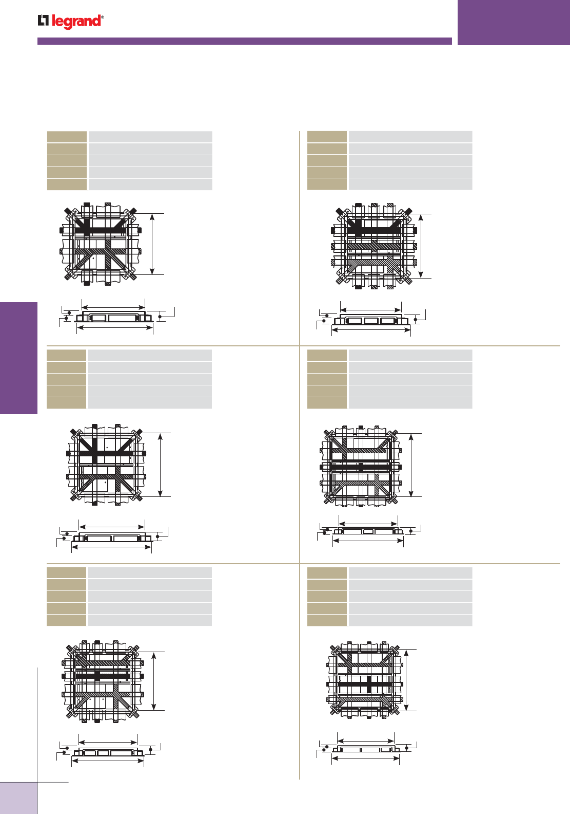
WWW.LEGRAND.US/WIREMOLD
566
INFLOOR DUCTS
WIREMOLD
WALKERDUCT
®
UNDERFLOOR DUCT SYSTEMS
One No. 2 Duct and
one No. 4 Duct per
side. Square cover
plate measures
15" x 15" [381mm x
381mm]. Diameter of
round cover plate is
13.063" [332mm].
15 1/4"
[387mm]
Duct Step to
Duct Step
15"
[381mm]
2 5/8"
[65mm]
1 5/8"
[41mm] 19 5/8"
[499mm]
15/16"
[23.8mm]
Two No. 4 Ducts per
side. Square cover
plate measures
18 3/8" x 18 3/8"
[467mm x 467mm].
Diameter of round
cover plate is 16.438"
[418mm].
18 3/8"
[473mm]
2 5/8"
[65mm]
1 5/8"
[41mm] 25"
[584mm]
15/16"
[23.8mm]
18 5/8"
[473mm]
Duct Step to
Duct Step
Three No. 2
Ducts per side.
Square cover plate
measures 15" x 15"
[381mm x 381mm].
Diameter of round
cover plate is
13.063" [332mm].
15 1/4"
[387mm] Duct
Step to Duct
Step
15"
[381mm]
2 5/8"
[65mm]
1 5/8"
[41mm] 19 5/8"
[499mm]
15/16"
[23.8mm]
Two No. 2 Ducts and
one No. 4 Duct per
side. Square cover
plate measures
18 3/8" x 18 3/8"
[467mm x 467mm].
Diameter of round
cover plate is 16.438"
[418mm].
18 5/8"
[473mm]
Duct Step to
Duct Step
18 3/8"
[467mm] 2 5/8"
[65mm]
1 5/8"
[41mm] 23"
[543mm]
15/16"
[23.8mm]
Two No. 4 Ducts and
one No. 2 Duct per
side. No. 2 Duct is
centered between the
No. 4 Ducts. Square
cover plate measures
21 3/4" x 21 3/4"
[553mm x 553mm].
Diameter of round
cover plate is 19.813"
[503mm].
22"
[559mm]
Duct Step to
Duct Step
21 3/4"
[553mm] 2 5/8"
[65mm]
1 5/8"
[41mm]
26 5/8"
[670mm]
15/16"
[23.8mm]
One No. 2 Duct and
two No. 4 Ducts per
side. Square cover
plate measures
21 3/4" x 21 3/4"
[553mm x 553mm].
Diameter of round
cover plate is 19.813"
[503mm].
22" [559mm]
Duct Step to
Duct Step
21 3/4"
[553mm]
2 5/8"
[65mm]
1 5/8"
[41mm] 26 5/8"
[670mm]
15/16"
[23.8mm]
NOTE: For all 3 Duct Junction Boxes
– Center compartment cannot
be accessed with Corner
Conduit Adapter, part #255.
Walkerduct Junction Boxes Ordering Information (continued)
CAT. NO. DESCRIPTION
224JS- Square Access Plate
224JR- Round Access Plate
224HS- Heavy Duty – Square Access Plate
224HR- Heavy Duty – Round Access Plate
NOTE: Suffix denotes height.
CAT. NO. DESCRIPTION
244JS- Square Access Plate
244JR- Round Access Plate
244HS- Heavy Duty – Square Access Plate
244HR- Heavy Duty – Round Access Plate
NOTE: Suffix denotes height.
CAT. NO. DESCRIPTION
3224JS- Square Access Plate
3224JR- Round Access Plate
3224HS- Heavy Duty – Square Access Plate
3224HR- Heavy Duty – Round Access Plate
NOTE: Suffix denotes height.
CAT. NO. DESCRIPTION
3222JS- Square Access Plate
3222JR- Round Access Plate
3222HS- Heavy Duty – Square Access Plate
3222HR- Heavy Duty – Round Access Plate
NOTE: Suffix denotes height.
CAT. NO. DESCRIPTION
3424JS- Square Access Plate
3424JR- Round Access Plate
3424HS- Heavy Duty – Square Access Plate
3424HR- Heavy Duty – Round Access Plate
NOTE: Suffix denotes height.
CAT. NO. DESCRIPTION
3244JS- Square Access Plate
3244JR- Round Access Plate
3244HS- Heavy Duty – Square Access Plate
3244HR- Heavy Duty – Round Access Plate
NOTE: Suffix denotes height.
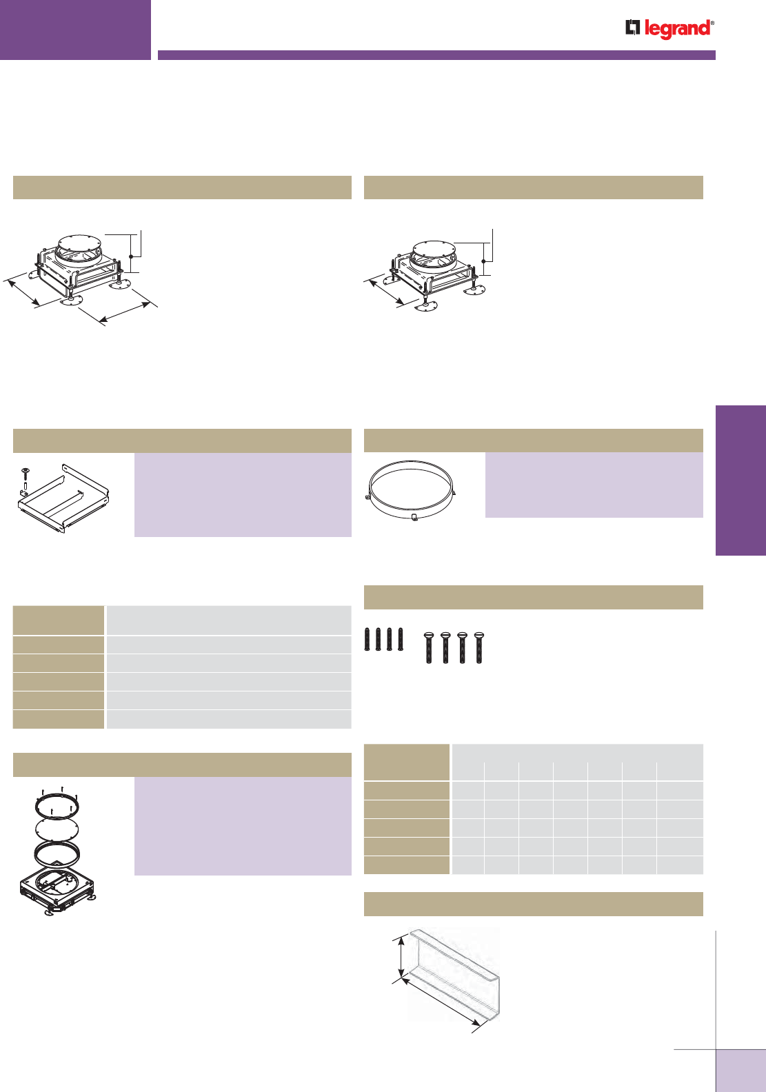
WWW.LEGRAND.US/WIREMOLD
567
INFLOOR DUCTS
WIREMOLD
WALKERDUCT
®
UNDERFLOOR DUCT SYSTEMS
Hand hole units are installed on
No. 4 Duct to facilitate feeding
and splicing of wire and cable.
6 15/16" [176mm] distance
between duct ends. 5 3/4"
[146mm] diameter cover plate.
Includes 1" [25mm] standard
extension. For concrete pours
over 1" [25mm] an extension ring
is required. See Cat. No. 6AEHR-.
Adaptable for either No. 2 Duct
or No. 4 Duct. No partitioning
required. Requires a 4" [102mm]
minimum pour. 3/8" [9.5mm]
upward adjustment of cover
plate is possible after pour.
5 3/4" [146mm] nominal
diameter round cover plate. 1/8"
[3.2mm] plate thickness. Use
adjustable extension ring when
additional height is needed. See
Cat. No. 6AER-.
Walkerduct Junction Box Accessories Ordering Information
1 9/16"
[40mm]
3 1/8"
[79mm]
NOTE: Use Cat. No. H202 Blank Washer for
142L and 14H Junction Boxes.
8 1/2"
[216mm]
8 1/2"
[216mm]
4"
[102mm]
2 9/16"
[65mm]
8 7/16"
[214mm]
142L-1 Two Level Junction Box 14H-1 Hand Hole Access Unit
SUFFIX FOR SIDE
RAIL EXTENSION* DEPTH OF CONCRETE OVER DUCT
1 1/2 1 1/2" [38mm] min. to 2" [51mm] max.
2 2" [51mm] min. to 2 1/2" [62mm] max.
2 1/2 2 1/2" [64mm] min. to 3" [76mm] max.
3 3" [76mm] min. to 3 1/2" [89mm] max.
3 1/2 3 1/2" [89mm] min. to 4" [102mm] max.
Kit to adapt JS, JR, HS, and HR style
junction boxes for deep concrete
pours.
For round JR style junction boxes.
Two-piece brass rings mount to
junction box cover plate. Inner ring is
filled with terrazzo. Screws are
recessed into inner ring and allow the
holder to be removed after floor is
ground and polished. Terrazzo units
hold 3/4" [19.1mm] deep terrazzo, but
increase the height of the junction box
by 1 1/4" [32mm].
For 142L-1, H338AU-1, H14-AS, and 14H-1 Boxes. Suffix
refers to adjustable height range of concrete over duct.
Select hardware bag below to attach ring to box.
AERHB-128, AERHB-144,
AERHB-152, AERHB-052
For adjustable extension ring.
Suffix indicates depth concrete over
duct. Use chart below to determine
hardware bag required. For 142L-
1, H338AU-1, H14-AS, and 14H-1
Boxes.
AERHB-120 Hardware Bag
For closing unused junction box
No. 2 Duct opening.
203UFD Blank Washer
Walkerduct Junction Boxes Ordering Information (continued)
HARDWARE BAG
CATALOG NO.
CONCRETE DEPTH OVER DUCT
1 1/2" 1 5/8" 1 3/4" 1 7/8" 2" 2 1/8" 2 3/8" -3"
AERHB-120 X X
AERHB-128 X X
AERHB-144 X
AERHB-152 X
AERHB-052 X
Side Rail Extension
PART NUMBERS:
12EXT-* (For 12 Size Boxes)
222EXT-* (For 14 or 222 Size Boxes)
3222EXT-* (For 224 or 3222 Size Boxes)
3224EXT-* (For 244 or 3224 Size Boxes)
3244EXT-* (For 3424 or 3244 Size Boxes)
Terrazzo Holder
PART NUMBERS:
RTT4 (For 12JR Box)
6RTT (142L or 14H Box)
RTT8 (For 14JR or 222JR Box)
RTT13 (For 224JR or 3222JR Box)
RTT16 (For 244JR or 3224JR Box)
RTT20 (For 3244 or 3424JR Box)
Adjustable Extension Ring
PART NUMBERS:
6AER-11/2-21/8 (2 1/8" Height Range of
Concrete Over Duct)
6AER-23/8-3 (3" Height Range of Concrete
Over Duct)
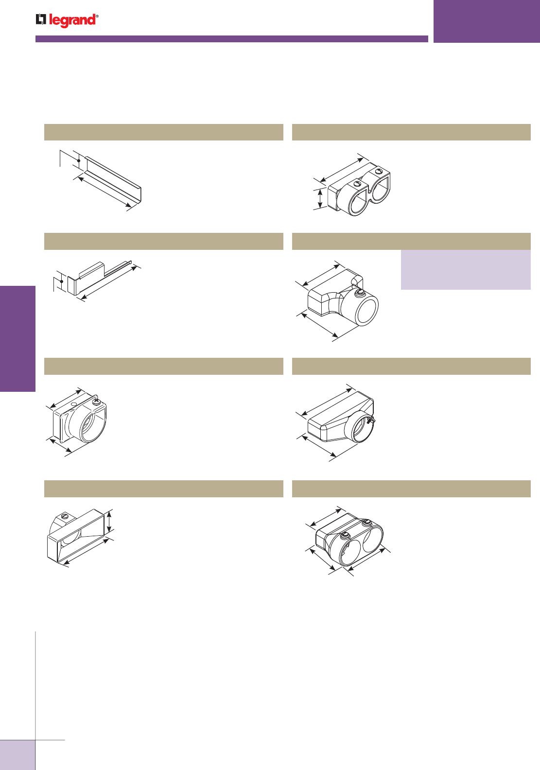
WWW.LEGRAND.US/WIREMOLD
568
INFLOOR DUCTS
WIREMOLD
WALKERDUCT
®
UNDERFLOOR DUCT SYSTEMS
1 9/16"
[40mm]
6 1/2"
[165mm]
1 1/2"
[38mm]
6 5/8"
[169mm]
275SL Pictured
For closing unused junction box
No. 4 Duct opening.
H203 Blank Washer
2 1/4"
[57mm]
A
255-1, 255-1 1/4, 255-1 1/2, 255-2
For one conduit. “A” dimension is 1 7/8"
[48mm] for -3/4 and -1; 2 1/4" [57mm] for
-1 1/4 and -1 1/2, and 2" [51mm] for -2.
Suffix indicates conduit trade size.
255-3/4 Box Conduit Corner Adapter
To reduce a No. 4 Duct opening
in a junction box to a No. 2 Duct
opening. Specify 275SL for left
hand or 275SR for right hand.
275SL, 275SR Adapter
1 1/4"
[32mm]
3 1/8"
[79mm]
For No. 2 Duct opening to one
3/4" trade size conduit.
212-3/4 Adapter
3 1/8"
[79mm]
1 1/2"
[38mm]
2 3/4"
[70mm]
3 1/8"
[79mm]
For No. 2 Duct opening to two
3/4" trade size conduits.
222-3/4 Adapter
For No. 2 Duct opening to one
conduit.
6 1/2"
[165mm]
3 3/4"
[95mm]
For No. 4 Duct opening to one 2"
trade size conduit.
H232-2 Male Adapter
3 1/8"
[79mm]
2 5/8"
[67mm]
4"
[102mm]
For No. 2 Duct opening to two
1 1/4" trade size conduits.
242-11/4 Male Adapter
Walkerduct Junction Box Accessories Ordering Information (continued)
NOTE: Use Cat. No. H202 Blank Washer
for 142L and 14H Junction Boxes.
Male Adapter
PART NUMBERS:
232-1 (1" Conduit Trade Size)
232-11/4 (1 1/4" Conduit Trade Size)
232-11/2 (1 1/2" Conduit Trade Size)

WWW.LEGRAND.US/WIREMOLD
569
INFLOOR DUCTS
WIREMOLD
Walkerduct Flanged Round Carpet/ Tile Holders Ordering Information
Flanged round carpet/tile pans in brass or stainless steel
for 12S, 14H, 142L, H338AU, 12FB or H14 Boxes. Mount
onto cover plate. Available in 1/4" or 1/8" [6.4mm or
3.2mm] depths for carpet or tile floors. 5 23/32" [144mm]
diameter (does not include flange). Flange is 3/8"
[9.5mm] wide.
Flanged round carpet/tile pans in brass or stainless steel
for 222FB Boxes. Mount onto cover plate. Available in 1/4"
or 1/8" [6.4mm or 3.2mm] depths for carpet or tile floors.
7 1/2" [191mm] diameter (does not include flange). Flange
is 3/8" [9.5mm] wide.
Flanged round carpet/tile pans in brass or stainless steel
for 14S, 222S, and 3222FB Boxes. Mount onto cover plate.
Available in 1/4" or 1/8" [6.4mm or 3.2mm] depths for
carpet or tile floors. 10 1/2" [267mm] diameter (does not
include flange). Flange is 3/8" [9.5mm] wide.
NOTE: Prior to completing installation, proper floor covering should be
installed in pan.
* Add suffix “-HD” for.090 thick material (.025 standard material thickness) to
accommodate high traffic and/or heavy loads.
Flanged round carpet/tile pans in brass or stainless steel
for 224S and 3222S Boxes. Also fits 2-1JB2510 Walkercell
Boxes and 18" [457mm] wide Junction Box Headers. Mount
onto cover plate. Available in 1/4" or 1/8" [6.4mm or 3.2mm]
depths for carpet or tile floors. 14 1/2" [368mm] diameter
(does not include flange). Flange is 3/8" [9.5mm] wide.
NOTE: Square Tile/Carpet Trims for heavy duty Junction Boxes – need to
increase depth of Pan by 1/8". Example: for 1/4" Carpet, use 3/8"
deep Carpet Holder.
WALKERDUCT
®
CARPET/TILE HOLDERS
Walkerduct® Carpet/Tile Holders provide an aesthetic solution for
identification and for accessing major pull points (Junction Boxes)
within a Walkerduct System.
CAT. NO. DESCRIPTION
6LHS-1/8 Stainless 1/8" [3.2mm] deep 6 39/64 [168mm] O.D.
6LHS-1/4 Stainless 1/4" [6.4mm] deep 6 39/64 [168mm] O.D.
6LHB-1/8 Brass 1/8" [3.2mm] deep 6 39/64 [168mm] O.D.
6LHB-1/4 Brass 1/4" [6.4mm] deep 6 39/64 [168mm] O.D.
CAT. NO. DESCRIPTION
7LHS-1/8 Stainless 1/8" [3.2mm] deep 8 11/64 [208mm] O.D.
7LHS-1/4 Stainless 1/4" [6.4mm] deep 8 11/64 [208mm] O.D.
7LHB-1/8* Brass 1/8" [3.2mm] deep 8 11/64 [208mm] O.D.
7LHB-1/4* Brass 1/4" [6.4mm] deep 8 11/64 [208mm] O.D.
CAT. NO. DESCRIPTION
10LHS-1/8 Stainless 1/8" [3.2mm] deep 11 15/64 [295mm] O.D.
10LHS-1/4 Stainless 1/4" [6.4mm] deep 11 15/64 [295mm] O.D.
10LHB-1/8* Brass 1/8" [3.2mm] deep 11 15/64 [295mm] O.D.
10LHB-1/4* Brass 1/4" [6.4mm] deep 11 15/64 [295mm] O.D.
CAT. NO. DESCRIPTION
14LHS-1/8 Stainless 1/8" [3.2mm] deep x 15.234" O.D. [387mm]
14LHS-1/4 Stainless 1/4" [6,4mm] deep x 15.234" O.D. [387mm]
14LHB-1/8* Brass 1/8" [3.2mm] deep x 15.234" O.D. [387mm]
14LHB-1/4* Brass 1/4" [6.4mm] deep x 15.234" O.D. [387mm]

WWW.LEGRAND.US/WIREMOLD
570
INFLOOR DUCTS
WIREMOLD
WALKERDUCT
®
CARPET/TILE HOLDERS
Flanged round carpet/tile pans in brass or stainless steel
for 244S, 3224S, 3244S, 3424S and 3444S Boxes. Also fits
33JB3510, 32JB3510, 22JB2510, 1 1/2 JB2510, 11JB2510,
Walkercell Boxes and 24" [610mm] wide and wider Junction
Box Headers. Mount onto cover plate. Available in 1/4" or
1/8" [6.4mm or 3.2mm] depths for carpet or tile floors. 22"
[559mm] diameter (does not include flange). Flange is 3/8"
[9.5mm] wide.
CAT. NO. DESCRIPTION
22LHS-1/8 Stainless 1/8" [3.2mm] deep x 23.234" O.D. [590mm]
22LHS-1/4 Stainless 1/4" [6.4mm] deep x 23.234" O.D. [590mm]
22LHB-1/8 Brass 1/8" [3.2mm] deep x 23.234" O.D. [590mm]
22LHB-1/4* Brass 1/4" [6.4mm] deep x 23.234" O.D. [590mm]
Flanged round carpet/tile pans in brass or stainless steel
for 12JR boxes. Mount onto cover plate. Available in 1/4"
or 1/8" [6.4mm or 3.2mm] depths for carpet or tile floors.
4 3/4" [121mm] diameter (does not include flange). Flange
is 3/8" [9.5mm] wide.
Flanged round carpet/tile pans in brass or stainless
steel for 14JR and 222JR boxes. Mount onto cover plate.
Available in 1/4" or 1/8" [6.4mm or 3.2mm] depths for
carpet or tile floors. 8 7/8" [225mm] diameter (does not
include flange). Flange is 3/8" [9.5mm] wide.
Flanged round carpet/tile pans in brass or stainless steel
for 224JR and 3222JR boxes. Mount onto cover plate.
Available in 1/4" or 1/8" [6.4mm or 3.2mm] depths for
carpet or tile floors. 13" [330mm] diameter (does not
include flange). Flange is 3/8" [9.5mm] wide.
Flanged round carpet/tile pans in brass or stainless steel
for 244JR and 3224JR boxes. Mount onto cover plate.
Available in 1/4" or 1/8" [6.4mm or 3.2mm] depths for
carpet or tile floors. 16 3/8" [416mm] diameter (does not
include flange). Flange is 3/8" [9.5mm] wide.
Flanged round carpet/tile pans in brass or stainless steel
for 3424JR and 3244JR boxes. Mount onto cover plate.
Available in 1/4" or 1/8" [6.4mm or 3.2mm] depths for
carpet or tile floors. 19 3/4" [502mm] diameter (does not
include flange). Flange is 3/8" [9.5mm] wide.
Flanged round carpet/tile pans in brass or stainless steel
for 3444JR boxes. Mount onto cover plate. Available in 1/4"
or 1/8" [6.4mm or 3.2mm] depths for carpet or tile floors.
23 1/8" [587mm] diameter (does not include flange). Flange
is 3/8" [9.5mm] wide.
* Add suffix “-HD” for.090 thick material (.025 standard material thickness)
to accommodate high traffic and/or heavy loads.
CAT. NO. DESCRIPTION
SFCS5-1/8 Stainless 1/8" [6.4mm] deep x 5.561" O.D. [141mm]
SFCS5-1/4 Stainless 1/4" [3.2mm] deep x 5.561" O.D. [141mm]
SFCB5-1/8* Brass 1/8" [6.4mm] deep x 5.561" O.D. [141mm]
SFCB5-1/4* Brass 1/4" [3.2mm] deep x 5.561" O.D. [141mm]
CAT. NO. DESCRIPTION
SFCS9-1/8 Stainless 1/8" [6.4mm] deep x 9.686" O.D. [246mm]
SFCS9-1/4 Stainless 1/4" [3.2mm] deep x 9.686" O.D. [246mm]
SFCB9-1/8* Brass 1/8" [6.4mm] deep x 9.686" O.D. [246mm]
SFCB9-1/4* Brass 1/4" [3.2mm] deep x 9.686" O.D. [246mm]
CAT. NO. DESCRIPTION
SFCS14-1/8 Stainless 1/8" [6.4mm] deep x 13.812" O.D. [351mm]
SFCS14-1/4 Stainless 1/4" [3.2mm] deep x 13.812" O.D. [351mm]
SFCB14-1/8 Brass 1/8" [6.4mm] deep x 13.812" O.D. [351mm]
SFCB14-1/4* Brass 1/4" [3.2mm] deep x 13.812" O.D. [351mm]
CAT. NO. DESCRIPTION
SFCS17-1/8 Stainless 1/8" [6.4mm] deep x 17.187" O.D. [437mm]
SFCS17-1/4 Stainless 1/4" [3.2mm] deep x 17.187" O.D. [437mm]
SFCB17-1/8 Brass 1/8" [6.4mm] deep x 17.187" O.D. [437mm]
SFCB17-1/4* Brass 1/4" [3.2mm] deep x 17.187" O.D. [437mm]
CAT. NO. DESCRIPTION
SFCS20-1/8 Stainless 1/8" [6.4mm] deep x 17.936" O.D. [456mm]
SFCS20-1/4 Stainless 1/4" [3.2mm] deep x 17.936" O.D. [456mm]
SFCB20-1/8 Brass 1/8" [6.4mm] deep x 17.936" O.D. [456mm]
SFCB20-1/4 Brass 1/4" [3.2mm] deep x 17.936" O.D. [456mm]
CAT. NO. DESCRIPTION
SFCS24-1/8 Stainless 1/8" [6.4mm] deep x 20.560" O.D. [522mm]
SFCS24-1/4 Stainless 1/4" [3.2mm] deep x 20.560" O.D. [522mm]
SFCB24-1/8 Brass 1/8" [6.4mm] deep x 20.560" O.D. [522mm]
SFCB24-1/4 Brass 1/4" [3.2mm] deep x 20.560" O.D. [522mm]
Walkerduct Flanged Round Carpet/ Tile Holders Ordering Information (continued)
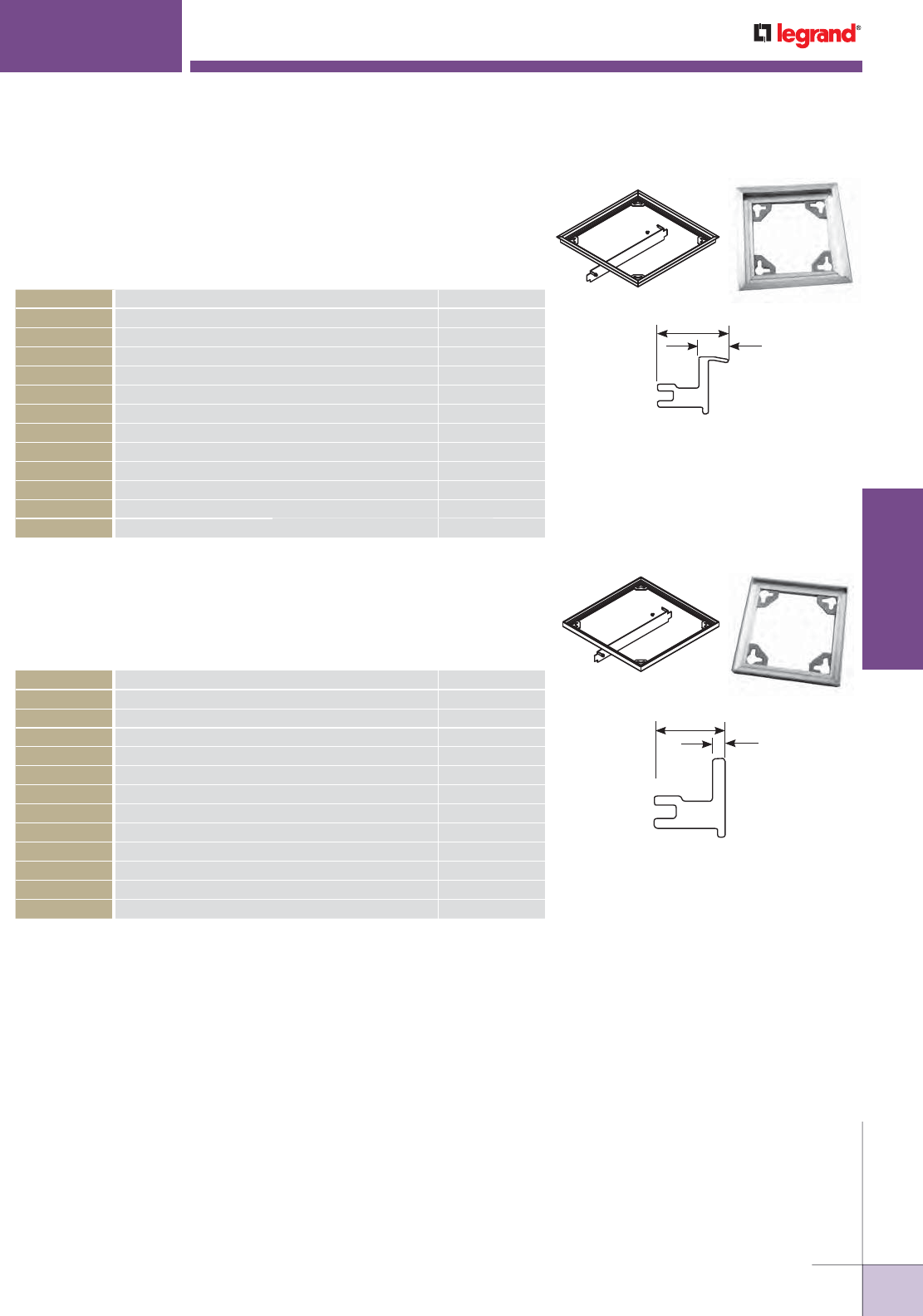
WWW.LEGRAND.US/WIREMOLD
571
INFLOOR DUCTS
WIREMOLD
WALKERDUCT
®
CARPET/TILE HOLDERS
Flanged square carpet/tile trim in aluminum for Walkerduct JS Series Boxes.
Mount onto junction box. Available in 1/4" or 1/8" [6.4mm or 3.2mm] depths
for carpet or tile floors. Flange is 1/2 [12.7mm] wide. Dimensions below do
not include flange.
11/16"
[17.5mm]
1/2"
[12.7mm]
Flangeless square carpet/tile trim in aluminum for Walkerduct JS Series
Boxes. Mount onto junction box. Available in 1/4" [6.4mm] or 1/8" [3.2mm]
depths for carpet or tile floors.
11/16"
[17.5mm]
1/8" [3.2mm]
Walkerduct Square Carpet/Tile Trim Ordering Information
NOTE: 1/8" or 1/4" is depth of tile or carpet when used with JS Boxes (1/4" thick cover plate). For
HS Boxes, depth will be reduced by 1/8" to accommodate the 3/8" thick cover plate.
CAT. NO. DESCRIPTION JUNCTION BOX
CT6-1/8 6 13/16" x 6 13/16" x 1/8" [173mm x 173mm x 3.2mm] 12JS
CT6-1/4 6 13/16" x 6 13/16" x 1/4" [173mm x 173mm x 6.4mm] 12JS
CT10-1/8 10 15/16" x 11 15/16" x 1/8" [278mm x 278mm x 3.2mm] 14JS, 222JS
CT10-1/4 10 15/16" x 11 15/16" x 1/4" [278mm x 278mm x 6.4mm] 14JS, 222JS
CT15-1/8 15 1/16" x 15 1/16" x 1/8" [383mm x 383mm x 3.2mm] 224JS, 3222JS
CT15-1/4 15 1/16" x 15 1/16" x 1/4" [383mm x 383mm x 6.4mm] 224JS, 3222JS
CT18-1/8 18 7/16" x 18 7/16" x 1/8" [468mm x 468mm x 3.2mm] 244JS, 3224JS
CT18-1/4 18 7/16" x 18 7/16" x 1/4" [468mm x 468mm x 6.4mm] 244JS, 3224JS
CT21-1/8 21 13/16" x 21 13/16" x 1/8" [554mm x 554mm x 3.2mm] 3424JS, 3244JS
CT21-1/4 21 13/16" x 21 13/16" x 1/4" [554mm x 554mm x 6.4mm] 3424JS, 3244JS
CT25-1/8 25 3/16" x 25 3/16" x 1/8" [640mm x 640mm x 3.2mm] 3444JS
CT25-1/4 25 3/16" x 25 3/16" x 1/4" [640mm x 640mm x 6.4mm] 3444JS
NOTE: 1/8" or 1/4" is depth of tile or carpet when used with JS Boxes (1/4" thick cover plate). For
HS Boxes, depth will be reduced by 1/8" to accommodate the 3/8" thick cover plate.
CAT. NO. DESCRIPTION JUNCTION BOX
FT6-1/8 6 13/16" x 6 13/16" x 1/8" [173mm x 173mm x 3.2mm] 12JS
FT6-1/4 6 13/16" x 6 13/16" x 1/4" [173mm x 173mm x 6.4mm] 12JS
FT10-1/8 10 15/16" x 11 15/16" x 1/8" [278mm x 278mm x 3.2mm] 14JS, 222JS
FT10-1/4 10 15/16" x 11 15/16" x 1/4" [278mm x 278mm x 6.4mm] 14JS, 222JS
FT15-1/8 15 1/16" x 15 1/16" x 1/8" [383mm x 383mm x 3.2mm] 224JS, 3222JS
FT15-1/4 15 1/16" x 15 1/16" x 1/4" [383mm x 383mm x 6.4mm] 224JS, 3222JS
FT18-1/8 18 7/16" x 18 7/16" x 1/8" [468mm x 468mm x 3.2mm] 244JS, 3224JS
FT18-1/4 18 7/16" x 18 7/16" x 1/4" [468mm x 468mm x 6.4mm] 244JS, 3224JS
FT21-1/8 21 13/16" x 21 13/16" x 1/8" [554mm x 554mm x 3.2mm] 3424JS, 3244JS
FT21-1/4 21 13/16" x 21 13/16" x 1/4" [554mm x 554mm x 6.4mm] 3424JS, 3244JS
FT25-1/8 25 3/16" x 25 3/16" x 1/8" [640mm x 640mm x 3.2mm] 3444JS
FT25-1/4 25 3/16" x 25 3/16" x 1/4" [640mm x 640mm x 6.4mm] 3444JS
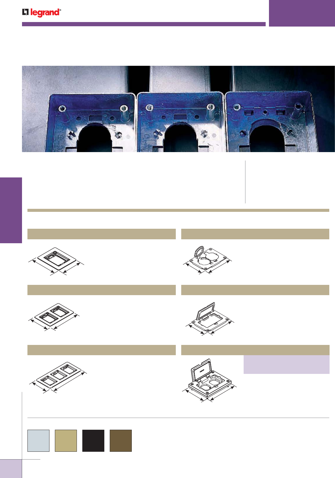
WWW.LEGRAND.US/WIREMOLD
572
INFLOOR DUCTS
WIREMOLD
6.080"
[154.4mm]
5.060"
[128.5mm]
WALKERDUCT
®
PRO SERIES SERVICE FITTINGS
CODE REFERENCE
cULus Listed Underfloor Raceway
Fittings:
File E11912, Guide RQKX
cULus Listed Metallic Outlet Boxes:
File E2961, Guide QCIT
Meets Articles 390 of NEC
Walkerduct® Pro Series Service Fittings offer a complete range
of service fittings to meet all power and communication requirements
while providing flush flanges with interchangeable covers offering an
aesthetic appearance.
COLOR OPTIONS
Walkerduct Pro Series Solid Brass Cover Plate Flanges & Metal Cover Plates Ordering Information*
Walkerduct® Pro Series Service Fittings are available in brushed
aluminum, brass, black or brown as indicated in the part number
description.
Accepts Ortronics® MAB6TJ
TracJack and MAB3S2 Series II
adapters and Wiremold CM Series
inserts, sold separately.
817B One-Gang Brass Carpet & Tile Flange
Accepts Ortronics® MAB6TJ
TracJack and MAB3S2 Series II
adapters and Wiremold CM Series
inserts, sold separately.
837B Three-Gang Brass Carpet & Tile Flange
Accepts Ortronics® MAB6TJ
TracJack and MAB3S2 Series II
adapters and Wiremold CM Series
inserts, sold separately.
827B Two-Gang Brass Carpet & Tile Flange
6.080"
[154.4 mm] 5.060"
[128.5 mm]
6.080"
[154.4mm]
5.060"
[128.5mm]
Flip lids. Can also be used with a
106 type frame for communication
adapter.
828R Brass Duplex Cover Plate
3.156"
[80.2mm]
4.182"
[106.2mm]
May be used with Wiremold CM
Series inserts and Ortronics®
Connectivity Systems in
conjunction with 817B, 827B, and
837B Flanges.
828GFITC Brass GFI Cover Plate
3.156"
[80.2mm]
4.182"
[106.2mm]
3.156"
[80.2mm]
4.182"
[106.2mm]
Brass Rectangular Cover Plate
PART NUMBERS:
828DPGFITC (Brass)
828DPGFITCAL (Aluminum)
Allows for mounting of a duplex
style receptacle with a rectan gular
style flip lid cover plate.
* Walkerduct Pro Series Activations are not recommended for concrete
floor types. Please consult the factory for concrete applications.
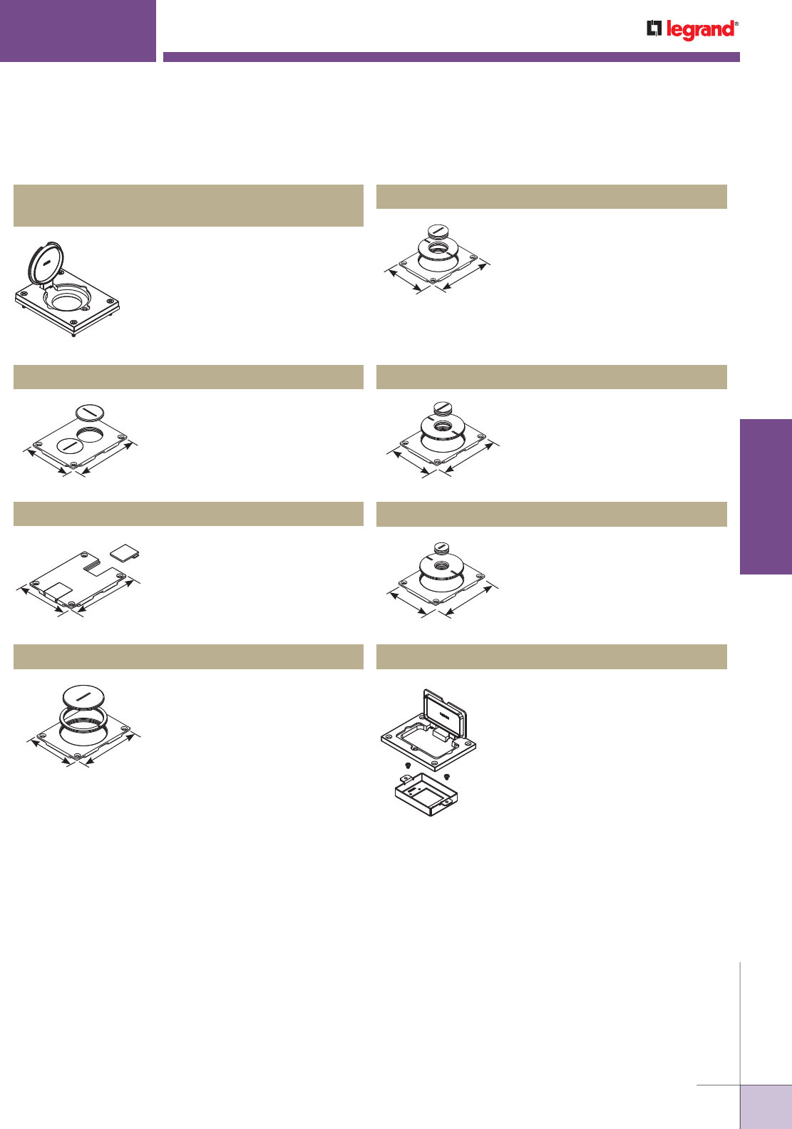
WWW.LEGRAND.US/WIREMOLD
573
INFLOOR DUCTS
WIREMOLD
WALKERDUCT
®
PRO SERIES SERVICE FITTINGS
4 1/8"
[105mm]
3 1/8"
[79mm]
Screw plugs. Screw plugs are
1 1/2" [38mm] in diameter.
828SPTC Brass Duplex Cover Plate
3 1/8"
[79mm]
4 1/8"
[105mm]
Data slides. Feed through only,
not for use with a mounting plate
for communication jacks.
829STC Brass Communication Cover Plate
4 11/64"
[106mm]
3 5/32"
[80mm]
2 5/8" and 2 1/4" [67mm and
57mm] plugs.
829CK Brass Communication Cover Plate
Single flip lid cover for 20A or 30A
single locking receptacles. Device
opening is 2 5/8" [67mm]. For use with
maximum female locking device of
1.58" diameter, and maximum male
plug face of 2.25" diameter
828DLR Brass Single Locking Receptacle
Cover Plate
Walkerduct Pro Series Metal Cover Plates Ordering Information
2 5/8" and 1/2" [67mm and
12.7mm] plugs.
829CK-1/2 Brass Communication Cover Plate
3.156"
[80.2mm]
4.182"
[106.2mm]
Sheet metal adapter plate that
accepts two (2) Extron® Electronics
MAAP style device plates, sold
separately. For use with 828GFITC
or 828GFITCAL cover plates, sold
separately. For use with minimum
2 1/2" [64mm] preset depths.
828MAAP A/V Adapter Plate
2 5/8" and 1" [67mm and 25mm]
plugs.
829CK-1 Brass Communication Cover Plate
3.156"
[80.2mm]
4.182"
[106.2mm]
2 5/8" and 3/4" [67mm and
19.1mm] plugs.
829CK-3/4 Brass Communication Cover Plate
3.156"
[80.2mm]
4.182"
[106.2mm]
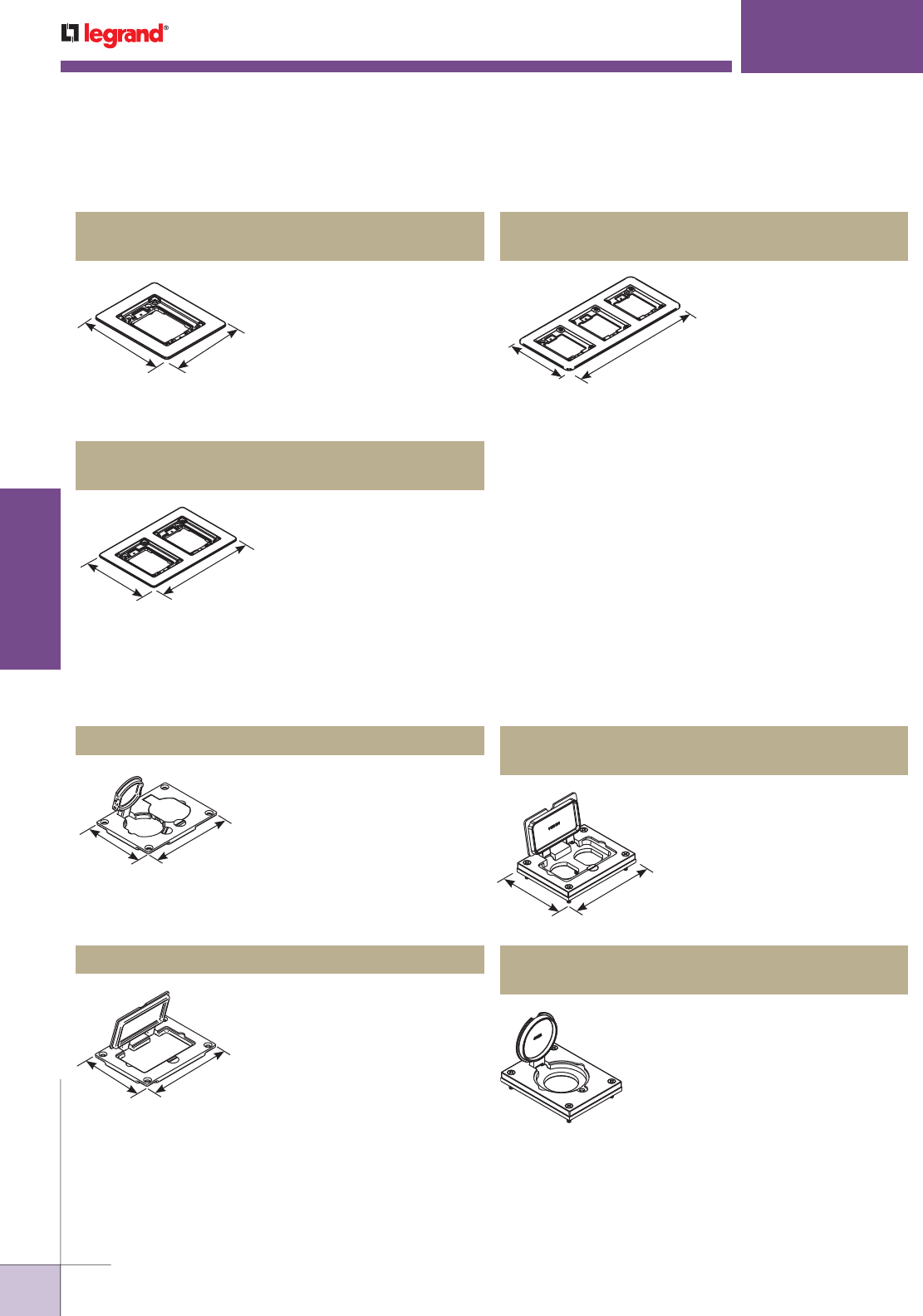
WWW.LEGRAND.US/WIREMOLD
574
INFLOOR DUCTS
WIREMOLD
WALKERDUCT
®
PRO SERIES SERVICE FITTINGS
Walkerduct Pro Series Brushed Aluminum Cover Plate Flanges Ordering Information
NOTE: Brushed aluminum flange comes with a beveled edge.
Accepts Ortronics® MAB6TJ
TracJack and MAB3S2 Series
II adapters and Wiremold
CM Series inserts, sold
separately.
838TCAL Three-Gang Brushed Aluminum
Combination Carpet & Tile Flange
5.940"
[150.9mm]
13.170"
[334.5mm]
NOTE: Brushed aluminum flange comes with a beveled edge.
Accepts Ortronics® MAB6TJ
TracJack and MAB3S2 Series
II adapters and Wiremold CM
Series inserts, sold separately.
818TCAL One-Gang Brushed Aluminum
Combination Carpet & Tile Flange
5.940"
[150.9mm]
4.920"
[125.0mm]
NOTE: Brushed aluminum flange comes with a beveled edge.
Accepts Ortronics® MAB6TJ
TracJack and MAB3S2 Series
II adapters and Wiremold CM
Series inserts, sold separately.
828TCAL Two-Gang Brushed Aluminum
Combination Carpet & Tile Flange
5.940"
[150.9mm]
9.045"
[229.7mm]
Flip lids. Can also be used with a
106 type communication adapter.
828R-TCAL Brushed Aluminum Duplex Cover Plate
Single flip lid cover for 20A or 30A
single locking receptacles. Device
opening is 2 5/8" [67mm]. For use
with maximum female locking
device of 1.58" diameter, and
maximum male plug face of 2.25"
diameter.
828DLRAL Brushed Aluminum Single Locking
Receptacle Cover Plate
Walkerduct Pro Series Brushed Aluminum Cover Plates Ordering Information
3.290"
[83.6]
4.310"
[109.5]
May be used with Activate and
Ortronics® Connectivity Systems
in conjunction with 817B, 827B,
and 837B Flanges.
828GFITCAL Brushed Aluminum GFI Cover Plate
3.290"
[83.6]
4.310"
[109.5]
Allows for mounting of a
duplex style receptacle with a
rectangular style flip lid cover.
828DPGFITCAL Brushed Aluminum
Rectangular Cover Plate
3.290"
[83.6]
4.310"
[109.5]
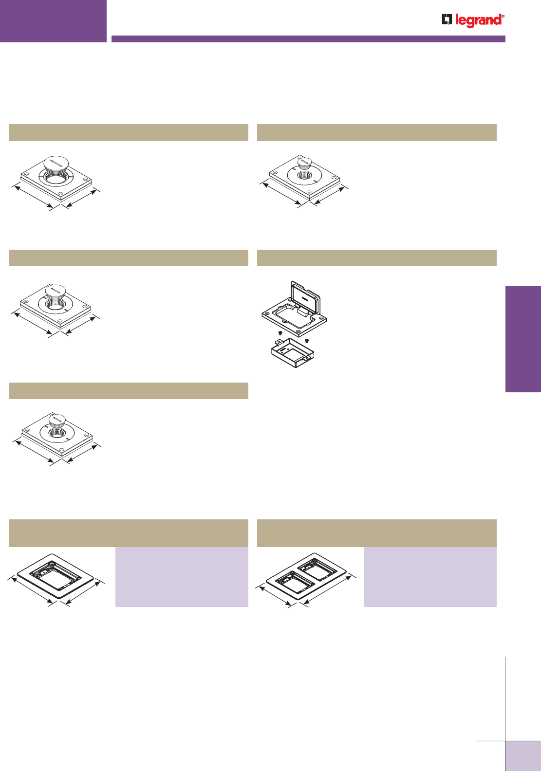
WWW.LEGRAND.US/WIREMOLD
575
INFLOOR DUCTS
WIREMOLD
WALKERDUCT
®
PRO SERIES SERVICE FITTINGS
NOTE: Brass covers and flanges are not interchangeable with aluminum
or nonmetallic covers and flanges. Nonmetallic covers are
interchangeable with aluminum flanges.
Power or communication
plate with 2" [51mm] and 3/4"
[19.1mm] plugs.
830CKTCAL-3/4 Brushed Aluminum Cover Plate
3.290"
[83.6mm] 4.310"
[109.5mm]
Power or communication
plate with 2" [51mm] and 1/2"
[12.7mm] plugs.
830CKTCAL-1/2 Brushed Aluminum Cover Plate
3.290"
[83.6mm] 4.310"
[109.5mm]
Power or communication plate
with 2" [51mm] and 1" [25mm]
plugs.
830CKTCAL-1 Brushed Aluminum Cover Plate
NOTE: Acceptable for use with threaded conduit when passing through
power cables.
3.290"
[83.6mm] 4.310"
[109.5mm]
Sheet metal adapter plate that accepts
two (2) Extron® Electronics MAAP style
device plates, sold separately. For use
with 828GFITC or 828GFITCAL cover
plates, sold separately. For use with
minimum of 2 1/2" [64mm] preset
depth.
828MAAP A/V Adapter Plate
6.080"
[154.4mm] 5.060"
[128.5mm] 6.080"
[154.4mm]
5.060"
[128.5mm]
Walkerduct Pro Series Powder-Coated Aluminum Cover Plate Flanges Ordering Information
Walkerduct Pro Series Brushed Aluminum Cover Plates Ordering Information (continued)
Power or communication plate
with 2" [51mm] and 1 1/4"
[32mm] plugs.
830CKTCAL Brushed Aluminum Cover Plate
3.290"
[83.6mm] 4.310"
[109.5mm] NOTE: Acceptable for use with threaded
conduit when passing through
power cables.
Accepts Ortronics® MAB6TJ
TracJack and MAB3S2 Series II
adapters and Wiremold CM
Series inserts, sold separately.
Three-Gang Powder-Coated Aluminum
Combination Carpet and Tile Flange
PART NUMBERS:
827TCAL-BK (Black)
827TCAL-GY (Grey)
827TCAL-BS (Brass)
827TCAL-NK (Nickel)
827TCAL-BZ (Bronze)
Accepts Ortronics® MAB6TJ
TracJack and MAB3S2 Series II
adapters and Wiremold CM
Series inserts, sold separately.
One-Gang Powder-Coated Aluminum
Combination Carpet and Tile Flange
PART NUMBERS:
817TCAL-BK (Black)
817TCAL-GY (Grey)
817TCAL-BS (Brass)
817TCAL-NK (Nickel)
817TCAL-BZ (Bronze)
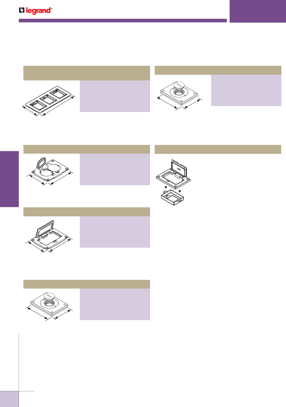
WWW.LEGRAND.US/WIREMOLD
576
INFLOOR DUCTS
WIREMOLD
WALKERDUCT
®
PRO SERIES SERVICE FITTINGS
6.080"
[154.4mm]
5.060"
[128.5mm]
Walkerduct Pro Series Powder-Coated Aluminum Cover Plate Flanges Ordering Information (continued)
3.290"
[83.6mm] 4.310"
[109.5mm]
3.290"
[83.6]
4.310"
[109.5]
3.290"
[83.6]
4.310"
[109.5]
NOTE: Acceptable for use with threaded conduit when passing through
power cables.
3.290"
[83.6mm] 4.310"
[109.5mm]
Sheet metal adapter plate that accepts
two (2) Extron® Electronics MAAP style
device plates, sold separately. For use
with 828GFITC or 828GFITCAL cover
plates, sold separately. For use with
minimum 2 1/2" [64mm] preset depths.
828MAAP A/V Adapter Plate
NOTE: Acceptable for use with threaded conduit when passing through
power cables.
Accepts Ortronics® MAB6TJ
TracJack and MAB3S2 Series II
adapters and Wiremold CM
Series inserts, sold separately.
Three-Gang Powder-Coated Aluminum
Combination Carpet and Tile Flange
PART NUMBERS:
837TCAL-BK (Black)
837TCAL-GY (Grey)
837TCAL-BS (Brass)
837TCAL-NK (Nickel)
837TCAL-BZ (Bronze)
Flip lids. Can also be used with a
106 type communication adapter.
Powder-Coated Aluminum Duplex Cover Plate
PART NUMBERS:
828R-TCAL-BK (Black)
828R-TCAL-GY (Grey)
828R-TCAL-BS (Brass)
828R-TCAL-NK (Nickel)
828R-TCAL-BZ (Bronze)
Allows for mounting a duplex
receptacle (Decorator or GFCI
style) with a rectangular flip
cover.
Powder-Coated Aluminum Rectangular Cover Plate
PART NUMBERS:
828GFITCAL-BK (Black)
828GFITCAL-GY (Grey)
828GFITCAL-BS (Brass)
828GFITCAL-NK (Nickel)
828GFITCAL-BZ (Bronze)
Power or communication plate
with 2" [51mm] and 1" [25mm]
plugs.
Powder-Coated Aluminum Cover Plate
PART NUMBERS:
829CKAL-BK (Black)
829CKAL-GY (Grey)
829CKAL-BS (Brass)
829CKAL-NK (Nickel)
829CKAL-BZ (Bronze)
Power or communication plate
with 2" [51mm] and 3/4"
[19.1mm] plugs.
Powder-Coated Aluminum Cover Plate
PART NUMBERS:
829CKAL-3/4BK (Black)
829CKAL-3/4GY (Grey)
829CKAL-3/4BS (Brass)
829CKAL-3/4NK (Nickel)
829CKAL-3/4BZ (Bronze)
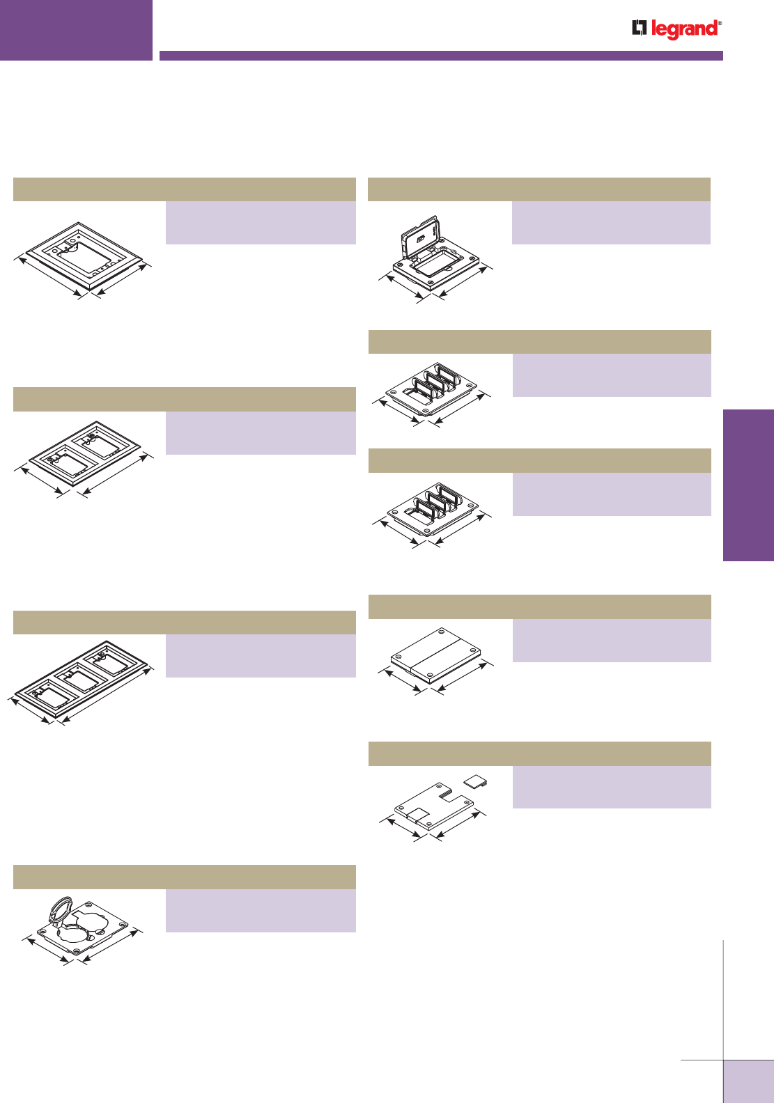
WWW.LEGRAND.US/WIREMOLD
577
INFLOOR DUCTS
WIREMOLD
WALKERDUCT
®
PRO SERIES SERVICE FITTINGS
Walkerduct Pro Series Nonmetallic Cover Plate Flanges Ordering Information
5 3/4"
[146mm] 4 3/4"
[121mm]
5 3/4"
[146mm]
8 7/8"
[225mm]
NOTE: UL Listed for tile, terrazzo, and carpet floors.
Brass covers and flanges are not interchangeable with aluminum
or nonmetallic covers and flanges. Nonmetallic covers are
interchangeable with aluminum flanges.
5 3/4"
[146mm]
13"
[330mm]
3.290"
[83.6mm]
4.310"
[109.5mm]
3 3/16"
[81mm]
4 1/8"
[105mm]
3 3/16"
[81mm]
4 1/8"
[105mm]
3 3/16"
[81mm]
4 1/8"
[105mm]
3 3/16"
[81mm]
4 1/8"
[105mm]
3 3/16"
[81mm]
4 1/8"
[105mm]
* Replacement flip lids can be ordered under Cat. No. PFL-BLK and PFL-
BRN. Each Cat. No. comes with three flip lids. The above cover plates are
listed for tile, terrazzo, and carpet floors.
NOTE: Brass covers and flanges are not interchangeable with aluminum
or nonmetallic covers and flanges. Nonmetallic covers are
interchangeable with aluminum flanges
One-Gang Nonmetallic Carpet Flange
PART NUMBERS:
817PCC-BLK (Black)
817PCC-BRN (Brown)
For Ortronics® connectivity use
with 829PFLRT Cover. For
Wiremold CM Series inserts use
with 829PFL Cover. Accepts
Ortronics® MAB6TJ TracJack and
MAB3S2 Series II adapters and
Wiremold CM Series inserts,
sold separately.
Three-Gang Nonmetallic Flange
PART NUMBERS:
837PCC-BLK (Black)
837PCC-BRN (Brown)
For Ortronics® connectivity use
with 829PFLRT Cover. For
Wiremold CM Series inserts use
with 829PFL Cover. Accepts
Ortronics® MAB6TJ TracJack and
MAB3S2 Series II adapters and
Wiremold CM Series inserts, sold
separately.
Two-Gang Nonmetallic Carpet Flange
PART NUMBERS:
827PCC-BLK (Black)
827PCC-BRN (Brown)
Available in black or brown.
For Ortronics® connectivity
use with 829PFLRT Cover. For
Wiremold CM Series inserts
use with 829PFL Cover. Accepts
Ortronics® MAB6TJ TracJack and
MAB3S2 Series II adapters and
Wiremold CM Series inserts,
sold separately.
Nonmetallic Duplex Cover Plate
PART NUMBERS:
828PR-BLK (Black)
828PR-BRN (Brown)
Flip lids. Can also be used
with a 106 type frame for
communications.
Nonmetallic GFI cover plate
PART NUMBERS:
828PRGFI-BLK (Black)
828PRGFI-BRN (Brown)
May be used with Ortronics®
Connectivity systems in
conjunction with 817, 827
and 837PCC Series flanges.
Nonmetallic Communications Cover Plate
PART NUMBERS:
829PFL-BLK (Black)
829PFL-BRN (Brown)
Individual flip lids.* Gasket
included.
Nonmetallic Communications Cover Plate
PART NUMBERS:
829PFLRT-BLK (Black)
829PFLRT-BRN (Brown)
Individual flip lids.* Gasket
included. Ortronics® MAB6TJ
TracJack and MAB3S2 Series II
adapters included.
Nonmetallic Communications Cover Plate
PART NUMBERS:
829PCK-BLK (Black)
829PCK-BRN (Brown)
Individual flip lids.* Gasket
included. Ortronics® MAB6TJ
TracJack and MAB3S2 Series II
adapters included.
Nonmetallic Communications Cover Plate
PART NUMBERS:
829PSTC-BLK (Black)
829PSTC-BRN (Brown)
Individual flip lids.* Gasket
included. Ortronics® MAB6TJ
TracJack and MAB3S2 Series II
adapters included.
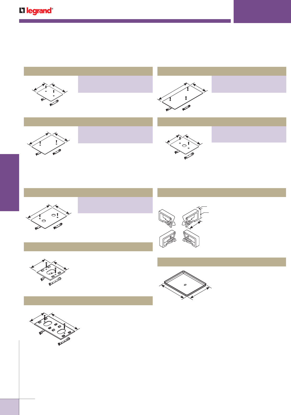
WWW.LEGRAND.US/WIREMOLD
578
INFLOOR DUCTS
WIREMOLD
WALKERDUCT
®
PRO SERIES SERVICE FITTINGS
13 5/16"
[338mm]
6 1/16"
[154mm]
5 1/16"
[129mm] 6 1/16"
[154mm]
Walkerduct Pro Series Trim Plates and Accessories Ordering Information
9 3/16"
[233mm]
6 1/16"
[154mm]
5 1/16"
[129mm] 6 1/16"
[154mm]
9 3/16"
[233mm]
6 1/16"
[154mm]
6 1/16"
[154mm] 5 1/16"
[129mm] Aluminum plate with opening
to attach 525 Series Service
Fitting Housing. Fits over single
Walkerduct Pro Series Preset.
430S505 Single 525 Trim Plate
6 1/16"
[154mm] 9 3/16"
[233mm]
Aluminum plate with openings
to attach two 525 Series Service
Fitting Housings. Fits over two
Walkerduct Pro Series Presets.
431D505 Double 525 Trim Plate
5/16"
[7.9mm]
5/8"
[15.9mm]
1"
[25mm]
Nonmetallic clips snap into
tabs in preset base. Hold
up to one meter of cable.
Maintain 1 1/4" [32mm]
bend radius. Four clips
included in kit.
427 Fiber Loop Kit
4 3/4"
121mm] 4"
[102mm]
Steel mudcap for
Walkerduct Pro Series
Preset.
421 Mudcap
Trim Plates and Accessories Ordering Information
Single Blanking Plate
PART NUMBERS:
430BR (Brass)
430AL (Aluminum)
Plate to cover single Walkerduct
Pro Series Presets.
Double Blanking Plate
PART NUMBERS:
431BR (Brass)
431AL (Aluminum)
Plate to cover two Walkerduct Pro
Series Presets.
Double Trim Plate
PART NUMBERS:
431BR075 (Brass)
431AL075 (Aluminum)
Plate with opening for 3/4" trade
size conduit or liquidtite
connection. Fits over two
Walkerduct Pro Series Presets.
Triple Blanking Plate
PART NUMBERS:
432BR (Brass)
432AL (Aluminum)
Plate to cover three Walkerduct
Pro Series Presets.
Single Trim Plate
PART NUMBERS:
430BR075 (Brass)
430AL075 (Aluminum)
Plate with opening for 3/4" trade
size conduit or liquidtite
connection. Fits over single
Walkerduct Pro Series Preset.
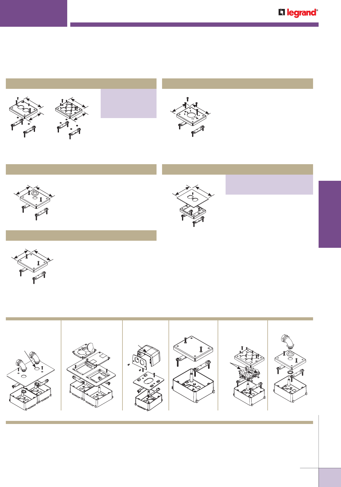
WWW.LEGRAND.US/WIREMOLD
579
INFLOOR DUCTS
WIREMOLD
WALKERDUCT
®
PRO SERIES SERVICE FITTINGS
Walkerduct Pro Series Flush Carpet Plates Ordering Information
Brass Flange and Covers
Cat. Nos. 827B,
828R and 829STC
Brass or Aluminum
Conduit Trim Plate
Cat. No. 431AL075
Openings Fit
3/4" trade size
Conduit
Conduit and
Lock Washers
Not Included
525 Trim Plate
Cat. No. 430S505
525 Series Service
Fitting Less Base Plate
Flush Double
Duplex Carpet
Plate Cat.
No. 428DR2
Receptacle
Screws
Must
Be
Removed
Before
Installation
Flush Carpet Plate
Cat. No. 428BL Flush Carpet Plate
Cat. No. 428B075
Conduit
and Lock
Washer Not
Included
Important: Flush carpet plates are to be used only within a protected, enclosed environment such as under a retail counter with carpeted floors.
Walkerduct Pro Series Service Fittings Installation Details
3 7/8"
[98mm] 4 5/8"
[117mm]
3 7/8"
[98mm] 4 5/8"
[117mm]
4 3/4"
[121mm] 5 3/8"
[137mm]
Important: A minimum 1 1/2" [38mm] preset or afterset is required on Pro
Series Underfloor Duct to support standard duplex receptacles
and communication devices when using flush activations. The
1" [25mm] preset or afterset should be specified for pedestal
style fittings or when cabling will be pulled through the
activation point.
3 7/8"
[98mm]
4 5/8"
[117mm]
3 7/8"
[98mm]
4 5/8"
[117mm]
For carpet floors only.
Steel plate mounts
inside preset and is
adjustable to floor
height.
3 7/8"
[98mm] 4 5/8"
[117mm]
428B075 Flush Conduit Carpet Plate
Opening fits 3/4" trade size
conduit or liquidtite. Includes
spacer for liquidtite connections.
For carpet floors only. Steel
plate mounts inside preset and is
adjustable to floor height.
428BL Blank Flush Carpet Plate
Blank carpet plate for custom
punched openings or for
abandoning preset. For carpet
floors when used for activations.
Steel plate mounts inside preset
and is adjustable to floor height.
428B525 Flush 525 Series Carpet Plate
Openings to attach 525 Series
Service Fitting on carpet plate.
For carpet floors only. Steel
plate mounts inside preset and is
adjustable to floor height.
Carpet plate and finishing plate.
Flush steel plate mounts inside
preset and is adjustable to floor
height. Brushed aluminum
finishing plate covers carpet plate
and mounts over carpet.
Flush Duplex Carpet Plate
PART NUMBERS:
432BR (Single Duplex
Opening)
428DR2 (Double Duplex
Opening)
Flush Duplex Carpet Trim Plate
PART NUMBERS:
433DR (For Single Duplex Openings)
433DR2 (For Double Duplex Openings)
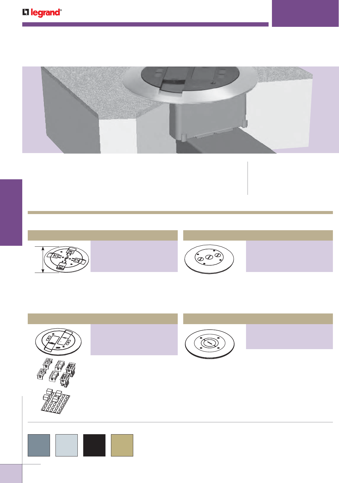
WWW.LEGRAND.US/WIREMOLD
580
INFLOOR DUCTS
WIREMOLD
NOTE: When using as a preset, the duct presets need to be staggered.
7"
[178mm]
PSRC9 SERIES
™
CODE REFERENCE
cULus Listed Underfloor Raceway
Fittings:
File E11912, Guide RQKX
Meets Article 390 of NEC
PSRC9 Series Poke-Thru Style Service Fittings provide flush preset
or afterset activations for Walkerduct and Walkercell infloor systems.
COLOR OPTIONS
PSRC9 Series Service Fittings Ordering Information
PSRC9 Series Service Fittings are available in gray, aluminum,
black, or brass as indicated in the part number description.
Flanged cover for use in tile or
carpet installation. Die-cast
aluminum assembly. Lid area is
flush with the finished floor, no
cutouts provided.
Quad Power Fitting
PART NUMBERS:
PSRC9TCGY (Gray)
PSRC9TCAL (Aluminum)
PSRC9TCBK (Black)
PSRC9TCBS (Brass)
Unit includes link straps and
adapter plate to attach preset
or afterset. Includes two (2)
Ortronics® TracJack adapters,
two (2) Ortronics® Series II
adapters and Wiremold Open
System adapters. Modular jacks,
sold separately.
Quad Communication Fitting
PART NUMBERS:
PSRC9AMDTCGY (Gray)
PSRC9AMDTCAL (Aluminum)
PSRC9AMDTCBK (Black)
PSRC9AMDTCBS (Brass)
Unit complete with link straps,
adapter plate and conduit
assembly featuring (1) 3/4" trade
size and (2) 1/2" trade size conduit
connectors and closure plugs.
Flush Furniture Feed Fitting
PART NUMBERS:
PSRC9FFTCGY (Gray)
PSRC9FFTCAL (Aluminum)
PSRC9FFTCBK (Black)
PSRC9FFTCBS (Brass)
Unit complete with link straps,
adapter plate and features
concentric screw plugs that allow
for 1 1/4" or 2" trade size conduit
fitting connection.
2" [51mm] Flush Furniture Feed Fitting
PART NUMBERS:
PSRC9FF2TCGY (Gray)
PSRC9FF2TCAL (Aluminum)
PSRC9FF2TCBK (Black)
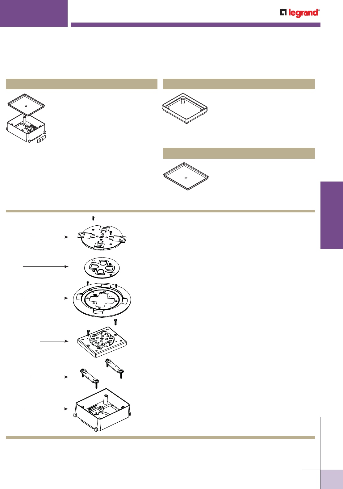
WWW.LEGRAND.US/WIREMOLD
581
INFLOOR DUCTS
WIREMOLD
Slide Cover
Gasket
Flange
Link Straps
(included)
Afterset
(2 1/2" or higher,
ordered separately)
Pro Series
Adapter Bracket
(included)
PSRC9 SERIES
™
2 1/2" and 3" [64mm, and 76mm]
Aftersets. Installed either before or
after concrete pour to create activation
from duct (minimum concrete depth of
2 1/2" [64mm]). Requires 6 1/2"[165mm]
core drilled hole in concrete and 2 1/2"
[64mm] diameter hole in duct. Grout fill
required around afterset once installed
to fill voids and support fitting flange.
Attaches to duct using locking tabs.
Extensions can be attached to increase
height (see below). Aftersets include
alignment clip and mudcap.
4225, 4230 Aftersets
1/2" and 1" [12mm and 25mm] high
extensions. Used to increase height of
preset or afterset. Die cast construction.
Attach to preset or afterset with push
on metal sleeves (included). Cat. No.
426 can be stacked, Cat. No. 425 cannot
be stacked.
425, 426 Extensions
Steel replacement cap for preset.
Recessed to hold 3/8" [9.5mm]
concrete.
421 Mudcap
PSRC9 Series Activation Accessories Ordering Information
PSRC9 Series Service Fittings Installation Details
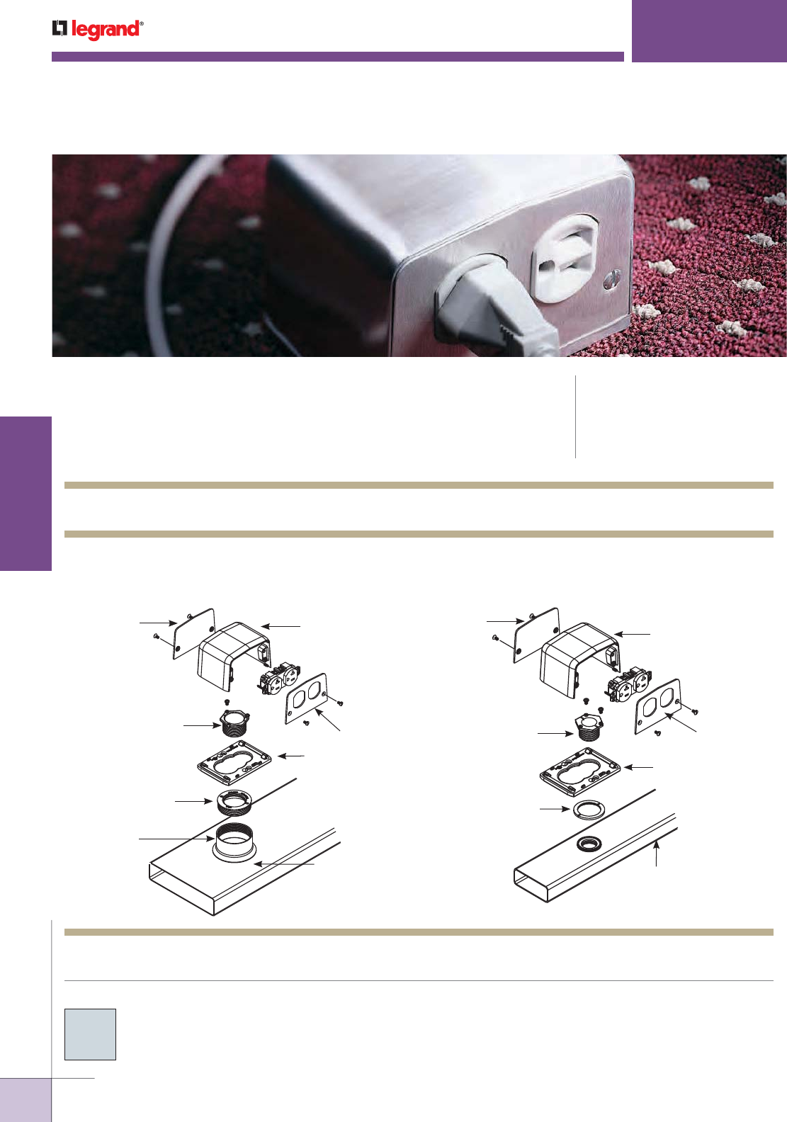
WWW.LEGRAND.US/WIREMOLD
582
INFLOOR DUCTS
WIREMOLD
1. Typical installation diagram to adapt 525 Series Service
Fittings to underfloor duct or cellular raceway:
2" [51mm] IPS Preset or afterset inserts.
Housing
500DR Plate
Base Plate
Walker #4 Duct)
2" IPS Preset Insert
or 436-2 Afterset
1126A-1 1/4
or 1 Adapter
1124-11/4 or 1
Locking Nipple
500B Blank Plate
2. Typical installation diagram to adapt 525 Series Service
Fittings to Flushduct (1 5/8" [41mm] opening).
Housing
500DR Plate
Base Plate
1124F-1
Locking Nipple
455F-1 Outlet Flange
12FST Flushduct
500B Blank Plate
525 Series Service Fittings Installation Details
525
SERIES
™ SERVICE FITTINGS
CODE REFERENCE
cULus Listed Underfloor Raceway
Fittings:
File E11912, Guide RQKX
Meets Article 390 of NEC
525 Series Service Fittings deliver the flexibility of interchangeable
faceplates and the durability to withstand multiple adds, moves and
changes.
COLOR OPTIONS
All 525 Series Service Fittings are brushed aluminum finish unless
otherwise specified in the part number description.
Custom color options are also available. Consult the factory for
more information.
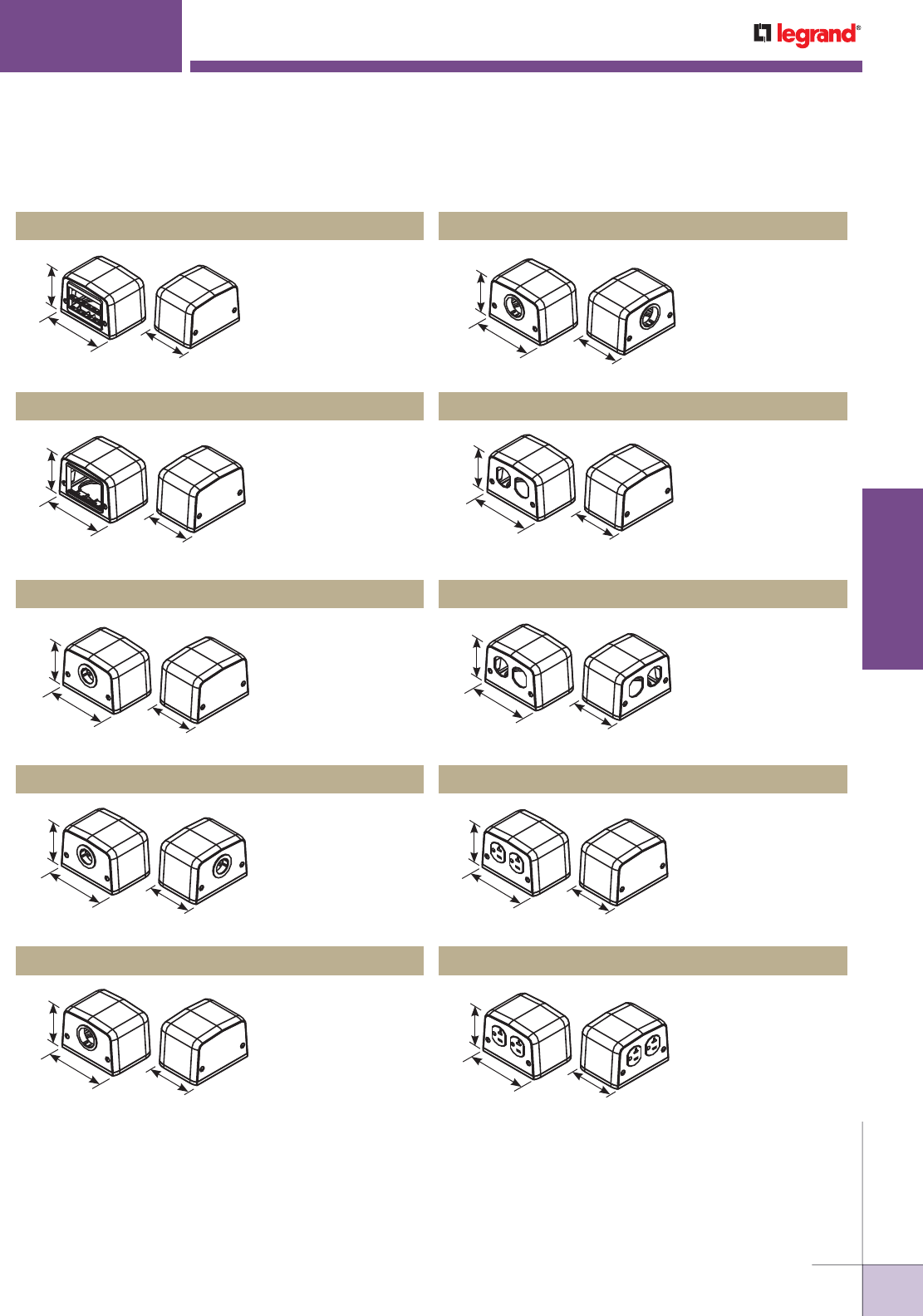
WWW.LEGRAND.US/WIREMOLD
583
INFLOOR DUCTS
WIREMOLD
3 1/8"
[79mm]
4 7/16"
[113mm]
3"
[76mm]
3 1/8"
[79mm]
4 7/16"
[113mm]
3"
[76mm]
3 1/8"
[79mm]
4 7/16"
[113mm]
3"
[76mm]
3 1/8"
[79mm]
4 7/16"
[113mm]
3"
[76mm]
3 1/8"
[79mm]
4 7/16"
[113mm]
3"
[76mm]
3 1/8"
[79mm]
4 7/16"
[113mm]
3"
[76mm]
3 1/8"
[79mm]
4 7/16"
[113mm]
3"
[76mm]
3 1/8"
[79mm]
4 7/16"
[113mm]
3"
[76mm]
3 1/8"
[79mm]
4 7/16"
[113mm]
3"
[76mm]
NOTE: Four-piece service fittings include: housing and base plate.
Receptacles included when indicated in part number description.
525 Series Service Fittings have 27 cubic inches [442ml] of capacity.
3 1/8"
[79mm]
4 7/16"
[113mm]
3"
[76mm]
525
SERIES
™ SERVICE FITTINGS
Includes faceplate
with opening one side.
Ortronics® Series II
and TracJack adapters
included.
525RT Four-Piece Communication Service Fitting
Duplex opening one
side. Receptacle not
included.
525F Four-Piece Power Service Fitting
6A opening with
communication
adapter on one side.
Accommodates
Wiremold Open
System communication
modules.
525ACT Four-Piece Communication Service Fitting
1" [25mm] I.D.
grommeted hole one
side. Blank plate other
side.
525A Four-Piece Communication Service Fitting
1" [25mm] I.D.
grommeted hole two
sides.
525B Four-Piece Communication Service Fitting
1 1/4" [32mm] I.D.
grommeted hole one
side. Blank plate other
side.
525C Four-Piece Communication Service Fitting
1 1/4" [32mm] I.D.
grommeted hole on
both sides.
525D Four-Piece Communication Service Fitting
Duplex opening both
sides. Receptacles not
included.
525G Four-Piece Power Service Fitting
20A 125V duplex plate
one side. Blank plate
other side. 20A 125V
Receptacle included.
525H Four-Piece Power Service Fitting
20A 125V duplex plate
two sides. 20A 125V
Receptacles included.
525I Four-Piece Power Service Fitting
525 Series Service Fittings Ordering Information
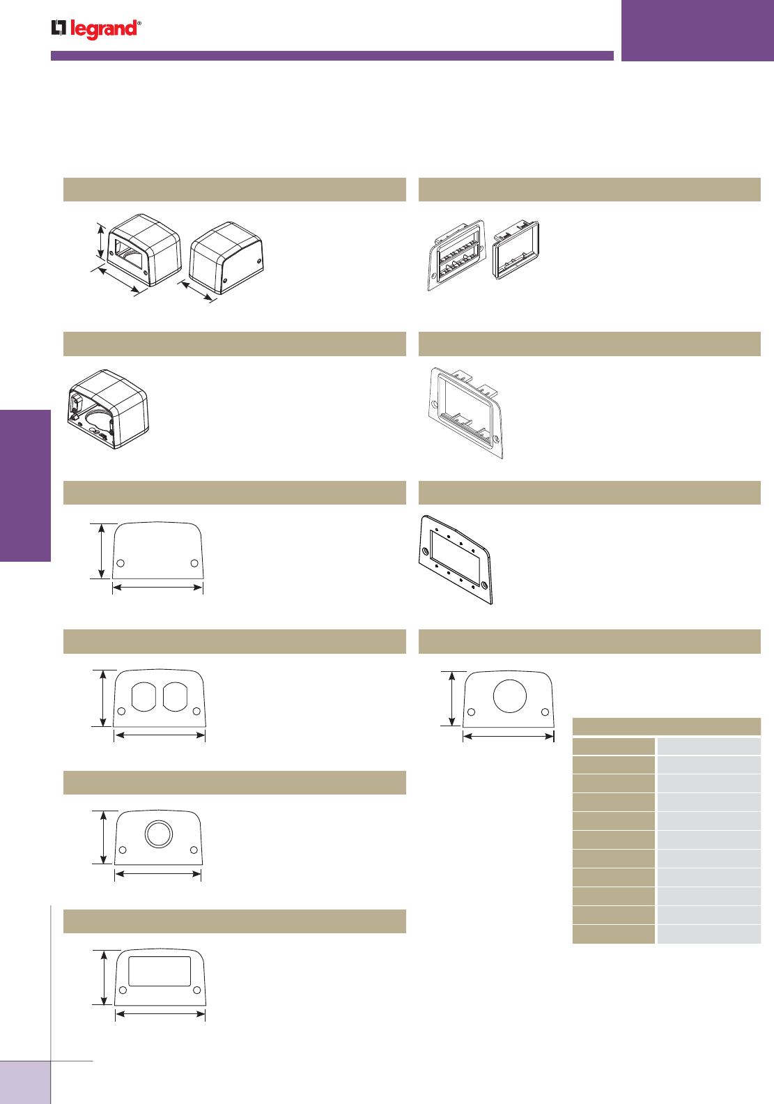
WWW.LEGRAND.US/WIREMOLD
584
INFLOOR DUCTS
WIREMOLD
3 1/8"
[79mm]
4 7/16"
[113mm]
3"
[76mm]
2 5/8"
[67mm]
4 1/2" [114mm]
2 5/8"
[67mm]
4 1/2" [114mm]
2 5/8"
[67mm]
4 1/2" [114mm]
2 5/8"
[67mm]
4 1/2" [114mm]
2 5/8"
[67mm]
4 1/2" [114mm]
525
SERIES
™ SERVICE FITTINGS
GFI device plate one
side. Blank plate other
side.
Housing and base plate for
all four-piece fittings.
Blank faceplate for all
four-piece fittings.
Accepts duplex receptacles.
1" [25mm] I.D. grommeted
opening.
Accepts GFI Decora style
receptacle.
Single opening. Ortronics®
Series II and TracJack adapters
included.
6A opening with mini adapter.
Will accommodate Wiremold CM2
Open System communication
modules.
Accepts four (4) Extron®
Electronics MAAP plates.
Single receptacle faceplate.
Suffix indicates hole diameter.
525J Four-Piece Power Service Fitting
525HB Service Fitting Housing
500B Blank Faceplate
500DR Duplex Faceplate
500T Communication Faceplate
500-GFI GFI Faceplate
500RT Communication Device Plate
500ACT Communication Device Plate
500-MAAP Extron® Device Plate
Single Receptacle Device Plate
525 Series Service Fittings Ordering Information (continued)
ORDERING INFORMATION
CAT. NO. METRIC DIAMETER
500SP-1.0625 [27mm]
500SP-1.39 [35mm]
500SP-1/2 [12.7mm]
500SP-7/8 [22.2mm]
500SP-1 7/8 [29mm]
500SP-1 7/16 [36mm]
500SP-1 1/2 [38mm]
500SP-1 9/16 [40mm]
500SP-1 5/8 [41mm]
500SP-2 [51mm]
* Other sizes custom sizes are available.
Consult factory for more information.
NOTE: Four-piece service fittings include: housing and base plate.
Receptacles included when indicated in part number description.
525 Series Service Fittings have 27 cubic inches [442ml] of capacity.
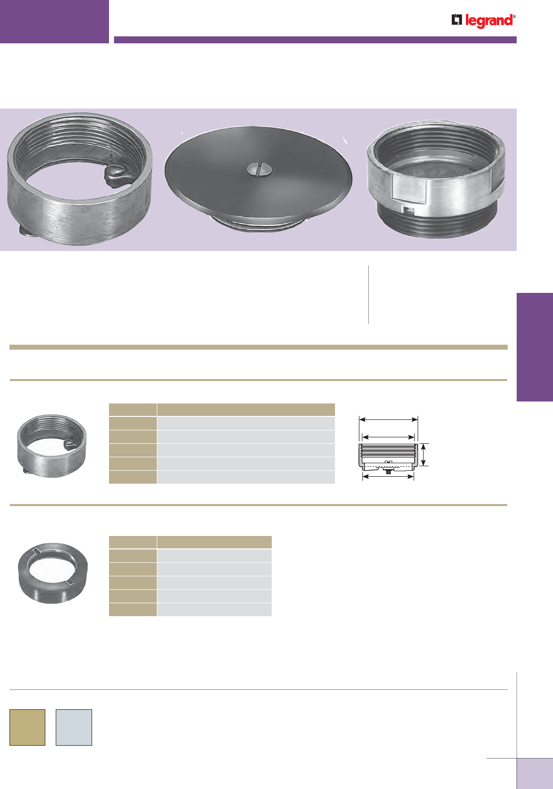
WWW.LEGRAND.US/WIREMOLD
585
INFLOOR DUCTS
WIREMOLD
2 1/2"
[64mm]
2" [51mm] IPS
7/8" to 3"
[22.2mm to 76mm]
2 1/4"
[57mm]
525 & Multiplex Series Activation Accessories Ordering Information
525 & MULTIPLEX
™
SERIES
CODE REFERENCE
cULus Listed Underfloor Raceway
Fittings:
File E11912, Guide RQKX
Meets Article 390 of NEC
525 and Multiplex™ Series Activation Accessories are designed to
complete the installation of the service fittings onto various types of
in floor systems offered by Wiremold as well as the various systems
sold by competitors.
COLOR OPTIONS
525 & Multiplex™ Series Activation Accessories are available in
either a brass or stainless steel finish as indicated in the part
number description.
CAT. NO. DESCRIPTION
436-2 7/8 2" [51mm] IPS afterset insert – 7/8" [22.2mm] high.
436-2-1 1/2 2" [51mm] IPS afterset insert – 1 1/2" [38mm] high
.
436-2-2 2" [51mm] IPS afterset insert – 2" [51mm] high
.
436-2-3/8 2" [51mm] IPS afterset insert – 2 3/8" [60mm] high.
436-2-3 2" [51mm] IPS afterset insert – 3" [76mm] high.
CAT. NO. DESCRIPTION
1126A-1/4 2" [51mm] IPS to 1/4" [6.4mm].
1126A-3/4 2" [51mm] IPS to 3/4" [19.1mm].
1126A-1 2" [51mm] IPS to 1" [25mm].
1126A-1 1/4 2" [51mm] IPS to 1 1/4" [32mm].
1126A-1 1/2 2" [51mm] IPS to 1 1/2" [38mm].
AFTERSET INSERTS
436-2-2
ADAPTERS FOR 2" [51mm] IPS PRESETS OR AFTERSET INSERTS
1126A-1 1/2
NOTE: IPS, Internal Pipe Size, is a trade size, not an actual size.
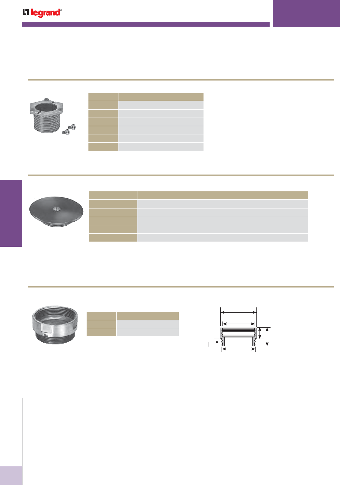
WWW.LEGRAND.US/WIREMOLD
586
INFLOOR DUCTS
WIREMOLD
1043
424
2 1/2"
[64mm]
2" [51mm] IPS
A
2 1/4"
[57mm]
B
9/16"
[14.3mm]
NOTE: IPS, Internal Pipe Size, is a trade size, not an actual size.
B = Brass, S = Stainless Steel.
1124-1
NOTE: IPS, Internal Pipe Size, is not actual size.
525 & MULTIPLEX
™
SERIES
525 & Multiplex Series Activation Accessories Ordering Information
LOCKING NIPPLES
CAT. NO. DESCRIPTION
1124-1 1" [25mm] IPS – 1" [25mm] long.
1124L-1 1" [25mm] IPS – 1 1/2" [38mm] long.
1124-1 1/4 1 1/4" [32mm] IPS – 1" [25mm] long.
1124L-1 1/4 1 1/4" [32mm] IPS – 1 1/2" [38mm] long.
1124-2 2" [51mm] IPS – 1" [25mm] long.
1124L-2 2" [51mm] IPS – 1 1/2" [38mm] long.
BLANKING PLATES
CAT. NO. DESCRIPTION
1043B, 1043S Brass or stainless steel blanking plate with threaded base for 2" [51mm] IPS.
1043BPO, 1043SPO Brass or stainless steel blanking plate only. Includes 1/4-20 screw.
1044B, 1044S Brass or stainless steel blanking plate with threaded base for 3/4" [19.1mm] IPS.
1045B, 1045S Brass or stainless steel blanking plate with threaded base for 1" [25mm] IPS.
1046B, 1046S Brass or stainless steel blanking plate with threaded base for 1 1/4" [32mm] IPS.
2" [51mm] IPS EXTENSIONS FOR AFTERSET INSERTS
CAT. NO. DESCRIPTION
424-3/4 3/4" [19.1mm] 1 5/16" [33mm]
424-1 1" [25mm] 1 9/16" [40mm]
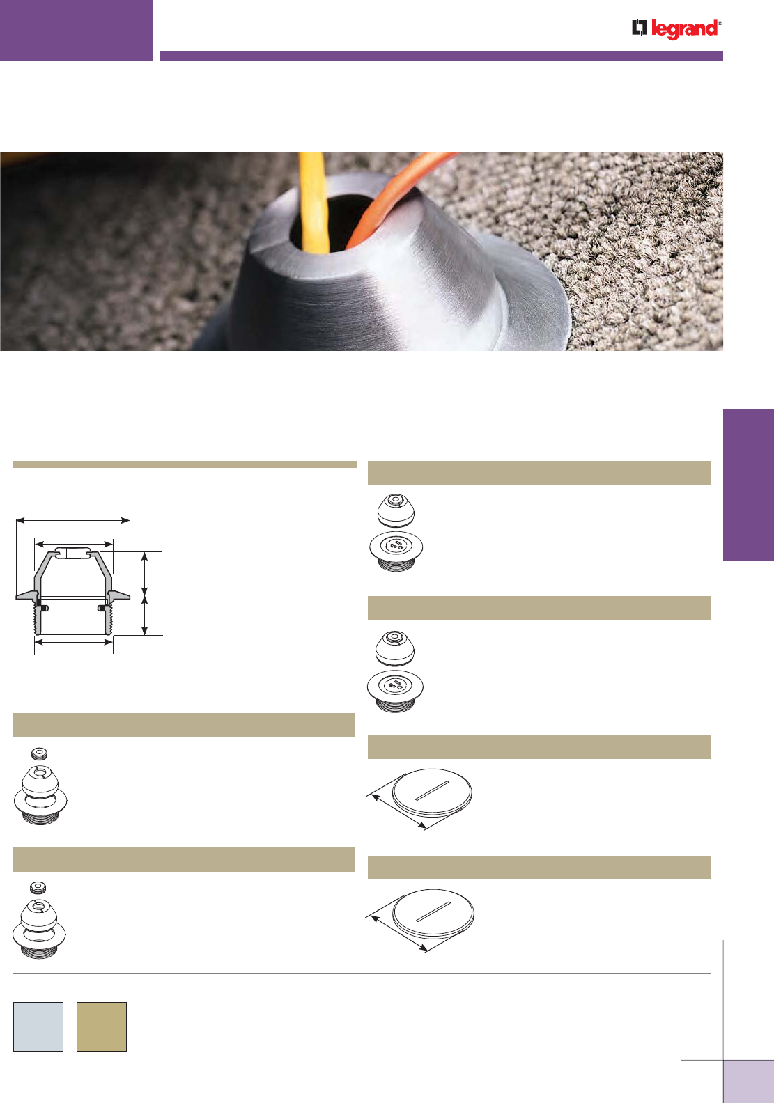
WWW.LEGRAND.US/WIREMOLD
587
INFLOOR DUCTS
WIREMOLD
3 1/2"
[89mm]
2 3/8"
[60mm]
1 7/8"
[48mm]
1 1/8"
[29mm]
2"-1 1/2" N.P.S.M.
[51mm – 1 1/2 N.P.S.M.]
Traditional pedestal style
fitting available for single
service applications.
1204BF/1204AL shown for
dimensional purposes.
1200 Series Service Fittings Ordering Information
2 1/4"
[57mm]
2 1/4"
[57mm]
1200 SERIES
™
CODE REFERENCE
cULus Listed Underfloor Raceway
Fittings:
File E11912, Guide RQKX
Meets Article 390 of NEC
1200 Series Service Fittings are bell-cap style pedestal fittings used to
provide power or communications to a work station.
1200 Series Service Fittings Assembly Details
Brass finish communication fitting furnished
with split bell cap and grommet. No device
plate is included.
1204BF Communication Service Fitting
Brass finish fitting includes housing, bell
cap, grommet, and single U-slot, three-wire
grounded, 20A, 125V receptacle.
1223BF Power Service Fitting
COLOR OPTIONS
All 1200 Series Service Fittings are available in either an
aluminum or brass finish as specified in the part number
description.
Aluminum communication fitting furnished
with split bell cap and grommet. No device
plate is included.
1204AL Communication Service Fitting
Aluminum fitting includes housing, bell cap,
grommet, and single U-slot, three-wire
grounded, 20A, 125V receptacle.
1223AL Power Service Fitting
Aluminum screw plug to abandon
service fitting. Screws into housing.
1230AL Screw Plug
Brass screw plug to abandon service
fitting. Screws into housing.
1230BF Screw Plug
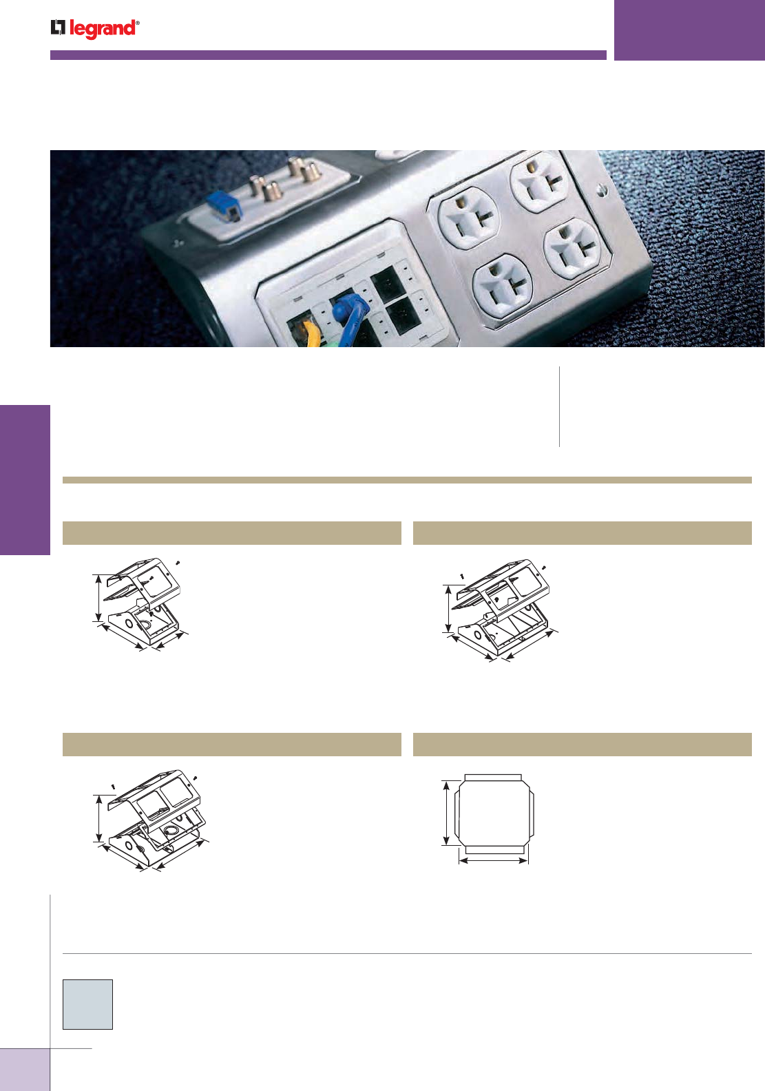
WWW.LEGRAND.US/WIREMOLD
588
INFLOOR DUCTS
WIREMOLD
3"
[76mm]
6 3/4"
[171mm]
4 3/4"
[121mm]
3"
[76mm]
6 3/4"
[171mm]
8 3/4"
[222mm]
3"
[76mm]
6 3/4"
[171mm]
8 3/4"
[222mm]
3"
[76mm]
3 5/16"
[84mm]
Multiplex Series Service Fittings Ordering Information
MULTIPLEX
™
SERIES
CODE REFERENCE
cULus Listed Underfloor Raceway
Fittings:
File E11912, Guide RQKX
Meets Article 390 of NEC
Multiplex Series Service Fittings are designed to be installed on the
various types of infloor systems and can handle large capacity single and
dual service power and/or communication requirements needed at the
point-of-use.
Single-service fitting includes
housing, base, two mounting
frames, and mounting hardware.
For use on 2" [51mm] IPS or
PK Preset Systems. For PK
activation, use in conjunction
with FloorPort Partition Feed
and PK Kit. Has 1/2" and 3/4"
trade size conduit knockouts on
each end. 53.3 cu. in. [906cm3]
capacity.
MP4 Single-Service Multiplex Service Fitting
COLOR OPTIONS
Multiplex Series Service Fittings are available in a brushed
aluminum finish unless otherwise indicated in the part number
description.
Dual-service fitting includes
housing, base, two mounting
frames, divider, and mounting
hardware. For use on one No.
2 and one No. 4 Duct. Has 1/2"
and 3/4" trade size conduit
knockouts on each end. 104.3
cu. in. [1709cm3] capacity.
MP8 Dual-service Multiplex Service Fitting
Same as MP8 except mounts on
PK, or one No. 2 or one No. 4
Pro Series Duct.
MP8-1 Dual-Service Multiplex Service Fitting
Blank Faceplate.
LTF48-B Blank Faceplate
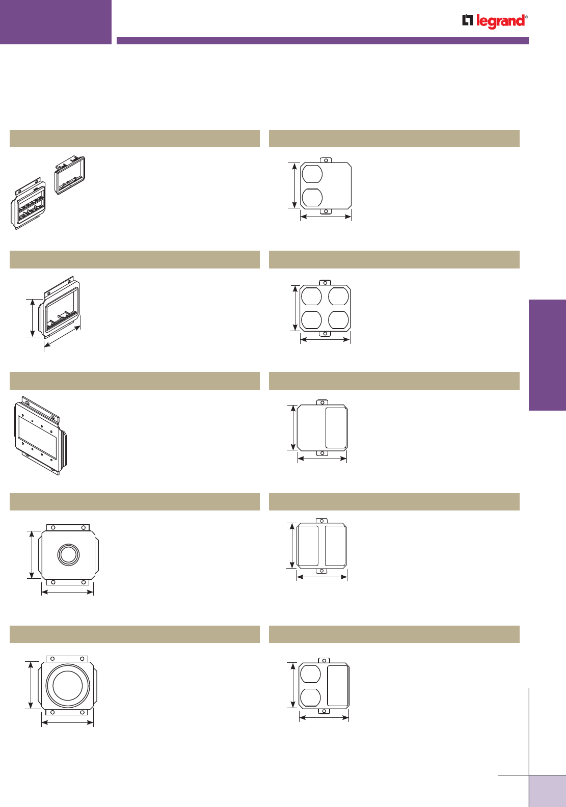
WWW.LEGRAND.US/WIREMOLD
589
INFLOOR DUCTS
WIREMOLD
3"
[76mm]
3 5/16"
[84mm]
Single opening with Ortronics®
MAB6TJ TracJack and MAB3S2
Series II adapters.
LTF48-RT Faceplate
MULTIPLEX
™
SERIES
3"
[76mm]
3 5/16"
[84mm]
3"
[76mm]
3 5/16"
[84mm]
3"
[76mm]
3 5/16"
[84mm]
3"
[76mm]
3 5/16"
[84mm]
3"
[76mm]
3 5/16"
[84mm]
3"
[76mm]
3 5/16"
[84mm]
3"
[76mm]
3 5/16"
[84mm]
Faceplate with 6a mini adapter
for Wiremold Open System CM2
communication modules.
LTF48-ACT Communication Faceplate
Accepts four (4) AVIP or Extron®
MAAP Plates.
LTF48-MAAP Extron® Device Plate
1" [25mm] diameter bushed
opening.
LTF48-1 Faceplate
2" [51mm] diameter bushed
opening.
LTF48-2 Faceplate
Single duplex opening faceplate.
M-DR Faceplate
Double duplex opening
faceplate.
M-2DR Faceplate
Single GFI opening faceplate.
M-GFI Faceplate
Double GFI opening faceplate.
M-2GFI Faceplate
Duplex and GFI openings
faceplate.
M-DR/GFI Faceplate
1200 Series Service Fittings Ordering Information (continued)
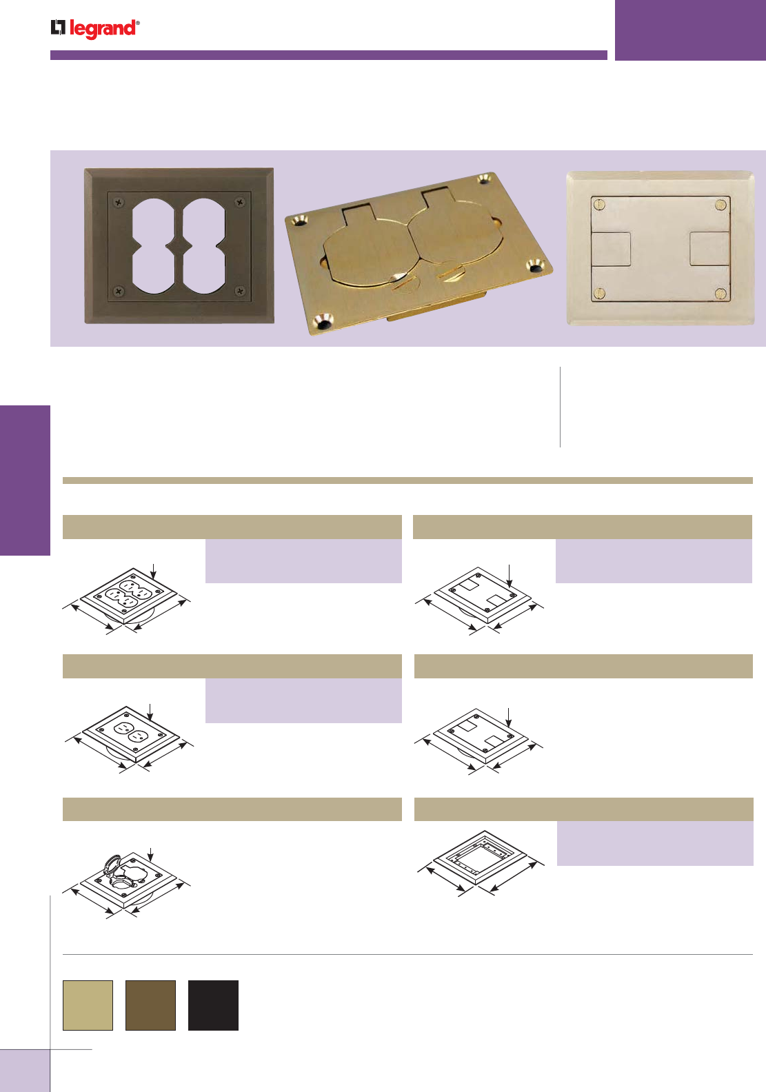
WWW.LEGRAND.US/WIREMOLD
590
INFLOOR DUCTS
WIREMOLD
Carpet Flange
PART NUMBERS:
S124BLK (Black)
S124BRN (Brown)
Complete Flush Activation
PART NUMBERS:
S166BLK (Black)
S166BRN (Brown)
Double Duplex Power Activation
PART NUMBERS:
S175BLK (Black)
S175BRN (Brown)
4 3/4"
[121mm]
5 25/32"
[147mm]
1/4" [6.4mm]
Flange Thickness
4 3/4"
[121mm]
5 3/4"
[146mm]
5/16" [7.9mm]
Flange Thickness
4 3/4"
[121mm]
5 3/4"
[146mm]
1/4" [6.4mm]
Flange Thickness
5 3/4"
[146mm] 4 3/4"
[121mm]
1/4" [6.4mm]
Flange Thickness
5 3/4"
[146mm] 4 3/4"
[121mm]
SOURCE I
®
SERVICE FITTINGS
CODE REFERENCE
cULus Listed Underfloor Raceway
Fittings:
File E11912, Guide RQKX
Meets Article 390 of NEC
Source I® Series Flush Activations offer a wide variety of single and dual
service power and communications for infloor raceways in both new
construction and renovations.
COLOR OPTIONS
Source 1 Series Service Fittings Ordering Information
Source 1® Series Service Fittings are available in brass, brown
polycarbonate or black as indicated in the part number description.
Double duplex polycarbonate
assembly, 7/8" to 3 3/8" [22.2mm
to 86mm] concrete topping. 15A,
125V receptacles included.
Flush brass power – single duplex
flip lids. May be used with 106 type
adapters for data applications.
S165B Complete Flush Activation
Flush polycarbonate
communication slides.
5/16" [7.9mm]
Flange Thickness
5 3/4"
[146mm] 4 3/4"
[121mm]
Flush brass communication
(slides). Used for data cable
pass-through.
S166B Complete Flush Activation
Flush polycarbonate carpet flange
only with mounting screws.
Complete Flush Activation
PART NUMBERS:
S165BLK (Black)
S165BRN (Brown)
Flush polycarbonate power –
single duplex. 15A, 125V
receptacles included.
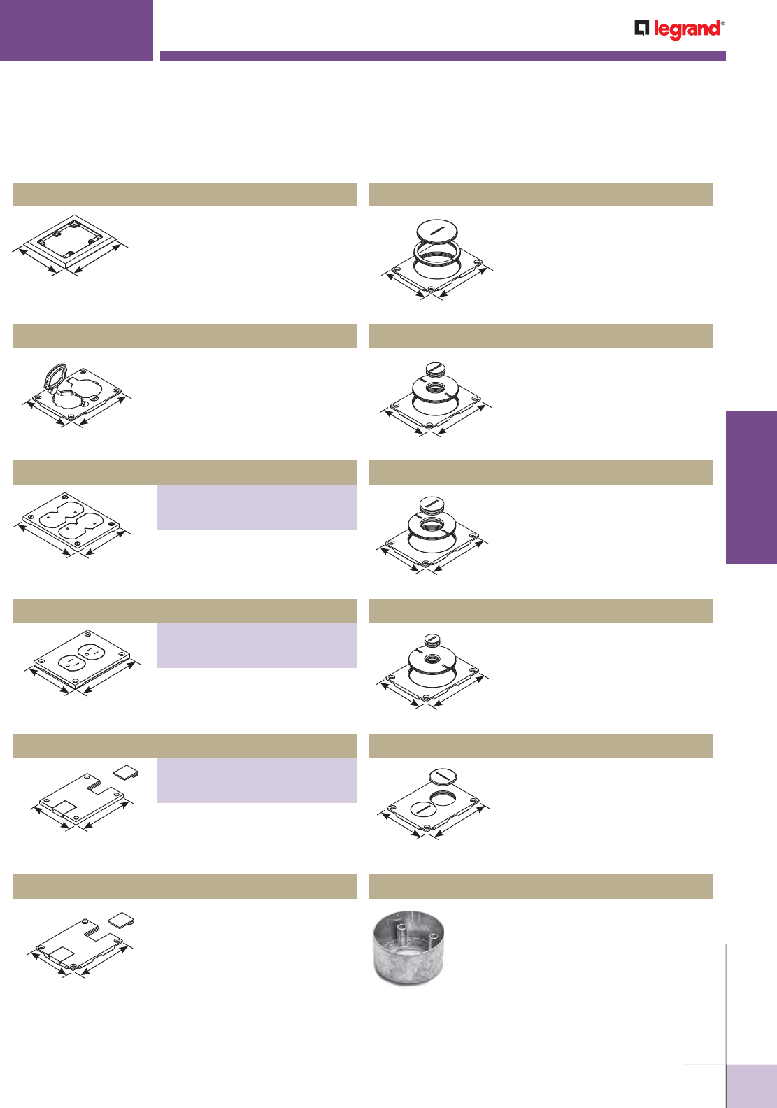
WWW.LEGRAND.US/WIREMOLD
591
INFLOOR DUCTS
WIREMOLD
4 3/4"
[121mm]
5 25/32"
[147mm]
Flush brass carpet flange only with
mounting screws.
S124B Carpet Flange
SOURCE I
®
SERVICE FITTINGS
Flush brass power cover plate
only (flip lid) with four mounting
screws.
S125B Cover Plate
Flush brass communication cover
plate (2 5/8" and 3/4" diameter
trade size screw plugs) with four
mounting screws.
829CK-3/4 Cover Plate
3 9/64"
[80mm]
4 11/64"
[106mm]
4 5/16"
[110mm]
3 19/64"
[84mm]
4 5/16"
[110mm]
3 19/64"
[84mm]
4 5/16"
[110mm]
3 19/64"
[84mm]
4 11/64"
[106mm]
3 5/32"
[80mm]
4 11/64"
[106mm]
3 5/32"
[80mm]
4 11/64"
[106mm]
3 5/32"
[80mm]
4 11/64"
[106mm]
3 5/32"
[80mm]
Flush brass communication cover
plate (2 5/8" and 1" diameter
trade size screw plugs) with four
mounting screws.
829CK-1 Cover Plate
Flush brass communication
cover plate with slides and four
mounting screws.
829STC Cover Plate
Flush brass communication cover
plate (2 5/8" and 1/2" diameter
trade size screw plugs) with four
mounting screws.
829CK-1/2 Cover Plate
Attaching Rings for Source I
(Preset or Afterset) zinc die-cast.
4" [102mm] O.D. Add suffix to Cat.
No. to indicate ring depth: 7/8",
1 1/8", 1 1/2", 2", 2 3/8", or 3 1/8".
437 Attaching Rings
Source 1 Series Service Fittings Ordering Information (continued)
4 11/64"
[106mm]
3 5/32"
[80mm]
Flush brass communication cover
plate (2 5/8" and 2 1/4" diameter
trade size screw plugs) with four
mounting screws.
829CK Cover Plate
4 11/64"
[106mm]
3 5/32"
[80mm]
Flush brass communication cover
plate. 1 1/2" diameter trade size
screw plugs.
828SPTC Cover Plate
Cover Plate
PART NUMBERS:
S125BLK (Black)
S125BRN (Brown)
Nonmetallic double duplex
membrane cover plate.
Cover Plate
PART NUMBERS:
S130BLK (Black)
S130BRN (Brown)
Nonmetallic double duplex
membrane cover plate.
Cover Plate
PART NUMBERS:
829PSTC-BLK (Black)
829PSTC-BRN (Brown)
Flush polycarbonate
communication cover plate with
slides and four mounting screws.
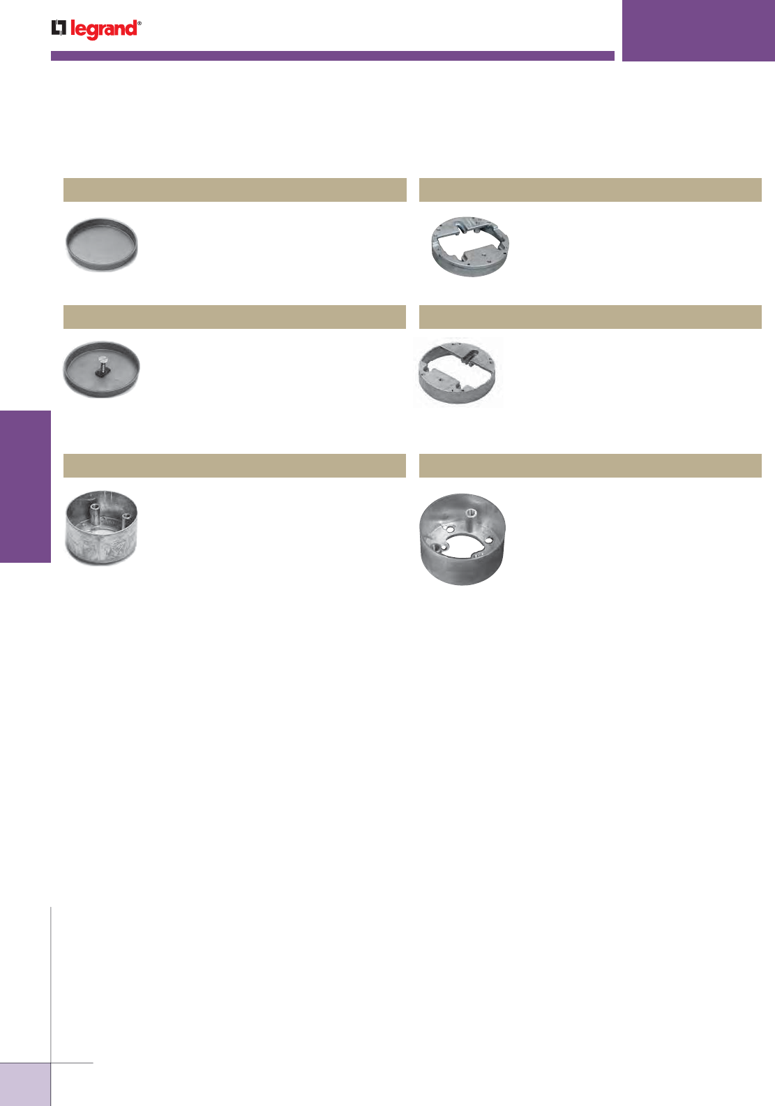
WWW.LEGRAND.US/WIREMOLD
592
INFLOOR DUCTS
WIREMOLD
SOURCE I
®
SERVICE FITTINGS
For Source I Attaching Ring with marker
screw. 4" [102mm] O.D. Use with 437
Attaching Rings only.
S1MC-MS Mudcap
Adjusting ring (with three adjusting
screws) for use with 437 Attaching
Rings – communication only (brass
and polycarbonate fittings) and power
for polycarbonate fitting only. 3 25/32"
[96mm] O.D.
898AR Adjusting Ring
For polycarbonate afterset use only. No
adjusting ring required. 4" [102mm] O.D.
Four #6-32 hold-down screws provided.
439 Attaching Ring
Adjusting ring (with three adjusting
screws) for use with 437 Attaching
Rings – power for brass fitting only.
3 25/32" [96mm] O.D.
897AR Adjusting Ring
Extension ring – mounts on top of 437
Attaching Ring. Includes extension ring
and three mounting screws. 4" [102mm]
O.D. Add suffix to indicate ring height:
7/8", 1 1/8", 1 1/2", 2", 2 3/8", 3 1/8".
We recommend using a shallow
Attaching Ring and deep extension ring
whenever possible.
S1ER Extension Ring
Source 1 Series Service Fittings Ordering Information (continued)
For Source I 437 Attaching Ring.
4" [102mm] O.D.
S1MC Mudcap
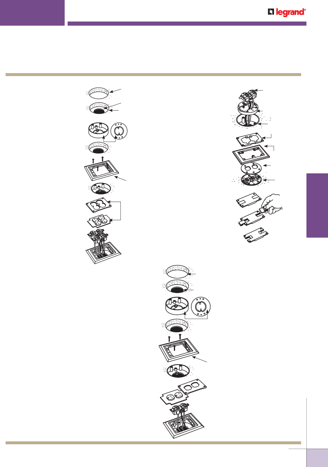
WWW.LEGRAND.US/WIREMOLD
593
INFLOOR DUCTS
WIREMOLD
4" [102mm] Core
Drilled Hole
2 1/2" [64mm]
Dia. Hole
Duct
439 Attaching
Ring for use with
Polycarbonate
Fittings Only
and Only as an
Afterset.
Double Duplex
Plate with
Membrane
Carpet
Flange
1. Establish location for the fitting, then core drill a 4"
[102mm] diameter hole through the concrete to the top
of the duct.
2. Next, drill a 2 1/2" [64mm] diameter opening in the top of
the duct, making sure this opening is in the center of the
4" [102mm] hole.
3. Install the 439 Attaching Ring, using the two locking tabs
to secure it to the duct.
4. Connect the carpet flange to the attaching ring, using the
four screws (#6-32 flathead) provided.
5. For duplex cover plate: Install the wiring device onto the
carpet flange and secure the cover plate over it, making
sure the plug-through membrane is in place.
6. For communication cover plate: Reverse the
communication slides as necessary to allow cable egress,
and install the cover plate, taking care to avoid pinching
any cables.
Note: The receptacle mounting shelf can be broken out to create additional
cable space when the communication cover plate is used.
Polycarbonate — Using a 439 Afterset Attaching Ring 4" [102mm] Core Drilled Hole
Duct 2 1/2" [64mm] Dia. Hole
439 Attaching Ring for Use
with Polycarbonate Fittings
Only and Only as an Afterset
Carpet Flange
S124BLK/BRN
Duplex Plate with
Membrane S130BLK/BRN
1. Establish location for the
fitting, then core drill a 4"
[102mm] diameter hole
through the concrete to the
top of the duct.
2. Next, drill a 2 1/2" [64mm]
diameter opening in the top
of the duct, making sure this
opening is in the center of
the 4" [102mm] hole.
3. Install the 439 Attaching
Ring using the two locking
tabs to secure it to the duct.
4. Connect the carpet flange
to the attaching rings using
the four screws provided.
5. Install the two duplex
receptacles and the double
duplex plate to complete
the installation.
S175 Double Duplex Power Activation Activation Guidelines – Flush Using 437 Ring
Wiring Device
Power Cover
Plate S125B
Carpet Plate
S124B (Shown)
or
S124 BLK/BRN
Adjusting Ring
Assembly
Neoprene Gasket
Communication Cover Plate 829STC
(Shown) or 829PSTC-BLK/BRN
Adjusting Ring
897AR for Power
(Shown) 898AR
for Communication
Attaching Ring
SOURCE I
®
SERVICE FITTINGS
Source 1 Series Service Fittings Installation Details
1. Pull wires through the hole
in the bottom of the attaching
rings. The adjusting ring
should then be installed
at the desired height. Wire
device and attach to the
adjusting ring.
2. After the gasket is put in
place, attach the flange to
the adjusting ring.
For Power: The flip lid
cover plate can be attached
to the flange.
3. For Communication: Turn
self storing slides upside
down with thin edge to the
inside. Attach cover plate
to flange.
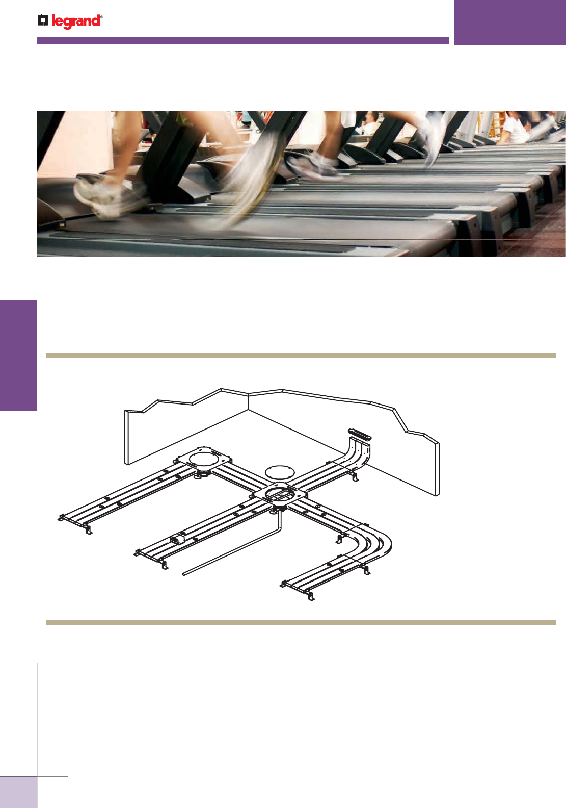
WWW.LEGRAND.US/WIREMOLD
594
INFLOOR DUCTS
WIREMOLD
FLUSHDUCT INFLOOR DUCT SYSTEMS
KEY
A. 334F-1-3 Triple Duct Terminal Bushing
B . 336F-3 Triple Duct 90° Vertical Elbow
C. 3222FCSA-28 Support
D. 255-1 Corner Conduit Connector
E. 338F-3 Triple Duct Horizontal 90°
Elbow
F. 3222F-0 10' Triple Blank Duct
G. 3222FB Triple Duct Junction Box
H. 3222FST 10' Triple Duct with staggered
threaded openings
I. 525 Series Service Fitting
HF
CE
B
A
D
G
I
Flushduct Infloor Duct Systems provide wire and cable management in open
space environments using 1, 2, or 3 #2 duct. It is ideal for renovations to existing
facilities where concrete depth is minimal.
CODE REFERENCE
ULus Listed Underfloor Raceway:
File E7020 Guide RKCZ
cULus Listed Underfloor Raceway
Fittings: File E11912 Guide RKQX.
Meets Article 390 of NEC.
Flushduct System Layout
NOTE: Illustration is for showing product applications only.

WWW.LEGRAND.US/WIREMOLD
595
INFLOOR DUCTS
WIREMOLD
Flushduct Quick Selection Guide
FLUSHDUCT INFLOOR DUCT SYSTEMS
DUCT 1-DUCT SYSTEM 2-DUCT SYSTEM 3-DUCT SYSTEM
BLANK 12F-0 222F-0 3222F-0
STAGGERED
1 5/8" [41mm] OPENINGS
12FST 222FST 3222FST
JUNCTION BOX 12FB 222FB 3222FB
3222FBCC
ACCESSORIES 1-DUCT SYSTEM 2-DUCT SYSTEM 3-DUCT SYSTEM
COUPLINGS 12FC 222FC 3222FC
COUPLINGS/SUPPORTS 12FCS
12FCSA-*
222FCS
222FCSA-*
3222FCS
3222FCSA-*
BOX OPENING CLOSURES 12F-WS 222F-WS 3222F-WS
DUCT CONDUIT ADAPTERS 312F-*
314F-*
324-
312F-*
314F-*
324-
312F-*
314F-*
324-*
BOX CORNER CONDUIT ADAPTER 255-* 255-* 255-*
DUCT END CLOSURE 304 304 304
VERTICAL ELBOWS 332F
336F
333F-2
336F-2
336F-3
TERMINAL BUSHINGS 334UF 334F-1-2 334F-1-3
HORIZONTAL ELBOWS 338UF
342F
338F-2
342F-2
338F-3
342F-3
OFFSET 372F 372F 372F
CROSSUNDERS 362F 362F-2 362F-3
DUCT OUTLET FLANGE 455F-1 455F-1 455F-1
FERRULE 450F-1 450F-1 450F-1
CRIMPING TOOL 470F-1 470F-1 470F-1
DUCT OPENING PLUGS 7140F
7141F
455FP-1
450FP-1
7140F
7141F
455FP-1
450FP-1
7140F
7141F
455FP-1
450FP-1
SEALANT 290G 290G 290G
TAPE H296 H296 H296
PRODUCT FAMILY
CATALOG
NUMBER
ACTIVATION
LOCATION
SERVICE
CAPACITY
SERVICE
COMPATIBILITY
MATERIAL/
COLORS
Pedestal
Single Service
Dual Service
Power
Communication
Audio/Visual
Alumi num
Multiplex
MP4 • • ••• •
MP8 • •••• •
MP8-1 • •••• •
525
Series
525A • • • • •
525B • • • • •
525C • • • • •
525D • • • • •
525F • • • •
525G • • • •
525H • • • •
525I • • • •
525J • • ••• •
525RT • • • •
525ACT •• • •
Flushduct Infloor Duct Systems Service Fitting Compatibility
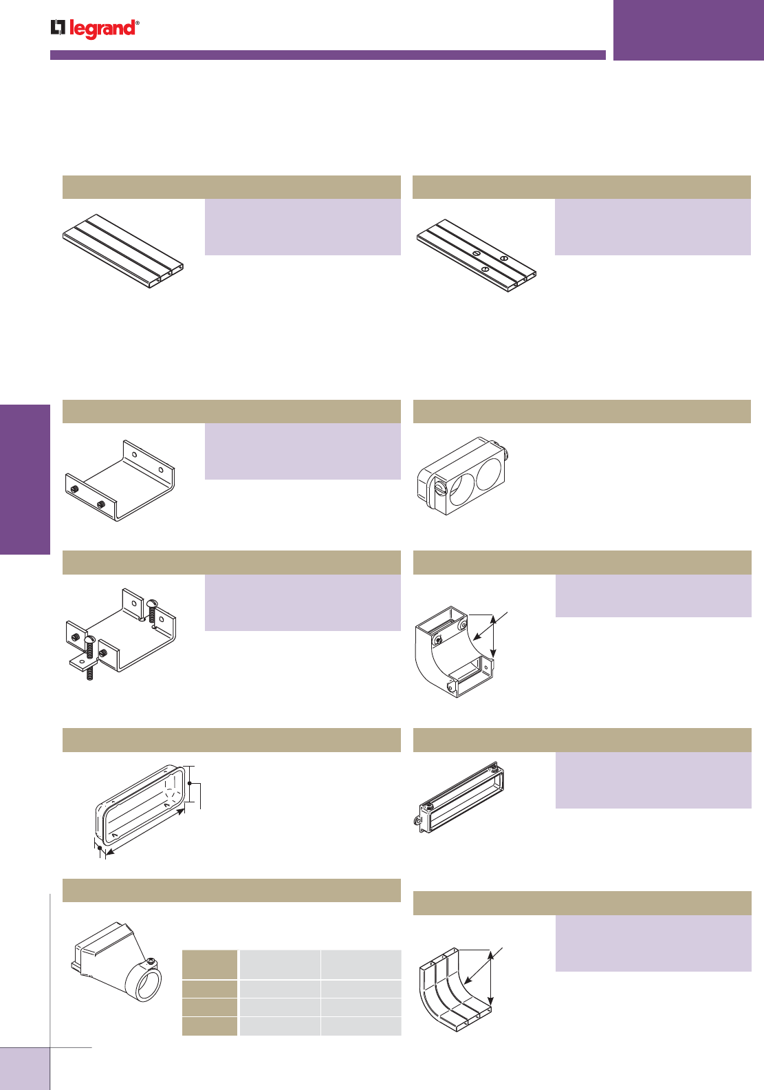
WWW.LEGRAND.US/WIREMOLD
596
INFLOOR DUCTS
WIREMOLD
1 1/8"
[29mm]
3 1/8"
[79mm]
1/2"
[12.7mm]
FLUSHDUCT INFLOOR DUCT SYSTEMS
To close off ends of duct.
304 Endcap
Used to feed single conduit into end of
duct. Suffix denotes conduit trade size.
Conduit Adapter
CATALOG
NUMBER
A
DIMENSION
B
DIMENSION
312F-1 1 3/8" [35mm] 2 1/4 [57mm]
312F-11/4 1 11/16" [43mm] 2 7/16 [62mm]
312F-11/2 3 1/8" [79mm] 2 3/4 [70mm]
Fits into end of Duct. For 3/4" trade
size rigid or PVC conduits.
314-3/4 Male Conduit Adapter
For extending Flushduct up a wall.
1 1/2" [38mm] bend radii. 332F is
for Single Duct and 332F-2 is for
Double Duct.
For securing Flushduct to cabinet.
334UF is for Single Duct, 334F-1-2
is for Double Duct, and 334F-1-3 is
for Triple Duct.
For extending Flushduct up a wall.
4" [102mm] bend radii.
Flushduct Accessories Ordering Information
Flushduct Duct Configuration Options
For feeder runs with precise
placement of openings. Double or
Triple Duct Systems are welded
together. 10' [3.05m] standard
length.
Provided with 1 5/8" [41mm]
diameter threaded openings
and removable plugs for service
fitting attachment. Openings are
staggered 24" [610mm] to facilitate
placement of service fittings. 10'
[3.05m] standard length.
Used to couple ends of duct
together. Set screws used to hold
duct in place.
Provides 1" [25mm] vertical
adjustment 3222FCS and
couple ends of duct together.
Recommended at 5' [1.524m]
intervals.
1 1/2"
[38mm]
Radius
3 1/8"
[130mm]
4"
[102mm]
Radius
10"
[254mm]
Blank Duct
PART NUMBERS:
12F-0 (Single Duct)
222F-0 (Double Duct)
3222F-0 (Triple Duct)
Staggered Ducts
PART NUMBERS:
12FST (Single Duct)
222FST (Double Duct)
3222FST (Triple Duct)
Couplings
PART NUMBERS:
12FC (Single Duct)
222FC (Double Duct)
3222FC (Triple Duct)
Couplings/Supports
PART NUMBERS:
12FCS (Single Duct)
222FCS (Double Duct)
3222FCS (Triple Duct)
Vertical 90° Elbow
PART NUMBERS:
336F (For Single Duct)
336F-2 (For Double Duct)
336F-3 (For Triple Duct)
Terminal Bushing
PART NUMBERS:
334UF (For Single Duct)
334F-1-2 (For Double Duct)
334-1-3 (For Triple Duct)
Vertical 90° Elbow
PART NUMBERS:
332F (For Single Duct)
333F-2 (For Double Duct)
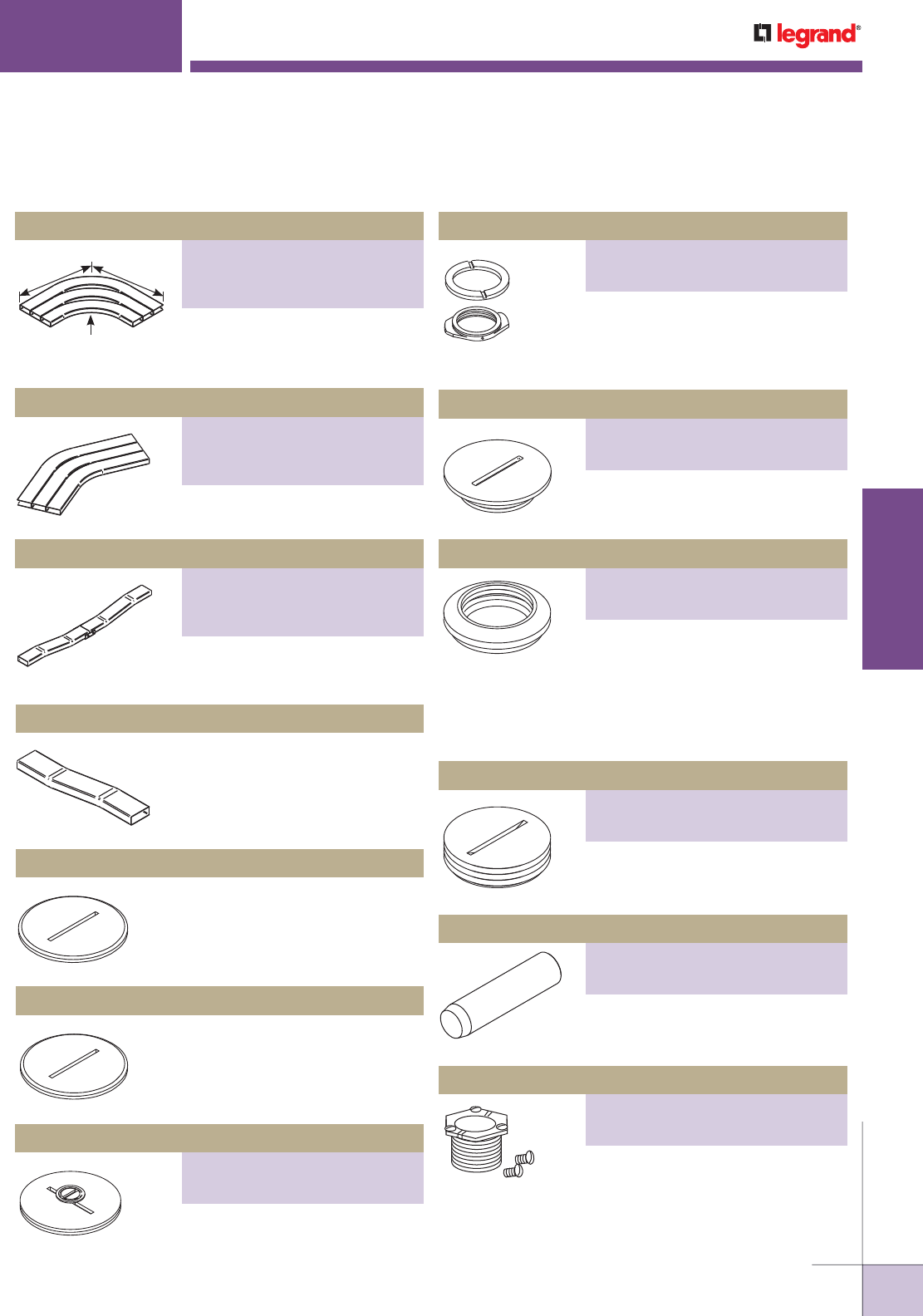
WWW.LEGRAND.US/WIREMOLD
597
INFLOOR DUCTS
WIREMOLD
8 1/4"
[222mm]
Radius
21 7/8"
[555mm]
21 7/8"
[555mm]
FLUSHDUCT INFLOOR DUCT SYSTEMS
For turning corner with duct.
For turning corner with duct.
To accommodate 1 3/8" [35mm]
change in system depth.
To accommodate 1 3/8" [35mm]
change in system depth.
372F Vertical Offset
1 1/4" [32mm] screw plug for
threaded openings in Flushduct.
Supports obsolete "F Series"
Flushduct system.
400F Screw Plug
1 5/8" [32mm] screw plug for
threaded openings in Flushduct.
Supports current "FST Series"
Flushduct system.
7107F Screw Plug
1 5/8" [41mm] screw plug for
threaded openings in Flushduct.
Used to designate service in
each duct.
For locking nipple or standpipe.
Requires 1 5/8" [41mm] hole.
Threads into 455F Threaded Outlet
Flange.
Used to create access into duct at a
custom location. Internal threads for
nipple or standpipe. To install, field cut
1 1/2" [38mm] for 1" [25mm] ferrule
(450F-1) or 1 7/8" [48mm] hole for
1 1/4" [32mm] ferrule (450F- 11/4).
Threads into brass ferrule to close
deactivated opening.
Used to install 450F Brass Ferrule.
Both are 5/8" [15.9mm] long.
Flushduct Accessories Ordering Information (continued)
Horizontal 90° Elbow
PART NUMBERS:
338UF (For Single Duct)
338UF-2 (For Double Duct)
338UF-3 (For Triple Duct)
Horizontal 45° Elbow
PART NUMBERS:
342F (For Single Duct)
342F-2 (For Double Duct)
342F-3 (For Triple Duct)
Vertical Offset
PART NUMBERS:
362F (For Single Duct)
362F-2 (For Double Duct)
362F-3 (For Triple Duct)
Threaded Outlet Flange
PART NUMBERS:
455F-3/4 (3/4")
455F-1 (1")
Die-Cast Plug
PART NUMBERS:
455FP-3/4 (3/4")
455FP-1 (1")
Brass Ferrule
PART NUMBERS:
450F-1 (1" [25mm] Internal Thread)
450F-11/4 (1 1/4" [32mm] Internal Thread)
Marker Screw Plug
PART NUMBERS:
7140F (Brass)
7141F (Zinc)
Brass Plug
PART NUMBERS:
450FP-1 (1")
450FP-11/4 (1 1/4")
Crimping Tool
PART NUMBERS:
470F-1 (1")
470F-11/4 (1 1/4")
Locking Nipple
PART NUMBERS:
1124F-3/4 (For 3/4" [19.1mm] IPS Opening)
1124F-1 (For 1" [25mm] IPS Opening)
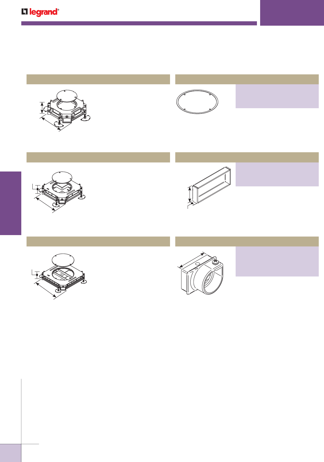
WWW.LEGRAND.US/WIREMOLD
598
INFLOOR DUCTS
WIREMOLD
FLUSHDUCT INFLOOR DUCT SYSTEMS
Used at duct intersections.
Provides access to system
for pulling and splicing of
wires. Constructed of cast
iron. Conduit openings at each
corner of box.
12FB Single Duct Junction Box
2 1/2"
[64mm]
9 9/16"
[243mm]
2 1/2"
[64mm]
12 1/2"
[318mm]
2 1/2"
[64mm]
16"
[406mm]
1 1/4"
[32mm]
1/2"
[12.7mm]
2 1/4"
[57mm]
Flanged stainless steel or brass
holders recessed to hold carpet
or tile. For “*”, specify “S” for steel
or “B” for brass. Specify 1/8 or
1/4 depth.
Used at duct intersections.
Provides access to system for
pulling and splicing of wires.
Constructed of cast iron.
Interiors of two- and three-
duct boxes have partitions
isolating each duct and
forming a continuous raceway
through the box. Conduit
openings at each corner of box.
222FB Double Duct Junction Box
Used at duct intersections.
Provides access to system for
pulling and splicing of wires.
Constructed of cast iron.
Interiors of two- and three-
duct boxes have partitions
isolating each duct and
forming a continuous raceway
through the box. Conduit
opening s at each corner
of box.
3222FB Triple Duct Junction Box
For closing off unused junction box
opening.
For one conduit.
Junction Boxes & Accessories Ordering Information
Carpet or Tile Holder
PART NUMBERS:
6LH*- (For 12FB Junction Box)
7LH*- (For 222FB Junction Box)
10LH*- (For 3222FB Junction Box)
Blank Washer
PART NUMBERS:
12F-WS (For Single Duct)
222F-WS (For Duble Duct)
3222F-WS (For Triple Duct)
Box Conduit Corner Adapter
PART NUMBERS:
255-3/4 (3/4" Conduit Trade Size)
255-11/4 (3/4" Conduit Trade Size)
255-11/2 (3/4" Conduit Trade Size)
255-2 (3/4" Conduit Trade Size)
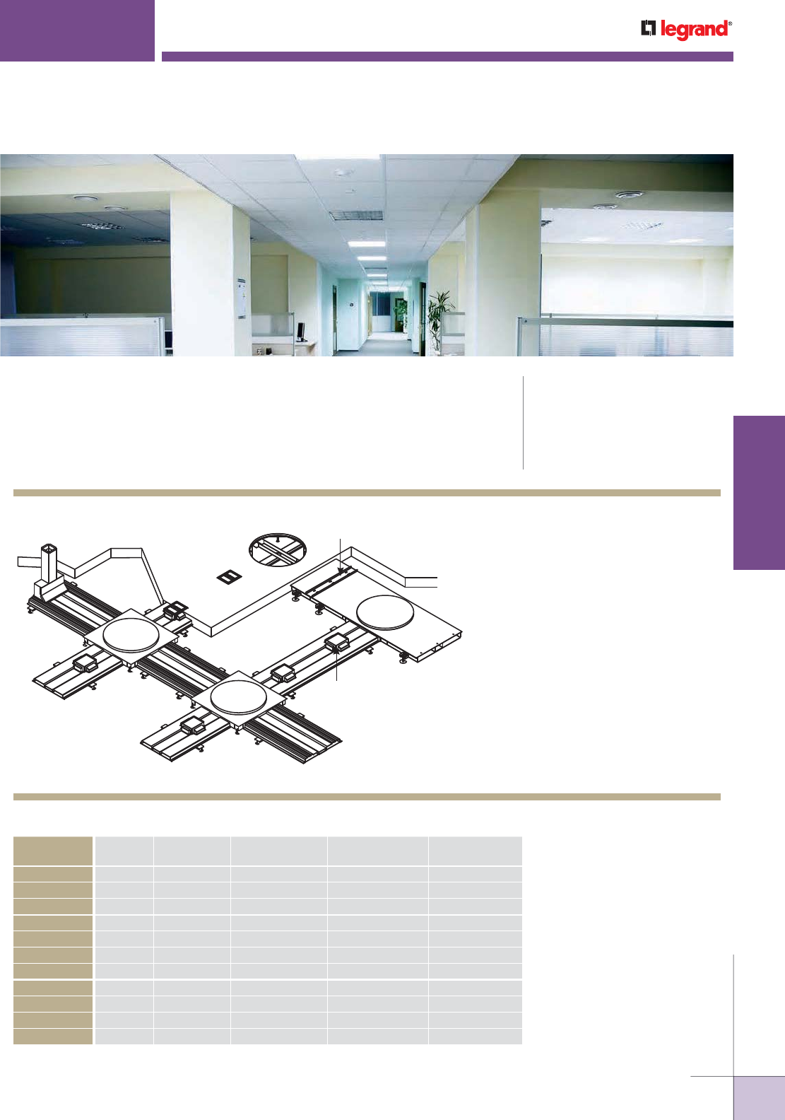
WWW.LEGRAND.US/WIREMOLD
599
INFLOOR DUCTS
WIREMOLD
KEY
A. CBR-LHT Vertical Boot Riser
B. WCR11/2-10/24 Cellular Raceway
C. FBTCAL FloorPort Activation Cover
D. JBHCC24 Junction Box Header
(WCR 11/2)
E. 2-11/2JB2510 Junction Box
F. RSCB-28 Support
G. WCR2-10/B Cellular Raceway
H. PK200 Preset
I. 11/2JBH242510-60 Junction Box
Header
Walkercell® Cellular Raceway Systems offer maximum capacity for distributing
power and communication services throughout any open space environment
while maintaining separation and security between services and provides point-
of-use services in a recessed activation.
CODE REFERENCE
cULus Listed Cellular Metal Floor
Raceway: File E26702 Guide RHZX
Meets Article 12-1800 to 12-1820 of
CEC
Meets Article 374 of NEC.
WALKERCELL
®
CELLULAR RACEWAY SYSTEMS
NOTE: Illustration is for showing product applications only.
A
C
D
H
G
E
F
B
I
Walkercell Cellular Raceway Selection Guide
WALKERCELL
SYSTEM
SYSTEM
DEPTH
PRESET
CATALOG NO.
DEPTH OVER
TOP OF SYSTEM
EXTENSION RING
HARDWARE BAG
EXTENSION
RING SIZE
WCR11/2 3 1/2" PK150 2" AERHB-148 22AER-11/2-21/4
WCR11/2 4" PK200 2 1/2" AERHB-048 22AER-23/8-31/8
WCR11/2 4 1/2" PK250 3" AERHB-048 22AER-23/8-31/8
WCR2 3 1/2" PK150 1 1/2" AERHB-116 22AER-11/2-21/4
WCR2 4" PK200 2" AERHB-14 8 22AER-11/2-21/4
WCR2 4 1/2" PK250 2 1/2" AERHB-048 22AER-23/8-31/8
WCR2 5" PK300 3" AERHB-048 22AER-23/8-31/8
WCR3 4 1/2" PK150 1 1/2" AERHB-116 22AER-11/2-21/4
WCR3 5" PK200 2" AERHB-14 8 22AER-11/2-21/4
WCR3 5 1/2" PK250 2 1/2" AERHB-048 22AER-23/8-31/8
WCR3 6" PK300 3" AERHB-048 22AER-23/8-31/8
Other sizes are available. Consult your local Wiremold representative.
Walkercell Cellular Raceway System Layout
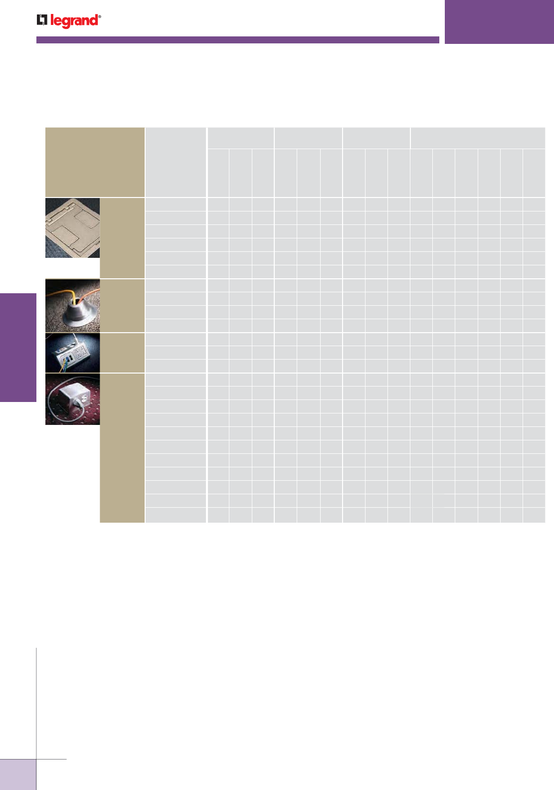
WWW.LEGRAND.US/WIREMOLD
600
INFLOOR DUCTS
WIREMOLD
WALKERCELL
®
CELLULAR RACEWAY SYSTEMS
PRODUCT FAMILY
CATALOG
NUMBER
ACTIVATION
LOCATION
SERVICE
CAPACITY
SERVICE
COMPATIBILITY
MATERIAL/COLORS
Flush
Recessed
Pedestal
Single Service
Dual Service
Triple Ser vice
Power
Communication
Audio/Visual
Alumi num
Brass
Gray
Black
Nickel
Bronze
FloorPort
FPCTC Series • ••••••••••
FPBTC Series • ••••••••••
FPFFTC Series• ••••••••••
FPCT Series • ••••••••••
FPBT Series • ••••••••••
FPFFT Series • ••••••••••
1200
Series
1204BF • • • •
1204AL • • • •
1223BF • • • •
1223AL • • • •
Multiplex
MP4 •• ••••
MP8 • • ••••
MP8-1 • • ••••
525
Series
525A •• •••
525B •• •••
525C •• •••
525D •• •••
525F • • • •
525G • • • •
525H • • • •
525I • • • •
525J •• ••••
525RT • • • •
525ACT •• • •
Walkercell Service Fitting Compatibility
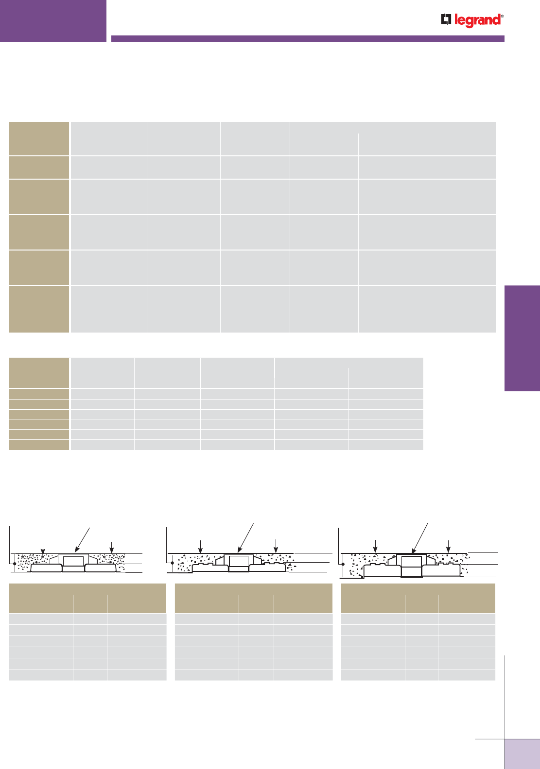
WWW.LEGRAND.US/WIREMOLD
601
INFLOOR DUCTS
WIREMOLD
Walkercell Cable Fill Capacities – Communications
40% FILL
CABLE/WIRE SIZE
DIAMETER Approx. AREA In2WCR11/2 WCR2 WCR3
Inches [mm] Sq. In. [Sq. mm] 8.2 in.2 [5264mm2] 11 in.2 [7097mm2]18.8 in.2 [12130mm
2]
UNSHIELDED
TWISTED PAIR
4-pair, 24 AWG, Cat 5 0.220 [5.6] 0.038 [24.5] 85 115 197
4-pair, 24 AWG, Cat 6 0.250 [6.4] 0.049 [31.7] 66 89 153
TELEPHONE 2-pair, 24 AWG 0.140 [3.6] 0.015 [9.9] 217 285 488
4-pair, 24 AWG 0.190 [4.8] 0.028 [18.1] 116 155 265
25-pair, 24 AWG 0.410 [10.4] 0.132 [85.2] 24 33 56
COAXIAL RG58/U 0.195 [4.9] 0.030 [19.4] 108 146 252
RG59/U 0.242 [6.1] 0.046 [29.7] 70 96 162
RG6/U 0.270 [6.8] 0.057 [36.8] 57 77 130
SHIELDED
TWISTED PAIR
TYPE 1 0.390 [9.9] 0.119 [76.8] 27 37 63
TYPE 2 0.465 [11.8] 0.170 [109.7] 19 26 44
TYPE 3 0.245 [6.2] 0.047 [30.3] 69 93 159
FIBER 2 Strand 0.180 [4.6] 0.025 [16.1] 130 173 296
4 Strand 0.190 [4.8] 0.028 [18.1] 116 155 264
6 Strand 0.210 [5.3] 0.035 [22.6] 93 127 216
Fiber ZipCord 0.110 [2.8] 0.010 [6.5] 326 463 791
WCR11/2
*1⁄8" min. [3.2mm]
2" [51mm]
1 1/2" [38mm]
Minimum System
Depth 3 1/2" [89mm] Preset PK150
Finished Floor
WCR2
1 1⁄2" [38mm]
2" [51mm]
*1⁄8" min. [3.2mm]
Minimum System
Depth 3 1/2" [89mm] Preset PK150
Finished Floor
WCR3
1 1⁄2"
[38mm]
3"
[76mm]
*1⁄8" min. [3.2mm]
Minimum System
Depth 4 1/2" [114mm] Preset PK150
Finished Floor
Walkercell Cellular Raceway Preset Selection Guide
OTHER SYSTEM DEPTHS FOR WCR11/2
SYSTEM
DEPTH
PRESET
CAT. NO.
FILL
OVER CELL
3 1/2" [89mm] PK150 2" [51mm]
4" [102mm] PK200 2 1/2" [64mm]
4 1/2" [114mm] PK250 3" [76mm]
5" [127mm] PK300 3 1/2" [89mm]
5 1/4" [133mm] PK325 3 3/4" [95mm]
5 1/2" [140mm] PK350 4" [102mm]
OTHER SYSTEM DEPTHS FOR WCR2
SYSTEM
DEPTH
PRESET
CAT. NO.
FILL
OVER CELL
3 1/2" [89mm] PK150 1 1/2" [38mm]
4" [102mm] PK200 2" [51mm]
4 1/2" [114mm] PK250 2 1/2" [64mm]
5" [127mm] PK300 3" [76mm]
5 1/4" [133mm] PK325 3 1/4" [83mm]
5 1/2" [140mm] PK350 4" [102mm]
OTHER SYSTEM DEPTHS FOR WCR3
SYSTEM
DEPTH
PRESET
CAT. NO.
FILL
OVER CELL
3 1/2" [89mm] PK150 1 1/2" [38mm]
4" [102mm] PK200 2" [51mm]
4 1/2" [114mm] PK250 2 1/2" [64mm]
5" [127mm] PK300 3" [76mm]
5 1/4" [133mm] PK325 3 1/4" [83mm]
5 1/2" [140mm] PK350 3 1/2" [89mm]
Recommend a minimum of 1/8" [3.2mm] concrete over preset.
* If concrete depth over preset is over 3/4" [19.1mm] it may be difficult to break-out concrete and excessive
spalling may occur. For system depth greater than above standard preset height use PK Extension Ring.
Walkercell Wire Fill Capacities – Power
DIAMETER
40% FILL
WIRE SIZE
AWG
AREA (In2)WCR11/2 WCR2 WCR3
Inches [mm] Sq. In. [Sq. mm] 4.22 in.2 [2722mm2]4.3 in.
2 [2774mm2]8.5 in.
2 [5484mm2]
14 0.111 [2.8] 0.010 [6.5] 168 172 351
12 0.130 [3.3] 0.013 [8.4] 126 129 256
10 0.164 [4.2] 0.021 [13.5] 80 82 161
8 0.216 [5.4] 0.037 [23.9] 45 47 93
6 0.254 [6.4] 0.051 [32.9] 33 34 67
4 0.324 [8.2] 0.082 [52.9] 20 21 41
NOTE: When using a Junction Box, calculate fill capacity according to the smallest compartment.
WALKERCELL
®
CELLULAR RACEWAY SYSTEMS
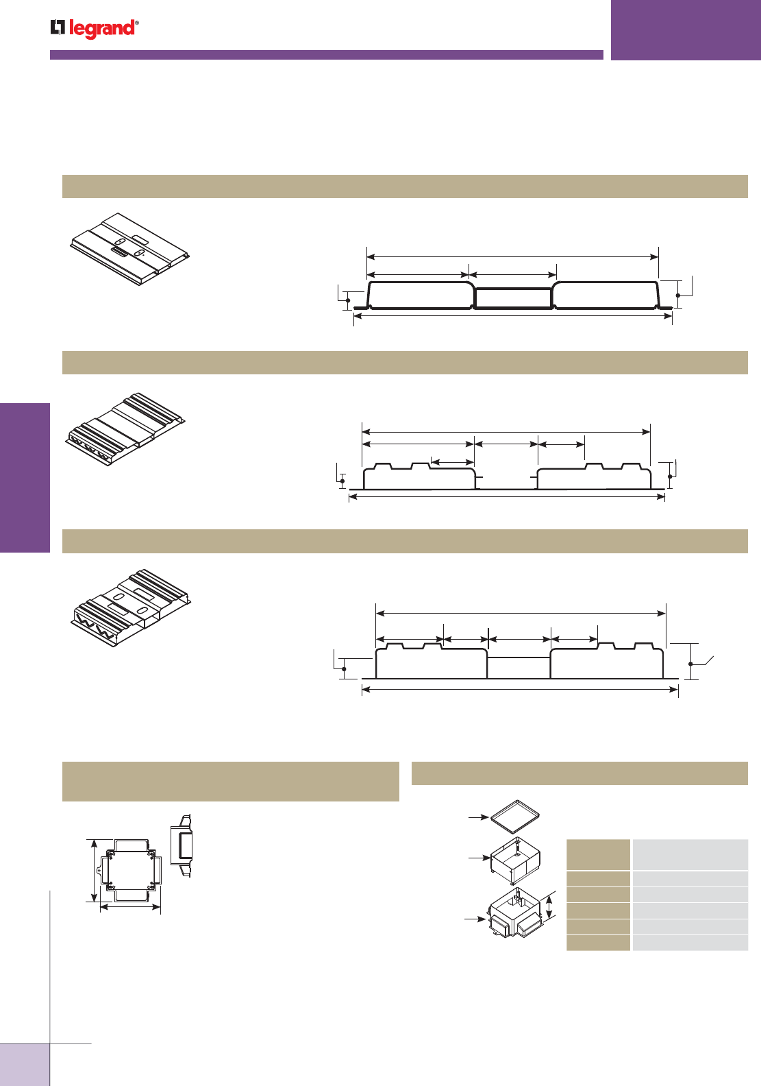
WWW.LEGRAND.US/WIREMOLD
602
INFLOOR DUCTS
WIREMOLD
Walkercell Raceway – Profile WCR11/2. 10' [3m] long without preset openings (WCR11/2-10/B)
or with prepunched preset openings 24" [610mm] on center (WCR11/2-10/24). First preset is 12"
[305mm] from end.
Walkercell Raceway – Profile WCR3. 10' [3m] long without preset openings (WCR3-10/B) or with
prepunched preset openings 24" [610mm] on center (WCR3-10/24). First preset is 12" [305mm]
from end.
Walkercell Raceway – Profile WCR2. 10' [3m] long without preset openings (WCR2-10/B) or with
prepunched preset openings 24" [610mm] on center (WCR2-10/24). First preset is 12" [305mm]
from end.
WCR11/2-10B, WCR11/2-10/24 Walkercell Raceway
WCR3-10B, WCR3-10/24 Walkercell Raceway
WCR2-10B, WCR2-10/24 Walkercell Raceway
WCR11/2-10/24 Walkercell
Raceway Top View
15 7⁄8" [403mm]
17 5/8" [448mm]
4 1⁄4" [108mm]
1 1⁄2"
[38mm]
1 1⁄8"
[29mm]
5 7/8" [149mm]
8.2 sq. in.
[5264 sq. mm] 4.22 sq. in.
[2722 sq. mm]
8.2 sq. in.
[5264 sq. mm]
WCR2-10/B Walkercell
Raceway Top View
20" [508mm]
21 3/4" [552mm]
4 1⁄4" [108mm]
3 1/4" [83mm] 1 15/16"
[49mm]
1 3/16"
[30mm]
7 7/8" [200mm]
11.0 sq. in.
[7097 sq. mm]
4.3 sq. in.
[2774 sq. mm]
11.0 sq. in.
[7097 sq. mm]
3 1⁄4"
[83mm]
20" [508mm]
22" [559mm]
4 1⁄4" [108mm]
3 1⁄4"
[83mm]
3 1⁄4"
[83mm]
2 15/16"
[75mm]
2 3/16"
[56mm]
7 7/8" [200mm]
18.8 sq. in.
[12130 sq. mm] 8.5 sq. in.
[5484 sq. mm]
18.8 sq. in.
[12130 sq. mm]
WCR3-10/24 Walkercell
Raceway Top View
NOTE: PK Presets ordered separately. Order one PK
Preset for each preset opening in the Walkercell.
Zinc die-cast construction with
a removable steel cap that is
recessed for concrete. Each preset
is capable of housing two duplex
power receptacles and up to eight
communication connectors. Each
preset has tapped openings for
mounting brackets, adjusting ring
and trim rings. The presets are
field installed using one 3/16"
[4.8mm] pop rivet (not provided).
Preset extensions can be used to
add height to presets as needed.
Attaches to preset to add height.
Can be field installed.
PK150, PK200, PK250, PK300, PK325
Triple Service Preset
Extensions
9 5/16"
[237mm]
9 5/8"
[244mm]
Mudcap
Extension Ring
PK Preset
A
EXTENSION
HEIGHT ABOVE PRESET
A
PKER-10 1" [25mm]
PKER-15 1 1/2" [38mm]
PKER-20 2" [51mm]
PKER-25 2 1/2" [64mm]
PKER-30 3" [76mm]
WALKERCELL
®
CELLULAR RACEWAY SYSTEMS
NOTE: Suffix indicates depth of concrete over WCR2 and WCR3.
For WCR11/2, concrete depth is 1/2" greater. (Example PK150 = 2"
of concrete)
Walkercell Cellular Raceway Ordering information
Walkercell Cellular Raceway Presets & Fittings Ordering information
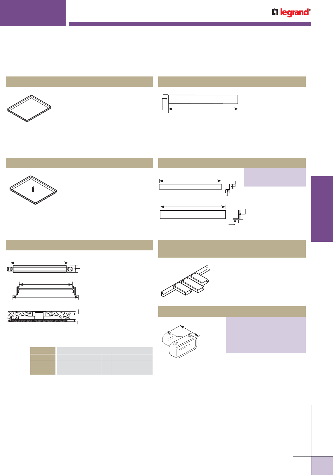
WWW.LEGRAND.US/WIREMOLD
603
INFLOOR DUCTS
WIREMOLD
Female Conduit Adapter
PART NUMBERS:
312-3/4 (3/4" Conduit Size)
312-1 (1" Conduit Size)
312-11/4 (1 1/4" Conduit Size)
312-11/2 (1 1/2" Conduit Size)
312-2 (2" Conduit Size)
Used to close off Walkercell PK
Preset.
Used to close off
ends of raceway. End
closures are held in
place during concrete
placement using blind
rivets or welds.
Provide ability to feed conduit
from ends of raceway. Use with
312 Fittings below.
Fits on outside of No. 2 duct. For
one rigid or PVC conduit. Suffix
indicates conduit size.
Replaces standard mudcap at
ends of runs and near feeder to
locate cellular runs after concrete
placement.
Holds raceway at proper
elevation during concrete
placement. Fasten
raceway to support using
four self-drilling screws
supplied. Supports are
used at raceway butt
joints and maximum 5'
[1.524m] spacing between
butt joint locations. See
selection guide below.
Suffix indicates distance
between Walkercell and
slab on grade.
PKCAP Mudcap
REC11/2-CA, REC2-CA, REC3-CA
End Closures for Duct Stubs
PMS-415N Marker Cap
Raceway Supports
2 7/16"
[62mm]
23 3/4" [603mm]
26 3/4" [679mm]
22 1/4" [565mm]
System Depth
1/2" Min. [12.7mm]
Depth Below Cell
CAT NO. DEPTH BELOW CELL
RSCB-18 1/2" [12.7mm] to 1 7/8" [48mm]
RSCB-33 1 1/2" [38mm] to 3 3/8" [86mm]
RSCB-48 3 1/2" [89mm] to 4 7/8" [124mm]
Installed at raceway
butt joints when
Walkercell is placed
on a mud slab or
concrete sidewalks
and RSCBs are not required. Used to maintain ground
continuity between Walkercell Raceways. Fasten raceway to
slab through 20 gauge grounding plate with power actuated
fastener (not provided). Field installed.
RGP Grounding Plate
24" Min. [610mm]
3"
[76mm]
1 1/2"
[38mm]
1"
[25mm]
16 1/2" [419mm]
REC11/2
2 29/32"
[74mm]
1 29/32"
[48mm]
20" [508mm]
REC
3 1/2"
[89mm]
WALKERCELL
®
CELLULAR RACEWAY SYSTEMS
Walkercell Cellular Raceway Presets & Fittings Ordering information (continued)
Blank End Closures
PART NUMBERS:
REC11/2 (For WCR11/2)
REC (For WCR2 and WCR3)
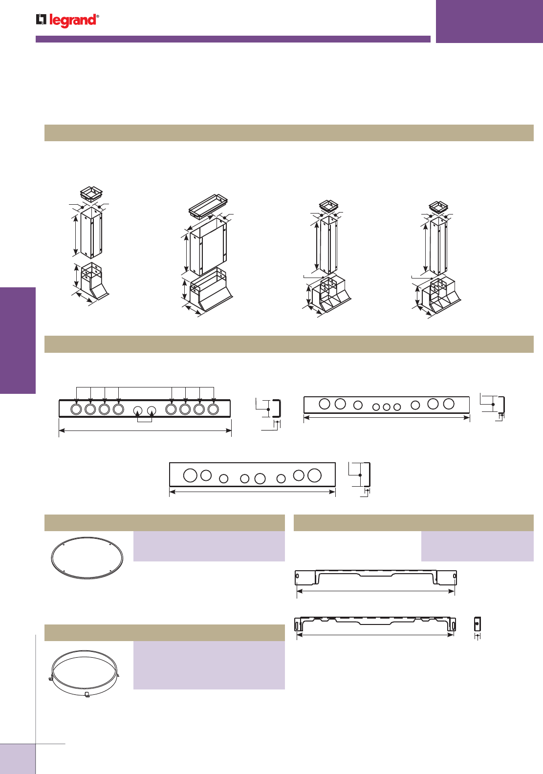
WWW.LEGRAND.US/WIREMOLD
604
INFLOOR DUCTS
WIREMOLD
Adjustable Extension Ring
PART NUMBERS:
22AER-11/2-21/4 (1 1/2"–2 1/4" Adjustable
Height Range of Concrete Over Duct)
22AER-23/8-31/8 (2 3/8"–3 1/8" Adjustable
Height Range of Concrete Over Duct)
Placed on top of junction box cover
plates to provide trim for flooring.
Recessed to hold carpet or tile.
Specify “B” for brass or “S” for steel.
For Walkercell junction boxes
and junction box header. Select
appropriate AERHB-Hardware Bag
(page 601) to attach ring to box.
Side adapter to attach Walkercell Raceway to the box.
Allows junction box side opening to be converted to another
size by replacing adapter. WCR3 cannot be used with 2 1/2"
[64mm] deep box.
Allow access into one, two, or three cells simultaneously. Field cut oblong opening in raceway and rivet or weld riser to
raceway. Void closures included (not shown).
Used to close off ends of raceway and provide conduit knockouts. End closures are held in place with blind rivets or welds.
CBR-HT, CBR-LT, CBR11/2-LHT, CBR-LHT Cell Boot Risers
REC11/2-C, REC2-C, REC3-C End Closures
CBR-HT (For Power Only)
4 1/8"
[105mm]
30"
[762mm]
6"
[152mm]
6"
[152mm]
3 1/2"
[89mm]
CBR-LT (Access to Two
Communication Compartments)
30"
[762mm]
12"
[305mm]
6"
[152mm]
6"
[152mm]
3 1/2"
[89mm]
CBR11/2-LHT (Access to
All Three Compartments
with Power Separated)
For WCR11/2
4 1/8"
[105mm]
30"
[762mm]
6"
[152mm]
6"
[152mm]
12"
[305mm]
3 1/2"
[89mm]
CBR-LHT (Access to
All Three Compartments
with Power Separated)
For WCR2/WCR3
4 1/8"
[105mm]
30"
[762mm]
6"
[152mm]
6"
[152mm]
12"
[305mm]
3 1/2"
[89mm]
16 1/2" [419mm]
1/2" [12.7mm] 1"
[25mm]
1 1/2"
[38mm]
1/2" [12.7mm] and 3/4" [19.1mm] concentric KOs
20" [508mm] 1 1/16"
[27mm]
1 15/16"
[49mm]
1"
[25mm]
1"
[25mm]
3/4"
[19.1mm]
1/2"
[12.7mm]
3/4"
[19.1mm]
1"
[25mm]
1"
[25mm]
20" [508mm] 1 1/16"
[27mm]
2 15/16"
[75mm]
1 1/4"
[32mm]
1"
[25mm]
3/4"
[19.1mm]
3/4"
[19.1mm]
1"
[25mm]
1 1/4"
[32mm]
3/4"
[19.1mm]
1"
[25mm]
22 5/8"
[575mm]
22 5/8"
[575mm] 7/8"
[22.2mm]
WALKERCELL
®
CELLULAR RACEWAY SYSTEMS
Walkercell Cellular Raceway Presets & Fittings Ordering information (continued)
Junction Box Adapters
PART NUMBERS:
1001757 (For WCR11/2)
929046 (For WCR2 and WCR3)
Carpet & Tile Holder
PART NUMBERS:
22LHS-1/8 (1/8" Deep)
22LHS-1/4 (1/4" Deep)
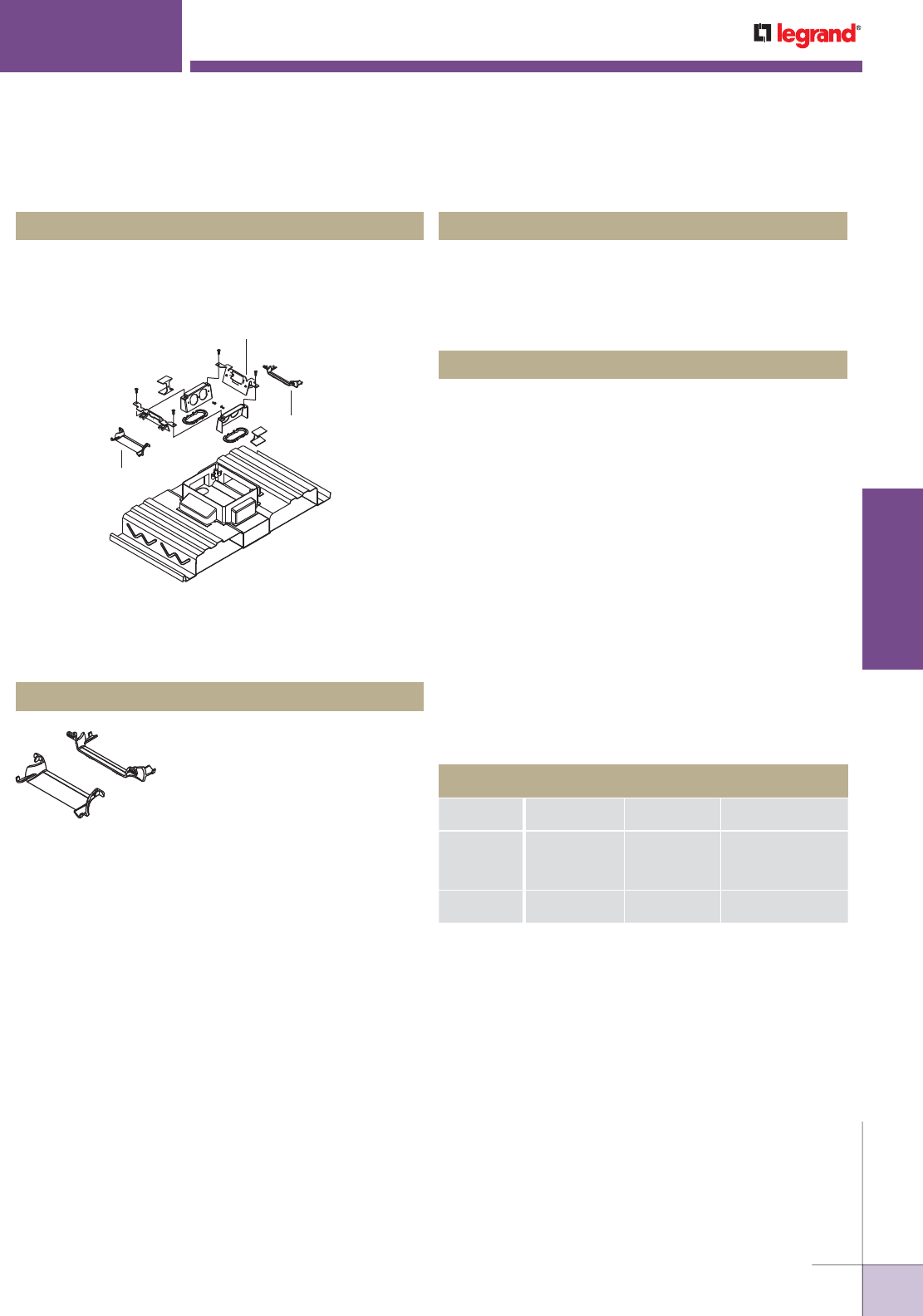
WWW.LEGRAND.US/WIREMOLD
605
INFLOOR DUCTS
WIREMOLD
WALKERCELL
®
CELLULAR RACEWAY SYSTEMS
FloorPort Activation Accessories for Use with Walkercell and Walkerdeck Systems
Two duplex receptacle brackets, receptacle insulators,
power grommets, and bend radius control grommets. For
use with recessed activations. Communication brackets
ordered separately. See next page.
WPACR-1G Internal Bracket
Two 15A, 120V duplex receptacles, two duplex receptacle
brackets, receptacle insulators, power grommets, and bend
radius control grommets. For use with recessed activations.
Communication brackets ordered separately. See next page.
WPACR-2G Internal Bracket
Two 20A, 120V duplex receptacles, two duplex receptacle
brackets, receptacle insulators, power grommets, and bend
radius control grommets. For use with recessed activations.
Communication brackets ordered separately. See next page.
WPACR-2G Internal Bracket
PKGRBR PK Preset Grommet
Bend Radius Control Grommets
Bend radius control grommet used
with PK preset. Maintains 1 1/4"
[32mm] minimum cable lay-in
radius.
NOTE: Not for use with communication brackets DTB-2-2AB or DTB-2-2RT.
FloorPort Bracket Compatibility
Fittings intended for a cellular raceway system must have a
minimum of 2 1/2" [64 mm] of concrete topping over the top
of the deck. A typical UL Fire Classified floor activation will
consist of the following components:
PK Series Preset Inserts
"()"Maximum Quantity of Units Allowed Inside of Preset Insert
Cover
Assembly
Activation
Assembly
Barrier
Assembly
Communication
Bracket
FPBTC
FPCTC
FPBT
FPCT
(1) WPACR — (2) DTB-2
FPFFTC
FPFFT (1) PKKIT (1) DTB-2FP
DTB-2-2A (Not Included)
Bend Radius Grommet
Bend Radius Grommet
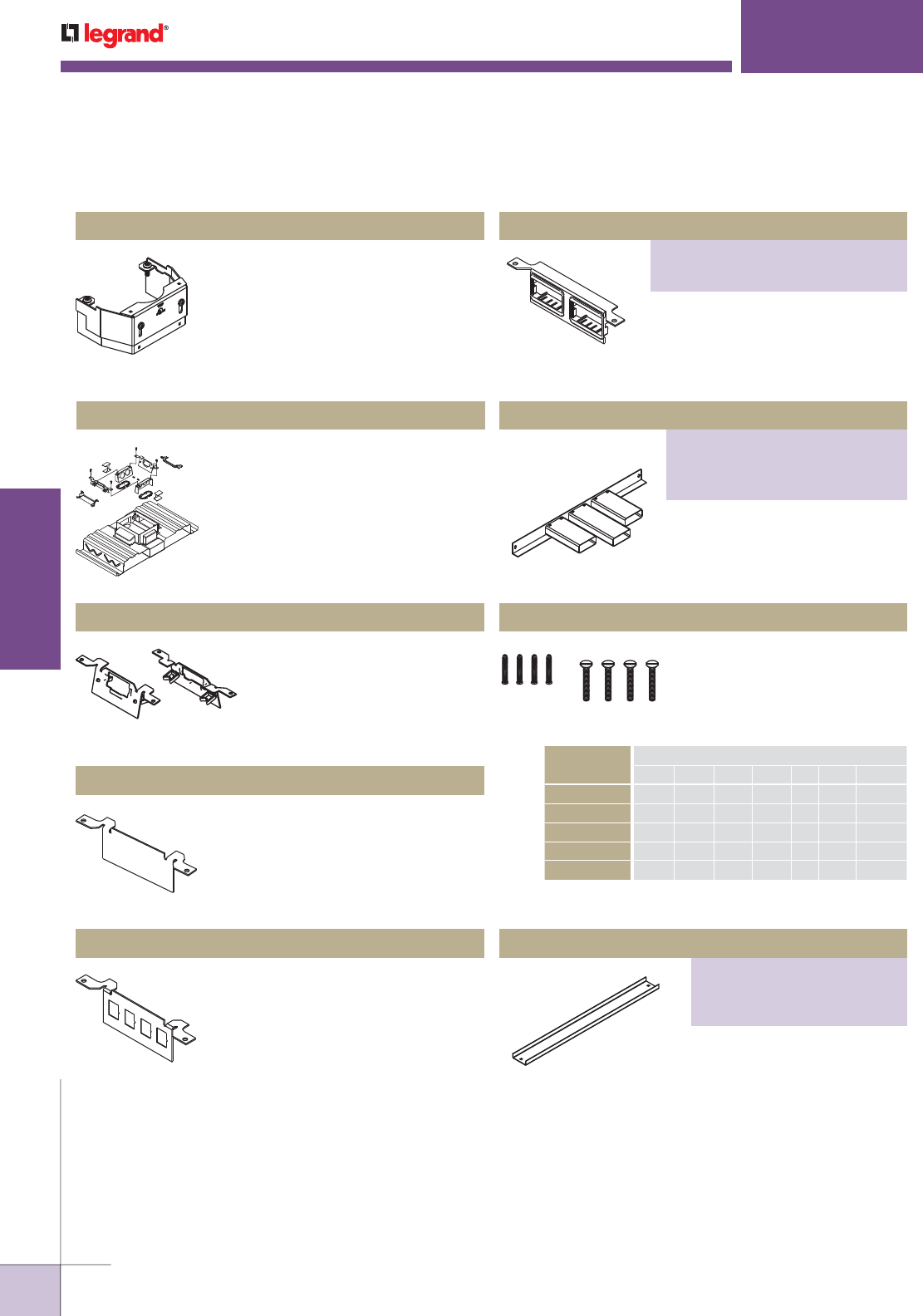
WWW.LEGRAND.US/WIREMOLD
606
INFLOOR DUCTS
WIREMOLD
Junction Box Closure
PART NUMBERS:
11/2JBC (For WCR11/2)
22JBC (For WCR2)
33JBC (For WCR3)
Provides ability to feed conduit from
junction box. Use with 312 Fittings.
Attaches to side of junction box
to close access.
For adjustable extension ring.
Suffix indicates depth of con-
crete over junction box cover.
Use chart below to determine
hardware bag required.
Junction Box Closure with Duct Stubs
Hardware Bag
HARDWARE
BAG CAT. NO.
Cover Depth Over Walkercell
1 1/2" 1 5/8" 1 3/4" 1 7/8" 2" 2 1/8" 2 3/8-3"
AERHB-116 X
AERHB-132 X X
AERHB-148 X X
AERHB-200 X
AERHB-048 X
WALKERCELL
®
CELLULAR RACEWAY SYSTEMS
FloorPort Activation Accessories for Use with Walkercell and Walkerdeck Systems
Used to separate power and
communication wires in partition feed
covers. Supplied with base and three
extensions to adjust to cover height.
Kit should be used on PK Presets
(Walkercell, Walkerdeck). Kits are
sold separately.
PKKIT Barrier Kit
Two duplex receptacle brackets,
receptacle insulators, power
grommets, and bend radius control
grommets. Communication brackets
ordered separately.
WPACR-1G Internal Bracket
Plastic clips on back of bracket
provide cable storage loop. For
use with WPACR. Activate 2A
jacks snap directly into bracket.
DTB-2-2A Communication Bracket
Blank bracket for customization in
field. For use with WPACR. Wiremold
Open System inserts sold separately.
DTB-2-B Communication Bracket
Four knockouts for RJ style jacks.
For use with WPACR. Wiremold Open
System inserts sold separately.
DTB-2-4TKO Communication Bracket
Ortronics® and Activate adapters
included.
Communication Bracket
PART NUMBERS:
DTB-2-2AB (For Activate Devices)
DTB-2-RT (For Ortronics® Devices)
PART NUMBERS:
11/2JBC-CA
22JBC-CA
33JBC-CA
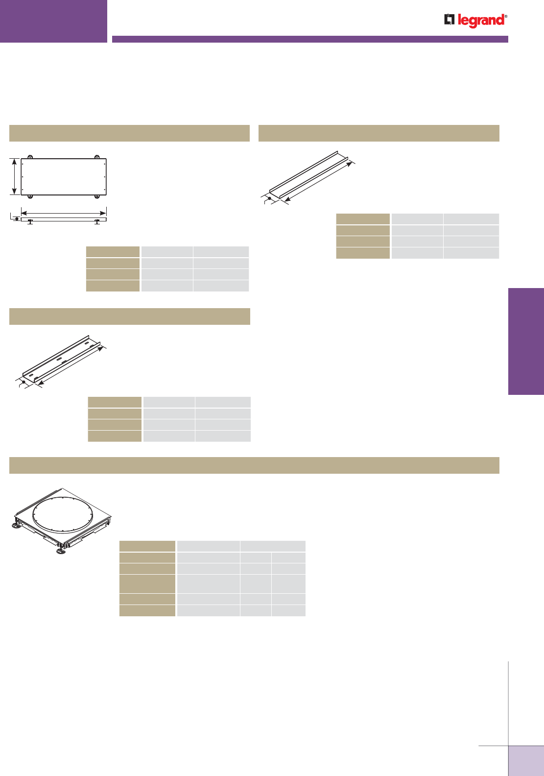
WWW.LEGRAND.US/WIREMOLD
607
INFLOOR DUCTS
WIREMOLD
Used as a feeder raceway for
Walkercell Systems. Standard
length is 60" [1524mm]. All
Headerduct is furnished with
1/4-20 threaded holes at each
end to fasten coupling channels.
Used to connect ends of
Headerduct Junction Boxes
together. Channels are furnished
with 1/4-20 screws.
Used to close end of Headerduct,
Header Junction Boxes, or
Junction Box Header. Secured
with blind rivet or weld
Walkercell Headerduct
Coupling Channels
Headerduct End Closure
60" [1524mm]
B
A
Walkercell Headerduct
CATALOG NO. A B
WCHD2425-60 24" [610mm] 2 1/2" [64mm]
WCHD3025-60 30" [762mm] 2 1/2" [64mm]
WCHD3625-60 36" [915mm] 2 1/2" [64mm]
A
B
A
B
Walkercell Cellular Raceway Headerduct Ordering Information
WALKERCELL
®
CELLULAR RACEWAY SYSTEMS
Headerduct Coupling Channel
CATALOG NO. A B
JBHCC24 24" [610mm] 2 1/2" [64mm]
JBHCC30 30" [762mm] 2 1/2" [64mm]
JBHCC36 36" [915mm] 2 1/2" [64mm]
Headerduct End Closure
CATALOG NO. A B
JBHEC2425 24" [610mm] 2 1/2" [64mm]
JBHEC3025 30" [762mm] 2 1/2" [64mm]
JBHEC3625 36" [915mm] 2 1/2" [64mm]
Used at intersections of Walkercell Raceway. Partitions inside box maintain separation of
services. 22" [559m] dia. cover provides access inside box. Access ring is 1" [25mm] over box.
Order extension ring for additional height. Cover plates have 1/2" [12.7mm] upward adjustment
for precise leveling after the pour. Side openings on junction boxes can be replaced to fit other
Walkercell profiles. Cell dimensions are 24" x 26" [610mm x 660mm].
Junction Boxes
NOTE: The minimum depth of Junction Box is 1/2"
[12.7mm] higher than WCR2 and WCR3, and is 1"
[25mm] higher than WCR11/2.
* WCR2 feeds WCR11/2 distribution and WCR3
feeds WCR2 distribution.
CATALOG NO. SIDE OPENINGS HEIGHT OF BOX
11/2JB2510 Four – WCR11/2 2 1/2" [64mm]
33JB3510 Four – WCR3 3 1/2" [89mm]
2-11/2JB2510* Two – WCR11/2,
Two – WCR2
2 1/2" [64mm]
32JB3510* Two – WCR2, 3 1/2" [76mm]
Two – WCR3
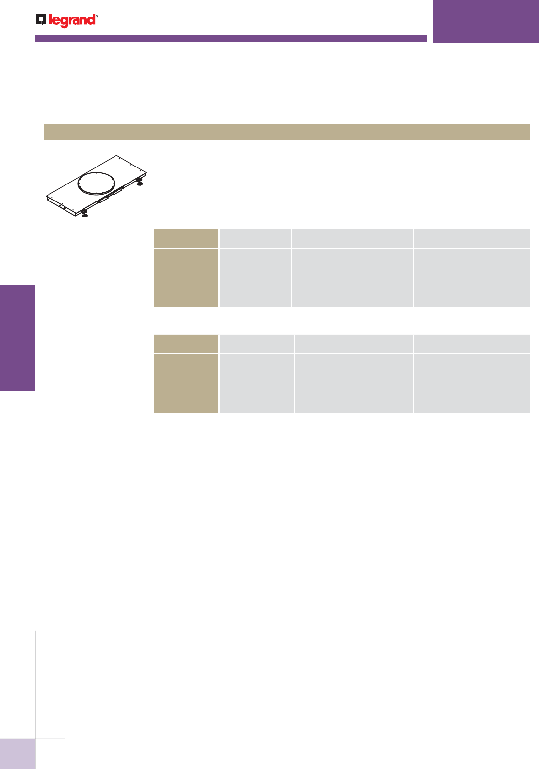
WWW.LEGRAND.US/WIREMOLD
608
INFLOOR DUCTS
WIREMOLD
Used as a large capacity feeder system for Walkercell. Cellular raceway attaches to side of
box. 22" [559mm] dia. cover plate access at center of unit. Standard length is 60" [1524mm].
The minimum depth of any JB, JHB, or HJB is 1/2" [12.7mm] higher than WCR2 and WCR3 and
1" higher than WCR11/2.
JBH Series Junction Box Header
NOTE: All capacities based on a minimum 80% allowance where cables may encounter a restriction point inside of
junction box. Consult factory for WCR3 capacities.
Junction Box Headers Used with WCR11/2
CATALOG
NUMBER
BODY
WIDTH
BODY
DEPTH
RING
HEIGHT
SYSTEM
DEPTH
POWER
CAPACITY
POWER
COMP. WIDTH
COMMUNICATION
CAPACITY
11/2JBH24251060 24"
[610mm]
2 1/2"
[64mm]
1"
[25mm]
3 1/2"
[89mm]
6.64
[4283.9mm2]
4 1/4"
[108mm]
18.60
[12000.0mm2]
11/2JBH30251560 30"
[762mm]
2 1/2"
[64mm]
1 1/2"
[38mm]
3 1/2"
[89mm]
8.64
[5574.2mm2]
5 1/8"
[130mm]
27.91
[18006.4mm2]
11/2JBH36251560 36"
[915mm]
2 1/2"
[64mm]
1 1/2"
[38mm]
4"
[102mm]
10.62
[6851.6mm2]
6"
[152mm]
31.25
[20161.3mm2]
Junction Box Headers Used with WCR2
CATALOG
NUMBER
BODY
WIDTH
BODY
DEPTH
RING
HEIGHT
SYSTEM
DEPTH
POWER
CAPACITY
POWER
COMP. WIDTH
COMMUNICATION
CAPACITY
2JBH242510-60 24"
[610mm]
2 1/2"
[64mm]
1"
[25mm]
3 1/2"
[89mm]
6.64
[4283.9mm2]
4 1/4"
[108mm]
18.60
[12000.0mm2]
2JBH302515-60 30"
[762mm]
2 1/2"
[64mm]
1 1/2"
[38mm]
4"
[102mm]
8.64
[5574.2mm2]
5 1/8"
[130mm]
26.49
[17090.3mm2]
2JBH362515-60 36"
[915mm]
2 1/2"
[64mm]
1 1/2"
[38mm]
4"
[102mm]
10.62
[6851.6mm2]
6"
[152mm]
28.53
[18406.4mm2]
WALKERCELL
®
CELLULAR RACEWAY SYSTEMS
Walkercell Cellular Raceway Headerduct Ordering Information (continued)
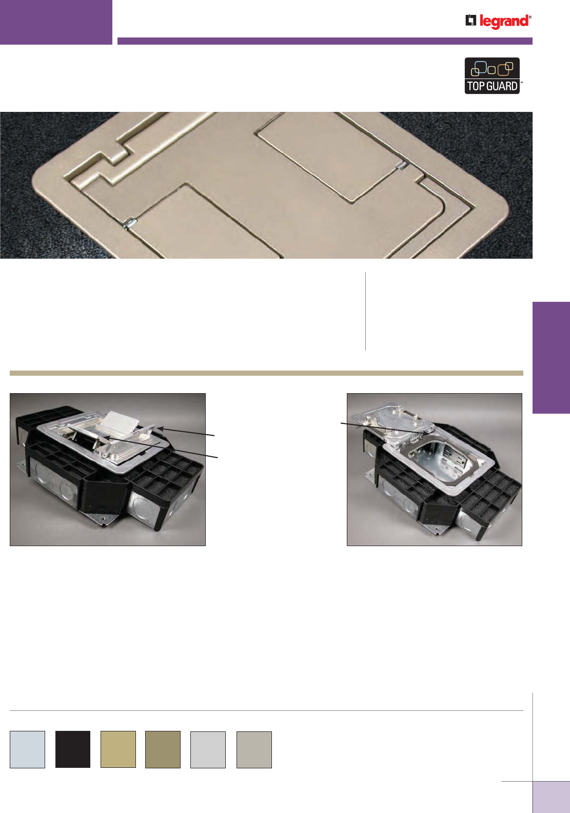
WWW.LEGRAND.US/WIREMOLD
609
INFLOOR DUCTS
WIREMOLD
New FloorPort™ Series
Cover Assemblies feature
a full 180° opening cover
with a new recessed handle
for easier opening and new
cable egress openings that
protect cabling while holding
them securely in place.
FLOORPORT™ SERIES
CODE REFERENCE
cULus Listed Metallic Outlet Boxes:
File E2961, Guide QCIT
cULus Listed Outlet Boxes &
Fittings Classified for Fire Resistance:
File R8209, Guide CEYY
Meets Article 341.40, 314.41 & 374 of NEC
FloorPort Service Fittings for Resource RFB® Series Floor Boxes,
Walkercell® Cellular Raceway, and Walkerdeck Systems provide flexibility
in recessed and furniture feed applications.
COLOR OPTIONS
FloorPort Series Service Fittings are available in aluminum, black,
brass, bronze, gray and nickel as indicated in the part number
description.
Wiremold products bearing the TopGuard
Protection logo meet or exceed the UL
scrub water exclusion requirement.
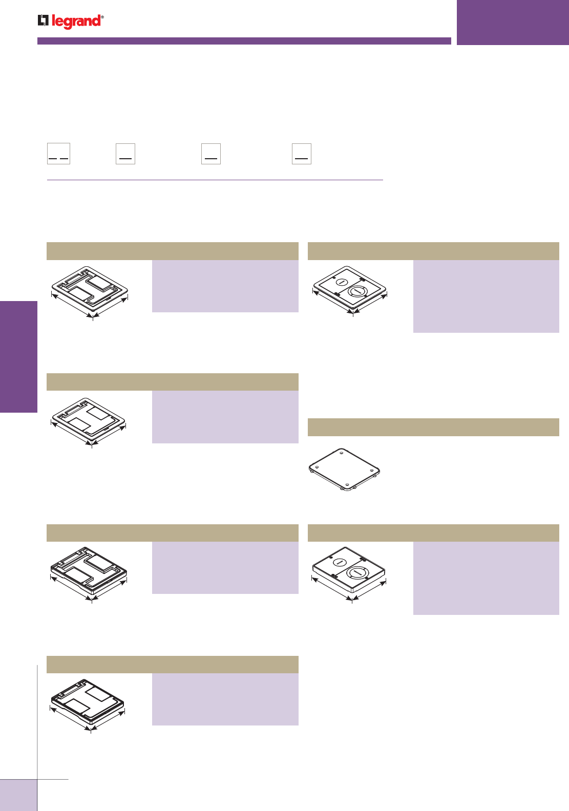
WWW.LEGRAND.US/WIREMOLD
610
INFLOOR DUCTS
WIREMOLD
FLOORPORT™ SERIES
Furniture Feed Cover Assembly
PART NUMBERS:
FPFFTBK (Black)
FPFFTBZ (Bronze)
FPFFTBS (Brass)
FPFFTNK (Nickel)
FPFFTGY (Gray)
FPFFTAL (Brushed Aluminum)
Cutout Cover Assembly
PART NUMBERS:
FPCTBK (Black), FPCTBZ (Bronze)
FPCTBS (Brass), FPCTNK (Nickel)
FPCTGY (Gray)
FPCTAL (Brushed Aluminum)
FloorPort™ Series Flangeless Cover Assemblies Ordering Information
7 3/4"
[197mm] 6 1/2"
[165mm]
Flanged cover for use in tile or carpet installation. Die-cast
aluminum assembly. Insert in lid allows for carpet or tile
cutouts to match finished.
6 3/4"
[197mm]
5 1/2"
[165mm]
Flangeless cover for use in tile or carpet installations.
Die-cast aluminum assembly. Insert in lid allows for carpet
or tile cutouts to match finished floor.
7 3/4"
[197mm]
6 1/2"
[165mm]
Flanged cover for use in tile or carpet installation. Die-cast
aluminum assembly. Lid area is flush with the finished floor,
no cutouts provided.
6 3/4"
[197mm]
5 1/2"
[165mm]
Flangeless cover for use in tile or carpet installation.
Die-cast aluminum assembly. Lid area is flush with the
finished floor, no cutouts provided.
7 3/4"
[197mm] 6 1/2"
[165mm]
Flanged cover for use in tile or carpet installation. Die-cast
aluminum assembly. Provided with one 1" trade size screw
plug for power or communication type cabling and one
combination 11/4" and 2" trade size screw plug for
communication type cabling. Allows for feeding both
power and communication cabling.
6 3/4"
[197mm] 5 1/2"
[165mm]
Flangeless cover for use in tile or carpet installation.
Die-cast aluminum assembly. Provided with one 1" trade
size screw plug for power or communication type cabling
and one combination 1 1/4" and 2" trade size screw plug for
communication type cabling. Allows for feeding both power
and communication cabling.
FloorPort™ Series Flanged Cover Plates Ordering Information
Floorport Part Number Configurator
Cover Style:
Blank Top = B
Cutout Top = C
Furniture Feed = FF
FloorPort Series: Cover Color:
Brushed Aluminum = AL
Black = BK
Brass = BS
Bronze = BZ
Gray = GY
Nickel = NK
Top Style:
Tile (flangeless) = T
Tile/Carpet = TC
(flanged)
FP
Cutout Cover Assembly
PART NUMBERS:
FPCTCBK (Black), FPCTCBZ (Bronze)
FPCTCBS (Brass), FPCTCNK (Nickel)
FPCTCGY (Gray)
FPCTCAL (Brushed Aluminum)
Furniture Feed Cover Assembly
PART NUMBERS:
FPFFTCBK (Black)
FPFFTCBZ (Bronze)
FPFFTCBS (Brass)
FPFFTCNK (Nickel)
FPFFTCGY (Gray)
FPFFTCAL (Brushed Aluminum)
Blank Cover Assembly
PART NUMBERS:
FPBTCBK (Black), FPBTCBZ (Bronze)
FPBTCBS (Brass), FPBTCNK (Nickel)
FPBTCGY (Gray)
FPBTCAL (Brushed Aluminum)
Blank Cover Assembly
PART NUMBERS:
FPBTBK (Black), FPBTBZ (Bronze)
FPBTBS (Brass), FPBTNK (Nickel)
FPBTGY (Gray)
FPBTAL (Brushed Aluminum)
Nonmetallic ring for use on bare polished
concrete and terrazzo floor applications.
NOTE: For RFB6 Series Floor Boxes.
FP-CTR Bare Concrete and Terrazzo Ring
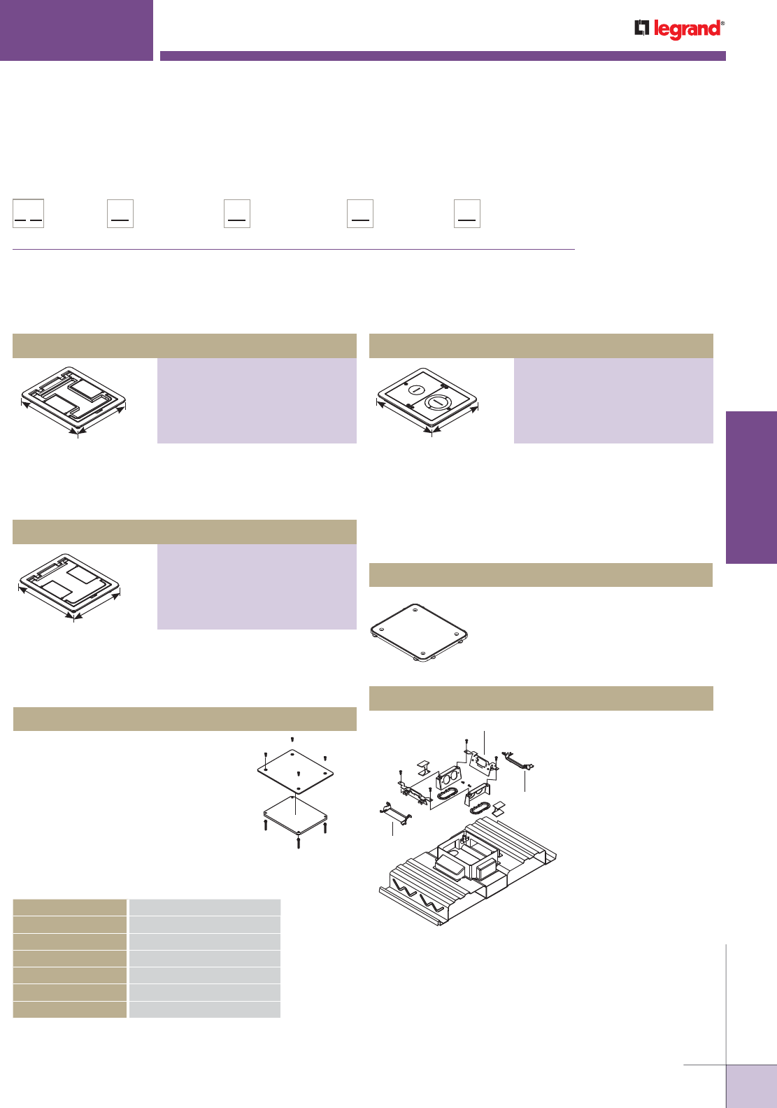
WWW.LEGRAND.US/WIREMOLD
611
INFLOOR DUCTS
WIREMOLD
DTB-2-2A (Not Included)
Bend Radius
Grommet
Bend Radius
Grommet
FLOORPORT™ SERIES
Two duplex receptacle
brackets, receptacle
insulators, power
grommets, and
bend radius control
grommets. For use with
recessed activations.
Communication brackets
ordered separately.
See next page 601.
WPACR-1G Internal Bracket
Aluminum top plate with steel support
plate and four (4) adjusting screws.
S3AXBP Blanking Plate
North American Made FloorPort™ Series Flanged Cover Plates Ordering Information
Floorport Part Number Configurator
Origin:
North American Made NA
Cover Style:
Blank Top = B
Cutout Top = C
Furniture Feed = FF
FloorPort Series: Cover Color:
Nickel = NK
Brass = BS
Black = BK
Bronze = BZ
Gray = GY
Top Style:
Tile (flangeless) = T
Tile/Carpet = TC
(flanged)
FP
Blank Cover Assembly
PART NUMBERS:
FPBTCBK-NA (Black)
FPBTCBZ-NA (Bronze)
FPBTCBS-NA (Brass)
FPBTCNK-NA (Nickel)
FPBTCGY-NA (Gray)
Cutout Cover Assembly
PART NUMBERS:
FPCTCBK-NA (Black)
FPCTCBZ-NA (Bronze)
FPCTCBS-NA (Brass)
FPCTCNK-NA (Nickel)
FPCTCGY-NA (Gray)
7 3/4"
[197mm]
6 1/2"
[165mm]
Flanged cover for use in tile or carpet installation. Die-cast
aluminum assembly. Insert in lid allows for carpet or tile
cutouts to match finished floor.
7 3/4"
[197mm]
6 1/2"
[165mm]
Flanged cover for use in tile or carpet installation. Die-cast
aluminum assembly. Lid area is flush with the finished floor,
no cutouts provided.
Load Capacities for FloorPort™ Cover Assemblies
CATALOG NUMBERS MAXIMUM LOAD IN POUNDS
FPCTC 1000
FPBTC 750
FPFFT 1000
FPBT 750
FPCT 1000
FPFF 1000
NOTE: Load applied through a 2" [51mm] mandrel in center
of service fitting. Loads above are static loads only
and do not pertain to rolling loads.
7 3/4"
[197mm] 6 1/2"
[165mm]
Flanged cover for use in tile or carpet installation. Die-
cast aluminum assembly. Provided with one 1" trade size
screw plug for power or communication type cabling and
one combination 1 1/4" and 2" trade size screw plug for
communication type cabling. Allows for feeding both power
and communication cabling.
Furniture Feed Cover Assembly
PART NUMBERS:
FPFFTCBK (Black)
FPFFTCBZ (Bronze)
FPFFTCBS (Brass)
FPFFTCNK (Nickel)
FPFFTCGY (Gray)
Nonmetallic ring for use on bare polished
concrete and terrazzo floor applications.
NOTE: For RFB6 Series Floor Boxes.
FP-CTR Bare Concrete and Terrazzo Ring
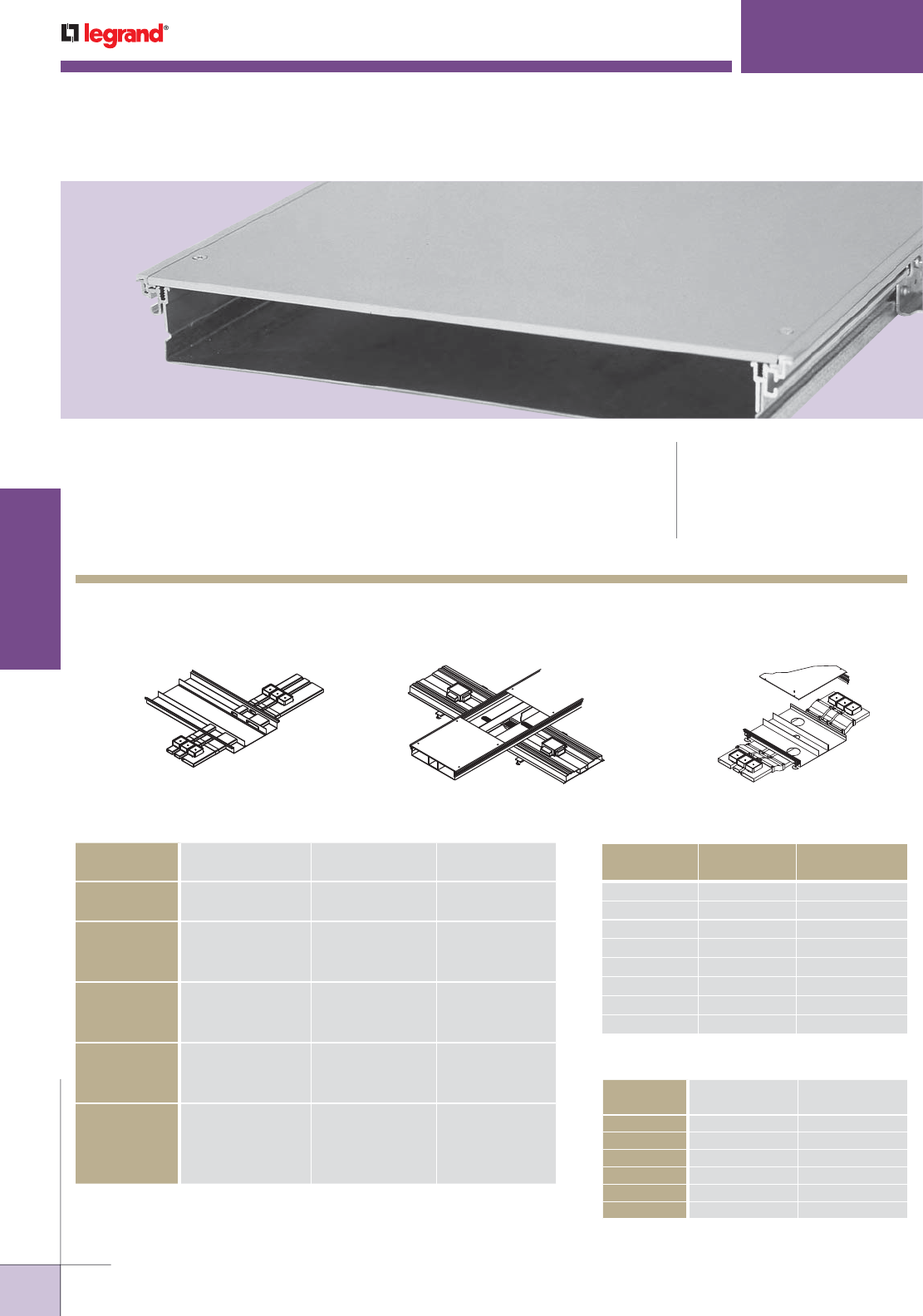
WWW.LEGRAND.US/WIREMOLD
612
INFLOOR DUCTS
WIREMOLD
TRENCHDUCT
Trenchduct is a large capacity feeder system used to distribute power and /or
communication services in an open space environment. CODE REFERENCE
cULus Listed Cellular Metal Floor
Raceway & Fittings:
File E26663 Guide RINV
Meets Article 374 of NEC.
Trenchduct Feeder System Layout
Trenchduct Side Feed into
Walkerduct® Pro Series
Trenchduct Crossunder Feed
into Walkercell
Trenchduct Crossunder Feed into
Walkerduct Pro Series
Cable Size/Fill Chart
CABLE/WIRE SIZE
DIAMETER Approx. AREA In2
Inches [mm] Sq. In. [Sq. mm]
UNSHIELDED
TWISTED PAIR
4-pair, 24 AWG, Cat 5 0.220 [5.6] 0.038 [24.5]
4-pair, 4 AWG, Cat 6 0.250 [6.4] 0.049 [31.7]
TELEPHONE 2-pair, 24 AWG 0.140 [3.6] 0.015 [9.9]
4-pair, 24 AWG 0.190 [4.8] 0.028 [18.1]
25-pair, 24 AWG 0.410 [10.4] 0.132 [85.2]
COAXIAL RG58/U 0.195 [4.9] 0.030 [19.4]
RG59/U 0.242 [6.1] 0.046 [29.7]
RG6/U 0.270 [6.8] 0.057 [36.8]
SHIELDED
TWISTED PAIR
TYPE 1 0.390 [9.9] 0.119 [76.8]
TYPE 2 0.465 [11.8] 0.170 [109.7]
TYPE 3 0.245 [6.2] 0.047 [30.3]
FIBER 2 Strand 0.180 [4.6] 0.025 [16.1]
4 Strand 0.190 [4.8] 0.028 [18.1]
6 Strand 0.210 [5.3] 0.035 [22.6]
Fiber ZipCord 0.110 [2.8] 0.010 [6.5]
Trench Capacity Chart
WIDTH DEPTH TOTAL CAPACITY
Inches [mm] Inches [mm] Sq. In. [Sq. mm]
6 [152] 2 1/2 [64] 11.1 [7161]
12 [305] 2 1/2 [64] 24.1 [15548]
18 [457] 2 1/2 [64] 37.2 [24000]
24 [610] 2 1/2 [64] 50.3 [32452]
6 [152] 3 1/4 [83] 14.9 [9613]
12 [305] 3 1/4 [83] 32.5 [20968]
18 [457] 3 1/4 [83] 50.1 [32323]
24 [610] 3 1/4 [83] 67.7 [43677]
Wire Size Chart
WIRE SIZE
AWG
DIAMETER AREA
Inches [mm] Sq. In. [Sq. mm]
14 AWG 0.111 [2.8] 0.010 [6.5]
12 AWG 0.130 [3.3] 0.013 [8.4]
10 AWG 0.164 [4.1] 0.021 [13.5]
8 AWG 0.216 [5.4] 0.037 [23.9]
6 AWG 0.254 [6.4] 0.051 [32.9]
4 AWG 0.324 [8.2] 0.082 [52.9]
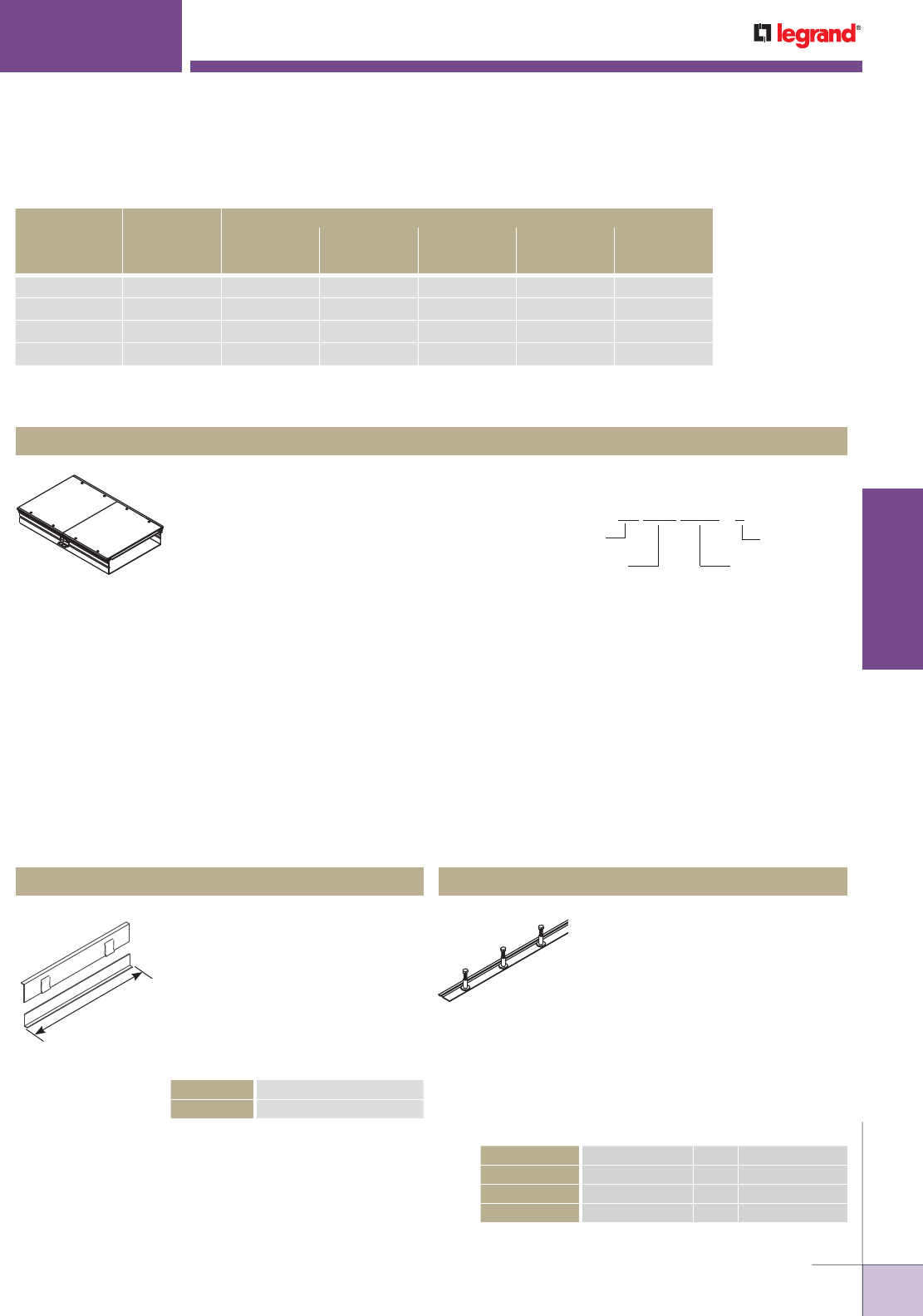
WWW.LEGRAND.US/WIREMOLD
613
INFLOOR DUCTS
WIREMOLD
Trenchduct Load Capacities (lbs)i
COVER PLATE
THICKNESS
LOAD
TYPE
TRENCHDUCT WIDTH
6" [152mm]
No
Supports
12" [305mm]
No
Supports
18" [457mm]
One Row
Supports
24" [610mm]
One Row
Supports
36" [914mm]
Two Row
Supports
1/4" [6.4mm] Concentrated 1300 1300 1300 800 1200
1/4" [6.4mm] Rolling 800 840 800 500 780
3/8" [9.5mm] Concentrated 2400 2400 2400 2000 2000
3/8" [9.5mm] Rolling 1500 1560 1500 1300 1300
VA12W250H-1, VA12W250H-2, VA12W250H-5,
VA12W250H-6, VA12W325H-1, VA12W325H-2,
VA12W325H-5, VA12W325H-6
Flush floor raceway with removable cover
plates. Cover plate is 1/4" [6.4mm] thick and
three pieces are supplied for 5' [1.5m] and
6' [1.8m] lengths (5' cover is two 24" and one
12" sections and 6' cover is three 24" sections). Partitions and supports
not included. Length, width, and depth described in catalog number
represent outside cover plate and body dimensions. The interior size of
the trenchduct bodies is always 13/16" [21mm] narrower than the cover
plate. The interior depth of the trenchduct bodies is always 5/16" [7.9mm]
shallower than depth specified by catalog number. Body is 16 gauge
steel. Vinyl trim and leveling feet are included. Can be leveled to screed
depth using leveling foot or support coupling up to 3/4" [19.1mm]. Use
catalog numbering system to select product. Consult Wiremold® sales
representative for custom sizes.
Body & Cover Assembly
Standard Selection Options:
Cover Plate Width = 6", 12", 18", or 24"
[152mm, 305mm, 457mm, or 610mm]
Depth =
250 or 325 (2 1/2" or 3 1/4"
[64mm or 83mm])
Length = 1', 2', 5' or 6'
[.3m, .6m, 1.5m, or 1.8m]
NOTE: For other widths, substitute cover plate width in
above catalog numbers with 12, 18, or 24.
NOTE: Covers are not intended to be used without floor
covering.
VA 12W 250H - 1
Trenchduct Length
(Feet)
Cover Plate
Width (Inch) Depth
(Inch)
Catalog Number System
Used to provide strength to support
cover plate. Required for clear spans
of 14" [456mm] or greater, or any
trench wider than 14" [456mm],
without partitions or when heavy
loads will be applied, such as in
casinos. Available in 6" or 12" [152mm or 305mm] on center
bolt spacing. 12" [305mm] O.C. spacing is adequate for
most applications. Select 6" [152mm] O.C. spacing for heavy
loads. Support bolts should be located 2" [51mm] from ends
of cover plates. Strip is field installed to base and adjusted
up to bottom of cover plate of Trenchduct with welds or
screws. Available in 5' [1.5m] lengths.
Support Strips
VA06SSS250-5 6" [152mm] O. C. 2 1/2" [64mm] Depth
VA06SSS325-5 6" [152mm] O. C. 3 1/4" [83mm] Depth
VA12SSS250-5 12" [305mm] O. C. 2 1/2" [64mm] Depth
VA12SSS325-5 12" [305mm] O. C. 3 1/4" [83mm] Depth
Used to separate Trenchduct
and fittings into two or more
compartments. Allows 3/4" [19.1mm]
upward adjustment. Field installed
to base and adjusted up to bottom of
cover plate of Trenchduct with welds
or screws. Available in 5' [1.5m]
length. Field modified for use in
T-Units, risers, and elbows.
Adjustable Partition
5'
[1.5m]
TRENCHDUCT FEEDER SYSTEMS
Trenchduct Body & Cover Assembly Ordering Information
Trenchduct Components & Fittings Ordering Information
T250HZP-5 2 1/2" [64mm] Depth
T325HZP-5 3 1/4" [83mm] Depth
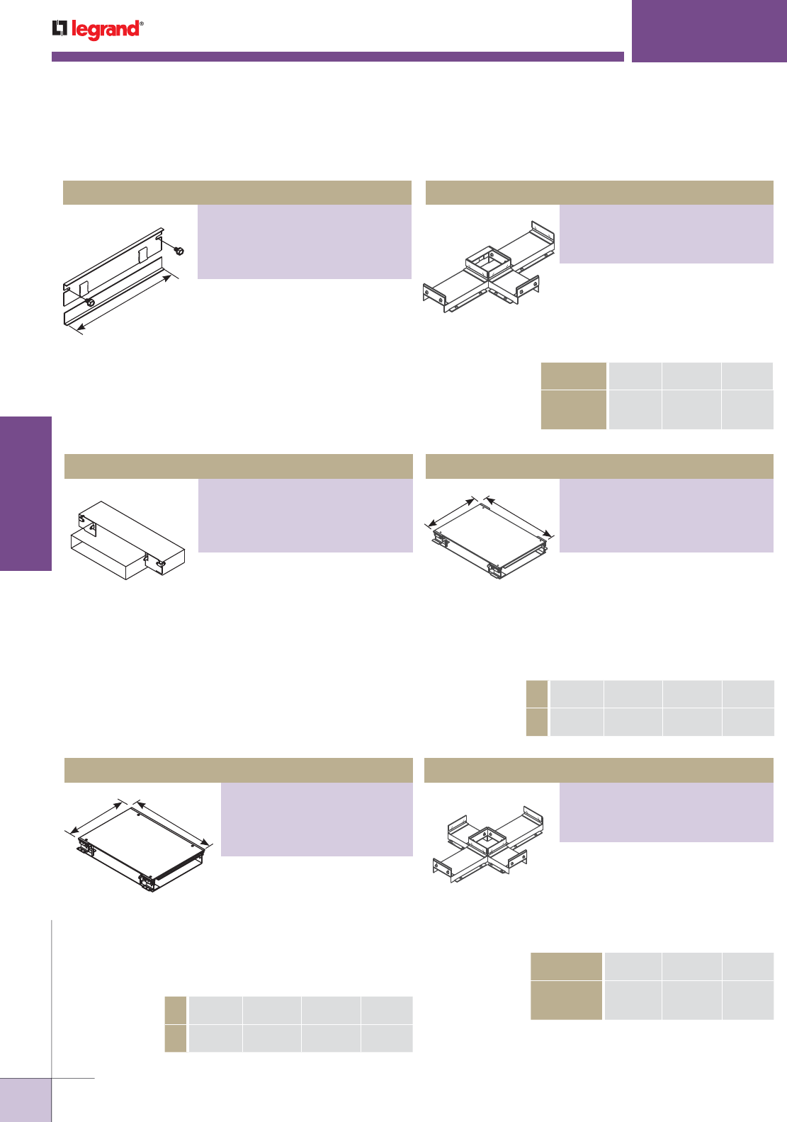
WWW.LEGRAND.US/WIREMOLD
614
INFLOOR DUCTS
WIREMOLD
Used to close off end of Trenchduct.
Two-piece design allows 3/4"
[19.1mm] vertical adjustment.
"A" dimension is 6" [152mm], 12"
[305mm], 18" [457mm] or 24"
[610mm].
End Closure
A
TRENCHDUCT FEEDER SYSTEMS
Used to reduce Trenchduct from one
piece to the next in a linear direction.
Order left or right side in widths of 3"
[76mm] or 6" [152mm].
Partial End Closure
Used to connect intersecting
runs of Trenchduct at 90°
angles on three sides. Length,
width, and depth specified by
catalog number. Closed side is
length. Use partition or tunnel
to separate services (ordered
separately for standard product).
T-Unit
B
A
A6"
[152mm]
12"
[305mm]
18"
[457mm]
24
[610mm]
B12"
[305mm]
18"
[457mm]
24"
[610mm]
30"
[762mm]
Used to separate three services
within T-Unit. Field attached with
screws or welds. See chart for width
of power compartment. Not available
for 6" [152mm] wide Trenchduct.
T-Unit Tunnel
TRENCH
WIDTH
12"
[305mm]
18"
[457mm]
24
[610mm]
POWER
CHANNEL
WIDTH
3 1/2"
[89mm]
4"
[102mm]
5"
[127mm]
Used to connect intersecting runs
of Trenchduct at 90° angles on on
all four sides. Length, width, and
depth specified by catalog number.
Use tunnel and partition as needed
to separate services (ordered
separately for standard product).
X-Unit
A6"
[152mm]
12"
[305mm]
18"
[457mm]
24
[610mm]
B 5"
[127mm]
7 1/2"
[191mm]
10"
[254mm]
12 1/2"
[318mm]
B
A
NOTE: Custom sizes are available. Consult the factory for more information.
Covers are not intended to be used without floor coverings.
Trenchduct Components & Fittings Ordering Information (continued)
Used to separate three services
within X-Unit. Field attached to
base of Trenchduct with screws or
welds. See chart for width of power
compartment. Not available for
6" [152mm] wide Trenchduct.
X-Unit Tunnel
TRENCH
WIDTH
12"
[305mm]
18"
[457mm]
24
[610mm]
POWER
CHANNEL
WIDTH
3 1/2"
[89mm]
4"
[102mm]
5"
[127mm]
PART NUMBERS:
VA06W250HEC, VA06W325HEC,
VA12W250HEC, VA12W325HEC,
VA18W250HEC, VA18W325HEC,
VA24W250HEC, VA24W325HEC
PART NUMBERS:
VAT12W250H3CT, VAT12W325H3CT,
VAT18W250H3CT, VAT18W325H3CT,
VAT24W250H3CT, VAT24W325H3CT
PART NUMBERS:
VA250PEC-LH3, VA250PEC-RH3,
VA325PEC-LH3, VA325PEC-RH3,
VA250PEC-LH6, VA250PEC-RH6,
VA325PEC-LH6, VA325PEC-RH6
PART NUMBERS:
VA06W250H-X, VA06W325H-X,
VA12W250H-X, VA12W325H-X,
VA18W250H-X, VA18W325H-X,
VA24W250H-X, VA24W325H-X
PART NUMBERS:
VA06W250H-T, VA06W325H-T,
VA12W250H-T, VA12W325H-T,
VA18W250H-T, VA18W325H-T,
VA24W250H-T, VA24W325H-T
PART NUMBERS:
VAT12W250H3CX, VAT12W325H3CX,
VAT18W250H3CX, VAT18W325H3CX,
VAT24W250H3CX, VAT24W325H3CX
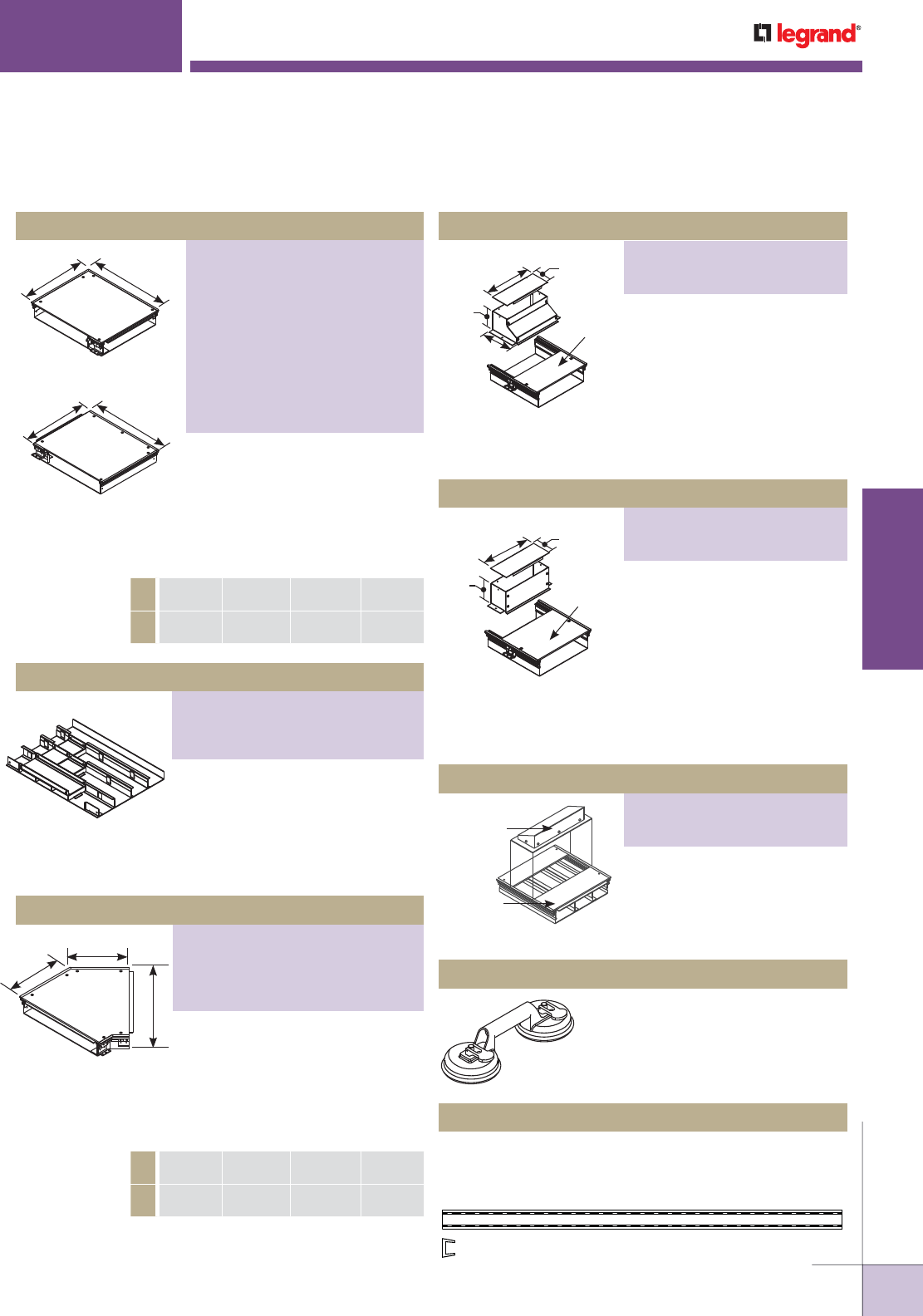
WWW.LEGRAND.US/WIREMOLD
615
INFLOOR DUCTS
WIREMOLD
Used to transition from
Trenchduct into perpendicular
run of Wallduct or into riser
to panel. Includes removable
cover plate.
* Important! 12" [305mm] Wide Rises to
10" [254mm] Wide to Attach to Wallduct.
Used to transition from
Trenchduct into perpendicular
run of Wallduct or into riser to
panel. Use partition to separate
services (ordered separately for
standard product).
* Important! 12" [305mm] Wide Rises to
10" [254mm] Wide to Attach to Wallduct.
Service fitting can be mounted
on Trenchduct in place of the
cover plate. Removable back
plate allows access into the
Trenchduct body.
Used to assist in removing cover
plates from Trenchduct.
Applied to edges of Trenchduct and fittings where cables
egress to protect against damage to cable insulation. 0.281"
wide by 0.188" deep. Packed 100' of grommet per unit.
Sweep Vertical Riser
Straight Vertical Riser
Access Hood
485 Cover Plate Lifter
686052-100FT Trenchduct Grommet
Used to change direction of
Trenchduct run 90° to the right
or left. Length, width, and depth
specified by catalog number. Use
partition to separate services
(ordered separately for standard
product).
Horizontal Elbow
AB
Right Hand Elbow
AB
Left Hand Elbow
A6"
[152mm]
12"
[305mm]
18"
[457mm]
24
[610mm]
B9"
[229mm]
15"
[381mm]
21"
[533mm]
27"
[686mm]
Used to divide services into 4 equal
compartments. Field attached with
screws or welds. Order one set
for T-Unit and two sets for X-Unit.
Not available for 6" [152mm] wide
Trenchduct. Fittings sold separately.
Four Compartment Fitting Tunnel
Used to change direction of
Trenchduct run 45° in either
direction. Length, width, and depth
determined by the catalog number.
Use partition to separate services
(ordered separately for standard
product).
45° Mitred Horizontal Elbow
A6"
[152mm]
12"
[305mm]
18"
[457mm]
24
[610mm]
B 5"
[127mm]
7 1/2"
[191mm]
10"
[254mm]
12 1/2"
[318mm]
A
B
B
Trenchduct
Width
Trenchduct
(not included)
4"
[102mm]
3 1/2"
[89mm]
6"
[152mm]
Trenchduct
Width
Trenchduct
(not included)
4"
[102mm]
3 1/2"
[89mm]
Access
Hood
Trenchduct
(not Included)
NOTE: Custom sizes are available. Consult the factory for more information.
Covers are not intended to be used without floor coverings.
TRENCHDUCT FEEDER SYSTEMS
Trenchduct Components & Fittings Ordering Information (continued)
NOTE: To continue separation/partition from Trenchduct, use partition
number WD350-P60.
NOTE: To continue separation/partition from Trenchduct, use partition part
numbers V130LBULK or V130RBULK.
PART NUMBERS:
Right Hand Elbow Catalog Nos.
VA06W250H-RL, VA06W325H-RL,
VA12W250H-RL, VA12W325H-RL,
VA18W250H-RL, VA18W325H-RL,
VA24W250H-RL, VA24W325H-RL
Left Hand Elbow Catalog Nos.
VA06W250H-LL, VA06W325H-LL,
VA12W250H-LL, VA12W325H-LL,
VA18W250H-LL, VA18W325H-LL,
VA24W250H-LL, VA24W325H-LL
PART NUMBERS:
VAT12W250H4CT, VAT12W325H4CT,
VAT18W250H4CT, VAT18W325H4CT,
VAT24W250H4CT, VAT24W325H4CT
PART NUMBERS:
VA06W250H-L45, VA06W325H-L45,
VA12W250H-L45, VA12W325H-L45,
VA18W250H-L45, VA18W325H-L45,
VA24W250H-L45, VA24W325H-L45
PART NUMBERS:
VA06W-VL, VA12W-VL10*,
VA18W-VL, VA24W-VL
PART NUMBERS:
VA06W-VR, VA12W-VR10*,
VA18W-VR, VA24W-VR
PART NUMBERS:
VA06W-AH3, VA12W-AH3,
VA18W-AH3, VA24W-AH3
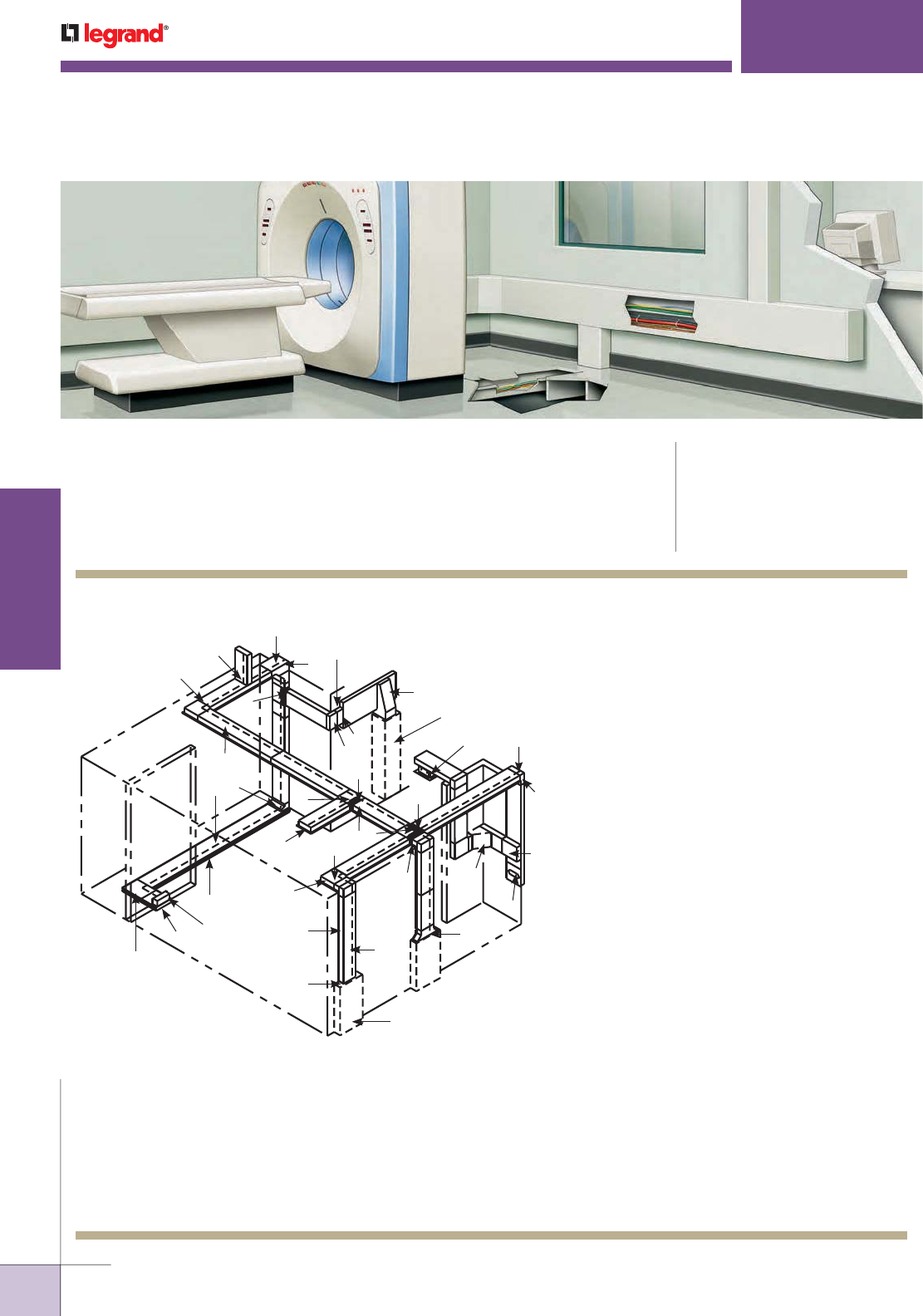
WWW.LEGRAND.US/WIREMOLD
616
INFLOOR DUCTS
WIREMOLD
WALLDUCT RACEWAY SYSTEMS
Wallduct Raceway Systems are high capacity raceway for use in or on walls that
is ideal for distributing power and communication cables in healthcare facilities,
under raised floors or as a large capacity feeder system.
CODE REFERENCE
cULus Listed Raceway:
File E4376 Guide RJBT
cULus Listed Fittings:
File E41751 Guide RJPR.
Meets Article 386 of NEC.
Wallduct Raceway System Layout
KEY
A.
WD10W350-60 5'-0" [1524mm] Straight Length
B.
CP10-F30 30" [762mm] L Flush Cover Plate
C.
WD10W350-IL Internal Wallduct Elbow
D.
CP10-ILF Internal Wallduct Elbow Cover Flush
E.
WD10W350-HL Horizontal Wallduct Elbow
F.
CP10-HLF Horizontal Wallduct Elbow Cover Flush
G.
WD10W350-T Wallduct T-Unit
H.
CP10-TF Wallduct T-Unit Cover Flush
I.
WD10W350-X Wallduct X-Unit
J.
CP10-XF Wallduct X-Unit Cover Flush
K.
WD10W350-ECF Wallduct End Closure
L.
VA12W250H-5 VA Style Trenchduct 12" Wide x 2 1/2"
Deep [304mm x 63mm]
M.
VA12W250H-EC VA Style Trenchduct End Closure
N.
VA12W250H-LL VA Style Trenchduct Horizontal Elbow
(Left Hand)
O.
VA12W-VR10 VA Style Trenchduct Vertical Riser
P.
WD10W350-CC/DO Wallduct Cabinet Connector
Q.
WD350-CP Corner Partition
R.
WD350-P60 Straight Partition
S.
WD10W350-TUN T-Unit Straight Tunnel
T.
WD10-ACPF Access Cover Plate with Grommet
U.
WD10W350-EL Wallduct External Elbow
V.
CP10W350-ELF Wallduct External Elbow Cover Flush
W.
WD10W350-FST Wallduct Flush to Surface Transition
X.
WD10W350-LTUN T-Unit Left Hand Tunnel
Y.
WD10W350-XTUN X-Unit Tunnel
Z.
T250HZP-5 Trenchduct Partition
AA.
VA12W-VL10 Trenchduct Vertical Riser
BB.
WD10W350-FCCF Flanged Cabinet Connector Flush
CC.
WD10W350-SWTS Sweep Surface Tee
DD.
WD-10CDO Ceiling Drop Out
EE.
WD350-R04 Wallduct Reducer
FF.
WD18W350-SWCCS Sweep Cabinet Connector Surface
GG.
WD10W350-SES Sweep Elbow Surface
NOTE: Illustration is for showing product applications only.
NOTE: Wallduct can be installed in the wall exposing only the cover plate,
or it can be wall mounted exposing the entire surface. Wallduct may
also be installed overhead or under a raised floor (but not infloor)
to connect cables/wires between rooms. Trenchduct can be used
in combination with Wallduct as a feeder or for access points in the
floor to feed equipment.
Pull Box (by others)
BB
A
P
F
L
M
N
O
E
K
G
Z
H
PU
V
X
Q
S
J
I
Y
C
D
W
T
B
R
GG
41
FF
EE DD
CC
AA
Cabinet (by others)
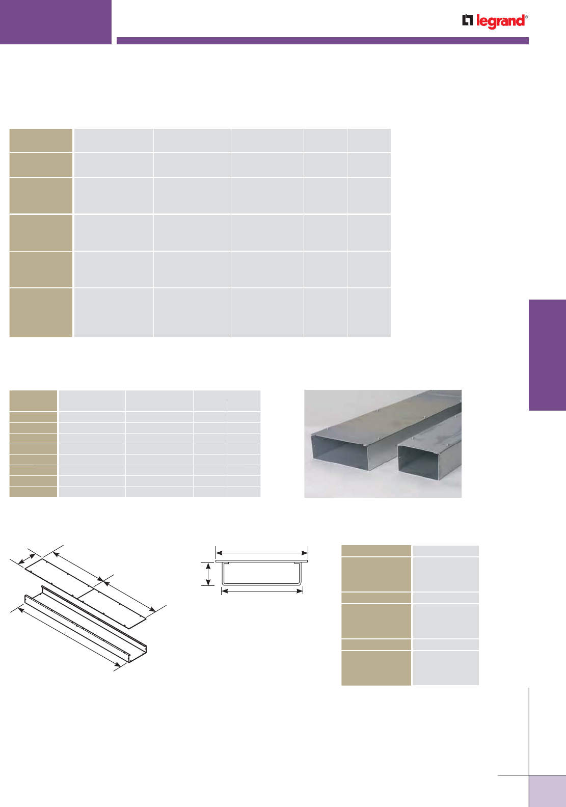
WWW.LEGRAND.US/WIREMOLD
617
INFLOOR DUCTS
WIREMOLD
WALLDUCT RACEWAY SYSTEMS
Steel Wallduct Wire Fill Capacities for Communications
CABLE/WIRE SIZE
DIAMETER AREA In240% FILL20% FILL
Inches [mm] Sq. In. [Sq. mm] (Per Sq. In.) (Per Sq. In.)
UNSHIELDED
TWISTED PAIR
4-Pair, Cat 5e 0.220 [5.6] 0.0381 [24.6] 10 5
4-Pair, Cat 6 0.250 [6.4] 0.0491 [31.7] 14 7
TELEPHONE 2-pair, 24 AWG 0.140 [3.5] 0.0154 [9.9] 20 13
4-pair, 24 AWG 0.190 [4.8] 0.0263 [18.2] 14 7
25-pair, 24 AWG 0.410 [10.4] 0.1321 [85.2] 3 1
COAXIAL RG58/U 0.195 [4.9] 0.0298 [19.2] 13 6
RG59/U 0.242 [6.1] 0.0459 [29.6] 9 4
RG6/U 0.270 [6.8] 0.0572 [36.9] 7 3
SHIELDED
TWISTED PAIR
TYPE 1 0.390 [9.9] 0.1194 [77.0] 3 1
TYPE 2 0.465 [11.8] 0.1698 [109.5] 2 1
TYPE 3 0.245 [6.2] 0.0471 [30.4] 0 4
FIBER 2-STRAND 0.180 [4.6] 0.0254 [16.4] 10 8
4-STRAND 0.190 [4.8] 0.0263 [15.3] 14 7
6-STRAND 0.210 [5.3] 0.0346 [22.3] 11 5
FIBER ZIP CORD 0.110 [2.8] 0.0095 [6.1] 42 21
Steel Wallduct Wire Fill Capacities for Power
WIRE SIZE
AWG
DIAMETER AREA (In2) 40% FILL
Inches [mm] Sq. In. [Sq. mm] No. 2 No. 4
14 0.111 [2.8] 0.0097 [6.3] 41.24 20.62
12 0.130 [3.3] 0.0133 [8.6] 30.08 15.04
10 0.164 [4.2] 0.0211 [13.6] 18.96 9.48
8 0.216 [5.5] 0.0366 [23.6] 10.93 5.46
6 0.254 [6.5] 0.0507 [32.7] 7.89 3.94
4 0.324 [8.2] 0.0824 [53.2] 4.85 2.43
3 0.352 [8.9] 0.0973 [62.8] 4.11 2.06
2 0.384 [9.8] 0.1158 [74.7] 3.45 1.73
BODIES
WD06W350-60 6" [152mm]
WD10W350-60 10" [254mm]
WD18W350-60 18" [457mm]
SURFACE COVERS “A”
CP06-S30 6" [152mm]
CP10-S30 10" [254mm]
CP18-S30 18" [457mm]
FLUSH COVERS “B”
CP06-F30 8" [203mm]
CP10-F30 12" [305mm]
CP18-F30 20" [508mm]
3 1⁄2"
[89mm]
B
A – End View
(Flush Cover Shown)
60"
[1524mm]
A30"
[762mm]
30"
[762mm]
NOTE: To order aluminum products, add the letter “A” to the beginning of the catalog number.
Custom sizes are available. Consult the factory for more information.
Wallduct Bodies & Covers Ordering Information
NOTE: Wire diameters can vary depending on manufacturer. Verify diameter and adjust fill capacities as required.
Values are per one square inch of Wallduct area.
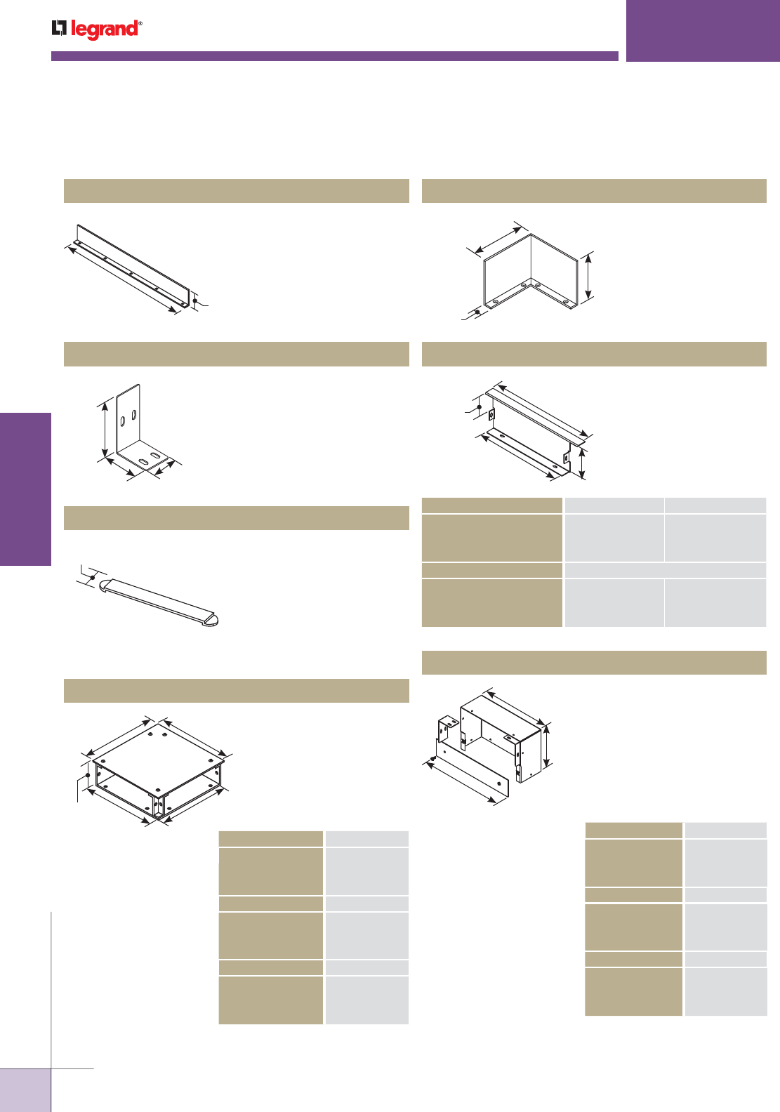
WWW.LEGRAND.US/WIREMOLD
618
INFLOOR DUCTS
WIREMOLD
WALLDUCT RACEWAY SYSTEMS
Used to separate services.
Includes assembly screws for
field installation.
Used to connect two pieces of
Wallduct. Includes assembly
screws. Two coupling angles
included with every straight
body assembly.
Used to hold wires in place
during installation and to close
gap between cover plates if
more than 1/8" [3.2mm]. Snap
in place prior to installing
cover plates. Two wire
retainers are included with
every straight body assembly.
WD350-P60 Straight Partition
WD350-CA Coupling Angle
WD06-WR, WD10-WR, WD18-WR Wire Retainer
60"
[1525mm] 3 1/4"
[83mm]
3 3⁄16"
[81mm]
2" [51mm] 1 1⁄2"
[38mm]
1 1⁄2"
[38mm]
Used in horizontal
elbow to form corner
partition. Assembly
screws included.
WD350-CP Corner partition
4"
[102mm]
9/16"
[14.3mm]
3 1/4"
[83mm]
Used to close off
end of Wallduct run.
Includes assembly
screws.
Surface & Flush End Closures
1"
[25mm]
A
B
3 1⁄2"
[89mm]
SURFACE END CLOSURES “A” “B”
WD06W350-ECS 6" [152mm] 6" [152mm]
WD10W350-ECS 10" [254mm] 10" [254mm]
WD18W350-ECS 18" [457mm] 18" [457mm]
FLUSH END CLOSURES “A” “B”
WD06W350-ECF 6" [152mm] 8" [203mm]
WD10W350-ECF 10" [254mm] 12" [305mm]
WD18W350-ECF 18" [457mm] 20" [508mm]
Used to change direction of
Wallduct runs 90° on same
plane. Includes one pair of
coupling angles, one retainer,
and assembly screws.
Complete unit requires one
body and one cover plate.
Horizontal Elbows
3 1⁄2"
[89mm] AA
B
B
BODIES "A"
WD06W350-HL 6" [152mm]
WD10W350-HL 10" [254mm]
WD18W350-HL 18" [457mm]
SURFACE COVERS “B”
CP06-HLS 7" [178mm]
CP10-HLS 11" [279mm]
CP18-HLS 19" [482mm]
FLUSH COVERS “B”
CP06-HLF 8" [203mm]
CP10-HLF 12" [305mm]
CP18-HLF 20" [508mm]
BODIES "A"
WD06W350-IL 6" [152mm]
WD10W350-IL 10" [254mm]
WD18W350-IL 18" [457mm]
SURFACE COVERS “B”
CP06-ILS 6" [152mm]
CP10-ILS 10" [254mm]
CP18-ILS 18" [457mm]
FLUSH COVERS “B”
CP06-ILF 8" [203mm]
CP10-ILF 12" [305mm]
CP18-ILF 20" [508mm]
Used to connect vertical
and horizontal run at 90°
when cover plates are on
inside of run. Includes one
pair of coupling angles,
wire retainer, and assembly
screws. Complete unit
requires one elbow body and
one cover plate.
Internal Elbow
B
A
6"
[152mm]
NOTE: To order aluminum products, add the letter “A” to the beginning of the
catalog number. Custom sizes are available. Consult the factory for
more information.
Wallduct Fittings Ordering Information
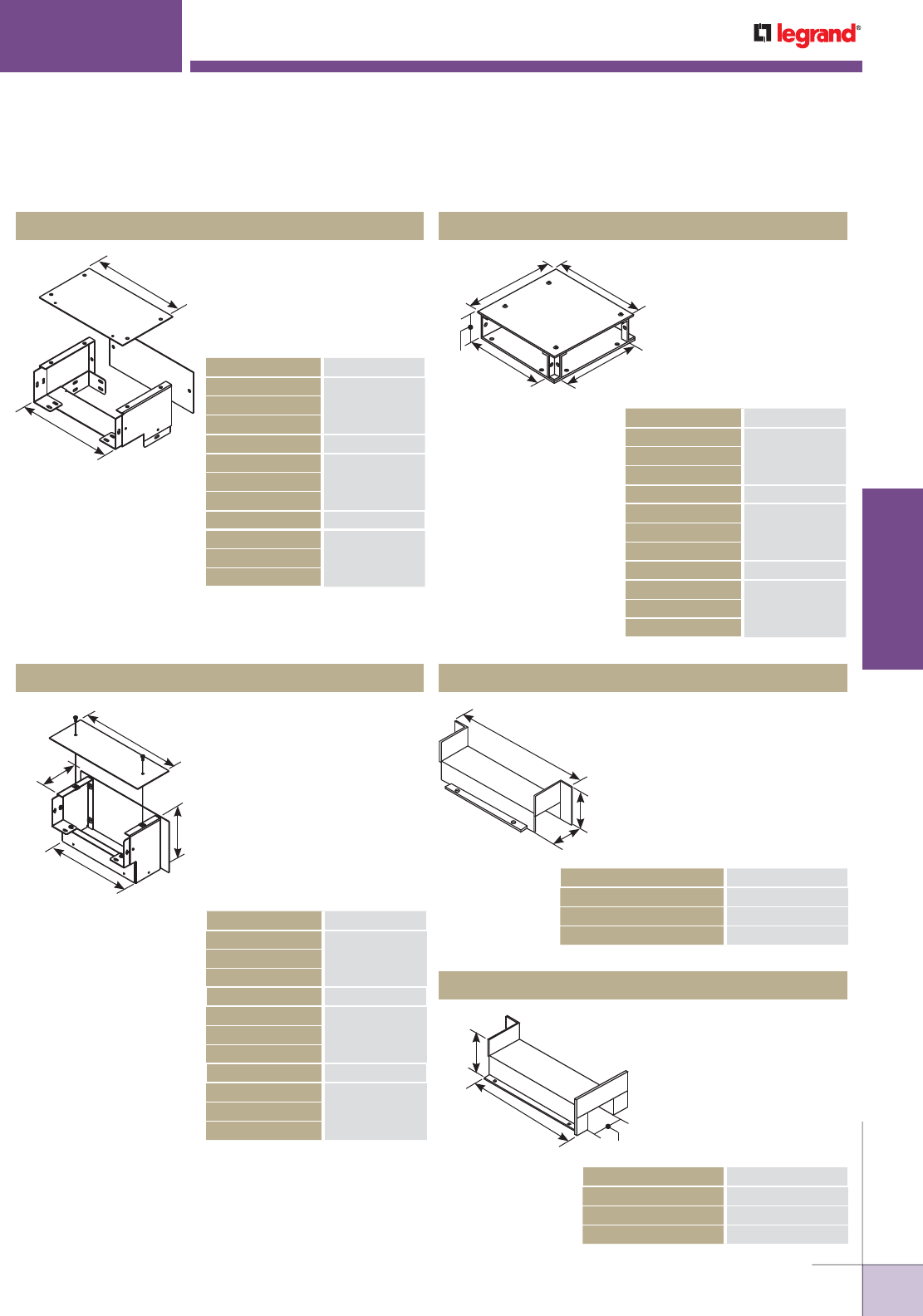
WWW.LEGRAND.US/WIREMOLD
619
INFLOOR DUCTS
WIREMOLD
WALLDUCT RACEWAY SYSTEMS
Internal elbow used to
change direction 90° while
also allowing for a change
in coverplate orientation.
Shipped as complete unit.
Used to connect vertical
and horizontal run at 90°
when cover plates are on
outside of run. Includes
attached coupling angles,
wire retainer, and assembly
screws. Complete unit
requires one elbow body
and two cover plates. Flush
and Surface Cover catalog
numbers include two covers.
Internal External Elbow
External Elbow
BODIES "A"
WD06W350-EL 6" [152mm]
WD10W350-EL 10" [254mm]
WD18W350-EL 18" [457mm]
SURFACE COVERS “B”
CP06W350-ELS 6" [152mm]
CP10W350-ELS 10" [254mm]
CP18W350-ELS 18" [457mm]
FLUSH COVERS “B”
CP06W350-ELF 8" [203mm]
CP10W350-ELF 12" [305mm]
CP18W350-ELF 20" [508mm]
A
B
BODIES "A"
WD06W350-IEL 6" [152mm]
WD10W350-IEL 10" [254mm]
WD18W350-IEL 18" [457mm]
SURFACE COVERS “B”
CP06W350-IELS 6" [152mm]
CP10W350-IELS 10" [254mm]
CP18W350-IELS 18" [457mm]
FLUSH COVERS “B”
CP06W350-IELF 8" [203mm]
CP10W350-IELF 12" [305mm]
CP18W350-IELF 20" [508mm]
A
B
6"
[152mm]
4 1/4"
[108mm]
Used to connect a second
run of Wallduct at 90° angle
to first run. Includes one
pair of coupling angles, one
wire retainer, and assembly
screws. Complete unit
requires one body and one
cover plate.
T-Unit
BODIES “A”
WD06W350-T 6" [152mm]
WD10W350-T 10" [254mm]
WD18W350-T 18" [457mm]
SURFACE COVERS “B”
CP06-TS 7" [178mm]
CP10-TS 11" [279mm]
CP18-TS 19" [482mm]
FLUSH COVERS “B”
CP06-TF 8" [203mm]
CP10-TF 12" [305mm]
CP18-TF 20" [508mm]
B
AA
3 1/2"
[89mm]
Provides 3" [76mm] straight
through compartment for
one service with crossover
for a second service.
Assembly screws included.
T-Unit Straight Tunnel
3 1⁄4"
[83mm]
3"
[76mm]
A
TUNIT STRAIGHT TUNNEL “A”
WD06W350-TUN 7 7/8" [200mm]
WD10W350-TUN 11 7/8" [301mm]
WD18W350-TUN 19 7/8" [457mm]
Used in conjunction with
straight partition to form
90° angle – 3" [76mm]
compartment with crossover
in T-Unit. Assembly screws
included.
Right Hand Tunnel
RIGHT HAND TUNNEL “A”
WD06W350-RTUN 4 7/8" [123mm]
WD10W350-RTUN 7 7/8" [200mm]
WD18W350-RTUN 15 7/8" [403mm]
3 1⁄4"
[83mm]
3"
[76mm]
A
NOTE: To order aluminum products, add the letter “A” to the beginning of the
catalog number. Custom sizes are available. Consult the factory for
more information.
Wallduct Fittings Ordering Information (continued)
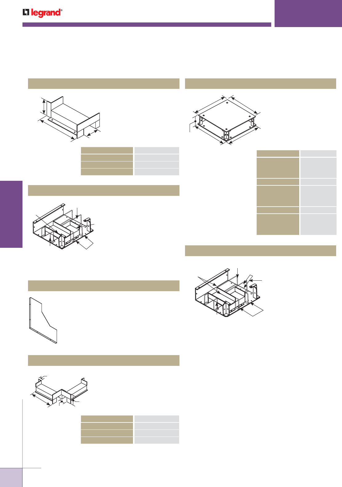
WWW.LEGRAND.US/WIREMOLD
620
INFLOOR DUCTS
WIREMOLD
Used in conjunction with
straight partition to form
90° angle – 3" [76mm]
compartment with crossover
in T-Unit. Assembly
screws included.
Provides three equal
compartments for
separation of services in
T-Unit. Assembly screws
included. Purchase
Partition Catalog No.
WD350-P60 to complete
installation. Not available
for 6" [162mm] wide
Wallduct. Not available for
6" [152mm] wide Wallduct.
Left Hand Tunnel
WD10W350-3TUN, WD18W350-3TUN T-Unit Tunnel
WALLDUCT RACEWAY SYSTEMS
LEFT HAND TUNNEL “A”
WD06W350-LTUN 4 7/8" [123mm]
WD10W350-LTUN 7 7/8" [200mm]
WD18W350-LTUN 15 7/8" [403mm]
3 1⁄4"
[83mm]
3"
[76mm]
A
Partitions
Partitions
Bridge
Tunnel
Partitions
Used in conjunction with
WDX-350SES to provide
partition within the elbow.
WD350-PSE Internal Sweep Elbow Partition
X-Unit
WD10W350-3TUN, WD18W350-3TUN X-Unit Tunnel
BODIES “A”
WD06W350-X 6" [152mm]
WD10W350-X 10" [254mm]
WD18W350-X 18" [457mm]
SURFACE COVERS “B”
CP06-XS 8" [203mm]
CP10-XS 12" [304mm]
CP18-XS 20" [508mm]
FLUSH COVERS “B”
CP06-XF 8" [203mm]
CP10-XF 12" [305mm]
CP18-XF 20" [508mm]
Used to connect two
intersecting runs of Wallduct
at 90° angle. Includes one
pair of coupling angles, one
wire retainer, and assembly
screws. Complete unit
requires one body and one
cover plate.
Provides three equal
compartments
for separation of
services in X-Unit.
Assembly screws
included. Purchase
Partition, Catalog
No. WD350-P60
separately to
complete installation.
Not available for
6" [162mm] wide
Wallduct.
BB
AA
3 1/2"
[89mm]
X-Unit Crossover
XUNIT CROSSOVER “A”
WD06W350-XTUN 3 7/8" [98mm]
WD10W350-XTUN 6 7/8" [174mm]
WD18W350-XTUN 14 7/8" [377mm]
Used to provide a 90°
angle – 3" [76mm]
compartment with
crossover in X-Unit.
Assembly screws
included.
3"
[76mm]
3 1⁄4"
[83mm]
1"
[25mm]
A
Partition
Partition
Bridge
Partition
Tunnel
Partitions
NOTE: To order aluminum products, add the letter “A” to the beginning of the
catalog number. Custom sizes are available. Consult the factory for
more information.
Wallduct Fittings Ordering Information (continued)
Complete X-Unit assembly
requires two X-Unit Tunnel units.
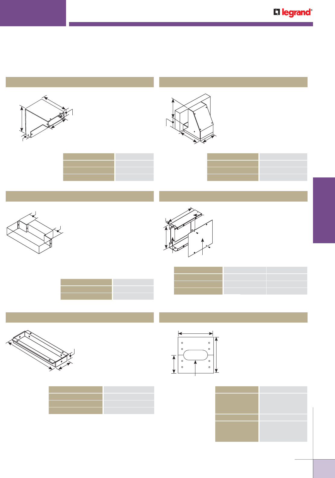
WWW.LEGRAND.US/WIREMOLD
621
INFLOOR DUCTS
WIREMOLD
Sweep Elbow
Reducer Coupling
Cabinet Connector/Dropout
WALLDUCT RACEWAY SYSTEMS
CONNECTOR/DROP OUT “A”
WD06W350-CC/DO 5 3/4" [146mm]
WD10W350-CC/DO 9 3/4" [247mm]
WD18W350-CC/DO 17 3/4" [450mm]
SWEEP ELBOW “A”
WD06W350-SES 6" [152mm]
WD10W350-SES 10" [254mm]
WD18W350-SES 18" [457mm]
REDUCER COUPLING “A”
WD350-RO2 2" [51mm]
WD350-RO4 4" [102mm]
Used to connect vertical and
horizontal runs of Wallduct
at a 90° angle with a 45°
internal sweep radius.
Includes one pair of coupling
angles and assembly
screws. For partition, use
Catalog No. WDXXW350-PSE
Series.
Used to reduce Wallduct
width by 4" [102mm] or 8"
[204mm]. Two-piece unit
allows 18" [457mm] wide
Wallduct to be reduced to
10" [254mm] wide, or 10"
[254mm] wide to be reduced
to 6" [152mm] wide. Can
also be used on other sizes
as needed. Assembly
screws included.
Used to connect ends of
Wallduct run to panel/
cabinet. Also used to
connect two runs of Wallduct
at 90° angle when one run
butts up to the bottom or
top of the other. Assembly
screws included.
A
14"
[356mm]
14"
[356mm] 3 1⁄2"
[89mm]
3 1⁄2"
[89mm]
A
A
A
3 1⁄4"
[82mm]
1"
25mm]
For use with GE medical
equipment. Attaches to
6" x 3 1/2" [152mm x 89mm],
10" x 3 1/2" [254m x 89mm],
or 18" x 3 1/2" [457mm x
89mm] horizontal surface
Wallduct. Not available
in aluminum.
Used to form a junction
between flush and surface
Wallduct at a 90° angle.
Includes assembly screws,
clips, one wire retainer, and
two coupling angles.
Two-piece cover with
grommeted hole in center.
Can be installed at any
location by match drilling
eight holes in duct body
flanges and attaching speed
nuts. Includes assembly
screws and grommet.
Sweep Cabinet Connector
Transition
Access Cover Plate
A
2 1⁄2"
[64mm]
10 1⁄2"
[266mm] 8"
[203mm]
SWEEP CONNECTOR “A”
WD06W350-SWCCS 6" [152mm]
WD10W350-SWCCS 10" [254mm]
WD18W350-SWCCS 18" [457mm]
SURFACE COVERS “A”
WD06-ACPS 6" [152mm]
WD10-ACPS 10" [254mm]
WD18-ACPS 18" [457mm]
FLUSH COVERS “A”
WD06-ACPF 8" [254mm]
WD10-ACPF 12" [305mm]
WD18-ACPF 20" [508mm]
TRANSITION “A” “B”
WD06W350-FST 6" [152mm] 8" [203mm]
WD10W350-FST 10" [254mm] 12" [304mm]
WD18W350-FST 18" [457mm] 20" [508mm]
A
1"
[25mm] BDuct Body
Surface
Cover Plate
Duct Body
Flush
6"
[152mm]
3"x 8" [76mm x 203mm] Hole
A
12"
[305mm]
NOTE: To order aluminum products, add the letter “A” to the beginning of the
catalog number. Custom sizes are available. Consult the factory for more
information.
Wallduct Fittings Ordering Information (continued)
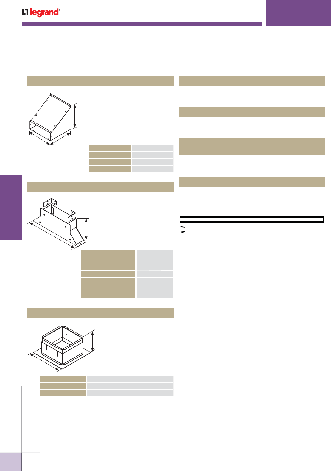
WWW.LEGRAND.US/WIREMOLD
622
INFLOOR DUCTS
WIREMOLD
WALLDUCT RACEWAY SYSTEMS
Used to connect horizontal
and vertical runs of
Wallduct at a 90° angle
with sweep radius. Includes
one pair of coupling angles
and assembly screws. Not
available in flush cover
version.
Used to connect end of
Wallduct run to panel
cabinet. Assembly screws
included. Use .166" [4.2mm]
diameter (#19 drill) for
assembly. Not available in
flush cover version or in
aluminum.
Used to drop cables and
wires from Wallduct
in ceiling to imaging
equipment. Available in 10"
[254mm] width only. Units
have adjustable depth.
Sweep Tee
Flanged Cabinet Connector
Ceiling Drop Out
CEILING DROP OUT “A”
WD-10CDO 4" [102mm] to 5 3/4" [146mm]
WD-10CDOD 5 1/2" [140mm] to 7 1/4" [184mm]
SWEEP TEE “A”
WD06W350-SWTS 6" [152mm]
WD10W350-SWTS 10" [254mm]
WD18W350-SWTS 18" [457mm]
FLANGED CONNECTOR “A”
WD06W350-FCCS 16" [406mm]
WD10W350-FCCS 22" [559mm]
WD10W350-FCCS 22" [559mm]
WD06W350-FCCF 18" [457mm]
WD10W350-FCCF 24" [610mm]
WD18W350-FCCF 26" [660mm]
A
10"
[254mm]
10"
[254mm]
A
6"
[152mm]
10"
[254mm]
A
Hardware bag with twelve (12) 10/32 x 1/4" palnut chips.
1000883 Wallduct Replacement Hardware
Hardware bag with twelve (12) 10/32 x 7/8" panhead screws.
1002412 Steel Wallduct Replacement Hardware
Hardware bag with twelve (12) panhead screws.
1002414
Aluminum Wallduct Replacement Hardware
Applied to edges of Wallduct and fittings where cables
egress to protect against damage to cable insulation.
Packed 100' of grommet per unit.
686039-100FT Wallduct Grommet
NOTE: To order aluminum products, add the letter “A” to the beginning of the
catalog number. Custom sizes are available. Consult the factory for
more information.
Wallduct Fittings Ordering Information (continued)
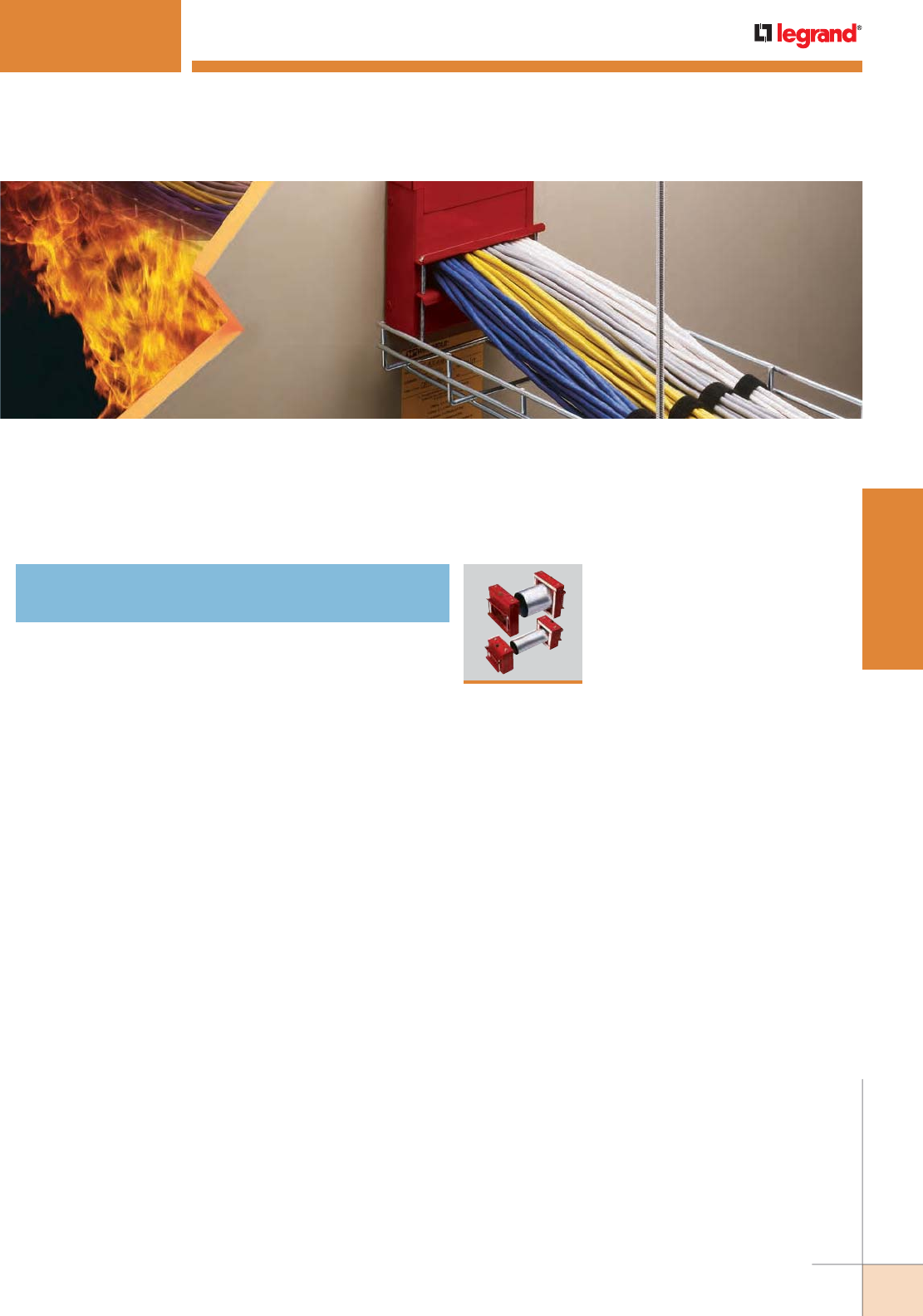
663
WWW.LEGRAND.US/WIREMOLD
WIREMOLD
FIRE STOP FITTINGS
FIRESTOP FITTINGS
Wiremold® FlameStopper™ Series Thru-Wall/Thru-Floor Fittings are
designed to provide a firestopping solution in a unique integral fitting
that can be used for both new and retrofit construction.
665
FlameStopper™ Series
Thru-Wall & Thru-Floor Fittings
Table of Contents

664
FIRE STOP FITTINGS
WWW.LEGRAND.US/WIREMOLD
WIREMOLD
FIRESTOP FITTINGS
FlameStopper FS2R & FS4R Series Through-Wall UL Ratings
Flame: The F Rating (F and FH in Canada) is expressed in hours. This number indicates the specific length of time that
a barrier can withstand fire before being consumed or before permitting the passage of flame through
the opening.
Temperature: The T Rating (FT and FTH in Canada) is expressed in hours. This number indicates the length of time that
the temperature on the non-fire side of the penetration does not exceed 325 degrees F above the ambient
temperature.
Air Leakage: The L Rating is expressed in CFM. This number indicates the amount of air (or cold smoke) that can leak
through a penetration.
Through-Wall Ratings for FS2R & FS4R Series
(UL Ratings for FS2R and FS4R Series when used alone for new construction or when used with heat shield for retrofit applications.)
NOTE: Minimum 4 1/2" [114mm] thick reinforced lightweight or normal weight (100-150 pcf) [1600-2400 kg/m3] concrete floor.
Maximum diameter of opening is 4 1/2" [114mm].
UL RATINGS (US RATINGS) MAX. RATING
F Rating with & without cables 4 Hours
T Rating with coax cable 4 Hours
T Rating with fiber optic cable 4 Hours
T Rating with Max. 1" fiber optic rcwy. with fiber optic fill 4 Hours
T Rating with Max. 4-pair cable (22 ga & smaller) 3 Hours
T Rating with Max. 4 conductor (2AWG & smaller) 1 Hour
T Rating with Max. 100-pair cable (24 ga & smaller) 1 Hour
T Rating with Max. 400-pair cable (24 ga & smaller) 45 Minutes
T Rating with MC cable (8 wire max. 12 ga & smaller) 15 Minutes
L Rating at ambient without cables (doors closed) 2.6 cfm
L Rating at 400°F without cables (doors closed) 1.9 cfm
L Rating at ambient with cables 2.8 cfm
L Rating at 400°F with cables 1.3 cfm
Suitable for use in air handling spaces (plenums) Yes
UL RATINGS (CANADIAN RATINGS) MAX. RATING
F & FH Rating with & without cables 4 Hours
FT & FTH Rating with coax cable 4 Hours
FT & FTH Rating with fiber optic cable 4 Hours
FT & FTH Rating with Max. 1" fiber optic raceway with
fiber optic fill
4 Hours
FT & FTH Rating with Max. 4-pair cable (22 ga & smaller) 3 Hours
FT & FTH Rating with Max. 4 conductor (2AWG & smaller) 1 Hour
FT & FTH Rating with Max. 100-pair cable (24 ga & smaller) 1 Hour
FT & FTH Rating with Max. 400-pair cable (24 ga & smaller) 45 Minutes
FT & FTH Rating with MC cable (8 wire max. 12 ga &
smaller)
15 Minutes
L Rating at ambient without cables (doors closed) 2.6 cfm
L Rating at 400°F without cables (doors closed) 1.9 cfm
L Rating at ambient with cables 2.8 cfm
L Rating at 400°F with cables 1.3 cfm
Suitable for use in air handling spaces (plenums) Yes
Through-Wall Ratings for FS2R & FS4R Series
(When used with wall plate for retrofit applications.)
UL RATINGS (US RATINGS) MAX. RATING
F Rating with & without cables 2 Hours
T Rating with Max. 4-pair cable (22 ga & smaller) 1.25 Hours
T Rating with coax cable 1 Hour
T Rating with fiber optic cable 1.25 Hours
T Rating with Max. 1" fiber optic raceway with
fiber optic fill
1.25 Hours
T Rating with MC cable (8 wire max. 12 ga & smaller) 15 Minutes
L Rating at ambient without cables (doors closed) 1.7 cfm
L Rating at 400°F without cables (doors closed) 1.8 cfm
L Rating at ambient with cables 3.3 cfm
L Rating at 400°F with cables 2.0 cfm
Suitable for use in air handling spaces (plenums) Yes
UL RATINGS (CANADIAN RATINGS) MAX. RATING
F & FH Rating with & without cables 2 Hours
FT & FTH Rating with Max. 4-pair cable (22 ga & smaller) 1.25 Hours
FT & FTH Rating with coax cable 1 Hour
FT & FTH Rating with fiber optic cable 1.25 Hours
FT & FTH Rating with Max. 1" fiber optic raceway with
fiber optic fill
1.25 Hours
FT & FTH Rating with MC cable (8 wire max. 12 ga &
smaller)
15 Minutes
L Rating at ambient without cables (doors closed) 2.6 cfm
L Rating at 400°F without cables (doors closed) 1.9 cfm
L Rating at ambient with cables 2.8 cfm
L Rating at 400°F with cables 1.3 cfm
Suitable for use in air handling spaces (plenums) Yes
UL RATINGS (CANADIAN RATINGS) MAX. RATING
F Rating with & without cables 3 Hours
T Rating without cables 3 Hours
T Rating with coax cable 3 Hour
T Rating with fiber optic cable 3 Hours
T Rating with Max. 4-pair cables (22 ga. or smaller) 3 Hours
T Rating with Max. 4-conductor (2 ga. or smaller) 45 Minutes
T Rating with Max. 100-pair cables (24 ga. or smaller) 1 Hour
T Rating with Max. 400-pair cables (24 ga. or smaller) 45 Minutes
T Rating with MC cable (8 wire Max. 12 ga. or smaller) 15 Minutes
L Rating at ambient without cables (doors closed) 2.6 cfm
L Rating at 400°F without cables (doors closed) 1.9 cfm
L Rating at ambient with cables 2.8 cfm
L Rating at 400°F with cables 1.3 cfm
Suitable for use in air handling spaces (plenums) Yes
Through-Floor Ratings for FS2R & FS4R Series
(When used alone.)
UL RATINGS (US RATINGS) MAX. RATING
F Rating with & without cables 3 Hours
T Rating without cables 3 Hours
T Rating with coax cable 3 Hour
T Rating with fiber optic cable 3 Hours
T Rating with Max. 4-pair cables (22 ga. or smaller) 3 Hours
T Rating with Max. 4-conductor (2 ga. or smaller) 45 Minutes
T Rating with Max. 100-pair cables (24 ga. or smaller) 1 Hour
T Rating with Max. 400-pair cables (24 ga. or smaller) 45 Minutes
T Rating with MC cable (8 wire Max. 12 ga. or smaller) 15 Minutes
L Rating at ambient without cables (doors closed) 2.6 cfm
L Rating at 400°F without cables (doors closed) 1.9 cfm
L Rating at ambient with cables 2.8 cfm
L Rating at 400°F with cables 1.3 cfm
Suitable for use in air handling spaces (plenums) Yes
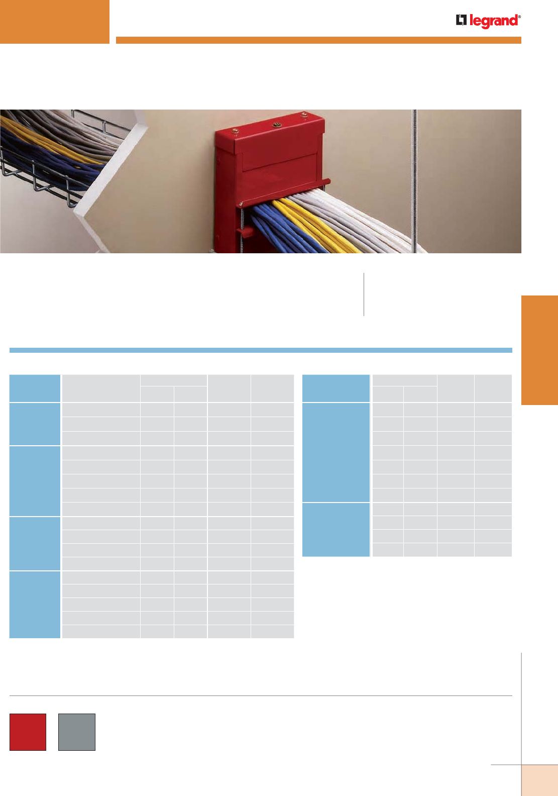
665
WWW.LEGRAND.US/WIREMOLD
WIREMOLD
FIRE STOP FITTINGS
CODE REFERENCE
UL Listed Classified
Fire Stop Devices:
File R21765.
FLAMESTOPPER
™
SERIES
FlameStopper™ Thru-Wall and Thru-Floor Fittings
FlameStopper™ Thru-Wall and Thru-Floor Fittings provide superior
fire protection and ease-of-installation.
CABLE TYPE
O.D. APPROX. DIA. FS2
MAXIMUM
FILL
FS4
MAXIMUM
FILLINCHES [MM]
UNSHIELDED
TWISTED
PAIR
4-pair, 24 AWG, Cat 3 0.190 [4.8] 71 312
4-pair, 24 AWG, Cat 5e 0.210 (5.3) 58 255
4-pair, 24 AWG, Cat 6 0.250 (6.3) 41 180
TELEPHONE 2-pair, 24 AWG 0.140 [3.6] 130 574
25-pair, 24 AWG 0.410 [10.4] 15 67
50-pair, 24 AWG 0.580 [14.7] 7 33
100-pair, 24 AWG 0.700 [17.8] 5 22
400-pair, 24 AWG 1.470 [37.3] 1 5
COAXIAL RG58/U 0.195 [5.0] 197 296
RG59/U 0.242 [6.1] 43 192
RG62/U 0.242 [6.1] 43 192
RG6/U 0.270 [6.9] 32 140
FIBER OPTIC 2 Count 0.180 [4.6] 79 347
4 Count 0.210 [5.3] 58 255
24 Count 0.400 [10.2] 16 70
48 Count 0.450 [11.4] 12 55
96 Count 0.560 [14.2] 8 35
FlameStopper Series Wire Fill Capacities for Communications
CABLE TYPE
O.D. APPROX. DIA. FS2
MAXIMUM
FILL
FS4
MAXIMUM
FILLINCHES [MM]
MAXIMUM 4 COND.
NO. 2 AWG
(OR SMALLER)
COPPER
CONDUCTOR
CABLE WITH
XLPE/PVX
INSULATION
AND PVC JACKET
0.375 [9.5] 18 80
0.500 [12.7] 10 45
0.625 [15.9] 6 28
0.750 [19.1] 4 20
0.875 [22.2] 3 14
1.000 [25.4] 12 11
1.125 [28.6] 2 8
MAXIMUM 8 COND.
NO. 12 AWG MC
(METAL CLAD)
CABLE
0.375 [9.5] 18 80
0.500 [12.7] 10 45
0.625 [15.9] 6 28
0.655 [16.9] 5 26
FlameStopper Series Wire Fill Capacities for Power
COLOR OPTIONS
FlameStopper Series™ Thru-Wall and Thru-Floor Fittings are
available in either red or a paintable A60 galvaneal finish.
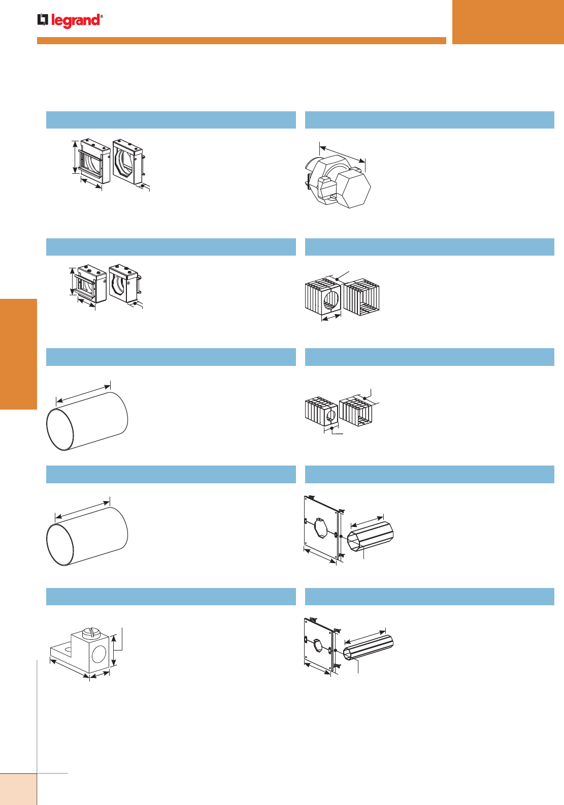
666
FIRE STOP FITTINGS
WWW.LEGRAND.US/WIREMOLD
WIREMOLD
FLAMESTOPPER
™
SERIES
Ordering Information
3 3/4"
[95mm]
3 5/8"
[92mm] 1 3/4"
[44mm]
7 5/8"
[194mm]
7 5/8"
[194mm]
1 1/2"
[38mm] 5/8"
[15.9mm]
7/8"
[22.2mm]
For transitioning cable through
fire rated walls/floors for both
new and retrofit applications.
Available in red (FS2R-RED),
or a paintable A60 galvaneal
finish (FS2R-GA). UL System
W-L-3264 and W-J-3137.
Precut to 7 5/8" [194mm] to fit
standard gypsum fire walls
with a two-hour fire rating
(6" [152mm] wall thickness).
FSPCC4758 Precut Conduit 4" Trade Size EMT
Precut to 7 5/8" [194mm] to fit
standard gypsum fire walls
with a two-hour fire rating
(6" [152mm] wall thickness).
FSPCC2758 Precut Conduit 2" Trade Size EMT
For use with SpecMate™ or
Cablofil® brand cable trays
to provide ground continuity.
Electroplated aluminum. Dual
rated for copper and aluminum
conductors, No. 2 to 14 gage
cable.
SPMGL Grounding Lug
6 3/8"
[162mm]
3 3/4"
[95mm]
6 3/8"
[162mm]
6 1/8"
[155mm]
10"
[254mm]
12"
[305mm] 12"
[305mm]
10"
[254mm]
8"
[203mm] 8"
[203mm]
6 1/4"
[159mm]
6"
[153mm] 1 3/4"
[44mm]
For transitioning cable through
fire rated walls/floors for both
new and retrofit applications.
Available in red (FS4R-RED),
or a paintable A60 galvaneal
finish (FS4R-GA). UL System
W-L-3264 and W-J-3137.
1 3/8"
[35mm] For use with Cablofil® brand
wire basket trays to provide
ground continuity. Electroplated
aluminum. Dual rated for copper
and aluminum conductors, No. 2 to
8 gage cable.
FS4R Firestop 4" Trade Size EMT Conduit Fitting WBSBC Split Bolt Connector
Used only when an existing
installed conduit extends 1"
[25mm] to 6" [152mm] beyond the
wall surface.
FS2R Firestop 2" Trade Size EMT Conduit Fitting FS4RHS Heat Shield 4" Trade Size Conduit
Used only when an existing
installed conduit extends 1"
[25mm] to 6" [152mm] beyond the
wall surface.
FS2RHS Heat Shield 2" Trade Size Conduit
Kit includes 4" trade size split
conduit sleeve to enclose existing
cables, and 12" x 12" [305mm x
305mm] ceramic heat protected
wall plate to cover irregular hole
cuts. For use with FS4R Series
Firestop.
FS4RWP12 Retrofit Kit for Existing Installations
Kit includes 2" trade size split
conduit sleeve to enclose existing
cables, and 8" x 8" [203mm x
203mm] ceramic heat protected
wall plate to cover irregular hole
cuts. For use with FS2R Series
Firestop.
FS2RWP8 Retrofit Kit for Existing Installations
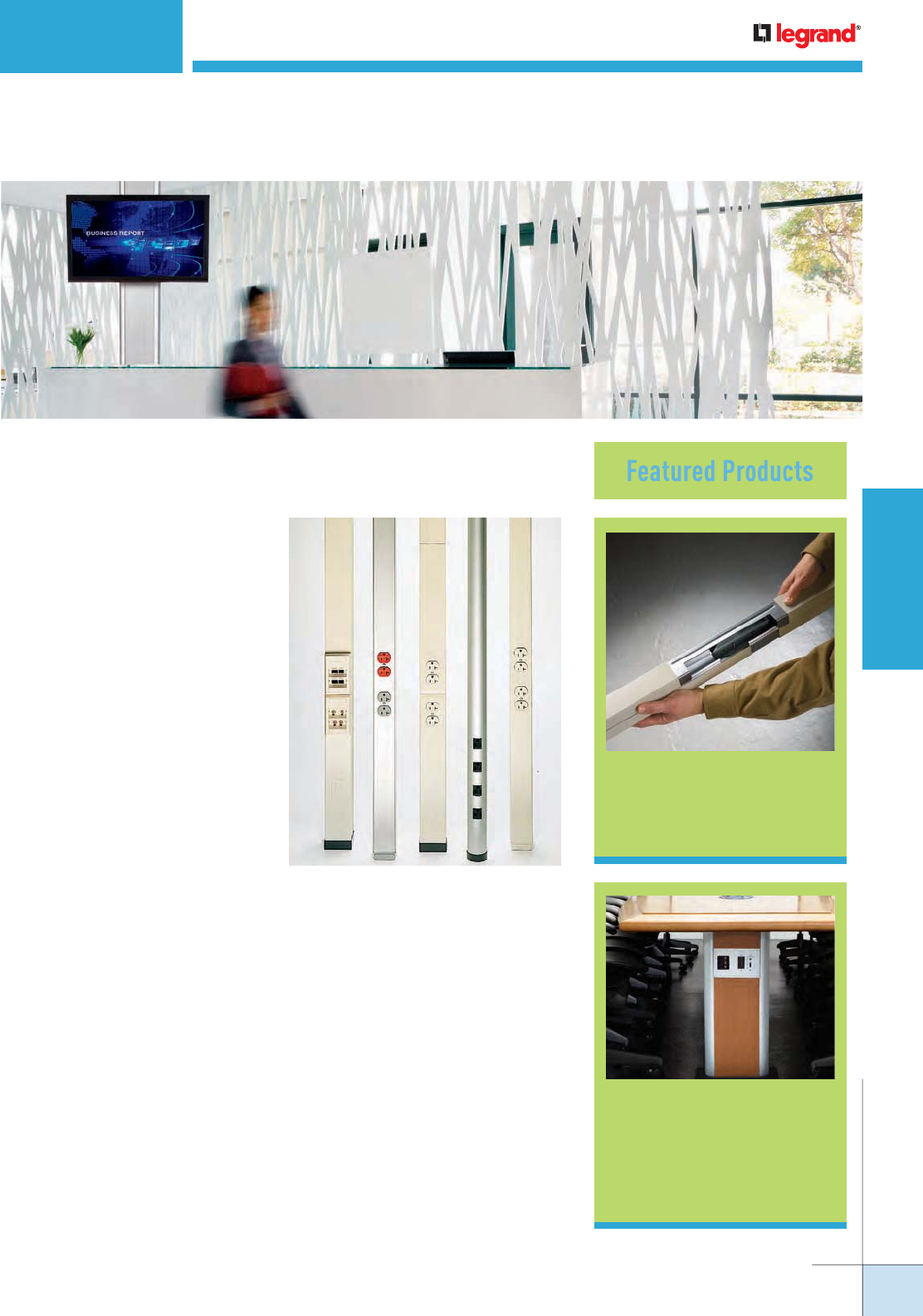
WIREMOLD
WWW.LEGRAND.US/WIREMOLD
623
POLES AND COLUMNS
Tele-Power® Pole
Extender 650
POLES AND COLUMNS
Wiremold® Vertical Solutions are innovative pathways for delivering power and
communication services to open office or retail environments.
Vista Point5™
Architectural
Columns
641
Tele-Power® Poles provide a wide range of options
for distributing services from overhead systems to
open space office, commercial, and retail areas.
WIREMOLD
WWW.LEGRAND.US/WIREMOLD
624
POLES AND COLUMNS
Vista™ Architectural Columns
Vista™ Point5 Architectural Columns
Vista™ CP Consolidation Point
POLES AND COLUMNS
Table of Contents
641
634
VLWAP VISTA™ Wireless Access Point Enclosure
Custom Tele-Power® Poles
Vertical Drop Poles
647
656
659
627
Tele-Power® Poles
648
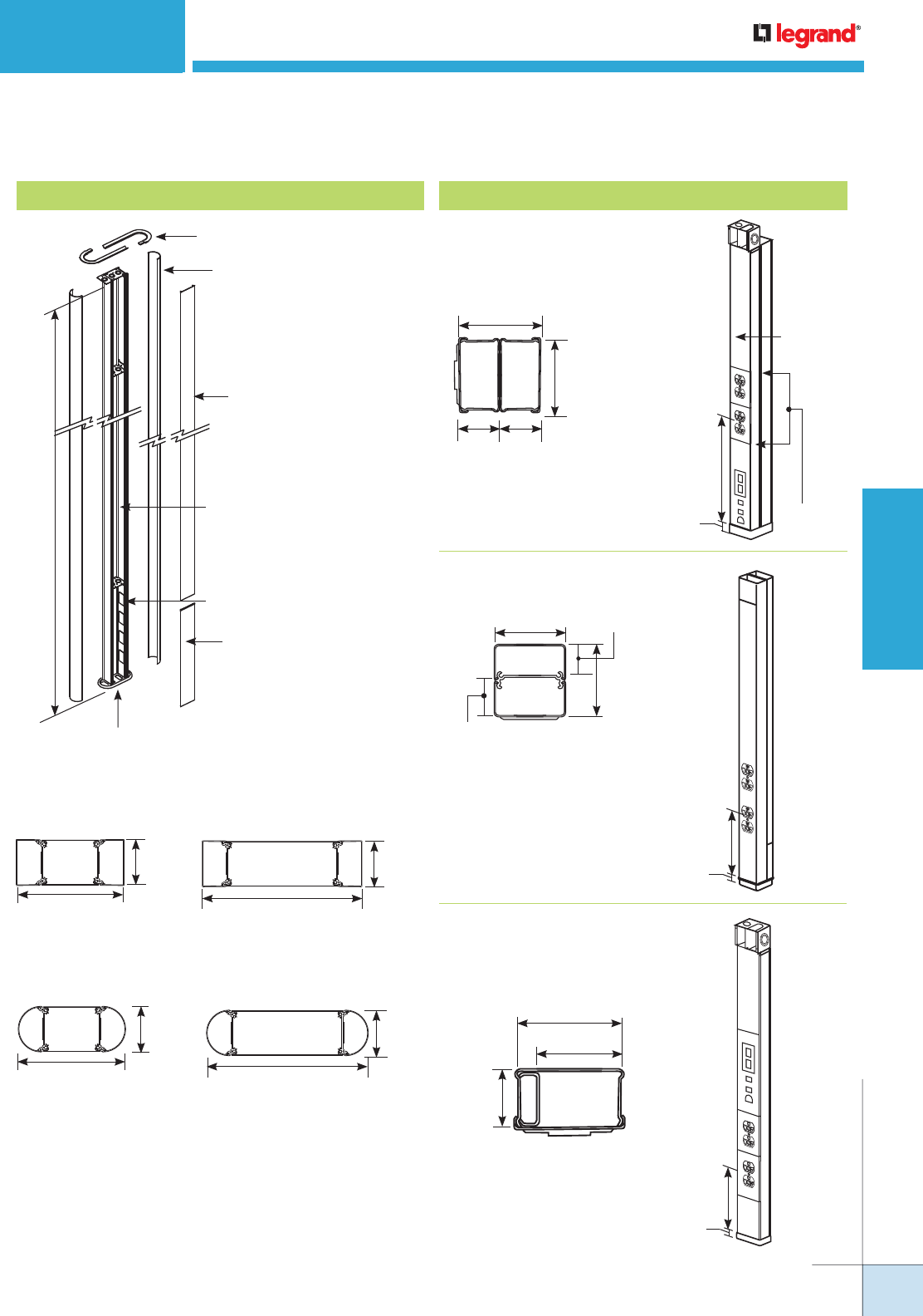
WIREMOLD
WWW.LEGRAND.US/WIREMOLD
625
POLES AND COLUMNS
WIREMOLD
POLES AND COLUMNS
Quick Selection Guide
Round
3 25/32"
[96mm]
8 29/32"
[226mm]
3 25/32"
[96mm]
13 3/8"
[340mm]
Large
Small
Square
3 25/32"
[96mm]
8 29/32"
[226mm]
3 25/32"
[96mm]
13 3/8"
[340mm]
Large
Small
10'6"
[3.2m]
Ceiling Trim Piece
Frame
Structure
Floor Trim Piece
Front
Access
Plate
Knockouts
End Channel
Center
Panel
30TP-4V
3"
[76mm]
1 1/2"
[38mm]
2 3/4"
[70mm]
1 1/2"
[38mm] 14 1/4"
[3.7m]
Power
Communications
1"
[25mm]
25DTP-4
COMMUNICATIONS
POWER
2 1/4"
[57mm]
2 5/16"
[59mm]
1 1/4"
[32mm]
1"
[25mm]
1"
[25mm]
15.875"
[403mm]
30TP-2V
COMMUNICATIONS
POWER
2 3/4"
[70mm]
1 7/8"
[48mm]
1 17/32"
[39mm]
1"
[25mm]
14 1/4"
[3.7m]
Steel Tele-Power™ PolesVista™ Architectural Column
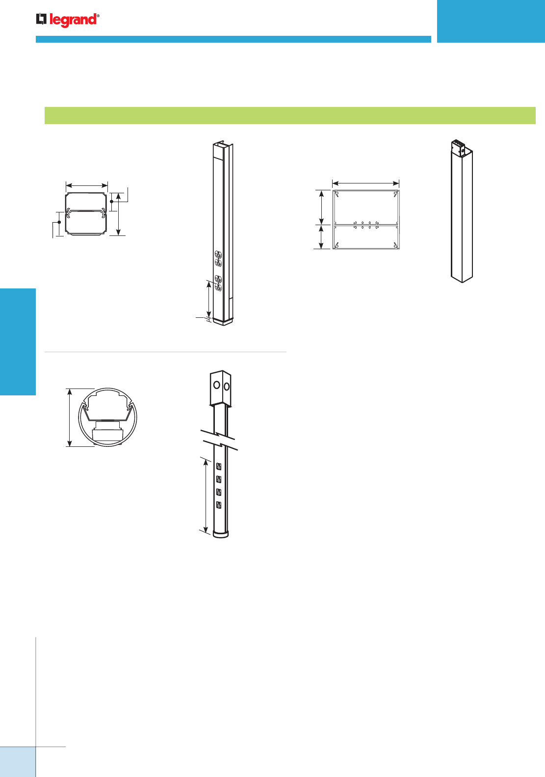
WIREMOLD
WWW.LEGRAND.US/WIREMOLD
626
POLES AND COLUMNS
AMDTP-4
POWER
2 1/4"
[57mm]
2 5/16"
[59mm]
1 1/4"
[32mm]
1"
[25mm]
COMMUNICATIONS
1"
[25mm]
15 7/8"
[4.03m]
5"
[127mm]
2 13/16"
[71mm]
1 15/16"
[49mm]
NP800C-10-2B
ALTP SERIES
12"
[305mm]
2"
[51mm]
POLES AND COLUMNS
Quick Selection Guide
Aluminum Tele-Power® Poles
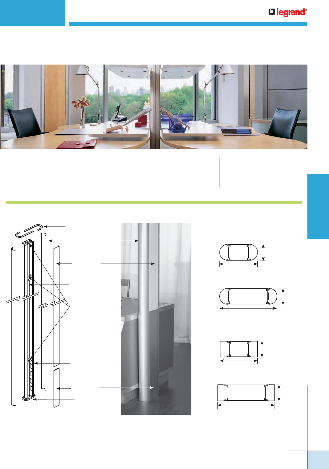
WIREMOLD
WWW.LEGRAND.US/WIREMOLD
627
POLES AND COLUMNS
CODE REFERENCE
cULus Listed Multioutlet Assemblies:
File E15191 Guide PVGT
Meets Article 380 of NEC.
Vista™ Architectural Columns provide aesthetically pleasing configurable
solutions for power, A/V and communication services in open spaces.
Vista Architectural Column System layout
3 25/32"
[96mm]
13 3/8"
[340mm]
Large
Overall Dimensions
Round
3 25/32"
[96mm]
8 29/32"
[226mm]
Small
3 25/32"
[96mm]
13 3/8"
[340mm]
Large
SQUARE
3 25/32"
[96mm]
8 29/32"
[226mm]
Small
Ceiling Trim Piece
Frame Structure
Floor
Trim Piece
Front
Access Plate
End Channel
Center Panel
Knockouts
3/4" & 1"
Trade Size
Knockouts
VISTA™ ARCHITECTURAL COLUMNS
WIREMOLD
WWW.LEGRAND.US/WIREMOLD
628
POLES AND COLUMNS
VISTA™ ARCHITECTURAL COLUMNS
Vista Wire Fill Capacity for Power
WIRE SIZE
THHN/THWN 6 AWG 8 AWG 10 AWG 12 AWG 14 AWG
One End Channel
Round or Square 7 9 16 26 35
Center (Large) 28 36 64 104 140
Center (Small) 14 18 32 52 70
One Extension
Round or Square 4 6 10 16 22
Vista Wire Fill Capacity for Communication
CABLE/WIRE SIZE
O.D.
ONE
SQUARE
END
CHANNEL
ONE
ROUND
END
CHANNEL
LARGE
CENTER
SMALL
CENTER
ONE
SQUARE
EXTENSION
ONE
ROUND
EXTENSION
Inches [mm]
Un-Shielded
Twisted
Pair
2-pair, 24 AWG, Cat 3
3-pair, 24 AWG, Cat 3
4-pair, 24 AWG, Cat 3
25-pair, 24 AWG, Cat 3
4-pair, 24 AWG, Cat 5e
4-pair, 24 AWG, Cat 6
0.140
0.150
0.190
0.410
0.220
0.250
[3.6]
[3.8]
[4.8]
[10.4]
[5.6]
[6.3]
190
165
103
22
77
59
150
131
81
17
61
47
80
68
44
8
32
24
40
34
22
4
16
12
131
114
71
15
53
41
94
82
51
11
38
29
Shielded
Twisted
Pair
Type 1, 22 AWG
Type 2, 22 AWG
Type 3, 22 AWG
0.390
0.465
0.245
[9.9]
[11.8]
[6.2]
24
17
62
19
13
49
8
4
24
4
2
12
16
11
42
12
8
30
Coaxial RG58/U, 20 AWG
RG58/U, 22 AWG
RG6/U, 22 AWG
RG6/U, 18 AWG
0.195
0.242
0.242
0.270
[5.0]
[6.1]
[6.1}
[6.9]
98
63
63
51
77
50
50
40
40
24
24
20
20
12
12
10
67
43
43
25
48
31
31
25
Twinaxial 100 Ohm 0.330 [8.4] 34 27 12 6 23 71
Fiber Optic 0.180 [4.6] 103 81 44 22 71 51
NOTE: Capacity range is calculated at 40% of raceway area as stated in a proposed revisions to the Commercial Building Standard for Telecommunication
Pathways & Spaces, EIA/TIA-569. Actual wire fill capacity may vary based on applications, cable types, and number, as well as type of fittings.
(Fittings may cause additional variances to the fill capacity.)
VL662345 In-Stock Large Vista Column
VS662345 In-Stock Small Vista Column
Vista Architectural Columns In-Stock Columns Ordering Information
Small profile frame, round end channels, anodized
aluminum finish. Accepts all adapters. Two 20A
duplex receptacles located 27" [686mm] above
floor. Includes one VSFF plate at bottom back side
of pole. Dimensions: 10'6" x 8 29/32" x 3 25/32"
[3200mm x 276mm x 96mm].
Large profile frame, round end channels, anodized
aluminum finish. Accepts all adapters. Three 20A
duplex receptacles located 27" [686mm] above
floor. Includes one VLFF plate at bottom back side
of pole. Dimensions: 10'6" x 13 3/8" x 3 25/32"
[3200mm x 340mm x 96mm].
VS662345FF Small Furniture Feed Vista Column
Small profile frame, round end channels, anodized
aluminum finish. Furniture feed. Includes one VSFF
plate at bottom back side of pole. Dimensions: 10'6"
x 8 29/32" x 3 25/32" [3200mm x 226mm x 96mm].
VL662345FF Large Furniture Feed Vista Column
Large profile frame, round end channels, anodized
aluminum finish. Furniture feed. Includes one VLFF
plate at bottom back side of pole. Dimensions: 10'6"
x 13 3/8" x 3 25/32" [3200mm x 340mm x 96mm].
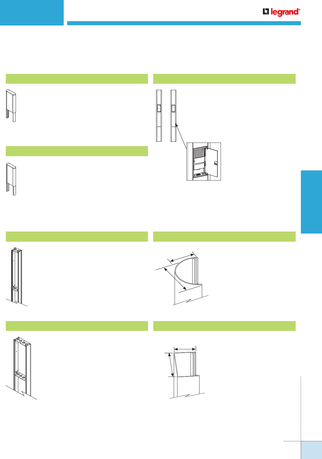
WIREMOLD
WWW.LEGRAND.US/WIREMOLD
629
POLES AND COLUMNS
VISTA™ ARCHITECTURAL COLUMNS
Tempered aluminum with heavy gauge
steel cross supports with two (2) 3/4" and
1" trade size concentric KOs. Accepts 4
3/4" [121mm] wide center panel.
Vista Architectural Columns In-Stock Columns Ordering Information
Small profile 24" [610mm] frame extension,
round end channels, anodized aluminum finish.
Large profile 24" [610mm] frame extension,
round end channels, anodized aluminum finish.
VES66234524 In-Stock Small Vista Column Ext.
Vista Architectural Columns In-Stock Columns Ordering Information
VLWAP Vista Wireless Access Point Enclosure
Vista solution for mounting wireless access
points. Large frame Vista with anodized round
end channels and center panels. Furniture
feed style access, 10'6" [3.2m] tall. Has
tempered glass panels to conceal access
point. Front panel is hinged and lockable.
Compartment measures 17 1/2" x 7 1/4" x 2
1/2" [445mm x 183mm x 64mm].
Front
View
Rear
View
Tempered aluminum with heavy gauge
steel cross supports with two (2) 3/4" and
1" trade size concentric KOs. Accepts
4 3/4" [121mm] wide center panel.
VEL66234524 In-Stock Large Vista Column Ext.
3 13/16"
[97mm]
2"
[51mm] Tempered aluminum. Anodized
finish or painted. Channel snaps
onto frame.
Round End Channel
3 13/16"
[97mm]
2"
[51mm] Tempered aluminum. Anodized
finish or painted. Channel snaps
onto frame.
Square End Channel
Small Frame
Large Frame
WIREMOLD
WWW.LEGRAND.US/WIREMOLD
630
POLES AND COLUMNS
VISTA™ ARCHITECTURAL COLUMNS
COLOR REFERENCE CODE
White = 3333
Black = 9999
Ivory = 5555
No Color – Anodized Aluminum = 2345
Warm White – Steelcase 4700 = 3136
Moss – Steelcase 4722 = 5169
Lt. Tone – Herman Miller LT = 2486
Mist – Steelcase 4606 = 5895
GSA Lt. Blue – GSA 25183 = 5911
Woodrose – Steelcase 4601 = 6137
Slate – Steelcase 4726 = 6142
Light Blue – Shaw Walker A751 = 1988
Greytone – Haworth – G = 2884
Furniture Feed = FF
Data Device Plates – Ortronics®
Series II or TracJack Adapters = RT*
Open System Adapters = CM*
AV Device Plates
Extron® Electronics MAAP –
(Has openings for 8 Wiremold AVIP or
Extron® MAAP Modules.
1 MAB Adapter included.) = EM
Extron® Electronics AAP –
(Has openings for 6 AAP Modules.
1 MAB Adapter included.) = EA
Crestron® Quick Media –
(Has openings for 1 two gang
or 2 single gang wall plates.
1 MAAP Adapter included.) = CR
Vista Architectural Column Frame Options Ordering Information
* RT and CM options include one each
electrical device plate with spec grade
duplex receptacle(s), single 120V circuit
and communications plate with
adapter(s) installed.
Duplex receptacles are located at 27"
[686mm] above the finish floor.
Communications modules are located
at 21" [533mm] above the finish floor.
Vista Architectural Column Panel Options Ordering Information
COLOR REFERENCE CODE
Aluminum:
White = 3333
Black = 9999
Ivory = 5555
No Color – Anodized Aluminum = 2345
Warm White – Steelcase 4700 = 3136
Moss – Steelcase 4722 = 5169
Lt. Tone – Herman Miller LT = 2486
Mist – Steelcase 4606 = 5895
GSA Lt. Blue – GSA 25183 = 5911
Woodrose – Steelcase 4601 = 6137
Slate – Steelcase 4726 = 6142
Light Blue – Shaw Walker A751 = 1988
Greytone – Haworth – G = 2884
Woodgrain Laminate:
Amber Cherry = 4407
Mahogany = 4410
COLOR REFERENCE CODE
Maple Fusion = 4401
Shaker Cherry = 4408
Fonthill Pear = 4406
Congo Spruce = 4451
Copper Bubinga = 4456
Natural Pear = 4411
Biltmore Cherry = 4413
Asian Sun = 4467
Metal Laminate:
Vertical Corrugated Matte Aluminum = 4748
Ragged Copper = 1999
Matte Aluminum Footplate = 2046
Light Hammer Copper = 2121
Double Brushed Aluminum = 2171
COLOR REFERENCE CODE
Fabric:
Quartz = 3805
Lavender Natural = 4055
Blue Neutral = 4105
Wedgewood = 1505
Grey Mix = 2385
Lake = 0995
Malibu = 0375
Globe = 0245
Flax = 0615
Daylight Blue = 0305
Glass:
Heavy Frost = 8675
NOTE: These are suggested colors. If there are other colors not incdicated here, send in a color
chip as most colors can be matched.
Size:
Small = S
Large = L
Prefix:
Frame = VF
End Channel:
Round = 66
Square = 77
Plate & End
Channel Color: Adapter: Device/Adapter Color:
Light Gray = GY
White = WH
Ivory/Light Almond = IV
Black = BK
No Device/Adapters = ZZ
Panel:
Center Panel = P
Glass Panel = G
No Panel = X
V F
Panel Finish:
Size:
Small = S
Large = L
Prefix:
Frame = VP
VP
Panel Type:
Aluminum = A3
Wood Grain = N3
Metal Finish = M3
Glass Finish = G4
Fabric = F8
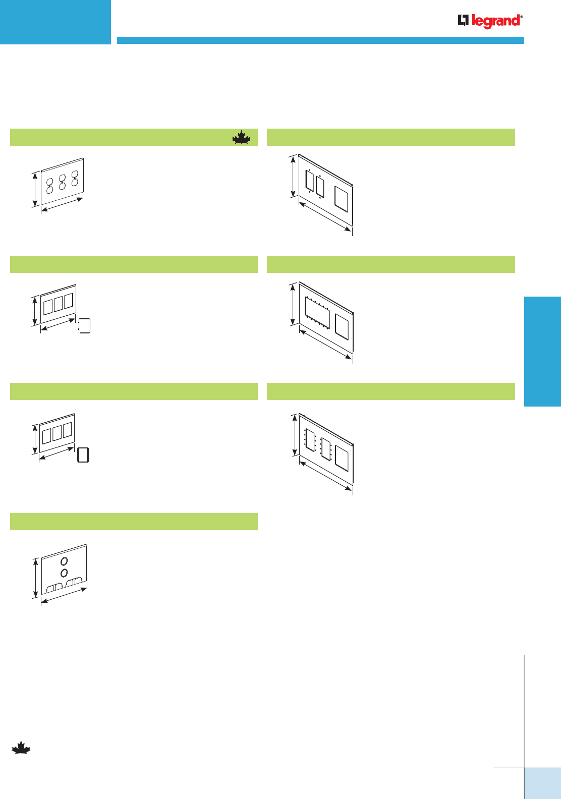
WIREMOLD
WWW.LEGRAND.US/WIREMOLD
631
POLES AND COLUMNS
VLRT* Device Cover
6"
[152mm]
9 1/4"
[235mm]
Has three (3) mini adapters for
Wiremold CM Series Open System
communications devices.
VLCM* Device Cover
VISTA™ ARCHITECTURAL COLUMNS
Has three (3) duplex receptacle
cutouts
Has three (3) mini adapters for
Ortronics® Series II or TracJack
devices.
6"
[152mm]
9 1/4"
[235mm]
Vista Architectural Column Add-On Plates for Large Frame Vista Series Ordering Information
6"
[152mm]
9 1/4"
[235mm]
6"
[152mm]
9 1/4"
[235mm]
Has two (2) concentric 1" and 3/4"
trade size knockouts, and two (2)
multiple twistout mouse holes. One
furniture feed plate is installed on
the assembly.
VLFF Furniture Feed Plate
VL3D Device Cover
Has openings for one (1) two-gang
or two (2) single-gang Crestron®
Quick Media wall plate(s) and one
mini adapter (included). Standard
color/material is anodized
aluminum or black.
VLCR** AV Device Cover
6"
[152mm]
9 1/4"
[235mm]
6"
[152mm]
9 1/4"
[235mm]
VLEA** AV Device Cover
Has openings for six (6) Extron®
Electronics AAP modules and one
mini adapter (included). Standard
color/material is anodized
aluminum or black.
6"
[152mm]
9 1/4"
[235mm]
VLEM** AV Device Cover
Has openings for eight (8)
Wiremold AVIP or Extron®
Electronics MAAP modules and
one mini adapter (included).
Standard color/material is
anodized aluminum or black.
*Refer to the list of colors in chart on page 582 for the four-digit code number.
Add “C”prefix to catalog number to denote Canadian version – Agency approved for
sale in Canada.
**Products are ETL Listed.
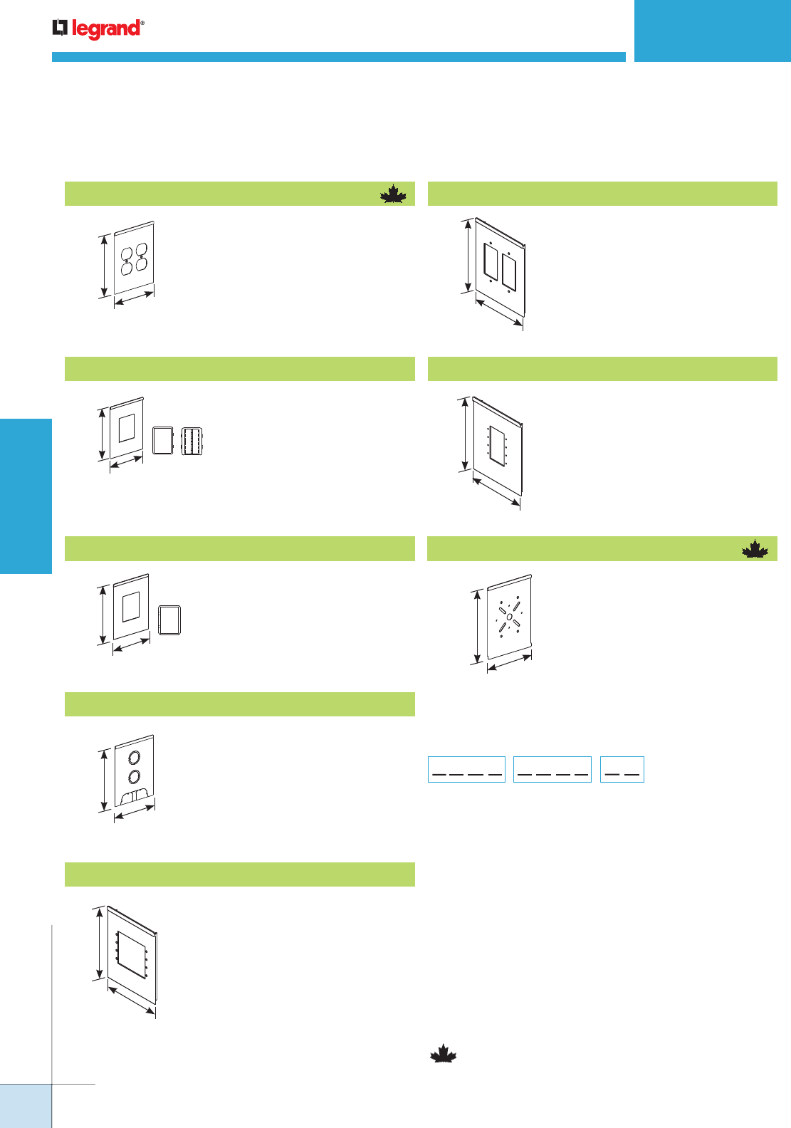
WIREMOLD
WWW.LEGRAND.US/WIREMOLD
632
POLES AND COLUMNS
6"
[152mm]
4 3/4"
[121mm]
6"
[152mm]
4 3/4"
[121mm]
6"
[152mm]
4 3/4"
[121mm]
6"
[152mm]
4 3/4"
[121mm]
6"
[152mm]
4 3/4"
[121mm]
6"
[152mm]
4 3/4"
[121mm]
Vista Architectural Column Add-On Plates for Small Frame Vista Series Ordering Information
VSRT* Device Cover
VSFF* Furniture Feed Plate
VSCM* Device Cover
VSEA** AV Device Plate
VSCR** AV Device Plate
Has two (2) duplex receptacle
cutouts.
Has one mini adapter for
Ortronics® Series II or TracJack
devices.
Has one mini adapter for
Wiremold CM Series Open System
communication devices.
Has two concentric and 3/4" trade
size KOs, and one multiple twistout
mouse hole. One furniture feed
plate is installed on the assembly.
Has openings for four (4) Extron®
Electronics AAP modules.
Standard color/material is
anodized aluminum or black.
Has openings for one (1) two-gang or
two (2) single-gang Crestron® Quick
Media wall plate(s). Standard color/
material is anodized aluminum or
black.
VISTA™ ARCHITECTURAL COLUMNS
6"
[152mm]
4 3/4"
[121mm]
6"
[152mm]
4 3/4"
[121mm]
VSEM** AV Device Plate
Has openings for four (4) Wiremold
AVIP or Extron® Electronics MAAP
modules. Standard color/material is
anodized aluminum or black.
Accommodates commercially
available lights weighing up to 10 lbs.
[4.5kg].
*Refer to the list of colors in chart on page 582 for the four-digit code number.
Add “C”prefix to catalog number to denote Canadian version – Agency
approved for sale in Canada.
**Products are ETL Listed.
VS2D* Device Cover
VSLB* Lighting Bracket
Plate Color:
Refer to color list
on the previous
page, enter
4-digit code
Base:
Enter Catalog
Number from
above choices
Adapter Color:
Light Gray = GY
White = WH
Ivory/Lt. Almond = IV
Black = BK
No Device Adapter = ZZ
Device Plate Part Number Configurator
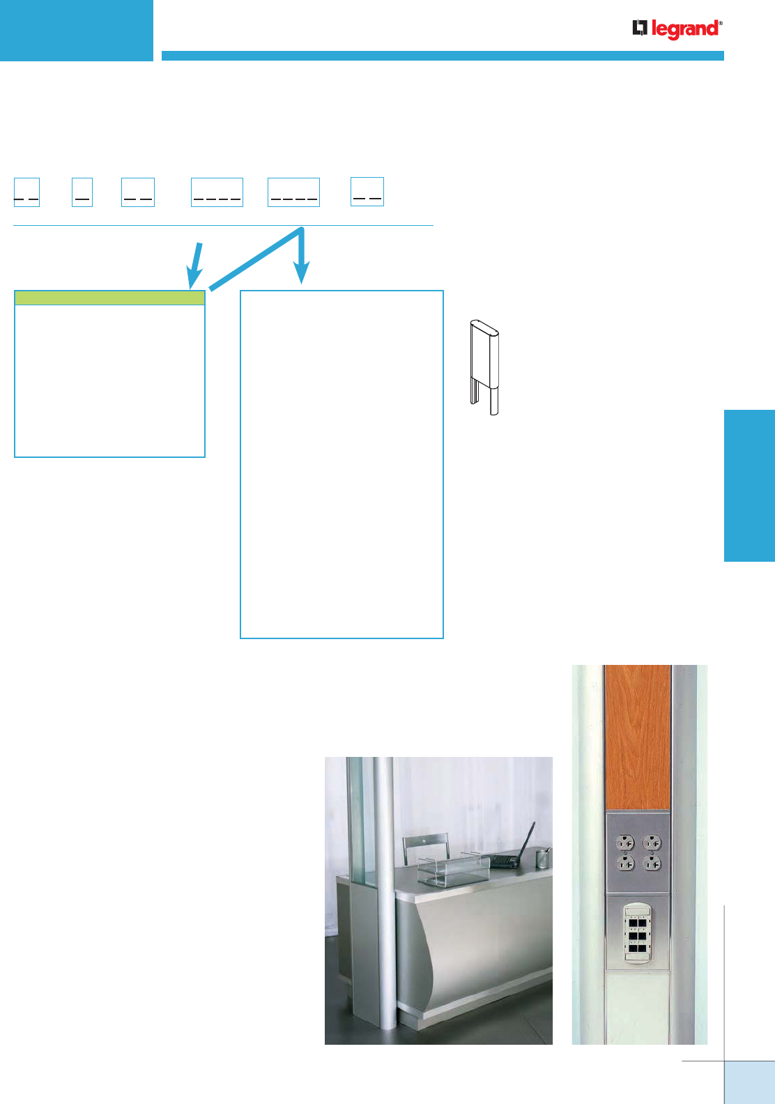
WIREMOLD
WWW.LEGRAND.US/WIREMOLD
633
POLES AND COLUMNS
VISTA™ ARCHITECTURAL COLUMNS
Woodgrain Laminate:
Amber Cherry = 4407
Mahogany = 4410
Maple Fusion = 4401
Shaker Cherry = 4408
Fonthill Pear = 4406
Congo Spruce = 4451
Copper Bubinga = 4456
Natural Pear = 4411
Biltmore Cherry = 4413
Asian Sun = 4467
Metal Laminate:
Vertical Corrugated Matte
Aluminum = 4748
Ragged Copper = 1999
Matte Aluminum Footplate = 2046
Light Hammer Copper = 2121
Double Brushed Aluminum = 2171
Fabric:
Quartz = 3805
Lavender Neutral = 4055
Blue Neutral = 4105
Wedgewood = 1505
Grey Mix = 2385
Lake = 0245
Malibu = 0375
Globe = 0245
Flax = 0615
Daylight Blue = 0305
Extension Kit Options –
COLOR REFERENCE CODE
White = 3333
Black = 9999
Ivory = 5555
No Color – Anodized Aluminum = 2345
Warm White – Steelcase 4700 = 3136
Moss – Steelcase 4722 = 5169
Lt. Tone – Herman Miller LT = 2486
Mist – Steelcase 4606 = 5895
GSA Lt. Blue – GSA 25183 = 5911
Woodrose – Steelcase 4601 = 6137
Slate – Steelcase 4726 = 6142
Light Blue – Shaw Walker A751 = 1988
Greytone – Haworth – G = 2884
Accommodates ceiling heights
between 10' [3m] and 15' [4.5m].
Includes hardware for attaching
to main section. Round or square
shapes available. Includes a
center panel.
For a full color view, bill of materials, or to request a quote for Vista Open-Space
Power and Communication Delivery, check out www.legrand.us.
Configuration Example
The product shown at the right is made of the
following components:
Frame
Large Frame with Square Anodized
Aluminum End Channels
Catalog number: VFL772345FFZZP
Center Panel
Large Wood Grain Laminate Panel
Catalog number: VPLA34410
Extension Kit (Optional)
Large Square Anodized End Channels
with Mahogany Wood Laminate Panels
and 24" [610mm] extension
Catalog number: VEL772345441024
All solutions include a furniture feed plate.
Vista Architectural Columns Part Configuration
Vista Architectural Column Extension Kit Ordering Information
Size:
Small = S
Large = L
Shape:
Round = 66
Square = 77
Height:
24" [610mm] = 24
60" [1.52m] = 60
End Channel
Finish:
Prefix:
Frame = VE
V E
Panel Finish:
NOTE: These are suggested colors. If there
are other colors not incdicated here,
send in a color chip as most colors
can be matched.
Design your own
Vista Architectural Column
online at www.legrand.us/tools-
resources/
wiremold & click on vista configurator
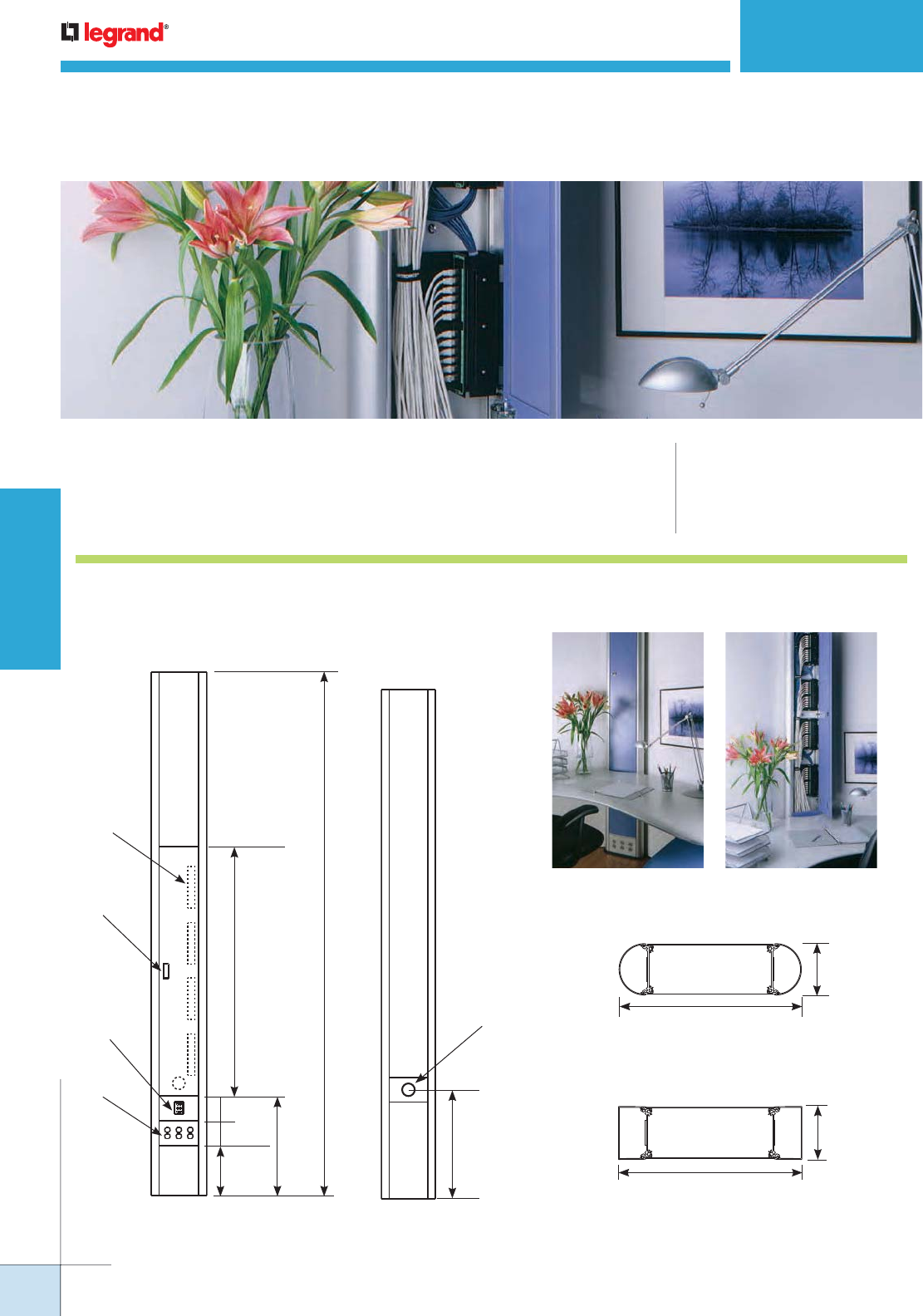
WIREMOLD
WWW.LEGRAND.US/WIREMOLD
634
POLES AND COLUMNS
Ortronics 89D
Patch Panel –
12 Ports Max Per
Patch Panel
(not provided)
Door Pull
Front View
Duplex Outlets
Communication
Ports
126"
[3.2m]
60"
[1.52m]
6"
[152mm]
6"
[152mm] 24"
[610mm]
12"
[305mm]
Rear View
27"
[686mm]
Data Cable Exit Hole
For Up To
48 Cat 6 Cables
3 25/32"
[96mm]
13 3/8"
[340mm]
Round
Large
3 25/32"
[96mm]
13 3/8"
[340mm]
Square
Large
Open and closed views of a Vista CP installation.
VISTA CP™ CONSOLIDATION POINT
CODE REFERENCE
cULus Listed Multioutlet
Assemblies:
File E15191 Guide PVGT
Meets Article 380 of NEC.
Vista CP™ Consolidation Point provides configurable solutions for
zoned cabling in open spaces.
Vista CP Consolidation Point System Layout
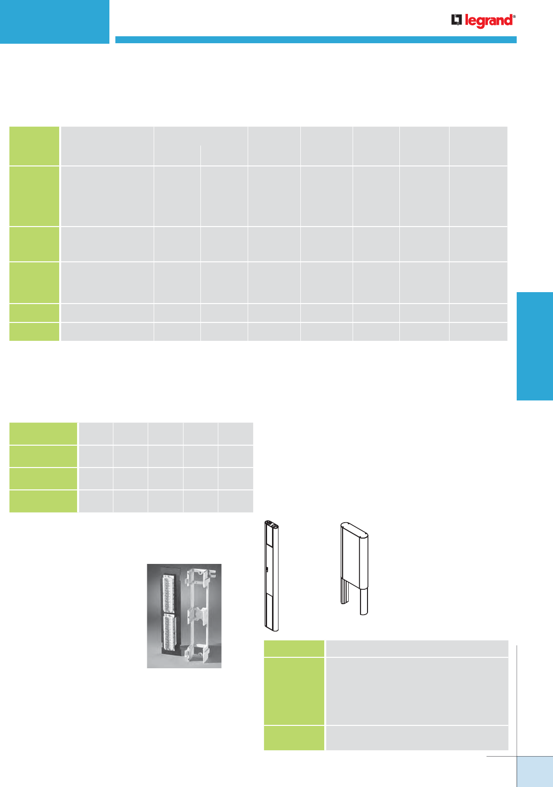
WIREMOLD
WWW.LEGRAND.US/WIREMOLD
635
POLES AND COLUMNS
CABLE/WIRE SIZE
O.D. ONE
SQUARE
END
CHANNEL
ONE
ROUND
END
CHANNEL
LARGE
CENTER
ONE
SQUARE
EXTENSION
ONE ROUND
EXTENSION
Inches [mm]
Unshielded
Twisted Pair 2-pair, 24 AWG, Cat 3
3-pair, 24 AWG, Cat 3
4-pair, 24 AWG, Cat 3
25-pair, 24 AWG, Cat 3
4-pair, 24 AWG, Cat 5e
4-pair, 24 AWG, Cat 6
0.140
0.150
0.190
0.410
0.220
0.250
[3.6]
[3.8]
[4.8]
[10.4]
[5.6]
[6.3]
190
165
103
22
77
59
150
131
81
17
61
47
80
68
44
8
32
24
131
114
71
15
53
41
94
82
51
11
38
29
Shielded
Twisted Pair Type 1, 22 AWG
Type 2, 22 AWG
Type 3, 22 AWG
0.390
0.465
0.245
[9.9]
[11.8]
[6.2]
24
17
62
19
13
49
8
4
24
16
11
42
12
8
30
Coaxial RG58/U, 20 AWG
RG58/U, 22 AWG
RG6/U, 22 AWG
RG6/U, 18 AWG
0.195
0.242
0.242
0.270
[5.0]
[6.1]
[6.1}
[6.9]
98
63
63
51
77
50
50
40
40
24
24
20
67
43
43
25
48
31
31
25
Twinaxial 100 Ohm 0.330 [8.4] 34 27 12 23 71
Fiber Optic 0.180 [4.6] 103 81 44 71 51
WIRE SIZE
THHN/THWN 6 AWG 8 AWG 10
AWG
12
AWG
14
AWG
One End Channel
Round or Square 7 9 16 26 35
Center (Large) 28 36 64 104 140
One Extension
Round or Square 4 6 10 16 22
VISTA CP™ CONSOLIDATION POINT
Vista CP Consolidation Point Wire Fill Capacity for Communication
NOTE: Capacity range is calculated at 40% of raceway area as stated in a proposed revisions to the Commercial Building Standard for Telecommunication
Pathways & Spaces, EIA/TIA-569. Actual wire fill capacity may vary based on applications, cable types, and number, as well as type of fittings.
(Fittings may cause additional variances to the fill capacity.)
Vista CP Consolidation Point Wire Fill Capacity for Power
The Vista Column Consolidation Point
accommodates the 89D style patch
panel, 12 ports maximum, and up to 4
panels per column.
Ortronics® Clarity5E TM or Clarity6 TM
Modular to 110 Mini Patch Panels are an
ideal solution.
Patch Panel Options
CAT. NO. DETAILS
VLCP662345 Large Anodized Aluminum Frame with round
channels, Ortronics TracJack and Series 2 adapters
in gray. Accommodates a 10' [3m] ceiling.
Anodized Aluminum Panel for the back of the Vista
Column.
Anodized Aluminum Door with a keyed lock and
flush, black door pull, 60" [5.2m] length.
VEL6623524 Extension for the column to accommodate up to 12'
[3.7m] ceilings.7
Vista CP Consolidation Point In-Stock Columns
Ordering Information
Vista Consolidation Point (CP)
Columns provide channels that conceal wires and cables behind a decorative
center panel and incorporate a user-installed patch panel with easy, secured
access through a lockable door. They can be placed anywhere in an open space,
providing maximum communication flexibility and unique design elements.
These modular columns are easily relocated to accommodate changing space
requirements.
VEL66234524VLCP662345
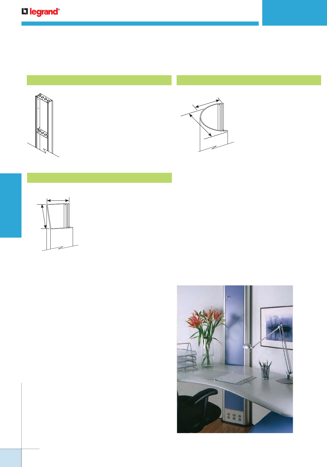
WIREMOLD
WWW.LEGRAND.US/WIREMOLD
636
POLES AND COLUMNS
VISTA CP™ CONSOLIDATION POINT
3 13/16"
[97mm]
2"
[51mm]
Vista CP Consolidation Point Frame Options Ordering Information
Large Frame
Tempered aluminum with heavy
gauge steel cross supports with
four (4) 3/4” and 1” trade size
concentric KOs. Accepts 9 1/4"
[235mm] wide center panel.
Round End Channel
Tempered aluminum.
Anodized finish or painted.
Channel snaps onto frame.
3 13/16"
[97mm]
2"
[51mm]
For a full color view of the Vista CP Consolidation Point,
check out www.legrand.us.
Configuration Example
The product shown at the right is made of the
following components:
Frame
Large Frame with Round Anodized
Aluminum End Channels
Catalog Number: VFL662345FFZZD
Center Panel
Large Locked Door Panel
Catalog Number: VY602345L2Y
Rear Center Panel
Large Aluminum Panel
Catalog Number: VPLY2345
Extension Kit (Optional)
Large Round End Channels
Catalog Number: VEL662345234524
All solutions include a furniture feed plate.
Square End Channel
Tempered aluminum. Anodized
finish or painted. Channel snaps
onto frame.
Vista CP Consolidation Point Part Configuration
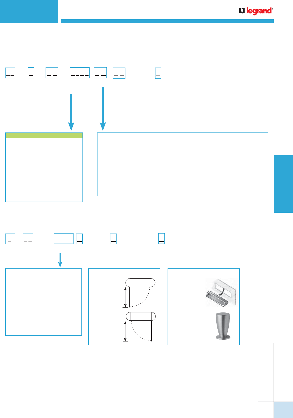
WIREMOLD
WWW.LEGRAND.US/WIREMOLD
637
POLES AND COLUMNS
VISTA CP™ CONSOLIDATION POINT
Vista CP Consolidation Point Center Panel Door Options Ordering Information
Aluminum:
White = 3333
Black = 9999
Ivory = 5555
No Color – Anodized Aluminum = 2345
Warm White – Steelcase 4700 = 3136
Moss – Steelcase 4722 = 5169
Lt. Tone – Herman Miller LT = 2486
Mist – Steelcase 4606 = 5895
GSA Lt. Blue – GSA 25183 = 5911
Woodrose – Steelcase 4601 = 6137
Slate – Steelcase 4726 = 6142
Light Blue – Shaw Walker A751 = 1988
Greytone – Haworth – G = 2884
VY
Height:
60" [1.25m] = 60
Prefix:
Door = VY
Handle:
Black Flush Door Pull = 1
Nickel-Plated Knob = 2
Color: Opening:
Left Hinged = L
Right Hinged = R
6 0
Keyed Lock:
Yes = Y
No = N
NOTE: Send in a color chip. Most colors can
be matched.
DOOR OPENING OPTIONS:
Left-Handed
Opening (L)
Right-Handed
Opening (R)
DOOR HANDLE OPTIONS:
Black Flush
Door Pull (1) –
Black plastic sits
flush to surface of
door.
Nickel-Plated
Knob (2) –
Nickel finish knob.
NOTE: The bottom of the door is located
24" [610mm] from the finish floor.
13 1/8"
[333mm]
13 1/8"
[333mm]
COLOR REFERENCE CODE
White = 3333
Black = 9999
Ivory = 5555
No Color – Anodized Aluminum = 2345
Warm White – Steelcase 4700 = 3136
Moss – Steelcase 4722 = 5169
Lt. Tone – Herman Miller LT = 2486
Mist – Steelcase 4606 = 5895
GSA Lt. Blue – GSA 25183 = 5911
Woodrose – Steelcase 4601 = 6137
Slate – Steelcase 4726 = 6142
Light Blue – Shaw Walker A751 = 1988
Greytone – Haworth – G = 2884
Vista CP Consolidation Point Frame Options Ordering Information
* RT and CM options include one each electrical device
plate with spec grade duplex receptacle(s), single
120V circuit and communications plate with adapter(s)
installed.
Duplex receptacles are located at 27" [686mm] above the
finish floor.
Communications modules are located at 21" [533mm]
above the finish floor.
Furniture Feed = FF
Data Device Plates – Ortronics®
Series II or TracJack Adapters = RT*
Open System Adapters = CM*
AV Device Plates
Extron® Electronics MAAP –
(Has openings for 8 Wiremold AVIP or
Extron® MAAP Modules.
1 MAB Adapter included.) = EM
Extron® Electronics AAP –
(Has openings for 6 AAP Modules.
1 MAB Adapter included.) = EA
Crestron® Quick Media –
(Has openings for 1 two gang or
2 single gang wall plates.
1 MAAP Adapter included.) = CR
Size:
Large = L
Prefix:
Frame = VF
End Channel:
Round = 66
Square = 77
Plate & End
Channel Color:
Style: Device/Adapter Color:
Light Gray = GY
White = WH
Ivory/Light Almond = IV
Black = BK
No Device/Adapters = ZZ
Panel:
Door Panel = D
L
V F D
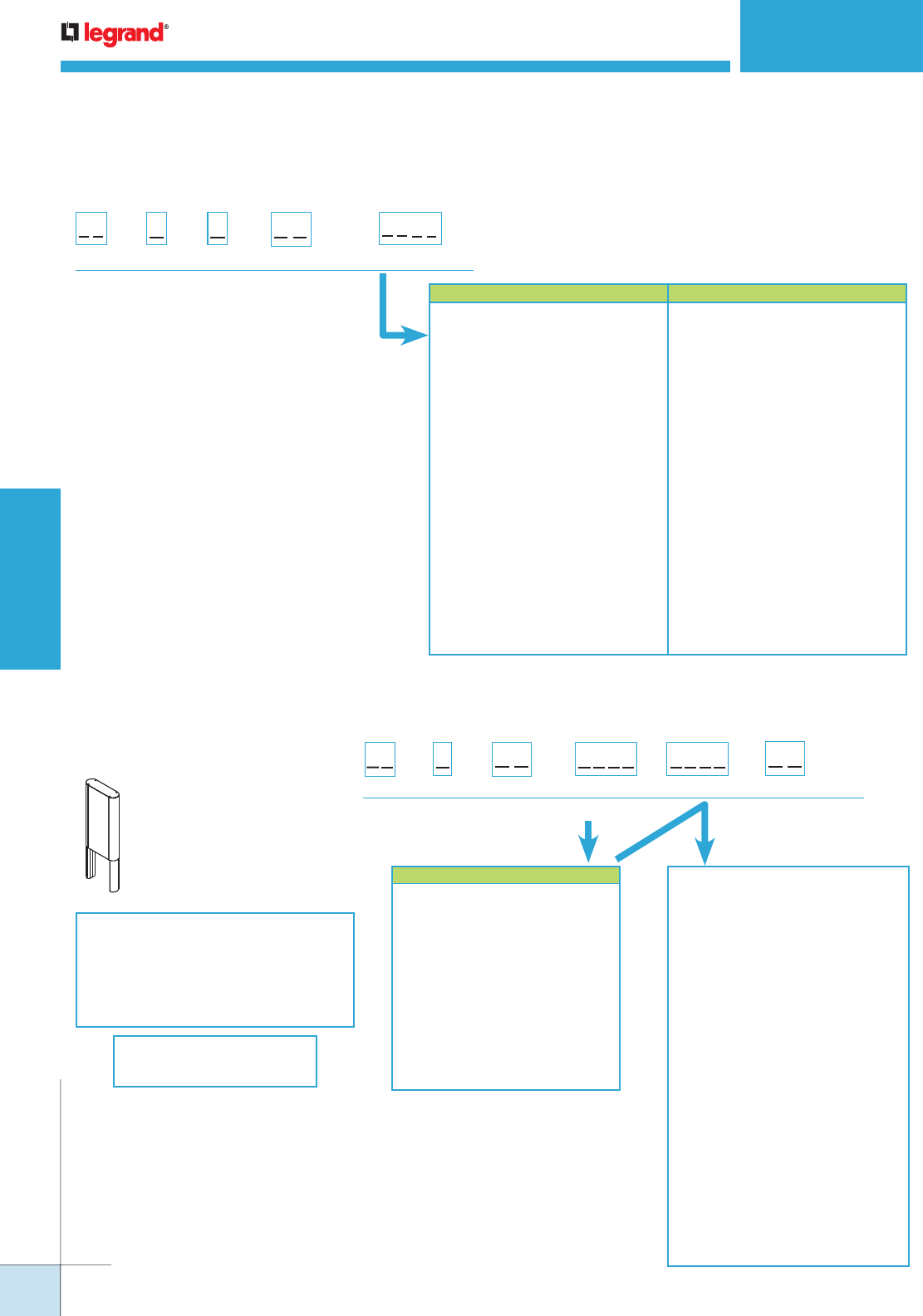
WIREMOLD
WWW.LEGRAND.US/WIREMOLD
638
POLES AND COLUMNS
VISTA CP™ CONSOLIDATION POINT
Vista CP Consolidation Point Rear Center Panel Options Ordering Information
Vista CP Consolidation Point Extension Kit Ordering Information
Size:
Large = L
Prefix:
Frame = VP
Panel:
Rear
Center = Y
Panel Finish:
Panel Type:
Wood Grain = N3
Metal Finish = M3
Glass Finish = G4
Fabric = F8
V P L Y
WOODGRAIN LAMINATE:
Amber Cherry = 4407
Mahogany = 4410
Maple Fusion = 4401
Shaker Cherry = 4408
Fonthill Pear = 4406
Congo Spruce = 4451
Copper Bubinga = 4456
Natural Pear = 4411
Biltmore Cherry = 4413
Asian Sun = 4467
METAL LAMINATE:
Vertical Corrugated Matte Aluminum = 4748
Ragged Copper = 1999
Matte Aluminum Footplate = 2046
Light Hammer Copper = 2121
Double Brushed Aluminum = 2171
FABRIC:
Quartz = 3805
Lavender Neutral = 4055
Blue Neutral = 4105
Wedgewood = 1505
Grey Mix = 2385
Lake = 0245
Malibu = 0375
Globe = 0245
Flax = 0615
Daylight Blue = 0305
COLOR REFERENCE CODE
White = 3333
Black = 9999
Ivory = 5555
No Color – Anodized Aluminum = 2345
Warm White – Steelcase 4700 = 3136
Moss – Steelcase 4722 = 5169
Lt. Tone – Herman Miller LT = 2486
Mist – Steelcase 4606 = 5895
GSA Lt. Blue – GSA 25183 = 5911
Woodrose – Steelcase 4601 = 6137
Slate – Steelcase 4726 = 6142
Light Blue – Shaw Walker A751 = 1988
Greytone – Haworth – G = 2884
Size:
Large = L
L
Shape:
Round = 66
Square = 77
Height:
24" [610mm] = 24
60" [1.52m] = 60
End Channel
Finish:
Prefix:
Frame = VE
V E
Panel Finish:
Extension Kit Options –
Accommodates ceiling
heights greater than 10'
[3m] to 15' [4.5m]. Includes
hardware for attaching to
main section. Round or
square shapes available.
Includes a center panel.
For additional system options,
contact your local
Wiremold sales representative.
Design your own
Vista Architectural Column
online at
www.legrand.us/tools-resources/
wiremold & click on vista configurator
COLOR REFERENCE CODE
Aluminum:
White = 3333
Black = 9999
Ivory = 5555
No Color – Anodized Aluminum = 2345
Warm White – Steelcase 4700 = 3136
Moss – Steelcase 4722 = 5169
Lt. Tone – Herman Miller LT = 2486
Mist – Steelcase 4606 = 5895
GSA Lt. Blue – GSA 25183 = 5911
Woodrose – Steelcase 4601 = 6137
Slate – Steelcase 4726 = 6142
Light Blue – Shaw Walker A751 = 1988
Greytone – Haworth – G = 2884
Woodgrain Laminate:
Amber Cherry = 4407
Mahogany = 4410
Maple Fusion = 4401
Shaker Cherry = 4408
Fonthill Pear = 4406
Congo Spruce = 4451
Copper Bubinga = 4456
COLOR REFERENCE CODE
Natural Pear = 4411
Bitmore Cherry = 4413
Asian Sun = 4467
Metal Laminate:
Vertical Corrugated
Matte Aluminum = 4748
Ragged Copper = 1999
Matte Aluminum Footplate = 2046
Light Hammer Copper = 2121
Double Brushed Aluminum = 2171
Fabric:
Quartz = 3805
Lavender Natural = 4055
Blue Neutral = 4105
Wedgewood = 1505
Grey Mix = 2385
Lake = 0995
Malibu = 0375
Globe = 0245
Flax = 0615
Daylight Blue = 0305
NOTE: These are suggested colors. If there are other colors not incdicated here, send in
a color chip as most colors can be matched.
NOTE: These are suggested colors. If there
are other colors not incdicated here,
send in a color chip as most colors
can be matched.
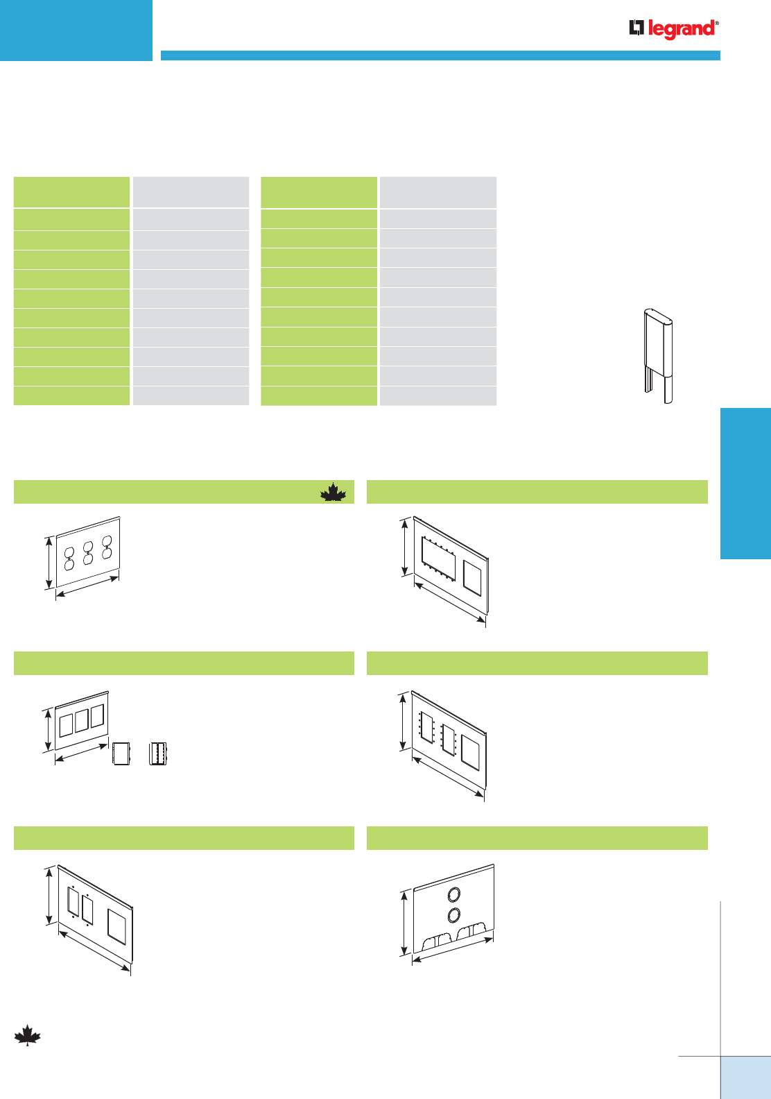
WIREMOLD
WWW.LEGRAND.US/WIREMOLD
639
POLES AND COLUMNS
VISTA CP™ CONSOLIDATION POINT
Vista CP Consolidation Point Extension Kit Ordering Information
COLOR REFERENCE
Woodgrain Laminate CODE
Amber Cherry 4407
Mahogany 4410
Maple Fusion 4401
Shaker Cherry 4408
Fonthill Pear 4406
Congo Spruce 4451
Copper Bubinga 4456
Natural Pear 4411
Biltmore Cherry 4413
Asian Sun 4467
COLOR REFERENCE
Fabric CODE
Quartz 3805
Lavendar Natural 4055
Blue Neutral 4105
Wedgewood 1505
Grey Mix 2385
Lake 0995
Malibu 0375
Globe 0245
Flax 0615
Daylight Blue 0305
For additional system options,
contact your local
Wiremold sales representative.
Design your own
Vista Architectural Column
online at www.legrand.us/tools-resources/
wiremold & click on vista configurator
Accommodates ceiling
heights between 10'
[3m] and 15' [4.5m].
Includes hardware
for attaching to
main section. Round
or square shapes
available. Includes a
center panel.
EXTENSION KIT OPTIONS
6"
[152mm]
9 1/4"
[235mm]
Vista CP Consolidation Point Add-On Plates Ordering Information
6"
[152mm]
9 1/4"
[235mm]
Has three (3) duplex receptacle
cutouts.
6"
[152mm]
9 1/4"
[235mm]
VLRT* Device Cover
Has three mini jack adapters for
Ortronics® Series II or TracJack
devices.
6"
[152mm]
9 1/4"
[235mm]
VLCR** AV Device Cover
Has openings for one (1) two-gang
or two (2) single-gang Crestron®
Quick Media wall plate(s) and one
mini adapter (included). Standard
color/material is anodized
aluminum or black.
VLEA** AV Device Cover
Has openings for six (6) Extron®
Electronics AAP modules and one
mini adapter (included). Standard
color/material is anodized
aluminum or black.
VL3D* Device Cover
*Refer to the list of colors in chart on page 590 for the four-digit code number.
Add “C”prefix to catalog number to denote Canadian version – Agency approved for sale
in Canada.
**Products are ETL Listed.
6"
[152mm]
9 1/4"
[235mm]
VLEM** AV Device Cover
Has openings for eight (8)
Wiremold AVIP or Extron®
Electronics MAAP modules and
one mini adapter (included).
Standard color/material is
anodized aluminum or black.
6"
[152mm]
9 1/4"
[235mm]
VLFF* Furniture Feed Plate
Has two concentric 1" and 3/4"
trade size KOs, and two multiple
twistout mouse holes. One
furniture feed plate installed on
the assembly.
NOTE: These are suggested colors. If there are other colors not incdicated here,
send in a color chip as most colors can be matched.
WIREMOLD
WWW.LEGRAND.US/WIREMOLD
640
POLES AND COLUMNS
VISTA CP™ CONSOLIDATION POINT
Vista CP Consolidation Point Add-On Plates Ordering Information (continued)
DEVICE PLATE PART
NUMBER CONFIGURATOR INSTRUCTIONS
Base Enter 4-digit Catalog Number
Plate Color Enter 4-digit Color Code
Adapter Color Light Gray = GY
White = WH
Ivory/Light Almond = V
Black = BK
No Device Adapter = ZZ
*Refer to the list of colors in chart on page 590 for the four-digit code number.
Add “C”prefix to catalog number to denote Canadian version – Agency approved for
sale in Canada.
**Products are ETL Listed.
6"
[152mm]
9 1/4"
[235mm]
VLCM* Furniture Feed Plate
Has three mini adapters for
Wiremold CM Series Open
System Communication Modules.
6"
[152mm]
9 1/4"
[235mm]
Accommodates commercially
available lights weighing up to
lbs. [4.5kg].
VLLB* Lighting Brackets
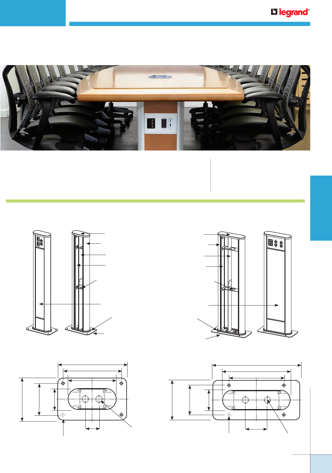
WIREMOLD
WWW.LEGRAND.US/WIREMOLD
641
POLES AND COLUMNS
Top Cap
End Channel
Small
Floor Trim Piece
Center Panel
Baseplate
Divider
Frame
Structure
Cable Pass-Through
with Grommet
(Communications Side)
Large
Top Cap
End Channel
Floor Trim Piece
Center Panel
Baseplate
Divider
Frame
Structure
Cable Pass-Through
with Grommet
(Communications Side)
Small Vista Point5
8"
[203mm]
13 1/8" [333mm]
11 1/8" [283mm]
9 3/16" [233mm]
6"
[152mm]
4"
[102mm
2 5/8"
[67mm]
1/2"
[12.7mm]
(4) Holes
3/4" & 1"
Trade Size
Knockouts (2)
Large Vista Point5
8"
[203mm]
17 5/8" [448mm]
13 11/16" [351mm]
11 1/8" [283mm]
6"
[152mm]
4"
[102mm]
4 7/16"
[113mm]
1/2"
[12.7mm]
(4) Holes
3/4" & 1"
Trade Size
Knockouts (2)
VISTA POINT5™ ARCHITECTURAL COLUMNS
CODE REFERENCE
cULus Listed Multioutlet
Assemblies:
File E15191 Guide PVGT
Meets Article 380 of NEC.
Vista Point5™ Architectural Columns provide configurable solutions
for power and communication services in open spaces.
Vista Point5 Architectural Columns System Layout
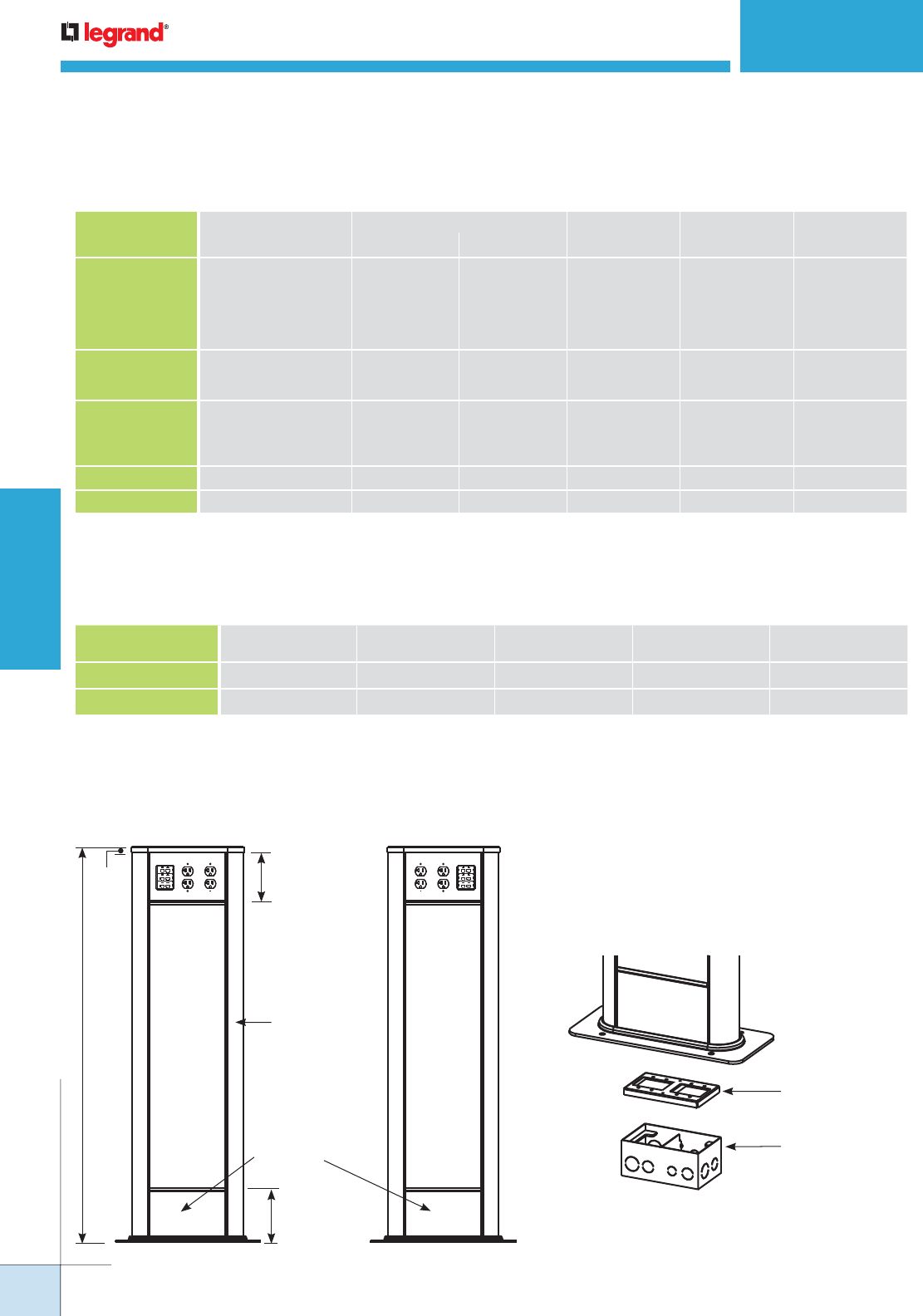
WIREMOLD
WWW.LEGRAND.US/WIREMOLD
642
POLES AND COLUMNS
NOTE: Capacity range is calculated at 40% of raceway area as stated in a proposed revisions to the Commercial Building Standard for Telecommunication
Pathways & Spaces, EIA/TIA-569. Actual wire fill capacity may vary based on applications, cable types, and number, as well as type of fittings.
(Fittings may cause additional variances to the fill capacity.)
VISTA POINT5™ ARCHITECTURAL COLUMNS
Options for Fill Capacity
Vista Point5 Wire Fill Capacity for Communication
CABLE/WIRE SIZE
O.D. LARGE
CENTER
SMALL
1/2 CENTER
LARGE
1/2 CENTERInches [mm]
Unshielded
Twisted Pair
2-pair, 24 AWG, Cat 3
3-pair, 24 AWG, Cat 3
4-pair, 24 AWG, Cat 3
25-pair, 24 AWG, Cat 3
4-pair, 24 AWG, Cat 5e
4-pair, 24 AWG, Cat 6
0.140
0.150
0.190
0.410
0.220
0.250
[3.6]
[3.8]
[4.8]
[10.4]
[5.6]
[6.3]
80
68
44
8
32
24
131
114
71
15
53
41
94
82
51
11
38
29
Shielded
Twisted Pair
Type 1, 22 AWG
Type 2, 22 AWG
Type 3, 22 AWG
0.390
0.465
0.245
[9.9]
[11.8]
[6.2]
8
4
24
16
11
42
12
8
30
Coaxial RG58/U, 20 AWG
RG58/U, 22 AWG
RG6/U, 22 AWG
RG6/U, 18 AWG
0.195
0.242
0.242
0.270
[5.0]
[6.1]
[6.1}
[6.9]
40
24
24
20
67
43
43
25
48
31
31
25
Twinaxial 100 Ohm 0.330 [8.4] 12 23 71
Fiber Optic 0.180 [4.6] 44 71 51
WIRE SIZE
THHN/THWN 6 AWG 8 AWG 10 AWG 12 AWG 14 AWG
Small 1/2 Center 7 9 16 26 35
Large 1/2 Center 7 9 16 26 35
Vista Point5 Wire Fill Capacity for Power
880S2 or 880W2
Floor Box
(order separately)
Box Adapter VB880
(order separately)
Front View
(Large Vista
Point5 Shown)
Back View
(Large Vista
Point5 Shown)
Access Panel
End Channel
Height
(FF to top
of Cap)
3/4"
[19.1mm]
6" [152mm]
Typical
Device Plate
6" [152mm]
Typical
Device Plate
Vista Point5 Architectural Columns Component Data
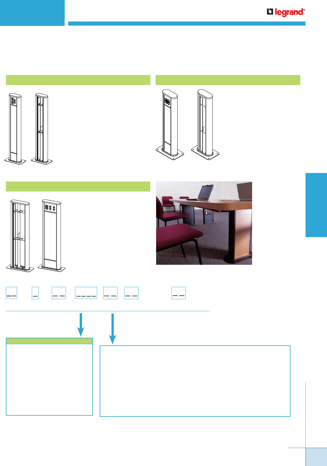
WIREMOLD
WWW.LEGRAND.US/WIREMOLD
643
POLES AND COLUMNS
VISTA POINT5™ ARCHITECTURAL COLUMNS
Options for Fill Capacity
Vista Point5 Architectural Columns In-Stock Columns Ordering Information
VSP5662345 Small Point5 Column
Small, round, 36" [914mm] high,
anodized aluminum. Has four
adapter adapters for Wiremold
Open System communication
modules, or Ortronics® Series
II or TracJack devices. Two 20A
Duplex receptacles located 32
1/4" [819mm] above floor.
VSP5662345USB Small Point5 USB Column
Small, round 36" [914mm] high,
anodized aluminum. Has two
Legrand® dual USB charging
duplexes on each side, for a
total of 16 unique charging
oportunities, located 32 1/4"
[8p10mm] above floor.
A Vista Point5 installation provides unobtrusive
access to power and communication services in a
conference room.
COLOR REFERENCE CODE
White = 3333
Black = 9999
Ivory = 5555
No Color – Anodized Aluminum = 2345
Warm White – Steelcase 4700 = 3136
Moss – Steelcase 4722 = 5169
Lt. Tone – Herman Miller LT = 2486
Mist – Steelcase 4606 = 5895
GSA Lt. Blue – GSA 25183 = 5911
Woodrose – Steelcase 4601 = 6137
Slate – Steelcase 4726 = 6142
Light Blue – Shaw Walker A751 = 1988
Greytone – Haworth – G = 2884
Size:
Small = S
Large = L
Prefix:
Frame = VF
End
Channel:
Round = 66
End Channel
Color: Adapter:
6 6
Height:
24" [607m] from
finished Floor = 24
Up to 84" [2134mm]
from finished Floor = 84
V F
Device/Adapter
Color:
Light Gray
* RT and CM options include one each electrical device plate
with spec grade duplex receptacle(s), single 120V circuit
and communications plate with adapter(s) installed.
Duplex receptacles are located at 27" [686mm] above the
finish floor.
Communications modules are located at 21" [533mm] above
the finish floor.
Furniture Feed = FF
Data Device Plates – Ortronics®
Series II or TracJack Adapters = RT*
Open System Adapters = CM*
AV Device Plates
Extron® Electronics MAAP –
(Has openings for 8 Wiremold AVIP or
Extron® MAAP Modules.
1 MAB Adapter included.) = EM
Extron® Electronics AAP –
(Has openings for 6 AAP Modules.
1 MAB Adapter included.) = EA
Crestron® Quick Media –
(Has openings for 1 two gang or
2 single gang wall plates.
1 MAAP Adapter included.) = CR
VLP5662345 Large Point5 Column
Large, round, 36" [914mm] high,
anodized aluminum. Has two
adapter adapters for Wiremold
Open System communication
modules, or Ortronics® Series II
or TracJack devices. Four 20A
Duplex receptacles located 32
1/4" [819mm] above floor.
WIREMOLD
WWW.LEGRAND.US/WIREMOLD
644
POLES AND COLUMNS
Vista Point5 Architectural Columns Center Panel Options Ordering Information
VISTA POINT5™ ARCHITECTURAL COLUMNS
Device Plate Part Number Configurator
Plate Color:
Refer to color
list on page 4,
enter 4-digit
code
Base:
Enter Catalog
Number from
above choices
Adapter Color:
Light Gray = GY
White = WH
Ivory/Lt. Almond = IV
Black = BK
No Device Adapter = ZZ
Orientation:
Left = L
Right = R
COLOR REFERENCE CODE
Aluminum:
White = 3333
Black = 9999
Ivory = 5555
No Color – Anodized Aluminum = 2345
Warm White – Steelcase 4700 = 3136
Moss – Steelcase 4722 = 5169
Lt. Tone – Herman Miller LT = 2486
Mist – Steelcase 4606 = 5895
GSA Lt. Blue – GSA 25183 = 5911
Woodrose – Steelcase 4601 = 6137
Slate – Steelcase 4726 = 6142
Light Blue – Shaw Walker A751 = 1988
Greytone – Haworth – G = 2884
COLOR REFERENCE CODE
Woodgrain Laminate:
Amber Cherry = 4407
Mahogany = 4410
Maple Fusion = 4401
Shaker Cherry = 4408
Fonthill Pear = 4406
Congo Spruce = 4451
Copper Bubinga = 4456
Natural Pear = 4411
Biltmore Cherry = 4413
Asian Sun = 4467
Metal Laminate:
Vertical Corrugated Matte Aluminum = 4748
Ragged Copper = 1999
COLOR REFERENCE CODE
Mirror Aluminum = 2021
Matte Footplate = 2046
Light Hammer Copper = 2121
Double Brushed Aluminum = 2171
Fabric:
Quartz = 3805
Lavender Natural = 4055
Blue Neutral = 4105
Wedgewood = 1505
Grey Mix = 2385
Lake = 0995
Malibu = 0375
Globe = 0245
Flax = 0615
Daylight Blue = 0305
Panel Finish:
Size:
Small = S
Large = L
Prefix:
Frame = VP
V P
Height:
24" [607m] from
finished Floor =
24
Up to 84" [2134mm]
from finished Floor =
84
Panel Type:
Wood Grain = W3
Metal Finish = M3
Glass Finish = G4
Fabric = F8
NOTE: These are suggested colors. If there are other colors not incdicated here, send in a color chip as most colors can be matched.
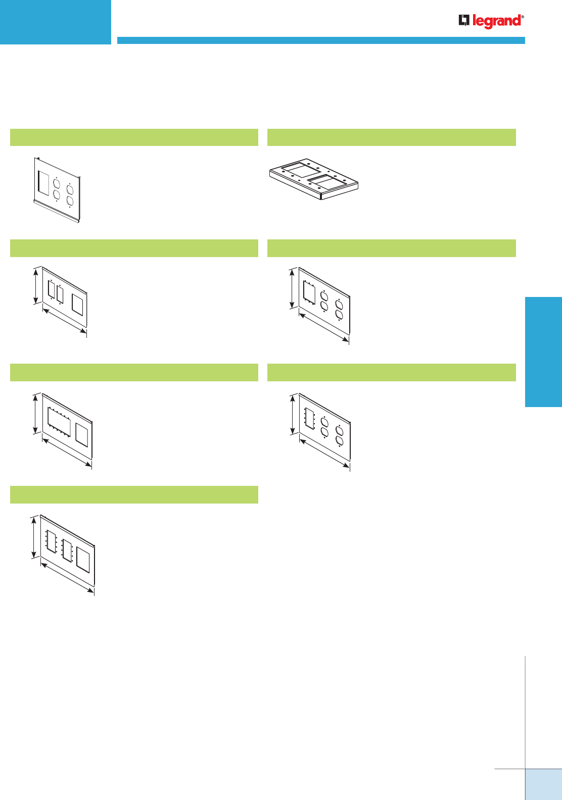
WIREMOLD
WWW.LEGRAND.US/WIREMOLD
645
POLES AND COLUMNS
VISTA POINT5™ ARCHITECTURAL COLUMNS
Vista Point5 Architectural Columns Add-On Plates for Large Frame Vista Series Ordering Information
6 1/4"
[159mm]
9 1/4"
[235mm]
6 1/4"
[159mm]
9 1/4"
[235mm]
* Refer to the list of colors in the chart on the previous page for the four-digit
code number.
**Products are ETL Listed.
NOTE: VLCR, VLEA or VLEM Device Covers, are only for use for A/V
connectivity. No power outets are accessible or available with these
covers.
VL2A Device Cover
Has two cutouts for duplex
receptacles and one adapter
for Wiremold CM Series Open
Systems communication modules,
and Ortronics® Series II or
TracJack devices.
Right Shown
VLCR** AV Device Cover
Has openings for one (1) two-gang
or two (2) single-gang Crestron®
Quick Media wall plate(s) and one
mini adapter (included). Standard
color/ material is anodized
aluminum or black.
6"
[152mm]
9 1/4"
[235mm]
VLEA** AV Device Cover
Has openings for six (6) Extron®
Electronics AAP modules and one
mini adapter (included). Standard
color/material is anodized
aluminum or black.
6"
[152mm]
9 1/4"
[235mm]
VLEM** AV Device Cover
Has openings for eight (8) Wiremold
AVIP or Extron® Electronics MAAP
modules and one mini adapter
(included). Standard color/material
is anodized aluminum or black.
VB880 Adapter Plate
Adapts Vista Point5 to 880 Series
Floor Boxes.
VLEAP5 AV Device Cover
Has two (2) duplex receptacle
cutouts and openings for three (3)
Extron® Electronics AAP modules.
Standard color/material is anodized
aluminum or black.
VLEMP5 AV Device Cover
Has two (2) duplex receptacle
cutouts and openings for four
(4) Wiremold AVIP Extron®
Electronics MAAP modules.
Standard color/material is
anodized aluminum or black.
6"
[152mm]
9 1/4"
[235mm]
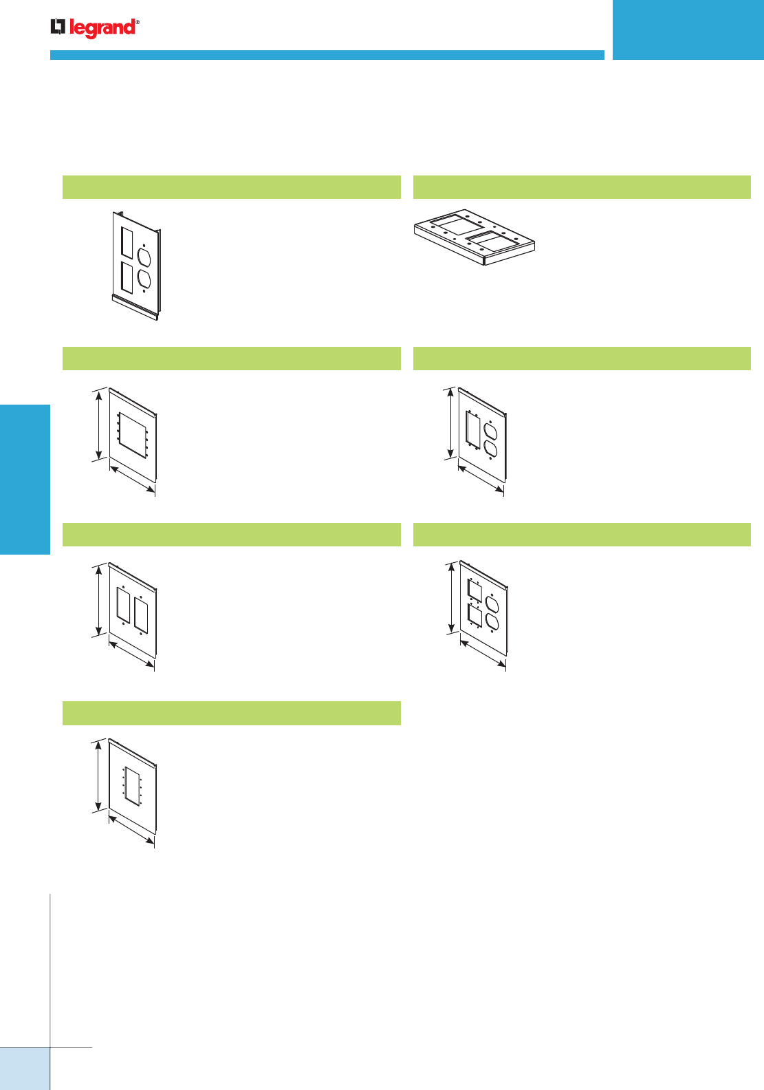
WIREMOLD
WWW.LEGRAND.US/WIREMOLD
646
POLES AND COLUMNS
VISTA POINT5™ ARCHITECTURAL COLUMNS
* Refer to the list of colors in th chart on page 596 for the four-digit code
number.
**Products are ETL Listed.
NOTE: If selecting VSEA, VSCR or VSEM Device Covers, such covers will
allow for only A/V connectivity. No power outlets are accessible or available
with these covers.
Vista Point5 Architectural Columns Add-On Plates for Small Frame Vista Series Ordering Information
VS1A Device Cover
Has one cutout for duplex
receptacle and two adapters
for Wiremold CM Series Open
Systems communication modules,
and Ortronics® Series II or
TracJack devices.
Right Shown
6"
[152mm]
4 3/4"
[121mm]
VSEA** AV Device Cover
Has openings for four (4) Extron®
Electronics AAP modules.
Standard color/material is
anodized aluminum or black.
6"
[152mm]
4 3/4"
[121mm]
VSCR** AV Device Cover
Has openings for one (1) two-gang
or two (2) single-gang Crestron®
Quick Media wall plate(s).
Standard color/ material is
anodized aluminum or black.
6"
[152mm]
4 3/4"
[121mm]
VSEM** AV Device Cover
Has openings for four (4) Wiremold
AVIP or Extron® Electronics MAAP
modules. Standard color/material
is anodized aluminum or black.
VB880 Adapter Plate
Adapts Vista Point5 to 880 Series
Floor Boxes.
6 1/4"
[159mm]
4 3/4"
[121mm]
VSEAP5 AV Device Cover
Has one (1) duplex receptacle
cutout and openings for two (2)
Extron® Electronics AAP modules.
Standard color/material is
anodized aluminum or black.
6 1/4"
[159mm]
4 3/4"
[121mm]
VSEMP5 AV Device Cover
Has one (1) duplex receptacle
cutout and openings for four
(4) Wiremold AVIP or Extron®
Electronics MAAP modules.
Standard color/material is
anodized aluminum or black.
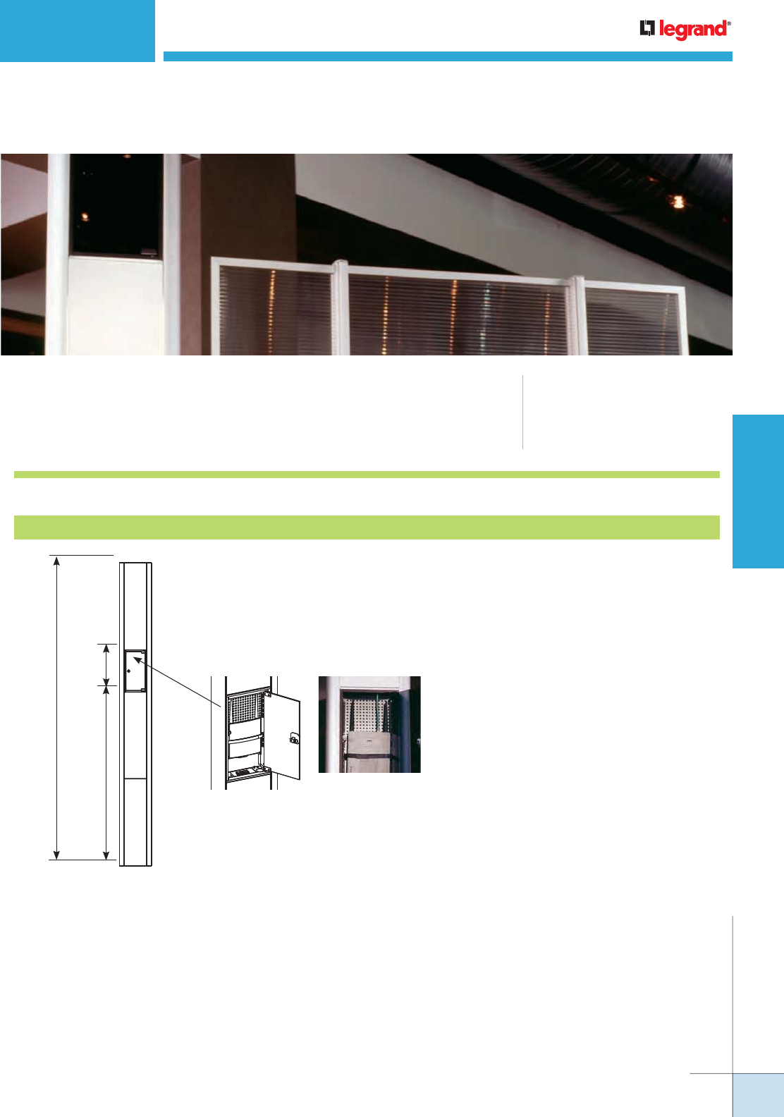
WIREMOLD
WWW.LEGRAND.US/WIREMOLD
647
POLES AND COLUMNS
VLWAP VISTA
™
WIRELESS ACCESS POINT ENCLOSURE
VLWAP Vista™ Wireless Access Point Mounting Enclosure provides an ideal
solution for integrating access points necessary for wireless connectivity into a
building’s communication infrastructure.
CODE REFERENCE
cULus Listed Multioutlet Assemblies:
File E15191 Guide PVGT
Meets Article 380 of NEC.
Vista Wireless Access Point Enclosure (VLWAP) Ordering Information
The Vista Wireless Enclosure (VLWAP) offers
an aesthetically-pleasing solution that can be
customized for any office environment as well as
providing an optimal location for wireless signals.
VLWAP Vista Wireless Access Point Enclosure
126"
[3200mm]
72"
[18.29mm]
18"
[457mm]
Vista solution for mounting wireless access points. Large frame Vista with anodized
round end channels and center panels. Furniture feed style access, 10'6" [3.2m]
tall. Has tempered glass panels to conceal access point. Front panel is hinged and
lockable. Compartment measures 17 1/2" x 7 1/4" x 2 1/2"
[445mm x 183mm x 64mm].
NOTE: For information on configuring a VLWAP within a Vista Architectural Column, visit the Open Space
Section of this catalog and review the Vista Architectural Column configuration options.
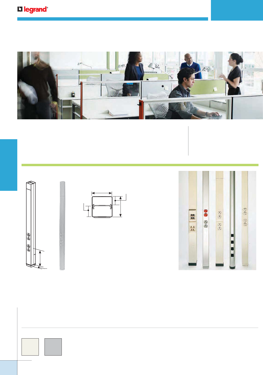
WIREMOLD
WWW.LEGRAND.US/WIREMOLD
648
POLES AND COLUMNS
TELEPOWER® POLES
CODE REFERENCE
cULus Listed Multioutlet Assemblies:
File E15191, E178348 Guide PVGT
Raceway Fittings: File E41751 Guide RJPR
Accessories: File E53857 Guide RVUR
Meets Article 380 & 386 of NEC.
Tele-Power® Poles provides a cost-effective, configurable solution
for distributing power and communication services to open spaces.
Steel Tele-Power Poles Ordering Information
COMMUNICATIONS
POWER
2 1/4"
[57mm]
2 5/16"
[59mm]
1 1/4"
[32mm]
1"
[25mm]
NOTE: Custom colors, other lengths
(20' [6.1m] max.) or additional
circuits are available on custom
order. Consult factory for more
information. Can be factory or field
wired with many commercially
available devices.
16"
[406mm]
1"
[25mm]
25DTP/DTC Series Tele-Power Poles are
now available in two colors: ivory and
designer gray.
Custom color options are also available.
Consult the factory for more information.
COLOR OPTIONS
Tele-Power Poles provide a wide range of options
for distributing services from overhead systems to
open space office, commercial, and retail areas.

WIREMOLD
WWW.LEGRAND.US/WIREMOLD
649
POLES AND COLUMNS
Two sections of a two-
compartment (power and
communi cation) pole (5' 4"
[1.626m] base + 5' [1.524m] extender) assembles to
form a 10' 4" [3.148m] pole. Nominal material thickness
.040" [1.0mm]. Ivory or designer gray boot base. Factory
wired with fed-spec general grade 20A 125V duplex style
receptacles. An 8" [203mm] cover at top front (power side)
of pole is removable for making power wiring connections.
KOs provided in removable cover for RJ11/RJ45 and modular
furniture communication connectors. Mounting hardware,
entrance end plate and two ceiling trim plates furnished.
Tele-Power Pole
PART NUMBERS:
25DTP-4 (10' 5" [3.2m] Length, Ivory)
25DTP-4-DG (10' 5" [3.2m] Length, Designer Gray)
25DTP-412 (12' 5" [3.8m] Length, Ivory)
25DTP-412-DG (12' 5" [3.8m] Length, Designer Gray)
25DTP-415 (15' 5" [4.7m] Length, Ivory)
25DTP 415-DG (15' 5" [4.7m] Length, Designer Gray)
Two-compartment pole (power and communications).
Nominal material thickness .030" [.8mm]. Ivory or designer
gray boot base. Factory wired with fed-spec general grade
20A 125V duplex style receptacles. An 8" [203mm] cover at
top front of pole is removable for making power wiring
connections. KOs provided in removable cover for RJ11/
RJ45 and modular furniture communication connectors.
Mounting hardware, entrance end plate and two ceiling trim
plates furnished. Also increase the length of any 25 Series
pole with the 25DTC-E5 Tele-Power Pole Extender.
TELEPOWER® POLES
Steel Tele-Power Poles
25DTP Series Tele-Power Poles Ordering Information
Tele-Power Pole
Identical to 25DTP-4 except
with one communications
insert mounting adapter
and three blank inserts.
Tele-Power Pole
Identical to 25DTP-4
except has one 20A 125V
dedicated/isolated ground
duplex receptacle and one
20A 125V standard duplex
receptacle.
Tele-Power Pole
Two-compartment pole (power and communications).
Nominal material thickness .030" [.8mm]. Ivory or designer
gray boot base. Factory wired with fed-spec general grade
15A 125V duplex style receptacles. An 8" [203mm] cover
at top front of pole is removable for making power wiring
connections. KOs provided in removable cover for RJ11/
RJ45 and modular furniture communication connectors
Mounting hardware, entrance end plate and two ceiling
trim plates furnished. Comes with a 10' [3.0m] cord. Also
increase the length of any 25 Series pole with the 25DTC-E5
Tele-Power Pole Extender.
*20% cable fill is calculated to approximate reduction in cable capacity due to connectors mounted within pole section that may restrict cross-sectional areas.
**40% cable fill is the maximum designed cable fill based on a proposed revision to TIA/EIA 569-A.
25DTP Series Tele-Power Poles Wire Fill Capacities
CATALOG
NUMBER
NO. & TYPE
OF POWER
OUTLETS
POLE HEIGHT
FINISH
WIRE SIZE
THHN/THWN CAT 5 CAT 6 RG58/U RG62A/U RG62/U
#10 #12
0.22"
20%*
[5.6mm]
0.25"
20%*
[6.3mm]
40%**
0.195"
20%*
[5.0mm]
40%**
0.242"
20%*
[6.1mm]
40%**
0.270
20%*
[6.9mm]
40%**Inches mm
25DTP-4
Two
Duplex
Receptacles
(20A, 125V)
10' 5" [3.175m] Ivory/Gray 10 15 10 19 9 17 13 25 8 16 7 13
25DTP-412 12' 5" [3.780m] Ivory/Gray 10 15 10 19 9 17 13 25 8 16 7 13
25DTP-415 15' 5" [4.700m] Ivory/Gray 10 15 10 19 9 17 13 25 8 16 7 13
25DTP-E10 10' 5" [3.175m] Ivory/Gray 10 15 10 19 9 17 13 25 8 16 7 13
25DTP-4 D
10' 5" [3.175m] Ivory/Gray 10 15 10 19 9 17 13 25 8 16 7 13
Two Duplex Receptacles (20A, 125V),
One Dedicated/ Isolated & One Standard Branch Circuit
25DTP-4ACT
10' 5" [3.175m] Ivory/Gray 10 15 10 19 9 17 13 25 8 16 7 13
Two Duplex Receptacles (20A, 125V),
One Communications Insert Mounting Adapter, One Dual
Cat 5e Insert, Two Blank Inserts & Labeling Supplies
Tele-Power Pole (Canada Only)
PART NUMBERS:
25DTP-4-C (10' 5" [3.2m] Length, Ivory)
25DTP-4-DG-C (10' 5" [3.2m] Length, Designer Gray)
25DTP-412-C (12' 5" [3.8m] Length, Ivory)
25DTP-412-DG-C (12' 5" [3.8m] Length, Designer Gray)
25DTP-415-C (15' 5" [4.7m] Length, Ivory)
25DTP-415-DG-C (15' 5" [4.7m] Length, Designer Gray)
PART NUMBERS:
25DTP-4ACT (Ivory)
25DTP-4ACT-DG (Designer Gray)
PART NUMBERS:
25DTP-4D (Ivory)
25DTP-4D-DG (Designer Gray)
PART NUMBERS:
25DTP-E10 (Ivory)
25DTP-E10-DG (Designer Gray)
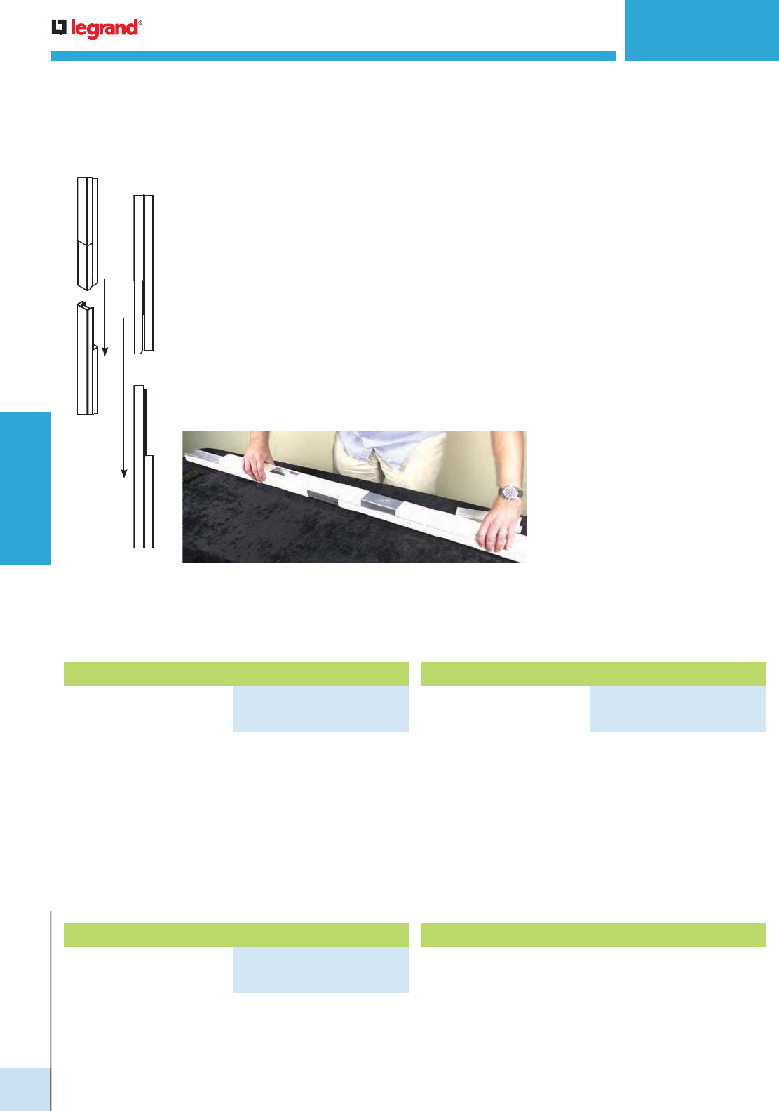
WIREMOLD
WWW.LEGRAND.US/WIREMOLD
650
POLES AND COLUMNS
Tele-Power Express Pole
TELEPOWER® POLES
Steel Tele-Power Poles
NOTE: No Tele-Power Pole can have more than three separate sections.
25DTP/C Series Poles cannot be combined with 25DTP/C-E10. The
25DTC-E5 can be used only to extend regular 25DTP/C poles.
Easier jobsite handling + easier and more reliable shipping options Wiremold Tele-Power Express
Pole and Tele-Power Pole Extender were introduced to make creating or altering poles easy. The TP
Express Pole allows you to create a single 10' pole using two sections, which are easy to ship and easy
to assemble on the jobsite.
Configurability of the TPP Extenders allows for on site modifications to accommodate a variety of ceiling
heights. TP Express Poles and TPP Extenders can ship UPS or air freight. TPP Extenders have been
designed to be compatible with existing poles, so relocating is literally, a snap – quick, easy, and done
with in-stock components. Existing poles can also be retrofit/extended to be used in a location with a
higher ceiling using TPP Extenders.
When you need a reliable open space power and/or data solution in the shortest amount of time,
no matter the length needed, think Wiremold TP Express Poles and TPP Extenders.
Side View
NOTE: When being used to modify or extend standard poles, the poles can
only be modified or extended in 5' [1.524m] increments.
Tele-Power Express Poles and Tele-Power Pole Extenders
TPP Extenders Ordering Information
Two sections of a two-
compartment (power and
communication) pole (5' 4"
[1.62m] base + 5' [1.52m] extender) assembles to form a 10'
4" [3.14m] pole. Nominal material thickness .040" [1.0mm].
Ivory or designer gray boot base. Factory wired with fed-
spec general grade 20A 125V duplex style receptacles. An 8"
[203mm] cover at top front (power side) of pole is removable
for making power wiring connections. KOs provided in
removable cover for RJ11/RJ45 and modular furniture
communication connectors. Mounting hardware, entrance
end plate and two ceiling trim plates furnished.
Blank Steel Tele-Power Pole Extender
Two-compartment extender
mounts onto existing 25DTP
or 25DTC series pole.
Nominal material thickness .040" [1.0mm]. Furnished
unwired without outlets. Use existing pole mounting
hardware, entrance end plate and ceiling trim plate.
Available in 5' [1.52m] length. Can be cut to desired length.
Two sections of a two-
compartment pole (5' 4"
[1.62m] base + 5' [1.52m]
extender) assembles to form a 10' 4" [3.14m] pole. Nominal
material thickness .040" [1.0mm]. Ivory or designer gray
boot base. Furnished unwired without outlets. Mounting
hardware, entrance end plate and ceiling trim plate
furnished. An 8" [203mm] cover at top front of pole is
removable for making power wiring connections.
25AM-AP Accessory Pack
Accessory pack for 25 Series and AM Series poles.
Contains ceiling trim plate, bracket, grommet and end plate.
Blank Steel Tele-Power Express Pole
PART NUMBERS:
25DTC-E10 (Ivory)
25DTC-E10-DG (Designer Gray)
PART NUMBERS:
25DTP-E10 (Ivory)
25DTP-E10-DG (Designer Gray)
PART NUMBERS:
25DTC-E5 (Ivory)
25DTC-E5-DG (Designer Gray)
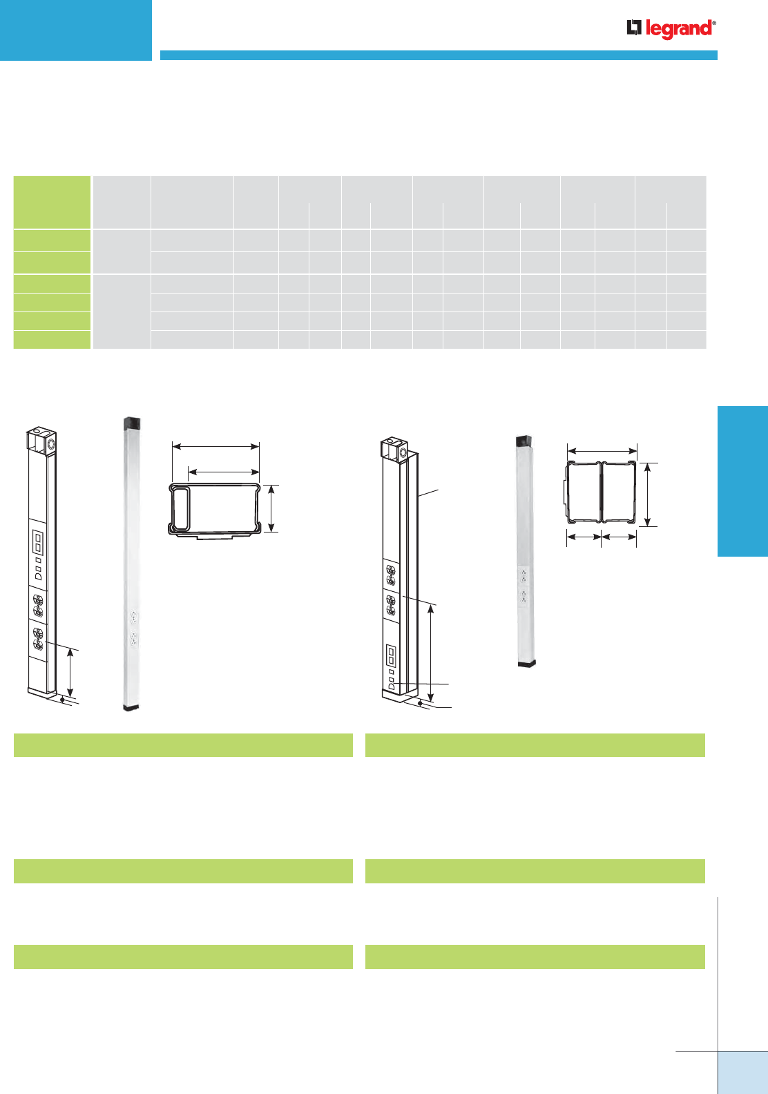
WIREMOLD
WWW.LEGRAND.US/WIREMOLD
651
POLES AND COLUMNS
TELEPOWER® POLES
Steel Tele-Power Poles
30TP-2V
POWER
COMMUNICATION
2 3/4"
[70mm]
1 7/8"
[48mm]
1 17/32"
[39mm]
NOTE: Custom colors, other
lengths (20' [6.1m] max.)
or additional circuits
are available on custom
order. Consult factory for
more information. 30TP-
2V and 30TP-4V can be
factory or field wired
with many commercially
available devices.
14.25"
[365mm]
1"
[25mm]
30TP Series Tele-Power Poles Ordering Information
30TP-2V Tele-Power Pole
Two-compartment pole (power and communications).
Nominal material thickness .040" [1.0mm]. Length 10'5"
[3.2m]. Factory wired with two specification grade 20A,
125V duplex receptacles. Mounting hardware, entrance end
fitting, and ceiling trim plate furnished.
30TP-212V Tele-Power Pole
Identical to 30TP-2V except length is 12'5" [3.8m]. Maximum
ceiling height 12' [3.7m].
30TP-4V Tele-Power Pole
Two-compartment pole (one power; one communication
with cross over below power devices). Nominal material
thickness .040" [1.0mm]. Length 10'5" [3.2m]. Factory wired
with two specification grade 20A, 125V duplex receptacles.
Mounting hardware, entrance end fitting, and ceiling trim
plate furnished.
30TP-4V3S2 Tele-Power Pole
Two duplex receptacles (20A, 125V). One Ortronics Series
II adapter. One Ortronics Series II dual Cat 5e insert, two
blank inserts and labeling supplies. Maximum ceiling height
10'5" [3.2m].
30TP-412V Tele-Power Pole
Same as 30TP-4V except length is 12'5" [3.8m]. Maximum
ceiling height 12'5" [3.8m].
30TP-412V3S2 Tele-Power Pole
Two duplex receptacles (20A, 125V). One Ortronics Series
II adapter. One Ortronics Series II dual Cat. 5e insert, two
blank inserts and labeling supplies. Maximum ceiling height
12'5" [3.8m].
3"
[76mm]
1 1/2"
[38mm]
2 3/4"
[70mm]
1 1/2"
[38mm]
30TP-4V
Communication
Communication
14.25"
[365mm]
1"
[25mm]
NOTE: 30TP Series Tele-Power
Poles now compatible with A/V
devices.
30TP Series Tele-Power Poles Wire Fill Capacities
* 20% cable fill is calculated to approximate reduction in cable capacity due to connectors mounted within pole section that may restrict cross-sectional areas.
** 40% cable fill is the maximum designed cable fill based on a proposed revision to TIA/EIA 569-A.
CATALOG
NUMBER
NO. & TYPE
OF POWER
OUTLETS
POLE HEIGHT
FINISH
WIRE SIZE
THHN/THWN CAT 5 CAT 6 RG58/U RG62A/U RG62/U
#10 #12
0.22"
20%*
[5.6mm]
40%**
0.25"
20%*
[6.3mm]
40%**
0.195"
20%*
[5.0mm]
40%**
0.242"
20%*
[6.1mm]
40%**
0.270
20%*
[6.9mm]
40%**Inches mm
30TP-2V Two Duplex
Receptacles
(20A, 125V)
10' 5" [3.175m] Ivory 9 14 16 31 13 26 20 40 13 25 10 20
30TP-212V 12' 5" [3.780m] Ivory 9 14 16 31 13 26 20 40 13 25 10 20
30TP-4V
Two
Duplex
Receptacles
(20A, 125V)
10' 5" [3.175m] Ivory 18 18 19 37 15 30 24 47 15 30 12 24
30TP-412V 12' 5" [3.780m] Ivory 18 18 19 37 15 30 24 47 15 30 12 24
30TP-4V3S2 10' 5" [3.175m] Ivory 18 18 19 37 15 30 24 47 15 30 12 24
30TP-412V3S2 12' 5" [3.780m] Ivory 18 18 19 37 15 30 24 47 15 30 12 24
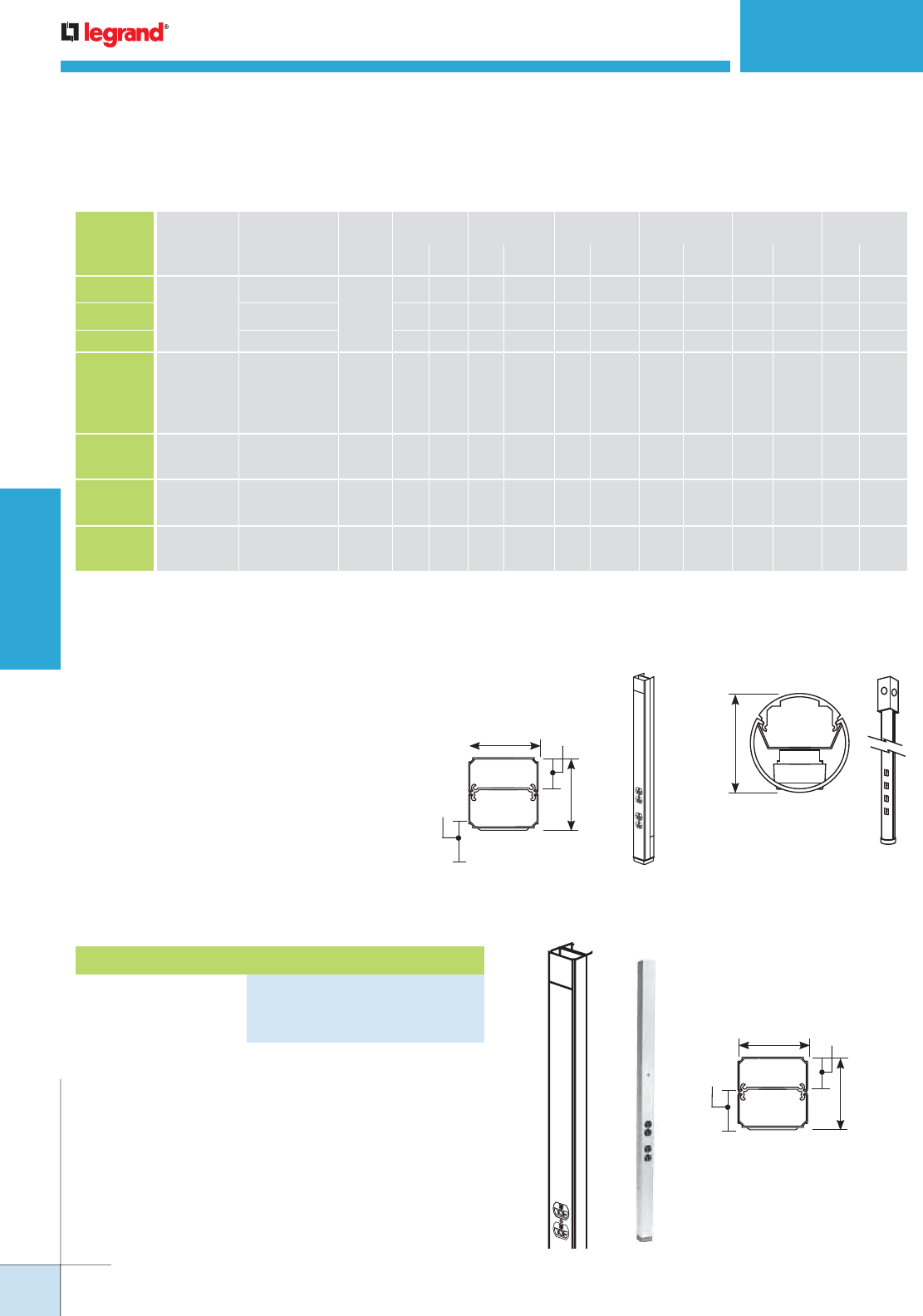
WIREMOLD
WWW.LEGRAND.US/WIREMOLD
652
POLES AND COLUMNS
TELEPOWER® POLES
Aluminum Tele-Power Poles
ALTP
2"
[51mm]
NOTE: There is no method
provided for mounting data
in this pole.
When looking to dress up a vertical solution,
Tele-Power Poles with a satin anodized
aluminum finish in either rectangular or round
styles can provide the answer. Light weight
aluminum construction makes these poles
easy to install and maneuver on the job site.
Available prewired with electrical devices
or blank to drop services feeding another
wire and cable management system, such as
electrified modular furniture. A full range of
accessories enables field configurability, or
have them delivered to your specifications.
Aluminum Tele-Power Poles
AMDTP-4
1 1/4"
[32mm] POWER
2 1/4"
[57mm]
2 5/16"
[59mm]
1"
[25mm]
COMMUNICATIONS
AMDTP-4 Series Tele-Power Poles Ordering Information
Two-compartment pole (power and communications).
Nominal material thickness .050" [1.8mm]. Length: 10'5"
[3.2m]. Factory wired with 20A 125V fed-spec general grade
duplex style receptacles. An opening for communication and
a 1/2" [12.7mm] hole for power is provided at top. The 8"
[203mm] cover at top front of pole is removable for making
power wiring connections. Communication KOs provided for
RJ11/RJ45 and modular furniture connectors. Mounting
hardware, entrance end fitting, and ceiling trim plates
furnished. Anodized aluminum finish.
COMMUNICATIONS
POWER
2 1/4"
[57mm]
2 5/16"
[59mm]
1 1/4"
[32mm]
1"
[25mm]
NOTE: Custom colors, other lengths
(20' [6.1m] max.) or additional
circuits are available on
custom order. Consult factory
for more information. Can be
factory or field wired with many
commercially available devices.
CATALOG
NUMBER
NO. & TYPE
OF POWER
OUTLETS
POLE HEIGHT
FINISH
WIRE SIZE
THHN/THWN CAT 5 CAT 6 RG58/U RG62A/U RG62/U
#10 #12
0.22"
20%*
[5.6mm]
40%**
0.25"
20%*
[6.3mm]
40%**
0.195"
20%*
[5.0mm]
40%**
0.242"
20%*
[6.1mm]
40%**
0.270
20%*
[6.9mm]
40%**Inches mm
AMDTP-4 Two
Duplex
Receptacles
(20A, 125V)
10' 5" [3.175m]
Satin
Anodized
Aluminum
10 15 10 19 8 16 13 25 8 16 7 13
AMDTP-412 12' 5" [3.780m] 10 15 10 19 8 16 13 25 8 16 7 13
AMDTP-415 15' 5" [4.700m] 10 15 10 19 8 16 13 25 8 16 7 13
AMDTP-4D
T
wo Duplex
Receptacles
(20A, 125V), One
Dedicated/Isolated
& One Standard
Branch Circuit
10' 5" [3.175m]
Satin
Anodized
Aluminum
10 15 10 19 8 16 13 25 8 16 7 13
ALTP-20W Four Single
Receptacles 10' 4" [3.150m] Painted
Office
White
––2524 3 62413
ALTP-2P Four Single
Receptacles 10' 4" [3.150m]
Polished
Anodized
Aluminum
––2524 3 62413
ALTP-2S Four Single
Receptacles 10' 4" [3.150m]
Polished
Anodized
Aluminum
––2524 3 62413
Aluminum Tele-Power Poles Wire Fill Capacities
* 20% cable fill is calculated to approximate reduction in cable capacity due to connectors mounted within pole section that may restrict cross-sectional areas.
** 40% cable fill is the maximum designed cable fill based on a proposed revision to TIA/EIA 569-A.
Tele-Power Pole
PART NUMBERS:
AMDTP-4 (10' 5" [3.2m] Length)
AMDTP-412 (12' 5" [3.8m] Length)
AMDTP-415 (15' 5" [4.7m] Length)
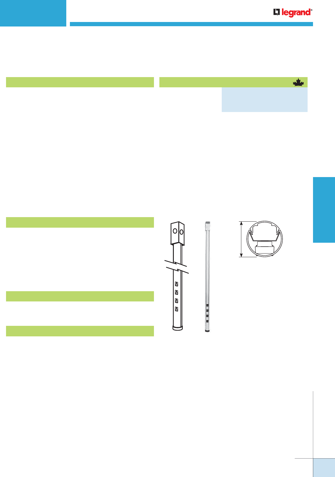
WIREMOLD
WWW.LEGRAND.US/WIREMOLD
653
POLES AND COLUMNS
Tele-Power Pole
PART NUMBERS:
AMDTP-4-C (10' 5" [3.2m] Length)
AMDTP-412-C (12' 5" [3.8m] Length)
AMDTP-415-C (15'5" [4.7m] Length)
TELEPOWER® POLES
Aluminum Tele-Power Poles
2"
[51mm]
NOTE: There is no method provided for
mounting data in this pole.
ALTP-20W Tele-Power Pole
Identical to ALTP-2S, with painted office white finish.
ALTP-2P Tele-Power Pole
Identical to ALTP-2S, with polished aluminum anodized
finish.
ALTP-2S Tele-Power Pole
Satin anodized extruded aluminum pole. Nominal wall
thickness .060" [1.5mm]. Length 10'5" [3.2m]. Two-
compartment (power and communication channels) Factory
wired with four 15A 125V NEMA 5-15R devices. Provided
with one 1/2" [12.7mm] trade size KO in cover at base for
communications. T-bar mounting hardware, ceiling trim kit,
and feed box furnished.
ALTP Series Tele-Power Poles Ordering Information
AMDTP-4D Tele-Power Pole
Identical to AMDTP-4 except factory wired with one 20A
125V dedicated/ isolated ground duplex receptacle and one
standard 20A 125V duplex receptacle.
Available in Canada Only. Two-compartment pole (power
and communications). Nominal material thickness .050"
[1.8mm]. Length: 10'5" [3.2m]. Factory wired with 15A 125V
fed-spec general grade duplex style receptacles. An opening
for communication and a 1/2" [12.7mm] hole for power
is provided at top. The 8" [203mm] cover at top front of
pole is removable for making power wiring connections.
Communication KOs provided for RJ11/RJ45 and modular
furniture connectors. Mounting hardware, entrance end
fitting, and ceiling trim plates furnished. Anodized aluminum
finish. Maximum ceiling height 10' [3m]. Comes with a 10'
[3.0m] cord.
AMDTP-4 Series Tele-Power Poles Ordering Information (continued)
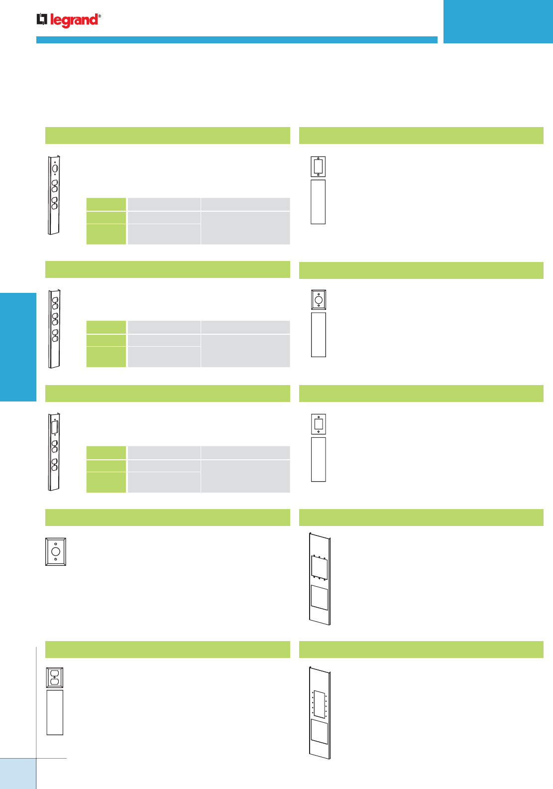
WIREMOLD
WWW.LEGRAND.US/WIREMOLD
654
POLES AND COLUMNS
TELEPOWER® POLES
Tele-Power Poles Device Plate Covers and Accessories Ordering Information
30TP-A Single Receptacle Cover
Single receptacle cover for field installation of
receptacles with face diameters of 1.38"-1.40"
[35mm-36mm]. G3007C Device Bracket included.
Ivory finish.
30TP-B Duplex Receptacle Cover
For installations of 15A and 20A duplex
receptacles. G3007C Device Bracket
included. Ivory finish.
30TP-C Single Gang Cover
Accepts up to 30A shallow-style device
and flushplate. G3007C Device Bracket
included. Ivory finish. Used to mount industry
standard straight and angled communication
faceplates.
30TP-J Single Receptacle Cover
For field installation of single receptacles
with face diameters of 1.56" [40mm]. G3007C
Device Bracket included. Ivory finish.
30TP-L Rectangular Device Cover
Rectangular faceplate to accommodate
Sentrex surge receptacle, GFCI and other
decorator style devices. G3007C Device
Bracket included. Ivory finish.
Add-On Power Cover
Add power receptacles or devices to existing
modular Tele-Power Poles. Includes receptacle
mounting bracket. Face diameter of single
receptacle: 1.38"-1.40" [35mm-36mm].
COLOR DIMENSIONS
25DTP-A Ivory Steel (25DTP-4) 1" x 2 1/4" x 28"
[25mm x 57mm x 711mm]
AMDTP-A Anodized Aluminum
(AMDTP-4)
Add-On Power Cover
Add power receptacles or devices to existing
modular Tele-Power Poles. Includes receptacle
mounting bracket.
COLOR DIMENSIONS
25DTP-B Ivory Steel (25DTP-4) 1" x 2 1/4" x 28"
[25mm x 57mm x 711mm]
AMDTP-B Anodized Aluminum
(AMDTP-4)
Add-On Power Cover
Add power receptacles or devices to existing
modular Tele-Power Poles. Includes receptacle
mounting bracket.
COLOR DIMENSIONS
25DTP-L Ivory Steel (25DTP-4) 1" x 2 1/4" x 28"
[25mm x 57mm x 711mm]
AMDTP-L Anodized Aluminum
(AMDTP-4)
30TP-AAP Add-on A/V Cover
Accepts three Extron® Electronics AAP plates
12" L x 2.75" W [305mm x 70mm]. Includes
three adapters to accommodate Ortronics®
or Wiremold Open System devices.
30TP-MAAP Add-on A/V Cover
Accepts five Wiremold AVIP or Extron®
Electronics MAAP plates 12" L x 2.75" W
[305mm x 70mm]. Includes three adapters to
accommodate Ortronics® or Wiremold Open
System devices.
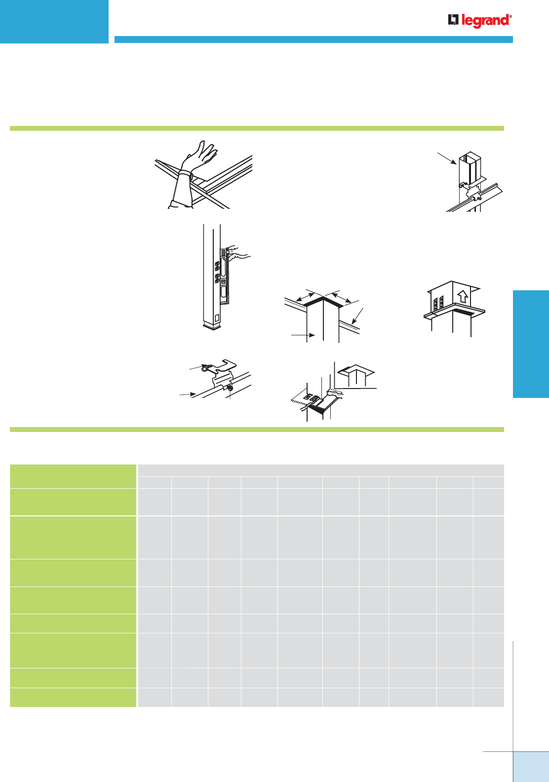
WIREMOLD
WWW.LEGRAND.US/WIREMOLD
655
POLES AND COLUMNS
TELEPOWER® POLES
Tele-Power Poles Installation Details
1. Remove ceiling panel. If
necessary to avoid overhead
obstructions, shorten Tele-
Power Pole prior to installing.
(NOTE: Pole must extend above mounting
bracket, with the bottom of pole
resting on the floor.)
2. Align pole vertically (using a level) with
top of pole resting against ceiling T-bar.
After aligning pole, anchor gripper pad
to hard surface floor with sticky pad
(furnished) or two screws (not furnished).
3. Assemble pole mounting bracket
on T-bar at approximate location
as shown. Tighten bracket,
locking thumbscrew loosely so
bracket is free to slide on T-bar.
Pole
Mounting
Bracket
T-Bar
Thumbscrew
4. Place pole in mounting bracket
(again check vertical alignment
with level) and tighten T-bar, locking
thumbscrew, and pole locking
thumbscrew. If additional support
is desired, bracket may be secured
to true ceiling with 3/8" [9.5mm]
threaded rod (not furnished).
Pole Locking
Thumbscrew
5. Notch ceiling tile as shown and install plates (Fig. 1).
Tabs should be in a vertical position as trim plate is
aligned around pole (Fig. 2). Following alignment, tabs
should be bent to form a secure grip over ceiling tile
(Fig.3).
Figure 2
Pole
Away
From
T-Bar
Figure 3
Engage Two
Trim Plates
on Pole
Trim Plates
on Ceiling
Notch Panel
Pole
Beside
T-bar
T-Bar
Figure 1
Pole
Field Modifications for Tele-Power Poles
MODIFICATION
TELE-POWER POLE SERIES
30TP4V 30TC4V 30TP2V 30TC2V 25DTP4 25DTP4D 25DTC4 AMDTP4 AMDTP4D AMTC4
Can the receptacles in the standard
pole be rewired in order to have a two
circuit pole with standard duplexes?
Yes
N/A Yes N/A No Yes N/A No Yes N/A
Can the receptacles in the standard
pole be replaced with other types?
(i.e. Hospital Grade, TVSS, GFCI, etc.)
Yes –
Using the
proper
device
cover
N/A Yes –
Using the
proper
device
cover
N/A Yes – with
2507C Bracket
& only with
NEMA duplex
receptacles
Yes – only
with NEMA
duplex
receptacles
N/A Yes – with
2507C Bracket
& only with
NEMA duplex
receptacles
Yes – only
with NEMA
duplex
receptacles
N/A
Can receptacles be added
to blank poles?
N/A Yes N/A Yes – Using
the proper
device cover
N/A N/A Yes N/A N/A Yes
Can blank poles be used for furniture
feed applications by field punching
KOs on poles for power and voltage?
N/A Yes N/A Yes N/A N/A Yes N/A N/A Yes
Can more than one add-on device
cover be used?
N/A N/A N/A N/A Yes Yes N/A Yes Yes N/A
Can receptacles be installed in both
sides of the pole?
Yes –
Power only
on both
sides
Yes –
Power only
on both
sides
N/AN/A No No N/A No No N/A
Can poles be field cut for use in lower
ceiling applications?
Yes* Yes* Yes* Yes* Yes* Yes* Yes* Yes* Yes* Yes*
Can poles be mounted to hard or
open ceilings?
Yes* Yes* Yes* Yes* Yes* Yes* Yes* Yes* Yes* Yes*
* Review instruction sheet for instructions for cutting poles.
** Pole housing cannot be penetrated. Ceiling mounting hardware must provide firm support and must be supplied by installer.
NOTE: All receptacles, additions, rewiring and other electrical modifications must be made by a qualified electrician in accordance with the NEC or other
applicable local codes and adhering to the wire fill capacity charts for the respective pole.

WIREMOLD
WWW.LEGRAND.US/WIREMOLD
656
POLES AND COLUMNS
VERTICAL DROP POLES
CODE REFERENCE
cULus Listed Multioutlet Assemblies:
File E15191, E178348 Guide PVGT
Raceway Fittings: File E41751 Guide RJPR
Accessories: File E53857 Guide RVUR
Meets Article 380 & 386 of NEC.
Vertical Drop Poles distribute power and communication services
form overhead wiring systems to open spaces.
Vertical Drop Poles Wire Fill Capacities
CATALOG
NUMBER
POLE HEIGHT
FINISH
CAT 5 CAT 6 RG58/U RG62A/U RG62/U
0.22"
COMP. [5.6mm]
LG. COMP.
0.25"
SM. COMP.
[6.3mm]
LG. COMP.
0.195"
SM. COMP.
[5.0mm]
LG. COMP.
0.242"
SM. COMP.
[6.1mm]
LG. COMP.
0.270
SM. COMP.
[6.9mm]
LG. COMP.
Inches mm
25DTC-4 10' 5" [3.175m] Ivory/Gray 10 19 9 17 13 24 8 16 7 13
25DTC-412 12' 5" [3.780m] Ivory/Gray 10 19 9 17 13 24 8 16 7 13
25DTC-415 15' 5" [4.700m] Ivory/Gray 10 19 9 17 13 24 8 16 7 13
25DTC-E10 10' 5" [3.175m] Ivory/Gray 10 19 9 17 13 24 8 16 7 13
30TC-2V 10' 5" [3.175m] Ivory N/A 33 N/A 30 N/A 47 N/A 30 N/A 24
30TC-2V212 12' 5" [3.780m] Ivory N/A 34 N/A 31 N/A 48 N/A 31 N/A 25
30TC-4V 10' 5" [3.175m] Ivory 37 37 30 30 47 47 30 30 24 24
30TC-4V412 12' 5" [3.780m] Ivory 37 37 30 30 47 47 30 30 24 24
30TC-3S2 10' 5" [3.175m] Ivory 37 37 30 30 47 47 30 30 24 24
AMTC-4 10' 5" [3.175m] Aluminum 19 26 16 22 25 33 16 21 13 17
AMTC-412 12' 5" [3.780m] Aluminum 19 26 16 22 25 33 16 21 13 17
AMTC-415 15' 5" [4.700m] Aluminum 19 26 16 22 25 33 16 21 13 17
ALTP-20W 10' 4" [3.150m] White 10 8 13 8 6
ALTP-2P 10' 4" [3.150m] Aluminum 10 8 13 8 6
ALTP-2S 10' 4" [3.150m] Aluminum 10 8 13 8 6
NP800C-12-2B 10' 2" [3.098m] Aluminum
NP800C-12-8B 12' 8" [3.860m] Aluminum
NP800C-15-2B 15' 2" [4.620m] Aluminum
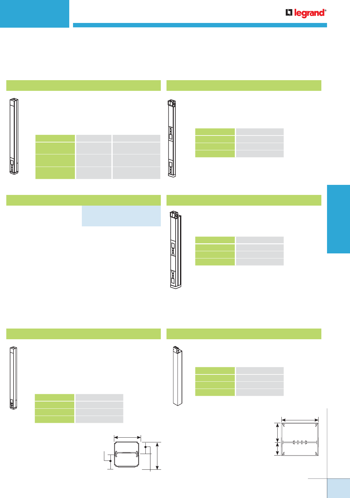
WIREMOLD
WWW.LEGRAND.US/WIREMOLD
657
POLES AND COLUMNS
Two-compartment pole. Nominal material
thickness .050" [1.8mm]. Furnished unwired
without outlets. Two 8" [203mm] removable
covers with KOs for modular jacks and modular
furniture communication outlets. Mounting
hardware, entrance end plate and ceiling trip
plates furnished.
Vertical Drop Steel Tele-Power Poles Ordering Information
VERTICAL DROP POLES
Blank Steel Pole
Two-compartment pole. Nominal material
thickness .040" [1.0mm]. Ivory or designer gray
boot base. Furnished unwired without outlets.
Mounting hardware, entrance end plate and
ceiling trip plates furnished.
Blank Steel Pole
Single-compartment pole. Furnished unwired
without outlets. Nominal wall thickness .040"
[1.0mm]. Mounting hardware, entrance end
fitting and ceiling trim plates furnished.
30TC-4V
NOTE: All poles have removable cover sections with KOs for modular
jacks and openings to accept modular furniture adapters for
communication devices.
Two sections of a two-compartment pole (5'4" [1.63m] base
+ 5' [1.52m] extender) assembles to form a 10'4" [3.15m]
pole. Nominal material thickness .040" [1.0mm]. Furnished
unwired without outlets. Mounting hardware, entrance end
plate and ceiling trip plate furnished. An 8" [203mm] cover
at top front of pole is removable for making power wiring
connections.
Blank Steel Pole
Two-compartment pole.Nominal wall thickness
.040" [1.0mm]. Mounting hardware, entrance end
fitting and ceiling trim plates furnished.
25DTC-4 30TC-2V
Vertical Drop Aluminum Tele-Power Poles Ordering Information
5"
[127mm]
2 13/16"
[71mm]
1 15/16"
[49mm]
12 sq. in.
[7742 sq. mm]
8 sq. in.
[5161 sq. mm]
AMTC-4
2 1/4"
[57mm]
1 1/4"
[32mm]
1"
[25mm]
Custom options: Features such as colors
or other lengths (20' [6.1m] maximum)
available on custom order.
Blank Aluminum Pole
Other heights available – consult factory;
30" [762mm] communication cover with
industry standard knockouts.
Blank Aluminum Pole
Two-compartment large capacity pole. Furnished
unwired without outlets. Box ended with industry
sized knockouts.
CAT. NO. COLOR AVAILABLE LENGTHS
25DTC-4
25DTC-4-DG
Ivory
Designer Gray 10'5" [3.2m]
25DTC-412
25DTC-412-DG
Ivory
Designer Gray 12'5" [3.8m]
25DTC-415
25DTC-415-DG
Ivory
Designer Gray 15'5" [4.7m]
Blank Steel Tele-Power Express Pole
PART NUMBERS:
25DTC-E10 (Ivory)
25DTC-E10-DG (Designer Gray)
CAT. NO. AVAILABLE LENGTHS
30TC-2V 10'5" [3.2m]
30TC-212V 12'5" [3.8m]
30TC-215V 15'5" [4.7m]
CAT. NO. AVAILABLE LENGTHS
30TC-4V 10'5" [3.2m]
30TC-412V 12'5" [3.8m]
30TC-415V 15'5" [4.7m]
CAT. NO. AVAILABLE LENGTHS
AMTC-4 10'5" [3.2m]
AMTC-412 12'5" [3.8m]
AMTC-415 15'5" [4.7m]
CAT. NO. STANDARD HEIGHTS
NP800C-10-2B 10'2" [3.1m]
NP800C-12-2B 12'8" [3.9m]
NP800C-15-2B 15'2" [4.6m]
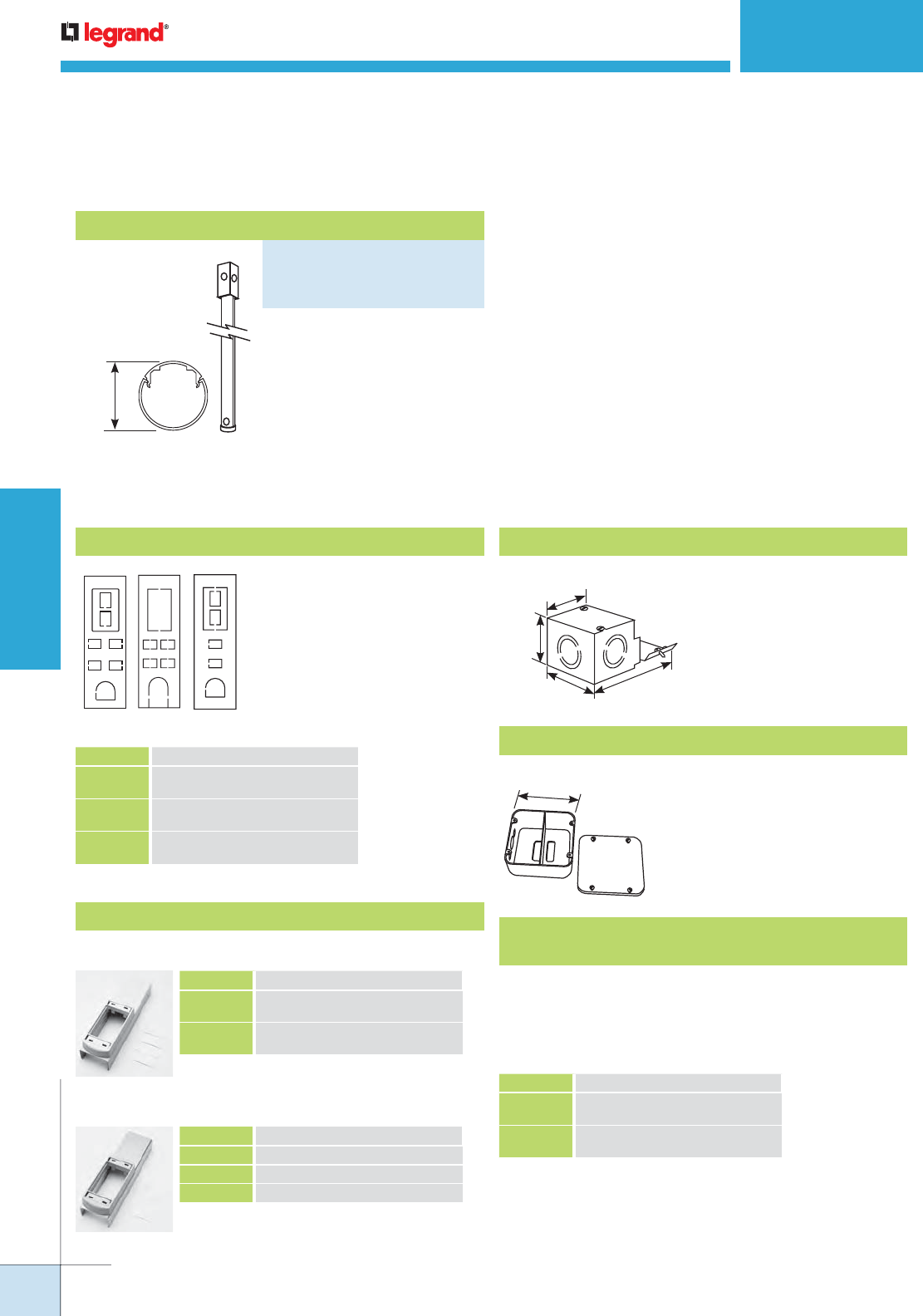
WIREMOLD
WWW.LEGRAND.US/WIREMOLD
658
POLES AND COLUMNS
VERTICAL DROP POLES
2"
[51mm]
Nominal wall thickness
.060" [1.5mm], length 10'3"
[3.1mm]. Provided with one 1/2"
[12.7mm] trade size KO at base.
T-bar mounting hardware,
ceiling trim kit, foot assembly,
and grommet included. Feed box
not furnished.
Vertical Drop Aluminum Tele-Power Poles Ordering Information (continued)
25DTP-4/
25DTC-4
AMDTP-4/
AMTC-4
30TC-2V/
30TC-4V
Vertical Drop Tele-Power Poles Accessories Ordering Information
Covers for Communication Connectivity
Communication covers
for additional voice/data
connectors. Each cover
includes KOs for four RJ11/
RJ45 connectors (.760" x .576"
[19.3mm x 14.6mm]), mouse
hole for exiting communication
cables (grommet furnished).
4 1/16"
[103mm]
2"
[51mm]
2 1/8"
[54mm]
4 1/4"
[108mm]
2 3/4"
[70mm]
TPB Gasketed Box
For 25DTP-4 and AMDTP-
4 Poles where local codes
require that electrical and
communications connections
be sealed when installed in
an air handling plenum.
G3010C Entrance End Fitting
Use as a communications
feed box for 30TP-4 Poles.
Accepts Wiremold Open System communications modules.
Communications Covers for Ortronics® Series II modular
connectivity solutions (adapter installed)
CAT. NO. DESCRIPTION
25DTC-CVR 8" [203mm] Cover for 25DTP-4 and
25DTC-4 Series.
30TC-CVR For 30TP-2V / 30TC-2V and 30TP-4V /
30TC-4V Series. 12" [305mm] long.
AMTC-CVR For AMDTP-4 and AMTC-4 Series
8" [203mm] long.
25DTC-ACT
AMTC-3S2
Add-on Plates for Power Poles
CAT. NO. DESCRIPTION
25DTC-ACT 25DTP Kit with 8" [203mm] hole cut
cover and mounting adapter
AMTC-ACT AMDTP Kit with 8" [203mm] hole cut
cover and mounting adapter
CAT. NO. DESCRIPTION
25DTC-3S2 For 25DTP/25DTC Series
30TC-3S2 For 30 Series
AMTC-3S2 For AMDTP/AMTC Series
CAT. NO. DESCRIPTION
25AM-AP Accessory Pack for 25DTP-4 and
AMDTP-4 Series
30TP-AP Accessory Pack for 30TP-2V and
30TP-4V Series
25AM-AP, 30TP-AP
Tele-Power Pole Accessory Packs
Accessory packs include two ceiling trim plates, hanger
clamp assembly, feed end fitting, and floor mounting
assembly. One Accessory Pack supplied with each
Tele-Power Pole at no extra charge. Boots are not offered
in accessory packs.
Blank Round Aluminum Pole
PART NUMBERS:
ALTC-2S (Satin Anodized Finish)
ALTC-20W (Painted White Finish)
ALTC-2P (Polished Aluminum Finish)

WIREMOLD
WWW.LEGRAND.US/WIREMOLD
659
POLES AND COLUMNS
CUSTOM TELEPOWER® POLES
Although Wiremold® has the most extensive selection of powerpole
products available, Wiremold offers Custom Tele-Power® Poles to
ensure proper distribution of power and communication services from
overhead wiring systems to open spaces as needed.
Custom Tele-Power Poles Fabrication Capabilities
• Modify the number and type of receptacles. Virtually any type of approved receptacle may be installed in the pole,
subject to size and voltage limitations. Receptacles may be standard specification, decorator style, isolated ground,
or surge. They may utilize straight-blade or locking type plugs.
• Device spacings may be altered for your customer needs.
• Sectional poles ranging from 20' [6.1m] to 30' [9.2m] high.
• Communication cabling interface with your choice of hole cuts for modular RJ jacks, RS, IBM, and coax connectors
and modular furniture configurations.
• Epoxy powder-coat or enamel paint capabilities to complement any interior decor.
A. B.1.
Contact your Wiremold sales representative for custom quotes
and additional information.
Walkerflex Feed Options
A. For “daisy-chain” activation, the NPA connector provides the feed-
through capability to power a series of poles.
B. For direct feed options.
1. Walkerflex NCW cable sets directly fastened to end of pole (instead of
standard box or cordset).
2. NWC connector mounted along the length of the pole.
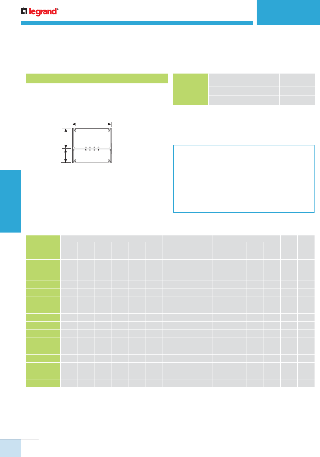
WIREMOLD
WWW.LEGRAND.US/WIREMOLD
660
POLES AND COLUMNS
General Specifications:
Receptacles: Each pole compartment may be wired with
up to 12 receptacles, with the number of circuits limited
by the feed method.
Feed method: All poles are provided with a utility box
(4" x 4" x 2 1/8" [102mm x 102mm x 54mm]) for all poles
with a cord up to 10' [3m].
Accessories:
Ceiling trim plates, pole clamp, and non-adjustable foot
with carpet gripper/adhesive pad furnished.
5"
[127mm]
2 13/16"
[71mm]
1 15/16"
[49mm]
12 sq. in.
[7742 sq. mm]
8 sq. in.
[5161 sq. mm]
NOTEs: Wire fill capacities calculated for a pole with a 4" x 4" x 2 1/8"
[102mm x 102mm x 54mm] box. Larger boxes can be used if higher
capacity is needed.
All of the standard profiles can be easily modified. Contact the
factory or the field sales representative for specifics.
Custom Tele-Power Poles Ordering Information
NP800 Jumbo Aluminum Tele-Power Pole
Two separate compartments can accommodate up
to 60A devices (#6 AWG maximum). Snap-in divider
permits up to six channels of varying sizes.
WIRE SIZE
THHN/THWN 40% FILL CIRCUITS
POWERING
WIRING 10 AWG 12 4
12 AWG 13 4
NP800 Series Wire Fill Capacities for Power
* Two Strand (Duplex) Multimode, 625/125m. Capacity range is calculated at 40% of raceway areas as stated in the Commercial Buildings Standard for
Telecommunication Pathways and Spaces, EIA/TIA 569-A.
NP800 Series Wire Fill Capacities for Communications
CABLE TYPE
Description
Nom.
O.D. Inches
UNSHIELDED TWISTED PAIR 24 AWG SHIELDED TWISTED PAIR COAXIAL CABLE TWINAX FIBER*
Cat 3 Cat3 Cat3 Cat 5 Cat 6 Cat 3 Type 1 Type 2 Type 3 RG58/U RG58/U RG6/U RG6/U 100 OHM
2 Pair 3 Pair 4 Pair 4 Pair 4 Pair 25 Pair 22 AWG 22 AWG 22 AWG 20 AWG 22 AWG 22AWG 18 AWG
0.14 0.15 0.19 0.22 0.25 0.41 0.39 0.465 0.245 0.195 0.242 0.242 0.27 0.33 0.19
Capacity of
Cross-Section (IN
2
)
2.4 62 54 33 25 19 7 8 5 20 32 20 20 16 11 33
2.8 72 63 39 29 22 8 9 6 23 37 24 24 19 13 39
3.2 83 72 45 33 26 9 10 7 27 42 27 27 22 14 45
4.2 109 95 59 44 34 12 14 9 35 56 36 36 29 19 59
4.3 111 97 60 45 34 13 14 10 36 57 37 37 30 20 60
4.8 124 108 67 50 38 14 16 11 40 64 41 41 33 22 67
5.0 129 113 70 52 40 15 16 11 42 66 43 43 34 23 70
5.2 135 117 73 54 42 15 17 12 44 69 45 45 36 24 73
5.8 150 131 81 61 46 17 19 13 49 77 50 50 40 27 81
6.2 161 140 87 65 50 18 20 14 52 83 53 53 43 28 87
7.0 181 158 98 73 56 21 23 16 59 93 60 60 48 32 98
7.7 200 174 108 81 62 23 25 18 65 103 66 66 53 36 108
8.0 207 181 112 84 64 24 26 18 67 107 69 69 55 37 112
12.0 311 271 169 126 96 36 40 28 101 160 104 104 83 56 169
CUSTOM TELEPOWER® POLES
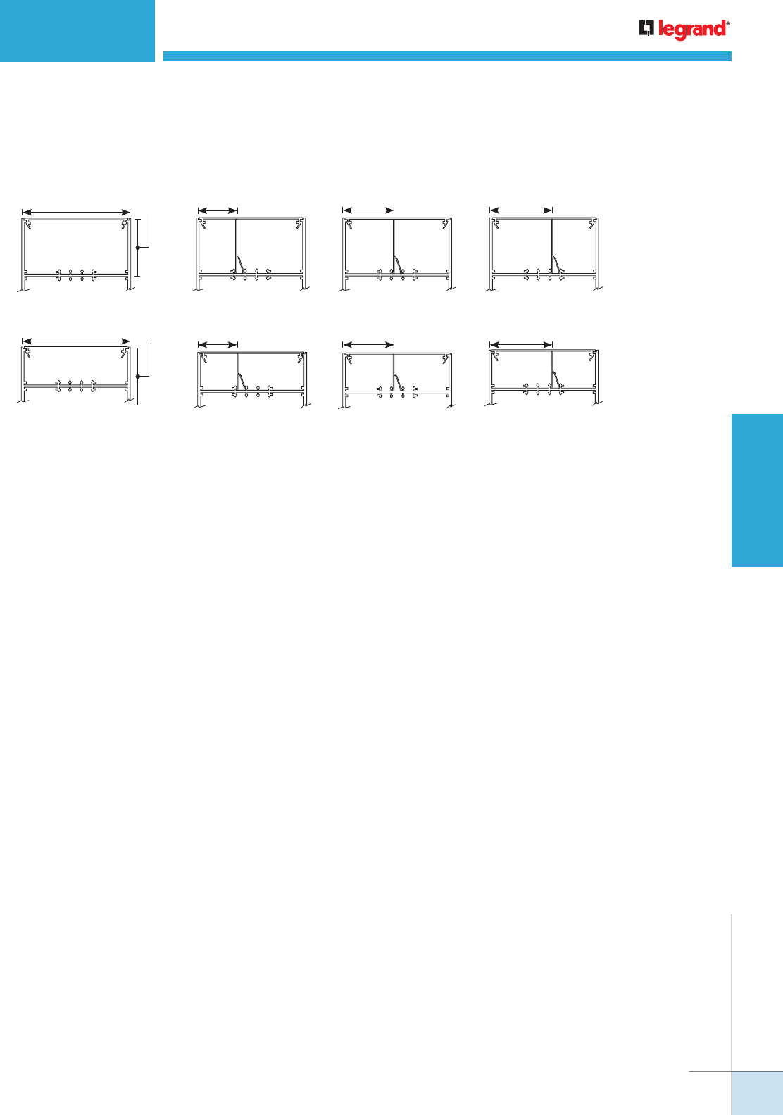
WIREMOLD
WWW.LEGRAND.US/WIREMOLD
661
POLES AND COLUMNS
4.3"
sq. in.
7.7"
sq.in.
1 5/8"
[41mm]
7"
sq. in.
6.2"
sq. in.
3 1/8"
[79mm]
5.8"
sq. in.
6.2"
sq.in.
2 3/16"
[56mm]
12"
sq. in.
5"
[127mm] 2 13/16"
[71mm]
2.8"
sq.
5.2"
sq.in.
1 5/8"
[41mm]
4.6"
sq. in.
3.2"
sq. in.
3 1/8"
[79mm]
3.8"
sq. in.
4.2"
sq.in.
2 3/16"
[56mm]
8"
sq. in.
5"
[127mm] 1 13/16"
[46mm]
NP800 Series Wire Fill Capacities for Communications (continued)
CUSTOM TELEPOWER® POLES

WIREMOLD
WWW.LEGRAND.US/WIREMOLD
662
POLES AND COLUMNS
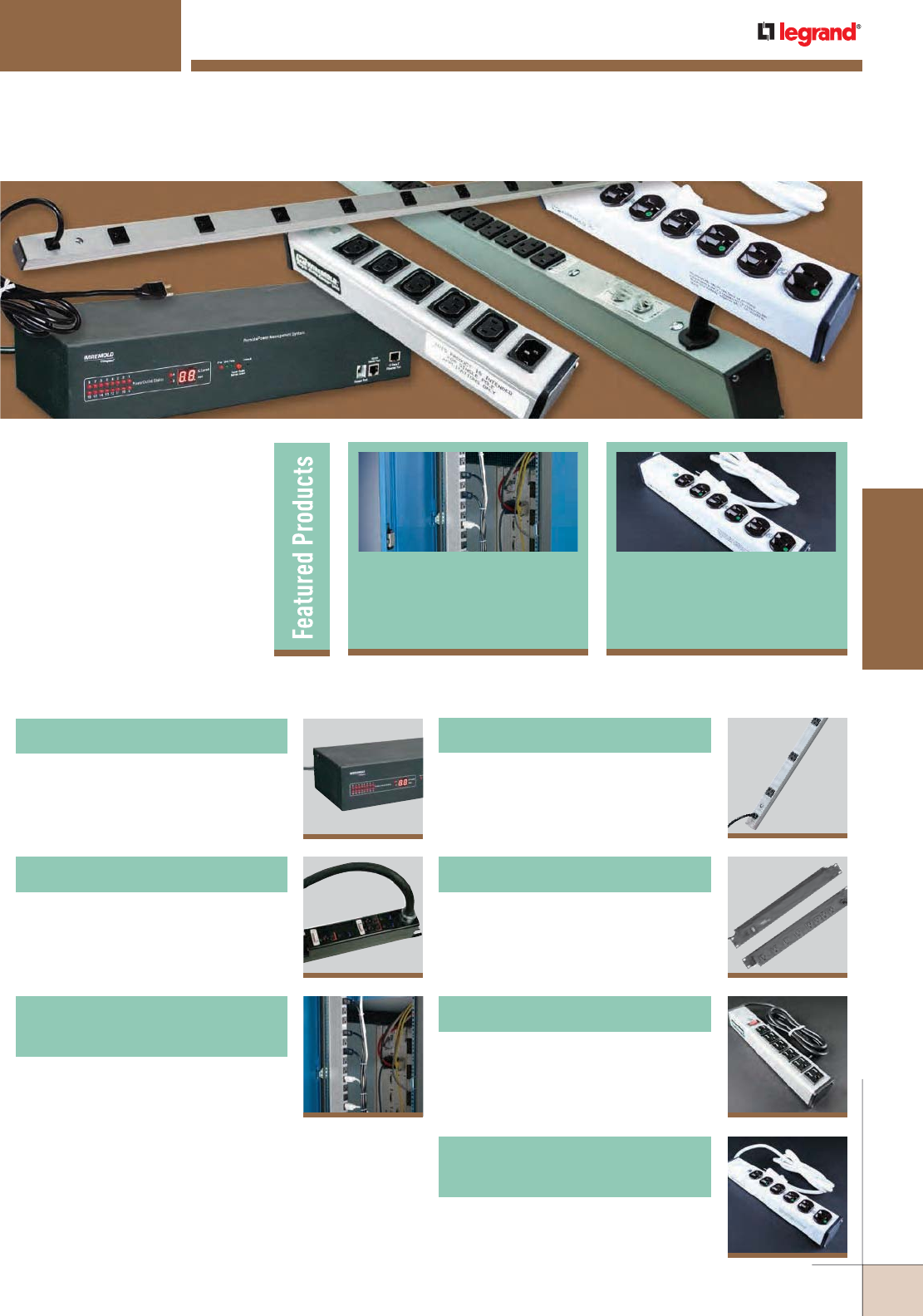
WWW.LEGRAND.US/WIREMOLD
667
WIREMOLD
POWER DISTRIBUTION
Wiremold® Power Distribution
Devices are designed to provide
complete power/protection
solutions for your power/
IT network from the service
entrance to point-of-use.
POWER DISTRIBUTION
668
Power Commander® IQ Series
Table of Contents
671
Power Commander® Plus Series
674
Power Commander® Series
High Amperage Units
682
Medical Grade/Special Use
Power Solutions
677
Rack Mounted Power Solutions
676
CabinetMate® Series
678
Workstation Power Solutions
Power Commander
®
Series High
Amperage Units
674
Medical Grade Plug-In
Outlet Centers
682
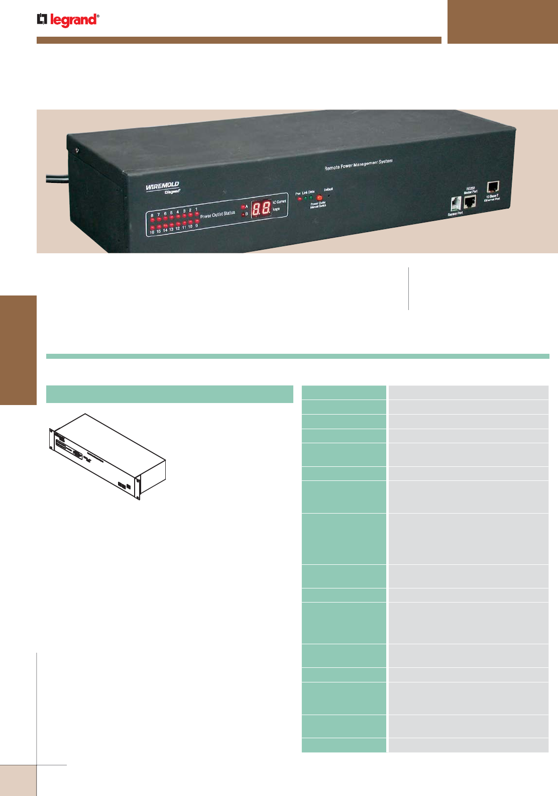
WWW.LEGRAND.US/WIREMOLD
668
POWER DISTRIBUTION
WIREMOLD
Power Commander® IQ Power Distribution Units offer remote current and
temperature monitoring of connected equipment and individual outlet control for
power recycling.
CODE REFERENCE
cTUVus Listed:
File 30783215.002 EN60950-1
POWER COMMANDER
®
IQ SERIES
NOTE: We are continually upgrading circuitry and features to provide the best possible power distribution
solutions; therefore, the products in this section of the catalog may change without notice. Contact
the factory for additional information.
AC Voltage Input 100 to 125V
AC Voltage Output 100 to 125V
Frequency 60 Hz
Load Capacity 15A
Output Receptacle 16 Pcs switched NEMA 5-15
(8 pieces each circuit)
Product Warranty 2 years
Power Cable –
AWG Length &
Plug Type
2 power cables, 14/3 SJT Type,
5-15P straight blade, 4 1/2 ft. [1.4m]
Console Interface
Local Master Port
1 RS232 Port. RJ-45 Connector.
Data: 7 or 8 bits. Stop Bits: 1 or 2.
Parity: None, Odd or Even.
Flow Control: None or RTS/CTS.
Baud rate 2400 to 115200.
Temperature
Sensing Port
Digital Input Port – RJ11
Network Interface 10-Base-T RJ45.
Display 16 Power Outlet On/Off status LEDs,
2 Network LEDs. 2 digit LED display
(1.00" x 0.65") [25mm x 16.5mm] for AC
Current Draw Status.
Network Protocols ICMP, TCP/IP, DHCP Telnet, DNS, POP3/
SMTP, SNMP, HTTPS/HTTP, and BootP
Weight 10 lbs. Shipping Weight
Operational
Temperature
Environment
32F° – 122F° (0C° – 50C°)
Storage
Temperature
-20F° – 140F° (-29C° – 60C°)
Humidity 10% – 90% RH
Sixteen (16) 15A simplex
outlets in two banks of 8.
Black housing.
Length: 19" [1.5m]
Width: 3 7/32" [82mm]
Depth: 6 1/4" [159mm]
SPDU16-2U
Power Commander IQ Series Ordering Information
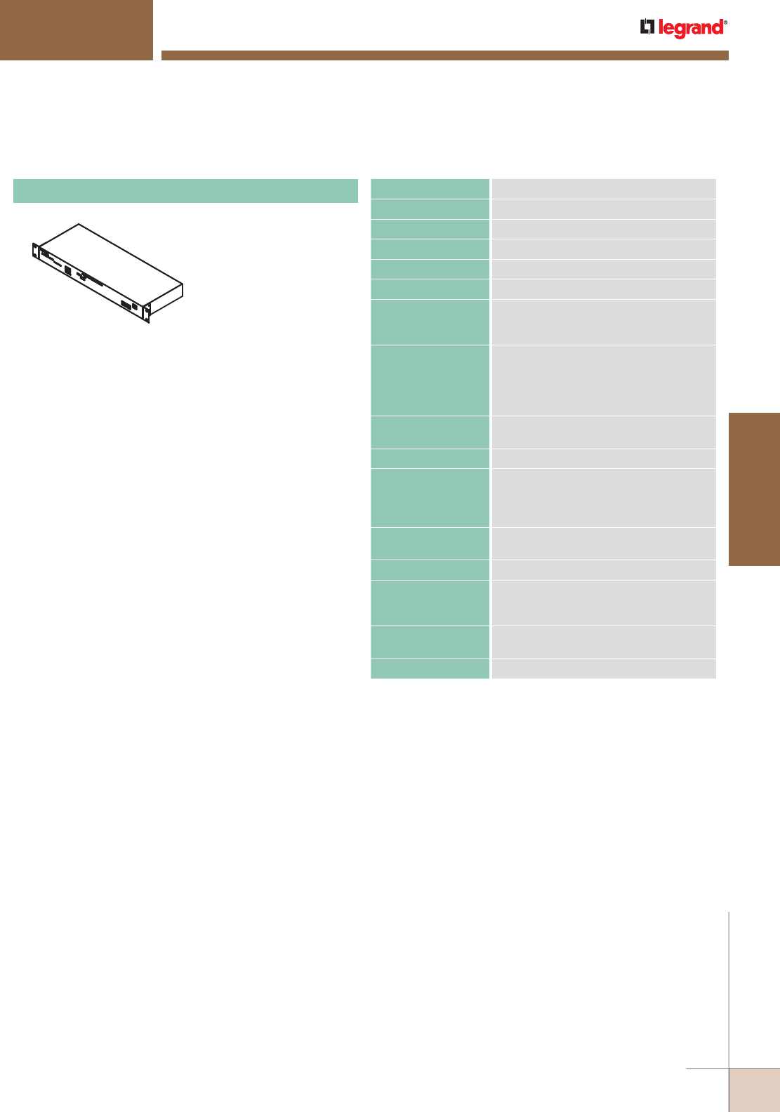
WWW.LEGRAND.US/WIREMOLD
669
WIREMOLD
POWER DISTRIBUTION
POWER COMMANDER
®
IQ SERIES
Ordering Information
AC Voltage Input 100 to 125V
AC Voltage Output 100 to 125V
Frequency 60 Hz
Load Capacity 15A
Output Receptacle 8 switched NEMA 5-15
Product Warranty 2 years
Power Cable –
AWG Length &
Plug Type
14/3 SJT Type, 5-15P straight blade,
4 1/2 ft. [1.4m]
Console Interface
Local Master Port
1 RS232 Port. RJ-45 Connector.
Data: 7 or 8 bits. Stop Bits: 1 or 2.
Parity: None, Odd or Even.
Flow Control: None or RTS/CTS.
Baud rate 2400 to 115200.
Temperature
Sensing Port
Digital Input Port – RJ11
Network Interface 10-Base-T RJ45.
Display 8 Power Outlet On/Off status LEDs, 2
Network LEDs. 2 digit LED display (1.00"
x 0.65") [25mm x 16.5mm] for AC Current
Draw Status.
Network Protocols ICMP, TCP/IP, DHCP Telnet, DNS, POP3/
SMTP, SNMP, HTTPS/HTTP, and BootP
Weight 7 lbs. Shipping Weight
Operational
Temperature
Environment
32F° – 122F° (0C° – 50C°)
Storage
Temperature
-20F° – 140F° (-29C° – 60C°)
Humidity 10% – 90% RH
Eight (8)15A simplex
outlets. Black housing.
Length: 19" [1.5m
Width: 1 5/8" [41mm]
Depth: 6 1/4" [159mm]
SPDU8-1U
Power Commander IQ Series Ordering Information (continued)
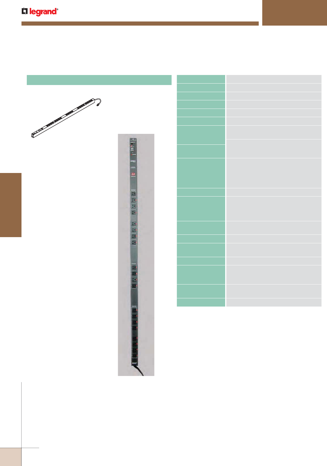
WWW.LEGRAND.US/WIREMOLD
670
POWER DISTRIBUTION
WIREMOLD
POWER COMMANDER
®
IQ SERIES
Ordering Information
AC Voltage Input 100 to 125V
AC Voltage Output 100 to 125V
Frequency 60 Hz
Load Capacity 20A
Output Receptacle 20 switched NEMA 5-15
Product Warranty 2 years
Power Cable
AWG Length &
Plug Type
12/3 SJT Type, L5-20P Locking plug, 91/2
ft. [2.9m]
Measurement of True RMS from all
CircuitsAC Current Draw
Monitoring
Console Interface
Local Master Port
1 RS232 Port. RJ-45 Connector Type.
Data: 7 or 8 bits. Stop Bits: 1 or 2.
Parity: None, Odd or Even.
Flow Control: None or RTS/CTS.
Baud rate 2400 to 115200.
Audio Buzzer 85 Decibel
Display 20 Power Outlet ON/OFF status LEDs,
1 Power On/Off LED. 2 Network LEDs.
2 digit LED display (1.00" x 0.65") [25mm x
16.5mm] for AC Current Draw Status.
Temperature
Sensing Port
Digital Input Port – RJ11
Network Interface 10-Base-T RJ45.
Network Protocols ICMP, TCP/IP, DHCP Telnet, DNS,
POP3/SMTP, SNMP, HTTP, and BootP
Weight 18 lbs. Shipping Weight
Operational
Temperature
Environment
32F° – 122F° (0C° – 50C°)
Storage
Temperature
-20F° – 140F° (-29C° – 60C°)
Humidity 10% – 90% RH
Twenty (20) 15A simplex
outlets. Black housing.
Length: 61" [1.5m]
Width: 1 3/4" [44mm]
Depth: 2 1/2" [60mm]
SPDU20-0U
SPDU20-0U
Power Commander IQ Series Ordering Information (continued)
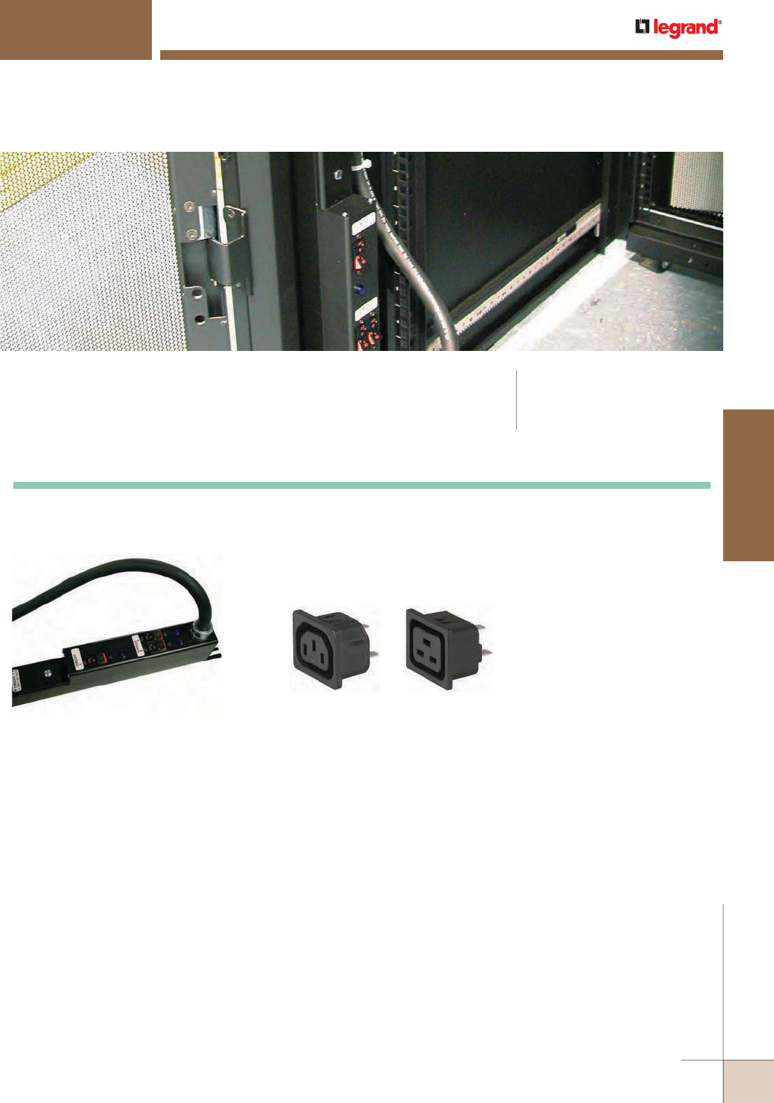
WWW.LEGRAND.US/WIREMOLD
671
WIREMOLD
POWER DISTRIBUTION
Power Commander® Plus High Current Power Distribution Units offer the capacity
to meet the ever-increasing power demands of data centers. CODE REFERENCE
cTUVus Listed:
File 30783215.002 EN60950-1
POWER COMMANDER
®
PLUS SERIES
NOTE: We are continually upgrading circuitry and features to provide the best possible power distribution
solutions; therefore, the products in this section of the catalog may change without notice. Contact
the factory for additional information.
A Hub assembly of a Power Commander Plus PDU
showing circuit breakers and LEDs.
C13 Receptacle
(Rated 15A) C19 Receptacle
(Rated 20A)
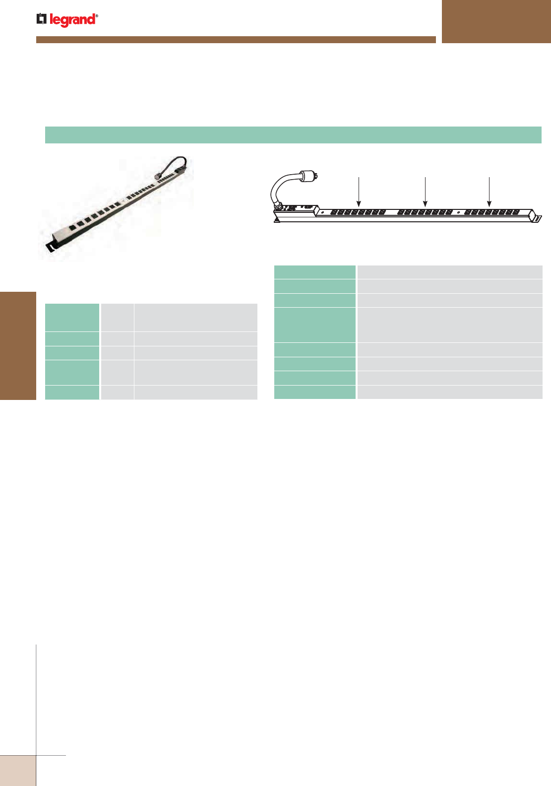
WWW.LEGRAND.US/WIREMOLD
672
POWER DISTRIBUTION
WIREMOLD
POWER COMMANDER
®
PLUS SERIES
Ordering Information
6W21N
6B21N, 6W21N
Eight (8) 5-20R outlets per circuit, twenty-four (24)
total outlets. Black (6B) or White (6W) top cover.
Length 64.12" [1.63m] overall,
67.12" [1.70m] with mounting ears.
Hub Length 10.12" [257mm]
Width 2.00" [50.8mm]
Depth 1.95"
3.20"
[49.5mm],
[81.3mm] with hub
Mounting 66.0" [1.68m] center-to-center
Power Commander Plus Series 60 Amp PDU Ordering Information – 120/208 System, 120V Output
5-20R 5-20R 5-20R
6B21N, 6W21N
AC Voltage Input 120/208V
AC Voltage Output 100 to 127V
Frequency 60 Hz
Load Capacity 30 Amps 3-phase, derated to 24 Amps:
3 – 20 Amp Circuits derated to 16 Amps
(Circuits 1, 2 & 3)
Circuit Breaker 3 – 20 Amp (Circuits 1, 2 & 3), UL489 Listed
Output Receptacles NEMA 5-20R, IEC C13 or IEC C19
Product Warranty 2 years
Power Cord 10/5 SOOW Type, L21-30P Plug, 10' [3.05m]
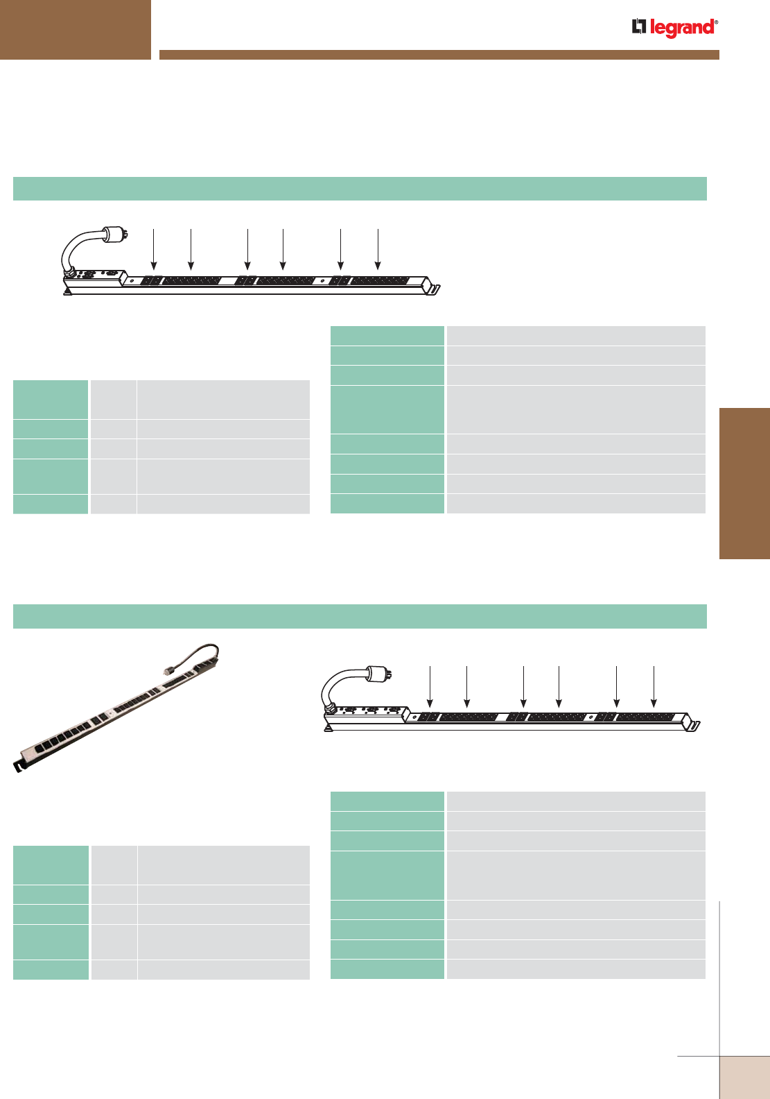
WWW.LEGRAND.US/WIREMOLD
673
WIREMOLD
POWER DISTRIBUTION
6B21E, 6W21E
6B22E, 6W22E
POWER COMMANDER
®
PLUS SERIES
Ordering Information
Two (2) C19 outlets per circuit, eight (8) C13 outlets
per circuit. Black (6B) or White (6W) top cover.
Length 64.12" [1.63m] overall,
67.12" [1.70m] with mounting ears.
Hub Length 10.12" [257mm]
Width 2.00" [50.8mm]
Depth 1.95"
3.20"
[49.5mm],
[81.3mm] with hub
Mounting 66.0" [1.68m] center-to-center
Two (2) C19 outlets per circuit, eight (8) C13 outlets
per circuit. Black (6B) or White (6W) top cover.
Length 64.12" [1.63m] overall,
67.12" [1.70m] with mounting ears.
Hub Length 14.12" [359mm]
Width 2.00" [50.8mm]
Depth 1.95"
3.20"
[49.5mm],
[81.3mm] with hub
Mounting 66.0" [1.68m] center-to-center
Power Commander Plus Series 60 Amp PDU Ordering Information – 120/208 System, 120V Output
Power Commander Plus Series 60 Amp PDU Ordering Information – 120/208 System, 208V Output
AC Voltage Input 120/208V
AC Voltage Output 100 to 127V
Frequency 60 Hz
Load Capacity 30 Amps 3-phase, derated to 24 Amps:
3 – 20 Amp Circuits derated to 16 Amps
(Circuits 1, 2 & 3)
Circuit Breaker 3 – 20 Amp (Circuits 1, 2 & 3), UL489 Listed
Output Receptacles NEMA 5-20R, IEC C13 or IEC C19
Product Warranty 2 years
Power Cord 10/5 SOOW Type, L21-30P Plug, 10' [3.05m]
AC Voltage Input 120/208V
AC Voltage Output 200 to 230V
Frequency 60 Hz
Load Capacity 30 Amps 3-phase, derated to 24 Amps:
3 – 20 Amp Circuits derated to 16 Amps
(Circuits 1, 2 & 3)
Circuit Breaker 3 – 20 Amp (Circuits 1, 2 & 3), UL489 Listed
Output Receptacles IEC C13 or IEC C19
Product Warranty 2 years
Power Cord 10/5 SOOW Type, L21-30P Plug, 10' [3.05m]
C19 C13 C19 C13 C19 C13
6B21E, 6W21E
C19 C13 C19 C13 C19 C13
6W22E
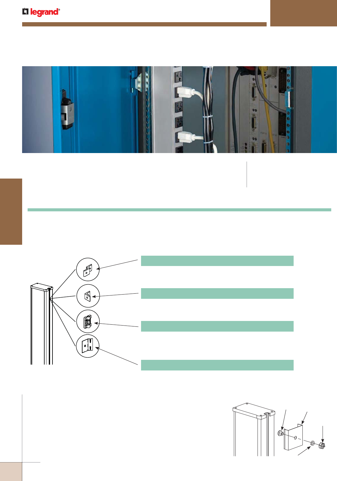
WWW.LEGRAND.US/WIREMOLD
674
POWER DISTRIBUTION
WIREMOLD
Power Commander® Series High Amperage Units (PDUs) have multiple circuits
to provide increased capacity for today’s high density server racks. Embedded or
remote ammeters are available to monitor current draw.
POWER COMMANDER
®
SERIES
High Amperage Units
NOTE: We are continually upgrading circuitry and features to provide the best possible power distribution
solutions; therefore, the products in this section of the catalog may change without notice. Contact
the factory for additional information.
CODE REFERENCE
cULus Listed:
File 173292 Guide: NWGQ
Power Commander Series Mounting Information
MOUNTING ACCESSORIES
Understanding that each cabinet, enclosure, rack and application is unique, Wiremold has designed four solutions for
mounting the 30 Amp Power Distribution Units using the universal T-slot built into the unit. The mounting kits listed below
are available for purchase as accessories.
STANDARD HARDWARE INSTALLATION
Attach the Spring Clips to the cabinet frame or cabinet wall making sure the top
clip is no more than 1 inch [25mm] from the top of the unit. Insert the 1/4 - 20
Phillips screw through the spring clip as shown, and then through the cabinet
frame or cabinet wall. On the other side of the mounting surface, put the 1/4
lock washer over the exposed Phillips screw and tighten into place with the 1/4
- 20 nut. Once the spring clips are secure, place unit in one side of the clips and
snap the other side into position.
30A-MK2 L Bracket
Allows mounting at a right angle. May be used for a side or
end mount.
30A-MK1 Z Bracket
Sturdy anodized aluminum bracket offsets the unit for front
access to the mounting. May be used for a side or end mount.
30A-MK3 Swivel Bracket
Allows unit to be mounted then rotated up to 270° (dependent
on mounting location) providing easy access to unit’s face
without losing space.
30A-MK4 Drop-In Clip
Clip is mounted directly on the unit and allows the strip to
install with a ‘drop and hold’ method that requires no
additional hardware.
NOTE: Accessory mounting kits are
not UL Listed.
1/4-20
Phillips
Clip
1/4 Lock
Washer
1/4-20
Nut
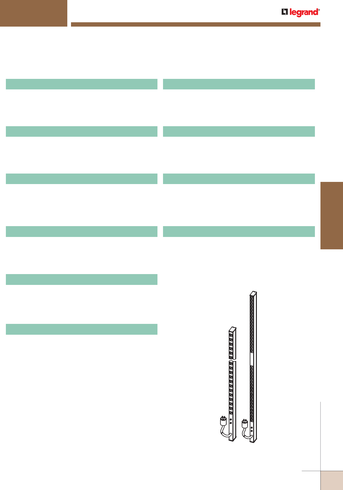
WWW.LEGRAND.US/WIREMOLD
675
WIREMOLD
POWER DISTRIBUTION
3A44B2-1 30 Amp Power Distribution Unit
3A86B2-1 30 Amp Power Distribution Unit
3B44B2-1 30 Amp Power Distribution Unit
3B86B2-1 30 Amp Power Distribution Unit
3B53B2-1-AM 30 Amp Power Distribution Unit
3B43B2-1-RAM 30 Amp Power Distribution Unit
4B44B2-2 40 Amp Power Distribution Unit
4B86B2-2 40 Amp Power Distribution Unit
4B53B2-2-AM 40 Amp Power Distribution Unit
4B43B2-2-RAM 40 Amp Power Distribution Unit
Two 15A resettable circuit breakers. Twenty-four 20A
outlets with T-slots, gray housing. 12' [3.6m] cord. Length
48" [1.2m].
Two 15A resettable circuit breakers. Thirty-six 20A outlets
with T-slots, gray housing. 12' [3.6m] cord. Length 70"
[1.8m].
Two circuits with two 15A resettable circuit breakers.
Twenty-four 20A outlets with T-slots, black housing. 12'
[3.6m] cord. Length 48" [1.2m].
Two circuits with two 15A resettable circuit breakers.
Thirty-six 20A outlets with T-slots, black housing. 12' [3.6m]
cord. Length 70" [1.8m].
Two circuits with two 15A resettable circuit breakers and
two lighted LCD digital ammeters. Eighteen 20A outlets
with T-slots, black housing. 12' [3.6m] cord. Length 54"
[1.4m].
Two circuits with two 15A resettable circuit breakers and
two lighted remote LCD digital ammeters. Eighteen 20A
outlets with T-slots, black housing. 12' [3.6m] cord. Length
48" [1.2m]. Includes two (2) 7' [1.2m] patch cables, two (2)
remote displays, and one (1) rack mountable faceplate.
Two circuits with two 20A resettable circuit breakers.
Twenty-four 20A outlets with T-slots, black housing.
12' [3.6m] cord. Length 48" [1.2m].
Two circuits with two 20A resettable circuit breakers.
Thirty-six 20A outlets with T-slots, black housing. 12' [3.6m]
cord. Length 70" [1.8m].
Two circuits with two 20A resettable circuit breakers and
two lighted LCD digital ammeters. Eighteen 20A outlets
with T-slots, black housing. 12' [3.6m] cord. Length
54" [1.4m].
Two circuits with two 20A resettable circuit breakers and
two lighted remote LCD digital ammeters. Eighteen 20A
outlets with T-slots, black housing. 12' [3.6m] cord. Length
48" [1.2m]. Includes two (2) 7' [1.2m] patch cables, two (2)
remote displays, and one (1) rack mountable faceplate.
POWER COMMANDER
®
SERIES
High Amperage Units
Power Commander High Amperage Units Ordering Information
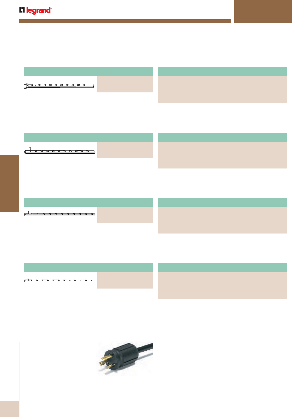
WWW.LEGRAND.US/WIREMOLD
676
POWER DISTRIBUTION
WIREMOLD
Plug-In Outlet Center Unit
PART NUMBERS:
3609ULBC (6' [1.8m] cord)
3609ULBD (15' [4.6m] cord)
CABINETMATE
®
SERIES
Power Only Products
Eight 20A outlets with t-slots. Length 20" [508mm].
Receptacle center-to-center 1 1/4" [32mm]. 20 Amp unit
with a 20A resettable circuit breaker.
Locking Plug
All units feature gray aluminum housing 1 1/2" x 1 3/16" [38mm x30mm] with
black receptacles and black power cord with straight blade plug.
Units with “-TL” suffix have twist lock plug.
CabinetMate Series Power Only Plug-In Outlet Centers Ordering Information
Nine outlets. Length 36" [915mm]. Receptacle center-to-
center 3" [76mm]. 15 Amp unit with a 15A resettable circuit
breaker.
Plug-In Outlet Center Unit
PART NUMBERS:
4810ULBC (6' [1.8m] cord)
4810ULBD (15' [4.6m] cord)
Ten outlets. Length 48" [1.2m]. Receptacle center-to-center
4" [101mm]. 15 Amp unit with a 15A resettable circuit
breaker.
Plug-In Outlet Center Unit
PART NUMBERS:
7011ULBC (6' [1.8m] cord)
7011ULBD (15' [4.6m] cord)
Eleven outlets. Length 70" [1.8m]. Receptacle center-to-
center 6" [152mm]. 15 Amp unit with a 15A resettable circuit
breaker.
Plug-In Outlet Center Unit
PART NUMBERS:
7712ULBC (6' [1.8m] cord)
7712ULBD (15' [4.6m] cord)
Twelve outlets. Length 77" [2m]. Receptacle center-to-
center 6" [152mm]. 15 Amp unit with a 15A resettable circuit
breaker.
Plug-In Outlet Center Unit
PART NUMBERS:
2008ULBC20R (6' [1.8m] cord, straight blade plug)
2008ULBC20R-TL (6' [1.8m] cord, locking Plug)
2008ULBD20R (15' [4.6m] cord, straight blade plug)
2008ULBD20R-TL (15' [4.6m] cord, locking Plug)
Ten 20A outlets with t-slots. Length 48" [1.2m]. Receptacle
center-to-center 4" [101mm]. 20 Amp unit with a 20A
resettable circuit breaker.
Plug-In Outlet Center Unit
PART NUMBERS:
4810ULBC20R (6' [1.8m] cord, straight blade plug)
4810ULBC20R-TL (6' [1.8m] cord, locking Plug)
4810ULBD20R (15' [4.6m] cord, straight blade plug)
4810ULBD20R-TL (15' [4.6m] cord, locking Plug)
Eleven 20A outlets with t-slots. Length 70" [1.8m].
Receptacle center-to-center 6" [152mm]. 20 Amp unit with a
20A resettable circuit breaker.
Plug-In Outlet Center Unit
PART NUMBERS:
7011ULBC20R (6' [1.8m] cord, straight blade plug)
7011ULBC20R-TL (6' [1.8m] cord, locking Plug)
7011ULBD20R (15' [4.6m] cord, straight blade plug)
7011ULBD20R-TL (15' [4.6m] cord, locking Plug)
Twelve 20A outlets with t-slots. Length 77" [2m]. Receptacle
center-to-center 6" [152mm]. 20 Amp unit with a 20A
resettable circuit breaker.
Plug-In Outlet Center Unit
PART NUMBERS:
7712ULBC20R (6' [1.8m] cord, straight blade plug)
7712ULBC20R-TL (6' [1.8m] cord, locking Plug)
7712ULBD20R (15' [4.6m] cord, straight blade plug)
7712ULBD20R-TL (15' [4.6m] cord, locking Plug)
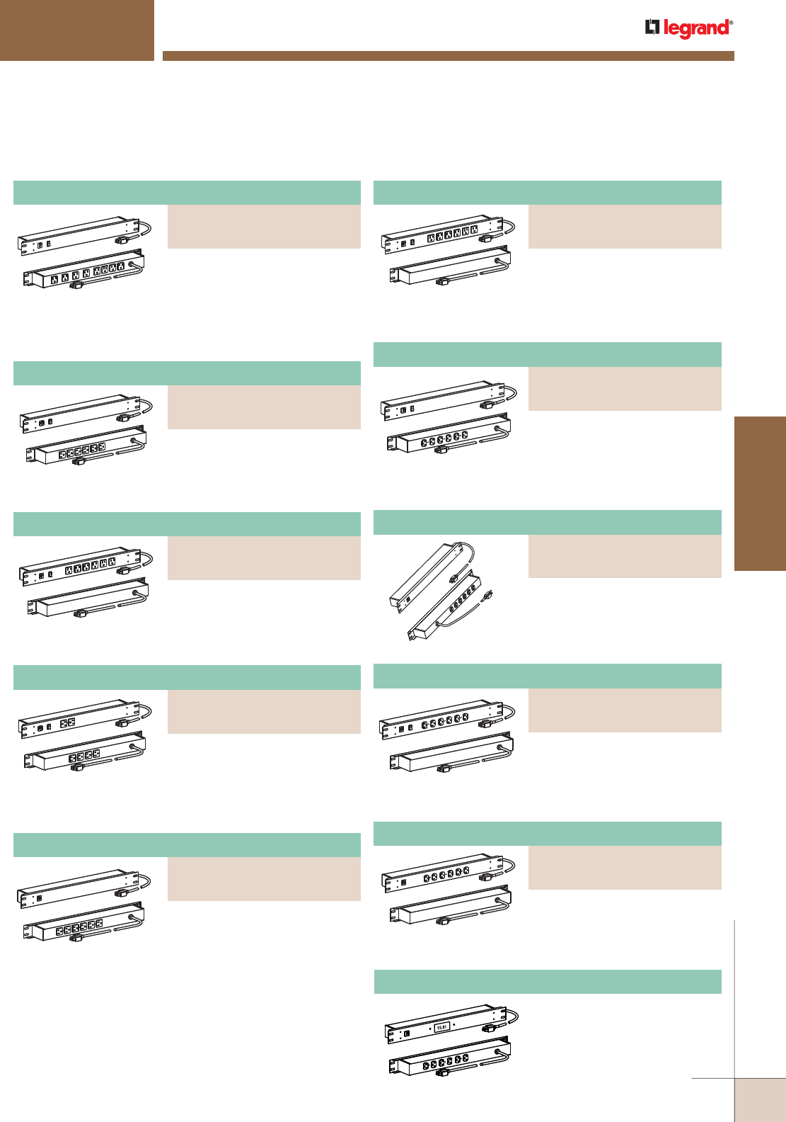
WWW.LEGRAND.US/WIREMOLD
677
WIREMOLD
POWER DISTRIBUTION
Plug-In Outlet Center Unit
PART NUMBERS:
J06B0BX (6 Foot Cord)
J06B2BX (15 Foot Cord)
Power Only Products Ordering Information
Eight rear outlets, lighted switch,
15A, receptacles rotated 90° and
4 outlets spaced to accommodate
transformers. 6' (J08B0B) or 15' (J08B2B) [1.8m or 4.6m]
cord. Receptacle center-to-center 1 1/2" [38mm] and
2" [51mm].
Six rear outlets, lighted switch,
15A, 6' (J06B0B) or 15' (J06B2B)
[1.8m or 4.6m] cord. Receptacle
center-to-center 1 1/2" [38mm].
Six front outlets, lighted switch,
15A, 6' (J60B0B) or 15' (J60B2B)
[1.8m or 4.6m] cord. Receptacle
center-to-center 1 1/2" [38mm].
Two front, four rear outlets,
lighted switch, 15A, 6' (J24B0B)
or 15' (J24B2B) [1.8m or 4.6m]
cord. Receptacle center-to-
center 1 1/2" [38mm].
Six rear outlets, 15A, 6'
(J06B0BX) or 15' (J06B2BX)
[1.8m or 4.6m] cord. Receptacle
center-to-center 1 1/2" [38mm].
Six rear 20A outlets, on/off
switch, 6' (J06B0B20) or 15'
(J06B2B20) [1.8m or 4.6m] cord.
Receptacle center-to-center
1 1/2" [38mm].
Six rear 20A outlets, 6'
(J06B0B20X) or 15' (J06B2B20X)
[1.8m or 4.6m] cord. Receptacle
center-to-center 1 1/2" [38mm].
Six front 20A outlets, on/off
switch, 6' (J60B0B20) or 15'
(J60B2B20) [1.8m or 4.6m] cord.
Receptacle center-to-center 1 1/2" [38mm].
Six front 20A outlets, 6'
(J60B0B20X) or 15' (J60B2B20X)
[1.8m or 4.6m] cord. Receptacle
center-to-center 1 1/2" [38mm].
RACK MOUNTED POWER SOLUTIONS
Power Only Products
J06B0B20X-AM Plug-In Outlet Center Unit
Digital ammeter with LCD
readout of current draw. Six
20A rear outlets. 6' [1.8m] cord.
Receptacle center-to-center
1 1/2" [38mm].
Plug-In Outlet Center Unit
PART NUMBERS:
J08B0B (6 Foot Cord)
J08B2B (15 Foot Cord)
Plug-In Outlet Center Unit
PART NUMBERS:
J06B0B20 (6 Foot Cord)
J06B2B20 (15 Foot Cord)
Plug-In Outlet Center Unit
PART NUMBERS:
J06B0B (6 Foot Cord)
J06B2B (15 Foot Cord)
Plug-In Outlet Center Unit
PART NUMBERS:
J06B0B20X (6 Foot Cord)
J06B2B20X (15 Foot Cord)
Plug-In Outlet Center Unit
PART NUMBERS:
J60B0B (6 Foot Cord)
J60B2B (15 Foot Cord)
Plug-In Outlet Center Unit
PART NUMBERS:
J60B0B20 (6 Foot Cord)
J60B2B20 (15 Foot Cord)
Plug-In Outlet Center Unit
PART NUMBERS:
J24B0B (6 Foot Cord)
J24B2B (15 Foot Cord)
Plug-In Outlet Center Unit
PART NUMBERS:
J60B0B20X (6 Foot Cord)
J60B2B20X (15 Foot Cord)
Six front outlets, 15A, receptacles
rotated 90° and spaced to
accommodate transformers.
6' (J60B0B-90) or 15' (J60B2B-90) [1.8m or 4.6m] cord.
Receptacle center-to-center 1 1/2" [38mm].
Plug-In Outlet Center Unit
PART NUMBERS:
J60B0B-90 (6 Foot Cord)
J60B2B-90 (15 Foot Cord)
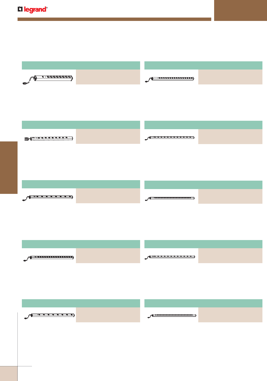
WWW.LEGRAND.US/WIREMOLD
678
POWER DISTRIBUTION
WIREMOLD
Twenty-four outlets, rugged gray aluminum housing,
15A, lighted switch, 6' [1.8m] (UL2065BC) or 15' [4.6m]
(UL2065BD) 14/3 SJT black cord with NEMA5-15 plug.
Length 72" [1.8m]. Receptacle center-to-center 2 1/2"
[64mm]. Snap-on, Slide-off mounting.
Twelve outlets, rugged gray aluminum housing, 15A,
6' [1.8m] (UL2062BC) or 15' [4.6m] (UL2062BD) 14/3
SJT black cord with NEMA5-15 plug. Length 72" [1.8m].
Receptacle center-to-center 5 1/4" [133mm].
Twenty-four outlets, rugged gray aluminum housing, 15A,
6' [1.8m] (UL2063BC) or 15' [4.6m] (UL2063BD) 14/3
SJT black cord with NEMA5-15 plug. Length 72" [1.8m].
Receptacle center-to-center 2 1/2" [64mm].
Twelve outlets, rugged gray aluminum housing, 15A, lighted
switch, 6' [1.8m] (UL2064BC) or 15' [4.6m] (UL2064BD) 14/3
SJT black cord with NEMA5-15 plug. Length 72" [1.8m].
Receptacle center-to-center 5 1/4" [133mm]. Snap-on,
Slide-off mounting.
Plug-In Outlet Center Unit
PART NUMBERS:
UL402BC (6 Foot Cord)
UL402BD (15 Foot Cord)
Plug-In Outlet Center Unit
PART NUMBERS:
UL401BC (6 Foot Cord)
UL401BD (15 Foot Cord)
Plug-In Outlet Center Unit
PART NUMBERS:
UL309BC (6 Foot Cord)
UL309BD (15 Foot Cord)
Plug-In Outlet Center Unit
PART NUMBERS:
UL300BC (6 Foot Cord)
UL300BD (15 Foot Cord)
Work Station Power Solutions – Power Only Plug-In Outlet Center Units Ordering Information
Eight outlets, lighted switch, rugged gray aluminum
housing, 15A, 6' [1.8m] (UL300BC) or 15' [4.6m] (UL300BD)
14/3 SJT black cord with NEMA5-15 plug. Length 24"
[609mm]. Receptacle center-to-center 2" [51mm]. Snap-on,
slide-off mounting.
Sixteen outlets, lighted switch, rugged gray aluminum
housing, 15A, 6' [1.8m](UL402BC) or 15' [4.6m] (UL402BD)
14/3 SJT black cord with NEMA5-15 plug. Length 48" [1.2m].
Receptacle center-to-center 2 1/2" [64mm]. Snap-on, slide-
off mounting.
Eight outlets, lighted switch, rugged gray aluminum
housing, 15A, 6' [1.8m](UL401BC) or 15' [4.6m] (UL401BD)
14/3 SJT black cord with NEMA5-15 plug. Length 48"
[1.2m]. Receptacle center-to-center 5 1/4" [133mm]. Snap-
on, slide-off mounting.
Nine outlets, lighted switch, rugged gray aluminum housing,
15A, 6' [1.8m](UL309BC) or 15' [4.6m] (UL309BD) 14/3 SJT
black cord with NEMA5-15 plug. Length 36" [915mm].
Receptacle center-to-center 3" [76mm]. Snap-on,
slide-off mounting.
WORKSTATION POWER SOLUTIONS
Ordering Information
Eight outlets, rugged gray aluminum housing, 15A, 6' [1.8m]
(UL403BC) or 15' [4.6m] (UL403BD) 14/3 SJT black cord with
NEMA5-15 plug. Length 48" [1.2m]. Receptacle center-to-
center 5 1/4" [133mm]. Snap-on, slide-off mounting.
Plug-In Outlet Center Units
PART NUMBERS:
UL403BC (6 Foot Cord)
UL403BD (15 Foot Cord)
Sixteen outlets, rugged gray aluminum housing, 15A,
6' [1.8m] (UL404BC) or 15' [4.6m] (UL404BD) 14/3 SJT black
cord with NEMA5-15 plug. Length 48" [1.2m]. Receptacle
center-to-center 2 1/2" [64mm]. Snap-on, slide-off
mounting.
Plug-In Outlet Center Units
PART NUMBERS:
UL404BC (6 Foot Cord)
UL404BD (15 Foot Cord)
Plug-In Outlet Center Unit
PART NUMBERS:
UL2063BC (6 Foot Cord)
UL2063BD (15 Foot Cord)
Plug-In Outlet Center Unit
PART NUMBERS:
UL2062BC (6 Foot Cord)
UL2062BD (15 Foot Cord)
Plug-In Outlet Center Unit
PART NUMBERS:
UL2064BC (6 Foot Cord)
UL2064BD (15 Foot Cord)
Plug-In Outlet Center Units
PART NUMBERS:
UL2065BC (6 Foot Cord)
UL2065BD (15 Foot Cord)
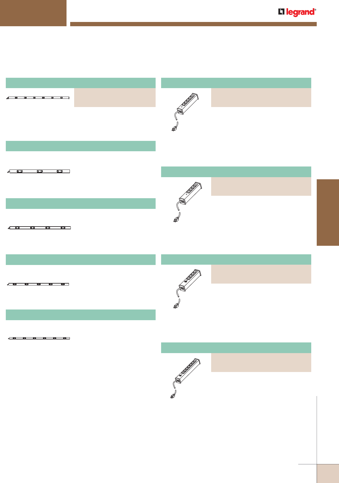
WWW.LEGRAND.US/WIREMOLD
679
WIREMOLD
POWER DISTRIBUTION
Work Station Power Solutions – Power Only Plug-In Outlet Center Units Ordering Information (continued)
WORKSTATION POWER SOLUTIONS
Ordering Information
NM20-C3 Plug-In Outlet Center Units
NM20-C4 Plug-In Outlet Center Units
Six outlets, steel housing with ivory (V20-C2) or gray finish
(G20-C2). 6' [1.8m] cord. Length 40" [1m]. Receptacle
center-to-center 6" [152mm].
Six (3 duplex) outlets,
nonmetallic housing with ivory
finish. 6' [1.8m] cord, Length
36" [915mm]. Receptacle
center-to-center 12" [305mm].
Eight (4 duplex) outlets,
nonmetallic housing with ivory
finish. 6' [1.8m] cord. Length
48" [1.2m]. Receptacle center-
to-center 12" [305mm].
NM20-C5 Plug-In Outlet Center Units
Ten (5 duplex) outlets,
nonmetallic housing with ivory
finish. 6' [1.8m] cord, Length
60" [1.5m]. Receptacle center-
to-center 12" [305mm].
Plug-In Outlet Center Unit
PART NUMBERS:
V20-C2 (6 Foot Cord)
G20-C2 (15 Foot Cord)
NM20-C6 Plug-In Outlet Center Units
Twelve (6 duplex) outlets,
nonmetallic housing with ivory
finish. 6' [1.8m] cord. Length
72" [1.8m]. Receptacle center-
to-center 12" [305mm].
Five outlets, rugged gray aluminum
housing, 15A. 6' [1.8m] (UL100BC) or
15' [4.6m] (UL100BD) 14/3 SJT black
cord with NEMA5-15 plug. Length 91/4"
[235mm]. Receptacle center-to-center
1 1/4" [32mm]. Snap-on, slide-off
mounting.
Four outlets, rugged gray aluminum
housing, 15A. 6' (UL101BC) or 15'
(UL101BD) [1.8m or 4.6m] 14/3 SJT
black cord with NEMA5-15 plug. Length
91/4" [235mm]. Receptacle center-to-
center 1 1/4" [32mm]. Snap-on, slide-off
mounting.
Four outlets, rugged gray aluminum
housing, 15A, lighted switch. 6' [1.8m]
(UL104BC) or 15' [4.6m] (UL104BD) 14/3
SJT black cord with NEMA5-15 plug.
Length 9 1/4" [235mm]. Receptacle
center-to-center 11/4" [32mm]. Snap-
on, slide-off mounting.
Seven outlets, rugged gray aluminum
housing, 15A, lighted switch. 6' [1.8m]
(UL204BC) or 15' [4.6m] (UL204BD)
14/3 SJT black cord with NEMA5-15
plug. Length 13" [330mm]. Receptacle
center-to-center 1 1/4" [32mm]. Snap-
on, slide-off mounting.
Plug-In Outlet Center Units
PART NUMBERS:
UL100BC (6 Foot Cord)
UL100BD (15 Foot Cord)
Plug-In Outlet Center Units
PART NUMBERS:
UL101BC (6 Foot Cord)
UL101BD (15 Foot Cord)
Plug-In Outlet Center Units
PART NUMBERS:
UL104BC (6 Foot Cord)
UL104BD (15 Foot Cord)
Plug-In Outlet Center Units
PART NUMBERS:
UL204BC (6 Foot Cord)
UL204BD (15 Foot Cord)
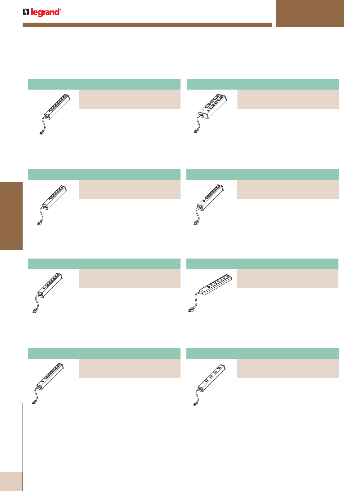
WWW.LEGRAND.US/WIREMOLD
680
POWER DISTRIBUTION
WIREMOLD
Plug-In Outlet Center Units
PART NUMBERS:
R610 (6 Foot Cord)
R612 (15 Foot Cord)
Six outlets, putty white aluminum
housing, 15A, lighted switch. 6' [1.8m]
(R610) or 15' [4.6m] (R612) 14/3 SJT
putty white cord with NEMA5-15 plug.
Length 12 1/4" [311mm]. Receptacle
center-to-center 1 1/4" [32mm]. Snap-
on, slide-off mounting.
Plug-In Outlet Center Units
PART NUMBERS:
P6 (6 Foot Cord)
P6-15 (15 Foot Cord)
Six outlets, putty white impact-resistant
polymeric housing, 15A, lighted switch,
6' [1.8m] (P6) or 15' [4.6m] (P6-15) 14/3
SJT putty white cord with NEMA5-15
plug. Length 12" [305mm]. Receptacle
center-to-center 1 1/4" [32mm].
Keyhole mounting.
Plug-In Outlet Center Units
PART NUMBERS:
UL1090BC (6 Foot Cord)
UL1090BD (15 Foot Cord)
Four outlets, rugged gray aluminum
housing, 15A, receptacles rotated
90° and spaced to accommodate
transformers. 6' [1.8m] (UL1090BC) or
15' [4.6m] (UL1090BD) 14/3 SJT black
cord with NEMA5-15 plug. Length 16"
[406mm]. Receptacle center-to-center
3" [76mm]. Snap-on, slide-off mounting.
Work Station Power Solutions – Power Only Plug-In Outlet Center Units Ordering Information (continued)
WORKSTATION POWER SOLUTIONS
Ordering Information
Eight outlets, rugged gray aluminum
housing, 15A. 6' [1.8m] (UL205BC) or
15' [4.6m] (UL205BD) 14/3 SJT black
cord with NEMA5-15 plug. Length 13"
[330mm]. Receptacle center-to-center
1 1/4" [32mm]. Snap-on, slide-off
mounting.
Six outlets, rugged gray aluminum
housing, 15A. 6' [1.8m] (UL206BC) or
15' [4.6m] (UL206BD) 14/3 SJT black
cord with NEMA5-15 plug. Length 12
1/4" [311mm]. Receptacle center-to-
center 1 1/4" [32mm]. Snap-on, slide-off
mounting.
Six outlets, rugged gray aluminum
housing, 15A, lighted switch. 6' [1.8m]
(UL207BC) or 15' [4.6m] (UL207BD) 14/3
SJT black cord with NEMA5-15 plug.
Length 12 1/4" [311mm]. Receptacle
center-to-center 1 1/4" [32mm]. Snap-
on, slide-off mounting.
Eight outlets, rugged gray aluminum
housing, 15A, lighted switch. 6' [1.8m]
(UL218BC) or 15' [4.6m] (UL218BD)
14/3 SJT black cord with NEMA5-15
plug. Length 15" [381mm]. Receptacle
center-to-center 1 1/4" [32mm]. Snap-
on, slide-off mounting.
Plug-In Outlet Center Units
PART NUMBERS:
UL205BC (6 Foot Cord)
UL205BD (15 Foot Cord)
Plug-In Outlet Center Units
PART NUMBERS:
UL206BC (6 Foot Cord)
UL206BD (15 Foot Cord)
Plug-In Outlet Center Units
PART NUMBERS:
UL207BC (6 Foot Cord)
UL207BD (15 Foot Cord)
Plug-In Outlet Center Units
PART NUMBERS:
UL218BC (6 Foot Cord)
UL218BD (15 Foot Cord)
Ten outlets, rugged gray aluminum
housing, 15A, lighted switch. 6' [1.8m]
(UL210BC) or 15' [4.6m] (UL210BD)
14/3 SJT black cord with NEMA5-15
plug. Length 13" [330mm], width 3 1/2"
[89mm]. Receptacle center-to-center
1 15/16" [49mm]. Keyhole mounting.
Plug-In Outlet Center Units
PART NUMBERS:
UL210BC (6 Foot Cord)
UL210BD (15 Foot Cord)
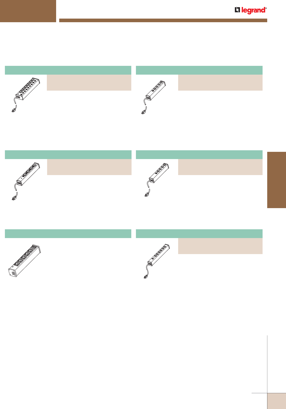
WWW.LEGRAND.US/WIREMOLD
681
WIREMOLD
POWER DISTRIBUTION
WORKSTATION POWER SOLUTIONS
Ordering Information
Work Station Power Solutions – Power Only Plug-In Outlet Center Units Ordering Information (continued)
Plug-In Outlet Center Units
PART NUMBERS:
UL209BC (6 Foot Cord)
UL209BD (15 Foot Cord)
Eight individually switched outlets,
lighted on/off switch, putty white finish
aluminum housing, 15A. 6' [1.8m]
(UL209BC) or 15' [4.6m] (UL209BD)
14/3 SJT black cord with NEMA5-15
plug. Length 13" [330mm], width 3 1/2"
[89mm]. Receptacle center-to-center
1 5/16" [33mm]. Snap-on, slide-off
mounting.
Plug-In Outlet Center Units
PART NUMBERS:
UL215BC (6 Foot Cord)
UL215BD (15 Foot Cord)
Four individually switched outlets,
lighted on/off switch, rugged gray
aluminum housing, 15A. 6' [1.8m]
(UL215BC) or 15' [4.6m] (UL215BD) 14/3
SJT black cord with NEMA5-15 plug.
Length 13" [330mm], width 2" [51mm].
Receptacle center-to-center 2 1/8"
[54mm]. Snap-on, slide-off mounting.
IEC5 Plug-In Outlet Center Units
Five 250V, IEC 320 outlets, gray finish,
10A single pole circuit breaker, power
cord not included. Length 11" [279mm].
Receptacle center-to-center 1 1/2"
[38mm]. Input is provided with a male
IEC320 Receptacle. Appropriate input
cord must be purchased separately.
Output receptacles are female IEC320.
Snap-on, slide-off mounting. Power
cord not included. cULus Listed, TUV
Nord Certified EN60950.
Plug-In Outlet Center Units
PART NUMBERS:
ULB620-6 (6 Foot Cord)
ULB620-15 (15 Foot Cord)
Six 20A, 120V, 60Hz, 2500 watt outlets,
lighted switch, putty white aluminum
housing, 6' [1.8m] (ULB620-6) or 15'
[4.6m] (ULB620-15) 12/3 SJT black
cord with NEMA5-20 plug. Length
13 1/4" [337mm]. Receptacle center-
to-center 1 1/2" [38mm]. Snap-on,
slide-off mounting.
Plug-In Outlet Center Units
PART NUMBERS:
ULB820-6 (6 Foot Cord)
ULB820-15 (15 Foot Cord)
Eight 20A, 120V, 60Hz, 2500 watt
outlets, lighted switch, putty white
aluminum housing, 6' [1.8m] (ULB820-
6) or 15' [4.6m] (ULB820-15) 12/3 SJT
black cord with NEMA5-20 plug. Length
17 1/4" [438mm]. Receptacle center-
to-center 1 1/2" [38mm]. Snap-on,
slide-off mounting.
Plug-In Outlet Center Units
PART NUMBERS:
ULB420-6 (6 Foot Cord)
ULB420-15 (15 Foot Cord)
Four 20A, 120V, 60Hz, 2500 watt outlets,
lighted switch, putty white aluminum
housing, 6' [1.8m] (ULB420-6) or
15' [4.6m] (ULB420-15) 12/3 SJT black
cord with NEMA5-20 plug. Length
10 3/4" [273mm]. Receptacle center-
to-center 1 1/2" [38mm]. Snap-on,
slide-off mounting.
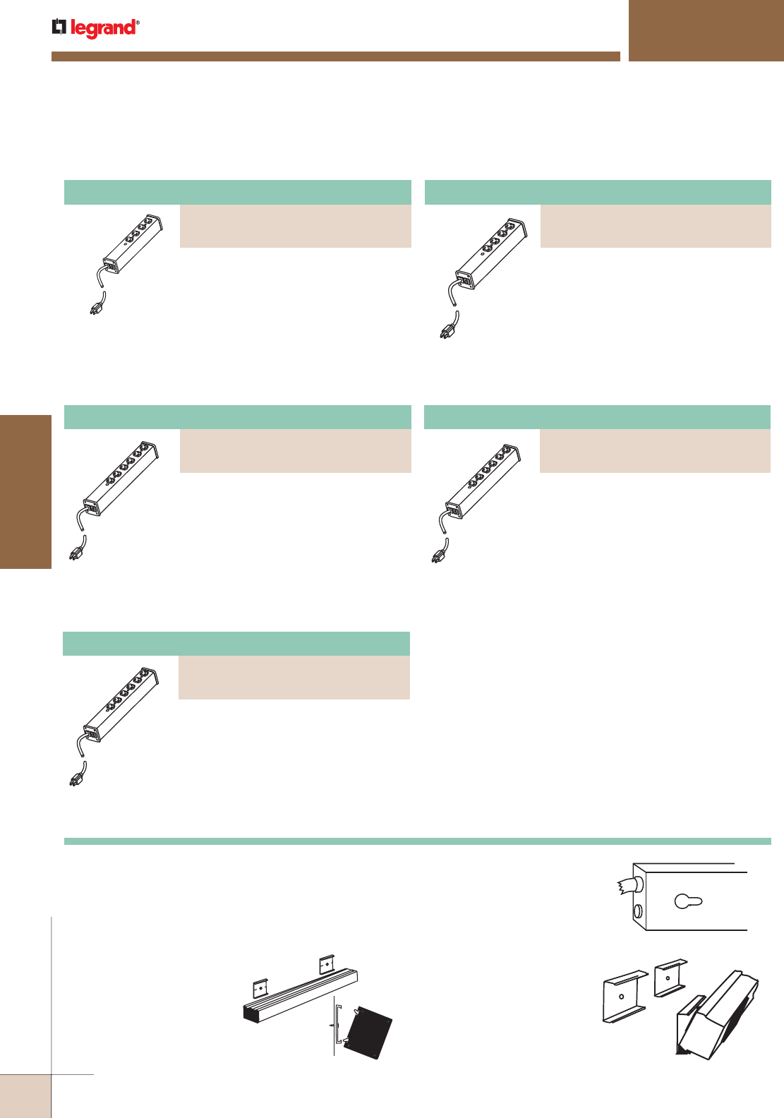
WWW.LEGRAND.US/WIREMOLD
682
POWER DISTRIBUTION
WIREMOLD
Plug-In Outlet Center Units
PART NUMBERS:
ULM4-6 (6 Foot Cord)
ULM4-15 (15 Foot Cord)
Four outlets. Rugged white aluminum
housing. 6' [1.8m] (ULMH4-6) or 15'
[4.6m] (ULMH4-15) 14/3 SJT white cord
with NEMA5-15 plug. Length 10 3/4"
[237mm]. Receptacle center-to-center
1 1/2" [38mm]. Snap-on, slide-off
mounting. cTUVus Listed as Medical
Electrical Equipment. Suitable for use
where Article 517 of NEC requires
Hospital Grade Outlets.
Plug-In Outlet Center Units
PART NUMBERS:
ULM6-6 (6 Foot Cord)
ULM6-15 (15 Foot Cord)
Six outlets. Rugged white aluminum
housing. 6' [1.8m] (ULMH6-6) or 15'
[4.6m] (ULMH6-15) 14/3 SJT white cord
with NEMA5-15 plug. Length 13 1/4"
[337mm]. Receptacle center-to-center
1 1/2" [38mm]. Snap-on, slide-off
mounting. cTUVus Listed as Medical
Electrical Equipment. Suitable for use
where Article 517 of NEC requires
Hospital Grade Outlets.
Special Use/Medical Grade Power Solutions – Power Only Plug-In Outlet Center Units Ordering Information
Plug-In Outlet Center Units
PART NUMBERS:
ULBH4-6 (6 Foot Cord)
ULBH4-15 (15 Foot Cord)
Four outlets. Rugged white aluminum
housing. 6' [1.8m] (ULBH4-6) or 15'
[4.6m] (ULBH4-15) 14/3 SJT white cord
with NEMA5-15 plug. Length 10 3/4"
[237mm]. Receptacle center-to-center
1 1/2" [38mm]. Snap-on, slide-off
mounting. Not for use in critical care
environments. Not for use where
Article 517 of NEC requires Hospital
Grade Outlets.
Plug-In Outlet Center Units
PART NUMBERS:
ULBH6-6 (6 Foot Cord)
ULBH6-15 (15 Foot Cord)
Six outlets. Rugged white aluminum
housing. 6' [1.8m] (ULBH6-6) or 15'
[4.6m] (ULBH6-15) 14/3 SJT white cord
with NEMA5-15 plug. Length 13 1/4"
[337mm]. Receptacle center-to-center
1 1/2" [38mm]. Snap-on, slide-off
mounting. Not for use in critical care
environments. Not for use where
Article 517 of NEC requires Hospital
Grade Outlets.
Plug-In Outlet Center Units
PART NUMBERS:
ULM620-6 (6 Foot Cord)
ULM620-15 (15 Foot Cord)
20A configuration. Four outlets, white
finish. 6' [1.8m] (ULM620-6) or 15'
[4.6m] (ULM620-15) cord. Length 10
3/4" [237mm]. Receptacle center-to-
center 1 1/2" [38mm]. cTUVus Listed as
Medical Electrical Equipment. Suitable
for use where Article 517 of the NEC
requires Hospital Grade Outlets.
MEDICAL GRADE/SPECIAL USE POWER SOLUTIONS
Ordering Information
MOUNTING TYPES
Each Plug-In Outlet Center unit has one of three different mounting
types. Each mounting method has been designed to optimize the
performance of the product. Complete mounting hardware and
installation instructions are included with every unit.
Mounting Information
Snap-On/Slide-Off
Mount unit in any position. Catalog
No. 8004 includes two aluminum
mounting clips that snap onto
mounting rails on the back of
the unit. Screws also included.
Used for all units with 2" [51mm]
aluminum housing.
Keyhole Mounting
Mount unit in almost any position.
Screws not included. Available on
all plastic units and units with 3 1/2"
[89mm] aluminum housing.
Spring Clip Mounting
Mount unit in any position.
Catalog No. 8002 includes two
spring steel mounting clips
that snap onto the unit. Screws
also included. Used for all units
with 1 1/2" [38mm] narrow
aluminum housing.
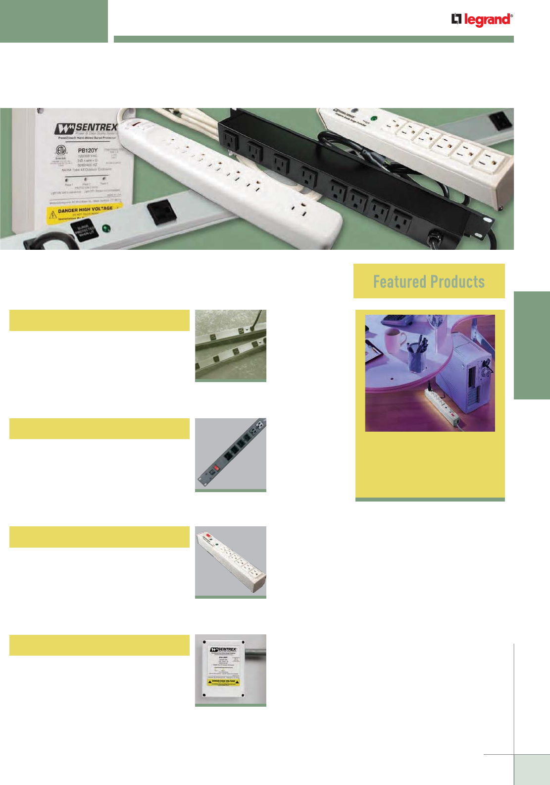
WWW.LEGRAND.US/WIREMOLD
683
WIREMOLD
SURGE PROTECTIVE DEVICES
Wiremold® Surge Protective Devices are designed to provide complete power/
protection solutions for your power/IT network from the service entrance to
point-of-use.
SURGE PROTECTIVE DEVICES
Workstation Surge
Solutions
689
Cabinet Surge Solutions
Workstation Surge Solutions
Hard-Wired Surge Protection
Rack Mounted Surge Solutions
Surge Protected
CabinetMATE
®
Series
685
Surge Protected
Products
687
Surge Protected
Plug-In Outlet
Center
®
Units
689
PA/PB™ Series
692
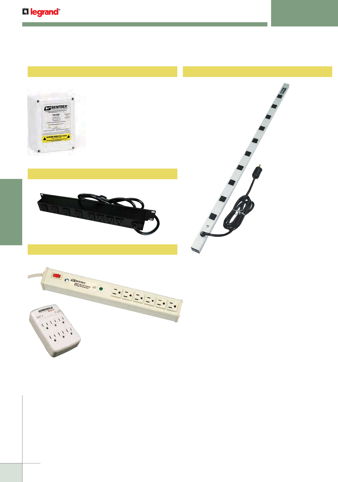
WWW.LEGRAND.US/WIREMOLD
684
SURGE PROTECTIVE DEVICES
WIREMOLD
SURGE PROTECTIVE DEVICES
Quick Selection Guide
PA120T
PR609N
4810ULBC
J60B2B
M6S
Work Station Solutions
Rack-Mounted Power Solutions
Hard-Wired Surge Protection Cabinet Power Solutions
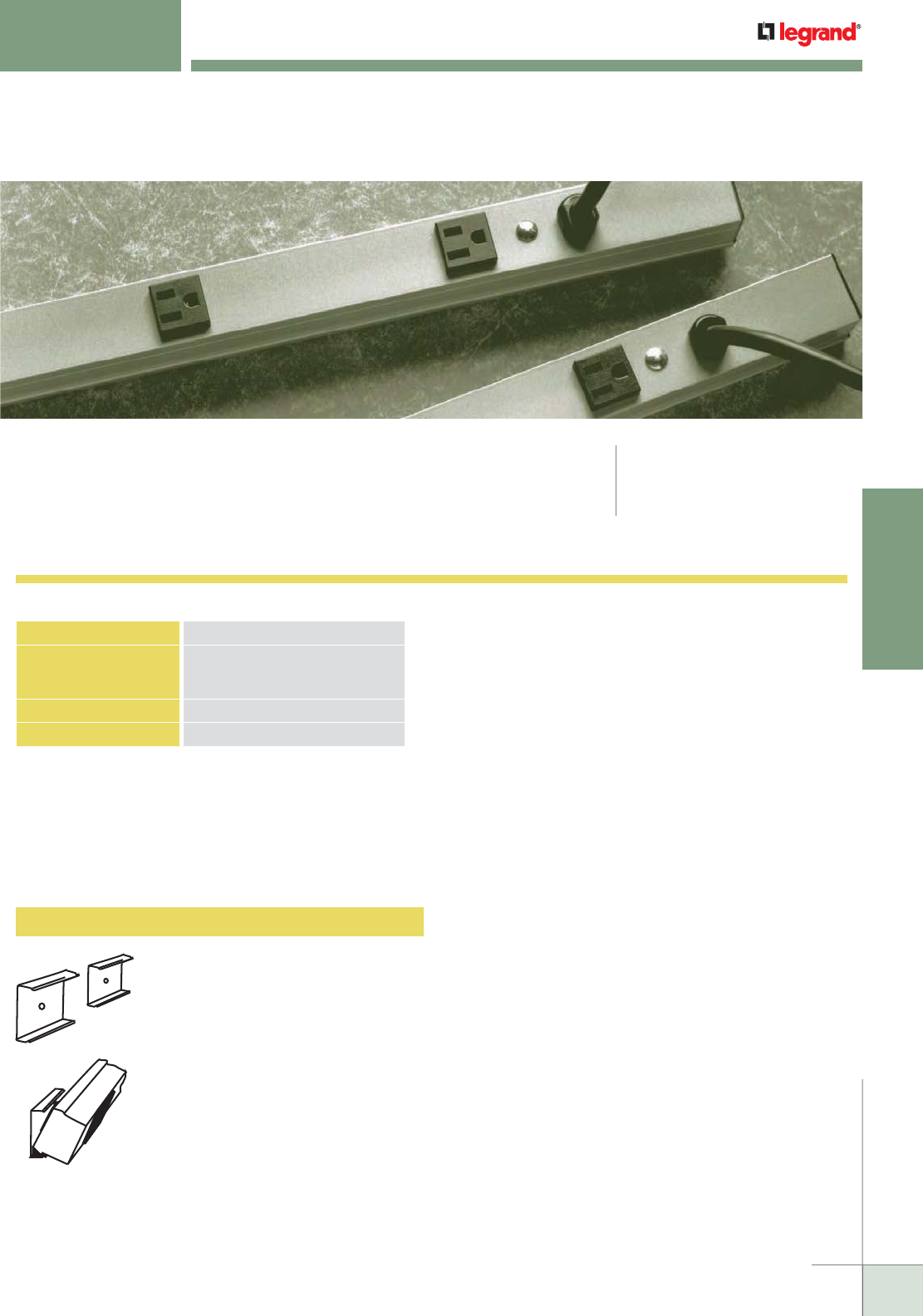
WWW.LEGRAND.US/WIREMOLD
685
WIREMOLD
SURGE PROTECTIVE DEVICES
8002 Spring Clip
CABINETMATE
™
SERIES
Surge Protected Products
CabinetMate Series Plug-In Outlet Center Units offer a low profile aluminum
housing to save space.
NOTE: We are continually upgrading circuitry and features to provide the best possible power distribution
solutions; therefore, the products in this section of the catalog may change without notice. Contact
the factory for additional information.
CODE REFERENCE
cULus Listed: File E66421
Guide XYBS, XUHT, VZCA
Surge Suppression Specifications
Surge Protection Circuitry Single Stage
Maximum Surge Current 36,000 Amps
(12,000 Amps L-N, 12,000 Amps L-G,
12,000 Amps N-G)
Noise Reduction +35dB
Response Time Less than 1 nanosecond
NOTE: See the Joule explanation later in this section.
MOUNTING TYPES
Each Cabinet Power Solution can be mounted via included
spring clip hardware. Complete mounting hardware and
installation instructions are included with every unit.
Mount unit in any position. Includes two
spring steel mounting clips that snap
onto the unit. Screws also included.
Used for all units with 1 1/2" [38mm]
narrow aluminum housing.
CabinetMate Series Mounting Information
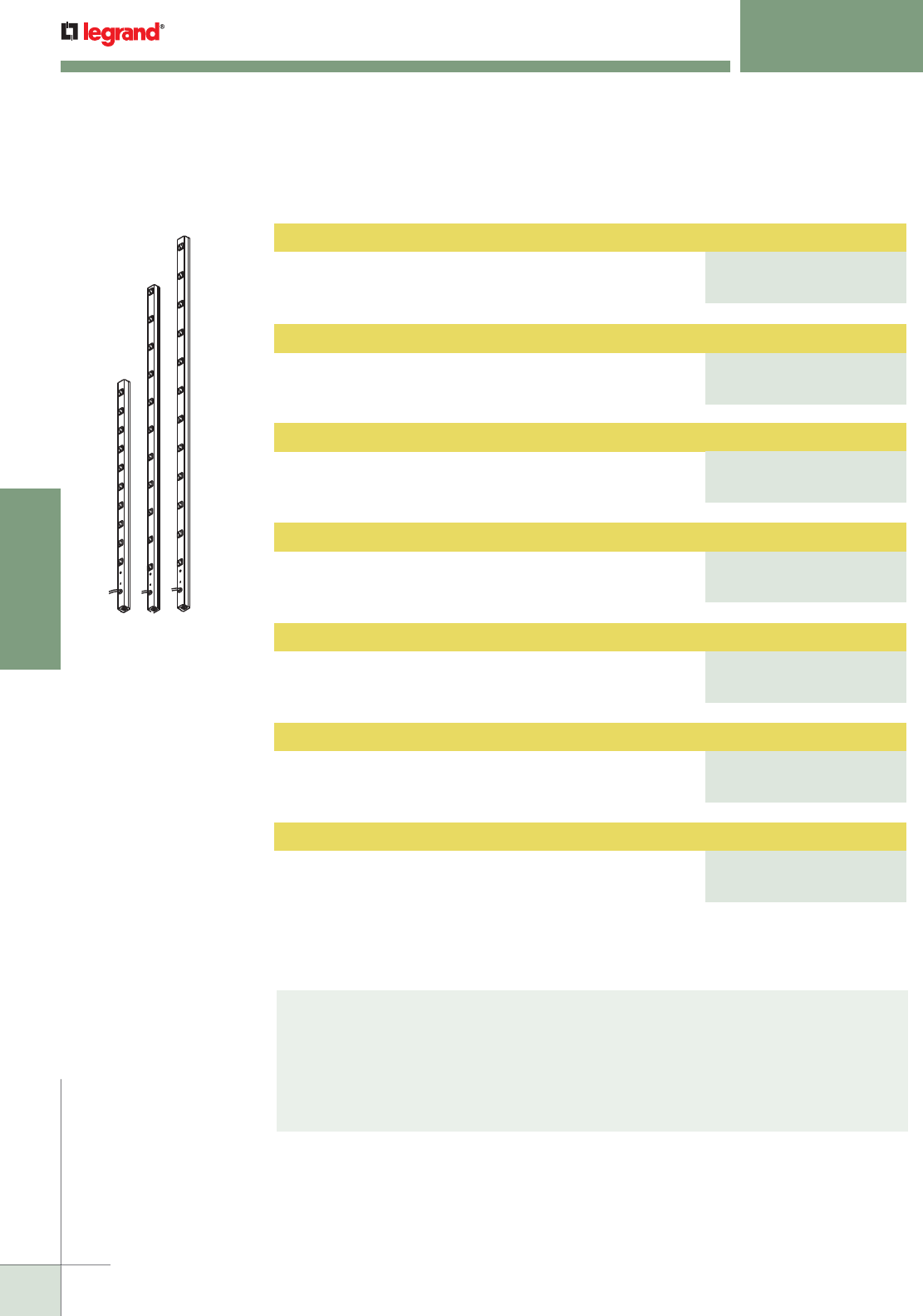
WWW.LEGRAND.US/WIREMOLD
686
SURGE PROTECTIVE DEVICES
WIREMOLD
Plug-In Outlet Center Unit
Ten outlets. 6' [1.8m] (4810BCS) or 15' [4.6m] (4810BDS)
cord. Length 48" [1.2m]. 15A resettable circuit breaker.
Computer grade surge protection, 15 Amps.
Plug-In Outlet Center Unit
Eleven outlets. 6' [1.8m] (7011BCS) or 15' [4.6m]
(7011BDS) cord. Length 70" [1.8m]. 15A resettable circuit
breaker. Computer grade surge protection, 15 Amps.
Plug-In Outlet Center Unit
Twelve outlets. 6' [1.8m] (7712BCS) or 15' [4.6m]
(7712BDS) cord. Length 77" [2m]. 15A resettable circuit
breaker. Computer grade surge protection, 15 Amps.
Plug-In Outlet Center Unit
Eight 20A outlets with t-slots. 6' [1.8m] (2008BCS20R)
or 15' [4.6m] (2008BDS20R) cord. Length 20" [508mm].
Computer grade surge protection, 20 Amps.
Plug-In Outlet Center Unit
Ten 20A outlets with t-slots. 6' [1.8m] (4810BCS20R)
or 15' [4.6m] (4810BDS20R) cord. Length 48" [1.2m].
Computer grade surge protection, 20 Amps.
Plug-In Outlet Center Unit
Eleven outlets with t-slots. 6' [1.8m] (7011BCS20R)
or 15' [4.6m] (4810BDS20R) cord. Length 70" [1.8m].
Computer grade surge protection, 20 Amps.
Plug-In Outlet Center Unit
Twelve outlets with t-slots. 6' [1.8m] (7712BCS20R)
or 15' [4.6m] (7712BDS20R) cord. Length 77" [2m].
20A resettable circuit breaker. Computer grade surge
protection, 20 Amps.
All units feature gray aluminum
housing 1 1/2" x 1 3/16" [38mm
x30mm] with black receptacles
and black power cord with
straight blade plug.
CABINETMATE™ SERIES
Surge Protected Products
Why Don’t We Specify Joules?
The Joule rating does not provide an accurate indication of the robustness of a surge
suppressor. The Joule rating is energy over time and it is very easy to artificially inflate
the Joule rating by changing the time base. The Institute of Electrical and Electronics
Engineers (IEEE) as well as the National Electrical Manufacturers Association (NEMA) both
warn against using Joules to compare surge suppressors.
CabinetMate Series Surge Protected Plug-In Outlet Centers Ordering Information
PART NUMBERS:
4810BCS (6 Foot Cord)
4810BDS (15 Foot Cord)
PART NUMBERS:
7011BCS (6 Foot Cord)
7011BDS (15 Foot Cord)
PART NUMBERS:
7712BCS (6 Foot Cord)
7712BDS (15 Foot Cord)
PART NUMBERS:
2008BCS20R (6 Foot Cord)
2008BDS20R (15 Foot Cord)
PART NUMBERS:
4810BCS20R (6 Foot Cord)
4810BDS20R (15 Foot Cord)
PART NUMBERS:
7011BCS20R (6 Foot Cord)
7011BDS20R (15 Foot Cord)
PART NUMBERS:
7712BCS20R (6 Foot Cord)
7712BDS20R (15 Foot Cord)
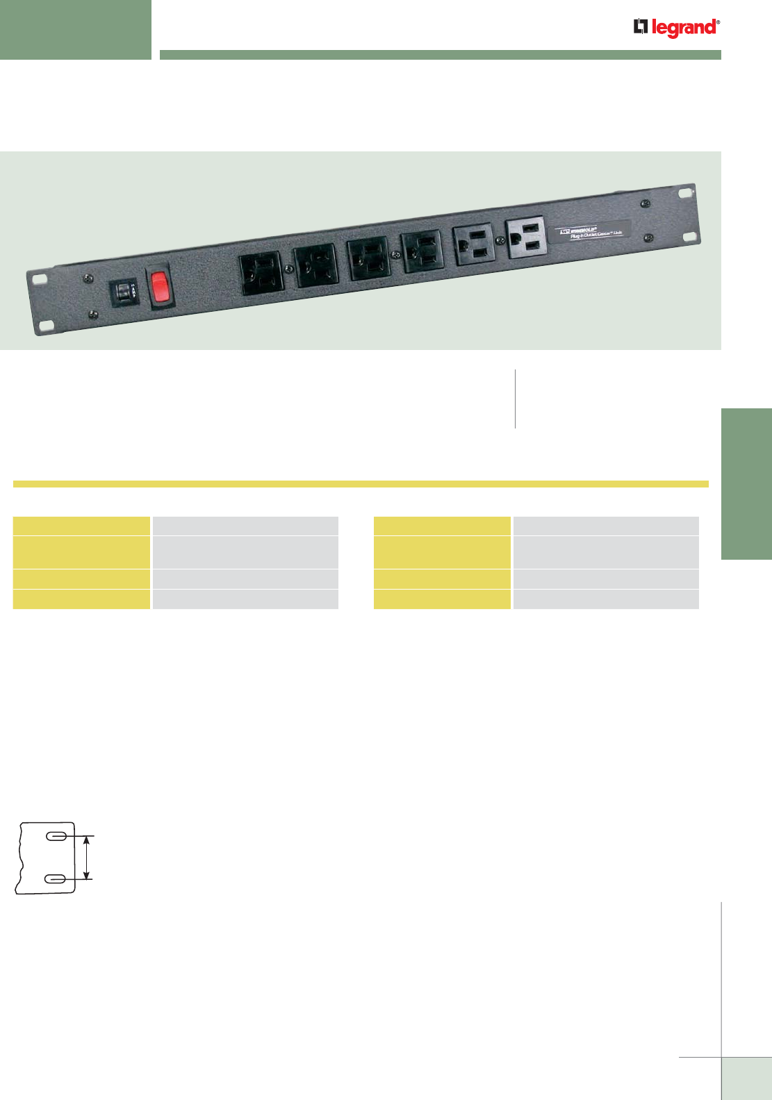
WWW.LEGRAND.US/WIREMOLD
687
WIREMOLD
SURGE PROTECTIVE DEVICES
RACK MOUNTED SURGE SOLUTIONS
Rack Mounted Power Solutions are designed to fit a standard 19" rack.
The compact 1U design takes up a minimum amount of rack space
NOTE: We are continually upgrading circuitry and features to provide the best possible power distribution
solutions; therefore, the products in this section of the catalog may change without notice. Contact
the factory for additional information.
CODE REFERENCE
cULus Listed: File E66421
Guide XBYS2, XUHT2, VZCA2
Sentrex® High Performance Surge Specifications
Surge Protection Circuitry
3 Element, 3-Stage Hybrid Circuit
Maximum Surge Current
56,000 Amps (32,000 Amps L-N,
12,000 Amps L-G, 12,000 Amps N-G)
Noise Reduction
+50dB
Response Time Less than 1 nanosecond
NOTE: See the Joule explanation on page 626.
Perma-Power® Computer Grade Surge Specifications
Surge Protection Circuitry
Single Stage
Maximum Surge Current
36,000 Amps (12,000 Amps L-N,
12,000 Amps L-G, 12,000 Amps N-G)
Noise Reduction
+35dB
Response Time Less than 1 nanosecond
MOUNTING TYPES
Each Rack Mounted Power Solution can be mounted to standard 19" [482mm] racks via the closed slots. Power Commander High
Amperage Unit can also be mounted in a 0U position as shown below. Complete mounting hardware and installation instructions
are included with every unit.
Rack Mounting
Fits standard 19" [482mm] rack.
Hardware not included.
Closed Slots
for Rigidity
Designed in accordance with
E.I.A. standards.
Mounting Information
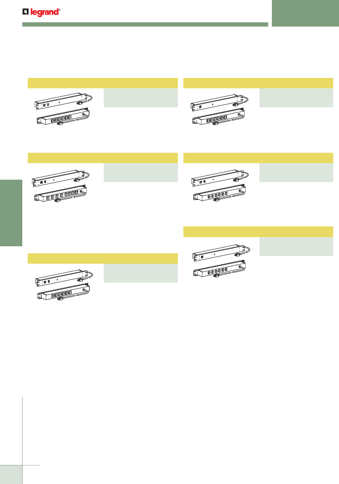
WWW.LEGRAND.US/WIREMOLD
688
SURGE PROTECTIVE DEVICES
WIREMOLD
Plug-In Outlet Center Unit
PART NUMBERS:
R5BZ20X (6 Foot Cord)
R5BZ20X-15 (15 Foot Cord)
Plug-In Outlet Center Unit
PART NUMBERS:
R5BZ20 (6 Foot Cord)
R5BZ20-15 (15 Foot Cord)
Plug-In Outlet Center Unit
PART NUMBERS:
R5BZX (6 Foot Cord)
R5BZX-15 (15 Foot Cord)
Plug-In Outlet Center Unit
PART NUMBERS:
R5BZ (6 Foot Cord)
R5BZ-15 (15 Foot Cord)
RACK MOUNTED SURGE SOLUTIONS
Surge Protected Products
Surge Protected Products Ordering Information
Eight rear outlets, lighted
switch, 15A. Receptacles
rotated 90° and 4 outlets
spaced to accommodate
transformers. 6' [1.8m]
(R8BZ) or 15' [4.6m] (R8BZ-
15) cord. Perma-Power®
computer grade surge
protection.
Six rear outlets, lighted
switch, 15A. 6' [1.8m] (R5BZ)
or 15'[4.6m] (R5BZ-15) cord.
Perma-Power® computer
grade, surge protection.
Six rear outlets, 15A. 6'
[1.8m] (R5BZX) or 15'[4.6m]
(R5BZX-15) cord. Perma-
Power® computer grade,
surge protection.
Six 20A rear outlets, on/off
switch. 6' [1.8m] (R5BZ20) or
15' [4.6m] (R5BZ20-15) cord.
Perma-Power® computer
grade surge protection.
Six 20A rear outlets. 6' [1.8m]
(R5BZ20X) or 15' [4.6vm]
(R5BZ20X-15) cord. Perma-
Power® computer grade
surge protection.
Six rear outlets, lighted
switch, 15A. 6' [1.8m] (R5S)
or 15' [4.6m] (R5S-15) cord.
Sentrex® high performance
surge protection.
Plug-In Outlet Center Unit
PART NUMBERS:
R5S (6 Foot Cord)
R5S-15 (15 Foot Cord)
Plug-In Outlet Center Unit
PART NUMBERS:
R8BZ (6 Foot Cord)
R8BZ-15 (15 Foot Cord)
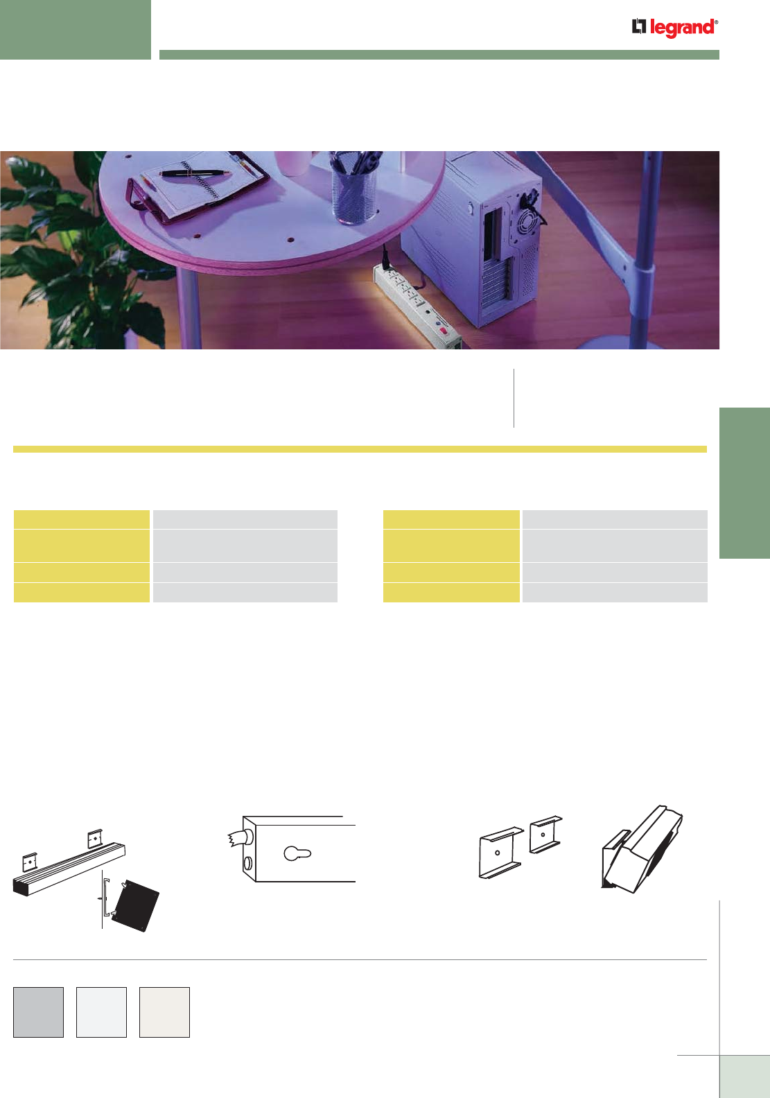
WWW.LEGRAND.US/WIREMOLD
689
WIREMOLD
SURGE PROTECTIVE DEVICES
WORKSTATION SURGE SOLUTIONS
Work Station Power Solutions are point-of-use, plug-in outlet centers available
with and without surge suppression. CODE REFERENCE
cULus Listed: File E66421
Guide XYBS, XUHT, VZCA
Sentrex® High Performance Surge Specifications
Surge Protection Circuitry
3 Element, 3-Stage Hybrid Circuit
Maximum Surge Current
56,000 Amps (32,000 Amps L-N,
12,000 Amps L-G, 12,000 Amps N-G)
Noise Reduction
+50dB
Response Time Less than 1 nanosecond
NOTE: See the Joule explanation located on the Cabinet Power Solutions
page 626.
Perma-Power® Computer Grade Surge Specifications
Surge Protection Circuitry
Single Stage
Maximum Surge Current
36,000 Amps (12,000 Amps L-N,
12,000 Amps L-G, 12,000 Amps N-G)
Noise Reduction
+35dB
Response Time Less than 1 nanosecond
MOUNTING TYPES
Each Plug-In Outlet Center unit has one of three different mounting types. Each mounting method has been designed to optimize
the performance of the product. Complete mounting hardware and installation instructions are included with every unit.
Mounting Information
COLOR OPTIONS
Workstation Power Solutions Plug-In Outlet Center Units Part
Number descriptions indicate available color options.
Surge Suppression Specifications
Snap-On/Slide-Off
Mount unit in any position. Catalog No.
8004 includes two aluminum mounting
clips that snap onto mounting rails
on the back of the unit. Screws also
included. Used for all units with 2"
[51mm] aluminum housing.
Keyhole Mounting
Mount unit in almost any position. Screws not
included. Available on all plastic units and
units with 3 1/2" [89mm] aluminum housing.
Spring Clip Mounting
Mount unit in any position. Catalog No. 8002
includes two spring steel mounting clips that
snap onto the unit. Screws also included.
Used for all units with 1 1/2" [38mm] narrow
aluminum housing.
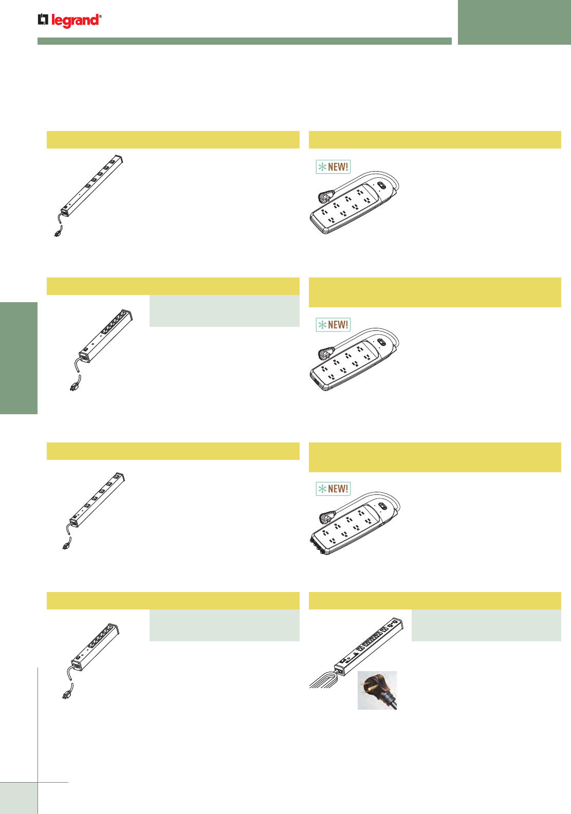
WWW.LEGRAND.US/WIREMOLD
690
SURGE PROTECTIVE DEVICES
WIREMOLD
Plug-In Outlet Center Units
PART NUMBERS:
M6BZ (6 Foot Cord)
M6BZ-15 (15 Foot Cord)
Plug-In Outlet Center Units
PART NUMBERS:
M6S (6 Foot Cord)
M6S-15 (15 Foot Cord)
WORKSTATION SURGE SOLUTIONS
Ordering Information
Work Station Power Solutions – Surge Protected Plug-In Outlet Center Units Ordering Information
M5S Plug-In Outlet Center Units
M5BZ Plug-In Outlet Center Units
Sentrex® high performance
surge protection. Five outlets,
lighted switch, durable putty
white aluminum housing, 15A.
Receptacles rotated 90° and spaced
to accommodate transformers.
Length 24" [610mm]. 6' [1.8m]
14/3 SJT putty white cord with
NEMA5-15 plug. Snap-on, slide-off
mounting.
Sentrex® high performance surge
protection. Six outlets, lighted
switch, durable putty white
aluminum housing, 15A. 6' [1.8m]
(M6S) or 15' [4.6m] (M6S-15) 14/3
SJT putty white cord with NEMA5-
15 plug. Length 15 1/4" [387mm].
Snap-on, slide-off mounting.
Perma-Power® computer grade
surge protection. Five outlets,
lighted switch, durable putty
white aluminum housing, 15A.
Receptacles rotated 90° and spaced
to accommodate transformers.
6' [1.8m] 14/3 SJT putty white
cord with NEMA5-15 plug. Length
21" [533mm]. Snap-on, slide-off
mounting.
Perma-Power® computer grade
surge protection. Six outlets,
lighted switch, durable putty
white aluminum housing, 15A. 6'
[1.8m] (M6BZ) or 15' (M6BZ-15)
[4.6m] 14/3 SJT putty white cord
with NEMA5-15 plug. Length 13
1/4" [337mm]. Snap-on, slide-off
mounting.
Six outlets, two spaced for
transformers. Lighted switch,
data line protector with RJ45 jacks.
6' [1.8m] (M6BZNET) or
15' [4.6m] (M6BZNET-15) power
cord with 45° right angle plug.
Length 18" [457mm].
Right Angle Plug
Plug-In Outlet Center Units
PART NUMBERS:
M6BZNET (6 Foot Cord)
M6BZNET-15 (15 Foot Cord)
77000N Basic Surge Protection
8 outlets spaced for plug-in
transformers, lighted switch,
impact-resistant putty white
polymeric housing. 15A. 6’ [1.8m]
14/3 SJT putty white cord with
NEMA 5-15 plug. Maximum surge
current 6500 Amps. 14” x 4 ¼” x
1 ½” [356mm x 108mm x 38mm].
Keyhole mounting.
77001N
Basic Surge Protection Plus Phone/Fax Protection
8 outlets spaced for plug-in
transformers, lighted switch,
impact-resistant putty white
polymeric housing. 15A. 6’ [1.8m]
14/3 SJT putty white cord with
NEMA 5-15 plug. Maximum surge
current 6500 Amps. 14” x 4 ¼” x
1 ½” [356mm x 108mm x 38mm].
Keyhole mounting.
77002N Basic Surge Protection Plus Digital
Satellite, Coax and Phone/Fax Protection
8 outlets spaced for plug-in
transformers, lighted switch,
impact-resistant putty white
polymeric housing. 15A. 6’ [1.8m]
14/3 SJT putty white cord with
NEMA 5-15 plug. Maximum surge
current 6500 Amps. 14” x 4 ¼” x
1 ½” [356mm x 108mm x 38mm].
Keyhole mounting.
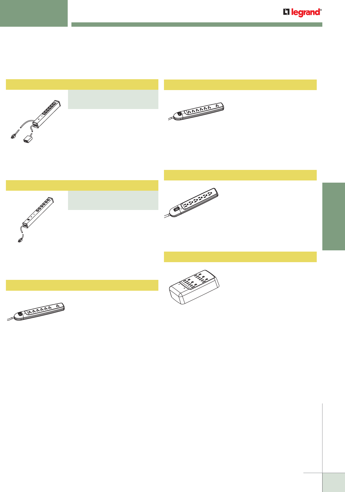
WWW.LEGRAND.US/WIREMOLD
691
WIREMOLD
SURGE PROTECTIVE DEVICES
Plug-In Outlet Center Units
PART NUMBERS:
M620BZLS (6 Foot Cord)
M620BZLS-15 (15 Foot Cord)
Plug-In Outlet Center Units
PART NUMBERS:
M6BZR (6 Foot Cord)
M6BZR-15 (15 Foot Cord)
SR10N Plug-In Outlet Center Units
Perma-Power® computer grade
surge protection. Six outlets,
remote switch, durable putty white
aluminum housing, 15A, 6' [1.8m]
(M6BZR) or 15' [4.6m] (M6BZR-
15) 14/3 SJT putty white cord
with NEMA5-15 plug. Length 13
1/4" [337mm]. Snap-on, slide-off
mounting.
Perma-Power® computer grade
surge protection. Six outlets,
lighted switch, durable putty
white aluminum housing, 20A. 6'
[1.8m] (M620BZLS) or 15' [4.6m]
(M620BZLS-15) 12/3 SJT putty
white cord with NEMA5-20 plug.
Length 18" [457mm]. Snap-on,
slide-off mounting.
Basic surge protection. Seven
outlets, lighted switch, impact-
resistant putty white polymeric
housing, 15A. 6' [1.8m] 14/3 SJT
putty white cord with NEMA5-15
plug. Maximum surge current 6500
Amps. 13 1/4" x 2 1/2" x 1 9/16"
[337mm x 64mm x 40mm]. Keyhole
mounting.
WORKSTATION SURGE SOLUTIONS
Ordering Information
Work Station Power Solutions – Surge Protected Plug-In Outlet Center Units Ordering Information (continued)
SRD10N Plug-In Outlet Center Units
Basic surge protection. Seven
outlets, lighted switch, impact-
resistant putty white polymeric
housing, 15A. 6' [1.8m] 14/3 SJT
putty white cord with NEMA5-15
plug. Maximum surge current
6500 Amps. Phone/fax protection.
13 1/4" x 2 1/2" x 1 9/16" [337mm
x 64mm x 40mm]. Keyhole
mounting.
PR610N Plug-In Outlet Center Units
Basic surge protection. Six
outlets, lighted switch, impact-
resistant putty white polymeric
housing, 15A. 6' [1.8m] 14/3 SJT
putty white cord with NEMA5-15
plug. Maximum surge current
6500 Amps. 11 3/4" x 2 1/4" x 1
1/2" [298mm x 57mm x 38mm].
Keyhole mounting.
PR609N Plug-In Outlet Center Units
Perma-Power® basic surge
protection. Six outlet wall plug,
impact-resistant putty white
polymeric housing, 15A. Maximum
surge current 6500 Amps. 5" x 3
3/8" x 1 3/4" [127mm x 86mm x
44mm].
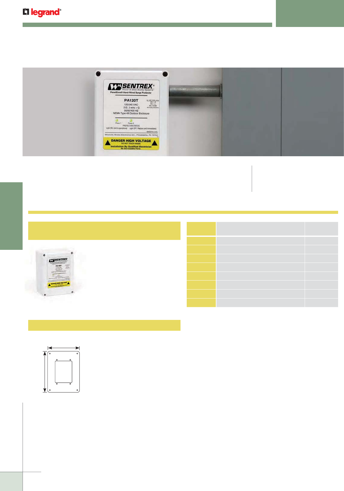
WWW.LEGRAND.US/WIREMOLD
692
SURGE PROTECTIVE DEVICES
WIREMOLD
PA/PB
™
SERIES
Hard Wired Surge Protection
PA/PB Series Hard-Wired Surge Protection provide superior protection and ease-
of-installation for sub-panel applications. The PA120T & PB120T are ideally suited
for residential applications. Meets UL1449 Third Edition requirements. Short circuit
current rating of 10,000A.
PA Series, PB Series
80kA Surge Protection, 160kA Surge Protection
PABFMC Flush Mount Cover
For installing PA/PB units on
sheetrock or firewall construction.
Cover hides the hole cut and gives
the unit a finished look.
CODE REFERENCE
cETLus Listed:
CATALOG
NO. ELECTRICAL SERVICE
SURGE
PROTECTION
PA120T 120/240V, Single Ø 3-Wire & Ground 80kA
PA120Y 120/208V, 3Ø, 4-Wire & Ground 80kA
PA240DCT 120/240/120V, Hi-Leg Delta 80kA
PA277Y 277/480V, 3Ø, 4-Wire & Ground 80kA
PB120T 120/240V, Single Ø 3-Wire & Ground 160kA
PB120Y 120/208V, Single 3Ø, 4-Wire & Ground 160kA
PB240DCT 120/240/120V, Hi-Leg Delta 160kA
PB277Y 277/480V, 3Ø, 4-Wire & Ground 160kA
NOTE: Add suffix “–A” to part number for NO/NC dry contact relay for
connecting remote monitoring device. Add suffix “–B” to part number
for EMI/RFI noise filter. Add “–AB” to part number for both options.
For surge protection at the
sub panel or near sensitive
equipment. Designed for
residential and light commercial/
industrial applications.
Dimensions: 6 5/16" x 4 3/4"
x 39/16" [160mm x 120mm x
90mm]. Ten year unconditional
product warranty.
9"
[229mm]
7"
[178mm]

WWW.LEGRAND.US/WIREMOLD
693
WIREMOLD
TECHNICAL INFORMATION
TECHNICAL INFORMATION
Table of Contents
Raceway Cross Sectional Areas/Wire and Cable
Cross-Sectional Areas
Raceway Wire and Cable Dimensions
Device Box Cubic Inch Capacities
Calculating Wire and Cable Capacities
Master Format 2004 Design Checklist
Conductor Derating (Lighting and Power Circuits)
National Electrical Code Articles
Mounting Methods for Wiremold Raceways
Electrical Symbols in Accordance
with ANSI Y32.9 – 1972
Steel Raceway Color Specifications
702
700
700
699
698
697
696
695
694
WWW.LEGRAND.US/WIREMOLD
694
WIREMOLD
TECHNICAL INFORMATION
TECHNICAL INFORMATION
Raceway Cross - Sectional Area
* Without Devices.
METAL RACEWAY CROSSSECTIONAL AREA
RACEWAY
SERIES
CROSSSECTIONAL AREA
sq. in. mm2
500 0.19 [122.6]
700 0.26 [167.7]
1500 0.22 [141.9]
2000 0.80 [516.1]
2400 1.39 [896.8]
2400D 1/3 Compartment
2/3 Compartment
0.37
0.86
[238.7]
[554.8]
2600 0.72 [464.5]
3000 3.70 [2387.1]
4000 Undivided
Each Compartment
7.20
3.50
[4645.2]
[2258.1]
6000 Undivided
Each Compartment
16.00
7.20
[10322.6]
[4645.2]
DS4000 Each Compartment
with Down Crossover, Power
with Down Crossover, Comm*
5.02
1.13
2.04
[3235.5]
[729.0]
[1316.0]
AL2000 1.10 [709.7]
AL2400 Divided 1/3 Compartment 1.70 [1096.8]
AL3300 Single Compartment 4.40 [2838.7]
ALA3800/
ALA4800
Each Compartment 6.10 [3935.5]
AL5200 Undivided
Center Divided
Offset Divided
Offset Divided
8.50
3.90
3.78
4.85
[5483.9]
[2516.1]
[2438.7]
[3129.0]
ALDS4000 Each Compartment 4.85 [3129.0]
NOTE: Cross-Sectional Area for use in low voltage cable capacity
calculations only, not for use in power cable capacity calculations.
NONMETALLIC RACEWAY CROSSSECTIONAL AREA
RACEWAY
SERIES
CROSSSECTIONAL AREA
sq. in. mm2
400 0.13 [83.9]
800 0.27 [174.2]
2300 Undivided 0.85 [548.4]
2300D Each Compartment 0.425 [274.2]
NM2000 1.14 [735.5]
PN03 0.22 [141.9]
PN05 0.44 [283.9]
PN10 0.99 [638.7]
2700 0.16 [103.2]
2800 0.35 [219.4]
2900 0.87 [561.3]
5000 Power Compartment
Data Compartment
1.94
1.40
[1251.6]
[903.2]
5400 Divided 1/2 Compartment
Undivided
3.72
7.44
[2400.0]
[4800.0]
5500 Divided 1/3 Compartment
Undivided
2.64
8.14
[1703.2]
[5251.6]
40N2 Single Compartment
(no Communications Box)
Single Compartment
(with Communications Box)
3.22
1.71
[2077.4]
[1103.2]
60N2 Single Compartment
(no Communications Box)
Single Compartment
(with Communications Box)
4.31
1.71
[2780.6]
[1103.2]
2300D Each Compartment 0.425 [274.2]
OFR Each Compartment 0.216 [5.5]

WWW.LEGRAND.US/WIREMOLD
695
WIREMOLD
TECHNICAL INFORMATION
TECHNICAL INFORMATION
* Category 6 augmented (6a) cable for 10 gigabit ethernet –
max allowed cable diameter per addenda No. 11 ANSI TIA/EIA 568-B.2.
DIMENSIONS OF LOW VOLTAGE CABLES & SIGNAL WIRE*
CABLE/WIRE SIZE APPROX. DIA APPROX. AREA
Inches [mm] sq. in. [mm2]
UNSHIELDED
TWISTED PAIR
(UTP) 24 AWG
2-Pair 24 AWG 0.150 3.8 0.0177 11.419
3-Pair 24 AWG, Cat 3 0.160 4.1 0.0201 12.986
4-Pair 24 AWG, Cat 3 0.190 4.8 0.0284 18.323
4-Pair 24 AWG, Cat 5 0.210 5.3 0.0346 22.323
4-Pair 24 AWG, Cat 5e 0.210 5.3 0.0346 22.323
4-Pair 24 AWG, Cat 6 0.250 6.3 0.0490 31.613
4-Pair 24 AWG, Cat 6a* 0.354 9.0 0.0980 63.226
25-Pair 24 AWG, Cat 3 0.360 9.1 0.1018 65.677
25-Pair 24 AWG, Cat 5 0.337 8.6 0.0892 57.548
50-Pair 24 AWG 0.500 12.7 0.1963 126.645
75-Pair 24 AWG 0.600 15.2 0.2827 182.387
100-Pair 24 AWG 0.680 17.3 0.3632 234.322
SHIELDED
TWISTED PAIR
(STP) 22 AWG
TYPE 1 0.390 9.9 0.1195 77.097
TYPE 2 0.465 11.8 0.1698 109.548
TYPE 3 0.275 7.0 0.0573 36.968
COAXIAL
RG58/U 0.195 5.0 0.0299 19.290
RG59/U 0.242 6.1 0.0460 29.677
RG62/U 0.242 6.1 0.0460 29.677
RG6/U 0.270 6.9 0.0573 36.968
TWINAXIAL 100 Ohm 0.240 6.1 0.0452 29.161
SIGNAL WIRE
24 AWG 0.044 1.1 0.0015 0.968
22 AWG 0.050 1.3 0.0020 1.290
20 AWG 0.057 1.4 0.0026 1.677
18 AWG 0.066 1.7 0.0034 2.194
FIBER
2 Strand (ZipCord) 0.118 x 0.236 3 x 6 0.0278 18.0
Round 4 Strand Fiber 0.187 4.8 0.0275 18.1
Round 6 Strand Fiber 0.256 6.5 0.0514 32.2
Raceway Wire & Cable Dimensions
DIMENSIONS OF RUBBERCOVERED & THERMOPLASTIC CONDUCTORS
2005 EDITION OF THE NATIONAL ELECTRICAL CODE
SIZE
AWG
TYPES: THHM, THWN
APPROX. APPROX.
dia. in. [mm] sq. in. [mm2]
14 0.111 [2.8] 0.0097 [6.258]
12 0.130 [3.3] 0.0133 [8.581]
10 0.164 [4.2] 0.0211 [13.613]
8 0.216 [5.5] 0.0366 [23.613]
6 0.254 [6.5] 0.0507 [32.710]
4 0.324 [8.2] 0.0824 [53.162]
3 0.352 [8.9] 0.0973 [62.775]
2 0.384 [9.8] 0.1158 [74.711]
1 0.446 [11.3] 0.1562 [100.776]
1/0 0.486 [12.3] 0.1855 [119.679]
2/0 0.532 [13.5] 0.2223 [143.421]
3/0 0.584 [14.8] 0.2679 [172.841]
4/0 0.642 [17.3] 0.3237 [208.842]
250 0.711 [18.1] 0.3970 [256.132]
300 0.766 [19.5] 0.4608 [297.294]
WWW.LEGRAND.US/WIREMOLD
696
WIREMOLD
TECHNICAL INFORMATION
NOTE: When planning a layout, it is important to remember that it is permissible to make splices and taps in surface raceway equipped with
a removable cover. Refer to ARTICLE 386-56 of the National Electrical Code.
TECHNICAL INFORMATION
Wiremold Device Boxes – Cubic Inch Capacities
CUBIC INCH CAPACITY OF WIREMOLD BOXES
CAT. NO.
AVAILABLE
INSIDE VOLUME
MAXIMUM NUMBER OF
CONDUCTORS
cu. in. [cm3]NO. 14 NO. 12 NO. 10 NO. 8
1542D 5.7 [93.0] 2 2 2 1
1546A 15.6 [255.0] 7 6 6 5
1546B 15.6 [255.0] 7 6 6 5
2337A 22.2 [364.0] 11 9 8 7
2338 15.9 [260.0] 7 7 6 5
2344 32.5 [532.0] 16 14 13 10
2344-2 53.1 [870.0] 26 23 21 17
2347 16.1 [264.0] 8 7 6 5
2347-2 26.4 [432.0] 13 11 10 8
2348 20.2 [331.0] 10 9 8 6
2348-2 32.9 [538.7] 16 14 13 11
2348-3 49.8 [816.8] 24 22 19 16
2348S/51 10.0 [164.0] 5 4 4 3
2642D 11.8 [194.0] 5 5 4 4
AL2044 28.3 [464.0] 14 12 11 9
AL2044-2 51.6 [846.0] 25 23 20 17
AL2044-3 82.3 [1348.0] 41 36 32 27
AL2047 17.3 [283.0] 8 7 6 5
AL2047-2 27.9 [458.0] 14 12 11 9
G2048 22.3 [366.0] 11 9 8 7
G2048-2 37.8 [619.0] 18 16 15 12
G3028 71.8 [1177.0] 35 31 28 23
G3044-2 107.4 [1760.0] 53 47 43 35
NM2044 32.5 [532.0] 16 14 13 10
NM2044-2 53.1 [870.0] 26 23 21 17
NM2048 20.2 [331.0] 10 9 8 6
NM2048-2 32.9 [538.7] 16 14 13 11
PSB1 20.2 [331.0] 10 9 8 6
PSB2 32.9 [538.7] 16 14 13 11
PSB3 49.8 [816.8] 24 22 19 16
R5752 29.7 [486.0] 14 13 11 9
R5753 59.9 [982.0] 30 26 24 20
V2048 22.3 [366.0] 11 9 8 7
V2048-2 37.8 [619.0] 18 16 15 12
V2448 22.3 [366.0] 11 9 8 7
V2448-2 37.8 [619.0] 18 16 15 12
V5719 10.3 [168.0] 5 4 4 3
V57240 10.2 [166.7] 5443
CUBIC INCH CAPACITY OF WIREMOLD BOXES
CAT. NO.
AVAILABLE
INSIDE VOLUME
MAXIMUM NUMBER OF
CONDUCTORS
cu. in. [cm3]NO. 14 NO.12 NO. 10 NO. 8
V57242 10.2 [167.1] 5 4 4 3
V57243G 10.2 [167.1] 5 4 4 3
V5733 5.7 [94.0] 2 2 2 1
V5734 17.2 [282.0] 8 7 6 5
V5734A 17.2 [282.0] 8 7 6 5
V5735 29.5 [484.0] 14 13 11 9
V5737 17.2 [282.0] 8 7 6 5
V5737A 22.2 [364.0] 11 9 8 7
V5738 17.2 [282.0] 8 7 6 5
V5738A 22.2 [364.0] 11 9 8 7
V5738AF 22.2 [364.0] 11 9 8 7
V5739 29.8 [488.0] 14 13 11 9
V5739A 29.8 [488.0] 14 13 11 9
V5741 17.7 [290.0] 8 7 7 5
V5744 34.4 [564.0] 17 15 13 11
V5744-2 58.9 [966.0] 29 26 23 19
V5744-3 80.3 [1316.0] 40 35 32 26
V5744S 28.8 [472.0] 14 12 11 9
V5744S-2 48.3 [792.0] 24 21 19 16
V5744S-3 66.9 [1096.0] 33 29 26 22
V5745 22.3 [366.0] 11 9 8 7
V5747 17.9 [294.0] 9 7 7 5
V5747-2 30.0 [491.0] 15 13 12 10
V5747-3 40.9 [670.0] 20 18 16 13
V5748 22.3 [366.0] 11 9 8 7
V5748-2 37.5 [614.0] 18 16 15 12
V5748-3 52.2 [856.0] 26 23 20 17
V5748-4 67.4 [1104.0] 33 29 27 22
V5748-5 80.9 [1324.9] 40 35 32 27
V5748-6 95.3 [1561.8] 47 42 38 31
V5748S 11.9 [195.0] 6 5 4 4
V5751 11.9 [195.0] 6 5 4 4
V5751-2 18.3 [300.0] 9 8 7 6
V5751-3 28.0 [458.8] 14 12 11 9
V5752 29.7 [486.0] 14 13 11 9
V5753 59.9 [982.0] 30 26 24 20
V5760 11.9 [195.0] 6544

WWW.LEGRAND.US/WIREMOLD
697
WIREMOLD
TECHNICAL INFORMATION
TECHNICAL INFORMATION
General:
• Wire Fill Charts are rounded down to the nearest whole number.
• All cross sectional areas have been calculated using CAD models.
Power:
• Wire Fill capacities are calculated using stranded wire diameters per NEC Chapter 9, Table 5.
• Wire capacities are actual maximum fills in nonmetallic raceways. This is based on heat rise testing as required
by Underwriters Laboratories Standard UL5A for Nonmetallic Raceways.
• Wire capacities in metal raceways are calculated at 40% of cross-sectional area per the NEC and verified to fit as
required by Underwriters Laboratories Standard UL5 for Metal Raceways.
Data/Communications:
• Cable diameters used are approximate and represent a typical cable for each category. Check with cable
manufacturer for more accurate dimensions.
• Cable fills as stated in charts are theoretical and should be achievable in straight raceway sections without
devices or when using radiused full capacity fittings. Unless noted in each section, raceway fittings will offer full
wire fill capacity.
• The wire fill specifications cited in this Buyer’s Guide are based on calculated theoretical wire fills of each
raceway. Actual real world testing done by Wiremold/Legrand has shown that a raceway considered completely
“full” is typically using only 60% of its available theoretical area. For this reason a 60% maximum fill should be
only used to determine the absolute maximum number of cables a raceway is capable of containing. Therefore,
the practical capacity for telecommunications cabling in perimeter raceway systems ranges from 20% – 40%
wire fill. Wiremold/Legrand recommends following EIA/TIA guidelines that specify a 40% wire fill be used as a
maximum in planning and specifying the raceway. This fill will accommodate adds, moves, and changes, and
the combination in certain raceway fittings, may restrict the usable cross section of the raceway in that location.
Designers utilizing raceway systems should use this information along with the expected life of the raceway, to
properly select the appropriate system to fit their needs.
Calculating Wire & Cable Capacities
How to Determine Wire Capacities (Power) Formula*
To find the maximum Number of Conductors when devices
are utilized, use the following formula:
40% (cross-sectional area of Raceway
– cross-sectional area of Device)**
cross-sectional area of Conductor
NOTE: Use fill capacities as stated on ordering data pages of this catalog only.
* This formula cannot be used with nonmetallic raceways with a material
thickness of .025" [.6mm] or less (i.e., 2000 Raceway).
**Obtain cross-sectional area of devices from device manufacturer.
How to Determine Wire Capacities (Low-Voltage) Formula
Number of Conductors =
20-40% cross-sectional area of Raceway
cross-sectional area of Cable
This allows room for bending radii and future expansion.
The raceways may be filled to their maximum physical
capacity providing the cables may be readily installed or
removed without damage to the insulation or conductors.
Important Notes for Understanding Wire Fill Capacities & Calculations

WWW.LEGRAND.US/WIREMOLD
698
WIREMOLD
TECHNICAL INFORMATION
TECHNICAL INFORMATION
DIVISION 28 Electronic Safety and Security:
28 05 28 Pathways for Electronic Safety and Security
28 05 28.29 Hangers and Supports for Electronic Safety
and Security
28 05 28.33 Conduits and Backboxes for Electronic
Safety and Security
28 05 28.36 Cable Trays for Electronic Safety and
Security
28 05 28.39 Surface Raceways for Electronic Safety and
Security
28 05 48 Vibration and Seismic Controls for Electronic
Safety and Security
DIVISION 26 Electrical: (continued)
26 27 23 Indoor Service Poles
26 27 26 Wiring Devices
26 35 23 Electromagnetic-Interference Filters
26 35 46 Radio-Frequency-Interference Filters
26 41 23 Lightning Protection Surge Arresters
and Suppressors
26 43 13 Transient-Voltage Suppression for
Low-Voltage
DIVISION 27 Communications:
27 05 28 Pathways for Communications Systems
27 05 28.29 Hangers and Supports for Communications
Systems
27 05 28.33 Conduits and Backboxes for
Communications Systems
27 05 28.36 Cable Trays for Communications Systems
27 05 28.39 Surface Raceways for Communications
Systems
27 05 48 Vibration and Seismic Controls for
Communications Systems
27 11 16 Communications Cabinets, Racks, Frames
and Enclosures
27 11 19 Communications Termination Blocks and
Patch Panels
27 11 23 Communications Cable Management and
Ladder Rack
27 11 26 Communications Rack Mounted Power
Protection and Power Strips
DIVISION 26 Electrical:
26 05 29 Hangers and Supports for Electrical
Systems
26 05 33 Raceway and Boxes for Electrical Systems
26 05 36 Cable Trays for Electrical Systems
26 05 39 Underfloor Raceways for Electrical Systems
26 05 48 Vibration and Seismic Controls for Electrical
Systems
26 06 20.23 Electrical Circuit Schedule
26 06 20.26 Wiring Device Schedule
26 09 23 Lighting Control Devices
26 09 26 Lighting Control Panelboards
26 09 33.13 Multichannel Remote-Controlled Dimmers
26 09 33.16 Remote-Controlled Dimming Stations
26 09 36 Modular Dimming Controls
26 09 36.13 Manual Modular Dimming Controls
26 09 36.16 Integrated Multipreset Modular Dimming
Controls
26 09 43 Network Lighting Controls
26 09 43.13 Digital-Network Lighting Controls
26 09 43.16 Addressable Fixture Lighting Control
26 09 61 Theatrical Lighting Controls
26 18 19 Medium-Voltage Lightning Arresters
26 18 23 Medium-Voltage Surge Arresters
26 27 16 Electrical Cabinets and Enclosures
26 27 19 Multi-Outlet Assemblies
DIVISION 25 Integrated Automation:
25 05 28 Pathways for Integrated Automation
25 05 28.29 Hangers and Supports for Integrated
Automation
25 05 28.33 Conduits and Backboxes for Integrated
Automation
25 05 28.36 Cable Trays for Integrated Automation
25 05 28.39 Surface Raceways for Integrated Automation
25 05 48 Vibration and Seismic Controls for
Integrated Automation
DIVISION 07 Thermal and Moisture Protection:
07 84 13 Penetration Firestopping
07 84 13.16 Penetration Firestopping Devices
Master Format 2004 – Design Checklist

WWW.LEGRAND.US/WIREMOLD
699
WIREMOLD
TECHNICAL INFORMATION
National Electrical Code Articles
TECHNICAL INFORMATION
ARTICLE 90 - Introduction
90-4: Enforcement
ARTICLE 100 - Definitions
Accessible
Branch Circuit
Concealed
Device
Exposed Outlet
Feeder
Fitting
Ground
Grounded
Grounding
Conductor
Grounding Conductor,
Equipment
Locations:
Damp, Dry, Wet
Multioutlet Assembly
Raceway
Receptacle
Receptacle Outlet
ARTICLE 310 - Conductors for General Wiring
310-4: Conductors in Parallel
310-13: Conductor Application Table
310-15 – Ampacities for Conductors
Rated 0-2000 Volts
ARTICLE 386 - Surface Metal Raceways
ARTICLE 388 - Surface Nonmetallic Raceways
ARTICLE 380 - Multioutlet Assembly
ARTICLE 390 - Underfloor Raceways
ARTICLE 374 - Cellular Metal Floor Raceway
ARTICLE 376 - Metal Wireways and Nonmetallic Wireways
ARTICLE 363 - Flat Cable Assemblies, Type FC
Entire Section
ARTICLE 370 - Boxes and Fittings Table 370-16(b)
ARTICLE 517 - Health Care Facilities
517-13(b): Methods for Grounding Receptacles and
Fixed Electric Equipment.
ARTICLE 518 - Places of Assembly
518-4: Wiring Methods
ARTICLE 645 - Information Technology Equipment
645-5: Data Processing Supply Circuits
and Interconnecting Cables.
ARTICLE 700 - Emergency Systems
700-1: Scope
700-9: Wiring
ARTICLE 701 - Legally Required Standby Systems
701-1: Scope
701-10: Wiring
ARTICLE 702 - Optional Standby Systems
702-1: Scope
702-9: Wiring
ARTICLE 725 - Class 1, Class 2, and Class 3
Remote Control, Signaling and
Power-Limiting Circuits
725-26: Conductors of Different Circuits in Same
Enclosure, Cable or Raceway
725-28: Number of Conductors in Raceways and
Cables, and Derating.
725-54(a): Separation from Light, Power, and
Class Conductors in Enclosures,
Raceways and Cables.
725-54(b): Conductors of Different Class 2
and Class 3 Circuits in Same Cables,
Enclosure or Raceway.
ARTICLE 770 - Optical Fiber Cables and Raceways
ARTICLE 780 - Closed Loop and Programmed
Power Distribution
ARTICLE 800 - Communication Circuits
800-52(a)1: Installation of Conductors in Raceways
and Boxes.
ARTICLE 110 - Requirements for Electrical Installation
110-12: Mechanical Execution of Work
110-13: Mounting of Equipment
ARTICLE 200 - Use and Identification of Grounded
Conductors
ARTICLE 210 - Branch Circuits
210-20: Overcurrent Protection
210-21: Outlet Devices
210-22: Maximum Loads
210-23: Permissible Loads
210-24: Branch Circuit Requirements–Summary
210-50: Receptacle Outlets Required
ARTICLE 250 - Grounding
250-2: Effective Grounding Path
250-118(14): Types of Equipment
Grounding Conductors
250-120: Equipment Grounding Conductor
250-8: Attachment to Conductors and Equipment
ARTICLE 300 - Wiring Methods
300-10: Electrical Continuity of Metal
Raceways and Enclosures
300-11: Secured in Place
300-12: Mechanical Continuity –
Raceways and Cables
300-15(a): Boxes of Fittings –
Where Required. Exception No. 1
300-17: Number and Size of Conductors
in Raceway
300-18: Inserting Conductors in Raceway
300-22(c): Hollow Spaces Used as Ducts or
Plenums for Environmental Air
ARTICLE 220 - Branch Circuit, Feeder and
Service Calculations
220-3(c): Exception No. 1. Computation of Branch
Circuits using Multioutlet Systems.
CHAPTER 9 – Tables and Examples
The excerpts contained in this catalog from the National
Electrical Code have been reprinted with the specific
approval of the copyright owner, the National Fire Protection
Association. Copies of the entire edition of the National
Electrical Code are available from the Association of
Batterymarch Park, Quincy, MA 02269.
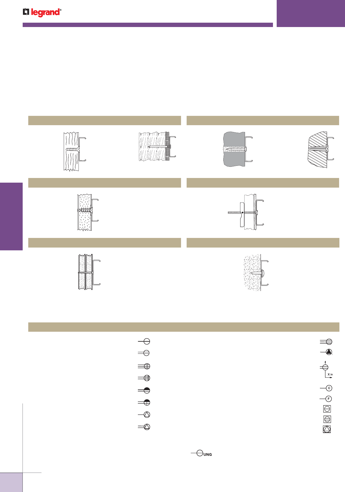
WWW.LEGRAND.US/WIREMOLD
700
WIREMOLD
TECHNICAL INFORMATION
Legrand/Wiremold Raceways can be mounted to any type of surface in an interior dry location through the use of the
fastening means shown below. Although a two-piece raceway is illustrated, the same means can be used – with the
couplings, clips, or straps – for fastening one-piece raceways to these surfaces.
CAUTION: Make sure that the correct size of screw or nail is used (noted in installation details).
Use plastic anchor
with flathead sheet
metal screw.
Use flathead
wood screw.
Use common nail. Use masonry
nail.
Use plastic shield
with flathead sheet
metal screw.
Use plastic shield
with flathead sheet
metal screw.
Use toggle bolt.
Use drive pin fastener.
* American National Standards Institute, Inc.
** For ungrounded receptacle outlets use UNG subscript next to symbol. Example:
*** Use number or letter either within the symbol or as a subscript alongside the symbol keyed to
explanation in the drawing list of symbols to indicate the type of receptacle or usage.
TECHNICAL INFORMATION
Wiremold Raceways – Mounting Methods
Wood
Tile
Dry Wall
Plaster Reinforced Concrete
Brick/Concrete/Cinder Block
Electrical Symbols – In accordance with ANSI* Standard Y32.9 – 1972
Single Receptacle Outlet
Duplex Receptacle Outlet
Triplex Receptacle Outlet
Quadruplex Receptacle Outlet
Duplex Receptacle Outlet – Split Wired
Triplex Receptacle Outlet – Split Wired
Single Special-Purpose Receptacle Outlet***
Duplex Special-Purpose Receptacle Outlet***
Range Outlet (Typical)
Special-Purpose Connection or Provision for Connection
Multioutlet Assembly
(Extend arrows to limit of installation. Use appropriate
symbol to indicate type of outlet. Also indicate spacing of
outlets as x inches.)
Clock Hanger Receptacle
Fan Hanger Receptacle
Floor Single Receptacle Outlet
Floor Duplex Receptacle Outlet
Floor Special-Purpose Outlet
Receptacle Outlets, Grounded**
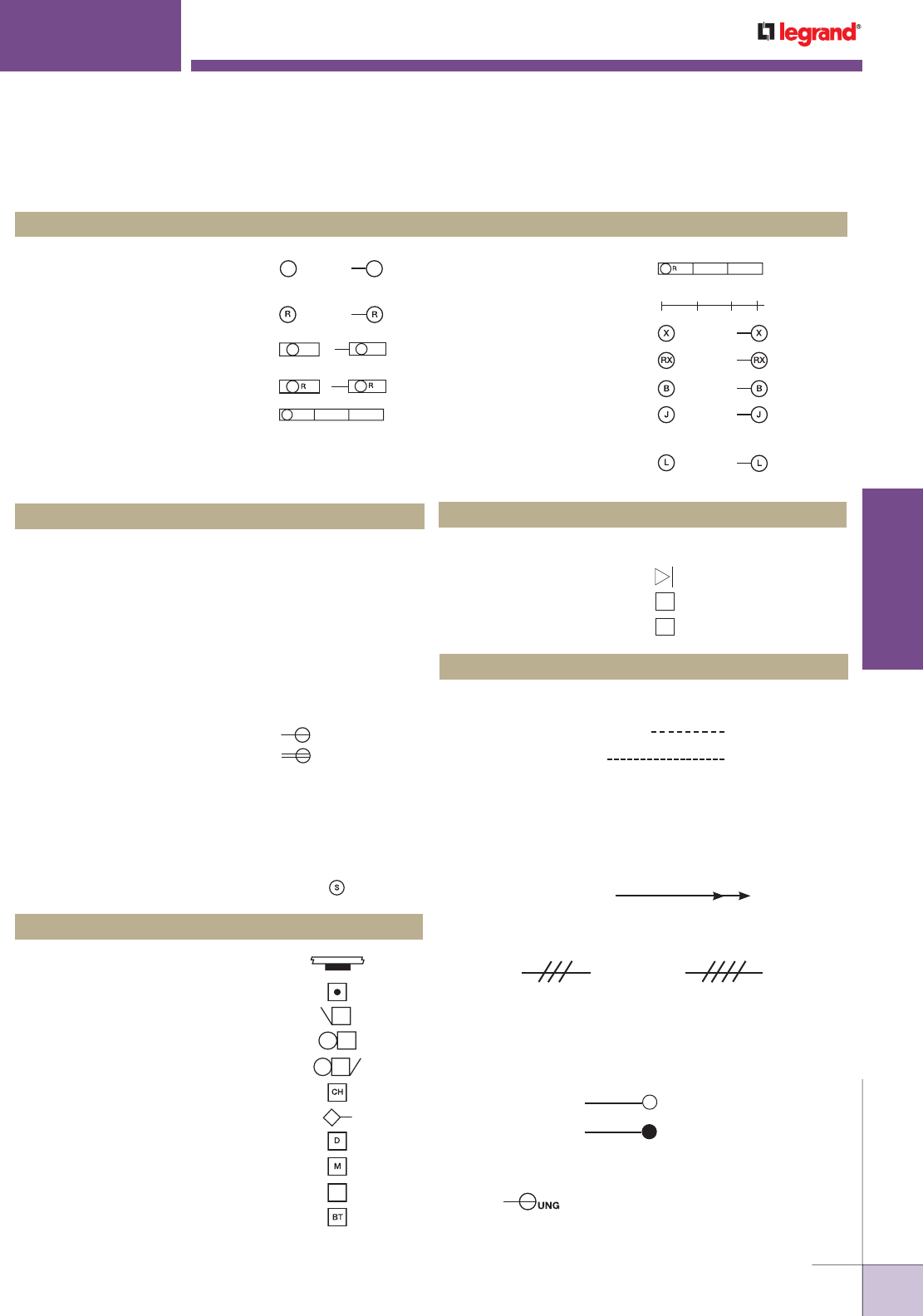
WWW.LEGRAND.US/WIREMOLD
701
WIREMOLD
TECHNICAL INFORMATION
Electrical Symbols – In accordance with ANSI* Standard Y32.9 – 1972 (continued)
Lighting Outlets
TECHNICAL INFORMATION
S
urface or Pendant Incandescent,
Mercury-Vapor, or Similar Lamp Fixture
Recessed Incandescent,
Mercury-Vapor, or Similar Lamp Fixture
Surface or Pendant Individual
Fluorescent Fixture
Recessed Individual Fluorescent Fixture
Surface or Pendant Continuous-Row
Fluorescent Fixture
Ceiling
Recessed Continuous-
Row Fluorescent Fixture
Bare-Lamp Fluorescent Strip
Surface or Pendant Exit Light
Recessed Exit Light
Blanked Outlet
Junction Box
Outlet Controlled by Low Voltage
Switching when Relay is Installed
in Outlet Box
Wall Ceiling Wall
Switch Outlets
Single-Pole Switch:
Double-Pole Switch:
Three-Way Switch:
Four-Way Switch:
Key-Operated Switch:
Switch and Pilot Lamp:
Switch for Low Voltage Switching System:
Master Switch for Low Voltage Switching System:
Switch and Single Receptacle:
Switch and Double Receptacle:
Door Switch:
Time Switch:
Circuit Breaker Switch:
Momentary Contact Switch or Push Button
for Other than Signaling System:
Ceiling Pull Switch:
S
S2
S3
S4
SK
SP
SL
SLM
S
S
SD
ST
SCB
SMC
Miscellaneous
Surface Mounted Panel Board and Cabinet: **
Push Button:
Buzzer:
Bell:
Combination Bell-Buzzer:
Chime:
Annunciator:
Electric Door Opener:
Maid’s Signal Plug:
Interconnection Box:
Bell-Ringing Transformer:
Miscellaneous
TV
R
V
Outside Telephone:
Interconnecting Telephone:
Radio Outlet:
Television Outlet:
Circuiting
2 1
Wiring Concealed in Ceiling or Wall:
Wiring Concealed in Floor:
Wiring Exposed:
---------
NOTE: Use heavy-weight line to identify service and feeders. Indicate empty
conduit by notation CO (conduit only).
Branch circuit home run to panel board. Number of arrows
indicates number of circuits. (A number at each arrow may be used
to identify circuit number.)
NOTE: Any circuit without further identification indicates two-wire circuit.
For a greater number of wires, indicate with cross lines, e.g.:
3 Wires 4 Wires, etc.
Unless indicated otherwise, the wire size of the circuit is the
minimum size required by the specification. Identify different
functions or wiring system, e.g. signalling system, by notation or
other means.
Wiring Turned Up:
Wiring Turned Down:
* American National Standards Institute, Inc.
** For ungrounded receptacle outlets use UNG subscript next to symbol.
Example:
*** Use number or letter either within the symbol or as a subscript alongside
the symbol keyed to explanation in the drawing list of symbols to indicate
the type of receptacle or usage.

WWW.LEGRAND.US/WIREMOLD
702
WIREMOLD
TECHNICAL INFORMATION
NOTE: Munsell Standards were generated with gloss 30 ± 5 on 60 degree meter. See document “Spectraflash SF600X
Calibration Setup” for spectrometer calibration readings.
Wiremold/Legrand assumes no liability for color accuracy and provides this information as a baseline to assist
customers in making initial color decisions. Wiremold/Legrand recommends that customers request samples to
review for color accuracy in circumstances where color matching is critical.
NOTE: The color swatches
shown throughout this
catalog are as close to the
product colors as is possible
through the printing
process. They should not
be used by customers
to make color decisions.
Legrand/Wiremold always
recommends that customers
request color samples
to review for accuracy in
circumstances where color
matching is critical.
TECHNICAL INFORMATION
Steel Raceway Color Specifications
COLOR MUNSELL
NOTATION
TOLERANCE L TOLERANCE A TOLERANCE B TOLERANCE E
Ivory 6.7Y8.98/1.4 ±1.00 ±0.5 ±0.5 1.00
White N9 Matte ±1.00 ±0.5 ±0.5 1.00
International
White 61/9.24/0.4 ±1.00 ±0.5 ±0.5 1.00
Black 3.2PB1.99/0.2 ±1.00 ±0.5 ±0.5 1.00
Gray 8.3G6.10/0.54 ±1.00 ±0.5 ±0.5 1.00
Light Gray 8.0Y7.09/0.4 ±1.00 ±0.5 ±0.5 1.00
Fog White
L = 89.13
A = -0.02
B = 6.88
±1.00 ±0.5 ±0.5 1.00

WIREMOLD
WWW.LEGRAND.US/WIREMOLD
703
INDEX
INDEX
1
1500 .............................. 694
1502 .............................. 119
1504 .............................. 119
1511 .............................. 119
1517 .............................. 119
1518 .............................. 119
1528 .............................. 120
1585 .............................. 120
1000883 ........................ 622
1001757 ........................ 604
1002412 ........................ 622
1002414 ........................ 622
1043B ............................ 586
1043BPO ....................... 586
1043S ............................ 586
1043SPO ....................... 586
1044B ............................ 586
1044S ............................ 586
1045B ............................ 586
1045S ............................ 586
1046B ............................ 586
1046S ............................ 586
10LH ............................. 598
10LHB1/4 .................... 569
10LHB1/8 .................... 569
10LHS1/4 .................... 569
10LHS1/8 .................... 569
11/2JB2510 ................... 607
11/2JBC ........................ 606
11/2JBH24251060 ........ 608
11/2JBH30251560 ........ 608
11/2JBH36251560 ........ 608
11241 ........................... 586
11241 1/4 ..................... 586
11242 ........................... 586
1124F1......................... 597
1124F3/4 ..................... 597
1124L1 ......................... 586
1124L1 1/4 .................. 586
1124L2 ......................... 586
1125CHA ................343, 351
1126A1 ........................ 585
1126A1 1/2 .................. 585
1126A1 1/4 .................. 585
1126A1/4 ..................... 585
1126A3/4 ..................... 585
1204AL ... 556, 558, 587, 600
1204BF... 556, 558, 587, 600
1223AL ... 556, 558, 587, 600
1223BF... 556, 558, 587, 600
1230AL .......................... 587
1230BF.......................... 587
125CRR ......................... 429
12EXT ............................ 567
12F0 .....................595, 596
12FWS ..................595, 598
12FB ......................595, 598
12FC .......................595, 596
12FCS ....................595, 596
12FCSA ......................... 595
12FST .....................595, 596
12HR ......................554, 565
12HS ......................554, 565
12JR ....................... 554, 565
12JS ...............554, 565, 571
142L .............................. 554
142L1 .......................... 567
14H1 ............................ 567
14HR ......................554, 565
14HS ......................554, 565
14JR ....................... 554, 565
14JS ...............554, 565, 571
14LHB1/4 .................... 569
14LHB1/8 .................... 569
14LHS1/4 .................... 569
14LHS1/8 .................... 569
1500 .............................. 694
150010 ......................... 119
1500WC ..................119, 120
1502 .............................. 119
1504 .............................. 119
1511 .............................. 119
1517 .............................. 119
1518 .............................. 119
1528 .............................. 120
1585 .............................. 120
152CHA ......................... 343
1542D .....................120, 696
1543GL ...................120, 124
1546A .............120, 124, 696
1546B .............120, 124, 696
1546T .....................120, 124
15FFHA ......................... 343
175CHA .................. 343, 351
175CHAL JB .......... 343, 351
1BHA ............................. 344
1BLH ............................. 343
1BLHN .......................... 351
1PTHA ....................343, 351
2
20................................. 559
211/2JB2510 ............... 607
212X2X11/2 ................. 560
212X2X2 ....................... 560
212X2X21/2 ................. 560
212X2X3 ....................... 560
212X2X7/8 ................... 560
200H/BTC .................... 375
2000 .............................. 694
2001 .................37, 242, 261
2003 ......................... 37,242
2006 .............................. 242
2009 .................38, 243, 261
2000WC ....................37, 242
2008BCS20R ................. 686
2008BDS20R ................. 686
2008ULBC20R .............. 676
2008ULBC20RTL ........ 676
2008ULBD20R .............. 676
2008ULBD20RTL ........ 676
2010A2 .......................... 243
2010A3 ............................ 38
2017TC .....................38, 243
203 ................................ 555
203UFD ......................... 567
20GB12 ......................... 241
20GB18 ......................... 241
20GB206 ....................... 241
20GB30 ......................... 241
20GB306 ....................... 241
20GB506 ....................... 241
20GB512 ....................... 241
20GB606 ....................... 241
20GB609 ....................... 241
20GB612 ....................... 241
20GB618 ....................... 241
20GBA12 ....................... 241
20GBA512 ..................... 241
20GBA609 ..................... 241
20GBA612 ..................... 241
20GBA618 ..................... 241
20IG306 ......................... 241
20IG512 ......................... 241
20IG606 ......................... 241
212 ................................ 555
2123/4 ......................... 568
22121 ........................... 376
2223/4 ......................... 568
222EXT .......................... 567
222F0 ...................595, 596
222FWS ................595, 598
222FB ....................595, 598
222FC .....................595, 596
222FCS ..................595, 596
222FCSA ....................... 595
222FST ...................595, 596
222HR ....................554, 565
222HS ....................554, 565
222JR .....................554, 565
222JS .............554, 565, 571
224HR ....................554, 566
224HS ....................554, 566
224JR .....................554, 566
224JS .............554, 566, 571
22AER11/221/4 .......... 604
22AER23/831/8 .......... 604
22CHA ........................... 351
22JBC ........................... 606
22JBCCA ..................... 606
22LHB1/4 .................... 570
22LHB1/8 .................... 570
22LHS1/4 .............570, 604
22LHS1/8 .............570, 604
2300 .............................. 694
2300BAC ................126, 137
2300BACWH ................ 137
2300BACD..............126, 137
2300BACDWH ............. 137
2300D ............................ 694
2300WC ......................... 137
2306WH ....................... 137
2310AWH..................... 137
2310B ............................ 137
2310BWH .................... 137
2310DFOWH ................ 138
2311WH ....................... 137
2311DFOWH ................ 138
23120AWH ................... 137
2315WH ....................... 137
2317WH ....................... 137
2317DFOWH ................ 138
2318WH ....................... 137
2318DFOWH ................ 138
2321 ............................. 568
2321 1/2....................... 568
2321 1/4....................... 568
2336WH ....................... 138
2337A ............................ 696
2337AWH..................... 138
2338 .............................. 696
2338AWH..................... 138
2344 .............................. 696
23442 ....................138, 696
23442WH ................... 138
2344WH ....................... 138
2344DWH .................... 139
2344SD2A ...................... 18
2344SD2AWH ............ 139
2347 .......................139, 696
23472 ....................139, 696
23472WH ................... 139
2347WH ....................... 139
2348 .......................139, 696
23482 ....................139, 696
23482WH ................... 139
23483 ....................139, 696
23483WH ................... 139
2348WH ....................... 139
2348AMPWH ............... 139
2348D ............................ 139
2348DWH .................... 139
2348S/51 ....................... 696
2348S/51WH ............... 139
2389WH ....................... 137
2389AWH..................... 138
2400 .............................. 694
2400B ............................ 249
2400B10FW ................... 41
2400BFW ....................... 41
2400BD ......................... 249
2400BDFW .................... 47
2400CFW ................. 41, 47
2400D ............................ 694
2400WC..............41, 47, 248
2401 .........................41, 248
2401D .............................. 47
2406FW ................... 41, 48
24072CMFW .................. 45
24072TJFW .................... 45
24073TJFW .................... 45
2409 .........................41, 248
2600 .............................. 694
2602 .............................. 123
2611 .............................. 123
2700 .............................. 694
2800 .............................. 694
2900 .............................. 694
241H/BTC .................... 375
2410AFW ....................... 41
2410BFW ....................... 42
2410BDFW .................... 48
2410CFW ....................... 42
2410DFW ....................... 48
2410DFOFW ............ 42, 48
CAT. NO. PAGE CAT. NO. PAGE CAT. NO. PAGE CAT. NO. PAGE CAT. NO. PAGE
1 — 2

WIREMOLD
WWW.LEGRAND.US/WIREMOLD
INDEX
704
INDEX
2 — 4
2410FCFW ..................... 42
2411DFW ....................... 48
2411DFOFW .................. 48
2411FOFW ..................... 42
2411MFW ...................... 42
2415DFOFW .................. 48
2415FOFW ..................... 42
2415MFW ...................... 42
2417DFW ....................... 48
2417DFOFW .................. 48
2417FOFW ..................... 42
2417MFW ...................... 42
2418DFOFW .................. 48
2418FOFW ..................... 43
2418MFW ...................... 43
2421 1/4....................... 568
2426FW ......................... 43
24442FW ....................... 44
24442LSFW ................... 44
2444FW ......................... 43
2444D2A ........................ 18
2444D2AFW................... 49
2444D2NFW .................. 49
2444DFW ................. 43, 49
24482FW ....................... 44
2448FW ......................... 44
244HR ....................554, 566
244HS ....................554, 566
244JR .....................554, 566
244JS .....................554, 566
2450FW ......................... 49
2451HFW ....................... 44
2475DFW ................. 44, 50
24DWNDFW ............ 43, 49
24DWNRFW ............ 43, 49
24DWNSFW .......12, 43, 49
24DWNUFW .......12, 43, 49
24S3612GBA99IV .......... 247
24S3612GBX99IV .......... 247
24S6012GBA99IV .......... 247
24S6012GBX99IV .......... 247
24S6012IGX99IV ............ 247
24S7212GBA99IV .......... 247
24S7212GBX99IV .......... 247
24S7212IGX99IV ............ 247
24S7218GBA99IV .......... 247
24S7218GBX99IV .......... 247
24S7218IGX99IV ............ 247
24S7224GBA99IV .......... 247
24S7224GBX99IV .......... 247
24S7224IGX99IV ............ 247
255 .........................555, 595
2551 ............................. 568
2551 1/2....................... 568
2551 1/4....................... 568
25511/2 ....................... 598
2551 1/4....................... 598
2552 ......................568, 598
2553/4 ..................568, 598
25AMAP ...............650, 658
25DTC3S2 .................... 658
25DTC4DG ................. 657
25DTC412 .................... 657
25DTC412DG ............. 657
25DTC415 .................... 657
25DTC415DG ............. 657
25DTCACT ................... 658
25DTCCVR ................... 658
25DTCE10.............650, 657
25DTCE10DG ......650, 657
25DTCE5 ..................... 650
25DTCE5DG ............... 650
25DTP 415DG .............. 649
25DTP4 .................625, 649
25DTP4 D .................... 649
25DTP4C .................... 649
25DTP4DG ................. 649
25DTP4DGC ............. 649
25DTP412 .................... 649
25DTP412C ................ 649
25DTP412DG ............. 649
25DTP412DGC ......... 649
25DTP415 .................... 649
25DTP415C ................ 649
25DTP415DGC ......... 649
25DTP4ACT ................. 649
25DTP4ACTDG .......... 649
25DTP4DDG ............... 649
25DTPA ....................... 654
25DTPB ....................... 654
25DTPE10.............649, 650
25DTPE10DG ......649, 650
25DTPL ....................... 654
25G ................................ 558
260010 ......................... 123
2600WC ......................... 123
2642D .....................123, 696
2686FO .............44, 123, 250
2700FW ....................... 279
2700WH ....................... 279
2700L8 .......................... 279
2700L8FW ................... 279
2700L8WH ................... 279
2700WC ......................... 145
2706FW ....................... 279
2706WH ....................... 279
2710BFW ..................... 279
2710BWH .....279, 280, 281
2711FW ....................... 279
2711WH ....................... 279
2715FW ....................... 279
2715WH ....................... 279
2717FW ....................... 279
2717WH ....................... 279
2718FW ....................... 279
2718WH ....................... 279
275SL .....................555, 568
275SR ....................555, 568
2786FW ....................... 279
2786WH ....................... 279
2800FW ....................... 280
2800WH ....................... 280
2800L8FW ................... 280
2800L8WH ................... 280
2800WC ......................... 145
2806FW ....................... 280
2806WH ....................... 280
2810BFW ..................... 280
2810BWH .................... 280
2811FW ....................... 280
2811WH ....................... 280
2811FOFW ................... 280
2811FOWH .................. 280
2815FW ....................... 280
2815WH ....................... 280
2815FOFW ................... 280
2815FOWH .................. 280
2817FW ....................... 280
2817WH ....................... 280
2817FOFW ................... 280
2817FOWH .................. 280
2818FW ....................... 281
2818WH ....................... 281
2818FOFW ................... 281
2818FOWH .................. 281
2886FW ....................... 281
2886WH ....................... 281
2889FW ....................... 281
2889WH ....................... 281
2900FW ....................... 281
2900WH ....................... 281
2900L8 .......................... 281
2900L8WH ................... 281
2900WC ......................... 145
2906FW ....................... 281
2906WH ....................... 281
290C .............................. 564
290G .......................555, 595
291H/BTC .................... 378
2910BFW ..................... 281
2910BWH .................... 281
2911FW ....................... 281
2911WH ....................... 281
2911FOFW ................... 282
2911FOWH .................. 282
2915FW ....................... 282
2915WH ....................... 282
2915FOFW ................... 282
2915FOWH .................. 282
2917FW ....................... 282
2917WH ....................... 282
2917FOFW ................... 282
2917FOWH .................. 282
2918FW ....................... 282
2918WH ....................... 282
2918FOFW ................... 282
2918FOWH .................. 282
292H/BTC .................... 378
2986FW ....................... 282
2986WH ....................... 282
2989FW ....................... 282
2989WH ....................... 282
2989AFW ..................... 282
2989AWH..................... 282
2CRR ............................. 429
2HUB .....................429, 451
2JBH24251060 ............ 608
2JBH30251560 ............ 608
2JBH36251560 ............ 608
3
300 ................................ 286
302 .........................555, 562
304 ......... 555, 562, 595, 596
306 ................................ 286
3000 .......................234, 694
3004 ............................. 562
30AMK1 ....................... 674
30AMK2 ....................... 674
30AMK3 ....................... 674
30AMK4 ....................... 674
30TC212V .................... 657
30TC215V .................... 657
30TC2V ........................ 657
30TC3S2 ...................... 658
30TC412V .................... 657
30TC415V .................... 657
30TC4V ........................ 657
30TCCVR ..................... 658
30TP212V .................... 651
30TP2V .................625, 651
30TP412V .................... 651
30TP412V3S2 .............. 651
30TP4V .................625, 651
30TP4V3S2 .................. 651
30TPA .......................... 654
30TPAAP ................15, 654
30TPAP ....................... 658
30TPB .......................... 654
30TPC .......................... 654
30TPJ .......................... 654
30TPL .....................15, 654
30TPMAAP .............15, 654
311 ................................ 286
312 ................................ 555
3121 ......................562, 603
3121 1/2................562, 603
3121 1/4................562, 603
3122 ......................562, 603
3123/4 ..................562, 603
312F .......................595, 596
312F1 1/2 .................... 596
312F1 1/4 .................... 596
314 ................................ 555
3143/4 ..................562, 596
314F .............................. 595
317 .........................286, 555
3173/4 ......................... 562
318 ................................ 286
322 ................................ 555
3221 1/2....................... 562
3221 1/4....................... 562
3222EXT ........................ 567
3222F0..................595, 596
3222FWS ..............595, 598
3222FB...................595, 598
3222FBCC ..................... 595
3222FC ...................595, 596
3222FCS........................ 595
3222FCSA ..................... 595
3222FST .................595, 596
3222HR ..................554, 566
3222HS ..................554, 566
3222JR ...................554, 566
3222JS ...........554, 566, 571
3224EXT ........................ 567
3224HR ..................554, 566
3224HS ..................554, 566
3224JR ...................554, 566
3224JS ...................554, 566
324 .........................555, 595
3243/4 ......................... 562
3244EXT ........................ 567
3244HR ..................554, 566
3244HS ..................554, 566
3244JR ...................554, 566
3244JS ...........554, 566, 571
32JB3510 ...................... 607
332F .......................595, 596
332UF ....................555, 563
333F2 ...................595, 596
33413 ......................... 596
334F12 ................595, 596
334F13 ....................... 595
334UF .... 555, 563, 595, 596
336F .......................595, 596
336F2 ...................595, 596
336F3 ...................595, 596
338F2 .......................... 595
338F3 .......................... 595
338UF .... 555, 563, 595, 597
338UF2 ........................ 597
338UF3 ........................ 597
33JB3510 ...................... 607
33JBC ........................... 606
33JBCCA ..................... 606
3424HR ..................554, 566
3424HS ..................554, 566
3424JR ...................554, 566
3424JS ...........554, 566, 571
342F .......................595, 597
342F2 ...................595, 597
342F3 ...................595, 597
342UF ....................555, 563
3444HR ......................... 554
3444HS ......................... 554
3444JR .......................... 554
3444JS ...................554, 571
3609ULBC ..................... 676
3609ULBD .................... 676
362F .......................595, 597
362F2 ...................595, 597
362F3 ...................595, 597
372 .........................555, 563
372F .......................595, 597
375 ................................ 555
382 .........................555, 564
3A44B21 ...................... 675
3A86B21 ...................... 675
3B43B21RAM ............ 675
3B44B21 ...................... 675
3B53B21AM ............... 675
3B86B21 ...................... 675
4
40................................. 559
400 ................................ 694
4000 .......................234, 694
4015 ................................ 73
4050 ................................ 18
4000C .............................. 65
4001A .............................. 65
4001DA ..................... 66, 76
400BAC ..................126, 134
400BACWH .................. 134
400F .............................. 597
400WC ........................... 134
4010B .............................. 73
4010DFC ......................... 73
4010DFO ......................... 73
4011/15RI........................ 67
4011DRI .......................... 68
4014A .............................. 73
4015D .............................. 73
4015DRI .......................... 68
4015FO ............................ 73
4017/18RI........................ 68
404 ................................ 561
406WH ......................... 134
4064H2 .......................... 73
40N2 ................18, 236, 694
40N2B08 ....................... 127
40N2B08V ..................... 149
40N2B08WH ................. 149
40N2C08V ..................... 149
40N2C08WH ................. 149
40N2F05V ..................... 149
40N2F05WH.................. 149
40N2F06V ..................... 149
40N2F06WH.................. 149
40N2F11V ..................... 150
40N2F11WH.................. 150
40N2F15V ..................... 150
40N2F15WH.................. 150
40N2F17V ..................... 150
40N2F17WH.................. 150
40N2F19V ..................... 150
40N2F19WH.................. 150
40N2F20V ..................... 150
40N2F20WH.................. 150
40N2F21V ..................... 150
40N2F21WH.................. 150
40N2F31V ..................... 150
40N2F31WH.................. 150
40N2F55 ....................... 150
40N2F74V ..................... 150
40N2F74WH.................. 150
40N2FWC ...................... 149
40N2FWCWH ................ 149
410B .............................. 134
410BWH ...................... 134
411 ................................ 134
411WH ......................... 134
415 ................................ 134
415WH ......................... 134
415B .............................. 561
415N ............................. 561
417 ................................ 134
417WH ......................... 134
418WH ......................... 135
421 ......... 555, 561, 578, 581
4215 .............................. 564
4220 .............................. 564
42222HR ....................... 554
42222HS ....................... 554
CAT. NO. PAGE CAT. NO. PAGE CAT. NO. PAGE CAT. NO. PAGE CAT. NO. PAGE

WIREMOLD
WWW.LEGRAND.US/WIREMOLD
705
INDEX
INDEX
4 — 5
42222JR ........................ 554
42222JS ........................ 554
422GR ....................555, 561
422RD ....................555, 561
4225 .......................564, 581
4230 .......................564, 581
4241 ............................. 586
4243/4 ......................... 586
425 .........................561, 581
426 .........................561, 581
427 ................................ 578
428B075 ........................ 579
428B525 ........................ 579
428BL ........................... 579
428DR2 ......................... 579
430AL ............................ 578
430AL075 ...................... 578
430BR ........................... 578
430BR075 ..................... 578
430S505 ........................ 578
431AL ............................ 578
431AL075 ...................... 578
431BR ........................... 578
431BR075 ..................... 578
431D505 ........................ 578
432AL ............................ 578
432BR ....................578, 579
433DR ........................... 579
433DR2 ......................... 579
4362 7/8....................... 585
43621 1/2 ............585, 564
43622 ..................564, 585
43622 3/8 ................... 564
43623 ..................564, 585
43623/8 ...................... 585
43627/8 ...................... 564
437 ................................ 591
439 ................................ 592
450F1 ...................595, 597
450F11/4 ..................... 597
450FP1 .................595, 597
450FP11/4 ................... 597
455F1 ...................595, 597
455F3/4 ....................... 597
455FP1 .................595, 597
455FP3/4 ..................... 597
470F1 ...................595, 597
470F11/4 ..................... 597
4810BCS ....................... 686
4810BCS20R ................. 686
4810BDS ....................... 686
4810BDS20R ................. 686
4810ULBC ..............676, 684
4810ULBC20R .............. 676
4810ULBC20RTL ........ 676
4810ULBD .................... 676
4810ULBD20R .............. 676
4810ULBD20RTL ........ 676
485 ................................ 615
4B43B22RAM ............ 675
4B44B22 ...................... 675
4B53B22AM ............... 675
4B86B22 ...................... 675
4FFATC ......................... 544
4FFATCAL ..................... 367
4FFATCAL422CW .......... 544
4FFATCBK .................... 367
4FFATCBK422CW ......... 544
4FFATCB S ..................... 367
4FFATCBS422CW ......... 544
4FFATCGY ..................... 367
4FFATCGY422CW .......... 544
4FFCTCAL ..................... 367
4FFCTCBK .................... 367
4FFCTCBS .................... 367
4FFCTCGY ..................... 367
5
520R .............................. 45
500 ................................ 694
5000 .............................. 694
500GFI ......................... 584
500MAAP ................15, 584
5000B .....................127, 143
5000CBK ....................... 143
5000CGY ....................... 143
5000COA ....................... 143
5000CW ......................... 143
5000CWH ...................... 143
5000TBK ....................... 143
5000TGY ........................ 143
5000TOA........................ 143
5000TW ......................... 143
5000TWH ...................... 143
5001 .............................. 143
5004BK ......................... 145
5004GY .......................... 145
5004OA.......................... 145
5004W ........................... 145
5004WH ........................ 145
5005BK ......................... 145
5005GY .......................... 145
5005WH ........................ 145
5006A ............................ 143
5006BK ......................... 143
5006GY .......................... 143
5006WH ........................ 143
5007C ............................ 145
5007C1ABK ................. 144
5007C1AGY .................. 144
5007C1AWH ................ 144
5007C2ABBK ............... 144
5007C2ABGY ............... 144
5007C2ABWH .............. 144
5007C2RTBK ............... 145
5007C2RTGY................ 145
5007C2RTWH .............. 145
500ACT.......................... 584
500B .............................. 584
500DR ........................... 584
500RT .......................15, 584
500SP1 1/2 .................. 584
500SP1 5/8 .................. 584
500SP1 7/16 ................ 584
500SP1 7/8 .................. 584
500SP1 9/16 ................ 584
500SP1.0625 ............... 584
500SP1.39 ................... 584
500SP1/2 ..................... 584
500SP2 ........................ 584
500SP7/8 ..................... 584
500T .............................. 584
5010A ............................ 147
5010ABK ....................... 143
5010AGY ........................ 143
5010AWH ...................... 143
5010LBK ....................... 144
5010LGY ........................ 144
5010LWH ...................... 144
5010R ............................ 143
5010RBK ....................... 143
5010RGY ....................... 143
5017B ............................ 144
5017CBK ....................... 144
5017CGY ....................... 144
5017CWH ...................... 144
5017WG ......................... 144
5018B ............................ 144
5018CBK ....................... 144
5018CGY ....................... 144
5018CWH ...................... 144
5018WG ......................... 144
502 .................................. 27
522222HR ..................... 554
522222HS...................... 554
522222JR ...................... 554
522222JS ...................... 554
525A ..............556, 558, 583,
..........................595, 600
525ACT..........556, 558, 583,
..........................595, 600
525B ..............556, 558, 583,
..........................595, 600
525C ..............556, 558, 583,
..........................595, 600
525D ..............556, 558, 583,
..........................595, 600
525F ..............556, 558, 583,
..........................595, 600
525G ....... 556, 583, 595, 600
525H..............556, 558, 583,
..........................595, 600
525HB ........................... 584
525I ...............556, 558, 583,
..........................595, 600
525J ..............556, 558, 584,
..........................595, 600
525RT ............556, 558, 583,
..........................595, 600
5400 .......................236, 694
5400C ............................ 152
5400CWH .................... 152
5400TB ...........127, 152, 153
5400TBWH .................. 152
5400TC .......................... 152
5400TCWH .................. 152
5400TWC ....................... 152
5400TWCWH ............... 152
5406A ............................ 152
5406AWH..................... 152
5406T ............................ 152
5406TWH ..................... 152
5406TBWH .................. 153
5408L ............................ 153
5408LWH ..................... 153
5408R ............................ 153
5408RWH .................... 153
5410 .............................. 153
5410WH ....................... 153
5410DFOWH ................ 153
5411FO .......................... 153
5411FOWH .................. 153
5415 .............................. 153
5415FO .......................... 153
5415FOWH .................. 153
5417FOWH .................. 153
5418 .............................. 153
5418WH ....................... 153
5418FO .......................... 154
5418FOWH .................. 154
5450 .........................18, 154
5450ORAP ................... 154
5450WH ....................... 154
5450A3 .......................... 154
5450A3WH ................... 154
5450T ............................ 154
5450TWH ..................... 154
5474 .............................. 154
5474WH ....................... 154
5500 .......................236, 694
5500BD3 ................127, 159
5500BD3WH ................ 159
5500C ............................ 159
5500CWH .................... 159
5500WCA ...................... 159
5506 .............................. 159
5506WH ....................... 159
5506B ............................ 160
5506BWH .................... 160
55074TJ ..................51, 164
55074TJFW ...........51, 164
55074TJG ................... 164
55074TJWH ................ 164
55076TJ ..................51, 164
55076TJFW ................ 164
55076TJG ................... 164
55076TJWH ................ 164
55076TJFW .................... 51
55074TJWH ................. 400
55076TJWH ................. 400
5507AAP .............12, 13, 14,
............................51, 164
5507AAPBK .............13, 14,
............................51, 164
5507AAPFW ............13, 14,
............................51, 164
5507AAPG ..........12, 13, 14
............................51, 164
5507AAPGY ......13, 14, 164
5507AAPWH ............ 13, 14
............................51, 164
5507AD ..................... 50, 63
5507ADFW .............50, 163
5507ADGY ................... 163
5507ADWH .................. 163
5507B .......................50, 163
5507BFW ................50, 163
5507BG ........................ 163
5507BGY ...................... 163
5507BWH .............163, 400
5507D .......................50, 163
5507DBK ..................... 163
5507DFW ................50, 163
5507DG ........................ 163
5507DGY ...................... 163
5507DWH .............163, 400
5507FRJ ...................51, 163
5507FRJBK ................. 163
5507FRJFW ............51, 163
5507FRJG .................... 163
5507FRJGY .................. 163
5507FRJWH ................ 163
5507MAAP ..........12, 13, 14,
............................51, 164
5507MAAPBK ..........13, 14,
............................51, 164
5507MAAPFW .........13, 14,
............................51, 164
5507MAAPG ............12, 13,
......................14, 51, 164
5507MAAPGY ..........13, 14,
................................. 164
5507MAAPWH .........13, 14,
............................51, 164
5507R ..................12, 13, 14,
............................50, 164
5507RBK ................. 13, 14
5507RFW .................13, 14,
............................50, 164
5507RG ....................12, 13,
............................14, 164
5507RGY .................. 13, 14
5507RWH ................13, 14,
..........................164, 400
5507RJ .....................51, 164
5507RJFW ..............51, 164
5507RJG ...................... 164
5507RJGY .................... 164
5507RJWH ................... 164
5507S ............................ 164
5507SBK ..................... 164
5507SFW ..................... 164
5507SG ........................ 164
5507SGY ...................... 164
5507SWH ..............164, 400
5507SW ....................50, 164
5507SWFW .............50, 164
5507SWG ..................... 164
5507SWWH ................. 164
5507T1 .....................50, 164
5507T1FW ..............50, 164
5507T1G ...................... 164
5507T1WH ............164, 400
5507T2 .....................51, 164
5507T2FW ..................... 51
5507T2FW ................... 164
5507T2G ...................... 164
5507T2WH ............164, 400
5510 .............................. 160
5510WH ....................... 160
5510D ............................ 160
5510DWH .................... 160
5511 .............................. 160
5511WH ....................... 160
5514A ............................ 160
5514AWH..................... 160
5515 .............................. 160
5515WH ....................... 160
5517FO .......................... 160
5517FOWH .................. 160
5518 .............................. 160
5518WH ....................... 160
5518FO .......................... 160
5518FOWH .................. 160
5550 .........................18, 161
5550WH ....................... 161
5550A4 .......................... 161
5550A4WH ................... 161
5574 .............................. 160
5574WH ....................... 160
5574A .....................158, 161
5574AWH..................... 161
5700CG ........................... 27
5700LL ............................ 27
5701 ................................ 29
5703WH .......................... 29
5709 ................................ 29
5709GC ........................... 29
5711LHA ......................... 29
5711LHAWH ................... 29
5711RHA ......................... 29
5715WH .......................... 29
5719WH .......................... 29
5736WH .......................... 31
5737AWH ........................ 32
5737WH .......................... 32
5738AFWH ...................... 32
5738AWH ........................ 32
5738WH .......................... 32
5739WH .......................... 32
5741WH .......................... 32
5744WH ......................... 32
5744S2WH ..................... 33
5744SWH ........................ 33
5745WH .......................... 33
57472WH ....................... 33
5747WH .......................... 33
57482WH ....................... 33
57483WH ....................... 33
5748SWH ........................ 33
5748WH .......................... 33
57512WH ....................... 33
5751AWH ........................ 34
5751WH .......................... 33
575CHA ..................343, 350
5780 ................................ 30
5781A .............................. 30
5782A .............................. 30
5785WH .......................... 31
5786WH .......................... 31
5791 ................................ 31
5790B .............................. 31
5BLH ...................... 343, 350
5PTHA ....................343, 350
CAT. NO. PAGE CAT. NO. PAGE CAT. NO. PAGE CAT. NO. PAGE CAT. NO. PAGE

WIREMOLD
WWW.LEGRAND.US/WIREMOLD
INDEX
706
INDEX
6 — 8
6
605 .................................. 27
607 .................................. 28
6000 .................65, 234, 694
6000B .............................. 65
6001A .............................. 83
600B ................................ 34
605K ................................ 27
607 .................................. 28
6074A .............................. 73
607K ................................ 28
615 .................................. 34
616 .................................. 34
620 ...........................37, 242
620BCK ....................37, 242
624 .....................41, 47, 249
624BCK ..............41, 47, 249
630B ................................ 53
630BDK ........................... 53
630C ................................ 54
630CDK ........................... 54
640B ................................ 65
640BDK ........................... 65
640C .......................... 65, 83
640CDK ..................... 65, 83
640DS ............................. 62
640DSBDK ...................... 62
650RT .............................. 62
656 .........................119, 123
660B ................................ 82
660BDK ........................... 83
682A .......................342, 350
682APT .................342, 350
686039100FT ............... 622
686052100FT ............... 615
60N2 ............................. 694
68B .........................342, 349
68MAAP .......9, 10, 342, 349
68REC ....................342, 349
68REC25...............342, 349
6AAP ......................... 9, 341
6ACT8A ......................... 341
6AER1 1/22 1/8 .......... 567
6AER2 3/83 ................ 567
6ATBK ........................... 338
6ATBS ........................... 338
6ATBZ ........................... 338
6ATCBK .................. 338, 339
6ATCBS ..................338, 339
6ATCBZ ..................338, 339
6ATCFF ......................... 541
6ATCGY ..................338, 339
6ATCNK .................338, 339
6ATCPAVBK .................. 339
6ATCPAVBS .................. 339
6ATCPAVBZ................... 339
6ATCPAVGY ................... 339
6ATCPAVNK .................. 339
6ATCPBK ...................... 338
6ATCPBS ...................... 338
6ATCPBZ ....................... 338
6ATCPGY ....................... 338
6ATCPNK ...................... 338
6ATGY ............................ 338
6ATNK ........................... 338
6ATPAVBK..................... 339
6ATPAVB S ..................... 339
6ATPAVBZ ..................... 339
6ATPAVGY ..................... 339
6ATPAVNK .................... 339
6ATPBK ......................... 338
6ATPBS ......................... 338
6ATPBZ ......................... 338
6ATPGY ......................... 338
6ATPNK ........................ 338
6B ................................. 341
6B21E ........................... 673
6B21N ........................... 672
6B22E ........................... 673
6CFFAF B ..................... 518
6CFFTCBK ............341, 452,
................................. 518
6CFFTCBS ............341, 452,
................................. 518
6CFFTCBZ ............341, 452,
................................. 518
6CFFTCGY.............341, 452,
................................. 518
6CFFTCNK ............341, 452,
................................. 518
6CTBK ....................340, 452
6CTBS ........................... 340
6CTBZ ........................... 340
6CTCBK .................340, 452
6CTCBS ..................340, 452
6CTCBZ ..................340, 452
6CTCGY ..................340, 452
6CTCNK .................340, 452
6CTGY ....................340, 452
6CTNK .......................... 340
6DEC ......................... 9, 341
6DP ............................... 341
6ER1 1/2 ...................... 565
6ER2 ............................ 565
6ER2 1/2 ...................... 565
6ER3 ............................ 565
6ER3 1/2 ...................... 565
6FFAFBHWB ............. 518
6FFAFB.5BP ............... 518
6LH ............................... 598
6LHB1/4 ...................... 569
6LHB1/8 ...................... 569
6LHS1/4 ...................... 569
6LHS1/8 ...................... 569
6MAAP ...................... 9, 342
6MAAP2A ................ 9, 342
6MOS ............................ 341
6MOSBS ........................ 341
6PPS ............................. 340
6RTT ............................. 567
6S1 ................................ 341
6S2 ................................ 341
6SER ......................... 9, 341
6STC ............................. 339
6STCP ....................340, 540
6STCPAV ................340, 540
6TRAC ........................... 342
6TS .................341, 452, 518
6W21E ........................... 673
6W21N .......................... 672
6W22E ........................... 673
7
700 ................................ 694
700WH ............................ 28
7011BCS ....................... 686
7011BCS20R ................. 686
7011BDS ....................... 686
7011BDS20R ................. 686
7011ULBC ..................... 676
7011ULBC20R .............. 676
7011ULBC20RTL ........ 676
7011ULBD .................... 676
7011ULBD20R .............. 676
7011ULBD20RTL ........ 676
702 .................................. 28
704WH ............................ 28
706WH ............................ 28
7107F ............................ 597
711WH ............................ 29
712WH ............................ 29
7140F .....................595, 597
7141F ............................ 595
717WH ............................ 29
718WH ............................ 29
77000N.......................... 690
77001N.......................... 690
77002N.......................... 690
7712BCS ....................... 686
7712BCS20R ................. 686
7712BDS ....................... 686
7712BDS20R ................. 686
7712ULBC ..................... 676
7712ULBC20R .............. 676
7712ULBC20RTL ........ 676
7712ULBD .................... 676
7712ULBD20R .............. 676
7712ULBD20RTL ........ 676
7LH ............................... 598
7LHB1/4 ...................... 569
7LHB1/8 ...................... 569
7LHS1/4 ...................... 569
7LHS1/8 ...................... 569
8
800 ................................ 694
8002 .............................. 685
800BAC ..................126, 135
800BACWH .................. 135
800CILCK ...................... 480
800LCK ......................... 480
800WC ........................... 135
806 ................................ 135
806WH ......................... 135
810A2 ............................ 135
810A2WH..................... 135
810B .............................. 135
810BWH ...................... 135
811 ................................ 136
811WH ......................... 136
815 ................................ 136
815WH ......................... 136
817 ................................ 136
817WH ......................... 136
817B ...... 406, 417, 431, 469,
.......... 484, 556, 558, 572
817C ....... 406, 417, 469, 484
817PCC .........435, 474, 489,
..................556, 558, 577
817PCCBR N ............... 435,
..................474, 489, 577
817T .......................469, 484
817TAL ...................473, 487
817TALGY .............473, 487
817TALNK ............473, 487
817TALBS .............473, 487
817TALBZ ............. 473, 487
817TCAL .......410, 420, 433,
..................473, 487, 575
817TCALBS .........410, 420,
.......... 433, 473, 487, 575
817TCALBZ .........410, 420,
.......... 433, 473, 487, 575
817TCALGY .........410, 420,
.......... 433, 473, 487, 575
817TCALNK .........410, 420,
.......... 433, 473, 487, 575
818 ................................ 136
818WH ......................... 136
818TAL ...................471, 486
818TCAL .......408, 419, 432,
................ 471, 486, 556,
..........................558, 574
825A .............................. 481
825A1 .......................... 481
825A1/2 ....................... 481
825A3/4 ....................... 481
825CK ........................... 481
825CK1 ........................ 481
825CK1/2 ..................... 481
825CK3/4 ..................... 481
825CP ........................... 481
825SFCK ....................... 481
827B ...............406, 431,469,
.......... 484, 556, 558, 572
827C ...............406, 469, 484
827PCC .........435, 474, 489,
..................556, 558, 577
827PCCBRN ........435, 474,
..........................489, 577
827T .......................469, 484
827TAL ...................473, 488
827TALGY .............473, 488
827TALNK ............473, 488
827TALBS .............473, 488
827TALBZ ............. 473, 488
827TCAL ...............410, 434,
..................473, 487, 575
827TCALBS .........410, 434,
..................473, 487, 575
827TCALBZ .........410, 434,
..................473, 487, 575
827TCALGY .........410, 434,
..................473, 487, 575
827TCALNK .........410, 434,
..................473, 487, 575
828COMTC .....407, 470, 485
828COMTCAL ........408, 472
828DLR .................407, 418,
.......... 431, 470, 485, 573
828DLRAL.............408, 419,
.......... 433, 472, 486, 574
828DPGFITC .........407, 418,
.......... 431, 470, 485, 572
828DPGFITCAL .....408, 419,
.........................433, 472,
..................486, 572, 574
828GFITC ......407, 418, 431,
..................469, 484, 572
828GFITCAL ..........408, 410,
.................419, 420, 433,
......... 434, 472, 474, 486,
..................488, 574, 576
828GFITCALBK ........... 474
828GFITCALBS ...410, 420,
.......... 434, 474, 488, 576
828GFITCALBZ ...410, 420,
........... 434, 474,488, 576
828GFITCALGY ....410, 420,
.......... 434, 474, 488, 576
828GFITCALNK ...410, 420,
.......... 434, 474, 488, 576
828MAAP ..........7, 407, 409,
......... 410, 418, 420, 432,
......... 433, 434, 470, 472,
......... 474, 485, 487, 488,
..................573, 575, 576
828PR ...................435, 475,
..........................489, 577
828PRBRN ..........435, 475,
..........................489, 577
828PRGFI ..............435, 475,
..........................489, 577
828PRGFIBRN ........... 435,
..................475, 489, 577
828R ..............407, 418, 431,
..................469, 484, 572
828RTCAL ...........408, 410,
.................419, 420, 433,
.................434, 472, 474,
.......... 486, 488, 574, 576
828RTCALBS .....410, 420,
.......... 434, 474, 488, 576
828RTCALBZ .....410, 420,
.......... 434, 474, 488, 576
828RTCALGY .....410, 420,
.......... 434, 474, 488, 576
828RTCALNK.....410, 420,
.........................434, 474,
..........................488, 576
828SPTC .......407, 418, 431,
.........................470, 485,
..........................573, 591
828TAL ...................471, 486
828TCAL ........408, 432,471,
.........................486, 556,
..........................558, 574
829CK ...........407, 418, 432,
.........................470, 485,
..........................573, 591
829CK1 ........407, 418, 432,
..................470, 485, 591
829CK1/2 ..... 407, 418, 432,
.........................470, 485,
..........................573, 591
829CK3/4 .............407, 418,
.................432, 470, 485,
..........................573, 591
829CK1 ......................... 573
829CKAL ................410, 576
829CKAL1 ...........420, 434,
..........................474, 488
829CKAL1BS .......410, 420,
..................434, 474, 488
829CKAL1BZ .......410, 420,
..................434, 474, 488
829CKAL1GY .......410, 420,
..................434, 474, 488
829CKAL1NK ......410, 420,
..................434, 474, 488
829CKAL3/4 ........420, 434,
..................474, 488, 576
829CKAL3/4BS ...410, 420,
.........................434, 474,
..........................488, 576
829CKAL3/4BZ ...410, 420,
.........................434, 474,
..........................488, 576
829CKAL3/4GY ....410, 420,
.........................434, 474,
..........................488, 576
829CKAL3/4NK ...410, 420,
.........................434, 474,
..........................488, 576
829CKALB S ................. 576
829CKALB Z ................. 576
829CKALGY ................. 576
829CKALNK ................ 576
829PCK .................435, 475,
..........................489, 577
829PCKBR N ............... 435,
..................475, 489, 577
829PFL .................435, 475,
..........................489, 577
829PFLBRN ........435, 475,
..........................489, 577
829PFLRT .............435, 475,
..........................489, 577
829PFLRTBRN ........... 435,
..................475, 489, 577
829PSTC .......435, 475, 489,
..........................577, 591
829PSTCBRN ......435, 489,
..........................577, 591
829STC ..........407, 418, 431,
.......... 470, 485, 573, 591
830CKTCAL...........409, 419,
.......... 433, 472, 487, 575
830CKTCAL1 .......409, 419,
.........................433, 472,
..........................487, 575
830CKTCAL1/2 ....409, 420,
.......... 433, 472, 487, 575
CAT. NO. PAGE CAT. NO. PAGE CAT. NO. PAGE CAT. NO. PAGE CAT. NO. PAGE

WIREMOLD
WWW.LEGRAND.US/WIREMOLD
707
INDEX
INDEX
8 — A
830CKTCAL3/4 ....409, 419,
.........................433, 472,
..........................487, 575
837B ..............406, 431, 469,
.......... 484, 556, 558, 572
837C ...............406, 469, 484
837PCC .................435, 475,
.......... 489, 556, 558, 577
837PCCBRN ........435, 475,
..........................489, 577
837T .......................469, 484
837TCAL ...............410, 434,
..................473, 487, 576
837TCALBS ................. 576
837TCALBZ ................. 576
837TCALGY .........410, 434,
..................473, 487, 576
837TCALNK .........410, 434,
..................473, 487, 576
837TCALBS .........410, 434,
..........................473, 487
837TCALBZ .........410, 434,
..........................473, 487
838TAL880CM3 ........... 471
838TAL880CS3 ............ 471
838TAL880M3 ............. 471
838TAL880S3 .............. 471
838TCAL .......408, 432, 471,
.......... 486, 556, 558, 574
861 ................................ 491
861AMDTCAB ............... 491
861AMDTCAL................ 491
861AMDTCBK ............... 491
861AMDTCBS ............... 491
861AMDTCGY ................ 491
861DB ........................... 491
861FFTCAL ................... 491
861FFTCBK .................. 491
861FFTCBS ................... 491
861FFTCGY ................... 491
861QTCAA ..................... 491
861QTCAB ..................... 491
861QTCAL ..................... 491
861QTCBK .................... 491
861QTCBS ..................... 491
861QTCGY ..................... 491
862 ................................ 494
862C .............................. 494
862DB ........................... 494
862GFI .......................... 494
862KIT ........................... 494
862TGFI ........................ 494
863DPCOM ................... 497
863DPCOMAL ............... 497
863DRGFICOM .............. 497
863DRGFICOMAL ......... 497
8801SFC ...................... 405
8802SFC ...................... 405
8803SFC ...................... 405
880CM11 ..................... 468
880CM21 ..................... 468
880CM31 ..................... 468
880CS11 ...................... 466
880CS1NA ................... 467
880CS21 ...................... 466
880CS2NA ................... 467
880CS31 ...................... 466
880CS3NA ................... 467
880M1 ........................... 465
880M2 ........................... 465
880M3 ........................... 465
880MP2 ......................... 430
880MPA ..................417, 430
880MPFC ...................... 417
880S1 ............................ 464
880S2 ............................ 464
880S3 ............................ 464
880W1 ........................... 482
880W1817B ................... 483
880W1818TCAL ............ 483
880W2 ........................... 482
880W2827B ................... 483
880W2828TCAL ............ 483
880W3 ........................... 483
880W3837B ................... 483
880W3838TCAL ............ 483
881 ................................ 423
881ADP ....................... 423
881DIV ......................... 423
881ADP ......................... 421
881AMD8CTCAL ............... 8
881AMD8CTCBK ............... 8
881AMD8CTCBS ............... 8
881AMD8CTCGY ............... 8
881AV3CTC ....................... 8
881AV3CTCAL ................... 8
881AV3CTCBK .................. 8
881AV3CTCBS ................... 8
881AV3CTCGY ................... 8
881FC ............................ 421
885B .............................. 477
886B .............................. 477
887B .............................. 477
889AWH ...................... 136
889B .............................. 477
895 ................ 422, 424, 478,
..........................492, 495
895DCC ......................... 424
895GFI ..........422, 424, 478,
..........................492, 495
895GFICAL ............422, 424,
..........................492, 495
895GTCAL ..................... 424
895P ....... 425, 478, 492, 495
895PAL ........ 425, 478, 492,
................................. 495
895PBRN ............425, 478,
..........................492, 495
895PBRZ .............425, 478,
..........................492, 495
895SGFICAL ................. 478
895SP ............424, 478, 492,
................................. 495
895SPAL .......424, 478, 492,
................................. 495
895T ..............422, 424, 478,
..........................492, 495
895TAL ..........422, 424, 478,
..........................492, 495
895TCAL .......422, 425, 478,
..........................492, 495
895TCALBK ................. 422
895TCALBS .........422, 425,
..................478, 492, 495
895TCALBZ .........422, 425,
..................478, 492, 495
895TCALGY .........422, 425,
..................478, 492, 495
895TCALNK .........422, 425,
..................478, 492, 495
895TGFI ................422, 424,
..................478, 492, 495
895TGFIAL ............422, 424,
..................478, 492, 495
895TSP..........424, 478, 492,
................................. 495
895TSPAL ..............492, 495
896 .........................424, 478
896CK ....................424, 478
896CK1 ................. 425, 479
896CK1/2 .............. 424, 479
896CK3/4 .............. 425, 479
896CKAL1/2 .........424, 479
896PCK ..................425, 479
896PCKAL ............425, 479
896PCKBR N .........425, 479
896PCKBRZ .........425, 479
896T .......................424, 478
896TCK ..................424, 478
896TCK1 ...............425, 479
896TCK1/2 ................... 479
896TCK3/4 ............425, 479
896TCKAL1/2 .............. 479
897AR ........................... 592
898AR ........................... 592
8AAP ........................10, 349
8ACT6A ......................... 348
8ATBK ........................... 346
8ATBS ........................... 346
8ATBZ ........................... 346
8ATCBK ......................... 346
8ATCBS ......................... 346
8ATCBZ ......................... 346
8ATCGY ......................... 346
8ATCNK ........................ 346
8ATCPBK ...................... 346
8ATCPBS ...................... 346
8ATCPBZ ....................... 346
8ATCPGY ....................... 346
8ATCPNK ...................... 346
8ATGY ............................ 346
8ATNK ........................... 346
8ATPBK ......................... 346
8ATPBS ......................... 346
8ATPBZ ......................... 346
8ATPGY ......................... 346
8ATPNK ........................ 346
8B ................................. 348
8CREST ....................10, 348
8CREST3G ...............10, 349
8CT ................................ 348
8CTBK ....................455, 515
8CTBS ............348, 455, 515
8CTBZ ............348, 455, 515
8CTC ............................. 348
8CTCBK .........455, 515, 539
8CTCBS ......... 348, 455, 515,
................................. 539
8CTCBZ .........348, 455, 515,
................................. 539
8CTCGY .........348, 455, 515,
................................. 539
8CTCNK .........348, 455, 515
8CTGY ............348, 455, 515
8CTNK ...........348, 455, 515
8DEC ........................10, 348
8DIV .............................. 351
8DP ............................... 348
8MAAP .....................10, 349
8MOS ............................ 348
8PPS ............................. 347
8S1 ................................ 348
8S2 ................................ 348
8SER ........................10, 349
8STC ............................. 347
8STCP ....................347, 541
8TRAC ........................... 349
8TS .........................348, 455
9
929046 .......................... 604
A
AAPCTM4 ...................... 270
AATCTM4 ...................... 270
AB2TJ .............................. 21
AB2TJBK ....................... 21
AB2TJG.......................... 21
AB2TJGY ........................ 21
ABPLUG3 ..............353, 355,
.................357, 369, 371,
..........................373, 380
ABPLUG4 ..............359, 361,
................. 363, 365, 367
ABPLUG6 ...................... 340
ABPLUG8 ...................... 347
ABS2 ............................... 21
ABS2BK ........................ 21
ABS2G ........................... 21
ABS2GY ......................... 21
AC10105 ........................ 538
AC101052 .................... 512
AC10105YC2111PA ....... 538
AC10105YC2222PA ....... 538
AC10105YC42222PA ..... 538
AC8104 .......................... 510
AC8104YC2111PA ......... 537
AC8104YC2222PA ......... 537
AC8105 .......................... 508
AC8105YC2111PA ......... 537
AC8105YC2222PA ......... 537
AC8105YC42222PA ....... 537
AC8840 .......................... 510
AC8840YC2111PA ......... 537
AC8840YC2222PA ......... 537
AC8850 .......................... 508
AC8850YC2111PA ......... 537
AC8850YC2222PA ......... 537
AC8850YC42222PA ....... 537
ADPD453LM2 ............... 268
AERHB048 .................. 606
AERHB052 .................. 567
AERHB116 .................. 606
AERHB120 .................. 567
AERHB128 .................. 567
AERHB132 .................. 606
AERHB144 .................. 567
AERHB148 .................. 606
AERHB152 .................. 567
AERHB200 .................. 606
AF1 .............................. 502
AF3 .............................. 503
AF2KC2111PA............... 536
AF2KC2222PA............... 536
AF2KC4222PA............... 536
AF2KT2111PA ............... 536
AF2KT2222PA ............... 536
AF2KT4222PA ............... 536
AF2NC2111PA .............. 536
AF2NC2222PA .............. 536
AF2NC4222PA .............. 536
AF2NT2111PA............... 536
AF2NT2222PA............... 536
AF2NT4222PA............... 536
AF2YC2111PA ............... 536
AF2YC2222PA ............... 536
AF2YC4222PA ............... 536
AF2YT2111PA ............... 536
AF2YT2222PA ............... 536
AF2YT4222PA ............... 536
AF3KC ......................... 503
AF3KT ......................... 503
AF3NC ......................... 503
AF3NT ......................... 503
AF3YC .......................... 503
AF3YT .......................... 503
AF4KC2111PA............... 536
AF4KC2222PA............... 536
AF4KC4222PA............... 536
AF4KT2111PA ............... 536
AF4KT2222PA ............... 536
AF4KT4222PA ............... 536
AF4NC2111PA .............. 536
AF4NC2222PA .............. 536
AF4NC4222PA .............. 536
AF4NT2111PA............... 536
AF4NT2222PA............... 536
AF4NT4222PA............... 536
AF4YC2111PA ............... 536
AF4YC2222PA ............... 536
AF4YC4222PA ............... 536
AF4YT2111PA ............... 536
AF4YT2222PA ............... 536
AF4YT4222PA ............... 536
AGFTR153M4 ................ 268
AL0GB506TR ................ 262
AL2000 .......................... 694
AL2000B ................168, 171
AL2000B10 .................. 258
AL2000B5 .................... 258
AL2000C ....................... 168
AL2000C5 .............171, 258
AL2000WC .............171, 258
AL2001 ...........171, 258, 262
AL2003 ...................171, 258
AL2006 ...................171, 258
AL2009 ...........172, 258, 262
AL2010A ........172, 258, 262
AL2010B ........172, 258, 262
AL2011 ...................172, 258
AL2015 ...................172, 259
AL2017 ...................172, 259
AL2018 ...................172, 259
AL2038 ...................172, 259
AL2040A ................172, 259
AL2043 ...................172, 259
AL2043IG ...............172, 259
AL2044 ...........173, 259, 696
AL20442 ...............259, 696
AL20443 ...................... 696
AL2047 ..........173, 259, 262,
................................. 696
AL20472 ...............259, 696
AL2051H ........173, 259, 262
AL20GB306 ................... 257
AL20GB306TR .............. 262
AL20GB306TRGFI ......... 263
AL20GB306TRUSB ....... 264
AL20GB506 ................... 257
AL20GB506TRGFI ......... 263
AL20GB506TRUSB ....... 264
AL20GB512 ................... 257
AL20GB606 ................... 257
AL20GB612 ................... 257
AL20GB618 ................... 257
AL20GBA 606 ................. 257
AL20GBA 612 ................. 257
AL20GBA 618 ................. 257
AL20IG306 .................... 257
AL20IG506 .................... 257
AL20IG606 .................... 257
AL2400 .......................... 694
AL2400B ....................... 168
AL2400B5 .................... 175
AL2400C ................168, 175
AL2400WC .................... 175
AL2401 .......................... 175
AL2406 .......................... 175
AL2409 .......................... 175
AL2410B ....................... 175
AL2410B2 ..................... 175
AL2411 .......................... 175
AL2415 .......................... 175
AL2416 .......................... 175
AL2417 .......................... 175
AL2418 .......................... 176
AL241FP6A6A ............. 306
AL241FP6AB ............... 307
AL241FP6AD ............... 306
AL241FP6ADEC .......... 307
AL241FPB6A ............... 306
AL241FPBB................. 306
AL241FPBD................. 307
CAT. NO. PAGE CAT. NO. PAGE CAT. NO. PAGE CAT. NO. PAGE CAT. NO. PAGE

WIREMOLD
WWW.LEGRAND.US/WIREMOLD
INDEX
708
INDEX
A — B
AL241FPD 6A ............... 306
AL241FPDB................. 307
AL241FPDD................. 306
AL241FPDEC6A .......... 307
AL241FPDECB ............ 306
AL241FPDECDEC ....... 306
AL241SHB ................... 305
AL2446PD ................... 176
AL2451H ....................... 176
AL3000 .......................... 208
AL3001 .......................... 210
AL3010B ....................... 210
AL3010B1 ..................... 210
AL3011 .......................... 210
AL3012A ....................... 210
AL3012B ....................... 210
AL3015 .......................... 210
AL3017 .......................... 210
AL3018 .......................... 210
AL3300 ...........205, 208, 694
AL3300B ....................... 168
AL3300B10 ................... 178
AL3300C ....................... 168
AL3300D5 ..............178, 213
AL3300WC .............178, 213
AL3301 ...................178, 213
AL3301D ................178, 213
AL3309 ...................178, 213
AL3310B ................179, 213
AL3310B1 ..............179, 213
AL3311 ...................179, 214
AL3315 ...................179, 214
AL3316 ...................179, 214
AL3317 ...................179, 214
AL3318 ...................179, 214
AL3320 .......................... 205
AL3346D ....................... 179
AL3346DO ..................... 179
AL3346E........................ 179
AL3346G ....................... 179
AL3346GO ..................... 180
AL3356ACTLPB........... 180
AL3356LPB3S2 ........... 180
AL33562A...................... 180
AL3356ABRT ................ 180
AL3356R ....................... 180
AL3356Z ........................ 180
AL4000 ...................205, 208
AL4001 .......................... 215
AL4010B ....................... 215
AL4010B2 ..................... 215
AL4011 .......................... 215
AL4012A ................215, 217
AL4012B ....................... 215
AL4015 .......................... 216
AL4017 .......................... 216
AL4018 .......................... 216
AL4301 .......................... 221
AL4310B ....................... 221
AL4310B2 ..................... 221
AL4311 .......................... 221
AL4312A ....................... 221
AL4312B ....................... 222
AL4315 .......................... 222
AL4317 .......................... 222
AL4318 .......................... 222
AL4320 .......................... 208
AL4400 ...................205, 208
AL4401 .......................... 217
AL4410B ....................... 217
AL4410B2 ..................... 217
AL4411 .......................... 217
AL4412B ....................... 218
AL4415 .......................... 218
AL4417 .......................... 218
AL4418 .......................... 218
AL4501 .......................... 223
AL4510B ....................... 223
AL4510B2 ..................... 223
AL4511 .......................... 223
AL4512A ....................... 223
AL4512B ....................... 224
AL4515 .......................... 224
AL4517 .......................... 224
AL4518 .......................... 224
AL4520 ...................205, 208
AL4701 .......................... 219
AL4710B ....................... 219
AL4710B2 ..................... 219
AL4711 .......................... 219
AL4712A ....................... 219
AL4712B ....................... 220
AL4715 .......................... 220
AL4717 .......................... 220
AL4718 .......................... 220
AL4750 ...................205, 208
AL5200 .......................... 694
AL5200B ....................... 169
AL5200B10 .................. 195
AL5200B5 .................... 195
AL5200C ....................... 169
AL5200C10 .................. 195
AL5200C5 .................... 195
AL5200D5 .................... 195
AL5200WC .................... 195
AL5200WC3 .................. 195
AL5201 .......................... 195
AL5206 .......................... 195
AL5209 .......................... 195
AL5210B ....................... 195
AL5210B1 ..................... 196
AL5210B2 ..................... 196
AL5210B3 ..................... 196
AL5211 .......................... 196
AL5214 .......................... 196
AL5215 .......................... 196
AL5216 .......................... 196
AL5217 .......................... 196
AL5217A ....................... 196
AL5217N ....................... 196
AL5218 .......................... 196
AL5246B ...................... 196
AL5246D ...................... 196
AL5246DD ................... 196
AL5246F ...................... 197
AL5246G ...................... 197
AL52562A .................... 198
AL52562LPB3S2 ......... 198
AL5256ABRT ............... 197
AL5256ACT2LP ........... 197
AL5256ACTLPB........... 197
AL5256ACTMAB .......... 197
AL5256D2A ................. 197
AL5256DABRT ............ 198
AL5256DACT ............... 197
AL5256DMABRT ......... 198
AL5256DZ .................... 197
AL5256G2A.................. 198
AL5256GABRT ............ 198
AL5256GACT ............... 197
AL5256GMABRT ......... 198
AL5256GZ .................... 198
AL5256LPB3S2 ........... 198
AL5256MABRT ............ 198
AL5256Z ...................... 198
AL5260 .......................... 198
AL7301 .......................... 229
AL7310B ....................... 229
AL7310B3 ..................... 229
AL7311 .......................... 229
AL7312A ....................... 229
AL7312B ....................... 230
AL7315 .......................... 230
AL7317 .......................... 230
AL7318 .......................... 230
AL7320 ...................206, 208
AL7401 .......................... 231
AL7410B ....................... 231
AL7410B3 ..................... 231
AL7411 .......................... 231
AL7412A ....................... 231
AL7412B ....................... 232
AL7415 .......................... 232
AL7417 .......................... 232
AL7418 .......................... 232
AL7450 ...................206, 208
ALA2A ..................188, 192
ALAABRT .................... 191
ALABL ......................... 191
ALADR .................. 187, 191
ALAE ....................187, 191
ALAF ....................187, 191
ALAG ....................187, 191
ALAJ .....................187, 191
ALALP B ................187, 192
ALALPB3S2..........187, 192
ALAMA B ...............187, 192
ALAMABRT ..........187, 192
ALAN ....................187, 191
ALASG ..................188, 192
ALAZ.....................188, 192
ALA01 ...................186, 190,
..................211, 212, 225
ALA09 ............190, 211, 225
ALA11R ......................... 226
ALA11R1 ................212, 192
ALA17/18R .................... 226
ALA17/18R1 ........... 212, 192
ALA17A ..........190, 211, 225
ALA3000 ....................... 205
ALA3800 ........205, 208, 694
ALA3800B ..................... 168
ALA3800B10................ 186
ALA3800C ..................... 168
ALA3806 ................186, 211
ALA3810B ..............186, 211
ALA3810B1 ............186, 212
ALA3811 ................186, 212
ALA3815 ................186, 212
ALA3817 ................186, 212
ALA3817N .............. 186, 212
ALA3818 ................186, 212
ALA4800 ........205, 208, 226
ALA4800B ..................... 168
ALA4800B10................ 190
ALA4800C ..................... 168
ALA4806 ................190, 225
ALA4810B ..............190, 225
ALA4810B2 ............190, 226
ALA4811 ................190, 226
ALA4812A ..................... 226
ALA4812B ..................... 226
ALA4815 ................190, 226
ALA4817 ................190, 226
ALA4817N .............. 191, 226
ALA4818 ................191, 226
ALAC5 ..................186, 190
ALAWC ...................186, 190
ALAWC ...................211, 225
ALDS4000 ...... 205, 208, 694
ALDS4000B............169, 183
ALDS4000C ............169, 183
ALDS4006 ..............183, 227
ALDS4010A ............183, 227
ALDS4010B............183, 227
ALDS4011 ..............183, 227
ALDS4015 ..............183, 228
ALDS4017 ..............183, 228
ALDS4018 ..............183, 228
ALDS40472A ............... 184
ALDS4047C ................... 184
ALDS4047D .................. 184
ALDS4047E ................... 184
ALDS4047F ................... 184
ALDS4047MAB ............. 184
ALDS4047R ................... 184
ALEXTLEDTM4 ............. 269
ALLNLEDTM4 ............... 269
ALPKLEDTM4 ............... 269
ALTC20W ..................... 658
ALTC2P........................ 658
ALTC2S ........................ 658
ALTP ......................626, 652
ALTP20W ..................... 653
ALTP2P ....................... 653
ALTP2S ........................ 653
AMD8APTCBK .............. 359
AMD8AP TCGY ............... 359
AMD8CTCAL ................. 359
AMD8CTCBK ................ 359
AMD8CTCBS ................. 359
AMD8CTCGY ................. 359
AMD8SHTCAL............... 359
AMD8SHTCBK .............. 359
AMD8SHTCBS .............. 359
AMD8SH TCGY ............... 359
AMD8STC...................... 359
AMDTP4 ...............626, 652
AMDTP4C .................. 653
AMDTP412 .................. 652
AMDTP412C .............. 653
AMDTP415 .................. 652
AMDTP415C .............. 653
AMDTP4D .................... 653
AMDTPA ...................... 654
AMDTPB ...................... 654
AMDTPL ...................... 654
AMTC3S2 ..................... 658
AMTC4 ......................... 657
AMTC412 ..................... 657
AMTC415 ..................... 657
AMTCACT .................... 658
AMTCCVR .................... 658
APFITTC ...................... 376
APCB1TM4 ................... 268
APCB2TM2 ................... 268
APCB3TM4 ................... 268
APCCTM4...................... 267
APDWCTM1 .................. 268
APME18TM2 ................. 267
APMT12TM2 ................. 267
APMT18TM4 ................. 267
APMT27TM2 ................. 267
APST9TM1 .................... 268
APTR15TM4 .................. 270
APUSB2TM4 ................. 270
ARAS2 ............22, 161, 165
ARAS2BK ......22, 161, 165
ARAS2FW .....22, 161, 165
ARAS2G ........22, 161, 165
ARAS2GY ......22, 161, 165
ARAS2IV ...................... 22
ARAS2WH ........... 161, 165
AUDMTM1 .................... 270
AV1000BK ......................... 2
AV1002BK ......................... 2
AV2002BK ......................... 3
AV2003BK ......................... 3
AV2004BK ......................... 5
AV3000BK ......................... 3
AV3APTCBK .................. 361
AV3APTCGY .................. 361
AV3ATC ......................... 543
AV3ATCAA ....................... 10
AV3ATCAA111PA .......... 543
AV3ATCAB ................10, 361
AV3ATCAB111PA .......... 543
AV3ATCAL ................10, 361
AV3ATCAL111PA ........... 543
AV3ATCBK ...............10, 361
AV3ATCBS ................10, 361
AV3ATCBS111PA .......... 543
AV3ATCGY ................10, 361
AV3ATCGY111PA ........... 543
AV3ATCVY ....................... 10
AV3CTCAA....................... 10
AV3CTCAB ...............10, 361
AV3CTCAL ................10, 361
AV3CTCBK ...............10, 361
AV3CTCBS ...............10, 361
AV3CTCGY ................10, 361
AV3CTCVY ....................... 10
AV3SHTCAL .................. 361
AV3SHTCBK .................. 361
AV3SHTCBS .................. 361
AV3SHTCGY .................. 361
AV3STC ..................361, 367
AV4000BK ......................... 2
AV4005BK ......................... 2
AV5000BK ......................... 3
AV5001BK ......................... 3
AV5002BK ......................... 3
AV5004BK ......................... 3
AV5005BK ......................... 5
AV6001BK ......................... 4
AV7000BK ......................... 4
AV7004BK ......................... 4
AV7005BK ......................... 4
AV8008BK ......................... 4
AV8009BK ......................... 4
AV8010BK ......................... 4
AV9003BK ......................... 5
AV9004BK ......................... 5
AV9008BK ......................... 5
AV9010BK ......................... 3
AV9012BK ......................... 5
AV9014BK ......................... 5
AV9015BK ......................... 5
AV9016BK ......................... 4
AVATCBK111PA ............ 543
B
BE120010 .................... 276
BE12005 ...................... 276
BE120050 .................... 276
BE12005R ................... 276
BE140010 .................... 277
BE14005 ...................... 277
BE140050 .................... 277
BE160010 .................... 277
BE160025 .................... 277
BE16005 ...................... 277
BK120010 .................... 276
BK12005 ...................... 276
BK120050 .................... 276
BK140010 .................... 277
BK14005 ...................... 277
BK140050 .................... 277
BK160010 .................... 277
BK160025 .................... 277
BK16005 ...................... 277
BK2000B10 ................. 242
BK2000B5 ................... 242
BK2000BC .................... 242
BK2000C ....................... 242
BK2006 ......................... 242
BK2010A2 ..................... 261
BK2010A3 ..................... 243
BK2010B ................ 243, 261
BK2011 ......................... 243
BK2015 ......................... 243
BK2018C ....................... 243
BK2040B ....................... 261
BK2048 ......................... 243
CAT. NO. PAGE CAT. NO. PAGE CAT. NO. PAGE CAT. NO. PAGE CAT. NO. PAGE

WIREMOLD
WWW.LEGRAND.US/WIREMOLD
709
INDEX
INDEX
B — C
BK20482 ...................... 244
BK2051H ....................... 244
BK20GB306TR .............. 260
BK20GB306TRGFI ........ 263
BK20GB306TRUSB ....... 264
BK20GB506TR .............. 260
BK20GB506TRGFI ........ 263
BK20GB506TRUSB ....... 264
BK20GB606TRGFI ........ 263
BK20GB606TRUSB ....... 264
BKWEP .......................... 62
BKWES .......................... 62
BR120010 .................... 276
BR12005 ...................... 276
BR120050 .................... 276
BR12005R ................... 276
BR140010 .................... 277
BR14005 ...................... 277
BR140050 .................... 277
BR160010 .................... 277
BR160025 .................... 277
BR16005 ...................... 277
C
C10105P3ACT ............. 512
C10105P3RT ........... 9, 512
C10105PAAP6A ..... 9, 512
C10105PB ................... 512
C10105PMAAP6A .. 9, 512
C11040 ........................ 100
C11041 ........................ 100
C11042 ........................ 100
C11045 ........................ 100
C1104BH ..................... 102
C1104C ........................ 101
C1104E ........................ 100
C1104E45 .................... 100
C1104E45VI ................. 101
C1104E45VO ................ 101
C1104EB ..................... 101
C1104EVI ..................... 101
C1104EVO.................... 101
C1104F ........................ 102
C1104H ........................ 103
C1104T ........................ 102
C1104TH ...................... 102
C1104X ........................ 102
C11260 ........................ 100
C11261 ........................ 100
C11262 ........................ 100
C11265 ........................ 100
C1126BH ..................... 102
C1126C ........................ 101
C1126E ........................ 100
C1126E45 .................... 100
C1126E45VI ................. 101
C1126E45VO ................ 101
C1126EB ..................... 101
C1126EVI ..................... 101
C1126EVO.................... 101
C1126F ........................ 102
C1126H ........................ 103
C1126R6 ...................... 102
C1126T ........................ 102
C1126TH ...................... 102
C1126X ........................ 102
C11200 .......................... 100
C11201 .......................... 100
C11202 .......................... 100
C11205 .......................... 100
C112BH ......................... 102
C112C ........................... 101
C112E............................ 100
C112E45 ........................ 100
C112E45VI..................... 101
C112E45VO ................... 101
C112EB ......................... 101
C112EVI ........................ 101
C112EVO ....................... 101
C112F ............................ 102
C112FB ......................... 103
C112H ........................... 103
C112R8 ......................... 102
C112T ............................ 102
C112TH ......................... 102
C112X ............................ 102
C11861 ........................ 100
C11862 ........................ 100
C11865 ........................ 100
C1186BH ..................... 102
C1186C ........................ 101
C1186E ........................ 100
C1186E45 .................... 100
C1186E45VI ................. 101
C1186E45VO ................ 101
C1186EB ..............101, 102
C1186EVI ..................... 101
C1186EVO.................... 101
C1186F ........................ 102
C1186R126 ................ 102
C1186T .................102, 103
C1186TH ...................... 102
C1186X ........................ 102
C12461 ........................ 100
C12462 ........................ 100
C12465 ........................ 100
C1246BH ..................... 102
C1246C ........................ 101
C1246E ........................ 100
C1246E45 .................... 100
C1246E45VI ................. 101
C1246E45VO ................ 101
C1246EB ..............101, 102
C1246EVI ..................... 101
C1246EVO.................... 101
C1246F ........................ 102
C1246R186 ................ 102
C1246T .................102, 103
C1246TH ...................... 102
C1246X ........................ 102
C1250 ............................ 100
C1251 ............................ 100
C1252 ............................ 100
C1255 ............................ 100
C125BH ......................... 102
C125C ........................... 101
C125E............................ 100
C125E45 ........................ 100
C125E45VI..................... 101
C125E45VO ................... 101
C125EB ......................... 101
C125EVI ........................ 101
C125EVO ....................... 101
C125F ............................ 102
C125FB ......................... 103
C125H ........................... 103
C125T ............................ 102
C125TH ......................... 102
C125X ............................ 102
C1400 ............................ 100
C1401 ............................ 100
C1402 ............................ 100
C1405 ............................ 100
C14BH ........................... 102
C14C ............................. 101
C14E ............................. 100
C14E45 .......................... 100
C14E45VI ...................... 101
C14E45VO ..................... 101
C14EB ........................... 101
C14EVI .......................... 101
C14EVO ......................... 101
C14F.............................. 102
C14FB ........................... 103
C14H ............................. 103
C14R25 ......................... 102
C14T .............................. 102
C14TH ........................... 102
C14X .............................. 102
C1600 ............................ 100
C1601 ............................ 100
C1602 ............................ 100
C1605 ............................ 100
C16BH ........................... 102
C16C ............................. 101
C16E ............................. 100
C16E45 .......................... 100
C16E45VI ...................... 101
C16E45VO ..................... 101
C16EB ........................... 101
C16EVI .......................... 101
C16EVO ......................... 101
C16F.............................. 102
C16FB ........................... 103
C16H ............................. 103
C16R4 ........................... 102
C16T .............................. 102
C16TH ........................... 102
C16X .............................. 102
C1800 ............................ 100
C1801 ............................ 100
C1802 ............................ 100
C1805 ............................ 100
C18BH ........................... 102
C18C ............................. 101
C18E ............................. 100
C18E45 .......................... 100
C18E45VI ...................... 101
C18E45VO ..................... 101
C18EB ........................... 101
C18EVI .......................... 101
C18EVO ......................... 101
C18F.............................. 102
C18FB ........................... 103
C18H ............................. 103
C18R6 ........................... 102
C18T .............................. 102
C18TH ........................... 102
C18X .............................. 102
C8004P2ACT ............... 511
C8004P2DBP............... 511
C8004P2RT ............. 9, 511
C8005P3ACT ............... 510
C8005P3DBP............... 509
C8005P3RT ................. 509
C8005PAAP6A ....... 9, 510
C8005PMAAP6A .... 9, 510
C8005PRT ....................... 9
C8850P2ACT ............... 509
C8850P2RT ................. 509
C8850PACT ................. 509
C8850PRT ................... 509
CBRHT ........................ 604
CBRLHT ...................... 604
CBRLT ......................... 604
CBR11/2LHT ............... 604
CCBBL .......................... 524
CCBBLCTCAL ............... 524
CCBBS .......................... 523
CCBBSDIV ............526, 527
CCBBSOG ................... 523
CCBBSBTCAL ............... 524
CCBBSCTCAL ............... 524
CCFB ............................ 520
CCFBEBCH ................. 521
CCFBEBCI ................... 521
CCFBH B ...................... 521
CCFBPH ...................... 521
CCFBQT ...................... 521
CCFBCCRHC1.......... 520
CCFBCCRHC2.......... 520
CCFBCCRHC3.......... 520
CCFBCCRHC4.......... 520
CCFBCCRHC5.......... 520
CCFBCNSHC1 ......... 520
CCFBCNSHC2 ......... 520
CCFBCNSHC3 ......... 520
CCFBCNSHC4 ......... 520
CCFBCNSHC5 ......... 520
CCFBCNSNC5 ......... 520
CCWB ........................... 522
CIH/LTB....................... 445
CIHTD .......................... 445
CIHTGFI....................... 445
CILT2RT ..................... 446
CILT2AB ...................... 445
CILT4TKO .................... 446
CM2AB .......................... 21
CM2ABBK .................... 21
CM2ABG ...................... 21
CM2ABGY .................... 21
CMARA .......................... 21
CMARABK ..........161, 165
CMARAFW ..........161, 165
CMARAG .......21, 161, 165
CMARAGY .....21, 161, 165
CMARAWH .........161, 165
CMDAP .......................... 22
CMDFP .......................... 22
CMEPLA ..........21, 51, 165,
................................. 315
CMEPLAFW ...........21, 51,
................................. 165
CMEPLAG .................... 21
CMEPLAWH .............. 165
CMEPLAG ................... 165
CMMAB ......................... 21
CMMABBK................... 21
CMMABFW .................. 21
CMMMB231 ............... 140
CMMMB231WH........ 140
CMMMB232 ............... 140
CMMMB232WH........ 140
CMMMB233 ............... 140
CMMMB233WH........ 140
CMMMB291 ............... 283
CMMMB291WH........ 283
CMMMB292 ............... 283
CMMMB292WH........ 283
CMMMB293 ............... 283
CMMMB293WH........ 283
CMMMB571 ................. 34
CMSAP .......................... 22
CMSAPG ...................... 22
CMSAPGY .................... 22
CMSFP .......................... 22
CMSFPG ...................... 22
CM2BL .......................... 20
CM2BLBK .................... 20
CM2BLG ...................... 20
CM2BLGY .................... 20
CM2U1ATT .................... 19
CM2U1ATTBK .............. 19
CM2U1ATTG ................ 19
CM2U1ATTGY .............. 19
CM2U1KEYA .................. 19
CM2U1KEYABK ........... 19
CM2U1KEYAG .............. 19
CM2U1KEYAGY ............ 19
CM2U1NOR ................... 20
CM2U1NORBK ............ 20
CM2U1NORG ............... 20
CM2U1NORGY ............. 20
CM2U2AMP ................... 20
CM2U2AMPBK ............ 20
CM2U2AMPG ............... 20
CM2U2AMPGY ............. 20
CM2U2ATT .................... 19
CM2U2ATTBK .............. 19
CM2U2ATTG ................ 19
CM2U2ATTGY .............. 19
CM2U2KEYA .................. 19
CM2U2KEYABK ........... 19
CM2U2KEYAG .............. 19
CM2U2KEYAGY ............ 19
CM2U2NOR ................... 20
CM2U2NORBK ............ 20
CM2U2NORG ............... 20
CM2U2NORGY ............. 20
CM2U2SC ...................... 20
CM2U2SCBK ............... 20
CM2U2SCG .................. 20
CM2U2SCGY ................ 20
CM2U2ST ...................... 20
CM2U2STBK ................ 20
CM2U2STG .................. 20
CM2U2STGY ................ 20
CM2U2SVGA .................. 20
CM2U2SVGABK ........... 20
CM2U2SVGAG.............. 20
CM2U2SVGAGY ............ 20
CM2U2TJ ....................... 20
CM2U2TJBK ................ 20
CM2U2TJG ................... 20
CM2U2TJGY ................. 20
COM75 ..........353, 363, 365,
................................. 369
CP06F30 ...................... 617
CP06HLF ..................... 618
CP06HLS ..................... 618
CP06ILF ...................... 618
CP06ILS ...................... 618
CP06S30 ...................... 617
CP06TF........................ 619
CP06TS ....................... 619
CP06XF ....................... 620
CP06XS ....................... 620
CP06W350ELF ............ 619
CP06W350ELS ............ 619
CP06W350IELF ........... 619
CP06W350IELS ........... 619
CP10F30 ...................... 617
CP10HLF ..................... 618
CP10HLS ..................... 618
CP10ILF ...................... 618
CP10ILS ...................... 618
CP10S30 ...................... 617
CP10TF........................ 619
CP10TS ....................... 619
CP10XF ....................... 620
CP10XS ....................... 620
CP10W350ELF ............ 619
CP10W350ELS ............ 619
CP10W350IELF ........... 619
CP10W350IELS ........... 619
CP18F30 ...................... 617
CP18HLF ..................... 618
CP18HLS ..................... 618
CP18ILF ...................... 618
CP18ILS ...................... 618
CP18S30 ...................... 617
CP18TF........................ 619
CP18TS ....................... 619
CP18XF ....................... 620
CP18XS ....................... 620
CP18W350ELF ............ 619
CP18W350ELS ............ 619
CP18W350IELF ........... 619
CP18W350IELS ........... 619
CRFB ............................ 538
CRFB6COM4 ............. 517
CRFBAB1................... 515
CRFBAB2................... 516
CRFBAB3................... 517
CRFBB1 ..................... 515
CAT. NO. PAGE CAT. NO. PAGE CAT. NO. PAGE CAT. NO. PAGE CAT. NO. PAGE

WIREMOLD
WWW.LEGRAND.US/WIREMOLD
INDEX
710
INDEX
C — F
CRFBB2 ..................... 516
CRFBB3 ..................... 516
CRFBB4 ..................... 517
CRFBB EZ6A4 ....... 9, 517
CRFBCGFI4 ................... 9
CRFBD1 ..................... 515
CRFBD2 ..................... 516
CRFBD3 ..................... 516
CRFBD4 ..................... 517
CRFBG FI 1 .............. 9, 515
CRFBG FI 2 .............. 9, 516
CRFBG FI 3 .............. 9, 516
CRFBG FI 4 .................. 517
CRFBHOUSING ........... 514
CRFBMAAP4 ......... 9, 517
CRFBR T1 ................... 515
CRFBR T2 ................... 516
CRFBR T3 ................... 517
CRFBS R11 ................. 515
CRFBS R12 ................. 516
CRFBS R13 ................. 516
CRFBS R14 ................. 517
CRFBS R22 ................. 516
CRFBTUN ................... 515
CRFB4 .......................... 514
CRFB4P2111PA ............ 538
CRFB4P2222PA ............ 538
CRFB4P4222PA ............ 538
CRFBBTCBK..........514, 539
CRFBBTCBKTR .....515, 539
CRFBBTCBS ..........514, 539
CRFBBTCBSTR .....515, 539
CRFBBTCBZ ..........514, 539
CRFBBTCBZTR .....515, 539
CRFBBTCGY ..........514, 539
CRFBBTCGYTR ......515, 539
CRFBBTCNK .........514, 539
CRFBBTCNKTR .....515, 539
CRFBCTCBK ..........514, 539
CRFBCTCBKTR .....514, 539
CRFBCTCBS ..........514, 539
CRFBCTCBSTR .....514, 539
CRFBCTCBZ ..........514, 539
CRFBCTCBZTR ......514, 539
CRFBCTCGY ..........514, 539
CRFBCTCGYTR ...... 514, 539
CRFBCTCNK..........514, 539
CRFBCTCNKTR .....514, 539
CT10 .............................. 555
CT101/4 ....................... 571
CT101/8 ....................... 571
CT15 .............................. 555
CT151/4 ....................... 571
CT151/8 ....................... 571
CT18 .............................. 555
CT181/4 ....................... 571
CT181/8 ....................... 571
CT211/4 ....................... 571
CT211/8 ....................... 571
CT251/4 ....................... 571
CT251/8 ....................... 571
CT6 ................................ 555
CT61/4 ......................... 571
CT61/8 ......................... 571
CZE242412A ................ 328
CZE242412PP ............. 328
CZE242412WB ............ 328
D
D2075 ............................ 561
D21210 ..................554, 559,
..........................614, 615
D21215 ...................554, 559
D21220 ...................554, 559
D21225 ...................554, 559
D21230 ...................554, 559
D22410 ...................554, 559
D22415 ...................554, 559
D22420 ...................554, 559
D22425 ...................554, 559
D22430 ...................554, 559
D4075 ............................ 561
D41210 ...................554, 560
D41215 ...................554, 560
D41220 ...................554, 560
D41225 ...................554, 560
D41230 ...................554, 560
D42410 ...................554, 560
D42415 ...................554, 560
D42420 ...................554, 560
D42425 ...................554, 560
D42430 ...................554, 560
DGT2DP ....................... 504
DGTAAP .................. 8, 504
DGTACT ....................... 504
DGTB ........................... 504
DGTDP/B ..................... 504
DGTMAAP ............... 8, 504
DGTRT ..................... 8, 505
DGWES .......................... 62
DQFP15BK .................... 296
DQFP15ST .................... 296
DQFP20BK .................... 296
DQFP20ST .................... 296
DQFP20ST2A .............. 296
DR20AG ......................... 57
DR20AV ......................... 57
DRP20AV ....................... 57
DS4000 ..................234, 694
DS4000B ......................... 60
DS4000CBK ................... 60
DS4000CDG................... 60
DS4000CDV ................... 60
DS4000WC .......60, 183, 227
DS4001 ............60, 183, 227
DS4006 ........................... 60
DS4006BK ..................... 60
DS4006DG ..................... 60
DS4006DV ..................... 60
DS4006B ......................... 60
DS4006BBK .................. 60
DS4006BDG .................. 60
DS4010ABK ................... 60
DS4010ADG ................... 60
DS4010ADV ................... 60
DS4010BBK .................. 60
DS4010BDG .................. 60
DS4010BDV ................... 60
DS4011BK ..................... 60
DS4011DG ..................... 60
DS4011DV ..................... 60
DS4014A ..........60, 183, 228
DS4015 ........................... 60
DS4015BK ..................... 60
DS4015DG ..................... 60
DS4015DV ..................... 60
DS4017BK ..................... 61
DS4017DG ..................... 61
DS4017DV ..................... 61
DS4018BK ..................... 61
DS4018DG ..................... 61
DS4018DV ..................... 61
DS4047BK ..................... 61
DS4047DG ..................... 61
DS4047DV ..................... 61
DS4047CBK ................... 61
DS4047CDG................... 61
DS4047CDV ................... 61
DS4047DQBK ................ 61
DS4047DQDG ................ 61
DS4047DQDV ................ 61
DS4047MABBK ............. 61
DS4047MABDG ............. 61
DS4047MABDV ............. 61
DS4047RBK .................. 61
DS4047RDG .................. 61
DS4047RDV ................... 61
DS4075BK ..................... 62
DS4075DG ..................... 62
DS4075DV ..................... 62
DS4075ABK ................... 62
DS4075ADG ................... 62
DS4075ADV ................... 62
DS4089 ........................... 73
DS4089BK ..................... 62
DS4089DG ..................... 62
DS4089DV ..................... 62
DSDWNDB K .................. 61
DSDWNDD G .................. 61
DSDWNDDV .................. 61
DSDWNDQBK ............... 61
DSDWNDQDG ............... 61
DSDWN RBK ............ 12, 61
DSDWNRBZ .................. 12
DSDWNRD G ............ 12, 61
DSDWNRDV ............ 12, 61
DSDWNSBK ............ 12, 62
DSDWNSBZ .................. 12
DSDWNSDG ............ 12, 62
DSDWNSDV ............ 12, 62
DSDWNUBK ............ 12, 62
DSDWNUBZ .................. 12
DSDWNUD G ............ 12, 62
DSDWNUDV ............ 12, 62
DSDWN X ......................... 62
DSTRK ............................ 62
DTB22A ...................... 606
DTB22AB ............443, 606
DTB22RT ................... 443
DTB24TKO ..........443, 606
DTB2AAP ................... 443
DTB2B ....................... 606
DTB2DECORA ........... 443
DTB2DT ..................... 443
DTB2EXT ................... 443
DTB2RT ..................... 606
DTB2SD ..................... 443
DVWEP .........45, 47, 50, 62
DVWES .........45, 47, 50, 62
E
ECB1RUMB ................. 320
ECB2RUMB ................. 320
ECBCBKIT ................... 321
ECBCLK ...................... 320
ECBEMB ..................... 319
ECBFAN ...................... 319
ECBFC ......................... 319
ECBKE Y ....................... 320
ECBKO ........................ 321
ECBPD ........................ 319
ECBPPD ...................... 319
ECBPTP ...................... 321
ECBSD ........................ 319
ECBSHELF .................. 319
ECBSPD ...................... 319
ECB2S .................... 316, 317
ECB2SCR .............316, 317
ECB2SRLNK ........316, 318
ECB2SP .................316, 317
ECB2SPCR ...........316, 317
ECB2SPRLNK ......316, 318
EFB50A ................396, 401
EFBAAP ..................6, 312,
..................320, 392, 396
EFBB ...................312, 320,
..........................393, 396
EFBCL L ................396, 401
EFBMAAP ...............6, 312,
..................320, 393, 396
EFBMOS ..............312, 320,
..........................393, 396
EFBTEMPLATE ........... 402
EFB10 DEC ................. 399
EFB1023GM B .............. 398
EFB102C ..................... 399
EFB103S2 ................... 399
EFB105GM B ................ 398
EFB106AB ................... 399
EFB10AA P ............... 6, 399
EFB10B ....................... 399
EFB10DEC ...................... 6
EFB10DP ..................... 399
EFB10MAAP............ 6, 399
EFB10MB .................... 398
EFB10MO S .................. 400
EFB10S1 ..................... 399
EFB10S2 ..................... 399
EFB10M ........................ 398
EFB10S ......................... 397
EFB10SFC ................... 398
EFB10SOG .................. 397
EFB63/411/4 .............. 393
EFB6DI V ...................... 393
EFB6MB ...................... 392
EFB6TUN .................... 393
EFB610TS ................... 402
EFB610BTBK ................ 402
EFB610BTBS ................ 402
EFB610BTBZ ................ 402
EFB610BTCBK ............. 402
EFB610B TCB S .............. 402
EFB610B TCBZ .............. 402
EFB610BTCGY .............. 402
EFB610BTCNK ............. 402
EFB610BTGY ................ 402
EFB610BTNK ............... 402
EFB610CTBK ................ 401
EFB610CTBS ................ 401
EFB610CTBZ ................ 401
EFB610CTCBK.............. 401
EFB610CTCBS .............. 401
EFB610CTCBZ .............. 401
EFB610CTCGY .............. 401
EFB610CTCNK ............. 401
EFB610CTGY................. 401
EFB610CTNK ................ 401
EFB610CTR .................. 402
EFB6M .......................... 392
EFB6S ........................... 391
EFB6S2HU B ................ 393
EFB6SFC ..................... 392
EFB6SOG .................... 391
EFB822GM B ................ 395
EFB84GMB.................. 395
EFB8MB ...................... 395
EFB8102 .......312, 396, 400
EFB8103/41 1/4 ........ 312,
..........................396, 400
EFB8103/43/4 ..... 396, 400
EFB810DIV ...........396, 401
EFB810TUN .........396, 401
EFB8M .......................... 395
EFB8S ........................... 394
EFB8SFC ..................... 395
EFB8SOG .................... 394
EFBCLL ........................ 393
EFBCMG ........393, 396, 401
EFBFF ........................... 403
EFBFFCLL .................. 404
EFBFFDIV ................... 404
EFBFFOG .................... 403
EFSDB ......................... 312
EFSDIV ........................ 312
EFSDM ........................ 312
EFSMB ........................ 312
EFSSM ........................ 312
EFSTUN ...................... 312
EFSB2 ......................11, 311
EFSB4 ......................11, 311
EFSC ............................ 312.
F
FFDP ........................... 371
FIFP1.390 ............. 375, 379
FIFP1.562 ............. 375, 379
FIFPB ...................375, 379
FIFPR ...................375, 379
FIFPSS .................375, 379
FIFPT ...................375, 379
FIFP50 ...................375, 379
FIFP75 ...................375, 379
FIT ................................. 375
FITEX T ......................... 376
FPCTR ......... 404, 413, 416,
..................440, 448, 456
FPCTR ..................610, 611
FP1.3901.390 .............. 375
FP1.5621.562 .............. 376
FP2R ......................376, 379
FP2T ......................376, 379
FP5050 .................376, 379
FP7550 .................376, 379
FP7575 .................376, 379
FPACTACT ............376, 379
FPB2RT ................376, 380
FPBACT ................376, 380
FPBB .................... 376, 379
FPBRT .................. 376, 380
FPBT ..............556, 600, 605
FPBTAL ..........441, 449, 457
FPBTAL ......................... 610
FPBTBK ........441, 449, 457,
................................. 610
FPBTBS ........441, 449, 457,
................................. 610
FPBTBZ ........441, 449, 457,
................................. 610
FPBTC....................413, 416
FPBTC............556, 600, 605
FPBTCAL ...... 413, 416, 440,
..................448, 456, 610
FPBTCBK ......440, 448, 456,
................................. 610
FPBTCBKNA .......413, 416,
.......... 440, 448, 456, 611
FPBTCBS ......413, 416, 440,
..................448, 456, 610
FPBTCBSNA .......413, 416,
.......... 440, 448, 456, 611
FPBTCBZ ..............413, 416,
..................440, 448, 456
FPBTCBZ ...................... 610
FPBTCBZNA .......413, 416,
.......... 440, 448, 456, 611
FPBTCGY ..............413, 416,
.......... 440, 448, 456, 610
FPBTCGYNA........413, 416,
.......... 440, 448, 456, 611
FPBTCNK .............413, 416,
.......... 440, 448, 456, 610
FPBTCNKNA .......413, 416,
.......... 440, 448, 456, 611
FPBTGY .........441, 449, 457,
................................. 610
FPBTNK ........ 441, 449, 457,
................................. 610
FPCT ..............556, 600, 605
FPCTAL .........441, 449, 457,
................................. 610
FPCTBK ........441, 449, 457,
................................. 610
FPCTBS ........441, 449, 457,
................................. 610
CAT. NO. PAGE CAT. NO. PAGE CAT. NO. PAGE CAT. NO. PAGE CAT. NO. PAGE

WIREMOLD
WWW.LEGRAND.US/WIREMOLD
711
INDEX
INDEX
F — M
FPCTBZ ........441, 449, 457,
................................. 610
FPCTC ...........413, 416, 556,
..........................600, 605
FPCTCAL ......413, 416, 440,
..................448, 456, 610
FPCTCBK ......440, 448, 456,
................................. 610
FPCTCBKNA .......413, 416,
.......... 440, 448, 456, 611
FPCTCBS ......413, 416, 440,
..................448, 456, 610
FPCTCBSNA .......413, 416,
.......... 440, 448, 456, 611
FPCTCBZ ......413, 416, 440,
..................448, 456, 610
FPCTCBZNA .......413, 416,
.......... 440, 448, 456, 611
FPCTCGY ......413, 416, 440,
..................448, 456, 610
FPCTCGYNA ........413, 416,
.......... 440, 448, 456, 611
FPCTCNK..............413, 416,
.......... 440, 448, 456, 610
FPCTCNKNA .......413, 416,
.......... 440, 448, 456, 611
FPCTGY .........441, 449, 457,
................................. 610
FPCTNK ........441, 449, 457,
................................. 610
FPFFT ............556, 600, 605
FPFFTAL .......441, 449, 457,
................................. 610
FPFFTBK ......441, 449, 457,
................................. 610
FPFFTBS ......441, 449, 457,
................................. 610
FPFFTBZ ......441, 449, 457,
................................. 610
FPFFTC .........413, 416, 440,
.................448, 456, 556,
..........................600, 605
FPFFTCAL .... 404, 413, 416,
................................. 610
FPFFTCBK .....404, 610, 611
FPFFTCBS .... 404, 413, 416,
.................440, 448, 456,
..........................610, 611
FPFFTCBZ ....404, 413, 416,
.................440, 448, 456,
..........................610, 611
FPFFTCGY ....404, 413, 416,
.................440, 448, 456,
..........................610, 611
FPFFTCNK ...404, 413, 416,
.................440, 448, 456,
..........................610, 611
FPFFTGY .......441, 449, 457,
..........................610, 611
FPFFTNK ......441, 449, 457,
................................. 610
FPSSSS ................376, 379
FS2R ............................. 666
FS2RHS ........................ 666
FS2RWP8 ...................... 666
FS4R ............................. 666
FS4RHS ........................ 666
FS4RWP12 .................... 666
FSPCC2758 ................... 666
FSPCC4758 ................... 666
FSS18 .......................... 315
FT10 .............................. 555
FT101/4 ....................... 571
FT101/8 ....................... 571
FT15 .............................. 555
FT151/4 ....................... 571
FT151/8 ....................... 571
FT18 .............................. 555
FT181/4 ....................... 571
FT181/8 ....................... 571
FT21 .............................. 555
FT211/4 ....................... 571
FT211/8 ....................... 571
FT25 .............................. 555
FT251/4 ....................... 571
FT251/8 ....................... 571
FT6 ................................ 555
FT61/4 ......................... 571
FT61/8 ......................... 571
G
G20C2 .......................... 679
G2000B10 ...............37, 242
G2000B5 ...................... 242
G2000BC ..................37, 242
G2000C ....................37, 242
G2006 .......................38, 242
G2010A2 ...................38, 261
G2010A3 ...................38, 243
G2010B ............38, 243, 261
G2011 .......................38, 243
G2015 .......................38, 243
G2018C ....................38, 243
G2040B ......................... 261
G2048 ...............39, 243, 696
G20482 ...........39, 244, 696
G2051H ....................39, 244
G20GB306TR ................ 260
G20GB306TRGFI ........... 263
G20GB306TRUSB ......... 264
G20GB506TR ................ 260
G20GB506TRGFI ........... 263
G20GB506TRUSB ......... 264
G20GB606TRGFI ........... 263
G20GB606TRUSB ......... 264
G3000B ........................... 53
G3000C075 ...................... 53
G3000C195 ...................... 53
G3000CE ......................... 53
G3000WC ........................ 54
G3001 .............................. 54
G3001A ........................... 54
G3003 .............................. 54
G3006E............................ 54
G3007C ........................... 54
G3008C ........................... 54
G3010AE ......................... 54
G3010B ........................... 54
G3010C ....................54, 658
G3011E............................ 55
G3014C ........................... 55
G3015E............................ 55
G3017TCE ....................... 55
G3018AE ......................... 55
G3027AE ......................... 55
G3028 .......................55, 696
G3033JE .......................... 55
G3036HE ......................... 55
G3040CE ......................... 56
G3043BE ......................... 56
G3043GE ......................... 56
G30442 ...................56, 696
G3046BE ......................... 56
G3046H2 ........................ 56
G3046KD ......................... 56
G3046KTSQ ..................... 56
G3046QOU ...................... 56
G3046S ...................... 12, 57
G3046U ..................... 12, 57
G3046V ...................... 12, 57
G3048R ........................... 56
G3051LE ......................... 56
G3082 .............................. 57
G4000B10 ...................... 65
G4000C ........................... 65
G4000C075 ...................... 65
G4000C135 ...................... 65
G4000C195 ...................... 65
G4000C315 ...................... 65
G4000D ..................... 65, 76
G4000WC ........................ 65
G4006 .............................. 66
G4010B ........................... 66
G4010DFO ....................... 66
G4011 .............................. 66
G4011FO ......................... 66
G4012TX .......................... 66
G4014A ........................... 66
G4015 .............................. 66
G4015D ........................... 66
G4015DFO ....................... 67
G4015FO ......................... 67
G4017 .............................. 67
G4017FO ......................... 67
G4017N ........................... 67
G4017TCA ................. 67, 77
G4018 .............................. 67
G4018FO ......................... 67
G4046H2 ........................ 69
G4046VX .......................... 12
G40472BBB ................... 71
G40472BBFF ................. 72
G40472BBMM ............... 72
G40472BBSS ................. 72
G40472BBTT ................. 72
G40472BBXX ................. 72
G40472RRXX ................. 72
G40472WWFF................ 72
G40472WWMM .............. 72
G40472WWSS................ 72
G40472WWTT ................ 73
G40472WWXX ................ 73
G4047AX ......................... 69
G4047BB ......................... 69
G4047BF ................... 69, 70
G4047BM .................. 69, 70
G4047BS ......................... 70
G4047BT ......................... 70
G4047BX ......................... 69
G4047C1 ........................ 70
G4047C2 ........................ 70
G4047JX .......................... 70
G4047RF ......................... 70
G4047RX ......................... 70
G4047UX ........12, 13, 73, 84
G4047VX ...............13, 73, 84
G4047WF ........................ 71
G4047WM........................ 71
G4047WS ........................ 71
G4047WT......................... 71
G4047WX......................... 71
G4050 ...................68, 85, 90
G4074A ........................... 73
G4074DA ......................... 68
G4075D ........................... 68
G4075DA ......................... 68
G4086A ........................... 68
G6000B10 ...................... 82
G6000C ........................... 82
G6000DA ......................... 82
G6000WC ........................ 83
G6001DA ......................... 83
G6001TX .................... 83, 84
G6006 .............................. 83
G6007C1 ........................ 83
G6007C2 ........................ 83
G6008A ........................... 83
G6010B ........................... 83
G6011TX .......................... 84
G6012TX .......................... 84
G6014A ........................... 84
G6017TX .......................... 84
G6046KD ......................... 84
G6074 .............................. 85
G6074A ........................... 85
GR120010 .................... 276
GR12005 ...................... 276
GR120050 .................... 276
GR12005R ................... 276
GR140010 .................... 277
GR14005 ...................... 277
GR140050 .................... 277
GR160010 .................... 277
GR160025 .................... 277
GR16005 ...................... 277
GWEP ...........39, 55, 69, 84
GWES ........... 39, 55, 69, 84
H
H14AS ..................564, 565
H14BA ......................... 564
H14ABD .................564, 565
H14BC ........................... 565
H203.......................555, 568
H232.............................. 555
H2322 .......................... 568
H296.............................. 595
H302.......................555, 562
H304.......................555, 562
H312.............................. 555
H3123/4 ....................... 562
H317.............................. 555
H3173/4 ....................... 562
H322.............................. 555
H3221 1/2 .................... 562
H3221 1/4 .................... 562
H324.............................. 555
H332.......................555, 563
H334.......................555, 563
H338.......................555, 563
H338AU1 ..................... 563
H342.......................555, 563
H372.......................555, 563
H375.............................. 555
H382.......................555, 564
HS12 ............................. 561
HS14 ............................. 561
HS222 ........................... 561
HS224 ........................... 561
HS244 ........................... 561
HS3222 ......................... 561
HS3244 ......................... 561
HS342 ........................... 561
I
IEC5 .............................. 681
IG2427GA ........................ 45
IG2427GA ...................... 250
IG2427GT ........................ 45
IG2427GT ...................... 250
IWEP ........... 34, 39, 45, 47,
..................50, 55, 69, 84
IWES ............34, 39, 45, 47,
..................50, 55, 69, 84
J
J06B0B ......................... 677
J06B0B20 ..................... 677
J06B0B20X ................... 677
J06B0B20XAM ............ 677
J06B0BX ....................... 677
J06B2B ......................... 677
J06B2B20 ..................... 677
J06B2B20X ................... 677
J06B2BX ....................... 677
J08B0B ......................... 677
J08B2B ......................... 677
J24B0B ......................... 677
J24B2B ......................... 677
J60B0B ......................... 677
J60B0B90 .................... 677
J60B0B20 ..................... 677
J60B0B20X ................... 677
J60B2B ..................677, 684
J60B2B90 .................... 677
J60B2B20 ..................... 677
J60B2B20X ................... 677
JBHCC24 ...................... 607
JBHCC30 ...................... 607
JBHCC36 ...................... 607
JBHEC2425 ................... 607
JBHEC3025 ................... 607
JBHEC3625 ................... 607
K
KA102RT ....................... 294
KA104CM ...................... 294
KA301 ........................... 294
KA302 ......................11, 294
KA305 ......................11, 294
KA305AAP ..............11, 294
KA700 ........................... 294
KC10CM2 ...................... 293
KC10RT8 ....................... 293
KC15RT8 ....................... 293
KF10CM8 ...................... 293
KF15RT2 ....................... 293
KP9999 ......................... 296
L
LBPAAP ...................... 303
LBPMAAP ................... 303
LBP2 ............................. 303
LBP2114BASE ............ 303
LBPBHA ....................... 303
LTF481 ........................ 589
LTF482 ........................ 589
LTF48ACT .................... 589
LTF48B ........................ 588
LTF48MAAP ...........15, 589
LTF48RT ...................... 589
M
M2DR .......................... 589
M2GFI .......................... 589
MDR ............................ 589
MDR/GFI ..................... 589
MGFI ............................ 589
M5BZ ............................ 690
M5S ............................... 690
M620BZLS .................... 691
M6BZ ............................ 690
M6BZNET ..................... 690
M6BZR .......................... 691
M6S ........................684, 690
MAB3S2 .......................... 21
MAB3S2BK ................... 21
MAB3S2G ...................... 21
MAB6TJ .......................... 21
MAB6TJBK .................... 21
MAB6TJG ...................... 21
MP4 ...............556, 558, 588,
..........................595, 600
MP8 ...............556, 558, 588,
..........................595, 600
MP81 ........... 556, 558, 588,
..........................595, 600
MRTC ............................ 274
MXN2A08 ...................... 155
MXN2A08WH ............... 155
CAT. NO. PAGE CAT. NO. PAGE CAT. NO. PAGE CAT. NO. PAGE CAT. NO. PAGE

WIREMOLD
WWW.LEGRAND.US/WIREMOLD
INDEX
712
INDEX
M — R
MXN2F21 ...................... 155
MXN2F21WH ............... 155
MXN2FWC .................... 155
N
NCBS111 ...................... 534
NCS111AL10 ................ 532
NCW111AL10F ............. 532
NDU222WC6 ................. 531
NDU332FF .................... 531
NDUP222WC6 .............. 531
NE1000GC ...................... 87
NE1000TB ....................... 87
NE1000WC ...................... 87
NE1001 ........................... 87
NE1008A ......................... 88
NE1008AW ...................... 88
NE1010B ......................... 88
NE1010BK ...................... 88
NE1010D ......................... 88
NE1010DFO .................... 88
NE1010DFOT .................. 88
NE1010DT ....................... 88
NE1010FO ....................... 88
NE1010FOT ..................... 88
NE1011 ........................... 88
NE1011RFO .................... 88
NE1011RFOT .................. 88
NE1011T ......................... 88
NE1014 ........................... 88
NE1014T ......................... 88
NE1015 ........................... 89
NE1015FO ....................... 88
NE1015FOT ..................... 88
NE1015L ......................... 89
NE1015LFO..................... 89
NE1015LFOT................... 89
NE1015LT ....................... 89
NE1015T ......................... 89
NE1017 ........................... 89
NE1017FO ....................... 89
NE1017FOT ..................... 89
NE1017P ......................... 89
NE1017PT ....................... 89
NE1017T ......................... 89
NE1017WCT .................... 89
NE1018 ........................... 89
NE1018FO ....................... 89
NE1018FOT ..................... 89
NE1018T ......................... 89
NE1046 ........................... 90
NE10462 ........................ 90
NE1046AP ....................... 90
NE1046APN .................... 90
NE1046T ......................... 90
NE1046T2T .................... 90
NE1047 ........................... 89
NE1047WC ...................... 89
NE1086A ......................... 90
NE1406H ......................... 90
NE1406HT....................... 90
NE1407 ........................... 89
NE1407T ......................... 89
NE1C ............................... 86
NE1CT ............................. 86
NE1CTW ......................... 86
NE1CW ........................... 86
NE610 ............................. 90
NE610C ........................... 90
NM20C3 ...................... 679
NM20C4 ...................... 679
NM20C5 ...................... 679
NM20C6 ...................... 679
NM2000 .........253, 254, 694
NM2000B ...................... 253
NM2000BC.................... 253
NM2000C ...................... 253
NM2000WC ................... 253
NM2003 ........................ 253
NM2006 .................253, 255
NM2010A ...............253, 255
NM2010B ...............253, 255
NM2011 .................253, 255
NM2015 .................254, 255
NM2017 .................254, 255
NM2018 .................254, 255
NM202715 ................... 254
NM202720 ................... 254
NM2044 ........................ 254
NM2044 ........................ 283
NM2044 ........................ 696
NM20442 .............254, 283,
................................. 696
NM20442FW................ 283
NM20442WH ............... 283
NM2044FW ................. 283
NM2044WH ................. 283
NM2048 ................254, 255,
..........................283, 696
NM20482 .............254, 283,
................................. 696
NM20482FW................ 283
NM20482WH ............... 283
NM2048FW ................. 283
NM2048WH ................. 283
NM2051H ...............254, 255
NM2051V ...................... 254
NM20GB12 ................... 252
NM20GB412.................. 252
NM20GB512.................. 252
NM20GB515.................. 252
NM20GB530.................. 252
NM20GB609.................. 252
NM20GB612.................. 252
NM20GB618.................. 252
NM20GBA12 ................. 252
NM20GBA412 ............... 252
NM20GBA512 ............... 252
NM20GBA609 ............... 252
NM20GBA612 ............... 252
NM20IG412 ................... 252
NM20IG512 ................... 252
NM20IG612 ................... 252
NM24GB412.................. 252
NM24GB512.................. 252
NM24GB530.................. 252
NM24GB612.................. 252
NM24GB618.................. 252
NM24GBA412 ............... 252
NM24GBA512 ............... 252
NM24GBA612 ............... 252
NME1250AP ................. 325
NP800 ........................... 660
NP800C102B ......626, 657
NP800C128B ............. 657
NP800C152B ............. 657
NPA222AL10M.............. 533
NPA222AL15 ................. 533
NPT18B111 ................... 534
NWC222AL12FL ........... 535
NWC222AL12FS ........... 535
NWC222AL12ML .......... 535
NWC222AL12MS .......... 535
NWC332AL12FS ........... 535
NWC332AL12MS .......... 535
O
OFR ............................... 694
OFR1 ............................. 116
OFR10A ......................... 115
OFR10W ........................ 115
OFR11 ........................... 116
OFR12 ........................... 116
OFR15 ........................... 116
OFR472A ..................... 117
OFR47B ....................... 117
OFR47D ....................... 117
OFR47R ..................13, 117
OFR47U ..................13, 117
OFR47U2A ..............13, 117
OFR47V ..................13, 117
OFR482 ....................... 115
OFR482MRTC .......116, 274
OFR484 ....................... 115
OFR484GX ................... 115
OFR6 ............................. 114
OFR892400 .................. 115
OFR894000 .................. 115
OFR89DS4000 ............. 115
OFR89VFL ................... 116
OFR89VIS .................... 115
OFR9 ............................. 116
OFRB8 ......................... 114
OFRBC8 ...................... 114
OFRC8 ......................... 114
OFRPT3 ........................ 116
OFRPT4 ........................ 116
OFRWC ......................... 115
P
P101054DP.................. 512
P101055DP.................. 512
P6 ................................. 680
P81042DP ................... 511
P81054DP ................... 509
P88402DP ................... 511
P88504DP ................... 509
PA120T ................... 684, 692
PA120Y .......................... 692
PA240D CT ..................... 692
PA277Y .......................... 692
PABFMC ....................... 692
PB120T ......................... 692
PB120Y ......................... 692
PB240DCT .................... 692
PB277Y ......................... 692
PBB2S2 ........................ 132
PBB2S2V ...................... 132
PBB2S2WH ................... 132
PBB4TJ ......................... 132
PBB4TJV ....................... 132
PBB4TJWH ................... 132
PDB1CM ....................... 131
PDB1CMV ..................... 131
PDB1CMWH ................. 131
PDB1S2FW ................... 131
PDB1S2V ...................... 131
PDB1S2WH ................... 131
PDB2CM ....................... 132
PDB2CMV ..................... 132
PDB2CMWH ................. 132
PDB2S2 ........................ 131
PDB2S2V ...................... 131
PDB2S2WH ................... 131
PDB2TJFW ............132, 279,
..................280, 281, 282
PDB2TJV ....................... 132
PDB2TJWH ................... 132
PDB4TJ ......................... 132
PDB4TJV ....................... 132
PDB4TJWH ................... 132
PK150 ........................... 602
PK200 ........................... 602
PK250 ........................... 602
PK300 ........................... 602
PK325 ........................... 602
PKCAP .......................... 603
PKER10 ....................... 602
PKER15 ....................... 602
PKER20 ....................... 602
PKER25 ....................... 602
PKER30 ....................... 602
PKGRBR ....................... 605
PKKIT ............................ 606
PM48T ........................... 248
PMS415N .................... 603
PN03 ......................126, 694
PN03F06FW.................. 129
PN03F06V ..................... 129
PN03F06WH ................. 129
PN03F11FW.................. 130
PN03F11V ..................... 130
PN03F11WH ................. 130
PN03F15FW.................. 130
PN03F15V ..................... 130
PN03F15WH ................. 130
PN03F17FW.................. 130
PN03F17V ..................... 130
PN03F17WH ................. 130
PN03F18FW.................. 130
PN03F18V ..................... 130
PN03F18WH ................. 130
PN03F19FW.................. 130
PN03F19V ..................... 130
PN03F19WH ................. 130
PN03F20FW.................. 130
PN03F20V ..................... 130
PN03F20WH ................. 130
PN03L08V ..................... 129
PN03L08WH ................. 129
PN03L10FW .................. 129
PN03L10V ..................... 129
PN03L10WH ................. 129
PN05 ......................126, 694
PN05F06FW.................. 129
PN05F06V ..................... 129
PN05F06WH ................. 129
PN05F11FW.................. 130
PN05F11V ..................... 130
PN05F11WH ................. 130
PN05F15FW.................. 130
PN05F15V ..................... 130
PN05F15WH ................. 130
PN05F17FW.................. 130
PN05F17V ..................... 130
PN05F17WH ................. 130
PN05F18FW.................. 130
PN05F18V ..................... 130
PN05F18WH ................. 130
PN05F19GW ................. 130
PN05F19V ..................... 130
PN05F19WH ................. 130
PN05F20FW...........130, 131
PN05F20V ..................... 130
PN05F20WH ................. 130
PN05F86FW.................. 131
PN05F86V ..................... 131
PN05F86WH ................. 131
PN05L08FW .................. 129
PN05L08V ..................... 129
PN05L08WH ................. 129
PN05L10FW .................. 129
PN05L10V ..................... 129
PN05L10WH ................. 129
PN10 ............................. 694
PN10F06FW.................. 129
PN10F06V ..................... 129
PN10F06WH ................. 129
PN10F11FW.................. 130
PN10F11V ..................... 130
PN10F11WH ................. 130
PN10F15FW.................. 130
PN10F15V ..................... 130
PN10F15WH ................. 130
PN10F17FW.................. 130
PN10F17V ..................... 130
PN10F17WH ................. 130
PN10F18FW.................. 130
PN10F18V ..................... 130
PN10F18WH ................. 130
PN10F19FW.................. 130
PN10F19V ..................... 130
PN10F19WH ................. 130
PN10F20FW.................. 130
PN10F20V ..................... 130
PN10F20WH ................. 130
PN10F21FW.................. 131
PN10F21V ..................... 131
PN10F21WH ................. 131
PN10F86FW.................. 131
PN10F86V ..................... 131
PN10F86WH ................. 131
PN10L08FW .................. 129
PN10L08V ..................... 129
PN10L08WH ................. 129
PN10L10FW .................. 129
PN10L10V ..................... 129
PN10L10WH ................. 129
PN153RFW ................... 130
PN153RV....................... 130
PN153RWH ................... 130
PPDU620 ..................... 522
PR609N ..................684, 691
PR610N ......................... 691
PSB1 ......................131, 696
PSB1V ........................... 131
PSB1WH ....................... 131
PSB2 ......................131, 696
PSB2V ........................... 131
PSB2WH ....................... 131
PSB3 ......................131, 696
PSB3V ........................... 131
PSB3WH ....................... 131
PSRC9AMDTC ............. 556,
..........................558, 580
PSRC9AMDTCAL .......... 580
PSRC9AMDTCBK ......... 580
PSRC9A MDTCBS .......... 580
PSRC9FF2TC ................ 580
PSRC9FF2TCAL ........... 580
PSRC9FF2TCBK ........... 580
PSRC9FFTC ..........556, 558,
................................. 580
PSRC9FFTCAL ............. 580
PSRC9FFTCBK ............. 580
PSRC9FFTCBS ............. 580
PSRC9TC ..............556, 558,
................................. 580
PSRC9TCAL .................. 580
PSRC9TCBK ................. 580
PSRC9TCBS ................. 580
PVC1 .............134, 135, 137
PVC1 ............279, 280, 281,
................................. 286
R
R5752 .......................34, 696
R5753 .......................34, 696
R5BZ ............................. 688
R5BZ15........................ 688
R5BZ20 ......................... 688
R5BZ20X ....................... 688
R5BZX ........................... 688
R5BZX15 ..................... 688
R5S ............................... 688
R5S15 .......................... 688
R610 .............................. 680
R8BZ ............................. 688
R8BZ15........................ 688
RC37REC ....... 353, 361, 363
RC37REC25 .........353, 361,
................................. 363
RC3APTCBK ................. 362
RC3APTCGY .................. 362
RC3ATCAB .................... 363
RC3ATCAL .................... 363
CAT. NO. PAGE CAT. NO. PAGE CAT. NO. PAGE CAT. NO. PAGE CAT. NO. PAGE

WIREMOLD
WWW.LEGRAND.US/WIREMOLD
713
INDEX
INDEX
R — S
RC3ATCBK .................... 363
RC3ATCBS .................... 363
RC3ATCGY .................... 363
RC3CTCAB .................... 363
RC3CTCAL .................... 363
RC3CTCBK.................... 363
RC3CTCBS .................... 363
RC3CTCGY .................... 363
RC3SHTCAA ................. 363
RC3SHTCBK ................. 363
RC3SHTCBS ................. 363
RC3SHTCGY .................. 363
RC3STC ......................... 362
RC4APTCBK ................. 365
RC4APTCBS ................. 365
RC4APTCGY .................. 365
RC4ATC ......................... 542
RC4ATCAA222PA .......... 542
RC4ATCAB .................... 365
RC4ATCAB222PA .......... 542
RC4ATCAL .................... 365
RC4ATCAL222PA .......... 542
RC4ATCBK .................... 365
RC4ATCBK222PA ......... 542
RC4ATCBS .................... 365
RC4ATCBS222PA .......... 542
RC4ATCGY .................... 365
RC4ATCGY222PA .......... 542
RC4CTCAB .................... 365
RC4CTCAL .................... 365
RC4CTCBK.................... 365
RC4CTCBS .................... 365
RC4CTCGY .................... 365
RC4KTCAL .................... 365
RC4KTCBK ................... 365
RC4KTCBS .................... 365
RC4KTCGY .................... 365
RC4REC2 ...................... 365
RC4REC225 ................. 365
RC4SHTCAL.................. 364
RC4SHTCBK ................. 364
RC4SHTCBS ................. 364
RC4SHTCGY .................. 364
RC4STC ......................... 364
RC7AFFTC .................... 369
RC7AFFTCAL ................ 369
RC7AFFTCBS ............... 369
RC7AFFTCGY ................ 369
RC7AM2TCAL ............... 373
RC7AM2TCBK............... 373
RC7AM2TCBS ............... 373
RC7AM2TCGY ............... 373
RC7APTCGY .................. 353
RC7ATC ......................... 543
RC7ATCAA111CW ......... 543
RC7ATCAB .................... 353
RC7ATCAB111CW ......... 543
RC7ATCAL .................... 353
RC7ATCAL111CW ......... 543
RC7ATCBK .................... 353
RC7ATCBK111CW ........ 543
RC7ATCBS .................... 353
RC7ATCBS111CW ......... 543
RC7ATCGY .................... 353
RC7ATCGY111CW ......... 543
RC7CFFTCAL .........369, 373
RC7CFFTCBK ........369, 373
RC7CFFTCBS ........369, 373
RC7CFFTCGY .........369, 373
RC7CTCAB .................... 353
RC7CTCAL .................... 353
RC7CTCBK.................... 353
RC7CTCBS .................... 353
RC7CTCGY .................... 353
RC7SHTCAA ................. 353
RC7SHTCBK ................. 353
RC7SHTCBS ................. 353
RC7SHTCGY .................. 353
RC7STC ..................353, 369
RC91GHBTC ................. 378
RC92GHBTC ................. 378
RC9A ............................. 542
RC9A15TC ..................... 542
RC9A15TCAA111CW ..... 542
RC9A15TCAB ................ 355
RC9A15TCAB111CW .... 542
RC9A15TCAL ................ 355
RC9A15TCAL111CW ..... 542
RC9A15TCBK ................ 355
RC9A15TCBK111CW .... 542
RC9A15TCBS ................ 355
RC9A15TCBS111CW..... 542
RC9A15TCGY ................ 355
RC9A15TCGY111CW ..... 542
RC9AFFTCBK ............... 371
RC9AFFTCGY ................ 371
RC9AM2STC ..........357, 373
RC9AM2TCAL ............... 373
RC9AM2TCBK............... 373
RC9AM2TCGY ............... 373
RC9AMDTCAA ................ 10
RC9AMDTCAB .........10, 357
RC9AMDTCAL..........10, 357
RC9AMDTCBK .........10, 357
RC9AMDTCBS .........10, 357
RC9AMDTCGY ..........10, 357
RC9AMDTCVY ................. 10
RC9APTC ...............355, 357
RC9APTCBK .........353, 355,
................................. 357
RC9CFFTCBK ............... 371
RC9CFFTCGY ................ 371
RC9CM2TCAL ............... 373
RC9CM2TCBK .............. 373
RC9CM2TCGY ............... 373
RC9CMDTCAB .............. 357
RC9CMDTCAL .............. 357
RC9CMDTCBK .............. 357
RC9CMDTCBS .............. 357
RC9CMDTCGY............... 357
RC9CTCAB .................... 355
RC9CTCAL .................... 355
RC9CTCBK.................... 355
RC9CTCBS .................... 355
RC9CTCGY .................... 355
RC9FFS ..................371, 378
RC9REC ........................ 355
RC9REC25 ................... 355
RC9SHMDTCAL ............ 357
RC9SHMDTCBK ........... 357
RC9SHM DTCBS ............ 357
RC9SHTCAA ................. 355
RC9SHTCBK ................. 355
RC9SHTCBS ................. 355
RC9SH TCGY .................. 355
RC9STC ......................... 355
RCAPFFTC .............371, 373
RCAPFFTCBK .......371, 373,
................................. 380
REC ............................... 603
REC11/2 ........................ 603
REC11/2C .................... 604
REC11/2CA ................. 603
REC2C ......................... 604
REC2CA ....................... 603
REC3C ......................... 604
REC3CA ....................... 603
RECDU111 .................... 531
RFB2SSR T ................. 447
RFB2ABSS................. 447
RFB4TKOSS .............. 447
RFBB ........................... 443
RFBBSS ..................... 447
RFBDR ........................ 443
RFBDR4DB ................ 415
RFBGFI........................ 443
RFBGFI4DB ........415, 444
RFBGFISS .............. 6, 447
RFBRBSS .................. 447
RFBWTB ..............415, 444
RFB11 ........................... 458
RFB11OG .................... 458
RFB1192SAB .......461, 526
RFB1192SB .......... 460, 526
RFB1192SR T ........461, 526
RFB1193B ................... 527
RFB1193D ............461, 527
RFB1193GFI .....7, 461, 527
RFB1193SB .......... 460, 526
RFB119AAP .........461, 526
RFB119AB ............ 462, 528
RFB119B ..............461, 527
RFB119D ..............461, 527
RFB119GFI .......7, 461, 527
RFB119KO ............462, 527
RFB119MAAP ......462, 527
RFB119PAN ................ 460
RFB119RT ............462, 528
RFB119SB .................. 460,
..........................526, 527
RFB119SGFI ....7, 460, 526
RFB119SKO ................ 461
RFB119SPACER ......... 462,
..........................527, 528
RFB119SR1 .......... 461, 527
RFB119SR2 .......... 461, 527
RFB119SR3 .......... 461, 527
RFB119SSR1 ........ 460, 526
RFB119SSR2 ........ 460, 526
RFB119SXLR................... 7
RFB119TS ................... 460
RFB119XLR .............7, 462,
..........................526, 528
RFB119BTC .................. 459
RFB119BTCBK ............. 459
RFB119BTCGY .............. 459
RFB119CTC .................. 459
RFB119CTCBK ............. 459
RFB119CTCGY .............. 459
RFB119SD .............460, 526
RFB2 ............................. 438
RFB2AAP .........6, 412, 439
RFB2OG ...................... 438
RFB2SS ....................... 437
RFB22AB ...............412, 439
RFB2B ...................412, 439
RFB2DP .................412, 439
RFB2EXT ...........6, 412, 439
RFB2GFI ............6, 412, 439
RFB2RT .............6, 412, 439
RFB2SFC ..................... 411
RFB4 ............................. 442
RFB44DB .................... 442
RFB4CI1 .................... 445
RFB4CINA ................. 445
RFB4GFI4DB ................. 6
RFB4LPB .................... 443
RFB4LPBS2 ................ 443
RFB4SS ....................... 446
RFB4SSAAP .......... 6, 447
RFB4SSMAAP ....... 6, 447
RFB4E ........................... 450
RFB4ECTR .................. 452
RFB4EOG .................... 450
RFB4EKIT ..................... 451
RFB4SFC ..................... 414
RFB6 ............................. 453
RFB6AAP .........7, 451, 454
RFB6OG ...................... 453
RFB62A ..................451, 454
RFB6B ...................451, 454
RFB6DP .................451, 454
RFB6E ........................... 453
RFB6ECTR .................. 455
RFB6EOG .................... 453
RFB6EXT ...........7, 451, 454
RFB6GFI ............7, 451, 454
RFB6RT .............7, 451, 454
RFB6S1 .................. 451, 454
RFB6S2 .................. 451, 454
RFB9 ............................. 459
RFB9OG ...................... 459
RFBCIKI ........................ 446
RFBKIT ..........439, 444, 447
RFE242412 .................. 329
RFE25256 .................... 329
RFE25257RB ............... 329
RGP ............................... 603
RPDIV .......................... 429
RP4FFCTCAL ................ 428
RP4FFCTCBK ............... 428
RP4FFCTCBS ............... 428
RP4FFCTCGY ................ 428
RP7CTCAA .................... 427
RP7CTCAB .................... 427
RP7CTCAL .................... 427
RP7CTCBK.................... 427
RP7CTCBS .................... 427
RP7CTCGY .................... 427
RP9AM2CTCAL ............. 428
RP9AM2CTCBK ............ 428
RP9AM2CTCBS ............ 428
RP9AM2CTCGY ............. 428
RPAMD4CTCAA ............ 428
RPAMD4CTCAB ............ 428
RPAMD4CTCAL ............ 428
RPAMD4CTCBK ............ 428
RPAMD4CTCBS ............ 428
RPAMD4CTCGY ............ 428
RPAMD8CTCAA ............ 428
RPAMD8CTCAB ............ 428
RPAMD8CTCAL ............ 428
RPAMD8CTCBK ............ 428
RPAMD8CTCBS ............ 428
RPAMD8CTCGY ............ 428
RPAV3CTCAA ................ 427
RPAV3CTCAB ................ 427
RPAV3CTCAL ................ 427
RPAV3CTCBK ............... 427
RPAV3CTCBS ................ 427
RPAV3CTCGY ................ 427
RPSFB .......................... 426
RPSFBOG .................... 426
RRPNFB ....................... 427
RSCB18 ....................... 603
RSCB33 ....................... 603
RSCB48 ....................... 603
RTT13 ........................... 567
RTT16 ........................... 567
RTT20 ........................... 567
RTT4 ............................. 567
RTT8 ............................. 567
S
S124B ........................... 591
S124BLK ....................... 590
S124BRN ...................... 590
S125B ........................... 591
S125BLK ....................... 591
S125BRN ...................... 591
S130BLK ....................... 591
S130BRN ...................... 591
S165 .............................. 556
S165B ............556, 558, 590
S165BLK ....................... 590
S165BLK/BR N .............. 558
S165BRN ...................... 590
S166 .............................. 556
S166B ............556, 558, 590
S166BLK ....................... 590
S166BLK/BR N .............. 558
S166BRN ...................... 590
S175 .............................. 556
S175BLK ....................... 590
S175BLK/BR N .............. 558
S175BRN ...................... 590
S1ER ............................. 592
S1MC ............................ 592
S1MCMS...................... 592
S2EPL ............51, 165, 315
S2EPLFW .............51, 165
S2EPLWH .................. 165
S2EPLG ....................... 165
S2000B10 .................... 242
S2000B5 ...................... 242
S2000BC ....................... 242
S2000C .......................... 242
S2006 ............................ 242
S2010A2 ........................ 261
S2010B...................243, 261
S2011 ............................ 243
S2018C .......................... 243
S2040B.......................... 261
S2048 ............................ 243
S20482......................... 244
S2051H ......................... 244
S20GB306TR ................. 260
S20GB306TRGFI ........... 263
S20GB306TRUSB ......... 264
S20GB506TR ................. 260
S20GB506TRUGFI ........ 263
S20GB506TRUSB ......... 264
S20GB606TR ................. 260
S20GB606TRUGFI ........ 263
S20GB606TRUSB ......... 264
S3AXBP ......................... 611
S4000B............................ 75
S4000C5 ........................ 75
S4000C075 ...................... 75
S4000C090 ...................... 75
S4000C135 ...................... 75
S4000C150 ...................... 76
S4000C195 ...................... 76
S4000C270 ...................... 76
S4000C315 ...................... 76
S4000C390 ...................... 76
S4000C435 ...................... 76
S4007C1 ........................ 77
S4007C1R ...................... 78
S4007C2 ........................ 78
S4010B0 .......................... 76
S4010B1 .......................... 76
S4010B2 .......................... 76
S4010D ........................... 77
S4011 .............................. 77
S4014A ............................ 77
S4015 .............................. 77
S4015D ........................... 77
S4017 .............................. 77
S4018 .............................. 77
S4046 .............................. 79
S4046ARJ ....................... 78
S4046B2 ........................ 78
S4046DRJ ....................... 78
S4046DRJ2 .................... 78
S4046JRJ ........................ 78
S4046RRJ ....................... 78
S4048 .............................. 79
S4048B............................ 78
S4048BF ......................... 79
S4048J ............................ 78
S4048R............................ 79
S4048RF ......................... 79
S4086A ............................ 79
S6008A ............................ 76
CAT. NO. PAGE CAT. NO. PAGE CAT. NO. PAGE CAT. NO. PAGE CAT. NO. PAGE

WIREMOLD
WWW.LEGRAND.US/WIREMOLD
INDEX
714
INDEX
S — V
SAF ............................... 506
SAF21/2KC .................. 506
SAF21/2KT .................. 506
SAF21/2NC ................. 506
SAF21/2NT .................. 506
SAF21/2YC .................. 506
SAF21/2YT ................... 506
SAFKC2111PA .............. 536
SAFKC2222PA .............. 536
SAFKT2111PA............... 536
SAFKT2222PA............... 536
SAFNC2111PA .............. 536
SAFNC2222PA .............. 536
SAFNT2111PA .............. 536
SAFNT2222PA .............. 536
SAFYC2111PA ............... 536
SAFYC2222PA ............... 536
SAFYT2111PA ............... 536
SAFYT2222PA ............... 536
SC12 ......................555, 561
SC14 ......................555, 561
SC222 .....................555, 561
SC224 .....................555, 561
SC244 .....................555, 561
SC3222 ...................555, 561
SC3224 ...................555, 561
SC3244 ...................555, 561
SC3424 .......................... 561
SFCB14 ......................... 555
SFCB141/4 .................. 570
SFCB141/8 .................. 570
SFCB17 ......................... 555
SFCB171/8 .................. 570
SFCB20 ......................... 555
SFCB201/4 .................. 570
SFCB201/8 .................. 570
SFCB24 ......................... 555
SFCB241/4 .................. 570
SFCB241/8 .................. 570
SFCB5 ........................... 555
SFCB51/4 .................... 570
SFCB51/8 .................... 570
SFCB9 ........................... 555
SFCB91/4 .................... 570
SFCB91/8 .................... 570
SFCS14 ......................... 555
SFCS141/4 .................. 570
SFCS141/8 .................. 570
SFCS17 ......................... 555
SFCS171/4 .................. 570
SFCS171/8 .................. 570
SFCS20 ......................... 555
SFCS201/4 .................. 570
SFCS201/8 .................. 570
SFCS24 ......................... 555
SFCS241/4 .................. 570
SFCS241/8 .................. 570
SFCS5 ........................... 555
SFCS51/4 .................... 570
SFCS51/8 .................... 570
SFCS9 ........................... 555
SFCS91/4 .................... 570
SFCS91/8 .................... 570
SG2B ........................... 507
SG2DP ......................... 507
SGB3S2 ................... 8, 505
SGB3TJ ........................ 505
SGBACT ....................... 505
SGBB ........................... 505
SGBDP ........................ 505
SGBMAAP ............... 8, 505
SGC2ACT ..................... 507
SGC2B ......................... 507
SGC2MAAP ............. 8, 507
SGC2RT ................... 8, 507
SGT1KO ....................... 504
SGT3S2 .................... 8, 504
SGT3TJ ........................ 505
SGTACT ....................... 504
SGTB ........................... 504
SGTDP ......................... 504
SGTH ........................... 504
SGTMAAP ................ 8, 504
SPDU162U .................. 668
SPDU200U .................. 670
SPDU81U .................... 669
SPMGL .......................... 666
SPMJ10104 .............. 108
SPMJ10106 .............. 108
SPMJ12124 .............. 108
SPMJ12126 .............. 108
SPMJ18124 .............. 108
SPMJ18126 .............. 108
SPMJ18128 .............. 108
SPMJ18184 .............. 108
SPMJ18186 .............. 108
SPMJ18188 .............. 108
SPMJ24186 .............. 108
SPMJ24188 .............. 108
SPMJ24246 .............. 108
SPMJ30246 .............. 108
SPMJ30248 .............. 108
SPMJ362412 ............ 108
SPMJ36248 .............. 108
SPMJ644 .................. 108
SPMJ664 .................. 108
SPMJ864 .................. 108
SPMJ866 .................. 108
SPMJ884 .................. 108
SPMJ886 .................. 108
SPMJF10104 ............ 109
SPMJF10106 ............ 109
SPMJF12124 ............ 109
SPMJF12126 ............ 109
SPMJF18124 ............ 109
SPMJF18126 ............ 109
SPMJF18184 ............ 109
SPMJF18186 ............ 109
SPMJF24186 ............ 109
SPMJF24246 ............ 109
SPMJF30246 ............ 109
SPMJF664 ................ 109
SPMJF864 ................ 109
SPMJF866 ................ 109
SPMJF884 ................ 109
SPMJF886 ................ 109
SPMJL12126 ............ 105
SPMJL18126 ............ 105
SPMJL18186 ............ 105
SPMJL202010 .......... 105
SPMJL24126 ............ 105
SPMJL24186 ............ 105
SPMJL24246 ............ 105
SPMJL303010 .......... 105
SPMJL362410 .......... 105
SPMJP10104 ............ 106
SPMJP10106 ............ 106
SPMJP12124 ............ 106
SPMJP12126 ............ 106
SPMJP18124 ............ 106
SPMJP18126 ............ 106
SPMJP18128 ............ 106
SPMJP18186 ............ 106
SPMJP18188 ............ 106
SPMJP24186 ............ 106
SPMJP24188 ............ 106
SPMJP24246 ............ 106
SPMJP30246 ............ 106
SPMJP30248 ............ 106
SPMJP362412 .......... 106
SPMJP36248 ............ 106
SPMJP644................ 106
SPMJP664................ 106
SPMJP864................ 106
SPMJP866................ 106
SPMJP884................ 106
SPMJP886................ 106
SPMJW1244 ............. 107
SPMJW1266 ............. 107
SPMJW1888 ............. 107
SPMJW2444 ............. 107
SPMJW2466 ............. 107
SPMJW2488 ............. 107
SPMJW3644 ............. 107
SPMJW3666 ............. 107
SPMJW3688 ............. 107
SPMJW4844 ............. 107
SPMJW4866 ............. 107
SPMJW4888 ............. 107
SPMJW6044 ............. 107
SPMJW6066 ............. 107
SPMJW6088 ............. 107
SPMJW7244 ............. 107
SPMJW7266 ............. 107
SPMJW7288 ............. 107
SR10N ........................... 691
SRD10N ........................ 691
T
T250HZP5.................... 613
T325HZP5.................... 613
TB672AP ......................... 11
TB672APAL ..............11, 290
TB672APBK .................. 290
TBCR3.5MM...........275, 291
TBCRCAT6 .............275, 291
TBCRHDMI ............275, 291
TBCRHMK .............275, 291
TBCRVGA ...............275, 291
TG1 ...............371, 375, 380
TSAM1F0AL1U ............. 297
TSAM1F1AL1U ............. 297
TSAM1F2AL1U ............. 297
TSAX1F0AL1U .............. 297
TSAX1F1AL1U .............. 297
TSAX1F2AL1U .............. 297
U
UL100BC....................... 679
UL100BD ...................... 679
UL101BC....................... 679
UL101BD ...................... 679
UL104BC....................... 679
UL1090BC ..................... 680
UL1090BD .................... 680
UL204BC....................... 679
UL204BD ...................... 679
UL205BC....................... 680
UL205BD ...................... 680
UL2062BC ..................... 678
UL2062BD .................... 678
UL2063BC ..................... 678
UL2063BD .................... 678
UL2064BC ..................... 678
UL2064BD .................... 678
UL2065BC ..................... 678
UL2065BD .................... 678
UL206BC....................... 680
UL206BD ...................... 680
UL207BC....................... 680
UL207BD ...................... 680
UL209BC....................... 681
UL209BD ...................... 681
UL210BC....................... 680
UL210BD ...................... 680
UL215BC....................... 681
UL215BD ...................... 681
UL218BC....................... 680
UL218BD ...................... 680
UL300BC....................... 678
UL309BC....................... 678
UL401BC....................... 678
UL402BC....................... 678
UL403BC....................... 678
UL403BD ...................... 678
UL404BC....................... 678
UL404BD ...................... 678
ULB42015 ................... 681
ULB4206 ..................... 681
ULB6206 ..................... 681
ULB82015 ................... 681
ULB8206 ..................... 681
ULBH415 ..................... 682
ULBH46 ....................... 682
ULBH615 ..................... 682
ULBH66 ....................... 682
ULM46 ......................... 682
ULM66 ......................... 682
ULM620 15 .................. 682
ULM6206 ..................... 682
UTCM5 .......................... 273
V
V1517B .......................... 119
V20C2 .......................... 679
V2000B10 ...................... 37
V2000B5 ........................ 37
V2000BC ......................... 37
V2000C ............................ 37
V2003 .............................. 37
V2006 .............................. 38
V2010A2 .......................... 38
V2010A2 ........................ 261
V2010A3 .......................... 38
V2010B ............................ 38
V2010B ..................242, 243,
..........................244, 261
V2011 .............................. 38
V2015 .............................. 38
V2018C ............................ 38
V2040B .......................... 261
V2048 .......................39, 696
V20482 ....................39, 696
V2051H .....................39, 261
V2089 .......................39, 244
V2089E .....................39, 244
V20GB306TR ................. 260
V20GB306TRGFI ........... 263
V20GB306TRUSB ......... 264
V20GB506TR ................. 260
V20GB506TRGFI ........... 263
V20GB506TRUSB ......... 264
V20GB606TRGFI ........... 263
V20GB606TRUSB ......... 264
V2400B .....................41, 248
V2400B10 ...................... 41
V2400BC ......................... 41
V2400BD ......................... 47
V2400C ...............41, 47, 248
V2406 .................41, 48, 248
V24072CM ..................... 45
V24072TJ ....................... 45
V24073TJ ....................... 45
V2410A .....................41, 248
V2410B .....................42, 248
V2410BD ......................... 48
V2410C .....................42, 248
V2410D ............................ 48
V2410DFO ................. 42, 48
V2410FC .......................... 42
V2411D ............................ 48
V2411DFO ....................... 48
V2411FO .......................... 42
V2411M ....................42, 249
V2415DFO ....................... 48
V2415FO .......................... 42
V2415M ........................... 42
V2417D ............................ 48
V2417DFO ....................... 48
V2417FO .......................... 42
V2417M ....................42, 249
V2418DFO ....................... 48
V2418FO .......................... 43
V2418M ....................43, 249
V2426 .......................43, 250
V2427GA ..................45, 249
V2427GT ...................45, 250
V2444 .......................43, 249
V24442 ....................44, 249
V24442LS ...................... 44
V2444D ...................... 43, 49
V2444D2A ...................... 49
V2444D2N ..................... 49
V2448 ...............44, 249, 696
V24482 ............44, 249, 696
V2450 .............................. 49
V2451H .....................44, 249
V2475D ...................... 44, 50
V2489 .......................44, 249
V2489TB .......................... 44
V24DWND ................. 43, 49
V24DWNR ................. 43, 49
V24DWNS ............12, 43, 49
V24DWNU ............12, 43, 49
V24GB306 ..................... 247
V24GB506 ..................... 247
V24GB512 ..................... 247
V24GB606 ..................... 247
V24GB612 ..................... 247
V24GB618 ..................... 247
V24GBA512 ................... 247
V24GBA612 ................... 247
V24GBA618 ................... 247
V3000B ............................ 53
V3000C075 ...................... 53
V3000C195 ...................... 53
V3000CE.......................... 53
V3003 .............................. 54
V3006E ............................ 54
V3010AE .......................... 54
V3010B ............................ 54
V3010C ............................ 54
V3011E ............................ 55
V3014C ............................ 55
V3015E ............................ 55
V3017TCE........................ 55
V3018AE .......................... 55
V3027AE .......................... 55
V3028 .............................. 55
V3033JE .......................... 55
V3036HE ......................... 55
V3040CE.......................... 56
V3043BE ......................... 56
V3043GE ......................... 56
V30442 ........................... 56
V3046BE ......................... 56
V3046H2 ........................ 56
V3046KD ......................... 56
V3046KTSQ ..................... 56
V3046QOU ....................... 56
V3046S ...................... 12, 57
V3046U ...................... 12, 57
V3046V ...................... 12, 57
V3048R ............................ 56
V3051LE .......................... 56
V4000B10 ...................... 65
V4000C ............................ 65
V4000C075 ...................... 65
V4000C135 ...................... 65
V4000C195 ...................... 65
V4000C315 ...................... 65
V4006 .............................. 66
V4010B ............................ 66
V4010DFO ....................... 66
V4011 .............................. 66
CAT. NO. PAGE CAT. NO. PAGE CAT. NO. PAGE CAT. NO. PAGE CAT. NO. PAGE

WIREMOLD
WWW.LEGRAND.US/WIREMOLD
715
INDEX
INDEX
V — W
V4011FO .......................... 66
V4012TX .......................... 66
V4014A ............................ 66
V4015 .............................. 66
V4015D ............................ 66
V4015DFO ....................... 67
V4015FO .......................... 67
V4017 .............................. 67
V4017FO .......................... 67
V4017N ........................... 67
V4018 .............................. 67
V4018FO .......................... 67
V4046H2 ........................ 69
V40472BBB ................... 71
V40472BBBB ................. 71
V40472BBFF ................. 72
V40472BBMM................ 72
V40472BBSS ................. 72
V40472BBTT.................. 72
V40472BBXX ................. 72
V40472RRXX .................. 72
V40472WWFF ................ 72
V40472WWMM .............. 72
V40472WWSS ................ 72
V40472WWTT ................ 73
V40472WWXX ................ 73
V4047AX .......................... 69
V4047BB ......................... 69
V4047BF ................... 69, 70
V4047BM ................... 69, 70
V4047BS ......................... 70
V4047BT .......................... 70
V4047BX .......................... 69
V4047C1 ........................ 70
V4047C2 ........................ 70
V4047JX .......................... 70
V4047RF.......................... 70
V4047RX .......................... 70
V4047UX.........12, 13, 73, 84
V4047VX .........12, 13, 73, 84
V4047WF ......................... 71
V4047WM ........................ 71
V4047WS ......................... 71
V4047WT ......................... 71
V4047WX ......................... 71
V4050 ...................68, 85, 90
V4074DA ......................... 68
V4075D ............................ 68
V4075DA ......................... 68
V4086A ............................ 68
V4089 ...................45, 50, 68
V500 ................................ 27
V5005 ............................. 27
V504 ................................ 27
V506 ................................ 27
V511 ................................ 27
V512 ................................ 27
V517 ................................ 27
V518 ................................ 27
V5700F ............................ 29
V5703 .............................. 29
V5715 .............................. 29
V5719 .......................29, 696
V57240 .....................32, 696
V57242 .....................32, 696
V57243G ...................32, 696
V5731 .............................. 31
V5733 .......................31, 696
V5734 ............................ 696
V5734A .......................... 696
V5735 .......................31, 696
V5736 .............................. 31
V5737 .......................32, 696
V5737A .....................32, 696
V5738 .......................32, 696
V5738A .....................32, 696
V5738AF ...................32, 696
V5739 .......................32, 696
V5739A .....................32, 696
V5741 .......................32, 696
V5744 .......................32, 696
V57442 ....................32, 696
V57443 ....................32, 696
V5744S .....................33, 696
V5744S2 .................33, 696
V5744S3 .................33, 696
V5745 .......................33, 696
V5747 .......................33, 696
V57472 ....................33, 696
V57473 ....................33, 696
V5748 .......................33, 696
V57482 ....................33, 696
V57483 ....................33, 696
V57484 ....................33, 696
V57485 ....................33, 696
V57486 ....................33, 696
V5748S .....................33, 696
V5751 .......................33, 696
V57512 ....................33, 696
V57513 ....................33, 696
V5751A ............................ 34
V5752 .......................34, 696
V5753 .......................34, 696
V5760 .......................30, 696
V5781 .............................. 30
V5782 .............................. 30
V5783 .............................. 30
V5784 .............................. 30
V5785 ........................ 31, 73
V5786 .............................. 31
V6000B10 ...................... 82
V6000C ............................ 82
V6006 .............................. 83
V6007C1 ........................ 83
V6007C2 ........................ 83
V6010B ............................ 83
V6011TX .......................... 84
V6012TX .......................... 84
V6014A ............................ 84
V6017TX .......................... 84
V6046KD ......................... 84
V6074 .............................. 85
V6074A ............................ 85
V6086 .............................. 85
V700 ................................ 28
V704 ................................ 28
V706 ................................ 28
V711 ................................ 29
V712 ................................ 29
V717 ................................ 29
V718 ................................ 29
VA06SSS250.................. 613
VA06SSS325.................. 613
VA06WVL ..................... 615
VA06W250HL45 ........... 615
VA06W250HLL ............ 615
VA06W250HRL ............ 615
VA06W250HT ............... 614
VA06W250HX ............... 614
VA06W325HL45 ........... 615
VA06W325HLL ............ 615
VA06W325HRL ............ 615
VA06W325HT ............... 614
VA06W325HX ............... 614
VA06W325HEC .............. 614
VA12SSS250.................. 613
VA12SSS325.................. 613
VA12WAH3 .................. 615
VA12WVL10 ................. 615
VA12WVR10 ................. 615
VA12W250H1 ............... 613
VA12W250H2 ............... 613
VA12W250H5 ............... 613
VA12W250H6 ............... 613
VA12W250HL45 ........... 615
VA12W250HLL ............ 615
VA12W250HRL ............ 615
VA12W250HT ............... 614
VA12W250HX ............... 614
VA12W250HEC .............. 614
VA12W325H1 ............... 613
VA12W325H2 ............... 613
VA12W325H5 ............... 613
VA12W325H6 ............... 613
VA12W325HL45 ........... 615
VA12W325HLL ............ 615
VA12W325HRL ............ 615
VA12W325HT ............... 614
VA12W325HX ............... 614
VA12W325HEC .............. 614
VA18WAH3 .................. 615
VA18WVL ..................... 615
VA18WVR ..................... 615
VA18W250HL45 ........... 615
VA18W250HLL ............ 615
VA18W250HRL ............ 615
VA18W250HT ............... 614
VA18W250HX ............... 614
VA18W250HEC .............. 614
VA18W325HL45 ........... 615
VA18W325HLL ............ 615
VA18W325HRL ............ 615
VA18W325HT ............... 614
VA18W325HX ............... 614
VA18W325HEC .............. 614
VA24WAH3 .................. 615
VA24WVR ..................... 615
VA24W250HL45 ........... 615
VA24W250HLL ............ 615
VA24W250HRL ............ 615
VA24W250HT ............... 614
VA24W250HX ............... 614
VA24W250HEC .............. 614
VA24W325HL45 ........... 615
VA24W325HLL ............ 615
VA24W325HRL ............ 615
VA24W325HT ............... 614
VA24W325HX ............... 614
VA24W325HEC .............. 614
VA250PECLH3 ............. 614
VA250PECLH6 ............. 614
VA250PECRH3 ............ 614
VA250PECRH6 ............ 614
VA325PECLH3 ............. 614
VA325PECLH6 ............. 614
VA325PECRH3 ............ 614
VA325PECRH6 ............ 614
VAT12W250H3CX .......... 614
VAT12W325H3CT .......... 614
VAT12W325H3CX .......... 614
VAT12W325H4CT .......... 615
VAT18W250H3CT .......... 614
VAT18W250H3CX .......... 614
VAT18W250H4CT .......... 615
VAT18W325H3CT .......... 614
VAT18W325H3CX .......... 614
VAT18W325H4CT .......... 615
VAT24W250H3CT .......... 614
VAT24W250H3CX .......... 614
VAT24W250H4CT .......... 615
VAT24W325H3CT .......... 614
VAT24W325H3CX .......... 614
VAT24W325H4CT .......... 615
VB880 .....................645, 646
VEL662345234524 ........ 636
VEL66234524 ................ 629
VEL6623524 .................. 635
VEL772345441024 ........ 633
VES66234524 ................ 629
VFL662345FFZZD ......... 636
VFL772345FFZZP ......... 633
VL2A.........................14, 645
VL3D ......................631, 639
VL662345 ...................... 628
VL662345FF .................. 628
VLCM .....................631, 640
VLCP662345.................. 635
VLCR ........ 14, 631, 639, 645
VLEA ........ 14, 631, 639, 645
VLEAP5 ....................14, 645
VLEM .............................. 14
VLEM .............631, 639, 645
VLEMP5 ...................14, 645
VLFF ......................631, 639
VLLB ............................. 640
VLP5662345 .................. 643
VLRT ................14, 631, 639
VLWAP .......................... 647
VPLA34410 ................... 633
VPLY2345 ...................... 636
VS1A ............................. 646
VS2D ............................. 632
VS662345 ...................... 628
VS662345FF .................. 628
VSCM ............................ 632
VSCR ................14, 632, 646
VSEA ................14, 632, 646
VSEAP5 ....................14, 646
VSEM ...............14, 632, 646
VSEMP5 ...................14, 646
VSFF ............................. 632
VSLB ............................. 632
VSP5662345 .................. 643
VSRT ........................14, 632
VY602345L2Y ................ 636
W
W30 ..................37, 253, 258
W30/W30G .............171, 242
W30G ...............37, 253, 258
WAPBRKT ..................... 326
WAPE101200KIT ......... 322
WAPE101232KIT ......... 323
WAPE10BLKIT ............ 322
WAPE10DOME ............ 323
WAPE51200KIT ........... 322
WAPE51232KIT ........... 323
WAPE51242KIT ........... 323
WAPE51250KITD......... 323
WAPE51250KITR ......... 323
WAPE5BLKIT .............. 322
WAPE5UNIKIT ............ 323
WAPENCL ..................... 324
WAPENCL24244 ...... 324
WBC072ABK ............... 315
WBC072AG .................. 315
WBC072AGY ................ 315
WBSBC ......................... 666
WCHD2425.................... 607
WCHD3025.................... 607
WCHD3625.................... 607
WCR11/2 ................599, 604
WCR11/210/24 ............ 602
WCR11/210B ............... 602
WCR2 .....................599, 606
WCR210/24 ................. 602
WCR210B .................... 602
WCR3 ............................ 599
WCR310/24 ................. 602
WCR310B .................... 602
WD10CDO ................... 622
WD10CDOD ................. 622
WD06ACPF .................. 621
WD06ACPS.................. 621
WD06WR ..................... 618
WD06W35060 .............. 617
WD06W350CC/DO ....... 621
WD06W350ECF ........... 618
WD06W350ECS ........... 618
WD06W350EL ............. 619
WD06W350FCCF ......... 622
WD06W350FCCS ......... 622
WD06W350FST ........... 621
WD06W350HL ............. 618
WD06W350IEL ............ 619
WD06W350IL............... 618
WD06W350LTUN......... 620
WD06W350RTUN ........ 619
WD06W350SES ........... 621
WD06W350SWCCS ..... 621
WD06W350SWTS ........ 622
WD06W350T ................ 619
WD06W350TUN .......... 619
WD06W350X ................ 620
WD06W350XTUN ........ 620
WD10ACPF .................. 621
WD10ACPS.................. 621
WD10WR ..................... 618
WD10W3503TUN ........ 620
WD10W35060 .............. 617
WD10W350CC/DO ....... 621
WD10W350ECF ........... 618
WD10W350ECS ........... 618
WD10W350EL ............. 619
WD10W350FCCF ......... 622
WD10W350FCCS ......... 622
WD10W350FST ........... 621
WD10W350HL ............. 618
WD10W350IEL ............ 619
WD10W350IL............... 618
WD10W350LTUN......... 620
WD10W350RTUN ........ 619
WD10W350SES ........... 621
WD10W350SWCCS ..... 621
WD10W350SWTS ........ 622
WD10W350T ................ 619
WD10W350TUN .......... 619
WD10W350X ................ 620
WD10W350XTUN ........ 620
WD18ACPF .................. 621
WD18ACPS.................. 621
WD18WR ..................... 618
WD18W3503TUN ........ 620
WD18W35060 .............. 617
WD18W350CC/DO ....... 621
WD18W350ECF ........... 618
WD18W350ECS ........... 618
WD18W350EL ............. 619
WD18W350FCCF ......... 622
WD18W350FST ........... 621
WD18W350HL ............. 618
WD18W350IEL ............ 619
WD18W350IL............... 618
WD18W350LTUN......... 620
WD18W350RTUN ........ 619
WD18W350SES ........... 621
WD18W350SWCCS ..... 621
WD18W350SWTS ........ 622
WD18W350T ................ 619
WD18W350TUN .......... 619
WD18W350X ................ 620
WD18W350XTUN ........ 620
WD350CA .................... 618
WD350CP .................... 618
WD350P60 ................... 618
WD350PSE .................. 620
WD350RO2 .................. 621
WD350RO4 .................. 621
WH2000B10 ................ 242
WH2000B5 .................. 242
WH2000BC.................... 242
WH2000C ...................... 242
WH2006 ........................ 242
WH2010A2 .................... 261
CAT. NO. PAGE CAT. NO. PAGE CAT. NO. PAGE CAT. NO. PAGE CAT. NO. PAGE

WIREMOLD
WWW.LEGRAND.US/WIREMOLD
INDEX
716
INDEX
W — Y
CAT. NO. PAGE CAT. NO. PAGE CAT. NO. PAGE CAT. NO. PAGE CAT. NO. PAGE
WH2010A3 .................... 243
WH2010B ...................... 261
WH2011 ........................ 243
WH2015 ........................ 243
WH2018C ...................... 243
WH2040B ...................... 261
WH2048 ........................ 243
WH20482 ..................... 244
WH2051H ...................... 244
WH20GB306TR ............. 260
WH20GB306TRGFI ....... 263
WH20GB306TRUSB ...... 264
WH20GB506TR ............. 260
WH20GB506TRGFI ....... 263
WH20GB506TRUSB ...... 264
WH20GB606TRGFI ....... 263
WH20GB606TRUSB ...... 264
WH22010B .................... 243
WHWES ......................... 34
WMFB1D RB .................. 499
WMFB1DRN ................. 499
WMFB1KS2B ................ 500
WMFB1KS2N ................ 500
WMFB1KS4B ................ 500
WMFB1KS4N ................ 500
WMFB1SRB .................. 499
WMFB1SRKS1B ........... 499
WMFB1SRKS1N ........... 499
WMFB1SRN .................. 499
WMFB2DR2B ................ 499
WMFB2DR2N ............... 499
WMFB2DRKS4B ........... 500
WMFB2DRKS4N ........... 500
WMFB2KS8B ................ 500
WMFB2KS8N ................ 500
WPACR1G ....605, 606, 611
WPACR2G ................... 605
WS6FBK ......................... 11
WS6FBS .......................... 11
WS6FBZ .......................... 11
WS6FGY .......................... 11
WS6FNK ......................... 11
WS6SBK ......................... 11
WS6SBS .......................... 11
WS6SBZ .......................... 11
WS6SNK ......................... 11
WS8FBK ......................... 11
WS8FBS .......................... 11
WS8FBZ .......................... 11
WS8FGY .......................... 11
WS8FNK ......................... 11
WS8SBK ......................... 11
WS8SBS .......................... 11
WS8SBZ .......................... 11
WS8SGY .......................... 11
WS8SNK ......................... 11
WSA004BK .................. 315
WSA004GY................... 315
WSA004WH ................. 315
WSA074A ..................... 314
WSA074AB K ................ 314
WSA074AG .................. 314
WSA074AGY ................ 314
WSA07A .......................... 18
WSA424 ....................... 314
WSA86 .......................... 315
WSB072A .................... 315
WSB422 ....................... 314
WSC076ABK................ 314
WSC076AG .................. 314
WSC076AGY ................ 314
WSC320S ..................... 300
WSC426 ....................... 315
WSCEDTCBK ................ 548
WSCEDTCSL ................. 548
WSDM210BK ................ 301
WSDM210BKR .............. 302
WSDM211BK ................ 301
WSDM211BKR .............. 302
WSDMDC ...................... 302
WSDMUC ...................... 302
WSF6FBK ....................... 11
WSF6FBS........................ 11
WSF6FB Z ........................ 11
WSF6FGY ........................ 11
WSF6FNK ....................... 11
WSF6SBK ....................... 11
WSF6SBS ....................... 11
WSF6SB Z ........................ 11
WSF6SGY ........................ 11
WSF6SNK ....................... 11
WSF8FBK ....................... 11
WSF8FBS........................ 11
WSF8FB Z ........................ 11
WSF8FGY ........................ 11
WSF8FNK ....................... 11
WSF8SBK ....................... 11
WSF8SBS ....................... 11
WSF8SB Z ........................ 11
WSF8SGY ........................ 11
WSF8SNK ....................... 11
WSMEDTC60SLDK ....... 547
WSMEDTC60SLDK2 .... 547
WSMEDTC60SLSK ....... 547
WSMEDTC60SLSK2 .... 547
WSMEDTC72SLDK ....... 547
WSMEDTC72SLDK2 .... 547
WSMEDTC72SLSK ....... 547
WSMEDTC72SLSK2 .... 547
WSMPQ D ..................... 549
WSMPT ....................... 549
WSMPCMM12 ............... 549
WSMPDUT60BKSK ...... 548
WSMPDUT60BKSK2 ... 548
WSMPDUT72BKSK ...... 548
WSMPDUT72BKSK2 ... 548
WSMPHWSC72 ............. 549
WSMPQDSFF ................ 549
WTB2AB .............415, 444
WTB2RT ..............415, 444
WTBAAP ...........6, 415, 444
WTBMAAP ........6, 415, 444
WWEP ........................... 34
Y
YL120050 ..................... 276
YL140050 ..................... 277
YL160025 ..................... 277

WWW.LEGRAND.US/WIREMOLD
WIREMOLD
WARRANTY & TRADEMARK INFORMATION
Wiremold® Trademarks
Wiremold® Raceways and Fittings are listed by Underwriters Laboratories Inc. and the Canadian Standards Association. Registered
Trademarks of Wiremold and its subsidiaries include: 500, 700, 2000, 3000, 4000, 6000, 4000 Designer Series, Access, CabinetMATE,
CableSmart, Centerex, Chan-L-Wire, CordMate, CordMate II, Corduct, DS4000, EZ-Pole, FiberReady, Flushduct, HideAcord, Isoduct,
On-Wall, Pancake, Perma Power, Plug-In Outlet Center, Plugmold, Plugmold Plus, Plugmold Tough, Power Commander, Resource RFB,
Sentrex, Snapicoil, Source II, Sure-Snap, Synergy, Tele-Power, Uniduct, V500, V700, Walker, Walkercell, Walkerdeck, Walkerduct,
Walkerduct Pro, Walkerflex, Walkerflex AWS, Wiremold, and Wiring Projects Made Easy.
Trademarks of Wiremold include 300 Series, 400 Series, 525 Series, 800 Series, 800W Series, 861 Series, 862 Series, 863 Series,
880 Series, 882C Series, 884C Series, 1200 Series, 1400 Series, 1500 Series, 1600 Series, 2300 Series, 2300D Series, 2400 Series,
2400D Series, 2600 Series, 4047 Series, 4FFATC Series, 5400 Series, 5500 Series, 5507 Series, AC Series, AF Series, AL2000 Series,
AL2400 Series, AL3000 Series, AL3300 Series, AL4000 Series, AL4320 Series, AL4400 Series, AL4520 Series, AL4750 Series, AL5200 Series,
AL7320 Series, AL7450 Series, ALA3800 Series, ALA4800 Series, ALDS4000 Series, AMD8 Series, AnySize, AV3 Series, CableMate,
CornerMate, CM Series, CRFB Series, CZE Series, Data-Fense, deQuorum, Eclipse, Evolution, FieldMate, FIT Series, FlameStopper,
FloorPort, FloorSource, Isoduct, MeterReader, Modulink, Multiplex, NM2000 Series, OFR Series, Omnibox, PA/PB Series, PSRC9 Series,
Prewired Select, RC3 Series, RC4 Series, RC7 Sereis, RC7AFFTC Series, RC700XR Series, RC9 Series, RC9AFFTC Series,
RC9AM2TC Series, RC9AMD Series, RC91GHBTC Series, RC92GHBTC Series, RFE Series, ScuffCoat, TableSource, TopGuard,
Vista Architectural, WallSource and WMFB Series.
Wiremold Prewired XPress is a Service Mark of Wiremold.
All brand and product names are registered trademarks or trademarks of their respective holders.
All Wiremold products, unless specifically noted, are listed by Underwriters Laboratories Inc. and conform to Federal Specifications
W-C-582 and the National Electrical Code. Products designed for use in telephone or communications wiring normally do not require
UL listing. Most products in this catalog are also certified by the Canadian Standards Association. Special ordering information for
products to be installed in Canada is available upon request.
Wiremold® Limited Warranty & Liability Statement
Wiremold warrants, to the original purchaser or owner only, that any product manufactured and sold by Wiremold will be substantially
free from defects in material and workmanship under normal use and service, for a period of one year from the date of original installation
or two years from the date of purchase, whichever is sooner. This limited warranty applies only to products, which have been installed
properly in accordance with Installation Instructions supplied by Wiremold and any applicable codes and standards.
This limited warranty is void and Wiremold shall not be liable for any damages or held responsible for the quality, performance or safety
of products that have been repaired, altered or tampered with outside of Wiremold facilities or which have been intermixed (used within a
system) with products or materials not approved by Wiremold or have been subjected to accident, negligence, misuse or abuse.
Wiremold’s sole obligation (and the sole and exclusive remedy of the purchaser or owner of the product) with respect to any products
which are proven to be defective, shall be the repair or replacement of the defective products, at the sole option of Wiremold. Returned
products will not be accepted unless Wiremold is notified and authorizes the return, prior to shipment.
Wiremold shall not be liable for any damages in excess of the purchase price of the defective products, and under no circumstances shall
Wiremold be liable for incidental, consequential, special or punitive damages.
Certain products of Wiremold may have a specific limited warranty or limitation of liability which is included with such products and which
differs from that set forth in this Statement. The terms of any such specific limited warranty or limitation of liability will supersede that
set forth in this Statement.
Except as set forth in the preceding paragraph, THIS LIMITED WARRANTY IS EXCLUSIVE AND WIREMOLD MAKES NO OTHER
WARRANTIES WITH RESPECT OF ITS PRODUCTS, EXPRESSED OR IMPLIED, INCLUDING NO WARRANTY OF MERCHANTABILITY OR OF
FITNESS FOR A PARTICULAR PURPOSE.
© Copyright 2013 Legrand All Rights Reserved
Wiremold Catalog on the Web!
The latest version of the Wiremold Catalog is also available in online.
You can access it through our website: www.legrand.us/wiremold,
then click on the link for the online catalog. The online version is fully
searchable, has lots of special features and makes locating and
accessing product information fast and easy. Give it a try!
Legrand, North America
60 Woodlawn Street
West Hartford, CT 06110
1.877.BY.LEGRAND (295.3472)
www.legrand.us
570 Applewood Crescent
Vaughan, Ontario L4K 4B4
905.738.9195
www.legrand.ca
Wiremold®
60 Woodlawn Street
West Hartford, CT 06110
800.621.0049
©2014 Legrand All Rights Reserved ED1560R6 0214
