1000282850 Catalog
169600-Brochure 169600-Brochure 169600-Brochure 783643 Batch4 unilog cesco-content
2016-09-04
: Pdf 1000282850-Catalog 1000282850-Catalog B4 unilog
Open the PDF directly: View PDF ![]() .
.
Page Count: 54

1Safety & DISCOnneCt
SwItCheS
POWER PRODUCT Safety & Disconnect Switches
Contents - Safety Switches
Air Conditioning Disconnects 1-3
Safety Switch Guide Form Specifications 1-5
Feature Comparison 1-6
Enclosure Types 1-7
Catalogue Numbering System 1-8
General Duty Safety Switches
Plug Fuse Enclosed Type, 120/240V Fusible—Selection 1-9
60A Special Application Type, 240V Non-Fusible—Selection 1-10
General Duty Switches—Features 1-11
240V Fusible and Non-Fusible—Selection 1-11
Heavy Duty Safety Switches
Heavy Duty Switches—Features 1-12
240V Fusible—Selection 1-13
600V Fusible—Selection 1-14
600V Non-Fusible—Selection 1-15
Type 4/4X and 12 with Viewing Window—Selection 1-16
Special Applications Safety Switches
4-Pole and 6-Pole—Selection 1-17
Interlocked Receptacle—Selection 1-18
Accessories—General and Heavy Duty Switches
Class R Fuse Clips 1-19
Class J Fusing 1-19
Class T Fuse Adapter Kits 1-19
Neutral Kits 1-19
200% Neutral Kits 1-19
Fuse Puller Kits 1-19
Auxiliary Contacts 1-20
Copper Lug Kits 1-20
Equipment Ground Kits 1-20
Isolated Ground Kits 1-20
Interchangeable Hubs 1-21
Compression Lug, Neutral Barrier Kits 1-21
Lugs and Wire Ranges 1-21
Multiple Padlocks 1-21
VBII Safety Switch Replacement Parts 1-22
Dimensions and Weights
General and Heavy Duty Switches 1-23 – 1-26
Type 1 and 3R Knockout Diagrams 1-26 – 1-28
4-Pole and 6-Pole Switch Dimensions 1-29
Cross Reference and Replacement Parts for SE and ID Switches 1-30 – 1-31
Double-Throw Switches
Selection 1-32
Accessories 1-33
Dimensions 1-34
Enclosed Rotary Disconnect Switches 1-35 – 1-36

1
SAFETY & DISCONNECT
SWITCHES
Contents - Disconnect Switches
Compact Non-Fusible Switches
Rotary and Toggle Switch—Selection 1-37 – 1-39
Dimensions and Wire Ranges 1-40
Type VBII (30-600A)
Features and Ordering Information 1-41
Switch and Handle Selection 1-42
Accessories 1-43 – 1-44
Dimensions and Lug Wire Ranges 1-45
Type MCS (30-200A)
Switches, Fuse, and No Fuse Kit—Selection 1-46
Handle Operators and Accessories 1-47
Type CFS Compact Fusible Switches
Features and Ordering Information 1-48
Switch and Handle—Selection 1-49
Accessories & 600-800 Handle Selection 1-50
Dimensions and Technical Characteristics 1-51
Type HCP Switchboard Units
Selection and accessories 1-52
Dimensions 1-53
POWER PRODUCT Safety & Disconnect Switches
Siemens Canada Limited Power Product Catalogue 1-3
1Safety
SwitcheS
Safety Switches
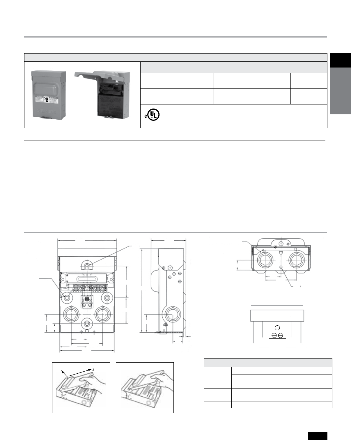
Non-Fused Air Conditioning Disconnects
Wiring Diagram
5.14
@ 0.312
x3
@.240
R.156
2.375
0.867
1.375
1.375
0.750
2.250
4.750
6x @ 0.50 x @ 0.75 x @ 1.00
2.750
2.750
2.750
7. 250
1.562
1.562
0.667
0.219
3.049
5.14
@ 0.312
x3
@.240
R.156
2.375
0.867
1.375
1.375
0.750
2.250
4.750
6x @ 0.50 x @ 0.75 x @ 1.00
2.750
2.750
2.750
7. 250
1.562
1.562
0.667
0.219
3.049
5.14
@ 0.312
x3
@.240
R.156
2.375
0.867
1.375
1.375
0.750
2.250
4.750
6x @ 0.50 x @ 0.75 x @ 1.00
2.750
2.750
2.750
7. 250
1.562
1.562
0.667
0.219
3.049
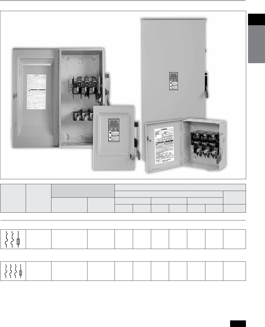
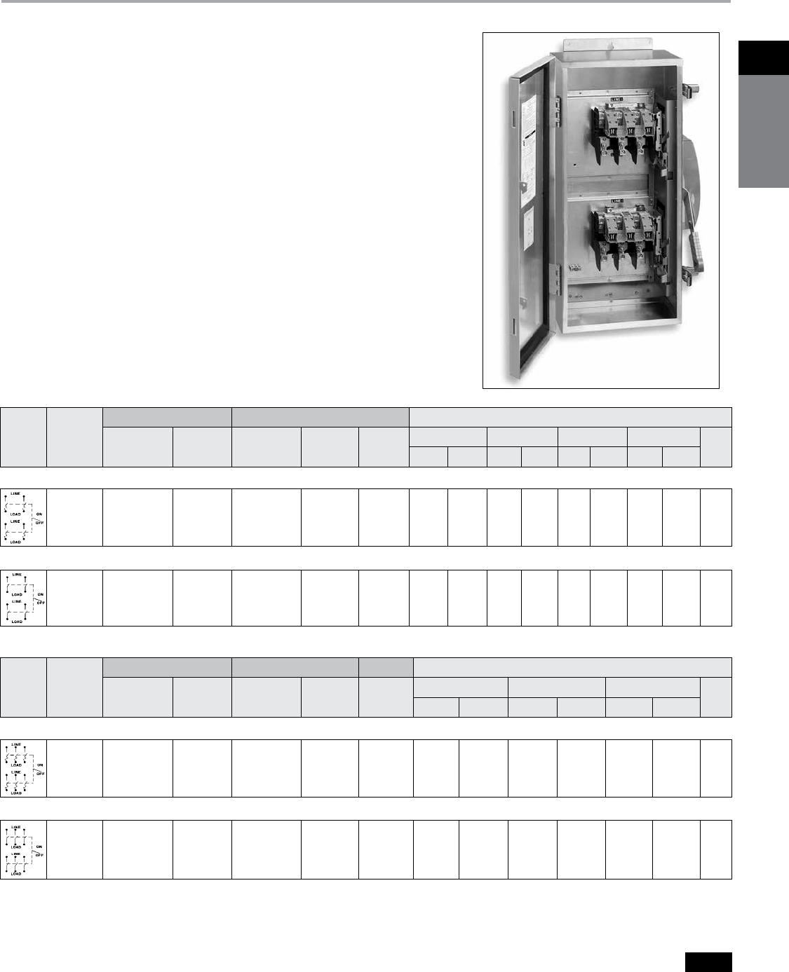
Features Benefits
b Ample Wiring Space b The larger enclosure allows for ample wiring space.
b
Rugged Design
b Manufactured with powder coated G90 galvanized steel for fade, scratch
and corrosion resistance
b
Numerous Knockouts
b All (6) knockouts are easy to remove. The sidewall knockouts provide access from the
sides of the device. Every knockout has 1/2", 3/4" and 1" provisions.
b
Raised Mounting Embosses
b
(4) Raised mounting embosses keep the unit away from the wall, preventing dirt
build-up. The upper mounting hole is shaped to be used as a hanger.
b
Copper Conductors
b
Copper current carrying part allows for a cooler, longer lasting operation.
b
Pullout Switch
b The pullout switch design allows you to safely and easily de-energize the load terminals.
b
Removable Door
b The easily removable door makes it possible to wire the device with absolutely no
interference.
Selection
240V Non-Fused Disconnect cUL listed, Type 3R enclosure
Catalogue
Number
Ampere
Rating
Maximum
Horsepower
Disconnect
Type
Std.
Pkg.
WN2060 60 10 Non-Fused Pullout 6
Wire Range Table
Connector Copper Aluminum
Solid Standard Solid Standard
Line #14-8 #14-3 #12-8 #12-3
Load #14-8 #14-3 #12-8 #12-3
Neutral #12-8 #12-2 #12-8 #12-2
Equip Grnd. #12-8 #12-2 #12-8 #12-2
Removable Door
5.14
@ 0.312
x3
@.240
R.156
2.375
0.867
1.375
1.375
0.750
2.250
4.750
6x @ 0.50 x @ 0.75 x @ 1.00
2.750
2.750
2.750
7. 250
1.562
1.562
0.667
0.219
3.049
Pullout Disconnect
LOAD Bonded
Neutral
LOAD
LINELINE
* For inches/millimeters conversion, multiply inches by 25.4.
Dimensions - Inches*
Non-Fused
Siemens Canada Limited Power Product Catalogue
1-4
1
safety
switches
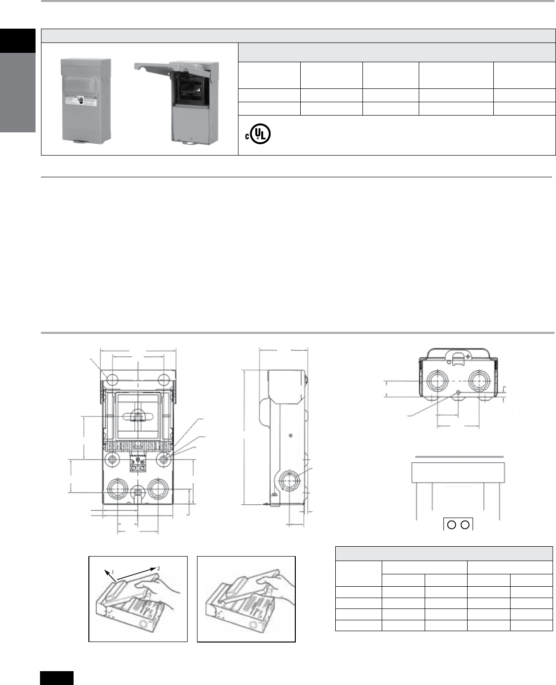
Selection
240V Fused Disconnect cUL listed, Type 3R enclosure
Catalogue
Number
Ampere
Rating
Maximum
Horsepower
Fuse
Class
Std.
Pkg.
WF2030 30 3 H 6
WF2060 60 10 H 6
Safety Switches
Fused Air Conditioning Disconnects
Wiring Diagram
2x @ 0.875 MAX
3x @ 0.50
1.000
3.425
9.09
1.00
1.00 0.25
6x @ 0.50 @ 0.75 @ 1.00
KNOCKOUT
1.375
0.219
1.375
2.25
2.921
@ 0.250 THRU
5.144
3.50
3.00
2.750
2.750
2.375
4.750
3x @ 1.00
3x @ 0.312
THRU
2x @ 0.875 MAX
3x @ 0.50
1.000
3.425
9.09
1.00
1.00 0.25
6x @ 0.50 @ 0.75 @ 1.00
KNOCKOUT
1.375
0.219
1.375
2.25
2.921
@ 0.250 THRU
5.144
3.50
3.00
2.750
2.750
2.375
4.750
3x @ 1.00
3x @ 0.312
THRU
5.14
@ 0.312
x3
@.240
R.156
2.375
0.867
1.375
1.375
0.750
2.250
4.750
6x @ 0.50 x @ 0.75 x @ 1.00
2.750
2.750
2.750
7. 250
1.562
1.562
0.667
0.219
3.049
Features Benefits
b Ample Wiring Space b The larger enclosure allows for ample wiring space.
b
Rugged Design
b Manufactured with powder coated G90 galvanized steel for fade, scratch
and corrosion resistance
b
Numerous Knockouts
b All (6) knockouts are easy to remove. The sidewall knockouts provide access from the
sides of the device. Every knockout has 1/2", 3/4" and 1" provisions.
b
Raised Mounting Embosses
b
(4) Raised mounting embosses keep the unit away from the wall, preventing dirt
build-up. The upper mounting hole is shaped to be used as a hanger.
b
Copper Conductors
b
Copper current carrying part allows for a cooler, longer lasting operation.
b
Pullout Switch
b The pullout switch design allows you to safely and easily de-energize the load terminals.
b
Removable Door
b The easily removable door makes it possible to wire the device with absolutely no
interference.
Wire Range Table
Connector Copper Aluminum
Solid Standard Solid Standard
Line #14-8 #14-3 #12-8 #12-3
Load #14-8 #14-3 #12-8 #12-3
Neutral #12-8 #12-2 #12-8 #12-2
Equip Grnd. #12-8 #12-2 #12-8 #12-2
Removable Door
2x @ 0.875 MAX
3x @ 0.50
1.000
3.425
9.09
1.00
1.00 0.25
6x @ 0.50 @ 0.75 @ 1.00
KNOCKOUT
1.375
0.219
1.375
2.25
2.921
@ 0.250 THRU
5.144
3.50
3.00
2.750
2.750
2.375
4.750
3x @ 1.00
3x @ 0.312
THRU
Fuse Block
LOAD
Bonded
Neutral
LOAD
LINELINE
* For inches/millimeters conversion, multiply inches by 25.4.
Dimensions - Inches*
Fused
Siemens Canada Limited Power Product Catalogue 1-5
1Safety
SwitcheS
Type VBII Safety Switches
Guide Form Specifications
Product Overview
a
The protective device can either be a fuse installed in a
fusible switch or an upstream fuse or circuit breaker
protecting a non-fusible switch. The ampere rating of the
upstream protective device must not exceed the switch
ampere rating.
b
Class T kit available for 240V max. applications on
1200A switches.
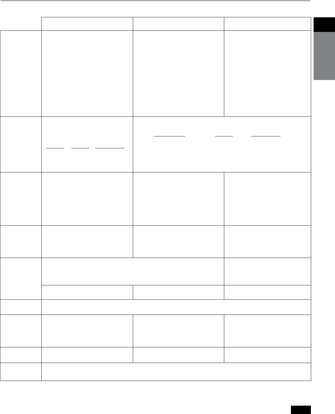
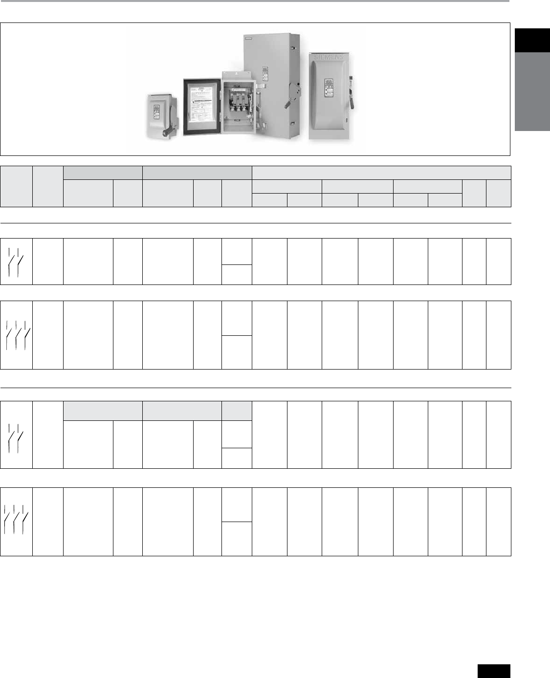
General Duty Heavy Duty Double Throw
Application
General Duty Switches are intended for
applications where reliable performance and
continuity of service are needed, but where duty
requirements are not severe and usual service
conditions prevail. (These switches are intended for
use primarily with supply circuits rated 240V AC or
less where the available fault current is less than
100,000A when used with Class R or T fuses or
10,000A max. when used with Class H fuses.)
Heavy Duty Switches are intended for use in
applications where:
1.
Rugged construction, reliable performance,
continuity of service and ease of maintenance are
emphasized, or
2.
Available fault currents higher than 10,000A are
likely to be encountered, such as in manufacturing
plants, mass production industries, and
commercial, institutional and other large buildings
served by network systems or transformers of
higher capacities.
3.
System voltage is 600V AC or DC Max.
4.
A Type 12 or 4/4X enclosure is required.
Double throw switches are intended to
transfer loads from one power source to another.
All double throw switches are CSA certified.
Switches are rated for use on systems with an
available fault current of up to 10,000 AIC when
protected with Class H fuses or 200,000 AIC when
protected with Class R, J or Class T fuses. They
can also be used to connect a single source of
power to either of two loads. In this application
it is necessary to field modify fusible switches
so that the fuses are on the load side of the
switching mechanism.
Short Circuit
Withstand
Ratings
Suitable for use on systems capable of
delivering not more than 100,000 RMS
symmetrical amperes of fault current as
follows:
Sw. Rating AIC Rating Protective Devicea
30-200A 10,000 Circuit Breaker
30-200A 10,000 Class H Fuse
30-200A 100,000 Class R Fuse
100-200A 100,000 Class J or T Fuse
Suitable for use on systems capable of delivering not more than 200,000 RMS symmetrical amperes of
fault current as follows:
Sw. Rating & Tpye AIC Rating Protective Devicea
All Heavy Duty & DT 10,000 Circuit Breaker
30-600A HD & DT 10,000 Class H Fuse
30-600A HD 200,000 Class R, J or T Fuse
30-600A DTFC & DTNFC DT 200,000 Class R, J or T Fuse
800 & 1200A HD 200,000 Class L or T Fuse
Fuses
Fusible switches will accept the following CSA
class fuses:
30 “LF” - 30A max plug Fuses
30-200A “GD” Class H & K, Class R with kit
100-200A “GD” Class J-move base
100-200A “GD” Class T with kit
Fusible switches will accept the following CSA
class fuses:
30-600A “HD” Class H & K, Class R with kit
30-600A, 600V “HD” Class J-move base
100-600A, 240V “HD” Class J-move base
100-200A “HD” Class T with kit
400-600A “HD” Class T-move bases
800-1200A “HD” Class L, Class T with kitb
Fusible switches will accept the following CSA
class fuses:
30-200A “DT” - Class H & K, Class R with kit
30 & 60A 600V “DT” - Class J-move base
100-200A “DT” - Class J-move base, Class T with kit
400-600A “DT” - Class J-standard, Class T-move
bases
Cover
Interlocks
Voidable – cover interlocks on switches prevent
the switch door from being opened when in the
“ON” position. No cover interlock on plug fuse type
switches.
Voidable dual cover interlocks standard on all
heavy duty switches. Prevents cover from being
opened when switch is in the “ON” position and
prevents switch from being turned “ON” when door
is opened.
Dual cover interlocks standard on all double
throw switches. Prevents cover from being
opened when switch is in the “ON” position and
prevents switch from being turned “ON” when
door is opened.
Specifications CSA certified under file #24563 as enclosed switches. Fusible switches also suitable as service
entrance when neutral bonded to the enclosure is installed. Meets CSA C22.2 No.4 Enclosed
Switches.
CSA certified under file #24563 as enclosed
switches. Meets CSA C22.2 No.4 Enclosed
switches.
Meet NEMA standard KS-1-2001 for type GD
switches.
Meet NEMA standard KS-1-2001 for type HD
switches.
Meet NEMA standard KS-1-2001 type HD for
“DT” switches.
Seismic
Qualifications
All GD & HD switches and “DT” type double throw switches have been tested and comply with the 2010 California Building Code (CBC)
and with the 2009 International Building Code (IBC) - Compliance Level SDS = 1.85 g
Groundable
Neutral
(All neutrals are
bondable for service
entrance use.)
Fusible switches have groundable neutral blocks
factory installed.
All switches (both Fusible and Non-Fusible) are
either supplied with factory installed neutrals or
accept field addable neutrals.
All 2-3 pole DT will accept field addable
neutrals.
Padlocks
Padlockable cover latch. OFF padlock
provisions on handle.
Padlockable cover latch and multipleOFF
padlock provisions on handle.
Padlockable cover latch and multipleOFF
padlock provisions on handle.
HP & Load
Break Ratings
All General Duty, Heavy Duty and Double Throw Switches are both load break and horsepower rated.
Siemens Canada Limited Power Product Catalogue
1-6
1
safety
switches
Feature Comparison
Product Overview
General Heavy Double Features /
Duty Duty Throw Ratings
b b b 30 thru 600 Amps
— b — 800 and 1200 Amps
b b b 240 Volt AC
— b b 600 Volt AC
b b b 250 Volt DC
— b — 600 Volt DC
b b b Double-break visible blade design
(30-200A)
b b b
Quick-make, quick-break switching action
b b b Highly visible ON/OFF handle indication
— b — Handle design for hook stick operation
b b b Padlockable cover latch
b b b Padlockable handle
bc — b
Single voidable cover interlock
— b b Dual voidable cover interlock
b b b Type 1 enclosure
b b b Type 3R enclosure
— b — Type 12 enclosure
— b — Type 4/4X enclosures
b b b
Generous wiring gutters that meet CSA and
CEC
wire-bending space requirements
b b b Lugs suitable for copper or aluminum at
60˚ or 75˚C
b b b CU/AL wire lugs that meet CSA C22.2
No.65-03 requirements
b b Suitable for field-convertible
— compression connectors
bf b b
All plated copper current carrying parts
(except lugs)
b b b Spring reinforced Fuse Clips
(except 30A general duty)b
— b b Clear pivoting line terminal shield
b b b Replacement parts
— b — Field addable 200% neutral
bg b
ag b
ag Provisions for CSA Class T, R and H Fuses
— b ba Provisions for CSA Class J and L Fuses
— b b Metal nameplate
60-200A b b Aux. switch kits
— bd — Type 4X with stainless steel interior parts
be b — Rolled flange enclosure design (30-200A)
— b b Isolated ground kits
a
400, 600V & 600A fusible, double-throw switches accept
only Class J or T fuses. Only 800 & 1200A HD switches
will accept Class L fuses.
b
30A general duty switches have fuse clips constructed
of spring type copper.
c
Not supplied on 30A outdoor & plug fuse switches.
d
30-200A Type VBII in stainless steel enclosures.
e
60-200A.
f
200A general duty switches have aluminum neutral
assemblies.
g
100-200A GD, 100-600A DT and 100-1200A HD switches
will accept Class T fuses.
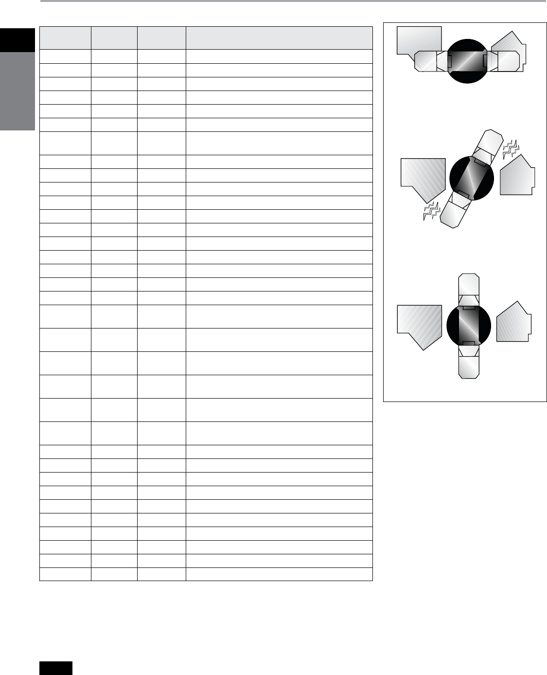
Double Break Switching Action
Like the time-proven Vacu-Break Design,
the Siemens VBII double break switching
action breaks the arc in two places in
30-200A ratings. This reduces heat
generation and increases switching
speed by doubling the breaking distance.
The result is enhanced performance and
increased longevity. We also provide the
most visible blade design available today.
Unlike conventional knife blade switches,
the blades are self-aligning to ensure
positive contact. In addition, they have
no wear and friction point since the
“electrical hinge” has been eliminated.
The result is a very fast, positive and
reliable switching action for even the
most severe applications.
on
in operation
off
Siemens Canada Limited Power Product Catalogue 1-7
1Safety
SwitcheS
Safety Switches
General Duty and Heavy Duty
Product Overview
Enclosure Types
h Type 1 enclosures are intended for indoor use primarily to
A
provide protection against contact with the enclosed equipment
in locations where unusual service conditions do not exist.
h Type 3R enclosures are intended for outdoor use primarily
B
to provide a degree of protection against falling rain and sleet
and must remain undamaged by the formation of ice on the
enclosure. They are not intended to provide protection against
conditions such as dust, internal condensation, or internal icing.
h Type 4, 4X enclosures are intended for indoor or outdoor
C
use primarily to provide a degree of protection against
windblown dust, rain, splashing water and hose-directed water.
They are not intended to provide protection against conditions
such as internal condensation or internal icing. Also meets
4X definition by providing a high degree of protection
against corrosion. Siemens 30-200A stainless steel 4X switches
are supplied stainless interior parts and hardware as standard.
h Type 4 enclosures are intended for indoor or outdoor use
D
primarily to provide a degree of protection against windblown
dust, rain, splashing water and hose-directed water. They are
not intended to provide protection against conditions such as
internal condensation or internal icing.
h Type 12
a
enclosures are intended for indoor use primarily to
E
provide a degree of protection against dust, falling dirt and
dripping water. They are not intended to provide protection
against conditions such as internal condensation.
a
VBII Type 12 switches are also rated 3R & 3S for outdoor use. Type 3R is defined in B
above. 3S rated enclosures provide a degree of protection against windblown dust and
allow operation when the enclosure is ice laden.
b All switches above are rated at 10 KA when protected by any CSA certified or cUL Listed CB
c Circuit breaker trip rating must not exceed switch ampere rating
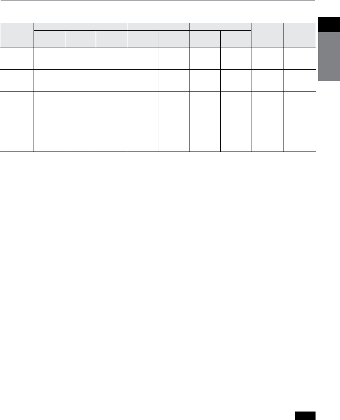
30–100 6 6000 4000 10000
200 5 6000 2000 8000
400 4 1000 5000 6000
600 3 1000 4000 5000
800 2 500 3000 3500
1200 1 500 2000 2500
Number of
Switch ON/OFF Number of Operations
Ampere Operations With Without
Rating per Minute Current Current Total
100 6 50
500 1 10
Max HP Number of ON/OFF Number of Cycles
Rating Operations per minute of Operation
Non- Fusible Safety Switch AIC Ratings
When Protected by a Circuit Breakerbc
Breaker Frame Non-Fused Switch
Short Circuit Current
Rating
NEG, NGB, ED4 30 DT (240V) 18 kA Thru 240 VAC
NEB, NEG, NGG,
NGB, ED4
60-100A GD & DT (240V) 18 kA Thru 240 VAC
NEB, NEG, NGG,
NGB, ED4
30-100A HD & DT (600V) 18 kA Thru 480 VAC
ED6 30-100A HD & DT (600V) 18 kA Thru 600 VAC
FD6-A, JD6-A 200A HD & DT (600V) 18 KA Thru 600 VAC
JD6-A, LD6-A 400A DT (240V) 18 kA Thru 240 VAC
JD6-A, LD6-A 400A HD & DT (600V) 18 kA Thru 600 VAC
LD6-A 600A DT (240V) 25kA Thru 240 VAC
LD6-A 600A HD & DT (600V) 25kA Thru 600 VAC
NNG 1200A HD (600V) 25 kA Thru 600 VAC
Load Break Ratings
All Siemens safety switches are load break rated. The load
break rating is assigned by CSA after the switching unit has
successfully performed the following tests:
Horsepower Ratings
All Siemens safety switches, where appropriate, are horse-
power rated. The assignment of such ratings is made by CSA
only after the switching unit has undergone testing to deter-
mine its acceptability which includes repeated interruption
of the locked rotor current of the motor for which it is to be
rated as follows:
h
A
h h
C D
hB
h
E
Siemens Canada Limited Power Product Catalogue
1-8
1
safety
switches
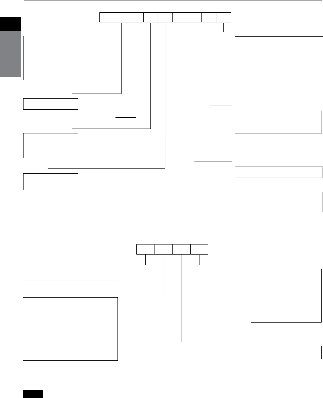
Catalogue Numbering System
Type VBII Safety Switch Catalogue Numbering System
Product Overview
Switch Type
Fused or Non-Fused
C = Built to meet Canadian requirements
Special Applications With:
Enclosure Type
With or Without Neutral
Voltage
L = General Duty
10k AIC Max.
(Plug Fused &
60A Max
Non-Fused)
G = Gen. Duty
H = Heavy Duty
DT = Double Throw
F = Fused
NF = Non-Fused
Number of Poles
1 = 1
2 = 2
3 = 3
4 = 4
6 = 6
1 = 120V or 120/240V
2 = 240V
6 = 600V
CH = Crouse-Hinds Receptacle
W = Viewing Window
Omit = Type 1, Indoor
R = Type 3R, Outdoor
S = Type 4/4X, Stainless Steel
J = Type 12, Industrial
Omit = Less Neutral
N = With Neutral
Amperes
1 = 30A
2 = 60A
3 = 100A
4 = 200A
5 = 400A
6 = 600A
7 = 800A
8 = 1200A
H R 6 4
H = Heavy Duty
G = General Duty
Switch Type
1 = 30A
2 = 60A
12 = 30/60A
3 = 100A
23 = 60/100A
123 = 30/60/100A
1234 = 30/60/100/200A
4 = 200A
56 = 400/600A
5678 = 400/600/800/1200A
78 = 800/1200A
Amperes
2 = 240V Max
6 = 600V Max
A1 = Auxiliary Switch 1/NO and 1/NC
A2 = Auxiliary Switch 2/NO and 2/NC
A3 = Auxiliary Switch Low Current
CL = Compression Lug Barrier /
Mounting Kit
G = Ground Lug Kit
G2 = Insulated Ground Lug Kit
LC = Copper Lug Kit
NC = Neutral
NC2 = 200% Neutral
P = Fuse Puller Kit
R = Class R - Fuse Clip Kit
T = Class T - Fuse Kit
Type VBII Accessories Catalogue Numbering System
Accessory Type
Maximum Voltage
FC 3 64 N CHR
H
Siemens Canada Limited Power Product Catalogue 1-9
1Safety
SwitcheS
Enclosure Type Height Width Depth
1 81⁄4 (210) 51⁄2 (140) 3 (76)
3R 81⁄4 (210) 53⁄8 (137) 31⁄8 (79)
Switch Type Wire Range
120/240 Volt Fusible
30 Amp
#14 AWG - #8 AWG Al/Cud
120/240 Volt Non-Fusible
60 Amp #14 AWG - #3 AWG Al/Cu
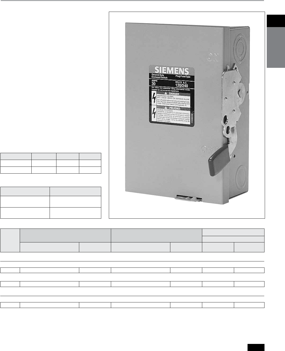
General Duty Enclosed Switches
Plug Fuse and 60A Special Application Type
Selection
a Dual horsepower ratings:
Std. — applies when non-time delay plug fuses
are installed.
Max — applies when time-delay plug fuses are installed.
b
Has service entrance label. CSA certified as
"Enclosed Switches" (suitable for use as service
equipment where indicated).
c Bottom cable entry and exit only. No hub provision
supplied. GSGK60 is included and factory installed.
d Line lugs are CSA approved for #14 to #6 Cu/Al cable.
Features
b CSA Certified under file #24563
b Compact size
b Horsepower rated
b Indoor and outdoor enclosures
b Quick make-quick break mechanism
b Visible “ON”-“OFF” indications
b Padlock-off handle feature
b Door padlock provision
b All fusible switches suitable for use as service
entrance equipement
b Bondable neutral (where indicated)
b Lugs suitable for copper or aluminum wire
b Switches accept plug fuses only - fuses
not included
b Hubsc — see page 1-21
b Lugs — see page 1-21
b Ground Bar Kit: GSGK60c
b Knockout diagrams — see page 1-26 and 1-27
Dimensions - in. (mm)
Wire Range Table
Ampere
Rating
Indoor — Type 1 Outdoor — Type 3R Horsepower Ratingsa
1-Phase, 2-Wire
Catalogue Number Ship. Wt. (lbs.) Catalogue Number Ship. Wt. (lbs.)
Pkg. of 10 Standard Maximum
120/240 Volt Fusible
1-Pole and Solid Neutralb 120 Volt — 1-Phase, 2-Wire
30 LFC111N 3.6 — — 1/2 2
2-Pole and Solid Neutralb 120/240 Volt — 2-Phase, 3-Wire
30 LFC211N 3.5 LFC211NR 35 1/2 2
240 Volt Non-Fused
2-Pole Special Application Switch 240 Volt — 1-Phase, 2-Wire
60 ——LNFC222R
c
35 3 10
Siemens Canada Limited Power Product Catalogue
1-10
1
safety
switches
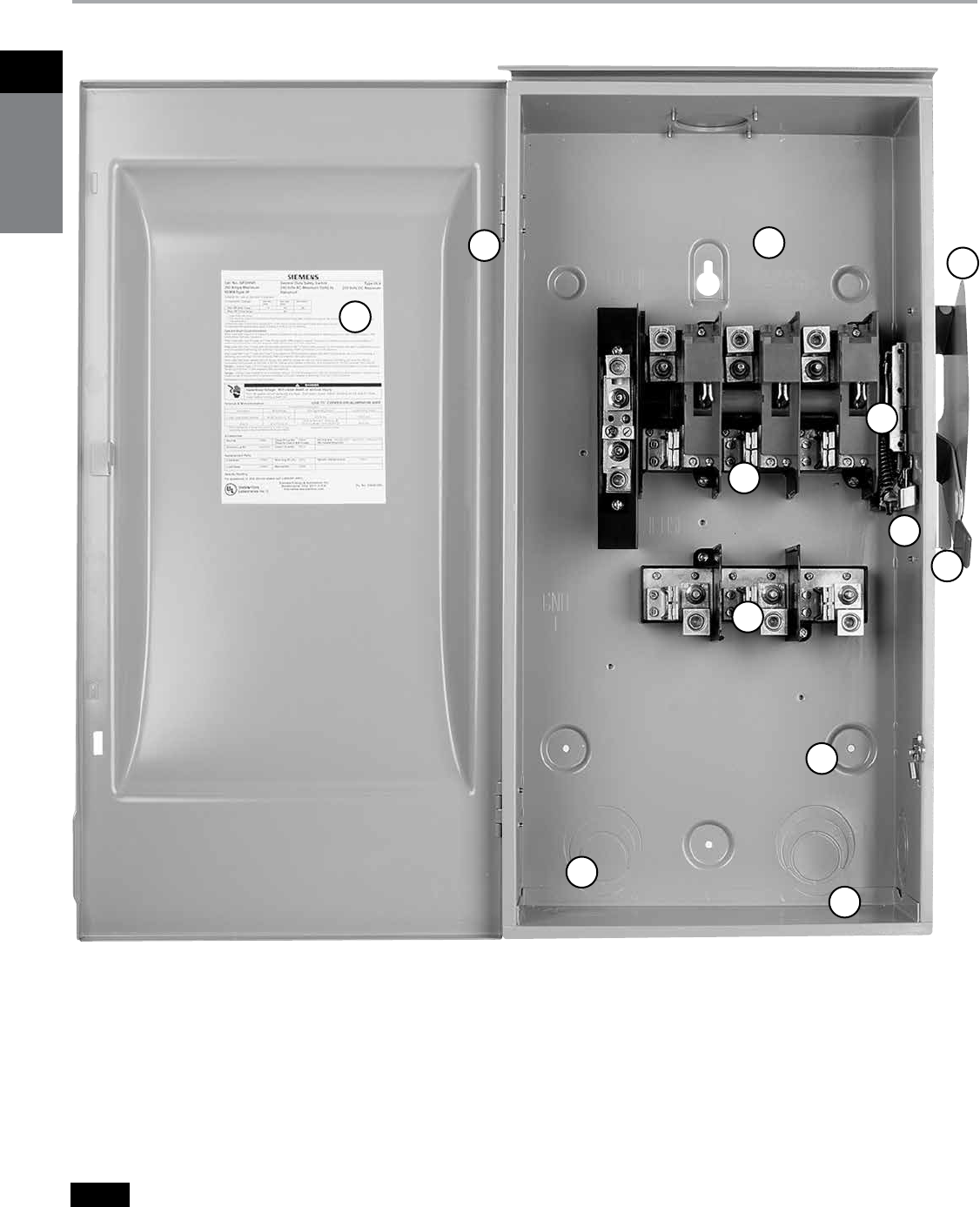
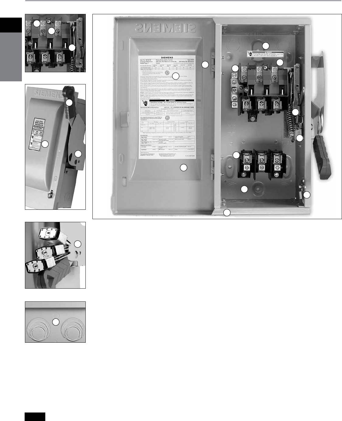
General Duty Safety Switches
Features (60-200A)
Product Overview
12
10
11 5
9
6
3
1
8
4
7
2
1. Cover interlock
2. Tangential knockouts through
200A for easy conduit lineup
3. Quick-make, quick-break operating
mechanism that ensures positive
operation
4. Provisions for T, R, J, H, and K
class fuses (T & J 100-200A)
5. Generous wiring gutters that
meet or exceed CEC
wire-bending space requirements
6. Visible blade, double-break switch
action
7. Positive 2 or 3 point mounting
8. Highly visible red handle grip
9. Informative door labeling which
includes replacement parts list
10. Handle and cover padlocking
provisions
11. Side-hinged door that opens
180 degrees for easier wiring
12. A unique enclosure design that
adds rigidity and strength. Its
rolled edge prevents cuts and
scrapes to conductors and to
installer’s hands
Siemens Canada Limited Power Product Catalogue 1-11
1Safety
SwitcheS
General Duty Safety Switches
Selection
System Ampere
Rating
Indoor — Type 1
Horsepower Ratingsa
240V AC
250 Volt DC
Catalogue Number Ship. Wt. (lbs.)
Std. Pkg.
1-Phase, 2-Wire 2-Phase, 4-Wire 3-Phase, 3-Wire
Std. Max. Std. Max. Std. Max. Std.
240 Volt Fusible
2-Pole, 2-Fuse, and Solid Neutralbcd 240 Volt AC/250 Volt DC
30
60
100
200
GFC221N
GFC222N
GFC223N
GFC224N
35e
14
23
47
11/2
3
71/2
15
3
10
15
—
—
—
—
—
—
—
—
—
3
71/2
15
25
71/2
15
30
60
5
10
20
40
3-Pole, 3-Fuse, and Solid Neutrald 240 Volt AC/250 Volt DC
30
60
100
200
GFC321N
GFC322N
GFC323N
GFC324N
24f
15
25
49
11/2
3
71/2
15
3
10
15
—
—
—
—
—
—
—
—
—
3
71/2
15
25
71/2
15
30
60
5
10
20
40
a Dual horsepower ratings: Std.- applies when non-time
delay fuses are installed. Max.- applies when time-
delay fuses are installed.
b These switches are CSA certified for application on
grounded B-phase systems.
c
Suitable for use on 3-phase motor loads.
d
Suitable for use as service entrance when neutral is
bonded to the enclosure.
e
10 switches per standard package.
f
5 switches per standard package.
Siemens Canada Limited Power Product Catalogue
1-12
1
safety
switches
Heavy Duty Safety Switches
Features
15
3
2
4
18
6
7
10
11
19
12
14
13
8
5
1
16
20
17
9
1. Quick-make, quick-break operating mechanism
that ensures positive operation.
2. Visible blade, double-break switching action.
3. Arc chutes dissipate heat and prolong switch life.
4. Highly visible red handle grip.
Designed for hook stick operation.
5. Defeatable dual cover interlock.
6. Center punch provided for field drilling
to allow ON padlocking.
7. Handle can be padlocked in the OFF position
with up to (3) padlocks with 5/16" hasps.
8. Generous top, bottom and side gutters that
meet or exceed CEC wire-bending space
requirements.
9. Informative door labeling which includes
replacement parts list.
10. Tangential knockouts through 600A for easy
conduit lineup.
11. Side-hinged door that opens past 180 degrees
for easier wiring.
12. Unique enclosure design increases rigidity and
prevents cuts and scrapes to conductors and
installer’s hands.
13. Spring reinforced fuse clips that assure reliable
contact for cool operation.
14. Door latch securely holds door closed and
allows cover padlocking.
15. Front removable mechanical lugs that are
suitable for CU/AI 60 or 75° C conductors.
16. Lugs are field convertible to copper
body and to a wide variety of compression
connectors.
17. Hinged clear line terminal shield
with probe holes for inspecting or
testing line side terminals.
18. Embossed aluminum nameplate on Heavy
Duty Switches.
19. Drawn cover for increased rigidity
and resistance to abuse.
20. Top key hole and bottom mounting holes
provide easy 2 or 3 point mounting.
Siemens Canada Limited Power Product Catalogue 1-13
1Safety
SwitcheS
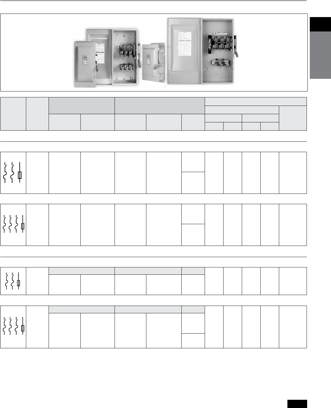
Heavy Duty Safety Switches
Selection
a
Suitable for use as service equipment when neutral is
bonded to the enclosure.
b Dual horsepower ratings: Std.- applies when non-time
delay fuses are installed. Max.- applies when time-delay
fuses are installed.
c
These switches are CSA certified for application on
grounded B-phase systems and are suitable for
3-phase motor applications.
d
Hub catalogue numbers available p. 1-21
e
304 grade stainless steel.
f
Also rated for Type 3S/3R application. Factory provided
drain plug must be removed from the bottom of the
enclosure for type 3S/3R application.
g Hub type SSH are suitable for type 4/4X and type 12
applications.
System Ampere
Rating
Indoor — Type 1 Outdoor — Type 3R
Horsepower Ratingsb
240V AC
250 Volt DC
Catalogue
Number
Ship. Wt. (lbs.)
Std. Pkg.
Catalogue
Number
Ship. Wt. (lbs.)
Std. Pkg.
Hub
Type
d
1-Phase, 2-Wire 3-Phase, 3-Wire
Std. Max. Std. Max.
240 Volt Fusiblea
2-Pole, 2-Fuse and Solid Neutralc (Also used for 2-Pole, 2-Wire Applications) 240 Volt AC/250 Volt DC
30
60
100
200
400
600
800
1200
HFC221N
HFC222N
HFC223N
HFC224N
HFC225N
HFC226N
HFC227N
HFC228N
12
18
23
47
153
155
365
385
HFC221NR
HFC222NR
HFC223NR
HFC224NR
HFC225NR
HFC226NR
HFC227NR
HFC228NR
13
19
24
48
157
159
365
385
11/2
3
71/2
15
15
15
—
—
3
10
15
—
—
—
—
—
3
71/2
15
25
50
75
100
100
71/2
15
30
60
125
200
250
250
5
10
20
40
50
50
50
50
ECHS
ECHV
3-Pole, 3-Fuse and Solid Neutral (Also used for 3-Pole, 3-Wire Applications) 240 Volt AC/250 Volt DC
30
60
100
200
400
600
800
1200
HFC321N
HFC322N
HFC323N
HFC324N
HFC325N
HFC326N
HFC327N
HFC328Nn
14
19
25
49
158
161
375
395
HFC321NR
HFC322NR
HFC323NR
HFC324NR
HFC325NR
HFC326NR
HFC327NR
HFC328NRn
15
20
26
50
162
165
375
388
11/2
3
71/2
15
15
15
—
—
3
10
15
—
—
—
—
—
3
71⁄2
15
25
50
75
100
100
71⁄2
15
30
60
125
200
250
250
5
10
20
40
50
50
50
50
ECHS
ECHV
240 Volt Fusiblea
2-Pole, 2-Fuse 240 Volt AC/250 Volt DC
Type 4/4X StainlessgType 12 IndustrialfHub Type
g
30
60
100
200
HFC221NS
HFC222NS
HFC223NS
HFC224NS
13
19
24
48
HFC221NJ
HFC222NJ
HFC223NJ
HFC224NJ
13
19
24
48
SSH
11/2
3
71/2
15
3
10
15
—
3
71/2
15
25
71/2
15
30
60
5
10
20
40
3-Pole, 3-Fuse (Also used for 2-Pole, 2-Wire Applications in 400–800A Ratings) 240 Volt AC/250 Volt DC
Type 4/4X StainlesseType 12 IndustrialfHub Type
g
30
60
100
200
400
600
800
HFC321NS
HFC322NS
HFC323NS
HFC324NS
HFC325NS
HFC326NS
HFC327NSn
14
20
25
49
154
157
370
HFC321NJ
HFC322NJ
HFC323NJ
HFC324NJ
HFC325NJn
HFC326NJn
HFC327NJn
14
20
25
49
110
161
365
SSH
11/2
3
71/2
15
15
15
—
3
10
15
—
—
—
—
3
71/2
15
25
50
75
100
71/2
15
30
60
125
200
250
5
10
20
40
50
50
50
*
* Consult Siemens representant.
n Built to order.
Siemens Canada Limited Power Product Catalogue
1-14
1
safety
switches
Heavy Duty Safety Switches
Selection
a 60-200A 3-Pole switches are also rated 600V DC.
b 600V DC & 600V DC horsepower rating shown requires
(2) poles to be connected in series.
c
Use 3-Pole switch for 200A applications.
d
Dual horsepower ratings: Std.- applies when non-time
delay fuses are installed. Max.- applies when time-delay
fuses are installed.
e
Suitable for use as service equipment when neutral is
bonded to the enclosure, except for 1200A when used on
480V or 600V grounded wye system.
f Hub catalogue number available p.1-21
g
When a neutral is required use neutral kit displayed on
p.1-19
h Also rated for Type 3S/3R application. Factory provided
drain plug must be removed from the bottom of the
enclosure for type 3S/3R application.
i
304 grade stainless steel.
j Hub type SSH are suitable for type 4/4X and type 12
applications.
k 3-Pole, 3-Fuse with solid neutral factory installed, suitable
for use as service equipment.
* Consult Siemens representative
System Ampere
Rating
Indoor — Type 1 Outdoor — Type 3R Horsepower Ratingsd
480V AC 600V AC
250
Volt
DC
600
Volt
DC
Catalogue
Number
Ship.
Wt. (lbs.)
Std. Pkg.
Catalogue
Number
Ship. Wt.
(lbs.)
Std. Pkg.
Hub Type
f
1-Phase,
2-Wire
3-Phase,
3-Wire
1-Phase,
2-Wire
3-Phase,
3-Wire
Std. Max. Std. Max. Std. Max. Std. Max.
600 Volt Fusible
2-Pole, 2-Fusec 480 Volt AC/600 Volt AC/600 Volt DC
30
60
100
400
600
HFC261
HFC262
HFC263
HFC265n
HFC266n
15
20
26
149
150
HFC261R
HFC262R
HFC263R
HFC265Rn
HFC266Rn
15
20
27
152
155
ECHS
3
10
15
—
—
71/2
20
30
50
50
—
—
—
—
—
—
—
—
—
—
3
10
15
50
50
10
25
40
—
—
—
—
—
—
—
—
—
—
—
—
5
10
20
40
50
15
30
50
50
50
ECHV
3-Pole, 3-Fuse 480 Volt AC/600 Volt AC/250 Volt DCa
30
60
100
200
400
600
800
1200
HFC361
HFC362
HFC363
HFC364
HFC365
HFC366
HFC367
HFC368
14
19
24
48
154
157
365
383
HFC361R
HFC362R
HFC363R
HFC364R
HFC365R
HFC366R
HFC367R
HFC368R
15
20
25
49
157
161
365
385
3
5
5
25
—
—
—
—
71/2
20
20
50
—
—
—
—
5
15
25
50
100
150
200
200
15
30
60
125
250
400
500
500
3
10
15
30
—
—
—
—
10
25
40
50
—
—
—
—
71/2
15
30
60
125
200
250
250
20
50
75
150
350
500
500
500
5
10
20
40
50
50
50
50
—
30b
50b
50
—
—
—
—
ECHS
ECHV
3-Pole, 3-Fuse and Solid Neutral
e 480 Volt AC/600 Volt AC/250 Volt DCa
30
60
100
200
400
600
800
1200
HFC361N
HFC362N
HFC363N
HFC364N
HFC365N
HFC366N
HFC367N
HFC368N
14
19
25
49
158
161
375
395
HFC361NR
HFC362NR
HFC363NR
HFC364NR
HFC365NR
HFC366NR
HFC367NR
HFC368NR
15
20
26
50
162
165
375
388
ECHS
3
5
10
25
—
—
—
—
71/2
20
30
50
—
—
—
—
5
15
25
50
100
150
250
250
15
30
60
125
250
400
500
500
3
10
15
30
—
—
—
—
10
25
40
50
—
—
—
—
71/2
15
30
60
125
200
250
250
20
50
75
150
350
500
500
500
5
10
20
40
50
50
50
50
—
30b
50b
50
—
—
—
—
ECHV
600 Volt Fusibleg (For 2-Pole Applications use outside poles of 3-Pole Switches)
2-Pole, 2-Fusec 480 Volt AC/600 Volt AC/600 Volt DC
Type 4/4X StainlessiType 12 Industrial
g
Hub Type
fj
30
60
100
400
600
HFC261S
HFC262S
HFC263Sn
HFC265Sn
HFC266Sn
15
20
27
153
156
HFC261Jn
HFC262Jn
HFC263Jn
HFC265Jn
HFC266Jn
15
20
27
155
156
SSH
3
5
10
—
—
71/2
20
30
50
50
—
—
—
—
—
—
—
—
—
—
3
10
15
50
50
10
25
40
—
—
—
—
—
—
—
—
—
—
—
—
5
10
20
40
50
15
30
50
50
50
*
3-Pole, 3-Fuse 480 Volt AC/600 Volt AC/250 Volt DCa
30
60
100
200
400
600
800
1200
HFC361S
HFC362S
HFC363S
HFC364S
HFC365S
HFC366NSk
HFC367NSk
HFC368NSkn
13
20
25
49
158
161
370
388
HFC361J
HFC362J
HFC363J
HFC364J
HFC365J
HFC366J
HFC367NJkn
HFC368NJkn
14
20
25
49
160
161
365
388
SSH
—
—
—
—
—
—
—
—
—
—
—
—
—
—
—
—
5
15
25
50
100
150
200
250
15
30
60
125
250
400
500
500
—
—
—
—
—
—
—
—
—
—
—
—
—
—
—
—
71/2
15
30
60
125
200
250
250
20
50
75
150
350
500
500
500
5
10
20
40
50
50
50
50
—
30b
50b
50
—
—
—
—
*
n Built to order.
Siemens Canada Limited Power Product Catalogue 1-15
1Safety
SwitcheS
Heavy Duty Safety Switches
Selection
a
Also rated 600V DC.
b
When neutral is required, use neutral kit displayed on p.1-19
c
Use 3-Pole switch for 200A application.
d
Hub catalogue numbers available p.1-21
e
Also rated for Type 3S/3R application. Factory provided drain
plug must be removed from the bottom of the enclosure for
type 3S/3R application.
f
600V DC horsepower rating shown requires (2) poles to be
connected in series.
g
304 grade stainless steel.
h
Hub type SSH are suitable for type 4/4X and type 12
applications.
*Consult Siemens representative.
System Ampere
Rating
Indoor — Type 1 Outdoor — Type 3R Horsepower Ratings
Catalogue
Number
Ship.
Wt.
(lbs.)
Catalogue
Number
Ship.
Wt.
(lbs.)
Hub
d
Type
240 Volt 480 Volt 600 Volt 250V
DC
600V
DC
1-Phase 3-Phase 1-Phase 3-Phase 1-Phase 3-Phase
600 Volt Non-Fusible
2-Polec 480 Volt AC / 600 Volt AC / 600 Volt DC
30
60
100
400
600
HNFC261
HNFC262
HNFC263
HNFC265
HNFC266 n
12
19
24
109
111
HNFC261R
HNFC262R
HNFC263R
HNFC265R
HNFC266Rn
13
20
25
113
115
ECHS —
—
—
15
15
—
—
—
—
—
71/2
20
30
50
50
—
—
—
—
—
10
25
40
50
50
—
—
—
—
—
5
10
20
40
50
15
30
50
50
50
ECHV
3-Pole 480 Volt AC/600 Volt AC/250 Volt DC
30
60
100
200
400
600
800
1200
HNFC361
HNFC362a
HNFC363a
HNFC364a
HNFC365
HNFC366
HNFC367
HNFC368
12
18
23
46
114
116
295
305
HNFC361R
HNFC362Ra
HNFC363Ra
HNFC364Ra
HNFC365R
HNFC366R
HNFC367R
HNFC368R
13
19
24
47
118
120
295
307
ECHS
5
10
15
15
15
15
15
15
10
20
40
60
125
200
250
250
71/2
20
30
50
50
50
50
50
20
50
75
125
250
400
500
500
10
25
40
50
50
50
50
50
30
60
100
150
350
500
500
500
5
10
20
40
50
50
50
50
—
30f
50f
50
—
—
—
—
ECHV
600 Volt Non-Fusibleb
2-Polec 480 Volt AC / 600 Volt AC / 600 Volt DC
Type 4/4X Stainless
g
Type 12 IndustrialeHub
Type
dh
30
60
100
400
600
HNFC261S
HNFC262S
HNFC263Sn
HNFC265Sn
HNFC266Sn
13
20
25
113
115
HNFC261J
HNFC262J
HNFC263Jn
HNFC265Jn
HNFC266Jn
13
20
25
114
120
SSH —
—
—
15
15
—
—
—
—
—
71/2
20
30
50
50
—
—
—
—
—
10
25
40
—
—
—
—
—
—
—
5
10
20
40
50
15
30
50
50
50
*
3-Pole 480 Volt AC / 600 Volt AC / 250 Volt DC
30
60
100
200
400
600
800
1200
HNFC361S
HNFC362Sa
HNFC363Sa
HNFC364Sa
HNFC365S
HNFC366S
HNFC367S
—
13
19
24
47
118
120
295
—
HNFC361J
HNFC362Ja
HNFC363Ja
HNFC364Ja
HNFC365J
HNFC366J
HNFC367Jn
HNFC368Jn
13
19
24
47
119
120
295
310
SSH
5
10
15
15
15
15
15
15
10
20
40
60
125
200
250
250
71/2
20
30
50
50
50
50
50
20
50
75
125
250
400
500
500
10
25
40
50
50
50
50
50
30
60
100
150
350
500
500
500
5
10
20
40
50
50
50
50
—
30f
50f
50
—
—
—
—
*
n Built to order.

Siemens Canada Limited Power Product Catalogue
1-16
1
safety
switches
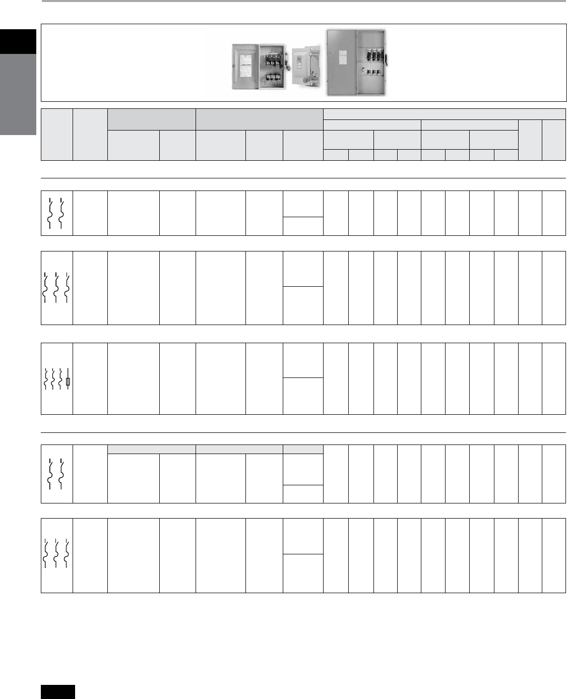
Heavy Duty Safety Switches
Type 4/4X & 12 with Viewing Window
Selection
Description
30–600A, 3-pole 600V max. in fusible and
non-fusible versions in Type 4/4X stainless
steel and Type 12 enclosures.
All allow viewing of visible blade position.
30–200A also allow viewing of indicating
type fuses.
Features
b Rugged installer-friendly enclosure
design features a gasket flange with
continuously welded seams
b Tool-free cover latches
b Two, three and four point mounting
b Metal handle with large insulating grip
features a positive stop in both ON and
OFF position
b Ground lugs provided as standard
b Type 12 enclosures are fabricated from
galvanized steel and are also rated for
3R/3S outdoor applications
b Type 4X stainless steel switches
(30–200A) are 304 grade stainless steel
and are provided with stainless steel
interior parts
b The widest range of accessories
available including 200% neutrals,
gold plated PLC auxiliary contacts
and isolated ground kits
a 200A switches are also rated 600V DC.
b
Maximum HP ratings listed apply only when time delay
fuses are used.
c
Also rated for Type 3S/3R application. Factory provided
drain plug must be removed from the bottom of the
enclosure for type 3S/3R application.
d
Suitable for use as service equipment when neutral is
bonded to the enclosure.
e
600V DC horsepower rating shown requires (2) poles to
be connected in series.
f
304 grade stainless steel.
* Consult Siemens representative.
System
Ampere
Rating Catalogue Number
Hub
Type
Ship.
Wt. (lbs.)
Maximum Horsepower Ratingsb
240V AC 480V AC 600V AC 250V
DC
600V
DC
1-Phase, 2-Wire 3-Phase, 3-Wire 3-Phase, 3-Wire 3-Phase, 3-Wire
3-Pole, 3-Wire Fusible, Type 12cd (For 2-Pole Applications use outside poles of 3-Pole Switches) 600 Volt AC / 250 Volt DCa
30
60
100
200
400
600
HFC361JW
HFC362JW
HFC363JW
HFC364JW
HFC365JW
HFC366JW
SSH
17
22
26
53
166
168
3
10
15
—
—
—
71/2
15
30
60
125
200
15
30
60
125
250
400
20
50
75
150
350
500
5
10
20
40
50
50
—
30e
30e
50
—
—
*
3-Pole, 3-Wire Non-Fusible, Type 12c 600 Volt AC / 250 Volt DCa
30
60
100
200
400
HNFC361JW
HNFC362JW
HNFC363JW
HNFC364JW
HNFC365JW
SSH
14
21
25
51
133
3
10
15
15
15
10
20
40
60
125
20
50
75
125
250
30
60
100
150
350
5
10
20
40
50
—
30e
50e
50
—
*
3-Pole, 3-Wire Fusible, Type 4X Stainlessdf (For 2-Pole Applications use outside poles of 3-Pole Switches) 600 Volt AC / 250 Volt DCa
30
60
100
200
400
HFC361SW
HFC362SW
HFC363SW
HFC364SW
HFC365SW
SSH
17
23
28
55
168
3
10
15
—
15
71⁄2
15
30
60
125
15
30
60
125
250
20
50
75
150
350
5
10
20
40
50
—
30e
50e
50
—
*
3-Pole, 3-Wire Non-Fusible, Type 4X Stainlessf 600 Volt AC / 250 Volt DCa
30
60
100
200
400
HNFC361SW
HNFC362SW
HNFC363SW
HNFC364SW
HNFC365SW
SSH
15
23
27
54
134
3
10
15
15
15
10
20
40
60
125
20
50
75
125
250
30
60
100
150
350
5
10
20
40
50
—
30e
50e
50
—
*
Siemens Canada Limited Power Product Catalogue 1-17
1Safety
SwitcheS
Heavy Duty Safety Switches
Type VBII 4 & 6-Pole Heavy Duty Safety Switches
Selection
Application
4 & 6-pole Switches are commonly
used as a disconnecting means for
two-speed, two-winding motors.
Fused switches provide both over
current and short circuit protection.
Non-fusible switches normally provide
a local disconnection means for two-
speed motors which are remote from
their motor controller. 4-pole switches
are also used in 3-phase, 4-wire circuits
when a switching neutral is required.
Description
4 & 6-pole switches are available in
30-200A ratings and in both fusible and
non-fusible versions. 4-pole switches are
supplied with either Type 1 or Type12/3R
enclosures.
6-pole switches are available with either
Type 12/3R or Type 4X stainless steel
enclosures.
Standards
b cUL & UL listed under file #E4776
b Meets UL98 for enclosed switches
b Meets NEMA Standard KS-1 for
enclosed switches
b Meets CEC wire bending space
requirements
Features
b Visible blade, double break switching
action
b Highly visible ON/OFF indication
b Defeatable dual cover interlock
b Padlock option in OFF position
b All copper current carrying parts
a
b Tangenital knockouts (Type 1,
4-pole switches)
HNF663S
4-Pole Type VBII Switchesa
6-Pole Type VBII Switchesad
n
Built to order.
a
Lugs are aluminum alloy as standard. Optional cop-
per body lugs are available.
b
Dual horsepower ratings: Std. – applies when
non-time-delay fuses are installed. Max. – applies
when time delay fuses are installed.
c Fusible switches accept Class H Fuses as the stan-
dard. Class R & J fuses can also be installed and
increase the rating from 10,000 to 200,000 AIC. For
Class J, the load base is moved upward. For Class R
fuses, rejection kits are required.
d Supplied with factory installed ground lugs.
e Hub catalogue number available p. 1-21
f Hub type SSH are suitable for type 4/4X and
type 12 applications.
System
Ampere
Rating
Indoor Type 1 Type 12/3R IndustrialdHorsepower Ratingsb
Catalogue
Number
Ship.
Wt. (lbs.)
Catalogue
Number
Ship.
Wt. (lbs.)
Hub
Typee
240V, 2
Ø
, 4W 240V 3
Ø
480V, 3
Ø
600V, 3
Ø
250V
DC
Std. Max. Std. Max. Std. Max. Std. Max.
Fusible 600 Volt AC, 250 Volt DC — 4-Pole, 4 Fusec
30
60
100
200
HF461
HF462
HF463
HF464n
36
40
43
88
HF461J
HF462J
HF463J
HF464Jn
36
40
43
88
SSH
3
71⁄2
15
25
10
20
30
50
3
71⁄2
15
25
71⁄2
15
30
60
5
15
25
50
15
30
60
125
71⁄2
15
30
60
20
50
75
150
5
10
20
40
Non-fusible 600 Volt AC, 250 Volt DC — 4-Pole
30
60
100
200
HNF461
HNF462
HNF463n
HNF464n
32
34
36
78
HNF461J
HNF462J
HNF463Jn
HNF464Jn
32
34
36
78
SSH
—
—
—
—
10
20
30
50
—
—
—
—
10
20
40
60
—
—
—
—
20
50
75
125
—
—
—
—
30
60
100
150
5
10
20
4
System
Ampere
Rating
Type 12 Industrial Type 4X Stainless Steel Horsepower Ratingsc
Catalogue
Number
Ship.
Wt. (lbs.)
Catalogue
Number
Ship.
Wt. (lbs.)
Hub
Typeef
240V 3
Ø
480V, 3
Ø
600V, 3
Ø
250V
DC
Std. Max. Std. Max. Std. Max.
Fusible 600 Volt AC, 250 Volt DC — 6-Pole, 6 Fusec
30
60
100
200
HF661J
HF662J
HF663Jn
HF664Jn
37
41
44
90
HF661S
HF662S
HF663S
HF664Sn
37
41
44
90
SSH
3
71⁄2
15
25
71⁄2
15
30
60
5
15
25
50
15
30
60
125
71⁄2
15
30
60
20
50
75
150
5
10
20
40
Non-fusible 600 Volt AC, 250 Volt DC — 6-Pole
30
60
100
200
HNF661J
HNF662J
HNF663J
HNF664J
33
35
37
80
HNF661S
HNF662S
HNF663S
HNF664Sn
33
35
37
80
SSH
—
—
—
—
10
20
40
60
—
—
—
—
20
50
75
125
—
—
—
—
30
60
100
150
5
10
20
40

Siemens Canada Limited Power Product Catalogue
1-18
1
safety
switches
Heavy Duty Safety Switches
Special Application Switches / Interlocked Receptacle Switches
Selection
Application
Receptacle Safety Switches
provide cord connection protection
of heavy-duty portable equipment
(welders, infrared ovens, batch
feeders, portable conveyors, assem-
bly line fixtures and tools, refrigerator
trucks, etc.) under load or fault
conditions.
Standards
All receptacle switches with a view-
ing window are CSA certified under
file #24563 and UL listed under file
#E4776.
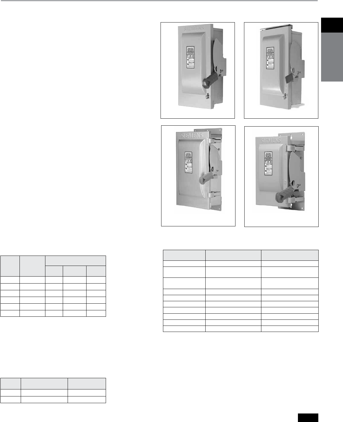
Descriptionab
Type 12 and 4/4X Receptacle Safety
Switches are available with 3-phase,
4-wire grounded type Crouse-Hinds
Arkite™, pre-wired and mounted with
interlock linkage to the switch mecha-
nism. Insertion or removal of the plug
is prevented by the interlock linkage
while the switch is in the “ON” posi-
tion. Receptacle prevents operation of
switch if incorrect plug is inserted.
a
Arktite™ is a registered trademark of the Crouse-
Hinds Company. Plugs are not sold or supplied by
Siemens.
b Also rated Type 3R/3S.
c Enclosure is constructed of Type 304 stainless steel.
d Hub catalogue available p.1-21
Receptacle switches dimensions
B
C
D
E
A
G
F
Ampere
Rating
Dimensions - Inches (mm)
A B C D E F G
Cr-H Type Fusible (240 & 600V)
30
60
100
14.27 (363)
16.27 (413)
21.96 (558)
7.42 (188)
9.17 (233)
9.65 (245)
9.02 (229)
11.47 291)
12.02 (305)
6.22 (158)
6.34 (161)
6.80 (172)
1.52 (39)
1.52 (39)
1.52 (39)
6.1( 155)
6.4 (163)
6.5 (165)
6.0 (152)
7.4 (188)
7.6 (193)
Cr-H Type Non-Fused (600V max.)
30
60
100
14.27 (363)
16.27 (413)
21.96 (558)
7.42 (188)
9.17 (233)
9.65 (245)
9.02 (229)
11.47 (291)
12.02 (305)
6.22 (158)
6.34 (161)
6.80 (172)
1.52 (39)
1.52 (39)
1.52 (39)
6.1 (155)
6.4 (163)
6.5 (165)
6.0 (152)
7.4 (188)
7.6 (193)
Ampere
Ratingc
Type 12bType 4/4Xc
Hub
Typed
Shipping
Wt. (lbs.)
Std. Pkg.
Accepts Crouse-Hinds
Arktitea Plug
Catalogue Number
Catalogue
Number
Catalogue
Number
600V Fusible, 3-Pole, 3-Wire with Viewing Window
30
60
100
HF361JCHW
HF362JCHW
HF363JCHW
HF361SCHW
HF362SCHW
HF363SCHW
SSH
24
30
36
APJ3485 & NPJ3485
APJ6485 & NPJ6485
APJ10487 & NPJ10487
600V Non-Fusible, 3-Pole, 3-Wire with Viewing Window
30
60
100
HNF361JCHW
HNF362JCHW
HNF363JCHW
HNF361SCHW
HNF362SCHW
HNF363SCHW
SSH
22
29
35
APJ3485 & NPJ3485
APJ6485 & NPJ6485
APJ10487 & NPJ10487
Crouse-Hinds Interlocked Receptacle Switches
Siemens Canada Limited Power Product Catalogue 1-19
1Safety
SwitcheS
General and Heavy Duty Safety Switches
Accessories
Selection
a
One kit per pole required.
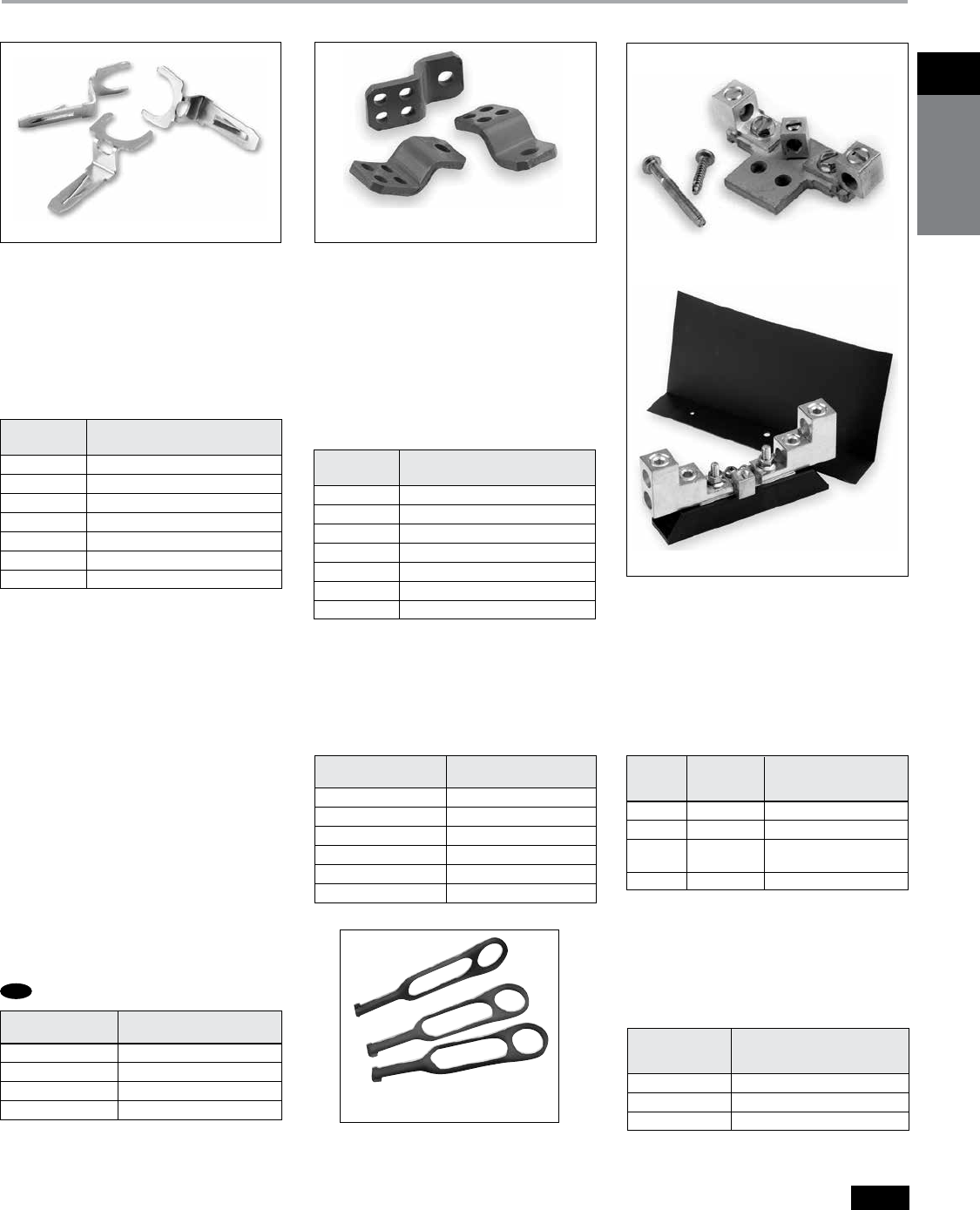
Class R Fuse Clip Kits
All General Duty and Heavy Duty
Switches are field convertible to accept
Class R Fuse Clip Kits. The kits prevent
the installation of Class H and K fuses
(one kit required per 3-pole switch).
Catalogue
Number Description
GSRK321 30A, 240V Kit (GD only)
HR21 30A, 240V Kit (HD only)
HR612 30A, 600V Kit/60A, 240V Kit
HR62 60A, 600V Kit
HR63 100A Kit
HR64 200A Kit
HR656 400A/600A Kit
Class R Fuse Clip Kits
HR612
Class J Fusing
All 30-600A, 600V and 100-600A,240V
fusible Heavy Duty Switches are field
convertible to accept Class J fuses by
moving the load base to a pre-drilled J
fuse position. All 100-600A, 240V
fusible General Duty switches can
also
be field converted to accept Class J
fuses.
Class T Fuse Adapter Kits
All 100-600A, General Duty and 100-
1200A Heavy Duty Switches are field
convertible to accept Class T fuses.
400-600A switches are field convertible
to accept Class T fuses by moving the
load base to a pre-drilled T fuse position.
Neutral Kits
Standard Neutral Kits can be field
installed in General and Heavy Duty
Switches.
Internal Shield Kits
(for fusible switches)
Kits provide a clear plastic inner door
to prevent accidental contact with live
parts. Test probe holes are provided
and fuses can be replaced without
removal of kit.
Catalogue
Number Description
HT23 100A, 240V Kit
HT63 100A, 600V Kit
HT24 200A, 240V Kit
HT64 200A, 600V Kit
TFAK72 800A, 240V Kit
TFAK75 800A, 600V Kit
TFAK82 1200A, 240V Kit
Class T Fuse Adapter Kitsa
Switch
Ampere Rating Catalogue Number
30 GD W410190
30 HD, 60 GD HNC612
60, 100 HD, 100 GD HNC623
200 HNC64
400 & 600 HNC656
800 & 1200 HNC678
Neutral Kits
200% Neutral Kits
CSA certified 200% Neutrals are avail-
able on 100-600A Heavy Duty Switches.
They are typically used with non-linear
transformers or where increased neutral
ampacity/lug capacity is required.
Switch Wire Range
Ampere Catalogue Line & Load
Rating Number Lugs (Cu/Al)
100 HNC263 (2) #14 AWG - 1/0 AWG
200 HNC264 (2) #6 AWG - 300 Kcmil
400 HNC656
(2) 1/0 AWG - 750 Kcmil or
(4) 1/0 AWG - 250 Kcmil
600 HNC678 (4) 1/0 AWG - 750 Kcmil
200% Neutral Kits
HNC264
HNC612
HT63
Fuse Puller Kits
Fuse Puller Kits are field installable in
30-100A Type VBII Heavy Duty Switches
(one kit required per 3-pole switch).
HP61
Switch
Ampere Rating Kit Catalogue Number
30A HD HSK61SSW
60A HD HSK62SSW
100A HD HSK63SSW
200A HD HSK64SSW
Internal Shield Kits
NEW
030 HP61
060 HP62
100 HP63
Fuse Puller Kits
Switch
Ampere Fuse Puller Kit
Rating Catalogue Number
Siemens Canada Limited Power Product Catalogue
1-20
1
safety
switches
General and Heavy Duty Safety Switches
Accessories
Selection
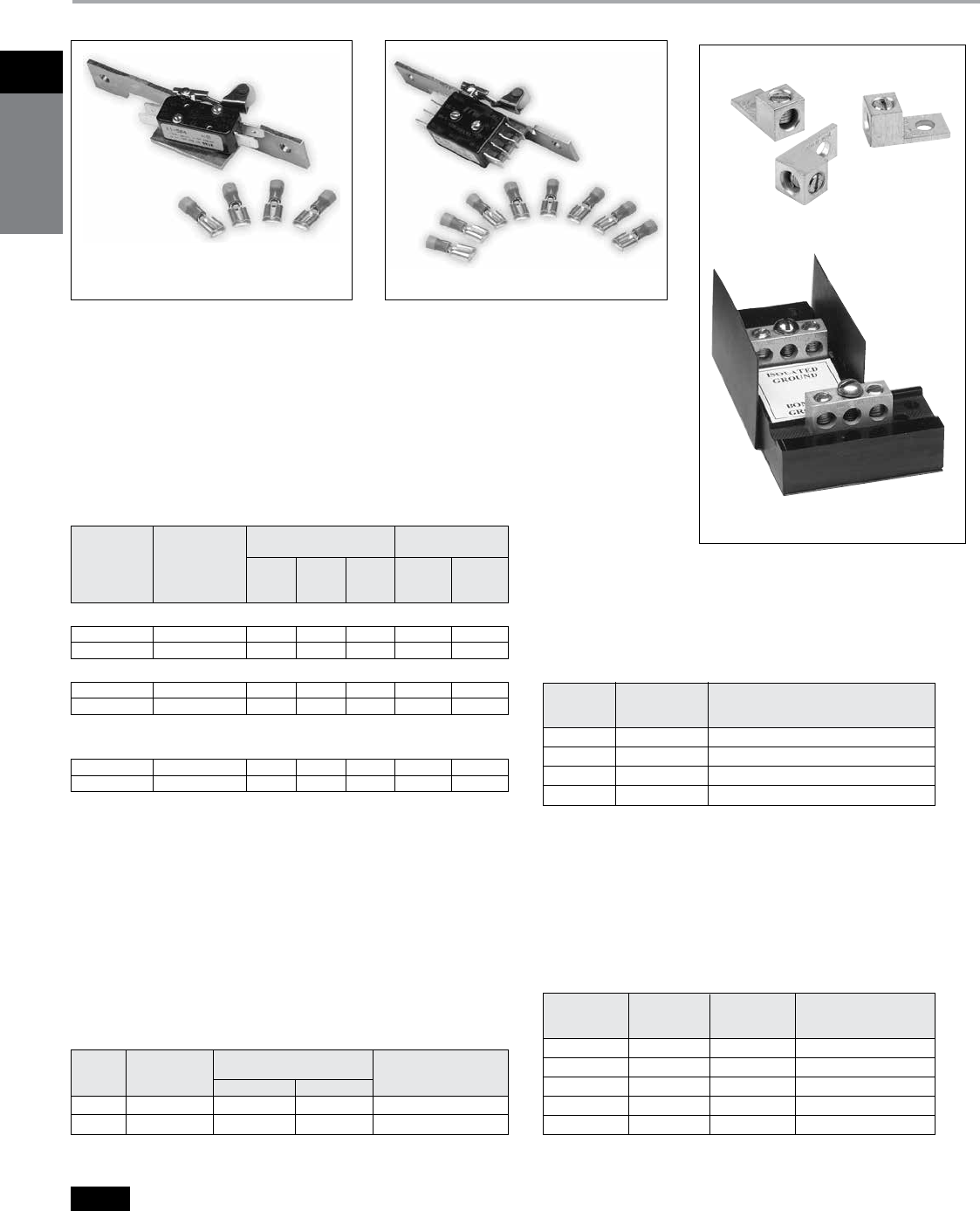
Auxiliary Contacts
Auxiliary Contacts are available only for Heavy Duty Switches.
The auxiliary contacts are available in 1 normally open and
1 normally closed or 2 normally open and 2 normally closed
configurations. Siemens offers a PLC Auxiliary Switch (30-
200A) that has very low resistance for low voltage and current
typical in PLC circuits. All auxiliary contacts make after and
break before main switch contacts.
HA161234
Isolated Ground Kits
Isolated Ground Kits are available on 30-600A Heavy Duty
Switches. They are normally used on circuits with a high
content of computer or other electronic loading which
require a ground which is isolated from the building ground
and neutral circuits. The kit includes both isolated and
grounded terminals as listed below.
Equipment Ground Kits
Equipment Ground Lug Kits are available for all General
and Heavy Duty Switches. They are field installable in
Type 1 and Type 3R Switches and are factory installed
as standard in Type 4/4X, Type 12 and also in all VBII
4&6-pole Switches.
Copper Lug Kits
Heavy duty switches are CSA approved to accept
field installed copper lug kits.
HLC612
HG261234
Copper Lug Kits
30A GD GSGK60 2 #14-8 AWG
60–200 GD HG61234 2 #14-4 AWG
30–200 HD HG61234 2 #14-4 AWG
400 & 600 HG656 4 #14-2/0 AWG
800–1200 HG678 8 #6 AWG-250 Kcmil
Switch
Ampere Catalogue Number of Wire Range
Rating Number Terminals Per Terminal (Cu/Al)
Equipment Ground Kits
30–200 HG261234 2 2 #14-4 AWG
400–600 HG2656 4 4 #14-2/0 AWG
Switch
Ampere Catalogue Number of Terminals Wire Range
Rating Number Isolated Grounded Per Terminal (Cu/Al)
Isolated Ground Kits
HA261234
Auxiliary Contacts
Switch
Ampere
Aux. Switch
Catalogue
Number
Kit Ampere
Rating
Horsepower
Rating
125V
AC
Max.
250V
AC
Max.
28V
DC
Max.
125V
AC
Max.
250V
AC
Max.
With 1 NO & 1 NC Isolated Contacts
30-200 HA161234 10 10 — 1/2 3/4
400-1200 HA165678 10 10 — 1/2 3/4
With 2 NO & 2 NC Isolated Contacts
30-200 HA261234 10 10 7 1/2 3/4
400-1200 HA265678 10 10 7 1/2 3/4
Low Current PLC Type with 1 NO &
1 NC Gold Plated Contacts
30-200 HA361234 10 10 — 1/2 3/4
400-1200 HA365678 10 10 — 1/2 3/4
Switch Copper Lug
Ampere Catalogue
Rating Number Description
30–60 HLC612 (9) Lugs/Kit #14-4 AWG Cu
100 HLC63s (9) Lugs/Kit #14-1/0 AWG Cu
200 HLC64s (9) Lugs/Kit #6 AWG-300 Kcmil Cu
400–1200 HLC65678 (1) Lugs/ Kit #1/0 AWG-600 Kcmil Cu

Siemens Canada Limited Power Product Catalogue 1-21
1Safety
SwitcheS
General and Heavy Duty
Hub and Lug Data
Selection
SSH150 ECHV300 ECHS200 SL0420
Interchangeable Hubs
Conduit hubs are available for Type 3R,
12 and 4 / 4X applications. 30-200A
Type 3R Switches are provided with a
conduit hub provision and a removable
hub plate on their top rainshed.
Compression Lug Mounting &
Neutral Barrier Kit
All Heavy Duty Switches are field
convertible for crimp type lugs.
When compression lugs are required for
30-100A switches, a neutral barrier kit is
required for 1-Phase, 3W or 3-Phase, 4W
applications. When compression lugs
are required on 400-1200A switches, lug
mounting kits are required.
Multiple Padlock Accessory
A tamper-proof device to provide for
multiple padlocking to meet OSHA or
plant requirements. Accepts up to 6
1/4” padlocks. Catalog number SL0420.
Standard Carton-12.
Lugs
30 & 60A Switches are suitable for use
with 60° or 75°C wire. 100–1200A are
suitable for use with 75°C rated wire.
Note: 30 thru 200A Type 3R Switches have
removable hub plates on rainshed. 400A and
larger Type 3R Switches have no provisions for
mounting hubs. Drill or punch hole in the field to
accommodate hub size desired.
a Hubs suitable for 3R Switches.
b Also suitable for Type 12 applications.
c Neutral Barrier kits are required on 30-100A switches
only and only with 1-Phase / 3W or 3-Phase / 4W loads.
Compression Lugs mounting kits are required on 400-
1200A switches only.
d Provides mounting for a single line or load lug.
e Provides mounting for (2) compression lugs per phase
on line or load.
f Line lugs are CSA approved to accept #14-6 CU/Al cable.
g All 200A Heavy Duty Switches have a wire range
& wire bending space for (1) #6-300 Kcmil (Cu/Al).
h All but 60A GD are also CSA approved for #2 Cu/Al
conductors.
Conduit
Size Catalogue
(inches) Number Used On
Hubs
Cover ECHA000
3/4 ECHA075
1 ECHA100
1 1/4 ECHA125
Cover ECHS000
3/4 ECHS075
1 ECHS100
1 1/4 ECHS125 30–200A
1 1/2 ECHS150
2 ECHS200
2 1/2 ECHS250
2 1/2 ECHV250
3 ECHV300
400–1200A
3 1/2 ECHV350
4 ECHV400
Type 3Ra
3/4 SSH075
1 SSH100
1 1/4 SSH125 30–200A
1 1/2 SSH150
2 SSH200
Type 4/4Xb
30 HCL612 Neutral Barrier Kit
60 & 100 HCL623 Neutral Barrier Kit
400d HCL65
1 Pole, Compression
Lug Mounting Kit
400 HCL65678
1 Pole, Compression
& 600e Lug Mounting Kit
800 HCL65678
1 Pole, Compression
& 1200e Lug Mounting Kit
Switch
Ampere Catalogue
Rating Number Kit Description
Compression Lug Mountingc
and Neutral Barrier Kits
Wire Ranges
(Line, Load and Standard Neutral)
30GD #14-8 AWG (Cu/Al)f
30HD #14-2 AWG (Cu/Al)
60h #14-2 AWG (Cu/Al)
100 #14-1/0 AWG (Cu/Al)
200g #6 AWG-300 Kcmil (Cu/Al)
400 (1) 1/0 AWG-750 Kcmil (Cu/Al) or
(2) 1/0 AWG-250 Kcmil (Cu/Al)
600 (2) 1/0 AWG-750 Kcmil (Cu/Al) or
(4) 1/0 AWG-250 Kcmil (Cu/Al)
800 (3) 1/0 AWG-750 Kcmil (Cu/Al) Line Load
(4) 1/0 AWG-750 Kcmil (Cu/Al) neutral
1200 (4) 1/0 AWG-750 Kcmil (Cu/Al) Line Load
(4) 1/0 AWG-750 Kcmil (Cu/Al) neutral
Switch
Ampere
Rating Lug Wire Range
30A GD Only

Siemens Canada Limited Power Product Catalogue
1-22
1
safety
switches
General and Heavy Duty
VBII Safety Switch Replacement Parts
Selection
a
Three lugs included in kit.
b
Includes lugs.
c
Lugs not included.
d
One lug per kit.
e
One per switch required unless otherwise noted.
f
One required per pole.
g
For type 4/4X stainless steel switches add “S” to end of
catalogue number.
h
For replacement door for heavy duty switches add
“DOOR” to end of switch catalogue number.
i
Lugs included with line and load bases.
Handle / Handle Guard
Ampere Line Base Load Base General Duty Heavy Duty
Rating Catalogue Number Catalogue Number Catalogue Number Catalogue Number
VBII Safety Switch Replacement Parts
30 HD 240V HFB21b HBB21b — HH6123g
60 GD HFB612b HBB612b GH223 —
60 HD 240V HFB22b HBB22b — HH6123g
30 600V HFB612b HBB612b — HH6123g
60 600V HFB62b HBB62b — HH6123g
100 HFB63b HBB63b GH223 HH6123g
200 HFB64b HBB64b GH24 HH64g
400 HFB65cf HBB656cf HH65678 HH65678g
600 HFB66cf HBB656cf HH65678 HH65678g
800 HFB67Abf HBB67Abf — HH65678g
1200 HFB68bf HBB68bf — HH68g
Fusible 2- and 3-Pole 60-600A General Duty & 30-1200A Heavy Dutyeh
30 HD HNB612b — — HH6123g
60 GD HNB612b — GH223 —
60 HD HNB623b — — HH6123g
100 HNB623b — GH223 HH6123g
200 HNB64b — GH24 HH64g
400 HNB65cf — HH65678 HH65678g
600 HNB66cf — HH65678 HH65678g
800 HNB67Abf — — HH65678g
1200 HNB678f — — HH68g
Non-Fusible 3-Pole 60-600A General Duty & 30-1200A Heavy Dutyeh
30 HD HM6123g HL612a
60 GD HM6123 HL612a
60 HD HM6123g HL612a
100 HM6123g HL63a
200 HM64g HL64a
400 HM65 HL65678d
600 HM66 HL65678d
800 HM67A HL67Afi
1200 HM678 i
Non-Fusible 3-Pole 60-600A General Duty & 30-1200A
Heavy Dutyeh
30 HD 240V HM6123g HL612a
60 GD HM6123 HL612a
60 HD 240V HM6123g HL612a
30 600V HM6123g HL612a
60 600V HM6123g HL612a
100 HM6123g HL63a
200 HM64g HL64a
400 HM65 HL65678d
600 HM66 HL65678d
800 HM67A HL67Afi
1200 HM678 i
Fusible 2- and 3-Pole 60-600A General Duty & 30-1200A
Heavy Dutyeh
Ampere Mechanism Assembly Line & Load Lugs
Rating Catalogue Number Catalogue Number
HBB612
HNB623
HM6123
HFB612
HFB656
HH6123
Siemens Canada Limited Power Product Catalogue 1-23
1Safety
SwitcheS
General and Heavy Duty Safety Switches
Dimensions
a
Knocks not provided on Type 4 / 4X and 12 or on 800 & 1200A switches.
Safety Switch Dimensions & Shipping Weights
Catalogue
Number
Height - Inches (mm) Width - Inches (mm) Depth - Inches (mm)
Knockout
Diagram
a
Shipping
Weight (lbs.)
Box
A
With
Door
B
With
Rain Shed
C
Box
D
With
Handle
E
Box
F
With
Handle
G
GFC221N
GFC222N
GFC223N
GFC224N
7.79 (202)
14.26 (362)
21.95 (558)
29.90 (760)
8.13 (207)
15.45 (392)
23.15 (588)
31.07 (789)
—
—
—
—
5.50 (140)
6.64 (169)
9.84 (245)
14.62 (391)
5.94 (151)
8.70 (221)
11.70 (297)
16.68 (424)
3.00 (76)
5.05 (128)
5.05 (128)
6.36 (162)
5.88 (149)
8.63 (219)
8.63 (219)
10.92 (277)
S1
S6
S10
S12
35j
14
23
47
GFC321N
GFC322N
GFC323N
GFC324N
7.97 (202)
14.26 (362)
21.95 (558)
29.90 (760)
8.19 (208)
15.45 (392)
23.15 (588)
31.07 (789)
—
—
—
—
7.19 (183)
6.64 (169)
9.64 (245)
14.62 (371)
7.69 (195)
8.70 (221)
11.70 (297)
16.68 (424)
3.00 (76)
5.05 (128)
5.05 (128)
6.36 (162)
5.88 (149)
8.63 (219)
8.63 (219)
10.92 (277)
S2
S6
S10
S12
24e
15
25
49
HFC221NJ
HFC221N
HFC221NR
HFC221NS
14.27 (363)
14.26 (362)
14.39 (366)
14.27 (263)
17.33 (440)
15.45 (392)
—
17.33 (440)
—
—
15.77 (401)
—
6.64 (169)
6.64 (169)
6.64 (169)
6.64 (169)
9.02 (229)
9.01 (229)
9.01 (229)
9.01(229)
5.32 (135)
5.05 (128)
5.05 (128)
5.32 (135)
10.46 (266)
10.17 (258)
10.17 (258)
10.46 (266)
—
S6
S8
—
13
12
13
13
HFC222NJ
HFC222N
HFC222NR
HFC222NS
16.22 (412)
16.26 (413)
16.26 (413)
16.22 (413)
19.31 (491)
17.46 (444)
—
19.31 (491)
—
—
17.77 (451)
—
9.17(233)
9.15 (232)
9.16 (233)
9.17 (233)
11.47 (291)
11.53 (293)
11.53 (293)
11.47 (291)
5.33 (135)
5.05 (128)
5.05 (128)
5.33 (135)
10.46 (266)
10.17 (258)
10.17 (258)
10.46 (266)
—
S16
S17
—
19
18
19
19
HFC223NJ
HFC223N
HFC223NR
21.96 (558)
21.95 (558)
21.95 (558)
23.16 (588)
23.15 (588)
—
—
—
23.46 (596)
9.65 (245)
9.64 (245)
9.64 (245)
12.02 (305)
12.01 (305)
11.97 (304)
5.34 (136)
5.05 (128)
5.05 (128)
10.46 (266)
10.17 (258)
10.17 (258)
—
S10
S 11
24
23
24
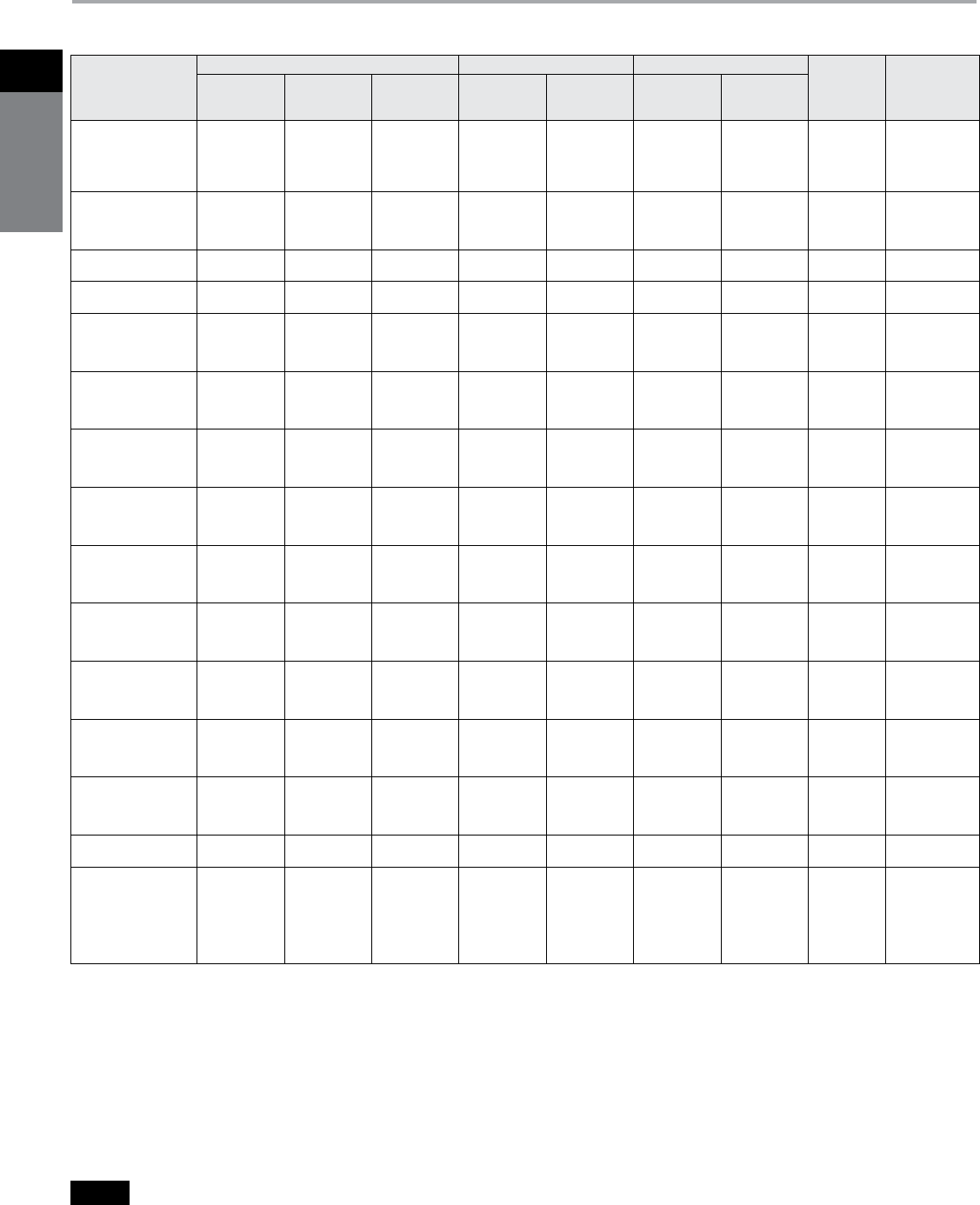
Siemens Canada Limited Power Product Catalogue
1-24
1
safety
switches
General and Heavy Duty Safety Switches
Dimensions
a
Knocks not provided on Type 4/4X and 12 or on 800 & 1200A switches.
Safety Switch Dimensions & Shipping Weights
Catalogue
Number
Height - Inches (mm) Width - Inches (mm) Depth - Inches (mm)
Knockout
Diagrama
Shipping
Weight (lbs.)
Box
A
With
Door
B
With
Rain Shed
C
Box
D
With
Handle
E
Box
F
With
Handle
G
HFC223NS
HFC224NJ
HFC224N
HFC224NR
HFC224NS
21.96 (558)
29.96 (761)
29.90 (760)
29.90 (760)
29.96 (761)
23.16 (508)
31.07 (789)
31.07 (789)
—
31.07 (789)
—
—
—
31.42 (798)
—
9.65 (245)
14.62 (371)
14.62 (371)
14.61 (371)
14.62 (371)
12.02 (305)
16.95 (431)
16.98 (431)
16.99 (432)
16.95 (431)
5.34 (136)
6.63 (168)
6.36 (162)
6.36 (162)
6.63 (168)
10.46 (266)
12.58 (269)
12.33 (313)
12.33 (313)
12.58 (269)
—
—
S12
S13
—
24
48
47
48
48
HFC225N
HFC225NR
HFC226N
HFC226NR
56.00 (1422)
56.07 (1424)
56.00 (1422)
56.07 (1429)
56.57 (1183)
—
56.57 (1183)
—
—
57.19 (1453)
—
57.19 (1453)
24.65 (626)
24.65 (626)
24.65 (626)
24.65 (626)
26.21 (666)
26.70 (678)
26.21 (666)
26.70 (678)
9.23 (234)
9.23 (234)
9.23 (234)
9.23 (234)
14.68 (373)
14.68 (373)
14.68 (373)
14.68 (373)
S14
S15
S14
S15
153
162
155
159
HFC227N
HFC227NR
66.67 (1693)
66.67 (1693)
67.16 (1706)
—
—
67.74 (1721)
38.40 (975)
38.40 (975)
39.96 (1015)
39.96 (1015)
9.24 (235)
9.24 (235)
14.68 (373)
14.68 (373)
—
—
360
362
HFC228N
HFC228NR
66.67 (1693)
66.67 (1693)
67.16 (1706)
—
—
67.74 (1721)
38.40 (975)
38.40 (975)
39.96 (1015)
39.96 (1015)
9.24 (235)
9.24 (235)
14.68 (373)
14.68 (373)
—
—
352
364
HFC265
HFC265J
HFC265R
HFC265S
56.00 (1422)
56.14 (1426)
56.07 (1424)
56.14 (1426)
56.57 (1183)
56.57 (1183)
—
56.57 (1183)
—
—
57.19 (1453)
—
24.65 (626)
24.82 (630)
24.65 (626)
24.82 (630)
26.21 (666)
26.44 (672)
26.70 (678)
26.44 (672)
9.23 (234)
9.19 (233)
9.23 (234)
9.19 (233)
14.68 (373)
14.64 (372)
14.68 (373)
14.64 (372)
S14
—
S15
—
149
155
152
153
HFC266
HFC266J
HFC266R
HFC266S
56.00 (1422)
56.14 (1426)
56.07 (1424)
56.14 (1426)
56.57 (1183)
56.57 (1183)
—
56.57 (1183)
—
—
57.19 (1453)
—
24.65 (626)
24.82 (630)
24.65 (626)
24.82 (630)
26.21 (666)
26.44 (672)
26.70 (678)
26.44 (672)
9.23 (234)
9.19 (233)
9.23 (234)
9.19 (233)
14.68 (373)
14.68 (373)
14.68 (373)
14.68 (373)
S14
—
S15
—
155
156
155
161
HFC321NJ
HFC321N
HFC321NR
HFC321NS
14.27 (363)
14.26 (362)
14.39 (366)
14.27 (363)
17.33 (440)
15.45 (392)
—
17.33 (440)
—
—
15.77 (401)
—
6.65 (169)
6.64 (169)
6.64 (169)
6.65 (169)
9.02 (229)
9.01 (229)
9.01 (229)
9.02 (229)
5.32 (135)
5.05 (128)
5.05 (128)
5.32 (135)
10.46 (266)
10.17 (258)
10.17 (258)
10.46 (266)
—
S6
S8
—
14
14
15
14
HFC322NJ
HFC322N
HFC322NR
HFC322NS
16.27 (413)
16.26 (413)
16.26 (413)
16.27 (413)
19.31 (490)
17.46 (443)
—
19.31 (440)
—
—
17.77 (451)
—
9.17 (233)
9.15 (232)
9.16 (233)
9.17 (233)
11.47 (291)
11.53 (293)
11.53 (293)
11.47 (291)
5.33 (135)
5.05 (128)
5.05 (128)
5.33 (135)
10.46 (266)
10.17 (258)
10.17 (258)
10.46 (266)
—
S16
S17
—
20
19
20
20
HFC323NJ
HFC323N
HFC323NR
HFC323NS
21.96 (558)
21.96 (558)
21.95 (558)
21.96 (558)
23.16 (588)
23.15 (588)
—
23.16 (588)
—
—
23.46 (596)
—
9.65 (245)
6.64 (169)
6.64 (169)
9.65 (245)
12.02 (305)
12.01 (305)
11.97 (304)
12.02 (305)
5.34 (136)
5.05 (128)
5.05 (128)
5.34 (136)
10.46 (266)
10.17 (258)
10.17 (258)
10.46 (266)
—
S10
S 11
—
25
25
26
25
HFC324NJ
HFC324N
HFC324NR
HFC324NS
29.96 (761)
29.90 (760)
29.90 (760)
21.96 (558)
31.07 (789)
31.07 (789)
—
31.07 (789)
—
—
31.42 (798)
—
14.62 (371)
14.62 (371)
14.61 (371)
14.62 (371)
16.95 (431)
16.98 (431)
16.99 (432)
16.95 (431)
6.63 (168)
6.36 (162)
6.36 (162)
6.63 (168)
12.58 (269)
12.33 (313)
12.33 (313)
12.58 (269)
—
S12
S13
—
49
49
50
49
HFC325NJ
HFC325N
HFC325NR
HFC325NS
56.14 (1426)
56.00 (1422)
56.07 (1424)
56.14 (1426)
56.57 (1183)
56.57 (1183)
—
56.57 (1183)
—
—
57.19 (1453)
—
24.82 (630)
24.65 (626)
24.65 (626)
24.82 (630)
26.44 (672)
26.21 (666)
26.70 (678)
26.44 (672)
9.19 (233)
9.23 (234)
9.23 (234)
9.19 (233)
14.64 (372)
14.68 (373)
14.68 (373)
14.64 (372)
S14
S14
S15
—
160
158
162
158
HFC326NJ
HFC326N
HFC326NR
HFC326NS
56.14 (1426)
56.00 (1422)
56.07 (1424)
56.14 (1426)
56.57 (1183)
56.57 (1183)
—
56.67 (1183)
—
—
57.19 (1453)
—
24.82 (630)
24.64 (626)
24.64 (626)
24.82 (630)
26.44 (672)
26.21 (666)
26.70 (678)
26.44 (672)
9.19 (233)
9.23 (234)
9.23 (234)
9.19 (233)
14.64 (372)
14.68 (373)
14.68 (373)
14.64 (372)
—
S14
S15
—
161
161
165
161
HFC327NJ
HFC327N
HFC327NR
HFC327NS
66.67 (1693)
66.67 (1693)
66.67 (1693)
66.67 (1693)
67.16 (1706)
67.16 (1706)
—
67.16 (1706)
—
—
64.74 (1721)
—
38.40 (975)
38.40 (975)
38.40 (975)
38.40 (975)
39.96 (1015)
39.96 (1015)
40.25 (1022)
39.96 (1015)
9.24 (235)
9.24 (235)
9.24 (235)
9.24 (235)
14.68 (373)
14.68 (373)
14.68 (373)
14.68 (373)
—
—
—
—
367
380
383
367
HFC328N
HFC328NR
66.67 (1693)
66.67 (1693)
67.16 (1706)
—
—
67.74 (1721)
38.40 (975)
38.40 (975)
39.96 (1015)
40.25 (1022)
9.24 (235)
9.24 (235)
14.68 (373)
14.68 (373)
—
—
382
385
HFC361
HFC361J, JW, NJW
HFC361N
HFC361NR
HFC361R
HFC361S, SW, NSW
HFC362
14.26 (302)
14.27 (413)
14.26 (362)
14.39 (366)
14.39 (366)
14.27 (413)
16.26 (413)
15.45 (1545)
17.33 (440)
15.45 (1545)
—
—
17.33 (440)
17.46 (443)
—
—
—
15.77 (401)
15.77 (401)
—
—
6.64 (169)
6.65 (245)
6.64 (169)
6.64 (169)
6.64 (169)
6.65 (245)
9.15 (232)
9.01 (229)
9.02 (229)
9.01 (229)
9.01 (229)
9.01 (229)
9.02 (229)
11.53 (313)
5.05 (128)
5.32 (135)
5.05 (128)
5.05 (128)
5.05 (128)
5.32 (135)
5.05 (128)
10.17 (258)
10.46 (266)
10.17 (258)
10.17 (258)
10.17 (258)
10.46 (266)
10.17 (258)
S6
—
S6
S8
S8
—
S16
14
14
14
15
15
15
19

Siemens Canada Limited Power Product Catalogue 1-25
1Safety
SwitcheS
General and Heavy Duty Safety Switches
Dimensions
Safety Switch Dimensions & Shipping Weights
Catalogue
Number
Height - Inches (mm) Width - Inches (mm) Depth - Inches (mm)
Knockout
Diagrama
Shipping
Weight
(lbs.)
Box
A
With
Door
B
With
Rain Shed
C
Box
D
With
Handle
E
Box
F
With
Handle
G
HFC362J, JW, NJW
HFC362N
HFC362NR
HFC362R
HFC362S, SW, NSW
16.27 (413)
16.26 (413)
16.26 (413)
16.26 (413)
16.27 (413)
19.31 (490)
17.46 (444)
—
—
19.31 (490)
—
—
17.77 (457)
17.77 (457)
—
9.17 (233)
9.15 (232)
9.16 (233)
9.16 (233)
9.17 (233)
11.47 (291)
11.53 (293)
11.53 (293)
11.53 (293)
11.47 (291)
5.33 (135)
5.05 (128)
5.05 (128)
5.05 (128)
5.33 (135)
10.46 (266)
10.17 (258)
10.17 (258)
10.17 (258)
10.46 (266)
—
S16
S17
S17
—
20
19
20
20
20
HFC363
HFC363J, JW, NJW
HFC363N
HFC363NR
HFC363R
HFC363S, SW, NSW
21.95 (558)
21.96 (558)
21.95 (558)
21.95 (558)
21.95 (558)
21.96 (558)
23.15 (588)
23.16 (588)
23.15 (588)
—
—
23.16 (588)
—
—
—
23.46 (596)
23.46 (596)
—
9.64 (245)
9.65 (245)
9.64 (245)
9.64 (245)
9.64 (245)
9.65 (245)
12.01 (305)
12.02 (305)
12.01 (305)
11.97 (304)
11.97 (304)
12.02 (305)
5.05 (128)
5.34 (136)
5.05 (128)
5.05 (128)
5.05 (128)
5.34 (136)
10.17 (258)
10.46 (266)
10.17 (258)
10.17 (258)
10.17 (258)
10.46 (266)
S10
—
S10
S 11
S 11
—
24
25
25
26
25
35
HFC364
HFC364J, JW, NJW
HFC364N
HFC364NR
HFC364R
HFC364S, SW, NSW
29.90 (760)
29.96 (761)
29.90 (760)
29.90 (760)
29.90 (760)
29.96 (761)
31.07 (789)
31.07 (789)
31.07 (789)
—
—
31.07 (789)
—
—
—
31.42 (798)
31.42 (798)
—
14.62 (371)
14.62 (371)
14.62 (371)
14.61 (371)
14.61 (371)
14.62 (371)
16.98 (431)
16.95 (431)
16.98 (431)
16.99 (431)
16.99 (431)
16.95 (431)
6.36 (162)
6.63 (168)
6.36 (162)
6.36 (162)
6.36 (162)
6.63 (168)
12.33 (313)
12.58 (320)
12.33 (313)
12.33 (313)
12.33 (320)
12.58 (320)
S12
—
S12
S13
S13
—
48
49
49
48
49
49
HFC365
HFC365J, JW, NJW
HFC365N
HFC365NR
HFC365R
HFC365S, SW, NSW
56.00 (1422)
56.14 (1426)
56.00 (1422)
56.07 (1424)
56.07 (1424)
56.14 (1426)
56.57 (1437)
56.57 (1437)
56.57 (1437)
—
—
56.57 (1437)
—
—
—
57.19 (1453)
57.19 (1453)
—
24.65 (626)
24.82 (630)
24.65 (626)
24.65 (626)
24.65 (626)
24.82 (630)
26.21 (666)
26.44 (672)
26.21 (666)
26.70 (678)
26.70 (678)
26.44 (672)
9.23 (234)
9.19 (233)
9.23 (234)
9.23 (234)
9.23 (234)
9.19 (233)
14.68 (373)
14.64 (372)
14.68 (373)
14.68 (373)
14.68 (373)
14.64 (372)
S14
—
S14
S15
S15
—
154
160
158
162
157
158
HFC366
HFC366J, JW, NJW
HFC366N
HFC366NR
HFC366R
HFC366NS
56.00 (1422)
56.14 (1426)
56.00 (1422)
56.07 (1424)
56.07 (1424)
56.14 (1426)
56.57 (1437)
56.57 (1437)
56.57 (1437)
—
—
56.57 (1437)
—
—
—
57.19 (1453)
57.19 (1453)
—
24.64 (626)
24.82 (630)
24.65 (626)
24.65 (626)
24.65 (626)
24.82 (630)
26.21 (666)
26.44 (672)
26.21 (666)
26.70 (678)
26.70 (678)
26.44 (672)
9.23 (234)
9.19 (233)
9.23 (234)
9.23 (234)
9.23 (234)
9.19 (233)
14.68 (373)
14.64 (372)
14.68 (373)
14.68 (373)
14.68 (373)
14.64 (372)
S14
—
S14
S15
S15
—
157
161
161
165
161
161
HFC367
HFC367NJ
HFC367N
HFC367NR
HFC367R
HFC367NS
66.67 (1693)
66.67 (1693)
66.67 (1693)
66.67 (1693)
66.67 (1693)
66.67 (1693)
67.16 (1706)
67.16 (1706)
67.16 (1706)
—
—
67.16 (1706)
—
—
—
67.74 (1712)
67.74 (1712)
—
38.40 (975)
38.40 (975)
38.40 (975)
38.40 (975)
38.40 (975)
38.40 (975)
39.96 (1015)
39.96 (1015)
39.96 (1015)
40.25 (1022)
40.25 (1022)
39.96 (1015)
9.24 (234)
9.24 (234)
9.24 (234)
9.24 (234)
9.24 (234)
9.24 (234)
14.68 (373)
14.68 (373)
14.68 (373)
14.68 (373)
14.68 (373)
14.68 (373)
—
—
—
—
—
—
380
380
382
386
382
380
HFC368, NS, NS
HFC368N
HFC368NR
HFC368R
66.67 (1693)
66.67 (1693)
66.67 (1693)
66.67 (1693)
67.16 (1706)
67.16 (1706)
—
—
—
—
67.74 (1712)
67.74 (1712)
38.40 (975)
38.40 (975)
38.40 (975)
38.40 (975)
39.96 (1015)
39.96 (1015)
40.25 (1022)
40.25 (1022)
9.24 (234)
9.24 (234)
9.24 (234)
9.24 (234)
14.68 (373)
14.68 (373)
14.68 (373)
14.68 (373)
—
—
—
—
383
385
388
385
HNFC265
HNFC265J
HNFC265R
HNFC265S
44.00 (1118)
44.14 (1121)
44.07 (1119)
44.14 (1121)
44.57 (1132)
44.57 (1132)
—
44.57 (1132)
—
—
45.19 (1148)
—
24.65 (626)
24.82 (630)
24.64 (626)
24.82 (630)
26.21 (666)
26.44 (672)
26.70 (678)
26.44 (672)
9.23 (234)
9.19 (233)
9.23 (234)
9.19 (233)
14.68 (373)
14.64 (372)
14.68 (373)
14.64 (372)
S14
—
S15
—
109
119
118
118
HNFC266
HNFC266J
HNFC266R
HNFC266S
44.00 (1118)
44.14 (1121)
44.07 (1119)
44.14 (1121)
44.57 (1132)
44.57 (1132)
—
44.57 (1132)
—
—
45.19 (1148)
—
24.65 (626)
24.82 (630)
24.64 (626)
24.82 (630)
26.21 (666)
26.44 (672)
26.70 (678)
26.44 (672)
9.23 (234)
9.19 (233)
9.23 (234)
9.19 (233)
14.68 (373)
14.64 (372)
14.68 (373)
14.64 (372)
S14
—
S15
—
111
115
120
115
HNFC361
HNFC361J, JW
HNFC361R
HNFC361S, SW
HNFC362
HNFC362J, JW
HNFC362R
HNFC362S, SW
11.11 (282)
11.12 (282)
11.11 (282)
11.12 (282)
16.26 (413)
16.27 (413)
16.26 (413)
16.27 (413)
12.31 (313)
14.14 (359)
—
14.14 (339)
17.46 (444)
17.46 (444)
—
17.46 (444)
—
—
12.63 (321)
—
—
—
17.77 (451)
—
6.64 (169)
6.65 (169)
6.64 (169)
6.65 (169)
9.15 (232)
9.17 (232)
9.16 (233)
9.17 (233)
9.01 (229)
9.02 (229)
9.01 (229)
9.02 (229)
11.53 (293)
11.47 (291)
11.53 (293)
11.47 (291)
5.05 (128)
5.56 (141)
5.05 (128)
5.56 (141)
5.05 (128)
5.33 (135)
5.05 (128)
5.33 (135)
10.17 (258)
10.46 (266)
10.17 (258)
10.46 (266)
10.17 (258)
10.46 (266)
10.17 (258)
10.46 (266)
S7
—
S9
—
S16
—
S17
—
12
13
13
13
18
19
19
19
HNFC363
HNFC363J, JW
HNFC363R
HNFC363S, SW
21.95 (558)
21.95 (558)
21.95 (558)
21.96 (558)
23.15 (588)
23.16 (588)
—
23.16 (588)
—
—
23.46 (596)
—
9.64 (245)
9.65 (245)
9.64 (245)
9.65(245)
12.01 (305)
12.02 (305)
11.97 (304)
12.02 (305)
5.05 (128)
5.34 (136)
5.05 (128)
5.34 (136)
10.17 (258)
10.46 (266)
10.17 (258)
10.46 (266)
S10
—
S 11
—
23
24
24
24
HNFC364
HNFC364J, JW
HNFC364R
HNFC364S, SW
29.90 (760)
29.96 (761)
29.90 (760)
29.96 (761)
31.07 (789)
31.07 (789)
—
31.07 (789)
—
—
31.42(798)
—
14.62(371)
14.62(371)
14.61(371)
14.62(371)
16.98 (431)
16.95 (431)
16.99 (431)
16.95 (431)
6.36 (162)
6.63 (168)
6.36 (162)
6.63 (168)
12.33 (313)
12.58 (320)
12.33 (313)
12.58 (320)
S12
—
S13
—
46
47
47
47
a
Knocks not provided on Type 4 / 4X and 12 or on 800 & 1200A switches.
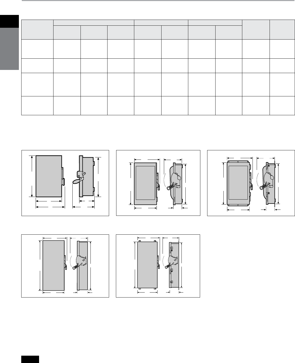
Siemens Canada Limited Power Product Catalogue
1-26
1
safety
switches
General and Heavy Duty Safety Switches
Dimensions
Safety Switch Dimensions & Shipping Weights
Catalogue
Number
Height - Inches (mm) Width - Inches (mm) Depth - Inches (mm)
Knockout
Diagrama
Shipping
Weight
(lbs.)
Box
A
With
Door
B
With
Rain Shed
C
Box
D
With
Handle
E
Box
F
With
Handle
G
HNFC365
HNFC365J, JW
HNFC365R
HNFC365S, SW
44.00 (1118)
44.14 (1121)
44.07 (1119)
44.14 (1121)
44.57 (1132)
44.57 (1132)
—
44.57 (1132)
—
—
45.19 (1148)
—
24.65 (626)
24.82 (630)
24.65 (626)
24.82 (630)
26.21 (626)
26.44 (672)
26.95 (685)
26.44 (672)
9.23 (234)
9.19 (233)
9.23 (234)
9.19 (233)
14.68 (373)
14.64 (372)
14.68 (373)
14.64 (372)
S14
—
S15
—
114
114
118
118
HNFC366
HNFC366J, S
HNFC366R
44.00 (1118)
44.14 (1121)
44.07 (1119)
44.57 (1132)
44.57 (1132)
—
—
—
45.19 (1148)
24.65 (626)
24.82 (630)
24.65 (626)
26.21 (626)
26.44 (672)
26.95 (685)
9.23 (234)
9.19 (233)
9.23 (234)
14.68 (373)
14.64 (372)
14.68 (373)
S14
—
S15
116
115
120
HNFC367, J
HNFC367R
HNFC367S
HNFC368, J
HNFC368R
54.67 (1389)
54.67 (1389)
54.67 (1389)
54.67 (1389)
54.67 (1389)
55.16 (1401)
—
55.16 (1401)
55.16 (1401)
55.16 (1401)
—
55.70 (1515)
—
—
—
38.40 (975)
38.40 (975)
38.40 (975)
38.40 (975)
38.40 (975)
39.96 (1015)
40.25 (1022)
39.96 (1015)
39.96 (1015)
40.25 (1022)
9.24 (235)
9.24 (235)
9.24 (235)
9.24 (235)
9.24 (235)
14.68 (373)
14.68 (373)
14.68 (373)
14.68 (373)
14.68 (373)
—
—
—
—
—
302
304
302
305
307
LFC11N
LFC211N
LFC211NR
LNFC222R
7.97 (202)
7.97 (202)
8.07 (205)
8.07 (205)
8.13 (207)
8.13 (207)
—
—
—
—
8.16 (207)
8.16 (207)
5.50 (140)
5.50 (140)
5.16 (131)
5.16 (131)
5.94 (151)
5.94 (151)
5.94 (151)
5.94 (151)
3.00 (76)
3.00 (76)
3.13 (80)
3.13 (80)
5.38 (137)
5.38 (137)
5.38 (137)
5.38 (137)
S2
S1
S3
S5
36j
35j
35j
35j
B
or
C
A
D
E
F
G
B
or
C
A
D
E
F
G
B
or
C
A
D
E
F
G
Type 1 or 3R
30A GD Type VBII, LFC & LNFC
Type 1 or 3R
60-200A GD, 30-200A HD Type VBII
Type 4/4X or 12
30-200A HD Type VBII
B
or
C
A
D
E
F
G
B
or
C
A
D
E
F
G
Type 1 or 3R
400-1200A HD Type VBII
Type 4/4X or 12
400-1200A HD Type VBII
a
Knocks not provided on Type 4 / 4X and 12 or on 800 & 1200A switches.
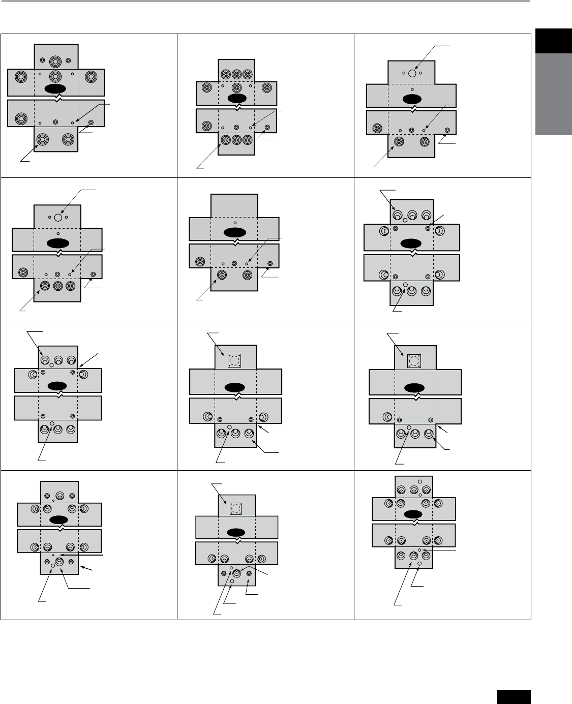
Siemens Canada Limited Power Product Catalogue 1-27
1Safety
SwitcheS
General and Heavy Duty Safety Switches
Knockout Diagrams
* For inches / millimeters conversion, multiply inches by 25.4.
4 K.O.'s for
Conduit 0.5-0.75 in.
7 K.O.'s for Conduit 0.5-0.75-1 in.
Embossed .25 in.
mounting holes
(4 places)
S1
4 K.O.'s for Conduit
0.75, 1 in.
2 0.25 dia. K.O's
8 K.O.'s for Conduit
0.50, 0.75, 1 in.
S7
S2
10 K.O.'s for Conduit 0.5-0.75-1 in.
2 K.O.'s for
Conduit 0.5-0.75 in.
Embossed .25 in.
mounting holes
(4 places)
2 K.O.'s for Conduit
0.75, 1 in.
1 0.25 dia. K.O.
Removable plate covering
HS Type Hub opening
(Max. 2.5 Conduit)
S8
5 K.O.'s for Conduit
0.50, 0.75, 1 in.
S3
Removable
plate covering
HA Type
Hub opening
(Max. 1.25 Conduit)
Embossed .25 in.
mounting holes
(3 places)
2 K.O.'s for
Conduit 0.5-0.75 in.
3 K.O.'s for Conduit 0.5-0.75-1 in.
2 K.O.'s for Conduit
0.75, 1 in.
1 0.25 dia. K.O.
Removable plate covering
HS Type Hub opening
(Max. 2.5 Conduit)
S9
5 K.O.'s for Conduit
0.50, 0.75, 1 in.
1 0.88 dia. K.O.
S10
10 K.O.'s for Conduit
1, 1.25, 1.50, 2 in.
4 K.O.'s for Conduit
0.75, 1, 1.25, 1.50 in.
2 0.25 dia. K.O.
2 K.O.'s for Conduit
0.75, 1, 1.25, 1.50 in.
1 0.25 dia. K.O.
Removable plate covering
HS Type Hub opening
(Max. 2.5 Conduit)
S11
1 0.88 dia. K.O.
5 K.O.'s for Conduit
1, 1.25, 1.50, 2 in.
14 K.O.'s for Conduit
1.25, 1.50, 2.00, 2.50 in.
S12
1 0.88 dia. K.O.
1 0.25 dia. K.O.
Type 1 & 3R Enclosures
S4
Removable
plate covering
HA Type
Hub opening
(Max. 1.25 Conduit)
Embossed .25 in.
mounting holes
(3 places)
2 K.O.'s for
Conduit 0.5-0.75 in.
4 K.O.'s for Conduit 0.5-0.75-1 in.
S5 Embossed .25 in.
mounting holes
(3 places)
2 K.O.'s for
Conduit 0.5-0.75 in.
3 K.O.'s for Conduit 0.5-0.75-1 in.
4 K.O.'s for Conduit
0.75, 1 in.
2 0.25 dia. K.O's
10 K.O.'s For Conduit
0.50, 0.75, 1 in.
S6
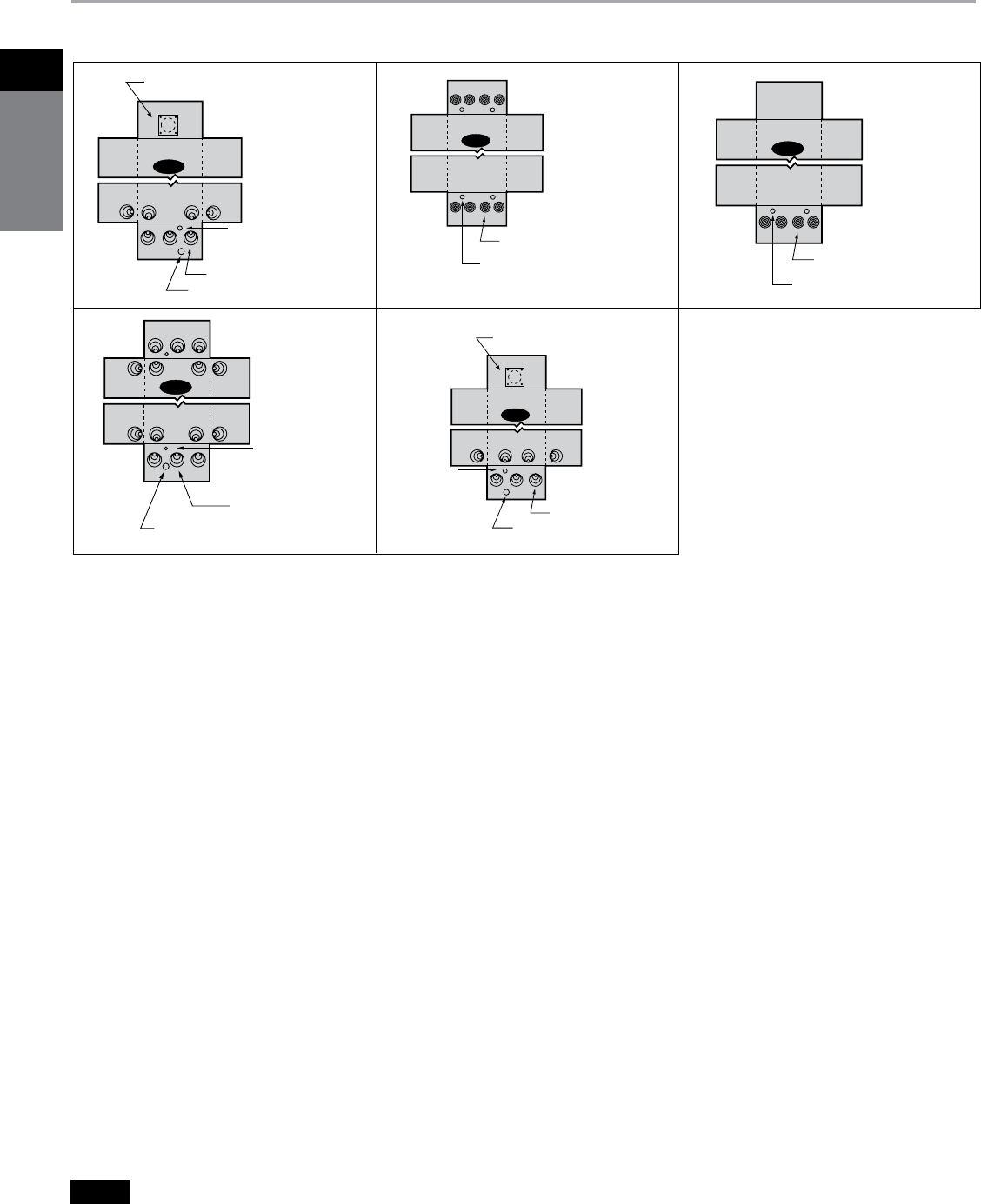
Siemens Canada Limited Power Product Catalogue
1-28
1
safety
switches
Siemens / Speedfax Previous folio: 1-18
General and Heavy Duty Safety Switches
Knockout Diagrams
* For inches / millimeters conversion, multiply inches by 25.4.
Type 1 & 3R Enclosures
7 K.O.'s for Conduit
1.25, 1.50, 2.00, 2.50 in.
Removable plate covering
HS Type Hub opening
(Max. 2.5 Conduit)
S13
1 0.88 dia K.O.
1, 0.25, dia. K.O 8 K.O.'s for Conduit
2.00, 2.50, 3.00, 3.50 in.
S14
4 0.50, 0.75 dia. K.O.'s
4 K.O.'s for Conduit
2.00, 2.50, 3.00, 3.50 in.
S15
2 0.50, 0.75 dia. K.O.'s
1 0.88 dia. K.O.
S16
14 K.O.'s for Conduit
0.50, 0.75, 1, 1.25 in.
2 0.25 dia. K.O.
7 K.O.'s for Conduit
0.50, 0.75, 1, 1.25 in.
Removable plate covering
HS Type Hub opening
(Max. 2.5 Conduit)
S17
1 0.88 dia. K.O.
1 0.25 dia. K.O.
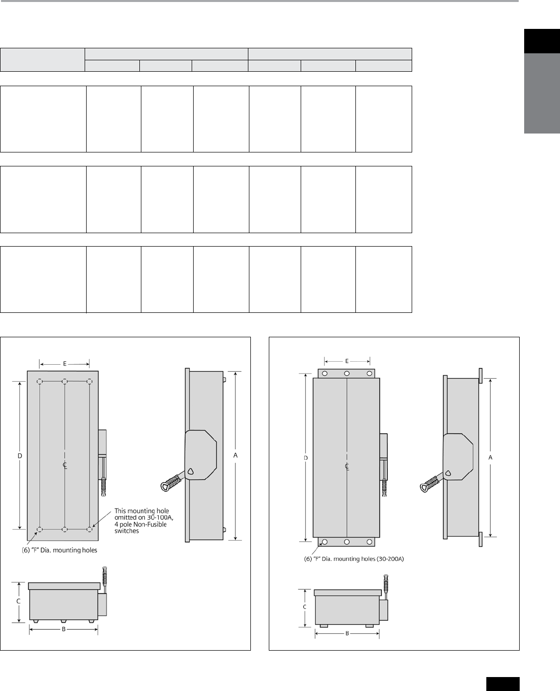
Siemens Canada Limited Power Product Catalogue 1-29
1Safety
SwitcheS
Special Application Safety Switches Dimension Drawings
4-Pole & 6-Pole
Dimensions
Enclosure - Inches (mm) Mounting - Inches (mm)
Catalogue Number A B C D E F
Figure 1, 4-Pole Fusible and Non-fusible, Type 1
4 & 6-Pole Safety Switch Dimensions
HNF461 24.50 (622) 9.53 (242) 6.09 (155) 19.00 (483) 6.75 (171) 0.268 (7)
HF461 29.12 (740) 9.53 (242) 6.09 (155) 23.50 (597) 6.75 (171) 0.268 (7)
HNF462 24.88 (632) 11.50 (292) 6.09 (155) 19.00 (483) 9.38 (238) 0.268 (7)
HF462 33.53 (852) 11.50 (292) 6.09 (155) 27.50 (699) 9.38 (238) 0.268 (7)
HNF463 27.62 (702) 12.18 (309) 6.09 (155) 19.36 (492) 8.00 (203) 0.268 (7)
HF463 36.44 (926) 12.18 (309) 6.09 (155) 28.11 (714) 8.00 (203) 0.268 (7)
HNF464 36.00 (914) 19.12 (486) 6.42 (163) 30.88 (784) 15.00 (381) 0.44 (11)
HF464 49.48 (1257) 19.12 (486) 6.42 (163) 45.50 (1130) 15.00 (381) 0.44 (11)
Figure 2, 4 & 6-Pole Fusible Type 12/3R and 4X
HF461J, HF661J, 29.50 (622) 9.53 (242) 6.48 (165) 31.65 (804) 5.47 (139) 0.27 (7)
HF661S
HF462J, HF662J, 33.53 (852) 11.50 (292) 6.48 (165) 35.69 (907) 8.00 (203) 0.27 (7)
HF662S
HF463J, HF663J, 36.44 (926) 12.18 (309) 6.48 (165) 38.67 (982) 8.47 (215) 0.27 (7)
HF663S
HF464J, HF664J, 49.48 (1257) 19.12 (486) 6.78 (172) 51.64 (1312) 13.44 (341) 0.33 (8)
HF664S
Figure 2, 4 & 6-Pole Non-fusible Type 12/3R and 4X
HNF461J, HNF661J, 24.50 (622) 9.53 (242) 6.48 (165) 26.65 (667) 5.47 (139) 0.27 (7)
HNF661S
HNF462J, HNF662J, 24.88 (632) 11.50 (292) 6.48 (165) 27.03 (687) 8.00 (203) 0.27 (7)
HNF662S
HNF463J, HNF663J, 27.54 (700) 12.18 (309) 6.48 (165) 29.77 (756) 8.47 (215) 0.27 (7)
HNF663S
HNF464J, HNF664J, 36.00 (914) 19.12 (486) 6.78 (172) 38.16 (969) 13.44 (341) 0.33 (8)
HNF664S
Figure 1: Type 1 Figure 2 : Type 12/3R and 4X

Siemens Canada Limited Power Product Catalogue
1-30
1
safety
switches
Safety Switches
Cross References for SE and ID switches
a
Solid neutral factory installed. b
No viewing window.
System
Ampere
Rating
Indoor — Type 1
Catalogue Number VBII Cross Reference
General Duty 240 Volt Fusible
2-Pole, 2-Fuse, Service Entrance and Solid Neutral
30
60
100
200
SE221
SE222
SE223
SE224
GFC221N
GFC222N
GFC223N
GFC224N
3-Pole, 3-Fuse, Service Entrance and Solid Neutral
30
60
100
200
SE321
SE322
SE323
SE324
GFC321N
GFC322N
GFC323N
GFC324N
System
Ampere
Rating
Indoor — Type 1 Type 12 Industrial Type 4/4X Stainless
Catalogue Number
VBII Cross
Reference Catalogue Number
VBII Cross
Reference Catalogue Number VBII Cross Reference
Fusible Heavy Duty
2-Pole, 2-Fuse and Solid Neutral 240 Volt / 250 Volt DC
30
60
100
200
400
600
—
—
—
—
ID225
ID226
—
—
—
—
HFC225N
HFC226N
12ID221
12ID222
12ID223
12ID224
12ID225
12ID226
HFC221NJ + HNC612
HFC222NJ + HNC623
HFC223NJ + HNC623
HFC224NJ + HNC64
HFC325NJ + HNC656
HFC326NJ + HNC656
4ID221
4ID222
4ID223
4ID224
—
—
HFC221NS + HNC612
HFC222NS + HNC623
HFC223NS + HNC623
HFC224NS + HNC64
—
—
3-Pole, 3-Fuse 240 Volt / 250 Volt DC
30
60
100
200
400
600
ID321
ID322
ID323
ID324
ID425
ID426
HFC321Na
HFC322Na
HFC323Na
HFC324Na
HFC325Na
HFC326Na
12ID321
12ID322
12ID323
12ID324
12ID425
12ID426
HFC321NJab
HFC322NJab
HFC323NJab
HFC324NJab
HFC325NJab
HFC326NJab
4ID321
4ID322
4ID323
4ID324
—
—
HFC321NS + HNC612ab
HFC322NS + HNC623ab
HFC323NS + HNC623ab
HFC324NS + HNC64ab
—
—
System
Ampere
Rating
Indoor — Type 1 Type 12 Industrial Type 4/4X Stainless Type 12 with Receptacle Type 4/4X with Receptacle
Catalogue
Number
VBII Cross
Reference
Catalogue
Number
VBII Cross
Reference
Catalogue
Number
VBII Cross
Reference
Catalogue
Number
VBII Cross
Reference
Catalogue
Number
VBII Cross
Reference
Fusible Heavy Duty
3-Pole, 3-Fuse 480 Volt AC / 600 Volt AC / 250 Volt DC
30
60
100
200
400
600
ID361
ID362
ID363
ID364
ID365
ID366
HFC361
HFC362
HFC363
HFC364
HFC365
HFC366
12ID361
12ID362
12ID363
12ID364
12ID365
12ID366
HFC361JW
HFC362JW
HFC363JW
HFC364JW
HFC365JW
HFC366JW
4ID361
4ID362
4ID363
4ID364
—
—
HFC361SW
HFC362SW
HFC363SW
HFC364SW
—
—
12ID361W
12ID362W
12ID363W
—
—
—
HF361JCHW
HF362JCHW
HF363JCHW
—
—
—
4ID361W
4ID362W
—
—
—
—
HF361SCHW
HF362SCHW
—
—
—
—
Non-Fusible Heavy Duty
3-Pole, 3-Fuse 480 Volt AC / 600 Volt AC / 250 Volt DC
30
60
100
200
400
600
ID361NF
ID362NF
ID363NF
ID364NF
ID365NF
ID366NF
HNFC361
HNFC362
HNFC363
HNFC364
HNFC365
HNFC366
12ID361NF
12ID362NF
12ID363NF
12ID364NF
12ID365NF
12ID366NF
HNFC361JW
HNFC362JW
HNFC363JW
HNFC364JW
HNFC365JW
HNFC366Jb
4ID361NF
4ID362NF
4ID363NF
4ID364NF
—
—
HNFC361SW
HNFC362SW
HNFC363SW
HNFC364SW
—
—
12ID361NFW
12ID362NFW
12ID363NFW
—
—
—
HNF361JCHW
HNF362JCHW
HNF363JCHW
—
—
—
4ID361NFW
4ID362NFW
—
—
—
—
HNF361SCHW
HNF362SCHW
—
—
—
—
SE Switch ID Switch
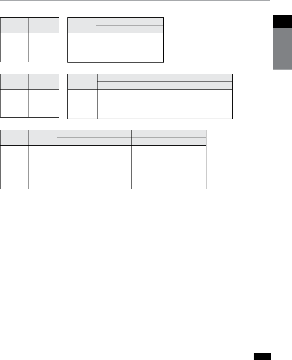
Siemens Canada Limited Power Product Catalogue 1-31
1Safety
SwitcheS
a
Auxiliary contacts for ID safety switches are of a positive action design
and meet CSA standards & section 38 of the Canadian Electrical Code.
Industrial Duty Safety Switches
Replacement parts for ID switches
Selection
Neutral Kits Auxiliary Contacts
Lug Size Data ID switches
Switch
Ampere
Rating
Neutral Kit for
ID Switches
30
60
100
200
400
600
N60
N60
N100
N200
N400ID
N600ID
Switch
Ampere
Rating
Aux. Contact Kit for ID Switchesa
1NO-1NC 2NO-2NC
30
60
100
200
400
600
MSSAK116
MSSAK116
MSSAK116
MSSAK126
—
—
MSSAK216
MSSAK216
MSSAK216
MSSAK226
—
—
Fuse Conversion Kits
Switch
Ampere
Rating
Conversion Kits for HRCI-R and HRCI-T
HRCI-R 240V HRCI-R 600V HRCI-T 240V HRCI-T 600V
30
60
100
200
400
600
RFAK21b
RFAK22
RFAK3
RFAK4
—
—
RFAK61
RFAK62
RFAK3
RFAK4
—
—
—
—
TFAK32
TFAK42
TFAK52
TFAK62
—
—
TFAK35
TFAK45
TFAK55
TFAK65
Fuse Puller
Switch
Ampere
Rating
Fuse Puller
Kits for
ID switches
30
60
100
200
400
600
FP2
FP2
FP3
FP4
—
—
Switch
Ampere
Rating
Number of
Lugs per pole
Line, Load Neutral
Wire range Al/Cu Wire range Al/Cu
30
60
100
200
1
1
1
1
(1) #14 AWG - #2 AWG
(1) #14 AWG - #2 AWG
(1) #6 AWG - 2/0 AWG
(1) #6 AWG - 300 Kcmil
(1) #14 AWG - #2 AWG
(1) #14 AWG - #2 AWG
(1) #14 AWG - 2/0 AWG
(1) #14 AWG - 300 Kcmil
400 1 (1) 1/0 AWG - 750 Kcmil or
(2) 1/0 AWG - 250 Kcmil
(1) 1/0 AWG - 750 Kcmil or
(2) 1/0 AWG - 250 Kcmil
600 2 (1) 1/0 AWG - 750 Kcmil or
(2) 1/0 AWG - 250 Kcmil
(1) 1/0 AWG - 750 Kcmil or
(2) 1/0 AWG - 250 Kcmil
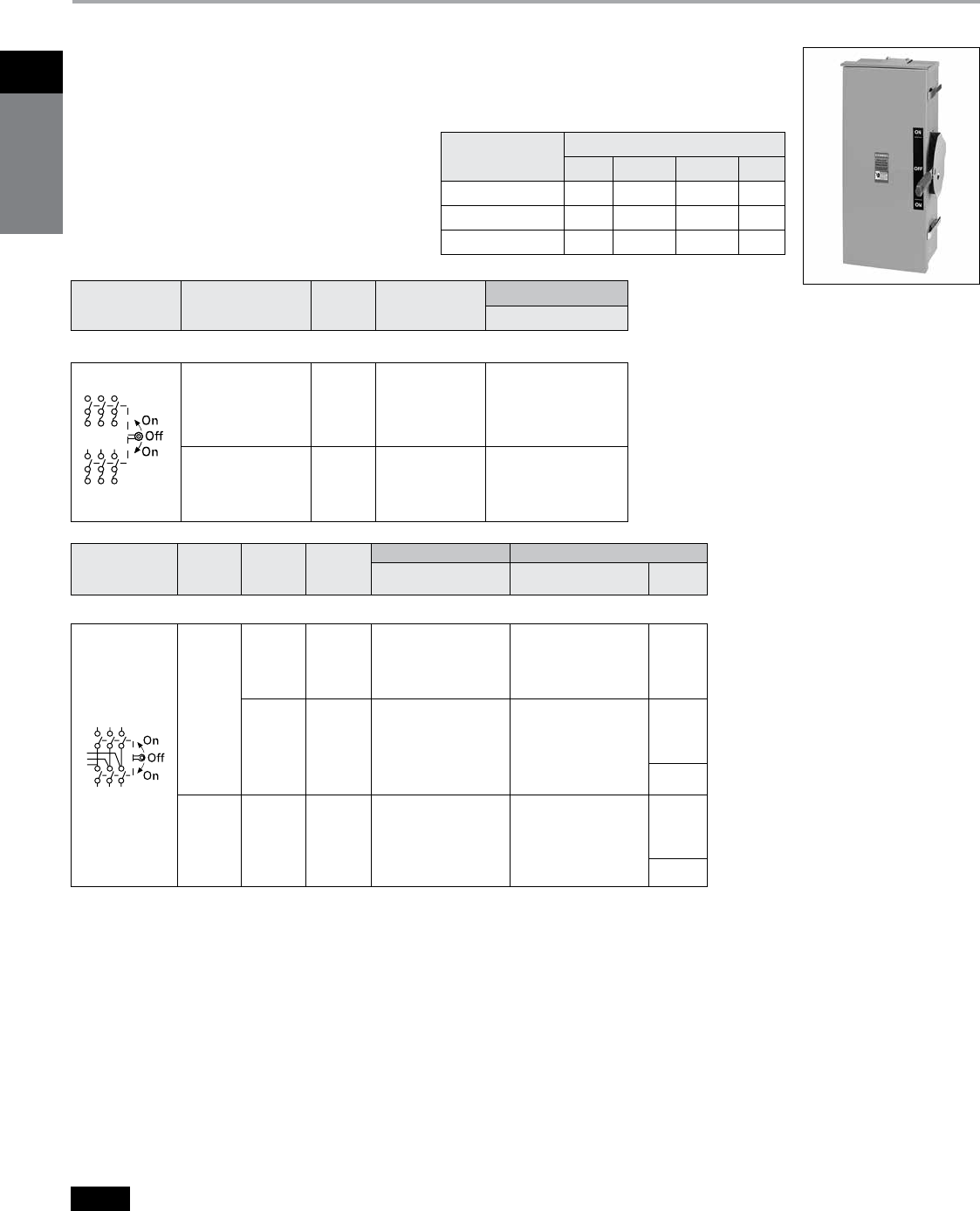
Siemens Canada Limited Power Product Catalogue
1-32
1
safety
switches
Special Application Safety Switches Dimension Drawings
Double Throw
Selection
Description
Double throw switches are intended to transfer loads
from one power source to another. All 2 & 3-pole
double throw switches are CSA certified and both
horsepower and load break rated. Switches are rated
for use on systems up to 10,000A when protected
with Class H fuses or 200,000A when protected with
Class R or Class T fuses
b
.
They can also be used to
connect a single source of power to either of two
loads. In this application it is necessary to field modify
fusible switches so that the fuses are on the load side
of the switching mechanism.
A cover interlock is provided on all ampere ratings. The
operating handle may be padlocked in the off position.
Double Throw Switches
a
Hub catalogue number available p.1-33
b
All Heavy Duty double throw switches with a catalogue
number starting with “DT” are rated 200,000 AIC max.
when protected by Class R, J or T fuses. Fuse ampere
rating must not exceed switch ampere rating.
c
Move load base.
* Consult Siemens representative, 400A and larger
Switches do not have hub provisions.
System Voltage
Number
of Poles Amps
Type 1 — Indoor
Catalogue Number
Heavy Duty Fusible (30-200A) with Class H fuse spacings — Less Neutralb
240
Volt AC
or
250
Volt DC
3
30
60
100
200
DTFC321
DTFC322
DTFC323
DTFC324
600
Volt AC,
250
Volt DC
3
30
60
100
200
DTFC361
DTFC362
DTFC363
DTFC364
Fuse Capabilities of Fusible DT Switches
System Voltage
Number
of Poles Amps
Type 1 — Indoor Type 3R — Outdoor a
Catalogue Number Catalogue Number
Hub
Typea
Heavy Duty Non-Fusible —Less Neutralb
240
Volt AC
or
250
Volt DC
2
30 DTNFC221 —
*
60 DTNFC222 —
100 DTNFC323 —
200 DTNFC224 —
400 DTNFC225 DTNFC225R
3
30 DTNFC321 —
60 DTNFC322 — ECHS
100 DTNFC323 DTNFC323R
200 DTNFC324 DTNFC324R
400 DTNFC325 —
600 DTNFC326 — *
600
Volt AC,
or
250
Volt DC
3
30 DTNFC361 DTNFC361R
60 DTNFC362 DTNFC362R ECHS
100 DTNFC363 DTNFC363R
200 DTNFC364 DTNFC364R
400 DTNFC365 DTNFC365R
600 DTNFC366 DTNFC366R *
Amp
Rating
Fuse Type
H R T J
30 & 60A, 240V Std Yes (kit) No No
30 & 60A, 600V Std Yes (kit) No Yesc
100 & 200A Std Yes (kit) Yes (kit) Yesc
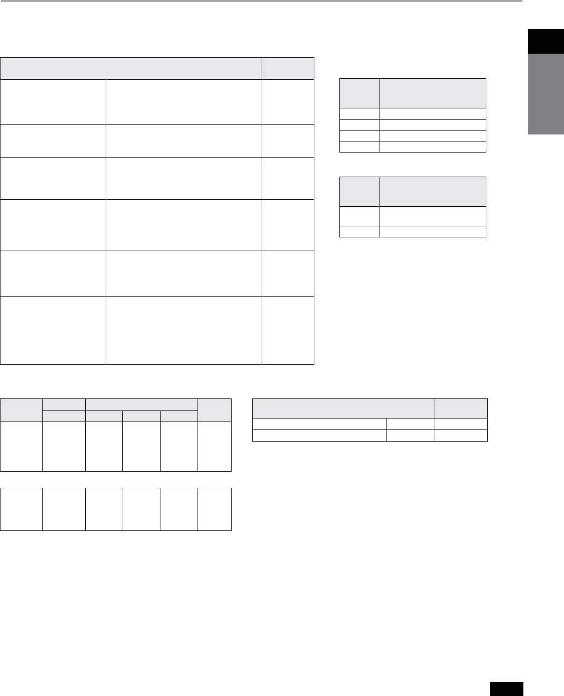
Siemens Canada Limited Power Product Catalogue 1-33
1Safety
SwitcheS
Safety Switches
Double Throw
Selection
Accessories, Lug Data and Horsepower Ratings Wire Ranges (Line, Load
and Neutral) per CEC
Requirements
a
For “DT” VBII Type switches only. b
One aux. required for normal and one required for
emergency switch line base.
Accessories – 2 and 3-Pole Switches Type “DT” Only
a
Maximum Horsepower Ratings
Fused
Ampere 1-Phase AC 3-Phase AC 250V
Rating 240V 240V 480V 600V DC
0 30 03 071/2 015 020 05
0 60 10 15 030 050 10
100 15 30 060 075 20
200 15 60 125 150 40
400 — 125 125 125 50
600 — 125 — — 50
Non-Fused
0 30 05 10 020 030 05
0 60 10 20 050 060 10
100 15 40 075 100 20
200 15 60 125 150 40
400-600 — 125 250 350 50
Replacement Parts – 2 and 3-Pole Switches Only
a
Catalogue
Description Number
Type 1, 3R Replacement Handle 30-200A
HHD61234
Replacement Handle 400-600A HHD656
Switch Wire Range (Cu/Al)
Ampere DT VBII Design
Rating Line, Load and Neutral
0 30 (1) #14–6
060 (1) #14–2
100 (1) #14–1/0 AWG
200 (1) #6–250 kcmil
30-200A – 2 & 3-Pole Switches
Switch Wire Range (Cu/Al)
Ampere DT VBII Design
Rating Line, Load and Neutral
400 (1) 1/0 AWG–750 kcmil or
(2) 1/0 AWG–250 kcmil
600 (2) 1/0 AWG–500 kcmil
400-600A – 2 & 3-Pole Switches
Description
Catalogue
Number
Neutral Kits
30
60 & 100A
200A
400 & 600A
HNC612
HNC263
HNC264
HNC678
Equipment Ground Kit 30-200A (2) #14-4 AWG
400 & 600A (4) #14-2/0
HG61234
HG656
Auxiliary Contacts (HD Only)
(two required per switch)b
30-200A with (1) NO & (1) NC contact
30-200A with (2) NO & (2) NC contact
400-600A with (1) NO & (1) NC contact
400-600A with (2) NO & (2) NC contact
HA161234
HA261234
HA165678
HA265678
Class R Fuse Clip Kits
(two required per switch)
30A, 240V Kit
30A, 600V Kit and 60A, 240V Kit
60A, 600V Kit
100A Kit
200A Kit
HR21
HR612
HR62
HR63
HR64
Class T Fuse Adapter Kits
(two required per pole)
100A, 240V Kit
100A, 600V Kit
200A, 240V Kit
200A, 600V Kit
HT23
HT63
HT24
HT64
Type 3R Hubs (20-200A)
For 3/4” Conduit
For 1” Conduit
For 1 1/4” Conduit
For 1 1/2” Conduit
For 2” Conduit
For 2 1/2” Conduit
ECHS075
ECHS100
ECHS125
ECHS150
ECHS200
ECHS250
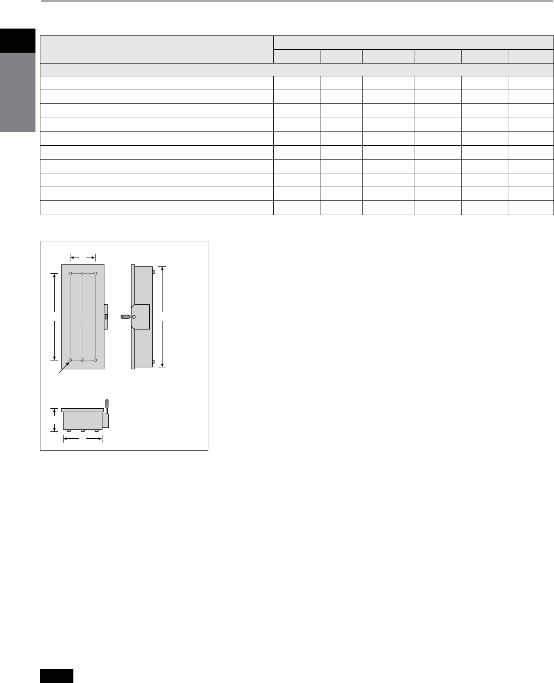
Siemens Canada Limited Power Product Catalogue
1-34
1
safety
switches
Safety Switches
Dimensions
a
Drip hood not shown but provided on
Type 3R enclosures.
VBII Design Double Throw Dimensions
Figure 1
Type 1 & 3R
a
B
E
D
C
C
L A
(6) “F” dia. mounting holes (30-200A)
(4) “F” dia. mounting holes (400-600A)
B
E
D
C
A
(6) “F” dia. mounting holes (30-200A)
(4) “F” dia. mounting holes (400-1200A)
C
L
Catalogue Number
Enclosure dimensions - Inches (mm)
A B C D E F
Figure 1 (30-600A Type 1 & 3R)
DTNFC221, DTNFC321, DTNFC361, DTNFC361R 24.50 (622) 9.53 (242) 6.09 (155) 19.00 (483) 6.75 (171) 0.268 (7)
DTFC321, DTFC321R, DTFC361 29.12 (740) 9.53 (242) 6.09 (155) 23.50 (597) 6.75 (171) 0.268 (7)
DTNFC222, DTNFC322, DTNFC362, DTNFC362R 24.88 (632) 11.50 (292) 6.09 (155) 19.00 (483) 9.38 (238) 0.268 (7)
DTFC322, DTFC362 33.45 (852) 11.50 (292) 6.09 (155) 27.50 (699) 9.38 (238) 0.268 (7)
DTNFC223, DTNFC323, DTNFC323R, DTNFC363, DTNFC363R 27.62 (702) 12.18 (309) 6.09 (155) 19.36 (492) 8.00 (203) 0.268 (7)
DTFC323, DTFC363 36.44 (926) 12.18 (309) 6.09 (155) 28.11 (714) 8.00 (203) 0.268 (7)
DTNFC224, DTNFC224R, DTNFC324, DTNFC324R, DTNFC364, DTNFC364R 36.00 (914) 19.12 (486) 6.42 (163) 31.00 (787) 15.00 (381) 0.44 (11)
DTFC324, DTFC364 49.44 (1256) 19.12 (486) 6.42 (163) 44.50 (1130) 15.00 (381) 0.44 (11)
DTNFC225, DTNFC225R, DTNFC325, DTNFC365, DTNFC365R 57.71 (1466) 28.22 (717) 9.44 (240) 49.75 (1264) 16.00 (406) 0.56 (14)
DTNFC326, DTNFC366, DTNFC366R 57.71 (1466) 28.22 (717) 9.44 (240) 49.75 (1264) 16.00 (406) 0.56 (14)
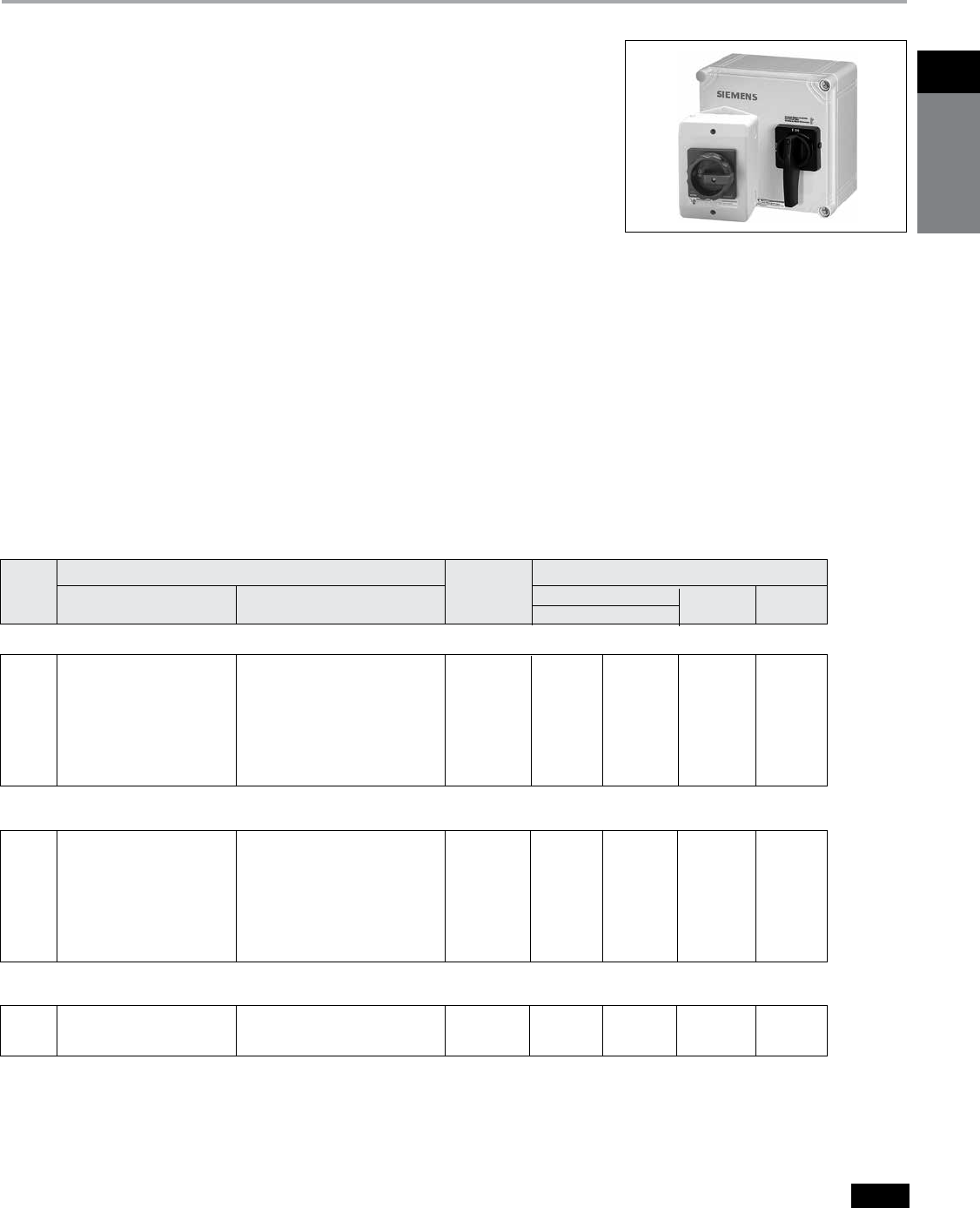
Siemens Canada Limited Power Product Catalogue 1-35
1Safety
SwitcheS
Enclosed Switches
Rotary Disconnect Switches in Non-Metallic Enclosures
d
Selection
Application
Siemens Rotary Disconnect switches
are ideally suited for use as ”in sight“
disconnects for motor loads and other
electrical equipment which is remotely
located from its branch circuit protective
device. All are supplied in non-metallic
enclosures which are UL & cUL or
CSA approved for a wide range of both
indoor and outdoor environments. All
meet UL508 requirements.
Description
16–125A non-fusible switches are
available in fiberglass reinforced
polycarbonate enclosures which
are UL approved as Type 12 & 4X and
for either indoor or outdoor use.
All are horsepower and load break
rated. All are panel mounted and are
either supplied with factory installed
aux. contacts or will accept contact
kits. All are compact in size while pro-
viding ample wiring space for copper
line & load conductors.
Siemens Enclosed Rotary
Disconnect Switches
b 16–125A, Non-Fusible
b 600VAC max. rated (except cata-
logue no. HNF3100CX is rated
480VAC max.)
b Available in both Type 12 and 4X
non-metallic enclosures
b Both screw and hinged cover
designs available
b Listed and marked “suitable for use
as motor disconnect” per NEC
Section 430-109
b Screw cover switches are UL listed
under File No. E47705 and are CSA
certified under File No. 249236
b IEC 60947-3 rated and CE marked
(enclosures are IP65 rated)
b Hinged door switches are UL listed
for multiple line and load conductors
per phase in 30–100A ratings. They
are UL & cUL listed under File No.
E191706
b HP rated
b Rotary handles are available in
black, red, and yellow and in pistol
grip designs
b 16–63A screw cover switches have
factory installed ground bars. All
hinge cover switches accept
ground lug kits
b Screw cover switches are
provided with knockouts
b Padlockable in OFF position
with up to (3) padlocks
Catalogue Number Horsepower Ratings
Ampere 3 Pole, 3 Wire with (1) NO Shipping 240V AC 480V AC 600V AC
Rating 3 Pole, 3 Wire & (1) NC Aux. Contactgh Weight (lbs.) 1 Phase 3 Phase 3 Phase 3 Phase
Non-Fusible, Type 1, 4X & 12Ka with Screw Cover and Black Rotary Handle 600V AC Max.d
Non-Fusible, Type 1, 4X & 12Ka with Screw Cover and Red and Yellow Rotary Handle 600V AC Max.d
Non-Fusible, Type 4Xc with Hinged Door and Black Pistol Grip Rotary Handle 480V AC Max. bd
16 3LD2064-0TB51-0US2 3LD2064-1GP51-0US2 1 11⁄2 3 71⁄2 10
25 3LD2164-0TB51-0US2 3LD2164-1GP51-0US2 1 3 71⁄2 10 15
30 3LD2264-0TB51-0US2 3LD2264-1GP51-0US2 1 3 71⁄2 15 20
30 — 3LD2264-1TS51-0US2f 1 3 71⁄2 15 20
30 — 3LD2264-2TW51-0US2g 1 3 71⁄2 15 20
63 3LD2565-0TB51-0US2 3LD2565-1GP51-0US2 3 10 15 40 50
100 3LD2766-0TB51-0US2 3LD2766-1GP51-0US2 6 — 30 60 75
125 3LD2866-0TB51-0US2 3LD2866-1GP51-0US2 6 — 40 75 100
16 3LD2064-0TB53-0US2 3LD2064-1GP53-0US2 1 11⁄2 3 71⁄2 10
25 3LD2164-0TB53-0US2 3LD2164-1GP53-0US2 1 3 71⁄2 10 15
30 3LD2264-0TB53-0US2 3LD2264-1GP53-0US2 1 3 71⁄2 15 20
30 — 3LD2264-1TS53-0US2f 1 3 71⁄2 15 20
30 — 3LD2264-2TW53-0US2g 1 3 71⁄2 15 20
63 3LD2565-0TB53-0US2 3LD2565-1GP53-0US2 3 10 15 40 50
100 3LD2766-0TB53-0US2 3LD2766-1GP53-0US2 6 — 30 60 75
125 3LD2866-0TB53-0US2 3LD2866-1GP53-0US2 6 — 40 75 100
30 HNF3030CX — 4 3 71⁄2 15 20
60 HNF3060CX — 4 10 15 40 50
100 HNF3100CX — 5 15 25 50 —
a
Approved for both indoor and outdoor use. No cover
interlock provided.
b
30 and 60A switches are also rated 600V AC.
c
Also rated as Type 12 and UL approved for both indoor
and outdoor use. Defeatable cover interlock provided.
d
Screw cover enclosures are constructed from Makrolon
9425. Hinged cover enclosures are constructed from
fiberglass reinforced polycarbonate.
e
Switch is supplied with (2) NO and no NC aux. contacts.
f
Switch is supplied with (4) NO and no NC aux. contacts.
Ground bar is not provided or available.
g
Aux. contacts break about 3 Ms before and make about
3 Ms after main switch contacts.
h
6P, 25A, switch with 1 NO & 1 NC aux. contacts and a
black operating handle is also available. Order catalogue
number 3LD2165-4VD51.
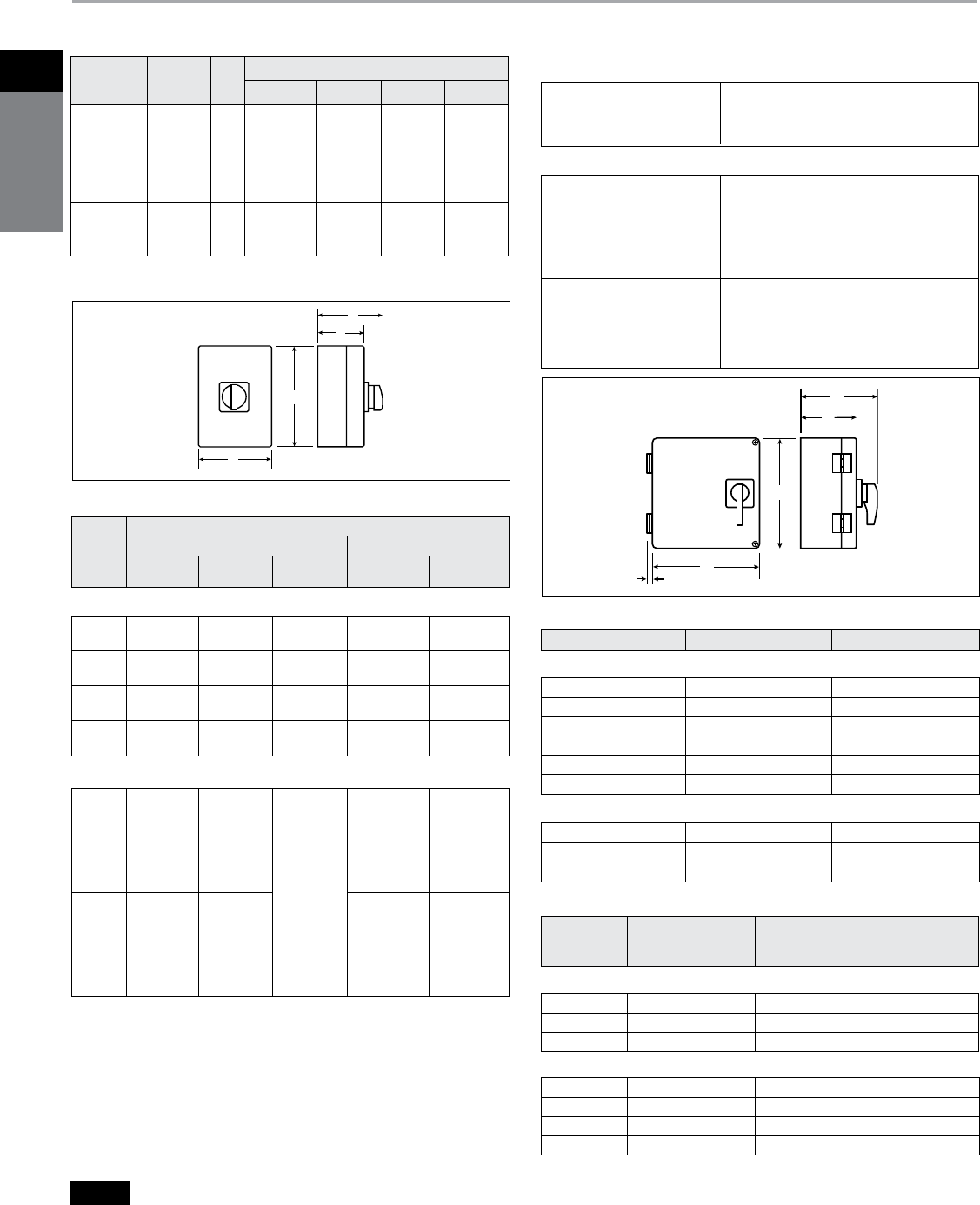
Siemens Canada Limited Power Product Catalogue
1-36
1
safety
switches
Enclosed Switches
Rotary Disconnect Switches
Selection
Ampere Rating
gG Fuse Size Short Circuit Rating
16 Amps (1) #18-10 AWG
25–30 Amps (1) #14- 10 AWG
63 Amps (1) #14- 6 AWG
100–125 Amps (1) #12- 1 AWG
Enclosed Disconnect Switch Dimensions
3LD2 Type Switchesc
(1) #14-#10 AWG Solid
(1) #14-#4 AWG Stranded
Up to (4) #12 AWG Solid
30 Amps Up to (3) #12 AWG Stranded
Up to (6) #14 AWG Stranded
Up to (4) #14 AWG Stranded
with (1) #10 AWG Stranded
(1) #14-#10 AWG Solid
(1) #14-#1 AWG Stranded
60 & 100 Amps (2) #6 AWG Stranded
Up to (3) #8 AWG Stranded
Up to (6) #10 AWG Stranded
Up to (6) #12 AWG Solid
HNF Type Switches
B
A
C
D
Figure 1
B
.5
A
D
C
Figure 2
16 20A 5k Arms
25 25A 10k Arms
32 50A 10k Arms
63 63A 15k Arms
100 100A 20k Arms
125 125A 20k Arms
3LD2 Screw Cover Switches
30 63A 10k Arms
60 100A 10k Arms
100 100A 10k Arms
HNF Hinged Cover Switches
a
For use as supplemental protection on the load side of the branch circuit over current
protective device.
b
Ground lug kit has two lugs for #14-4 Cu/Al wire.
c
Factory installed ground lugs supplied as follows: 16-30A #14-10 Cu, 63A #14-8 Cu.
Ground lug not provided and is not available on catalogue numbers 3LD2264-2TW51-
0US2 and 3LD2264-2TW53-0US2.
d
6.38 inches(162mm) high including mounting feet.
e
7.85 inches(199mm) high including mounting feet.
f
60 & 100A HNF switches are rated 10kA at 480V max. with line side Class H, K & RK5
150A max. fuses.
g
Wire range (1) #14-2 AWG 60/75 °C Cu only.
h
16-63A 3LD switches are also rated 5kA at 600VAC max when protected by a 3RV type
MSP of the same or lesser ampere rating.
Note: 3LD2 Type switches only have top and bottom end KOs as follows:
16-30A - 1/2” & 3/4”, 63A - 3/4” & 1”, 100 & 25A - 1” & 1 1/4”
16 RK5 — — — —
(50A Max)
25 & 30 RK5 — — — —
(80A Max)
63 RK5 — — — —
(175A Max)
100 & — RK5 — — —
125 (200A Max)
Short Circuit Withstand Rating and Fuse Class
With Line Side Fusing With Load Side Fusinga
Ampere 5 kA at 10 kA at 18 kA at 5 kA at 18 kA at
Rating
600V Max
600V Max
480V Max
480V Max
480V Max
3LD2 Type Switchesh
Ferraz
Shawmut
H, K & RK5 H, K & RK5 A50P or lower
30 — (100A Max) (30A Max) let-through
semiconductor
fuses
J, T & CC (60A Max)
H, K & RK5 (100A Max) Ferraz
60 (150A Max) Shawmut
H, K & RK5 A50P or lower
(60A Max) let-through
semiconductor
100 fuses
(100A Max)
HNF Type Switches
f
f
30–100A GSGK60 Ground Lug Kit
b
30A LBRA1 Auxiliary Contact Kit (1 NO-1 NC)
60–100A LBRA2 Auxiliary Contact Kit (1 NO-1 NC)
30–100A HF63CX
g
Neutral Kit
Switch
Ampere Catalogue
Rating Number Description
HNF Type Switches
16–30A 3LD9220-2C Neutral Kit
63A 3LD9250-2CA Neutral Kit
100–125A 3LD9280-2C Neutral Kit
3LD2 Type Switches
c
Accessories
IEC Fuse and Withstand Ratings
UL and cUL Short Circuit Withstand Ratings
Wire ranges 60/75°C Cu Only
Catalogue
Number
Amprere
Rating
Fig.
No.
Dimensions - Inches (mm)
A B C D
3LD2064-
3LD2164-
3LD2264-
3LD2565-
3LD2766-
3LD2866-
16
25
30
63
100
125
1
5.52 (140)
d
5.52 (140)
d
5.52 (140)
d
6.93 (176)
e
11.90 (302)
11.90 (302)
3.94 (100)
3.94 (100)
3.94 (100)
5.75 (146)
8.35 (212)
8.35 (212)
3.19 (81)
3.19 (81)
3.19 (81)
4.10 (104)
5.36 (136)
5.36 (136)
4.57 (116)
4.57 (116)
4.57 (116)
5.87 (149)
7.13 (181)
7.13 (181)
HNF3030CX
HNF3060CX
HNF3100CX
30
60
100
2
7.87 (200)
11.77 (299)
11.77 (299)
7.87 (200)
7.87 (200)
7.87 (200)
5.20 (132)
5.20 (132)
5.20 (132)
7.29 (185)
7.29 (185)
7.29 (185)
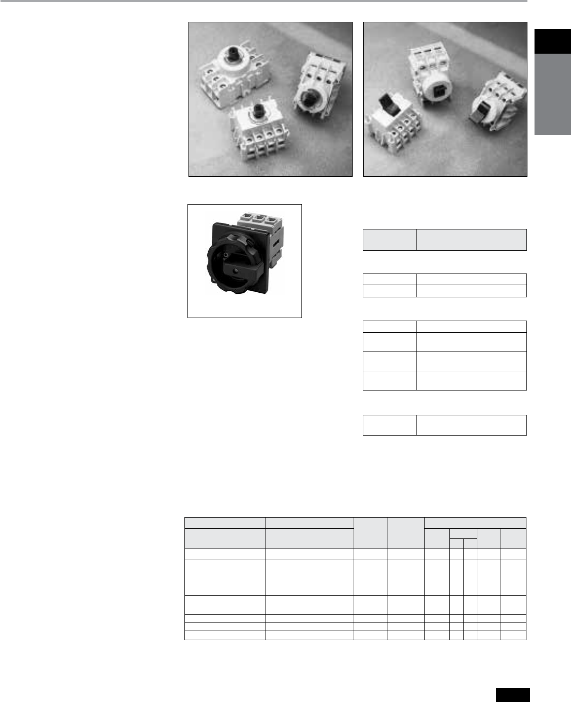
1Disconnect
switches
Siemens Canada Limited Power Product Catalogue 1-37
Disconnect Switches
Compact Non-Fusible — Rotary and Toggle
Selection
Ordering Information
Door Mounted Switches (Rotary
Type Only) — Order either complete
“3LD2” assemblies or individual “LBR”
components as follows:
Complete Assemblies include switch,
handle, and shaft. Certain 25 and 32A
assemblies are also available with facto-ry
installed neutral blocks and/or aux.
contacts. These accessories can also
be ordered as field installed kits.
Individual Components are ordered as
follows:
25A — LBR3025D switch + LBRH3 or 4
handle.
40–100A — LBR switch + LBRH3 or 4
handle + LBRD1.
Notes: (LBR Type switches only)
1. Aux contacts are available as field
installed kits on 25A units only.
2. Lugs on 25A units face to the rear and
lugs on 40–100A units face toward the
front.
Features
b
16–250 Ampere, to 100 hp, 480V & 600V
b
Rotary and Toggle actuation models
b
LBR Type switches are padlockable in
the OFF position and are cUL & UL listed
under File No. E191706 as manual motor
controllers per UL Standard UL508
b
3LD2 Type switches are padlockable in
the OFF position and are CSA certified
under file No. 203576 and are UL listed
under file No. E47705
b
Base, DIN-rail and door mounting
b
Multiple conductor, distribution terminal
type rating LBR & LBT Type (40A -100A
only)
b
IEC 947-1 rated, CE marked
b
Listed and marked “suitable as motor
disconnect” per NEC Section 430-109
Application
Siemens Load Break Switches are listed
as manual motor controllers and are
suitable as motor disconnects. They are
load break rated and act as enclosure
discon-nects when short circuit protection
is provided upstream of the switch. If
upstream over current protection is not
provided, use a Siemens fusible Type VBII,
CFS or MCS Disconnect Switch.
Type LBR Rotary Switches
3LD2254-0TK51
Type LBT Toggle Switches
Shaft Mounted 4 Hole Mounted AC Horsepower Ratings
Number Ampere 120V 240V 480V 600V
Catalogue Numberc Catalogue Numberc of Poles Rating 1
Ø
1
Ø
3
Ø
3
Ø
3
Ø
— 3LD2003-1TP53a 3 16 1⁄2 11⁄2 3 71⁄2 10
3LD2154-0TK 3LD2103-0TK 3
3LD2154-1TP 3LD2103-1TP 3a
3LD2154-1TL 3LD2103-1TL 3 + N 25 2 3 71/2 10 15
3LD2154-2EP 3LD2103-2EP 3 + Na
3LD2254-0TK 3LD2203-0TK 3
3LD2254-1TL 3LD2203-1TL 3 + N 32 2 3 10 20 20
3LD2555-0TK 3LD2504-0TK 3 63 — 10 15 40 50
— 3LD2704-0TK 3 100 — — 30 60 75
— 3LD2804-0TK 3 125 — — 40 75 100
Switch Rating
& Type Max. Line Side Fuse Rating
25 & 32A 3LD2 80A Max. at 600V AC Max.
63A 3LD2 175A Max. at 600V AC Max.
Short Circuit Withstand Ratings
5kA with Line Side Class H, K, or
RK5 Fuses
25A LBR 30A Max. at 480V AC Max.
40A, 4P 60A Max. at 480V AC Max.
LBR & LBT
40 & 60A, 3P 100A Max. at 480V AC Max.
LBR & LBT
80 & 100A 150A Max. at 480V AC Max.
LBR & LBT
10kA with Line Side Class H, K, or
RK5 Fuses
d
40–100A, 3P 100A Max. at 480V AC Max.
LBR & LBT
18kA with Line Side Class J, T, or
CC Fuses
Door Mounted Complete Assemblies
Operator, Shaft, & Switch) 600V AC Max.b
a
Includes auxiliary contacts (1 NO and 1 NC).
b
Handles are IP65 rated and are also UL Listed for Type 1,
4X and 12 applications.
c
Add 51 for a black handle or 53 for a red & yellow handle
to the end of the catalogue number.
d
100-250A 3LD2 switches are rated 10kA when protected by
200A Max. Class RK5 fuses.
Base/DIN Rail Mounted Switches
(Rotary or Toggle Type) — Order
individual components as follows:
Toggle — Order the LBT switch required
and a toggle switch cover plate if
needed.
Rotary, Base Mounted with Door
Mounted Handle — Order “LBR”
switch + door mounted handle + shaft +
any accessories.
Rotary, Base Mounted with Direct
Mounted Handle — Order “LBR”
switch + direct mounted handle.
Note: 3LD2 switches are also rated 5kA at 600V
AC Max. when protected by a 3RV motor starter
with a FLA rating equal to or less than the switch
ampere rating.

1
Disconnect
switches
Siemens Canada Limited Power Product Catalogue
1-38
Disconnect Switches
Compact Non-Fusible — Rotary and Toggle
Selection
3LD Type Base Mounted Complete Assemblies
(Operator, Shaft, & Switch) 600V AC Max.b
3LD2217-0TK13
3LD9220-2C
a
Handles and line side terminal covers are supplied as
standard with 3LD2 switches.
b
Add suffix 1 for a black or 3 for a red & yellow handle to the
catalogue number (except 3LD2244-1TL53 & 3LD2213-
1TL53). Handles are IP65 rated and are also listed by UL for
Type 1, 4X and 12 applications.
c
Aux. contacts break about 30 Ms before and make about 3
Ms after main switch contacts.
Ratings 10A at 120V AC
6A at 240V AC
1.4A at 480V AC
d
Can be used as replacement handles on enclosed 3LD2
switches.
e
Base mounted switches with direct mount handles
are also available (3LD2330-0TK1 _
b
rated 160A and
3LD2430-0TK1_
b
rated 250).
Accessories for Front Mounted 3LD2 Switches
Catalogue Switches
Number Description Used With
3LD9200-5Bc 1 NO, 1 NC Aux. Contact 25-125A
3LD9200-5BFc 1 NO, 1 NC Aux. with Gold Plated Contacts 25-125A
3LD9220-2B Neutral/Ground Terminal 25 & 32A
3LD9250-2BA Neutral/Ground Terminal 63A
3LD9280-2B Neutral/Ground Terminal 100 & 125A
3LD9220-0B 4th Pole (leading ON, lagging OFF) 25 & 32A
3LD9250-0BA 4th Pole (leading ON, lagging OFF) 63A
3LD9280-0B 4th Pole (leading ON, lagging OFF) 100 & 125A
3LD9224-1Ba Black Handle (4 hole mtg.) 25 & 32A
3LD9284-1Ba Black Handle (4 hole mtg.) 63-125A
3LD9224-3Ba Red/Yellow Handle (4 hole mtg.) 25 & 32A
3LD9284-3Ba Red/Yellow Handle (4 hole mtg.) 63-125A
3LD9224-1Da Black Handle (shaft mtg.)d 25 & 32A
3LD9284-1Da Black Handle (shaft mtg.)d 63-125A
3LD9224-3Da Red/Yellow Handle (shaft mtg.)d 25 & 32A
3LD9284-3Da Red/Yellow Handle (shaft mtg.)d 63-125A
3LD9221-2Aa Terminal Cover 1P (Pack of 4) 25 & 32A
3LD9221-0Aa Terminal Cover 3P (Pack of 4) 25 & 32A
3LD9251-0Aa Terminal Cover 3P (Pack of 4) 63A
Accessories for Base Mounted 3LD2 Switches
3LD9200-5Cc 1 NO, 1 NC Aux. Contact 25-250A
3LD9200-5CFc 1 NO, 1 NC Aux. with Gold Plated Contacts 25-250A
3LD9220-2C Neutral/Ground Terminal 25 & 32A
3LD9250-2CA Neutral/Ground Terminal 63A
3LD9280-2C Neutral/Ground Terminal 100 & 125A
3LD9240-2C Neutral/Ground Terminal 160 & 250A
3LD9220-0C 4th Pole (leading ON, lagging OFF) 25 & 32A
3LD9250-0CA 4th Pole (leading ON, lagging OFF) 63A
3LD9280-0C 4th Pole (leading ON, lagging OFF) 100 & 125A
3LD9240-0C 4th Pole (leading ON, lagging OFF) 160 & 250A
3LD9224-1Ba Black Handle (4 hole mtg. no defeat) 25 & 32A
3LD9284-1Ba Black Handle (4 hole mtg. no defeat) 63-125A
3LD9224-3Ba Red/Yellow Handle (4 hole mtg. no defeat) 25 & 32A
3LD9284-3Ba Red/Yellow Handle (4 hole mtg. no defeat) 63-125A
3LD9224-1Da Black Handle (shaft mtg.) 25 & 32A
3LD9284-1Da Black Handle (shaft mtg.) 63-125A
3LD9224-3Da Red/Yellow Handle (shaft mtg.) 25 & 32A
3LD9284-3Da Red/Yellow Handle (shaft mtg.) 63-125A
3LD9221-2Aa Terminal Cover 1P (Pack of 4) 25 & 32A
3LD9221-0Aa Terminal Cover 3P (Pack of 4) 25 & 32A
3LD9251-0Aa Terminal Cover 3P (Pack of 4) 63A
Note: Shaft length allows a maximum depth from switch mounting surface to the outside of the cover of 15.25” on 25 &
32A switches and of 15.75” on 63-125A switches. 23.6 max for 160 & 250 switches.
Handle mountingb
Number
of Poles
Ampere
Rating
AC Horsepower Ratings
Shaft
(center hole)
4 Hole
(no defeat)
4 Hole
(with defeat) 120V 240V 480V 600V
Catalogue
Number
Catalogue
Number
Catalogue
Number 1
Ø
1
Ø
3
Ø
3
Ø
3
Ø
—3LD2013-0TK5 3LD2017-0TK1 316 ½ 1½ 3 7½ 10
—— 3LD2017-1TL1 3 + N
3LD2144-0TK5 3LD2113-0TK5 — 325 2 3 7½ 10 15
3LD2144-1TL5 3LD2113-1TL5 — 3 + N
3LD2244-0TK5 3LD2213-0TK5 3LD2217-0TK1 332 2 3 10 20 20
3LD2244-1TL53 3LD2213-1TL53 3LD2217-1TL1 3 + N
3LD2545-0TK5 3LD2514-0TK5 3LD2517-0TK1 363 3 10 15 40 50
—— 3LD2517-1TL1 3 + N
—3LD2714-0TK5 —3 100 — — 30 60 75
—3LD2814-0TK5 —3 125 — — 40 75 100
—3LD2318-0TK1 —3160 — — 40 75 75
—3LD2318-1TK1e—3 + N
—3LD2418-0TK1 —3250 — — 50 100 75
—3LD2418-1TK1e—3 + N
3LD9251-0A
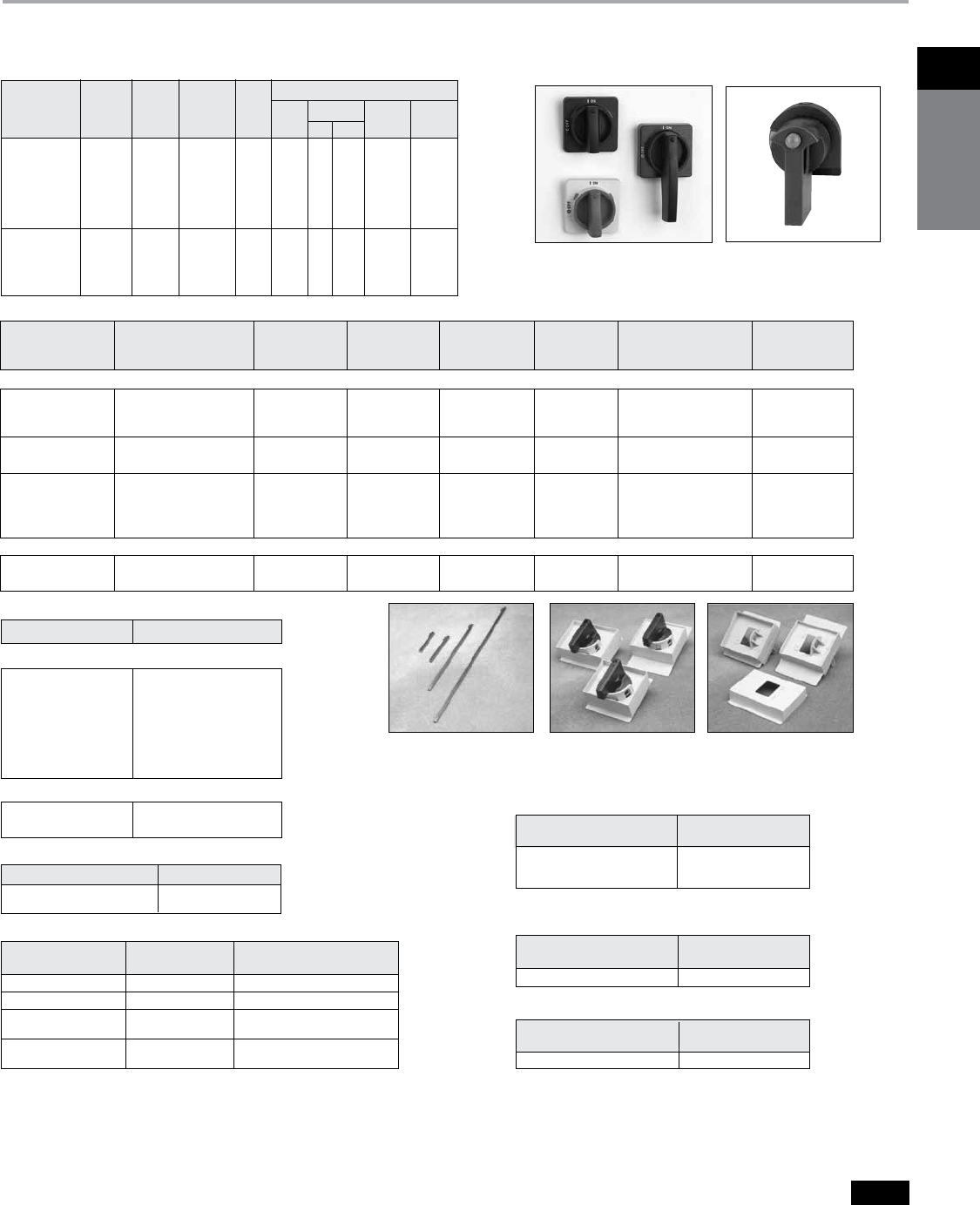
1Disconnect
switches
Siemens Canada Limited Power Product Catalogue 1-39
Disconnect Switches
Compact Non-Fusible — Rotary and Toggle
Selection
a
No cover interlock defeat mechanism provided.
To elimi-
nate cover interlock, order additional catalogue number
LBRDC1.
b
LBRH2 is IP54 rated. All others are IP65.
c
Ratings
15.1A resistive at 250V AC max.
.5A at 125V DC
.25A at 250V DC
.5 HP at 250V AC max.
d
Auxiliary switch contacts break about 30 Ms before and
make about 3 Ms after main switch contacts.
e
Lug wire ranges:
HF63CX —(1) #14-2 AWG 60/75°C Cu only
f
Only door mountable and for use with LBRH3 &
4 handles only.
g
For door mounting of 40–100A LBR switches use
door mounting kit LBRD1 & LBRH3 or 4 handle.
Rotary and Toggle Switches
Max AC Horsepower Ratings
Catalogue Switch No. of Ampere AC 115V 240V 480V 600V
Number Type Poles Rating Volt 1
Ø
1
Ø
3
Ø
3
Ø
3
Ø
LBR3025 Rotary 3 25 480 3⁄4 2 5 10 —
LBR3025D
f
Rotary 3 25 480 3⁄4 2 5 10 —
LBR3040
g
Rotary 3 40 600 2 3 71⁄2 20 25
LBR3060
g
Rotary 3 60 480 2 5 10 25 —
LBR3080
g
Rotary 3 80 600 3 10 20 40 50
LBR3100
g
Rotary 3 100 480 5 15 25 50 —
LBR4040 Rotary 4 40 480 2 3 71⁄2 20 —
LBT3040 Toggle 3 40 600 2 3 71⁄2 20 25
LBT3060 Toggle 3 60 480 2 5 10 25 —
LBT3080 Toggle 3 80 600 3 10 20 40 50
LBT3100 Toggle 3 100 480 5 15 25 50 —
LBT4040 Toggle 4 40 480 2 3 71⁄2 20 —
LBR Type Handles
Standard Duty Rotary
Switch Door Handles
Used on Catalogue No Catalogue Number
LBR3025 LBRP25
LBR3025D LBRP25D
25 Amp, 4th Pole
Used on Catalogue
Rotary Switch Number Contact Arrangement
LBR3025 LBRA25cd 1 NO & 1 NC
LBR3025D LBRA25Dcd 1 NO & 1 NC
LBR3040, LBRA1cd 1 NO/1 NC
LBR3060 with common point
LBR3080, LBRA2cd 1 NO/1 NC
LBR3100 with common point
Auxiliary Switch Kits
Individual Components
Heavy Duty Rotary
Switch Door Handle
Used with
Catalogue Number Catalogue Number
All HF63CX
LBR/LBT Neutral Kite
Used on
Rotary Switch Catalogue Number
40-100 Amps LBRD1
LBR Type Rotary Switch Door Mounting
Kit (For use with LBRH3 & LBRH4 only)
Used on
Toggle Switches Catalogue Number
LBT3040, LBT3060 LBTCP1
LBT3080, LBT3100 LBTCP2
LBT4040 LBTCP3
LBR Type Toggle Switch Cover Plate
Catalogue
Number
Used on
Rotary Switches
NEMA
Type Mounting Marking Colour
Cover
Interlock
Supplied Padlockable
Standard Duty
LBRH2b
LBRH3b
LBRH4b
All
All
All
1
1, 3R, 12, 4X
1, 3R, 12, 4X
Door
Door
Door
ON/OFF
O/I, ON/OFF
O/I, ON/OFF
Black
Black
Red/Yel
No
Yes
a
Yes
a
No
Yes
Yes
LBRH9b
LBRH10b
All (Pistol Grip Type)
All (Pistol Grip Type)
1, 3R, 12, 4X
1, 3R, 12, 4X
Door
Door
O/I, ON/OFF
O/I, ON/OFF
Black
Red/Yel
Yes
Yes
Yes
Yes
LBRH5
LBRH6
LBRH7
LBRH8
25 Amps
3-Pole, 40-60 Amps
3-Pole, 80-100 Amps
4-Pole, 40-60 Amps
1
1
1
1
Direct Mount
Direct Mount
Direct Mount
Direct Mount
O/I
O/I
O/I
O/I
Black
Black
Black
Black
—
—
—
—
Yes
Yes
Yes
Yes
Heavy Duty
CFSH10B12
CFSH10R12
All
All
1, 3R, 12
1, 3R, 12
Door
Door
O/I, ON/OFF
O/I, ON/OFF
Black
Red/Yel
Yes
Yes
Yes
Yes
Catalogue Number Length - In. (mm)
For Standard Duty Handles
LBRS040
LBRS050
LBRS055
LBRS080
LBRS120
LBRS180
LBRS305
1.57 (40)
1.97 (50)
2.17 (55
3.15 (80)
4.72 (120)
7.09 (180)
12.00 (305)
For Heavy Duty Handles
CFSS5200H
CFSS5400H
7.9 (200)
15.7 (400)
Rotary Switch Direct
Mount Handles
Rotary Shafts Toggle Switch Cover
Plates
LBR Type Rotary Shafts
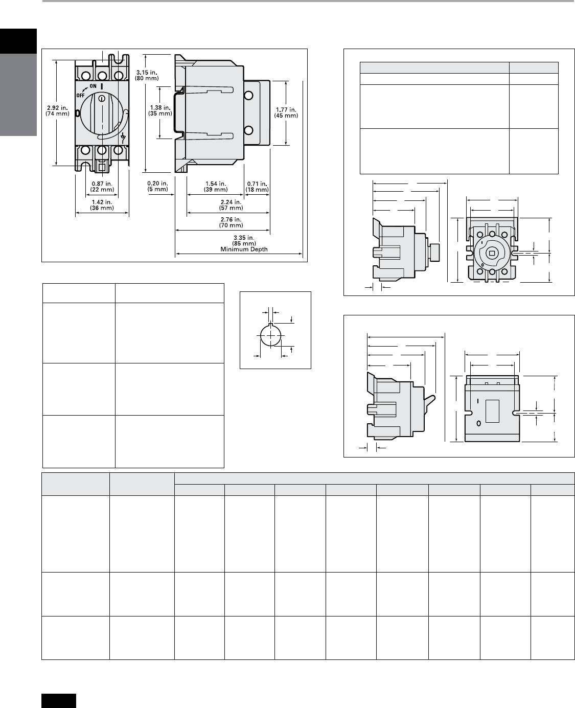
1
Disconnect
switches
Siemens Canada Limited Power Product Catalogue
1-40
Disconnect Switches
Compact Non-Fusible — Rotary and Toggle
Dimensions
Switch Switch Dimensions - Inches (mm)
Type Catalogue No. A B C D E F G H
Rotary LBR3040 2.00 (51) 2.72 (69) 2.72 (69) 1.78 (45) 2.16 (55) 1.67 (42) 1.50 (38) 1.22 (31)
Rotary LBR3060 2.00 (51) 2.72 (69) 2.72 (69) 1.78 (45) 2.16 (55) 1.67 (42) 1.50 (38) 1.22 (31)
Rotary LBR3080 2.09 (53) 3.32 (84) 2.92 (74) 1.97 (50) 2.29 (58) 1.69 (42) 1.66 (42) 1.66 (42)
Rotary LBR3100 2.09 (53) 3.32 (84) 2.92 (74) 1.97 (50) 2.29 (58) 1.69 (42) 1.66 (42) 1.66 (42)
Rotary LBR4040 2.42 (61) 2.72 (69) 2.72 (69) 2.28 (58) 2.16 (55) 1.67 (42) 1.50 (38) 1.22 (31)
Rotary Front Mtg. 3LD20b 1.89 (48) 1.97 (50) 1.97 (50) — — — — —
Rotary Front Mtg. 3LD21 & 2b 1.81 (46) 2.17 (55) 1.97 (50) — — — — —
Rotary Front Mtg. 3LD25b 2.36 (60) 2.52 (64) 2.32 (59) — — — — —
Rotary Front Mtg. 3LD27 & 8b 2.40 (61) 3.27 (83) 2.40 (61) — — — — —
Rotary Base Mtg. 3LD20b 1.89 (48) 1.97 (50) 2.29 (58) — — — — —
Rotary Base Mtg. 3LD21 & 2b 1.81 (46) 2.17 (55) 2.29 (58) — — — — —
Rotary Base Mtg. 3LD25b 2.36 (60) 2.52 (64) 2.68 (68) — — — — —
Rotary Base Mtg. 3LD27 & 8b 2.80 (71) 3.27 (83) 2.76 (70) — — — — —
Rotary Base Mtg. 3LD23 & 4 4.41 (112) 5.83 (148) 4.10 (104) — — — — —
Toggle LBT3040 2.00 (51) 2.72 (69) 2.75 (70) 1.78 (45) 2.16 (55) 1.67 (42) 1.50 (38) 1.22 (31)
Toggle LBT3060 2.00 (51) 2.72 (69) 2.75 (70) 1.78 (45) 2.16 (55) 1.67 (42) 1.50 (38) 1.22 (31)
Toggle LBT3080 2.09 (53) 3.32 (84) 2.90 (74) 1.97 (50) 2.29 (58) 1.69 (42) 1.66 (42) 1.66 (42)
Toggle LBT3100 2.09 (53) 3.32 (84) 2.90 (74) 1.97 (50) 2.29 (58) 1.69 (42) 1.66 (42) 1.66 (42)
Toggle LBT4040 2.42 (61) 2.72 (69) 2.75 (70) 2.28 (58) 2.16 (55) 1.67 (42) 1.50 (38) 1.22 (31)
LBR3025
0.31 in.
(8 mm)
F
E
C
D
A
H
G
0.16 in.
(4 mm)
B
J
LBR 40-100 Amps & 3LD2 16-250A
0.31 in.
(8 mm)
F
E
C
B
D
A
H
G
0.16 in.
(4 mm)
Minimum Depth
3.00 in.
(76 mm)
LBT Toggle — 40-100 Amps
Wire Ranges 60/75°C Cu only
25 Amps LBR (1) #14 - #10 AWG Solid
(1) #14 - #8 AWG Stranded
(1) #14 - #10 AWG Solid
(1) #14 - #4 AWG Stranded
40 & 60 Amps UP to (4) #12 AWG Solid
LBR & LBT Up to (3) #12 AWG Stranded
Up to (6) #14 AWG Stranded
Up to (4) #14 AWG Stranded
with (1) #10 AWG Stranded
(1) #14 - #10 AWG Solid
(1) #14 - #1 AWG Stranded
80 & 100 Amps (2) #6 AWG Stranded
LBR & LBT Up to (3) #8 AWG Stranded
Up to (6) #10 AWG Stranded
Up to (6) #12 AWG Solid
16A, 3LD20 (1) #18-10 AWG
25A, 3LD21 (1) #14-8 AWG
32A, 3LD22 (1) #14-8 AWG
63A, 3LD25 (1) #14-6 AWG
100, 125A, 3LD2 (1) #12-1 AWG
160, 250A, 3LD2 (1) #1-400 MCM
Dimension J Minimum Deptha - Inches (mm)
Switch Dimension J
LBR 40-100A 3.35 (85)
3LD2 25 & 32A Front Shaft Mounted 3.07 (78)
3LD2 63 Front Shaft Mounted 3.35 (85)
3LD2 16-32A Front 4-hole Mounted 2.13 (54)
3LD2 63A Front 4-hole Mounted 2.48 (63)
3LD2 100 & 125A Front 4-hole Mounted 2.56 (65)
3LD2 25 & 32A Base w/shaft Mtg. Handle 6.46 (164)
3LD2 63A Base w/shaft Mtg. Handle 6.77 (172)
3LD2 16-32A Base w/4-hole Mtg. Handle 5.59 (142)
3LD2 63A Base w/4-hole Mtg. Handle 5.99 (152)
3LD2 100-250A Base w/4-hole Mtg. Handle 6.07 (154)
Dimension Drawings and Wire Ranges
a
Depth from outside of cover to back of switch
.
b
Handle front plate dimensions:
3LD 16-32A—2.64 inches square
3LD 63-125—3.55 inches square
Shaft Mounted
3LD2 Handle Cutout
.877
(22.5)
.95
(24.1
)
.125
(3.2)
Drilling
Pattern
a
a
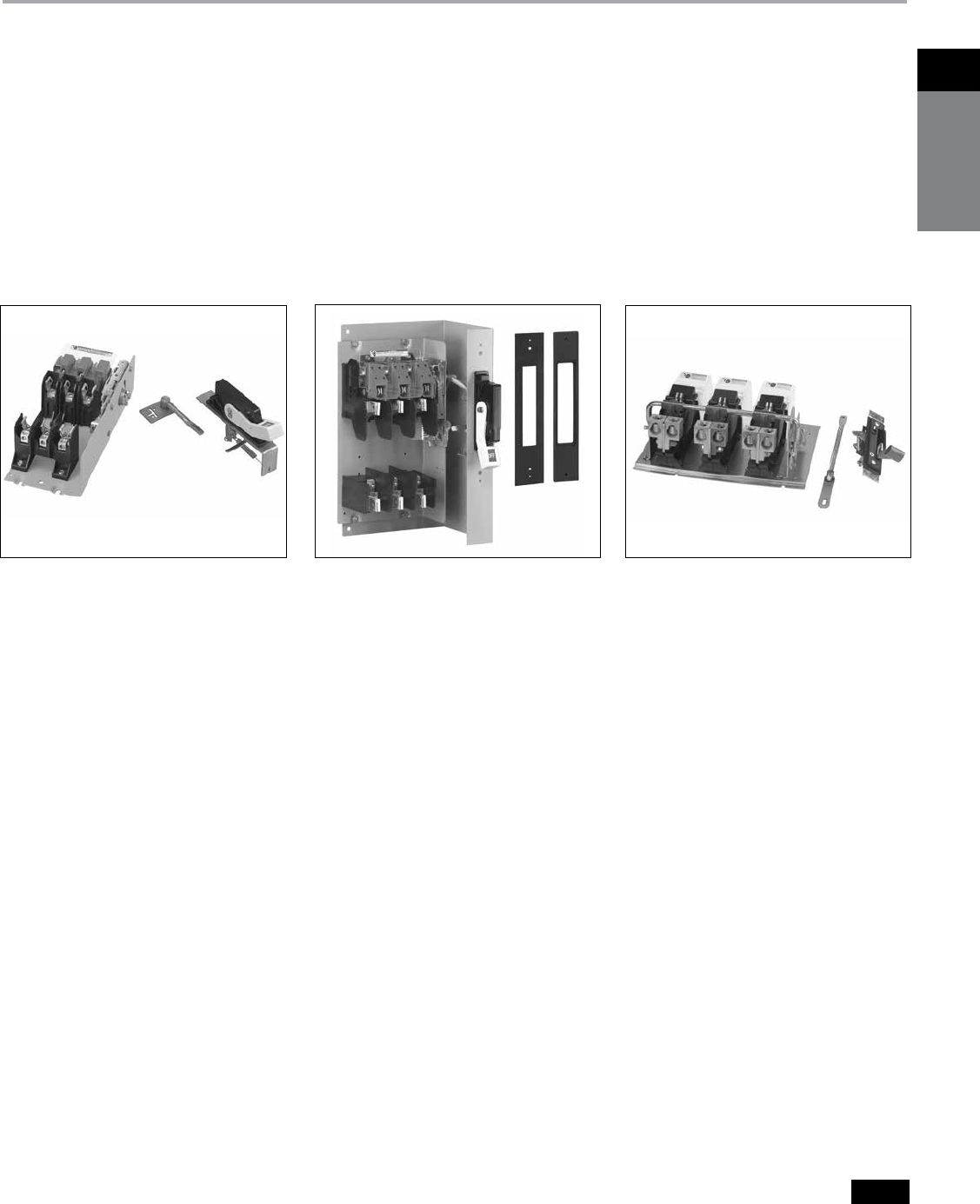
1Disconnect
switches
Siemens Canada Limited Power Product Catalogue 1-41
Disconnect Switches
Type VBII (30-600A) with Flange Mounted Operating Handle
Features and Ordering Information
Features
b
30-600A, 600VAC and DC ratings
b
240 & 600V AC switches are CSA
certified under file number 154852 and
UL recognized under file E121152, Vol.
3.
b
Visible blade quick make and break
switching action
b
Panel and Flange mounted assemblies
facilitate installation
b
Panel mounted switches are variable
depth
b
Short circuit rating of 10,000 AIC with
class H fuse, and of 200,000 AIC with
class R or J fuses.
b
Flange mounted handles rated as Type
1, 3R & 12 or 4X are padlockable in
the off position with up to (3) padlocks
with 5/16 hasps
b
Meets UL98 requirements and suitable
for both main and branch circuit
applications
b
A complete line of aux contacts are
available
b
Load break and horsepower rated
b
Defeatable cover interlock standard
with all handles
b
Meets NFPA79 requirements
b
Seismic qualified
—
complies with the
2010 California Building Code (CBC)
—
and with the International Building
Code (IBC)
—
Compliance Level
SDS = 1.85 g
VBFS361, VBLK1 & VBH1 VBNFS365, VBLK4 & VBH2
VBFS363F
Ordering Information
1. Determine the ratings required (amps,
volts, HP, Fusible, NF), the mounting
needed (Panel or Flange), and select
the appropriate switch.
2. For panel mounted switches with a
rigid operating shaft (30-600A), order
panel mounted switch, flange mount-
ed operating handle & rigid linkage kit
based on depth required.
3. For panel mounted switches with a
Max-Flex operator, order panel mount-
ed switch, Max-Flex Handle & Adapter
Kit and drive cable.
4. Select accessories if required.

1
Disconnect
switches
Siemens Canada Limited Power Product Catalogue
1-42
Disconnect Switches
Type VBII (30-600A) with Flange Mounted Operating Handle
Selection
Cable Kit
For use with 30-200A panel mounted switches
and Max-Flex handle and adapter kit.
Catalogue
Number Description
FHOEC036 36" long drive cable
FHOEC048 48" long drive cable
VBNFS361, VBHM1 & FHOEC036
a Rated 5 HP at 250V DC.
b Rated 10 HP at 250V DC.
c 600V DC & 600V DC horsepower rating shown requires
(2) poles to be connected in series.
d Std. - applies when non-time delay fuses are used.
Max. - applies when time delay fuses are used.
e Includes line base, load base, operating mechanism
and line and load lugs. Order operating handle and
linkage kits from tables on pages 1-42 or 1-40.
f Includes line base, load base, operating mechanism
line and load lugs plastic operating handle and
required linkage.
g Rated 250V DC max and 50HP at 250V DC.
Note: Fusible switches include fuse provisions for Class H Fuses. The load base can be moved to pre-drilled holes for Class J Fuses on all 600V switches. If Class R
Fuses are required, add a Class R Fuse Clip Kit.
Switches—for Standard 600V Max AC or DC Applications
Max-Flex
TM
Handle and Adapter Kit
(Type 1, 12, 3R & 4X) Use with 30-200A panel mounted switches and cable kit.
Catalogue
Number Description
VBHM1 30-200A Max-Flex Adapter Kit
Switch
Ampere
Rating
Max. AC
Voltage
Rating Catalogue Number
Horsepower Rating, Switches and 3-Phased
600
Volts DC
(max)d
240 Volts AC 480 Volts AC 600 Volts AC
Standard Max. Standard Max. Standard Max.
Fusible Panel Mounted Variable Depth Switches - 3-Polee
30
60
30
60
100
200
400
600
240
240
600
600
600
600
600
600
VBFS321
VBFS322
VBFS361
VBFS362
VBFS363
VBFS364
VBFS365
VBFS366
3
71/2
—
—
—
—
—
—
71/2
15
—
—
—
—
—
—
—
—
5
15
25
50
100
150
—
—
15
30
60
125
250
400
—
—
71/2
15
30
60
125
200
—
—
20
50
75
150
350
500
— a
— b
15 c
30 c
50 c
50
— g
— g
Non-fusible Panel Mounted Variable Depth Switches - 3-Polee
30
60
100
200
400
600
600
600
600
600
600
600
VBNFS361
VBNFS362
VBNFS363
VBNFS364
VBNFS365
VBNFS366
—
—
—
—
—
—
10
20
40
60
125
200
—
—
—
—
—
—
20
50
75
125
250
400
—
—
—
—
—
—
30
60
100
150
300
500
15 c
30 c
50 c
50
— g
— g
Fusible Flange Mounted Switches - 3-Polef
30
60
30
60
100
200
240
240
600
600
600
600
VBFS321F
VBFS322F
VBFS361F
VBFS362F
VBFS363F
VBFS364F
3
71/2
—
—
—
—
71/2
15
—
—
—
—
—
—
5
15
50
100
—
—
15
30
60
125
—
—
71/2
15
30
60
—
—
20
50
75
150
— a
— a
15 c
30 c
50 c
50
Non-fusible Flange Mounted Switches – 3-Polef
30
60
100
200
600
600
600
600
VBNFS361F
VBNFS362F
VBNFS363F
VBNFS364F
—
—
—
—
10
20
40
60
—
—
—
—
20
50
75
125
—
—
—
—
30
60
100
150
15 c
30 c
50 c
50
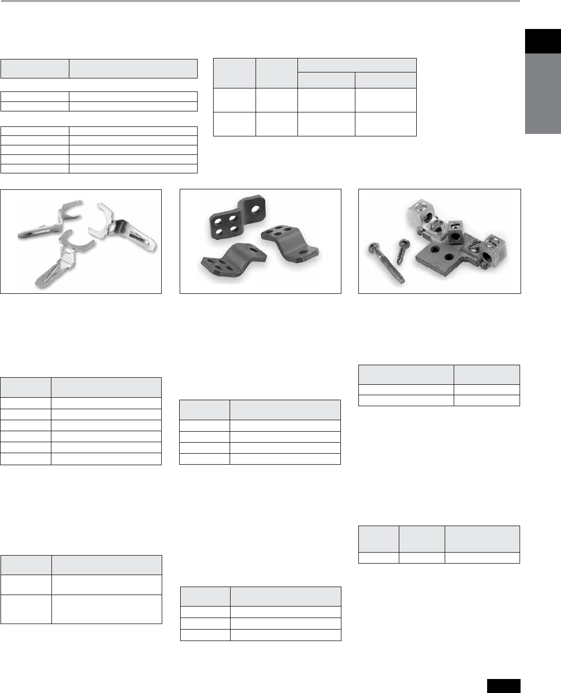
1Disconnect
switches
Siemens Canada Limited Power Product Catalogue 1-43
Disconnect Switches
Type VBII (30-600A) with Flange Mounted Operating Handle
Selection & Accessories
Class R Fuse Clip Kits
These kits prevent the installation of
Class H and K fuses (one kit required per
switch).
Internal Door Latch Kits
For use with enclosures with door
mounted latching bar. Required when a
flange mounted switch is mounted in a
Hoffmann or Rittal enclosure provided
with an AB cutout.
Class J Fuse Provisions
All 30-600A, 600V fusible switches are
field convertible to accept Class J fuses
by moving the load base to a pre-drilled
J fuse position.
200% Neutral Kits
CSA certified 200% Neutrals are avail-
able on 60 & 100A switches. They are
typically used with non-linear transform-
ers or where increased neutral ampacity/
lug capacity is required.
Neutral Kitsd
Standard Neutral Kits can be field
installed in 30-100A switches.
HR612 HNC612
HT63
a
Dimensions (min. & max.) from enclosure mounting pan
to outside surface of enclosure handle mounting flange.
b 7.12 for 200A switches.
c One kit per pole required.
Window Kits (Type 1, 12, 3R and 4x)
Allows viewing of visible blades and of
indicating fuses through 200A.
Class T Fuse Adapter Kits
100-600A fusible switches are field
convertible to accept Class T fuses.
400-600A switches are field convertible
to accept Class T fuses by moving the
load base to a pre-drilled T fuse position.
Class T Fuse Adapter Kitsc
Catalogue Number Operating Handle Description
Plastic Handles
VBH1 30-200A Type 1, 3R & 12
VBH14X 30-200A Type 4X
Metal Handles
VBH112 30-200A Type 1, 3R & 12
VBH14 30-200A Type 4X
VBH2 400A Type 1 & 12
VBH2R 400 & 600A Type 1, 3R & 12
VBH24X 400 & 600A Type 4X
Flange Mounted Operating Handles
For use with Panel Mounted Switches. Plastic handle is includ-
ed with Flange Mounted Switches as standard.
Catalogue
Number Description
DKR2 2 point (for use with
enclosures less than 40" high)
3 point (for use with
DKR3 enclosures 40" or larger
in height)
Catalogue
Number Description
VBWK1 30A Window Kit
VBWK2 60 & 100A Window Kit
VBWK3 200-600A Window Kit
Rigid Linkage Kits
For use with Panel Mounted Switches. Not
required for Flange Mounted Switches.
HR21 30A, 240V Kit (HD only)
HR612 30A, 600V Kit/60A, 240V Kit
HR62 60A, 600V Kit
HR63 100A Kit
HR64 200A Kit
HR656 400A/600A Kit
Class R Fuse Clip Kits
Catalogue
Number Description
Catalogue
Number Description
HT23 100A, 240V Kit
HT63 100A, 600V Kit
HT24 200A, 240V Kit
HT64 200A, 600V Kit
Neutral Kits
30A 600V, 60A 240V HNC612
60A, 600V & 100A HNC623
Switch Kit Catalog
Ampere Rating Number
200% Neutral Kits
Switch Kit
Ampere Catalogue Wire Range Line &
Rating Number Load Lugs (Cu/Al)
60 & 100A HNC263 (2) #14-1/0 AWG
Catalogue
Number
Switch
Amprere
Rating
Enclosure Deptha - Inches (mm)
Min. Max.
VBLK1
VBLK2
30-200
30-200
6.94b (176)
6.94b (176)
6.94b (176)
19.0
(483)
VBLK3
VBLK4
400 & 600
400 & 600
9.00 (229)
9.00 (229)
8.75
(222)
19.0
(483)
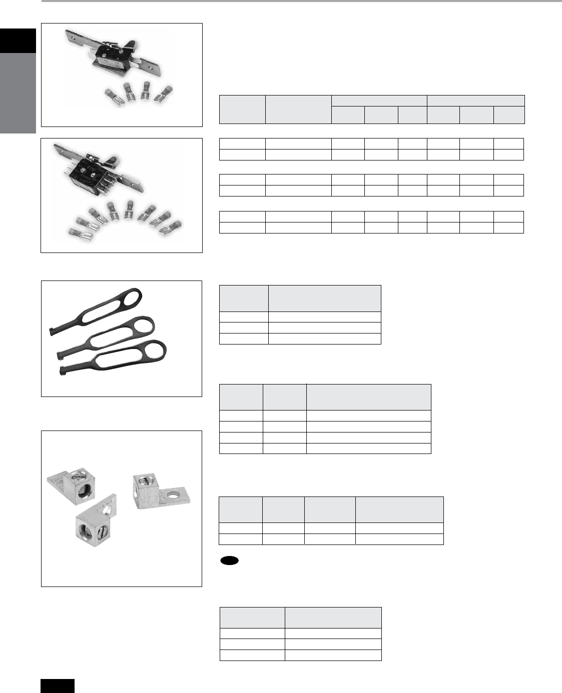
1
Disconnect
switches
Siemens Canada Limited Power Product Catalogue
1-44
Disconnect Switches
Type VBII (30-600A) with Flange Mounted Operating Handle
Accessories
Fuse Puller Kits
Fuse Puller Kits are field installable in 30-100A Type VBII Heavy Duty
Switches (one kit required per 3-pole switch).
Internal Shield Kits (for fusible switches)
Kits provide a “skirt” that encloses the VBII switch and also a clear plastic
inner door to prevent accidental contact with live parts. Test probe holes
are provided and fuses can be replaced without removal of kit.
Auxiliary Contacts
The auxiliary contacts are available in 1 normally open and 1 normally closed
or 2 normally open and 2 normally closed configurations. Siemens offers a
PLC Auxiliary Switch (30-200A) that has very low resistance for low voltage
and current typical in PLC circuits. All auxiliary contacts make after and break
before main switch contacts.
30-200 HA161234 10 10 — 1/2 3/4 —
400-600 HA165678 10 10 — 1/2 3/4 —
Switch Kit Ampere Rating Kit Horsepower Rating
Ampere Aux. Switch 125V AC 250V AC 28V DC 125V AC 250V AC 28V DC
Rating Catalogue Number Max. Max. Max. Max. Max. Max.
With 1 NO & 1 NC Isolated Contacts
30-200 HA261234 10 10 7 1/2 3/4 —
400-600 HA265678 10 10 7 1/2 3/4 —
With 2 NO & 2 NC Isolated Contacts
30-200 HA361234 10 10 — 1/2 3/4 —
400-600 HA365678 10 10 — 1/2 3/4 —
Low Current PLC Type with 1 NO & 1 NC Gold Plated Contacts
030 HP61
060 HP62
100 HP63
Switch
Ampere Fuse Puller Kit
Rating Catalogue Number
30A HSK61
60-100A HSK623
200A HSK64
Switch Shield Kit
Ampere Rating Catalogue Number
HA161234
HA261234
HP61
HLC612
Copper Lug Kits
All switches are CSA approved to accept field installed copper lug kits.
30–60 HLC612 (9) Lugs/Kit #14-4 AWG Cu
100 HLC63 (9) Lugs/Kit #14-1/0 AWG Cu
200 HLC64 (9) Lugs/Kit #6 AWG-300 Kcmil Cu
400–600A HLC65678 (1) Lugs/ Kit #1/0 AWG-600 Kcmil Cu
Switch Copper Lug
Ampere Catalogue
Rating Number Description
Equipment Ground Kits
Equipment Ground Lug Kits are available for all switches.
30–200 HG61234 2 #14-4 AWG
400 & 600 HG656 4 #6 AWG-250 Kcmil
Switch
Ampere Catalogue Number of Wire Range
Rating Number Terminals Per Terminal (Cu/Al)
NEW
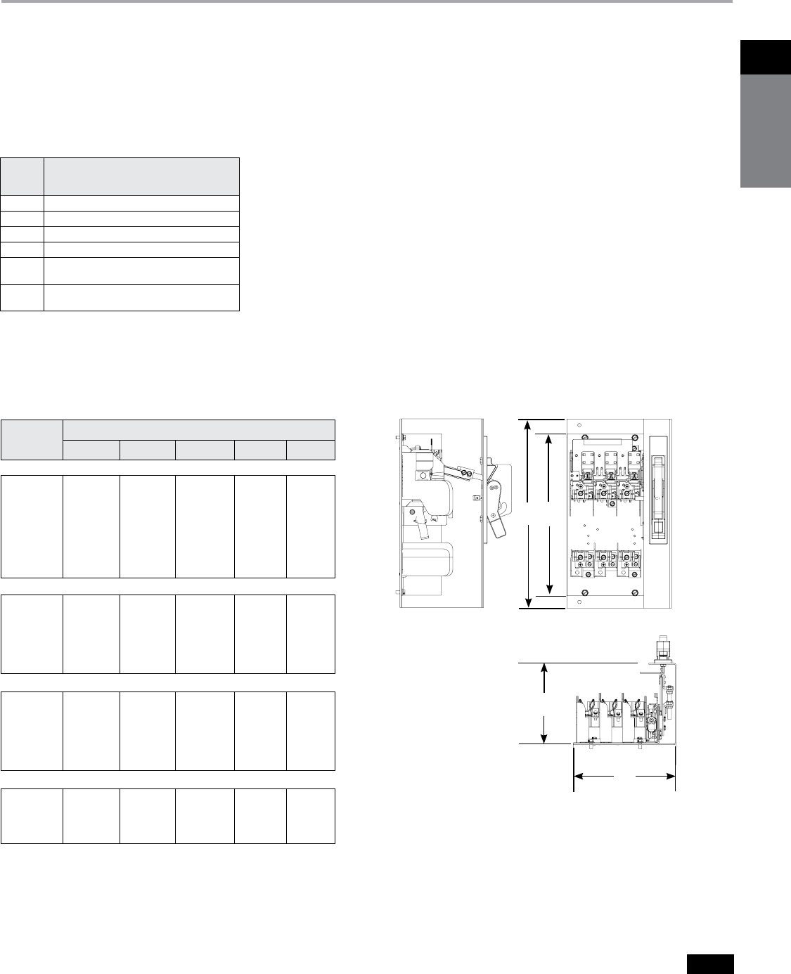
1Disconnect
switches
Siemens Canada Limited Power Product Catalogue 1-45
Disconnect Switches
Type VBII (30-600A) with Flange Mounted Operating Handle
Lug Wire Ranges & Dimensions
Lugs
30 & 60A switches are suitable for use with 60° or 75°C wire. 100–600A
switches are suitable for use with 75°C rated wire. All switches are supplied
with factory installed line and load lugs.
Approximate Dimensions
Mounting bracket shown with handle installed is supplied
with Flange Mounted Switches only. All Panel Mounted
Switches have a “L” shaped mounting pan with a line base,
load base (if fusible) and mechanism installed.
A
B
D
C
a
Dimension C for panel mounted switches indicates the minimum width from the left
hand edge of the switch mounting pan to the right hand inside surface of the enclosure.
Switch
Ampere
Rating Lug Wire Range
30 #14-2 AWG (Cu/Al)
60 #14-2 AWG (Cu/Al)
100 #14-1/0 AWG (Cu/Al)
200 #6 AWG-300 Kcmil (Cu/Al)
400 (1) 1/0 AWG-750 Kcmil (Cu/Al) or
(2) 1/0 AWG-250 Kcmil (Cu/Al)
600 (2) 1/0 AWG-750 Kcmil (Cu/Al) or
(4) 1/0 AWG-250 Kcmil (Cu/Al)
Wire Ranges
(Line, Load and Standard Neutral)
Catalogue
Number
Dimensions - Inches (mm)
A B CaD (min) D (max)
Fusible, Panel Mounted
VBFS321
VBFS322
VBFS361
VBFS362
VBFS363
VBFS364
VBFS365
VBFS366
11.88 (302)
13.12 (333)
11.88 (302)
13.12 (333)
13.12 (333)
17 (432)
26.25 (667)
26.25 (667)
N/A
N/A
N/A
N/A
N/A
N/A
N/A
N/A
7.47 (189)
8.50 (216)
7.47 (189)
8.50 (216)
8.50 (216)
12.33 (313)
16.50 (419)
16.50 (419)
6.94 (176)
6.94 (176)
6.94 (176)
6.94 (176)
6.94 (176)
7.12 (181)
8.63 (219)
8.63 (219)
19 (483)
19 (483)
19 (483)
19 (483)
19 (483)
19 (483)
19 (483)
19 (483)
Non-fusible, Panel Mounted
VBNFS361
VBNFS362
VBNFS363
VBNFS364
VBNFS365
VBNFS366
9.79 (249)
9.79 (249)
9.79 (249)
10.77 (234)
13 (330)
13 (330)
N/A
N/A
N/A
N/A
N/A
N/A
7.47 (189)
8.50 (216)
8.50 (216)
12.33 (313)
16.50 (419)
16.50 (419)
6.94 (176)
6.94 (176)
6.94 (176)
7.12 (181)
8.63 (219)
8.63 (219)
19 (483)
19 (483)
19 (483)
19 (483)
19 (483)
19 (483)
Fusible, Flange Mounted
VBFS321F
VBFS322F
VBFS361F
VBFS362F
VBFS363F
VBFS364F
11.88 (302)
13.12 (333)
11.88 (302)
13.12 (333)
13.12 (333)
17 (432)
14.08 (358)
15.83 (402)
14.08 (358)
15.83 (402)
15.83 (402)
18.20 (462)
7.47 (189)
8.85 (225)
7.47 (189)
8.85 (225)
8.85 (225)
12.68 (322)
7.27 (185)
7.27 (185)
7.27 (185)
7.27 (185)
7.27 (185)
7.57 (192)
N/A
N/A
N/A
N/A
N/A
N/A
Non-fusible, Flange Mounted
VBNFS361F
VBNFS362F
VBNFS363F
VBNFS364F
9.79 (249)
9.79 (249)
9.79 (249)
10.77 (274)
11.78 (299)
11.78 (299)
11.78 (299)
11.97 (304)
7.47 (189)
8.85 (225)
8.85 (225)
12.68 (322)
7.27 (185)
7.27 (185)
7.27 (185)
7.57 (192)
N/A
N/A
N/A
N/A
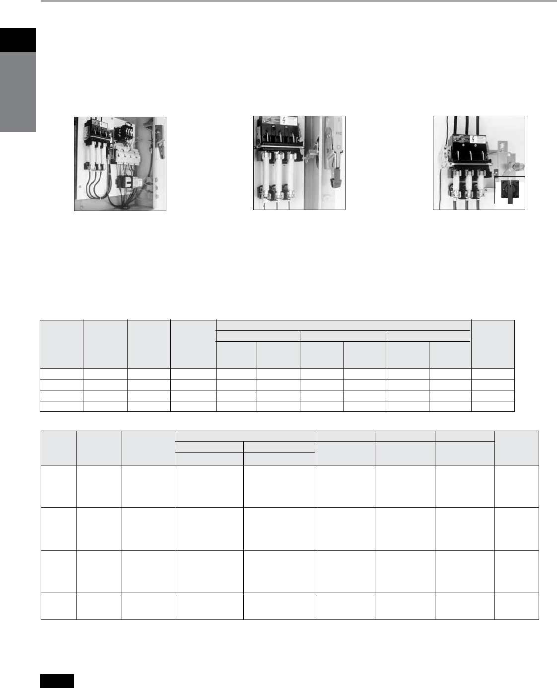
1
Disconnect
switches
Siemens Canada Limited Power Product Catalogue
1-46
Disconnect Switches
Type MCS (30-200A) — Switches, Fuse and No Fuse Kits
Selection
Features
b
30, 60, 100 and 200 Ampere Switches
b
CSA Certified under file #84625 and
UL Recognized under file #E121152
b
Simple Mounting — with an integral
switch and over center mechanism
b
Horsepower & load break rated
b
Compact Size
b
Visible Blade Contacts
b
Rugged Construction — with a short
circuit current rating of 10,000 amps
with Class H or 200,000 amps at 600V
maximum AC, when fused with Class
R or Class J fuses
b
Available with three operator handle
options, allowing flexible placement
of switch
b
Field Installable Auxiliary Contacts
b
Flexible Fuse Class Configurations
b
Flange mounted handles meet NFPA79
requirements
Ordering Information
1. Select the basic switch size you need
(30, 60, 100 or 200 ampere).
2. Check the switch selected against the
maximum horsepower rating required
for our application. “L” or “R” suffix on
switch catalogue numbers denotes left
or right-handed mechanism drive.
3. Choose either fuse or no fuse kit from
chart below.
Information
4. Check “Minimum Dimensions
”
on page
1-47 for installation space requirements.
5. Select from the list of handle operators,
the type which best suits your
application. Handle operators can be
selected from the next page.
a
For “copper only” connectors, order as follows:
Fusible—order standard switch, standard fuse kit and cop-
per only no fuse kit.
Non-Fusible—order standard switch and copper only no
fuse kit.
b
Includes both line and load lugs.
c
For Class R fuses order Class H kit from this table and the
Class R conversion kit from the next page.
d
HP ratings for time delay fuses and for 250V DC also
apply to Non-fusible switches.
Type MCS Disconnect Switch with
Max-Flex™ handle operator
Type MCS Disconnect Switch with
rotary handle
Type MCS Disconnect Switch with
fixed-depth, flange-mounted handle
Basic Switches
Maximum Horsepower Rating, 3 Phased
Catalogue Catalogue 240 Volts AC 480 Volts AC 600 Volts AC 250
Switch Maximum Number Number Time Time Time Volts
Ampere Voltage Right Left Standard Delay Standard Delay Standard Delay DC
Rating Rating Hand Hand Fuse Fuse Fuse Fuse Fuse Fuse (max)d
130 600 MCS603R MCS603L 13 171/2 15 115 171/2 120 15
160 600 MCS606R MCS606L 171/2 15 15 130 15 150 10
100 600 MCS610R MCS610L 15 30 25 160 30 175 20
200 600 MCS620R MCS620L 25 60 50 125 60 150 40
Fuse and No Fuse Kits (Includes load base plus line and load fuse clips)
a
Basic
Switch
Ampere
Rating
Switch
Catalogue
Number
Kit
Description
No Fuse Kits For Class H For Class J For Class R
Lug
Wire
Size
Standard Cu Onlyb
Catalogue
Number a
Catalogue
Numbera
Catalogue
Number a
Catalogue Number Catalogue Number
1
30
MCS603R
or
MCS603L
No Fuse TMK606 — — — —
30A, 250V — — FCK203 —FCRK203 #14 to
30A, 600V — — FCK206 FCJK603 FCRK206 #4 AWG
60A, 250V — — FCK206 —FCRK206 Cu/AI
60A, 600V — — FCK606 FCJK606 FCRK606
1
60
MCS606R
or
MCS606L
No Fuse TMK606 — — — —
60A, 250V — — FCK206 —FCRK206 #14 to
60A, 600V — — FCK606 FCJK606 FCRK606 #4 AWG
100A, 250V — — OFCK661 OFCK661 cCu/AI
100A, 600V — — OFCK661 OFCK661 c
100
MCS610R
or
MCS610L
No Fuse TMK610 TMK610C ———
100A, 250V — — FCK610 FCK610 c#14 to
100A, 600V — — FCK610 FCK610 c#2/0 AWG
200A, 250V — — OFCK620 OFCK620 cCu/AI
200A, 600V — — OFCK620 OFCK620 c
200
MCS620R
or
MCS620L
No Fuse TMK620 TMK620C ———#6 to
200A, 250V — — FCK620 FCK620 c300 kcmil
200A, 600V — — FCK620 FCK620 cCu/AI

1Disconnect
switches
Siemens Canada Limited Power Product Catalogue 1-47
Disconnect Switches
Type MCS (30-200A)
Accessories
a
For Type 4 and 4X applications, order handle only
Catalogue Number
100A - FDH104 200A - FDH204
b
For Type 4 and 4X applications, order handle only
Catalogue Number FHOHS4
c
Standard cable length is 36 inches (914 mm). Alternate
lengths are available as follows:
Length Amps Cat. No.
48" (1219mm) 30–100 FHOEC048
60" (1524mm) 30–100 FHOEC060
48" (1219mm) 200 FHOJC048
60" (1524mm) 200 FHOJC060
d
For Type 4 and 4X applications, order handle only
Catalogue Number RHOH4
e
For Type 3 and 3R applications, order handle only
Catalogue Number RHOH
f
Min. enclosure depth from mounting pan to handle mount-
ing surfaces: 30-100A: 6.44" (164mm)
200A: 10.93" (278mm)
Panel Space Requirements Minimum Dimensions - Inches (mm)
“A” – Dimension is measured
from each cross bail pin.
“B” – Dimension is measured
from line side barrier to
load side barrier.
“C” – Dimension is measured
from line side terminal
of switch to load side
terminal of fuse load
base.
MCS Disconnect Switch Panel Space Requirements
Auxiliary Switch Kits
Switch
Catalogue Number
Contact Arrangement
1 NO/1 NC
Catalogue Number
2 NO/2 NC
Catalogue Number
MCS603R MCSAKR136 MCSAKR236
MCS603L MCSAKL136 MCSAKL236
MCS606R MCSAKR136 MCSAKR236
MCS606L MCSAKL136 MCSAKL236
MCS610R MCSAK116 MCSAK216
MCS610L MCSAK116 MCSAK216
MCS620R MCSAK126 MCSAK226
MCS620L MCSAK126 MCSAK226
Class R Fuse Conversion Kits
Fuse Clip Rating Catalogue Number
100A, 600V SSRK33
200A, 600V SSRK34
Fuse Ejector Kits
Switch
Catalogue Number
Fuse Ejector Kit
Catalogue Number
MCS610 FE100
MCS620 FE200
Handle Operators
Fixed Depth, Flange Mounted, Types 1, 3, 3R, 12af
Switch
Catalogue Number
Complete Handle Mechanism Handle Only Switch Operator Only
Catalogue Number Catalogue Number Catalogue Number
MCS603R FDFS06R FDH10 FDS06R
MCS603L FDFS06L FDH10 FDS06L
MCS606R FDFS06R FDH10 FDS06R
MCS606L FDFS06L FDH10 FDS06L
MCS610R FDFS06R FDH10 FDS06R
MCS610L FDFS06L FDH10 FDS06L
MCS620R FDFS20R FDH20 FDS20R
MCS620L FDFS20L FDH20 FDS20L
Variable Depth, Flange Mounted Max-Flex™, Types 1, 3, 3R, 12b
Switch
Catalogue Number
Complete Handle Mechanism Handle Only Switch Operator Only Cable Onlyc
Catalogue Number Catalogue Number Catalogue Number Catalogue Number
MCS603R FHOS06036R FHOHS FHOS06R FHOEC036
MCS603L FHOS06036L FHOHS FHOS06L FHOEC036
MCS606R FHOS06036R FHOHS FHOS06R FHOEC036
MCS606L FHOS06036L FHOHS FHOS06L FHOEC036
MCS610R FHOS06036R FHOHS FHOS06R FHOEC036
MCS610L FHOS06036L FHOHS FHOS06L FHOEC036
MCS620R FHOS20036R FHOHS FHOS20R FHOJC036
MCS620L FHOS20036L FHOHS FHOS20L FHOJC036
Variable Depth Rotary, Through-The-Door-Mounted, Types 1, 12de
Variable Depth Shaft Only Variable Depth
MCS603R CRHOS06VD CRHOH RHOS06 RHOSVD
MCS606R CRHOS06VD CRHOH RHOS06 RHOSVD
MCS610R CRHOS06VD CRHOH RHOS06 RHOSVD
MCS620R CRHOS20VD RHOH RHOS20 RHOSVD
Switch
Catalogue
Number Size "A" "B" "C"
Fuse
Class
MCS603
30A/240V
30A/600V
30A/240V
6.13 (156)
6.13 (156)
6.13 (156)
5.52 (140)
5.52 (140)
5.52 (140)
8.11 (206)
10.11 (257)
8.48 (215)
H, K, R
H, K, R
J
MCS606
60A/240V
60A/600V
60A/240V
6.13 (156)
6.13 (156)
6.13 (156)
5.52 (140)
5.52 (140)
5.52 (140)
7.86 (200)
10.38 (264)
8.35 (212)
H, K, R
H, K, R
J
MCS610
100A/240V
100A/600V
100A/240V
7.38 (188)
7.38 (188)
7.38 (188)
7.59 (193)
7.59 (193)
7.59 (193)
11.85 (301)
13.85 (352)
10.6 (269)
H, K, R
H, K, R
J
MCS620
200A/240V
200A/600V
200A/240V
9.17 (233)
9.17 (233)
9.17 (233)
9.00 (229)
9.00 (229)
9.00 (229)
14.7 (273)
17.2 (437)
13.32 (338)
H, K, R
H, K, R
J
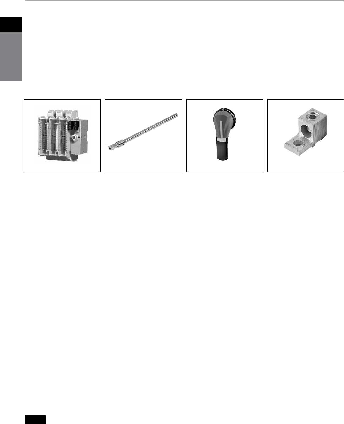
1
Disconnect
switches
Siemens Canada Limited Power Product Catalogue
1-48
Disconnect Switches
Type CFS Compact Fusible Switches
Features and Ordering Information
Features
b
30–400A ratings
b
CSA Certified under file #222227 and
UL Listed under file #E121152 & E68312
b
IEC 60 947-3 Certified & CE marked
b
Door mounted rotary handles with
defeatable cover interlock
b
Meets CSA requirements for both main
and branch circuit applications
b
Compact size
b
100KA with Class CC fuses or up to
200KA with Class J fuses
b
Load break and horsepower rated
b
Quick make and break operation
b
All handles are padlockable with up to
(3) padlocks with 5/16" hasps in the
OFF position
b
Catalogue number CFS361C5,
CFS361J5 & CNFS361 can be DIN-rail
mounted and can be either front or side
operated with standard rotary handles
b
Handles are available in Type 1, 3R,
4/4X & 12 ratings
b
NFPA 79 field installed kits are available
Ordering Information
1. Select the panel mounted switch
required based on Ampere, HP and
AIC requirements. Switches with a
right hand mechanism are standard.
30-100A switches with a left hand
mechanism are available.
2. Select handle based on environmental
rating required.
3. Select operating shaft (200 or 400mm
in length). For enclosure depths of 9.0”
or less from panel mounting surface to
inside of door use 200mm long shafts.
For deeper enclosures use 400mm
long shafts. 30A 65kA switches can be
used in 10” deep enclosures (panel to
inside of door) with 200mm shaft and
CFSH5N handles.
Note: Be sure to check shaft and handle
compatibility with the switch selected
by using the information provided in the
selection tables.
4. Line & load lugs are provided as
standard on 30–100A switches.
Terminal kits are available for
200–800A switches if needed.
5. Auxiliary contacts are available if
needed as follows:
A. 30A switch CFS361C5 and non-
fusible 30A switch CNFS361 will
accept up to (4) aux contacts.
B. 30A switch CFS361J5 will accept
up to (2) aux contacts without an
aux contact holder. If more than (2)
aux contacts are required order aux
contacts PLUS aux contact holder kit
CFSAUXH1. All other switches will
accept up to (4) aux contacts.
6. If non-fusible switch is required
order a shorting bar for 60-600A
switches or catalogue number
CNFS361 for 30A.
7. 30–100A switches are designed to
prevent inadvertent contact with live
parts and shields are not required.
200–800A switches are supplied as
standard with line shields and terminal
shroud kits are available for the load
side.
CFS363JN with (2) CFSAUX1NO CFSL200CFSS10200HN
Switch Shaft Lugs/Accessories
CFSH10BL12N
Handle
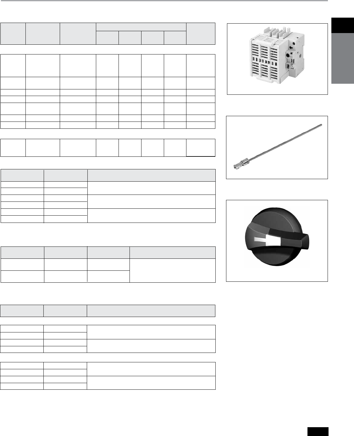
1Disconnect
switches
Siemens Canada Limited Power Product Catalogue 1-49
Disconnect Switches
Type CFS Compact Fusible Switches
Switch and Handle Selection
Operating Shafts for 30–400A switchese
Catalogue Shaft Length
Number In. (mm) Switch & Handle Compatibility
CFSS5200N 7.9 (200) 5mm x 5mm for use with CFS361C5, CFS361J5 &
CFSS5400N 15.7 (400) CNFS361 switches & with “CFSH5” handles only
CFSS5200HN 7.9 (200) 5mm x 5mm for use with all “CFSH10” handles & with
CFSS5400HN 15.7 (400) CFS361C5, CFS361J5 & CNFS361 switches only
CFSS10200HN 7.9 (200) 10mm x 10mm for use with all “CFSH10” handles & with
CFSS10400HN 15.7 (400) all 30–400A switches except CFS361C5, CFS361J5 & CNFS361
Rotary Operating Handles—Door Mounted (for use with
65kA CFS361C5, CFS361J5 & CNFS361 switches only)f
Rotary Operating Handles—Door Mounted (for use with
CFSS5200HN, CFSS5400HN, CFSS10200HN & CFSS10400HN)
CFSH10B12N Blue & Black Heavy duty pistol grip
CFSH10R12N Yellow & Red (2.75”(70mm) long for use with 30A switches & CFS362JN1)
CFSH10BL12N Blue & Black Heavy duty pistol grip (4.92”(125mm) long for 30–400A switches)
CFSH10RL12N Yellow & Red
Catalogue
Number Colour Description
Type 1, 3R & 12g
CFSH10B4N Blue & Black Heavy duty pistol grip
CFSH10R4N Yellow & Red (2.75”(70mm) long for use with 30A switches & CFS362JN1)
CFSH10BL4N Blue & Black Heavy duty pistol grip (4.92” (125mm) long for 30–400A switches)
CFSH10RL4N Yellow & Red
Type 1, 3R, 4/4X & 12g
CFS361J5
CFSS5400N
CFSH5B12N
Fusible Switches, 3-Pole 600V AC Max, 250V DC Maxe
a
Line and load lugs included.
b Line and load lugs are not included.
Order from table on next page if required.
c
DC HP rating shown requires (2) poles to be connected
in series.
d
DC HP rating shown requires (3) poles to be connected
in series.
e
Catalogue numbers CFS361C5, CFS361J5 & CNFS361
accept 5mm x 5mm operating shafts. All other 30–400A
switches accept 10mm x 10mm operating shafts.
f
Compact pistol grip design (2.75” long) with defeatable
cover interlock. Cover can be opened when handle is
padlocked in the OFF position.
g
Defeatable cover interlock provided. Cover cannot be
opened when handle is padlocked in the OFF position.
h
Catalogue number CNFS361 is a non-fusible switch.
i
4-Pole 600 & 800A switches, CFS466J & CFS467L are
also available.
j CFS366J and CFS367L are rated 250 & 600V DC when (2)
poles are connected in series.
k CNFS361 is rated 65kA when protected by Class J or CC
30A max. fuses.
Contact sales office for ordering information
Catalogue
Number Colour Type Operating Shaft Compatibility
CFSH5B12N Blue & Black 1, 3R & 12
CFSH5R12N Yellow & Red CFSS5200N or CFSS5400N
CFSH5B4N Blue & Black 1, 3R, 12 & 4/4X
CFSH5R4N Yellow & Red
Switch
Ampere
Rating
Catalogue
Number
Fuse Provisions
Provided
Max Horsepower Ratings AC
Short
Circuit
Rating
240V
3Ø AC
480V
3Ø AC
600V
3Ø AC
250V
DC
Standard—with Right Hand Mounted Mechanism
30a
CFS361C5
CFS361J5
CFS361JN
CNFS361h
Class CC
Class J
Class J
None
7.5
7.5
7.5
7.5
15
15
15
15
20
20
20
20
5c
5c
5c
5c
100kA
100kA
200kA
100kA
60aCFS362JN1
CFS362JN Class J 15
15
30
30
50
50
10c
10c
100kA
200kA
100aCFS363JN Class J 30 60 75 20c200kA
200bCFS364JN Class J 60 125 150 40d200kA
400bCFS365J
CFS365JN Class J 125
125
250
250
350
350
50d
50d
200kA
200kA
600bCFS366Jij Class J 200 400 500 —200kA
800bCFS367Lij Class J 200 400 500 —200kA
Optional—with Left Hand Mounted Mechanism
30a
60a
100a
Class J
7.5
15
30
15
30
60
20
50
75
5c
10c
20c
200kA

1
Disconnect
switches
Siemens Canada Limited Power Product Catalogue
1-50
Disconnect Switches
Type CFS Compact Fusible Switches
Selection and Accessories
a Supplied as standard on 30–100A switches.
b CFS361C5 and CNFS361 will accept (4) aux contacts
without an aux contact holder. CFS361J5 will accept (2)
aux contacts without an aux contact holder.
c Supplied as standard on all but 30A compact switches.
d 12.6 inch (320 mm) long operating shaft included.
e 11.3 inch (288 mm) long operating shaft included.
f Line side terminal shrouds supplied with switch.
g Defeatable cover interlock provided. Cover cannot
be opened when the handle is padlocked in the OFF
position.
Catalogue
Number Description
CFSL200 200A Lug Kit (6 lugs per kit) (1)#6–3/0
CFSL400N 400A Lug Kit (6 lugs per kit) (1)#2–600kcmil (for CFS365JN only)
CFSL400 CFS365J & 600–800A Lug Kit (6 lugs per kit) (2)#2–600kcmil
Terminalsa
CFSSB60 60A Shorting Bar Kit (3 links per kit)
CFSSB100 100A Shorting Bar Kit (3 links per kit)
CFSSB200 200A Shorting Bar Kit (3 links per kit)
CFSSB400 400A Shorting Bar Kit (3 links per kit)
CFSSB680 600 & 800A Shorting Bar Kit (1 link per kit)
Shorting Bars (no fuse kits)
Auxiliary Contacts (NEMA ratings AC A600 DC N600)
CFSAUXH1b Aux Contact Holder (CFS361J5, CFS361C5 & CNFS361)
CFSAUXH2 Aux contact holder required for CFS365J
CFSAUX1NO Aux Contact 1 NO (30–800A Sws)
CFSAUX1NC Aux Contact 1 NC (30–800A Sws)
CFS11AUX 1NO, 1NC Aux Contact Kit for use with CFSNFPA2N & 3N (side mount)
CFS22AUX 2NO, 2NC Aux Contact Kit for use with CFSNFPA2N & 3N (side mount)
CFSTS200Nf 200A Shroud Kit (Line or load 3-Pole kit)
CFSTS400Nf 400A Shroud Kit (Line or load 3-Pole kit)
CFSTS680f 600/800A 3-Pole Shroud Kit
CFSTS6804f 600/800A 4-Pole Shroud Kit
Terminal Shrouds (line or load)
CFSPLK Shaft Padlocking Kit for 30A Compact Switch when door is openc
CFSH5CDM Direct Mount Handle Kit for CFS361C5
CFSH5JDM Direct Mount Handle Kit for CFS361J5
30A Compact Switch Kits
Type CFS Fusible Switch Accessories
600 & 800A Rotary Operating Handles
—
Door Mounted 8.27" (210 mm) longg
CFSL200 & 400
CFSAUX1NC
CFS5B100 – 400
NFPA 79 Kits
Kits provide an operating shaft suitable for use with all heavy duty handles
(not for use with CFSH5 handles). Kits also provide an internal operating
handle & an internal OFF padlocking provision.
CFSNFPA1d For use with CFS361C5, CFS361J5 & CNFS361
CFSNFPA2Ne For use with CFS361JN, CFS361CN, CFS362JN & CFS363JN
CFSNFPA2 For use with CFS365J only (requires previous handle design)
CFSNFPA3N For use with CFS364JN & CFS365JN
Note: CFSNFPA2N & CFSNFPA3N cannot be used in combination with CFSAUX1NO or CFSAUX1NC auxiliary contacts.
Catalogue Number Colour CSA Type
CFSH12BL12 Blue & Black 1, 3R & 12
CFSH12RL12 Yellow & Red 1, 3R & 12
CFSH12BL4 Blue & Black 1, 3R, 12 & 4/4X
CFSH12RL4 Yellow & Red 1, 3R, 12 & 4/4X
600 & 800A Operating Shafts (Cross section 12X12 mm)
Catalogue
Number
Shaft Length
In. (mm)
Enclosure Depth
(switch mounting surface to door OD)
CFSS12200H 12.59 (320) 10.43 — 16.68 inches (265-424 mm)
CFSS12400H 15.75 (400) 10.43 — 19.84 inches (265-504 mm)
1Disconnect
switches
Siemens Canada Limited Power Product Catalogue 1-51
Disconnect Switches
Type CFS Compact Fusible Switches
Dimensions and Technical Characteristics
Switch Mechanical
Ampere Wire Range
Rating of Lug (75°C)
30 #14–10 Cu
60 #10–3 Cu
100 #12–1 Cu
200 #6–3/0 Cu/Al
400 CFS365J (2) #2-600 kcmil Cu/Al
400 (1)#2–600 kcmil Cu/Al
600 (2)#2–600 kcmil Cu/Al
800 (2)#2–600 kcmil Cu/Al
Wire Ranges Line & Load Lugs
CSA & UL Technical Characteristics and Panel Space Requirements
a Minimum dimension from mounting surface to inside
of cover. Dimensions shown can be decreased if aux
contacts are not required.
b CNFS361 is rated 100kA when protected by 30A max.
Class J or CC fuses.
Catalogue
Number Amps
Fuse
Class
AC Short
Circuit Rating
Electrical
Endurance
Mechanical
Endurance
Panel Space Requirements – Inches (mm)
Height Width Deptha
CFS361C5 30 CC 100kA 6000 10000 4.56 (116) 3.78 (96) 6.00 (152)
CFS361J5 30 J 100kA 6000 10000 4.56 (116) 4.15 (96) 6.00 (152)
CFS361JN 30 J 200kA 6000 10000 5.35 (136) 5.89 (150) 6.00 (152)
CFS361JL 30 J 200kA 6000 10000 5.88 (149) 6.75 (171) 7.00 (178)
CNFS361 30 None 100kAb6000 10000 4.56 (116) 3.78 (96) 6.00 (152)
CFS362JN1 60 J 100kA 6000 10000 5.35 (136) 5.89 (150) 6.00 (152)
CFS362JN 60 J 200kA 6000 10000 7.32 (186) 5.89 (150) 6.00 (152)
CFS362JL 60 J 200kA 6000 10000 5.88 (149) 6.75 (171) 7.00 (178)
CFS363JN 100 J 200kA 6000 10000 7.32 (186) 5.89 (150) 6.00 (152)
CFS363JL 100 J 200kA 6000 10000 7.19 (183) 8.25 (210) 7.00 (178)
CFS364JN 200 J 200kA 6000 8000 11.46 (291) 7.72 (196) 6.00 (152)
CFS365J 400 J 200kA 1000 6000 14.94 (363) 11.94 (303) 8.00 (203)
CFS365JN 400 J 200kA 1000 6000 15.35 (390) 10.19 (259) 8.00 (203)
CFS366J 600 J 200kA 1000 5000 11.81 (300) 14.33 (364) 11 (280)
CFS466J 600 J 200kA 1000 5000 11.81 (300) 18.03 (458) 11 (280)
CFS367L 800 L 200kA 500 3500 11.81 (300) 14.33 (364) 11 (280)
CFS467L 800 L 200kA 500 3500 11.81 (300) 18.03 (458) 11 (280)
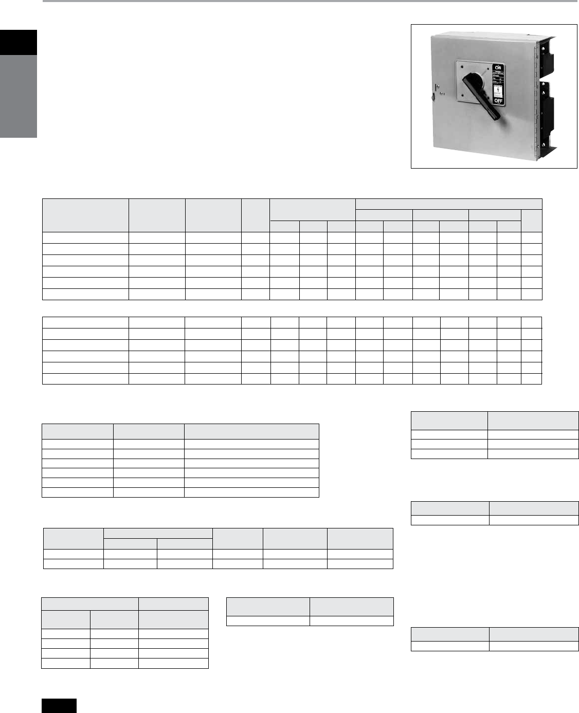
1
Disconnect
switches
Siemens Canada Limited Power Product Catalogue
1-52
Features
b
CSA certified under file #24563 and UL
Listed under file #E6849 Vol 1, Sect. 8
b
400-1200A ratings
b
Visible contacts
b
Field installable shunt trip and auxiliary
switch accessory kits
b
Installs in existing Siemens
switchboards
b
Suitable for use on systems with up to
200,000A available fault current,
RMS symmetrical when equipped with
Class J or Class L fuses
b
Group mounts with other 30A through
600A switches, and 100 through 1200
amp frame breakers
b
Allows 800A and 1200A switches in
standard 38" wide distribution sections
in either main or branch configurations
b
16 1
⁄4" mounting height is the smallest
1200A design in the industry, allowing
up to 4 units in one vertical section
b
Field reversible horizontal mounting
design for left or right hand cabling
b
Handle can be padlocked in the OFF
position with up to three padlocks with
5/16" hasps. A cover padlocking
provision is also supplied
Disconnect Switches
Type HCP Switchboard Units, Accessories
Selection
*For inches / millimeters conversion, multiply inches by
25.4.
s
Built to order. Allow 6–8 weeks for delivery.
a
For horizontal mounting only in either 38" wide min
switchboards or S5/F2 power panelboards.
b
Both 240 and 600V AC switches are also rated 250V DC
max.
3-Pole, Horizontal Mount a
3-Pole, Vertical Mount
HCP367VJ400 1400 600 J 17.00 16.25 7.38 150 125 100 250 125 350 40
HCP367VJ600s 1600 600 J 17.00 16.25 7.38 175 200 150 400 200 400 40
HCP327VT 800 240 T 17.00 16.25 7.38 100 250 — — — — 50
HCP367V 1800 600 L 17.00 16.25 7.38 100 250 200 500 250 500 50
HCP328VT 1200 240 T 17.00 16.25 7.38 100 250 — — — — 50
HCP368V 1200 600 L 17.00 16.25 7.38 100 250 200 500 250 500 50
Compression Lug Adapter Kit
The use of this kit provides for the
mounting of up to four lugs per phase.
Each kit accepts lugs with (2) 3/8" diam-
eter mounting holes on 1" centers. One
kit per pole line or load is required. Lugs
are not provided.
T Fuse Adapter Kits (one per pole)
Catalogue
Number Description
TFAK72 1800A, 300V AC
TFAK75 1800A, 600V AC
TFAK82 1200A, 300V AC
HCP Replacement Handle Kit
(For use on all HCP switches)
SW Ampere Rating Catalogue Number
400–1200A HCPHK
Ampere Rating Catalog Number
400–1200A HCPCLP
Shunt Trip Kit
Control Voltage
AC DC
Catalogue
Number
120 — HCPST120
240 — HCPST240s
277 — HCPST277
480 — HCPST480s
Switchboard Connection Strap Kita
Switch
Ampere Rating Catalogue Number
400–1200A F6162DCAN
Auxiliary Switch Kits
Contact
Ampere Rating
Maximum Voltage Switch
Mounting Contacts
Catalogue
NumberAC DC
15A 480 125 Left Pole 1NO/1NC A01HCPL4s
15A 480 125 Right Pole 1NO/1NC A01HCPR4
Accessories
Terminal Connectors (one lug per kit)
Ampere Rating Catalogue Number Connector Wire Range
400–600A TA2K500 (2) #1 AWG–500 kcmil (Cu or AI)
400–600A TC2K500 (2) #1 AWG–500 kcmil (Cu only)
400–800A TA3K500 (3) #1 AWG–500 kcmil (Cu or AI)
400–800A TC3K350 (3) #1 AWG–350 kcmil (Cu only)
800-1200A TA4H500 (4) #2 AWG–500 kcmil (Cu or AI)
800-1200A TA3H750 (3) 250–750 kcmil (Cu or AI)
Maximum Maximum Horsepower Rating
Catalogue Ampere AC Voltage Fuse Dimensions (inches*) 240V 480V 600V 250V
Number Rating Ratingb Class H W D Std Max Std Max Std Max DC
HCP367HJ400 1400 600 J 16.25 17.22 7.38 150 125 100 250 125 350 40
HCP367HJ600 1600 600 J 16.25 17.22 7.38 175 200 150 400 200 400 40
HCP327HT 800 240 T 16.25 17.22 7.38 100 250 — — — — 50
HCP367H 1800 600 L 16.25 17.22 7.38 100 250 200 500 250 500 50
HCP328HT 1200 240 T 16.25 17.22 7.38 100 250 — — — — 50
HCP368H 1200 600 L 16.25 17.22 7.38 100 250 200 500 250 500 50
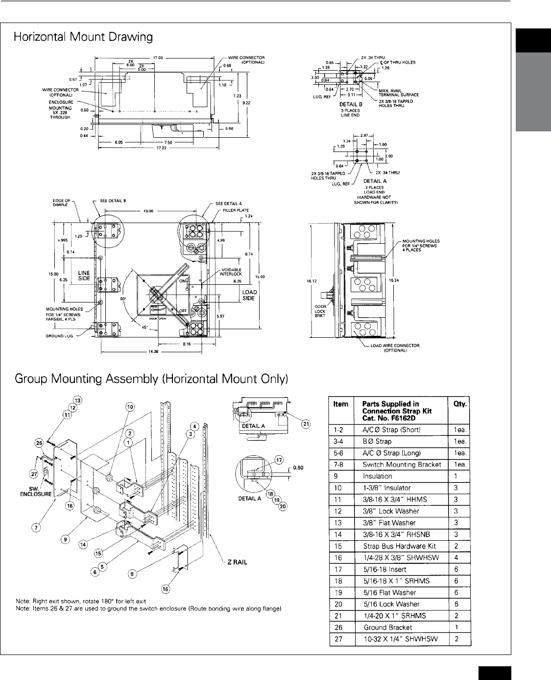
1Disconnect
switches
Siemens Canada Limited Power Product Catalogue 1-53
Disconnect Switches
Type HCP Switchboard Units
Dimensions

1
Disconnect
switches
Siemens Canada Limited Power Product Catalogue
1-54
Notes
