Schneider Electric Sensors Master Catalog 1000283156
104879-Catalog 104879-Catalog 104879-Catalog B4 unilog cesco-content
1000470827-Catalog 1000470827-Catalog 1000470827-Catalog B5 unilog cesco-content
2016-07-29
: Pdf 1000283156-Catalog 1000283156-Catalog B2 unilog
Open the PDF directly: View PDF ![]() .
.
Page Count: 172 [warning: Documents this large are best viewed by clicking the View PDF Link!]
Sensors
Proximity, Photoelectric, and Ultrasonic
Sensors, Limit Switches, Pressure
Sensors, Machine Safety, Encoders,
RFID, and Machine Cabling
This document provided by Barr-Thorp Electric Co., Inc. 800-473-9123 www.barr-thorp.com

5/1
1
Contents 5–OsiSense® XU Photoelectric
sensors
Selection guide . . . . . . . . . . . . . . . . . . . . . . . . . . . . . . . . . . . . . . . . . . . . . page 5/4
Multimode: Simpliity through innovation . . . . . . . . . . . . . . . . . . . . . . . . . page 5/14
Overview . . . . . . . . . . . . . . . . . . . . . . . . . . . . . . . . . . . . . . . . . . . . . . . . page 5/16
OsiSense® XU cylindrical
Design ø18
XUB0 multimode function, metal or plastic . . . . . . . . . . . . . . . . . . . . . page 5/28
XUB• single mode function, plastic . . . . . . . . . . . . . . . . . . . . . . . . . . page 5/30
XUB• single mode function, metal . . . . . . . . . . . . . . . . . . . . . . . . . . . page 5/32
XU5 luminescence sensor . . . . . . . . . . . . . . . . . . . . . . . . . . . . . . . . . page 5/34
XUBT for detection of transparent materials . . . . . . . . . . . . . . . . . . . . page 5/36
Food & Beverage–XUB0, stainless steel, multimode function . . . . . . page 5/38
Food & Beveverage–XU•, stainless steel, single mode function . . . . . page 5/40
XUBL laser thru-beam transmission . . . . . . . . . . . . . . . . . . . . . . . . . . page 5/44
Material Handling–XU5 with analog output signal 4–20 mA . . . . . . . . page 5/46
Material Handling–XU2 thru-beam system with high excess gain . . . page 5/48
Design 18, AC or DC supply, solid-state output
with adjustable sensitivity . . . . . . . . . . . . . . . . . . . . . . . . . . . . . . . . . . page 5/50
Design ø8
Assembly–metal case, cylindrical, threaded M8x1 . . . . . . . . . . . . . . . page 5/52
OsiSense® XU compact design
Dual mount design
XUN single and multimode function . . . . . . . . . . . . . . . . . . . . . . . . . . page 5/54
Miniature design
XUM0 multimode function, plastic . . . . . . . . . . . . . . . . . . . . . . . . . . . page 5/56
XUM• single mode function, plastic . . . . . . . . . . . . . . . . . . . . . . . . . . page 5/58
XUM•single mode function, metal . . . . . . . . . . . . . . . . . . . . . . . . . . . page 5/62
Compact design, 50 x 50
XUK0 mulitmode function, 5-wire AC or DC 1 C/O relay output . . . . . page 5/66
XUK• single mode, 5-wire AC or DC 1 C/O relay output . . . . . . . . . . . page 5/68
Material handling–XUK8 diffuse with adjustable
background suppression . . . . . . . . . . . . . . . . . . . . . . . . . . . . . . . . . . page 5/70
XUKT for detection of transparent materials . . . . . . . . . . . . . . . . . . . . page 5/72
1
2
3
4
5
6
7
8
9
10
This document provided by Barr-Thorp Electric Co., Inc. 800-473-9123 www.barr-thorp.com

5/2
1
Contents 5–OsiSense® XU Photoelectric
sensors
Detection of contrast
XUKR color mark reader . . . . . . . . . . . . . . . . . . . . . . . . . . . . . . . . . . page 5/74
XUKC for color detection . . . . . . . . . . . . . . . . . . . . . . . . . . . . . . . . . . page 5/76
XURK color mark reader . . . . . . . . . . . . . . . . . . . . . . . . . . . . . . . . . . page 5/78
XURC for color detection, Þ ber design, with teach mode . . . . . . . . . . page 5/80
Compact design, 60 x 54 diffuse with background suppression
Material handling–XUYP diffuse with laser transmission . . . . . . . . . . page 5/82
Material handling–XUYP diffuse with 2 channels using triangulation . page 5/84
Compact design, 30 x 92 x 77
XUX0 mulitmode function, 5-wire AC or DC 1 C/O relay output . . . . . page 5/86
XUX• single mode, 5-wire AC or DC 1 C/O relay output . . . . . . . . . . . page 5/88
Material handling–XUX8 diffuse with adjustable
background suppression . . . . . . . . . . . . . . . . . . . . . . . . . . . . . . . . . . page 5/90
OsiSense® XU limit switch design
Limit switch body type
XUC with stability LED and alarm output . . . . . . . . . . . . . . . . . . . . . . page 5/92
XUC AC or DC supply, 1 CO time delay relay output
with stability LED . . . . . . . . . . . . . . . . . . . . . . . . . . . . . . . . . . . . . . . . page 5/94
OsiSense® XU application sensors
Conveying series
XULH 3-wire DC . . . . . . . . . . . . . . . . . . . . . . . . . . . . . . . . . . . . . . . . . page 5/96
XULA 2-wire AC . . . . . . . . . . . . . . . . . . . . . . . . . . . . . . . . . . . . . . . . . page 5/97
XULM 5-wire AC or DC 1 C/O relay output . . . . . . . . . . . . . . . . . . . page 5/100
Material handling series
XUJK analog output signal 4–20 mA and 0–10 V . . . . . . . . . . . . . . . . page 5/102
Conveying and access control series
XUY• miniature design 4-wire DC . . . . . . . . . . . . . . . . . . . . . . . . . . . page 5/104
XUY• miniature design 5-wire AC or DC 1 C/O relay output
or 3-wire DC with teach mode adjustment . . . . . . . . . . . . . . . . . . . . . page 5/106
Packaging series
XUMW thru-beam for detection of water and aqueous liquids . . . . . . page 5/108
1
2
3
4
5/
6
7
8
9
10
This document provided by Barr-Thorp Electric Co., Inc. 800-473-9123 www.barr-thorp.com

5/3
1
OsiSense® XU amplifi er and fi ber optics
AmpliÞ ers
XUDA ampliÞ ers with teach mode . . . . . . . . . . . . . . . . . . . . . . . . . . .page 5/110
XUYA ampliÞ ers for plastic or glass Þ ber optics . . . . . . . . . . . . . . . . .page 5/112
XUYD color mark readers with teach mode . . . . . . . . . . . . . . . . . . . .page 5/114
XUYA ampliÞ ers for illuminiation . . . . . . . . . . . . . . . . . . . . . . . . . . . . .page 5/116
Fibers
Plastic Þ ber optics with end Þ ttings for thru-beam . . . . . . . . . . . . . . . .page 5/118
Plastic Þ ber optics with end Þ ttings for diffuse . . . . . . . . . . . . . . . . . . page 5/120
Plastic Þ ber optics with end Þ ttings for full color . . . . . . . . . . . . . . . . page 5/122
Plastic Þ ber optics without end Þ ttings for thru-beam . . . . . . . . . . . . page 5/123
Glass Þ ber optics with end Þ ttings for diffuse and thru-beam . . . . . . page 5/124
EcoÞ ber system in Plastic for customer assembly . . . . . . . . . . . . . . page 5/130
Fiber optic accessories . . . . . . . . . . . . . . . . . . . . . . . . . . . . . . . . . . . . page 5/132
OsiSense® XU fork and frame
Forks design
XUVR/XUVA optical fork without adjustment . . . . . . . . . . . . . . . . . . page 5/135
XUY• optical fork with teach mode . . . . . . . . . . . . . . . . . . . . . . . . . . page 5/137
XUY• optical fork with laser transmission and with teach mode . . . . page 5/139
XUF•optical fork with teach mode, for detection of labels . . . . . . . . page 5/141
XUV•for detection of labels . . . . . . . . . . . . . . . . . . . . . . . . . . . . . . . page 5/143
XUVU ultrasonic fork, packaging series . . . . . . . . . . . . . . . . . . . . . . page 5/145
XUV•optical fork with integral ampliÞ er, mechanical
handling series . . . . . . . . . . . . . . . . . . . . . . . . . . . . . . . . . . . . . . . . . page 5/147
Frame design
XUVF•dynamic detection of passage of objects, conveying series . page 5/149
OsiSense® XU supporting pages
Accessories . . . . . . . . . . . . . . . . . . . . . . . . . . . . . . . . . . . . . . . . . . . . . page 5/151
Operating curves . . . . . . . . . . . . . . . . . . . . . . . . . . . . . . . . . . . . . . . . . page 5/158
Substitution table . . . . . . . . . . . . . . . . . . . . . . . . . . . . . . . . . . . . . . . . . page 5/168
Contents 5–OsiSense® XU Photoelectric
sensors
1
2
3
4
5
6
7
8
9
10
This document provided by Barr-Thorp Electric Co., Inc. 800-473-9123 www.barr-thorp.com
5/4
1
1
2
3
4
5/
6
7
8
9
10
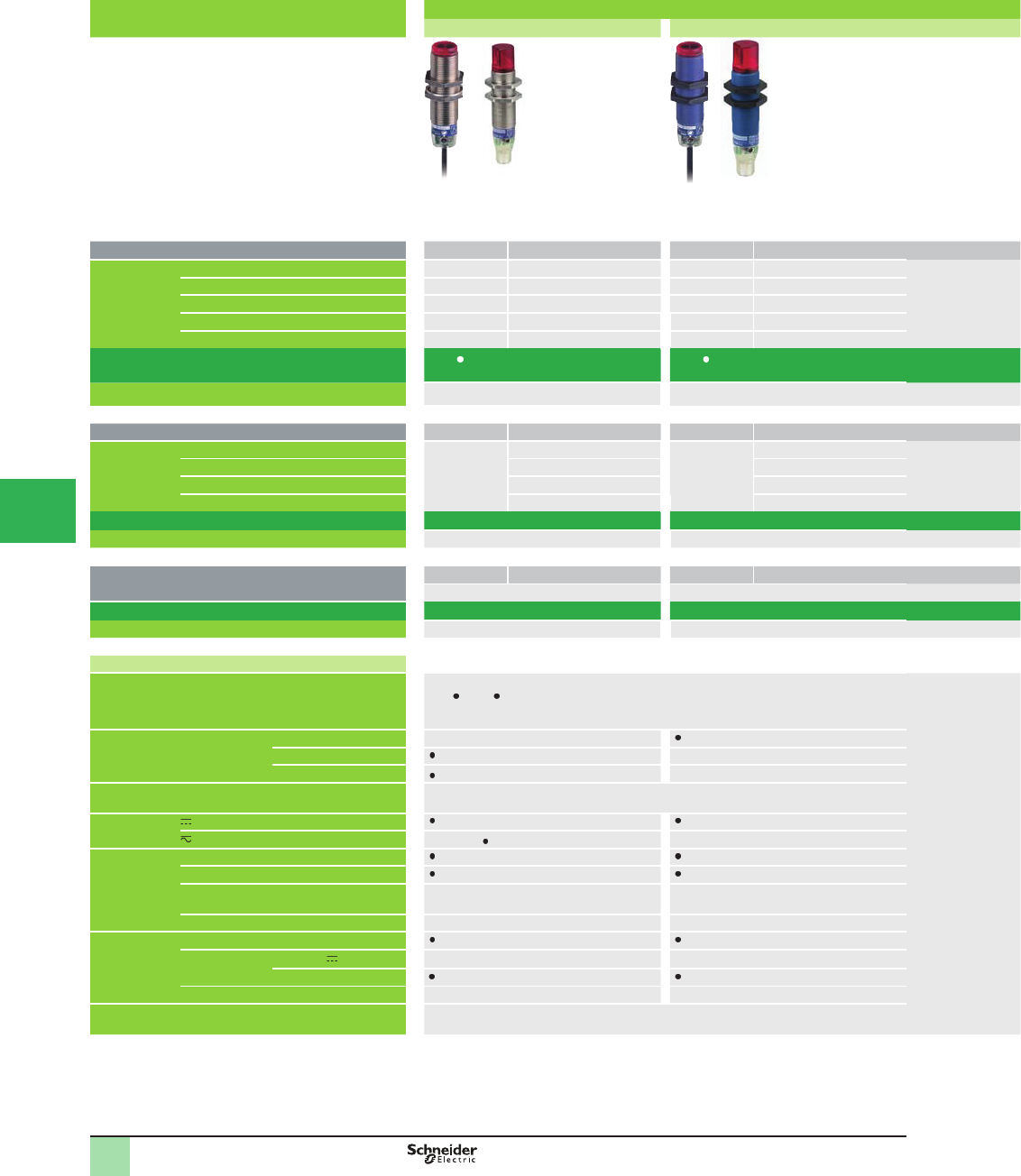
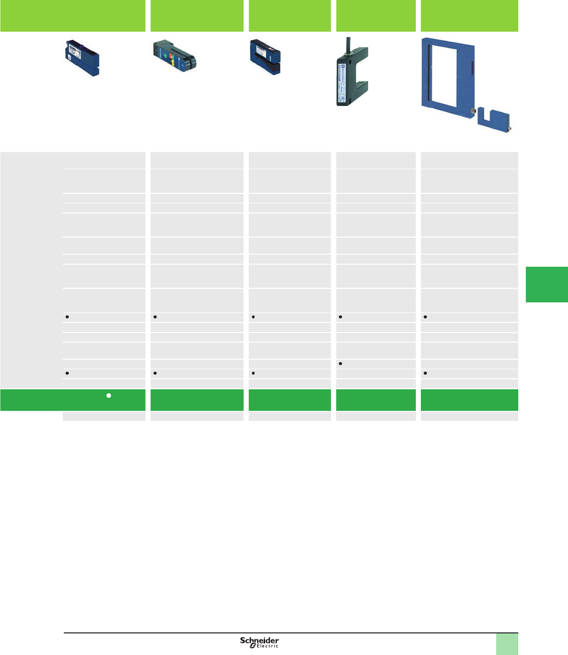
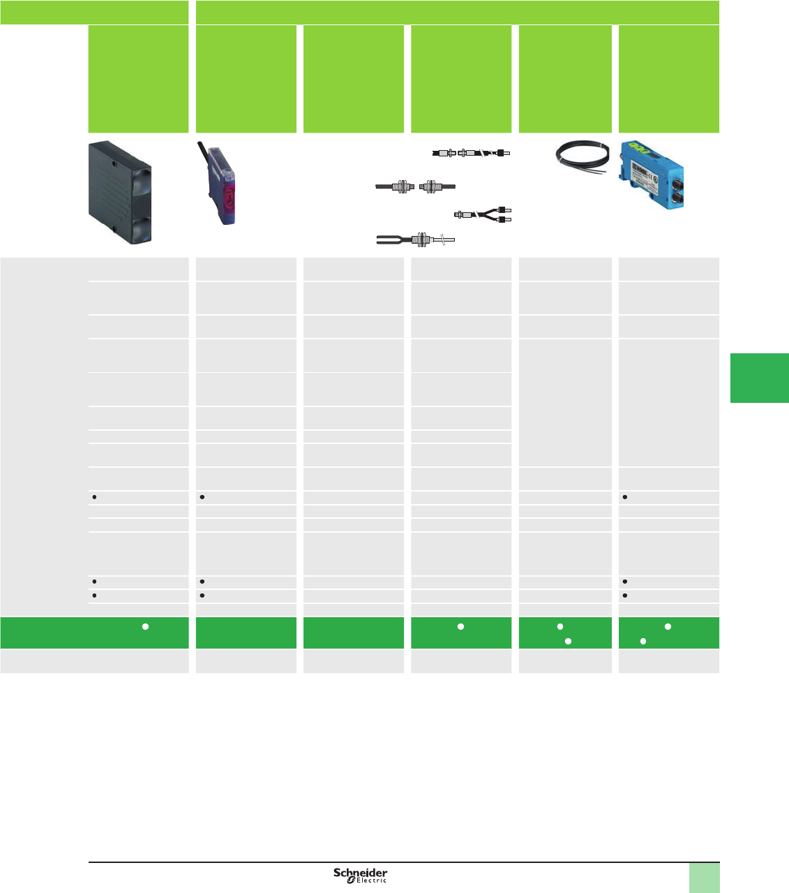
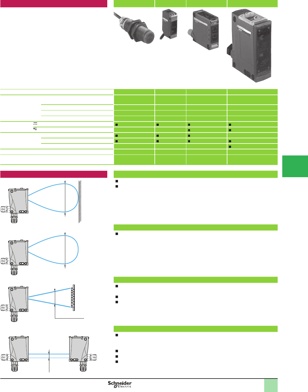
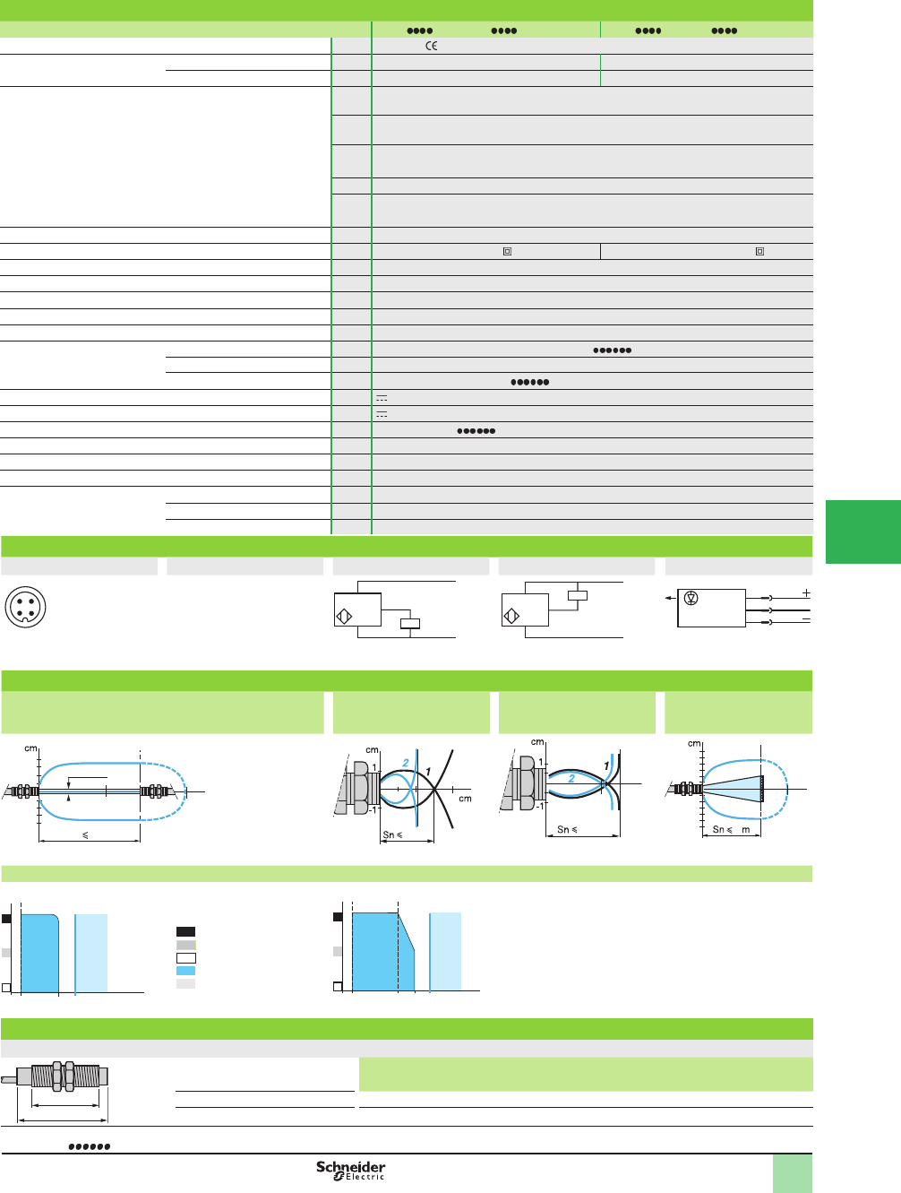
Format Design ø18
Metal Plastic
Single mode function Type Sensing distance, m (ft) Type Sensing distance, m (ft)
Sensing
distance, m (ft)
related to
system
Diffuse with adjustable sensitivity XUB5B 0.6 (1.97) XUB5A 0.6 (1.97)
Diffuse XUB4B 0.1 (0.33) XUB4A 0.1 (0.33)
Polarized retroreß ective XUB9B 2 (6.56) XUB9A 2 (6.56)
Retroreß ective XUB1B 4 (13.12) XUB1A 4 (13.12)
Thru-beam XUB2B 15 (49.21) XUB2A 15 (49.21)
Catalog Number XUB B (1) XUB A (1)
Pages 32 30
Multimode function Type Sensing distance , m (ft) Type Sensing distance, m (ft)
Sensing
distance, m (ft)
related to
system
Diffuse with background suppression XUB0B 0.12 (0.39) XUB0A 0.12 (0.39)
Diffuse 0.30 (0.98) 0.30 (0.98)
Polarized retroreß ective 2 (6.56) 2 (6.56)
Thru-beam 15 (49.21) 15 (49.21)
Catalog Number XUB0B (1) XUB0A (1)
Pages 28 28
High performance diffuse with adjustable background
suppression
Type Sensing distance, m (ft) Type Sensing distance, m (ft)
– –
Catalog Number – –
Pages – –
Specifi cations
Dimensions (w x h x d) in mm Ø 18, threaded M18 x 1.
XUB A/XUB B: length 46 (62 for XUB5 and connector version)
XUB0A/XUB0B: length 62 (pre-cabled version) or length 78 (connector version)
Case Materials Plastic, PBT –
Nickel plated brass –
Stainless steel (XUB0S: see page 38 ) –
Degree of protection IEC 60529
DIN 40050
IP 65, IP 67 cable versions
IP 69K connector versions
Supply 3-wire (PNP/NPN)
5-wire, relay output (2-wire XU M18, see page 50 ) –
Function NO
NC
NO/NC – –
NO +NC – –
Connection Pre-cabled (L = 2 m) (2)
Connector M8 (4-pin) 3-wire – –
M12
Screw terminals – –
Remote connector M8 and M12 remote connectors available: consult the Sensor Competency Center.
(1) Sensors also available with line of sight 90° to case axis.
(2) Cable lengths of 5 and 10 m also available, depending on model.
Selection Guide OsiSense® XU
Photoelectric sensors
Single mode or multimode function
This document provided by Barr-Thorp Electric Co., Inc. 800-473-9123 www.barr-thorp.com
5/5
1
1
2
3
4
5
6
7
8
9
10
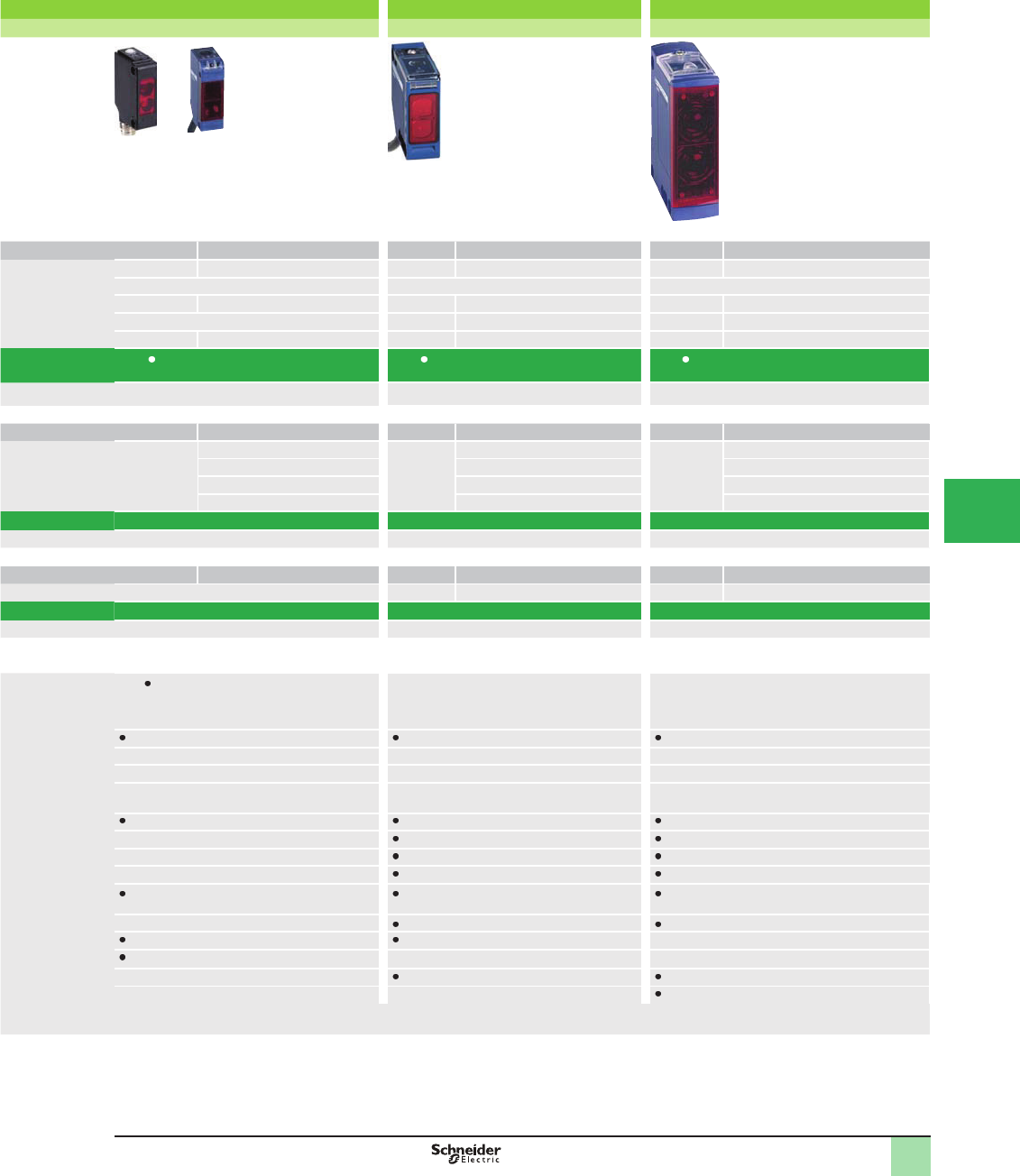
Miniature design Compact design, 50 x 50 Compact design, 92 x 71
Plastic Plastic Plastic
Type Sensing distance, m (ft) Type Sensing distance, m (ft) Type Sensing distance, m (ft)
XUM5A 1 (with adjustable sensitivity) XUK5A 1 (3.28) (with adjustable sensitivity) XUX5A 2 (6.56) (with adjustable sensitivity)
– – –
XUM9A 5 (with adjustable sensitivity) XUK9A 5 (16.40) XUX9A 11 (36.09) (with adjustable sensitivity)
– XUK1A 7 (22.97) XUX1A 14 (45.93) (with adjustable sensitivity)
XUM2A 15 (with adjustable sensitivity) XUK2A 30 (98.42) XUX2A 40 (131.23) (with adjustable sensitivity)
XUM A XUK A XUX A
56 68 88
Type Sensing distance, m (ft) Type Sensing distance, m (ft) Type Sensing distance, m (ft)
XUM0A 0.10 (0.33) XUK0A 0.28 (0.92) XUX0A 1.3 (4.27)
0.4 (1.31) 0.8 (2.62) 2 (6.56)
3 (9.84) 4 (13.12) 11 (36.09)
10 (32.81) 30 (98.42) 40 (131.23)
XUM0A XUK0A XUX0A
56 66 86
Type Sensing distance, m (ft) Type Sensing distance, m (ft) Type Sensing distance, m (ft)
– XUK8 1 (3.28) XUX8 2 (6.56)
–XUK8 XUX8
– 70 90
XUM A: 11 x 34 x 20 (pre-cabled) or 11 x 43 x 20
(M8)
XUM0A: 12 x 34 x 20 (pre-cabled) or 12 x 45 x 20
(M8)
18 x 50 x 50 31 x 92 x 77
– – –
– – –
IP 65, IP 67 IP 65 IP 65, IP 67
–
–
–
conÞ gurable using switch and by programming
(XUM0A)
by programming (XUK0A and XUK8) by programming (XUX0A and XUX8)
–relay output relay output
–
– –
–
– –
M8 and M12 remote connectors available: consult the Sensor Competency Center.
Selection Guide OsiSense® XU
Photoelectric sensors
Single mode or multimode function
This document provided by Barr-Thorp Electric Co., Inc. 800-473-9123 www.barr-thorp.com
5/6
1
1
2
3
4
5/
6
7
8
9
10
Recommended applications Detection of objects on
small conveyors
Detection of labels on strip.
Detection of sheet feed on
printing machine
Detection on vibrating rail.
Detection of transparent
objects
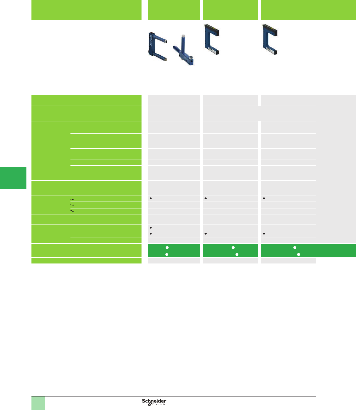
Format Optical fork Optical fork Laser optical fork
Dimensions (w x h x d) in mm Passageway: 30 to 180
Depth: 30, 60, 95
Passageway: 2 to 120
Depth: 42, 59, 95
Case Metal Metal Metal
Sensing distance,
mm (in.) related to
system
Diffuse with background suppression – – –
Diffuse – – –
Polarized retroreß ective – – –
Retroreß ective – – –
Thru-beam 2–180 (0.08–7.09)(2) 2–120 (0.08–4.72) (1) (2) 2–120 (0.08–4.72) (1) (2)
Degree of protection IP 65, IP 67 IP 65 IP 65
Supply
– – –
– – –
Output PNP/NPN
NO/NC
PNP/NPN (3)
NO/NC (4)
PNP/NPN (3)
NO/NC (4)
Connection Pre-cabled – –
Connector
Screw terminals – – –
Catalog Number XUVR
XUVA
XUYFNEP
XUYFANEP
XUYFLNEP
XUYFALNEP
Pages 135 137 139
(1) With or without teach mode, depending on model
(2) Depending on model
(3) Depending on wiring
(4) By programming
Selection Guide OsiSense® XU
Photoelectric sensors
Application
Fork and frame form
This document provided by Barr-Thorp Electric Co., Inc. 800-473-9123 www.barr-thorp.com
5/7
1
1
2
3
4
5
6
7
8
9
10
Detection of opaque
labels
Detection of opaque labels,
of different colors
Detection of transparent
labels
Detection of fl ags in lifts
and transtockers.
Integrated amplifi er
Material handling: detection
and counting of objects being
fed to or exiting a machine
Optical fork Optical fork Ultrasonic fork Optical fork Frame design
12 x 37.5 x 80 20 x 90 x 26 16 x 47.3 x 90.5 14 x 58 x 68 15 x 50 x 108
15 x 86 x 131
25 x 230 x 205/265/335
Metal Metal Metal Plastic Metal
– – – – –
– – – – –
– – – – –
– – – – –
3 or 5 (0.12 or 0.20) (2) 2 (0.08) 3 (0.12) 3 (0.12) 3, 6, 12,18, 25
(0.12, 0.24, 0.47, 0.71, 0.98)
(2)
IP 65 IP 65 IP 65 IP 54 IP 65
– – – – –
– – – – –
PNP and NPN
NO/NC (4)
PNP and NPN
NO/NC (4)
PNP and NPN
NO/NC (4)
Solid-state (PNP or NPN
NO
PNP and NPN
NO/NC (3)
– – – –
–
– – – – –
XUYFA98 XUVK XUVU06 XUVH
XUVJ
XUVF
141 143 145 147 149
Selection Guide OsiSense® XU
Photoelectric sensors
Application
Fork and frame form
This document provided by Barr-Thorp Electric Co., Inc. 800-473-9123 www.barr-thorp.com
5/8
1
1
2
3
4
5/
6
7
8
9
10
Recommended applications Packaging
Color mark
readers
Color mark
readers
Color mark
readers
Luminescence
sensors
Illumination
sensors
Detection of
reference
marks,
contrasting
colors and
markings on
packaging,
printing,
labelling
machines, etc.
Detection of
reference
marks on
packaging
paper, tubes
Detection of
reference
marks,
contrasting
colors and
markings on
packaging,
printing,
labelling
machines, etc.
Detection of
invisible
reference marks,
markings,
adhesives,
varnishes, etc.
Sensitive to the
bluing agents
generally
present in inks,
adhesives,
varnishes, etc.
Verifying
operation of
indicator lights
Format Compact design Fiber design Compact
design
Design ø18 Fiber design
Dimensions (w x h x d) in mm 50 x 50 x 15 13 x 72 x 30 31 x 81 x 58 Ø 18, threaded,
M18 x 1
L: 82
13 x 76.7 x 30
Case Plastic Plastic Metal Plastic
Sensing distance,
m (ft) related to
system
Diffuse with background suppression – – – – Sensing
distance
depending on
Þ ber used
Diffuse 0.019 (0.06) 0.009 (0.03) 0.02 (0.07)
Polarized retroreß ective – – – –
Retroreß ective – – – –
Thru-beam – – – –
Degree of protection IEC 60529
DIN 40050
IP 65 IP 65 IP 67 IP 67 IP 65
Supply
– – – – –
– – – – –
Output Solid-state (PNP or NPN) Solid-state (PNP) PNP/NPN
NO/NC
programmable
Connection Pre-cabled – – – – –
Connector
Screw terminals – – – – –
Catalog Number XUKR XUYDCF
966S
XURK XU5M XUYAFL
966S
Pages 74 114 78 34 112
Selection Guide OsiSense® XU
Photoelectric sensors
Application
This document provided by Barr-Thorp Electric Co., Inc. 800-473-9123 www.barr-thorp.com
5/9
1
1
2
3
4
5
6
7
8
9
10
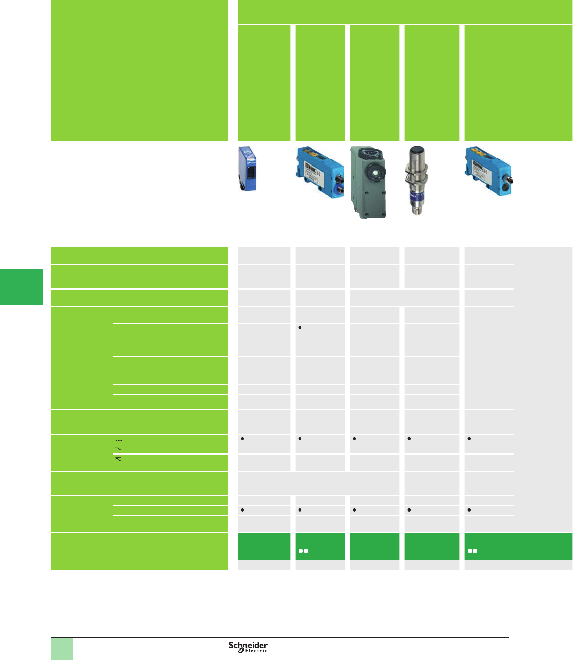
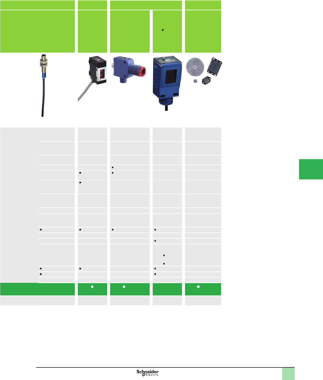
Packaging Food and
beverage
processing
Detection of any transparent object For detection of colors, sorting Detection of water
and aqueous liquids
STAINLESS STEEL cylindrical sensor
(grade 304 CU)
Bottle, ß ask, containers, Þ lm, etc. Recognizes colors for sorting or checking
parts
Level in opaque ß asks
etc.
For use in vicinity of food or beverage
processing machines
Design ø18 Compact design,
50 x 50
Compact design Compact design or
Þ ber design
Compact design Design ø18 Design ø18
Ø 18, threaded,
M18 x 1
L: 64, 78 or 92
18 x 50 x 50 50 x 50 x 25 30 x 80 x 57
25 x 92 x 54
13 x 47 x 23 Ø 18, threaded,
M18 x 1
L: 64–92
Ø 18, threaded,
M18 x 1
L: 62–88
Plastic or stainless
steel (2)
Plastic Plastic Metal Plastic Stainless steel Stainless steel
– – – – – 0.12 (0.39) –
– – 0.02 (0.07) 0.040–0.060
(0.13–0.20)
0.04–0.25
(0.13–0.82) (1)
– 0.3 (0.98) 0.10 (0.33)
0–10.4 (0–34.12)
(with reß ector)
– – – – 2 (6.56) 2 (6.56)
– 1.5 (4.92) – – – 4 (13.12)
– – – – 50 (164.04) 15 (49.21) 15 (49.21)
IP 65, IP 67 cable
IP 69K connector
IP 65 IP 65 IP 65, IP 67 (2) IP 65 IP 69K IP 67
––––– ––
––––– ––
Solid-state (PNP or NPN) Solid-state (PNP or
NPN)
Solid-state (PNP
and NPN)
Solid-state (PNP
and NPN)
–
– –
––––– ––
XUBT XUKT XUKC XURC XUMW XUB0S XU N18
36 72 76 80 108 38 40
(1) Depending on Þ bers used
(2) Depending on model
Selection Guide OsiSense® XU
Photoelectric sensors
Application
This document provided by Barr-Thorp Electric Co., Inc. 800-473-9123 www.barr-thorp.com
5/10
1
1
2
3
4
5/
6
7
8
9
10
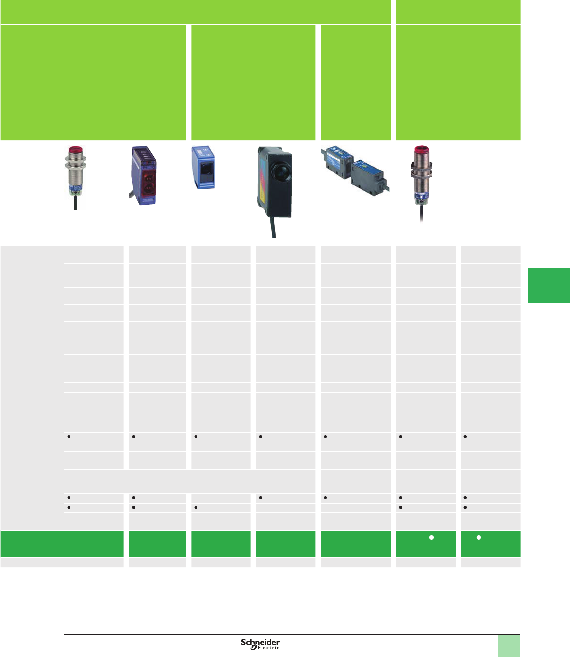
Recommended applications Material Handling
Laser Diffuse with analog output Thru-beam with
high excess gain
Diffuse with
background
suppression, laser
transmission
Measurement, servo control,
position control, eccentricity
monitoring, concentricity
monitoring, etc
Detection of objects
in difÞ cult
environments
(smoke, dust, mist,
etc.). Measuring
opacity
High precision,
detection of any dark
or shiny object,
including small sized
Format Design ø18 Compact
design
Design ø18 Design ø18 Compact design
Dimensions (w x h x d) in mm Ø 18, threaded
M18 x 1
27 x 85 x 61 Ø 18, threaded
M18 x 1
L: 82
Ø 18, threaded
M18 x 1
L: 82
18 x 60 x 60
Case Plastic or
brass (2)
Plastic Metal Metal Plastic
Sensing distance,
m (ft) related to
system
Diffuse with background
suppression
– – – – Adjustable from 50 to
300 mm
(1.97 to 11.81 in.)
Diffuse – 0.20–0.80
(0.66–2.62)
0.05–0.4
(0.16–1.31)
– –
Polarized retroreß ective – – – – –
Retroreß ective – – – – –
Thru-beam 0–100 (0–3.94)
with teach mode
– – 50 (164.04) –
Degree of protection IP 67 IP 67 IP 67 IP 67 IP 65
Supply
– – – – –
– – – – –
Output PNP, NPN
NO/NC by
programming
Analog (PNP) Solid-state (PNP)
+Analog
PNP and NPN
NO/NC depending
on wiring
Connection Pre-cabled – – – –
Connector –
Screw terminals – – – –
Catalog Number XUBL XUJ XU5M XU2M XUYPS1
Pages 44 102 46 48 82
Selection Guide OsiSense® XU
Photoelectric sensors
Application
This document provided by Barr-Thorp Electric Co., Inc. 800-473-9123 www.barr-thorp.com
5/11
1
1
2
3
4
5
6
7
8
9
10
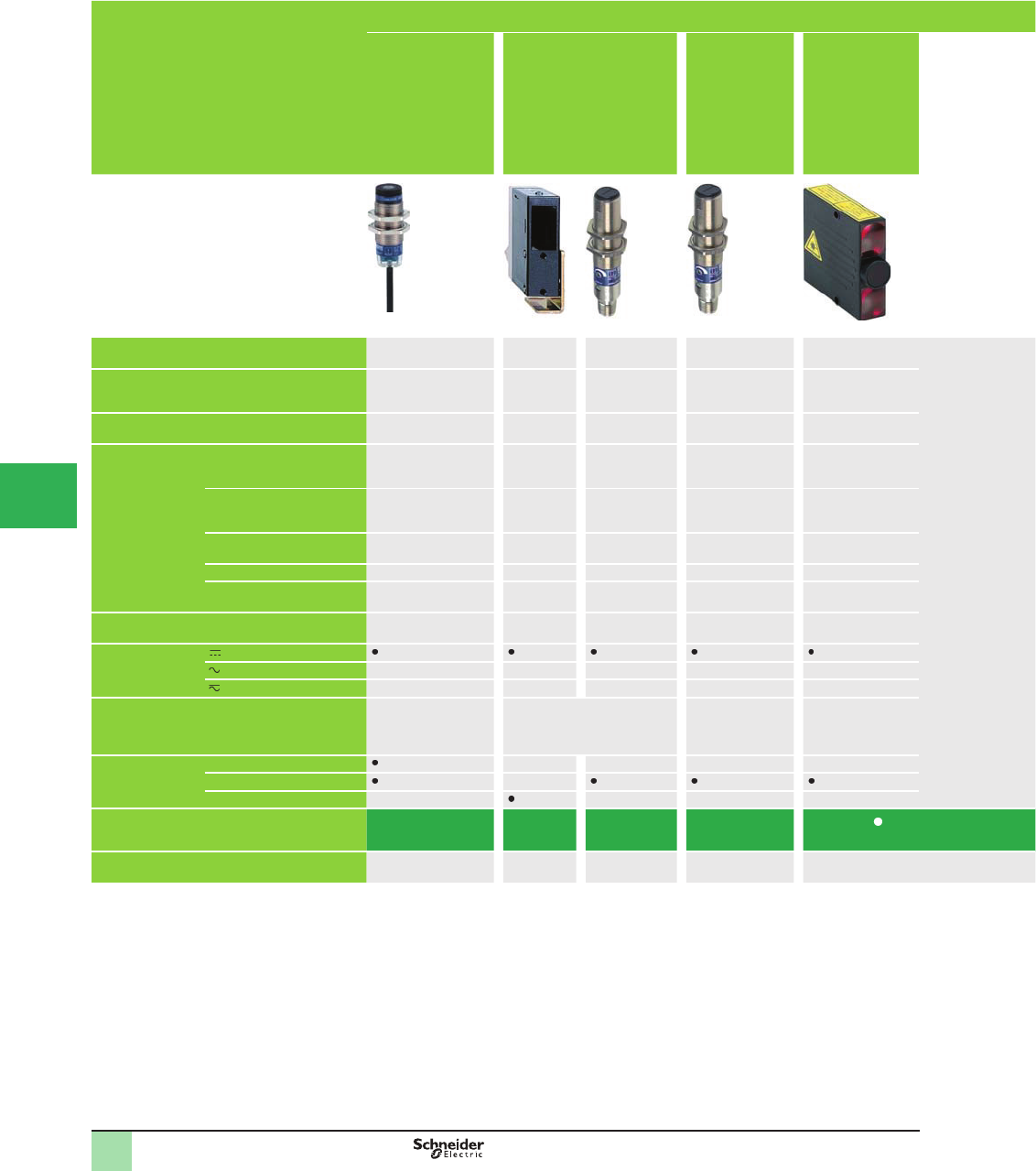
Amplifi er and fi ber optics
Diffuse with two
channels using
triangulation, with
background
suppression
Amplifi er, teach mode Plastic fi ber optics
with end fi ttings
Glass fi ber optics with
end fi ttings
Ecofi ber concept
Bare Þ ber optics and
end Þ ttings supplied
separately for
customer assembly
Amplifi er, teach mode
or potentiometer
Compact design Fiber design – – – Fiber design
18 x 60 x 60 10 x 40 x 65 (ampliÞ er) Length (1) :
1 m, 2 m or 10 m
Length (1) :
0.60 m, 1 m, 1.5 m or
2 m
Length (1) :
1 m, 10 m or 50 m
13 x 72.2 x 30
13 x 76.7 x 30
Plastic Plastic Plastic Glass Plastic Plastic
Adjustable from 50 to
600 mm
(1.97 to 23.62 in.)
– – – Sensing distance:
70 mm–
4,000 mm
(2.76–157.48 in.)
(1)
Sensing distance
depending on Þ ber used
– 0.006–0.095 (0.02–0.31)
(2)
6–95
(19.68– 311.68)(1)
80 (262.47)
– – – –
– – – –
– 0.050–2
(0.16–6.56) (2)
30–2500
(98.42–8,202.07) (1)
80 or 200
(262.47 or 656.17) (1)
IP 65 IP 65 (ampliÞ er)
IP 64 (Þ bers)
IP 64, IP 641 (1)
IP 65, IP 651 (1)
– – IP 65
– – –
––––––
––––––
PNP and NPN
NO/NC programmable
Solid-state (PNP or
NPN) (3)
NO or NC
(programmable)
– – – PNP/NPN
NO/NC (3) or
programmable (1)
– – –
– – –
––––––
XUYPS2 XUDA XUF XUYFV XUYA
XUYFP
XUYAF 966
AF 946
84 110 118 124 130 112
(1) Depending on model
(2) Depending on Þ ber
(3) Depending on wiring
Selection Guide OsiSense® XU
Photoelectric sensors
Application
This document provided by Barr-Thorp Electric Co., Inc. 800-473-9123 www.barr-thorp.com
5/12
1
1
2
3
4
5/
6
7
8
9
10
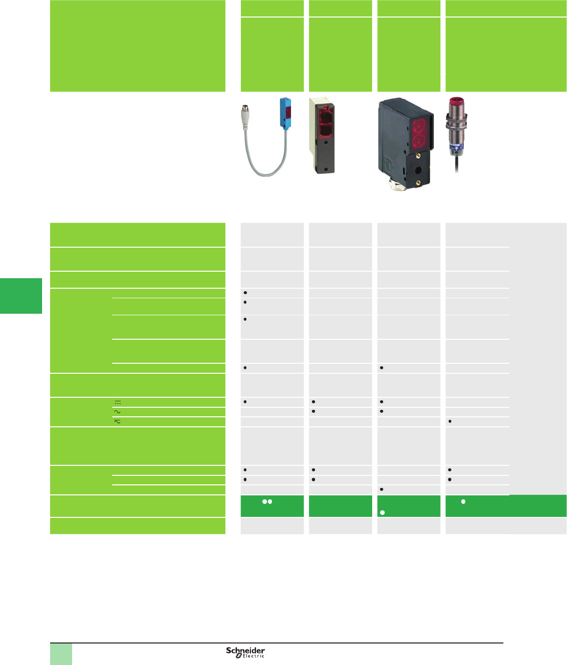
Recommended applications Conveying Ø 18 AC/DC
Detection of
objects on
conveyor and
access control
Conveying 2-wire AC or DC
supply
Format Miniature design Compact design – Design ø18
Dimensions (w x h x d) in mm 20 x 32 x 13
10 x 40 x 13.5
18 x 70 x 35 29 x 95 x 60 Ø 18, threaded M18 x 1
L: 82–110
Case Plastic Plastic Plastic Metal
Sensing distance,
m (ft) related to
system
Diffuse with background suppression – – 0.12 (0.39)
Diffuse 0.7 (2.30) 1.5 or 4
(4.92 or 13.12) (2)
0.4 (1.31)
Polarized retroreß ective 4 (13.12)
(with Ø 80 mm
reß ector)
6 or 10 (19.68 or
32.81) (2)
2 (6.56)
Retroreß ective – 6 (19.68)
(with Ø 80 mm
reß ector)
– –
Thru-beam 8 (26.25) 15 (49.21)
Degree of protection IP 65 and
IP 67
IP 67 IP 65 and IP 67 IP 67
Supply –
– –
–––
Output PNP or NPN NO/NC
(1)
Solid-state
PNP or NPN
PNP/NPN
Relay
NO/NC
programmable
Solid-state
Connection Pre-cabled –
Connector –
Screw terminals – – –
Catalog Number XUY 989 XUL XUY
952/954
XU M18
Pages 104 96 106 50
(1) Depending on wiring.
(2) Depending on model.
Selection Guide OsiSense® XU
Photoelectric sensors
Application
This document provided by Barr-Thorp Electric Co., Inc. 800-473-9123 www.barr-thorp.com
5/13
1
1
2
3
4
5
6
7
8
9
10
Assembly Assembly and
machine tools
Other formats Accessories
Diameter 8 metal
range
Miniature,
metal
Dual Mount With stability
LED.
With alarm
output (for
XUC AK only)
Refl ectors,
mounting clamps,
mounting and
adjustment
accessories, etc.
Design 8 Miniature design Dual mount design
with ø 18 mm snout
Compact design Accessories
Ø 8, threaded,
M8 x 1
L: 40
16.2 x 41.15 x
29.5
Ø 18, threaded snout,
18 x 43.8 x 60,
45 x 95 x 44 –
Metal Metal Plastic Plastic –
– – 1.2 (3.94) –
0.05 (0.16) – –
–2 (6.56) 6 (19.68) –
– – – – –
2 (6.56) 15 (49.21) 15 (49.21) 50 (164.04) –
IP 65 (2)
IP 67 (2)
IP 65
IP 67
IP 69K
IP 67 IP 67 and NEMA
4X
–
–
– – – – –
– – – –
Solid-state (PNP or
NPN)
PNP or NPN
NO/NC
PNP or NPN
NO
Solid-state - PNP
or NPN
(XUC AK)
1 CO relay
(XUC AR)
–
– –
– M12 –
– – – – –
XUA XUM B XUN XUC XUZ
52 62 54 92 151
Selection Guide OsiSense® XU
Photoelectric sensors
Application
This document provided by Barr-Thorp Electric Co., Inc. 800-473-9123 www.barr-thorp.com
5/14
1
OsiSense® XU
Photoelectric sensors 1
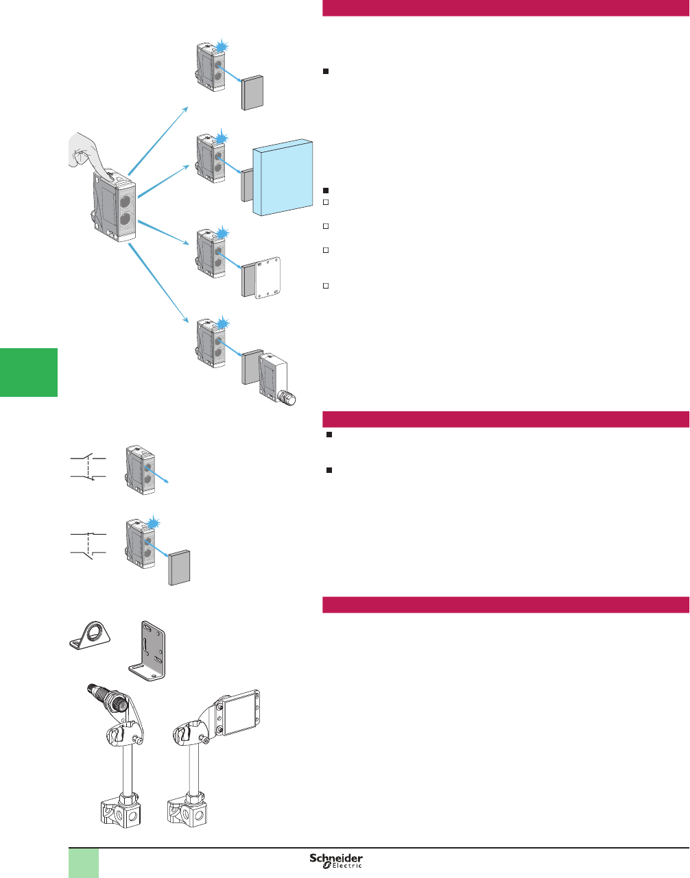
Multimode: Simplicity through innovation
Principle
In proposing multimode products, Schneider Electric offers simplicity through
innovation.
With the multimode function, a single product meets a wide variety of
requirements for optical detection.
Effectively, by simply pressing the Teach mode button, the sensor automatically
acquires Single mode conÞ guration for the application requirements.
1Diffuse system detection of object
2Diffuse system, with background suppression, detection of object
3Retroreß ective system (reß ector accessory) detection of object
4Thru-beam system, on optical receiver (transmitter accessory for thru-beam use),
detection of object
In addition to this, a multimode sensors also means:
improved performance:
maximum sensing distance guaranteed and optimized for each application
simpliÞ ed use:
intuitive setup plus less and easier maintenance
lower costs:
the number of catalog numbers is reduced by 90% and, consequently, selection
and supply is simpliÞ ed and storage costs signiÞ cantly reduced
maximum productivity
Straightforward NO or NC output
Irrespective of the detection mode used (diffuse, retroreß ective, thru-beam, etc.),
the outputs become either NO or NC (1).
A multimode sensor means immediate,intuitive, accessible setup.
(1) The sensor is supplied in NO conÞ guration. NO or NC selection is performed by simply
pressing the Teach mode button.
Mounting accessories
A complete range of inexpensive mounting accessories (clamps, traditional or 3D
brackets, etc.) that provides solutions for all installation and adjustment problems.
2
3
4
1
Max. sensing
distance
Max. sensing
distance
Max. sensing
distance
Max. sensing
distance
NO
NC
NO
NC
No object present
Object present
Overview
1
2
3
4
5/
6
7
8
9
10
This document provided by Barr-Thorp Electric Co., Inc. 800-473-9123 www.barr-thorp.com
5/15
1
OsiSense® XU
Photoelectric sensors 1
Multimode: Simplicity through innovation
Design Cylindrical 18 Miniature Compact 50 x 50 Compact 92 x 77
Dimensions (w x h x d) in mm M18 x 64 12 x 34 x 20 18 x 50 x 50 30 x 92 x 77
Maximum
sensing distance
m (ft)
Without accessory with background
suppression
0.12 (0.39) 0.10 (0.33) 0.28 (0.92) 1.3 (4.27)
Without accessory 0.4 (1.31) 0.55 (1.80) 1.2 (3.94) 3 (9.84)
With polarized reß ector 3 (9.84) 4 (13.12) 5.7 (18.70) 15 (49.21)
With thru-beam accessory 20 (65.62) 14 (45.93) 35 (114.83) 60 (196.85)
Supply Solid-state output
Relay output – –
Connection Pre-cabled –
Connector
Screw terminals – – –
Sensor type XUB0 XUM0 XUK0 XUX0
Pages
Sensing distances (see table above) Sensing distance with background suppression
The multimode sensor detects objects irrespective of their color or background
A clean environment is recommended
Sensing distance
Beyond the sensing distance with background suppression, the same multimode
sensor without accessory detects objects but may be inß uenced by the
backgrounds and color of the objects to be detected
Sensing distance with polarized refl ector
By installing a reß ector opposite, the same multimode sensor detects objects
irrespective of their shininess and color
The size of the reß ector must be smaller than that of the object to be detected
The larger the area of the reß ector the longer the sensing distance
Sensing distance with thru-beam transmitter accessory
After setup and connection of a thru-beam transmitter accessory opposite, the
same multimode sensor detects objects irrespective of their shininess, color or
background
The detection distance is a maximum
The sensor and the thru-beam transmitter must be carefully aligned
Good resistance to accumulation of dirt and dust
400 mm
(15.75 in.)
400 mm
(15.75 in.)
Depending on reß ector
20 mm
0
.79 in.)
Presentation
1
2
3
4
5
6
7
8
9
10
This document provided by Barr-Thorp Electric Co., Inc. 800-473-9123 www.barr-thorp.com
5/16
1
OsiSense®XU
Photoelectric sensors 1
Standards and certifi cations
Parameters related to the environment
Recommendation
The sensors detailed in this catalog are designed for use in standard industrial applications
relating to presence detection.
These sensors do not incorporate the required redundant electrical circuit enabling their usage
in safety applications.
For safety applications, refer to the PreventaTM Machine Safety Product’s Catalog
Quality control
A variety of considerations are taken in order to provide photoelectric sensors suitable
for the harsh industrial environments.
Qualifi cation
The product speciÞ cations stated in this catalog are subjected to a qualifi cation procedure
carried out in our laboratories
In particular, the products are subjected to climatic cycle tests for 3,000 hours while
powered-up to verify their ability to maintain their speciÞ cations over time
Production
The electrical speciÞ cations and sensing distances at both ambient temperature and
extreme temperatures are 100% checked
Products are randomly selected during the course of production and subjected to
monitoring tests relating to all their speciÞ cations
Customer returns
Products that are returned to us and claimed inoperative are subjected to systematic
analysis and may result in corrective actions or continuous improvement
Immunity to ambient light
OsiSense® XU photoelectric sensors use the pulsed light principle. This provides a high
degree of immunity to spurious light and conforms to standard IEC 60947-5-2
Resistance to electromagnetic interference
The Photoelectric sensors are tested in accordance with the recommendations of the
standard IEC 60947-5-2
Electrostatic discharges IEC/EN 61000-4-2
15 kV version, level 4
8 kV version, level 3
Radiated electromagnetic Þ elds
(electromagnetic waves)
IEC/EN 61000-4-3
10 V/meter, level 3
Fast transients in salvos (motor start/stop interference) IEC/EN 61000-4-4
2 kV, level 4
Impulse voltages, lightning IEC 60947-5-2
2.5 kV version
1 kV version
Mechanical shock resistance
The sensors are tested in accordance with standard IEC 60068-2-27, 30 gn, duration 11 ms.
Vibration resistance
The sensors are tested in accordance with standard IEC 60068-2-6,
7 gn, amplitude ± 1.5 mm, f = 10–55 Hz.
Resistance to chemicals in the environment
Due to the very wide range of chemicals encountered in industry, it is very difÞ cult to give
general guidelines common to all sensors
End users should verify that the application does not subject sensors to chemicals that may
damage them (refer to the speciÞ cations pages for the various sensors)
The materials selected (see product speciÞ cations) provide satisfactory compatibility in most
industrial environments (for further information, consult the Sensor Competency Center).
0 2 4 6 8 10 12 14 16 18
100
80
60
20
0
75
50
25
0
- 25
˚C %
Temperature °C
Relative humidity %
- 25° +55 °C (-13 to +131 °F) cycle, 85% RH
Temperature
Relative humidity
Overview
1
1
2
3
4
5/
6
7
8
9
10
This document provided by Barr-Thorp Electric Co., Inc. 800-473-9123 www.barr-thorp.com
5/17
1
OsiSense®XU
Photoelectric sensors 1
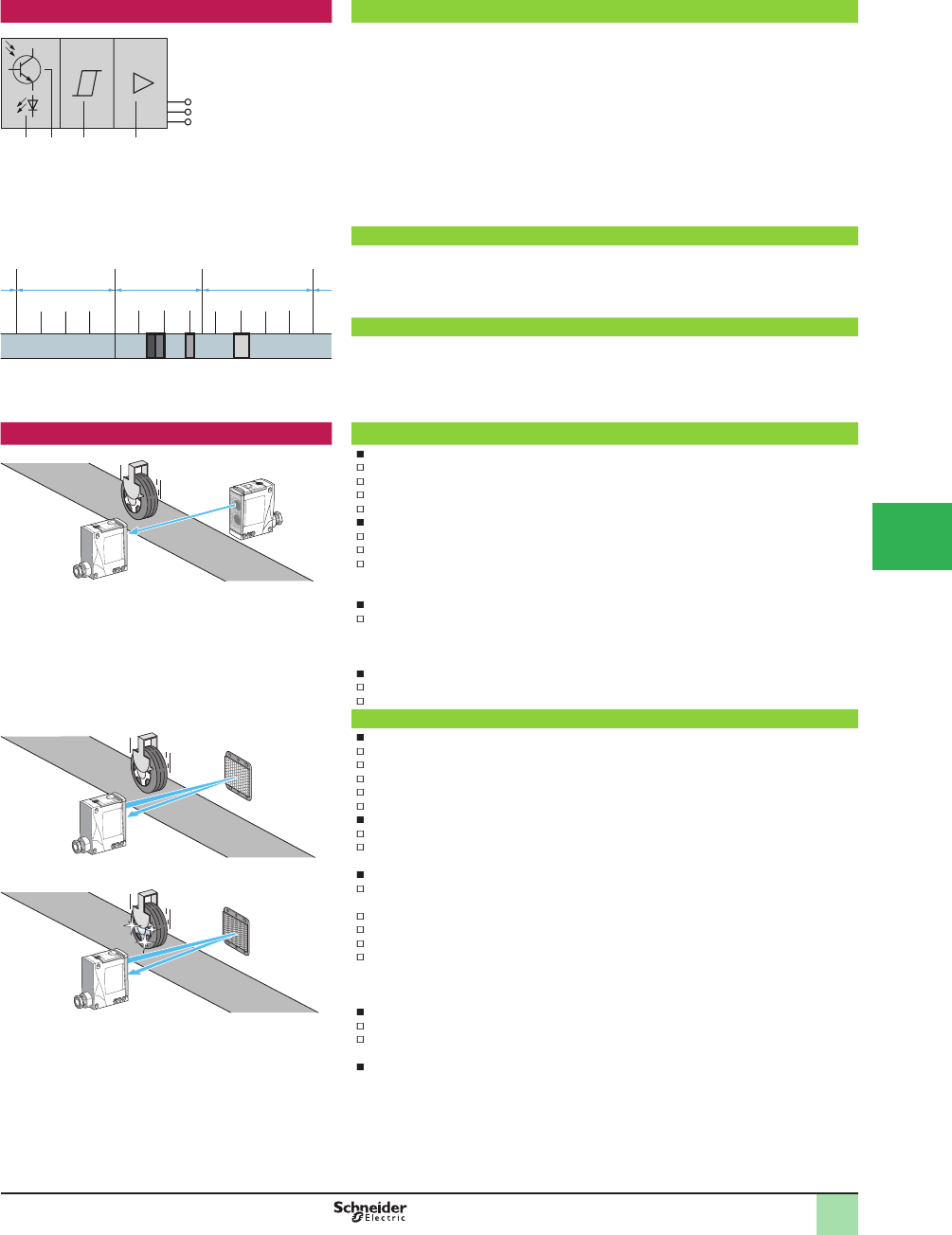
Principle of optical detection Composition of a photoelectric sensor
1 Light beam transmitter
2 Light beam receiver
3 Signal processing stage
4 Output stage
A Photoelectric sensor essentially comprises a light beam transmitter (light-emitting diode) and a
light-sensitive receiver (photo-transistor).
A light-emitting diode is an electronic semi-conductor component that emits light when an
electric current ß ows through it. This light can be visible or invisible, depending on the
transmission wavelength.
Detection occurs when an object enters the transmitted light beam and, in so doing, affects the
intensity of the light at the receiver. As the light intensity at the receiver decreases a point is
reached whereby the output of the sensor changes state.
1 X rays, 2 Ultraviolet, 3 Visible light,
4 Near infrared, 5 Far infrared
Light spectrum
Depending on the model and application requirements, the transmission beam is either non-
visible infrared (most common case) or ultraviolet (detection of luminescent materials). It may
also be visible red or green (color mark reading etc.) and laser red (long sensing distance and
short focal length).
Modulation
The advantage of LEDs is their very fast response. To render the system insensitive to ambient
light, the current ß owing through the LED is modulated so as to produce a pulsed light
transmission.
Only the pulsed signal will be used by the photo-transistor and processed to control the load.
Detection systems Thru-beam system or multimode with thru-beam accessory
Advantages
Long sensing distance(up to 60 m)
Very precise detection, high repeat accuracy
Detection not affected by color of object
Good resistance to difÞ cult environments (dust, grime, etc.)
Drawbacks
Two units to be wired
The object to be detected must be opaque
Precise alignment required, which can be difÞ cult since the sensor transmits in the infrared
range (invisible)
Operating considerations
When several sensors are used, care must be taken to ensure that no sensor is disrupted by
another sensor (e.g. alternate mounting of transmitter/receiver etc.)
Advantages of multimode sensor with thru-beam accessory
Easy alignment
The sensor transmits in the visible red range during the alignment phase
Three LEDs providing setup assistance.
Polarized retrorefl ective system or multimode with refl ector accessory
Advantages
Medium sensing distance (up to 15 m)
Precise detection
Only one unit to be wired
Detection not affected by color of object
Visible red beam transmission
Drawbacks
Precise alignment required
The object to be detected must be opaque and larger than the reß ector
Operating considerationss
When several sensors are used, they must be aligned in such a manner that no sensor is
disrupted by another sensor
For short distance detection use a reß ector with large trihedrons, type XUZC24
For long distance detection use a reß ector XUZC50 or XUZC80
To increase the sensing distance use reß ector XUZC100
If reß ective tape is used, use rolls of tape XUZB1 or XUZB15 which are specially adapted for
polarized retroreß ective systems
Advantages of multimode sensor with refl ector accessory
Easy alignment
Three LEDs providing setup assistance
The anti-interference function enables two sensors to be used without speciÞ c alignment
considerations
Semi-transparent objects can be detected by using the teach mode function
1
1 32 4
100 200 300 500 600 700 800 900 1,100
400 nm 750 nm
10 A
1 nm 3 µm
1,000
1 2 3 4 5
Overview (continued)
1
1
2
3
4
5
6
7
8
9
10
This document provided by Barr-Thorp Electric Co., Inc. 800-473-9123 www.barr-thorp.com
5/18
1
OsiSense®XU
Photoelectric sensors
Detection systems (continued) Diffuse system or multimode
Advantage
Only one unit to be wired
Drawbacks
Short sensing distance
Sensitivity to differences in object color or background color
Object sighting line difÞ cult since the sensor transmits in the infrared range (invisible)
Operating considerations
When several sensors are used, they must be aligned in such a manner that no sensor is
disrupted by another sensor
Advantages of a multimode sensor
Easy alignment:
- the sensor transmits in the visible red range during the alignment phase
- three LEDs providing setup assistance
- the anti-interference function enables two sensors to be used without speciÞ c alignment
considerations
ReÞ ned detection: the position of the object can be detected using the teach mode
Diffuse, with or without background suppression, system or multimode
Advantages
Only one unit to be wired
Detection not affected by color of object or background
Drawbacks
Short sensing distance
Alignment can be challenging because the sensor transmits in the infrared range (invisible)
Operating considerations
Detection can be affected by the object’s direction of movement. To overcome this
phenomenon (the hat effect), it is recommended that the sensor be mounted so that the
object simultaneously breaks the beam of both lenses
When several sensors are used, they must be aligned in such a manner that no sensor is
disrupted by another sensor
Advantages of a multimode sensor
Easy alignment:
- the sensor transmits in the visible red range during the alignment phase
- three LEDs providing setup assistance
- the anti-interference function enables two sensors to be used without speciÞ c alignment
considerations
- the hat effect is minimized using the background teach mode
ReÞ ned detection: the position of the object can be detected using the teach mode
Specifi c systems Optical forks
Constructed from metal, the optical fork is a robust sensor that is particularly suited to
conveying and packaging applications and detection of labels
Rugged optical detection device not requiring alignment in thru-beam mode
The beam from the transmitter limb is transmitted to the receiver limb. Due to its construction,
only one connection is required as opposed to two for a traditional thru-beam function. The
transmission sources are LEDs of various technologies:
Red for much improved efÞ ciency during adjustment and maintenance
Red laser for detection of transparent materials or very small parts
Infrared, particularly for optical frames
Ultrasonic for detection of transparent labels (clear on clear)
The beam is adjustable or Þ xed depending on the version. Adjustment enables the sensitivity
to be altered and, therefore, detection of small parts down to dimensions of less than tenths
of millimeters (minimum size of detectable object: 0.05 mm [0.001 in.])
The high switching frequency (from 4 kHz up to 25 kHz) is very useful in industrial applications
involving high operating rates
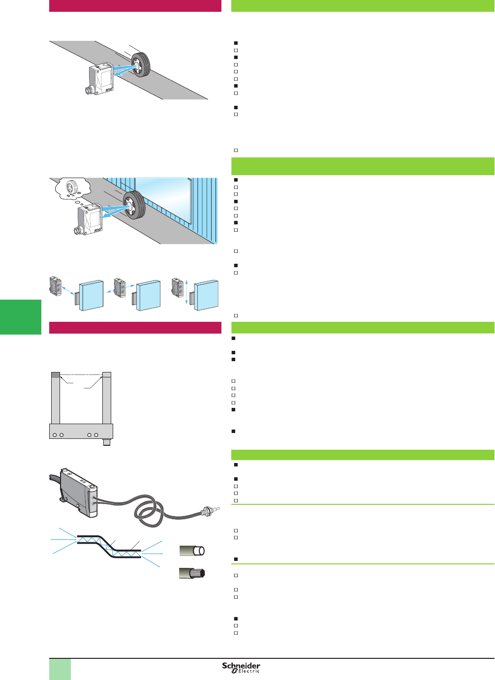
Fiber optics
1Core
2Sheath
The Þ ber acts as a light conductor. Light rays entering the Þ ber at a certain angle are
conveyed to the required location, with minimum loss
Separate ampliÞ er
Size kept to minimum
This system enables detection of very small objects (approximately 1 mm [0.04 in.])
Detection is very precise
Plastic fi bers
The core of the Þ ber is ß exible plastic (PMMA). In general, there is only a single Þ ber of diameter
0.25 to 1 mm (0.01 to 0.04 in.), depending on the model
Fibers are used with ampliÞ ers transmitting red light
Minimum bend radius:
- 10 mm (0.39 in.) for Þ bers with 0.25 mm (0.01 in.) diameter core
- 25 mm (0.98 in.) for Þ bers with 1 mm (0.04 in.) diameter core
Advantages: Þ bers can be cut to the required length
Glass fi bers
The core of the Þ ber is silica. For maximum ß exibility, each Þ ber comprises numerous
strands that are approximately 50 µ in diameter
Fibers are used with ampliÞ ers transmitting infrared or red light
Minimum bend radius:
- 10 mm (0.39 in.) with plastic sheath
- 90 mm (3.54 in.) with stainless steel sheath
Advantages
Fibers suitable for use at high temperatures (250 °C [482 °F])
Fibers with stainless steel sheath provide protection against mechanical impact and
crushing
1 2
Overview (continued)
1
Plastic Þ ber
Glass Þ ber
(1)
(2)
Optical axisAxe A
(1) Transmission LED
(2) Output LED
Positioning recommendations for sensor with background suppression
Recommended Recommended Not recommended
1
2
3
4
5/
6
7
8
9
10
This document provided by Barr-Thorp Electric Co., Inc. 800-473-9123 www.barr-thorp.com
5/19
1
OsiSense® XU
Photoelectric sensors
1
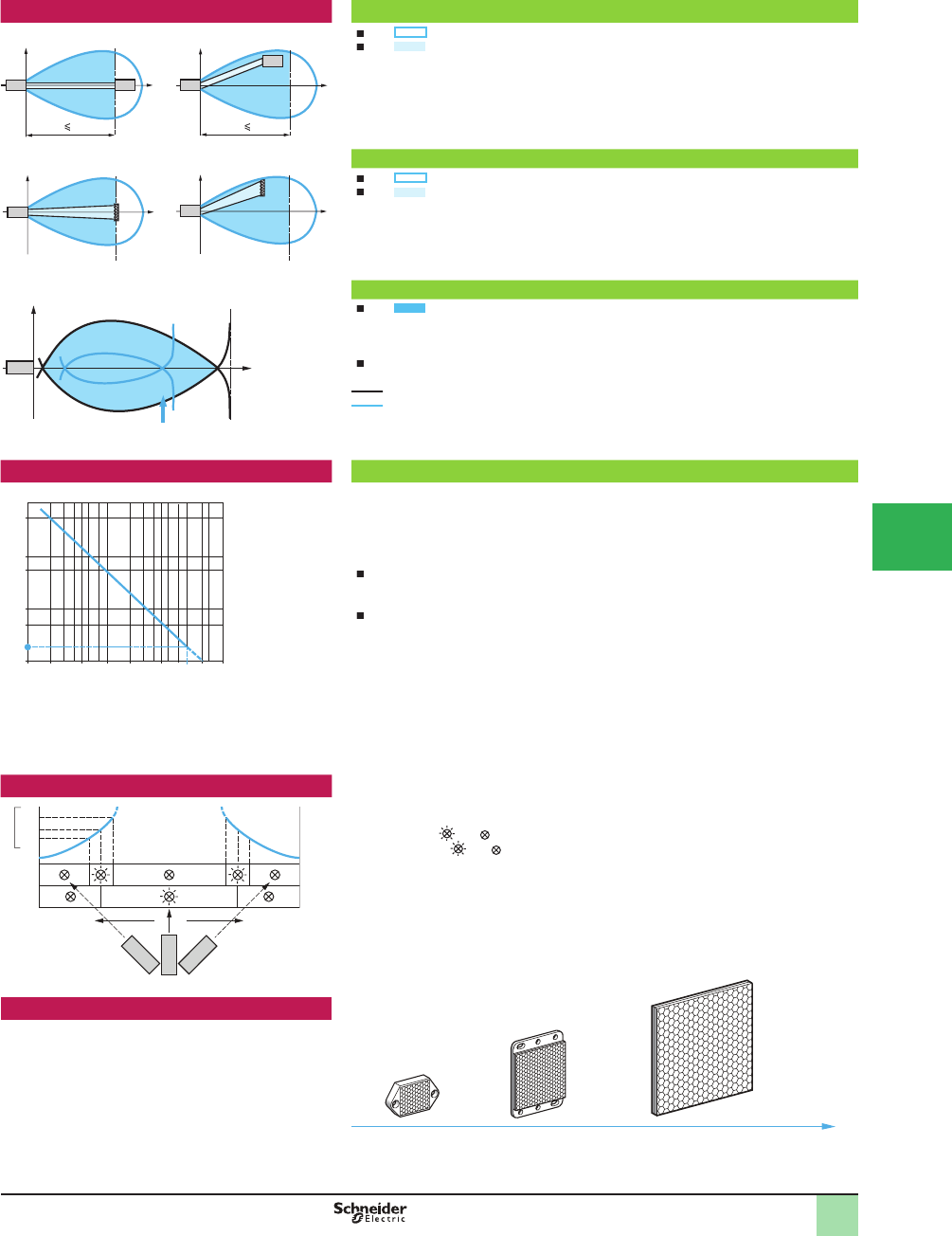
Operating Curves Thru-beam system
The zone indicates the positioning tolerance of the receiver
The zone represents the usable sensing zone of the system. Any opaque object
entering this zone breaks the beam and causes the sensor’s output to change state
1Ideal detection
2Acceptable detection
T = transmitter
R = receiver
Polarized retrorefl ective system
The zone indicates the positioning tolerance of the reß ector
The zone represents the usable sensing zone of the system. Any opaque object
entering this zone breaks the beam and causes the sensor’s output to change state
1Ideal detection
2Acceptable detection
T = transmitter
R = receiver
Diffuse, with or without background suppression, system
The zone represents the sensor’s sensitivity zone
All of this zone is usable: any object that is adequately reß ective entering this zone, in the
direction of the arrow, will cause the sensor’s output to change state. The black line
corresponds to a light color surface and the blue line to a darker color surface.
A test using the object to be detected will determine the zone of sensitivity in relation to its
reß ection coefÞ cient
White 90% object
Gray 18% object
For speciÞ c aspects of diffuse systems see page 18
T = transmitter
R = receiver
Excess gain Operating margin
To ensure correct operation of a sensor in spite of environmental constraints, the sensors
feature an operating margin.
This margin can be expressed in terms of excess gain, which is the ratio:
Excess gain = Signal level received/Signal required for switching.
For all OsiSense® XU sensors
The nominal sensing distance Sn is deÞ ned as the sensing distance with an excess gain
of 2, i.e. the sensing distance for which the sensor receives twice as much light energy as it
strictly needs to switch it
The maximum sensing distance is deÞ ned as the sensing distance with an excess gain of
1. It corresponds to the maximum detection value
The use of the sensor at the nominal sensing distance helps ensure the sensor’s correct
operation in normal operating conditions.
In extreme conditions, refer to the following setup recommendations:
clean environment: work at nominal sensing distance Sn,-
slightly polluted environment: work at sensing distance Sn/2,-
moderately polluted environment: work at sensing distance Sn/4,-
heavily polluted environment: preferably use multimode sensors with thru-beam accessory -
(or the thru-beam system) with a sensing distance Sn/10.
Optical alignment aid
A red LED assists setup by illuminating when Single mode alignment of the sensor is achieved.
1Signal level
2Red LED, on , off
3Green LED, on , off
4Single mode alignment
Detection distance using refl ector
Detection distance depending on reß ector size.
1
2
RE
R
E
d Sn d Sn
1
2
E/R E/R
Sn Sn
E/R
Object 20 x 20cm
2
50.5 100.1 0.2 1 2 3015
500
100
50
10
5
1
Sn
D (m)
Smax.
gain
1.2
1
0.8
1
3
4
2
Overview (continued)
1
40 % 100 %
0170 %
XUZC24
XUZC50
XUZC100
1
2
3
4
5
6
7
8
9
10
This document provided by Barr-Thorp Electric Co., Inc. 800-473-9123 www.barr-thorp.com
5/20
1
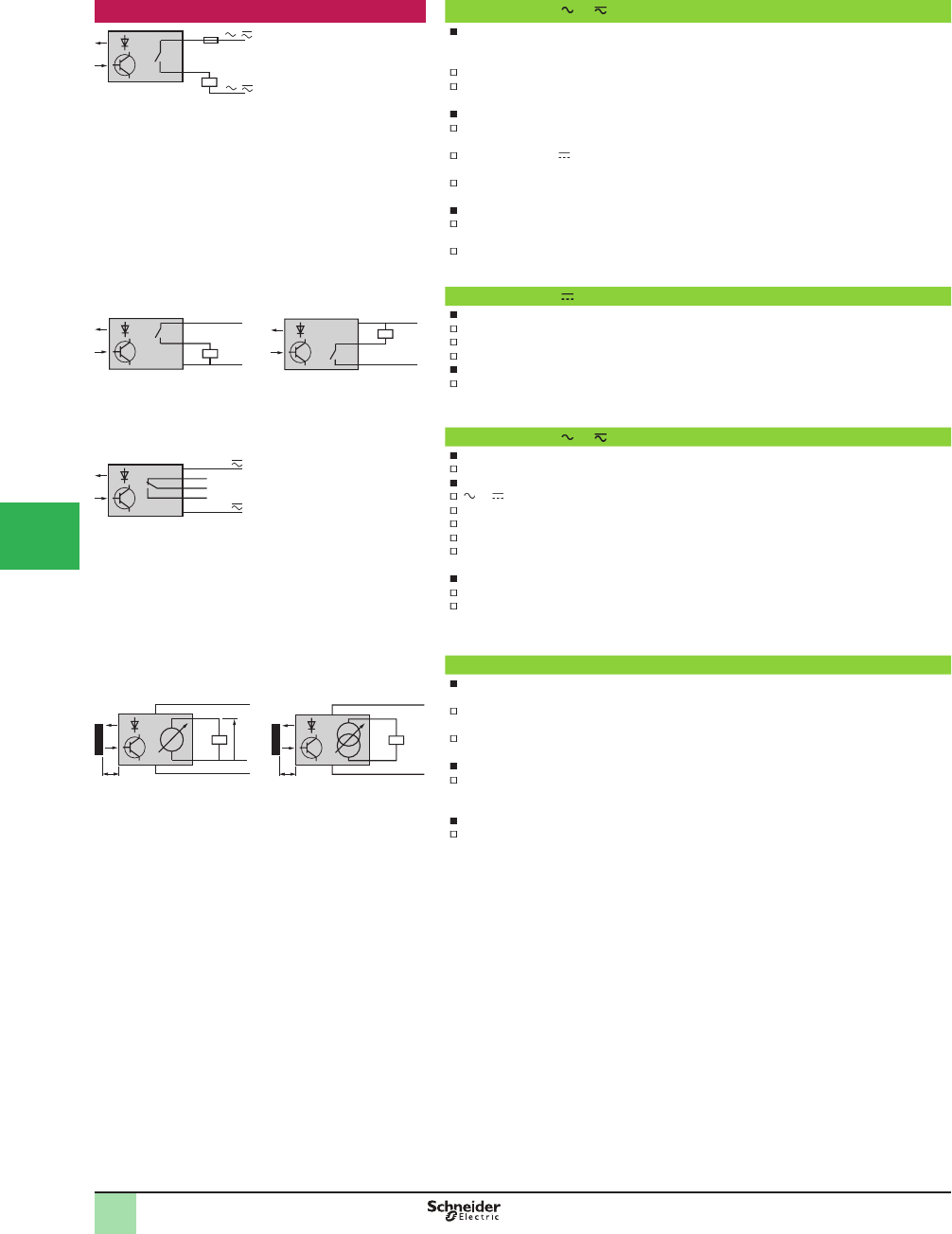
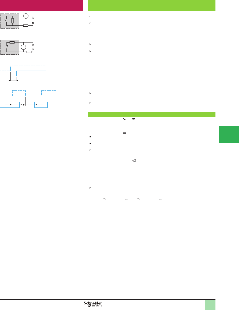
Outputs 2-wire technique or
Specifi c aspects
These sensors are wired in series with the load to be switched
As a consequence, they are subject to:
A residual current in the open state (current ß owing through the sensor in the open state),
A voltage drop in the closed state (voltage drop across the sensor’s terminals in the closed
state)
Advantages
Only two wires to be connected. They can be wired in series in the same way as mechanical
limit switches
For use on 2-wire , they can be connected to either positive (PNP) or negative (NPN) logic
PLC inputs
Simple, reversible connections
Operating considerations
Check the possible effects of residual current and voltage drop on the actuator or input
connected
These sensors do not incorporate overload or short-circuit protection and therefore, a 0.4
fast-acting fuse must be connected in series with the load
3-wire technique
Specifi c aspects
These sensors comprise 2-wires for the DC supply and a 3-wire for the output signal
PNP type: switching the positive side to the load
NPN type: switching the negative side to the load
Advantages
No residual current, low voltage drop
5-wire technique or , relay output
Specifi c aspects
Sensors incorporating output relay. The supply and output circuits are electrically separate
Advantages
or supply with a wide voltage range
High breaking capacity (approximately 3 A)
Direct control of a simple automation system
Availability of a NC (normally closed) contact and a NO (normally open) contact
The sensor/relay contact galvanic isolation is 1,500 to 2,500 V, depending on the model
,
Operating considerations
Low switching frequency. Check that it is suitable for the application
Limited service life of relay. Check that it is suitable for the application
Analog technique
Specifi c aspects
There are two output conÞ gurations:
Voltage output: the output voltage varies in proportion to the distance between the sensor
and the object to be detected
Current output: the output current varies in proportion to the distance between the sensor
and the object to be detected
Advantage
Availability of a physical item of data proportional to the distance between the sensor and the
object to be detected
Operating considerations
Refer to the detailed descriptions of the sensor to assess the relative inß uence of the color of
the object to be detected
1Voltage output
2Current output
BN
BU
/
/
BN
BU
BK
PNP
+
–
BN
BU
BK
NPN
+
–
BK
OG
RD
BN
BU
3
1
5
6
+
–
mA
D
3
1
4
6
+
–
Vs
D
12
Overview (continued)
1
OsiSense®XU
Photoelectric sensors 1
1
2
3
4
5/
6
7
8
9
10
This document provided by Barr-Thorp Electric Co., Inc. 800-473-9123 www.barr-thorp.com
5/21
1
OsiSense®XU
Photoelectric sensors
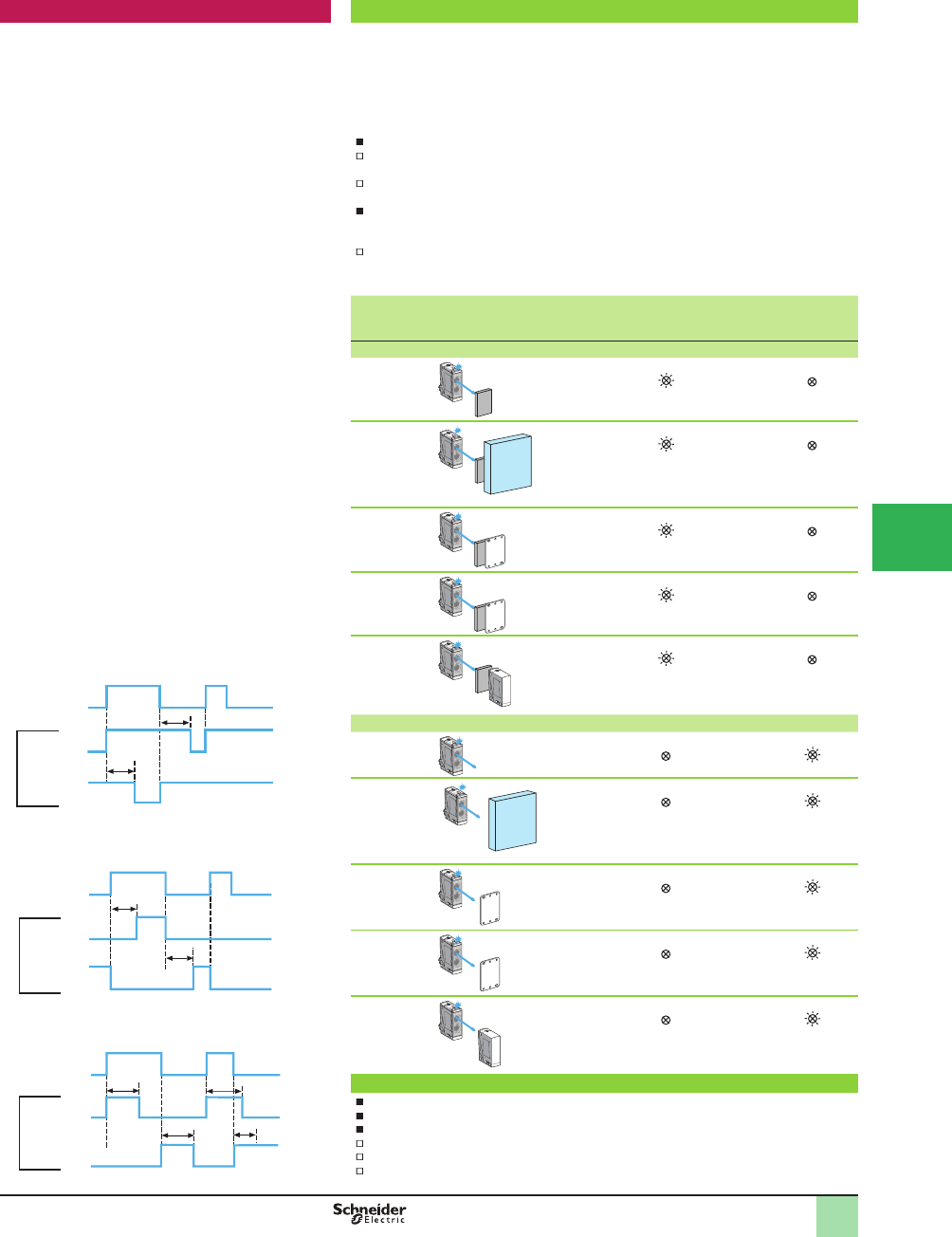
Outputs (continued) Output functions
In the past, the output functions of photoelectric sensors were always governed by the light/dark
principle, i.e. the output would be activated on light being received for light switching and the
output would be activated on light not being received for dark switching.
This called for fastidious programming speciÞ c to each detection mode.
Now, the output functions of the OsiSense® XU range of photoelectric sensors are in
phase with the language of the automation system engineer, i.e. NO (normally open) or
NC (normally closed).
Advantages
NO output (or NO programming for multimode sensors): irrespective of the detection mode,
the output of the sensor is activated when the object to be detected is present
NC output (or NC programming for multimode sensors): irrespective of the detection mode,
the output of the sensor is activated when the object to be detected is not present
Advantages of multimode sensors
By default, the output is NO programmed, i.e. the output of the sensor is activated when the
object to be detected is present
By pressing the teach button, the output can programmed to NC, i.e. the output of the sensor
is activated when the object to be detected is not present
System NO output or
NO
programming
Yellow
LED
NC output or
NC
programming
Yellow
LED
Object present
Diffuse Activated On Not activated Off
Diffuse with
background
suppression
Activated On Not activated Off
Retrorefl ective Activated On Not activated Off
Polarized
retrorefl ective
Activated On Not activated Off
Thru-beam Activated On Not activated Off
No object present
Diffuse Not activated Off Activated On
Diffuse with
background
suppression
Not activated Off Activated On
Retrorefl ective Not activated Off Activated On
Polarized
retrorefl ective
Not activated Off Activated On
Thru-beam Not activated Off Activated On
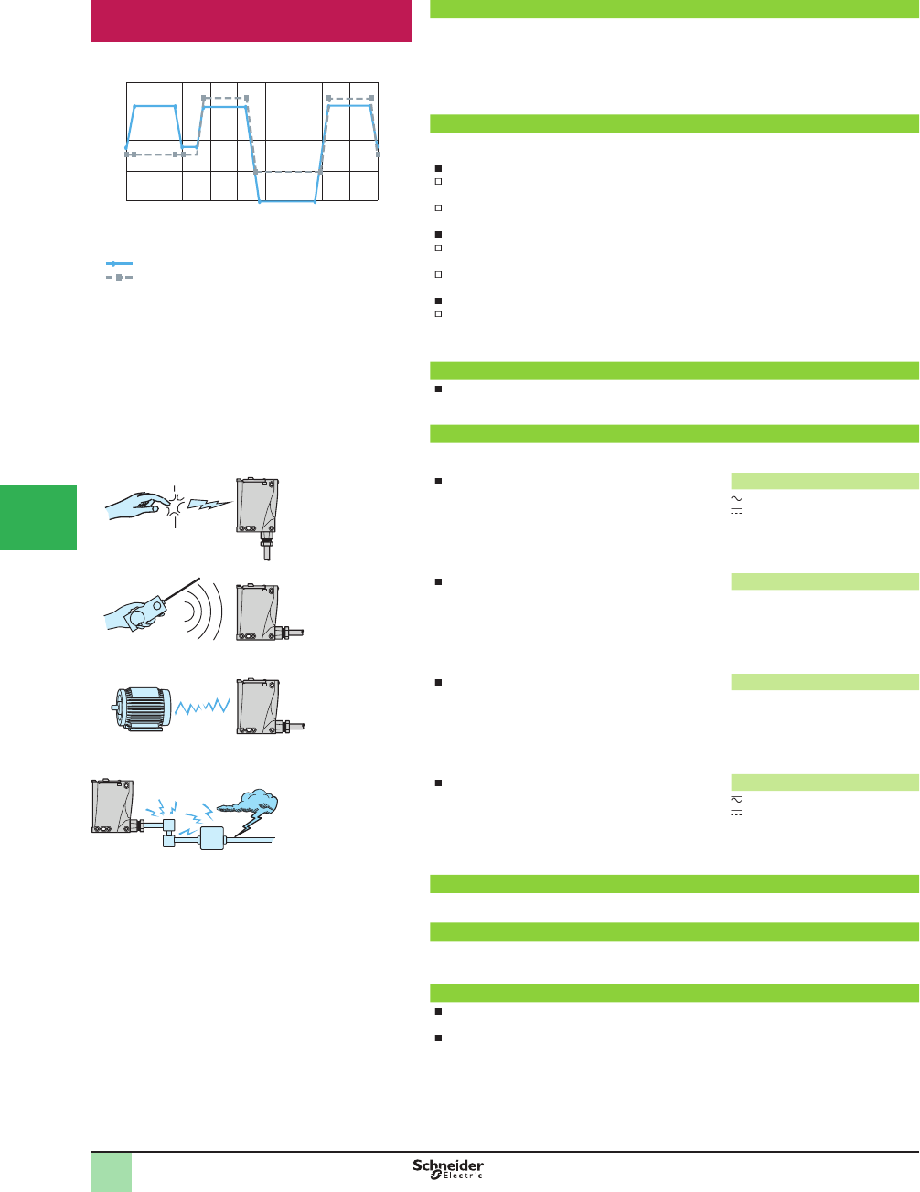
Output signal time delay
Certain sensor models (XUK, XUX and XUD) incorporate a time delay output
These time delays enable simple automation systems to be established
There are three types of time delay
Time delay on beam make (ON delay)
Time delay on beam break (Off delay)
Monostable (one shot)
t
t
t
t
t
tt
t
Yes
No
On
Off
On
Off
NO
NC
Output
Yes
No
On
Off
On
Off
NO
NC
Output
Yes
No
On
Off
On
Off
NO
NC
Output
Time delay on beam break
Monostable
Overview (continued)
1
1
2
3
4
5
6
7
8
9
10
This document provided by Barr-Thorp Electric Co., Inc. 800-473-9123 www.barr-thorp.com
5/22
1
OsiSense®XU
Photoelectric sensors
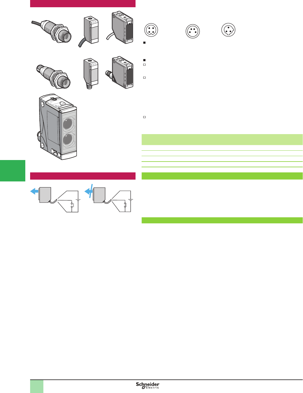
Connections All of our sensors are available either in pre-cabled version (except XUX; screw terminal with
cable gland version) or connector version.
The connectors used are:
Types of connection
1Factory-Þ tted molded cable: good protection against splashing liquids.
2Connector: easy installation and maintenance.
3Screw terminals: ß exibility, cable runs to required length.
Wiring advice
Length of cable: no limitation up to 200 m or up to a line capacitance of < 0.1 PF
(speciÞ cations of sensors remain unaffected). In this case, it is important to take into account
the voltage drop on the line.
Separation of control and power circuit wiring: the sensors are immune to electrical
interference encountered in normal industrial conditions. Where extreme conditions of
electrical noise could occur (motors etc.), it is advisable to protect against transients in the
normal way:
suppress interference at source and Þ lter the power supply,-
separate power and control wiring from each other,-
ensure the HF equipotentiality of the site,-
limit the length of cable,-
connect the sensor with supply switched off.-
Dust and damp protection of connections: the level of dust and damp protection depends on
how carefully the cable glands or connectors are tightened. To efÞ ciently protect the sensors
from dust and damp, select the correct diameter cable for the cable gland used.
Cable gland Diameter of cable
Minimum Maximum
9P 6 8
11P 8 10
13P 10 12
ISO 16 7 10
ISO 20 10 12
Complementary functions Diagnostics, beam break test
A test input enables the transmitted beam to be broken in order to verify that the output of the
sensor changes state.
Diagnostics regarding correct operation of the sensor can therefore be carried out.
1Beam made
2Beam broken
VI: test input for breaking transmitted beam.
Verifi cation of correct operation
In the event of dirty lenses (reß ectors), an excessively polluted atmosphere or a slight
disturbance of optical alignment (mechanical impact on support), the level of light energy
received by the sensor will decrease until it ceases to operate.
To overcome this problem, all of our products incorporate:
a red alarm LED,-
an alarm output, for connection in the automation system, to warn the operator that the -
operation of the sensor is stable but close to its limits (applies to sensors XUK, XUX, XUD).
24
1 3
1 2
4 3
1
32
M12 (4-pin) M8 (4-pin) 1/2 20UNF (3-pin)
1
2
3
BN +
–
VI
BU
1
BN +
–
VI
BU
2
Overview (continued)
1
1
2
3
4
5/
6
7
8
9
10
This document provided by Barr-Thorp Electric Co., Inc. 800-473-9123 www.barr-thorp.com
5/23
1
OsiSense®XU
Photoelectric sensors
Specifi c aspects of electronic sensors Terminology
Residual current (Ir)
The residual current (Ir) corresponds to the current ß owing through the sensor when in the
Open state.
SpeciÞ cations of 2-wire type sensors.
Voltage drop (Ud)
The voltage drop (Ud) corresponds to the voltage drop at the sensor’s terminals when in the
Closed state (value measured at nominal current rating of sensor)
Characteristic of 2-wire type proximity sensors
First-up delay
The Þ rst-up delay corresponds to the time (t) between the connection of the power supply to the
sensor and its fully operational state.
1Supply voltage U on
2Sensor operational at state 1
3Sensor at state 0
Response time
Response time (Ra): the time delay between the object to be detected entering the sensor’s
operating zone and the subsequent change of output state. This parameter limits the
speed and size of the object
Recovery time (Rr): the time delay between an object to be detected leaving the sensor’s
operating zone and the subsequent change of output state. This parameter limits the interval
between successive objects
Power supplies
Sensors for AC circuits
( and models )
Check that the voltage limits of the sensor are compatible with the nominal voltage of the AC
supply used.
Sensors for DC circuits ( models)
DC source: check that the voltage limits of the sensor and the acceptable level of ripple are
compatible with the supply used
AC source (comprising transformer, rectiÞ er, smoothing capacitor): the supply voltage must
be within the operating limits speciÞ ed for the sensor
Where the voltage is derived from a single-phase AC supply, the voltage must be rectiÞ ed
and smoothed to ensure that:
the peak voltage of the DC supply is lower than the maximum voltage rating of the sensor -
Peak voltage = nominal voltage x
the minimum voltage of the supply is greater than the minimum voltage rating of the sensor, -
given that:
'V = (I x t)/C
'V = max. ripple: 10% (V)
I = anticipated load current (mA)
t = period of 1 cycle (10 ms full-wave rectiÞ ed for a 50 Hz supply frequency)
C = capacitance (µF)
As a general rule, use a transformer with a lower secondary voltage (Ue) than the required
DC voltage (U)
Example: 18 V to obtain 24 V, 36 V to obtain 48 V. Fit a smoothing capacitor of
400 µF minimum per sensor, or 2,000 µF minimum per ampere required
Ir
mA
XU
Ud
V
XU
t
1
2
3
Ra Rr
Overview
1
1
2
3
4
5
6
7
8
9
10
This document provided by Barr-Thorp Electric Co., Inc. 800-473-9123 www.barr-thorp.com
5/24
1
OsiSense®XU
Photoelectric sensors
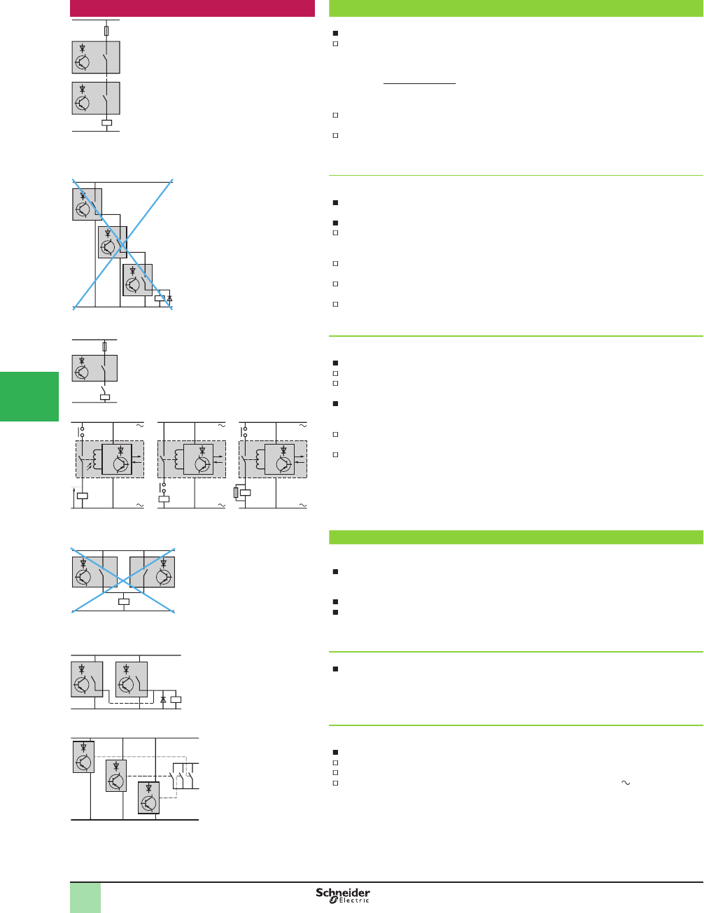
Setup Connection in series
2-wire type sensors
The following points should be taken into account:
Series wiring is only possible using sensors with wide voltage limits
Based on the assumption that each sensor has the same residual current value, each
sensor, in the Open state, will share the supply voltage, i.e
U sensor = .
U sensor and U supply must remain within the sensor’s voltage limits.
If only one sensor in the circuit is in the Open state, it will be supplied at a voltage almost
equal to the supply voltage
When in the closed state, a small voltage drop is present across each sensor. The resultant
loss of voltage at the load will be the sum of the individual voltage drops and therefore, the
load voltage should be selected accordingly
3-wire type sensors
This connection method is not recommended.
Correct operation of the sensors cannot be assured and, if this method is used, tests should
be made before installation
The following points should be taken into account:
The Þ rst sensor carries the load current in addition to the no-load current consumption
values of the other sensors connected in series. For certain models, this connection method
is not possible unless a current limiting resistor is used
When in the closed state, a small voltage drop is present across each sensor. The load
should therefore be selected accordingly
As sensor 1 closes, sensor 2 does not operate until a certain time (t) has elapsed
(corresponding to the Þ rst-up delay) and likewise for the following sensors in the sequence
The use of ß ywheel diodes is recommended when an inductive load is being switched
Wiring sensors to devices with mechanical contact
2 and 3-wire type sensors
The following points should be taken into account:
When the mechanical contact is open, the sensor is not supplied
When the contact closes, the sensor does not operate until a certain time (t) has elapsed
(corresponding to the Þ rst-up delay)
In diagram 1, as the external contact opens, the voltage transient caused by the breaking of
the inductive load will appear inside the sensor and, if greater than the recommended max.
insulation voltage, may cause a ß ashover within the sensor
The return path of this voltage will be back to one line of the supply, through the sensor, and
should ß ashover occur anywhere on the printed circuit board, severe damage could occur
It is therefore recommended to use diagram 2 or 3
Connection in parallel
2-wire type sensors
This connection method is not recommended.
Should one of the sensors be in the closed state, the sensor in parallel will be shorted-out
and no longer supplied. As the Þ rst sensor passes into the Open state, the second sensor will
become energized and will be subject to its Þ rst-up delay
This conÞ guration is only permissible where the sensors will be working alternately
This method of connection can lead to irreversible damage of the units
3-wire type sensors
No speciÞ c restrictions. The use of ß ywheel diodes is recommended when an inductive load
(relay) is being switched
Wiring sensors to devices with mechanical contact
2 and 3-wire type sensors
No speciÞ c restrictions
For these sensors, the supply and output circuits are electrically separate
The sensor/relay contact galvanic isolation is 1,500 to 2,500 V, depending on the model
The maximum voltage, depending on the model, across each contact is 250 V
U supply
n sensors
Sensor 1
Sensor 2
Sensor 3
U
1 2 3
Overview (continued)
1
1
2
3
4
5/
6
7
8
9
10
This document provided by Barr-Thorp Electric Co., Inc. 800-473-9123 www.barr-thorp.com
5/25
1
OsiSense®XU
Photoelectric sensors
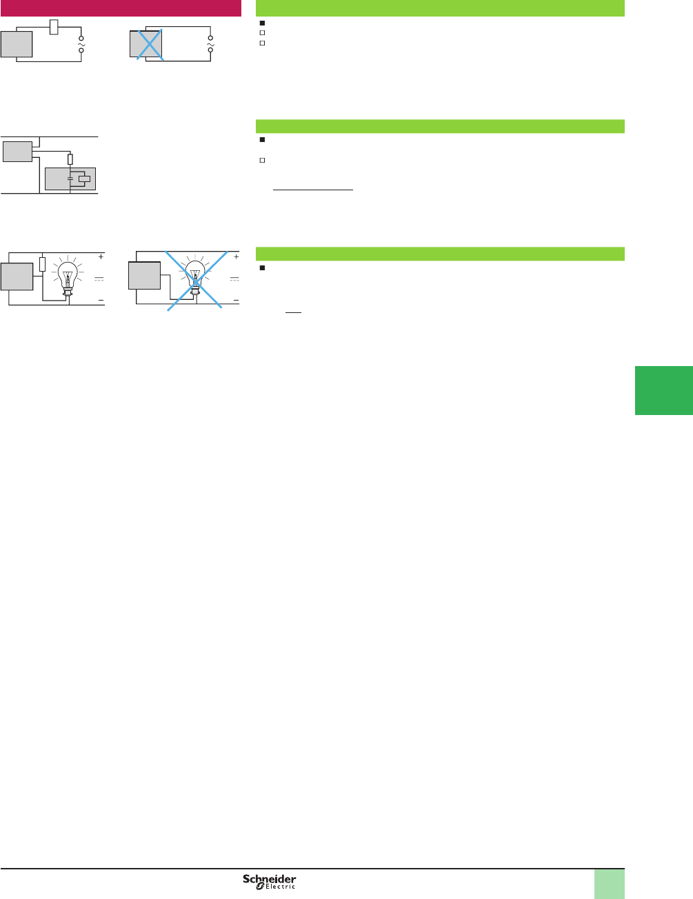
Setup considerations (continued) AC supply
2-wire type sensors cannot be connected directly to an AC supply.
Improper installation can result in injury or sensor damage
An appropriate load (refer to the instruction sheet supplied with the sensor) must always be
connected in series with the sensor
Capacitive load (C > 0.1 PF)
On power-up, it is necessary to limit (by resistor) the charging current of the capacitive load
C.
The voltage drop in the sensor can also be taken into account by subtracting it from the
supply voltage for the calculation of R
R =
Load comprising an incandescent lamp
If the load comprises an incandescent lamp, the hot state resistance can be 10 times higher
than the cold state resistance. This can cause very high current levels on switching. Fit a
pre-heat resistor in parallel with the sensor
R = U2
Px 10 , U = supply voltage and P = lamp power
– R
– C
U (supply)
I max. (sensor)
Overview (continued)
1
1
2
3
4
5
6
7
8
9
10
This document provided by Barr-Thorp Electric Co., Inc. 800-473-9123 www.barr-thorp.com

5/26
1
OsiSense®XU
Photoelectric sensors
Fast trouble shooting guide
Problem Possible causes Remedy
The sensor’s output will not change state when an object
enters the operating zone
On multimode sensor: setup error
(detection mode programming)
Use the detection mode display option. After a reset,
follow the environment teach mode procedure
Inoperative sensor or the short
circuit protection has opened
Check that the sensor is compatible with the supply
being used
Check the load current speciÞ cations:
if load current I t maximum switching capacity, an
auxiliary relay (type CADN, for example) should be
interposed between the sensor and the load
if I d maximum switching capacity, check or wiring
issues (short-circuit)
In all cases, a 0.4 A fast-acting fuse should be
connected in series with the sensor
Wiring error Check that the wiring conforms to the wiring shown on
the sensor label or instruction sheet
Improper power supply Check that the sensor is compatible with the supply
( or )
Check that the supply voltage is within the voltage
limits of the sensor. Remember that with a rectiÞ ed,
smoothed supply:
U peak = U nominal x with a ripple voltage of d
10%)
With a retroreß ective system:
incorrect use or poor state of
reß ector
The retroreß ective system must operate in conjunction
with a reß ector. Adhere to the operating distances and
check the alignment between the sensor and the
reß ector
Replace the reß ector if it has been damaged
Clean the reß ector and sensor lenses
Inß uence of ambient light Make sure that the sensor is not distracted by stray
light (neon, sun, oven, etc.)
Fit a lens hood or turn the sensor
False or erratic operation, with or without the presence of
an object in the operating zone
On multimode sensor: setup error
(detection mode programming)
Use the detection mode display option. After a
RESET, follow the environment teach mode procedure
Inß uence of background or surface
condition of the object to be detected
(stray reß ections)
Refer to the instruction sheet supplied with the sensor.
For sensors with adjustable sensitivity, reduce or
increase the sensing distance
Operating distance too poorly
deÞ ned for the reß ector or object to
be detected
Apply the correction coefÞ cients
Realign the system
Clean the sensor lenses and reß ector, or, if damaged,
replace it
Inß uence of immediate
environment
Check the cleanliness of the lenses and reß ector
Fit a lens hood, where required
Inß uence of transient interference
on the supply lines
Ensure that any DC supplies, when derived from
rectiÞ ed AC, are correctly smoothed (C > 400 µF)
Separate AC power cables from low-level DC cables
( 24 V low level)
Where very long distances are involved, use suitable
cable: shielded and twisted pairs of the correct
cross-sectional wire gauge
Equipment prone to emitting
electromagnetic interference
Position the sensors as far away as possible from any
sources of interference
Response time of the sensor too
slow for the particular object being
detected
Check the suitability of the sensor for the position or
shape of the object to be detected
If necessary, select a sensor with a higher switching
frequency
Inß uence of high temperature Eliminate sources of radiated heat or protect the
sensor casing with a heat shield
Realign, having adjusted the temperature around the
mounting support
Inß uence of ambient light Make sure that the sensor is not disrupted by an
intermittent source of light (ß ashing light, rotating
mirror beacon, hinged mirror, reß ective door, etc.)
Fit a lens hood or turn the sensor
Overview
1
1
2
3
4
5/
6
7
8
9
10
This document provided by Barr-Thorp Electric Co., Inc. 800-473-9123 www.barr-thorp.com

5/27
1
Fast troubleshooting guide (continued)
Problem Possible causes Remedy
No detection following a period of service Vibration, shock Realign the system
Replace the support or protect the sensor
Deterioration of relay contact On an inductive load, use an RC suppressor
connected in parallel with the load
To eliminate contact contamination, the minimum
current recommended is 15 mA
Relay output models are not recommended for fast
counting of objects since their service life is too short.
Use models with a solid-state output
Dusty atmosphere Clean the lenses and reß ector with a soft cloth
Note:
Sensors with a test input enable automatic veriÞ cation of their correct operation
Sensors with an alarm output enable the operator to be informed, for preventive maintenance purposes, that the operating limits of sensors have been
reached (dirty etc.)
OsiSense®XU
Photoelectric sensors 1
Overview
1
1
2
3
4
5
6
7
8
9
10
This document provided by Barr-Thorp Electric Co., Inc. 800-473-9123 www.barr-thorp.com
5/28
1
Ø 18 metal
Pre-cabled (1)
Sensing distance
Sn, m (ft) (2)
Function Output Line of sight Catalog Number Weight
kg (lb)
0–15 (0–49.21)
depending on which
accessories are used
NO or NC, by
programming
PNP Along case axis XUB0BPSNL2 0.105 (0.23)
90° to case axis XUB0BPSWL2 (3) 0.110 (0.24)
NPN Along case axis XUB0BNSNL2 0.105 (0.23)
90° to case axis XUB0BNSWL2 (3) 0.110 (0.24)
M12 connector
0–15 (0–49.21)
depending on which
accessories are used
NO or NC, by
programming
PNP Along case axis XUB0BPSNM12 0.055 (0.12)
90° to case axis XUB0BPSWM12 (3) 0.060 (0.13)
NPN Along case axis XUB0BNSNM12 0.055 (0.12)
90° to case axis XUB0BNSWM12 (3) 0.060 (0.13)
Accessories
Description Connection Line of sight Catalog Number Weight
kg (lb)
Thru-beam transmitter Pre-cabled
(1)
Along case axis XUB0BKSNL2T 0.105 (0.23)
90° to case axis XUB0BKSWL2T (3) 0.110 (0.24)
M12
connector
Along case axis XUB0BKSNM12T 0.055 (0.12)
90° to case axis XUB0BKSWM12T (3) 0.060 (0.13)
Refl ector 50 x 50 mm – – XUZC50 0.020 (0.04)
Ø 18 plastic
Pre-cabled (1)
Sensing distance
Sn, m (ft) (2)
Function Output Line of sight Catalog Number Weight
kg (lb)
0–15 (0–49.21)
depending on which
accessories are used
NO or NC, by
programming
PNP Along case axis XUB0APSNL2 0.095 (0.21)
90° to case axis XUB0APSWL2 (3) 0.100 (0.22)
NPN Along case axis XUB0ANSNL2 0.095 (0.21)
90° to case axis XUB0ANSWL2 (3) 0.100 (0.22)
M12 connector
0–15 (0–49.21)
depending on
whether accessories
are used
NO or NC, by
programming
PNP Along case axis XUB0APSNM12 0.045 (0.10)
90° to case axis XUB0APSWM12 (3) 0.050 (0.11)
NPN Along case axis XUB0ANSNM12 0.045 (0.10)
90° to case axis XUB0ANSWM12 (3) 0.050 (0.11)
Accessories
Description Connection Line of sight Catalog Number Weight
kg (lb)
Thru-beam transmitter Pre-cabled
(1)
Along case axis XUB0AKSNL2T 0.095 (0.21)
90° to case axis XUB0AKSWL2T (3) 0.100 (0.22)
M12
connector
Along case axis XUB0AKSNM12T 0.045 (0.11)
90° to case axis XUB0AKSWM12T (3) 0.050 (0.21)
Refl ector 50 x 50 mm – – XUZC50 0.020 (0.04)
Mounting accessories (2)
Description Catalog Number Weight
kg (lb)
3D mounting kit (for use on M12 rod) for XUB or XUZC50 XUZB2003 0.170 (0.37)
M12 rod XUZ2001 0.050 (0.11)
Support for M12 rod XUZ2003 0.150 (0.33)
Stainless steel mounting bracket XUZA118 0.045 (0.10)
Plastic mounting bracket with adjustable ball-joint XUZA218 0.035 (0.08)
(1) For a 5 m cable, replace L2 with L5.
Example: XUB0BPSNL2 becomes XUB0BPSNL5.
For availability, consult the Sensor Competency Center.
(2) For further information, see accessory section
(3) For line of sight 90° to case axis versions, see sensing distances on page 29.
Catalog Numbers
550001
XUB0 WL2
XUB0 NM12
55
0002
XUB0 WM12
550000
XUB0 NL2
55
00
55
550003
XUZB2003
805799
XUZC50
XUZA118
805817
805818
XUZA218
520312
XUZ2001
520984
XUZ2003
OsiSense® XU
Photoelectric sensors 1
Multimode
Design ø18, metal or plastic
Three-wire DC, solid-state output
1
2
3
4
5/
6
7
8
9
10
This document provided by Barr-Thorp Electric Co., Inc. 800-473-9123 www.barr-thorp.com
5/29
1
Specifi cations
Sensor type XUB0 M12, XUB0 M12T XUB0 L2, XUB0 L2T
Product certifi cations UL, CSA,
Connection Connector DIN 40050 M12 –
Pre-cabled IEC 60529 – Length: 2 m
Sensing distance:
nominal Sn (excess gain = 2)
maximum (excess gain = 1)
Line of sight
along case axis
Line of sight 90° to
case axis
Accessory
m (ft) 0.12 / 0.12
(0.39 /0.39)
0.11 / 0.11
(0.36 / 0.39)
Without (diffuse with background
suppression)
m (ft) 0.3 / 0.4
(0.98 / 1.31)
0.2 / 0.3
(0.66 / 0.98)
Without (diffuse)
m (ft) 2 / 3 (6.56 / 9.84) 1.5 / 2 (4.92 / 6.56) With reß ector (polarized retroreß ective)
m (ft) 15 / 20
(49.21 / 65.62)
7 / 10
(22.97 / 32.81)
With thru-beam transmitter (thru-beam)
Type of transmission Infrared, except for polarized retroreß ective (red)
Degree of protection IP 69K, double insulation IP 65, IP 67, double insulation
Storage temperature °C -40 to +70 (-40 to +158 °F)
Operating temperature °C -25 to +55 (-13 to +122 °F)
Materials Case: nickel plated brass for XUB0B or PBT for XUB0A; Lens: PMMA; Cable: PvR
Vibration resistance IEC 60068-2-6 7 gn, amplitude ± 1.5 mm (f = 10 to 55 Hz)
Shock resistance IEC 60068-2-27 30 gn, duration 11 ms
Indicator lights Output state Yellow LED (transmission present for XUB0 T)
Supply on Green LED
Optical alignment aid/dirty Red LED (except for XUB0 T)
Rated supply voltage V 12–24 with protection against reverse polarity
Voltage limits (including ripple) V 10–36
Current consumption, no-load mA 35 (20 for XUB0 T)
Switching capacity mA d 100 with overload and short-circuit protection
Voltage drop, closed state V < 1.5
Maximum switching frequency Hz 250 (200 for diffuse with background suppression)
Delays First-up ms < 200
Response ms < 2 (< 2.5 for diffuse with background suppression)
Recovery ms < 2 (< 2.5 for diffuse with background suppression)
Wiring diagrams
M12 connector Pre-cabled Receiver, PNP output Receiver, NPN output Thru-beam transmitter
3 (-)
1 (+)
4 OUT/Output
2 Beam break
input (1)
(-) BU (Blue)
(+) BN (Brown)
OUT/Output BK (Black)
Beam break input (1)
VI (Violet)
Input 2/VI:
- not connected: beam made
- connected to –: beam broken
Operating curves (line of sight along case axis)
With thru-beam accessory (thru-beam) Without accessory
(diffuse)
Without accessory
(diffuse with background
suppression)
With refl ector
(polarized retrorefl ective)
Object: 10 x 10 cm, 1: white 90%, 2 : gray 18% With reß ector XUZC50
Variation of usable sensing distance Su (without accessory, with adjustable background suppression)
Teach mode at minimum. Teach mode at maximum.
A-B: object reß ection
coefÞ cient
Black 6%
Gray 18%
White 90%
Sensing range
Non-sensing zone
(matte surfaces)
Dimensions (mm)
XUB
Pre-cabled (mm) Connector (mm)
a b a b
Ø 18, line of sight along case axis 64 (2) 44 78 (2) 44
Ø 18, line of sight 90° to case axis 78 44 92 44
(1) Beam break input on thru-beam transmitter only.
(2) For XUB0 T, 64 becomes 62 mm and 78 becomes 76 mm.
1 2
4 3
–
BN/1
BU/3
+
PNP BK/4
BN/1
BU/3
+
–
BK/4
NPN
1/BN
3/BU
2/VI
Sn 15 m
15
-15
1510 20m
Ø 12 mm
40
30 cm
8
12 cm
12 cm
2
4
6
-2
-4
-62
m
3
2
A
B
10
8
0.1S (cm) 12
A
B
17
10
0.1S (cm)
a
b
SpeciÞ cations, Wiring
Diagrams,
Operating Curves,
Dimensions
OsiSense® XU
Photoelectric sensors 1
Multimode
Design ø18, metal or plastic
Three-wire DC, solid-state output
1
2
3
4
5
6
7
8
9
10
This document provided by Barr-Thorp Electric Co., Inc. 800-473-9123 www.barr-thorp.com
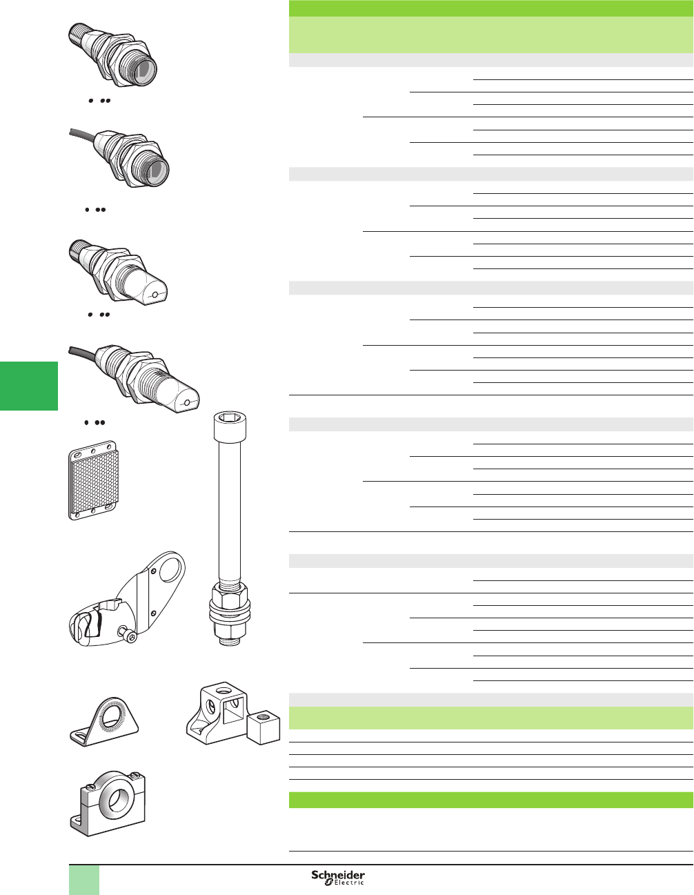
5/30
1
Connector
Sensing
distance Sn,
m (ft)
Function Output Line of sight Catalog Number Weight
kg (lb)
Diffuse system
0.1 (0.33) NO PNP Along case axis XUB4APANM12 0.040 (0.09)
90° to case axis XUB4APAWM12 0.040 (0.09)
NPN Along case axis XUB4ANANM12 0.040 (0.09)
90° to case axis XUB4ANAWM12 0.040 (0.09)
NC PNP Along case axis XUB4APBNM12 0.040 (0.09)
90° to case axis XUB4APBWM12 0.040 (0.09)
NPN Along case axis XUB4ANBNM12 0.040 (0.09)
90° to case axis XUB4ANBWM12 0.040 (0.09)
Diffuse system with adjustable sensitivity
0.6 (1.97) NO PNP Along case axis XUB5APANM12 0.045 (0.10)
90° to case axis XUB5APAWM12 0.050 (0.11)
NPN Along case axis XUB5ANANM12 0.045 (0.10)
90° to case axis XUB5ANAWM12 0.050 (0.11)
NC PNP Along case axis XUB5APBNM12 0.045 (0.10)
90° to case axis XUB5APBWM12 0.050 (0.11)
NPN Along case axis XUB5ANBNM12 0.045 (0.10)
90° to case axis XUB5ANBWM12 0.050 (0.11)
Polarized retrorefl ective system
2 (6.56) NO PNP Along case axis XUB9APANM12 0.040 (0.09)
90° to case axis XUB9APAWM12 0.040 (0.09)
NPN Along case axis XUB9ANANM12 0.040 (0.09)
90° to case axis XUB9ANAWM12 0.040 (0.09)
NC PNP Along case axis XUB9APBNM12 0.040 (0.09)
90° to case axis XUB9APBWM12 0.040 (0.09)
NPN Along case axis XUB9ANBNM12 0.040 (0.09)
90° to case axis XUB9ANBWM12 0.040 (0.09)
Refl ector
50 x 50 mm
– – – XUZC50 0.020 (0.04)
Retrorefl ective system
4 (13.12) NO PNP Along case axis XUB1APANM12 0.040 (0.09)
90° to case axis XUB1APAWM12 0.040 (0.09)
NPN Along case axis XUB1ANANM12 0.040 (0.09)
90° to case axis XUB1ANAWM12 0.040 (0.09)
NC PNP Along case axis XUB1APBNM12 0.040 (0.09)
90° to case axis XUB1APBWM12 0.040 (0.09)
NPN Along case axis XUB1ANBNM12 0.040 (0.09)
90° to case axis XUB1ANBWM12 0.040 (0.09)
Refl ector
50 x 50 mm
– – – XUZC50 0.020 (0.04)
Thru-beam system
Transmitter
15 (49.21)
– – Along case axis XUB2AKSNM12T 0.040 (0.09)
90° to case axis XUB2AKSWM12T 0.040 (0.09)
Receiver
15 (49.21)
NO PNP Along case axis XUB2APANM12R 0.040 (0.09)
90° to case axis XUB2APAWM12R 0.040 (0.09)
NPN Along case axis XUB2ANANM12R 0.040 (0.09)
90° to case axis XUB2ANAWM12R 0.040 (0.09)
NC PNP Along case axis XUB2APBNM12R 0.040 (0.09)
90° to case axis XUB2APBWM12R 0.040 (0.09)
NPN Along case axis XUB2ANBNM12R 0.040 (0.09)
90° to case axis XUB2ANBWM12R 0.040 (0.09)
Mounting accessories (1)
Description Catalog Number Weight
kg (lb)
3D mounting kit (for use on M12 rod) for XUB or XUZ C50 XUZB2003 0.170 (0.37)
M12 rod XUZ2001 0.050 (0.11)
Support for M12 rod XUZ2003 0.150 (0.33)
Stainless steel mounting bracket XUZA118 0.045 (0.10)
Plastic mounting bracket with adjustable ball-joint XUZA218 0.035 (0.08)
Pre-cabled
For a pre-cabled sensor, replace M12 by L2 for a 2 m long cable, or by L5 for a 5 m long cable.
Example: XUB1APANM12 becomes XUB1APANL2 for a 2 m long cable and XUB1APANL5 for
a 5 m long cable.
For availability, consult the Sensor Competency Center.
(1) For further information, see accessory section.
Catalog Numbers
XUB A NM12
550009
5
20983
XUB A WM12
XUZC50
XUB A NL2
520982
XUB A WL2
805799550003
XUZB2003 XUZ2001
520312
520984
XUZ2003
XUZA218
805817
XUZA118
805817
OsiSense® XU
Photoelectric sensors 1
Single mode function
Design ø18, plastic
Three-wire DC, solid-state output
1
2
3
4
5/
6
7
8
9
10
This document provided by Barr-Thorp Electric Co., Inc. 800-473-9123 www.barr-thorp.com
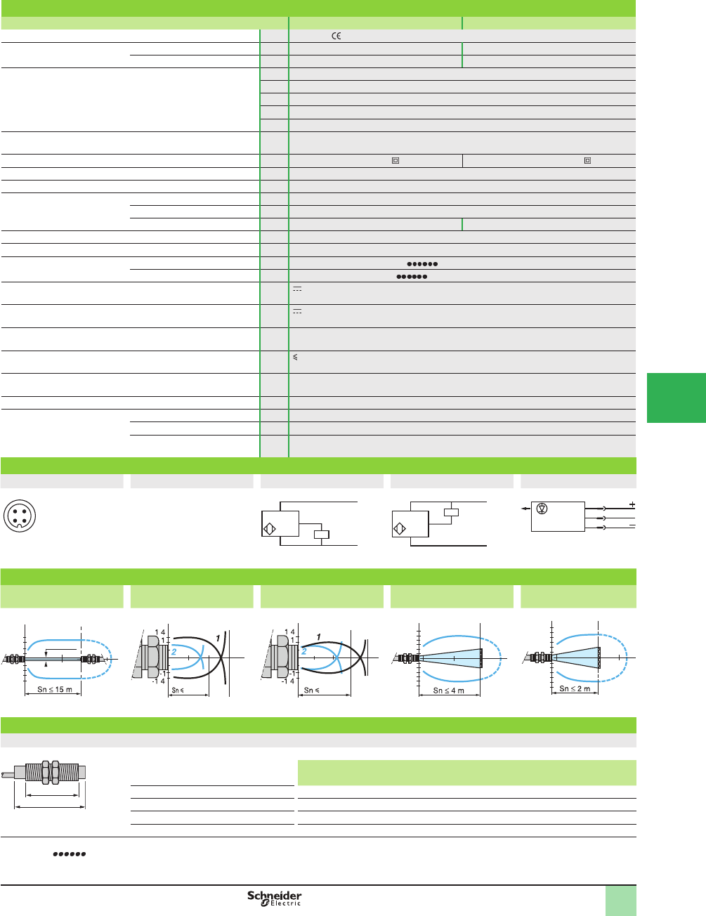
5/31
1
Specifi cations
Sensor type XUB1, XUB2, XUB4, XUB5, XUB9 XUB1, XUB2, XUB4, XUB5, XUB9
Product certifi cations UL, CSA,
Connection Connector DIN 40050 M12 –
Pre-cabled IEC 60529 – Length: 2 m
Sensing distance:
nominal Sn (excess gain = 2)
maximum (excess gain = 1)
m (ft) 0.1 / 0.15 (0.33 / 0.49) diffuse
m (ft) 0.6 / 0.8 (1.97 / 2.62) diffuse with adjustable sensitivity
m (ft) 2 / 3 (6.56 / 9.84) polarized retroreß ective
m (ft) 4 / 5.5 (13.12 / 18.04) retroreß ective
m (ft) 15 / 20 (49.21 / 65.62) thru-beam
Type of transmission Infrared, except polarized retroreß ective (red)
Degree of protection IP 69K, double insulation IP 65, IP 67, double insulation
Storage temperature °C -40 to +70 (-40 to +158 °F)
Operating temperature °C -25 to +55 (-13 to +122 °F)
Materials Case PBT
Lens PMMA
Cable – PvR
Vibration resistance Conforming to IEC 60068-2-6 7 gn, amplitude ± 1.5 mm (f = 10 to 55 Hz)
Shock resistance Conforming to IEC 60068-2-27 30 gn, duration 11 ms
Indicator lights Output state Yellow LED (except for XUB2 T)
Supply on Green LED (only for XUB2 T)
Rated supply voltage V 12–24 with protection against reverse polarity
Voltage limits (including ripple) V 10–36
Current consumption, no-load mA 35
Switching capacity mA 100 with overload and short-circuit protection
Voltage drop, closed state V 1.5
Maximum switching frequency Hz 500
Delays First-up ms < 15
Response ms < 1
Recovery ms < 1
Wiring diagrams
M12 connector Pre-cabled PNP NPN Transmitter
3 (-)
1 (+)
4 OUT/Output
2 Beam break
input (1)
(-) BU (Blue)
(+) BN (Brown)
(OUT/Output) BK (Black)
Beam break input (1)
VI (Violet)
Input 2/VI:
- not connected: beam made
- connected to –: beam broken
Operating curves
Thru-beam system Diffuse system Diffuse system with
adjustable sensitivity
Retrorefl ective system Polarized retrorefl ective
system
Object 10 x 10 cm; 1White 90%; 2 Gray 18% With reß ector XUZC50 With reß ector XUZC50
Dimensions (mm)
XUB
Pre-cabled (mm) Connector (mm)
a b a b
Ø 18, line of sight along case axis 46 (2) 28 60 (1) 28
Ø 18, line of sight 90° to case axis 62 28 76 28
Ø 18, line of sight along case axis XUB5 62 44 76 44
Ø 18, line of sight 90° to case axis XUB5 78 44 92 44
(1) Beam break input on thru-beam transmitter only.
(2) For XUB9 (polarized retroreß ective) 46 becomes 48 mm and 60 becomes 62 mm.
1 2
4 3
–
BN/1
BU/3
+
PNP BK/4 (NO/NC)
BN/1
BU/3
+
–
BK/4 (NO/NC)
NPN
1/BN
3/BU
2/VI
15
-15
1510 m
cm
Ø 12 mm
5
1 5
cm
cm
10 cm
.
.
80
cm
cm
60 cm
.
.
4
10
-4
-10
m
4
2
cm
2
4
6
-2
-4
-6
0.2 m
3
2
cm
E/R
Ø of beam
a
b
SpeciÞ cations, Wiring
Diagrams,
Operating Curves,
Dimensions
OsiSense® XU
Photoelectric sensors 1
Single mode function
Design ø18, plastic
Three-wire DC, solid-state output
1
2
3
4
5
6
7
8
9
10
This document provided by Barr-Thorp Electric Co., Inc. 800-473-9123 www.barr-thorp.com
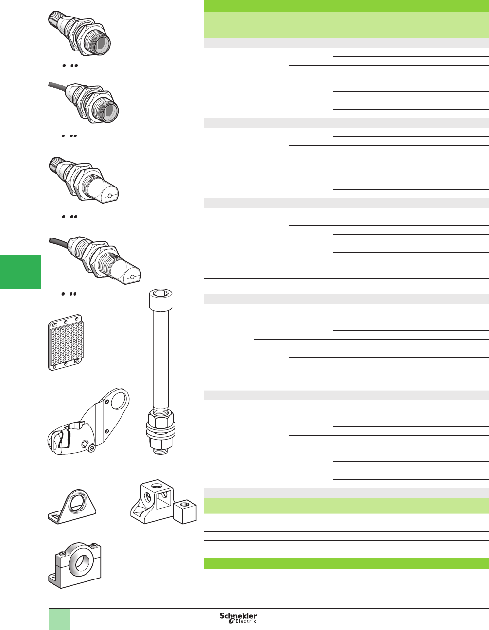
5/32
1
Connector
Sensing
distance Sn,
m (ft)
Function Output Line of sight Catalog Number Weight
kg (lb)
Diffuse system
0.1 (0.33) NO PNP Along case axis XUB4BPANM12 0.050 (0.11)
90° to case axis XUB4BPAWM12 0.050 (0.11)
NPN Along case axis XUB4BNANM12 0.050 (0.11)
90° to case axis XUB4BNAWM12 0.050 (0.11)
NC PNP Along case axis XUB4BPBNM12 0.050 (0.11)
90° to case axis XUB4BPBWM12 0.050 (0.11)
NPN Along case axis XUB4BNBNM12 0.050 (0.11)
90° to case axis XUB4BNBWM12 0.050 (0.11)
Diffuse system with adjustable sensitivity
0.6 (1.97) NO PNP Along case axis XUB5BPANM12 0.055 (0.12)
90° to case axis XUB5BPAWM12 0.060 (0.13)
NPN Along case axis XUB5BNANM12 0.055 (0.12)
90° to case axis XUB5BNAWM12 0.060 (0.13)
NC PNP Along case axis XUB5BPBNM12 0.055 (0.12)
90° to case axis XUB5BPBWM12 0.060 (0.13)
NPN Along case axis XUB5BNBNM12 0.055 (0.12)
90° to case axis XUB5BNBWM12 0.060 (0.13)
Polarized retrorefl ective system
2 (6.56) NO PNP Along case axis XUB9BPANM12 0.050 (0.11)
90° to case axis XUB9BPAWM12 0.050 (0.11)
NPN Along case axis XUB9BNANM12 0.050 (0.11)
90° to case axis XUB9BNAWM12 0.050 (0.11)
NC PNP Along case axis XUB9BPBNM12 0.050 (0.11)
90° to case axis XUB9BPBWM12 0.050 (0.11)
NPN Along case axis XUB9BNBNM12 0.050 (0.11)
90° to case axis XUB9BNBWM12 0.050 (0.11)
Refl ector
50 x 50 mm
– – – XUZC50 0.020 (0.04)
Retrorefl ective system
4 (13.12) NO PNP Along case axis XUB1BPANM12 0.050 (0.11)
90° to case axis XUB1BPAWM12 0.050 (0.11)
NPN Along case axis XUB1BNANM12 0.050 (0.11)
90° to case axis XUB1BNAWM12 0.050 (0.11)
NC PNP Along case axis XUB1BPBNM12 0.050 (0.11)
90° to case axis XUB1BPBWM12 0.050 (0.11)
NPN Along case axis XUB1BNBNM12 0.050 (0.11)
90° to case axis XUB1BNBWM12 0.050 (0.11)
Refl ector
50 x 50 mm
– – – XUZC50 0.020 (0.04)
Thru-beam system
Transmitter
15 (49.21)
– – Along case axis XUB2BKSNM12T 0.050 (0.11)
90° to case axis XUB2BKSWM12T 0.050 (0.11)
Receiver
15 (49.21)
NO PNP Along case axis XUB2BPANM12R 0.050 (0.11)
90° to case axis XUB2BPAWM12R 0.050 (0.11)
NPN Along case axis XUB2BNANM12R 0.050 (0.11)
90° to case axis XUB2BNAWM12R 0.050 (0.11)
NC PNP Along case axis XUB2BPBNM12R 0.050 (0.11)
90° to case axis XUB2BPBWM12R 0.050 (0.11)
NPN Along case axis XUB2BNBNM12R 0.050 (0.11)
90° to case axis XUB2BNBWM12R 0.050 (0.11)
Mounting accessories
Description Catalog Number Weight
kg (lb)
3D mounting kit (for use on M12 rod) for XUB or XUZC50 XUZB2003 0.170 (0.37)
M12 rod XUZ2001 0.050 (0.11)
Support for M12 rod XUZ2003 0.150 (0.33)
Stainless steel mounting bracket XUZA118 0.045 (0.10)
Plastic mounting bracket with adjustable ball-joint XUZA218 0.035 (0.08)
Pre-cabled
For a pre-cabled sensor, replace M12 by L2 for a 2 m long cable, or by L5 for a 5 m long cable.
Example: XUB1BPANM12 becomes XUB1BPANL2 for a 2 m long cable and XUB1BPANL5 for
a 5 m long cable.
For availability, consult the Sensor Competency Center.
XUB B NM12
550009
520983
XUB B WM12
XUZC50
520983
XUB B NL2
520982
XUB B WL2
550003
XUZB2003 XUZ2001
520312
XUZA118
805817
XUZA218
805817 805799
520984
XUZ2003
Catalog Numbers OsiSense® XU
Photoelectric sensors 1
Single mode function
Design ø18, metal
Three-wire DC, solid-state output
1
2
3
4
5/
6
7
8
9
10
This document provided by Barr-Thorp Electric Co., Inc. 800-473-9123 www.barr-thorp.com

5/33
1
Specifi cations
Sensor type XUB1, XUB2, XUB4, XUB5, XUB9 XUB1, XUB2, XUB4, XUB5, XUB9
Product certifi cations UL, CSA,
Connection Connector DIN 40050 M12 –
Pre-cabled IEC 60529 – Length: 2 m
Sensing distance:
nominal Sn (excess gain = 2)
maximum (excess gain = 1))
m (ft) 0.1 / 0.15 (0.33 / 0.49) diffuse
m (ft) 0.6 / 0.8 (1.97 / 2.62) diffuse with adjustable sensitivity
m (ft) 2 / 3 (6.56 / 9.84) polarized retroreß ective
m (ft) 4 / 5.5 (13.12 / 18.04) retroreß ective
m (ft) 15 / 20 (49.21 / 65.62) thru-beam
Type of transmission Infrared, except polarized retroreß ective (red)
Degree of protection IP 69K, double insulation IP 65, IP 67, double insulation
Storage temperature °C -40 to +70 (-40 to +158 °F)
Operating temperature °C -25 to +55 (-13 to +122 °F)
Materials Case Nickel plated brass
Lens PMMA
Cable – PvR
Vibration resistance Conforming to IEC 60068-2-6 7 gn, amplitude ± 1.5 mm (f = 10 to 55 Hz)
Shock resistance Conforming to IEC 60068-2-27 30 gn, duration 11 ms
Indicator lights Output state Yellow LED (except for XUB2 T)
Supply on Green LED (only for XUB2 T)
Rated supply voltage V 12–24 with protection against reverse polarity
Voltage limits (including ripple) V 10–36
Current consumption, no-load mA 35
Switching capacity mA 100 with overload and short-circuit protection
Voltage drop, closed state V 1.5
Maximum switching frequency Hz 500
Delays First-up ms < 15
Response ms < 1
Recovery ms < 1
Wiring diagrams
M12 connector Pre-cabled PNP NPN Transmitter
3 (-)
1 (+)
4 OUT/Output
2 Beam break
input (1)
(-) BU (Blue)
(+) BN (Brown)
(OUT/Output) BK (Black)
Beam break input (1)
VI (Violet) Input 2/VI:
- not connected: beam made
- connected to –: beam broken
Operating curves
Thru-beam system Diffuse system Diffuse system with
adjustable sensitivity
Retrorefl ective system Polarized retrorefl ective
system
Object 10 x 10 cm; 1White 90%; 2 Gray 18% With reß ector XUZC50 With reß ector XUZC50
Dimensions (mm)
XUB
Pre-cabled (mm) Connector (mm)
a b a b
Ø 18, line of sight along case axis 46 (2) 28 60 (1) 28
Ø 18, line of sight 90° to case axis 62 28 76 28
Ø 18, line of sight along case axis XUB5 62 44 76 44
Ø 18, line of sight 90° to case axis XUB5 78 44 92 44
(1) Beam break input on thru-beam transmitter only.
(2) For XUB9 (polarized retroreß ective) 46 becomes 48 mm and 60 becomes 62 mm.
1 2
4 3
–
BN/1
BU/3
+
PNP BK/4 (NO/NC)
BN/1
BU/3
+
–
BK/4 (NO/NC)
NPN
1/BN
3/BU
2/VI
15
-15
1510 m
cm
Ø 12 mm
5
1 5
cm
cm
10 cm
.
.
80
cm
cm
60 cm
.
.
4
10
-4
-10
m
4
2
cm
2
4
6
-2
-4
-6
0.2 m
3
2
cm
E/R
Ø of beam
a
b
SpeciÞ cations, Wiring
Diagrams,
Operating Curves,
Dimensions
OsiSense® XU
Photoelectric sensors 1
Single mode function
Design ø18, metal
Three-wire DC, solid-state output
1
2
3
4
5
6
7
8
9
10
This document provided by Barr-Thorp Electric Co., Inc. 800-473-9123 www.barr-thorp.com
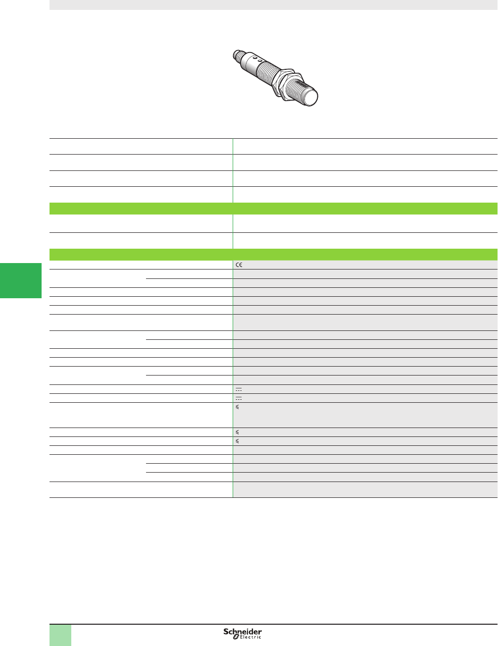
5/34
1
Design ø18
System Diffuse
Type of transmission Ultraviolet (370 nm)
Nominal sensing distance Sn, mm (in.) 20 (0.79) for color mark reading,
0–80 (0–3.15) in diffuse mode
Sensitivity adjustment By potentiometer
Catalog Number
3-wire, PNP NO function (2) XU5M18U1D
Weight, kg (lb) 0.075 (0.17)
Specifi cations
Product certifi cations , CSA, UL
Ambient air temperature For operation -25 to +55 °C (-13 to +122 °F)
For storage -40 to +70 °C (-40 to +158 °F)
Vibration resistance Conforming to IEC 60068-2-6 7 gn, amplitude ± 0.6 mm (f = 10–55 Hz)
Shock resistance Conforming to IEC 60068-2-27 30 gn, duration 11 ms
Degree of protection Conforming to IEC 60529 IP 67
Connection M12 connector
(suitable female connectors, including pre-wired versions)
Materials Case Nickel plated brass
Lenses PMMA
Spot diameter At 20 mm: Ø 3 x 1 mm
Auxiliary functions External synchronization, locking
Indicator lights Output state Green LED
Teach mode –
Rated supply voltage 12–24 V with protection against reverse polarity
Voltage limits 10–30 V (including ripple)
Switching capacity (sealed) 100 mA
with protection against reverse polarity, overload and
short-circuit
Voltage drop, closed state 1.5 V (PNP)
Current consumption, no-load 20 mA
Maximum switching frequency 1 kHz
Delays First-up ≤ 100 ms
Response ≤ 500 Ps
Recovery ≤ 500 Ps
Time delay Off delay: 20 ms, activated/deactivated by cabling method
(1) Applications: detection of invisible reference marks, markings, glues or varnishes containing bluing agents.
(2) Output activated when a blued mark on a non-blued background is present.
Catalog Numbers
SpeciÞ cations
OsiSense® XU
Photoelectric sensors 1
Application, packaging series
Luminescence sensor (1)
DC supply. Solid-state output
1
2
3
4
5/
6
7
8
9
10
This document provided by Barr-Thorp Electric Co., Inc. 800-473-9123 www.barr-thorp.com
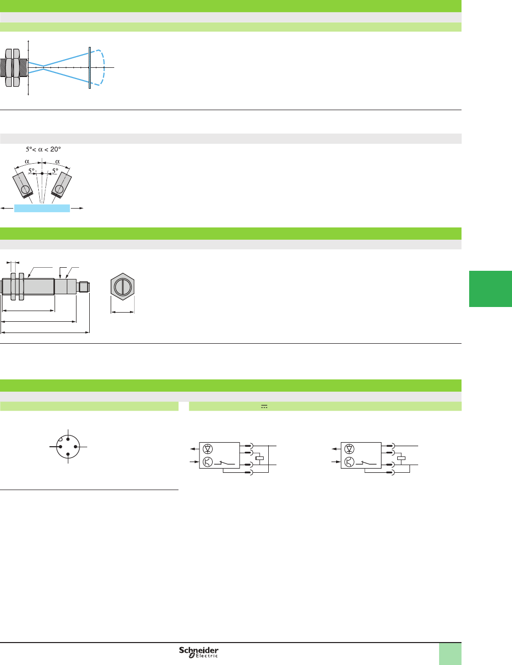
5/35
1
Curves
XU5M18U1D
Operating curves
Object 5 x 5 cm, white 90%
Spot size at 20 mm: oval, Ø 3 x 1 mm
Vertical inclination
An angle of 5 to 10°
from vertical is recommended
for reß ective or transparent
surfaces
Maximum vertical inclination: 20°
Dimensions (mm)
XU5M18U1D
(1) Potentiometer
(2) Green LED
Mounting nut tightening torque: 15 N•m. (132.76 lb-in)
Wiring diagrams
XU5M18U1D
Connector diagram Wiring diagram (3-wire )
(1) Off delay of output signal:
- no time delay: connect contact 2 to (+)
-20 ms time delay: connect contact 2 to (-)
cm
cm
8
2
3
3
82
55
95
4
24
(1)
M18x1 (2)
1 (+)
3 (
–
)
4
2
Time delay (1) Output
(
Sensor connector pin view)
1
4
3
2
+
–
PNP output
Without output signal time delay
1
4
3
2
+
–
With output signal time delay (20 ms)
Operating Curves,
Dimensions,
Wiring Diagrams
OsiSense® XU
Photoelectric sensors 1
Application, packaging series
Luminescence sensor (1)
DC supply. Solid-state output
1
2
3
4
5
6
7
8
9
10
This document provided by Barr-Thorp Electric Co., Inc. 800-473-9123 www.barr-thorp.com
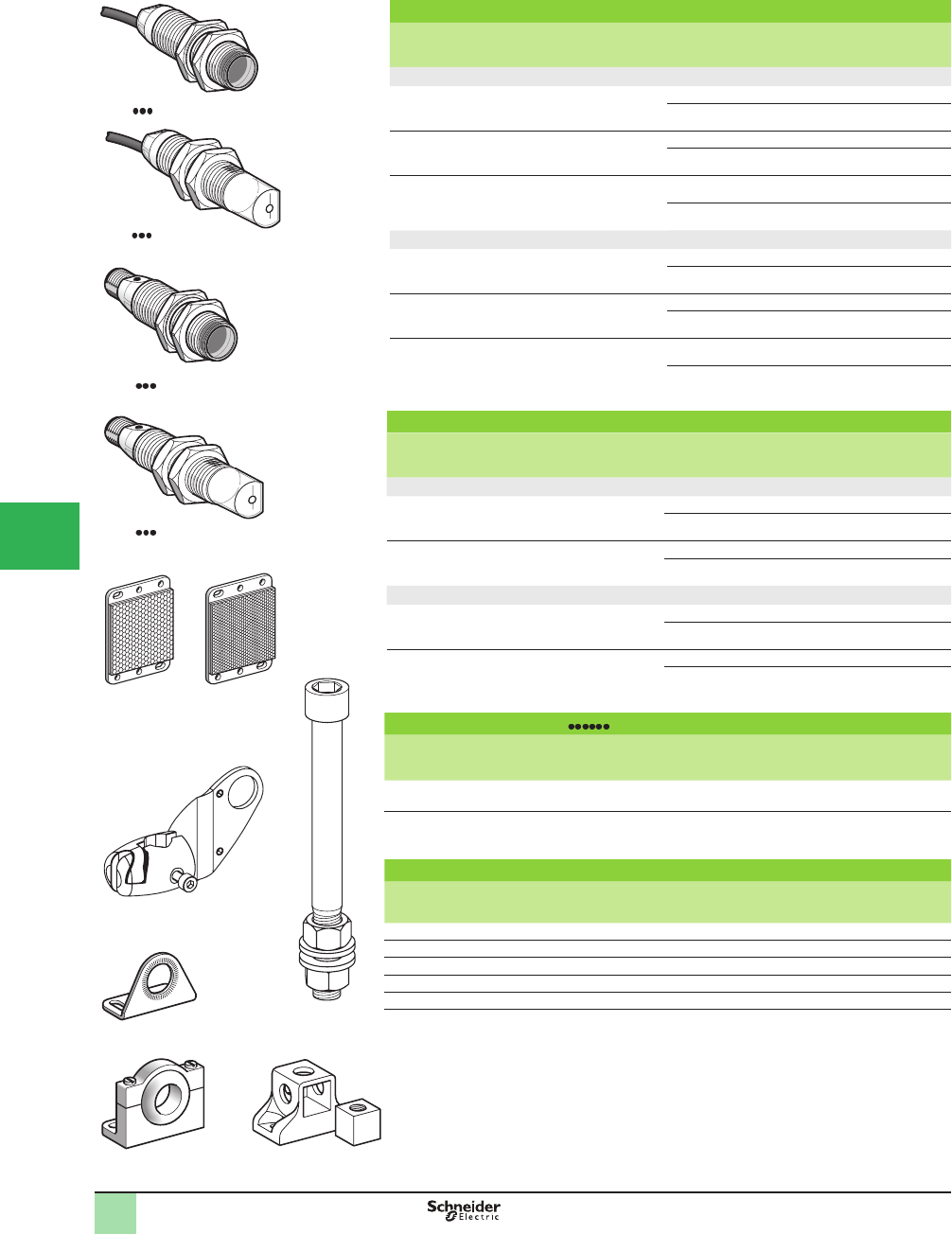
5/36
1
Ø 18 plastic, coaxial polarized retrorefl ective with teach mode
Sensing distance
Sn, m (ft)
Function Line of
sight
Output Catalog Number Weight
kg (lb)
Pre-cabled (2)
0–1.4 (0–4.59)
With reß ector
XUZC50/C50HP
NO or NC, by
programming
Along case
axis
PNP XUBTAPSNL2 (1) 0.110 (0.24)
NPN XUBTANSNL2 (1) 0.110 (0.24)
0–0.8 (0–2.62)
With reß ector
XUZC50/C50HP
NO or NC, by
programming
90° to case
axis
PNP XUBTAPSWL2 (1) 0.113 (0.25)
NPN XUBTANSWL2 (1) 0.113 (0.25)
0–0.8 (0–2.62)
With reß ector
XUZC50/C50HP
NO or NC, by
programming
Along case
axis
PNP XUBT1PSNL2 0.110 (0.24)
NPN XUBT1NSNL2 0.110 (0.24)
M12 connector
0–1.4 (0–4.59)
With reß ector
XUZ C50/C50HP
NO or NC, by
programming
Along case
axis
PNP XUBTAPSNM12 (1) 0.045 (0.10)
NPN XUBTANSNM12 (1) 0.045 (0.10)
0–0.8 (0–2.62)
With reß ector
XUZC50/C50HP
NO or NC, by
programming
90° to case
axis
PNP XUBTAPSWM12 (1) 0.048 (0.11)
NPN XUBTANSWM12 (1) 0.048 (0.11)
0–0.8 (0–2.62)
With reß ector
XUZC50/C50HP
NO or NC, by
programming
Along case
axis
PNP XUBT1PSNM12 0.110 (0.24)
NPN XUBT1NSNM12 0.110 (0.24)
Ø 18 stainless steel, coaxial polarized retrorefl ective with teach mode
Sensing distance
Sn, m (ft)
Function Line of
sight
Output Catalog Number Weight
kg (lb)
Pre-cabled (2)
0–1.4 (0–4.59)
With reß ector
XUZC50/C50HP
NO or NC, by
programming
Along case
axis
PNP XUBTSPSNL2 (1) 0.135 (0.30)
NPN XUBTSNSNL2 (1) 0.135 (0.30)
0–0.8 (0–2.62)
With reß ector
XUZC50/C50HP
NO or NC, by
programming
90° to case
axis
PNP XUBTSPSWL2 (1) 0.138 (0.30)
NPN XUBTSNSWL2 (1) 0.138 (0.30)
M12 connector
0–1.4 (0–4.59)
With reß ector
XUZ C50/C50HP
NO or NC, by
programming
Along case
axis
PNP XUBTSPSNM12 (1) 0.070 (0.15)
NPN XUBTSNSNM12 (1) 0.070 (0.15)
0–0.8 (0–2.62)
With reß ector
XUZC50/C50HP
NO or NC, by
programming
90° to case
axis
PNP XUBTSPSWM12 (1) 0.073 (0.16)
NPN XUBTSNSWM12 (1) 0.073 0.16)
Accessories for XUBT
Description Dimensions Catalog Number Weight
kg (lb)
Universal refl ector
(without blind zone)
50 x 50 mm XUZC50 0.020 (0.04)
Application refl ector
(accuracy, detection sensitivity)
50 x 50 mm XUZC50HP 0.020 (0.04)
Mounting accessories
Description Catalog Number Weight
kg (lb)
3D mounting kit for use on M12 rod for XUBT or XUZC50/C50HP XUZB2003 0.170 (0.17)
M12 rod XUZ2001 0.050 (0.11)
Support for M12 rod XUZ2003 0.150 (0.33)
Stainless steel mounting bracket XUZA118 0.045 (0.10)
Plastic mounting bracket with adjustable ball-joint XUZA218 0.035 (0.08)
(1) Application refl ector XUZC50HP included with the sensor.
(2) For a 5 m cable, replace L2 by L5.
Example: XUBTAPSNL2 becomes XUBTAPSNL5.
Catalog Numbers
524074
XUBT WL2
XUBT WM12
524038
XUBT NL2
5
2
4
0
7
2
550003
XUZB2003
805799
XUZC50
XUZA118
805817
805818
XUZA218
520312
XUZ2001
520984
XUZ2003
XUBT NM12
524073
XUZC50HP
536353
OsiSense®XU
Photoelectric sensors 1
Application, packaging series
For detection of transparent materials
Design ø18, plastic or stainless steel
Three-wire DC, solid-state output
1
2
3
4
5/
6
7
8
9
10
This document provided by Barr-Thorp Electric Co., Inc. 800-473-9123 www.barr-thorp.com
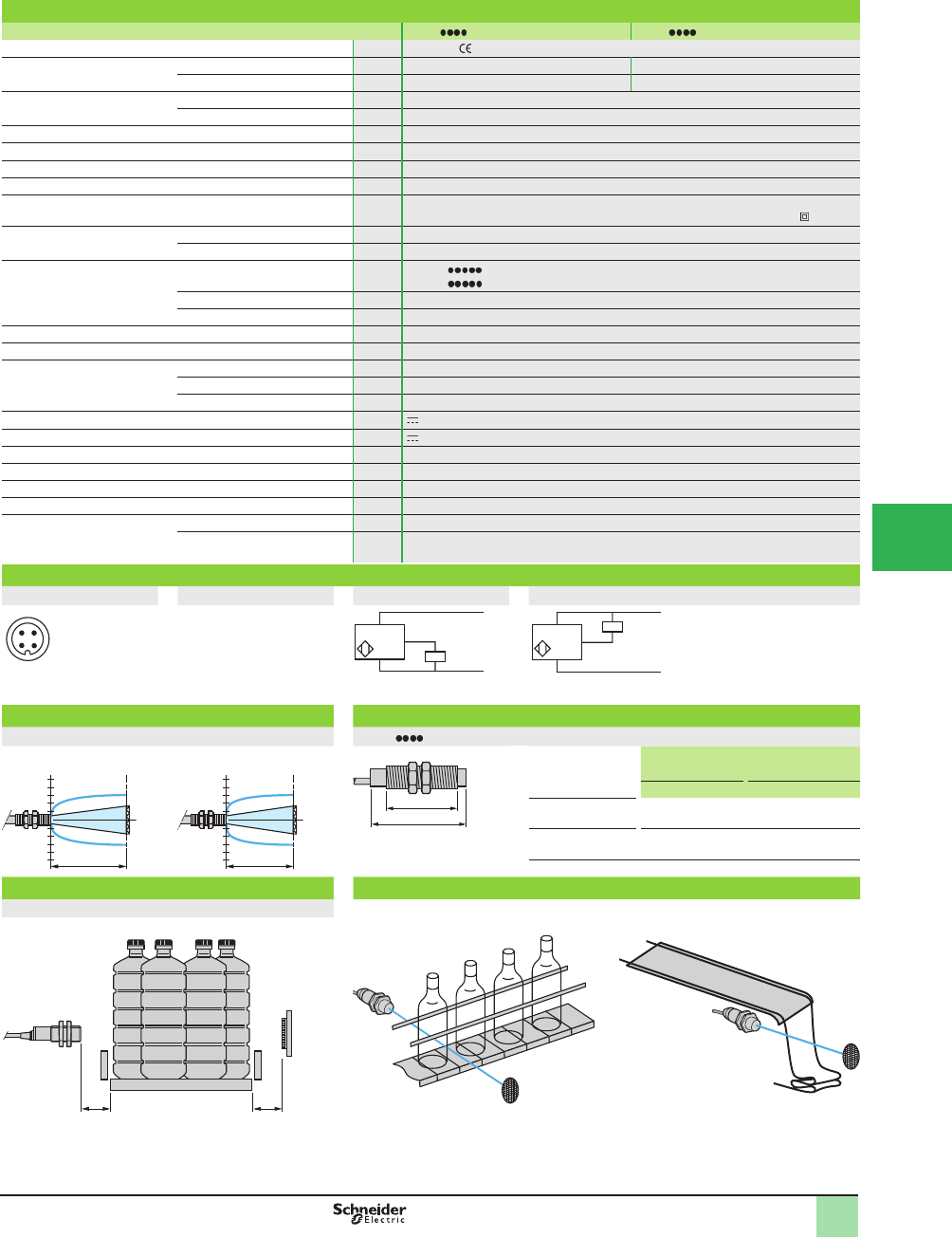
5/37
1
Specifi cations
Sensor type XUBT M12 XUBT L2
Product certifi cations UL, CSA,
Connection Connector DIN 40050 M12 –
Pre-cabled IEC 60529 – Length: 2 m
Nominal sensing distance Sn Line of sight along case axis m (ft) 0–1.4 (0–4.59) with reß ector XUZC50/C50HP
Line of sight 90° to case axis m (ft) 0–0.8 (0–2.62) with reß ector XUZC50/C50HP
Beam divergence 1.5° (Ø 37 mm spot at 1.4 m)
Blind zone 0
Preferred approach direction Any
Type of transmission Coaxial polarized red
Degree of protection XUBTA (plastic) IP65, IP67, cable version (IEC 60529); IP 69K connector version
(DIN 40050) XUBTS (stainless) IP 65, IP 67, and IP 69K double insulation
Temperature Storage °C (°F) -40 to +70 (-40 to +158)
Operation °C (°F) 0 to +55 (+32 to +131)
Materials Case XUBTA : plastic, PBT
XUBTS : stainless steel (grade 304Cu)
Lens PMMA
Cable PvR
Vibration resistance Conforming to IEC 60068-2-6 7 gn, amplitude ± 1 mm (f = 10 to 55 Hz)
Shock resistance Conforming to IEC 60068-2-27 30 gn, duration 11 ms
Indicator lights Output state Yellow LED
Supply on Green LED
Stability Red LED
Rated supply voltage V 12–24 with protection against reverse polarity
Voltage limits (including ripple) V 10–32
Current consumption, no-load mA 45
Switching capacity per output mA d 100 with overload and short-circuit protection
Voltage drop, closed state V d 1.5
Maximum switching frequency Hz 1000
Delays First-up ms < 200
Response and recovery µs < 500
Wiring diagrams
M12 connector Pre-cabled PNP NPN
3 (-)
1 (+)
4 OUT/Output
2 Not connected
(-) BU (Blue)
(+) BN (Brown)
OUT/Output BK (Black)
Operating curves Dimensions (mm)
With refl ector XUZC50 XUBT
Line of sight along case axis Line of sight 90° to case axis
Pre-cabled
(mm)
Plug-in connector
(mm)
a b a b
Ø 18, line of sight
along case axis
64 44 78 44
Ø 18, line of sight
90° to case axis
78 44 92 44
Setup Application examples
Recommended distances and application restraints
(1) No blind zone. Detection of transparent bottles. Detection of plastic Þ lm.
1 2
4 3
–
BN/1
BU/3
+
PNP BK/4
BN/1
BU/3
+
–
BK/4
NPN
a
b
2
4
-2
-4 Sn y 1.4 m
2
4
-2
-4 Sn y 0.8 m
(1) (1)
SpeciÞ cations, Wiring
Diagrams,
Operating Curves,
Dimensions
OsiSense®XU
Photoelectric sensors 1
Application, packaging series
For detection of transparent materials
Design ø18, plastic or stainless steel
Three-wire DC, solid-state output
1
1
2
3
4
5
6
7
8
9
10
This document provided by Barr-Thorp Electric Co., Inc. 800-473-9123 www.barr-thorp.com
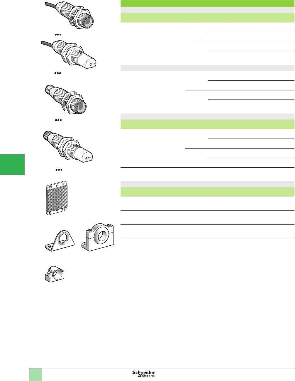
5/38
1
Ø 18 stainless steel
Pre-cabled (1)
Sensing distance
Sn, m (ft)
Function Output Line of
sight
Catalog Number Weight
kg (lb)
0–15 (0–49.21)
depending on
whether
accessories are used
NO or NC, by
programming
PNP Along case
axis
XUB0SPSNL2 0.105 (0.23)
90° to case
axis
XUB0SPSWL2 (3) 0.110 (0.24)
NPN Along case
axis
XUB0SNSNL2 0.105 (0.23)
90° to case
axis
XUB0SNSWL2 (3) 0.110 (0.24)
M12 connector
0–15 (0–49.21)
depending on
whether accessories
are used
NO or NC,
by programming
PNP Along case
axis
XUB0SPSNM12 0.055 (0.12)
90° to case
axis
XUB0SPSWM12 (3) 0.060 (0.13)
NPN Along case
axis
XUB0SNSNM12 0.055 (0.12)
90° to case
axis
XUB0SNSWM12 (3) 0.060 (0.13)
Accessories
Description Connection Line of
sight
Catalog Number Weight
kg (lb)
Thru-beam accessories
(transmitter)
Pre-cabled
(1)
Along case
axis
XUB0SKSNL2T 0.105 (0.23)
90° to case
axis
XUB0SKSWL2T (3) 0.110 (0.24)
M12
connector
Along case
axis
XUB0SKSNM12T 0.055 (0.12)
90° to case
axis
XUB0SKSWM12T (3) 0.060 (0.13)
Refl ector 50 x 50 mm – – XUZC50 0.020 (0.04)
Mounting accessories
Description Catalog Number Weight
kg (lb)
Stainless steel mounting bracket XUZA118 0.045 (0.10)
Plastic mounting bracket with adjustable ball-joint XUZA218 0.035 (0.08)
Plastic mounting clamp, 24.1 mm centers
with locking screw
XUZB2005 0.007 (0.02)
(1) For a 5 m cable, replace L2 with L5.
Example: XUB0SPSNL2 becomes XUB0SPSNL5.
XUB0 WL2
XUB0 NM12
XUB0 WM12
XUB0 NL2
XUZC50
XUZA118 XUZA218
XUZB2005
805818
Catalog Numbers OsiSense® XU
Photoelectric sensors 1
Application, multimode
food and beverage processing series
Design ø18, metal, stainless steel
Three-wire DC, solid-state output
1
2
3
4
5/
6
7
8
9
10
This document provided by Barr-Thorp Electric Co., Inc. 800-473-9123 www.barr-thorp.com
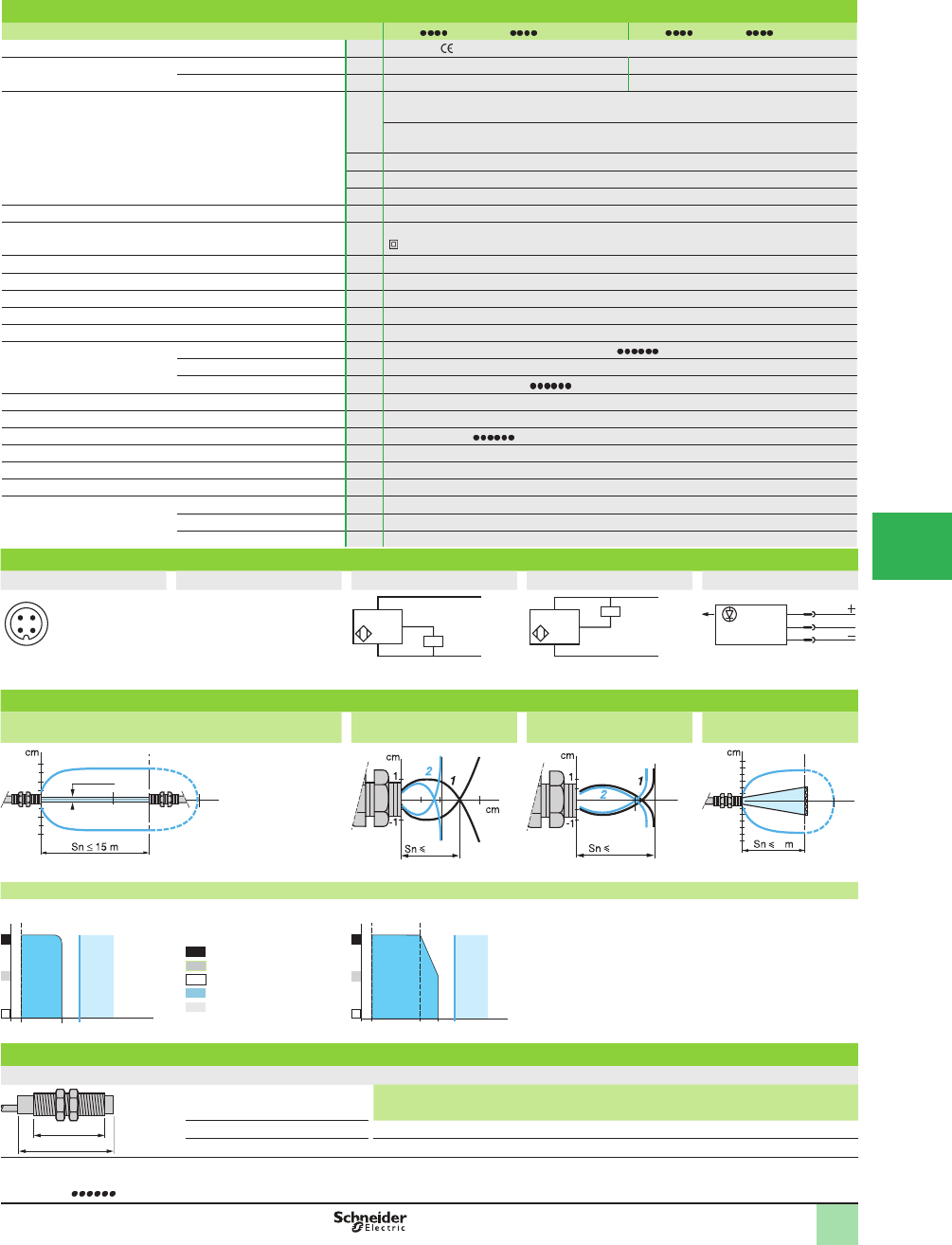
5/39
1
Specifi cations
Sensor type XUB0 M12, XUB0 M12T XUB0 L2, XUB0 L2T
Product certifi cations UL, CSA,
Connection Connector M12 –
Pre-cabled – Length: 2 m
Sensing distance:
nominal Sn (excess gain = 2)
maximum (excess gain = 1)
Line of sight along
case axis
Line of sight 90° to
case axis
Accessory
m (ft) 0.12 / 0.12
(0.39 / 0.39)
0.11 / 0.11
(0.36 / 0.36)
Without (diffuse with background
suppression)
m (ft) 0.3 / 0.4 (0.98 / 1.31) 0.2 / 0.3 (0.66 / 0.98) Without (diffuse)
m (ft) 2 / 3 (6.56 / 9.84) 1.5 / 2 (4.92 / 6.56) With reß ector (polarized retroreß ective)
m (ft) 15 / 20 (49.21 / 65.62) 10 / 14 (32.81 / 45.93) With thru-beam accessory (thru-beam)
Type of transmission Infrared, except polarized retroreß ective (red)
Degree of protection IP 65, IP 67 conforming to IEC 60529; IP 69K conforming to DIN 40050; double insulation
Storage temperature °C -40 to +70 (-40 to +158 °F)
Operating temperature °C -25 to +55 (-13 to +131 °F)
Materials Case: stainless steel, grade 304CU; Lens: PMMA; Cable: PvR
Vibration resistance Conforming to IEC 60068-2-6 7 gn, amplitude ± 1.5 mm (f = 10 to 55 Hz)
Shock resistance Conforming to IEC 60068-2-27 30 gn, duration 11 ms
Indicator lights Output state Yellow LED (transmission present for XUB0 T)
Supply on Green LED
Stability Red LED (except for XUB0 T)
Rated supply voltage Vdc 12–24 with protection against reverse polarity
Voltage limits (including ripple) Vdc 10–36
Current consumption, no-load mA 35 (20 for XUB0 T)
Switching capacity mA ≤ 100 with overload and short-circuit protection
Voltage drop, closed state V 1.5
Maximum switching frequency Hz 250
Delays First-up ms < 200
Response ms < 2
Recovery ms < 2
Wiring diagrams
M12 connector Pre-cabled PNP NPN Thru-beam accessory
3 (-)
1 (+)
4 OUT/Output
2 Beam break
input (1)
.
(-) BU (Blue)
(+) BN (Brown)
OUT/Output BK (Black)
Beam break input (1)
VI (Violet)
Input 2/VI:
- not connected: beam made
- connected to –: beam broken
Operating curves (line of sight along case axis)
With thru-beam accessory (thru-beam) Without accessory
(diffuse)
Without accessory (diffuse
with bckgrnd. suppression
With refl ector
(polarized retrorefl ective)
Object: 10 x 10 cm, 1: white 90%, 2: gray 18% With reß ector XUZC50
Variation of usable sensing distance Su (without accessory, with adjustable background suppression)
Teach mode at minimum Teach mode at maximum
A-B: object reß ection
coefÞ cient
Black 6%
Gray 18%
White 90%
Sensing range
Non-sensing zone
(matte surfaces)
Dimensions (mm)
XUB
Pre-cabled (mm) Connector (mm)
a b a b
Ø 18, line of sight along case axis 64 (2) 44 78 (2) 44
Ø 18, line of sight 90° to case axis 78 44 92 44
(1) Beam break input on thru-beam transmitter only.
(2) For XUB0 T, 64 becomes 62 mm and 78 becomes 76 mm.
1 2
4 3
–
BN/1
BU/3
+
PNP BK/4
BN/1
BU/3
+
–
BK/4
NPN
1/BN
3/BU
2/VI
15
-15
1510 20m
Ø 12 mm
40
30 cm
8
12 cm
12 cm
2
4
6
-2
-4
-6 2
m
3
2
A
B
10
8
1S (cm)
12
A
B
17
9
1S (cm)
a
b
SpeciÞ cations, Wiring
Diagrams,
Operating Curves,
Dimensions
OsiSense®XU
Photoelectric sensors 1
Application, multimode
food and beverage processing series
Design ø18, metal, stainless steel
Three-wire DC, solid-state output
1
2
3
4
5
6
7
8
9
10
This document provided by Barr-Thorp Electric Co., Inc. 800-473-9123 www.barr-thorp.com
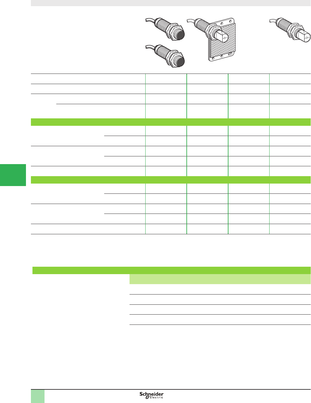
5/40
1
Design ø18
1 2 3
System Thru-beam 1Retrorefl ective 2Polarized
retrorefl ective 2
Diffuse 3
Type of transmission Infrared Infrared Red Infrared
Sensing
distance,
m (ft)
Nominal Sn (excess gain = 2) 15 (49.21) 4 (13.12) 2 (6.56) 0.10 (0.33)
Maximum (excess gain = 1) 20 (65.62) 5.5 (18.04)
(with 50 x 50 mm
reß ector)
3 (9.84)
(with 50 x 50 mm
reß ector)
0.15 (0.49)
Catalog numbers of pre-cabled versions (1)
3-wire, PNP
NO or NC programmable function
Line of sight along case
axis
XU2N18PP341 (2) XU1N18PP341 (3) XU9N18PP341 (3) XU5N18PP341
Line of sight 90° to
case axis
XU2N18PP341W (2) XU1N18PP341W (3) XU9N18PP341W (3) XU5N18PP341W
3-wire, NPN
NO or NC programmable function
Line of sight along case
axis
XU2N18NP341 (2) XU1N18NP341 (3) XU9N18NP341 (3) XU5N18NP341
Line of sight 90° to
case axis
XU2N18NP341W (2) XU1N18NP341W (3) XU9N18NP341W (3) XU5N18NP341W
Weight, kg (lb) 0.270 (0.60) 0.155 (0.34) 0.155 (0.34) 0.135 (0.30)
Catalog numbers of connector versions
3-wire, PNP
NO or NC programmable function
Line of sight along case
axis
XU2N18PP341D (2) XU1N18PP341D (3) XU9N18PP341D (3) XU5N18PP341D
Line of sight 90° to
case axis
XU2N18PP341WD (2) XU1N18PP341WD (3) XU9N18PP341WD (3) XU5N18PP341WD
3-wire, NPN
NO or NC programmable function
Line of sight along case
axis
XU2N18NP341D (2) XU1N18NP341D (3) XU9N18NP341D (3) XU5N18NP341D
Line of sight 90° to
case axis
XU2N18NP341WD (2) XU1N18NP341WD (3) XU9N18NP341WD (3) XU5N18NP341WD
Weight, kg (lb) 0.130 (0.29) 0.085 (0.19) 0.085 (0.19) 0.065 (0.14)
(1) Sensors available with 5 m long cable: To order, add L5 to the end of the catalog number selected from above.
Example: sensor XU1N18PP341 with 5 m cable becomes XU1N18PP341L5.
(2) Catalog numbers for both transmitter and receiver for thru-beam system sensors.
(3) 50 x 50 mm reß ector included with retroreß ective system sensors.
Catalog numbers of mounting accessories
Description Catalog Number Weight
kg (lb)
Stainless steel mounting bracket XUZA118 0.045 (0.10)
Plastic mounting bracket XUZA218 0.035 (0.08)
Set of 2 stainless steel nuts XSZE318 0.020 (0.04)
Set of 2 plastic nuts XSZE218 0.004 (0.01)
Catalog Numbers OsiSense® XU
Photoelectric sensors 2
Application, single mode
food and beverage processing series
Stainless steel case M18 x 1
DC Solid-state output
1
2
3
4
5/
6
7
8
9
10
This document provided by Barr-Thorp Electric Co., Inc. 800-473-9123 www.barr-thorp.com
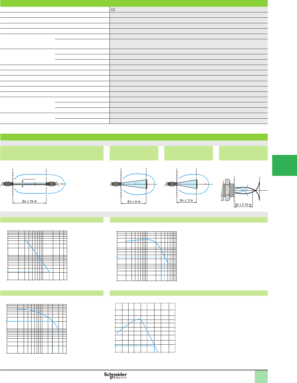
5/41
1
Specifi cations
Product certifi cations , UL, CSA
Ambient air temperature For operation: -25 to +55 °C (-13 to +131 °F). For storage: -40 to+70 °C (-40 to +158 °F)
Vibration resistance Conforming to IEC 60068-2-6 25 gn, amplitude ± 1.5 mm (f = 10–55 Hz)
Shock resistance Conforming to IEC 60068-2-27 30 gn, duration 11 ms
Degree of protection Conforming to IEC 60529 IP 67
Connection Pre-cabled Pre-cabled, diameter 4.2 mm, length 2 m (3), wire c.s.a.: 4 x 0.34 mm
2
(22 AWG)
Connector M12 male connector, 4-pin (suitable female connectors, including pre-wired versions. )
Materials Case Food and beverage processing stainless steel, grade 304 Cu
Lenses PMMA
Cable PvR
Rated supply voltage 12–24 Vdc with protection against reverse polarity
Voltage limits 10–0 Vdc (including ripple)
Switching capacity (sealed) ≤100 mA with overload and short-circuit protection
Voltage drop, closed state d 1.5 V
Current consumption, no-load d 30 mA (retroreß ective and diffuse), d 50 mA (thru-beam)
Maximum switching frequency 500 Hz
Delays First-up d 15 ms
Response d 1 ms
Recovery d 1 ms
Indicator lights Supply on Green LED, on transmitter only
Output state Yellow LED, on receiver only
(1) Sensors available with 5 m long cable: To order, add L5 to the end of the catalog number selected from above.
Example: sensor XU1N18PP341 with 5 m cable becomes XU1N18PP341L5.
Operating Curves
Thru-beam system Retrorefl ective system
with refl ector XUZC50
Polarized retrorefl ective
system with refl ector
XUZC50
Diffuse system
Object 10 x 10 cm
1 White 90% 2 Gray 18%
Excess gain curves (ambient temperature: +25 °C [+77 ° F] )
Thru-beam system Retrorefl ective system with refl ector XUZC50
Polarized retrorefl ctive system with refl ector XUZC50 Diffuse system
Object 10 x 10 cm
White 90%
15
-15
1510 m
Ø 12 mm
E
Ø of beam
cm
4
10
-4
-10
m
4
2
E/R
Ø of beam
cm
2
4
6
-2
-4
-6
2
0.2 m
3
E/R
Ø of beam
cm E/R
Ø of beam
cm
1 2 3 4 5 6 8 20 30 50
100
80
50
30
20
8
5
3
2
10
1
D (m)
10 15
Gain
100
1
20
0.1
10
D (m)
4
0.1 10.5 5 10
0.2
Gain
0.1 0.5 23 5
10
1
0.1
D (m)
1
Gain
0.1 0.2 1 5
50
20
10
1
3
7
15
D (cm)
2
0.5
30
5
2
602010
Gain
SpeciÞ cations
2
1
1.4
-1.4
-1
15 cm
1
.
OsiSense® XU
Photoelectric sensors 2
Application, single mode
food and beverage processing series
Stainless steel case M18 x 1
DC Solid-state output
1
2
3
4
5
6
7
8
9
10
This document provided by Barr-Thorp Electric Co., Inc. 800-473-9123 www.barr-thorp.com
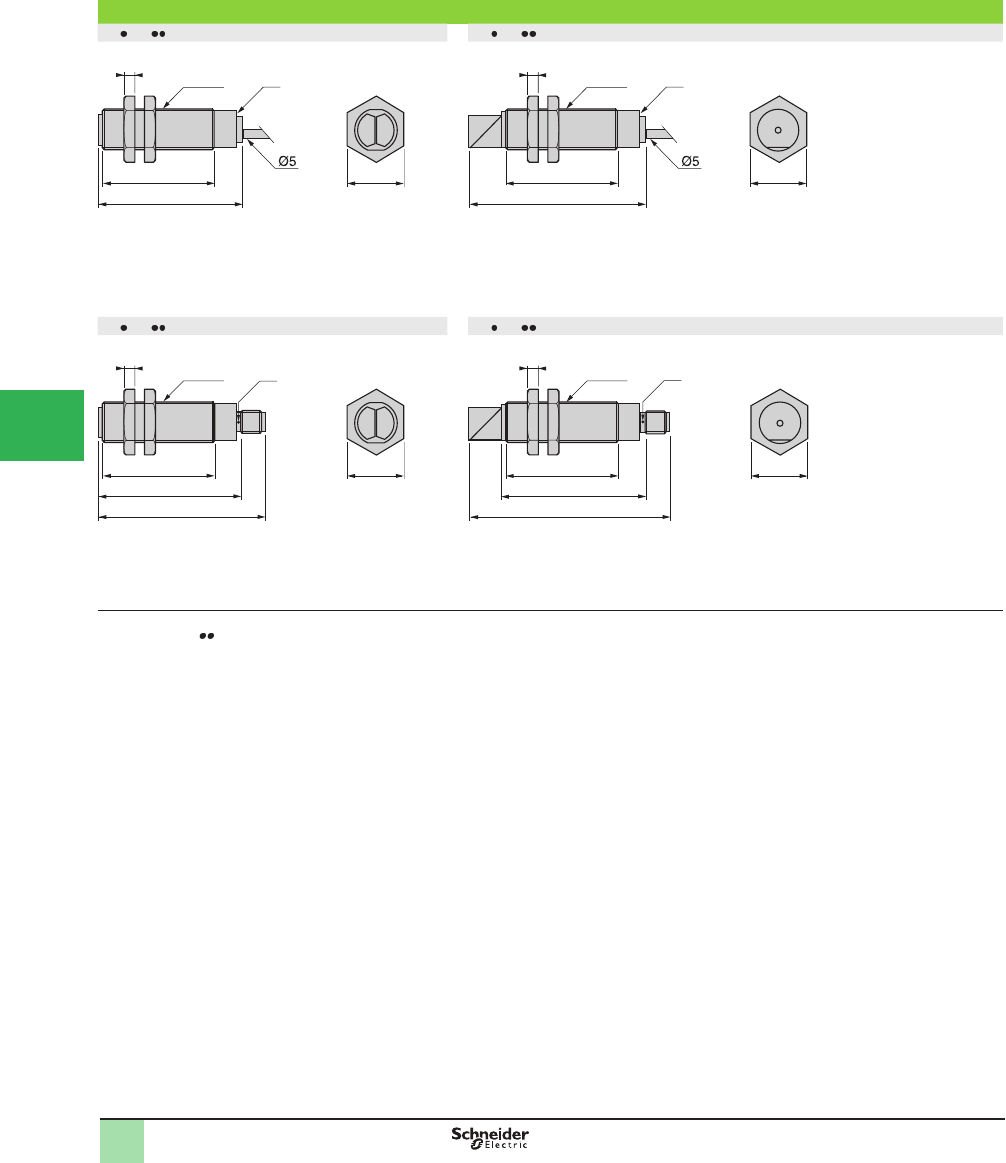
5/42
1
Dimensions (mm)
XU N18 341 XU N18 341W
XU N18 341D XU N18 341WD
(1) LED
(2) 64 for XU9N18 341
mounting nut tightening torque: < 15 N•m (132.76 lb-in)
Connector tightening torque: 2 N•m (17.70 lb-in)
4
62 (2)
50 24
(1)
M18x1
4
78
50 24
(1)
M18x1
4M18x1
62
(1)
50
72
24
4M18x1
62
50
88
24
(1)
Dimensions OsiSense® XU
Photoelectric sensors 2
Application, single mode
food and beverage processing series
Stainless steel case M18 x 1
DC Solid-state output
1
2
3
4
5/
6
7
8
9
10
This document provided by Barr-Thorp Electric Co., Inc. 800-473-9123 www.barr-thorp.com
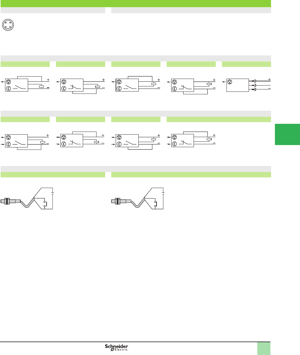
5/43
1
Wiring diagrams
M12 connector Pre-cabled
3 (–) (–) BU (Blue)
1 (+) (+) BN (Brown)
4 OUT/Output (Out/Output) BK (Black)
2 Prog (or beam break input
for thru-beam transmitter only)
(Prog) OG (Orange)
(Beam break input) VI (Violet) on thru-beam transmitter only
Wiring diagrams - diffuse
PNP NO PNP NC NPN NO NPN NC Transmitter
Wiring diagrams - retrorefl ective and thru-beam
PNP NO PNP NC NPN NO NPN NC
Beam break input on thru-beam transmitter only
Beam made Beam broken
34
21
BN/1
BU/3
BK/4
OG/2
BN/1
BU/3
BK/4
OG/2
BN/1
BU/3
BK/4
OG/2
BN/1
BU/3
BK/4
OG/2
1/BN
3/BU
2/VI
BN/1
BU/3
BK/4
OG/2
BN/1
BU/3
BK/4
OG/2
BN/1
BU/3
BK/4
OG/2
BN/1
BU/3
BK/4
OG/2
+
–
BN/1
VI/2
BU/3
+
–
BN/1
VI/2
BU/3
Wiring Diagrams OsiSense® XU
Photoelectric sensors 2
XU Application, single mode
food and beverage processing series
Stainless steel case M18 x 1
DC Solid-state output
1
2
3
4
5
6
7
8
9
10
This document provided by Barr-Thorp Electric Co., Inc. 800-473-9123 www.barr-thorp.com
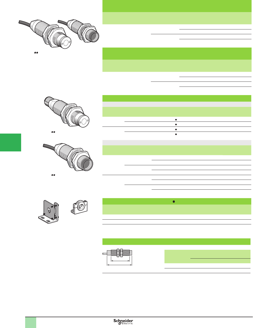
5/44
1
1
2
3
4
5/
6
7
8
9
10
Catalog Numbers,
Dimensions
OsiSense® XU
Photoelectric sensors
Application, material handling series
Laser transmission. Design ø18, plastic or metal
Three-wire DC Solid-state output
Ø 18, plastic, thru-beam system with teach mode,
laser transmission (Transmitter +receiver)
Sensing
distance (Sn)
m, (ft)
Function Connection Output Catalog Number Weight
kg (lb)
0–100
(328.08)
NO or NC, by
programming
Pre-cabled PNP XUBLAPCNL2 0.180 (0.40)
NPN XUBLANCNL2 0.180 (0.40)
M12 connector PNP XUBLAPCNM12 0.078 (0.17)
NPN XUBLANCNM12 0.078 (0.17)
Ø 18, metal, thru-beam system with teach mode,
laser transmission (Transmitter +receiver)
Sensing
distance (Sn)
m, (ft)
Function Connection Output Catalog Number Weight
kg (lb)
0–100
(328.08)
NO or NC, by
programming
Pre-cabled PNP XUBLBPCNL2 0.230 (0.51)
NPN XUBLBNCNL2 0.230 (0.51)
M12 connector PNP XUBLBPCNM12 0.130 (0.29)
NPN XUBLBNCNM12 0.130 (0.29)
Separate components
Ø 18 transmitter
Description Connection Output For use with Catalog Number Weight
kg (lb)
Plastic Pre-cabled – XUBLA CNL2 XUBLAKCNL2T 0.090 (0.20)
M12 connector – XUBLA CNM12 XUBLAKCNM12T 0.040 (0.09)
Metal Pre-cabled – XUBLB CNL2 XUBLBKCNL2T 0.110 (0.24)
M12 connector – XUBLB CNM12 XUBLBKCNM12T 0.060 (0.13)
Ø 18 receiver
Description Connection Output For use with Catalog Number Weight
kg (lb)
Plastic Pre-cabled PNP XUBLAPCNL2 XUBLAPCNL2R 0.090 (0.20)
NPN XUBLANCNL2 XUBLANCNL2R 0.090 (0.20)
M12 connector PNP XUBLAPCNM12 XUBLAPCNM12R 0.040 (0.09)
NPN XUBLANCNM12 XUBLANCNM12R 0.040 (0.09)
Metal Pre-cabled PNP XUBLBPCNL2 XUBLBPCNL2R 0.120 (0.26)
NPN XUBLBNCNM12 XUBLBNCNL2R 0.120 (0.26)
M12 connector PNP XUBLBPCNM12 XUBLBPCNM12R 0.070 (0.15)
NPN XUBLBNCNM12 XUBLBNCNM12R 0.070 (0.15)
Mounting accessories for XUBL
Description Catalog Number Weight
kg (lb)
Precision mounting bracket with micrometric adjustment XUZA318 0.170 (0.37)
Plastic mounting bracket with adjustable ball-joint XUZA218 0.035 (0.08)
Dimensions (mm)
a
b
Pre-cabled
(mm)
Connector
(mm)
a b a b
Receiver (1) 62 44 76 44
Transmitter (2) 52 28 66 28
(1) Yellow, green and red LED on receiver
(2) Green LED on transmitter
Note: mounting nut tightening torque: < 4 Nm (35.40 lb-in)
536362
XUBL CNL2
536379
XUBL CNM12T
536506
XUBL CNL2R
536355
XUZA318
536356
XUZA218
This document provided by Barr-Thorp Electric Co., Inc. 800-473-9123 www.barr-thorp.com
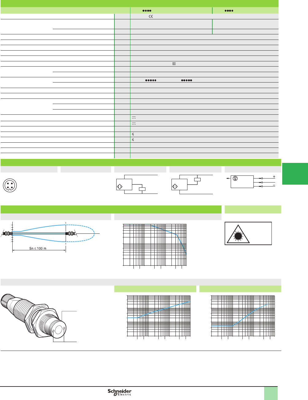
5/45
1
1
2
3
4
5
6
7
8
9
10
SpeciÞ cations,
Wiring Diagrams,
Operating Curves
OsiSense® XU
Photoelectric sensors
Application, material handling series
Laser transmission. Design ø18, plastic or metal
Three-wire DC Solid-state output
Specifi cations
Sensor type XUBL M12 XUBL L2
Product certifi cations UL, CSA,
Connection Connector M12 (suitable female connectors, including
pre-wired versions
–
Pre-cabled – Length: 2 m
Nominal sensing distance Sn m 0–100, excess gain 70–3
Blind zone 0
Preferred object approach direction Any
Type of transmission Red laser, wavelength 670 nm
Transmission power Power < 1 mW, class 1 conforming to IEC 825-1
Degree of protection Conforming to IEC 60529 IP 67, double insulation
Temperature Storage °C -40 to +70 (-40 to +158 °F)
Operation °C -10 to +45 (+14 to +113 °F)
Materials Case XUBLA : PBT; XUBLB : nickel plated brass
Lens PMMA
Vibration resistance Conforming to IEC 60068-2-6 7 gn, amplitude ± 1.5 mm (f = 10 to 55 Hz)
Shock resistance Conforming to IEC 60068-2-27 30 gn, duration 11 ms
Indicator lights Output state and alignment aid Yellow LED
Supply on and teaching Green LED
Stability Red LED
Rated supply voltage V 12–24 with protection against reverse polarity
Voltage limits (including ripple) V 10–30
Current consumption, no-load mA 25 for transmitter or receiver
Switching capacity per output mA 100 with overload and short-circuit protection
Voltage drop, closed state V 1.5
Maximum switching frequency Hz 1500
Delays First-up ms < 80
Response and recovery ms < 0.4
Wiring diagrams
M12 connector Pre-cabled PNP NPN Transmitter
3 (-)
1 (+)
4 OUT/Output
2 Beam break
input
(-) BU (Blue)
(+) BN (Brown)
OUT/Output BK (Black)
Beam break input
VI (Violet) –
BN/1
BU/3
+
PNP BK/4
BN/1
BU/3
+
–
BK/4
NPN
1/BN
3/BU
2/VI
Input 2/VI:
- not connected: beam made
- connected to -: beam broken
Operating curves Operating considerations
Detection curve (set to infi nity) Excess gain curve
10
-10
m
1
2
3
4
6
10
20
30
40
60
80
0.1 0.2
0.3
0.4 1
0.6 234 10
62030
40 100
60
D (m)
Laser class 1, conforming to
IEC 825-1.
Adjustment
Standard curve Detection limit curve
1
2
0.01
0.02
0.04
0.1
0.2
0.4
1
2
4
8
0.1 0.2
0.3
0.4 1
0.6 234 10
62030
40 100
D (m)
60
0.01
0.02
0.04
0.1
0.2
0.4
1
2
4
8
0.1 0.2
0.3
0.4 1
0.6 234 10
62030
40 100
D (m)
60
The adjustment of the focus point enables the detection of objects down to a size of < 0.2 mm (0.01 in.).
After loosening the mounting screws (1). adjust the focusing point of the laser beam by rotating the serrated sleeve (2) located on the face of the
sensor. Re-tighten mounting screws.
Note: mounting clamp XUZA218 with ball-joint and, in particular, bracket XUZA318 with precise micrometric adjustment and locking by 6 screws, are specially
suited for mounting the sensor and adjusting beam alignment when the sensing range is several tens of meters.
1 2
4 3
Gain
Laser
class 1
Minimum size of the object to be
detected (mm)
Minimum size of the object to be
detected (mm)
Focusing point Focusing point
This document provided by Barr-Thorp Electric Co., Inc. 800-473-9123 www.barr-thorp.com

5/46
1
Design ø18
System Diffuse
Type of transmission Infrared
Nominal sensing distance
Sn, mm (in.)
50–400 (1.97–15.75)
Catalog Numbers
3-wire, PNP XU5M18AB20D
Weight, kg (lb) 0.075 (0.17)
Specifi cation
Product certifi cations , CSA, UL
Ambient air temperature For operation: -25 to +55 °C (-13 to +131 °F).
For storage: -40 to +70 °C (-40 to +158 °F)
Vibration resistance Conforming to IEC 60068-2-6 25 gn, amplitude ± 2 mm (f = 10–55 Hz)
Shock resistance Conforming to IEC 60068-2-27 30 gn, duration 11 ms
Degree of protection Conforming to IEC 60529 IP 67
Connection M12 male connector, 4-pin
(suitable female connectors, including pre-wired versions)
Materials Case: nickel plated brass, lens: PMAA
Rated supply voltage 12–24 V with protection against reverse polarity
Voltage limits 10–30 V (including ripple)
Output current Maximum 20 mA
Minimum 4 mA
Output current drift in relation to temperature < 10% between -25 and +55 °C (-13 and +122 °F), < 5% between 0 and +40 °C
(+32 and +104 °F)
Output current drift in relation to supply < 3%
Current consumption, no-load 30 mA
Maximum switching frequency 20 Hz (for an output current variation of 10 mA)
Delays First-up: 50 ms
Indicator light The brightness of the green LED is proportional to the output current
Ie = 20 mA: indicator light at maximum intensity
Ie = 4 mA: indicator light at minimum intensity
(1) Applications: position control, monitoring concentricity or eccentricity, closed loop regulation, monitoring displacement, etc.
Catalog Numbers,
SpeciÞ cations
OsiSense® XU
Photoelectric sensors 0
Application, material handling series
With analog output signal 4–20 mA (1)
DC supply
1
2
3
4
5/
6
7
8
9
10
This document provided by Barr-Thorp Electric Co., Inc. 800-473-9123 www.barr-thorp.com
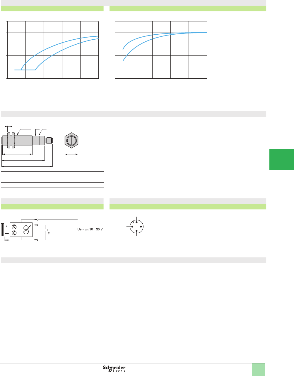
5/47
1
Output signal (related to distance of object)
Potentiometer set at maximum Potentiometer set at minimum
1 White 90% object
2 Gray 15% object
1 White 90% object
2 Gray 15% object
Dimensions (mm)
(1) Potentiometer.
(2) Green LED.
Mounting nut tightening torque: 15 N•m. (132.76 lb-in)
Connector tightening torque: 2 N•m. (17.70 lb-in)
Wiring diagrams Connector diagram
Diffuse system Sensor connector pin view
Output current
Load specifi cations (R)
The output current varies between 4 and 20 mA, depending on the distance of the object, and therefore, the load must be less than 800 : for a 24 V supply and less
than 300 Ω for a 12 V supply.
12
0 50
D (cm)
20 3010 40
1
5
4
10
15
20
25
Is (mA)
0 50
D (cm)
20 3010 40
1
5
4
10
15
20
25
Is (mA)
12
82
55
95
4
24
(1)
M18x1
( )
D
3
1
+
–
2
mA
Ie = 4–20 mA
R
–
1 (
+
)
3 (
–
)
4
2
Analog
output
Operating Curves,
Dimensions,
Wiring Diagrams
OsiSense® XU
Photoelectric sensors 0
Application, material handling series
With analog output signal 4–20 mA
DC supply
1
2
3
4
5
6
7
8
9
10
This document provided by Barr-Thorp Electric Co., Inc. 800-473-9123 www.barr-thorp.com
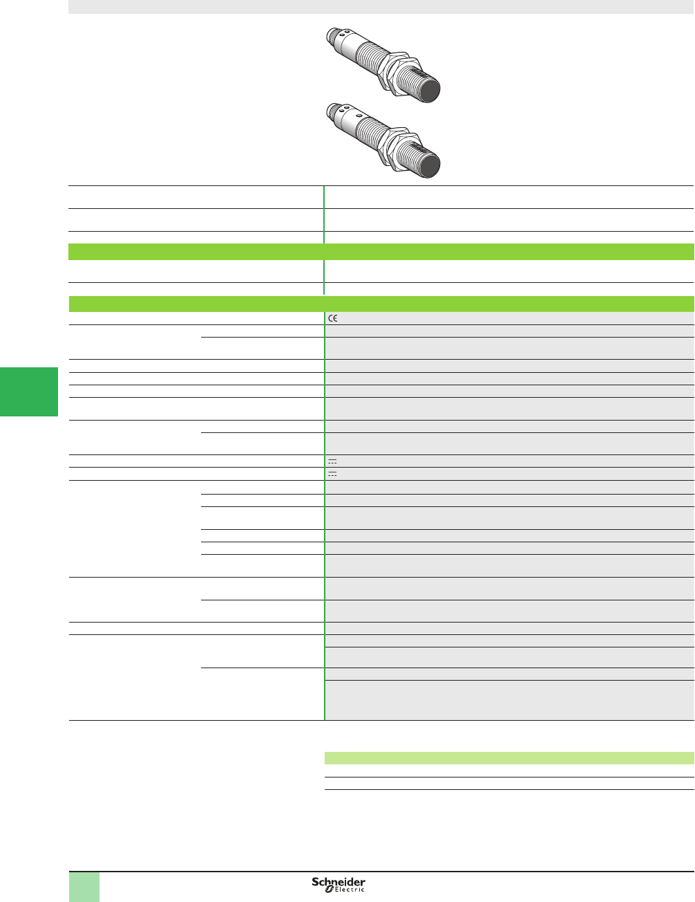
5/48
1
Design ø18
System Thru-beam
Type of transmission Infrared
Nominal sensing distance (Sn) / maximum, m (ft) 50 (164.04 / 70 (229.66) (transmitter +receiver)
Catalog Number
3-wire, PNP NO (object detection) +
analog output
XU2M18AP20D (2)
Weight, kg (lb) 0.155 (0.34)
Specifi cations
Product certifi cations , CSA, UL
Ambient air temperature For operation -25 to +55 °C (-13 to +131 °F)
For storage -40 to +70 °C (-40 to +158 °F)
Vibration resistance Conforming to IEC 60068-2-6 25 gn, amplitude ± 2 mm (f = 10–55 Hz)
Shock resistance Conforming to IEC 60068-2-27 30 gn, duration 11 ms
Degree of protection Conforming to IEC 60529 IP 67
Connection M12 male connector, 4-pin (suitable female connectors, including pre-wired versions)
Materials Case Nickel plated brass
Lenses PMMA
Rated supply voltage 12–24 V with protection against reverse polarity
Voltage limits 10–30 V (including ripple)
Solid-state digital output Switching capacity (sealed) d100 mA with overload and short-circuit protection
Voltage drop, closed state d 1.5 V
Maximum switching frequency 30 Hz
First-up delay d 50 ms
Response delay d 15 ms
Recovery delay d 15 ms
Analog output Output current 4–20 mA
Drift < 5% for temperature between 0 and +40 °C (+32 and 104 °F)
Delay d 15 ms
Current consumption, no-load d 55 mA (transmitter +receiver)
Indicator lights Transmitter Green LED, supply on
Yellow LED illuminated = beam transmission
Receiver Yellow LED illuminated = solid-state output On = object detected within beam
Green LED: the brightness of the LED is proportional to the output current:
- for l = 20 mA, object slightly opaque, intensity at maximum,
- for I = 4 mA, object completely opaque, intensity at minimum.
(1) Applications: detection of objects in spite of a difÞ cult environment (smoke, dust, mist, etc.),
detection of objects inside packaging, etc.
Example of values
Object: white sheets of 80 gsm paper. Transmitter-receiver distance = 10 cm
Number of sheets 1 11 27 31
Analog output current (mA) 17.3 12 6 5
(2) Catalog number for both transmitter and receiver for thru-beam system.
Catalog Numbers,
SpeciÞ cations
OsiSense® XU
Photoelectric sensors 1
Application, material handling series
Thru-beam system with high excess gain (1)
Solid-state output and analog output 4–20 mA
1
2
3
4
5/
6
7
8
9
10
This document provided by Barr-Thorp Electric Co., Inc. 800-473-9123 www.barr-thorp.com
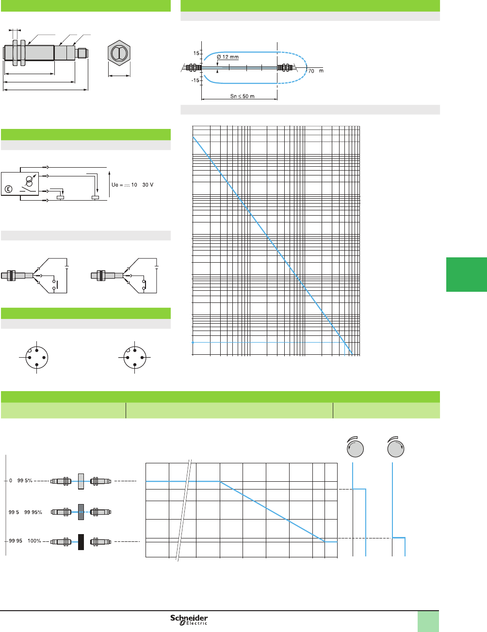
5/49
1
Dimensions,
Operating Curves,
Wiring Diagrams,
Operation
Dimensions (mm) Operating Curves
(1) LEDs
(2) Potentiometer (only on receiver)
Mounting nut tightening torque: 15 N•m (132.76 lb-in)
Connector tightening torque: 2 N•m (17.70 lb-in)
Detection curve
Thru-beam system
Excess gain curve (ambient temperature: +25 °C [+77 °F])
Thru-beam system
Wiring diagrams
Receiver
R max. < 800 Ω (Ue = 24 V), < 300 Ω (Ue = 12 V)
Beam break test (only on transmitter)
Beam made Beam broken
Connector diagram
Sensor connector pin view
Transmitter Receiver
Operation, settings
Type, opacity of object Analog output curve Switching level of digital solid-state
PNP output
82
55
95
4
24
(1)
M18x1 (2)
Ø of beam
cm
0.1 0.2 0.3 0.5 2 3 5
10
80
50
30
20
8
3
2
10
1
D (m)
150
3
800
500
300
200
100
10
8
5
3
2
8
5
3
2
5
5
10
4
5
3
2
10 20 30 100
3
1
+
–
2Ie = 4–20 mA
R
4Ie = 0–100 mA
mA –
+
–
2
1
3
+
–
2
1
3
1 (+)
3 (–)
4
2
Test
1 (+)
3 (–)
4
2
Analog
output
0
5
4
99.95
0
10
15
18
20
25
mA
99.8
99.4
0.1 100
%
0 1 0 1
99.5 99.6 99.7 99.9
.
..
.
–
–
–
Degree of opacity of object Output current
Potentiometer
set at minimum
Potentiometer
set at maximum
Degree of opacity of object
Solid-state
output
OsiSense® XU
Photoelectric sensors 1
Application, material handling series
Thru-beam system with high excess gain (1)
Solid-state output and analog output 4–20 mA
1
2
3
4
5
6
7
8
9
10
This document provided by Barr-Thorp Electric Co., Inc. 800-473-9123 www.barr-thorp.com
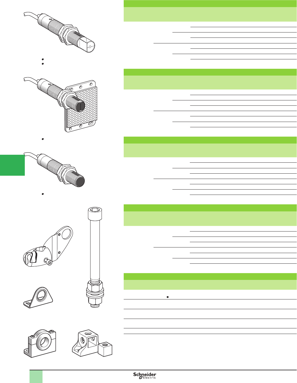
5/50
1
Diffuse system with adjustable background suppression
Sensing
distance (Sn)
m (ft)
Function Line of
sight
Connection Catalog Numbers Weight
kg (lb)
0.12 (0.39) NO Along
case axis
Pre-cabled (2) XU8M18MA230 0.150 (0.33)
1/2-20UNF XU8M18MA230K 0.075 (0.17)
90° to
case axis
Pre-cabled (2) XU8M18MA230W 0.150 (0.33)
1/2-20UNF XU8M18MA230WK 0.075 (0.17)
NC Along
case axis
Pre-cabled (2) XU8M18MB230 0.150 (0.33)
1/2-20UNF XU8M18MB230K 0.075 (0.17)
90° to
case axis
Pre-cabled (2) XU8M18MB230W 0.150 (0.33)
1/2-20UNF XU8M18MB230WK 0.075 (0.17)
Diffuse system
Sensing
distance (Sn)
m (ft)
Function Line of
sight
Connection Catalog Numbers Weight
kg (lb)
0.40 (1.31) NO Along
case axis
Pre-cabled (2) XU5M18MA230 0.150 (0.33)
1/2-20UNF XU5M18MA230K 0.075 (0.17)
90° to
case axis
Pre-cabled (2) XU5M18MA230W 0.150 (0.33)
1/2-20UNF XU5M18MA230WK 0.075 (0.17)
NC Along
case axis
Pre-cabled (2) XU5M18MB230 0.150 (0.33)
1/2-20UNF XU5M18MB230K 0.075 (0.17)
90° to
case axis
Pre-cabled (2) XU5M18MB230W 0.150 (0.33)
1/2-20UNF XU5M18MB230WK 0.075 (0.17)
Polarized retrorefl ective system (3)
Sensing
distance (Sn)
m (ft)
Function Line of
sight
Connection Catalog Numbers Weight
kg (lb)
2 (6.56) NO Along
case axis
Pre-cabled (2) XU9M18MA230 0.170 (0.37)
1/2-20UNF XU9M18MA230K 0.090 (0.20)
90° to
case axis
Pre-cabled (2) XU9M18MA230W 0.170 (0.37)
1/2-20UNF XU9M18MA230WK 0.090 (0.20)
NC Along
case axis
Pre-cabled (2) XU9M18MB230 0.170 (0.37)
1/2-20UNF XU9M18MB230K 0.095 (0.21)
90° to
case axis
Pre-cabled (2) XU9M18MB230W 0.170 (0.37)
1/2-20UNF XU9M18MB230WK 0.090 (0.20)
Thru-beam system (4)
Sensing
distance (Sn)
m (ft)
Function Line of
sight
Connection Catalog Numbers Weight
kg (lb)
15 (49.21) NO Along
case axis
Pre-cabled (2) XU2M18MA230 0.285 (0.63)
1/2-20UNF XU2M18MA230K 0.155 (0.34)
90° to
case axis
Pre-cabled (2) XU2M18MA230W 0.285 (0.63)
1/2-20UNF XU2M18MA230WK 0.155 (0.34)
NC Along
case axis
Pre-cabled (2) XU2M18MB230 0.285 (0.63)
1/2-20UNF XU2M18MB230K 0.155 (0.34)
90° to
case axis
Pre-cabled (2) XU2M18MB230W 0.285 (0.63)
1/2-20UNF XU2M18MB230WK 0.155 (0.34)
Mounting accessories
Description Catalog Numbers Weight
kg (lb)
3D mounting kit
for use on M12 rod, for XU M18 or XUZC50
XUZB2003 0.170 (0.37)
M12 rod XUZ2001 0.050 (0.11)
Support for M12 rod XUZ2003 0.150 (0.33)
Stainless steel mounting bracket XUZA118 0.045 (0.10)
Plastic mounting bracket with adjustable ball-joint XUZA218 0.035 (0.08)
(1) These sensors do not incorporate overload or short-circuit protection and therefore,
a 0.4 A fast-acting fuse must be connected in series with the load.
(2) For a 5 m long cable add L5.
Example: XU2M18MA230 becomes XU2M18MA230L5.
(3) 50 x 50 mm reß ector XUZC50 included with polarized retroreß ective system.
(4) Comprising both thru-beam transmitter and receiver.
Catalog Numbers
XU2M18M 230
XU5M18M 230W
XU8M18M 230W
XU9M18M 230
XUZB2003
XUZ2003
XUZA118 XUZ2001
XUZA218
OsiSense® XU
Photoelectric sensors 1
Application
Design ø18
Two-wire AC (1) or DC, solid-state output with
adjustable sensitivity
1
2
3
4
5/
6
7
8
9
10
This document provided by Barr-Thorp Electric Co., Inc. 800-473-9123 www.barr-thorp.com
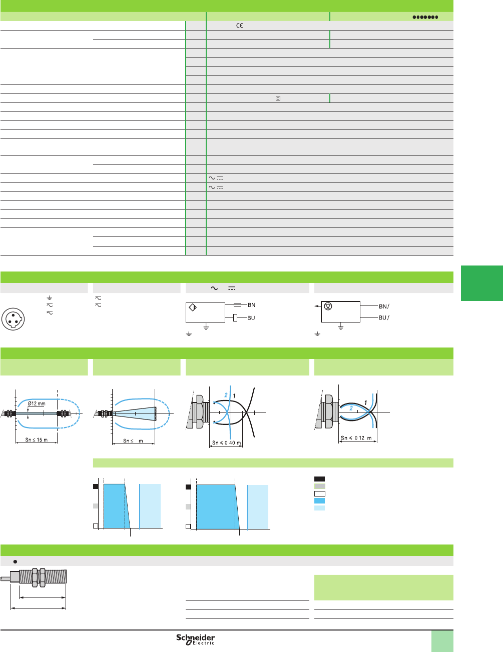
5/51
1
Specifi cations
Sensor type XU2M, XU5M, XU8M, XU9M XU2M, XU5M, XU8M, XU9M K
Product certifi cations UL, CSA,
Connection Connector – 1/2-20UNF
Pre-cabled Length: 2 m –
Sensing distance:
nominal Sn (excess gain = 2)
maximum (excess gain = 1)
m (ft) 0.12 / 0.12 (0.39 / 0.39) diffuse with background suppression
m (ft) 0.4 / 0.6 (1.31 / 1.97) diffuse
m (ft) 2 / 3 (6.56 / 9.84) polarized retroreß ective
m (ft) 15 / 20 (49.21 / 65.62) thru-beam
Type of transmission Infrared, except XU9 (red)
Degree of protection Conforming to IEC 60529 IP 67, double insulation IP 67
Storage temperature °C -40 to +70 (-40 to +158 °F)
Operating temperature °C -25 to +55 (-40 to +122 °F)
Materials Case: nickel plated brass; Lens: PMMA; Cable: PvR
Vibration resistance Conforming to IEC 60068-2-6 7 gn, amplitude ± 1.5 mm (f = 10 to 55 Hz)
Shock resistance Conforming to IEC 60068-2-27 30 gn, duration 11 ms
Indicator lights Output state Yellow LED
Stability Red LED (for retroreß ective and thru-beam only)
Rated supply voltage V / 24–240
Voltage limits (including ripple) V / 200–264
Residual current, open state mA < 1.5
Switching capacity mA 10–200 (1)
Voltage drop, closed state V 6
Maximum switching frequency Hz 25
Delays First-up ms < 300
Response ms < 20
Recovery ms < 20
(1) These sensors do not incorporate overload or short-circuit protection and therefore, a 0.4 A
fast-acting fuse must be connected in series with the load.
Wiring diagrams
Connector Pre-cabled 2-wire or Transmitter
1/2-20UNF 1
2
3
( ) BU (Blue)
() BN (Brown)
on connector models on connector models
Operating curves
Thru-beam system Polarized retrorefl ctive
system
Diffuse system Diffuse system with adjustable background
suppression
With reß ector XUZC50 Object 10 x 10 cm; 1White 90%; 2 Gray 18%
Variation of usable sensing distance Su
Potentiometer set at minimum Potentiometer set at maximum A-B: object reß ection coefÞ cient
Black 6%
Gray 18%
White 90%
Sensing range
Non-sensing zone (matte surfaces)
Dimensions (mm)
XU
Pre-cabled (mm) Connector (mm)
a b a b
Ø 18, line of sight along case axis 82 55 95 55
Ø 18, line of sight 90° to case axis 97 55 110 55
1
32
/2
/3
1
1
2
3
15
-15
1510 20 m
2
4
6
-2
-4
-6
1
0.2 m
2 3
2
-1
1
60 cm
.
0.3
12 cm
1
-1
.
A
B
0.1
0.08
0.01 S (m)
0.07
0.12
A
B
0.15
0.11
0.01 S (m)
a
b
SpeciÞ cations, Wiring
Diagrams,
Operating Curves,
Dimensions
OsiSense® XU
Photoelectric sensors 1
Application
Design ø18
Two-wire AC (1) or DC, solid-state output with
adjustable sensitivity
1
2
3
4
5
6
7
8
9
10
This document provided by Barr-Thorp Electric Co., Inc. 800-473-9123 www.barr-thorp.com
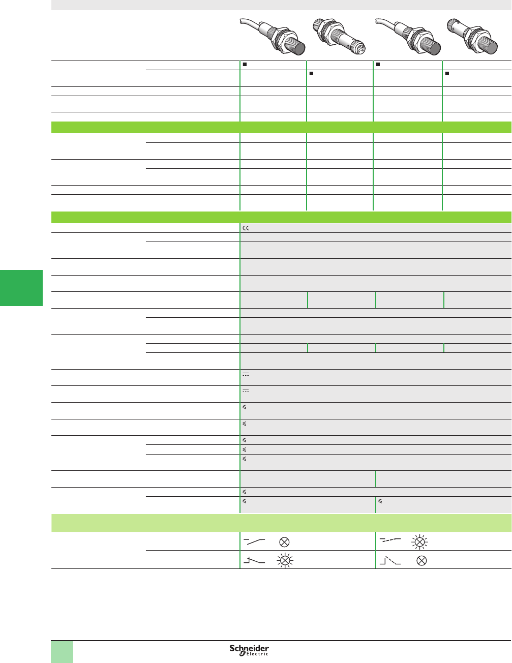
5/52
1
Design
Connection Pre-cabled – –
Connector – –
System Thru-beam Thru-beam Diffuse Diffuse
Type of transmission Infrared Infrared Infrared Infrared
Nominal sensing distance Sn, m (ft) 2 (6.56) 2 (6.56) 0.05 (0.16) 0.05 (0.16)
Catalog Number
3-wire, PNP NO function XUAH0214 XUAH0214S XUAH0515 XUAH0515S
NC function XUAH0224 XUAH0224S XUAH0525 XUAH0525S
3-wire, NPN NO function XUAJ0214 XUAJ0214S XUAJ0515 XUAJ0515S
NC function XUAJ0224 XUAJ0224S XUAJ0525 XUAJ0525S
Transmitter XUAH0203 XUAH0203S – –
Weight, kg (lb) 0.050 (0.11) 0.015 (0.03) 0.50 (1.10) 0.015 (0.03)
Specifi cation
Product certifi cations , CULUS
Ambient air temperature For operation -25 to +55 °C (-13 to +131 °F)
For storage -30 to +70 °C (-22 to +158 °F)
Vibration resistance Conforming to IEC 60068-2-6 7 gn, amplitude ± 1 mm (f = 10–55 Hz)
Shock resistance Conforming to IEC 60068-2-27 30 gn, duration 11 ms
Degree of protection Conforming to IEC 60529 IP 67 - IP 65 IP 65 IP 67 - IP 65 IP 65
Connection Pre-cabled Ø 3.5 mm, length 2 m, wire c.s.a.: 3 x 0.14 mm² (26 AWG)
Connector M8 female connectors, 3-pin
Materials Case Nickel plated brass
Cable PvR – PvR –
Lenses PMMA
Rated supply voltage 12–24 V with protection against reverse polarity
Voltage limits (including ripple) 10–30 V
Switching capacity (sealed) 100 mA with overload and short-circuit protection
Voltage drop, closed state 1 V
Current consumption, no-load Transmitter 15 mA
Receiver 10 mA
Diffuse 25 mA
Maximum switching frequency 2000 Hz 1000 Hz
Delays First-up 20 ms
Response and recovery 0.25 ms 0.5 ms
Function table Function Diffuse or through beam system
No object present in the beam Object present in the beam
Output state (PNP or NPN)
indicator: yellow LED
(illuminated when sensor output
is ON)
NO
NC
501335_1
501336_1
501335_1
501337_1
Catalog Numbers,
SpeciÞ cations
OsiSense® XU
Photoelectric sensors 1
Application, assembly series
Metal case, cylindrical, threaded M8 x 1
DC supply. Solid-state output
1
2
3
4
5/
6
7
8
9
10
This document provided by Barr-Thorp Electric Co., Inc. 800-473-9123 www.barr-thorp.com
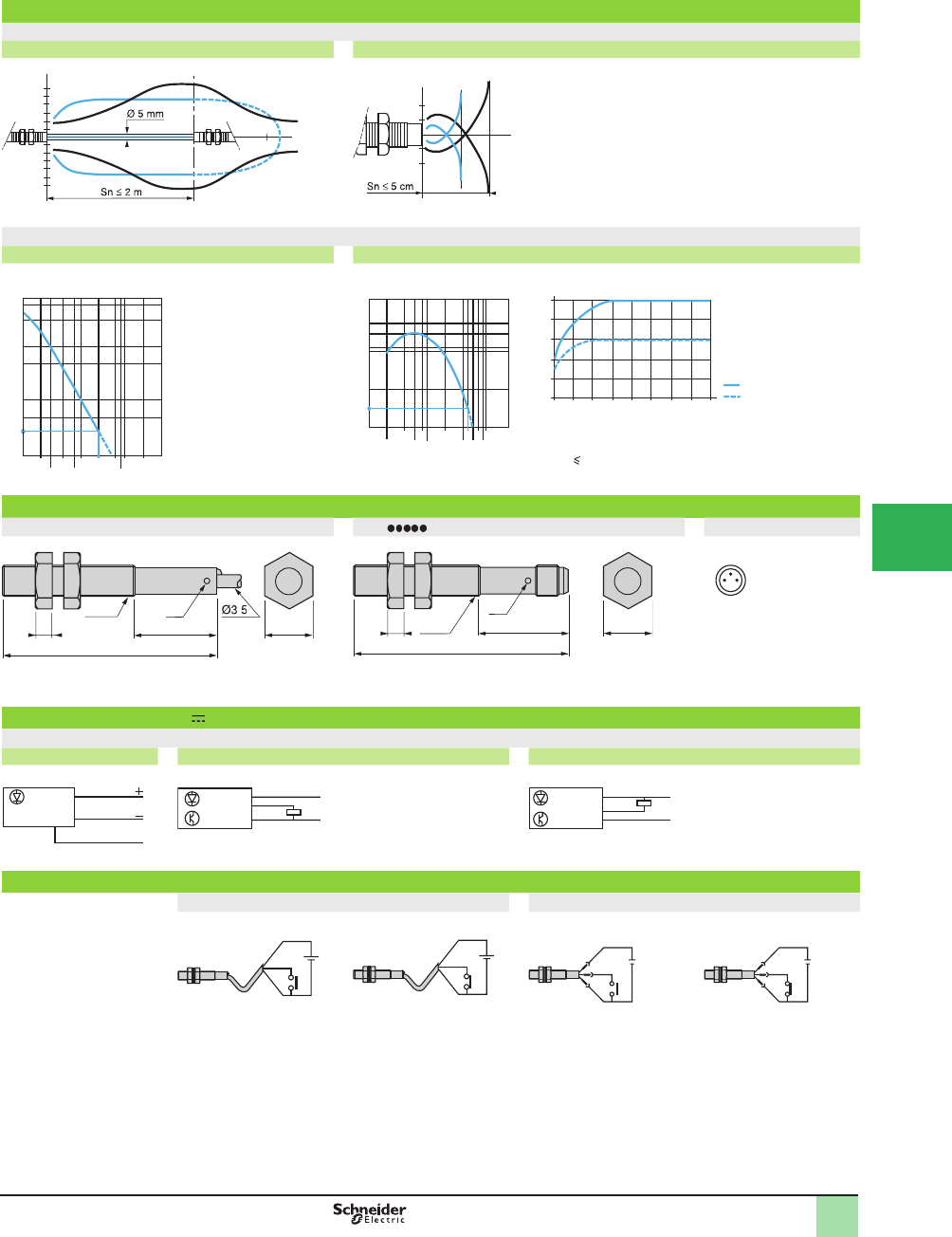
5/53
1
Operating curves
Detection curves
Thru-beam system Diffuse system
Object 5 x 5 cm; 1White 90%; 2 Gray 18%
Excess gain curves (ambient temperature: ± 25 °C)
Thru-beam system Diffuse system
Variation of sensing distance Sn
Detection differential (H) when object approaches from the
front: H 25% of Sn
Object 5 x 5 cm, White 90%
Dimensions (mm)
XUA XUA S M8 connector
1 +
3 -
4 OUT or test
(1) LED, 4 viewing ports at 90°. (1) LED, 4 viewing ports at
90°.
Note: mounting nut tightening torque: < 2 N•m (17.70 lb-in)
Wiring diagrams (3-wire )
XUA
Transmitter PNP NPN
Beam break test
For thru-beam transmitter XUAH0203 only For thru-beam transmitter XUAH0203S only
Beam made
LED on (steady light)
Beam broken
LED ß ashing
Beam made
LED on (steady light)
Beam broken
LED ß ashing
5
10
15
-5
-10
-15
23m
2
0.5
1
-0.5
-1
5 cm
1
300
100
50
10
5
1
500
2
0.2
0.1 0.30.5
0.8
156D (m)
3
10
Gain
0.8
6
D (cm)
0.10.2 1259
10
40
20
10
1
0.4
3
9
15
0.6 4
8
Gain
0
20
40
60
80
100
0 2 4 6 8 10 12 14
C (cm)
16
13
418
M8x1
48
.
(1)
13
421
M8x1
47
(1)
1 3
4
BN/1
BU/3
VI/4
BN/1
BK/4
BU/3
+
–
BN/1
BU/3
BK/4
+
–
+BN
VI
BU –
+BN
VI
BU –
+
–
4
1
3
+
–
4
1
3
Operating Cur ves,
Dimensions,
Wiring Diagrams
C Side of square object
White
Gray
OsiSense® XU
Photoelectric sensors 1
Application, assembly series
Metal case, cylindrical, threaded M8 x 1
DC supply. Solid-state output
1
2
3
4
5
6
7
8
9
10
This document provided by Barr-Thorp Electric Co., Inc. 800-473-9123 www.barr-thorp.com
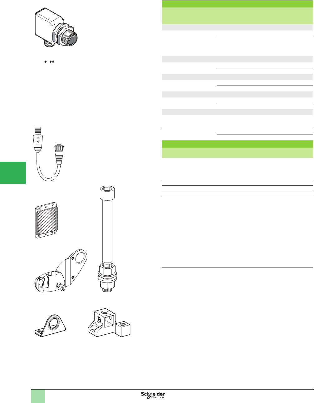
5/54
1
Connector
Sensing
distance Sn,
m (ft)
Function Output Catalog Number Weight
kg (lb)
Multimode
0–15 (0–49.2)
depending on
whether
accessories are
used
NO/NC PNP XUN0APSNM12 0.045 (0.10)
NPN XUN0ANSNM12 0.045 (0.10)
Diffuse system, short range
0.1 (0.33) NO PNP XUN4APANM12 0.040 (0.09)
NPN XUN4ANANM12 0.040 (0.09)
Diffuse system, long range
0.6 (2.0) NO PNP XUN5APANM12 0.045 (0.10)
NPN XUN5ANANM12 0.045 (0.10)
Polarized Retrorefl ective system
2 (6.6) NO PNP XUN9APANM12 0.040 (0.09)
NPN XUN9ANANM12 0.040 (0.09)
Thru-beam system
Transmitter
15 (49.21)
–XUN0AKSNM12T 0.045 (0.10)
Receiver
15 (49.21)
NO PNP XUN0APSNM12 0.045 (0.10)
NPN XUN0ANSNM12 0.045 (0.10)
Accessories
Description Catalog Number Weight
kg (lb)
Teach pushbutton XXZPB100 0.40 (0.10)
Reß ector, 50 x 50 mm XUZC50 0.20 (0.44)
3D mounting kit for use on M12 rod, for XUN
or XUZC50
XUZB2003 0.170 (0.37)
M12 rod XUZ2001 0.050 (0.11)
Support for M12 rod XUZ2003 0.150 (0.33)
Stainless steel mounting bracket XUZA118 0.045 (0.10)
Plastic mounting bracket with adjustable
ball-joint
XUZA218 0.035 (0.08)
Catalog Numbers OsiSense® XU
Photoelectric sensors 1
Single and multimode function
Dual Mount Design with ø18 snout, plastic
Three-wire DC, solid-state output
XUN A NM12
XUZC50
XXZPB100
XUZB2003 XUZ2001
XUZA118 XUZ2003
1
2
3
4
5/
6
7
8
9
10
This document provided by Barr-Thorp Electric Co., Inc. 800-473-9123 www.barr-thorp.com
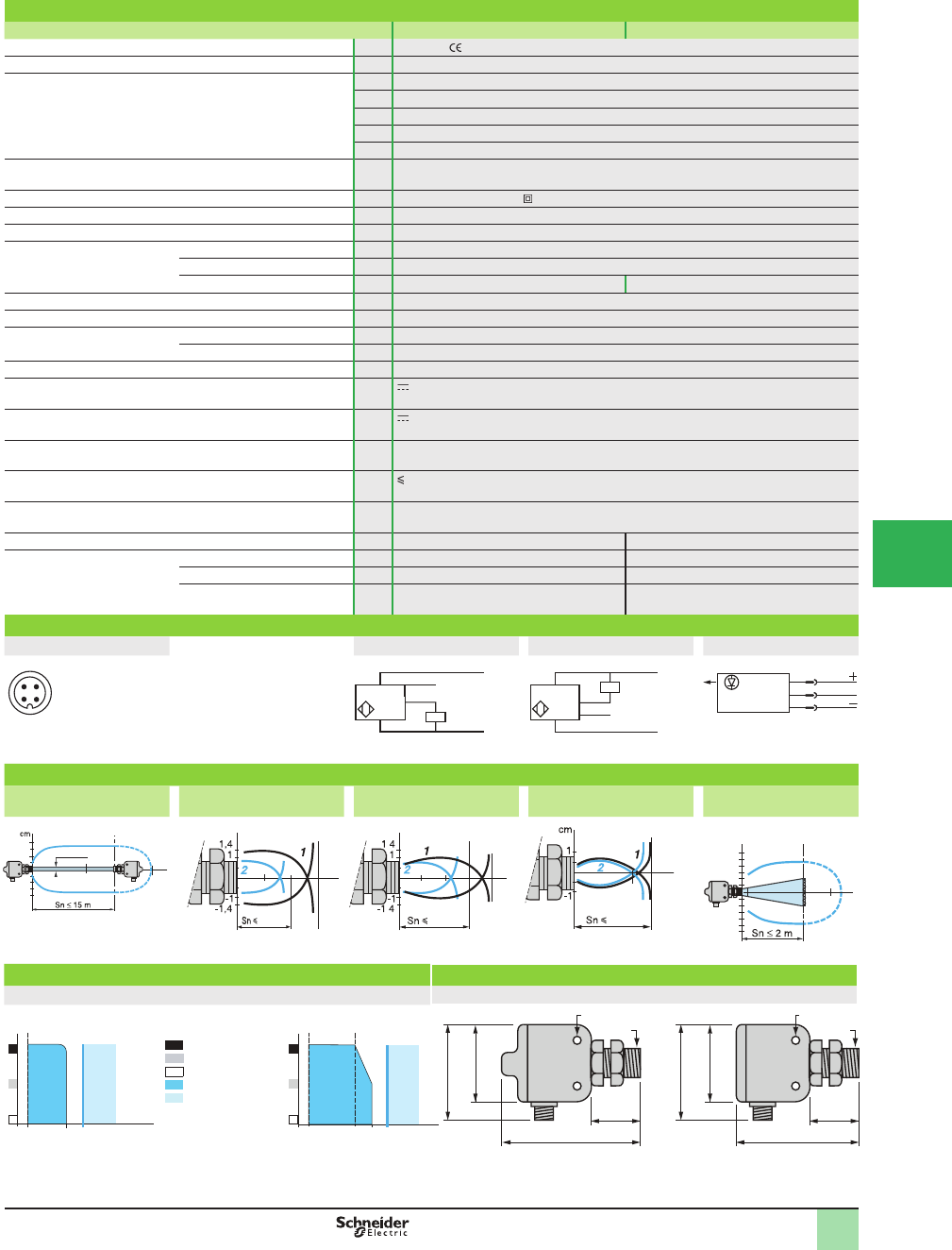
5/55
1
Specifi cations
Sensor type XUN0•••M12, XUN0•••M12T XUN4, XUN5, XUN9
Product certifi cations UL, CSA,
Connection Connector M12
Sensing distance:
nominal Sn (excess gain = 2)
maximum (excess gain = 1)
m (ft) 0.12 / 0.12 (0.39 / 0.39) diffuse with adjustable sensitivity
m (ft) 0.1 / 0.15 (0.33 / 0.49) diffuse, short range
m (ft) 0.6 / 0.8 (1.97 / 2.62) diffuse, long range
m (ft) 2 / 3 (6.56 / 9.84) polarized retroreß ective
m (ft) 15 / 20 (49.21 / 65.62) thru-beam
Type of transmission Infrared, except polarized retroreß ective (red)
Degree of protection Conforming to IEC 60529 IP 67, double insulation
Storage temperature °C -40 to +70 (-40 to +158 °F)
Operating temperature °C -25 to +55 (-13 to +122 °F)
Materials Case Valox®
Lens PMMA
Cable – PvR
Vibration resistance Conforming to IEC 60068-2-6 7 gn, amplitude ± 1.5 mm (f = 10 to 55 Hz)
Shock resistance Conforming to IEC 60068-2-27 30 gn, duration 11 ms
Indicator lights Output state Yellow LED (transmission present for XUN0•••T)
Supply on Green LED
Instability Red LED (except for XUN0•••T)
Rated supply voltage V 12–24 with protection against reverse polarity
Voltage limits (including ripple) V 10–36
Current consumption, no-load mA 35 (20 for XUN0•••T)
Switching capacity mA 100 with overload and short-circuit protection
Voltage drop, closed state V 1.5
Maximum switching frequency Hz 250 500
Delays First-up ms < 200 < 15
Response ms < 2 < 1
Recovery ms < 2 < 1
Wiring diagrams
M12 connector PNP NPN Transmitter
3 (-)
1 (+)
4 OUT/Output
2 Beam break
input (1)
Input 2/VI:
- not connected: beam made
- connected to –: beam broken
Operating curves
Thru-beam system Diffuse system,
short range
Diffuse system,
long range
Diffuse system with
adjustable sensitivity
Polarized retrorefl ective
system
Object 10 x 10 cm; 1White 90%; 2 Gray 18% With reß ector XUZC50
Variation of usable sensing distance Dimensions (mm)
(without accessory, with adjustable background suppression XUN
1 2
4 3
–
BN/1
BU/3
+
PNP
BK/4
WH/2
BN/1
BU/3
+
–
BK/4
NPN
WH/2
1/BN
3/BU
2/VI (1)
SpeciÞ cations, Wiring
Diagrams,
Operating Curves,
Dimensions
OsiSense® XU
Photoelectric sensors 1
Single and multimode function
Dual Mount Design with ø18 snout, plastic
Three-wire DC, solid-state output
65 60
25 25
33.02
43.85
33.02
43.85
M3
M18x1
M3
M18x1
Teach mode at minimum A-B: object reflection
coefficient
Black 6%
Gray 18%
White 90%
Sensing range
Non-sensing zone
(matte surfaces)
Teach mode at maximum
A
B
10
8
1S (cm) 12
A
B
17
9
1S (cm)
15
-15
1510 20m
Ø 12 mm
8
12 cm
12 cm
5
1 5
cm
cm
10 cm
2
4
6
-2
-4
-6
0.2 m
3
2
cm
E/R
Ø of beam
80
cm
cm
60 cm
.
.
(1) beam break input on thru-beam transmitter only
1
2
3
4
5
6
7
8
9
10
This document provided by Barr-Thorp Electric Co., Inc. 800-473-9123 www.barr-thorp.com
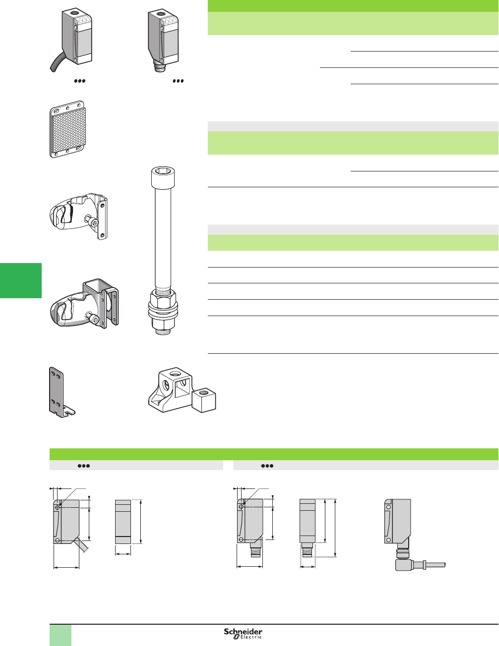
5/56
1
Miniature design, DC supply
Sensing
distance Sn,
m (ft)
Function Output Connection Catalog
Number
Weight
kg (lb)
0–10 (0–32.81)
depending on
whether
accessories are
used
N/O or N/C
by programming
PNP Pre-cabled
(L = 2 m) (1)
XUM0APSAL2 0.050 (0.11)
M8 connector XUM0APSAM8 0.035 (0.08)
NPN Pre-cabled
(L = 2 m) (1)
XUM0ANSAL2 0.050 (0.11)
M8 connector XUM0ANSAM8 0.035 (0.08)
Accessories
Description Connection Catalog
Number
Weight
kg (lb)
Thru-beam transmitter Pre-cabled
(L = 2 m) (1)
XUM0AKSAL2T 0.050 (0.11)
M8 connector XUM0AKSAM8T 0.035 (0.08)
Refl ector
50 x 50 mm
–XUZC50 0.020 (0.04)
Mounting accessories
Description Catalog
Number
Weight
kg (lb)
3D mounting kit
for use on M12 rod for XUM or XUZC50
XUZM2003 0.140 (0.31)
3D mounting kit
for use on M12 rod and with protective cover for XUM
XUZM2004 0.155 (0.34)
M12 rod XUZ2001 0.050 (0.11)
Support for M12 rod XUZ2003 0.150 (0.33)
Mounting bracket XUZA50 0.015 (0.03)
(1) For a 5 m cable, replace L2 with L5.
Example: XUM0APSAL2 becomes XUM0APSAL5.
Dimensions (mm)
XUM0A L2 XUM0A M8
Elbowed connector
501543_1
501542_1
XUM0A M8XUM0A L2
805799
XUZC50
550014
XUZM2003
562213
XUZM2004
520312
XUZ2001
520984
XUZ2003
520960
XUZA50
12
20
34
25.5
Ø3
6
2.8
12
20
34
45
25.5 6
Ø3
2.8
Catalog Numbers,
Dimensions
1
OsiSense® XU
Photoelectric sensors
Multimode
Miniature design
Three-wire DC supply, solid-state output
1
2
3
4
5/
6
7
8
9
10
This document provided by Barr-Thorp Electric Co., Inc. 800-473-9123 www.barr-thorp.com

5/57
1
Specifi cations
Sensor type XUM M8 XUM L2
Product certifi cations UL, CSA,
Connection Connector M8 –
Pre-cabled – Length: 2 m
Sensing distance:
nominal Sn (excess gain = 2)
maximum (excess gain = 1)
m (ft) 0.11 (0.36) without accessory (diffuse system with background suppression)
m (ft) 0.4 (1.31) / 0.55 (1.80) without accessory (diffuse system)
m (ft) 3 (9.84) / 4 (13.12) with reß ector (polarized retroreß ective)
m (ft) 10 (32.81) / 14 (45.93) with thru-beam transmitter (thru-beam)
Type of transmission Infrared, except for polarized retroreß ective (red)
Degree of protection Conforming to IEC 60529 IP 65, IP67 IP65, IP67
Storage temperature range °C -40 to +70 (-40 to +158 °F)
Operating temperature range °C -25 to +55 (-13 to +131 °F)
Materials Case PBT PBT double insulation
Lens PMMA
Cable – PvR
Vibration resistance Conforming to IEC 60068-2-6 7 gn, amplitude ± 1.5 mm (f = 10 to 55 Hz)
Shock resistance Conforming to IEC 60068-2-27 30 gn, duration 11 ms
Indicator lights Output state Yellow LED (transmission present for XUM0 T)
Supply on Green LED
Optical alignment aid/Dirt indication Red LED (except for XUM0 T)
Rated supply voltage Vdc 12–24 with protection against reverse polarity
Voltage limits (including ripple) Vdc 10–30
Current consumption, no-load mA 35 (20 for XUM0 T)
Switching capacity mA 100 with overload and short-circuit protection
Voltage drop, closed state V 1.5
Maximum switching frequency Hz 250 (200 for diffuse system with adjustable background suppression)
Delays First-up ms < 200
Response ms < 2 (< 2.5 for diffuse system with adjustable background suppression)
Recovery ms < 2 (< 2.5 for diffuse system with adjustable background suppression)
Wiring diagrams
M8 Connector Pre-cabled Receiver with PNP ouput Receiver with NPN output Thru-beam transmitter
3 (-)
1 (+)
4 OUT/Output
2 beam break
input (1)
(-) BU (Blue)
(+) BN (Brown)
OUT/Output BK (Black)
Beam break input
VI (Violet) (1)
Transmitter
2/VI input:
- not connected: beam made
- connected to –: beam broken
Operating curves
With thru-beam accessory
(thru-beam)
Without accessory
(diffuse system)
Without accessory
(diffuse system with
adjustable background
suppression)
With refl ector
(polarized retrorefl ective)
Object: 10 x 10 cm, 1: white 90 %, 2: gray 18 %
Variation of usable sensing distance Sn (without accessory, with adjustable background suppression)
Teach mode at minimum. Teach mode at maximum.
A-B: object reß ection coefÞ cient
Black 6 %
Gray 18 %
White 90 %
Sensing range
Non-sensing zone (matte surfaces)
24
1
3
–
BN/1
BU/3
+
PNP BK/4
BN/1
BU/3
+
–
NPN BK/4
1/BN
3/BU
2/VI
10
-10
10
Sn 10 m
Ø 10 mm
14 m
cm
Sn 40 cm
-2
-1
1
2
101
30
55 cm
cm
cm
10 cm
1
2
4
6
-2
-4
-6
34m
Sn 3 m
cm
A
B
6
5
1S (cm) 11
A
B
15
1S (cm)
SpeciÞ cations,
Wiring Diagrams,
Operating Curves
1
(1) Beam break input on thru-beam transmitter only.
OsiSense® XU
Photoelectric sensors
Multimode
Miniature design
Three-wire DC solid-state output
1
2
3
4
5
6
7
8
9
10
This document provided by Barr-Thorp Electric Co., Inc. 800-473-9123 www.barr-thorp.com
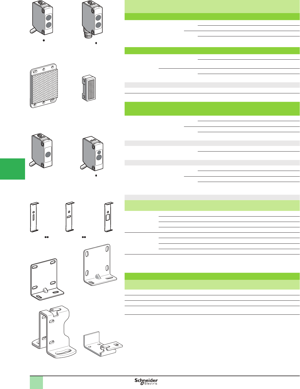
5/58
1
1
2
3
4
5/
6
7
8
9
10
Sensing
distance Sn,
m (ft)
Function Output Connection Catalog
Number
Weight
kg (lb)
Diffuse system with adjustable sensitivity
1 (3.28) NO/NC
conÞ guration
switch
PNP Pre-cabled (L = 2 m) XUM5APCNL2 0.063 (0.14)
M8 connector XUM5APCNM8 0.010 (0.02)
NPN Pre-cabled (L = 2 m) XUM5ANCNL2 0.063 (0.14)
M8 connector XUM5ANCNM8 0.010 (0.02)
Polarized retrorefl ective system with adjustable sensitivity
5 (16.40) with
reß ector XUZC50
2 (6.56) with
reß ector XUZC08
NO/NC
conÞ guration
switch
PNP Pre-cabled (L = 2 m) XUM9APCNL2 0.063 (0.14)
M8 connector XUM9APCNM8 0.010 (0.02)
NO/NC
conÞ guration
switch
NPN Pre-cabled (L = 2 m) XUM9ANCNL2 0.063 (0.14)
M8 connector XUM9ANCNM8 0.010 (0.02)
Refl ectors
Universal reß ector 50 x 50 mm – – XUZC50 0.020 (0.04)
Lateral reß ector 8.6 x 29.5 mm – – XUZC08 0.006 (0.01)
Thru-beam system (transmitter +receiver) with adjustable
sensitivity
15 (49.21) NO/NC
conÞ guration
switch
PNP Pre-cabled (L = 2 m) XUM2APCNL2 0.119 (0.26)
M8 connector XUM2APCNM8 0.019 (0.04)
NPN Pre-cabled (L = 2 m) XUM2ANCNL2 0.119 (0.26)
M8 connector XUM2ANCNM8 0.019 (0.04)
Transmitter only
15 (49.21) Pre-cabled (L = 2 m) XUM2AKCNL2T 0.063 (0.14)
M8 connector XUM2AKCNM8T 0.010 (0.02)
Receiver only
15 (49.21) NO/NC
conÞ guration
switch
PNP Pre-cabled (L = 2 m) XUM2APCNL2R 0.063 (0.14)
M8 connector XUM2APCNM8R 0.010 (0.02)
NPN Pre-cabled (L = 2 m) XUM2ANCNL2R 0.063 (0.14)
M8 connector XUM2ANCNM8R 0.010 (0.02)
Accessories for thru-beam system
Description Dimensions Sensing distance Catalog
Number
Weight
kg (lb)
mm m, (ft)
Vertical
diaphragm
Sold in lots of 2
0.5 x 6.4 1.2 (3.94) XUZMSV05 0.002 (0.004)
1 x 6.4 3 (9.84) XUZMSV10 0.002 (0.004)
1.5 x 6.4 4 (13.12) XUZMSV15 0.002 (0.004)
2 x 6.4 5 (16.40) XUZMSV20 0.002 (0.004)
Horizontal
diaphragm
Sold in lots of 2
0.5 x 6.4 1.2 (3.94) XUZMSH05 0.002 (0.004)
1 x 6.4 3 (9.84) XUZMSH10 0.002 (0.004)
1.5 x 6.4 4 (13.12) XUZMSH15 0.002 (0.004)
2 x 6.4 5 (16.40) XUZMSH20 0.002 (0.004)
Anti-interference
Þ lter
Sold in lots of 4
– 7 (22.97) XUZMU01 0.006 (0.013)
Mounting accessories
Description Catalog
Number
Weight
kg (lb)
Base mounting bracket XUZAM01 0.017 (0.04)
Side mounting bracket XUZAM04 0.026 (0.06)
Vertical mounting bracket with protective cover XUZAM02 0.062 (0.14)
Horizontal mounting bracket with protective cover XUZAM03 0.026 (0.06)
567547
XUM5A CNL2
567548
XUM5A CNM8
567542
XUZC50
567543
XUZC08
567551
XUM2AKCNL2T
567552
XUM2A CNL2R
567553
XUZMSV
567554
XUZMSH
567555
XUZMU01
567556
XUZAM01
Catalog Numbers OsiSense® XU
Photoelectric sensors
Single mode
Miniature design, plastic
Three-wire DC solid-state output
NO/NC conÞ guration switch
XUZAM04
524755
XUZAM02
524754
XUZAM03
524753
This document provided by Barr-Thorp Electric Co., Inc. 800-473-9123 www.barr-thorp.com

5/59
1
1
2
3
4
5
6
7
8
9
10
Specifi cations
Sensor type XUM A M8 XUM A L2
Product certifi cations , cULus, CTick
Connection Connector M8 –
Pre-cabled – Length: 2 m
Sensing distance:
nominal Sn (excess gain = 2)
m (ft) 1 (3.28), diffuse system with adjustable sensitivity
m (ft) 5 (16.40), polarized retroreß ective with adjustable sensitivity
m (ft) 15 (49.21), thru-beam with adjustable sensitivity
Type of transmission Red, except diffuse system (Infrared)
Degree of protection Conforming to IEC 60529 IP 65, IP 67
Storage temperature °C -40 to +70 (-40 to +158 ûF)
Operating temperature °C -30 to +60 (-22 to +140 ûF)
Materials Case PBT
Lens PMMA
Cable – PVC (black for transmitter, gray for other
versions)
Vibration resistance Conforming to IEC 60068-2-6 10 to 55 Hz, amplitude ± 1.5 mm, 2 hours in each direction X, Y, and Z
Shock resistance Conforming to IEC 60068-2-27 500 m/s2 10 x in each direction X, Y and Z
Indicator lights Output state Orange LED (excluding transmitter)
Stability Green LED
Transmitter Orange LED: supply on
Receiver Red LED: light received; green LED: supply on
Rated supply voltage Vdc 12–24 with protection against reverse polarity
Voltage limits (including ripple) Vdc 10–30
Current consumption, no-load mA 16 for XUM5; 13 for XUM9; 11 for transmitter XUM2; 13 for receiver XUM2
Switching capacity mA 100 with overload and short-circuit protection
Voltage drop, closed state V
Maximum switching frequency Hz 1000
Delays First-up ms < 100
Response ms 0.5
Recovery ms 0.5
Wiring diagrams
M8 connector Pre-cabled PNP NPN Transmitter
3 (-)
1 (+)
4 OUT/Output
.
(-) BU (Blue)
(+) BN (Brown)
OUT/Output BK (Black)
Operating curves
Diffuse Polarized retrorefl ective Thru-beam
Distance (m)
Parallel movement (cm)
-2.5
-2
-1.5
-1
-0.5
0
0.5
1
1.5
2
2.5
0 10.5
Vertical movement
Horizontal movement
Parallel movement (cm)
Distance (m)
-12
-10
-8
-6
-4
-2
0
2
4
6
8
10
12
012345678
XUZC08
XUZC50
Parallel movement (cm)
Distance (m)
-40
-35
-30
-25
-20
-15
-10
-5
0
5
10
15
20
25
30
35
40
0 5 10 15 20
24
1 3
–
BN/1
BU/3
+
PNP BK/4 (NO,NC)
BN/1
BU/3
+
–
BK/4 (NO,NC)
NPN
1/BN
3/BU
SpeciÞ cations,
Wiring Diagrams
Operating Curves
OsiSense® XU
Photoelectric sensors
Single mode
Miniature design, plastic
Three-wire DC solid-state output
NO/NC conÞ guration switch
This document provided by Barr-Thorp Electric Co., Inc. 800-473-9123 www.barr-thorp.com
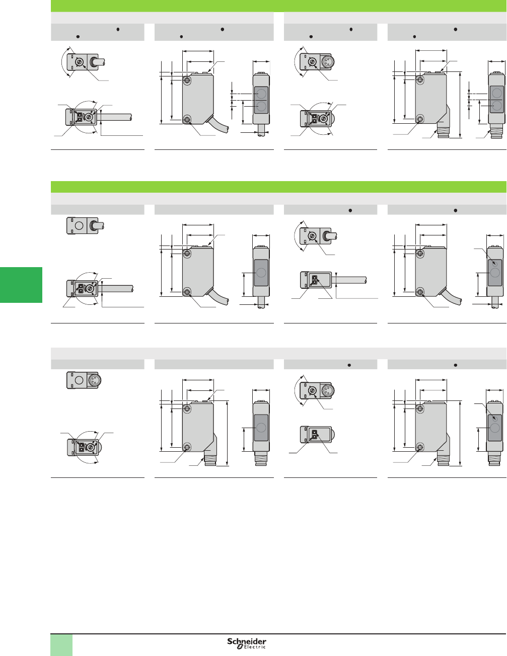
5/60
1
1
2
3
4
5/
6
7
8
9
10
Diffuse system, polarized retrorefl ective system (mm)
Pre-cabled version Connector version
Description - XUM5A CNL2,
XUM9A CNL2
Dimensions - XUM5A CNL2,
XUM9A CNL2
Description - XUM5A CNM8,
XUM9A CNM8
Dimensions - XUM5A CNM8,
XUM9A CNM8
NO
NC
D
D
L
L
(1)
3.8
20
(1)
17
2.431
25.4
3.8
15.5
2.8
10.8
Ø4.2
2xM3
R
T
NO
NC
D
D
L
L
(1)
M8M8
10.8
15.5
20
17
2.431
25.42.8
2xM3
42.5
3,83.8
(1)
R
T
(2)
(3)
(4)
Ø 4.2 L = 2 m
(4)
(3)
(2)
(1) ConÞ guration switch
(2) Output state LED
(3) Stability and power-on LED
(4) Adjustment potentiometer
R: Reception, T: Transmission
(1) Potentiometer
(1) ConÞ guration switch
(2) Output state LED
(3) Stability and power-on LED
(4) Adjustment potentiometer
R: Reception, T: Transmission
(1) Potentiometer
Thru-beam system (mm)
Pre-cabled version
Description - XUM2AKCNL2T
Dimensions - XUM2AKCNL2T
Description - XUM2A CNL2R
Dimensions - XUM2A CNL2R
10.8
20
17
2.431
25.42.8
2xM3
15.5
(1)
Ø4.2
T
NO
NC
D
D
L
L
(1)
10.8
15.5
20
17
2.431
25.42.8
2xM3 Ø4.2
(1)
R
(4)
(5)
Ø 4.2 L = 2 m
Ø 4.2 L = 2 m
(3) (2)
(4) Adjustment potentiometer
(5) Power-on LED
T: Transmission
(1) Potentiometer
(1) ConÞ guration switch
(2) Output state LED
(3) Stability and power-on LED
R: Reception
(1) Output state LED on front face
Connector version
Description - XUM2AKCNM8T
Dimensions - XUM2AKCNM8T
Description - XUM2A CNM8R
Dimensions - XUM2A CNM8R
10.8
15.5
20
17
2.431
25.42.8
2xM3 M8
42.5
(1)
T
NO
NC
D
D
L
L
(1)
10.8
M8
20
17
2.431
25.42.8
2xM3
42.5
15.5
(1)
R
(5) (4)
(3) (2)
(4) Adjustment potentiometer
(5) Power-on LED
T: Transmission
(1) Potentiometer
(1) ConÞ guration switch
(2) Output state LED
(3) Stability and power-on LED
R: Reception
(1) Output state LED on front face
Dimensions OsiSense® XU
Photoelectric sensors
Single mode
Miniature design, plastic
Three-wire DC solid-state output
NO/NC conÞ guration switch
This document provided by Barr-Thorp Electric Co., Inc. 800-473-9123 www.barr-thorp.com
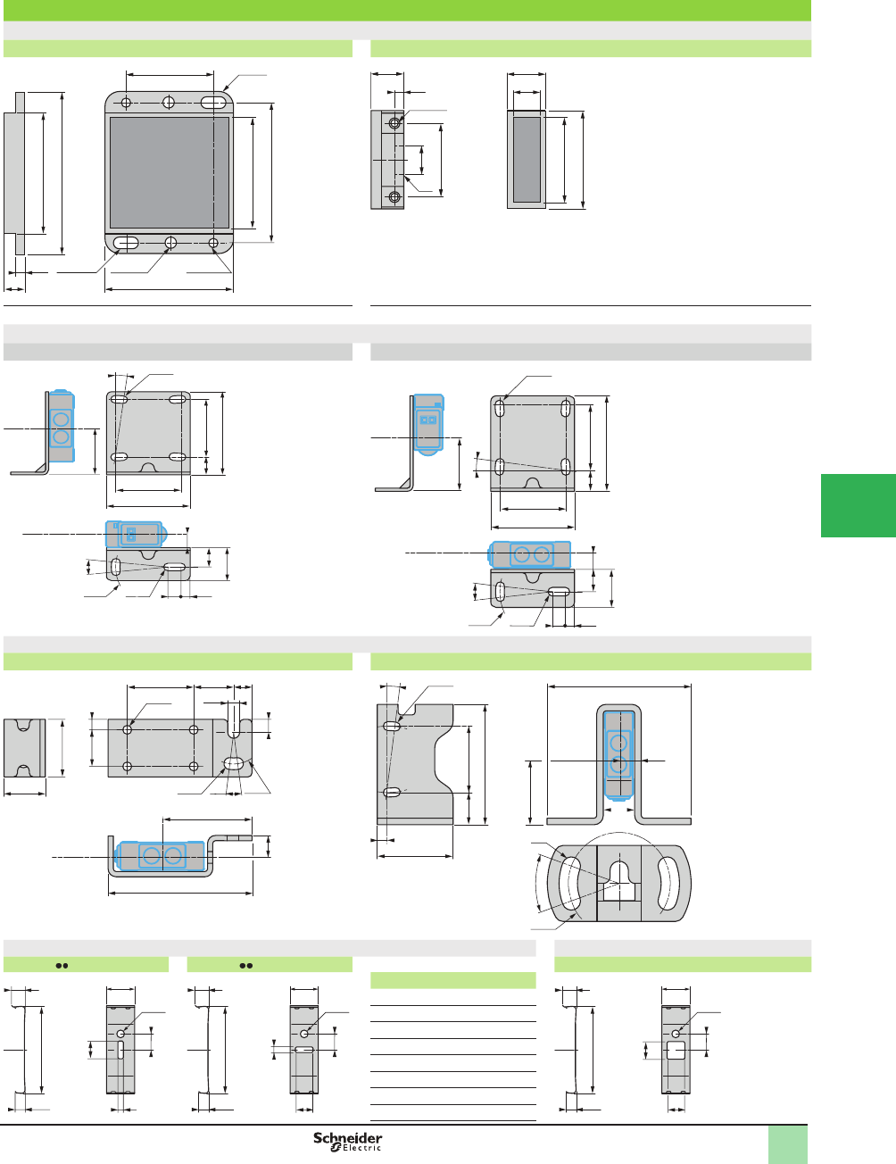
5/61
1
1
2
3
4
5
6
7
8
9
10
Accessories (mm)
Refl ectors
XUZC50 XUZC08
2xØ4.5
3.5
51
69
8
47
60
4xR5
35
51.5
2xØ5.5
4.5 x 8
elongated
holes
(1)
29.5
25
10
33.3
8.63.2
11 12.8
2xM3
1) 2 x M3
Mounting brackets
XUZAM01 XUZAM04
Ø40 Ø3.3
20.5
12˚
7˚ Ø3.3
32
25.4
7.8
36.5
25.4
8.5
14.5
3.5
5
Optical
axis
Optical axis
7.8
36.5
25.4
20.5
Ø40 Ø3.3
12˚
8.5
5.4
14.5
3.5
5
7˚
Ø3.3
32
25.4
Optical
axis
Optical axis
Mounting bracket with protective cover
XUZAM03 XUZAM02
Optical axis
Ø24
22
4
5
14
14˚
25.4 7
15.3
4.5
Ø4.5
Ø3.4
8.4
55
35
15.8
Optical axis
12.3
46
25.4
29
55
12
4
25
40˚
5.4
7˚
Ø7
Ø39
Ø3.4
Diaphragms Filter
XUZMSV XUZMSH XUZMU01
5.8
31.8
10.2
5
6.4
a
3.5
Ø2.8
a
6.4
5.8
10.2
Ø2.8
31.8
5
3.5
XUZ a
6.4
6.4
5.8
10.2
Ø2.8
31.8
5
3.5
MSV05 0.5
MSV10 1
MSV15 1.5
MSV20 2
MSH05 0.5
MSH10 1
MSH15 1.5
MSH20 2
Dimensions (continued) OsiSense® XU
Photoelectric sensors
Single mode
Miniature design, plastic
Three-wire DC solid-state output
NO/NC conÞ guration switch
This document provided by Barr-Thorp Electric Co., Inc. 800-473-9123 www.barr-thorp.com
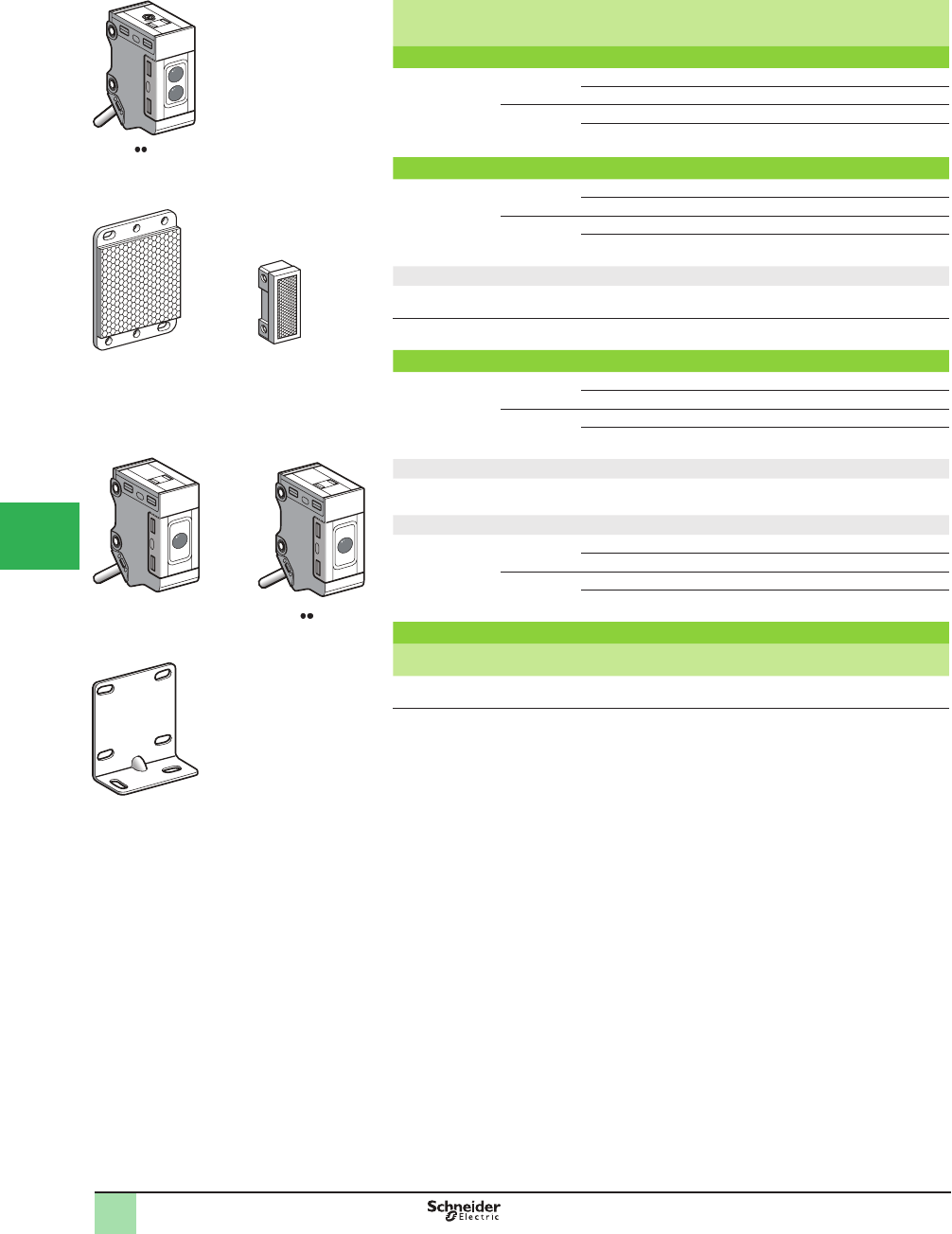
5/62
1
1
2
3
4
5/
6
7
8
9
10
Sensing
distance Sn,
m (ft)
Function Output Connection Catalog
Number
Weight
kg (lb)
Diffuse system with adjustable sensitivity
0.77 (2.53) NO PNP Pre-cabled (L = 2 m) XUM5BPANL2 0.128 (0.28)
NPN Pre-cabled (L = 2 m) XUM5BNANL2 0.128 (0.28)
NC PNP Pre-cabled (L = 2 m) XUM5BPBNL2 0.128 (0.28)
NPN Pre-cabled (L = 2 m) XUM5BNBNL2 0.128 (0.28)
Polarized retrorefl ective system
5 (16.40) with
reß ector XUZC50
2 (6.56) with
reß ector XUZC08
NO PNP Pre-cabled (L = 2 m) XUM9BPANL2 0.128 (0.28)
NPN Pre-cabled (L = 2 m) XUM9BNANL2 0.128 (0.28)
NC PNP Pre-cabled (L = 2 m) XUM9BPBNL2 0.128 (0.28)
NPN Pre-cabled (L = 2 m) XUM9BNBNL2 0.128 (0.28)
Refl ectors
Universal reß ector 50 x 50 mm – – XUZC50 0.020 (0.04)
Lateral reß ector 8.6 x 29.5 mm – – XUZC08 0.006 (0.01)
Thru-beam system (transmitter +receiver)
15 (49.21) NO PNP Pre-cabled (L = 2 m) XUM2BPANL2 0.237 (0.52)
NPN Pre-cabled (L = 2 m) XUM2BNANL2 0.237 (0.52)
NC PNP Pre-cabled (L = 2 m) XUM2BPBNL2 0.237 (0.52)
NPN Pre-cabled (L = 2 m) XUM2BNBNL2 0.237 (0.52)
Transmitter only
15 (49.21) Pre-cabled (L = 2 m) XUM2BKCNL2T 0.128 (0.28)
Receiver only
15 (49.21) NO PNP Pre-cabled (L = 2 m) XUM2BPANL2R 0.128 (0.28)
NPN Pre-cabled (L = 2 m) XUM2BNANL2R 0.128 (0.28)
NC PNP Pre-cabled (L = 2 m) XUM2BPBNL2R 0.128 (0.28)
NPN Pre-cabled (L = 2 m) XUM2BNBNL2R 0.128 (0.28)
Mounting accessory
Description Catalog
Number
Weight
kg (lb)
Base mounting bracket XUZAM81 0.020 (0.04)
567541
XUM5B NL2
567542
XUZC50
567543
XUZC08
524751
XUM2B2KCL2T
524752
XUM2B NL2R
567546
XUZAM81
Catalog Numbers OsiSense® XU
Photoelectric sensors
Application
Miniature design, metal
Three-wire DC solid-state output
This document provided by Barr-Thorp Electric Co., Inc. 800-473-9123 www.barr-thorp.com
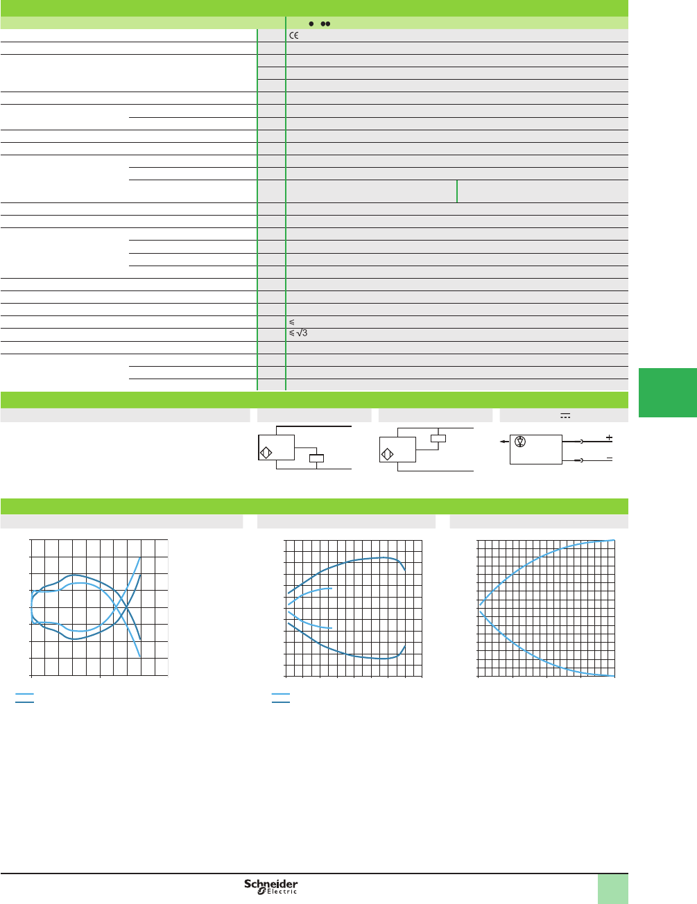
5/63
1
1
2
3
4
5
6
7
8
9
10
Specifi cations
Sensor type XUM B NL2
Product certifi cations , cULus, CTick
Connection Pre-cabled Length: 2 m
Sensing distance:
nominal Sn (excess gain = 2)
m (ft) 0.77 (2.53), diffuse system with adjustable sensitivity
m (ft) 5 (16.40), polarized retroreß ective
m (ft) 15 (49.21), thru-beam
Type of transmission Red, except diffuse system (Infrared)
Degree of protection Conforming to IEC 60529 IP67
DIN 40050 IP69 K, IP67 G
Storage temperature °C -40 to +70 (-40 to +158 ûF)
Operating temperature °C -30 to +60 (-22 to +140 ûF)
Materials Case Zamak and stainless steel
Lens Glass
Cable – PVC (black for transmitter, gray for other
versions)
Vibration resistance Conforming to IEC 60068-2-6 10 to 55 Hz, amplitude ± 1.5 mm, 2 hours in each direction X, Y, and Z
Shock resistance Conforming to IEC 60068-2-27 500 m/s2 10 x in each direction X, Y and Z
Indicator lights Output state Orange LED (excluding transmitter)
Stability Green LED
Transmitter Orange LED: supply on
Receiver Red LED: light received; green LED: supply on
Rated supply voltage Vdc 12–24 with protection against reverse polarity
Voltage limits (including ripple) Vdc 10–30
Current consumption, no-load mA 16 for XUM5; 13 for XUM9; 11 for transmitter XUM2; 13 for receiver XUM2
Switching capacity mA 100 with overload and short-circuit protection
Voltage drop, closed state V
Maximum switching frequency Hz 1000
Delays First-up ms < 100
Response ms 0.5
Recovery ms 0.5
Wiring diagrams
Pre-cabled PNP NPN Transmitter
(-) BU (Blue)
(+) BN (Brown)
OUT/Output BK (Black)
–
BN/1
BU/3
+
PNP BK/4 (NO,NC)
Operating Curves
Diffuse Polarized retrorefl ective Thru-beam
Distance (m)
Parallel movement (cm)
-2
-1.5
-1
-0.5
0
0.5
1
1.5
2
0
1
0.5
Vertical movement
Horizontal movement
Parallel movement (cm)
Distance (m)
-12
-10
-8
-6
-4
-2
0
2
4
6
8
10
12
012345678
XUZC08
XUZC50
Parallel movement (cm)
Distance (m)
-40
-35
-30
-25
-20
-15
-10
-5
0
5
10
15
20
25
30
35
40
0 5 10 15 20
BN/1
BU/3
+
–
BK/4 (NO,NC)
NPN
1/BN
3/BU
SpeciÞ cations
Wiring Diagrams,
Operating Curves
OsiSense® XU
Photoelectric sensors
Application
Miniature design, metal
Three-wire DC solid-state output
This document provided by Barr-Thorp Electric Co., Inc. 800-473-9123 www.barr-thorp.com
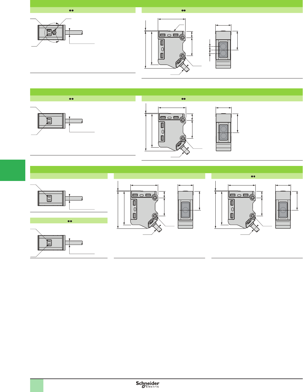
5/64
1
1
2
3
4
5/
6
7
8
9
10
Dimensions OsiSense® XU
Photoelectric sensors
Application
Miniature design, metal
Three-wire DC solid-state output
Diffuse system (mm)
Description - XUM5B NL2 Dimensions - XUM5B NL2
MAX
MIN
(1)
(2)
(3)
Ø 4.2 L = 2 m
19.8
29.5
2xM3
Ø4.2
20 7.1
0.35
40.8
36.8
16.2
(1)
3.8 3.8
R
T
(1) Output state LED.
(2) Stability and power-on LED.
(3) Adjustment potentiometer. (1) Potentiometer.
R: Reception, T: Transmission.
Polarized retrorefl ective system (mm)
Description - XUM9B NL2 Dimensions - XUM9B NL2
Ø 4.2 L = 2 m
(1)
(2)
19.8
16.2
29.5
2xM3
Ø4.2
20 7.1
0.35
40.8
36.8
T
R
(1) Output state LED.
(2) Stability and power-on LED. R: Reception, T: Transmission.
Thru-beam system (mm)
Description - XUM2BKCNL2T Dimensions - XUM2BKCNL2T Dimensions - XUM2B NL2R
Ø 4.2 L = 2 m
(1)
19.8
29.5
2xM3
Ø4.2
20 7.1
0.35
40.8
36.8
16.2
T
19.8
29.5
2xM3
Ø4.2
20 7.1
0.35
40.8
36.8
16.2
R
(1) Output state LED.
Description - XUM2B NL2R
Ø 4.2 L = 2 m
(1)
(2)
(1) Output state LED.
(2) Stability and power-on LED.
T: Transmission. R: Reception
This document provided by Barr-Thorp Electric Co., Inc. 800-473-9123 www.barr-thorp.com
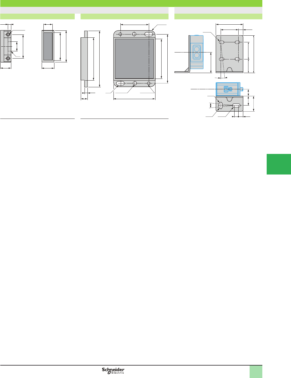
5/65
1
1
2
3
4
5
6
7
8
9
10
Accessories (mm)
Refl ectors Mounting bracket
XUZC08 XUZC50 XUZAM81
3.2
(1)
29.5
25
10
33.3
8.6
11 12.8
2xØM3
2xØ4.5
3.5
51
69
8
47
60
(1)
4xR5
35
51.5
2xØ5.5
23.3
16
44
20
5.521
32
8.111
18
12˚
7˚
Ø4.2
Ø32 Ø4.25.5
5
Ø3.3
Optical
axis
Optical axis
(1) 2 x M3 (1) Elongated holes 4.5 x 8
Dimensions OsiSense® XU
Photoelectric sensors
Application
Miniature design, metal
Three-wire DC solid-state output
This document provided by Barr-Thorp Electric Co., Inc. 800-473-9123 www.barr-thorp.com
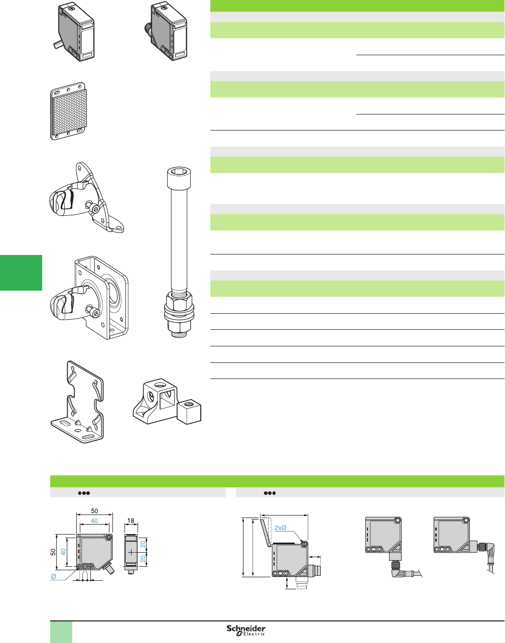
5/66
1Catalog Numbers
DC
Sensing distance (Sn)
m (ft)
Function Output Connection Catalog Number Weight
kg (lb)
0–30 (0–98.42)
depending on whether
accessories are used
NO or NC,
by
programming
PNP/NPN Pre-cabled
(L = 2 m) (1)
XUK0AKSAL2 0.175 (0.39)
M12
connector
XUK0AKSAM12 0.090 (0.20)
Accessories
Description Connection Catalog Number Weight
kg (lb)
Transmitter for thru-beam function Pre-cabled
(L = 2 m) (1)
XUK0AKSAL2T 0.140 (0.31)
M12
connector
XUK0AKSAM12T 0.090 (0.20)
Refl ector 50 x 50 mm – XUZC50 0.020 (0.44)
AC or DC
Sensing distance (Sn)
m (ft)
Function Output Connection Catalog Number Weight
kg (lb)
0–30 (0–98.42)
depending on whether
accessories are used
NO or NC,
by
programming
Time
delay
relay
Pre-cabled
(L = 2 m) (1)
XUK0ARCTL2 0.175 (0.39)
Accessories
Description Connection Catalog Number Weight
kg (lb)
Transmitter for thru-beam function Pre-cabled
(L = 2 m) (1)
XUK0ARCTL2T 0.140 (0.31)
Refl ector 50 x 50 mm – XUZC50 0.020 (0.44)
Mounting accessories
Description Catalog Number Weight
kg (lb)
3D mounting kit
for use on M12 rod, for XUK or XUZ C50
XUZK2003 0.170 (0.37)
3D mounting kit
for use on M12 rod, with protective cover for XUK
XUZK2004 0.270 (0.60)
M12 rod XUZ2001 0.050 (0.11)
Support for M12 rod XUZ2003 0.150 (0.33)
Mounting bracket XUZA51 0.050 (0.11)
(1) For a 5 m long cable replace L2 by L5; for a 10 m long cable replace L2 by L10.
Example: XUK0AKSAL2 becomes XUK0AKSAL5 or XUK0AKSAL10.
Dimensions (mm)
XUK0A L2 XUK0A M12
Possible orientation of elbowed connector
7 4 6.5
4.4
66
20
20
76
84
4.5
Catalog Numbers,
Dimensions
XUK0AKSAL2
523273
XUK0AKSAM12
523272
550028
XUZK2003
XUZK2004
550029
520312
XUZ2001
550030
XUZA51
XUZC50
805799
XUZ2003
520984
OsiSense® XU
Photoelectric sensors 1
Multimode
Compact design 50 x 50
5-wire AC or DC, 1 CO relay output
3-wire DC, solid state output
1
2
3
4
5/
6
7
8
9
10
This document provided by Barr-Thorp Electric Co., Inc. 800-473-9123 www.barr-thorp.com
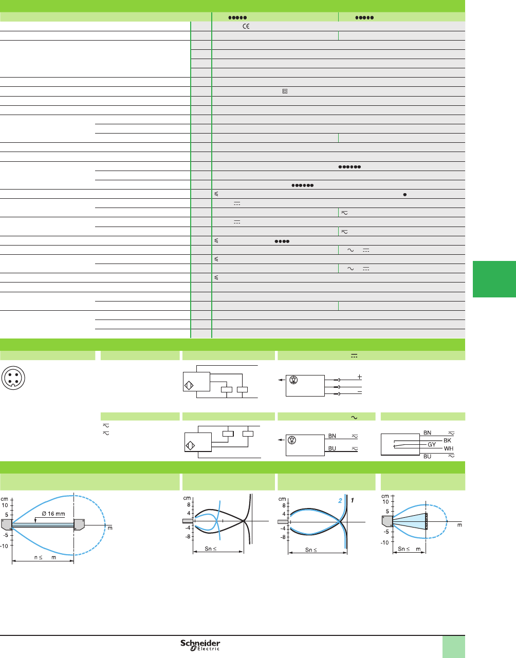
5/67
1
Specifi cations
Sensor type XUK M12 XUK L2
Product certifi cations UL, CSA,
Connection M12 connector Pre-cabled, length: 2 m
Sensing distance:
nominal Sn (excess gain = 2)
maximum (excess gain = 1)
m (ft) 0.28 / 0.28 (0.92 / 0.92) without accessory (diffuse with background suppression)
m (ft) 0.8 / 1.2 (2.62 / 3.94) without accessory (diffuse)
m (ft) 4 / 5.7 (13.12 / 18.70) with reß ector (polarized retroreß ective)
m (ft) 30 / 35 (98.42 / 114.83) with transmitter for thru-beam function (thru-beam)
Type of transmission Infrared, except polarized retroreß ective (red)
Degree of protection Conforming to IEC 60529 IP 65, double insulation
Storage temperature °C -40 to +70 (-40 to +158 °F)
Operating temperature °C -25 to +55 (-13 to +131 °F)
Materials Case PBT
Lens PMMA
Cable – PvR
Vibration resistance Conforming to IEC 60068-2-6 7 gn, amplitude ± 1.5 mm (f = 10 to 55 Hz)
Shock resistance Conforming to IEC 60068-2-27 30 gn, duration 11 ms
Indicator lights Output state Yellow LED (transmission present for XUK0 T)
Supply on Green LED
Optical alignment aid/dirty Red LED (except for XUK0 T)
Alarm output mA 50 with overload and short-circuit protection (except XUK0ARCT )
Rated supply voltage PNP/NPN V12–24 with protection against reverse polarity
Relay output V– 24–240
Voltage limits (including
ripple)
PNP/NPN V10–36
Relay output V– 20–264
Current consumption, no-load PNP/NPN mA 35; 20 for XUK0AK T
Power consumption Relay output W– 3 or
Switching capacity PNP/NPN mA 100 with overload and short-circuit protection
Relay output A– 3 or
Voltage drop, closed state V 1.5
Time delay Relay output s 0–10 on-delay, off-delay, monostable
Maximum switching
frequency
PNP/NPN Hz 250 (200 for diffuse with background suppression)
Relay output Hz – 20
Delays First-up ms < 200 (PNP/NPN); < 300 (relay output)
Response ms < 2 (PNP/NPN); < 25 (relay output) (< 2.5 for diffuse with background suppression)
Recovery ms < 2 (PNP/NPN); < 25 (relay output) (< 2.5 for diffuse with background suppression)
Wiring diagrams
M12 connector Pre-cabled Receiver, PNP output Thru-beam transmitter
3 (-)
1 (+)
4 OUT/Output
2 Alarm or beam
break input (1)
(-) BU (Blue)
(+) BN (Brown)
OUT/Output BK (Black)
Alarm/WH (White)
Beam break input (1)VI
(Violet)
Transmitter
Input 2/VI:
- not connected: beam made
- connected to –: beam broken
Pre-cabled, relay output Receiver, NPN output Thru-beam transmitter Relay output
(1) Beam break input on thru-beam
transmitter only.
() BU (Blue)
() BN (Brown)
Relay common/GY (Gray)
NO BK (Black)
NC WH (White)
Transmitter
Operating curves
With thru-beam accessory (thru-beam) Without accessory (diffuse) Without accessory (diffuse
with background suppression)
With refl ector (polarized
retrorefl ective)
Object 10 x 10 cm; 1White 90%; 2 Gray 18% With reß ector XUZC50
1 2
4 3
–
BN/1
BU/3
+
PNP BK/4 WH/2
1/BN
3/BU
2/VI
BN/1
BU/3
+
–
NPN BK/4 WH/2
30
30
35
S
120 c
m
80 cm
2
1
403
28 cm
28 cm
3
4
4
5.7
SpeciÞ cations,
Wiring Diagrams,
Operating Curves
OsiSense® XU
Photoelectric sensors 1
Multimode
Compact design 50 x 50
5-wire AC or DC, 1 CO relay output
3-wire DC, solid state output
1
2
3
4
5
6
7
8
9
10
This document provided by Barr-Thorp Electric Co., Inc. 800-473-9123 www.barr-thorp.com
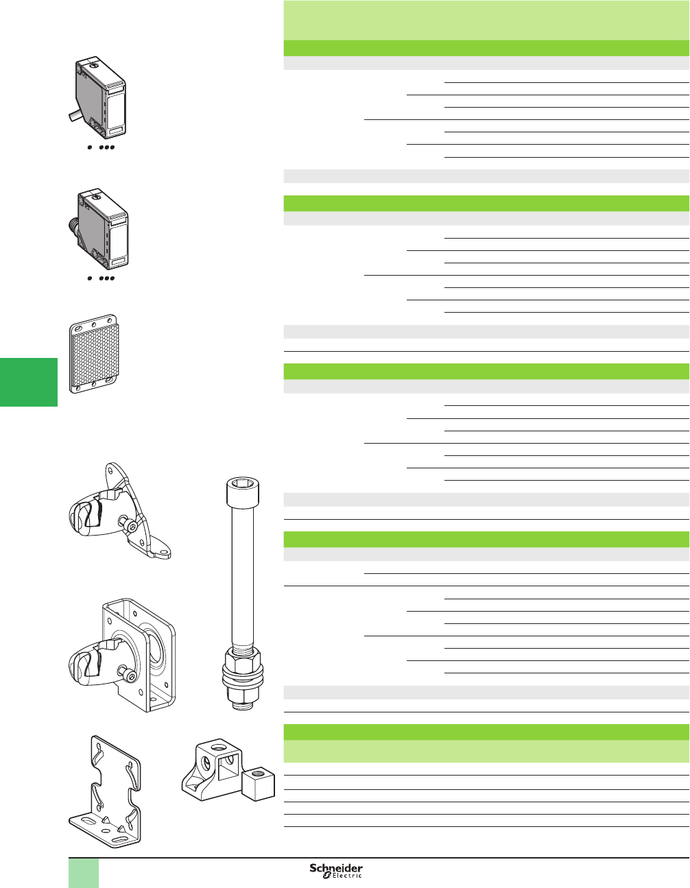
5/68
1
Sensing distance
(Sn)
m (ft)
Function Output Connection Catalog Number Weight
kg (lb)
Diffuse system with adjustable sensitivity
DC
1 (3.28) NO PNP Pre-cabled (L = 2 m) (1) XUK5APANL2 0.190 (0.42)
M12 connector XUK5APANM12 0.070 (0.15)
NPN Pre-cabled (L = 2 m) (1) XUK5ANANL2 0.190 (0.42)
M12 connector XUK5ANANM12 0.070 (0.15)
NC PNP Pre-cabled (L = 2 m) (1) XUK5APBNL2 0.190 (0.42)
M12 connector XUK5APBNM12 0.070 (0.15)
NPN Pre-cabled (L = 2 m) (1) XUK5ANBNL2 0.190 (0.42)
M12 connector XUK5ANBNM12 0.070 (0.15)
AC or DC
1 (3.28) NO +NC Relay Pre-cabled (L = 2 m) (1) XUK5ARCNL2 0.190 (0.42)
Polarized retrorefl ective system
DC
5 (16.40) NO PNP Pre-cabled (L = 2 m) (1) XUK9APANL2 0.190 (0.42)
M12 connector XUK9APANM12 0.070 (0.15)
NPN Pre-cabled (L = 2 m) (1) XUK9ANANL2 0.190 (0.42)
M12 connector XUK9ANANM12 0.070 (0.15)
NC PNP Pre-cabled (L = 2 m) (1) XUK9APBNL2 0.190 (0.42)
M12 connector XUK9APBNM12 0.070 (0.15)
NPN Pre-cabled (L = 2 m) (1) XUK9ANBNL2 0.190 (0.42)
M12 connector XUK9ANBNM12 0.070 (0.15)
DC or AC
5 (16.40) NO +NC Relay Pre-cabled (L = 2 m) (1) XUK9ARCNL2 0.190 (0.42)
Refl ector 50 x 50 mm (2) – – XUZC50 0.020 (0.04)
Retrorefl ective system
DC
7 (22.97) NO PNP Pre-cabled (L = 2 m) (1) XUK1APANL2 0.070 (0.15)
M12 connector XUK1APANM12 0.070 (0.15)
NPN Pre-cabled (L = 2 m) (1) XUK1ANANL2 0.070 (0.15)
M12 connector XUK1ANANM12 0.070 (0.15)
NC PNP Pre-cabled (L = 2 m) (1) XUK1APBNL2 0.070 (0.15)
M12 connector XUK1APBNM12 0.070 (0.15)
NPN Pre-cabled (L = 2 m) (1) XUK1ANBNL2 0.070 (0.15)
M12 connector XUK1ANBNM12 0.070 (0.15)
AC or DC
7 (22.97) NO +NC Relay Pre-cabled (L = 2 m) (1) XUK1ARCNL2 0.175 (0.39)
Refl ector 50 x 50 mm (2) – – XUZC50 0.020 (0.04)
Thru-beam system
DC
Transmitter
30 (98.42)
– – Pre-cabled (L = 2 m) (1) XUK2AKSNL2T 0.190 (0.42)
– – M12 connector XUK2AKSNM12T 0.070 (0.15)
Receiver
30 (98.42)
NO PNP Pre-cabled (L = 2 m) (1) XUK2APANL2R 0.140 (0.31)
M12 connector XUK2APANM12R 0.075 (0.17)
NPN Pre-cabled (L = 2 m) (1) XUK2ANANL2R 0.140 (0.31)
M12 connector XUK2ANANM12R 0.075 (0.17)
NC PNP Pre-cabled (L = 2 m) (1) XUK2APBNL2R 0.140 (0.31)
M12 connector XUK2APBNM12R 0.075 (0.17)
NPN Pre-cabled (L = 2 m) (1) XUK2ANBNL2R 0.140 (0.31)
M12 connector XUK2ANBNM12R 0.075 (0.17)
AC or DC
Transmitter (98.42) – – Pre-cabled (L = 2 m) (1) XUK2ARCNL2T 0.140 (0.31)
Receiver (98.42) NO +NC Relay Pre-cabled (L = 2 m) (1) XUK2ARCNL2R 0.070 (0.15)
Mounting accessories
Description Catalog Number Weight
kg (lb)
3D mounting kit for use on M12 rod, for XUKor XUZC50 XUZK2003 0.170 (0.37)
3D mounting kit for use on M12 rod, with protective cover for XUK XUZK2004 0.270 (0.60)
M12 rod XUZ2001 0.050 (0.11)
Support for M12 rod XUZ2003 0.150 (0.33)
Mounting bracket XUZA51 0.050 (0.11)
(1) For a 5 m long cable replace L2 by L5; for a 10 m long cable replace L2 by L10. Example:
XUK5APANL2 becomes XUK5APANL5 or XUK5APANL10.
For availability, consult the Sensor Competency Center.
XUK A L2
523273
XUK A M12
523272
XUZC50
805799
XUZK2004 XUZ2001
XUZA51
XUZ2003
XUZK2003
Catalog Numbers OsiSense® XU
Photoelectric sensors
Single mode function
Compact design, 50 x 50
Five-wire AC or DC, 1 CO relay output
Three-wire DC, solid-state output
1
2
3
4
5/
6
7
8
9
10
This document provided by Barr-Thorp Electric Co., Inc. 800-473-9123 www.barr-thorp.com
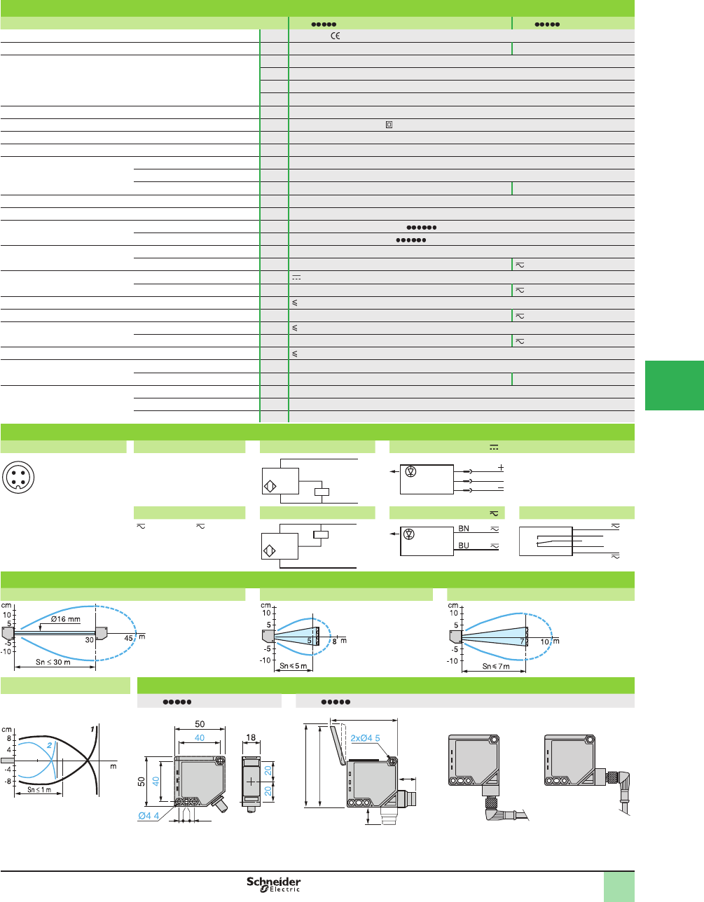
5/69
1
1
Specifi cations
Sensor type XUK M12 XUK L2
Product certifi cations UL, CSA,
Connection M12 connector Pre-cabled, length: 2 m
Sensing distance:
nominal Sn (excess gain = 2)
maximum (excess gain = 1)
m (ft) PNP/NPN or relay output 1 / 1.5 (3.28 / 4.92) diffuse
m (ft) PNP/NPN or relay output 5 / 8 (16.40 / 26.25) polarized retroreß ective
m (ft) PNP/NPN or relay output 7 / 10 (22.97 / 32.81) retroreß ective
m (ft) PNP/NPN or relay output 30 / 45 (98.42 / 147.64) thru-beam
Type of transmission Infrared, except polarized retroreß ective (red)
Degree of protection Conforming to IEC 60529 IP 65, double insulation
Storage temperature °C -40 to +70 (-40 to +158 °F)
Operating temperature °C -25 to +55 (-13 to 131 °F)
Materials Case PBT
Lens PMMA
Cable – PVC
Vibration resistance Conforming to IEC 60068-2-6 7 gn, amplitude ± 1.5 mm (f = 10 to 55 Hz)
Shock resistance Conforming to IEC 60068-2-27 30 gn, duration 11 ms
Indicator lights Output state Yellow LED (except for XUK2 T)
Supply on Green LED (only for XUK2 T)
Rated supply voltage PNP/NPN V12–24 with protection against reverse polarity
Relay output V– 24–240
Voltage limits (including ripple) PNP/NPN V 10–36
Relay output V– 20–264
Current consumption, no-load PNP/NPN mA 35
Power consumption Relay output W–2
Switching capacity PNP/NPN mA 100 with overload and short-circuit protection
Relay output A–3
Voltage drop, closed state V 1.5
Maximum switching frequency PNP/NPN Hz 250
Relay output Hz – 20
Delays First-up ms < 15 (PNP/NPN); < 60 (relay output)
Response ms < 2 (PNP/NPN); < 25 (relay output)
Recovery ms < 2 (PNP/NPN); < 25 (relay output)
Wiring diagrams
M12 connector Pre-cabled, PNP/NPN Receiver, PNP output Thru-beam transmitter
3 (-)
1 (+)
4 OUT/Output
2 Beam break input
(1)
(1) Beam break input on
thru-beam transmitter only.
(-) BU (Blue)
(+) BN (Brown)
OUT/Output BK (Black)
Beam break input (1) VI
(Violet)
Input 2/VI:
- not connected: beam made
- connected to –: beam broken
Pre-cabled, relay output Receiver, NPN output Thru-beam transmitter Relay output
() BU (Blue), ( ) BN
(Brown)
Relay common/GY (Gray)
NO BK (Black)
NC WH (White)
Operating curves
Thru-beam system Polarized retrorefl ective system Retrorefl ective system
Diffuse system Dimensions (mm)
XUK L2 XUK M12
Object: 10 x 10 cm,
1: white 90%, 2: gray 18%
Possible orientation of elbowed connector
1 2
4 3
–
BN/1
BU/3
+
PNP BK/4 (NO,NC)
1
3
2
BN
VI
BU
BN/1
BU/3
+
–
BK/4 (NO,NC
)
NPN
BN
BU
GY WH
BK
With reß ector XUZC50 With reß ector XUZC50
1.5
0,8
0.5
7 4 6.5
.
66
20
20
76
84
.
SpeciÞ cations, Wiring
Diagrams,
Operating Curves,
Dimensions
OsiSense® XU
Photoelectric sensors 1
Single mode function
Compact design, 50 x 50
Five-wire AC or DC, 1 CO relay output
Three-wire DC, solid-state output
1
2
3
4
5
6
7
8
9
10
This document provided by Barr-Thorp Electric Co., Inc. 800-473-9123 www.barr-thorp.com
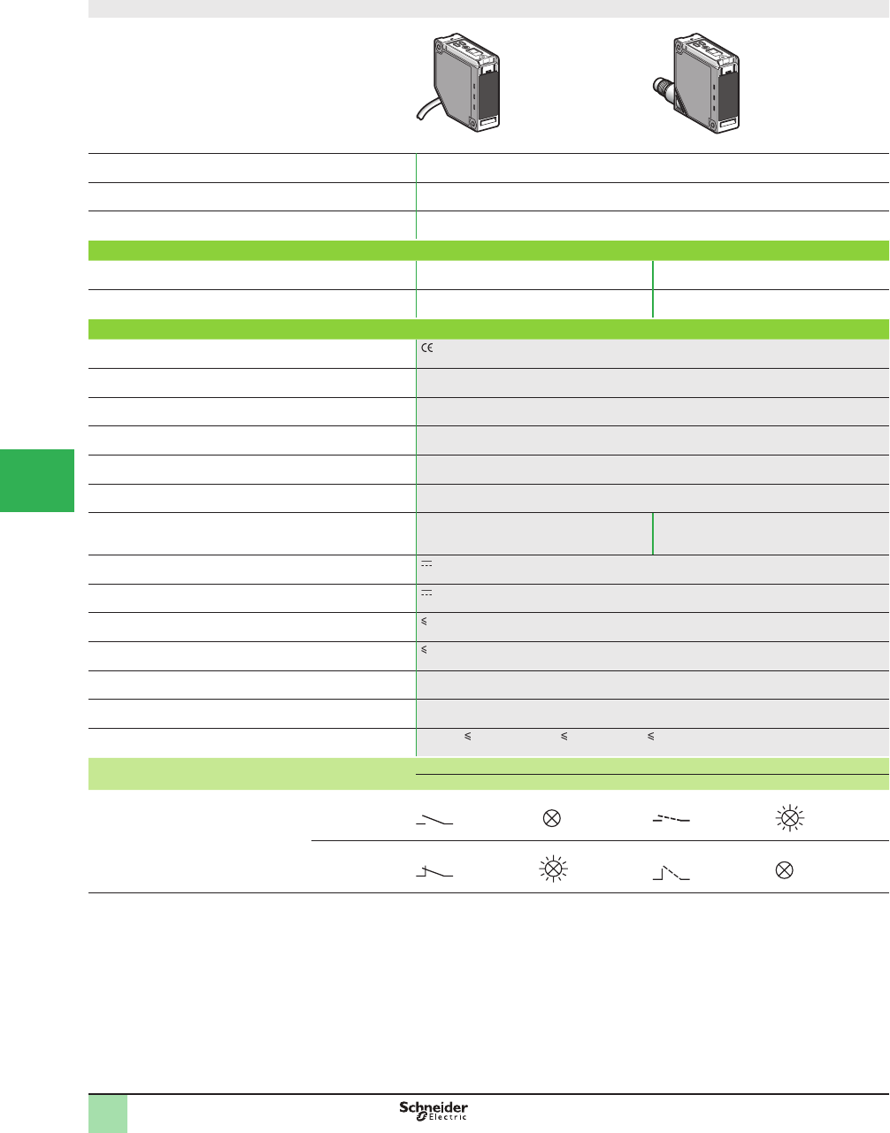
5/70
1Compact design
System Diffuse with adjustable background suppression, long sensing distance with high
accuracy
Type of transmission Infrared
Nominal sensing distance Sn, m (ft) 1 (6.56)
Catalog Numbers
3-wire, PNP or NPN
programmable
NO or NC programmable
function
XUK8AKSNL2 XUK8AKSNM12
Weight, kg (lb) 0.190 (0.42) 0.070 (0.15)
Specifi cations
Product certifi cations , UL, CSA
Ambient air temperature For operation: -25 to +55 °C (-13 to +122 °F)
For storage: -30 to +70 °C (-22 to +158 °F)
Vibration resistance Conforming to IEC 60068-2-6 7 gn (f = 10–55 Hz)
Shock resistance Conforming to IEC 60068-2-27 10 gn, duration 11 ms
Degree of protection Conforming to IEC 60529 IP 65 (IP 30 with cover open).
NEMA 4X indoor use, 12 and 13 double insulation
Materials Case: PC, lenses: PMMA, cable: PVC
Connection
(1)
Pre-cabled, diameter 6 mm, length 2 m,
wire c.s.a.: 5 x 0.34 mm2 (22 AWG)
M12 male connector, 4-pin, can be set at 2
positions (suitable female connectors,
including pre-wired versions)
Rated supply voltage 12–24 V with protection against reverse polarity
Voltage limits 10–36 V (including ripple)
Switching capacity (sealed) 100 mA with overload and short-circuit protection
Voltage drop, closed state 1.5 V
Current consumption, no-load 35 mA
Maximum switching frequency 250 Hz
Delays First-up: 80 ms; response: 2 ms; recovery: 2 ms
Function table Function Diffuse system
No object present in the beam Object present in the beam
Output state (PNP or NPN) indicator:
yellow LED (illuminated when sensor
output is ON)
NO
NC
(1) For a 5 m long cable replace L2 by L10.
Catalog Numbers,
SpeciÞ cations
OsiSense® XU
Photoelectric sensors 0
Application, material handling series
Diffuse with adjustable background suppression
Mechanical display of setting
DC supply. Solid-state output
1
2
3
4
5/
6
7
8
9
10
This document provided by Barr-Thorp Electric Co., Inc. 800-473-9123 www.barr-thorp.com
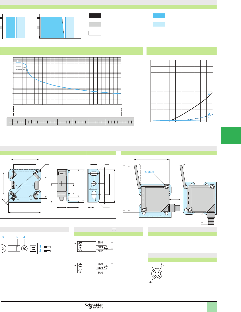
5/71
1
Detection curves
Variation of usable sensing distance Su
Adjustment at 10 cm Adjustment at 1 m A-B: Object reß ection coefÞ cient
Black 6% Sensing range
Gray 18% Non-sensing zone
(Matte surfaces)
White 90%
Sensing distance adjustment Relative difference in sensing distances
according to object color
1
2
3
White 90%
Gray 18%
Black 6%
1
2
3
White 90%
Gray 18%
Black 6%
Dimensions (mm)
XUK8AKSNL2 Bracket mounting XUK8AKSNM12 with cover raised
(1) Cover locking tongue.
(2) 1 elongated hole Ø 6 x 12.
(3) 1 elongated hole Ø 6 x 13.
Functions Wiring diagram (3-wire ) Cable connections
NO/NC programming XUK8AKSNL2
PNP output (-)
(+)
(OUT)
BU (Blue)
BN (Brown)
BK (Black)
Connector diagram
Switches NPN output
NO: detection of object presence
NC: detection of object absence
XUK8AKSNM12
1NO/NC programming
2PNP or NPN output
LED
3Yellow LED, output
Potentiometer
4Sensing distance adjustment
Setting indicator
5Potentiometer setting indication
A
B
10.5
5S (cm)
10
A
B
104
91
5S (cm)
100
1
1000
1
10
100
0
0.5
1.5
2
2.5
10
4
5
6
72
3
3
1
2
NEAR
FAR
Max.
Min.
Number of turns on potentiometer
Setting indicator position (mm)
Sensing distance (cm)
010020 40 60 80
20
0
10
18
16
14
12
8
6
4
2
%
Sensing distance (cm)
50
40 (1)
58
18 22
34
10
O
40
40
35
20
50
60
58
40.5
18 715135
(2)
(3)
12
Ø 6
12
65
82
80
29.5
.
29.5
1
2
FAR NEAR
1
43
Operating Curves,
Dimensions,
Wiring Diagrams
OsiSense® XU
Photoelectric sensors 0
Application, material handling series
Diffuse with adjustable background suppression
Mechanical display of setting
DC supply. Solid-state output
1
2
3
4
5
6
7
8
9
10
This document provided by Barr-Thorp Electric Co., Inc. 800-473-9123 www.barr-thorp.com
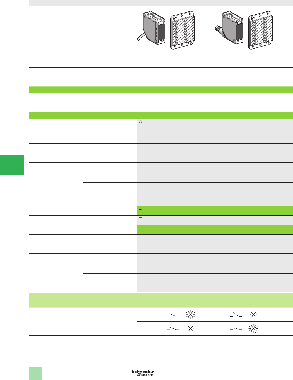
5/72
1
Compact design
System Retrorefl ective
Type of transmission Red
Nominal sensing distance Sn, m (ft) 1.5 (4.92) (with 50 x 50 mm reß ector)
Catalog Numbers
3-wire, PNP or NPN Light or dark programmable
switching
XUKT1KSML2 (2) XUKT1KSMM12 (2)
Weight, kg (lb) 0.280 (0.62) 0.120 (0.26)
Specifi cations
Product certifi cations , UL, CSA
Ambient air temperature For operation -25 to +55 °C (-13 to +131 °F)
For storage -30 to +70 °C (-22 to +158 °F)
Vibration resistance Conforming to IEC 60068-2-6 7 gn (f = 10–55 Hz)
Shock resistance Conforming to IEC 60068-2-27 10 gn, duration 11 ms
Degree of protection Conforming to IEC 60529 IP 65
Materials Case PC
Lenses PMMA
Cable PVC
Connection Pre-cabled, diameter 6 mm, length 2 m,
wire c.s.a.: 4 x 0.34 mm2 (22 AWG)
M12 male connector, adjustable to 2 positions
(suitable female connectors, including
pre-wired versions)
Rated supply voltage 12–24 V with protection against reverse polarity
Voltage limits 10–30 V (including ripple)
Switching capacity (sealed) d 100 mA with overload and short-circuit protection
Voltage drop, closed state d 2 V
Current consumption, no-load d 35 mA
Maximum switching frequency 1500 Hz
Delays First-up d 80 ms
Response d 0.3 ms
Recovery d 0.3 ms
Time delay Monostable, on-delay or off-delay (programmable) adjustable from 0.1 to 5 seconds
Function table Function Retrorefl ective system
No object present
in the beam
Object present
in the beam
Output state (PNP or NPN) indicator: yellow LED
(illuminated when sensor output is ON)
Light switching
Dark switching
(1) Sensor memorizes, in teach mode, the environmental conditions in which the object is to be detected and adapts to any variations.
(2) 50 x 50 mm reß ector catalog number XUZC50 included with the sensor.
Catalog Numbers,
SpeciÞ cations
OsiSense® XU
Photoelectric sensors 0
Application, packaging series
For detection of transparent materials, with teach mode and
automatic compensation for accumulation of dirt (1)
DC supply, solid-state output
1
2
3
4
5/
6
7
8
9
10
This document provided by Barr-Thorp Electric Co., Inc. 800-473-9123 www.barr-thorp.com
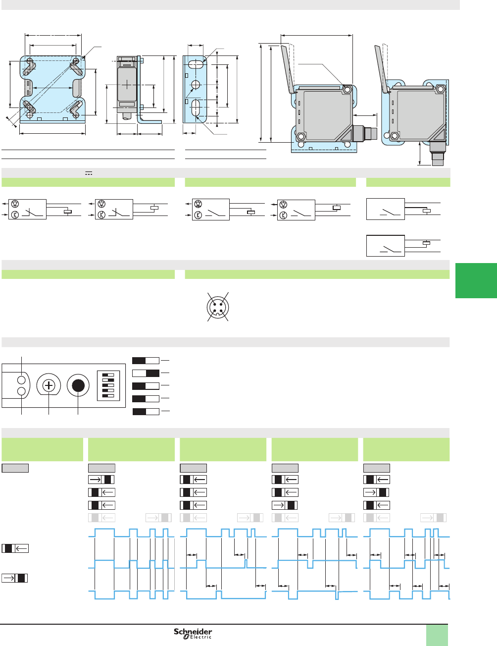
5/73
1
Dimensions
XUKT1KSML2 Bracket mounting XUKT1KSMM12 with cover raised
mounting bracket mounting according to position of connector
80
82
29.5
65
2 x Ø4.5
29.5
(1) Cover locking tongue
(2) 1 elongated hole Ø 6 x 12
(3) 1 elongated hole Ø 6 x 13
Wiring diagrams (3-wire )
Light switching programmed (no object present) Dark switching programmed (no object present) Alarm output
PNP output programmed NPN output programmed PNP output programmed NPN output programmed PNP programmed
NPN programmed
Connection
Cable connections Connector diagram
XUKT1KSML2 XUKT1KSMM12
(–) BU (Blue)
(+) BN (Brown)
(OUT) BK (Black)
Alarm WH (White)
Functions
Switches LEDs
1Light/dark switching programming 6Yellow LED: output and teach mode aid
2Time delay activated or deactivated 7Red LED: alignment aid and alarm indicator
3Normal time delay or monostable
4Normal time delay On-delay or Off-delay Potentiometer and button
5PNP or NPN output TTime delay adjustment
8Teach mode button
Time delays
Switch positions No time delay
Normal time delay (T)
Time delay on trip On-delay
Normal time delay (T)
Time delay on reset
Off-delay
Monostable time delay (T)
= light or dark
switching function
(see below)
or or or or
Receiver state
Light switching Beam intact
Beam broken
Dark switching Output On
Output Off
Output On
Output Off
12
Ø6
(2)
(1)
10
O
(3)
12
22
18
58
50
34
40
40
40
35
20
50
60
18 715135
40.5
58
BN/1
BK/4
BU/3
+
–
BN/1
BK/4
BU/3
+
–
BN/1
BU/3
BK/4
+
–
BN/1
BU/3
BK/4
+
–
BN/1
WH/2
BU/3
+
–
BN/1
BU/3
WH/2
+
–
12
43
(–)
(+)
Output
signal
Alarm output
1
2
3
4
1
2
3
4
7T8
5
5
6
TT
TT
TT
TT
TT T
TT T
Dimensions,
Wiring Diagram,
Operation
OsiSense® XU
Photoelectric sensors 0
Application, packaging series
For detection of transparent materials, with teach mode and
automatic compensation for accumulation of dirt (1)
DC supply, solid-state output
1
2
3
4
5
6
7
8
9
10
This document provided by Barr-Thorp Electric Co., Inc. 800-473-9123 www.barr-thorp.com
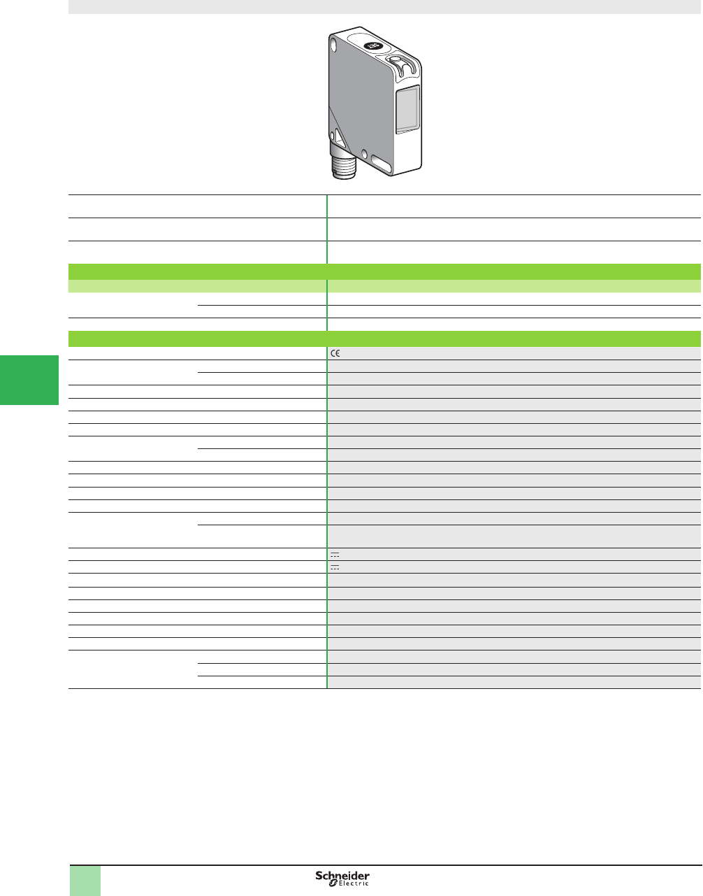
5/74
1
Compact design, 50 x 50
System Diffuse
Type of transmission White LED (400-700 nm)
Nominal sensing distance Sn, mm (in.) 19 (0.75)
Catalog Numbers
Description Catalog Number
3-wire, PNP or NPN PNP output XUKR1PSMM12
NPN output XUKR1NSMM12
Weight, kg (lb) 0.045 (0.10)
Specifi cations
Product certifi cations , cULus
Ambient air temperature For operation -10 to +55 °C (+14 to +122 °F)
For storage -20 to +70 °C (-4 to +158 °F)
Vibration resistance Conforming to IEC 60068-2-6 Amplitude ± 0.5 mm, f = 10–55 Hz for each axis
Shock resistance Conforming to IEC 60068-2-27 30 gn, duration 11 ms, 6 shocks on each axis
Degree of protection Conforming to IEC 60529 IP 65
Connection M12, 4-pin connector; can be set at 90°
Materials Case ABS
Lenses Glass (window tilted, anti-reß ective glass)
Spot diameter At 19 mm: Ø 3.5 mm
Resolution 0.5 mm
Depth of fi eld ± 2 mm
Adjustment Teach mode using button or remotely using remote wire
Indicator lights Output Yellow LED
Stability Green LED: Ready
Flashing green/red: error
Rated supply voltage 12–24 V
Voltage limits 10–30 V (including ripple)
Switching capacity (sealed) d100 mA with protection against reverse polarity, overload and short-circuit
Voltage drop, closed state (saturation voltage) d 2 V
Current consumption, no-load d 30 mA
Maximum linear speed of mark 2.5 m/s for 1 mm wide mark
Maximum switching frequency 5 kHz
Delay 100 Ps for response and recovery
Time delay Time delay function Minimum time output active: 20 ms
Auxiliary functions Remote teaching via remote wire; teach mode button locking
Operating mode Standard teaching: output activated on dark mark
(1) Applications: detection of contrasting colors on reß ective, matte or embossed surfaces; color mark and index mark reading function on automated packaging and
Þ lling systems and on labelling, heat sealing, thermo-forming and printing machines, etc.
Catalog Numbers,
SpeciÞ cations
OsiSense® XU
Photoelectric sensors 1
Application, packaging series
Compact design, 50 x 50
Color mark readers (1)
DC supply. Solid-state output
1
2
3
4
5/
6
7
8
9
10
This document provided by Barr-Thorp Electric Co., Inc. 800-473-9123 www.barr-thorp.com
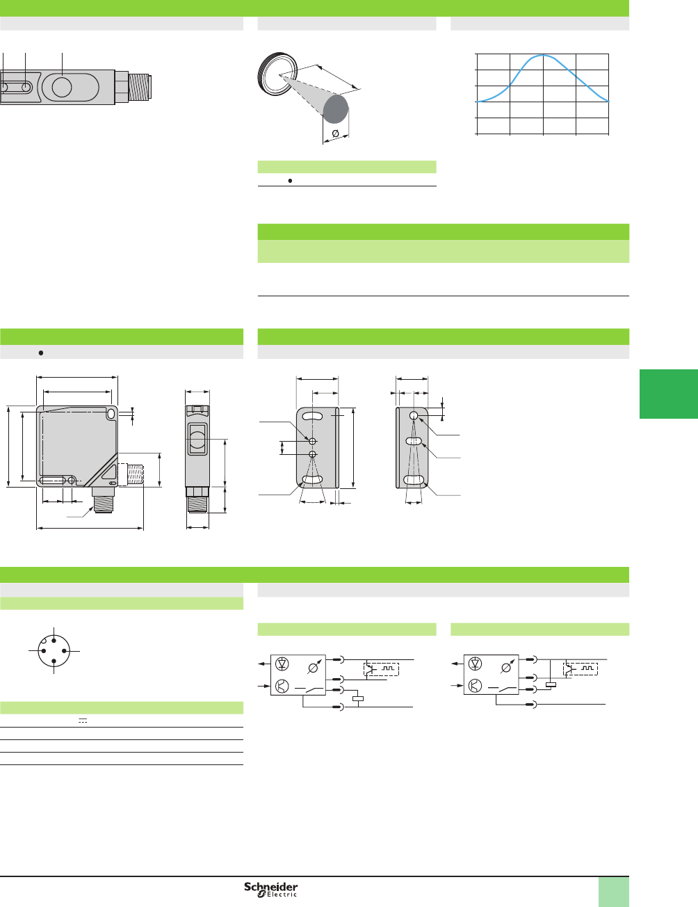
5/75
1
Presentation
Description Detection zone and spot size Detection curve
1Output LED
2 Dual color stability LED
3 SET button a (mm) Ø (mm)
XUKR1 SMM12 19 3.5
Mounting accessory
Description Catalog Number Weight
kg (lb)
Mounting bracket
(2 screws, 2 nuts and 2 washers included)
XUZK2000 0.040 (0.09)
Dimensions (mm)
XUKR1 SMM12 Mounting bracket XUZK2000
Wiring Diagrams
Connector diagram Wiring diagram
Sensor connector pin view Automatic NC or NO selection depending on chronological order of teaching for the
mark and the background.
PNP output NPN output
.
Pin N° Type Color
110–30 V Brown
2 Adjustment input (1) White
3 0 V Blue
4 Output Black
(1) Connecting the remote adjustment input to +Vdc is
equivalent to pressing the Set button.
SET
21 3
a
0
20
40
60
80
100%
20
10 30 40
%
o
f
signal
Detection distance (mm)
Ø15
29.5
50
16
66
M12
11 6
50
2
18x45
42
42 15
9
2xØx4.1
16.5
26.5 20
50
30°
5
8
2
2
2xØx4.4 Øx5.3
Øx4.3
Øx5.1
10°
1 (+)
3 (
–
)
4
2
Setting
adjust-
ment
Output
1
2
4
3
+
–
1
2
4
3
+
–
Presentation,
Dimensions,
Wiring Diagrams
OsiSense® XU
Photoelectric sensors 1
Application, packaging series
Compact design, 50 x 50
Color mark readers (1)
DC supply. Solid-state output
1
2
3
4
5
6
7
8
9
10
This document provided by Barr-Thorp Electric Co., Inc. 800-473-9123 www.barr-thorp.com
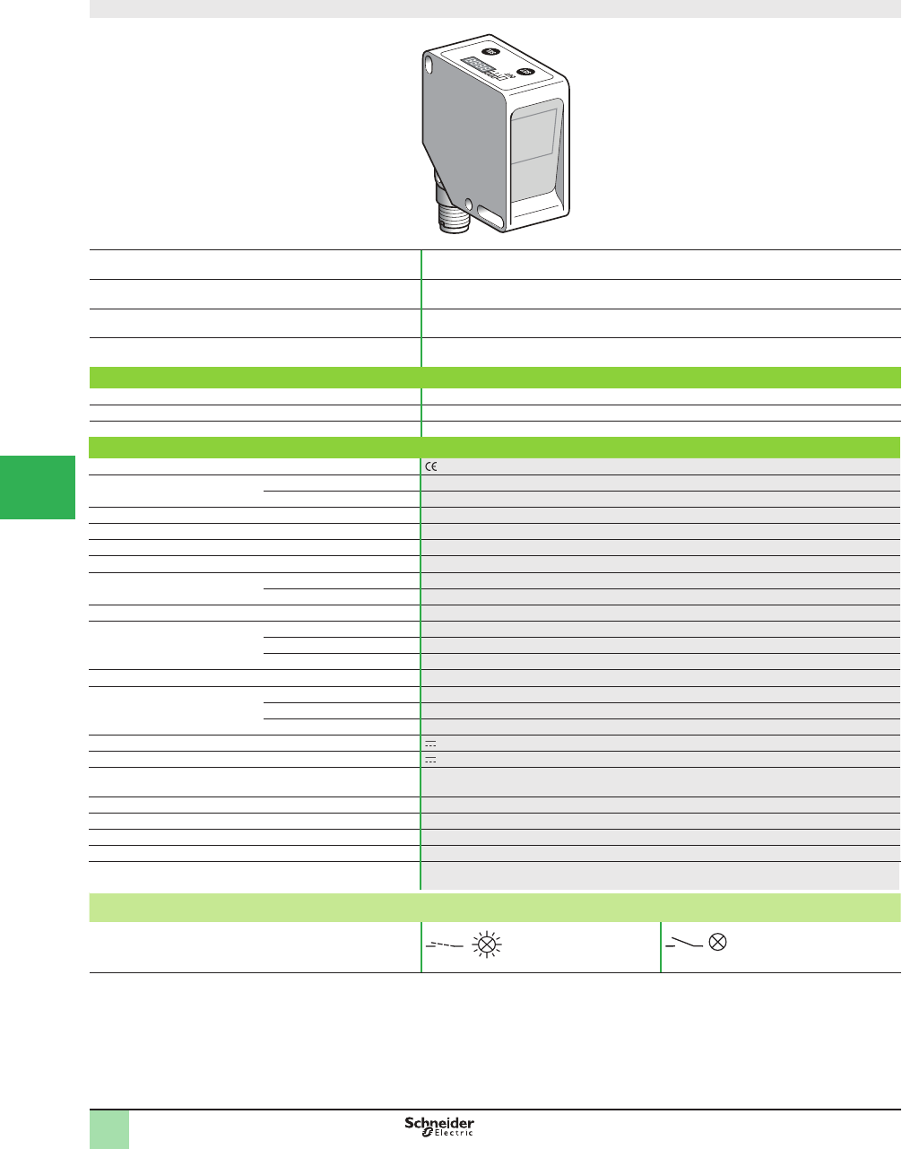
5/76
1
Compact design, 50 x 50
System Diffuse
Type of transmission White LED (400-700 nm)
Type of color processing RGB
Nominal sensing distance Sn, mm (in.) 20 (0.79) (Operational distance, see operating curve on page 77 )
Catalog Number
3-wire, PNP +1 synchro input NO function XUKC1PSMM12
3-wire, NPN +1 synchro input NO function XUKC1NSMM12
Weight, kg (lb) 0.085 (0.19)
Specifi cations
Product certifi cations , cULus
Ambient air temperature For operation -10 to +55 °C (+14 to +122 °F)
For storage -20 to +70 °C (-4 to +158 °F)
Vibration resistance Conforming to IEC 60068-2-6 Amplitude ± 0.5 mm, f = 10–55 Hz for each axis
Shock resistance Conforming to IEC 60068-2-27 30 gn, duration 11 ms, 6 shocks on each axis
Degree of protection Conforming to IEC 60529 IP 65
Connection M12, 8-pin connector; can be set at 90°
Materials Case ABS
Lenses Glass (window tilted, anti-reß ective glass)
Spot diameter At 20 mm: Ø 4 mm
Adjustment Teach mode Teaching using SET (adjustment) and SEL (Selection) buttons
Operating mode C (color) or C+I (color +intensity), independent for each channel
Tolerance level Selectable tolerance for varying shades of color from TOL 0 to TOL 9
Auxiliary functions External synchronization, locking
Indicator lights and display Display 4-digit
Output active 3 green LEDs: output 1, 2 or 3
Output state OUT Yellow LED if one output (1, 2 or 3) activated
Rated supply voltage 12–24 V
Voltage limits 10–30 V (including ripple)
Switching capacity (sealed) d100 mA with protection against reverse polarity, overload and short-circuit
Voltage drop, closed state d 2 V
Current consumption, no-load d 60 mA
Maximum switching frequency 1.5 kHz
Delay 335 Ps for response and recovery
Time delay Selectable (5, 10, 20, 30 or 40 ms)
Function table for each channel (3 channels)
NO function
Color recognized by sensor Color not recognized by sensor
Output state (PNP or NPN) indicator
(illuminated when sensor output is ON)
(1) Applications: OsiSense® XU Full color is a color sensor that can recognize up to 3 colors. It can be used to sort objects by color or to monitor colors, and is
insensitive to surface Þ nishes (matte or reß ective), as well as ambient lighting. The sensor is suitable for use in many industrial sectors, such as packaging
machines, printing machines, etc.
Catalog Numbers,
SpeciÞ cations
OsiSense® XU
Photoelectric sensors 1
Application, packaging series
Compact design, 50 x 50
For color detection (1)
DC supply. Solid-state output
1
2
3
4
5/
6
7
8
9
10
This document provided by Barr-Thorp Electric Co., Inc. 800-473-9123 www.barr-thorp.com
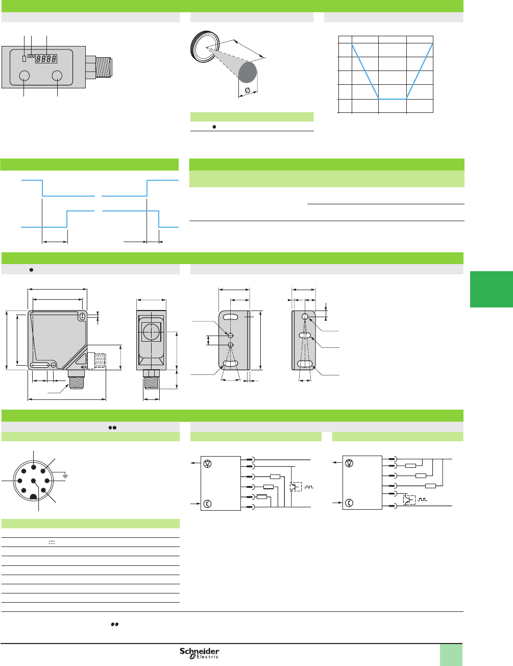
5/77
1
Presentation
Description Detection zone and spot size Operating curve
1Output LED
2OUT1, OUT2 and OUT3 LEDs
3 Display (green, 4-digit)
4 SEL button (adjustment)
5 SET button
a (mm) Ø (mm)
XUKC1 SMM12 20 4
Detection distance related to object’s degree of
reß ection
Diagram Accessories
SYNC passive = Vdc, SYNC active = 0 V Description Diameter
mm
Length
m
Catalog Number Weight
kg (lb)
Pre-wired M12, 8-pin
connectors, shielded
cable (1)
6.5 3 XSZMCR03 0.230 (0.51)
10 XSZMCR10 0.715 (1.58)
Mounting bracket
(2 screws, 2 nuts and 2
washers included)
– – XUZK2000 0.040 (0.09)
Dimensions (mm)
XUKC1 SMM12 Mounting bracket XUZK2000
Wiring diagrams
Pre-wired connector XSZMCR Wiring diagram
Sensor connector pin view PNP output +synchro input NPN output +synchro input
Pin N° Type Color (2)
1 – WH (white)
210...30 V BN (brown)
3 Output 1 TAN (tan)
4 Output 2 YE (yellow)
5 Output 3 GY (gray)
6 – PK (pink)
7 0 V VT (violet)
8 Synchro RD (red)
– Screening TR (transparent)
(1) The use of shielded cable is recommended for correct operation of the sensor, especially in environments subject to electromagnetic interference.
(2) With pre-wired connector XSZMCR .
1
OUT
2 3
SET SEL
21 3
4
5
a
18
36
54
72
90
99
%
5 15 250 35
Object reß ection
White
Yellow
light
Dark blue
Black
Detection distance (mm)
335 Ps
max. 170 Ps
max.
5.5
11.5
18x45
Ø15
M12
2
31.65
50
16
66
50
42
42 25
9
2xØx4.1
16.5
26.5 20
50
30°
5
8
2
2
2xØx4.4 Øx5.3
Øx4.3
Øx5.1
10°
2
+
–
3
4
6
5
7
8
1
2
8
3
4
5
7
+
–
2
3
4
5
8
7
+
–
Presentation,
Dimensions,
Wiring Diagrams
OsiSense® XU
Photoelectric sensors 1
Application, packaging series
Compact design, 50 x 50
For color detection
DC supply. Solid-state output
1
2
3
4
5
6
7
8
9
10
This document provided by Barr-Thorp Electric Co., Inc. 800-473-9123 www.barr-thorp.com
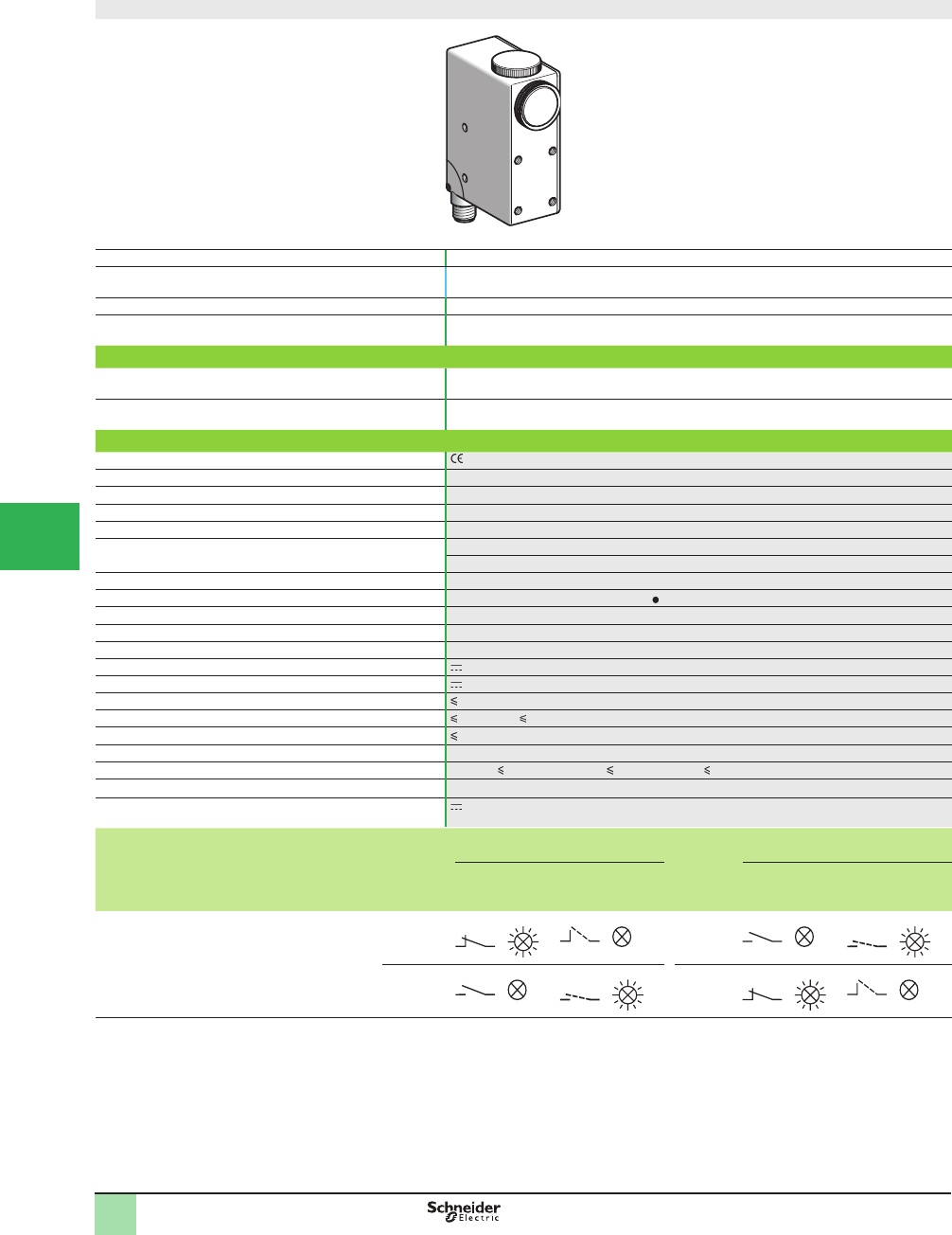
5/78
1
Compact design
System Diffuse
Type of transmission (line of sight along case axis or at 90°
depending on position of lens)
Red or green, automatically selected when using teach mode
Nominal sensing distance Sn, mm (in.) 9 (0.35), 7 (0.28) with XURZ02 or 18 (0.71) with XURZ01 (2)
Sensitivity adjustment Automatic when using teach mode
Catalog number
3-wire, PNP or NPN
programmable
NO or NC programmable
function (3)
XURK1KSMM12
Weight, kg, (lb) 0.550 (0.26)
Specifi cations
Product certifi cations
Ambient air temperature For operation: -10 to +55 °C (+14 to 131 °F). For storage: -20 to +70 °C (-4 to 158 °F)
Vibration resistance Conforming to IEC 60068-2-6 7 gn, amplitude ± 0.6 mm (f = 10–55 Hz)
Shock resistance Conforming to IEC 60068-2-27 30 gn, duration 11 ms
Degree of protection Conforming to IEC 60529 IP 67
Connection M12 connector, can be set at 3 positions
(suitable female connectors, including pre-wired versions)
Materials Case: zinc alloy; lenses: glass
Spot dimensions At 9 mm: 1.5 x 5 mm (with lens XURZ0 )
Minimum detectable width of mark 0.5 mm
Maximum vertical inclination of reader 20°
Maximum linear speed of mark 10 m/s (for 1 mm wide mark)
Rated supply voltage 12–24 V with protection against reverse polarity
Voltage limits 10–30 V (including ripple)
Switching capacity (sealed) 200 mA with overload and short-circuit protection
Voltage drop, closed state 1 V (NPN); 2 V (PNP)
Current consumption, no-load 80 mA
Maximum switching frequency 10 kHz
Delays First-up: 100 ms; response: 50 Ps; recovery: 50 Ps
Time delay Off delay: 20 ms, activated/deactivated by internal switch
Analogue output 0–5.5 V (voltage proportional to light reß ected by the object)
Function table Function Detection of dark mark on light
background
Function Detection of light mark on dark
background
No mark present
in the beam
Mark present
in the beam
No mark present
in the beam
Mark present in
the beam
Output state (PNP or NPN) indicator:
red LED
(illuminated when sensor output is ON)
NC NO
NO NC
(1) Applications: detection of contrasting colors on reß ective, matte or embossed surfaces; color mark and index mark reading function on automated packaging and
Þ lling systems and on labelling, heat sealing, thermo-forming and printing machines, etc.
(2) Lenses for reduction or magniÞ cation of spot.
(3) Automatic programming depending on chronological order of teaching for the mark and the background.
Catalog Numbers,
SpeciÞ cations
OsiSense® XU
Photoelectric sensors 0
Application, packaging series
Color mark readers (1)
DC supply. Solid-state output
1
2
3
4
5/
6
7
8
9
10
This document provided by Barr-Thorp Electric Co., Inc. 800-473-9123 www.barr-thorp.com
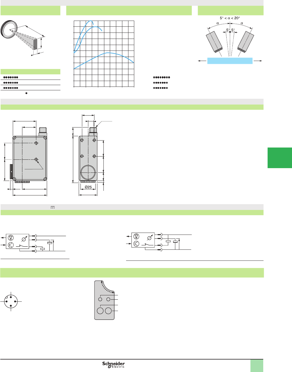
5/79
1
XURK1KSMM12
Detection zone and spot size
(mm)
Detection curve Vertical inclination
XUR a b c
K9 5 1.5 1XURK An angle of 5 to 10° from vertical is
recommended for reß ective or
transparent surfaces.
Maximum vertical inclination: 20°.
K +XURZ01 18 7 2 2XURK +XURZ02
K +XURZ02 741 3XURK +XURZ01
Lenses XURZ0
Dimensions (mm)
XURK1KSMM12
42.2
24
8.5
39.8
5.9
58 31
8xM5x6
M12x1
36.6 28
27.514.1 28
81.2 15
21
4.3
Wiring diagrams (3-wire )
XURK1KSMM12
Automatic NC or NO selection depending on chronological order of teaching for the mark and the background
PNP output NPN output
R = 2.2 k
Connector diagram Functions
(sensor connector
pin view)
1
2
3
4
Green LED, sensor in teach
mode
Red LED, output state
Teach mode button for mark
Teach mode button for
background
PNP/NPN programming
and time delay by internal switches
.
b
c
a
0
0
10
20
30
40
50
60
70
80
90
100
110
510 15 20 25
12
3
Distance (mm)
1
2
4
3
+
–
0–5.5 V
R
1
2
4
3
+
–
R0–5.5 V
1 (+)
3 (
–
)
4
2
2
3
4
1
Operating Curves,
Dimensions,
Wiring Diagrams
OsiSense® XU
Photoelectric sensors 0
Application, packaging series
Color mark readers (1)
DC supply. Solid-state output
1
2
3
4
5
6
7
8
9
10
This document provided by Barr-Thorp Electric Co., Inc. 800-473-9123 www.barr-thorp.com
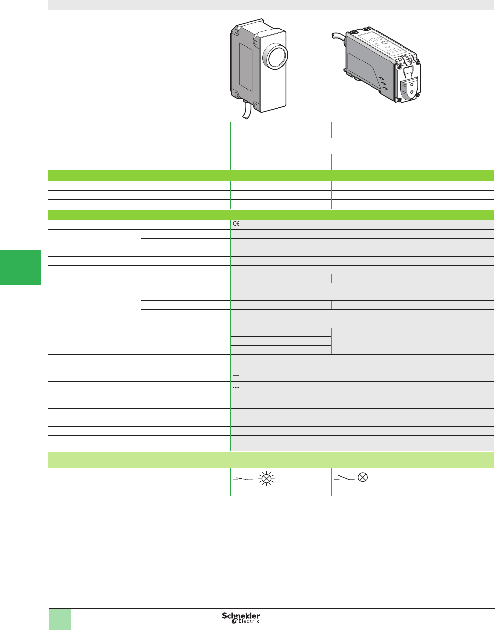
5/80
1
Compact design and fi ber design
System Diffuse Thru-beam or diffuse depending on fi bers optics
selected
Type of transmission Red, blue and green
Nominal sensing distance, Sn, mm (in.) 40–60 (1.57–2.36) 4–250 (0.16–9.84) depending on fi ber optics used
(see page 118 )
Catalog Number
3-wire, PNP NO function XURC3PPML2 XURC4PPML2
3-wire, NPN NO function XURC3NPML2 XURC4NPML2
Weight, kg (lb) 0.260 (0.57) 0.190 (0.42)
Specifi cations
Product certifi cations
Ambient air temperature For operation -10 to +50 °C (+14 to 122 °F)
For storage -30 to +70 °C (-22 to +158 °F)
Ambient humidity 35–85% RH (without condensation)
Vibration resistance Conforming to IEC 60068-2-6 Amplitude ± 0.75 mm, f = 10–55 Hz, 2 hours on the 3 axes
Shock resistance Conforming to IEC 60068-2-27 50 gn, 5 shocks on the 3 axes
Degree of protection Conforming to IEC 60529 IP 67 IP 65
Connection Pre-cabled: diameter 5.4 mm, length 2 m, wire c.s.a.: 7 x 0.2 mm² (24 AWG)
Materials Case Aluminium
Lenses Glass –
Cable Vinyl rubber sleeve
Cover Polyacrylate
Spot diameter, mm (in.) At 40 (1.57): 4 (0.16) Depending on Þ ber optics used: 2.5–8 (0.10–0.31)
(see page 118 )
At 50 (1.97): 6 (0.24)
At 60 (2.36): 8 (0.31)
Immunity to ambient light Sunlight 10 000 Lux max.
Halogen light 3000 Lux max.
Rated supply voltage 12–24 V
Voltage limits 10–30 V (including ripple)
Switching capacity (sealed) d100 mA with overload and short-circuit protection
Voltage drop, closed state d 1.5 V
Current consumption, no-load d 150 mA
Switching time Programmable by switch: 0.8 ms, 1.5 ms or 6 ms
Maximum switching frequency 1.2 kHz
Time delay Programmable by switch: 40 ms on falling edge
Function table for each channel (3 channels)
NO function
Color recognized
by sensor
Color not recognized
by sensor
Output state (PNP or NPN) indicator
(illuminated when sensor output is ON)
(1) Applications: OsiSense® XU Full color is a color sensor that can recognize up to three colors. It can be used to sort objects by color or to monitor colors, and is
insensitive to surface Þ nishes (matte or reß ective), as well as ambient lighting. The sensor is suitable for use in many industrial sectors, such as packaging
machines, printing machines, etc.
Catalog Numbers,
SpeciÞ cations
OsiSense® XU
Photoelectric sensors 1
Application, packaging series
For color detection (1)
DC supply. Solid-state output
1
2
3
4
5/
6
7
8
9
10
This document provided by Barr-Thorp Electric Co., Inc. 800-473-9123 www.barr-thorp.com
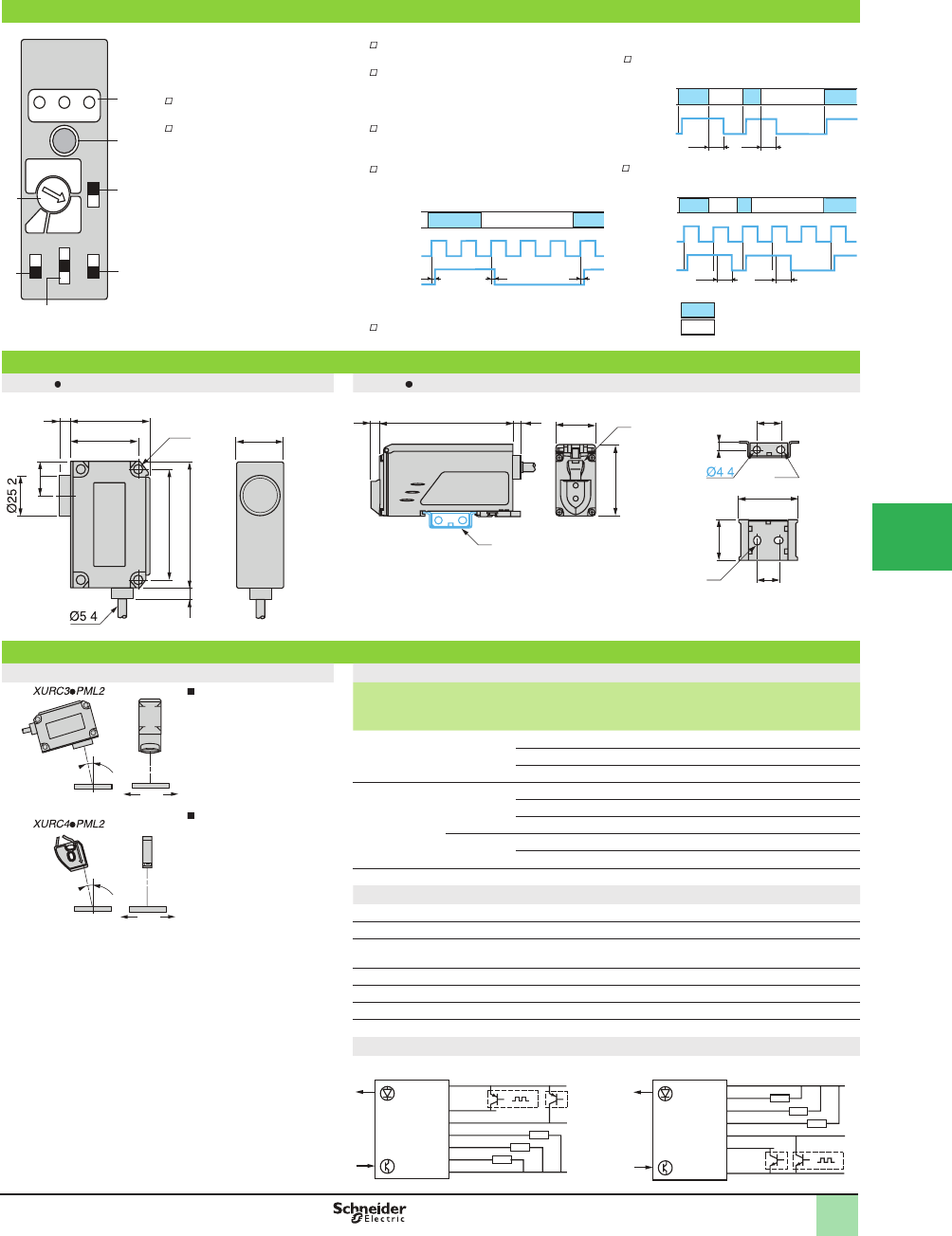
5/81
1
Presentation
1 Operational status LED
2 Teach mode button, for
memorizing reference colors
3 Reference colors and operating
mode selector
Selection of reference colors
(SET)
Selection of operating mode:
- TOLERANCE mode (positions
1–5): 5 positions allow selection of
the tolerance level to be applied to
the shading of the color to be
detected.
- RUN mode (position S): this mode
enables sorting by color.
4 C or C +I selector
Mode C: this mode is used for the
detection of different colored objects.
Mode C +I: in this mode the sensor is
insensitive to varying surface Þ nishes of the
object.
5 Synchronization mode selector
Internal synchronization mode (INT): in
this mode, color detection is performed
continually.
External synchronization mode (EXT): in
this mode, color detection is synchronized
with an external signal.
6 Response time mode selector
Fast mode (F), normal mode (N) or slow
mode (S).
7 Output time delay selector
(T-ON/T-OFF)
Output time delay, internal synchronization
mode
Output time delay, external synchronization
mode
R = response time
Dimensions (mm)
XURC3 PML2 XURC4 PML2
(1) 2 holes for M5 screws, depth 10 mm
(1) Mounting on rail
(2) Fiber optic clamp
(3) 1 elongated hole Ø 4.4 x 5.4
(4) 2 elongated holes Ø 4.4 x 6.4
Mounting rail
Mounting
Installation considerations Suitable fi ber optics. For further information, see pages 118 – 131 .
To obtain optimal
detection of the colors, it
is recommended that
the sensor be positioned
such that the
transmitted light beams
strikes the object at an
angle of 15° from its
vertical axis (Þ gure 1).
The direction of travel of
the object must be as
shown in Þ gure 2. This
provides detection that
is less sensitive to
variations in the angle of
detection.
Type of
fi ber
System Catalog Number Sensing
distance
mm (in.)
Diameter of spot
mm
Focused Diffuse XUFN5L01L2 10 (0.39) Ø 2.5
XUFN5L02L2 20 (0.79) Ø 5
XUFN5L03L2 30 (1.18) Ø 8
Standard Diffuse XUFN05321 5 (0.20) –
XUFS0520 4 (0.16) –
XUFN02323 +XUFZ06 7 (0.28) Ø 0.5
Thru-beam
(1)
XUFN12301 +XUFZ01 250 (9.84) –
XUFS2020 +XUFZ01 150 (5.91) –
(1) Detection of color by transparency
Cable connections
BN (brown) +Supply (12–24 V)
BU (blue) -
PK (pink) SET signal (remote activation of teach mode to memorize
reference colors)
VI (violet) EXT signal (external synchronization)
BK (black) Output A
WH (white) Output B
GR (gray) Output C
Wiring diagram
PNP NPN
A
A
B
B
OUT
SET
C
EXT
INT
T-ON
(40ms)
T-OFF
FAST
N
SLOW
C
C
S
RUN SET
1
2 4
5
3
1
4
7
2
3
5
6
C + I
RRR
Object
detected
Output On
OFF
Ext. synchro
signal
40 ms 40 ms
Object
detected
Output On
OFF
40 ms
40 ms
Object
detected
Output On
OFF
Ext. synchro
signal
Same color
Different color
68
80
(1)
7
42 30
22
50
7
.
.
582.4 25
5
(1)
44
(2)
15
16
37
25
(4)
(3)
5
.
15°
15°
BU
GY
WH
BK
VI
PK
BN +
–
BU
GY
WH
BK
VI
PK
BN
+
–
Presentation,
Dimensions,
Mounting,
Wiring Diagrams
OsiSense® XU
Photoelectric sensors 1
Application, packaging series
For color detection
DC supply. Solid-state output
1
2
3
4
5
6
7
8
9
10
This document provided by Barr-Thorp Electric Co., Inc. 800-473-9123 www.barr-thorp.com
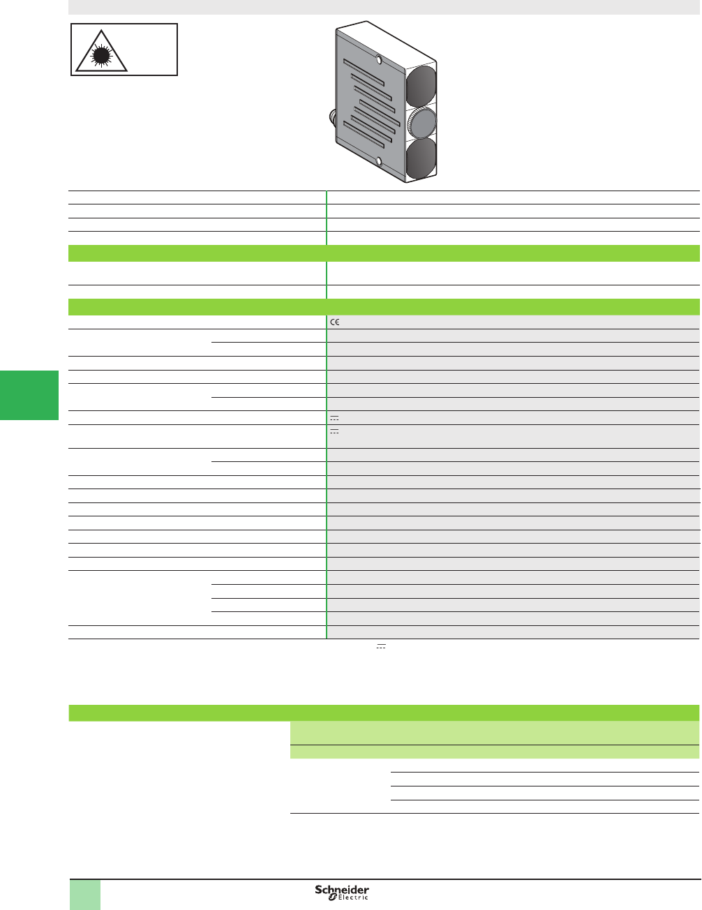
5/82
1
1
2
3
4
5/
6
7
8
9
10
Compact design
Laser
class 2
Laser class 2, conforming to IEC 825-1
Visible laser radiation: do not stare
into beam.
System Diffuse with background suppression
Type of transmission Red laser, pulsed, Class 2, wavelength: 675 nm
Detection distance Adjustable from 50 to 300 mm (1.97 to 11.81 in.)
Minimum size of object 0.5 mm (0.02 in.)
Catalog Number
4-wire, PNP and NPN output NO/NC
depending on wiring
XUYPS1LCO965S
Weight, kg (lb) 0.081 (0.18)
Specifi cations
Product certifi cations , cULus (1)
Ambient air temperature For operation 0 to +50 °C (+32 to 122 °F)
For storage -20 to +80 °C (-4 to +176 °F)
Degree of protection Conforming to IEC 60529 IP 65
Connection M8, 4-pin male connector (for pre-cabled version consult the Sensor Competency Center)
Materials Case Glass impregnated nylon
Lens PMMA
Rated supply voltage 12–24 V with protection against reverse polarity
Voltage limits (including ripple) 10–30 V
Immunity to ambient light Incandescent bulb 500 lux
Natural light 10,000 lux
Laser transmission Pulsed laser LED T pulse: 6 µs, T period < 50 µs
Spot size Manual adjustment of focusing
Switching capacity 100 mA with overload and short-circuit protection
Voltage drop, closed state < 2 V
Current consumption, no-load 35 mA
Maximum switching frequency 5 kHz
Delays Response and recovery < 150 µs
Indicator lights Time delay active Red indicator
Output state Green indicator
NO function Red indicator
NC function Indicator off
Output signal time delay 40 ms, depending on wiring
(1) This product is UL Listed if supplied by a class II or isolated supply delivering 30 V max. (isolated transformer for example) and protected by a UL fuse rated
at 3 A max.
Applications: monitoring of small parts on production machine, detection of components on a printed circuit, monitoring for a crack on a component, control of
level, suppression of a background.
Accessories
Description Details Length
of cable
Catalog Number Weight
m kg (lb)
Pre-wired M8
connector
Straight 2 XZC P0941L2 0.080 (0.18)
Elbowed (90°) 2 XZC P1041L2 0.080 (0.18)
Straight 5 XZC P0941L5 0.180 (0.40)
Elbowed (90°) 5 XZC P1041L5 0.180 (0.40)
Catalog Numbers,
SpeciÞ cations,
Accessories
OsiSense® XU
Photoelectric sensors
Application, material handling series
Diffuse, with laser transmission
With background suppression
DC supply. Solid-state output
This document provided by Barr-Thorp Electric Co., Inc. 800-473-9123 www.barr-thorp.com
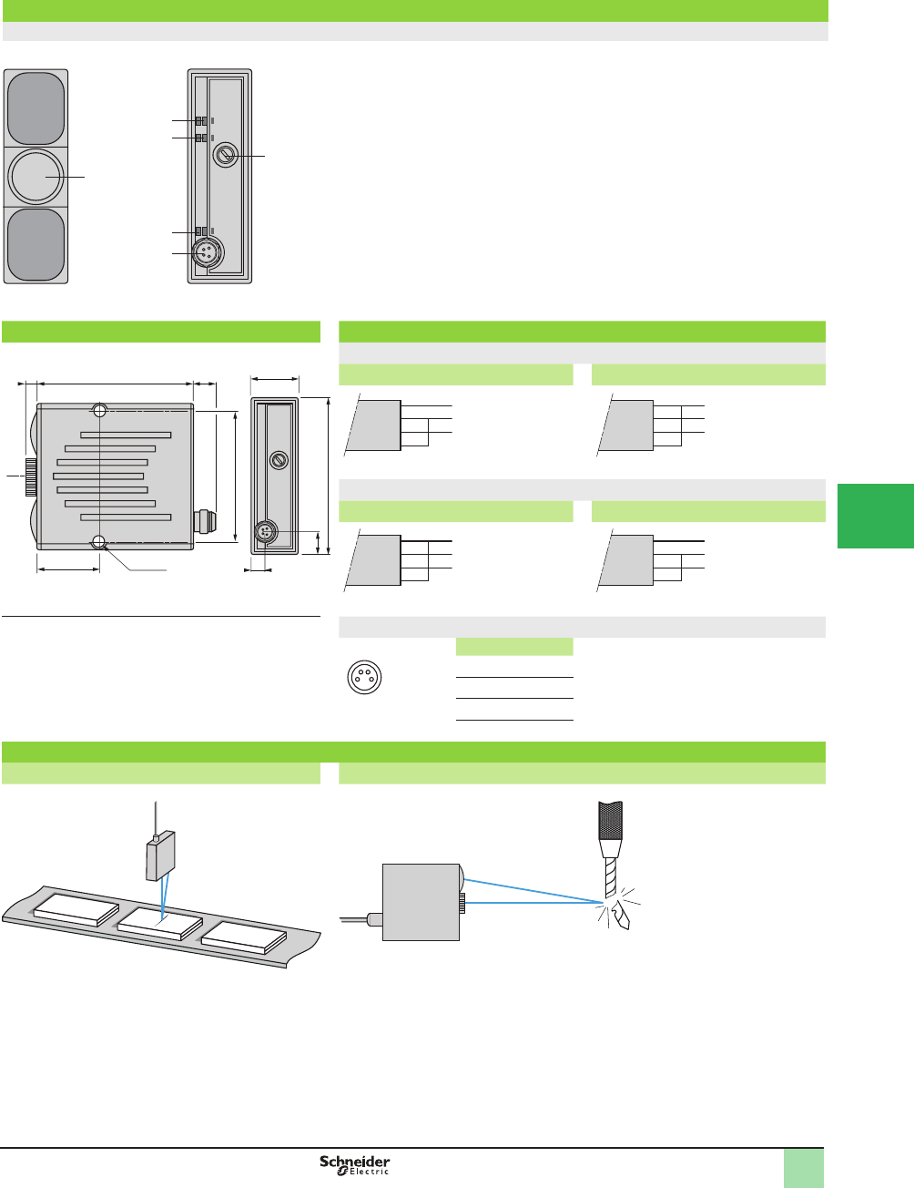
5/83
1
1
2
3
4
5
6
7
8
9
10
Presentation,
Dimensions,
Wiring Diagrams
OsiSense® XU
Photoelectric sensors
Application, material handling series
Diffuse, with laser transmission
With background suppression
DC supply. Solid-state output
Presentation
XUYPS1LCO965S
LO/DO
Timer
6
5
4
3
Output
2
1
Rear view
1
2
3
4
5
6
Adjustment of spot size
Detection distance adjustment screw
M8 connector
On: NO function
Off: NC function
Object detected
Time delay active
Dimensions (mm) Wiring diagrams
18
60
(1)
8
23 2xØ4.1
54
6
60
5
9
NO function
Without time delay With 40 ms time delay
WH
BN
BU
BK
WH
BN
BU
BK
NC function
Without time delay With 40 ms time delay
WH
BN
BU
BK
WH
BN
BU
BK
(1) Optical axis of laser M8 connector
24
1 3
Pin n° - color
1 BN: Brown
2 WH: White
3 BU: Blue
4 BK: Black
Application examples
Monitoring for a crack in a component Monitoring for a broken punch on press tool
+
–
Output
+
–
Output
–
+
Output
–
+
Output
This document provided by Barr-Thorp Electric Co., Inc. 800-473-9123 www.barr-thorp.com
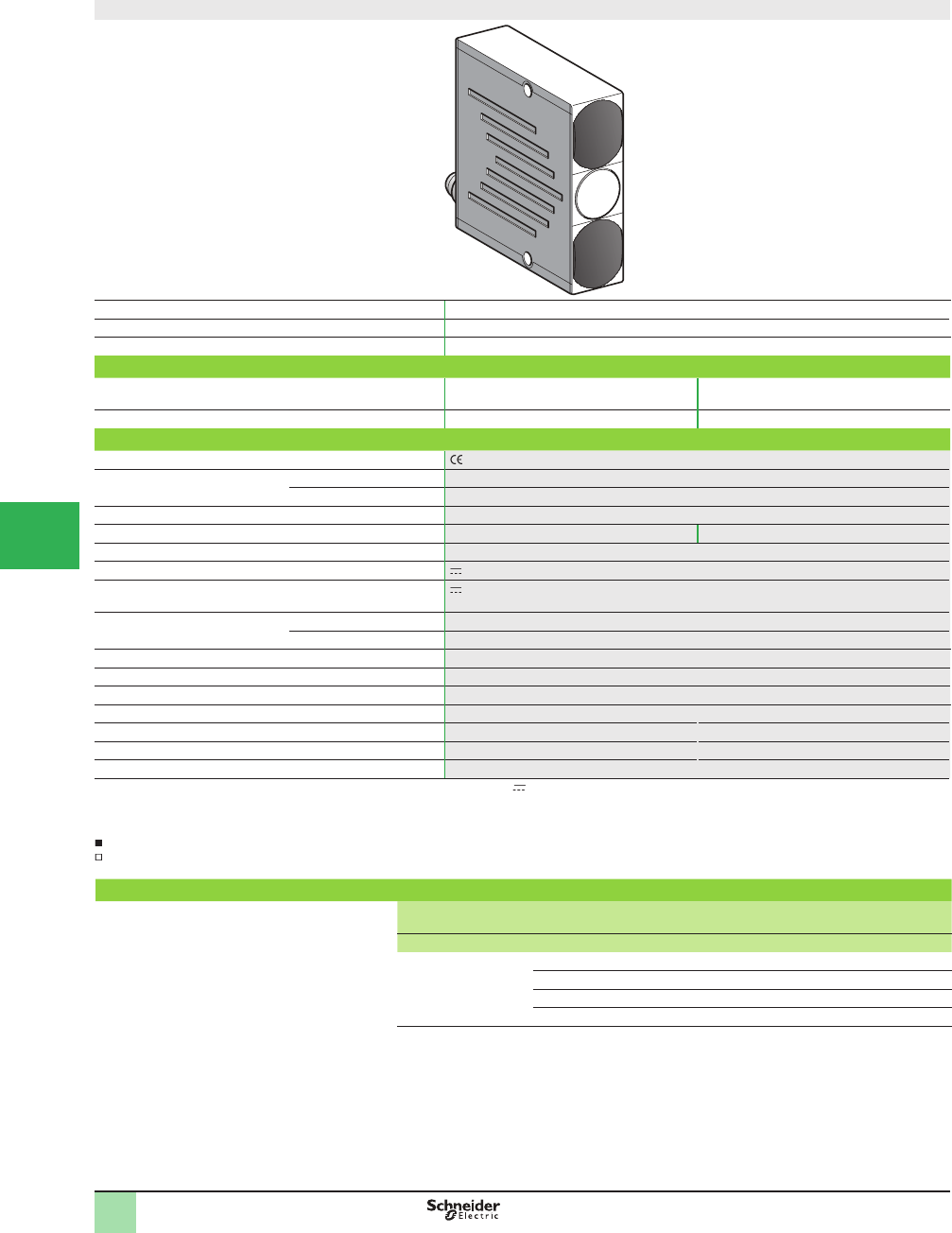
5/84
1
1
2
3
4
5/
6
7
8
9
10
Compact design
System Diffuse with background suppression
Type of transmission Infrared LED, modulated, Ø 15 mm beam
Detection distance, mm (in.) Adjustable from 50 to 600 (1.97 to 23.62)
Catalog Number
4-wire, PNP and NPN output NO/NC programmable
function
XUYPS2945S XUYPS2CO945S
Weight, kg (lb) 0.135 (0.30) 0.055 (0.12)
Specifi cations
Product certifi cations , cULus (1)
Ambient air temperature For operation 0 to +50 °C (+32 to 122 °F)
For storage -20 to +80 °C (-4 to +176 °F)
Degree of protection Conforming to IEC 60529 IP 65
Connection Pre-cabled, length 2 m M8, 4-pin male connector
Materials Case Glass impregnated nylon
Rated supply voltage 12–24 V with protection against reverse polarity
Voltage limits
(including ripple)
10–30 V
Immunity to ambient light Incandescent bulb 1,300 lux
Natural light 10,000 lux
Switching capacity 100 mA with overload and short-circuit protection
Voltage drop, closed state < 2 V
Current consumption, no-load < 1.5 W
Maximum switching frequency 370 Hz
Delay Response and recovery < 1.8 ms
Output signal time delay For A and B/A or B (2) Determined by wiring
Indicator light Output signal Green LED
(1) This product is UL Listed if supplied by a class II or isolated supply delivering 30 V max. (isolated transformer for example) and protected by a UL fuse rated
at 3 A max.
(2) See page 85
Applications:
Control of Þ lling, detection of object on conveyor against reß ective background.
Accessories
Description Details Length
of cable
Catalog Number Weight
m kg (lb)
Pre-wired M8
connector
Straight 2 XZCP0941L2 0.080 (0.18)
Elbowed (90°) 2 XZCP1041L2 0.080 (0.18)
Straight 5 XZCP0941L5 0.180 (0.40)
Elbowed (90°) 5 XZCP1041L5 0.180 (0.40)
Catalog Numbers,
SpeciÞ cations,
Accessories
OsiSense® XU
Photoelectric sensors
Application, material handling series
Diffuse, with 2 channels using triangulation
with background suppression
DC supply. Solid-state output
This document provided by Barr-Thorp Electric Co., Inc. 800-473-9123 www.barr-thorp.com
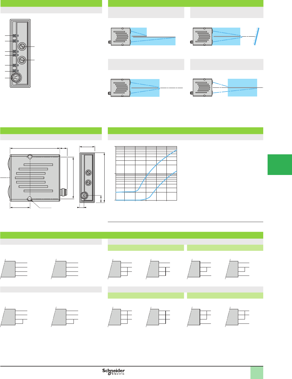
5/85
1
1
2
3
4
5
6
7
8
9
10
Presentation, Description,
Dimensions,
Operating Curves,
Wiring Diagrams
OsiSense® XU
Photoelectric sensors
Application, material handling series
Diffuse, with 2 channels using triangulation
with background suppression
DC supply. Solid-state output
Presentation Description (four operating modes)
XUYPS2945S, XUYPS2CO945S Two independent sensors with
triangulation: A, B
Immunity to refl ection: A and B
Rear view
A
B
A xor B
LO/DO
Timer
A and B
9
1
2
8
7
6
5
4
3
1
2
3
4
5
6
7
8
9
5& 8
Adjustment of zone A detection
distance
Adjustment of zone B detection
distance
Pre-cabled connection
(XUYPS2945S)
or M8 connector
(XUYPS2CO945S)
On in direct mode
Illuminates when the exclusive
OR function between the two
zones A and B is obtained
On when the object is present
in zone B
On when the object is present
in zone A
Illuminates when the AND
object logic function between
the two zones A and B is
obtained
Indicates time delay mode
Simultaneously on when the
OR logic function between the
two zones A or B is obtained
Detection of contrasting objects:
A or B
Monitoring of distance: A xor B
Dimensions (mm) Operating curves (typical)
XUYPS2945S, XUYPS2CO945S XUYPS2945S, XUYPS2CO945S
18
60 8
23 2xØ4.1
54
60
(1)
6
9
50
1
10
100
100 200 300 400 500 600
mm
1 2
1 Black 6%
2 Gray 18% - Distance (mm) set on 92% (Kodak 1527795)
(1) Optical axis.
Wiring diagrams and outputs
Two independent sensors with triangulation: A, B Immunity to refl ection: A and B
Without time delay With 40 ms time delay
NO output NC output NO output NC output NO output NC output
WH
BR
BU
BK
WH
BR
BU
BK
WH
BR
BU
BK
WH
BR
BU
BK
WH
BR
BU
BK
WH
BR
BU
BK
Detection of contrasting objects: A or B Monitoring of distance: A xor B
Without time delay With 40 ms time delay
NO output NC output NO output NC output NO output NC output
WH
BR
BU
BK
WH
BR
BU
BK
WH
BR
BU
BK
WH
BR
BU
BK
WH
BR
BU
BK
WH
BR
BU
BK
BR: Brown
BU: Blue
BK: Black
WH: White
Detected zones Detected zone
Detected zone Detected zone
Mirror
+10/30 V
0 V
Zone A output
Zone B
output
0 V
+10/30 V
Zone A output
Zone B
output
+10/30 V
0 V
Output
0 V
+10/30 V
Output
+10/30 V
0 V
Output
0 V
+10/30 V
Output
+10/30 V
0 V
Output
0 V
+10/30 V
Output
+10/30 V
0 V
Output
0 V
+10/30 V
Output
+10/30 V
0 V
Output
0 V
+10/30 V
Output
This document provided by Barr-Thorp Electric Co., Inc. 800-473-9123 www.barr-thorp.com
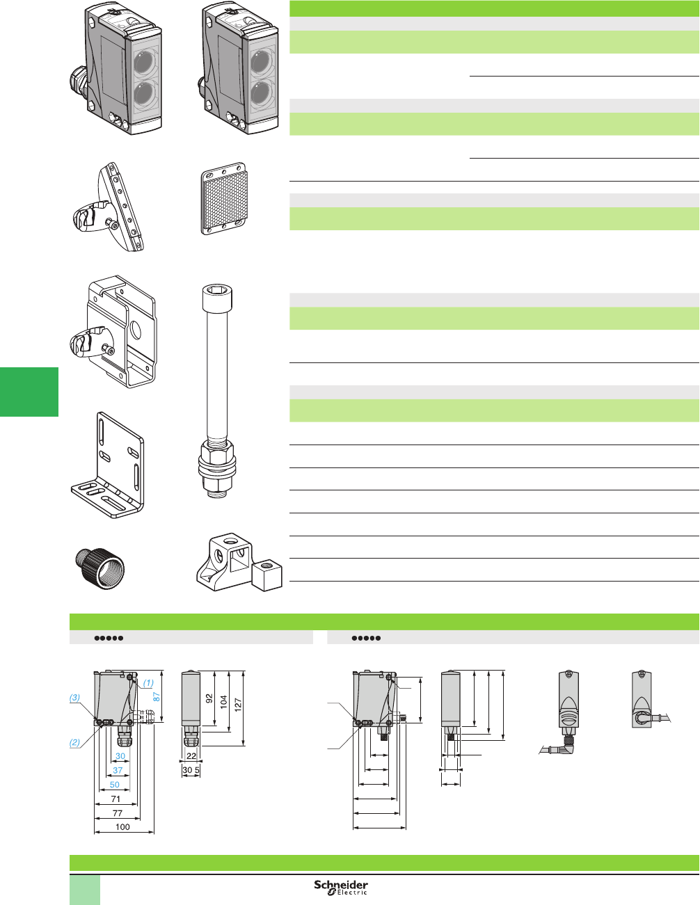
5/86
1
Catalog Numbers
DC
Sensing distance
Sn, m (ft)
Function Output Connection Catalog Number Weight
kg (lb)
0–40 (131.23)
depending on
whether accessories
are used
NO or NC, by
programming
PNP/NPN Screw terminals, ISO
16 cable gland (2)
XUX0AKSAT16 0.200 (0.44)
M12
connector
XUX0AKSAM12 0.200 (0.44)
Accessories
Description Connection Catalog Number Weight
kg (lb)
Transmitter for thru-beam function Screw terminals, ISO
16 cable gland (2)
XUX0AKSAT16T 0.200 (0.44)
M12
connector
XUX0AKSAM12T 0.200 (0.44)
Refl ector 50 x 50 mm – – XUZC50 0.020 (0.44)
AC or DC
Sensing distance
(Sn) m
Function Output Connection Catalog Number Weight
kg (lb)
0–40 (131.23)
depending on
whether accessories
are used
NO or NC, by
programming
Time delay
relay
Screw terminals, ISO
16 cable gland (2)
XUX0ARCTT16 0.200 (0.44)
Accessories
Description Connection Catalog Number Weight
kg (lb)
Transmitter for thru-beam function Screw terminals, ISO
16 cable gland (2)
XUX0ARCTT16T 0.200 (0.44)
Refl ector 50 x 50 mm XUZC50 0.020 (0.44)
Mounting accessories
Description Catalog Number Weight
kg (lb)
3D mounting kit
for use on M12 rod, for XUX or XUZC50
XUZX2003 0.220 (0.49)
3D mounting kit
for use on M12 rod, with protective cover for XUX
XUZX2004 0.420 (0.93)
M12 rod XUZ2001 0.050 (0.11)
Support for M12 rod XUZ2003 0.150 (0.33)
Mounting bracket XUZX2000 0.120 (0.26)
Adapter, ISO 16 - 1/2 NPT XUZX2001 0.050 (0.11)
Adapter, ISO 16 - ISO 20 XUZX2002 0.050 (0.11)
(1) For further information on the multimode function, see page 14 .
(2) For Ø 7 to 10 mm cable.
Dimensions (mm)
XUX T16 XUX M12
Possible orientation of elbowed
connector (rear view)
Specifi cations
XUZ2003
562266
XUX0ARCTT16
562267
XUX0AKSAM12
562068
XUZX2003
562069
XUZX2004
562070 562073
XUZC50
562072
562074
XUZX2001
XUZX2000
XUZ2001
.
M12
92
104
114
21
73
30
37
50
71
77
87
30.5
(3)
(2)
(1)
562071
Catalog Numbers,
Dimensions OsiSense® XU
Photoelectric Sensors 1
Multimode function (1)
Compact design
Five-wire AC or DC, 1 CO relay output
Three-wire DC, solid-state output
1
2
3
4
5/
6
7
8
9
10
This document provided by Barr-Thorp Electric Co., Inc. 800-473-9123 www.barr-thorp.com
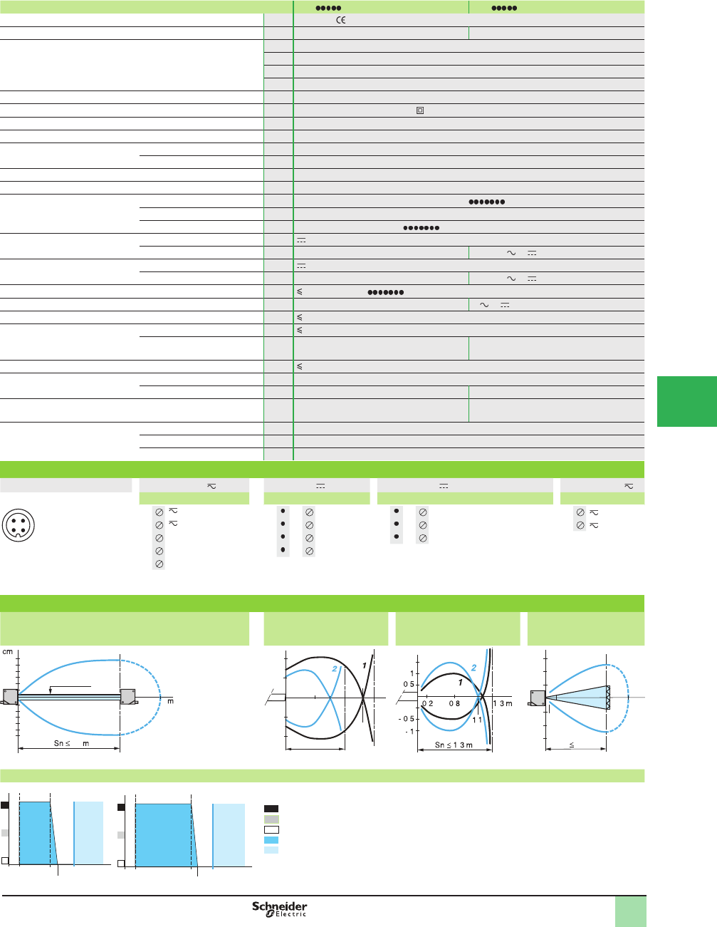
5/87
1
Sensor type XUX M12 XUX T16
Product certifi cations UL, CSA,
Connection M12 connector Screw terminals, ISO 16 cable gland
Sensing distance:
nominal Sn (excess gain = 2)
maximum (excess gain = 1)
m (ft) 1.3 / 1.3 (4.27 / 4.27) without accessory (diffuse with background suppression)
m (ft) 2 / 3 (6.56 / 9.84) without accessory (diffuse)
m (ft) 11 / 15 (36.09 / 49.21) with reß ector (polarized retroreß ective)
m (ft) 40 / 60 (131.23 / 196.85) with transmitter for thru-beam function (thru-beam)
Type of transmission Infrared, except for polarized retroreß ective (red)
Degree of protection Conforming to IEC 60529 IP 65, IP 67, double insulation
Storage temperature °C -40 to +70 (-40 to +158 °F)
Operating temperature °C -25 to +55 (-13 to +131 °F)
Materials Case PBT
Lens PMMA
Vibration resistance Conforming to IEC 60068-2-6 7 gn, amplitude ± 1.5 mm (f = 10 to 55 Hz)
Shock resistance Conforming to IEC 60067-2-27 30 gn, duration 11 ms
Indicator lights Output state Yellow LED (transmission present for XUX0 T)
Supply on Green LED
Stability Red LED (except for XUX0 T)
Rated supply voltage PNP/NPN V12–24 with protection against reverse polarity
Relay output V– 24–240 or
Voltage limits
(including ripple)
PNP/NPN V10–36
Relay output V– 20–264 or
Current consumption, no-load PNP/NPN mA 35 (20 for XUX0 T)
Power consumption Relay output W– 2 or
Alarm output mA 100 with overload and short-circuit protection
Switching capacity PNP/NPN mA 100 with overload and short-circuit protection
Relay output A–500,000 operating cycles
3 A: cos M = 1/0.5 A: cosM = 0.4
Voltage drop, closed state V 1.5
Maximum switching frequency PNP/NPN Hz 240
Relay output Hz – 20
Time delay Relay output s– 0.02–15 on-delay, off-delay, monostable
Delays First-up ms < 200
Response ms < 2 (PNP/NPN); < 25 (relay output)
Recovery ms < 2 (PNP/NPN); < 25 (relay output)
Wiring diagrams
M12 connector Relay output PNP/NPN Transmitter Transmitter
Terminals M12 Terminals M12 Terminals Terminals
11 1 + 1 1 + 1
23 2 - 3 2 - 2
3 NO 4 3 Output 2 3 Beam break input (1)
4 Relay common 2 4 Alarm (1) Input not connected: beam made.
Input connected to –: beam broken.
5 NC
Maximum permissible conductor c.s.a.: 1 x 1.5 mm2 (15 AWG) or 1 x 0.75 mm2 (18 AWG) with
cable end.
Operating curves
With thru-beam accessory (thru-beam) Without accessory (diffuse) Without accessory (diffuse
with background
suppression)
With refl ector (polarized
retrorefl ective)
Object: 10 x 10 cm, 1: white 90%, 2: gray 18% With reß ector XUZC50
Variation of usable sensing distance Su (without accessory, with adjustable background suppression)
Teach mode at minimum. Teach mode at maximum.
A-B: object reß ection coefÞ cient
Black 6%
Gray 18%
White 90%
Sensing range
Non-sensing zone (matte surfaces)
1 2
4 3
40
Ø 8 mm
40
20
40
80
-80
-40
-20 60
20
1
1
2
2.6
2
2
1
3 m
cm
1.5
Sn < 2 m
cm
.
.. .
.
.
.
10
15
-10
0.05
-15
11 15
m
Sn 11 m
cm
A
B
0.45
0.41
0.07 S (m)
0.4
1.35
A
B
1.5
1.3
0.01 S (m)
SpeciÞ cations,
Wiring Diagrams,
Operating Curves
OsiSense® XU
Photoelectric Sensors 1
Multimode function
Compact design
Five-wire AC or DC, 1 CO relay output
Three-wire DC, solid-state output
1
2
3
4
5
6
7
8
9
10
This document provided by Barr-Thorp Electric Co., Inc. 800-473-9123 www.barr-thorp.com
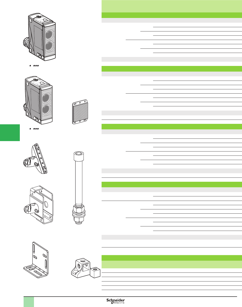
5/88
1
Sensing
distance Sn,
m (ft)
Function Output Connection Catalog Number Weight
kg (lb)
Diffuse system (1)
DC
2.1 (6.89) NO PNP Screw terminals (2) XUX5APANT16 0.200 (0.44)
M12 connector XUX5APANM12 0.200 (0.44)
NPN Screw terminals (2) XUX5ANANT16 0.200 (0.44)
M12 connector XUX5ANANM12 0.200 (0.44)
NC PNP Screw terminals (2) XUX5APBNT16 0.200 (0.44)
M12 connector XUX5APBNM12 0.200 (0.44)
NPN Screw terminals (2) XUX5ANBNT16 0.200 (0.44)
M12 connector XUX5ANBNM12 0.200 (0.44)
AC or DC
2.1 (6.89) NO +NC Relay Screw terminals (2) XUX5ARCNT16 0.200 (0.44)
Polarized retrorefl ective system (1)
DC
11 (36.09) NO PNP Screw terminals (2) XUX9APANT16 0.200 (0.44)
M12 connector XUX9APANM12 0.200 (0.44)
NPN Screw terminals (2) XUX9ANANT16 0.200 (0.44)
M12 connector XUX9ANANM12 0.200 (0.44)
NC PNP Screw terminals (2) XUX9APBNT16 0.200 (0.44)
M12 connector XUX9APBNM12 0.200 (0.44)
NPN Screw terminals (2) XUX9ANBNT16 0.200 (0.44)
M12 connector XUX9ANBNM12 0.200 (0.44)
AC or DC
11 (36.09) NO +NC Relay Screw terminals (2) XUX9ARCNT16 0.200 (0.44)
Refl ector 50 x 50 mm (2) – – XUZC50 0.020 (0.44)
Retrorefl ective system (1)
DC
14 (45.93) NO PNP Screw terminals (2) XUX1APANT16 0.200 (0.44)
M12 connector XUX1APANM12 0.200 (0.44)
NPN Screw terminals (2) XUX1ANANT16 0.200 (0.44)
M12 connector XUX1ANANM12 0.200 (0.44)
NC PNP Screw terminals (2) XUX1APBNT16 0.200 (0.44)
M12 connector XUX1APBNM12 0.200 (0.44)
NPN Screw terminals (2) XUX1ANBNT16 0.200 (0.44)
M12 connector XUX1ANBNM12 0.200 (0.44)
AC or DC
14 (45.93) NO +NC Relay Screw terminals (2) XUX1ARCNT16 0.200 (0.44)
Refl ector 50 x 50 mm (2) – – XUZC50 0.020 (0.44)
Thru-beam system (1)
DC
Transmitter
40 (131.23)
Screw terminals (2) XUX0AKSAT16T 0.200 (0.44)
M12 connector XUX0AKSAM12T 0.200 (0.44)
Receiver
40 (131.23)
NO PNP Screw terminals (2) XUX2APANT16R 0.200 (0.44)
M12 connector XUX2APANM12R 0.200 (0.44)
NPN Screw terminals (2) XUX2ANANT16R 0.200 (0.44)
M12 connector XUX2ANANM12R 0.200 (0.44)
NC PNP Screw terminals (2) XUX2APBNT16R 0.200 (0.44)
M12 connector XUX2APBNM12R 0.200 (0.44)
NPN Screw terminals (2) XUX2ANBNT16R 0.200 (0.44)
M12 connector XUX2ANBNM12R 0.200 (0.44)
AC or DC
Transmitter
40 (131.23)
Screw terminals (2) XUX0ARCTT16T 0.200 (0.44)
Receiver
40 (131.23)
NO +NC Relay Screw terminals (2) XUX2ARCNT16R 0.200 (0.44)
Mounting accessories
Description Catalog Number Weight
kg (lb)
3D mounting kit for use on M12 rod, for XUX or XUZC50 XUZX2003 0.220 (0.49)
3D mounting kit for use on M12 rod, with protective cover for XUX XUZX2004 0.420 (0.93)
M12 rod XUZ2001 0.050 (0.11)
Support for M12 rod XUZ2003 0.150 (0.33)
Mounting bracket XUZ 2000 0.120 (0.26)
(1) With adjustable sensitivity.
(2) Screw terminals with ISO 16 cable gland for cable Ø 7 to 10 mm.
562268
XUX A T16
562269
XUX A M12
562073
562072
562071
562070
562069
XUZC50
XUZX2003
XUZX2004
XUZ2003
XUZX2000
XUZ2001
562068
Catalog Numbers
1
OsiSense®XU
Photoelectric sensors 1
Single mode function
Compact design
Five-wire AC or DC, 1 CO relay output
Three-wire DC, solid-state output
1
2
3
4
5/
6
7
8
9
10
This document provided by Barr-Thorp Electric Co., Inc. 800-473-9123 www.barr-thorp.com
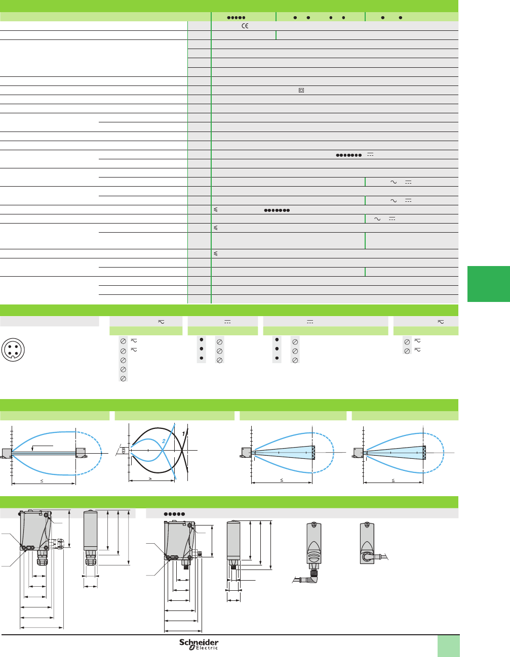
5/89
1
Specifi cations
Sensor type XUX M12 XUX AN NT16, AP NT16 XUX ARC T16
Product certifi cations UL, CSA,
Connection M12 connector Screw terminals, ISO 16 cable gland
Sensing distance:
nominal Sn (excess gain = 2)
maximum (excess gain = 1)
m (ft) 2.1 / 3 (6.89 / 9.84) diffuse with adjustable sensitivity
m (ft) 11 / 15 (36.09 / 49.21) polarized retroreß ective with adjustable sensitivity
m (ft) 14 / 20 (45.93 / 65.62) retroreß ective with adjustable sensitivity
m (ft) 40 / 60 (131.23 / 196.85) thru-beam with adjustable sensitivity
Type of transmission Infrared, except polarized retroreß ective (red)
Degree of protection Conforming to IEC 60529 IP 65, IP 67, double insulation
Storage temperature °C (°F) -40 to +70 (-40 to +158)
Operating temperature °C (°F) -25 to +55 (-13 to 131)
Materials Case PBT
Lens PMMA
Vibration resistance Conforming to IEC 60068-2-6 7 gn, amplitude ± 1.5 mm (f = 10 to 55 Hz)
Shock resistance Conforming to IEC 60068-2-27 30 gn, duration 11 ms
Indicator lights Output state Yellow LED (transmission present for XUX0 T )
Supply on Green LED
Rated supply voltage PNP/NPN V12–24 with protection against reverse polarity
Relay output V– 24–240 or
Voltage limits (including ripple) PNP/NPN V
Relay output V– 20–264 or
Current consumption, no-load PNP/NPN mA 35 (20 for XUX0 T)
Power consumption Relay output W– 2 or
Switching capacity PNP/NPN mA 100 with overload and short-circuit protection
Relay output A–500 000 operating cycles
3 A: cos M = 1/0.5 A: cosM = 0.4
Voltage drop, closed state V 1.5
Maximum switching frequency PNP/NPN Hz 250
Relay output Hz – 20
Delays First-up ms < 15 (PNP/NPN); < 60 (relay output)
Response ms < 2 (PNP/NPN); < 25 (relay output)
Recovery ms < 2 (PNP/NPN); < 25 (relay output)
Wiring diagrams
M12 connector Relay output PNP/NPN Transmitter Transmitter
Terminals M12 Terminals M12 Terminals Terminals
1 1 1 + 1 1 + 1
2 3 2 - 3 2 - 2
3NO 4 3 Output 2 3 Beam break input (1)
4Relay common (1) Input not connected: beam made.
Input connected to –: beam broken.
5NC
Maximum permissible conductor c.s.a.: 1 x 1.5 mm2 (15 AWG) or 1 x 0.75 mm2 (18 AWG) with
cable end..
Operating curves
Thru-beam system Diffuse system Retrorefl ective system Polarized retrorefl ective system
Object 10 x 10 cm; 1White 90%; 2 Gray 18%
With reß ector XUZC50 With reß ector XUZC50
Dimensions (mm)
XUX T16 XUX M12
1 2
4 3
-20
Ø 8 mm
40
20
40
80
-80
-40
60
20 m
cm
Sn 40 m
Sn 2.1 m
-4
-2
2
6
4
0.7 3
cm
m
-6 0.05
2 .10
5
10
15
-5
-10
-15
813 20 m
Sn 14 m
cm
0.05
m
5
10
15
-5
-10
-15
510 15
Sn 11 m
cm
0.05
(1) Elongated hole Ø 5.5 x 7
(2) Elongated hole Ø 5.5 x 9
(3) Ø 5.5 hole
M12
92
104
114
21
73
30
37
50
71
77
87
30.5
(3)
(2)
(1)
Possible orientation of elbowed connector
(rear view)
SpeciÞ cations, Wiring
Diagrams,
Operating Curves,
Dimensions
92
104
127
22
87
30
(3)
(2)
(1)
37
50
71
77
100
5
30,5
30.5
OsiSense®XU
Photoelectric sensors 1
Single mode function
Compact design
Five-wire AC or DC, 1 CO relay output
Three-wire DC, solid-state output
1
2
3
4
5
6
7
8
9
10
This document provided by Barr-Thorp Electric Co., Inc. 800-473-9123 www.barr-thorp.com
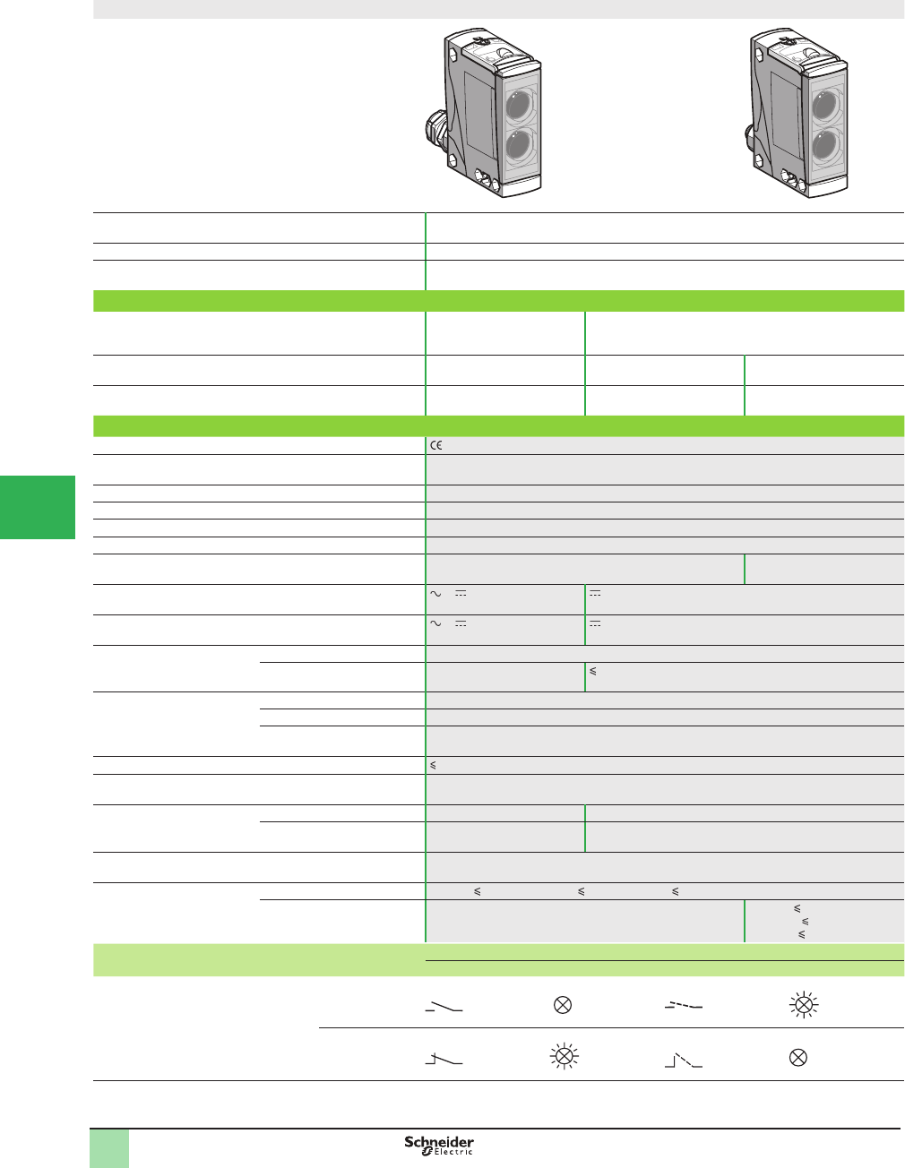
5/90
1
Catalog Numbers,
SpeciÞ cations
Compact design
System Diffuse with adjustable background suppression, long sensing distance with high
accuracy
Type of transmission Infrared
Nominal sensing distance
(Sn), m (ft)
2 (6.56)
Catalog Number
5-wire, AC/DC with terminal
connections and ISO 16 cable
gland
NO or NC programmable
function
XUX8ARCTT16
3-wire, PNP or NPN
programmable
NO or NC programmable
function
XUX8AKSAT16 XUX8AKSAM12
Weight, kg (lb) 0.200 (0.44) 0.200 (0.44) 0.200 (0.44)
Specifi cations
Product certifi cations , UL, CSA
Ambient air temperature For operation: -25 to +55 °C (-13 to +131 °F)
For storage: -40 to +70 °C (-40 to +158 °F)
Vibration resistance Conforming to IEC 60068-2-6 7 gn (f = 10–55 Hz)
Shock resistance Conforming to IEC 60068-2-27 10 gn, duration 11 ms
Degree of protection Conforming to IEC 60529 IP 65, IP 67, double insulation (IP 30 with cover open)
Materials Case: PC, lenses: PMMA
Connection Terminal connections via ISO 16 cable gland
(7 to 10 mm cable)
M12 male connector,
4-pin, can be set at 2 positions
Rated supply voltage or 24–240 V 12–24 V with protection against reverse polarity
Voltage limits or 200–264 V (including
ripple)
10–0.36 V (including ripple)
Switching capacity
(sealed)
Relay output 500,000 operating cycles; 3 A Cos φ = 1; 0.5 A Cos φ = 0.4
PNP/NPN – 100 mA with overload and short-circuit protection
Indicator lights Output state Yellow LED
Supply on Green LED
Instability Red LED
Voltage drop, closed state 1.5 V
Current consumption, no-load 35 mA
Maximum switching
frequency
Relay output 20 Hz –
PNP/NPN – 150 Hz
Time delay Relay output 0.02–15 s monostable, on delay or off-delay
Delays Relay output First-up: 200 ms; response: 25 ms; recovery: 25 ms
PNP/NPN First-up: 200 ms;
response: 3.5 ms;
recovery: 2.5 ms
Function table Function Diffuse system
No object present in the beam Object present in the beam
Output state (PNP or NPN) indicator:
yellow LED (illuminated when sensor
output is ON)
NO
NC
OsiSense® XU
Photoelectric sensors
Materials handling series
With adjustable background suppression
Five-wire AC or DC 1 NC/NO relay output
1
2
3
4
5/
6
7
8
9
10
This document provided by Barr-Thorp Electric Co., Inc. 800-473-9123 www.barr-thorp.com
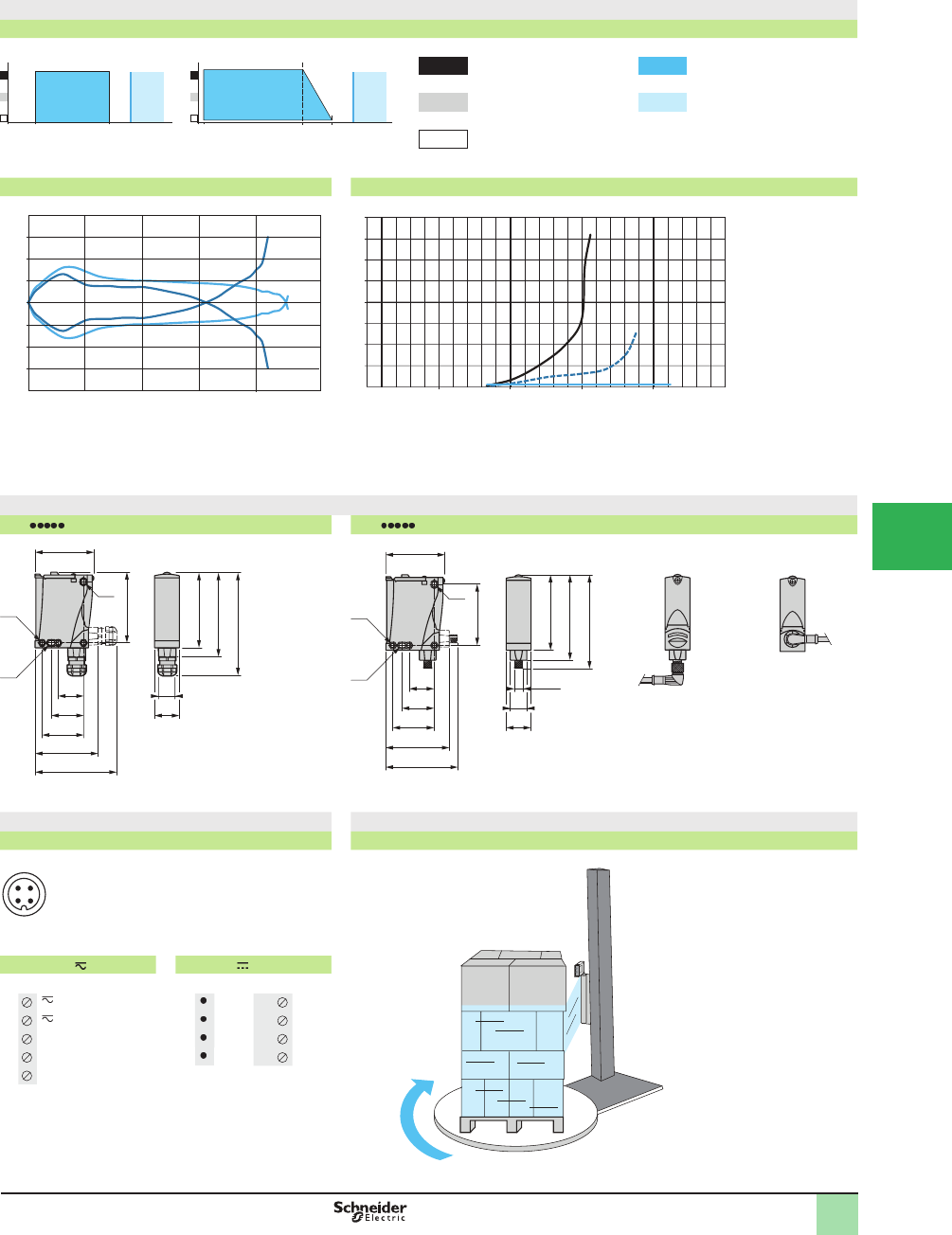
5/91
1
Curves,
dimensions,
Wiring Diagrams
Detection curves
Variation of usable sensing distance Su
Teach mode at minimum Teach mode at maximum A-B: Object reß ection coefÞ cient
A
B
0.15 0.4 0.45 S (m) A
B
0.01 1.5 2 2.3 S (m)
Black 6% Sensing range
Gray 18% Non-sensing zone
(Matte surfaces)
White 90%
Detection curves Relative difference in sensing distances according to object color
Object distance (m)
Detection lobe (cm)
0.00
-1.00
-2.00
-3.00
-4.00
1.00
2.00
3.00
4.00
1
1
2
0.5 22.51.5
Object distance (m)
Relative error (%)
0
0
5
10
15
20
25
30
35
40
0.5 1 1.5 2
1
2
3
2.5
Object: 10 x 10 cm Object: 10 x 10 cm
1
2
white 90%
gray 18%
1
2
3
white 90%
gray 18%
black 6%
Dimensions (mm)
XUX T16 XUX M12
(1) Elongated hole Ø 5.5 x 7
(2) Elongated hole Ø 5.5 x 9
(3) Hole Ø 5.5
92
104
127
22
87
30
(3)
(2)
(1)
37
50
71
77
100
30.5
M12
92
104
114
21
73
30
37
50
71
77
87
30.5
(3)
(2)
(1)
Possible orientation of elbowed
connector (rear view)
Wiring diagrams Typical applications
M12 connector Wrapping system/outer wrapping of pallets
Relay output PNP / NPN
Terminals M12 Terminals
11 1 +
2 3 2 -
3NO 43 output
4Relay common 24 Alarm
inactive
5NC
Maximum permissible conductor c.s.a.: 1 x 1.5 mm2 (15 AWG) or
1 x 0.75 mm2 (18 AWG) with cable end. with cable end.
1 2
4 3
OsiSense® XU
Photoelectric sensors
Materials handling series
With adjustable background suppression
Five-wire AC or DC 1 NC/NO relay output
1
2
3
4
5
6
7
8
9
10
This document provided by Barr-Thorp Electric Co., Inc. 800-473-9123 www.barr-thorp.com
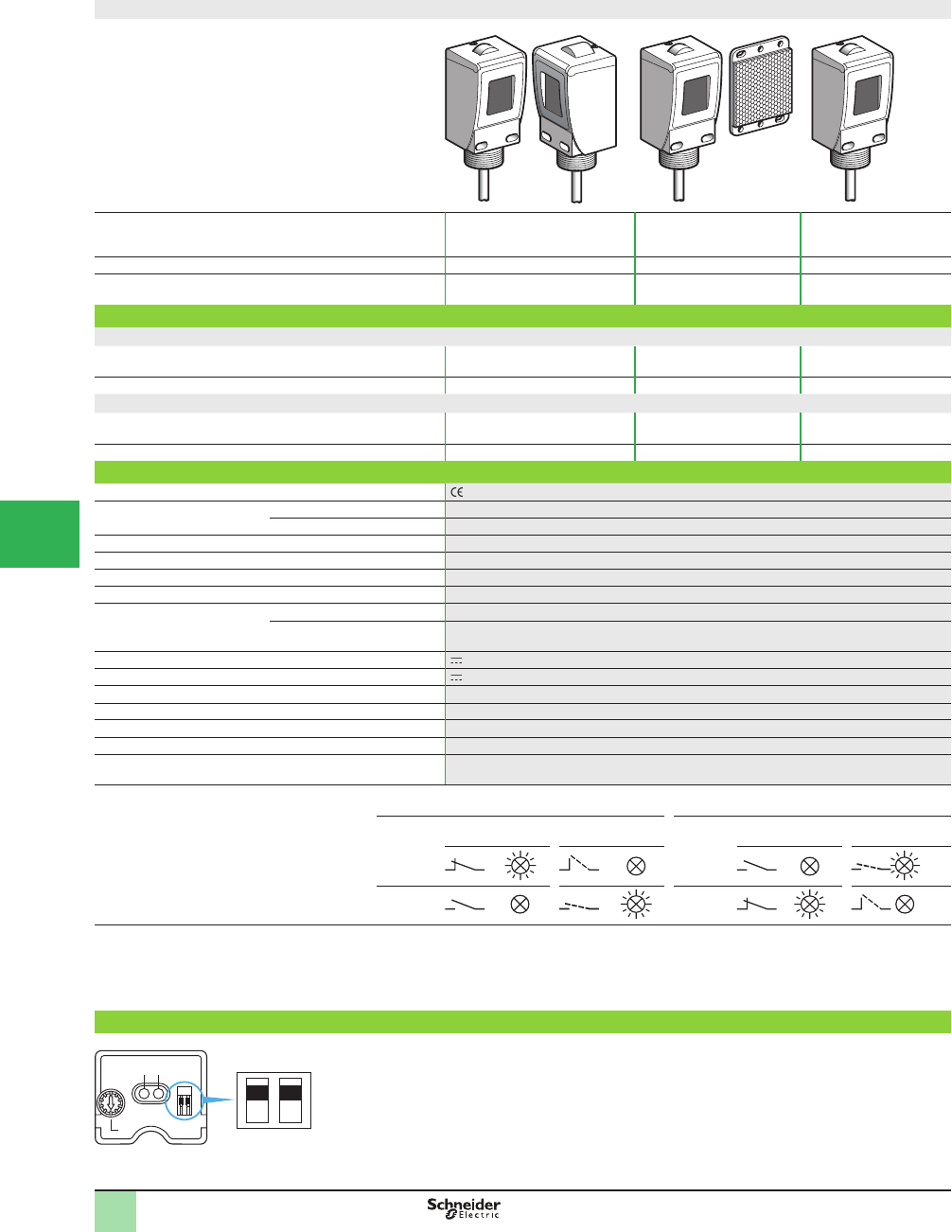
5/92
1
Compact design
System Thru-beam 1Polarized retroreß ective 2Diffuse with background
suppression 3
Type of transmission Infrared Red Infrared
Nominal sensing distance, Sn, m (ft) / maximum 50 (164.04) / 60 (196.85) 6 (19.68) / 9 (29.53)
(with 50 x 50 mm reß ector)
1.2 (3.94) / 1.2 (3.94)
Catalog number of sensors
Pre-cabled versions
3-wire,
PNP or NPN programmable
NO or NC programmable
function XUC2AKSAL2 (2) XUC9AKSAL2 (3) XUC8AKSNL2
Weight, kg (lb) 0.520 (1.15) 0.280 (0.62) 0.260 (0.57)
Connector versions
3-wire,
PNP or NPN programmable
NC or NO programmable
function XUC2AKSAM12 (2) XUC9AKSAM12 (3) XUC8AKSNM12
Weight, kg (lb) 0.400 (0.88) 0.220 (0.49) 0.200 (0.44)
Specifi cations
Product certifi cations , UL, CSA
Ambient air temperature For operation -25 to +55 °C (-13 to +131 °F)
For storage -40 to +70 °C (-40 to +158 °F)
Vibration resistance Conforming to IEC 60068-2-6 7 gn (f = 10–55 Hz)
Shock resistance Conforming to IEC 60068-2-27 20 gn, duration 11 ms
Degree of protection Conforming to IEC 60529 IP 67 (IP 30 with cover open). NEMA 3, 4, 4X, 6, 6P, 12, 13
Materials Case: PC, lenses: PMMA, cable: PvR
Connection Pre-cabled Diameter 6 mm cable, length 2 m (4), wire c.s.a.: 5 x 0.34 mm2 (22 AWG)
Connector M12 male connector, 4-pin (suitable female connectors, including pre-wired versions)
Rated supply voltage 12–24 V with protection against reverse polarity
Voltage limits 10–38 V (including ripple)
Switching capacity (sealed) ≤ 100 mA with overload and short-circuit protection
Voltage drop, closed state ≤ 1.5 V
Current consumption, no-load Thru-beam (transmitter and receiver): ≤ 50 mA, retroreß ective and diffuse: 35 mA
Maximum switching frequency 500 Hz
Delays First-up: ≤ 15 ms; response: ≤ 1 ms; recovery: ≤ 1 ms
Function table Function Thru-beam and retrorefl ective
systems
Function Diffuse
No object present
in the beam
Object present in
the beam
No object present
in the beam
Object present
in the beam
Output state (PNP or NPN) indicator: yellow LED
(illuminated when sensor output is ON)
NC NO
NO NC
(1) Alarm output Only applicable to thru-beam and retroreß ective system sensors.
(2) Catalog number for both transmitter and receiver for thru-beam system sensors.
(3) 50 x 50 mm reß ector included with retroreß ective system sensors.
(4) Sensors available with 5 m cable. To order, change the catalog sufÞ x L2 to L5.
Example: Transmitter +receiver XUC2AKSAL2 with 2 m cable becomes XUC2AKSAL5 with 5 m cable.
Description
Yellow LED, output
Red LED, stability
Sensing distance adjustment potentiometer
NC/NO programming switch
PNP/NPN programming switch
123
PNP
NPN
4 5
1
3
2
Light on
Dark on
Catalog Numbers,
SpeciÞ cations OsiSense® XU
Photoelectric sensors
Single mode function,
Compact, Limit switch body style
DC supply. Solid-state output
With stability LED and alarm output (1)
1
2
3
4
5/
6
7
8
9
10
This document provided by Barr-Thorp Electric Co., Inc. 800-473-9123 www.barr-thorp.com
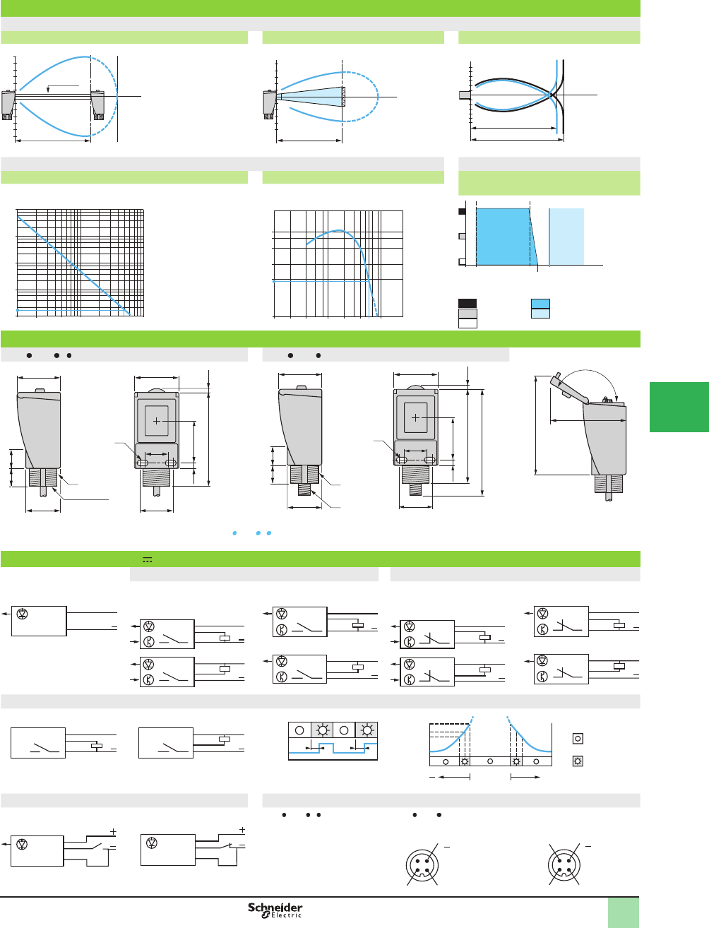
5/93
1
Operating Curves
Detection curves
Thru-beam system Retrorefl ective system Diffuse
Object 20 x 20 cm 1 White 90% 2 Black 6%
Excess gain curves (ambient temperature: +25 °C [77 °F]) Variation of usable sensing distance
Thru-beam system Retrorefl ective system Diffuse with background suppression
A-B: Object reß ection coefÞ cient
Black 6%
Gray 18%
White 90%
Sensing range
Non-sensing zone
Dimensions (mm)
XUC AKS L XUC AKS M12 Side view, cover hinged open
(1) Two elongated holes Ø 5.5 x 11 for mounting by front face (M5 screws included)
(2) M30 x 1.5 threaded boss (and 1/2 NPSM inside for XUC AKS L ), for direct mounting.
Max. tightening torque: 25 N•m. (221.27 lb-in)
(3) M12 connector.
Tightening torque ≤ 2 N•m.
(17.70 lb-in)
Wiring diagrams (3-wire )
NO programmed (no object present) NC programmed (no object present)
Transmitter Thru-beam receiver and
retrorefl ective
PNP output
Diffuse
PNP output
Thru-beam receiver and
retrorefl ective
PNP output
Diffuse
PNP output
NPN output NPN output NPN output NPN output
Alarm output, alarm signal and verifi cation of correct operation (for thru-beam and retroreß ective systems only)
PNP NPN
State 0: output off
State 1: output On
t = 160 ms
Beam break test (for thru-beam transmitter only) Cable connections and connector diagrams (see connections on page)
Beam made Beam broken XUC AKS L XUC AKS M12
(–)
(+)
(OUT)
Alarm
Test
BU (Blue)
BN (Brown)
BK (Black)
WH (White)
VI (Violet)
Thru-beam transmitter Thru-beam receiver,
retroreß ective and diffuse
60
m
60
Ø16 mm
-
60 Sn ≤ 50 m
Ø of beam (cm)
10
5
m9
-5 0.2 6
-
10
Sn 6 m
Ø of beam (cm)
8
4
-4
12
-8
m
1.30
Sn 1.10 m
Sn 1.30 m
Ø of beam (cm)
000
000
10
1
100
D (m)1 105 50 1002
gain
D (m)0.1 0.2 0.4 1 2 4 10
4
0
3
0
2
0
1
0
1
5
6
gain
1.30
A
B
1.50
1.10
0.05 S (m)
44
35
20
(2)
45
23
(1)
34
5.5 43.5
18
3.795.1
1/2" NPSM
44
35
45
23
34
5.5 43.5
3.795.1
(2)
(3)
108
20
18
(1)
80
1
50˚
100
BN/1
BU/3
+
BN/1
BU/3
BK/4
+
BN/1
BK/4
BU/3
+
BN/1
BK/4
BU/3
+
BN/1
BU/3
BK/4
+
BN/1
BU/3
BK/4
+
BN/1
BK/4
BU/3
+
BN/1
BK/4
BU/3
+
BN/1
BU/3
BK/4
+
BN/1
WH/2
BU/3
+
BN/1
BU/3
WH/2
+
t t
A
larm
signal
Red
LED
0.85
1
1.15
+
Single mode
alignment
DEL off
DEL on
Red LED
BN/1
VI/2
BU/3
BN/1
VI/2
BU/3
( )
12
3
(
+
)
4
Test input
12
43
(
+
)
( )
Alarm output
(except diffuse)
Output
Operating Curves,
Dimensions,
Wiring Diagrams
Output
signal
OsiSense® XU
Photoelectric sensors 0
Single mode function,
Compact, Limit switch body style
DC supply. Solid-state output
With stability LED and alarm output (1)
1
2
3
4
5
6
7
8
9
10
This document provided by Barr-Thorp Electric Co., Inc. 800-473-9123 www.barr-thorp.com
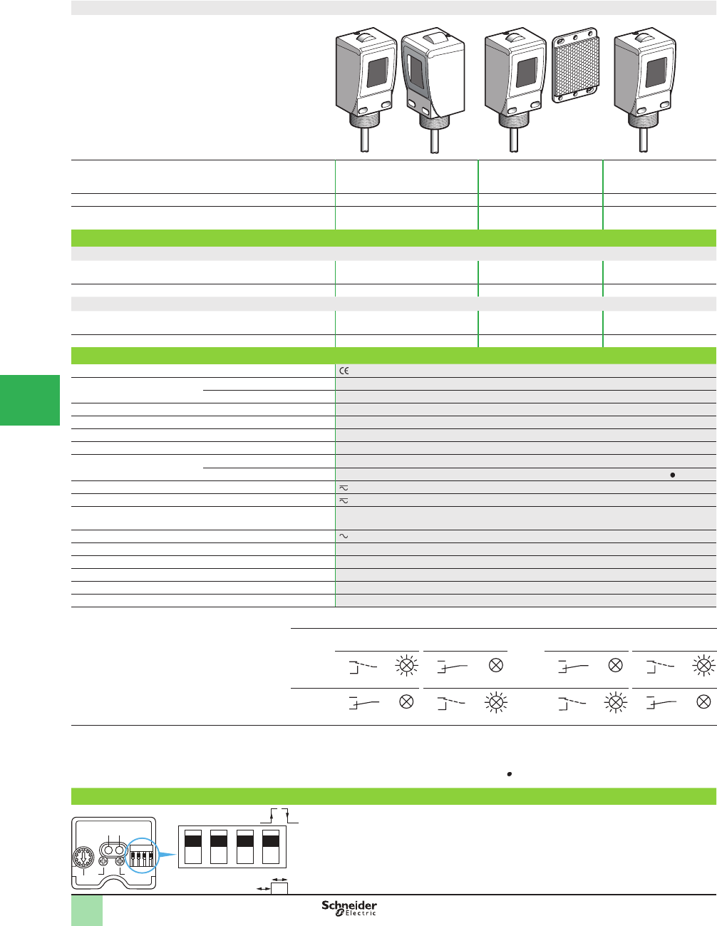
5/94
1
Compact design
System Thru-beam 1Polarized retroreß ective 2Diffuse with background
suppression 3
Type of transmission Infrared Red Infrared
Nominal sensing distance Sn, m (ft) / maximum 50 (164.04) / 60 (196.85) 6 (19.68) / 9 (29.53)
(with 50 x 50 mm reß ector)
1.2 (3.94) / 1.2 (3.94)
Catalog Numbers
Pre-cabled versions
5-wire NO or NC programmable
function XUC2ARCTL2 (1) XUC9ARCTL2 (2) XUC8ARCTL2
Weight, kg (lb) 0.520 (1.15) 0.280 (0.62) 0.260 (0.57)
Connector versions
5-wire NO or NC programmable
function XUC2ARCTU78 (1) XUC9ARCTU78 (2) XUC8ARCTU78
Weight , kg (lb) 0.400 (0.88) 0.220 (0.49) 0.200 (0.44)
Specifi cations
Product certifi cations , UL, CSA
Ambient air temperature For operation -25 to +55 °C (-13 to 131 °F)
For storage -40 to +70 °C (-40 to +158 °F)
Vibration resistance Conforming to IEC 60068-2-6 7 gn (f = 10–55 Hz)
Shock resistance Conforming to IEC 60068-2-27 20 gn, duration 11 ms
Degree of protection Conforming to IEC 60529 IP 67 (IP 30 with cover open). NEMA 3, 4, 4X, 6, 6P, 12, 13
Materials Case: PC, lenses: PMMA, cable: PvR
Connection Pre-cabled Diameter 6 mm cable, length 2 m (3), wire c.s.a.: 5 x 0.34 mm2 (22 AWG)
Connector 7/8-16UN male connector, 5-pin (suitable female pre-wired connectors XZ CP1764L ) (4)
Rated supply voltage 24–240 V
Voltage limits 20–264 V
Switching capacity 3 A (cos M = 1) for a contact life of 0.5 million operating cycles at an operating rate of 1
operating cycle per second, at 250 V
Maximum voltage on output relay contacts 250 V
Power consumption 2 W
Maximum switching frequency 20 Hz
Electrical durability > 5 x 10⁵ operating cycles (cos M = 1)
Time delay Monostable, on-delay or off-delay (programmable). 2 adjustable ranges, covering 0 to 15 seconds
Delays First-up: ≤ 60 ms; response: ≤ 25 ms; recovery: ≤ 25 ms
Function table Function Thru-beam and retrorefl ective systems Func-
tion
Diffuse
No object present in
the beam
Object present in the
beam
No object present in
the beam
Object present in the
beam
Output state of relay contacts indicator: yellow LED
(illuminated when relay energized)
NC NO
NO NC
(1) Catalog number for both transmitter and receiver for thru-beam system sensors.
(2) 50 x 50 mm reß ector included with retroreß ective system sensors.
(3) Sensors available with 5 m cable. To order, change the catalog sufÞ x L2 to L5.
Example: Transmitter +receiver XUC2ARCTL2 with 2 m cable becomes XUC2ARCTL5 with 5 m cable.
(4) To compete the catalog number for a pre-wired female connector with a 2 m, 5 m or 10 m cable, replace the by 2, 5 or 10 respectively. Example, pre-wired
connector with 2 m cable: XZCP1764L2.
Description
LED
1 Yellow LED,
output
2 Red LED, stability
Potentiometers
3 Sensing distance
adjustment
4 T1 time delay
adjustment
5 T2 time delay
adjustment
Switches
6 NC/NO programming
7 T1 setting range
8 T2 setting range
9 Normal time delay (on-delay or
off-delay) or monostable
123
BK
WH GY
Relay energized
BK
WH GY
Relay de-energized
BK
WH GY
Relay de-energized
BK
WH GY
Relay energized
BK
WH GY
Relay de-energized
BK
WH GY
Relay energized
BK
WH GY
Relay energized
BK
WH GY
Relay energized
T1 T2
0–2 s
0–15 s
T1
T2
T1 T2
6 7 8 9
1
354
2
Catalog Numbers,
SpeciÞ cations
OsiSense® XU
Photoelectric sensors 0
Single mode function
Compact, Limit switch body style
AC or DC supply, 1 CO time delay relay output
With stability LED
1
2
3
4
5/
6
7
8
9
10
This document provided by Barr-Thorp Electric Co., Inc. 800-473-9123 www.barr-thorp.com
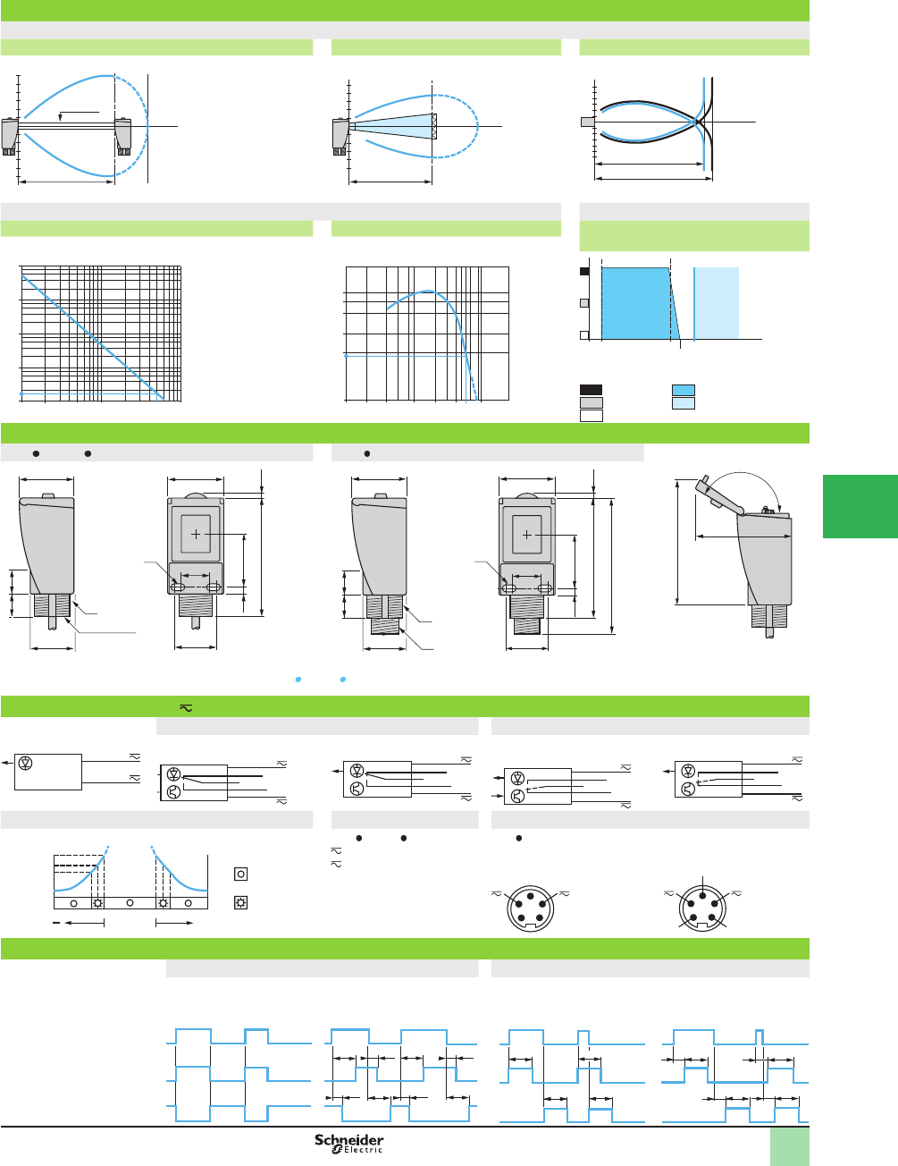
5/95
1
BK/1
BN/4
BU/2
GY/3 WH/5
BK/1
BN/4
BU/2
GY/3 WH/5
Operating Curves
Detection curves
Thru-beam system Retrorefl ective system Diffuse
Object 20 x 20 cm 1 White 90% 2 Black 6%
Excess gain curves (ambient temperature: +25 °C [+77 °F]) Variation of usable sensing distance
Thru-beam system Retrorefl ective system Diffuse with background suppression
A-B: Object reß ection coefÞ cient
Black 6%
Gray 18%
White 90%
Sensing range
Non-sensing zone
Dimensions (mm)
XUC ARCTL XUC ARCTU78 Side view, cover hinged open
(1) 2 elongated holes Ø 5.5 x 11 for mounting by front face (M5 screws included)
(2) M30 x 1.5 threaded boss (and 1/2 NPSM inside for XUC ARCTL ), for direct mounting. Max. tightening torque: 25 N•m.
(221.27 lb-in)
(3) 7/8 connector.
Tightening torque ≤ 3 N•m.
(26.55 lb-in)
Wiring diagrams (5-wire )
NO programmed (no object present) NC programmed (no object present)
Transmitter Thru-beam receiver and
retrorefl ective
Diffuse Thru-beam receiver and
retrorefl ective
Diffuse
Verifi cation of correct operation Cable connections Connector diagram
Thru-beam and retroreß ective
systems
XUC ARCTL XUC ARCTU78
Relay common
NO contact
NC contact
BU (Blue)
BN (Brown)
GY (Gray)
BK (Black)
WH (White)
Thru-beam transmitter Thru-beam receiver,
retroreß ective and diffuse
Time delays
Normal time delay Monostable time delay
T1 = time delay on trip On-delay
T2 = time delay on reset Off-delay
T1 = time delay on trip On-delay
T2 = monostable period
Time delay adjustment T1 = T2 = 0 T1 ≠ 0, T2 z 0 T1 = 0, T2 z 0 T1 z 0, T2 z 0
Receiver state
NC function
NO function
60
m
60
Ø16 mm
-
60 Sn ≤ 50 m
Ø of beam (cm)
10
5
m9
-5 0.2 6
-
10
Sn 6 m
Ø of beam (cm)
8
4
-4
12
-8
m
1.30
Sn 1.10 m
Sn 1.30 m
Ø of beam (cm)
000
000
10
1
100
D (m)
1 105 50 1002
ga
i
n
D (m)0.1 0.2 0.4 1 2 4 10
4
0
3
0
2
0
1
0
1
5
6
ga
i
n
1.30
A
B
1.50
1.10
0.05 S (m)
44
35
45
34
3.795.1
20
18
5.5 43.5
(1)
(2)
1/2" NPSM
23
44
35
45
23
34
3.791.5
(2)
(3)
108
5.5 43.5
20
18
(1)
80
1
50˚
100
BN/4
BU/2
BK/1
BN/4
BU/2
GY/3 WH/5
BK/1
BN/4
BU/2
GY/3 WH/5
0.85
1
1.15
+
Single mode
alignment
DEL off
DEL on
Output
signal
Red LED
5
2
4
3
1
5NC NO
2
4
3
1
Relay common
T1 T1T2 T2
T2 T1 T2 T1
Beam intact
Beam broken
Relay ON
Relay OFF
Relay ON
Relay OFF
T2 T2
T2T T2
T1 T1
T2 T2
T1 T2 T1 T2
Operating Curves,
Dimensions,
Wiring Diagrams
OsiSense® XU
Photoelectric sensors 0
AC or DC supply
1 CO time delay relay output
With stability LED
1
2
3
4
5
6
7
8
9
10
This document provided by Barr-Thorp Electric Co., Inc. 800-473-9123 www.barr-thorp.com
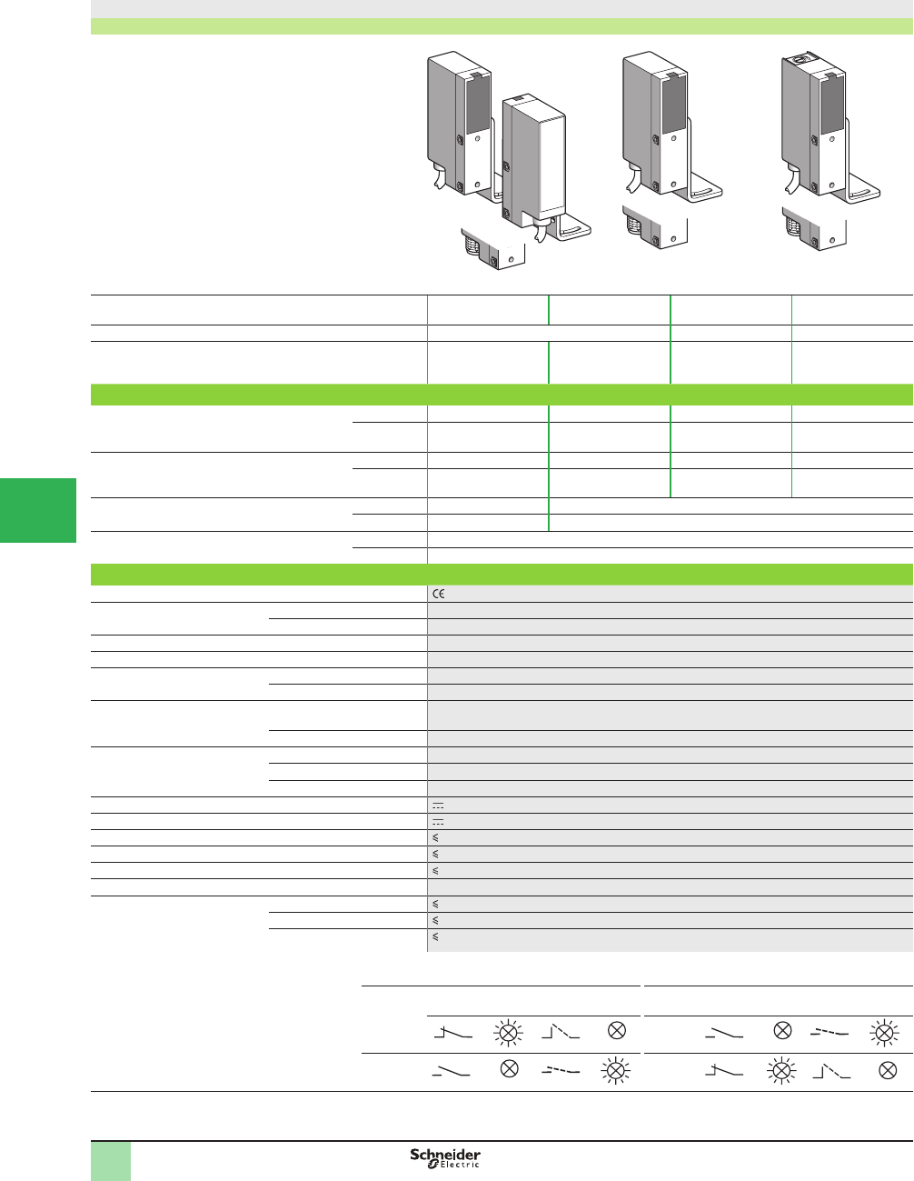
5/96
1
Compact design
Pre-cabled and connector versions
System Thru-beam
1
Retrorefl ective
2
Polarized
retrorefl ective
2
Diffuse 3
Type of transmission Infrared Red Infrared
Nominal sensing distance Sn, m (ft) 8 (26.25) 6 (19.68)
(with Ø 80 mm
reß ector)
4 (13.12)
(with Ø 80 mm
reß ector)
0.7 (2.30)
Catalog Number
3-wire,
PNP
NO or NC
programmable
function
Connection Pre-cabled XULH083534 XULH06353 XULH043539 XULH703535
Connector XULH083534D XULH06353D XULH043539D XULH703535D
3-wire,
NPN
NO or NC
programmable
function
Connection Pre-cabled XULJ083534 XULJ06353 XULJ043539 XULJ703535
Connector XULJ083534D XULJ06353D XULJ043539D XULJ703535D
Transmitter Connection Pre-cabled XULK0830 –
Connector XULK0830D –
Weight, kg (lb) Connection Pre-cabled 0.195 (0.43)
Connector 0.135 (0.30)
Specifi cations
Product certifi cations . Special H7 version: UL, CSA
Ambient air temperature For operation -25 to +55 °C (-13 to +131 °F)
For storage -40 to +70 °C (-40 to +158 F)
Vibration resistance Conforming to IEC 60068-2-6 7 gn, amplitude ± 2 mm (f = 10–55 Hz)
Shock resistance Conforming to IEC 60068-2-27 20 gn, duration 11 ms
Degree of protection Conforming to IEC 60529 IP 67
Conforming to NF C 20-010 IP 671
Connection Pre-cabled Diameter 6 mm, length 2 m (1)
Wire c.s.a.: 4 x 0.34 mm2 (22 AWG) (2 x 0.34 mm2 [22 AWG] for thru-beam transmitter)
Connector M12
Materials Case ABS
Lenses PMMA
Cable PVC
Rated supply voltage 12–24 V with protection against inversion of the 3 wires
Voltage limits 10–30 V (including ripple)
Switching capacity (sealed) 200 mA with overload and short-circuit protection
Voltage drop, closed state 1.5 V
Current consumption, no-load 35 mA
Maximum switching frequency 250 Hz
Delays First-up 15 ms
Response 2 ms
Recovery 2 ms
Function table Function Thru-beam and retrorefl ective
systems
Function Diffuse system
No object present
in the beam
Object present
in the beam
No object present
in the beam
Object present
in the beam
Output state (PNP or NPN) indicator
(illuminated when sensor output is ON)
NC NO
NO NC
(1) For a sensor with a 5 m long cable add L05 to the end of the catalog number; for a 10 m long cable add L10 to the end of the catalog number.
Example: sensor XULH083534 with 5 m cable becomes XULH083534L05
123
Catalog Numbers,
SpeciÞ cations OsiSense® XU
Photoelectric sensors 1
Application, conveying series
Compact design
3-wire DC, solid-state output
1
2
3
4
5/
6
7
8
9
10
This document provided by Barr-Thorp Electric Co., Inc. 800-473-9123 www.barr-thorp.com
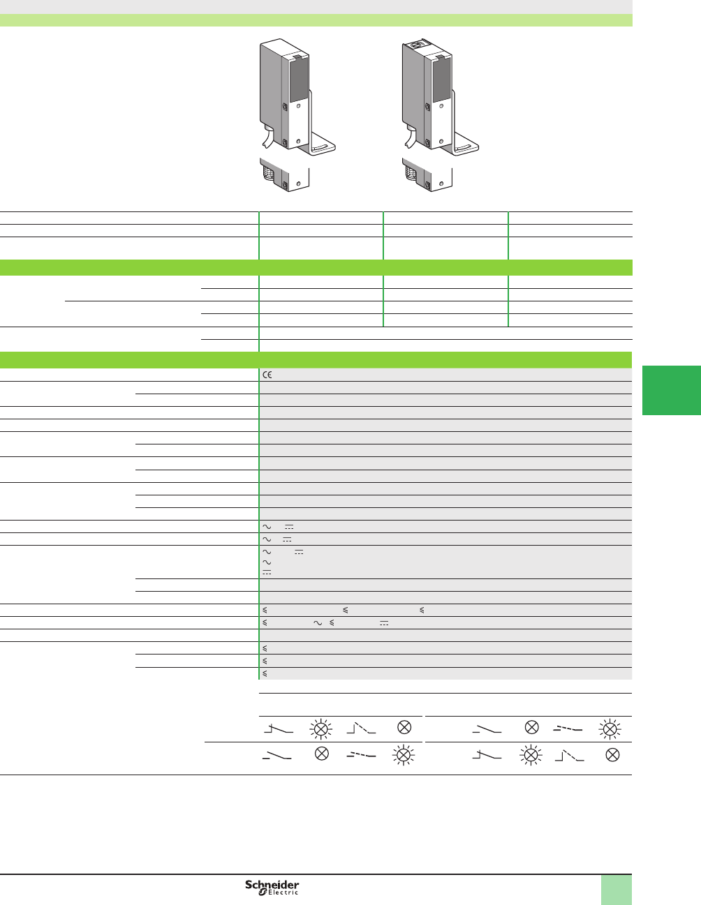
5/97
1
Compact design
Pre-cabled and connector versions
System Retrorefl ective
1
Polarized retrorefl ective
1
Diffuse
2
Type of transmission Infrared Red Infrared
Nominal sensing distance Sn, m (ft) 6 (19.68)
(with Ø 80 mm reß ector)
4 (13.12)
(with Ø 80 mm reß ector)
0.7 (2.30)
Catalog Number
2-wire NC
function
Connection Pre-cabled XULA06021 XULA040219 XULA700115
Connector XULA06021K XULA040219K XULA700115K
NO
function
Connection Pre-cabled XULA06011 XULA040119 XULA700215
Connector XULA06011K XULA040119K XULA700215K
Weight, kg (lb) Connection Pre-cabled 0.195 (0.43)
Connector 0.135 (0.30)
Specifi cations
Product certifi cations . Special H7 version: UL, CSA
Ambient air temperature For operation -25 to +60 °C (-13 to 140 °F)
For storage -40 to +80 °C (-40 to +176 °F)
Vibration resistance Conforming to IEC 60068-2-6 7 gn, amplitude ± 2 mm (f = 10–55 Hz)
Shock resistance Conforming to IEC 60068-2-27 20 gn, duration 11 ms
Degree of protection Conforming to IEC 60529 IP 65
Conforming to NF C 20-010 IP 651
Connection Pre-cabled Diameter 6 mm, length 2 m (1), wire c.s.a.: 2 x 0.34 mm2 (22 AWG)
Connector 1/2-20UNF
Materials Case ABS/PC
Lenses PMMA
Cable PVC
Rated supply voltage or 24–240 V
Voltage limits or 20–264 V
Switching capacity (2)
Sealed Maximum
12 or 12 (resistive load): 0.5 A/240 V
140 (inductive load): 0.3 A/240 V
13 (inductive load): 0.1 A/240 V; 0.2 A/110 V; 0.5 A/48 V
Minimum 5 mA
Inrush 3000 mA
Voltage drop, closed state 3 V (I = 0.1–0.5 A); 5.5 V (I = 10 mA); 10 V (I = 5 mA)
Residual current, open state 1.7 mA (on ); 1.5 mA (on )
Maximum switching frequency 20 Hz
Delays First-up 300 ms
Response 20 ms
Recovery 20 ms
Function table Function Retrorefl ective system Function Diffuse system
No object present
in the beam
Object present
in the beam
No object present
in the beam
Object present
in the beam
Output state indicator
(illuminated when sensor output is ON)
NC NO
NO NC
(1) For a sensor with a 5 m long cable add L05 to the end of the catalog number; for a 10 m long cable add L10 to the end of the catalog number.
Example: sensor XULA06021 with 5 m cable becomes XULA06021L05
(2) These sensors do not incorporate overload or short-circuit protection and therefore, a 0.4 A fast-acting fuse must be connected in series with the load.
12
Catalog Numbers,
SpeciÞ cations
OsiSense® XU
Photoelectric sensors 1
Application, conveying series
Compact design
2-wire AC, solid-state output
1
2
3
4
5
6
7
8
9
10
This document provided by Barr-Thorp Electric Co., Inc. 800-473-9123 www.barr-thorp.com
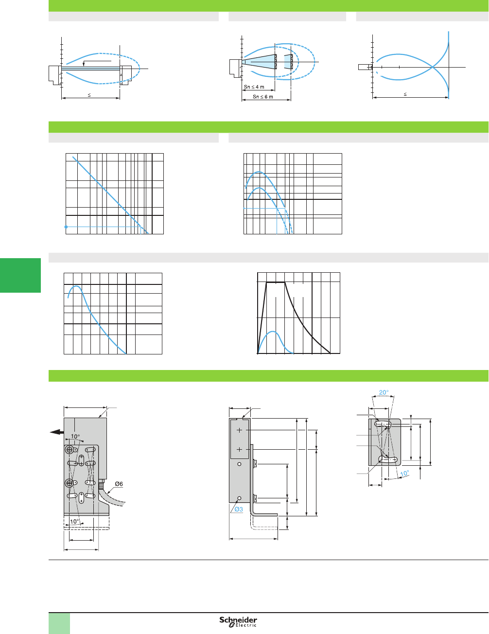
5/98
1
Operating curves
Thru-beam system Retrorefl ective system Diffuse system
Excess gain curves (ambient temperature: +25 °C [+77°F])
Thru-beam system Retrorefl ective system
Diffuse system
Dimensions (mm)
(1) Optical axis
(2) Sensitivity potentiometer (diffuse model)
(3) Output LED indicator
(4) Front mounting (Ø 3 screws and inserts included)
(5) 1 elongated hole Ø 4.1 x 10 and 1 x Ø 4.1
(6) 1 elongated hole Ø 3.1 x 10 and 1 x Ø 3.1
Sn 8 m
10
5
-10
-5
m
Ø 16 mm
Ø of beam
mm
10
5
-10
4
-5
m
0.2 6
(1)
(2)
Ø of beam
cm
(1) Polarized
(2) Infrared
0.3
2
6
-6
-2
10
-10
0.7 m
Sn 0.7 m
8
4
-4
-8
0.1
Ø of beam
mm
Object 20 x 20 cm
White 90%
8
5
6
4
10
0.1
0.2 0.40.6
0.8
123 13
500
100
50
10
5
1
D (m)9
gain
2
D (m)
4 6
2
8
10
20
30
1.5
0.7
1
1
3
7
10
15
25
30
50 1
gain
With reß ector XUZC80
1Infrared
2 Polarized
0
1D (cm)
10
2
3
4
7
10
20 30 40 50 60 70 80
5
gain
Object 20 x 20 cm
White 90 %
0 10 20 30 40 50 60 70 80 D (cm)
1/2
21
ON
(OFF)
OFF
(ON)
Object 20 x 20 cm
1 White 90 %
2 gray 18 %
Min.
Max.
Potentiometer adjustment
(1)
35 (2)
20.6
30
17
(6)
(6)
28
30
(5)
7
4.5
12.5
39
(5)
28 (4)
(3)
18
45
14
70
80
54.5 11
12
R
E
Operating Cur ves,
Dimensions,
Wiring Diagrams
OsiSense® XU
Photoelectric sensors 1
Conveying series
AC and DC supply
Solid-state output
Pre-cabled and connector versions
1
2
3
4
5/
6
7
8
9
10
This document provided by Barr-Thorp Electric Co., Inc. 800-473-9123 www.barr-thorp.com
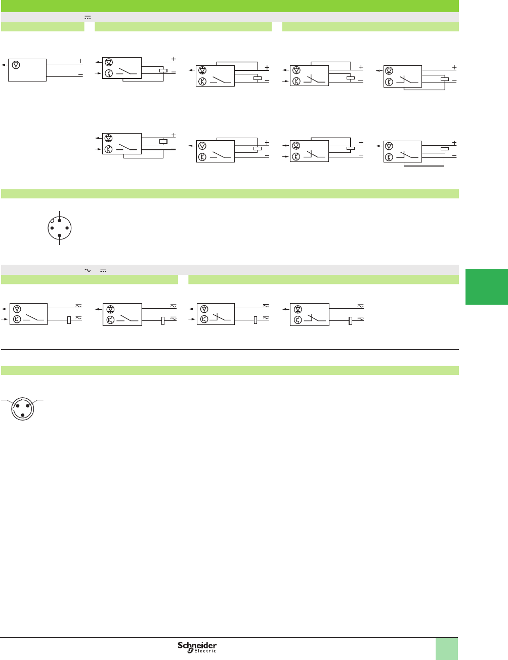
5/99
1
Wiring diagrams
Wiring diagrams (3-wire )
Transmitter NO programmed (no object present) NC programmed (no object present)
Thru-beam receiver and
retrorefl ective
Diffuse Thru-beam receiver and
retrorefl ective
Diffuse
PNP output PNP output PNP output PNP output
NPN output NPN output NPN output NPN output
Connector diagram (sensor connector pin view)
Wiring diagrams (2-wire or )
NO function (no object present) NC function (no object present)
Retrorefl ective Diffuse Retrorefl ective Diffuse
Attention: it is essential to connect a load in series with the sensor
Connector diagram (sensor connector pin view)
Solid-state output (retroreß ective and diffuse system)
BN/1
BU/3
BN/1
BU/3
OG/2
BK/4
OG/2
BN/1
BK/4
BU/3
OG/2
BN/1
BK/4
BU/3
BN/1
BU/3
OG/2
BK/4
BN/1
BU/3
BK/4
OG/2
BN/1
BU/3
BK/4
OG/2
BN/1
BU/3
BK/4
OG/2
BN/1
BU/3
BK/4
OG/2
1 (+)
3 (–)
4
2
Programming Output
BN/2
BU/3
BN/2
BU/3
BN/2
BU/3
BN/2
BU/3
3
2
Operating Cur ves,
Dimensions,
Wiring Diagrams
OsiSense® XU
Photoelectric sensors 1
Application, conveying series
AC and DC supply
Solid-state output
Pre-cabled and connector versions
1
2
3
4
5
6
7
8
9
10
This document provided by Barr-Thorp Electric Co., Inc. 800-473-9123 www.barr-thorp.com
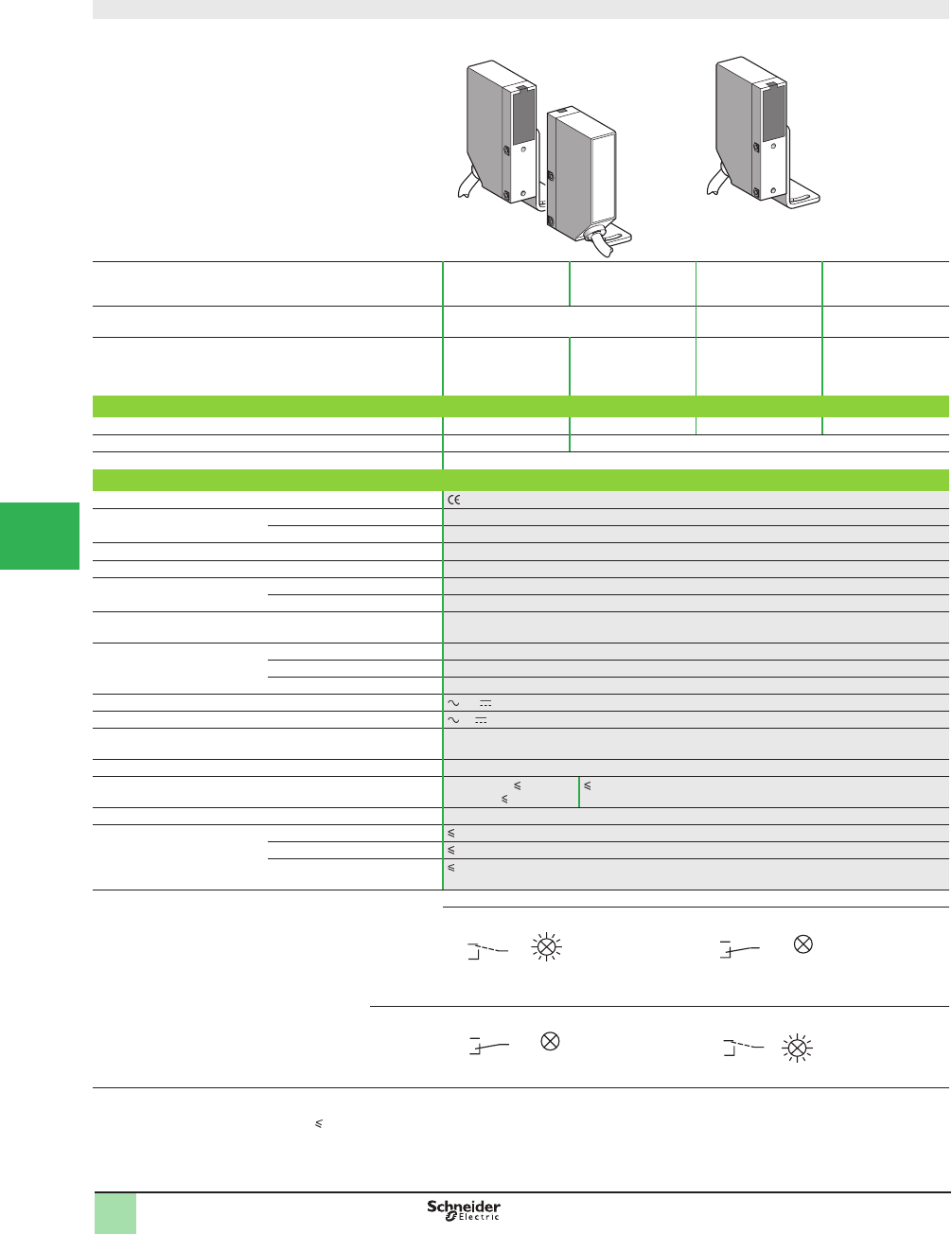
5/100
1
OsiSense® XU
Photoelectric sensors 1
Application, conveying series
Compact design
5-wire AC or DC, 1 CO relay output
Compact design
System Thru-beam
1
Retrorefl ective
2
Polarized
retrorefl ective
2
Diffuse with
background
suppression
2
Type of transmission Infrared Red Infrared
Nominal sensing distance Sn, m (ft) 8 (26.25) 6 (19.68)
(with Ø 80 mm
reß ector)
4 (13.12)
(with Ø 80 mm
reß ector)
0.25 (0.82)
(Þ xed sensing
distance)
Catalog Number
5-wire NC function XULM080314 XULM06031 XULM040319 XULM300318
Transmitter XULM0600 –
Weight, kg (lb) 0.195 (0.43)
Specifi cations
Product certifi cations . Special H7 version: UL, CSA
Ambient air temperature For operation -25 to +55 °C (-13 to +131 °F)
For storage -40 to +70 °C (-40 to +158 °F)
Vibration resistance Conforming to IEC 60068-2-6 7 gn, amplitude ± 2 mm (f = 10–55 Hz)
Shock resistance Conforming to IEC 60068-2-27 20 gn, duration 11 ms
Degree of protection Conforming to IEC 60529 IP 67
Conforming to NF C 20-010 IP 671
Connection Pre-cabled: diameter 6 mm, length 2 m (1), wire c.s.a.: 5 x 0.34 mm2 (22 AWG)
(2 x 0.34 mm2 [22 AWG] for thru-beam transmitter)
Materials Case ABS
Lenses PMMA
Cable PVC
Rated supply voltage or 24–240 V
Voltage limits or 20–264 V
Switching capacity 2000 mA (cos
M
= 1), 500 mA (cos
M
= 0.4) for a contact life of 0.5 million operating cycles at an
operating rate of 1 operating cycle per second, at 250 V
Maximum voltage on output relay contacts 250 V
Current consumption, no-load Transmitter: 5 mA
Receiver: 40 mA (2)
40 mA (2)
Maximum switching frequency 20 Hz
Delays First-up 60 ms
Response 25 ms
Recovery 25 ms
Function table Function Thru-beam and retrorefl ective systems
No object present in the beam Object present in the beam
Output state of relay contact indicator
(illuminated when relay energised)
NC
Function Diffuse system
No object present in the beam Object present in the beam
NO
(1) For a sensor with a 5 m long cable add L05 to the end of the catalog number; for a 10 m long cable add L10 to the end of the catalog number.
Example: sensor XULM080314 with 5 m cable becomes XULM080314L05
(2) No-load current consumption at 220 V: 25 mA
12
BN
OG RD
BN
OG
RD
Relay de-energised
BN
OG
RD
Relay de-energised
BN
OG RD
Relay energised
Catalog Numbers,
SpeciÞ cations
1
2
3
4
5/
6
7
8
9
10
This document provided by Barr-Thorp Electric Co., Inc. 800-473-9123 www.barr-thorp.com
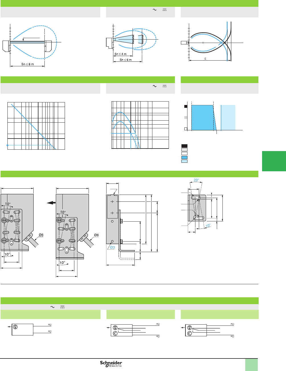
5/101
1
OsiSense® XU
Photoelectric sensors 1
Application, conveying series
Compact design
5-wire AC or DC, 1 CO relay output
Detection curves
Thru-beam system Retrorefl ective system or Diffuse system with background
suppression
Excess gain curves (ambient temperature: +25 °C) Variation of usable sensing distance Su
Thru-beam system Retrorefl ective system or Diffuse system with background
suppression
Dimensions
(1) Optical axis
(2) Output LED indicator
(3) Front mounting (Ø 3 screws and inserts included)
(4) 1 elongated hole Ø 4.1 x 10 and 1 x Ø 4.1
(5) 1 elongated hole Ø 3.1 x 10 and 1 x Ø 3.1
Diagrams
Wiring diagrams (5-wire, or )
1 CO output
Transmitter
NC function (object present)
Thru-beam receiver and retrorefl ective
NO function (no object present)
Diffuse
10
5
-10
-5
m
Ø 16 mm
Ø
o
f
beam
cm
10
5
-10
4
-5
m
0.2 6
(1)
(2)
Ø of beam
cm
(1) Polarized
(2) Infrared
21
0.25
0.1
2
6
-6
-2
10
-10 Sn 0.25 m
m
8
4
-4
-8
0.2
Ø of beam
mm
Object 20 x 20 cm
White 90%
2 black 6 %
8
5
6
4
10
0.1
0.2 0.40.6
0.8
123 13
500
100
50
10
5
1
D (m)9
gain
2
D (m)
4 6
2
8
10
20
30
1.5
0.7
1
1
3
7
10
15
25
30
50 1
gain
With reß ector XUZ C80
1 Polarized
2 Infrared
0.25
A
B
0.35
0.20
0.100.05 S (m)
gain
black 6 %
Gray 18 %
White 90 %
Sensing range
Non-sensing zone
(Matte surfaces)
A-B : Object reß ection coefÞ cient
28 (3)
(2)
18
45
14
70
80
54.5 11
12
R
E
45
20.6
30
45
20.6
30
(1)
17
(6)
(6)
28
30
(5)
7
4.5
12.5
39
(5)
BN
BK
BU
RD OG
BN
BK
BU
RD OG
Operating C urves,
Dimensions,
Wiring Diagrams
BN
BU
1
2
3
4
5
6
7
8
9
10
This document provided by Barr-Thorp Electric Co., Inc. 800-473-9123 www.barr-thorp.com
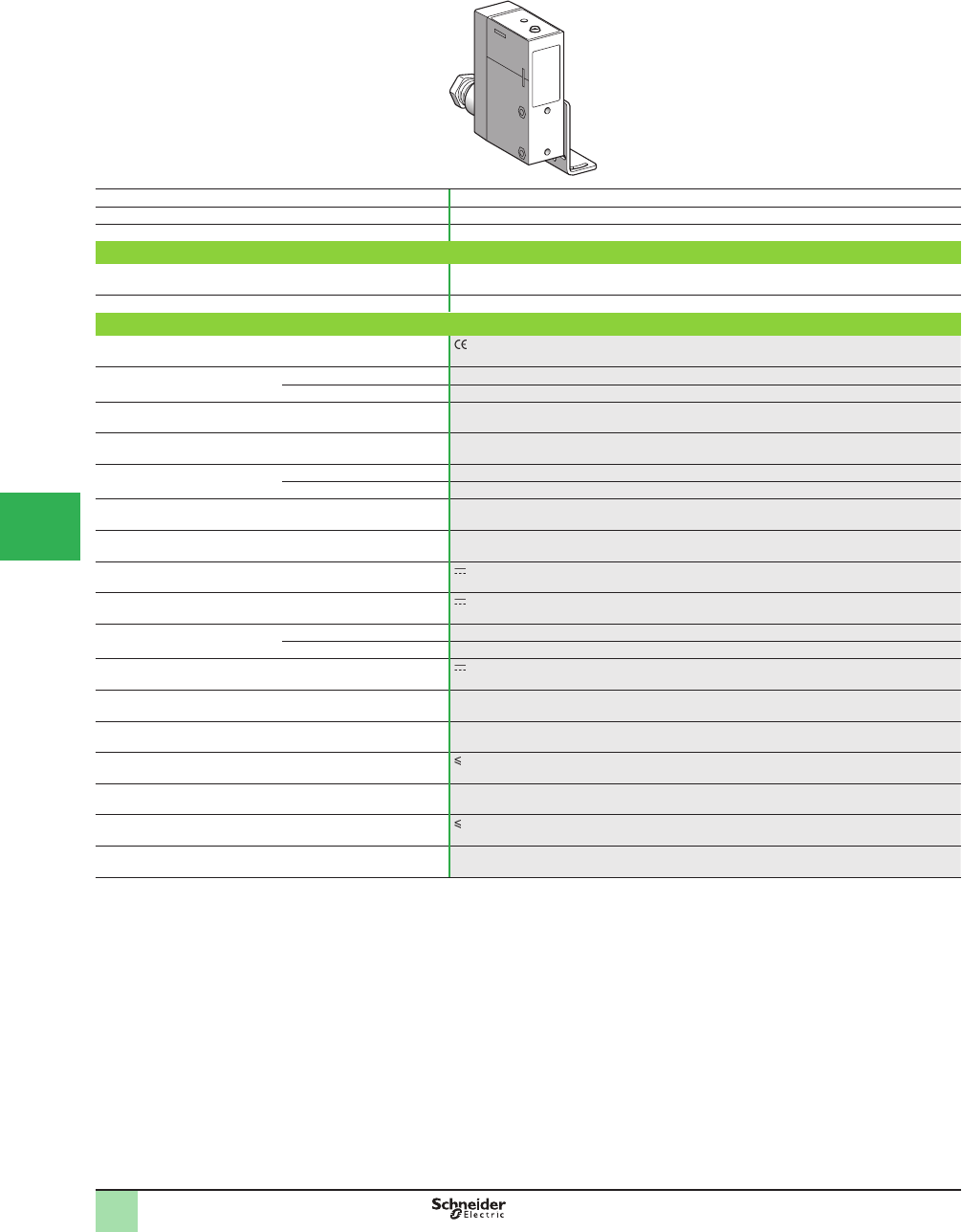
5/102
1
Compact design
System Diffuse
Type of transmission Infrared
Nominal sensing distance Sn, mm (in.) 200–80 (0.79–3.15)
Catalog Number
3-wire PNP XUJK803538
Weight, kg (lb) 0.200 (0.44)
Specifi cation
Product certifi cations , CSA, UL
Ambient air temperature For operation -25 to +60 °C (-13 to +140 °F)
For storage -40 to +80 °C (-40 to +176 °F)
Vibration resistance Conforming to IEC 60068-2-6 7 gn, amplitude ± 1.5 mm (f = 10–55 Hz)
Shock resistance Conforming to IEC 60068-2-27 20 gn, duration 11 ms
Degree of protection Conforming to IEC 60529 IP 67
Conforming to NF C 20-010 IP 671
Connection Screw terminals, maximum capacity: 2 x 1.5 mm2 (15 AWG) or 1 x 2.5 mm2 (13 AWG)
Materials Case: PEI (2)
Rated supply voltage 24 V with protection against reverse polarity
Voltage limits (including ripple) 20–30 V
Output current Maximum 20 mA
Minimum 4 mA
Output voltage (Vs) 0–10 V
Output voltage drift
in relation to temperature
< 10% between -25 and +60 °C (-13 to +140 °F)
Output voltage drift
in relation to object color
< 10%
Current consumption, no-load 35 mA
Maximum switching frequency 10 Hz (for an output voltage variation of 1 V)
Delays First-up 150 ms
Indicator light The brightness of the LED is proportional to the output voltage
(1) Applications: position control, monitoring concentricity or eccentricity, closed loop regulation,
monitoring displacement, etc.
(2) PEI: high quality synthetic resin providing excellent withstand to mechanical shocks, vibration
and the effects of external agents frequently encountered in industry: alcohol, salts,
petroleum, oils, greases, washing agents (diluted sodium carbonate 4%, nitric acid 2%),
formaldehyde vapor, splashing lactic acid, etc.
Catalog Numbers,
SpeciÞ cations
2
OsiSense® XU
Photoelectic Sensors 2
Application, material handling series
With analog output signal 4–20 mA and 0–10 V (1)
DC supply. Solid-state output
1
2
3
4
5/
6
7
8
9
10
This document provided by Barr-Thorp Electric Co., Inc. 800-473-9123 www.barr-thorp.com
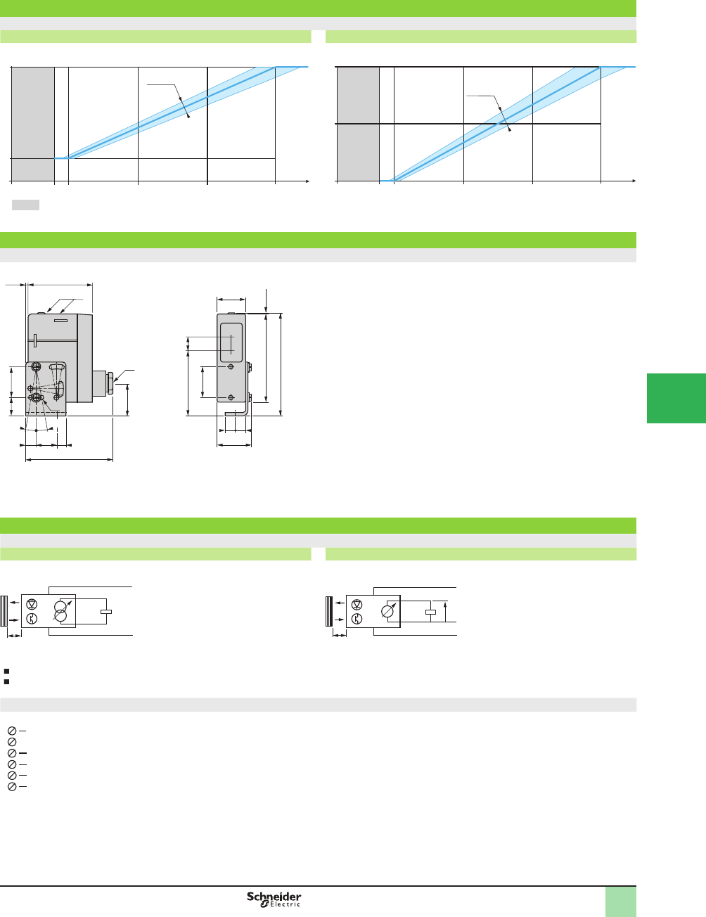
5/103
1
Operating curves
Output signal (related to distance of object). Test performed with 20 x 20 cm, white 90% object
Output current Output voltage
Dimensions (mm)
XUJK803538
(1) LED.
(2) 11P cable gland.
(3) 1 elongated hole Ø 4.2 x 14.
(4) Front mounting (Ø 4 screws and inserts included).
Wiring diagrams
Diffuse system
Current output Voltage output
Load specifi cations
Output current: the output current varies between 4 and 20 mA depending on the distance of the object and therefore, the load must be less than 1 kΩ.
Voltage output: since the minimum rated output current of the sensor is 10 mA, the load must always have a resistive value of more than 1 kΩ
Terminal connections
Terminals 1 and 6 connected internally.
220 40 60 80 D (cm)
0
4
20
mA
15
± 10 %
Blind zone
220 40 60 80 D (cm)
0
5
10
V
15
± 10 %
2.6
30.5
62.5 13
1.35
85
98.85
30
30 (4)
17
61
27.2
32.6
9
10 20
10° 1010
10°
83.6
(1)
(2)
(3)
6
D
3
1
+
–
5
mA
6
Vs
3
1
+
–
4
D
(
–
)
1
2
3
4
5
6
(–)
(+)
Output voltage
Output current
Operating Curves,
Dimensions,
Wiring Diagram,
Connections
2
OsiSense® XU
Photoelectic Sensors 2
Application, material handling series
With analog output signal 4–20 mA and 0–10 V (1)
DC supply. Solid-state output
1
2
3
4
5
6
7
8
9
10
This document provided by Barr-Thorp Electric Co., Inc. 800-473-9123 www.barr-thorp.com
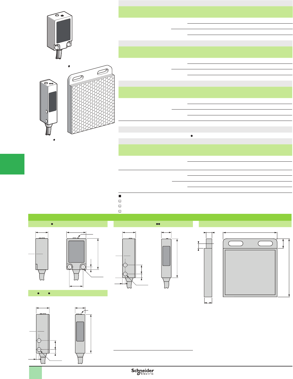
5/104
1
1
2
3
4
5/
6
7
8
9
10
OsiSense® XU
Photoelectric sensors
Application
Conveying and access control series
Miniature design
Four-wire DC, solid-state output
Diffuse system with background suppression
Sensing dist.
Sn, m (ft)
Function Output Connection Catalog Number Weight
kg (lb)
0.015–0.08
(0.05–0.26)
NO/NC
depending
on wiring
PNP Pre-cabled (L = 2 m) XUYPS989SP 0.075 (0.17)
M8 connector XUYPSCO989SP 0.044 (0.10)
NPN Pre-cabled (L = 2 m) XUYPS989SN 0.075 (0.17)
M8 connector XUYPSCO989SN 0.044 (0.10)
Diffuse system with adjustable sensitivity
Sensing dist.
(Sn) m
Function Output Connection Catalog Number Weight
kg (lb)
0.03–0.25
(0.10–0.85)
NO/NC
depending
on wiring
PNP Pre-cabled (L = 2 m) XUYP989SP 0.075 (0.17)
M8 connector XUYPCO989SP 0.044 (0.10)
NPN Pre-cabled (L = 2 m) XUYP989SN 0.075 (0.17)
M8 connector XUYPCO989SN 0.044 (0.10)
Polarized retrorefl ective system
Sensing dist.
(Sn) m
Function Output Connection Catalog Number Weight
kg (lb)
1 (3.28)
with
50 x 50 mm
reß ector
NO/NC
depending
on wiring
PNP Pre-cabled (L = 2 m) XUYB989SP (1) 0.093 (0.21)
M8 connector XUYBCO989SP (1) 0.061 (0.13)
NPN Pre-cabled (L = 2 m) XUYB989SN (1) 0.093 (0.21)
M8 connector XUYBCO989SN (1) 0.061 (0.13)
(1) 50 x 50 mm reß ector (XUY1111) and multi-adjustment mounting bracket included with sensor.
Accessory For use with
Refl ector, 50 x 50 mm XUYB989S XUY1111 0.018
Thru-beam system
Sensing dist.
(Sn) m
Function Output Connection Catalog Number Weight
kg (lb)
4 (13.12)
(Transmitter)
– Pre-cabled (L = 2 m) XUYE989 0.075 (0.17)
M8 connector XUYECO989 0.044 (0.10)
4 (13.12)
(Receiver)
NO/NC
depending
on wiring
PNP Pre-cabled (L = 2 m) XUYR989SP 0.075 (0.17)
M8 connector XUYRCO989SP 0.044 (0.10)
NPN Pre-cabled (L = 2 m) XUYR989SN 0.075 (0.17)
M8 connector XUYRCO989SN 0.044 (0.10)
Applications:
Monitoring position or presence of parts, with background suppression
Detection of height of objects on a conveyor
Detection of product, pellet, powder levels.
Dimensions (mm)
XUYPS989S XUYE989 and XUYR989 XUY1111
13
14.5
2xØ3.1
2.8
20
32
(1)
(2) 13.5 10
2.5
40
3 9.5
2xØ3.1
(1)
8
60
10
506
5
XUY 989S
Transmitter/Receiver
13.5 10
2.5
40
3 9.5
2xØ3.1
(2)
(1)
(1) Optical axis
(2) Accuracy adjustment
XUYPS989S
DF524712
XUYB989S
DF524713
Catalog Numbers,
Dimensions
XUY1111
DF538427
This document provided by Barr-Thorp Electric Co., Inc. 800-473-9123 www.barr-thorp.com
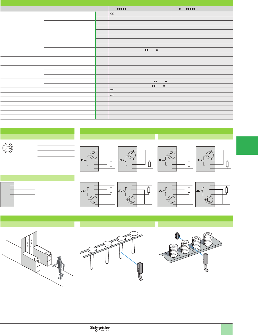
5/105
1
1
2
3
4
5
6
7
8
9
10
SpeciÞ cations,
Wiring Diagrams
OsiSense® XU
Photoelectric sensors
Application
Conveying and access control series
Miniature design
Four-wire DC, solid-state output
Specifi cations
Sensor type XUY XUY CO
Product certifi cations , cULus (1)
Connection Connector – M8, 4-pin, on 0.2 m ß ying lead
Pre-cabled Length: 2 m –
Nominal sensing distance
(Sn)
m (ft) 0.08 (0.26) diffuse with background suppression
m (ft) 0.25 (0.82) diffuse with adjustable sensitivity
m (ft) 1 (3.28) polarized retroreß ective (with 50 x 50 mm reß ector)
m (ft) 4 (13.12) thru-beam
Type of transmission LED Red, pulsed
Modulation frequency 6 kHz (4 kHz for XUYPS 989S )
Degree of protection Conforming to IEC 60529 IP 65 and IP 67
Ambient air temperature For storage °C -20 to +80 (-4 to +176 °F)
For operation °C 0 to +50 (+32 to 122 °F)
Materials Case ABS
Lens PMMA
Cable PVC PUR
Immunity to ambient light Natural light Lux 10,000 (insensitive for XUYPS 989S )
Incandescent bulb Lux 5,000 (insensitive for XUYPS 989S )
Rated supply voltage V 12–24 with protection against reverse polarity
Voltage limits (including ripple) V 10–30
Current consumption, no-load mA < 25
Switching capacity per output mA 100 with overload and short-circuit protection
Voltage drop, closed state V At 100 mA: < 2; at 10 mA: < 1
Maximum switching frequency Hz 500
Delays Response and recovery ms 1
(1) This product is UL Listed if supplied by a class II or isolated supply delivering 30 V max. (isolated transformer for example) and protected by a UL fuse rated
at 3 A max.
Wiring diagram - connector Wiring diagram - pre-cabled
M8 Pin n° - color Diffuse Polarized retrorefl ective and thru-beam
24
1 3
1 BN: Brown PNP output PNP output
2 WH: White
0 V
c 10-30 V
BU
WH
BK
BN
NO
0 V
c 10-30 V
BU
WH
BK
BN
NC
0 V
c 10-30 V
BU
WH
BK
BN
NC
0 V
c 10-30 V
BU
WH
BK
BN
NO
3 BU: Blue
4 BK: Black
Transmitter NPN output NPN output
0 V
Nc
Nc
c 10-30 V
BU
WH
BK
BN Nc: Not connected
0 V
c 10-30 V
BU
WH
BK
BN
NO
0 V
c 10-30 V
BU
WH
BK
BN
NC
0 V
c 10-30 V
BU
WH
BK
BN
NC
0 V
c 10-30 V
BU
WH
BK
BN
NO
Application examples
Access control Monitoring metal rods Detection of tin cans on a conveyor
This document provided by Barr-Thorp Electric Co., Inc. 800-473-9123 www.barr-thorp.com
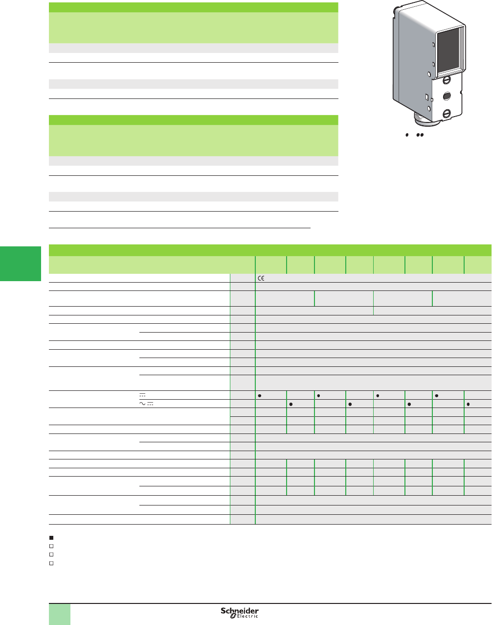
5/106
1
1
2
3
4
5/
6
7
8
9
10
Catalog Numbers,
SpeciÞ cations
OsiSense® XU
Photoelectric sensors
Application
Conveying and access control series
Compact design with teach mode adjustment
Five-wire AC or DC, 1 CO relay output
Three-wire DC, solid-state output
Diffuse system (1)
Sensing
distance
(Sn)
m (ft)
Function Output Catalog Number Weight
kg (lb)
DC
1.5 (4.92) NO/NC programmable PNP/NPN XUYP954S 0.130 (0.29)
4 (13.12) NO/NC programmable PNP/NPN XUYP952S 0.130 (0.29)
AC or DC
1.5 (4.92) NO/NC programmable Relay XUYP954R 0.150 (0.33)
4 (13.12) NO/NC programmable Relay XUYP952R 0.150 (0.33)
Polarized retrorefl ective system (2)
Sensing
distance
(Sn)
m
Function Output Catalog Number Weight
kg (lb)
DC
6 (19.68) NO/NC programmable PNP/NPN XUYB954S 0.130 (0.29)
10 (32.81) NO/NC programmable PNP/NPN XUYB952S 0.130 (0.29)
AC or DC
6 (19.68) NO/NC programmable Relay XUYB954R 0.150 (0.33)
10 (32.81) NO/NC programmable Relay XUYB952R 0.150 (0.33)
(1) On 300 x 300 mm white paper
(2) With Ø 84 mm reß ector
Specifi cations
XUY
P954S
XUY
P954R
XUY
P952S
XUY
P952R
XUY
B954S
XUY
B954R
XUY
B952S
XUY
B952R
Product certifi cations , cULus for XUYP954S/952S and XUYB954S/952S
Connection Screw terminals
Nominal sensing distance (Sn)
Adjustment using teach (Þ ne or standard mode)
m (ft) 1.5 (4.92) 4 (13.12) 6 (19.68) 10 (32.81)
Type of transmission LED Infrared Red
Degree of protection Conforming to IEC 60529 IP 65 and IP 67
Ambient air temperature For storage °C (°F) -20 to +80 (-4 to +176)
For operation °C (°F) 0 to +60 (+32 to 140)
Materials Polycarbonate
Immunity to ambient light Incandescent bulb Lux 10,000 at 5° to the optical axis
Natural light Lux 20,000 at 5° to the optical axis
Indicator lights Green LED Output signal
Red LED Dirty optics, limit of detection, alignment assistance, time delay active, time function
indicator
Voltage limits
(including ripple)
10–30 V – – – –
/ 20–250 V V– – – –
Current consumption, no-load mA 50 – 50 – 50 – 50 –
VA – 2 – 2 – 2 – 2
Type of output PNP/NPN Relay PNP/NPN Relay PNP/NPN Relay PNP/NPN Relay
Switching capacity PNP/NPN mA 100 with overload and short-circuit protection
Relay A 3 (max. continuous)
Voltage drop, closed state PNP/NPN VAt 100 mA: < 2; at 10 mA: < 1
Maximum switching frequency Hz 1000 25 60 25 1000 25 60 25
Delays Response and recovery ms 0.5 20 8 20 0.5 20 8 20
Test input Active V< 1.4 – < 1.4 – < 1.4 – < 1.4 –
Inactive V> 3 – > 3 – > 3 – > 3 –
Output time delay Type Retriggerable: leading edge and/or trailing edge
Duration of each increment ms 0 to 11 s in 23 adjustment increments of 50 ms, then 0.5 s per press
Adjustment Using teach mode and/or Þ ne manual adjustment
Applications
Detection of belt breakage
Material handling
Access control
XUY 95
DF524707
This document provided by Barr-Thorp Electric Co., Inc. 800-473-9123 www.barr-thorp.com
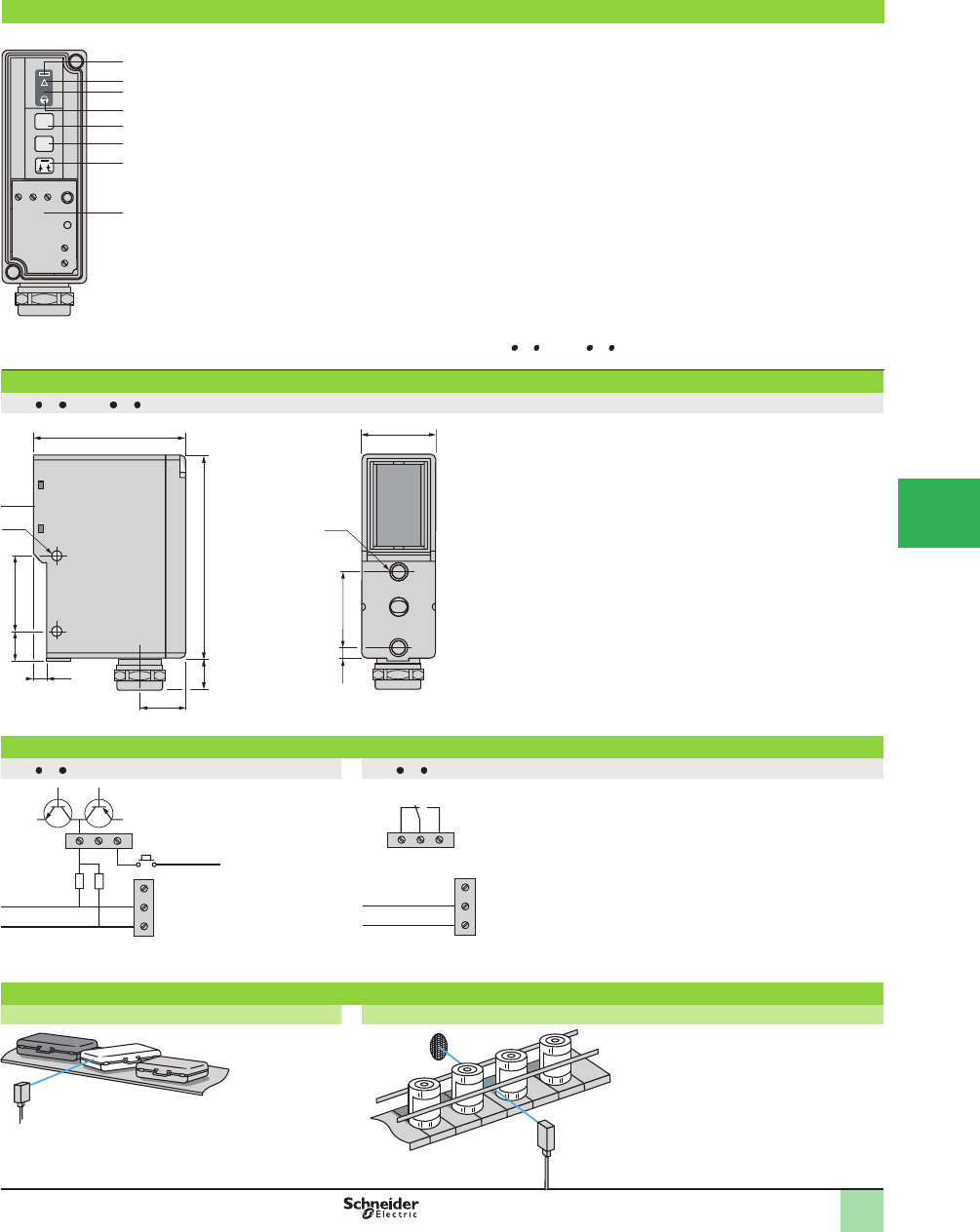
5/107
1
1
2
3
4
5
6
7
8
9
10
Presentation,
Dimensions,
Wiring Diagrams
OsiSense® XU
Photoelectric sensors
Application
Conveying and access control series
Compact design with teach mode adjustment
Five-wire AC or DC, 1 CO relay output
Three-wire DC, solid-state output
Presentation
Rear view
t
SET
t
LO-DO
+
1
2
4
3
5
6
7
8
1
2
3
4
Indicator lights
- Output signal: Green LED
- Dirty optics: Red LED
- Limit of detection: Red LED
- Alignment assistance: ß ashing red
LED
- Activation/adjustment of time delay:
Red LED
- Action keypad
- Keypad: Action/Locking
5
6
7
8
Controls
- Automatic adjustment of threshold
- Access to special functions
- Zero reset of time delay
- Sensitivity increase
- NO/NC programming
- Time delay increase
- Sensitivity decrease
- Inversion of time delay setting:
On-delay, Off-delay
- Time delay decrease
- Access to terminals
Note: Both the red and green LEDs ß ash in the event of a short-circuit on the output (for XUYP 95 S/XUYB 95 S versions).
Dimensions (mm)
XUY 95 S/XUY 95 R
(1) Optical axis.
2xØ4 2xM4
3010.8
30
4.5
(1)
18
60 29
8015
5.5
.
Wiring diagrams
XUY 95 S XUY 95 R
N
c 10/30 V
0 V
0 V
P
250 V, 1.5 mm2 (15 AWG) terminals.
C NONC
a/c 20/250 V
Application examples
Monitoring for blockages on a baggage conveyor Monitoring of gluing, fastening or labelling operations
Test input
Output
Supply
This document provided by Barr-Thorp Electric Co., Inc. 800-473-9123 www.barr-thorp.com
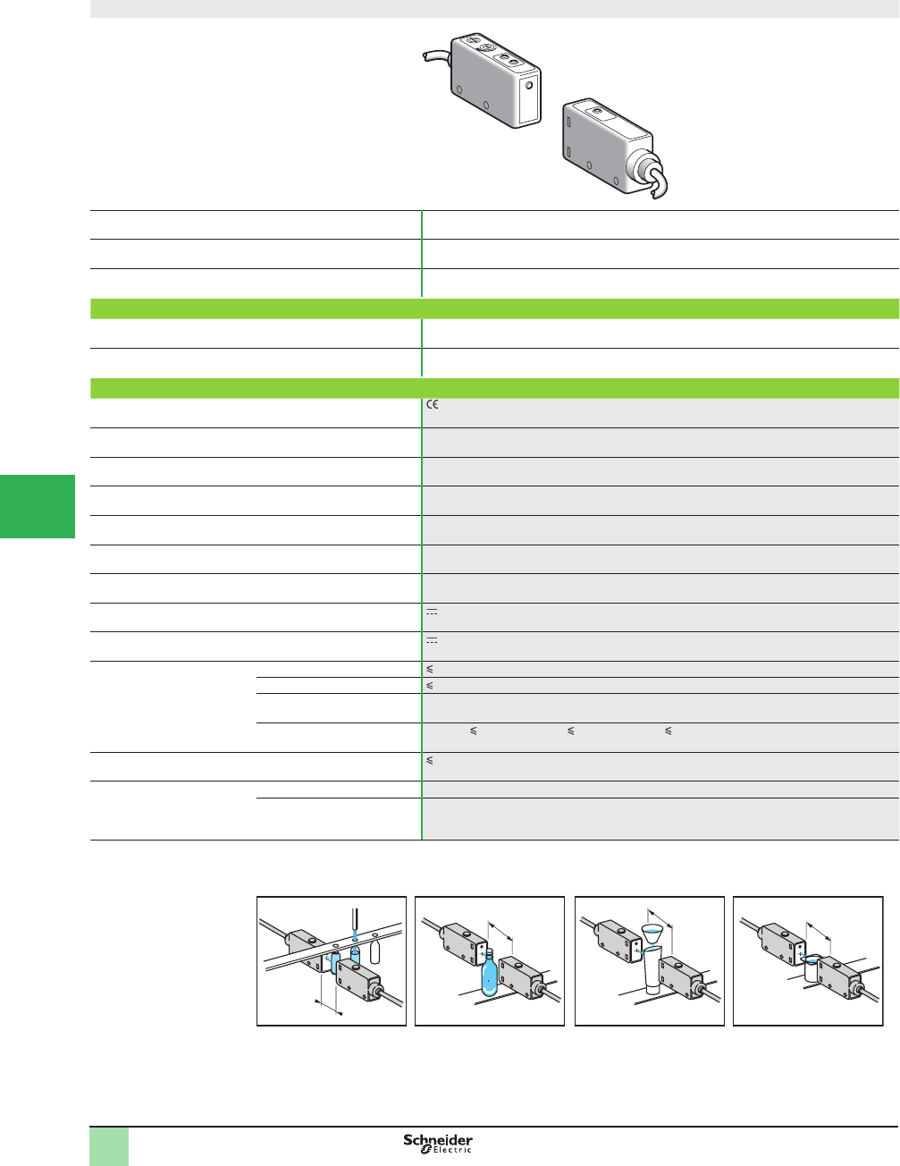
5/108
1
Miniature design
System Thru-beam
Type of transmission Infrared (transmission frequency = 1450 nm)
Nominal sensing distance Sn, m (ft) 50 (164.04) (use between 10 and 20 cm, see applications)
Catalog Number
3-wire, PNP and NPN
NO or NC programmable function
XUMW1KSNL2 (1)
Weight, kg (lb) 0.155 (0.34)
Specifi cations
Product certifi cations
Ambient air temperature For operation: 0 to +40 °C (32 to +104 °F). For storage: -5 to +50 °C (+23 to +122 °F)
Vibration resistance Conforming to IEC 60068-2-6 25 gn, amplitude ± 2 mm (f = 10–55 Hz)
Shock resistance Conforming to IEC 60068-2-27 30 gn, duration 11 ms
Degree of protection Conforming to IEC 60529 IP 65
Connection Pre-cabled, diameter 4 mm, length 2 m, wire c.s.a.: 2 x 0.2 mm2 (24 AWG) (transmitter)
or 4 x 0.2 mm2 (receiver)
Materials Case: PBT, lenses: polycarbonate, cable: PUR
Rated supply voltage 10.8–26.4 V with protection against reverse polarity
Voltage limits 10–30 V (including ripple)
Solid-state digital output Switching capacity (sealed) 100 mA
with overload and short-circuit protection
Voltage drop, closed state 2 V
Maximum switching frequency 1 kHz
Delays First-up: 50 ms; response: 0.5 ms; recovery: 0.5 ms
Current consumption, no-load 45 mA (transmitter +receiver)
Indicator lights Transmitter Green LED, supply on
Receiver Yellow LED: solid-state output (LED on, output On)
Green LED: stability
(1) Catalog number is for both transmitter and receiver for thru-beam system.
(2) Application examples: detection of the level of aqueous liquids in any transparent or almost opaque container, and any product containing water molecules
(adhesives, ice creams, damp fabrics, etc.).
d
d = 10 cm
d
d = 20 cm
d
d = 10 cm
d
d = 5 cm
Transparent containers Almost opaque containers
Catalog Numbers,
SpeciÞ cations
OsiSense® XU
Photoelectric sensors 0
Application, packaging series
Thru-beam system for detection of water
and aqueous liquids
1
2
3
4
5/
6
7
8
9
10
This document provided by Barr-Thorp Electric Co., Inc. 800-473-9123 www.barr-thorp.com
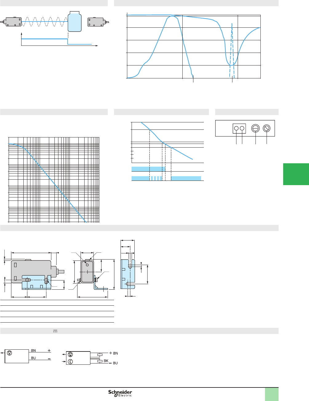
5/109
1
Detection principle Transmission curves
The wave length of the transmitted beam corresponds to the
maximum absorption frequency of water molecules.
1
2
3
Transmission curve of a standard photoelectric sensor
Transmission curve of sensor XUMW1KSNL2
Curve of water absorption against incident beam wave length
Excess gain curve Stability curve Functions
LED
1
2
Yellow LED, output
Green LED, stability
Potentiometer
3Sensitivity adjustment
Switch
4NO/NC programming
NO: detection of object
NC: detection of object absence
Dimensions (mm)
Bracket mounting
(1) Output LED.
(2) Output LED and stability LED.
(3) 2 holes Ø 3.2.
(4) Locknut plate.
Wiring diagrams (3-wire )
Transmitter BK Receiver. PNP output
WH Receiver. NPN output
BN (+)
BU (-)
Beam
intensity
80
100
500
1100
1700
1450
60
40
20
2
0
1
2
1000 1500
3
Transmission wavelength (nm)
Absorption level (%)
10
2
1.25
1
0.75
Off
On
Off
On
Signal
level
Output
Yellow LED
Stability
Green LED
123 4
41
20
(3)
(1)
(4)
(2)
3216
5.6 13
2.5 1.5
10
23
32
11.5
M3
3
15
10
3.2
2
20
WH /
/
Operating Curves,
Dimensions,
Wiring Diagrams
10
50
20
2
10
3
500
200
100
5
2
5
10
4
G
ain
OsiSense® XU
Photoelectric sensors 0
Application, packaging series
Thru-beam system for detection of water
and aqueous liquids
1
2
3
4
5
6
7
8
9
10
This document provided by Barr-Thorp Electric Co., Inc. 800-473-9123 www.barr-thorp.com
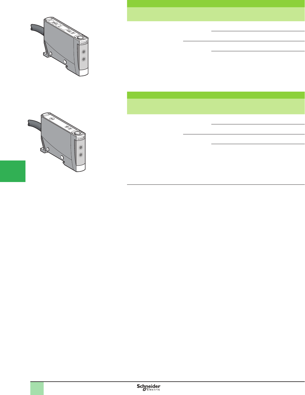
5/110
1
Amplifi ers with fi ne adjustment and 4-digit screen
Sensing
distance (Sn)
m
Function Output Connection Catalog Number Weight
kg (lb)
Depending on
fi ber
NO/NC
Programmable
PNP Pre-cabled XUDA2PSML2 0.040 (0.09)
M8
connector
XUDA2PSMM8 0.040 (0.09)
NPN Pre-cabled XUDA2NSML2 0.040 (0.09)
M8
connector
XUDA2NSMM8 0.040 (0.09)
Amplifi ers using teach mode
Sensing
distance (Sn)
m
Function Output Connection Catalog Number Weight
kg (lb)
Depending on
fi ber
NO/NC
Programmable
PNP Pre-cabled XUDA1PSML2 0.040 (0.09)
M8
connector
XUDA1PSMM8 0.040 (0.09)
NPN Pre-cabled XUDA1NSML2 0.040 (0.09)
M8
connector
XUDA1NSMM8 0.040 (0.09)
+
-
XUDA1
561785
XUDA2
561584
Catalog Numbers OsiSense® XU
Photoelectric sensors 1
Application
Fiber design, ampliÞ ers
Three-wire DC, solid-state output
Teach mode
1
2
3
4
5/
6
7
8
9
10
This document provided by Barr-Thorp Electric Co., Inc. 800-473-9123 www.barr-thorp.com
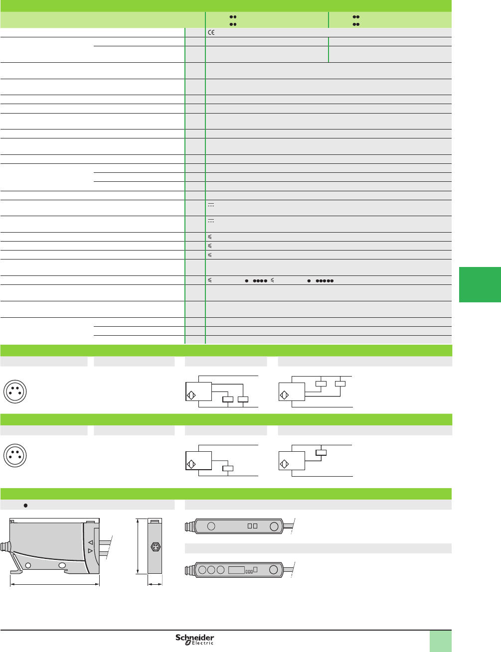
5/111
1
Specifi cations
Sensor type XUDA1 SMM8,
XUDA2 SMM8
XUDA1 SML2,
XUDA2 SML2
Product certifi cations , cULus
Connection Connector M8 –
Pre-cabled – Length: 2 m
Sensing distance (Sn) Depending on fi ber used,. Sensing distance halved for XUDA2 conÞ gured for fast
frequency
Sensitivity adjustment Teach mode on XUDA1,
Teach mode and Þ ne adjustment (± button) plus 4-digit screen on XUDA2
Type of transmission Red
Degree of protection Conforming to IEC 60529 IP 65 with Ø 2 mm Þ ber (IP 64 with Ø 1 mm Þ ber)
Storage temperature °C -30 to +70 (-22 to +158 °F)
Operating temperature °C -10 to +55 (14 to 131 °F)
Vibration resistance Conforming to IEC 60068-2-6 7 gn, amplitude ± 0.5 mm (f = 10 to 55 Hz)
Shock resistance Conforming to IEC 60068-2-27 30 gn, duration 11 ms
Indicator lights Output state Yellow LED
Stability Red LED for XUDA1
Stability Green LED for XUDA2
Signal level By 7 segment/4-digit display for XUDA2
Rated supply voltage V 12–24 with protection against reverse polarity
Voltage limits (including ripple) V 10.8–26.4
Current consumption, no-load mA 50
Switching capacity mA 100 with overload and short-circuit protection
Alarm output mA 50 for XUDA2 with overload and short-circuit protection
Protection against mutual interference Yes for XUDA2
Voltage drop, closed state V 2 for XUDA P , 1 for XUDA N
Maximum switching frequency kHz 1 kHz for XUDA1, 1 or 5 kHz conÞ gurable for XUDA2
Output time delay ms 0 or 40 on recovery for XUDA2
Delays First-up ms < 120
Response ms < 0.5 (0.1 for XUDA2 in fast frequency mode)
Recovery ms < 0.5 (0.1 for XUDA2 in fast frequency mode)
XUDA2 wiring diagrams
M8 connector Pre-cabled PNP NPN
1(+)
3 (-)
4 (OUT/output)
2 (alarm)
BN Brown (+)
BU Blue (-)
BK Black (output)
WH White (alarm)
(WH only on XUDA2)
XUDA1 wiring diagrams
M8 connector Pre-cabled PNP NPN
1(+)
3 (-)
4 (OUT/output)
2
BN Brown (+)
BU Blue (-)
BK Black (Output)
Dimensions (mm)
XUDA XUDA1
XUDA2
24
1 3
–
BN/1
BU/3
+
PNP BK/4 WH/2
BN/1
BU/3
+
–
NPN BK/4 WH/2
24
1 3
–
BN/1
BU/3
+
PNP BK/4
BN/1
BU/3
+
–
NPN BK/4
65 10
40
SET
OUTALM
-+
SET
OUT
H T S
12 34
SpeciÞ cations,
Wiring Diagrams,
Dimensions
OsiSense® XU
Photoelectric sensors 1
Application
Fiber design, ampliÞ ers
Three-wire DC, solid-state output
Teach mode
1
2
3
4
5
6
7
8
9
10
This document provided by Barr-Thorp Electric Co., Inc. 800-473-9123 www.barr-thorp.com
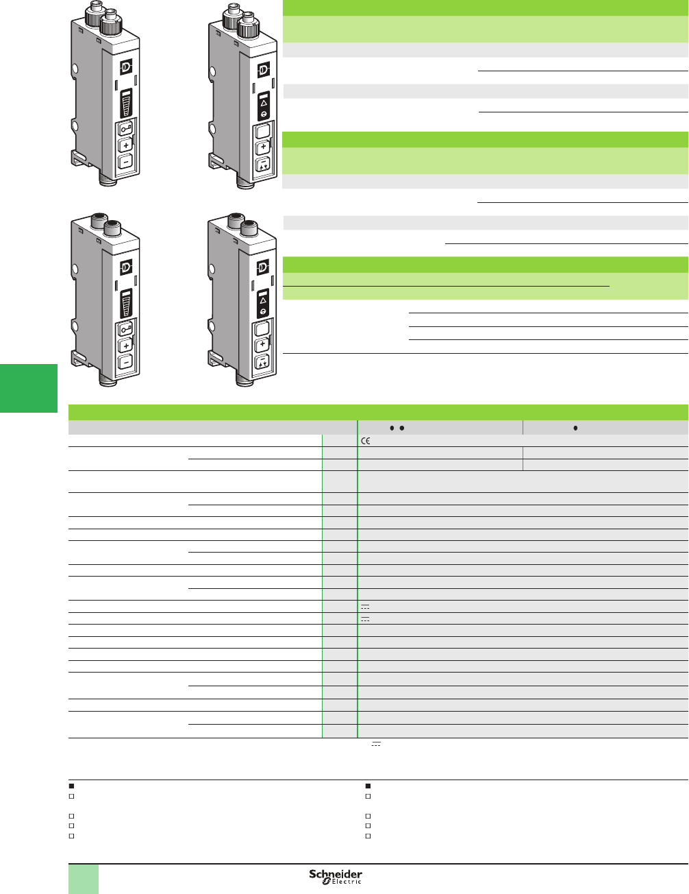
5/112
1
1
2
3
4
5/
6
7
8
9
10
Catalog Numbers,
SpeciÞ cations
OsiSense® XU
Photoelectric sensors
Application
AmpliÞ ers for plastic or glass Þ ber optics
Amplifi ers for plastic fi ber optics (1)
Sensing distance (Sn)
m (ft)
Function Output Connection Catalog Number Weight
kg (lb)
Adjustment using ± button (2)
Depending on fi ber NO/NC
dpg. on wiring
PNP/NPN Pre-cabled XUYAFP966S 0.124 (0.27)
M8 connector XUYAFPCO966S 0.056 (0.12)
Adjustment using teach mode (3)
Depending on fi ber NO/NC
programmable
PNP/NPN Pre-cabled XUYAFP946S 0.124 (0.27)
M8 connector XUYAFPCO946S 0.056 (0.12)
Amplifi ers for glass fi ber optics
Sensing distance (Sn)
m
Function Output Connection Catalog Number Weight
kg (lb)
Adjustment using ± button (2)
Depending on fi ber NO/NC
dpg. on wiring
PNP/NPN Pre-cabled XUYAFV966S 0.116 (0.26)
M8 connector XUYAFVCO966S 0.047 (0.10)
Adjustment using teach mode (3)
Depending
on fi ber
NO/NC
programmable
PNP/NPN Pre-cabled XUYAFV946S 0.124 (0.27)
M8 connector XUYAFVCO946S 0.047 (0.10)
Accessories
Description Details Length of cable Catalog Number Weight
m kg (lb)
Pre-wired M8
connector
Straight 2 XZCP0941L2 0.080 (0.18)
Elbowed (90°) 2 XZCP1041L2 0.080 (0.18)
Straight 5 XZCP0941L5 0.180 (0.40)
Elbowed (90°) 5 XZCP1041L5 0.180 (0.40)
(1) Fiber trimmer included
(2) Indication of level by bargraph, adjustment by pressing button
(3) Fine mode or standard mode, adjustment using teach
Specifi cations
Sensor type XUYAF 9 6S XUYAFCO9 6S
Product certifi cations , cULus (4)
Connection Connector – M8, 4-pin
Pre-cabled Length: 2 m –
Nominal sensing distance
(Sn)
Depending on Þ ber optic used
Type of transmission LED Red LED
Modulation frequency 8 kHz
Sensitivity adjustment Using teach (Þ ne mode or standard mode) and/or ± button, depending on model
Degree of protection Conforming to IEC 60529 IP 65
Ambient air temperature For storage °C (°F) -20 to +80 (-4 to +176)
For operation °C (°F) 0 to +60 (+32 to 140)
Materials Polycarbonate
Immunity to ambient light Incandescent bulb Lux 10,000
Natural light Lux 20,000
Rated supply voltage V 12–24 with protection against reverse polarity
Voltage limits (including ripple) V 10–30
Current consumption, no-load mA < 40
Switching capacity mA 100 with overload and short-circuit protection
Voltage drop, closed state V < 2
Maximum switching frequency kHz < 1
External input (5) Active V< 1.4
Inactive V> 3
Delays Response and recovery ms < 0.5
Output time delay (5) Range s0–5 in 11 adjustment increments
Duration of each increment ms First increment 40 ms then 500 ms for each press
(4) This product is UL Listed if supplied by a class II or isolated supply delivering 30 V max. (isolated transformer for example) and protected by a UL fuse rated
at 3 A max.
(5) Only for models with teach mode.
Applications using plastic fi ber optics
Monitoring position or presence of parts
on an assembly or packing machine
Detection of objects on small conveyor
Use of Þ ber optics in vibratory environments (robot arms)
Detection of reference and color marks in packaging
Applications with glass fi ber optics
Monitoring position or presence of parts
on an assembly or packing machine
Detection of presence of parts in a plastic mould
Detection in aggressive environments
Detection of items exiting an oven (high temperature Þ bers)
SET
t
LO-DO
t
524696
XUYAFP946S
524698
XUYAFP966S
524697
XUYAFV966S
t
SET
t
LO-DO
524699
XUYAFV946S
This document provided by Barr-Thorp Electric Co., Inc. 800-473-9123 www.barr-thorp.com
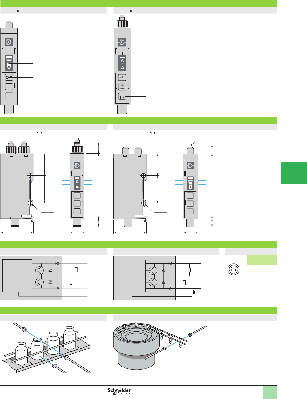
5/113
1
1
2
3
4
5
6
7
8
9
10
Presentation,
Dimensions,
Wiring Diagrams
OsiSense® XU
Photoelectric sensors
Application
AmpliÞ ers for plastic or glass Þ ber optics
Presentation
XUYAF , adjustment using button XUYAF , adjustment using teach mode
1
2
4
5
3
+
1
2
3
4
5
Detection
Indication of the level of
adjustment
Keypad locking
Sensitivity increase
Sensitivity decrease
1
2
4
5
6
7
3
t
1
2
3
4
5
6
7
Detection
Dirty optics, limit of detection, alignment assistance
Time delay active
Action keypad, keypad locking
Automatic adjustment of the threshold, access to special
functions
Sensitivity increase, direct/inverse output, time delay
increase
Sensitivity decrease, On-delay, Off-delay inversion, time
delay decrease
Dimensions (mm)
XUYAFP966S/AFPCO966S XUYAFV966S/AFVCO966S
Mounting on 35 mm rail Mounting on 35 mm rail
(1) Plastic Þ ber optic: Ø 2.2 mm (1) Glass Þ ber optic: Ø 3 mm
Wiring diagrams
XUYAFP966/AFV966 XUYAFP946/AFV946 M8 connector
N
P
BN
BK
BU
WH
c 10/30 V
0 V
N
P
BN
BK
BU
WH
c 10/30 V
0 V
24
1 3
Pin
N°
Color
1 BN Brown
2 WH White
3 BU Blue
4 BK Black
Application examples
Thru-beam and diffuse system detection Thru-beam system detection
2xØ4.1
2025.4
30 13
(1)
60 106.7
SET
2xØ4.1
2025.4
30 13
60
5.5
6.7
SET
(1)
Microprocessor Microprocessor
Remote teaching
If not used: connect to +
Connected to +: direct function
Connected to –: inverse function
This document provided by Barr-Thorp Electric Co., Inc. 800-473-9123 www.barr-thorp.com
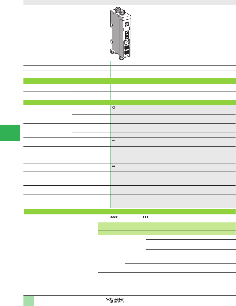
5/114
1
1
2
3
4
5/
6
7
8
9
10
Color mark reading using plastic fi ber optic
Remote reading by coaxial Þ ber optic
System Diffuse
Type of transmission White LED (450 - 650 nm)
Nominal sensing distance Sn, mm (in.) 18 (0.71) with fi ber optic XUYFPDC61/101
4 (0.16) with fi ber optic XUYFPDCM861/M8101
Catalog Numbers
4-wire, PNP/NPN output NO/NC function XUYDCFCO966S (1)
Weight, kg (lb) 0.047 (0.10)
Specifi cations
Product certifi cations
Ambient air temperature For operation 0 to +40 °C (+32 to 104 °F)
For storage -20 to +80 °C (-4 to +175 °F)
Degree of protection Conforming to IEC 60529 IP 65
Connection M8 male connector
Materials Case Polyamide
Lens Polyamide
Rated supply voltage 24 V
Spot diameter 1.5 mm
Modulation frequency 40 kHz
Depth of fi eld FPDC: +7/- 5 mm Black/White, +1/- 3 mm Gray/White
FPDCM8: ± 1 mm
Adjustment By teaching background and mark
Voltage limits
(including ripple)
10–30 V with protection against reverse polarity
Immunity to ambient light Incandescent bulb 10,000 lux
Natural light 20,000 lux
Switching capacity 100 mA with overload and short-circuit protection
Voltage drop, closed state < 2 V
Current consumption, no-load 50 mA
Maximum switching frequency 20 kHz
Delays Response and recovery 25 µs
Output state indication LED
Accessories
(1) Sensor XUYDCFCO966S only operates with Þ bers XUYFPDC and XUYFPDCM8 , to be ordered separately.
Description Details Length
of fi ber
Length
of cable
Catalog Number Weight
mm m kg (lb)
Integrated fi ber
optic
to be ordered at the
same time as the
ampliÞ er
M18 600 – XUYFPDC61 0.100 (0.22)
1000 – XUYFPDC101 0.115 (0.25)
M8 600 – XUYFPDCM861 0.060 (0.13)
1000 – XUYFPDCM8101 0.075 (0.17)
Pre-wired M8
connector
Straight – 2 XZCP0941L2 0.080 (0.18)
Elbowed (90°) – 2 XZCP1041L2 0.080 (0.18)
Straight – 5 XZCP0941L5 0.180 (0.40)
Elbowed (90°) – 5 XZCP1041L5 0.180 (0.40)
Catalog Numbers,
SpeciÞ cations,
Accessories
OsiSense® XU
Photoelectric sensors
Application, packaging series
Color mark readers
With teach mode
DC supply. Solid-state output
This document provided by Barr-Thorp Electric Co., Inc. 800-473-9123 www.barr-thorp.com
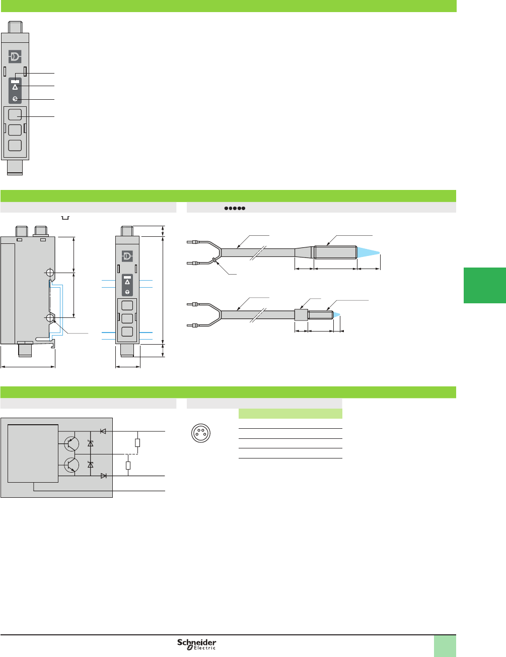
5/115
1
1
2
3
4
5
6
7
8
9
10
Presentation,
Dimensions,
Wiring Diagrams
OsiSense® XU
Photoelectric sensors
Application, packaging series
Color mark readers
With teach mode
DC supply. Solid-state output
Presentation
SET
t
1
2
4
3
1
2
3
4
Detection of the lightest shade
Programming assistance
Alarm/press button
Programming button
Dimensions (mm)
XUYDCFCO966S XUYFPDC
Mounting on 35 mm rail
2xØ4.1
2025.4
30 13
60 57
SET
.
M18x100 (3)Ø8 (2)
18
(1) 40 18
Ø 9
Ø8 (2) M8x100 (3)
10 16 4
(1) The ring indicates that the Þ ber is transmitting.
(2) Bend radius: 15 mm (0.59 in.).
(3) 2 nuts included with Þ ber optic.
Wiring diagram
Cabling M8 connector
Nc
BN
BK
N
P
BU
WH
c 10/30 V
0 V
(1)
24
1 3
Pin n° - color
1 BN: Brown
2 WH: White
3 BU: Blue
4 BK: Black
(1) High level on Þ rst shade taught.
Nc: Not connected
Microprocessor
This document provided by Barr-Thorp Electric Co., Inc. 800-473-9123 www.barr-thorp.com
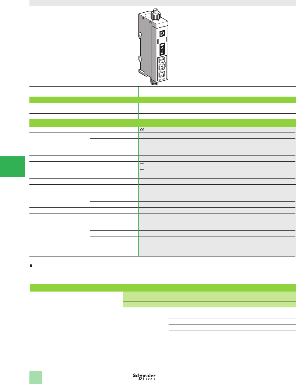
5/116
1
1
2
3
4
5/
6
7
8
9
10
Catalog Numbers,
SpeciÞ cations
OsiSense® XU
Photoelectric sensors
Application, packaging series
Detection of illumination using plastic Þ ber optic
and teach mode
4-wire DC Solid-state output
Fiber design
Nominal sensing distance (Sn) Depending on fi ber optic used
Catalog Number
4-wire, PNP/NPN output NO/NC programmable
function
XUYAFLCO966S
Weight, kg (lb) 0.054 (0.12)
Specifi cations
Product certifi cations
Ambient air temperature For operation 0 to +60 °C (+32 to 140 °F)
For storage 0 to +80 °C (+32 to 176 °F)
Degree of protection Conforming to IEC 60529 IP 65
Connection M8, 4-pin male connector
Materials Case Polycarbonate
Rated supply voltage 12–24 V with protection against reverse polarity
Voltage limits (including ripple) 10–30 V
Switching capacity 100 mA with overload and short-circuit protection
Voltage drop, closed state 2 V
Current consumption, no-load < 40 mA
Maximum switching frequency < 5 Hz
External input Active < 1.4 V
Inactive > 3 V
Delays Response and recovery < 100 ms
Output time delay Range 0–5 s in 11 adjustment increments
Duration of each increment First increment 40 ms then 500 ms for each press
Indicator lights Output signal Green LED
Limit of detection Red LED
Time delay active Red LED
Sensitivity adjustment Using teach (Þ ne mode or standard mode)
Adjustment possible using ± button
Remote teaching using external input (Þ ne mode)
Applications
Verifying operation of indicator lights on electrical appliances
Testing car headlights on production line
Accessories
Description Details Length
of cable
Catalog Number Weight
m kg (lb)
Plastic fi ber optic (1) Ø 2.2 mm 1 XUYA005 0.007 (0.02)
Pre-wired M8 connector Straight 2 XZCP0941L2 0.080 (0.18)
Elbowed (90°) 2 XZCP1041L2 0.080 (0.18)
Straight 5 XZCP0941L5 0.180 (0.40)
Elbowed (90°) 5 XZCP1041L5 0.180 (0.40)
This document provided by Barr-Thorp Electric Co., Inc. 800-473-9123 www.barr-thorp.com
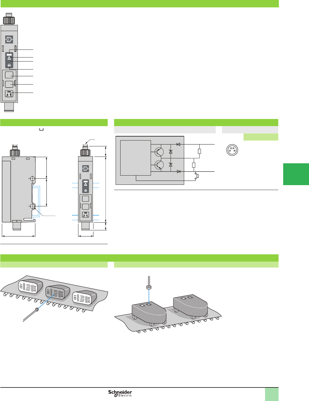
5/117
1
1
2
3
4
5
6
7
8
9
10
Presentation,
Dimensions,
Wiring Diagrams
OsiSense® XU
Photoelectric sensors
Application, packaging series
Detection of illumination using plastic Þ ber optic
and teach mode
4-wire DC Solid-state output
Presentation
LO-DO
+
SET
t
t
1
2
3
5
6
7
4
1
2
3
4
5
6
7
Output signal
Limit of detection
Positioning assistance
Time delay active
Action keypad
Keypad locking
Automatic adjustment of threshold
Access to special functions
Sensitivity increase
NO/NC output
Time delay increase
Sensitivity decrease
On-delay, Off-delay inversion
Time delay decrease
Dimensions (mm) Wiring diagrams
Mounting on 35 mm rail diagram M8 connector
+
t
2xØ4.1
2025.4
30 13
60
6.7 10
(1)
BN
BK
N
P
BU
WH (1)
c 10/30 V
0 V
Pin n° - color
24
1 3
1 BN: Brown
2 WH: White
3 BU: Blue
4 BK: Black
(1) Remote teaching. If not used: connect to +.
(1) Ø 2.2 mm plastic Þ ber optic.
Application examples
Verifying operation of car headlights on an assembly line Verifying operation of indicator lights on electrical appliances
This document provided by Barr-Thorp Electric Co., Inc. 800-473-9123 www.barr-thorp.com
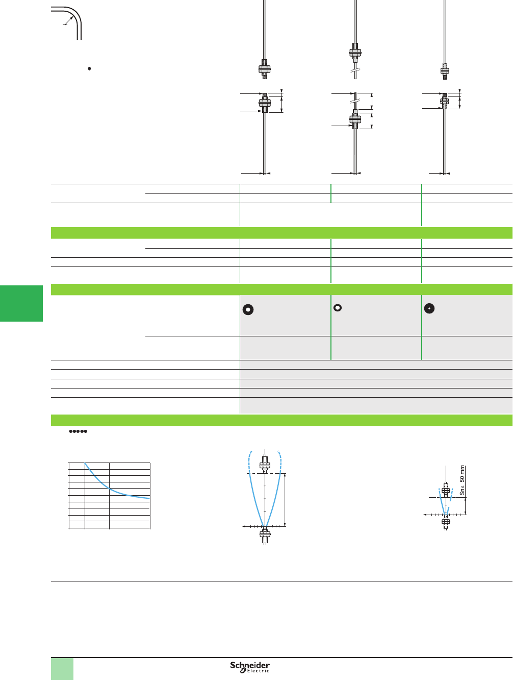
5/118
1
R = minimum bend radius
Fiber of ext. Ø 2.2 mm, R = 25 mm (0.98 in.)
Fiber of ext. Ø 1 mm, R = 10 mm (0.39 in.)
XUFN2S01L , R = 4 mm (0.16 in.)
12
M3
x0.5
M2.6
x0.45
3
Ø1
Nominal sensing distance
Sn, mm (in.)
With Þ ber L = 2 m 200 (7.87) (1) 180 (7.09) 50 (1.97)(1)
With lens 1500 (59.05) (2) –1000 (39.37) (2)
Application, features General purpose Accurate positioning
Catalog Number (complete assembly - 2 fi bers)
With standard
end fi ttings
L = 2 m
XUFN12301
–
XUFN35301
L = 10 m
XUFN12301L10
– –
With 90 mm fl exible end fi ttings, L = 2 m –
XUFN12311
–
Weight, kg (lb) 0.058 (0.13) (L = 2 m) 0.030 (0.07) 0.045 (0.10)
Specifi cations
Fiber (view on sensing face)
Core (Ø mm) 1 x Ø 1 1 x Ø 1 1 x Ø 0.5
Trimmable to required length
(trimmer XUF Z11 included)
Yes Yes Yes
Ambient air temperature For operation:- 25 to +60 °C (-13 to +140 °F). For storage: -40 to +80 °C (-40 to +176 °F)
Vibration resistance 7 gn, amplitude ± 1.5 mm (f = 10–55 Hz), conforming to IEC 60068-2-6
Shock resistance 30 gn, duration 11 ms, conforming to IEC 60068-2-27
Degree of protection IP 64 conforming to IEC 60529 and IP 641 conforming to NF C 20-010
Materials Fibers: PMMA; sheath: PE
Operating curves
XUFN L10 XUFN12301, N12311 XUFN35301
Percentage reduction in sensing distance
related to length of Þ ber
c
m3
6-3 6
mm
25
Ø of
beam
(1) Can be used with 90° mirror XUFZ02
(2) With lens accessory XUFZ01
R
12 3
M4
x0.7
M2.6
x0.45
Ø2.2
M4
x0.7
Ø1.5
90
5
15
Ø2.2
100%
2 m 10 m
0%
50%
5 m
Length of Þ ber
200
3
6-3 -6
cm
mm
Sn ≤ 200 mm
100
Ø of
beam
Dimen sions,
Catalog Numbers,
SpeciÞ cations,
Operating Curves
OsiSense® XU
Photoelectric sensors 0
Application
Fiber optics for ampliÞ ers
Plastic Þ bers with end Þ ttings, thru-beam system
1
2
3
4
5/
6
7
8
9
10
This document provided by Barr-Thorp Electric Co., Inc. 800-473-9123 www.barr-thorp.com
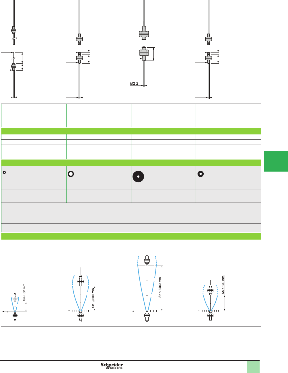
5/119
1
30 (1.18) 300 (11.81) (1) 2500 (98.42) 100 (3.94) (1)
–2000 (78.74) (2) –750 (29.53) (2)
Accurate positioning Long sensing distance Þ bers Fibers with integral lens
Resistant to accumulation of dirt
Flexible Þ bers for cyclic movements,
areas with restricted access
–
XUFN2P01L2 XUFN2L01L2 XUFN2S01L2
–
XUFN2P01L10 XUFN2L01L10 XUFN2S01L10
XUFN35311
–––
0.045 (0.10) 0.058 (0.13) (L = 2 m) 0.060 (0.13) (L = 2 m) 0.062 (0.14) (L = 2 m)
1 x Ø 0.5 1 x Ø 1.5 1 x Ø 1 1 x Ø 1
Yes Yes Yes Yes
For operation: - 25 to +60 °C (-13 to +140 °F). For storage: -40 to +80 °C (-40 to +176 °F)
7 gn, amplitude ± 1.5 mm (f = 10–55 Hz), conforming to IEC 60068-2-6
30 gn, duration 11 ms, conforming to IEC 60068-2-27
IP 64 conforming to IEC 60529 and IP 641 conforming to NF C 20-010
Fibers: PMMA; sheath: PE
XUFN35311 XUFN2P01L2 XUFN2L01L2 XUFN2S01L2
15
M3
x0.5
90
Ø1
Ø0.8
12 3
M4
x0.7
M2.6
x0.45
Ø2.2
M8
x1.25
20
.
12 3
M4
x0.7
M2.6
x0.45
Ø2.2
cm 3
6-3 6
mm
15
Ø of
beam
3
6-3 -6
cm
mm
200
300
Ø of
beam
3
69 -9
-3 -6
cm
mm
2500
700
2000
Ø of
beam
3
6-3 -6
cm
mm
100
Ø of
beam
Dimen sions,
Catalog Numbers,
SpeciÞ cations,
Operating Curves
OsiSense® XU
Photoelectric sensors 0
Application
Fiber optics for ampliÞ ers
Plastic Þ bers with end Þ ttings, thru-beam system
1
2
3
4
5
6
7
8
9
10
This document provided by Barr-Thorp Electric Co., Inc. 800-473-9123 www.barr-thorp.com
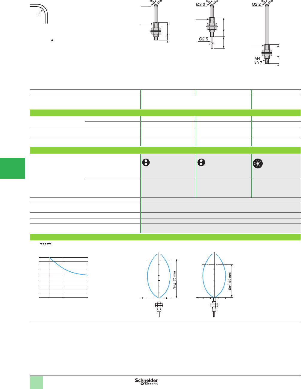
5/120
1
R = minimum bend radius
Fiber of ext. Ø 2.2 mm, R = 25 mm (0.98 in.)
Fiber of ext. Ø 1 mm, R = 10 mm (0.39 in.)
XUFN5S01L , R = 4 mm (0.16 in.)
Nominal sensing distance Sn, mm (in.) 70 (2.76) 60 (2.36) 60 (2.36)
Application, features General purpose Positioning
Catalog Numbers
With standard
end fi ttings
L = 2 m XUFN05321 –XUFN05323
L = 10 m XUFN05321L10 – –
With 90 mm fl exible end fi ttings, L = 2 m –XUFN05331 –
Weight, kg (lb) 0.058 (0.13) (L = 2 m) 0.030 (0.07) 0.060 (0.13)
Specifi cations
Fiber (view on sensing face)
Core (Ø mm) 2 x Ø 1 2 x Ø 1 1 x Ø 1 +16 x Ø 0.265
Trimmable to required length
(trimmer XUFZ11 included)
Yes Yes Yes
Ambient air temperature For operation: - 25 to +60 °C (-13 to +140 °F). For storage: -40 to +80 °C (-40 to +176 °F)
Vibration resistance 7 gn, amplitude ± 1.5 mm (f = 10–55 Hz), conforming to IEC 60068-2-27
Shock resistance 30 gn, duration 11 ms, conforming to IEC 60068-2-27
Degree of protection IP 64 conforming to IEC 60529 and IP 641 conforming to NF C 20-010
Materials Fibers: PMMA; sheath: PE
Operating curves (object 10 x 10 cm, white 90%)
XUFN L10 XUFN05321 XUFN05331, XUFN05323
Percentage reduction in sensing distance
related to length of Þ ber
(1) Mounting clamps included with Þ ber optic.
R
M6
x0.75
15
3
Ø2.2
155
90
M6
x0.75
.
.
M6
x0.75
158
.
.
2 m 10 m
0
100%
5 m
50%
Length of Þ ber
70
50
mm
20
mm 3
96-3 -6 -9
Ø of
beam
50
mm
20
mm 3
96-3 -6 -9
Ø of
beam
D imensions,
Catalog Numbers,
SpeciÞ cations,
Operating Curves
OsiSense® XU
Photoelectric sensors 0
Application
Fiber optics for ampliÞ ers
Plastic Þ bers with end Þ ttings, diffuse system
1
2
3
4
5/
6
7
8
9
10
This document provided by Barr-Thorp Electric Co., Inc. 800-473-9123 www.barr-thorp.com
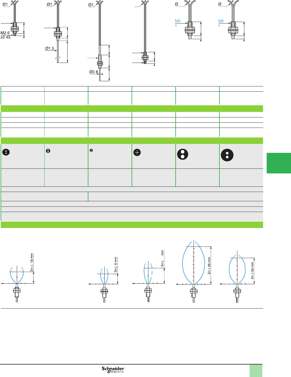
5/121
1
18 (0.71) 18 (0.71) 6 (0.24) 15 (0.59) 95 (3.74) 55 (2.17)
Positioning Positioning Areas with restricted
access
Positioning Long sensing distance
Þ bers
Flexible Þ bers for cyclic
movements, areas with
restricted access
XUFN01321 –
XUFN04331 XUFN02323 XUFN5P01L2 XUFN5S01L2
––––
XUFN5P01L10 XUFN5S01L10
–XUFN01331 ––––
0.045 (0.10) 0.045 (0.10) 0.045 (0.10) 0.040 (0.09) 0.058 (0.13) (L = 2 m) 0.062 (0.14) (L = 2 m)
2 x Ø 0.5 2 x Ø 0.5 2 x Ø 0.265 1 x Ø 0.5 +4 x Ø 0.25 2 x Ø 1.5 2 x Ø 1
Yes Yes Yes Yes Yes Yes
For operation: -25 to +60 °C (-13 to +140 °F). For storage: -40 to +80 °C (-40 to +176 °F)
7 gn, amplitude ± 1.5 mm (f = 10–55 Hz), conforming
to IEC 60068-2-27
7 gn, amplitude ± 1.5 mm (f = 10–55 Hz), conforming to IEC 60068-2-6
30 gn, duration 11 ms, conforming to IEC 60068-2-27
IP 64 conforming to IEC 60529 and IP 641 conforming to NF C 20-010
Fibers: PMMA; sheath: PE
XUFN01321, N01331 XUFN04331 XUFN02323 XUFN5P01L2 XUFN5S01L2
12
M4
x0.7
3
.
.
M4
x0.7
12
3
90
.
M3
x0.5
15 12
15
.
12
M4
x0.7
3
M2.6
x0.45
Ø1
15
3
2.2
0.75
13
3
0.75
2.2
mm 3
6-3 -6
mm
10
Ø of
beam
mm 3
6-3 -6
mm
3
Ø of
beam
mm 36 -3 -6
mm
7.5
15
15
Ø of
beam
70
50
mm
20
mm 3
96-3 -6 -9
90
Ø of
beam
50
mm
20
mm 36 -3-6
Ø of
beam
D imensions,
Catalog Numbers,
SpeciÞ cations,
Operating Curves
OsiSense® XU
Photoelectric sensors 0
Application
Fiber optics for ampliÞ ers
Plastic Þ bers with end Þ ttings, diffuse system
1
2
3
4
5
6
7
8
9
10
This document provided by Barr-Thorp Electric Co., Inc. 800-473-9123 www.barr-thorp.com
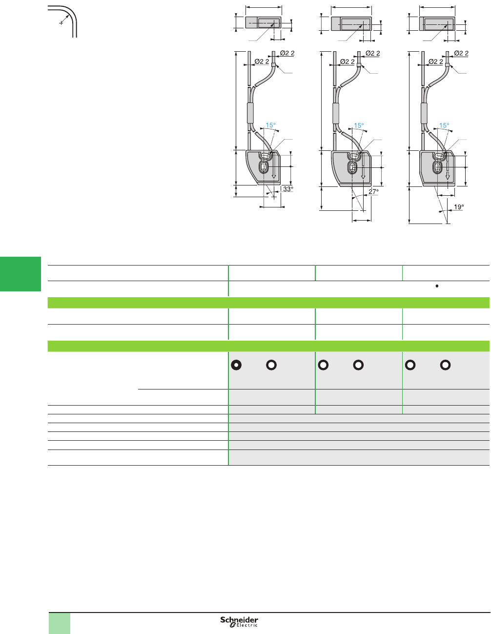
5/122
1
R = minimum bend radius
R = 40 mm (1.57 in.)
(1) Fiber reference ring for transmitter
(2) Transmitter
(3) 2 elongated holes Ø 3.2 x 6.7 for M3 screws
Maximum tightening torque: 0.3 N•m (2.66 lb-in)
Nominal sensing distance Sn, mm (in.)
with Þ ber L = 2 m
10 (0.39) 20 (0.79) 30 (1.18)
Application, features Focused Þ bers, specially suited to OsiSense® XU Full color sensors XURC4 PML2
Catalog Number
With specifi c end fi ttings for
detection of colors
L = 2 m
XUFN5L01L2
XUFN5L02L2
XUFN5L03L2
Weight, kg (lb) 0.030 (0.07) 0.030 (0.07) 0.030 (0.07)
Specifi cations
Fiber (view on sensing face)
Core (Ø mm) Transmitter: 1 x Ø 1
Receiver: 1 x Ø 1.5
Transmitter: 1 x Ø 1.5
Receiver: 1 x Ø 1.5
Transmitter: 1 x Ø 1.5
Receiver: 1 x Ø 1.5
Trimmable to required length No No No
Spot diameter, mm (in.) 2.5 (0.10) 5 (0.20) 8 (0.31)
Ambient air temperature For operation: -10 to +55 °C (+14 to +131 °F). For storage: -20 to +70 °C (-4 to +158 °F)
Vibration resistance 7 gn, amplitude ± 1.5 mm (f = 10–55 Hz), conforming to IEC 60068-2-6
Shock resistance 30 gn, duration 11 ms, conforming to IEC 60068-2-27
Degree of protection IP 65 conforming to IEC 60529 and IP 651 conforming to NF C 20-010
Materials Fibers: PMMA; sheath: PE. Head: PA 66, lens: PC
R
2000 9.229.710
30
6
4
(2)
(1)
(3)
9.8
15
14.5
..
200030.720 11.6
7
(2)
5
34
(1)
(3)
9.8
15
16
.
.
200030.730
(1)
7
30
5
(2)
(3)
11.6
9.8
15
15
.
.
Dim ensions,
Catalog Numbers,
SpeciÞ cations
OsiSense® XU
Photoelectric sensors
Application
Fiber optics for ampliÞ ers Full color
Plastic Þ bers with end Þ ttings, diffuse system
1
2
3
4
5/
6
7
8
9
10
This document provided by Barr-Thorp Electric Co., Inc. 800-473-9123 www.barr-thorp.com
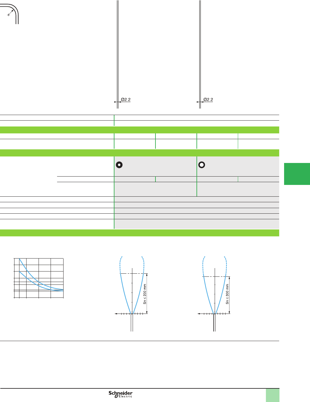
5/123
1
R = minimum bend radius
Fiber of ext. Ø 2.2 mm, R = 25 mm
Nominal sensing distance (Sn) L = 2 m See detection curves below (1)
Application General purpose
Catalog Number
Fiber without end fi tting XUFZ910 XUFZ920 XUFZ911 XUFZ921
Weight, kg (lb) 0.020 (0.04) 0.040 (0.09) 0.040 (0.09) 0.080 (0.18)
Specifi cations
Fiber
Core (Ø mm) 1 x Ø 1 1 x Ø 1.4
Length 10 m 20 m 10 m 20 m
Trimmable to required length
(trimmer XUFZ11 included)
Yes Yes
Ambient air temperature For operation: -25 to +60 °C (-13 to +140 °F). For storage: -40 to +80 °C (-40 to +176 °F)
Vibration resistance 7 gn, amplitude ± 1.5 mm (f = 10–55 Hz), conforming to IEC 60068-2-6
Shock resistance 30 gn, duration 11 ms, conforming to IEC 60068-2-27
Degree of protection IP 64 conforming to IEC 60529 and IP 641 conforming to NF C 20-010
Materials Fibers: PMMA; sheath: PE
Operating curves
XUFZ911, Z921
XUFZ910, Z920
XUFZ910, Z920 XUFZ911, Z921
1XUFZ911, Z921
2XUFZ910, Z920
Total length = sum of the 2 strands
used to constitute a thru-beam system
(1) It is possible to increase the sensing distance of Þ bers without end Þ ttings by using mounting clamps with lens (XUFZ03, Z04 or Z05).
R
. .
30 m
2
50 mm
300 mm
200 mm
4 m 40 m
0 mm
150 mm
1
250 mm
100 mm
20 m
10 m
120 mm
Length of Þ ber
Sensing distance (thru-beam system)
100
200
3
6-3 -6
cm
mm
Ø of
beam
150
300
4
8-4 -8
cm
mm
Ø of
beam
Dim ensions,
Catalog Numbers,
SpeciÞ cations,
Operating Curves
OsiSense® XU
Photoelectric sensors
Application
Fiber optics for ampliÞ ers
Plastic Þ bers without end Þ ttings, thru-beam system
1
2
3
4
5
6
7
8
9
10
This document provided by Barr-Thorp Electric Co., Inc. 800-473-9123 www.barr-thorp.com
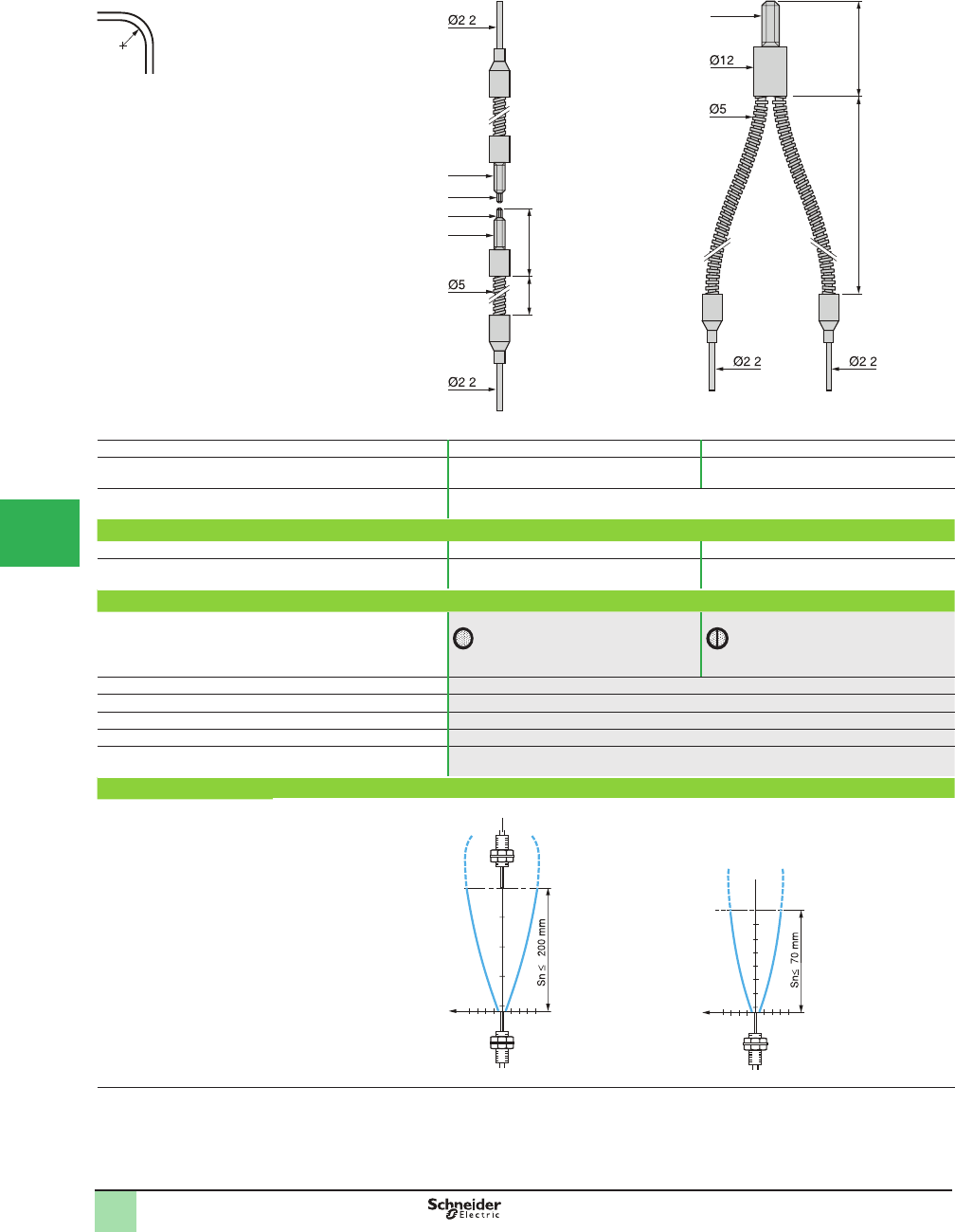
5/124
1
R = minimum bend radius
Metal sheath, R = 90 mm (3.54 in.)
System Thru-beam Diffuse
Nominal sensing distance Sn, mm (in.)
with fi ber L = 1 m
200 (7.87) (1)
1500 (59.05) (2) 70 (2.76)
Application High temperatures
Catalog Number (complete assembly - 2 fi bers for thru-beam system)
With standard end fi ttings L = 1 m XUFS2020 XUFS0520
Weight, kg (lb) 0.070 (0.15) 0.075 (0.17)
Specifi cations
Fiber (view on sensing face)
Core (Ø mm) 1 x Ø 1 2 x Ø 1
Ambient air temperature For operation and storage: -40 to +180 °C (-40 to +356 °F)
Vibration resistance 7 gn, amplitude ± 1.5 mm (f = 10–55 Hz), conforming to IEC 60068-2-6
Shock resistance 30 gn, duration 11 ms, conforming to IEC 60068-2-27
Degree of protection IP 64 conforming to IEC 60529 and IP 641 conforming to NF C 20-010
Materials Fibers: glass; sheath: metal
Operating curves
XUFS2020 XUFS0520
(1) Can be used with 90° mirror XUFZ02.
(2) With lens accessory XUFZ01.
R
M4
M2.6
970
M4
M2.6
25
.
.
32.5
970
M6
. .
100
200
3
6-3 -6
cm
mm
Ø of
beam
1
2-1 -2
cm
mm
50
70
Ø of
beam
Dim ensions,
CatalogNumbers,
SpeciÞ cations,
Operating Curves
OsiSense® XU
Photoelectric sensors 0
Application
Fiber optics for ampliÞ ers
Glass Þ bers with end Þ ttings, thru-beam and diffuse
systems
1
2
3
4
5/
6
7
8
9
10
This document provided by Barr-Thorp Electric Co., Inc. 800-473-9123 www.barr-thorp.com
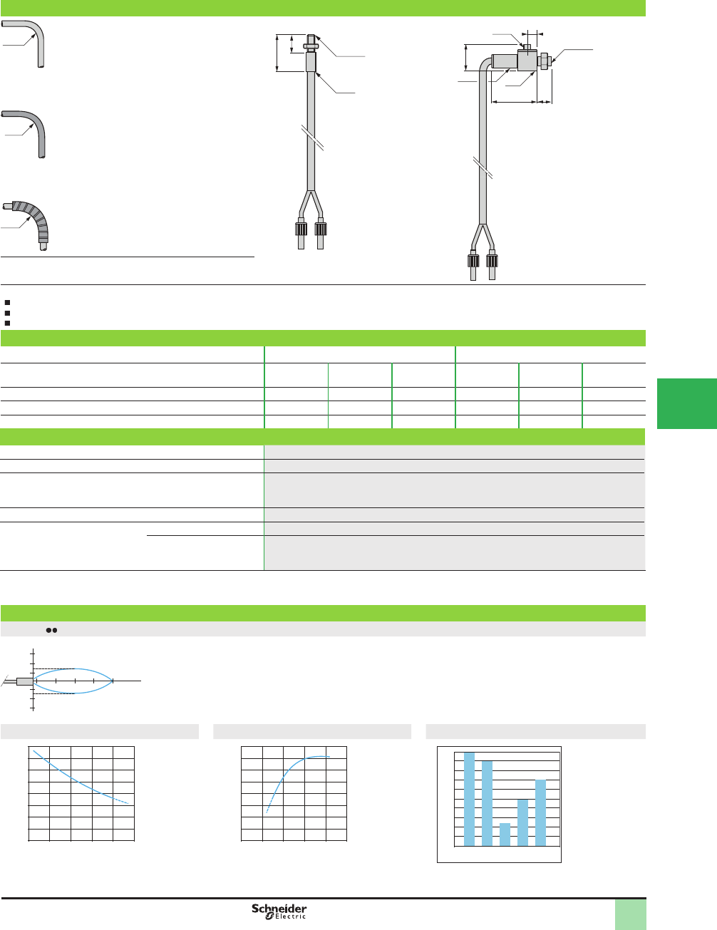
5/125
1
1
2
3
4
5
6
7
8
9
10
2
1
3
4
6
7
8
9
10
5/125
SpeciÞ cations,
Catalog Numbers,
Dimensions,
Operating Curves
OsiSense® XU
Photoelectric sensors
Application
Fiber optics for ampliÞ er
Glass Þ bers with end Þ ttings
For diffuse and thru-beam systems
Glass fi ber optics for diffuse system
R
10 mm
Standard sheath
External Ø
XUYFVP: 5 mm
XUYFVER: 3 mm
R
20 mm
Metal reinforced sheath
XUYFVP: 5 mm
XUYFVER: 3.5 mm
R
30 mm
High temperature
sheath
XUYFVP: 5 mm
XUYFVER: 5 mm
R = minimum bend radius
Applications
Detection in high temperature environment (up to 200 °C [392 °F])
Detection in aggressive environment
Application requiring high level of performance
Catalog Number
Type of end fi tting Straight Lateral
Sheath Standard Metal
reinforced
High
temperature
Standard Metal
reinforced
High
temperature
Catalog number with 0.60 m long Þ ber (1) XUYFVPSD61 XUYFVPMD61 XUYFVPTD61 XUYFVPSL61 XUYFVPML61 XUYFVPTL61
Nominal sensing distance Sn, mm (in.) 80 (3.15) 80 (3.15) 80 (3.15) 80 (3.15) 80 (3.15) 80 (3.15)
Weight, kg (lb) 0.040 (0.09) 0.045 (0.10) 0.052 (0.11) 0.042 (0.09) 0.056 (0.12) 0.056 (0.12)
Specifi cations
Fiber 400 strands per mm2
Usable diameter of fi ber 1.2 mm
Ambient air temperature For operation Standard: -25 to +60 °C (-13 to +140 °F)
Metal reinforced: -25 to +120 °C (-13 to +248 °F)
High temperature : -25 to +200 °C (-13 to +392 °F)
Detection end fi tting Nickel plated brass
Materials Fiber 50 µ glass
Sheath Standard: PVC +thermo polyoleÞ ne,
Metal reinforced: spiralled metal +polyoleÞ ne
High temperature: ß exible stainless steel
(1) For 1 m long Þ ber, replace 61 in the catalog number by 101. Example: XUYFVPSD61 becomes XUYFVPSD101 for a 1 m long Þ ber.
For 1.5 m long Þ ber, replace 61 in the catalog number by 151. Example: XUYFVPMD61 becomes XUYFVPMD151 for a 1.5 m long Þ ber.
For 2 m long Þ ber, replace 61 in the catalog number by 201. Example: XUYFVPTD61 becomes XUYFVPTD201 for a 2 m long Þ ber.
Operating and attenuation curves
XUYFVP 61
Attenuation related to length Bending infl uence Material infl uence
8x8
Ø6.5
Ø3.5
11
20 6
4
M4x0.7
Ø6.5
M4x0.7
21
9
50 100 % D
mm
5
5
10
10
15
15
0
0 1 2 3 4 5 m
-25
-50
-75
0
0 10 20 mm
-10
-20
-30
-40
-50
-60
0.9
1
0
0.8
0.6
0.5
0.4
0.2
0.1
0.7
0.3
1 2 34 5
Attenuation (%)
Attenuation (%)
Attenuation (%)
Length of Þ bers Bend radius
1 White paper
2 Wood, beige
cardboard
3 Black paper
4 Raw steel
5 Raw aluminium
This document provided by Barr-Thorp Electric Co., Inc. 800-473-9123 www.barr-thorp.com
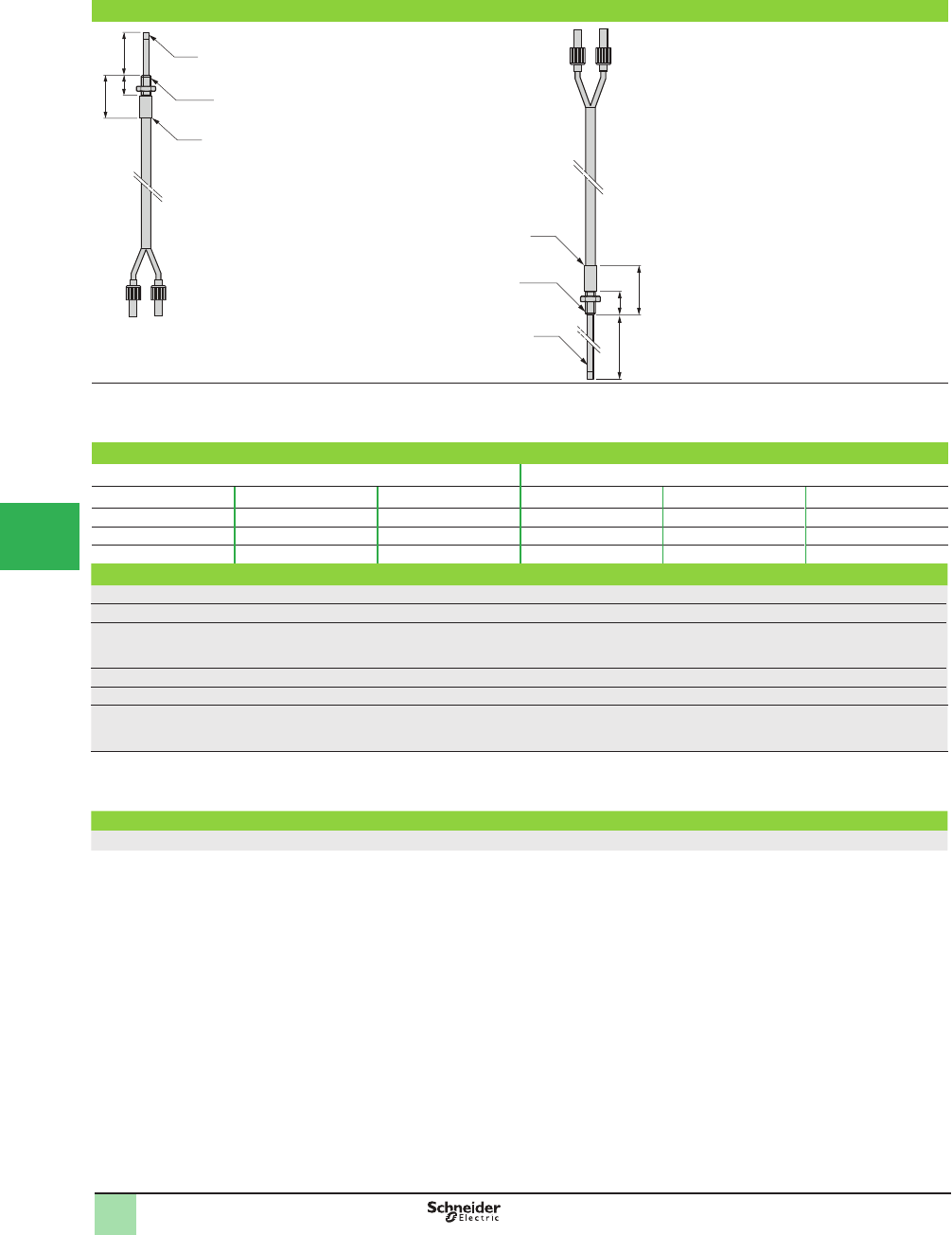
5/126
1
1
2
3
4
5/
6
7
8
9
10
Catalog Numbers
Dimensions,
Operating Curves
OsiSense® XU
Photoelectric sensors
Application
Fiber optics for ampliÞ er
Glass Þ bers with end Þ ttings
For diffuse and thru-beam systems
Extended Pliable
Standard Metal reinforced High temperature Standard Metal reinforced High temperature
XUYFVPSA61 (1) XUYFVPMA61 (1) XUYFVPTA61 (1) XUYFVPSC61 (1) XUYFVPMC61 (1) XUYFVPTC61 (1)
80 (3.15) 80 (3.15) 80 (3.15) 80 (3.15) 80 (3.15) 80 (3.15)
0.041 (0.09) 0.046 (0.10) 0.053 (0.12) 0.043 (0.09) 0.057 (0.13) 0.057 (0.13)
400 strands per mm2
1.2 mm
Standard: - 25 to +60 °C (-13 to +140 °F)
Metal reinforced: - 25 to +120 °C (-13 to +248 °F)
High temperature :-25 to +200 °C (-13 to +392 °F)
Nickel plated brass
50 µ glass
Standard: PVC +thermo polyoleÞ ne,
Metal reinforced: spiralled metal +polyoleÞ ne
High temperature: ß exible stainless steel
(1) For 1 m long Þ ber, replace 61 in the catalog number by 101. Example: XUYFVPSA61 becomes XUYFVPSA101 for a 1 m long Þ ber.
For 1.5 m long Þ ber, replace 61 in the catalog number by 151. Example: XUYFVPMA61 becomes XUYFVPMA151 for a 1.5 m long Þ ber.
For 2 m long Þ ber, replace 61 in the catalog number by 201. Example: XUYFVPTA61 becomes XUYFVPTA201 for a 2 m long Þ ber.
89
21
9
Ø6.5
M4x0.7
Ø2.5
209
21
Ø6.5
M4x0.7
Ø2.5
This document provided by Barr-Thorp Electric Co., Inc. 800-473-9123 www.barr-thorp.com

5/127
1
1
2
3
4
5
6
7
8
9
10
Accessories OsiSense® XU
Photoelectric sensors
Application
Fiber optics for ampliÞ er
Glass Þ bers with end Þ ttings
For diffuse and thru-beam systems
Accessories
Focusers for diffuse system fi ber optics
Description For use with Nominal sensing
distance Sn
Catalog Number Weight
mm (in.) kg (lb)
Focusers
for pinpoint reading of reference marks,
contrasts, faults, etc.
XUYFVERSD61
XUYFVERMD61
XUYFVERTD61
10 (0.39) XUY1120 0.003 (0.01)
30 (1.18) XUY1125 0.004 (0.01)
Focusers for thru-beam system fi ber optics
Description
hhhh
For use with Nominal sensing
distance Sn
Catalog Number Weight
mm (in.) kg (lb)
Focusers
for increasing sensing distances
(sold in lots of 2)
XUYFVERSD61
XUYFVERMD61
XUYFVERTD61
800 (31.50) XUY1121 (1) 0.004 (0.01)
3000 (118.11) XUY1124 (2) 0.012 (0.03)
800 (31.50) XUY1122 (1) 0.006 (0.01)
(1) 70° max.
(2) 250° max.
Focusers
XUY1120 XUY1125
25 10
Ø6,5
M4x0,7
35 30
M4x0.7
Ø8.5
XUY1121 XUY1124 XUY1122R
18
Ø5
M4x0.7
20
M4x0.7
Ø8.5
1117
Ø6,5
M4x0,7
8x8
This document provided by Barr-Thorp Electric Co., Inc. 800-473-9123 www.barr-thorp.com
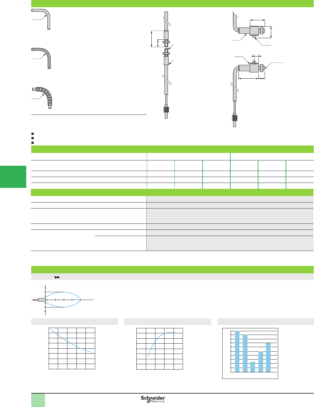
5/128
1
1
2
3
4
5/
6
7
8
9
10
Catalog Numbers,
Dimensions,
Operating Curves
OsiSense® XU
Photoelectric sensors
Application
Fiber optics for ampliÞ er
Glass Þ bers with end Þ ttings
For diffuse and thru-beam systems
Glass fi ber optics for thru-beam system
R
10 mm
Standard sheath
External Ø
XUYFVP: 5 mm
XUYFVER: 3 mm
R
20 mm
Metal reinforced sheath
XUYFVP: 5 mm
XUYFVER: 3.5 mm
R
30 mm
High temperature sheath
XUYFVP: 5 mm
XUYFVER: 5 mm
R = minimum bend radius
Applications
Detection in high temperature environment (up to 200 °C)
Detection in aggressive environment
Application requiring high level of performance
Catalog Numbers
Type of end fi tting Straight Lateral
Sheath Standard Metal
reinforced
High
temperature
Standard Metal
reinforced
High
temperature
Catalog Number with 0.6 m long Þ ber (1) XUYFVERSD61 XUYFVERMD61 XUYFVERTD61 XUYFVERSL61 XUYFVERML61 XUYFVERTL61
Nominal sensing distance Sn, mm (in.) 200 (7.87) 200 (7.87) 200 (7.87) 200 (7.87) 200 (7.87) 200 (7.87)
Weight, kg (lb) 0.042 (0.09) 0.046 (0.10) 0.060 (0.13) 0.052 (0.11) 0.061 (0.13) 0.075 (0.17)
Specifi cations
Fiber 400 strands per mm2
Usable diameter of fi ber 1.2 mm
Ambient air temperature For operation Standard: -25 to +60 °C (-13 to +140 °F)
Metal reinforced: -25 to +120 °C (-13 to +248 °F)
High temperature :-25 to +200 °C (-13 to +392 °F)
Detection end fi tting Nickel plated brass
Materials Fiber 50 µ glass
Sheath Standard: PVC +thermo polyoleÞ ne
Metal reinforced: spiralled metal +polyoleÞ ne
High temperature: ß exible stainless steel
(1) For 1 m long Þ ber, replace 61 in the catalog number by 101. Example: XUYFVERSD61 becomes XUYFVERSD101 for a 1 m long Þ ber.
For 1.5 m long Þ ber, replace 61 in the catalog number by 151. Example: XUYFVERMD61 becomes XUYFVERMD151 for a 1.5 m long Þ ber.
For 2 m long Þ ber, replace 61 in the catalog number by 201. Example: XUYFVERTD61 becomes XUYFVERTD201 for a 2 m long Þ ber.
Operating and attenuation curves
XUYFVER 61
50 100 % D
mm
15
15
30
30
45
45
Attenuation related to length Bending infl uence Material infl uence
Ø3.5
14
8x8
Ø6.5
20 6
4
M4x0.7
11
9
21
0
0 1 2 3 4 5 m
-10
-20
-30
0
0 10 20 mm
-10
-20
-30
-40
-50
-60
0.9
1
0
0.8
0.6
0.5
0.4
0.2
0.1
0.7
0.3
1 2 34 5
Attenuation (%)
Length of Þ bers
Attenuation (%)
Bend radius
1 White paper
2 Wood, beige
cardboard
3 Black paper
4 Raw steel
5 Raw aluminium
This document provided by Barr-Thorp Electric Co., Inc. 800-473-9123 www.barr-thorp.com
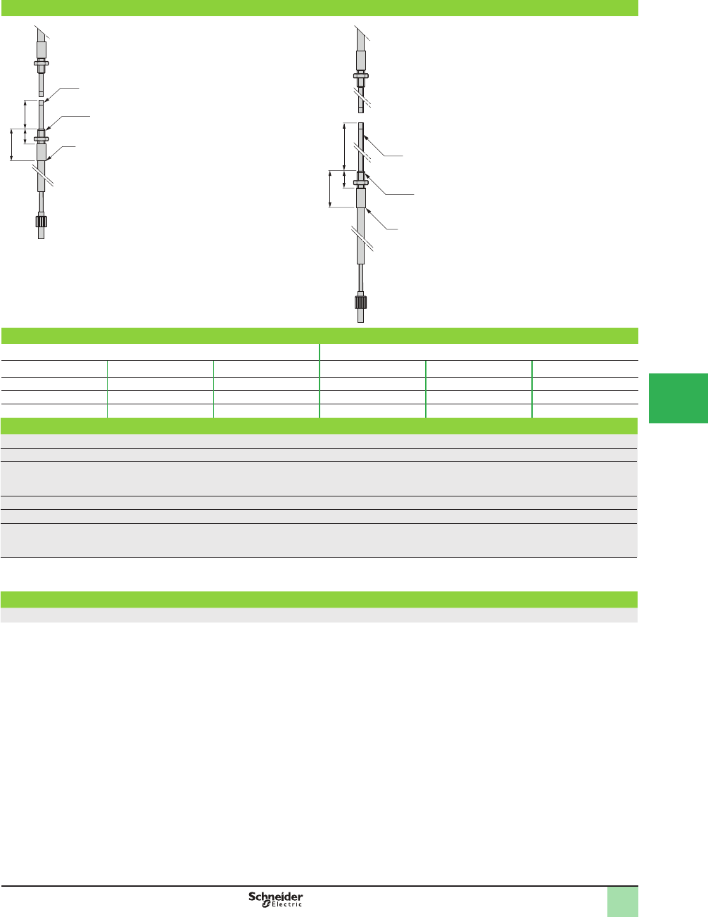
5/129
1
1
2
3
4
5
6
7
8
9
10
Catalog Numbers,
Dimensions,
Operating Curves
OsiSense® XU
Photoelectric sensors
Application
Fiber optics for ampliÞ er
Glass Þ bers with end Þ ttings
For diffuse and thru-beam systems
Extended Pliable
Standard Metal reinforced High temperature Standard Metal reinforced High temperature
XUYFVERSA61 (1) XUYFVERMA61 (1) XUYFVERTA61 (1) XUYFVERSC61 (1) XUYFVERMC61 (1) XUYFVERTC61 (1)
80 (3.15) 80 (3.15) 80 (3.15) 80 (3.15) 80 (3.15) 80 (3.15)
0.043 (0.09) 0.047 (0.10) 0.061 (0.13) 0.053 0.061 (0.13) 0.076 (0.17)
400 strands per mm2
1.2 mm
Standard: - 25 to +60 °C (-13 to +140 °F)
Metal reinforced: - 25 to +120 °C (-13 to +248 °F)
High temperature :-25 to +200 °C (-13 to +392 °F)
Nickel plated brass
50 µ glass
Standard: PVC +thermo polyoleÞ ne
Metal reinforced: spiralled metal +polyoleÞ ne
High temperature: ß exible stainless steel
(1) For 1 m long Þ ber, replace 61 in the catalog number by 101. Example: XUYFVERSA61 becomes XUYFVERSA101 for a 1 m long Þ ber.
For 1.5 m long Þ ber, replace 61 in the catalog number by 151. Example: XUYFVERMA61 becomes XUYFVERMA151 for a 1.5 m long Þ ber.
For 2 m long Þ ber, replace 61 in the catalog number by 201. Example: XUYFVERTA61 becomes XUYFVERTA201 for a 2 m long Þ ber.
Ø2.5
Ø5
M4x0.7
899
21
Ø5
M4x0.7
Ø2.5
209
21
This document provided by Barr-Thorp Electric Co., Inc. 800-473-9123 www.barr-thorp.com
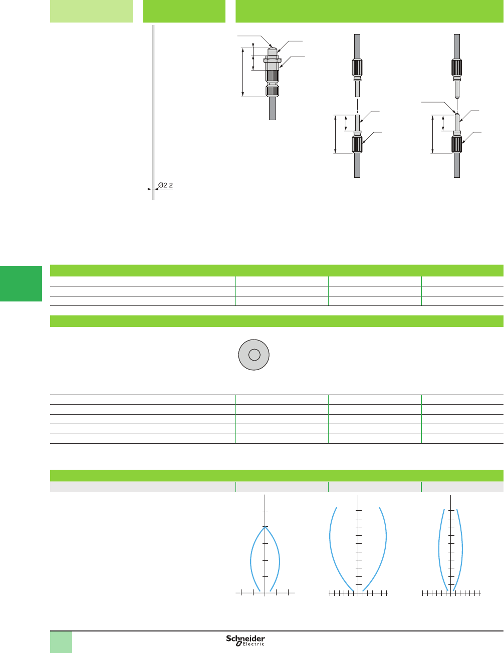
5/130
1
1
2
3
4
5/
6
7
8
9
10
Catalog Numbers,
Operating Curves
OsiSense® XU
Photoelectric sensors
Application
Fiber optics for ampliÞ er
EcoÞ ber system in Plastic for customer assembly
Ecofi ber concept Fibers without
end fi tting
End fi ttings
Assemble your own Þ ber
optics.
.
End fi ttings
Nominal sensing distance Sn, mm (in.) 70 (2.76) 200 (7.87) 800 (31.50)
Catalog number XUYA110 XUYA210 XUYA211
Weight, kg (lb) 0.009 (0.02) 0.004 (0.01) 0.004 (0.01)
Fibers without end fi tting
Type of fi ber Single fi ber, plastic, single strand
Length (m) 1 10 50
Usable diameter (mm) 111
External diameter (mm) 2.2 2.2 2.2
Catalog number XUYA005 XUYA00510 XUYA00550
Weight, kg (lb) 0.006 (0.01) 0.042 (0.09) 0.220 (0.49)
Operating curves
End fi ttings XUYA110 XUYA210 XUYA211
1
2
3
4
5
cm
1
0.50.50.5
1
cm
5
01 12 23 3
10
cm
20
01 12 23 3
40
M8x1
410
Ø5.5
28
Ø3
16
9
Ø5
Ø3
16
9
Ø5
Optic
Optic
This document provided by Barr-Thorp Electric Co., Inc. 800-473-9123 www.barr-thorp.com
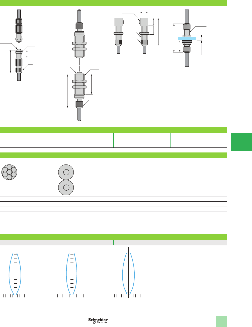
5/131
1
1
2
3
4
5
6
7
8
9
10
Catalog Numbers,
Operating Curves
OsiSense® XU
Photoelectric sensors
Application
Fiber optics for ampliÞ er
EcoÞ ber system in Plastic for customer assembly
1200 (47.24) 4000 (157.48) 1200 (47.24) –
XUYA212 XUYA213 XUYA220 XUYA310
0.011 (0.02) 0.045 (0.10) 0.018 (0.04) 0.017 (0.04)
Single fi ber, plastic, multistrand Dual fi ber, plastic, single strand
1 1
1 1
2.2 2.2
XUYAU005 XUYFP2BRINA005B
0.006 (0.01) 0.080 (0.18)
XUYA212 XUYA213 XUYA220
cm
40
01 12 23 3
80
cm
01 12 23 3
400
200
cm
40
01 12 23 3
80
M6x1
10
25
Ø6
M12x1
35
Ø8
25
8
Ø8
M6x1
8x8
3–10
30
32
Ø6M6x1
0–8 (1)
13.5
Optic
Optic
Optic
End Þ tting for passing through
partition
(1) Ø 6.2 cut-out
This document provided by Barr-Thorp Electric Co., Inc. 800-473-9123 www.barr-thorp.com
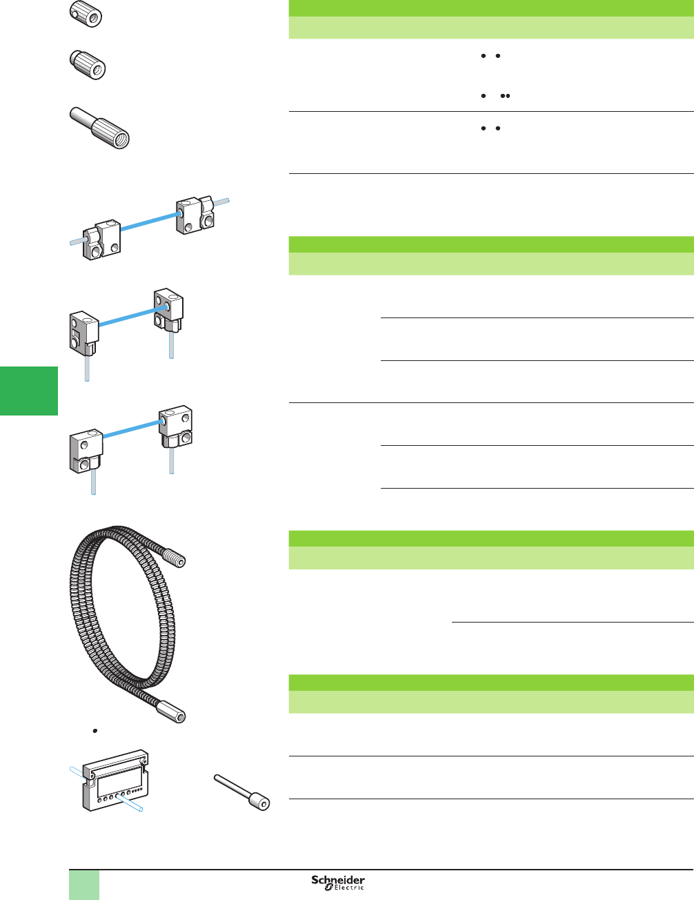
5/132
1
Accessories for fi bers with threaded end fi ttings
Description For use with Catalog Number Weight
kg (lb)
90° mirror
(set of 2)
Fiber optics
XUFN1 30 ,
XUFN35301 and
XUFS2020 (thru-beam
system)
XUFN2 01L
XUFZ02 0.005 (0.01)
Lenses for increasing sensing
distance
(set of 2)
Fiber optics
XUFN1 30 ,
XUFN35301 and
XUFS2020 (thru-beam
system)
XUFZ01 0.005 (0.01)
Focusing lens for high
precision detection. Detection of
0.5 mm objects at a distance of 7 mm.
Also enables detection of objects against
a background (1)
Fiber optics
XUFN02323
(diffuse system)
XUFZ06 0.001 (0.002)
Accessories for plastic fi bers without end fi ttings
Description Mounting plane For use with Catalog Number Weight
kg (lb)
Mounting clamps
(set of 2)
Axial Plastic Þ ber optics
XUFZ
XUFZ13 0.002 (0.004)
Frontal Plastic Þ ber optics
XUFZ
XUFZ14 0.002 (0.004)
Lateral Plastic Þ ber optics
XUFZ
XUFZ15 0.002 (0.004)
Mounting clamps
with lens (set of 2)
Axial Plastic Þ ber optics
XUFZ
XUFZ03 0.002 (0.004)
Frontal Plastic Þ ber optics
XUFZ
XUFZ04 0.002 (0.004)
Lateral Plastic Þ ber optics
XUFZ
XUFZ05 0.002 (0.004)
Protection accessories
Description For use with Catalog Number Weight
kg (lb)
Protective tubing
Length 1 m
Plastic Þ ber optic light
guides with M4
threaded end Þ ttings
XUFZ210 0.040 (0.09)
Plastic Þ ber optic light
guides with M6
threaded end Þ ttings
XUFZ310 0.065 (0.14)
Other accessories
Description Sold in lots of Catalog Number Weight
kg (lb)
Fiber trimmer 1XUFZ11 0.006 (0.01)
Plastic end adapter, for connecting
Ø 1 mm Þ bers to ampliÞ ers XUD A
2XUFZ08 0.002 (0.004)
(1) SpeciÞ cations obtained when the Þ ber is fully screwed into the lens (screwing depth = 4 mm).
XUFZ02
XUFZ01
XUFZ06
XUFZ13, XUFZ03
XUFZ14, XUFZ04
XUFZ15, XUFZ05
XUFZ 10
XUFZ11 XUFZ08
Catalog Numbers OsiSense® XU
Photoelectric sensors
Application
Fiber optics for ampliÞ ers
Accessories
1
2
3
4
5/
6
7
8
9
10
This document provided by Barr-Thorp Electric Co., Inc. 800-473-9123 www.barr-thorp.com
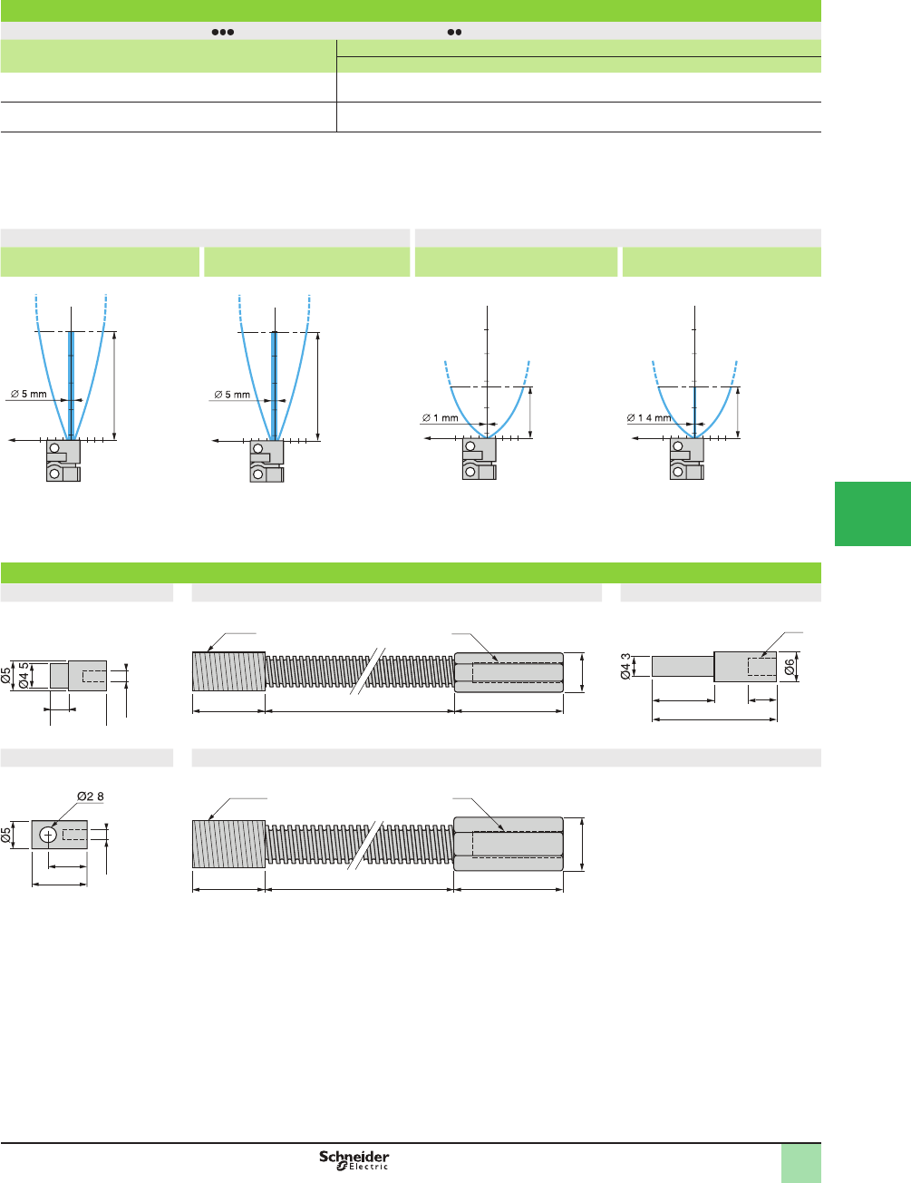
5/133
1
Operating curves for plastic fi ber optic light guides with mounting clamps
Sensing distance of fi bers XUFZ9 fi tted with mounting clamps XUFZ
Fiber type Clamp type
XUFZ13 XUFZ14, Z15 XUFZ03 XUFZ04, Z05 Without clamp
XUFZ910, Z920 (2 Þ bers L = 2 m) Sn, mm (in.) 150 (5.91) 100 (3.94) 800 (31.50) 600 (23.62) 200 (7.87)
XUFZ911, Z921 (2 Þ bers L = 2 m) Sn, mm (in.) 220 (8.66) 150 (5.91) 1200 (49.24) 900 (35.43) 300 (11.81)
Other Þ ber lengths:
5 m Þ bers: reduce the sensing distance by a factor of 0.7.
10 m Þ bers: reduce the sensing distance by a factor of 0.5.
20 m Þ bers: reduce the sensing distance by a factor of 0.3.
Operating curves with lens Operating curves without lens
Mounting clamp XUFZ03, Z04 or
Z05 +fi ber XUFZ910 or Z920
Mounting clamp XUFZ03, Z04 or Z05
+fi ber XUFZ911 or Z921
Mounting clamp XUFZ13, Z14 or Z15
+fi ber XUFZ910 or Z920
Mounting clamp XUFZ13, Z14 or
Z15 +fi ber XUFZ911 or Z921
Dimensions (mm)
XUFZ01 XUFZ210 XUFZ06
XUFZ02 XUFZ310
cm
mm
Sn
2 -2
Ø of
beam
cm
mm
Sn
4 -4
Ø of
beam
cm
mm
Sn
6 -6
Ø of
beam
cm
mm
Sn
6 -6
.
Ø of
beam
M2.6
3
1
0
.
20
1000
15
M8x1
7
M4
11
22
4
M4
.
6.5
9.2
.
M2.6
20
1000
15
M10x1 M6
10
across ß ats
Operating Cu rves OsiSense® XU
Photoelectric sensors 0
Application
Fiber optics for ampliÞ ers
Accessories
1
2
3
4
5
6
7
8
9
10
This document provided by Barr-Thorp Electric Co., Inc. 800-473-9123 www.barr-thorp.com
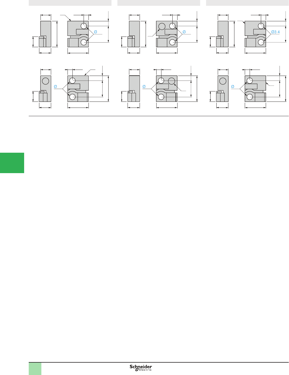
5/134
1
XUFZ03, XUFZ13 XUFZ04, XUFZ14 XUFZ05, XUFZ15
(1) Light beam window.
7.5
6
9.5 2.75
3.05
(1)
15
6
9.5 2.75
15
3.05 (1)
7.5
6
12.5
12.5
6
3.4
3.4
7.5
6
9.5 2.75
3.05
(1)
15
6
9.5 2.75
15
3.05
(1)
7.5
6
12.5
12.5
6
3.4
3.4
7.5
6
9.5 2.75
3.05
(1)
15
6
9.5 2.75
15
(1)
7.5
6
12.5
12.5
6
3.4
3.05
.
Dimensions OsiSense® XU
Photoelectric sensors 0
Application
Fiber optics for ampliÞ ers
Accessories
1
2
3
4
5/
6
7
8
9
10
This document provided by Barr-Thorp Electric Co., Inc. 800-473-9123 www.barr-thorp.com
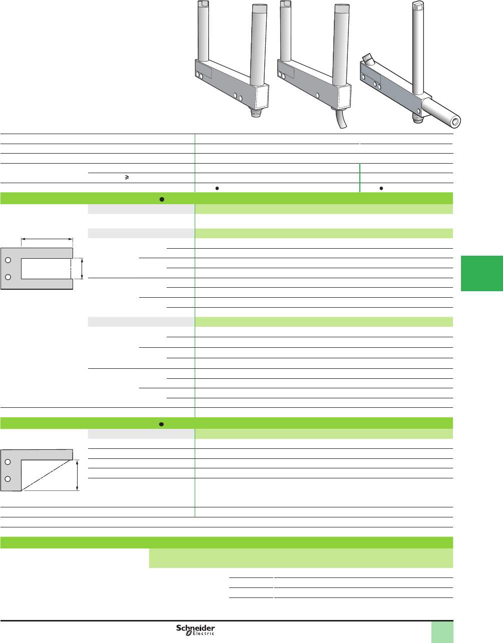
5/135
1
1
2
3
4
5
6
7
8
9
10
2
1
3
4
6
7
8
9
10
5/135
Catalog Numbers,
SpeciÞ cations
Optical fork without adjustment Connector Pre-cabled Angular fork
System Thru-beam
Type of transmission Red LED, modulated
Nominal sensing distance Sn, mm (in.) 2–180 (0.08–7.09)
Minimum size of object
detected, mm (in.)
Passageway 2–120 mm 0.8 (0.03) 1.2 (0.05)
Passageway 150 mm 1 (0.04) 1.5 (0.06)
Fork type XUVR XUVA
Catalog numbers of forks type XUVR
3-wire
NO or NC function
PNP or NPN output
Passageway (A) Function Output Pre-cabled, length 2 m. Depth (B): 40 mm (1.18 in.)
30 mm (1.18 in.) NO PNP XUVR0303PANL2
A
BPassageway (A) Function Output M8 connector, 3-pin. Depth (B): 60 mm (2.36 in.)
50 mm (1.97 in.) NO PNP XUVR0605PANM8
NPN XUVR0605NANM8
NC PNP XUVR0605PBNM8
NPN XUVR0605NBNM8
80 mm (3.15 in.) NO PNP XUVR0608PANM8
NPN XUVR0608NANM8
A = Passageway NC PNP XUVR0608PBNM8
B = Depth NPN XUVR0608NBNM8
Passageway (A) Function Output M8 connector, 3-pin. Depth (B): 120 mm (4.72 in.)
120 mm
(4.72 in.)
NO PNP XUVR1212PANM8
NPN XUVR1212NANM8
NC PNP XUVR1212PBNM8
NPN XUVR1212NBNM8
180 mm
(7.09 in.)
NO PNP XUVR1218PANM8
NPN XUVR1218NANM8
NC PNP XUVR1218PBNM8
NPN XUVR1218NBNM8
Weight kg 0.080 to 0.190 (0.18 to 0.42 lb) depending on model
Catalog numbers of forks type XUVA
3-wire
NO function, PNP output
Type Function Output M8 connector, 3-pin
50 mm (1.97 in.) NO PNP XUVA0505PANM8
80 mm (3.15 in.) NO PNP XUVA0808PANM8
120 mm (4.72 in.) NO PNP XUVA1212PANM8
150 mm (5.91 in.) NO PNP XUVA1515PANM8
A = Passageway
Weight (kg) 0.100 to 0.195 (0.22 to 0.43 lb) depending on model
Other versions: consult the Sensor Competency Center.
Applications: detection on conveyor, detection on vibrating rail.
Accessories
Description Details Length of
cable (m)
Catalog Number Weight
kg (lb)
Pre-wired M8 connector Straight 2 XZCP0566L2 0.060 (0.13)
Elbowed (90°) 2 XZCP0666L2 0.060 (0.13)
Straight 5 XZCP0566L5 0.120 (0.26)
Elbowed (90°) 5 XZCP0666L5 0.120 (0.26)
OsiSense® XU
Photoelectric sensors
Optical fork without adjustment
DC supply. Solid-state output
A
This document provided by Barr-Thorp Electric Co., Inc. 800-473-9123 www.barr-thorp.com
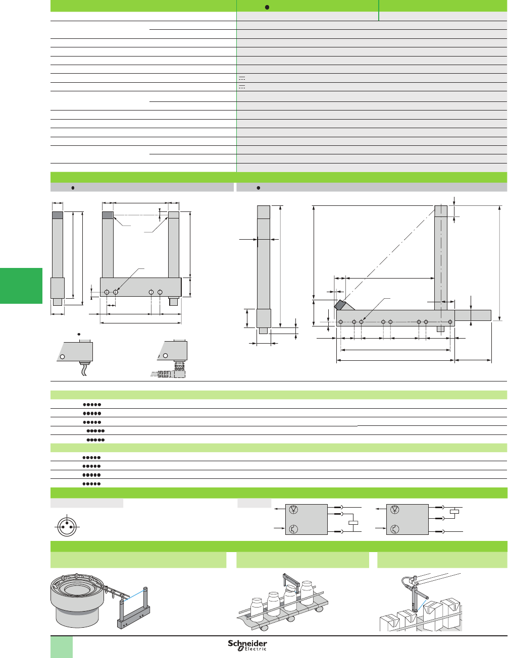
5/136
1
1
2
3
4
5/
6
7
8
9
10
Specifi cations XUVR XUVA
Product certifi cations CE, UL, CSA CE
Ambient air temperature For operation -10 to +60 °C (+14 to 140 °F)
For storage -40 to +80 °C (-40 to +176 °F)
Degree of protection Conforming to IEC 60529 IP 65 and IP 67
Vibration resistance Conforming to IEC 60068-2-6 7 gn, amplitude ± 0.75 mm (f = 10 to 55 Hz)
Shock resistance Conforming to IEC 60068-2-27 30 gn, duration 11 ms
Materials Case Painted aluminium and polyamide
Rated supply voltage 12–24 V with protection against reverse polarity
Voltage limits (including ripple) 10–30 V
Immunity to ambient light Natural light 10,000 lux
Incandescent bulb 5,000 lux
Switching capacity 100 mA with overload and short-circuit protection
Voltage drop, closed state < 1.5 V
Current consumption, no-load < 20 mA
Maximum switching frequency 4000 Hz
Delays First-up 140 ms max.
Stability ± 15 µs
Indicator lights Yellow LED Output signal
Dimensions (mm)
XUVR XUVA
3
4
b1
b
A 1010
10
12.1
17.5 B
8
G
a
Ø
G1 G3G2
(1)
(2)
8
A
G4 G5 G6 G7
8
20.5
4.5
12.1
e
c
17.5
b1
A
d
4.5
b
10.7
G3
50
a
10.5
12
Ø
G
Ø
Ø
4
(2)
(1)
XUVR0303 (pre-cabled version detail) Orientation of elbowed connector
(1) Transmission LED - (2) Yellow LED: output signal (1) Transmission LED - (2) Yellow LED: output signal
Type XUVR
Passageway A
Depth B a b b1 G G1 G2 G3 Ø
XUVR0303 30 40 54 65.7 57.5 30 17 – – 4 x 4.3
XUVR0605 50 60 74 85.7 77.5 40 6.5 8 19.5 4 x 4.3
XUVR0608 80 60 104 85.7 77.5 70 6.5 8 19.5 4 x 4.3
XUVR01212 120 124.3 144 150.2 142 100 17 10 17 4 x 4.3
XUVR01218 180 124.3 204 150.2 142 152 22 8 22 4 x 4.3
Type XUVA Type Depth A a b b1 G G1 G2 G3 Ø G4 G5 G6 G7 c d e
XUVA0505 50 44.3 75 83 75 66 – – 4.5 4 x 4.3 ––––14.75 26.41 0
XUVA0808 80 74.3 105 113 105 96 – – 4.5 4 x 4.3 ––––14.75 26.41 0
XUVA1212 120 112.3 145 154 146 136 – – 4.5 4 x 4.3 ––––19.75 29.24 3
XUVA1515 150 142.3 175 184 176 166 – – 4.5 8 x 4.3 24 8 60 8 19.75 29.24 3
Wiring diagrams
M8 connector Pin n° - color Cabling +
–
BN/1
BK/4
BU/3
PNP
+
–
BN/1
BK/4
BU/3
NPN
4
13
1 BN
3 BU
4 BK
Application examples
Vibrating bowl Monitoring height of objects passing on a
conveyor
Detecting position of object on a
conveyor
OsiSense® XU
Photoelectric sensors
Optical fork without adjustment
DC supply. Solid-state output
SpeciÞ cations,
Dimensions,
Wiring Diagrams
This document provided by Barr-Thorp Electric Co., Inc. 800-473-9123 www.barr-thorp.com
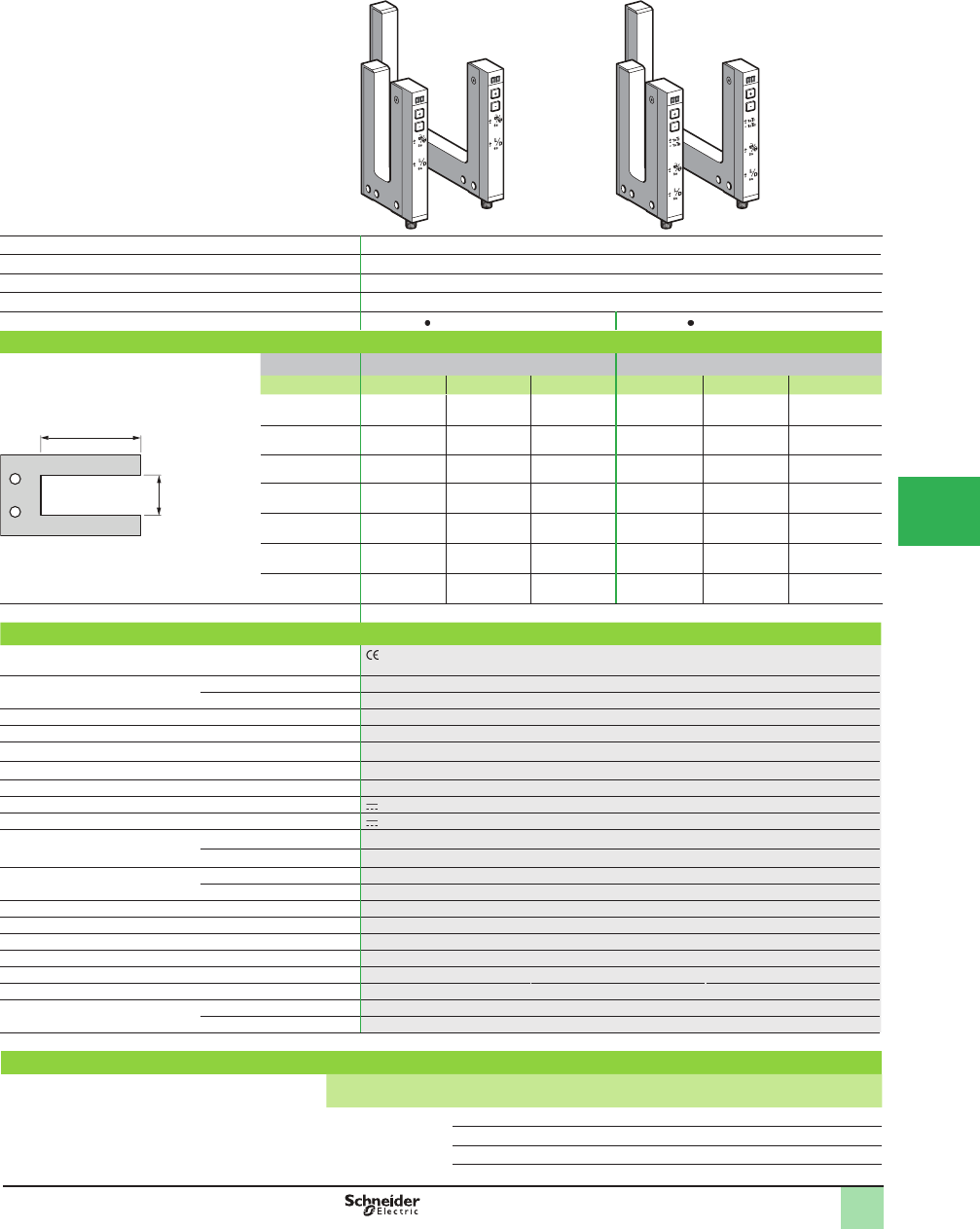
5/137
1
1
2
3
4
5
6
7
8
9
10
Catalog Numbers,
SpeciÞ cations,
Accessories
Optical fork with teach mode ± numeric potentiometer mode
Green keypad
Teach mode
Yellow keypad
System Thru-beam
Type of transmission Infrared LED, modulated
Nominal sensing distance (Sn) 2–120 mm (0.08–4.72 in.)
Minimum size of object detected Passageway 2–120 mm 0.2 mm (0.008 in.)
Fork type XUYFNEP XUYFANEP
Catalog Number
4-wire, PNP/NPN
independent outputs
NO/NC
function,
selectable
Passageway (A) Depth (B) Depth (B)
mm (in.) 42 (1.65) 59 (2.32) 95 (3.74) 42 (1.65) 59 (2.32) 95 (3.74)
2 (0.08)
XUY
FNEP40002
XUY
FNEP60002
XUY
FNEP100002
XUY
FANEP40002
XUY
FANEP60002
XUY
FANEP100002
A
B
5 (0.12)
XUY
FNEP40005
XUY
FNEP60005
XUY
FNEP100005
XUY
FANEP40005
XUY
FANEP60005
XUY
FANEP100005
15 (0.59)
XUY
FNEP40015
XUY
FNEP60015
XUY
FNEP100015
XUY
FANEP40015
XUY
FANEP60015
XUY
FANEP100015
30 (1.18)
XUY
FNEP40030
XUY
FNEP60030
XUY
FNEP100030
XUY
FANEP40030
XUY
FANEP60030
XUY
FANEP100030
50 (1.97)
XUY
FNEP40050
XUY
FNEP60050
XUY
FNEP100050
XUY
FANEP40050
XUY
FANEP60050
XUY
FANEP100050
A = Passageway
B = Depth 80 (3.15)
XUY
FNEP40080
XUY
FNEP60080
XUY
FNEP100080
XUY
FANEP40080
XUY
FANEP60080
XUY
FANEP100080
120 (4.72
XUY
FNEP40120
XUY
FNEP60120
XUY
FNEP100120
XUY
FANEP40120
XUY
FANEP60120
XUY
FANEP100120
Weight, kg (lb) 0.055 to 0.128 (0.12 to 0.28) depending on model
Specifi cations
Product certifi cations , cULus. This product is UL Listed if supplied by a class II or isolated supply delivering
c 30 V max. (isolated transformer for example) and protected by a UL fuse rated at 3 A max.
Ambient air temperature For operation -20 to +60 °C (-4 to +140 °F)
For storage -30 to+80 °C (-22 to +176°F)
Degree of protection Conforming to IEC 60529 IP 65
Connection M8, 4-pin male connector (for 3-pin version, consult the Sensor Competency Center)
Vibration resistance
Conforming to IEC 60068-2-6
7 gn, amplitude ± 0.75 mm (f = 10 to 55 Hz)
Shock resistance
Conforming to IEC 60068-2-27
30 gn, duration 11 ms
Materials Case Painted aluminium and polyamide/glass
Rated supply voltage 12–24 V with protection against reverse polarity
Voltage limits (including ripple) 10–30 V
Immunity to ambient light Natural light 10,000 Lux
Incandescent bulb 5,000 Lux
Outputs PNP and NPN By independent wire
NO/NC By programming
Switching capacity 100 mA with overload and short-circuit protection
Voltage drop, closed state < 2 V
Current consumption, no-load 40 mA
Permissible capacitive load 330 nF
Maximum switching frequency 10 kHz
Response time Stability ±20 µs
Indicator lights Yellow LED Output signal
Red LED Adjustment mode and keypad locking
Application: Detection of labels, detection of double sheet, detection of reference marks, detection on conveyor, detection on vibrating rail.
Accessories
Description Details Length of
cable (m)
Catalog Number Weight
kg (lb)
Pre-wired M8
connector
Straight 2 XZCP0941L2 0.080 (0.18)
Elbowed (90°) 2 XZCP1041L2 0.080 (0.18)
Straight 5 XZCP0941L5 0.180 (0.40)
Elbowed (90°) 5 XZCP1041L5 0.180 (0.40)
OsiSense® XU
Photoelectric sensors
Application
Optical fork with teach mode
DC supply, solid-state output
This document provided by Barr-Thorp Electric Co., Inc. 800-473-9123 www.barr-thorp.com
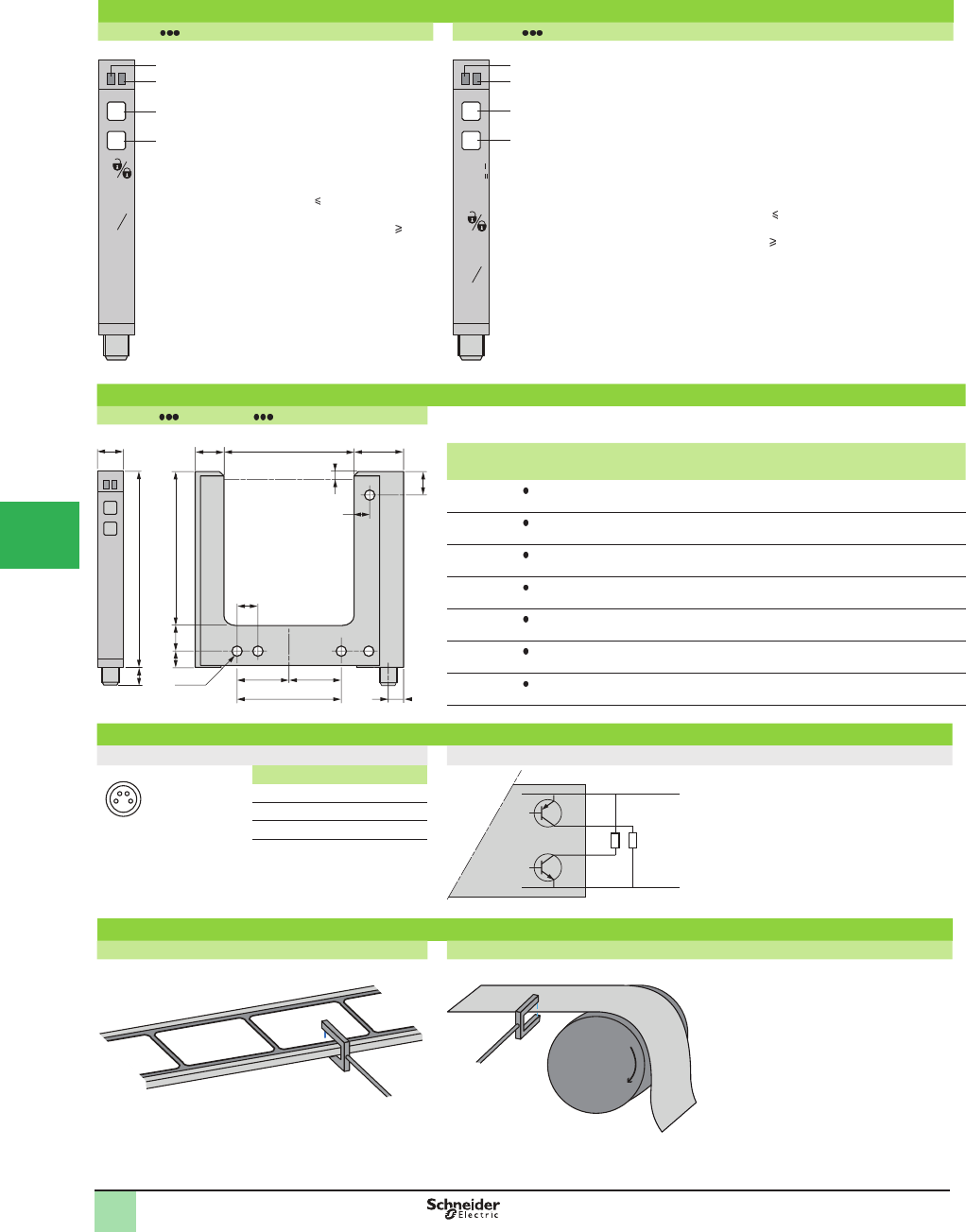
5/138
1
1
2
3
4
5/
6
7
8
9
10
Presentation
XUYFNEP XUYFANEP
-
+
+
-
+
-
L
D
3s
6s
1
2
3
4
1
2
3, 4
3 +4
3 +4
Yellow LED On:
Output activated
Red LED On:
Adjustments and keypad
locking
Sensitivity adjustment
Keypad locking
(3 s press time < 6 s)
NO/NC (press time 6 s)
-
+
+
-
+
-
L
D
+
-
-
1sT
1sT
3s
6s
1
2
3
4
1
2
3, 4
3 +4
3 +4
3 +4
Yellow LED On:
Output activated
Red LED On:
Adjustments and keypad locking
Sensitivity adjustment
Teach mode and automatic adjustment of sensitivity
(press time < 3 seconds)
Keypad locking (3 s press time < 6 s)
NO/NC (press time 6 s)
Dimensions (mm)
XUYFNEP / XUYFANEP
A
C
10 B5
3
9
5xØ4
-
+
10 11
= =
6
6
8
19
7
b1
Optical axis
.
XUY Passageway Depth
AB (mm) b1 (mm) C
FNEP/FANEP 002 2 (0.08 in.) 42, 59, 95
(1.65, 2.32, 3.74 in.)
57, 74, 110
(2.24, 2.91, 4.33 in.)
14
FNEP/FANEP 005 5 (0.20 in.) 42, 59, 95
(1.65, 2.32, 3.74 in.)
57, 74, 110
(2.24, 2.91, 4.33 in.)
14
FNEP/FANEP 015 15 (0.59 in.) 42, 59, 95
(1.65, 2.32, 3.74 in.)
57, 74, 110
(2.24, 2.91, 4.33 in.)
27
FNEP/FANEP 030 30 (1.18 in.) 42, 59, 95
(1.65, 2.32, 3.74 in.)
57, 74, 110
(2.24, 2.91, 4.33 in.)
42
FNEP/FANEP 050 50 (1.97 in.) 42, 59, 95
(1.65, 2.32, 3.74 in.)
57, 74, 110
(2.24, 2.91, 4.33 in.)
40
FNEP/FANEP 080 80 (3.15 in.) 42, 59, 95
(1.65, 2.32, 3.74 in.)
57, 74, 110
(2.24, 2.91, 4.33 in.)
70
FNEP/FANEP 120 120 (4.72 in.) 42, 59, 95
(1.65, 2.32, 3.74 in.)
57, 74, 110
(2.24, 2.91, 4.33 in.)
110
Wiring diagrams
Cabling M8 connector
24
1 3
Pin n° - color
WH
BN
BK
P
N
BU
c 10/30 V
c 0 V
1 BN: Brown
2 WH: White
3 BU: Blue
4 BK: Black
Application examples
Green keypad: Potentiometer mode Yellow keypad: Teach mode
Detection of labels on belt Detection of sheet feed on printing machine
+
OsiSense® XU
Photoelectric sensors
Application
Optical fork with teach mode
DC supply, solid-state output
Presentation,
Dimensions,
Wiring Diagrams
This document provided by Barr-Thorp Electric Co., Inc. 800-473-9123 www.barr-thorp.com
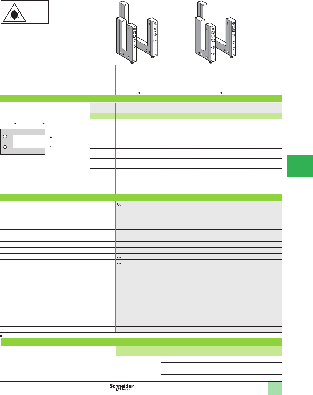
5/139
1
1
2
3
4
5
6
7
8
9
10
Catalog Numbers,
SpeciÞ cations,
Accessories
OsiSense® XU
Photoelectric sensors
Application
Optical fork with laser transmission, with teach mode
DC supply, solid-state output
High sensitivity fork range ± numeric potentiometer mode
Green keypad
Teach mode
Yellow keypad
Laser
Class 1
Laser class 1, conforming to
IEC 825-1
System Thru-beam
Type of transmission Red laser, modulated, class 1, wavelength: 670 m (2198 ft)
Nominal sensing distance (Sn) 2–120 mm (0.0804.72 in.)
Minimum size of object detected Passageway 2–120 mm 0.05 mm (0.002 in.) (repeat accuracy 0.01 mm (0.0004 in.)
Fork type XUYFLNEP XUYFALNEP
Catalog Numbers
4-wire, PNP/NPN
independent outputs
NO/NC
function,
selectable
Passageway
(A)
Depth (B) Depth (B)
mm (in.) 42 (1.65) 59 (2.32) 95 (3.74) 42 (1.65) 59 (2.32) 95 (3.74)
2 (0.08)
XUY
FLNEP40002
XUY
FLNEP60002
XUY
FLNEP100002
XUY
FALNEP40002
XUY
FALNEP60002
XUY
FALNEP100002
5 (0.20)
XUY
FLNEP40005
XUY
FLNEP60005
XUY
FLNEP100005
XUY
FALNEP40005
XUY
FALNEP60005
XUY
FALNEP100005
15 (0.59)
XUY
FLNEP40015
XUY
FLNEP60015
XUY
FLNEP100015
XUY
FALNEP40015
XUY
FALNEP60015
XUY
FALNEP100015
30 (1.18)
XUY
FLNEP40030
XUY
FLNEP60030
XUY
FLNEP100030
XUY
FALNEP40030
XUY
FALNEP60030
XUY
FALNEP100030
50 (1.97)
XUY
FLNEP40050
XUY
FLNEP60050
XUY
FLNEP100050
XUY
FALNEP40050
XUY
FALNEP60050
XUY
FALNEP100050
A = Passageway
B = Depth
80 (3.15)
XUY
FLNEP40080
XUY
FLNEP60080
XUY
FLNEP100080
XUY
FALNEP40080
XUY
FALNEP60080
XUY
FALNEP100080
120 (4.72)
XUY
FLNEP40120
XUY
FLNEP60120
XUY
FLNEP100120
XUY
FALNEP40120
XUY
FALNEP60120
XUY
FALNEP100120
Weight, kg (lb) 0.055 to 0.128 (0.12 to 0.28) depending on model
Specifi cations
Product certifi cations , cULus. This product is UL Listed if supplied by a class II or isolated supply delivering
c 30 V max. (isolated transformer for example) and protected by a UL fuse rated at 3 A max.
Ambient air temperature For operation -20 to +50 °C (-4 to +122 °F)
For storage - 30 to +80 °C (-22 to +176 °F)
Degree of protection Conforming to IEC 60529 IP 65
Connection M8, 4-pin male connector
Vibration resistance
Conforming to IEC 60068-2-6
7 gn, amplitude ± 0.75 mm (f = 10 to 55 Hz)
Shock resistance
Conforming to IEC 60068-2-27
30 gn, duration 11 ms
Materials Case Painted aluminium and polyamide/glass
Rated supply voltage 12–24 V with protection against reverse polarity
Voltage limits (including ripple) 10–30 V
Immunity to ambient light Natural light 10,000 Lux
Incandescent bulb 5,000 Lux
Outputs PNP/NPN By wiring
NO/NC Using teach
Switching capacity 100 mA with overload and short-circuit protection
Voltage drop, closed state < 2 V
Current consumption, no-load < 40 mA
Permissible capacitive load 330 nF
Maximum switching frequency 10 kHz
Response time Stability ±20 µs
Indicator lights Yellow LED: output signal; red LED: keypad locking and adjustments.
Applications: Detection of reference marks, detection on conveyor, detection on vibrating rail, detection of transparent object.
Accessories
Description Details Length of
cable (m)
Catalog Number Weight
kg (lb)
Pre-wired M8
connector
Straight 2 XZCP0941L2 0.080 (0.18)
Elbowed (90°) 2 XZCP1041L2 0.080 (0.18)
Straight 5 XZCP0941L5 0.180 (0.40)
Elbowed (90°) 5 XZCP1041L5 0.180 (0.40)
A
B
This document provided by Barr-Thorp Electric Co., Inc. 800-473-9123 www.barr-thorp.com
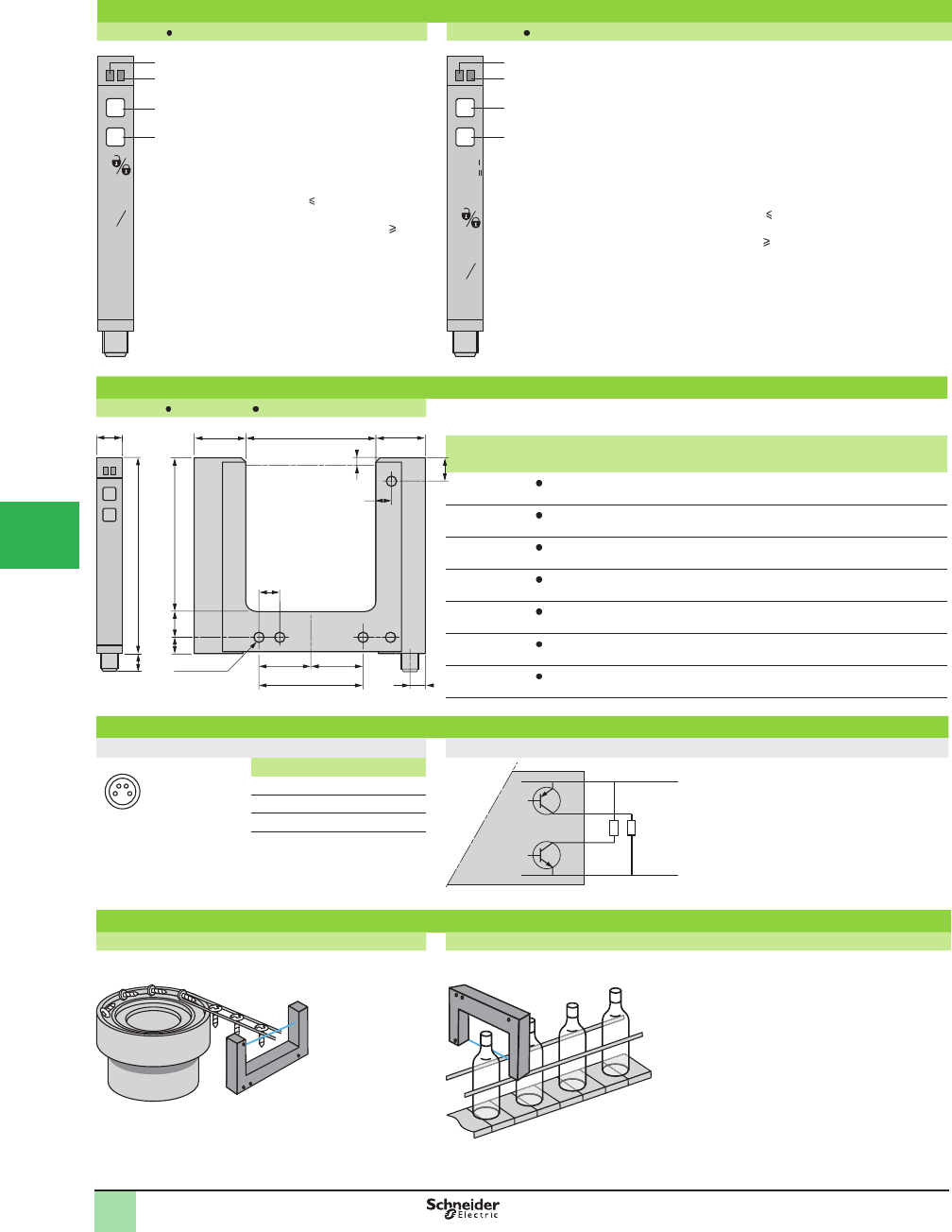
5/140
1
1
2
3
4
5/
6
7
8
9
10
Presentation,
Dimensions,
Wiring Diagrams
OsiSense® XU
Photoelectric sensors
Application
Optical fork with laser transmission, with teach mode
DC supply, solid-state output
Presentation
XUYFLNEP XUYFALNEP
1
2
3, 4
3 +4
3 +4
Yellow LED On:
Output activated
Red LED On:
Adjustments and keypad
locking
Sensitivity adjustment
Keypad locking
(3 s press time < 6 s)
NO/NC (press time 6 s)
1
2
3, 4
3 +4
3 +4
3 +4
Yellow LED On:
Output activated
Red LED On:
Adjustments and keypad locking
Sensitivity adjustment
Teach mode and automatic adjustment of sensitivity
(press time < 3 seconds)
Keypad locking (3 s press time < 6 s)
NO/NC (press time 6 s)
Dimensions (mm)
XUYFLNEP / XUYFALNEP
A
C
10 B5
3
9
5xØ4
-
+
10 19.5
= =
6
6
8
19
7
b1
.
XUY
Passageway
Depth b1 C
A B
FLNEP/FALNEP 22 (0.08 in.) 42, 59, 95
(1.65, 2.32, 3.74 in.)
57, 74, 110
(2.24, 2.91, 4.33 in.)
14
FLNEP/FALNEP 5 5 (0.20 in.) 42, 59, 95
(1.65, 2.32, 3.74 in.)
57, 74, 110
(2.24, 2.91, 4.33 in.)
14
FLNEP/FALNEP 15 15 (0.59 in.) 42, 59, 95
(1.65, 2.32, 3.74 in.)
57, 74, 110
(2.24, 2.91, 4.33 in.)
27
FLNEP/FALNEP 30 30 (1.18 in.) 42, 59, 95
(1.65, 2.32, 3.74 in.)
57, 74, 110
(2.24, 2.91, 4.33 in.)
42
FLNEP/FALNEP 50 50 (1.97 in.) 42, 59, 95
(1.65, 2.32, 3.74 in.)
57, 74, 110
(2.24, 2.91, 4.33 in.)
40
FLNEP/FALNEP 80 80 (3.15 in.) 42, 59, 95
(1.65, 2.32, 3.74 in.)
57, 74, 110
(2.24, 2.91, 4.33 in.)
70
FLNEP/FALNEP 120 120 (4.72 in.) 42, 59, 95
(1.65, 2.32, 3.74 in.)
57, 74, 110
(2.24, 2.91, 4.33 in.)
110
Wiring diagrams
Cabling M8 connector
24
1 3
Pin n° - color
WH
BN
BK
N
P
BU
c 10/30 V
c 0 V
1 BN: Brown
2 WH: White
3 BU: Blue
4 BK: Black
Application examples
Green keypad: Potentiometer mode Yellow keypad: Teach mode
Detection of an object exiting a vibrating bowl Detection of transparent bottles (glass, PET…)
-
+
+
-
+
-
L
D
3s
6s
1
2
3
4-
+
+
-
+
-
L
D
+
-
-
1sT
1sT
3s
6s
1
2
3
4
Optical axis
This document provided by Barr-Thorp Electric Co., Inc. 800-473-9123 www.barr-thorp.com

5/141
1
1
2
3
4
5
6
7
8
9
10
Fork design
System Thru-beam
Type of transmission Infrared, continuous
Nominal sensing distance Sn,
mm (in.)
(Passageway) 3 (0.12) 5 (0.20)
Catalog Number
4-wire, PNP and NPN NO or NC programmable
function (1)
Automatic adjustment using
teach mode
XUYFA983003COS XUYFA983005COS
Weight, kg (lb) 0.07 (0.15) 0.07 (0.15)
Specifi cations
Product certifi cations , cULus
Ambient air temperature For operation -20 to +60 °C (-40 to +140 °F)
For storage -30 to +80 °C (-22 to +176 °F)
Degree of protection Conforming to IEC 60529 IP 65
Connection M8, 4-pin connector (for pre-cabled version, consult the Sensor Competency Center)
Materials Anodised aluminium
Rated supply voltage 12–24 V with protection against reverse polarity
Voltage limits (including ripple) 10–30 V
Switching capacity (sealed) 100 mA with overload and short-circuit protection
Immunity to ambient light Natural light 3,000 lux
Incandescent bulb 3,000 lux
Voltage drop, closed state < 2 V
Current consumption, no-load 40 mA
Maximum switching frequency 10 kHz
Delays Response: 50 Ps; recovery: 50 Ps
Indicator lights Green LED: no object present
Red LED: keypad locking and adjustments.
Function table Function Thru-beam system
No label present in the beam Label present in the beam
Output state (PNP or NPN) indicator: green LED
(illuminated when sensor output is ON)
NC
NO
(1) By reversing supply connections.
Catalog Numbers,
SpeciÞ cations
OsiSense® XU
Photoelectric sensors
Application, packaging series
Optical fork with teach mode
For detection of labels
DC supply. Solid-state output
This document provided by Barr-Thorp Electric Co., Inc. 800-473-9123 www.barr-thorp.com
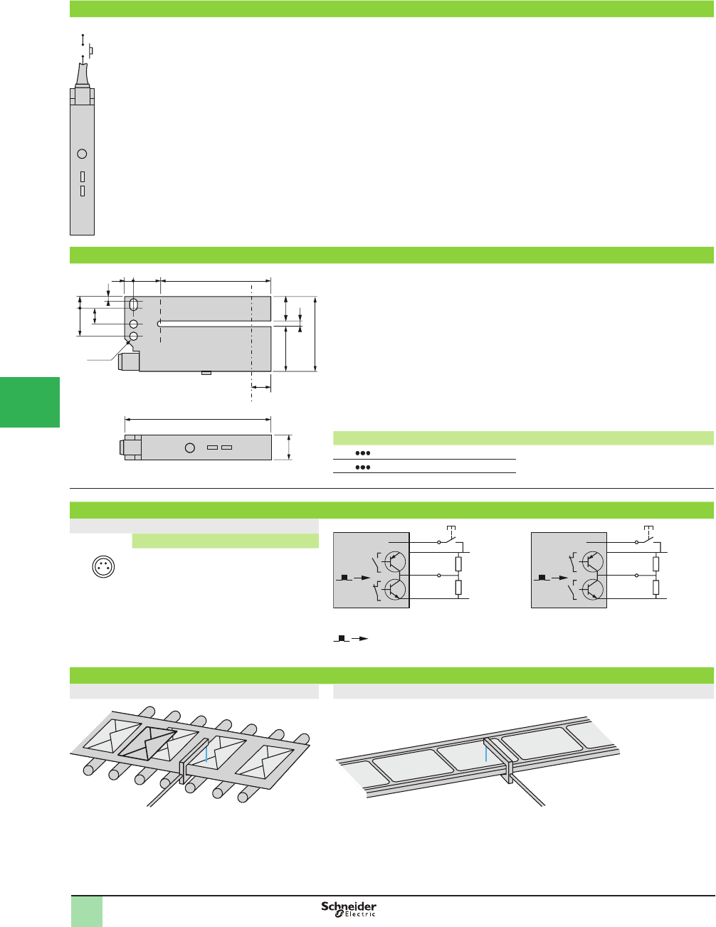
5/142
1
1
2
3
4
5/
6
7
8
9
10
Presentation (adjustment and indicators)
+
1
1
2
Optional use of the white wire
Teaching is performed on the item to which the label is afÞ xed
1 Teach mode button
1 press: standard teaching (red LED ß ashes for 2 s) -
2 presses: Þ ne teaching (green LED ß ashes for 2 s) -
1 prolonged press: keypad locking (red LED on) -
2 Red LED and green LED ß ash: short-circuit or object too opaque.
Dimensions (mm)
80
12 22 .5
37
.5
a
12
6
60
515
Ø4.2
14
8
1
6
Optical axis
XUY a (passageway)
FA98 3COS 2
FA98 5COS 5
Wiring diagrams (sensor connector pin view)
Connector
0 V
c 10/30 V
N
P
BK
WH
BN
BU 0 V
c 10/30 V
N
P
BK
WH
BU
BN
Pin n° - color
1 BN: Brown
2 WH: White (input)
3 BU: Blue
4 BK: Black (PNP and NPN outputs)
Object detected
If the white wire is not used, connect to 0 V.
Application examples
Detection of overlapping envelopes Detection of labels on belt
Presentation,
Dimensions,
Wiring Diagrams
OsiSense® XU
Photoelectric sensors
Application, packaging series
Optical fork with teach mode
For detection of labels
DC supply. Solid-state output
NO NC
24
1 3
This document provided by Barr-Thorp Electric Co., Inc. 800-473-9123 www.barr-thorp.com
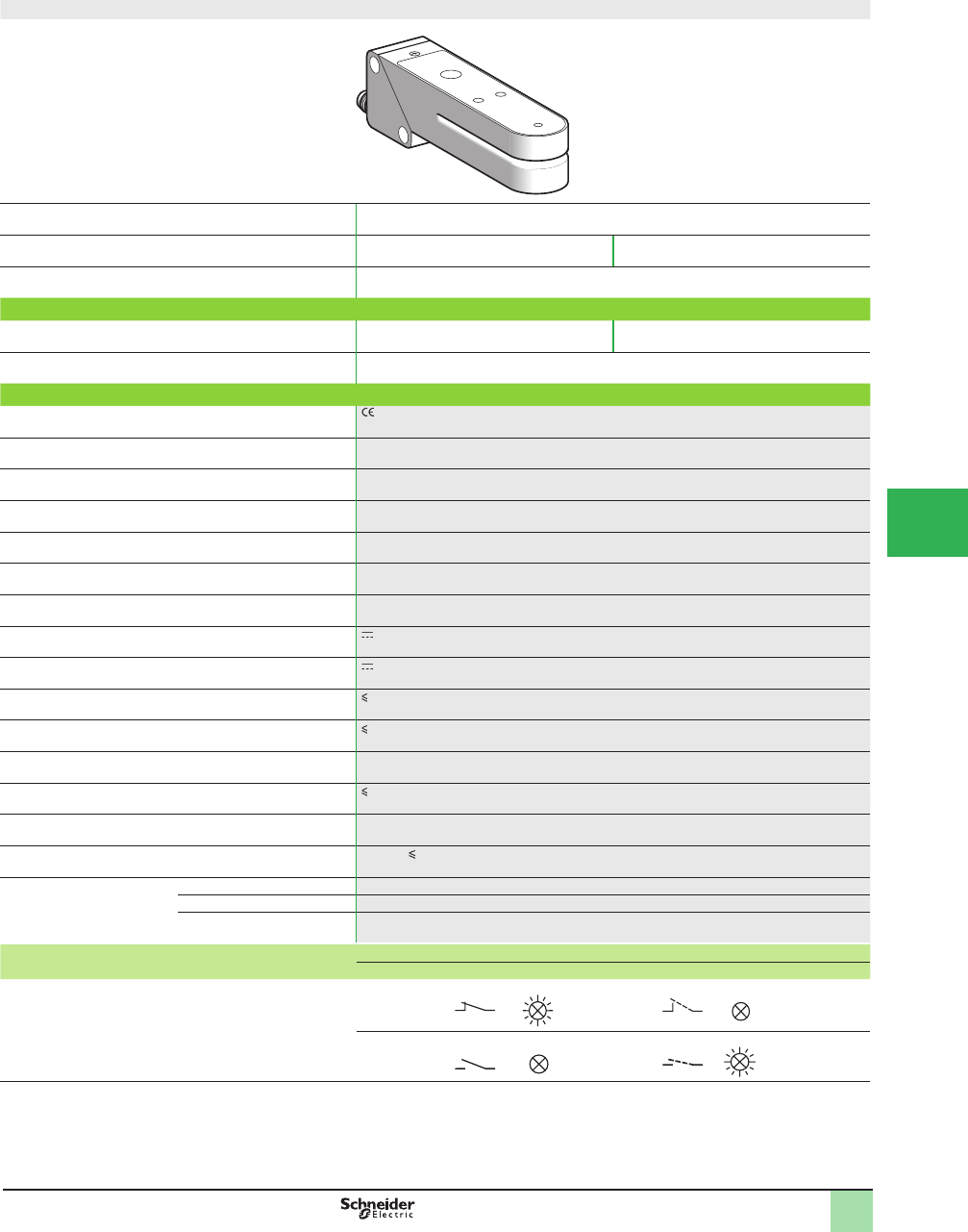
5/143
1
Fork design
System Thru-beam
Type of transmission Infrared Red/green
Nominal sensing distance (Sn) 2 mm (0.26 in.)
Catalog Numbers
3-wire, PNP and NPN Light or dark programmable
switching (2)
XUVK0252S XUVK0252VS
Weight, kg (lbs) 0.120 (0.26)
Specifi cations
Product certifi cations
Ambient air temperature For operation: 0 to +55 °C (+32 to +131 °F) For storage: -20 to +70 °C (-4 to +158 °F)
Vibration resistance Conforming to IEC 60068-2-6 Amplitude ± 1.5 mm up to 55 Hz, 7 gn (f = 10–55 Hz)
Shock resistance Conforming to IEC 60068-2-27 30 gn, duration 11 ms
Degree of protection Conforming to IEC 60529 IP 65
Connection M8 connector (suitable female connectors)
Materials Case: zinc alloy; lens: glass
Rated supply voltage 12–24 V with protection against reverse polarity
Voltage limits 10–30 V (including ripple)
Switching capacity (sealed) 100 mA with overload and short-circuit protection
Voltage drop, closed state 1.5 V
Output clamping resistor 10 k:
Current consumption, no-load 50 mA
Maximum switching frequency 25 kHz
Delays First-up: 30 ms; response: < 100 Ps; recovery: < 100 Ps
Indicator lights Output state Yellow LED
Sensor ready Green LED
Read error Red LED
Function table Function Thru-beam system
No label present in the path Label present in the path
Output state (PNP or NPN) indicator: yellow LED
(illuminated when sensor output is on)
Light switching
Dark switching
(1) Applications: the infrared transmission beam sensor XUVK0252S is suitable for the detection of all types of opaque legends; the red/green transmission sensor
XUVK0252VS is suitable for the detection of all types of legends of different colors.
(2) This sensor is adjustable using teach mode: the light or dark switching function is selected when performing the Þ rst stage of teaching for setting up the sensor
(see Programming using teach mode on page).
Catalog Numbers,
SpeciÞ cations
OsiSense® XU
Photoelectric sensors 0
Application, packaging series
For detection of labels (1)
DC supply, solid-state output
1
2
3
4
5
6
7
8
9
10
This document provided by Barr-Thorp Electric Co., Inc. 800-473-9123 www.barr-thorp.com
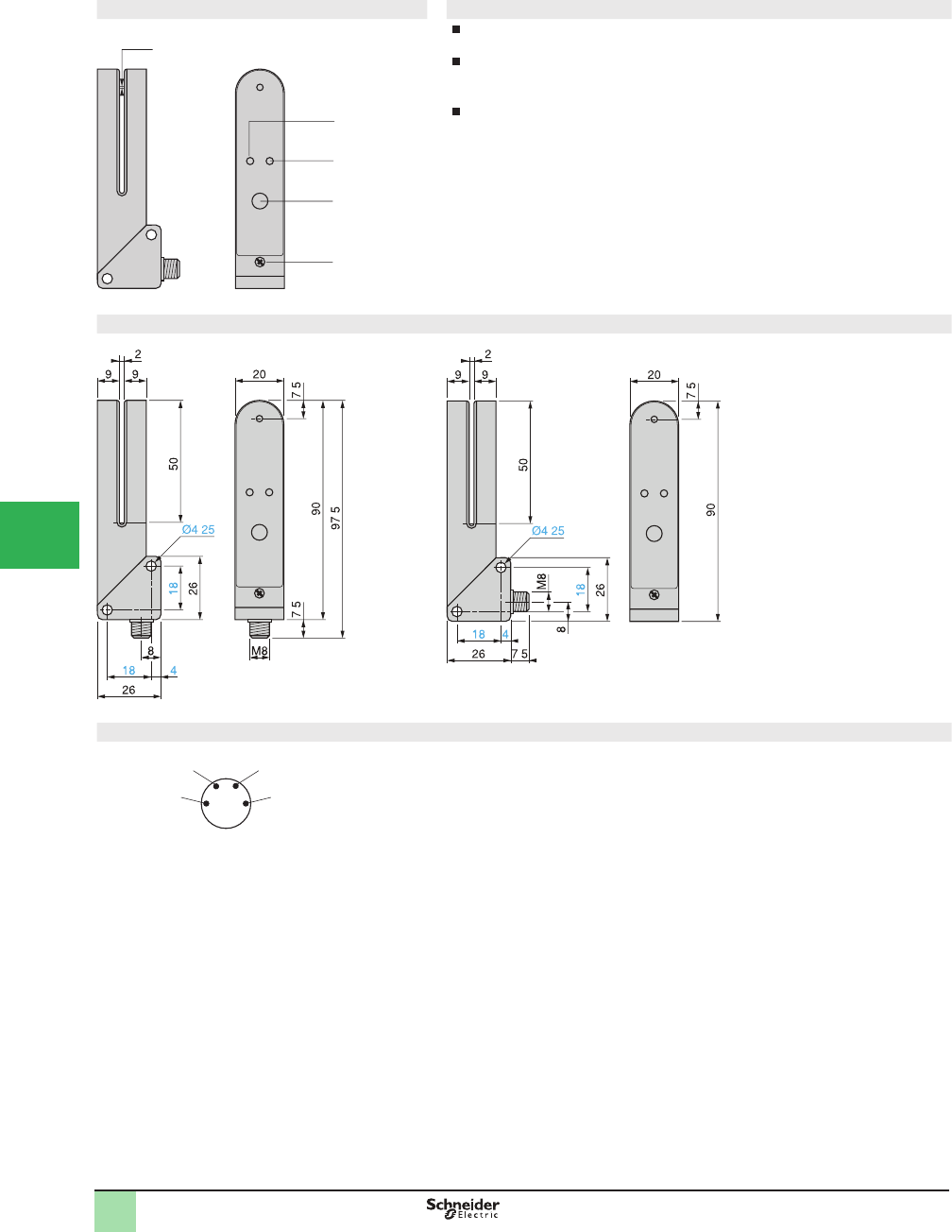
5/144
1
Presentation Programming using teach mode
Place the label to be detected in the beam of the optical fork. Press the Set button
and hold down until the green LED
2
goes out.
When the green LED
2
ß ashes, the detector has learned the label. Following this,
place the item to which the label is afÞ xed in the beam of the optical fork. Press the
Set button and hold down until the green LED
2
goes out.
When the green LED
2
illuminates as a steady light, teaching is completed and
the sensor is ready for operation.
1 Yellow LED, output state indicator
2 Dual color green/red LED, Ready/Error
3 Teach mode programming Set button
4 Locking screw
Dimensions (mm)
Connector diagram (sensor connector pin view)
.
3
1
2
4
1 mm
.
.
.
.
.
.
.
+
–
2
31
4
NPN output PNP output
Presentation,
Dimensions,
Wiring Diagrams
OsiSense® XU
Photoelectric sensors 0
Application, packaging series
For detection of labels
DC supply, solid-state output
1
2
3
4
5/
6
7
8
9
10
This document provided by Barr-Thorp Electric Co., Inc. 800-473-9123 www.barr-thorp.com

5/145
1
1
2
3
4
5
6
7
8
9
10
Fork design
System Thru-beam
Type of transmission Ultrasonic
Nominal sensing distance Sn, mm (in.) 3 (0.12 )
Catalog Number
4-wire, PNP and NPN Light switching (NC) or dark
switching (NO) programmable
XUVU06M3KCNM8
Adjustment By numerical potentiometer (± buttons) and red LED
Protection of settings By locking keypad
Weight, kg (lb) 0.130 (0.29)
Specifi cations
Product certifi cations , IEC 60947-5-2, CSA, cULus. This product is UL listed if supplied by a class II or isolated supply
delivering 30 V max. (isolated transformer for example) and protected by a UL fuse rated 3 A max.
Materials Aluminium case
Connection M8 4-pin connector
Detection performance Minimum length of label 2 mm (0.08 in.)
Minimum distance between
2 labels
2 mm (0.08 in.)
Maximum ß ow rate 120 m/min
Detection accuracy ± 0.16 mm (0.52 in.) at 60 m/min
± 0.30 mm (0.98 in.) at 120 m/min
Power supply Rated supply voltage 12–24 V with protection against reverse polarity
Voltage limits 10–30 V (including ripple)
Current consumption, no-load 40 mA
Residual voltage
At 100 mA < 2 V
At 10 mA < 1 V
Output Type NPN and PNP
Function Light switching (NC) or dark switching (NO), to be programmed
Maximum rated current 100 mA with overload and short-circuit protection
Maximum switching frequency 500 Hz
LED indicators
Output state Yellow LED
Delay On and Off: 500 µs
Environment Operating temperature +5 to +55 °C (+41 to +131 °F)
Storage temperature -20 to +70 °C (-4 to +158 °F)
Degree of protection IP 65
Function table Function Thru-beam system
No label present in the beam
(output inactive)
Label present in the beam
(output active)
Output state (PNP or NPN) yellow LED
(illuminated when sensor output is on)
Light switching
(NC)
Dark switching
(NO)
Catalog Numbers,
SpeciÞ cations
OsiSense® XX
Ultrasonic sensor
Application, packaging series
For detection of transparent labels
DC supply, solid-state output
This document provided by Barr-Thorp Electric Co., Inc. 800-473-9123 www.barr-thorp.com
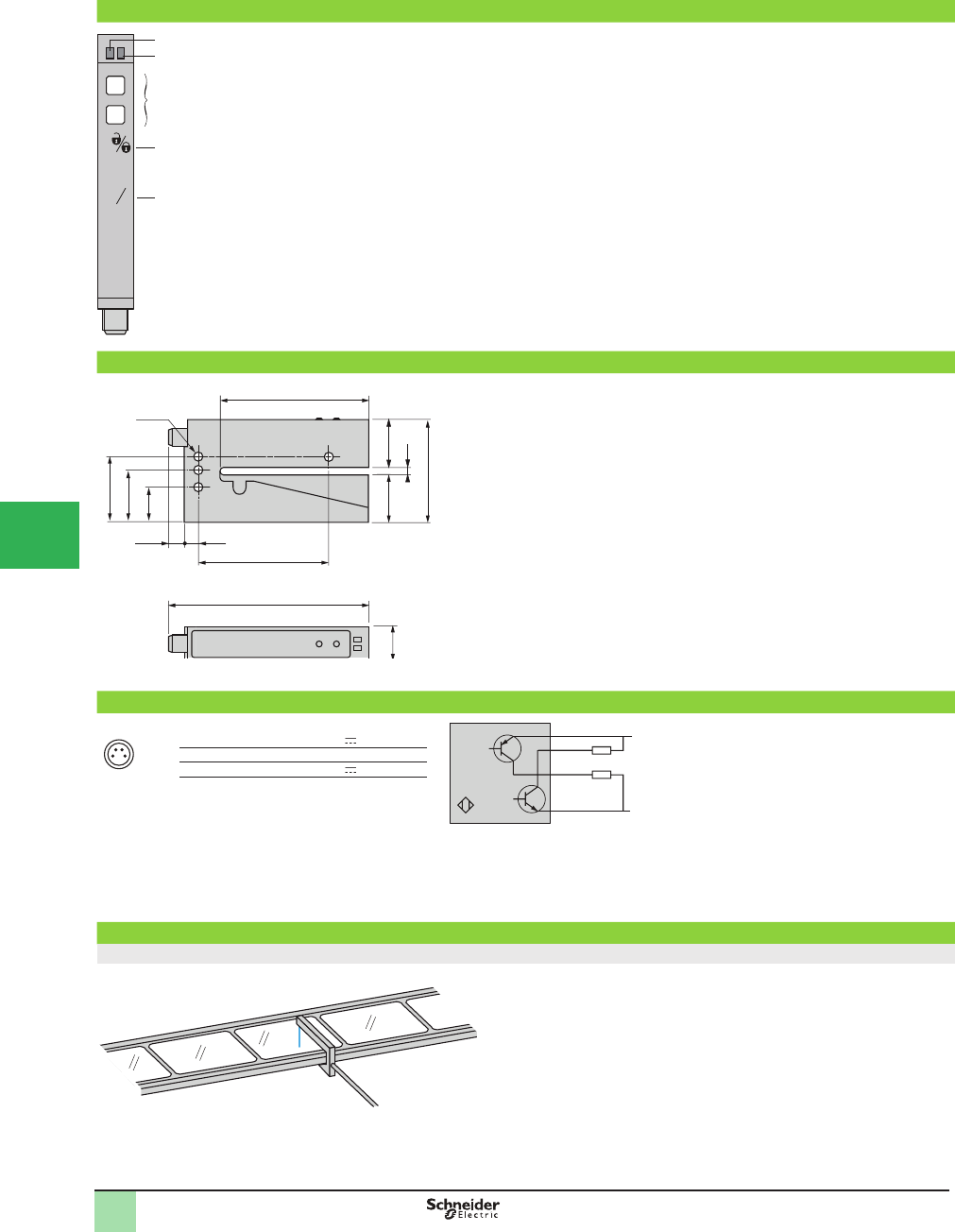
5/146
1
1
2
3
4
5/
6
7
8
9
10
Presentation (adjustment and display)
-
+
+
-
+
-
L
D
3s
6s
4
5
2
1
3
1 Tripping threshold adjustment using ± buttons
2 Locking of keypad by simultaneously pressing ± buttons and holding down for 3 s
3 Selection of output type (NO or NC) by simultaneously pressing ± buttons and
holding down for 6 s
4 Yellow LED: On when outputs active (current established)
Yellow LED: Flashes slowly in event of output short-circuit
5 Red LED: On each time the ± buttons are pressed
Red LED: Permanently On when keypad locked
Red LED: Off when keypad unlocked
Dimensions (mm)
92.5
16 22
47
.3
3
22.3
60
7.20 6.5
68.8
Ø4.2
16.2
24
30.2
Wiring diagram (sensor connector pin view)
Connector
0 V
c 10/30 V
1 BN
2 WH
4 BK
3 BU
24
1 3
1 Brown +10... 30 V
2 White NPN output
3 Blue 0 V
4 Black PNP output
Application example
Detection of transparent labels on transparent or opaque strip
L
Presentation,
Dimensions,
Wiring Diagram
OsiSense® XX
Ultrasonic sensor
Application, packaging series
For detection of transparent labels
DC supply, solid-state output
NPN
PNP
This document provided by Barr-Thorp Electric Co., Inc. 800-473-9123 www.barr-thorp.com
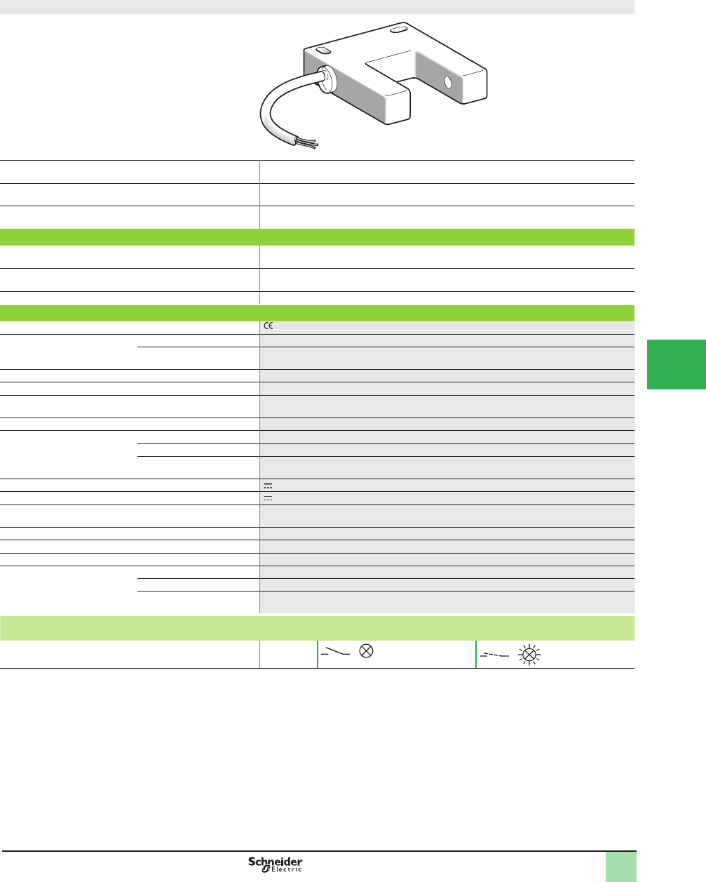
5/147
1
Fork design
System Thru-beam
Type of transmission Infrared
Nominal sensing distance Sn, mm (in.) 30 (1.18)
Catalog Number
3-wire, PNP NO function XUVH0312
3-wire, NPN NO function XUVJ0312
Weight, kg (lb) 0.130 (0.29)
Specifi cations
Product certifi cations
Ambient air temperature For operation -5 to +55 °C (+23 to 131°F)
For storage -20 to +70 °C (-4 to +158 °F)
Vibration resistance Conforming to IEC 60068-2-6 Amplitude ±1 mm up to 42 Hz, 7 gn (f = 10–42 Hz)
Shock resistance Conforming to IEC 60068-2-27 30 gn, duration 11 ms
Degree of protection Conforming to IEC 60529 IP 54
Connection Pre-cabled: diameter 5 mm, length 2 m, wire c.s.a.: 3 x 0.34 mm² (22 AWG)
Materials Case PC/ABS
Lenses PMMA
Cable PvR
Rated supply voltage 24 V with protection against reverse polarity
Voltage limits 19–38 V (including ripple)
Switching capacity (sealed) d150 mA with overload and short-circuit protection
Voltage drop, closed state d 1.5 V
Current consumption, no-load d 20 mA
Maximum switching frequency 1000 Hz
Delays First-up d 30 ms
Response 500 Ps
Recovery 500 Ps
Function table Function Thru-beam system
NO function No object present in the beam Object present in the beam
Output state (PNP or NPN) indicator: red LED
(illuminated when sensor output is ON)
NO
Catalog Numbers,
SpeciÞ cations
1
OsiSense® XU
Photoelectric sensors 1
Application, material handling series
Optical fork with integrated ampliÞ er
DC supply. Solid-state output
1
2
3
4
5
6
7
8
9
10
This document provided by Barr-Thorp Electric Co., Inc. 800-473-9123 www.barr-thorp.com
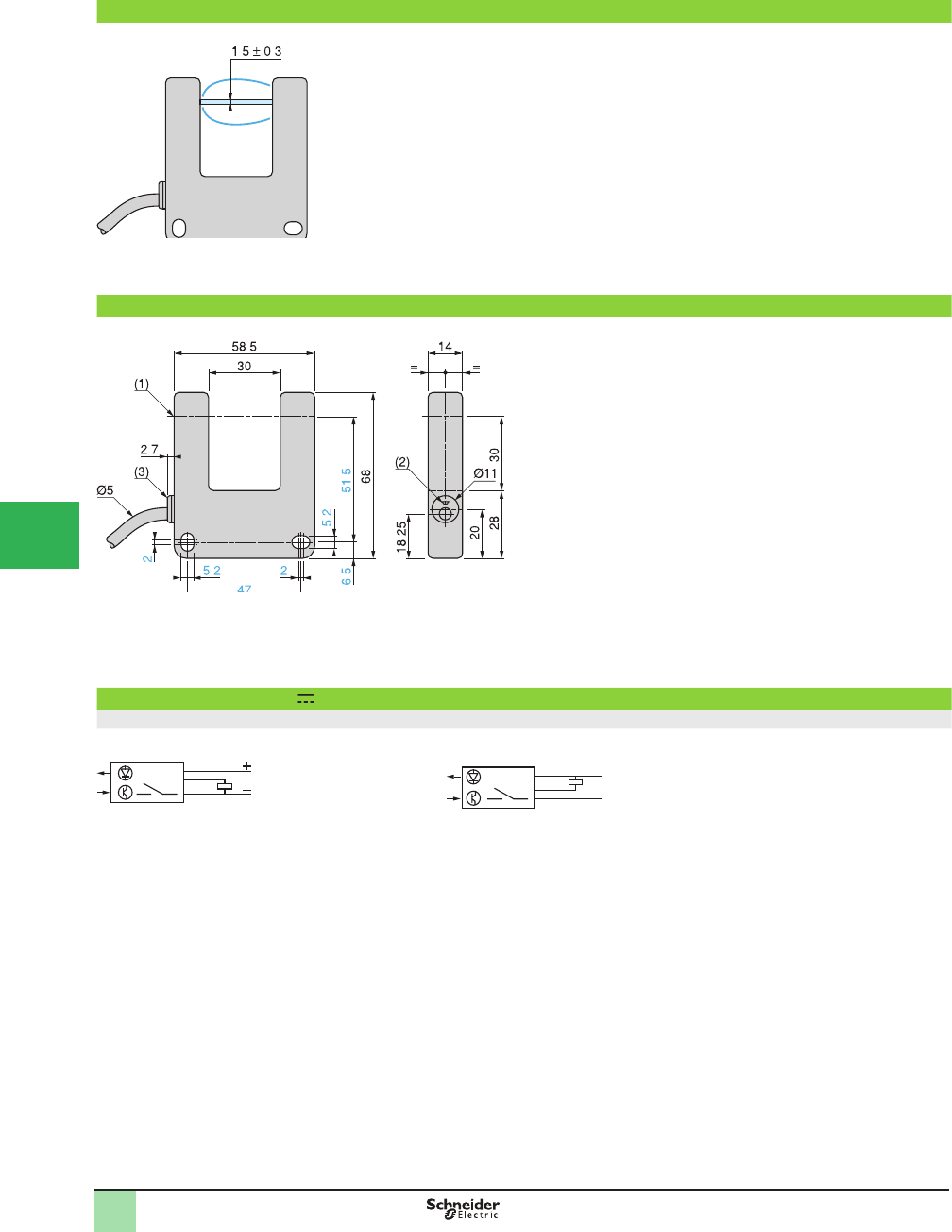
5/148
1
Operating curve
Dimensions (mm)
(1) Optical axis
(2) Red LED
(3) Diffuser
Max. tightening torque of mounting screws: 3 N•m (26.55 lb-in)
Wiring diagrams (3-wire )
NO function
PNP output NPN output
. .
.
.
.
.
.
.
.
BN
BK
BU
BN
BU
BK
+
–
Operating Curves,
Dimensions,
Wiring Diagrams
1
OsiSense® XU
Photoelectric sensors 1
Application, material handling series
Optical fork with integrated ampliÞ er
DC supply. Solid-state output
1
2
3
4
5/
6
7
8
9
10
This document provided by Barr-Thorp Electric Co., Inc. 800-473-9123 www.barr-thorp.com
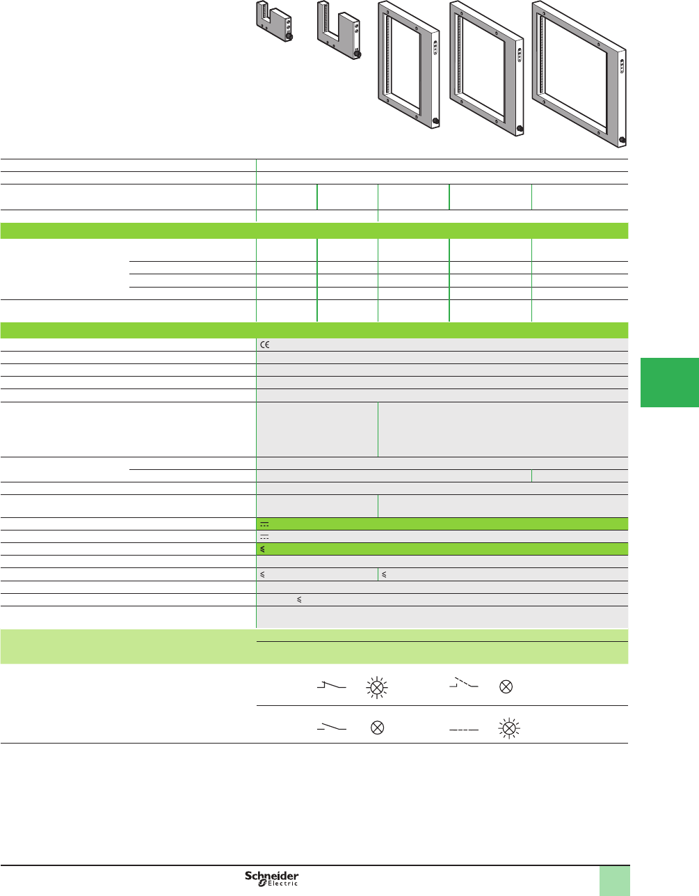
5/149
1
System Thru-beam
Type of transmission Infrared
Passageway dimensions, mm (in.) 30 x 30
(1.18 x 1.18)
60 x 60
(2.36 x 2.36)
200 x 120
(7.87 x 4.72)
200 x 180
(7.87 x 7.08)
200 x 250
(7.87 x 9.87)
Minimum size of object to be detected, mm (in.) Ø 2 mm (0.08) Ø 4 mm (0.016)
Catalog Number
3-wire, PNP and NPN
Output function On or
Off on passage of object,
programmable
Minimum size of object detected
– – – – –
Ø 2 mm (0.08 in.) XUVF30M8 XUVF60M8 – – –
Ø 4 mm (0.16 in.) – – XUVF120M12 XUVF180M12 XUVF250M12
Ø 10 mm (0.39 in.) – – XUYFRS120S XUYFRS180S XUYFRS250S
Weight, kg (lb) 0.080
(0.18)
0.140
(0.31)
1.060
(2.34)
1.200
(2.65)
1.320
(2.91)
Specifi cations
Product certifi cations , cULus
Ambient air temperature For operation: 0 to +60 °C (+32 to +140 °F). For storage: -20 to +80 °C (-4 to +176 °F)
Vibration resistance 25 gn, amplitude ± 2 mm (f = 10–55 Hz), conforming to IEC 60068-2-6
Shock resistance 30 gn, duration 11 ms, conforming to IEC 60068-2-27
Degree of protection Conforming to IEC 60529 IP 65
Connection M8 connector (suitable
female connectors, including
pre-wired versions)
M12 connector (suitable female connectors, including
pre-wired versions)
Materials Case Painted aluminium
Lenses Polycarbonate Altuglass
Immunity to ambient light Sunlight: 4,000 lux max., incandescent light: 400 lux max.
Passing speed of object Min.: 10 cm/s, max.: 15 m/s
(Ø 2 mm object)
Min.: 10 cm/s, max.: 15 m/s (Ø 4 mm object)
Rated supply voltage 24 V with protection against reverse polarity
Voltage limits 18–30 Vdc (including ripple)
Switching capacity
(sealed)
100 mA with overload and short-circuit protection
Voltage drop, closed state < 2 Vdc
Current consumption, no-load 120 mA 400 mA
Maximum switching frequency 500 Hz
Delays First-up: 100 ms; response: < 1 ms; recovery: < 1 ms
Time delay Off-delay (reset): adjustable between 0 and 5 seconds
Function table Function Thru-beam system
No object present
in the path
Passage of object
through the path
Output state (PNP or NPN) indicator:
green LED
(illuminated when sensor output is On)
Output Off
on passage
of object
Output On
on passage
of object
(1) XUVF sensors are suitable for detecting the passage of all types of objects (metal or plastic, of any shape or color), provided that the ß ow is dynamic.
Applications: counting parts, ß ow control of injection machine parts, etc.
Catalog Numbers,
SpeciÞ cations OsiSense® XU
Photoelectric sensors 0
Application, assembly series
Dynamic detection of passage of objects, counting parts (1)
DC supply, solid-state output
1
2
3
4
5
6
7
8
9
10
This document provided by Barr-Thorp Electric Co., Inc. 800-473-9123 www.barr-thorp.com
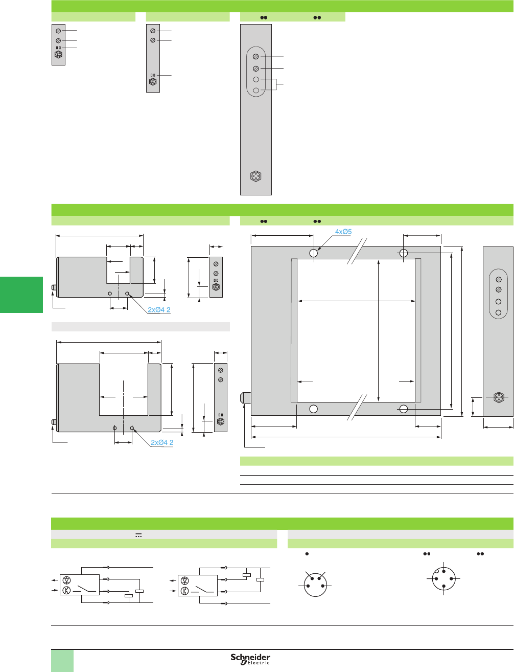
5/150
1
Presentation,
Dimensions,
Wiring Diagrams
Presentation
XUVF30M8 XUV F60M8 XUVF 0M12, XUYFRS 0S
1 Sensitivity adjustment potentiometer.
2 Time delay adjustment potentiometer.
3 Indicators:
Green LED: output
Red LED: alarm
Notes:
In the event of a supply malfunction, the red LED -
ß ashes.
In the event of a short-circuit on the output, both -
the red and green LEDs ß ash.
Dimensions (mm)
XUVF30M8 XUVF 0M12, XUYFRS 0S
XUVF60M8
XUV XUY a a1
F120M12 FRS120S 205 120 (4.72 in.)
F180M12 FRS180S 265 180 (7.08 in.)
F250M12 FRS250S 335 250 (9.84 in.)
(1) Transmitting face.
(2) Reception face.
Wiring diagrams
Wiring diagrams (3-wire ) Connector diagram (sensor connector pin view)
Output On on passage of object programmed (1) Output On on passage of object programmed (1)
PNP output NPN output XUVF 0M8 XUVF 0M12, XUYFRS 0S
Note: the alarm (2) triggers in the event of an object stopping within the beam.
(1) To program the sensor for Output Off on passage of object, connect contact 3 to (+) and contact 1 to (–).
3
1
2
3
1
2
1
2
3
1630
108
22
M8
3.5
50
11.6
15
(2)
(1)
36
.
85
a1
a
200
222.5
50
22
230
60
M12
25 25
(2) (1)
1660
131
86
11.6
22
15
M8
3.5
(2) (1)
70
.
+
–
3
4
2
1
+
–
3
4
2
1
1 (+) 3 ( )
–
42
A
larm Output
1 (+)
3 (
–
)
4
2
A
larm Output
OsiSense® XU
Photoelectric sensors 0
Application, assembly series
Dynamic detection of passage of objects, counting parts
DC supply, solid-state output
1
2
3
4
5/
6
7
8
9
10
This document provided by Barr-Thorp Electric Co., Inc. 800-473-9123 www.barr-thorp.com
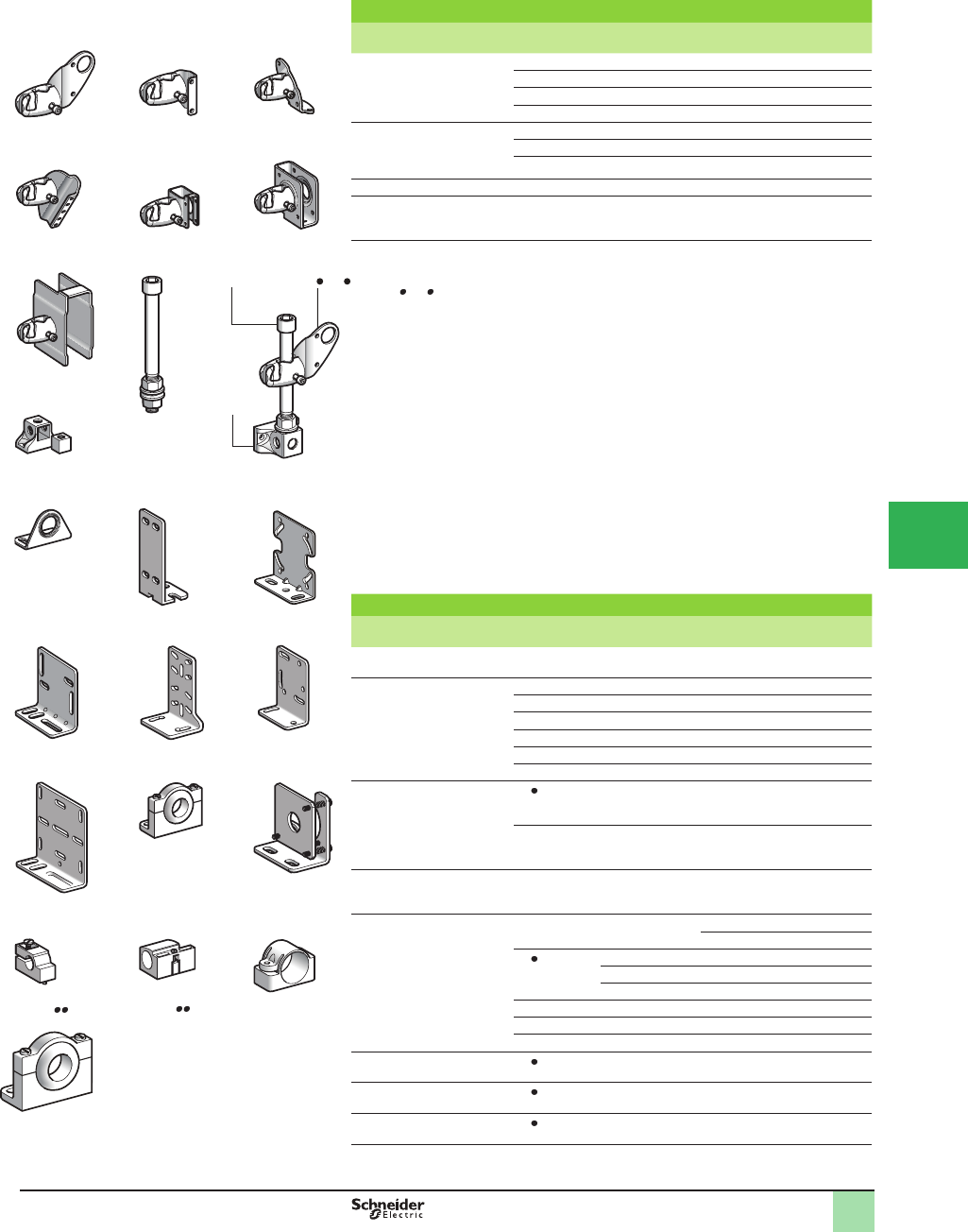
5/151
1
OsiSense® XU
Photoelectric sensors 1
Accessories
3D mounting kit (1)
Description For use with
sensor type
Catalog
Number
Weight
kg (lb)
Ball-joint mounted bracket
for mounting on M12 rod
XUB or XUZC50 XUZB2003 0.170 (0.37)
XUM0 or XUZC50 XUZM2003 0.140 (0.31)
XUK or XUZC50 XUZK2003 0.170 (0.37)
XUX or XUZC50 XUZX2003 0.220 (0.49)
Ball-joint mounted bracket
with protective cover for
mounting on M12 rod
XUM0 XUZM2004 0.155 (0.34)
XUK XUZK2004 0.270 (0.60)
XUX XUZX2004 0.420 (0.93)
Support for M12 rod –XUZ2003 0.150 (0.33)
M12 rod
(adjustment possible over
complete height)
–XUZ2001 0.050 (0.11)
(1) To obtain a 3D mounting kit, order:
- XUZ2003 rod support
- XUZ2001 M12 rod
- XUZ 200 ball-joint mounted bracket
Mounting accessories
Description For use with
sensor type
Catalog
Number
Weight
kg (lb)
Stainless steel mounting
bracket
XUB XUZA118 0.045 (0.10)
Metal mounting brackets XUM XUZA50 0.025 (0.06)
XUK XUZA51 0.050 (0.11)
XUX XUZX2000 0.065 (0.14)
XUL XULZ41 0.050 (0.11)
XUJ XUZA41 0.050 (0.11)
XUJ B XUZA49 0.120 (0.26)
Plastic mounting bracket
with adjustable ball-joint
XU (Ø 18 mm) XUZA218 0.035 (0.08)
XUC XSZSB30 0.068 (0.15)
Precision mounting bracket
with micrometric adjustment
XU2 (Ø 18 mm)
with laser transmission
XUZA318 0.170 (0.37)
Plastic mounting clamps
with locking screw
XUA (Ø 8 mm) XSAZ108 0.007 (0.02)
XSZB108 0.006 (0.01)
XU (Ø 18 mm) With lug XSAZ118 0.020 (0.04)
With indexing pin XSZB118 0.010 (0.02)
With 24.1 mm ctrs. XUZB2005 0.007 (0.02)
Glass Þ ber optics XUFS0810 XSAZ145 0.005 (0.01)
Fiber optics XUFS2510 XSAZ155 0.005 (0.01)
Fiber optics XUFS0210 XSAZ185 0.005 (0.01)
Set of 2 plastic nuts XU (Ø 18 mm) XSZE218 0.004 (0.01)
Set of 2 metal nuts XU (Ø 18 mm) XSZE118 0.015 (0.03)
Set of 2 stainless steel nuts XU (Ø 18 mm) XSZE318 0.015 (0.03)
XUZ 2003
XUZ 2001 200XUZ
XUZA51
XUZX2004
XUZK2004XUZM2004
XUZX2003
XUZK2003XUZM2003
X
UZB2003
XUZ2001
XUZX2000
XUZA50
3D mounting kit
example
XSAZ1
X
UZA49
XUZA41
XULZ41
XUZA118
XUZA318
XUZA218
X
UZ2003
XSZB1 XUZB2005
Catalog Numbers
1
XSZSB30
1
2
3
4
5
6
7
8
9
10
This document provided by Barr-Thorp Electric Co., Inc. 800-473-9123 www.barr-thorp.com
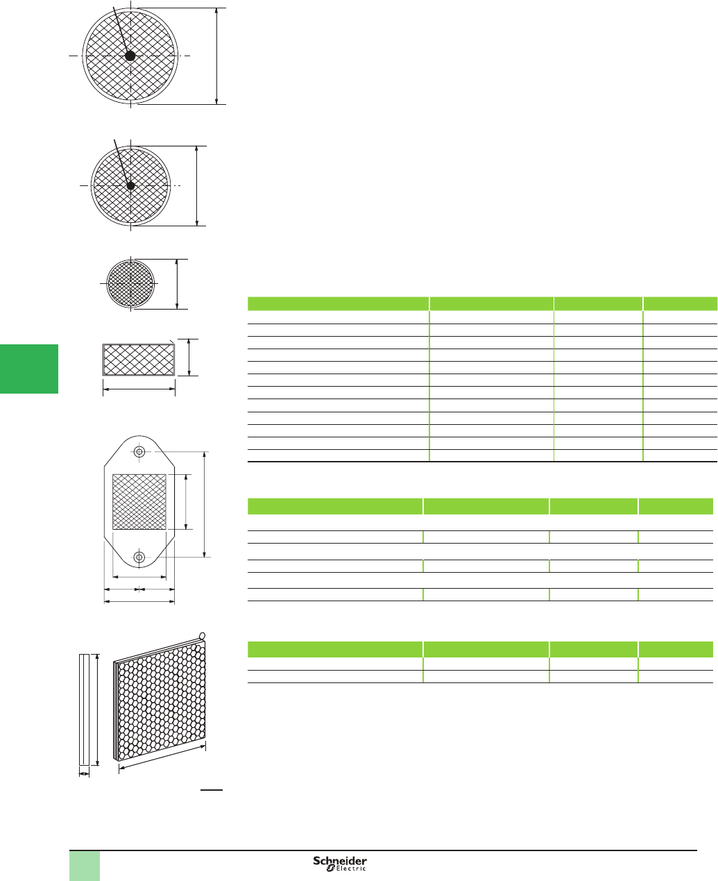
5/152
1Corner cube reß ectors used with retroreß ective photoelectric sensors provide a high degree of
reliability, since they return the light to its source even if the reß ector and the sensor are
signiÞ cantly skewed with respect to one another. Corner cube reß ectors also have the only
reß ective surface that works with polarized photoelectric sensors.
The nominal sensing distance for every retroreß ective sensor model in this catalog was
established using a 3 in. (76 mm) RF30 reß ector. Smaller reß ectors will result in shorter
sensing distances. These reß ectors are used to detect smaller targets comparable with their
dimension. The standard reß ectors present a blind spot at about 10% of the sensing distance.
Special reß ectors XUZC24/50 are designed to eliminate this inconvenience and even allow
the reß ector to touch the sensor lenses.
RF30 and RF20 models can be mounted with a bolt. The RF10 model can be mounted by
using a bezel or plate (not provided) or by using their own adhesive tape.
Rectangular reß ectors increase sensing precision. They are also easier to mount side by side
to increase the reß ective surface.
Retroreß ective tape can be used to cover unusually shaped targets. Reß ector tape not a
corner cube reß ective. Only Super-reß ective tape is a corner cube reß ective. Super-reß ective
tape can be used with both polarized and non-polarized retroreß ective sensors.
Refl ectors
Description Refl ectivity Temperature Range Catalog Number
76 mm (3 in.) diameter, acrylic lens 4000X 65 °C (150 °F) RF30
51 mm (2 in.) diameter, acrylic lens 4000X 65 °C (150 °F) RF20
25 mm (1 in.) diameter, acrylic lens 4000X 65 °C (150 °F) RF10
83 x 38 mm (3.25 x 1.5 in.), acrylic lens (orange) 4000X 65 °C (150 °F) RF13
102 x 102 mm (4 x 4 in.) diameter, acrylic lens 4000X 65 °C (150 °F) XUZC100
33 x 28 mm (1.3 x 1.1 in.) close proximity—acrylic (1) 6000X 65 °C (150 °F) XUZC24
51 x 51 mm (2 x 2 in.) close proximity—acrylic (1) 6000X 65 °C (150 °F) XUZC50
16 mm (0.63 in.) 4000X 65 °C (150 °F) XUZC16
21 mm (0.83 in.) 4000X 65 °C (150 °F) XUZC21
31 mm (1.22 in.) 4000X 65 °C (150 °F) XUZC31
39 mm (1.53 in.) 4000X 65 °C (150 °F) XUZC39
80 mm (3.15 in.) 4000X 65 °C (150 °F) XUZC80
(1) XUZC24/50 reß ectors must always be mounted in the vertical plane with respect to the optical axis of the sensor.
Retrorefl ective Tape
Description Typical Luminance Factor (2) Temperature Catalog Number
Photoelectric grade sheeting with adhesive backing (3)
76 mm (3 in.) wide, 0.3 m (1 ft) long (4) 200X 93.4 °C (200 °F) RF7590
High intensity sheeting with adhesive backing—vinyl sealed (3)
76 mm (3 in.) wide, 0.3 m (1 ft) long (4) 670X 65.6 °C (150 °F) RF3870
High gain sheeting with adhesive backing—porous surface (3)
51 mm (2 in.) wide, 0.3 m (1 ft) long (4) 900X 79.5 °C (175 °F) RF7610
Super Refl ective Tape—corner cube type, adhesive backing
Can be used with polarized retrorefl ective systems
Description Typical Luminance Factor (2) Temperature Catalog Number
1 in. (25 mm) wide, 3 ft (1 m) long 2000X 60 °C (140 °F) XUZB11
1 in. (25 mm) wide, 16 ft (5 m) long 2000X 60 °C (140 °F) XUZB15
(2) Perpendicular reading. Expressed as times brighter than a perfectly diffusing, white surface.
(3) Not suitable for polarized models.
(4) Also available in 3 m (10 ft), 15 m (50 ft) and 30 m (100 ft) lengths.
3.9
100
3.9
100
0.31 (8)
3
76
2.0
51
1.0
25
3.25
83
1.0
25
0.82
21
1.30
33
0.94
24
= =
1.14
29
0.3 (8)
0.3 (8)
XUZC100
XUZC24
RF10
RF13
RF20
RF30
OsiSense® XU
Photoelectric sensors 1
Accessories
Catalog Numbers (continued)
in.
mm
1
2
3
4
5/
6
7
8
9
10
This document provided by Barr-Thorp Electric Co., Inc. 800-473-9123 www.barr-thorp.com
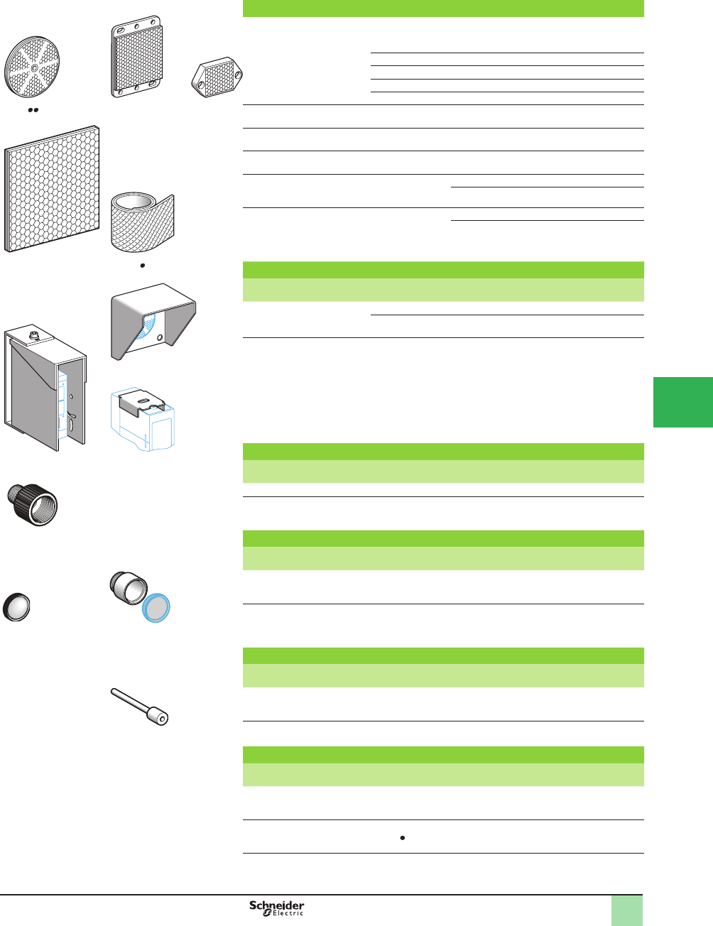
5/153
1
OsiSense® XU
Photoelectric sensors 1
Accessories
Refl ectors
Description Dimensions
(mm)
Length
(m)
Catalog
Number
Weight
kg (lb)
Standard refl ectors Ø 16 – XUZC16 0.002 (0.002)
Ø 21 – XUZC21 0.002 (0.002)
Ø 31 – XUZC31 0.005 (0.010)
Ø 39 – XUZC39 0.008 (0.020)
Ø 80 – XUZC80 0.029 (0.060)
Universal refl ector
(without blind zone)
50 x 50 – XUZC50 0.020 (0.040)
Refl ector for short sensing
distances
24 x 21 – XUZC24 0.007 (0.020)
Refl ector for long sensing
distances
100 x 100 – XUZC100 0.062 (0.140)
Standard refl ective adhesive
tape (1)
Width: 22
Thickness: 0.4
1 XUZB01 0.015 (0.030)
5XUZB05 0.075 (0.170)
Refl ective adhesive
tape (1)
(speciÞ cally for polarized
retroreß ective systems)
Width: 22
Thickness: 0.4
1XUZB11 0.020 (0.040)
5XUZB15 0.085 (0.190)
Protective covers
Description For use with Catalog
Number
Weight
kg (lb)
Protective covers Sensors XUX and XUJ XUZD25 0.920 (2.030)
Reß ectors XUZC80
or XUZC24
XUZD15 0.270 (0.600)
Potentiometer
protective cover
Sensors XUJ XUJZ01 0.015 (0.030)
Cabling accessories
Description Catalog
Number
Weight
kg (lb)
Adapter, ISO 16 - 1/2 NPT XUZX2001 0.050 (0.110)
Adapter, ISO 16 - ISO 20 XUZX2002 0.050 (0.110)
Lenses
Description For use with Catalog
Number
Weight
kg (lb)
Lens for spot
enlargement
Sensors XUR XURZ01 0.010 (0.020)
Lens accessory for
spot reduction
Sensors XUR XURZ02 0.015 (0.030)
Spare parts
Description For use
with
Sold in
lots of
Catalog
Number
Weight
kg (lb)
Plastic end adapter for
connecting Ø 1 mm Þ ber optics
AmpliÞ ers XUD
A
2XUFZ08 0.002 (0.002)
Protection fuses
Description For use
with
Sold in
lots of
Catalog
Number
Weight
kg (lb)
Cartridge fuse
5 x 20
0.4 A fast-acting
Sensors without
short-circuit
protection
10 XUZE04 0.001 (0.001)
Fuse terminal block Cartridge fuses
XUZE0
50 AB1FU10135U 0.040 (0.010)
(1) Suitable for use at maximum ambient temperature of +50 °C (122 °F).
XUZC50XUZC XUZC24
XUZB0XUZC100
XUJZ01XUZD25
XUZD15
XURZ02XURZ01
XUZX2001
XUFZ08
Catalog Numbers (continued)
1
1
2
3
4
5
6
7
8
9
10
This document provided by Barr-Thorp Electric Co., Inc. 800-473-9123 www.barr-thorp.com
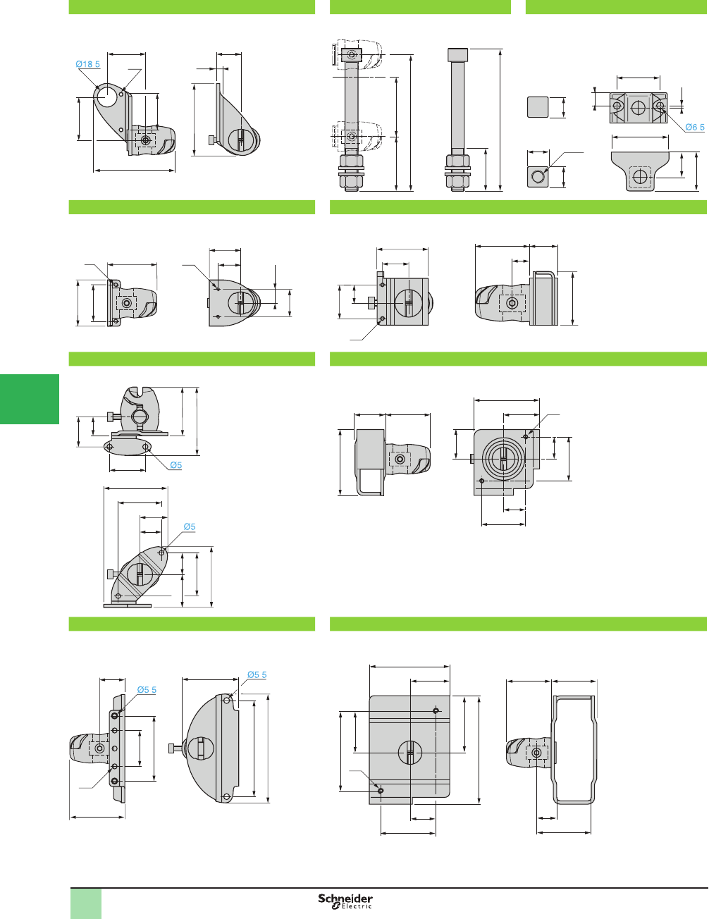
5/154
1
OsiSense® XU
Photoelectric sensors 1
Accessories
XUZB2003 XUZ2001 XUZ2003
Ball-joint mounted bracket for XUB or XUZC50 M12 rod Support for M12 rod
XUZM2003 XUZM2004
Ball-joint mounted bracket for XUM (1) or XUZC50 Ball-joint mounted bracket with protective cover for XUM (1)
XUZK2003 XUZK2004
Ball-joint mounted bracket for XUK (1) or XUZC50 Ball-joint mounted bracket with protective cover for XUK (1)
XUZX2003 XUZX2004
Ball-joint mounted bracket for XUX (1) or XUZC50 Ball-joint mounted bracket with protective cover for XUX (1)
(1) Accessory mounting screws included.
5.7
22.9
40
33
36
76.5
M4
67
.
126
50 55
132
40
23
40
M12
1.9
12
19
53
36
19 19
.
45
M4
33
42
29
25
M3 21
12.5
38
19.5
M3
25
49
13.5
40.5 21
13
33
45
63
28
17.5
59.5
40
20
25.8
56.5
40
2030.6
40.528 M4
27
60
40
20
33
60
40
20
52.5
51
73
100
23.1
33
60
4.5
.
.
40.5 41.5
73
50
36
23.5
M5
38
73
99
52
49.5
18
Dimensions (mm)
1
1
2
3
4
5/
6
7
8
9
10
This document provided by Barr-Thorp Electric Co., Inc. 800-473-9123 www.barr-thorp.com
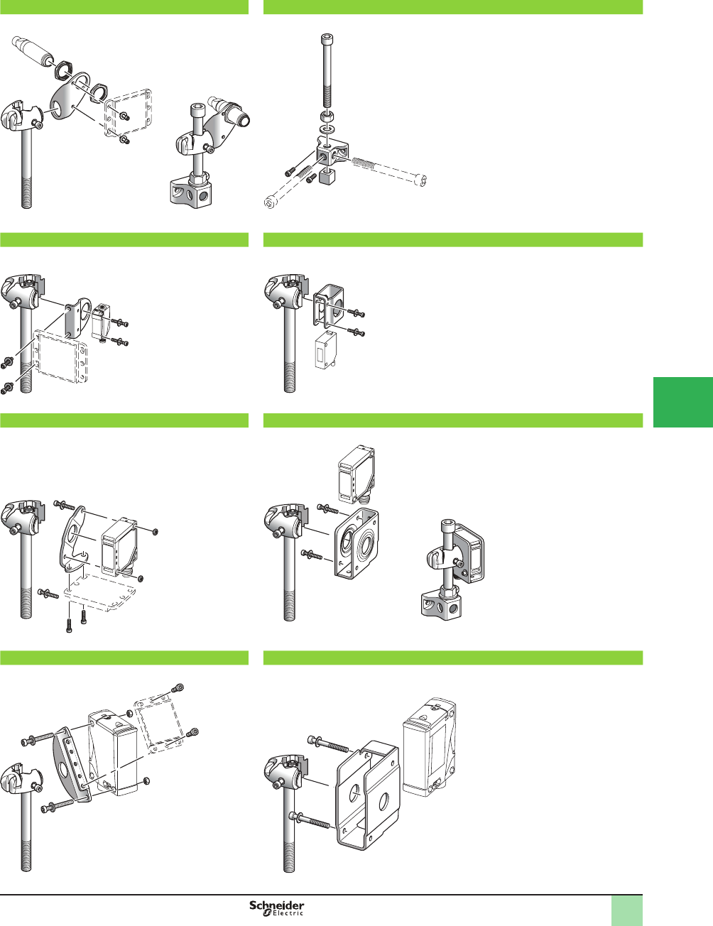
5/155
1
OsiSense® XU
Photoelectric sensors 1
Accessories
XUZB2003 +XUZ2001 +XUZ2003 XUZ2001 +XUZ2003
3D mounting kit for XUB or reß ector XUZC50 M12 rod +rod support
XUZM2003 +XUZ2001 XUZM2004 +XUZ2001
3D mounting kit for XUM or reß ector XUZC50 3D mounting kit with protective cover for XUM
XUZK2003 +XUZ2001 XUZK2004 +XUZ2001 +XUZ2003
3D mounting kit for XUK or reß ector XUZC50 3D mounting kit with protective cover for XUK
XUZX2003 +XUZ2001 XUZX2004 +XUZ2001
3D mounting kit for XUX or reß ector XUZC50 3D mounting kit with protective cover for XUX
Mounting example
Mounting
1
1
2
3
4
5
6
7
8
9
10
This document provided by Barr-Thorp Electric Co., Inc. 800-473-9123 www.barr-thorp.com
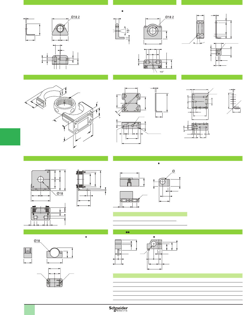
5/156
1
OsiSense® XU
Photoelectric sensors 1
Accessories
XUZA118 XUZA218 XUZA50
Mounting bracket for XUB (Ø 18) Mounting bracket with adjustable ball-joint
for XU (Ø 18)
Mounting bracket for XUM (2)
XSZSB30 XUZA51 XUZX2000
Mounting bracket for XUC (2) Mounting bracket for XUK (2) Mounting bracket for XUX (2)
XUZA318 XSZB108, XSZB118
Mounting bracket with micrometric adjustment for XU2 (Ø 18)
with laser transmission
Mounting clamps for XUA and XU (Ø 18)
XCZ a a1 b b1 b2 Ø
B108 21.1 14.5 14.2 12.8 7.5 8
B118 26 15.7 22.3 20.1 11.5 18
(1) 2 elongated holes Ø 4 x 8.
XUZB2005 XSAZ1
Mounting clamps with 24.1 mm centers for XU (Ø 18) Mounting clamps for XUA, XU (Ø 18), XUF
XSA a b b1 c d Ød1 Ød2 Ød3 fG G1
Z108 23.5 14.2 16.7 10 8 8.1 2410.5 16 5
Z118 41 30 33 17 18 18.1 3.9 624 30 7
Z145 23.5 14.2 16.7 10 8 4.7 2410.5 16 5
Z155 23.5 14.2 16.7 10 8 5.7 2410.5 16 5
(2) Accessory mounting screws included. Z185 23.5 14.2 16.7 10 8 8.6 2410.5 16 5
2.5
35
28
1
15
206.5
6.5
=
10
=
16.5
= =
50
.
45
248
= =
10
25
55
8
5
6.5
19.5
27
.
39
15
3
3
35
45
6.5
9.5
55
64
34 30
=
=
59
8 249.5 9.58
=
=
44
4822.3
(1)
38.3
b
b2
a
3.5
b1
a1
Ø3 Ø3
13.2
16 30.7
==
20
24.1
d2
= =
c
2.5
b1
d
f
b
d3
d1
= =
G G1
a
Dimensions
1
58
¯5.5
30
R3
R3
R6
52
106
64
714
2412±0.1
6.5
12.8
16.5 28 20
18
64
63
5 13
40
10°
34
15
58
48.5
18 7
6 x 13
622
6 x 12
12 40
40
60
12
3
47.5
3.2
8.3
15
18
5°
10 3
41
3 x 4
525.5 4.5
8.2 x 3.2
27.9
(1.10)
29.2
(1.15)
28.7
(1.13) 50.8
(2.00)
66.7
(2.62)
12.7
(0.50)
M30x1
14.2
(0.56)
6.34
(0.25)
20.3
(0.80)
1
2
3
4
5/
6
7
8
9
10
This document provided by Barr-Thorp Electric Co., Inc. 800-473-9123 www.barr-thorp.com
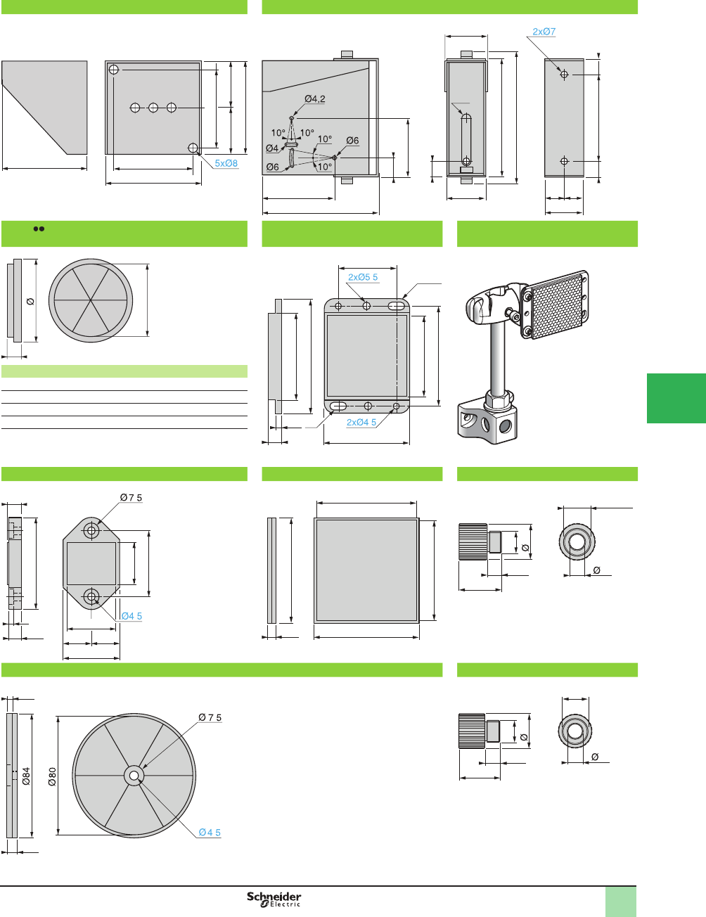
5/157
1
OsiSense® XU
Photoelectric sensors 1
Accessories
XUZD15 XUZD25
Protective cover for XUZC80 or XUZC24 Protective cover for XUX or XUJ
XUZC XUZC50 XUZM2003 +XUZ2001 +XUZ2003
+XUZC50
Mounting example
XUZ Ø c d
C16 21 5.5 17
C21 25.5 6 20.5
C31 35 7.5 30.5
C39 46 6.5 37
(1) 2 elongated holes Ø 4.5 x 8
XUZC24 XUZC100 XUZX2001
XUZC80 XUZX2002
80 73
72
91
88
==
128–135
83.4
22
66
133.5
149
16
44
48
(1)
101.5 1616
44
= =
c
d
3.5
51
69
8
47
60
(1)
4xR5
35
51.5
.
.
4
7.5
45
9
21
33
29
=
=
24 .
.
100
9.5 100
96
96
11.3
32
M16
27
1/2" NPT
11
7.5
4.5
.
.
M20
M16
11.3
31
26
11
Dimensions (continued)
1
1
2
3
4
5
6
7
8
9
10
This document provided by Barr-Thorp Electric Co., Inc. 800-473-9123 www.barr-thorp.com
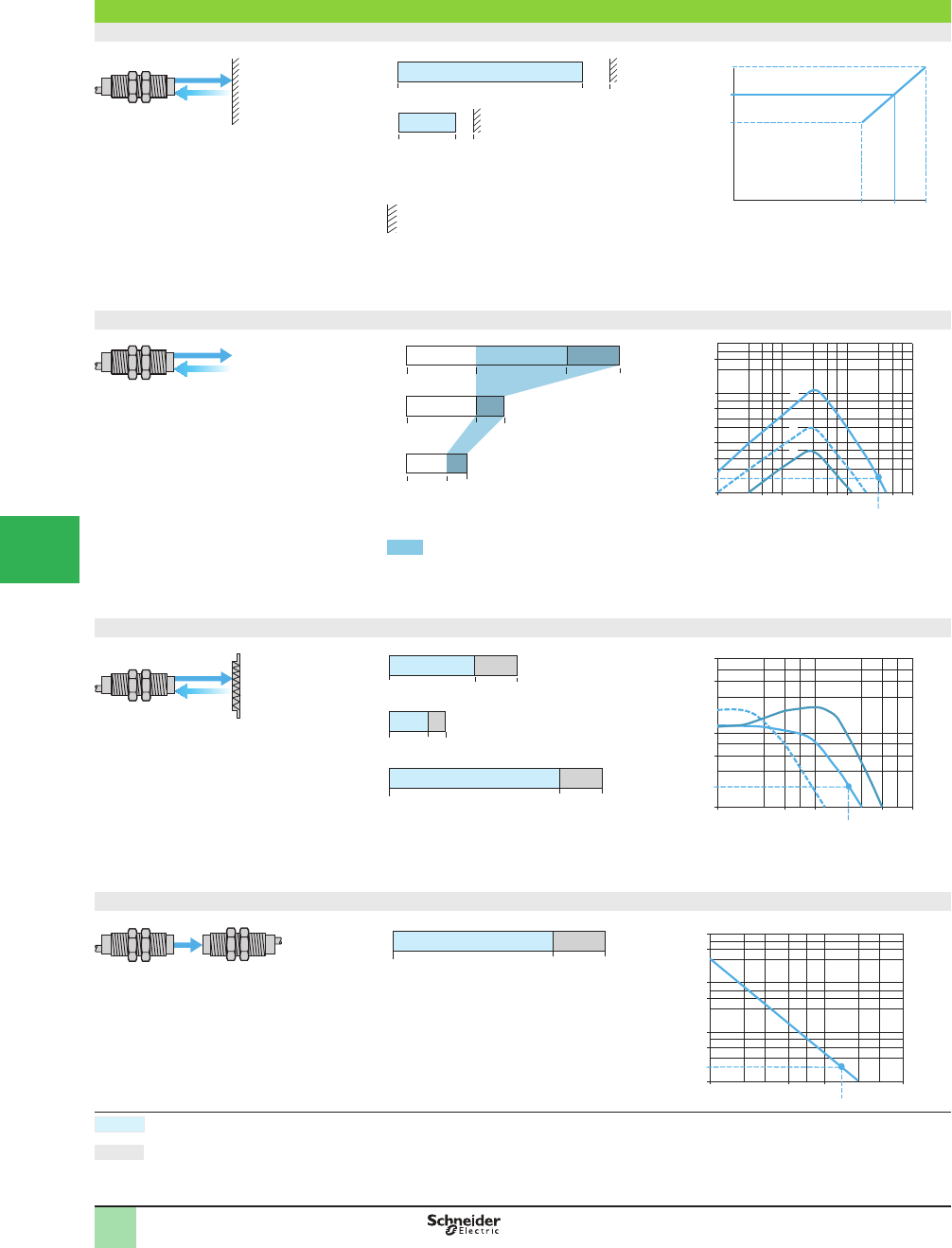
5/158
1
OsiSense® XU
Photoelectric sensors 1
XUB0 Multimode function
with line of sight along case axis
Sensing distance and operating margin
Background suppression mode
Without accessory
a: with background teaching at maximum
recommended distance.
b: with background teaching at minimum
recommended distance.
Example: teaching against a background located at
13.5 cm enables detection of an object at 1 to
10 cm.
(1) From white 90% to black 6%.
Diffuse mode
Without accessory
(1) White 90%. (2) Gray 18%. (3) Black 6%.
Object teaching zone 1White object
2Gray object
3Black object
In diffuse mode, teaching of the position of the object to be detected, located between 0 and 12 cm,
automatically conÞ gures the product to background suppression mode. This provides a constant usable
sensing distance, whatever the color of the object.
Polarized retrorefl ective mode
With refl ector
1With reß ector XUZC50
2With reß ector XUZC24
3With reß ector XUZC100
Thru-beam mode
With thru-beam accessory
EG: Excess gain, operating margin.
20 m15
0
Gain
Nominal sensing distance. EG ≥ 2.
Maximum sensing distance. The maximum sensing distances indicated are average values.
Background
EG = 2
EG = 2
EG = 2
Operating Curves
(1)
(2)
(3)
30 13
18 cm
40 cm
8
13
11 cm
0.3 cm
0
0
0.01–0.12 m max.
b
a
1 cm
1 cm
17 cm12
10 cm8 cm
5 cm
5 cm
8 12 cm10 cm
13,5 cm
17 cm
10
Background distance(1)
Maximum distance of object to be detected (1
)
500.1 cm
5
10
20
50
100
1
500
0.5 1 5 10 100 cm
2
3
1
Sn = 30 cm
Distance
Gain
0–0.4 m max.
0.003–5 m max.
XUZC50
XUZC24
XUZC100
5 m4 m
2 m
0.9 m 1.3 m
3 m
5 mm
3 mm
3 mm
50.1 m 0.5
5
10
1
100
50
1 10 m
2
3
1
Sn = 2 m
Gain
Distance
50 m1 m
5
10
50
100
1
1000
500
5 10
Sn = 15 m
Distance
0–20 m max.
1
2
3
4
5/
6
7
8
9
10
This document provided by Barr-Thorp Electric Co., Inc. 800-473-9123 www.barr-thorp.com
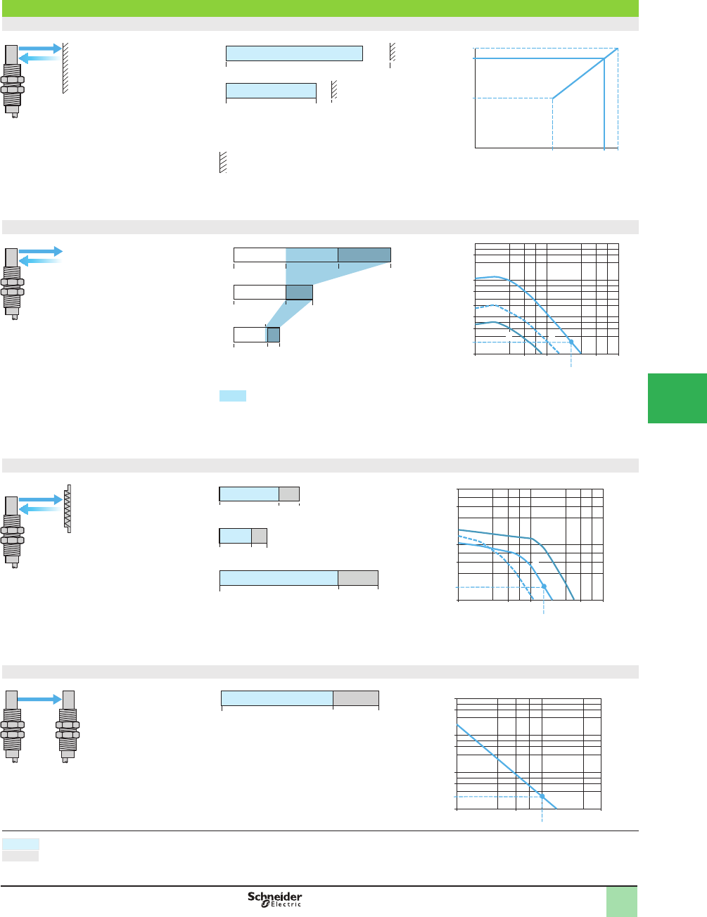
5/159
1
OsiSense® XU
Photoelectric sensors
XUB0 Multimode function
with line of sight 90° to case axis
Sensing distance and operating margin
Background suppression mode
Without accessory
a: with background teaching at maximum
recommended distance.
b: with background teaching at minimum
recommended distance.
Example: teaching against a background located at
13.5 cm enables detection of an object at 0 to
10 cm.
(1) From white 90% to black 6%.
Diffuse mode
Without accessory
(1) White 90%. (2) Gray 18%. (3) Black 6%.
Object teaching zone 1White object
2Gray object
3Black object
In diffuse mode, teaching of the position of the object to be detected, located between 0 and 11 cm,
automatically conÞ gures the product to background suppression mode. This provides a constant usable
sensing distance, whatever the color of the object.
Polarized retrorefl ective mode
With refl ector
1With reß ector XUZC50
2With reß ector XUZC24
3With reß ector XUZC100
Thru-beam mode
With thru-beam accessory
EG: Excess gain, operating margin.
14 m10
0
Nominal sensing distance. EG ≥ 2.
Maximum sensing distance. The maximum sensing distances indicated are average values.
Background
EG = 2
EG = 2
Operating Curves
50 m1 m
5
10
50
100
1
1000
500
5
Sn = 10 m
Gain
Distance
50.1 m 0.5
5
10
1
100
50
1 10 m
3
2
1
Sn = 1.5 m
Gain
Distance
XUZC50
XUZC24
XUZC100
4 m3 m
1.5 m
0.8 m 1.2 m
2 m
0 cm
3 cm
0 cm
0–4 m max.
0
–
14
m max.
0–0.3 m max.
(1)
(2)
(3)
20 10
14 cm
30 cm
6
10
8 cm
6.5
0.3 cm
0
0
1
501 cm
5
10
20
50
100
1
500
5 10 100 cm
2
3
Sn = 20 cm
Distance
Gain
0 cm
0 cm
6 11 cm10
13.5 cm
15 cm
7.5
Background distance (1)
Maximum distance of object to be detected (1)
b
a
0 cm
0 cm
15 cm11
10 cm8 cm
0.01–0.11 m max.
EG = 2
1
2
3
4
5
6
7
8
9
10
This document provided by Barr-Thorp Electric Co., Inc. 800-473-9123 www.barr-thorp.com
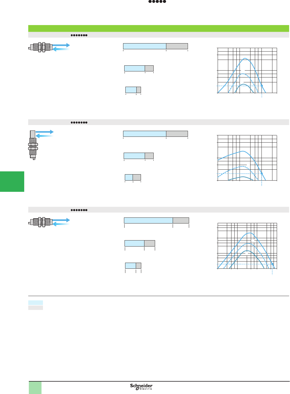
5/160
1
OsiSense® XU
Photoelectric Sensors 1
Single mode function
XUB with line of sight along or at 90° to case axis
Sensing distance and operating margin
Diffuse sensor XUB4 with line of sight along case axis
(1) White 90%. (2) Gray 18%. (3) Black 6%. 1White object
2Gray object
3Black object
Diffuse sensor XUB4 with line of sight 90° to case axis
(1) White 90%. (2) Gray 18%. (3) Black 6%. 1White object
2Gray object
3Black object
Diffuse sensor XUB5 with line of sight along or at 90° to case axis
(1) White 90%. (2) Gray 18%. (3) Black 6%.
(4) No detection.
1White object
2Gray object
3Black object
Nominal sensing distance. EG ≥ 2.
Maximum sensing distance. The maximum sensing distances indicated are average values.
EG: Excess gain, operating margin.
a: Potentiometer set at maximum.
b: Potentiometer set at minimum.
0.001–0.15 m max.
(1)
(2)
(3)
7 cm
10
5
15 cm
0.1 cm
34 cm
0.3 cm
0.6 cm
50 cm0.1 cm 0.5
5
10
50
100
11 5
2
1
3
Sn = 10 cm
Gain
Distance
0–0.15 m max.
(1)
(2)
(3)
7 cm
10
5
15 cm
0 cm
24 cm
0.1 cm
0.3 cm
50 cm0.1 cm 0.5
5
10
50
100
11 5
2
3
1
Sn = 10 cm
Gain
Distance
0.001–0.8 m max.
(1)
(2)
(3)
38 cm
60
25
80 cm
0,1 cm
15 21 cm
0,2 cm
0.4 cm
a
b
a
b
a
b
(4)
(4)
(4)
500.1 cm 0.5
5
10
50
100
500
11 5 10 100 cm
2
3
1
Sn = 60 cm
Gain
EG = 2
EG = 2
Distance
EG = 2
Operating Curves
1
2
3
4
5/
6
7
8
9
10
This document provided by Barr-Thorp Electric Co., Inc. 800-473-9123 www.barr-thorp.com
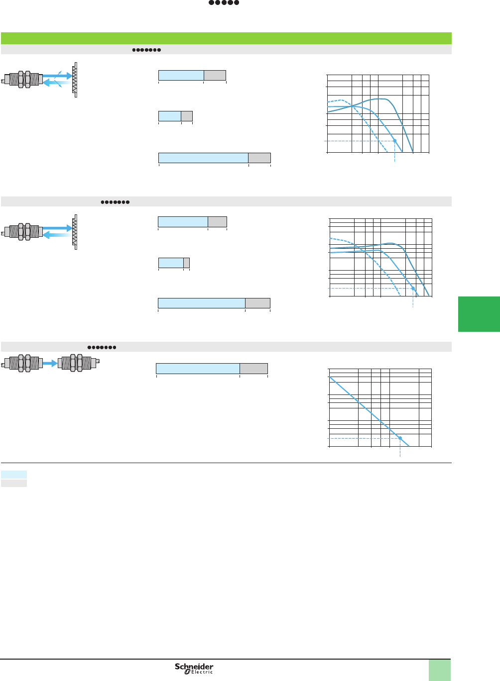
5/161
1
OsiSense® XU
Photoelectric Sensors 1
Single mode function
XUB with line of sight along or at 90° to case axis
Sensing distance and operating margin
Polarized retrorefl ective sensor XUB9 with line of sight along or at 90° to case axis
With refl ector
1With reß ector XUZC50
2With reß ector XUZC24
3With reß ector XUZC100
Retrorefl ective sensor XUB1 with line of sight along or at 90° to case axis
With refl ector
1With reß ector XUZC50
2With reß ector XUZC24
3With reß ector XUZC100
Thru-beam sensor XUB2 with line of sight along or at 90° to case axis
With thru-beam accessory
Nominal sensing distance. EG ≥ 2.
Maximum sensing distance. The maximum sensing distances indicated are average values.
EG: Excess gain, operating margin.
0.003–5 m max.
4 m 5 m
1 m 1.5 m
2 m 3 m
5 mm
3 mm
5 mm
XUZC50
XUZC24
XUZC100
50.1 m 0.5
5
10
1
100
50
1 10 m
2
3
1
Sn = 2 m
Gain
Distance
0.003–9 m max.
7 m 9 m
2 m 2.5 m
5 mm
3 mm
4 m 5.5 m
5 mm
XUZC50
XUZC24
XUZC100
50.1 m 0.5
5
10
1
100
50
500
1 10 m
2
3
1
Sn = 4 m
Gain
0–20 m max.
20 m15
0 m
50 m1 m 5
5
10
1
100
50
500
1000
10
Sn = 15 m
Gain
Distance
EG = 2
Distance
EG = 2
EG = 2
Operating Curves
1
2
3
4
5
6
7
8
9
10
This document provided by Barr-Thorp Electric Co., Inc. 800-473-9123 www.barr-thorp.com
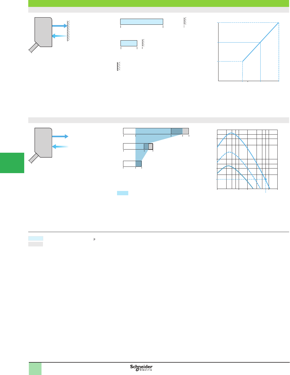
5/162
1
OsiSense® XU
Photoelectric sensors 1
XUM0 multimode function
Sensing distance and operating margin
Background suppression mode
Without accessory
a: with background teaching at maximum
recommended distance.
b: with background teaching at minimum
recommended distance.
Example: teaching against a background located at
10 cm enables detection of an object at 1 to 7 cm.
(1) From white 90% to black 6%.
Diffuse mode
Without accessory
(1) White 90%. (2) Gray 18%. (3) Black 6%.
Object teaching zone
1White object
2Gray object
3Black object
In diffuse mode, teaching of the position of the object to be detected, located between 0 and 10 cm,
automatically conÞ gures the product to background suppression mode. This provides a constant usable
sensing distance, whatever the color of the object.
Nominal sensing distance. EG 2.
Maximum sensing distance. The maximum sensing distances indicated are average values.
EG: Excess gain, operating margin.
0–0.11 m max.
b
a
1 cm
1 cm
11 cm
6 cm5 cm
15 cm
0
0
54 11 cm
cm
7
10
15
5
Background distance (1)
Maximum distance of object to be detected (1)
0–0.55 m max.
(1)
(2)
(3)
40 10
25 cm
55 cm50
10 15 cm
18
0
0
0
Sn = 40 cm
501 cm
5
10
50
100
1
5 10 100 cm
2
3
1
Distance
Gain
Background
EG = 2
Operating Curves
1
2
3
4
5/
6
7
8
9
10
This document provided by Barr-Thorp Electric Co., Inc. 800-473-9123 www.barr-thorp.com
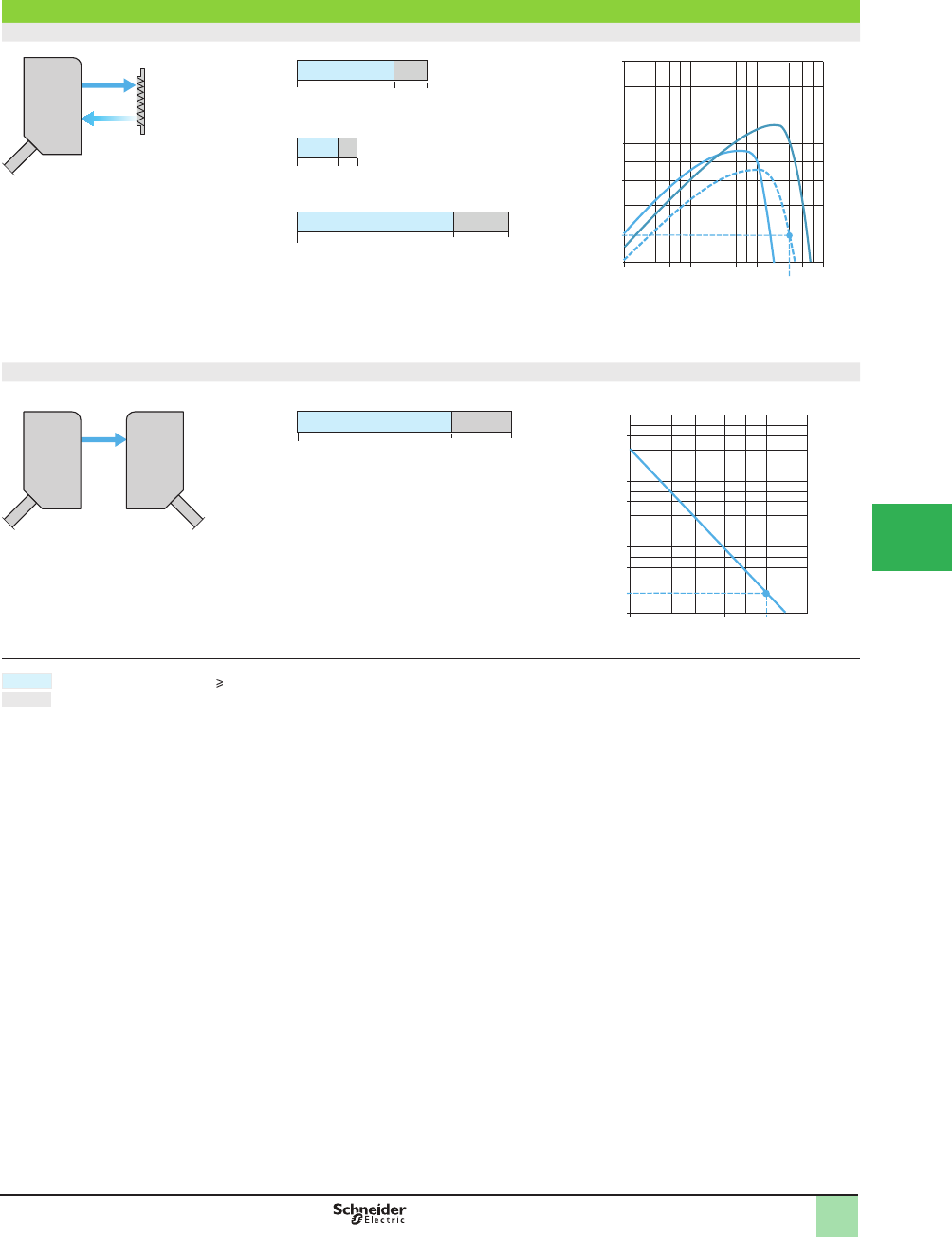
5/163
1
OsiSense® XU
Photoelectric sensors 1
XUM0 multimode function
Sensing distance and operating margin (continued)
Polarized retrorefl ective mode
With refl ector
1With reß ector XUZC50
2With reß ector XUZC24
3With reß ector XUZC100
Thru-beam mode
With thru-beam accessory
Nominal sensing distance. EG 2.
Maximum sensing distance. The maximum sensing distances indicated are average values.
EG: Excess gain, operating margin.
0.02–6.5 m max.
XUZC50
XUZC24
XUZC100
6.5 m4.8 m
3 m
1.4 m 1.6 m
4 m
2 cm
1 cm
2 cm
Sn = 3 m
1 cm 5 0.5
5
10
1
50
0.1 m 1 m 5 m 10 m
2
3
1
Gain
Distance
EG = 2
0–14 m
max.
14 m10
0
20 m1 m
5
10
50
100
1
1000
500
5Sn = 10 m
Distance
EG = 2
Gain
Operating Curves (continued)
1
2
3
4
5
6
7
8
9
10
This document provided by Barr-Thorp Electric Co., Inc. 800-473-9123 www.barr-thorp.com
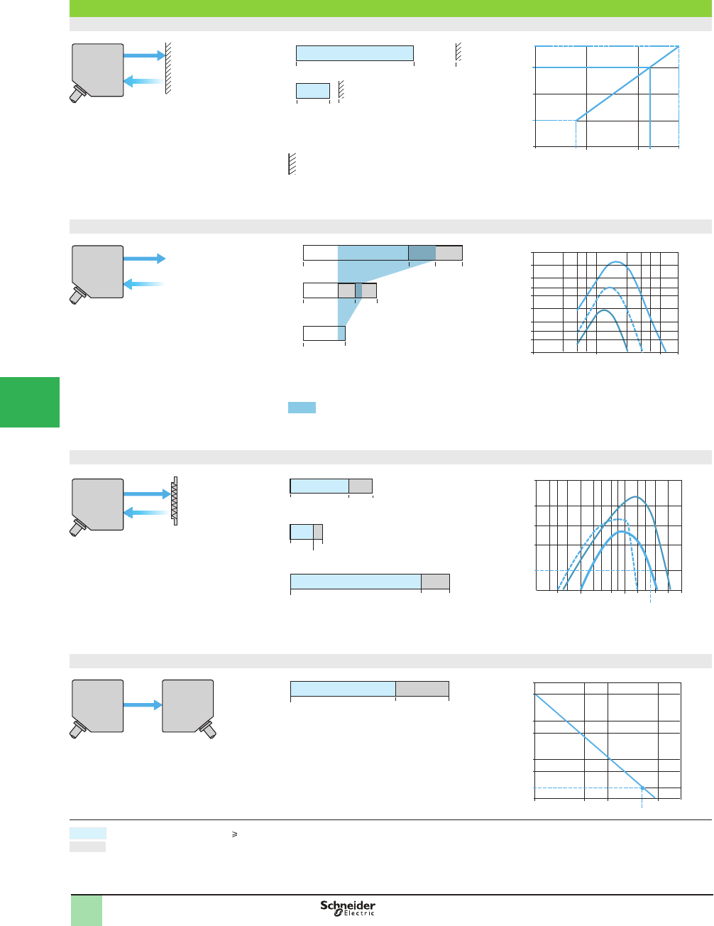
5/164
1
OsiSense® XU
Photoelectric sensors 1
Multimode function
XUK0
Sensing distance and operating margin
Background suppression mode
Without accessory
a: with background teaching at maximum
recommended distance.
b: with background teaching at minimum
recommended distance.
Example: teaching against a background located at
30 cm enables detection of an object at 0 to 22 cm.
(1) From white 90% to black 6%.
Diffuse mode
Without accessory
(1) White 90%. (2) Gray 18%. (3) Black 6%.
Object teaching zone
1White object
2Gray object
3Black object
In diffuse mode, teaching of the position of the object to be detected, located between 0 and 0.3 m,
automatically conÞ gures the product to background suppression mode. This provides a constant usable
sensing distance, whatever the color of the object.
Polarized retrorefl ective mode
With refl ector
1With reß ector XUZC50
2With reß ector XUZC24
3With reß ector XUZC100
Thru-beam mode
With thru-beam accessory
EG: Excess gain, operating margin.
0–28 cm max.
0 cm
b
a
0 cm
38 cm28
10 cm8 cm
28 cm0
0
10 20 8 22
20
30
38
cm
10
Background distance (1)
Maximum distance of object to be detected (1)
0–1.2 m max.
(1)
(2)
(3)
1 m 0.8
0.55 m
1.2 m
0.4
0.3 m
1.5 cm
0
0
1
2
3
0.1
0.2
0.3
0.5
1
2
3
5
10
20
1 cm 10 5 50 100 200 cm
Distance
Gain
0.02–11 m max.
XUZC50
XUZC24
XUZC100
11 m9 m
4 m
1.7 2 m
5.7 m
2 cm
0.5 cm
2 cm
5 5 20 m10 cm
5
10
1
20
50
50 30 0,1 m 1 m 2 10
23
1
Sn = 4 m
Gain
EG = 2
0–45 m
max.
45 m30 m
0
1
5
1
10
100
1000
5 10 m 50 100 m
50
500
Sn = 30 m
EG = 2
Gain
Nominal sensing distance. EG 2.
Maximum sensing distance. The maximum sensing distances indicated are average values.
Background
Operating Curves
1
2
3
4
5/
6
7
8
9
10
This document provided by Barr-Thorp Electric Co., Inc. 800-473-9123 www.barr-thorp.com
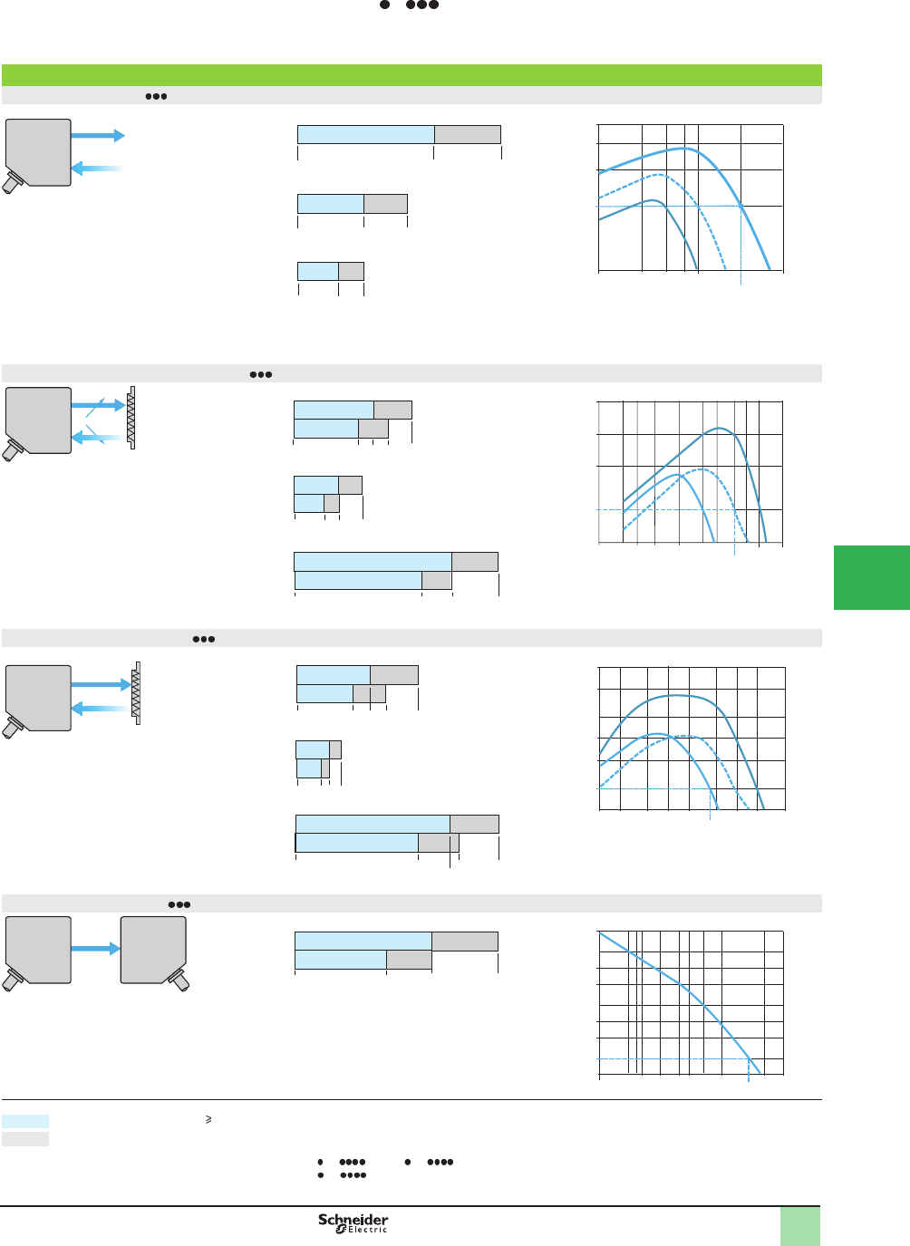
5/165
1
OsiSense® XU
Photoelectric sensors 1
Multimode function
XUK A
Sensing distance and operating margin
Diffuse sensor XUK5A
Without accessory
(1) White 90%. (2) Gray 18%. (3) Black 6%.
(4) No detection.
1White object
2Gray object
3Black object
Polarized retrorefl ective sensor XUK9A
With refl ector
1With reß ector XUZC50
2With reß ector XUZC24
3With reß ector XUZC100
Retrorefl ective sensor XUK1A
With refl ector
1With reß ector XUZC50
2With reß ector XUZC24
3With reß ector XUZC100
Thru-beam sensor XUK2A
With thru-beam accessory
a: Potentiometer set at maximum.
b: Potentiometer set at minimum.
EG: Excess gain, operating margin.
c: XUK AP or XUK AN , DC solid-state output version.
d: XUK AR , AC/DC relay output version.
0–1.5 m max.
(1)
(2)
(3)
a
b
a
b
a
b
0.8 m
1 m
0.5 m
1.5 m
0.3 m 0.5 m
0
0
0
(4)
(4)
(4)
5
0.1 0.2 0.3 0.5 2 m
1
4
3
1
Sn = 1 m
3
2
EG = 2
0.10–13 m max.
5 cm 21.4
c
d
c
d
c
d
10 m 13 m
3 m
10 cm
6 7.5 m
4 5
5 cm
8 m
XUZC50
XUZC24
XUZC100
5
10
1
20
1 m
10 cm 50 30 20 10 20 m
23
1
Sn = 5 m
Gain
EG = 2
0.05–25 m max.
a
b
c
d
c
d
20 m 25 m
43 5.5 m
5 cm
3 cm
11 m9 15 m
7 m
5 cm
15 m
19 m
XUZC50
XUZC24
XUZC100
Sn = 4 m
15020 510 cm 1 m 10 m 20 50 m
5
50
10
100
23
1
Gain
EG = 2
0–45 m
max.
45 m20 m 30 m0
c
d
Sn = 30 m
150 510 cm 1 m 10 m 50 100 m
5
50
10
100
1000
Gain
EG = 2
Nominal sensing distance. EG 2.
Maximum sensing distance. The maximum sensing distances indicated are average values.
Gain
Operating Curves
1
2
3
4
5
6
7
8
9
10
This document provided by Barr-Thorp Electric Co., Inc. 800-473-9123 www.barr-thorp.com
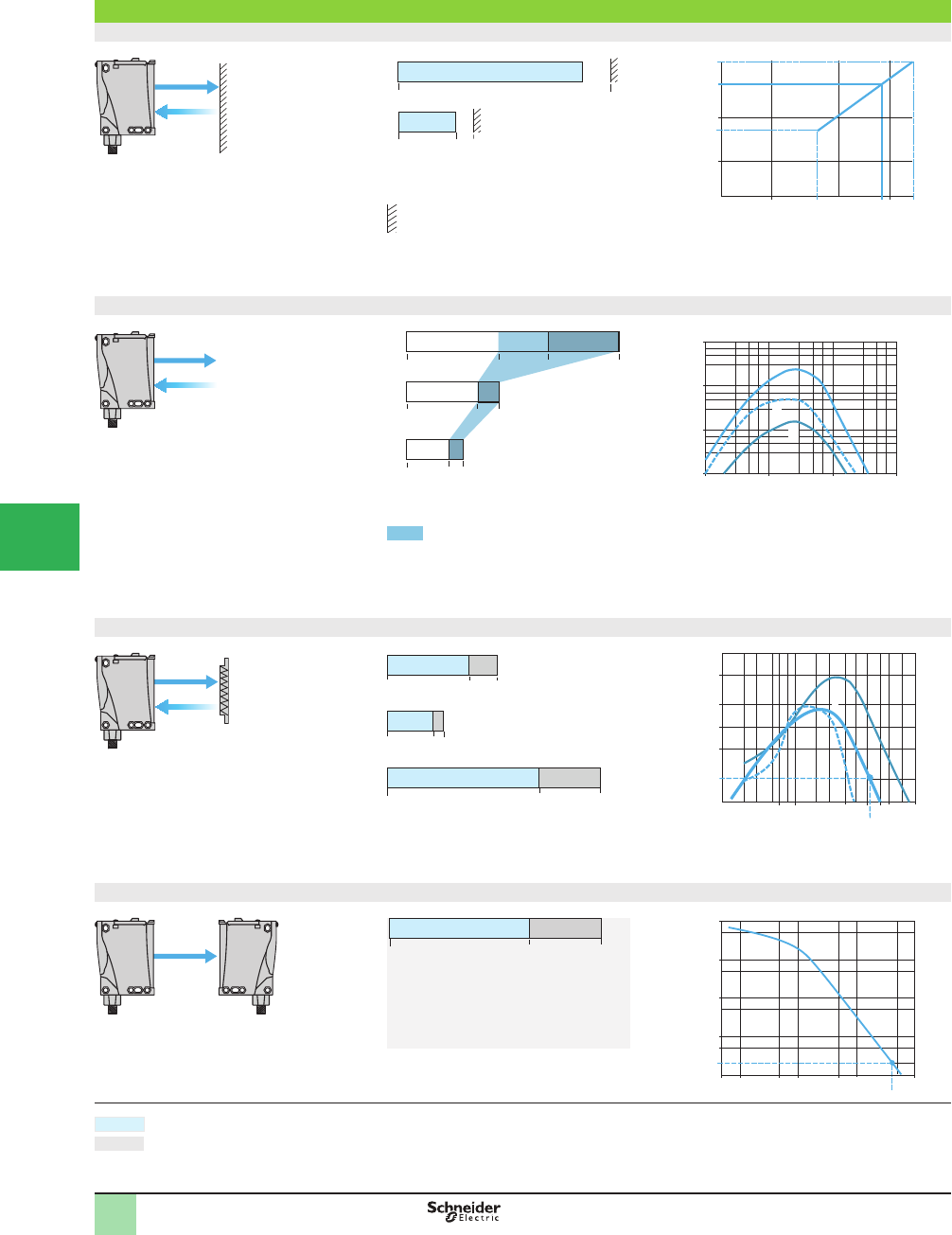
5/166
1
Sensing distance and operating margin
Background suppression mode
Without accessory
a: with background teaching at maximum
recommended distance.
b: with background teaching at minimum
recommended distance.
Example: teaching against a background located at
1 m enables detection of an object at 0 to 90 cm.
(1) From white 90% to black 6%.
Diffuse mode
Without accessory
(1) White 90%. (2) Gray 18%. (3) Black 6%.
Object teaching zone 1White object
2Gray object
3Black object
In diffuse mode, teaching of the position of the object to be detected, located between 0 and 1.3 m,
automatically conÞ gures the product to background suppression mode. This provides a constant usable
sensing distance, whatever the color of the object.
Polarized retrorefl ective mode
With refl ector
1With reß ector XUZC50
2With reß ector XUZC24
3With reß ector XUZC100
Thru-beam mode
With thru-beam accessory
EG: Excess gain, operating margin.
0.01–1.3 m max.
b
a
6 cm
0 cm
1.5 m1.3
40 cm38 cm
10 cm
10 cm
20 1 m 38 1.3 m90
20
50
1 m
1
.5 m
40
Background distance (1)
Maximum distance of object to be detected (1)
0–3 m max.
(1)
(2)
(3)
2 1.3
1.3 m
3 m
1
0.8 m0.6
1.5 cm
0
0
1
1 cm 10 cm 1 m 10 m
10
100
1000
1
2
3
Distance
Gain
0.05–35 m max.
XUZC50
XUZC24
XUZC100
35 m25 m
11 m
5 m 6 m
15 m
5
cm
3
cm
5
cm
510 cm
5
10
20
50
50 1 m
10 15 20
40 m
Sn = 11 m
2
3
1
Gain
EG = 2
0–60 m max.
60 m40
0
10
5
10
100
1000
10 000
50 5 cm 1 m 5 10 100 m
Sn = 40 m
EG = 2
Gain
Nominal sensing distance. EG ≥ 2.
Maximum sensing distance. The maximum sensing distances indicated are average values.
Background
Operating Curves OsiSense® XU
Photoelectric sensors 1
Multimode function
XUX0
1
2
3
4
5/
6
7
8
9
10
This document provided by Barr-Thorp Electric Co., Inc. 800-473-9123 www.barr-thorp.com
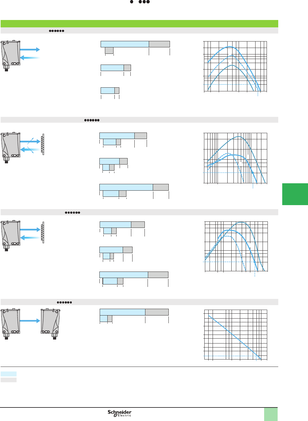
5/167
1
1
Sensing distance and operating margin
Diffuse sensor XUX5A
(1) White 90%. (2) Gray 18%. (3) Black 6%.
(4) No detection.
1White object
2Gray object
3Black object
Polarized retrorefl ective sensor XUX9A
With refl ector
1With reß ector XUZC50
2With reß ector XUZC24
3With reß ector XUZC100
Retrorefl ective sensor XUX1A
With refl ector
1With reß ector XUZC50
2With reß ector XUZC24
3With reß ector XUZC100
Thru-beam sensor XUX2A
With thru-beam accessory
a: Potentiometer set at maximum.
b: Potentiometer set at minimum.
EG: Excess gain, operating margin.
0–3 m max.
(1)
(2)
(3)
a
b
a
b
a
b
1.3 m
2.1 m
1 m
3 m
0.6 m 0.8 m
18 cm
0
0
55 cm
(4)
(4)
1 m3 cm 5 10 50 5 m3
1
5
1
10
50
100
200
Sn = 2.1 m
3
2
EG = 2
0.05–30 m max.
a
b
a
b
a
b
20 m 26 m7.5 m
4.4
65 cm
1.1 1.9
5.7 m
2.5 m
1.2
11 m 15 m
3.7 4.8
5 cm
3 cm
5 cm
10 m
XUZC
50
XUZC24
XUZC100
Sn = 11 m
1 m50 cm 5 m
1
5
10
20
30
15 20 30
m
2
1
3
Gain
EG = 2
0.05–35 m max.
a
b
a
b
a
b
25 m 35 m9
5.2
60 cm
0.45 2.1
7.1 m
3 m
1.4
5
cm
3
cm
14 m 20 m
5.1 7 m
5
cm
12 m
XUZC50
XUZC24
XUZC100
5 7
0.2
5
10
20
50
0.5 1 m
10 20 40 m
Sn = 15 m
3
1
2
Gain
EG = 2
0–60 m max.
60 m5.5 m 40 m0 3.6
a
b
1
70 cm 5 40 601 m 10 100 m
5
50
10
100
1000
10 000
Gain
EG = 2
Nominal sensing distance. EG ≥ 2.
Maximum sensing distance. The maximum sensing distances indicated are average values.
Gain
Operating Curves OsiSense® XU
Photoelectric sensors 1
Single mode function
XUX A
1
2
3
4
5
6
7
8
9
10
This document provided by Barr-Thorp Electric Co., Inc. 800-473-9123 www.barr-thorp.com

5/168
1
Substitution Table OsiSense® XU
Photoelectric sensors 1
Old sensor New OsiSense® XU sensor
Diameter 18 mm sensors
XU1B18NP340 XUB0ANSNL2+XUZC50 (1)
XU1B18NP340D XUB0ANSNM12+XUZC50 (1)
XU1B18PP340 XUB0APSNL2+XUZC50 (1)
XU1B18PP340D XUB0APSNM12+XUZC50 (1)
XU1N18NP340 XUB1BNANL2+XUZC50 (2)
XUB1BNBNL2+XUZC50 (3)
XU1N18NP340D XUB1BNANM12+XUZC50 (2)
XUB1BNBNM12+XUZC50 (3)
XU1N18NP340L5 XUB1BNANL5+XUZC50 (2)
XUB1BNBNL5+XUZC50 (3)
XU1N18NP340W XUB1BNAWL2+XUZC50 (2)
XUB1BNBWL2+XUZC50 (3)
XU1N18NP340WD XUB1BNAWM12+XUZC50 (2)
XUB1BNBWM12+XUZC50 (3)
XU1N18PP340 XUB1BPANL2+XUZC50 (4)
XUB1BPBNL2+XUZC50 (5)
XU1N18PP340D XUB1BPANM12+XUZC50 (4)
XUB1BPBNM12+XUZC50 (5)
XU1N18PP340L5 XUB1BPANL5+XUZC50 (4)
XUB1BPBNL5+XUZC50 (5)
XU1N18PP340W XUB1BPAWL2+XUZC50 (4)
XUB1BPBWL2+XUZC50 (5)
XU1N18PP340WD XUB1BPAWM12+XUZC50 (4)
XUB1BPBWM12+XUZC50 (5)
XU1N18PP340WL5 XUB1BPAWL5+XUZC50 (4)
XUB1BPBWL5+XUZC50 (5)
XU1P18NP340 XUB1ANANL2+XUZC50 (2)
XUB1ANBNL2+XUZC50 (3)
XU1P18NP340D XUB1ANANM12+XUZC50 (2)
XUB1ANBNM12+XUZC50 (3)
XU1P18NP340L5 XUB1ANANL5+XUZC50 (2)
XUB1ANBNL5+XUZC50 (3)
XU1P18NP340W XUB1ANAWL2+XUZC50 (2)
XUB1ANBWL2+XUZC50 (3)
XU1P18NP340WD XUB1ANAWM12+XUZC50 (2)
XUB1ANBWM12+XUZC50 (3)
XU1P18PP340 XUB1APANL2+XUZC50 (4)
XUB1APBNL2+XUZC50 (5)
XU1P18PP340D XUB1APANM12+XUZC50 (4)
XUB1APBNM12+XUZC50 (5)
XU1P18PP340L5 XUB1APANL5+XUZC50 (4)
XUB1APBNL5+XUZC50 (5)
XU1P18PP340W XUB1APAWL2+XUZC50 (4)
XUB1APBWL2+XUZC50 (5)
XU1P18PP340WD XUB1APAWM12+XUZC50 (4)
XUB1APBWM12+XUZC50 (5)
XU1P18PP340WL5 XUB1APAWL5+XUZC50 (4)
XUB1APBWL5+XUZC50 (5)
XU2B18NP340 XUB0ANSNL2
+XUB0AKSNL2T
Old sensor New OsiSense® XU sensor
XU2B18NP340D XUB0ANSNM12
+XUB0AKSNM12T
XU2B18PP340 XUB0APSNL2
+XUB0AKSNL2T
XU2B18PP340D XUB0APSNM12
+XUB0AKSNM12T
XU2M18NP340 XUB0BNSNL2
+XUB0BKSNL2T (6)
XU2M18NP340D XUB0BNSNM12
+XUB0BKSNM12T (6)
XU2M18NP340WD XUB2BNAWM12R
+XUB2BKSWM12T (2) (6)
XUB2BNBWM12R
+XUB2BKSWM12T (3) (6)
XU2M18PP340 XUB0BPSNL2
+XUB0BKSNL2T (6)
XU2M18PP340D XUB0BPSNM12
+XUB0BKSNM12T (6)
XU2M18PP340L10 XUB0BPSNM12
+XUB0BKSNM12T
+XZCP1141L10 (6) (7)
XU2M18PP340L5 XUB0BPSNL5
+XUB0BKSNL5T (6)
XU2M18PP340W XUB2BPAWL2R
+XUB2BKSWL2T (4) (6)
XUB2BPBWL2R
+XUB2BKSWL2T (5) (6)
XU2M18PP340WD XUB2BPAWM12R
+XUB2BKSWM12T (4) (6)
XUB2BPBWM12R
+XUB2BKSWM12T (5) (6)
XU2M18PP340WL5 XUB2BPAWL5R
+XUB2BKSWL5T (4) (6)
XUB2BPBWL5R
+XUB2BKSWL5T (5) (6)
XU2N18NP340 XUB2BNANL2R
+XUB2BKSNL2T (2)
XUB2BNBNL2R
+XUB2BKSNL2T (3)
XU2N18NP340D XUB2BNANM12R
+XUB2BKSNM12T (2)
XUB2BNBNM12R
+XUB2BKSNM12T (3)
XU2N18NP340WD XUB2BNAWM12R
+XUB2BKSWM12T (2)
XUB2BNBWM12R
+XUB2BKSWM12T (3)
XU2N18PP340 XUB2BPANL2R
+XUB2BKSNL2T (4)
XUB2BPBNL2R
+XUB2BKSNL2T (5)
XU2N18PP340D XUB2BPANM12R
+XUB2BKSNM12T (4)
XUB2BPBNM12R
+XUB2BKSNM12T (5)
XU2N18PP340L5 XUB2BPANL5R
+XUB2BKSNL5T (4)
XUB2BPBNL5R
+XUB2BKSNL5T (5)
XU2N18PP340W XUB2BPAWL2R
+XUB2BKSWL2T (4)
XUB2BPBWL2R
+XUB2BKSWL2T (5)
Old sensor New OsiSense® XU sensor
XU2N18PP340WD XUB2BPAWM12R
+XUB2BKAWM12T (4)
XUB2BPBWM12R
+XUB2BKAWM12T (5)
XU2N18PP340WL5 XUB2BPAWL5R
+XUB2BKSWL5T (4)
XUB2BPBWL5R
+XUB2BKSWL5T (5)
XU2P18NP340 XUB2ANANL2R
+XUB2AKSNL2T (2)
XUB2ANBNL2R
+XUB2AKSNL2T (3)
XU2P18NP340D XUB2ANANM12R
+XUB2AKSNM12T (2)
XUB2ANBNM12R
+XUB2AKSNM12T (3)
XU2P18NP340W XUB2ANAWL2R
+XUB2AKSWL2T (2)
XUB2ANBWL2R
+XUB2AKSWL2T (3)
XU2P18NP340WD XUB2ANAWM12R
+XUB2AKSWM12T (2)
XUB2ANBWM12R
+XUB2AKSWM12T (3)
XU2P18PP340 XUB2APANL2R
+XUB2AKSNL2T (4)
XUB2APBNL2R
+XUB2AKSNL2T (5)
XU2P18PP340D XUB2APANM12R
+XUB2AKSNM12T (4)
XUB2APBNM12R
+XUB2AKSNM12T (5)
XU2P18PP340L10 XUB0APSNM12
+XUB0AKSNM12T
+XZCP1141L10 (6) (7)
XU2P18PP340L5 XUB2APANL5R
+XUB2AKSNL5T (4)
XUB2APBNL5R
+XUB2AKSNL5T (5)
XU2P18PP340W XUB2APAWL2R
+XUB2AKSWL2T (4)
XUB2APBWL2R
+XUB2AKSWL2T (5)
XU2P18PP340WD XUB2APAWM12R
+XUB2AKSWM12T (4)
XUB2APBWM12R
+XUB2AKSWM12T (5)
XU5B18NP340 XUB0ANSNL2 (8)
XU5B18NP340D XUB0ANSNM12 (8)
XU5B18PP340 XUB0APSNL2 (8)
XU5B18PP340D XUB0APSNM12 (8)
XU5B18PP340L5 XUB0APSNL5 (8)
XU5M18NP340 XUB0BNSNL2 (8)
XU5M18NP340D XUB0BNSNM12 (8)
XU5M18NP340L5 XUB0BNSNL5 (8)
XU5M18NP340W XUB5BNAWL2 (2)
XUB5BNBWL2 (3)
XU5M18NP340WL5 XUB5BNAWL5 (2)
XUB5BNBWL5 (3)
XU5M18PP340 XUB0BPSNL2 (8)
XU5M18PP340D XUB0BPSNM12 (8)
Note: XUZC50 is a 50 x 50 mm refl ector, XUZA5 and XUZX2000 are metal mounting brackets and XUZX2001 is an M16 to 1/2 NPT adapter.
(1) Sn = 2 m instead of 4 m.
(2) Sensor output NO, PNP connection.
(3) Sensor output NC, NPN connection.
(4) Sensor output NO, PNP connection.
(5) Sensor output NC, PNP connection.
(6) M18 threaded length = 44 mm instead of 50/55 mm.
(7) For a cable length = 10 m, the use of an M12 connector
version sensor combined with an XZCP1141L10 jumper
cable (M12 with 10 m cable) is recommended.
(8) Sn = 0.3 m instead of 0.4 m. For a sensing distance Sn
greater than 0.3 m, see catalog number XUB5 on
page
1
2
3
4
5/
6
7
8
9
10
This document provided by Barr-Thorp Electric Co., Inc. 800-473-9123 www.barr-thorp.com

5/169
1
Old sensor New OsiSense® XU sensor
Diameter 18 mm sensors (continued)
XU5M18PP340L5 XUB0BPSNL5 (8)
XU5M18PP340W XUB5BPAWL2 (4)
XUB5BPBWL2 (5)
XU5M18PP340WD XUB5BPAWM12 (4)
XUB5BPBWM12 (5)
XU5M18PP340WL5 XUB5BPAWL5 (4)
XUB5BPBWL5 (5)
XU5N18NP340 XUB4BNANL2 (2)
XUB4BNBNL2 (3)
XU5N18NP340D XUB4BNANM12 (2)
XUB4BNBNM12 (3)
XU5N18NP340L5 XUB4BNANL5 (2)
XUB4BNBNL5 (3)
XU5N18NP340W XUB4BNAWL2 (2)
XUB4BNBWL2 (3)
XU5N18NP340WD XUB4BNAWM12 (2)
XUB4BNBWM12 (3)
XU5N18NP340WL5 XUB4BNANL5 (2)
XUB4BNBNL5 (3)
XU5N18PP340 XUB4BPANL2 (4)
XUB4BPBNL2 (5)
XU5N18PP340D XUB4BPANM12 (4)
XUB4BPBNM12 (5)
XU5N18PP340L5 XUB4BPANL5 (4)
XUB4BPBNL5 (5)
XU5N18PP340W XUB4BPAWL2 (4)
XUB4BPBWL2 (5)
XU5N18PP340WD XUB4BPAWM12 (4)
XUB4BPBWM12 (5)
XU5N18PP340WL5 XUB4BPANL5 (4)
XUB4BPBNL5 (5)
XU5P18NP340 XUB4ANANL2 (2)
XUB4ANBNL2 (3)
XU5P18NP340D XUB4ANANM12 (2)
XUB4ANBNM12 (3)
XU5P18NP340L5 XUB4ANANL5 (2)
XUB4ANBNL5 (3)
XU5P18NP340W XUB4ANAWL2 (2)
XUB4ANBWL2 (3)
XU5P18NP340WD XUB4ANAWM12 (2)
XUB4ANBWM12 (3)
XU5P18PP340 XUB4APANL2 (2)
XUB4APBNL2 (3)
XU5P18PP340D XUB4APANM12 (2)
XUB4APBNM12 (3)
XU5P18PP340L10 XUB4APANM12
+XZCP1141L10 (4) (7)
XUB4APBNM12
+XZCP1141L10 (5) (7)
XU5P18PP340L5 XUB4APANL5 (4)
XUB4APBNL5 (5)
Old sensor New OsiSense® XU sensor
XU5P18PP340W XUB4APAWL2 (4)
XUB4APBWL2 (5)
XU5P18PP340WD XUB4APAWM12 (4)
XUB4APBWM12 (5)
XU5P18PP340WL5 XUB4APAWL5 (4)
XUB4APBWL5 (5)
XU8B18NP340 XUB0ANSNL2
XU8B18NP340D XUB0ANSNM12
XU8B18PP340 XUB0APSNL2
XU8B18PP340D XUB0APSNM12
XU8B18PP340L10 XUB0APSNM12
+XZCP1141L10 (7)
XU8M18NP340 XUB0BNSNL2 (6)
XU8M18NP340D XUB0BNSNM12 (6)
XU8M18NP340L5 XUB0BNSNL5 (6)
XU8M18NP340W XUB0BNSWL2 (6)
XU8M18NP340WD XUB0BNSWM12 (6)
XU8M18PP340 XUB0BPSNL2 (6)
XU8M18PP340D XUB0BPSNM12 (6)
XU8M18PP340L5 XUB0BPSNL5 (6)
XU8M18PP340W XUB0BPSWL2 (6)
XU8M18PP340WD XUB0BPSWM12 (6)
XU9B18NP340 XUB0ANSNL2+XUZC50
XU9B18NP340D XUB0ANSNM12+XUZC50
XU9B18PP340 XUB0APSNL2+XUZC50
XU9B18PP340D XUB0APSNM12+XUZC50
XU9B18PP340L5 XUB0APSNL5+XUZC50
XU9M18NP340 XUB0BNSNL2+XUZC50 (6)
XU9M18NP340D XUB0BNSNM12+XUZC50 (6)
XU9M18NP340L5 XUB0BNSNL5+XUZC50 (6)
XU9M18NP340W XUB9BNAWL2+XUZC50 (2) (9)
XUB9BNBWL2+XUZC50 (3) (9)
XU9M18PP340 XUB0BPSNL2+XUZC50 (6)
XU9M18PP340D XUB0BPSNM12+XUZC50 (6)
XU9M18PP340L5 XUB0BPSNL5+XUZC50 (6)
XU9M18PP340W XUB9BPAWL2+XUZC50 (4) (9)
XUB9BPBWL2+XUZC50 (5) (9)
XU9M18PP340WD XUB9BPAWM12+XUZC50 (4) (9)
XUB9BPBWM12+XUZC50 (5) (9)
XU9M18PP340WL5 XUB9BPAWL5+XUZC50 (4) (9)
XUB9BPBWL5+XUZC50 (5) (9)
XU9N18NP340 XUB0BNSNL2+XUZC50 (6)
XU9N18NP340D XUB0BNSNM12+XUZC50 (6)
XU9N18NP340L5 XUB0BNSNL5+XUZC50 (6)
XU9N18NP340W XUB0BNSWL2+XUZC50 (6)
XU9N18NP340WD XUB0BNSWM12+XUZC50 (6)
XU9N18PP340 XUB0BPSNL2+XUZC50 (6)
XU9N18PP340D XUB0BPSNM12+XUZC50 (6)
XU9N18PP340L5 XUB0BPSNL5+XUZC50 (6)
XU9N18PP340W XUB0BPSWL2+XUZC50 (6)
XU9N18PP340WD XUB0BPSWM12+XUZC50 (6)
XU9N18PP340WL5 XUB0BPSWL5+XUZC50 (6)
Old sensor New OsiSense® XU sensor
XU9P18NP340 XUB0ANSNL2+XUZC50 (6)
XU9P18NP340D XUB0ANSNM12+XUZC50 (6)
XU9P18NP340L5 XUB0ANSNL5+XUZC50 (6)
XU9P18NP340W XUB0ANSWL2+XUZC50 (6)
XU9P18NP340WD XUB0ANSWM12+XUZC50 (6)
XU9P18PP340 XUB0APSNL2+XUZC50 (6)
XU9P18PP340D XUB0APSNM12+XUZC50 (6)
XU9P18PP340W XUB0APSWL2+XUZC50 (6)
XU9P18PP340WD XUB0APSWM12+XUZC50 (6)
XU9P18PP340WL5 XUB0APSWL5+XUZC50 (6)
Amplifi ers for fi ber optics
XUDH003537 XUDA1PSML2
XUDH003537S XUDA1PSMM8
XUDH003937 XUDA2PSML2
XUDH003937S XUDA2PSMM8
XUDJ003537 XUDA1NSML2
XUDJ003537S XUDA1NSMM8
XUDJ003937 XUDA2NSML2
XUDJ003937S XUDA2NSMM8
Compact design sensors type XUE
XUEF010315 XUX0ARCTT16+XUZX2000 (10)
XUEF010315H7 XUX0ARCTT16
+XUZX2000+XUZX2001
XUEF080319 XUX0ARCTT16+XUZX2000
+XUZC50 (10)
XUEF080319H4 XUX0ARCTT16 +XUZX2000
+XUZX2001+XUZC50
XUEF10031 XUX0ARCTT16+XUZX2000
+XUZC50 (10) (11)
XUEF10031H7 XUX0ARCTT16 +XUZX2000
+XUZX2001+XUZC50 (11)
XUEF300314 XUX0ARCTT16+XUZX2000 (10)
(12)
XUEF300314H7 XUX0ARCTT16+XUZX2000
+XUZX2001 (12)
XUEH017535 XUX0AKSAT16+XUZX2000 (10)
(13)
XUEH017535H7 XUX0AKSAT16+XUZX2000
+XUZX2001 (13)
XUEH10753 XUX0AKSAT16+XUZX2000 (10)
(13)
XUEH10753H7 XUX0AKSAT16+XUZX2000
+XUZX2001 (13)
XUEH3000 XUX0ARCTT16T+XUZX2000 (10)
(12)
XUEH3000H7 XUX0ARCTT16T+XUZX2000
+XUZX2001 (12)
XUEH307534 XUX0AKSAT16+XUZX2000
(10) (12) (13)
XUEH307534H7 XUX0AKSAT16+XUZX2000
+XUZX2001 (12) (13)
XUEH753538 XUX8AKSAT16+XUZX2000
(10) (13)
XUEH753538H4 XUX8AKSAT16+XUZX2000
+XUZX2001 (13)
XUET010315 XUX0ARCTT16+XUZX2000 (10)
(14)
Substitution Table OsiSense® XU
Photoelectric sensors1
(2) Sensor output NO, PNP connection.
(3) Sensor output NC, NPN connection.
(4) Sensor output NO, PNP connection.
(5) Sensor output NC, PNP connection.
(6) M18 threaded length = 44 mm instead of 50/55 mm.
(7) For a cable length = 10 m, the use of an M12 connector
version sensor combined with an XZCP1141L10 jumper
cable (M12 with 10 m cable) is recommended.
(8) Sn = 0.3 m instead of 0.4 m. For a sensing distance Sn
greater than 0.3 m, see catalog number XUB5 .
(9) M18 threaded length = 28 mm instead of 55 mm.
(10) Sensor with M16 threaded cable entry instead of
Pg 13.5.
(11) Sn = 11 m instead of 15 m.
(12) Sn = 40 m instead of 50 m.
(13) Output current switching capacity = 100 mA instead of
200 mA
(14) Time delay relay output 0.02–15 s instead of 0.03–60 s.
Note: XUZC50 is a 50 x 50 mm refl ector, XUZA5 and XUZX2000 are metal mounting brackets and XUZX2001 is an M16 to 1/2 NPT adapter
1
2
3
4
5
6
7
8
9
10
This document provided by Barr-Thorp Electric Co., Inc. 800-473-9123 www.barr-thorp.com

5/170
1
Old sensor New OsiSense® XU sensor
Compact design sensors type XUE (continued)
XUET010315H7 XUX0ARCTT16 +XUZX2000
+XUZX2001 (14)
XUET080319 XUX0ARCTT16+XUZX2000
+XUZC50 (10) (14)
XUET080319H4 XUX0ARCTT16 +XUZX2000
+XUZX2001+XUZC50 (14)
XUET10031 XUX0ARCTT16+XUZX2000
+XUZC50 (10) (11) (14)
XUET10031H7 XUX0ARCTT16 +XUZX2000
+XUZX2001+XUZC50 (11) (14)
XUET300314 XUX0ARCTT16+XUZX2000 (10)
(12) (14)
XUET300314H7 XUX0ARCTT16+XUZX2000
+XUZX2001 (12) (14)
Compact design sensors type XUJ
XUJK06353 XUX0AKSAT16+XUZX2000
+XUZC50 (13) (15)
XUJK063539 XUX0AKSAT16+XUZX2000
+XUZC50 (13) (15)
XUJK063539D1 XUX0AKSAM12+XUZX2000
+XUZC50(13)
XUJK063539D2 XUX0AKSAM12+XUZX2000
+XUZC50(13)
XUJK063539H7 XUX0AKSAT16+XUZX2000
+XUZC50 +XUZX2001 (13)
XUJK063539P9 XUX0AKSAT16+XUZX2000
+XUZC50 (13) (16)
XUJK06353D1 XUX0AKSAM12+XUZX2000
+XUZC50(13)
XUJK06353D2 XUX0AKSAM12+XUZX2000
+XUZC50(13)
XUJK06353H7 XUX0AKSAT16+XUZX2000
+XUZC50 +XUZX2001 (13)
XUJK06353P9 XUX0AKSAT16+XUZX2000
+XUZC50 (13) (16)
XUJK103534 XUX0AKSAT16+XUZX2000
(13) (15)
XUJK103534D1 XUX0AKSAM12+XUZX2000 (13)
XUJK103534D2 XUX0AKSAM12+XUZX2000 (13)
XUJK103534H7 XUX0AKSAT16+XUZX2000
+XUZX2001 (13)
XUJK103534P9 XUX0AKSAT16+XUZX2000
(13) (16)
XUJK123538 XUX8AKSAT16+XUZX2000
(13) (15)
XUJK123538D1 XUX8AKSAM12+XUZX2000 (13)
XUJK123538D2 XUX8AKSAM12+XUZX2000 (13)
XUJK123538H7 XUX8AKSAT16+XUZX2000
+XUZX2001 (13)
XUJK123538P9 XUX8AKSAT16+XUZX2000
(13) (16)
XUJK703538 XUX8AKSAT16+XUZX2000
(13) (15)
XUJK703538D1 XUX8AKSAM12+XUZX2000 (13)
XUJK703538D2 XUX8AKSAM12+XUZX2000 (13)
XUJK703538H7 XUX8AKSAT16+XUZX2000
+XUZX2001 (13)
XUJK703538P9 XUX8AKSAT16+XUZX2000
(13) (16)
XUJLM0619 XUX9ARCNT16+XUZX2000
+XUZC50 (15)
Old sensor New OsiSense® XU sensor
XUJLM0619H7 XUX9ARCNT16+XUZX2000
+XUZX2001 +XUZC50
XUJLM0619P9 XUX9ARCNT16+XUZX2000
+XUZC50 (16)
XUJLM0811 XUX1ARCNT16+XUZX2000
+XUZC50 (15)
XUJLM0811H7 XUX1ARCNT16+XUZX2000
+XUZX2001 +XUZC50
XUJLM0811P9 XUX1ARCNT16+XUZX2000
+XUZC50 (16)
XUJLM1503 XUX0ARCTT16T+XUZX2000 (15)
XUJLM1503H7 XUX0ARCTT16T+XUZX2000
+XUZX2001
XUJLM1503P9 XUX0ARCTT16T +XUZX2000 (16)
XUJLM1514 XUX2ARCNT16R+XUZX2000 (15)
XUJLM1514H7 XUX2ARCNT16R+XUZX2000
+XUZX2001
XUJLM1514P9 XUX2ARCNT16R+XUZX2000 (16)
XUJM06031 XUX1ARCNT16+XUZX2000
+XUZC50 (15)
XUJM060319 XUX9ARCNT16+XUZX2000
+XUZC50 (16)
XUJM060319D1 XUX9ARCNT16+XUZX2000
+XUZC50
XUJM060319D2 XUX9ARCNT16+XUZX2000
+XUZC50
XUJM060319H7 XUX9ARCNT16+XUZX2000
+XUZX2001+XUZC50
XUJM060319P9 XUX9ARCNT16+XUZX2000
+XUZC50 (16)
XUJM06031D1 XUX1ARCNT16+XUZX2000
+XUZC50
XUJM06031D2 XUX1ARCNT16+XUZX2000
+XUZC50
XUJM06031H7 XUX1ARCNT16+XUZX2000
+XUZX2001 +XUZC50
XUJM06031P9 XUX1ARCNT16+XUZX2000
+XUZC50 (16)
XUJM1000 XUX0AKSAT16T+XUZX2000 (15)
XUJM1000D1 XUX0AKSAM12T+XUZX2000
XUJM1000D2 XUX0AKSAM12T+XUZX2000
XUJM1000H7 XUX0AKSAT16T+XUZX2000
+XUZX2001
XUJM1000P9 XUX0AKSAT16T+XUZX2000 (16)
XUJM100314 XUX0ARCTT16+XUZX2000 (15)
XUJM100314D1 XUX0ARCTT16+XUZX2000
XUJM100314D2 XUX0ARCTT16+XUZX2000
XUJM100314H7 XUX0ARCTT16+XUZX2000
+XUZX2001
XUJM100314P9 XUX0ARCTT16+XUZX2000 (16)
XUJM120318 XUX8ARCTT16+XUZX2000 (15)
XUJM120318D1 XUX8ARCTT16+XUZX2000
XUJM120318D2 XUX8ARCTT16+XUZX2000
XUJM120318H7 XUX8ARCTT16+XUZX2000
+XUZX2001
XUJM120318P9 XUX8ARCTT16+XUZX2000 (16)
XUJM700318 XUX8ARCTT16+XUZX2000 (15)
Old sensor New OsiSense® XU sensor
XUJM700318D1 XUX8ARCTT16+XUZX2000
XUJM700318D2 XUX8ARCTT16+XUZX2000
XUJM700318H7 XUX8ARCTT16+XUZX2000
+XUZX2001
XUJM700318P9 XUX8ARCTT16+XUZX2000 (16)
XUJT06031 XUX0ARCTT16+XUZX2000
+XUZC50 (15)
XUJT060319 XUX0ARCTT16+XUZX2000
+XUZC50 (15)
XUJT060319D1 XUX0ARCTT16+XUZX2000
+XUZC50
XUJT060319D2 XUX0ARCTT16+XUZX2000
+XUZC50
XUJT060319H7 XUX0ARCTT16+XUZX2000
+XUZC50+XUZX2001
XUJT060319P9 XUX0ARCTT16+XUZX2000
+XUZC50 (16)
XUJT06031D1 XUX0ARCTT16+XUZX2000
+XUZC50
XUJT06031D2 XUX0ARCTT16+XUZX2000
+XUZC50
XUJT06031H7 XUX0ARCTT16+XUZX2000
+XUZC50+XUZX2001
XUJT06031P9 XUX0ARCTT16+XUZX2000
+XUZC50 (16)
XUJT100314 XUX0ARCTT16+XUZX2000 (15)
XUJT100314D1 XUX0ARCTT16+XUZX2000
XUJT100314D2 XUX0ARCTT16+XUZX2000
XUJT100314H7 XUX0ARCTT16+XUZX2000
+XUZX2001
XUJT100314P9 XUX0ARCTT16+XUZX2000 (16)
XUJT120318 XUX8ARCTT16+XUZX2000 (15)
XUJT120318D1 XUX8ARCTT16+XUZX2000
XUJT120318D2 XUX8ARCTT16+XUZX2000
XUJT120318H7 XUX8ARCTT16+XUZX2000
+XUZX2001
XUJT120318P9 XUX8ARCTT16+XUZX2000 (16)
XUJT700318 XUX8ARCTT16+XUZX2000 (15)
XUJT700318D1 XUX8ARCTT16+XUZX2000
XUJT700318D2 XUX8ARCTT16+XUZX2000
XUJT700318H7 XUX8ARCTT16+XUZX2000
+XUZX2001
XUJT700318P9 XUX8ARCTT16+XUZX2000 (16)
Compact design sensors type XUK
XUK1ARCTL10 XUK1ARCNL10+XUZA51
+XUZC50
XUK1ARCTL2 XUK1ARCNL2+XUZA51
+XUZC50
XUK2AKSAL10 XUK2APANL10R
+XUK0AKSNL10T
+2 x XUZA51 (4)
XUK2APBNL10R
+XUK0AKSNL10T
+2 x XUZA51 (5)
XUK2ANANL10R
+XUK0AKSNL10T
+2 x XUZA51 (2)
XUK2ANBNL10R
+XUK0AKSNL10T
+2 x XUZA51 (3)
Substitution Table OsiSense® XU
Photoelectric sensors
(2) Sensor output NO, PNP connection.
(3) Sensor output NC, NPN connection.
(4) Sensor output NO, PNP connection.
(5) Sensor output NC, PNP connection.
(10) Sensor with M16 threaded cable entry instead of Pg 13.
(11) Sn = 11 m instead of 15 m.
(12) Sn = 40 m instead of 50 m.
(13) Output current switching capacity = 100 mA instead of
200 mA.
(14) Time delay relay output 0.02...15 s instead of 0.03…60 s.
(15) Sensor with M16 threaded cable entry instead of Pg 11.
(16) Sensor with M16 threaded cable entry instead of Pg 9.
Note: XUZC50 is a 50 x 50 mm refl ector, XUZA5 and XUZX2000 are metal mounting brackets and XUZX2001 is an M16 to 1/2 NPT adapter.
1
2
3
4
5/
6
7
8
9
10
This document provided by Barr-Thorp Electric Co., Inc. 800-473-9123 www.barr-thorp.com

5/171
1
Old sensor New OsiSense® XU sensor
Compact design sensors type XUK (continued)
XUK2AKSAL2 XUK2APANL2R
+XUK0AKSNL2T
+2 x XUZA51 (4)
XUK2APBNL2R +XUK0AKSNL2T
+2 x XUZA51 (5)
XUK2ANANL2R
+XUK0AKSNL2T
+2 x XUZA51 (2)
XUK2ANBNL2R
+XUK0AKSNL2T
+2 x XUZA51 (3)
XUK2AKSAM12 XUK2APANM12R
+XUK0AKSNM12T
+2 x XUZA51 (4)
XUK2APBNM12R
+XUK0AKSNM12T
+2 x XUZA51 (5)
XUK2ANANM12R
+XUK0AKSNM12T
+2 x XUZA51 (2)
XUK2ANBNM12R
+XUK0AKSNM12T
+2 x XUZA51 (3)
XUK2ARCTL10 XUK0ARCTL10
+XUK0ARCTL10T
+2 x XUZA51
XUK2ARCTL2 XUK0ARCTL2
+XUK0ARCTL2T
+2 x XUZA51
XUK5AKSAL10 XUK5APANL10+XUZA51 (4)
XUK5APBNL10+XUZA51 (5)
XUK5ANANL10+XUZA51 (2)
XUK5ANBNL10+XUZA51 (3)
XUK5AKSAL2 XUK5APANL2+XUZA51 (4)
XUK5APBNL2+XUZA51 (5)
XUK5ANANL2+XUZA51 (2)
XUK5ANBNL2+XUZA51 (3)
XUK5AKSAM12 XUK5APANM12+XUZA51 (4)
XUK5APBNM12+XUZA51 (5)
XUK5ANANM12+XUZA51 (2)
XUK5ANBNM12+XUZA51 (3)
XUK5ARCTL10 XUK5ARCNL10+XUZA51
XUK5ARCTL2 XUK5ARCNL2+XUZA51
XUK9AKSAL10 XUK9APANL10+XUZA51
+XUZC50 (4)
XUK9APBNL10+XUZA51
+XUZC50 (5)
XUK9ANANL10+XUZA51
+XUZC50 (2)
XUK9ANBNL10+XUZA51
+XUZC50 (3)
XUK9AKSAL2 XUK9APANL2+XUZA51 +XUZC50
(4)
XUK9APBNL2+XUZA51 +XUZC50
(5)
XUK9ANANL2+XUZA51
+XUZC50 (2)
XUK9ANBNL2+XUZA51
+XUZC50 (3)
Old sensor New OsiSense® XU sensor
XUK9AKSAM12 XUK9APANM12+XUZA51
+XUZC50 (4)
XUK9APBNM12+XUZA51
+XUZC50 (5)
XUK9ANANM12+XUZA51
+XUZC50 (2)
XUK9ANBNM12+XUZA51
+XUZC50 (3)
XUK9ARCTL10 XUK9ARCNL10+XUZA51
+XUZC50
XUK9ARCTL2 XUK9ARCNL2+XUZA51
+XUZC50
Compact design sensors type XUL
XULH153538 XUK8AKSNL2+XUZA51 (13)
XULH153538D XUK8AKSNM12+XUZA51 (13)
XULH153538H7 XUK8AKSNM12+XUZA51 (13)
XULH153538L05 XUK8AKSNL5+XUZA51 (13)
XULH153538L10 XUK8AKSNL10+XUZA51 (13)
XULH303538 XUK8AKSNL2+XUZA51 (13)
XULH303538D XUK8AKSNM12+XUZA51 (13)
XULH303538DH7 XUK8AKSNM12+XUZA51 (13)
XULH303538L05 XUK8AKSNL5+XUZA51 (13)
XULH303538L10 XUK8AKSNL10+XUZA51 (13)
XULJ153538 XUK8AKSNL2+XUZA51 (13)
XULJ153538D XUK8AKSNM12+XUZA51 (13)
XULJ153538H7 XUK8AKSNM12+XUZA51 (13)
XULJ153538L05 XUK8AKSNL5+XUZA51 (13)
XULJ303538 XUK8AKSNL2+XUZA51 (13)
XULJ303538D XUK8AKSNM12+XUZA51 (13)
XULJ303538L05 XUK8AKSNL5+XUZA51 (13)
Compact design sensors type XUM
XUM1ANANL2 XUM9ANCNL2 (17)
XUM1ANANL5 XUM9ANCNM8+XZCP0941L5 (17)
XUM1ANANM8 XUM9ANCNM8 (17)
XUM1ANBNL2 XUM9ANCNL2 (17)
XUM1ANBNM8 XUM9ANCNM8 (17)
XUM1APANL10 XUM9APCNM8+XZCP0941L10
(17)
XUM1APANL2 XUM9APCNL2 (17)
XUM1APANL5 XUM9APCNM8+XZCP0941L5 (17)
XUM1APANM8 XUM9APCNM8 (17)
XUM1APBNL10 XUM9APCNM8+XZCP0941L10
(17)
XUM1APBNL2 XUM9APCNL2 (17)
XUM1APBNL5 XUM9APCNM8+XZCP0941L5 (17)
XUM1APBNM8 XUM9APCNM8 (17)
XUM2AKSNL2T XUM2AKCNL2T (17)
XUM2AKSNL5T XUM2AKCNM8T+XZCP0941L5
(17)
XUM2AKSNM8T XUM2AKCNM8T (17)
XUM2ANANL2R XUM2ANCNL2R (17)
XUM2ANANL5R XUM2ANCNM8R+XZCP0941L5
(17)
XUM2ANANM8R XUM2ANCNM8R (17)
Old sensor New OsiSense® XU sensor
XUM2ANBNL2R XUM2ANCNL2R (17)
XUM2ANBNM8R XUM2ANCNM8R (17)
XUM2APANL2R XUM2APCNL2R (17)
XUM2APANL5R XUM2APCNM8R+XZCP0941L5
(17)
XUM2APANM8R XUM2APCNM8R (17)
XUM2APBNL2R XUM2APCNL2R (17)
XUM2APBNL5R XUM2APCNM8R+XZCP0941L5
(17)
XUM2APBNM8R XUM2APCNM8R (17)
XUM5ANANL2 XUM5ANCNL2 (17)
XUM5ANANM8 XUM5ANCNM8 (17)
XUM5ANBNL2 XUM5ANCNL2 (17)
XUM5ANBNM8 XUM5ANCNM8 (17)
XUM5APANL2 XUM5APCNL2 (17)
XUM5APANL5 XUM5APCNM8+XZCP0941L5 (17)
XUM5APANM8 XUM5APCNM8 (17)
XUM5APBNL2 XUM5APCNL2 (17)
XUM5APBNL5 XUM5APCNM8+XZCP0941L5 (17)
XUM5APBNM8 XUM5APCNM8 (17)
XUM6ANANL2 XUM5ANCNL2 (17)
XUM6ANANM8 XUM5ANCNM8 (17)
XUM6ANBNL2 XUM5ANCNL2 (17)
XUM6ANBNM8 XUM5ANCNM8 (17)
XUM6APANL2 XUM5APCNL2 (17)
XUM6APANL5 XUM5APCNM8+XZCP0941L5 (17)
XUM6APANM8 XUM5APCNM8 (17)
XUM6APBNL2 XUM5APCNL2 (17)
XUM6APBNL5 XUM5APCNM8+XZCP0941L5 (17)
XUM6APBNM8 XUM5APCNM8 (17)
XUM9ANANL2 XUM9ANCNL2 (17)
XUM9ANANL5 XUM9ANCNM8+XZCP0941L5 (17)
XUM9ANANM8 XUM9ANCNM8 (17)
XUM9ANBNL2 XUM9ANCNL2 (17)
XUM9ANBNM8 XUM9ANCNM8 (17)
XUM9APANL2 XUM9APCNL2 (17)
XUM9APANL5 XUM9APCNM8+XZCP0941L5 (17)
XUM9APANM8 XUM9APCNM8 (17)
XUM9APBNL2 XUM9APCNL2 (17)
XUM9APBNL5 XUM9APCNM8+XZCP0941L5 (17)
XUM9APBNM8 XUM9APCNM8 (17)
Substitution Table OsiSense® XU
Photoelectric sensors
(2) Sensor output NO, PNP connection.
(3) Sensor output NC, NPN connection.
(4) Sensor output NO, PNP connection.
(5) Sensor output NC, PNP connection.
(13) Output current switching capacity = 100 mA instead of
200 mA.
(17) Sensor with NO/NC outputs.
Note: XUZC50 is a 50 x 50 mm refl ector, XUZA5 and XUZX2000 are metal mounting brackets and XUZX2001 is an M16 to 1/2 NPT adapter.
1
2
3
4
5
6
7
8
9
10
This document provided by Barr-Thorp Electric Co., Inc. 800-473-9123 www.barr-thorp.com
