Industrial Pressure And Vacuum Switches 9012G, 9016G, XMLA, B, C, D 1000284458 Catalog
133298-Catalog 133298-Catalog 133298-Catalog B5 unilog cesco-content
104638-Attachment 104638-Attachment 104638-Attachment 785901 Batch12 unilog cesco-content
106628-Catalog 106628-Catalog 106628-Catalog 804428 Batch5 unilog cesco-content
104707-Catalog 104707-Catalog 104707-Catalog 785901 Batch8 unilog cesco-content
564942-Catalog 564942-Catalog 564942-Catalog 785901 Batch8 unilog cesco-content
2016-06-25
: Pdf 1000284458-Catalog 1000284458-Catalog B1 unilog
Open the PDF directly: View PDF ![]() .
.
Page Count: 104 [warning: Documents this large are best viewed by clicking the View PDF Link!]
Simply easy!™
Industrial
Pressure and
Vacuum Switches
9012G, 9016G, and XMLA, B, C, D
Catalog
>

1
2
3
4
5
6
8
9
10
7
3
8 – Industrial pressure switches
Selection Guide ..................................................8/2
b Selecting a pressure switch ......................................... 6
b Terminology ..................................................... 8
OsiSense™ XML electromechanical pressure
and vacuum switches
b Introduction .................................................... 11
b Selection and specications ........................................ 22
b Accessories .................................................... 73
b Dimensions .................................................... 74
b Materials in contact with uid ....................................... 77
9012G pressure switches
b Introduction ...................................................8/79
b Technical overview ..............................................8/81
b Selection and specications .......................................8/85
b Modications and accessories .....................................8/91
b Dimensions .................................................... 96
b Renewal parts .................................................. 98
9016G vacuum switches
b Selection and specications ........................................ 94
b Dimensions and modications ...................................... 99
Contents
1
2
3
4
5
6
8
9
10
7
4
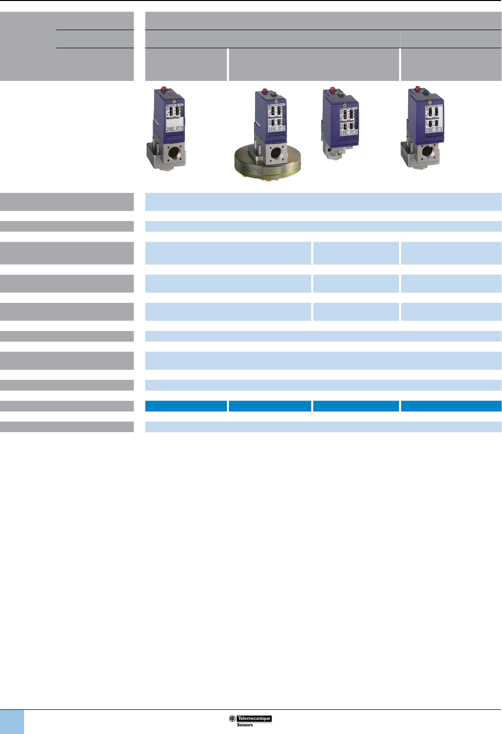
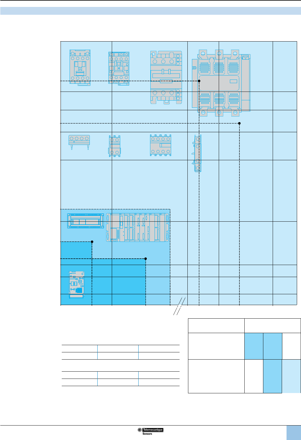
Applications Type of installation Control circuits
Media controlled Air, water, hydraulic oils, corrosive uids, viscous products
Type of operation Fixed differential:
Detection of a
single threshold
Adjustable differential:
Regulation between
two thresholds
Dual-stage switches:
Fixed differential,
detection at each threshold
Fluid characteristics Air, fresh water, sea water, corrosive uids, viscous products, up to 320 °F (160 °C)
depending on model
Size (pressure range) –1 to 500 bar (–14.5 to 7250 psi)
Dimensions of case: mm (in.)
Width x height x depth
35 x 68 x 75 (1.4 x 2.7 x 3.0) 46 x 68 x 85 (1.8 x 2.7 x 3.3) 35 x 68 x 75 (1.4 x 2.7 x 3.0)
Type of contacts 1 C/O single-pole, snap action 2 C/O single-pole,
simultaneous, snap action
2 C/O single-pole,
staggered, snap action
Degree of protection IP66 with terminal connections
IP65 with plug-in connector
IP66 with terminal
connections
IP66 with terminal connections
IP65 with plug-in connector
Agency listings UL, CSA, CCC, BV, LROS, RINA, GL, DNV, VIT-SEPRO
Electrical connection Screw terminals: 1 tapped entry: 1/2 NPT; M20 x 1.5 mm for ISO conduit/cable; or PG 13.5 conduit/cable entry
Connector: DIN 43650, M12
Pressure connection G 1⁄4 (BSP female), 1/4” NPTF, PT 1/4 (JIS B0203)
Catalog number XMLA XMLB XMLC XMLD
Pages 11
Other versions For electromechanical pressure and vacuum switches with alternative tapped cable or uid entries, consult the
Customer Care Center.
OsiSense™ XML
Electromechanical pressure and
vacuum switches
Selection guide
1
2
3
4
5
6
8
9
10
7
5
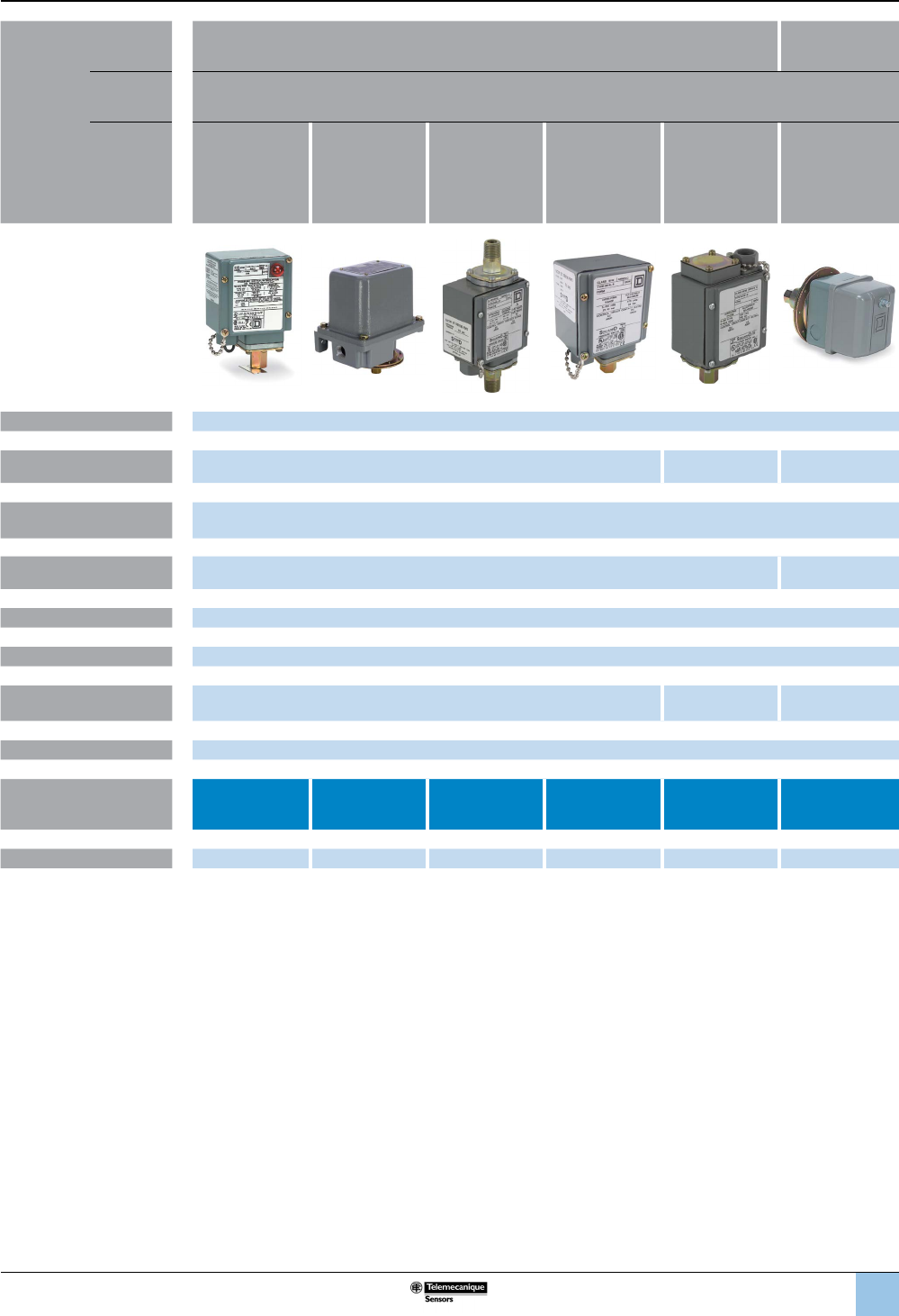
Applications Type of
installation
Control circuits Power circuits
Media
controlled
Air, water, hydraulic oils (1), gases, steam
Type of
operation
Fixed differential:
Detection of a
single threshold
Adjustable
differential:
Regulation
between
two thresholds
Differential-
pressure
(change in the
difference
between two
pressures)
Dual-stage
switches:
Fixed differential,
detection at each
threshold
Vacuum switches
for control circuits
Vacuum switches
for power circuits
Fluid characteristics up to 248 °F (120 °C)
Size (pressure range) Diaphragm: 0.2–675 psi on falling pressure
Piston actuated: 20–9,000 psi on falling pressure
0–28.7 inHg 0–25 inHg
Dimensions of case: mm (in.)
Width x height x depth
See page 96 and following pages
Type of contacts SPDT or DPDT double break contacts; SPDT single break contacts DPST
(SPDT for Form H)
Degree of protection IP66 conforming to IEC 60957
Agency listings UL Listed and CSA certied as industrial control equipment
Electrical connection
(enclosed devices)
1/2"-14 NPTF, PG13.5, or ISO M20; 3/4"-14 NPTF available only on NEMA 7 and 9.
NEMA 1 is 1/2" conduit entry, unthreaded.
1/2"-14 NPT 3 x 1/2" conduit
entry, unthreaded
Pressure connection G1/4 (BSP) female, 1/4"-18 NPTF, 1/4-18 NPT internal or external (depending on model), 1/2"-14 NPT
Catalog number 9012GD, GE,
GF, GR, GS, GT
9012GA, GB,
GC, GN, GP, GQ
9012GGW,
GHW, GJW
9012GKW, GLW,
GMW
9016GAW, GAR 9016GVG
Pages 8/85 8/87 8/89 8/90 94 95
Other versions (1) The hydraulic uids used for laboratory testing are equivalent to SAE 30 W oils. If oils have less viscosity than this type of oil,
leakage can be expected. Schneider Electric does not have test data to support or predict uid bypass with oils less than SAE
30W.
9012G and 9016G
Industrial pressure and vacuum switches
Selection guide (continued)
1
2
3
4
5
6
8
9
10
7
6
Steps for selecting a pressure switch
The deciding factors in the selection of a pressure switch for use on control circuits1 depend on the
requirements of the application. Consider the following requirements to help determine the
appropriate catalog number for your application.
1. Setpoints: Do you want to control/monitor one setpoint or two?
• One setpoint: xed differential • Two setpoints: adjustable differential
2. Fluids: What uids do you want to control?
• Hydraulic oil, air, fresh water ≤ 70 °C (158 °F) • Steam
• Hydraulic oil, air, fresh water ≤ 160 °C (320 °F) • Corrosive uid ≤ 160 °C (320 °F)
• Sea water ≤ 70 °C (158 °F) • Viscous uid ≤ 160 °C (320 °F)
• Sea water ≤ 160 °C (320 °F)
Ensure that the wetted parts of the switch are compatible with the system uid.
3. Pressure range: What pressure range does the system experience?
Note: Select pressure settings that fall within the middle 80% of the pressure range. The pressure
applied during a normal cycle should never exceed the maximum range value listed for the switch.
Pressure surges should be less than the maximum allowable pressure listed for the switch.
Rated pressure
XML 9012G / 9016 G (a)
psi bar psi bar
−14.5 to −4.06 −1 to −0.28 0 to 28 inHg
−14.5 to −2.03 −1 to −0.14 0 to 25 inHg
−2.9 to −0.029 −0.2 to −0.02 5 to 25 inHg (9016GVG only)
−7.25 to 72.5 −0.5 to 5 0.2 to 10 0.01 to 0.69
0 to 0.725 0 to 0.05 1 to 40 0.07 to 2.76
0 to 5.075 0 to 0.35 1.5 to 75 0.10 to 5.17
0 to 14.5 0 to 1 3 to 150 0.21 to 10.34
0 to 36.25 0 to 2.5 5 to 250 0.34 to 17.24
0 to 58 0 to 4 13 to 425 0.90 to 29.30
0 to 145 0 to 10 20 to 675 1.38 to 46.54
0 to 290 0 to 20 20 to 1000 1.38 to 68.95
0 to 507.5 0 to 35 90 to 2900 6.21 to 199.95
0 to 580 0 to 40 170 to 5600 11.72 to 386.11
0 to 1015 0 to 70 270 to 9000 18.62 to 620.53
0 to 2320 0 to 160 0 to 75 (b) 0 to 5.17 (b)
0 to 4350 0 to 300 0 to 175 (b) 0 to 12.07 (b)
0 to 7250 0 to 500 0 to 500 (b) 0 to 34.47 (b)
0 to 5000 (b) 0 to 344.74 (b)
(a) For 9016G vacuum switches, the unit of rated pressure is inHg.
(b) Pressure switches for differential-pressure operation.
4. Surges: How frequent are surges in your system, and what is their maximum pressure level?
Applications experiencing frequent or high-pressure surges may require a device with a higher
pressure range.
5. Differential: The required differential may exclude some pressure range choices.
(1) For switches used on power circuits, see catalog 9013CT9701, Commercial Pressure Switches, Class 9013 Types F and G.
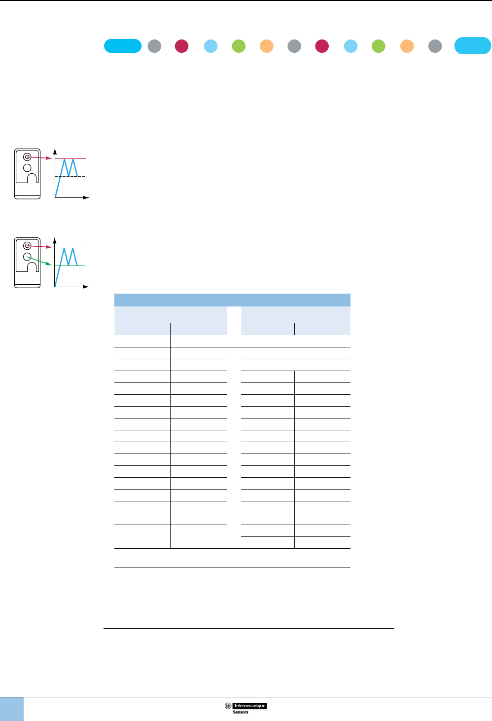
PH
Fixed differential
PH
PB
Adjustable differential
Industrial pressure switches
Selecting a
pressure switch
>>>>
3
Pressure
Range
4
Surges
5
Differential
>
Choose :>Catalog
Number
2
Fluids
1
Setpoints
>>>>>
Fluid
Connection
9
Special
Features
10 11
System
Response Time
8
Electrical
Connection
Enclosure
67
Output
1
2
3
4
5
6
8
9
10
7
7
6. Enclosure: What type of enclosure do you need?
• Open style • NEMA Type 7, 9
• NEMA Type 1 • NEMA Type 4, 4X, 13 / IP66, IP65
7. Output: What output type do you require?
• SPDT contacts, 1 N/O, 1 N/C • Dual stage, 1 SPDT contact each stage, 1 N/O, 1 N/C
• 2 SPDT contacts, 1 N/O, 1 N/C • Horsepower rated, 9016GVG vacuum switch only
8. Electrical connection: What type of electrical connection do you require?
• ½"- 14 NPTF • ¾"-14 NPTF (available only on NEMA 7 & 9)
• ISO M20 metric threads • No threaded connection
(open style or NEMA 1 only)
• Type 13 (PG 13.5) metric threads
9. Pressure connection: What type of pressure connection do you require?
• ¼"- 18 NPTF (female) • PT ¼ (JIS B0203)
• ½" - 14 NPT • 7/16"-20 UNF-2B
• G 1/4 BSP (female) metric thread
10. Special features: Do you require any special features?
See the modication table on page 8/91 for available modications for 9012 and 9016G
pressure switches. (Form designations are added to the end of the part number of the standard
device for these products.) Some examples are:
• Pilot light
• Prewired receptacles
• External range adjustment
• Range scale window
• Special factory pressure settings
• Pressure connections
When switches must be factory set and only one setting is identied, specify whether this setting
is on rising or falling pressure. See “Special factory setting specied (If indicating only one
special setting, specify whether this setting is on increasing or decreasing pressure.)” in the
modication table on page 8/91.
11. System response time
• If system response time is critical, select a switch with a volumetric displacement that is
compatible with the overall system. See the table below .
Volumetric displacement of 9012G pressure switches
Class 9012 Type Volumetric displacement (1)
(in3)
Volumetric displacement (1)
(cm3)
GAR, GAW, GDR, GDW-1& 21 0.20774 3.40422
GAR, GAW, GDR, GDW-2 & 22 0.07040 1.15385
GAR, GAW, GDR, GDW-4 & 24 0.04320 0.70805
GAR, GAW, GDR, GDW-5 & 25 0.02144 0.35140
GAR, GAW, GDR, GDW-6 & 26 0.01376 0.22553
GBR, GBW, GER, GEW-1 & 21 0.00200 0.13112
GBR, GBW, GER, GEW-2 & 22 0.00512 0.08392
GCR, GCW, GFR, GFW-1 & 21 0.00320 0.05245
GCR, GCW, GFR, GFW-2 & 22 0.00117 0.01922
GCR, GCW, GFR, GFW-3 & 23 0.00060 0.00924
GCR, GCW, GFR, GFW-4 & 24 0.00037 0.00612
(1) Figures shown are total displacement. When the switch is operated between settings only, displacement is 1/3 of the
values shown.
Industrial pressure switches
Selecting a
pressure switch
(continued)
1
2
3
4
5
6
8
9
10
7
8
Industrial pressure switches
Terminology
Measuring range
The measuring range (MR) of a pressure sensor corresponds to the difference
between the upper and lower values measured by the load cell. It ranges between 0
and the pressure corresponding to the size of the sensor.
Operating range
The operating range of a pressure transmitter corresponds to its measuring
range. Within this range, its analog output signal varies between 4 and 20 mA or 0
and 10 V, and is proportional to the measured pressure.
The operating range of a pressure or vacuum switch is the difference between
the values of the minimum low setpoint (PB) and the maximum high setpoint (PH).
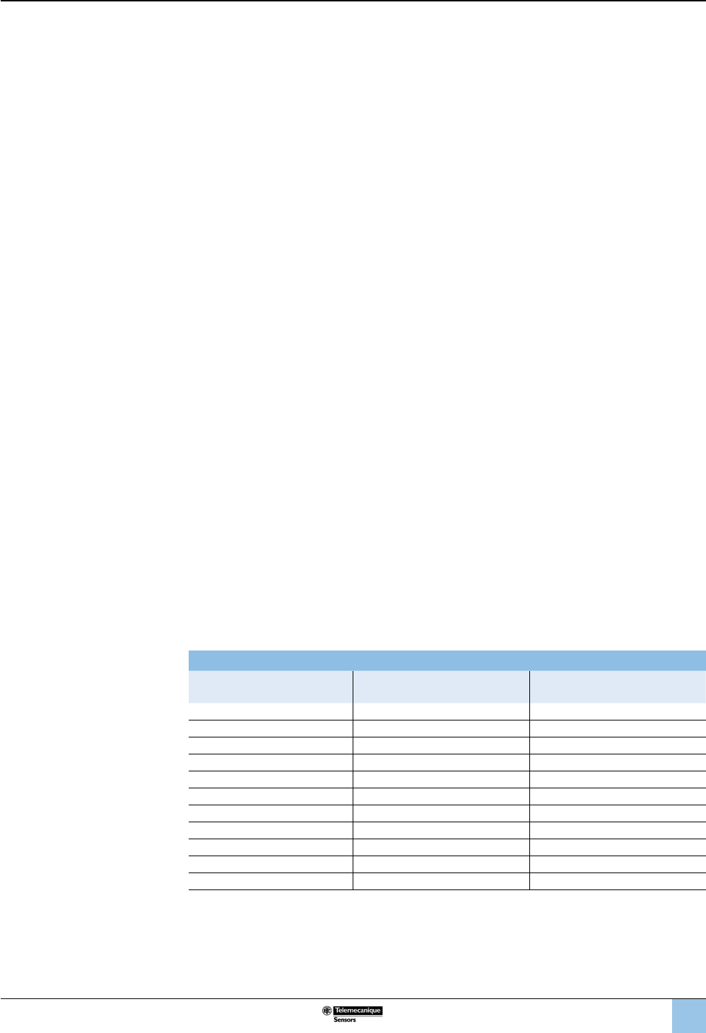
Precision
This includes linearity, hysteresis, repeat accuracy, and setting tolerances. It is
expressed as a percentage of the measuring range of the load cell (%MR).
The linearity is the maximum deviation
between the real transmitted curve and
the ideal curve.
The hysteresis is the maximum
deviation between the rising pressure
curve and the falling pressure curve.
The repeat accuracy is the maximum
drift encountered at varying pressures
under given conditions.
The setting tolerances are the
manufacturer's tolerances with regard
to the zero point and sensitivity
(gradient of output signal curve from
pressure transmitter).
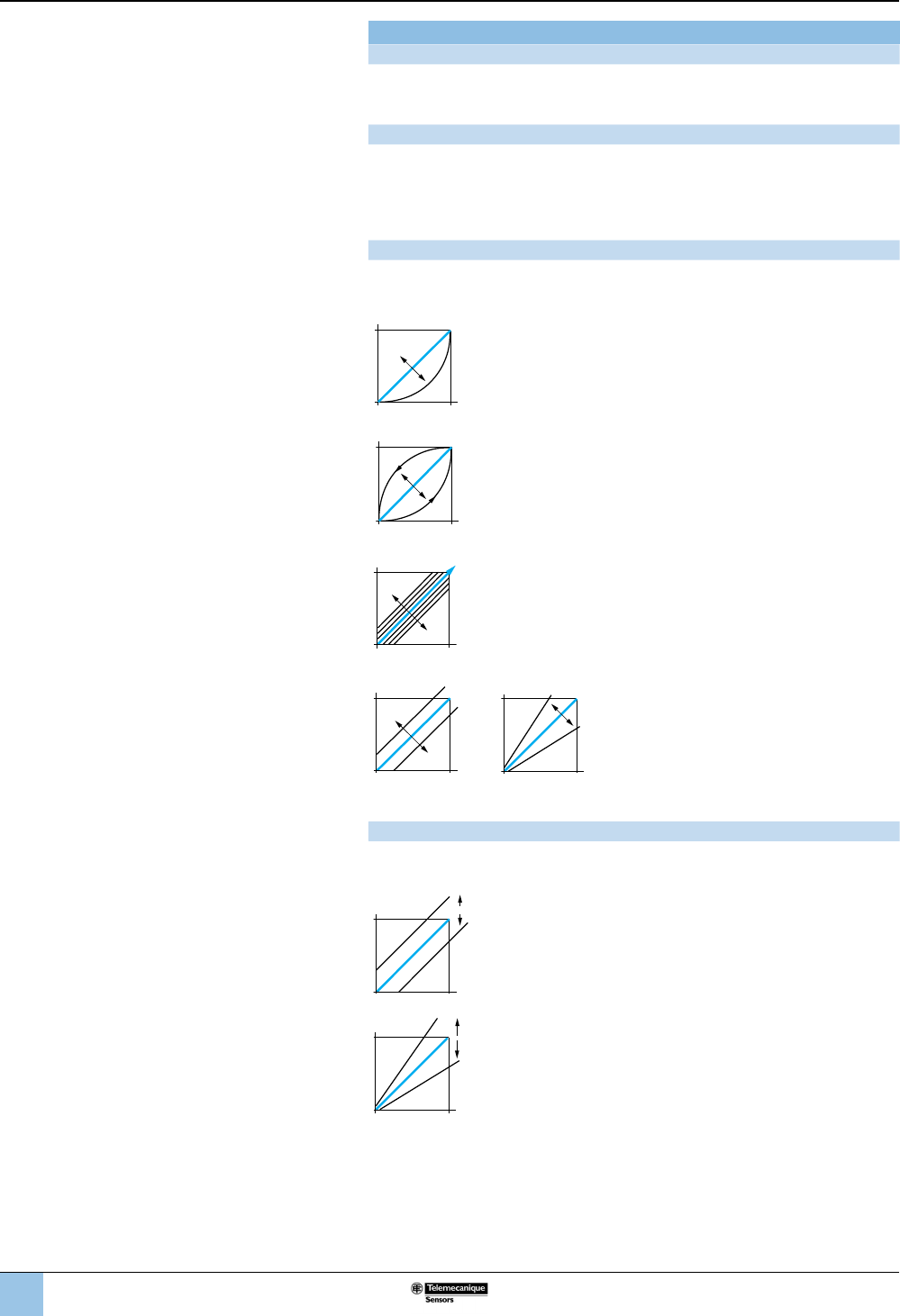
Temperature drift
The precision of a pressure sensor is susceptible to variation due to the operating
temperature.
Zero point drift, proportional to the
temperature, is expressed as %MR/°C.
Sensitivity drift, proportional to the
temperature, is expressed as %MR/°C.
Signal
Pressure
Signal
Pressure
Signal
Pressure
Signal
Pressure
Signal
Pressure
t°
t°
Signal
Pressure
t°
t°
Signal
Pressure
Terminology
1
2
3
4
5
6
8
9
10
7
9
Industrial pressure switches
Terminology (continued)
Switching point on rising pressure (PH)
This is the upper pressure setting at which the output of the electronic pressure or
vacuum switch changes state on rising pressure.
Switching point on falling pressure (PB)
This is the lower pressure setting at which the output of the electronic pressure or
vacuum switch changes state on falling pressure.
Differential
This is the difference between the switching point on rising pressure (PH) and the
switching point on falling pressure (PB). The low point can be set at the values
indicated on the operating curves shown on the product pages.
Switches with xed differential
Depending on the switch, either the high or low operating point is adjustable, and
the other operating point follows. The window is xed.
Switches with adjustable differential
An adjustable differential allows independent setting of both operating points.
Spread
For dual-stage switches, the spread indicates the difference between the two
operating points on rising pressure (PH2 and PH1) and, for vacuum switches, the
difference between the two operating points on falling pressure (PB2 and PB1).
Differential-pressure sensing
Switches for differential-pressure sensing measure the difference between two
pressures.
Size
Pressure transmitters and pressure switches
This is the maximum value of the operating range.
Vacuum transmitters and vacuum switches
This is the minimum value of the operating range.
+
–
Setting point
Accuracy (switches with setting scale)
The tolerance between the point at which the switch actuates its contacts and the
value indicated on the setting scale. Where very high setting accuracy is required
(initial installation of the product), it is recommended that you use separate
measuring equipment (pressure gauge, etc.).
R
Repeat accuracy
This is the variation in the operating point between several successive operations,
or the tolerance between two consecutive switching operations.
F
Drift (F)
The tolerance of the operating point throughout the entire service life of the switch.
Terminology
(continued)
1
2
3
4
5
6
8
9
10
7
10
Terminology (continued)
300
bar
200
100
0
050 100 150
ms
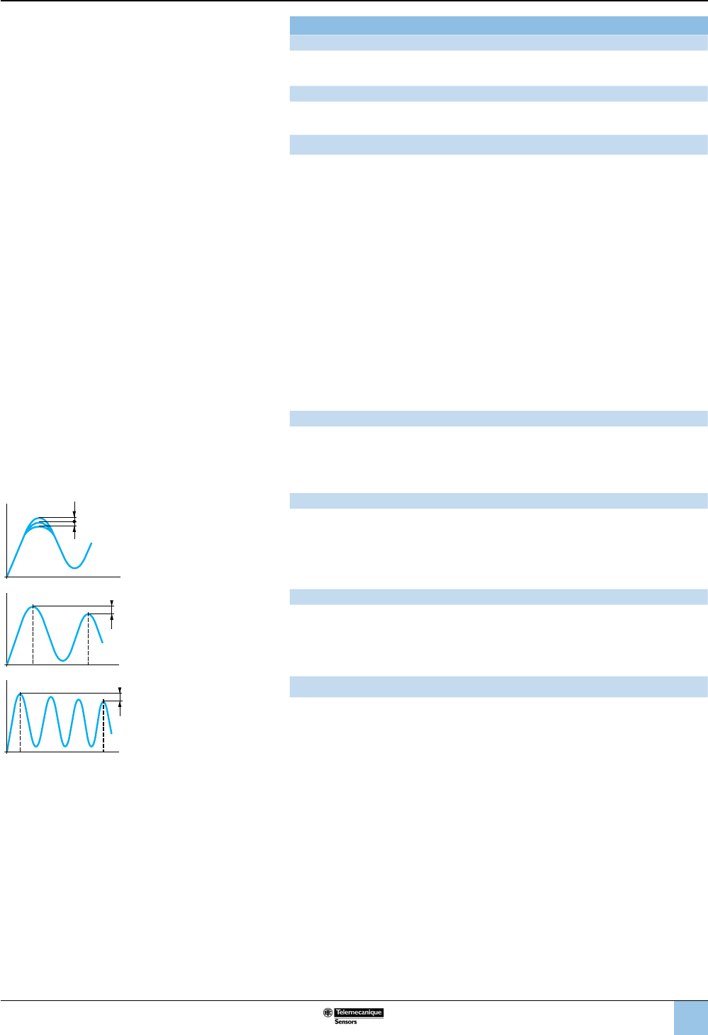
Maximum allowable pressure
The maximum value of an accidental pressure surge of very short duration (a few
milliseconds).
Maximum permissible accidental pressure
This is the maximum pressure (excluding pressure surges) that the sensor can
occasionally withstand without permanent damage.
Maximum allowable pressure per cycle (Ps)
The maximum pressure level per cycle that the switch can withstand for optimum
service life.
Surge
A surge is a high rate of rise in pressure, normally of short duration, caused by
starting a pump or by opening and closing a valve. Depending on frequency and
duration, surge can reduce service life. Extremely high rates of rise in pressure can
be damaging even if they are within the limits of the maximum allowable pressure.
Destruction pressure
Also called burst pressure, the destruction pressure is the pressure value which, if
exceeded, is likely to cause serious damage to the sensor—such as leaking,
bursting, or permanent damage.
Load resistance of pressure transmitters
The supply voltage and load resistance of a pressure transmitter must be selected
according to the following formula:
R load = U supply – U supply min. (U supply min = 11 V for XMLE and 17 V for XMLF)
0.02 A
050 100 150
0
50
100
bar
ms
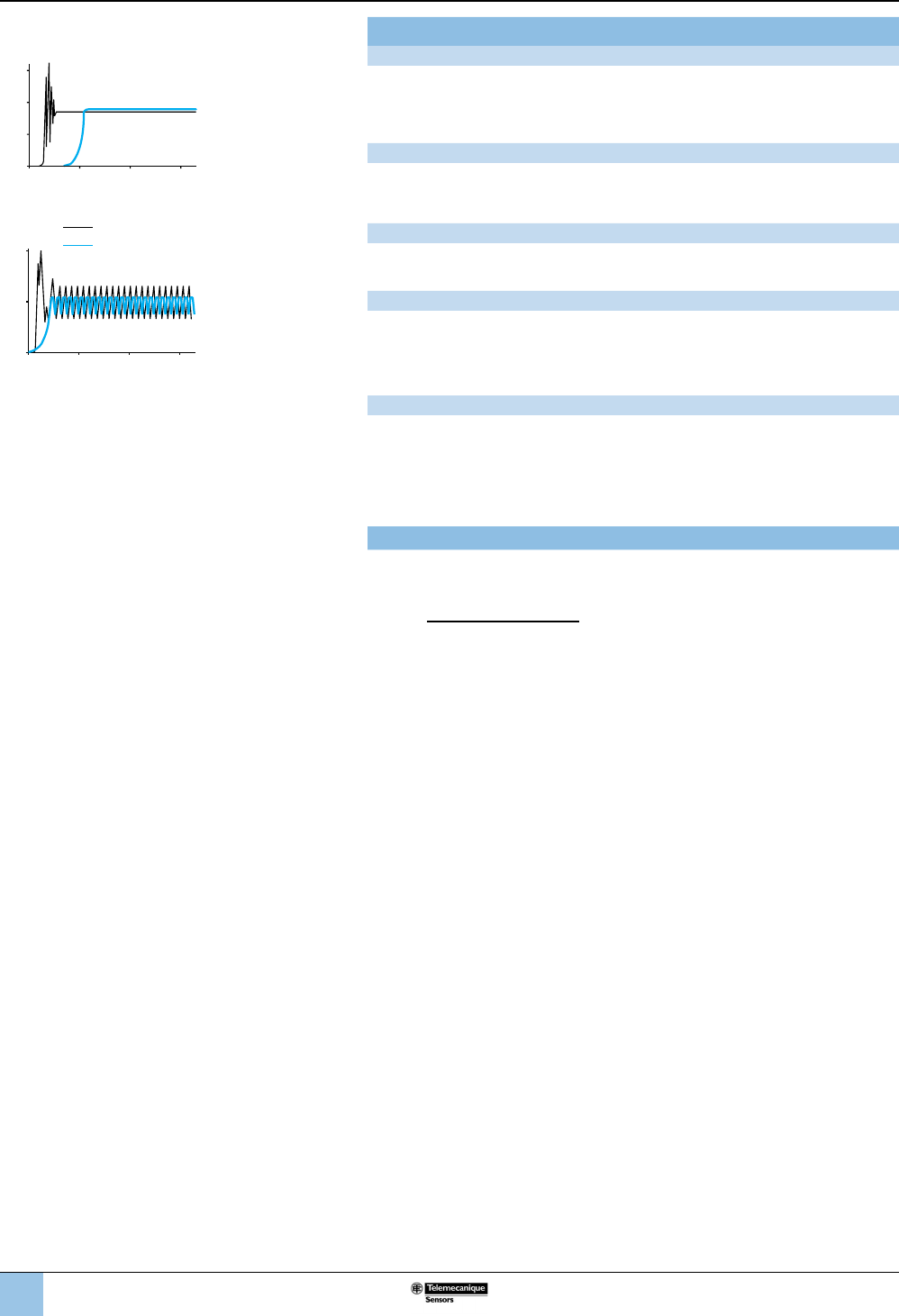
Example 1: With destructive (burst) pressure level
Industrial pressure switches
Example 2: With destructive (burst)
pressure level and destructive pressure
oscillations
Without damping device
With damping device
Terminology
(continued)
11
1
2
3
4
5
6
8
9
10
7
XML pressure and vacuum switches for control circuits are used to control the
pressure of hydraulic oils, fresh water, sea water, air, steam, corrosive uids, or
viscous products, up to 7250 psi (500 bar).
b XMLA pressure and vacuum switches have a xed differential and are for
detection of a single threshold. They incorporate a 1 C/O single-pole contact.
b XMLB pressure and vacuum switches have an adjustable differential and are for
regulation between two thresholds. They incorporate a 1 C/O single-pole contact.
b XMLC pressure and vacuum switches have an adjustable differential and are for
regulation between two thresholds. They incorporate two C/O single-pole
contacts.
b XMLD pressure and vacuum switches are dual-stage switches, each stage with a
xed differential, and are for detection at each threshold. They incorporate two
C/O single-pole contacts (one per stage).
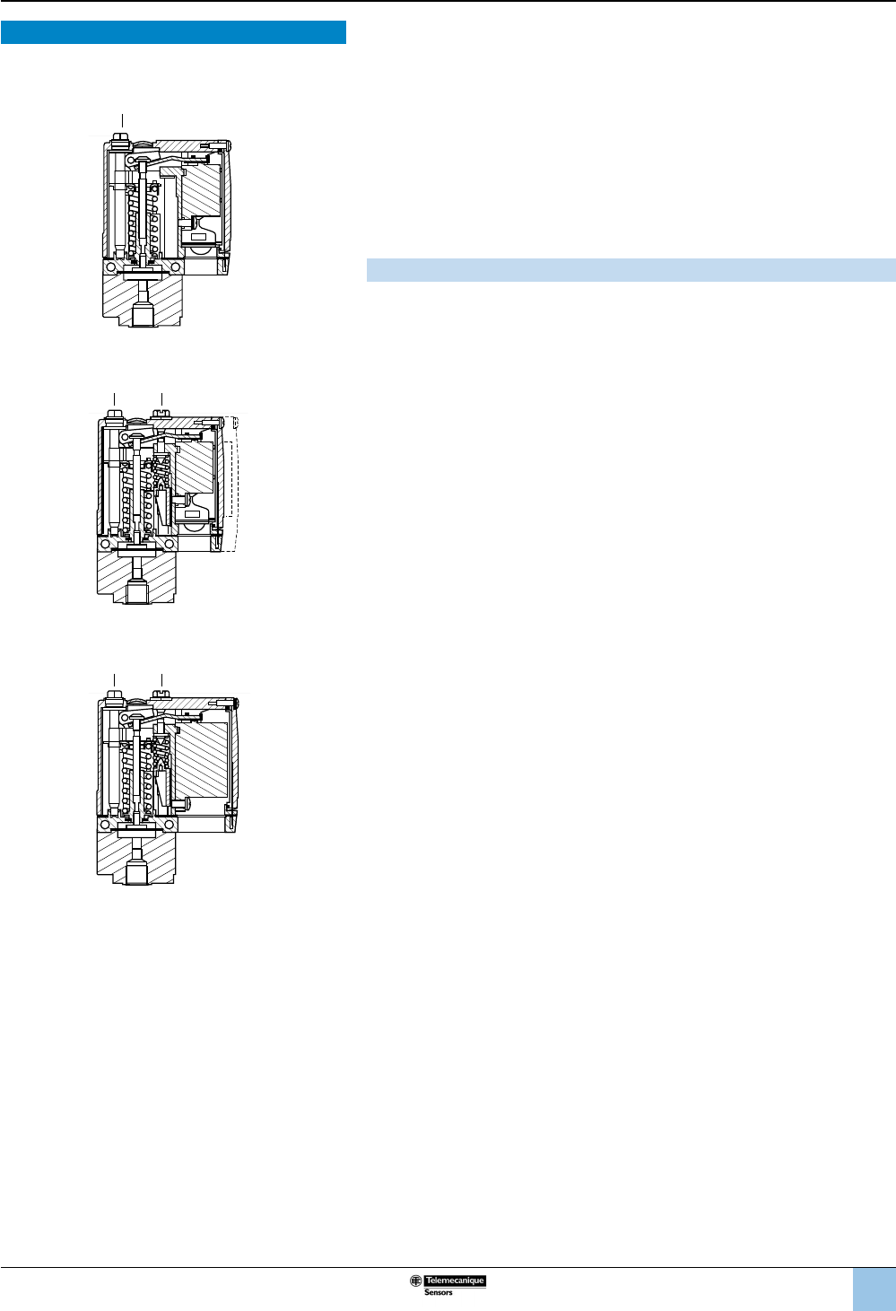
Setting
XMLA: Pressure and vacuum switches with xed differential
b Rising pressure—Operating point PH is set by adjusting the red screw (1).
b Falling pressure—Operating point PB is not adjustable.
The difference between the trip and reset points of the contact is the inherent
differential of the switch (contact differential, friction, etc.).
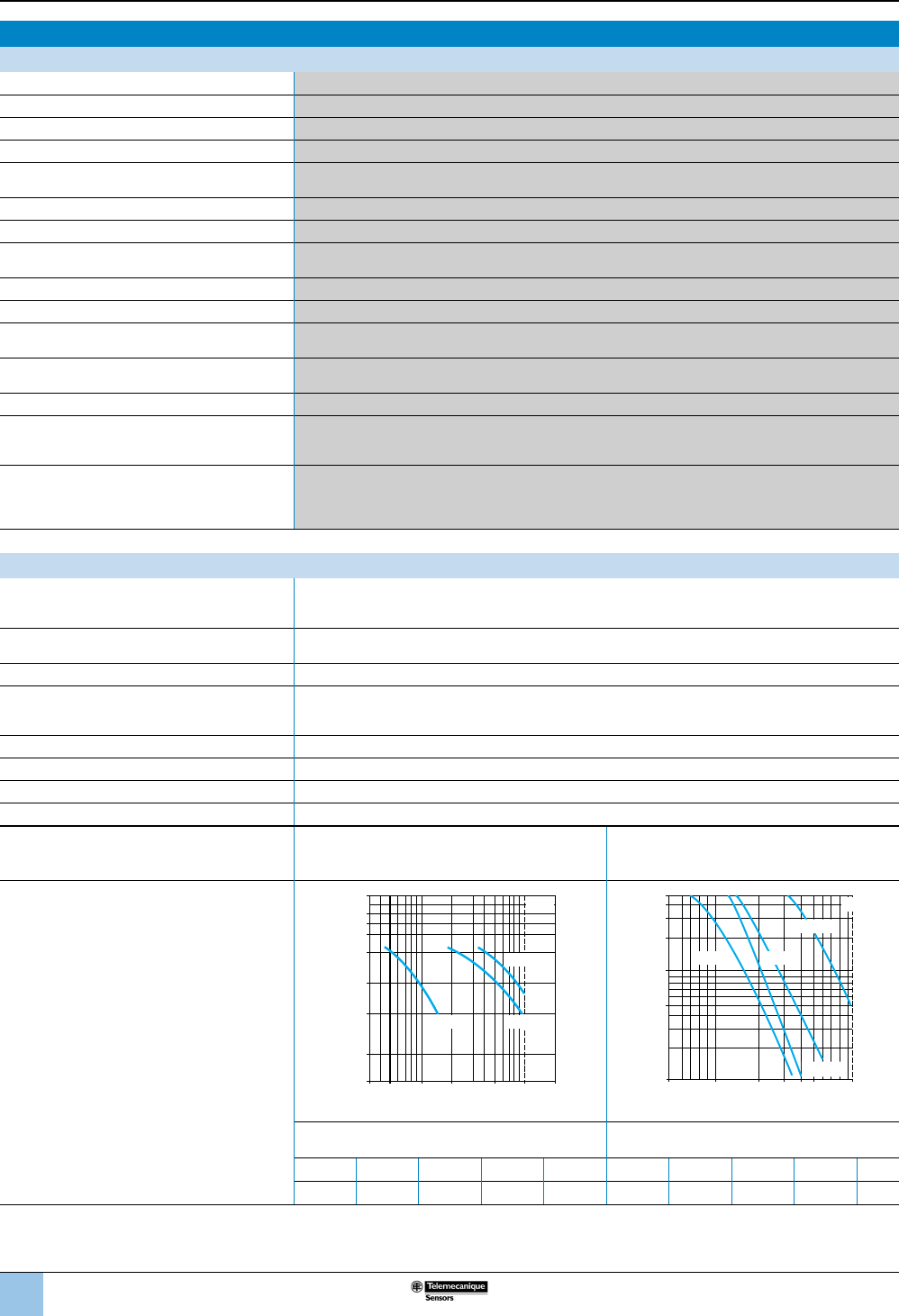
XMLB and XMLC: Pressure and vacuum switches with
adjustable differential
When setting the pressure and vacuum switches, rst adjust the operating point on
rising pressure (PH), then the operating point on falling pressure (PB).
b Rising pressure—Operating point PH is set by adjusting the red screw (1).
b Falling pressure—Operating point PB is set by adjusting the green screw (2).
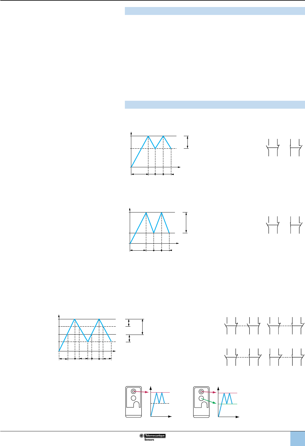
XMLD: Dual-stage pressure and vacuum switches with xed
differential for each threshold
Operating point on rising pressure of stage 1 and stage 2
b First stage operating point on rising pressure (PH1) is set by adjusting the red
screw (1).
b Second stage operating point on rising pressure (PH2) is set by adjusting the
blue screw (2).
Operating point on falling pressure
The operating points on falling pressure (PB1 and PB2) are not adjustable.
The difference between the trip and reset points of each contact is the inherent
differential of the switch (such as contact differential or friction).
OsiSense XML
Electromechanical
pressure and vacuum switches
Introduction
1 2
1 2
1
XMLA
XMLB, C
XMLD
Introduction
12
1
2
3
4
5
6
8
9
10
7
Specications
Environmental specications
Conformity to standards e, IEC/EN 60947-5-1, UL 508, CSA C22-2 n° 14
Product certications UL, CSA, CCC, BV, LROS, RINA, GL, DNV, VIT-SEPRO
Protective treatment Standard version TC. Special version TH
Ambient air temperature, °F (°C) For operation: –13 to +158 (–25 to +70). Storage: –40 to +158 (–40 to +70)
Fluids or products controlled Hydraulic oils, air, fresh water, sea water, 32–320 °F (0 to 160 °C), depending on model
Steam, corrosive uids, viscous products, 32–320 °F (0 to 160 °C), depending on model
Materials Case: zinc alloy. Component materials in contact with uid: see page 77
Operating position All positions
Vibration resistance 4 gn (30–500 Hz) conforming to IEC 68-2-6
except XML•L35••••, XML•001•••••and XMLBM03•••••: 2 gn
Shock resistance 50 gn conforming to IEC 68-2-27 except XML•L35•••••, XML•001••••• and XMLBM03••••: 30 gn
Electric shock protection Class I conforming to IEC 1140, IEC 536 and NF C 20-030
Degree of protection Screw terminal models: IP66 conforming to IEC/EN 60529
Connector models: IP65 conforming to IEC/EN 60529
Operating rate (operating cycles/minute) Piston version switches: up to 60 cycles/minute for temperatures greater than 32 °F (0 °C)
Diaphragm version switches: up to 120 cycles/minute for temperatures greater than 32 °F (0 °C),
Repeat accuracy < 2%
Pressure connection(1)
• G 1/4 (BSP female) conforming to NF E 03-005, ISO 228
• 1/4"-18 NPTF female
• PT 1/4 (JIS B0203).
Electrical connection(1)
for screw terminal models
• 1/2" NPT electrical connections
• ISO M20 x 1.5 tapped entry
• DIN Pg 13.5 (n° 13) tapped entry
• Connector models, either M12 or DIN 43650 A: consult the Customer Care Center.
(1) See page 21, “Interpretation of the Catalog Number for XML Devices,” for more information on specifying the electrical and pressure connections.
Contact block specications
Rated operational specications
a AC-15; B300 (Ue = 240 V, Ie = 1.5 A - Ue = 120 V, Ie = 3 A)
c DC-13; R300 (Ue = 250 V, Ie = 0.1 A) conforming to IEC 947-5-1 Appendix A,
EN 60 947-5-1
Rated insulation voltage Ui = 500 V conforming to IEC/EN 60947-1
Ui = 300 V conforming to UL 508, CSA C22-2 n° 14
Rated impulse withstand voltage Uimp = 6 kV conforming to IEC/EN 60947-1
Type of contacts
Silver tipped contacts
XMLA and XMLB: 1 C/O single-pole contact (4 terminal), snap action
XMLC: 2 C/O single-pole contacts (8 terminal), simultaneous, snap action
XMLD: 2 C/O single-pole contacts (8 terminal), staggered, snap action
Resistance across terminals (mΩ) < 25 conforming to NF C 93-050 method A or IEC 255-7 category 3
Terminal referencing Conforming to CENELEC EN 50013
Short-circuit protection 10 A cartridge fuse type gG (gl)
Connection Screw clamp terminals. Clamping capacity, min: 1 x 0.2 mm2, max: 2 x 2.5 mm2
Electrical durability
Conforming to IEC/EN 60947-5-1 Appendix C
Utilization categories AC-15 and DC-13
XMLA and XMLB
AC supply a 50/60 Hz
o Inductive circuit, lthe = 10 A
XMLC and XMLD
AC supply a 50/60 Hz
o Inductive circuit, lthe = 10 A
Operating rate:
3600 operating cycles/hour
Load factor: 0.5
DC supply c
Power broken in W for 1 million operating cycles
DC supply c
Power broken in W for 5 million operating cycles
Voltage V 24 48 120 Voltage V 24 48 120
oW 31 29 26 oW10 7 4
0.30.5 12 51
020
0.1
0.2
0.5
1
2
3
4
5
7
110 V
48 V
230 V
Ithe
Millions of operating cycles
Current in A
0.5 12 510
0.1
0.5
1
5
2
3
4
230 V 48 V
Ithe
12/24 V
34
110 V
Millions of operating cycles
Current in A
OsiSense XML
Electromechanical
pressure and vacuum switches
Introduction (continued)
13
1
2
3
4
5
6
8
9
10
7
Function
Pressure and vacuum switches control or regulate pressure or vacuum levels in
hydraulic or pneumatic systems. They transform the pressure change into a digital
electrical signal when the preset operating points are reached.
Switches for control circuits
Switches with control-duty rated electrical contacts, designed for control of
contactors, relays, power valves, PLC inputs, etc.
Switches for power circuits
Switches with power electrical contacts (1, 2, or 3 pole) designed for direct switching
of single-phase or three-phase motors (pumps, compressors, etc.).
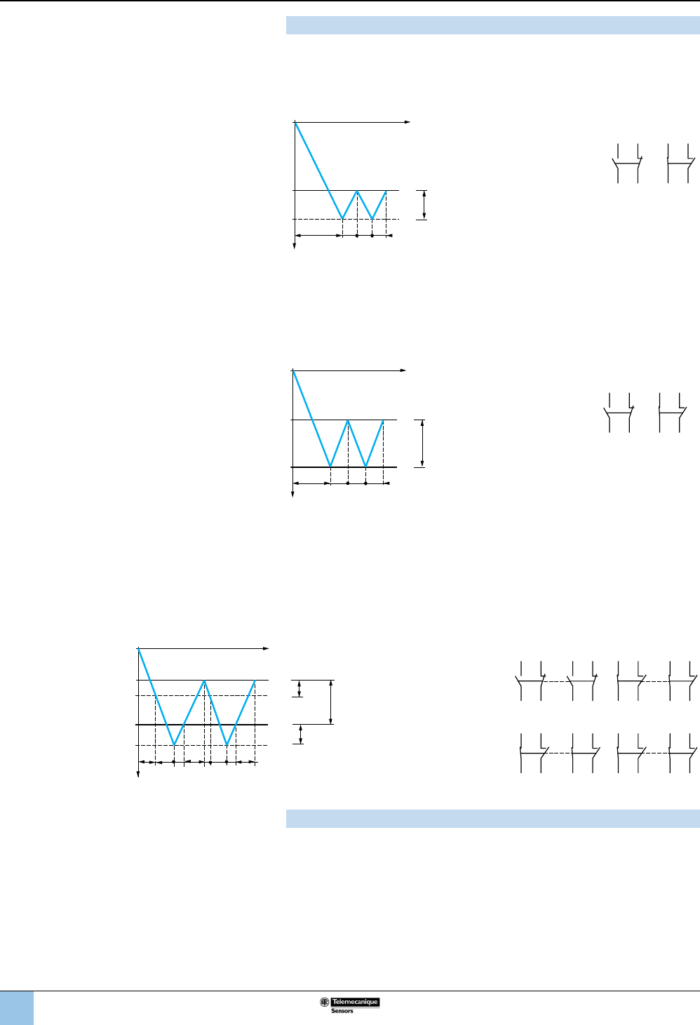
Pressure switch operating principle
Fixed Differential: Detection of a Single Threshold
Fixed differential switches have
a single adjustable setting point
(either PH or PB). The
differential between the high
and low points (PH–PB)
depends on the construction of
the switch. It is not adjustable.
–– Adjustable value
--- Nonadjustable value
PH = High point
(on rising pressure)
PB = Low point
(on falling pressure)
Example: Contact
schematics of XMLA
Adjustable Differential: Regulation between Two Thresholds
Adjustable differential switches
have setting points for both the
high point (PH) and the low
point (PB). Both of these points
can be independently adjusted.
–– Adjustable value
PH = High point
(on rising pressure)
PB = Low point
(on falling pressure)
Example: Contact
schematics of XMLB
Dual-Stage: Detection of Two Thresholds
Dual-stage switches allow two distinct levels of control to be monitored with one
device. Each stage allows detection of a single threshold with a single setting point
(xed differential). Both these points can be independently adjusted. However, for
both stages, the differential between the high point and the low point (PH1–PB1 and
PH2–PB2) is xed and depends on the construction of the switch.
–– Adjustable value
--- Nonadjustable value
PH = High point
(on rising pressure)
PB = Low point
(on falling pressure)
Example: Contact schematics of XMLD
1212
Pressure
Fixed
dif
ferential
Time
PB
PH
1314
12 11
1314
12 11
1 2
1212
Pressure
Adjustable
spread
Time
PH
PB
1314
12 11
1314
12 11
1 2
PH2
PH1
PB1
PB2
124
312 4
3
Pressure
Fixed
differ-
ential
Fixed
differ-
ential
Time
Adjustable
differential
2324
22 21
1314
12 11
2324
22 21
1314
12 11
2324
22 21
1314
12 11
2324
22 21
1314
12 11
12
34
OsiSense XML
Electromechanical
pressure and vacuum switches
Introduction (continued)
PH
Fixed differential
PH
PB
Adjustable differential
PH
Fixed differential
PH
PB
Adjustable differential
14
1
2
3
4
5
6
8
9
10
7
Vacuum switch operating principle
Detection of a single threshold
The switches for detection of a single threshold (xed differential) have a single
adjustable setting point (PH). The differential between the high and low points (PH–
PB) depends on the inherent characteristics of the switch. It is not adjustable.
–– Adjustable value
--- Nonadjustable value
PH = High point
PB = Low point
Example: Contact
schematics of XMLA
Regulation between two thresholds
The switches for regulation between two thresholds (adjustable differential) have
both a high point setting (PH) and a low point setting (PB). Both of these points can
be independently adjusted.
–– Adjustable value
PH = High point
PB = Low point
Example: Contact
schematics of XMLB
Detection of two thresholds
The dual-stage switches, for detection at each threshold, have an adjustable high
point setting for each stage (PH1 and PH2). Both of these points can be
independently adjusted.
For both stages, the differential between the high point and the low point (PH1–PB1 and
PH2–PB2) depends on the inherent characteristics of the switch. It is not adjustable.
–– Adjustable value
--- Nonadjustable value
PH = High point
PB = Low point
Example: Contact schematics of XMLD
Maximum allowable accidental pressure
The maximum accidental pressure of XML switches is equal to at least 2.25 times
the switch size.
If accidental overpressures occur and their duration is less than 50 milliseconds, the
pressure damping device incorporated in the XML switches (sizes 10 bar and
greater) reduces the effect.
12
12
Vacuum
Fixed
differential
Time
PB
PH
1
1
2
1
1314
12 11
1314
12 11
12
12
Vacuum
Adjustable
spread
Time
PB
PH
1
1
2
1
1314
12 11
1314
12 11
PH1
PH2
PB2
PB1
124
31243
Fixed
differ-
ential
Fixed
differ-
ential
Time
Adjustable
differential
Vacuum
2324
22 21
1314
12 11
2324
22 21
1314
12 11
12
34
2324
22 21
1314
12 11
2324
22 21
1314
12 11
OsiSense XML
Electromechanical
pressure and vacuum switches
Introduction (continued)
15
1
2
3
4
5
6
8
9
10
7
Application range of pressure and vacuum switches types XML, XMA and XMX, for control circuits
On standard loads: Continuous duty, frequent switching.
(1) Standard PLC input, type 1 Pressure switches Application range
(2) Standard PLC input, type 2
(3) Switching capacity conforming to IEC 947-5-1,
utilization category AC-15, DC-13
XMLA, XMLB, XMLC, XMLD
B300 240 V 1.5 A
R300 250 V 0.1 A
(4) Switching capacity conforming to IEC 947-5-1,
utilization category AC-15, DC-13
XMLE, XMLF, XMLG
B300 120 V 3 A
R300 125 V 0.22 A
PLC: programmable logic controller
On small loads: The use of electromechanical pressure and vacuum switches with programmable logic controllers
is becoming more prevalent. On small loads, the switches maintain a failure rate of less than 1 for 100 million
operating cycles. Results may vary depending on application.
OsiSense XML
Electromechanical
pressure and vacuum switches
Introduction (continued)
5
6
10
8
20
60
100
15
150
200
500
120
240
24
V
48
1 mA 2 mA 3 mA 6 mA 10 mA 2 A3
A6
A
10 A
1 A
(1)
(2)
(3)
(4)
I
1.5 A
Insulation voltage limit
Inductive loads
Heating limit (lth)
16
1
2
3
4
5
6
8
9
10
7
Selecting the switch size
After establishing the type of switch required for the application (single threshold
detection or regulation between two thresholds), the selection of its size depends on
the following criteria:
b the differential: difference between the high point (PH) and the low point (PB),
b the maximum pressure allowable per cycle,
b repeat accuracy, precision and minimum drift.
Selecting a xed differential pressure switch for detecting a
single threshold
Main criterion: minimum differential
Example: for a selected high point (PH) of 7 bar
XMLA010•••••
Differential = 0.5 bar
XMLA020•••••
Differential = 1 bar
XMLA035•••••
Differential = 2 bar
Select an XMLA010••••• (the lowest size)
Main criterion: tolerance to overpressures
Example: for a selected high point (PH) of 12 bar
XMLA020•••••
Allowable accidental overpressure = 45 bar
XMLA035•••••
Allowable accidental overpressure = 80 bar
Select an XMLA035••••• (the highest size)
Main criterion: repeat accuracy, precision and minimum drift
Example: for a selected high point (PH) of 18 bar
As a general rule,
avoid working at
the upper or lower
limits of the
operating range.
XMLA020•••••
Adjustable from 1–20 bar
XMLA035•••••
Adjustable from 1.5–35 bar
Select an XMLA035•••••
Converting Units of Pressure
psi kg/cm2bar atm mm Hg (Torr) mm H2O Pa
1 psi = 10.07031 0.06895 0.06805 51.71 703.7 6895
1 kg/cm2 = 14.22 1 0.98066 0.96784 735.55 10 000 98 066
1 bar = 14.50 1.0197 10.98695 750.06 10 197 105
1 atm = 14.70 1.0333 1.0132 1760.0 10 333 101 325
1 mm Hg = (Torr) 0.01934 1.360 x 10⁻³ 1.333 x 10⁻³ 1.316 x 10⁻³ 1 13.59 133.3
1 mm H2O= 1.421 x 10⁻³ 10-4 a 10-4 a 10-4 0.07361 1a 9.80
1 Pa = 1.45 x 10⁻⁴ 1.0197 x 10⁻⁵ 10-5 9.8695 x 10⁻⁶ 7.5 x 10⁻³ 0.10197 1
Example: 1 bar = 14.50 psi = 105 Pa
10 bar
0,6
76,
5
20 bar
1
76
35 bar
1,5
75
45 bar
1
12
20
25
80 bar
1,5
12
35
45
20 bar
1
18
35 bar
1,5
18
OsiSense XML
Electromechanical
pressure and vacuum switches
Introduction (continued)
17
1
2
3
4
5
6
8
9
10
7
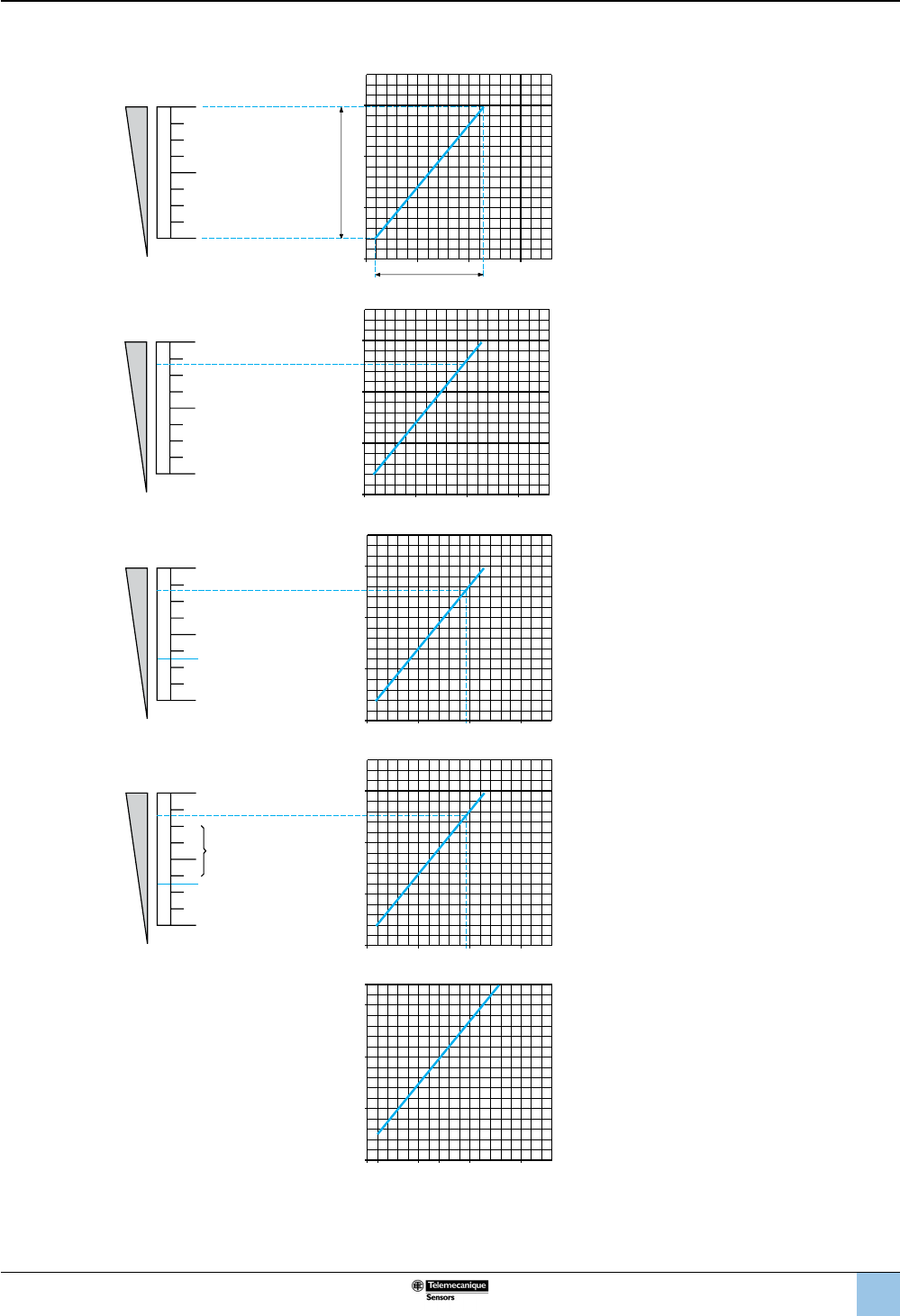
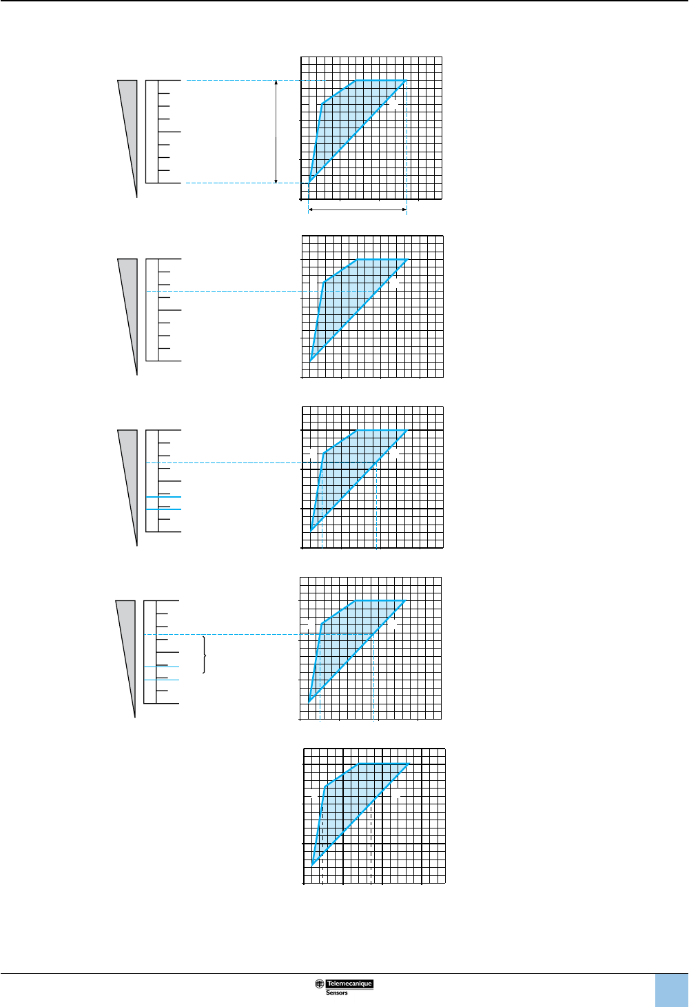
Operating curves: Fixed Differential, Detecting a Single Threshold
Adjustment
range of the
high point
Dened by the difference between the
minimum and maximum high point (PH)
setting values.
For a high set point (PH), the lower point
(PB) is xed and cannot be adjusted.
For a low set point (PB), the higher point
(PH) is xed and cannot be adjusted.
Operating
point on
rising
pressure (PH)
The upper pressure setting at which the
pressure or vacuum switch actuates the
contacts on rising pressure.
Adjustable throughout the range on rising
pressure.
Operating
point on
falling
pressure (PB)
The pressure at which the switch contact
changes state on falling pressure.
The lower point (PB) is not adjustable and is
entirely dependent on the high point setting
(PH) and the inherent differential of the
switch.
Differential PH–PB = inherent differential
The difference between the operating point
on rising pressure (PH) and the operating
point on falling pressure (PB).
This point is not adjustable, so the value of
the differential is xed.
It is the inherent differential of the switch
(contact differential, friction, etc.).
Example
0
28
PB 40 60203
20
PH 40
60
0
Rising pressure
Falling pressure
bar
bar
Operating point on rising pressure (PH) is
40 bar (set value at which the contact
changes state on rising pressure).
The operating point on falling pressure (PB)
is 28 bar (xed value at which the contact
returns to its original state).
Conclusion:
the differential is 40 – 28 = 12 bar.
Maxi
+
–
Mini
0
0
Rising pressure
Falling pressure
Adjustment range
of high point (PH)
Low point (PB)
range
0
PH
+
–
0
Rising pressure
Falling
pressure
0
PH
+
–
PB
PB
0
Rising pressure
Falling pressure
PH
+
–
PB
PB
PH – PB
0
0
Rising pressure
Falling pressure
OsiSense XML
Electromechanical
pressure and vacuum switches
Introduction (continued)
18
1
2
3
4
5
6
8
9
10
7
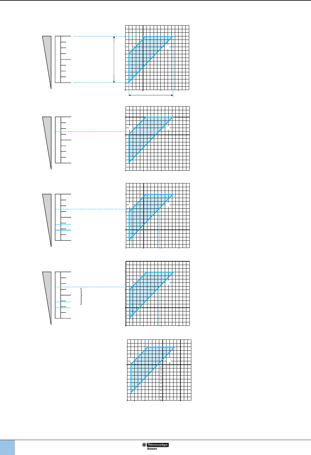
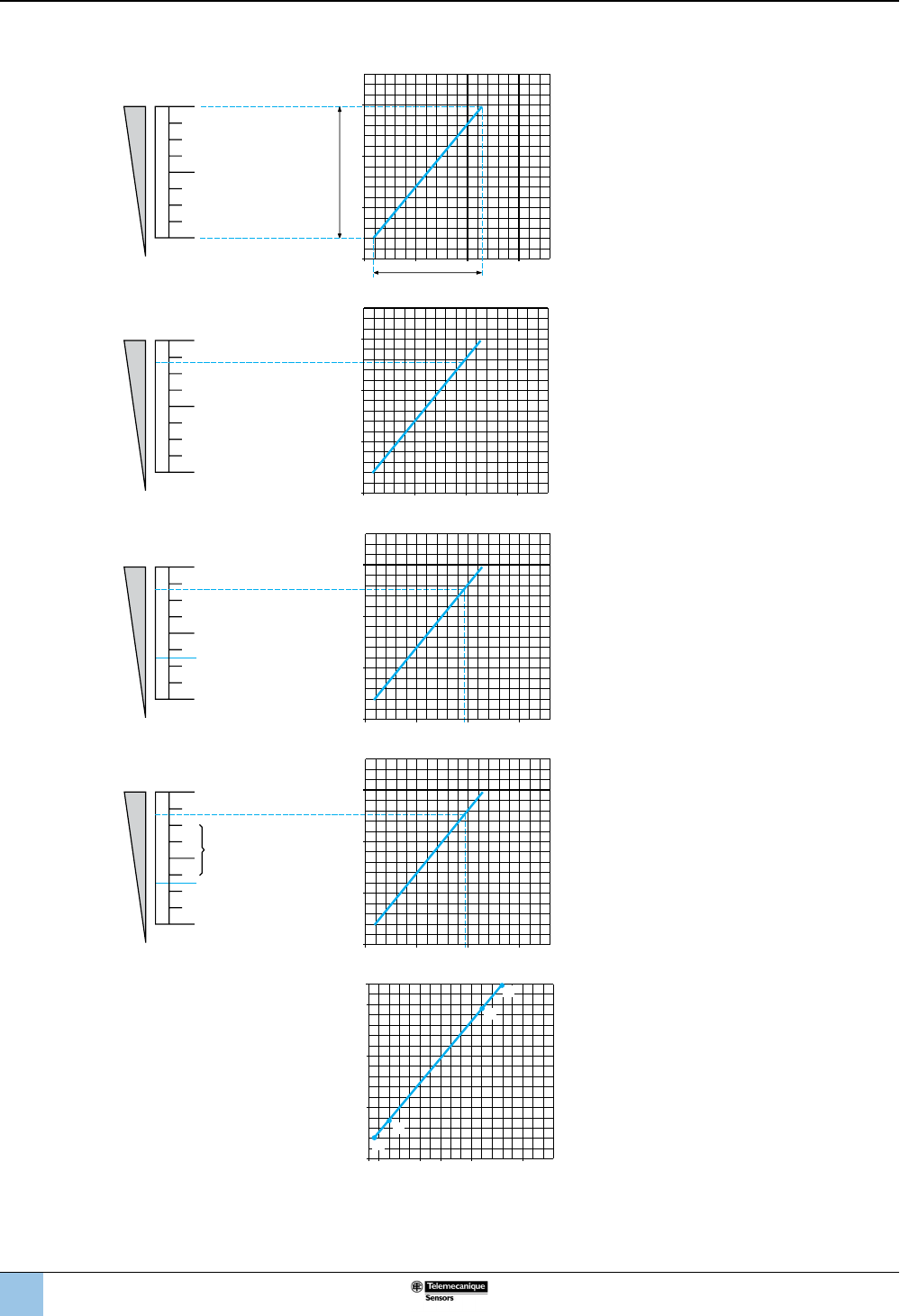
Operating curves: Adjustable Differential, Regulating between Two Thresholds
Adjustment
range of the
high point
Dened by the difference between the
minimum and maximum high point (PH) setting
values.
Operating
point on
rising
pressure (PH)
The upper pressure setting at which the
pressure or vacuum switch actuates the
contacts on rising pressure.
Adjustable throughout the range on rising
pressure.
Operating
point on
falling
pressure (PB)
The pressure at which the switch contact
changes state on falling pressure.
The adjustable differential enables the
independent setting of the lower point (PB).
Differential Low point < High point
PH–PB' = inherent differential
PH–PB" = minimum differential
The difference between the operating point on
rising pressure (PH) and the operating point on
falling pressure (PB).
Note: the low point can be set at any value
between PB' and PB".
Example Operating point on rising pressure (PH) is
22 bar (set value at which the contact changes
state on rising pressure).
The operating point on falling pressure (PB)
ranges from 4 and 19 bar (set value at which
the contact returns to its original state).
Conclusion:
the maximum differential is
22 – 4 = 18 bar,
the minimum differential is
22 – 19 = 3 bar.
Maxi
+
–
Mini
0
0
1 2
Falling
pressure
Rising pressure
Low point (PB)
range
Adjustment range
of high point (PH)
+
–
0
0
1 2
PH
Rising pressure
Falling pressure
+
–
PH
PB'
PB'
PB"
PB"
0
0
1 2
Rising pressure
Falling pressure
0
+
–
PB'
PB"
PH
PH – PB"
PH – PB'
PB' PB"
0
1 2
Rising pressure
Falling pressure
0
30
20
10
10 20 3019
PB"
4
PB'
0
1 2
PH 22
Rising pressure
Falling pressure
1 Maximum differential
2 Minimum differential
bar
bar
OsiSense XML
Electromechanical
pressure and vacuum switches
Introduction (continued)
19
1
2
3
4
5
6
8
9
10
7
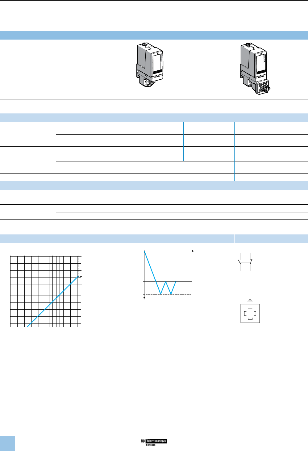
Operating curves: Dual-Stage, Fixed Differential, Detection at Each Threshold (switching on rising pressure)
Adjustment
ranges of the
operating points
PH1 and PH2 on
rising pressure
Dened by the difference between the
minimum and maximum high point setting
values of each stage (PH1 and PH2).
Operating point
PH2 on rising
pressure
The upper pressure setting at which the
pressure or vacuum switch actuates
contact 2 on rising pressure.
Adjustable throughout the range on rising
pressure.
Operating point
PH1
on rising
pressure
The upper pressure setting at which the
pressure or vacuum switch actuates
contact 1 on rising pressure.
Spread
0
+
–
PH1'
PH1"
PH2
PH2 – PH1"
PH2 – PH1'
PH1' PH1"
0
1 2
Rising pressure
Rising pressure
PH1 < PH2
PH2–PH1' = maximum spread
PH2–PH1" = minimum spread
The difference between operating points
PH2 and PH1 on rising pressure.
Note: operating point PH1 can be set at any
value between PH1' and PH1".
Example:
Determining
operating points
on rising
pressure for the
two stages
0
30
PH2 20
10
10 20 3017
PH1"
4,5
PH1'
0
1 2
Rising pressure
Rising pressure
1 Maximum spread
2 Minimum spread
bar
bar
Second stage operating point on rising
pressure (PH2) = 20 bar (set value at which
contact 2 changes state on rising pressure).
First stage operating point (PH1) can be set
between 4.5 and 17 bar on rising pressure.
Conclusion:
the maximum spread is:
20 – 4.5 = 15.5 bar,
the minimum spread is:
20 – 17 = 3 bar.
+
–
0
0
1 2
Rising
pressure
Rising pressure
Adjustment range
of high point PH1
Adjustment range
of high point (PH2)
+
–
0
0
1 2
PH2
Rising pressure
Rising pressure
+
–
PH2
PH1'
PH1'
PH1"
PH1"
0
0
1 2
Rising pressure
Rising pressure
OsiSense XML
Electromechanical
pressure and vacuum switches
Introduction (continued)
20
1
2
3
4
5
6
8
9
10
7
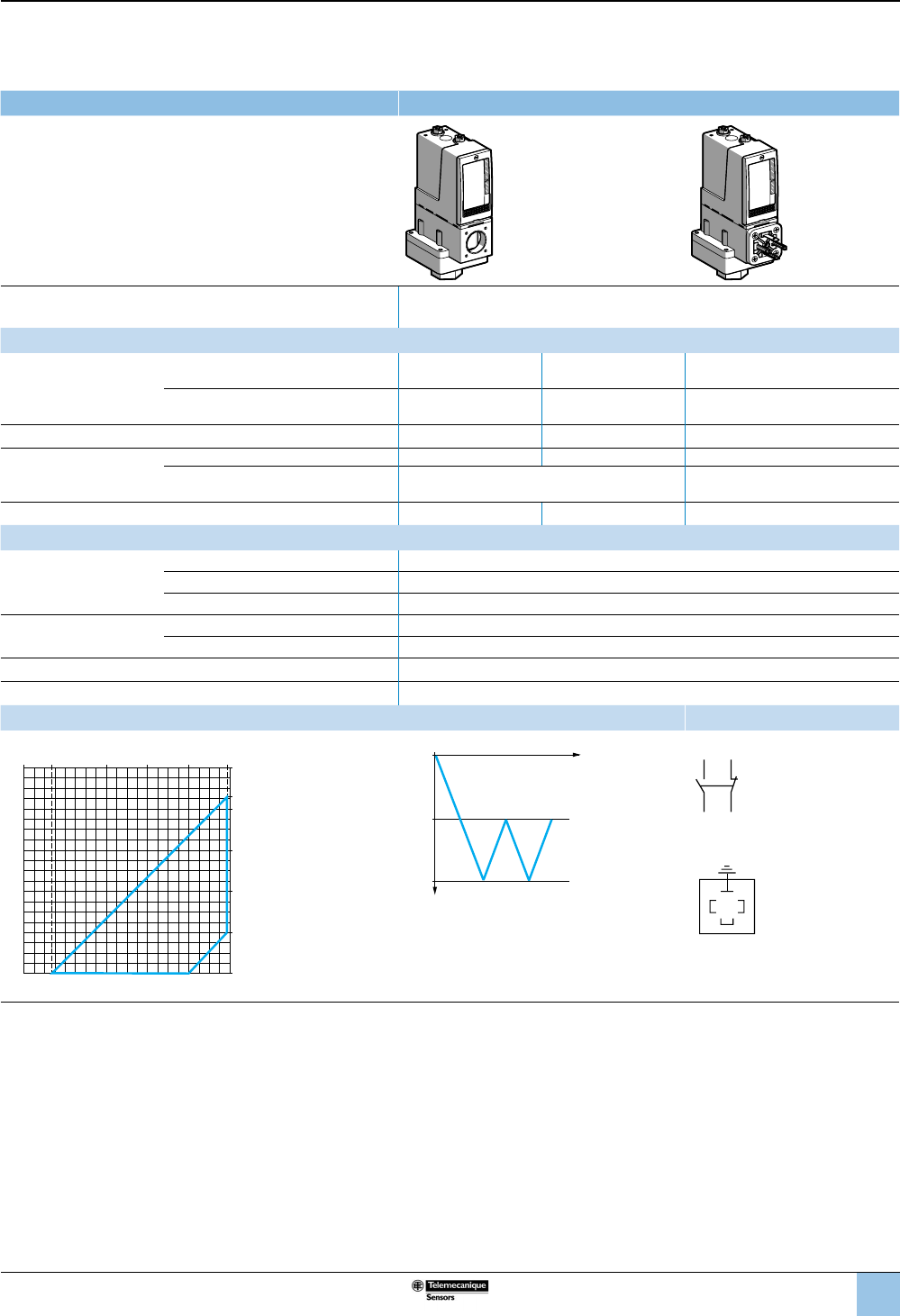
Operating curves: Dual-Stage, Fixed Differential, Detection at Each Threshold (switching on rising pressure)
Adjustment
range of
high point
(PH1 or PH2)
Dened by the difference between the
minimum and maximum high point (PH1 or
PH2) setting values for each stage.
For a high set point (PH1 or PH2), the
lower point (PB1 or PB2) is xed and
cannot be adjusted.
For a low set point (PB1 or PB2), the
higher point (PH1 or PH2) is xed and
cannot be adjusted.
Operating
point on
rising
pressure
(PH1 or PH2)
The upper pressure setting at which the
pressure or vacuum switch actuates the
contact, for each stage, on rising pressure.
Adjustable throughout the range on rising
pressure.
Operating
point on
falling
pressure
(PB1 or PB2)
The pressure at which the switch contact
changes state, for each stage, on falling
pressure.
The lower point (PB) is not adjustable and
is entirely dependent on the high point
setting (PH) and the inherent differential of
the switch.
Differential PH–PB = inherent differential
The difference between the operating
point on rising pressure (PH) and the
operating point on falling pressure (PB),
for each stage. This point is not adjustable,
so the value of the differential is xed. It is
the inherent differential of the switch
(contact differential, friction, etc.) for each
of its two stages.
Example:
stage 1 =
segment EF
stage 2 =
segment GH
For stage 2 (segment GH):
Operating point on rising pressure (PH2) is
20 bar (set value at which contact 2
changes state on rising pressure). The
operating point on falling pressure (PB2) is
14 bar (xed value at which contact 2
returns to its original state).
Conclusion: for stage 2, the differential is:
20 – 14 = 6 bar.
Repeat the same procedure for stage 1
(segment EF).
Maxi
+
–
Mini
0
0
Falling pressure
Rising pressure
Low point (PB)
range
Adjustment range
of high point
0
PH
+
–
0
Rising pressure
Falling
pressure
0
PH
+
–
PB
PB
0
Rising pressure
Falling pressure
PH
+
–
PB
PB
PH – PB
0
0
Rising pressure
Falling pressure
0
14
PB 20 30103
10
PH 20
30
0
E
G
F
H
Rising pressure
Falling pressure
1 Maximum spread
2 Minimum spread bar
bar
OsiSense XML
Electromechanical
pressure and vacuum switches
Introduction (continued)

21
1
2
3
4
5
6
8
9
10
7
Interpreting the Catalog Number for XML Devices
Example: XMLA004A2S13 XML A 004 A 2 S 1 3
Designation Catalog number
XML Pressure Switch XML
Type
Nonadjustable differential, single pole A
Adjustable differential, single pole B
Adjustable differential, double pole C
Nonadjustable differential, double pole D
Operating
range
bar (psi)
0 to 0.05 (0 to 0.725) L05
0 to 0.35 (0 to 5.075) L35
0 to 0.35 (0 to 5.075) Overpressure 0.30 (4.35) S35
–1 to –0.28 (−14.5 to −4.06) M01
–1 to –0.14 (−14.5 to −2.03) M02
–0.2 to –0.02 (−2.9 to −0.029) M03
–0.5 to 5 (−7.25 to 72.5) M05
0 to 1 (0 to 14.5) 001
0 to 2.5 (0 to 36.25) 002
0 to 2.5 (0 to 36.25) Overpressure 0.30 (4.35) S02
0 to 4 (0 to 58) 004
0 to 4 (0 to 58) Overpressure 0.30 (4.35) S04
0 to 10 (0 to 145) 010
0 to 10 (0 to 145) Overpressure 0.30 (4.35) S10
0 to 20 (0 to 290) 020
0 to 20 (0 to 290) Overpressure 0.30 (4.35) S20
0 to 35 (0 to 507.5) 035
0 to 40 (0 to 580) 040
0 to 70 (0 to 1015) 070
0 to 160 (0 to 2320) 160
0 to 300 (0 to 4350) 300
0 to 500 (0 to 7250) 500
Input uid
Diaphragm type
Hydraulic oils, air, fresh, or sea water, 32–158 °F (0–70 °C) A
Hydraulic oils, air, fresh, or sea water, 32–320 °F (0–160 °C) B
Corrosive uid C
Viscous products P
Hydraulic oils or air, 32–140 °F (0–60 °C) R
Fresh or sea water, 32–320 °F (0–160 °C) S
Vacuum type with diaphragm
Hydraulic oils, air, fresh or sea water, 32–158 °F (0–70 °C) V
Hydraulic oils, air, fresh or sea water, 32–320 °F (0–160 °C) T
Piston type
Hydraulic oils or air, 32–320 °F (0–160 °C) D
Fresh or sea water, 32–320 °F (0–160 °C) E
Corrosive uid, 32–320 °F (0–160 °C) N
Display Not provided 1
Provided 2
Electrical
connection
Threaded hole S
DIN 43650 connector C
M12 threaded connector (Micro Change type) D
Contact type Dry contact 1
Entry type
European
Pressure G 1/4 (BSP female)
G 1-1/4 for viscous products (input uid identier = P) 1
Electrical Type 13 (Pg 13.5)
Pressure G 1/4 (BSP female)
G 1-1/4 for viscous products (input uid identier = P) 2
Electrical ISO M20
U.S.A.
Pressure 1/4"-18 NPTF 3
Electrical 1/2"-14 NPT
Japan
Pressure PT 1/4 (JIS B0203) 4
Electrical 1/2 in. PF (JIS B0202)
Options May indicate factory setting •••
OsiSense XML
Electromechanical
pressure and vacuum switches
Introduction (continued)
22
1
2
3
4
5
6
8
9
10
7
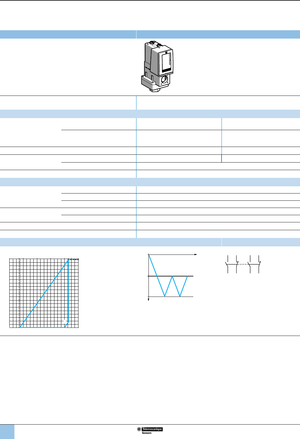
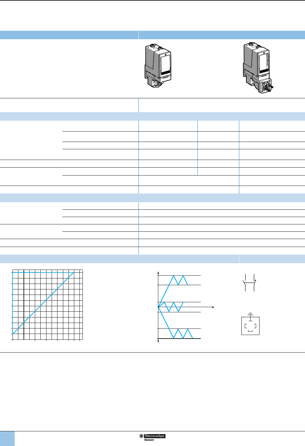
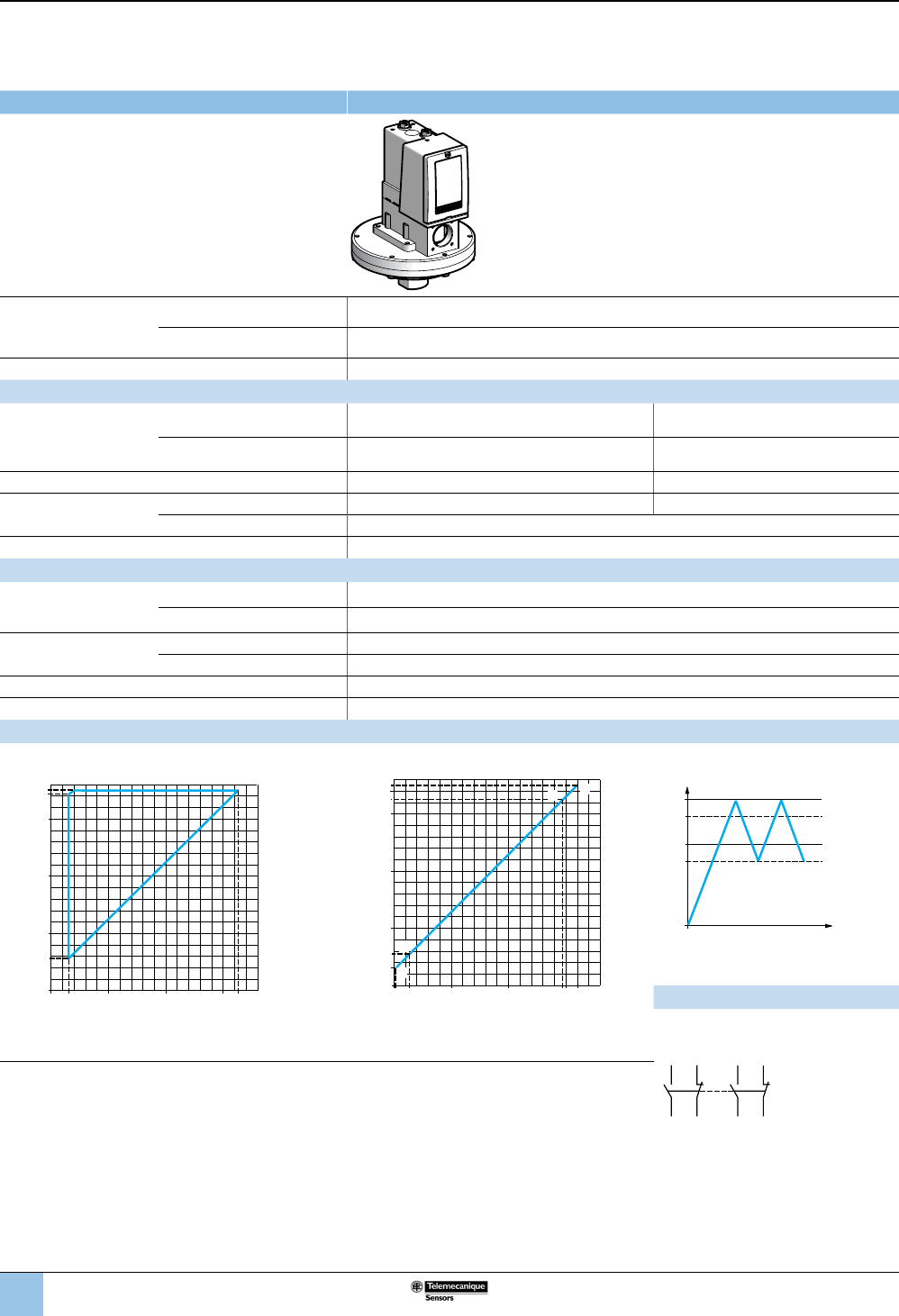
Size: –1 bar (–14.5 psi)
Fixed differential, for detection of a single threshold
1 C/O single-pole contact
XMLA vacuum switches With setting scale
Adjustable range of operating point (PB)
(falling pressure) –0.28 to –1 bar (–4.06 to –14.5 psi)
Catalog numbers
Fluids controlled
For materials in contact with
uid, see page 77.
Hydraulic oils, fresh water, sea water,
air, up to 158 °F (70 °C) XMLAM01V2S13 XMLAM01V2S11 XMLAM01V2C11
Hydraulic oils, fresh water, sea water, air,
corrosive uids, up to 320 °F (160 °C) XMLAM01T2S13 XMLAM01T2S11 XMLAM01T2C11
Pressure connection 1/4"-18 NPTF G 1/4-19 BSP G 1/4-19 BSP
Electrical connection
Conduit/cable entry 1/2" NPT Pg 13.5 DIN 43650A, 4-pin male.
Terminals 1 x 0.2 to 2 x 2.5 mm² (1 x 24 to 2 x 14 AWG) For suitable female connector,
see page 73.
Weight, lb (kg) 1.51 (0.685) 1.58 (0.715)
Supplementary specications (not shown under general specications)
Inherent differential
(add to PB to get PH)
At low setting 0.24 bar ±0.05 (3.48 psi ±0.72)
At high setting 0.24 bar ±0.05 (3.48 psi ±0.72)
Maximum allowable
pressure
Per cycle 5 bar (72.5 psi)
Accidental 9 bar (130.5 psi)
Destruction pressure 18 bar (261 psi)
Vacuum switch style Diaphragm
Operating curves Connection
–– Adjustable value
--- Nonadjustable value
Terminal model
1314
12 11
Connector model
Vacuum switch connector pin view
1 → 11 and 13
2 → 12
3 → 4
Other versions For switches with alternative tapped cable entries, consult the Customer Care Center.
bar
bar
0
-0.04-0.2-0.4-0.6-0.76
-0.2
-0.28
-0.4
-0.6
-0.8
-1
-1
Rising pressure
Falling pressure
PH
PB
Time
Vacuum
321
OsiSense XML
Electromechanical
pressure and vacuum switches
Selection and
specications
23
1
2
3
4
5
6
8
9
10
7
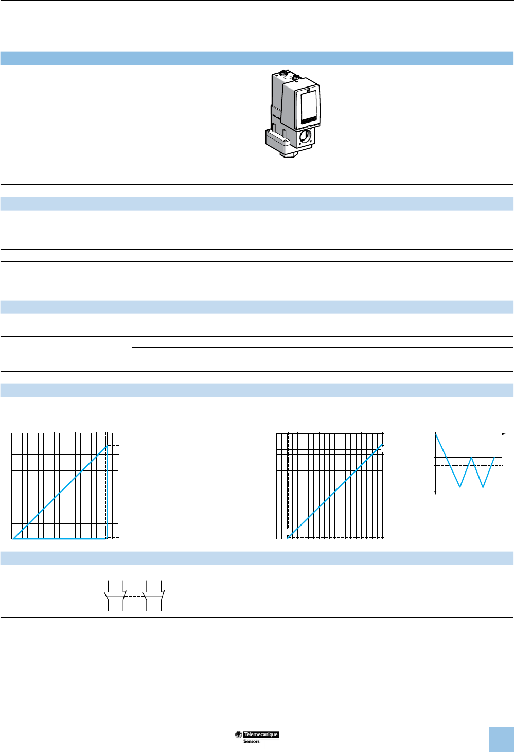
Size: –1 bar (–14.5 psi)
Adjustable differential, for regulation between two thresholds
1 C/O single-pole contact
XMLB vacuum switches With setting scale
Adjustable range of operating point (PB)
(falling pressure) –0.14 to –1 bar (–2.03 to –14.5 psi)
Catalog numbers
Fluids controlled
For materials in contact with
uid, see page 77.
Hydraulic oils, fresh water, sea water, air,
up to 158 °F (70 °C) XMLBM02V2S13 XMLBM02V2S11 XMLBM02V2C11
Hydraulic oils, fresh water, sea water, air,
corrosive uids, up to 320 °F (160 °C) XMLBM02T2S13 XMLBM02T2S11 XMLBM02T2C11
Pressure connection 1/4"-18 NPTF G 1/4-19 BSP G 1/4-19 BSP
Electrical connection
Conduit/cable entry 1/2" NPT Pg 13.5 DIN 43650A, 4-pin male
Terminals 1 x 0.2 to 2 x 2.5 mm² (1 x 24 to 2 x 14 AWG) For suitable female connector,
see page 73.
Weight, lb (kg) 2.24 (1.015) 2.24 (1.015) 2.27 (1.030)
Supplementary specications (not shown under general specications)
Possible differential
(add to PB to get PH)
Min. at low setting 0.13 bar ±0.02 (1.88 psi ±0.29)
Min. at high setting 0.13 bar ±0.02 (1.88 psi ±0.29)
Max. at high setting 0.8 bar (11.6 psi)
Maximum allowable
pressure
Per cycle 5 bar (72.5 psi)
Accidental 9 bar (130.5 psi)
Destruction pressure 18 bar (261 psi)
Vacuum switch style Diaphragm
Operating curves Connection
1 Maximum
differential
2 Minimum
differential
–– Adjustable
value
PH
PB
Time
Vacuum
Terminal model
1314
12 11
Connector model
Vacuum switch connector pin view
321
1 → 11 and 13
2 → 12
3 → 4
Other versions For switches with alternative tapped cable entries, consult the Customer Care Center.
bar
bar
0
-0.01-0.2-0.4-0.6-0.87
-0.2
-0.14
-0.4
-0.6
-0.8
-1
-1
1
2
Rising pressure
Falling pressure
OsiSense XML
Electromechanical
pressure and vacuum switches
Selection and
specications (continued)
24
1
2
3
4
5
6
8
9
10
7
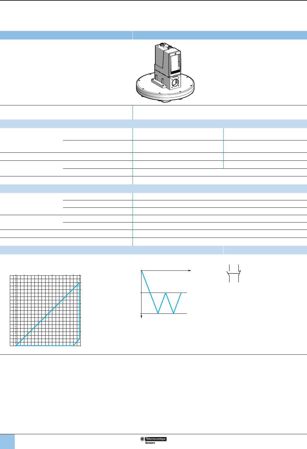
Size: –1 bar (–14.5 psi)
Adjustable differential, for regulation between two thresholds
2 C/O single-pole contacts
XMLC vacuum switches With setting scale
Adjustable range of operating point (PB)
(falling pressure) –0.14 to –1 bar (–2.03 to –14.5 psi)
Catalog numbers
Fluids controlled
For materials in contact with
uid, see page 77.
Hydraulic oils, fresh water, sea water,
air, up to 158 °F (70 °C) XMLCM02V2S13 XMLCM02V2S11
Hydraulic oils, fresh water, sea water,
air, corrosive uids, up to 320 °F
(160 °C)
XMLCM02T2S13 XMLCM02T2S11
Pressure connection 1/4"-18 NPTF G 1/4-19 BSP
Electrical connection Conduit/cable entry 1/2" NPT Pg 13.5
Terminals 1 x 0.2 to 2 x 2.5 mm² (1 x 24 to 2 x 14 AWG)
Weight, lb (kg) 2.24 (1.015)
Supplementary specications (not shown under general specications)
Possible differential
(add to PB to get PH)
Min. at low setting 0.13 bar ±0.02 (1.89 psi ±0.29)
Min. at high setting 0.14 bar ±0.02 (2.03 psi ±0.29)
Max. at high setting 0.8 bar (11.6 psi)
Maximum allowable
pressure
Per cycle 5 bar (72.5 psi)
Accidental 9 bar (130.5 psi)
Destruction pressure 18 bar (261 psi)
Vacuum switch style Diaphragm
Operating curves Connection
1 Maximum
differential
2 Minimum
differential
–– Adjustable value
PH
PB
Time
Vacuum
Terminal model
2324
22 21
1314
12 11
Other versions For switches with alternative tapped cable entries, consult the Customer Care Center.
bar
bar -0.01
0-0.14-0.4-0.6-0.86
-0.2
-0.4
-0.6
-0.8
2
1
Falling pressure
Rising pressure
OsiSense XML
Electromechanical
pressure and vacuum switches
Selection and
specications (continued)
25
1
2
3
4
5
6
8
9
10
7
Size: –1 bar (–14.5 psi)
Dual-stage, xed differential, for detection at each threshold
2 C/O single-pole contacts (one per stage)
XMLD vacuum switches Without setting scale
Adjustable range of operating
points (falling pressure)
2nd stage operating point (PB2) –0.12 to –1 bar (–1.74 to –14.5 psi)
1st stage operating point (PB1) –0.10 to –0.98 bar (–1.45 to –14.21 psi)
Spread between the two stages (PB2—PB1) 0.02 to 0.88 bar (0.29 to 12.76 psi)
Catalog numbers
Fluids controlled
For materials in contact with uid,
see page 77.
Hydraulic oils, fresh water, sea water, air,
up to 158 °F (70 °C) XMLDM02V1S13 XMLDM02V1S11
Hydraulic oils, fresh water, sea water, air,
corrosive uids, up to 320 °F (160 °C) XMLDM02T1S13 XMLDM02T1S11
Pressure connection 1/4”-18 NPTF G 1/4-19
Electrical connection Conduit/cable entry 1/2” NPT Pg 13.5
Terminals 1 x 0.2 to 2 x 2.5 mm² (1 x 24 to 2 x 14 AWG)
Weight, lb (kg) 2.24 (1.015)
Supplementary specications (not shown under general specications)
Inherent differential
(add to PB1/PB2 to get PH1/PH2)
At low setting 0.1 bar ±0.035 (1.45 psi ±0.51)
At high setting 0.1 bar ±0.02 (1.45 psi ±0.29)
Maximum allowable pressure Per cycle 5 bar (72.5 psi)
Accidental 9 bar (130.5 psi)
Destruction pressure 18 bar (261 psi)
Vacuum switch style Diaphragm
Operating curves
High setting trip points of contacts 1 and 2 Inherent differential of contacts 1 and 2
1 Maximum differential
2 Minimum differential
EF Contact 1 (stage 1)
GH Contact 2 (stage 2)
–– Adjustable value
--- Nonadjustable value
Connection: Terminal model
Contact 1 (stage 1) Contact 2 (stage 2)
Other versions For switches with alternative tapped cable entries, consult the Customer Care Center.
bar
bar
0
0
-0.12-0.4-0.6
-0.98
-0.2
-0.12
-0.4
-0.6
-0.8
-0.98
2
1
-0.8
PH1 setting (falling pressure)
PH2 setting (falling pressure)
Falling pressure
Rising pressure
bar
bar
0
-0.02-0.2-0.4
-0.6
-0.88
-0.2
-0.12
-0.4
-0.6
-0.8
-0.98
-1
E
H
G
F
2324
22 21
1314
12 11
OsiSense XML
Electromechanical
pressure and vacuum switches
Selection and
specications (continued)
PH1
PH2
PB2
PB1
Time
Vacuum
26
1
2
3
4
5
6
8
9
10
7
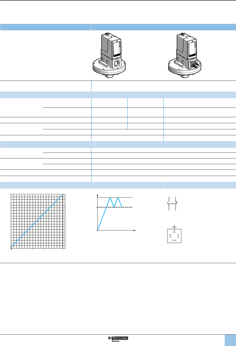
Size: –200 mbar (–2.9 psi)
Adjustable differential, for regulation between two thresholds
1 C/O single-pole contact
XMLB vacuum switches With setting scale
Adjustable range of operating point (PB)
(falling pressure) –20 to –200 mbar (–0.29 to –2.9 psi)
Catalog numbers
Fluids controlled
For materials in contact with
uid, see page 77.
Hydraulic oils, air, up to 320 °F
(160 °C) XMLBM03R2S13 XMLBM03R2S11
Fresh water, sea water, corrosive
uids, up to 320 °F (160 °C) XMLBM03S2S13 XMLBM03S2S11
Pressure connection 1/4”-18 NPTF G 1/4-19
Electrical connection Conduit/cable entry 1/2” NPT Pg 13.5
Terminals 1 x 0.2 to 2 x 2.5 mm² (1 x 24 to 2 x 14 AWG)
Weight, lb (kg) 7.30 (3.310)
Supplementary specications (not shown under general specications)
Possible differential
(add to PB to get PH)
Min. at low setting 18 mbar ±2 (0.26 psi ±0.29)
Min. at high setting 18 mbar ±2 (0.26 psi ±0.29)
Max. at high setting 180 mbar (2.6 psi)
Maximum allowable
pressure
Per cycle 1 bar (14.5 psi)
Accidental 2 bar (29 psi)
Destruction pressure 3.5 bar (50.75 psi)
Vacuum switch style Diaphragm
Operating curves Connection
Terminal model
1 Maximum
differential
2 Minimum
differential
PH
PB
Time
Vacuum
–– Adjustable value
1314
12 11
Other versions For switches with alternative tapped cable entries, consult the Customer Care Center.
mbar
mbar 0
-2-40-80-120-160
-40
-20
-80
-120
-160
-200
-182
1
2
-20
Rising pressure
Falling pressure
OsiSense XML
Electromechanical
pressure and vacuum switches
Selection and
specications (continued)
27
1
2
3
4
5
6
8
9
10
7
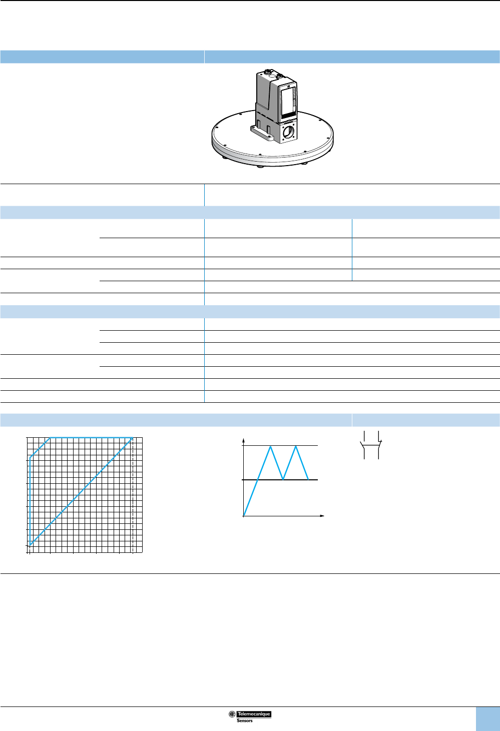
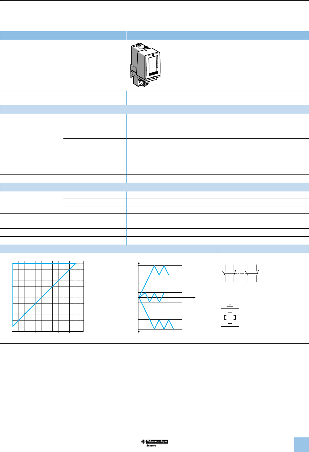
Size 50 mbar (0.72 psi)
Adjustable differential, for regulation between two thresholds
1 C/O single-pole contact
XMLB pressure switches With setting scale
Adjustable range of operating point (PH)
(rising pressure) 2.6–50 mbar (0.038–0.72 psi)
Catalog numbers
Fluids controlled
For materials in contact with
uid, see page 77.
Hydraulic oils, air, up to 320 °F
(160 °C) XMLBL05R2S13 XMLBL05R2S11
Fresh water, sea water, corrosive
uids, up to 320 °F (160 °C) XMLBL05S2S13 XMLBL05S2S11
Pressure connection 1/4”-18 NPTF G 1/4-19
Electrical connection Conduit/cable entry 1/2” NPT Pg 13.5
Terminals 1 x 0.2 to 2 x 2.5 mm² (1 x 24 to 2 x 14 AWG)
Weight, lb (kg) 5.34 (2.420)
Supplementary specications (not shown under general specications)
Possible differential
(subtract from PH
to get PB)
Min. at low setting 1.4 mbar, –0.8, +1.1 (0.02 psi, –0.01, +0.02)
Min. at high setting 4 mbar ±1.4 (0.06 psi ±0.02)
Max. at high setting 40 mbar (0.58 psi)
Maximum allowable
pressure
Per cycle 62.5 mbar (0.90 psi)
Accidental 112.5 mbar (1.63 psi)
Destruction pressure 225 mbar (3.26 psi)
Pressure switch style Diaphragm
(1) For, replace S13 with S11 (example: XMLBL05R2S13 becomes XMLBL05R2S11).
Operating curves Connection: Terminal model
1 Maximum
differential
2 Minimum
differential
–– Adjustable value
Other versions For switches with DIN 43650A connector or alternative tapped cable entries, consult the Customer Care Center.
mbar
mbar
0
10 30 4640
10
20
30
1.2
2.6
40
50
2
1
20
Falling pressure
Rising pressure
PH
PB
Pressure
Time
1314
12 11
OsiSense XML
Electromechanical
pressure and vacuum switches
Selection and
specications (continued)
28
1
2
3
4
5
6
8
9
10
7
Size 5 bar (72.5 psi)
Adjustable differential, for regulation between two thresholds
1 C/O single-pole contact
XMLB vacu-pressure switches With setting scale
Adjustable range of operating point (PH)
(rising pressure) –0.5 to 5 bar (–7.25 to 72.5 psi)
Catalog numbers
Fluids controlled
For materials in contact with
uid, see page 77.
Hydraulic oils, fresh water, sea water,
air, up to 158 °F (70 °C) XMLBM05A2S13 XMLBM05A2S11 XMLBM05A2C11
Hydraulic oils, fresh water, sea water,
air, up to 320 °F (160 °C) XMLBM05B2S13 XMLBM05B2S11 XMLBM05B2C11
Corrosive uids, up to 320 °F (160 °C) XMLBM05C2S13 XMLBM05C2S11 XMLBM05C2C11
Viscous products, up to 320 °F (160 °C)
(G1-1/4" pressure connection) XMLBM05P2S13 XMLBM05P2S11 XMLBM05P2C11
Pressure connection 1/4”-18 NPTF G 1/4-19 G 1/4-19
Electrical connection
Conduit/cable entry 1/2” NPT Pg 13.5 DIN 43650A, 4-pin male
Terminals 1 x 0.2 to 2 x 2.5 mm² (1 x 24 to 2 x 14 AWG) For suitable female connector,
see page 73.
Weight, lb (kg) 1.51 (0.685) 1.58 (0.715)
Supplementary specications (not shown under general specications)
Possible differential
(subtract from PH to get PB)
Min. at low setting 0.5 bar ±0.05 (7.25 psi ±0.72)
Min. at high setting 0.5 bar ±0.05 (7.25 psi ±0.72)
Max. at high setting 6 bar (87 psi)
Maximum allowable
pressure
Per cycle 6.25 bar (90.62 psi)
Accidental 11.25 bar (163.12 psi)
Destruction pressure 23 bar (333.5 psi)
Vacu-pressure switch style Diaphragm
Operating curves Connection
1 Maximum
differential
2 Minimum
differential
–– Adjustable value
Terminal model
Connector model
Vacu-pressure switch pin view
1 →11 and 13
2 →12
3 →14
Other versions For switches with alternative tapped cable entries, consult the Customer Care Center.
4.5-1
-1
-0.5
0.5
12344.5 5
4
5
0
3
2
1
0
bar
bar
2
1
Rising pressure
Falling pressure
PH1
PB1
PH2
PB2
PH3
PB3
0
1
2
3
Time
Vacuum
Pressure
1314
12 11
3
21
OsiSense XML
Electromechanical
pressure and vacuum switches
Selection and
specications (continued)
29
1
2
3
4
5
6
8
9
10
7
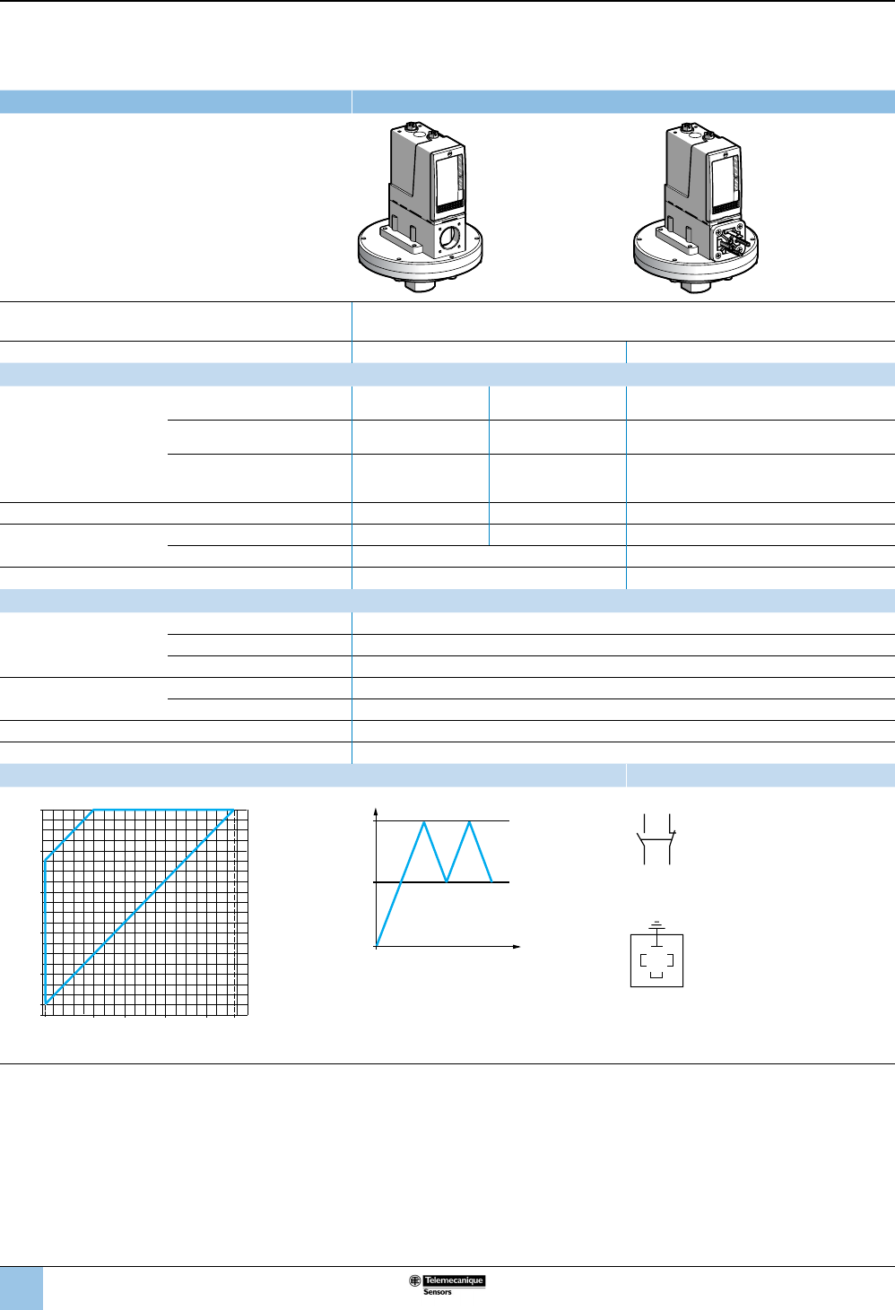
Size 5 bar (72.5 psi)
Adjustable differential, for regulation between two thresholds
2 C/O single-pole contacts
XMLC vacu-pressure switches With setting scale
Adjustable range of operating point (PH)
(rising pressure) –0.55 to 5 bar (–7.97 to 72.5 psi)
Catalog numbers
Fluids controlled
For materials in contact with
uid, see page 77.
Hydraulic oils, fresh water, sea
water, air, up to 158 °F (70 °C) XMLCM05A2S13 XMLCM05A2S11
Hydraulic oils, fresh water, sea
water, air, up to 320 °F (160 °C) XMLCM05B2S13 XMLCM05B2S11
Corrosive uids, up to 320 °F
(160 °C) XMLCM05C2S13 XMLCM05C2S11
Pressure connection 1/4”-18 NPTF G 1/4-19
Electrical connection Conduit/cable entry 1/2” NPT Pg 13.5
Terminals 1 x 0.2 to 2 x 2.5 mm² (1 x 24 to 2 x 14 AWG)
Weight, lb (kg) 1.51 (0.685)
Supplementary specications (not shown under general specications)
Possible differential
(subtract from PH to get PB)
Min. at low setting 0.45 bar ±0.1 (6.52 psi ±1.45)
Min. at high setting 0.45 bar ±0.1 (6.52 psi ±1.45)
Max. at high setting 6 bar (87 psi)
Maximum allowable
pressure
Per cycle 6.25 bar (90.62 psi)
Accidental 11.25 bar (163.12 psi)
Destruction pressure 23 bar (333.5 psi)
Vacu-pressure switch style Diaphragm
Operating curves Connection
1 Maximum
differential
2 Minimum
differential
–– Adjustable
value
Terminal model
Connector model
Vacu-pressure switch pin view
1 →11 and 13
2 →12
3 →14
Other versions For switches with alternative tapped cable entries, consult the Customer Care Center.
4.55-1
-1
-0.55
0.5
1234 5
4
5
0
3
2
1
0
bar
bar
2
1
Rising pressure
Falling pressure
PH1
PB1
PH2
PB2
PH3
PB3
0
1
2
3
Time
Vacuum
Pressure
2324
22 21
1314
12 11
3
21
OsiSense XML
Electromechanical
pressure and vacuum switches
Selection and
specications (continued)
30
1
2
3
4
5
6
8
9
10
7
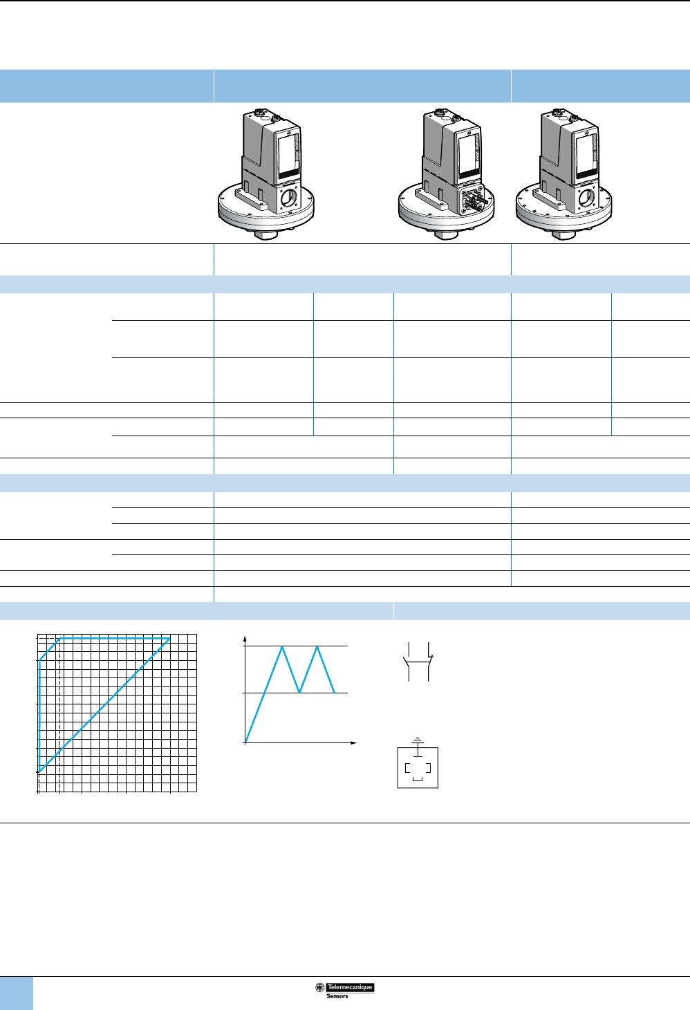
Size 350 mbar (5.07 psi)
Adjustable differential, for regulation between two thresholds
1 C/O single-pole contact
XMLB pressure switches With setting scale With setting scale
overpressure 30 bar (435 psi)
Adjustable range of operating point
(PH) (rising pressure) 45–350 mbar (0.65–5.07 psi) 42–330 mbar (0.61–4.78 psi)
Catalog numbers
Fluids controlled
For materials in contact
with uid, see page 77.
Hydraulic oils, air,
up to 320 °F (160 °C) XMLBL35R2S13 XMLBL35R2S11 XMLBL35R2C11 XMLBS35R2S13 XMLBS35R2S11
Fresh water, sea
water, corrosive uids,
up to 320 °F (160 °C)
XMLBL35S2S13 XMLBL35S2S11 XMLBL35S2C11 — —
Viscous products,
up to 320 °F (160 °C),
G1-1/4" pressure
connection
XMLBL35P2S13 XMLBL35P2S11 XMLBL35P2C11 — —
Pressure connection 1/4”-18 NPTF G 1/4-19 G 1/4-19 1/4”-18 NPTF G 1/4-19
Electrical
connection
Conduit/cable entry 1/2” NPT Pg 13.5 DIN 43650A, 4-pin male 1/2” NPT Pg 13.5
Terminals 1 x 0.2 to 2 x 2.5 mm²
(1 x 24 to 2 x 14 AWG)
For suitable female
connector, see page 73
.
1 x 0.2 to 2 x 2.5 mm²
(1 x 24 to 2 x 14 AWG)
Weight, lb (kg) 5.68 (2.575) 5.71 (2.590) 7.72 (3.500)
Supplementary specications (not shown under general specications)
Possible differential
(subtract from PH
to get PB)
Min. at low setting 42 mbar –8, +3 (0.60 psi –0.12, +0.04) 33 mbar –8, +3 (0.48 psi –0.12, +0.04)
Min. at high setting 50 mbar ±8 (0.72 psi ±0.11) 58 mbar ±8 (0.84 psi ±0.11)
Max. at high setting 300 mbar (4.35 psi) 250 mbar (3.62 psi)
Maximum allowable
pressure
Per cycle 1.25 bar (18.12 psi) 30 bar (435 psi)
Accidental 2.25 bar (32.62 psi) 37.5 bar (543.75 psi)
Destruction pressure 4.5 bar (65.25 psi) 67.5 bar (978.75 psi)
Pressure switch style Diaphragm
Operating curves Connection
350
mbar
mbar
0100 200 300
100
200
300
350
45
2
1
Rising pressure
Falling pressure
PH
PB
Time
Pressure
–– Adjustable value
1 Maximum differential
2 Minimum differential
Terminal model
1314
12 11
Connector model
Pressure switch connector pin view
1 →
11 and 13
2 →
12
3 →
14
Other versions For switches with alternative tapped cable entries, consult the Customer Care Center.
3
21
OsiSense XML
Electromechanical
pressure and vacuum switches
Selection and
specications (continued)
31
1
2
3
4
5
6
8
9
10
7
Size 350 mbar (5.07 psi)
Adjustable differential, for regulation between two thresholds
2 C/O single-pole contacts
XMLC pressure switches With setting scale With setting scale
overpressure 30 bar (435 psi)
Adjustable range of operating point (PH)
(rising pressure) 45–350 mbar (0.65–5.07 psi) 42–330 mbar (0.61–4.78 psi)
Catalog numbers
Fluids controlled
For materials in contact with
uid, see page 77.
Hydraulic oils, air, up to 320 °F
(160 °C) XMLCL35R2S13 XMLCL35R2S11 XMLCS35R2S13 XMLCS35R2S11
Fresh water, sea water,
corrosive uids, up to 320 °F
(160 °C)
XMLCL35S2S13 XMLCL35S2S11 — —
Pressure connection 1/4”-18 NPTF G 1/4-19 1/4”-18 NPTF G 1/4-19
Electrical connection Conduit/cable entry 1/2” NPT Pg 13.5 1/2” NPT Pg 13.5
Terminals 1 x 0.2 to 2 x 2.5 mm² (1 x 24 to 2 x 14 AWG)
Weight, lb (kg) 5.68 (2.575) 7.72 (3.500)
Supplementary specications (not shown under general specications)
Possible differential
(subtract from PH to get PB)
Min. at low setting 20 mbar ±20 (0.29 psi ±0.29) 40 mbar ±20 (0.58 psi ±0.29)
Min. at high setting 35 mbar ±20 (0.51 psi ±0.29) 88 mbar ±20 (1.27 psi ±0.29)
Max. at high setting 300 mbar (4.35 psi) 230 mbar (3.33 psi)
Maximum allowable
pressure
Per cycle 1.25 bar (18.12 psi) 30 bar (435 psi)
Accidental 2.25 bar (32.62 psi) 37.5 bar (543.75 psi)
Destruction pressure 4.5 bar (65.25 psi) 67.5 bar (978.75 psi)
Pressure switch style Diaphragm
Operating curves Connection
1 Maximum
differential
2 Minimum
differential
PH
PB
Time
Pressure
–– Adjustable value
Terminal model
Other versions For switches with alternative tapped cable entries, consult the Customer Care Center.
02550mbar
mbar
0100 200 315
100
200
300
350
45
2
1
Rising pressure
Falling pressure
2324
22 21
1314
12 11
OsiSense XML
Electromechanical
pressure and vacuum switches
Selection and
specications (continued)
32
1
2
3
4
5
6
8
9
10
7
Size 350 mbar (5.07 psi)
Dual-stage, xed differential, for detection at each threshold
2 C/O single-pole contacts (one per stage)
XMLD pressure switches Without setting scale
Adjustable range of
each operating point
(rising pressure)
2nd stage operating point (PH2) 58–350 mbar (0.84–5.07 psi)
1st stage operating point (PH1) 33–325 mbar (0.48–4.71 psi)
Spread between the two stages (PH2–PH1) 25–310 mbar (0.36–4.50 psi)
Catalog numbers
Fluids controlled
For materials in contact
with uid, see page 77.
Hydraulic oils, air, up to 320 °F
(160 °C) XMLDL35R1S13 XMLDL35R1S11
Fresh water, sea water, corrosive
uids, up to 320 °F (160 °C) XMLDL35S1S13 XMLDL35S1S11
Pressure connection 1/4”-18 NPTF G 1/4-19
Electrical connection Conduit/cable entry 1/2” NPT Pg 13.5
Terminals 1 x 0.2 to 2 x 2.5 mm² (1 x 24 to 2 x 14 AWG)
Weight, lb (kg) 5.68 (2.575)
Supplementary specications (not shown under general specications)
Inherent differential
(subtract from PH1/PH2
to get PB1/PB2)
At low setting 30 mbar ±10 (0.44 psi ±0.15)
At high setting 30 mbar ±8 (0.44 psi ±0.11)
Maximum allowable
Pressure
Per cycle 1.25 bar (18.12 psi)
Accidental 2.25 bar (32.62 psi)
Destruction pressure 4.5 bar (65.25 psi)
Pressure switch style Diaphragm
Operating curves
High setting trip points of contacts 1 and 2 Inherent differential of contacts 1 and 2
033mbar
mbar
0100 200 300 325
100
200
300
343
350
58
2
1
PH2 setting (falling pressure)
PH1 setting (falling pressure)
1 Maximum differential
2 Minimum differential
328
mbar
mbar
0100 200 295 320
100
200
300
325
350
33
58
E
G
FH
Falling pressure
Rising pressure
EF Contact 1 (stage 1)
GH Contact 2 (stage 2)
PH2
PH1
PB1
PB2
Time
Pressure
–– Adjustable value
--- Nonadjustable value
Connection
Terminal model
Contact 1 (stage 1) Contact 2 (stage 2)
Other versions
For switches with alternative tapped cable entries,
consult the Customer Care Center.
2324
22 21
1314
12 11
OsiSense XML
Electromechanical
pressure and vacuum switches
Selection and
specications (continued)
33
1
2
3
4
5
6
8
9
10
7
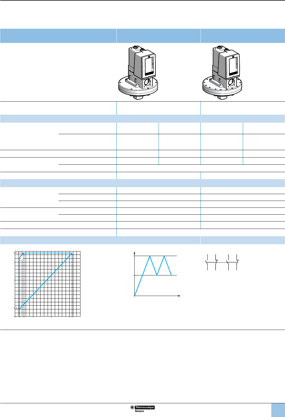
Size 1 bar (14.5 psi)
Fixed differential, for detection of a single threshold
1 C/O single-pole contact
XMLA pressure switches With setting scale
Adjustable range of operating point (PH)
(rising pressure) 0.03–1 bar (0.435–14.5 psi)
Catalog numbers
Fluids controlled
For materials in contact with
uid, see page 77.
Hydraulic oils, air, up to 320 °F
(160 °C) XMLA001R2S13 XMLA001R2S11 XMLA001R2C11
Fresh water, sea water, corrosive
uids, up to 320 °F (160 °C) XMLA001S2S13 XMLA001S2S11 XMLA001S2C11
Pressure connection 1/4"-18 NPTF G 1/4-19 G 1/4-19
Electrical connection Conduit/cable entry Terminals: 1/2” NPT, Pg 13.5 DIN 43650A, 4-pin male
Terminals 1 x 0.2 to 2 x 2.5 mm² (1 x 24 to 2 x 14 AWG) For suitable female connector, see page 73.
Weight, lb (kg) 5.63 (2.555) 5.67 (2.570)
Supplementary specications (not shown under general specications)
Inherent differential
(subtract from PH to get PB)
At low setting 0.02 bar ±0.01 (0.29 psi ±0.14)
At high setting 0.04 bar ±0.01 (0.58 psi ±0.14)
Maximum allowable
pressure
Per cycle 1.25 bar (18.12 psi)
Accidental 2.25 bar (32.62 psi)
Destruction pressure 4.5 bar (65.25 psi)
Pressure switch style Diaphragm
Operating curves Connection
bar
bar
0
0.8
0.6
0.4
0.2
0.03
1
0.9
6
0.80.60.40.20.01
Rising pressure
Falling pressure
PH
PB
Time
Pressure
–– Adjustable value
--- Nonadjustable value
Terminal model
1314
12 11
Connector model
Pressure switch connector pin view
3
21
1 → 11 and 13
2 → 12
3 → 14
Other versions For switches with alternative tapped cable entries, consult the Customer Care Center.
OsiSense XML
Electromechanical
pressure and vacuum switches
Selection and
specications (continued)
34
1
2
3
4
5
6
8
9
10
7
Size 1 bar (14.5 psi)
Adjustable differential, for regulation between two thresholds
1 C/O single-pole contact
XMLB pressure switches With setting scale
Adjustable range of operating point (PH)
(rising pressure) 0.05–1 bar (0.72–14.5 psi)
Electrical connection Terminals DIN connector
Catalog numbers
Fluids controlled
For materials in contact with
uid, see page 77.
Hydraulic oils, air, up to 320 °F
(160 °C) XMLB001R2S13 XMLB001R2S11 XMLB001R2C11
Fresh water, sea water, corrosive
uids, up to 320 °F (160 °C) XMLB001S2S13 XMLB001S2S11 XMLB001S2C11
Viscous products, up to 320 °F
(160 °C)
(G1-1/4" pressure connection)
XMLB001P2S13 XMLB001P2S11 XMLB001P2C11
Pressure connection 1/4”-18 NPTF G 1/4-19 G 1/4-19
Electrical connection Conduit/cable entry 1/2” NPT Pg 13.5 DIN 43650A, 4-pin male
Terminals 1 x 0.2 to 2 x 2.5 mm² (1 x 24 to 2 x 14 AWG) For suitable female connector, see page 73.
Weight, lb (kg) 5.68 (2.575) 5.71 (2.590)
Supplementary specications (not shown under general specications)
Possible differential
(subtract from PH to get PB)
Min. at low setting 0.04 bar ±10 (0.58 psi ±0.14)
Min. at high setting 0.06 bar ±20 (0.87 psi ±0.29)
Max. at high setting 0.75 bar (10.87 psi)
Maximum allowable
pressure
Per cycle 1.25 bar (18.12 psi)
Accidental 2.25 bar (32.62 psi)
Destruction pressure 4.5 bar (65.25 psi)
Pressure switch style Diaphragm
Operating curves Connection
1 Maximum
differential
2 Minimum
differential
–– Adjustable
value
PH
PB
Time
Pressure
Terminal model
1314
12 11
Connector model
Pressure switch connector pin view
3
21
1 → 11 and 13
2 → 12
3 → 14
Other versions For switches with alternative tapped cable entries, consult the Customer Care Center.
bar
bar
0
0.05
0.8
0.6
0.4
0.2
1
0.940.80.60.40.250.01
1
2
Rising pressure
Falling pressure
OsiSense XML
Electromechanical
pressure and vacuum switches
Selection and
specications (continued)
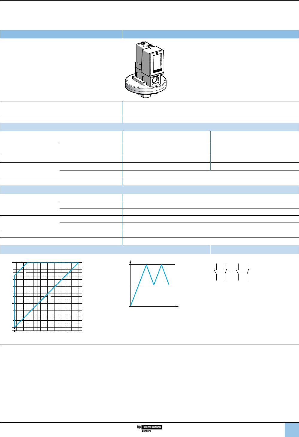
35
1
2
3
4
5
6
8
9
10
7
Size 1 bar (14.5 psi)
Adjustable differential, for regulation between two thresholds
2 C/O single-pole contacts
XMLC pressure switches With setting scale
Adjustable range of operating point (PH)
(rising pressure) 0.05–1 bar (0.725–14.5 psi)
Electrical connection Terminals
Catalog numbers
Fluids controlled
For materials in contact with
uid, see page 77.
Hydraulic oils, air, up to 320 °F
(160 °C) XMLC001R2S13 XMLC001R2S11
Fresh water, sea water, corrosive
uids, up to 320 °F (160 °C) XMLC001S2S13 XMLC001S2S11
Pressure connection 1/4”-18 NPTF G 1/4-19
Electrical connection Conduit/cable entry 1/2” NPT Pg 13.5
Terminals 1 x 0.2 to 2 x 2.5 mm² (1 x 24 to 2 x 14 AWG)
Weight, lb (kg) 5.63 (2.555)
Supplementary specications (not shown under general specications)
Possible differential
(subtract from PH to get PB)
Min. at low setting 0.03 bar ±0.01 (0.43 psi ±0.14)
Min. at high setting 0.04 bar ±0.03 (0.58 psi ±0.43)
Max. at high setting 0.8 bar (11.6 psi)
Maximum allowable
pressure
Per cycle 1.25 bar (18.12 psi)
Accidental 2.25 bar (32.62 psi)
Destruction pressure 4.5 bar (65.25 psi)
Pressure switch style Diaphragm
Operating curves Connection
1 Maximum
differential
2 Minimum
differential
–– Adjustable
value
PH
PB
Time
Pressure
Terminal model
2324
22 21
1314
12 11
Other versions For switches with alternative tapped cable entries, consult the Customer Care Center.
bar
bar
0
0.05
0.6
0.4
0.2
1
0.960.80.60.40.20.02
1
2
Rising pressure
Falling pressure
OsiSense XML
Electromechanical
pressure and vacuum switches
Selection and
specications (continued)
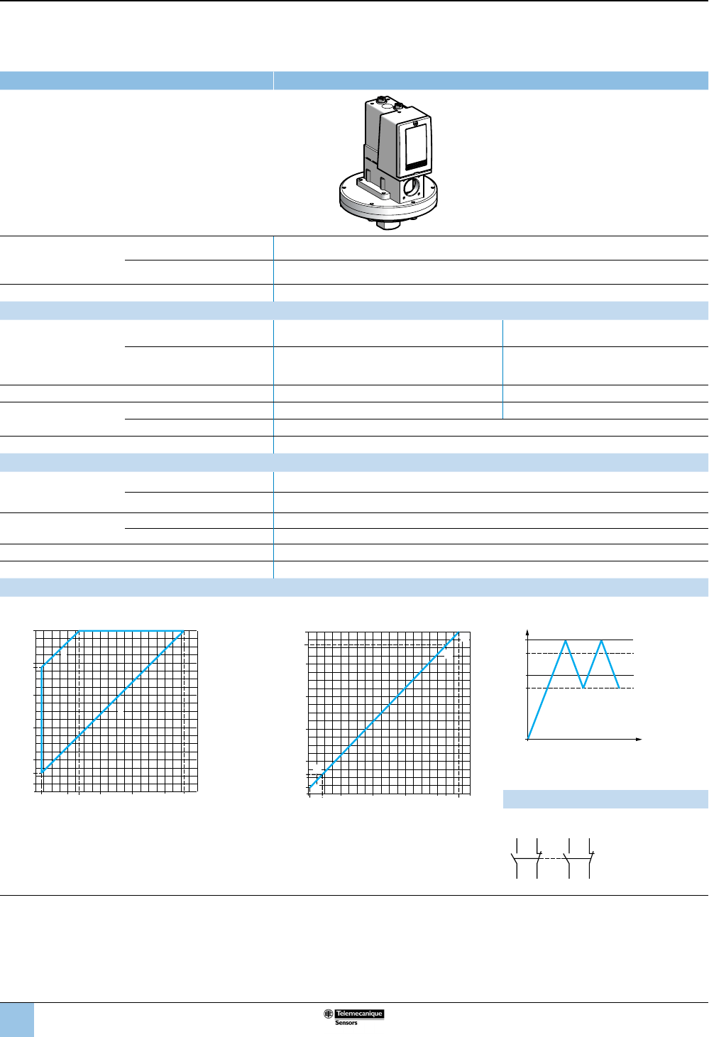
36
1
2
3
4
5
6
8
9
10
7
Size 1 bar (14.5 psi)
Dual-stage, xed differential, for detection at each threshold
2 C/O single-pole contacts (one per stage)
XMLD pressure switches Without setting scale
Adjustable range of
each operating point
(rising pressure)
2nd stage operating point (PH2) 0.12–1 bar (1.74–14.5 psi)
1st stage operating point (PH1) 0.04–0.92 bar (0.58–13.34 psi)
Spread between the two stages (PH2–PH1) 0.08–0.73 bar (1.16–10.59 psi)
Catalog numbers
Fluids controlled
For materials in contact
with uid, see page 77.
Hydraulic oils, air, up to 320 °F
(160 °C) XMLD001R1S13 XMLD001R1S11
Fresh water, sea water, corrosive
uids, up to 320 °F (160 °C) XMLD001S1S13 XMLD001S1S11
Pressure connection 1/4”-18 NPTF G 1/4-19
Electrical connection Conduit/cable entry 1/2” NPT Pg 13.5
Terminals 1 x 0.2 to 2 x 2.5 mm² (1 x 24 to 2 x 14 AWG)
Weight, lb (kg) 5.68 (2.575)
Supplementary specications (not shown under general specications)
Inherent differential
(subtract from PH1/PH2
to get PB1/PB2)
At low setting 0.03 bar ±0.01 (0.44 psi ±0.14)
At high setting 0.07 bar ±0.04 (1.02 psi ±0.58)
Maximum allowable
pressure
Per cycle 1.25 bar (18.12 psi)
Accidental 2.25 bar (32.62 psi)
Destruction pressure 4.5 bar (65.25 psi)
Pressure switch style Diaphragm
Operating curves
High setting trip points of contacts 1 and 2 Inherent differential of contacts 1 and 2
bar
bar
0
0.12
0.77
0.6
0.4
0.2
1
0.920.80.60.40.270.04
1
2
PH2 setting (rising pressure)
PH1 setting (rising pressure)
1 Maximum differential
2 Minimum differential
bar
bar
0
0.8
0.92
0.6
0.4
0.2
0.04
0.12
1
0.85 0.930.60.40.20.01 0.09
E
G
F
H
Rising pressure
Falling pressure
EF Contact 1 (stage 1)
GH Contact 2 (stage 2)
PH
2
PH
1
PB1
PB2
Time
Pressure
–– Adjustable value
--- Nonadjustable value
Connection: Terminal model
Contact 2 (stage 2) Contact 1 (stage 1)
2324
22 21
1314
12 11
Other versions For switches with alternative tapped cable entries, consult the Customer Care Center.
OsiSense XML
Electromechanical
pressure and vacuum switches
Selection and
specications (continued)
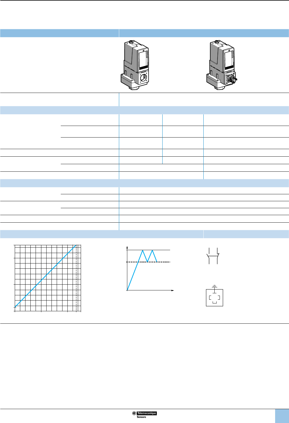
37
1
2
3
4
5
6
8
9
10
7
Size 2.5 bar (36.25 psi)
Fixed differential, for detection of a single threshold
1 C/O single-pole contact
XMLA pressure switches With setting scale
Adjustable range of operating point (PH)
(rising pressure) 0.15–2.5 bar (2.17–36.25 psi)
Catalog numbers
Fluids controlled
For materials in contact with
uid, see page 77.
Hydraulic oils, fresh water, sea
water, air, up to 158 °F (70 °C) XMLA002A2S13 XMLA002A2S11 XMLA002A2C11
Hydraulic oils, fresh water, sea
water, air, up to 320 °F (160 °C) XMLA002B2S13 XMLA002B2S11 XMLA002B2C11
Corrosive uids, up to 320 °F
(160 °C) XMLA002C2S13 XMLA002C2S11 XMLA002C2C11
Pressure connection 1/4”-18 NPTF G 1/4-19 G 1/4-19
Electrical connection Conduit/cable entry 1/2” NPT Pg 13.5 DIN 43650A, 4-pin male
Terminals 1 x 0.2 to 2 x 2.5 mm² (1 x 24 to 2 x 14 AWG) For suitable female connector, see page 73.
Weight, lb (kg) 2.19 (0.995) 2.23 (1.010)
Supplementary specications (not shown under general specications)
Inherent differential
(subtract from PH to get PB)
At low setting 0.13 bar ±0.03 (1.88 psi ±0.43)
At high setting 0.13 bar ±0.03 (1.88 psi ±0.43)
Maximum allowable
Pressure
Per cycle 5 bar (72.5 psi)
Accidental 9 bar (130.5 psi)
Destruction pressure 18 bar (261 psi)
Pressure switch style Diaphragm
Operating curves Connection
0.02
0
0.15
22.37
2
2.5
1
1
ba
r
bar
Rising pressure
Falling pressure
PH
PB
Time
Pressure
–– Adjustable value
--- Nonadjustable value
Terminal model
1314
12 11
Connector model
Pressure switch connector pin view
1 → 11 and 13
2 → 12
3 → 14
Other versions For switches with alternative tapped cable entries, consult the Customer Care Center.
3
21
OsiSense XML
Electromechanical
pressure and vacuum switches
Selection and
specications (continued)
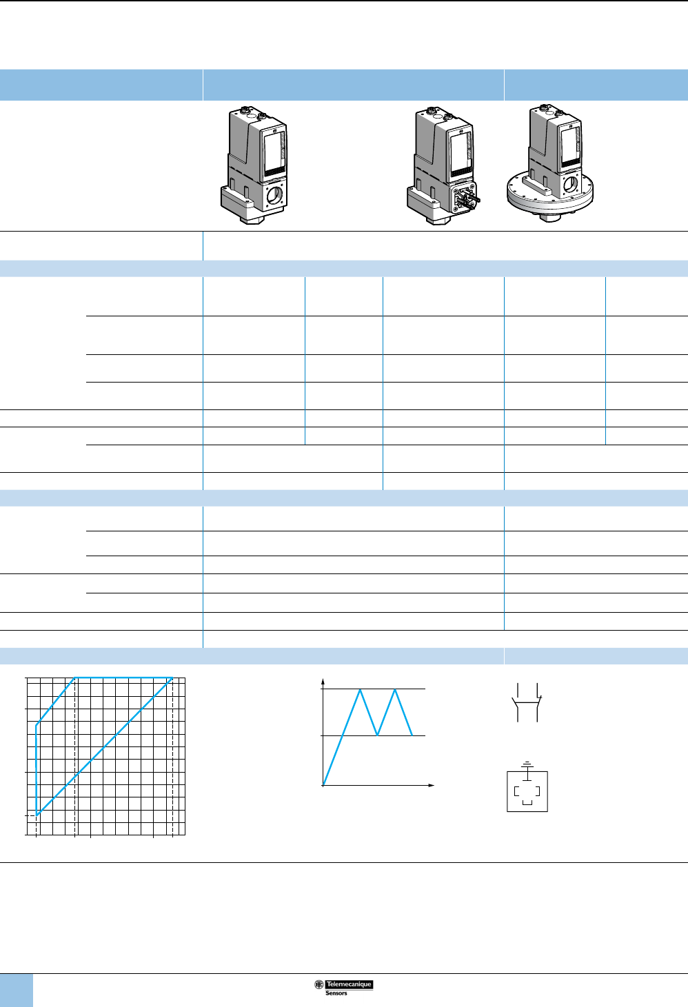
38
1
2
3
4
5
6
8
9
10
7
Size 2.5 bar (36.25 psi)
Adjustable differential, for regulation between two thresholds
1 C/O single-pole contact
XMLB pressure switches With setting scale With setting scale
overpressure 30 bar (435 psi)
Adjustable range of operating point
(PH) (rising pressure) 0.3–2.5 bar (4.35–36.25 psi)
Catalog numbers
Fluids
controlled
For materials in
contact with uid,
see page 77.
Hydraulic oils, fresh water,
sea water, air, up to 158 °F
(70 °C)
XMLB002A2S13 XMLB002A2S11 XMLB002A2C11 — —
Hydraulic oils, fresh water,
sea water, air, up to 320 °F
(160 °C)
XMLB002B2S13 XMLB002B2S11 XMLB002B2C11 — —
Hydraulic oils, fresh water,
air, up to 320 °F (160 °C) — — — XMLBS02B2S13 XMLBS02B2S11
Corrosive uids,
up to 320 °F (160 °C) XMLB002C2S13 XMLB002C2S11 XMLB002C2C11 — —
Pressure connection 1/4”-18 NPTF G 1/4-19 G 1/4-19 1/4”-18 NPTF G 1/4-19
Electrical
connection
Conduit/cable entry 1/2" NPT Pg 13.5 DIN 43650A, 4-pin male 1/2” NPT Pg 13.5
Terminals 1 x 0.2 – 2 x 2.5 mm²
(1 x 24 to 2 x 14 AWG)
For suitable female
connector, see page 73.
1 x 0.2 – 2 x 2.5 mm²
(1 x 24 to 2 x 14 AWG)
Weight, lb (kg) 2.24 (1.015) 2.27 (1.030) 7.72 (3.500)
Supplementary specications (not shown under general specications)
Possible
differential
(subtract from PH
to get PB)
Min. at low setting 0.16 bar, –0.8 mbar, +1.1 mbar (2.32 psi, –0.01, +0.02) 0.1 bar –0.8 mbar, +1.1 mbar
(1.45 psi –0.01, +0.02)
Min. at high setting 0.21 bar ±1.4 mbar (3.04 psi ±0.02) 0.22 bar ±1.4 mbar
(3.19 psi ±0.02)
Max. at high setting 1.75 bar (25.37 psi) 1.45 bar (21 psi)
Maximum
allowable
pressure
Per cycle 5 bar (72.5 psi) 30 bar (435 psi)
Accidental 9 bar (130.5 psi) 37.5 bar (543.75 psi)
Destruction pressure 18 bar (261 psi) 67.5 bar (978.75 psi)
Pressure switch style Diaphragm
Operating curves Connection
1 Maximum
differential
2 Minimum
differential
PH
PB
Time
Pressure
–– Adjustable value
Terminal model
1314
12 11
Connector model
Pressure switch connector pin view
3
21
1 → 11 and 13
2 → 12
3 → 14
Other versions For switches with alternative tapped cable entries, consult the Customer Care Center.
0.14
0
0.3
22.29
2
2.5
1
1
bar
bar
0.75
2
1
Rising pressure
Falling pressure
OsiSense XML
Electromechanical
pressure and vacuum switches
Selection and
specications (continued)
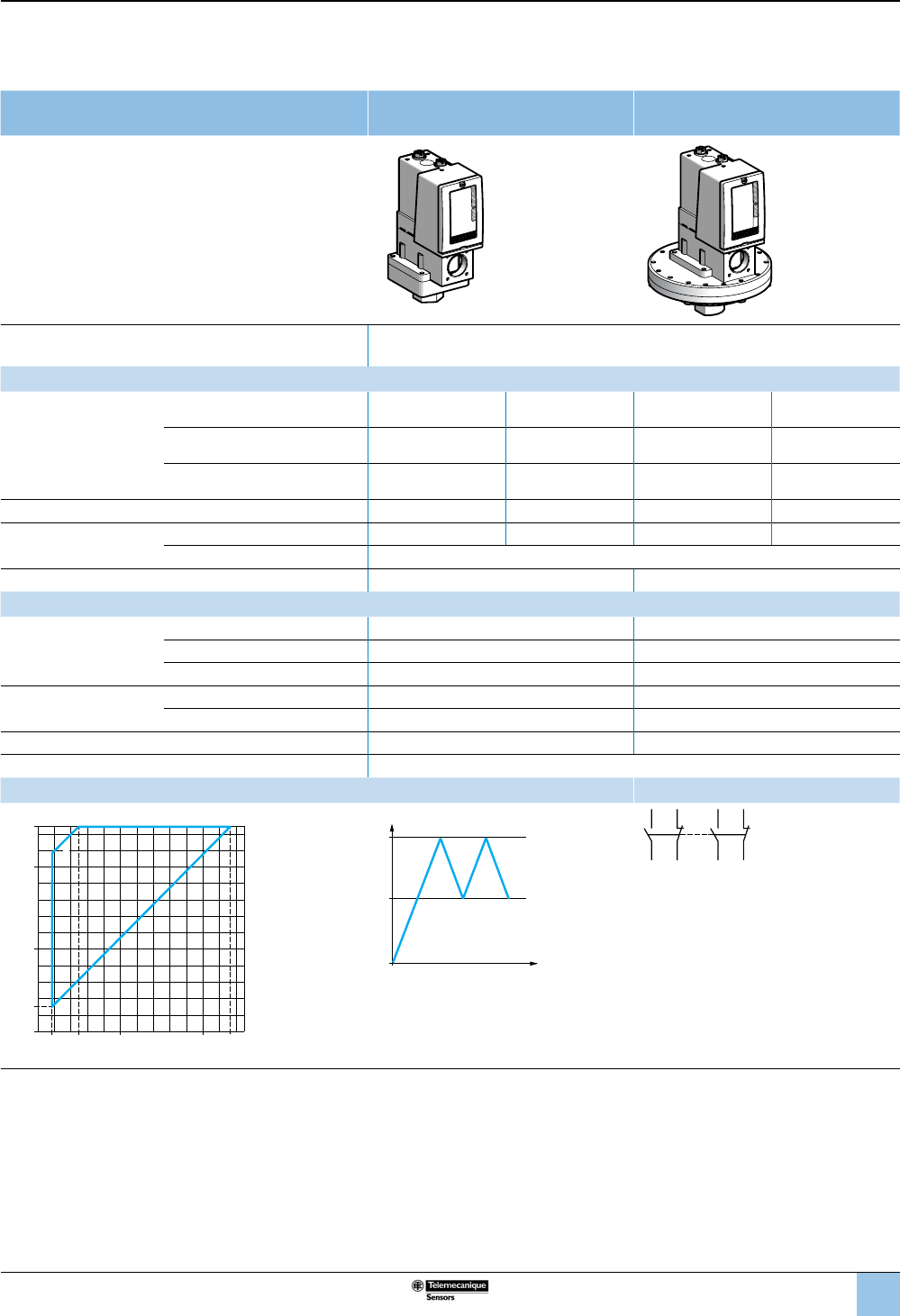
39
1
2
3
4
5
6
8
9
10
7
Size 2.5 bar (36.25 psi)
Adjustable differential, for regulation between two thresholds
2 C/O single-pole contacts
XMLC pressure switches With setting scale With setting scale
overpressure 30 bar (435 psi)
Adjustable range of operating point (PH)
(rising pressure) 0.3–2.5 bar (4.35–36.25 psi)
Catalog numbers
Fluids controlled
For materials in contact with
uid, see page 77.
Hydraulic oils, fresh water, air, up to
320 °F (160 °C) — — XMLCS02B2S13 XMLCS02B2S11
Hydraulic oils, fresh water, sea
water, air, up to 320 °F (160 °C) XMLC002B2S13 XMLC002B2S11 — —
Corrosive uids, up to 320 °F
(160 °C) XMLC002C2S13 XMLC002C2S11 — —
Pressure connection 1/4”-18 NPTF G 1/4-19 1/4”-18 NPTF G 1/4-19
Electrical connection Conduit/cable entry 1/2” NPT Pg 13.5 1/2” NPT Pg 13.5
Terminals 1 x 0.2 to 2 x 2.5 mm² (1 x 24 to 2 x 14 AWG)
Weight, lb (kg) 2.19 (0.995) 7.72 (3.500)
Supplementary specications (not shown under general specications)
Possible differential
(subtract from PH to get PB)
Min. at low setting 0.13 bar ±0.02 (1.89 psi ±0.29) 0.1 bar ±0.02 (1.45 psi ±0.29)
Min. at high setting 0.17 bar ±0.03 (2.47 psi ±0.43) 0.18 bar ±0.03 (2.61 psi ±0.43)
Max. at high setting 2 bar (29 psi) 1.25 bar (18.12 psi)
Maximum allowable
pressure
Per cycle 5 bar (72.5 psi) 30 bar (435 psi)
Accidental 9 bar (130.5 psi) 37.5 bar (543.75 psi)
Destruction pressure 18 bar (261 psi) 67.5 bar (978.75 psi)
Pressure switch style Diaphragm
Operating curves Connection
1 Maximum
differential
2 Minimum
differential
PH
PB
Time
Pressure
–– Adjustable value
2324
22 21
1314
12 11
Other versions For switches with alternative tapped cable entries, consult the Customer Care Center.
0.17 0.5
0
0.3
22.33
2
2.5
1
1
bar
bar
2
1
Rising pressure
Falling pressure
OsiSense XML
Electromechanical
pressure and vacuum switches
Selection and
specications (continued)
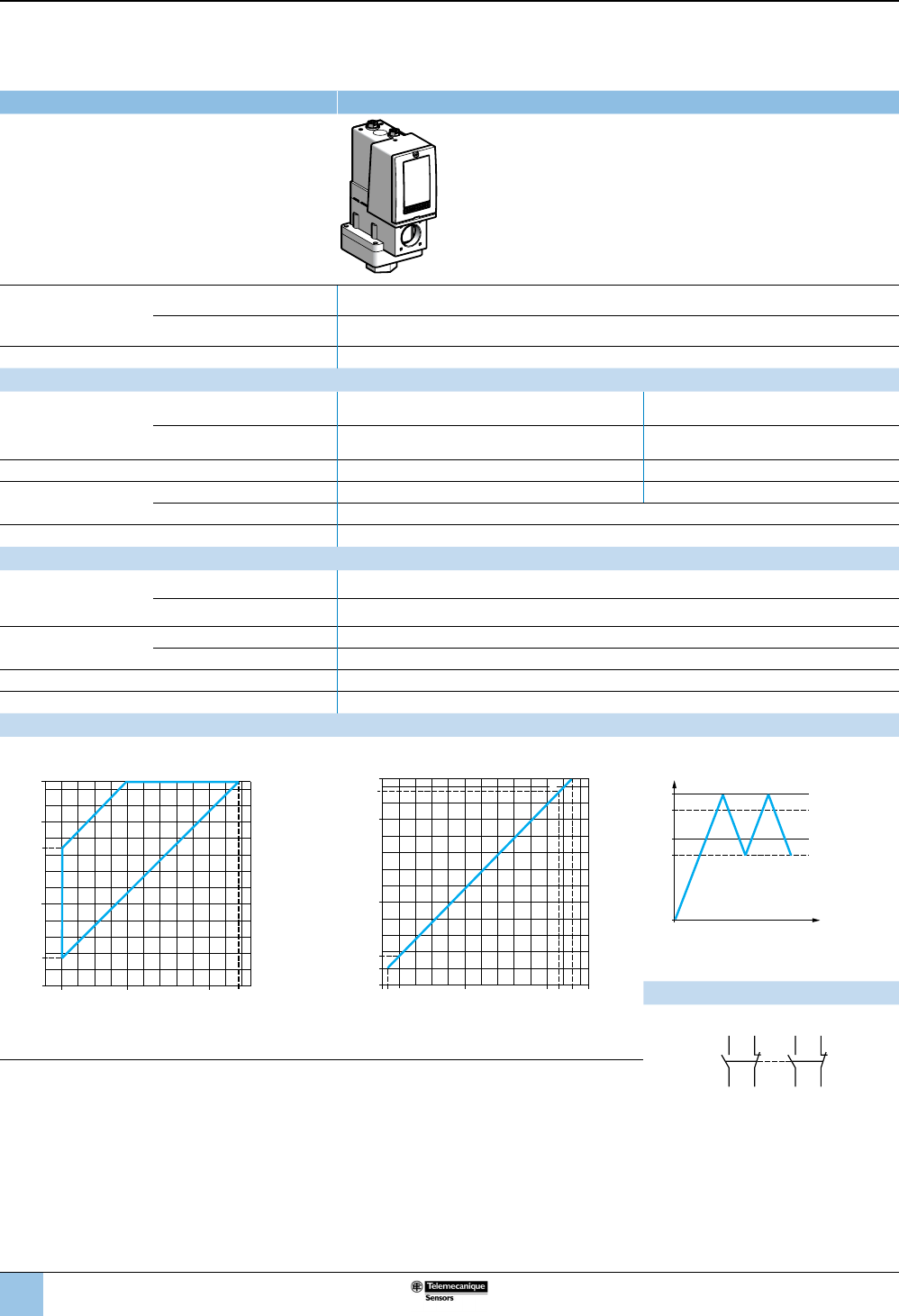
40
1
2
3
4
5
6
8
9
10
7
OsiSense XML
Electromechanical
pressure and vacuum switches
Selection and
specications (continued)
Size 2.5 bar (36.25 psi)
Dual-stage, xed differential, for detection at each threshold
2 C/O single-pole contacts (one per stage)
XMLD pressure switches Without setting scale
Adjustable range of
each operating point
(rising pressure)
2nd stage operating point (PH2) 0.34–2.5 bar (4.93–36.25 psi)
1st stage operating point (PH1) 0.2–2.36 bar (2.9–34.22 psi)
Spread between the two stages (PH2–PH1) 0.14–1.5 bar (2.03–21.75 psi)
Catalog numbers
Fluids controlled
For materials in contact
with uid, see page 77.
Hydraulic oils, fresh water, sea
water, air, up to 320 °F (160 °C) XMLD002B1S13 XMLD002B1S11
Corrosive uids, up to 320 °F
(160 °C) XMLD002C1S13 XMLD002C1S11
Pressure connection 1/4”-18 NPTF G 1/4-19
Electrical connection Conduit/cable entry 1/2” NPT Pg 13.5
Terminals 1 x 0.2 to 2 x 2.5 mm² (1 x 24 to 2 x 14 AWG)
Weight, lb (kg) 2.24 (1.015)
Supplementary specications (not shown under general specications)
Inherent differential
(subtract from PH1/PH2
to get PB1/PB2)
At low setting 0.14 bar ±0.04 (2.03 psi ±0.58)
At high setting 0.19 bar ±0.07 (2.76 psi ±1.02)
Maximum allowable
pressure
Per cycle 5 bar (72.5 psi)
Accidental 9 bar (130.5 psi)
Destruction pressure 18 bar (261 psi)
Pressure switch style Diaphragm
Operating curves
High setting trip points of contacts 1 and 2 Inherent differential of contacts 1 and 2
0.2
0
0.34
2 2.36
2
2.5
1
1
1.69
bar
bar
2
1
PH2 setting (rising pressure)
PH1 setting (rising pressure)
1 Maximum differential
2 Minimum differential
0.06
0
0.20
0.34
2.17 2.31
2
2.5
2.36
1
1
bar
bar
H
F
G
E
Rising pressure
Falling pressure
EF Contact 1 (stage 1)
GH Contact 2 (stage 2)
PH2
PH1
PB1
PB2
Time
Pressure
–– Adjustable value
--- Nonadjustable value
Connection: Terminal model
Contact 2 (stage 2) Contact 1 (stage 1)
2324
22 21
1314
12 11
Other versions For switches with alternative tapped cable entries, consult the Customer Care Center.
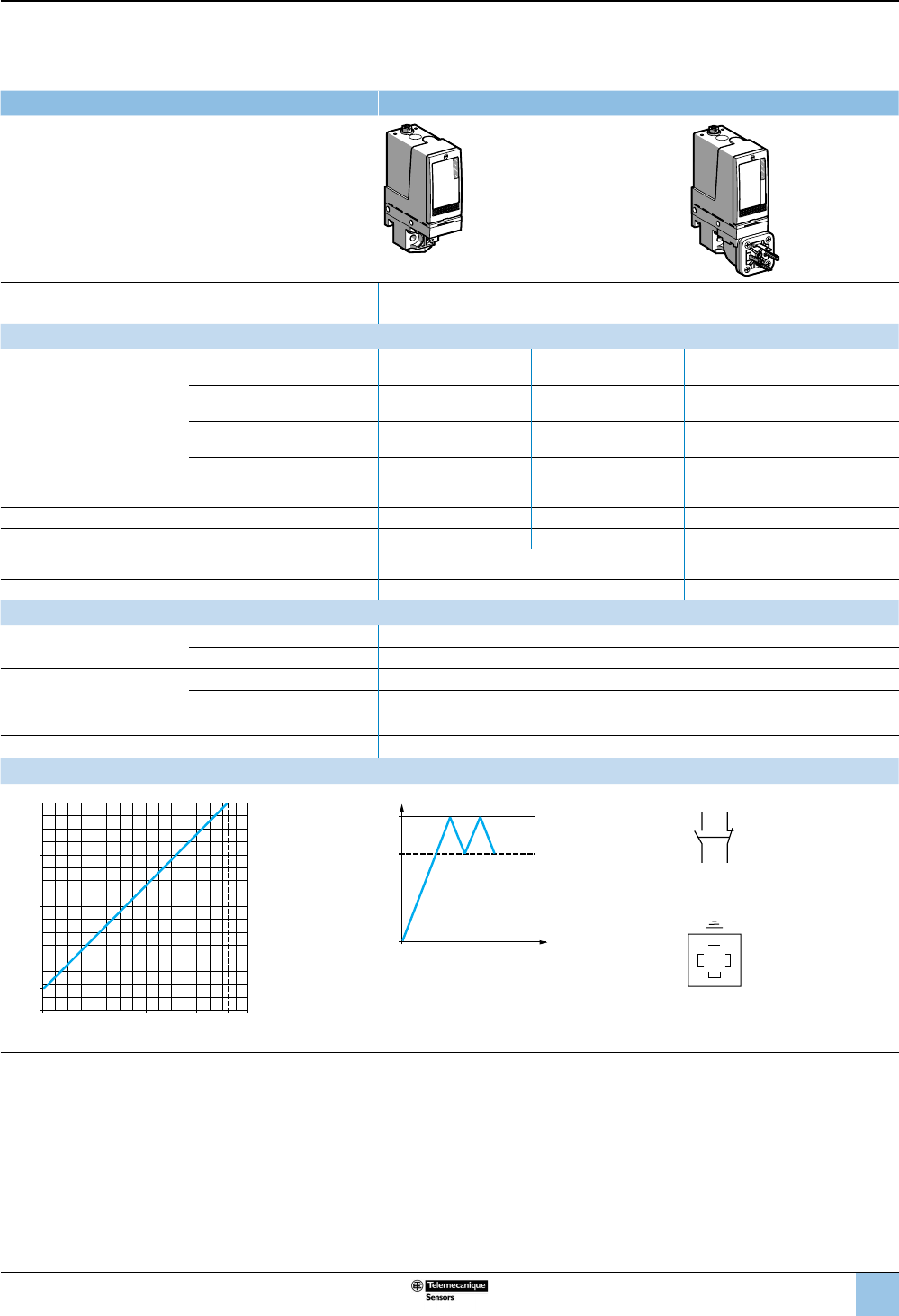
41
1
2
3
4
5
6
8
9
10
7
Size 4 bar (58 psi)
Fixed differential, for detection of a single threshold
1 C/O single-pole contact
XMLA pressure switches With setting scale
Adjustable range of operating point (PH)
(rising pressure) 0.4–4 bar (5.8–58 psi)
Catalog numbers
Fluids controlled
For materials in contact with
uid, see page 77.
Hydraulic oils, fresh water, sea
water, air, up to 158 °F (70 °C) XMLA004A2S13 XMLA004A2S11 XMLA004A2C11
Hydraulic oils, fresh water, sea
water, air, up to 320 °F (160 °C) XMLA004B2S13 XMLA004B2S11 XMLA004B2C11
Corrosive uids, up to 320 °F
(160 °C) XMLA004C2S13 XMLA004C2S11 XMLA004C2C11
Viscous products, up to 320 °F
(160 °C) (G1-1/4" pressure
connection)
XMLA004P2S13 XMLA004P2S11 XMLA004P2C11
Pressure connection 1/4”-18 NPTF G 1/4-19 G 1/4-19
Electrical connection
Conduit/cable entry 1/2” NPT Pg 13.5 DIN 43650A, 4-pin male
Terminals 1 x 0.2 to 2 x 2.5 mm² (1 x 24 to 2 x 14 AWG) For suitable female connector, see
page 73.
Weight, lb (kg) 1.51 (0.685) 1.58 (0.715)
Supplementary specications (not shown under general specications)
Inherent differential
(subtract from PH to get PB)
At low setting 0.35 bar ±0.03 (5.07 psi ±0.43)
At high setting 0.35 bar ±0.03 (5.07 psi ±0.43)
Maximum allowable
pressure
Per cycle 5 bar (72.5 psi)
Accidental 9 bar (130.5 psi)
Destruction pressure 18 bar (261 psi)
Pressure switch style Diaphragm
Operation curves Connection
0.05 bar
bar
0
12 4
1
2
3
0.4
33.65
4
Rising pressure
Falling pressure
PH
PB
Time
Pressure
–– Adjustable value
--- Nonadjustable value
Terminal model
1314
12 11
Connector model
Pressure switch connector pin view
3
21
1 → 11 and 13
2 → 12
3 → 14
Other versions For switches with alternative tapped cable entries, consult the Customer Care Center.
OsiSense XML
Electromechanical
pressure and vacuum switches
Selection and
specications (continued)
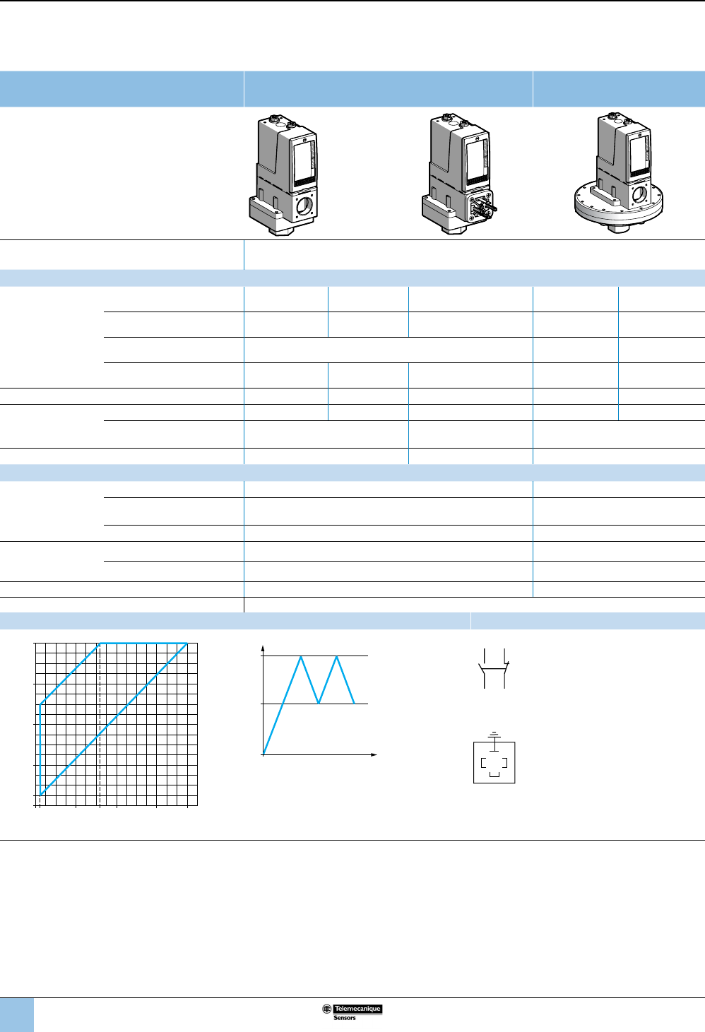
42
1
2
3
4
5
6
8
9
10
7
Size 4 bar (58 psi)
Adjustable differential, for regulation between 2 thresholds
1 C/O single-pole contact
XMLB pressure switches With setting scale With setting scale
overpressure 30 bar (435 psi)
Adjustable range of operating point (PH)
(rising pressure) 0.25–4 bar (3.62–58 psi)
Catalog numbers
Fluids controlled
For materials in
contact with uid, see
page 77.
Hydraulic oils, fresh water, sea
water, air, up to 158 °F (70 °C) XMLB004A2S13 XMLB004A2S11 XMLB004A2C11 — —
Hydraulic oils, fresh water, sea
water, air, up to 320 °F (160 °C) XMLB004B2S13 XMLB004B2S11 XMLB004B2C11 — —
Hydraulic oils, freshwater, air,
up to 320 °F (160 °C) —XMLBS04B2S13 XMLBS04B2S11
Corrosive uids, up to 320 °F
(160 °C) XMLB004C2S13 XMLB004C2S11 XMLB004C2C11 — —
Pressure connection 1/4”-18 NPTF G 1/4-19 G 1/4-19 1/4”-18 NPTF G 1/4-19
Electrical
connection
Conduit/cable entry 1/2” NPT Pg 13.5 DIN 43650A, 4-pin male 1/2” NPT Pg 13.5
Terminals 1 x 0.2 to 2 x 2.5 mm²
(1 x 24 to 2 x 14 AWG)
For suitable female
connector, see page 73.
1 x 0.2 to 2 x 2.5 mm²
(1 x 24 to 2 x 14 AWG)
Weight, lb (kg) 2.24 (1.015) 2.27 (1.030) 7.72 (3.500)
Supplementary specications (not shown under general specications)
Possible
differential
(subtract from PH to
get PB)
Min. at low setting 0.2 bar ±0.01 (2.9 psi ±0.14) 0.15 bar ±0.01 (2.18 psi ±0.14)
Min. at high setting 0.25 bar, –0.03, +0.05 (3.62 psi, –0.43, +0.72) 0.34 bar, –0.03, +0.05
(4.93 psi, –0.43, +0.72)
Max. at high setting 2.4 bar (34.8 psi) 2.46 bar (35.67 psi)
Maximum
allowable
pressure
Per cycle 5 bar (72.5 psi) 30 bar (435 psi)
Accidental 9 bar (130.5 psi) 37.5 bar (543.75 psi)
Destruction pressure 18 bar (261 psi) 67.5 bar (978.75 psi)
Pressure switch style Diaphragm
Operating curves Connection
0.05
bar
bar
0
121.6
1
2
3
0.25
3 3.75
4
12
Rising pressure
Falling pressure
PH
PB
Time
Pressure
–– Adjustable value
1 Maximum differential
2 Minimum differential
Terminal model
1314
12 11
Connector model
Pressure switch connector pin view
3
21
1 → 11 and 13
2 → 12
3 → 14
Other versions For switches with alternative tapped cable entries, consult the Customer Care Center.
OsiSense XML
Electromechanical
pressure and vacuum switches
Selection and
specications (continued)
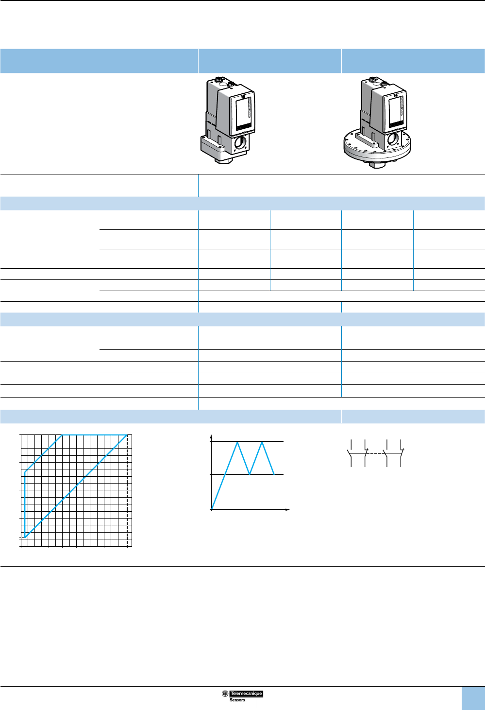
43
1
2
3
4
5
6
8
9
10
7
Size 4 bar (58 psi)
Adjustable differential, for regulation between two thresholds
2 C/O single-pole contacts
XMLC pressure switches With setting scale With setting scale
overpressure 30 bar (435 psi)
Adjustable range of operating point (PH)
(rising pressure) 0.3–4 bar (4.35–58 psi)
Catalog numbers
Fluids controlled
For materials in contact with
uid, see page 77.
Hydraulic oils, fresh water, air,
up to 320 °F (160 °C) ——XMLCS04B2S13 XMLCS04B2S11
Hydraulic oils, fresh water, sea
water, air, up to 320 °F (160 °C) XMLC004B2S13 XMLC004B2S11 — —
Corrosive uids, up to 320 °F
(160 °C) XMLC004C2S13 XMLC004C2S11 — —
Pressure connection 1/4”-18 NPTF G 1/4-19 1/4”-18 NPTF G 1/4-19
Electrical connection Conduit/cable entry 1/2” NPT Pg 13.5 1/2” NPT Pg 13.5
Terminals 1 x 0.2 to 2 x 2.5 mm² (1 x 24 to 2 x 14 AWG)
Weight, lb (kg) 1.51 (0.685) 7.72 (3.500)
Supplementary specications (not shown under general specications)
Possible differential
(subtract from PH to get PB)
Min. at low setting 0.15 bar ±0.02 (2.18 psi ±0.29) 0.1 bar ±0.02 (1.45 psi ±0.29)
Min. at high setting 0.17 bar ±0.02 (2.47 psi ±0.29) 0.25 bar ±0.02 (3.62 psi ±0.29)
Max. at high setting 2.5 bar (36.25 psi) 2.20 bar (31.9 psi)
Maximum allowable
pressure
Per cycle 5 bar (72.5 psi) 30 bar (435 psi)
Accidental 9 bar (130.5 psi) 37.5 bar (543.75 psi)
Destruction pressure 18 bar (261 psi) 67.5 bar (978.75 psi)
Pressure switch style Diaphragm
Operating curves Connection
1 Maximum
differential
2 Minimum
differential
PH
PB
Time
Pressure
–– Adjustable value
Terminal model
2324
22 21
1314
12 11
Other versions For switches with alternative tapped cable entries, consult the Customer Care Center.
0.15 ba
r
bar
0
121.5
1
2
3
0.3
33.83
4
1
2
Rising pressure
Falling pressure
OsiSense XML
Electromechanical
pressure and vacuum switches
Selection and
specications (continued)
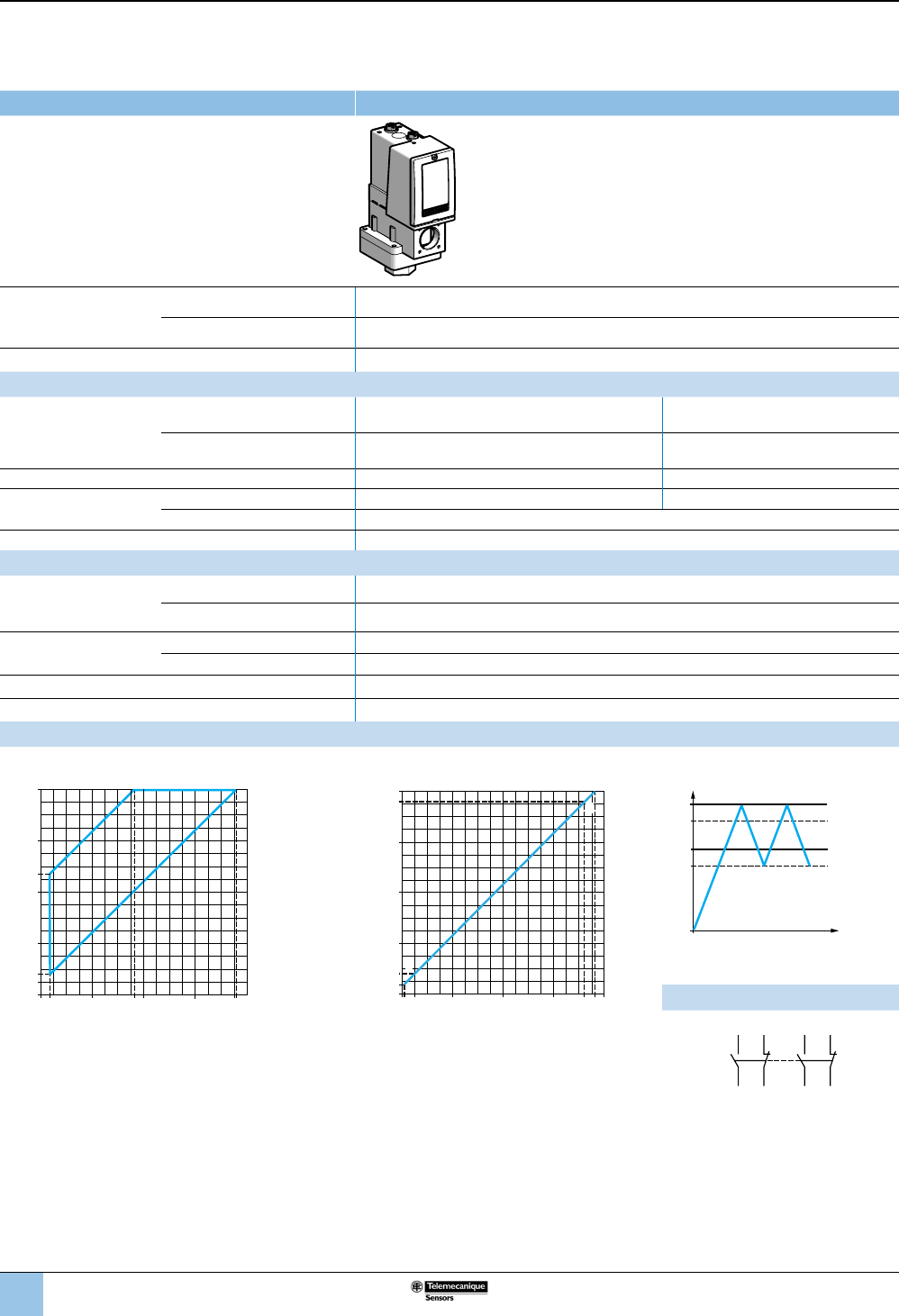
44
1
2
3
4
5
6
8
9
10
7
Size 4 bar (58 psi)
Dual-stage, xed differential, for detection at each threshold
2 C/O single-pole contacts (one per stage)
XMLD pressure switches Without setting scale
Adjustable range of
each operating point
rising pressure)
2nd stage operating point (PH2) 0.40–4 bar (5.8–58 psi)
1st stage operating point (PH1) 0.19–3.79 bar (2.76–54.96 psi)
Spread between the two stages (PH2–PH1) 0.21–2.18 bar (3.05–31.61 psi)
Catalog numbers
Fluids controlled
For materials in contact with
uid, see page 77.
Hydraulic oils, fresh water, sea
water, air, up to 320 °F (160 °C) XMLD004B1S13 XMLD004B1S11
Corrosive uids, up to 320 °F
(160 °C) XMLD004C1S13 XMLD004C1S11
Pressure connection 1/4”-18 NPTF G 1/4-19
Electrical connection Conduit/cable entry 1/2" NPT Pg 13.5
Terminals 1 x 0.2 to 2 x 2.5 mm² (1 x 24 to 2 x 14 AWG)
Weight, lb (kg) 2.24 (1.015)
Supplementary specications (not shown under general specications)
Inherent differential
(subtract from PH1/PH2
to get PB1/PB2)
At low setting 0.15 bar ±0.03 (2.18 psi ±0.43)
At high setting 0.19 bar, ±0.03 (2.76 psi ±0.43)
Maximum allowable
pressure
Per cycle 5 bar (72.5 psi)
Accidental 9 bar (130.5 psi)
Destruction pressure 18 bar (261 psi)
Pressure switch style Diaphragm
Operating curves
High setting trip points of contacts 1 and 2 Inherent differential of contacts 1 and 2
1 Maximum
differential
2 Minimum
differential
EF Contact
1 (stage 1)
GH Contact
2 (stage 2)
0.04 bar
bar
0
12
1
2
3
0.19
0.40
33.6 3.81
4
3.79
E
G
H
F
Rising pressure
Falling pressure
PH2
PH1
PB1
PB2
Time
Pressure
–– Adjustable value
--- Nonadjustable value
Connection: Terminal model
Contact 2 (stage 2) Contact 1 (stage 1)
Other versions For switches with alternative tapped cable entries, consult the Customer Care Center.
2324
22 21
1314
12 11
0.19 bar
bar
0121.82
1
2
2.35
3
0.4
3 3.79
4
1
2
PH2 setting (rising pressure)
PH1 setting (rising pressure)
OsiSense XML
Electromechanical
pressure and vacuum switches
Selection and
specications (continued)
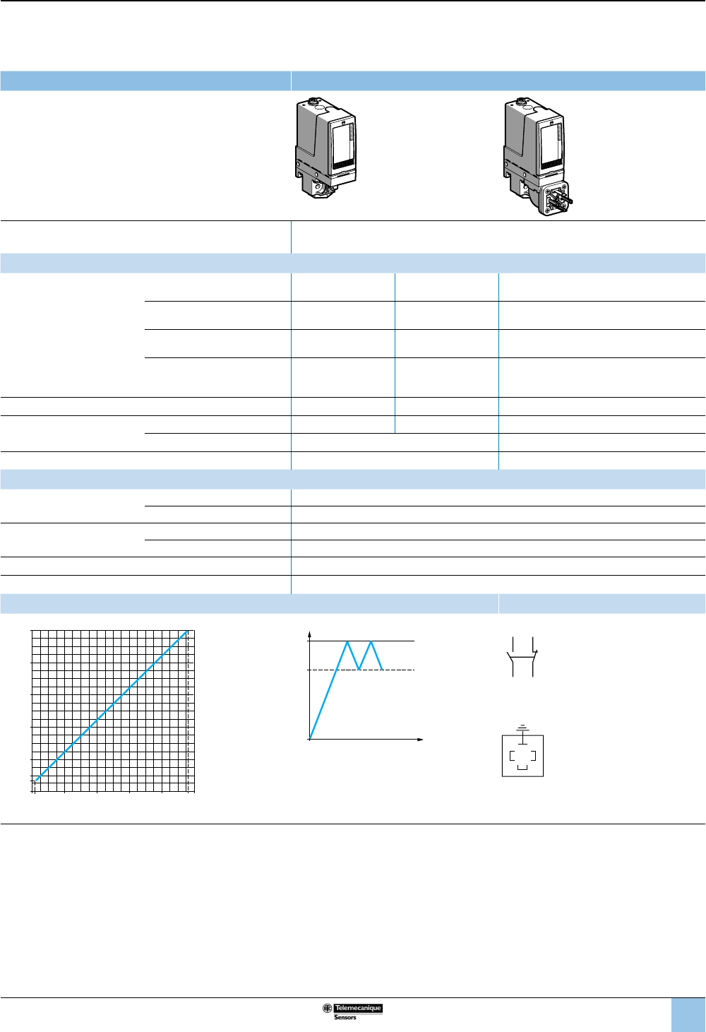
45
1
2
3
4
5
6
8
9
10
7
Size 10 bar (145 psi)
Fixed differential, for detection of a single threshold
1 C/O single-pole contact
XMLA pressure switches With setting scale
Adjustable range of operating point (PH)
(rising pressure) 0.6–10 bar (8.7–145 psi)
Catalog numbers
Fluids controlled
For materials in contact with
uid, see page 77.
Hydraulic oils, fresh water, sea
water, air, up to 158 °F (70 °C) XMLA010A2S13 XMLA010A2S11 XMLA010A2C11
Hydraulic oils, fresh water, sea
water, air, up to 320 °F (160 °C) XMLA010B2S13 XMLA010B2S11 XMLA010B2C11
Corrosive uids, up to 320 °F
(160 °C) XMLA010C2S13 XMLA010C2S11 XMLA010C2C11
Viscous products, up to 320 °F
(160 °C) (G1-1/4" pressure
connection)
XMLA010P2S13 XMLA010P2S11 XMLA010P2C11
Pressure connection 1/4”-18 NPTF G 1/4-19 G 1/4-19
Electrical connection Conduit/cable entry 1/2” NPT Pg 13.5 DIN 43650A, 4-pin male
Terminals 1 x 0.2 to 2 x 2.5 mm² (1 x 24 to 2 x 14 AWG) For suitable female connector, see page 73.
Weight, lb (kg) 1.51 (0.685) 1.58 (0.715)
Supplementary specications (not shown under general specications)
Inherent differential
(subtract from PH to get PB)
At low setting 0.5 bar ±0.05 (7.25 psi ±0.72)
At high setting 0.5 bar ±0.05 (7.25 psi ±0.72)
Maximum allowable
pressure
Per cycle 12.5 bar (181.25 psi)
Accidental 22.5 bar (326.25 psi)
Destruction pressure 45 bar (652.5 psi)
Pressure switch style Diaphragm
Operating curves Connection
bar
bar
0
8
6
4
2
1
0.6
10
9.586420.1
Rising pressure
Falling pressure
PH
PB
Time
Pressure
–– Adjustable value
--- Nonadjustable value
Terminal model
1314
12 11
Connector model
Pressure switch connector pin view
3
21
1 →
11 and 13
2 →
12
3 →
14
Other versions For switches with alternative tapped cable entries, consult the Customer Care Center.
OsiSense XML
Electromechanical
pressure and vacuum switches
Selection and
specications (continued)
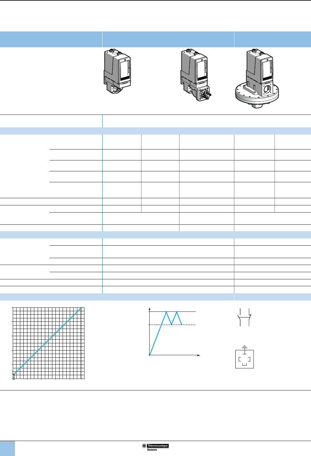
46
1
2
3
4
5
6
8
9
10
7
Size 10 bar (145 psi)
Adjustable differential, for regulation between two thresholds
1 C/O single-pole contact
XMLB pressure switches With setting scale With setting scale,
overpressure 30 bar (435 psi)
Adjustable range of operating point (PH)
(rising pressure) 0.7–10 bar (10.15–145 psi)
Catalog numbers
Fluids controlled
For materials in contact
with uid, see
page 77.
Hydraulic oils, fresh water,
sea water, air, up to 158 °F
(70 °C)
XMLB010A2S13 XMLB010A2S11 XMLB010A2C11 — —
Hydraulic oils, fresh water,
air, up to 320 °F (160 °C) — — — XMLBS10A2S13 XMLBS10A2S11
Hydraulic oils, fresh water,
air, up to 320 °F (160 °C) XMLB010B2S13 XMLB010B2S11 XMLB010B2C11 — —
Corrosive uids, up to
320 °F (160 °C) XMLB010C2S13 XMLB010C2S11 XMLB010C2C11 — —
Viscous products, up to
320 °F (160 °C) (G1-1/4"
pressure connection)
XMLB010P2S13 XMLB010P2S11 XMLB010P2C11 — —
Pressure connection 1/4”-18 NPTF G 1/4-19 G 1/4-19 1/4”-18 NPTF G 1/4-19
Electrical
connection
Conduit/cable entry 1/2” NPT Pg 13.5 DIN 43650A, 4-pin male 1/2” NPT Pg 13.5
Terminals 1 x 0.2 to 2 x 2.5 mm²
(1 x 24 to 2 x 14 AWG)
For suitable female
connector, see page 73.
1 x 0.2 to 2 x 2.5 mm²
(1 x 24 to 2 x 14 AWG)
Weight, lb (kg) 1.55 (0.705) 1.62 (0.735) 7.72 (3.500)
Supplementary specications (not shown under general specications)
Possible differential
(subtract from PH
to get PB)
Min. at low setting 0.57 bar ±0.05 (8.26 psi ±0.72). 0.45 bar ±0.05 (6.52 psi ±0.72).
Min. at high setting 0.85 bar, –0.1, +0.15 (12.32 psi, –1.45, +2.17) 0.85 bar, –0.1, +0.15
(12.32 psi, –1.45, +2.17)
Max. at high setting 7.5 bar (108.75 psi 6.25 bar (90.62 psi)
Maximum allowable
pressure
Per cycle 12.5 bar (181.25 psi) 30 bar (435 psi)
Accidental 22.5 bar (326.25 psi) 37.5 bar (543.75 psi)
Destruction pressure 45 bar (652.5 psi) 67.5 bar (978.75 psi)
Pressure switch style Diaphragm
Operating curves Connection
1 Maximum differential
2 Minimum differential
PH
PB
Time
Pressure
–– Adjustable value
Terminal model
1314
12 11
Connector model
Pressure switch connector pin view
3
21
1 →
11 and 13
2 →
12
3 →
14
Other versions For switches with alternative tapped cable entries, consult the Customer Care Center.
bar
bar
0
8
6
4
2
1
0.6
10
9.586420.1
Rising pressure
Falling pressure
OsiSense XML
Electromechanical
pressure and vacuum switches
Selection and
specications (continued)
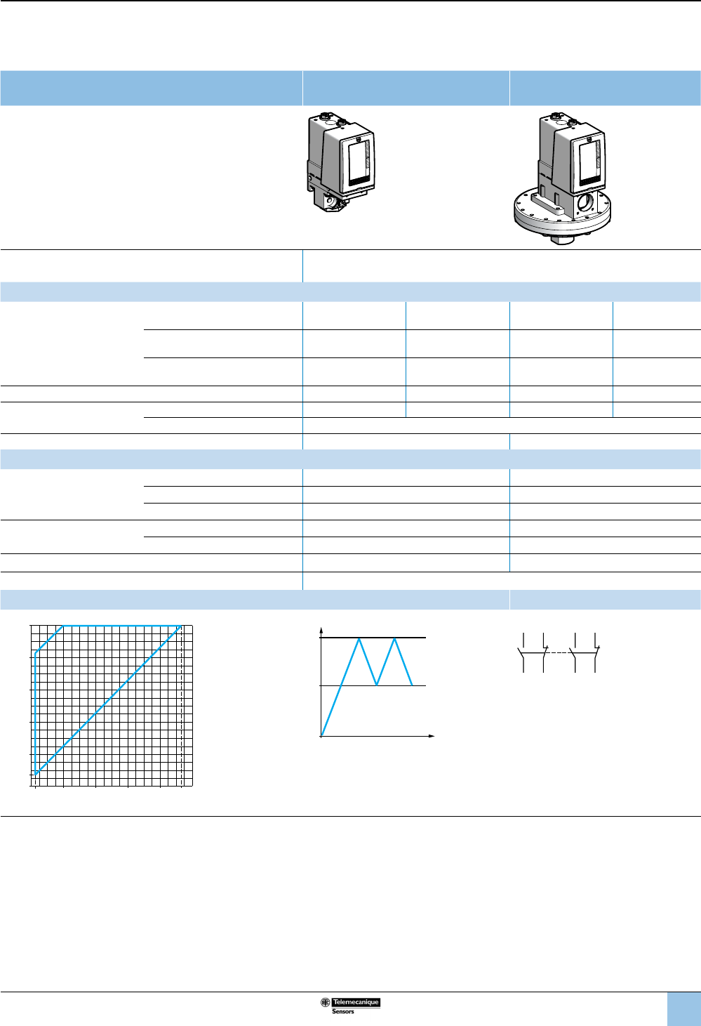
47
1
2
3
4
5
6
8
9
10
7
Size 10 bar (145 psi)
Adjustable differential, for regulation between two thresholds
2 C/O single-pole contacts
XMLC pressure switches With setting scale With setting scale
overpressure 30 bar (435 psi)
Adjustable range of operating point (PH)
(rising pressure) 0.7–10 bar (10.15–145 psi)
Catalog numbers
Fluids controlled
For materials in contact with
uid, see page 77.
Hydraulic oils, fresh water, air, up to
158 °F (70 °C) ——XMLCS10A2S13 XMLCS10A2S11
Hydraulic oils, fresh water, sea
water, air, up to 320 °F (160 °C) XMLC010B2S13 XMLC010B2S11 — —
Corrosive uids, up to 320 °F
(160 °C) XMLC010C2S13 XMLC010C2S11 — —
Pressure connection 1/4”-18 NPTF G 1/4-19 1/4”-18 NPTF G 1/4-19
Electrical connection Conduit/cable entry 1/2” NPT Pg 13.5 1/2” NPT Pg 13.5
Terminals 1 x 0.2 to 2 x 2.5 mm² (1 x 24 to 2 x 14 AWG)
Weight, lb (kg) 1.51 (0.685) 7.72 (3.500)
Supplementary specications (not shown under general specications)
Possible differential
(subtract from PH to get PB)
Min. at low setting 0.45 bar ±0.05 (6.53 psi ±0.72) 0.25 bar ±0.05 (3.62 psi ±0.72)
Min. at high setting 0.70 bar ±0.01 (10.15 psi ±1.45) 0.65 bar ±0.01 (9.42 psi ±1.45)
Max. at high setting 8 bar (116 psi) 5.6 bar (81.2 psi)
Maximum allowable
pressure
Per cycle 12.5 bar (181.25 psi) 30 bar (435 psi)
Accidental 22.5 bar (326.25 psi) 37.5 bar (543.75 psi)
Destruction pressure 45 bar (652.5 psi) 67.5 bar (978.75 psi)
Pressure switch style Diaphragm
Operating curves Connection
1 Maximum
differential
2 Minimum
differential
PH
PB
Time
Pressure
–– Adjustable value
Terminal model
2324
22 21
1314
12 11
Other versions For switches with alternative tapped cable entries, consult the Customer Care Center.
bar
bar
0
6
4
2
0.7
10
9.3
86420.25
2
1
Rising pressure
Falling pressure
OsiSense XML
Electromechanical
pressure and vacuum switches
Selection and
specications (continued)
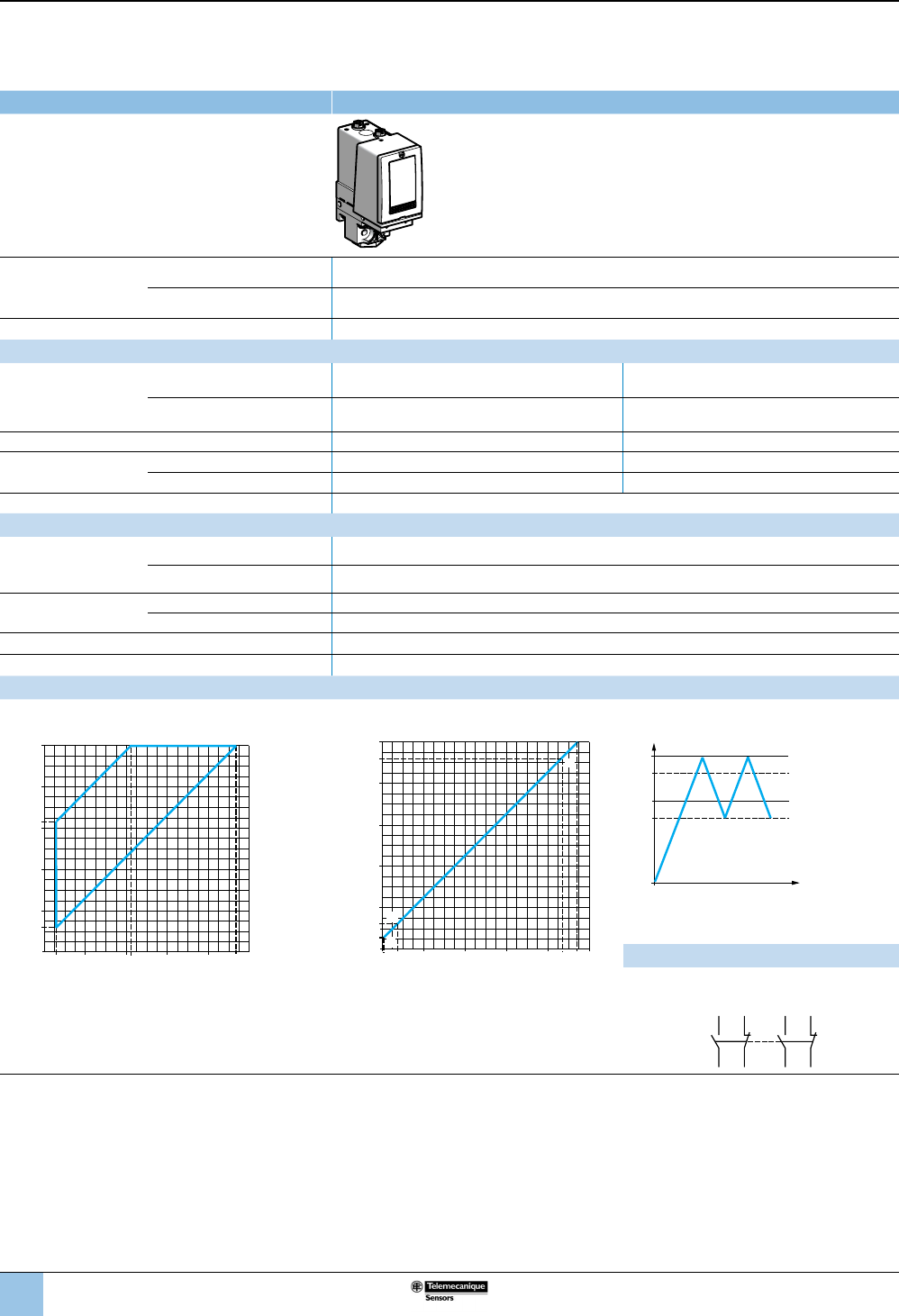
48
1
2
3
4
5
6
8
9
10
7
Size 10 bar (145 psi)
Dual-stage, xed differential, for detection at each threshold
2 C/O single-pole contacts (one per stage)
XMLD pressure switches Without setting scale
Adjustable range of
each operating point
(rising pressure)
2nd stage operating point (PH2) 1.2–10 bar (17.4–145 psi)
1st stage operating point (PH1) 0.52–9.32 bar (7.54–135.14 psi)
Spread between the two stages (PH2–PH1) 0.68–5.8 bar (9.86–84.1 psi)
Catalog numbers
Fluids controlled
For materials in contact
with uid, see page 77.
Hydraulic oils, fresh water, sea
water, air, up to 320 °F (160 °C) XMLD010B1S13 XMLD010B1S11
Corrosive uids, up to 320 °F
(160 °C) XMLD010C1S13 XMLD010C1S11
Pressure connection 1/4”-18 NPTF G 1/4-19
Electrical
connection
Conduit/cable entry 1/2” NPT Pg 13.5
Terminals 1 x 0.2 to 2 x 2.5 mm² (1 x 24 to 2 x 14 AWG)
Weight, lb (kg) 1.55 (0.705)
Supplementary specications (not shown under general specications)
Inherent differential
(subtract from PH1/PH2
to get PB1/PB2)
At low setting 0.45 bar ±0.05 (6.53 psi ±0.72)
At high setting 0.6 bar, ±0.1 (8.7 psi ±1.45)
Maximum allowable
pressure
Per cycle 12.5 bar (181.25 psi)
Accidental 22.5 bar (326.25 psi)
Destruction pressure 45 bar (652.5 psi)
Pressure switch style Diaphragm
Operating curves
High setting trip points of contacts 1 and 2 Inherent differential of contacts 1 and 2
bar
bar
0
8
6
6.34
4
2
1.2
10
9.32
864.220.52
2
1
PH2 setting (rising pressure)
PH1 setting (rising pressure)
1 Maximum differential
2 Minimum differential
bar
bar
0
8
9.32
6
4
2
0.52
1.2
10
9.48.726420.07 0.75
H
F
G
E
Rising pressure
Falling pressure
EF Contact 1 (stage 1)
GH Contact 2 (stage 2)
PH
2
PH
1
PB
1
PB
2
Time
Pressure
–– Adjustable value
--- Nonadjustable value
Connection
Terminal model
Contact 2 (stage 2) Contact 1 (stage 1)
Other versions For switches with alternative tapped cable entries, consult the Customer Care Center.
2324
22 21
1314
12 11
OsiSense XML
Electromechanical
pressure and vacuum switches
Selection and
specications (continued)
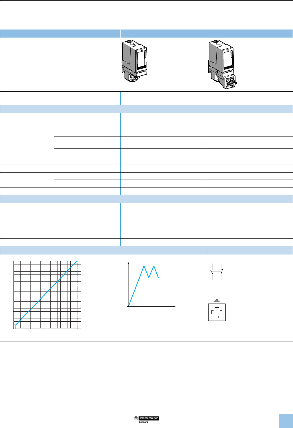
49
1
2
3
4
5
6
8
9
10
7
Size 20 bar (290 psi)
Fixed differential, for detection of a single threshold
1 C/O single-pole contact
XMLA pressure switches With setting scale
Adjustable range of operating point (PH)
(rising pressure) 1–20 bar (14.5–290 psi)
Catalog numbers
Fluids controlled
For materials in contact with
uid, see page 77.
Hydraulic oils, fresh water, sea
water, air, up to 158 °F (70 °C) XMLA020A2S13 XMLA020A2S11 XMLA020A2C11
Hydraulic oils, fresh water, sea
water, air, up to 320 °F (160 °C) XMLA020B2S13 XMLA020B2S11 XMLA020B2C11
Corrosive uids, up to 320 °F
(160 °C) XMLA020C2S13 XMLA020C2S11 XMLA020C2C11
Viscous products, up to 320 °F
(160 °C) (G1-1/4" pressure
connection)
XMLA020P2S13 XMLA020P2S11 XMLA020P2C11
Pressure connection 1/4”-18 NPTF G 1/4-19 G 1/4-19
Electrical connection Conduit/cable entry 1/2” NPT Pg 13.5 DIN 43650A, 4-pin male
Terminals 1 x 0.2 to 2 x 2.5 mm² (1 x 24 to 2 x 14 AWG) For suitable female connector, see page 73.
Weight, lb (kg) 1.51 (0.685) 1.58 (0.715)
Supplementary specications (not shown under general specications)
Inherent differential
(subtract from PH to get PB)
At low setting 0.4 bar ±0.2 (5.8 psi ±2.9)
At high setting 1 bar ±0.1 (14.5 psi ±1.45)
Maximum allowable
pressure
Per cycle 25 bar (362.5 psi)
Accidental 45 bar (652.5 psi)
Destruction pressure 90 bar (1305 psi)
Pressure switch style Diaphragm
Operating curves Connection
0.6
bar
bar
0
510
5
10
15
1
15 19
20
Rising pressure
Falling pressure
PH
PB
Time
Pressure
–– Adjustable value
--- Nonadjustable value
Terminal model
1314
12 11
Connector model
Pressure switch connector pin view
3
21
1 →
11 and 13
2 →
12
3 →
14
Other versions For switches with alternative tapped cable entries, consult the Customer Care Center.
OsiSense XML
Electromechanical
pressure and vacuum switches
Selection and
specications (continued)
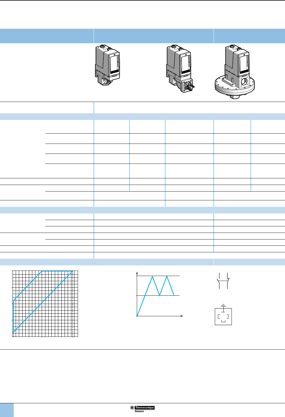
50
1
2
3
4
5
6
8
9
10
7
Size 20 bar (290 psi)
Adjustable differential, for regulation between two thresholds
1 C/O single-pole contact
XMLB pressure switches With setting scale With setting scale
overpressure 30 bar (435 psi)
Adjustable range of operating point (PH)
(rising pressure) 1.3–20 bar (18.9–290 psi)
Catalog numbers
Fluids controlled
For materials in contact
with uid, see
page 77.
Hydraulic oils, fresh water,
sea water, air, up to
158 °F (70 °C)
XMLB020A2S13 XMLB020A2S11 XMLB020A2C11 — —
Hydraulic oils, fresh water,
air, up to 320 °F (160 °C) ——— XMLBS20A2S13 XMLBS20A2S11
Hydraulic oils, fresh water,
air, up to 320 °F (160 °C) XMLB020B2S13 XMLB020B2S11 XMLB020B2C11 — —
Corrosive uids, up to
320 °F (160 °C) XMLB020C2S13 XMLB020C2S11 XMLB020C2C11 — —
Viscous products, up to
320 °F (160 °C) (G1-1/4"
pressure connection)
XMLB020P2S13 XMLB020P2S11 XMLB020P2C11 — —
Pressure connection 1/4”-18 NPTF G 1/4-19 G 1/4-19 1/4”-18 NPTF G 1/4-19
Electrical
connection
Conduit/cable entry 1/2” NPT Pg 13.5 DIN 43650A, 4-pin male 1/2” NPT Pg 13.5
Terminals 1 x 0.2 to 2 x 2.5 mm²
(1 x 24 to 2 x 14 AWG)
For suitable female
connector, see page 73.
1 x 0.2 to 2 x 2.5 mm²
(1 x 24 to 2 x 14 AWG)
Weight, lb (kg) 1.55 (0.705) 1.62 (0.735) 7.72 (3.500)
Supplementary specications (not shown under general specications)
Possible differential
(subtract from PH
to get PB)
Min. at low setting 1 bar ±0.25 (14.5 psi ±3.63) 0.95 bar ±0.25 (13.78 psi ±3.63)
Min. at high setting 1.6 bar ±0.25 (23.20 psi ±3.63) 1.45 bar ±0.25 (21.03 psi ±3.63)
Max. at high setting 11 bar (159.5 psi) 12.6 bar (182.7 psi)
Maximum allowable
pressure
Per cycle 25 bar (362.5 psi) 30 bar (435 psi)
Accidental 45 bar (652.5 psi) 37.5 bar (543.75 psi)
Destruction pressure 90 bar (1305 psi) 67.5 bar (978.75 psi)
Pressure switch style Diaphragm
Operating curves Connection
1 Maximum differential
2 Minimum differential
PH
PB
Time
Pressure
–– Adjustable value
Terminal model
1314
12 11
Connector model
Pressure switch connector pin view
3
21
1 →
11 and 13
2 →
12
3 →
14
Other versions For switches with alternative tapped cable entries, consult the Customer Care Center.
0.3 bar
bar
0
5109
5
10
15
1.3
15 18.4
20
12
Rising pressure
Falling pressure
OsiSense XML
Electromechanical
pressure and vacuum switches
Selection and
specications (continued)
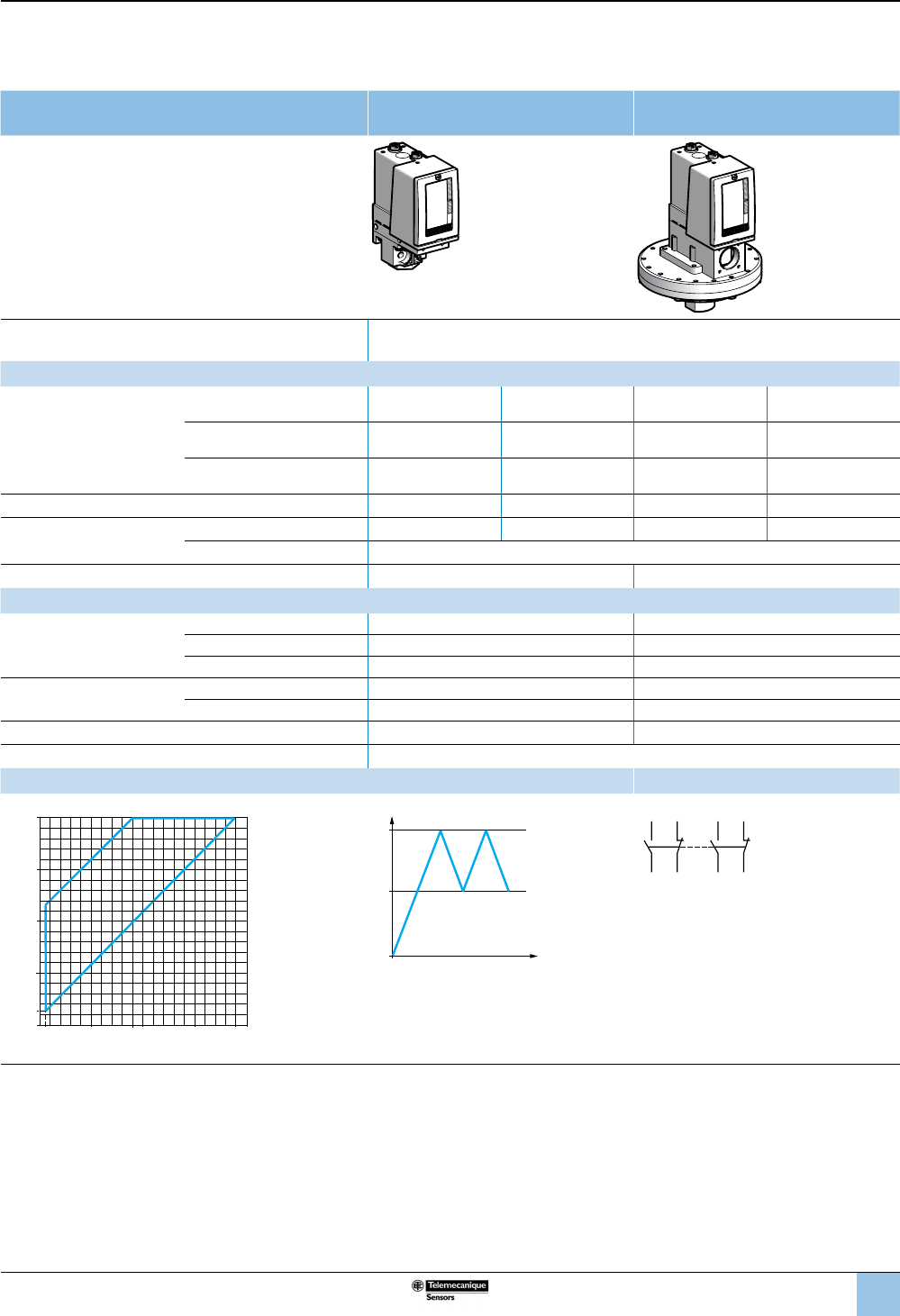
51
1
2
3
4
5
6
8
9
10
7
Size 20 bar (290 psi)
Adjustable differential, for regulation between two thresholds
2 C/O single-pole contacts
XMLC pressure switches With setting scale With setting scale
30 bar (435 psi) overpressure
Adjustable range of operating point (PH)
(rising pressure) 1.3–20 bar (18.85–290 psi)
Catalog numbers
Fluids controlled
For materials in contact with
uid, see page 77.
Hydraulic oils, fresh water, air,
up to 158 °F (70 °C) ——XMLCS20A2S13 XMLCS20A2S11
Hydraulic oils, fresh water, sea
water, air, up to 320 °F (160 °C) XMLC020B2S13 XMLC020B2S11 — —
Corrosive uids, up to 320 °F
(160 °C) XMLC020C2S13 XMLC020C2S11 — —
Pressure connection 1/4”-18 NPTF G 1/4-19 1/4”-18 NPTF G 1/4-19
Electrical connection Conduit/cable entry 1/2” NPT Pg 13.5 1/2” NPT Pg 13.5
Terminals 1 x 0.2 to 2 x 2.5 mm² (1 x 24 to 2 x 14 AWG)
Weight, lb (kg) 1.51 (0.685) 7.72 (3.500)
Supplementary specications (not shown under general specications)
Possible differential
(subtract from PH to get PB)
Min. at low setting 0.7 bar ±0.2 (10.15 psi ±2.9) 0.7 bar ±0.2 (10.15 psi ±2.9)
Min. at high setting 1 bar ±0.2 (14.5 psi ±2.9) 1.15 bar ±0.2 (16.67 psi ±2.9)
Max. at high setting 11 bar (159.5 psi) 11.70 bar (169.6 psi)
Maximum allowable
pressure
Per cycle 25 bar (362.5 psi) 30 bar (435 psi)
Accidental 45 bar (652.5 psi) 37.5 bar (543.75 psi)
Destruction pressure 90 bar (1305 psi) 67.5 bar (978.75 psi)
Pressure switch style Diaphragm
Operating curves Connection
1 Maximum
differential
2 Minimum
differential
PH
PB
Time
Pressure
–– Adjustable value
Terminal model
2324
22 21
1314
12 11
Other versions For switches with alternative tapped cable entries, consult the Customer Care Center.
0.6 bar
bar
0
5910
5
15
1.3
15 19
20
12
10
Rising pressure
Falling pressure
OsiSense XML
Electromechanical
pressure and vacuum switches
Selection and
specications (continued)
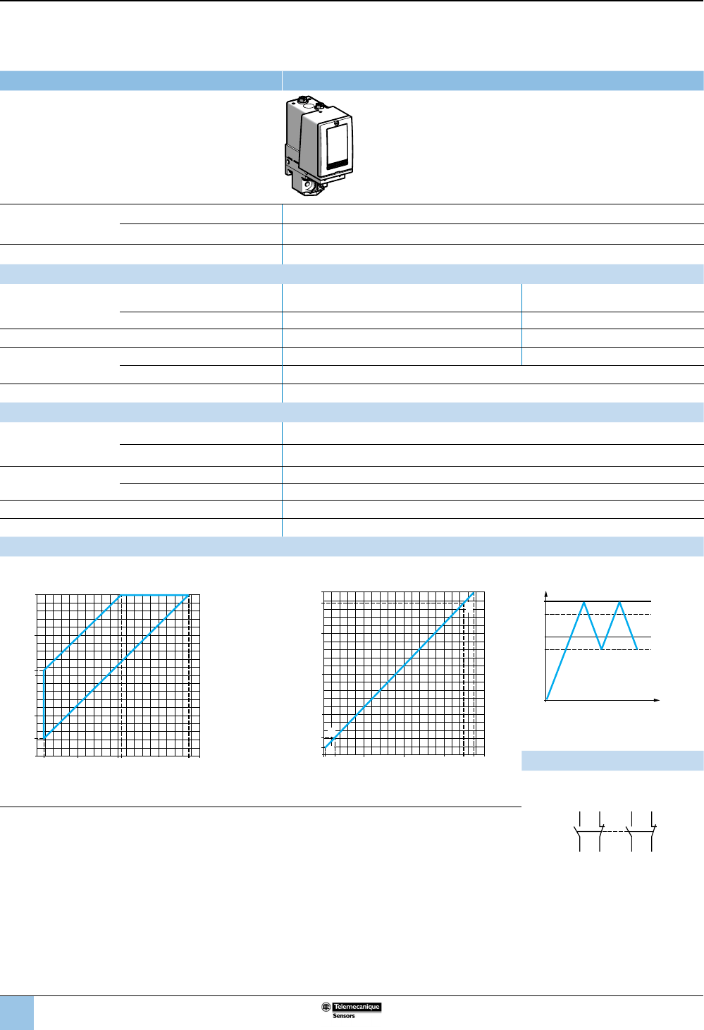
52
1
2
3
4
5
6
8
9
10
7
Size 20 bar (290 psi)
Dual-stage, xed differential, for detection at each threshold
2 C/O single-pole contacts (one per stage)
XMLD pressure switches Without setting scale
Adjustable range of
each operating point
(rising pressure)
2nd stage operating point (PH2) 2.14–20 bar (31.03–290 psi)
1st stage operating point (PH1) 0.9–18.76 bar (13.05–272.02 psi)
Spread between the two stages (PH2–PH1) 1.24–9.55 bar (17.98–138.48 psi)
Catalog numbers
Fluids controlled
For materials in contact
with uid, see page 77.
Hydraulic oils, fresh water, sea
water, air, up to 320 °F (160 °C) XMLD020B1S13 XMLD020B1S11
Corrosive uids, up to 320 °F (160 °C) XMLD020C1S13 XMLD020C1S11
Pressure connection 1/4”-18 NPTF G 1/4-19
Electrical connection Conduit/cable entry 1/2” NPT Pg 13.5
Terminals 1 x 0.2 to 2 x 2.5 mm² (1 x 24 to 2 x 14 AWG)
Weight, lb (kg) 1.55 (0.705)
Supplementary specications (not shown under general specications)
Inherent differential
(subtract from PH1/PH2
to get PB1/PB2)
At low setting 0.7 bar ±0.15 (10.15 psi ±2.18)
At high setting 1.3 bar ±0.3 (18.85 psi ±4.35)
Maximum allowable
pressure
Per cycle 25 bar (362.5 psi)
Accidental 45 bar (652.5 psi)
Destruction pressure 90 bar (1305 psi)
Pressure switch style Diaphragm
Operating curves
High setting trip points of contacts 1 and 2 Inherent differential of contacts 1 and 2
0.9 bar
bar
0510.45
5
10.6
15
2.14
15 18.76
20
12
PH2 setting (rising pressure)
PH1 setting (rising pressure)
1 Maximum differential
2 Minimum differential
0.21.44 bar
bar
0510
5
10
15
18.76
0.9
2.14
15 17.46 18.7
20
E
F
H
G
Rising pressure
Falling pressure
EF Contact 1 (stage 1)
GH Contact 2 (stage 2)
PH2
PH1
PB1
PB2
Time
Pressure
–– Adjustable value
--- Nonadjustable value
Connection
Terminal model
Contact 2 (stage 2) Contact 1 (stage 1)
Other versions For switches with alternative tapped cable entries,
consult the Customer Care Center.
2324
22 21
1314
12 11
OsiSense XML
Electromechanical
pressure and vacuum switches
Selection and
specications (continued)

53
1
2
3
4
5
6
8
9
10
7
Size 35 bar (507.5 psi)
Fixed differential, for detection of a single threshold
1 C/O single-pole contact
XMLA pressure switches With setting scale
Adjustable range of operating point (PH)
(rising pressure) 1.5–35 bar (21.75–507.5 psi)
Catalog numbers
Fluids controlled
For materials in contact with
uid, see page 77.
Hydraulic oils, fresh water, sea
water, air, up to 158 °F (70 °C) XMLA035A2S13 XMLA035A2S11 XMLA035A2C11
Hydraulic oils, fresh water, sea
water, air, up to 320 °F (160 °C) XMLA035B2S13 XMLA035B2S11 XMLA035B2C11
Corrosive uids, up to 320 °F
(160 °C) XMLA035C2S13 XMLA035C2S11 XMLA035C2C11
Viscous products,
up to 320 °F (160 °C)
(G1-1/4" pressure connection)
XMLA035P2S13 XMLA035P2S11 XMLA035P2C11
Pressure connection 1/4”-18 NPTF G 1/4-19 G 1/4-19
Electrical connection Conduit/cable entry 1/2” NPT Pg 13.5 DIN 43650A, 4-pin male
Terminals 1 x 0.2 to 2 x 2.5 mm² (1 x 24 to 2 x 14 AWG) For suitable female connector, see page 73.
Weight, lb (kg) 1.53 (0.695) 1.60 (0.725)
Supplementary specications (not shown under general specications)
Inherent differential
(subtract from PH to get PB)
At low setting 1.25 bar ±0.25 (18.12 psi ±3.62)
At high setting 1.25 bar ±0.25 (18.12 psi ±3.62)
Maximum allowable
Pressure
Per cycle 45 bar (652.5 psi)
Accidental 80 bar (1160 psi)
Destruction pressure 160 bar (2320 psi)
Pressure switch style Diaphragm
Operating curves Connection
0.25 bar
bar
010 20 30 33.75
10
20
30
1.5
35
Rising pressure
Falling pressure
PH
PB
Time
Pressure
–– Adjustable value
--- Nonadjustable value
Terminal model
1314
12 11
Connector model
Pressure switch connector pin view
3
21
1 →
11 and 13
2 →
12
3 →
14
Other versions For switches with alternative tapped cable entries, consult the Customer Care Center.
OsiSense XML
Electromechanical
pressure and vacuum switches
Selection and
specications (continued)
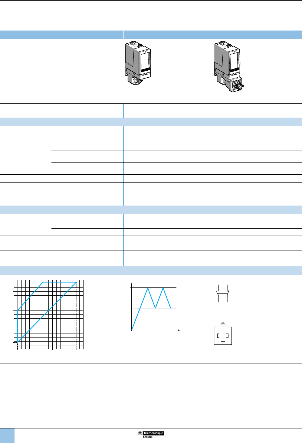
54
1
2
3
4
5
6
8
9
10
7
Size 35 bar (507.5 psi)
Adjustable differential, for regulation between two thresholds
1 C/O single-pole contact
XMLB pressure switches With setting scale
Adjustable range of operating point (PH)
(rising pressure) 3.5–35 bar (50.75–507.5 psi)
Catalog numbers
Fluids controlled
For materials in contact
with uid, see page 77.
Hydraulic oils, fresh water, sea water,
air, up to 158 °F (70 °C) XMLB035A2S13 XMLB035A2S11 XMLB035A2C11
Hydraulic oils, fresh water, sea water,
air, up to 320 °F (160 °C) XMLB035B2S13 XMLB035B2S11 XMLB035B2C11
Corrosive uids, up to 320 °F
(160 °C) XMLB035C2S13 XMLB035C2S11 XMLB035C2C11
Viscous products, up to 320 °F (160 °C)
(G1-1/4" pressure connection) XMLB035P2S13 XMLB035P2S11 XMLB035P2C11
Pressure connection 1/4”-18 NPTF G 1/4-19 G 1/4-19
Electrical connection Conduit/cable entry 1/2” NPT Pg 13.5 DIN 43650A, 4-pin male
Terminals 1 x 0.2 to 2 x 2.5 mm² (1 x 24 to 2 x 14 AWG) For suitable female connector, see page 73.
Weight, lb (kg) 1.58 (0.715) 1.64 (0.745)
Supplementary specications (not shown under general specications)
Possible differential
(subtract from PH to get
PB)
Min. at low setting 1.7 bar, –0.5, +0.7 (24.65 psi, –7.25, +10.15)
Min. at high setting 2.55 bar, –0.5, +0.7 (36.97 psi, –7.25, +10.15)
Max. at high setting 20 bar (290 psi)
Maximum allowable
pressure
Per cycle 45 bar (652.5 psi)
Accidental 80 bar (1160 psi)
Destruction pressure 160 bar (2320 psi)
Pressure switch style Diaphragm
Operating curves Connection
1.8
bar
bar
010 15 20 32.45
10
20
30
3.5
35
12
Rising pressure
Falling pressure
PH
PB
Time
Pressure
–– Adjustable value
1 Maximum differential
2 Minimum differential
Terminal model
1314
12 11
Connector model
Pressure switch connector pin view
3
21
1 →
11 and 13
2 →
12
3 →
14
Other versions For switches with alternative tapped cable entries, consult the Customer Care Center.
OsiSense XML
Electromechanical
pressure and vacuum switches
Selection and
specications (continued)

55
1
2
3
4
5
6
8
9
10
7
Size 35 bar (507.5 psi)
Adjustable differential, for regulation between two thresholds
2 C/O single-pole contacts
XMLC pressure switches With setting scale
Adjustable range of operating point (PH)
(rising pressure) 3.5–35 bar (50.75–507.5 psi)
Catalog numbers
Fluids controlled
For materials in contact with
uid, see page 77.
Hydraulic oils, fresh water, sea
water, air, up to 320 °F (160 °C) XMLC035B2S13 XMLC035B2S11
Corrosive uids, up to 320 °F
(160 °C) XMLC035C2S13 XMLC035C2S11
Pressure connection 1/4”-18 NPTF G 1/4-19
Electrical connection Conduit/cable entry 1/2” NPT Pg 13.5
Terminals 1 x 0.2 to 2 x 2.5 mm² (1 x 24 to 2 x 14 AWG)
Weight, lb (kg) 1.53 (0.695)
Supplementary specications (not shown under general specications)
Possible differential
(subtract from PH to get PB)
Min. at low setting 1 bar ±0.2 (14.5 psi ±2.9)
Min. at high setting 1.5 bar ±0.5 (21.75 psi ±7.25)
Max. at high setting 22 bar (319 psi)
Maximum allowable
pressure
Per cycle 45 bar (652.5 psi)
Accidental 80 bar (1160 psi)
Destruction pressure 160 bar (2320 psi)
Pressure switch style Diaphragm
Operating curves Connection
1 Maximum
differential
2 Minimum
differential
PH
PB
Time
Pressure
–– Adjustable value
Terminal model
2324
22 21
1314
12 11
Other versions For switches with alternative tapped cable entries, consult the Customer Care Center.
2.5 bar
bar
010 13 20 33.5
10
20
30
3.5
35
1
2
Rising pressure
Falling pressure
OsiSense XML
Electromechanical
pressure and vacuum switches
Selection and
specications (continued)
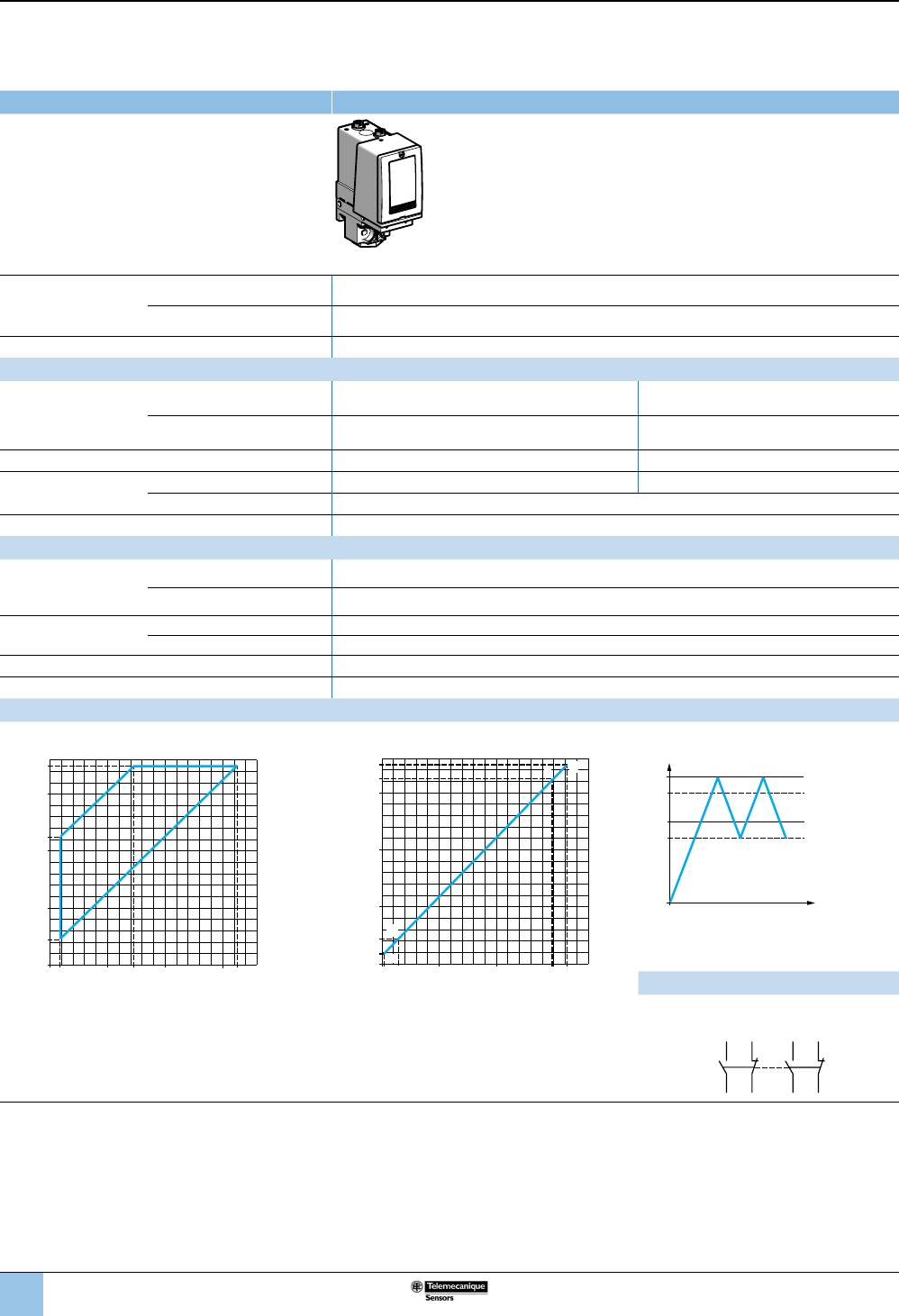
56
1
2
3
4
5
6
8
9
10
7
Size 35 bar (507.5 psi)
Dual-stage, xed differential, for detection at each threshold
2 C/O single-pole contacts (one per stage)
XMLD pressure switches Without setting scale
Adjustable range of
each operating point
(rising pressure)
2nd stage operating point (PH2) 4.4–35 bar (63.8–507.5 psi)
1st stage operating point (PH1) 1.9–32.5 bar (27.55–471.25 psi)
Spread between the two stages (PH2–PH1) 2.5–20.4 bar (36.25–295.8 psi)
Catalog numbers
Fluids controlled
For materials in contact
with uid, see page 77.
Hydraulic oils, fresh water, sea
water, air, up to 320 °F (160 °C) XMLD035B1S13 XMLD035B1S11
Corrosive uids, up to 320 °F
(160 °C) XMLD035C1S13 XMLD035C1S11
Pressure connection 1/4”-18 NPTF G 1/4-19
Electrical
connection
Conduit/cable entry 1/2” NPT Pg 13.5
Terminals 1 x 0.2 to 2 x 2.5 mm² (1 x 24 to 2 x 14 AWG)
Weight, lb (kg) 1.58 (0.715)
Supplementary specications (not shown under general specications)
Inherent differential
(subtract from PH1/PH2
to get PB1/PB2)
At low setting 1.5 bar ±0.3 (21.75 psi ±4.35)
At high setting 2.6 bar ±0.7 (37.7 psi ±10.15)
Maximum allowable
pressure
Per cycle 45 bar (652.5 psi)
Accidental 80 bar (1160 psi)
Destruction pressure 160 bar (2320 psi)
Pressure switch style Diaphragm
Operating curves
High setting trip points of contacts 1 and 2 Inherent differential of contacts 1 and 2
1.9 bar
bar
010 14.620 32.5
10
20
22.3
30
4.4
35
1
2
30
PH2 setting (rising pressure)
PH1 setting (rising pressure)
1 Maximum differential
2 Minimum differential
0.4 2.9
bar
bar
010 20 29.9 32.4
10
20
30
32.5
1.9
4.4
35
E
G
FH
Rising pressure
Falling pressure
EF Contact 1 (stage 1)
GH Contact 2 (stage 2)
PH2
PH1
PB1
PB2
Time
Pressure
–– Adjustable value
--- Nonadjustable value
Connection
Terminal model
Contact 2 (stage 2) Contact 1 (stage 1)
2324
22 21
1314
12 11
Other versions For switches with alternative tapped cable entries, consult the Customer Care Center.
OsiSense XML
Electromechanical
pressure and vacuum switches
Selection and
specications (continued)
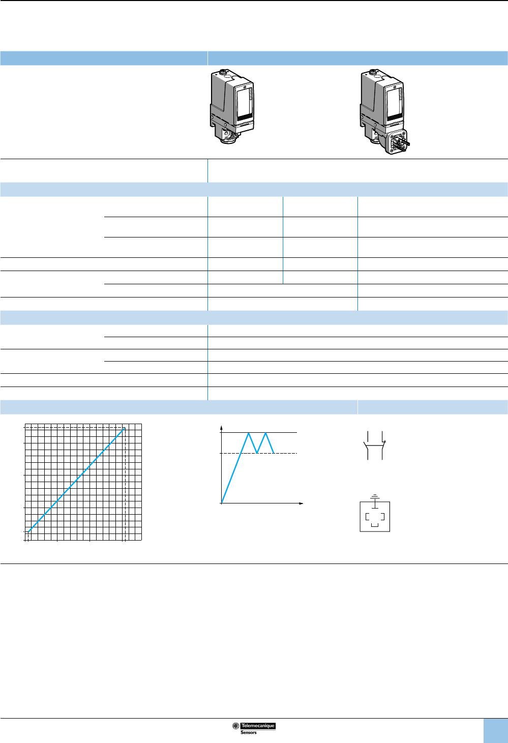
57
1
2
3
4
5
6
8
9
10
7
Size 70 bar (1015 psi)
Fixed differential, for detection of a single threshold
1 C/O single-pole contact
XMLA pressure switches With setting scale
Adjustable range of operating point (PH)
(rising pressure) 5–70 bar (72.5–1015 psi)
Catalog numbers
Fluids controlled
For materials in contact with
uid, see page 77.
Hydraulic oils, up to 320 °F
(160 °C) XMLA070D2S13 XMLA070D2S11 XMLA070D2C11
Fresh water, sea water, up to
320 °F (160 °C) XMLA070E2S13 XMLA070E2S11 XMLA070E2C11
Corrosive uids, air, up to
320 °F (160 °C) XMLA070N2S13 XMLA070N2S11 XMLA070N2C11
Pressure connection 1/4”-18 NPTF G 1/4-19 G 1/4-19
Electrical connection Conduit/cable entry 1/2” NPT Pg 13.5 DIN 43650A, 4-pin male
Terminals 1 x 0.2 to 2 x 2.5 mm² (1 x 24 to 2 x 14 AWG) For suitable female connector, see page 73.
Weight, lb (kg) 1.53 (0.695) 1.60 (0.725)
Supplementary specications (not shown under general specications)
Inherent differential
(subtract from PH to get PB)
At low setting 3 bar ±1 (43.5 psi ±14.5)
At high setting 7.5 bar ±1 (108.75 psi ±14.5)
Maximum allowable
pressure
Per cycle 90 bar (1035 psi)
Accidental 160 bar (2320 psi)
Destruction pressure 320 bar (4640 psi)
Pressure switch style Piston
Operating curves Connection
02 bar
bar
0
5
40
40
8
20
60
70
20 62.5
Rising pressure
Falling pressure
PH
PB
Time
Pressure
–– Adjustable value
--- Nonadjustable value
Terminal model
1314
12 11
Connector model
Pressure switch connector pin view
3
21
1 →
11 and 13
2 →
12
3 →
14
Other versions For switches with alternative tapped cable entries, consult the Customer Care Center.
OsiSense XML
Electromechanical
pressure and vacuum switches
Selection and
specications (continued)
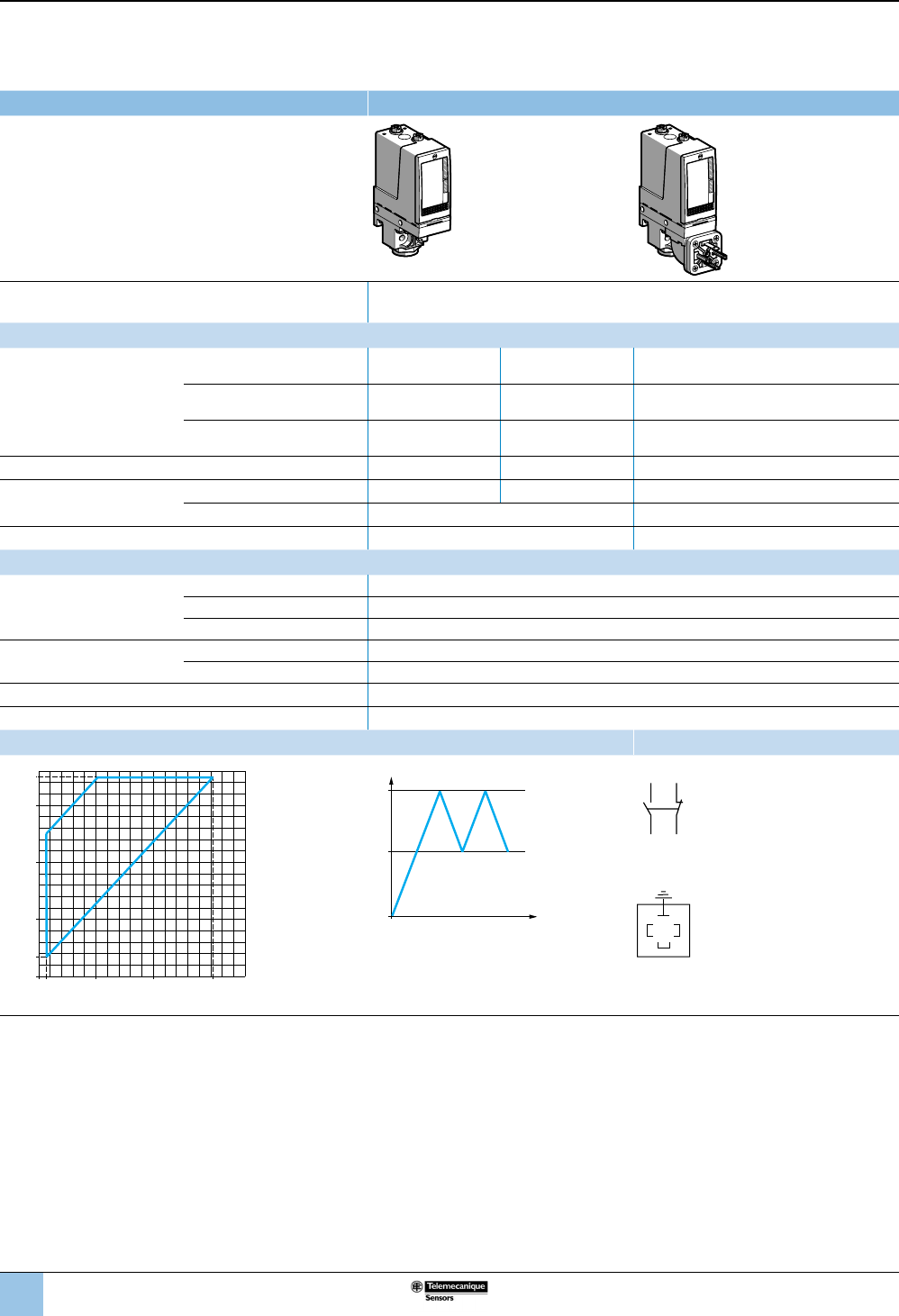
58
1
2
3
4
5
6
8
9
10
7
Size 70 bar (1015 psi)
Adjustable differential, for regulation between two thresholds
1 C/O single-pole contact
XMLB pressure switches With setting scale
Adjustable range of operating point (PH)
(rising pressure) 7–70 bar (101.5–1015 psi)
Catalog numbers
Fluids controlled
For materials in contact with
uid, see page 77.
Hydraulic oils, up to 320 °F
(160 °C) XMLB070D2S13 XMLB070D2S11 XMLB070D2C11
Fresh water, sea water,
up to 320 °F (160 °C) XMLB070E2S13 XMLB070E2S11 XMLB070E2C11
Corrosive uids, air,
up to 320 °F (160 °C) XMLB070N2S13 XMLB070N2S11 XMLB070N2C11
Pressure connection 1/4”-18 NPTF G 1/4-19 G 1/4-19
Electrical connection Conduit/cable entry 1/2” NPT Pg 13.5 DIN 43650A, 4-pin male
Terminals 1 x 0.2 to 2 x 2.5 mm² (1 x 24 to 2 x 14 AWG) For suitable female connector, see page 73.
Weight, lb (kg) 1.58 (0.715) 1.64 (0.745)
Supplementary specications (not shown under general specications)
Possible differential
(subtract from PH to get PB)
Min. at low setting 4.7 bar, –0.4, +0.7 (68.15 psi, –5.8, +10.15)
Min. at high setting 8.8 bar, –0.6, +0.8 (127.6 psi, –8.7, +11.6)
Max. at high setting 50 bar (725 psi)
Maximum allowable
pressure
Per cycle 90 bar (1035 psi)
Accidental 160 bar (2320 psi)
Destruction pressure 320 bar (4640 psi)
Pressure switch style Piston
Operating curves Connection
1 Maximum
differential
2 Minimum
differential
PH
PB
Time
Pressure
–– Adjustable value
Terminal model
1314
12 11
Connector model
Pressure switch connector pin view
3
21
1 →
11 and 13
2 →
12
3 →
14
Other versions For switches with alternative tapped cable entries, consult the Customer Care Center.
2.3 bar
bar
0
7
40
40
20
60
70
20 61.2
1
2
Rising pressure
Falling pressure
OsiSense XML
Electromechanical
pressure and vacuum switches
Selection and
specications (continued)
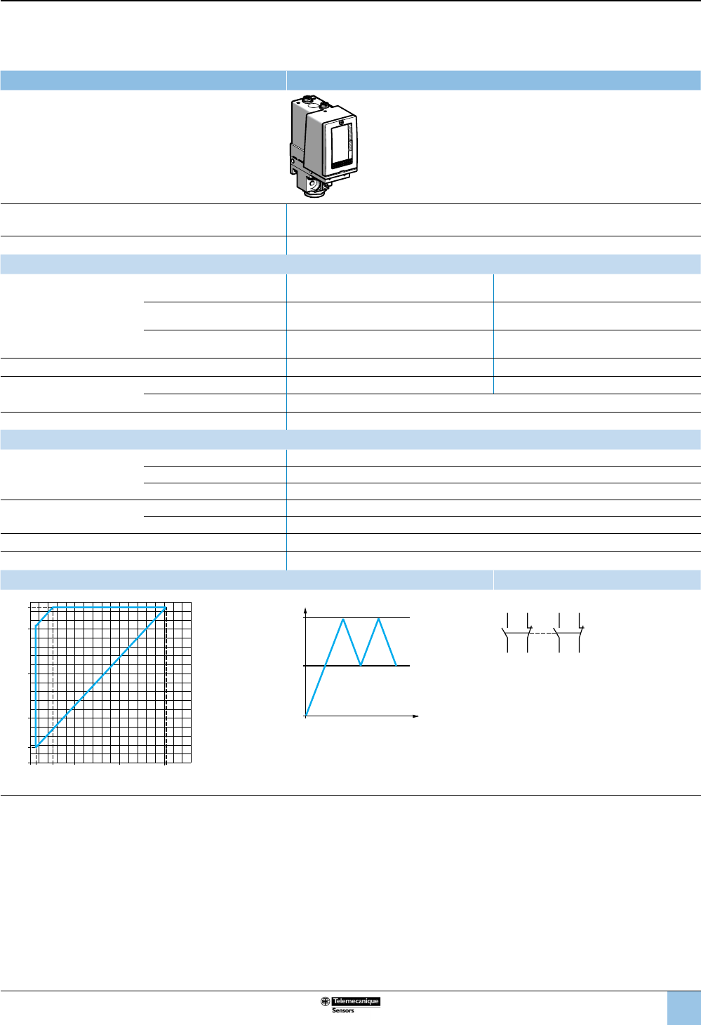
59
1
2
3
4
5
6
8
9
10
7
Size 70 bar (1015 psi)
Adjustable differential, for regulation between two thresholds
2 C/O single-pole contacts
XMLC pressure switches With setting scale
Adjustable range of operating point (PH)
(rising pressure) 7–70 bar (101.5–1015 psi)
Electrical connection Terminals
Catalog numbers
Fluids controlled
For materials in contact with
uid, see page 77.
Hydraulic oils, up to 320 °F
(160 °C) XMLC070D2S13 XMLC070D2S11
Fresh water, sea water, up to
320 °F (160 °C) XMLC070E2S13 XMLC070E2S11
Corrosive uids, up to 320 °F
(160 °C) XMLC070N2S13 XMLC070N2S11
Pressure connection 1/4”-18 NPTF G 1/4-19
Electrical connection Conduit/cable entry 1/2” NPT Pg 13.5
Terminals 1 x 0.2 to 2 x 2.5 mm² (1 x 24 to 2 x 14 AWG)
Weight, lb (kg) 1.53 (0.695)
Supplementary specications (not shown under general specications)
Possible differential
(subtract from PH to get PB)
Min. at low setting 4.5 bar ±0.8 (65.25 psi ±11.6)
Min. at high setting 8.9 bar ±0.8 (129.05 psi ±11.6)
Max. at high setting 60 bar (870 psi)
Maximum allowable
pressure
Per cycle 90 bar (1035 psi)
Accidental 160 bar (2320 psi)
Destruction pressure 320 bar (4640 psi)
Pressure switch style Piston
Operating curves Connection
1 Maximum
differential
2 Minimum
differential
PH
PB
Time
Pressure
–– Adjustable value
Terminal model
2324
22 21
1314
12 11
Other versions For switches with alternative tapped cable entries, consult the Customer Care Center.
2.510
bar
bar
0
7
40
40
20
70
20 61.1
1
2
60
Rising pressure
Falling pressure
OsiSense XML
Electromechanical
pressure and vacuum switches
Selection and
specications (continued)
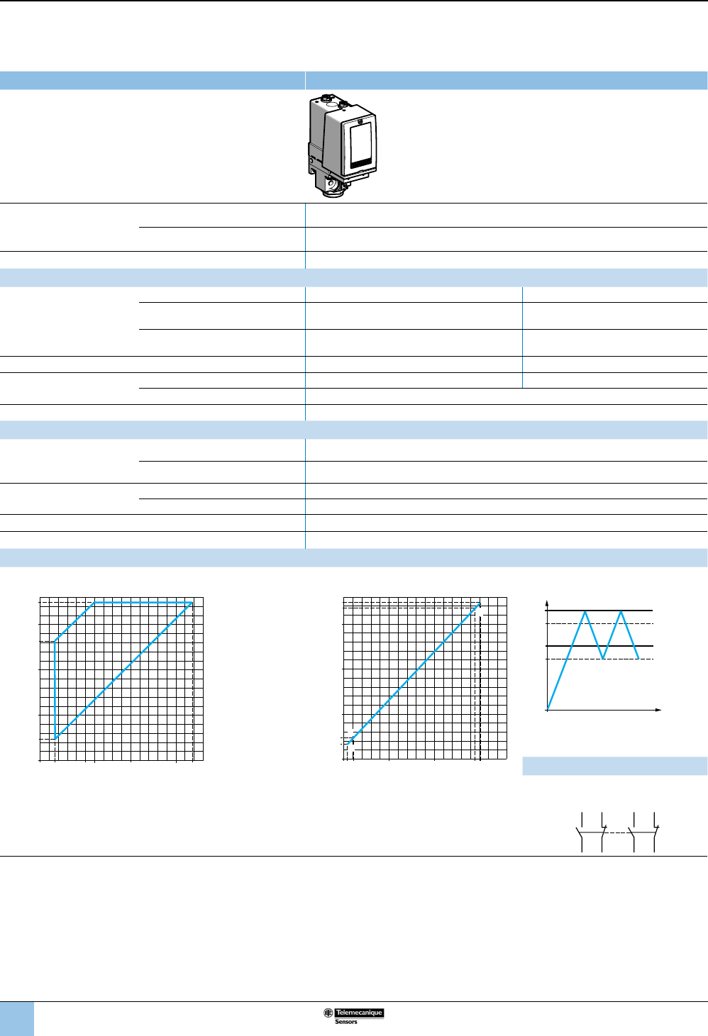
60
1
2
3
4
5
6
8
9
10
7
Size 70 bar (1015 psi)
Dual-stage, xed differential, for detection at each threshold
2 C/O single-pole contacts (one per stage)
XMLD pressure switches Without setting scale
Adjustable range of each
operating point
(rising pressure)
2nd stage operating point (PH2) 9.4–70 bar (136.3–1015 psi)
1st stage operating point (PH1) 6.6–67.2 bar (95.7–974.4 psi)
Spread between the two stages (PH2–PH1) 2.8–46 bar (40.6–667 psi)
Catalog numbers
Fluids controlled
For materials in contact with
uid, see page 77.
Hydraulic oils, up to 320 °F (160 °C) XMLD070D1S13 XMLD070D1S11
Fresh water, sea water, up to 320 °F
(160 °C) XMLD070E1S13 XMLD070E1S11
Corrosive uids, air, up to 320 °F
(160 °C) XMLD070N1S13 XMLD070N1S11
Pressure connection 1/4”-18 NPTF G 1/4-19
Electrical connection Conduit/cable entry 1/2” NPT Pg 13.5
Terminals 1 x 0.2 to 2 x 2.5 mm² (1 x 24 to 2 x 14 AWG)
Weight, lb (kg) 1.58 (0.715)
Supplementary specications (not shown under general specications)
Inherent differential
(subtract from PH1/PH2
to get PB1/PB2)
At low setting 5 bar ±1.5 (72.5 psi ±21.75)
At high setting 9.5 bar ±2 (137.75 psi ±29)
Maximum allowable
pressure
Per cycle 90 bar (1035 psi)
Accidental 160 bar (2320 psi)
Destruction pressure 320 bar (4640 psi)
Pressure switch style Piston
Operating curves
High setting trip points of contacts 1 and 2 Inherent differential of contacts 1 and 2
6.6
bar
bar
0
9.4
40
40
20
60
52.6
70
20 24 67.2
1
2
60
PH2 setting (rising pressure)
PH1 setting (rising pressure)
1 Maximum differential
2 Minimum differential
1.6 bar
bar
0
6.6
9.4
40
40
4.4
20
60
70
67.2
20 60.557.7
G
H
F
E
Rising pressure
Falling pressure
EF Contact 1 (stage 1)
GH Contact 2 (stage 2)
PH2
PH1
PB1
PB2
Time
Pressure
–– Adjustable value
--- Nonadjustable value
Connection
Terminal model
Contact 2 (stage 2) Contact 1 (stage 1)
2324
22 21
1314
12 11
Other versions For switches with alternative tapped cable entries, consult the Customer Care Center.
OsiSense XML
Electromechanical
pressure and vacuum switches
Selection and
specications (continued)
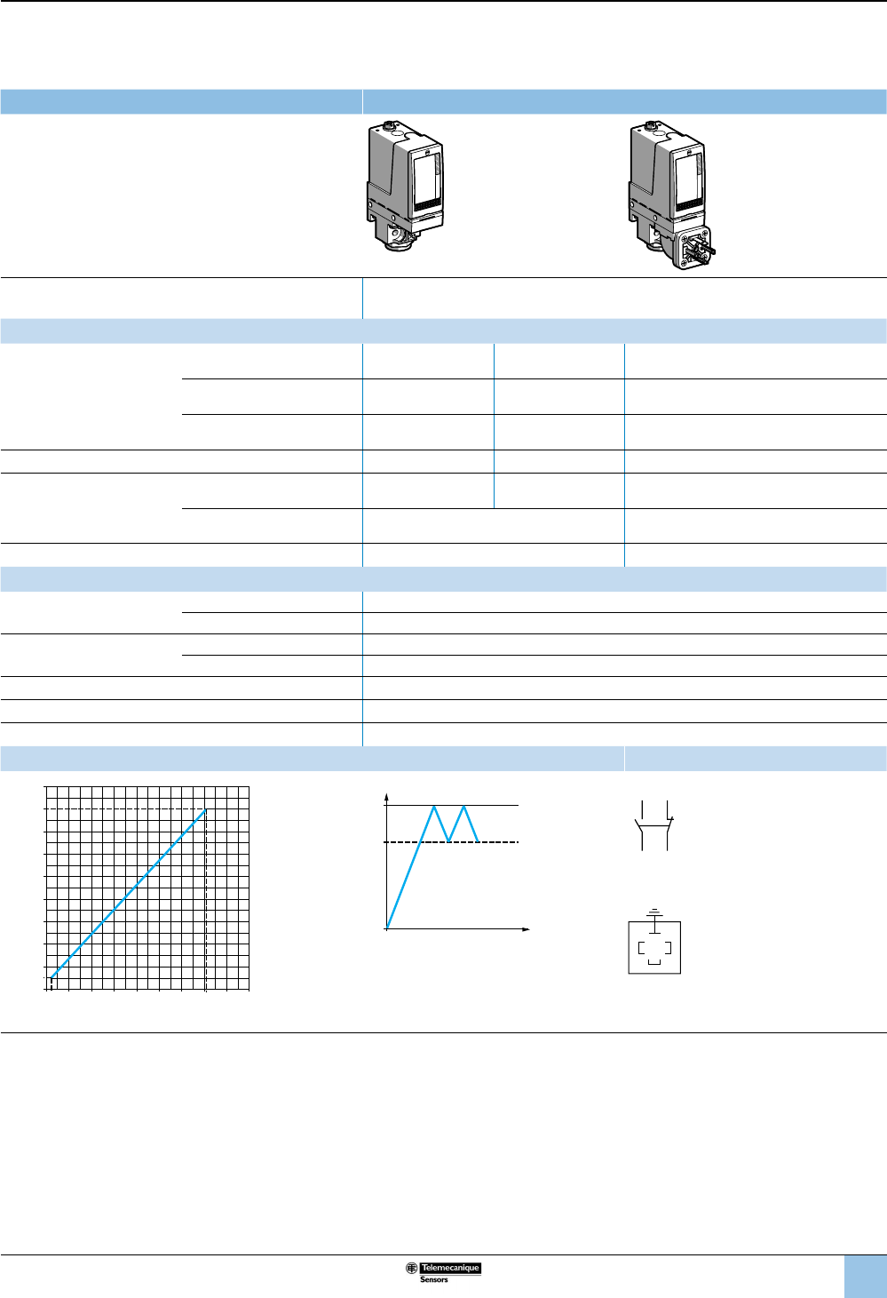
61
1
2
3
4
5
6
8
9
10
7
OsiSense XML
Electromechanical
pressure and vacuum switches
Selection and
specications (continued)
Size 160 bar (2320 psi)
Fixed differential, for detection of a single threshold
1 C/O single-pole contact
XMLA pressure switches With setting scale
Adjustable range of operating point (PH)
(rising pressure) 10–160 bar (145–2320 psi)
Catalog numbers
Fluids controlled
For materials in contact with
uid, see page 77.
Hydraulic oils, up to 320 °F
(160 °C) XMLA160D2S13 XMLA160D2S11 XMLA160D2C11
Fresh water, sea water, up to
320 °F (160 °C) XMLA160E2S13 XMLA160E2S11 XMLA160E2C11
Corrosive uids, air, up to
320 °F (160 °C) XMLA160N2S13 XMLA160N2S11 XMLA160N2C11
Pressure connection 1/4”-18 NPTF G 1/4-19 G 1/4-19
Electrical connection
Conduit/cable entry 1/2” NPT Pg 13.5 DIN 43650A, 4-pin male.
Terminals 1 x 0.2 to 2 x 2.5 mm² (1 x 24 to 2 x 14 AWG) For suitable female connector, see page 73.
Weight, lb (kg) 1.65 (0.750) 1.72 (0.780)
Supplementary specications (not shown under general specications)
Inherent differential
(subtract from PH to get PB)
At low setting 5.5 bar ±1 (79.75 psi ±14.5)
At high setting 18 bar ±3 (261 psi ±43.5)
Maximum allowable
pressure
Per cycle 200 bar (2900 psi)
Accidental 360 bar (5220 psi)
Destruction pressure 720 bar (10,440 psi)
Mechanical life (depending on the application) 6 x 10⁶ operating cycles
Pressure switch style Piston
Operating curves Connection
bar
bar
0
40 100 142
40
100
4.5
20
10
120 160
60
80
120
140
160
20 60 80
Rising pressure
Falling pressure
PH
PB
Time
Pressure
–– Adjustable value
--- Nonadjustable value
Terminal model
1314
12 11
Connector model
Pressure switch connector pin view
3
21
1 →
11 and 13
2 →
12
3 →
14
Other versions For switches with alternative tapped cable entries, consult the Customer Care Center.
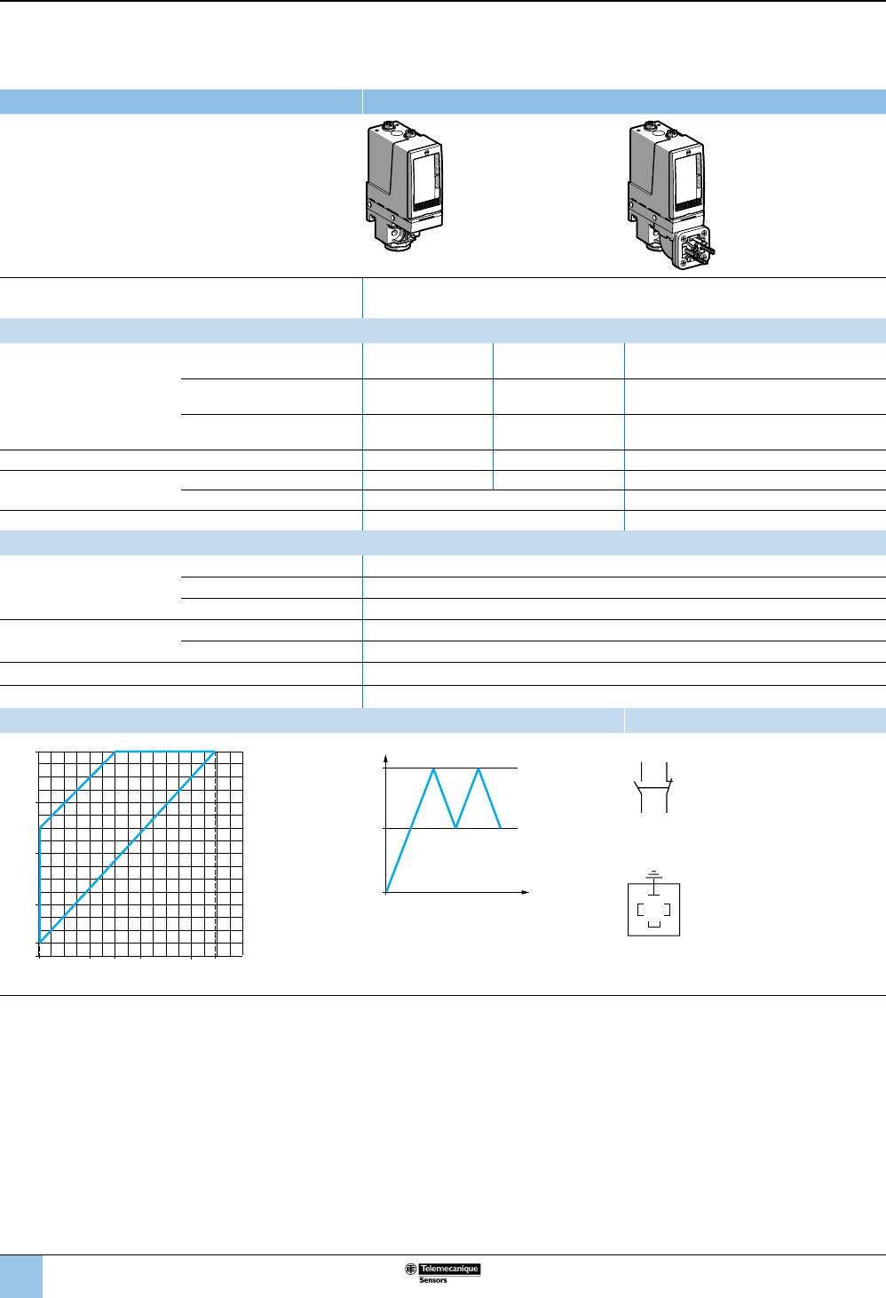
62
1
2
3
4
5
6
8
9
10
7
Size 160 bar (2320 psi)
Adjustable differential, for regulation between two thresholds
1 C/O single-pole contact
XMLB pressure switches With setting scale
Adjustable range of operating point (PH)
(rising pressure) 10–160 bar (145–2320 psi)
Catalog numbers
Fluids controlled
For materials in contact with
uid, see page 77.
Hydraulic oils, up to 320 °F
(160 °C) XMLB160D2S13 XMLB160D2S11 XMLB160D2C11
Fresh water, sea water, up to
320 °F (160 °C) XMLB160E2S13 XMLB160E2S11 XMLB160E2C11
Corrosive uids, air, up to
320 °F (160 °C) XMLB160N2S13 XMLB160N2S11 XMLB160N2C11
Pressure connection 1/4”-18 NPTF G 1/4-19 G 1/4-19
Electrical connection Conduit/cable entry 1/2” NPT Pg 13.5 DIN 43650A, 4-pin male.
Terminals 1 x 0.2 to 2 x 2.5 mm² (1 x 24 to 2 x 14 AWG) For suitable female connector, see page 73.
Weight, lb (kg) 1.65 (0.750) 1.72 (0.780)
Supplementary specications (not shown under general specications)
Possible differential
(subtract from PH to get PB)
Min. at low setting 9.3 bar, –1.8, +1.5 (134.85 psi, –26.1, +21.75)
Min. at high setting 20.8 bar, –1.9, +1.6 (301.6 psi, –27.55, +23.2)
Max. at high setting 100 bar (1450 psi)
Maximum allowable
pressure
Per cycle 200 bar (2900 psi)
Accidental 360 bar (5220 psi)
Destruction pressure 720 bar (10,440 psi)
Pressure switch style Piston
Operating curves Connection
1 Maximum
differential
2 Minimum
differential
PH
PB
Time
Pressure
–– Adjustable value
Terminal model
1314
12 11
Connector model
Pressure switch connector pin view
3
21
1 →
11 and 13
2 →
12
3 →
14
Other versions For switches with alternative tapped cable entries, consult the Customer Care Center.
0.7 bar
bar
0
40 8060
40
80
120
10
120 139.2
160
1
2
Rising pressure
Falling pressure
OsiSense XML
Electromechanical
pressure and vacuum switches
Selection and
specications (continued)
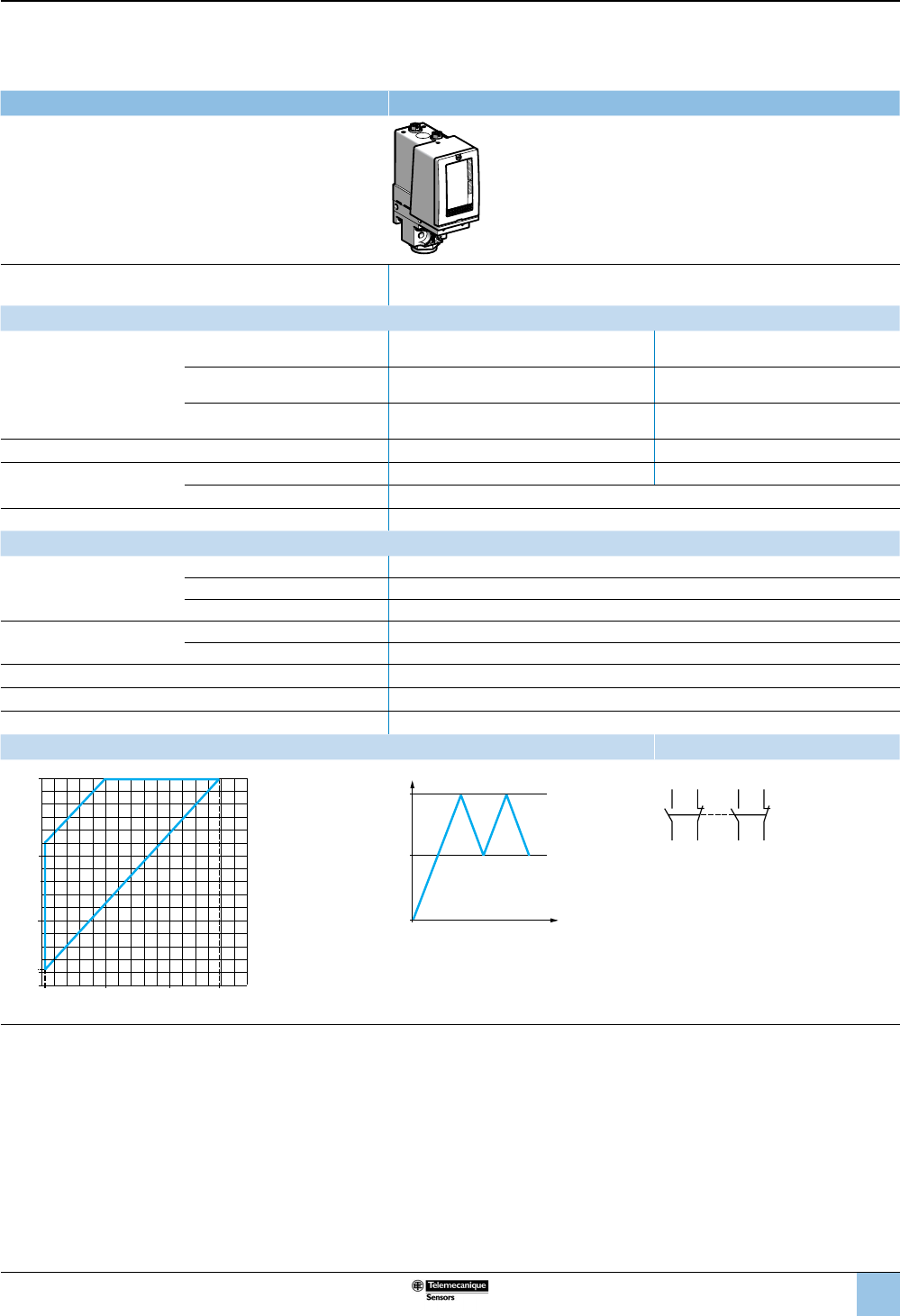
63
1
2
3
4
5
6
8
9
10
7
Size 160 bar (2320 psi)
Adjustable differential, for regulation between two thresholds
2 C/O single-pole contacts
XMLC pressure switches With setting scale
Adjustable range of operating point (PH)
(rising pressure) 12–160 bar (174–2320 psi)
Catalog numbers
Fluids controlled
For materials in contact with
uid, see page 77.
Hydraulic oils, up to 320 °F (160 °C) XMLC160D2S13 XMLC160D2S11
Fresh water, sea water,
up to 320 °F (160 °C) XMLC160E2S13 XMLC160E2S11
Corrosive uids, up to 320 °F
(160 °C) XMLC160N2S13 XMLC160N2S11
Pressure connection 1/4”-18 NPTF G 1/4-19
Electrical connection Conduit/cable entry 1/2” NPT Pg 13.5
Terminals 1 x 0.2 to 2 x 2.5 mm² (1 x 24 to 2 x 14 AWG)
Weight, lb (kg) 1.65 (0.750)
Supplementary specications (not shown under general specications)
Possible differential
(subtract from PH to get PB)
Min. at low setting 9 bar ±0.9 (130.5 psi ±13.05)
Min. at high setting 21 bar ±0.9 (304.5 psi ±13.05)
Max. at high setting 110 bar (1590 psi)
Maximum allowable
pressure
Per cycle 200 bar (2900 psi)
Accidental 360 bar (5220 psi)
Destruction pressure 720 bar (10,440 psi)
Mechanical life (depending on the application) 6 x 10⁶ operating cycles
Pressure switch style Piston
Operating curves Connection
1 Maximum
differential
2 Minimum
differential
PH
PB
Time
Pressure
–– Adjustable value
Terminal model
2324
22 21
1314
12 11
Other versions For switches with alternative tapped cable entries, consult the Customer Care Center.
3ba
r
bar
0
50
50
12
100139
160
1
2
100
Rising pressure
Falling pressure
OsiSense XML
Electromechanical
pressure and vacuum switches
Selection and
specications (continued)
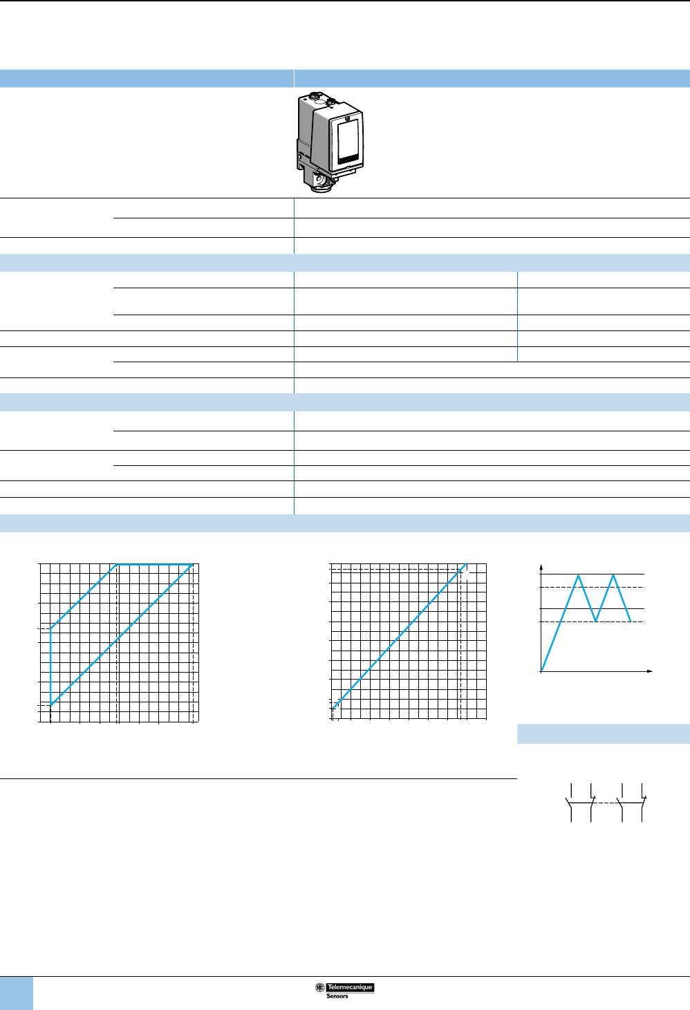
64
1
2
3
4
5
6
8
9
10
7
Size 160 bar (2320 psi)
Dual-stage, xed differential, for detection at each threshold
2 C/O single-pole contacts (one per stage)
XMLD pressure switches Without setting scale
Adjustable range of
each operating point
(rising pressure)
2nd stage operating point (PH2) 16.5–160 bar (239.25–2320 psi)
1st stage operating point (PH1) 10.5–154 bar (152.25–2233 psi)
Spread between the two stages (PH2–PH1) 6–83 bar (87–1203.5 psi)
Catalog numbers
Fluids controlled
For materials in contact
with uid, see page 77.
Hydraulic oils, up to 320 °F (160 °C) XMLD160D1S13 XMLD160D1S11
Fresh water, sea water, up to 320 °F
(160 °C) XMLD160E1S13 XMLD160E1S11
Corrosive uids, air, up to 320 °F (160 °C) XMLD160N1S13 XMLD160N1S11
Pressure connection 1/4”-18 NPTF G 1/4-19
Electrical
connection
Conduit/cable entry 1/2” NPT Pg 13.5
Terminals 1 x 0.2 to 2 x 2.5 mm² (1 x 24 to 2 x 14 AWG)
Weight, lb (kg) 1.65 (0.750)
Supplementary specications (not shown under general specications)
Inherent differential
(subtract from PH1/PH2
to get PB1/PB2)
At low setting 8.8 bar ±1.5 (127.6 psi ±21.75)
At high setting 20 bar ±7 (290 psi ±101.5)
Maximum allowable
pressure
Per cycle 200 bar (2900 psi)
Accidental 360 bar (5220 psi)
Destruction pressure 720 bar (10,440 psi)
Pressure switch style Piston
Operating curves
High setting trip points of contacts 1 and 2 Inherent differential of contacts 1 and 2
0 10.5 bar
bar
0
40 7760
40
80
94.5
120
10
16.5
120100 154
160
1
2
PH2 setting (rising pressure)
PH1 setting (rising pressure)
1 Maximum differential
2 Minimum differential
bar
bar
0
40 100 134140
40
100
1.7 7.7
10.5
16.5
160
60
80
120
140
154
60 80
E
F
H
G
Rising pressure
Falling pressure
EF Contact 1 (stage 1)
GH Contact 2 (stage 2)
PH2
PH1
PB1
PB2
Time
Pressure
–– Adjustable value
--- Nonadjustable value
Connection
Terminal model
Contact 2 (stage 2) Contact 1 (stage 1)
Other versions For switches with alternative tapped cable entries,
consult the Customer Care Center.
2324
22 21
1314
12 11
OsiSense XML
Electromechanical
pressure and vacuum switches
Selection and
specications (continued)
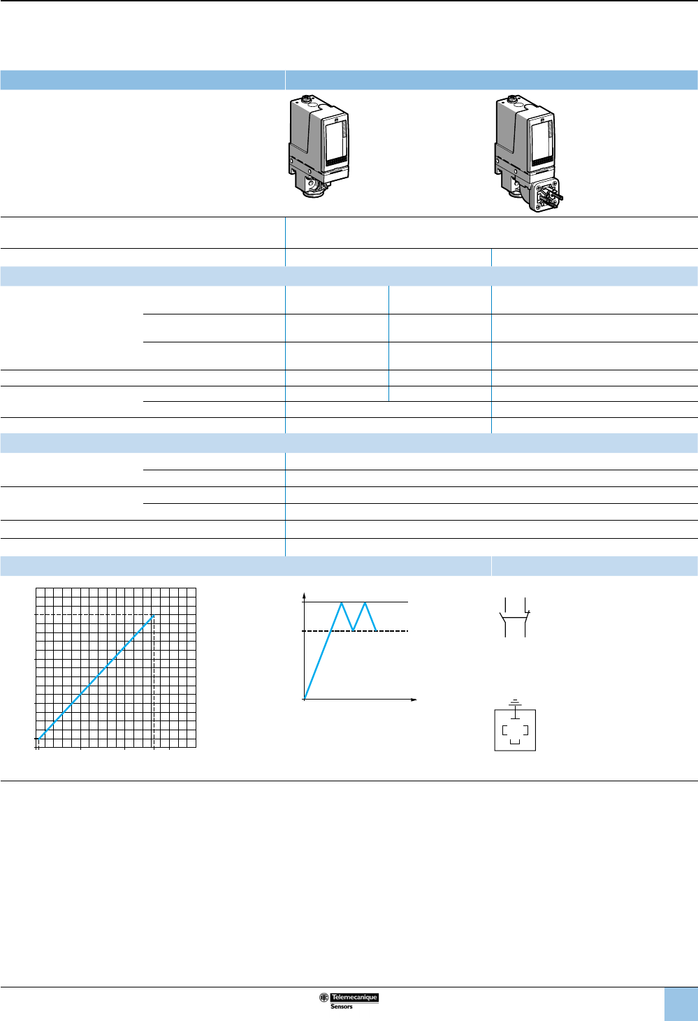
65
1
2
3
4
5
6
8
9
10
7
Size 300 bar (4350 psi)
Fixed differential, for detection of a single threshold
1 C/O single-pole contact
XMLA pressure switches With setting scale
Adjustable range of operating point (PH)
(rising pressure) 20–300 bar (290–4350 psi)
Electrical connection Terminals DIN connector
Catalog numbers (1)
Fluids controlled
For materials in contact with
uid, see page 77.
Only for control of group 2
uids, in accordance with
directive 97/23/EEC.
Hydraulic oils, up to 320 °F
(160 °C) XMLA300D2S13 XMLA300D2S11 XMLA300D2C11
Fresh water, sea water, up to
320 °F (160 °C) XMLA300E2S13 XMLA300E2S11 XMLA300E2C11
Corrosive uids, air, up to
320 °F (160 °C) XMLA300N2S13 XMLA300N2S11 XMLA300N2C11
Pressure connection 1/4”-18 NPTF G 1/4-19 G 1/4-19
Electrical connection Conduit/cable entry 1/2” NPT Pg 13.5 DIN 43650A, 4-pin male
Terminals 1 x 0.2 to 2 x 2.5 mm² (1 x 24 to 2 x 14 AWG) For suitable female connector, see page 73.
Weight, lb (kg) 1.65 (0.750) 1.72 (0.780)
Supplementary specications (not shown under general specications)
Inherent differential
(subtract from PH to get PB)
At low setting 16.5 bar ±3 (239.25 psi ±43.5)
At high setting 35 bar ±6 (507.5 psi ±87)
Maximum allowable
pressure
Per cycle 375 bar (5437.5 psi)
Accidental 675 bar (9787.5 psi)
Destruction pressure 1350 bar (19,575 psi)
Pressure switch style Piston
Operating curves Connection
3.5
bar
bar
0100 200265 300
100
200
300
20
Rising pressure
Falling pressure
PH
PB
Time
Pressure
–– Adjustable value
--- Nonadjustable value
Terminal model
1314
12 11
Connector model
Pressure switch connector pin view
3
21
1 →
11 and 13
2 →
12
3 →
14
Other versions For switches with alternative tapped cable entries, consult the Customer Care Center.
OsiSense XML
Electromechanical
pressure and vacuum switches
Selection and
specications (continued)
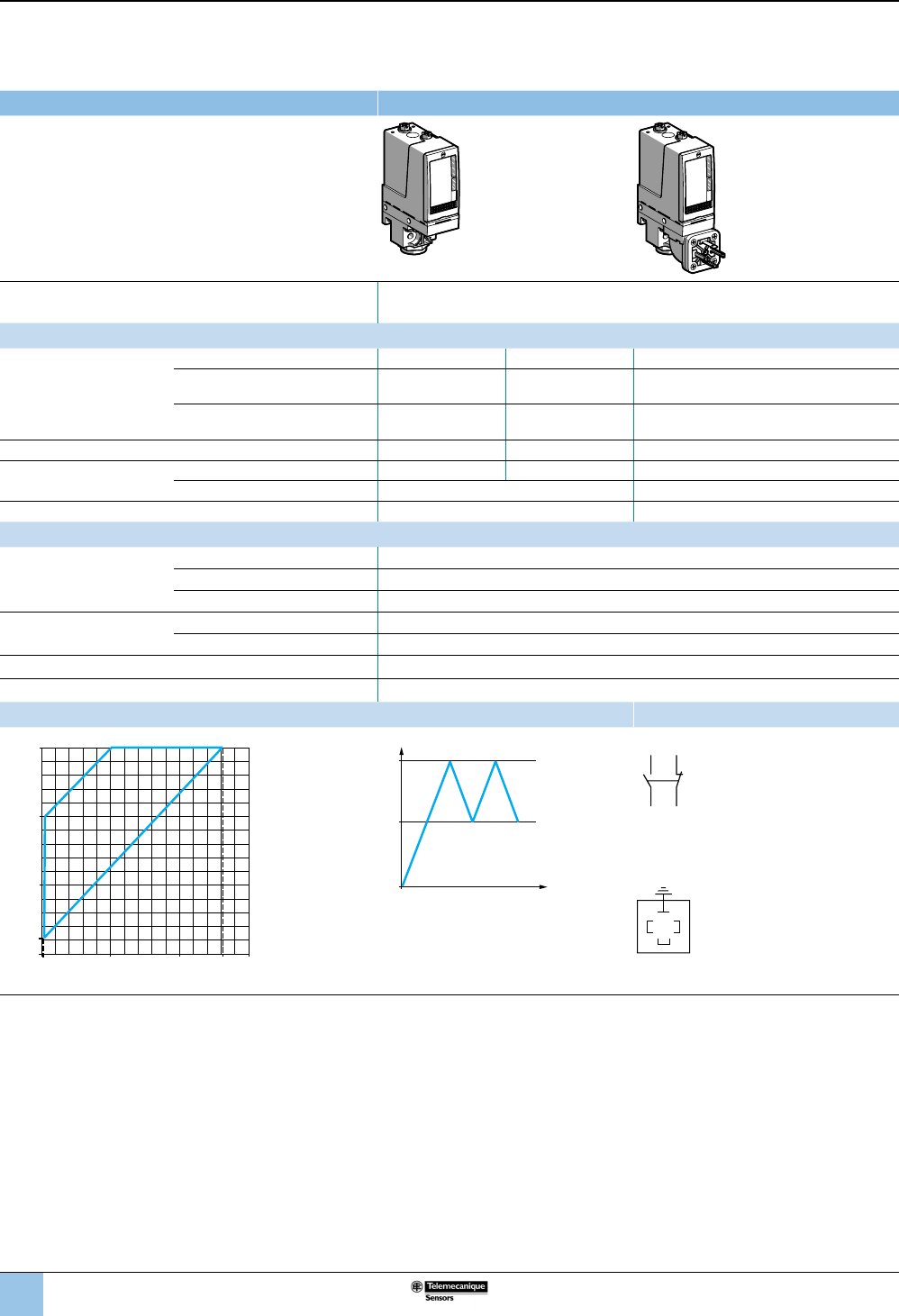
66
1
2
3
4
5
6
8
9
10
7
Size 300 bar (4350 psi)
Adjustable differential, for regulation between two thresholds
1 C/O single-pole contact
XMLB pressure switches With setting scale
Adjustable range of operating point (PH)
(rising pressure) 22–300 bar (319–4350 psi)
Catalog numbers
Fluids controlled
For materials in contact with
uid, see page 77.
Only for control of group 2
uids, in accordance with
directive 97/23/EEC.
Hydraulic oils, up to 320 °F (160 °C) XMLB300D2S13 XMLB300D2S11 XMLB300D2C11
Fresh water, sea water, up to
320 °F (160 °C) XMLB300E2S13 XMLB300E2S11 XMLB300E2C11
Corrosive uids, air, up to 320 °F
(160 °C) XMLB300N2S13 XMLB300N2S11 XMLB300N2C11
Pressure connection 1/4”-18 NPTF G 1/4-19 G 1/4-19
Electrical connection Conduit/cable entry 1/2” NPT Pg 13.5 DIN 43650A, 4-pin male.
Terminals 1 x 0.2 to 2 x 2.5 mm² (1 x 24 to 2 x 14 AWG) For suitable female connector, see page 73.
Weight, lb (kg) 1.65 (0.750) 1.72 (0.780)
Supplementary specications (not shown under general specications)
Possible differential
(subtract from PH to get PB)
Min. at low setting 19.4 bar –1.5, +1.7 (281.3 psi, –21.75, +24.65)
Min. at high setting 37 bar, –1, +4 (536.5 psi, –14.5, +58)
Max. at high setting 200 bar (2900 psi)
Maximum allowable
pressure
Per cycle 375 bar (5437.5 psi)
Accidental 675 bar (9787.5 psi)
Destruction pressure 1350 bar (19,575 psi)
Pressure switch style Piston
Operating curves Connection
1 Maximum
differential
2 Minimum
differential
PH
PB
Time
Pressure
–– Adjustable value
Terminal model
1314
12 11
Connector model
Pressure switch connector pin view
3
21
1 →
11 and 13
2 →
12
3 →
14
Other versions For switches with alternative tapped cable entries, consult the Customer Care Center.
ba
r
bar
0
200
100
22
300
2632001002.6
2
1
Rising pressure
Falling pressure
OsiSense XML
Electromechanical
pressure and vacuum switches
Selection and
specications (continued)
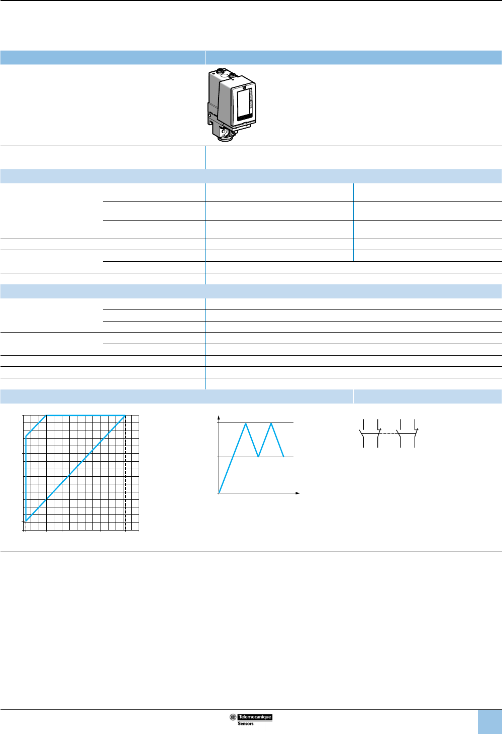
67
1
2
3
4
5
6
8
9
10
7
Size 300 bar (4350 psi)
Adjustable differential, for regulation between two thresholds
2 C/O single-pole contacts
XMLC pressure switches With setting scale
Adjustable range of operating point (PH)
(rising pressure) 22–300 bar (319–4350 psi)
Catalog numbers
Fluids controlled
For materials in contact with
uid, see page 77.
Only for control of group 2
uids, in accordance with
directive 97/23/EEC.
Hydraulic oils, up to 320 °F
(160 °C) XMLC300D2S13 XMLC300D2S11
Fresh water, sea water, up to
320 °F (160 °C) XMLC300E2S13 XMLC300E2S11
Corrosive uids, air, up to
320 °F (160 °C) XMLC300N2S13 XMLC300N2S11
Pressure connection 1/4”-18 NPTF G 1/4-19
Electrical connection Conduit/cable entry 1/2” NPT Pg 13.5
Terminals 1 x 0.2 to 2 x 2.5 mm² (1 x 24 to 2 x 14 AWG)
Weight, lb (kg) 1.65 (0.750)
Supplementary specications (not shown under general specications)
Possible differential
(subtract from PH to get PB)
Min. at low setting 16 bar ±0.9 (232 psi ±13.05)
Min. at high setting 35 bar ±0.9 (507.5 psi ±13.05)
Max. at high setting 240 bar (3480 psi)
Maximum allowable
pressure
Per cycle 375 bar (5437.5 psi)
Accidental 675 bar (9787.5 psi)
Destruction pressure 1350 bar (19,575 psi)
Mechanical life (depending on the application) 3 x 10⁶ operating cycles
Pressure switch style Piston
Operating curves Connection
1 Maximum
differential
2 Minimum
differential
PH
PB
Time
Pressure
–– Adjustable value
Terminal model
2324
22 21
1314
12 11
Other versions For switches with alternative tapped cable entries, consult the Customer Care Center.
ba
r
bar
0
200
100
22
300
265200
60
6
2
1
100
Rising pressure
Falling pressure
OsiSense XML
Electromechanical
pressure and vacuum switches
Selection and
specications (continued)
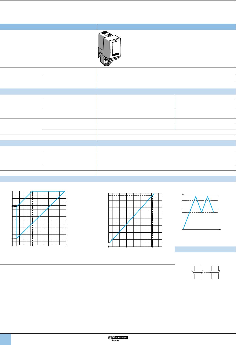
68
1
2
3
4
5
6
8
9
10
7
Size 300 bar (4350 psi)
Dual-stage, xed differential, for detection at each threshold
2 C/O single-pole contacts (one per stage)
XMLD pressure switches Without setting scale
Adjustable range of
each operating point
(rising pressure)
2nd stage operating point (PH2) 36–300 bar (522–4350 psi)
1st stage operating point (PH1) 25–289 bar (362.5–4190.5 psi)
Spread between the two stages (PH2–PH1) 11–189 bar (159.5–2740.5 psi)
Catalog numbers
Fluids controlled
For materials in contact with
uid, see page 77.
Only for control of group 2
uids, in accordance with
directive 97/23/EEC.
Hydraulic oils, up to 320 °F (160 °C) XMLD300D1S13 XMLD300D1S11
Fresh water, sea water, up to 320 °F
(160 °C) XMLD300E1S13 XMLD300E1S11
Corrosive uids, air, up to 320 °F
(160 °C) XMLD300N1S13 XMLD300N1S11
Pressure connection 1/4”-18 NPTF G 1/4-19
Electrical connection Conduit/cable entry 1/2” NPT Pg 13.5
Terminals 1 x 0.2 to 2 x 2.5 mm² (1 x 24 to 2 x 14 AWG)
Weight, lb (kg) 1.65 (0.750)
Supplementary specications (not shown under general specications)
Inherent differential
(subtract from PH1/PH2
to get PB1/PB2)
At low setting 17 bar ±2.5 (246.5 psi ±36.25)
At high setting 42 bar ±9 (609 psi ±130.5)
Maximum allowable
pressure
Per cycle 375 bar (5437.5 psi)
Accidental 675 bar (9787.5 psi)
Destruction pressure 1350 bar (19,575 psi)
Operating curves
Pressure switch style Piston
bar
bar
0
200
215
100
20
36
300
289200
111
025
2
1
PH2 setting (rising pressure)
PH1 setting (rising pressure)
1 Maximum differential
2 Minimum differential
819bar
bar
0100 200 247 258
100
200
300
289
25
36
E
G
H
F
300
Rising pressure
Falling pressure
EF Contact 1 (stage 1)
GH Contact 2 (stage 2)
PH
2
PH
1
PB
1
PB
2
Time
Pressure
–– Adjustable value
--- Nonadjustable value
Connection
Terminal model
Contact 2 (stage 2) Contact 1 (stage 1)
Other versions For switches with alternative tapped cable entries,
consult the Customer Care Center.
2324
22 21
1314
12 11
OsiSense XML
Electromechanical
pressure and vacuum switches
Selection and
specications (continued)
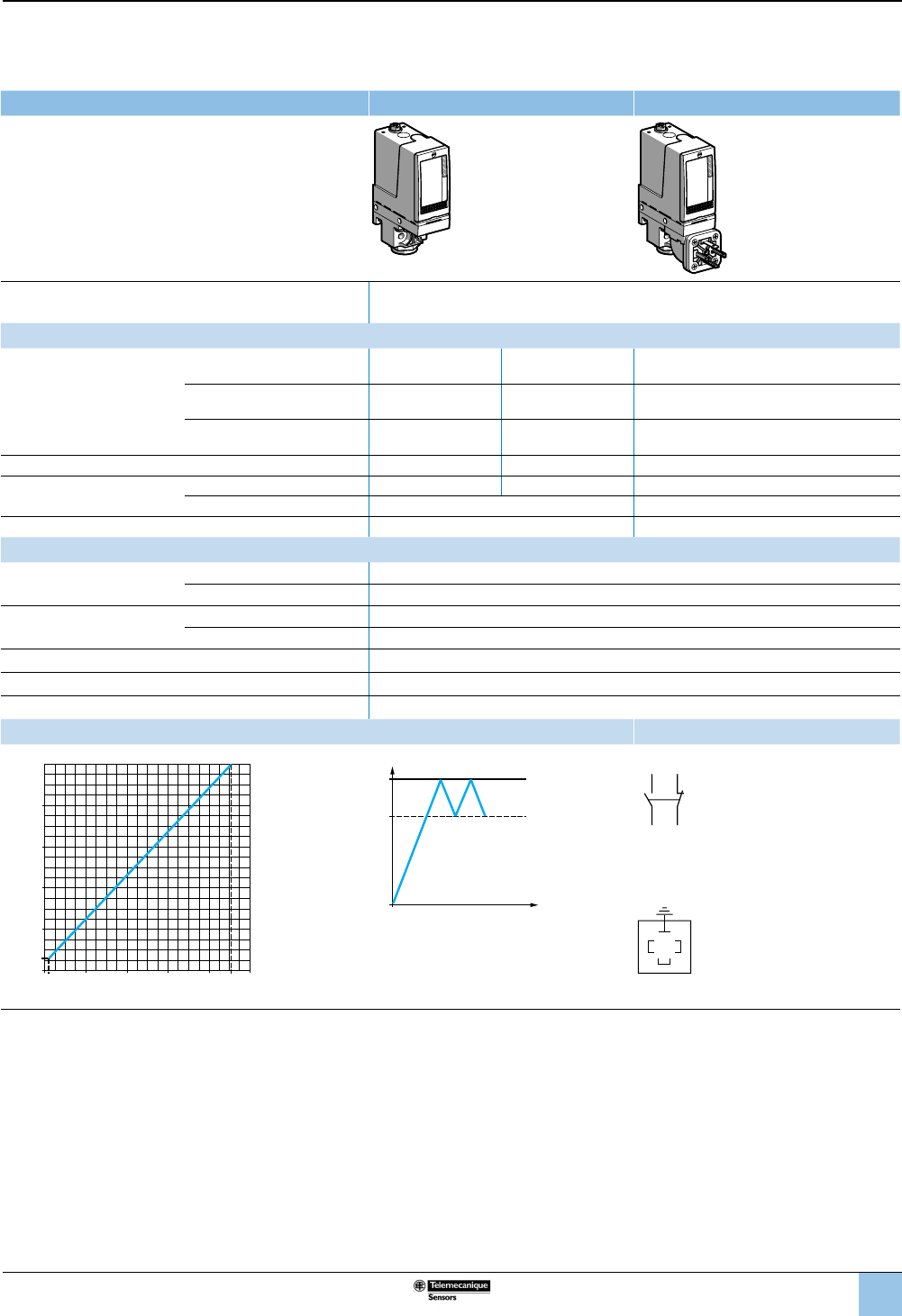
69
1
2
3
4
5
6
8
9
10
7
Size 500 bar (7250 psi)
Fixed differential, for detection of a single threshold
1 C/O single-pole contact
XMLA pressure switches With setting scale Without setting scale
Adjustable range of operating point (PH)
(rising pressure) 30–500 bar (435–7250 psi)
Catalog numbers (1)
Fluids controlled
For materials in contact with
uid, see page 77.
Only for control of group 2
uids, in accordance with
directive 97/23/EEC.
Hydraulic oils, up to 320 °F
(160 °C) XMLA500D2S13 XMLA500D2S11 XMLA500D2C11
Fresh water, sea water, up to
320 °F (160 °C) XMLA500E2S13 XMLA500E2S11 XMLA500E2C11
Corrosive uids, air, up to
320 °F (160 °C) XMLA500N2S13 XMLA500N2S11 XMLA500N2C11
Pressure connection 1/4”-18 NPTF G 1/4-19 G 1/4-19
Electrical connection Conduit/cable entry 1/2” NPT Pg 13.5 DIN 43650A, 4-pin male
Terminals 1 x 0.2 to 2 x 2.5 mm² (1 x 24 to 2 x 14 AWG) For suitable female connector, see page 73.
Weight, lb (kg) 1.65 (0.750) 1.72 (0.780)
Supplementary specications (not shown under general specications)
Inherent differential
(subtract from PH to get PB)
At low setting 20 bar ±6 (290 psi ±87)
At high setting 45 bar ±10 (652.5 psi ±145)
Maximum allowable
pressure
Per cycle 625 bar (9062.5 psi)
Accidental 1125 bar (16,312.5 psi)
Destruction pressure 2250 bar (32,625 psi)
Mechanical life (depending on the application) 3 x 10⁶ operating cycles
Pressure switch style Piston
Operating curves Connection
bar
bar
0
100 200 400
100
200
300
10
30
300
400
500
455
Rising pressure
Falling pressure
PH
PB
Time
Pressure
–– Adjustable value
--- Nonadjustable value
Terminal model
1314
12 11
Connector model
Pressure switch connector pin view
3
21
1 →
11 and 13
2 →
12
3 →
14
Other versions For switches with alternative tapped cable entries, consult the Customer Care Center.
OsiSense XML
Electromechanical
pressure and vacuum switches
Selection and
specications (continued)
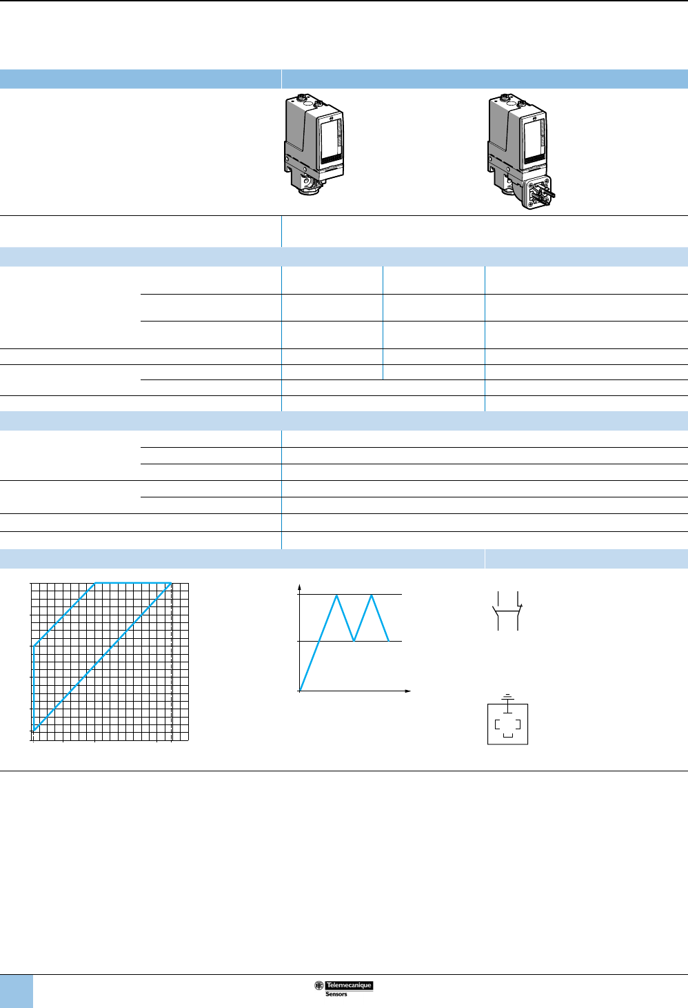
70
1
2
3
4
5
6
8
9
10
7
Size 500 bar (7250 psi)
Adjustable differential, for regulation between two thresholds
1 C/O single-pole contact
XMLB pressure switches With setting scale
Adjustable range of operating point (PH)
(rising pressure) 30–500 bar (435–7250 psi)
Catalog numbers
Fluids controlled
For materials in contact with
uid, see page 77.
Only for control of group 2
uids, in accordance with
directive 97/23/EEC.
Hydraulic oils, up to 320 °F
(160 °C) XMLB500D2S13 XMLB500D2S11 XMLB500D2C11
Fresh water, sea water, up to
320 °F (160 °C) XMLB500E2S13 XMLB500E2S11 XMLB500E2C11
Corrosive uids, air, up to
320 °F (160 °C) XMLB500N2S13 XMLB500N2S11 XMLB500N2C11
Pressure connection 1/4”-18 NPTF G 1/4-19 G 1/4-19
Electrical connection Conduit/cable entry 1/2” NPT Pg 13.5 DIN 43650A, 4-pin male
Terminals 1 x 0.2 to 2 x 2.5 mm² (1 x 24 to 2 x 14 AWG) For suitable female connector, see page 73.
Weight, lb (kg) 1.65 (0.750) 1.72 (0.780)
Supplementary specications (not shown under general specications)
Possible differential
(subtract from PH to get PB)
Min. at low setting 23 bar, –2.6, +3.8 (333.5 psi, –37.7, +55.1)
Min. at high setting 52.6 bar, –14.8, +11.2 (762.7 psi, –214.6, +162.4)
Max. at high setting 300 bar (4350 psi)
Maximum allowable
pressure
Per cycle 625 bar (9062.5 psi)
Accidental 1125 bar (16,312.5 psi)
Destruction pressure 2250 bar (32,625 psi)
Pressure switch style Piston
Operating curves Connection
1 Maximum
differential
2 Minimum
differential
PH
PB
Time
Pressure
–– Adjustable value
Terminal model
1314
12 11
Connector model
Pressure switch connector pin view
3
21
1 →
11 and 13
2 →
12
3 →
14
Other versions For switches with alternative tapped cable entries, consult the Customer Care Center.
ba
r
bar
0
100200 447.4400
100
200
300
7
30
400
500
2
1
Rising pressure
Falling pressure
OsiSense XML
Electromechanical
pressure and vacuum switches
Selection and
specications (continued)
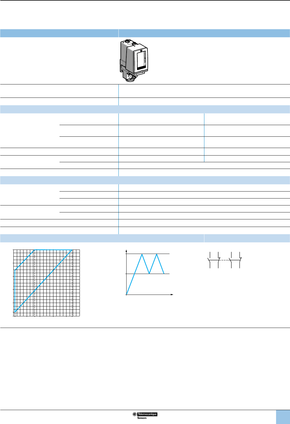
71
1
2
3
4
5
6
8
9
10
7
Size 500 bar (7250 psi)
Adjustable differential, for regulation between 2 thresholds
2 C/O single-pole contacts
XMLC pressure switches With setting scale
Adjustable range of operating point (PH)
(rising pressure) 30–500 bar (435–7250 psi)
Electrical connection Terminals
Catalog numbers
Fluids controlled
For materials in contact with
uid, see page 77.
Only for control of group
2 uids, in accordance with
directive 97/23/EEC.
Hydraulic oils, up to 320 °F
(160 °C) XMLC500D2S13 XMLC500D2S11
Fresh water, sea water, up to
320 °F (160 °C) XMLC500E2S13 XMLC500E2S11
Corrosive uids, air, up to
320 °F (160 °C) XMLC500N2S13 XMLC500N2S11
Pressure connection 1/4”-18 NPTF G 1/4-19
Electrical connection Conduit/cable entry 1/2” NPT Pg 13.5
Terminals 1 x 0.2 to 2 x 2.5 mm² (1 x 24 to 2 x 14 AWG)
Weight, lb (kg) 1.65 (0.750)
Supplementary specications (not shown under general specications)
Possible differential
(subtract from PH to get PB)
Min. at low setting 19 bar ±0.9 (275.5 psi ±13.05)
Min. at high setting 52 bar ±0.9 (754 psi ±13.05)
Max. at high setting 340 bar (4930 psi)
Maximum allowable
pressure
Per cycle 625 bar (9062.5 psi)
Accidental 1125 bar (16,312.5 psi)
Destruction pressure 2250 bar (32,625 psi)
Pressure switch style Piston
Operating curves Connection
1 Maximum
differential
2 Minimum
differential
PH
PB
Time
Pressure
–– Adjustable value
Terminal model
2324
22 21
1314
12 11
Other versions For switches with alternative tapped cable entries, consult the Customer Care Center.
ba
r
bar
0
100 160 300 448400
100
200
300
11
30
400
500
2
1
200
Rising pressure
Falling pressure
OsiSense XML
Electromechanical
pressure and vacuum switches
Selection and
specications (continued)
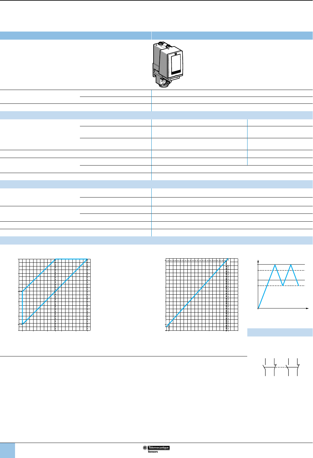
72
1
2
3
4
5
6
8
9
10
7
Size 500 bar (7250 psi)
Dual-stage, xed differential, for detection at each threshold
2 C/O single-pole contacts (one per stage)
XMLD pressure switches Without setting scale
Adjustable range of each
operating point (rising pressure)
2nd stage operating point (PH2) 41–500 bar (594.5–7250 psi)
1st stage operating point (PH1) 25–484 bar (362.5–7018 psi)
Spread between the two stages (PH2–PH1) 16–244 bar (232–3538 psi)
Catalog numbers
Fluids controlled
For materials in contact with uid, see
page 77.
Only for control of group 2 uids, in
accordance with directive 97/23/EEC.
Hydraulic oils, up to 320 °F (160 °C) XMLD500D1S13 XMLD500D1S11
Fresh water, sea water, up to 320 °F
(160 °C) XMLD500E1S13 XMLD500E1S11
Corrosive uids, air, up to 320 °F
(160 °C) XMLD500N1S13 XMLD500N1S11
Pressure connection 1/4”-18 NPTF G 1/4-19
Electrical connection Conduit/cable entry 1/2” NPT Pg 13.5 conduit/cable entry
Terminals 1 x 0.2 to 2 x 2.5 mm² (1 x 24 to 2 x 14 AWG)
Weight, lb (kg) 1.65 (0.750)
Supplementary specications (not shown under general specications)
Inherent differential
(subtract from PH1/PH2
to get PB1/PB2)
At low setting 21 bar ±3 (304.5 psi ±43.5)
At high setting 65 bar ±10 (942.5 psi ±145)
Maximum allowable pressure Per cycle 625 bar (9,062.5 psi)
Accidental 1125 bar (16,312.5 psi)
Destruction pressure 2250 bar (32,625 psi)
Pressure switch style Piston
Operating curves
High setting trip points of contacts 1 and 2 Inherent differential of contacts 1 and 2
bar
bar
0
100 200 256 300 484400
100
200
273.5
300
25
41
400
500
2
1
PH2 setting (rising pressure)
PH1 setting (rising pressure)
1 Maximum differential
2 Minimum differential
bar
bar
0
100 200 419
100
200
300
420
25
41
300
400
484
435
G
E
F
H
Rising pressure
Falling pressure
EF Contact 1 (stage 1)
GH Contact 2 (stage 2)
PH2
PH1
PB1
PB2
Time
Pressure
–– Adjustable value
--- Nonadjustable value
Connection
Terminal model
Contact 2
(stage 2)
Contact 1
(stage 1)
Other versions
For switches with alternative tapped cable entries, consult the Customer Care Center.
2324
22 21
1314
12 11
OsiSense XML
Electromechanical
pressure and vacuum switches
Selection and
specications (continued)
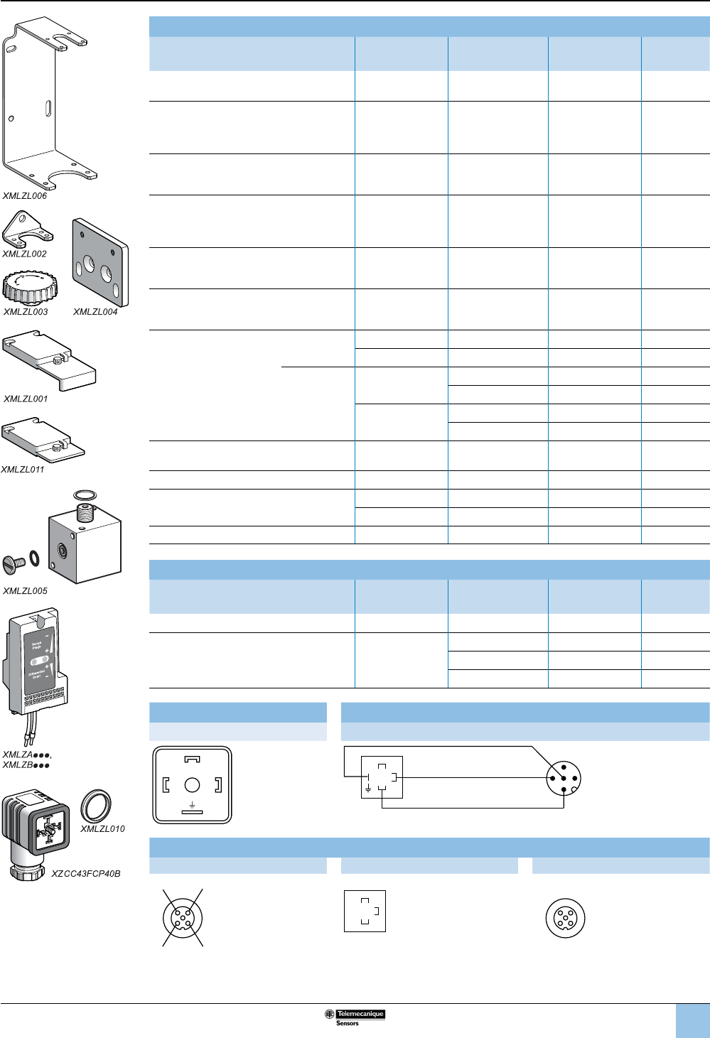
73
1
2
3
4
5
6
8
9
10
7
Accessories for pressure switches and vacuum switches
Description Specic
characteristics
For use with
switches
Catalog
number
Weight
lb (kg)
Rear xing bracket
for vibrations > 2 gn —XML•L35
XML•001 XMLZL006 0.51 (0.230)
Additional top support bracket
for vibrations > 4 gn —
XMLAM01
XML•M05
XMLA004
XML•010 to XML•500
XMLZL002 0.04 (0.020)
Knurled adjustment knob, Ø36 mm
ts over adjustment screw(s) to facilitate
setting
—All models XMLZL003 0.022 (0.010)
Mounting plate
for replacing an XMJA or XMGB switch
by an XML switch
—
XMLAM01
XML•M05
XMLA004
XML•010 to XML•500
XMLZL004 0.024 (0.110)
Lead sealable protective cover
to prevent unauthorized access to adjustment
screws and xing screw of switch cover
—XMLA
XMLB XMLZL001 0.08 (0.035)
Lead sealable protective cover
to deter unauthorized access to the
adjustment screws
—All models XMLZL011 0.07 (0.030)
Indicator modules and
associated covers, 2 LEDs
(orange and green)
Without setting
scale
24/48 Vac/Vdc XMLA/B XMLZZ024 0.20 (0.090)
110/240 Vac XMLA/B XMLZZ120 0.20 (0.090)
With setting
scale
24/48 Vac/Vdc XMLA XMLZA024 0.20 (0.090)
XMLB XMLZB024 0.20 (0.090)
110/240 Vac XMLA XMLZA120 0.20 (0.090)
XMLB XMLZB120 0.20 (0.090)
Hydraulic block
for base mounting directly onto uid manifold —All models XMLZL005 0.53 (0.240)
Female connector, DIN 43650A — XML••••••C11 XZCC43FCP40B 0.08 (0.035)
Jumper cables, DIN 43650A -
M12, straight male, for splitter boxes
1 m XML••••••C11 XZCR1523062K1 0.18 (0.080)
2 m XML••••••C11 XZCR1523062K2 0.024 (0.110)
Adapter, G 1/4" – G 3/8" male/female —All models XMLZL012 0.29 (0.130)
Renewal parts
Description Specic
characteristics
For use with
switches
Catalog
number
Weight
lb (kg)
Sealing gasket For sizes u 300 bar XMLA/B/C/D XMLZL010 0.03 (0.015)
Diaphragms —
XML•S35 XMLZL013 0.13 (0.060)
XML•S02 XMLZL014 0.09 (0.040)
XML•S04 XMLZL015 0.07 (0.030)
Connector pinout Jumper cables, DIN 43650A, M12 straight male
XZCC43FCP40B XZCR15230D62K•
3
12
3
12
3
1
4
1ÊÊ
5
2
4
Cable connections
XZCPV, XZCP XZCC43F XZCC12F
21
BU BK
WH BN
3
21
4
BU BK
WH BN
1
2
3
21
3
21
4
OsiSense XML
Electromechanical
pressure and vacuum switches
Accessories
Selection and
specications (continued)
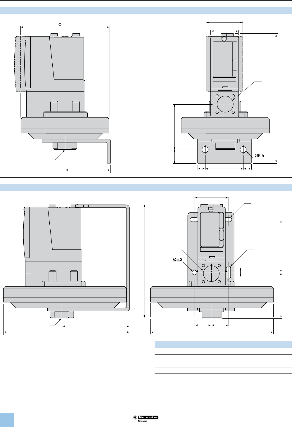
74
1
2
3
4
5
6
8
9
10
7
XML•L35, XML•001, XML•S
(1) 1 uid entry, tapped G 1/4 (BSP female) (1) 1 electrical connection entry, tapped M20 x 1.5, Pg 13.5, or 1/4"-18 NTP
XMLBM03, XMLBL05
(1) 1 uid entry, tapped G 1/4 (BSP female)
(2) 1 electrical connection entry, tapped M20 x 1.5, Pg 13.5, or 1/2" NTP
(3) 2 elongated holes Ø10.2 x 5.2 (0.40 x 0.20)
(4) 1 elongated hole Ø15.2 x 5.2 (0.60 x 0.20)
XML Øa c1 c2
BM03 150 (5.91) 155.5 (6.12) 80.5 (3.17)
BL05 200 (7.87) 204 (8.03) 104 (4.09)
•L35, •001 110 (4.33) — —
•S35, •S02, •S04 110 (4.33) — —
•S10, •S20 86 (3.39) — —
56.5 (2.22)
17
(0.67)
45
(1.77)
==
57
2.24
(1)
(2)
XMLC/D: 46 (1.81)
XMLA/B: 35 (1.38)
max: 162 (6.38)
aDim.: mm (in.)
(0.26)
OsiSense XML
Electromechanical
pressure and vacuum switches
Dimensions
c1
40
(1.57)
20
(0.79)
20
(0.79)
145
(5.71)
56
(2.20)
65
(2.56)
10
(0.39)
(3)
(4)
c2
(1)
(2)
Øa
0.20
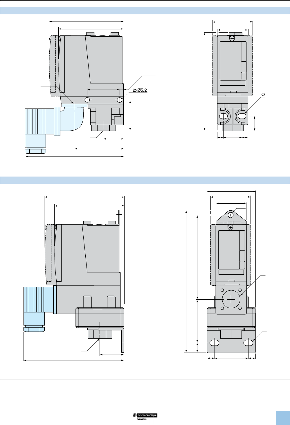
75
1
2
3
4
5
6
8
9
10
7
XMLAM01, XMLBM05, XMLCM05, XMLA004, XML•010 to 500
37
(1.46)
(2)
XMLA/B: 75 (2.95)
23
(0.91)
(1)
37
(1.46)
5
(0.197)
56
(2.20)
120
(4.72)
XMLC/D: 46 (1.81)
XMLA/B: 35 (1.38)
20–22
(0.79–0.87)
==
113
(4.45)
17.5
(0.69)
XMLC/D: 85 (3.35)
DIN connector
(0.205)
(1) 1 uid entry, tapped G 1/4 (BSP female)
(2) 1 electrical connection entry, tapped M20 x 1.5, Pg 13.5, or 1/4"-18 NTP
Ø: 2 elongated holes, Ø5.2 x 6.7
XML•M02, XML•002, XMLB004, XMLC004, XMLD004
(1) 1 uid entry, tapped G 1/4 (BSP female)
(2) 1 electrical connection entry, tapped M20 x 1.5, Pg 13.5, or 1/4"-18 NTP
Ø: 2 elongated holes, Ø10.2 x 5.2
XMLA/B: 77.5 (3.05)
XMLC/D: 46 (1.81)
XMLA/B: 35 (1.38)
XMLC/D: 90 (3.54)
13
(0.51)
34
(1.34)
55 (2.17)
37–40
(1.46–1.57)
==
30
(1.18)
158
(6.22)
Ø
(2)
(1)
122
(4.80)
Ø5.2
(0.20)
106
(4.17)
OsiSense XML
Electromechanical
pressure and vacuum switches
Dimensions (continued)
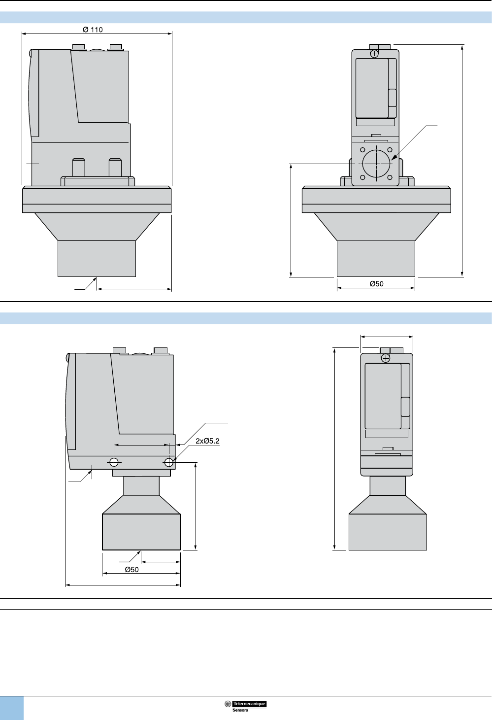
76
1
2
3
4
5
6
8
9
10
7
XMLBL35P, XMLB001P (viscous products)
(1) 1 uid entry, tapped G 1-1/4 (BSP female). (2) 1 electrical connection entry, tapped M20 x 1.5 or Pg 13.5.
XMLBM05P, XMLA004P, XML•010P, XML•020P, XML•035P (viscous products)
(1) 1 uid entry, tapped G 1-1/4 (BSP female). (2) 1 electrical connection entry, tapped M20 x 1.5 or Pg 13.5.
86.5
(3.41)
175
(6.89)
55
(2.17)
(1)
(2)
(4.33)
(1.97)
130
(5.12)
54
(2.13)
(2)
76
(2.99)
35
(1.38)
25
(0.98)
(1)
37
(1.46)
5
(0.197)
(1.97)
(0.205)
OsiSense XML
Electromechanical
pressure and vacuum switches
Dimensions (continued)
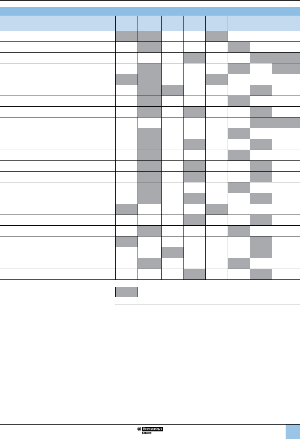
77
1
2
3
4
5
6
8
9
10
7
Component Materials in Contact with Fluid
Pressure or vacuum switch catalog number Zinc
alloy
Stainless
steel Brass Steel Nitrile PTFE FPM,
FKM Aluminium
XMLAM01V••••, XML•M02V•••• (1)
XMLAM01T••••, XML•M02T•••• (2)
XMLBM03R••••
XMLBM03S•••• (3)
XML•M05A•••• (1)
XML•M05B•••• (1)
XML•M05C•••• (1)
XMLBM05••••• (1)
XMLBL05R••••
XMLBL05S•••• (3)
XML•L35R••••, XML•S35R•••• (1)
XML•L35S•••• (3)
XMLBL35P•••• (1)
XML•001R•••• (1)
XML•001S•••• (3)
XMLB001P•••• (1)
XML•002A••••
XML•002B••••, XML•S02B••••
XML•002C•••• (3)
XMLA004A••••
XMLA004B••••
XMLA004C•••• (2)
XMLA004P••••
Materials in contact with uid
(1) 1.4307 (AISI 316L)
(2) 1.4404 (AISI 316L)
(3) 1.4305 (AISI 303)
OsiSense XML
Electromechanical
pressure and vacuum switches
Materials in contact
with uid
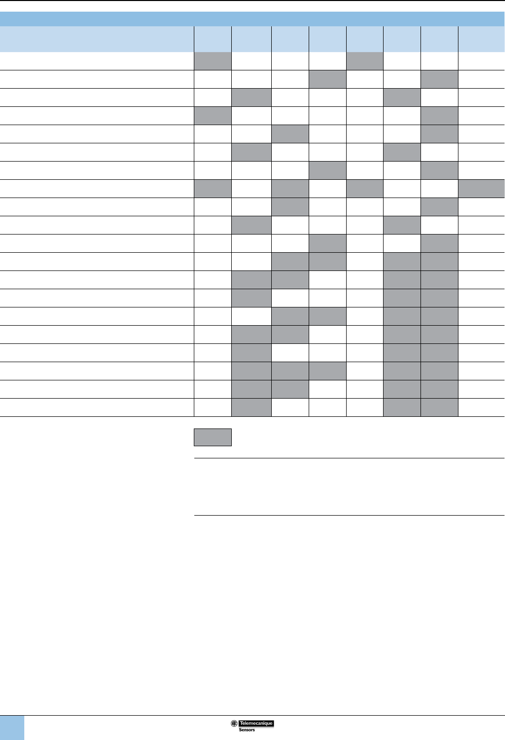
78
1
2
3
4
5
6
8
9
10
7
OsiSense XML
Electromechanical
pressure and vacuum switches
Materials in contact
with uid (continued)
Component Materials in Contact with Fluid (continued)
Pressure switch catalog number Zinc
alloy
Stainless
steel Brass Steel Nitrile PTFE FPM,
FKM Aluminium
XMLB004A••••
XML•004B••••, XML•S04B••••
XML•004C•••• (3)
XML•010A••••
XML•010B••••
XML•010C•••• (2)
XML•010P••••, XML•S10A••••
XML•020A••••, XML•035A••••
XML•020B••••, XML•035B••••
XML•020C••••, XML•035C•••• (2)
XML•020P••••, XML•035P••••, XML•S20A••••
XML•070D••••, XML•160D••••
XML•070E••••, XML•160E•••• (4)
XML•070N••••, XML•160N•••• (5)
XML•300D••••
XML•300E•••• (4)
XML•300N•••• (5)
XML•500D••••
XML•500E••••
XML•500N••••4 (5)
Materials in contact with uid
Grade of Stainless Steel
(1) 1.4307 (AISI 316L)
(2) 1.4404 (AISI 316L)
(3) 1.4305 (AISI 303)
(4) 1.4404 (AISI 316L) + 1.4462
(5) 1.4404 (AISI 316L) + 1.4305 (AISI 303)
1
2
3
4
5
6
8
9
10
7
8/79
™
The 9012G pressure switches are UL Listed and CSA certied as industrial control
equipment. They are used to interface pneumatic or hydraulic systems with electrical
control systems by opening or closing electrical contacts in response to pressure
changes in the system. They have outstanding repeatability and drift performance.
Their efcient design uses durable, low mass components for excellent performance
under heavy duty vibration and shock conditions.
The 9012G pressure switches line offers devices with either diaphragm or piston
actuators—for optimum life, versatility, and speed of operation. Features include the
following:
b High shock resistance b Dual numerical range scale (psi and kPa)
b High set-point stability b One or two SPDT double-break contacts
b Internal or external range
adjustment
b Adjustable or xed (nonadjustable)
differential
b No drain line required b Single-stage, dual-stage, or differential-
pressure operation
A variety of modications is available (see also page 12):
The 9012G diaphragm switches range from 0.2–675 psi falling pressure. Nitrile
diaphragms and zinc-plated steel anges are standard. Diaphragms of Viton®
uorocarbon or ethylene propylene are available as well as stainless steel anges.
The 9012G piston-actuated switches range from 20–9,000 psi falling pressure.
They have sealed pistons and can be used on air, water, oil, or any media compatible
with the actuator material. The switches come standard with stainless steel pistons
and housings, Viton diaphragms and O-ring seals, and Teon® retaining rings.
Ethylene propylene diaphragms and O-ring seals are also available.
The 9012G industrial pressure switches are available as open type or in NEMA 1
enclosures. The backplate is steel with a plastic cover. Open devices in pressure
ranges up to 250 psi are available with internal- or external-threaded pressure
connectors, ideally suiting them for panel mounting.
The 9012G machine tool pressure switches with NEMA 4, 4X, or 13 (IP66) cast
aluminum enclosures are UL Listed and CSA certied as industrial control
equipment. They are also UL Marine Listed for use on vessels greater than 65 ft long
where ignition protection is not required.
The 9012G machine tool switches are also available in NEMA 7 & 9 cast aluminum
enclosures. These are UL Listed for use in Class I, Divisions 1 and 2, Groups C and
D, and Class II, Divisions 1 and 2, Groups E, F, G hazardous locations.
Application and general information
9012 pressure switches can generally be used in any application where electrical
contacts must open or close in response to a system pressure change, within the
electrical and pressure ratings of the switch. Pressure switches are used in a wide
variety of applications such as the following:
b compressed air systems b stamping presses
b HVAC equipment b automatic grinders
b chillers b welders
b pumping systems b process equipment
b machine tools b molding machines
Pressure switches typically perform one of the following two functions:
Monitoring the pressure in the system. The switch can be used either as an interlock
that sequences operations in an automatic system, or to give an audio or visual
signal, typically an alarm of an undesired condition, at predetermined pressures. A
switch with a xed differential is generally used in these applications.
Controlling the pressure in the system by starting and stopping a pump or a
compressor at predetermined pressures. A switch with an adjustable differential is
usually needed in these applications.
9012G and 9016G
Industrial pressure and vacuum switches
9012G pressure switches
Introduction
Introduction
1
2
3
4
5
6
8
9
10
7
8/80
™
Diaphragm life
The elastomer diaphragms used on 9012G switches can withstand high speed
cycling and wide pressure changes. They can tolerate operating speeds up to 200
cycles per minute with no negative impact on the life of the diaphragm.
Diaphragm life is affected by pressure medium compatibility. Standard diaphragms
on 9012G devices are nitrile in zinc-plated steel anges. Also available are Viton
uorocarbon and ethylene propylene diaphragms, as well as Type 316 stainless
steel anges.
The diaphragm can withstand wide pressure changes on each operating cycle.
However, the pressure applied to the diaphragm during the normal operating cycle
should never exceed the maximum value listed in the Range column in the catalog
listing. Regularly cycling the pressure above this value reduces life considerably. If
signicant surges are common, or if pressures are higher than those listed in the
Range column, consider using a piston device.
Piston life
For long piston life, the pressure medium should be ltered to keep foreign matter
such as dirt and chips out of the piston assembly. 9012G sealed piston devices are
not recommended for use on dry gas media, since this usage could cause some
leakage past the seal. Depending on the gas, the media pressure, and the rate of
operation, the amount of leakage could render the switch inoperable. (Note,
however, that some weepage of the media is necessary to lubricate the seals. This
small amount of weepage does not indicate a problem.)
Surges
One of the most destructive conditions for a pressure switch is hydraulic surge. A
surge is a high rate of rise in pressure, normally of short duration, caused by starting
a pump or by opening and closing a valve. Extremely high rates of rise in pressure
can be damaging even if they are within the limits of the maximum allowable
pressure.
To limit the effect of surges, the switch should be mounted as close to an
accumulator and as far from the pump or quick acting valve as possible. The 9012G
piston-actuated switches have a 0.020 in. pressure orice to help reduce the effects
of minor surges. 9012G diaphragm-actuated switches have a 0.060 in. pressure
orice. A restrictor with a small orice placed in the line between the switch and the
pump or valve will further help to protect the switch. Using a surge snubber such as
the 9049A26 or A26S will also protect the switch.
Vibration
Among other things, excessive vibration can cause contact bounce, chatter, or
premature contact transfer, especially when system pressure is near the operating
point of the switch. Remote mounting of the switch is the best way to avoid problems.
Use on steam
Switches should not be applied directly on steam exceeding 15 psig. However, with
steam capillary tubing installed between the pressure connection and the switch,
steam pressure up to 250 psig can be applied—provided this does not exceed the
maximum allowable pressure rating of the switch or the maximum temperature rating
at the actuator. Refer to the instruction bulletin supplied with the device.
Dual-stage operation
The 9012G dual-stage pressure switches provide two distinct levels of control from
one device. These switches are most commonly used where dual functions are
required, or in sequencing applications such as alarm-shutdowns.
Differential-pressure operation
The 9012G pressure switches for differential-pressure sensing can monitor changes
in the difference between two pressures. These unidirectional devices signal that a
predetermined pressure difference was reached, resulting from a widening or
narrowing of the difference between two pressures.
9012G and 9016G
Industrial pressure and vacuum switches
9012G pressure switches
Introduction (continued)
1
2
3
4
5
6
8
9
10
7
8/81
™
Piston- vs. diaphragm-actuated devices
Whether to select a piston or diaphragm device depends on several criteria:
b maximum allowable pressure
b range and differential
b surges
b medium (whether hydraulic or pneumatic)
Maximum allowable pressures for piston devices are much higher than for
diaphragm devices. Most diaphragm devices have a maximum allowable pressure of
850 psi or less, whereas all piston devices have a maximum allowable pressure of
10,000 psi or more.
Range and differential for diaphragm devices are lower than for piston devices.
Many applications call for a low differential, such as 20 psi. This may exclude piston
devices, which have a minimum differential of 60 psi or more.
Surges are a part of every hydraulic system. While many are small and have only a
small effect on the switch, some are signicant and can potentially destroy a
pressure switch. Diaphragm devices are the most sensitive to surges and are most
easily damaged. Piston devices are more tolerant of surges and last longer in the
same application.
Hydraulic systems, which typically use oil-based media, are more demanding
applications than pneumatic systems. Pressure switches used in hydraulic
applications typically experience higher pressures, have wider pressure variations,
and produce more surges, since the medium does not compress. Pneumatic
systems, which typically use air, place fewer demands on a system, since these
applications typically experience lower pressures and the medium can compress,
cushioning the effects of surges. Table 1 offers basic guidelines for determining the
selection of a piston- versus a diaphragm-operated pressure switch.
Piston vs. diaphragm
Maximum allowable pressures High Piston
Lower Diaphragm
Pressures High pressures Piston
Low differentials or pressures Diaphragm
Surges Constant Piston
Minimal Diaphragm or piston
Media Hydraulic systems Piston
Pneumatic systems Diaphragm
Operating points (set points)
Pressure switches have two operating points:
b Increasing pressure (rising pressure)
b Decreasing pressure (falling pressure)
These operating points are also called the set points of the switch.
Differential
The differential is the difference in pressure between the rising and falling pressure
points. It can be adjustable or xed.
Range
The range refers to the pressure limits within which the operating points (settings)
can be adjusted. The range of the 9012G pressure switch is tied to the decreasing
pressure operating point. Adding the differential to the decreasing pressure
operating point determines the increasing pressure operating point.
9012G and 9016G
Industrial pressure and vacuum switches
9012G pressure switches
Introduction (continued),
technical overview
Technical overview
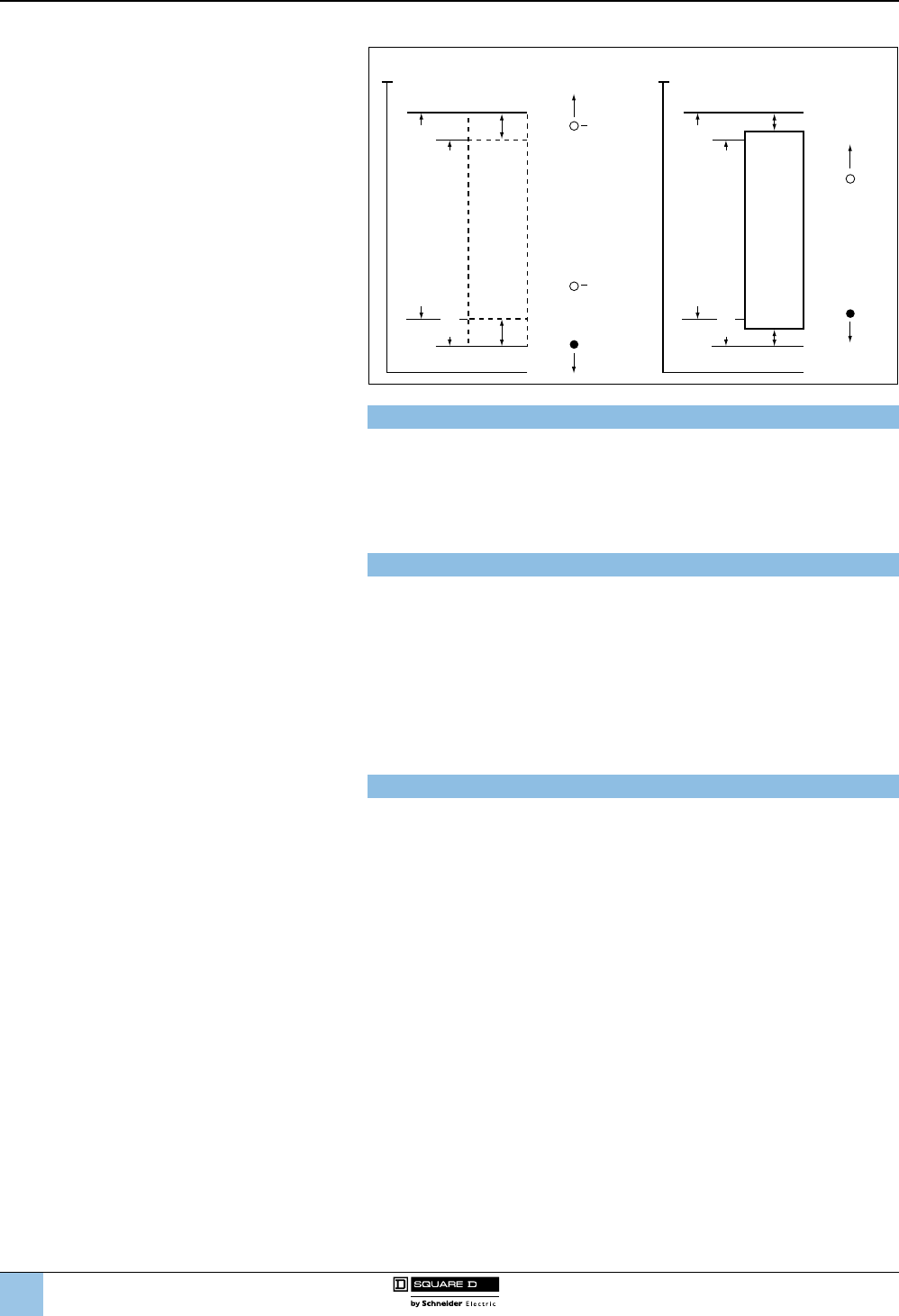
1
2
3
4
5
6
8
9
10
7
8/82
™
Differential
Fixed differential
To determine the operating range on rising pressure for a xed differential switch,
add the differential to the decreasing pressure operating point. For example, to
determine the range on increasing pressure for a 9012GDW5 switch:
b Range on decreasing pressure = 3 to 150 psi
b Fixed differential = 6.0 ± 0.8 psi
b Range on increasing pressure = 9 ± 0.8 to 156 ± 0.8 psi
Adjustable differential
For adjustable differential switches, add the minimum differential to the low end of
the range and the maximum differential to the high end of the range. For example, to
determine the range on increasing pressure for a 9012GAW5:
b Range on decreasing pressure = 3 to 150 psi
b Adjustable differential = 6.0 to 30 psi
b Range on increasing pressure = 9 to 180
During the normal operating cycle, system pressure should never exceed the upper
limit of the range when using a diaphragm-actuated switch. This greatly reduces the
life of the diaphragm. For optimum life, operate the switch in the middle 80% of the
range.
Maximum allowable pressure
Maximum allowable pressure is the pressure to which a switch can be subjected
without causing a change in operating characteristics, shift in settings, or damage
to the device.
System pressure surges may occur during machine startup or from valve operation.
Surges are not normally detrimental to the life of a switch if the surge is within the
maximum allowable pressure rating of the switch. Diaphragm-actuated switches
should not be subjected to more than 10 surges per day. More frequent surges
greatly reduce the life of the diaphragm.
9012G and 9016G
Industrial pressure and vacuum switches
9012G pressure switches
Technical overview
(continued)
0 psi
Reset Point
Min.
Trip Point
Max.
Trip Point
Maximum Allowable Pressure
Maximum Allowable Pressure
Adjustable Range—Rising Pressure
Adjustable Range—Falling Pressure
Maximum
Differential
Minimum
Differential
0 psi
Reset Point
Trip Point
Adjustable Range—Rising Pressure
Adjustable Range—Falling Pressure
Adjustable Differential Fixed Differential
Adjustable Differential
Fixed Differential
0 psi
Reset Point
Min.
Trip Point
Max.
Trip Point
Maximum Allowable Pressure
Maximum Allowable Pressure
Adjustable Range—Rising Pressure
Adjustable Range—Falling Pressure
Maximum
Differential
Minimum
Differential
0 psi
Reset Point
Trip Point
Adjustable Range—Rising Pressure
Adjustable Range—Falling Pressure
Adjustable Differential Fixed Differential
Adjustable Differential
Fixed Differential
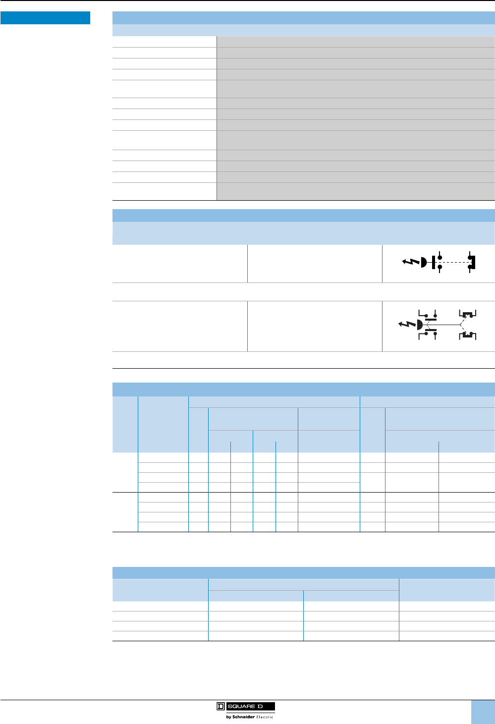
1
2
3
4
5
6
8
9
10
7
8/83
™
Environment
Environmental specications
Conformity to standards CE, IEC 60957.5.1, UL 508, CSA 3211-03
Product certications UL Listed and CSA certied as industrial control equipment
Protective treatment Marine use: HT (does not apply to 9016GVG)
Fluids controlled Air, water, hydraulic oils, gases, steam (depending on the model)
Materials Cast aluminum enclosures
(9012 NEMA 1 and 9016 GVG are stamped metal enclosure and molded cover)
Operating position Operates in all positions
Shock resistance 50 g
Degree of protection Depends on the model
Operating rate
(operating cycles/minute)
120 operations/minute max.
9016GVG: 60 operations/minute max.
Repeat accuracy ±0.1 to ±1.0% (does not apply to 9016GVG)
Drift ±1.0% of the adjustable range over 1 million operations
Pressure connection G1/4 (BSP) female, 1/4"-18 NPTF, or 1/2"-14 NPT
Electrical connection 1/2"-14 NPTF, Pg13.5, or ISO M20 (also, 3/4"-14 NPTF available only on NEMA 7 and 9).
NEMA 1 is 1/2" conduit entry, unthreaded.
Contact arrangement
9012G and 9016G machine tool and vacuum switches (except GVG)
Type Contact arrangement Contact symbol
Single Pole
Double Throw
(SPDT)
1 N.O., 1 N.C.
1
3
2
4
Same
Polarity
Snap switch contains two double-break contact elements (1 N.O., 1 N.C.) that must be used on circuits of the same
polarity.
Double Pole
Double Throw
(DPDT)
2 N.O., 2 N.C.
Same
Polarity
Same
Polarity
1
2
5
6
3
4
7
8
Snap switch contains two electrically separated sets of contact elements allowing use on circuits of opposite polarity. Each
set contains two double-break contact elements (1 N.O. and 1 N.C.) that must be used on circuits of the same polarity.
Circuit ratings
Contacts
Continuous
carrying
amperes
AC—50 or 60 Hz DC
Voltage (V)
Inductive
35% power factor
Resistive, 75%
power factor
Voltage (V)
Inductive and resistive
Make Break Make and
break amperes
Make and break amperes
AVA AVA Single throw Double throw
SPDT
10 120 60 7200 6720 6 125 0.55 0.22
10 240 30 7200 3720 3250 0.27 0.11
10 480 15 7200 1.5 720 1.5 301–
600 (1) 0.10 —
— 600 12 7200 1.2 720 1.2
DPDT
10 120 60 7200 6720 6 125 0.22 0.22
10 240 30 7200 3720 3250 0.11 0.11
10 480 15 7200 1.5 720 1.5 600 — —
— 600 12 7200 1.2 720 1.2 — — —
(1) Continuous carrying ampere rating does not apply.
Acceptable wire sizes: 12–22 AWG. Recommended terminal clamp torque: 7 lb-in
Not recommended for use on circuits below 24 V, 20 mA.
Electrical Ratings—9016GVG
Voltage AC DC
Single Phase Polyphase
110 V 2 hp 3 hp 1 hp
220 V 3 hp 5 hp 1 hp
440–550 V 5 hp 5 hp —
32 V — — 0.5 hp
Note: Control Circuit Rating: A600
9012G and 9016G
Industrial pressure and vacuum switches
9012G pressure and 9016G vacuum switches
Technical overview
(continued)
Specications
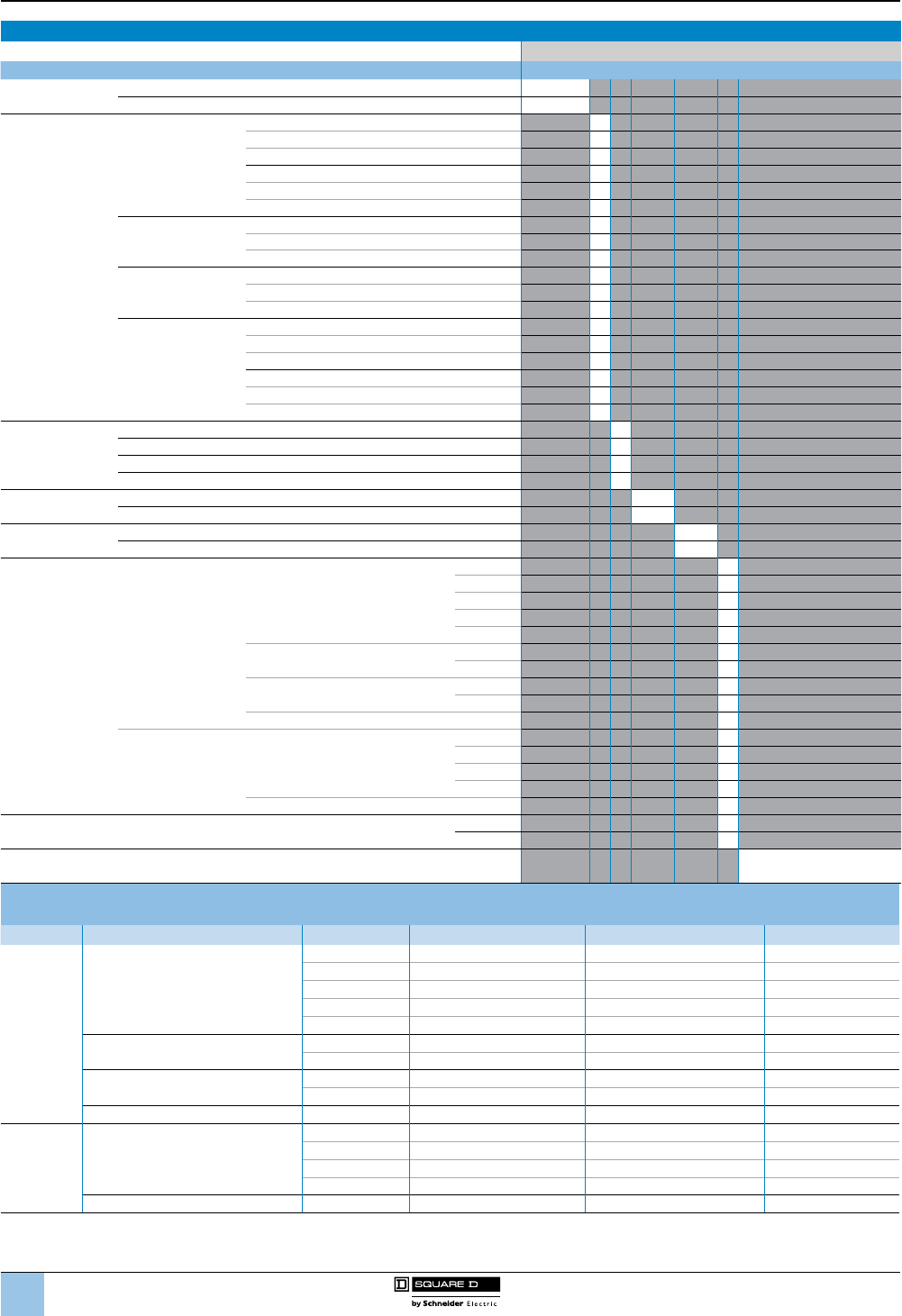
1
2
3
4
5
6
8
9
10
7
8/84
™
Interpreting the catalog number (excluding 9016GVG)
Use this table for interpretation only. Some combinations are not available. 9012G A R 2 2
Designation Catalog number
Classication Pressure Switch 9012G
Vacuum Switch 9016G
Actuator Type—
Differential Type
Single-Stage
Machine Tool
Diaphragm, Low Pressure—Adjustable A
Diaphragm, High Pressure—Adjustable B
Piston—Adjustable C
Diaphragm, Low Pressure—Fixed D
Diaphragm, High Pressure—Fixed E
Piston—Fixed F
Differential-Pressure
Diaphragm, Low Pressure—Adjustable G
Diaphragm, High Pressure—Adjustable H
Piston— Adjustable J
Dual-Stage
Diaphragm, Low Pressure—Adjustable K
Diaphragm, High Pressure—Adjustable L
Piston—Adjustable M
Single-Stage
Industrial
Diaphragm, Low Pressure—Adjustable N
Diaphragm, High Pressure—Adjustable P
Piston—Adjustable Q
Diaphragm, Low Pressure—Fixed R
Diaphragm, High Pressure—Fixed S
Piston—Fixed T
Enclosure,
NEMA Type
1G
Open O
7, 9 R
4, 4X, 13 W
Threads 1/4”-18 NPTF blank
Metric M
Contacts Single-pole, double-throw blank
Double-pole, double-throw 2
Pressure
Range (psi)
Diaphragm
Single or Dual Stage, Low Pressure
0.2–10 1
1–40 2
1.5–75 4
3–150 5
5–250 6
Single or Dual Stage, High Pressure 13–425 1
20–675 2
Differential-Pressure, Low Pressure 0–75 1
0–175 4
Differential-Pressure, High Pressure 0–500 1
Piston Single or Dual Stage
20–1000 1
90–2900 2
170–5600 3
270–9000 4
Differential-Pressure 0–5000 1
Vacuum (inHg) Diaphragm Single Stage, Low Pressure 0–28 1
0–25 2
Options Factory modications and accessories See tables on pages 8/91,
8/93 and 99.
9012G machine tool pressure switches for single-stage operation
Pressure range (psi)—Contacts change on decreasing pressure
Actuator Switch style Range (psi) Fixed differential Adjustable differential Pressure code
Diaphragm
Single or Dual Stage,
Low Pressure
0.2–10 0.6±0.1 0.6–2 1
1–40 1.6±0.4 1.6–8 2
1.5–75 3.0±0.5 3.5–15 4
3–150 6.0±0.8 6.0–30.0 5
5–250 10.0±1.5 10.0–49 6
Single or Dual Stage, High Pressure 13–425 16±3.5 16–90 1
20–675 27±5 27–130 2
Differential-Pressure, Low Pressure 0–75 0.25±10 0.25–10 1
0–175 — 0.5–36 4
Differential-Pressure, High Pressure 0–500 — 3–175 1
Piston Single or Dual Stage
20–1000 89±18 89–200 1
90–2900 255±30 255–560 2
170–5600 578±110 578–1260 3
270–9000 788±140 788–1900 4
Differential-Pressure 0–5000 — 15–825 1
The 9012G single-stage pressure switches are control-circuit rated devices. These switches are used in pneumatic or hydraulic systems on a
wide variety of machine and process applications to protect the equipment. They either control or monitor the system pressure.
9012G and 9016G
Industrial pressure and vacuum switches
9012G pressure switches
Technical overview
(continued)
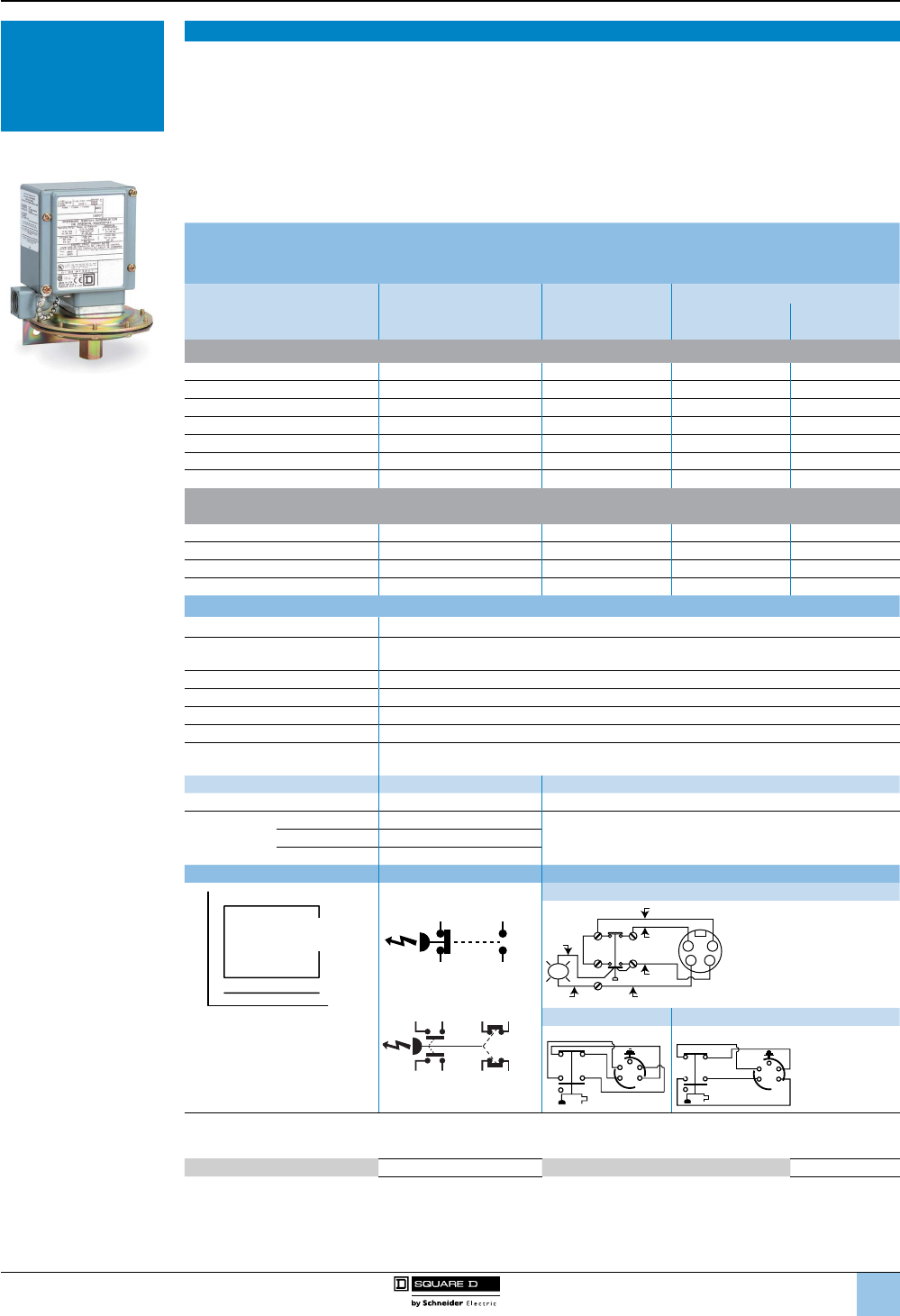
1
2
3
4
5
6
8
9
10
7
8/85
™
Single-Stage Operation
Class 9012 single-stage pressure switches are control circuit rated devices used in pneumatic or hydraulic
systems on a wide variety of machine and process applications to protect the equipment and control or monitor
the system pressure.
■ Type G machine tool switches are available with NEMA 4, 4X, and 13 (IEC IP66) enclosure ratings.
■ The NEMA 7 and 9 devices are UL listed for use in the following hazardous locations: Class I, Divisions 1 and 2,
Groups C and D; and Class II, Divisions 1 and 2, Groups E, F, and G.
■ NEMA 4, 4X, and 13 devices are suitable for use in Class I, Division 2, Groups A, B, C, and D hazardous
locations or nonhazardous locations only.
■ Enclosure materials are cast aluminum.
■ To ensure repeatability and minimize setting drift, pressure settings should fall within the middle 80 percent of
the pressure range.
Fixed differential
NEMA 4, 4X, 13 Enclosure
UL Listed and CSA Certied as Industrial Control Equipment
Range on decreasing
pressure psig
Approximate
differential at
mid-range, psig (1)
Maximum
allowable
pressure, psig
Class 9012 Type
SPDT DPDT
Diaphragm actuated—Nitrile diaphragm, zinc plated steel housing
0.2–10 0.6 ± 0.1 100 GDW1 GDW21
1–40 1.6 ± 0.4 100 GDW2 GDW22
1.5–75 3.0 ± 0.5 240 GDW4 GDW24
3–150 6.0 ± 0.8 475 GDW5 GDW25
5–250 10.0 ± 1.5 750 GDW6 GDW26
13–425 16 ± 3.5 850 GEW1 GEW21
20–675 27 ± 5 2000 GEW2 GEW22
Piston actuated—#440 stainless steel piston
#303 stainless steel housing, Viton® uorocarbon diaphragm and O-ring, Teon® retaining ring
20–1000 59 ± 9 10,000 GFW1 GFW21
90–2900 170 ± 15 15,000 GFW2 GFW22
170–5600 289± 55 20,000 GFW3 GFW23
270–9000 495 ± 70 25,000 GFW4 GFW24
Specications
Fluids controlled Air, water, hydraulic oils, gases, steam (depending on the model)
Pressure connection 1/4”-18 NPTF is standard. For metric threads, add M after the W on all types. (2)
Other options are available (see page 8/91).
Weight (approximate) 3 lb (1.36 kg)
Voltage limits 600 V
Continuous current 10 A
Electrical connections 1/2”-14 NPTF (standard), For Pg 13.5, or ISO M20, see footnote (2).
Standards/Ratings
CE, IEC 60957.5.1, UL 508, CSA 3211-03. UL Marine Listed for use on ships/vessels greater
than 65 ft long where ignition protection is not required.
Temperature ratings Minimum Maximum
Ambient –23 °C (–10 °F) +85 °C (+185 °F)
Media
Diaphragm –40 °C (–40 °F)
+120 °C (+250 °F)Piston –26 °C (–15 °F)
All with Form Q4 –26 °C (–15 °F)
Operating curves Contact blocks Connection
Falling pressure
Ma
x. Differenti
a
l
M
in
. Differen
ti
a
l
Rising Pressure
Fixed
Differential
1 N.O., 1 N.C.
2 N.O., 2 N.C.
Form H17
1
1
2
4
6
82
34
LED
Red
Black
Black
Blue
Brown
White
Form H10 Form H11
ORG
BLK
RED
WHT
GRN
1
26
84
1
2
3
4
5
ORG RED
WHT
BLK
GRN
1
26
8
4
1
2
3
4
5
SPDT snap switches contain two double-break contact elements (1 N.O., 1 N.C.) that must be used on circuits of the same polarity.
DPDT snap switches contain two electrically separated sets of contact elements allowing use on circuits of opposite polarity.
Each set contains two double-break contact elements (1 N.O., 1 N.C.) that must be used on circuits of the same polarity.
Acceptable wire sizes: 12–22 AWG
Recommended terminal clamp torque:
7 lb-in
(1) The differential adds to the range setting and determines the operating point on rising pressure.
(2) To order a Pg13.5 electrical conduit entry and a 1/4"-19 BSP pressure connection, add M12 to the end of the catalog number,
as well as adding “M” after “W” for metric threads. For example:
9012GAW1 = 1/2" NPT electrical conduit entry
9012GAWM1 = 20 x 1.5 mm electrical conduit entry and 1/4”-19 BSP pressure connection
9012GAWM1M12 = Pg13.5 electrical conduit entry and 1/4"-19 BSP pressure connection
1
3
2
4
Same
Polarity
Same
Polarity
Same
Polarity
1
2
5
6
3
4
7
8
9012G and 9016G
Industrial pressure and vacuum switches
9012G machine tool pressure switches
Selection and
specications
9012GDW1
Selection and
specications—
9012G pressure
switches
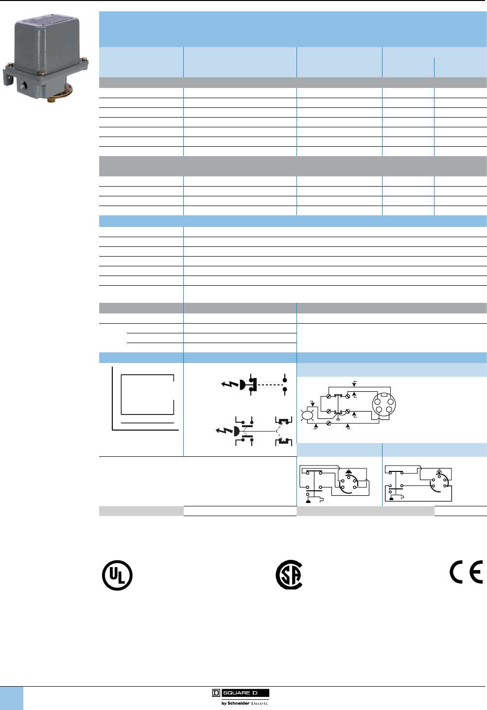
1
2
3
4
5
6
8
9
10
7
8/86
™
Fixed Differential
NEMA 7 & 9 Enclosure, Class I & II, Division 1 & 2, Groups C, D, E, F, G
UL Listed as Industrial Control Equipment
Range on
Decreasing Pressure
psig
Approximate Differential
at Mid Range
psig (1)
Maximum Allowable
Pressure,
psig
Class 9012 Type
SPDT DPDT
Diaphragm Actuated—Nitrile Diaphragm, Zinc Plated Steel Housing
0.2–10 1.0 ± 0.1 100 GDR1 GDR21
1–40 2.4 ± 0.8 100 GDR2 GDR22
1.5–75 4.5 ± 1 240 GDR4 GDR24
3–150 9 ± 1.5 475 GDR5 GDR25
5–250 15 ± 3 750 GDR6 GDR26
13–425 25 ± 7 850 GER1 GER21
20–675 41 ± 10 2000 GER2 GER22
Piston Actuated—#440 Stainless Steel Piston.
#303 Stainless Steel Housing, Viton® Fluorocarbon Diaphragm and O-ring, Teon® Retaining Ring
20–1000 89 ± 18 10,000 GFR1 GFR21
90–2900 255 ± 30 15,000 GFR2 GFR22
170–5600 578 ± 110 20,000 GFR3 GFR23
270–9000 788 ± 140 25,000 GFR4 GFR24
Specications
Fluids Controlled Air, water, hydraulic oils, gases, steam (depending on the model)
Pressure Connection 1/4"-18 NPTF (standard) or 1/2"-14 NPT. See page 8/91.
Weight (approximate) 10 lb (4.54 kg)
Voltage Limits 600 V
Continuous Current 10 A
Electrical Connections 1/2"-14 NPTF, 3/4"-14 NPTF
Standards/Ratings CE, IEC 60957.5.1, UL 508, CSA 3211-03. UL Marine Listed for use on vessels greater than 65 ft long
where ignition protection is required.
Temperature Ratings Minimum Maximum
Ambient –23 °C (–10 °F) +85 °C (+185 °F)
Media
Diaphragm –40 °C (–40 °F)
+120 °C (+250 °F)Piston –26 °C (–15 °F)
All with Form Q4 –26 °C (–15 °F)
Operating Curves Contact Blocks Connection
Falling pressure
Ma
x. Differenti
a
l
M
in
. Differen
ti
a
l
Rising Pressure
Fixed
Differential
1 N.O.,
1 N.C
2 N.O.,
2 N.C.
Form H17
1
1
2
4
6
82
34
LED
Red
Black
Black
Blue
Brown
White
Form H10 Form H11
SPDT snap switches contain two double-break contact elements
(1 N.O., 1 N.C.) that must be used on circuits of the same polarity.
DPDT snap switches contain two electrically separated sets of
contact elements allowing use on circuits of opposite polarity.
Each set contains two double-break contact elements (1 N.O.,
1 N.C.) that must be used on circuits of the same polarity.
ORG
BLK
RED
WHT
GRN
1
26
84
1
2
3
4
5
ORG RED
WHT
BLK
GRN
1
26
8
4
1
2
3
4
5
Acceptable Wire Sizes: 12–22 AWG Recommended Terminal Clamp Torque: 7 lb-in
(1) The differential adds to the range setting and determines the operating point on rising pressure.
NOTE: When pressure settings of the switches must be factory set (Form Y1), and only one setting is identied, specify whether
this setting is on increasing or decreasing pressure.
File E12443 CCN NOWT Haz. Loc., G•R File LR 25490 Class 3211-03 G•W, G•O, G•G
File E12158 CCN NKPZ G•W, G•O, G•G File LR 26817 Class 3218-02 G•R
File E12158 CCN NTHT Marine Use, G•W
1
3
2
4
Same
Polarity
Same
Polarity
Same
Polarity
1
2
5
6
3
4
7
8
9012G and 9016G
Industrial pressure and vacuum switches
9012G machine tool pressure switches
Selection and
specications (continued)
9012GDR
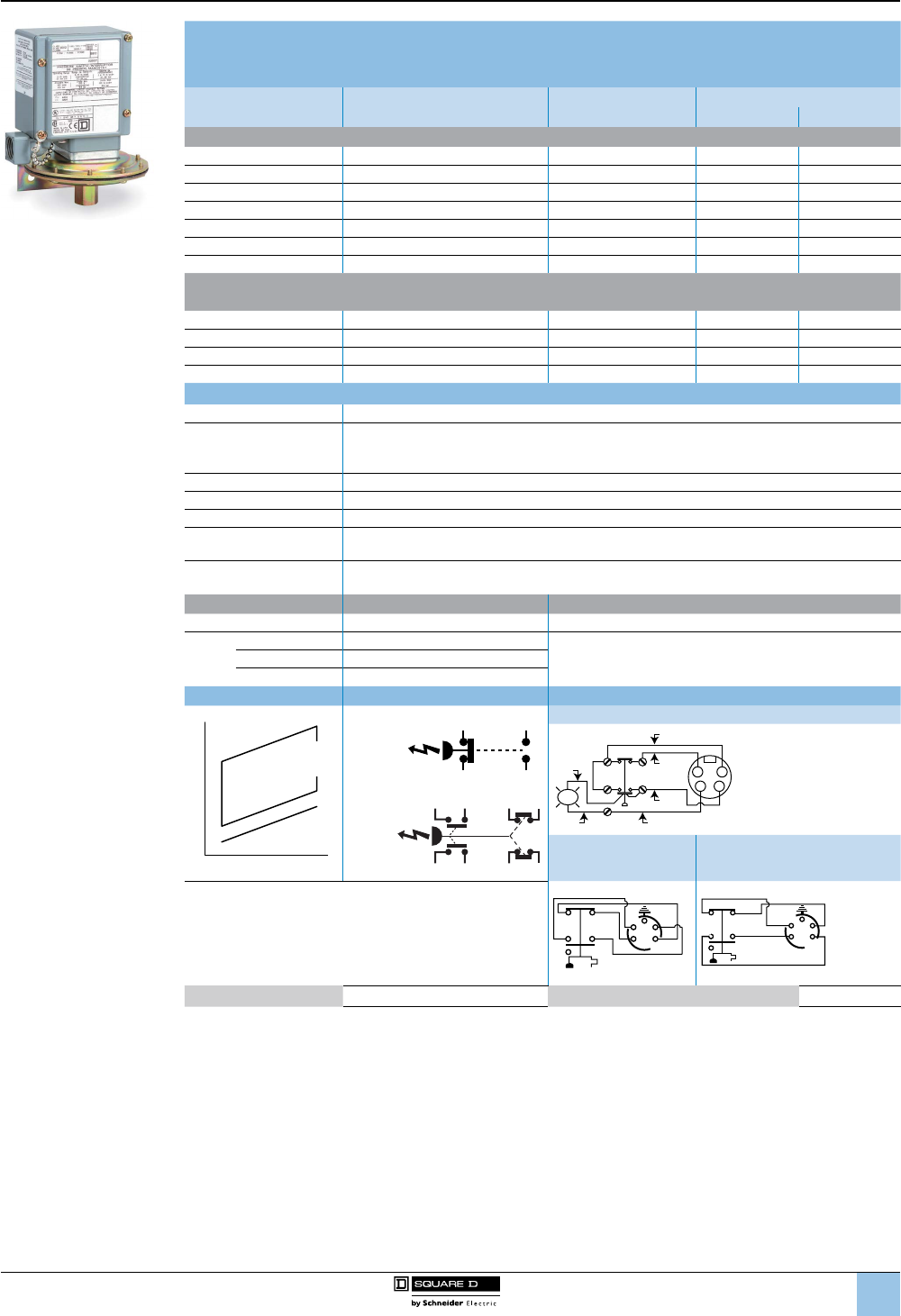
1
2
3
4
5
6
8
9
10
7
8/87
™
Adjustable Differential
NEMA 4, 4X, 13 Enclosure
UL Listed and CSA Certied as Industrial Control Equipment
Range on Decreasing
Pressure, psig
Adjustable Differential (1)
Approximate at Mid Range
Maximum Allowable
Pressure, psig
Class 9012 Type
SPDT DPDT
Diaphragm Actuated—Nitrile Diaphragm, Zinc Plated Steel Housing
0.2–10 0.7–2 100 GAW1 GAW21
1–40 2.4–8 100 GAW2 GAW22
1.5–75 3.9–15 240 GAW4 GAW24
3–150 6.6–30 475 GAW5 GAW25
5–250 11–49 750 GAW6 GAW26
13–425 20–82 850 GBW1 GBW21
20–675 35–130 2000 GBW2 GBW22
Piston Actuated—#440 Stainless Steel Piston.
#303 Stainless Steel Housing, Viton® Fluorocarbon Diaphragm and O-ring, Teon® Retaining Ring
20–1000 65–200 10,000 GCW1 GCW21
90–2900 187–560 15,000 GCW2 GCW22
170–5600 425–1050 20,000 GCW3 GCW23
270–9000 580–1500 25,000 GCW4 GCW24
Specications
Fluids Controlled Air, water, hydraulic oils, gases, steam (depending on the model)
Pressure Connection
1/4”-18 NPTF is standard. For metric threads (G1/4 BSP female pressure connection and M20
electrical connection), add M after the W in the catalog number. For additional pressure
connections, see page 8/91. (1)
Weight (approximate) 3 lb (1.36 kg)
Voltage Limits 600 V
Continuous Current 10 A
Electrical Connections 1/2"-14 NPTF is standard. For metric threads (G1/4 BSP female pressure connection and M20
electrical connection), add M after the W in the catalog number. (2).
Standards/Ratings CE, IEC 60957.5.1, UL 508, CSA 3211-03. UL Marine Listed for use on ships/vessels greater than
65 ft long where ignition protection is not required.
Temperature Ratings Minimum Maximum
Ambient –23 °C (–10 °F) +85 °C (+185 °F)
Media
Diaphragm –40 °C (–40 °F)
+120 °C (+250 °F)Piston –26 °C (–15 °F)
All with Form Q4 –26 °C (–15 °F)
Operating Curves Contact Blocks Connection
1 N.O.,
1 N.C.
2 N.O.,
2 N.C.
Form H17
1
1
2
4
6
82
34
LED
Red
Black
Black
Blue
Brown
White
Form H10 Form H11
SPDT snap switches contain two double-break contact elements
(1 N.O., 1 N.C.) that must be used on circuits of the same
polarity.
DPDT snap switches contain two electrically separated sets of
contact elements allowing use on circuits of opposite polarity.
Each set contains two double-break contact elements (1 N.O.,
1 N.C.) that must be used on circuits of the same polarity.
ORG
BLK
RED
WHT
GRN
1
26
84
1
2
3
4
5
ORG RED
WHT
BLK
GRN
1
26
8
4
1
2
3
4
5
Acceptable Wire Sizes: 12–22 AWG Recommended Terminal Clamp Torque: 7 lb-in
(1) The differential adds to the range setting and determines the operating point on rising pressure.
(2) To order a Pg13.5 electrical conduit entry and a 1/4"-19 BSP pressure connection, add M12 to the end of the catalog number,
as well as adding “M” after “W” for metric threads. For example:
9012GAW1 = 1/2" NPT electrical conduit entry
9012GAWM1 = 20 x 1.5 mm electrical conduit entry and 1/4”-19 BSP pressure connection
9012GAWM1M12 = Pg13.5 electrical conduit entry and 1/4"-19 BSP pressure connection
Falling pressure
Max. Diff
erential
Min. D
i
ff
eren
tial
Rising Pressure
Adjustable
Differential
1
3
2
4
Same
Polarity
Same
Polarity
Same
Polarity
1
2
5
6
3
4
7
8
9012G and 9016G
Industrial pressure and vacuum switches
9012G machine tool pressure switches
Selection and
specications (continued)
9012GAW1
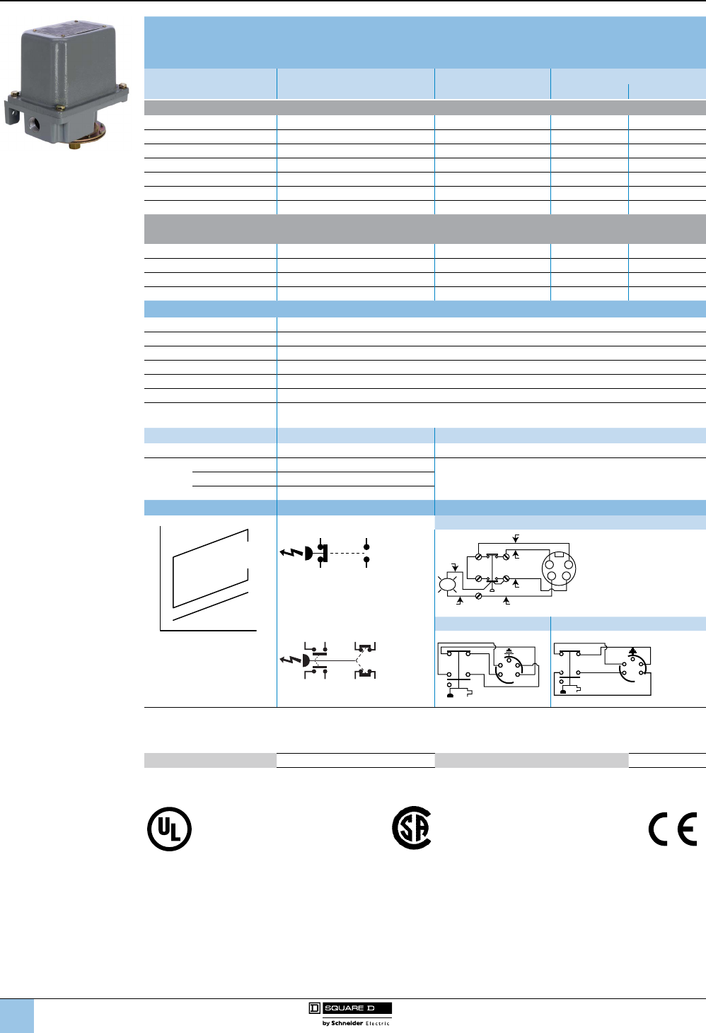
1
2
3
4
5
6
8
9
10
7
8/88
™
Adjustable Differential
NEMA 7 & 9 Enclosure, Class I & II, Division 1 & 2, Groups C, D, E, F, G
UL Listed as Industrial Control Equipment
Range on Decreasing
Pressure, psig
Adjustable Differential (1)
Approximate at Mid Range
Maximum Allowable
Pressure, psig
Class 9012 Type
SPDT DPDT
Diaphragm Actuated—Nitrile Diaphragm, Zinc Plated Steel Housing
0.2–10 1.0–2 100 GAR1 GAR21
1–40 4–8 100 GAR2 GAR22
1.5–75 8–15 240 GAR4 GAR24
3–150 16–30 475 GAR5 GAR25
5–250 23–49 750 GAR6 GAR26
13–425 36–82 850 GBR1 GBR21
20–675 65–130 2000 GBR2 GBR22
Piston Actuated—#440 Stainless Steel Piston.
#303 Stainless Steel Housing, Viton® Fluorocarbon Diaphragm and O-ring, Teon® Retaining Ring
20–1000 98–200 10,000 GCR1 GCR21
90–2900 281–560 15,000 GCR2 GCR22
170–5600 638–1050 20,000 GCR3 GCR23
270–9000 870–1500 25,000 GCR4 GCR24
Specications
Fluids Controlled Air, water, hydraulic oils, gases, steam (depending on the model)
Pressure Connection 1/4”-18 NPTF (standard) or 1/2”-14 NPT. See page 8/91.
Weight (approximate) 10 lb (4.54 kg)
Voltage Limits 600 V
Continuous Current 10 A
Electrical Connections 1/2"-14 NPTF, 3/4"-14 NPTF
Standards/Ratings CE, IEC 60957.5.1, UL 508, CSA 3211-03. UL Marine Listed for use on vessels longer than 65 ft
where ignition protection is required.
Temperature Ratings Minimum Maximum
Ambient –23 °C (–10 °F) +85 °C (+185 °F)
Media
Diaphragm –40 °C (–40 °F)
+120 °C (+250 °F)Piston –26 °C (–15 °F)
All with Form Q4 –26 °C (–15 °F)
Operating Curves Contact Blocks Connection
Falling pressure
Max. Diff
erential
Min. D
i
ff
eren
tial
Rising Pressure
Adjustable
Differential
1 N.O.,1 N.C. Form H17
1
3
2
4
Same
Polarity
1
1
2
4
6
82
34
LED
Red
Black
Black
Blue
Brown
White
2 N.O., 2 N.C. Form H10 Form H11
Same
Polarity
Same
Polarity
1
2
5
6
3
4
7
8
ORG
BLK
RED
WHT
GRN
1
26
84
1
2
3
4
5
ORG RED
WHT
BLK
GRN
1
26
8
4
1
2
3
4
5
SPDT snap switches contain two double-break contact elements (1 N.O., 1 N.C.) that must be used on circuits of the same polarity
.
DPDT snap switches contain two electrically separated sets of contact elements allowing use on circuits of opposite polarity.
Each set contains two double-break contact elements (1 N.O., 1 N.C.) that must be used on circuits of the same polarity.
Acceptable Wire Sizes: 12–22 AWG Recommended Terminal Clamp Torque: 7 lb-in
(1) The differential adds to the range setting and determines the operating point on rising pressure.
File E12443 CCN NOWT Haz. Loc., G•R File LR 25490 Class 3211-03 G•W, G•O, G•G
File E12158 CCN NKPZ G•W, G•O, G•G File LR 26817 Class 3218-02 G•R
File E12158 CCN NTHT Marine Use, G•W
9012G and 9016G
Industrial pressure and vacuum switches
9012G machine tool pressure switches
Selection and
specications (continued)
9012GAR
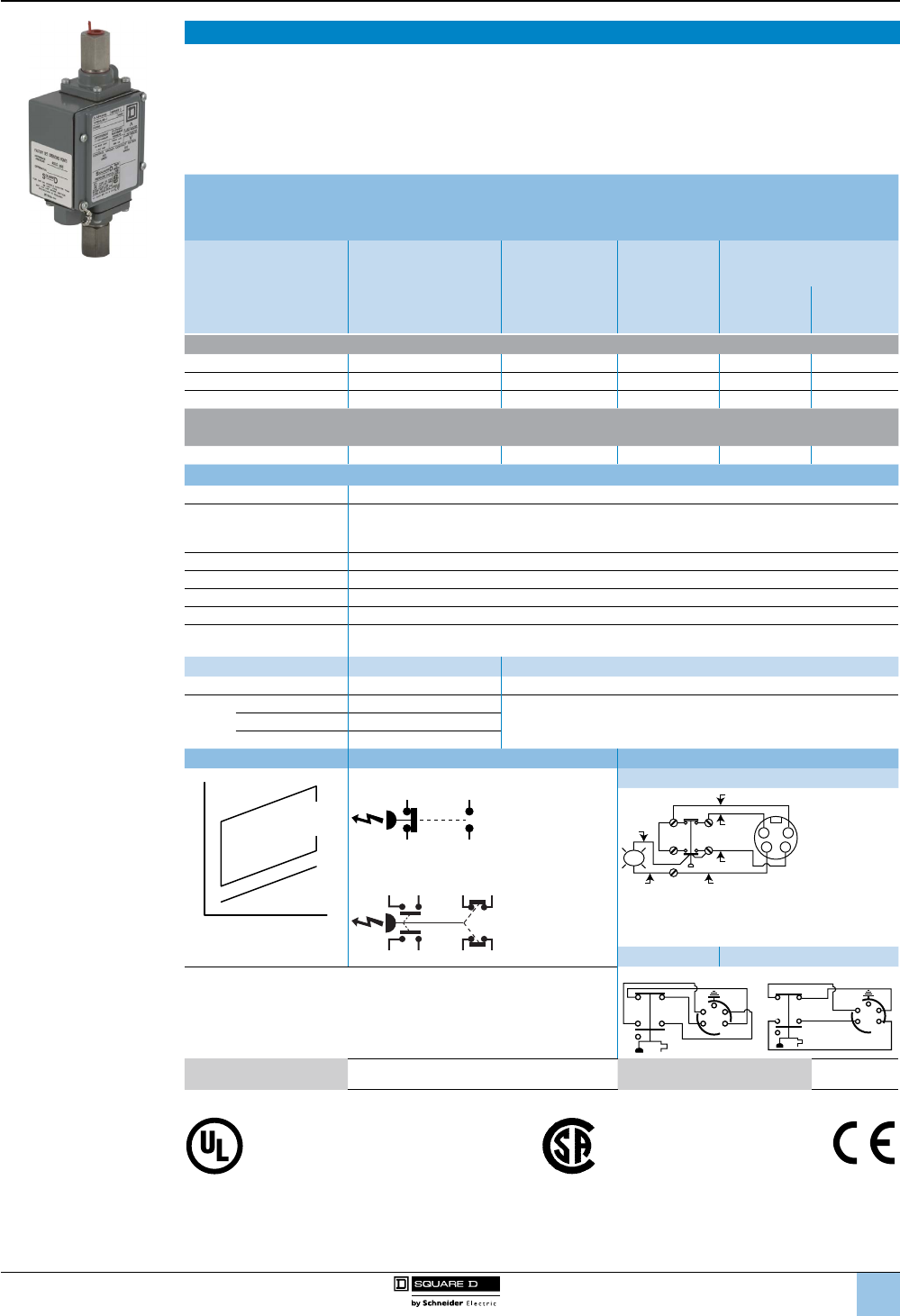
1
2
3
4
5
6
8
9
10
7
8/89
™
Differential-Pressure Operation
Pressure switches for differential-pressure operation are used to monitor the change in the difference between
two pressures. The 9012G differential-pressure switches are unidirectional devices and are used in applications to
signal that a predetermined pressure difference has been reached as a result of a widening or increasing difference
between the two pressures. They can also be used in applications to signal that a predetermined pressure
difference has been reached as a result of a narrowing or decreasing difference between the two pressures.
NEMA 4, 4X, and 13 devices are suitable for use in Class I, Division 2, Groups A, B, C, and D hazardous locations
or nonhazardous locations only.
Adjustable differential
NEMA 4, 4X, 13 Enclosures
UL Listed and CSA Certied as Industrial Control Equipment
Working Pressure
Range on decreasing
X (upper) actuator
Adjustable
Difference on
Decreasing Pressure
(Adds to
working pressure)
Y (lower) actuator
Adjustable
Differential
Actuates on
increasing pressure
(adds to adjustable
difference)
Maximum
Allowable
Pressure
Class 9012 Type
SPDT DPDT
Diaphragm Actuated—Nitrile Diaphragm, Zinc Plated Steel Housing
0–75 0.25–10 1–2 100 GGW1 GGW21
0–175 0.5–36 5.6–15 240 GGW4 GGW24
0–500 3–175 26–90 850 GHW1 GHW21
Piston Actuated—#440 Stainless Steel Piston.
#303 Stainless Steel Housing, Viton® Fluorocarbon Diaphragm and O-ring, Teon® Retaining Ring
0–5000 15–825 97–200 7500 GJW1 GJW21
Specications
Fluids Controlled Air, water, hydraulic oils, gases, steam (depending on the model)
Pressure Connection
1/4”-18 NPTF is standard. For metric threads (G1/4 BSP female pressure connection and
M20 electrical connection), add M after the W in the catalog number. For other options, see
page 8/91. (1)
Weight (approximate) 3 lb (1.36 kg)
Voltage Limits 600 V
Continuous Current 10 A
Electrical Connections 1/2"-14 NPTF (standard), For Pg 13.5, or ISO M20, see footnote (2) on page 8/87 .
Standards/Ratings CE, IEC 60957.5.1, UL 508, CSA 3211-03. UL Marine Listed for use on vessels greater than
65 ft long where ignition protection is not required.
Temperature Ratings Minimum Maximum
Ambient –23 °C (–10 °F) +85 °C (+185 °F)
Media
Diaphragm –40 °C (–40 °F)
+120 °C (+250 °F)Piston –26 °C (–15 °F)
All with Form Q4 –26 °C (–15 °F)
Operating Curves Contact Blocks Connection
Falling pressure
Max. Diff
erential
Min. D
i
ff
eren
tial
Rising Pressure
Adjustable
Differential
1 N.O., 1 N.C. Form H17
1
3
2
4
Same
Polarity
1
1
2
4
6
82
34
LED
Red
Black
Black
Blue
Brown
White
2 N.O., 2 N.C.
Same
Polarity
Same
Polarity
1
2
5
6
3
4
7
8
Form H10 Form H11
SPDT snap switches contain two double-break contact elements (1 N.O.,
1 N.C.) that must be used on circuits of the same polarity.
DPDT snap switches contain two electrically separated sets of contact
elements allowing use on circuits of opposite polarity. Each set contains two
double-break contact elements (1 N.O., 1 N.C.) that must be used on circuits
of the same polarity.
ORG
BLK
RED
WHT
GRN
1
26
84
1
2
3
4
5
ORG RED
WHT
BLK
GRN
1
26
8
4
1
2
3
4
5
Acceptable Wire Sizes: 12–22 AWG Recommended
Terminal Clamp Torque: 7 lb-in
File E12158 CCN NKPZ File LR25490 Class 3211-03
File E12158 CCN NTHT - Marine Use
9012G and 9016G
Industrial pressure and vacuum switches
9012G pressure switches for
differential-pressure operation
Selection and
specications (continued)
9012GJW1
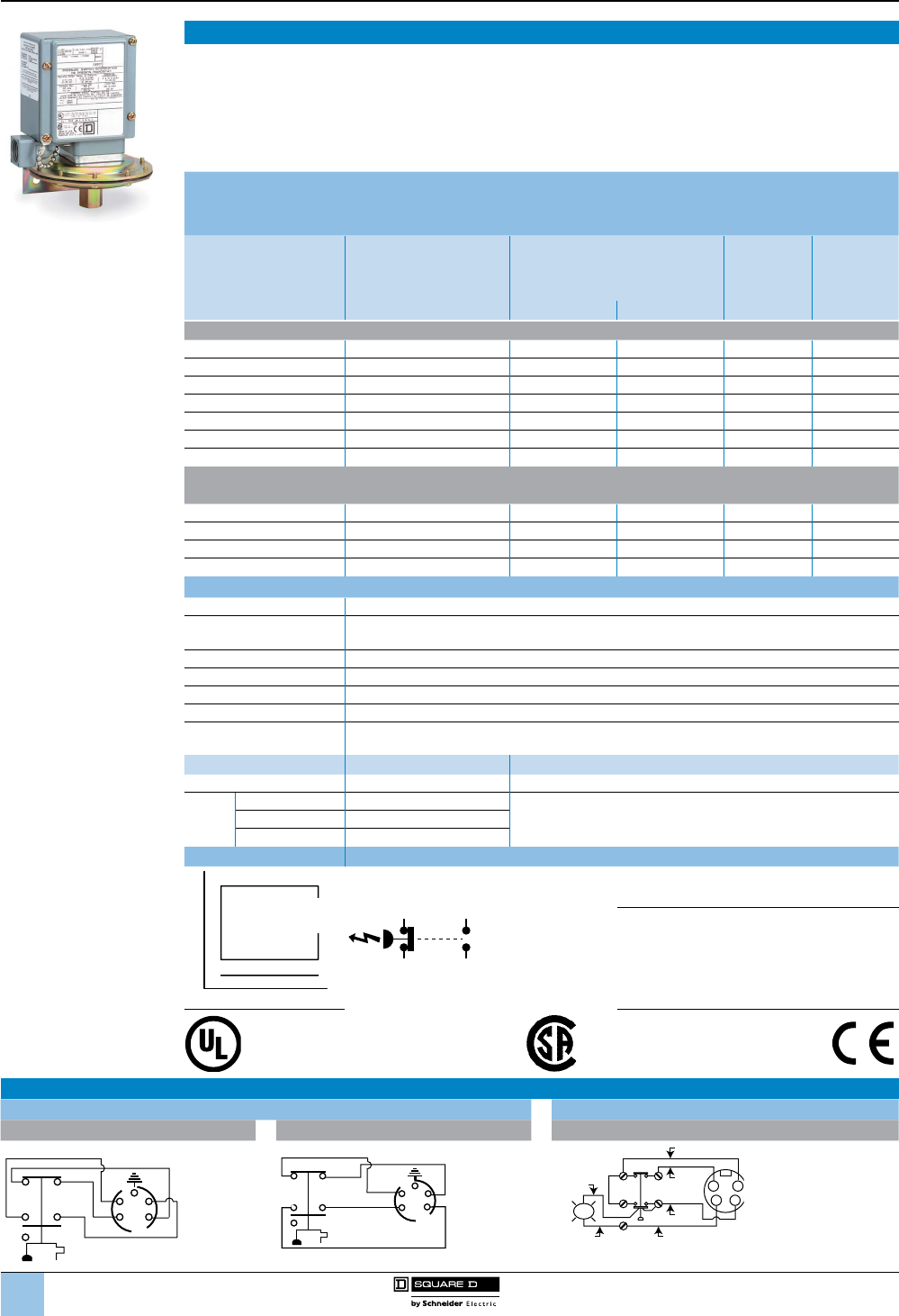
1
2
3
4
5
6
8
9
10
7
8/90
™
Dual-Stage Operation
The 9012G dual-stage pressure switches are designed for use in applications where two separate pressure
operations must be controlled by a single pressure monitoring device. These controls are most commonly used
where dual functions are required or in sequencing applications such as alarm shutdowns. The spread between
the two stages is adjustable, but the differential between the high (rising) and low (falling) operating points of each
stage is xed.
NEMA 4, 4X, and 13 devices are suitable for use in Class I, Division 2, Groups A, B, C, and D hazardous locations
or nonhazardous locations only.
Fixed Differential
NEMA 4, 4X, 13 Enclosure
UL Listed and CSA Certied as Industrial Control Equipment
9012GKW1 Range Setting
Pressure limits between
which Stage 1 can be
adjusted to operate on
decreasing pressure
Adjustable Spread
Add to the range setting
to obtain the decreasing
operating point of Stage 2
Fixed Differential
Add to the low operating point to
obtain the approximate high
operating point for each stage
Maximum
Allowable
Pressure
SPDT Each
Stage
Stage 1 Stage 2 Type
Diaphragm Actuated—Nitrile Diaphragm, Zinc Plated Steel Housing
0.2–10 1.1–5 1.0 ± 0.2 1.5 ± 0.4 100 GKW1
1–40 4.4–20 4.0 ± 1.0 6.0 ± 1.5 100 GKW2
1.5–75 6.6–30 6.0 ± 1.5 8.0 ± 2.0 240 GKW4
3–150 13.2–75 8.0 ± 2.0 12 ± 3 475 GKW5
5–250 24.2–110 14 ± 3 21 ± 5 750 GKW6
13–425 44–180 20 ± 4 30 ± 7.5 850 GLW1
20–675 50–250 30 ± 6 45 ± 11 2000 GLW2
Piston Actuated—#440 Stainless Steel Piston.
#303 Stainless Steel Housing, Viton® Fluorocarbon Diaphragm and O-ring, Teon® Retaining Ring
20–1000 72–300 50 ± 10 75 ± 19 10,000 GMW1
90–2900 176–800 140 ± 30 210 ± 52 15,000 GMW2
170–5600 360–1700 275 ± 60 400 ± 100 20,000 GMW3
270–9000 550–2500 400 ± 80 800 ± 150 25,000 GMW4
Specications
Fluids Controlled Air, water, hydraulic oils, gases, steam (depending on the model)
Pressure Connection 1/4”-18 NPTF is standard. For metric threads, add M after the W on all types.
Other options are available (see page 8/91). (1)
Weight (approximate) 3 lb (1.36 kg)
Voltage Limits 600 V
Continuous Current 10 A
Electrical Connections 1/2"-14 NPTF (standard), For Pg 13.5, or ISO M20, see footnote (2) on page 8/87 .
Standards/Ratings CE, IEC 60957.5.1, UL 508, CSA 3211-03. UL Marine Listed for use on vessels greater than 65 ft
long where ignition protection is not required.
Temperature Ratings Minimum Maximum
Ambient –23 °C (–10 °F) +85 °C (+185 °F)
Media
Diaphragm –40 °C (–40 °F)
+120 °C (+250 °F)Piston –26 °C (–15 °F)
All with Form Q4 –26 °C (–15 °F)
Operating Curves Contact Blocks
Falling pressure
Ma
x. Differenti
a
l
M
in
. Differen
ti
a
l
Rising Pressure
Fixed
Differential
1 N.O.,
1 N.C.
Acceptable Wire Sizes:
12–22 AWG
1
3
2
4
Same
Polarity
Recommended Terminal Clamp Torque:
7 lb-in
File E12158 CCN NKPZ File LR25490 Class 3211-03
File E12158 CCN NTHT - Marine Use
Wiring Diagrams for Receptacles and Connectors—Factory Modications (Forms)—see page 8/91.
Prewired 5-pin male receptacle Micro connector, 4-pin, for 24 Vdc pilot light
Form H10 Form H11 Form H17
ORG
BLK
RED
WHT
GRN
1
26
84
1
2
3
4
5
ORG
RED
WHT
BLK
GRN
1
26
8
4
1
2
3
4
5
1
1
2
4
6
82
34
LED
Red
Black
Black
Blue
Brown
White
9012G and 9016G
Industrial pressure and vacuum switches
9012G dual-stage pressure switches
Selection and
specications (continued)
1
2
3
4
5
6
8
9
10
7
8/91
™
Modications, Renewal Parts, and Accessories
9012G Machine Tool Factory Modications (Forms)
Modication Applies to Form
Lock on rising pressure, manual reset only
Available on GDW, GDWM, GEW, GEWM, GFW, GFWM only
E3
120 Vac or Vdc neon pilot light Available on all GAW–GMW and
GAWM–GFWM
clear lens G17
red lens G18
24 Vdc only LED For pilot light conversion kits:
See 9998PC306–308
clear lens G21
red lens G22
24 Vdc LED pilot light with green lens Class 9012 GAW–GMW and GAWM–GFWM, or Class 9016 GAW G23
SPDT snap switch rated 1.1 A at 125 Vdc (minimum differential doubles) Available on GAR–GFR, GAW–GJW, and GAWM–GFWM H3
Prewired 5-pin male receptacle: Brad Harrison #41310 or
interchangeable Crouse-Hinds receptacle at our convenience. For use with
Brad Harrison female portable plug #41306, 41307, 41308 or equal
Available on GAW–GJW single pole devices only.
See wiring diagrams on page 8/90.
H10
or
H11
Micro connector, 4-pin, for 24 Vdc pilot light (see diagram on page 8/90) G•W (single pole only), except GAW2 and Form B2. H17
External range adjustment
with range scale window
With knob GAW–GFW, GAWM–GFWM, and GKW–GMW K
Slotted for screwdriver GAW–GFW, GAWM–GFWM, and GKW–GMW K1
Pg 13.5 conduit thread and 1/4"-19 BSP pressure connection GAW–GFW and GKW–GMW M12
#316 stainless steel ange
Standard nitrile diaphragm GAR, GBR, GDR, GER, GAW, GBW, GDW, GEW, GGW, GHW,
GAWM, GBWM, GDWM, GEWM, GKW, GLW, except Types 1 and 21 Q1
Ethylene propylene diaphragm
Available on all GGW, GHW except GGW-1, 21.
Available on all GAR, GBR, GDR, GER, GAW, GBW, GDW, GEW,
GAWM, GBWM, GDWM, GEWM, GKW, GLW, except Types 1 and 21
Q3
Viton® uorocarbon diaphragm GAR, GAW, GBR, GBW, GDR, GDW, GER, GEW, GGW, GHW,
GAWM, GBWM, GDWM, GEWM, GKW, GLW, except Types 1 and 21 Q4
Range scale window (standard with Forms K and K1) GAW–GMW, GAWM–GFWM V1
Special factory setting specied (If indicating only one special setting,
specify whether this setting is on increasing or decreasing pressure.) All 9012G Y1
Pressure connection
Not available in combination
with Forms Q1, Q3, Q4
1⁄4"-18 NPT external thread GAR, GAW, GDR, GDW, GGW, GKW Z
1⁄2"-14 NPT external thread,
1⁄4"-18 NPTF internal thread GAR, GAW, GDR, GDW, GGW, GKW Z16
7⁄16"-20 UNF-2B internal thread GAR–GFR; GAW–GMW Z18
9012G Pressure Switches, Factory Modications (Forms) for Renewal Parts Kits, Class 9998
For sufxes for renewal parts kits, see the table below.
Modication Applies to Parts Kit Type Form
SPDT snap switch rated 1.1 A at 125 Vdc (minimum differential doubles) PC313 H3
#316 stainless steel ange
Standard nitrile diaphragm PC177–179, PC268, 269 Q1
PC265–267
Ethylene propylene diaphragm PC177–178, PC268, 269 Q3
PC266, 267
Viton® uorocarbon diaphragm PC177–178, PC268, 269 Q4
PC265–267
Pressure connection
1⁄4"-18 NPT external thread PC265–269 Z
1⁄2"-14 NPT external thread,
1⁄4"-18 NPTF internal thread PC265–269 Z16
7⁄16"-20 UNF-2B internal thread PC177, 178, PC265–273 Z18
Renewal Parts Kits, Class 9998, for Class 9012 and 9016 Devices
Description Equipment To Be Serviced Parts Kit Type
Actuator assembly
9012GA, GD, GG, GK, GN, GR 5, 25, 55 Series C only PC268 (1)
9012GA, GD, GG, GK, GN, GR 6, 26, 36, 46, 56 Series C only PC269 (1)
9012GB, GE, GH1, 21, 31, 41, 51; GL, GP, GS1 PC177 (1)
9012GB, GE, GH2, 22, 32, 42, 52; GL, GP, GS2 PC178 (1)
Diaphragm assembly
9012GA, GD, GN, GR1, 21 Series C only PC265 (1)
9012GA, GD, GG, GK, GN, GR 2, 3, 22, 52 Series C only PC266 (1)
9012GA, GD, GG, GK, GN, GR4, 24, 54 Series C only PC267 (1)
9016 GAW-1, 21 PC233
Gasket kit Contains all replaceable gaskets for all 9012 Open, NEMA 1, 4, 4X, 13 PC184
Pilot light 9012, 9016G Forms G7, G8, G9, G10, G21, G22; 24 Volts DC PC305
Piston assembly
9012GC, GF, GJ, GQ, GT1, 21, 31, 41, 51 Series C only PC270 (1)
9012GC, GF, GJ, GQ, GT2, 22, 32, 42, 52 Series C only PC271 (1)
9012GC, GF, GQ, GT4, 24, 34, 44, 54 Series C only PC273 (1)
Snap switch SPDT, for 9012GA, GB, GC, GD, GE, GF, GG, GH, GJ Single Pole; Except Forms E2, E3, E4, H3: Series C only PC313 (1)
DPDT, 9012GA, GB, GC, GD, GE, GF, GG, GH, GJ Double Pole; Except Forms E2, E3, H6, H7: Series C only PC314 (1)
(1) If one of these Form designations appears on the pressure switch nameplate, the 9998 PC number must be completed by adding that same Form sufx
from the table above, and the Form price added to the kit price.
Accessories Class 9049 Accessories for 9012G Pressure Switches
Description Type
Stainless steel surge reducer for use on oils, coolants, and hydraulic uids (not recommended for air or water) A26S
9012G and 9016G
Industrial pressure and vacuum switches
9012G machine tool modications and renewal parts
Selection and
specications (continued)
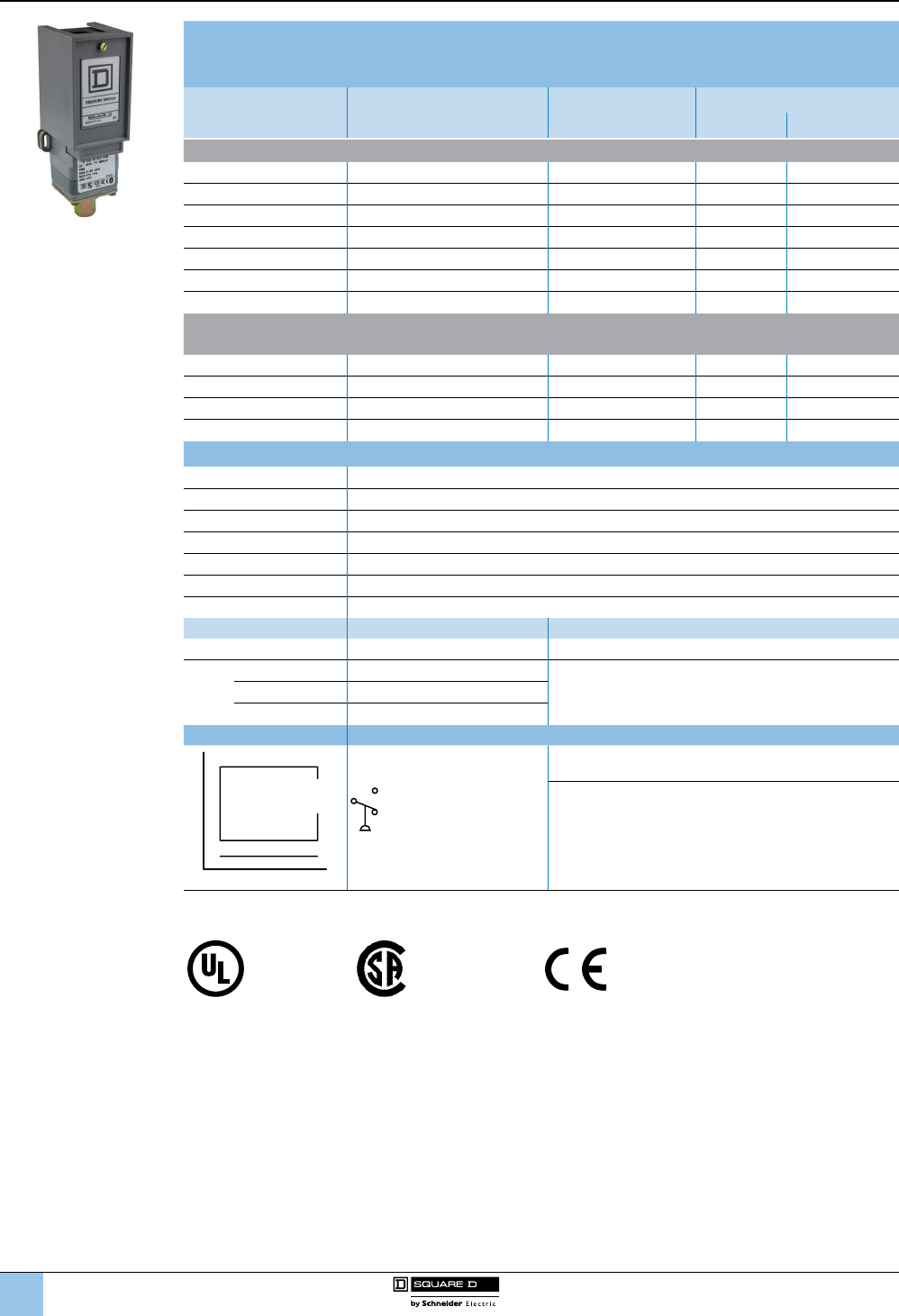
1
2
3
4
5
6
8
9
10
7
8/92
™
Fixed Differential
Open Type or NEMA 1 Enclosure
UL Listed and CSA Certied as Industrial Control Equipment
Range on Decreasing
Pressure, psig
Approximate Differential (1)
At Mid Range, psig
Maximum Allowable
Pressure, psig
Class 9012 Type
Open Type NEMA 1
Diaphragm Actuated—Nitrile Diaphragm, Zinc Plated Steel Housing
0.2–10 0.4 ± 0.1 100 GRO1 GRG1
1–40 1.2 ± 0.3 100 GRO3 GRG3
1.5–75 2.2 ± 0.4 240 GRO4 GRG4
3–150 4.2 ± 1 475 GRO5 GRG5
5–250 7.4 ± 2 750 GRO6 GRG6
13–425 13 ± 3 850 GSO1 GSG1
20–675 19 ± 5 2000 GSO2 GSG2
Piston Actuated—#440 Stainless Steel Piston.
#303 Stainless Steel Housing, Viton® Fluorocarbon Diaphragm and O-Ring, Teon® Retaining Ring
20–1000 49 ± 10 10,000 GTO1 GTG1
90–2900 141 ± 15 15,000 GTO2 GTG2
170–5600 200 ± 40 20,000 GTO3 GTG3
270–9000 350 ± 45 25,000 GTO4 GTG4
Specications
Fluids Controlled Air, water, hydraulic oils, gases, steam (depending on the model)
Pressure Connection 1/4”-18 NPTF (standard), 1/2”-14 NPT, or 7/16”-20 UNF-2B. See Forms table on page 8/93.
Weight (approximate) Type 1: 2 lb (0.91 kg); Open: 1.7 lb (0.77)
Voltage Limits 600 V
Continuous Current 10 A
Electrical Connections 1/2" conduit entry, unthreaded
Standards/Ratings CE, IEC 60957.5.1, UL 508, CSA 3211-03
Temperature Ratings Minimum Maximum
Ambient –23 °C (–10 °F) +85 °C (+185 °F)
Media
Diaphragm –40 °C (–40 °F)
+120 °C (+250 °F)Piston –26 °C (–15 °F)
All with Form Q4 –26 °C (–15 °F)
Operating Curves Contact Blocks
Falling pressure
Ma
x. Differenti
a
l
M
in
. Differen
ti
a
l
Rising Pressure
Fixed
Differential
SPDT
Form C contacts
Acceptable Wire Sizes:
12–22 AWG
Recommended Terminal Clamp Torque:
7 lb-in
(1) Determines the operating point on rising pressure.
File E12158
CCN NKPZ
File LR 25490
Class 3211-03
9012G and 9016G
Industrial pressure and vacuum switches
9012G industrial pressure switches
Selection and
specications (continued)
9012GRG5
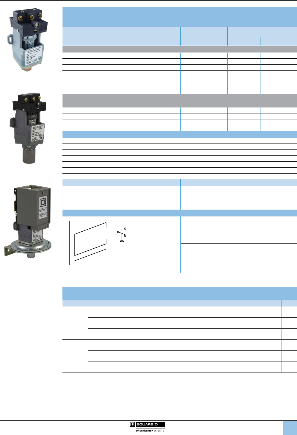
1
2
3
4
5
6
8
9
10
7
8/93
™
Adjustable Differential
Open Type or NEMA 1 Enclosure
UL Listed and CSA Certied as Industrial Control Equipment
Range on
Decreasing Pressure
psig
Approximate Mid Range (1)
Differential (adds to the
decreasing set point)
Maximum Allowable
Pressure psig
Class 9012 Type
Open Type NEMA 1
Diaphragm Actuated—Nitrile Diaphragm, Zinc Plated Steel Housing
0.2–10 0.6–1.0 100 GNO1 GNG1
1–40 1.6–5.0 100 GNO3 GNG3
1.5–75 2.5–6.5 240 GNO4 GNG4
3–150 4.8–13 475 GNO5 GNG5
5–250 8.5–20.5 750 GNO6 GNG6
13–425 20–41 850 GPO1 GPG1
20–675 35–66 2000 GPO2 GPG2
Piston Actuated—#440 Stainless Steel Piston.
#303 Stainless Steel Housing, Viton® Fluorocarbon Diaphragm and O-Ring, Teon® Retaining Ring
20–1000 56–98 10,000 GQO1 GQG1
90–2900 162–308 15,000 GQO2 GQG2
170–5600 355–563 20,000 GQO3 GQG3
270–9000 481–1050 25,000 GQO4 GQG4
Specications
Fluids Controlled Air, water, hydraulic oils, gases, steam (depending on the model)
Pressure Connection 1/4”-18 NPTF (standard), G1/4 (BSP) female, or 1/2"-14 NPT. See Forms in the table below.
Weight (approximate) Type 1: 2 lb (0.91 kg); Open: 1.7 lb (0.77)
Voltage Limits 600 V
Continuous Current 10 A
Electrical Connections 1/2" conduit entry, unthreaded
Standards/Ratings CE, IEC 60957.5.1, UL 508, CSA 3211-03
Temperature Ratings Minimum Maximum
Ambient –23 °C (–10 °F) +85 °C (+185 °F)
Media
Diaphragm –40 °C (–40 °F)
+120 °C (+250 °F)Piston –26 °C (–15 °F)
All with Form Q4 –26 °C (–15 °F)
Operating Curves Contact Blocks
Falling pressure
Max. Diff
erential
Min. D
i
ff
eren
tial
Rising Pressure
Adjustable
Differential
SPDT Form C contacts
Acceptable Wire Sizes:
12–22 AWG
Recommended Terminal Clamp Torque:
7 lb-in
(1) Determines the operating point on rising pressure.
Factory Modications (Forms) for 9012G Pressure Switches, Open Type or NEMA 1
UL Listed and CSA Certied as Industrial Control Equipment
Modication Applies to Form
Diaphragm
Standard Nitrile in #316 stainless steel
housing GNG, GNO, GPG, GPO, GRG, GRO, GSG, GSO Q1
Ethylene propylene in #316 stainless steel
housing
Not available on GNG, GNO, GRG, GRO1. Available on all
other GNG, GNO, GPG, GPO, GRG, GRO, GSG, GSO Q3
Viton® uorocarbon in #316 stainless steel
housing GNG, GNO, GPG, GPO, GRG, GRO, GSG, GSO Q4
Pressure
connection
1/4”-18 NPT external thread GNG, GNO, GRG, GRO Z
1/2”-14 NPT external thread, 1/4”-18 NPTF
internal thread. Standard actuator only. GNG, GNO, GRG, GRO Z16
7/16”-20 UNF-2B internal thread GNG, GNO, GPG, GPO, GQG, GQO, GRG, GRO, GSG,
GSO, GTG, GTO Z18
9012G and 9016G
Industrial pressure and vacuum switches
9012G industrial pressure switches
Selection and
specications (continued)
9012GNO5
9012GQO2
9012GNG1
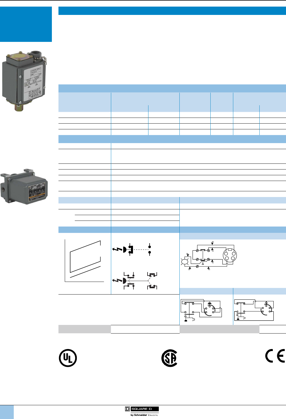
1
2
3
4
5
6
8
9
10
7
94
™
9016GAW Switches for Sensitive Control Applications
9016GAW vacuum switches have double throw contacts. Normally open and normally closed circuits allow the
use of these controls for standard or reverse action applications.
Standard controls can be mounted from the front using the bracket provided. Two mounting screws are required for
rm attachment to any smooth, at surface. Allowance must be made for ange projection.
Controls with the Form F modication include two mounting feet with 9/32” mounting holes on 3–3/4 in. centers.
The Range and Differential adjustments are accessed by removing the front cover.
■ Maximum allowable positive pressure: 100 psig.
■ Diaphragms are oil resisting, nitrile butadiene rubber (Buna-N).
■ For electrical ratings and temperature limitations, see table on page 8/83.
■ For dimensions and modications, see page 99.
9016GAW Vacuum Switch for Control Applications, Diaphragm Actuated
Range on Decreasing
Vacuum (inHg)
Adjustable Differential (inHg)
Adds to Range (1) Contact
Arrangement
Pipe Tap
(NPTF)
Class 9016 Type
NEMA Enclosure Type
@ Minimum Range @ Mid-Range 4, 4X & 13 7 & 9
0–28.7 0.8–9 1.3–7.4 1 N.O.–1 N.C. 1/4"-18 GAW1 GAR1
0–25 5–20 5–20 1 N.O.–1 N.C. 1/4"-18 GAW2 N/A
0–28.3 1–9 1.7–7.4 2 N.O.–2 N.C. 1/4"-18 GAW21 GAR21
0–25 5–20 5–20 2 N.O.–2 N.C. 1/4"-18 GAW22 N/A
Specications
Fluids Controlled Air, water, hydraulic oils, gases, steam (depending on the model)
Pressure Connection
NEMA 4, 4X & 13: 1/4”-18 NPTF (standard), G1/4 (BSP) female, or 1/2”-14 NPT.
See Forms table on page 99.
NEMA 7 & 9: 1/4” NPTF
Weight (approximate) Type 4, 4X, and 13: 3 lb (1.36 kg); Type 7 & 9: 10 lb (4.54 kg)
Voltage Limits 600 V
Continuous Current 10 A
Electrical Connections NEMA 4, 4X & 13: 1/2"-14 NPTF
NEMA 7 & 9: 3/4”-14 NPTF
Standards/Ratings CE, IEC 60957.5.1, UL 508, CSA 3211-03
Temperature Ratings Minimum Maximum
Ambient –23 °C (–10 °F) +85 °C (+185 °F)
Media
Diaphragm –40 °C (–40 °F)
+120 °C (+250 °F)Piston –26 °C (–15 °F)
All with Form Q4 –26 °C (–15 °F)
Operating Curves Contact Blocks Connection
Falling pressure
Max. Diff
erential
Min. D
i
ff
eren
tial
Rising Pressure
Adjustable
Differential
1 N.O., 1 N.C. Form H17
1
3
2
4
Same
Polarity
1
1
2
4
6
82
34
LED
Red
Black
Black
Blue
Brown
White
2 N.O., 2 N.C.
Same
Polarity
Same
Polarity
1
2
5
6
3
4
7
8
Form H10 Form H11
SPDT snap switches contain two double-break contact elements
(1 N.O., 1 N.C.) that must be used on circuits of the same polarity.
DPDT snap switches contain two electrically separated sets of
contact elements allowing use on circuits of opposite polarity. Each
set contains two double-break contact elements (1 N.O., 1 N.C.)
that must be used on circuits of the same polarity.
ORG
BLK
RED
WHT
GRN
1
26
84
1
2
3
4
5
ORG RED
WHT
BLK
GRN
1
26
8
4
1
2
3
4
5
Acceptable Wire Sizes: 12–22 AWG Recommended Terminal Clamp Torque: 7 lb-in
(1) Add the Differential to the Range to obtain the operating point on increasing vacuum (within vacuum limitations).
The differential increases linearly over the range. The minimum differential doubles with NEMA 7 & 9 enclosures.
File LR 25490
Class 3211 06
Type GAW only
File LR26817
Type GAR only
(NEMA 7 and 9 Haz. Loc.)
File E12443 Haz Loc CCN NOWT (GAR)
File E12158 CCN NKPZ (GAW)
File E12158 CCN NTHT
Marine Use (GAW)
9012G and 9016G
Industrial pressure and vacuum switches
9016G vacuum switches
Control applications
Selection and
specications (continued)
9016GAW2
9016GAR1
Selection and
Specications—
9016G Vacuum
Switches
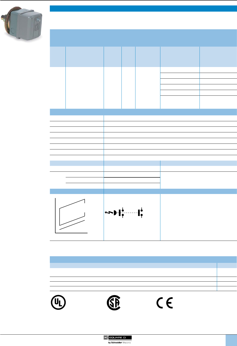
1
2
3
4
5
6
8
9
10
7
95
™
9016GVG Power Switches
The 9016GVG1 is designed as a companion to the 9036GG oat switches in common use on vacuum heating
pumps. Electrical ratings of oat and vacuum switch types are equal.
For dimensions and modications, see page 98.
9016GVG Vacuum Switch for Power Applications
NEMA 1 Enclosure
Contacts Open on Increasing Vacuum
Cut-
Out
Range,
inHg
Approximate
Adjustable
Differential,
inHg
Cut-In
Range,
inHg
Poles Pressure
Connection
Vacuum Setting,
inHg
NEMA 1 Enclosure
Class 9016 Type
5–25 5–10 inHg 0–20 21/4"-18 NPSF
3–8 GVG1J09
16.5–25 GVG1J10
17–22 GVG1J11
18–23 GVG1J12
20–25 GVG1J13
Specify other vacuum
(minimum order quantity:
4 pieces)
GVG1J99
Specications
Fluids Controlled Air, water, hydraulic oils, gases, steam (depending on the model)
Pressure Connection 1/4”-18 NPTF (standard), G1/4 (BSP) female, or 1/2"-14 NPT. See Forms table, page 99.
Max. Allowable Positive Pressure 100 psig
Weight (approximate) 2 lb (0.91)
Voltage Limits 600 V
Continuous Current 10 A
Electrical Connections 3 knockouts for 1/2" conduit
Standards/Ratings CE, IEC 60957.5.1, UL 508, CSA 3211-03
Temperature Ratings Minimum Maximum
Ambient –23 °C (–10 °F) +85 °C (+185 °F)
Media
Diaphragm –40 °C (–40 °F)
+120 °C (+250 °F)Piston –26 °C (–15 °F)
All with Form Q4 –26 °C (–15 °F)
Operating Curves Contact Blocks
Falling pressure
Max. Diff
erential
Min. D
i
ff
eren
tial
Rising Pressure
Adjustable
Differential
DPST
L1
L2
T1
T2
Acceptable Wire Sizes:
8–14 AWG
Recommended Terminal Clamp Torque:
22-27 lb-in
For other ratings and specications, see page 8/82.
Available Modications for 9016GVG Vacuum Switches
Description Form
3-way lever plus nameplate with marking: Float only—Vacuum and Float—Continuous
(factory modication only) E
Mounting bracket (for retrot, order 9049A53 bracket kit) F
Reverse action, normally open contacts R
1/4 in. male pipe connection (1/4"-18 NPT, external thread) (for retrot, use 1/4" pipe nipple) Z
File
E12158
CCN
NKPZ
File
LR 25490
9012G and 9016G
Industrial pressure and vacuum switches
9016G vacuum switches
Power applications
Selection and
specications (continued)
9016GVG1J10
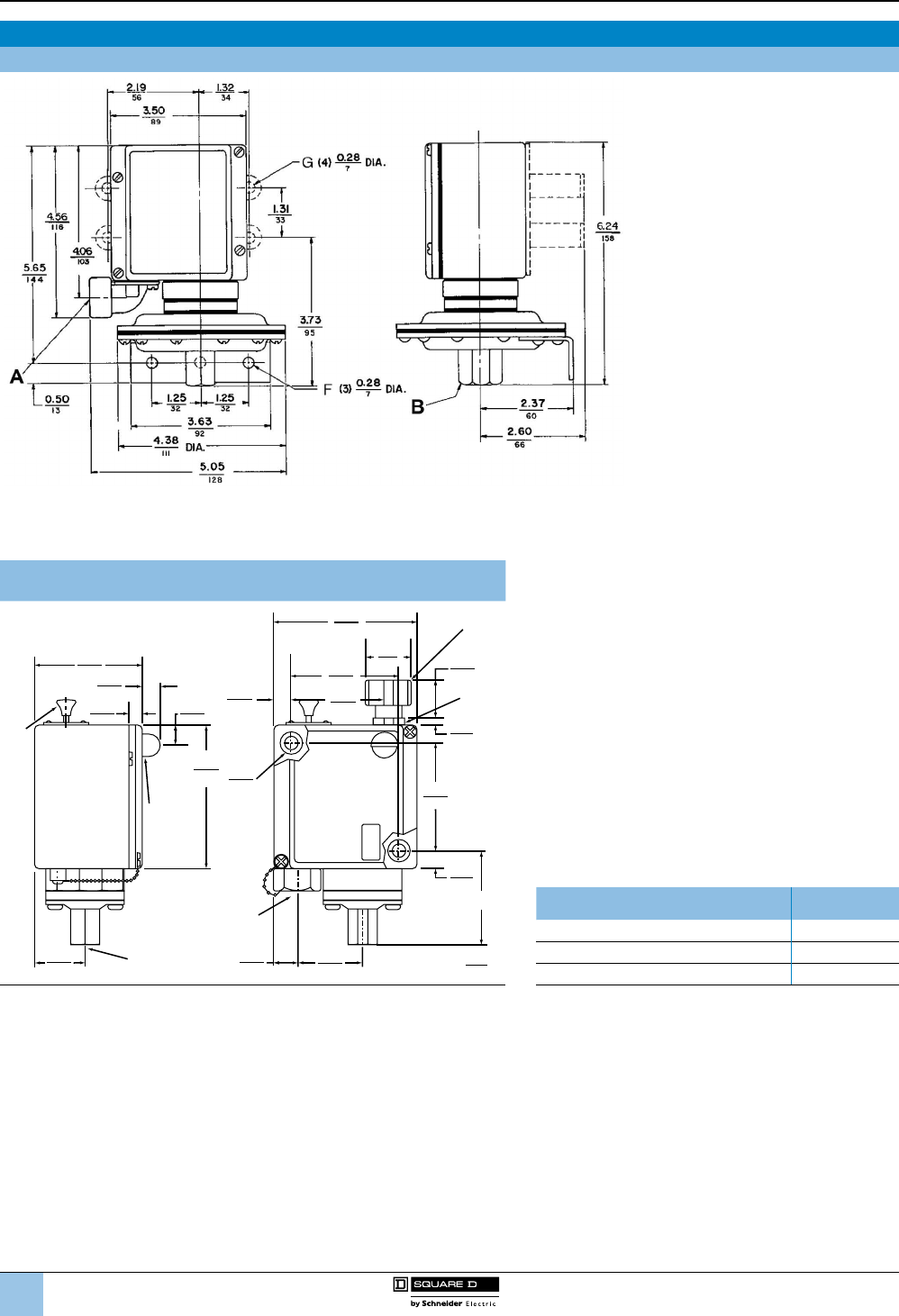
1
2
3
4
5
6
8
9
10
7
96
™
Machine Tool Pressure Switch Dimensions
9012 GAW, GDW, GKW 1, 21
A: Conduit connection: G•W = 1/2-14 NPT; G•WM = 20mm BS4568, Form M12 = Pg13.5; DIN40430.
B: Pressure connection: G•W = 1/4"-18 NPTF; G•WM = 8; Form M14 = G 1/4 BS 2779;
RP1/4 ISO 711; R 1/4 DIN 2999; GJ 1/4 UN1339.
9012 GAW, GBW, GCW, GDW, GEW, GFW, GKW, GLW, and GMW
(except GAW, GDW, GKW 1, 21)
0.38
10
0.27
7
dia.
Mtg. Holes
(2)
in.
mm
0.17
4
0.88
22
2.72
69
2.30
58
1.13
29
0.38
10
3.50
89
2.72
69
2.63
67 0.48
12
0.48
12
0.40
10
3.60
91
1.22
31
1/4-18 NPTF
Pipe Thread
Pressure Connection
1/2-14 NPT Conduit
Electrical Connection
Dual Dimensions:
Forms G17,
G18, G21,
G22, G23
Form
K
Form
K1
Forms
E1,
E2,
E3,
E4
0.58
15
1.61
41
AType Dimension A,
in. (mm)
GAW, GDW, GKW 2, 4, 5, 6, 22, 24, 25, 26 2.33 (59)
GBW, GEW, GLW 1, 2, 21 2.23 (57)
GCW, GFW, GMW 1, 2, 3, 4, 21,. 22, 23, 24 3.15 (80)
NOTE: Dimensions change with metric thread.
For ange and mounting bracket dimensions for low pressure device, see gure on page 99.
9012G and 9016G
Industrial pressure and vacuum switches
9012G pressure switches
Dimensions,
wiring
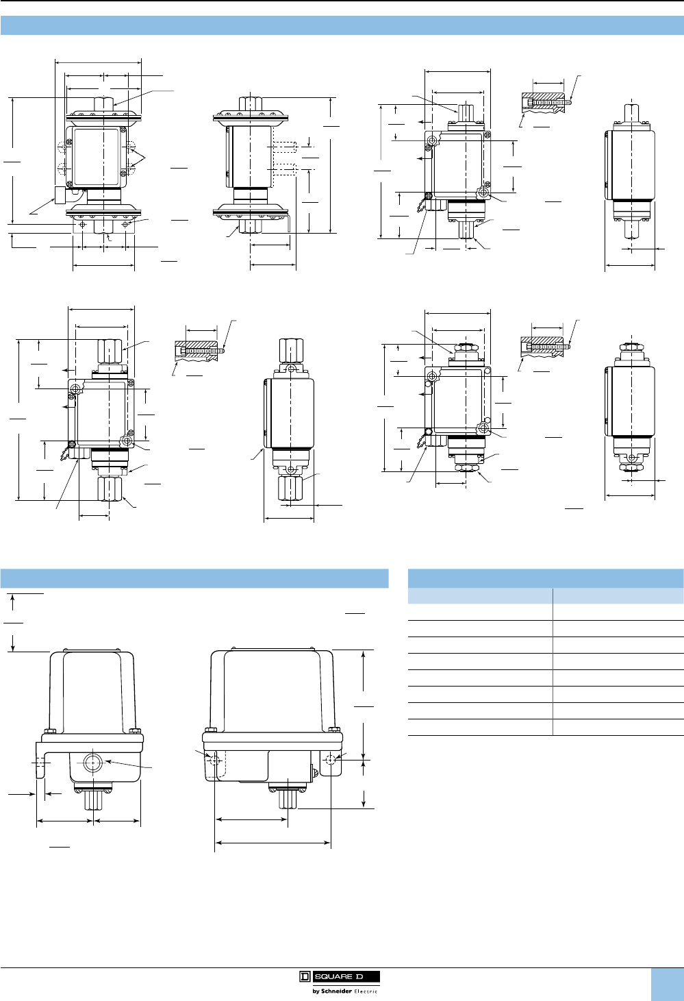
1
2
3
4
5
6
8
9
10
7
97
™
9012 GGW, GHW, GJW (Differential-Pressure)
GGW1, 21
5.05
128
2.31
59 4.38
111
1.44
37
0.28
7
ØX
M
(4) Ø
7.52
195
0.50
13
1.25
32 3.63
92
1.25
32
0.28
7
(3) Ø
Y
2.86
73
Turn Radius
2.37
60
2.71
69
3.76
96
7.98
203
1.31
33
GGW4, 24
3.50
89
2.72
69
1.89
48
7.08
180
X
A
A
M
Y
2.72
69
2.47
63
1.61
41 C
C
C
C
2.63
67
Tu rn Radius
0.27
7
(2)Ø
1.67
42
0.47
12
ØMax. Head
1/4 Bolt or Screw
Section A–A
1.22
32
2.63
67
GJW1, 21
X
M
3.50
89 2.72
69
2.63
67
7.08
180
A
A
Y
2.72
69
3.20
81
1.61
41
B
B
B
B
2.63
67
Turn Radius
0.27
7
(2)Ø
1.67
42
0.47
12
ØMax
Head
1/4 Bolt or Screw
Section A–A
Mounting Detail
1.22
32
2.63
67
in.
mm
Dim. =
GHW1, 21
M
3.50
89
2.72
69
1.73
44
6.76
172
A
A
Y
2.72
69
2.31
59
1.61
41
2.63
67
Tu rn Radius
0.27
7
(2)Ø
1.67
42
0.47
12
ØMax.
Head
1/4 Bolt or Screw
Section A–A
X
1.22
32
2.63
67
Fluid
connection
Electrical
conduit
entry
9012G and 9016G
Industrial pressure and vacuum switches
9012G pressure switches
Dimensions (continued)
Types GAR, GBR, GCR, GDR, GER, and GFR Dimension A for G•R Switches
4.95
126
0.41
10
2.91
74
2.34
59
in.
mm
4.90
125
Turn Radius
Dim. =
3/4-14
NPT
MM
3.69
94
5.88
149
5.78
147
A
Cover Removal Clearance
Type Dimension A, in. (mm)
GAR1, 2, 21, 22 2.02 (56)
GAR4, 5, 6, 24, 25, 26 1.42 (36)
GBR1, 2, 21, 22; GCR1, 21 1.32 (34)
GCR2, 3, 4, 22, 23, 24 2.24 (57)
GDR1, 2, 21, 22 2.02 (56)
GDR4, 5, 6, 24, 25, 26 1.42 (36)
GER1, 2, 21, 22; GFR1, 21 1.32 (34)
GFR2, 3, 4, 22, 23, 24 2.24 (57)
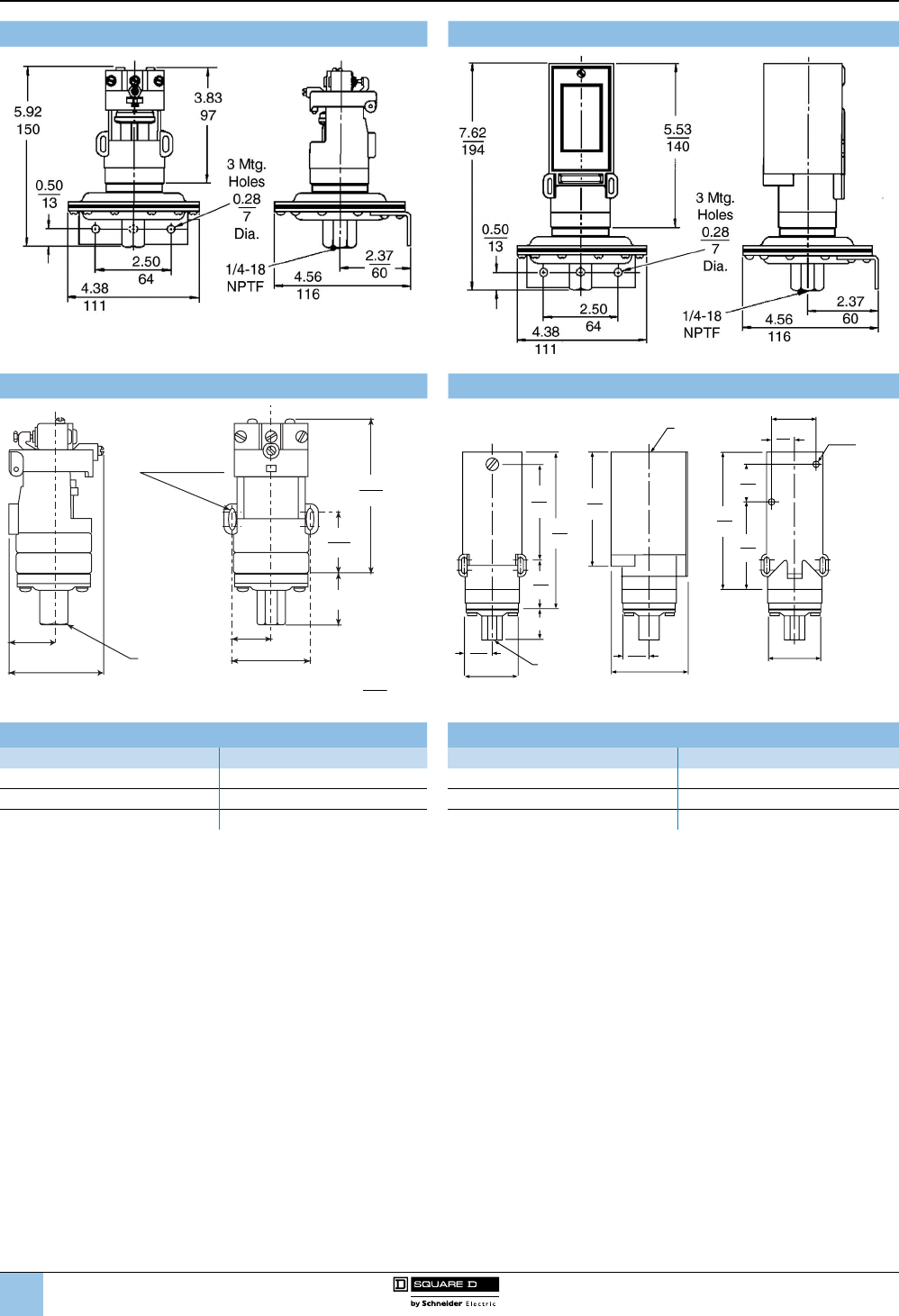
1
2
3
4
5
6
8
9
10
7
98
™
Types GNO1, GRO1 Types GNG1, GRG1
Types GNO, GRO Types GNG, GPG, GQG, GRG, GSG, and GTG
4.00
102
0.58
15
x0.22
6
2.46
63
1/4-18 NPTF
internal thread
1.17
30
2
mounting
slots 1.60
41
1.03
26 2.06
52
A
in.
mm
Dim. =
3.59
91
1.60
41
1.03
26 2.06
52
5.53
140
4.13
105 5.03
128
3.22
82
1.38
35
1.62
41
.82
21
1.11
28 2.75
70
2.21
56
A
1/4 - 18
NPTF
internal thread
Hole for
1/2 Conduit 0.20 Dia.
5
Mounting
Holes (2)
Dimension A for G•O Switches Dimension A for G•G Switches
Type Dimension A, in. (mm) Type Dimension A, in. (mm)
GNO, GRO 3, 4, 5, 6 1.41 (36) GNG, GRG 3, 4, 5, 6 1.41 (36)
GPO, GSO 1, 2, 3 1.31 (33) GPG, GSG 1, 2, 3 1.31 (33)
GQO, GTO 1, 2, 3, 4 2.24 (57) GQG, GTG 1, 2, 3, 4 2.24 (57)
9012G and 9016G
Industrial pressure and vacuum switches
9012G pressure switches
Dimensions (continued)
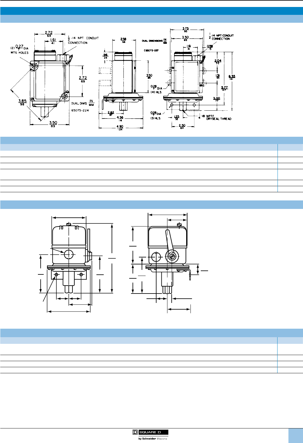
1
2
3
4
5
6
8
9
10
7
99
™
Vacuum Switch Dimensions and Modications
9016GAW Control Vacuum Switches—Dimensions
9016GAW Vacuum Switches—Available Modications
Description Form
Mounting feet (GAW 1, 21 only) F
Viton® diaphragm with #316 stainless steel ange Q4
Range scale window (standard with Forms K and K1) V1
Special setting specied
(If indicating only one special setting, specify whether this setting is on increasing or decreasing pressure.) Y1
1/4"-18 NPT external thread pressure connection Z
1/2"-14 NPT external thread, 1/4"-18 NPTF internal thread pressure connection (standard actuator only) Z16
9016GVG Power Vacuum Switches—Dimensions
3.44
87
7.13
181
3.81
97
3.88
99 1.94
49
1.06
27
0.47
12
1.09
28
2.38
60
3.06
78
3.8
97
3.88
98
4
102
1.25
32
1.25
32 2.31
59
4.38
111
Three 0.88 in. (22 mm
)
knockouts for 0.5 inch conduit
0.28 in. (7 mm)
diameter holes Diameter
9016GVG Vacuum Switches—Available Modications
Description Form
3-way lever plus nameplate with marking: Float only—Vacuum and Float—Continuous
(factory modication only) E
Mounting bracket (for retrot, order 9049A53 bracket kit) F
Reverse action, normally open contacts R
1/4 in. male pipe connection (1/4"-18 NPT, external thread) (for retrot, use 1/4" pipe nipple) Z
NOTE: For renewal parts, see page 98.
9012G and 9016G
Industrial pressure and vacuum switches
9016G vacuum switches
Dimensions (continued),
modications

1
2
3
4
5
6
8
9
10
7
100
™
Electrical equipment should be installed, operated, serviced, and maintained only by qualied
personnel. No responsibility is assumed by Schneider Electric for any consequences arising out
of the use of this material.
The information provided in this documentation contains general descriptions and/or technical
characteristics of the performance of the products contained herein. This documentation is not
intended as a substitute for and is not to be used for determining suitability or reliability of these
products for specic user applications. It is the duty of any such user or integrator to perform the
appropriate and complete risk analysis, evaluation and testing of the products with respect to
the relevant specic application or use thereof. Neither Schneider Electric nor any of its afliates
or subsidiaries shall be responsible or liable for misuse of the information contained herein.
Schneider Electric, Square D, Telemecanique, OsiSense, and Simply easy! are trademarks
owned by Schneider Electric Industries SAS or its afliated companies. All other trademarks are
the property of their respective owners.
9012CT9701R06/13 August 2013 © 1998 –2013 Schneider Electric. A ll Rights Reser ved.
Replaces 9012CT9701R04/09 dated 10/2009
Schneider Electric USA, Inc.
1875 Founders Drive
Dayton, Ohio 45420
(800) 435-2121
www.tesensors.us
Schneider Electric Canada,
Inc.
5985 McLaughlin Road
Mississauga, Ontario L5R 1B8
(800) 435-2121
www.tesensors.ca
www.tesensors.com
Telemecanique™ Sensors
