DIVIDERS SESCO 1000284970 Catalog
118444-Catalog 1 118444-Catalog_1 118444-Catalog_1 783164 Batch7 unilog cesco-content
2016-07-29
: Pdf 1000284970-Catalog 1000284970-Catalog B2 unilog
Open the PDF directly: View PDF ![]() .
.
Page Count: 63
Distribution Equipment
Medium Voltage
Switchgear
Bus-ways
Low Voltage
Switch-gear
Motor Control Centers
Panel Boards
Power Factor
Improvement Plants
Load Centers
Circuit Breakers &
Enclosures
MCCB
Power Circuit Breaker
Air Circuit Breaker
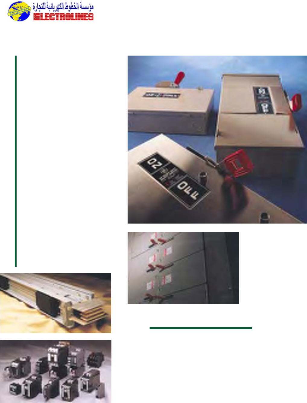
Safety Switches
SQ - D
Telemecanique
Cutler Hammer
Electrolines Est.
General Electric
P. O. Box. 942 Yanbu Saudi Arabia Tel: +966 4 3225418 Fax: +966 4 3222213 Al-Jubail: Tel: +966 3 3632967 Fax: +966 3 3612967

Distribution Equipment
Breaker Features
1. FRONT PANEL: This 11-guage steel
front panel fits into a collar-frame in the
equipment when the breaker is in the
CONNECT position.It provides a metal
barrier between the breaker compart-
ment and the secondary device com-
partment.Well marked and easy-to-read
operating controls and indicators
include TRIP button,CLOSE button,
OPEN/CLOSE indicator,CHARGE/DIS-
CHARGE indicator,OPERATIONS
counter and provision for manual charg-
ing the breaker.
2. PRIMARY DISCONNECT:The
primary disconnect finger set is rugged
and easy to inspect.Designed for
A. MAIN BUS
COMPARTMENT is
completely isolated by metal
barriers.Bus bars are provided
with high dielectric insulation
and pass through track-
resistant polyester glass
barriers between cubicles.All
main bus is tin-plated for
positive contact and low
resistance,and are insulated
with preformed boots (not
shown in this photo).Porcelain
insulation to ground is optional.
B. SECONDARY DISCON-
NECTS combine the positive-
contact reliability of a plug with
the automatic, self-aligning con-
venience of sliding-type con-
tacts.While in the
test position,sec-
ondary contacts are
easily disengaged or
reengaged by a
linkage operated from
the front of the cir-
cuit breaker.
C. CURRENT
TRANSFORMERS
are typically located
behind a mechanically actuated
safety shutter barrier that
isolates the primary
disconnects as the breaker is
moved into the DISCONNECT
position.Two single accuracy
CT’s per phase can be
accommodated on both the
line and load sides of the
breaker (as many as 12 CT’s
per breaker). CT’s are front-
accessible after removal of the
shutter safety barrier.
D.VOLTAGE
TRANSFORMERS meet all
applicable industry standards
and are mounted in an easy-
access roll-out tray.
E. DRY TYPE CONTROL
POWER TRANSFORMERS
have molded epoxy resin
insulation and are mounted in a
draw out tray for easy access.
Ratings run through 15kVA
optimum contact,built of silver-plated
copper and tested for continuous and
momentary currents.These disconnects
provide proper contact integrity
throughout the life of the gear for the
critical primary disconnect function.
3. CONTACT EROSION
INDICATOR: GE Vacuum interrupter
contacts seldom wear out over the
normal duty life-span of a circuit
breaker. Nevertheless, a contact erosion
indicator is provided for inspection
convenience. It is visible when the
breaker is withdrawn from the
compartment.
4. INTERRUPTER SUPPORT:
A rugged,high strength,track-resistant
polyester glass support assembly firmly
positions and holds the interrupter and
primary conductors while providing
insulation to ground and between
phases.This support assembly can be
removed quickly by disengaging six
bolts.Only a simple alignment of
contact wipe is required in the unlikely
event that the interrupter assembly
needs to be replaced.
5. BREAKER MECHANISM: Both ML-
17 and ML-18 mechanisms use a spring-
charged,stored-energy design that is
mechanically and electrically trip-free
and can be operated by dc control
voltages of 48V,125V, or 250V,or ac
voltages of 115V and 230V.High quality
mechanism parts are precision-tooled
for operating consistency, reliability,
maintenance ease and long life.
6. ROLL-IN OPTION: A roll-in breaker
designed for use in the lower
compartment of indoor switchgear is
available in all breaker ratings.The roll-in
feature eliminates the need for a lift
truck and reduces the required front
aisle space. Upper compartments may
be left blank or used as auxiliary
compartments above 1200A and 2000A
breakers.Above 3000A breakers,they
must be left blank for ventilation.The
breaker used for this option is the same
as used for the two-high product,with
the addition of an undercarriage.
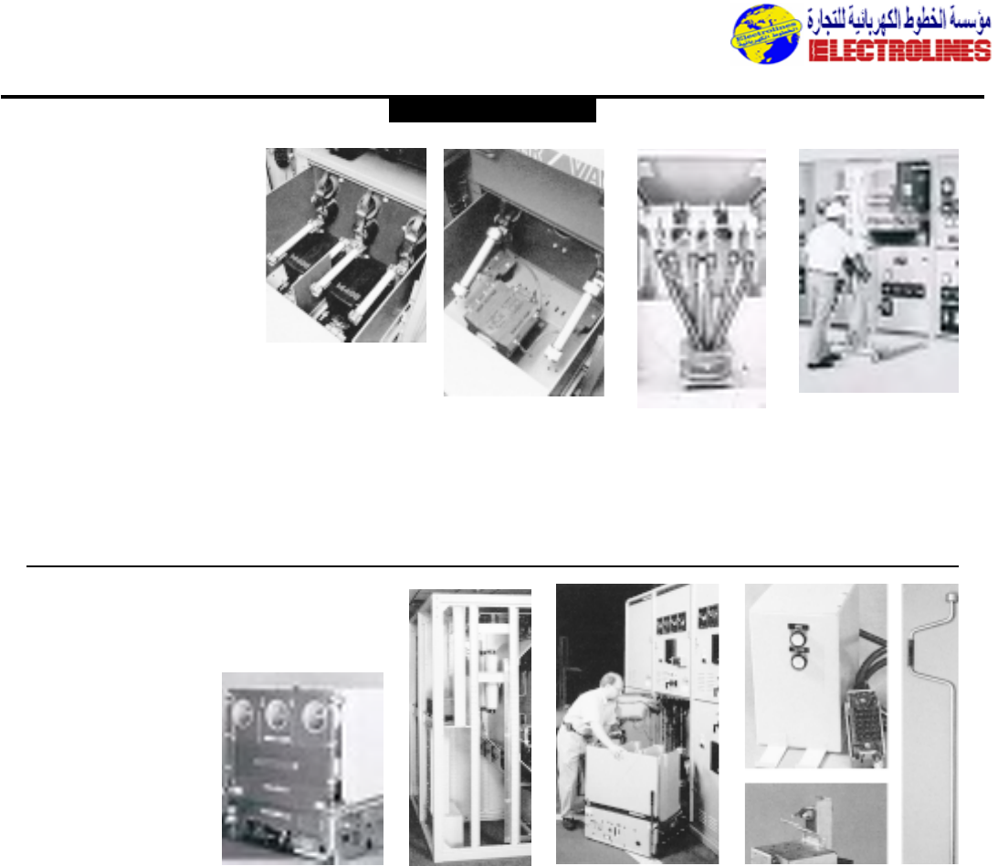
Medium Voltage Switchgear
Metalclad Switchgear
4.16kV-250 MVA through
13.8kV-1500 MVA
Power/Vac®
THESE SUPERIOR DESIGN FEATURES ARE STANDARD ON POWER/VAC®SWITCHGEAR
Roll-in optionInterrupter Support Breaker Mechanism
GENERAL ELECTRIC
Electrolines Est.
P. O. Box. 942 Yanbu Saudi Arabia Tel: +966 4 3225418 Fax: +966 4 3222213 Al-Jubail: Tel: +966 3 3632967 Fax: +966 3 3612967
Distribution Equipment
single phase.When a higher
rating,or 3 CPT’s,are required,
a key interlocked fused roll-out
tray will be supplied with
stationary CPT’s mounted in
the rear of the unit.
F. CABLE
COMPARTMENT in a basic
two-breaker vertical section
has ample space for
termination of up to two 750
MCM cables per phase,
including stress cone makeup.
When only one breaker is
required in a vertical section,
the entire cable area space is
available for use.
In two-high breaker equipment,
a vertical steel trough serves as
a separation barrier from the
1. Two-High Breaker
Stacking can save up to 50%
in floor space for most
applications,depending
on the rating,and results
in fewer shipping splits. In
addition,cubicle dimen-
sions are the same across
all ratings so space
requirements are clearly
defined at the outset.
System planning and lay-
out are thus simplified.
2. Breakers Roll Along Side-
Rails Into Position to assure
proper alignment.Positive
stops are provided in
TEST/DISCONNECT and
CONNECT positions.
Movement to the CONNECT
position is accomplished with a
racking mechanism that can be
manually,or (as an option)
remote electrically operated
from the front of the unit with
the door closed.
3. Precision Tooling brings uni-
form quality to breaker and
equipment parts and facilitates
trouble-free field assembly and
operation.
4. Transformer Roll-Out
Trays can be mounted as a
combination of two trays
either in the top or bottom
cubicles.The combination can
be two sets of VT’s or one VT
and one CPT up to 15 KVA in
either the top or bottom sec-
tion.The transformer primaries
are connected with insulated
bus and are automatically
grounded when withdrawn.
5. A Rugged Steel Frame
employs bolted reinforced gus-
sets for added strength and
dimensional integrity.Seismic-
qualified versions are available.
Grounded metal barriers iso-
late all high voltage compart-
ments.
6. Easy Installation results
because many foundations that
are smooth and level don’t
require embedded floor steel
or grouting.To reduce installa-
tion time, equipment can be
lifted into place without using
skids.
7. Ample Relay and Terminal
Block Space accepts complex
configurations and is compart-
mentalized by the front panel
enclosing the breaker. Meters,
relays, instruments and handles
are positioned on compart-
ment doors for easy reading
or operation.Open doors are
securely held with positive
stops so breakers can be
inserted and withdrawn with-
out damaging control,indica-
tion or protective devices.
A Full Selection of
Accessories
To facilitate inspection,mainte-
nance and test operations,
General Electric offers a full
selection of devices and acces-
sories for POWER/VAC metalclad
switchgear.
A. OPTIONAL GROUND
AND TEST DEVICES are
manually or electrically operat-
ed and provide facilities for
grounding either the bus side
or the outgoing cable side of
the metalclad unit,or for
“phasing out” operating cir-
cuits.
B. TEST CABINET provides a
convenient means to close and
trip breakers for maintenance
or inspection.
C.OPTIONAL REMOTE
RACKING DEVICE is
portable and connects to a
remote control panel via a 30
foot cable. It is motorized and
electrically racks the breaker
between the CONNECT and
DISCONNECT positions with
the door closed.
D.RACKING HANDLE manu-
ally operates the breaker rack-
ing mechanism to move the
breaker between the CON-
NECT and TEST/DISCON-
NECT positions.
other cable compartment.
This duct is easily
removed to facilitate ini-
tial installation of the “inside”
cables.When the vertical steel
duct is in place, there is still
access to the “inside” termina-
tions.The power cable com-
partment can be arranged to
permit both sets of cables to
exit below or above.
G. PORTABLE BREAKER
LIFT is provided for handling a
breaker or roll-out during
installation into a
compartment, or during
removal for inspection or
maintenance. Lifts for both
indoor and outdoor equipment
have interlocks on the lifting
forks to lock the breaker in
place during transporting.
Power/Vac®Features
GENERAL ELECTRIC
Electrolines Est.
P. O. Box. 942 Yanbu Saudi Arabia Tel: +966 4 3225418 Fax: +966 4 3222213 Al-Jubail: Tel: +966 3 3632967 Fax: +966 3 3612967
Distribution Equipment
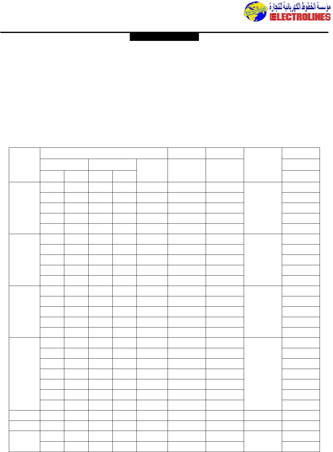
POWER/VAC Circuit Breaker Characteristics
Symmetrical Rating Basis ANSI C37.06 (1987)*
Identification
(6) & (7)
Normal
rms
Voltage
Class (kV)
4.16 250 4.76 1.24 19 60 1200 29 5 2 3.85 36 36 58
4.16 250 4.76 1.24 19 60 2000 29 5 2 3.85 36 36 58
4.16 250 4.76 1.24 19 60 3000 29 5 2 3.85 36 36 58
4.16 350 4.76 1.19 19 60 1200 41 5 2 4.0 49 49 78
4.16 350 4.76 1.19 19 60 2000 41 5 2 4.0 49 49 78
4.16 350 4.76 1.19 19 60 3000 41 5 2 4.0 49 49 78
4.16 350 4.76 1.19 19 60 3500 41 5 2 4.0 49 49 78
4.16 350 4.76 1.19 19 60 4000* 41 5 2 4.0 49 49 78
7.2 500 8.25 1.25 36 95 1200 33 5 2 6.6 41 41 66
7.2 500 8.25 1.25 36 95 2000 33 5 2 6.6 41 41 66
7.2 500 8.25 1.25 36 95 3000 33 5 2 6.6 41 41 66
7.2 500 8.25 1.25 36 95 3500 33 5 2 6.6 41 41 66
7.2 500 8.25 1.25 36 95 4000* 33 5 2 6.6 41 41 66
13.8 500 15 1.30 36 95 1200 18 5 2 11.5 23 23 37
13.8 500 15 1.30 36 95 2000 18 5 2 11.5 23 23 37
13.8 500 15 1.30 36 95 3000 18 5 2 11.5 23 23 37
13.8 750 15 1.30 36 95 1200 28 5 2 11.5 36 36 58
13.8 750 15 1.30 36 95 2000 28 5 2 11.5 36 36 58
13.8 750 15 1.30 36 95 3000 28 5 2 11.5 36 36 58
13.8 750 15 1.30 36 95 3500 28 5 2 11.5 36 36 58
13.8 750 15 1.30 36 95 4000* 28 5 2 11.5 36 36 58
13.8 1000 15 1.30 36 95 1200 37 5 2 11.5 48 48 77
13.8 1000 15 1.30 36 95 2000 37 5 2 11.5 48 48 77
13.8 1000 15 1.30 36 95 3000 37 5 2 11.5 48 48 77
13.8 1000 15 1.30 36 95 3500 37 5 2 11.5 48 48 77
13.8 1000 15 1.30 36 95 4000* 37 5 2 11.5 48 48 77
13.8 (8) 1500 15 1.00 36 95 1200 63 5 2 15.0 63 63 170
13.8 (8) 1500 15 1.00 36 95 2000 63 5 2 15.0 63 63 170
13.8 (8) 1500 15 1.00 36 95 3000 63 5 2 15.0 63 63 170
13.8 (8) 1500 15 1.00 36 95 3500 63 5 2 15.0 63 63 170
13.8 (8) 1500 15 1.00 36 95 4000* 63 5 2 15.0 63 63 170
Non-Standard Breakers – High Close and Latch Capability
4.16 250 4.76 1.24 19 60 1200 29 5 2 3.85 36 36 78
2000
13.8 500 15 1.30 36 95 1200 18 5 2 11.5 23 23 58
2000
13.8 750 15 1.30 36 95 1200 28 5 2 11.5 36 36 77
2000
Normal 3-
phase
Class
(MVA)
Rated
Maximum
rms Voltage
(kV) (1)
Rated
Voltage
Range
Factor K
(2)
Low
Frequency
rms Voltage
(kV)
Crest
Impulse
Voltage
(kV)
Continuous
rms Current
Rating at 60
Hz (amperes)
Short circuit
rms Current
Rating (at
Rated Max
kV) (kA)
(3) (4)
Rated
Interrupting
Time (Cycles)
Rated
Permissible
Tripping
Delay,Y
(Seconds)
Rated
Maximum
rms Voltage
Divided by
K (kV)
K times Related Short-
circuit rms Current
(kA) (kA)
Closing and
Latching
Capability
peak amp
(kA)
Voltage Insulation
Rated Withstand
Test Voltage
Maximum
Symmetrical
Interrupting
Capability (5)
3 Sec Short
time Current
Carrying
Capability
Current Current Values
Rated Values Related Required Capabilities
Notes Applying to Table
(1)Maximum voltage for which the breaker is designed and the
upper limit for operation.
(2)k is the ratio of rated maximum voltage to the lower limit of
the range of operating voltage in which the required
symmetrical and asymmetrical interrupting capabilities vary in
inverse proportion to the operating voltage.
(3)To obtain the required symmetrical interrupting capability of a
circuit breaker at an operating voltage between 1/K times
rated maximum voltage and rated maximum voltage,the
following formula shall be used:
Required Symmetrical Interrupting Capability =
Rated Short-circuit Current x (Rated Max.Voltage)
(Operating Voltage)
For operating voltages below 1/K times rated maximum
voltage,the required symmetrical interrupting capability of the
circuit breaker shall be equal to K times rated short-circuit
current.
(4)With the limitation stated in 5.10 of ANSI-C37.04-1991,all
values apply for polyphase and line-to-line faults.For single
phase-to-ground faults,the specific conditions stated in
5.10.2.3 of ANSI-C37.04-1991 apply.
(5)Current values in this column are not to be exceeded even
for operating voltages below 1/K times rated maximum
voltage.For voltages between rated maximum voltage and
1/times rated maximum voltage,follow
(3) above.
(6)NOTE:1500 MVA not a listed rating according to ANSI
C37.06 Table 2.1.
(7)GE PowerVac circuit breakers are designed as type VB.“Kv”.
“MVA” or type VB1.“kV”.“MVA”.The VB designation applies
to breakers with an ML-18 mechanism.All 3000 Amp
continuous current rated and 1500mVA breakers are
furnished with the ML-17 mechanism.All other 1200 and 2000
Amp rated breakers are furnished with the ML-18 mechanism
except when a special application is required.
(8)NOTE:GE reserves the right to improve the design and/or
modify the specifications in this publication without notice.
*Fan cooled only.
GENERAL ELECTRIC
Electrolines Est.
P. O. Box. 942 Yanbu Saudi Arabia Tel: +966 4 3225418 Fax: +966 4 3222213 Al-Jubail: Tel: +966 3 3632967 Fax: +966 3 3612967
Distribution Equipment
BUS COMPARTMENT
•1200A and 2000A:Copper standard.
•3000A bus and 3500A bus is copper only.
•Bus supports designed for 80,000A momentary.
•All joints connected with 2 bolts and booted.
•Bus support insulation system:
Non-tracking polyester glass (std.5kV & 15kV)
Porcelain inserts (optional)
Fluidized bed epoxy bus insulation.
CABLE COMPARTMENT
•Designed for up to 2-750 MCM/ Ø per breaker; cables
above or below.
•CT’s with greater than ANSI accuracy must be mounted
in cable compartment and may limit such cases to one
breaker per vertical section.
•Stress cone space of 21 inches is provided and use of pre-
formed stress cones,such as GE Termimatic (TM), is rec-
ommended.
*Certain simple cable compartment configurations such as
clamp type terminations for one moderate-sized cable
per phase, with or without Ground Sensor,permit a unit
*STD.(82” Optional.See Note Under “Cable Compt.”)
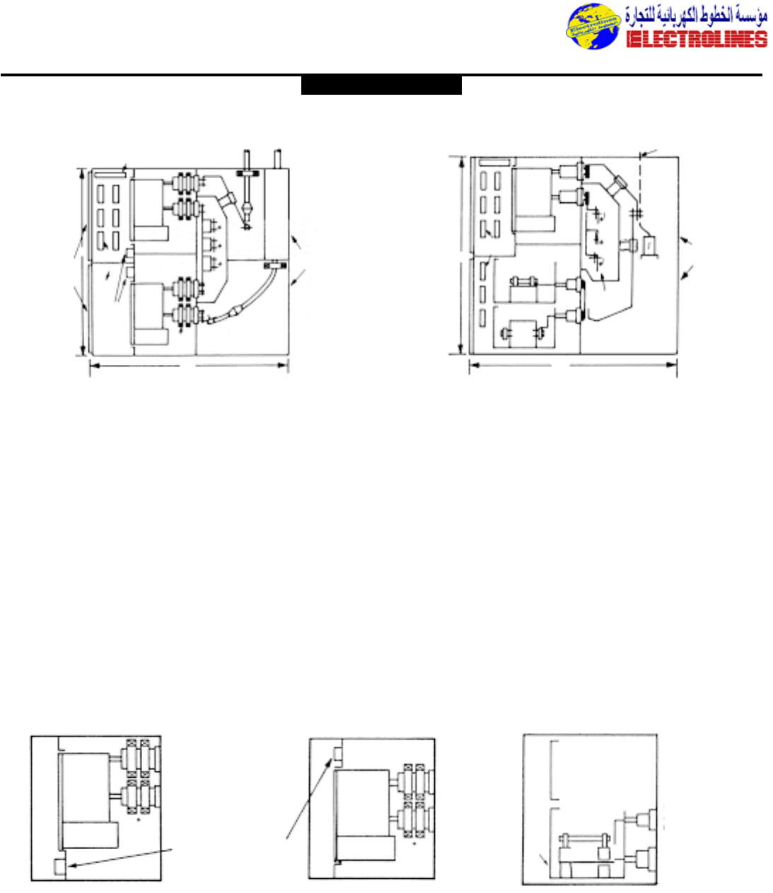
Typical 2Bkr. Feeder Unit Clamp Type Term.For Cable Above Typical Incoming Line Unit With Main Breaker & CPT & VT Roll-
outs in Same Unit
*STD.(82” Optional - See Below)
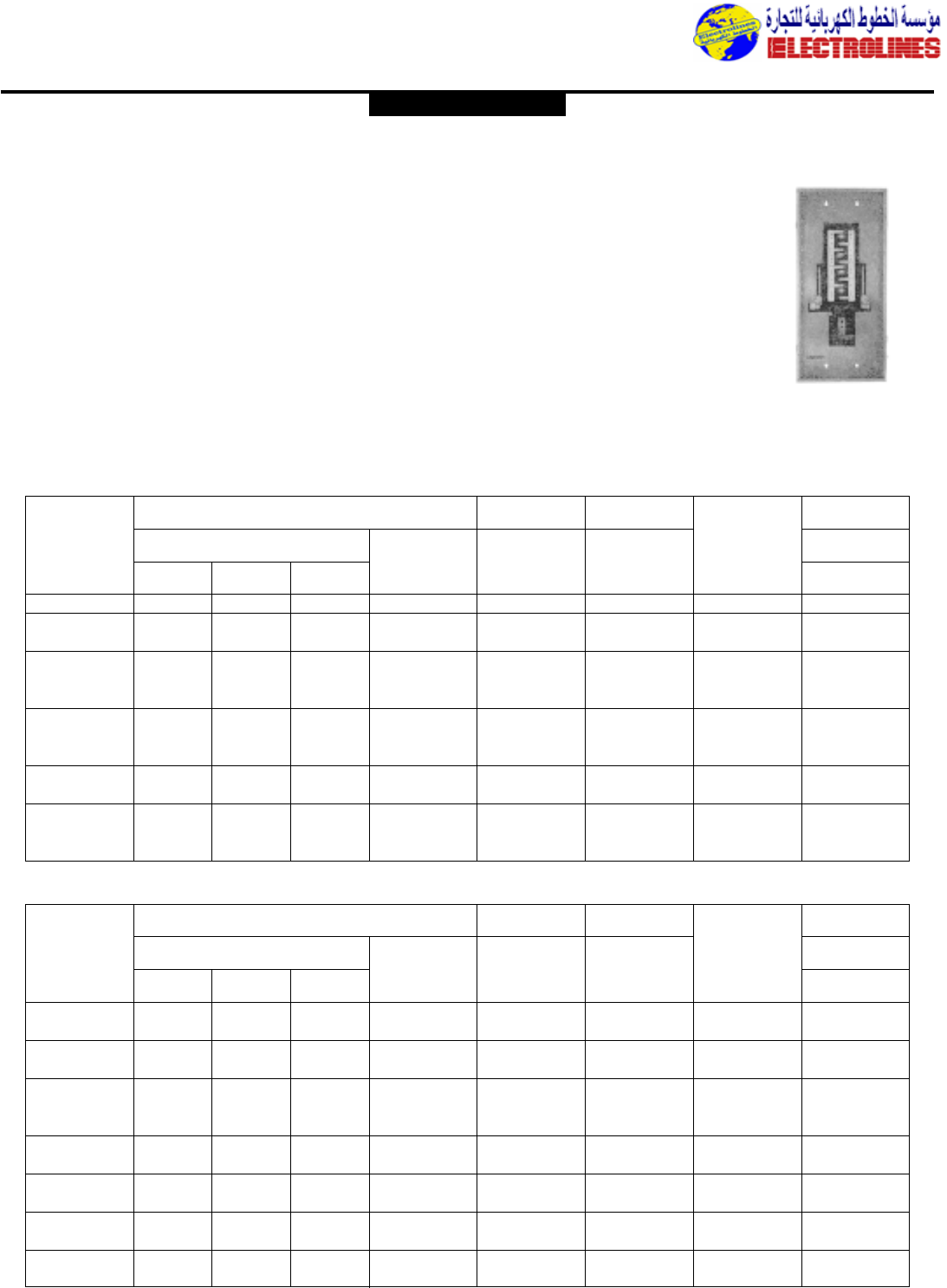
Typical Equipment Section Views
Typical Upper and Lower Unit Configurations
(1) Typical Breaker Units – 5/15 kV (2) Typical Auxiliary Units – 5/15 kV
Upper 1200A or 2000A BKR. Lower 1200A, 2000A or 3000A BKR. Alt.Lower:Fuses Only
Bus Conn
Fuse Blocks & Misc
Surface Mtd Bkr
Control Devices
Fuses for 3 Ø CPT or 1 Ø CPT >
15 kVA CPT and secondary break-
er located in Cable Compartment.
*Space for 4CTS Per Phase, 2 in Upper Studs & 2 on Lower Studs. Rating Range: 150A - 4000A Accuracy Per ANSI C37.20.
Bus Conn Line/Bus conn.
To out going
conn.
GENERAL ELECTRIC
Control Wiring
Bkr
CTS
95 Term
Blocks
Bkr
Fuse Block
& Misc.
Surface
Mtd. Bkr.
Cont. Dev. CTS
94*
GSR
CT
Bolted
Covers
Upper
Cable
Compt.
GSR
CT
Cable
Trough
Leads
Above
Lower Cable
Compt.
Hinged
Device
Panels
1200/2000A
Incoming Cable or Bus Duct
Cable
Compt.
Bolted
Covers
Bus
Compt.
1
2
3
Bkr
Terminal
Block
VT Roll-Out
VT Roll-Out
15 KVA
Fuses
CPT
94”
95
BKR
BKR
Roll-
out
Tray
Fuses
Electrolines Est.
P. O. Box. 942 Yanbu Saudi Arabia Tel: +966 4 3225418 Fax: +966 4 3222213 Al-Jubail: Tel: +966 3 3632967 Fax: +966 3 3612967

Distribution Equipment
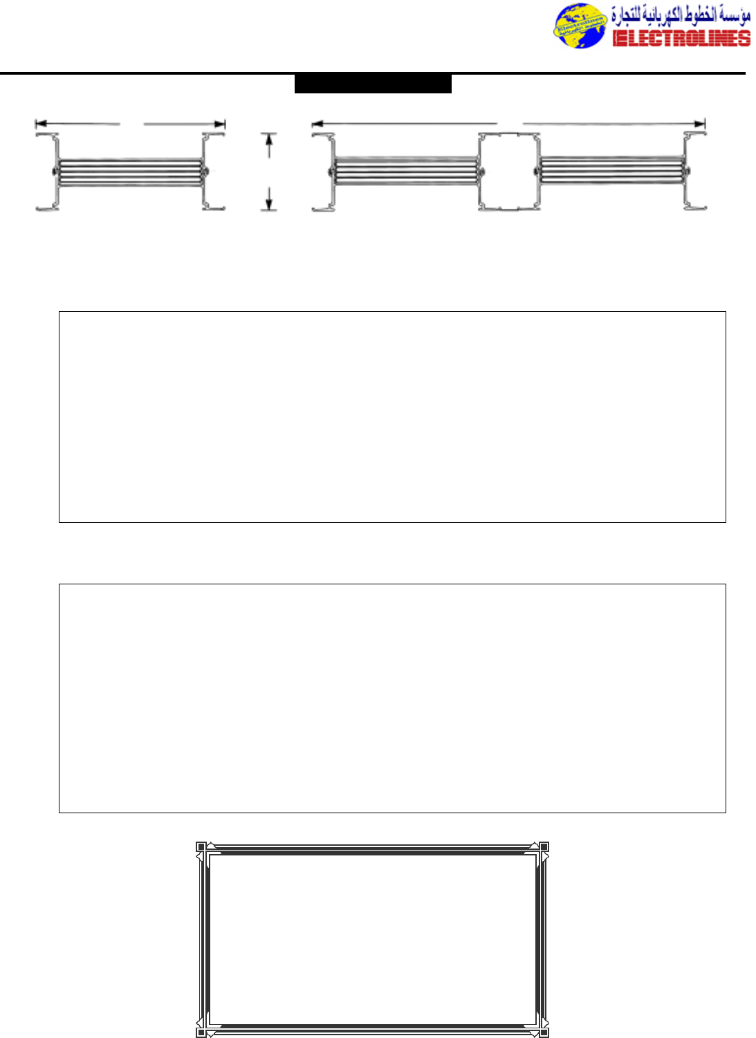
Spectra Series Busway
GE’s Spectra SeriesTM busway sets a new industry mark for
convenience and performance. High current-carrying capacity.
Superior short-circuit protection. Low voltage drop.Exclusive
adjustable joint connectors.Compact design.All from a
busway that’s up to half the weight of other systems.
Low-weight design reduces labor costs.
GE’s Spectra Series bus features a computer-designed alu-
minum housing that dramatically cuts busway weight up to
50%.Less weight means less labor – and significantly lower
installation costs.
Spectra bus sections can often be
hung with just a single drop rod
hanger.And bus sections are
quickly and easily joined by a sin-
gle, positive bolt.You can carry,
position,and install bus sections
to form entire busway runs–with-
out special assembly tools.
No other bus can match the
installation simplicity and ease of
Spectra bus.
Adjustable joints – an industry exclusive.
Spectra bus features a special joint connector that allows
quick and easy ±1/2” length adjustment – right in the field.It
saves time and labor, and assures perfect installation every
time.
Lightweight design doesn’t mean
lightweight performance.
GE engineers have broken the weight barrier with a system
that provides the current-carrying capacity (up to 5,000
amps),short-circuit protection,and ruggedness you’ve always
counted on from GE bus.
The Spectra bus not only han-
dles the electrical demands of
any project – it also helps
save money.The busway’s
ultralow reactance and volt-
age-drop characteristics cut
power loss to the absolute
minimum.
Epoxy insulation
protects your
ivestment.
GE has accumulated over 25 years pioneering sophisticated
material coating.And now GE brings this experience to the
electrical distribution industry by applying its most advanced
epoxy insulation technology to Spectra bus. Unlike the mylar,
PVC, and glass tape insulators used by other manufacturers,
epoxy provides significantly longer life, higher impact strength,
and better resistance to water absorption.For instance,
epoxy has twice the impact strength of mylar – providing
extra durability during shipment and installation.Epoxy also
offers better thermal characteristics,allowing a 130˚ C rating
(typical PVC-based busways are rated at 105˚C).
Another important advantage of epoxy insulation is consis-
tency.The insulation on typical busway is manually wrapped
on,leaving the quality of the insulation dependent on the skill
of the technician.Voids and air gaps are inevitable.Spectra
bus,on the other hand, uses an automated process to coat
epoxy on the conductors in a precisely defined and con-
trolled manner. For consistent,repeatable quality.A higher
degree of safety.And performance that protects your busway
investment – and your equipment.
We built a better
belleville – for long-
lasting joint strength.
Ordinary belleville joints can lose
significant holding force (up to
one-third of original force) over
time.This degradation can lead to
joint and busway failure – and
expensive downtime.
The combat compressive joint
relaxation,GE engineers
researched and selected their
time-proven belleville spring that retains over 90% of its origi-
nal contact pressure – for confident, long-term reliability and
minimal maintenance.
Streamlined – yet durable.
Contemporary. Clean. Compact. Just a few of the words that
describe Spectra bus.Its aluminum construction provides
great strength and rigidity – plus natural corrosion resistance.
With GE’s Spectra bus, you can be confident of years of
trouble-free operation.
Adapts quickly to changing requirements.
As your needs change,so can your busway.Spectra bus is
designed to be taken apart, relocated,and reassembled – as
many times as required – without loss of electrical or
mechanical integrity.Tees, elbows,plugs, tap boxes, and other
components can all be reused,maximizing the value of your
busway investment.
A load of extras.
Removable isolation joints enable
individual sections to be taken
out of service without shutting
down the entire system. For
example, this allows electrical
maintenance to be performed on
a specific floor in a high rise –
while leaving other floors
energized.
Additional benefits include up to 1600-amp tapoffs at bus
joints;plug position locators for positive, safe installation; plug
assist to simply connection;and a standard 50% housing
ground.
Easier installation and better performance
– all the way down the line.
Looking for lightweight, high-performance,cost-saving busway?
Get a load of the new Spectra Series busway from GE.It’s just
one of the many cost- and labor-saving products of our new
Spectra Series line. For more busway information,write or
call Electrolines.
Installation was never
this easy.
Every bus bar is 100% integri-
ty-tested – for absolute per-
formance confidence.
Isolation Joints simplify
maintenance
Designed to cut power loss to the
absolute minimum.
GENERAL ELECTRIC
Electrolines Est.
P. O. Box. 942 Yanbu Saudi Arabia Tel: +966 4 3225418 Fax: +966 4 3222213 Al-Jubail: Tel: +966 3 3632967 Fax: +966 3 3612967
Distribution Equipment
One Stack
WW
4.50 in.
114mm
Two Stack
Plug-In and Feeder
Ampere No. “W” Width Bar Width Short Circuit Weight Voltage Drop
Rating Stacks Inches MM x .25 in Rating – RMS SYM LBS/FT Ωx 10
-3
/100FT Volts/100Ft*
3W 4W R X .4 PF .9 PF
225 1 4.38 111 1.09 50,000 4 5 5.99 1.72 1.35 2.39
400 1 4.38 111 1.09 50,000 4 5 6.54 1.50 2.76 4.53
600 1 4.38 111 1.63 85,000 5 6 4.52 1.28 1.97 2.99
800 1 5.63 143 2.88 100,000 6 7 2.48 .79 2.38 3.57
1000 1 6.13 156 3.38 100,000 7 8 2.17 .68 2.58 3.90
1200 1 7.00 178 4.25 125,000 8 9 1.73 .55 2.49 3.73
1350 1 8.50 216 5.75 150,000 9 10 1.24 .41 2.04 3.03
1600 1 9.25 235 6.50 150,000 10 12 1.12 .36 2.16 3.23
2000 1 11.00 279 8.25 150,000 12 15 .89 .29 2.15 3.21
2500 2 15.50 394 (2) 4.50 200,000 17 20 .82 .26 2.45 3.69
3000 2 18.00 457 (2) 5.75 200,000 19 23 .64 .21 2.33 3.47
4000 2 23.00 584 (2) 8.25 200,000 25 30 .45 .14 2.14 3.23
Ampere No. “W” Width Bar Width Short Circuit Weight Voltage Drop
Rating Stacks Inches MM x .25 in Rating – RMS SYM LBS/FT Ωx 10
-3
/100FT Volts/100Ft*
3W 4W R X .4 PF .9 PF
225 1 4.38 111 1.09 50,000 6 7 3.39 1.72 1.14 1.48
400 1 4.38 111 1.09 50,000 6 7 3.59 1.72 2.09 2.76
600 1 4.38 111 1.09 50,000 6 7 3.94 1.50 3.07 4.36
800 1 4.38 111 1.63 85,000 8 9 2.62 1.28 2.25 2.89
1000 1 5.00 127 2.25 100,000 10 12 1.90 .98 2.87 3.70
1200 1 5.63 143 2.88 100,000 12 15 1.49 .79 2.74 3.50
1350 1 6.13 156 3.38 100,000 14 17 1.27 .68 2.65 3.37
1600 1 7.00 178 4.25 125,000 16 20 1.00 .55 2.51 3.16
2000 1 8.50 216 5.75 150,000 21 26 .73 .41 2.31 2.90
2500 1 11.00 279 8.25 150,000 29 37 .50 .29 2.02 2.50
3000 2 15.00 381 (2) 4.25 200,000 32 40 .49 .28 2.35 2.93
4000 2 18.00 457 (2) 5.75 200,000 42 52 .37 .21 2.36 2.94
5000 2 23.00 584 (2) 8.25 200,000 58 74 .25 .14 1.98 2.48
*Concentrated 3 ø line-line. For distributed loads divide by 2.
ALUMINUMCOPPER
GENERAL ELECTRIC
Contact
for comprehensive
catalogue and
Technical Information.
ELECTROLINES
Electrolines Est.
P. O. Box. 942 Yanbu Saudi Arabia Tel: +966 4 3225418 Fax: +966 4 3222213 Al-Jubail: Tel: +966 3 3632967 Fax: +966 3 3612967
Min.depth 15”
Main lugs to 2000A
All devices bolt on
Self-supporting. May be mounted
against wall.
Insulated bus not available.
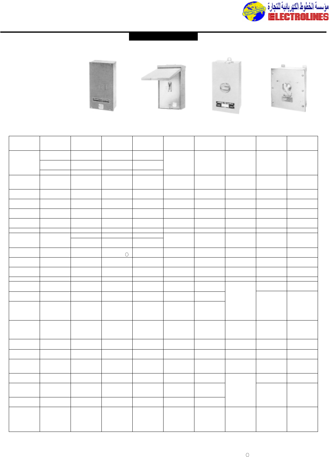
Main and Feeder Devices
Group-Mounted
Molded case circuit breakers
E,F, J, K,TLB4 150-1200A
Fusible switches
QMR 30-1200A
MicroVersaTrip®molded case
circuit breakers¿
Current-limiting circuit breakers
Fuseless THLC 150-400A,TEL,TFL
Fused Tri-Break®100-800A
PMCU Size 0-4 (feeder only)
AV-2
Main device individually-mounted,
feeders group-mounted.Maximum
4000A mains and 1200A feeders.
Front accessibility and rear alignment
standard.Rear access may be required
for main.Side access may be required
for busway entrance.
Individually-Mounted
Main, Group-Mounted
Feeders, Front-Accessible
Maximum 4000A mains,1200A
feeders
Rear alignment standard
Depths:Mains 25”-60”
Feeders 20” min.
Insulated bus not available
Main, Sub-Main,Tie
Devices, Individually-
Mounted
Molded case circuit breakers
J,K 400-1200A
Fusible switches
QMR 400-1200A
Distribution Equipment
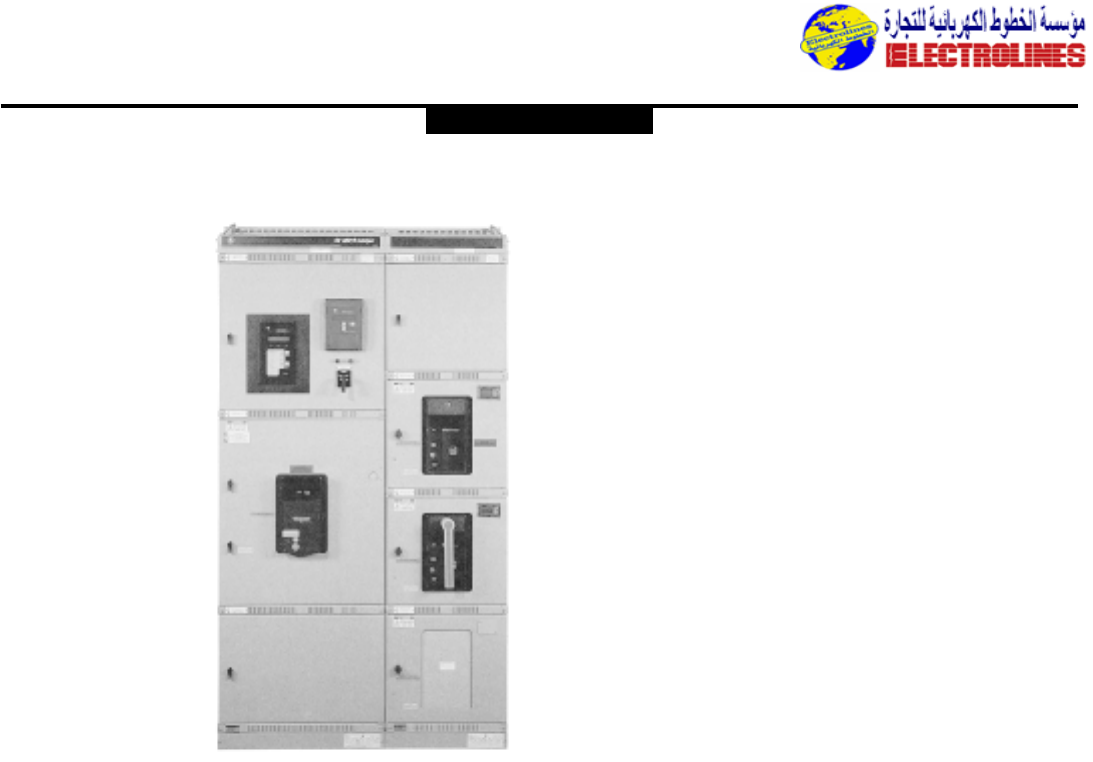
Five types of construction to fit any
application … a complete line-up of
the features you need …important
options to choose from, too,like
compact,easy-to-install panel motor
control units for tough-job motor
starting… state-of-the-art design… it
all adds up to the safety,savings,and
simplicity you’ve been looking for in a
value-packed switchboard:AV-LINE.®
Select the protection
level you need.
With AV-LINE®switchboards,you can
select from a wide range of circuit
breakers—low-voltage power circuit,
molded-case, and Power Break®
insulated-case breakers–along with
high pressure contact or fusible
switches.And with MicroVersaTrip®
and Micro Versa-Trip®RMS-9
programmable trip devices,you can
choose the precise level of protection
you need,thanks to an eight-point trip
adjustment switch,multiple time-delay
bands and fast flexible functions:long-
time, short-time, instantaneous,
ground-fault, signalling, and system
interlocking.
AV-LINE® SWITCH-
BOARDS —TYPES
OF CONSTRUCTION
AV-LINE®switchboards are available
with group or individually mounted,
main and feeder devices.Group-
mounted devices are front-accessible.
Individually-mounted require front-
and rear-accessibility Devices available
include:
•Molded Case Circuit Breakers
•Insulated Case Circuit Breakers
•Low Voltage Power Circuit
Breakers
•Fusible Switches
Ground fault protection and automatic
transfer are available.
AV-LINE®switchboards meet
Underwriters Laboratories No.891
and NEMA PB2 Standards.AV-1
switchboards have group (panel)-
mounted main and distribution sec-
tions.
AV-2 switchboards have individually-
mounted main and group (panel)-
mounted distribution sections.
AV-3 switchboards have individually-
mounted main and feeder sections.
Feeder devices have external
operating handles.Feeder device
compartmentation and
insulated/isolated main vertical bus in
feeder section is available.
AV-4 switchboards consist of Power
Break® main section and AV-3 distribu-
tion sections.All bus (main and feed-
ers) is insulated/isolated,and devices
compartmentalized.
AV-5 switchboards contain higher
ampere rated feeders than are avail-
able in other switchboards types.All
feeders are individually-mounted.
Insulated/isolated bus is not available.
AV-LINE® Switchboard
Types
GE AV-LINE®switchboards are avail-
able front-accessible with feeder
devices group-mounted, and rear-
accessible with feeders individually-
mounted.There are five types to meet
a variety of installation requirements.
AV-1
Main and feeder devices are group-
mounted maximum 1200A main and
feeders,and 2000A main lugs. Front
accessibility and rear alignment stan-
dard for mounting against a wall.
Group-Mounted Main and
Feeders Front-Accessible
Maximum 1200A mains,1200A
feeders Rear alignment standard
Low Voltage Gear
AV-LINE® SWITCHBOARDS
GENERAL ELECTRIC
AV-1
AV-2
Electrolines Est.
P. O. Box. 942 Yanbu Saudi Arabia Tel: +966 4 3225418 Fax: +966 4 3222213 Al-Jubail: Tel: +966 3 3632967 Fax: +966 3 3612967
Distribution Equipment
MicroVersa Trip®circuit breakers¿
Tri-Break®circuit breakers
TB6,TB8, 600-800A
Current-limiting circuit breakers THLC
150-400A
Power Break®insulated case circuit
breakers 800-4000A
AKR low voltage power circuit
breakers fused and unfused 800-
4000A
High pressure contact switches 800-
4000A
Bolted pressure switches 800-4000A
AV-3
Main and feeder devices individually
mounted.Maximum 4000A mains,
1200A feeders (200A fusible).Front
and rear accessibility.Front and rear
alignment.Feeder devices can be com-
partmented. Barriers between sections
available.Feeder main and vertical bus
can be insulated/isolated.
Individually-Mounted
Mains and Feeders
Rear accessible
Front and rear alignment
Depths-30-60”
Maximum 4000A mains;1200A
feeders molded case circuit breakers,
200A fusible switches
Working space required behind
switchboard
Insulated bus available on feeders only
Feeders have external operating
handles Device compartmentation
available.
Main, Sub-Main,Tie
Devices, Individually-
Mounted
Same as AV-2
Feeder Devices,
Individually-Mounted
Molded case circuit breakers
E,F, J, K,TLB4 150-1200A
Micro Versa Trip®molded case circuit
breakers¿
Fusible switches
QMR 30-200A
Current-limiting circuit breakers
Fuseless THLC 150-400A,TEL,TFL
Fused Tri-Break®100-800A
AV-4
Same as AV-3 except main and feeder
vertical and horizontal bus may be
insulated/isolated,and devices com-
partmented. Main section is a POWER
BREAK®switchboard main section and
is limited to molded case circuit
breakers, POWER BREAK®breakers,
and high pressure contact switches.
Individually-Mounted
Mains and Feeders
Rear accessible
Front and rear alignment
Power Break® main section
AV-3 feeder section
Main and feeder bus
insulation/isolation available
Device compartmentation available
Depths 35-60”
Maximum 4000A mains;feeders
1200A molded case circuit breakers,
200A fusible switches
Working space required behind
switchboard
Feeders have external operating
handles
Main, Sub-Main,Tie
Devices Individually-
Mounted
Power Break®circuit breaker 800-
4000A
High pressure contact switches 800-
4000A
Feeder Devices,
Individually-Mounted
Same as AV-3
AV-5
Main and feeder devices individually
mounted.Feeders higher ampere rated
than those available in AV-3,AV-4, and
sized as main devices.Front and rear
alignment.Front and rear accessibility.
Device compartmentation and insulat-
ed/isolated bus not available.
Individually-Mounted
Mains and Feeders
Rear accessible
Front and rear alignment
Depths-35-60”
Maximum 4000A mains;1600A➁
feeders
Working space required
behind switchboard
Insulated bus and device
compartmentation not available
For use when feeders larger than
available in AV-3 are required
Main, Sub-Main,Tie,
Devices Individually-
Mounted
Same as AV-3
Feeder Devices
Individually-mounted
Power Break®circuit breaker 800-
1600A¡
High pressure contact switch 800-
1600A¡
Bolted pressure switch 800-1600A¡
Low voltage Power Circuit Breaker
800-1600A¡
Molded case circuit breakers
E,F, J, K,TLB4 150-1200A
Micro Versa Trip®molded case circuit
breakers¿
Current-limiting circuit breakers
Fuseless THLC 150-400A,TEL,TFL
Fused Tri-Break®100-800A
AV-3 AV-4 AV-5
GENERAL ELECTRIC
Electrolines Est.
P. O. Box. 942 Yanbu Saudi Arabia Tel: +966 4 3225418 Fax: +966 4 3222213 Al-Jubail: Tel: +966 3 3632967 Fax: +966 3 3612967
Distribution Equipment
General description
AKD-8 Switchgear is industrial-duty
equipment built to ANSI standards and
uses 100% rated Low-Voltage AKR
Power Circuit Breakers. It is designed
to have more margin within its ratings
to provide maximum continuity of
service for those applications subject
to severe duty, such as repetitive
switching encountered with motor
starting , power factor correction,
demand control,load shedding,etc.
A major factor contributing to this
extended continuity of service is the
availability of renewal parts complete
with detailed maintenance instructions
and original equipment
documentation.From a coordination
standpoint,type AKR circuit breakers
provide full selectivity with each other
and with other protective devices.
The bus sizing is based on
temperature rise rather than on
current density (as with switchboard
construction).
AKD-8 switchgear is available with the
following maximum nominal ratings:
•600 Vac, 250 Vdc
•5000 Aac, 6000 Adc
•50/60 Hz
•2200 Vac RMS dielectric
•200 kA symmetrical short circuit
AKD-8 switchgear sections are
provided in either 22”,30” or 38”
widths.
It is designed to be operated in an
ambient temperature between -30˚C
and 40˚C.
Type AKR low-voltage power circuit
breakers are available for AKD-8
switchgear in six frame sizes:
•800A AKR-30, 30H, 30L
•1600A AKR-50, 50H
•2000A AKRT-50H
•3200A AKR-75, 75H
•4000A AKR-100
•5000A AKR-125
All breakers can be equipped with
current limiting fuses.AKRU-30 and
AKRU-50 are provided with integrally
mounted fuses,while a separate fuse
carriage is required for AKRT-50H,
AKR-75,AKR-100, and AKR-125.
Low-voltage circuit breakers rated
800/1600/2000 amps can be stacked in
four-high combinations resulting in
reduced floor space requirements.The
11-gauge, bolted modular-designed
steel frame permits flexibility in
arrangements of breakers and
associated components.
AKD-8 switchgear houses low-voltage
power circuit breakers,
instrumentation,and other auxiliary
circuit protective devices in single or
multiple source configurations.AKD-8
switchgear can be applied either as a
unit substation in indoor or outdoor
construction.
AKD-8 switchgear is manufactured in
GE’s ISO 9002 certified facility in
Burlington,Iowa.It complies with
ANSI standards C37.20.1 and NEMA
SG-5,and it is UL listed to standard
1558,file no.E76012.The switchgear
has been conformance tested
according to ANSI C37.51.
ANSI standards require that
switchgear operate at the ratings of
devices installed.Switchgear short
circuit ratings are based on two 30-
cycle withstand tests with 15-seconds
interval,performed at 15% power
factor and 635 Vac maximum. For
switchboards,a single 3-cycle
withstand test at 20% power factor
and 600 Vac maximum is performed.
General Electric’s AKD-8 low-voltage
switchgear can help you meet today’s
challenges for greater productivity,
increased operator safety and
improved equipment reliability and
maintainability.
AKD – Switchgear
GENERAL ELECTRIC
Electrolines Est.
P. O. Box. 942 Yanbu Saudi Arabia Tel: +966 4 3225418 Fax: +966 4 3222213 Al-Jubail: Tel: +966 3 3632967 Fax: +966 3 3612967
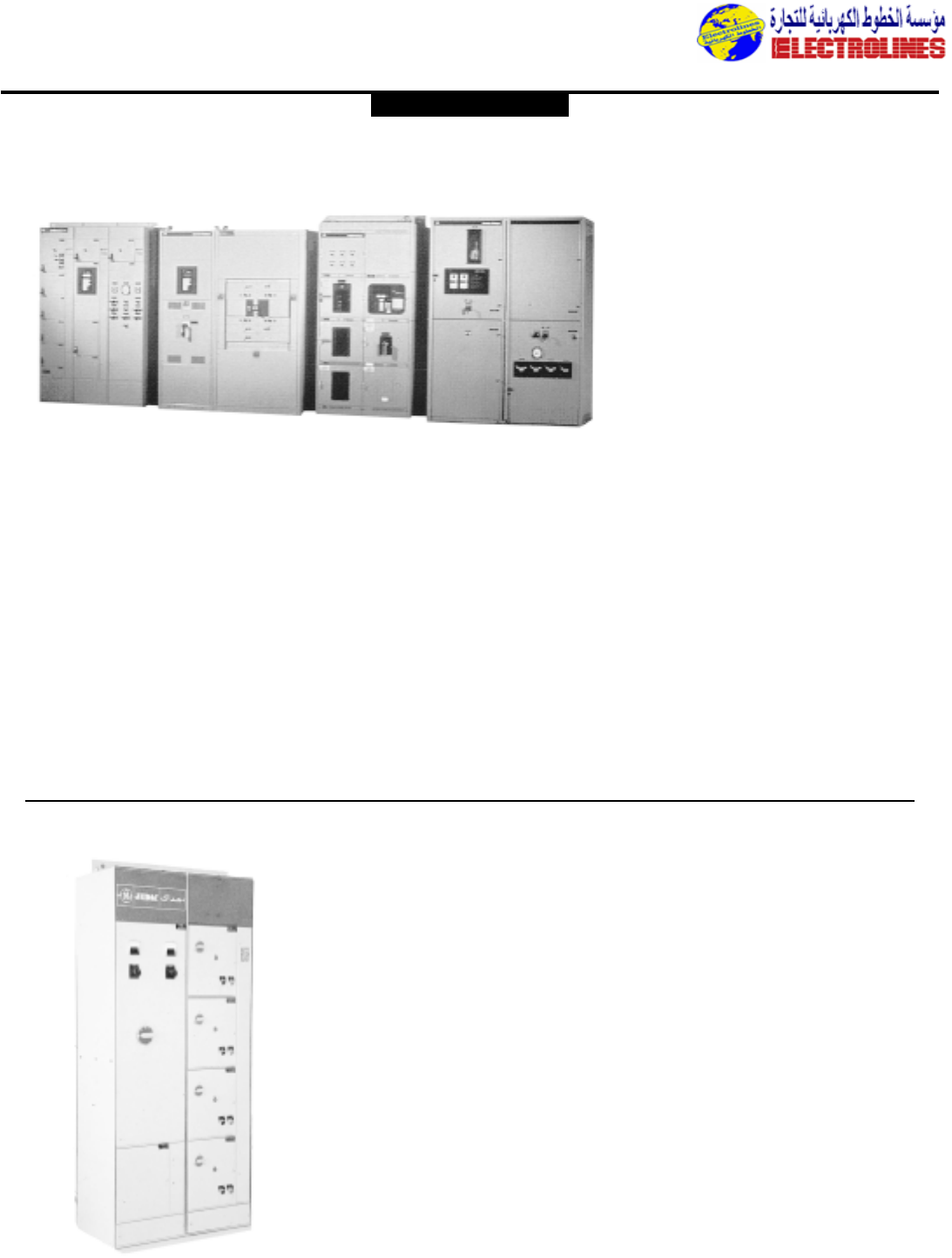
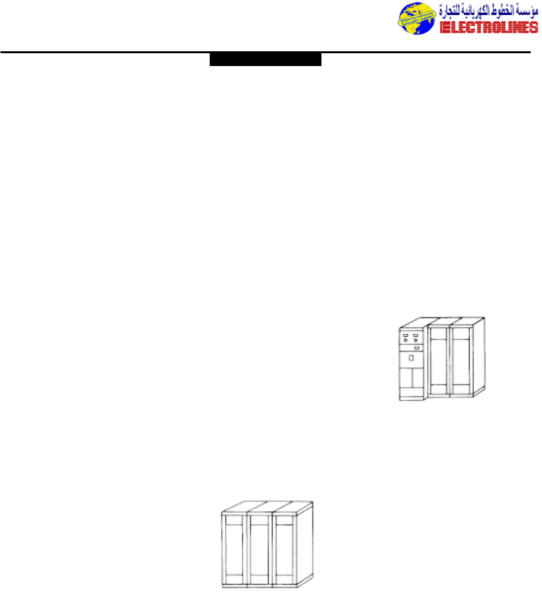
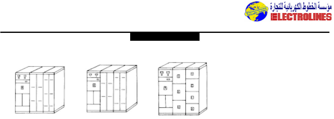
8000-Line Motor Control Centers
7700-Line Motor Control Centers
Distribution Equipment
Fully integrated motor
control centers
•Order management
•Coordinated drawings
•Applications support
•Mechanical transitions
•Start-up support
The traditional values pioneered in the
7700-Line Motor Control Center remain,
but the 8000-Line has been significantly
updated and improved.Added design
flexibility and the latest component
technology create an integrated product.
Now,you can add the application flexibility
of solid-state reduced-voltage starters,
Spectra RMS circuit breakers,
programmable controls and ac adjustable
Design Features:
•Structures of heavy gauge steel provide
reliable,permanent installation whether
indoor or outdoor service is required.
7700-Line motor control centers stand up
to severe environmental and service
conditions.
•Each indoor section contains space for a
12-inch (305mm) high and a 6–inch
(152mm) high isolated horizontal wireway
compartment, one located at the top of
the structure,the other at the bottom.
The 12-inch (305mm) high compartment
can be positioned at the top or bottom of
the enclosure to best fit your incoming
and outgoing cable schedule.
•For most configurations,an isolated,full-
height vertical wireway is built into each
section.This 4 5/8-inch (117mm) wide by
8–inch (203mm) deep wire trough
provides convenient access for installation
of power and control cable without
disturbing adjacent unit compartments.
•Indoor Enclosures NEMA 1 General
Purpose (standard) NEMA 1 Gasketed,
NEMA 2 Drip-proof,NEMA 12 Dust-tight.
•Outdoor Enclosures NEMA 3R non-walk-
in (front only),NEMA 3R non-walk-in
(back-to-back).
•A Zinc-phosphate primer treatment
provides corrosion – resistance, topped
off with light grey ANSI-61 finish. (Other
colors upon request.)
•Designed and manufactured in accordance
with NEMA ICS 2-322,U/L845 and IEC
standards.
•Bracing for 25,000 Amperes RMS
symmetrical fault current is standard.The
main and vertical bus can be strengthened
for short circuit capacities of 42,000,
65,000 and 100,000 A/C.
•Standard MCC main bus is 600 Amperes
Tin-plated copper.We can also supply
main bus ratings up to 2000 Amperes,
2500 Amperes.
•Vertical busbar standard ratings are 300-
450-600 Amperes tin-plated or silver
plated copper.
•Standard dimensions or section:
Height:2286mm (90inch.)
Width:508mm (20inch.)
speed drives.This presents significant new
opportunities for industrial users who are
building new plants or updating existing
facilities.
Technical data
Ratings
System 208,240,380, 575 volt;
50/60 Hz;
3ø4w, 3ø3w
Short circuit 22,25,42, 65,100 kA
symmetrical amperes
Bus bracing 42,65,100, kA symmetrical
amperes
Horizontal/ 600, 800, 1200 A aluminum
Main/Neutral (tin plated) 600,800,1000,
bus 1200,1600,2000,A copper
(tin- or silver-plated)
Vertical bus 300,450,600 A copper (tin-
or silver-plated)
Ground bus 300, 600 A aluminum (tin-
plated) 300,600 A copper
(tin-or silver-plated or
unplated)
Standards NEMA ICS 2-322,UL-845,
CSA C22.2,EEMAC
Enclosures
Types Indoor,back-to-back,
outdoor non walk-in,
outdoor walk-in,
outdoor walk-through
NEMA 1 gasketed,NEMA 2
drip-proof,NEMA 3R
rainproof,NEMA 12 dust-
tight
Seismic bracing - Zones 1
through 4
Dimensions 78” or 90” high x 20”,24”,
30”,36” or 40” wide x 13”,
20”,22”or 30”
Features & Options
•Insulated and isolated vertical bus
with polyester barriers
•Vertical ground and load ground bus
•Horizontal and vertical bus shutters
•SIS wiring,ring terminals,wire
markers
•Vacuum contactors
•Lighting and distribution panelboards
•Meter and relay panels
•Distribution transformers
•Solid state starters
•Drives
•PLCs
GENERAL ELECTRIC
Electrolines Est.
P. O. Box. 942 Yanbu Saudi Arabia Tel: +966 4 3225418 Fax: +966 4 3222213 Al-Jubail: Tel: +966 3 3632967 Fax: +966 3 3612967
Distribution Equipment
Depth:508mm (20inch.) or 330mm
(13inch.)
• Full drawout starter units simplify
servicing.Safe unit replacement is easy
with our drawout units.The power stab
block is plugged into the vertical bus.Full
drawout is possible because of split
terminal boards.a positive system, wedge-
shaped stabs,and mechanical insertion.
• Split terminals are next to the vertical
wiring trough away from power devices,
to permit easy connection for field wiring.
Split power terminal boards are available
through 150 Amperes for full drawout of
full-voltage non-reversing Size 4 starters.
• MCC is specifically designed to be
interchangeable with previous General
Electric motor control centers.No costly
installation procedure or special hardware
is needed to update your 7700/800 line
center with a new vertical section or
drawout unit.
• Size 1 and Size 2 starters can be inter-
changed in the same 305mm (12inch) high
unit space.This makes system upgrading
quick and easy by minimizing re-
arrangement of the original layout.
• The operating handle mechanisms are of
the G.E.TDR type (rotary-type).When the
breaker is set in the ON position, the
mechanism is locked and the door can not
be opened.It can also be padlocked for
additional security.
Types NAB,NHB
Panelboards
Service—NAB,Max.240V,ac;
125/250V, dc. NHB,
Max.600V,ac;250V,dc
Mains — 800 A, main lugs or 600 A
main breaker
Branches — Standard — 15-
150A.,1-, 2-, 3-pole;
Sub/feed–225 A. max. 2-
& 3-pole
Features
1. Ample variety of knockouts supplied
as standard in top and bottom of boxes.
2. Solid neutral bar has solderless
mechanical type connectors.
3. Panel frame is reinforced steel for
rigid support and accurate alignment of
interior with front.
4. Bus bars and connection straps are
bolted together and rigidly supported
on molded insulators.Connection straps
adequately rated for maximum branch-
circuit capacity.Bus bars are located
behind circuit breakers.Branch straps are
anti-turn type.
5. Sequence phasing of bus – modular
drilling of bus bars permits field
rearrangement to maintain balanced phase
loading.
6. Solderless connectors at load
terminals of branch devices permit quick
wiring.
7. Code-size wiring gutters provide
ample space for wiring.
8. Mains – Panelboards are available with
removable anti-turn solderless mechanical
lugs or moldedcase circuit breakers in
mains.
9. Code-gage galvanized sheet-steel
box meets underwriters’ standards.Full
flanged for strength and rigidity.
10. Interchangeable branch-circuit
protective units are quick-make,
quick-break types.Branch breakers are
thermalmagnetic types and are trip-free
on overload or short circuit. Panelboards
utilize bolted-in breakers.
11. Fronts are code-gage steel with
attractive grey finish over rust inhibitor.
Available for flush or surface mounting.
12. Rotating, quarter-turn trim clamps
are provided to permit easy attachment
of front to box and compensate for any
misalignment in box mounting.
13. Semiconcealed hinges provide neat
appearance.
14. Combination catch and lock, flush-
type, with milled key. On doors more than
48 inches high,a three-point combination
catch and lock is provided with vault-type
handle.All locks are keyed alike.
Directory card holder and card
provided for easy branch circuit
identification.Installation instruction card
included.
15. Branch circuits clearly marked to
assure quick circuit identification and
lessen possibility of switching wrong
circuit.
16. Dead-front shield provides access to
wiring gutters with front removed,
without exposing bus compartment.
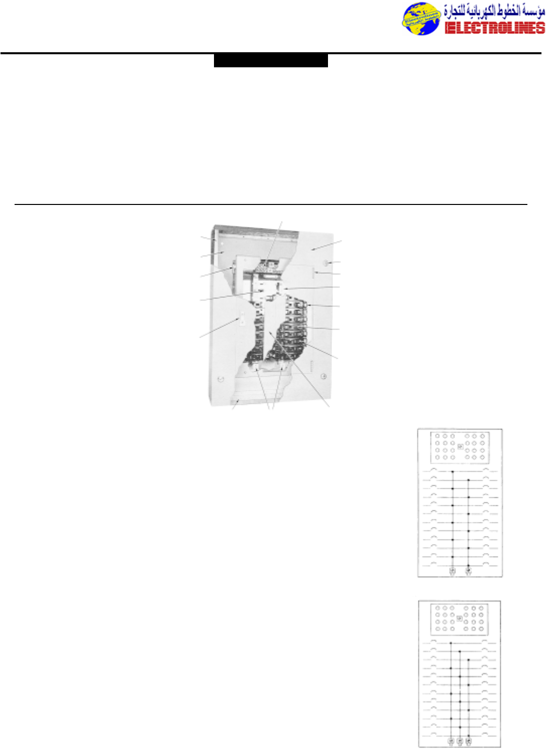
Panelboards
3-Wire
4-Wire
2
9
7
3
4
14
11
12
13
5
6
10
15
16
81
Standards
National Electrical Code
NEMA No.PB1
Underwriters’ Laboratories
No.UL-67,Panelboards
No.UL-50,Cabinets and Boxes
U.S.Federal Specifications
Circuit Breaker Panelboards
Type 1,Class 1,per W-P-115a
Circuit Breakers
W-C-375b.For class,see molded-
case circuit breaker selection table.
Typical Wiring Diagram
Types NLTQ, NLAB
GENERAL ELECTRIC
Electrolines Est.
P. O. Box. 942 Yanbu Saudi Arabia Tel: +966 4 3225418 Fax: +966 4 3222213 Al-Jubail: Tel: +966 3 3632967 Fax: +966 3 3612967
Distribution Equipment
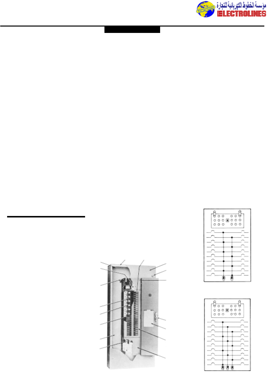
Types NLTQ, NLAB
Panelboards
NLTQ-Plug-Branch Breakers
NLAB Bolt-on Branch Breakers
Service—NLTQ, NLAB
–220/127,380/220 or
415/240Vac Max.
Mains — 800 A, main lugs or 600 A
main breaker
Branches — Standard — 15-
150A.,1-, 2-, 3-pole;
Sub/feed–225 A. max. 2-
& 3-pole
Features
1. Ample variety of knockouts
supplied as standard in top and
bottom of boxes.
2. Solid neutral bar has solderless
mechanical type connectors.
3. Panel frame is reinforced steel
for rigid support and accurate
alignment of interior with front.
4. Bus bars and connection straps
are bolted together and rigidly
supported on molded insulators.
Connection straps adequately rated
for maximum branch-circuit capacity.
Bus bars are located behind circuit
breakers.
5. Sequence phasing of bus –
modular drilling of bus bars permits
field rearrangement to maintain
balanced loading.
6. Solderless connectors at load
terminals of branch devices permit
quick wiring.
7. Code-size wiring gutters provide
ample space for wiring.
8. Mains – Panelboards are available
with removable anti-turn solderless
mechanical lugs or molded-case circuit
breakers in mains.
9. Code-gage galvanized sheet-steel
box meets Underwriters’
standards. Full flanged for strength
and rigidity.
10. Interchangeable branch-circuit
protective units are quick-make,
quick-break types.Branch breakers
are thermalmagnetic types and are
trip-free on overload or short circuit.
NLTQ panelboards feature plug-in
breakers while NLAB utilize bolted-in
breakers.
11. Fronts are code-gage steel with
attractive grey finish over rust
inhibitor.Available for flush or surface
mounting.
12. Rotating, quarter-turn trim
clamps are provided except on
Typical Modifications
Available
1. Increased Gutters – side or end
gutters.
2. Increased Depth.
3. Weatherproof Cabinets–with single
door or door back-of-door.
4. Extra space in Cabinet–for time clock,
current transformer,etc.
5. Dust-Resisting Cabinets–gasket
furnished for door and between box
and front.
6. Dripproof Cabinets–Drip hood on
top of cabinet,or drip shield welded
to front over door.
7. Increased Gage–10 gage maximum.
8. Special Knockouts or Drilling–drilling
template must accompany order.
9. Remote Control
Switches–mechanically held,2- or 3-
pole, 30-225 amperes or magnetically
held 2 or 3 pole 30-300 amperes,
starters.
10. Push-button,toggle, or momentary
contact switch or pilot light
11. Handle Locking Device.
12. Sub-Feed Breakers,225 amp. max.
13. Sub-Feed Lugs.
14. Split Bus or Meter Loop–one per
panel,includes splitting bus bars and
main lugs for separate section.
15. Increased Mains.
16. Special Colors.
17. Concealed Hinges.
3-Wire
4-Wire
910 11
12
13
14
15
16
17
8
7
6
5
4
3
2
1
GENERAL ELECTRIC
column types to permit easy
attachment of front to box and
compensate for any misalignment in
box mounting.
13. Semiconcealed hinges provide neat
appearance.
14. Combination catch and lock,
flush-type, with milled key. On doors
more than 48 inches high,a three-
point combination catch and lock is
provided with vault-type handle.All
locks are keyed alike.
15. Directory card holder and card
provided for easy branch circuit
identification.Installation instruction
card included.
16. Branch circuits clearly marked to
assure quick circuit identification and
lessen possibility of switching wrong
circuit.
17. Dead-front shield provides access
to wiring gutters with front removed,
without exposing bus compartment.
Underwriters’ Laboratories Listing
on all panels, except where noted,and
are suitable for use as service entrance
equipment.
Typical Wiring Diagram
Types NAB,NHB
Electrolines Est.
P. O. Box. 942 Yanbu Saudi Arabia Tel: +966 4 3225418 Fax: +966 4 3222213 Al-Jubail: Tel: +966 3 3632967 Fax: +966 3 3612967
Distribution Equipment
Typical Modifications
Available
1. Increased Gutters – side or end
gutters.
2. Increased Depth.
3. Weatherproof Cabinets–with single
door or door back-of-door.
4. Extra Space in Cabinet–for time clock,
current transformers,etc.
5. Dust-Resisting Cabinets–gasket
furnished for door and between box
and front.
6. Increased Gage – 10 gage maximum.
7. Special Knockouts or Drilling–drilling
template must accompany order.
8. Remote Control Switches –
mechanically held 2 or 3 pole 30-225
amperes,magnetically held 2 or 3 pole
30-300 amperes,starters.
9. Push-button,Toggle, Momentary
Contact Switch,or Pilot Light
mounted in panelboard trim.
10. Handle Locking Devices.
11. Sub-Feed Breakers–225 amp. max.
12. Sub-Feed Lugs–one per panel,specify
double main lug or thru-feed
construction.
13. Split Bus or Meter Loop–one per
panel,included splitting bus bars and
main lugs for separate section.
14. Increased Mains
15. Special colors
16. Concealed Hinges
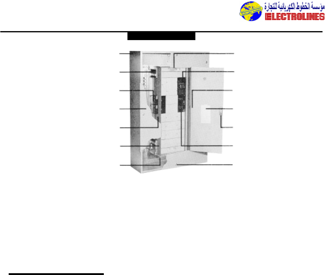
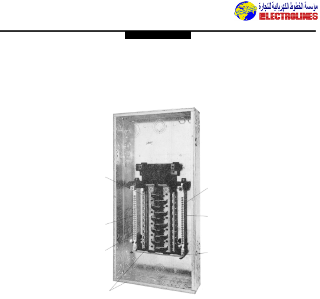
Type CCB Panel
board Circuit
Breaker
Main Lugs
1200 Amperes Max.
Main Circuit Breaker
1200 Amperes Max.
600 Volts,ac.
250 Volts,dc.
Features
1. Code-gage galvanized sheet-
steel box meets Underwriters
standards.Full flanged for
strength and rigidity.
2. Panel frame is reinforced
steel for rigid support and
accurate alignment of interior
with front.
3. Solderless connectors at load
terminals of branch devices
permit quick wiring.
4. Fronts are code-gage steel
with attractive gray finish over
rust inhibitor.Available for flush
or surface mounting.
5. Code-size wiring gutters
provide ample space for wiring.
6. Antu-turn branch straps.
7. Mains – Panelboards are
available with removable, anti-
turn solderless mechanical lugs or
molded-case circuit breakers in
mains.
8. Dead-front shield Provides
access to wiring gutters with
front removed,without exposing
bus compartment.
9. Interchangeable branch-cir-
cuit protective units are
quick-make, quick-break
types. Branch breakers are ther-
mal-magnetic types and are trip-
free on overload or short circuit.
10. Semi-concealed hinges
provide neat appearance.
11. Directory card holder and
card provided for easy branch
circuit identification.Installation
instruction card included.
12. Combination catch and lock,
flush-type, with milled key. On
doors more than 48 inches high,a
three-point combination catch
and lock is provided with vault-
type handle.All locks are keyed
alike.
13. Branch Circuits
clearly marked to
assure quick circuit
identification and lessen
possibility of switching
wrong circuit.
14. Rotating, quarter-
turn trim clamps are
provided to permit
easy attachment of
front to box and
compensate for any
misalignment in box
mounting.
Typical
Modifications
Available
1. Increased gutters – side or end
gutters.
2. Increased depth.
3. Raintight cabinets–with single
door,or door back-of-door.
4. Extra space in cabinet for time
clock,current transformers,etc.
5. Dust-resisting cabinets–gasket
furnished for door and between
box and front.
6. Dripproof cabinets–Drip hood on
top of cabinet,or drip shield
welded to front over door.
7. Increased gage–10 gage
maximum.
8. Special knockouts or
drilling–drilling template must
accompany order.
9. Remote control
switches–mechanically or
magnetically held,2- or 3-pole,
30-300 amperes.
10. Automatic transfer switches.
11. Push-button,toggle, momentary
contact switch or pilot
light–mounted in panelboard
trim.
12. Handle locking devices.
13. Sub-feed lugs–one per panel,
specify double main lug or thru-
feed construction (1200 amp
max.)
14. Split bus or meter loop–one per
panel,includes splitting bus bars
and main lugs for separate
section.
8
9
10
11
12
13
14
1
2
3
4
5
6
7
GENERAL ELECTRIC
Electrolines Est.
P. O. Box. 942 Yanbu Saudi Arabia Tel: +966 4 3225418 Fax: +966 4 3222213 Al-Jubail: Tel: +966 3 3632967 Fax: +966 3 3612967
Distribution Equipment
GENERAL ELECTRIC
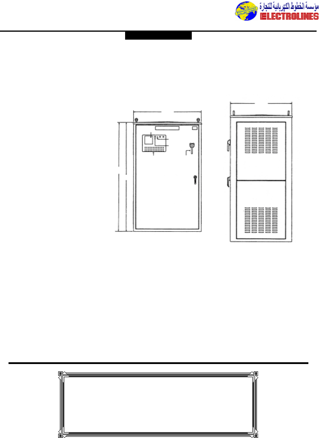
Power Capacitors
Type GEMATICTM Power Capacitors
Enclosed Automatic Power Factor Control Equipment Three-phase, 60 Hertz 240, 480, 600 Volts.
Description
General Electric GEMATIC multi-step
power factor control equipment
automatically maintains desired power
factor level, adjusting to system load
requirements in selected kVAR steps.
The solid-state control responds to a
current signal from customer’s current
transformer and to a voltage signal
from a potential transformer included
in the equipment.These are complete
packages including:
•Solid state multi-step power
factor control
•Digital display of power factor
and capacitor stages
•Trays of capacitor cells
•Contactors
•Inductors
•Potential transformer
•Single door
•Plated copper bus
•NEMA 1 enclosure (NEMA 3R
or NEMA 12 optional)
•Three fuses for each step
•Modular construction easily
uprated
•UL Listed. CSA Labeling
available upon request.
GEMATIC equipments feature
modular cell trays of GEM cells. GEM
capacitor cells feature a metallized
polypropylene film system providing a
self-healing action and reduced energy
losses.The GEM biodegradable
Front View
Right Side View
46”
1168.4mm
54”
(1371.6mm)
72”
(1828.8mm)
BLOWN FUSE
INDICATING LIGHTS
(OPTIONAL)
POWER
ON
POWER
SWITCH
CIRCUIT BREAKER
OPERATING HANDLE
(OPTIONS)
STEP
CONTROLLER
GENERAL ELECTRIC
36”
914.4mm
impregnant is a class IIIB combustible
fluid. Discharge resistors on each cell
reduce the cell voltage to 50 volts or
less within one minute of the de-
energization.
•The capacitor cells are single
phase connected for 3 phase,
each cell includes a UL
Recognized pressure sensitive
interrupter (PSI). Capacitors
are designed for a maximum of
110% of rated voltage and
135% of rated current, and
135% of rated kVAR.
•CT to be supplied by customer.
The power factor controller
required a CT signal for
operation.The CT primary
should be sized for the total
phase current to be
compensated (capacitor current
and load current).The CT
secondary should be rated 5A.
The CT is connected to one
phase of the equipment, the
factory installed PT is
connected across the other
two phases.
For complete Range or Power
Correction Equipment,
Please contact
ELECTROLINES.
Electrolines Est.
P. O. Box. 942 Yanbu Saudi Arabia Tel: +966 4 3225418 Fax: +966 4 3222213 Al-Jubail: Tel: +966 3 3632967 Fax: +966 3 3612967
Distribution Equipment
One-piece interior
removes and reinstalls
easily
Full-length neutrals are
easier to wire,reducing
installation time and cost
Minimum 100% neutral
terminations
Sturdy copper bus and
galvanized box increase
durability and reliability
Combination
slotted/Robertson screws
speed wiring
All holes rated for 14-4
wire
100% rated split neutral on
each side
Accepts GE Q-Line branch
circuit breakers,including
GE’s exclusive 1/2” THQPs
Load Centers
New PowerMark GoldTM Load Centers
Key Features and Benefits
GE’s new PowerMark GoldTM load centers give you higher performance for a lower installed cost
The PowerMark Gold load center represents the next
generation in residential load centers.It reduces total
installed cost through faster, easier installation;enhanced
application flexibility;and reduced inventory requirements,
while simultaneously delivering enhanced product quality.
Product Features
•Single phase, 100-225A, 12-42 circuits
•Copper bus with 22kAIC main standard,series
rated 22/10
•Split neutrals extend the full length of the interior
for ease of wiring
•Galvanized box and breaker mounting rails
•Easily removable, easily reinstallable interior
•Entire main lug line easily convertible to main
breaker
•Combination surface/flush front with spring
reinforced pan
•Front packed in inner carton for added protection
•Field installable feed-through lugs up to 200A
•Straight-through main wiring
•Clearly marked main breaker and circuit numbers
stamped on front
•Available isolated ground bar
•Box is smaller and lighter and maintains optimum
wire-bending space
•Fewer catalog numbers reduce inventory
requirements while maintaining application flexibility
GENERAL ELECTRIC
Electrolines Est.
P. O. Box. 942 Yanbu Saudi Arabia Tel: +966 4 3225418 Fax: +966 4 3222213 Al-Jubail: Tel: +966 3 3632967 Fax: +966 3 3612967

Distribution Equipment
PowerMark PlusTM and GoldTM Load Centers
Catalog Number Guide for Load Centers
(Catalog number for illustrative purposes only)
GE Identification
T
Type
M = Main breaker
FM = Main fusible
L = Main lug
LM = Convertible
PL = Main lug
(Thermoplastic)
Insert for Specials
G or T = Factory installed ground bar
B = Bottom feed main breaker
FL = Factory-installed feed-thru lugs
Insert for PowerMark Gold
CU = Copper Bus
Enclosure Type
C=Combination surface/flush
F =Flush
S =Surface
R=Outdoor
Bus Ampere Rating
40 = 40 Amps
70 = 70 Amps
10 = 100 Amps
12 = 125 Amps
15 = 150 Amps
20 = 200 Amps
22 = 225 Amps
30 = 300 Amps
40 = 400 Amps
60 = 600 Amps
Maximum Number 1” Spaces
2,4, 6… 42
Insert for 3-phase 4-Wire
Load Centers
M 42 4 20 C CU B
GENERAL ELECTRIC
ELECTROLINES - KSA
Electrolines,
distributes a full line of electrical products, including distribution equipment,
transformers, industrial controls, lamps, lighting, wiring devices, motors, drives,
silicones, conduit, wire and accessories,
components, fuse, ballast and lighting fixtures from other leading manufacturers.
boxes, fittings, enclosures, hazardous duty,
Electrolines Est.
P. O. Box. 942 Yanbu Saudi Arabia Tel: +966 4 3225418 Fax: +966 4 3222213 Al-Jubail: Tel: +966 3 3632967 Fax: +966 3 3612967
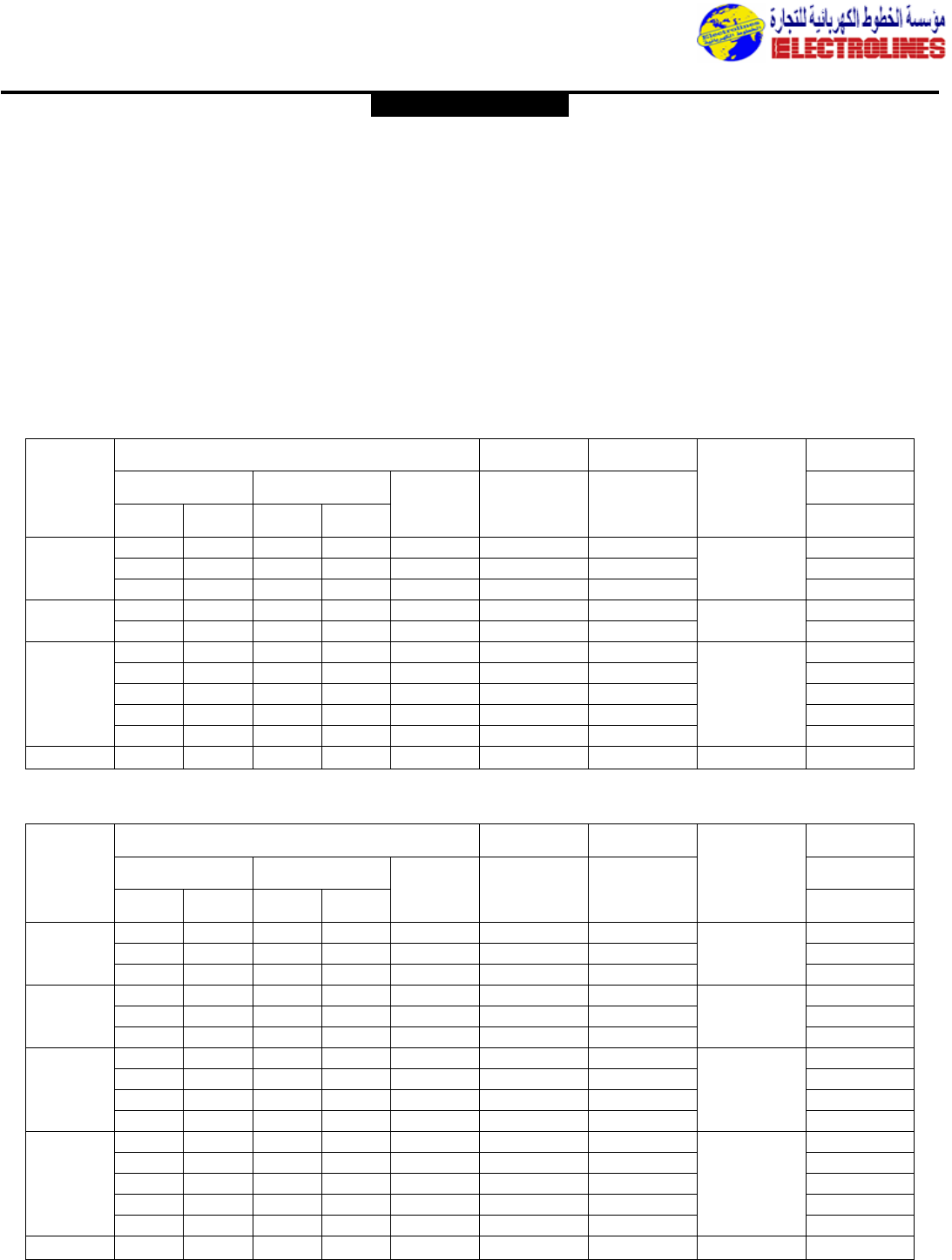
12 6 24 10 24 TLM1212CCU TLM1212RCU TGK12 or TGK24
125 16 8 16 6 24 TLM1612CCU – 6-2/0 TGK12 or TGK24
24 12 – – 24 TLM2412CCU TLM2412RCU TGK24
150 20 10 20 8 30 TLM2015CCU – 1-3/0(Cu) TGK32
24 12 12 4 30 TLM2415CCU TLM2415RCU 2-3/0(AI) TGK24 or TGK32
12 6 24 10 24 – TLM1220RCU TGK24
16 8 32 14 32 TLM1620CCU TLM1620RCU 1-250(Cu) TGK32
200 20 10 40 18 40 TLM2020CCU TLM2020RCU TGK24 or TGK42
32 16 16 6 40 TLM3220CCU – 2/0-250(AI) TGK32
40 20 – – 40 TLM4020CCU TLM4020RCU TGK42
225 42 20 – – 42 TLM4222CCU TLM4222RCU 1-300(Cu) TGK42
2/0-300(AI)
Distribution Equipment
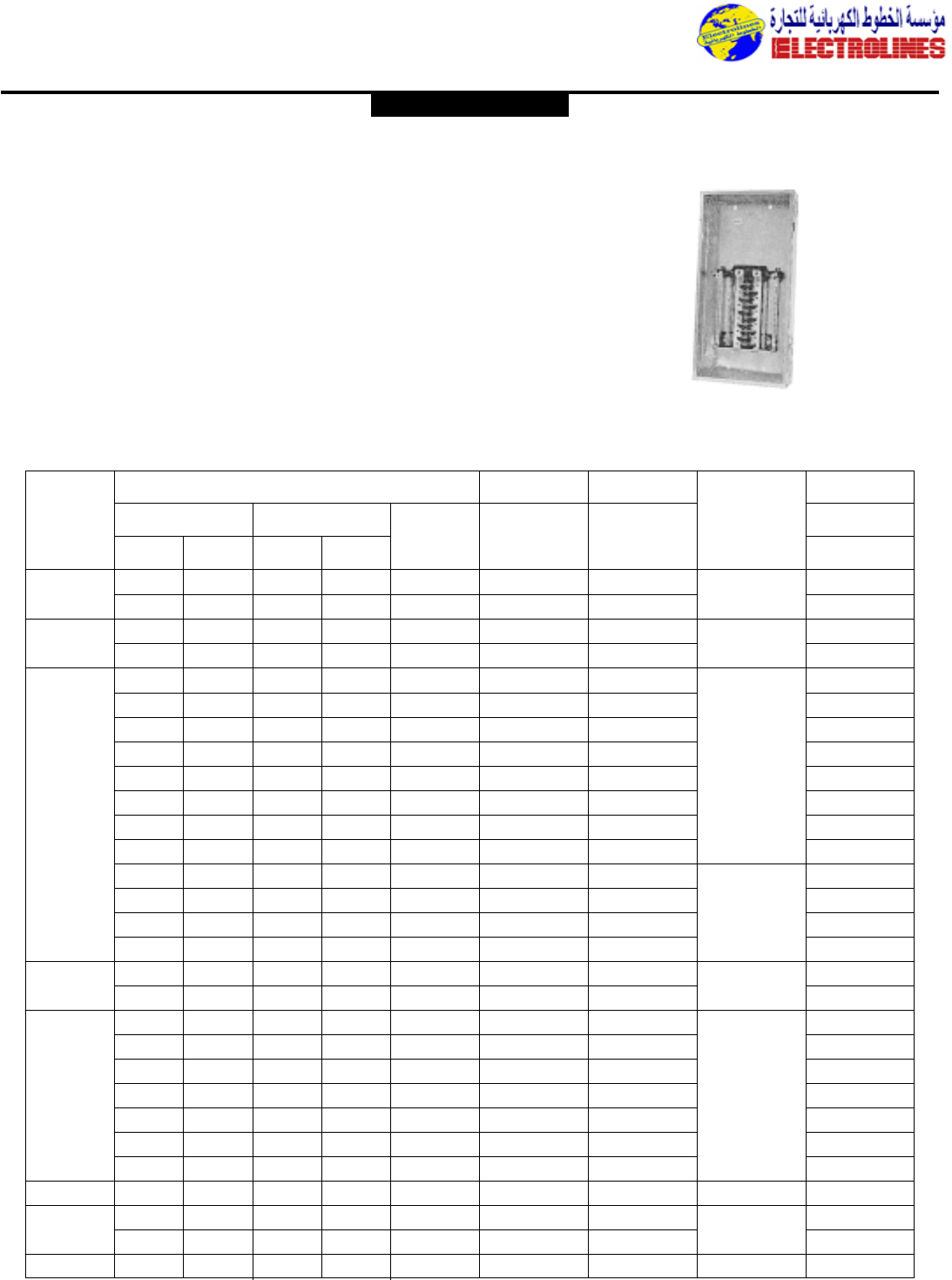
PowerMark GoldTM Circuit Breaker Load Centers
Tin Plated Copper Bus
22kAIC when used with THQMV or THHQL. Main UL Listed (Panelboards No. 67)
60˚C/75˚C Conductor Rating
Indoor Fronts Combination Surface/Flush
Suitable for Use as Service Entrance
Equipment when installed in accordance with the National Electrical Code
Main
Ampere
Rating
1” THQL
1p 2p
1/2” THQP
1p 2p
Total
1-Pole
Spaces Catalog Number Catalog Number
Main Wire
Size AWG/
kcmil Cu-Al
Equipment
Ground Kit
Outdoor Type 3R
Enclosure
Indoor Type 1
Enclosure
Order Separately
Cat. No.
Maximum Spaces
12 6 24 10 24 TM1210CCU TM1210RCU TGK12 or TGK24
100 20 10 – – 20 TM2010CCU TM2010RCU 4-1/0 TGK24
32 16 – – 32 TM3210CCU – TGK32
12 6 24 10 24 TM1212CCU TM1212RCU TGK12 or TGK24
125 16 8 16 6 24 TM1612CCU – 1-2/0 TGK12 or TGK24
24 12 – – 24 TM2412CCU TM2412RCU TGK24
8 4 16 6 16 – TM815RCUFL 1-3/0(Cu) TGK24
150 16 8 32 14 32 TM1615CCU TM1615RCU TGK24 or TGK32
24 12 12 4 30 TM2415CCU TM2415RCU 2-3/0(AI) TGK24 or TGK32
32 16 – – 32 TM3215CCU TM3215RCU TGK32
8 4 16 6 16 – TM820RCUFL TGK24
16 8 32 16 32 TM1620CCU – 1-250(Cu) TGK32
200 20 10 40 20 40 TM2020CCU TM2020RCU TGK24 or TGK42
32 16 16 6 40 TM3220CCU TM3220RCU 2/0-250(AI) TGK32
40 20 – – 40 TM4020CCU TM4020RCU TGK42
225 42 20 – – 42 TM4222CCU TM4222RCU 1-300(Cu) TGK42
2/0-300(AI)
Main
Ampere
Rating 1” THQL
1p 2p
1/2” THQP
1p 2p
Total
1-Pole
Spaces Catalog Number Catalog Number
Main Wire
Size AWG/
kcmil Cu-Al
Equipment
Ground Kit
Outdoor Type 3R
Enclosure
Indoor Type 1
Enclosure
Order Separately
Cat. No.
Maximum Spaces
Factory Installed Main Breaker
Single-phase,Three-Wire,120/240 Volts ac
Factory Installed Main Lugs – Field Convertible to Main Circuit Breaker
GENERAL ELECTRIC
Electrolines Est.
P. O. Box. 942 Yanbu Saudi Arabia Tel: +966 4 3225418 Fax: +966 4 3222213 Al-Jubail: Tel: +966 3 3632967 Fax: +966 3 3612967
Distribution Equipment
2 1 4 1 4 TL240C TL240R1 14-6(Cu) TGL1
40 2 1 4 1 4 TLP240C TPL240R 12-6(AI) TGL1
2 1 4 1 4 TL270C TL270R1 6-2/0 TGL1
70 2 1 4 1 4 TL270C TL270R1 TGL1
2 1 4 1 4 TL212C TPL212R TGL1
4 2 8 3 8 TL412C TL412R1 TGL1
4 2 8 3 8 TL412CT TL412RT1 TGL1 Installed
4 2 8 3 8 – TL412R2 1-2/0 TGL1
4 2 8 3 8 TPL412C TPL412R TGL1
125 4 2 8 3 8 TPL412CT TPL412RT TGL1 Installed
6 3 12 4 12 TLM612F1,S1 TLM612R TGL2
8 4 16 6 16 TLM812F1,S1 TLM812R TGL2
12 6 24 10 24 TLM1212CCU TLM1212RCU TGK12 or TGK24
12 6 24 10 24 TLM1212CCUG – TGK24 Installed
16 8 16 6 24 TLM1612CCU – 6-2/0 TGK12 or TGK24
24 12 – – 24 TLM2412CCU TLM2412RCU TGK24 or TGK32
150 20 10 20 8 30 TLM2015CCU – 1-3/0(Cu) TGK32
24 12 12 4 30 TLM2415CCU TLM2412RCU 2-3/0(AI) TGK24 or TGK32
12 6 24 10 24 – TLM1220RCU TGK24
16 8 32 14 32 TLM1620CCU TLM1620RCU TGK32
16 8 32 16 32 TLM1620CCUG – 1-250(Cu) TGK32 Installed
200 20 10 40 18 40 TLM2020CCU TLM2020RCU 2/0-250(AI) TGK24 or TGK42
20 10 40 18 40 TLM2020CCUG – TGK42 Installed
32 16 16 6 40 TLM3220CCU – TGK32
40 20 – – 40 TLM4020CCU TLM4020RCU TGK42
225 42 20 – – 42 TLM4222CCU TLM4222RCU 1-300(Cu) TGK42
400 24 20 – – 24 TL2440F,S TL2440R (2)2/0-250 (2) TGL2
42 20 – – 42 TL4240F,S TL4240R (2) TGL2
600 42 20 – – 42 TL4260F,S TL4260R (2)250-350(Cu) (2) TGL2
(2)350-500(AI)
PowerMark Plus
TM
and Gold
TM
Circuit Breaker Load Centers
UL Listed (Panelboards No. 67)
60˚C/75˚C Conductor Rating
Indoor Fronts Combination Surface/Flush
Suitable for Use as Service Entrance
Equipment when Installed in
Accordance with the National
Electrical Code
22,000 Amps RMS Symmetrical
Short Circuit Rating except
where noted
TLM2020CCU
Main
Ampere
Rating 1” THQL
1p 2p
1/2” THQP
1p 2p
Total
1-Pole
Spaces Catalog Number Catalog Number
Main Wire
Size AWG/
kcmil Cu-Al
Equipment
Ground Kit
Outdoor Type 3R
Enclosure
Indoor Type 1
Enclosure
Order Separately
Cat. No.
Maximum Spaces
Single-phase,Three-Wire,120/240 Volts ac,Top Feed
Factory Installed Main Lugs – PowerMark Gold
2/0-300(AI)
GENERAL ELECTRIC
Electrolines Est.
P. O. Box. 942 Yanbu Saudi Arabia Tel: +966 4 3225418 Fax: +966 4 3222213 Al-Jubail: Tel: +966 3 3632967 Fax: +966 3 3612967
Distribution Equipment
8 4 16 6 16 TM810F1,S1 TM810R TGL2
12 6 24 10 24 TM1210CCU TM1210RCU TGK12 or TGK24
100 12 6 24 10 24 TM1210CCUG – TGK24 Installed
20 10 – – 30 TM2010CCU TM2010RCU 4-1/0 TGK24
32 16 – – 32 TM3210CCU – TGK32
12 12 24 10 24 TM1212CCU TM1212RCU TGK12 or TGK24
12 12 24 10 24 TM1212CCUG – TGK24 Installed
125 16 8 16 6 24 TM1612CCU – 1-2/0 TGK12 or TGK24
16 8 16 6 24 TM1612CCUG – TGK24 Installed
24 12 – – 24 TM2412CCU – TGK24
8 4 16 6 16 – TM815RCUFL TGK24
16 8 32 14 32 TM1615CCU TM1615RCU 1-3/0(Cu) TGK24 or TGK32
150 16 8 32 14 32 TM1615CCUG – 2-3/0(AI) TGK32 Installed
24 12 12 4 30 TM2415CCU TM2415RCU TGK24 or TGK32
32 16 – – 32 TM3215CCU TM3215RCU TGK32
8 4 16 6 16 – TM820RCUFL TGK24
16 8 32 16 32 TM1620CCU – 1-250(Cu) TGK32
16 8 32 16 32 TM1629CCUG – TGK32 Installed
200 20 10 40 20 40 TM2020CCU TM2020RCU 2/0-250(A) TGK24 or TGK42
20 10 40 20 40 TM2020CCUG – TGK42 Installed
32 16 16 6 40 TM3220CCU TM3220RCU TGK32
40 20 – – 40 TM4020CCU TM4020RCU TGK42
225 42 20 – – 42 TM4222CCU TM4222RCU 1-300(Cu) TGK42
300 42 20 – – 42 TM4230F,S – (2) TGL2
400 24 12 – – 24 – TM2440R (2)2/0-250 (2) TGL2
42 20 – – 42 TM4240F,S TM4240R (2) TGL2
PowerMark Plus
TM
and Gold
TM
Circuit Breaker Load Centers
Main Breaker Factory Installed
UL Listed (Panelboards No. 67)
60˚C/75˚C Conductor Rating
Indoor Fronts Combination Surface/Flush
Suitable for Use as Service Entrance
Equipment when Installed in
Accordance with the National
Electrical Code
Main
Ampere
Rating 1” THQL
1p 2p
1/2” THQP
1p 2p
Total
1-Pole
Spaces Catalog Number Catalog Number
Main Wire
Size AWG/
kcmil Cu-Al
Equipment
Ground Kit
Outdoor Type 3R
Enclosure
Indoor Type 1
Enclosure
Order Separately
Cat. No.
Maximum Spaces
Single-phase,Three-Wire,120/240 Volts ac,Top Feed
Factory Installed Main Breaker – PowerMark Gold
2/0-300(AI)
GENERAL ELECTRIC
Electrolines Est.
P. O. Box. 942 Yanbu Saudi Arabia Tel: +966 4 3225418 Fax: +966 4 3222213 Al-Jubail: Tel: +966 3 3632967 Fax: +966 3 3612967
125 12 6 4 12 TL12412C TL12412R 6-2/0 TGK12 or TGK24
150 18 8 6 18 TL18415C TL18415R 1-3/0Cu or TGK24 or TGK32
24 12 8 24 TL24415C TL24415R 2/0-3/0Al TGK24 or TGK32
18 8 6 18 TL18420C TL18420R 1-250 Cu or TGK32
200 30 14 10 30 TL30420C TL30420R 2/0-250 Al TGK32
42 20 14 42 TL42420C TL42420R TGK42
30 14 10 30 TL30422C – 1-300 Cu or (2) TGL2
225 42 20 14 42 TL42422C TL42422R 2/0-300 Al (2) TGL2 Indoor/
TGK42 Outdoor 3R
400 24 12 8 24 TL24440F,S TL24440R (2)2/0-250 (2)TGL2
42 20 14 42 TL42440F, S TL42440R (2) TGL2
(2)250-350 Cu
600 42 20 14 42 TL42460F, S TL42460R or (2)TGL2
(2)350-500 Al
Distribution Equipment
PowerMark PlusTM Circuit Breaker Load Centers
Three-phase
Main Circuit Breaker or Main Lugs
Factory Installed
UL Listed (Panelboard No. 67)
60˚C/75˚C Conductor Rating
10,000 Amps rms Symmetrical
Short Circuit Rating Standard
(Main Breaker)
22,000 Amps rms Symmetrical
Short Circuit Rating Optional
(Main Lugs,Main Breaker by field
replacing main breaker.)
Indoor Fronts Combination Surface/Flush
Suitable for Use as Service Entrance
Equipment When Installed in
Accordance the National Electrical Code
TM24420CB
Main
Ampere
Rating 1” THQL
1-pole 2-pole 3-pole
Total
1-Pole
Spaces
Catalog
Number Catalog
Number
Main Wire
Size AWG/
kcmil Cu-Al
Equipment
Ground Kit
Outdoor Type
3R Enclosure
Indoor Type 1
Enclosure Order
Separately
Catalog
Number(s)
Maximum Spaces
Three Phase, Four-wire, 208Y/120 Volts ac,Top Feed,Main Lugs Factory Installed
100 12 6 4 12 TM12410C – 6-1/0 Cu or TGK12 or TGK24
18 8 6 18 TM18410C TM18410R 4-1/0 Al TGK24 or TGK32
125 30 14 10 30 TM30412C TM30412R 1-3/0 Cu or TGK32
/0-3/0 Al
24 12 8 24 TM24415C TM24415R 1-3/0 Cu or TGK32
150 30 14 10 30 TM30415C TM30415R 2/0-3/0 Al TGK32
42 20 14 42 TM42415C – TGK42
200 30 14 10 30 TM30420C TM30420R 1-250 Cu or TGK32
42 20 14 42 TM42420C TM42420R 2/0-250 Al TGK42
225 42 20 14 42 TM42422C TM42422R 1-300 Cu or (2)TGL2 Indoor/
2/0-300 Al TGK42 Outdoor
300 42 20 14 42 TM42430F,S – (1)6-600 or (2)TGL2
(2)2/0-250
400 42 20 14 42 TM42440F,S TM42440R (1)6-600 or
(2)2/0-250 (2)TGL2
Main
Ampere
Rating 1” THQL
1-pole 2-pole 3-pole
Total
1-Pole
Spaces Catalog
Number Catalog
Number
Main Wire
Size AWG/
kcmil Cu-Al
Equipment
Ground Kit
Outdoor Type
3R Enclosure
Indoor Type 1
Enclosure Order
Separately
Catalog
Number(s)
Maximum Spaces
Three Phase, Four-wire, 208Y/120 Volts ac,Top Feed,Main Breaker Factory Installed
GENERAL ELECTRIC
Electrolines Est.
P. O. Box. 942 Yanbu Saudi Arabia Tel: +966 4 3225418 Fax: +966 4 3222213 Al-Jubail: Tel: +966 3 3632967 Fax: +966 3 3612967
Distribution Equipment
TQL70F➀
THQL, 70 1,2,3 TQL70S➀TQL70R
THQL-GF, TQL100F➀
THQL 100 1,2,3 TQL100S➀TQL100R – – included – –
125 1,2 TPL212C TPL212R
THQC, TQC100F➀
THHQC, 100 1,2,3 TQC100S TQC100R – – included – –
TXQC,THQE
TEB, 100 2,3 TE100F TE100R TE100D TE100CS➅included – –
TED,THED TE100S TE100J➄
SE150 100 2,3 TE100F TE100R SE100D SE100CS➇included – –
TE100S SE100J
TED,THED 150 2,3 TE150F TE150R – – included – –
TE150S
SE150 150 2,3 TE150F TE150R – – included – –
TE150S
TB1 100 3 – – TB100J – included – –
2 – TQD225NR➃
TQD,THQD 225 2,3 TQD225F➀TQD225R – – included – –
TQD225S
TFJ 225 2,3 TF225F TF225R TF225D TF225CS TNIA225 – –
TFK,THFK TF225S TF225J
SF250 250 2,3 TF225F TF225R SF250D SF250CS TNIA225 – –
TF225S SF250J
TJD,TJJ 400 2,3 TJ400F TJ400R TJ400D TJ400CS TNIA400 – –
TJK,THJK ➈TJ400S TJ400J
TB4 400 2,3 – – TB400J – TNIA400 – –
TJK,THJK 600 2,3 TJ600F TJ600R TJ600J TJ600CS – –
TJ600S
TJ4V, 600 3 TJ4V600F TJ4V600R TJ4V600J TJ4V600CS TNIA400➆TSRG201
THJ4V,TJL4V TJ4V600S TNIA600 TSRG202
TNIA400VG TSRG203
TNIA600VG TSRG204
TJH 600 3 TJ9V600F TJ9V600R TJ9V600J – TSRG205
TJL TJ9V600S TSRG206
TSRG201
SG400 400 2,3 SG400F SG400R SG400D SG400CS TNIA400 TNIA400VG TSRG202
SG400S SG400J TSRG203
TSRG204
SG600 600 2,3 SG600F SG600R SG600J – TNIA600 TNIA600VG TSRG205
SG600S TSRG206
TB6 600 3 – – TB800J – TNIA400 ––
TNIA600
TNIA400
TB8 800 3 – – TB800J – TNIA600 – –
TNIA800
TKMA, 1200 2,3 TK4V1200F TK4V1200R TK1200J – – –
THKMA TK4V1200S TNIA400➇
TKL4V, 1200 3 TK4V1200F TK4V1200R TKV1200J – TNIS600➇
TK4V TK4V1200S TNIA800 –
TNIA1200 TNIA800G TSKG408
TKH,TKL 1200 3 TK9V1200J TNIAC1200 TNIA1200G TSKG410
TSKG412
TNIA400
TNIA600 TSKG408
SK1200 1200 2,3 TK4V1200F TKV1200R SK1200J – TNIA800 TNIA800G TSKG410
TK4V1200S TNIA1200 TNIA1200G TSK412
TNIAC1200
Molded Case Circuit Breakers Enclosures
Suitable for use as service
equipment
60˚C/75˚C conductor
ratings.
Short circuit ratings
are equal to the rating
of the installed breaker.
70-1200 Amperes
240-600 Volts ac,
125-250 Volts dc
Breaker
Type Max.
Amp Rating Poles Type 1➀
Indoor Type 3R➁
Outdoor Type 12➂
Oil-tight/
Dust-tight
Type 4/4X
Stainless
Steel
Neutral
Catalog
Number
Neutral
for Ground
Fault
Current
Trans. for
Gd. Fault
Type 1,
indoor surface or
flush mounting
Type 3R
outdoor, raintight Types 12K and 12 rotary
handle integral with
breaker
Types 4/4X
stainless steel,
watertight, dust tight
11
GENERAL ELECTRIC
➈Suitable for parallel 250
MCM maximum.If larger cable is
applied,use 600-amp enclosure.
➉For 250A rating use copper cable only.
Add suffix X2 for 415Y240
Vac application
11
➀F-flush;S-surface.
➁70-250 amp devices have removable
closing cap.Larger ampere devices
require field cut openings.Order hubs
separately.
➂D = Type 12K with KO’s
J = Type 12 without KO’s
➃Suitable only for 2-pole breaker.
➄For three-pole breaker only.
➅Neutral not included;if required,order
Catalog Number TNI100.
➆Do not use with TJ4V or THJ4V.
➇Do not use with TK4V or THJ4V.
Electrolines Est.
P. O. Box. 942 Yanbu Saudi Arabia Tel: +966 4 3225418 Fax: +966 4 3222213 Al-Jubail: Tel: +966 3 3632967 Fax: +966 3 3612967
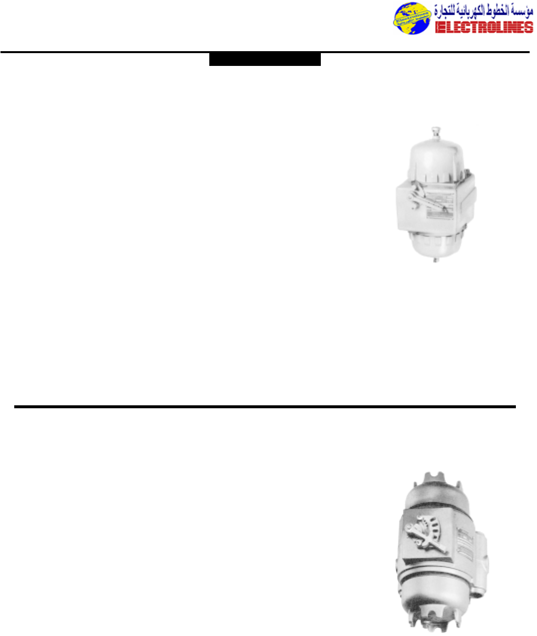
Distribution Equipment
Application:
EPC Circuit breakers and enclosures are
used:
•for service entrance*, feeder or branch
circuit protection for lighting, heating,
appliance and motor circuits
•in areas made hazardous due to the pres-
ence of flammable vapors,gases or com-
bustible dusts
•in damp, wet or corrosive locations
•indoors or outdoors at petroleum
refineries,chemical or petrochemical
plants and other process industry
facilities where similar hazards exist
•to provide disconnect means,short
circuit protection and thermal time delay
overload protection
Features:
•Quick-opening covers–less than two
turns to remove or install
•Three section design for ease of installa-
tion
•Water-shedding construction with female
threads on top cover,male threads on
bottom cover, and top cover skirted
•Specially located stops and locks insure
adequate thread engagement and prevent
overtightening
•Separate replaceable mounting bracket
attached to the rear of the body pro-
vides three-point suspension for quick
installation and leveling – one keyhole
slot at top and two open slots at bottom
•Bodies have two taper-tapped conduit
hubs with integral bushings on the top,
and two more directly below
•Mounting plates are supplied with all nec-
essary holes and hardware to attach any
of the circuit breakers.Breaker and inte-
rior mounting frames are easily removed
as a unit,providing free access to the
wiring chamber
•Breaker is operated by an external han-
dle which can be padlocked in either
“ON” or “OFF” positions by as many as
three padlocks.Breaker is trip-free of the
handle and will open under short circuit
or overload, even if the handle is locked
in the “ON” position
Standard Materials:
•Bodies and covers – copper-free-alu-
minum
•operating handles – copper-free alu-
minum
•Operating shafts – stainless steel
•Interior parts – sheet steel
Standard Finishes:
•Copper-free aluminum – natural
•Stainless steel – natural
•Sheet steel – electrogalvanized
Electrical Rating Ranges:
•100,150, 225, 250, 400 and 600 ampere
frame sizes
EPC Circuit Breakers and
Enclosures
CI.I,Div.1 & 2,Groups C,D
CI.II,Div.1,Groups E,F,G
CI.II,Div.2,Groups F,G
CI.III
NEMA 3,4,7CD,9EFG
Explosionproof
Dust-Ignitionproof
Raintight
Wet Locations
Watertight
Application:
EPCB Circuit breakers are used:
•for service entrance,feeder or branch
circuit protection for lighting, heating,
appliance and motor circuits
•in areas made hazardous due to the
presence of hydrogen or gases or vapors
of equivalent hazard such as
manufactured gas
•in damp, wet or corrosive locations
•indoors or outdoors in hydrogen areas
of process industries,missile bases where
hydrogen fuel is used and gas
manufacturing plants,as well as in areas
of lesser hazard
•to provide disconnect means,short
circuit protection and thermal time delay
overload protection
Features:
•Three section design and three-point
suspension make installation and leveling
quick and easy
•Covers are easily loosened by using a
bare or length of 3/4” conduit with the
four driving lugs provided
•Bodies have tow tapper-tapped conduit
hubs with integral bushings located at the
top, and two directly below
•Breaker and interior mounting frame are
easily removed as a unit,providing free
access to the wiring chamber
•Breaker is operated by an external
handle which can be padlocked in either
“ON” or “OFF” positions. Breaker is
trip-free of the handle and will open
under short circuit or overload,even if
the handle is locked in the “ON” position
•When installing,seals suitable for Class I,
Group B hazardous areas must be
installed within 11/2” each conduit
opening
Standard Materials:
•Bodies and covers – copper-free-
aluminum
•operating handle – copper-free aluminum
•Operating shaft – stainless steel
•Interior parts – sheet steel
Standard Finishes:
•Copper-free aluminum – natural
•Stainless steel – natural
•Sheet steel – electrogalvanized
Electrical Rating Ranges:
•100,150 and 225 ampere frame sizes
EPCB Circuit Breakers CI.I,Div.1 & 2,Groups B,C,D
CI.II,Div.1,Groups E,F,G
CI.II,Div.2,Groups F,G
CI.III
NEMA 3,4,7BCD,9EFG
Explosionproof
Dust-Ignitionproof
Raintight
Wet Locations
Watertight
CROUSE-HINDS
Electrolines Est.
P. O. Box. 942 Yanbu Saudi Arabia Tel: +966 4 3225418 Fax: +966 4 3222213 Al-Jubail: Tel: +966 3 3632967 Fax: +966 3 3612967
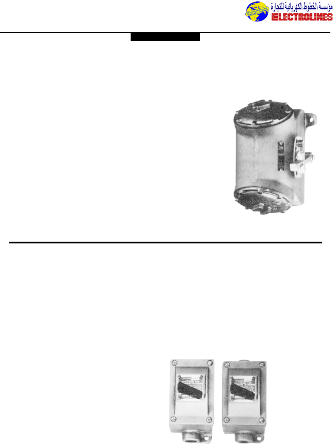
Distribution Equipment
Application:
FLB circuit breakers and enclosures are
used:
•for service entrance,feeder or branch
circuit protection for lighting, heating,
appliance and motor circuits
•in areas made hazardous due to the
presence of flammable vapors, gases or
combustible dusts
•in damp, wet or corrosive locations
•indoors or outdoors at petroleum
refineries,chemical or petrochemical
plants and other process industry
facilities where similar hazards exist
•to provide disconnect means,short
circuit protection and thermal time
delay overload protection
Features:
•Semi-cylindrical body shape for maxi-
mum strength at lowest practical weight
•Round threaded covers at each end,set
at an angle to provide ready access to
interior for ease of wiring
•Breaker is operated by an external han-
dle which can be padlocked in either
“ON” or “OFF” positions.Breaker is
trip-free of the handle and will open
under short circuit or overload even if
the handle is locked in the “ON” posi-
tion
•Bodies have vertical through feed con-
duit hubs of sizes given in the listings
Standard Materials:
•Bodies,covers and operating handles –
copper-free aluminum
•Operating shafts – stainless steel
•Interior parts – sheet steel
Standard Finishes:
•Copper-free aluminum – natural
•Stainless steel – natural
•Sheet steel – zinc electroplate with
chromate finish
Electrical Rating Ranges:
•100 and 225 ampere frame sizes
FLB Circuit Breakers and
Enclosures
CI.I,Div.1 & 2,Groups C,D
CI.II,Div.1,Groups E,F,G
CI.II,Div.2,Groups F,G
CI.III
NEMA 3,4,7CD,9EFG
Explosionproof
Dust-Ignitionproof
Raintight
Wet Locations
Watertight
Application:
EFD circuit breakers and enclosures are
used:
•for branch circuit protection for lighting,
appliance, and motor circuits
•in areas made hazardous due to the
presence of flammable vapors, gases or
combustible dusts
•in corrosive locations
•for installation at petroleum refineries,
chemical and petrochemical plants and
other process industry facilities where
similar hazards exist
•to provide disconnect means,short
circuit protection and thermal time
delay overload protection
Features:
•Small,compact enclosures with accu-
rately ground,wide flange on both body
and cover for flametight joint
•Dead-end (EFD) or through feed
(EFDC) hubs 3/4” to 1” sizes
•Breaker mounted on cover and back
wired for ease of installation
•Breaker can be padlocked in “ON” or
“OFF” positions with trip-free handle
mechanism
Standard Materials:
•Bodies and covers – Feraloy®iron alloy
•Operating handles – type 6/6 nylon
•Operating shaft – stainless steel
Standard Finishes:
•Feraloy – electrogalvanized and aluminum
acrylic paint
•Type 6/6 nylon – black
•Stainless steel – natural
Electrical Ratings:
•Single pole – 120/240 vac max.
•Trip ratings – 15, 20 and 30 amp.
EFD and EFDC Circuit Breakers
and Enclosures
120VAC, Single Pole
CI.I,Div.1 & 2,Groups B,C,D
CI.II,Div.1,Groups E,F,G
CI.II,Div.2,Groups F,G
CI.III
NEMA 3,7BCD,9EFG,12
Explosionproof
Dust-Ignitionproof
Raintight
Wet Locations
EFD dead end EFDC through feed
CROUSE-HINDS
Electrolines Est.
P. O. Box. 942 Yanbu Saudi Arabia Tel: +966 4 3225418 Fax: +966 4 3222213 Al-Jubail: Tel: +966 3 3632967 Fax: +966 3 3612967
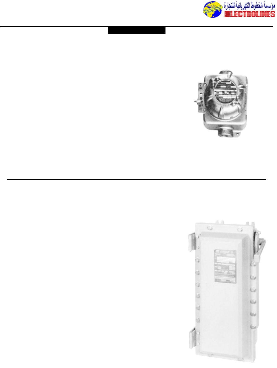
Distribution Equipment
Application:
GUSC auxiliary circuit breaker enclosures
are used:
•for manual control of motor operated
appliances and other small loads,when
used in series with motor branch circuit
fuses or circuit breakers as required by
NEC.
Not intended for branch circuit overcur-
rent or short circuit protection.
•As follows for Standard Units:
•in areas made hazardous due to the
presence of flammable vapors, gases or
highly combustible dusts
•in damp, wet or corrosive locations
•indoors or outdoors at petroleum
refineries,chemical and petrochemical
plants and other process industry facilities
where similar hazards exist
As follows for Group B units:
•in areas made hazardous due to the
presence of hydrogen or gases or vapors
of equivalent hazard such as manufactured
gas
Features:
•Compact rectangular enclosures with
round threaded covers
•Operating handles may be padlocked in
either “ON” or “OFF” positions. Breakers
are trip-free of the handle and will open
under short circuit or overload,even if
handles are locked in the “ON” position
•Bodies are furnished with
3
/
4
” vertical
through feed conduit hubs.
•On group B Unit installations,seals suit-
able for Class I,Group B hazardous areas
must be installed within 1
1
/
2
” of each con-
duit opening
Standard Materials:
•Bodies – Feraloy
®
iron alloy
•Covers and operating handles – copper-
free aluminum
•Operating shafts – stainless steel
•Interior parts – sheet steel
GUSC Auxiliary Circuit Breaker
Enclosures
CI.I,Div.1 & 2,Groups BC,D
CI.II,Div.1,Groups E,F,G
CI.II,Div.2,Groups F,G
CI.III
NEMA 3,4,7BCD,9EFG
Explosionproof
Dust-Ignitionproof
Raintight
Wet Locations
Application:
Spectrum EBMTM hinged cover motor control
enclosures are used:
•For general motor control and circuit pro-
tection – indoors and outdoors – in damp,
wet,dirty,dusty hazardous locations without
the need for a protective shelter.
•In areas where frequent washdowns are nec-
essary or where heavy rain or water spray is
prevalent.
•To provide line disconnect means and short
circuit protection.
•For service entrance,feeder or branch
circuit protection for lighting,heating,
appliance and motor circuits.
•On switchcracks or other assemblies where
it’s desired that motor control be centrally
located.
Features:
•Rugged,corrosion resistant,cast copper-free
aluminum construction (Less than 0.4 of 1%).
•Circuit breaker operating handle located
through the right side wall of the body
permits visual confirmation of correct
component assembly and operation.
•Total compliance to the wiring end room
requirements of the National Electrical
Code®.
•Semi-clamshell enclosure design,with an
external flanged ground joint between body
and cover makes interior components more
accessible.
•Minimum enclosure-to-enclosure spacing
with little interference between the opened
cover and an adjacent enclosure.
•Copper-free aluminum hinges allow the
cover to swing well out of the way.
•Stainless steel,quick release,captive,hex
head cover bolts. Stainless steel springs pro-
vide clear indication cover bolts are fully
retracted from body.
•Versatile, internal operating mechanisms
allow for field adjustment to accommodate
popular manufacturers’ breakers.
•Simple, straightforward installation of breaker
on pre-drilled mounting plate within enclo-
sure.Mounting plate also field removable.
•Circuit breaker external operating handle
can be padlocked in either “ON” or “OFF”
positions.
•Neoprene cover gasket permanently
attached to the cover seals out moisture.
•Bodies have top and bottom drilled and
tapped entrances for power conduits and
control conduits.Removable reducers are
supplied,as standard,to accommodate small-
er size conduits.All conduit entrances are
plugged.
•Tap-on mounting feet.
Electrical Rating Ranges:
•Circuit breakers – 100,150,225,250, 400,
600,800,1000** ampere frame sizes
EBMB Circuit Breakers
and Enclosures
CI.I,Div.1 & 2,Groups C,D
CI.II,Div.1,Groups E,F,G
CI.II,Div.2,Groups F,G
CI.III
NEMA 3,3R,4,7CD,9EFG,12
Explosionproof
Dust-Ignitionproof
Raintight
Wet Locations
Watertight
Spectrum EBM motor control enclosures
accommodate popular makes of circuit breakers.
CROUSE-HINDS
Electrolines Est.
P. O. Box. 942 Yanbu Saudi Arabia Tel: +966 4 3225418 Fax: +966 4 3222213 Al-Jubail: Tel: +966 3 3632967 Fax: +966 3 3612967
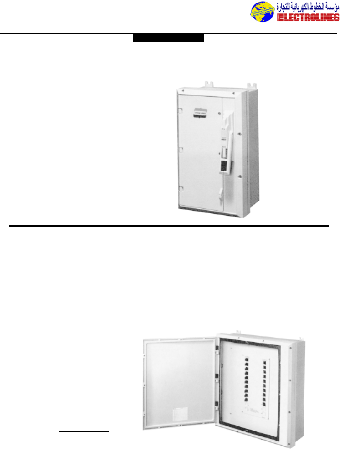
Distribution Equipment
Application:
NCB circuit breakers are for use in conjunction with a
variety of heating,lighting and power circuits to provide
disconnect means and short circuit protection.
•Enclosures are made of Krydon®, Crouse-Hinds high
impact strength fiberglass-reinforced polyester material
having excellent corrosion resistance and stability to
heat
•Unitized,strong and durable enclosure construction
provides longer service life for equipment
•Enclosure has hinged access door which opens 160˚
for easy wiring and maintenance.Three screws for
door frame are hidden behind access door.
•Access door may be padlocked to prevent
unauthorized access
Electrical Rating Ranges:
•100,150,225, 250 and 400 amp frames
NCB Circuit Breakers
Enclosures
600VAC/250VDC Heavy Duty
Corrosion-Resistant
Dusttight
Watertight
Weatherproof
NEMA 3,4X,12
Application:
N2PB panelboards are for use in central
control and protection of a large number
of feeder or branch circuits and for
housing circuit breakers in Class I,Division
2,Groups C&D, hazardous areas.
Features:
•Enclosures are made of Krydon®, Crouse-
Hinds high impact strength fiberglass-
reinforced polyester material with excel-
lent corrosion resistance and stability to
heat
•Enclosure access door provided with
stainless steel thumb screws for easy
access.Access door may be padlocked
to prevent unauthorized access
•Circuit breakers are contained in com-
pact,individual factory sealed enclosures
suitable for Class I, Division 2, Groups C
& D,hazardous areas
Size Ranges:
Max. No.of Breakers
Single- Two-
Panel Designation Pole Pole
N2PB1426 12 6
N2PB2426 24 12
Electrical Rating Ranges:
•Circuit breakers
•Single-pole – 120/240 vac max.
•Two-pole – 120/240 vac max.
•Trip ratings – 15, 20 and 30 amp.
N2PB Circuit Breaker
Panelboards
Factory Sealed Single & Two-Pole Breakers
CI.I,Div.2,Groups C,D
CI.II,Div.2,Groups F,G
NEMA 3,7CD (Div. 2),9FG (Div.2),12
Watertight
Weatherproof
Corrosion-Resistant
Dusttight
Circuit breaker panelboard - open view
Circuit breaker
enclosure with built-in
Krydon material handle
CROUSE-HINDS
Electrolines Est.
P. O. Box. 942 Yanbu Saudi Arabia Tel: +966 4 3225418 Fax: +966 4 3222213 Al-Jubail: Tel: +966 3 3632967 Fax: +966 3 3612967
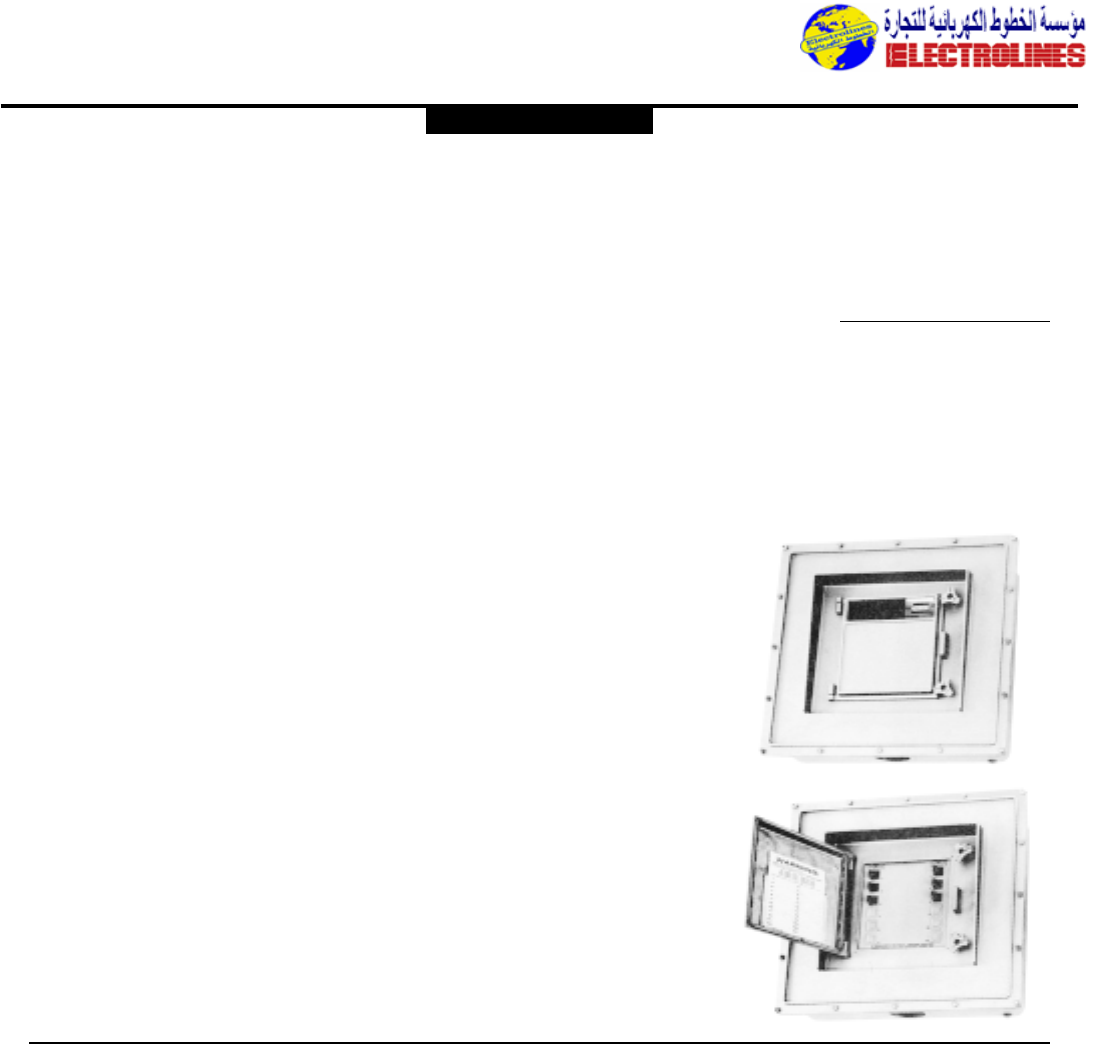
Distribution Equipment
Application:
D2PB panelboards are designed specifically
for use:
•in Class 1,Division 2, Groups C, D haz-
ardous areas where flammable vapors or
gases may be present due to accident or
abnormal locations.
•in damp, wet or corrosive locations
•indoors or outdoors in Division 2 area
of petroleum refineries, chemical and
petrochemical plants,and other process
industry facilities
Features:
•Enclosures are of external flange design,
which makes the interior completely
accessible when the cover is removed
•Provided with concealed mounting,
which is made possible by having four
clearance holes for lag screws or
mounting bolts in the back of the enclo-
sure,one in each corner.
•The interior sub-assembly, consisting of
a mounting plate, main terminal blocks,
and circuit breakers,is removable as a
complete unit
•Ample gutter space is provided for ease
of field wiring
•Circuit breakers are contained in com-
pact,individual factory sealed enclosures
suitable for Class 1, Division 2, Groups
C, D hazardous areas.The individual
enclosures are easily removed and
replaced,therefore changing or adding
individual circuit breakers will not pre-
sent a problem
•The main cover, which is gasketted to
exclude dirt and moisture, is attached to
the body with hex head bolts and is
removed only when installing the panel-
board or making wiring changes.In the
center of the main cover is a gasketed
hinged door,which provides access only
to the circuit breaker operating handles,
and is held closed by two quick-release
catches.The door can be locked by as
many as 3 padlocks to prevent unautho-
rized operation
•Tapped conduit openings are provided
for main conduit and branch circuits.
Standard openings can be reduced or
plugged to meet most installation
requirements.
•Circuit breakers are arranged in two
vertical rows and have the circuit num-
bers marked on the handles.The left
row is numbered 1,3,5,7,etc. and the
right row 2,4, 6, 8, etc.Identifying infor-
mation may be typed on the circuit
directory card attached to the inside of
the hinged door
Standard Materials:
•Bodies,covers and hinged doors –
copper-free aluminum
•Breaker operating handles – type 6/6
nylon
•Interior parts – sheet steel
Standard Finishes:
•Copper-free aluminum – natural
•Type 6/6 nylon – natural (black)
•Sheet steel – electrogalvanized with
chromate finish
Size Ranges:
Panel Max. No.of Breakers
Size Single-Pole Two-Pole
1126
22412
Electrical Rating Ranges:
•Circuit breakers
•Single-pole – 120/240vac max
•Two-pole – 120/240vac max
•Trip ratings – 15, 20 and 30 amp
D2PB Division 2 Circuit Breaker
Panelboards
Factory Sealed Single & Two-Pole Circuit Breakers
CI.I,Div.2,Groups C,D
NEMA 3,7CD (Div. 2),12
Dusttight
Raintight
Wet Locations
PowerPlus factory sealed Panelboards
provide flexibility and labor savings when
installed,and for future changes in the field.
Panels are prewired to maximum circuit
capacity and ratings with field replaceable
factory sealed components.
Applications:
EPL and D2L PowerPLUS panelboards are
used:
•in areas made hazardous by the presence
of flammable gases and vapors,and
combustible dusts.
•in areas subject to weather,dampness and
corrosion.
•for branch power distribution and circuit
protection to motors,valves, pumps,
lighting,heat tracing,receptacles,etc.
•for indoor and outdoor applications in
petroleum refineries, chemical and
petrochemical plants,and other process
industry facilities where similar hazards
exist.
•in areas where flammable vapors or gases
or highly combustible dusts may be
present due to accidential or abnormal
conditions.
•to accommodate up to 100 amp branch
loads.
Standard Materials:
•Body and cover – cast copper-free
aluminum
•Gasket – neoprene
•Hinges and operating handles – extruded
aluminum (copper-free)
•Operating shafts and bushings,cover bolts,
washers,and retractile springs – stainless
steel
•Circuit breaker operators – die cast
aluminum (copper-free)
•Lifting bracket – cold rolled steel
Standard Finishes:
•Aluminum – natural
•Stainless steel – natural
•Cold rolled steel – electrogalvanized
PowerPlusTM Panelboards
Lighting and Heat Tracing
EPL Series
D2L Series (Div. 2)
CI.I,Div.1 & 2,Groups B,C,D
CI.II,Div.1,Groups E,F,G
CI.II,Div.2,Groups F,G
CI.III
NEMA 3,4,7BCD, 9EFG,12
CSA Enc. 3,4,5
Explosionproof
Dust-Ignitionproof
Factory Sealed
Wet Locations
Watertight
CROUSE-HINDS
Electrolines Est.
P. O. Box. 942 Yanbu Saudi Arabia Tel: +966 4 3225418 Fax: +966 4 3222213 Al-Jubail: Tel: +966 3 3632967 Fax: +966 3 3612967
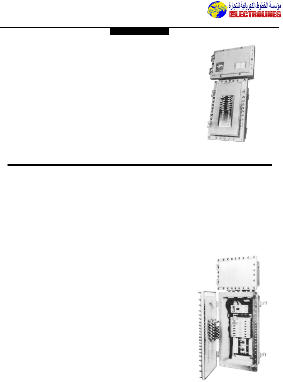
Distribution Equipment
Features:
•Factory-sealed,no external seals required for
most branch circuits.
•Fully wired from circuit breaker housing to
pre-numbered terminals in wiring
compartment.
•Copper-free aluminum hinges allow the
cover to swing well out of the way.
•Stainless steel,quick release,captive hex-
head bolts with spring loaded action provide
a clear indication that cover bolts are fully
retracted from body.
•Cast copper-free aluminum construction
(less than 0.4 of 1%) provide excellent
resistance to corrosion.
•External flange design-wide unobstructed
cover opening provides a completely
accessible interior for wiring.
•Neoprene cover gasket provides a watertight
seal to meet NEMA 4/CSA ENC. 4/IP65
requirements, and provides superior
protection for enclosed equipment against
water and corrosion.
•External operating handles for circuit
breakers can be padlocked in either “ON” or
“OFF” positions.
•Furnished with (1) 3 1/2” and (12) 1 1/2”
conduit openings,all with Crouse-Hinds LNR
conduit liner bushings.
•Available with or without main circuit
breaker.
•Breather and drain provided for each
enclosure.
•Isolated neutral and ground bar provided.
Electrical Ratings:
Branch Breaker (120/240VAC Bolt-ON) Trip
Ratings:
1,2,3-pole
10,15, 20, 25, 30, 40,45,50, 55, 60, 70, 80,90,
100 amp
•GFI type, 1, 2-pole (5mA sensitivity) 15,20,
25,30,40 amp
•EPD type, 1 2-pole(30mA sensitivity) 15, 20,
25,30,40 amp
D2LB Lighting Panelboard
EXD Panelboard
Applications:
EXD and D2D PowerPlus panelboards are
used:
•in areas made hazardous by the presence of
flammable gases and vapors,and combustible
dusts.
•in areas subject to weather,dampness and
corrosion
•for indoor and outdoor applications in
petroleum refineries, chemical and
petrochemical plants,and other process
industry facilities where similar hazards exist.
•in areas where flammable vapors or gases or
highly combustible dusts may be present due
to accidental or abnormal conditions.
•to accommodate up to 100 amp branch
loads.
Standard Materials:
•Body and cover – cast copper-free aluminum
•Gasket – neoprene
•Hinges and operating handles – extruded
aluminum (copper-free)
•Operating shafts and bushings,cover bolts,
washers,and retractile springs – stainless
steel
•Circuit breaker operators – die cast
aluminum (copper-free)
•Lifting bracket – cold rolled steel
Standard Finishes:
•Aluminum – natural
•Stainless steel – natural
•Cold rolled steel – electrogalvanized
Features:
•Factory-sealed,no external seals required for
branch circuits.
•Fully wired from circuit breaker housing to
pre-numbered terminals in wiring
compartment.
•Copper-free aluminum hinges allow the
cover to swing well out of the way.
•Stainless steel,quick release,captive hex-
head bolts with spring loaded action provide
a clear indication that cover bolts are fully
retracted from body.
•Cast copper-free aluminum construction
(less than 0.4 of 1%) provides excellent
resistance to corrosion.
•External flange design – wide unobstructed
cover opening provides a completely
accessible interior for wiring.
•Neoprene cover gasket provides a watertight
seal to meet NEMA 4 requirements, and
provides superior protection for enclosed
equipment against water and corrosion.
•External operating handles for circuit
breakers can be padlocked in either “ON” or
“OFF” positions.
•Furnished with (1) 31/2” and (12) 11/2”
conduit openings,all with Crouse-Hinds LNR
conduit liner bushings.
•Available with or without main circuit
breaker.
Circuit Breaker Ratings:
(Westinghouse,Series C)
Circuit Breaker Trip Ratings:
15,20, 30, 40, 50, 60,70,80, 90, 100 amp
•EHD frame circuit breakers
Single-Pole – 277 VAC or 125 VDC
Two and Three-Pole – 480 VAC or 250 VDC
•FDB frame (600 VAC)
Main Breaker Trip Ratings:
70,100,150, 200, 225 amp
•JDB frame circuit breakers
Two and Three-Pole – 600 VAC or 250 VDC
Main Lugs:225 amp
Circuit Capacity:
Maximum Number of Breaker Spaces:
Single-pole 30
Two-pole 14
Three-pole 10
PowerPlusTM Panelboards
Power EXD Series D2D Series (Div. 2)
CI.I,Div.1 & 2,Groups B,C,D
CI.II,Div.1,Groups E,F,G
CI.II,Div.2,Groups F,G
CI.III
NEMA 3,4,7BCD, 9EFG,12
Explosionproof
Dust-Ignitionproof
Wet Locations
Watertight
Factory Sealed
CROUSE-HINDS
Electrolines Est.
P. O. Box. 942 Yanbu Saudi Arabia Tel: +966 4 3225418 Fax: +966 4 3222213 Al-Jubail: Tel: +966 3 3632967 Fax: +966 3 3612967
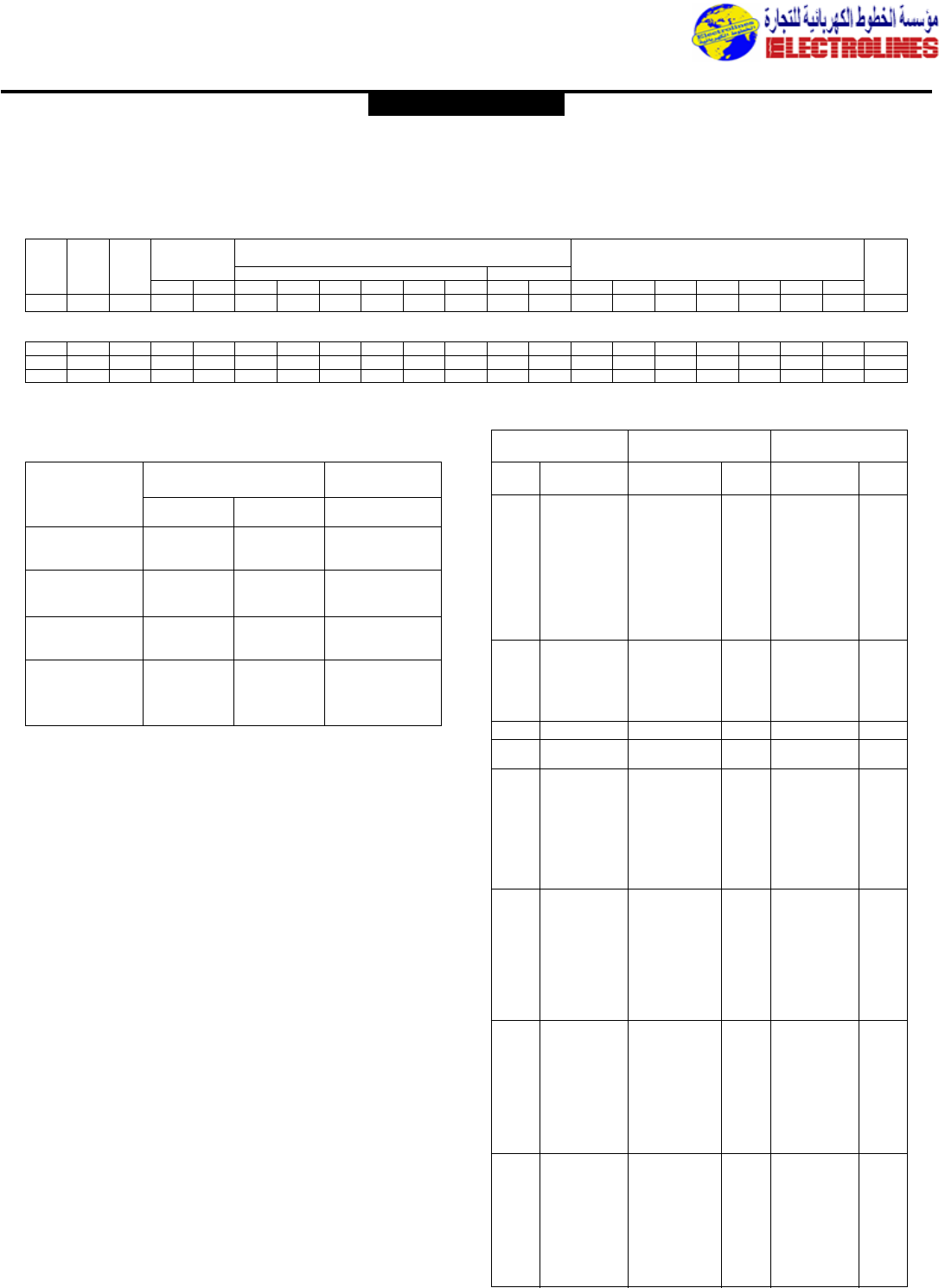
Distribution Equipment
GENERAL ELECTRIC
Circuit
Maximum UL Listed Interrupting Ratings– Dimensions
Approx.
Breaker Ampere
No. Voltage Rating rms Symmetrical Amps (In Thousands) (In.)
Ship Wt./
Type Rating
Poles ac Voltage dc Voltage
Std.Pack
ac dc 120 120/240 240 277 480 600 125 250 H W D A B C E
TLB4 250-400 3 480 – – – 85 – 65 – – – 131/16 523/32 47/8523/32 417/32 13/419/32 –
THLC1 15-150
3 600 – – – 200 – 200 50Å––8
3/441/843/16 53/825/813/83/8–
THLC2 125-225
3 600 – – – 200 – 200 50 – – 117/16 523/32 47/8523/32 417/32 13/419/32 –
THLC4 250-400
3 600 – – – 200 – 200 50 – – 131/16 523/32 47/8523/32 417/32 13/419/32 –
Å15-50A THLC1 rated 480 Vac max., 150kA.
GE Molded Case Circuit Breakers
Quick Reference Guide Ratings do not apply to molded case switches.
TLB High Interrupting Lines (UL File E11592;Fixed Thermal Magnetic Trip Units)
THLC Current Limiting Line (UL File E11592; Fixed Thermal Magnetic Trip Units)
Molded Case
Switch Catalog
Number
Maximum Rating
Protective Device➂
AmpsVoltage Amps rms Sym.
Short Circuit
Withstand Rating
TQL,TQB,TQC21Y60
120/240 60 10,000
TQL,TQB,TQC21Y10
120/240 100 10,000
TQL,TQB,TQC22Y60
240 60 10,000
TQL,TQB,TQC22Y100
240 100 10,000
TQL,TQB,TQC32Y60
240 60 10,000
TQL,TQB,TQC32Y100
240 100 10,000
TEB111Y100
240 100 10,000
TEB122Y100
240 100 10,000
TEB132Y100
240 100 10,000
Q-Line and TEB Molded Case Switches
Short Circuit Withstand RatingÇMolded Case Switch
Ampere
Rating Catalog Number
Protective Device➃
Max.Amp
Rating
Type
Amps rms Sym. Max.
Voltage
Short Circuit
Withstand Rating
100 TED113Y100 Any fuse or circuit 100 10,000 240
breaker rated
10,000A 240V
100 TED134Y100 TED134100 100 14,000 480
100 SEDA36ANO100 See Note 5 100 200,000 240
25,000 600
150 TED136Y150 TED136150 150 14,000 600
TED134150 150 14,000 480
150 SEDA36ANO150 See Note 5 150 200,000 240
100,000 480
25,000 600
225 TFJ236Y225 TED,THED 150 14,000 600
TFJ,TFK,THFK 225 14,000 600
Class J Fuse 400 14,000 600
250 SFDA36ANO250 See Note 5 250 200,000 240
100,000 480
25,000 600
225 TQD32Y225 TQD 225 14,000 240
400 TJD432Y400 TJD 400 22,000 240
Class T Fuse 400 50,000 240
400 SGDA36ANO400 See Note 5 400 200,000 240
100,000 480
42,000 600
400 TJJ436Y400 TFJ,TFK,THFK 225 18,000 600
22,000 480
TJJ,THJK, 22,000 600
TJ4V,THJ4V 400 30,000 480
THJ9V
Class J Fuse 400 50,000 600
600 SGDA36ANO600 See Note 5 600 200,000 240
100,000 480
42,000 600
600 TJK636Y600 TJJ,THJK, 22,000 600
TJ4V,THJ4V 400 30,000 480
THJ9V
Class J Fuse 600 50,000 600
TJK,THJK, 22,000 600
TJ4V,THJ4V, 600 30,000 480
THJ9V 30,000 480
800 SKDA36ANOK00 See Note 5 800 100,000 240
65,000 480
42,000 600
800 TKMA836Y800 TJK,THJK, 22,000 600
TJ4V,THJ4V, 600 30,000 480
THJ9V
TKM,THKM, 22,000 600
TK4V,THK4V, 800 30,000 480
THK9V
Class L Fuse 800 50,000 600
1200 SKDA36AN1200 See Note 5 1200 100,000 240
65,000 480
42,000 600
1200 TKMA3Y1200 TJK,THJK, 22,000 600
TJ4V,THJ4V, 600 30,000 480
THJ9V
TKM,THKM, 22,000 600
TK4V,THK4V 1200 30,000 480
THJ9V
Class L Fuse 1200 50,000 600
Molded Case Switches Short Circuit Withstand Rating
Spectra RMS switches include a fixed, high-set instantaneous trip.
}
}
}
}
}
}
}
ÇQ-Line and TEB molded case
switches have a 10,000 amp
symmetrical short circuit
withstand rating when
protected by a fuse or circuit
breaker rated 10,000 amps IC
or greater and whose ampere
rating does not exceed the
ampere rating of the switch.
➂Protective device must be on
line side of molded case switch.
➃Three-pole,600 volt switches
cover 2-pole,600 volt and 2-
and 3-pole, 480 volt switches.
➄The maximum withstand rating
is limited by the application to
the value set forth in this table
or the short circuit rating of
the upstream fuse or circuit
breaker,whichever is less.
The upstream protective device
must have an instantaneous trip
function or element and its
rated ampacity.
Electrolines Est.
P. O. Box. 942 Yanbu Saudi Arabia Tel: +966 4 3225418 Fax: +966 4 3222213 Al-Jubail: Tel: +966 3 3632967 Fax: +966 3 3612967
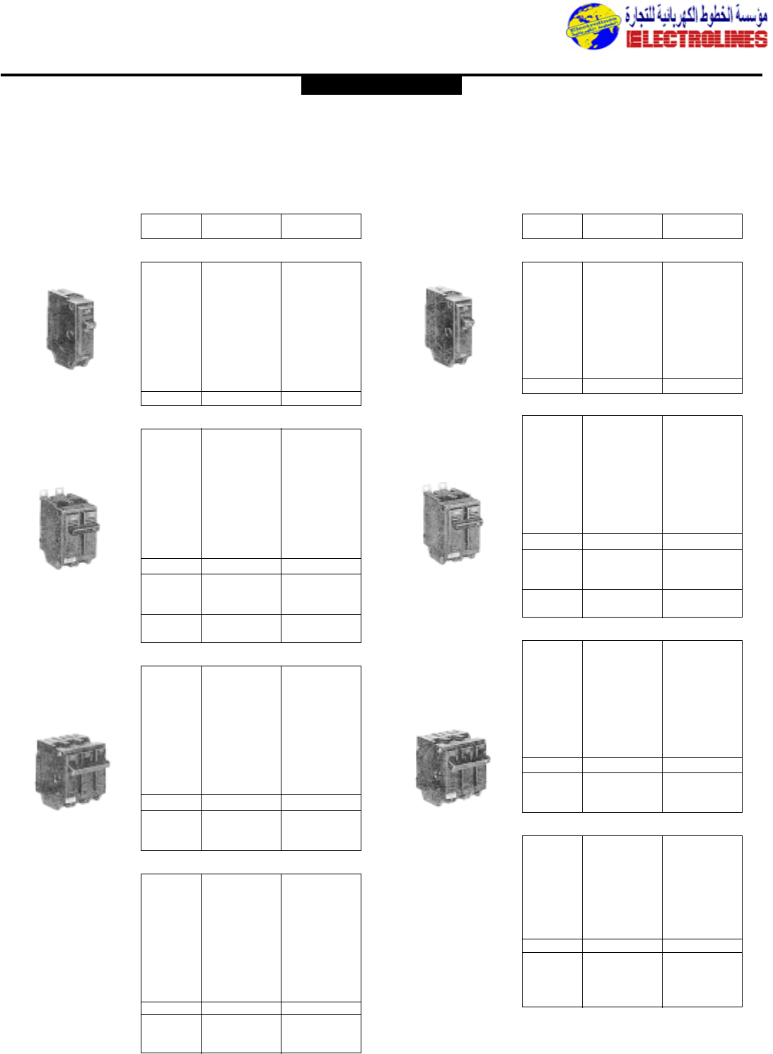
Distribution Equipment
Q Line Circuit Breakers
Types TQL,THQL,TQB,THQB
10-125 Amps
10,000 Amps IC, UL HACR Listed
Ampere TQL,THQL Plug-in TQB,THQB Bolt-on
Rating Catalog Number Catalog Number
Single-pole, 120/240 Volts ac
10 TQL1110 TQB1110
15 THQL1115 THQB1115
20 THQL1120 THQB1120
25 THQL1125 THQB1125
30 THQL1130 THQB1130
35 THQL1135 THQB1135
40 THQL1140 THQB1140
45 THQL1145 THQB1145
50 THQL1150 THQB1150
60 THQL1160 THQB1160
70 THQL1170 THQB1170
Two-pole, 120/240 Volts ac
10 TQL2110 TQB2110
15 THQL2115 THQB2115
20 THQL2120 THQB2120
25 THQL2125 THQB2125
30 THQL2130 THQB2130
35 THQL2135 THQB2135
40 THQL2140 THQB2140
45 THQL2145 THQB2145
50 THQL2150 THQB2150
60 THQL2160 THQB2160
70 THQL2170 THQB2170
80 THQL2180 THQB2180
90 THQL2190 THQB2190
100 THQL21100 THQB21100
110 THQL21110 –
125 THQL21125 –
Two-pole, 240 Volts ac
10 TQL22010 TQB22010
15 THQL22015 THQB22015
20 THQL22020 THQB22020
25 THQL22025 THQB22025
30 THQL22030 THQB22030
35 THQL22035 THQB22035
40 THQL22040 THQB22040
45 THQL22045 THQB22045
50 THQL22050 THQB22050
60 THQL22060 THQB22060
70 THQL22070 THQB22070
80 THQL22080 THQB22080
90 THQL22090 THQB22090
100 THQL22100 THQB22100
Three-pole, 240 Volts ac
10 TQL32010 TQB32010
15 THQL32015 THQB32015
20 THQL32020 THQB32020
25 THQL32025 THQB32025
30 THQL32030 THQB32030
35 THQL32035 THQB32035
40 THQL32040 THQB32040
45 THQL32045 THQB32045
50 THQL32050 THQB32050
60 THQL32060 THQB32060
70 THQL32070 THQB32070
80 THQL32080 THQB32080
90 THQL32090 THQB32090
100 THQL32100 THQB32100
THQL1120
THQB2115
THQL32015
Types THHQL,THHQB,THHQC
10-100 Amps
22,000 Amps IC, UL HACR Listed
Ampere Plug-in Bolt-on
Rating
Catalog Number Catalog Number
Single-pole, 120/240 Volts ac
15➀THHQL1115 THHQB1115
20➀THHQL1120 THHQB1120
25 THHQL1125 THHQB1125
30 THHQL1130 THHQB1130
35 THHQL1135 THHQB1135
40 THHQL1140 THHQB1140
45 THHQL1145 THHQB1145
50 THHQL1150 THHQB1150
60 THHQL1160 THHQB1160
70 THHQL1170 THHQB1170
Two-pole, 120/240 Volts ac
15 THHQL2115 THHQB2115
20 THHQL2120 THHQB2120
25 THHQL2125 THHQB2125
30 THHQL2130 THHQB2130
35 THHQL2135 THHQB2135
40 THHQL2140 THHQB2140
45 THHQL2145 THHQB2145
50 THHQL2150 THHQB2150
60 THHQL2160 THHQB2160
70 THHQL2170 THHQB2170
80 THHQL2180 THHQB2180
90 THHQL2190 THHQB2190
100 THHQL21100 THHQB21100
100 THHQL21110 –
125 THHQL21125 –
Two-pole, 240 Volts ac
15 THHQL22015 THHQB22015
20 THHQL22020 THHQB22020
25 THHQL22025 THHQB22025
30 THHQL22030 THHQB22030
35 THHQL22035 THHQB22035
40 THHQL22040 THHQB22040
45 THHQL22045 THHQB22045
50 THHQL22050 THHQB22050
60 THHQL22060 THHQB22060
70 THHQL22070 THHQB22070
80 THHQL22080 THHQB22080
90 THHQL22090 THHQB22090
100 THHQL22100 THHQB22100
Three-pole, 240 Volts ac
15 THHQL32015 THHQB32015
20 THHQL32020 THHQB32020
25 THHQL32025 THHQB32025
30 THHQL32030 THHQB32030
35 THHQL32035 THHQB32035
40 THHQL32040 THHQB32040
45 THHQL32045 THHQB32045
50 THHQL32050 THHQB32050
60 THHQL32060 THHQB32060
70 THHQL32070 THHQB32070
80 THHQL32080 THHQB32080
90 THHQL32090 THHQB32090
100 THHQL32100 THHQB32100
THHQL1120
THHQB2115
THHQL32015
➀UL Listed as swd (switching duty)
rated.Suitable for switching 120-volt ac
fluorescent lighting loads.
GENERAL ELECTRIC
Electrolines Est.
P. O. Box. 942 Yanbu Saudi Arabia Tel: +966 4 3225418 Fax: +966 4 3222213 Al-Jubail: Tel: +966 3 3632967 Fax: +966 3 3612967
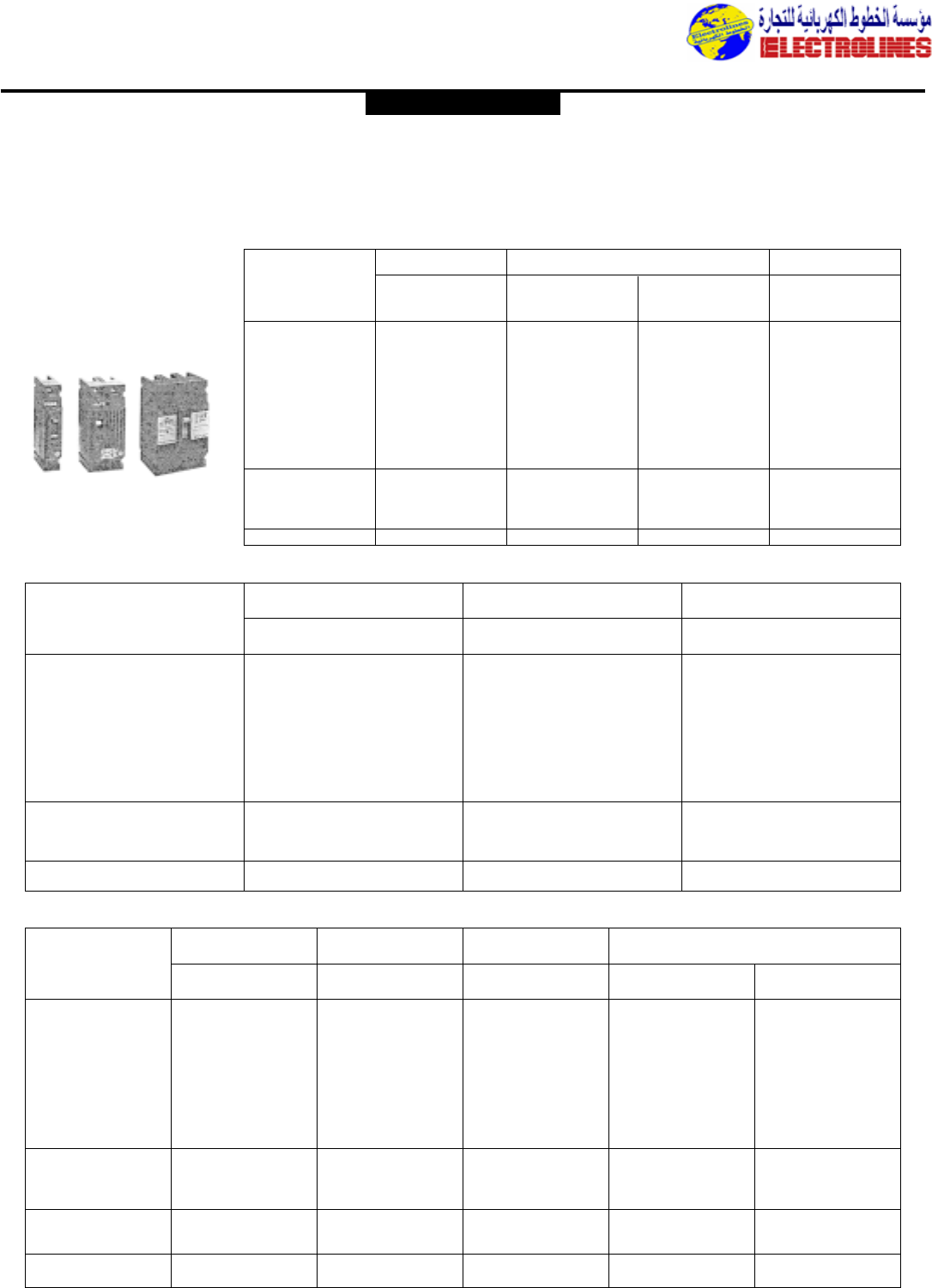
Distribution Equipment
E150 Line Circuit Breakers
10-150 Amperes 120-600 Volts ac 125, 250 Volts dc
Ampere
Rating 277V ac
125V dc
Catalog Number
120V ac
125V dc
Catalog Number
Type TEB Type TED
347 Volts ac
Catalog Number 347 Volts ac
Catalog Number
Type THED
10 TEB111010 TED113010
15 TEB111015 TED113015 TED114015 THED114015
20 TEB111020 TED113020 TED114020 THED114020
25 TEB111025 TED113025 TED114025 THED114025
30 TEB111030 TED113030 TED114030 THED114030
35 TEB111035 TED113035 – –
40 TEB111040 TED113040 – –
45 TEB111045 TED113045 – –
50 TEB111050 TED113050 – –
60 TEB111060 TED113060 – –
70 TEB111070 TED113070 – –
80 TEB111080 TED113080 – –
90 TEB111090 TED1113090 – –
100 TEB111100 TED113100 – –
100NA TEB111Y100 TED113Y100 – –
Single-pole—Includes Cu/Al load lugs only. If line lugs are required,
add suffix “WL” to Catalog Number.
Ampere
Rating 480V ac, 250V dc
Catalog Number
240V ac, 250V dc
Catalog Number
Type TEB Type TED
480V ac, 250V dc
Catalog Number
Type THED, Hi-Break
10 TEB122010WL TED124010WL
15 TEB122015WL TED124015WL THED124015WL
20 TEB122020WL TED124020WL THED124020WL
25 TEB122025WL TED124025WL THED124025WL
30 TEB122030WL TED124030WL THED124030WL
35 TEB122035WL TED124035WL THED124035WL
40 TEB122040WL TED124040WL THED124040WL
45 TEB122045WL TED124045WL THED124045WL
50 TEB122050WL TED124050WL THED124050WL
60 TEB122060WL TED124060WL THED124060WL
70 TEB122070WL TED124070WL THED124070WL
80 TEB122080WL TED124080WL THED124080WL
90 TEB122090WL TED124090WL THED124090WL
100 TEB122100WL TED124100WL THED124100WL
100NA TEB122Y100 TED124Y100 –
150NA – TED124Y150 –
Two-pole—Includes Cu/Al line and load lugs.
Ampere
Rating 480 Volts ac
Catalog Number
240 Volts ac
Catalog Number
Type TEB Type TED
600 Volts ac
Catalog Number
Type TED
480 Volts ac
Catalog Number
Type THED, Hi-Break
600 Volts ac
Catalog Number
10 TEB132010WL TED134010WL – – –
15 TEB132015WL TED134015WL TED136015WL – THED136015WL
20 TEB132020WL TED134020WL TED136020WL – THED136020WL
25 TEB132025WL TED134025WL TED136025WL – THED136025WL
30 TEB132030WL TED134030WL TED136030WL – THED136030WL
35 TEB132035WL TED134035WL TED136035WL – THED136035WL
40 TEB132040WL TED134040WL TED136040WL – THED136040WL
45 TEB132045WL TED134045WL TED136045WL – THED136045WL
50 TEB132050WL TED134050WL TED136050WL – THED136050WL
60 TEB132060WL TED134060WL TED136060WL – THED136060WL
70 TEB132070WL TED134070WL TED136070WL – THED136070WL
80 TEB132080WL TED134080WL TED136080WL – THED136080WL
90 TEB132090WL TED134090WL TED136090WL – THED136090WL
100 TEB132100WL TED134100WL TED136100WL – THED136100WL
110 – TED134110WL TED136110WL THED134110WL THED136110WL
125 – TED134125WL TED136125WL THED134125WL THED136125WL
150 – TED134150WL TED136150WL THED134150WL THED136150WL
100NA TEB132Y100 TED134YT100 TED136YT100 – –
150NA – TED134YT150 TED136YT150 – –
Three-pole—Includes Cu/Al line and load lugs.
Types TEB,TED,
THED—
Non-interchangeable Trip
One-pole Three-poleTwo-pole
GENERAL ELECTRIC
Electrolines Est.
P. O. Box. 942 Yanbu Saudi Arabia Tel: +966 4 3225418 Fax: +966 4 3222213 Al-Jubail: Tel: +966 3 3632967 Fax: +966 3 3612967
Two-pole Three-pole
70 600 900 TFJ224070WL TFJ236070WL
80 700 1000 TFJ224080WL TFJ236080WL
90 600 900 TFJ224090WL TFJ236090WL
100 600 1250 TFJ224100WL TFJ236100WL
110 660 1250 TFJ224110WL TFJ236110WL TCAL24 #4-300
125 600 1250 TFJ224125WL TFJ236125WL kcmil
150 700 1500 TFJ224150WL TFJ236150WL
175 800 1750 TFJ224175WL TFJ236175WL
200 900 2000 TFJ224200WL TFJ236200WL
225 1000 2250 TFJ224225WL TFJ236225WL
250 1000 2250 – TFJ236250WL
225NA – – TFJ226Y225 TFJ236Y225 TCAL24 _
Distribution Equipment
F225 Line Circuit Breakers
70-250 Amperes-TFJ Non-Interchangeable Trip
70-225A TFK,THFK Interchangeable Trip
480 or 600 volts ac
250 Volts dc
Ampere
Rating Catalog
Number
Lo
Adjustable Trip Range Amp
Hi
Complete Breaker
480V ac Max Complete Breaker
600V ac Max
Catalog Number
Copper/
Aluminum
Lugs Wire
Size
Type TFJ—Non-interchangeable Trip
Includes line and load lugs. Suitable for reverse feed.
Ampere
Rating
Use with Standard
and Hi-Break
Frames
Lo Hi
Standard
Catalog Number Hi-Break
Catalog Number
Adjustable Trip Range Amp Complete Circuit Breaker
Includes Line and Load Lugs Trip Unit
Only Frame Only
Catalog Number
(Order 1 line and
1 load per pole)
Catalog
Number Wire Size
Terminal Lugs for Front
Connection (Copper/Aluminum)
Two-pole, 480 Volts ac Max., 250 Volts dc Max.
70 600 900 TFK224070WL THFK224070WL TFK226T070
80 700 1000 TFK224080WL THFK224080WL TFK226T080 TFK224F000
90 600 900 TFK224090WL THFK224090WL TFK226T090 Standard
100 600 1250 TFK224100WL THFK224100WL TFK226T100 Frame
110 660 1250 TFK224110WL THFK224110WL TFK226T110
125 600 1250 TFK224125WL THFK224125WL TFK226T125 TCAL24 #4-300
150 700 1500 TFK224150WL THFK224150WL TFK226T150 kcmil
175 800 1750 TFK224175WL THFK224175WL TFK226T175
200 900 2000 TFK224200WL THFK224200WL TFK226T200 THFK224F000
225 1000 2250 TFK224225WL THFK224225WL TFK226T225 Hi-Break
225NA – – TFK226Y225 – TFKY2 Frame
Types TFK,THFK—Interchangeable Trip
Frame
Type TFK
Three-pole, 600 Volts ac Max., 250 Volts dc Max.
70 600 900 TFK236070WL THFK236070WL TFK236T070
80 700 1000 TFK236080WL THFK226080WL TFK236T080 TFK236F000
90 600 900 TFK236090WL THFK236090WL TFK236T090 Standard
100 600 1250 TFK236100WL THFK236100WL TFK236T100 Frame
110 660 1250 TFK236110WL THFK236110WL TFK236T110
125 600 1250 TFK236125WL THFK236125WL TFK236T125
150 700 1500 TFK236150WL THFK236150WL TFK236T150 THFK236F000 TCAL24 #4-300
175 800 1750 TFK236175WL THFK236175WL TFK236T175 Hi-Break kcmil
200 900 2000 TFK236200WL THFK236200WL TFK236T200 Frame
225 1000 2250 TFK236225WL THFK236225WL TFK236T225
225A
Mag 600 1400 – – TFK236TM1225
Only 1000 2250 – – TFK236TM2225
225NA – – TFK236Y225 – TFKY3
GENERAL ELECTRIC
Electrolines Est.
P. O. Box. 942 Yanbu Saudi Arabia Tel: +966 4 3225418 Fax: +966 4 3222213 Al-Jubail: Tel: +966 3 3632967 Fax: +966 3 3612967
Distribution Equipment
125 375 1250 TJJ426125WL TJJ436125WL
150 450 1500 TJJ426150WL TJJ436150WL
175 525 1750 TJJ426175WL TJJ436175WL
200 600 2000 TJJ426200WL TJJ436200WL
225 675 2250 TJJ426225WL TJJ436225WL TCAL43
250 750 2500 TJJ426250WL TJJ436250WL Included (1)6-600 kcmil
300 900 3000 TJJ426300WL TJJ436300WL in price (2)2/0-250 kcmil
350 1050 3500 TJJ426350WL TJJ436350WL of breaker
400 1200 4000 TJJ426400WL TJJ436400WL
400NA – – TJJ426Y400 TJJ436Y400WL
J600 Line Circuit Breakers
125-600 Amperes 600 volts ac 250 Volts dc
Ampere
Rating
Catalog Number
Lo
Adjustable Trip
Range Amp
Hi
2-pole, 400-amp Frame
600V ac, 250V dc 3-pole, 400-amp Frame
600 Volts ac
Catalog Number
Copper/
Aluminum
Lugs Wire
Size
Type TJJ—Non-interchangeable Trip (Includes Line and Load Lugs)
Suitable for reverse feed.
Ampere
Rating
Catalog Number
Lo Hi
Standard
Catalog Number Hi-Break
Catalog Number
Adjustable Trip Range Amp Complete Circuit Breaker
Includes Line and Load Lugs
Frame Only Trip Unit Only
Catalog Number
(Order 2per pole)
Use with Standard
and Hi-Break
Frames
Wire Size
Terminal Lugs for Front Connection
(Copper/Aluminum)
400-amp Frame
Two-pole
125 375 1250 TJK426125WL THJK426125WL TJK436T125
150 450 1500 TJK426150WL THJK426150WL TJK426F000 TJK436T150
175 525 1750 TJK426175WL THJK426175WL Standard TJK436T175
200 600 2000 TJK426200WL THJK426200WL Frame TJK436T200 (1)
225 675 2250 TJK426225WL THJK426225WL TJK436T225 TCAL43 6-600 kcmil
250 750 2500 TJK426250WL THJK426250WL TJK436T250 or Twin
300 900 3000 TJK426300WL THJK426300WL THJK426F000 TJK436T300 2/0-250
350 1050 3500 TJK426350WL THJK426350WL Hi-Break TJK436T350
400 1200 4000 TJK426400WL THJK426400WL TJK436T400
400NA – – TJK426Y400 – TJKY3
Types TJK,THJK Interchangeable Trip
Frame
Trip
Lugs
Type TJK
600-amp Frame
Two-pole
250 750 2500 TJK626250WL THJK626250WL TJK636T250 (1)
300 900 3000 TJK626300WL THJK626300WL TJK626F000 TJK636T300 TCAL43 6-600 kcmil
350 1050 3500 TJK626350WL THJK626350WL Standard TJK636T350 or Twin
400 1200 4000 TJK626400WL THJK626400WL Frame TJK636T400 2/0-250 kcmil
450 1350 4500 TJK626450WL THJK626450WL THJK626F000 TJK636T450 Twin 4/0-350
500 1500 5000 TJK626500WL THJK626500WL Hi-Break TJK636T500 TCAL63 kcmil-Cu or
600 1800 6000 TJK626600WL THJK626600WL Frame TJK636T600 Twin 300-500
600NA –
– TJK626Y600 – TJKY36 kcmil-Al
Three-pole
125 375 1250 TJK436125WL THJK436125WL TJK436T125
150 450 1500 TJK436150WL THJK436150WL TJK436T150
175 525 1750 TJK436175WL THJK436175WL TJK436T175
200 600 2000 TJK436200WL THJK436200WL TJK436T200
225 675 2250 TJK436225WL THJK436225WL TJK436F000 TJK436T225
250 750 2500 TJK436250WL THJK436250WL Standard TJK436T250 (1)
300 900 3000 TJK436300WL THJK436300WL Frame TJK436T300 6-600 kcmil
350 1050 3500 TJK436350WL THJK436350WL TJK436T350 TCAL43 or Twin
400 1200 4000 TJK436400WL THJK436400WL THJK436F000 TJK436T400 2/0-250 kcmil
400A 600 2000 – – Hi-Break TJK436TM1400
Mag 1200 4000 – – Frame TJK436TM1400
Only 350 1000 – TJK436TM3400
400NA – – TJK436Y400 – TJKY3
Three-pole
250 750 2500 TJK636250WL THJK636250WL TJK636T250 (1)
300 900 3000 TJK636300WL THJK636300WL TJK636T300 TCAL43 6-600 kcmil
350 1050 3500 TJK636350WL THJK636350WL TJK636F000 TJK636T350 or Twin
400 1200 4000 TJK636400WL THJK636400WL Standard TJK636T400 2/0-250 kcmil
450 1350 4500 TJK636450WL THJK636450WL Frame TJK636T450
500 1500 5000 TJK636500WL THJK636500WL THJK636F000 TJK636T500
600 1800 6000 TJK636600WL THJK636600WL Hi-Break TJK636T600 Twin 4/0-350
600A Frame TCAL63 kcmil-Cu or
Mag 600 2000 – – TJK636TM1600 Twin 300-500
Only 1800 6000 – – TJK636TM2600 kcmil-Al
600NA – – TJK636Y600 – TJKY36
GENERAL ELECTRIC
Electrolines Est.
P. O. Box. 942 Yanbu Saudi Arabia Tel: +966 4 3225418 Fax: +966 4 3222213 Al-Jubail: Tel: +966 3 3632967 Fax: +966 3 3612967
Distribution Equipment
K1200 Line Circuit Breakers
300-1200 Amperes 600 volts ac 250 Volts dc
Ampere
Rating
Catalog NumberLo Hi Standard
Catalog Number Hi-Break
Catalog Number
Adjustable Trip Range Amp Complete Circuit Breaker
Includes Line and Load Lugs Frame Only Trip Unit Only
Catalog Number
(Order 2per pole)
Use with Standard
and Hi-Break
Frames
Wire Size
Terminal Lugs for Front
Connection (Copper/Aluminum)
800-ampere Frame
Two-pole
300 900 3000 TKMA826300WL THKMA826300WL TKMA836T300
350 1050 3500 TKMA826350WL THKMA826350WL TKM826F000 TKMA836T350
400 1200 4000 TKMA826400WL THKMA826400WL Standard TKMA836T400 TCAL61 (2) 2/0-500
450 1350 4500 TKMA826450WL THKMA826450WL Frame TKMA836T450 kcmil
500 1500 5000 TKMA826500WL THKMA826500WL TKMA836T500
600 1800 6000 TKMA826600WL THKMA826600WL TKMA836T600
700 2100 6400 TKMA826700WL THKMA826700WL THKM826F000 TKMA836T700
800 2400 6400 TKMA826800WL THKMA826800WL Hi-Break Frame TKMA836T800 TCAL81 (3) 3/0-500
800NA – – TKMA826Y800 – TKMAY3 kcmil
Types TKM,THKM Interchangeable Trip
1200-ampere Frame
Two-pole
600 1800 6000 TKMA20600WL THKMA20600WL TKM2F TKMA3T0600 (3) 3/0-500
700 2100 6400 TKMA20700WL THKMA20700WL Standard TKMA3T0700 TCAL81 kcmil
800 2400 6400 TKMA20800WL THKMA20800WL Frame TKMA3T0800
1000 3000 10000 TKMA21000WL THKMA21000WL TKMA3T1000 (4) 250-350
1200 3600 10000 TKMA21200WL THKMA21200WL THKM2F TKMA3T1200 kcmil Cu
1000NA – – TKMA2Y1000 – Hi-Break TCAL121 (4)35-500
1200NA – – TKMA2Y1200 – Frame TKMA3Y12 kcmil Al
Three-pole
300 900 3000 TKMA836300WL THKMA836300WL TKMA836T300
350 1050 3500 TKMA836350WL THKMA836350WL TKM836F000 TKMA836T350
400 1200 4000 TKMA836400WL THKMA836400WL Standard TKMA836T400 (2) 2/0-500
450 1350 4500 TKMA836450WL THKMA836450WL Frame TKMA836T450 TCAL61 kcmil
500 1500 5000 TKMA836500WL THKMA836500WL TKMA836T500
600 1800 6000 TKMA836600WL THKMA836600WL TKMA836T600
700 2100 6400 TKMA836700WL THKMA836700WL TKMA836T700
800 2400 6400 TKMA836800WL THKMA836800WL TKMA836T800
800 THKM836F000
Mag 1200 4000 – – Hi-Break TKMA836TM48 (3) 3/0-500
Only 2400 8000 – – Frame TKMA836TM68 TCAL81 kcmil
800NA _ _ TKMA836Y800 – TKMAY3
Three-pole
600 1800 6000 TKMA30600WL THKMA30600WL TKMA3T0600 (3) 3/0-500
700 2100 6400 TKMA30700WL THKMA30700WL TKMA3T0700 TCAL81 kcmil
800 2400 6400 TKMA30800WL THKMA30800WL TKM3F TKMA3T0800
1000 3000 10000 TKMA31000WL THKMA31000WL Standard TKMA3T1000
1200 3600 10000 TKMA31200WL THKMA31200WL Frame TKMA3T1200 (4) 250-350
1200 TCAL121 kcmil Cu
Mag 1800 6000 – – TKMA3TM512 (4) 350-500
Only 2400 8000 – – THKM3F TKMA3TM612 kcmil Al
1000NA – – TKMA3Y1000 – Hi-Break
1200NA – – TKMA3Y1200 – Frame TKMA3Y12
GENERAL ELECTRIC
Electrolines Est.
P. O. Box. 942 Yanbu Saudi Arabia Tel: +966 4 3225418 Fax: +966 4 3222213 Al-Jubail: Tel: +966 3 3632967 Fax: +966 3 3612967
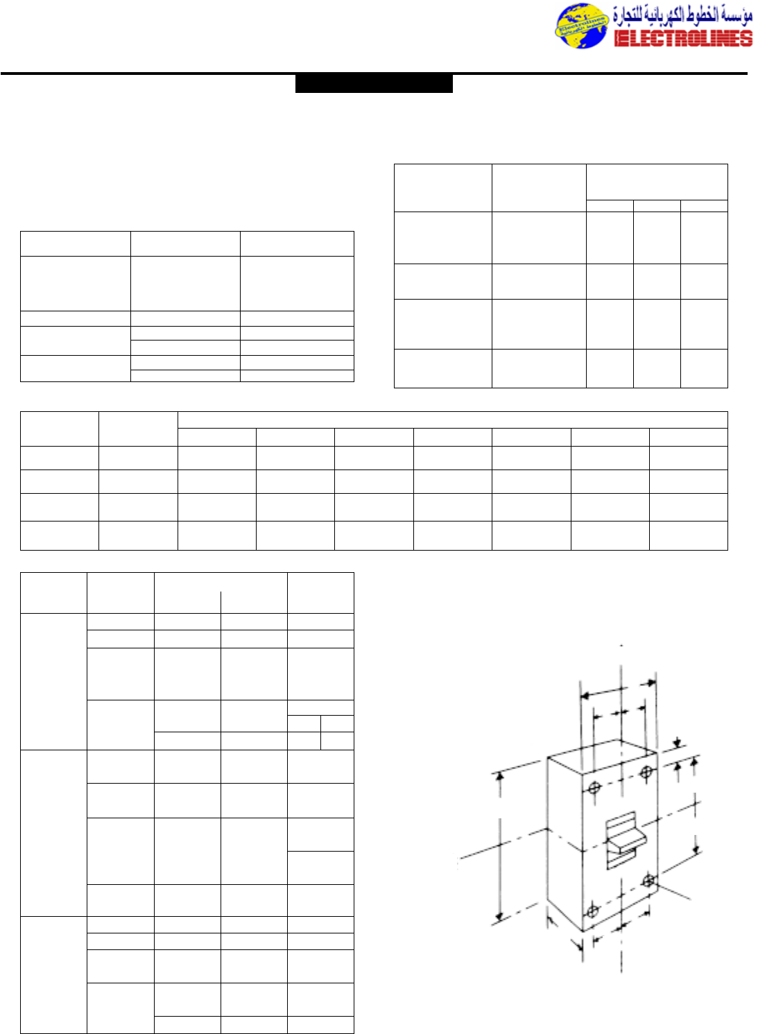
Distribution Equipment
Spectra RMSTM Molded Case Circuit Breakers
Spectra RMSTM breakers provide true RMS sensing.A short-time
function is standard on all breakers–for an extra level of motor
and transformer protection.The entire line is available in IC
ratings to 200kA @ 240 Vac and 100kA @ 480 Vac.
Sensor
Frame Type Amp Rating Plugs
30 15-30
SE150 60 40-60
100 70-100
150 110-150
SF250 250 70-250
SG600 400 125-400
600 250-600
SK1200 800 300-800
1200 600-1200
Interrupting
Frame Capacity,
Frame Type Designation RMS Sym kA
Prefix 240 480 600
SEDA 18 14 14
SE150 SEHA 65 25 18
SELA 100 65 25
SEPA 200 100 25
SFHA 65 25 18
SE250 SFLA 100 65 25
SFPA 200 100 25
SGDA 65 – –
SG600 SGHA 65 35 25
SGLA 100 65 65
SGPA 200 100 65
SKHA 65 50 25
SK1200 SKLA 100 65 42
SKPA 200 100 65
FRAME DESIGNATION & AMPACITIES
Wire Range (Qty)
For Use Catalog
Accessory With Copper Aluminum Number
SE150 #12-3/0 #12-3/0 TCAL18
SF250 #8-350 kcmil #8-350 kcmil TCAL29
TCLK265
SG600
(2)2/0-400 kcmil or (2)2/0-500 kcmil or
TCLK365
(1)#6-600 kcmil (1)#6-600 kcmil
(Upper) (Lower)
SK1200
(3)3/0-500 kcmil (3)3/0-500 kcmil TCAL81 TCAL91
(4)250-350 kcmil (4)250-500 kcmil TCAL121 TCAL131
SE150 – – SE3LCK
(252B1661G1)
SF250 – – SF3LCK
(252B1659G1)
––
SG1LCK
(331A1770G1)
SG600 SG1BCK
(331A1770G2)
SK1200 – – SK1LCK
(252B1660G1)
SE150 #12-3/0 – TC018
SF250 #8-350 kcmil – TC029
SG600 (2) 2/0-400 kcmil or – TCOK265
(1) #6-600 kcmil – TCOK365
(Upper) (Lower)
SK1200 (3) 250-500 kcmil – TC081A TC091
(4) 250-400 kcmil – TC0121 TC0131
LUGS, LUG COVERS,AND BUS COVERS
Circuit Dimensions inches (mm)
Breaker
Frame Type Poles H W D A B C E
SE150 26.31(160.3) 4.12(104.8) 3.38(85.9) 2.82(71.6) 2.06(52.3) .69(17.5) .72(18.3)
3
SF250 210.12(257.0) 4.12(104.8) 3.81(96.8) 3.88(98.6) 3.88(98.5) .69(17.5) 1.19(30.2)
3
SG600 210.09 (256.3) 5.50(139.7) 3.81(96.8) 4.45(113.0) 3.30(83.8) .91(23.1) 1.18(30.0)
3
SK1200 215.50 (393.7) 8.25(209.6) 5.50(139.7) 8.56(217.4) 5.69(144.5) 1.38(34.9) .62(15.8)
3
DIMENSIONS
INTERRUPTING CAPACITIES
Plated
extruded
aluminum lugs
for terminating
copper or
aluminum
cables
Replacement
Lug Covers
and End
Covers
Plated
Copper
Lugs
HANDLE
PIVOT
VERTICAL
GENERAL ELECTRIC
¢
¢
H
CC
C
DC
E
A
B
Electrolines Est.
P. O. Box. 942 Yanbu Saudi Arabia Tel: +966 4 3225418 Fax: +966 4 3222213 Al-Jubail: Tel: +966 3 3632967 Fax: +966 3 3612967
Distribution Equipment
Select Internal Accessories
All Spectra RMSTM circuit breakers from the SE150 through the
SK1200,including instantaneous-trip Mag-Break®breakers and
Molded Case Switches,use the same UL Listed, field-installable
internal accessories that do not require cover removal to install.
UL File No. E57253. Installation instructions – GEH-5551 (Shunt
Trip and UVR) and GEH-5593 (Auxiliary Switch and Bell Alarm).
•Micro Versa Trip Digital RMS Trip System – expanded function-
ality in the same space-saving size of standard Spectra RMS breakers.
Standard
– 3-phase Ammeter with ±4% accuracy.
– Adjustable Long Time (L) pickup,0.5-1.0X,and delay (3-4 bands).
– Adjustable Instantaneous (I) pickup, 1.5-10X.
– Local Overload and Short Circuit Trip Indicators(T) with overload
pickup warning.
– Interchangeable trip rating plugs with test set jack for TVRMS test set.
– Digital LCD display with four-button keypad for function selection and
set point adjustment and sealable, clear Lexan®cover for tamper-
resistant settings.
– True RMS sensing for accurate response to high harmonic content
waveforms.
– EMI immunity per ANSI C37.90.
Optional
– Adjustable Short Time (S) pickup, 1.0-9.0C,and delay (4 bands) with
I2t ON/OFF selection.
– Adjustable Ground fault (G) pickup, 0.2-1.0S, and delay (4 bands) with
I2t ON/OFF selection and trip indicator.The 4 short time and ground
fault delay bands provide broader system selectivity.
•World Standards – All frames rated to UL,CSA,IEC 947-2,and JIS.
•Universal internal accessories – uses the same front-mounted,
field-installable shunt trips,undervoltage releases,bell alarms,and aux-
iliary switches as standard Spectra RMS breakers.
•Accessory lead rounting left or right – side channels
mean no extra space required for accessory leads.
•Current Limiting – SG600 frames rated 65kA and 100kA @
480Vac are UL Listed as current limiting.
•Reverse Feed – Front-mounted interchangeable rating plugs
mean all frames are UL Listed for reverse feed.
•Wide Current Setting Range – Interchangeable rating
plugs combined with 5 current sensors and 0.5-1.0X long time
pickup yield ampere ratings from 30 to 1200A.
•100% Continuous Current Rated – Optionally available for
100% UL continuous current rating applications.
•Interrupting Capacities – RMS Symmetrical kA
– UL,CSA Vac
Frame 240 480 600
SGH 65 35 25
SGL 100 65 65
SGP 200 100 65
SKH 65 50 25
SKL 100 65 42
SKP 200 100 65
Auxiliary No. of
Switch Switch Switch
Cat. No. Elements Rating
SAUXPAB1 1 form C 5A @ 240 Vac/
SAUXPAB2 2 form C 0.5A @ 125 Vdc
GOLD-PLATED
SAUXGAB1 1 form C CONTACTS
SAUXGAB2 2 form C 0.5A @ 30V
Auxiliary Switches provide remote indication of whether the circuit breaker
main contacts are opened or closed via open or closed SPDT switch elements.
AUXILIARY SWITCH
Table
Bell Alarm No. of
Switch Switch Switch
Cat. No. Elements Rating
SABAP1 1 form C 5A @ 240 Vac/
0.5A @ 125 Vdc
GOLD-PLATED
SABAG1 1 form C CONTACTS
0.5A @ 30V
All Bell Alarm Switch provides remote indication of whether the circuit
breaker has been tripped via open or closed SPDT switch elements,but
remains unchanged during “On/Off” circuit breaker operation.
BELL ARARM SWITCH
Table
Undervoltage Voltage Peak
Cat. No. ac dc Current (mA)
SAUV1 120 125 200
SAUV2 240 250 200
SAUV3 24 24 100
SAUV4 48 48 100
The Undervoltage Release provides automatic circuit breaker
tripping when there is a power loss or major dip (to 35%-70% of
rated voltage) in accessory control voltage.Ac devices are rated
for 50-400 Hz and UL Listed for 50-60 Hz.Cat.No. SAUV1 may
be used with time delay unit Cat. No.TD110A530 or TD1000
(120 Vac input,125 Vdc output).
UNDERVOLTAGE RELEASE
Table
Shunt Trip Voltage Current (mA)
Cat. No. ac dc Inrush Cont
SAST1 120 125 500 6.0
SAST2 240 250 400 5.0
SAST3 24 24 300 10.0
SAST4 48 48 300 10.0
For remote tripping of breaker,use with momentary close
contact.Not recommended for use with latching relay contact
since electronics in Shunt Trip will pulse power to the coil if
continuously energized,and breaker shut tripping upon reclosure
will be delayed 1-2 seconds at rated control voltage. (A short
circuit trip would be instantaneous.)
If maintained (latching relay) contact must be used and delayed
shunt tripping is not acceptable, use bell alarm in series with
control power for SE150 and SF250 frames and auxiliary switch
for SG600 and SK1200 breakers.
These devices are suitable for use with Ground Fault Sensing and
Relaying Equipment. Maximum VA is 75.Ac devices are rated for
50-400 Hz and UL Listed for 50-60 Hz.
SHUNT TRIP
Table
Spectra RMSTM Circuit Breakers with MicroVersaTripPlus &
MicroVersa PM Digital RMS Trip System
GENERAL ELECTRIC
Electrolines Est.
P. O. Box. 942 Yanbu Saudi Arabia Tel: +966 4 3225418 Fax: +966 4 3222213 Al-Jubail: Tel: +966 3 3632967 Fax: +966 3 3612967
Distribution Equipment
– IEC 947-2,Icu,JIS Vac
Frame 220-240 380-415 500 690
SGH 65 25 18 –
SGL 100 65 35 22
SGP 200 100 65 35
SKH 65 50 25 –
SKL 100 65 42 14
SKP 140 70 50 18
– IEC 947-2,Ics Vac
Frame 220-240 380-415 500 690
SGH 33 13 9 –
SGL 50 33 18 11
SGP 100 50 33 18
SKH 16 13 13 –
SKL 25 16 21 14
SKP 35 25 25 18
Catalog Numbers
Description Code
Frame Designation SG600 G
SK1200 K
IC/Capacity Rating
Standard UL Rating 65kA @ 480 Vac LB
100kA @ 480 Vac PB
100% Continuous UL Rating 65kA @ 480 Vac LL
100kA @ 480 Vac PP
Poles/Max. UL Voltage 3 poles,600 Vac 36
Trip System MicroVersaTrip®Plus B
MicroVersaTrip®PM C
with Metering and
POWER LEADERTM
Communications Bus
MicroVersaTrip®PM with D
Metering,POWER LEADERTM
Communications Bus
and Protective Relays
Overcurrent Protection LIT A
Functions LSIT B
LIGT C
LSIGT D
Sensor Amperes 150A 0150
G Frame 400A 0400
600A 0600
K Frame 800A 0800
1200A 1200
Frame Sensor Current Frame Sensor Current
Types Amps Rating Rating Plug Types Amps Rating Rating Plug
SGHB, 150 ............................60 SRPG150B60 SKHB, 800.............................300 SRPK800B300
SGHH, 80 SRPG150B80 SKHH, 400 SRPK800B400
SGLB, 100 SRPG150B100 SKLB, 500 SRPK800B500
SGLL, 125 SRPG150B125 SKLL, 600 SRPK800B600
SGPB, 150 SRPG150B150 SKPB, 700 SRPK800B700
SGPP 400............................150 SRPG400B150 SKPP 800 SRPK800B800
200 SRPG400B200 1200............................600 SRPK1200B600
225 SRPG400B225 700 SRPK1200B700
250 SRPG400B250 800 SRPK1200B800
300 SRPG400B300 1000 SRPK1200B1000
350 SRPG400B350 1200 SRPK1200B1200
400 SRPG400B400
600............................300 SRPG600B300
400 SRPG600B400
450 SRPG600B450
500 SRPG600B500
600 SRPG600B600
GS LL 36 B A 0150
Interrupting Capacities
GENERAL ELECTRIC
Electrolines Est.
P. O. Box. 942 Yanbu Saudi Arabia Tel: +966 4 3225418 Fax: +966 4 3222213 Al-Jubail: Tel: +966 3 3632967 Fax: +966 3 3612967
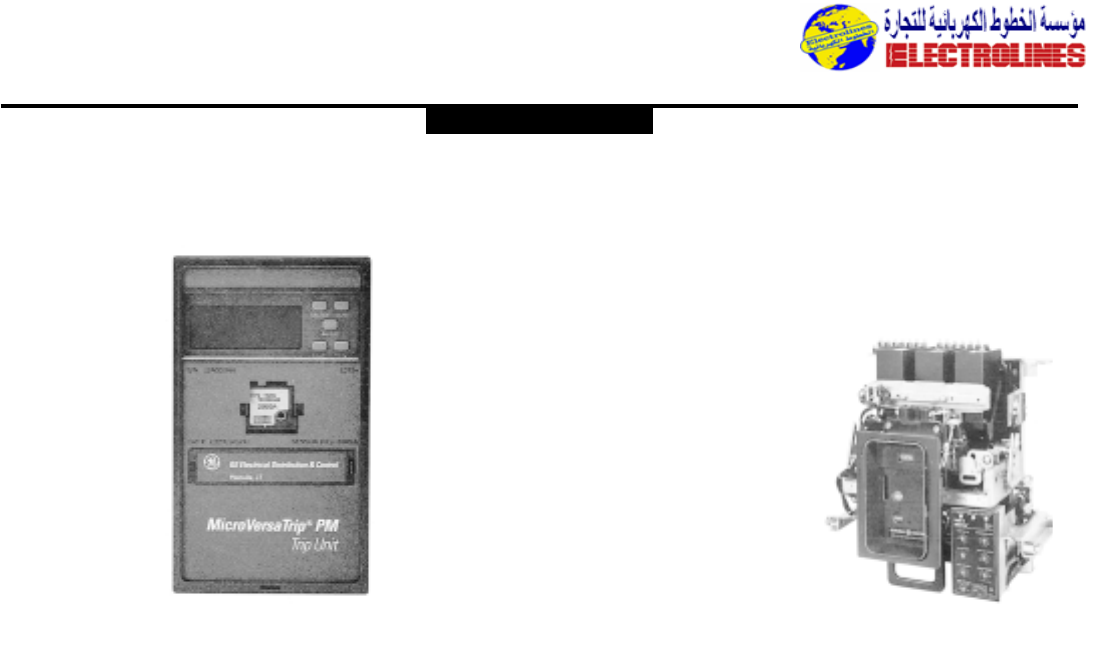
Distribution Equipment
Type AKR Power Circuit Breakers with MicroVersaTrip®
Trip Units
Features
•Intended for use in commercial,industrial, and utility
applications.
•For use as feeders or mains,and in such applications as
capacitor switching,motor circuits, generators,and resistance
welding.
•100% rated,40˚C room ambient temperature
•6 frame sizes:AKR-30,H/AKR-50,H/AKRT-50H/AKR-75,
75H/AKR-100/AKR-125.
•RMS digital sensing of sinusoidal and non-sinusoidal currents
by the solid-state trip device.MicroVersaTrip®Trip Units
provide accurate and predictable overload and short-circuit
protection for distribution systems that include ac and dc
variable speed drives,rectifiers, induction heating, and other
loads that cause non-sinusoidal currents.
•Electromechanical trip devices for dc ratings:Types EC-1,EC-
1B,EC-2A
•Fault trip indicators with MicroVersa Trip trip units
•Easy access to major components
•Multi-contact design
•Stored energy closing–manual and electrical
•Complete line of accessories
•Short-circuit ratings through 200,000 amps
•Metal frame construction provides rigidity and endurance
MicroVersaTrip®Digital RMS Trip
Systems
•Digital LCD display with five-button keypad for function selec-
tion and set point adjustment,and a sealable, clear Lexan®
cover for tamper-resistant settings.
•True RMS sensing for accurate response to high harmonic
content waveforms for overload,short circuit,and ground fault
protection
•50/60 Hz operation
•Interchangeable trip rating plugs with test set jack for TVRMS
test set
•EMI immunity per ANSI C37.90.
•Integral long-life battery for cold setup and trip target viewing
•Two trip unit options:
– MicroVersaTrip Plus trip units for overcurrent protection
– MicroVersaTrip PM trip units for metering,protective relay-
ing,and
GE POWER LEADERTM communications
MicroVersaTrip
Standard
•3-phase Ammeter with ±2%
accuracy
•Adjustable long-time (L)
pickup, 0.5-1.1x, with four
delay bands
•Adjustable instantaneous (I)
pickup, 1.5-15X
•Local overload, short cir-
cuit,trip indicators (T) with
overload pickup warning,
trip operations counter
•Test set initiated trip
indication
Options
•Adjustable short-time (S) pickup,1.0-9.0C, and delay (3 bands
with I2t ON/OFF selection
•Adjustable ground fault (G) pickup, 0.2-0.6S, and delay
(3 bands) with I2t ON/OFF selection and trip indicator
•High range instantaneous fixed at 1.0H. Zone selective inter-
locking for short-time and/or ground fault
•Switchable instantaneous/short-time (OFF) and ground fault
(OFF) (non-UL)
•Defeatable ground fault function (non-UL)
MicroVersaTrip PMTM Trip Units
Additional Options
•POWER LEADER communications system link with user-selec-
table address assignment for commnet communication
•Metering
– 3-phase Voltmeter,±2% @ 1X,configurable for Wye and
Delta systems.
– Frequency Meter, ±1Hz
– kW Meter,±3.5%
– kVA Meter, ±3.5%
– kWh Meter,±3.5%
Protective Relaying–user selectable in any combination from 1 to
5 relays
•Current Unbalance Relay
– Adjustable pickup,10-50%
– Adjustable delay, 1-15 seconds, OFF
•Overvoltage Relay
– Adjustable delay, 110-150%
– Adjustable delay, 1-15 seconds, OFF
•Voltage Unbalance Relay
– Adjustable pickup,10-50%
– Adjustable delay, 1-15 seconds, OFF
•Power Reversal Relay
– Adjustable pickup,10-990kW
– Normal powerflow direction
Note: MicroVersa Trip PM functions require 24Vdc control power
GENERAL ELECTRIC
Electrolines Est.
P. O. Box. 942 Yanbu Saudi Arabia Tel: +966 4 3225418 Fax: +966 4 3222213 Al-Jubail: Tel: +966 3 3632967 Fax: +966 3 3612967
Distribution Equipment
Type AKR Circuit Breakers
Ratings
100-5000 Amperes
600 Volts ac,50/60 Hertz
100-2000 Amperes
250 Volts dc
Short-circuit Rating-
Rated Frame rms Symmetrical kA
Voltage Breaker Size With Short-time
(Nominal) Type (Amps) Instantaneous Interrupting
ac Trip Rating
AKR-30 800 30 30
AKR-30H 42 42
AKR-50 1600 42 42
AKR-50H 65 65
600 AKRT-5OH 2000 65 65
AKR-75 3200 65 65
AKR-75H 85 85
AKR-100 4000 85 85
AKR-125 5000 85 85
AKR-30 800 30 30
AKR-30H 42 42
AKR-50 1600 50 50
AKR-50H 65 65
480 AKRT-50H 2000 65 65
AKR-75 3200 65 65
AKR-75H 85 85
AKR-100 4000 85 85
AKR-125 5000 85 85
AKR-30 800 42 30
AKR-30H 50 42
AKR-50 1600 65 50
AKR-50H 65 65
240 AKRT-50H 2000 65 65
AKR-75 3200 85 65
AKR-75H 130 85
AKR-100 4000 130 85
AKR-125 5000 130 85
50/60 Hz ac Current Ratings
Fuse Rating Interrupting
Amps➀Rating
Breaker Frame rms
Type Size Min. Max. Symmetrical
(Amps) kA
AKRU 800 300 1600 200
AKRU-50
AKRT-50H 1600 450 2500 200
➁
AKR-75
➁3200 2000 4000 200
AKR-100 4000 2000 5000 200
➁
Fused Breaker Ratings
Max. 600V ac 50/60 Hz
With With Short-time trip
Breaker Instantaneous Characteristic➂
Type Trip 2C 2B 2A
AKR-30 100 175 200 250
AKR-50 200 350 400 500
Minimum EC Trip Ratings
Amps at 250V dc
Frame Short
Breaker Size Circuit
Type Amps kA
AKR-30 800 25
AKR-50 2000 50
250V dc Current Ratings
with EC Trip Device Only
➀The maximum fuse rating is the largest fuse which tests show
will result in proper performance of the breaker and fuse in
combination under short circuit conditions.
②Fuses are mounted on separate fuse roll-out element.
➂Refer to time-current curves
GES-6000 (for EC-1) and
GES-6005 (for EC-1B).
④Observe minimum overcurrent trip ratings.
➄AKR-75/75H/100/125 not available for dc applications.
GENERAL ELECTRIC
MicroVersaTrip®50/60 Hz ac
Breaker Sensor Rating Rating Plug EC Device Rating
Frame Amps (s) Amps (x) dc ➄
150 60,80, 100, 125,150
400 150,200, 225,250 100, 125,150, 175,200
AKR-30 300,400 225,250, 300, 350
AKR-30H 800 300,400, 450,500, 400, 500,600
600,700, 800
800 300,400, 450,500 200, 225,250, 300
AKR-50 600, 700,800 350, 400,500, 600
AKR-50H 1600 600,800, 1000, 800, 1000,1200,1600
110,1200, 1600 2000
AKRT-50H 2000 800,1000, 1200 –
1500,1600, 2000
AKR-75➃3200 1200,1600, 2400. –
AKR-75H➄3200
AKR-100➄4000 1600,2000, 2500 –
3000,3600, 4000
AKR-125➄5000 5000 –
Overcurrent Trip Device Current Ratings in Amperes
x = Rating plug amps s = Sensor amp rating
Electrolines Est.
P. O. Box. 942 Yanbu Saudi Arabia Tel: +966 4 3225418 Fax: +966 4 3222213 Al-Jubail: Tel: +966 3 3632967 Fax: +966 3 3612967
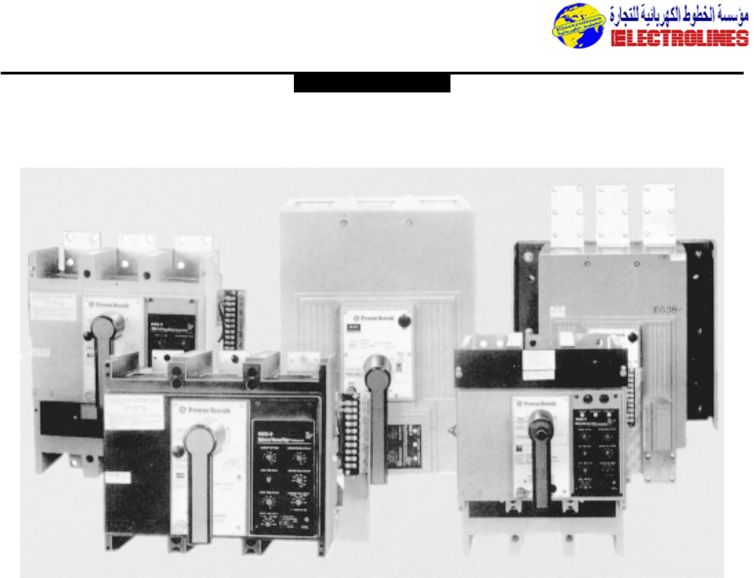
Distribution Equipment
Power Break®Circuit Breakers
Rugged,Durable Construction Combined with Accuracy,Versatility, and Coordination
The General Electric line of POWER BREAK®insulated
case circuit breakers offers the rugged, reliable type of
system protection critical for heavy-duty applications.
POWER BREAK circuit breakers are rated up to 200,000
amperes rms symmetrical interrupting capacity without
fuses or current limiters.The POWER BREAK design
consists of five physical envelope sizes from 200 to 4000
amperes.
POWER BREAK is a versatile breaker,designed for a wide
variety of applications with features such as—temperature
insensitive trip units—push-to-open and close buttons—
maximum five-cycle closing time—field installable rating
plugs to change ampere ratings—U/L listed,field installable
accessories—easy to operate, rotary,stored energy
operating mechanism.
A full line of selective tripping characteristics can be used
to provide overcurrent protection from overloads,short-
circuits and ground faults.Additionally, trip indicators are
available to aid in fault diagnosis.
POWER BREAK circuit breakers offer application
flexibility for ac as well as dc power systems with ratings
up to 700 volts dc and 750 volts ac.
The custom tailored support required for today’s exacting
applications is available with a full line of POWER BREAK
draw-out structures,interlocks,internal accessories,
electrical operators,connectors,and a solid-stat test kit.
GENERAL ELECTRIC
Electrolines Est.
P. O. Box. 942 Yanbu Saudi Arabia Tel: +966 4 3225418 Fax: +966 4 3222213 Al-Jubail: Tel: +966 3 3632967 Fax: +966 3 3612967
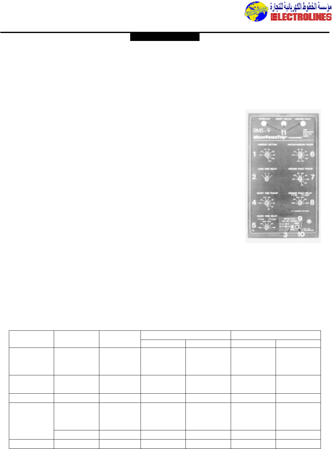
Distribution Equipment
Power Break®Circuit Breakers with Enhanced
MicroVersaTrip PlusTM and MicroVersaTrip PMTM Trip Units
Features
•High-dielectric strength,glass reinforced insulating case
for increased durability and safety of operation.
•Interphase barrier partitions mesh with breaker cover
to completely isolate each pole for high transient
voltage withstandability.
•Green (OFF),Red (ON),indicators display the position
of the breaker contacts.
•Extra heavy-duty,low torque handle mechanism for
simple, stored energy charging.
•Easy quick-make, quick-break close/open operation.
•Complete line of accessories,UL-Listed for field
installation.
•Short circuit ratings through 200,000 Amps.
•RMS digital sensing of sinusoidal and non-sinusoidal
currents by the solid-state trip device.
•Field-installable, interchangeable rating plugs.
•Two trip unit options:
MicroVersaTrip Plus trip units for overcurrent
protection.
MicroVersaTrip PM trip units for metering,protective
relays,and GE POWER LEADER communications.
MicroVersaTrip Plus Trip Unit
MicroVersaTrip Plus Trip units utilize a digital, LCD display
with a five-button keypad to provide local setup and
readout of trip settings.A selectable phase ammeter and
trip indicators are standard, as is a clear plastic cover.
•Digital LCD display with five-button keypad for function
selection and setpoint adjustment,and a sealable clear
Lexan®cover for tamper-resistant set
•True RMS sensing for
accurate response to
high harmonic content
waveforms for Long-
Time, Short-Time, and
Ground Fault
protection.
•50/60 Hz operation
•Interchangeable trip
rating plugs with test
set jack for TVRMS2
test set
•EMI immunity per ANSI
C37.90.
•Integral long-life battery
for cold setup and trip
target viewing
MicroVersaTrip
PM Trip Unit
MicroVersaTrip PM trip unit adds power management
system capability, advanced metering,and protective relays
to the basic functions of MicroVersaTrip Plus.
MicroVersaTrip PM trip units communicate directly on the
GE POWER LEADER communications bus.
Sensor Stationery Draw-out
Frame Frame Size Rating
Size (Amps) (Amps) Standard Break Hi-Break®Standard Break Hi-Break®
200 TP82TT THP82TT TC82TT THC82TT
800 800 400 TP84TT THP84TT TC84TT THC84TT
800 TP88TT THP88TT TC88TT THC88TT
1600 1600 1000 TP1610TT THP1610TT TC1610TT THC1610TT
1600 TP1616TT THP1616TT TC1616TT THC1616TT
2000 2000 2000 TP2020TT THP2020TT TC2020TT THC2020TT
1000 TP2510TT THP2510TT TC2510TT THC2510TT
2500 2000 TP2520TT THP2520TT TC2520TT THC2520TT
3000 2500 TP2525TT THP2525TT TC2525TT THC2525TT
3000 3000 TP3030TT THP3030TT TC3030TT THC3030TT
4000 4000 4000 TP4040T THP4040T TC4040TT THC4040TT
Power Break Circuit Breaker with enhanced MicroVersaTrip Plus
& MicroVersaTrip PM Trip Units
GENERAL ELECTRIC
Electrolines Est.
P. O. Box. 942 Yanbu Saudi Arabia Tel: +966 4 3225418 Fax: +966 4 3222213 Al-Jubail: Tel: +966 3 3632967 Fax: +966 3 3612967
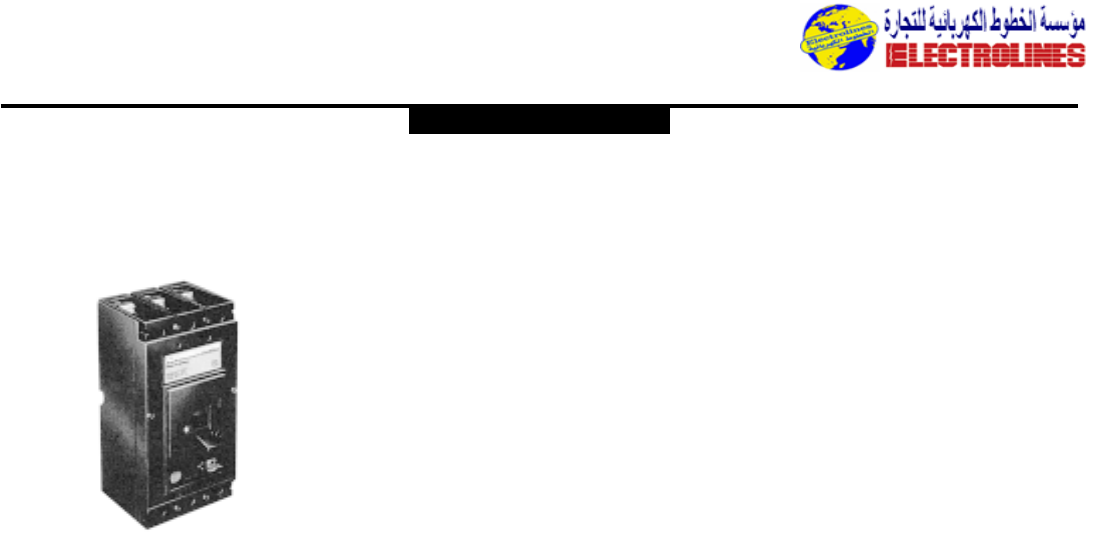
Distribution Equipment
RECORD - Moulded Case Circuit Breakers
Basic Units
Use The RECORD circuit breakers are suitable for 3 levels of performances:
– Normal RECORD, type D
– High breaking capacity RECORD type DH,
– Limiter RECORD, type D…L.
By adding or replacing elements,it is possible to perform following functions:
– Ground leakage protection,
– Visible isolation,
– Low magnetic threshold protection,
– Protection selectivity.
As variant:
– Branch circuit brakers for low voltage subscriber,
– Source changeover switches for replacement source,
– Switches for controlling and isolating circuits.
Description
Within an isolating box,the RECORD circuit breaker
contains:
•2,3 or 4 poles.
•A mechanism enabling a fully visible isolation:
The control lever can only indicate the “OFF” position
if all the contacts are actually open and separated by a
distance greater than:
– 9 mm for D125
– 15 mm for D160,D250
– 20 mm for D400,D630, D800, D1250,
•1 indicator indicating the exact position of the contacts:
– Red :contact closed
– White :contact open,unit tripped
– Green :contact open,fully visible isolation,
•1 release unit:
– Integrated for D125,D160, D250
– Interchangeable for D400,D630, D800, D1250
containing:
– One trip push-button
– Compensated thermal elements from -5˚C to
+40˚C adjustable from :
0,75 to 1 for D125,D160, D250
0,8 to 1 for D400,D630, D800, D1250
– Adjustable magnetic releases (fixed for D125)
Structure
The RECORD circuit breakers are structured as :
– Fixed unit,Front or Rear terminals.
– Withdrawable unit,front terminals or rear terminals.
The withdrawable version contains:
– A monoblock isolating fixed part, protection degree
IP2X,
– A safety system at withdrawal,
– An upline-dowline error prevention device,
– As an option : rating error protection device,wiring
isolation.
Withdrawable RECORD D800 and D1250 have a fixed
part built with plug-in and withdrawal control by cranck
with isolation shutter and position indicator option.
Versions :
– Standard magneto-thermal
– Low threshold type A magnetor-thermal
– Magnetic type B (D125) magnetic only
– Magneto-thermal type SM or S
– Fixed,selective magnetic releases
– For direct current.
Possibility of lead sealing the access (on the front panel)
against adjustments.
Auxiliaries, accessories
The RECORD circuit breakers can receive :
– Auxiliaries :
Display contacts (ON-OFF, fault)
Voltmetric releases (shunt type ST, undervoltage type UV)
– Installation, connection accessories :
Terminals, terminal covers,
– Locks by padlock or lock or keylock.
Service withstand
The RECORD circuit breakers and complementary
devices,complies to structure II of standard NF C 63-100 :
– Relative humidity :80% at 55˚C and 95% at 45˚C.(Hot
and humid weather).
Accreditation & certification
IEC 947-2
BS,CEI, NB, NF C,VDE
ASEFA - BUREAU VERITAS - GERMANISCHER LLYOD -
LLYOD’s REGISTER OF SHIPPING - RINA
GE POWER CONTROLS
Electrolines Est.
P. O. Box. 942 Yanbu Saudi Arabia Tel: +966 4 3225418 Fax: +966 4 3222213 Al-Jubail: Tel: +966 3 3632967 Fax: +966 3 3612967
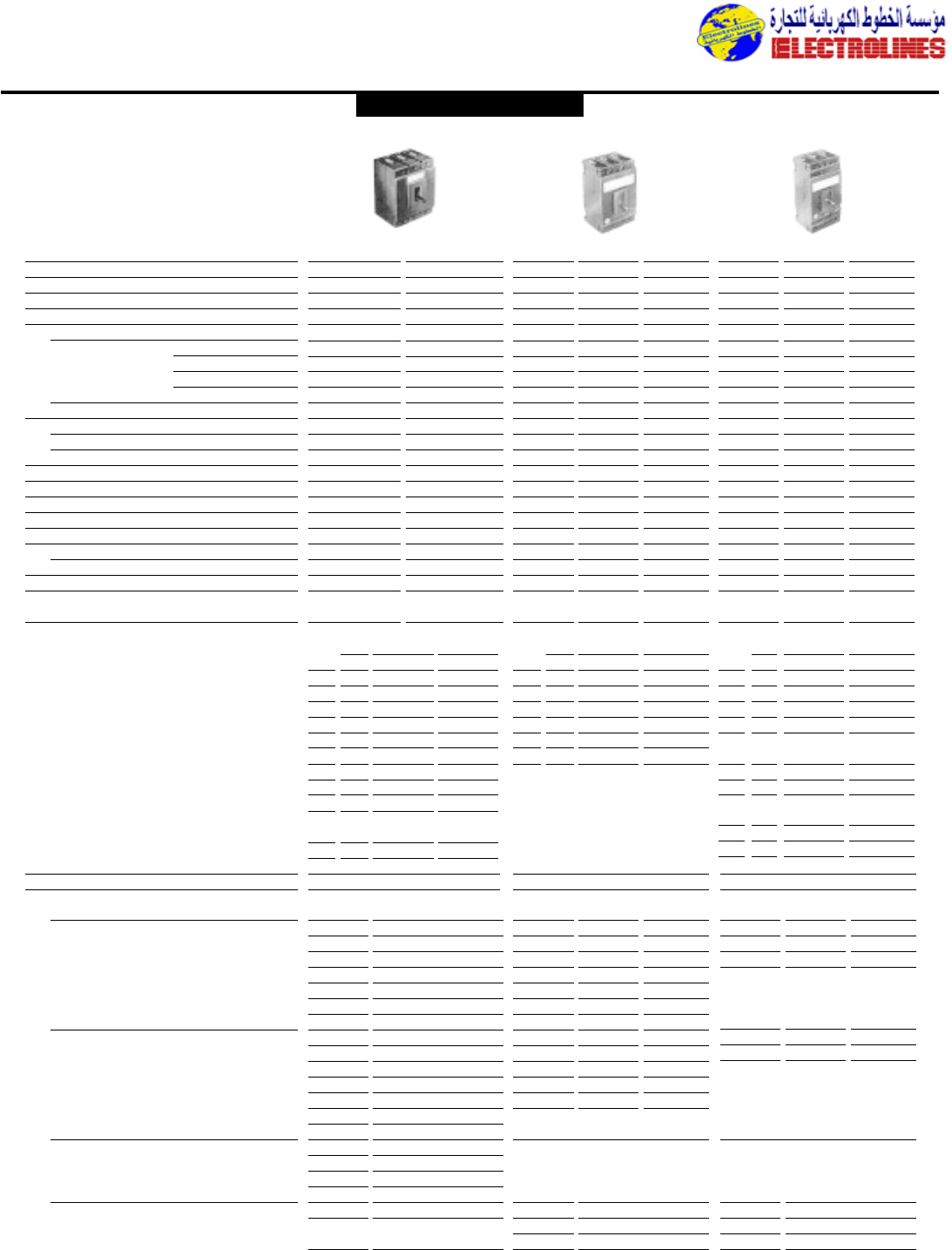
Rated insulation voltage (V) Ui 500 500 690 690 690 690 690 690
Rated impulse withstand voltage (kV) U imp 8 8 8 8 8 8 8 8
Rated operational voltage (V) Ue 500 500 690 690 690 690 690 690
Conventional thermal current at 40˚C (A) Ith 100 100 160 160 160 250 250 230
Rated ultimate short-circuit breaking capacity (kA) Icu
50/60 Hz AC voltage : ■ 240V 100 130 70 80 130 70 80 130
■ 415V 22 (2) 100 30 50 100 35 50 100
■ 500V 10 100 12 14 70 20 22 80
■ 690V – – 5 7 25 7 8 30
DC voltage :L/R = 15 ms (*) ■ 250V 30 100 20 40 100 35 50 100
Rated service short-circuit breaking capacity Ics
50/60 Hz AC current :Ics = … % Icu 50 100 75 75 75 75 75 75
DC current :L/R = 15 ms (*) : Ics = …% Icu 50 100 75 75 75 75 75 75
Rated short-circuit making capacity (1)(kA) Icm 220 286 154 176 286 154 176 286
Utilization category A A A A A A A A
Number of poles 2-3-4 2-3-4 3-4 3-4 3-4 3-4 3-4 3-4
Suitability for isolation (Visible breaking indication)
• • ••• •••
Endurance (number of operating cycles)
Mechanical (total) / Electrical 10000/5000 10000/5000 10000/4000 10000/4000 10000/4000 10000/4000 10000/4000 10000/4000
Fault elimination time (ms) 8 2 8 8 3,5 8 8 3,5
Pollution degree 3 3 3 3 3 3 3 3
Over-current releases (integrated)
Fixed or adjustable Adjustable Adjustable Adjustable
Inverse time delay over-current operation Rated current (A) Rated current (A) Rated current (A)
Ambient temperature compensation In at 40˚C Adjustment le (max.) (A) In at 40˚C Adjustment Ie (max.) (A) In at 40˚C Adjustment le(max.)(A)
between -5˚C to +40˚C N (3) min. max. 50˚C 60˚C N (3) min. max. 50˚C 60˚C N (3) min. max. 50˚C 60˚C
16 – 12 16 15 14,5 25 18 25 23,5 22,5 125 63 90 125 118,5 112,5
25 – 18 25 23,5 22,5 40 25 30 40 38 36 160 100 120 160 152 144
40 25 30 40 38 36 63 40 45 63 59,5 56,5 200 100 150 200 190 180
63 40 45 63 60 57 100 63 75 100 95 90 250 125 180 250 237,5 225
80 40 60 80 76 72 125 63 90 125 118,5 112,5
100 63 75 100 95 90 160 100 120 160 152 144 D250 W/D D250 L, D250 M Fixed
125 63 90 125 118 112 200 100 120 200 190 180
D125 M W/D D125 Lfixed 230 125 150 230 215 205
95/120* 63/63* 60/90* 95/120* 90/115* 85/120*
*Rating 125 D250 l, D250 M W/D
D125 L W/D 180 100 120 180 170 160
90/110* 63/63* 60/90* 90/110* 85/100* 80/90* 205 100 150 205 195 185
*Rating 125
Instantaneous short-circuit releases (fixed or adjustable) Fixed Adjustable Adjustable
Rated Operational Rated Adjustment range(A) Rated Adjustment range (A)
current in (A) threshold (A) current in (A) mini maxi current (A) mini maxi
Standard release 16 200 25 250 300 160 800 1900
25 300 40 320 480 200 1000 2400
40 480 63 440 750 250 1250 2500
63 750 100 600 1200
80 1000 125 750 1500
100 1200 160 800 1900
125 1200
Type A release 25 90 40 240 300 200 275 750
Low magnetic 40 130 63 250 315 250 625 1500
63 260 100 300 500
80 400 125 300 500
100 400 160 375 625
125 1200
Type B release 63 750
Magnetic only 80 1000
100 1200
125 1200
Type SM release 100 2000 160 2500
Selective 125 2000 200 2500
160 2000 250 2500
Distribution Equipment
Characteristics according
to IEC 947-2
D125 D125 L D160 DH160 D160 L D250 DH250 D250 L
(*) Number of poles participating in the breaking
■
125 V = : all circuit breakers 2 poles
■
250 V = : D125- D125L : 4 poles ; other circuit breakers : 2 poles
(1) Maxi under 240 V
(2) 12 kA for 16A rating
(3) Reduced neutral
GE POWER CONTROLS
Electrolines Est.
P. O. Box. 942 Yanbu Saudi Arabia Tel: +966 4 3225418 Fax: +966 4 3222213 Al-Jubail: Tel: +966 3 3632967 Fax: +966 3 3612967
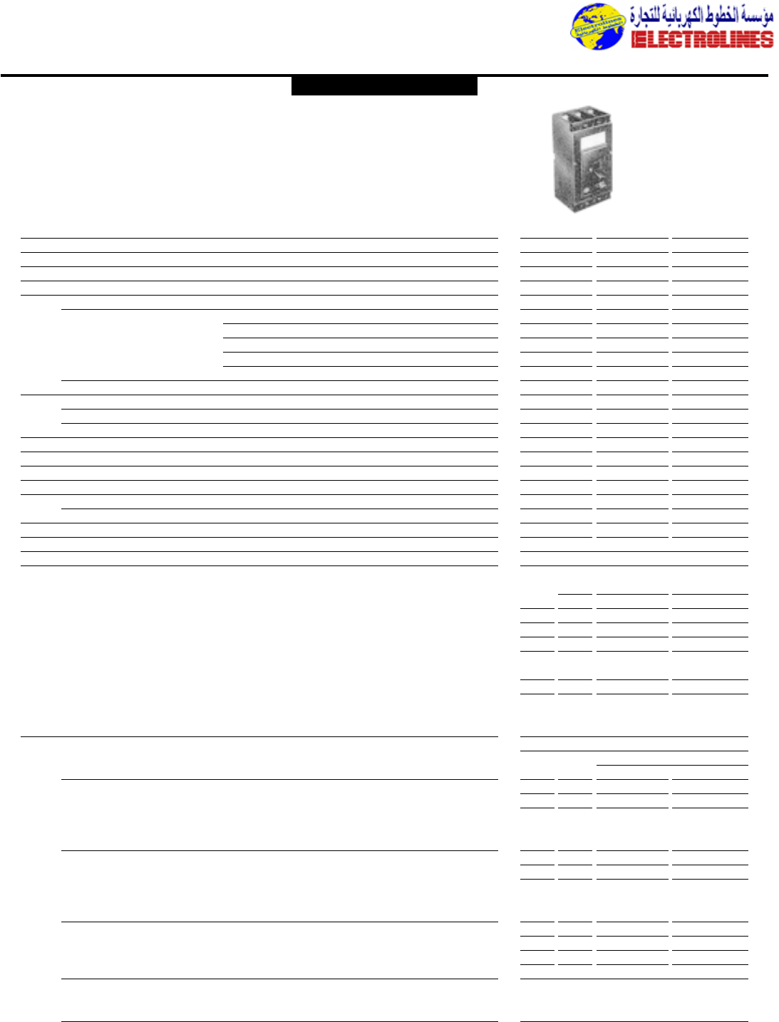
Distribution Equipment
Characteristics according to IEC 947-2
Rated insulation voltage (V) Ui 690 690 690
Rated impulse withstand voltage (kV) U imp 8 8 8
Rated operational voltage (V) Ue 690 690 690
Conventional thermal current at 40˚C (A) Ith 400 400 400
Rated ultimate short-circuit breaking capacity (kA) Icu
50/60 Hz AC voltage : ■ 240 V 50 70 130
■ 415V 35 50 100
■ 500 V 30 35 50
■ 690V 10 12 18
■ 1000V (4) – – 10
DC voltage :L/R = 15 ms (*) ■ 250/500 V 60/40 85/50 100/60
Rated service short-circuit breaking capacity Ics
50/60 Hz AC current :Ics = … % Icu 100 75 75
DC current :L/R = 15 ms (*) : Ics = …% Icu 100 75 75
Rated short-circuit making capacity (1)(kA) Icm 105 154 286
Utilization category AAA
Number of poles 3-4 3-4 3-4
Suitability for isolation (Visible breaking indication) • • •
Endurance (number of operating cycles)
Mechanical (total) / Electrical 5000/2000 5000/2000 5000/2000
Fault elimination time (ms) 886
Pollution degree 333
Over-current releases (interchangeable) Adjustable
Inverse time delay over-current operation Rated current (A)
Ambient temperature compensation In at 40˚C Adjustment le (max.) (A)
between -5˚C to +40˚C N (3) min. max. 50˚C 60˚C
250 125 200 250 237 225
320 160 250 320 304 288
400 200 320 400 380 360
D400 W/D
370 200 320 370 340 310
Instantaneous short-circuit releases Adjustable
Rated Adjustment range(A)
current in (A) mini maxi
Standard release 320 1900 3850
400 2000 4800
Type A release 320 750 1200
Low magnetic 400 960 1700
Type S release 250 3000
Selective 320 3850
400 4800
Type C release
Magnetic only
for DC operation
D400 LD400 DH400
(*) Number of poles participating in the breaking
■
250 V = : 2 poles
■
500 V = : 3 poles
(1) Maxi under 240 V
(2) No thermal release in DC operation
(3) Reduced neutral
(4) Made on request
GE POWER CONTROLS
Electrolines Est.
P. O. Box. 942 Yanbu Saudi Arabia Tel: +966 4 3225418 Fax: +966 4 3222213 Al-Jubail: Tel: +966 3 3632967 Fax: +966 3 3612967
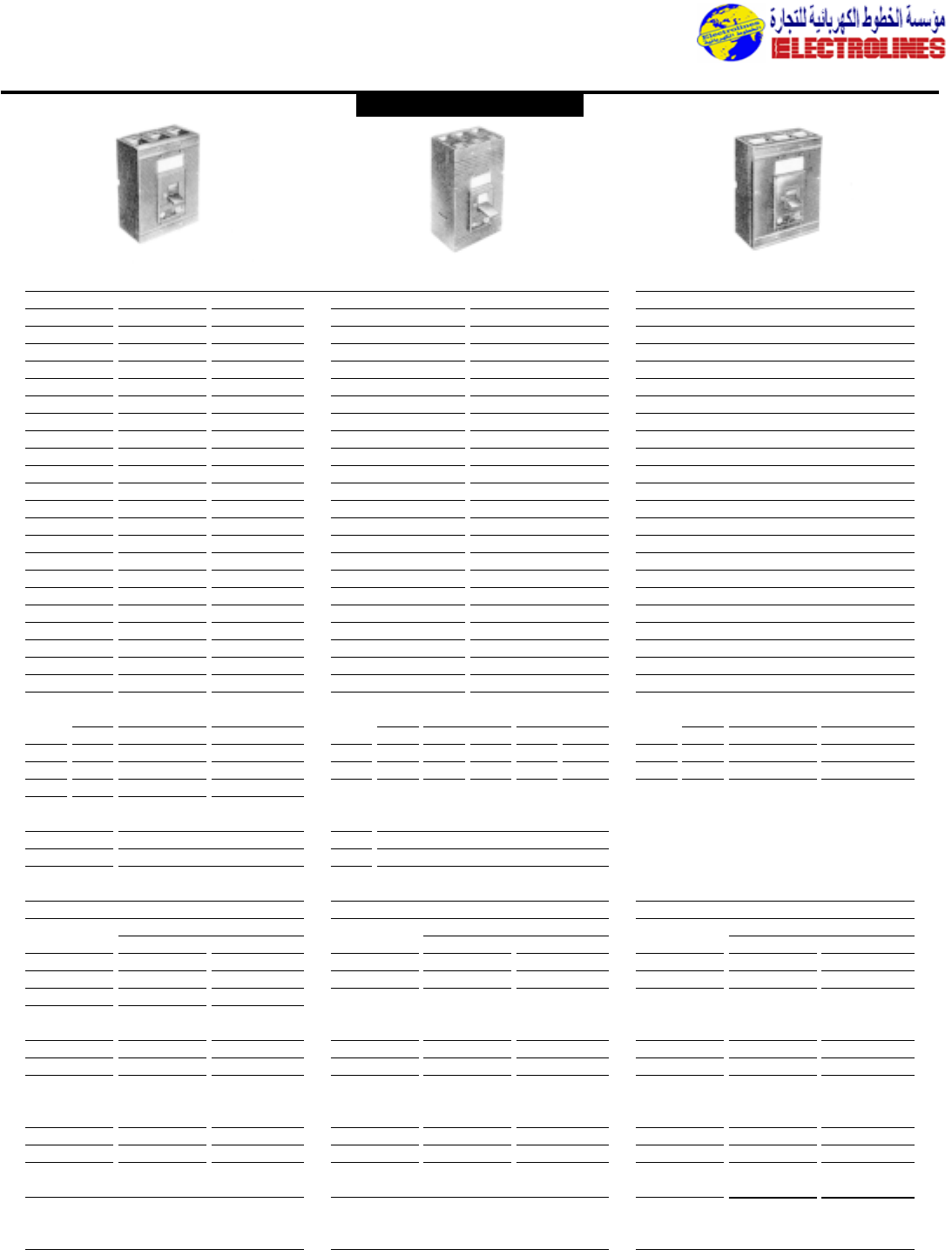
Distribution Equipment
690 690 690 690 690 690
888 8 8 8
690 690 690 690 690 690
630 630 630 800 800 1250
70 80 130 70 80 60
35 50 100 50 70 60
20 25 60 25 35 35
10 12 25 15 20 25
––12 - - 21
60/40 85/50 100/60 60/40 80/50 50/70
75 75 75 75 75 75
75 75 75 75 75 75
105 154 286 154 176 132
AAA A A A
3-4 3-4 3-4 3-4 3-4 3-4
••• • •
5000/2000 5000/2000 5000/2000 5000/1000 5000/1000 3000/1000
12 12 6 12 12 20
333 3 3 3
Adjustable Adjustable Adjustable
Rated current(A) Rated current(A) Rated current(A)
In at 40C Adjustment le (max.) (A) In at 40˚C Adjustment le (max.) (A) In at 40˚C Adjustment le (max.) (A)
N (3) min. max. 50˚C 60˚C N (30 min. max. 50˚C 60˚C N (3) min. max. 50˚C 60˚C
400 200 320 400 370 340 630 (2) 320 500 630 580 535 1000(2) 500 800 1000 950 850
500 250 400 500 460 425 800 (2) 400 630 800 760 720 1250(2) 630 1000 1250 1150 1050
630 (2) 320 500 630 580 535
D630 W/D D800 W/D
460 250 400 460 425 390 600 (2) 320 500 600 550 505
580 (2) 320 500 580 535 495 720 (2) 400 630 720 675 635
Adjustable Adjustable Adjustable
Rated Adjustment range (A) Rated Adjustment range (A) Rated Adjustment range (A)
current in (A) min maxi current in (A) mini maxi current in (A) mini maxi
400 2000 4000 630 3150 5000 1000 5000 10000
500 2500 5000 800 4000 6400 1250 6250 12500
630 3150 5000
500 1000 2000 630 1250 2500 1000 2400 4000
630 1250 2500 800 2000 3000 1250 3000 5000
500 5000 630 5000 1000 5000 10000
630 5000 800 6400 1250 6250 12500
3000 6000
D630 DH630 D630 L D800 DH800 D1250
GE POWER CONTROLS
Electrolines Est.
P. O. Box. 942 Yanbu Saudi Arabia Tel: +966 4 3225418 Fax: +966 4 3222213 Al-Jubail: Tel: +966 3 3632967 Fax: +966 3 3612967
Distribution Equipment
• SP 800 to 2500 A
Rated short-circuit breaking capacity (IEC 947-2) :35 to 60 kA
• SPE 800 to 1250 A
Rated short-circuit breaking capacity (IEC 947-2) :25 to 36 kA
The SPECTRONIC range combines the legendary reliability of
our air circuit breakers with :
– A design adapted to the new panelboards
– Hi-tech protection relays
Main advantages :
– Original design to combine reliability and longevity,
– Optimal service :total selectivity is insured,even at closing on short-
circuit,
– Optimal rationalization :same overall dimensions for the 2 ranges from
800A to 1600A,
– Safety ensured by fully visible breaking.
Characteristics
Circuit breaker
Conformity,tropicalization, anti-corrosion treatment
Conformity
– The SP-SPE circuit breakers are built according to
the following standards :
IEC 947-2,BS,CEI, NBN, NFC,VDE
– Certification :BUREAU VERITAS,LLOYD’S REG-
ISTER OF SHIPPING,GERMANISCHER LLOYD,
ASEFA
Class I (Standard) :
Relative humidity of 80% at 40˚C
(Hot and dry or damp climate of temperate zones).
Class II
Relative humidity of 95% at 45˚C (Hot and damp
climate).
For special atmospheres,consult us.
Tropicalization Anti-corrosion treatment
SP SPE
800 1000 1250 1600 2000 2500 800 1000 1250
Rated insulation voltage (V) Ui 1000 1000 1000 1000 1000 1000 1000 1000 1000
Rated impulse voltage (kV) U imp 8 8 8 8 8 8 8 8 8
Rated maximum nominal voltage (V) Ue 690 690 690 690 690 690 690 690 690
Rated current at 40˚C (A) Ith 800 1000 1250 1600 2000 2500 800 1000 1250
Rated ultimate short-circuit breaking capacity (kA) Icu
Alternating current 50/60 Hz : ■ 415 V 55 55 55 55 60 60 36 36 36
■ 500 V 35 35 40 40 40 40 25 25 25
■ 690 V (2) 35 35 35 35 35 35 – – –
Rated service short-circuit breaking capacity (kA) Ics
Alternating current 50/60 Hz : ■ 415 V 50 50 50 50 55 55 36 36 36
■ 500 V 35 35 40 40 40 40 25 25 25
■ 690 V (2) 35 35 35 35 35 35 – – –
Rated peak short-circuit
making current (kA peak) Icm 120 120 120 120 130 130 75 75 75
RMS short time withstand current :1 sec. Icw
■ 415 V (kA eff) 50 50 50 50 55 55 36 36 36
■ 500 V (kA eff) 35 35 35 35 35 35 25 25 25
Utilization category B B B B B B B B B
Number of poles 3-4 3-4 3-4 3-4 3-4 3-4 3-4 3-4 3-4
Suitability for isolation (Visible breaking indication) •••••••••
Endurance (Number of operating cycles)
Mechanical (Total) 10000 10000 10000 10000 10000 10000 10000 10000 10000
Electrical (at 415 V) (3) 10000 10000 10000 10000 10000 10000 10000 10000 10000
Mean time between maintenances 3500 3000 2500 1500 1500 1500 1500 1500 1500
Power dissipation (Withdrawable, 3 Poles) (W) 150 200 300 400 300 500 100 150 230
4th pole conventional thermal current (A) 800 1000 1250 1600 1250 1250 800 1000 1250
Pollution degree 3 3 3 3 3 3 3 3 3
(1) For IP32 to the open air
(2) Structure upon request
(3) To guarantee this number of operations,it is necessary to check the spark arrestor and the arc chute “Maintenance frequency” (Replace them when necessary).
This can be done easily on site.
SPECTRONIC SP/SPE - Air Circuit Breakers
General features
GE POWER CONTROLS
Electrolines Est.
P. O. Box. 942 Yanbu Saudi Arabia Tel: +966 4 3225418 Fax: +966 4 3222213 Al-Jubail: Tel: +966 3 3632967 Fax: +966 3 3612967
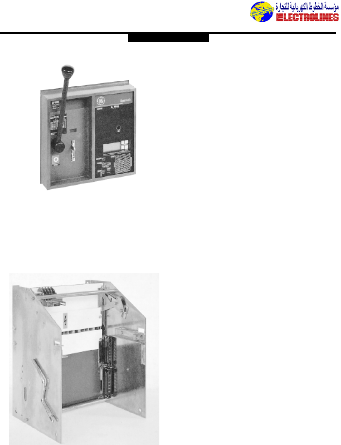
Distribution Equipment
Fixed Circuit breaker Description
Fitted at the factory with a control panel which provide
IP30 protection degree.
For panel mounting,a seal and a cover are supplied as
standard feature to :
– Insure protection degree (IP 20)
– Provide aesthetic finish of door cut-out
Installation
•Fastened to two vertical uprights or to an horizontal
surface.
•Main connections by rear horizontal terminal board or
front terminals.
•Connections to the auxiliary circuits by terminals
located at the front of the unit.
Power supply orientation
Up to 415V,either on the upper or lower terminal boards.
Beyond 415V,only on the upper terminal boards.
Withdrawable circuit breaker
Description
The circuit breaker is mounted in a cradle fitted with
slides that enable two breaker positions :“Inserted and
“Withdrawn-isolated”.
The operations are performed by screw-nut systems,
controlled by two removable cranks.
Automatic tripping of the breaker at insertion and at
withdrawal.
Automatic withdrawal of the auxiliary wiring simultaneous
with the main circuit by wiring isolating device
(24 circuits).
For installation inside cabinet,a seal and a cover are
supplied as standard to provide IP20 protection degree
when the panel door is closed.
Breaker withdrawable :door closed or door open.
Installation
•Fastening on vertical upright by rear surface or on a
horizontal surface by adding L-pieces on side faces.
•Main connections by front or rear terminals boards.
•Connection of auxiliary circuits laterally by
disconnectable clips.
Power supply orientation
Up to 415V,either on the upper or lower terminal boards.
Beyond 415V,only on the upper terminal boards.
GE POWER CONTROLS
Electrolines Est.
P. O. Box. 942 Yanbu Saudi Arabia Tel: +966 4 3225418 Fax: +966 4 3222213 Al-Jubail: Tel: +966 3 3632967 Fax: +966 3 3612967
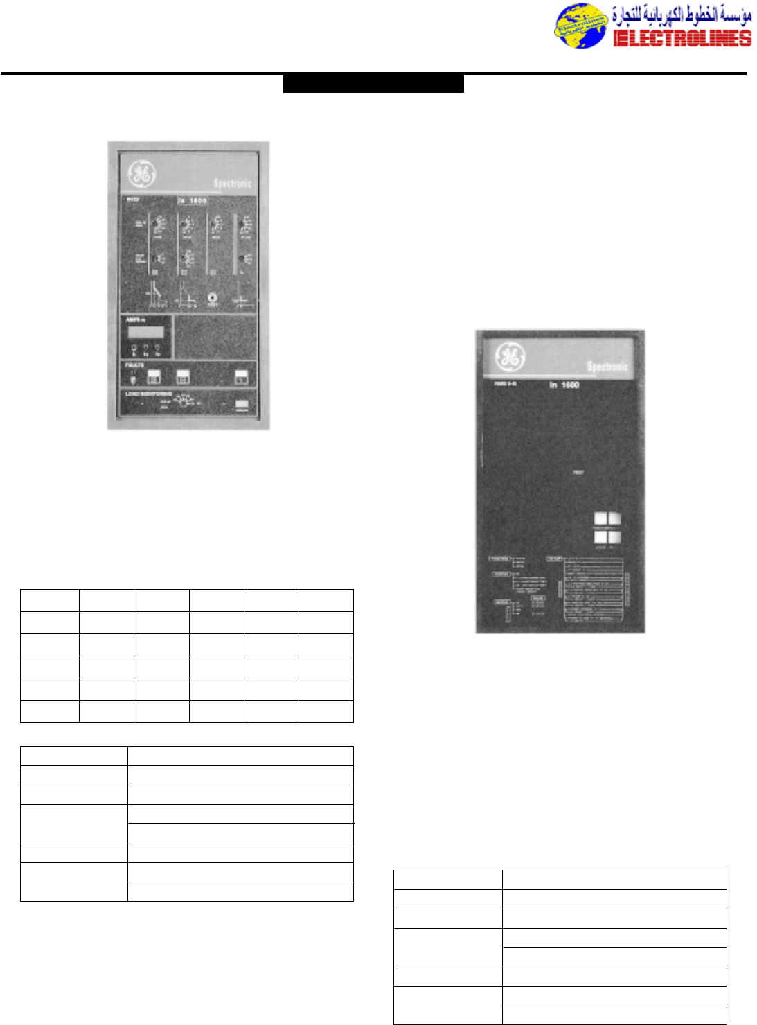
Distribution Equipment
RV : Protection and monitoring unit
Description
The RV unit is powered by the current transformers and
performs following current protections :
– Overload protection (LT)
– Short-circuit protection (ST et I)
– Ground fault protection (GF)
To adapt to the new electrical distribution needs, RV protection and monitoring units
feature a range completed with specialized units,providing large operating range:
1 - RV types of releases
LT LTD ST-1 GF N
RV 03 ••
RV 04 •••
RV 13 •••
RV 14 ••• •
RV 23 ••••
2 - RV setting ranges
setting points
LT (x lr) 0.5 - 0,6 - 0,7 - 0,8 - 0,9 - 1
LTD (s) 5 - 15 - 40 / time delay at 6 lr
ST (x lr) 2 - 3 - 4 - 6 - 8 - 10
Delay (ms) 0 - 50 - 100 - 200 - 300 - 500
I(x lr) 2 - 3 - 5 - 8 - 10 - OFF
GF (x ln) 0.25 - 0,3 - 0,4 - 0,5 - 0,6 - 0,7
Delay (ms) 200 - 300 - 400
RMS9 : Protection and measurement unit
Description
The RMS 9 is powered by the current transformers.The unit
perform all the necessary current protections as well as the
measurement (RMS) of all the network parameters.
Besides providing above functions,the communicating model of
RMS 9 can also operate remote event measurement and
recording.
1 - Standard protection functions
- Overload protection (Long time LT)
- Short-circuit protection (Short time,Instantaneous ST,I)
- Ground fault protection (GF)
2 - RMS9 setting ranges
Setting points
LT (x lr) 0.5 - 1 (step of 0,05)
LTD (s) 3 -6 - 12 - 25 / to 6 Ir
ST (x lr) 1,5 - 9 (step of 0,5)
Delay (ms) 100 - 210 - 350
I(x lr) 1,5 - 15 (step of 0,5)
GF (x Ir) 0,2 - 0,6 (step of 0,01)
Delay (ms) 100 - 210 - 350
B - Load monitoring
- Threshold setting :(0.5 - 0,6 - 0,7 - 0,8 - 0,9 - 1.0) x Ir
- Stabilized changeover (anti-hunting) by :
•Time delay at closing of 60 seconds.
•Desactivation at 0.8xthreshold level
- Remote transmission by dry contacts.
C - Ammeter
A digital ammeter permanantly displays the current inten-
sity on the most loaded phase.
The current on the other phases is available by local
monitoring.
3- The RV options
To facilitate the Spectronic circuit breakers integration within
automated systems,the RV unit can receive (all or part) following
modules :
A - Positive fault indication and display (LT, ST, I,GF)
- Local display by LED diodes
- Remote indication by relay contacts (dry contacts).
GE POWER CONTROLS
Electrolines Est.
P. O. Box. 942 Yanbu Saudi Arabia Tel: +966 4 3225418 Fax: +966 4 3222213 Al-Jubail: Tel: +966 3 3632967 Fax: +966 3 3612967
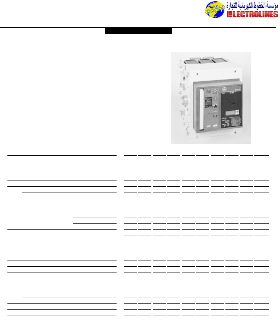
Distribution Equipment
• Selective S :800 to 6400A
With total discrimination guarantee
Rated short-circuit breaking capacity (IEC 947-2) :55 to 120 kA
• Limiting L : 640 to 2000A
With very high interrupting capacity
Short-circuit breaking capacity (IEC 947-2) :130 kA
The SPECTRONIC range combines the known reliability of our air circuit
breakers with :
– A design adapted to the new panelboards
– Hi-tech protection relays
SPECTRONIC S/L - Air Circuit Breakers
General features
Selective S circuit breakers : technical data
Circuit breaker S 800 S 1000 S 1250 S 1600 S 2000 S 2500 S 3200 S 4000 S 5000 S 6400
Rated insulation voltage (V) Ui 1000 1000 1000 1000 1000 1000 1000 1000 1000 1000
Rated impulse voltage (kV) U imp 8 8 8 8 8 8 8 8 8 8
Rated maximum nominal voltage (V) Ue 1000 1000 1000 1000 1000 1000 1000 1000 1000 1000
Rated current at 40˚C (1) (A) Ith 800 1000 1250 1600 2000 2500 3200 4000 5000 6400
Rated ultimate short-circuit breaking capacity (kA) Icu
Alternating current 50/60 Hz :■ 415 V 55 55 65 65 65 70 85 90 120 120
■ 500 V 55 55 55 55 55 65 70 85 100 100
■ 690 V (2) 40 40 40 40 40 40 50 50 70 70
Rated service short-circuit breaking capacity (kA) Ics
Alternating current 50/60 Hz :■ 415 V 55 55 55 55 55 65 70 85 100 100
■ 500 V 55 55 55 55 55 65 70 85 100 100
■ 690 V (2) 40 40 40 40 40 40 50 50 70 70
Rated peak short-circuit
making current (kA peak) Icm 125 125 140 140 140 150 190 200 270 270
RMS short time withstand current (415 V) Icw
■ 0,5 s.(kA eff) 55 55 55 55 65 70 – – – –
■ 1 s. (kA eff) 50 50 55 55 65 70 85 90 120 120
Utilization category B B B B B B B B B B
Number of poles 3-4 3-4 3-4 3-4 3-4 3-4 3-4 3-4 3-4 3-4
Suitability for isolation (Visible breaking indication) ••••••••••
Endurance (Number of operating cycles)
Mechanical (Total) 20000 20000 20000 20000 20000 20000 10000 10000 5000 5000
Electrical (at 415 V) (3) 20000 20000 20000 20000 20000 20000 10000 10000 5000 5000
Mean time between maintenances 3500 3000 2500 2000 1500 1500 1500 1500 1500 1500
Power dissipation (Withdrawable,3 Poles) (W) 150 200 300 400 400 500 920 1000 1320 1310
4th pole conventional thermal current (A) 800 1000 1250 1600 2000 2500 3200 4000 5000 6400
Pollution degree 3 3 3 3 3 3 3 3 3 3
Conformity
– The S circuit breakers are built according
to the following standards :
IEC 947-2,BS,CEI, NBN, NFC,VDE
– Certification : BUREAU VERITAS,
LLOYD’S REGISTER OF SHIPPING, GER-
MANISCHER LLOYD, ASEFA
Class I (Standard) :
Relative humidity of 80% at 40˚C
(Hot and dry or damp climate of temperate
zones).
Class II
Relative humidity of 95% at 45˚C (Hot and
damp climate).
GE POWER CONTROLS
For special atmospheres,consult us.
Tropicalization Anti-corrosion treatment
Conformity, tropicalization, anti-corrosion treatment
Electrolines Est.
P. O. Box. 942 Yanbu Saudi Arabia Tel: +966 4 3225418 Fax: +966 4 3222213 Al-Jubail: Tel: +966 3 3632967 Fax: +966 3 3612967
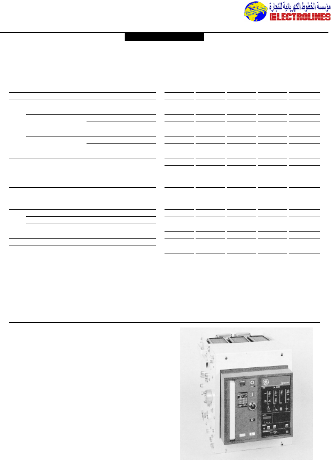
Distribution Equipment
Limiter L circuit breakers : technical data
Circuit breaker L 640 L 1000 L 1250 L 1600 L 2000
Rated insulation voltage (V) Ui 1000 1000 1000 1000 1000
Rated impulse voltage (kV) U imp 8 8 8 8 8
Rated maximum nominal voltage *(V) Ue 690 690 690 690 690
Rated current at 40˚C (1) (A) Ith 640 1000 1250 1600 2000
Rated ultimate short-circuit breaking capacity (kA) Icu
Alternating current 50/60 Hz : ■ 415 V 130 130 130 130 130
■ 500 V 100 100 100 100 100
■ 690 V 60 60 60 60 60
Rated service short-circuit breaking capacity (kA) Ics
Alternating current 50/60 Hz : ■ 415 V 130 130 130 130 130
■ 500 V 100 100 100 100 100
■ 690 V 60 60 60 60 60
Rated peak short-circuit
making current (kA peak) Icm 290 290 290 290 290
Fault elimination time (ms.) 8 8 8 8 8
Utilization category A A A A A
Number of poles 3-4 3-4 3-4 3-4 3-4
Suitability for isolation (Visible breaking indication) •••••
Endurance (Number of operating cycles)
Mechanical (Total) 20000 20000 20000 20000 20000
Electrical (at 415 V) (2) 20000 20000 20000 20000 20000
Mean time between maintenances 1500 1500 1500 1500 1500
Power dissipation (Withdrawable, 3 Poles) (W) 135 230 220 270 420
4th pole conventional thermal current (A) 640 1000 1250 1600 2000
Pollution degree 3 3 3 3 3
Conformity, tropicalization,anti-corrosion treatment
Conformity
– The L circuit breakers are built according
to the following standards :
IEC 947-2,BS,CEI, NBN, NFC,VDE
– Certification : BUREAU VERITAS,
LLOYD’S REGISTER OF SHIPPING, GER-
MANISCHER LLOYD.
Class I (Standard) :
Relative humidity of 80% at 40˚C
(Hot and dry or damp climate of temperate
zones).
Class II
Relative humidity of 95% at 45˚C (Hot and
damp climate).
For special atmospheres,consult us.
Tropicalization Anti-corrosion treatment
Fixed circuit breaker
Description
Equipped at factory with an IP32 face plate,receiving a gasket,
delivered with the breaker, easily fitted to on door or panel,and
a front cover providing an IP2X protection degree.
Installation
■Fastening by side L-pieces with built-in ground connection.
By cross members on circuit breakers.
S 5000 - 6400 (Vertical or horizontal).
■Connection by horizontal terminal strip rear connectors,
(Vertical on vertical S 5000 - 6400).
Power supply
– Up to 500 V (415 V for the L circuit breakers),either on the
upper or the lower lugs.
– At higher voltage to the upper lugs or right connectors on
vertical breakers (Breakers seen from the front).
GE POWER CONTROLS
Electrolines Est.
P. O. Box. 942 Yanbu Saudi Arabia Tel: +966 4 3225418 Fax: +966 4 3222213 Al-Jubail: Tel: +966 3 3632967 Fax: +966 3 3612967
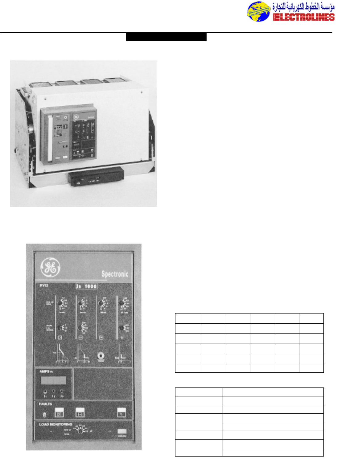
Distribution Equipment
Arrangement
■Ratings ≤4000 A
Cradle equipped with retractible rails enabling 3 circuit
breaker
positions :“Connected”,“Test”,“Disconnected-isolated”,
plus an “Extracted” position.
■Ratings 5000 – 6400 A (Vertical)
Cradle equipped with guide rails in which are engaged
the rollers equipping the breaker, enabling 2 circuit
breaker positions :“Plugged-in”,“Withdrawn-isolated”.
Like the fixed breaker, the withdrawable circuit breaker is
delivered with front cover, face plate,gasket and ammeter
(On request).
The plug-in operation,which can be done with the door
closed,uses a screw-nut system, actuated by a removable
crank.Tripping the circuit breaker before introducing the
crank guarantees safety when withdrawing.
Power supply
– Up to 500 V (415 V for the L circuit breakers),either on
the upper or the lower lugs.
– At higher voltage to the upper lugs or right connectors
on vertical breakers (Breakers seen from the front).
Description
The RV unit is powered by the current transformers and
performs following current protections :
- Overload protection (LT)
- Short-circuit protection (ST el I)
- Ground fault protection (GF)
Withdrawable circuit breaker
To adapt to the new electrical distribution needs,RV
protection and monitoring units feature a range completed
with specialized units,providing large operating range:
1- The RV range
LT LTD ST-1 GF N
RV 03 ••
RV 04 •••
RV 13 •••
RV 14 ••• •
RV 23 ••••
2 - RV setting ranges
setting points
LT (x lr) 0,5 - 0,6 - 0,7 - 0,8 - 0,9 - 1
LTD (s) 5 - 15 - 40 / time delay at 6 lr
ST (x lr) 2 - 3 - 4 - 6 - 8 - 10
Delay (ms) 0 - 50 - 100 - 200 - 300 - 500
I(x lr) 2 - 3 - 5 - 8 - 10 - OFF
GF (x lr) 0,25 - 0,3 - 0,4 - 0,5 - 0,6 - 0,7
Delay (ms) 200 - 300 - 400
GE POWER CONTROLS
RV : Protection and monitoring unit
Electrolines Est.
P. O. Box. 942 Yanbu Saudi Arabia Tel: +966 4 3225418 Fax: +966 4 3222213 Al-Jubail: Tel: +966 3 3632967 Fax: +966 3 3612967
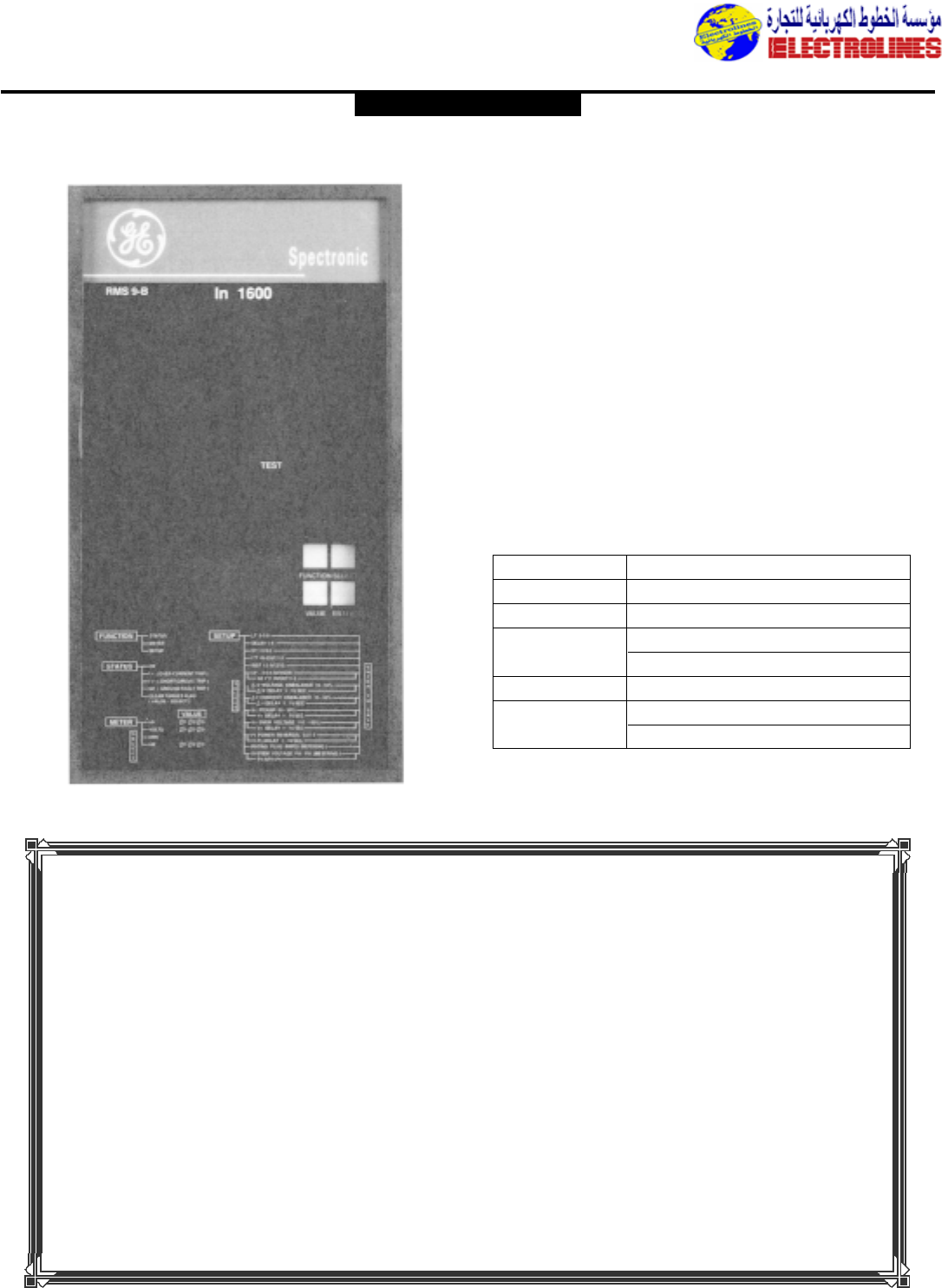
Distribution Equipment
RMS9 : Protection and monitoring unit Description
The RMS 9 is powered by the current transformers.The
unit perform all the necessary current protections as well
as the measurement (RMS) of all the network parameters.
Besides providing above functions,the communicating
model of RMS 9 can also operate remote event
measurement and recording.
1 - Standard protection functions
– Overload protection (Long time LT)
– Short-circuit protection (Short time, Instantaneous
ST,I)
– Ground fault protection (GF)
2 - RMS 9B setting ranges
setting points
LT (x lr) 0,5 - 1 (Step of 0,05)
LTD (s) 3 - 6 - 12 - 16/Delay at 6 lr
ST (x lr) 1,5 - 9 (Step of 0,5)
Delay (ms) 100 - 210 - 350
I(x lr) 1,5 - 15 (Step of 1,5)
GF (x lr) 0,2 - 0,3 (Step of 0,02)
Delay (ms) 100 - 210 - 350
GE POWER CONTROLS
ELECTROLINES
The single source
Electrolines Est.
P. O. Box. 942 Yanbu Saudi Arabia Tel: +966 4 3225418 Fax: +966 4 3222213 Al-Jubail: Tel: +966 3 3632967 Fax: +966 3 3612967
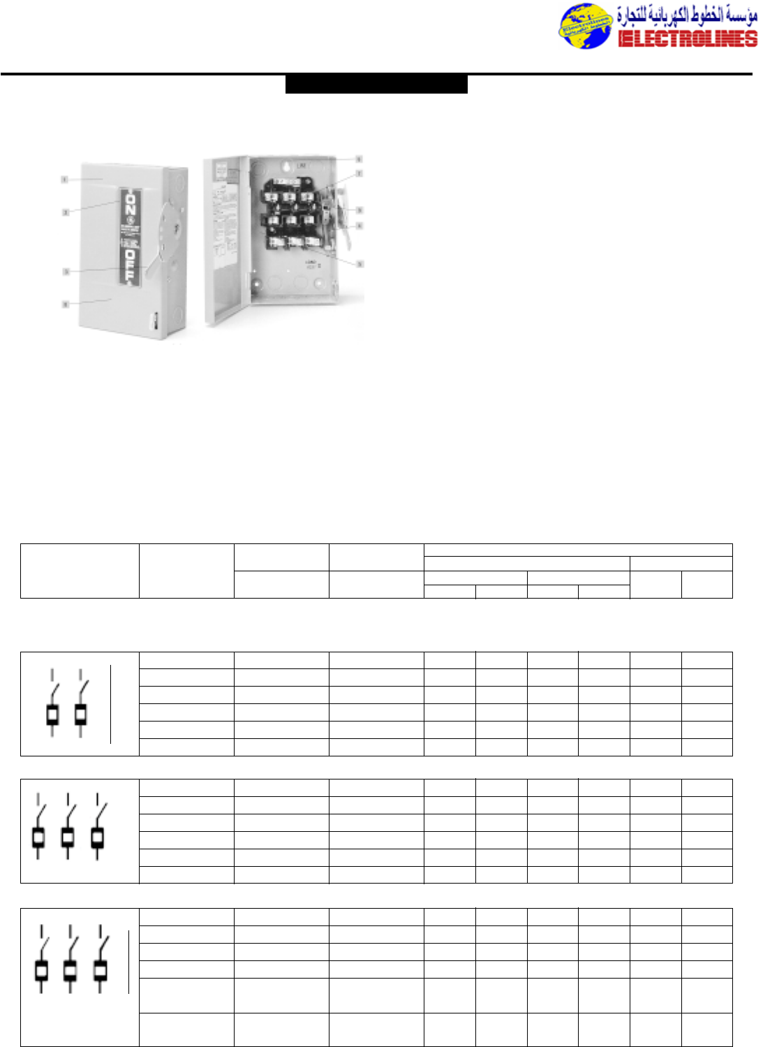
Distribution Equipment
5. Wide, unobstructed gutter
and removable interior make
wire pulling quick and easy.
6. Positive three-point mounting
speeds installation,simplifies
ganging in close quarters.
7. Silver plated
stationary/movable contacts.
8. Galvannealed steel for
superior rust protection in
outdoor applications.
9. Silver-plated visible blades
inform you whether the
switch is ON or OFF.
1. GE’s General Duty switches
are available for residential
and light commercial
applications,indoor or
outdoor applications.
2. Extra-large and legible
ON/OFF label takes the
guesswork out of safety.
3. Bright red handle is easy to
see, easy to grip.
4. Direct-drive, quick-make,
quick-break mechanism
provides long life and positive
ON/OFF indication.
GE’s General Duty Type TG Safety Switches
are designed for residential or light
commercial applications duty is not severe.
The general duty line is available in 30-600
amps,240 Vac, 250 Vdc maximum in both
no-fuse and fusible units.Enclosure types
include UL (NEMA) Type 1 (indoor) and
Type 3R (outdoor).The UL listed short
circuit rating is 10,000 rms symmetrical
amps as standard.When Class R fuses and
fuse kits are installed,our 30-200 amp
switches have a UL listed short circuit
rating of 100,000 rms symmetrical amps.
GE’s General Duty Safety Switch is suitable
for use as service entrance equipment
when installed in accordance with the
National Electrical Code.
All switches are UL listed and CSA
certified under (UL98 Enclosed
Switches/CSA-C22.2 No. 4-M89) and meet
or exceed NEMA Enclosed Switch
Standard KS1-1990.
GE Safety Switches
General Duty
Safety Switches
General Duty Type TG
30-600 Amperes 240 Volts ac,250 Volts dc Max.
Max. Indoor, Type 1 Outdoor,Type 3R Horsepower Ratings
Schematic Ampere EnclosureÅEnclosureÇ240 Volts ac dc
Diagram Rating NEC Standard Time Delay 125 250
Catalog Number Catalog Number 1-ph 3-ph 1-ph 3-ph Volts Volts
Fusible
Two-pole,120/240 and 240 Volts ac; 250 Volts dc (30-100 amps only)
Three-wire SN, 240 Volts ac 30 TG3221 TG3221R 11/2337
1/225
60 TG3222 TG3222R 3 71/210 15 3 10
100 TG3223 TG3223R 71/215 15 30 – 20
200 TG3224 TG3224R 15 25 15 50 – –
400 TG3225 TG3225R – 50 – 100 – –
600 TG3226 TG3226R – 75 – 100 – –
Three-pole, 240 Volts ac
30 TG4321 TG4321R 11/2337
1/2–5
60 TG4322 TG4322R 3 71/210 15 3 10
100 TG4323 TG4323R 71/215 15 30 – 20
200 TG4324 TG4324R 15 25 15 50 – –
400 TG3325 TG3325R – 50 – 100 – –
600 TG3326 TG3326R – 75 – 100 – –
Four-wire SN,208/120 and 240 Volts ac
30 TG4321 TG4321R 11/2337
1/2–5
60 TG4322 TG4322R 3 71/210 15 3 10
100 TG4323 TG4323R 71/215 15 30 – 20
200 TG4324 TG4324R 15 25 15 50 – –
400 TG4325 TG3325R –50–100– –
Plus TN165
600 TG4326 TG3326R –75–100– –
Plus TN166
GENERAL ELECTRIC
NEUT.
NEUT.
Electrolines Est.
P. O. Box. 942 Yanbu Saudi Arabia Tel: +966 4 3225418 Fax: +966 4 3222213 Al-Jubail: Tel: +966 3 3632967 Fax: +966 3 3612967
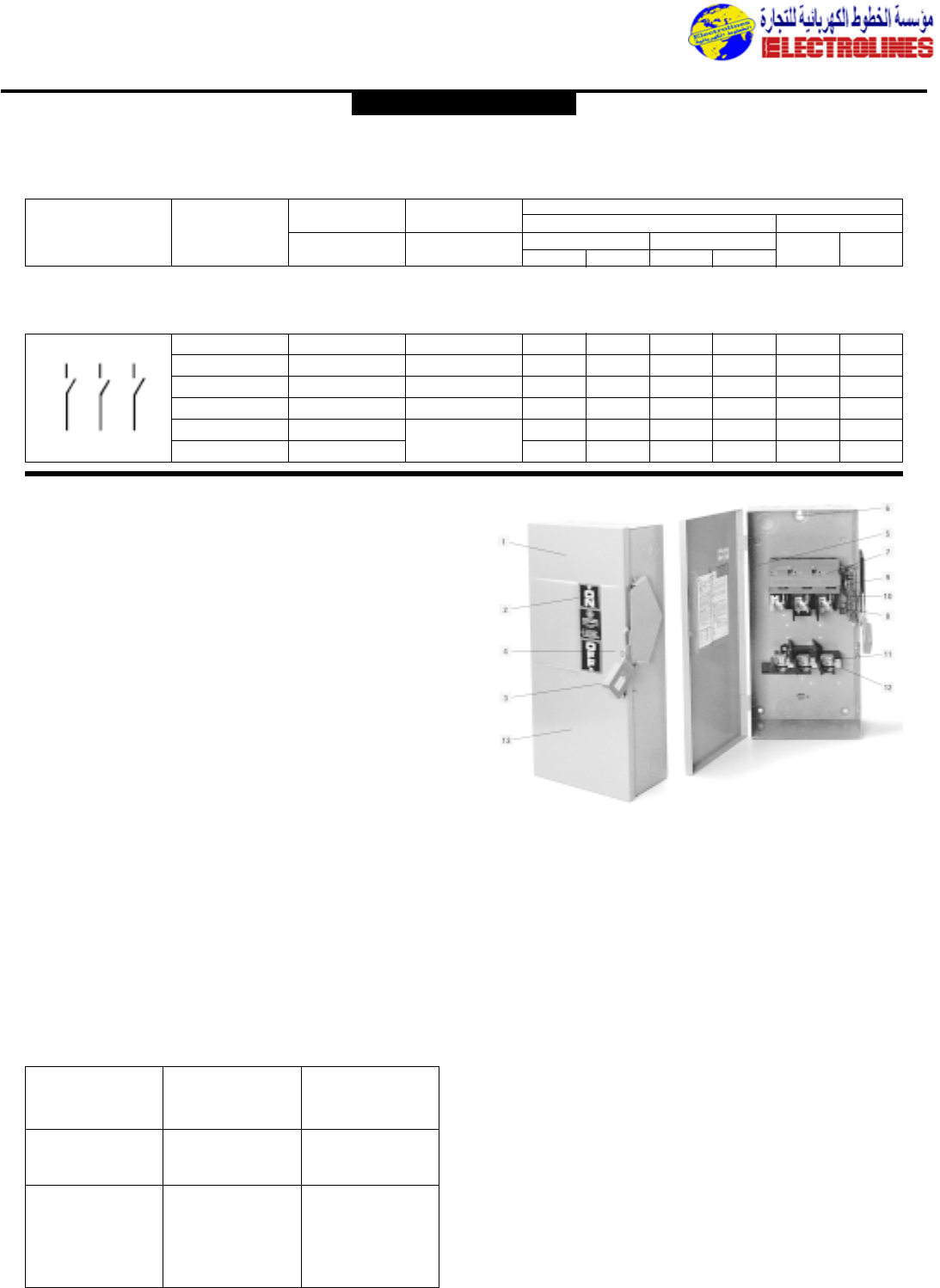
Distribution Equipment
1. GE’s Heavy Duty switches
are available for
commercial and industrial
applications.
2. Highly visible ON/OFF
label takes the guesswork
out of safety.
3. Unique red “donut” handle
molded out of GE SE1
Noryl Thermoplastic is
easy to see, easy to grip.
Ideal for hook stick
operation.
4. Coin-proof defeatable dual
interlocks meet all safety
inspection requirements.
5. Wide, unobstructed gutter
and removable interior
make wire pulling quick
and easy.
6. Positive three-point
mounting speeds
installation,simplifies
ganging in close quarters.
7. Exclusive SE1 Noryl resin
arc shield helps provide
maximum UL listed
horsepower ratings while
guarding against accidental
contact with live parts.
8. Accessories,such as
auxiliary switch kits, are
quickly field installable.
9. Silver-plated visible blades
inform you whether the
switch is ON or OFF.
10. Direct-drive, quick-make,
quick-break mechanism
provides long life and
positive ON/OFF
indication.
11. Spring-reinforced fuse
clips,suitable for Class H,
K,J,or R fuses,assure
reliable contact for cool
operation.
12. Cu-Al lugs 60/75˚C rated
permit greater wire
selection.
13. Galvannealed steel for
superior rust protection in
outdoor applications.
GE’s Heavy Duty Safety Switches Type TH are designed for
applications where safety, high performance, and continuity
of service are essential.
The heavy duty line is available in 30-1200 amps,600 Vac,
600 Vdc maximum, no-fuse and fusible units. Enclosure
types include UL (NEMA) Type 1 (indoor),Type 3R
(outdoor),Type 4/4x Stainless Steel (water and dust-tight),
and Type 5/12 and JIC (drip and dust-tight).When used
with Class R or J fuses,30-600 amp switches have a UL
listed short circuit rating of 200,000 rms symmetrical
amps.
Type TC 800-1200 amps switches used with Class L fuses
are good for 100,000 rms symmetrical amps.GE’s Heavy
Duty Safety Switches are suitable for use as service
entrance equipment when installed in accordance with the
National Electrical Code.
Heavy Duty Safety Switches are UL listed and CSA
certified under (UL98 Enclosed Switches/CSA-C22.2 No.
4-M89) and meet NEMA Enclosed Safety Switches meet
Federal Specification WS-865C for heavy duty switches.
Heavy Duty
Safety Switches Type TH
30-1200 Amperes 240 Volts ac,250 Volts dc Max.
General Duty Type TG (Cont.)
30-600 Amperes 240 Volts ac,250 Volts dc Max.
Max. Indoor, Type 1 Outdoor,Type 3R Horsepower Ratings
Schematic Ampere EnclosureÅEnclosureÇ240 Volts ac dc
Diagram Rating NEC Standard Time Delay 125 250
Catalog Number Catalog Number 1-ph 3-ph 1-ph 3-ph Volts Volts
No Fuse
Two-pole,240 Volts ac (Use three-pole switch for two-pole application); 250 Volts dc (30-100 amps only)
Three-pole, 240 Volts ac or Two-pole with Switching Neutral
30 TGN3321 TGN3321R 3 71/237
1/2–5
60 TGN3322 TGN3322R 10 15 10 15 3 10
100 TGN3323 TGN3323R 15 30 15 30 – 20
200 TGN3324 TGN3324R 15 50 15 50 – –
400 TGN3325
Available in heavy
– 100 – 100 – –
600 TGN3326
duty, type TH models
– 100 – 100 – –
Type TH Interrupting and
Withstandability Ratings
Switch Interrupting Fuse Cleaning12t
Rating Rating (Amps 2x
(Amps) rms Amps, Seconds x 103)
600 Volt ac 3-ph
30 360 50
60 1200 200
100 1200 500
200 3,400 2,000
400 10,000 2,000
600 10,000 12,000
GENERAL ELECTRIC
Electrolines Est.
P. O. Box. 942 Yanbu Saudi Arabia Tel: +966 4 3225418 Fax: +966 4 3222213 Al-Jubail: Tel: +966 3 3632967 Fax: +966 3 3612967
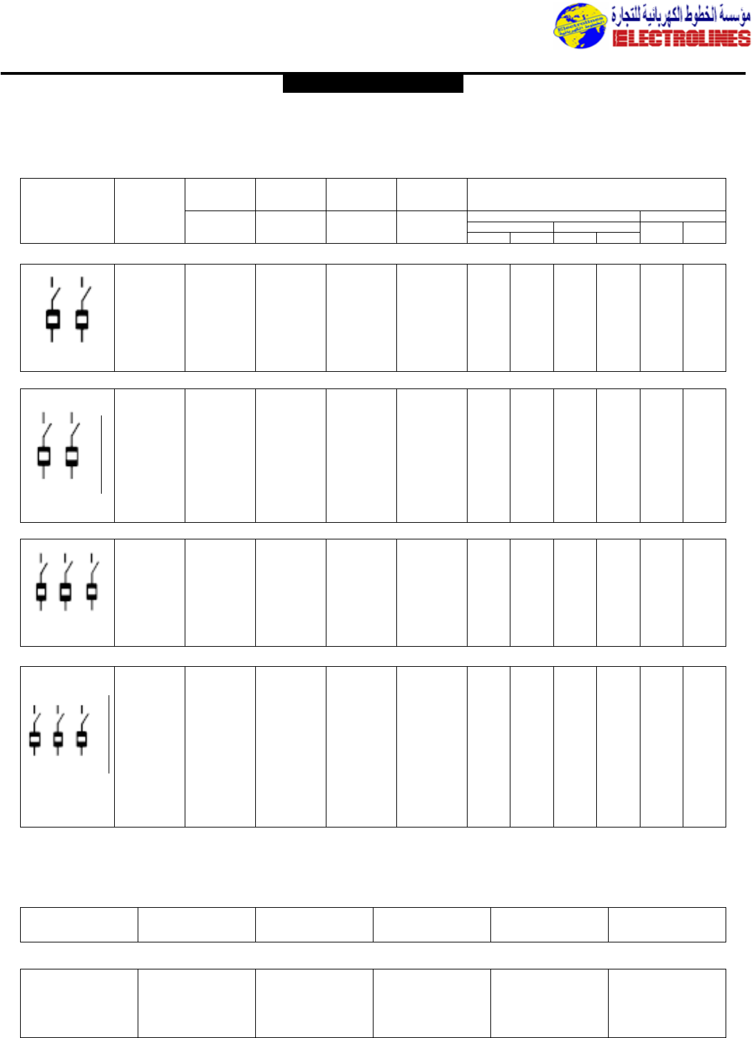
Distribution Equipment
Safety Switches,Heavy Duty Type TH (Cont.)
30-1200 Amperes 240 Volts ac,250 Volts dc Max.
Two-pole,240 Volts ac–250 Volts dc
30 TH3221 TH3221R TH2221SS TH2221J 11/2337
1/2–5
60 TH3222 TH3222R TH2222SS TH2222J 3 71/210 15 5 10
100 TH3223 TH3223R TH3223SS TH3223J 71/215 15 30 – 20
200 TH3224 TH3224R TH3224SS TH3224J 15 25 – 60 – 40
400 TH3225 TH3225R TH3225SS TH3225J – 50 – 125 – 50
600 TH3226 TH3226R TH3226SS TH3226J – 75 – 200 – 50
800 TC72267 TC72267R – – – – – – – –
1200 TC72268 TC72268R – – – – – – – –
Three-wire SN, 120/240 and 240 Volts ac
30 TH3221 TH3221R TH3221SS TH3221J 11/2337
1/2–5
60 TH3222 TH3222R TH3222SS TH3222J 3 71/210 15 5 10
100 TH3223 TH3223R TH3223SS TH3223J 71/215 15 30 – 20
200 TH3224 TH3224R TH3224SS TH3224J 15 25 – 60 – 40
400 TH3225 TH3225R TH3225SS TH3225J – 50 – 125 – 50
600 TH3226 TH3226R TH3226SS TH3226J – 75 – 200 – 50
800 TC72267 TC72267R – – – – – – – –
plus TNI67 plus TNI67
1200 TC72268 TC72268R – – – – – – – –
plus TNI68A plus TNI68
Three-pole, 240 Volts ac30 TH4321 TH4321R TH3321SS TH3321J 11/2337
1/2–5
60 TH4322 TH4322R TH3322SS TH3322J 3 71/210 15 5 10
100 TH4323 TH4323R TH4323SS TH4323J 71/215 15 30 – 20
200 TH4324 TH4324R TH4324SS TH4324J 15 25 – 60 – 40
400 TH3325 TH3325R TH4325SS TH4325J – 50 – 125 – 50
600 TH3326 TH3326R TH4326SS TH4326J – 75 – 200 – 50
800 TC72367 TC72367R – – – – – – – –
1200 TC72368 TC72368R – – – – – – – –
Four-wire SN,208/120 and 240 Volts ac
30 TH4321 TH4321R TH3321SS TH4321J 11/2337
1/2–5
60 TH4322 TH4322R TH4322SS TH4322J 3 71/210 15 5 10
100 TH4323 TH4323R TH4323SS TH4323J 71/215 15 30 – 20
200 TH4324 TH4324R TH4324SS TH4324J 15 25 – 60 – 40
400 TH4325 TH3325R TH4325SS TH4325J – 50 – 125 – 50
plus TNI65
600 TH4326 TH3326R TH4326SS TH4326J – 75 – 200 – 50
plus TNI66
800 TC72367 TC72367R – – – – – – – –
plus TNI67 plus TNI67 – – – – – – – –
1200 TC72368 TC72368R – – – – – – – –
plus TNI68A plus TNI68A
240 Volts—Fusible
Schematic
Diagram Max.
Ampere
Rating
Indoor
Type 1
Catalog
Number Catalog
Number Catalog
Number Catalog
Number
Outdoor
Type 3R
Water- and Dust-tight
Types 4/4X
Stainless Steel
Drip- and Dust-tight
Type 5, 12 and JIC
Without Knockouts
Horsepower Ratings
240 Volts ac
NEC Std Time Delay 125
Volts 250
Volts
1-ph 3-ph 1-ph 3-ph
•Superior corrosion resistance and high temperature strength
•Excellent resistance to pitting corrosion due to chlorides •Excellent resistance to reducing acids and similar media
30 600 TH2261SSDC3 30 600 THN3361SS317
30 240 TH3221SS317 60 600 THN3362SS317
30 600 TH3361SS317 100 600 THN3363SS317
60 600 TH3362SS317 600 600 THN3366SS317
100 600 TH3363SS317
200 600 TH3364SS317
Heavy Duty Safety Switches with 317 Stainless Steel Type NEMA 4/4X,Water & Dust-tight
30-1200 Amperes 240,480 and 600 Volts ac,600 Volts dc
Max.
Ampere
Rating Volts Catalog
Number Max.
Ampere
Rating Volts Catalog
Number
240/600 Volts—Fusible 600 Volts—Non-Fusible
NEUT.
NEUT.
GENERAL ELECTRIC
Electrolines Est.
P. O. Box. 942 Yanbu Saudi Arabia Tel: +966 4 3225418 Fax: +966 4 3222213 Al-Jubail: Tel: +966 3 3632967 Fax: +966 3 3612967
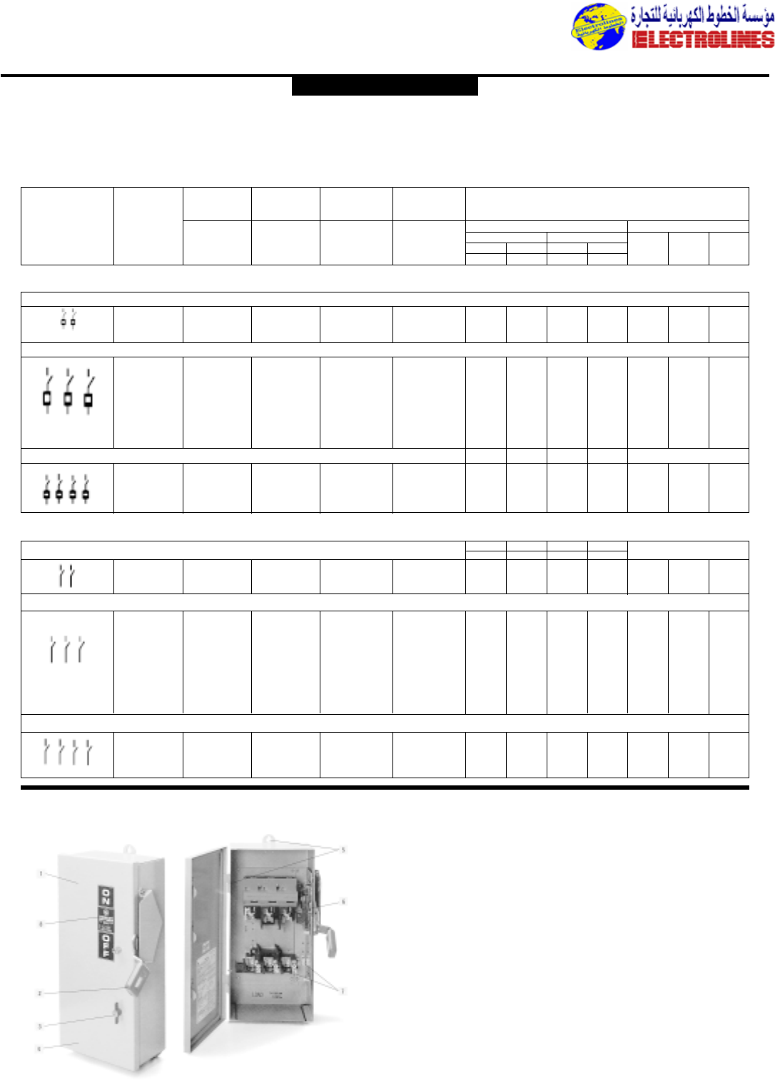
600 Volts—Fusible
Two-pole, 600 Volts dc
30 TH2261DC TH2261RDC TH2261SSDC TH2261JDC – – – – – – 15
60 TH2262DC TH2262RDC TH2262SSDC TH2262JDC – – – – – – 25
100 TH2263DC TH2263RDC TH2262SSDC TH2263JDC – – – – – – 25
Three-pole, 480, 480Y/277 and 600 Volts ac-250 Volts dc
30 TH3361 TH3361R TH3361SS TH3361J 5 71/215 20 – 5 –
60 TH3362 TH3362R TH3362SS TH3362J 15 15 30 50 – 10 –
100 TH3363 TH3363R TH3363SS TH3363J 25 30 60 75 – 20 –
200 TH3364 TH3364R TH3364SS TH3364J 50 60 125 150 – 40 –
400 TH3365 TH3365R TH3365SS TH3365J 100 125 250 350 – 50 –
600 TH3366 TH3366R TH3366SS TH3366J 150 200 400 500 – 50 –
800 TC72367 TC72367R – – – – – – – – –
1200 TC72368 TC72368R – – – – – – – – –
Four-pole, 480 and 600 Volts ac
30 TH6661 TH6661 – TH6661 71/210 20 25 – 5 –
60 TH6662 TH6662 – TH6662 15 20 40 50 – 10 –
100 TH6663 TH6663 – TH6663 25 30 50 50 – 20 –
200 TH6664 TH6664 – TH6664 50 50 – – – 40 –
600 Volts—No Fuse
Two-pole,600 Volts dc30 THN2261DC THN2261RDC THN2261SSDC THN2261JDC – – – – – – 15
60 THN2262DC THN2262RDC THN2262SSDC THN2262JDC – – – – – – 25
100 THN2263DC THN2263RDC THN2263SSDC THN2263JDC – – – – – – 25
Three-pole, 480 and 600 Volts ac–250 Volts dc or Two-pole with Switching Neutral
30 THN3321 – – – 3 10 – – 3 5 –
30 THN3361 THN3361R THN3361SS THN3361J 3 10 20 30 3 5 –
60 THN3362 THN3362R THN3362SS THN3362J 10 20 50 60 5 10 –
100 THN3363 THN3363R THN3363SS THN3363J 20 40 75 100 – 20 –
200 THN3364 THN3364R THN3364SS THN3364J 30 60 125 150 – 40 –
400 THN3365 THN3365R THN3365SS THN3365J – 125 250 350 – 50 –
600 THN3366 THN3366R THN3366SS THN3366J – 200 400 500 – 50 –
800 TC36367 – – – – – – – – – –
1200 TC36368 – – – – – – – – – –
Four-pole, 480 and 600 Volts ac
30 THN6661 THN6661 – THN6661 – 10 20 25 – 5 –
60 THN6662 THN6662 – THN6662 – 20 40 50 – 10 –
100 THN6663 THN6663 – THN6663 – 30 50 50 – 20 –
200 THN6664 THN6664 – THN6664 – 50 – – – 40 –
Distribution Equipment
Safety Switches
Schematic
Diagram Max.
Ampere
Rating
Indoor
Type 1
Catalog
Number Catalog
Number Catalog
Number Catalog
Number
Outdoor
Type 3R
Water- and Dust-tight
Types 4/4X
Stainless Steel
Drip- and Dust-tight
Type 5, 12 and JIC
Without Knockouts
Horsepower Ratings
ac dc
NEC Std Time Delay 125
Volts
125
Volts 250
Volts
480V 600V 600V
480V
1-ph 3-ph 3-ph1-ph
2-ph 2-ph 2-ph2-ph
480V 600V 480V
1-ph 3-ph 1-ph
Safety Switches,Heavy Duty Type TH (Cont.)
30-1200 Amperes 240,480 and 600 Volts ac,600 Volts dc
1. GE’s Mill Duty switches are
available for mill,foundry,and
heavy industrial applications.
2. All-steel handle with a highly
visible red “donut” type grip
directly drives the heavy duty
switch mechanism.Switch han-
dle accepts three padlocks in
OFF position.
3. Manual interlock lever permits
contact inspection when
switch is OFF.
4. Standard NEMA 12 enclosure
protects interior from dust,
lint,fibers,coolants, metal fil-
ings,and other non-corrosive
contaminants;stainless steel
NEMA 4/4x additionally shields
interior from hosedowns,
splashing,and falling liquids.
Interlocks on all enclosures
assure gasket compression
before switch can be turned
ON.
5. Trim,space-saving enclosures;
three-point mounting;unob-
structed side wiring gutter,
easily removable cover and
interior.
6. Spring-reinforced fuse clips,
suitable for Class H,K,J, or R
fuses,assure reliable contact
for cool operation.
7. Equipment ground lugs sup-
plied;lugs approved for both
copper and aluminum wire;
60/75˚C rated tang lugs are
field convertible to compres-
sion (crimp) connectors.
8. Clean,modem appearance;
permanent acrylic-polyester
nameplate with UV inhibitors
provides clear ON/OFF
indication.
Mill Duty Safety Switches
GENERAL ELECTRIC
3-ph
600V
Electrolines Est.
P. O. Box. 942 Yanbu Saudi Arabia Tel: +966 4 3225418 Fax: +966 4 3222213 Al-Jubail: Tel: +966 3 3632967 Fax: +966 3 3612967
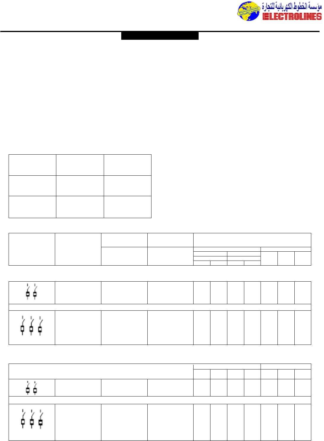
Distribution Equipment
GE’s Mill Duty Safety Switches are designed
specifically for application in steel mills,
cement foundries,and other industries
where heavy use and difficult environments
create potentially hazardous conditions.
GE’s Mill Duty Safety Switches offer full-line
availability 30-600 amps;600 Vac,600 Vdc
maximum,no-fuse and fusible units.
Enclosure types include UL (NEMA) Type
12 and Type 4/4x Stainless Steel.
Horsepower ratings are to UL listed
maximums;published I2t ratings are
available. Short circuit ratings are UL listed
to 200,000 rms symmetrical amps when
Class J or R fuses are installed.
All Mill Duty Safety Switches are UL listed
and CSA certified under (UL98 Enclosed
Switches/CSA-C22.2 No. 4-M89), meet
Federal Specification WS-865C for heavy
duty switches,and meet NEMA Enclosed
Safety Switch Standard KS1-1990.
Mill Duty Safety Switches (Cont.)
Type TH
30-600 Amperes 240,480 and 600 Volts ac,250 and 600 Volts dc
240 Volts—Fusible
Two-pole,240 Volts ac–250 Volts dc
30 TH2221M TH2221MSS 11/2–3––5–
60 TH2222M TH2222MSS 3 – 10 – 5 10 –
100 TH2223M TH2223MSS 71/2–15– –20–
200 TH2224M TH2224MSS 15 – – – – 40 –
Three-pole, 240 Volts ac
30 TH3321M TH3321MSS 11/2337
1/2–5–
60 TH3322M TH3322MSS 3 71/210 15 5 10 –
100 TH3323M TH3323MSS 71/215 15 30 – 20 –
200 TH3324M TH3324MSS 15 25 – 60 – 40 –
400 TH3325M TH3325MSS – 50 – 125 – 50 –
600 TH3326M TH3326MSS – 75 – 200 – 50 –
240 Volts—No Fuse Use 600-volt switches
600 Volts—Fusible
Two-pole,600 Volts dc
30 TH2261MDC TH2261MSSDC – – – – – – 15
60 TH2262MDC TH2262MSSDC – – – – – – 25
100 TH2263MDC TH2263MSSDC – – – – – – 25
Three-pole, 480 and 600 Volts ac—250 Volts dc
30 TH3361M TH3361MSS 5 71/215 20 – 5 –
60 TH3362M TH3362MSS 15 15 30 50 5 10 –
100 TH3363M TH3363MSS 25 30 60 75 – 20 –
200 TH3364M TH3364MSS 50 60 125 150 – 40 –
400 TH3365M TH3365MSS 100 125 250 350 – 50 –
600 TH3366M TH3366MSS 150 200 400 500 – 50 –
Type TH Interrupting and
Withstandability Ratings
Switch Interrupting Fuse Cleaning12t
Rating Rating (Amps2x
(Amps) rms Amps, Seconds x 103)
600 Volt ac 3-ph
30 360 50
60 1200 200
100 1200 500
200 3,400 2,000
400 10,000 6,000
600 10,000 12,000
Schematic
Diagram Max.
Ampere
Rating
Type 12
Catalog
Number Catalog
Number
Type 4/4X Stainless Steel
Horsepower Ratings
ac dc
NEC Std Time Delay 250
Volts
125
Volts 600
Volts
240 Volts 240 Volts
1-ph 3-ph 3-ph1-ph
125V
600V
3-ph
480V
3-ph
600V
3-ph
480V
3-ph 250V 600V
dcac
240 Volts—Fusible
GENERAL ELECTRIC
Electrolines Est.
P. O. Box. 942 Yanbu Saudi Arabia Tel: +966 4 3225418 Fax: +966 4 3222213 Al-Jubail: Tel: +966 3 3632967 Fax: +966 3 3612967
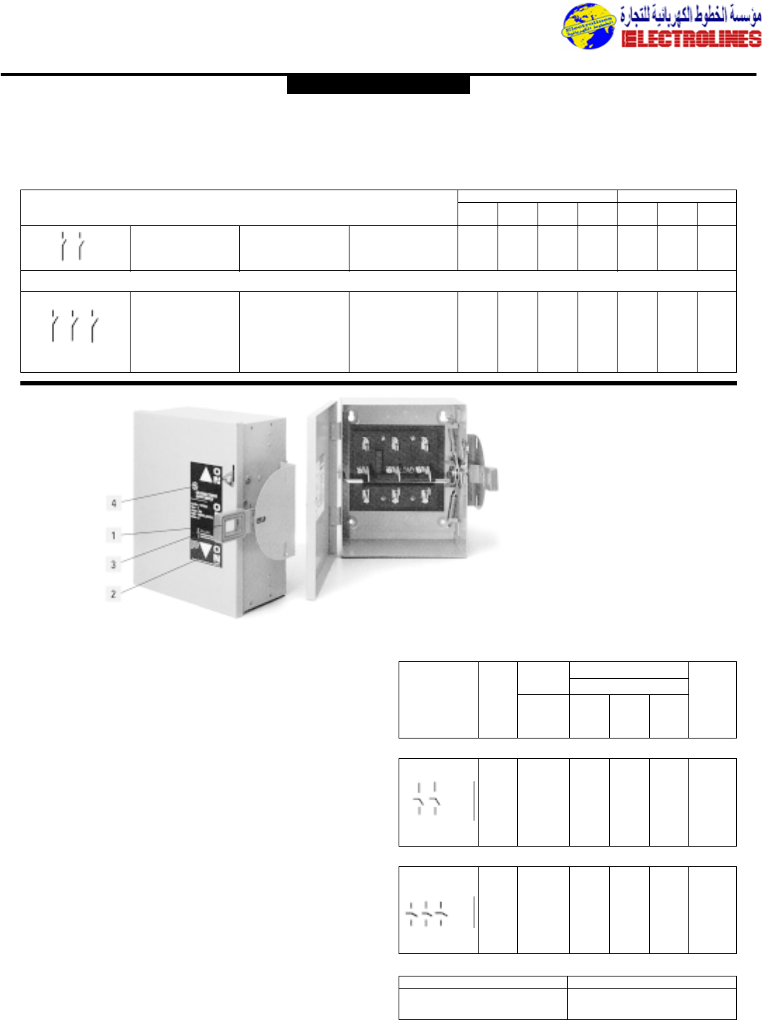
Double-throw Type TC
600 Volts—No Fuse
Two-pole,600 Volts dc
30 TH2261MDC TH2261MSSDC – – – – – – 15
60 TH2262MDC TH2262MSSDC – – – – – – 25
100 TH2263MDC TH2263MSSDC – – – – – – 25
Three-pole, 480 and 600 Volts ac—250 Volts dc
30 THN3361M THN3361MSS 3 10 20 30 3 5 –
60 THN3362M THN3362MSS 10 20 50 60 5 10 –
100 THN3363M THN3363MSS 20 40 75 100 – 20 –
200 THN3364M THN3364MSS 30 60 125 150 – 40 –
400 THN3365M THN3365MSS – 125 250 350 – 50 –
600 THN3366M THN3366MSS – 200 400 500 – 50 –
Distribution Equipment
1. Unique red “donut” handle is
easy to see, easy to grip.Ideal
for hook stick operation.
2. Vivid acrylic-polyester ON-
OFF-ON nameplate for posi-
tive identification.Takes the
guesswork out of safety.
3. Three position lockable handle
(ON-OFF-ON).
4. Safety cover interlock.
GE’s full line of no-fuse Double-Throw Safety Switches is
designed for application where safety,high performance,
and continuity of service are essential.
The TC line is available in 30-600 amps,600 Vac,250 Vdc
maximum for no-fuse applications.Enclosures are UL
(NEMA) Type 1 (indoor).
TC Double-Throw Safety Switches are UL listed (UL98
Enclosed Switches).They meet Federal Specification WS-
865C for enclosed switches;meet or exceed NEMA
Enclosed Switch Standard KS1-1900,Type GD for 30-600
amps.
Double-Throw
Safety Switches
Spec-SetterTM Safety Switches,Mill Duty Type TH (Cont.)
30-600 Amperes 240,480 and 600 Volts ac,250 and 600 Volts dc
125V
600V
3-ph
480V
3-ph
240V
3-ph
240V
1-ph 250V 600V
dcac
240 Volts ac, 250 Volts dc
30 TC35321 2 – – 14-8
60 TC35322 3 – – 14-4
100 TC35323 71/2– – 14-1/0
200 TC35324 15 – – 6-250
400 TC35325 30 – – (2) 1/0-250
600 TC35326 50 – – (2) 3/0-350
600 Volts ac, 250 Volts dc
30 TC35362 10 10 10 14-4
60 TC35362 10 10 10 14-4
100 TC35363 15 15 15 14-1/0
200 TC35364 30 30 30 6-250
400 TC35365 – – – (2) 1/0-250
600 TC35366 – – – (2) 3/0-350
Solid Neutrals – Not UL Listed, Factory Installed
Switch Ampere Rating Catalog Number
30-100 Order by
200-600 Description
Schematic
Diagram
Max.
Ampere
Rating
Indoor
Type 1
Enclosure
Horsepower Ratings
NEC Standard
Catalog
Number 240V,
3-ph 480V,
3-ph 600V,
3-ph
Lug
Wire Size
AWG/kc
mil
Cu only
GENERAL ELECTRIC
NEUT.
NEUT.
Electrolines Est.
P. O. Box. 942 Yanbu Saudi Arabia Tel: +966 4 3225418 Fax: +966 4 3222213 Al-Jubail: Tel: +966 3 3632967 Fax: +966 3 3612967
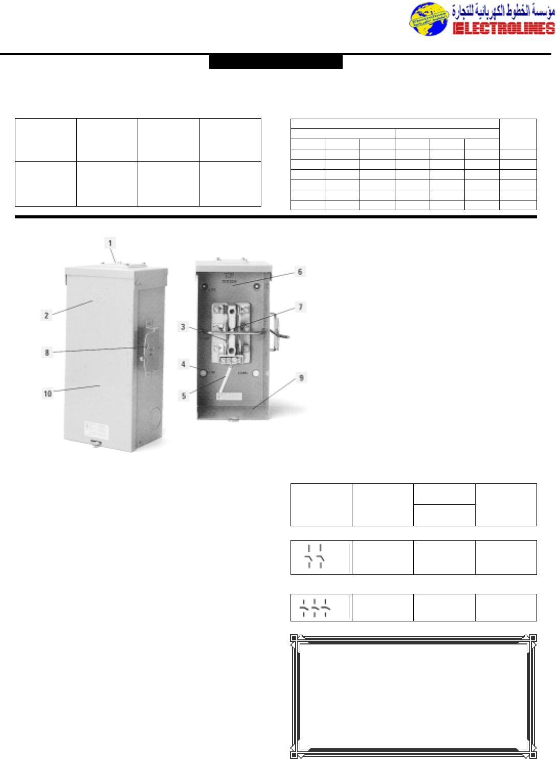
Distribution Equipment
Max.
Ampere
Rating
30 TDT3321 R TDT3361
60 TDT3322 R TDT3362
100 TDT3323 R TDT3363
200 TDT3324 R TDT3364
400 TDT3325 – TDT3365
600 TDT3326 – –
Fusible Double-
Throw Safety
Switches
Type NEMA 1
240 Vac
Fusible Double-
Throw Safety
Switches
Type NEMA 3R
240 Vac Add Suffix
Fusible Double-
Throw Safety
Switches
Type NEMA 1,
600 Vac
Fusible Double-Throw Safety Switches
30-400 Amperes
Max. Horsepower Rating with Time-delay fuses
Single-phase ac Three-phase ac 250V
240V 480V 600V 240V 480V 600V dc
37
1
/
2
10 7
1
/
2
15 20 5
10 20 25 15 30 50 10
15 30 40 30 60 75 20
15 50 50 60 125 150 40
– – – 125 100 125 50
–––75––50
1. Threaded hole in top of box makes it easy to
install.
2. Code-gauge steel box fitted with drip-shield for
protection against rain; resists corrosion, rust,
chipping.
3. Silver-plated copper current-carrying parts pre-
vent oxidation, assure low-resistance contact;
cool operation.
4. Mounting holes permit quick, easy installation.
5. Bonding strap can be used to ground neutral for
service entrance applications.
6. Ample wiring space provided within compact
enclosure.
7. Positive make and break provided by fiber loop
straps between knife blade contacts and one-
piece operating yoke.
8. Provision for locking handle in ON or OFF
position; protects against accidental contact with
live parts.
9. Concentric knockouts are conveniently located,
easy to remove.
10. Galvannealed steel enclosures for superior rust
protection in outdoor applications.
GE’s Emergency Power Transfer Switches are specifically
designed to permit the connection of power from a
standby generator or other emergency source of
electricity.
The switch is a no-fuse unit, available in three-wire SN
(120/24D Vac), 100 and 200 amp ratings or four-wire SN
(240 Vac), 200 amp rating.The enclosure is surface-
mounted, rain-tight NEMA Type 3R (outdoor).The switch
is ideally suited for outdoor applications in rural dwellings
and farm buildings. Its side-operated handle can be locked
in either the ON or OFF position.
Type TC Emergency Power Transfer Switches are UL listed
(UL98 Enclosed Switches).The switches are suitable for
use as service entrance equipment when installed in
accordance with the National Electrical Code.
Emergency Power Transfer
Switches,Type TC
Schematic
Diagram
Three–wire SN, 120/240 Volts ac
100 TC10323R 12-1
200 TC10324R 6-250
Four–wire SN, 240 Volts ac
200 TC10424R 6-250
Max.
Ampere
Rating
Raintight
Type 3R Enclosure
No-Fuse
Catalog Number
Lug
Wire
Size
AWG/kcmil
Cu/AI
GENERAL ELECTRIC
NEUT.NEUT.
Need a special
electrical product?
Call us first!
Electrolines Est.
P. O. Box. 942 Yanbu Saudi Arabia Tel: +966 4 3225418 Fax: +966 4 3222213 Al-Jubail: Tel: +966 3 3632967 Fax: +966 3 3612967
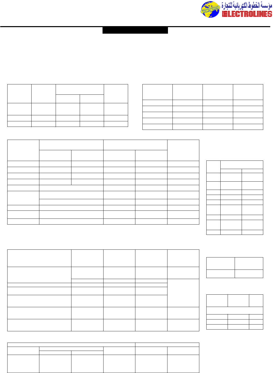
Distribution Equipment
30-60 TGL1 (4) 14-8 (4) 14-8 20
(3) 14-4 (3)6-4
100-200 TNG3 (3) 10-1/0 (3) 10-1/0 1
400-600 TGL6 (3) 2-250 (3) 2-250 1
Safety Switches,Accessories
For Type 1 and 3R Enclosures
30-600 Amperes:TG and TH
800-1200 Amperes:TC
Neutral
Ampere
Rating
30-60 Fusible TNIJ62CL 14-2 1
30-60 No Fuse TNIJA62CL 14-2 1
100 TNIJ63CL 14-1/0 1
200 TNIJ64CL 1/0-250 1
400-600 TNIJ66CL (2) 1/0-600 1
Catalog
Number Lug Wire Size
AWG/kcmil
CU Only Std
Pkg
Switch
Ampere
Rating Catalog
Number
Lug Wire Size
AWG/kcmil
Copper Aluminum
Std
Pkg
Equipment Ground Kits Optional Copper Lug Neutrals
GENERAL ELECTRIC
Auxiliary Contact Kits—Auxiliary contacts open before switch
blades.UL Listed for field or factory installation.
Switch Wire Range
Ampere AWG/kcmil
Rating Copper Aluminum
30 14-8 12-8
(250V)
30 12-2 12-2
(600V)
60 12-2 12-2
100 10-1/0 10-1/0
200 2-250 2-250
400 (1) 2-600 or (1) 2-600 or
(2) 1/0-250 (2) 1/0-250
600 (2) 4-500 (2) 4-500
800 (3) 2-600 (3) 2-600 or
(6) 1/0-250 (6) 1/0-250
1200 (4) 3/0-800 (4) 3/0-800
Switch
Ampere
Rating No FuseFusible
Catalog Number Lug Wire Size (AWG/kcmil)
Copper Wire Aluminum Wire
Std
Pkg
30-240V TN121 TNI21 14-8 12-8 1
30-600V TNI62 TNI62 14-2 12-2 1
60 TNIA62 TNI62 14-2 12-2 1
100 TNIA63 TNI63 10-1/0 10-1/0 1
200 TNIA64 1-300 1-300 1
TNI65 (1) 2-600 or (1) 2-600 or 1
400 (2) 1/0-250 (2) 1/0-250
TNI65A (1) 350-800 (1) 350-800 1
600 TNI66 (2) 4-500 (2) 4-500 1
800 TNI67 (3) 2-600 or (3) 2-600 or 1
(6) 1/0-250 (6) 1/0-250
1200 TNI68A (4) 3/0-800 (4) 250-800 1
Switching Neutral: Order standard switch of required number of poles and use dummy fuse in neutral pole.
Neutral Kits—Insulated, Groundable and Bondable
Neutral Kits—Insulated, Groundable and Bondable
Lug Wire Sizes
Line and Load
Terminal
Safety Switch Rating,
Type 1 and 3R
Field
Installed
Catalog Number
(Std. Pkg.-1)
Switch
Suffix for
Factory
Installed Contacts Contact
Ratings
10A,125/250Vac
THAUX21D A21D DPDT .3A,125Vdc
.15A,250Vdc
TH,THN, 30A,2 and 3 poles THAUX61S A61S SPDT
TH,THN, 60-200A,2 and 3 poles THAUX64D A64D DPDT 15A,125/250Vac
15A,480/600Vac
TH,THN, 200A,6 poles THAUX66D2 A66D2 DPDT .50A,125Vdc
TH,THN, 400-600A,2 and 3 poles .25A,250Vdc
TH,THN, 30-100A,6 poles THAUX66D A66D DPDT
400-600A,6 poles 15A,125/250Vac
TC, 800-1200A,2 and 3 poles – – SPDT .50A,125Vdc
.25A,250Vdc
15A,125/250Vac
TC, double throw – – SPDT .50A, 125Vdc
.25A,250Vdc
Qty.
Catalog No. (same
wording)
75C141109P109 1-5
6-10
Special Phenolic
Nameplates
(15 letters maximum)
ac dc (Resistive)
Volts Inrush Current Break Normal Volts Break Normal
N.C. N.O. Current Current
115 30 15 15 125 0.5
230 30 15 15 250 0.25
460 30 15 15 – –
575 15 15 2 – –
Switch Kit Cat No. Std
Ampere (Field Pkg
Rating Mounted)
Types TH Indoor,TG and TH
Outdoor Switches
30-100 THG106 1
200 THG107 1
400 and 600 THG108 1
Semidust-tight
Door Gasket Kits
Electrolines Est.
P. O. Box. 942 Yanbu Saudi Arabia Tel: +966 4 3225418 Fax: +966 4 3222213 Al-Jubail: Tel: +966 3 3632967 Fax: +966 3 3612967
Distribution Equipment
NEMA 1 enclosures are suitable for indoor use primarily
to provide protection against contact with the enclosed
equipment and where unusual service environments do
not exit.
NEMA 3R enclosures are intended for outdoor use to
provide a degree of protection against falling rain,sleet,
and external enclosure ice formation.
NEMA 4, 4x enclosures are intended for indoor or
outdoor use to provide a degree of protection against
windblown dust and rain,and splashing or hose-directed
water and external enclosure ice formation.Additionally,
these enclosures meet 4x description by providing a
degree of protection against corrosion.
NEMA 5, 12 enclosures are intended for indoor use
primarily to provide a degree of protection against settling
airborne and circulating dust,falling dirt, and dripping, non-
corrosive liquids.
Enclosure Types GE Safety Switches provide a full line of factory and field-
installable accessories to customize for our customers’
special applications:
EQUIPMENT GROUND KITS available for 30-600
amp safety switches.
INSULATED, GROUNDABLE AND BONDABLE
NEUTRAL KITS for 30-1200 amp safety switches.
COPPER LUG NEUTRALS for 30-600 amp safety
switches.
UL LISTED FACTORY OR FIELD INSTALLABLE
AUXILIARY CONTACT KITS in both single pole
double-throw and double pole double-throw.
SEMI-DUST-TIGHT DOOR GASKET, field installable.
KEY INTERLOCKS (factory installed) available for TH
switches Types 1,5,12, 4/4x, and Mill Duty.
FUNGUS MOISTURE PROOFING for 30-600 amp
switches.
SPECIAL PHENOLIC NAMEPLATES are
customized to your specifications.
Accessories
GENERAL ELECTRIC
GE provides the following special purpose safety switches
to satisfy a variety of unique applications:
SIX-POLE SWITCHES are available in 30-200 amp;
600 Vac,250 Vdc maximum.Provided in a single enclosure
rated Type 1, 3R, 5 and 12.
INTERLOCKED RECEPTACLE SWITCHES are
offered in a Type 12 enclosure, 60 amp rating, 600 Vac
maximum.
COPPER LUG SWITCHES are available in 30-600
amp;600 Vac, 250 Vdc maximum.Enclosure types include
Type 1,4/4x,5 and 12.
PLUG-FUSE SWITCHES in GE Valox®enclosures
(Type 1) are available in one and two-pole designs,240 Vac
maximum.
AIR CONDITIONER DISCONNECTS are provided
in fusible and no-fuse designs;30 and 60 amp ratings; steel
and phenolic enclosures.
Special Purpose
GE Safety Switches
provides
you one-stop
shopping for all
your electrical
needs.
30,000 discrete
electrical products
in stock.
ELECTROLINES
Electrolines Est.
P. O. Box. 942 Yanbu Saudi Arabia Tel: +966 4 3225418 Fax: +966 4 3222213 Al-Jubail: Tel: +966 3 3632967 Fax: +966 3 3612967
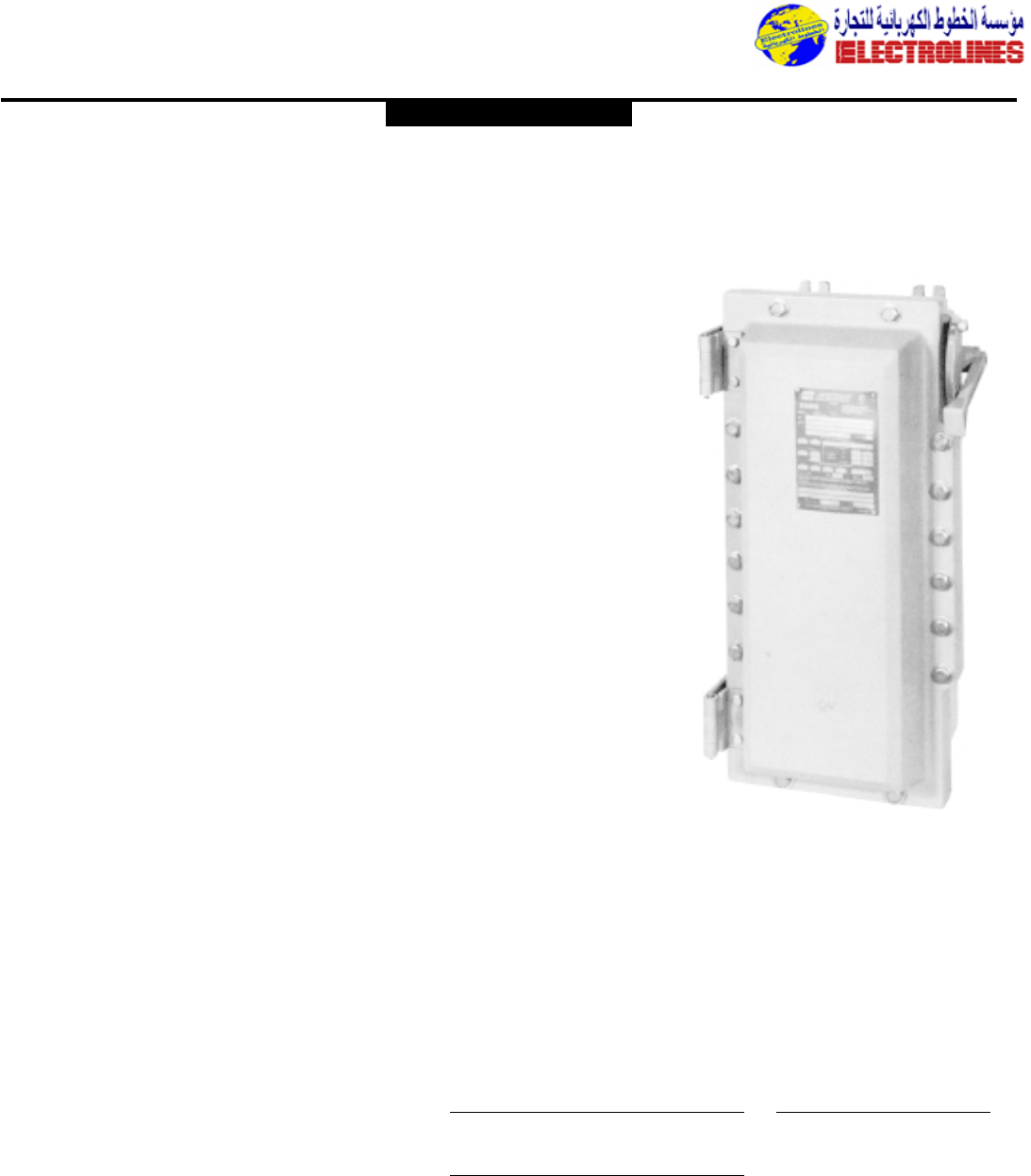
Distribution Equipment
Application:
EBM series hinged cover disconnect
switches are used:
•to disconnect motor,lighting and
other circuits.
•in locations made hazardous by the
presence of flammable or vapors or
ignitable dusts.
•indoors or outdoors in damp,wet
and dirty locations, or in areas
where frequent washdowns, heavy
rain or water spray is prevalent.
•to provide disconnect means and
short circuit protection,(fusible ver-
sion).
•on switchracks or other assemblies
where it is desired that motor con-
trol be centrally located.
Features:
•Rugged corrosion resistant cast
copper-free aluminum construction
(less than 0.4 of 1%).
•Switch operating handle is located
through the right side wall of the
body, permits visual confirmation of
correct alignment and operation.
•Total compliance to the wiring end
room requirements of the National
Electrical Code.
•Semi-clamshell enclosure design,
with an external flanged ground
joint between body and cover
makes interior components more
accessible.
•Minimum enclosure-to-enclosure
spacing with little interference
between the opened cover and an
adjacent enclosure.
•Copper-free aluminum hinges allow
the cover to swing well out of the
way.
•Stainless steel quick release captive
hex-head cover bolts.Stainless steel
springs provide clear indication that
cover bolts are fully retracted from
the body.
•Switch operating handle can be pad-
locked in either the “ON” or “OFF”
position.
•Neoprene cover gasket permanently
attached to the cover,seals out
moisture.
•Bodies have top and bottom drilled
and tapped conduit entrances for
power and conduits.Removable
reducers are supplied as standard,
to accommodate smaller size con-
duits.All conduit entrances are
plugged.
•Tap on mounting feet.
Standard Materials:
•Body and cover – copper-free alu-
minum
•Operating handle – copper-free alu-
minum
•Operating shaft and bushing – stain-
less steel
•Interior parts – sheet steel, electro-
galvanized
•Cover bolts,washers and retractile
springs – stainless steel
Electrical Rating Ranges:
•600 VAC
•30,60 and 100 Amp.
NOTE: 200 Amp. switch available.
Consult US.
Ordering Information:
To order an enclosure complete with
the disconnect switch,select the cata-
log number (based on the necessary
rating of the switch),from the listing
below.
Enclosures only, without the discon-
nect switch,can be ordered.Select the
catalog number for the required
enclosure from the listing below.
EBM Disconnect Switches
and Enclosures
600 V AC Heavy Duty
CI.I,Div.1 & 2,Groups C,D
CI.II,Div.1,Groups E,F,G
CI.II,Div.2,Groups F,G
CI.III
NEMA 3,3R,4*, 7CD,9EFG,12
Explosionproof
Dust-Ignitionproof
Watertight
Wet Locations
Enclosure Without
With Swith Switch
600VAC Cat. # Cat. #
EBMBB FD W30360 EBMBB FD
EBMBB FD W60360 EBMBB FD
EBMBD FD W10360 EBMBD FD
EBMBB FD W30361 EBMBB FD
EBMBB FD W60361 EBMBB FD
EBMBD FD W10361 EBMBD FD
Max. HP Rating DC using
AC Polyphase 2 poles
Amp only
Rating 200/240V 440/480V 550/600V 250V Max.
Non-Fusible
30 10 20 25 71/2
60 20 40 60 15
100 30 75 75 25
Fusible
30 – 5 71/25
60 – 151510
100 15 25 30 20
CROUSE-HINDS
Electrolines Est.
P. O. Box. 942 Yanbu Saudi Arabia Tel: +966 4 3225418 Fax: +966 4 3222213 Al-Jubail: Tel: +966 3 3632967 Fax: +966 3 3612967
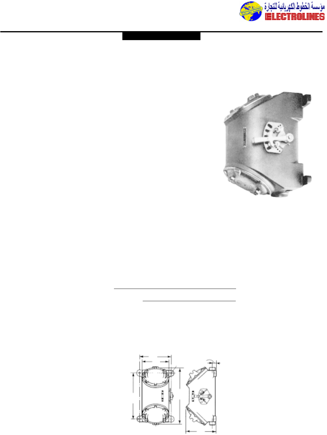
Distribution Equipment
Application:
FLS heavy duty enclosed switches are
used:
•in a rigid metallic conduit system
for surface mounting adjacent to or
remote from equipment being
controlled.
•as disconnect switches for main
feed or individual motor control
•to prevent arcing of the enclosed
switch from causing ignition of a
specific hazardous atmosphere,or
atmospheres,external to the
enclosure
•in industrial areas such as chemical
plants,oil and gas refineries,paint
and varnish manufacturing plants,
gasoline bulk loading terminals,grain
elevators,grain processing
industries,coal processing or
handling areas and metal handling or
finishing areas where atmosphere
may contain hazardous gases and/or
dust
•in non-hazardous area where sturdy,
durable enclosures are required
Features:
•Enclosed devices are unfused, visible
blade motor circuit switches.
•Rugged cast metal enclosures with
mounting lugs and taper tapped
hubs with integral bushings,in
through feed arrangement.
•Interior of the enclosures is readily
accessible through threaded cover
openings at each end,set at an angle
to facilitate wiring.
•Threaded covers and a threaded
type operating shaft and bushing
provide quick assembly and easy
maintenance.
•A padlock can be used to lock the
operating handle in an “ON” or
“OFF” position.
•Body and cover threads treated
with lubricant at factory to provide
raintightness.
Standard Materials:
•Body – Feraloy®iron alloy
•Cover – copper-free aluminum
•Shaft – stainless steel
•Shaft bushings – stainless steel
Standard Finishes:
•Feraloy – electrogalvanized and alu-
minum acrylic paint
•Copper-free aluminum – natural
•Stainless steel – natural
Options:
•FLS enclosed switches with auxiliary
contacts
Size Ranges:
•Hub size – 1” to 11/2” incl.(through
feed)
FLS Enclosed Switches
Heavy Duty
CI.I,Div.1 & 2,Groups C,D
CI.II,Div.1,Groups E,F,G
CI.II,Div.2,Groups F,G
CI.III
NEMA 3,4,7CD,9EFG,12
Explosionproof
Dust-Ignitionproof
Watertight
Wet Locations
Series a b c
FLS30364 71/2131/881/2
FLS60364 71/2131/881/2
FLS10364 73/417 9
de f g
FLS30364 93/491/87/16 13/4
FLS60364 93/413/47/16 93/4
FLS10364 55/891/47/16 15/8
Enclosure
Through With
Feed 3-Pole
Hub Switch
Size Cat. #
1 FLS30364-1-33
11/4FLS60364-1-44
11/2FLS10364-1-55
Switch Ratings
Maximum HP – 3 Phase
Volts AC
Amperes 125 240 480 600
30 5 102025
60 71/220 40 50
100 20 40 75 100
Furnished with Non-Fusible,Visible Blade Motor Circuit Switch
Dimensions*
* Dimensions are approximate, not for construction purposes.
CROUSE-HINDS
ca
db
fg
e
Electrolines Est.
P. O. Box. 942 Yanbu Saudi Arabia Tel: +966 4 3225418 Fax: +966 4 3222213 Al-Jubail: Tel: +966 3 3632967 Fax: +966 3 3612967
