1000290454 Catalog
1000394605-Catalog 1000394605-Catalog 1000394605-Catalog B4 unilog cesco-content
1000421430-Catalog 1000421430-Catalog 1000421430-Catalog B5 unilog cesco-content
137463-Catalog 137463-Catalog 137463-Catalog B5 unilog cesco-content
2016-09-04
: Pdf 1000290454-Catalog 1000290454-Catalog B4 unilog
Open the PDF directly: View PDF ![]() .
.
Page Count: 84
Selection and application guide
Panelboards
usa.siemens.com/panelboards
1
Contents
PAGE
Introduction 2
General Specifications 3-5
Catalog Numbering System 6
SECTION
P1 Panelboards
2
SECTION
P2 Panelboards
3
SECTION
P3 Panelboards
4
SECTION
P4 Panelboards
5
SECTION
P5 Panelboards
6
SECTION
C1/C2 Panelboards
7
Miscellaneous
A detailed Table of Contents is located
at the beginning of each product section.
SECTION

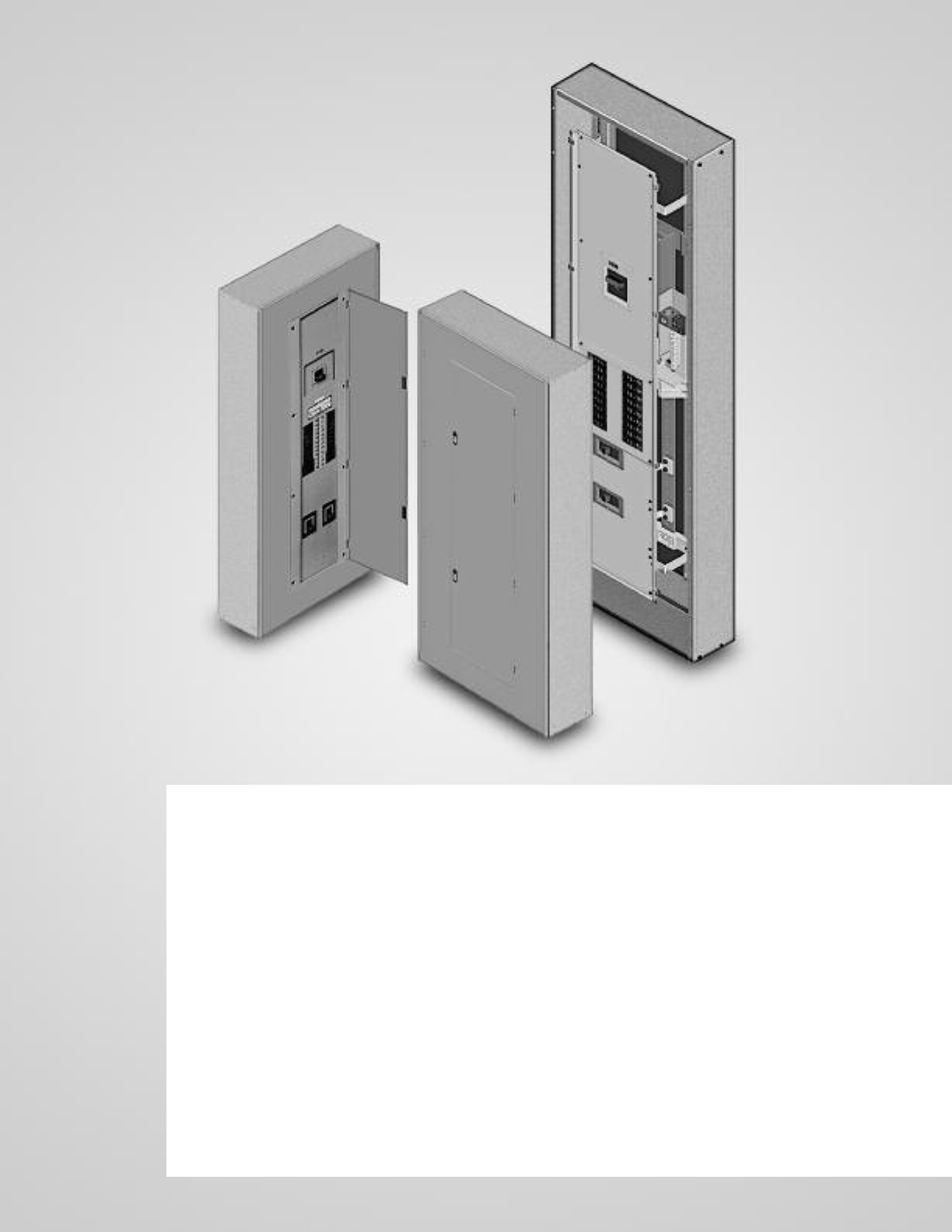
2
This new generation of products from Siemens offers the high
level of engineering and innovation you’ve come to expect from
the leader in power distribution technology. The “P Series” line of
panelboards offers a stepped approach to power distribution.
Additional strength has been added to an already rugged and
durable panelboard family. Engineered specifically to provide
maximum flexibility, the new designs simplify wiring and reduce
material requirements making them easier to install and less
costly than competitive products. At the heart of the product
line is the extensive research and technology found among
Siemens circuit protection devices – both fusible switches and
molded case circuit breakers.
The line is anchored by the innovative P1. Featuring the industry’s
most flexible designs, the P1 virtually eliminates common
errors, such as feed direction, and main lug versus main breaker.
Increasing distribution is simplified by the ability to add feed-thru
lugs. Because of its unique design, the P1 meets the majority of
lighting panel needs with only six standard sizes.
Subsequent steps in the P Series offer increased capacity and
more design options:
• The highly flexible P2 provides options to fit the most
demanding specifications.
• Sized more like a lighting panel, the P3 packs the power of a
distribution panel in a space-saving, highly flexible design.
• The P4 is a mid-sized distribution panel that allows both fusible
and circuit breaker branch and main devices.
• The powerful P5 anchors the high end of the series. With
larger fusible and circuit breaker branch and main devices, the
venerable P5 delivers maximum power and flexibility to larger
distribution systems.
Siemens also offers a number of specialty panels, like column
panels. Don’t see a panel to meet your requirements? Ask your
Siemens representative about our custom capabilities.
Features Overview
P Series lighting panel features include Fas-Latch trim, which is
popular among installers; the jacking screw system, that permits
adjustments even after wiring has been installed; our exclusive
split neutral, and more. Many panelboards have the capability of
mixing and matching breakers of different sizes and ratings – or
changing from main lug to main breaker, or adding subfeed
breakers without changing the box size. Other models accept
a wide range of fuse types, including Siemens exclusive
Vacu-Break® technology.
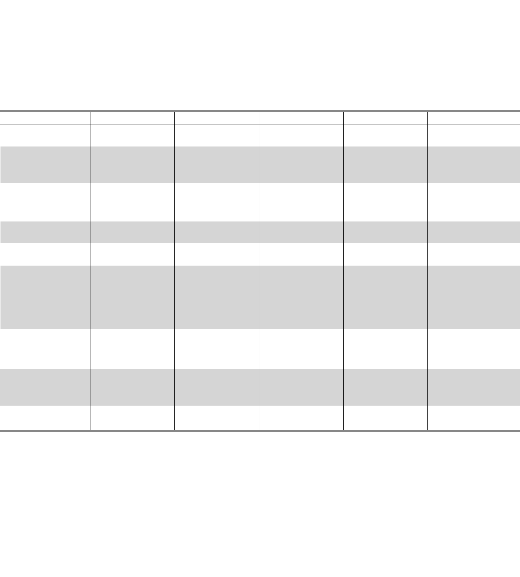
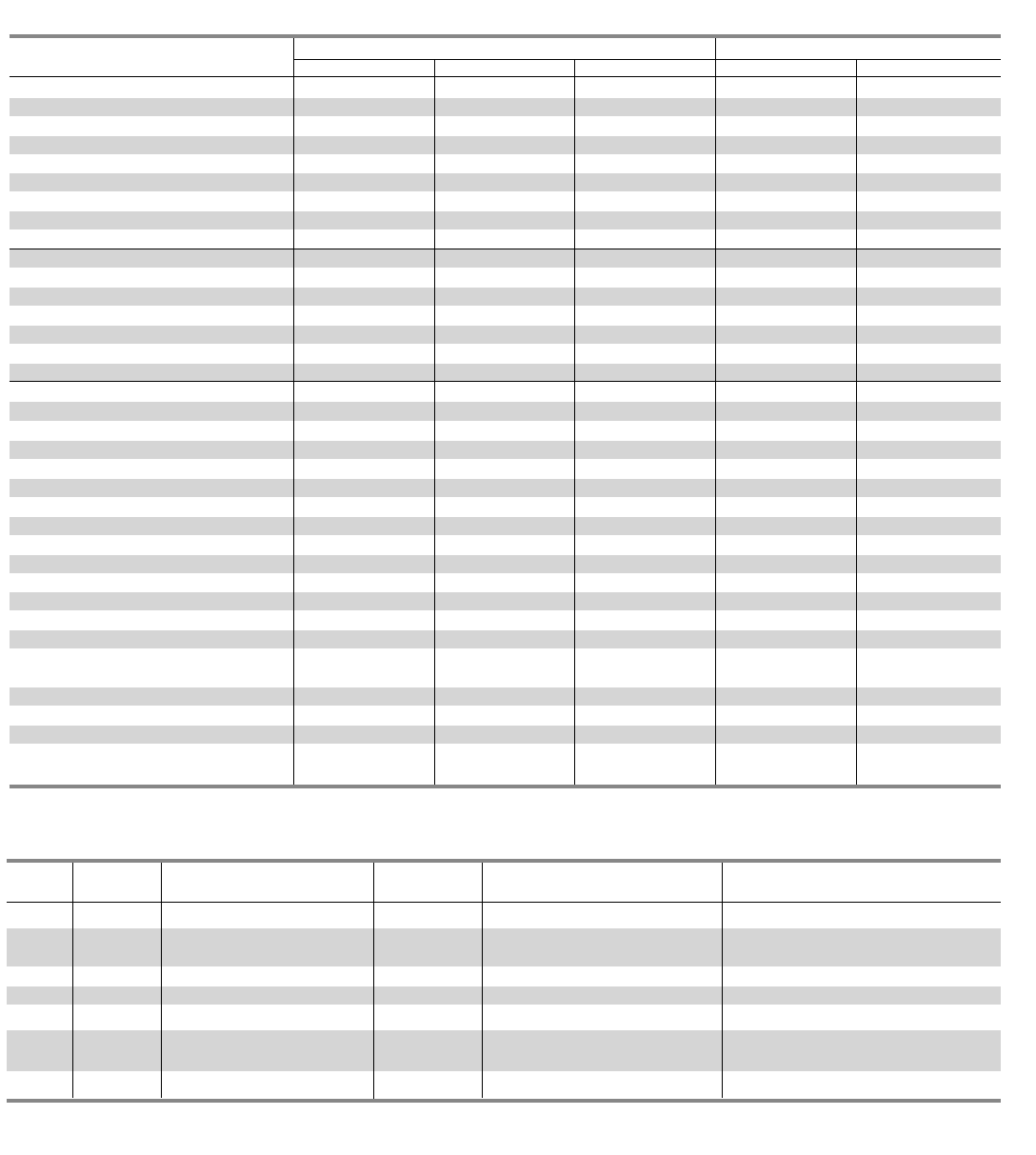
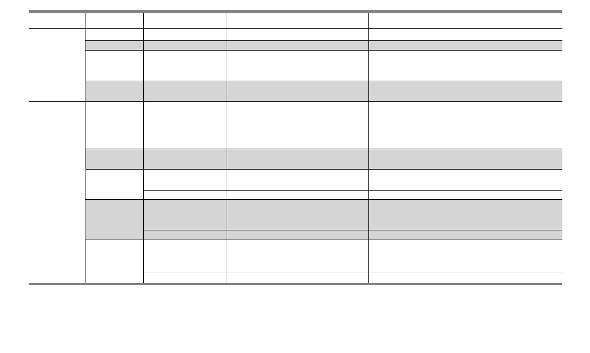
Table G1 – Key Panelboard Features
Introduction
P1 P2 P3 P4 P5
Lighting And Appliance Applications (Pre 2008 NEC) •••••
Power Panelboard Applications — • •••
Convertible From Top Feed To Bottom Feed Or Vice Versa •————
Change From Main Lug To Main Breaker Or •————
Add Subfeed Without Changing Enclosure Size
Space-Saving, Horizontally Mounted Main Breaker Up To 250 Amps Up To 250 Amps Up To 250 Amps ••
Short-Circuit Rating Label Giving Performance Level •••••
Standard Aluminum Ground Assembly •••••
Blank End-Walls Standard1•••••
Bolted Current-Carrying Parts •••••
Split Neutral •••••
Connection Accessible From Front •••••
Screw-Type Mechanical Lugs •••••
Time-Reducing Wing Nuts To Secure Interior Without Tools •••••
Main and Branch Devices Connected With •••••
Case-Hardened Hardware
Flush Lock, Concealed Door Hinges/Trim Screws •••
——
Symmetrical Interior Mounting Studs •••••
To Eliminate Upside-Down Mounting of Box
Interior Height Adjustment For Flush Applications •••••
Mix and Match Fusible Switch Circuit Breaker Capability ——— • •
Shallow Depth 5.75” 5.75” 7.75” 10.00” 12.75”
Accepts A Wide Range Of Fuse Types ——— ••
Accepts Vacu-Break Fusible Switch ——— ••
Accepts A Wide Range Of Circuit Breakers — ••••
Accepts ACCESSTM Communications Tie-In 2—••••
Optional Compression Lugs •••••
•Standard
1KO’s available on P1 and P2 – 5.75” Deep x 20” Wide boxes and P3 7.75”
deep X 24” wide boxes.
2Panelboards equipped with Siemens Sensitrip® circuit breakers or Power Meters
can be integrated into Siemens ACCESS™ electrical monitoring system.
3
General Specifications
Class CTL Panelboards (when applicable)
Class CTL panelboards incorporate physical features which, in
conjunction with the physical size, configuration, or other means
provided in Class CTL circuit breakers, are designed to prevent
the installation of more over current protective poles than the
number for which the device is designed and rated, per UL 67
and National Electrical Code (NEC) NFPA70.
Service Entrance Equipment
When a panelboard is used as service entrance equipment, it
must be located near the point of entrance of building supply
conductors. In a main lugs only panel, the number of breakers
or switches directly connected to the main bus must be limited
to six. In a panel having a main breaker or main switch, the
number of circuits are not limited except as may be provided
under other panelboard requirements, i.e., lighting and
appliance branch circuit panelboards. Also, panels must include
a connector for bonding and grounding neutral conductor.
Panelboard Code Data (where applicable)
42-Circuit Rule: NEC Paragraph 408.14 defines a lighting
and appliance branch circuit panelboard as one having more
than 10 percent of its over current devices rated 30 amperes
or less, for which neutral connectors are provided. NEC
paragraph 480.35 states that not more than 42 over current
devices (other than those provided in the mains) of a lighting
and appliance branch-circuit panelboard shall be installed in
any one cabinet. For the purpose of this publication, a two-pole
circuit breaker shall be considered two over current devices; a
three-pole circuit breaker shall be considered three over current
devices. (NEC 480.34 and .35 do not apply to panelboards
feeding and communication circuits. Panelboards for this
application must be so marked.)
Integrated Equipment Short Circuit Rating
The term “Integrated Equipment Short Circuit Rating” refers
to the application of series connected circuit breakers in a
combination that allows some breakers to have lower individual
interrupting ratings than the available fault current. This is
permitted as long as the series combination has been tested
and certified by UL.
Standards
NEC: 2008 (where accepted)
NEMA: PB1
UL: 67 and 50. Listed by Underwriter’s Laboratories, Inc.,
under “Panelboards” File #E2269, and #E4016. Meets
Federal Specification W-P-115c.
Wire Connectors
Standard wire connectors in Siemens panels are suitable for
copper or aluminum cables rated 60/75 degree. Copper main
lugs are a price-added option for most panel types and some
Circuit Breakers (check with Siemens sales for availability). It
should be noted that most copper lugs will only accept copper
cables. Some applications, 100% rated devices in particular,
require that the cable and connectors be rated 90 degree but
are sized to the 75 degree tables.
Standard ground connectors are also suitable for copper or
aluminum wire. Ground connector assemblies (EGK, IGK) have
(7) 1/0 max. and (15) #6 max. connections. The 1/0 holes are
capable of connecting up (3) #10 max. wires. Copper ground
assemblies (ECGK, ICGK) are rated for copper wire only and
have the same wiring capacity as the Al/Cu connectors.
Standard neutrals, like standard main lugs, are also rated for
copper or aluminum wire. The neutral cross bar material follows
the selection bus. Copper neutral lugs are rated for copper cable
only and available as a price added option.
Lug Data
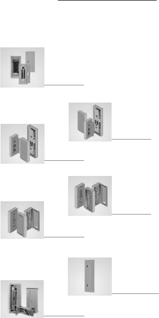
Space Required for Mounting of Double Panels
Use two or more panelboards with feed-thru or subfeed lugs
when:
1. Lighting and appliance panelboards are required with more
than 42 circuits in areas where the zone code has not been
accepted.
2. More circuit mounting space is required than is provided in
the largest box size.
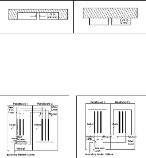
Feed-Thru Lugs Subfeed Lugs or Double Lugs
Feed-thru lugs are mounted at the opposite end of the main bus
from the main lugs or main breaker and are used to connect two
or more panelboards to the incoming feeder. The feeder cables
are brought into Panelboard 1 and connected to the main lugs or
main breaker. Cables interconnecting the two panelboards are
connected to the feed-thru lugs in Panelboard1 and are carried
over the main lugs in Panelboard 2. This arrangement could be
reversed with the main lugs located at the top and the feed-thru
lugs at the bottom of the panel. Subfeed lugs are mounted
directly beside the main incoming lugs and are used to connect
two or more panelboards to the incoming feeder. The feeder
cables are brought into Panelboard 1 and connected to the main
lugs. Another set of cables that are the same size are connected
to the subfeed lugs of Panelboard 1 and are carried over the main
lugs of Panelboard 2.
Shown mounted in wall Shown mounted on surface of wall
Wall Wall
Fig. G-1 Fig. G-2
4
General Specifications
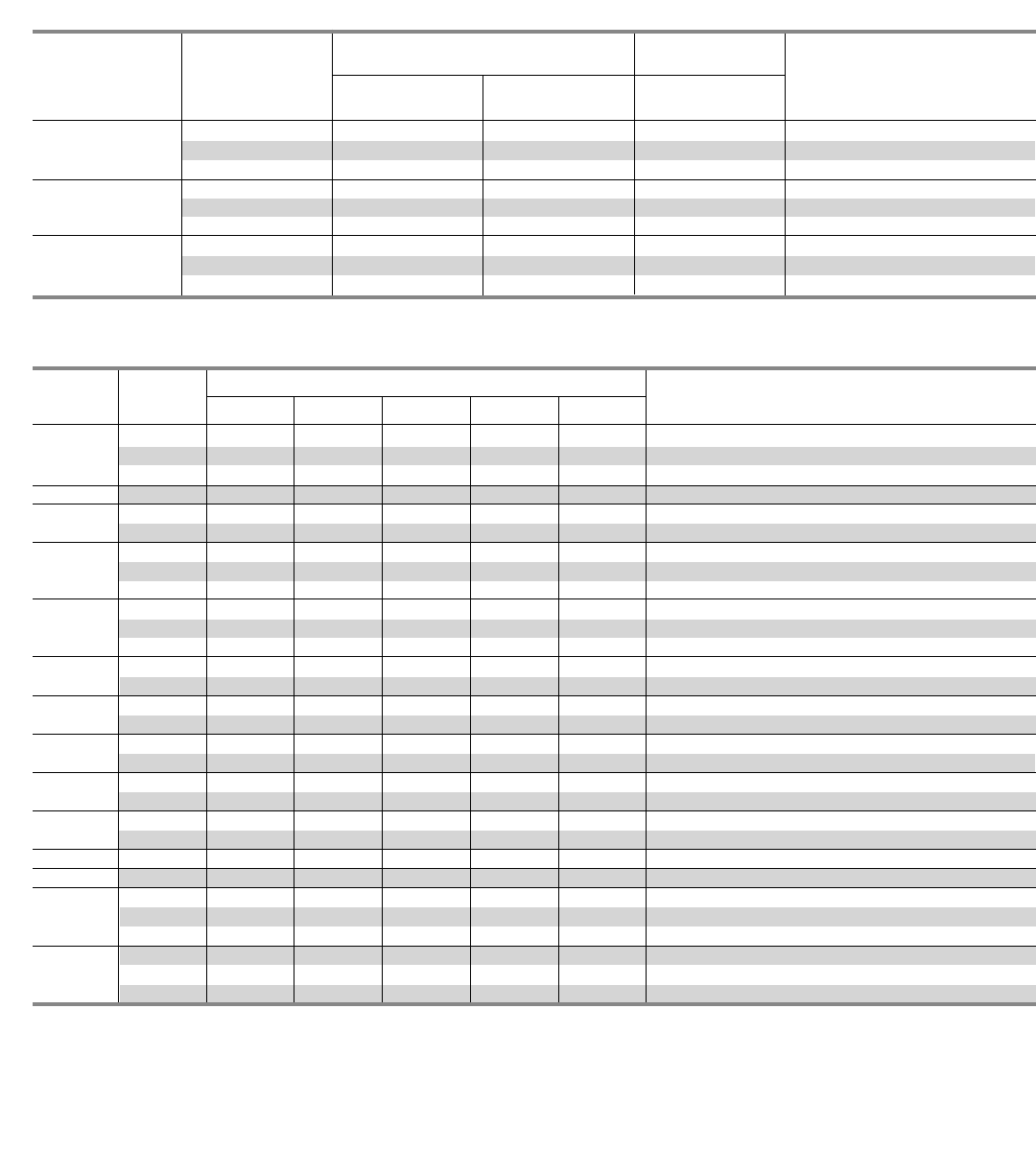
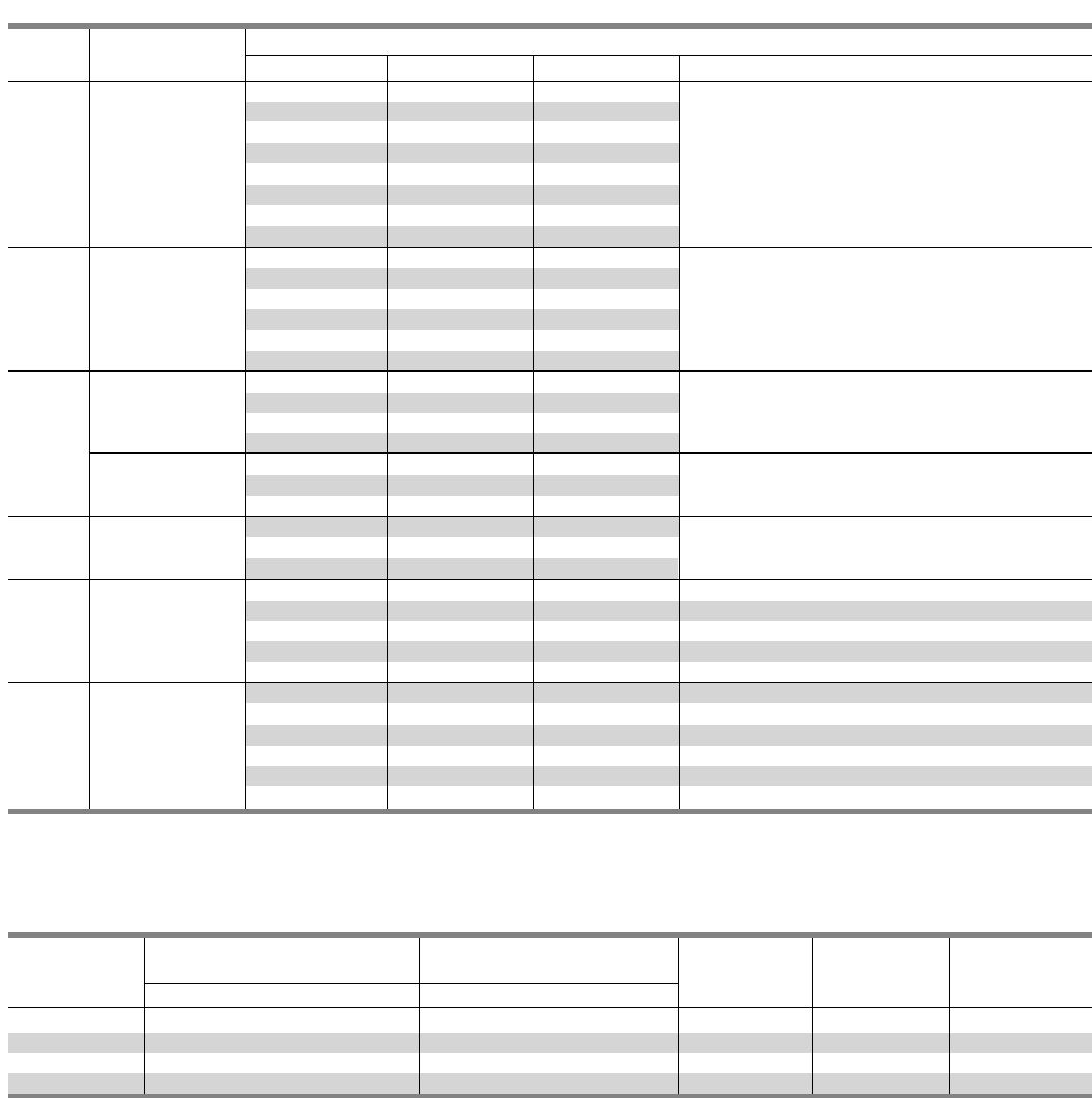
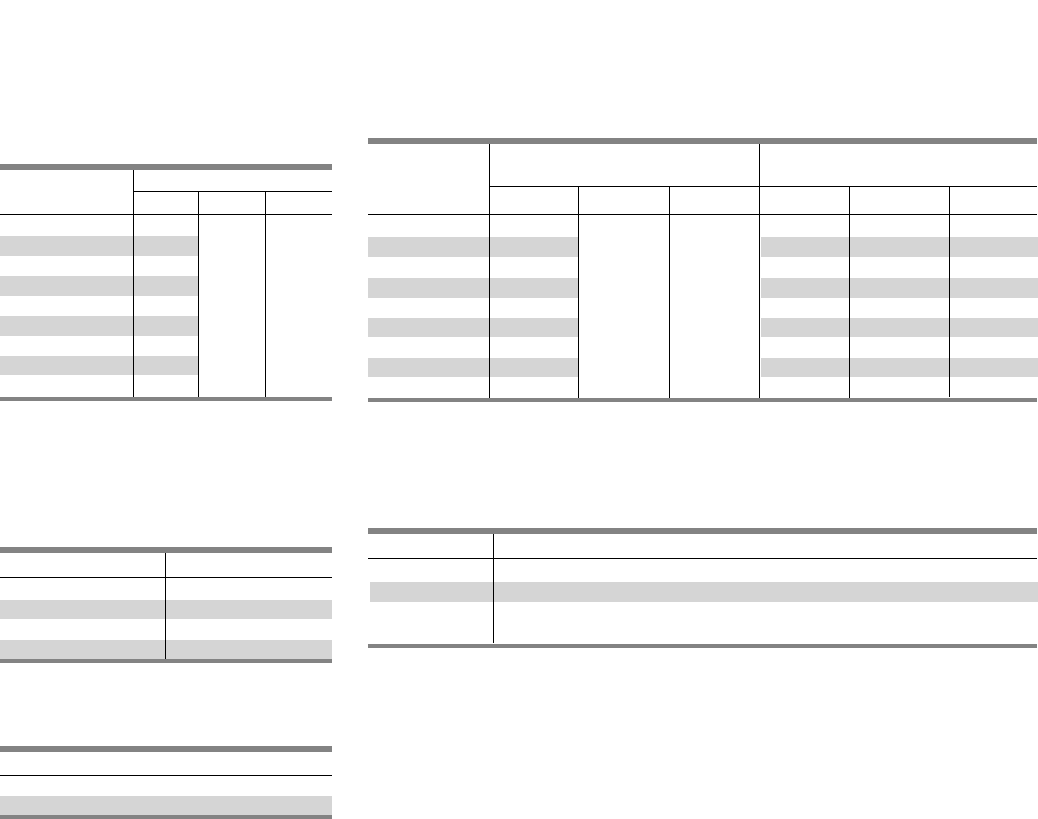
Table G2 – Panelboard Ratings
1Functional pricing is based on circuits shown. However, the panel can be figured with less circuits.
2P1 can have 1 subfeed breaker. P2 and P3 can have up to (2) FD subfeed breakers.
3JD and FD breakers are mounted vertical. Limitations apply.
4Trim ring provided for flush applications.
5A maximum of (4) QJ breakers may be mounted in a P2 Panel and are single mounted.
6A maximum of (6) QJ breakers may be mounted in a P3 panel and are twin mounted.
Bussing Sequence
Interiors are designed to accommodate top or bottom feed.
Regardless of which is specified, the uppermost pole is always
on “A” phase; the second pole down is always on “B” phase,
and the third pole down is always on ”C” phase (assuming
3Ø panel).
As standard, branch breakers shall be mounted at the top of
the panel with “spaces” at the bottom, regardless of the direction
panel is fed.
All breakers have bolted connections except plug-in type. The
panel design provides bracing up to 200,000A IR UL short
circuit rating. Case-hardened, high performance, thread rolling
screws are used on branch bus.
Description P1 P2 P3 P4 P5
Max. Voltage 480Y/277V AC Max. 600V AC Max. 600V AC Max. 600V AC Max. 600V AC Max.
250V DC Max 500V DC Max. 500V DC Max. 500V DC Max. 500V DC Max.
System 1-Phase, 2-wire 1-Phase, 2-wire 1-Phase, 2-wire 1-Phase, 3-wire 1-Phase, 3-wire
1-Phase, 3-wire 1-Phase, 3-wire 1-Phase, 3-wire 3-Phase, 4-wire 3-Phase, 4-wire
3-Phase, 3-wire 3-Phase, 3-wire 3-Phase, 4-wire 3-Phase, 3-wire 3-Phase, 3-wire
3-Phase, 4-wire 3-Phase, 4-wire 3-Phase, 3-wire
Mains
Main Lugs 125A-400A 125A-600A 250A-800A 400A-1200A 800A-1200A
Main Breaker 100A-400A 100A-600A 225A-600A 400A-800A 800A-1200A
Main Switch ————200A-1200A
Circuits 18, 30, 42 18, 30, 42, 54, 66 ———
78, 90 1
Branch Ratings 15-125A 215-400A 15-400A 15-800A C/B 15-1200A C/B
30-200A Fusible 30-1200 Fusible
Branch BL, BLH, HBL, BQD, BL, BLH, HBL, BQD, BL, BLH, HBL, BQD, All 15-600A All 15-1200A C/B
Disconnect BQD6, BLE, BLEH, BQD6, QJ25, HQJ25, BQD6, QJ26, HQJ26, Breakers and VL MG 30A-600A VB Switches
Devices BLF, BLHF, BAF, BAFH, QJ2H5, HQJ2H5, ED2, QJ2H6, HQJ2H6, ED2, at 800A, HHED6, BLE 400-1200A HCP
BGL, NGB ED4, HED4, ED6, ED4, HED4, ED6, BLEH, BLF,
HHED6, BLE, BLEH, BLF, BLHF, BAF, BAFH, BGL, Fusible Switches
BLHF, BAF, BAFH, NGB, NEB, HEB 30-200A
BGL, NGB
Subfeed ED2, ED4, ED6, HED4, JD6, JXD6, HJD6, JD6, JXD6, HJD6, ——
Circuit HHED6, QJ2, QJH2, HJXD6, FD6, HFD6, FD6, HFD6, FXD6,
Breakers QJ2-H, FXD6, FD6, FXD6, HFXD6 2 3 HFXD6 2 3
HFD6, HFXD6 3
Enclosure 32, 38, 44 @250 A 26, 32, 38, 44, 50, 56, 56, 62, 68, 74, 80 60, 75, 90 60, 75, 90
Heights (813, 965, 1118) 62, 68, 74 (1422-2032) (1524, 1905, 2286) (1524, 1905, 2286)
Inches – (mm) 56, 62, 68 @400 A (660-1880)
(1422, 1575, 1727)
Standard Fas-Latch – 1 Piece Fas-Latch – 1 Piece Fas-Latch – 1 Piece Four Piece 4Four Piece 4
Trims Surface or Flush Surface or Flush Surface or Flush Surface or Flush Surface or Flush
General Specifications
5
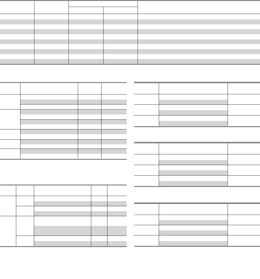
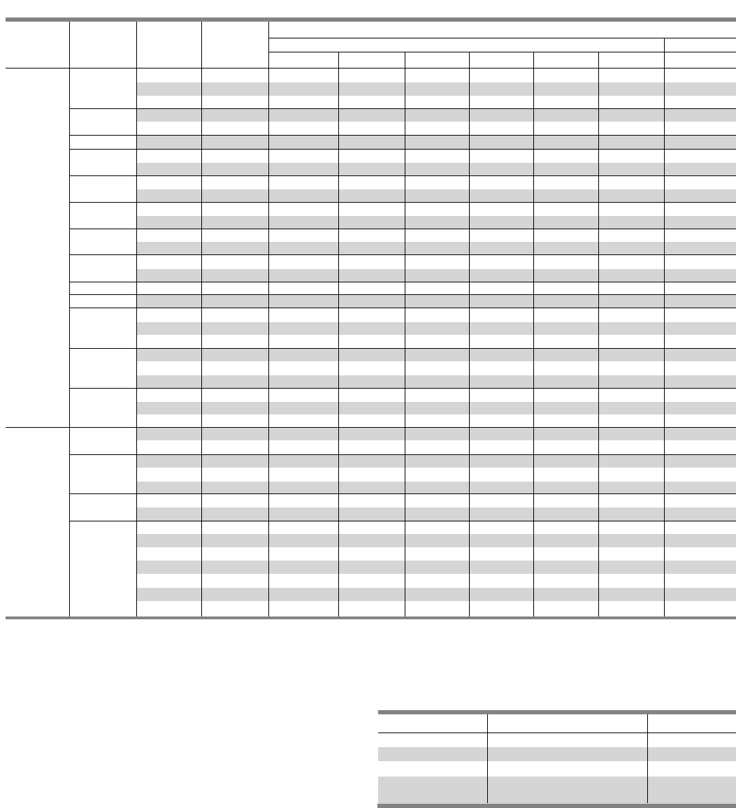
Table G3 – Typical Panelboard Modifications
All aluminum bus is tin-plated. •Available as an option.
Table G4 – UL Fuse Classes
1Per UL 67.
2Fuses do not prohibit the use of Class H type fuse in switch.
Description Lighting and Distribution Panelboards Distribution Panelboards
P1 P2 P3 P4 P5
Box
Type 3R/12 •••••
Type 4, 4X •••••
Drip Proof •••••
Drip Proof Hood Only •••••
Sealed Box •••••
Gasketed Trim •••••
Wider Box •••••
Deeper Box —• • • •
Front
Hinged Front •••••
Door-in-Door Front •••••
Common Front •••——
Split Door •••——
Special Locks •••••
Nameplate •••••
Interior
Aluminum Equipment Ground Bar Standard Standard Standard Standard Standard
Copper Equipment Ground Bar •••••
Insulated Equipment Ground •••••
Subfeed Lugs —• • • •
Feed-Thru Lugs •••••
Split Bus —• • • •
Compression Lugs •••••
Copper Lugs •••••
200% Neutral •••400 - 600A 400 - 600A
Temperature Rated - Aluminum1 Standard Standard Standard Standard Standard
Temp. Rise Over Ambient - Copper 1•••••
750 Ampere / in. - Aluminum —• • • •
1000 Ampere / in. - Copper —• • • •
Copper Plating Tin Tin Std./ Tin Std./ Silver Silver
Silver Optional Silver Optional
Remote Control Switches External Mounted ••••
Time Clocks External Mounted ••••
Circuit Breaker Shunt Trips •••••
R, J and T Fuse Clips ———• •
Interrupting
Class Amperes Volts Ratings (kA) l2t, li Circuits
H 1-600 250 and 600V or less AC 10 — Less than 10,000A Available
K5 21-600 250 and 600V or less AC 100 l•t – RK5 up to 100A, Feeder circuits
li – RK5 up to 100A
J 1-600 600V or less 200 l•t – Low, li – Low Feeder circuits (motor load small %)
RK1 1/10 - 600 600V or less and 250V or less 200 l•t – Slightly >J, li – Slightly > J Feeder circuits (motor load small %)
RK5 1/10 - 600 600V or less and 250V or less 200 l•t – > RK-1, li – > RK-1 Motor starting currents a factor
T1 - 800, 300 and 600V or less AC To 200 l•t – Low, li– Low Non-Motor loads
1 - 1200
L 601 - 1200 600V or less 200 l•t – Low, li – Low Mains, feeder circuits
6
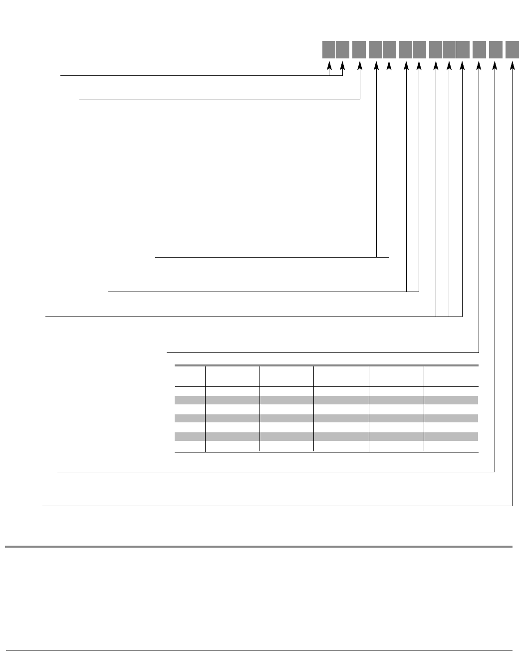
Catalog Numbering System
Main Breaker Code
(Breaker Type) Code
(BAF) BA, (BAFH) BF, (BQD) BQ, (BQD6) B6, (BL) BL, (BLEH) BE, (BLH) BH, (BLR) BR, (HBL) HB, (BGL-SWI) B1, (BLE-GFCI) BG, (BLF-GFCI) BC, (CED6) CE,(ED2)
ED, (ED4) E4, (ED6) E6, (HED4) H4, (HHED6) HA, (BLHF-GFCI) B4, (BL-HID) B2, (NGB) NB, (HQP) HQ, (QP) QP, (QPH) PQ, (CEG) C4, (QJ2) QJ, (QJ2H) Q2,
(QJH2) QH, HQJ2H (Q3), (CFD6) CF, (FD6) FD, (FXD6) FX, (HFD6) HF, (HFXD6) H2, (HHFD6) H1, (HHFXD6) H3, (CJD6) CJ, (HHJD6) H4, (HHJXD6) H9,
(HJD6) H6, (HJXD6) H5, (HJXD6H) H7, (JD6) J6, (JXD2) JD, (JXD2H) J2, (JXD6) JX, (JXD6H) JH, (NJX) J1, (HJX) J7, (LJX) J3, (NJY) J4, (SJD6H) SH, (SJD6)
SJ, (SHJD6) SX, (SHJD6H) SY, (SCJD6) SC, (HJY) J5, (LJY) J8, (CLD6) CL (HHLD6) HH, (HHLXD6) XH, (HLD6) HL, (HLXD6) HO, (HLXD6H) HP, (LD6) L6,
(LXD6) LX, (LXD6H) LH, (NLX) L7, (HLX) L2, (LLX) L3, (SLD6) SL, (SHLD6) S2, (SCLD6) S1, (HLMD6) HJ, (HLMXD6) HK, (LMD6) L1, (LMXD6) LM, (CMD
CM, (CMD6H) CH, (HMD6) HM, (HMXD6) HR, (HMXD6H) HS, (MD6) MD, (MXD6) MX, (MXD6H) MH, (NMX) M1, (HMX) M2, (LMX) M3, SCMD6 (SO),
SCMD6H (SQ), SMD6 (SM), SMD6H (AX), SHMD6 (S5), SHMD6H (S6)(CND6) CN, (CND6H) C6, (HND6) HN, (HNXD6) HT, (HNXD6H) HX, (ND6) ND,
(NXD6) NX, (NXD6H) NT, (NNX) N1, (HNX) N2, (LNX) N3, (NNY) N4, (HNY) N5, (LNY) N6, SCND6 (SR), SCND6H (ST), SND6 (SN), SHND6 (AD), SND6H (AY),
SHND6H (AE)
P1 4 2
CAT
2 5 0
F X S
Type of Panel
P1, P2, P3, P4, P5
Amperage
100–400 Amp = P1 250–800 = P3
100–600 = P2 400–1200 = P4, P5
Bus Material Bus Plating Letter
Temp rated Al. Tin-Plated A
750A/sq. in. Al. Tin-Plated B
Temp rated Cu. Tin-Plated C
Temp rated Cu. Silver-Plated E
Temp rated Cu. Tin-Plated F
1000A/sq. in. Cu. Tin-Plated G
1000A/sq. in. Cu. Silver-Plated H
Feed Location
T = Top
B = Bottom
Mounting
S = Surface
F = Flush. Flush trims extend 1 1/2" beyond the base box dimensions on P1, P2 and P3 and 2" on P4 and P5 panels.
Circuits or Enclosure Height
P1 – 18, 30, 42 P3 – 56, 62, 68, 74, 80
P2 – 18, 30, 42, 54 1P4, P5 – 60, 75, 90
Main Lug (ML), Main Breaker
(See Main Breaker Table coding below), Main Switch (MS)
Voltage and System
C= 208Y/120 3Ø 4 W Wye AC - All
E= 480Y/277 3Ø 4 W Wye AC - All
D= 240 3Ø 3 W Delta AC - All
F= 480 3Ø 3 W Delta AC - P2, P3, P4, P5
G= 600 3Ø 3 W Delta AC - P2, P3, P4, P5
I= 347AC - P2, P3, P4, P5
B= 240/120 3Ø 4 W Delta BØ High Leg AC - All
Q= 240/120 3Ø 4 W Delta CØ High Leg AC - P2, P3, P4, P5
X= 120/240 2Ø 5 W Single Neutral AC - P2, P3, P4, P5
A= 120/240 1Ø 3 W Grounded Neutral AC (2) - All
H= 120 1Ø 2 W Grounded Neutral AC (2) - All
J= 240 1Ø 2 W No Neutral AC (3) - All
Y= 125 1Ø 2 W Grounded Neutral AC (2) - P2, P3, P4, P5
Z= 500 2W DC - P2, P3, P4, P5
K= 220/127 3Ø 4 W Wye AC - All
M=380/220 3Ø 4 W Wye AC - All
Bus
Code P12P2 P3 P4 P5
A • • • • •
B n/a • • • •
C ••• n/ a n/ a
F n/a • • • •
E n/a • • • •
G n/a • • optional optional
H n/a optional optional • •
• indicates default for this bus type.
1Panel must not be a lighting and appliance panel. See NEC article 408.34.
2Standard bussing in P1 panels is tin-plated for aluminum and copper.
Standard bus is temperature rated to the maximum amperage.
R= 415/240 3Ø 4 W Wye AC - All
S= 440/250 3Ø 4 W Wye AC - All
L= 600/347 3Ø 4 W Wye AC - All
T= 230 3Ø 3 W Delta AC - All
W=380 3Ø 3 W Delta AC - P2, P3, P4, P5
1= 24V DC 1 Pole Branches Only (3) - All
2= 24V DC 2 Pole Branches Only (3) - All
3= 48V DC 1 Pole Branches Only (3) - All
4= 48V DC 2 Pole Branches Only (3) - All
5= 125V DC 1 Pole Branches Only (3) - All
N= 125V DC 2 Pole Branches Only - All
O= 125/250V DC 2 Pole Branches Only - All
P= 125/250V DC 2 & 3 Pole Branches - All
U= 120V AC 3Ø3w - All
V= 24V 3Ø3w Grounded B Phase - All
SECTION 1
Description Page
General Information 1-2
Selection and Application 1-2
Application 1-3 – 1-6
Main Breaker Panel Size Selector 1-3
Main Breaker Selection 1-3
Main Lugs Size Selector 1-4
Branch Circuit Breakers 1-4
Subfeed Breakers 1-5
Breaker Mounting Kits 1-5
Lug Kits 1-5
Main Breaker Gutter Dimensions 1-6
Main Lug End Gutter Dimensions 1-6
Side Gutter Wiring Space 1-6
Branch Breaker Side Gutters 1-6
Typical Catalog Numbers 1-7
Main Lugs Only 1-7
Main Circuit Breaker 1-7
Standard Enclosures 1-7
Standard Modifications 1-8
Connector Modifications 1-9
Compression Lugs 1-9
Enclosure Modifications 1-9
Remote Switch Modifications 1-9
Dimensions 1-10
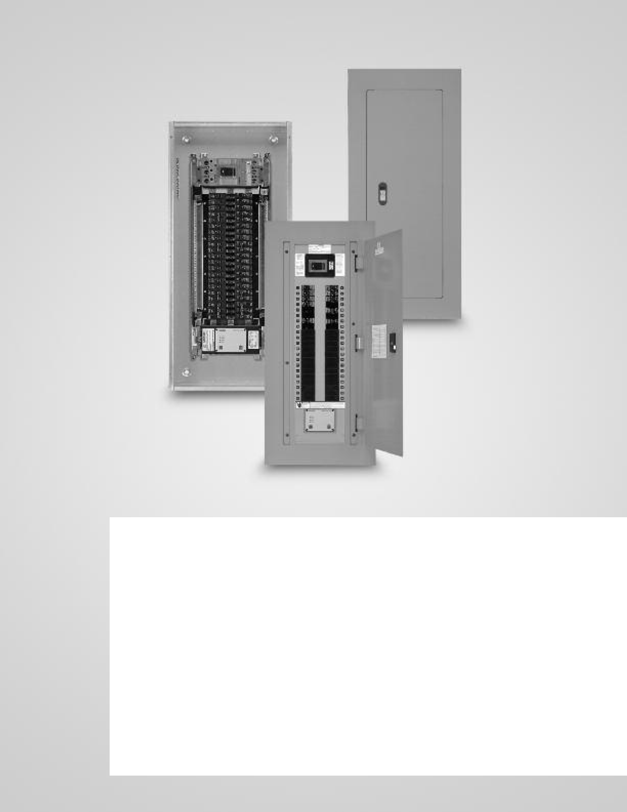
P1 Panelboards

1-2
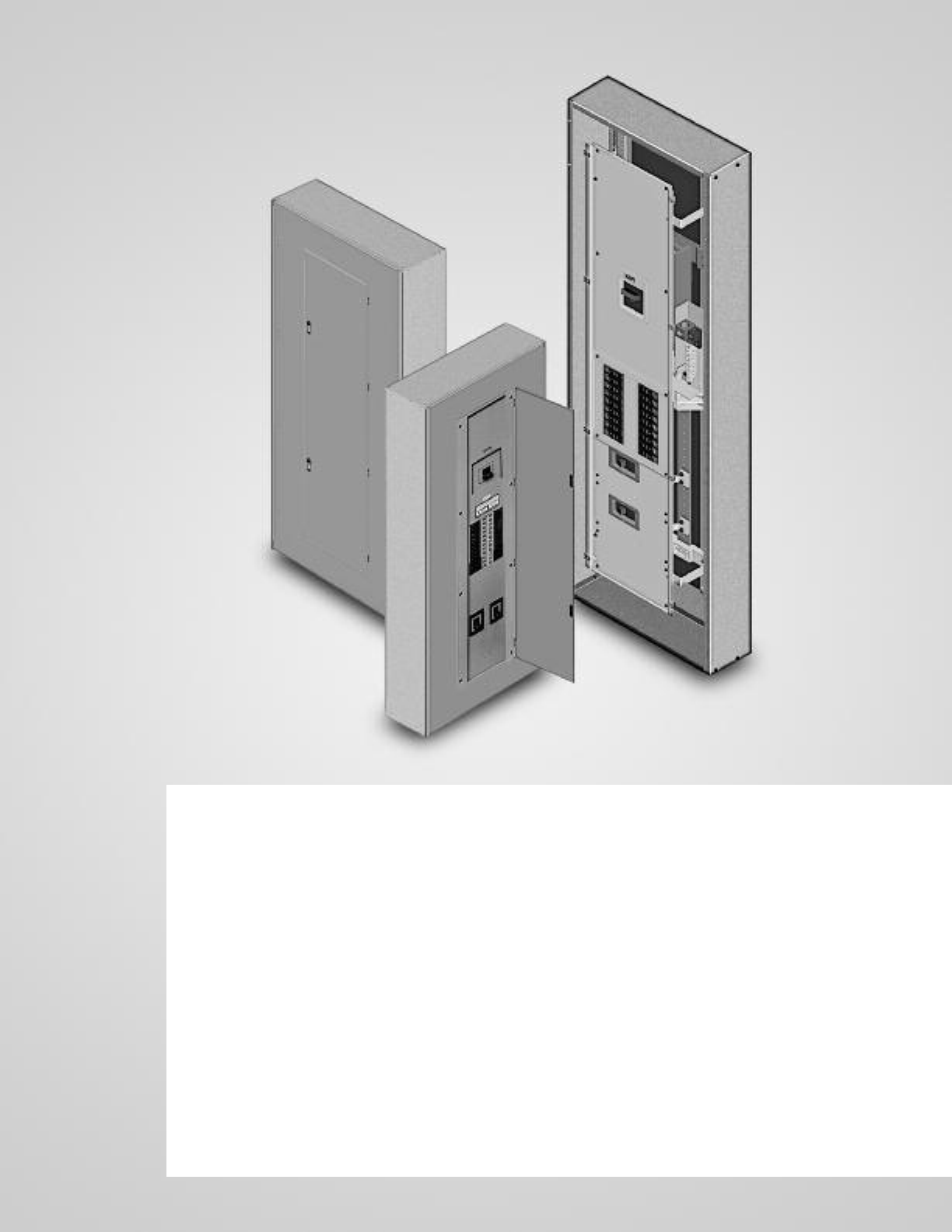
Type P1 Panelboards
P1 panelboards are pre-engineered to accept the most common
modifications without increasing box height. The enclosure size
is determined by the number of circuits as shown in the Main Lug
Table P1-5 or the Main Circuit Breaker Table P1-3. All P1 main lug
or main breaker panelboards have space built-in to accept either
feed-thru lugs equal to the panel rating, one subfeed circuit
breaker up to 250 amperes or a surge suppressor (TVSS) without
increasing box height.
Note the following features, all found in the innovative P1
lighting panelboards:
• Symmetrical Interiors - No top or bottom! To change from
top to bottom (or vice-versa), simply invert the interior. The
deadfront labeling is always right-side up.
• First in the Industry Ratings of 125 through 400A main lug and
main breaker. Field convertible from main lug to main breaker
and vice versa – with no increase in enclosure height.
• Field adaptability of feed-thru lugs or subfeed circuit breaker
without increasing enclosure size.
• Neutral system is field upgradeable to 200% capacity –
another industry first.
• Three circuit sizes means only three box heights, regardless
of main configuration through 250 amp and an additional
three circuit version and boxes available at 400 amps.
• Suitable for use as service entrance given compliance
with NEC.
• Bonding provisions are shipped with each panel.
• 240V and 480Y / 277V for versions utilize identical boxes
and fronts.
Enclosure – Standard Type 1 enclosure is 20" wide x 5.75"
deep. Box Height is determined only by the number of
circuits, not by main lug or main circuit breaker. See chart
P1-5 for box height.
Voltage – 480Y/277 Vac max.
250 Vdc max.
Amperage – 400 amp max.
Short Circuit Rating – 200 KAIC max. symmetrical or equal
to the lowest rated device installed unless a series rating is
indicated. Panels with subfeed or feed-thru lugs without a
main device, circuit breaker or fusible unit, are limited to a
three-cycle rating. The three-cycle rating for the P1 panel is
limited to 22 KAIC. Note that the main device may be mounted
remote from the panel.
Bussing – The P1 panel meets the majority of the markets
bussing requirements. The standard bussing is temperature
rated aluminum. The rating is per the requirements of UL 67–
the standard for panelboards. All aluminum bussing is tin-plated.
Optional bussing for the P1 panel is temperature rated copper.
The copper bus option for this panel is tin-plated.
Weight – Approximate
Total panelboard weight when filled with a normal quantity of
breakers and accessories is about 3 lbs. (1 kg) per inch (54g per
mm) of box height
Selection and Application
Table P1-2 – Trim Material Gauge
Table P1-1 – Box Material Gauge
3 Easy Steps for Selecting a Siemens P1 Panelboard
Determine voltage, system, amperage
and interrupting rating of branch
devices, and modifications if any.
Example for standard lighting
panelboard:
Amperage 250A
Voltage 208Y/120V
System 3Ø4W
Main Main Lug
Branches 10K AIR, 42-20/1
Modifications None
Feed Location Top
Mounting Surface
Step 1 Step 2
Create a catalog number by following
the Panelboard Catalog Numbering
System on page 6. The BL branch breakers
were selected from the branch breaker
selection table on page 1-4.
1-P1C42ML250ATS
42-20/1 BL
Select enclosure size by the number
of circuits as shown in the panelboard
dimensional chart on page 1-6.
1-P1C42ML250ATS
42-20 BL
Box size – 44” high
Step 3
A unique feature of P1 panels is that they
can accommodate either feed-thru lugs
or one subfeed circuit breaker (up to
250A) without any addition to box
height. For our example changing the
branch circuits to 39-20/1 and 1-125/3,
we have the following:
1-P1C42ML250ATS
39-20/1 BL
1-125/3 QJ2
Box size – 44” high
The QJ2 subfeed was selected from the
table of subfeed breakers on page 1-5.
The box height remains the same.
20” 32, 38, 44 #14
56, 62, 68
Width Height (inches) Gauge Steel
20” 32, 38, 44 #16
56, 62, 68
1-3
Application
Type P1 Panelboards
Note: Main breakers use breaker connectors. For sizes, see breaker connector chart. 400 amp main breaker panel
has wire bending space for 600 kcmil cables as standard. Use 750 Kcmil lug if 600 Kcmil cable is to be used.
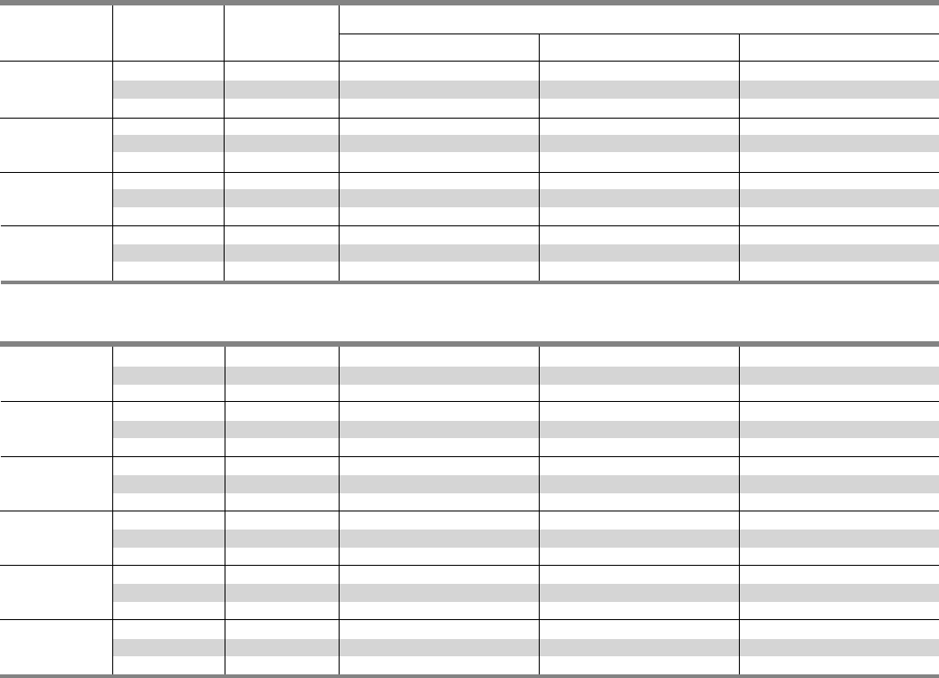
Table P1-4 – Main Breaker Selection
Max.
Ampere Breaker IR (kA) at
Rating Type 240V AC 480/277V AC Additional Trip Values
BL (STD) 10 — 15, 20, 25, 30, 35, 40, 45, 50, 60, 70, 80, 90, 100
100 BLH 22 — 15, 20, 25, 30, 35, 40, 45, 50, 60, 70, 80, 90, 100
HBL 65 — 15, 20, 25, 30, 35, 40, 45, 50, 60, 70, 80, 90, 100
BQD 65 14 15, 20, 25, 30, 35, 40, 45, 50, 60, 70, 80, 90, 100
125 NGB (STD) 100 25 50, 60, 70, 80, 90, 100, 110, 125
ED4 (STD) 65 25 50, 60, 70, 80, 90, 100, 110, 125
HED4 100 42 50, 60, 70, 80, 90, 100, 110, 125
QJ2 (STD) 10 — 60, 70, 80, 90, 100, 110, 125, 150, 175, 200, 225
225 QJH2 22 — 60, 70, 80, 90, 100, 110, 125, 150, 175, 200, 225
QJ2-H 42 — 60, 70, 80, 90, 100, 110, 125, 150, 175, 200, 225
HQJ2H 100 — 60, 70, 80, 90, 100, 110, 125, 150, 175, 200, 225
FXD6 (STD) 65 35 70, 80, 90, 100, 110, 125, 150, 175, 200, 225, 250
250 FD6 65 35 70, 80, 90, 100, 110, 125, 150, 175, 200, 225, 250
HFD6 100 65 70, 80, 90, 100, 150, 175, 200, 225, 250
HFXD6 100 65 70, 80, 90, 100, 110, 125, 150, 175, 200, 225, 250
JXD6 (STD) 65 35 200, 225, 250, 300, 350, 400
400 JD6 65 35 200, 225, 250, 300, 350, 400
HJD6 100 65 200, 225, 250, 300, 350, 400
HJXD6 100 65 200, 225, 250, 300, 350, 400
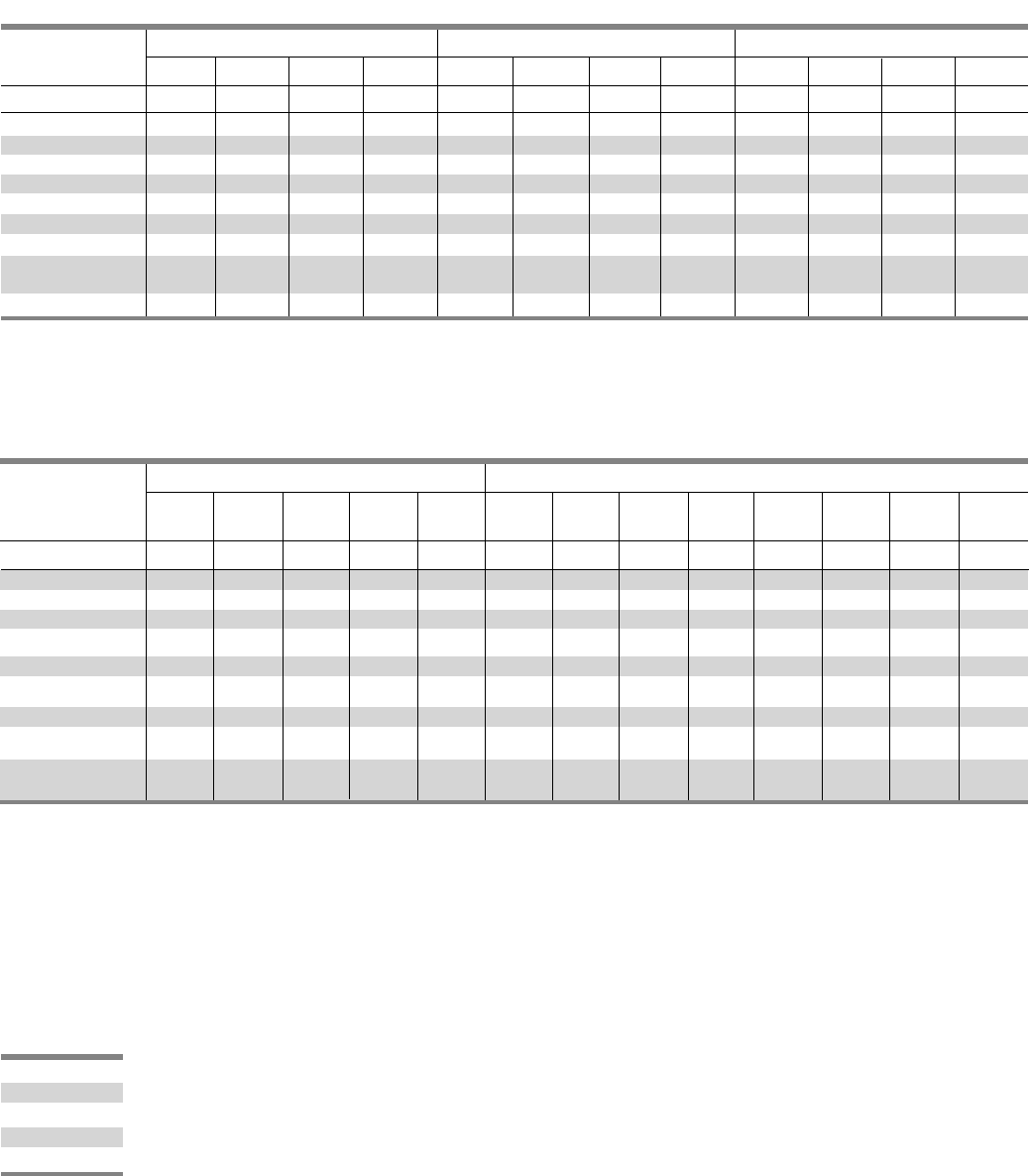
Table P1-3 – Main Breaker Panel Size Selector
Dimensions in Inches (mm)
Maximumum Main Max.
Ampere Breaker No. of Unit Space Box Height Weight In
Rating Types Poles A B lbs. (kg)
BL, BLH 9 (229) 32 (813) 105 (48)
100 HBL 15 (381) 38 (965) 120 (55)
BQD 21 (533) 44 (1118) 135 (61)
9 (229) 32 (813) 110 (50)
NGB 15 (381) 38 (965) 125 (57)
125 21 (533) 44 (1118) 140 (64)
ED2, ED4, 18 9 (229) 32 (813) 110 (50)
ED6, HED4, 30 15 (381) 38 (965) 125 (57)
HED6 42 21 (533) 44 (1118) 140 (64)
QJ2 9 (229) 32 (813) 110 (50)
225 QJH2 15 (381) 38 (365) 125 (57)
QJ2-H 21 (533) 44 (1118) 140 (64)
FXD6 9 (229) 32 (813) 115 (52)
250 FD6 15 (381) 38 (965) 130 (59)
HFD6, HFXD6 21 (533) 44 (1118) 145 (66)
9 (229) 32 (813) 115 (52)
<250 MLO 15 (381) 38 (365) 125 (57)
21 (533) 44 (1118) 135 (61)
JD6, JXD6 9 (229) 56 (1422) 172 (78)
HJD6 18 15 (381) 62 (1575) 190 (86)
400 HJXD6 30 21 (533) 68 (1727) 208 (95)
42 9 (229) 56 (1422) 115 (52)
MLO 15 (381) 62 (1575) 130 (59)
21 (533) 68 (1722) 145 (66)
SECTION 1
1-4
Application
Type P1 Panelboards
Table P1-6 – Branch Circuit Breakers
1Two-pole breaker is one phase and neutral. Three-pole is two phases and neutral.
2P1 panel with NGB branch devices will not accept BL or BQD frames in the same panel as branch devices.
NOTE: BL, HBL and BQD breakers are mounted in common mountings in 3” or (6) pole increments.
Max. Interrupting Rating (kA)
Breaker Number
Type of Poles 120V 120/240V 240V 277V 480/277V Available Trip Values
1 10 ————15, 20, 25, 30, 35, 40, 45, 50, 55, 60, 70
BL 2—10 ———15, 20, 25, 30, 35, 40, 50, 60, 70, 80, 90, 100
3——10 ——15, 20, 25, 30, 35, 40, 50, 60, 70, 80, 90, 100
BLR 2——10 ——15, 20, 30, 40, 50, 60, 70, 90, 100
BL, HID 1 10 ————15, 20, 30
2—10 ———15, 20, 30
1—22 ———15, 20, 30, 40, 50, 55, 60, 70
BLH 2—22 ———15, 20, 30, 40, 50, 60, 70, 90, 100
3——22 ——15, 20, 30, 40, 50, 60, 70, 80, 90, 100
1—65 ———15, 20, 30, 40, 50
HBL 2—65 ———15, 20, 30, 40, 50, 60, 70
3——65 ——15, 20, 30, 40, 50, 60, 70, 80, 90, 100
BLF 1 10 ————15, 20, 30
2—10 ———15, 20, 30, 40, 50, 60
BLHF 1 22 ————15, 20, 30
2—22 ———15, 20, 30, 40, 50, 60
BGL12 10 ————15, 20, 30
3—10 ———15, 20, 30
BLE 1 10 ————15, 20, 30
2—10 ———15, 20, 30, 40, 50, 60
BLEH 1 22 ————20, 30
2—22 ———15, 20, 30, 40, 50, 60
BAF 1 10 ————15, 20
BAFH 1 22 ————15, 20
1—65 — 14 —
BQD 2—65 ——14 15, 20, 25, 30, 35, 40, 50, 60, 70, 80, 90, 100
3——65 — 14
1 100 ——25 —
NGB 22—100 100 — 25 15, 20, 25, 30, 35, 40, 50, 60 70, 80, 90, 100, 125
3—100 100 — 25
Dimensions
in Inches (mm)
Maximum Maximum Connectors
Ampere Number Unit Space Height Weight In Suitable for
Rating of Poles A B lbs. (kg) Cu or Al
18 9 (229) 32 (813) 100 (45)
125 30 15 (381) 38 (965) 115 (52) (1) #6 AWG - 350 kcmil
42 21 (533) 44 (1118) 135 (61)
18 9 (229) 32 (813) 100 (45)
250 30 15 (381) 38 (965) 115 (52) (1) #6 AWG - 350 kcmil
42 21 (533) 44 (1118) 175 (80)
18 9 (229) 56 (1422) 100 (45) (2) #3/0-250 kcmil or
400 30 15 (381) 62 (1575) 115 (52) (1) #3/0-600 kcmil
42 21 (533) 68 (1727) 175 (80)
Table P1-5 – Main Lugs Size Selector
1-5
Application
Type P1 Panelboards
Table P1-7 – Subfeed Breakers
Max. Interrupting Rating (kA)
Breaker Number
Type of Poles 240V 480Y/277V Available Trip Values
QJ2 2, 3 10 — 60, 70, 80, 90, 100, 110, 125, 150, 175, 200, 225
QJH2 2, 3 22 — 60, 70, 80, 90, 100, 110, 125, 150, 175, 200, 225
QJ2H 2, 3 42 — 60, 70, 80, 90, 100, 110, 125, 150, 175, 200, 225
HQJ2H 2, 3 100 — 60, 70, 80, 90, 100, 110, 125, 150, 175, 200, 225
ED4 2, 3 65 18 15, 20, 25, 30, 35, 40, 45, 50, 55, 60, 70, 80, 90, 100, 110, 125
HED4 2, 3 100 42 15, 20, 25, 30, 35, 40, 45, 50, 55, 60, 70, 80, 90, 100, 110, 125
FXD6 2, 3 65 35 70, 80, 90, 100, 110, 125, 150, 175, 200, 225, 250
FD6 2, 3 65 35 70, 80, 90, 100, 110, 125, 150, 175, 200, 225, 250
HFD6 2, 3 100 65 70, 80, 90, 100, 110, 125, 150, 175, 200, 225, 250
HFXD6 2, 3 100 65 70, 80, 90, 100, 110, 125, 150, 175, 200, 225, 250
Amp Catalog
Rating Breaker Frames Service Number
BL, BLH, HBL 1 Phase MBKBL1
100 3 Phase MBKBL3
BQD 3 Phase MBKBC3
NGB 1 Phase MBKNB1
3 Phase MBKNB3
125 ED2, ED4, ED6, HED4, HED6 1 Phase MBKED1
3 Phase MBKED3
225 QJ2, QJH2, QJ2-H 1 Phase MBKQJ1
3 Phase MBKQJ3
250 FXD6, FD6, HFD 1 Phase MBKFD1
3 Phase MBKFD3
4001JD2, JD6, JXD6, HJD6, HJXD6 1 Phase MBKJD1
3 Phase MBKJD3
Table P1-8 – Breaker Mounting Kit
Main or Subfeed w/o Breaker
No. of Catalog
Circuits Description Number
18 2 Branch Neutral Strips,
1 Main Neutral Lug, Hardware CNLK18
30 2 Branch Neutral Strips,
1 Main Neutral Lug, Hardware CNLK30
42 2 Branch Neutral Strips, CNLK42
1 Main Neutral Lug, Hardware
Table P1-10 – Copper Neutral Lug Kits – 250A and 400A
No. of Catalog
Circuits Description Number
18 2 Branch Neutral Strips,
2 Main Neutral Lug, Hardware 2NLK18
30 2 Branch Neutral Strips,
2 Main Neutral Lug, Hardware 2NLK30
42 2 Branch Neutral Strips, 2NLK42
2 Main Neutral Lug, Hardware
Table P1-11 – 200% Neutral Lug Kits – 250A
No. of Catalog
Circuits Description Number
18 2 Branch Neutral Strips,
4 Main Neutral Lug, Hardware 42NLK18
30 2 Branch Neutral Strips,
4 Main Neutral Lug, Hardware 42NLK30
42 2 Branch Neutral Strips, 42NLK42
4 Main Neutral Lug, Hardware
Table P1-12 – 200% Neutral Lug Kits – 400A
1Main Only
Amp Catalog
Rating Material Wire Range Service Number
Al (1) #6 AWG-350 Kcmil (Cu or Al) 1 Phase MLKA1
250 (1) #6 AWG-350 Kcmil (Cu or Al) 3 Phase MLKA3
Cu (1) #6 AWG-350 Kcmil (Cu or Al) 1 Phase MLKC1
(1) #6 AWG-350 Kcmil (Cu or Al) 3 Phase MLKC2
AL (2) 3/0 - (1) 250 Kcmil or 1 Phase 4MLKA1
400 (1) 600 Kcmil
(2) 3/0 - (1) 250 Kcmil or 3 Phase 4MLKA3
(1) 600 Kcmil
Cu (1) 600 Kcmil 1 Phase 4MLKC1
(1) 600 Kcmil 3 Phase 4MLKC3
Table P1-9 – Lug Kits Main or Feed-Thru
SECTION 1
1-6
Application
Type P1 Panelboards
Fig P1-1
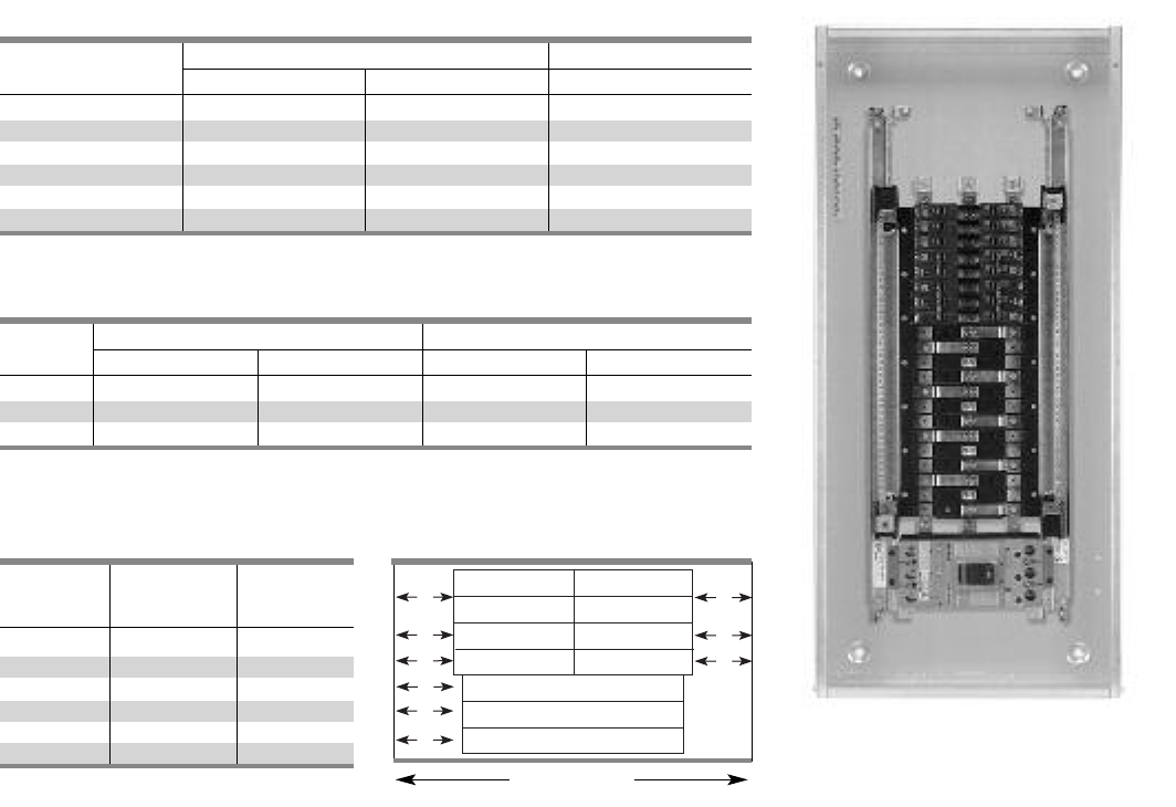
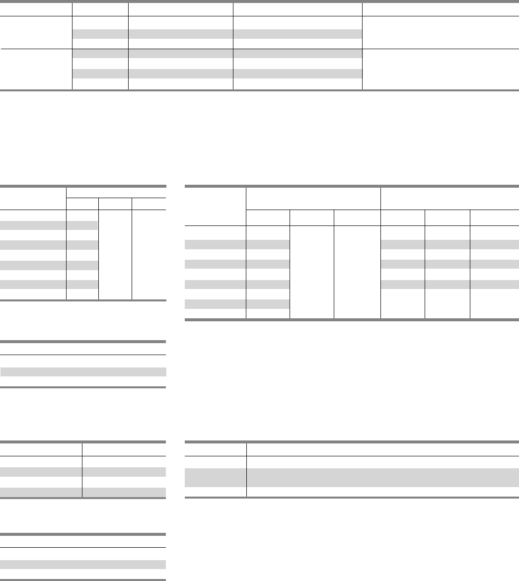
Table P1-15 – Side Gutter Wiring
Space Inches (mm) (Fig P1-1)
Reference Panel Panel
Letter Width 20” Width 24”
Optional
A6.375 (162) 8.375 (213)
B5.500 (140) 7.500 (191)
C 5.000 (127) 7.000 (178)
D16.125 (156) 8.125 (206)
E 16.500 (165) 8.500 (216)
F 15.250 (133) 7.250 (184)
Table P1-13 – Main Breaker Gutter Dimensions Inches (mm)
Gutter Neutral Location
Main Breaker 20” wide box 24” wide box 20” wide box
BL, BLH, HBL, BQD 8.500 (216) 10.500 (267) 11.500 (292)
NGB 8.000 (203) 10.000 (254) 11.500 (292)
ED2, ED4, ED6, HED4 6.125 (156) 8.125 (206) 11.500 (292)
QJ2, QJH2, QJ2-H 6.500 (165) 8.500 (216) 11.500 (292)
FD6, FXD6, HFD6 5.250 (133) 7.250 (184) 11.500 (292)
JD6, JXD6 115.000 (381) 15.000 (381) 26.750 (680)
Table P1-14 – Main Lug End Gutter Dimensions Inches (mm)
Amp End Gutter Neutral Location
Rating 20” wide box 24” wide box 20” wide box 24” wide box
125 10.500 (267) 10.500 (267) 11.500 (292) 11.500 (292)
250 10.500 (267) 10.500 (267) 11.500 (292) 11.500 (292)
400 25.500 (648) 25.500 (648) 26.750 (680) 26.750 (680)
1Subfeed mounting limit 1 per panel.
1JD frame mounted vertically.
BL, BLH, HBL BL, BLH, HBL
BLF, BLHF BLF, BLHF
BQD BQD
NGB NGB
ED2, ED4, ED6, HED4, HED6
QJ2, QJH2, QJ2-H
FXD6, FD6, HFD6
A
B
D
E
F
A
B
CC
Panel Width
20 in. (508 mm)
NOTE: Feed-thru lug and neutral wire bending space is 15.000” and 16.250” respectively on 400A panel.

1-7
Typical Catalog Numbers
Type P1 Panelboards
Table P1-16 – Main Lugs Only
Table P1-17 – Main Circuit Breaker
Maximum Maximum Box Catalog Number
Panel 1-Pole Height
Amp Rating Circuits (inches) 3Ø4W 208Y/120V 1Ø3W 120/240V 3Ø4W 480Y/277V
18 32 P1C18ML125ATS P1A18ML125ATS P1E18ML125ATS
125 30 38 P1C30ML125ATS P1A30ML125ATS P1E30ML125ATS
42 44 P1C42ML125ATS P1A42ML125ATS P1E42ML125ATS
18 32 P1C18ML250ATS P1A18ML250ATS P1E18ML250ATS
250 30 38 P1C30ML250ATS P1A30ML250ATS P1E30ML250ATS
42 44 P1C42ML250ATS P1A42ML250ATS P1E42ML250ATS
18 56 P1C18ML400ATS P1A18ML400ATS P1E18ML400ATS
400 30 62 P1C30ML400ATS P1A30ML400ATS P1E30ML400ATS
42 68 P1C42ML400ATS P1A42ML400ATS P1E42ML400ATS
18 32 P1C18BL100ATS P1A18BL100ATS P1E18BD100ATS
100 30 38 P1C30BL100ATS P1A30BL100ATS P1E30BD100ATS
42 44 P1C42BL100ATS P1A42BL100ATS P1E42BD100ATS
18 32 P1C18NB125ATS P1A18NB125ATS P1E18NB125ATS
125 30 38 P1C30NB125ATS P1A30NB125ATS P1E30NB125ATS
42 44 P1C42NB125ATS P1A42NB125ATS P1E42NB125ATS
18 32 P1C18QJ225ATS P1A18QJ225ATS P1E18QJ225ATS
225 30 38 P1C30QJ225ATS P1A30QJ225ATS P1E30QJ225ATS
42 44 P1C42QJ225ATS P1A42QJ225ATS P1E42QJ225ATS
18 32 P1C18FX250ATS P1A18FX250ATS P1E18FX250ATS
250 30 38 P1C30FX250ATS P1A30FX250ATS P1E30FX250ATS
42 44 P1C42FX250ATS P1A42FX250ATS P1E42FX250ATS
18 56 P1C18JX400ATS P1A18JX400ATS P1E18JX400ATS
400 30 62 P1C30JX400ATS P1A30JX400ATS P1E30JX400ATS
42 68 P1C42JX400ATS P1A42JX400ATS P1E42JX400ATS
Table P1-18 – Standard Enclosures
Catalog Number
Box Type 1 Type 3R Type 3R/12
Height Standard Trim
(in.) Box Surface Flush
32 B32 S32B F32B NR32 WP32
38 B38 S38B F38B NR38 WP38
44 B44 S44B F44B NR44 WP44
56 B56 S56B F56B NR56 WP56
62 B62 S62B F62B NR62 WP62
68 B68 S68B F68B NR68 WP68
SECTION 1
Standard Modifications
Type P1 Panelboards
Panel Options
Enclosures
• Extra gutter to sides or ends of the can
• 24" wide boxes
• Hinged trims
• Door-in-door trims
• Screw to the box trims
• Painted boxes
• Custom colors
• Increase gauge trims and boxes
• Stainless steel trims and boxes, Type 1
• Aluminum trims and boxes, Type 1
Panel Modifications
• Main Bus
Standard main bus is tin-plated aluminum. For copper main
bus, add from the table for each panel. Includes copper neutral
cross bar. For copper neutral branch lugs, see miscellaneous.
• Compression lug for MLO1
• Contactor mains - Mount in 23" enclosure ahead of panel.
- Asco 920 through 225 amps 3
- Asco 911 through 150 amps 3
- Siemens LEN through 30 amps 3
• Branch and main breaker accessories
- Handle blocks
- Handle locks
• Feed-thru lugs 1
Cannot be used in conjunction with TVSS or subfeed
breakers. Do not add height to the panel.
• 200% neutral 1
• Copper lugs, mechanical line and branch neutral 1
• NEMA 3R enclosures
• NEMA 3R/12 enclosures
• NEMA 4 enclosures
• NEMA 4X enclosures
• Special keyed locks
- TEY
- TEU1
- Cat 60
- LL803
- LL806
- Yale
• Panel skirts
• Gaskets between trim and box
• Bus mounted TVSS 1
• Service entrance labeling
• Grounding of Panelboards
Ground Bars except for brazed to box are shipped with
the panel interior factory mounted.
- Non-Insulated Equipment Ground Bar – Standard
- Copper Non-Insulated Ground Bar
- Al Insulated Equipment Ground Bar
- Cu Insulated Equipment Ground Bar
- Ground Bar Brazed to Box (recommended for painted boxes)
• Shunt Trip on Main or Branch
BL2, BLH2, HBL2, BQD2, NGB2as branch use 1” unit space for
shunt trip.
• Remote control switches – 480V AC max. mounted in a
23” enclosure to be cable connected to the panel.
• Time Clocks – mounted in a 23” enclosure to be cable
connected to the panel. Sangamo, Tork or Paragon time
clock can be supplied and mounted in panelboard cabinet.
1Do not increase panel or enclosure size
2Accessories on 1" pole breakers (BL, BQD, NGB, ED) will take l” unit space.
3External to the panel, supplied in a separate enclosure.
Connector
Amp Rating Type Cu/Al Range
250 Al Lay-in (1) - #6 AWG -
Mechanical (1) 350 Kcmil
250 Cu Lay-In (1) - #6 AWG -
Mechanical (1) 350 Kcmil
250 Al (1) - #6 AWG -
Compression (1) 350 Kcmil
400 Al (2) - #4 AWG -
Mechanical (1) 600 Kcmil
Description
Time Clock (1-or 2-Pole, Single or Double Throw Contacts;
3-Pole Single Throw)
277V Maximum with Plain Dial
Options:
Astronomical Dial
An Omitting Device
Reserve Power or Carryover
Space and Mounting Provisions Only
1-8
QJ2, QJ2-H, QJH2, ED2, ED4, ED6, HED4, HED6, HHED6, FD6, FXD6, HFD6,
HFXD6, JXD6, JD6, HJD6, HJXD6, HQJ2H
1-9
Connector Modifications
Type P1 Panelboards
Enclosure Modifications
Remote Switch Modifications
Box Height Enclosure Size
(inches) H W D
26 26
32 32
38 38
44 44
50 50 20 5.75
56 56
62 62
68 68
74 74
NEMA-4 For Type P1
Water Tight, Dust Tight, Steel Enclosure
Table P1-24 – Applications for a Remote Switch
Switch Type Modification
920 Mounts in 23” relay cabinet as a main only
911 ≤ 150 AMPS mounts in 23” relay cabinet as a main only
>150 AMPS not available
LEN 30A mounts in 23” relay cabinet as a mai n only
Table P1-25 – Remote Control
Switch Modification
Description
Separate Door in Deadfront Over Switch
Auxiliary Contacts (mounted, not wired)
2-Wire Control
Table P1-23 – Control Power Transformer
Size VA Relay
0,1 50
2 75
3 150
4 250
Style Amp Rating Breaker Type Compression Connectors Box Height Addition
250 N/A (1)#4 AWG - 350 Kcmil
MLO 400 N/A (1) 250-600 Kcmil or None
(2)#3/0 AWG - 250 Kcmil
125 ED4, ED6, HED4 (1)#12-1/0 AWG
Main Breaker HHED6, CED6 Box must be increased to 24” wide
225 QJ2, QJH2, QJ2H (1)#6 AWG - 350 Kcmil Cu or Al
250 FXD6, HFD6, FD6 (1)#6 AWG - 350 Kcmil Cu or Al
Compression Lugs
Table P1-22 – Additional Enclosure
Modifications
Description
Strip Heaters
Humidstat Control
Thermostat Control
Table P1-19 – Lugs
Table P1-20
NEMA-4X For Type P1
Water Tight, Dust Tight and Corrosion Resistant
(consult plant to verify actual enclosure size)
Table P1-21
NOTE: Standard compression lugs used for P1 panels are range taking lugs and may require a particular crimping tool to accommodate the range. Consult factory for information.
Enclosure - Stainless Steel and Enclosure - Stainless Steel and
Steel with Epoxy Coating Steel w/Epoxy Coating 1
Box Height
(inches) HWD H D W
26 26 36 30 8
32 32 36 30 8
38 38 48 36 12
44 44 48 36 12
50 50 20 5.75 60 36 12
56 56 60 36 12
62 62 ———
68 68 ———
74 74 ———
1Limited to sizes shown.
SECTION 1
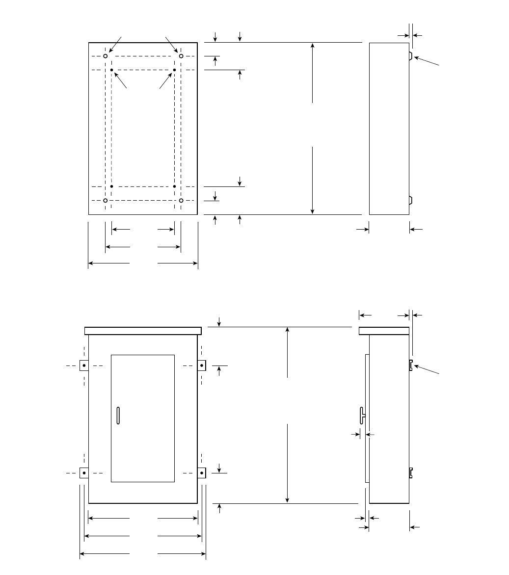
1-10
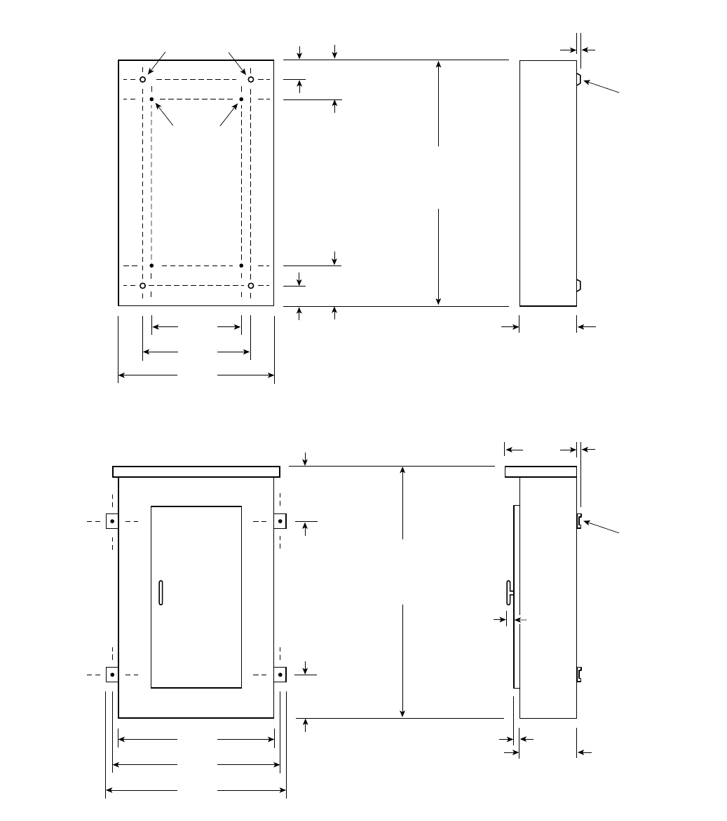
Dimensions
Type P1 Panelboards
20 in.
[ 508 ]
15 in.
[ 381 ]
12.63 in.
[ 321 ]
2 in.
[ 51 ]
Interior To Box
Mounting
Stubs
Box To Wall
Mounting Holes
32 in.,
[ 813 ]
38 in.,
[ 965 ]
44 in.
[ 1118 ]
56 in.,
[ 1422 ]
62 in.,
[ 1574 ]
68 in.
[ 1727 ]
.31 in.
[ 8 ]
Mounting
Dimple
5.75 in.
[ 146 ]
32 in.,
[ 813 ]
38 in.,
[ 965 ]
44 in.
[ 1118 ]
56 in.,
[ 1422 ]
62 in.,
[ 1574 ]
68 in.
[ 1727 ]
4.63 in.
[ 118 ]
2 in.
[ 51 ]
4.63 in.
[ 118 ]
20 in.
[ 508 ]
2 in.
[ 51 ]
7.5 in.
[ 191 ]
.50 in.
[ 13 ]
Mounting
Bracket
5.75 in.
[ 146 ]
1 in.
[25]
21.5 in.
[ 546 ]
23.5 in.
[ 597 ]
2 in.
[ 51 ]
2 in.
[ 51 ]
a
a
a
a
a
a
Type 1 Box
Box is symmetrical
Type 3R and 3R/12 Box
1
1
1
1
1
1Dimensions are interior of the box. Add 5/8” to width for
absolute dimension. Add 1/8” to height for absolute dimension.
2250 Amp panel.
3400 Amp panel.
Dimensions shown in inches and millimeters [ ].
1
2
3
2
3
P2 Panelboards
Description Page
General Information 2-2
Selection and Application 2-2
Application 2-3 – 2-5
Panel Unit Space To Box Height Requirements 2-3
Main Lug Connectors 2-3
Branch Breaker Side Gutters 2-3
Main Breaker Selection 2-4
Subfeed Breakers 2-4
Branch Circuit Breakers 2-5
Branch Neutral Connections 2-5
Typical Catalog Numbers 2-6
Main Lugs Only 2-6
Main Circuit Breakers 2-6
Standard Modifications 2-7
Box Size Additions For Optional Features 2-8
Connector Modifications 2-9 – 2-10
Compression Lugs 2-9
Enclosure Modification 2-10
Remote Switch Modifications 2-10
Dimensions 2-11
Kits and Accessories 2-12
SECTION 2

2-2
P2 Panelboards
Flexibility is the hallmark of the P2 panel. This panel offers a wide
array of factory-assembled options to meet virtually any lighting
panel application. The ability to mix breaker frames within the
unit space up to 225 amps will also meet certain distribution
panel requirements in a much smaller package. Bussing options
for the P2 vary from a typical temperature rating of 750 A/Si
aluminum, to 1000 A/Si copper. Standard bussing in the P2
panel is tin-plated. Silver-plated copper is offered as an option.
Integrated time clocks, bus mounted contactors (as mains or
sub mains), split bus, and subfeed lugs (up to 400 amps) are
just a few of the options available in this unique panel.
As with our other lighting panelboards, the standard P2 panel set
up includes 18, 30, 42 or 54 breakers. In specific applications, the
panel can accept 66, 78 or 90 circuits. The 6" circuit increments
allow the user to configure the smallest possible panel size. The
P2 starts with 9" of unit space (18 circuits of 1 pole breakers).
Breakers mounted in the unit space can be mixed and matched
to meet customer requirements. The 1" pole devices (BL, BOD,
NGB, ED) are mounted in 3" or 6" increments. Breaker frames
above 125A are single mounted in a 6" space. An example of a
minimum panel is as follows: (6) 20A, 1-pole, BL breakers (3"
of unit space) and a 225A, 3-pole, QJ breaker (6" of unit space)
equaling 9" of unit space can be configured in a P2 panel without
any extra provisions or space required. FD 250 and JD 400A
breakers are mounted outside the unit space.
Another unique feature of the P2 panel is that blank unit space
can be added to allow for future expansion or modifications.
All expansion or modifications must be in 3” increments. BL,
BQD, NGB, and ED frame breakers have 3” or 6” pole kits, and
can be mixed within unit space by these increments. Breakers
of the same frame can cross from one mounting to another if
contiguous. QJ frame breakers are mounted in 6” increments
for two and three pole, single mounted units. Changes in the
unit space length for BL, BQD, NGB or ED frame breakers require
an addition deadfront, center strip kit. Check with sales or the
factory for additional unit space kits.
Main Lug / Main Breaker
Enclosure – Standard Type 1 enclosure is 20" wide x 5.75"
deep X. Box Height is determined by main device and unit space.
See charts for box height.
Voltage – 600 Vac Max.
250 Vdc Max.
Amperage – 600 amp Max.
Short circuit rating – 200 KAIC Max. symmetrical or equal to the
lowest rated device installed unless a series rating is indicated.
Panels with subfeed or feed-thru lugs without a main device,
circuit breaker or fusible unit, are limited to a three-cycle rating.
The three-cycle rating for the P2 panel is limited to 22 KAIC. Note
that the main device may be mounted remote from the panel.
Bussing – The P2 panel has more options to meet market
requirements. The standard bussing is temperature rated
aluminum. The rating is per the requirements of UL 67 – the
standard for panelboards. All aluminum bussing is tin-plated.
Optional bussing for the P2 panel is: 750 A/Si aluminum,
temperature rated copper, and 1000 A/Si copper. The copper
bus option for this panel is tin-plated.
Weight – Approximate
Total panelboard weight when filled with a normal quantity
of breakers and accessories is about 3 lbs. (1 kg) per inch
(54g per mm) of box height.
Dimensions in inches (mm) Gauge Steel
Width Height Box Front
20” 26 - 74 #16 #14
(508) (660, 1880)
Table P2-1 – Gauge Steel of Boxes
Fronts, Surface and Flush
Selection and Application
Determine configuration required.
Example:
Amperage 250A
Voltage 208Y/120V
System 3Ø4W
Main Main Lug
Bus Material ASI
rated aluminum
Interrupt Rating 10 Ka
Branch Devices (6) 20 amp,1-pole
(1) 225 amp, 3-pole
Feed Location Top
Mounting Surface
Step 1 Step 2
Create a catalog number by following the
Catalog Numbering System on page 6.
Note that the number of circuits number
(4th and 5th position) will be 18 for those
panels with 6-18 circuits, 30 for those
panels with 19-30 circuits, 42 for those
panels 31 to 42 circuits and 54 for those
panels 43 to 54 circuits. The most cost
effective 20 amp 1-pole breaker for this
application would be BL. However, a
myriad of other breakers with options
may be used in the P2 panel. The most
cost effective 225 amp breaker for this
application is the QJ2.
Step 3
Determine the enclosure size. The matrix on
page 2-3 shows the enclosure sizes based
on the amperage, main device and unit
space required.
Check with sales or the factory for other
options as we will be adding to our
capabilities.
Based on the above
P2C18ML250ATS
(6) BL 20 amp 1-Pole
(1) QJ2 225 amp 3-pole
2-3
Application
Type P2 Panelboards
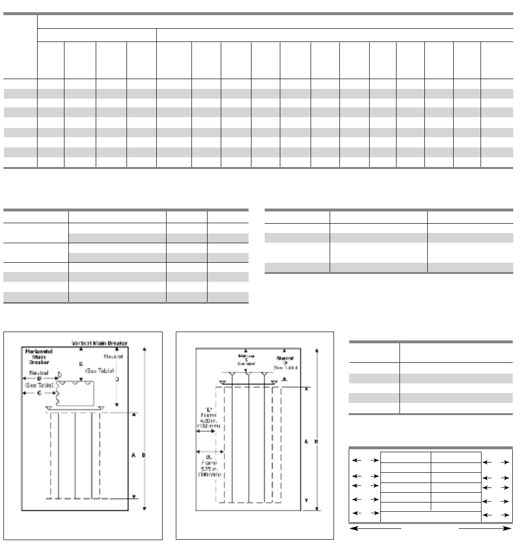
Table P2-2 – Panel Unit Space To Box Height Requirements
P2 Panels With Standard Line Lugs. Unit Space (starting with 9" and adding 6" increments) “A” Dimension
“B” Main Lugs Main Breakers
Dimen-
sion 125A 250A 400A 600A 125A 125A 125A 225A 225 250A 250A 250A 400A 400A 600A 600A
Box Horiz. Horiz. Vert. Horiz. Vert. Horiz. Vert. Vert. Vert. Vert. Vert. Vert.
Height BL,BQD,
NGB, ED CED ED QJ QJ FD FD CFD JD CJD LD CLD
26 9— — — 9 ———————————
32 15 9 ——15 999 —————-— ——
38 21 15 9 9 21 15 15 15 99——————
44 27 21 15 15 27 21 21 21 15 15 9——— ——
50 33 27 21 21 33 27 27 27 21 21 15 99———
56 39 33 27 27 39 33 33 33 27 27 21 15 15 —9—
62 45 39 33 33 45 39 39 39 33 33 27 21 21 9 15
68 — 45 39 39 — 45 45 45 39 39 33 27 27 15 21 15
74 —— 45 45 ————45 45 39 33 33 21 27 21
Table P2-4 – Main Lug Connectors (Fig. P2-2)
Panel Amps Standard Connectors C D
125 (1) #14 - 2/0 6.62 8.19
250 (1) #6 AWG - 350 Kcmil 12.34 11.22
400 (1) #4 AWG - 600 Kcmil 14.00 13.09
or (2) #6 - 250 Kcmil
600 (2) #4 AWG - 500 Kcmil 14.00 11.00
Table P2-3 – Main Breaker (Fig. P2-1)
Panel Amps Breaker Frames C D
100 BL 5.75 8.00
BQD 5.125 8.00
NGB 4.63 8.00
125 ED 4.00 8.00
225 QJ 5.00 7.00
250 FD 5.00 7.00
400 JD 14.00 25.00
600 LD 15.50 23.00
Fig. P2-3
Fig. P2-1 Fig. P2-2
Box depth = 5.75 in. (146 mm)
Box width – 20 in. (508 mm)
for 100-600A
Box depth = 5.75 in. (146 mm)
Box width – 20 in. (508 mm)
for 100-600A
Table P2-5 – Branch Breaker Side
Gutters Inches (mm) (Fig. P2-3)
Reference Panel
Letter Width 20” (508)
A5.750 (146)
B5.125 (130)
C4.600 (117)
D4.000 (102)
E15.000 (127)
1 Single branch mounting construction.
BL, BLH, HBL BL, BLH, HBL
BLF, BLFH BLF, BLFH
BQD, BQD6 BQD, BQD6
NGB NGB
ED, ED4, ED6 ED, ED4, ED6
HED4, HHED6 HED4, HHED6
A
Panel Width
20 in. (508 mm)
QJ2,QJH2,QJ2-H, HQJ2H
A
BB
CC
DD
Note: When the number of circuits exceeds 54 on a 125 and 250A MLO and 125 and 250A main breaker application, add 6” to the box height.
EE
SECTION 2
2-4
Application
Type P2 Panelboards
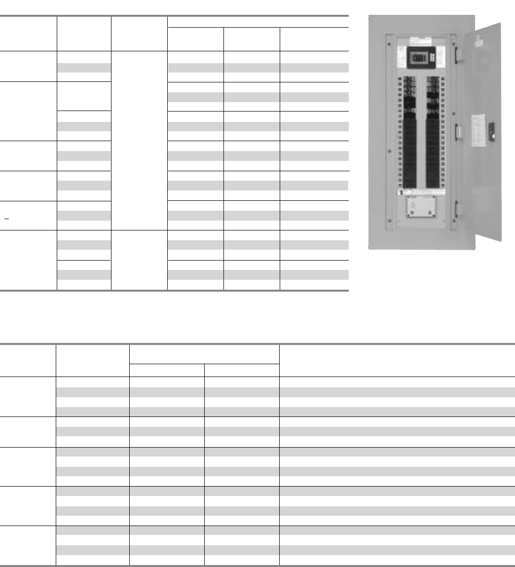
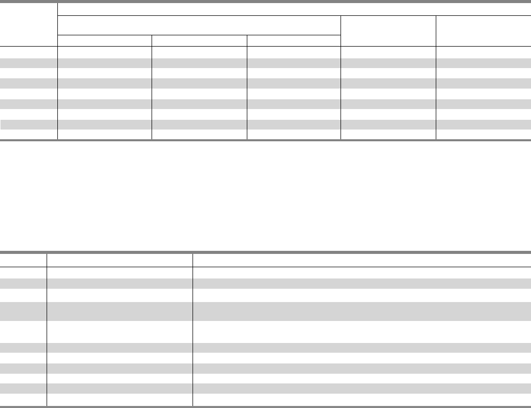
Table P2-6 – Main Breaker Selection1
Ampere Breaker Maximum Interrupting Rating (kA)
Rating Type 240V 480V 600V Available Trip Values
BL (STD) 10 ——
HBL 65 14 —
BQD 265 18 —
100 ED4 65 25 — 15, 20, 25, 30, 35, 40, 50, 60, 70, 80, 90, 100
ED6 100 42 18
HED4 100 65 —
HHED6 100 65 25
CED6 200 200 100
ED4 (STD) 65 18 —
ED6 65 25 18
125 NGB 100 25 18
HED4 100 42 — 125
HHED6 100 65 25
CED6 200 200 100
QJ2 (STD) 10 ——
QJH2 22 ——
60, 70, 80, 90, 100, 110, 125, 150, 175, 200, 225
QJ2H 42 ——
HQJ2H 100 ——
225 FD6, FXD6 65 35 18
HFD6, HFXD6 100 65 25 70, 80, 90, 100, 110, 125, 150, 175, 200, 225
CFD6 200 150 100
FD6, FXD6 (STD) 65 35 18
250 HFD6, HFXD6 100 65 25 250
CFD6 200 150 100
JXD6 (STD), JD6 65 35 25 200, 225, 250, 300, 350, 400
400 HJD6, HJXD6 100 65 35 200, 225, 250, 300, 350, 400
SJD6 65 35 25 200, 300, 400
SHJD6 100 65 35 200, 300, 400
CJD6,SCJD6 200 200 100 200, 300, 400
LXD6 (STD) 65 35 25 450, 500, 600
LD6 65 35 25 250, 300, 350, 400, 450, 500, 600
600 HLD6, HLXD6 100 65 35 250, 300, 350, 400, 450, 500, 600
SLD6 65 35 25 300, 400, 500, 600
SHLD63100 65 35 300, 400, 500, 600
CLD6, SCLD6 200 150 100 300, 400, 500, 600
1Interchangeable trip
2For use on 480Y/277 volt systems not suitable for 480 Delta 3 phase, 3 wire systems.
3Top feed only.
1Twin mounted subfeed breakers are mounted at bottom of panelboard only and adds 24" to the panel height. Single mounted FD subfeed breaker is horizontally
mounted and requires 12” additional box height.
2Subfeed breaker is mounted at bottom of panelboard only. 400 amp subfeed breaker adds 30" to the panel height.
Table P2-7 – Subfeed Breakers
Mounting Position Maximum Interrupting
Breaker When Used As Subfeed Breaker Rating (kA) Symmetrical
Type Vertical Ampere Ratings For Load 240V AC 480V AC 600V DC
FD61, FXD6 Twin/Single 70 - 250 65 35 18
HFD61, HFXD6 Twin/SIngle 70 - 250 100 65 25
JD6 2, JXD6 Single 200 - 400 65 35 25
HJD6 2, HJXD6 Single 200 - 400 100 65 35
2-5
Application
Type P2 Panelboards
Table P2-8 – Branch Circuit Breakers
Max. Bolt-On No. Maximum Interrupting Rating (kA)
Amp Breaker of Amp Volts – AC DC
Rating Type Poles Rating 120 120/240 240 277 480 600 250
1 15 - 70 10 ——————
BL 2 15 - 100 — 10 —— — — —
3 15 - 100 —— 10 ————
BL, HID 1 15 - 30 10 ——————
2 15 - 30 — 10 —— — — —
BLR 2 15 - 100 —— 10 ————
BLE 1 15 - 30 10 ——————
2 15 - 60 — 10 —— — — —
BLEH 1 15 - 30 22 ——————
2 15 - 60 — 22
BLF 1 15 - 30 10 ——————
2 15 - 60 — 10 —— — — —
100 BLHF 1 15 - 30 22 ——————
3 15 - 60 — 22 —— — — —
BGL12 15 - 30 10 ——————
3 15 - 30 — 10 —— — — —
BAF 1 15, 20 10 ——————
BAFH 1 15, 20 22 ——————
1 15 - 70 — 22 —— — — —
BLH 2 15 - 100 — 22 —— — — —
3 15 - 100 —— 22 ————
1 15 - 70 — 65 —— — — —
HBL 2 15 - 100 — 65 —— — — —
3 15 - 100 —— 65 ————
1—65 — 14 ——14
BQD 2 15 - 100 — 65 —— 14 — 14
3——65 — 14 — 14
NGB 1 100 ——25 ——14
2/3 15 - 125 — 100 100 —25
2——
1 15 - 125 65 ——22 ———
ED4 2——65 — 18 — 30
3——65 — 18 ——
ED6 2 15 - 125 —— 65 — 25 18 30
3——65 — 25 18 —
125
HED4 1 100 ——————
HHED6 2 15 - 125 —— —65 ———
3——100 42 42 — 30
QJ2 2/3 60 - 225 —— 10 ————
QJH2 2/3 60 - 225 —— 22 ————
QJ2-H 2/3 60 - 225 —— 42 ————
HQJ2H 2/3 100 - 225 ——100 ————
Branch Device Limitations
In areas where 2008 NEC has not been adopted, some
limitations may apply for panels used in systems requiring
neutral connections. By application rule (480.14 in all versions
of the NEC prior to 2008), lighting and appliance panels are
limited to 42 installed circuits. Each over current device pole
counts as a circuit.
Table P2-9 – Branch Neutral Connections
Wire Range Max. Number of Connections Max. Amps 1
#14-#6 48 65
#14-1/0 56 125
#6 - 350 Kcmil 4 250
(1) #4-600 Kcmil 1 400
or (2) #6-250 Kcmil
1 Two pole breaker is one phase and neutral. Three pole is two phase and neutral.
2For use on 480Y/277 volt systems. Not suitable for 480 delta, 3-phase,
3-wire systems.
NOTE: QJ Breakers are single mounted in unit space and take 6” of unit space.
Limited to (4) per panel max. BL, HBL, BLH, NGB and BQD breakers are mounted in
common mountings in 3” or (6) pole increments. ED4, ED6, HED4 and HHED6
breakers are mounted in common mountings in 3” or (6) pole increments.
1Based on 75 degree copper.
SECTION 2
2-6
Typical Catalog Numbers
Type P2 Panelboards
Table P2-10 – Main Lugs Only
Table P2-11 – Main Circuit Breaker
Maximum Maximum Box Catalog Number
Panel 1-Pole Height
3Ø4W 208Y/120V 1Ø3W 120/240V 3Ø4W 480Y/27V
Amp Rating Circuits
inches (mm)
18 26 (660) P2C18ML125ATS P2A18ML125ATS P2E18ML125ATS
125 30 32 (813) P2C30ML125ATS P2A30ML125ATS P2E30ML125ATS
42 38 (965) P2C42ML125ATS P2A42ML125ATS P2E42ML125ATS
18 32 (813) P2C18ML250ATS P2A18ML250ATS P2E18ML250ATS
250 30 38 (965) P2C30ML250ATS P2A30ML250ATS P2E30ML250ATS
42 44 (1118) P2C42ML250ATS P2A42ML250ATS P2E42ML250ATS
18 38 (965) P2C18ML400ATS P2A18ML400ATS P2E18ML400ATS
400 30 44 (1118) P2C30ML400ATS P2A30ML400ATS P2E30ML400ATS
42 50 (1270) P2C42ML400ATS P2A42ML400ATS P2E42ML400ATS
18 38 (965) P2C18ML600ATS P2A18ML600ATS P2E18ML600ATS
600 30 44 (1118) P2C30ML600ATS P2A30ML600ATS P2E30ML600ATS
42 50 (1270) P2C42ML600ATS P2A42ML600ATS P2E42ML600ATS
18 26 (660) P2C18BL100ATS P2A18BL100ATS P2E18BD100ATS
100 30 32 (813) P2C30BL100ATS P2A30BL100ATS P2E30BD100ATS
42 38 (965) P2C42BL100ATS P2A42BL100ATS P2E42BD100ATS
18 26 (660) P2C18NB125ATS P2A18NB125ATS P2E18NB125ATS
125 30 32 (813) P2C30NB125ATS P2A30NB125ATS P2E30NB125ATS
42 38 (965) P2C42NB125ATS P2A42NB125ATS P2E42NB125ATS
18 32 (813) P2C18QJ225ATS P2A18QJ225ATS P2E18FX225ATS
225 30 38 (965) P2C30QJ225ATS P2A30QJ225ATS P2E30FX225ATS
42 44 (1118) P2C42QJ225ATS P2A42QJ225ATS P2E42FX225ATS
18 38 (965) P2C18FX250ATS P2A18FX250ATS P2E18FX250ATS
250 30 44 (1118) P2C30FX250ATS P2A30FX250ATS P2E30FX250ATS
42 50 (1270) P2C42FX250ATS P2A42FX250ATS P2E42FX250ATS
18 50 (1270) P2C18JX400ATS P2A18JX400ATS P2E18JX400ATS
400 30 56 (1422) P2C30JX400ATS P2A30JX400ATS P2E30JX400ATS
42 62 (1575) P2C42JX400ATS P2A42JX400ATS P2E42JX400ATS
18 56 (1422) P2C18LX600ATS P2A18LX600ATS P2E18LX600ATS
600 30 62 (1575) P2C30LX600ATS P2A30LX600ATS P2E30LX600ATS
42 68 (1727) P2C42LX600ATS P2A42LX600ATS P2E42LX600ATS

2-7
Standard Modifications
Type P2 Panelboards
P2 Panel Options
Enclosures
• Extra gutter to sides or ends of the can
• 24" wide boxes
• Hinged trims
• Door-in-door trims
• Screw to the box trims
• Trim mounted devices (Devices mounted and wired
to the trim should also have hinged trim specified)
• Pilot lights
• Toggle switches
• Push buttons
• Painted boxes
• Custom colors
• Increase gauge trims and boxes
• Stainless steel trims and boxes, Type1
Panel Modifications
• Main Bus
Standard main bus is temperature rated tin-plated aluminum.
Bus options are 750 A/Si aluminum, tin-plated temperature
rated copper tin-plated standard – silver optional. 1000 A/Si
copper tin-plated standard – silver optional. Includes copper
neutral cross bar. For copper neutral branch lugs, see
miscellaneous.
• Split bus adds 6” to unit space
• Compression lug for MLO
• Compression lugs on Main breaker (may require
extra width or length on enclosure).
• Contactor mains or submain
• Asco 920 through 225 amps. Adds 12” unit space as main,
15” unit space as submain.
• Asco 911 through 150 amps. Adds 21” unit space.
• Siemens LEN through 30 amps. Adds 12” unit space.
Makes box 10" deep.
• Control power transformers (contact engineering for extra
gutter requirements)
• Branch and main breaker accessories
• Handle blocks
• Handle locks
• Aux. Contacts 1
• UVR1
• Feed-thru lugs
• 200% neutral
• Copper lugs, mechanical
• Bus mounted TVSS
• Service entrance labeled
Type P2 Panelboards are factory labeled suitable for use as
service entrance equipment when NEC requirements are met.
A panelboard cannot have more than six main disconnects,
unless it is a lighting and appliance branch panelboard.
Lighting and appliance branch panelboards are limited to
two main disconnects.
1Accessories on 1" pole breakers (BL, BQD, ED) will take unit space
• Aluminum trims and boxes, Type1
• NEMA 3R enclosures
• NEMA 3R/12 enclosures
• NEMA 4 enclosures
• NEMA 4X enclosures
• Special keyed locks
• TEY • LL803
• TEU1 • LL806
• Cat 60 • Yale
• Gasketing trim to box
• Meters (Contact application engineering for space
requirements)
• Panel Skirts
• Grounding of panelboards
Ground Bars, except brazed-to-box, are shipped with the
panel interior factory mounted.
• Non-Insulated Equipment Ground Bar – Standard
• Copper Non-Insulated Ground Bar
• Al Insulated Equipment Ground Bar
• Cu Insulated Equipment Ground Bar
• Ground Bar Brazed to Box (recommended for
painted boxes)
• Shunt Trip on Main or Branch
BL, BLH, HBL, ED2, ED4, HED4, HED6, HHED6 uses 1” unit
space for shunt trip. All may be used on mains or subfeeds.
•Remote control switches – 480V AC max. mounted in a
23” enclosure to be cable connected to the panel.
• Time Clocks – mounted in a 23” enclosure to be cable
connected to the panel. Sangamo, Tork or Paragon time
clock can be supplied and mounted in panelboard cabinet.
QJ2, QJ2-H, QJH2, HQJ2H, ED2, ED4, ED6, HED4, HED6,
HHED6, FXD6, HFD6, JXD6, JD6, HJD6, HJXD6, HQJ2H
Description
Time Clock (1-or 2-Pole, Single or Double Throw Contacts;
3-Pole Single Throw)
277V Maximum with Plain Dial
Options –
Astronomical Dial
An Omitting Device
Reserve Power or Carryover
Space and Mounting Provisions Only
SECTION 2
Standard Modifications
Type P2 Panelboards
Table P2-12 – Box Size Additions (In.) For Optional Features on MLO Applications
MLO – Standard Lugs MLO – Copper Only Lugs MLO – Compression Lugs
Optional Features 125 250 400 600 125 250 400 600 125 250 400 600
Min. Box Size126 32 38 38 32 38 44 38 32 38 44 44
Sub-Feed lugs 066N/A N/A N/A N/A N/A N/A N/A N/A N/A
Feed Thru Lugs 6612 12 6612 N/A 6 12 N/A N/A
(1) 1FD sub-feed Bkr. N/A 12 12 12 N/A 12 12 12 N/A 12 12 12
(2) FD sub-feed Bkrs. N/A 24 24 24 N/A 24 24 24 N/A 24 24 24
(1) JD sub-feed Bkr. N/A N/A 24 24 N/A N/A 24 24 N/A N/A 24 24
TVSS 12 12 12 12 12 12 12 12 12 12 12 12
200% Neutral 0066 00 0N/A 00 0
4N/A
200% Neutral
w/Feed Thru Lugs N/A N/A N/A N/A N/A N/A N/A N/A N/A N/A N/A N/A
Split Bus 12 212218 318 318 218 324 324 318218 324 324 3
1Based on 9" of unit space.
2Based on 9" of upper unit space and 6" of lower unit space.
3Based on 6" of upper unit space and 6" of lower unit space.
4200% neutral is not available when the panel is supplied by (2) cables in lieu of (1).
Table P2-13 – Box Size Additions (In.) For Optional Features on Main Breaker Applications
Main Breaker – Horizontal Mounting Main Breaker – Vertical Mounting
Optional Features 100A 125A 125A 225A 250A 125A 225A 250A 250A 400A 400A 600A 600A
BL, BQD NGB, ED CED QJ FD ED QJ FD CFD JD CJD LD CLD
Min. Box Size126 26 32 32 38 32 38 44 50 50 62 56 62
CopperLugs N/A N/A N/A N/A N/A 00 0 0 0 0 0 0
Compression Lugs N/A N/A N/A N/A N/A 00 0 0 0 0 0 0
Feed Thru Lugs 66 6N/A N/A 66 6 612 212 312 312 3
(1) FD sub-feed Bkr. N/A N/A N/A N/A 12 N/A N/A 12 12 12 12 12 12
(2) FD sub-feed Bkr. N/A N/A N/A N/A 24 N/A N/A 24 24 24 N/A N/A N/A
(1) JD sub-feed Bkr. N/A N/A N/A N/A N/A N/A N/A N/A N/A 24 N/A N/A N/A
TVSS 12 12 12 12 12 12 12 12 12 12 12 12 12
200% Neutral 000N/A N/A 000 00
2020303
200% Neutral w/ N/A N/A N/A N/A N/A N/A N/A N/A N/A N/A N/A N/A N/A
Feed Thru Lugs
1Based on 9" of unit space.
2This featue is not available when the panel is supplied by (2) cables in lieu of (1).
3Not available with copper or compression lugs.
The definition and reference to lighting and appliance panelboards and power panelboards was removed from the 2008 NEC. This
change removed the basic 42 circuit limitation for lighting and appliance panelboards. The NEC still has a 42 circuit limitation for
special applications referred to in 408.36 Exception 2 and 645.17. As a result, of this change, the panel capability has been expanded
to support up to 90 circuits.
In some cases, this expanded capability will require an extra 6" of box height. See the chart below.
MLO - 125A
MLO - 250A
MB -100A
MB -125A
MB - 250A
2-8
2-9
Connector Modifications
Type P2 Panelboards
Style Amp Rating Breaker Type Compression Connectors Box Height Addition
125 N/A (1) #6 - 350KCMIL Al/Cu 6
250 N/A (1) #6 - 350KCMIL Al/Cu 6
(1) 500 - 750KCMIL Al 6
MLO 400 N/A (1) 500KCMIL Cu 6
(2) #6 - 350KCMIL Al/Cu 6
600 N/A (2) #6 - 350KCMIL Cu 6
(2) 500 – 750KCMIL Al 6
125 ED4, ED6, HED4 (1) #14-2/0 AWG Al/Cu
ED4, ED6, HED4, HHED6 are vertically mounted and
require a 6” increase in box height
HHED6, CED6 Box must go to 24”W for CED6 breaker and an
additional 6” of box height is required for neutral)
225 QJ2, QJH2, QJ2H, (1) #6 - 350KCMIL Al/Cu The breaker is vertically mounted only.
HQJ2H Add 6” to the box height
250
FD6, FXD6, HFD6, (1) #6 - 350KCMIL Al/Cu This breaker is vertically mounted only.
Main Breaker HFXD Add 6” to the box height
CFD (1) #6 - 350KCMIL AL/Cu —
JD6, JXD6, HJD6, (1) #3/0 - 600KCMIL Cu
400 HJXD6, HQJ2H (2) #3/0 - 500KCMIL Al —
SJD6, SHJD6 (1) 500 - 750KCMIL Al
CJD6, SCJD6 —
LD6, LXD6, HLD6, (1) #3/0 - 600KCMIL Cu
600 HLXD6 (2) #3/0 - 500KCMIL Al —
SLD6, SHLD6 (1) 500 - 750KCMIL Al
CLD6, SCLD6 —
Compression Lugs
Table P2-14 – Lugs
SECTION 2
2-10
Connector Modifications
Type P2 Panelboards
Enclosure Modifications
Remote Switch Modifications
Box Height Enclosure Size
Inches H W D
26 26
32 32
38 38
44 44
50 50 20 5.75
56 56
62 62
68 68
74 74
Enclosure Modification NEMA 4 for
Type P2 Water Tight and Dust Tight,
Steel Enclosure (consult plant to verify
enclosure size)
Table P2-18 – Applications for a Remote Switch
Switch Type Modification
ASCO 920 30 to 225A – Add 12” to MLO box height
ASCO 9111≤ 225A – Add 21” to the box height. >225A is not available in P2
LEN 60A to 100A adds 6” to the box height with a min. depth of 7.75”
200A adds 6” to the box height with a min. depth of 10.00”
1>225A is recommended for use in a P4 panel.
.
Table P2-19 – Remote Control
Switch Modification
Description
Auxiliary Contacts (mounted not wired)
Ea. 2-Wire Control
Table P2-17 – Control Power
Transformer
Size VA
0,1 50
2 75
3 150
4 250
Table P2-15
NEMA-4X For Type P2
Water Tight, Dust Tight and Corrosion Resistant
(consult plant to verify enclosure size)
Enclosure - Stainless Steel Enclosure - Stainless Steel and
and Steel with Epoxy Coating Steel with Epoxy Coating 1
Box Height
Inches HWD H W D
26 26 36 30 8
32 32 36 30 8
38 38 48 36 12
44 44 48 36 12
50 50 20 5.75 60 36 12
56 56 60 36 12
62 62 —— —
68 68 —— —
74 74 —— —
Table P2-16
1Limited to the sizes shown.
2-11
Dimensions
Type P2 Panelboards
20 in.
[ 508 ]
15 in.
[ 381 ]
12.63 in.
[ 321 ]
2 in.
[ 51 ]
Interior To Box
Mounting
Stubs
Box To Wall
Mounting Holes
.31 in.
[ 8 ]
Mounting
Dimple
5.75 in.
[ 146 ]
32 in.
[ 816 ]
38 in.
[ 965 ]
44 in.
[ 1118 ]
56 in.
[ 1422 ]
62 in.
[ 1575 ]
68 in.
[ 1727 ]
26 in.
[ 660 ]
50 in.
[ 1270 ]
74 in.
[ 1880 ]
a
32 in.
[ 816 ]
38 in.
[ 965 ]
44 in.
[ 1118 ]
56 in.
[ 1422 ]
62 in.
[ 1575 ]
68 in.
[ 1727 ]
26 in.
[ 660 ]
50 in.
[ 1270 ]
74 in.
[ 1880 ]
a
4.63 in.
[ 118 ]
2 in.
[ 51 ]
4.63 in.
[ 118 ]
20 in.
[ 508 ]
Mounting
Bracket
5.75 in.
[ 146 ]
21.5 in.
[ 546 ]
23.5 in.
[ 597 ]
a
a
a
a
7.5 in.
[ 191 ]
.50 in.
[ 13 ]
2 in.
[ 51 ]
2 in.
[ 51 ]
2 in.
[ 51 ]
1 in.
[25]
Type 1 Box
Box is symmetrical
Type 3R and 3R/12 Box
1
1
1
1
SECTION 2
2
1
2
1
1Dimensions are interior of the box. Add 5/8” to width for
absolute dimension. Add 1/8” to height for absolute dimension.
2See table P2-12 to match ratings with height.
Dimensions shown in inches and millimeters [ ].
2-12
Kits and Accessories
Type P2 Panelboards
Table P2-20 – Standard Enclosures
Options For Type 1 Trims
Hinged trim – Replace “B” suffix with “H”
Door-in-door – Replace “B” suffix with “D”
Metal card holder – Replace “B” suffix with “M” on standard trim, add “M” suffix on optional trims
Option For 24” Wide Enclosures with Equal Gutter on Both Sides
24” wide with equal gutter on both sides - Add “24” as prefix
Catalog Number
Box Type 1 Type 3R Type 3R/12
Height Standard Trim
Inches Box Surface Flush
26 B26 S26B F26B NR26 WP26
32 B32 S32B F32B NR32 WP32
38 B38 S38B F38B NR38 WP38
44 B44 S44B F44B NR44 WP44
50 B50 S50B F50B NR50 WP50
56 B56 S56B F56B NR56 WP56
62 B62 S62B F62B NR62 WP62
68 B68 S68B F68B NR68 WP68
74 B74 S74B F74B NR74 WP74
Table P2-21 – Breaker Kits and Accessories
Kit No. Description Contents
BBKB32 BL/BQD 6-pole 3” branch breaker kit Kit contains top barrier, (3) A/C connectors, (1) B connector, hardware
BBKNB32 NGB 6-pole 3” branch breaker kit Kit contains braker support, interphase barriers, (3) A/C connectors, (1) B-phase connector, hardwre
BBKED32 ED 6-pole 3” branch breaker kit Kit contains breaker support, inter-phase barriers, (3) A/C connectors, (1) B-phase connector, hardware
BBKQ1 QJ branch breaker kit for 2 and Kit to contain all connectors and cover plates necessary to mount both 2 and 3-pole breakers
3-pole single mount
DFK1 BL, BQD, ED deadfront kit for Center strips 3”, 6”, 9,” 15,” 21” plus mounting hardware
1” pole breakers
DFFP3 Deadfront filler 3” 3” empty space filler and hardware
DFFP6 Deadfront filler 6” 6” empty space filler and hardware
BNK2 Branch neutral (P2) Three tier lug with mounting hardware to increase neutral capacity
P2BK1 P2 250A max. Bonding Kit Bonding strap and hardware
P2BK2 P2 400A max. Bonding Kit Bonding strap and hardware
P2BK3 P2 600A max. Bonding Kit Bonding strap and hardware
P3 Panelboards
Description Page
General Information 3-2
Selection and Application 3-2
Application 3-3 – 3-5
Panel Unit Space to Box Height Requirements 3-3
Main Breaker and Main Lug Wire Bending 3-3
Branch Breaker Side Gutters 3-3
Main Lug and Main Breaker
Unit Space Dimensions 3-3
Main Breaker Selection 3-4
Subfeed Breakers 3-4
Neutral Connectors 3-4
Branch Circuit Breakers 3-5
Typical Catalog Numbers 3-6 – 3-7
Main Lugs 3-6
Main Circuit Breakers 3-7
Standard Modifications 3-8 – 3-9
Option Combinations 3-9
Connector Modifications 3-10
Compression Lugs 3-10
Enclosure Modifications 3-10
Remote Switch Modifications 3-10
Dimensions 3-11
Kits and Accessories 3-12
SECTION 3

3-2
Type P3 Panelboards
The innovative P3 panelboard from Siemens is a smaller
footprint distribution panel designed for applications that
require more large-branch devices than typical lighting panels
can support. This panel offers a wide array of factory-assembled
options and has the ability to mix breaker frames in unit space
up to 225 amps. Bussing options include standard, temperature-
rated aluminum and temperature rated (750 ASI1and 1,000
AlSq") copper. All aluminum bussing in the P3 panel is tin-plated
as a standard. Silver-plating is the default for copper bus with tin
as an option. Integrated time clocks, bus mounted contactors as
mains or sub-mains, split bus and sub-feed lugs (up to 400 amps)
are just a few of the options available in this unique panel.
The panel configurations, defined by unit space, allow for given
amperage, main device, and box height. The P3 panel starts with
a 56" high box. Breakers in unit space can be mixed and matched
to meet customer requirements. All 1"pole breakers (Bl, BOD,
NGB, NEB, HEB and ED frames) are mounted in 3" or 6-pole
increments. Breaker frames, rated 225 amps, are dual mounted
in 6" increments in unit space. Also available are one or two 250
amp frame breakers or one 400 amp frame breaker, mounted as
sub-feed devices outside the unit space.
Like other distribution panels, the P3 panel can include blank
space for future expansion or modifications. Any expansions or
modifications must be in 3"increments. BL, BQD, NGB, NEB, HEB,
and ED frame breakers have 3" or 6-pole kits and can be mixed
in unit space by these increments. Breakers of the same frame
can cross from one mounting to another if contiguous. QJ frame
breakers are mounted in 6" increments for two and three pole
single and twin mounted units. Changes in the unit space length
for Bl, BQD, NGB, NEB, HEB, and ED frame breakers require an
additional deadfront center strip kit. Contact your Siemens
representative for additional unit space kits.
Main Lug / Main Breaker
Enclosure – Standard Type 1 enclosure is 24" wide x 7.75"
deep. X Box Height is determined by main device and unit space.
See charts for box height.
Voltage – 600 Vac Max.
250 Vdc Max.
Amperage – 800 amp Max.
Short Circuit Rating – 200 KAIC Max. symmetrical or equal
to the lowest rated device installed unless a series rating is
indicated. Panels with subfeed or feed-thru lugs without a
main device, circuit breaker or fusible unit, are limited to a
three-cycle rating. The three-cycle rating for the P3 panel is
limited to 22 KAIC. Note that the main device may be mounted
remote from the panel.
Bussing – The P3 panel has more options to meet market
requirements. The standard bussing is temperature rated
aluminum. The rating is per the requirements of UL 67 – the
standard for panelboards. All aluminum bussing is tin-plated.
Optional bussing for the P3 panel is: 750 A/si aluminum,
temperature rated copper, and 1000 A/si copper. The copper
bus option for this panel is tin-plated.
Weight – Approximate
Total panelboard weight when filled with a normal quantity
of breakers and accessories is about 5 lbs. (1 kg) per inch
(54g per mm) of box height.
Table P3-1 – Gauge Steel of Boxes Fronts, Surface & Flush
Selection and Application
1) To specify a particular panelboard, first determine voltage,
system, amperage and type main, amperage and type of
branch devices, and modifications, if any. (Step 1)
2) List branch devices and modifications requiring space
additions. List unit space requirements of each.
Note: Some units are twin mounted meaning two breakers
occupy the same unit space.
Select appropriate enclosure height from selection chart on
page 3-3, based on unit space requirements. (Step 2)
3) Select panelboard catalog number from appropriate table
based upon voltage, system, amperage and unit space
requirements. (Step 3)
Dimensions in inches (mm) Gauge Steel
Width Height Box Front
24” 56 - 80 #16 #14
(610) (1422, 2032)
Step #1
Amperage 400
Voltage 208Y/120
System 3 Phase, 4 wire
Main Main Lug
Bus Standard Aluminum
Branches 6-20A13, 2-225/3,
Modifications None
Feed Top
Mounting Surface
Step #2
6-20A/3 3x3” = 6 poles = 9”
2-225/3 QJ2 6” = 6”
15”
Enclosure is 56” from Table P3-2
(24” wide, 56” high, 7.75” deep).
Step #3
Panel - P3C56ML400ATS
Box - 24WD56
Trim - P3S56
1ASI = Amperes per square inch
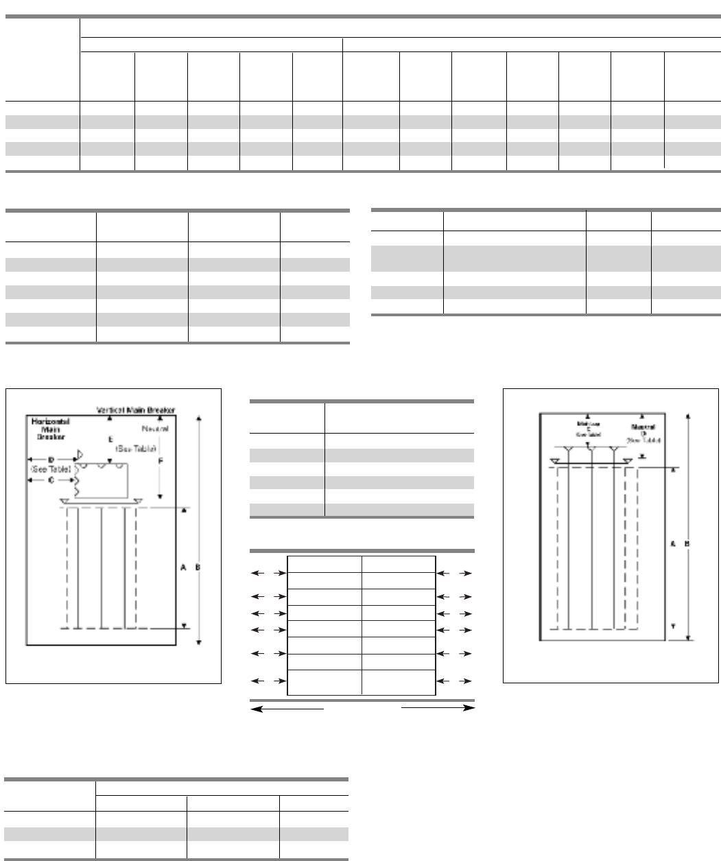
Application
Type P3 Panelboards
Table P3-4 – Main Lug Wire Bending (Fig. P3-2)
Table P3-3 – Main Breaker Wire Bending (Fig. P3-1)
Breaker
Frame C E F
FD Horiz. 7.25 — 20.13
FD Vert. — 12.25 25.38
CFD — 13.63 31.38
JD — 15.63 29.38
CJD — 14.75 35.38
LD — 14.75 29.38
CLD — 14.00 35.38
Fig. P3-3
Fig. P3-1 Fig. P3-2
Box depth = 7.75 in. (197 mm)
Box width = 24 in. (610 mm)
Box depth = 7.75 in. (197 mm)
Box width = 24 in. (610 mm)
Table P3-5 – Branch Breaker
Side Gutters Inches (mm) (Fig. P3-3)
Reference Panel
Letter Width 24” (609)
A7.750 (197)
B7.125 (181)
C6.000 (152)
D7.000 (178)
E5.000 (127)
F7.000 (178)
Panel Width
24 in. (610 mm)
1This lug is classified as removable.
Panel Amps Standard Connectors C D
250 (1) #6 AWG - 350KCMIL 10.75 113.50
400 (2) #3/0 AWG - 250KCMIL 16.00 17.88
or (1) #3/0 600KCMIL
600 (2) #3/0 AWG - 500KCMIL or 16.00 17.88
800 (2) #3/0 - 600KCMIL 16.00 17.88
800 (3) #3/0 AWG - 500KCMIL 17.50 23.88
Table P3-2 – Panel Unit Space To Box Height Requirements
P3 Panels With Standard Line Lugs. Unit Space (starting with 9" and adding 6" increments) “A” Dimension
Main Lugs Main Breakers
“B” 250A 400A 600A 800A 800A 250A 250A 250A 400A 400A 600A 600A
Dimension with with Horizontal Vertical Vertical Vertical Vertical Vertical Vertical
Box Height 2-600 3-500 FD FD CFD JD CJD LD CLD
Kcmil Kcmil
56 27 21 21 21 15 21 15 99—9—
62 33 27 27 27 21 27 21 15 15 9 15 9
33 39 33 33 33 27 33 27 21 21 15 21 15
74 45 39 39 39 33 39 33 27 27 21 27 21
80 — 45 45 45 39 45 39 33 33 27 33 27
3-3
Table P3-6 – Subfeed Breaker Wire Bending (Fig. P3-1)
Breaker Reference Dimensions
Family C E F
FD Single 7.25 — 8.25
Dual FD — 15.25 8.25
Single JD 8.00 — 29.38
ED, ED4, ED6 ED, ED4, ED6
HED4, HHED6 HED4, HHED6
QJ2, QJH2,
QJ2-H, HQJ2H
QJ2, QJH2,
QJ2-H, HQJ2H
BL, BLH, HBL BL, BLH, HBL
BLF, BLFH BLF, BLFH
BQD, BQD6 BQD, BQD6
A
B
C
D
A
B
C
D
FF
NGB NGB
NEB, HEB NEB, HEB
EE
SECTION 3

3-4
Application
Type P3 Panelboards
Table P3-7 – Main Breaker Selection1
Ampere Breaker Maximum Interrupting Rating (kA)
Rating Type 240V 480V 600V Available Trip Values
FD 65 35 18
250 HFD 100 65 25 70, 80, 90. 100, 110, 125, 150, 200, 225, 250
CFD 200 200 100
JXD6 (STD), JD6 65 35 25 200, 225, 250, 300, 350, 400
400 HJXD6, HJD6 100 65 35 200, 225, 250, 300, 350, 400
SJD6 65 35 25 200, 300, 400
SHJD61100 65 35 200, 300, 400
CJD6, SCJD6 200 150 100 200, 300, 400
LXD (STD), LD6 65 35 25 250, 300, 350, 400, 450, 500, 600
600 HLXD6, HID6 100 65 35 250, 300, 350, 400, 450, 500, 600
SID6, 65 35 25 300, 400, 500, 600
SHLD61100 65 35 300, 400, 500, 600
CLD6, SCLD6 200 150 100 300, 400, 500, 600
1Interchangeable trip main breakers and the SHJD and SHLD used as mains can be supplied only in top feed applications.
Table P3-8 – Subfeed Breaker Selection and Mounting Reference
Mounting Orientation Maximum Interrupting Rating (ka)
Breaker and Configuration
Type Vertical Horizontal 240V AC 480V AC 600V DC Available Trip Values
FD , FXD Twin — 65 35 18
HFD, HFX6 — Single 100 65 25 70, 80, 90, 100, 110, 125, 150, 200, 225, 250
JXD, JD6 — Single 65 35 25
200, 225, 250, 300, 350, 400HJXD6 100 65 35
HJD6
Branch Device Limitations
For applied on systems requiring connections, some limitations
may apply.
If the 2008 edition of the NEC has been adopted in the service
area, the following statement will not apply.
By application rule (NEC 480.14) lighting and appliance panels
are limited to 42 circuits installed. Each over currect device pole
counts as a circuit.
Table P3-9 – Neutral Connectors
(Based on 75ºC copper)
Max. Number
Wire Range of Connections Max. Amps
#14AWG - #4 AWG 46 85
#14AWG - #1/0 AWG 44 125
#4AWG - 350KCMIL 6 250
(1)#4AWG - 600KCMIL 1 400
(2)#6 - 350KCMIL

3-5
Application
Type P3 Panelboards
Table P3-10 – Branch Circuit Breakers
Maximum Interrupting Rating (kA)
Maximum Bolt-on Number Volts – AC DC
Ampere Breaker of Amp
Rating Type Poles Rating 120 120/240 240 277 480 600 250
1 15 - 70 10 ——————
BL12 15 - 100 — 10 —— — — —
3 15 - 100 —— 10 ————
BL HID 1 15 - 30 10 ——————
2 15 - 30 — 10 —— — — —
BLR 2 15 - 100 —— 10 ————
BLE 1 15 - 30 10 ——————
2 15 - 60 — 10 —— — — —
BLEH 1 15 - 30 22 ——————
2 15 - 60 — 22 —— — — —
BLF 1 15 - 30 10 ——————
2 15 - 60 — 10 —— — — —
100 BLHF 1 15 - 30 22 ——————
3 15 - 60 — 22 —— — — —
BGL 2 15 - 30 10 ——————
3 15 - 30 — 10 —— — — —
BAF 1 15, 20 10 ——————
BAFH 1 15, 20 22 ——————
1 15 - 70 — 22 —— — — —
BLH12 15 - 100 — 22 —— — — —
3 15 - 100 —— 22 ————
1 15 - 70 — 65 —— — — —
HBL 12 15 - 100 — 65 —— — — —
3 15 - 100 —— 65 ————
1 15 - 100 — 65 — 14 ——14
BQD12 15 - 100 — 65 —— 14 — 14
3 15 - 100 —— 65 — 14 — 14
1 15 - 125 100 ——25 ——14
NGB 1 2 2 15 - 125 — 100 100 — 25 ——
3 15 - 125 — 100 100 — 25 ——
1 15 - 125 100 ——65 ———
HEB 3 4 2 15 - 125 — 100 100 — 65 ——
3 15 - 125 — 100 100 — 65 ——
125 ED4 51 15 - 125 65 ——22 ———
2 15 - 125 —— 65 — 18 — 30
3 15 - 125 —— 65 — 18 ——
ED662 15 - 125 —— 65 — 25 18 30
3 15 - 125 —— 65 — 25 18 —
1 100 ——————
HED4 2 15 - 125 —— —65 ———
HHED6 3——100 42 42 — 30
QJ262/3 60 - 225 —— 10 ————
225 QJH2 62/3 60 - 225 —— 22 ————
QJ2-H 62/3 60 - 225 —— 42 ————
HQJ2H 62/3 100 - 225 ——100 ————
1BL, HBL, BLH and BQD breakers are mounted in common mountings in 3” or 6
pole increments.
2NGB breakers are counted in common mountings of 3” or 6 pole increments.
3For use on 480Y/277 volt systems. Not suitable for 480 Delta 3 phase 3
wire systems.
4NEB/HE breakers are counted in common mountings of 3” or 6 pole increments.
5ED4, ED6, HED4 and HHED6 breakers are mounted in common mountings in 3”or
(6) pole increments.
6QJ Breakers are dual mounted and take 6” of unit space. Limit to (6) per panel max.
SECTION 3

3-6
Typical Catalog Numbers
Type P3 Panelboards
Table P3-11 – Main Lugs Only – shown with aluminum bus, top fed, and surface trims
2
08Y/120V 240/120V
120/240V or
250 Vdc Max
Maximum 3 Phase, 4 Wire 3 Phase, 4 Wire 1 Phase, 3 Wire
Panel Amp Rating Unit Space (inches) Catalog Number Catalog Number Catalog Number
27 P3C56ML250ATS P3B56ML250ATS P3A56ML250ATS
33 P3C62ML250ATS P3B62ML250ATS P3A62ML250ATS
250 39 P3C68ML250ATS P3B62ML250ATS P3A62ML250ATS
45 P3C74ML250ATS P3B74ML250ATS P3A74ML250ATS
51 P3C80ML250ATS P3B80ML250ATS P3A80ML250ATS
21 P3C56ML400ATS P3B56ML400ATS P3A56ML400ATS
27 P3C62ML400ATS P3B62ML400ATS P3A62ML400ATS
400 33 P3C68ML400ATS P3B68ML400ATS P3A68ML400ATS
39 P3C74ML400ATS P3B74ML400ATS P3A74ML400ATS
45 P3C80ML400ATS P3B80ML400ATS P3A80ML400ATS
21 P3C56ML600ATS P3B56ML600ATS P3A56ML600ATS
27 P3C62ML600ATS P3B62ML600ATS P3A62ML600ATS
600 33 P3C68ML600ATS P3B68ML600ATS P3A68ML600ATS
39 P3C74ML600ATS P3B74ML600ATS P3A74ML600ATS
45 P3C80ML600ATS P3B80ML600ATS P3A80ML600ATS
21 P3C56ML800ATS P3B56ML800ATS P3A56ML800ATS
27 P3C62ML800ATS P3B62ML800ATS P3A62ML800ATS
800 33 P3C68ML800ATS P3B68ML800ATS P3A68ML800ATS
39 P3C74ML800ATS P3B74ML800ATS P3A74ML800ATS
45 P3C80ML800ATS P3B80ML800ATS P3A80ML800ATS
240V 408Y/277V
480V 1
Maximum 3 Phase, 3 Wire 3 Phase, 4 Wire 3 Phase, 3 Wire
Panel Amp Rating
Unit Space
(inches) Catalog Number Catalog Number Catalog Number
27 P3D56ML250ATS P3E56ML250ATS P3F56ML250ATS
33 P3D62ML250ATS P3E62ML250ATS P3F62ML250ATS
250 39 P3D68ML250ATS P3E68ML250ATS P3F68ML250ATS
45 P3D74ML250ATS P3E74ML250ATS P3F74ML250ATS
51 P3D80ML250ATS P3E80ML250ATS P3F80ML250ATS
21 P3D56ML400ATS P3E56ML400ATS P3F56ML400ATS
27 P3D62ML400ATS P3E62ML400ATS P3F62ML400ATS
400 33 P3D68ML400ATS P3E68ML400ATS P3F68ML400ATS
39 P3D74ML400ATS P3E74ML400ATS P3F74ML400ATS
45 P3D80ML400ATS P3E80ML400ATS P3F80ML400ATS
21 P3D56ML600ATS P3E56ML600ATS P3F56ML600ATS
27 P3D62ML600ATS P3E62ML600ATS P3F62ML600ATS
600 33 P3D68ML600ATS P3E68ML600ATS P3F68ML600ATS
39 P3D74ML600ATS P3E74ML600ATS P3F74ML600ATS
45 P3D80ML600ATS P3E80ML600ATS P3F80ML600ATS
21 P3D56ML800ATS P3E56ML800ATS P3F56ML800ATS
27 P3D62ML800ATS P3E62ML800ATS P3F62ML800ATS
800 33 P3D68ML800ATS P3E68ML800ATS P3F68ML800ATS
39 P3D74ML800ATS P3E74ML800ATS P3F74ML800ATS
45 P3D80ML800ATS P3E80ML800ATS P3F80ML800ATS
1
For 600V, change “F” in position 3 to “G.” Price only branch breakers with 600V ratings.

3-7
Typical Catalog Numbers
Type P3 Panelboards
Table P3-12 – Main Circuit Breaker – shown with aluminum bus, top fed and surface trims.
Maximum Unit 2
08Y/120V 240/120V
120/240V or 250V dc Max
Panel Space 3 Phase, 4 Wire 3 Phase, 4 Wire 1 Phase, 3 Wire
Amp Rating (inches) Catalog Number Catalog Number Catalog Number
21 P3C56FD250ATS P3B56FD250ATS P3A56FD250ATS
27 P3C62FD250ATS P3B62FD250ATS P3A62FD250ATS
250 33 P3C68FD250ATS P3B68FD250ATS P3A68FD250ATS
39 P3C74FD250ATS P3B74FD250ATS P3A74FD250ATS
45 P3C80FD250ATS P3B80FD250ATS P3A80FD250ATS
9P3C56JD400ATS P3B56JD400ATS P3A56JD400ATS
15 P3C62JD400ATS P3B62JD400ATS P3A62JD400ATS
400 21 P3C68JD400ATS P3B68JD400ATS P3A68JD400ATS
27 P3C74JD400ATS P3B74JD400ATS P3A74JD400ATS
33 P3C80JD400ATS P3B80JD400ATS P3A80JD400ATS
9P3C56LD600ATS P3B56LD600ATS P3A56LD600ATS
15 P3C62LD600ATS P3B62LD600ATS P3A62LD600ATS
600 21 P3C68LD600ATS P3B68LD600ATS P3A68LD600ATS
27 P3C74LD600ATS P3B74LD600ATS P3A74LD600ATS
33 P3C80LD600ATS P3B80LD600ATS P3A80LD600ATS
Maximum Unit
240V 408Y/277V
480V 1
Panel Space 3 Phase, 3 Wire 3 Phase, 4 Wire 3 Phase, 3 Wire
Amp Rating (inches) Catalog Number Catalog Number Catalog Number
21 P3D56FD250ATS P3E56FD250ATS P3F56FD250ATS
27 P3D62FD250ATS P3E62FD250ATS P3F62FD250ATS
250 33 P3D68FD250ATS P3E62FD250ATS P3F62FD250ATS
39 P3D74FD250ATS P3E74FD250ATS P3F74FD250ATS
45 P3D80FD250ATS P3E80FD250ATS P3F80FD250ATS
9P3D56JD400ATS P3E56JD400ATS P3F56JD400ATS
15 P3D62JD400ATS P3E62JD400ATS P3F62JD400ATS
400 21 P3D68JD400ATS P3E68JD400ATS P3F68JD400ATS
27 P3D74JD400ATS P3E74JD400ATS P3F74JD400ATS
33 P3D80JD400ATS P3E80JD400ATS P3F80JD400ATS
9P3D56LD600ATS P3E56LD600ATS P3F56LD600ATS
15 P3D62LD600ATS P3E62LD600ATS P3F62LD600ATS
600 21 P3D68LD600ATS P3E68LD600ATS P3F68LD600ATS
27 P3D74LD600ATS P3E74LD600ATS P3F74LD600ATS
33 P3D80LD600ATS P3E80LD600ATS P3F80LD600ATS
1
For 600V, change “F” in position 3 to “G.” Price only branch breakers with 600V ratings.
SECTION 3

Standard Modifications
Type P3 Panelboards
P3 Panel Options
Enclosures
• Extra gutter to sides or ends of the can
• Hinged trims
• Door-in-door trims
• Screw to the box trims
• Trim mounted devices (Devices mounted and wired
to the trim should also have hinged trim specified)
- Pilot lights
- Toggle switches
- Push buttons
• Painted boxes
• Custom colors
• Increase gauge trims and boxes
• Stainless steel trims and boxes, Type 1
• Aluminum trims and boxes, Type 1
• NEMA 3R enclosures
Panel Modifications
• Main Bus
Standard main bus in tin-plated aluminum. For copper main
bus, add from the table for each panel. Includes copper neutral
cross bar. For copper neutral branch lugs, see miscellaneous.
• Split bus requires 6” of unit space.
• Compression lug for MLO
• Compression lugs on Main breaker (may require extra
width or length on enclosure).
• Contactor mains or submain
- Asco 920 through 225 amps - Adds 12" unit space as main,
15” unit space as submain
- Asco 911 through 150 amps - Adds 21" unit space.
- Siemens LEN through 30 amps - Adds 12” unit space. Makes
box 10” deep.
• Control power transformers (contact engineering for
extra gutter requirements)
• Branch and main breaker accessories
- Handle blocks
- Handle locks
- Aux. Contacts 1
- UVR 1
• Feed-thru lugs
Cannot be used in conjunction with TVSS or sub-feed breakers.
See Page 3-10 for unit space impact. Wire ranges are the same
as main lug.
• 200% neutral
• Copper lugs, mechanical
• Bus mounted TVSS
•Service Entrance Label
Type P3 Panelboards are factory labeled suitable for use as
service entrance equipment when NEC requirements are met.
A panelboard cannot have more than six main disconnects,
unless it is a lighting and appliance branch panelboard.
Lighting and appliance branch panelboards are limited to two
main disconnects.
• NEMA 3R/12 enclosures
• NEMA 4 enclosures
• NEMA 4X enclosures
• Special keyed locks
- TEY
- TEU1
- Cat 60
- LL803
- LL806
- Yale
• Meters (Contact application engineering for space requirements)
• Panel Skirts
• Gasketing between trim and box (Type 1)
• Name Plates
•Grounding of Panelboards
Ground Bars except for brazed-to-box are shipped with the
panel interior.
- Non-Insulated Equipment Ground Bar – Standard
- Copper Non-Insulated Ground Bar
- Al Insulated Equipment Ground Bar
- Cu Insulated Equipment Ground Bar
- Ground Bar Brazed to Box (recommended for painted boxes)
• Shunt Trip 1
BL, BLH, HBL, BQD, NGB, NEB, HEB, ED2, ED4, HED4, ED6, HED6,
HHED6, QJ2, QJ2H, QJH2, HQJ2H as branch only. BL, BLH, HBL,
ED2, ED4, HED4, ED6, HED6, HHED6 uses 1” unit space for
shunt trip. All others may be used on mains or subfeeds.
• Remote control switches – 480V AC max. mounted in
a 23” enclosure to be cable connected to the panel.
• Time Clocks – mounted in a 23” enclosure to be cable
connected to the panel. Sangamo, Tork or Paragon
time clock can be supplied and mounted in panelboard
cabinet.
1Accessories on 1" pole breakers (BL, BQD, ED) will take unit space.
FXD6, HFD6, JXD6, JD6, HJD6, HJXD6
Description
Time Clock (1-or 2-Pole, Single or Double Throw Contacts;
3-Pole Single Throw)
277V Maximum with Plain Dial
Options:
Astronomical Dial
An Omitting Device
Reserve Power or Carryover
Space and Mounting Provisions Only
3-8

3-9
Standard Modifications
Type P3 Panelboards
Table P3-13 – Option Combinations
Subfeed Feed-thru TVSS (1) FD (2) FD (1) JD 200% Min. Box Unit Space
Amps Incoming Lugs 1Lugs Subfeed Subfeed Subfeed Neutral Size (in.) (in.)
Breaker Breaker Breaker
—•————• 56 27
Main Lug Only ——• ———• 56 15
—— — • — — • 56 15
—— — — • — • 56 9
•—————• 56 21
Main Lugs ••————• 56 21
250A •—• ———• 56 9
w/Subfeed Lugs •——• ——• 56 9
•———• —• 62 9
FD Main Breaker —• — — — — • 56 21
Horizontally Mtd. —— • — — — • 56 9
—— — • — — • 56 9
FD Main Breaker —• — — — — • 56 15
Vertically Mtd. —— • — — — • 62 9
CFD Main Breaker —• — — — — • 56 9
Vertically Mtd. —— • — — — • 68 9
•4—————• 56 21
—• — — — — •456 15
Main Lug Only —— • — — — • 56 9
—— — • — — • 56 9
—— — — — — • 62 9
—— — — • • • 56 9
—— — — — — • 56 9
—• — — — — •462 9
4002JD Main Breaker —— • — — — • 68 9
—— — • — — • 68 9
—— — — • — • 74 9
—— — — — • •468 9
—— — — — — • 62 9
—• — — — — •468 9
CJD Main Breaker —— • — — — • 74 9
—— — • — — • 74 9
—— — — • — • 80 9
—— — — — • •474 9
—— — — — — • 56 21
—• — — — — • 56 15
—— • — — — • 56 9
Main Lug Only —— — • — — • 56 9
—— — — • — • 62 9
—— — — — • • 56 9
—— — — — — • 56 9
—• — — — — • 62 9
60023 LD Main Breaker —— • — — — • 68 9
—— — • — — • 68 9
—— — — • — • 74 9
—— — — — • • 68 9
—— — — — — • 62 9
—• — — — — • 68 9
CLD Main Breaker —— • — — — • 74 9
—— — • — — • 74 9
—— — — • — • 80 9
—— — — — • • 74 9
—— — — — — • 56 21
—• — — — — • 56 9
Main Lug Only —— • — — — • 56 9
800 (2) 600Kcmil —— — • — — • 56 9
—— — — • — • 62 9
—— — — — • • 56 9
Main Lug Only —— — — — — — 56 15
(2) 500 Kcmil —— • — — — — 62 9
—— — • — — — 62 9
—— — — • — — 62 9
—— — — — • — 62 9
1 Subfed lugs are currently not offered as a standard with main circuit breakers.
2 Subfeed lugs on panels above 400A are not standard.
3 A 200% neutral cannot be provided along with a 400A subfeed breaker or because the breaker blocks the 4th lug position.
4 This feature is not available when the panel is fed by (2) cables per phase and neutral.
SECTION 3
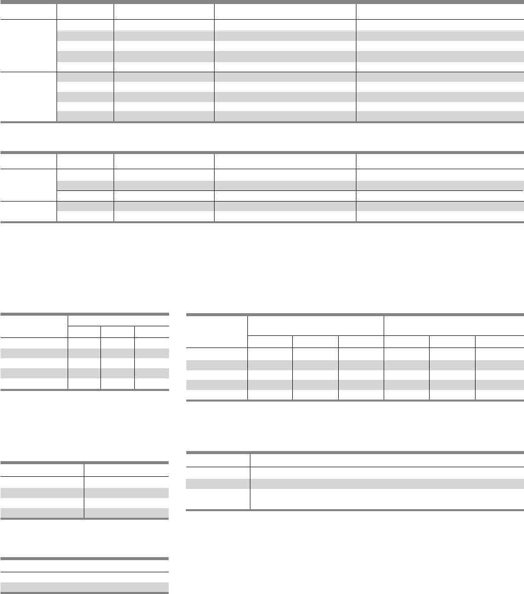
3-10
Connector Modifications
Type P3 Panelboards
Compression Lugs
Style Amp Rating Breaker Type Compression Connectors Box Height Addition
250 N/A (1)#6 AWG - 350 Kcmil —
MLO 400 N/A (1) 250 - 500 Kcmil or —
(2)# 1/0 AWG - 250 Kcmil —
600 N/A (2)#3/0 AWG - 500 Kcmil —
800 N/A (2) 400-750 Kcmil Al only —
250 FXD6, HFD6, CFD6 (1)#6 AWG - 350 Kcmil Cu or Al CFD6 requires an additional 6.0” box height
Main 400 JD6, JXD6, HJD6, (2)#1/0 AWG - 500 Kcmil Cu or Al 6
Breaker CJD6, SJD6, SHJD6, SCJD6
600 LD6, LXD6, HLD6, CJD6, (2)#2/0 AWG - 500 Kcmil Cu or Al 6
SLD6, SHLD6, SCLD6
Table P3-14 – Lugs
Style Amp Rating Breaker Type Compression Connectors Box Height Addition
MLO 400 N/A (1) 250 - 750 Kcmil or 6
(2)#6 AWG - 350 Kcmil Cu or Al
800 N/A (2) 600 Kcmil
Main Breaker 400 JD6, JXD6, HJD6, CJD6, (1)#4/0 AWG - 750 Kcmil Cu or Al 6
SJD6, SHJD6, SCJD6
Table P3-15 – Alternate Lugs
Enclosure Modifications
Remote Switch Modifications
Box Height Enclosure Size
Inches H W D
56 60 36 8
62 66 36 8
68 72 36 8
74 78 36 8
80 84 36 8
NEMA-4 For Type P3
Water Tight, Dust Tight, Steel Enclosure
(consult plant for actual enclosure size)
Table P3-19 – Application For Remote Switch
Switch Type Modification
920 Adds 12” to unit space
911 ≤ 225A Adds 21” unit space
LEN >30A ≤ 100 Adds 12” to unit space
100 A ≤ 200 Adds 12” to unit space and 10” Dp. min.
Table P3-20 – Remote Control
Switch Modification
Description
Auxiliary Contacts (mounted, not wired)
Ea. 2-Wire Control
Table P3-18 – Control Power
Transformer
Size VA
0,1 50
2 75
3 150
4 250
Table P3-16
NEMA-4X For Type P3
Water Tight, Dust Tight and Corrosion Resistant
(consult plant for actual enclosure size)
Enclosure - Stainless Steel Enclosure - Fiberglass
Box Height
and Steel with Epoxy Coating Size (inches)
Inches HWD H W D
56 60 36 12 60 36 12
62 66 36 8 66 36 8
68 72 36 8 72 36 8
74 78 36 8 78 36 8
80 84 36 8 84 36 8
Table P3-17
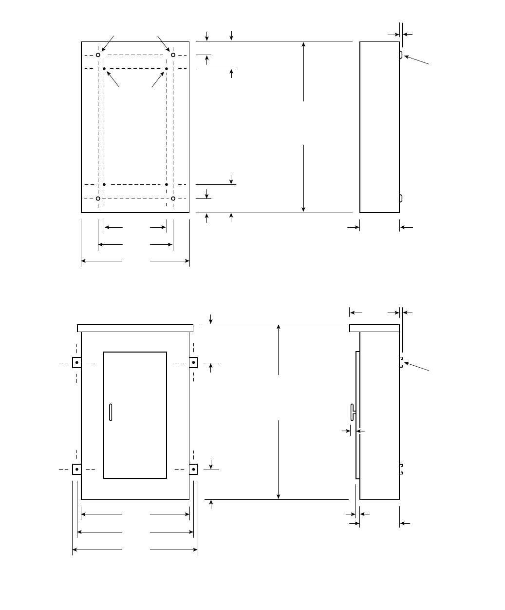
3-11
Dimensions
Type P3 Panelboards
24 in.
[610]
15 in.
[ 381 ]
12.63 in.
[ 321 ]
2 in.
[ 51 ]
Interior To Box
Mounting
Stubs
Box To Wall
Mounting Holes
.31 in.
[ 8 ]
Mounting
Dimple
7.75 in.
[ 197 ]
2 in.
[ 51 ]
24 in.
[ 610 ]
Mounting
Bracket
7.75 in.
[ 146 ]
25.5 in.
[ 648 ]
27.5 in.
[ 699 ]
a
a
a
a
9.5 in.
[ 241 ]
.50 in.
[ 13 ]
2 in.
[ 51 ]
2 in.
[ 51 ]
2 in.
[ 51 ]
1 in.
[25]
56 in.
[ 1422 ]
62 in.
[ 1575 ]
68 in.
[ 1727 ]
a
74 in.
[ 1880 ]
80 in.
[ 2032 ]
7.625 in.
[ 199 ]
7.625 in.
[ 199 ]
56 in.
[ 1422 ]
62 in.
[ 1575 ]
68 in.
[ 1727 ]
a
74 in.
[ 1880 ]
80 in.
[ 2032 ]
Type 1 Box
Box is symmetrical
Type 3R and 3R/12 Box
1Dimensions are interior of the box. Add 5/8” to width for
absolute dimension. Add 1/8” to height for absolute dimension.
2See table P3-2 to match ratings.
Dimensions shown in inches and millimeters [ ].
1
1
1
SECTION 3
1
1
2
1
2
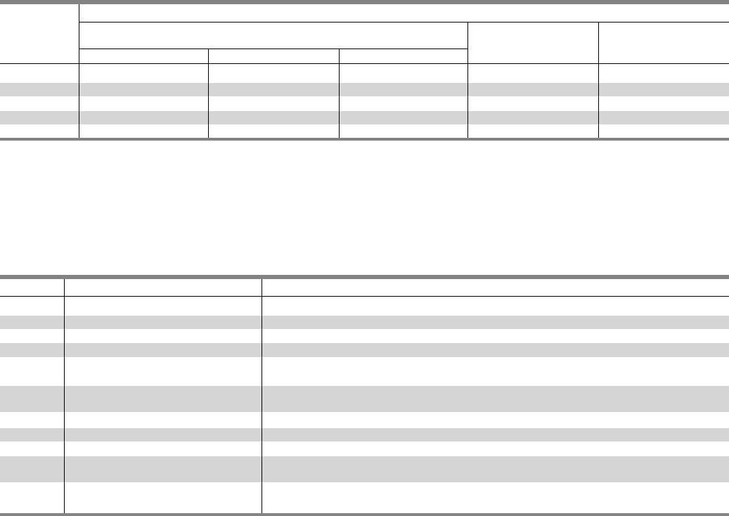
3-12
Kits and Accessories
Type P3 Panelboards
Table P3-21 – Standard Enclosures
Catalog Number
Box Type 1 Type 3R Type 3R/12
Height Standard Trim
(in.) Box Surface Flush
56 24WD56 P3S56 P3F56 24NRD56 24WPD56
62 24WD62 P3S62 P3F62 24NRD62 24WPD62
68 24WD68 P3S68 P3F68 24NRD68 24WPD68
74 24WD74 P3S74 P3F74 24NRD74 24WPD74
80 24WD80 P3S80 P3F80 24NRD80 24WPD80
Table P3-22 – Breaker Kits and Accessories
Kit No. Description Contents
BBKB32 BL/BQD 6-pole 3” branch breaker kit Kit contains top barrier, (3) A/C connectors, (1) B connector, hardware
BBKND32 NGB 6-pole 3” branch mounting kit Kit contains top barrier, (3) A/C connectors, (1) B connector, hardware
BBKED32 NEB/HEB 6-pole 3” branch mounting kit Kit contains top barrier, (3) A/C connectors, (1) B connector, hardware
BBKED32 ED 6-pole 3” branch breaker kit Kit contains breaker support, inter-phase barriers, (3) A/C connectors, (1) B connector, hardware
BBKQ1 QJ branch breaker kit for 2 and Kit contains all connectors and cover plates necessary to mount 2 and 3 pole breakers
3-pole single mount
BBKQ2 Branch breaker kit for 2 and 3 pole Kit contains all connectors and cover plates necessary to mount both 2 and 3-pole breakers
QJ twin mount
DFFP3 Deadfront filler 3” 3” empty space filler and hardware
DFFP6 Deadfront filler 6” 6” empty space filler and hardware
P3BK1 P3 bonding kit Bonding strap and hardware
QF3 Filler plate for BL, BQD, ED frame 1” filler plate
branch breaker provisions
EBF1 Filler plate for NEB/HEB branch 1” filler plate
breaker provision content
Options For Type 1 Trims
Items must be ordered as manual line item on factory
Hinged trim – Add “H” suffix
Door-in-door – Add “D” suffix
Metal card holder – Add “M” suffix
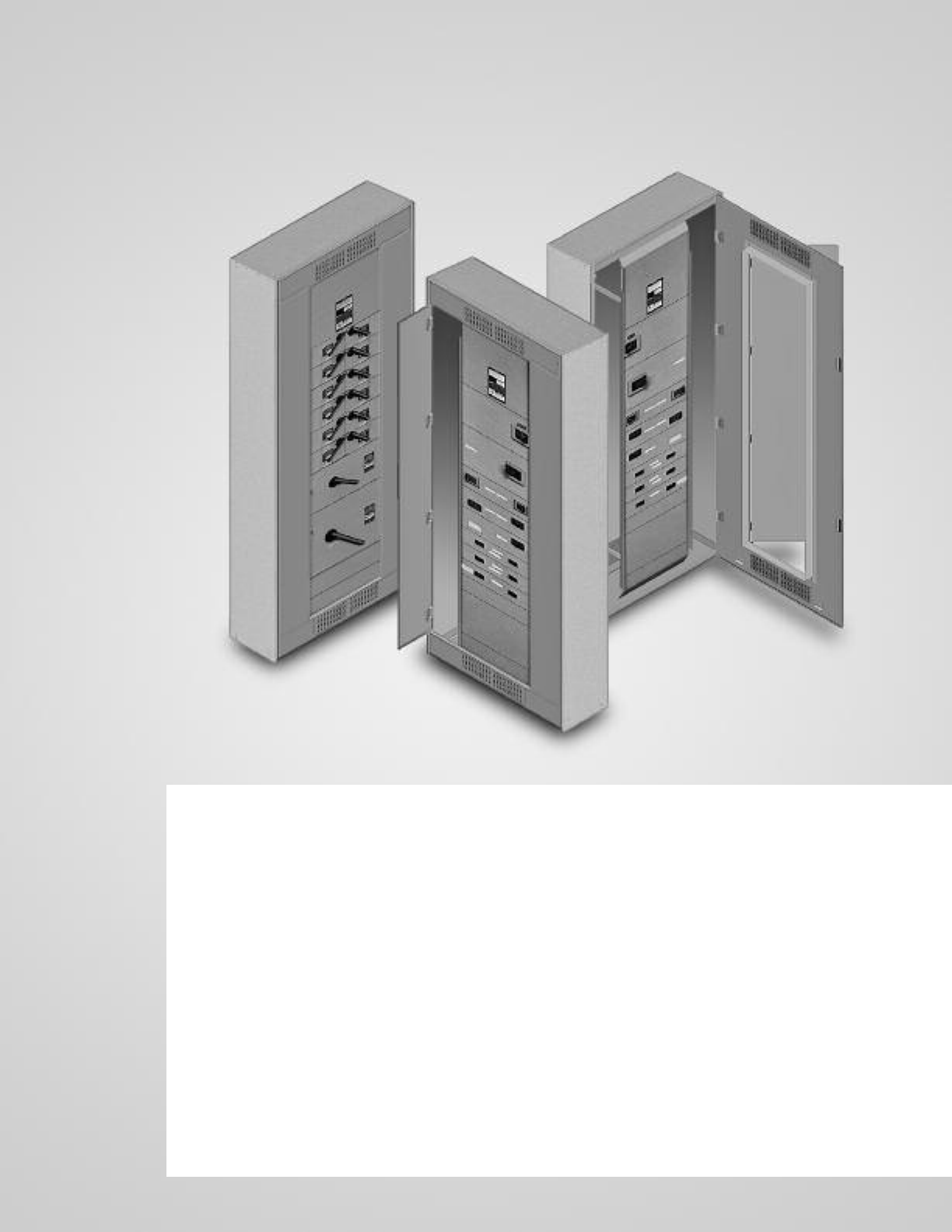
P4 Panelboards
Description Page
General Information 4-2
Selection and Application 4-2
Applications 4-3 – 4-6
Main Breaker Selection 4-3
Main Switch Connectors 4-3
Enclosure Selection 4-3
Main Breaker Unit Space Dimensions 4-3
Main Lugs Only Unit Space Dimensions 4-4
Branch Switch Unit Space 4-4
Branch Circuit Breakers 4-5 – 4-6
Branch Breaker Unit Space 4-6
Branch Breaker Side Gutter 4-7
Typical Catalog Numbers 4-8
Main Lugs Only 4-8
Main Circuit Breakers Only 4-8
Modifications and Additions 4-9
Connector Modifications 4-10
Compression Lugs 4-10
Alternate Lugs 4-10
Dimensions 4-11
Kits and Accessories 4-12 – 4-13
SECTION 4
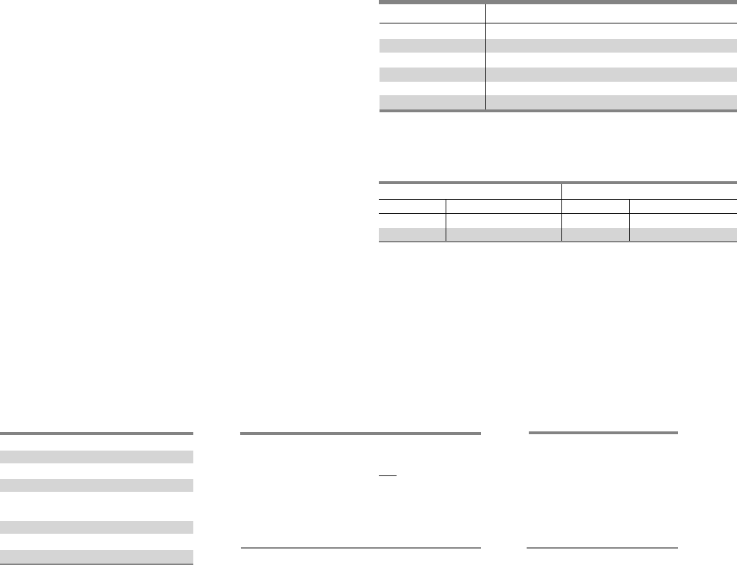
4-2
Type P4 Panelboards
The Siemens P4 is a medium-sized distribution panel designed
for applications that require more or larger branch devices and
higher amp ratings than typical lighting panels can support.
Even with the increased capacity, this panel is a space saver
with its 32" width and 10" depth. The P4 panel offers a wide
array of factory-assembled options and has the ability to mix
breaker frames in unit space up to 800 amps and fusible
switches up to 200 amps. Bussing options vary from standard
temperature rated aluminum to temperature rated copper and
750NSi aluminum and 1000A/Si copper designs. All aluminum
bussing in the P4 panel is tin-plated. All Copper bussing in the
P4 panel is silver plated. Integrated time clocks, bus mounted
contactors as mains or submains, split bus and subfeed lugs (up
to 600 amp) are just a few of the options of this flexible panel.
The 4 panel configurations defined by the unit space allowed
for a given amperage, main device and box height. The P4 panel
starts with a 60” high box. All of the branch devices are unit
space mounted. Breakers and switches can be mixed and
matched to meet customer requirements.
Main Lug / Main Breaker / Main Switch
Enclosure – Standard Type 1 enclosure is 32" wide x 10" deep.
X Box Height is determined by main device and unit space. See
charts for box height.
Voltage – 600 Vac Max.
250 Vdc Max.
Amperage – 400-800 amp main breaker, 400-1200 amp MLO,
100-200 amp main switch.
Short Circuit Rating – 200 KAIC Max. symmetrical or equal to
the lowest rated device installed unless a series rating is indicated.
Panels with subfeed or feed-thru lugs without a main device,
circuit breaker or fusible unit, are limited to a three-cycle rating.
The three-cycle rating for the P4 panel is limited to 42 KAIC. Note
that the main device may be mounted remote from the panel.
Bussing – The P4 panel has more options to meet market
requirements. The standard bussing is temperature rated
aluminum. The rating is per the requirements of UL 67 – the
standard for panelboards. All aluminum bussing is tin-plated.
Optional bussing for the P4 panel is: 750 A/Si aluminum,
temperature rated copper, and 1000 A/Si copper. The copper
bus option for this panel is silver-plated.
Weight – Approximate
Total panelboard weight when filled with a normal quantity of
breakers and accessories is about 8 lbs. (1 kg) per inch (54g per
mm) of box height.
Table P4-2 – Gauge Steel of Boxes
Fronts, Surface and Flush
Selection and Application
1) To specify a particular panelboard, first determine voltage,
system, amperage and type of main, amperage and type
of branch devices, and modifications, if any. (Step 1)
2) List branch devices and modifications requiring space
additions. List unit space requirements of each.
Note: Some units are twin mounted meaning two breakers
occupy the same unit space.
Select appropriate enclosure height from selection chart on
page 4-3, based on unit space requirements. (Step 2)
3) Select panelboard catalog number from appropriate table
based upon voltage, system, amperage and unit space
requirements. (Step 3)
Ampere Rating Connectors Suitable for Copper or Aluminum
400 (1) - #3/0 AWG-600 Kcmil
(2) - #3/0 AWG-250 Kcmil
600 (2) - #3/0 AWG-600 Kcmil
800 (3) - #3/0 AWG-600 Kcmil
1000 (4) - #3/0 AWG-600 Kcmil
1200 (4) - #3/0 AWG-600 Kcmil
1Alternate lugs for 750 kcmil cable are available, but result in significant loss of
branch unit mounting space. Consult Siemens.
Step #1
Amperage 400
Voltage 208Y/120
System 3 Phase, 4 wire
Main Main Breaker
Branches 5-125/3, 2-225/3,
1-250/3
Modifications None
Feed Top
Mounting Surface
Step #2
5-125/3 ED4 3.75” = 11.25” Twin Mounted
2-225/3 QJ2 5” = 5” Twin Mounted
1-250/3 FXD6 5” = 5”
21.25
Enclosure is B275 from Selection
Chart on Page 4-3.
(32” wide, 75” high, 10” deep)
Step #3
1-P4C75JX400ATS
3-ED4 1-Pole Provision
5-125/3
2-225/3 QJ2
1-250/3 FXD6
12” Space
Dimensions in inches (mm) Gauge Steel
Width Height Box Fronts
32” 60 - 75 - 90 #16 1#14 (1 piece trim)
(813) (1524, 1905, 2286) #16 (4 piece trim)
1 Box has 16 gauge side panels and 12 gauge back support.
Table P4-1 – Main Lugs 1
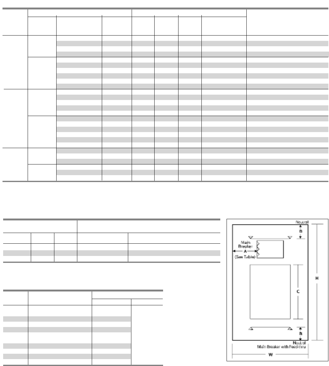
4-3
Application
Type P4 Panelboards
Table P4-4 – Enclosure Selection 1
Enclosure Dimension Available Unit Space in Inches (mm)
in Inches (mm) Dimension “C” in Fig. 4-1
Main Lug Only Main Breaker
H W D 400 / 800A 400A/600A 800A
60 (1524) 32 (813) 10 (254) 30 (762) 23.75 (603) 21.25 (540)
75 (1905) 32 (813) 10 (254) 45 (1143) 38.75 (984) 26.25 (921)
90 (2286) 32 (813) 10 (254) 60 (1524) 53.75 (1365) 51.25 (1302)
1Standard trim is four piece without door. Surface or flush one piece trim is
available for 32 in. (813 mm) wide circuit breaker panels.
Table P4-5 – Main Breaker Lug Location Reference (Fig. P4-1)
Ampere Breaker Dimensions in Inches (mm)
Rating Type AB
400 JXD6, JD6, HJXD6, HJD6 10.425 (265)
400 HHJXD6, HHJD6
400 NJ, HJ, LJ 12.500 (318)
400 SJD6, SHJD6 10.425 (265)
400 CJD6, SCJD6 8.250 (210)
600 LXD6, LD6, HLXD6, HLD6,
HHLXD6, HHLD6 10.425 (265) 13.125 (333)
600 NL, HL, LL 11.250 (286)
600 SLD6, SHLD6 10.425 (265)
600 CLD6, SCLD6 8.250 (210)
800 NM, HM, LM, 10.425 (265)
SECTION 4
Table P4-3 – Main Breaker Selection
Breaker type Maximum IC (KA) Symmetrical Amperes
Main Breaker
Ampere Trip Frame Breaker Unit Space in
rating type 1type family 240V 480V 600V inches (mm) Continuous Current Rating
JXD6, JD6 Sentron 65 35 22 8.75 (222) 200, 225, 250, 300, 350, 400
TMTU HJXD6, HJD6 Sentron 100 65 35 8.75 (222) 200, 225, 250, 300, 350, 400
HHJXD6, HHJD6 Sentron 200 100 50 8.75 (222) 200, 225, 250, 300, 350, 400
CJD6 Sentron 200 150 100 8.75 (222) 200, 225, 250, 300, 350, 400
400A NJ VL 65 35 25 6.25 (159) 250, 400
SJD6 Sentron 65 35 25 8.75 (222) 200, 300, 400
ETU HJ VL 100 65 25 6.25 (159) 250, 400
SHJD6 Sentron 100 65 35 8.75 (222) 200, 300, 400
LJ VL 200 100 25 6.25 (159) 250, 400
SCJD6 Sentron 200 150 100 8.75 (222) 200, 300, 400
LXD6 Sentron 65 35 25 8.75 (222) 450, 500, 600
LD6 Sentron 65 35 25 8.75 (222) 250, 300, 350, 400, 450, 500, 600
TMTU HLXD6, HLD6 Sentron 100 65 35 8.75 (222) 250, 300, 350, 400, 450, 500, 600
HHLXD6, HHLD6 Sentron 200 100 50 8.75 (222) 250, 300, 350, 400, 450, 500, 600
600A CLD6 Sentron 200 150 100 8.75 (222) 250, 300, 350, 400, 450, 500, 600
NL 2VL 65 35 18 6.25 (159) 400, 600
SLD6 Sentron 65 35 25 8.75 (222) 300, 400, 500, 600
HL 2VL 100 65 18 6.25 (159) 400, 600
ETU SHLD6 Sentron 100 65 35 8.75 (222) 300, 400, 500, 600
LL 2VL 200 100 18 6.25 (159) 400, 600
SCLD6 Sentron 200 150 100 8.75 (222) 300, 400, 500, 600
NM 3 VL 65 35 25 8.75 (222) 600, 700, 800
HM 3VL 100 65 35 8.75 (222) 600, 700, 800
800A
TMTU LM 3VL 200 100 50 8.75 (222) 600, 700, 800
ETU
NM 3VL 65 35 25 8.75 (222) 600, 800
HM 3VL 100 65 35 8.75 (222) 600, 800
LM 3VL 200 100 50 8.75 (222) 600, 800
1 TMTU = Thermal Magnetic Trip Unit and ETU = Electronic Trip Unit.
2100% ratings are not available for the VL LG frame, replace with VL MG frame @ 600A rated 100%.
3100% ratings are not available for the VL MG. Use a P5 panel for this application with the VL NG frame @ 800A rated 100%.
Fig. P4-1
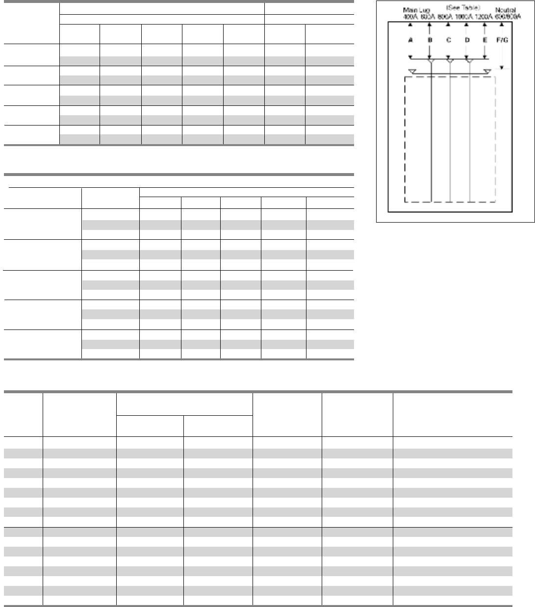
4-4
Table P4-8 – Branch Switch Unit Space
Unit Space
in inches (mm)
Ampere Number Twin Single AC Cables Per Connectors Suitable For
Rating of Poles Mounted Mounted Voltage Connector Copper or Aluminum
30-30 2,3 2.50 (64) — 240 1 #14 - #8 AWG (Cu Only)
30-30 2,3 5.00 (127) — 240 1 #14 - #4 AWG
30-60 2,3 5.00 (127) — 240 1 #14 - #4 AWG
60-60 2,3 5.00 (127) — 240 1 #14 - #4 AWG
60-100 2,3 7.50 (191) — 240 1 #10 - #1/0 AWG
100-100 2,3 7.50 (191) — 240 1 #10 - #1/0 AWG
200-200 3 10.00 (254) — 240 1 #6 AWG - 350 Kcmil
200 2—7.50 (191) 240 1 #6 AWG - 350 Kcmil
200 3—10.00 (254) 240 2 #6 AWG - 350 Kcmil
30-30 2,3 7.5 (191) — 600 1 #14 - #8 AWG
30-60 2,3 7.5 (191) — 600 1 #14 - #4 AWG
60-60 2,3 7.5 (191) — 600 1 #14 - #4 AWG
60-100 2,3 7.5 (191) — 600 1 #10-#1/0 AWG
100-100 2,3 7.5 (191) — 600 1 #10-#1/0 AWG
200-200 3 10.00 (254) — 600 1 #6 AWG - 250 Kcmil
100 2,3 — 7.50 (191) 600 1 #10-#1/0 AWG
200 2,3 — 10.00 (254) 600 1 #6 AWG - 250 Kcmil
Table P4-6 – Main Lugs Location Reference (Fig. P4-2)
Dimensions in inches (mm)
Main Lug Neutral
400A 600A 800A 1000A 1200A 400-600A 800-1200A
Lugs
A B C D E F G
Standard
16.500 16.750 15.969 15.969 15.969 13.125 13.125
(419) (425) (406) (406) (406) (333) (333)
Oversize 16.500 21.750 25.969 25.969 25.969 18.125 23.125
(419) (552) (660) (660) (660) (460) (587)
Crimp 19.187 18.250 18.687 18.250 18.250 15.937 15.937
(487) (464) (475) (464) (464) (405) (405)
Standard 16.750 15.969 — — — 13.125 13.125
w/Subfeed (425) (406) (333) (333)
Standard 16.500 16.750 — — — 13.125 13.125
w/Feed-thru (419) (425 ) (333) (333)
Fig. P4-2
Application
Type P4 Panelboards
Table P4-7 – Available Unit Space – MLO
Dimensions in inches (mm)
Ampere Rating
Lug Type Box Height 400 600 800 1000 1200
Standard 60 30 30 30 30 30
Mechanical 75 45 45 45 45 45
90 60 60 60 60 60
Oversized 60 30 25 20 20 20
Mechanical 75 45 40 35 35 35
90 60 55 50 50 50
60 25 25 25 25 24
Crimp Type 75 40 40 40 40 40
90 55 55 55 55 55
Std Mechanical 60 30 30 —— —
W/ Sub-feed 75 45 45 —— —
90 60 60 —— —
Std. Mechancial 60 20 20 12.5 12.5 12.5
W/ Feed-thru 75 35 35 27.5 27.5 27.5
90 50 50 42.5 42.5 42.5

4-5
Application
Type P4 Panelboards
Table P4-9 – Branch Circuit Breakers
1 CSA listed only at 600V AC.
215-30A trip (shown) 65 KA, 35-100A 25 KA.
Maximum Bolt-on Number Trip Amp Maximum IC (KA) Symmetrical Amperes
Ampere Breaker of Poles Rating Voltage -AC
Rating Type 120 120/240 240 277 480/ 277 480 600/347 600
BLF 1 15-30 10 ———————
2 15-60 — 10 ———— ——
BLHF 1 15-30 22 ———————
2 15-60 — 22 ———— ——
BLE 1 15-30 10 ———————
2 15-60 — 10 ———— ——
BLEH 1 15-30 22 ———————
2 15-60 — 22 ———— ——
BAF, BAFC 1 15-20 10 ———————
BAFH, BAFHC 1 15-20 22 ———————
BAF 2 15-20 — 10 ———— ——
BAFH 2 15-20 — 22 ———— ——
BGL 2 15-30 10 ———————
3 15-30 — 10 ———— ——
100 BLR 2 15-100 ——10 ——— ——
BL 1 15-70 10 ———————
2 15-100 — 10 ———— ——
3 15-100 ——10 ——— ——
BLH 1 15-70 — 22 ———— ——
2 15-100 — 22 ———— ——
3 15-100 ——22 ——— ——
HBL 1 15-70 — 65 ———— ——
2 15-100 — 65 ———— ——
3 15-100 ——65 ——— ——
BQD 1 15-100 — 65 — 14 —— — —
2 15-100 — 65 ——14 ———
3 15-100 ——65 — 14 ———
BQD611 15-70 65 ———————
2/3 15-100 ——65 ——— —10
BL (HID) 1/2 15-30 — 10 ———— ——
BLF (GFCI) 1 15-60 — 10 ———— ——
2 40-60 — 10 ———— ——
BLE (EQ GFI) 1/2 15-30 — 10 ———— ——
BLG (SWN) 2 15-30 10 ———————
3 15-30 — 10 ———— ——
BLHF (GCFI) 1/2 15-30 — 22 ———— ——
NGB 1 15-125 100 ——25 —— ——
2/3 15-125 — 100 100 — 25 — 14 —
NEB 1 15-125 100 85 85 35 —— ——
2/3 15-125 — 85 85 — 35 35 22 —
HEB 1 15-125 200 100 100 65 —— — —
2/3 15-125 100 100 — 100 65 25 25 —
125 ED4 1 15-125 65 ——22 —— ——
2/3 15-125 — 65 65 — 18 18 —
ED6 2 15-125 —— ——25 25 30 —
3 15-125 ——65 — 25 25 — 18
HED4 1 15-125 100 ——652—— ——
2/3 15-125 — 100 100 — 42 42 ——
HHED6 2/3 15-125 100 ———65 65 18 18
CED6 2/3 15-125 200 ———200 200 100 100
QJ2 2/3 60-225 ——10 ——— ——
225 QJH2 2/3 60-225 ——22 ——— ——
QJ2H 2/3 60-225 ——42 ——— ——
HQJ2H 2/3 60-225 ——100 ——— ——
FXD6, FD6 2/3 70-250 ——65 — 35 35 18 18
250 HFXD6, HFD6 2/3 70-250 ——100 — 65 65 25 25
HHFXD6, HHFD6 2/3 70-250 ——200 — 100 100 25 25
CFD 2/3 70-250 ——200 — 200 200 100 100
JXD6, JD6, SJD6 2/3 200-400 ——65 — 35 35 25 25
HJXD6,HJD6, SHJD6 2/3 200-400 ——100 — 65 65 35 35
400 HHJXD6, HHJD6 2/3 200-400 ——200 — 100 100 50 50
CJD6 2/3 200-400 ——200 — 150 150 100 100
LXD6 2/3 450-600 ——65 — 35 35 25 25
LD6 2/3 250-600 ——65 — 35 35 25 25
SLD6 2/3 300-600 ——65 — 35 35 25 25
600 HLD6, HLXD6 2/3 250-600 ——100 — 65 65 35 35
SHLD6 2/3 300-600 ——100 — 65 65 35 35
HHLD6, HHLXD6 2/3 250-600 ——200 — 100 100 50 50
CLD6 2/3 450-600 ——200 — 150 150 100 100
SCLD6 2/3 300-600 ——200 — 150 150 100 100
SECTION 4
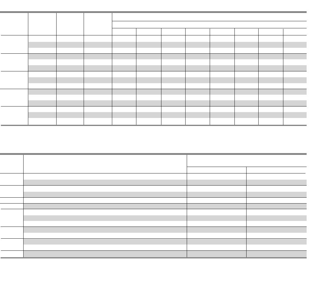
4-6
Application
Type P4 Panelboards
Mounting Height
Amp Breaker in Inches (mm)
Rating Type Twin Single
100 1BL, BLH, HBL, BQD, BLE, BLEH, BLR, BLF, BLHF, BAF, BAFC, BAFH, BAFCH 3.75 (95) —
BGL, BL, BLH, HBL, BQD – with accessories 6.25 (159) —
125 NGB, NEB, HEB, ED4, ED6, HED4, HHED6, CED6, 3.75 (95) —
NGB, ED41 2, ED61 2, HED41 2, HHED61 2, CED61 2 – with accessories 6.25 (159) —
150 ND, HD, LD 5.00 (127) —
225 QJ2, QJH2, QJ2-H, HQJ2H 5.00 (127) —
FD6, FXD6, HFD6, HFXD6, HHFD6, HHFXD6 5.00 (127) —
250 CFD6 — 5.00 (127)
NF, HF, LF 5.00 (127) —
400 JD6, JXD6, HJD6, HJXD6, HHJD6, HHJXD6, CJD6, — 8.75 (222)
NJ, HJ, LJ — 6.25 (159)
600 LD6, LXD6, HLD6, HLXD6, HHLD6, HHLXD6, CLD6 — 8.75 (222)
NL, HL, LL — 6.25 (159)
800 NM, HM, LM — 8.75 (222)
1Mounting height shown will accommodate from (1) to (6) poles.
2Accessories such as shunt trips on three pole breakers requires 6.25" of unit space
Table P4-11 – Branch Breaker Unit Space Requirements
Table P4-10 – Branch Circuit Breakers (VL)
Maximum IC (KA) Symmetrical Amperes
Maximum Bolt-on Number Trip Volts – AC
Ampere Breaker of Amp
Rating Type Poles Rating 120 120/240 240 277 480/277 480 600/347 600
ND 3 60 - 150 — 65 65 — 35 35 18 18
150 1HD 3 60 - 150 — 100 100 — 65 65 20 20
LD 3 60 - 150 — 200 200 — 100 100 25 25
NF 3 100 - 250 — 65 65 — 35 35 18 18
250 1HF 3 100 - 250 — 100 100 — 65 65 20 20
LF 3 100 - 250 — 200 200 — 100 100 25 25
NJ 3 250 - 400 — 65 65 — 35 35 25 25
400 1HJ 3 250 - 400 — 100 100 — 65 65 25 25
LJ 3 250 - 400 — 200 200 — 100 100 25 25
NL 3 400 - 600 — 65 65 — 35 35 18 18
600 1HL 3 400 - 600 — 100 100 — 65 65 18 18
LL 3 400 - 600 — 200 200 — 100 100 18 18
NM 2/3 600 - 800 — 65 65 — 35 35 25 25
800 HM 2/3 600 - 800 — 100 100 — 65 65 35 35
LM 2/3 600 - 800 — 200 200 — 100 100 50 50
1Only offered with Electronic Trip Units.
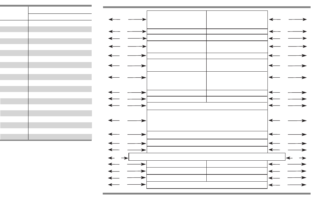
4-7
Fig. P4-3
A
B
F
D
E
C
H
VB 100 - 200A Single
VB 30A, VB 60A (5”) VB 30A, VB 60A (5”)
VB 30A, VB 60A (5”) VB 30A, VB 60A (5”)
VB 100 - 200A VB 100 - 200A
A
B
F
D
E
C
H
P
Q
R
I
J
L
S
T
M
N
O
P
K
Q
R
I
J
L
S
T
M
N
O
K
BL, BLH, HBL, BQD, BLE BL, BLH, HBL, BQD, BLE
BLEH, BLR, BLF, BLHF, BLEH, BLR, BLF, BLHF,
BAF, BAHF, BGL, BQD BAF, BAHF, BGL, BQD
NGB NGB
NEB, HEB NEB, HEB
ED4, ED6, ED4, ED6,
HED4, HHED6 HED4, HHED6
CED CED
QJ2, QJH2, QJ2, QJH2,
QJ2H, HQJ2H QJ2H, HQJ2H
FXD6, FD6, HFXD6, FXD6, FD6, HFXD6,
HFD6, HHFXD6, HHFD6, HFD6, HHFXD6, HHFD6
SFD6, SHFD6 SFD6, SHFD6
ND, HD, LD ND, HD, LD
NF, HF, LF NF, HF, LF
CFD6, SCFD6
JD6, JXD6, SJD6, HJD6, HXJD6, SHJD6, HHJD6,
HHJXD6, LD6, LXD6, SLD6, HLD6, HXLD6, SHLD6,
HHLD6, HHLXD6
CJD6, SCJD6, CLD6, SCLD6
NJ, HJ, LJ
NL, HL, LL
NM, HM, LM
SECTION 4
Table P4-12 – Branch Breaker Side
Gutter Inches (mm) (Fig. P4-3)
Reference Panel Width 32 in (813)
Letter Dimensions in inches (mm)
A 11.0 (279)
B 10.98 (279)
C 8.62 (219)
D7.0 (178)
E 5.75 (146)
F 5.25 (133)
G —
H 4.62 (177)
I 8.76 (223)
J 10.42 (265)
K 10.0 (254)
L 8.25 (210)
M 10.0 (254)
N7.0 (178)
O5.0 (127)
P7.50 (191)
Q7.9 (200)
R7.9 (200)
S2.5 (318)
T11.25 (286)
Application
Type P4 Panelboards
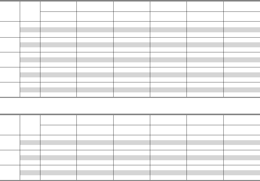
4-8
Application
Type P4 Panelboards
Table P4-13 – Main Lugs Only – shown with aluminum bus, top fed, and surface trims
Max. 2
08Y/120V 240/120V
120/240V or 240V 480Y/277V 480V 1
Panel Unit 250 Vdc Max
Amp Space 3 Phase, 4 Wire 3 Phase, 4 Wire 1 Phase, 3 Wire 3 Phase, 3 Wire 3 Phase, 4 Wire 3 Phase, 3 Wire
Rating (inches) Catalog Number Catalog Number Catalog Number Catalog Number Catalog Number Catalog Number
30 P4C60ML400ATS P4B60ML400ATS P4A60ML400ATS P4D60ML400ATS P4E60ML400ATS P4F60ML400ATS
400 45 P4C75ML400ATS P4B75ML400ATS P4A75ML400ATS P4D75ML400ATS P4E75ML400ATS P4F75ML400ATS
60 P4C90ML400ATS P4B90ML400ATS P4A90ML400ATS P4D90ML400ATS P4E90ML400ATS P4F90ML400ATS
30 P4C60ML600ATS P4B60ML600ATS P4A60ML600ATS P4D60ML600ATS P4E60ML600ATS P4F60ML600ATS
600 45 P4C75ML600ATS P4B75ML600ATS P4A75ML600ATS P4D75ML600ATS P4E75ML600ATS P4F75ML600ATS
60 P4C90ML600ATS P4B90ML600ATS P4A90ML600ATS P4D90ML600ATS P4E90ML600ATS P4F90ML600ATS
30 P4C60ML800ATS P4B60ML800ATS P4A60ML800ATS P4D60ML800ATS P4E60ML800ATS P4F60ML800ATS
800 45 P4C75ML800ATS P4B75ML800ATS P4A75ML800ATS P4D75ML800ATS P4E75ML800ATS P4F75ML800ATS
60 P4C90ML800ATS P4B90ML800ATS P4A90ML800ATS P4D90ML800ATS P4E90ML800ATS P4F90ML800ATS
30 P4C60ML101ATS P4B60ML101ATS P4A60ML101ATS P4D60ML101ATS P4E60ML101ATS P4F60ML101ATS
1000 45 P4C75ML101ATS P4B75ML101ATS P4A75ML101ATS P4D75ML101ATS P4E75ML101ATS P4F75ML101ATS
60 P4C90ML101ATS P4B90ML101ATS P4A90ML101ATS P4D90ML101ATS P4E90ML101ATS P4F90ML101ATS
30 P4C60ML120ATS P4B60ML120ATS P4A60ML120ATS P4D60ML120ATS P4E60ML120ATS P4F60ML120ATS
1200 45 P4C75ML120ATS P4B75ML120ATS P4A75ML120ATS P4D75ML120ATS P4E75ML120ATS P4F75ML120ATS
60 P4C90ML120ATS P4B90ML120ATS P4A90ML120ATS P4D90ML120ATS P4E90ML120ATS P4F90ML120ATS
Table P4-14 – Main Circuit Breakers Only – shown with standard mains, aluminum bus, top fed, and surface trims
Max. 2
08Y/120V 240/120V
120/240V or 240V 480Y/277V 480V 1
Panel Unit 250 Vdc Max
Amp Space 3 Phase, 4 Wire 3 Phase, 4 Wire 1 Phase, 3 Wire 3 Phase, 3 Wire 3 Phase, 4 Wire 3 Phase, 3 Wire
Rating (inches) Catalog Number Catalog Number Catalog Number Catalog Number Catalog Number Catalog Number
21.25 P4C60JX400ATS P4B60JX400ATS P4A60JX400ATS P4D60JX400ATS P4E60JX400ATS P4F60JX400ATS
400 36.25 P4C75JX400ATS P4B75JX400ATS P4A75JX400ATS P4D75JX400ATS P4E75JX400ATS P4F75JX400ATS
51.25 P4C90JX400ATS P4B90JX400ATS P4A90JX400ATS P4D90JX400ATS P4E90JX400ATS P4F90JX400ATS
21.25 P4C60LX600ATS P4B60LX600ATS P4A60LX600ATS P4D60LX600ATS P4E60LX600ATS P4F60LX600ATS
600 36.25 P4C75LX600ATS P4B75LX600ATS P4A75LX600ATS P4D75LX600ATS P4E75LX600ATS P4F75LX600ATS
51.25 P4C90LX600ATS P4B90LX600ATS P4A90LX600ATS P4D90LX600ATS P4E90LX600ATS P4F90LX600ATS
21.25 P4C60M1800ATS P4B60M1800ATS P4A60M1800ATS P4D60M1800ATS P4E60M1800ATS P4F60M1800ATS
800 36.25 P4C75M1800ATS P4B75M1800ATS P4A75M1800ATS P4D75M1800ATS P4E75M1800ATS P4F75M1800ATS
51.25 P4C90M1800ATS P4B90M1800ATS P4A90M1800ATS P4D90M1800ATS P4E90M1800ATS P4F90M1800ATS
1
For 600V, change “F” in position 3 to “G.”
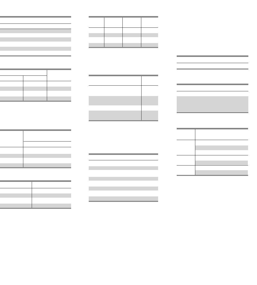
4-9
Modifications and Additions
P4 Panelboards
Devices Mounted on Gutter Cover
Includes Device, Mounting – Wired or
Unwired
Increased Capacity Neutral
Subfeed or Feed-Thru Lugs
(One Set Per Panel)
Subfeed Double Lugs
(Main Lug Panels)
Feed-Thru Lugs
Grounding of Panelboards
Ground Bars (except for brazed-to-box)
are shipped with the panel interior
factory mounted.
• Non-Insulated Equipment Ground
Bar – Standard
• Copper Non-Insulated Ground Bar
• Al Insulated Equipment Ground Bar
• Cu Insulated Equipment Ground Bar
• Ground Bar Brazed to Box
Fuse Clip Provisions
(Add to 250 Volts or 600 Volts
Unit Prices Per Switch)
Spanner Wrenches
(for Vacu-Break Switches)
Ground Fault on Main Breaker
Time Clocks 3
Sangamo, Tork or Paragon time clock
can be supplied, mounted in panelboard
cabinet. For required increase in enclosure
dimension, consult local sales office.
Circuit Breaker Accessories
Handle Blocking Device
Blocks handle in either the
“ON” or “OFF” position.
Padlocking Device – Padlocks
in “OFF” position.
Main Bus
Standard main bus and ground bus are
tin-plated aluminum. For copper main
bus, neutral bus and ground bus, add
from the table for each panel.
Lugs – For Main Lug Only Panels
Standard main lugs and neutral lugs
are tin-plated aluminum, UL listed for
use with aluminum/copper cables.
Copper only lugs are an option.
Shunt Trip on Main and Branches4
100% Rated Main Circuit Breakers
Amp
Description Rating
Conventional Ground Fault 1
Includes:
Ground Fault Relay, Ground 400-600
Sensor, CPT and Shunt Trip
Test and Monitor Panel 2
Ground Fault add to 400-600
Sensitrip III breaker price
Ampere Rating Unit Space
Phase Neutral ( inches)
400 600 0
400 800 0
600 1200 0
800 1200 0
Ampere Rating Unit Space (inches)
400 10
600 10
800 17.5
1200 17.5
Amp Class Class Class
Rating J RT
30 •••
60 •••
100 •••
200 •••
Unit Spaces
Amp (Additional inches)
Rating MLO
400 0
600 0
800 N/A
1200 N/A
1Available in 90” high enclosure only. Unit space is
42 1/2” with Test and Monitor Panel; 45” without
Test and Monitor Panel.
2Not available on Sensitrip III.
3For required unit space, consult local sales office.
4Shunt Trip on 100A frame breakers increases
mounting height to 6.25” for twin mounting.
5 The 600A, 100% rated breaker requires the use of
an 800A frame breaker.
Description
Time clock (1-or 2-Pole, Single or Double
Throw Contacts; 3-Pole Single Throw)
277V Maximum with Plain Dial
Optional:
Astronomical Dial
An Omitting Device
Reserve Power or Carryover
Space and Mounting Provisions Only
Description
BL, BQD, NGB (branch only)
All others to 800A HRJ2H, NEB, HEB,
ED4, ED6, HED4, HHED6, CED6, QJ2
HQJ2H, QJH2, QJ2H
Description
One piece front with door
Hinged Gutter Covers 4 pc front
Toggle Switch — SPST or 3-way
15A, 277V maximum
Pilot Light — General Purpose
Neon or Incandescent
Pushbutton
Ampere Rating
400 - 1200
SECTION 4
Ampere Breaker
Rating Type
JXD6H, HJXD6H
400A SCJD6H, SHJD6H
NJY, HJY, LJY
600A LXD6H, HLXD6H
NMY 5, HMY5, LMY5
800A MXD6H, HMXD6H, CMD6H
SMD6H, SHMD6H, SCMD6H
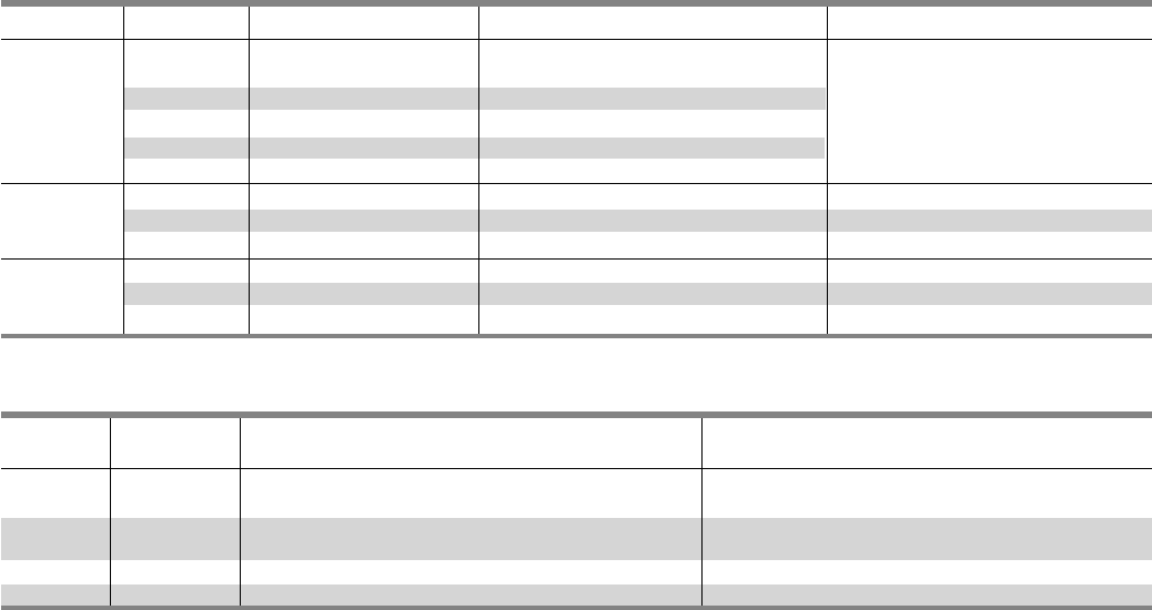
4-10
Connector Modifications
P4 Panelboards
Amp Breaker
Rating Type Compression Connectors Available Unit Space Reduction
400 N/A (1)#3/0 AWG - 750 Kcmil or Deduct 2.5” of Unit Space
(2)#3/0 AWG 250 Kcmil Cu or Al
600 N/A (2)#3/0 AWG - 750 Kcmil or Deduct 0” of Unit Space
(4)#3/0 - 350 Kcmil
800 N/A (3)#3/0 AWG - 750 Kcmil Cu or Al Deduct 5.0” of Unit Space
1200 N/A (4)#3/0 AWG - 750 Kcmil Cu or Al Deduct 7.5” of Unit Space
Table P4-16 – Alternate Lugs
Style Amp Rating Breaker Type Compression Connectors Available Unit Space Reduction
400 N/A (1)250 - 500 Kcmil
or (2)#2/0 AWG - 250 Kcmil Cu or Al
600 N/A (2)#3/0 AWG - 500 Kcmil
MLO 800 N/A (3)#3/0 AWG - 500 Kcmil Cu or Al Deduct 5.0” of Unit Space
1000 N/A (4)#3/0 AWG - 500 Kcmil Cu o Al
1200 N/A (4)#3/0 AWG - 500 Kcmil Cu or Al
Main Breaker 400
JD6, JXD6, HJD6, HJXD6,
HHJD6, HHJXD6, CJD6, (2)#2/0 AWG - 500 Kcmil Cu or Al Deduct 0” of Unit Space
SJD6, SHJD6, SCJD6
LD6, LXD6, HLD6, HLXD6,
Main Breaker 600 HHLD6, HHLXD6, CLD6, (2) #2/0 AWG - 500 Kcmil Cu or Al Deduct 0” of Unit Space
SLD6, SHLD6, SCLD6
Table P4-15 – Compression Lugs
Lug Modifications
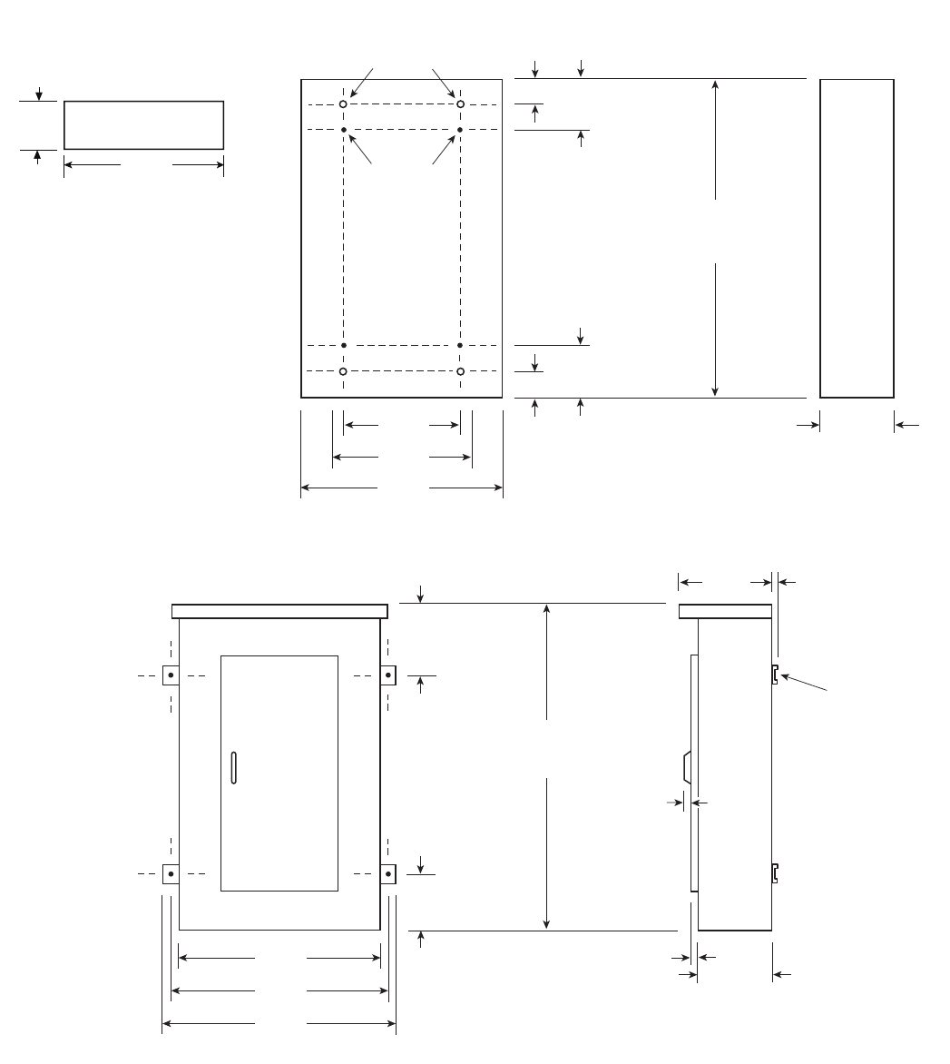
32 in.
[ 813 ]
24 in.
[ 610 ]
14 in.
[356]
4.375 in.
[ 111 ]
Interior To Box
Mounting
Stubs
Box To Wall
Mounting Holes
6.635 in.
[169 ]
4.375 in.
[ 111 ]
6.635 in.
[ 169 ]
a
10.0 in.
[ 254 ]
a
60 in.,
[ 1524 ]
75 in.,
[ 1905 ]
90 in.
[ 2286 ]
a
4-11
Dimensions
Type P4 Panelboards
32 in.
[813 ]
.375 in.
[ 10 ]
12 in.
[ 305 ]
.375 in.
[ 10 ]
Mounting
Bracket
10.0 in.
[ 254 ]
.87 in.
[ 22 ]
34 in.
[ 864 ]
36 in.
[ 914 ]
15.81 in.
[ 402 ]
15.81 in.
[ 402 ]
60 in.,
[ 1524 ]
75 in.,
[ 1905 ]
90 in.
[ 2286 ]
a
a
a
Type 1 Box
Box is symmetrical
Type 3R and 3R/12 Box
1
1
1
1
1
1Dimensions are interior of the box. Add 5/8” to width for
absolute dimension. Add 1/8” to height for absolute dimension.
Dimensions shown in inches and millimeters [ ].
SECTION 4
30.0 in.
[ 254 ]
8 in.
[ 203 ]
Recommended Conduit Area
30 in.
[ 762 ]
1
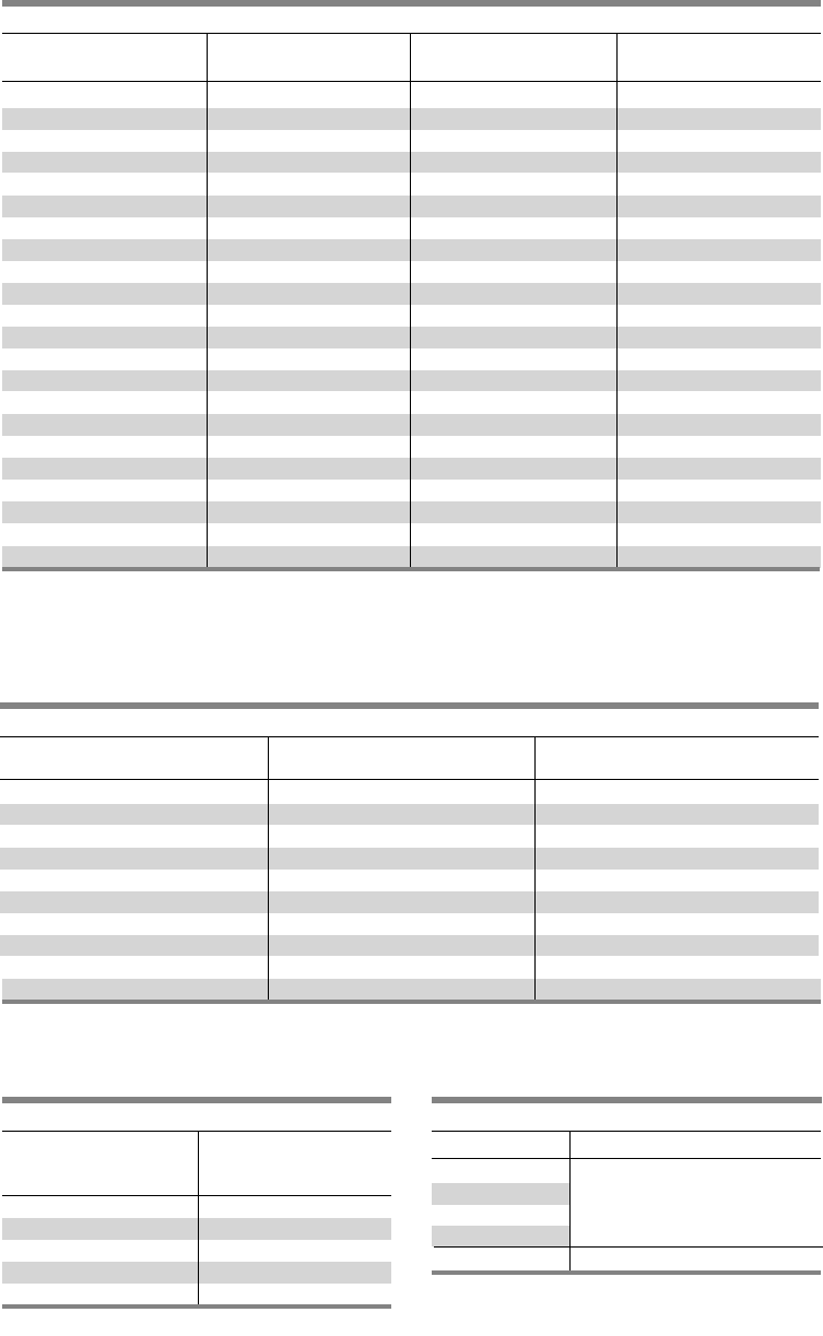
4-12
Kits and Accessories
Type P4 Panelboards
Table P4-17 – Connector Strap Kits – w/o Circuit Breaker 1 2
Table P4-19 – Blank Plates
Circuit Breaker and Vacu-Break
For use with Sentron SPP and Type P4 power panels
Height
Inches Catalog
(mm) Number
1.25 (32) 6FPB01
2.5 (63.5) 6FPB02
3.75 (95) 6FPB03
5.0 (127) 6FPB05
10.0 (254) 6FPB10
Table P4-18 – Connecting Strap Kits – Fusible
For use with Sentron Shallow Depth or Type SPP/FPP/F1/P4 power panels
Unit Height
Ampere Rating Inches (mm) Catalog Number
30–30 2.5 (63.5) F602
30–60 5.0 (127), 7.5 (191) F657
30–60 5.0 (127), 7.5 (191) F657
60–60 5.0 (127), 7.5 (191) F657
60–100 5.0 (127), 7.5 (191) F657
100–100 5.0 (127), 7.5 (191) F657
100 7.5 (191) F657
200 7.5 (191) F657
200 10.0 (254) F671
200–200 10.0 (254) F672
Table P4-20 – Filler Plates
Note: When a front filler plate is not completely filled with
breakers, the openings in the unused space must be
closed with filler plates selected from this table.
For use with Sentron SPP and P4 power panels
Breaker Type Filler Plate Catalog Number
BL, BLH, HBL,
BQD, NGB,
ED2, ED4, ED6 QF3
HED4, HHED6,
NEB, HEB EBF1
1 Includes cover plate and mounting hardware, less circuit breaker.
2Also for use with S4/F4 and SPP/FPP (10” Deep).
3VL family of circuit breakers.
For use with Sentron SPP Shallow Depth or Type P4 Power Panels
Unit Height
Breaker Type Mounting Type Inches (mm) Catalog Number
BL, BQD Twin 3.75 (95) SBL
NGB Twin 3.75 (95) SN
EB Twin 3.75 (95) SEB
ED Twin 3.75 (95) SE6
CED6 Twin 3.75 (95) SCE
DG
3
Twin 5.00 (127) SDG
QJ Twin 5.00 (127) SQJ
FG
3
Twin 5.00 (127) SFG
FD6 Twin 5.00 (127) SF6
CFD6 Single 5.00 (127) SCF
JG
3
Single 6.25 (159) SJG
JD Single 8.75 (223) SJ1
SJD Single 8.75 (223) SSJ1
CJD6 Single 8.75 (223) SCJ
SCJD Single 8.75 (223) SSCJ
LG
3
Single 6.25 (159) SLG
LD Single 8.75 (223) SL6
SLD Single 8.75 (223) SSL6
CLD6 Single 8.75 (223) SCL
SCLD Single 8.75 (223) SSCL
MG
3
Single 8.75 (223) MG1
LMD Single 8.75 (223) SLM1

4-13
SECTION 4
Kits and Accessories
Type P4 Panelboards
Description Catalog number
P4 Type 1 32” W x 10” D x 60” H PB60
P4 Type 1 32” W x 10” D x 75” H PB75
P4 Type 1 32” W x 10” D x 90” H PB90
P4 Type 3R/12 60” H WP260
P4 Type 3R/12 75” H WP275
P4 Type 3R/12 90” H WP290
Table P4-21 – Enclosures
Table P4-22 – Trims
Description Catalog number
Flush kit for P4 60” High F60
Flush kit for P4 75” High F75
Flush kit for P4 90” High F90
Table P4-23 – Flush mounting kits
Description Catalog number
P4 Std (4 piece trim) vented 60” P460V
P4 Std (4 piece trim) vented 75” P475V
P4 Std (4 piece trim) vented 90” P490V
P4 VBS Std (4 piece trim) vented 60” P460VV
P4 VBS Std (4 piece trim) vented 75” P475VV
P4 VBS Std (4 piece trim) vented 90” P490VV
P4 Std (4 piece trim) unvented 60” P460NV
P4 Std (4 piece trim) unvented 75” P475NV
P4 Std (4 piece trim) unvented 90” P490NV
P4 VBS Std (4 piece trim) unvented 60” P460NVV
P4 VBS Std (4 piece trim) unvented 75” P475NVV
P4 VBS Std (4 piece trim) unvented 90” P490NVV
P4 Std (4 piece trim) vented 60” with hinged gutter covers P460VHG
P4 Std (4 piece trim) vented 75” with hinged gutter covers P475VHG
P4 Std (4 piece trim) vented 90” with hinged gutter covers P490VHG
P4 VBS Std (4 piece trim) vented 60” with hinged gutter covers P460VVHG
P4 VBS Std (4 piece trim) vented 75” with hinged gutter covers P475VVHG
P4 VBS Std (4 piece trim) vented 90” with hinged gutter covers P490VVHG
P4 Std (4 piece trim) unvented 60” with hinged gutter covers P460NVHG
P4 Std (4 piece trim) unvented 75” with hinged gutter covers P475NVHG
P4 Std (4 piece trim) unvented 90” with hinged gutter covers P490NVHG
P4 VBS Std (4 piece trim) unvented 60” with hinged gutter covers P460NVVHG
P4 VBS Std (4 piece trim) unvented 75” with hinged gutter covers P475NVVHG
P4 VBS Std (4 piece trim) unvented 90” with hinged gutter covers P490NVVHG
P4 Std (1 PC Door) vented 60” P460VD
P4 Std (1 PC Door) vented 75” P475VD
P4 Std (1 PC Door) vented 90” P490VD
P4 Std (1 PC Door) unvented 60” P460NVD
P4 Std (1 PC Door) unvented 75” P475NVD
P4 Std (1 PC Door) unvented 90” P490NVD
P4 Std (1 PC Door-in-door) vented 60” P460VDD
P4 Std (1 PC Door-in-door) vented 75” P475VDD
P4 Std (1 PC Door-in-door) vented 90” P490VDD
P4 Std (1 PC Door-in-door) unvented 60” P460NVDD
P4 Std (1 PC Door-in-door) unvented 75” P475NVDD
P4 Std (1 PC Door-in-door) unvented 90” P490NVDD
Notes
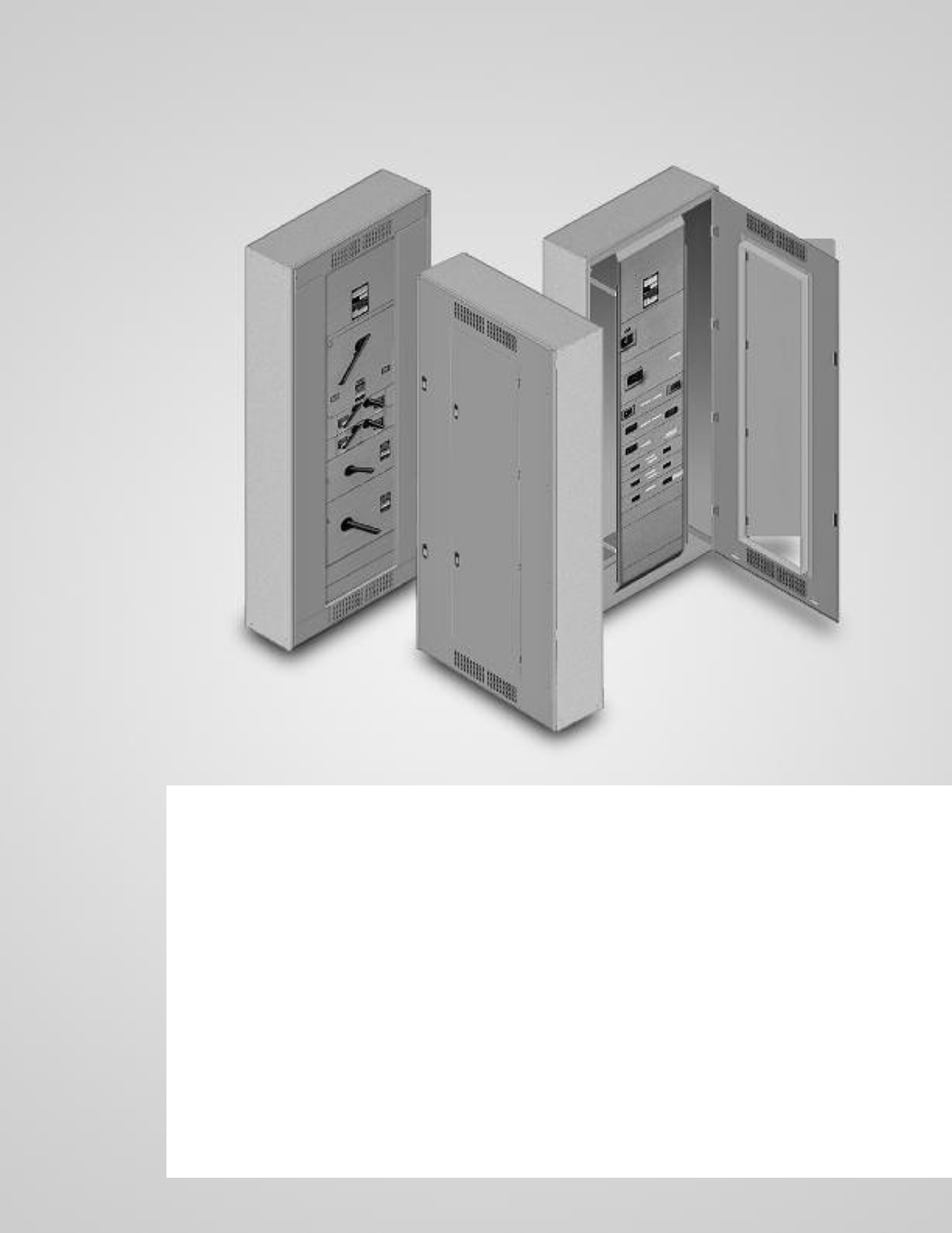
P5 Panelboards
Description Page
General Information 5-2
Selection and Application 5-2
Application 5-3 – 5-8
Main Breaker Selection 5-3
Enclosure Selection 5-4
Main Breaker and Main Switch 5-3 – 5-4
Main Switch Connectors 5-4
Main Lugs Only Unit Space 5-5
Branch Switch Unit Space 5-5
Branch Circuit Breakers 5-6
Branch Breaker Unit Space 5-7
Branch Breaker Side Gutters 5-8
Typical Catalog Numbers 5-9
Main Lugs Only 5-9
Main Circuit Breakers Only 5-9
Main Fusible Switch 5-9
Modifications and Additions 5-10 – 5-12
Motor Starters 5-11 – 5-12
Connector Modifications 5-12
Compression Lugs 5-12
Alternate Lugs 5-12
Dimensions 5-13
Kits and Accessories 5-14 – 5-15
SECTION 5
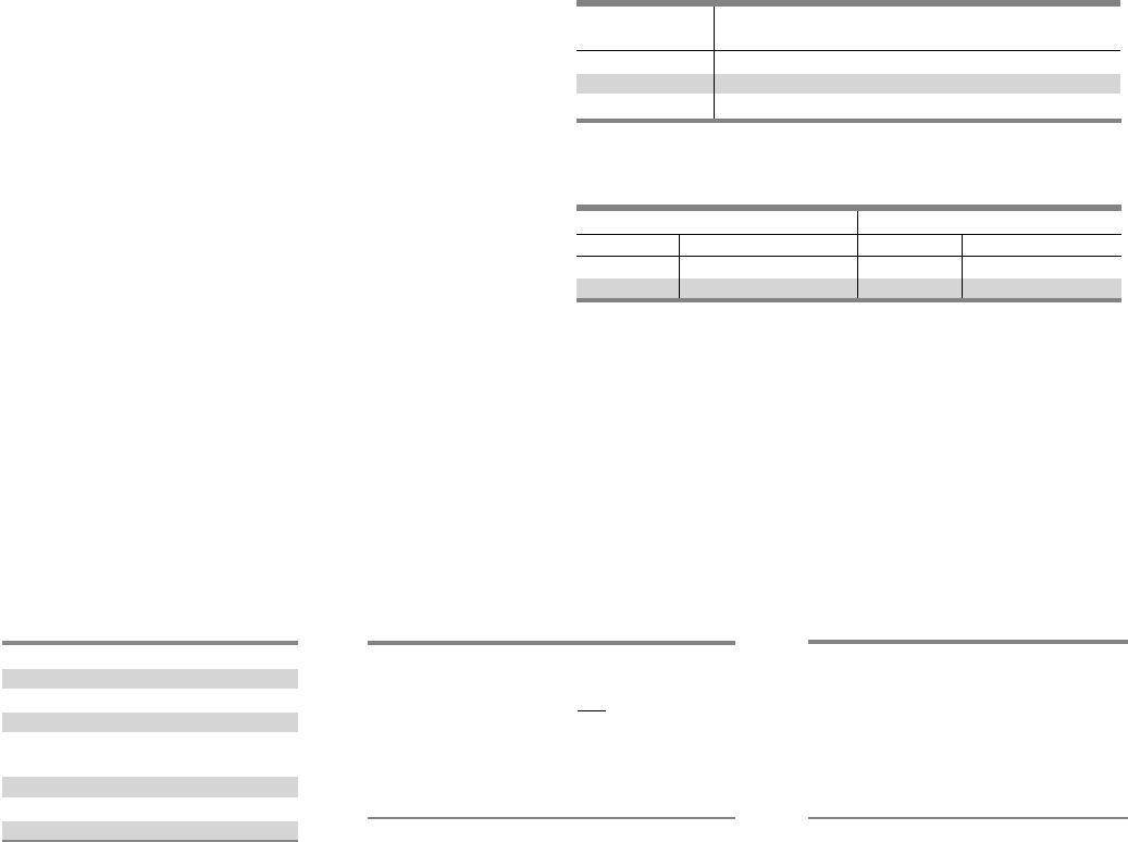
5-2
Type P5 Panelboards
The P5 panel is the largest distribution panel in the Siemens
panel family. Even so, the P5 panel is still a space saver with
it’s 38” width and 12.75” depth. With even higher main ratings
to fit the application that require more or larger branch devices.
This panel offers a wide array of factory assembled options and
enables users to mix breaker frames in unit space up to 1200
amps and fusible switches up to 1200 amps. Bussing options for
the P5 vary from the standard temperature rated aluminum to
temperature rated copper and 750 A/Si aluminum and 1000A/Si
copper designs. All aluminum bussing in the P5 panel is tin-
plated as a standard. All copper bus is silver plated. Integrated
time clocks, bus mounted contactors as mains or submains, split
bus and subfeed lugs (up to 600 amps) are just a few of the
options of this flexible panel.
P5 panel configurations are defined by the unit space allowed
for a given amperage, main device and box height. The P5 panel
starts with a 60” high box. All branch devices are unit space
mounted. Breakers and switches can be mixed and matched to
meet customer requirements.
Main Lug / Main Breaker / Main Switch
Enclosure – Standard Type 1 enclosure is 38" wide x 12.75"
deep. X Box Height is determined by main device and unit
space. See charts for box height.
Voltage – 600 Vac Max.
250 Vdc Max.
Amperage – 400-1200 amp Main breaker, 400-1200 amp MLO
200-1200 amp Main switch.
Short Circuit Rating – 200 KAIC Max. symmetrical or equal to
the lowest rated device installed unless a series rating is indicated.
Panels with subfeed or feed-thru lugs without a main device,
circuit breaker or fusible unit, are limited to a three-cycle rating.
The three-cycle rating for the P5 panel is limited to 42 KAIC. Note
that the main device may be mounted remote from the panel.
Bussing – The P5 panel has more options to meet market
requirements. The standard bussing is temperature rated
aluminum. The rating is per the requirements of UL 67 – the
standard for panelboards. All aluminum bussing is tin-plated.
Optional bussing for the P5 panel is: 750 A/Si aluminum,
temperature rated copper, and 1000 A/Si copper. The copper
bus option for this panel is silver-plated.
Weight – Approximate
Total panelboard weight when filled with a normal quantity of
breakers and accessories is about 10 lbs. (1 kg) per inch (54g
per mm) of box height.
Ampere Connectors Suitable for
Rating Copper or Aluminum
800 (3) - #3/0 AWG-600 Kcmil
1000 (4) - #3/0 AWG-600 Kcmil
1200 (4) - #3/0 AWB-600 Kcmil
1Alternate lugs for 750 Kcmil cable are available, but result in significant loss of
branch unit mounting space. Consult Siemens.
Table P5-1 – Main Lugs 1
Dimensions in inches (mm) Gauge Steel
Width Height Box Fronts
38” 60 - 75 - 90 #161#12 (1 piece trim)
(965) (1524, 1905, 2286) #12 2 (4 piece trim)
Table P5-2 – Gauge Steel of Boxes Fronts, Surface and Flush
Selection and Application
1) To specify a particular panelboard, first determine voltage,
system, amperage and type of main, amperage and type of
branch devices, and modifications, if any. (Step 1)
2) List branch devices and modifications requiring space
additions. List unit space requirements of each.
Note: Some units are twin mounted meaning two breakers
occupy the same unit space.
Select appropriate enclosure height from selection chart on
page 5-3 based on unit space requirements. (Step 2)
3) Select panelboard catalog number from appropriate table
based upon voltage, system, amperage and unit space
requirements. (Step 3)
Step #3
1-P5C75NI120ATS
5-125/3 NGB
3-NGB 1 Pole Provision
2-225/3 QJ2
1-250/3 FXD6
1-FXD6 Prov. 13.25” Space
Step #2
5-125/3 NGB 3.75” = 11.25” Twin Mounted
2-225/3 QJ2 5” = 5” Twin Mounted
1-250/3 FXD6 5” = 5”
21.25
Enclosure is B875 from Selection
Chart on Page 5-3.
(32” wide, 75” high, 10” deep)
1 16 gauge side panels, 12 gauge back support.
2 10 gauge gutter covers, 16 gauge vent covers.
Step #1
Amperage 1200
Voltage 208Y/120
System 3 Phase, 4 wire
Main Main Breaker
Branches 5-125/3, 2-225/3,
1-250/3
Modifications None
Feed Top
Mounting Surface
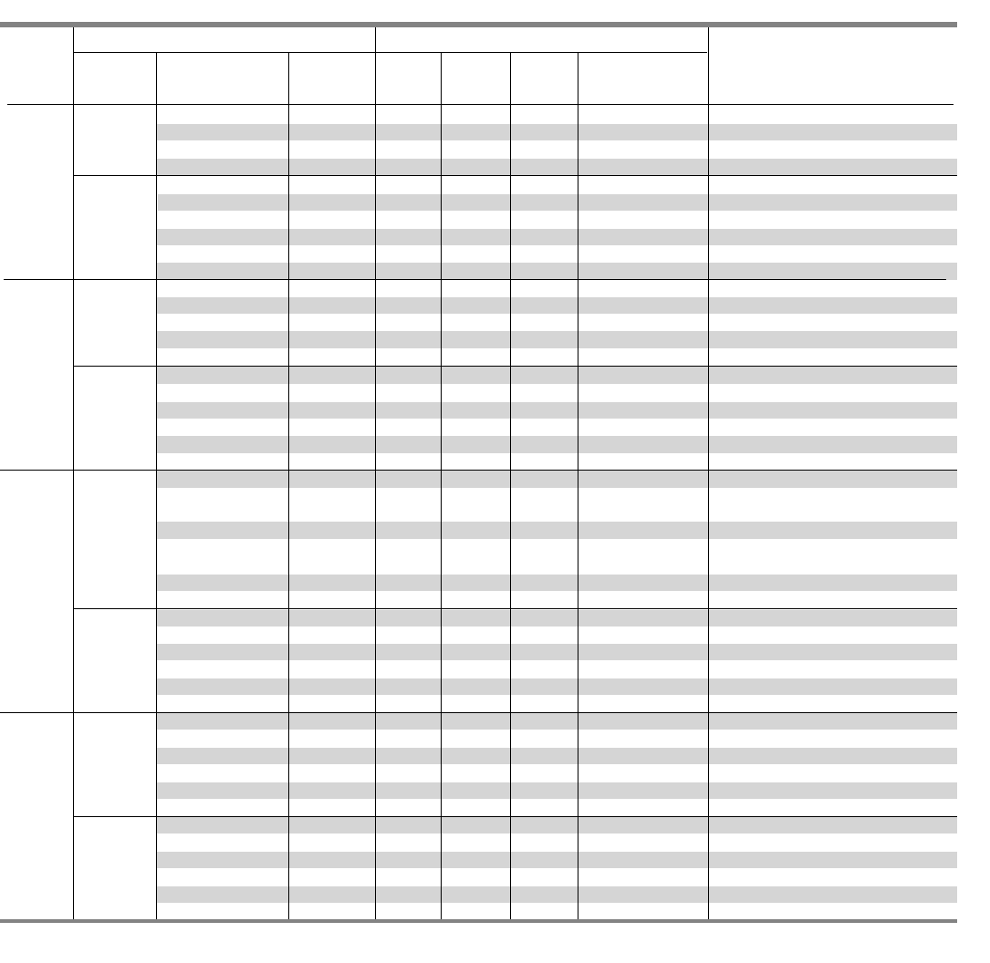
Application
Type P5 Panelboards
SECTION 5
Table P5-3 – Main Breaker Selection
Breaker type Maximum IC (KA) Symmetrical Amperes
Main Breaker
Ampere Trip Frame Breaker Unit Space in
rating type type family 240V 480V 600V inches (mm) Available Trip Values
JXD6 (STD), JD6 Sentron 65 35 22 8.75 (222) 200, 225, 250, 300, 350, 400
TMTU1HJXD6, HJD6 Sentron 100 65 35 8.75 (222) 200, 225, 250, 300, 350, 400
HHJXD6, HHJD6 Sentron 200 100 50 8.75 (222) 200, 225, 250, 300, 350, 400
CJD6 Sentron 200 150 100 8.75 (222) 200, 225, 250, 300, 350, 400
400A NJ VL 65 35 25 6.25 (159) 250, 400
SJD6 Sentron 65 35 25 8.75 (222) 200, 300, 400
ETU1HJ VL 100 65 25 6.25 (159) 250, 400
SHJD6 Sentron 100 65 35 8.75 (222) 200, 300, 400
LJ VL 200 100 25 6.25 (159) 250, 400
SCJD6 Sentron 200 150 100 8.75 (222) 200, 300, 400
LXD6 (STD) Sentron 65 35 25 8.75 (222) 450, 500, 600
LD6 Sentron 65 35 25 8.75 (222) 250, 300, 350, 400, 450, 500, 600
TMTU HLXD6, HHLD6 Sentron 100 65 35 8.75 (222) 250, 300, 350, 400, 450, 500, 600
HHLXD6, HHLD6 Sentron 200 100 50 8.75 (222) 250, 300, 350, 400, 450, 500, 600
CLD6 Sentron 200 150 100 8.75 (222) 250, 300, 350, 400, 450, 500, 600
NL 2VL 65 35 18 6.25 (159) 400, 600
600A SLD6 Sentron 65 35 25 8.75 (222) 300, 400, 500, 600
HL 2VL 100 65 18 6.25 (159) 400, 600
ETU SHLD6 Sentron 100 65 35 8.75 (222) 300, 400, 500, 600
LL 2VL 200 100 18 6.25 (159) 400, 600
SCLD6 Sentron 200 150 100 8.75 (222) 300, 400, 500, 600
NM 3 (STD) VL 65 35 25 8.75 (222) 600, 700, 800
MXD6, MD6 Sentron 65 50 25 10 (254) 500, 600, 700, 800
LMXD6, LMD6
TMTU HM 3VL 100 65 35 8.75 (222) 600, 700, 800
HMXD6, HMD6 Sentron 100 65 50 10 (254) 500, 600, 700, 800
HLMXD6, HLMD6
800A LM 3VL 200 100 50 8.75 (222) 600, 700, 800
CMD6 Sentron 200 100 65 10 (254) 500, 600, 700, 800
NM 3VL 65 35 25 8.75 (222) 600, 800
SMD6 Sentron 65 50 25 10 (254) 600, 700, 800
ETU HM 3VL 100 65 35 8.75 (222) 600, 800
SHMD6 Sentron 100 65 50 10 (254) 600, 700, 800
HM 3VL 200 100 50 8.75 (222) 600, 800
SCMD6 Sentron 200 100 65 10 (254) 600, 700, 800
NN (STD) VL 65 35 25 10 (254) 800, 900, 1000, 1200
NXD6 Sentron 65 50 25 10 (254) 900, 1000, 1200
HN VL 100 65 35 10 (254) 800, 900, 1000, 1200
TMTU HNXD6, HND6 Sentron 100 65 50 10 (254) 900, 1000, 1200
LN VL 200 100 65 10 (254) 800, 900, 1000, 1200
1200A CND6 Sentron 200 100 65 10 (254) 900, 1000, 1200
NN VL 65 35 25 10 (254) 800, 1000, 1200
SND6 Sentron 65 50 25 10 (254) 800, 1000, 1200
HN VL 100 65 35 10 (254) 800, 1000, 1200
ETU SHND6 Sentron 100 65 50 10 (254) 800, 1000, 1200
LN VL 200 100 65 10 (254) 800, 1000, 1200
SCND6 Sentron 200 100 65 10 (254) 800, 1000, 1200
1TMTU = Thermal Magnetic Trip Unit and ETU = Electronic Trip Unit.
2100% ratings are not available for the VL LG frame, replace with VL MG frame @ 600A rated 100%.
3100% ratings are not available for the VL MG. Use a VL NG frame @ 800A trip rated 100%.
5-3
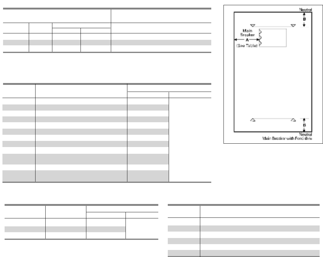
5-4
Application
Type P5 Panelboards
Fig. P5-1
Table P5-5 – Main Breaker Lug Location Reference (Fig. P5-1)
Table P5–7 Main Switch Connectors
Table P5-6 – Main Switch Lug Location Reference (Fig P5-1)
Ampere Breaker Dimensions in inches (mm)
Rating Type AB
200 VB 13.425 (265)
400/600 VB 15.500 (318) 13.125 (333)
400/1200 HCP 13.425 (265)
Ampere
Rating Connectors Suitable for Copper or Aluminum
200 (1) #6 AWG - #3/0 AWG
400 (1) #3/0 – 500KCMIL
(2) #3/0 – 250KCMIL
600 (2) #3/0 – 500KCMIL
800 (3) #3/0 – 500KCMIL
1200 (4) #3/0 – 500KCMIL
Table P5-4 – Enclosure Selection 1
1Standard trim is four piece without door. Surface or flush one piece trim is
available for 32 in. (813 mm) wide circuit breaker panels.
Ampere Breaker Dimensions in inches (mm)
Rating Type AB
400 JXD6, JD6, HJXD6, HJD6, HHJXD6, HHJD6 13.425 (265)
400 NJ, HJ, LJ 15.500 (318)
400 SJD6, SHJD6 13.425 (265)
400 CJD6, SCJD6 11.250 (210)
600 LXD6, LD6, HLXD6, HLD6, HHLXD6, HHLD6 13.425 (265) 13.125 (333)
600 NL, HL, LL 14.250 (286)
600 SLD6, SHLD6 13.425 (265)
600 CLD6, SCLD6 11.250 (210)
800 NM, HM, LM 13.425 (265)
800 MXD6, MD6, HMXD6, HMD6, 13.00 (330)
CMD6, SMD6, SHMD6, SCMD6 10.42 (265)
1200 NN, HN, LN 13.425 (265)
1200 NXD6, ND6, HNXD6, HMD6, 13.00 (330)
CND6, SND6, SHMD6, SCND6 13.00 (330)
Enclosure Dimension Available Unit Space in inches (mm)
in Inches (mm) Dimension “C” in Fig. P5-1
H W D Main Lug only Main Breaker Main Switch
Type 1 Type 3R/12 800 / 1200A 800 / 1200A 800 / 1200A
60 (1524) 38 (965) 12.75 (324) 14.25 (362) 30 (762) 20 (508) 13.75 (349)
75 (1905) 38 (965) 12.75 (324) 14.25 (362) 45 (1143) 35 (889) 28.75 (730)
90 (2286) 38 (965) 12.75 (324) 14.25 (362) 60 (1524) 50 (1270) 43.75 (1111)
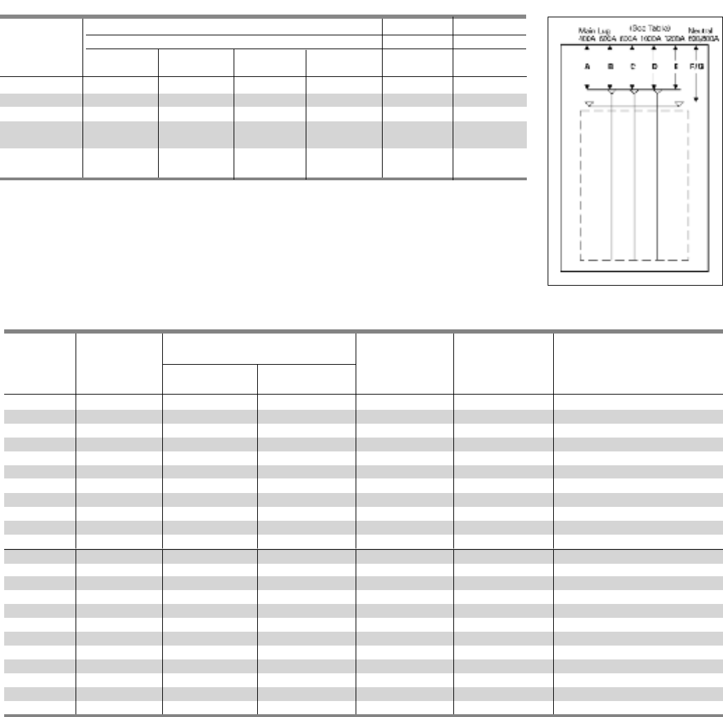
5-5
Table P5-9 – Branch Switch Unit Space
Unit Space
in Inches (mm)
Ampere Number Twin Single AC Cables Per Connectors Suitable For
Rating of Poles Mounted Mounted Voltage Connector Copper or Aluminum
30-30 2, 3 2.50 (64) — 240 1 #14 - #8 AWG (Cu Only)
30-30 2, 3 5.00 (127) — 240 1 #14 - #4 AWG
30-60 2, 3 5.00 (127) — 240 1 #14 - #4 AWG
60-60 2, 3 5.00 (127) — 240 1 #14 - #4 AWG
60-100 2, 3 7.50 (191) — 240 1 #10 - #1/0 AWG
100-100 2 ,3 7.50 (191) — 240 1 #10 - #1/0 AWG
200-200 3 10.00 (254) — 240 1 #6 AWG - 350 Kcmil
200 2— 7.50 (191) 240 1 #6 AWG - 350 Kcmil
200 3— 10.00 (254) 240 2 #6 AWG - 350 Kcmil
400 2,3 — 15.00 (381) 240 2 #4/0 AWG - 500 Kcmil
600 2, 3 — 15.00 (381) 240 2 #4/0 AWG - 500 Kcmil
30-30 2, 3 7.50 (191) — 600 1 #14 - #4 AWG
30-60 2, 3 7.50 (191) — 600 1 #14 - #4 AWG
60-60 2, 3 7.50 (191) — 600 1 #14 - #4 AWG
60-100 2, 3 7.50 (191) — 600 1 #10-#1/0 AWG
100-100 2, 3 7.50 (191) — 600 1 #10-#1/0 AWG
200-200 3 10.00 (254) — 600 1 #6 AWG - 350 Kcmil
100 2, 3 — 7.50 (191) 600 1 #10 - #1/0 AWG
200 2, 3 — 10.00 (254) 600 2 #6 AWG - 350 Kcmil
400 2, 3 — 15.00 (381) 600 2 #4/0 AWG - 500 Kcmil
600 2, 3 — 15.00 (381) 600 #4/0 AWG - 500 Kcmil
800 2, 3 — 16.25 (413) 600 3 #3/0 AWG - 500 Kcmil
1200 2, 3 — 16.25 (413) 600 4 #3/0 AWG - 500 Kcmil
Table P5-8 – Main Lugs Only Unit Space (Fig. P5-2)
Dimensions in inches (mm)
Main Lug Neutral
400A 600A 800A 1000A 1200A 800A
Lugs
ABCDEG
Standard
16.500 (419) 16.750 (425) 15.969 (406) 15.969 (406) 15.969 (406) 13.125 (333)
Oversize 16.500 (419) 21.750 (552) 25.969 (660) 25.969 (660) 25.969 (660) 23.125 (587)
Crimp 19.187 (487) 18.250 (484) 18.687 (475) 18.250 (464) 18.250 (464) 15.937 (405)
Standard with 16.750 (425) 15.969 (406) ———13.125 (333)
Subfeed
Standard with 16.500 (419) 16.750 (425) — — — 13.125 (333)
Feed-thru
Application
Type P5 Panelboards
Fig. P5-2
SECTION 5
—
—
—

5-6
Application
Type P5 Panelboards
Table P5-10 – Branch Circuit Breakers
1 CSA listed only at 600V AC.
215-30A trip (shown) 65 kA, 35-100A 25 kA.
Maximum Bolt-on Number Trip Amp Maximum IC (KA) Symmetrical Amperes
Ampere Breaker of Poles Rating Voltage – AC
Rating Type 120 120/240 240 277 480/ 277 480 600/347 600
BLF 1 15-30 10 ——— ————
2 15-60 — 10 —— — — — —
BLHF 1 15-30 22 ——— ————
2 15-60 — 22 —— — — — —
BLE 1 15-30 10 ——— ————
2 15-60 — 10 —— — — — —
BLEH 1 15-30 22 ——— ————
2 15-60 — 22 —— — — — —
BAF, BAFC 1 15-20 10 ——— ————
BAFH, BAFHC 1 15-20 22 ——— ————
BAF 2 15-20 — 10 —— — — — —
BAFH 2 15-20 — 22 —— — — — —
BGL 2 15-30 10 ——— ————
3 15-30 — 10 —— — — — —
BLR (240V) 2 15-100 ——10 —————
BL 1 15-70 10 ——— —— ——
2 15-100 — 10 —— — — — —
100 3 15-100 ——10 —————
BLH 1 15-70 — 22 —— — — — —
2 15-100 — 22 —— — — — —
3 15-100 ——22 —————
HBL 1 15-70 — 65 —— — — — —
2 15-100 — 65 —— — — — —
3 15-100 ——65 —————
BQD 1 15-70 — 65 — 14 —— ——
2 15-100 — 65 —— 14 ———
3 15-100 ——65 — 14 ———
BQD611 15-70 65 ——— ————
2 15-100 ——65 ————10
3 15-100 ——65 ————10
BL (HID) 1/2 15-30 — 10 —— — — — —
BLF (GFCI) 1 15-60 — 10 —— — — — —
2 40-60 — 10 —— — — — —
BLE (EQ GFI) 1/2 15-30 — 10 —— — — — —
BGL (SWN) 2 15-30 10 ——— ————
3 15-30 — 10 —— — — — —
BLHF (GFCI) 1/2 15-30 — 22 —— — — — —
NGB 1 15-125 100 ——25 —— ——
2/3 15-125 — 100 100 — 25 — 14 —
NEB 1 15-125 100 85 85 35 —— ——
2/3 15-125 — 85 85 — 35 35 22 —
HEB 1 15-125 200 100 100 65 —— ——
2/3 15-125 — 100 100 — 65 65 25 —
125 ED4 1 15-125 65 ——22 —— ——
2/3 15-125 — 65 65 — 18 18 —
ED6 2 15-125 —— —— 25 25 30 —
3 15-125 ——65 — 25 25 — 18
HED4 1 15-125 100 ——652—— ——
2/3 15-125 — 100 100 — 42 42 ——
HHED6 2/3 15-125 100 ——— 65 65 18 18
CED6 2/3 15-125 200 ———200 200 100 100
QJ2 2/3 60-225 ——10 —————
225 QJH2 2/3 60-225 ——22 —————
QJ2H 2/3 60-225 ——42 —————
HQJ2H 2/3 60-225 ——100 —————
FXD6, FD6 2/3 70-250 ——65 — 35 35 18 18
250 HFXD6, HFD6 2/3 70-250 ——100 — 65 65 25 25
HHFXD6, HHFD6 2/3 70-250 ——200 — 100 100 25 25
CFD6 2/3 70-250 ——200 — 200 200 100 100
JXD6, JD6, SJD6 2/3 200-400 ——65 — 35 35 25 25
HJXD6, HJD6,SHJD6 2/3 200-400 ——100 — 65 65 35 35
400 HHJXD6, HHJD6 2/3 200-400 ——200 — 100 100 50 50
CJD6, SCJD6 2/3 200-400 ——200 — 150 150 100 100
LXD6 2/3 450-600 ——65 — 35 35 25 25
LD6 2/3 250-600 ——65 — 35 35 25 25
SLD6 2/3 300-600 ——65 — 35 35 25 25
600 HLD6, HLXD6 2/3 250-600 ——100 — 65 65 35 35
SHLD6 2/3 300-600 ——100 — 65 65 35 35
HHLD6, HHLXD6 2/3 250-600 ——200 — 100 100 50 50
CLD6 2/3 450-600 ——200 — 150 150 100 100
SCLD6 2/3 300-600 ——200 — 150 150 100 100
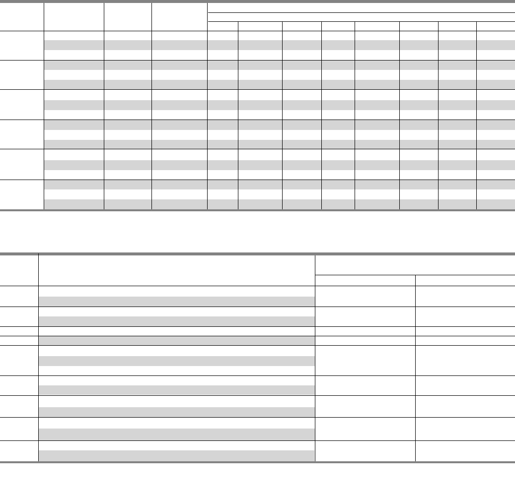
5-7
Application
Type P5 Panelboards
Table P5-11 – Branch Breaker Circuit Breakers (VL)
Maximum Trip Maximum IC (KA) Symmetrical Amperes
Ampere Breaker Number Amp Voltage – AC
Rating Type of Poles Rating 120 120/250 240 277 480/277 480 600/347 600
ND 3 60-150 — 65 65 — 35 35 18 18
1501HD 3 60-150 —100 100 —65 65 20 20
LD 3 60-150 — 200 200 —100 100 25 25
NF 3 100-250 — 65 65 —35 35 18 18
2501HF 3 100-250 — 100 100 —65 65 20 20
LF 3 100-250 — 200 200 —100 100 25 25
NJ 3 250-400 — 65 65 —35 35 25 25
4001HJ 3 250-400 — 100 100 —65 65 25 25
LJ 3 250-400 — 200 200 —100 100 25 25
NL 3 400-600 — 65 65 —35 35 18 18
6001HL 3 400-600 — 100 100 —65 65 18 18
LL 3 400-600 — 200 200 —100 100 18 18
NM 2/3 600-800 — 65 65 —35 35 25 25
800 HM 2/3 600-800 — 100 100 —65 65 35 35
LM 2/3 600-800 — 200 200 —100 100 50 50
NN 2/3 800-1200 — 65 65 —35 35 25 25
1200 HN 2/3 800-1200 — 100 100 —65 65 35 35
LN 2/3 800-1200 — 200 200 —100 100 50 50
Table P5-12 – Branch Breakers Unit Space Requirements
SECTION 5
1 Only available with Electronic Trip Units.
1 Mounting height shown will accomodate from (1) to (6) poles.
2 Accessories such as shunt trips on three pole breakers requires 6.25" of unit space.
Mounting Height
Amp Breaker in Inches (mm)
Rating Type Twin Single
1001 BL,BLH,HBL,BQD,BLE, BLEH, BLR, BLF, BLHF, BAF, BAFC, BAFH, BAFCH, BGL 3.75 (95) 1
BL, BLH, HBL, BQD -With accessories 6.25 (159) —
125 NGB, NEB, HEB, ED4, ED6, HED4, HHED6, CED6 3.75 (95)1
NGB, ED41 2, ED61 2, HED41 2, HHED61 2, CED61 2 (With accessories) 6.25 (159) —
150 ND, HD, LD 5.00 (127) —
225 QJ2, QJH2, QJ2H, HQJ2H 5.00 (127) —
NF, HF, LF 5.00 (127) —
250 FD6, FXD6, HFD6, HFXD6, HHFD6, HHFXD6 5.00 (127) —
CFD6 — 5.00 (127)
400 NJ, HJ, LJ —6.25 (159)
JD6, JXD6, HJD6, HJXD6, HHJD6, HHJXD6, CJD6 8.75 (222)
600 NL, HL, LL —6.25 (159)
LD6, LXD6, HLD, HLXD6, HHLD6, HHLXD6, CLD6 8.75 (222)
800 NM, HM, LM —8.75 (222)
MXD6, MD6, HMXD6, HMD6, CMD6 10.00 (254)
1200 NN, HN, LN — 10.00 (254)
NXD6, ND6, HNXD6, HND6, CND6
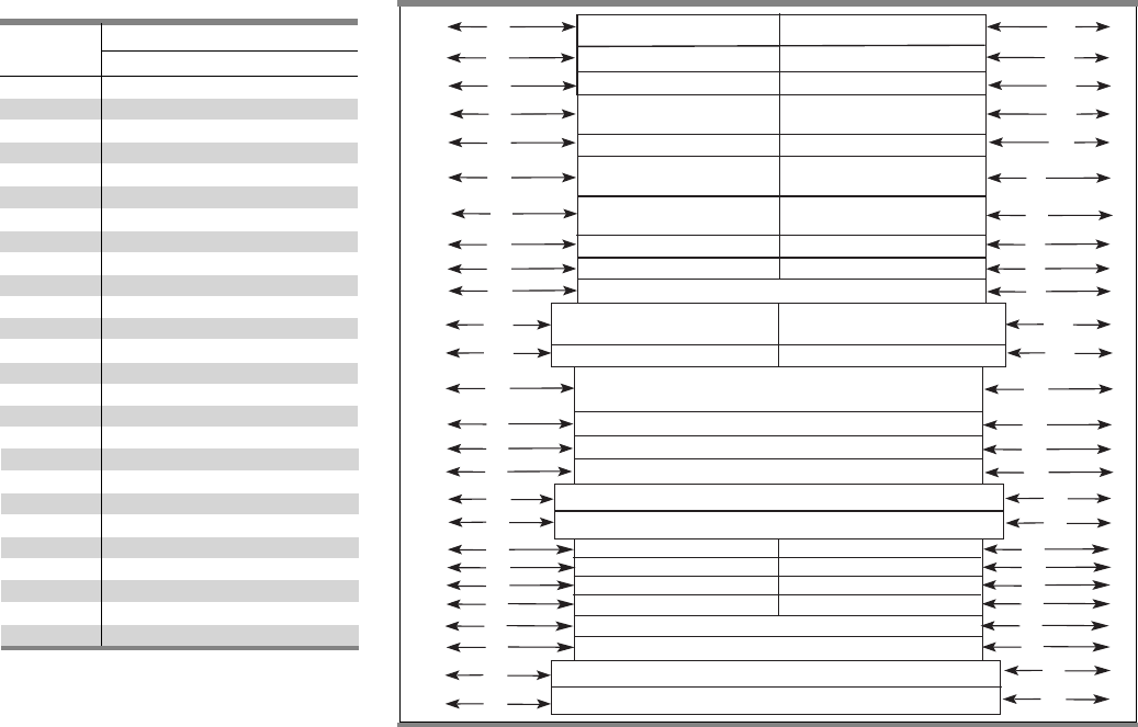
5-8
Application
Type P5 Panelboards
Fig. P5-3
Table P5-13 – Branch Breaker
Side Gutter
ED4, ED6 ED4, ED6
HED4, HHED6 HED4, HHED6
CED6 CED6
QJ2, QJH2 QJ2, QJH2
QJ2H, HQJ2H QJ2H, HQJ2H
FD6, FXD6, FD6, FXD6
HFD6, HHFD6 HFD6, HHFD6
ND, HD, LD ND, HD, LD
NF, HF, LF NF, HF, LF
CFD
JD6, JXD6, JD6, JXD6,
HJD6, HHJD6 HJD6, HHJD6
NJ, HJ, LJ NJ, HJ, LJ
SJD6, SHJD6, LD6, LXD6,
HLD6, HHLD6, SLD6, SHLD6
CJD6, SCJD6, CLD6, SCLD6
NJ, HJ, LJ
NL, HL, LL
NM, HM, LM
NN, HN, LN
A
D
VB 30 A VB 30 A
VB 30 - 60A VB 30 - 60 A
VB 60 -100A VB 60 - 100A
E
F
G
A
D
E
BL, BLH, HBL, BQD BL, BLH, HBL, BDQ
NGB NGB
NEB, HEB NEB, HEB
B B
C C
F
G
H H
I I
J J
K
K
L
L
M M
N N
O O
P P
VB 200A VB 200A
VB 100A Single
VB 200A Single
S
T
U
V
W
X
S
T
U
V
W
X
VB 5 Single
Q
Q
R
R
Y
Y
Z
Z
VB 400 – 600A Single
HCP 400 – 1200A Single
Reference Panel Width – 32 (813)
Letter Dimensions in inches (mm)
A 14.0 (356)
B 13.98 (355)
C 11.62 (295)
D 10.0 (254)
E 7.61 (193)
F 8.75 (222)
G 8.25 (210)
H 10.90 (276)
I 10.90 (276)
J 11.76 (299)
K 7.92 (201)
L 8.0 (203)
M 13.42 (341)
N 12.0 (305)
O 15.50 (393)
P 14.25 (362)
Q 13.42 (341)
R 13.42 (341)
S 10.0 (254)
T 8.0 (203)
U 10.50 (267)
V 10.50 (267)
W 9.30 (236)
X 10.30 (262)
Y 9.30 (236)
Z 10.30 (262)
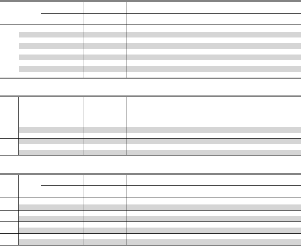
5-9
Typical Catalog Numbers
Type P5 Panelboards
Table P5-14 – Main Lugs Only – shown with aluminum bus, top fed, and surface trims
Max. 208Y/120V 240/120V 120/240V or 240 480Y/277V 480V 1
Panel Unit 250 Vdc Max
Amp Space 3 Phase, 4 Wire 3 Phase, 4 Wire 1 Phase, 3 Wire 3 Phase, 3 Wire 3 Phase, 4 Wire 1 Phase, 3 Wire
Rating (inches) Catalog Number Catalog Number Catalog Number Catalog Number Catalog Number Catalog Number
30 P5C60ML800ATS P5B60ML800ATS P5A60ML800ATS P5D60ML800ATS P5E60ML800ATS P5F60ML800ATS
800 45 P5C75ML800ATS P5B75ML800ATS P5A75ML800ATS P5D75ML800ATS P5E75ML800ATS P5F75ML800ATS
60 P5C90ML800ATS P5B90ML800ATS P5A90ML800ATS P5D90ML800ATS P5E90ML800ATS P5F90ML800ATS
30 P5C60ML101ATS P5B60ML101ATS P5A60ML101ATS P5D60ML101ATS P5E60ML101ATS P5F60ML101ATS
1000 45 P5C75ML101ATS P5B75ML101ATS P5A75ML101ATS P5D75ML101ATS P5E75ML101ATS P5F75ML101ATS
60 P5C90ML101ATS P5B90ML101ATS P5A90ML101ATS P5D90ML101ATS P5E90ML101ATS P5F90ML101ATS
30 P5C60ML120ATS P5B60ML120ATS P5A60ML120ATS P5D60ML120ATS P5E60ML120ATS P5F60ML120ATS
1200 45 P5C75ML120ATS P5B75ML120ATS P5A75ML120ATS P5D75ML120ATS P5E75ML120ATS P5F75ML120ATS
60 P5C90ML120ATS P5B90ML120ATS P5A90ML120ATS P5D90ML120ATS P5E90ML120ATS P5F90ML120ATS
Table P5-16 – Main Fusible Switch (fuses not included)
Max. 208Y/120V 240/120V 120/240V 240V 480Y/277V 480V 1
Panel Unit
Amp Space 3 Phase, 4 Wire 3 Phase, 4 Wire 1 Phase, 3 Wire 3 Phase, 3 Wire 3 Phase, 4 Wire 3 Phase, 3 Wire
Rating (inches) Catalog Number Catalog Number Catalog Number Catalog Number Catalog Number Catalog Number
20 P5C75MS400ATS P5B75MS400ATS P5A75MS400ATS P5D75MS400ATS P5E75MS400ATS P5F75MS400ATS
400 40 P5C90MS400ATS P5B90MS400ATS P5A90MS400ATS P5D90MS400ATS P5E90MS400ATS P5F90MS400ATS
25 P5C75MS600ATS P5B75MS600ATS P5A75MS600ATS P5D75MS600ATS P5E75MS600ATS P5F75MS600ATS
600 40 P5C90MS600ATS P5B90MS600ATS P5A90MS600ATS P5D90MS600ATS P5E90MS600ATS P5F90MS600ATS
28.75 P5C75MS800ATS P5B75MS800ATS P5A75MS800ATS P5D75MS800ATS P5E75MS800ATS P5F75MS800ATS
800 243.75 P5C90MS800ATS P5B90MS800ATS P5A90MS800ATS P5D90MS800ATS P5E90MS800ATS P5F90MS800ATS
28.75 P5C75MS120ATS P5B75MS120ATS P5A75MS120ATS P5D75MS120ATS P5E75MS120ATS P5F75MS120ATS
1200 243.75 P5C90MS120ATS P5B90MS120ATS P5A90MS120ATS P5D90MS120ATS P5E90MS120ATS
P5
F90MS120ATS
Table P5-15 – Main Circuit Breakers – shown with aluminum bus, top fed, and surface trims
Max. 208Y/120V 240/120V 120/240V or 240 480Y/277V 480V 1
Panel Unit 250 Vdc Max
Amp Space 3 Phase, 4 Wire 3 Phase, 4 Wire 1 Phase, 3 Wire 3 Phase, 3 Wire 3 Phase, 4 Wire 1 Phase, 3 Wire
Rating (inches) Catalog Number Catalog Number Catalog Number Catalog Number Catalog Number Catalog Number
21.25 P5C60M1800ATS P5B60M1800ATS P5A60M1800ATS P5D60M1800ATS P5E60M1800ATS P5F60M1800ATS
800 36.25 P5C75M1800ATS P5B75M1800ATS P5A75M1800ATS P5D75M1800ATS P5E75M1800ATS P5F75M1800ATS
51.25 P5C90M1800ATS P5B90M1800ATS P5A90M1800ATS P5D90M1800ATS P5E90M1800ATS P5F90M1800ATS
20 P5C60N1120ATS P5B60N1120ATS P5A60N1120ATS P5D60N1120ATS P5E60N1120ATS P5F60N1120ATS
1200 35 P5C75N1120ATS P5B75N1120ATS P5A75N1120ATS P5D75N1120ATS P5E75N1120ATS P5F75N1120ATS
50 P5C90N1120ATS P5B90N1120ATS P5A90N1120ATS P5D90N1120ATS P5E90N1120ATS P5F90N1120ATS
1
For 600V, change “F” in position 3 to “G.”
2
Alternate main breaker requires an additional 1.25” unit space.
SECTION 5
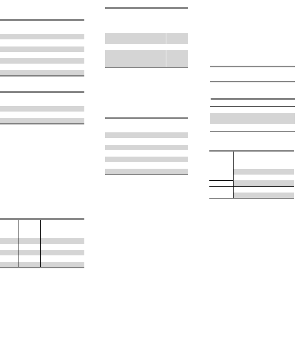
5-10
Devices Mounted on Gutter Cover
Includes Device, Mounting – Wired
or Unwired
Feed-Thru Lugs
Grounding of Panelboards
Ground Bars except for brazed to box
are shipped with the panel interior
factory mounted.
• Non-Insulated Equipment Ground
Bar – Standard
• Copper Non-Insulated Ground Bar
• Al Insulated Equipment Ground Bar
• Cu Insulated Equipment Ground Bar
• Ground Bar Brazed to Box
Fuse Clip Provisions
(Add to 250 Volts or 600 Volts
Unit Prices Per Switch)
Ground Fault on Main Breaker
Time Clocks 4
Sangamo, Tork or Paragon time clock
can be supplied, mounted in panel-
board cabinet. For required increase
in enclosure dimension, consult local
sales office.
Circuit Breaker Accessories
Handle Blocking Device
Blocks handle in either the
“ON” or “OFF” position.
Padlocking Device – Padlocks
in “OFF” position.
Main Bus
Standard main bus and ground bus are
tin-plated aluminum. For copper main
bus, neutral bus and ground bus, add
from the table for each panel.
Lugs – For Main Lug Only Panels
Standard main lugs and neutral lugs
are tin-plated aluminum, UL listed for
use with aluminum/copper cables.
Copper only lugs are an option.
Shunt Trip on Main and Branches5
100% Rated Main Circuit Breakers
Ampere Rating
400 - 1200
Description
BL, BQD, NGB, NEB, HEB (branch only)
QJ2, QJH2, QJ2H, ED2, ED4, HED4,
HQJ2H, HHED6, CED6 (branch only)
All others through 1200A
Modification and Additions
Type P5 Panelboards
Amp
Description Rating
Conventional Ground
Fault 2 Includes:
Ground Fault Relay, Ground
800-1200
Sensor, CPT and Shunt Trip
Test and Monitor Panel 3
Ground Fault add to
Sensitrip III breaker price
800-1200
(takes 5” of unit space)
Ampere Rating Unit Space (inches)
400 10
600 10
800 17.5
1200 17.5
Amp Class Class Class
Rating J RT
30 ••N/A
60 ••N/A
100 •••
200 1•••
400 •••
600 •••
1For use on main lug, main breaker or main switch panels without subfeed breakers.
2Available in 90” high enclosure only. Unit space is 42 1/2” with Test and Monitor Panel; 45” without Test Monitor Panel.
3Not available on Sensitrip III.
4For required unit space, consult local sales office.
5Shunt Trip on 100A frame breakers increases mounting height to 6.25” for twin mounting.
6The 600A, 100% rated braaker application requires the use of an 800A frame breaker.
7The 800A, 100% rated breaker application requires the use of a 1200A frame breaker.
Description
Time clock (1-or 2-Pole, Single or Double
Throw Contacts; 3-Pole Single Throw)
277V Maximum with Plain Dial
Options:
Astronomical Dial
An Omitting Device
Reserve Power or Carryover
Space and Mounting Provisions Only
Description
One piece front with door
(Depth increases to 14.25”)
Hinged Gutter Covers 4 pc front
Toggle Switch — SPST or 3-way
15A, 277V maximum
Pilot Light — General Purpose
Neon or Incandescent
Pushbutton •Indicates available
Ampere
Rating Breaker Type
JXD6H, HJXD6H
400 NJY, HJY, LJY
600 LXD6H, HLXD6H
6006NMY, HMY, LMY
8007NNY, HNY, LNY
1200 NNY, HNY, LNY
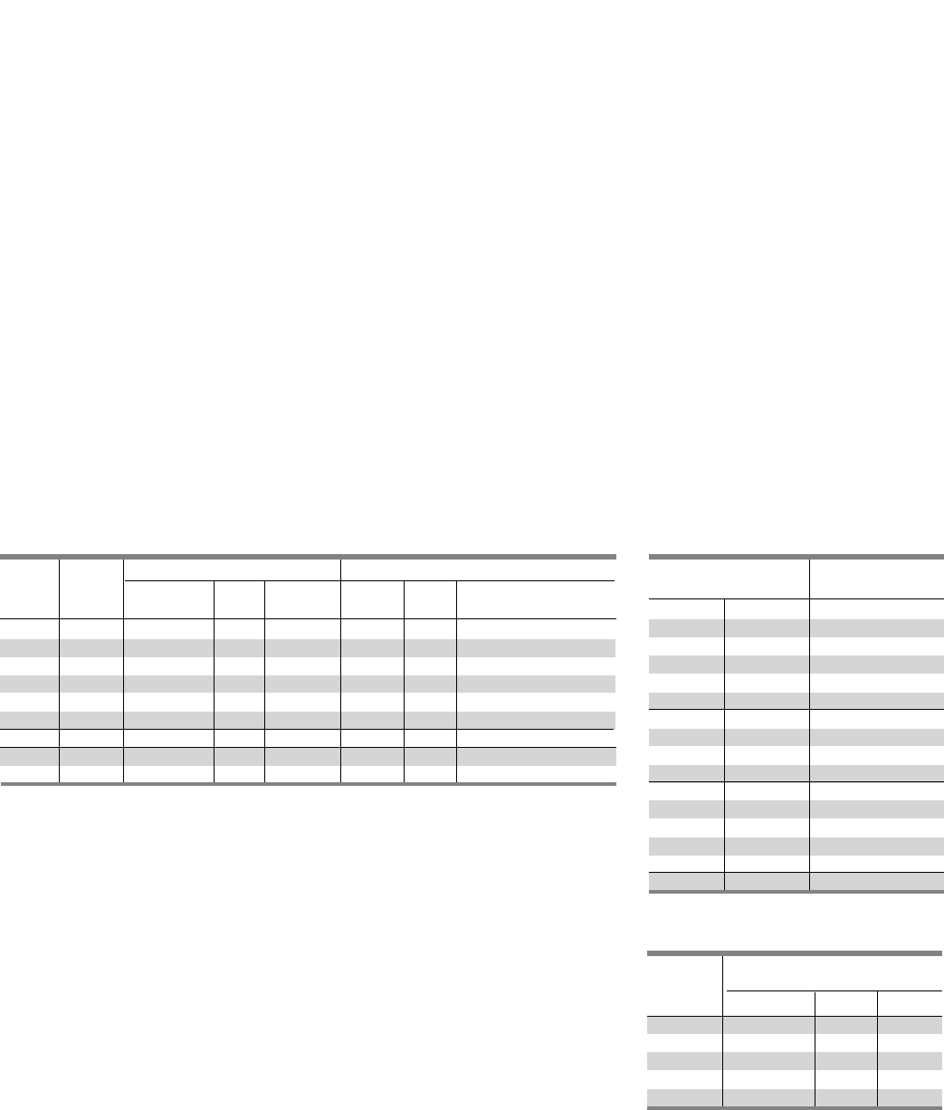
5-11
Modification and Additions
Type P5 Panelboards
Motor Starters
ETI instantaneous-trip circuit breakers
are recommended for use in combination
motor starters to provide selective short
circuit protection for the motor branch
circuit. The adjustable instantaneous-trip
feature provides a trip setting slightly
above the peak motor inrush current.
With this setting, there is no delay
opening the circuit when the fault occurs.
Since these circuit breakers have no time
delay trip element, they must be used in
conjunction with, and immediately ahead
of, the motor-running over-current
protective device.
Check the voltage and interrupting rating
of the circuit breaker to ensure they are
adequate for the electrical system. UL
recognized ETI breakers must be used.
Full voltage, non-reversing NEMA Size
1 through Size 4 motor starters are
available as additions to P5 panelboards.
P5 panelboards can accommodate motor
disconnect devices in either one of
two circumstances: 1. by using a branch
thermal magnetic (ETI) circuit breaker to
feed a remote starter that controls a
motor which is in sight of and within
fifty feet of the panelboard. 2. by using
a branch instantaneous trip only (ETI)
circuit breaker in conjunction with a
motor starter mounted in the same
enclosure which is in sight of and within
fifty feet of the controlled motor.
Whether a remote starter is used, or
the breaker and starter are mounted
in the same enclosure, a padlocking
device must be specified so a padlock
can be installed in the “OFF” position.
P2 panelboards incorporate motor
disconnect devices much in the same
way as P5 panelboards, except a fusible
Vacu-Break switch unit is utilized rather
than an ETI circuit breaker. In addition,
padlocking devices are standard on all
Vacu-Break switches eliminating the
need to order them as an accessory.
Standard Motor Starters Equipped
With:
• 3rd overload relay
• Mechanical interlock between circuit
breaker (or switch) and motor starter
door
• Reset button
• Class 1, Type A wiring
Optional Motor Control Accessories
• Pushbuttons: Start/Stop or Open/Close,
Reverse/Forward/Stop or High/Low/Stop
• Selector Switch: Hand/Off/Auto or
On/Off
• Pilot Light: Red or Amber
• Auxiliary interlock (normally open or
normally closed-unwired)
• Control transformer, 60Hz, fused LV,
Sizes 1 thru 4
• Class 1, Type B wiring
Maximum 3Ø Ratings Mounting Height in Inches (mm)
Amp Breaker Min. Section
Rating Type 220 (208)V 240V 480V1 2 Twin Single Width Inches (mm)
3——15 (127) — 32 (813)
5 0.5 0.5 2 5 (127) — 32 (813)
10 ED 12235 (127) — 32 (813)
25 5510 5 (127) — 32 (813)
50 15 15 30 5 (127) — 32 (813)
100 30 30 60 5 (127) — 32 (813)
150 FD6 240 40 75 5 (127) — 32 (813)
225 FD6, 50 50 100 5 (127) — 32 (813)
CFD6
Table P5-17 – ETI circuit Breakers (Instantaneous Trip Only)
For Branch-Circuit Use with AC Full Voltage Motor Starters
1 100,000 kA at 480V with E-frame and CFD6 frame breakers.
265,000 kA at 480V with F-frame breakers.
3Increase to 7.50 inches when pilot light or control transformer is required.
Table P5-18 – Full Voltage
Non-Reversing Starters Class A20
NEMA Unit Space
Starter Size Mtg. Ht. In. (mm)
Left Right
0 — 5 (127) 3
00 5 (127) 3
1—5 (127) 3
10 5 (127) 3
11 5 (127) 3
2—10 (254)
20 10 (254)
21 10 (254)
22 10 (254)
3—15 (381)
30 15 (381)
31 15 (381)
32 15 (381)
33 15 (381)
4—15 (381)
Table P5-19 – Maximum 3 Phase
Horsepower Rating
NEMA
Starter Voltage AC
Size 220 (208)V 240V 480V
0 3 3 5
1 7.5 7.5 10
2 10 15 25
3 25 30 50
4 40 50 100
SECTION 5
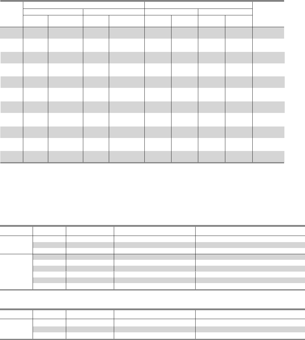
5-12
Connector Modifications
Style Amp Rating Breaker Type Compression Connectors Available Unit Space Reduction
800 N/A (3)#3/0 AWG - 750 Kcmil Cu or Al Deduct 5.0” Unit Space
MLO 1000 N/A (4)#3/0 AWG - 750 Kcmil Cu or Al Deduct 7.5” Unit Space
1200 N/A (4)#3/0 AWG - 750 Kcmil CU or Al Deduct 7.5” Unit Space
Table P5-22 – Alternate Lugs
Style Amp Rating Breaker Type Compression Connectors Available Unit Space Reduction
800 N/A All compression lugs Deduct 10.0” Unit Space
MLO 1000 N/A All compression lugs Deduct 10.0” Unit Space
1200 N/A All compression lugs Deduct 10.0” Unit Space
800 MD6, HMD6, CMD6, (3)#2/0 AWG - 500 Kcmil CU or Al 0
SMD6, SHMD6,
Main Breaker SCMD6
1200 ND6, HND6, CND6,
SND6, SHND6. (4)#250 - 500 Kcmil Cu or Al 0
SCND6
Table P5-21 – Compression Lugs
Compression Lugs
Modification and Additions
Type P5 Panelboards
Horsepower Ratings Mounting Height in Inches (mm)
240V AC 480V AC 240V AC 480V AC Min. Section
Amp With With Dual- With NEC With Dual- Width
Rating NEC Fuse Element Fuse Fuse Element Fuse Twin Single Twin Single Inches (mm)
30-30 3 7.5 — — 2.50 2—— — 32 (813)
(64)
30-30 3 7.5 5 10 5.00 —7.50 — 32 (813)
(127) (191)
30-60 3-7.5 7.5-15 5-15 25 5.00 —7.50 — 32 (813)
(127) (191)
60-60 7.5 15 15 25 5.00 —7.50 — 32 (813)
(127) (191)
60-100 7.5-15 15-30 15-25 25-50 7.50 —7.50 — 32 (813)
(191) (191)
100-100 15 30 25 50 7.50 —7.50 — 32 (813)
(191) (191)
100 —— 25 50 ———7.50 32 (813)
(191)
200 25 50 50 100 — 10.00 —10.00 32 (813)
(254) (254)
200-200 — 50 — 100 10.00 —10.00 — 32 (813)
(254) (254)
400 50 100 100 ——
15.00 —15.00 38 (965)
(381) (381)
600 75 100 —— —15.00 —15.00 38 (965)
(381) (381)
Table P5-20 – Vacu-Break Fusible Switches
For Branch Circuit Use with AC Combination Full Voltage Starters 1
1100,000 kA at 480V with Class J or Class RK5 fuses.
2The 2.50 inch (64mm) high unit is suitable for NEC Class H and K5 fuses only. Class R rejection type fuse holders are not available.
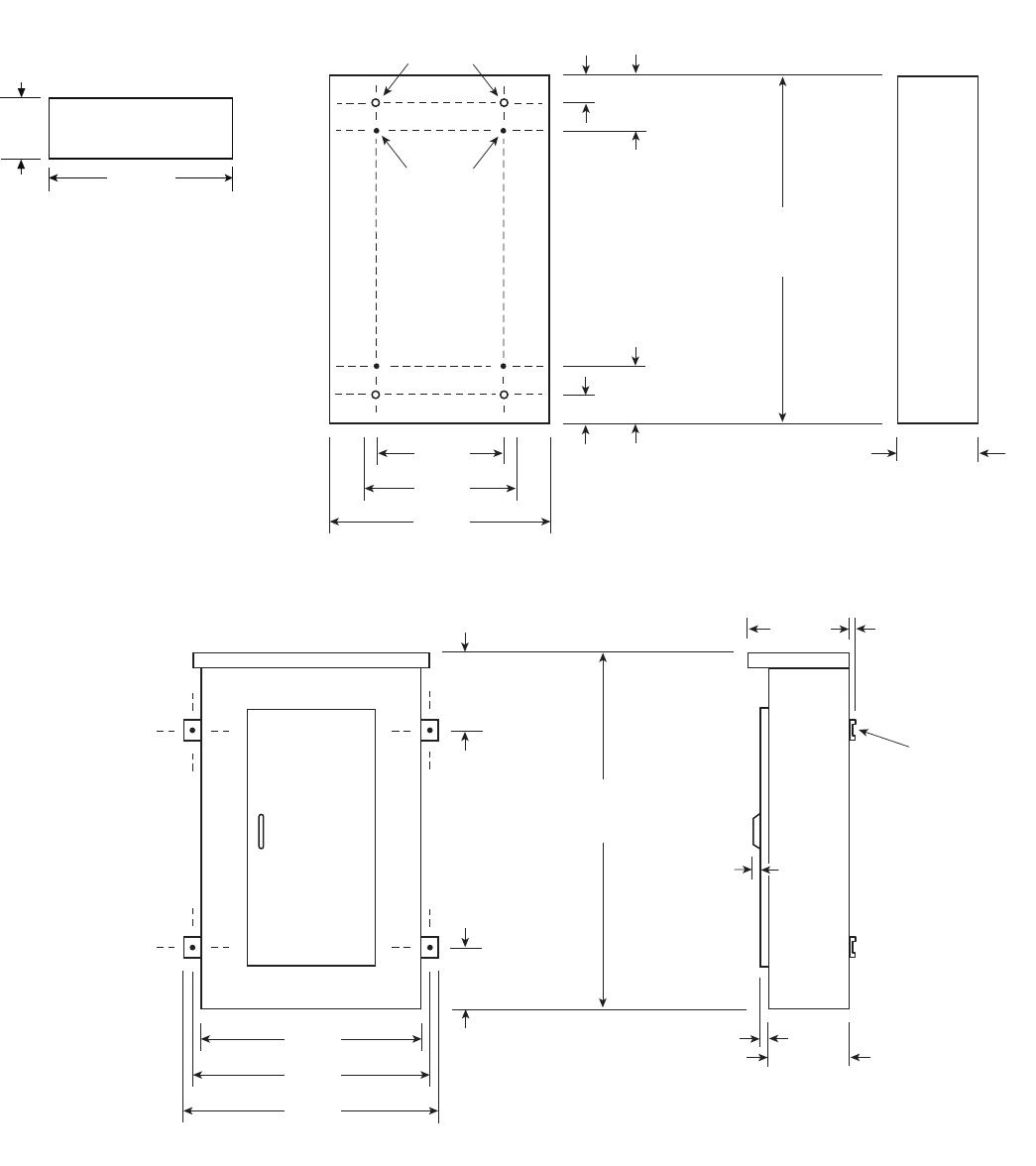
5-13
Dimensions
Type P5 Panelboards
38 in.
[ 965 ]
.375 in.
[ 10 ]
15.88 in.
[ 403 ]
.375 in.
[ 10 ]
Mounting
Bracket
14.25 in.
[ 362 ]
.87 in.
[ 22 ]
40 in.
[ 1016 ]
42 in.
[ 1067 ]
15.81 in.
[ 402 ]
15.81 in.
[ 402 ]
60 in.,
[ 1524 ]
75 in.,
[ 1905 ]
90 in.
[ 2286 ]
a
a
a
38 in.
[ 965 ]
30 in.
[ 762 ]
24 in.
[ 610 ]
4.375 in.
[ 111 ]
6.635 in.
[ 169 ]
4.375 in.
[ 111 ]
6.635 in.
[ 169 ]
a
12.75 in.
[ 324
a
60 in.,
[ 1524 ]
75 in.,
[ 1905 ]
90 in.
[ 2286 ]
a
Interior To Box
Mounting
Stubs
Box To Wall
Mounting Holes
Type 1 Box
Box is symmetrical
Type 3R and 3R/12 Box
1Dimensions are interior of the box. Add 5/8” to width for
absolute dimension. Add 1/8” to height for absolute dimension.
Dimensions shown in inches and millimeters [ ].
1
1
1
1
1
1
SECTION 5
36 in.
[ 914 ]
10 in.
[ 254 ]
Recommended Conduit Area
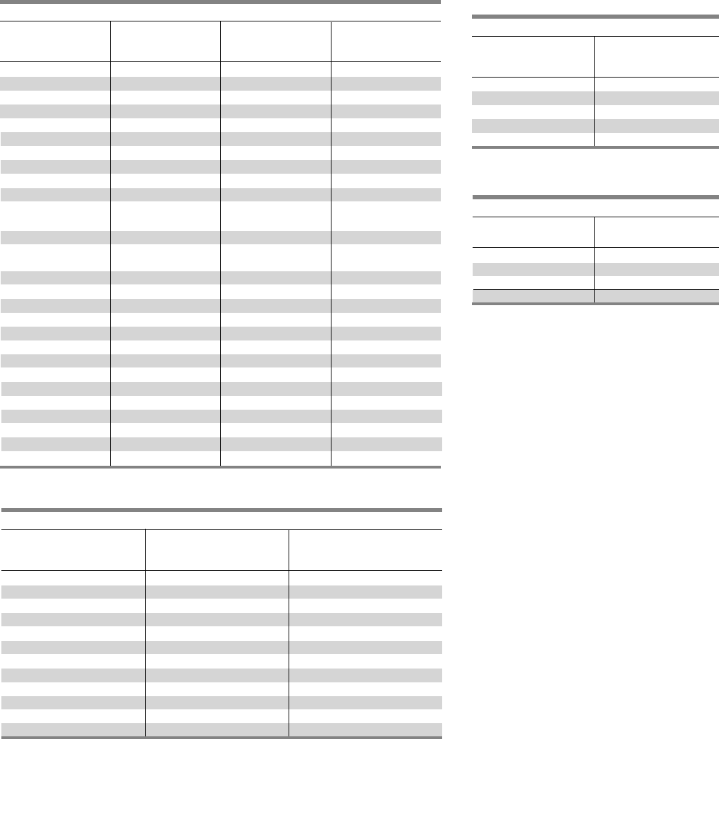
5-14
Kits and Accessories
Type P5 Panelboards
Table P5-23 – Branch Breaker Connecting Strap Kits 1 2
For use with Sentron Deep or Type P5 power panels
Unit
Breaker Mounting Height Catalog
Type Type Inches (mm) Number
BL, BQD Twin 3.75 (95) SBLBD
NGB Twin 3.75 (95) SNBD
NEB, HEB Twin 3.75 (95) SEBD
ED Twin 3.75 (95) SE6D
CED Twin 3.75 (95) SCED
DG4Twin 5.00 (127) SDGD
QJ Twin
5.00 (127) SQJD
FD Twin 5.00 (127) SF6D
FG4Twin 5.00 (127) SFGD
CFD Single 5.00 (127) SCFD
JD6 Single 8.75 (223) SJ1D
Twin SJ2D
SJD6 Single 8.75 (222) SSJ1D
JG4 5 Single 6.25 (159) SJG1D
Twin SJG2D
CJD Single 8.75 (222) SCJD
SCJD Single 8.75 (222) SSCJD
LD6 Single 8.75 (222) SL6D
SLD Single 8.75 (222) SSL6D
LG 4Single 6.25 (159) SLGD
CLD Single 8.75 (222) SCLD
SCLD Single 8.75 (222) SSCLD
MG4Single 8.75 (222) MG1D
LMD6 Single 8.75 (222) SLM1D
MD6, CMD6 Single 10.00 (254) SMND
SMD6 Single 10.00 (254) SSMND
NG4Single 10.00 (254) NG1D
ND6 Single 10.00 (254) SMND
SND6 Single 10.00 (254) SSMND
Table P5-24 – Blank Plates – Circuit
Breaker and Vacu-Break 1
For use with Sentron SPP and Type P5 power panels
Height
Inches Catalog
(mm) Number
1.25 (32) 6FPB01
2.5 (63.5) 6FPB02
3.75 (95) 6FPB03
5.0 (127) 6FPB05
10.0 (254) 46FPB10
Table P5-26 – Connecting Strap Kits – Fusible 3
For use with Sentron FPP Deep or Type F2/P5 power panels
Unit
Ampere Height Catalog
Rating Inches (mm) Number
30–30 2.5 (63.5) F602D
30–30 5.0 (127), 7.5 (191) F657D
30–60 5.0 (127), 7.5 (191) F657D
60–60 5.0 (127), 7.5 (191) F657D
60–100 5.0 (127), 7.5 (191) F657D
100–100 5.0 (127), 7.5 (191) F657D
100 7.5 (191) F657D
200 7.5 (191) F657D
200 10.0 (254) F671D
200–200 10.0 (254) F672D
400–600 15.0 (381) F6150D
800–1200
2
16.25 (413) F6162D
Table P5-25 – Filler Plates
For use with Sentron SPP and P5 power panels
Breaker Type Filler Plate
Catalog Number
BL, BLH, HBL, BQD, NGB
ED2, ED4, ED6 QF3
HED4, HHED6
NEB, HEB EBF1
Note: When a front filler plate is not completely filled
with breakers, the openings in the unused space must be
closed with filler plates selected from this table.
1Includes cover plate and mounting hardware, less circuit breaker.
2Also fits Types FCI, FCII, SB1, SB2 and SB3 switchboards.
3800-1200 amp units are HCP switch.
4VL family of circuit breakers.
5JG ETU are not viewable when twin mounted.
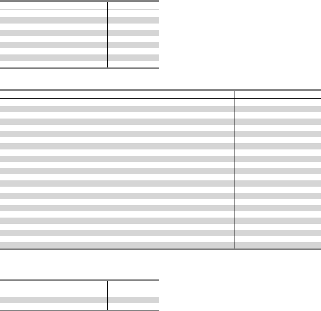
5-15
SECTION 5
Kits and Accessories
Type P5 Panelboards
Description Catalog number
P5 Type 1 38” W x 12.75” D x 60” H PB860
P5 Type 1 38”” W x 12.75” D x 75” H PB875
P5 Type 1 38”” W x 12.75” D x 90” H PB890
P5 Type 1 38” W x 14.75” D x 60” H PBD860 1
P5 Type 1 38”” W x 14.75” D x 75” H PBD875 1
P5 Type 1 38”” W x 14.75” D x 90” H PBD890 1
P5 Type 3R/12 60” H WP860
P5 Type 3R/12 75” H WP875
P5 Type 3R/12 90” H WP890
1Required with door over breaker handles.
Table P5-27 – Enclosures
Description Catalog number
P5 Std (4 piece trim) vented 60” P560V
P5 Std (4 piece trim) vented 75” P575V
P5 Std (4 piece trim) vented 90” P590V
P5 Std (4 piece trim) unvented 60” P560NV 1
P5 Std (4 piece trim) unvented 75” P575NV 1
P5 Std (4 piece trim) unvented 90” P575NV 1
P5 Std (4 piece trim) vented 60” with hinged gutter covers P560VHG
P5 Std (4 piece trim) vented 75” with hinged gutter covers P575VHG
P5 Std (4 piece trim) vented 90” with hinged gutter covers P590VHG
P5 Std (4 piece trim) unvented 60” with hinged gutter covers P560NVHG
P5 Std (4 piece trim) unvented 75” with hinged gutter covers P575NVHG
P5 Std (4 piece trim) unvented 90” with hinged gutter covers P590NVHG
P5 Std (1 PC Door) vented 60” P560VD 2
P5 Std (1 PC Door) vented 75” P575VD 2
P5 Std (1 PC Door) vented 90” P590VD 2
P5 Std (1 PC Door) unvented 60” P560NVD 2
P5 Std (1 PC Door) unvented 75” P575NVD 2
P5 Std (1 PC Door) unvented 90” P590NVD 2
P5 Std (1 PC Door-in-door) vented 60” P560VDD 2
P5 Std (1 PC Door-in-door) vented 75” P575VDD 2
P5 Std (1 PC Door-in-door) vented 90” P590VDD 2
P5 Std (1 PC Door-in-door) unvented 60” P560VDD 2
P5 Std (1 PC Door-in-door) unvented 75” P575VDD 2
P5 Std (1 PC Door-in-door) unvented 90” P590VDD 2
1Unvented trims require amps per square inch bussing.
2Requires 14.5” deep box.
Table P5-28 – Trims
Description Catalog number
Flush kit to P5 60” High F860
Flush kit to P5 75” High F875
Flush kit to P5 90” High F890
Table P5-29 – Flush mounting kits
Notes
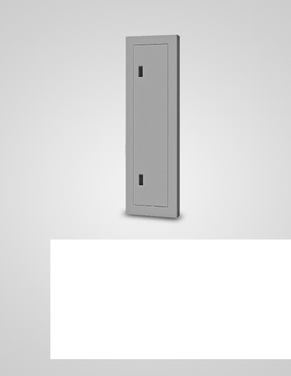
C1/C2 Panelboards
Description Page
General Specifications 6-2
Box Sizing 6-2
Gauge Steel Boxes 6-2
Fronts 6-2
Main Breaker Connectors 6-2
Main Lug Connectors 6-2
Selection 6-3 – 6-5
Main Lugs Only C1 and C2 6-3
Main Circuit Breaker C1 and C2 6-3
Alternate Main Breaker Selection C1 6-3
Branch Breaker Selection C1 6-4
Subfeed Breakers C1 6-4
Alternate Main Breaker Selection C2 6-5
Branch Circuit Breaker C2 6-5
Subfeed Breakers C2 6-5
Modification and Additions 6-6
Box Modifications 6-6
Interior Modifications 6-6
Column Extension 6-6
Pull Boxes 6-6
SECTION 6
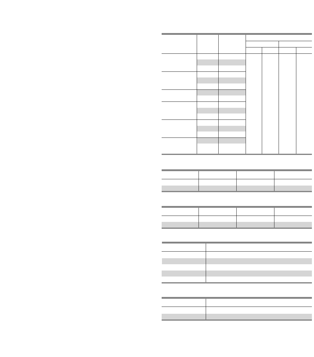
6-2
Type C1
250 Volts AC Maximum
250 Ampere Mains
250 Ampere Maximum Branch
UL Short Circuit Rating – 200,000 IR Maximum
Branch Breaker Symmetrical Interrupting Rating
Based on Underwriters’ Test Procedure
Type C2
480Y/277 Volts AC Maximum
250 Ampere Mains
250 Ampere Maximum Branch
UL Short Circuit Rating – 100,000 IR Maximum
Meets 2002 NEC wire bending requirement, section 312-6
Panelboards
Listed by Underwriter’s Laboratories, Inc., under “Panelboards”
File #E2269
Meets Federal Specification W-C375B/Gen.
Panelboards Fronts and Doors
Standard panelboards are furnished with trim with a flush door
lock. All are factory assembled for ease of installation. Fronts are
fabricated from code gauge steel and finished ANSI-61.
Main Breakers C1
BL, BLH and HBL frame breakers are mounted horizontally. All
other frames are mounted vertically.
Main Breakers C2
BQD frame breakers are mounted horizontally. All other frames
are mounted vertically.
Weight — Approximate
Total panelboard weight when filled with a normal quantity of
breakers and accessories is about 3 lbs. (1 kg) per inch (54g per
mm) of box height.
Column Extensions
Available in various standard lengths, extensions are 5.25 in.
(133 mm) deep with a width of 7 in. (178 mm). (These are
outside dimensions). Designed to fit into an 8 in. (203 mm)
structural WF beam. Column panels may also be surface
mounted.
Pull Boxes
Two styles of pull boxes are available, top and front mounted.
When the panel and its extensions are mounted in a structural
WF Beam, a front-mounted pull box is required. When the
panels are surface-mounted, top-mounted pull box may be used.
Provisions are made so that the neutral bar may be mounted in
the pull box when required.
Table C1/C2-1 – Box Sizing
Certain Modifications such as subfeed breakers and feed-thru
lugs require additional unit space. Use this table to determine
proper enclosure size.
General Specifications
C1 and C2 Panelboards
Main Lug with
Feed-Thru Lugs
Main Breaker
with Feed-Thru
Lugs
Main Breaker
with Subfeed
Breaker
Main Lug with
Subfeed Breaker
Main Breaker
Panel Height Dimensions in inches (mm)
Config- No. of Inches Width Depth
uration Circuits (mm) C1 C2 C1 C2
18 48 (1219)
Main Lug
30 73 (1854)
42 85 (2159)
18 73 (1854)
30 86 (2184)
42 85 (2159)
18 73 (1854)
30 85 (2159) 7.62 8.50 5.75 5.75
18 48 (1219) (194) (216) (146) (146)
30 73 (1854)
42 85 (2159)
18 73 (1854)
30 85 (2159)
42 85 (2159)
18 73 (1854)
30 85 (2159)
Table C1/C2-2 – Gauge Steel Boxes
Type Width Height Gauge Steel
C1 7 ⁵⁄₈ ” 48, 73, 85 #14
C2 8 ¹⁄₂” 48, 73, 85 #14
Table C1/C2-3 – Fronts
Type Width Height Gauge Steel
C1 7 ⁵⁄₈ ” 48, 73, 85 #14
C2 8 ¹⁄₂” 48, 73, 85 #14
Table C1/C2-4 – Main Breaker Connectors
Ampere Rating Connector Suitable for Cu or Al
100 (1) #14-1/0 AWG
125 (1) #4-1/0 AWG
225 (1) #6 AWG-300 kcmil
250 (1) #4 AWG-350 kcmil Al
(1) #6 AWG-350 kcmil Cu
Table C1/C2-5 – Main Lug Connectors
Ampere Rating Connector Suitable for Cu or Al
125 (1) #6 AWG-350 kcmil
250 (1) #6 AWG-350 kcmil
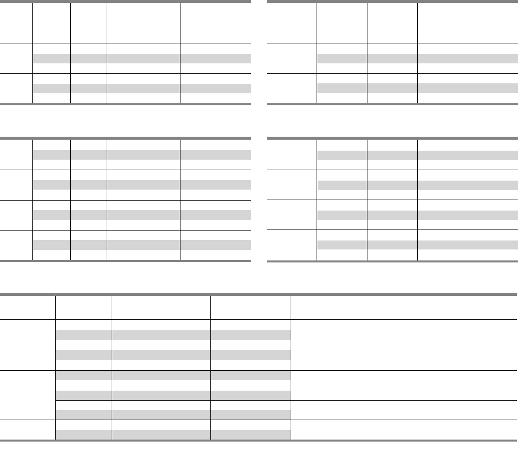
6-3
Selection
C1 and C2 Panelboards
Max.
Panel Max. Box 208Y/120V 120/240V
Amp 1-Pole Height 3, Phase 4 Wire 1 Phase, 3 Wire
Rating Circuits Inches Catalog Number Catalog Number
18 48 C1C18ML125CTS C1A18ML125CTS
125 30 73 C1C30ML125CTS C1A30ML125CTS
42 85 C1C42ML125CTS C1A42ML125CTS
18 48 C1C18ML250CTS C1A18ML250CTS
250 30 73 C1C30ML250CTS C1A30ML250CTS
42 85 C1C42ML250CTS C1A42ML250CTS
Table C1/C2-6 – Main Lugs Only C1
18 48 C1C18BL100CTS C1A18BL100CTS
100 30 73 C1C30BL100CTS C1A30BL100CTS
42 85 C1C42BL100CTS C1A42BL100CTS
18 48 C1C18E4125CTS C1A18E4125CTS
125 30 73 C1C30E4125CTS C1A30E4125CTS
42 85 C1C42E4125CTS C1A42E4125CTS
18 48 C1C18QJ225CTS C1A18QJ225CTS
225 30 73 C1C30QJ225CTS C1A30QJ225CTS
42 85 C1C42QJ225CTS C1A42QJ225CTS
18 48 C1C18FX250CTS C1A18FX250CTS
250 30 73 C1C30FX250CTS C1A30FX250CTS
42 85 C1C42FX250CTS C1A42FX250CTS
Table C1/C2-8 – Main Circuit Breaker C1 1 2
Max.
Panel Max. Box 480Y/277V
Amp 1-Pole Height 3 Phase, 4 Wire
Rating Circuits Inches Catalog Number
18 48 C2E18ML125CTS
125 30 73 C2E30ML125CTS
42 85 C2E42ML125CTS
18 48 C2E18ML250CTS
250 30 73 C2E30ML250CTS
42 85 C2E42ML250CTS
Table C1/C2-7 – Main Lugs Only C2
18 48 C2E18BD100CTS
100 30 73 C2E30BD100CTS
42 85 C2E42BD100CTS
18 48 C2E18E4125CTS
125 30 73 C2E30E4125CTS
42 85 C2E42E4125CTS
18 48 C2E18FX225CTS
225 30 73 C2E30FX225CTS
42 85 C2E42FX225CTS
18 48 C2E18FX250CTS
250 30 73 C2E30FX250CTS
42 85 C2E42FX250CTS
Table C1/C2-9 – Main Circuit Breaker C2 1 2
Amp Breaker Maximum Interrupting Catalog
Rating Type Rating (KA) Number Available Trip Values
BL 10 BL
100 BLH 22 LH 50, 60, 70, 80, 90, 100
HBL 65 HL
ED4 65 E4
125 HED4 100 H4 50, 60, 70, 80, 90, 100, 110, 125
QJ2 10 QJ
QJH2 22 QH 60, 70, 80, 90, 100, 110, 125, 150, 175, 200, 225
225 QJ2-H 42 Q2
FXD6 65 FX 70, 80, 90, 100, 110, 125, 150, 175, 200, 225
HFD6 2100 HF
250 FXD6 65 FX 250
HFD6 2100 HF
1BL, BLH, HBL and BQD are horizontally mounted. All others vertically mounted.
2 Interchangeable trip breakers such as FD6 and HFD6 cannot be back fed. Must be top feed only.
Table C1/C2-10– Alternate Main Breaker Selection C1 1 2
SECTION 6
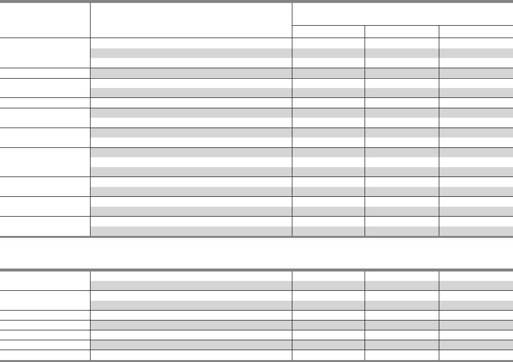
6-4
Selection
C1 and C2 Panelboards
Available Maximum Interrupting
Breaker Ampere Rating (kA)
Type Rating 120V 120/240V 240V
15, 20, 30, 40, 50, 60 — 10 —
BL (120V) 70 — 10 —
70, 80, 90, 100 — 10 —
BL (HID) 15, 20, 30 —— —
BLF (GFCI) 15, 20, 30 10 ——
40, 50, 60 10 ——
BLE (EQGFI) 15, 20, 30 10 ——
BGL (SWN) 15, 20, 30 10 ——
15, 20, 30 — 10 —
BLR (240V) 15, 20, 30, 40, 50, 60 —— 10
70, 80, 90, 100 —— 10
15, 20, 30, 40, 50, 60 — 22 —
BLH (120V) 70 — 22 —
70, 80, 90, 100 — 22 —
BLHF (GFCI) 15, 20, 30 — 22 —
40, 50, 60 — 22 —
HBL 15, 20, 30, 40, 50 — 65 65
60, 70, 80, 90, 100 — 65 65
BQD 15, 20, 30, 40, 50, 60 —— 65
70, 80, 90, 100 —— 65
ED4 15, 20, 30, 40, 50, 60, 70, 80, 90, 100 —— 65
110, 125 —— 65
HED4 15, 20, 30, 40, 50, 60, 70, 80, 90, 100 —— 65
110, 125 —— 100
QJ2 60, 70, 80, 90, 100, 110, 125, 150, 175, 200, 225 —— 10
QJH2 60, 70, 80, 90, 100, 110, 125, 150, 175, 200, 225 —— 22
QJ2-H 60, 70, 80, 90, 100, 110, 125, 150, 175, 200, 225 —— 42
FXD6 70, 80, 90, 100, 110, 125, 150, 175, 200, 225, 250 —— 65
HFD6 70, 80, 90, 100, 110, 125, 150, 175, 200, 225, 250 —— 100
Table C1/C2-12 – Subfeed Breakers - Limit One Per Panel – C1
Table C1/C2-11 – Branch Breaker Selection C1
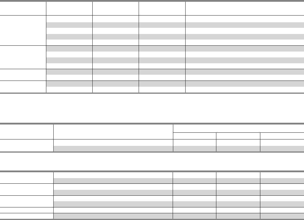
6-5
Selection
C1 and C2 Panelboards
Maximum Interrupting Rating (kA)
Breaker Type Available Ampere Rating 277V 480/277V 480V
15, 20, 30, 40, 50, 60 14 14 —
BQD 70, 80, 90, 100 14 14 —
Table C1/C2-14 – Branch Circuit Breakers C2
ED4 15, 20, 30, 40, 50, 60, 70, 80, 90, 100 — 18 18
110, 125 — 18 18
ED6 15, 20, 30, 40, 50, 60, 70, 80, 90, 100 —— 25
110, 125 —— 25
HED4 15, 20, 30, 40, 50, 60, 70, 80, 90, 100 —— 42
110, 125 —— 42
FXD6 70, 80, 90, 100, 110, 125, 150, 175, 200, 225, 250 —— 35
HFD6 70, 80, 90, 100, 110, 125, 150, 175, 200, 225, 250 —— 65
Table C1/C2-15 – Subfeed Breakers - Limit One Per Panel1 2 C2
1 No increase in box height. Space is already built into C1 panel.
2BL, BLH, HBL and BQD are horizontally mounted. All others vertically mounted.
1 No increase in box height. Space is already built into C1 panel.
2BL, BLH, HBL and BQD are horizontally mounted. All others vertically mounted.
3 Interchangeable trip breakers such as FD6 and HFD6 cannot be back fed. Must be
top feed only.
Ampere Breaker Catalog
Rating Type IR Number Available Trip Values
BQD 14 BD 50, 60, 70, 80, 90, 100
ED4 18 E4 50, 60, 70, 80, 90, 100
100 ED6 25 E6 50, 60, 70, 80, 90, 100
HED4 42 H4 50, 60, 70, 80, 90, 100
HHED6 65 H6 50, 60, 70, 80, 90, 100
ED4 18 E4 110, 125
125 ED6 25 E6 110, 125
HED4 42 H4 110, 125
HHED6 65 H6 110, 125
225 FXD6 35 FX 70, 80, 90, 100, 110, 125, 150, 175, 200, 225
HFD6 65 HF 70, 80, 90, 100, 110, 125, 150, 175, 200, 225
250 FXD6 35 FX 250
HFD6 65 HF 250
Table C1/C2-13 – Alternate Main Breaker Selection 1 2 3 C2
SECTION 6
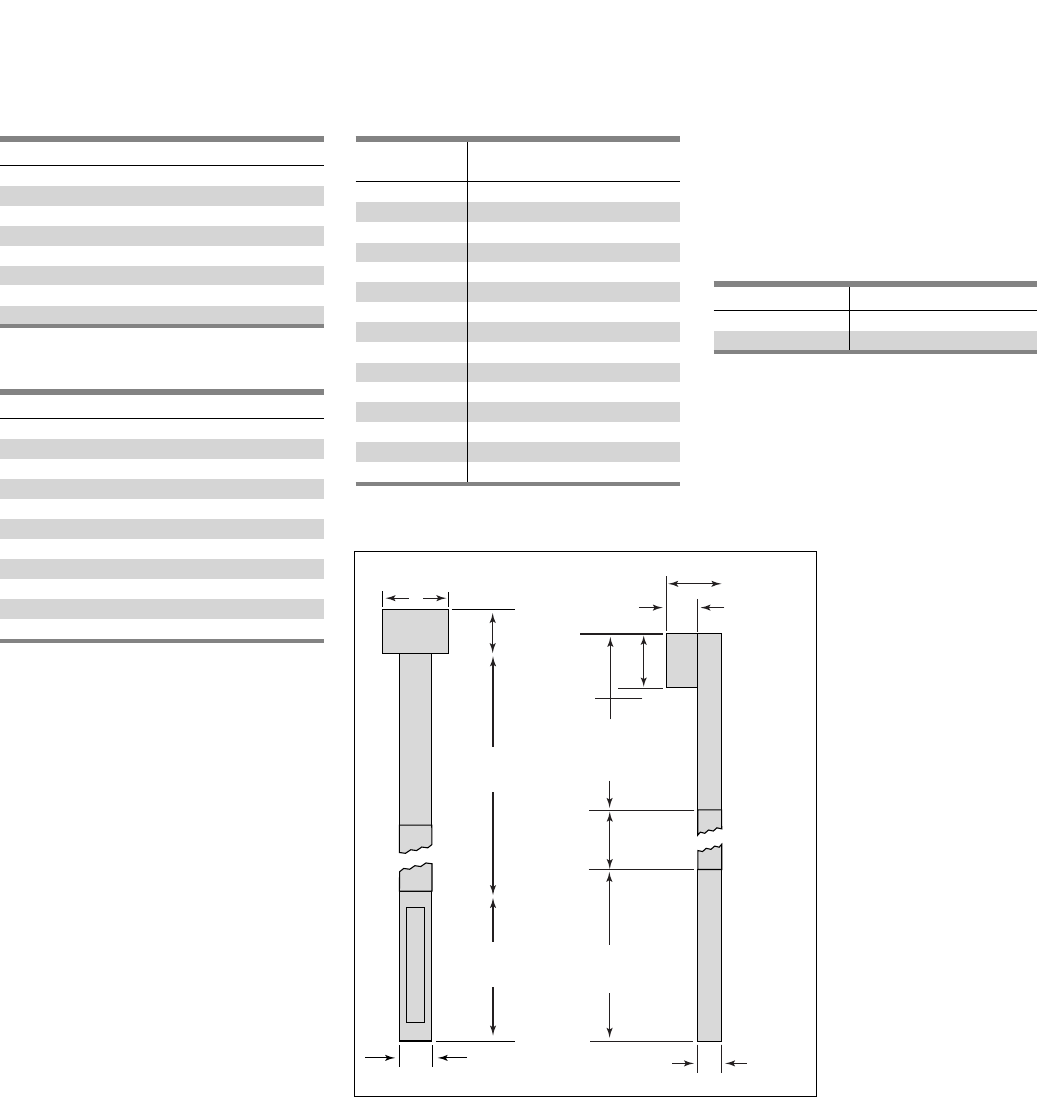
6-6
Description
Feed-Thru Lugs
Handle Blocking Devices – BL, BQD
Handle Blocking Devices – QJ, FD6
Handle Padlocking Devices – BL, BQD
Handle Padlocking Devices – QJ, FD6
Shunt Trip – BL, BQD
Shunt Trip – ED Frame, QJ
Shunt Trip – FD6
Cu Neutral Lugs
Cu Main Lugs 125A
Cu Main Lugs 250A
Table C1/C2-17 – Interior Modifications
Type C1/C2
When required, special constructions
or additions to standard panelboards
may be specified for factory-assembled
column panelboards.
Column Extension
Available in various standard lengths,
extensions are 5¹⁄₄ inches deep and
7 inches wide.
Pull Boxes
Two styles of pull boxes are available,
top and front mounted. When the panel
and its extensions are mounted in a
structural WF beam, a front mounted
pull box is required. When the panels
are surface mounted, a top mounted
pull box may be used. Provisions are
made so that the neutral bar may be
mounted in the pull box when required.
(Front mounted pull box dimensions
are 14” H x 20” W.)
Description Catalog Number
Top Mount LXXP-T
Front Mount 1LXX50-F
Table C1/C2-19 – Pull Boxes
Description
Gasketed
Metal Card Holder
Welded Metal Card Holder
Nameplate
Al Ground Bar
Cu Ground Bar
Insulated Al Ground Bar
Insulated Cu Ground Bar
Table C1/C2-16 – Box Modifications
Height Catalog Number
(inches)
14 LXX-14
20 LXX-20
26 LXX-26
32 LXX-32
38 LXX-38
41 LXX-41
44 LXX-44
53 LXX-53
56 LXX-56
62 LXX-62
65 LXX-65
68 LXX-68
74 LXX-74
80 LXX-80
86 LXX-86
Table C1/C2-18 – Column Extension
1Includes 50” extension.
Modification and Additions
C1 and C2 Panelboards
7.00 in
(178 mm)
H
Box
Height
H
Box
Height
Additional
Extensions
If Required
14.00 in.
(356 mm)
Pull Box
20.00 in.
(508 mm) 11.00 in.
(279 mm)
5.25 in.
(133 mm)
14.00 in.
(356 mm)
Pull Box
Top Extension
(For Front Mtg.)
53.99 in.
(1346 mm)
Additional
Extensions
If Required
5.25 in
(133 mm)
Fig. C1/C2-1
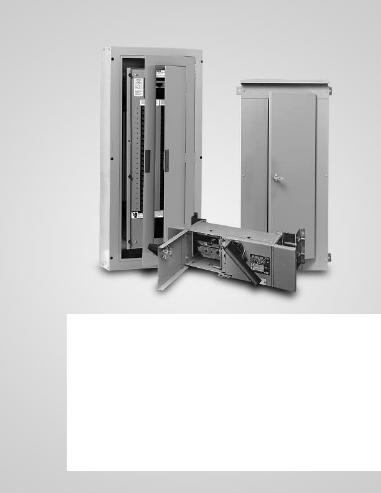
Miscellaneous
Description Page
Telephone Cabinets 7-2
Conduit Enclosing Shield (Panel Skirts) 7-2
Breaker Mechanical Lugs 7-2
Compression Lugs 7-2
Optional Mechanical Lugs 7-3
Aluminum Body Lugs for Copper or
Aluminum Wire 7-3
Miscellaneous Replacement Parts 7-4
Strap Kits 7-4
Connecting Strap Kits 7-4
Blank Plates – Vacu-Break 7-4
Molded Case Switches 7-4
SECTION 7
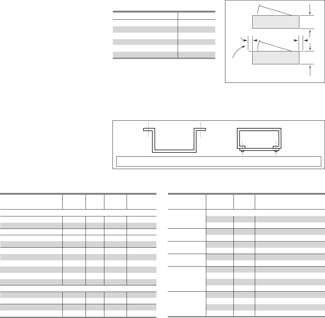
7-2
Miscellaneous
Conduit Enclosing Shield
(Panel Skirts)
Sheet metal to cover conduits above
or below a standard panelboard box.
Panel Skirts Standard Length
3 Sides Open Back 4 Sides Screw Front
8, 9, 10, 11, 12, 14, 17, 18, 23, 24, 25, 26, 27, 28, 29, 30, 31, 32, 33, 34, 35, 36, 37, 38, 39, 40, 41, 42, 43, 44
Table Misc. 3 – Breaker Mechanical Lugs
For Use Amp Cables
With Type(s) Rating Per Lug Lug Wire Range
Load Side
15-20 1 #14-#10 AWG Cu
1 #12-#10 AWG Al
25-35 1 #8-#6 AWG Cu
1 #8-#6 AWG Al
40-50 1 #8-#6 AWG Cu
1 #8-#4 AWG Al
55-70 1 #8-#4 AWG Cu
1 #8-#2 AWG Al
80-100 1 #4-#1/0 AWG Cu
1 #2-#1/0 AWG Al
110-125 1 #2-#1/0 AWG Cu
1 #1/0-#2/0 AWG Al
BQD
15-40 1 #14-#6 AWG Cu
BQD6
#12-#6 AWG Al
45-100 1 #8-1 AWG Cu
#6-#1/0 AWG Al
Telephone Cabinets
Conform to requirements of Underwriter’s
Laboratories, Inc., for all cabinets and boxes
bearing their label. Surface enclosures,
box and front constructed of code gauge
steel. Entire cabinet finished with light
gray, ANSI-61. Flush enclosures, box con-
structed of code-gauge galvanized steel,
front only finished with light gray, ANSI-61.
Boxes
Standard construction has blank ends,
without knockouts.
Front
Concealed hinges standard on fronts.
Double doors supplied when door width
exceeds 24 in. (610 mm). 3-point catch
and vault handle supplied with double
doors; two spring catches supplied on
doors more than 48 in. (1219 mm) high.
Backboard
0.75 in. (19mm) plywood backboard
supplied when specified.
Depth
Depth
Surface Mounting
0.75 in.
(19 mm)
0.75 in.
(19 mm)
Flush Mounting
Tri m
Overlap
Table Misc.–1
Box Width – In. (mm) Door
0 (0)–20 (508) Single
21 (533)–24 (610) Single
25 (635)–36 (914) Single
25 (635)–36 (914) Double
37 (940)–38 (965) Double
49 (1245)–60 (1524) Double
All available with 0.75 in. (19 mm) backboard.
Depth 12 in. (305 mm) or less. Height 72 in. (1829
mm) or less. Specify Mounting – Surface or Flush.
Box width minus 5 in. (127 mm) equals door width.
BQ, BQH,
BQHF, BQE
BQF,
BL, BLH
HBL, HBQ
Switching
Neutrals
BG
BLG
Table Misc. 2 – Compression Lugs
For Circuit Ampere Lugs Lug Wire
Breaker Types Rating Poles Per Kit Size
Lugs (contains indicated number of lugs and necessary hardware per kit)
ED2, ED4, ED6, 15-125 1,2,3 1 #2/0
HED4, HHED6, CED4
QJ2, QJH2, QJ2-H 125-225 2, 3 1 350 kcmil
F(X)D6-A, HF(X)D6, 125-250 2, 3 1 350 Kcmil
HHF(X)D6, CFD6
JXD2-A, J(X)D6-A,
HJ(X)D6-A, HHJXD6-A,
CJD6, SJD6-A, 200-600 2, 3 1 500 Kcmil
SHJD6-A, SCJD6, L(X)D6-A,
HL(X)D6-A, CLD6, SLD6-A,
SHLD6-A, SCLD6
Kits
(contains lug and hardware for complete line of load end of 2 or 3 pole breaker)
M(X)D6, HM(X)D6, CMD6, 500-800 26500 Kcmil
SMD6, SHMD6, SCMD6 39500 Kcmil
N(X)D6, HN(X)D6, CND6, 900-1200 28500 Kcmil
SND6, SHND6, SCND6 3 12 500 Kcmil
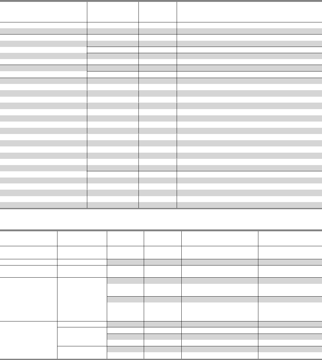
7-3
Miscellaneous
For Use Circuit Breaker Cables Lug Quantity per
With Type Ampere Rating Per Lug Material Lug Wire Range Catalog Number
QJ2, QJH2 60-225 1 Cu #6 AWG-250 Kcmil (Cu) 1
QJ2H, HQJ2H
ED, HED, 2&3 pole 2-3 pole 30-125 1 Cu #10-#1/0 (Cu)
HFD6, HHFD6 70-250 1 Cu #6 AWG-350 Kcmil (Cu) 1
CFD6, F(X)D6-A
J(X)D2(A), J(X)D6(A), 1 3/0-600 Kcmil (Cu) 1
HJD6(A), HHJD6, 1,2 Cu 3/0-500 Kcmil (Cu) 1
SHJD6(A), L(X)D6(A),
HHLD6, SCD6, 250-600 1 Al 500-750 Kcmil (Al) 1
HLD6(A), SHLD6(A),
CJD6, CLD6, SCJD6, 1 500-600 Kcmil (Cu) 1
SCLD6
SMD6, M(X)D6, 500-600 1-2 Cu #1 AWG-500 Kcmil (Cu) 1
HM(X)D6, HMD6, 1-3 Cu #1 AWG-350 Kcmil (Cu) 1
CMD6, SCMD6, SND6, 700-800 1-2 Al 500-750 Kcmil (Cu) 2
N(X)D6, HN(X)D6, 1-2 Al 500-750 Kcmil (Al) 3
SHND6, CND6, SCND6 800-1200 1-3 Al 500-750 Kcmil(Cu) 2
500-750 kcmil (Al) 3
Table Misc. 5 – Optional Mechanical Lugs
Circuit
For Use Breaker Cables
With Type Amp Rating Per Lug Lug Wire Range
QJ2, QJH2 60-225 1 #6 AWG-300 kcmil (Cu)
QJ2H, HQJ2H #4 AWG-300 Kcmil (Al)
All 2&3 pole 15-25 1 #14-#10 AWG (Cu)
ED2, ED4, ED6, #12-#10 AWG (Al)
ED6ETI 30-100 1 #10-#1/0AWG (Cu or Al)
HED4, 110-125 1 #3-3/0 (Cu)
HHED6 1 #1-2/0 (Al)
CED6, All 1 Pole, 30-60 1 #10-4 (Cu or Al)
ED, HED 70-100 1 #4-#1/0 (Cu or Al)
FXD6-A, FD6-A, HFD6, 70-250 1 #6 AWG-350 Kcmil (Cu)
CFD6, HHFD6 #4 AWG-350 Kcmil (Al)
SJD6(A), SHJD6(A), 65-200 1-2 #4 AWG-310 Kcmil (Cu or Al)
SCJD6
JXD2(A), JXD6(A),
JD6(A), SJD6(A),
HJD6(A), HHJXD6(A), 200-400 1-2 3/0-500 Kcmil (Cu)
HHJD6, SHJD6(A), 4/0-500 Kcmil (Al)
CJD6, SCJD6
LXD6(A), LD6(A),
SLD6(A), HLD6(A),
HHLXD6, HHLD6, 250-600 1-2 3/0-500 Kcmil (Cu)
SHLD6(A), CLD6, SCLD6 4/0-500 Kcmil (Al)
LMD6,1 LMXD6,1
HLMD6,1HLMXD6, 1500-600 1-2 250-500 Kcmil (Cu or Al)
MD6, MXD6, SMD6,
HMD6, HMXD6, SHMD6, 700-800 1-3 1/0-500 Kcmil (Cu or Al)
CMD6, SCMD6 500-750 Kcmil (Cu or Al)
ND6, NXD6, SND6,
HND6, HNXD6, SHND6, 800-1200 1-4 250-500 Kcmil (Cu or Al)
CND6, SCND6
Table Misc. 4 – Aluminum Body Lugs for Copper or Aluminum Wire
1Use TA2K500 or TA3K500 only.
SECTION 7
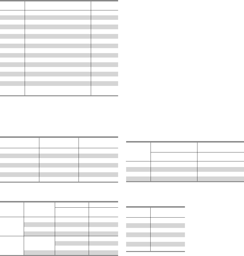
7-4
Miscellaneous
Connecting Strap Kits - Obsolete Circuit Breakers
For use with Series 5 or 6 CDP circuit breaker panelboards
FC20, FCI and FCII switchboards – includes copper straps, cover
plates and necessary hardware.
Table Misc. 7
Breaker Strap Kit Height
Frame 1Catalog Number (in.)
KM, HN 6KM1 10
CN 6CN1 10
KMB, HNB 6KMB1 10
SKM 6SKM1 10
KP, HK 6KP1 10
KPB, HKB 6KPB1 10
SKP, SHK 6SKP1 10
Table Misc. 9 – Connecting Strap Kits — Vacu-Break
For use with VB-23 and VB-32 Type Panelboards.
For Use With
Panel Catalog Ampere Unit Height
Type Number Rating (in.)
VB-23 V2AX25 30-30 2 1/2
V2BX50 30-30 and 60-60 5
V7AX25 30-30 2 1/2
V7BX50 30-30 and 60-60 5
VB-32 V7EX75 100-100 7 1/2
100 7 1/2
200 7 1/2 (2-Pole)
V7FX100 200 10 (3-Pole)
Table Misc. 8 – Blank Plates – Vacu-Break
For use with VB-23, VB-30, VB-32 and Uni-Power Switchboards
12 in. Units - 23 in. 17 in. Units - 30 in. and
Unit Wide Enclosure Only 32 in. Wide Enclosures
Height Catalog Catalog
Inches Number Number
2 1/2 VB2F025 VB7F025
5VB2F050 VB7F050
7 1/2 VB2F075 VB7F075
10 VB2F100 VB7F100
Table Misc. 10 – Molded Case
Switches (Non-Automatic
Circuit Interrupters)
Ampere Breaker
Rating Frame
100 ED2, ED4, ED6
225 QJ2
250 FXD6
400 JXD2, JXD6
600 LXD6
800 MD6
1200 ND6
Table Misc. 6 – Miscellaneous Replacement Accessories
Catalog For
Number Description Panel Type
EGK Al Ground Assembly 44 Connections P1, P2, P3
BK1 Bonding Kit for P1 250A Max. as noted
BK4 Bonding Kit for SE & P5 400 as noted
IMK Interior Adjusting Kit P1, P2, P3
11-1824-01 Directory Card Holder P1, P2, P3
12-1110-01 Directory Card P1, P2, P3
11-1056-01 NEMA Instruction Book All
NBK3 Number Strips 1-42 P1, P2, P3
NBK4 Number Strips 43-84 P1, P2, P3
NBK5 Number Strips 85-126 P1, P2, P3
NBK6 Number Strips 127-168 P1, P2, P3
ECGK Cu Ground Bus 44 Connections P1, P2, P3
IGK Insulated Al Ground Bus P1, P2, P3
ICGK Insulated Cu Ground Bus P1, P2, P3
EWK1 End Wall Kit with Knockouts P1
(20”W x 5.75” DP)
QF31Filler Plate P1, P2, P3,
P4, P5
1All 1” QP, BL, BQD and ED Frame Provisions.

Siemens Industry, Inc.
5400 Triangle Parkway
Norcross, GA 30092
1-800 -241-4453
info.us@siemens.com
usa.siemens.com/panelboards
Subject to change without prior notice.
Order No: PBCS-20301-0813
All rights reserved.
Printed in USA
©2013 Siemens Industry, Inc.
The information provided in this brochure contains merely
general descriptions or characteristics of performance
which in case of actual use do not always apply as described
or which may change as a result of further development
of the products. An obligation to provide the respective
characteristics shall only exist if expressly agreed in the
terms of contract.
All product designations may be trademarks or product
names of Siemens AG or supplier companies whose use by
third parties for their own purposes could violate the rights
of the owners.
