Bussmann Full Line Catalog # 1007 1000291624
111372-Catalog 111372-Catalog 111372-Catalog 051712 Batch5 unilog cesco-content
104085-Catalog 104085-Catalog 104085-Catalog 051712 Batch7 unilog cesco-content
553044-Catalog 553044-Catalog 553044-Catalog Batch9 unilog cesco-content
79953-Catalog 79953-Catalog 79953-Catalog 051712 Batch4 unilog cesco-content
2016-10-27
: Pdf 1000291624-Catalog 1000291624-Catalog B6 unilog
Open the PDF directly: View PDF ![]() .
.
Page Count: 542 [warning: Documents this large are best viewed by clicking the View PDF Link!]
Bussmann electrical full line catalog
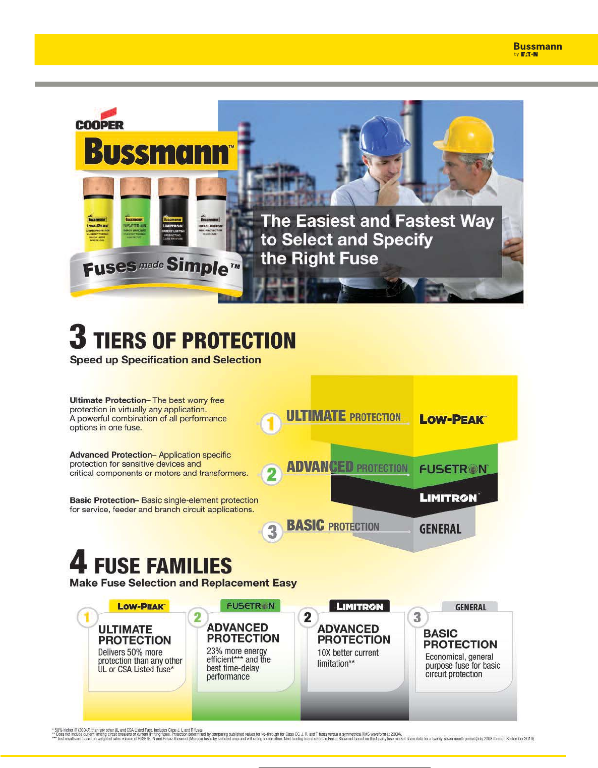
Leadership in Circuit
Protection
Introducing Bussmann by Eaton
The protection you rely on. For more, visit Bussmann.com

Leadership in Circuit Protection.
The only company
The Eaton advantage.
Powering business worldwide
As a global diversified power management company, we
help customers worldwide manage the power needed for
buildings, aircraft, trucks, cars, machinery and businesses.
Eaton’s innovative technologies help customers manage
electrical, hydraulic and mechanical power more reliably,
efficiently, safely and sustainably.
We provide integrated solutions that help make energy,
in all its forms, more practical and accessible.
With 2012 sales of $16.3 billion, Eaton has approximately
103,000 employees around the world and sells products
in more than 175 countries.
Eaton.com
Only Eaton can deliver...
• The most diverse solutions to mitigate arc flash energy to keep people and equipment safe
• The smallest and most cost effective way to meet selective coordination requirements
• The most experienced, time-tested solutions to meet national & local code requirements
• The easiest specifications with the most tested fuse/circuit breaker and circuit breaker/circuit breaker
series rated combinations
• The only one-stop shop to solve your design challenges using our expertise and an unmatched portfolio
that can provide a complete circuit
protection solution for all applications.
3
For product Data Sheets, visit www.cooperbussmann.com/DatasheetsEle
Introducing Fuses Made Simple™
For product Data Sheets, visit www.cooperbussmann.com/DatasheetsEle
4
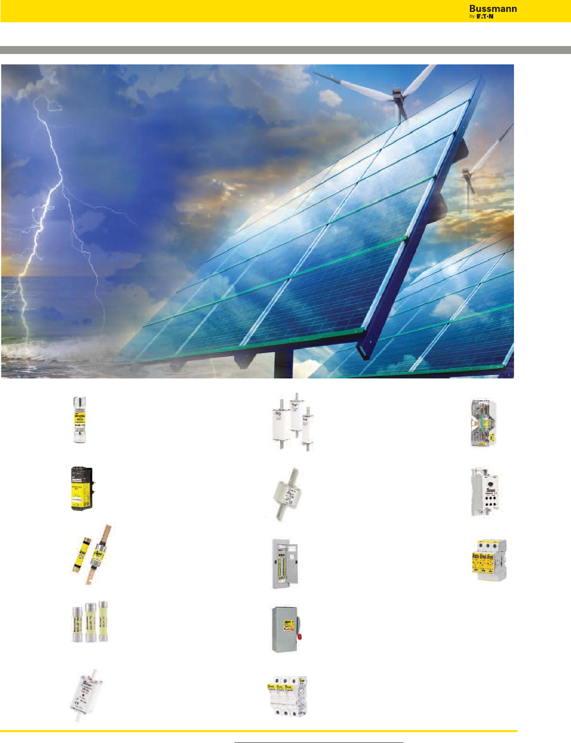
Alternative Energy Vertical Market
A Complete Line of
Circuit
Protection Solutions
for the
Alternative Energy Markets
60
Ferrule
Photovoltaic
Fus es
56
PVM Midget
& PV Fuses
59
PVS-R RK5
PV Fuses
57
CUBEFuse™
PVCF & WCF
121
Square Body,
BS and UL
High Speed Fuses
63
XL Photovoltaic
Fuses and Blocks
442
Surge Protection
Solutions
Photovoltaic and Wind
270
Safety Switches
AC & DC
274
Modular Fuse
Holders
325
Power
Distribution
Blocks
289
Modular
Knifeblade
Fuse Blocks
266
Quik-Spec™
Coordination
Panelboard
62
NH Fuses &
Fuse Blocks
For product Data Sheets, visit www.cooperbussmann.com/DatasheetsEle 5
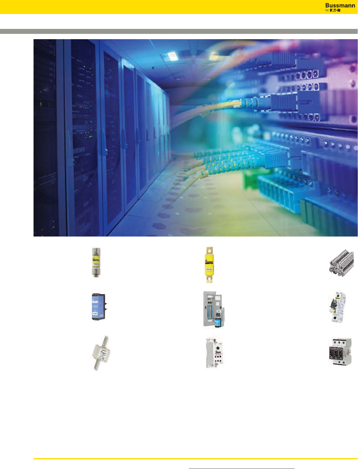
Data Centers Vertical Market
A Complete Line of
Circuit
Protection Solutions
for
Data Centers
23
Low-Peak™
CC Fuses
380
Compact Circuit
Protectors
333
DIN-Rail Terminal
Blocks and
Connectors
125
DFJ
High Speed
Fuses
266
Quik-Spec™
Coordination
Panelboard
121
Square Body,
BS and UL
High Speed Fuses
441
Surge Protection
Solutions
– UL, IEC and LV
28
CUBEFuse™
TCF & FCF
325
Power
Distribution
Blocks
For product Data Sheets, visit www.cooperbussmann.com/DatasheetsEle
6
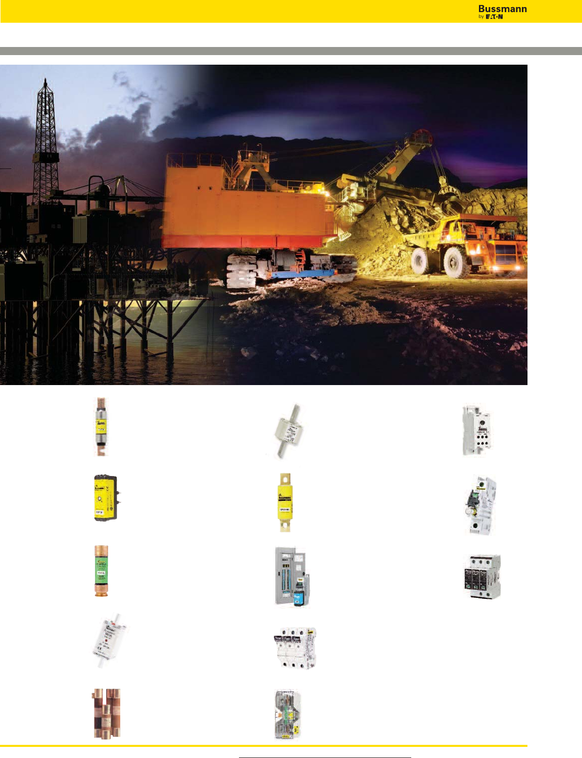
Oil & Gas/ Mining Vertical Market
A Complete Line of
Circuit
Protection Solutions
for
Oil & Gas / Mining
26
CUBEFuse™
TCF & FCF
46
Fusetron™ Energy
Efficient Fuses
23
Low-Peak™
Fuses
380
Compact Circuit
Protectors
327
Power
Distribution
Blocks
99
Medium
Voltage Fuses
121
Square Body,
BS and UL
High Speed Fuses
441
Surge Protection
Solutions
– UL, IEC and LV
274
Modular Fuse
Holders
62
NH Fuses &
Fuse Blocks
289
Modular
Knifeblade
Fuse Blocks
125
DFJ
High Speed
Fuses
266
Quik-Spec™
Coordination
Panelboard

For product Data Sheets, visit www.cooperbussmann.com/DatasheetsEle 7
Circuit Protection Products for the Electrical Industry
Table of Contents
Bussmann circuit protection solutions comply with major industrial standards and agency requirements such as: BS, IEC, DIN, UL, NEMA, CSA, CE, C-UL, etc. and are manufactured at facilities that are ISO 9000 certified.
This catalog is intended to present product data and provide technical information that will help the end user with design application. Bussmann reserves the right, without notice, to change design or construction or any products
and to discontinue or limit distribution of any products. Bussmann also reserves the right to change or update, without notice, any technical information contained in this catalog. Once a product has been selected, it should be
tested by the user in all possible applications. Further, Bussmann takes no responsibility for errors or omissions contained in this catalog, or for mis-application of any Bussmann product. Extensive product information is available
in the Bussmann product data sheets available on line at www.cooperbussmann.com/DatasheetsEle.©2013 Bussmann
RED indicates NEW information
Vertical Market Product Pages . . . . . . . . . . . . .4-6
Alternative energy . . . . . . . . . . . . . . . . . . . . . . . . . . . . . . . . . .4
Data centers . . . . . . . . . . . . . . . . . . . . . . . . . . . . . . . . . . . . . .5
Oil & gas / mining . . . . . . . . . . . . . . . . . . . . . . . . . . . . . . . . . .6
Peel and Stick Tabs . . . . . . . . . . . . . . . . . . . . . .11
Selecting Circuit Protection . . . . . . . . . . . . . .12-16
2011 NEC®guide to fuse selection for various
applications . . . . . . . . . . . . . . . . . . . . . . . . . . . . . . . . .12-16
Low Voltage, Branch Circuit Rated Fuses . . .17-52
Holders & blocks for branch circuit rated fuses . . . . . . .18-20
Dimensions data for branch circuit rated fuses . . . . . . .21-22
Class CC
LP-CC Low-Peak . . . . . . . . . . . . . . . . . . . . . . . . . . . . . . . .23
FNQ-R CC-Tron . . . . . . . . . . . . . . . . . . . . . . . . . . . . . . . . .24
KTK-R Limitron . . . . . . . . . . . . . . . . . . . . . . . . . . . . . . . . .25
Class CF
TCF, FCF & WCF CUBEFuse . . . . . . . . . . . . . . . . . . . . .26-31
CUBEFuse finger-safe holder system . . . . . . . . . . . . . . .32-33
Class G
SC . . . . . . . . . . . . . . . . . . . . . . . . . . . . . . . . . . . . . . . . . .34
Class J
LPJ-_SP & LPJ-_SPI Low-Peak . . . . . . . . . . . . . . . . . . . . .35
JKS Limitron . . . . . . . . . . . . . . . . . . . . . . . . . . . . . . . . . . .36
Class K5 & H
NON (250V) & NOS (600V) One time . . . . . . . . . . . . . . . . .37
Class L
KRP-C_SP Low-Peak . . . . . . . . . . . . . . . . . . . . . . . . . .38-39
KRP-CL . . . . . . . . . . . . . . . . . . . . . . . . . . . . . . . . . . . . . . .39
KTU & KLU Limitron . . . . . . . . . . . . . . . . . . . . . . . . . . . . . .40
Class RK1
LPN-RK_SP & LPN-RK_SPI (250V) Low-Peak . . . . . . . .41-43
LPS-RK_SP & LPS-RK_SPI (600V) Low-Peak . . . . . . . .41-43
KTN-R (250V) Limitron . . . . . . . . . . . . . . . . . . . . . . . . . . . .44
KTS-R (600V) Limitron . . . . . . . . . . . . . . . . . . . . . . . . . . . .45
Class RK5
FRN-R (250V) Fusetron (Energy Efficient) . . . . . . . . . . . . . .46
FRS-R (600V) Fusetron (Energy Efficient) . . . . . . . . . . . . . .47
Class T
JJN (300V) T-Tron . . . . . . . . . . . . . . . . . . . . . . . . . . . . . . .48
JJS (600V) T-Tron . . . . . . . . . . . . . . . . . . . . . . . . . . . . . . .49
Edison & Rejection Base Plug Fuses
Plug Fuses (S, SL, T, TL & W) . . . . . . . . . . . . . . . . . . . .50-51
MB Edison Base Circuit Breakers . . . . . . . . . . . . . . . . . . . .52
SA Rejection-base plug fuse adapters . . . . . . . . . . . . . . . .52
Solar Fuse Products . . . . . . . . . . . . . . . . . . .53-70
PVM (600Vdc) . . . . . . . . . . . . . . . . . . . . . . . . . . . . . . . . . .56
PVCF (600Vac/300Vdc) . . . . . . . . . . . . . . . . . . . . . . . .57-58
PVS-R (600Vac/dc) . . . . . . . . . . . . . . . . . . . . . . . . . . . . . .59
PV (1000Vdc) 10x38mm . . . . . . . . . . . . . . . . . . . . . . . . . .60
PV (1000/1100Vdc) 14x51mm . . . . . . . . . . . . . . . . . . . . .61
NH1 (1000Vdc) . . . . . . . . . . . . . . . . . . . . . . . . . . . . . . . . .62
XL PV (1000Vdc) XL Size 01, 1, 2, 3 . . . . . . . . . . . . . . .63-65
PV (1300/1500Vdc) 14x65mm . . . . . . . . . . . . . . . . . . . . .66
XL PV (1200/1500Vdc) XL Size 01, 1, 2, 3 . . . . . . . . . .67-69
Low Voltage Supplementary Fuses . . . . . . . .71-84
Holders & blocks for supplemental fuses . . . . . . . . . . . .72-73
Cable (K Series) & Welder (64000/68000 Series) Limiters . .74
13⁄32" x 1 1⁄2" fast-acting fuses BAF, KTK & KLM . . . . . . . . . . .75
13⁄32" x 1 1⁄2" time-delay fuses FNM & FNQ . . . . . . . . . . . . . .76
13⁄32" x 1 3⁄8" fast-acting fuses BBS . . . . . . . . . . . . . . . . . . . .77
Pin indication fuses GBA/GLD, MIC & MIN, FNA,
MIS & KAZ . . . . . . . . . . . . . . . . . . . . . . . . . . . . . . . .78-79
Limiters & blocks ANL & ANN . . . . . . . . . . . . . . . . . . . . . . .79
In-line size rejecting fuses and holders GLQ, GMQ, HLQ . . .80
In-line non-rejecting fuses and holders GLR, GMF, GRF,
HLQ . . . . . . . . . . . . . . . . . . . . . . . . . . . . . . . . . . . . . . .81
Automotive blade fuses and holders ATM, ATC, MAX . . .82-83
Automotive PCB fuse clips for ATM & ATC . . . . . . . . . . . . . .84
Electronic - PC Board and Small Dimension
Fuses . . . . . . . . . . . . . . . . . . . . . . . . . . . . .85-98
5 x 15mm Ferrule fuses C515, C516, C517, C518,
C519, C520 . . . . . . . . . . . . . . . . . . . . . . . . . . . . . . . . .86
5 x 20mm European (IEC) fuses
S500, S501, S505, S506, GDA, GDB, GDC . . . . . . . .87-88
5 x 20mm North American (UL) fuses GMA, GMC,
GMD- . . . . . . . . . . . . . . . . . . . . . . . . . . . . . . . . . . . . . .89
1⁄4" Diameter x 5⁄8" to 1" length ferrule fuses AGA,
AGW, AGX . . . . . . . . . . . . . . . . . . . . . . . . . . . . . . . . . . . . . . .90
1⁄4" Diameter x 1 1⁄4" length fast-acting ferrule fuses ABC,
AGC, GBB . . . . . . . . . . . . . . . . . . . . . . . . . . . . . . . . . . . . . . .91
1⁄4" Diameter x 1 1⁄4" length time-delay ferrule fuses MDA,
MDL, MDQ . . . . . . . . . . . . . . . . . . . . . . . . . . . . . . . . . .92
PC Board mount fuse holders HTC-, HBH-, HBV-, HBW-,
FBI, FBM . . . . . . . . . . . . . . . . . . . . . . . . . . . . . . . . .93-94
PC Board fuseclips HTC-_M, 1A_, 56_ . . . . . . . . . . . . .95-98

For product Data Sheets, visit www.cooperbussmann.com/DatasheetsEle
8
Circuit Protection Products for the Electrical Industry
Table of Contents RED indicates NEW information
Medium Voltage Fuses . . . . . . . . . . . . . . . .99-120
Introduction . . . . . . . . . . . . . . . . . . . . . . . . . . . . . . . . . . .100
E-Rated fuses for transformers & feeders . . . . . . . . .101-104
E-Rated fuses: CL-14 & bolt-in . . . . . . . . . . . . . . . . .105-107
E-Rated fuses for potential & small power
transformers . . . . . . . . . . . . . . . . . . . . . . . . . . . .108-110
Potential transformer fuses . . . . . . . . . . . . . . . . . . . . . . .111
R-Rated fuses for motor circuit protection . . . . . . . . .112-114
British Standard IEC fuses for motor circuit protection . . .115
DIN IEC fuses for transformers . . . . . . . . . . . . . . . . . . . . .116
Expuision Fuse Links . . . . . . . . . . . . . . . . . . . . . . . .117-118
EEI-NEMA Type K & T, and Type H & N fuses . . . . . . . . . . .119
Fuseclips for medium voltage fuses . . . . . . . . . . . . . . . . .120
High Speed Semiconductor Fuses . . . . . .121-244
General Applications . . . . . . . . . . . . . . . . . . . . . . . . .122-123
North American fuses and accessories
DFJ, FWA, FWH, FWJ, FWP, FWX, KAC, KBC, . . . .124-141
Square body fuses and accessories
DIN 43 620, DIN 43 653, flush-end contact, French Style,
US Style 170E, 170F, 170H, 170M . . . . . . . . . . . .142-213
British BS 88 fuses and accessories
CT, ET, EET, FE, FEE, FM, FMM, LCT, LET, LMMT, LMT,
MMT, MT . . . . . . . . . . . . . . . . . . . . . . . . . . . . . . .214-222
Ferrule fuses and accessories
FWA, FWC, FWH, FWJ, FWK, FWL, FWP, FWS,
FWX . . . . . . . . . . . . . . . . . . . . . . . . . . . . . . . . . .223-244
IEC & British Standard Fuses . . . . . . . . . .245-264
Application Data . . . . . . . . . . . . . . . . . . . . . . . . . . . .245-246
CSA Type P and Type D fuses CDN, CDS, PON . . . . . . . . .247
HRC Form II Class C Tron™fuses CGL . . . . . . . . . . . . . . . .248
HRCI Industrial ceramic body fuses CIF . . . . . . . . . . . . . . .249
HRCI-J Fast-acting fuses CJ . . . . . . . . . . . . . . . . . . . . . .250
MRCI-Miscellaneous Type K fuses CIH, CIK, CIL . . . . . . . . .251
HRC Form II Current-limiting fuses H07C, K07C, L09C,
L14C, M09C, M14C, P09C, P11C, R11C . . . . . . . . . . .252
BS 88 British Standard low voltage fuses AAO, AC, AD,
BAO, BC, BD, CD, CEO, DD, DEO, ED, EF, EFS, ESD, FF,
FG, GF, GG, GH, NITD, NSD, OSD, SSD, STD . . . . . .253-254
DIN Type D and Neozed low voltage fuses D16, D27, D33,
D125, NZ . . . . . . . . . . . . . . . . . . . . . . . . . . . . . . . . . .255
NH HRC Fuse links & bases NHG . . . . . . . . . . . . . . .256-259
Class gG/gL IEC 60 269 fuses C08G, C08M, C10G, C10M,
C14G, C14M, C22G, C22M . . . . . . . . . . . . . . . . .260-262
HRC Fuse holders CAMaster, SAFEloc . . . . . . . . . . . . . . . .263
Quik-Spec™ Electrical Gear . . . . . . . . . . .265-272
Quik-Spec™ Coordination Panelboards . . . . . . . . . . .266-267
Quik-Spec™ Power Module™ Elevator Disconnect
Switches & Panels PS, PMP . . . . . . . . . . . . . . . . .268-269
Quik-Spec™ DC Safety Switches BD . . . . . . . . . . . . . . . .270
Quik-Spec™ AC Safety Switches CF . . . . . . . . . . . . . . . .271
HVAC Disconnects B221, B222 . . . . . . . . . . . . . . . . . . . .272
Fuse Holders and Blocks . . . . . . . . . . . . . .273-322
CH Series global modular fuse holders - Class CC, midget & metric
CHCC, CHPV, CHM, CH08, CH14, CH22 . . . . . . . . .274-277
Remote fuse monitoring - CH-PLCCH . . . . . . . . . . . . . . . .278
Comb-bus bar specifications and selection guide . . . . . . .279
Comb-bus bar features and installation guide . . . . . . . . . .280
CH Series Class J global modular fuse holders CH . . . . . .281
Optima - fuse holder module and disconnect switch . . . . .282
Optima fuse holder module . . . . . . . . . . . . . . . . . . . . . . .283
Optima NG 3-pole overcurrent protection module . . . .284-285
Safety J Class J (finger-safe) fuse holder JT, JTN . . . .286-287
SAMI™ fuse covers SAMI . . . . . . . . . . . . . . . . . . . . . . . .288
Modular Knifeblade Fuse Holders . . . . . . . . . . . . . . .289-290
Class R, H(K), 250 & 600V . . . . . . . . . . . . . . . . . .291-292
Class J, 600V . . . . . . . . . . . . . . . . . . . . . . . . . . . . . . .293
Class H(K) and R fuse blocks - 250V . . . . . . . . . . . . .294-295
Class H(K) and R fuse blocks - 600V . . . . . . . . . . . . .296-297
Class J fuse blocks J600, JP, JA Add-a-Pole . . . . . . .298-299
Class T fuse blocks - 300V . . . . . . . . . . . . . . . . . . . .300-301
Class T fuse blocks - 600V . . . . . . . . . . . . . . . . . . . .302-303
Add-on fuse blocks BCA, BMA . . . . . . . . . . . . . . . . . . . . .304
Class CC, Type M and Class G fuse blocks BC, BCCM,
BG, BM, G . . . . . . . . . . . . . . . . . . . . . . . . . . . . . . . . . .305
Modular fuse blocks BH . . . . . . . . . . . . . . . . . . . . . . . . . .306
Box cover units for plug fuses SCY, SKA, SOU, SOW,
SOX, SOY, SRU, SRW, SRX, SRY, SSN, SSU, SSW, SSX,
SSY, STY, . . . . . . . . . . . . . . . . . . . . . . . . . . . . . . . . . .307
In-line fuse holders HFA, HFB, HHB, HHT, HM,
HR, HRK . . . . . . . . . . . . . . . . . . . . . . . . . . . . . . . .308-309
Tron™in-line fuse holders HEB, HEC, HEG, HEH, HEJ, HET,
HEX, HEY, HEZ . . . . . . . . . . . . . . . . . . . . . . . . . . .309-311
Panel mounted fuse holders (including indicating) HJL, HK,
HKP, HLD,HPC, HPD, HPF, HPG, HPM, HPS, HPS, HTB,
HTC . . . . . . . . . . . . . . . . . . . . . . . . . . . . . . . . . . .312-318
Fuse blocks for 1⁄4" x 1 1⁄4" and 1⁄4" x 1" fuses . . . . . . .319-320
Fuse blocks for 13⁄32" x 1 1⁄2" fuses . . . . . . . . . . . . . . . . . . .321
Rail mount fuse blocks & holders . . . . . . . . . . . . . . . . . . .322

For product Data Sheets, visit www.cooperbussmann.com/DatasheetsEle 9
Circuit Protection Products for the Electrical Industry
Table of Contents RED indicates NEW information
Power Distribution Blocks . . . . . . . . . . . . .323-332
Power Distribution Block Selection Chart . . . . . . . . . . . . . .324
PDBFS Series finger-safe power distribution blocks . . . . .325
PDB Series power distribution blocks . . . . . . . . . . . . . . . .326
163 Series power terminal blocks . . . . . . . . . . . . . . .327-328
Series 11675 & 11725 power terminal blocks . . . . . . . . .329
Series 160, 162, 163 & 165 power terminal blocks . . . . .329
Series 162, 163 & 165 power stud terminal blocks . . . . . .330
Series 160, 162, 163 & 165 power splicer terminal
blocks . . . . . . . . . . . . . . . . . . . . . . . . . . . . . . . . . . . . .330
Series 14002 (barrier) & 14004 (dead front) terminal
blocks . . . . . . . . . . . . . . . . . . . . . . . . . . . . . . . . . . . . .331
Connectors . . . . . . . . . . . . . . . . . . . . . . . .333-378
DIN-Rail
Feed through blocks (DS series) . . . . . . . . . . . . . . . . . . . .334
Feed through blocks (DP series) . . . . . . . . . . . . . . . .335-336
Mini feed through blocks (DM series) . . . . . . . . . . . . . . . .337
Double level blocks (DDP series) . . . . . . . . . . . . . . . . . . . .338
Disconnect blocks (DG series) . . . . . . . . . . . . . . . . . .339-340
Fuse holder blocks (F520 series) . . . . . . . . . . . . . . . .341-342
Internally jumpered blocks (DDNS series) . . . . . . . . . . . . .343
Test blocks (DTST2 series) . . . . . . . . . . . . . . . . . . . . . . . .343
Panel mount blocks . . . . . . . . . . . . . . . . . . . . . . . . .344-345
Short-Circuit Current Ratings (SCCRs) . . . . . . . . . . . .346-347
Top screw-on bridges . . . . . . . . . . . . . . . . . . . . . . . . . . .348
End brackets . . . . . . . . . . . . . . . . . . . . . . . . . . . . . . . . . .349
Partition plates . . . . . . . . . . . . . . . . . . . . . . . . . . . . . . . .349
Jumper slides . . . . . . . . . . . . . . . . . . . . . . . . . . . . . . . . .350
Top insertion bridges . . . . . . . . . . . . . . . . . . . . . . . . . . . .350
Side insertion bridges . . . . . . . . . . . . . . . . . . . . . . . .351-352
Mounting rails and brackets . . . . . . . . . . . . . . . . . . . . . . .353
Marking system . . . . . . . . . . . . . . . . . . . . . . . . . . . . . . . .354
Marking labels . . . . . . . . . . . . . . . . . . . . . . . . . . . . .355-357
Feed through blocks (NDN series) . . . . . . . . . . . . . . .358-359
Feed through blocks (C-Rail series) . . . . . . . . . . . . . .360-361
Depluggable blocks . . . . . . . . . . . . . . . . . . . . . . . . .362-363
Multi-pole panel mount blocks . . . . . . . . . . . . . . . . . . . . .364
Quick connect blocks . . . . . . . . . . . . . . . . . . . . . . . . . . . .365
Panel Mount
Series TB100 2- to 36-Pole blocks . . . . . . . . . . . . . .366-367
Series TB200 & TB200HB 2- to 30-Pole blocks . . . . .368-369
Series TB300 & TB345 2- to 24-Pole blocks . . . . . . .370-371
Marking options and covers for double row series . . . . . . .372
Top & bottom marking strips for terminal blocks . . . . . . . .373
Series TB400 2- to 12-Pole blocks . . . . . . . . . . . . . . . . . .374
Series KU 2- to 12-Pole panel mount blocks . . . . . . . . . . .375
Series C7021 1- to 6-Pole block . . . . . . . . . . . . . . . . . . .376
Series C7024 1- to 12-Pole block . . . . . . . . . . . . . . . . . .377
Disconnects . . . . . . . . . . . . . . . . . . . . . . . .379-424
Compact Circuit Protector (CCP) disconnect switches
30A Class CC, Midget & 10x38 . . . . . . . . . . . . . . . . . . 380-381
30A 60A and 100A Class CF . . . . . . . . . . . . . . . . . . . . 382-383
CCPB - Compact Circuit Protector Base . . . . . . . . . . . . 384-385
UL 98 fused disconnect switches 30 to 800A
Introduction & Agency Information . . . . . . . . . . . . . . . . . . . . 386
Product Line Summary . . . . . . . . . . . . . . . . . . . . . . . . . . . . 387
30A Compact Class CC & Class J . . . . . . . . . . . . . . . . 388-389
30A Class J . . . . . . . . . . . . . . . . . . . . . . . . . . . . . . . . 390-391
60A Compact Class J . . . . . . . . . . . . . . . . . . . . . . . . . 392-393
60A Class J . . . . . . . . . . . . . . . . . . . . . . . . . . . . . . . . 394-395
100A Class J . . . . . . . . . . . . . . . . . . . . . . . . . . . . . . . 396-397
200A & 400A Class J . . . . . . . . . . . . . . . . . . . . . . . . . 398-400
600A Class J and 800A Class L. . . . . . . . . . . . . . . . . . 402-403
UL 98 non-fused disconnect switches 30 to 1200A
Introduction & Agency Information . . . . . . . . . . . . . . . . . . . . 404
Product Line Summary . . . . . . . . . . . . . . . . . . . . . . . . . . . . 405
30A, 60A and 100A Compact . . . . . . . . . . . . . . . . . . . 406-407
100A, 200A and 400A Standard . . . . . . . . . . . . . . . . . 408-409
600A, 800A, 1000A and 1200A Standard . . . . . . . . . . 410-411
UL 508 non-fused disconnect switches 16 to 80A
Introduction and Agency Information . . . . . . . . . . . . . . . . . . 412
Product Line Summary . . . . . . . . . . . . . . . . . . . . . . . . . . . . 413
16A, 25A, 40A, 63A and 80A Standard . . . . . . . . . . . . 414-416
Enclosed UL 98 & UL 508 disconnect switches
Introduction & Agency Information . . . . . . . . . . . . . . . . . . . . 417
Fused UL 98
30A to 800A Enclosed Disconnects . . . . . . . . . . . . . . . 418-419
Non-Fused UL 98
30 to 1200A Enclosed Disconnects . . . . . . . . . . . . . . . 420-421
Non-Fused UL 508
16 to 80A Enclosed Disconnects . . . . . . . . . . . . . . . . . 422-423
Fused, dead front disconnect switches . . . . . . . . . . . . . . . . 424
Telecom Protection Devices . . . . . . . . . . .425-439
Telpower compact fused disconnect switch . . . . . . . . . . . .426
Telpower miniature fused disconnect switch . . . . . . . . . . .427
Fused disconnect switches for TPA fuses . . . . . . . . .428-429
Fused disconnect switches for TPS fuses . . . . . . . . . . . . .430
Fused disconnect switches . . . . . . . . . . . . . . . . . . . .431-437
Telpower specialty fuses . . . . . . . . . . . . . . . . . . . . . .438-439
Surge Protective Devices (SPD) . . . . . . . .441-460
SurgePOD HEAVY DUTY SPD . . . . . . . . . . . . . . . . . .442-445
SurgePOD PRO SPD . . . . . . . . . . . . . . . . . . . . . . . . .446-448
UL DIN-Rail - High SCCR SPDs
1-Pole, Type 2, BSPM_S2G . . . . . . . . . . . . . . . . . . .449-450
2-Pole, Type 2, BSPM_S3G . . . . . . . . . . . . . . . . . . .451-452
For product Data Sheets, visit www.cooperbussmann.com/DatasheetsEle
10
Circuit Protection Products for the Electrical Industry
Table of Contents
Catalog Sections Page
Low Voltage, Branch Circuit Rated Fuses...17
Solar Fuse Products.....................................53
Low Voltage Supplementary Fuses .............71
Electronic - PC Board and Small
Dimension Fuses ..........................................85
Medium Voltage Fuse and Fuse Links ........99
High Speed Fuses.......................................121
IEC & British Standard Fuses ....................245
Quik-Spec™Electrical Gear .......................265
Fuse Holders and Blocks ...........................273
Power Distribution & Terminal Blocks ......323
Connectors .................................................333
Disconnects................................................379
Telecom Protection Devices (SPD) ............425
Surge Protective Devices...........................441
Accessories ................................................503
Services & Application Guide ....................511
Index by Part Number................................532
RED indicates NEW information
Surge Protective Devices (SPD) - (Continued)
3-Pole, Type 2, BSPM_WYG/DLG . . . . . . . . . . . . . . .453-454
4-Pole, Type 2, BSPM_WYNG/HLG . . . . . . . . . . . . . .455-456
UL DIN-Rail - Low Voltage AC/DC Power
1-Pole, Type 2, BSPM_LV . . . . . . . . . . . . . . . . . . . . .457-458
UL DIN-Rail - Low Voltage AC/DC Control
2-Pole, Type 3, BSPH2A_LV . . . . . . . . . . . . . . . . . . .459-460
IEC DIN-Rail - Class I
2-Pole, Class I, BSPS_TN/TT . . . . . . . . . . . . . . . . . .461-462
3-Pole, Class I, BSPS_TNC . . . . . . . . . . . . . . . . . . . .463-464
4-Pole, Class I, BSPS_TNS/TT . . . . . . . . . . . . . . . . .465-466
IEC DIN-Rail - Class II
1-Pole, Class II, BSPM_TN / BSPG_NPE . . . . . . . . . .467-468
2-Pole, Class II, BSPM_TN / BSPH_TT . . . . . . . . . . .469-470
3-Pole, Class II, BSPM_TNC . . . . . . . . . . . . . . . . . . .471-472
4-Pole, Class II, BSPM_TNS / BSPH_TT . . . . . . . . . .473-474
PV DIN-Rail - Lightning Arrester
1-Pole, PV Advance Lightning Arrester / BSPS_PV . . .475-476
PV DIN-Rail - SPDs
2-Module, PV HEAVY DUTY SPD / BSPH2_PV . . . . . .477-478
3-Module, PV HEAVY DUTY SPD / BSPH_YPV . . . . . .479-480
3-Module, PV PRO SPD / BSPP_YPV . . . . . . . . . . . . .481-482
Wind Power DIN-Rail - Class I
1-Pole, Class I, BSPS_WE . . . . . . . . . . . . . . . . . . . .483-484
Wind Power DIN-Rail - Class II
1-Pole, Class II, BSPM_WE / BSPS_WE . . . . . . . . . .485-486
2-Pole, Class II, BSPM_WE / BSPH_WE . . . . . . . . . .487-488
3-Pole, Class II, BSPM_WE . . . . . . . . . . . . . . . . . . . .489-490
4-Pole, Class II, BSPM_WE / BSPH_WE . . . . . . . . . .491-492
UL 4978 Data Signals SPDs . . . . . . . . . . . . . . . . . . . .493-501
SurgePOD™ Series, 150 to 550Vac MCOV . . . . . . . . .502-503
DIN-Rail TVS Series with holder . . . . . . . . . . . . . . . . . . . . .504
Accessories . . . . . . . . . . . . . . . . . . . . . . . .505-512
Bussmann service kits and assortments . . . . . . . . . .506-508
Clip clamps and rail adapters (DIN & American) . . . . . . . . .509
Spare fuse holders, pullers, testers and cabinets . . . . . . . .510
Fuse reducers and dummy "neutrals" . . . . . . . . . . . . . . . .511
Services & Application Guide . . . . . . . . . . . . . .513
Testing . . . . . . . . . . . . . . . . . . . . . . . . . . . . . . . . . . . . . .514
Custom Products . . . . . . . . . . . . . . . . . . . . . . . . . . . . . . .515
Application Guide . . . . . . . . . . . . . . . . . . . . . . . . . .516-525
Bussmann fuse technology . . . . . . . . . . . . . . . . . . . .516-522
Motor Circuit Branch Circuit Protection . . . . . . . . . . . . . . .523
Glossary . . . . . . . . . . . . . . . . . . . . . . . . . . . . . . . . .524-526
Out-of-Stock Substitutions/Upgrades . . . . . . . . . . . . . . . .526
Commercial & industrial fuse applications . . . . . . . . . . . . .527
FUSEFinder cross reference . . . . . . . . . . . . . . . . . . . . . . .528
FC2Mobile App . . . . . . . . . . . . . . . . . . . . . . . . . . . . . . . .530
Index by Part Number . . . . . . . . . . . . . . . .532-537
Low-Peak Upgrade . . . . . . . . . . . . . .Inside back cover
Circuit Protection Products for the Electrical Industry
Services &
Application Guide
Services &
Application Guide
Low Voltage
Branch Circuit
Low Voltage
Branch Circuit
Low Voltage
Supplementary
Low Voltage
Supplementary
Electronic
Fuses
Electronic
Fuses
Medium Voltage
Fuses
Medium Voltage
Fuses
High Speed
Fuses
High Speed
Fuses
IEC & British
Standard Fuses
IEC & British
Standard Fuses
Quik-Spec™
Electrical Gear
Quik-Spec™
Electrical Gear
Fuse Holders
& Blocks
Fuse Holders
& Blocks
Power Distribution
& Terminal Blocks
Power Distribution
& Terminal Blocks
Connectors
Connectors
Disconnects
Disconnects
Index by
Part Number
Index by
Part Number
Telecom Protection
Devices
Telecom Protection
Devices
Surge Protection
Devices
Surge Protection
Devices
Accessories
Accessories
Solar
Products
Solar
Products
New
Product
New
Product
New
Product
New
Product
New
Product
New
Product
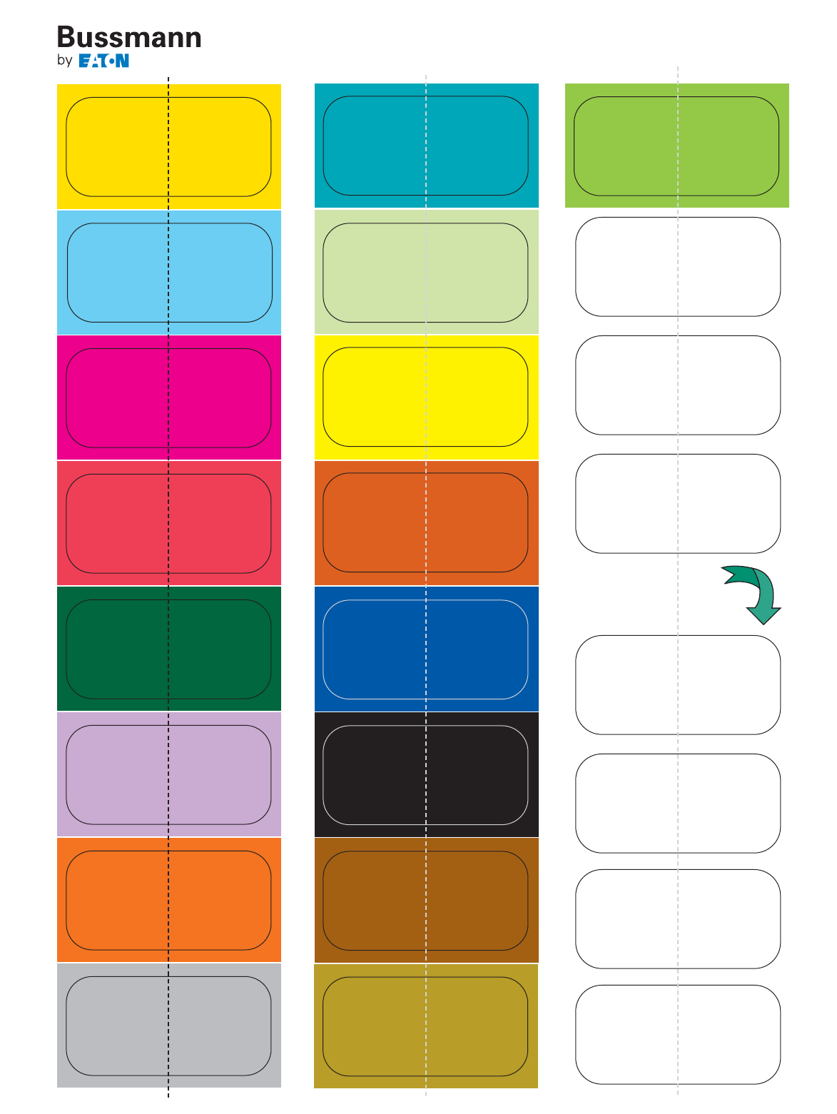
PEEL & STICK TABS
Mark the products that are important to you.
Write Your Own
Descriptions Here
11
For product Data Sheets, visit www.cooperbussmann.com/DatasheetsEle
12
Circuit Protection Products for the Electrical Industry
Selecting Circuit Protection
The following fuse selection guides are based on the 2011
NEC®and provided fuse recommendations for the various
applications listed.
These are only suggestions. Final fuse selection should be
performed only by qualified personnel able to fully assess an
application’s circuit protection requirements. If you need
assistance in selecting a fuse for a particular application, call
the Cooper Bussmann Application Engineering team for
technical and application support Monday – Friday, 8:00 a.m.
– 5:00 p.m. Central Time.
Application Engineering can be reached via phone and
e-mail:
• Toll-free phone: 855-287-7626 (855-BUSSMANN)
• E-mail: fusetech@cooperindustries.com
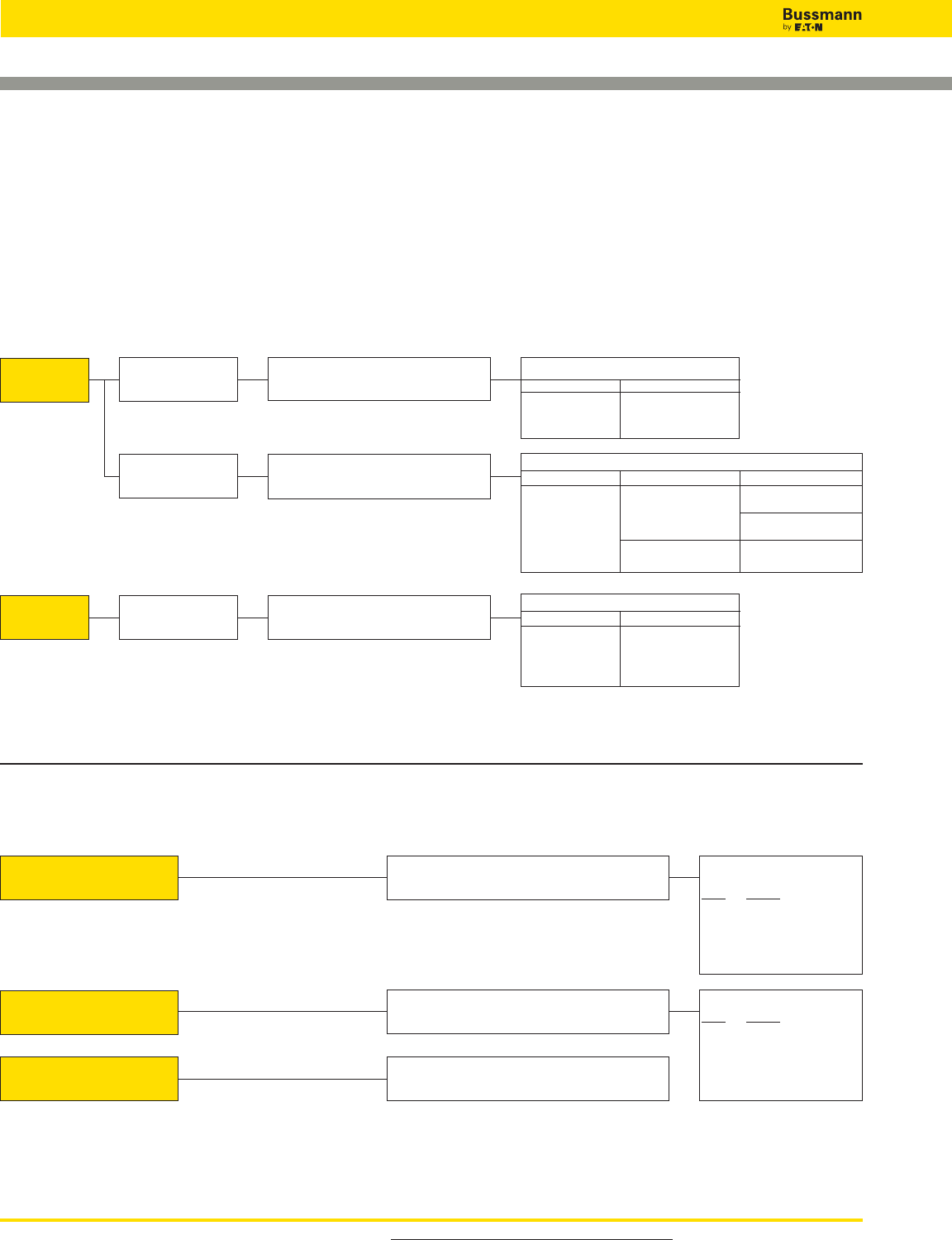
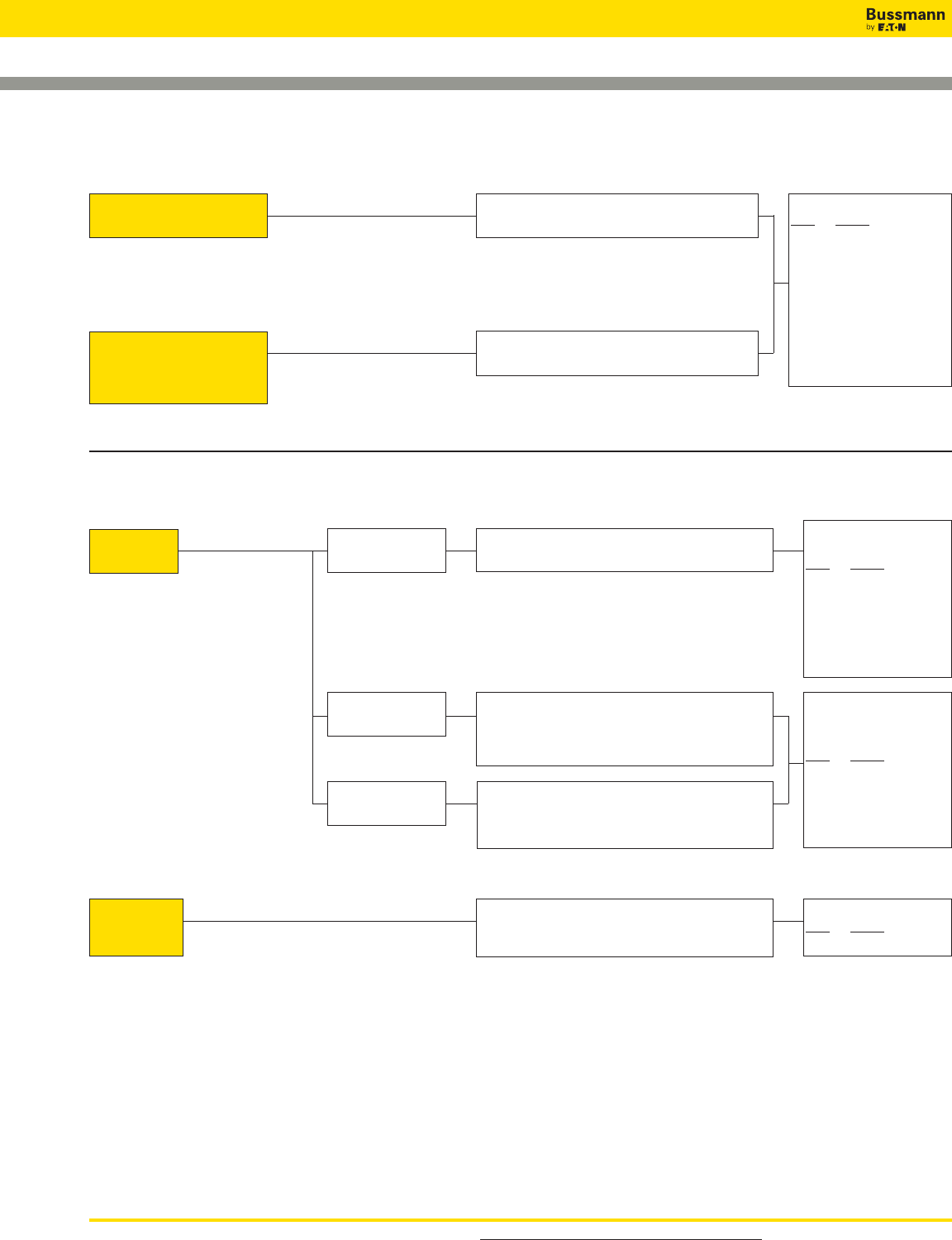
Fuse & Holder Recommendations
Fuse Holder(s) Fuse Holder(s)
BAF HEB KTK-R HEY
KTK HEX FNQ-R
FNM HPC-D LP-CC
FNQ
Mercury, Sodium, etc.
Fluorescent
All Other (Mercury,
Sodium, etc.)
Indoor
Outdoor
Consult fixture manufacturer for size and type.
Consult fixture manufacturer for size and type.
Consult fixture manufacturer for size and type.
Fuse & Holder Recommendations
Fuse Holder(s) Fuse Holder(s)
GLR HLR GLQ HLQ
GMF GMQ
GRF
Ballasts
Fuse & Holder Recommendations
Fuse Holder(s) Fuse Holder(s) Fuse Holder(s)
BAF HPF KTK-R HPS-RR SC 0-15 HPF-EE
KTK HPS FNQ-R HPF-RR HPS-EE
FNM LP-CC SC 20 HPF-JJ
FNQ HPS-JJ
KTQ HPS-L SC 25-30 HPF-FF
BBS HPF-L HPS-FF
Capacitors (NEC®460)
Protected by
Time-Delay Fuses. 150% to 175% of Full Load Current
On Load Side of Motor Running
Overcurrent Device. Protection recommended as shown, but not required.
Protected by
Non-Time-Delay Fuses. 250% to 300% of Full Load Current.
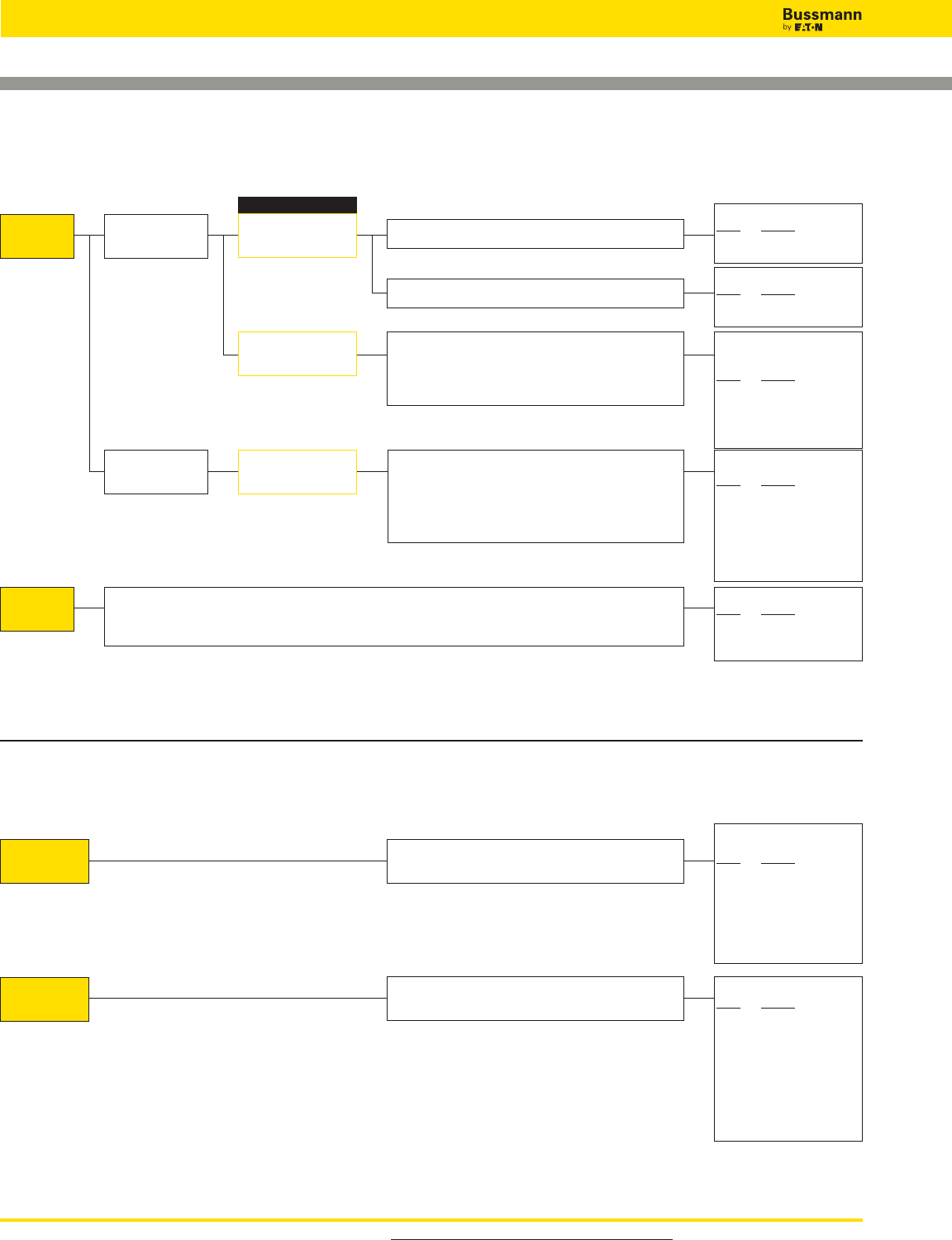
Fuse Recommendations
Volts Fuse(s)
0-250 LPN-RK_SP, FRN-R
0-600 LPS-RK_SP, FRS-R
LPJ_SP, LP-CC,
FNQ-R, TCF
Fuse Recommendations
Volts Fuse(s)
0-250 KTN-R, NON
0-300 JJN
0-600 KTS-R, NOS
JKS, KTK-R
JJS, FCF_RN
For product Data Sheets, visit www.cooperbussmann.com/DatasheetsEle 13
Selecting Circuit Protection
Circuit Protection Products for the Electrical Industry
Mains, Feeders, Branches (NEC®430)
Feeder Circuits
(600A & Less)
Fuse Recommendations
Volts Fuse(s)
0-25O LPN-RK_SP, FRN-R
0-600 LPS-RK_SP, FRS-R
0-600 LPJ- SP, LP-CC
Motor Loads
No Motor Load
Combination Motor
Loads and Other Loads
100% of non-continuous load plus 125% of continuous load.
150%* of the FLA of largest motor (if there are two or more
motors of same size, one is considered to be the largest) plus
the sum of all the FLA for all other motors plus 100% of non-
continuous, non-motor load plus 125% of continuous, non-
motor load.
150%* of the FLA of largest motor (if there are two or more
motors of same size, one is considered to be the largest) plus
the sum of all the FLA for all other motors.
*A max. of 175% (or the next standard size if 175% does not
correspond to a standard size) is allowed for all but wound
rotor and all dc motors.
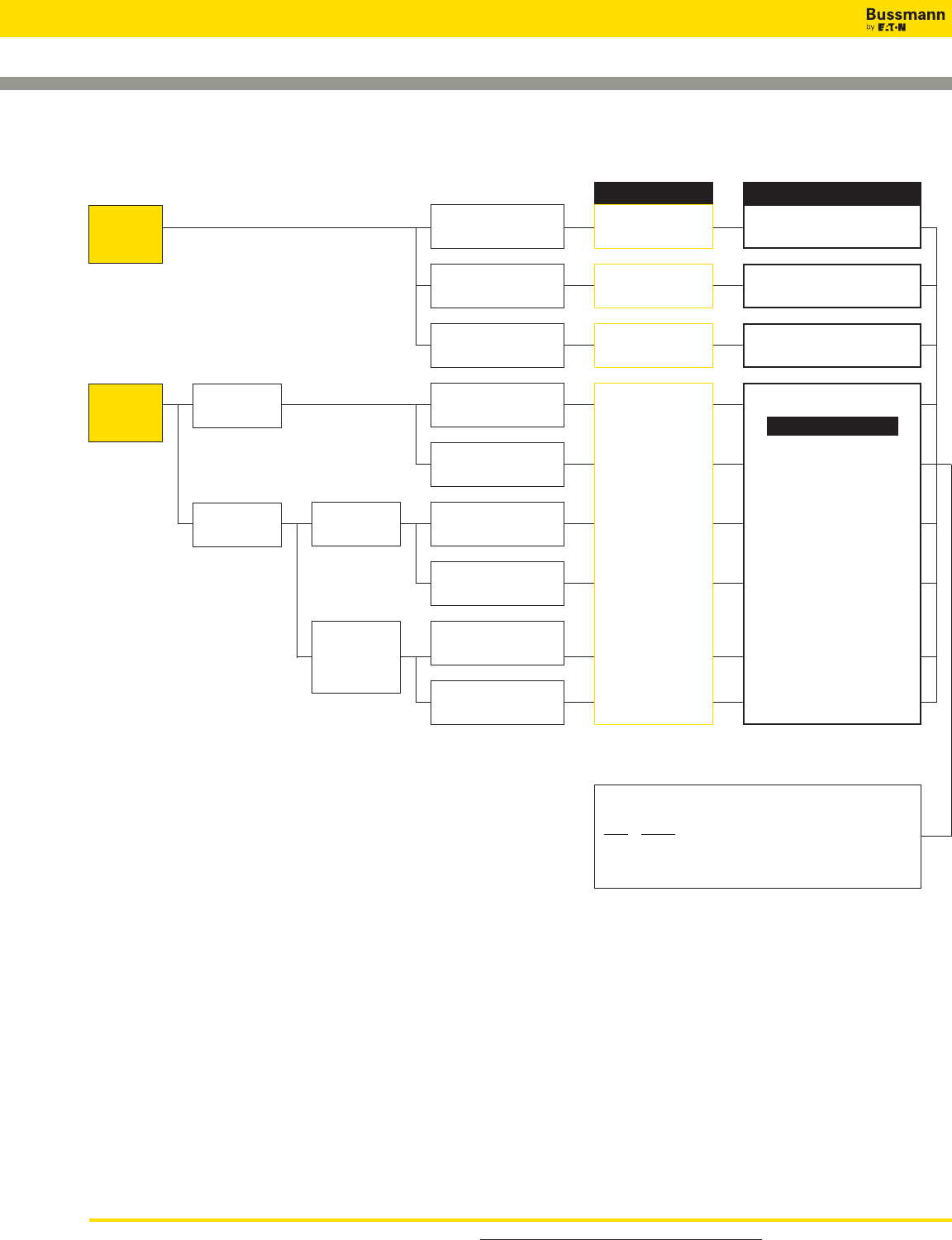
Fuse Recommendations
Volts Fuse(s)
0-250 LPN-RK_SP, FRN-R
0-300 JJN
0-600 LPS-RK_SP, FRS-R
0-600 JJS
0-600 LPJ_SP, LP-CC
JKS, KTK-R, LPT
Main, Branch &
Feeder Circuits
(601-6000A)
150% to 225% of full load current of largest motor plus 100%
of full load current of all other motors plus 125% of continuous
non-motor load plus 100% of non-continuous non-motor load.
Fuse Recommendation
Volts Fuse(s)
0-600 KRP-C_SP
Electric Heat (NEC®424)
Electric Space Heating Size at 125% or next size larger but in no case larger than
60 amps for each subdivided load.
Electric Boilers with
Resistance Type Immersion
Heating Elements in an ASME
Rated and Stamped Vessel
Size at 125% or next size larger but in no case larger than
150 amps for each subdivided load.
Fuse Recommendation
Volts Fuse(s)
0-250 LPN-RK_SP
FRN-R, NON
0-300 JJN
0-480 SC 25 to SC 60
0-600 LPS-RK_SP
FRS-R, NOS
0-600 JJS
0-600 LPJ_SP, LP-CC
FNQ-R, JKS, KTK-R,
TCF, SC 1⁄2to SC 20,
FCF_RN
For product Data Sheets, visit www.cooperbussmann.com/DatasheetsEle
14
Circuit Protection Products for the Electrical Industry
Selecting Circuit Protection
Above 600V
600V & Less
Fuse Recommendations
Volts Fuse(s)
0-250 LPN-RK_SP, FRN-R
0-600 LPS-RK_SP, FRS-R
LPJ_SP, TCF
Fuse Recommendations
Volts Fuse(s)
0-250 KTN-R, NON
0-300 JJN
0-600 KTS-R, NOS
JJS
LP-CC, JKS, KTK-R,
LPT, FCF_RN
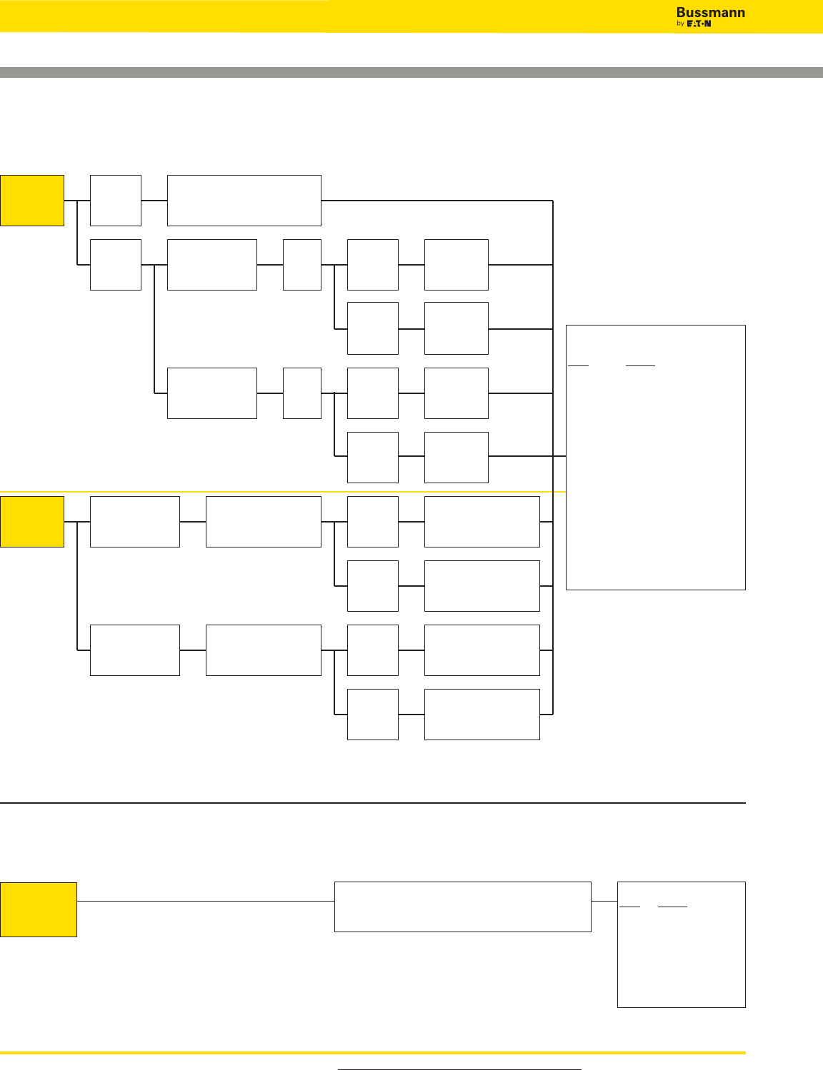
Short-Circuit Only
Backup Overload w/
Motor Starter & Short-
Circuit Protection
Short-Circuit Only
Protected by Time-
Delay Fuses
Protected by Non-
Time Delay Fuses &
all Class CC Fuses
Compare the min. melting time-current characteristics of the fuses with the time-current characteristics of the overload relay
curve. The size fuse which is selected should be such that short.circuit protection is provided by the fuse and overload
protection is provided by the controller overload relays.
Fuse Recommendations
Volts Fuse(s)
2400 JCK, JCK-A, JCH
4800 JCL, JCL-A, JCG
7200 JCR, 7.2 WKMSJ
Motor Loads (NEC®430)
125% of motor FLA or next size larger.
130% of motor FLA or next size larger.
175%* of motor FLA or next size larger. (If 175% does not
correspond to a standard size). If this will not allow motor to
start, due to higher than normal inrush currents or longer than
normal acceleration times (5 sec. or greater), fuse may be
sized up to 225% or next size smaller.
Max. of 300%* of motor FLA or next size larger (if 300% does
not correspond to a standard size). If this will not allow motor
to start due to higher than normal inrush currents or longer
than normal acceleration times (5 sec. or greater), fuses
through 600 amps may be sized up to 400% or next size
smaller.
Fuse Sized For:
*150% for wound rotor and all DC motors.
Fuse Recommendations
Volts Fuse(s)
0-250 FRN-R
0-600 FRS-R
Fuse Recommendations
Volts Fuse(s)
0-250 LPN-RK_SP
0-600 LPS-RK_SP
Solenoids (Coils)
Branch Circuit
Fuses Size at 125% or next size smaller.
Fuse Recommendation
Volts Fuse(s)
0-250 Best: LPN-RK_SP
FRN-R
0-600 LPS-RK_SP
FRS-R
0-600 LPJ_SP, LP-CC
FNQ-R, TCF
Supplementary
Fuses Size at 125% or next size larger. Fuse Recommendation
Volts Fuse(s)
0-32 MDL 9-30A,
FNM 20-30A
0-125 MDA 25-30A,
FNM 12-15A
0-250 MDL 1⁄16-8A,
MDA 2⁄10-20A,
FNM 1⁄10-10A,
MDQ 1⁄100-7A
0-500 FNQ 1⁄10-30A
For product Data Sheets, visit www.cooperbussmann.com/DatasheetsEle 15
Selecting Circuit Protection
Circuit Protection Products for the Electrical Industry
Primary
Protection
Only
*When 125% of FLA corresponds to
a standard rating, the next larger size
is not permitted.
Primary and
Secondary
Protection
Optimum Protection
125% or next size larger
125% or next size larger
125% or next size larger Max. of 125% or next larger*
NEC®Maximums
Max. 300% or next size smaller (See
NEC®430.72(C) for control circuit
transformer maximum of 500%
Max. 167% or next size smaller
Maximum Fuse Size
% of Primary FLA
(or next FLA size smaller)
A = 250%
B = 250%
C = 600%
D = 600%
E = 400%
F = 400%
% of Secondary FLA
A = 167% or next size smaller
B = 125% or next size larger*
C = 167% or next size smaller
D = 125% or next size larger*
E = 167% or next size smaller
F = 125% or next size larger*
Rated secondary current 9
amps or greater
Rated secondary current
less than 9 amps
Transformer
Impedance of 6%
or Less
Rated secondary current 9
amps or greater
Rated secondary current
less than 9 amps
Transformer
Impedance of
More Than 6%
But Less Than
10%
Rated secondary current
less than 9 amps
Rated secondary current 9
amps or greater
Without Thermal
Overload
Protection
With Thermal
Overload
Protection
Note: Components on the secondary still
need overcurrent protection Rated primary current less
than 2 amps
Rated primary current
greater than or equal to 9
amps
Rated primary current
greater than or equal to 2
amps but less than 9 amps
Transformers 600V Nominal or Less (NEC®450.3)
Fuse Recommendations
Volts Fuse(s)
250V LPN-RK_SP, FRN-R
600V KRP-C_SP, LPJ_SP, LPS-RK_SP, FNQ-R, FRS-R, TCF
AA
B
C
D
E
F
B
C
D
E
F
Primary and secondary
fuses at 125% of prima-
ry and secondary FLA or
next size larger
Maximum Fuse Size
16
Circuit Protection Products for the Electrical Industry
For product Data Sheets, visit www.cooperbussmann.com/DatasheetsEle
Selecting Circuit Protection
Solid State Devices (Diodes, SCRs, Triacs, Transistors)
Short-Circuit
Protection
Only
“F,” “S,” “K,” & 170M Series fuses sized up to several sizes
larger than full load RMS or DC rating of device.
Fuse Recommendations
Volts Fuse(s)
0-130 FWA
0-250 FWX
0-500 FWH
0-600 FWC, KAC, KBC
0-700 FWP, 170M Series,
SPP
0-1000 FWJ, 170M Series,
SPJ
Supervised
Installations
Unsupervised
Installations
Transformers Over 600V Nominal (NEC®450.3)
Fuse Recommendations
Volts Fuse(s)
250V LPN-RK_SP, FRN-R
600V LPS-RK_SP, LPJ-_SP,
KRP-C_SP, FRS-R, FNQ-R,
TCF
2475V JCD
2750V JCX
2750/5500V JCW
5500V MV05, 5.5 ABWNA,
5.5 AMWNA, 5.5 FFN
7200V 7.2 AMWNA, 7.2 TDLSJ,
7.2 TFLSJ
8300V JCZ, JDZ, 8.25 FFN
15500V MV155, 15.5 CAVH
17500V 17.5 CAV, 17.5 TDM
24000V 24 TDM, 24 TFM, 24 FFM
36000V 36 CAV, 36 TDQ, 36 TFQ
38000V 38 CAV
Note: Components on the secondary still need
overcurrent protection
Primary at code max. of 250% or
next standard size if 250% does not
correspond to a standard rating
Primary
Protection
Only
Transformer
Impedance Less
Than or Equal to 6%
Primary
at code
max. of
300%
Secondary
Over 600V
Secondary at
code max. of
250%
Secondary at
code max. of
250%
Secondary at
code max. of
225%
Secondary
Over 600V
Primary
at code
max.of
300%
Secondary at
code max. of
250%
Secondary
Over 600V
Primary at code max. of
300% or next standard size
if 300% does not corre-
spond to a standard rating
Transformer
Impedance Less
Than or Equal to 6%
Primary at code max. of
300% or next standard size
if 300% does not corre-
spond to a standard rating
Secondary
Over 600V
Secondary at code max. of
125% or next standard size
if 125% does not corre-
spond to a standard rating
Secondary at code max. of
225% or next standard size
if 225% does not corre-
spond to a standard rating
Secondary at code max. of
125% or next standard size
if 125% does not corre-
spond to a standard rating
Secondary at code max. of
250% or next standard size
if 250% does not corre-
spond to a standard rating
Transformer
Impedance Greater
Than 6% But Less
Than 10%
Secondary
600V or
Below
Secondary
600V or
Below
Primary
and
Secondary
Protection
Transformer
Impedance Greater
Than 6% But Less
Than 10%
Secondary
600V or
Below
Secondary
600V or
Below

17
Low Voltage
Branch Circuit
Fuses
Page
Fuse Holder & Block Selection Guide 18-20
Class Fuse Dimensions 21-22
Fuses By Fuse Class
Class Fuses Volts
CC . . . . . . LP-CC . . . . . . . . . . . . . . . 600V . . . . . 23
FNQ-R . . . . . . . . . . . . . . . 600V . . . . . 24
KTK-R . . . . . . . . . . . . . . . 600V . . . . . 25
CF . . . . . . . TCF* . . . . . . . . . . . . . . . . 600V . . . . . 26-27
FCF. . . . . . . . . . . . . . . . . . 600V . . . . . 28-29
WCF. . . . . . . . . . . . . . . . . 600V . . . . . 30-31
*Class J performance
CF . . . . . . . Holder System . . . . . . . . . 600V . . . . . 32-33
G . . . . . . . SC . . . . . . . . . . . . . . . . . . 600/480V . . 34
J . . . . . . . LPJ-_SP . . . . . . . . . . . . 600V . . . . . 35
LPJ-_SPI Indicator . . . . . 600V . . . . . 35
JKS . . . . . . . . . . . . . . . . . 600V . . . . . 36
K5 & H . . . NON . . . . . . . . . . . . . . . . 250V . . . . . 37
NOS . . . . . . . . . . . . . . . . 600V . . . . . 37
L . . . . . . . KRP-C_SP . . . . . . . . . . . . 600V . . . . . 38-39
KRP-CL . . . . . . . . . . . . . . 600V . . . . . 39
KLU . . . . . . . . . . . . . . . . . 600V . . . . . 40
KTU . . . . . . . . . . . . . . . . . 600V . . . . . 40
RK1 . . . . . LPN-RK_SP . . . . . . . . . . . 250V . . . . . 41-43
LPN-RK_SPI Indicator . . . 250V . . . . . 41-43
LPS-RK_SP . . . . . . . . . . . 600V . . . . . 41-43
LPS-RK_SPI Indicator . . . 600V . . . . . 41-43
KTN-R . . . . . . . . . . . . . . . 250V . . . . . 44
KTS-R . . . . . . . . . . . . . . . 600V . . . . . 45
RK5 . . . . . FRN-R (Energy Efficient). . . 250V . . . . . 46
FRN-R_ID (Energy Efficient).600V . . . . . 46
FRS-R (Energy Efficient). . . 600V . . . . . 47
FRS-R_ID (Energy Efficient).600V . . . . . 47
T . . . . . . . JJN . . . . . . . . . . . . . . . . . 300V . . . . . 48
JJS . . . . . . . . . . . . . . . . . 600V . . . . . 49
Plug Fuses W, SL, TL, S,
T, P, TC Series & MB
Edison Base Circuit
Breakers, SA . . . . . . . . . 125V . . . . . 50-52
Low Voltage, Branch
Circuit Rated Fuses
RED indicates NEW information
For product data sheets, visit www.cooperbussmann.com/DatasheetsEle
18
Low Voltage, Branch Circuit Rated Fuses
Holders & Blocks For Branch Circuit Rated Fuses
Class Fuses Volts Page
CC LP-CC 600V . . . . . . . . . . . . . . . . . . . . 23
FNQ-R 600V . . . . . . . . . . . . . . . . . . . . 24
KTK-R 600V . . . . . . . . . . . . . . . . . . . . 25
Holders
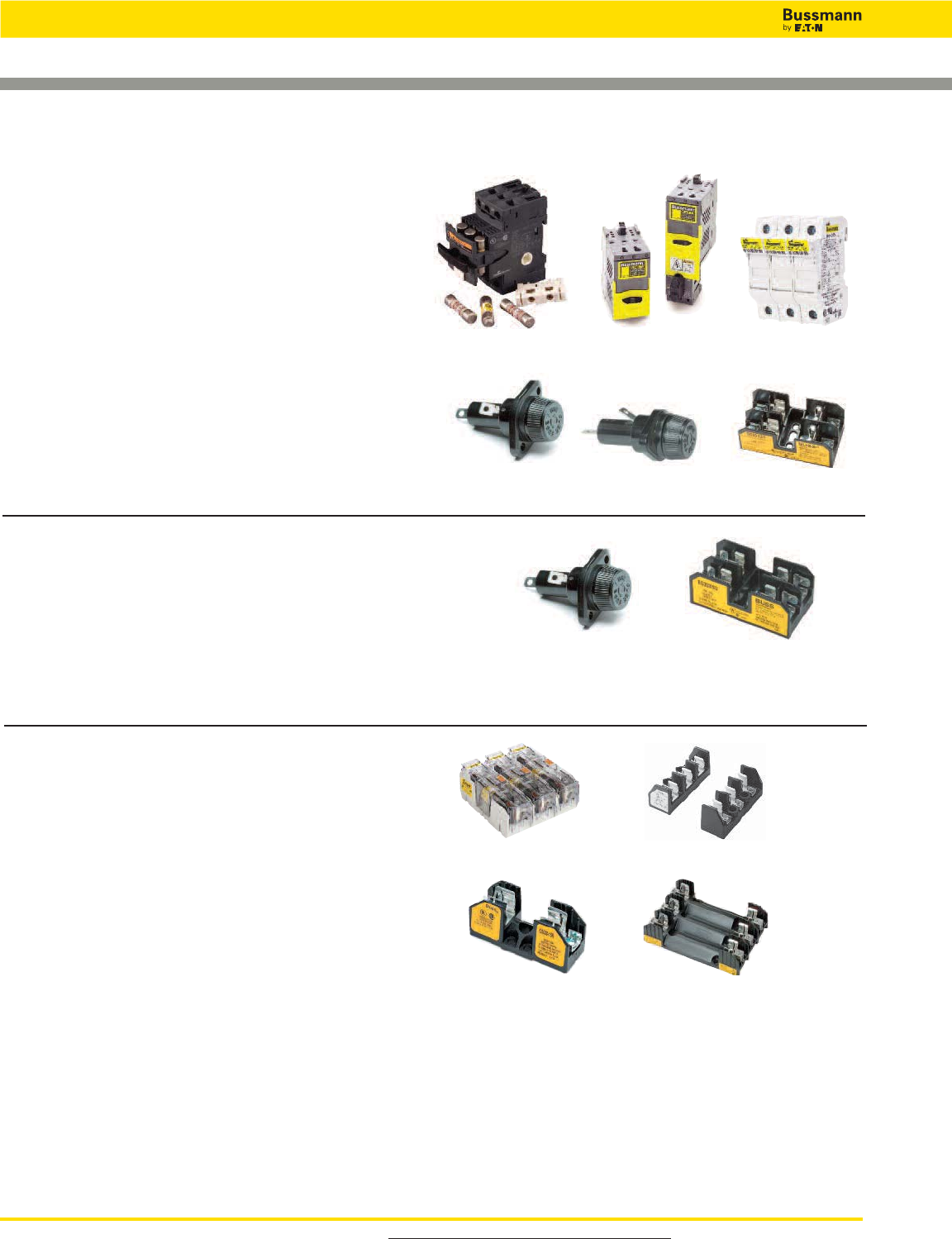
• OPM-NG-SC3 3-pole, panel/DIN rail mount . . . . . . . . . . . . 284
• OPM-1038R 3-pole, panel/DIN rail mount . . . . . . . . . . . . . 283
• OPM-1038RSW 3-pole w/ switch, panel/DIN rail mount . . 282
• CHCC_D 1 to 3-pole, DIN rail mount . . . . . . . . . . . . . . . . . 274
• HPF-RR, front panel mount . . . . . . . . . . . . . . . . . . . . . . . 317
• HPS-RR, front panel mount . . . . . . . . . . . . . . . . . . . . . . . 317
Blocks
• BC Series, panel mount . . . . . . . . . . . . . . . . . . . . . . . . . . 305
Class Fuses Volts Page
G SC 600/480V . . . . . . . . . . . . . . . . . 34
Holders
• HP Series front panel accessible, front panel mount . . . . . 317
Blocks
• BG Series, panel/DIN rail with adapters . . . . . . . . . . . . . . 305
• G Series, panel/DIN rail with adapters . . . . . . . . . . . . . . . 305
Class Fuses Volts Page
K5 & H NON 250V . . . . . . . . . . . . . . . . . . . . 37
NOS 600V . . . . . . . . . . . . . . . . . . . . 37
Blocks
• Modular Knifeblade Fuse Blocks 250/600V, panel mount . . 289
• Modular Type Fuse Blocks 250/600V, panel mount . . . . . . 306
• H250 Series 1 to 3-pole 250V, panel mount . . . . . . . . . . . .294
• H600 Series 1 to 3-pole 600V, panel mount . . . . . . . . . . . 296
OPM-NG-SC3 CHCC_D
HPF-RR HPS-RR BC Series
HP Series BG & G Series
Modular Knifeblade Modular Type
H250 Series H600 Series
OPM-1038R &
OPM-1038RSW
For product data sheets, visit www.cooperbussmann.com/DatasheetsEle 19
Low Voltage
Branch Circuit
Fuses
Holders & Blocks For Branch Circuit Rated Fuses
Class Fuses Volts Page
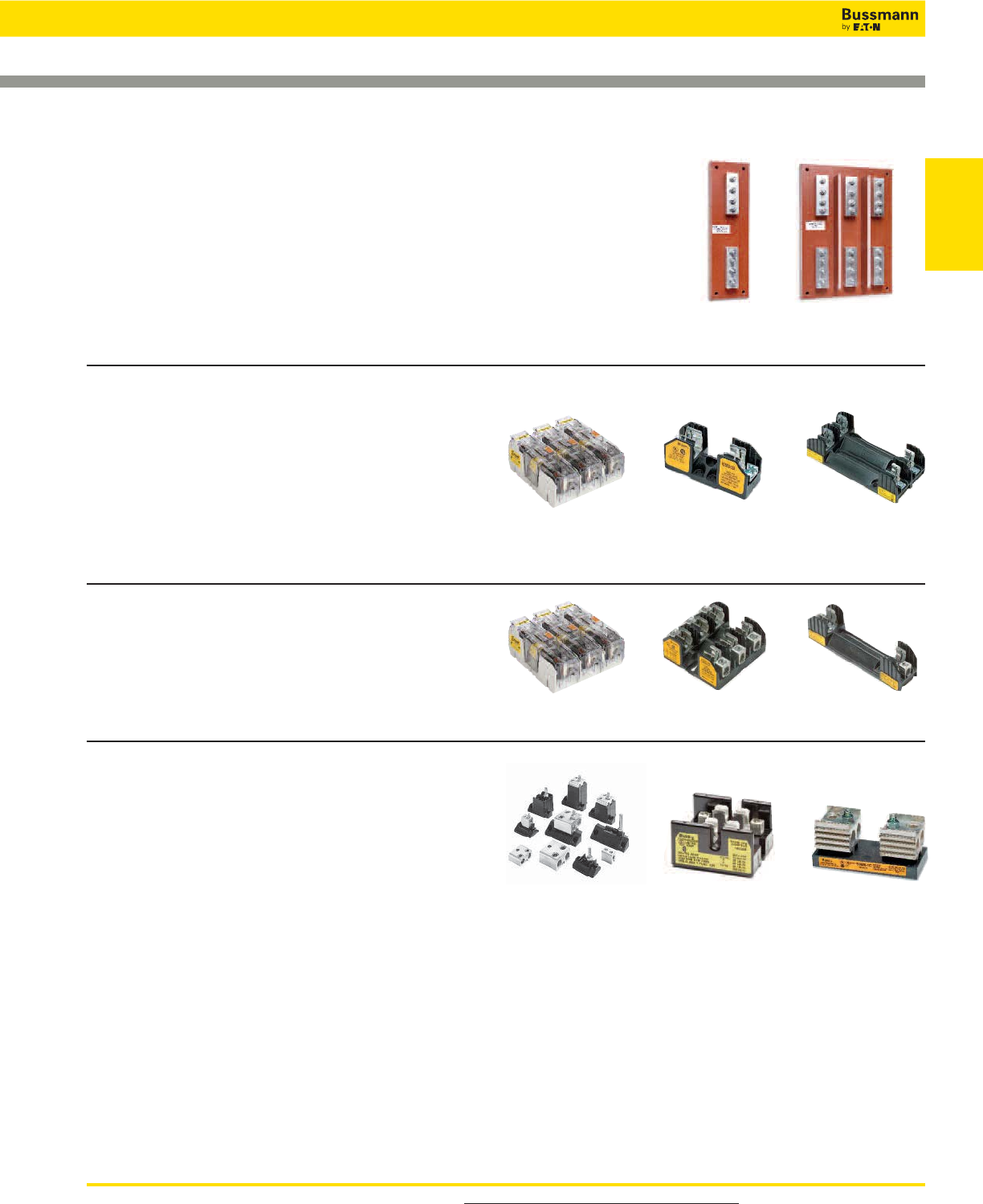
RK1 LPN-RK_SP 250V . . . . . . . . . . . . . . . . . . . . .41
LPS-RK_SP 600V . . . . . . . . . . . . . . . . . . . . .41
KTN-R 250V . . . . . . . . . . . . . . . . . . . . 44
Blocks
• Modular Knifeblade Fuse Blocks 250/600V, panel mount . . .289
• R250 Series 1- to 3-pole 250V, panel mount . . . . . . . . . . . .294
• R600 Series 1- to 3-pole 600V, panel mount . . . . . . . . . . . .296
Class Fuses Volts Page
RK5 FRN-R 250V . . . . . . . . . . . . . . . . . . . . 46
Blocks
• Modular Knifeblade Fuse Blocks 250/600V, panel mount . . . 289
• R250 Series 1- to 3-pole 250V, panel mount . . . . . . . . . . . .294
• R600 Series 1- to 3-pole 600V, panel mount . . . . . . . . . . . .296
51215 51235
R250 Series
R250 Series
R600 Series
R600 Series
BH Series T600 Series
T300 Series
Class Fuses Volts Page
L KRP-C_SP 600V . . . . . . . . . . . . . . . . . . . . 38
KRP-CL 600V . . . . . . . . . . . . . . . . . . . . 39
KLU 600V . . . . . . . . . . . . . . . . . . . . 40
KTU 600V . . . . . . . . . . . . . . . . . . . . 40
Blocks
• 51215 1-pole, panel mount*
• 51235 3-pole, panel mount*
*Call our customer satisfaction team at 636-527-3877 for more information.
Class Fuses Volts Page
T JJN 300V . . . . . . . . . . . . . . . . . . . . 48
JJS 600V . . . . . . . . . . . . . . . . . . . . 49
Blocks
• BH Series modular-style, panel mount (<60A) . . . . . . . . . . 306
• T300 Series 1 to 4-pole 300V, panel mount . . . . . . . . . . . .300
• T600 Series 1 to 3-pole 600V, panel mount . . . . . . . . . . . .302
Modular Knifeblade
Modular Knifeblade
Low Voltage, Branch Circuit Rated Fuses
For product data sheets, visit www.cooperbussmann.com/DatasheetsEle
20
Low Voltage, Branch Circuit Rated Fuses
Class Fuses Volts Page
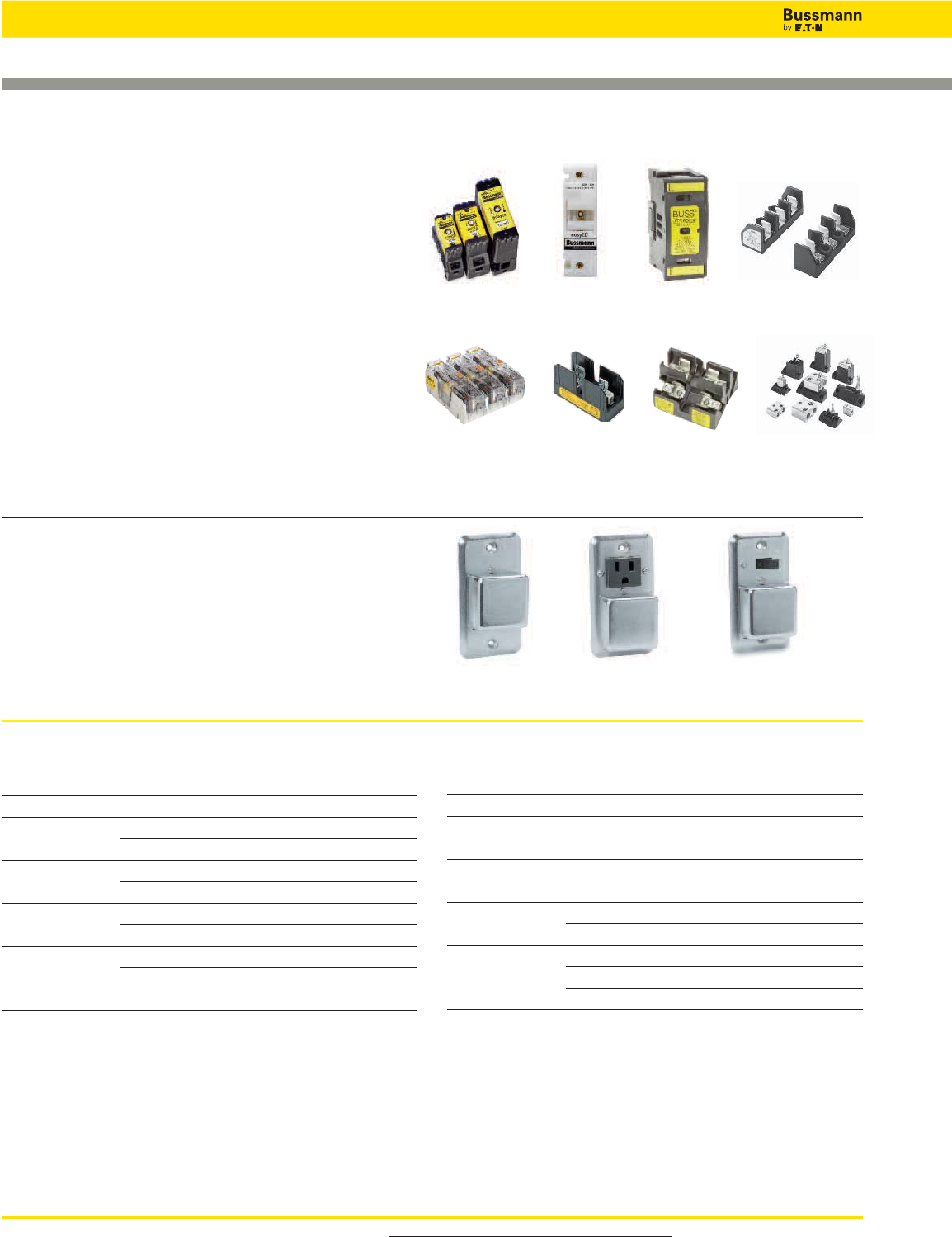
Plug Fuses W, SL*, TL, S*,
T, P and TC
Series 125V . . . . . . . . . . . . . . . . . . 50-52
Box Cover Units
• Standard electrical box mounting . . . . . . . . . . . . . . . . . . . 307
*Use of SL & S rejection fuses requires SA adapters, see page 52
Fuse Only With Grounded
Outlet
With Switch
Class Fuses Volts Page
J, CF TCF*, FCF, WCF 600V . . . . . . . . . . . . . . . . 31
LPJ-SP 600V . . . . . . . . . . . . . . . . 35
JKS 600V . . . . . . . . . . . . . . . . 36
*Class J performance
Holders
• TCFH CUBEFuse holder, panel/DIN-Rail mount . . . . . . . 32-33
• CH Series Class J modular 1- to 3-pole, panel/
DIN rail mount . . . . . . . . . . . . . . . . . . . . . . . . . . . . . . . . . 281
• Safety J™ Series modular holders,
panel/DIN rail mount . . . . . . . . . . . . . . . . . . . . . . . . . . . . .286
Blocks
• Modular Knifeblade Fuse Blocks 250/600V, panel mount . . 289
• Modular Type Fuse Blocks 600V, panel mount . . . . . . . . . .306
• J600 Series, panel mount . . . . . . . . . . . . . . . . . . . . . . . . . 298
• JP Series pyramid blocks, panel mount . . . . . . . . . . . . . . .299
• BH Series modular-style open blocks, panel mount . . . . . 306
TCFH CH Series
J600 Series JP Series BH Series
Safety J™ Series Modular Type
Holders & Blocks For Branch Circuit Rated Fuses
Equipment Desired Fuse Catalog No.
Fuse Clip Amps (Case) Amp Size (Pairs) 250V
60 30 NO.263-R
100 30 NO.213-R
60 NO.216-R
200 60 NO.226-R
100 NO.2621-R
400 100 NO.2641-R
200 NO.242-R
600 100 NO.2661-R
200 NO.2662-R
400 NO.2664-R*
*Single reducer only (pair not required).
Equipment Desired Fuse Catalog No.
Fuse Clip Amps (Case) Amp Size (Pairs) 600V
60 30 NO.663-R
100 30 NO.216-R
60 NO.616-R
200 60 NO.626-R
100 NO.2621-R
400 100 NO.2641-R
200 NO.642-R
600 100 NO.2661-R
200 NO.2662-R
400 NO.2664-R*
*Single reducer only (pair not required).
Fuse Reducers For Class R Fuses 250V Fuse Reducers For Class R Fuses 600V
Modular
Knifeblade
For product data sheets, visit www.cooperbussmann.com/DatasheetsEle 21
Low Voltage
Branch Circuit
Fuses
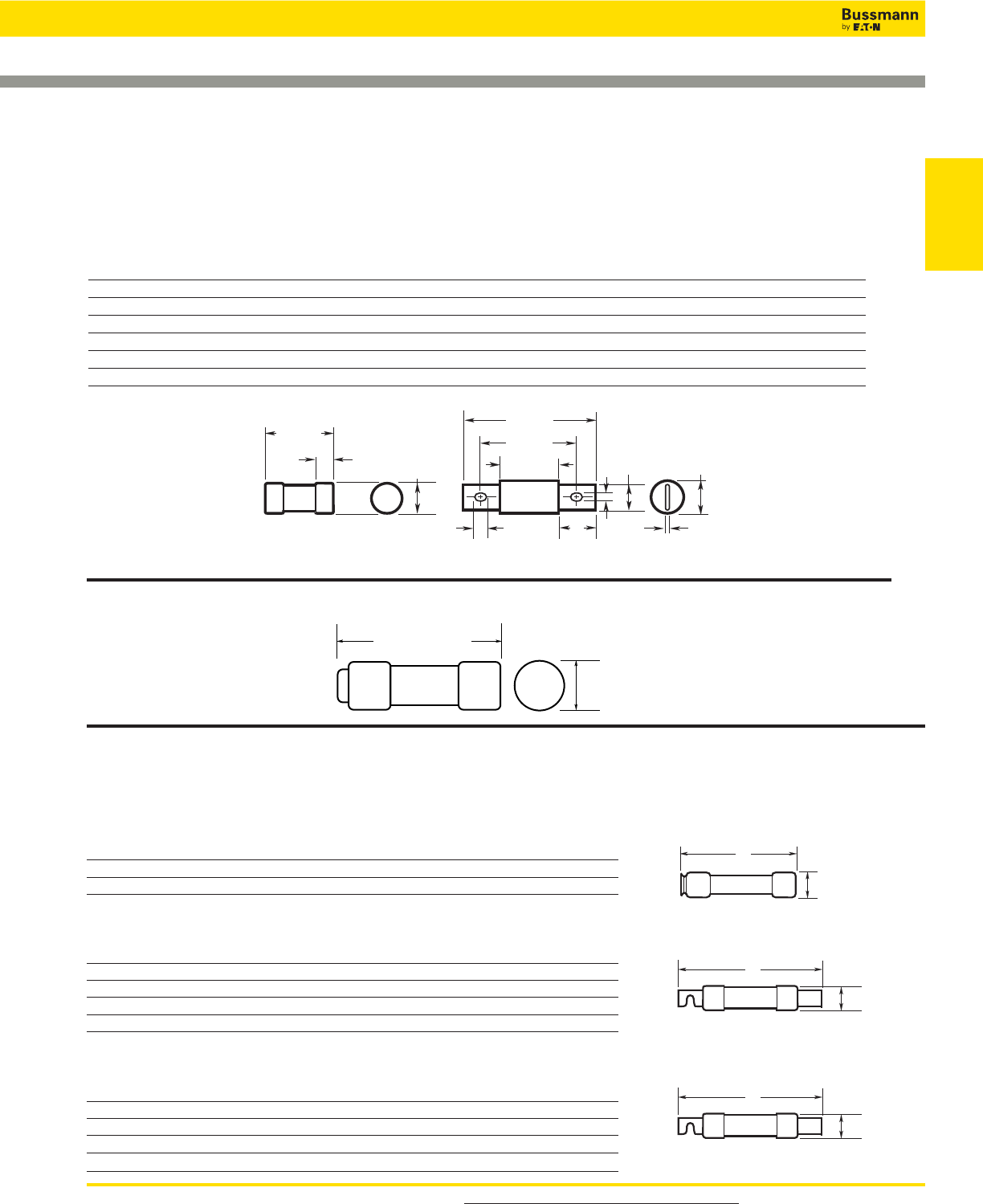
Class J Dimensions - in (mm)
Low-Peak and Limitron Fuses
LPJ & JKS — 600V
Amp Range A B C D E F G H I
1-30 2.25 (57.2) 0.81 (20.6) — — 0.50 (12.7) — — — —
35-60 2.38 (60.3) 1.06 (27.0) — — 0.63 (15.9) — — — —
65-100 4.63 (117.5) 1.13 (28.6) 3.63 (92.1) 2.63 (66.7) 1.00 (25.4) 0.75 (28.6) 0.13 (3.2) 0.41 (10.4) 0.28 (7.1)
110-200 5.75 (146.1) 1.63 (41.4) 4.38 (111.1) 3.00 (76.2) 1.38 (34.9) 1.13 (28.6) 0.19 (4.8) 0.38 (9.5) 0.28 (7.1)
225-400 7.12 (181.0) 2.11 (53.6) 5.25 (133.3) 3.26 (82.8) 1.87 (47.6) 1.62 (41.2) 0.25 (6.4) 0.56 (14.2) 0.40 (10.3)
450-600 8.00 (203.2) 2.60 (66.0) 6.00 (152.4) 3.31 (84.0) 2.12 (54.0) 2.00 (50.8) 0.53 (13.5) 0.72 (18.3) 0.53 (13.5)
21
Branch Circuit Rated Fuse Dimensions
Class RK1 & RK5 Dimensions - in (mm)
Basic dimensions are same as Class H (formerly NEC) One-Time (NON & NOS) and Superlag Renewable RES & REN fuses.
NOTE: These fuses can be used to replace existing Class H, RK1 and RK5 fuses relating to dimensional compatibility.
Ferrule Styles
Amp 250V 600V
Range A B A B
1⁄10-30 2 (50.8) 0.56 (14.3) 5.0 (127.0) 0.81 (20.6)
35-60 3 (76.2) 0.81 (20.6) 5.5 (139.7) 1.06 (27.0)
Fusetron — (FRN-R & FRS-R)& Limitron — (KTN-R & KTS-R)
Amp 250V 600V
Range A B A B
70-100 5.88 (149.2) 1.06 (26.9) 7.88 (200.0) 1.34 (34.0)
110-200 7.13 (181.0) 1.56 (39.6) 9.63 (244.5) 1.84 (46.7)
225-400 8.63 (219.1) 2.38 (60.5) 11.63 (295.3) 2.59 (65.8)
450-600 10.38 (263.5) 2.88 (73.2) 13.38 (339.7) 3.13 (79.5)
Low-Peak — (LPN-RK & LPS-RK)
Amp 250V 600V
Range A B A B
70-100 5.88 (149.2) 1.16 (29.5) 7.88 (200.0) 1.16 (29.5)
110-200 7.13 (181.0) 1.66 (42.2) 9.63 (244.5) 1.66 (42.2)
225-400 8.63 (219.1) 2.38 (60.5) 11.63 (295.3) 2.38 (60.5)
450-600 10.38 (263.5) 2.88 (73.2) 13.38 (339.7) 2.88 (73.2)
A
B
A
B
A
B
A
BB
A
C
D
E
F
G
E
H
I
1A to 60A 65A to 600A
1.5" (±0.031)
(38.1mm)
0.41" (±0.005)
(10.3mm)
Class CC Dimensions - in (mm)
Low Voltage, Branch Circuit Rated Fuses
For product data sheets, visit www.cooperbussmann.com/DatasheetsEle
22
Low Voltage, Branch Circuit Rated Fuses
22
Branch Circuit Rated Fuse Dimensions
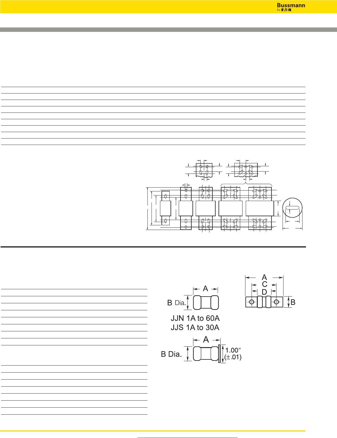
Class T Dimensions - in (mm)
T-Tron Fuses
JJN — 300V
Amp Range A B C D
1-30 0.88 (22.2) 0.41 (10.3) — —
35-60 0.88 (22.2) 0.56 (14.3) — —
70-100 2.16 (54.8) 0.75 (19.1) 1.56 (39.7) 0.84 (21.4)
110-200 2.44 (61.9) 0.88 (22.2) 1.69 (42.9) 0.84( 21.4)
225-400 2.75 (69.9) 1.00 (25.4) 1.84 (46.8) 0.86 (21.8)
450-600 3.06 (77.8) 1.25 (31.8) 2.03 (51.6) 0.88 (22.2)
601-800 3.38 (85.7) 1.75 (44.5) 2.22 (56.4) 0.89 (22.6)
801-1200 4.00 (101.6) 2.00 (50.8) 2.53 (64.3) 1.08 (27.4)
JJS — 600V
Amp Range A B C D
1-30 1.50 (14.3) 0.56 (38.1) — —
35-60 1.56 (20.6) 0.81 (39.7) — —
70-100 2.95 (19.1) 0.75 (75.0) 2..36 (59.9) 1.64 (41.7)
110-200 3.25 (22.2) 0.88 (82.6) 2.50 (63.5) 1.66 (42.1)
225-400 3.63 (25.4) 1.00 (92.1) 2.72 (69.1) 1.73 (44.1)
450-600 3.98 (31.8) 1.25 (101.2) 2.96 (75.0) 1.78 (45.2)
601-800 4.33 (44.5) 1.75 (109.9) 3.17 (80.6) 1.88 (47.6)
A
A
B
F
G
D
C1 C2
J1 J1
J2 J2
J3 J3
J4 J4
All Slots and Holes I
801A
to
2000A
601A
to
800A
2001A
to
3000A
3500A
to
4000A
4500A
to
6000A
Class L Dimensions - in (mm)
Low-Peak and Limitron Fuses
Amp
Range A B C1 C2 D F G I J1 J2 J3 J4
601-800 8.63 (219.1) 2.40 (61.0) 6.75 (171.5) 5.75 (146.1) 3.75 (95.3) 2.00 (50.8) 0.38 (9.5) 0.63 (15.9) ————
801-1200 10.75 (273.1) 2.40 (61.0) 6.75 (171.5) 5.75 (146.1) 3.75 (95.3) 2.00 (50.8) 0.38 (9.5) 0.63 (15.9) ————
1350-1600 10.75 (273.1) 3.00 (76.2) 6.75 (171.5) 5.75 (146.1) 3.75 (95.3) 2.38 (60.3) 0.44 (11.1) 0.63 (15.9) ————
1800-2000 10.75 (273.1) 3.50 (88.9) 6.75 (171.5) 5.75 (146.1) 3.75 (95.3) 2.75 (69.9) 0.50 (12.7) 0.63 (15.9) ————
2001-2500 10.75 (273.1) 4.80 (122.0) 6.75 (171.5) 5.75 (146.1) 3.75 (95.3) 3.50 (88.9) 0.75 (19.1) 0.63 (15.9) 1.75 (44.5) 1.38 (34.9) 0.88 (22.2) 0.81 (20.6)
3000 10.75 (273.1) 5.00 (127.0) 6.75 (171.5) 5.75 (146.1) 3.75 (95.3) 4.00 (101.6) 0.75 (19.1) 0.63 (15.9) 1.75 (44.5) 1.38 (34.9) 0.88 (22.2) 0.81 (20.6)
3500-4000 10.75 (273.1) 5.75 (146.1) 6.75 (171.5) 5.75 (146.1) 3.75 (95.3) 4.75 (120.7) 0.75 (19.1) 0.63 (15.9) 1.75 (44.5) 1.38 (34.9) 1.63 (41.3) 0.88 (22.2)
4500-5000 10.75 (273.1) 6.25 (158.8) 6.75 (171.5) 5.75 (146.1) 3.75 (95.3) 5.25 (133.4) 1.00 (25.4) 0.63 (15.9) 1.75 (44.5) 1.38 (34.9) 1.63 (41.3) 0.88 (22.2)
6000 10.75 (273.1) 7.13 (181.0) 6.75 (171.5) 5.75 (146.1) 3.75 (95.3) 5.75 (146.1) 1.00 (25.4) 0.63 (15.9) 1.75 (44.5) 1.38 (34.9) 1.63 (41.3) 0.88 (22.2)
NOTE: KRP-CL (150A to 600A) fuses have same
dimensions as 601-800A case size. KTU (200-600A)
have same dimensions, except tube 3” length x 2”
diameter (76.2 x 50.8mm); terminal 15⁄8” width x 11⁄4”
thick (41.3 x 31.8mm).
JJN 70A to 1200A
JJS 70A to 800A
JJS 35A to 60A

For product data sheets, visit www.cooperbussmann.com/DatasheetsEle 23
Low Voltage
Branch Circuit
Fuses
23
LP-CC Class CC
Specifications
Description: Time-delay, current-limiting,
rejection-type fuse – 12 seconds (minimum)
at 200% rated amps.
Dimensions: 13⁄32˝ x 1 1⁄2˝ (10.3 x 38.1mm).
Ratings:
Volts — 600Vac (or less)
— 300Vdc (1⁄2-21⁄2A & 20-30A)
— 150Vdc (28⁄10-15A)
Amps — 1⁄2-30A
IR — 200kA RMS Sym.
— 20kA DC
Agency Information: CE, Std. 248-4, Class CC, UL Listed,
Guide JDDZ, File E4273, CSA Certified; Class 1422-02,
File 53787.
Features and Benefits
• Time-delay coupled with Class CC current-limiting response
provides close sizing on small motor and relay circuits, and
maximum component short-circuit current rating protection.
• 200kA interrupting rating provides high ratings for control
circuit locations.
• Class CC rejection feature, with appropriate fuse block,
prevents inserting lesser-rated supplementary fuses.
• Inventory consolidation of 13⁄32 x 1 1⁄2inch supplementary
fuses reduces SKU investment and minimizes potential for
misapplying fuse.
• Selective coordination ratio of 2:1 (within Low-Peak fuse
family) prevents electrical shutdowns from extending
beyond the failed circuit.
Typical Applications
• Specialized Circuits
• Industrial Control
• Isolated, In-Line Fuse Holder
Catalog Numbers (Amps)
LP-CC-1⁄2LP-CC-2-1⁄2LP-CC-7 1⁄2
LP-CC-6⁄10 LP-CC-2-8⁄10 LP-CC-8
LP-CC-8⁄10 LP-CC-3 LP-CC-9
LP-CC-1 LP-CC-3-2⁄10 LP-CC-10
LP-CC-1-1⁄8LP-CC-3-1⁄2LP-CC-12
LP-CC-1-1⁄4LP-CC-4 LP-CC-15
LP-CC-1-4⁄10 LP-CC-4-1⁄2LP-CC-20
LP-CC-1-1⁄2LP-CC-5 LP-CC-25
LP-CC-1-6⁄10 LP-CC-5-6⁄10 LP-CC-30
LP-CC-1-8⁄10 LP-CC-6
LP-CC-2 LP-CC-6-1⁄4
LP-CC-2-1⁄4LP-CC-7
Low-Peak™Time-delay, Rejection-Type Fuses
200
100
10
TIME IN SECONDS
1
.1
.01
⁄/™
fl/¡º
°/¡º
1
1⁄/¢
3
3⁄/™
4
4⁄/™
6
8
10
12
15
20
25
30
AMP
RATING
.4
1
10
100
1000
CURRENT IN AMPS
Time Current Characteristics—Average Melt
Data Sheet: 1023
Recommended Fuse Holders & Blocks For Class CC Fuses
• See page 18
Current Limitation Curves
Low Voltage, Branch Circuit Rated Fuses
For product data sheets, visit www.cooperbussmann.com/DatasheetsEle
24
Low Voltage, Branch Circuit Rated Fuses
24
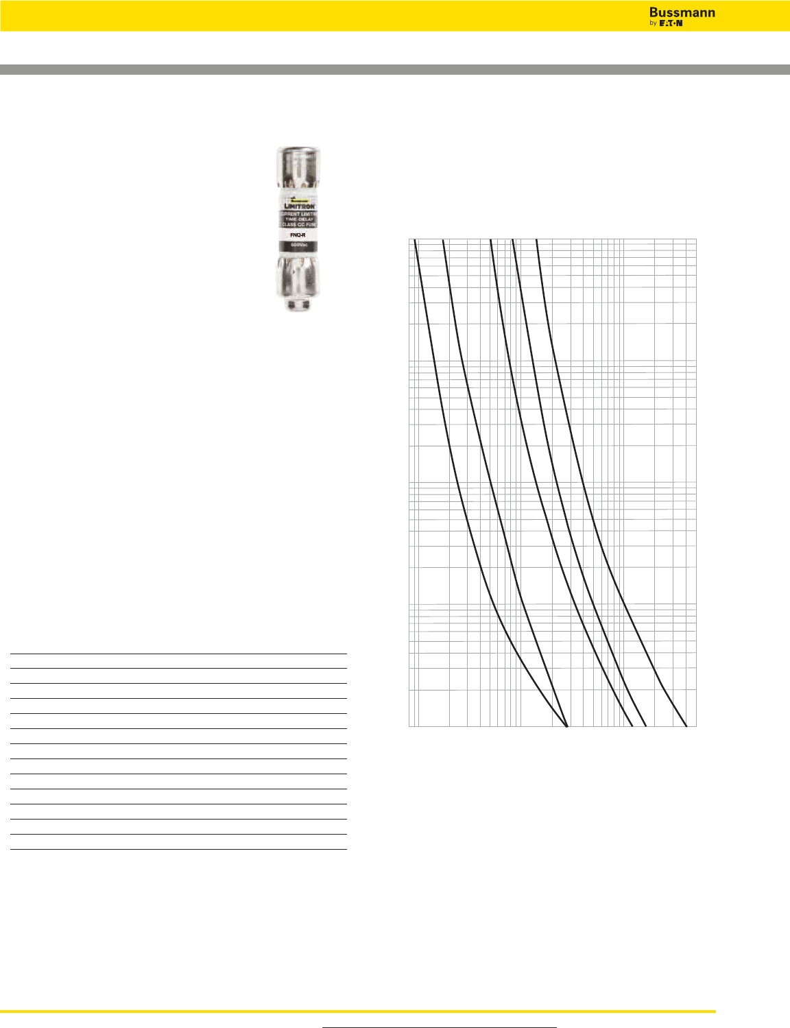
CC-Tron Rejection-type Fuses
Data Sheet: 1014
Specifications
Description: Time-delay, branch circuit,
rejection-type fuse.
Dimensions: 13⁄32˝ x 1 1⁄2˝ (10.3 x 38.1mm).
Ratings:
Volts — 600Vac (or less)
— 300Vdc (15-20A)
— 32Vdc (Self Certified)
Amps — 1⁄4-30A
IR — 200kA RMS Sym.
— 20kA DC (15 & 20A only)
Agency Information: CE, Std. 248-4, Class CC, UL
Listed, Guide JDDZ, File E4273 CSA Certified,
Class 1422-01, File 53787.
Features and Benefits
• Time-delay compatible with inrush characteristic of small
control transformers.
• Current limitation at Class CC levels provides maximum
component short-circuit current rating protection.
• 200kA interrupting rating provides high ratings for control
circuit locations.
• Class CC rejection feature, with appropriate fuse block,
prevents inserting lesser-rated supplementary fuses.
Typical Applications
• Line Protection, Small Control Transformers
• Industrial Control
• Isolated, In-Line Fuse Holders
Catalog Numbers (Amps)
FNQ-R-1⁄4FNQ-R-1-6⁄10 FNQ-R-6
FNQ-R-3⁄10 FNQ-R-1-8⁄10 FNQ-R-6-1⁄4
FNQ-R-4⁄10 FNQ-R-2 FNQ-R-7
FNQ-R-1⁄2FNQ-R-2-1⁄4FNQ-R-7-1⁄2
FNQ-R-6⁄10 FNQ-R-2-1⁄2FNQ-R-8
FNQ-R-3⁄4FNQ-R-2-8⁄10 FNQ-R-9
FNQ-R-8⁄10 FQN-R-3 FNQ-R-10
FNQ-R-1 FNQ-R-3-2⁄10 FNQ-R-12
FNQ-R-1-1⁄8FNQ-R-3-1⁄2FNQ-R-15
FNQ-R-1-1⁄4FNQ-R-4 FNQ-R-17-1⁄2
FNQ-R-1-3⁄10 FNQ-R-4-1⁄2FNQ-R-20
FNQ-R-1-4⁄10 FNQ-R-5 FNQ-R-25
FNQ-R-1-1⁄2FNQ-R-5-6⁄10 FNQ-R-30
AMP
RATING
100
10
1
0.01
0.08
1
10
100
200
CURRENT IN AMPS
300
400
500
TIME IN SECONDS
FNQ-R-1/2
FNQ-R-1
FNQ-R-3
FNQ-R-5
FNQ-R-7-1/2
0.01
Time-Current Characteristic Curves—Average Melt
FNQ-R Class CC
For superior electrical protection, Bussmann recommends upgrading FNQ-R
fuse applications to Low-Peak LP-CC fuses See page 17.
Recommended Fuse Holders & Blocks For Class CC
600V Fuses
• See page 18
For product data sheets, visit www.cooperbussmann.com/DatasheetsEle 25
Low Voltage
Branch Circuit
Fuses
25
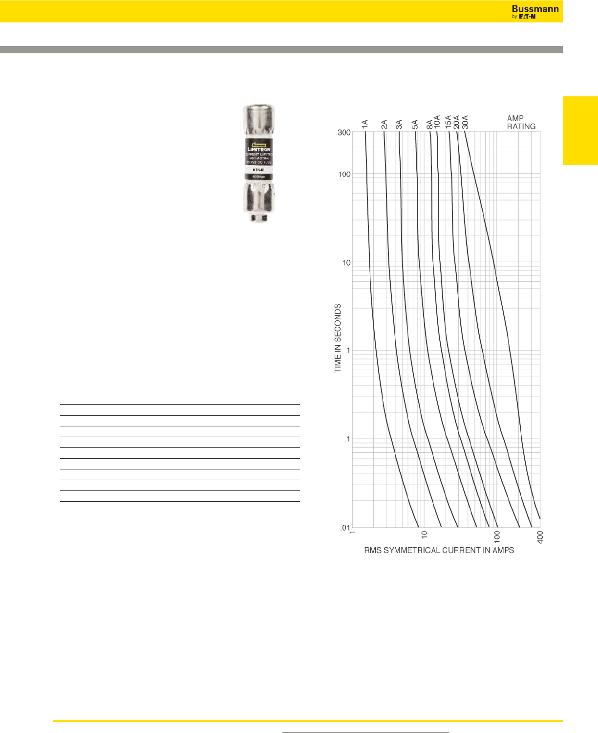
Limitron™Rejection-type Fuses
Data Sheet: 1015
Specifications
Description: Fast-acting, branch circuit,
rejection-type fuse.
Dimensions: 13⁄32˝ x 1 1⁄2˝ (10.3 x 38.1mm).
Ratings:
Volts — 600Vac (or less)
Amps — 1⁄10-30A
IR — 200kA RMS Sym.
Agency Information: CE, Std. 248-4,
Class CC, UL Listed, Guide JDDZ, File
E4273 CSA Certified, File 53787, Class 1422-02.
Features and Benefits
• Current limitation at Class CC levels provides maximum
component short-circuit current protection.
• 200kA interrupting rating provides high ratings for control
circuit locations.
• Class CC rejection feature, with appropriate fuse block,
prevents inserting lesser-rated supplementary fuses.
Typical Applications
• Specialized Circuits
• Industrial Control
• Isolated, In-Line Fuse Holders (street lighting)
Catalog Numbers (Amps)
KTK-R-1⁄10 KTK-R-1 KTK-R-7
KTK-R-1⁄8KTK-R-1-1⁄2KTK-R-8
KTK-R-2⁄10 KTK-R-2 KTK-R-9
KTK-R-1⁄4KTK-R-2-1⁄2KTK-R-10
KTK-R-3⁄10 KTK-R-3 KTK-R-12
KTK-R-4⁄10 KTK-R-3-1⁄2KTK-R-15
KTK-R-1⁄2KTK-R-4 KTK-R-20
KTK-R-6⁄10 KTK-R-5 KTK-R-25
KTK-R-3⁄4KTK-R-6 KTK-R-30
Time-Current Characteristic Curves—Average Melt
KTK-R Class CC
For superior electrical protection, Bussmann recommends upgrading KTK-R
fuse applications to Low-Peak LP-CC fuses See page 23.
Recommended Fuse Holders & Blocks For Class CC Fuses
• See page 18
Low Voltage, Branch Circuit Rated Fuses
For product data sheets, visit www.cooperbussmann.com/DatasheetsEle
26
Low Voltage, Branch Circuit Rated Fuses
26
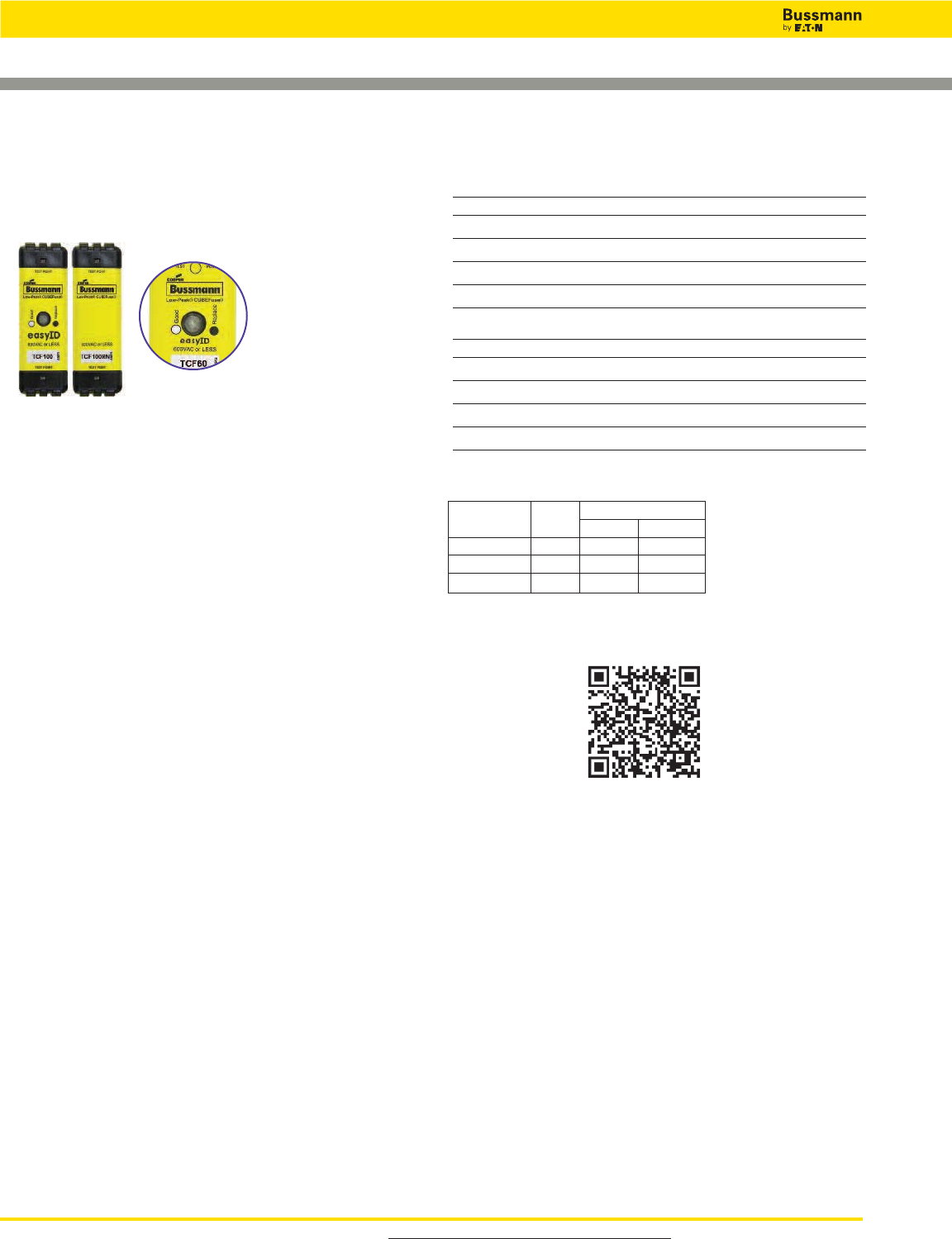
Time-Delay Low-Peak
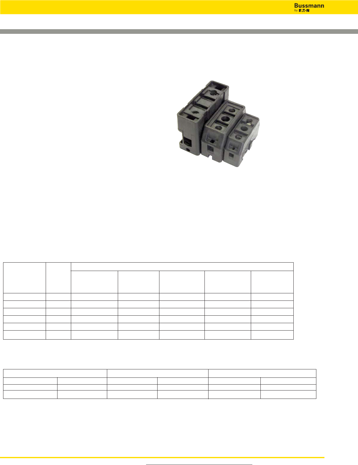
CUBEFuse™
Finger-safe Fuse and Fuse
Holder System
Data Sheet: 9000 (fuses) and 9007 (holders)
Fuse Catalog Numbers Indicating (Amps)
TCF6 TCF25 TCF50 TCF100
TCF10 TCF30 TCF60
TCF15 TCF35 TCF70
TCF17-1⁄2TCF40 TCF80
TCF20 TCF45 TCF90
Fuse Catalog Numbers Non-Indicating (Amps)
TCF1RN TCF17-1⁄2RN TCF40RN TCF80RN
TCF3RN TCF20RN TCF45RN TCF90RN
TCF6RN TCF25RN TCF50RN TCF100RN
TCF10RN TCF30RN TCF60RN
TCF15RN TCF35RN TCF70RN
TCF Class CF
Specifications
Description: Finger-safe fuse and fuse holder system;
dual-element, time-delay fuse; 10 seconds minimum
operating time at 500% rated amps.
Dimensions: See Dimensions illustration.
Poles: 1-pole (gangable)
Ratings:
Volts — 600Vac (or less)
— 300Vdc (or less)
Amps — 1-100A
IR — 300kA RMS Sym. (UL)
— 200kA RMS Sym. (CSA)
— 100kA DC (UL & CSA)
Agency Information: CE, UL Listed Guide JFHR, File
E4273, CSA Certified Fuse: Class 1422- 02, File 53787, UL
Listed Fuse holder: Guide IZND, File E214079, CSA
Certified Fuse holder: Class 6225-01, File 47235.
Features and Benefits
• Separate overload and short-circuit elements provide time
delay for sizing of high inrush loads linked with Class J
current limitation.
• Selective coordination ratio of 2:1 (within Low-Peak fuse
family) prevents electrical shutdowns from extending
beyond the failed circuit.
• Smallest footprint of any Class CC, J, T or RK fuse
provides substantial space savings and installation
flexibility.
• IEC 60529 and finger-safe rating provides enhanced
workplace safety.
Typical Applications
• Electrical Panelboards
• Machinery Disconnects
• Industrial Control
• Required Finger-Safe Systems
Available With
Indication
Amp Carton Weight Per Carton
Rating Qty. lbs kg
TCF1-30A 12 1.39 0.63
TCF35-60A 12 1.42 0.65
TCF70-100A 6 1.74 0.79
Carton Quantity and Weight
Scan this tag to get the latest product
information for the TCF CUBEFuse.
Recommended Fuse Holders For Class CF Fuses
• See pages 32 and 33
For product data sheets, visit www.cooperbussmann.com/DatasheetsEle 27
27
Time-Current Characteristic Curves–Average Melt
Time-Delay Low-Peak
CUBEFuse™
Finger-safe Fuse and Fuse
Holder System
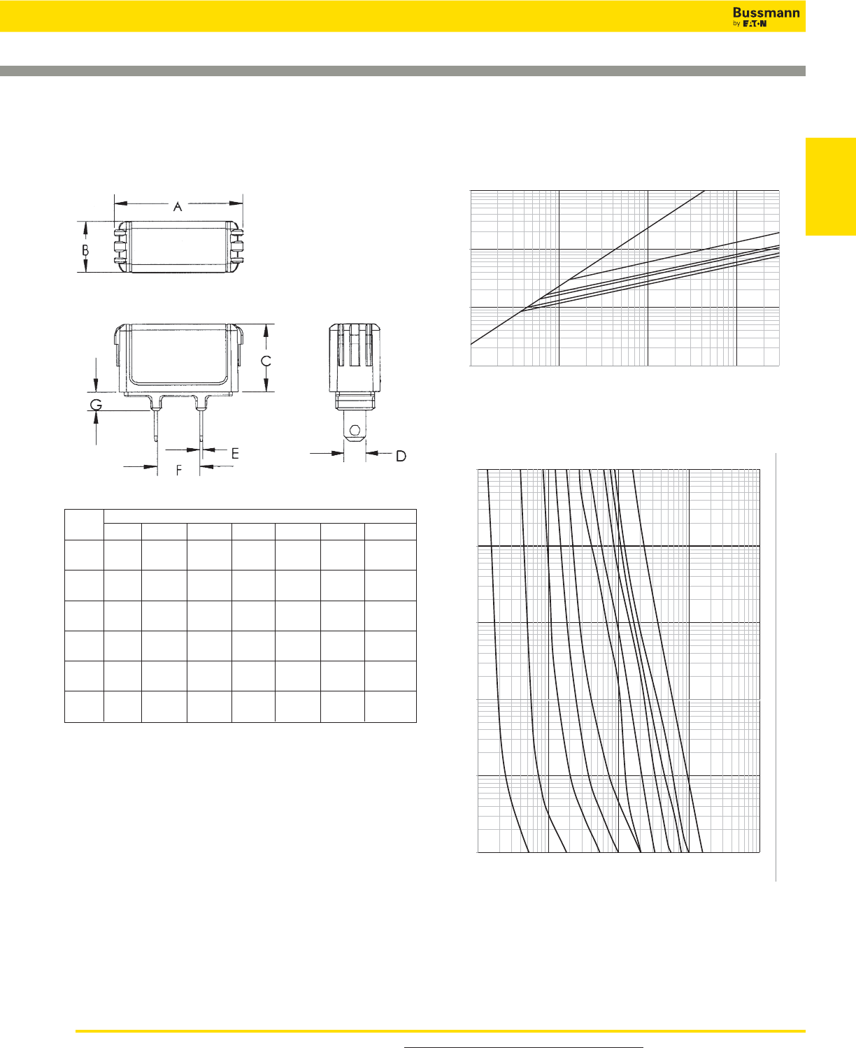
Dimensions for CUBEFuse Fuse and Fuse Holder Current Limitation Curves
Data Sheet: 9000 (fuses) and 9007 (holders)
Fuse Dimensions - in (mm)
Amps A B C D E F G
1-15 1.88 0.75 1.00 0.23 0.04 0.63 0.28
(47.75) (19.05) (25.40) (5.84) (1.02) (15.93) (7.11)
17 1⁄2
1.88 0.75) 1.00 0.31 0.04 0.63 0.28
(47.75) (19.05) (25.40) (7.87) (1.02) (15.93) (7.11)
20 1.88 0.75) 1.00 0.31 0.04 0.63 0.28
(47.75) (19.05) (25.40) (7.87) (1.02) (15.93) (7.11)
25-30 1.88 0.75 1.00 0.31 0.04 0.63 0.28
(47.75) (19.05) (25.40) (7.87) (1.02) (15.93) (7.11)
35-40 2.13 1.00 1.13 0.36 0.04 0.63 0.38
(54.10) (25.40) (28.58) (9.10) (1.02) (15.93) (9.65)
45-50 2.13 1.00 1.13 0.44 0.04 0.63 0.38
(54.10) (25.40) (28.58) (11.13) (1.02) (15.93) (9.65)
60 2.13 1.00 1.13 0.44 0.04 0.63 0.38
(54.10) (25.40) (28.58) (11.13) (1.02) (15.93) (9.65)
70 3.01 1.00 1.26 0.49 0.06 0.58 0.38
(76.45) (25.40) (32.00) (12.45) (1.60) (14.78) (9.65)
80-90 3.01 1.00 1.26 0.49 0.06 0.58 0.38
(76.45) (25.40) (32.00) (12.45) (1.60) (14.78) (9.65)
100 3.01 1.00 1.26 0.57 0.06 0.58 0.38
(76.45) (25.40) (32.00) (14.48) (1.60) (14.78) (9.65)
Low Voltage, Branch Circuit Rated Fuses
Low Voltage
Branch Circuit
Fuses
For product data sheets, visit www.cooperbussmann.com/DatasheetsEle
28
Low Voltage, Branch Circuit Rated Fuses
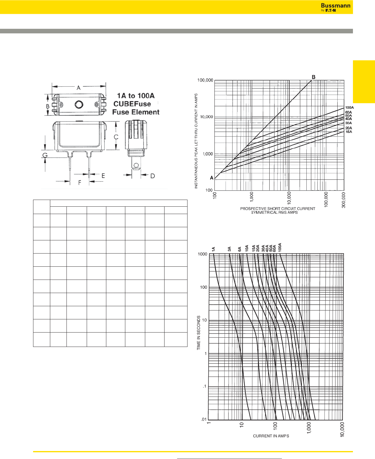
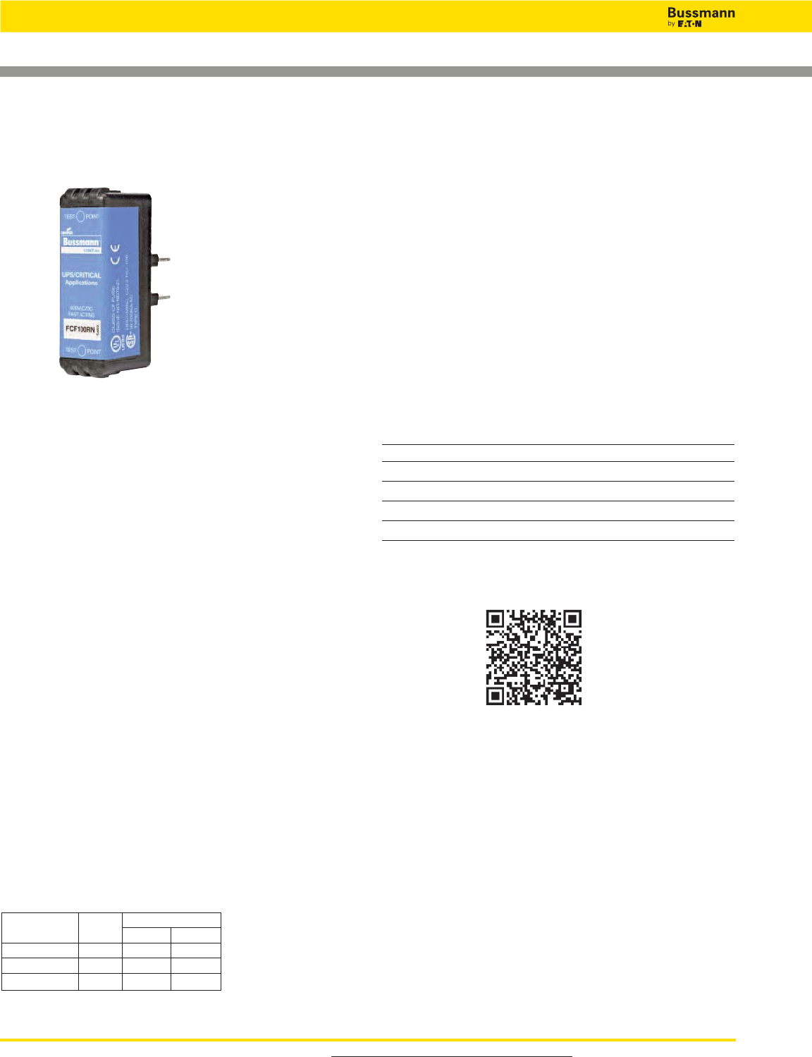
UPS & Critical Application Fast-Acting CUBEFuse™
Finger-safe Fuse
FCF Class CF Fuse
Carton Quantity and Weight
Amp Carton Weight Per Carton
Rating Qty. lbs kg
FCF-1-30A 12 1.39 0.63
FCF-35-60A 12 1.42 0.65
FCF-70-100A 6 1.74 0.79
Catalog Symbol: FCF_RN
Fast-Acting Fuse: 4 minutes maximum clearing time at 200%
rated current for 1 to 30A fuse
6 minutes maximum clearing time at 200%
rated current for 35 to 60A fuse
Dimensions: See Dimensions illustration.
Poles: 1-pole (gangable)
Ratings:
Volts — 600Vac (or less)
— 300Vdc (or less)
Amps — 1-100A
IR — 300kA RMS Sym. (UL)
— 200kA RMS Sym. (CSA)
— 50kA DC (UL & CSA)
Agency Information:
• UL Listed Fuse: Guide JFHR, File E4273
• CSA Certified Fuse: Class 1422- 02, File 53787
• CE compliance for the European Union low voltage directive
Other Ratings/Specifications:
Watts Loss at rated current: FCF15RN: 3.48W
FCF30RN: 5.45W
FCF60RN: 7.27W
Operating and Storage Temperature Range:
-40 to 80°C
Material Specifications:
• Case: Glass filled PES (Polyethersulfone)
• Terminals: Copper alloy
• Terminal plating: Electroless tin
Data Sheet: 2147
Features and Product Benefits
• The world’s first finger-safe power fuse system.
• Smallest footprint of any class fuse including Class J, CC, T
and RK.
• Class CF meets Class J fast-acting electrical
performance requirements.
• Faster response to damaging faults to help reduce
destructive thermal and magnetic forces.
• True fast-acting fuse construction.
• High interrupting rating to safely interrupt faults up to
300kA.
• No venting of arc or molten metal and gases during
opening.
• Low let-through currents under fault conditions.
Fuse Catalog Numbers Non-Indicating (Amps)
FCF1RN FCF20RN FCF45RN FCF90RN
FCF3RN FCF25RN FCF50RN FCF100RN
FCF6RN FCF30RN FCF60RN –
FCF10RN FCF35RN FCF70RN –
FCF15RN FCF40RN FCF80RN –
Scan this tag to get the latest product
information for the
New FCF CUBEFuse.
Recommended Fuse Holders For Class CF Fuses
• See pages 32 and 33
For product data sheets, visit www.cooperbussmann.com/DatasheetsEle 29
Low Voltage
Branch Circuit
Fuses
UPS & Critical Application Fast-Acting CUBEFuse™
Finger-safe Fuse
Data Sheet: 2147
FCF_RN Dimensions – in (mm)
Time-Current Characteristic Curves–Average Melt
Current Limitation Curves
100A
60A
10A
15A
20A
30A
40A
50A
1A
3A
6A
0.01
0.1
1
10
100
1000
1
10
100
1,000
10,000
TIME IN SECONDS
CURRENT IN AMPS
Fuse Dimensions - in (mm)
Amps A B C D E F G
1-15 1.88 0.75 1.00 0.23 0.04 0.63 0.28
(47.75) (19.05) (25.40) (5.84) (1.02) (15.93) (7.11)
20 1.88 0.75 1.00 0.31 0.04 0.63 0.28
(47.75) (19.05) (25.40) (7.87) (1.02) (15.93) (7.11)
25-30 1.88 0.75 1.00 0.31 0.04 0.63 0.28
(47.75) (19.05) (25.40) (7.87) (1.02) (15.93) (7.11)
35-40 2.13 1.00 1.13 0.36 0.04 0.63 0.38
(54.10) (25.40) (28.58) (9.10) (1.02) (15.93) (9.65)
45-50 2.13 1.00 1.13 0.44 0.04 0.63 0.38
(54.10) (25.40) (28.58) (11.13) (1.02) (15.93) (9.65)
60 2.13 1.00 1.13 0.44 0.04 0.63 0.38
(54.10) (25.40) (28.58) (11.13) (1.02) (15.93) (9.65)
70 3.01 1.00 1.26 0.49 0.06 0.58 0.38
(76.45) (25.40) (32.00) (12.45) (1.60) (14.78) (9.65)
80-90 3.01 1.00 1.26 0.49 0.06 0.58 0.38
(76.45) (25.40) (32.00) (12.45) (1.60) (14.78) (9.65)
100 3.01 1.00 1.26 0.57 0.06 0.58 0.38
(76.45) (25.40) (32.00) (14.48) (1.60) (14.78) (9.65)
A
30A
60A
15A
100A
100
1,000
10,000
100,000
100
1,000
10,000
100,000
INSTANTANEOUS PEAK LET THRU CURRENT IN AMPERES
PROSPECTIVE SHORT CIRCUIT CURRENT (SYMMETRICAL RMS AMPS)
B
300,000
Low Voltage, Branch Circuit Rated Fuses
For product data sheets, visit www.cooperbussmann.com/DatasheetsEle
30
Low Voltage, Branch Circuit Rated Fuses
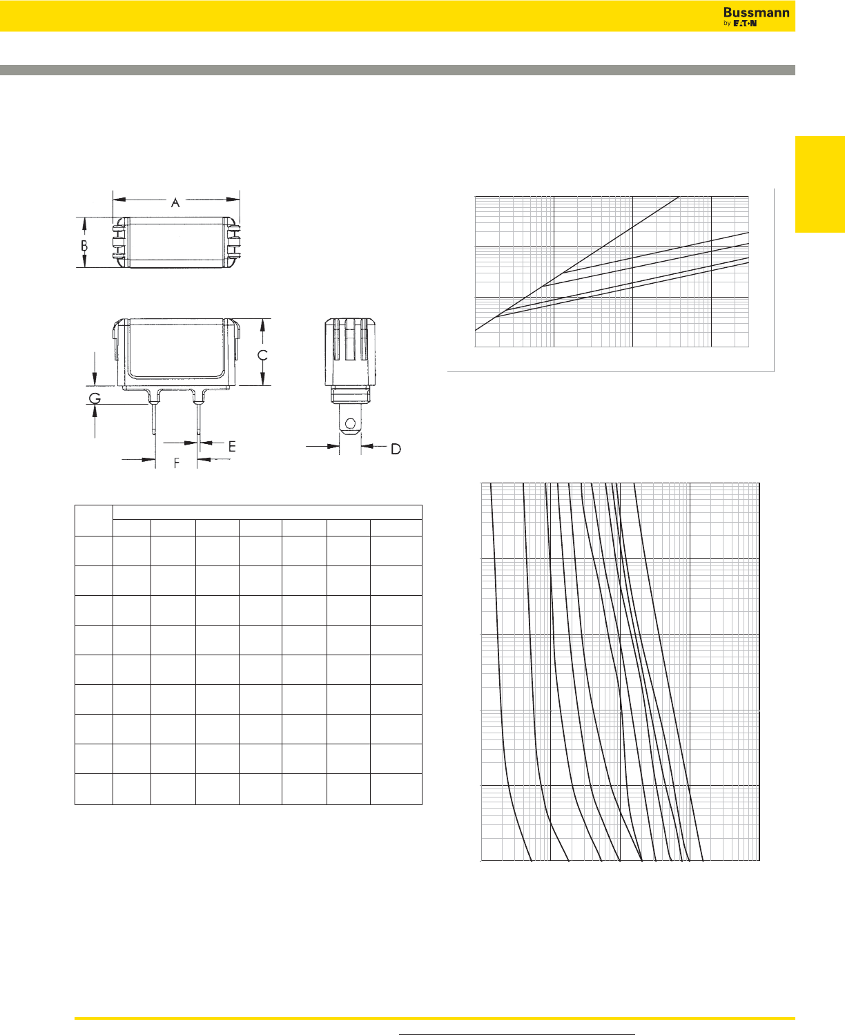
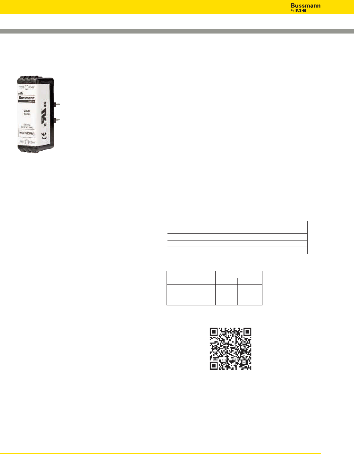
Wind Fast-Acting CUBEFuse™– Finger-safe Fuse
WCF Class CF Fuse
Data Sheet: 9009
Features and Product Benefits
• Maximize uptime and reliability using fuses designed and
listed to UL 248-1.
• Minimize chances of equipment failure and personnel injury
when using full range fuses having the industry’s fastest
response time to low-magnitude faults.
• Maximize return on investment with fuses proven to
withstand harsh temperatures.
• Minimize design time, operating outage time and
replacement cost with fuses qualified in excessively
changing enviromental conditions.
• Simplify compatibility with readily available industry
standard Class CF holders.
• Temperature Derating: Designed to maximize rated capacity
in elevated environmental temperatures.
• Overload Protection: Proven to clear faults faster than the
UL requirement.
• Power Loss: Minimal energy consumption leading to
increased efficiency.
Amp Carton Weight Per Carton
Rating Qty. lbs kg
WCF1-30A 12 1.39 0.63
WCF35-60A 12 1.42 0.65
WCF70-100A 6 1.74 0.79
Carton Quantity and Weight
Catalog Numbers (amp rating)
Non-Indicating Wind CUBEFuse
WCF1RN WCF15RN WCF35RN WCF60RN WCF100RN
WCF3RN WCF20RN WCF40RN WCF70RN —
WCF6RN WCF25RN WCF45RN WCF80RN —
WCF10RN WCF30RN WCF50RN WCF90RN —
Catalog Symbol: WCF_RN
Description: Finger-safe, fast-acting CUBEFuse for wind
power generation.
Electrical Characteristics: Maximum clearing time at 200%
rated current:
• 4 Minutes for 1 to 30A fuses
• 6 Minutes for 35 to 60A fuses
• 8 Minutes for 70 to 100A fuses
Agency Information:
• UL Recognized Fuse: Guide JFHR, File E56412
• cURus component certified C22.2
• CE compliance for the European Union low voltage
directive
Other Ratings/Specifications:
Watts Loss at Rated Current: WCF15RN: 3.48W
WCF30RN: 5.45W
WCF60RN: 7.27W
WCF100RN: 11.50W
Operating and Storage Temperature Range: -40 to 90°C
Material Specifications:
• Case: Glass filled PES (Polyethersulfone)
• Terminals: Copper alloy
• Terminal plating: Electroless tin
Installation:
Fits 690V WCF holders as listed in the table
Application:
• Wind Systems:
- Transformer protection
- Pitch and speed control
- Turbine HVAC and lighting
Ratings:
Volts — 690Vac
Amps — 1-100A
IR — 50kA AC (1-60A)
IR — 30kA AC (70-100A)
Scan this tag to get the latest product
information for the
New WCF CUBEFuse.
Recommended Fuse Holders For Class CF Fuses
• See pages 32 and 33
For product data sheets, visit www.cooperbussmann.com/DatasheetsEle 31
Low Voltage
Branch Circuit
Fuses
Wind Fast-Acting CUBEFuse™– Finger-safe Fuse
WCF_RN Dimensions – in (mm)
Data Sheet: 2155
Current Limitation Curves
60A
100A
40A
50A
35A
100
1,000
10,000
100,000
100
1,000
10,000
100,000
INSTANTANEOUS PEAK LET THRU CURRENT IN AMPS
PROSPECTIVE SHORT CIRCUIT CURRENT
SYMMETRICAL RMS AMPS
B
300,000
A
Fuse Dimensions - in (mm)
Amps A B C D E F G
35-40 2.13 1.00 1.13 0.36 0.04 0.63 0.38
(54.10) (25.40) (28.58) (9.10) (1.02) (15.93) (9.65)
45-50 2.13 1.00 1.13 0.44 0.04 0.63 0.38
(54.10) (25.40) (28.58) (11.13) (1.02) (15.93) (9.65)
60 2.13 1.00 1.13 0.44 0.04 0.63 0.38
(54.10) (25.40) (28.58) (11.13) (1.02) (15.93) (9.65)
70 3.01 1.00 1.26 0.49 0.06 0.58 0.38
(76.45) (25.40) (32.00) (12.45) (1.60) (14.78) (9.65)
80-90 3.01 1.00 1.26 0.49 0.06 0.58 0.38
(76.45) (25.40) (32.00) (12.45) (1.60) (14.78) (9.65)
100 3.01 1.00 1.26 0.57 0.06 0.58 0.38
(76.45) (25.40) (32.00) (14.48) (1.60) (14.78) (9.65)
Low Voltage, Branch Circuit Rated Fuses
Time-Current Characteristic Curves–Average Melt
100
A
60A
10A
15A
20A
30A
40A
50A
1A
3A
6A
0.01
0.1
1
10
100
1000
1
10
100
1,000
10,000
TIME
IN
SECONDS
CURRENT IN AMPS
Low Voltage, Branch Circuit Rated Fuses
32 For product data sheets, visit www.cooperbussmann.com/DatasheetsEle
CUBEFuse Fuse Holder
CUBEFuse™
Finger-safe Fuse Holder System
Catalog Symbols:
Ampacity
600V 690V (Wind) (holds any CUBEFuse)
TCFH30N TCFH30NW (1-30A)
TCFH60N TCFH60NW (1-60A)
TCFH100N TCFH100NW (1-100A)
Construction: Finger-safe
Mounting: 35mm DIN-Rail or panel mount
Ratings:
Volts: 600V (UL, CSA)
690V (cURus - Wind version)
Withstand Rating: 300kA RMS Sym. (UL)
200kA RMS Sym. (CSA)
100kA DC (UL & CSA)
50kA AC (cURus, 1-60A Wind version)
Agency Information:
• UL Listed Fuse Holder: Guide IZLT, File E14853
• CSA Certified Fuse Holder: Class 6225-01, File 47235
• cURus component Certified
• CE compliance for the European Union low voltage directive
Operating and Storage Temperature Range:
-40 to 80°C
Material Specifications:
• Holder case: Glass filled PBT
• Interface clips: Copper alloy
• Interface clip plating: Tin
• Terminals: Steel
• DIN Rail spring: Stainless steel
Data Sheet: 9007
CUBEFuse CUBEFuse Type and Ampacity Range Per CUBEFuse Holder
Holder Non-Indicating Indicating
Catalog Time-Delay Time-Delay Fast-Acting Photovoltaic Wind
Number Volts TCF_RN TCF_ FCF_RN PVCF_RN WCF_RN
TCFH30N 600 1-30 6-30 1-30 — —
TCFH60N 600 1-60 6-60 1-60 35-60 —
TCFH100N 600 1-100 6-100 1-100 35-100 —
TCFH30NW 690 — — — — 1-30
TCFH60NW 690 — — — — 1-60
TCFH100NW 690 — — — — 1-100
CUBEFuse™ Holder Applications
Terminal Torque Ratings by Conductor and Holder Size (75°C Cu only)
TCFH30N / TCFH30NW TCFH60N / TCFH60NW TCFH100N / TCFH100NW
Single Dual Single Dual Single Dual
10-8AWG 25Lb-In 18-10AWG 25Lb-In* 14-10AWG 20Lb-In 18-10AWG 20Lb-In 18-10AWG 25Lb-In** 6AWG 45Lb-In†
18-12AWG 20Lb-In 8-4AWG 35Lb-In 8-6AWG 35Lb-In 8-1AWG 40Lb-In†
* 18-10AWG Stranded, 14-18AWG solid
** Solid and stranded
† Stranded

For product data sheets, visit www.cooperbussmann.com/DatasheetsEle 33
Low Voltage
Branch Circuit
Fuses
Low Voltage, Branch Circuit Rated Fuses
Diamensions for CUBEFuse Fuse Holder
CUBEFuse™
Finger-safe Fuse Holder System
Data Sheet: 9007
Catalog CUBEFuse Wire Range (Cu/AWG) Dimensions - in (mm)
Number Amp Range Single Dual H I J K L M
TCFH30N 1-30 14-8 14-10 2.30 0.76 1.36 0.15 — —
TCFH30NW (58.5) (19.37) (34.24) (3.76) — —
TCFH60N 1-60 14-4 10-6 2.60 1.03 1.60 0.17 — —
TCFH60NW (66.12) (26.23) (40.64) (4.34) — —
TCFH100N 1-100 10-1 6 2.91 1.05 2.01 0.15 0.80 2.51
TCFH100NW (73.81) (26.74) (50.93) (3.81) (20.39) (63.65)
CUBEFuse™ Holder Catalog Numbers
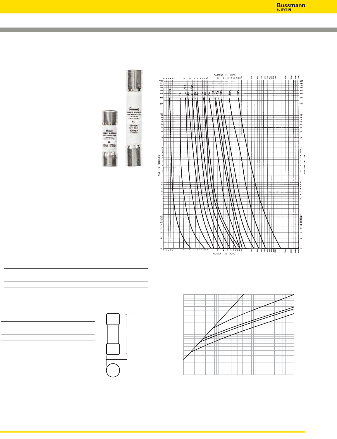
For product data sheets, visit www.cooperbussmann.com/DatasheetsEle
34
Low Voltage, Branch Circuit Rated Fuses
Time-delay Fuses
Data Sheet: 1024
Specifications
Description: Fast-acting (1⁄2-6A),
time-delay (7-60A)fuse.
Dimensions: See dimensions
illustration.
Ratings:
Volts — 600Vac (1⁄2-20A)
— 480Vac (25-60A)
— 170Vdc (1⁄2-20A)
— 300Vdc (30 & 60A only)
Amps — 1⁄2-60A
IR — 100kA RMS Sym.
— 10kA DC
Agency Information: CE, Std. 248-
5, Class G, UL Listed, Guide JDDZ, File E4273, CSA
Certified, Class 1422-01, File 53787.
Features and Benefits
• Current limiting for component protection, providing Class G
energy-limitation for branch circuit protection.
• 100kA interrupting rating provides cost-effective branch
circuit fusing.
• Variations in length help prevent overfusing.
Typical Applications
• Fusible Branch Panelboards
• HVAC Branch Circuit Protection
Catalog Numbers (Amps)
SC-1⁄2SC-2-1⁄2SC-6 SC-12 SC-30 SC-50
SC-1 SC-3 SC-7 SC-15 SC-35 SC-60
SC-1-1⁄2SC-4 SC-8 SC-20 SC-40
SC-2 SC-5 SC-10 SC-25 SC-45
SC Class G
Recommended Fuse Holders & Blocks For Class G Fuses
• See page 18
Dimensions -in (mm)
Fuse Amps Length Diameter
SC-1⁄2to -15 1.31 (33.3) 0.41” (10.4)
SC-20 1.41 (35.8) 0.41” (10.4)
SC-25 to -30 1.62 (41.2) 0.41” (10.4)
SC-35 to -60 2.25 (57.1) 0.41” (10.4)
A
(Length)
0.41"
(10.41mm
)
Current Limitation Curves
Time-Current Characteristic Curves—Average Melt
B60
30
20
15
AMP
RATING
A
10,000
1,000
100
100
1,000
10,000
100,000
INSTANTANEOUS PEAK LET-THROUGH
CURRENT IN AMPS
RMS SYMMETRICAL CURRENTS IN AMPS
A–B=ASYMMETRICAL AVAILABLE PEAK (2.3 X SYMM RMS AMPS)
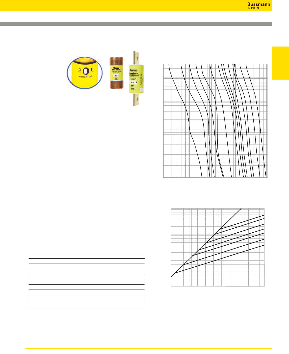
For product data sheets, visit www.cooperbussmann.com/DatasheetsEle 35
Low Voltage
Branch Circuit
Fuses
Low-Peak™Dual-element, Time-delay Fuses
LPJ_SP Class J
Available With
Indication
Specifications
Description:
Dual-element,
time-delay fuse;
10 seconds (minimum) at 500% rated amps. Now
available with optional indication on select ratings
(see Catalog Numbers table).
Dimensions: See page 11 for Class J dimensions.
Ratings:
Volts — 600Vac (or less)
— 300Vdc (or less)
Amps — 1-600A
IR — 300kA RMS Sym.
— 100kA DC
Agency Information: CE, UL Listed - Special Purpose*,
Guide JFHR, File E56412, CSA Certified (200k AIR) Class J
per CSA-22.2 No. 248.8, Class 1422-02, File 53787.
Features and Benefits
• Separate overload and short-circuit elements provide time
delay for sizing of high inrush loads linked with Class J
current limitation.
• Selective coordination ratio of 2:1 (within Low-Peak fuse
family) prevents electrical shutdowns from extending
beyond the failed circuit.
• Series combination ratings with branch circuit breakers
allows broad range of coverage, independent of breaker
manufacturer.
Typical Applications
• Power Panelboards
• Branch Circuit Breaker Panelboard Mains
• Machinery Disconnects
• Industrial Control
Catalog Numbers (Amps)
LPJ-1SP LPJ-4-1⁄2SP LPJ-25SP** LPJ-125SP**
LPJ-1-1⁄4SP LPJ-5SP LPJ-30SP** LPJ-150SP**
LPJ-1-6⁄10SP LPJ-5-6⁄10SP LPJ-35SP** LPJ-175SP**
LPJ-1-8⁄10SP LPJ-6SP** LPJ-40SP** LPJ-200SP**
LPJ-2SP LPJ-7SP** LPJ-45SP** LPJ-225SP**
LPJ-2-1⁄4SP LPJ-8SP** LPJ-50SP** LPJ-250SP**
LPJ-2-1⁄2SP LPJ-9SP** LPJ-60SP** LPJ-300SP**
LPJ-2-8⁄10SP LPJ-10SP** LPJ-70SP** LPJ-350SP**
LPJ-3SP LPJ-12SP** LPJ-80SP** LPJ-400SP**
LPJ-3-2⁄10SP LPJ-15SP** LPJ-90SP** LPJ-450SP**
LPJ-3-1⁄2SP LPJ-17-1⁄2SP** LPJ-100SP** LPJ-500SP**
LPJ-4SP LPJ-20SP** LPJ-110SP** LPJ-600SP**
*Meets all performance requirements of UL Standard 248-8 for Class J fuses.
**Available with optional permanent replace fuse indication. To order, place “I” at end of
catalog number. Example: LPJ-6SPI.
Available with silver plated terminals. Add SP/ in front of Catalog Number.
AMP
RATING
1A
3A
6A
300
100
10
1
.1
.01
TIME IN SECONDS
10A
15A
30A
60A
100A
400A
1,000
100
CURRENT IN AMPS
600A
125A
250A
200A
80A
200
10
10,000
1
Recommended Fuse Holders & Blocks For Class J Fuses
• See page 20
Time-Current Characteristic Curves–Average Melt
Current Limitation Curves
INSTANTANEOUS PEAK LET-THRU CURRENT IN AMPS
100,000
10,000
1,000
100
B
A
PROSPECTIVE SHORT-CIRCUIT CURRENT
SYMMETRICAL RMS AMPS
100
1,000
10,000
100,000
200,000
600A
400A
200A
100A
60A
30A
15A
RA
AMP
TING
LPJ Current Limitation Curves
300,000
Data Sheets: 1006 (0-60) and 1007 (70-600)
With indication 1062 (6-60) and 1063 (70-600)
Low Voltage, Branch Circuit Rated Fuses

For superior electrical protection, Bussmann recommends upgrading JKS fuse
applications to Low-Peak LPJ fuses See page 35.
Recommended Fuse Holders & Blocks For Class J Fuses
• See page 20
For product data sheets, visit www.cooperbussmann.com/DatasheetsEle
36
Low Voltage, Branch Circuit Rated Fuses
Limitron™Fast-acting Fuses
Specifications
Description: Fast-acting, cur-
rent-limiting fuse.
Dimensions: See page 15 for
Class J dimensions.
Ratings:
Volts — 600Vac (or less)
Amps — 1-600A
IR — 200kA RMS Sym.
Agency Information: CE, Std.
248-8, Class J, UL
Listed, Guide JDDZ,
File E4273, CSA
Certified, Class 1422-02, File 53787.
Features and Benefits
• Current limitation for non-inductive circuits provides Class J
current-limiting response to maximum ground fault and
short-circuit conditions.
• 200kA interrupting rating provides high ratings at all circuit
locations.
• Economical solutions for high-fault circuits.
Typical Applications
• Power Panelboards
• Machinery Disconnects
Catalog Numbers (Amps)
JKS-1 JKS-15 JKS-70 JKS-225
JKS-2 JKS-20 JKS-80 JKS-250
JKS-3 JKS-25 JKS-90 JKS-300
JKS-4 JKS-30 JKS-100 JKS-350
JKS-5 JKS-35 JKS-110 JKS-400
JKS-6 JKS-40 JKS-125 JKS-450
JKS-8 JKS-45 JKS-150 JKS-500
JKS-10 JKS-50 JKS-175 JKS-600
JKS-12 JKS-60 JKS-200
Data Sheet: 1026 (1-60) and 1027 (70-600)
JKS Class J
CURRENT IN AMPS
60A
100A
200A
30A
400A
AMP
RATING
600A
JKS
40
100
1,000
10,000
300
100
10
1
.1
.01
TIME IN SECONDS
600
400
200
AMP
RATING
100
INSTANTANEOUS PEAK LET-THRU CURRENT IN AMPS
1,000
10,000
100,000
200,000
400,000
100,000
10,000
1,000
RMS SYMMETRICAL CURRENTS IN AMPS
A–B=ASYMMETRICAL AVAILABLE PEAK (2.3 X SYMM RMS AMPS)
B
A
60
30
Time-Current Characteristic Curves—Average Melt
Current Limitation Curves
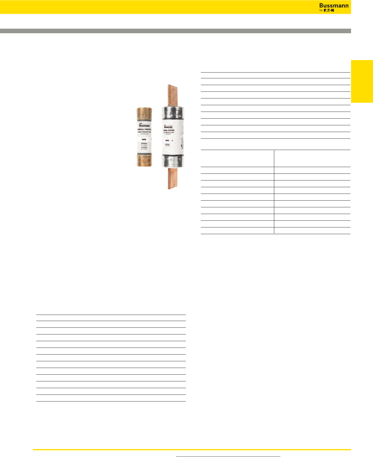
For product data sheets, visit www.cooperbussmann.com/DatasheetsEle 37
Low Voltage
Branch Circuit
Fuses
One-time General Purpose Fuses
Specifications
Description: General purpose,
non-current-limiting fuses.
Dimensions: See page 15 for
dimensions.
Ratings:
Volts — NON:
— 250Vac
— 125Vdc (0-100A)
— NOS:
— 600Vac
Amps — 1⁄8-600A
IR — 50kA RMS Sym. (NON & NOS Class
K5 0-60A)
— 10kA RMS Sym. (NON & NOS Class H65-600A)
— 50kA @ 125Vdc (NON Class K5 0-60A)
— 10kA @ 125Vdc (NON Class H 65-100A)
Agency Information: CE, UL Listed – 250V: Class K5
(0-60A), Std. 248-9, Class H (65-600A), Std. 248-6, (125Vdc:
NON 0-100), 600V: Class K5 (0-60A), Std. 248-9, Class H
(70-600A), Std. 248-6, Guide JDDZ, File E4273, CSA
Certified – 250V: (0-12, 65-600)†, 600V: (0-600), Class
1421-01, File 53787.
† For CSA Certified 15-60A Ratings, see PON Data Sheet 4126
Features and Benefits
• Original fuse providing circuit protection.
Typical Applications
• Light Duty Circuit Locations
NON (250Vac) Catalog Numbers (Amps)
NON-1⁄8NON-5 NON-40 NON-175
NON-1⁄2NON-6 NON-45 NON-200
NON-3⁄4NON-6-1⁄4NON-50 NON-225
NON-8⁄10 NON-7 NON-60 NON-250
NON-1 NON-8 NON-65 NON-300
NON-1-1⁄4NON-9 NON-70 NON-350
NON-1-1⁄2NON-10 NON-75 NON-400
NON-1-6⁄10 NON-12 NON-80 NON-450
NON-2 NON-15 NON-90 NON-500
NON-2-1⁄2NON-20 NON-100 NON-600
NON-3 NON-25 NON-110
NON-3-2⁄10 NON-30 NON-125
NON-4 NON-35 NON-150
NOS (600Vac) Catalog Numbers (Amps)
NOS-1 NOS-12 NOS-70 NOS-200
NOS-2 NOS-15 NOS-75 NOS-225
NOS-3 NOS-20 NOS-80 NOS-250
NOS-4 NOS-25 NOS-90 NOS-300
NOS-5 NOS-30 NOS-100 NOS-350
NOS-6 NOS-35 NOS-110 NOS-400
NOS-7 NOS-40 NOS-125 NOS-450
NOS-8 NOS-45 NOS-150 NOS-500
NOS-9 NOS-50 NOS-175 NOS-600
NOS-10 NOS-60
Recommended Fuse Reducers
250V 600V
Fuse Clip Catalog Fuse Clip Catalog
Amp Amp Number Amp Amp Number
Size Size (Pair) Size Size (Pair)
30 60 NO.263 30 60 NO.663
30 100 NO.213 30 100 NO.216
60 100 NO.216 60 100 NO.616
60 200 NO.226 60 200 NO.626
100 200 NO.2621 100 200 NO.2621
100 400 NO.2641 100 400 NO.2641
200 400 NO.2642 200 400 NO.2642
100 600 NO.2661 100 600 NO.2661
200 600 NO.2662 200 600 NO.2662
400 600 NO.2664 400 600 NO.2664
Data Sheet: 1030
NON (250Vac/125Vdc) Class K5 & H
NOS (600Vac) Class K5 & H
For superior electrical protection, Bussmann recommends upgrading NON
(250Vac) and NOS (600Vac) fuse applications to Low-Peak LPN-RK (250Vac)
and LPS-RK (600Vac) fuses See page 41.
Recommended Fuse Holders & Blocks For Class K5 & H
250V & 600V Fuses
• See page 18
Low Voltage, Branch Circuit Rated Fuses
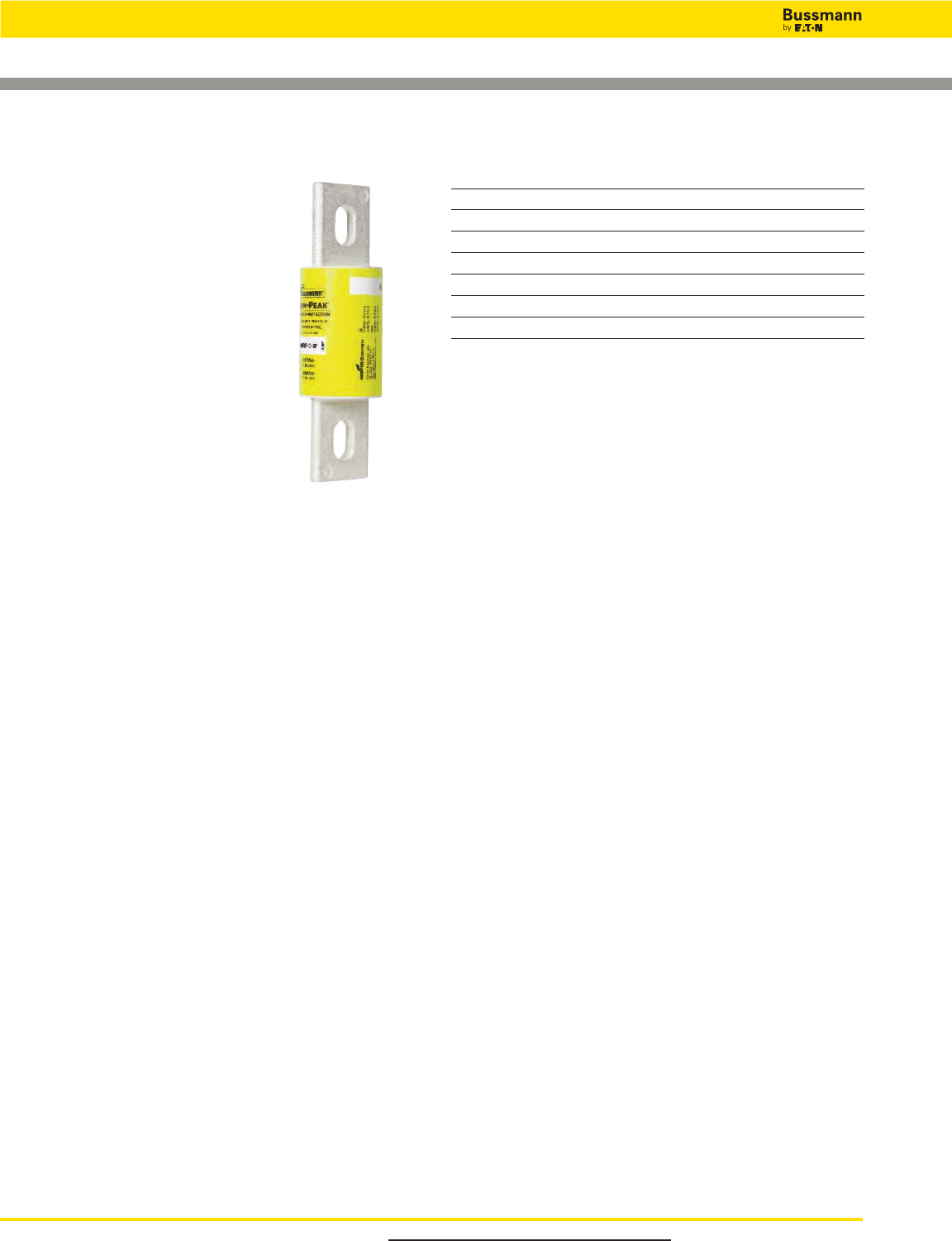
For product data sheets, visit www.cooperbussmann.com/DatasheetsEle
38
Low Voltage, Branch Circuit Rated Fuses
Low-Peak™Time-delay Fuses
Specifications
Description: Time-delay fuse – 4
seconds (minimum) at 500% rated amps.
Dimensions: See page 16 for Class L
dimensions.
Ratings:
Volts — 600Vac (or less)
— 300Vdc (601-2000A)
Amps — 601-6000A
(use KRP-CL for current ratings
under 601A)
IR — 300kA RMS Sym.
— 100kA DC
Agency Information: CE, UL Listed-
Special Purpose (meets all performance
requirements of UL Standard 248-10 for Class L
fuses),Guide JFHR, File E56412, CSA Certified (200k AIR),
Class 1422-02, File 53787, Class L per CSA C22.2, No.
248.10.
Features and Benefits
• Time-delay of four seconds at five times rating allows closer
sizing on large motor loads combined with Class L current
limitation.
• Selective coordination ratio of 2:1 (within Low-Peak fuse
family) prevents electrical shutdowns from extending
beyond the failed circuit.
• Interrupting rating of 300kA RMS symmetrical provides
adequate ratings without obsolescence for all electrical
systems, big or small.
• Quality construction, using high-grade materials, provides
lower watts loss and operating temperatures with superior
arc quenching during current-limiting action.
Typical Applications
• Large Distribution Switchboards
• Power Panelboards
• Large Machinery Disconnects
Catalog Numbers (Amps)
KRP-C-601SP KRP-C-1000SP KRP-C-1800SP KRP-C-3500SP
KRP-C-650SP KRP-C-1100SP KRP-C-1900SP KRP-C-4000SP
KRP-C-700SP KRP-C-1200SP KRP-C-2000SP KRP-C-4500SP
KRP-C-750SP KRP-C-1350SP KRP-C-2001SP KRP-C-5000SP
KRP-C-800SP KRP-C-1400SP KRP-C-2400SP KRP-C-6000SP
KRP-C-801SP KRP-C-1500SP KRP-C-2500SP
KRP-C-900SP KRP-C-1600SP KRP-C-3000SP
Data Sheets: 1008 and 1009
KRP-C_SP Class L
Recommended Fuse Holders & Blocks For Class L Fuses
• See page 19
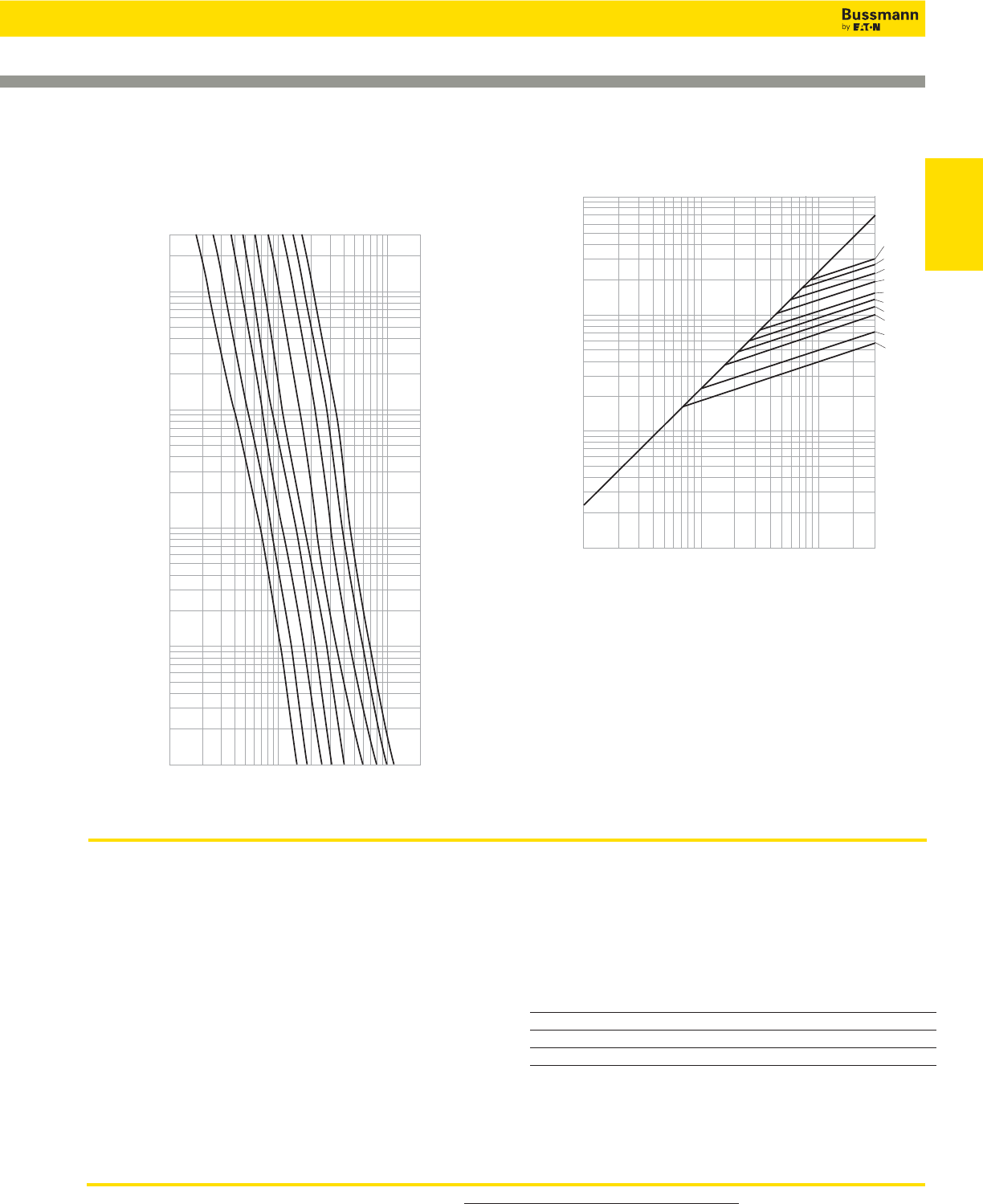
For product data sheets, visit www.cooperbussmann.com/DatasheetsEle 39
Low Voltage
Branch Circuit
Fuses
Low-Peak™Time-delay Fuses
1000,000
10,000
1,000
10,000
300,000
INSTANTANEOUS PEAK LET-THRU CURRENT IN AMPS
PROSPECITVE SHORT-CIRCUIT CURRENT
SYMMETRICAL RMS AMPS
100,000
100,000
6,000
A
5,000
A
4,000
A
3,000
A
2,500
A
2,000
A
1,600
A
1,200
A
800A
601A
A
AMP
RATING
B
1,000
300
100
10
1
.1
.01
1,000
10,000
100,000
200,000
CURRENT IN AMPS
TIME IN SECONDS
800A
1200A
1600A
2000A
2500A
3000A
4000A
5000A
6000A
AMP
RA TING
Current Limitation CurvesTime-Current Characteristic Curves—Average Melt
KRP-CL Current-limiting, Time-delay
Fuses
Specifications
Description: Current-limiting, time-delay fuse.
Dimensions: See page 16 for Class L dimensions.
Ratings:
Volts — 600Vac (or less)
Amps — 225-600A
IR — 200kA RMS Sym.
Features and Benefits
• Time-delay of four seconds at five times rating allows closer
sizing inductive loads coupled with an equivalent Class L
current limitation.
• Class L case size for amp ratings from 225 to 600A allows
downsize fusing of large Class L fused switches for improved
circuit protection.
Typical Applications
• Large Distribution Switchboards
• Power Panelboards
• Machinery Disconnects
Catalog Numbers (Amps)
KRP-CL-225 KRP-CL-350 KRP-CL-500
KRP-CL-250 KRP-CL-400 KRP-CL-600
KRP-CL-300 KRP-CL-450
Data Sheets: 1008 and 1009
Data Sheet: 1016
Recommended Fuse Holders & Blocks For Class L Fuses
• See page 19
Low Voltage, Branch Circuit Rated Fuses
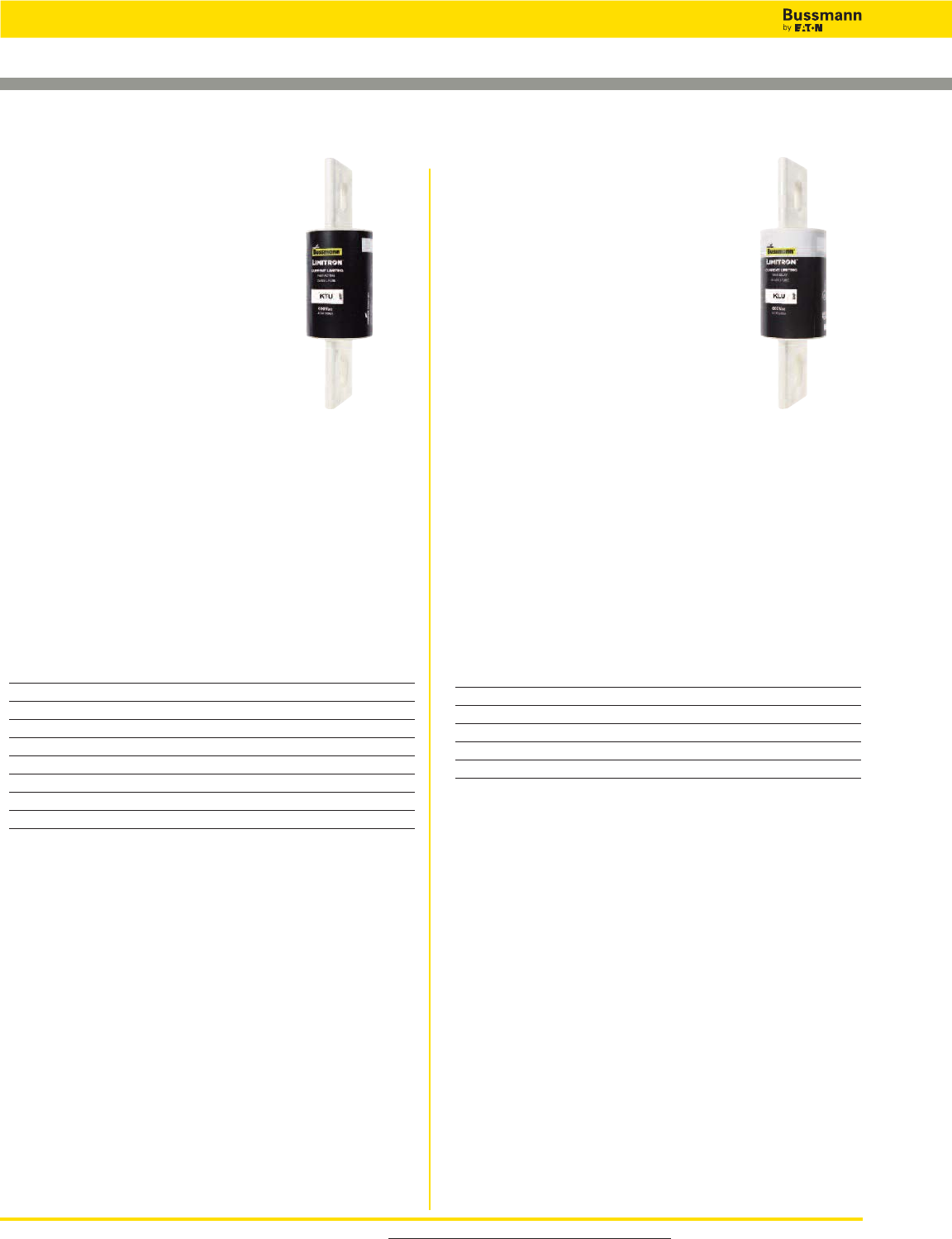
For product data sheets, visit www.cooperbussmann.com/DatasheetsEle
40
Low Voltage, Branch Circuit Rated Fuses
Limitron™Fuses
Specifications
Description: Fast-acting, bolt-mount
fuse.
Dimensions: See page 22 for Class L
dimensions.
Ratings:
Volts — 600Vac (or less)
Amps — 601-6000A
IR — 200kA RMS Sym.
Agency Information: CE, Std. 248-10,
Class L, UL Listed, Guide JDDZ, File
E4273 CSA Certified, Class 1422-02, File 53787.
Features and Benefits
• 200kA interrupting rating provides high ratings at all
circuit locations.
• Economical solutions for high-fault circuits.
• Quality construction using high-grade materials provides
lower watts loss and operating temperatures with superior
arc quenching during current-limiting action.
Typical Applications
• Large Distribution Switchboards
• Power Panelboards
Catalog Number (Amps)
KTU-601 KTU-1000 KTU-2001
KTU-650 KTU-1100 KTU-2400
KTU-700 KTU-1200 KTU-2500
KTU-750 KTU-1400 KTU-3000
KTU-800 KTU-1500 KTU-3500
KTU-801 KTU-1600 KTU-4000
KTU-850 KTU-1800 KTU-5000
KTU-900 KTU-2000 KTU-6000
Specifications
Description: Time-delay, bolt-mount fuse
- 5 seconds (minimum) at 500% rated
amps. See KRP-CL for amp ratings below
601A.
Dimensions: See page 22 for Class L
dimensions.
Ratings:
Volts — 600Vac (or less)
Amps — 601-4000A
IR — 200kA RMS Sym.
Agency Information: CE, Std. 248-10,
Class L, UL Listed, Guide JDDZ, File E4273, CSA Certified,
CSA Class 1422-02, File 53787.
Features and Benefits
• 200kA interrupting rating provides high ratings at all circuit
locations.
• Economical solutions for high fault circuits.
Typical Applications
• Large Distribution Switchboards
• Power Panelboards
• Large Machinery Disconnects
Catalog Numbers (Amps)
KLU-601 KLU-1200 KLU-2500
KLU-650 KLU-1500 KLU-3000
KLU-700 KLU-1600 KLU-4000
KLU-800 KLU-1800
KLU-1000 KLU-2000
Data Sheet: 1010 Data Sheet: 1013
KTU Class L KLU Class L
For superior electrical protection, Cooper Bussmann recommends upgrading
KLU fuse applications to Low-Peak KRP-C fuses See page 38.
Recommended Fuse Holders & Blocks For Class L Fuses
• See page 19
For superior electrical protection, Cooper Bussmann recommends upgrading
KTU fuse applications to Low-Peak KRP-C fuses See page 38.
Recommended Fuse Holders & Blocks For Class L Fuses
• See page 19
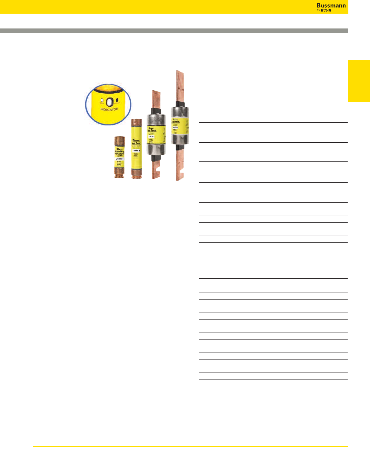
For product data sheets, visit www.cooperbussmann.com/DatasheetsEle 41
Low Voltage
Branch Circuit
Fuses
Typical Applications
• Large Distribution Switchboards
• Power Panelboards
• Motor Control Centers
• Machinery Disconnect Switches
LPN Catalog Numbers (Amps)
LPN-RK-1⁄10SP LPN-RK-3-1⁄2SP LPN-RK-60SP**
LPN-RK-15⁄100SP LPN-RK-4SP LPN-RK-70SP**
LPN-RK-2⁄10SP LPN-RK-4-1⁄2SP LPN-RK-80SP**
LPN-RK-3⁄10SP LPN-RK-5SP LPN-RK-90SP**
LPN-RK-4⁄10SP LPN-RK-5-6⁄10SP LPN-RK-100SP**
LPN-RK-1⁄2SP LPN-RK-6SP LPN-RK-110SP**
LPN-RK-6⁄10SP LPN-RK-6-1⁄4SP LPN-RK-125SP**
LPN-RK-8⁄10SP LPN-RK-8SP LPN-RK-150SP**
LPN-RK-1SP LPN-RK-9SP LPN-RK-175SP**
LPN-RK-1-1⁄8SP LPN-RK-10SP LPN-RK-200SP**
LPN-RK-1-1⁄4SP LPN-RK-12SP LPN-RK-225SP**
LPN-RK-1-4⁄10SP LPN-RK-15SP LPN-RK-250SP**
LPN-RK-1-6⁄10SP LPN-RK-17-1⁄2SP LPN-RK-300SP**
LPN-RK-1-8⁄10SP LPN-RK-20SP LPN-RK-350SP**
LPN-RK-2SP LPN-RK-25SP LPN-RK-400SP**
LPN-RK-2-1⁄4SP LPN-RK-30SP LPN-RK-450SP**
LPN-RK-2-1⁄2SP LPN-RK-35SP** LPN-RK-500SP**
LPN-RK-2-8⁄10SP LPN-RK-40SP** LPN-RK-600SP**
LPN-RK-3SP LPN-RK-45SP**
LPN-RK-3-2⁄10SP LPN-RK-50SP**
*Meets all performance requirements of UL Standard 248-12 for Class RK1 fuses.
**Available with optional indication. To order, place “I” at end of Catalog Number. Example:
LPN-RK-35SPI.
0-60A fuses available with Nickel plate option. (Ex: LPS-RK30SPNP) 70-600A fuses available
with Tin plate option. Example: LPS-RK-100SP-TP.
LPS Catalog Numbers - (Amps)
LPS-RK-1⁄10SP LPS-RK-2-1⁄4SP LPS-RK-10SP** LPS-RK-100SP**
LPS-RK-2⁄10SP LPS-RK-2-1⁄2SP LPS-RK-12SP** LPS-RK-110SP**
LPS-RK-3⁄10SP LPS-RK-2-8⁄10SP LPS-RK-15SP** LPS-RK-125SP**
LPS-RK-4⁄10SP LPS-RK-3SP LPS-RK-17-1⁄2SP** LPS-RK-150SP**
LPS-RK-1⁄2SP LPS-RK-3-2⁄10SP LPS-RK-20SP** LPS-RK-175SP**
LPS-RK-6⁄10SP LPS-RK-3-1⁄2SP LPS-RK-25SP** LPS-RK-200SP**
LPS-RK-8⁄10SP LPS-RK-4SP LPS-RK-30SP** LPS-RK-225SP**
LPS-RK-1SP LPS-RK-4-1⁄2SP LPS-RK-35SP** LPS-RK-250SP**
LPS-RK-1-1⁄8SP LPS-RK-5SP LPS-RK-40SP** LPS-RK-300SP**
LPS-RK-1-1⁄4SP LPS-RK-5-6⁄10SP LPS-RK-45SP** LPS-RK-350SP**
LPS-RK-1-4⁄10SP LPS-RK-6SP** LPS-RK-50SP** LPS-RK-400SP**
LPS-RK-1-1⁄2SP LPS-RK-6-1⁄4SP** LPS-RK-60SP** LPS-RK-450SP**
LPS-RK-1-6⁄10SP LPS-RK-7SP** LPS-RK-70SP** LPS-RK-500SP**
LPS-RK-1-8⁄10SP LPS-RK-8SP** LPS-RK-80SP** LPS-RK-600SP**
LPS-RK-2SP LPS-RK-9SP** LPS-RK-90SP**
*Meets all performance requirements of UL Standard 248-12 for Class RK1 fuses.
**Available with optional replace fuse indication. To order, place “I” at end of Catalog
Number. Example: LPS-RK-15SPI.
Low-Peak™Dual-element, Time-delay Fuses
LPN-RK_SP (250V) Class RK1
LPS-RK_SP (600V) Class RK1
Available With
Indication
Specifications
Description:
Current-limiting,
dual-element,
time-delay fuse; 10 seconds
(minimum) at 500% rated amps
(8 seconds for 0-30A sizes).
Now available with optional
indication on select ratings
(see Catalog Numbers table).
Dimensions: See page 15 for
Class RK1 dimensions.
Ratings:
Volts LPN-RK:
— 250Vac (or less)
— 125Vdc (0-60A)
— 250Vdc (70-600A)
LPS-RK:
— 600Vac (or less)
— 300Vdc
Amps — 1⁄10-600A
IR — 300kA RMS Sym.
— 100kA DC
Agency Information: CE, UL Listed – Special Purpose*,
Guide JFHR, File E56412, CSA Certified (200k AIR), Class
RK1 per CSA C22.2, No. 248.12, Class 1422-02, File 53787.
Features and Benefits
• Separate overload and short-circuit elements provide time
delay for close sizing of high inrush loads linked with RK1
current-limitation and selective coordination ratio of 2:1
(within Low-Peak fuse family) prevents widespread
blackouts.
• Inventory consolidation of Class RK1, RK5 and H fuses for
reduced SKU investment and minimizing potential for
misapplying fuse.
• 300kA RMS symmetrical interrupting rating provides
adequate ratings without obsolescence for all electrical
systems, big or small.
• Insulated end caps reduces exposure to live parts and
extends air gap to distance between blades of adjacent
mounted fuses or to housing.
Data Sheets: LPN-RK — 1003 (0-60) and 1004 (70-600)
LPN-RK with indication — 1066 (70-600)
LPS-RK — 1001 (0-60) and 1002 (70-600)
LPS-RK with indication — 1061 (0-60) and
1064 (70-600)
Recommended Fuse Holders & Blocks For Class RK1 Fuses
• See page 19
Low Voltage, Branch Circuit Rated Fuses
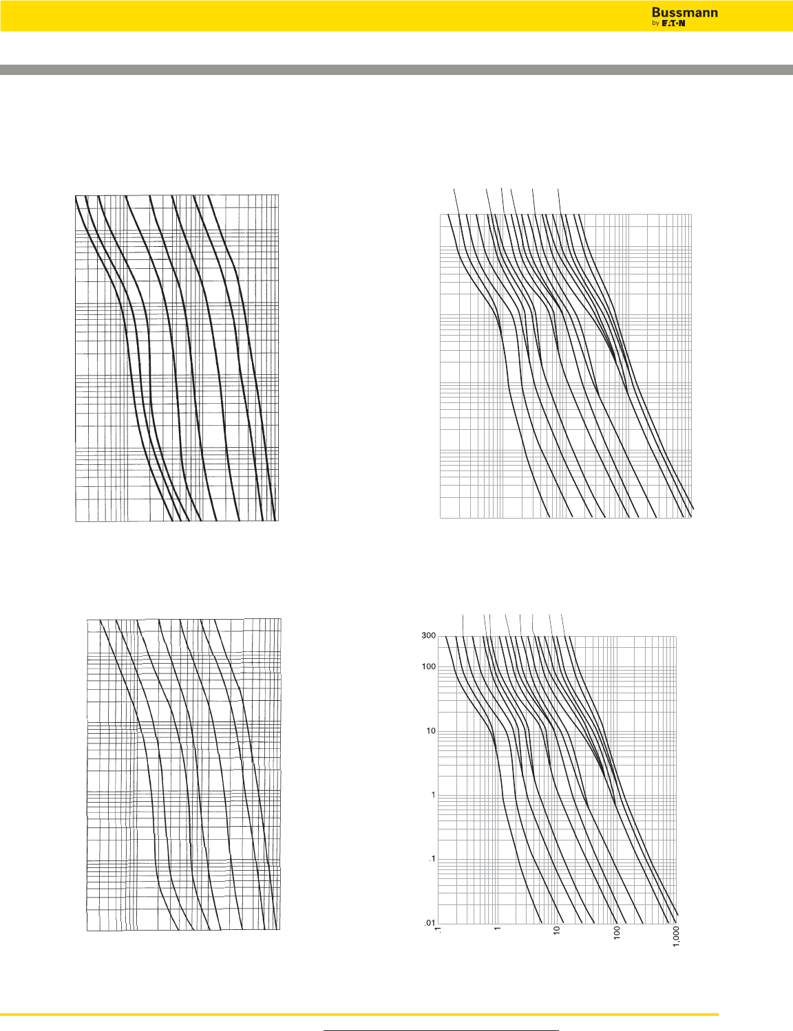
For product data sheets, visit www.cooperbussmann.com/DatasheetsEle
42
Low Voltage, Branch Circuit Rated Fuses
Low-Peak™Dual-element, Time-delay Fuses
Time-Current Characteristic Curves—Average Melt
TIME IN SECONDS
CURRENT IN AMPS
AMP RATING
300
100
10
1
.1
.01
20
100
1,000
10,000
15 20 30 60 100 200 400 600
LPN-RK
TIME IN SECONDS
CURRENT IN AMPS
AMP RATING
300
100
10
1
.1
.01
20
100
1,000
10,000
20 30 60 100 200 400 600
LPS-RK
1
2
4
5
8
10
12
AMP RATING
300
100
10
1
.1
.01
.1
1
10
100
1,000
TIME IN SECONDS
RMS SYMMETRICAL CURRENT IN AMPS
1/10 15/100
2/10
3/10
4/10 1/2
6/10 8/10
11/4
16/10
21/2
32/10
61/4
LPN-RK
1/10
15/100
2/10
4/10
6/10
16/10
8/10
1
2
4
5
8
12
10
11/4
21/232/10
61/4
1/2
3/10
LPS-RK
TIME IN SECONDS
CURRENT IN AMPS
AMP RATING
Data Sheets: LPN-RK — 1003 (0-60) and 1004 (70-600)
Data Sheets: LPS-RK — 1001 (0-60) and 1002 (70-600)
Recommended Fuse Holders & Blocks For Class RK1 Fuses
• See page 19
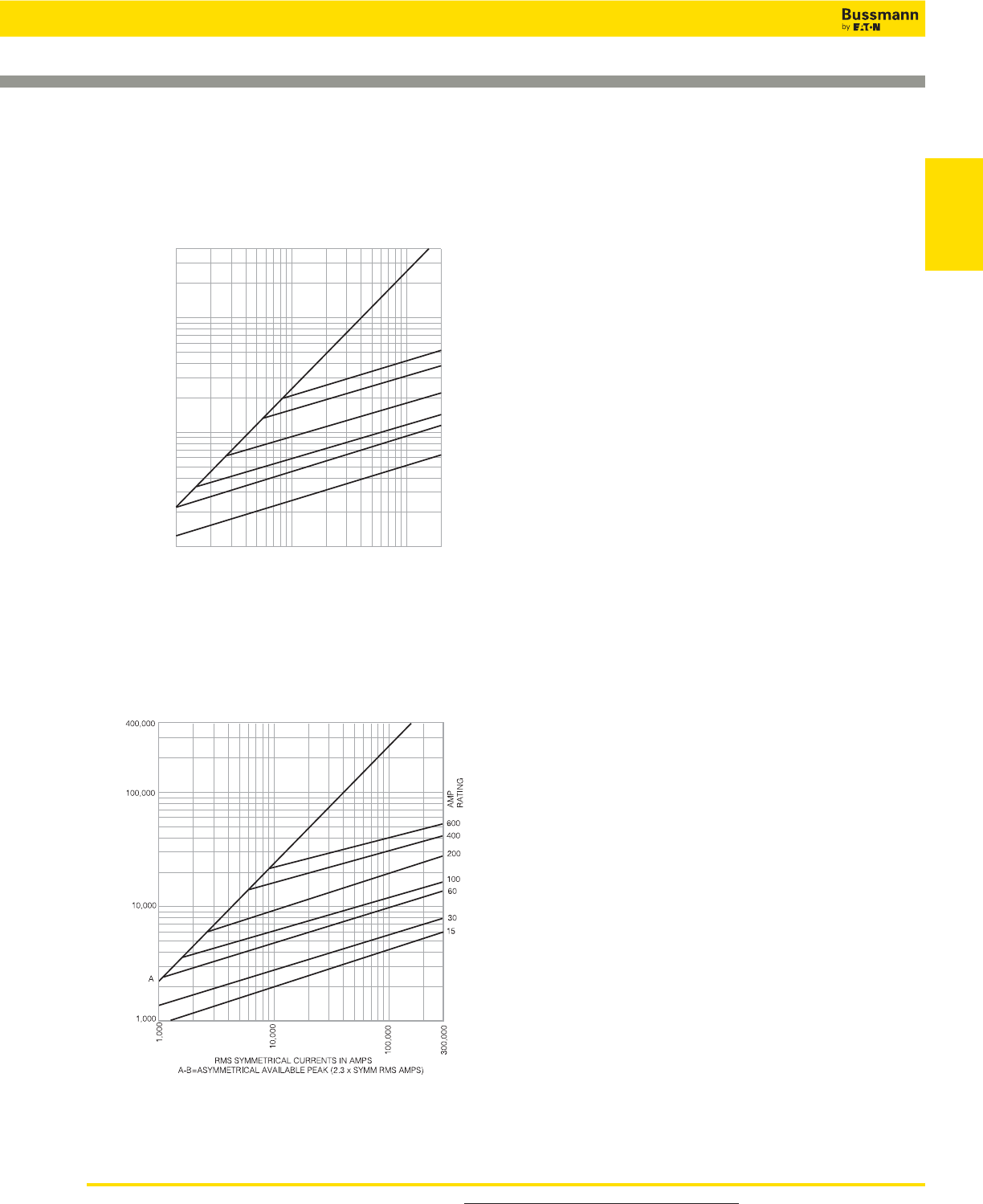
For product data sheets, visit www.cooperbussmann.com/DatasheetsEle 43
Low Voltage
Branch Circuit
Fuses
A
B
600
400
200
100
AMP
RATING
400,000
100,000
10,000
1,000
1,000
10,000
100,000
200,000
RMS SYMMETRICAL CURRENTS IN AMPS
A–B=ASYMMETRICAL AVAILABLE PEAK (2.3 X SYMM RMS AMPS)
INSTANTANEOUS PEAK LET-THRU CURRENT IN AMPS
60
30
Current Limitation Curves—LPN-RK
B
INSTANTANEOUS PEAK LET-THRU CURRENT IN AMPS
Current Limitation Curves—LPS-RK
Data Sheets: LPN-RK — 1003 (0-60) and 1004 (70-600)
Data Sheets: LPS-RK — 1001 (0-60) and 1002 (70-600)
Recommended Fuse Holders & Blocks For Class RK1 Fuses
• See page 19
Low-Peak™Dual-element, Time-delay Fuses
Low Voltage, Branch Circuit Rated Fuses
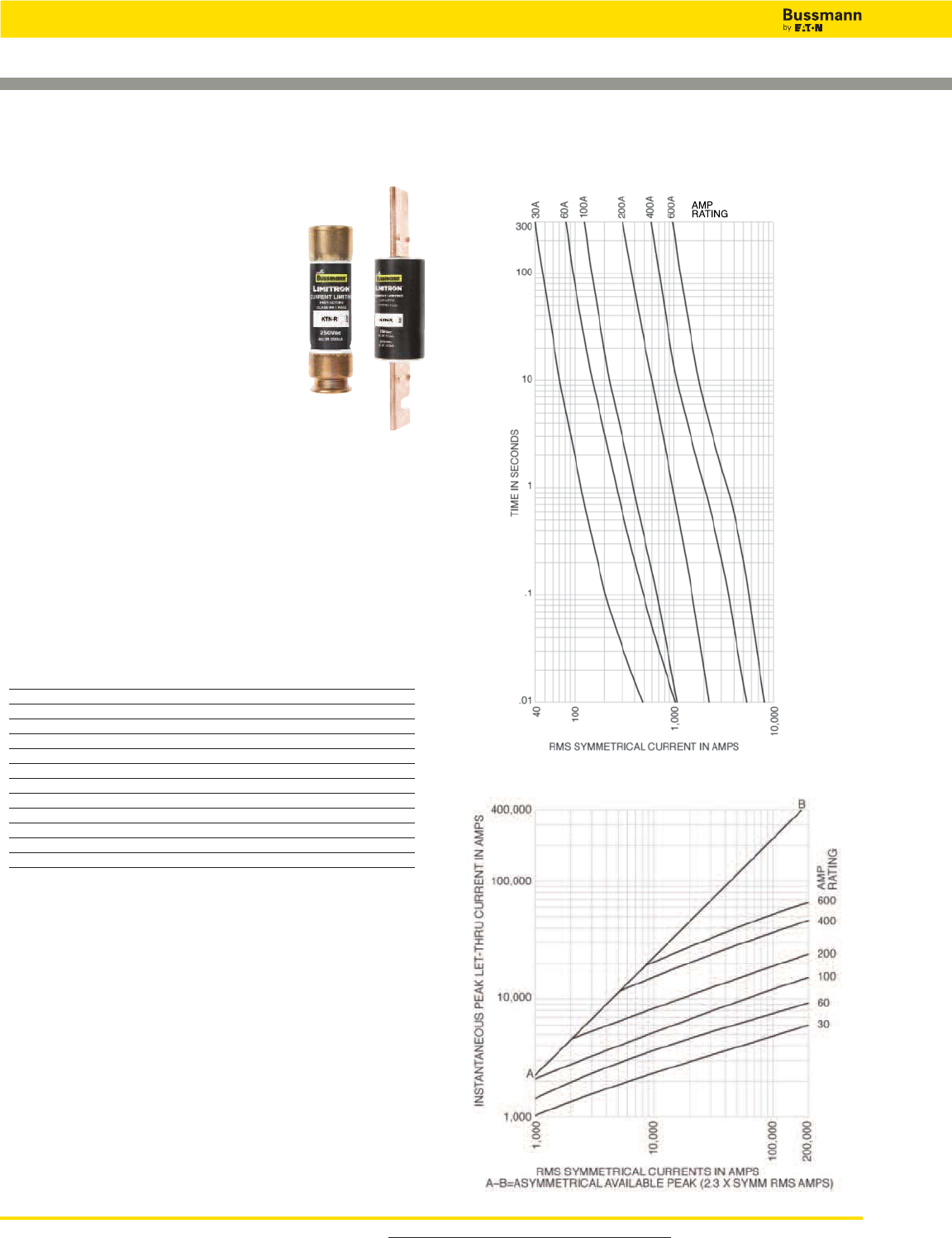
For product data sheets, visit www.cooperbussmann.com/DatasheetsEle
44
Low Voltage, Branch Circuit Rated Fuses
Limitron™Fast-acting Fuses
Data Sheet: 1043
Specifications
Description: Fast-acting, current-limiting
fuse.
Dimensions: See page 21 for Class RK1
dimensions.
Ratings:
Volts — 250Vac (or less)
Amps — 1-600A
IR — 200kA RMS Sym.
Agency Information: CE, Std. 248-12,
Class RK1, UL Listed, Guide JDDZ, File
E4273, CSA Certified, Class
1422-02, File 53787.
Features and Benefits
• Current limitation for non-inductive circuits provides Class
RK1 current-limiting response to maximum ground fault and
short-circuit conditions.
• 200kA interrupting rating provides high ratings at all circuit
locations.
• Economical solutions for high-fault circuits.
Typical Applications
• Panelboards
Catalog Numbers (Amps)
KTN-R-1 KTN-R-30 KTN-R-125
KTN-R-2 KTN-R-35 KTN-R-150
KTN-R-3 KTN-R-40 KTN-R-175
KTN-R-4 KTN-R-45 KTN-R-200
KTN-R-5 KTN-R-50 KTN-R-225
KTN-R-6 KTN-R-60 KTN-R-250
KTN-R-8 KTN-R-70 KTN-R-300
KTN-R-10 KTN-R-75 KTN-R-350
KTN-R-12 KTN-R-80 KTN-R-400
KTN-R-15 KTN-R-90 KTN-R-450
KTN-R-20 KTN-R-100 KTN-R-500
KTN-R-25 KTN-R-110 KTN-R-600
Time-Current Characteristic Curves—Average Melt
Current Limitation Curves
KTN-R (250V) Class RK1
For superior electrical protection, Bussmann recommends upgrading KTN-R
fuse applications to Low-Peak LPN-RK fuses See page 41.
Recommended Fuse Holders & Blocks For Class RK1 Fuses
• See page 19
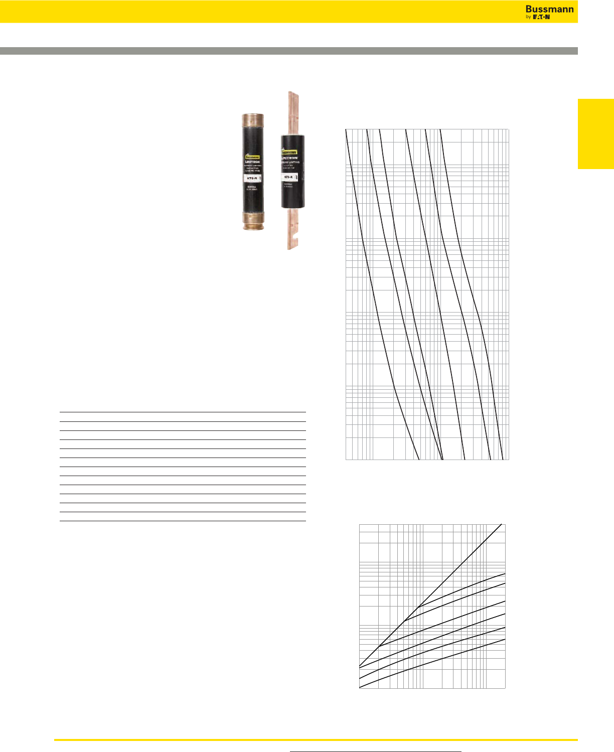
For product data sheets, visit www.cooperbussmann.com/DatasheetsEle 45
Low Voltage
Branch Circuit
Fuses
Low Voltage, Branch Circuit Rated Fuses
Limitron™Fast-acting Fuses
Data Sheet: 1044
Specifications
Description: Fast-acting, current-limiting
fuse.
Dimensions: See page 21 for Class RK1
dimensions.
Ratings:
Volts — 600Vac (or less)
Amps — 1-600A
IR — 200kA RMS Sym.
Agency Information: CE, Std. 248-12,
Class RK1, UL Listed, Guide JDDZ, File
E54273, CSA Certified, C22.2 No. 248.12, Class
1422-02, File 53787.
Features and Benefits
• Current limitation for non-inductive circuits provides Class
RK1 current-limiting response to maximum ground fault and
short-circuit conditions.
• 200kA interrupting rating provides high ratings at all circuit
locations.
• Economical solutions for high-fault circuits.
Typical Applications
• Panelboards
Catalog Numbers (Amps)
KTS-R-1 KTS-R-30 KTS-R-125
KTS-R-2 KTS-R-35 KTS-R-150
KTS-R-3 KTS-R-40 KTS-R-175
KTS-R-4 KTS-R-45 KTS-R-200
KTS-R-5 KTS-R-50 KTS-R-225
KTS-R-6 KTS-R-60 KTS-R-250
KTS-R-8 KTS-R-70 KTS-R-300
KTS-R-10 KTS-R-75 KTS-R-350
KTS-R-12 KTS-R-80 KTS-R-400
KTS-R-15 KTS-R-90 KTS-R-450
KTS-R-20 KTS-R-100 KTS-R-500
KTS-R-25 KTS-R-110 KTS-R-600
KTS-R (600V) Class RK1
For superior electrical protection, Bussmann recommends upgrading KTN-R
fuse applications to Low-Peak LPN-RK fuses See page 41.
Recommended Fuse Holders & Blocks For Class RK1 Fuses
• See page 19
600
100
60
AMPERE
RATING
30
400
200
200,000
100,000
10,000
1,000
1,000
INSTANTANEOUS PEAK LET-THROUGH CURRENT IN AMPS
400,000
100,000
10,000
RMS SYMMETRICAL CURRENTS IN AMPERES
A–B=ASYMMETRICAL AVAILABLE PEAK (2.3 x SYMM RMS AMPS)
B
A
Current-Limitation Curves
RMS SYMMETRICAL CURRENT IN AMPERES
TIME IN SECONDS
300
100
10
1
.1
.01
40
100
1,000
10,000
30A
60A
100A
200A
400A
600A
AMPERE
RATING
Time-Current Characteristic Curves–Average Melt
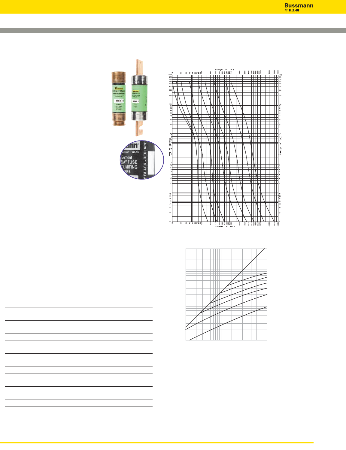
For product data sheets, visit www.cooperbussmann.com/DatasheetsEle
46
Low Voltage, Branch Circuit Rated Fuses
60
100
200
400
600
30
15
10
8
Time-Current Characteristic Curves—Average Melt
Fusetron™Energy Efficient, Dual-element, Time-delay Fuses
Specifications
Description: Dual-element, time-delay
fuse – 10 seconds (minimum) at 500%
rated amps (8 seconds for 0-30A sizes).
Available with indication on select ratings
(see Catalog Numbers table).
Dimensions: See page 15 for Class RK5
dimensions.
Ratings:
Volts — 250Vac (or less)
— 125Vdc (1⁄10-60A, 110-200A)
— 250Vdc (225-600A)
Amps — 1⁄10-600A
IR — 200kA RMS Sym.
— 20kA DC
Agency Information: CE, Std. 248-12, Class RK5,
UL Listed, Guide JDDZ, File E4273, CSA Certified, Class
1422-01, File 53787.
Features and Benefits
• Separate overload and short-circuit elements provide time
delay for sizing as close as 125% of motor FLA.
• 2:1 selective coordination amp ratio (within the Cooper
Bussmann RK5 fuse family) prevents overcurrent events
from opening upstream Fusetron fuses.
• Insulated end caps for 225A-600A fuses reduces exposure
to live parts and extends air gap to distance between
blades of adjacent mounted fuses or to housing.
Typical Applications
• Power Panelboards
• Motor Control Centers
Catalog Numbers (Amps)
FRN-R-1⁄10 FRN-R-2 FRN-R-10* FRN-R-100
FRN-R-1⁄8FRN-R-2-1⁄4FRN-R-12* FRN-R-110
FRN-R-15⁄100 FRN-R-2-1⁄2FRN-R-15* FRN-R-125
FRN-R-2⁄10 FRN-R-2-8⁄10 FRN-R-17-1⁄2* FRN-R-150
FRN-R-1⁄4FRN-R-3 FRN-R-20* FRN-R-175
FRN-R-3⁄10 FRN-R-3-2⁄10 FRN-R-25* FRN-R-200
FRN-R-4⁄10 FRN-R-3-1⁄2FRN-R-30* FRN-R-225
FRN-R-1⁄2FRN-R-4 FRN-R-35* FRN-R-250
FRN-R-6⁄10 FRN-R-4-1⁄2FRN-R-40* FRN-R-300
FRN-R-8⁄10 FRN-R-5 FRN-R-45* FRN-R-350
FRN-R-1 FRN-R-5-6⁄10 FRN-R-50* FRN-R-400
FRN-R-1-1⁄8FRN-R-6 FRN-R-60* FRN-R-450
FRN-R-1-1⁄4FRN-R-6-1⁄4FRN-R-70 FRN-R-500
FRN-R-1-4⁄10 FRN-R-7 FRN-R-75 FRN-R-600
FRN-R-1-1⁄2FRN-R-7-1⁄2FRN-R-80
FRN-R-1-6⁄10 FRN-R-8* FRN-R-85
FRN-R-1-8⁄10 FRN-R-9* FRN-R-90
Data Sheets: 1019 (1⁄10-60) and 1020 (70-600)
Data Sheet: 1169 (8-60) FRN-R with indication
Instantaneous Peak Let-Through Current Amps
RMS Symmetrical Currents In Amps
A–B = Asymmetrical Available Peak (2.3 x Sym RMS Amps)
400,000
100,000
10,000
1,000
1,000
10,000
100,000
200,000
60
600
100
Amp
Rating
400
200
B
A
30
FRN-R
Current Limitation Curves
FRN-R (250V) Class RK5
*Available with indication. To order, place “ID” at the end of the catalog number.
Example: FRN-R-30ID
• Combination Starters
• Machinery Disconnects
Recommended Fuse Reducers For Class R Fuses
• See page 20
For superior electrical protection, Bussmann recommends upgrading FRN-R fuse
applications to Low-Peak LPN-RK fuses. See page 41.
Recommended Fuse Holders & Blocks For Class RK5 Fuses
• See page 19
Available
With
Indication
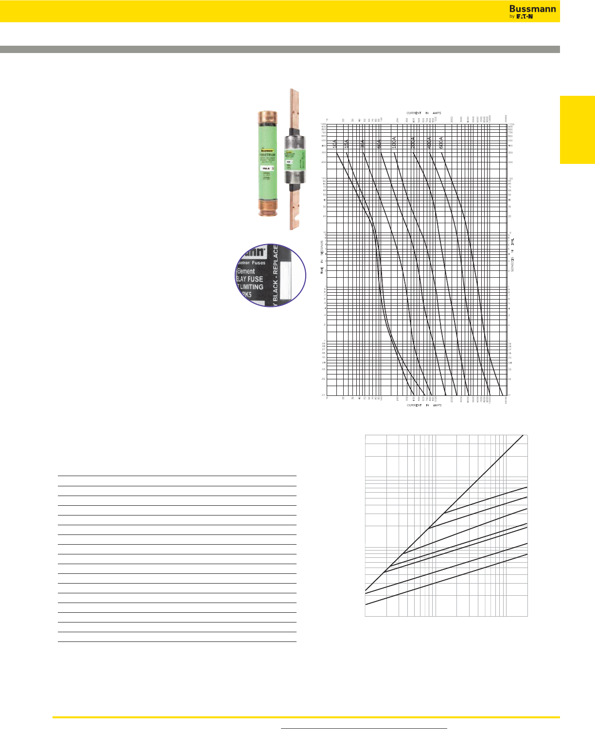
For product data sheets, visit www.cooperbussmann.com/DatasheetsEle 47
Low Voltage
Branch Circuit
Fuses
Fusetron™Energy Efficient, Dual-element, Time-delay Fuses
600A
100A
Amp
Rating
400A
200A
60A
Instantaneous Peak Let-Through Current Amps
RMS Symmetrical Currents In Amps
A–B = Asymmetrical Available Peak (2.3 x Sym RMS Amps)
B
A
400,000
100,000
10,000
1,000
1,000
10,000
100,000
FRS-R (600V)
30A
200,000
15A
Time-Current Characteristic Curves—Average Melt
Current Limitation Curves
FRS-R (600V) Class RK5
Specifications
Description: Dual-element, time-delay fuse – 10
seconds (minimum) at 500% rated amps. Now
available with optional indication on select ratings
(see Catalog Numbers table).
Dimensions:
See page 15 for Class RK5 dimensions.
Ratings:
.
Agency Information: CE, Std. 248-12,
Class RK5, UL Listed, Guide JDDZ, File E4273, CSA
Certified, Class 1422-02, File 53787.
Features and Benefits
• 2:1 selective coordination ratio (within RK5 fuse family)
prevents electrical shutdowns from extending beyond the
failed circuit.
• Insulated end caps for 65-600A fuses reduces exposure to
live parts and extends air gap to distance between blades
of adjacent mounted fuses or to housing.
Typical Applications
• Power Panelboards
• Motor Control Centers
Catalog Numbers (Amps)
FRS-R-1⁄10 FRS-R-2 FRS-R-10* FRS-R-100
FRS-R-1⁄8FRS-R-2-1⁄4FRS-R-12* FRS-R-110
FRS-R-15⁄100 FRS-R-2-1⁄2FRS-R-15* FRS-R-125
FRS-R-2⁄10 FRS-R-2-8⁄10 FRS-R-17-1⁄2* FRS-R-150
FRS-R-1⁄4FRS-R-3 FRS-R-20* FRS-R-175
FRS-R-3⁄10 FRS-R-3-2⁄10 FRS-R-25* FRS-R-200
FRS-R-4⁄10 FRS-R-3-1⁄2FRS-R-30* FRS-R-225
FRS-R-1⁄2FRS-R-4 FRS-R-35* FRS-R-250
FRS-R-6⁄10 FRS-R-4-1⁄2FRS-R-40* FRS-R-300
FRS-R-8⁄10 FRS-R-5 FRS-R-45* FRS-R-350
FRS-R-1 FRS-R-5-6⁄10 FRS-R-50* FRS-R-400
FRS-R-1-1⁄8FRS-R-6* FRS-R-60* FRS-R-450
FRS-R-1-1⁄4FRS-R-6-1⁄4* FRS-R-65 FRS-R-500
FRS-R-1-4⁄10 FRS-R-7* FRS-R-70 FRS-R-600
FRS-R-1-1⁄2FRS-R-7-1⁄2* FRS-R-75
FRS-R-1-6⁄10 FRS-R-8* FRS-R-80
FRS-R-1 8⁄10 FRS-R-9* FRS-R-90
Data Sheet: 1017 (1⁄10-60), 1018 (65-600)
Data Sheet: 1070 (6-60) FRS-R with Indication
For superior electrical protection, Bussmann recommends upgrading FRS-R fuse
applications to Low-Peak LPS-RK fuses. See page 41.
Recommended Fuse Holders & Blocks For Class RK5 Fuses
• See page 19
Recommended Fuse Reducers For Class R Fuses
• See page 20
• Combination Starters
• Machinery Disconnects
*Available with indication. To order, place “ID” at the end of the catalog number.
Example: FRS-R-7ID.
Available
With
Indication
Volts — 600Vac (or less)
Amps —
1⁄10-30A
IR — 200kA RMS Sym.
— 20kA @300Vdc
Amps — 35-60A
IR — 200kA RMS Sym.
— 20kA @250Vdc
Amps — 65-600A
IR — 200kA RMS Sym.
— 20kA @250Vdc
Low Voltage, Branch Circuit Rated Fuses
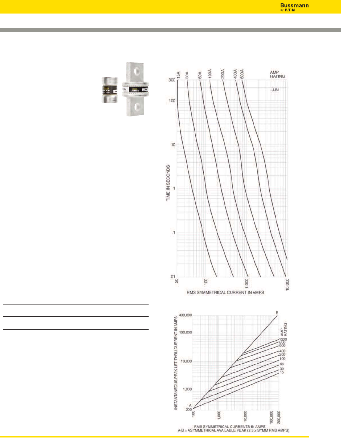
For product data sheets, visit www.cooperbussmann.com/DatasheetsEle
48
Low Voltage, Branch Circuit Rated Fuses
T-Tron™Fast-acting Fuses
Data Sheet: 1025
Specifications
Description: Fast-acting,
current-limiting fuse.
Dimensions: See page 16 for Class T
dimensions.
Ratings:
Volts — 300Vac (or less)
— 160Vdc (15-600A)
— 170Vdc (601-1200A)
Amps — 1-1200A
IR — 200kA RMS Sym.
— 20kA DC @ 160Vdc
— 100kA DC @ 170Vdc
Agency Information: CE, Std. 248-15, Class T, UL Listed,
Guide JDDZ, File E4273, CSA Certified, Class 1422-02, File
53787.
Features and Benefits
• Series combination ratings with branch circuit breakers
allows broad range of coverage, independent of breaker
manufacturer.
• Current limitation for non-inductive circuits provides Class T
current-limiting response to maximum ground fault and
short-circuit conditions.
• 200kA interrupting rating provides high ratings at all
circuit locations.
• Small footprint allows more efficient use of available space.
Typical Applications
• Large Apartment Complexes
• Multi-Family Meter Stacks
• VFD Line Protection
Catalog Numbers (Amps)
JJN-1 JJN-15 JJN-40 JJN-80 JJN-150 JJN-300 JJN-600
JJN-2 JJN-20 JJN-45 JJN-90 JJN-175 JJN-350 JJN-700
JJN-3 JJN-25 JJN-50 JJN-100 JJN-200 JJN-400 JJN-800
JJN-6 JJN-30 JJN-60 JJN-110 JJN-225 JJN-450 JJN-1000
JJN-10 JJN-35 JJN-70 JJN-125 JJN-250 JJN-500 JJN-1200
JJN Class T
Current Limitation Curves
JJN
Time-Current Characteristic Curves—Average Melt
Recommended Fuse Holders & Blocks For Class T Fuses
• See page 19

For product data sheets, visit www.cooperbussmann.com/DatasheetsEle 49
Low Voltage
Branch Circuit
Fuses
Low Voltage, Branch Circuit Rated Fuses
Specifications
Description: Very fast-acting,
current-limiting fuse.
Dimensions: See page 16 for Class T
dimensions.
Ratings:
Volts — 600Vac (or less)
Amps — 1-800A
IR — 200kA RMS Sym.
Agency Information: CE, Std. 248-15, Class T, UL Listed,
Guide JDDZ, File E4273, CSA Certified, Class 1422-02, File
53787.
Features and Benefits
• Series combination ratings with branch circuit breakers
allows broad range of coverage, independent of breaker
manufacturer.
• Current limitation for non-inductive circuits provides Class T
current-limiting response to maximum ground fault and
short-circuit conditions.
• 200kA interrupting rating provides high ratings at all
circuit locations.
• Small footprint allows more efficient use of available space.
Typical Applications
• Large Apartment Complexes
• Multi-Family Meter Stacks
• VFD Line Protection
Catalog Numbers (Amps)
JJS-1 JJS-15 JJS-40 JJS-80 JJS-150 JJS-300 JJS-600
JJS-2 JJS-20 JJS-45 JJS-90 JJS-175 JJS-350 JJS-800
JJS-3 JJS-25 JJS-50 JJS-100 JJS-200 JJS-400
JJS-6 JJS-30 JJS-60 JJS-110 JJS-225 JJS-450
JJS-10 JJS-35 JJS-70 JJS-125 JJS-250 JJS-500
Data Sheet: 1029
JJS Class T
T-Tron™Fast-acting Fuses
JJS
JJS
Time-Current Characteristic Curves—Average Melt
Recommended Fuse Holders & Blocks For Class T Fuses
• See page 19
Current Limitation Curves
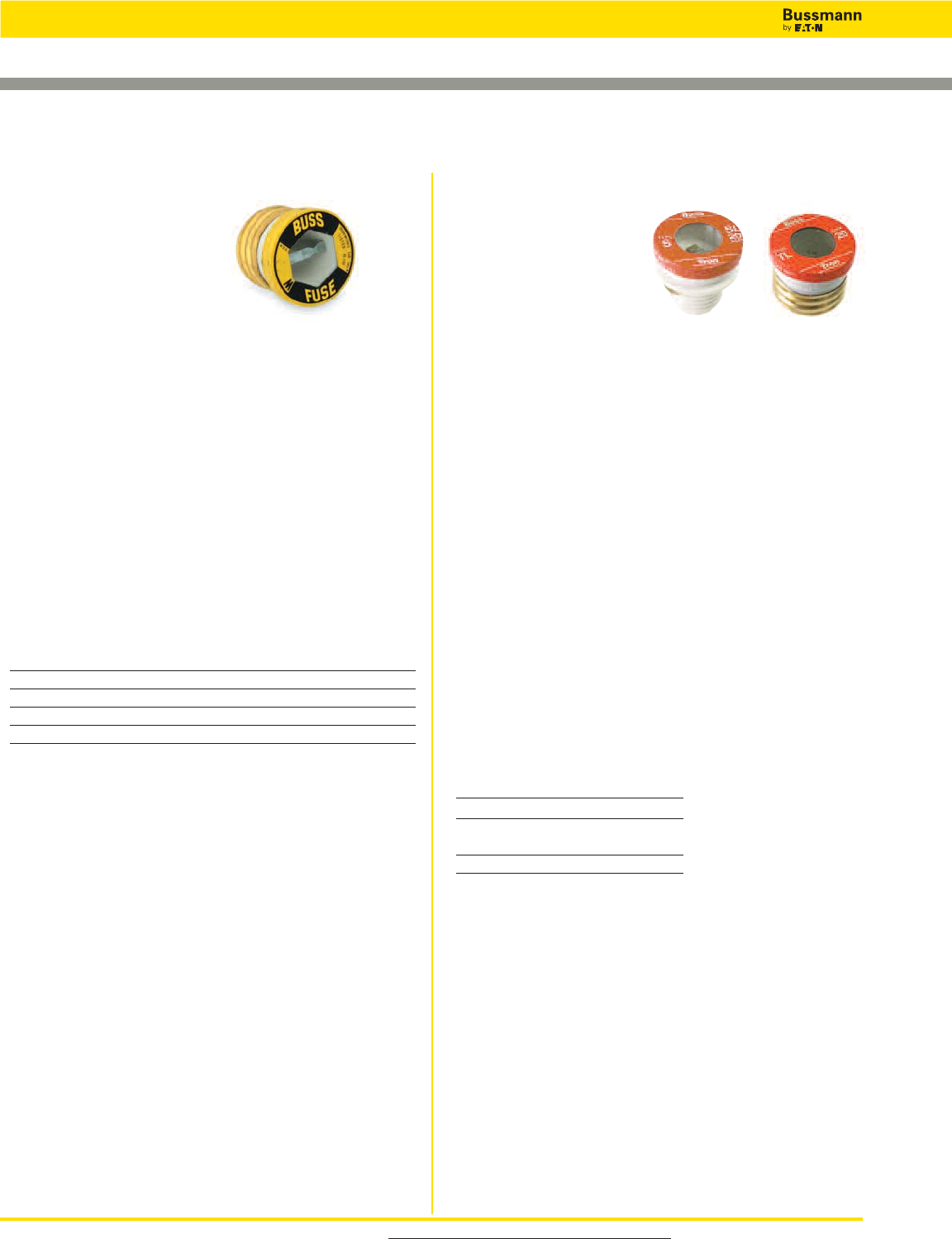
For product data sheets, visit www.cooperbussmann.com/DatasheetsEle
50
Low Voltage, Branch Circuit Rated Fuses
Plug Fuses
Data Sheets: 1033 (SL) & 1035 (TL)
Specifications
Description: Fast-acting plug
fuse.
Dimensions: Edison base plug.
Construction: Brass threads
with plastic body.
Ratings:
Volts — 125Vac
Amps — 1⁄2-12A
IR — 10kA RMS Sym.
Agency Information: CE, Std. 248-11, UL Listed, Guide
JEFV, File E12112.
Features and Benefits
• Dependable, fast-acting circuit protection with 10kA
interrupting rating for added safety when applied to existing
plug fuse systems and 125-volt single-phase control
circuits.
Typical Applications
• Replacement only in existing systems.
• For general purpose circuit protection.
• Use for lighting and other non-motor circuits.
Catalog Numbers* (Amps)
W-1⁄2W-2 1⁄2W-6 W-10
W-1 W-3 W-6 1⁄2W-12
W-1 8⁄10 W-4 W-7 W-DUMMY**
W-2 W-5 W-8
*W-15, W-20, W-25, and W-30 plug fuses obsoleted. Suggest replacing with either T-(Amp)
or TL-(Amp) plug fuses.
** Non-conductive dummy base. Not a fuse.
Specifications
Description: Time-delay,
loaded link plug fuse.
Dimensions:
SL — Rejection base
TL — Edison base
Construction:
SL — Plastic base with rejection threads
TL — Brass threads with plastic body
Ratings:
Volts — 125Vac
Amps — 15-30A
IR — 10kA RMS Sym.
Agency Information: CE, Std. 248-11, UL Listed, Guide
JEFV, File E12112.
Features and Benefits
• Time-delay loaded link TL Series Edison base plug fuses
pass motor overload starting currents without opening and
allow closer sizing to motor load for added protection.
• Time-delay loaded link SL Series fuses provide a rejection
feature (when used alone or with Fustat adapters to retrofit
Edison base holders) to help prevent overfusing.
Typical Applications
• Small motor and inductive load circuits with high in-rush
current levels.
• Used with box cover units to provide equipment protection.
• Applications benefiting from fuse rejection (SL Series only).
SL Catalog Numbers (Amps)
SL-15 SL-20 SL-25 SL-30
TL Catalog Numbers (Amps)
TL-15 TL-20 TL-25 TL-30
W Series SL and TL Series
Recommended Fuse Holders For W Series Plug Fuses
• See page 20
Recommended Fuse Holders For SL & TL Series Plug Fuses
• See page 20
• See page 52 for Fustat adapters for use with SL Series
Data Sheet: 1036
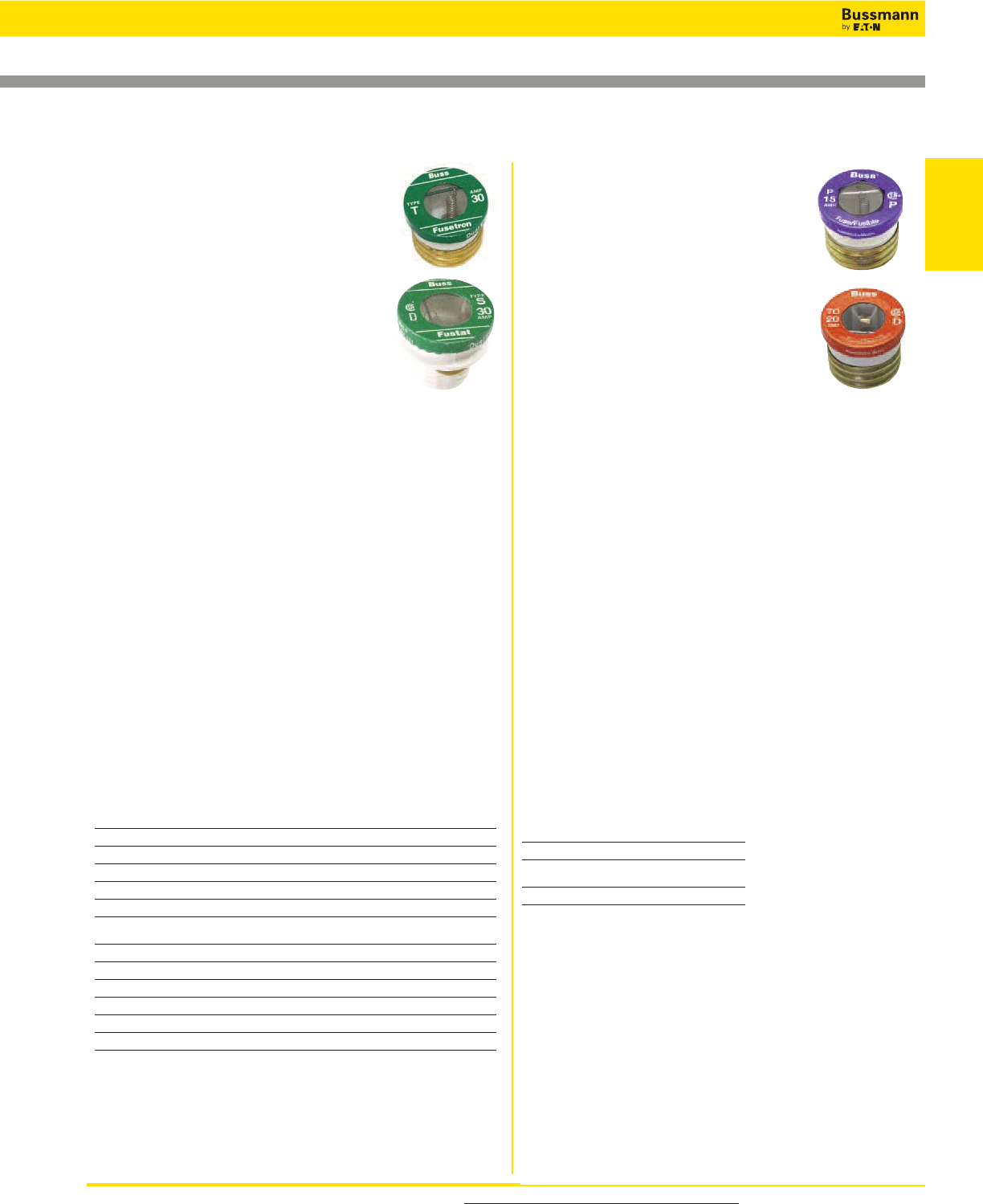
For product data sheets, visit www.cooperbussmann.com/DatasheetsEle 51
Low Voltage
Branch Circuit
Fuses
Low Voltage, Branch Circuit Rated Fuses
S and T Series
Specifications
Description: Dual-element, time-delay plug
fuse.
Dimensions:
S — Rejection base
T — Edison base
Construction:
S — Plastic base with rejection threads
T — Brass threads with plastic body
Ratings:
Volts — 125Vac
Amps — S Series: 1⁄4-30A
— T Series: 3⁄10-30A
IR — 10kA RMS Sym.
Agency Information: CE, Std. 248-11, Type S and T:
UL Listed (0-61⁄4) Guide JFHR, File E56412 (7-30A) Guide
JEFV, File E12112; CSA Certified, Class 1423-01, File
53787.
Features and Benefits
• Time-delay, dual-element T Series Edison base plug fuses
provide small motor overload protection when used with
box cover units.
• Time-delay, dual-element S Series plug fuses provide a
rejection feature (when used alone or with Fustat adapters
to retrofit Edison base holders) to prevent overfusing of
branch circuits.
Typical Applications
• S Series — Residential Load Centers
• T Series — Box Cover Units for small motor overload
protection
• Applications benefiting from fuse rejection (S Series only)
S Series Catalog Numbers (Amps)
S-1⁄4S-8⁄10 S-1-6⁄10 S-2-1⁄2S-4 S-7 S-14
S-3⁄10 S-1 S-1-8⁄10 S-2-8⁄10 S-4-1⁄2S-8 S-15
S-4⁄10 S-1-1⁄8S-2 S-3 S-5 S-9 S-20
S-1⁄2S-1-1⁄4S-2-1⁄4S-3-2⁄10 S-6 S-10 S-25
S-6⁄10 S-1-4⁄10 S-5-6⁄10 S-3-1⁄2S-6-1⁄4S-12 S-30
T Series Catalog Numbers (Amps)
T-3⁄10 T-1-1⁄8T-2-1⁄4T-4 T-7 T-15
T-4⁄10 T-1-1⁄4T-2-1⁄2T-4-1⁄2T-8 T-20
T-1⁄2T-1-4⁄10 T-2-8⁄10 T-5 T-9 T-25
T-6⁄10 T-1-6⁄10 T-3 T-5-6⁄10 T-10 T-30
T-8⁄10 T-1-8⁄10 T-3-2⁄10 T-6 T-12
T-1 T-2 T-3-1⁄2T-6-1⁄4T-14
Data Sheet: 1032 (S) & 1034 (T)
Recommended Fuse Holders For S & T Series Plug Fuses
• See page 20
• See page 52 for Fustat adapters for use with S Series
P & TC Series
Specifications
Description:
P Series - Type P dual-element fuse
TC Series - Type D dual-element,
time-delay fuse
Dimensions: Edison base
Construction: Brass threads with plastic
body.
Ratings:
Volts — 125Vac or less
Amps — 15-30A
IR — 10kA
Agency Information:
P Series - CSA Certified
TC Series - CSA Certified (Class 1423-01, File # 53787)
Features and Benefits
P Series
• “P” Rating for Canadian applications.
• Non-time delay for non-inductive loads
TC Series
• “D” Rating for Canadian applications
• Heavy duty TC fuses are industrial strength products,
featuring dual-element construction.
• This spring loaded design provides superior short-circuit
and overload protection.
• The TC fuses have more time-delay than the medium
duty fuses in order to better protect industrial motors and
residential circuits.
Typical Applications
• P Series — Non-inductive loads, residential load centers
• TC Series — Box Cover Units for small motor overload
protection
P Series Catalog Numbers (Amps)
P-15 P-20 P-25 P-30
TC Series Catalog Numbers (Amps)
TC-15 TC-20 TC-25 TC-30
Data Sheet: 1039 (TC Series only)
Recommended Fuse Holders For P & TC Series Plug Fuses
• See page 20
• See page 52 for Fustat adapters for use with S Series
Plug Fuses
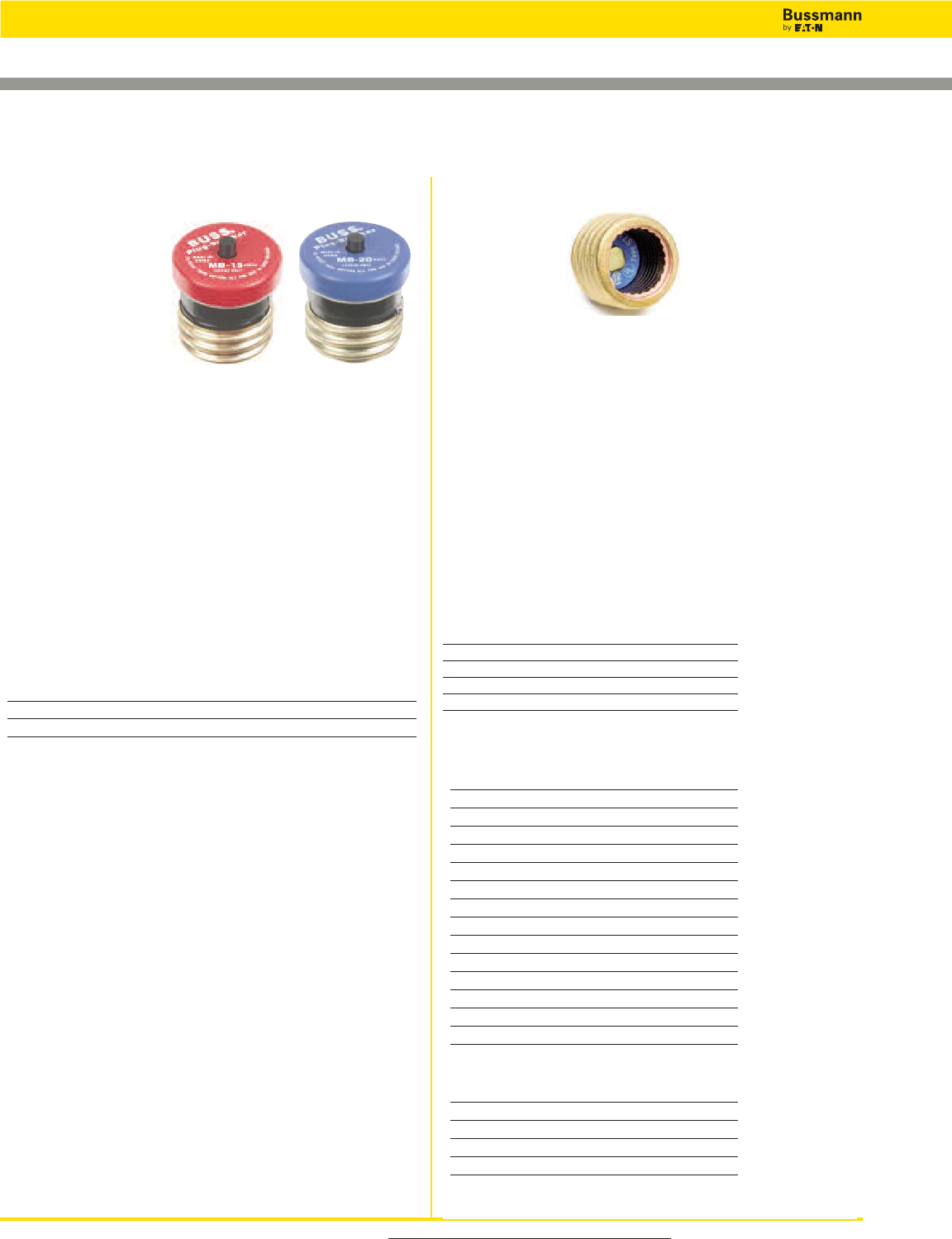
For product data sheets, visit www.cooperbussmann.com/DatasheetsEle
52
Low Voltage, Branch Circuit Rated Fuses
Plug Fuses
Specifications
Description: Edison base manual reset circuit breakers.
Dimensions: Edison base
Construction: Brass threads with plastic body
Ratings:
Volts — 125Vac only
Amps — 15-20A
IR — 10kA RMS Sym.
Agency Information: UL Listed, File E14942
Features and Benefits
• Fit standard Edison base fuse receptacles.
• Resettable upon overload event.
Typical Applications*
• Replacing Edison base plug fuses in residential fuse panels.
Catalog Numbers* (Amps)
MB-15
MB-20
* Not for use in box cover units or for inductive loads.
MB Edison Base Circuit Breakers
Specifications
Description: Adapters for using Type S and SL rejection
fuses in Edison base fuse sockets.
Agency Information: UL Listed, File E12853; CSA
Certified File #6225-01, File #47235.
Features and Benefits
• Fustat adapters screw into the “Edison” thread fuse sockets
of standard fuse boxes making it easy to retrofit existing
fuse installations
• Available in various amp ratings to cover a wide range of
rating requirements
Typical Applications
• Plug fuse installations where it is desirable to restrict fuse
amp ratings
Catalog Numbers (Amps)
SA-1* SA-3-2⁄10* SA-10*
SA-1-1⁄4* SA-4* SA-15**
SA-1-6⁄10* SA-5* SA-20**
SA-2* SA-6-1⁄4* SA-30**
SA-2-1⁄2* SA-8*
* Single motor circuits.
** Branch circuits.
Fustat®Adapters for Small Motor Protection*
Adapter Accepts Fuses
SA-1 S-1 or smaller
SA-1-1⁄4S-1-1⁄4or smaller
SA-1-6⁄10 S-1-6⁄10 or smaller
SA-2 S-2 or S-1-8⁄10
SA-2-1⁄2S-2-1⁄2to S-1-8⁄10
SA-3-2⁄10 S-3-2⁄10 to S-1-8⁄10
SA-4 S-4 to S-3-1⁄2
SA-5 S-5 to S-3-1⁄2
SA-6-1⁄4S-6-1⁄4to S-3-1⁄2
SA-8 S-8 to S-7
SA-10 S-10 to S-7
SA-15 S-15 to S-7
SA-20 S-20
SA-30 S-30 to S-20
* Both motor running and short-circuit protection.
Fustat®Adapters for Branch Circuit Protection
Adapter Accepts Fuses
SA-15 S-15 to S-7
SA-20 S-20
SA-30 S-25
SA 30 S-30 to S-20
SA Fustat Fuse Adapters
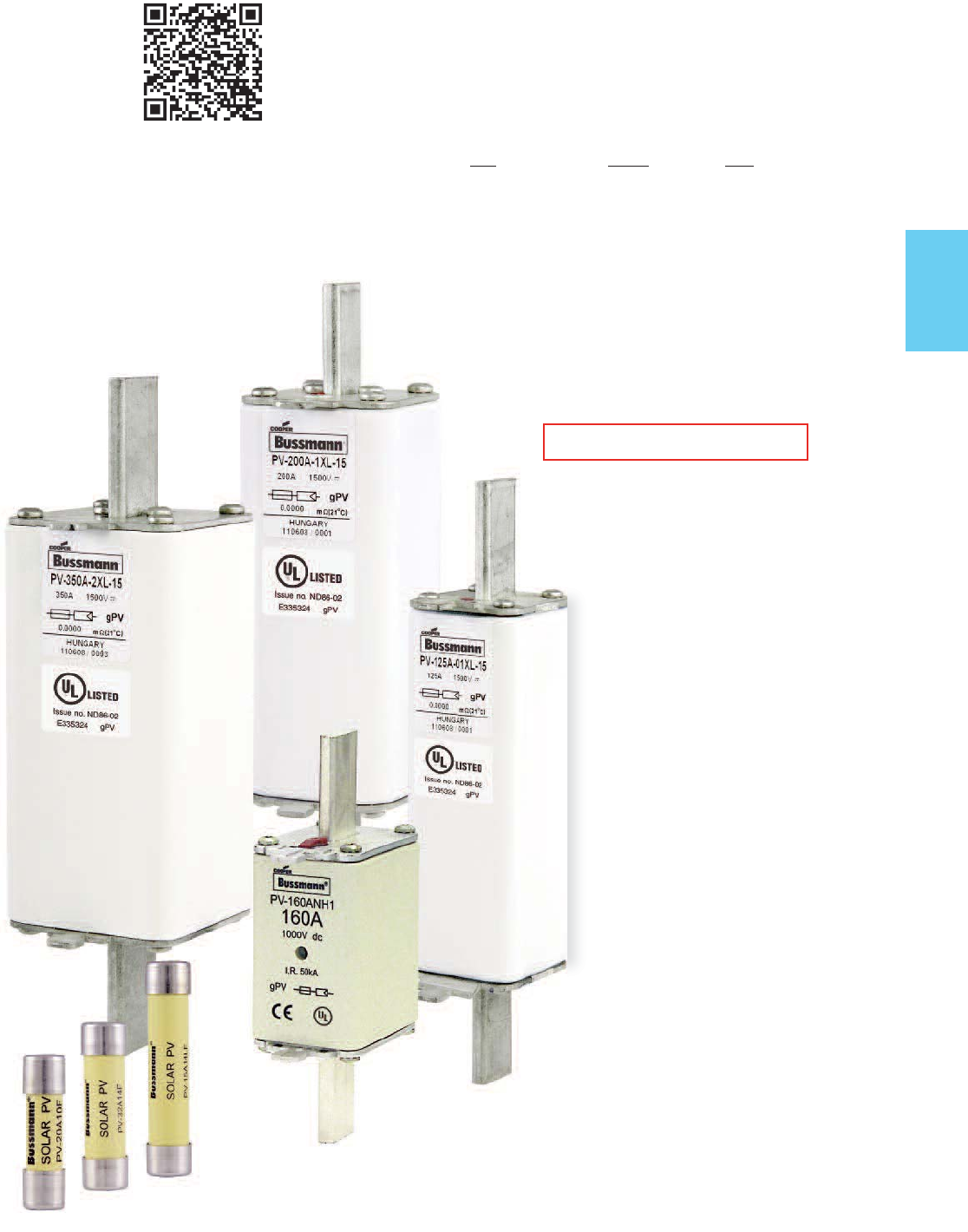
53
Solar
Products
Page
Fuse Holder & Block Selection Guide 54-55
Volt Fuses Size
600Vdc . . . . . . . . . PVM . . . . . 13⁄32˝ x 1 1⁄2˝ . . . . . . . . . . . 56
600Vac /300Vdc . . .PVCF . . . . .CUBEFuse . . . . . . . . .57-58
600Vac/dc . . . . . . . PVS-R . . . . RK5 . . . . . . . . . . . . . . . .59
1000Vdc . . . . . . . . PV . . . . . . .10x38mm . . . . . . . . . . . 60
1000/1100Vdc . . . . PV . . . . . . .14x51mm . . . . . . . . . . .61
1000Vdc . . . . . . . . NH1 . . . . . .NH Size 1 . . . . . . . . . . . 62
1000Vdc . . . . . . . . XL PV . . . . XL Size 01, 1, 2, 3 . . .63-65
1300/1500Vdc . . . . PV . . . . . . .14x65mm . . . . . . . . . . . 66
1200/1500Vdc . . . . XL PV . . . . XL Size 01, 1, 2, 3 . . .67-69
Solar Fuse Products
RED indicates NEW information
Scan this tag to get the latest product
information for Solar Products.
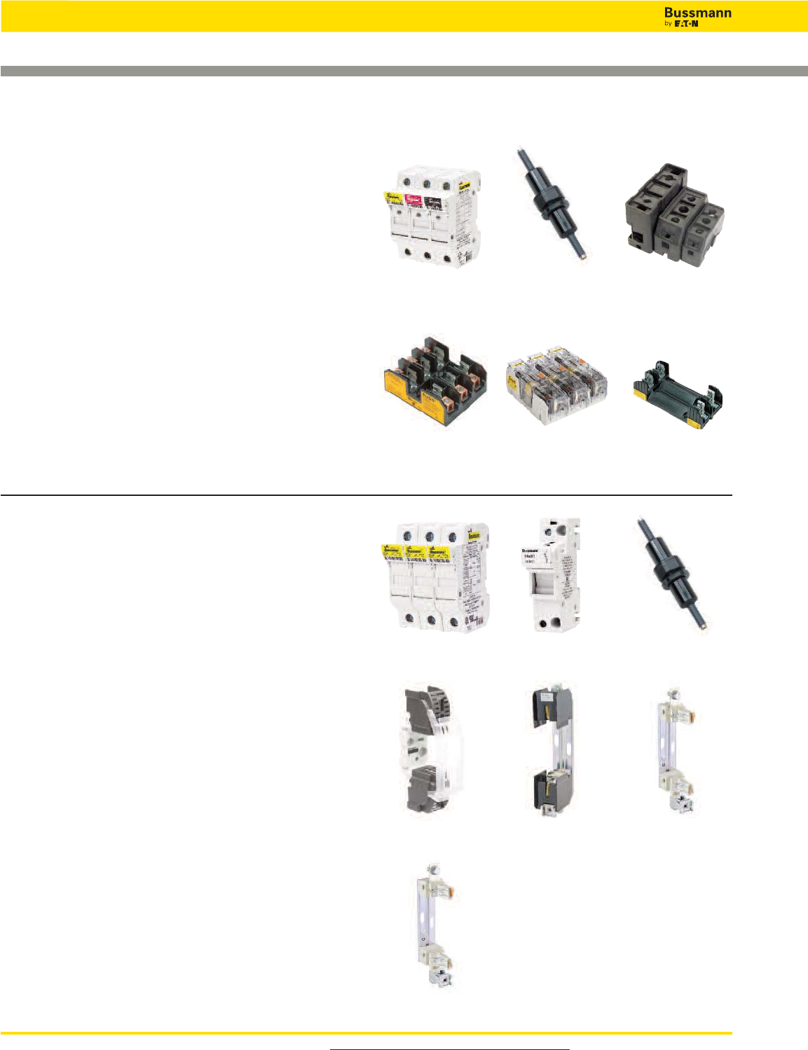
For product data sheets, visit www.cooperbussmann.com/DatasheetsEle
54
Solar Fuse Products
Holders & Blocks For Branch Circuit Rated Fuses
600 Volts Fuses Volts Page
Midget PVM 600V 56
CF CFPV 600V 57
RK5 PVS-R 600V 59
Holders
• TCFH Series CUBEFuse holder 32
• CHM Series DIN-Rail mount holders 274
• HEB Series in-line holders 310
Blocks
• Modular Knifeblade Fuse Blocks 250/600V, panel mount . . 289
• R600 Series RK5 open fuse blocks 296
• BM Series midget open fuse blocks 305
BM Series
HEB Series TCFH Series
R600 Series
Modular
Knifeblade
1000 Volts Fuses Volts Page
10x38mm PV-_A10 1000V 60
14x51mm PV-_A14 1000/1100V 61
NH1 PV-_ANH 1000V 62
01XL PV-_A-01XL 1000V 63
1XL PV-_A-1XL 1000V 63
2XL PV-_A-2XL 1000V 63
3L PV-_A-3L 1000V 63
Holders
• CHPV Series 10x38 DIN-Rail mount holders 274-277
• CH14 Series 14x51 DIN-Rail mount holders 274-277
• HEB Series* 10x38 in-line holders 310
• SD1 Series** NH1 holders 63
* Self certified to 1000Vdc.
** IEC only to 1000Vdc.
Blocks
• SD1XL-S Series 01XL & 1XL blocks 63
• SD2XL-S Series 2XL blocks 63
• SD3L-S Series 3L blocks 63
CHPV Series
CHM Series
CH14 Series HEB Series
SD1-D-PV Series SD1XL-S Series SD2XL-S Series
SD3L-S Series

For product data sheets, visit www.cooperbussmann.com/DatasheetsEle 55
Solar
Products
Holders & Blocks For Branch Circuit Rated Fuses
Solar Fuse Products
SD1XL-S Series SD2XL-S Series SD3L-S Series
1500 Volts Fuses Volts Page
01XL PV-_A-01XL-15 1500V 63
1XL PV-_A-1XL-15 1500V 63
2XL PV-_A-2XL-15 1500V 63
3L PV-_A-3L-15 1500V 63
14x65mm PV-_A14* 1300/1500V 66
Blocks
• SD1XL-S Series** 01XL & 1XL blocks 63
• SD2XL-S Series** 2XL blocks 63
• SD3L-S Series** 3L blocks 63
* Available with tags for bolt mounting or 10mm fixings for mounting in modular blocks
for 10mm diameter fuses.
** IEC only to 1500Vdc.
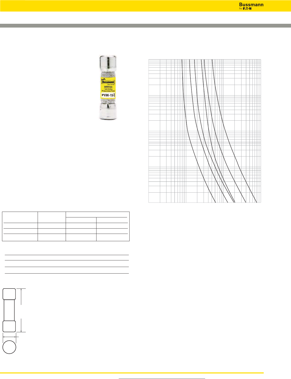
For product data sheets, visit www.cooperbussmann.com/DatasheetsEle
56
Solar Fuse Products
56
13⁄32˝ x 1 1⁄2˝ Midget PV Fuses
Recommended Fuse Holders & Blocks For the PVM Fuse
• See page 54
Specifications
Description: A range of UL 2579
fast-acting 600Vdc Midget fuses specifically
designed to protect solor power systems in
extreme ambient temperature, high cycling
and low level fault current conditions
(reverse current, multi-array fault).
Dimensions: 13⁄32˝ x 1 1⁄2˝
(10.3 x 38.1mm).
Ratings:
Volts — 600Vdc to UL 2579
Amps — 4-30A
IR — 50kA DC (4-30A)
Agency Information: UL Listed 2579, Guide JFGA, File
E335324, CSA Component Certified C22.2.
Features and Benefits
• Specifically designed to protect solar power systems in
extreme ambient temperature per UL 2579 listed
• Capable of withstanding high cycling and low level fault
current conditions
Typical Applications
• Solar Combiner Boxes
• Solar String Protectors
Catalog Numbers (Amps)
PVM-4 PVM-7 PVM-10 PVM-20
PVM-5 PVM-8 PVM-12 PVM-25
PVM-6 PVM-9 PVM-15 PVM-30
PVM
Data Sheet: 2153
Catalog Amp Power Loss (Watts)
Number Rating 0.8 x In1.0 x In
PVM-10 10 1.04 1.86
PVM-15 15 1.00 1.72
PVM-30 30 1.65 2.91
In= Rated current
Power Loss (Watts)
Dimensions - (mm)
1.5"
±0.031
(38.1mm)
0.407"
±0.005
(10.3mm)
1
10
100
CURRENT IN AMPS
.01
.1
1
10
100
AMP
RATING
15 A
10 A
20 A
30 A
8 A
5 A
1,000
TIME IN SECONDS
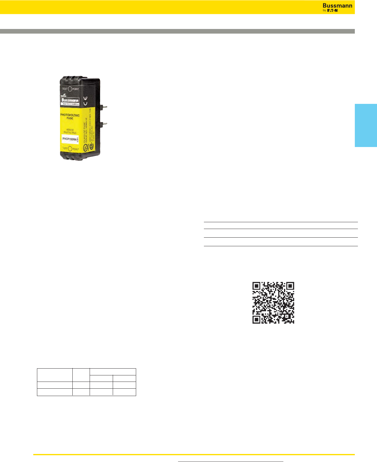
For product data sheets, visit www.cooperbussmann.com/DatasheetsEle 57
Solar
Products
57
Fast-Acting CUBEFuse™
Solar Fuse Products
PVCF Class CF Fuse
Data Sheet: 2155
Fuse Catalog Numbers Non-Indicating (Amps)
PVCF35RN PVCF50RN PVCF80RN
PVCF40RN PVCF60RN PVCF90RN
PVCF45RN PVCF70RN PVCF100RN
Carton Quantity and Weight
Amp Carton Weight Per Carton
Rating Qty. lbs kg
PVCF-35-60A 12 1.42 0.65
PVCF-70-100A 6 1.74 0.79
Catalog Symbol: PVCF_RN
Fast-Acting Fuse: 6 minutes maximum clearing time at 200%
rated current for 30 to 60A fuse
8 minutes maximum clearing time at 200%
rated current for 70 to 100A fuse
Ratings:
Volts — 600Vac (Photovoltaic applications)
— 300Vdc
Amps — 35-100A
IR — 300kA RMS Sym. (UL)
— 200kA RMS Sym. (CSA)
— 50kA DC (UL & CSA)
Agency Information:
• UL 2579 Listed Fuse: Guide JFGA, File E335324
• CSA Certified Fuse: Class C22.2
Other Ratings/Specifications:
Watts Loss at Rated Current: PVCF35RN: 5.45W
PVCF60RN: 7.27W
PVCF100RN: 11.50W
Operating and Storage Temperature Range: -40 to 90°C
Material Specifications:
• Case: Glass filled PES (Polyethersulfone)
• Terminals: Copper alloy
• Terminal plating: Electroless tin
Features and Product Benefits
• Maximize uptime and reliability using fuses designed and
listed to UL 2579: Low Voltage Fuses - Fuses for
Photovoltaic Systems.
• Minimize chances of equipment failure and personnel injury
when using full range fuses having the industry’s fastest
response time to low-magnitude faults.
• Maximize return on investment with fuses proven to
withstand harsh temperatures.
• Minimize design time, operating outage time and
replacement cost with fuses qualified in excessively
changing enviromental conditions.
• Simplify compatibility with readily available industry
standard Class CF holders.
• Temperature Derating: Designed to maximize rated capacity
in elevated environmental temperatures.
• Overload Protection: Proven to clear faults faster than the
UL requirement.
• Power Loss: Minimal energy consumption leading to
increased efficiency.
Recommended Fuse Holders For Class CF Fuses
• See pages 32 and 33
Scan this tag to get the latest product
information for the
New PVCF CUBEFuse.
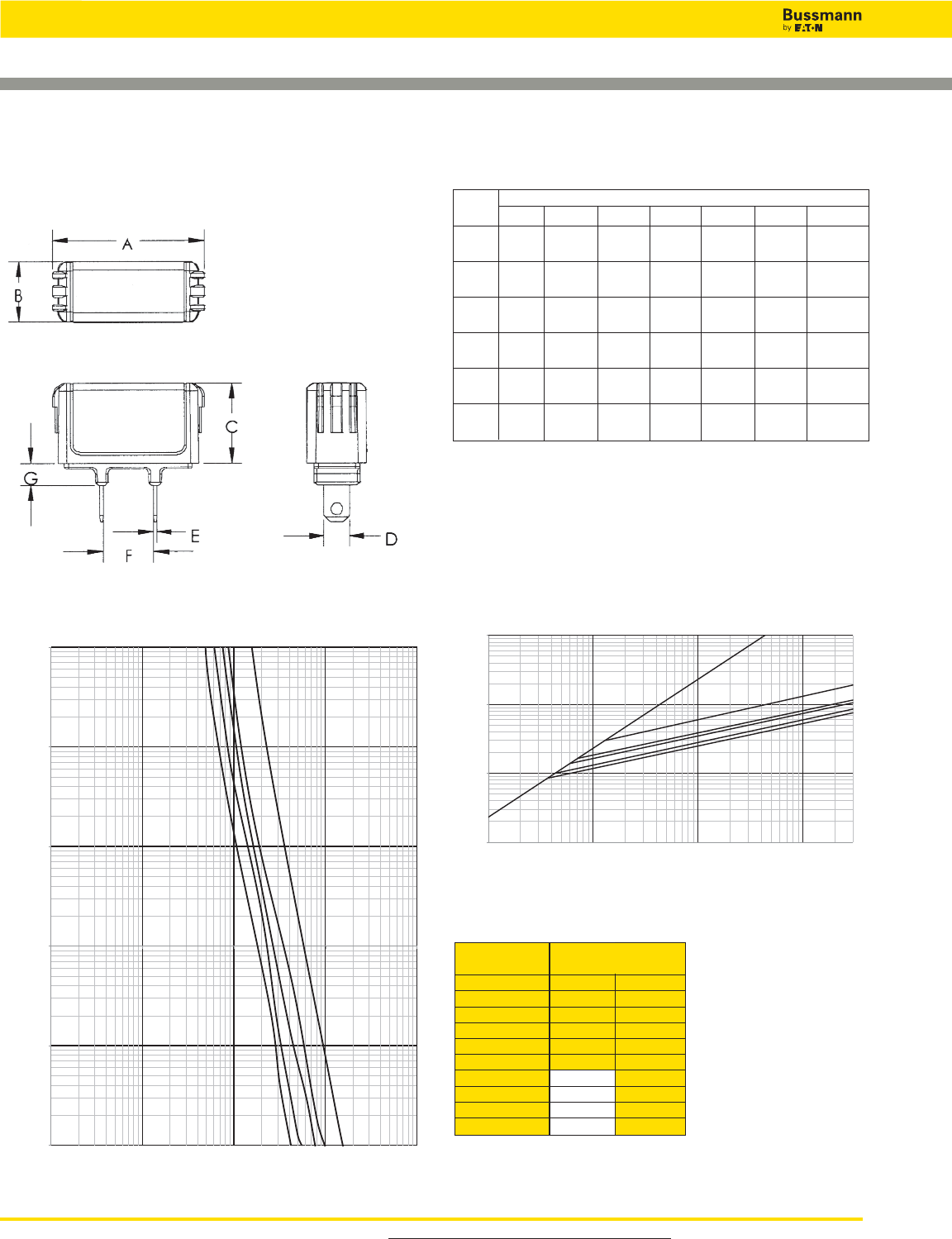
For product data sheets, visit www.cooperbussmann.com/DatasheetsEle
58
Solar Fuse Products
58
Fast-Acting CUBEFuse™
PVCF_RN Dimensions – in (mm)
Data Sheet: 2155
CUBEFuse Holders
Catalog Numbers
(amps) Fits Fuse Holder
Non-Indicating TCFH60N TCFH100N
PVCF35RN X X
PVCF40RN X X
PVCF45RN X X
PVCF50RN X X
PVCF60RN X X
PVCF70RN X
PVCF80RN X
PVCF90RN X
PVCF100RN X
Time-Current Characteristic Curves–Average Melt Current Limitation Curves
100A
60A
40A
50A
35A
0.01
0.1
1
10
100
1000
1
10
100
1,000
10,000
TIME IN SECONDS
CURRENT IN AMPS
60A
100A
40A
50A
35A
100
1,000
10,000
100,000
100
1,000
10,000
100,000
INSTANTANEOUS PEAK LET THRU CURRENT IN AMPS
PROSPECTIVE SHORT CIRCUIT CURRENT
SYMMETRICAL RMS AMPS
B
300,000
A
Fuse Dimensions - in (mm)
Amps A B C D E F G
35-40 2.13 1.00 1.13 0.36 0.04 0.63 0.38
(54.10) (25.40) (28.58) (9.10) (1.02) (15.93) (9.65)
45-50 2.13 1.00 1.13 0.44 0.04 0.63 0.38
(54.10) (25.40) (28.58) (11.13) (1.02) (15.93) (9.65)
60 2.13 1.00 1.13 0.44 0.04 0.63 0.38
(54.10) (25.40) (28.58) (11.13) (1.02) (15.93) (9.65)
70 3.01 1.00 1.26 0.49 0.06 0.58 0.38
(76.45) (25.40) (32.00) (12.45) (1.60) (14.78) (9.65)
80-90 3.01 1.00 1.26 0.49 0.06 0.58 0.38
(76.45) (25.40) (32.00) (12.45) (1.60) (14.78) (9.65)
100 3.01 1.00 1.26 0.57 0.06 0.58 0.38
(76.45) (25.40) (32.00) (14.48) (1.60) (14.78) (9.65)
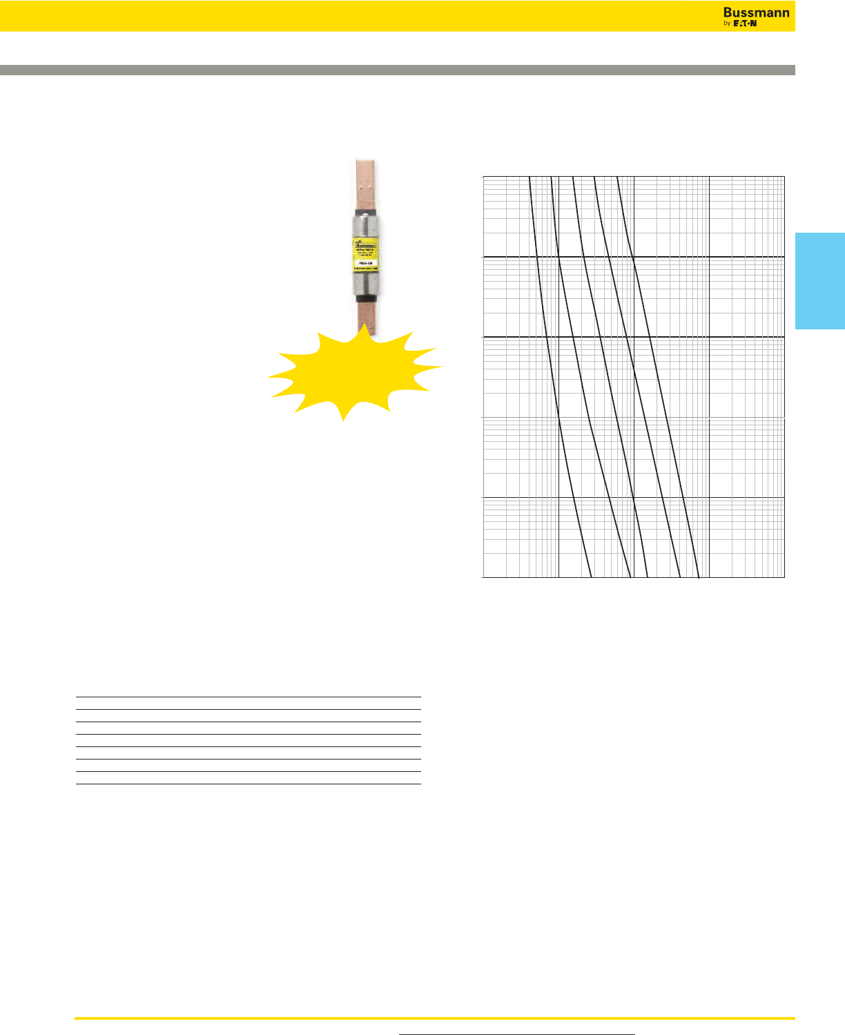
For product data sheets, visit www.cooperbussmann.com/DatasheetsEle 59
Solar
Products
59
Solar Fuse Products
Limitron™ Fast-acting Fuses
Data Sheet: 4203
Specifications
Description: A range of UL 2579 fast-acting
600Vdc Class RK5 fuses specifically
designed to protect solar power systems in
extreme ambient temperature, high cycling
and low level fault current conditions (reverse
current, multi-array fault).
Dimensions: See page 15 for Class RK5
dimensions.
Ratings:
Volts — 600Vac to UL 248-12
600Vdc to UL 2579
Amps — 20-400A
IR — 200kA RMS Sym. AC
20kA DC (20-60A)
10kA DC (70-400A)
Agency Information: UL Std. 248-12, Class RK5, UL
Listed, Guide JFGA, File E335324. Photovoltaic to UL 2579,
CSA Component Certified C22.2.
Features and Benefits
• Current limitation for non-inductive circuits provides Class
RK5 current-limiting response to ground fault and
short-circuit conditions.
• Designed for the protection and isolation of photovoltaic
systems.
Typical Applications
• Photovoltaic systems
• Inverters
• Solar DC Safety Switches
• Recombiner Boxes
Catalog Numbers (Amps)
PVS-R-20 PVS-R-70 PVS-R-175
PVS-R-25 PVS-R-80 PVS-R-200
PVS-R-30 PVS-R-90 PVS-R-225
PVS-R-35 PVS-R-100 PVS-R-250
PVS-R-40 PVS-R-110 PVS-R-300
PVS-R-50 PVS-R-125 PVS-R-350
PVS-R-60 PVS-R-150 PVS-R-400
30A 60A 100A 200A 400A
0.01
0.1
1
10
100
1000
10
100
1,000
10,000
100,000
Time in Seconds
Current in Amps
Time-Current Characteristic Curves—Average Melt
PVS-R (600Vac/dc) Class RK5
Recommended Fuse Holders & Blocks For Class RK5 Fuses
• See page 19
Designed
to meet the new
UL Photovoltaic Fuse
Standard

For product data sheets, visit www.cooperbussmann.com/DatasheetsEle
60
Solar Fuse Products
Specifications
Class: gPV
Description: A range of fuses specifically
designed for the protection and isolation of
photovoltaic strings.
Dimensions: 13⁄32” x 11⁄2”
(10.3 x 38.1mm).
Ratings:
Volts — 1000Vdc
Amps — 1-20A
IR — 33kAdc
IR (Min) — 1.3 x In
Agency Information: CCC pending, UL Listed E335324,
IEC 60269-6, UL 2579, CSA.
Features and Benefits
• Capable of interrupting low over currents associated with
faulted PV strings.
• High DC voltage rating.
• Variety of mounting options for flexibility.
Catalog Numbers (Amps)
PV Dimensions - mm
Time-Current Characteristic Curves—Average Melt
Data Sheet: 720110
Part Number
Current
Rating
(Amps)
Energy Integrals I2t (A2s) Watts Loss
Pre-Arcing Total at 1000V 0.8 InIn
PV-1A10F 1 0.15 0.4 0.8 1.5
PV-2A10F 2 1.2 3.4 0.6 1.0
PV-3A10F 3 4 11 0.8 1.3
PV-3-5A10F 3.5 6.6 18 0.9 1.4
PV-4A10F 4 9.5 26 1.0 1.5
PV-5A10F 5 19 50 1.0 1.6
PV-6A10F 6 30 90 1.1 1.8
PV-8A10F 8 3 32 1.2 2.1
PV-10A10F 10 770 1.2 2.3
PV-12A10F 12 12 120 1.5 2.7
PV-15A10F 15 22 220 1.7 2.9
PV-20A10F 20 34 350 2.1 3.6
10x38mm Photovoltaic Fuses
Recommended Fuse Holders & Blocks For Class RK5 Fuses
• See page 19
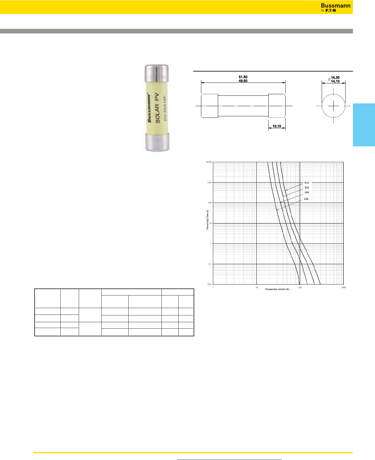
For product data sheets, visit www.cooperbussmann.com/DatasheetsEle 61
Solar
Products
Solar Fuse Products
Specifications
Description: A range of 14x51mm
package fuse links specifically designed
for protecting and isolating photovoltaic
strings. These fuse links are capable of
interrupting low overcurrents associated
with faulted PV systems (reverse
current, multi-array fault).
Dimensions: See dimension illustration.
Construction: Melamine tube with
silver fuse element.
Ratings:
Rated Volts — 1000Vdc (25 & 32A)
1100Vdc (15 & 20A)
Rated Breaking Capacity: 10kA
Amps — 15-32A
Agency Information: UL Listed, Guide JFGA, File
E335324. Photovoltaic to UL 2579,IEC 60269-6 gPV, CSA.
CCC pending.
Features and Benefits
• Specifically designed to provide fast-acting protection under
low fault current conditions associated with PV systems
• High DC voltage rating
• Demonstrated performance in extreme temperature
cycling conditions
Typical Applications
• Photovoltaic systems
Catalog Numbers
14x51mm
14x51mm Photovoltaic Fuses
Time-Current Characteristic Curves—Average Melt
Dimensions - mm
Current Energy Integrats I2t (A2s) Watts Loss
Part Rating Rated
Pre-Arcing Total at Rated
Number (Amps) Voltage Voltage 0.8InIn
PV-15A14F 15 1100Vdc 14 265 2.1 4
PV-20A14F 20 27 568 2.7 5
PV-25A14F 25 1000Vdc 65 943 2.7 5.1
PV-32A14F 32 120 1740 3.3 6.2
Data Sheet: 720132
Available Current (Amps), DC-Time Constant 1-3ms
Recommended Fuse Holders & Blocks For Class RK5 Fuses
• See page 19
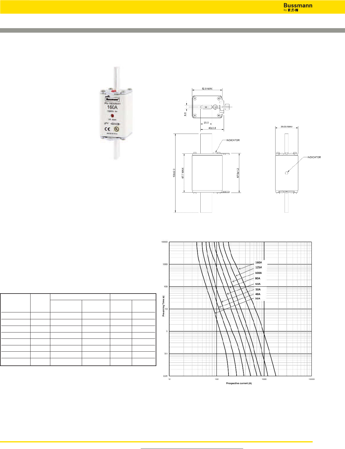
For product data sheets, visit www.cooperbussmann.com/DatasheetsEle
62
Solar Fuse Products
Specifications
Description: A range of NH fuse
links specifically designed for
protecting and isolating photovoltaic
array combiners and disconnects.
These fuse links are capable of
interrupting low overcurrents
associated with faulted PV systems
(reverse current, multi-array fault).
Dimensions: See dimension
illustration.
Construction: Melamine tube with
silver fuse element.
Ratings:
Rated Volts — 1000Vdc
Rated Breaking Capacity: 50kA
Amps — 32-160A
Agency Information: UL Listed, Guide JFGA, File
E335324. Photovoltaic to UL 2579,IEC 60269-6 gPV, CSA.
CCC pending.
Features and Benefits
• Specifically designed to provide fast-acting protection under
low fault current conditions associated with PV systems
• High DC voltage rating
• Variety of mounting options for flexibility
• Demonstrated performance in extreme temperature
cycling conditions
Typical Applications
• Photovoltaic systems
• Inverters
Catalog Numbers
NH1 Photovoltaic Fuses
Current Energy Integrats I2t (A2s) Watts Loss
Part Rating Pre-Arcing Total at
Number (Amps) 1000V 0.8InIn
PV-32ANH1 32 80 720 4.3 8.5
PV-40ANH1 40 185 1670 4.6 9
PV-50ANH1 50 400 3600 5.4 10.5
PV-63ANH1 63 470 4300 6.1 12
PV-80ANH1 80 640 5760 7.9 15.5
PV-100ANH1 100 1300 11,700 8.4 16.5
PV-125ANH1 125 2600 23,400 8.9 17.5
PV-160ANH1 160 5200 46,800 12.2 24
Time-Current Characteristic Curves—Average Melt
Dimensions - mm
Size 1
Available Current (Amps), DC-Time Constant 1-3ms
Data Sheet: 720133
Recommended NH1 Fuse Holders - SD(size)-D
• See page 54
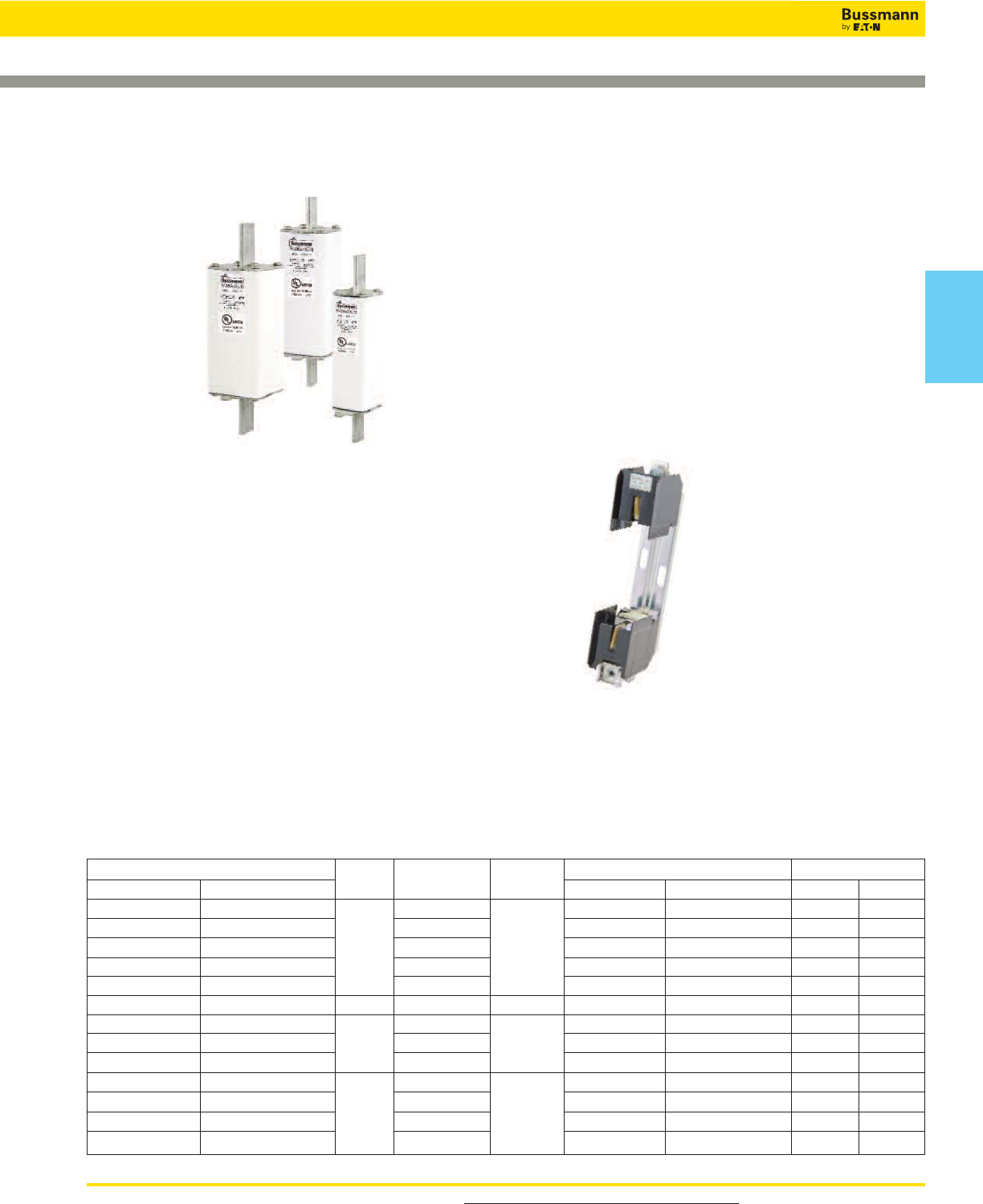
For product data sheets, visit www.cooperbussmann.com/DatasheetsEle 63
Solar
Products
Solar Fuse Products
Data Sheet: 720134
XL Photovoltaic Fuses
Specifications
Description: A range of XL package fuses specifically
designed for protecting and isolating photovoltaic array
combiners and disconnects.
These fuse links are capable of interrupting low overcurrents
associated with faulted PV systems (reverse current,
multi-array fault).
Dimensions: See dimension illustration.
Ratings:
Volts — 1000Vdc
Amps — 63 to 630A:
IR — 50kA @ 63 to 160A
— 33kA @ 200 to 315A
— 50kA @ 350 to 630A
Agency Information: — IEC 60269-6
— RoHS compliant
— UL 2579
— CSA
— CCC (pending
Features and Benefits
• Specifically designed to provide fast-acting protection under
low fault current conditions associated with PV systems
• High DC voltage rating
• Variety of mounting options for flexbility
• Demonstrated performance in extreme temperature
cycling conditions
Typical Applications
• Photovoltaic systems
• Inverters
Recomended Fuse Holders
• SD1XL-S (suitable for 01 and 1XL)
• SD2XL-S (suitable for 2XL)
• SD3L-S (suitable for 3L)
1000Vdc XL Style Photovoltaic
Fuses
Part Number/Style Body Current Energy Integrals I2t (A2s) Watts Loss
Bladed Bolted Size Rating (Amps) Volts Pre-Arcing Total @ 1000V 0.8InIn
PV-63A-01XL PV-63A-01XL-B 63 350 2520 12 24
PV-80A-01XL PV-80A-01XL-B 80 660 4752 14 27
PV-100A-01XL PV-100A-01XL-B 01 100 1000Vdc 1350 9720 15 30
PV-125A-01XL PV-125A-01XL-B 125 1930 13,896 20 40
PV-160A-01XL PV-160A-01XL-B 160 3900 28,080 25 44
PV-200A-1XL PV-200A-1XL-B 1 200 1000Vdc 9400 27,260 31 60
PV-200A-2XL PV-200A-2XL-B 200 4152 31,000 29 62
PV-250A-2XL PV-250A-2XL-B 2 250 1000Vdc 7721 57,000 35 70
PV-315A-2XL PV-315A-2XL-B 315 17,600 130,000 40 75
PV-350A-3L PV-350A-3L-B 350 30,885 160,700 41 90
PV-400A-3L PV-400A-3L-B 3400 1000Vdc 44,000 230,000 63 100
PV-500A-3L PV-500A-3L-B 500 48,300 251,200 71 138
PV-630A-3L PV-630A-3L-B 630 100,000 520,000 92 180
See Data Sheet 720146 for information
on the SD__-S Fuse Holders.
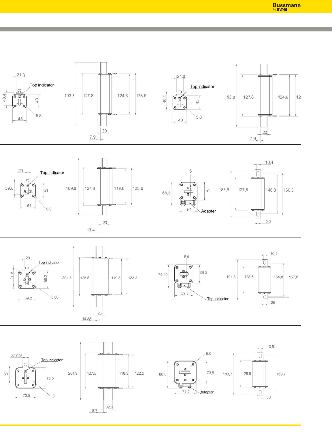
For product data sheets, visit www.cooperbussmann.com/DatasheetsEle
64
Solar Fuse Products
XL Photovoltaic Fuses for Solar Applications
1XL Blade Size 1XL Bolt Size
2XL Blade Size 2XL Bolt Size
Dimensions - mm (not to scale)
3L Blade Size 3L Bolt Size
01XL Blade Size 01XL Bolt Size
Data Sheet: 720134
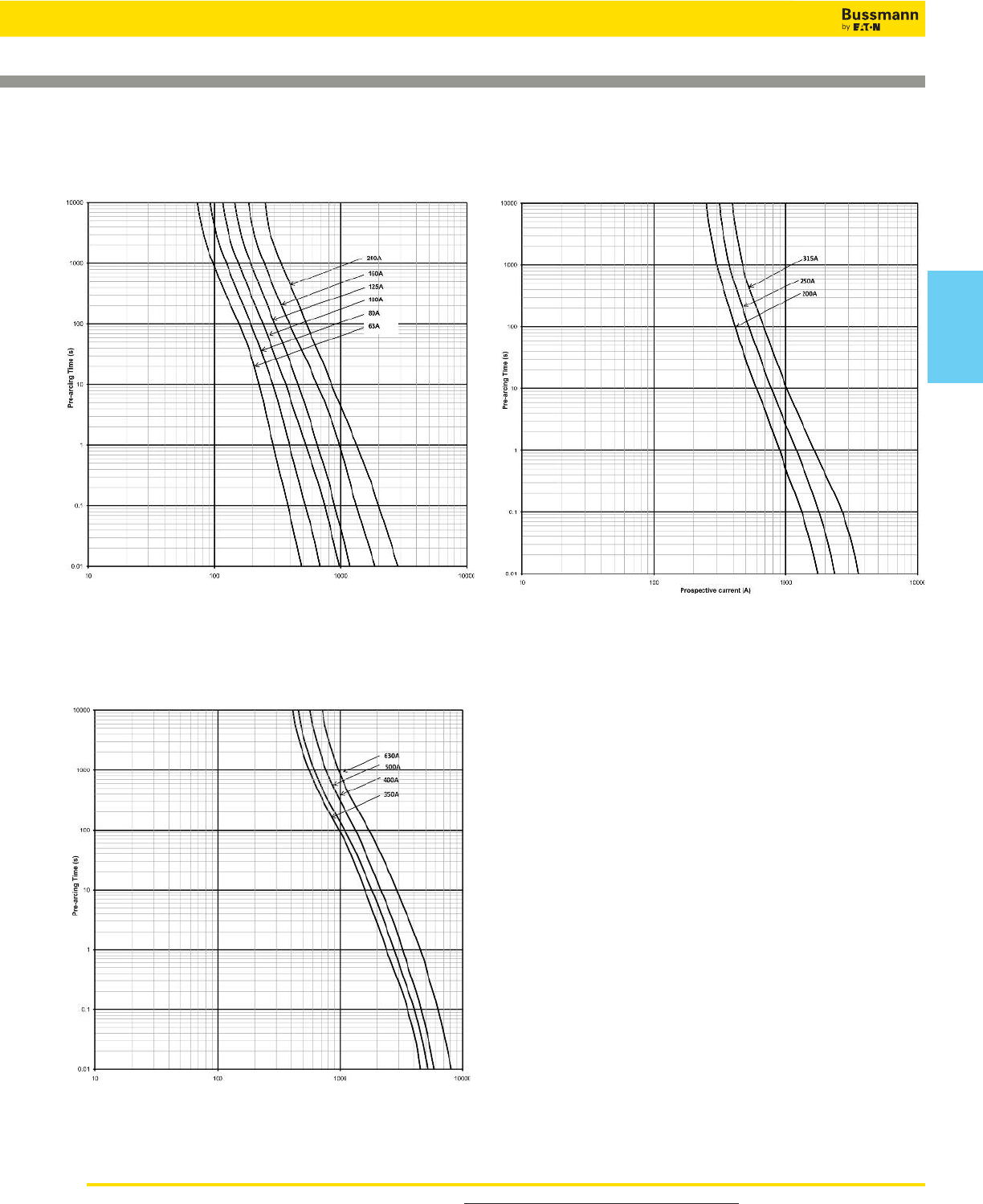
For product data sheets, visit www.cooperbussmann.com/DatasheetsEle 65
Solar
Products
Solar Fuse Products
Data Sheet: 720134
XL Photovoltaic Fuses for Solar Applications
Time Current Curves for 01XL and 1XL
Available Current (Amps), DC-Time Constant 1-3ms
Time Current Curves for 2XL
Available Current (Amps), DC-Time Constant 1-3ms
Time Current Curves for 3L
Available Current (Amps), DC-Time Constant 1-3ms
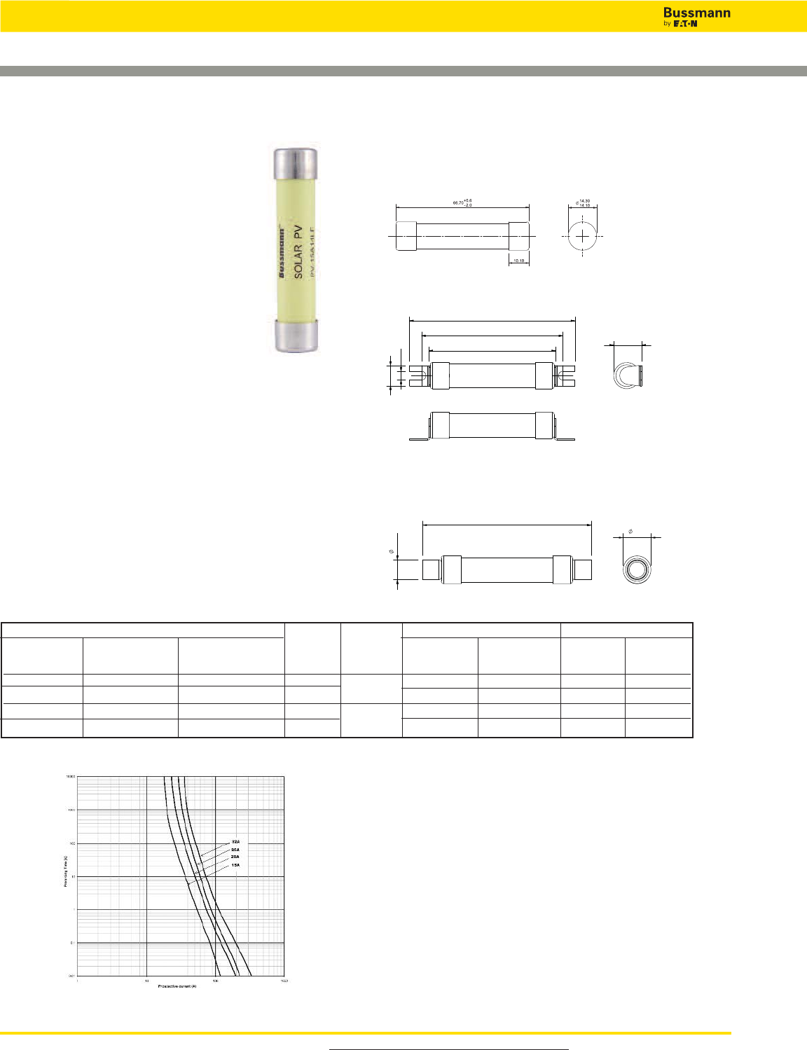
For product data sheets, visit www.cooperbussmann.com/DatasheetsEle
66
Solar Fuse Products
Cylindrical with 10mm Fixings PV - (amp rating)
A14LF10F
14x65mm Photovoltaic Fuses
Data Sheet: 720139
Specifications
Description: A range of 14x65mm
package fuse links specifically designed
for protecting and isolating photovoltaic
strings. These fuse links are capable of
interrupting low overcurrents associated
with faulted PV systems (reverse
current, multi-array fault).
Dimensions: See dimension illustration.
Construction: Melamine tube with
silver fuse element.
Ratings:
Rated Volts — 1300Vdc (25 & 32A)
1500Vdc (15 & 20A)
Rated Breaking Capacity: 10kA
Amps — 15-32A
Agency Information: UL Listed, Guide JFGA, File
E335324. Photovoltaic to UL 2579,IEC 60269-6 gPV, CSA.
CCC pending.
Features and Benefits
• Specifically designed to provide fast-acting protection under
low fault current conditions associated with PV systems
• High DC voltage rating
• Demonstrated performance in extreme temperature
cycling conditions
Typical Applications
• Photovoltaic systems
Catalog Numbers
Part Number Current Rated Energy Integrats Iat (A2s) Watts Loss
Cylindrical Cylindrical Cylindrical with Rating Voltage Pre-Arching Total at 0.8 InIn
with Tags 10mm Fixings (Amps) Rated Voltage
PV-15A14LF PV-15A14L-T PV-15A14LF10F 15 1500Vdc 14 160 3.2 5.8
PV-20A14LF PV-20A14L-T PV-20A14LF10F 20 34 400 3.6 6.5
PV-25A14LF PV-25A14L-T PV-25A14LF10F 25 1300Vdc 65 550 4.1 7.5
PV-32A14LF PV-32A14L-T PV-32A14LF10F 32 105 900 5.7 10.4
Dimensions - mm
Cylindrical PV - (amp rating) A14LF
Cylindrical with Tags PV - (amp rating) A14L-T
67.34
69.34
77.12
75.12
10.99
90.07
88.07
4.70
15.22
15.02
14.22
14.02
84.77
86.77
10.25
10.05
Time-Current Characteristic Curves—Average Melt
Available Current (Amps), DC-Time Constant 1-3ms
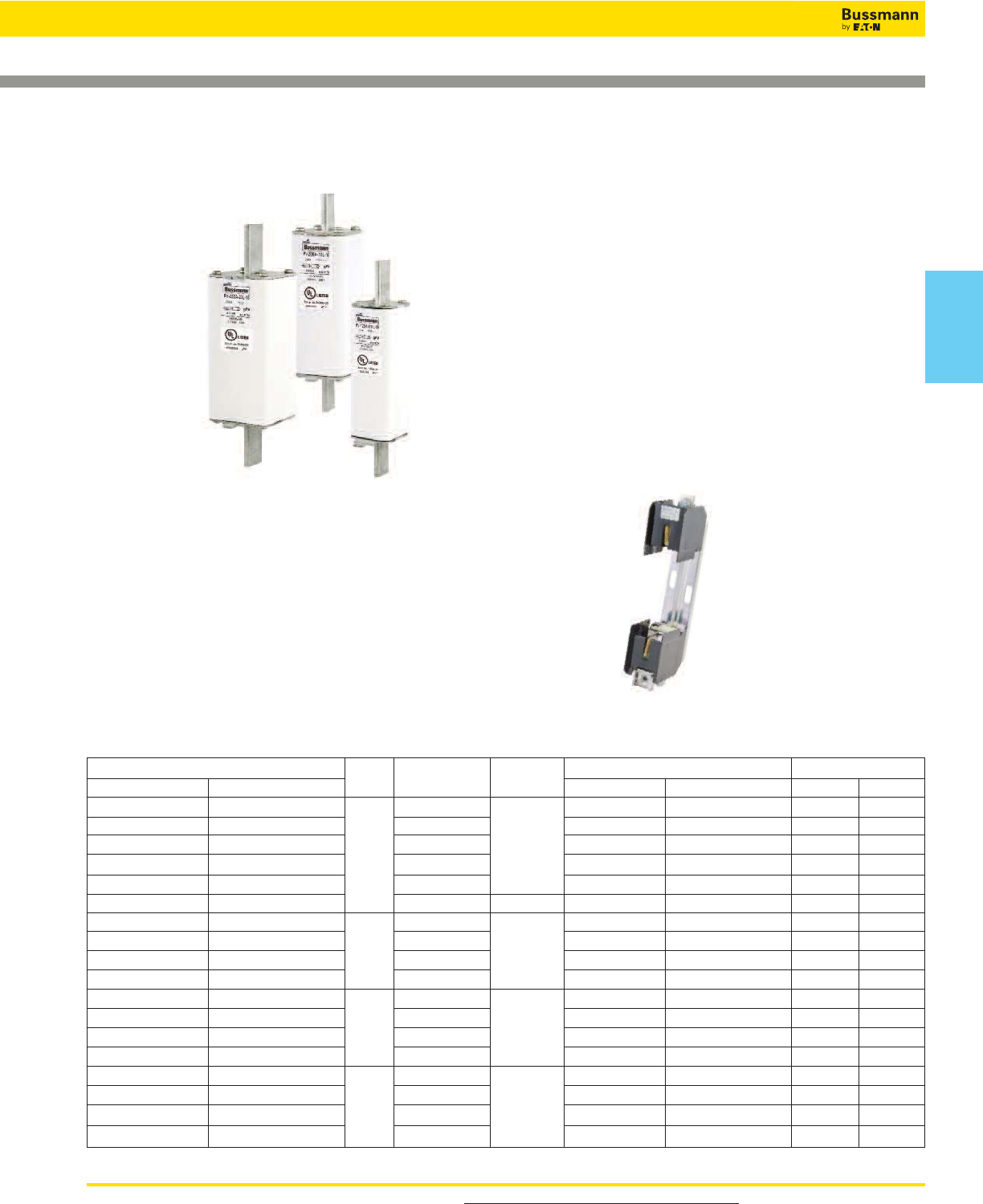
For product data sheets, visit www.cooperbussmann.com/DatasheetsEle 67
Solar
Products
Solar Fuse Products
Data Sheet: 720134
XL Photovoltaic Fuses
Specifications
Description: A range of XL package fuses specifically
designed for protecting and isolating photovoltaic array
combiners and disconnects.
These fuse links are capable of interrupting low overcurrents
associated with faulted PV systems (reverse current,
multi-array fault).
Dimensions: See dimension illustration.
Ratings:
Volts — 1200Vdc (160A)
— 1500Vdc (50-125A, 200-400A)
Amps — 63 to 400A:
IR — 33kA
Agency Information: UL Listed, Guide JFGA, File
E335324. Photovoltaic to UL 2579, IEC 60269-6 gPV, CSA.
CCC pending.
Features and Benefits
• Specifically designed to provide fast-acting protection under
low fault current conditions associated with PV systems
• High DC voltage rating
• Variety of mounting options for flexbility
• Demonstrated performance in extreme temperature
cycling conditions
Typical Applications
• Photovoltaic systems
• Inverters
Recomended Fuse Holders
• SD1XL-S (suitable for 01 and 1XL)
• SD2XL-S (suitable for 2XL)
• SD3L-S (suitable for 3L)
1500Vdc XL Style Photovoltaic
Fuses
Part Number/Style Body Current Energy Integrals I2t (A2s) Watts Loss
Bladed Bolted Size Rating (Amps) Volts Pre-Arcing Total @ 1000V 0.8InIn
PV-50A-01XL-15 PV-50A-01XL-B-15 50 280 1450 6 26
PV-63A-01XL-15 PV-63A-01XL-B-15 63 420 2250 17 28
PV-80A-01XL-15 PV-80A-01XL-B-15 01 80 1500Vdc 950 5000 18 30
PV-100A-01XL-15 PV-100A-01XL-B-15 100 1250 6500 22 38
PV-125A-01XL-15 PV-125A-01XL-B-15 125 2200 11,500 27 48
PV-160A-01XL-12 PV-160A-01XL-B-12 160 1200Vdc 5000 19,500 24 48
PV-100A-1XL-15 PV-100A-1XL-B-15 100 1250 6000 24 43
PV-125A-1XL-15 PV-125A-1XL-B-15 1125 1500Vdc 1950 9360 25 52
PV-160A-1XL-15 PV-160A-1XL-B-15 160 4200 20,160 30 58
PV-200A-1XL-15 PV-200A-1XL-B-15 200 9400 45,120 31 61
PV-125A-2XL-15 PV-125A-2XL-B-15 125 1500Vdc 2200 11,000 23 43
PV-160A-2XL-15 PV-160A-2XL-B-15 2160 5000 25,000 26 50
PV-200A-2XL-15 PV-200A-2XL-B-15 200 9300 36,000 28 56
PV-250A-2XL-15 PV-250A-2XL-B-15 250 13,700 68,000 38 72
PV-250A-3L-15 PV-250A-3L-B-15 250 20,000 61,000 35 62
PV-315A-3L-15 PV-315A-3L-B-15 3315 1500Vdc 38,000 116,000 40 72
PV-355A-3L-15 PV-355A-3L-B-15 355 44,000 136,000 46 84
PV-400A-3L-15 PV-400A-3L-B-15 400 58,000 177,000 50 91
See Data Sheet 720146 for information
on the SD__-S Fuse Holders.
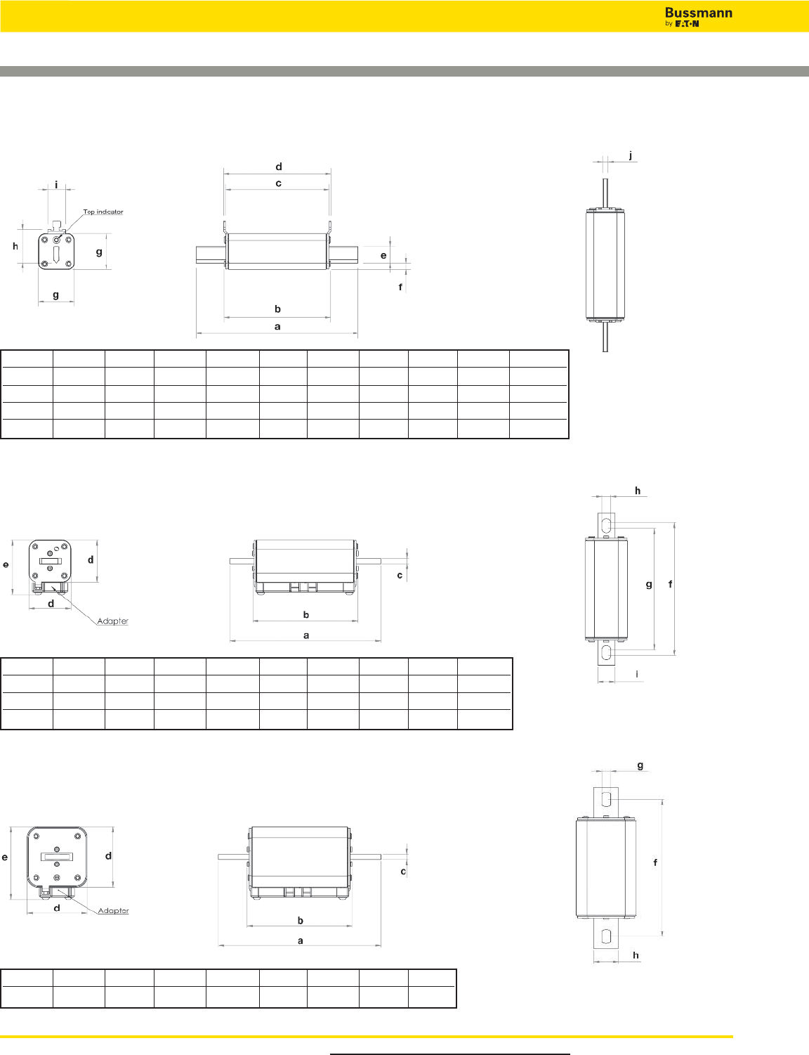
For product data sheets, visit www.cooperbussmann.com/DatasheetsEle
68
Solar Fuse Products
XL Photovoltaic Fuses
Dimensions - mm
Bladed - Size 01XL, 1XL, 2XL and 3L
Size a b c d e f g h i j
01XL 193.8 127.8 124.6 128.6 20 7.9 43 40.4 21.3 5.8
1XL 189.8 127.8 119.6 123.6 20 13.4 51 39.8 20 5.8
2XL 204.5 128.5 119.3 123.3 26 14.38 59.2 47.9 20 5.8
3L 204.9 127.5 118.3 122.3 32.3 18.7 73.5 60 22 6
Bladed - Size 01XL, 1XL, 2XL and 3L
Bladed - Size 01XL, 1XL, 2XL and 3L
Size a b c d e f g h i
01XL 187.6 127.8 6 43 58.3 164.3 150.3 10.4 20
1XL 183.6 127.8 6 51 66.3 160.3 146.3 10.4 20
2XL 191.3 128.5 6 59.2 74.5 167.8 154.8 10.5 25
Size a b c d e f g h
3L 199.7 128.5 6 73.5 88.8 169.7 10.5 30
Data Sheet: 720134
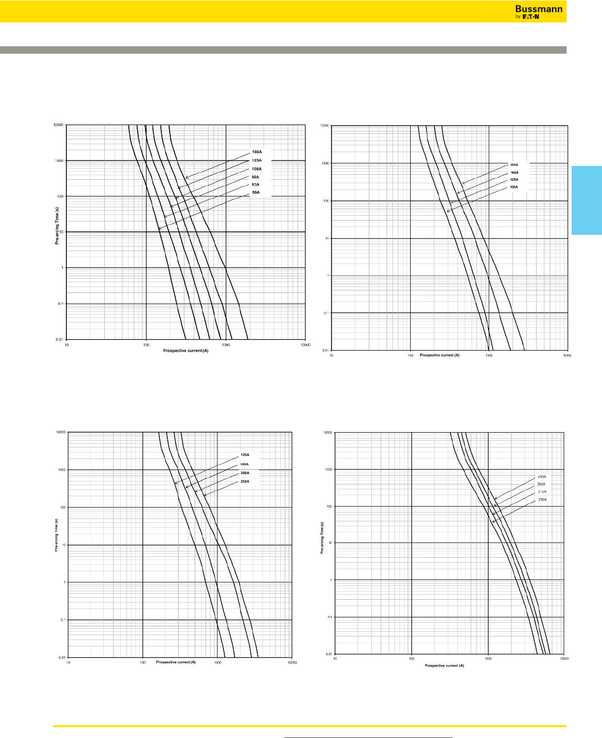
For product data sheets, visit www.cooperbussmann.com/DatasheetsEle 69
Solar
Products
Solar Fuse Products
Data Sheet: 720134
XL Photovoltaic Fuses
Time Current Curves for 01XL - 1500Vdc
Available Current (Amps), DC-Time Constant 1-3ms
Time Current Curves for 1XL - 1500Vdc
Available Current (Amps), DC-Time Constant 1-3ms
Time Current Curves for 2XL - 1500Vdc
Available Current (Amps), DC-Time Constant 1-3ms
Time Current Curves for 3L - 1500Vdc
Available Current (Amps), DC-Time Constant 1-3ms

70
Find blown fuses fast and easy.
Utilize LED technology to
indicate a blown fuse.
easy
ID™ fuses
and fuse holders
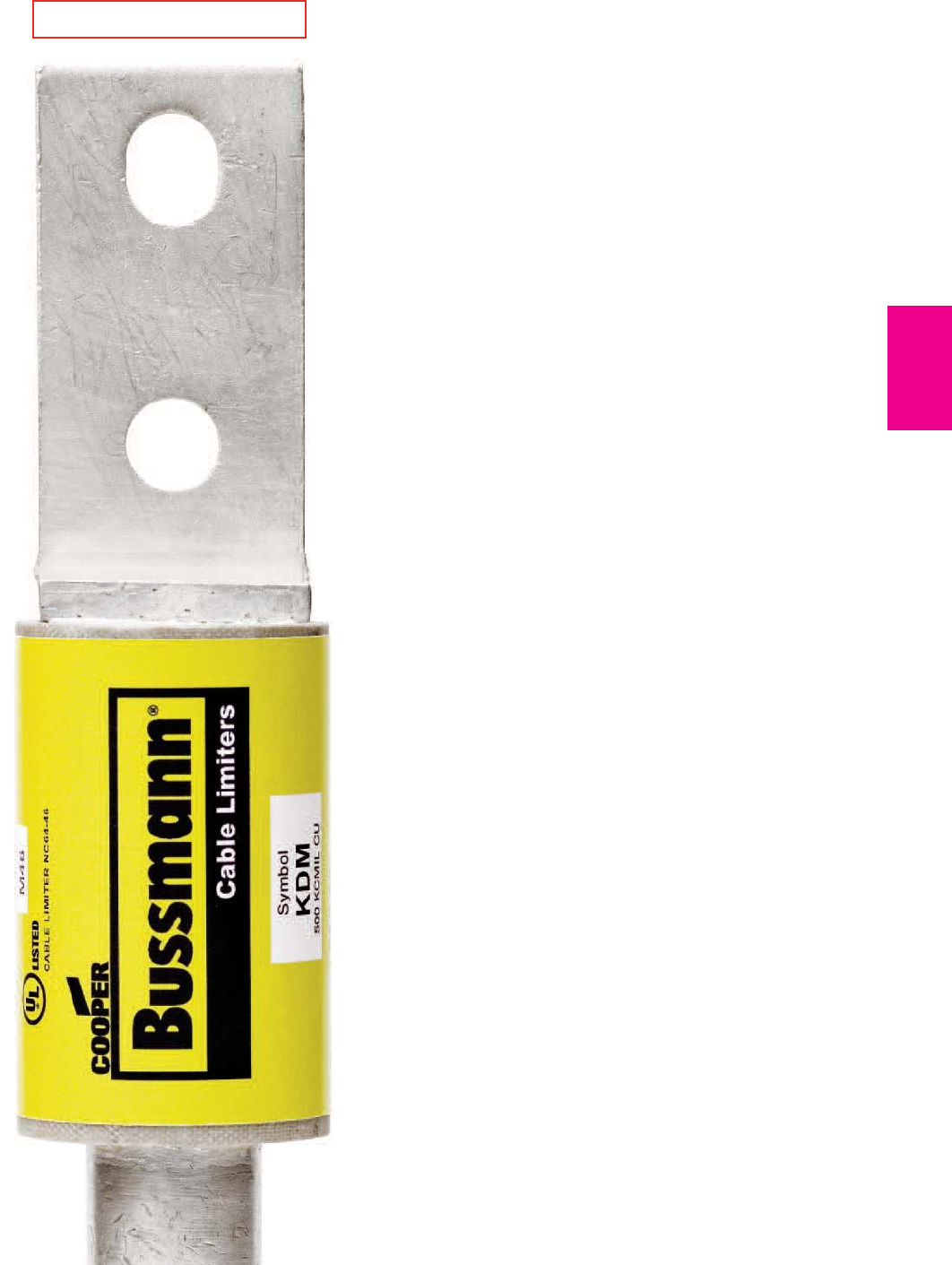
71
Low Voltage
Supplementary
Fuses
Low Voltage
Supplementary Fuses
Section Contents
Page
Fuse Holder & Block Selection Guide . . . . . 72-73
Cable limiters & welder limiters
K Series cable limiters . . . . . . . . . 600V . . . . . . . . . . 74
64000 & 68000 welder limiters . . . 600V . . . . . . . . . . 74
13⁄32˝ x 1 1⁄2˝ Fast-acting supplementary fuses
BAF . . . . . . . . . . . . . . . . . . . . . . 250V . . . . . . . . . . 75
KTK . . . . . . . . . . . . . . . . . . . . . . 600V . . . . . . . . . . 75
KLM . . . . . . . . . . . . . . . . . . . . . . 600Vac/dc . . . . . . 75
13⁄32˝ x 1 1⁄2˝ Time-delay supplementary fuses
FNM . . . . . . . . . . . . . . . . . . . . . . 250V . . . . . . . . . . 76
FNQ . . . . . . . . . . . . . . . . . . . . . . 500V . . . . . . . . . . 76
13⁄32˝ x 1 3⁄8˝ Fast-acting supplementary fuses
BBS . . . . . . . . . . . . . . . . . . . . . . 600V . . . . . . . . . . 77
Pin indication fuses and actuator
GBA . . . . . . . . . . . . . . . . . . . . . . 125V . . . . . . . . . . 78
GLD . . . . . . . . . . . . . . . . . . . . . . 125V . . . . . . . . . . 78
MIC . . . . . . . . . . . . . . 250V fast-acting . . . . . . . . . . . 78
MIN . . . . . . . . . . . . . . 250V fast-acting . . . . . . . . . . . 78
FNA . . . . . . . . . . . . . . 250V time-delay . . . . . . . . . . 78
MIS . . . . . . . . . . . . . . . . . . . . . . . 600V . . . . . . . . . . 79
KAZ . . . . . . . . . . . . . . . . . . . . . . . 600V . . . . . . . . . . 79
Limiters
ANN . . . . . . . . . . . . . . 125V fast-acting . . . . . . . . . 79
ANL . . . . . . . . . . . . . . 80Vdc time-delay . . . . . . . . . 79
4164 & 4164-FR . . . . . . . . . .fuse blocks . . . . . . . . . 79
In-line size rejecting fuses and fuse holders
GLQ . . . . . . . . . . . . . . . . . . . . . . 300V . . . . . . . . . . 80
GMQ . . . . . . . . . . . . . . . . . . . . . . 300V . . . . . . . . . . 80
In-line non-rejecting fuses and fuse holders
GLR . . . . . . . . . . . . . . . . . . . . . . 300V . . . . . . . . . . 81
GMF . . . . . . . . . . . . . . . . . . . . . . 300V . . . . . . . . . . 81
GRF . . . . . . . . . . . . . . . . . . . . . . 300V . . . . . . . . . . 81
Automotive blade-type fuses
ATC . . . . . . . . . . . . . . . . . . . . . . . 32Vdc . . . . . . . . . 82
ATC-_ID . . . . . . . . . . . . . . . . . . . . 32Vdc . . . . . . . . . 82
ATM . . . . . . . . . . . . . . . . . . . . . . . 32Vdc . . . . . . . . 82
ATM-_ID . . . . . . . . . . . . . . . . . . . .32Vdc . . . . . . . . . 82
ATM-LP . . . . . . . . . . . . . . . . . . . . 32Vdc . . . . . . . . . 82
MAX . . . . . . . . . . . . . . . . . . . . . . 32Vdc . . . . . . . . 83
MAX-_ID . . . . . . . . . . . . . . . . . . . .32Vdc . . . . . . . . . 83
Automotive blade-type fuse holders
HHC, HHD, HHF, HHG, ATC-FHID for ATC fuses . . . . 82
HHL, HHM, ATC-FHID for ATM fuses . . . . . . . . . . . . . 83
HHX for MAX fuses . . . . . . . . . . . . . . . . . . . . . . . . . . 83
PCB fuseclips for ATC/ATM blade, 5mm, 1⁄4˝ & 13⁄32˝
diameter fuses . . . . . . . . . . . . . . . . . . . . . . . . . . . . .84
RED indicates NEW information
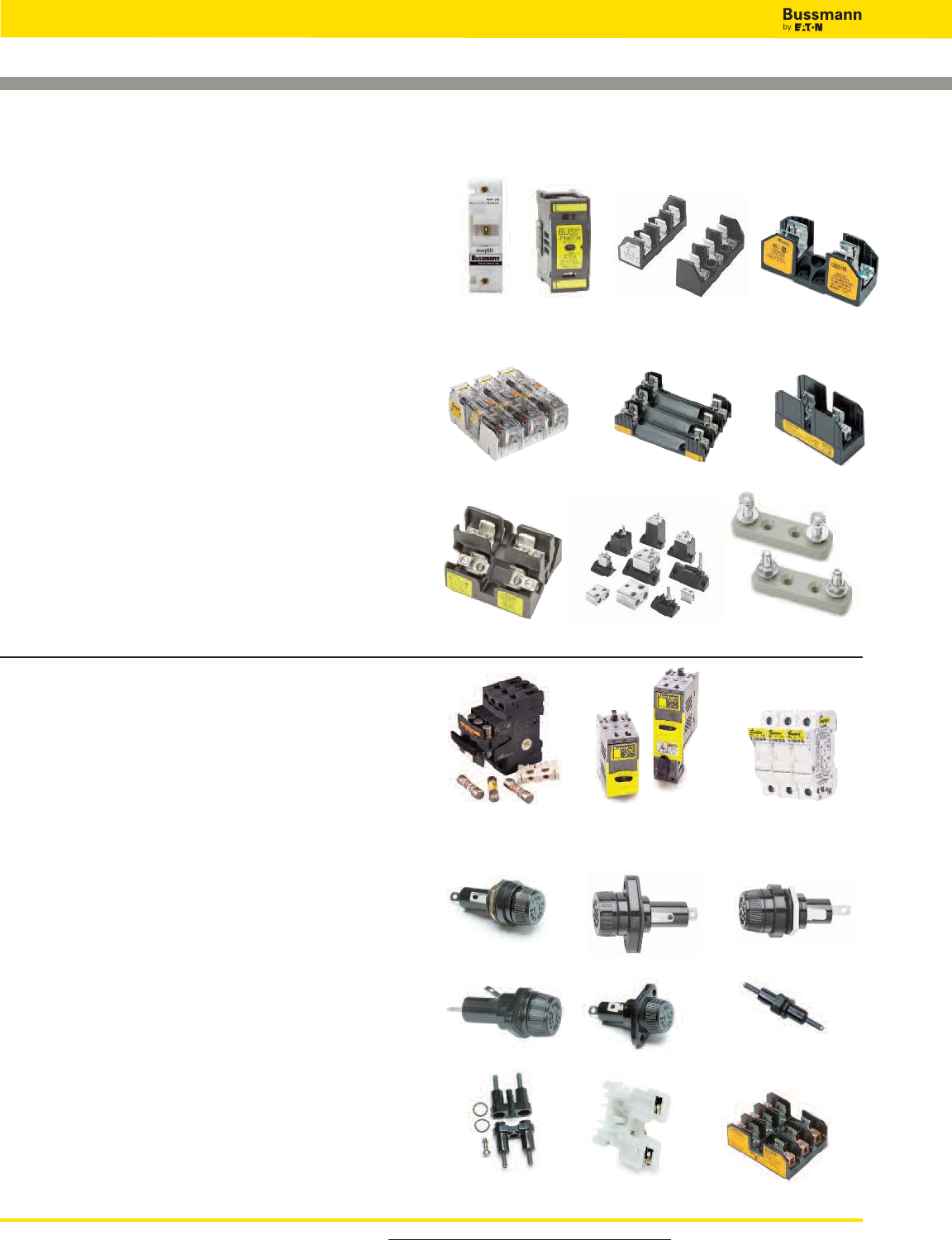
For product data sheets, visit www.cooperbussmann.com/DatasheetsEle
72
Low Voltage Supplementary Fuses
13⁄32˝ X 1 1⁄2˝ Fuses
Catalog Number Volts Page
BAF . . . . . . . . . . . . . . . . . . . . . . . 250V . . . . . . . . . . . . . . . . . . . 75
KTK . . . . . . . . . . . . . . . . . . . . . . . 600V . . . . . . . . . . . . . . . . . . . 75
KLM . . . . . . . . . . . . . . . . . . . . . . . 600Vac/dc . . . . . . . . . . . . . . . 75
FNM . . . . . . . . . . . . . . . . . . . . . . 250V . . . . . . . . . . . . . . . . . . . 76
FNQ . . . . . . . . . . . . . . . . . . . . . . . 500V . . . . . . . . . . . . . . . . . . . 76
Holders
• OPM-NG-SC3 3-pole, panel/DIN-Rail mount . . . . . . . . . . . . . . .286
• OPM-1038R 3-pole, panel/DIN-Rail mount . . . . . . . . . . . . . . . .285
• OPM-1038RSW 3-pole w/ switch, panel/DIN-Rail mount . . . . .284
• CH Series Global 1- to 3-pole, DIN-Rail mount . . . . . . . . . . . . .276
• HPG Panel mount fuse holder . . . . . . . . . . . . . . . . . . . . . . . . .322
• HPC-D Panel mount fuse holder . . . . . . . . . . . . . . . . . . . . . . .323
• HPM Panel mount fuse holder . . . . . . . . . . . . . . . . . . . . . . . .323
• HPS Series Panel mount fuse holder . . . . . . . . . . . . . . . . . . . .322
• HPF Series Panel mount fuse holder . . . . . . . . . . . . . . . . . . . . 322
• HEB Series 1-Pole in-line fuse holder . . . . . . . . . . . . . . . . . . . .315
• HEX & HEY Series 2-Pole in-line fuse holders . . . . . . . . . . . . . 315
• NDNF1-WH Fuse holding rail mount terminal block . . . . . . . . . 327
Blocks
• BM Series, panel/DIN-Rail with adapters . . . . . . . . . . . . . . . . . 310
• 3723, 3742 and 3743 multi-pole add-on fuse blocks . . . . . . . . 326
OPM-NG-SC3 CH Series
CH Series
J600 Series
JP Series BH Series 4164 & 4164-FR
Safety J™
Series
Modular
Type
H250 Series
H600 Series
OPM-1038R &
OPM-1038RSW
Holders & Blocks for Low Voltage Supplementary Fuses
Limiters
Catalog Number Volts Page
K Series . . . . . . . . . . . . . . . . . . . . 600V . . . . . . . . . . . . . . . . . . . 74
68000 Series . . . . . . . . . . . . . . . . 600V . . . . . . . . . . . . . . . . . . . 74
64000 Series . . . . . . . . . . . . . . . . 600V . . . . . . . . . . . . . . . . . . . 74
ANN Fast acting limiter . . . . . . . . . 125Vac/80Vdc . . . . . . . . . . . . 79
ANL Time-delay limiter . . . . . . . . . 80Vdc . . . . . . . . . . . . . . . . . . 79
Holders
• CH Series Class J modular 1 to 3-pole, panel/DIN rail mount . .283
• Safety J™ Series modular holders, panel/DIN rail mount . . . . . 288
Blocks
• Modular Type Fuse Blocks 250/600V, panel mount . . . . . . . . . 311
• H250 Series 1- to 3-pole 250V, panel mount . . . . . . . . . . . . . .296
• H600 Series 1- to 3-pole 600V, panel mount . . . . . . . . . . . . . .299
Blocks
• Modular Knifeblade Fuse Blocks 250/600V, panel mount . . . . 291
• Modular Type Fuse Blocks 600V, panel mount . . . . . . . . . . . . 311
• J600 Series, panel mount . . . . . . . . . . . . . . . . . . . . . . . . . . . 302
• JP Series pyramid blocks, panel mount . . . . . . . . . . . . . . . . . 304
• BH Series modular-style open blocks, panel mount . . . . . . . . 311
Limiter Blocks - ANN & ANL
• Blocks for 4164 & 4164-FR . . . . . . . . . . . . . . . . . . . . . . . . . . . 79
HPG HPC-D HPM
HPS HPF HEB Series
HEX & HEY
Series
NDNF1-WH BM Series
Modular Knifeblade
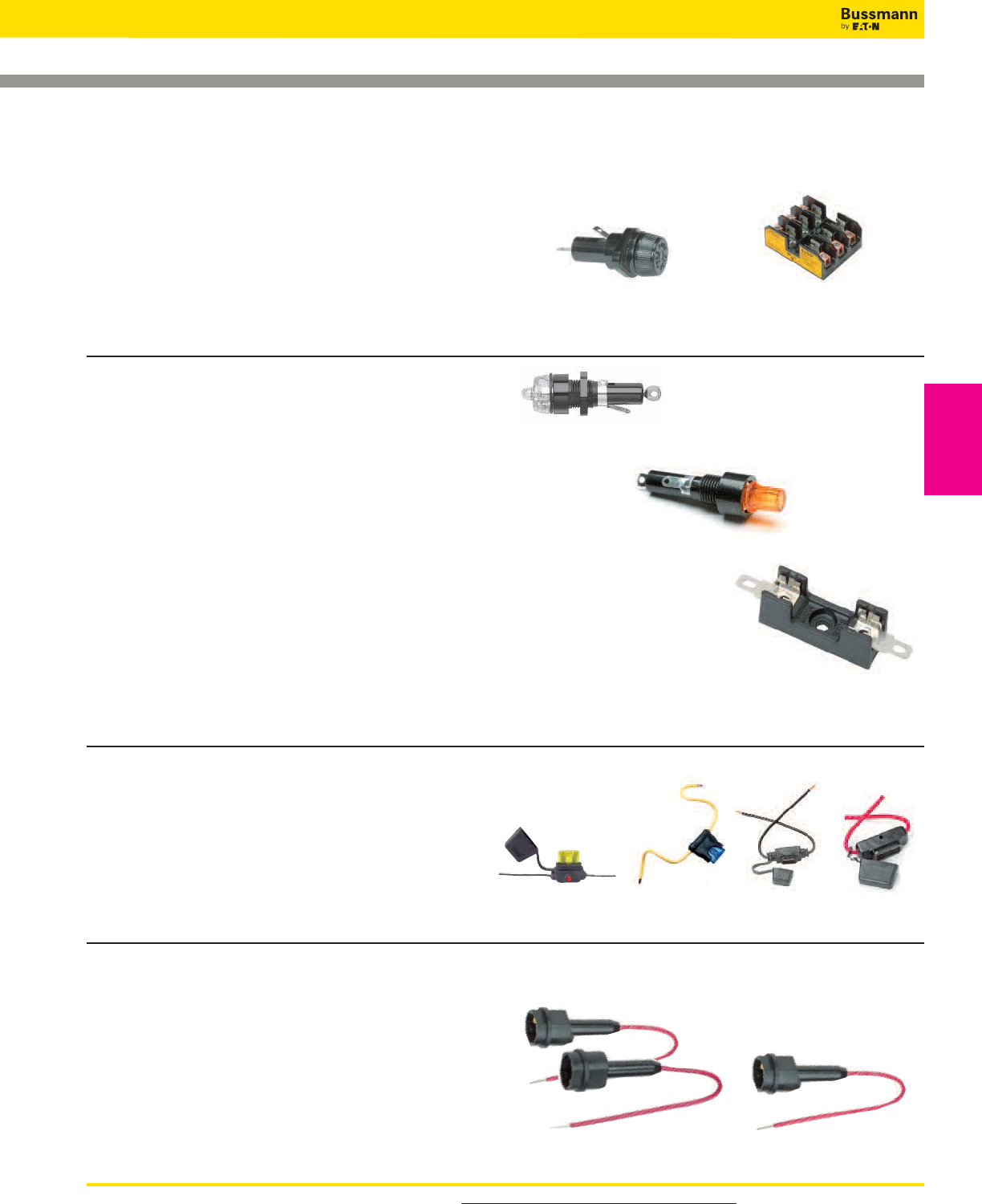
For product data sheets, visitwww.cooperbussmann.com/DatasheetsEle 73
Low Voltage Supplementary Fuses
Low Voltage
Supplementary
Fuses
Holders & Blocks for Low Voltage Supplementary Fuses
In-Line Rejecting and Non-Rejecting Fuses
Catalog Number Volts Page
GLQ rejecting fuse . . . . . . . . . . . . . . . . .300V . . . . . . . . . . . . . . . 80
GMQ rejecting fuse . . . . . . . . . . . . . . . . 300V . . . . . . . . . . . . . . . 80
GLR non-rejecting fuse . . . . . . . . . . . . . 300V . . . . . . . . . . . . . . . 81
GMF non-rejecting fuse . . . . . . . . . . . . . 300V . . . . . . . . . . . . . . . 81
GRF non-rejecting fuse . . . . . . . . . . . . . 300V . . . . . . . . . . . . . . . 81
Holders
• GLQ & GMQ: HLQ Rejection holder . . . . . . . . . . . . . . . . . . . . . 80
• GLR, GMF & GRF: HLR & HLR-2A non-rejection holders . . . . . .81
13⁄32˝ X 1 3⁄8˝ Fuses
Catalog Numbers Volts Page
BBS . . . . . . . . . . . . . . . . . . . . . . . . . . . 600V . . . . . . . . . . . . . . . 77
Holder
• HPS-L Panel mount holder . . . . . . . . . . . . . . . . . . . . . . . . . . .322
Blocks
• BM Series, panel/DIN rail with adapters . . . . . . . . . . . . . . . . . .310
• 3723, 3742 and 3743 multi-pole add-on fuse blocks . . . . . . . .326
Automotive Blade-type Fuses
Catalog Numbers Volts Page
ATC . . . . . . . . . . . . . . . . . . . . . . . . . . . . 32Vdc . . . . . . . . . . . . . . 82
ATM . . . . . . . . . . . . . . . . . . . . . . . . . . . 32Vdc . . . . . . . . . . . . . . 82
MAX . . . . . . . . . . . . . . . . . . . . . . . . . . . 32Vdc . . . . . . . . . . . . . . 83
Holders
• ATC: HHC, HHD, HHF, HHG & ATC-FHID In-line holders . . . . . . 82
• ATM: HHL, HHM & ATM-FHID In-line holders . . . . . . . . . . . . . 83
• MAX: HHX In-line holders . . . . . . . . . . . . . . . . . . . . . . . . . . . . 83
Pin Indicating Fuses
1⁄4˝ X 11⁄4˝ Fuse Catalog Numbers
Volts Page
GBA 1⁄4" X 1 1⁄4" . . . . . . . . . . . . . . . . . . . . .125V . . . . . . . . . . . . . . .78
GLD 1⁄4" X 1 1⁄4" . . . . . . . . . . . . . . . . . . . . .125V . . . . . . . . . . . . . . .78
MIC 13⁄32" X 1 1⁄2" . . . . . . . . . . . . . . . . . . . .250V . . . . . . . . . . . . . . . 78
MIN 13⁄32" X 1 1⁄2" . . . . . . . . . . . . . . . . . . . .250V . . . . . . . . . . . . . . . 78
FNA 13⁄32" X 1 1⁄2" . . . . . . . . . . . . . . . . . . . .250V . . . . . . . . . . . . . . . 78
MIS 13⁄32" X 2" . . . . . . . . . . . . . . . . . . . . . 600V . . . . . . . . . . . . . . . 79
KAZ 13⁄32" X 2" . . . . . . . . . . . . . . . . . . . . . 600V . . . . . . . . . . . . . . . 79
Holders
•1⁄4" X 1 1⁄4": HLD Panel mount visual indication . . . . . . . . . . . . .321
•1⁄4" X 1 1⁄4": HK Series Panel mount lamp indicating . . . . . . . . . .321
Blocks
•1⁄4" X 1 1⁄4": Series 8000 for visual indication . . . . . . . . . . . . . . .324
•13⁄32" X 1 1⁄2": 1-Pole signal block cat. # 3839 (not shown in catalog)*
•13⁄32" X 2": 1-Pole signal block cat. # 2778 (not shown in catalog)*
•13⁄32" X 2": 2-Pole signal block cat. # 2837 (not shown in catalog)*
•13⁄32" X 2": 3-Pole signal block cat. # 2838 (not shown in catalog)*
*Call our customer satisfaction team at 636-527-3877 for more
information.
HPS-L BM Series
HLD
HK Series
Series 8000
HHC, HHD, HHF
& HHG
easy
ID™
Illuminating Holders
HHX
HLQ3 Fuse Holders HLR Fuse Holder
HHL & HHM
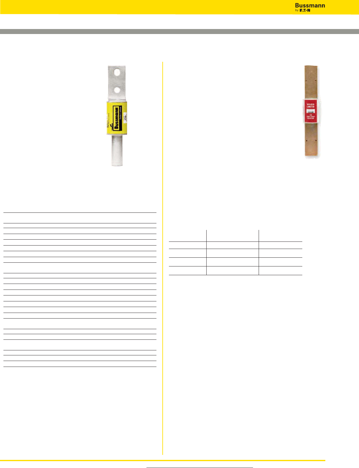
For product data sheets, visit www.cooperbussmann.com/DatasheetsEle
74
Low Voltage Supplementary Fuses
K Series
Specifications
Description: Cable limiters.
Ratings:
Volts — 600Vac
IR — 200kA RMS Sym. @
600Vac
Agency Information: UL
Listing: KDM, KDR, KDP and
KFM, KCM, KCM-B and KCR.
Features and Benefits
• Sizes and ratings available to
meet many applications.
Typical Applications
• Protecting low voltage distribution and service entrance
cables against short-circuit currents.
Catalog Numbers
Copper Cable Limiter — 600 Volts
Catalog Cable Catalog Cable
Number Size Number Size
Tubular Terminals
KCY #4 KCF 4/0
KCZ #3 KCH 250 MCM
KCA #2 KCJ1, 2 350 MCM
KCB #1 KCM1, 2, 3, KCM-B1500 MCM
KCC 1/0 KCV 600 MCM
KCD1, 2 2/0 KCR1, 2 750 MCM
KCE 3/0 KCS 1000 MCM
Tubular Terminal and Offset Bolt-Type Terminal
KQV #12 KDD12/0
KQT #10 KDE 3/0
KFZ #8 KDF 4/0
KIG #6 KDH 250 MCM
KDY #4 KDJ1, 2 350 MCM
KDA #2 KDM1, 2, 3500 MCM
KDB #1 KDU 600 MCM
KDC 1/0 KDR1,2750 MCM
Compression Connector Rod and Tubular Terminals
KEX 4/0 KQO 350 MCM
KFH-A 250 MCM KDT2500 MCM
*Center Bolt-Type Terminal and Off-Set Bolt-Type Terminal
KPF 4/0 KDP1500 MCM
KFT1250 MCM KFM1750 MCM
KEW1350 MCM
*Copper or aluminum cable; sizes of all other limiters pertain to copper only. KFM copper only.
1UL Listed (File E90818).
2Available with shrink tube “_V” suffix.
3Available with molded rubber boots. Add “–B” to end of part number.
Accessories
Boots can be purchased separately.
For KCM BOOT-KCM For KDM BOOT-KDM
Installation tools can be purchased separately from Thomas and Betts
• Crimp Tool: TBM-14M • Die: 15506 KDM/15515 KDR
Specifications
Description: Welder limiters.
Ratings:
Volts — 600Vac (or less)
IR — 200kA RMS Sym.
Features and Benefits
• Current-limiting devices designed specially for use
on welder circuits only
• Time-current characteristics are designed to hold
on the intermittent overloading encountered in
welder operation, while providing short-circuit
protection to the circuit and equipment
• Welder limiters have excess current capacity in the
operating range as needed for this type of service
Typical Applications
• Welder circuits
• Because welder limiters have special characteristics, they
are not intended for application on general-use circuits
Catalog Numbers
Catalog Fuse Holder Nominal
Numbers Type Amp Rating
68300 Class H 300
68600 Class H 600
64200 Class J 200
64300 Class J 300
Cable Limiters & Welder Limiters
Data Sheet: 1042 Data Sheet: 1045
64000 & 68000 Series
Recommended Fuse Blocks For 68000 & 64000
Series limiters
• See page 72
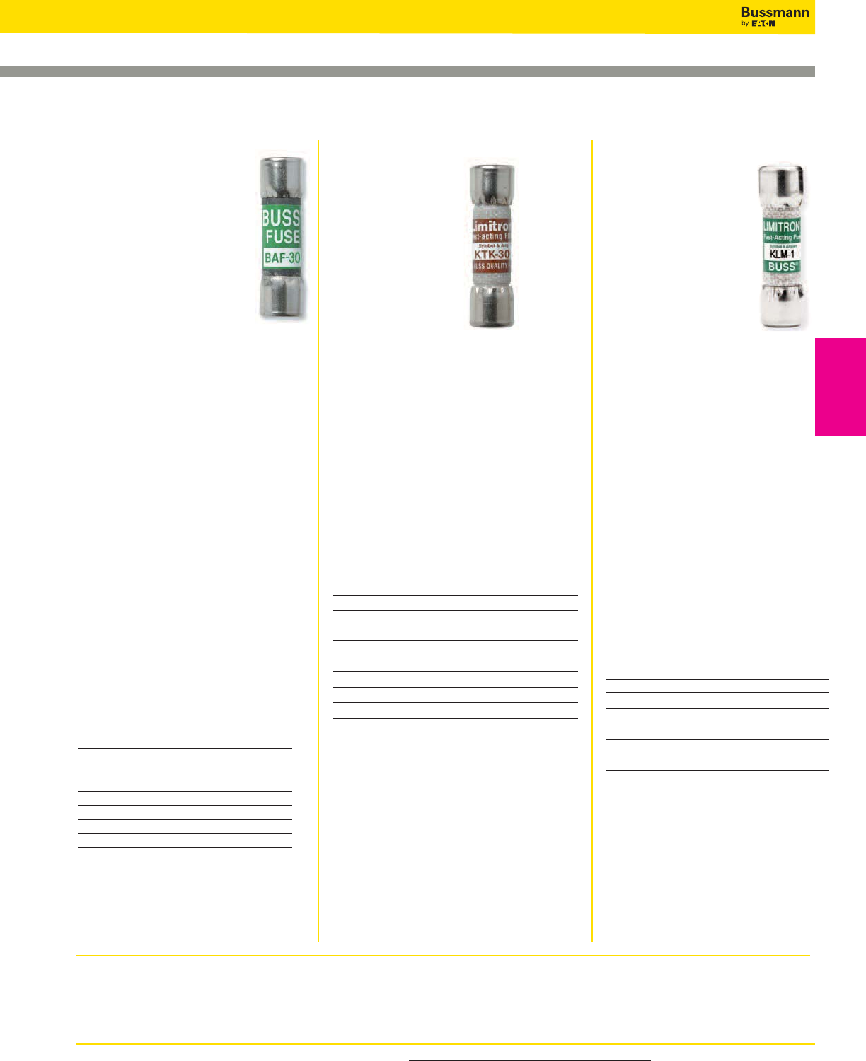
For product data sheets, visit www.cooperbussmann.com/DatasheetsEle 75
Low Voltage Supplementary Fuses
Low Voltage
Supplementary
Fuses
Recommended fuse blocks/fuse holders for 13⁄32” x 1 1⁄2” fuses
• See page 72
Data Sheet: 1011
Data Sheet: 2011 (0-30)
Specifications
Class: Supplemental
Description: Fast-acting
supplementary fuse.
Dimensions: 13⁄32˝ x 1 1⁄2˝
(10.3 x 38.1mm).
Ratings:
Volts — 250Vac (or less)
Amps — 2⁄10-30A
IR — 10kA @ 125Vac
(2⁄10-30A)
— 35A (2⁄10-1A @ 250Vac)
— 100A (11⁄2-3A @ 250Vac)
— 200A (4-10A @ 250Vac)
— 750A (12A- 15A @ 250Vac)
— 200A (20-30A @ 250Vac)
Agency Information: CE, Std. 248-14,
UL 0-15/250V, Guide JDYX, File E19180
CSA Certified, 0-15/250V, Class
1422-01, File 53787.
Features and Benefits
• Low cost supplemental protection of
125V and 250V non-inductive circuits.
• Upgrade with LP-CC product to reduce
SKU investment and minimize potential
arc-flash hazards. (and minimize
potential for misapplying fuse.)
Typical Applications
• General Purpose Circuits
• Lighting Circuit Protection
• Meter Circuits
Catalog Numbers (Amps)
BAF-1⁄4BAF-2-1⁄2BAF-9
BAF-1⁄2BAF-3 BAF-10
BAF-6⁄10 BAF-4 BAF-12
BAF-8⁄10 BAF-5 BAF-15
BAF-1 BAF-6 BAF-20
BAF-1-1⁄2BAF-6-1⁄4BAF-25
BAF-1-8⁄10 BAF-7 BAF-30
BAF-2 BAF-8
*All have interrupting rating of 10,000A at 125V.
KTK
Specifications
Class: Supplemental
Description: Fast-
acting supplementary
fuse.
Dimensions: 13⁄32˝ x
1 1⁄2˝ (10.3 x 38.1mm).
Ratings:
Volts — 600Vac (or
less)
Amps — 1⁄10-30A
IR — 100kA RMS Sym. (UL)
Agency Information: CE, Std. 248-14,
UL Listed, Guide JDYX, File E19180.
Features and Benefits
• Low cost supplemental protection of 600V
or less non-inductive circuits.
• Upgrade with LP-CC product to reduce
SKU investment and minimize potential
arc flash hazards.
Typical Applications
• Control Circuits
• Lighting Circuit Protection
• Meter Circuits
Catalog Numbers (Amps)
600Vac - UL Listed and CSA
KTK-
1⁄10 KTK-3⁄4KTK-4 KTK-12 KTK-50*
KTK-1⁄8KTK-1 KTK-5 KTK-15
KTK-2⁄10 KTK-1-1⁄4KTK-6 KTK-20
KTK-1⁄4KTK-1-1⁄2KTK-7 KTK-25
KTK-3⁄10 KTK-2 KTK-7-1⁄2KTK-30
KTK-4⁄10 KTK-2-1⁄2KTK-8 KTK-35*
KTK-1⁄2KTK-3 KTK-9 KTK-40*
KTK-6⁄10 KTK-3-1⁄2KTK-10 KTK-45*
*Rated for no more than 24A continuous.
13⁄32˝ x 1 1⁄2˝ Fast-acting Fuses
BAF KLM
Specifications
Class: Supplemental
Description: Full range,
fast-acting, DC midget
fuse.
Dimensions: 13⁄32˝ x 1 1⁄2˝
(10.3 X 38.1mm).
Ratings:
Volts — 600Vac/dc
Amps — 1⁄10-30A
IR — 100kA AC
— 50kA DC
Agency Information: CE, UL
Listed: STD. 248-14,
(FILE #E19180), CSA Certified,
C22.2 NO. 248. 14 (CLASS
#1422-01, FILE #53787).
Features and Benefits
• Full range, fast-acting, 600Vac/dc
midget fuse.
• Minimum interrupting rating or 200%
rated current at 600Vdc.
Typical Applications
• DC Control Circuits Requiring
Fast-Acting Fuses.
• Solar power energy sources - use the
Bussmann PVM fuse for DC ratings
up to 600Vdc.
Catalog Numbers (Amps) - KLM
KLM-
1⁄10 KLM-3⁄4KLM-5 KLM-20
KLM-1⁄8KLM-1 KLM-6 KLM-25
KLM-2⁄10 KLM-1-1⁄2KLM-8 KLM-30
KLM-1⁄4KLM-2 KLM-10
KLM-3⁄10 KLM-3 KLM-12
KLM-1⁄2KLM-4 KLM-15
Data Sheet: 2020
For superior electrical protection, Bussmann
recommends upgrading BAF and fuse applications to
Low-Peak LP-CC fuses See page 23.
For superior electrical protection, Bussmann
recommends upgrading KTK fuse applications to
Low-Peak LP-CC fuses See page 23.
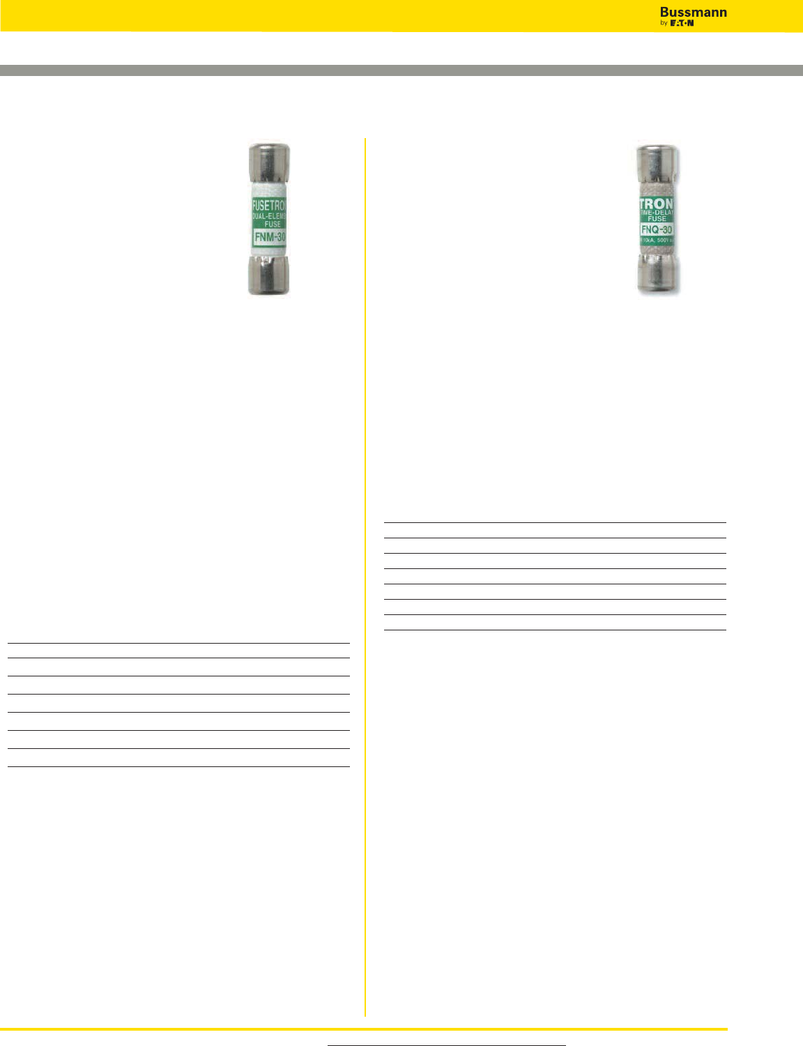
For product data sheets, visit www.cooperbussmann.com/DatasheetsEle
76
Low Voltage Supplementary Fuses
Specifications
Class: Supplemental
Description: Time-delay
supplementary fuse.
Dimensions: 13⁄32˝ x 11⁄2˝
(10.3 x 38.1mm).
Ratings:
Volts — 250Vac (or less)
Amps — 1⁄10-30A
IR — 35A (1⁄10-1A @ 250Vac)
— 100A (11⁄8-31⁄2A @ 250Vac)
— 200A (4-10A @ 250Vac)
— 10kA (1⁄10-10A @ 125Vac)
— 10kA (12-30A @ 250Vac)
Agency Information: CE, Std. 248-14, UL Listed,
0-30/250Vac; File E19180, Guide JDYX, CSA Certified,
1-30/250Vac; Class 1422-01, File 53787.
Features and Benefits
• Low cost supplemental protection of 125V and 250V
inductive circuits.
Typical Applications
• General Purpose Circuits
• Lighting Circuit Protection
• Meter Circuits
• Upgrading to LP-CC product will reduce SKU investment
and minimize potential for misapplying fuse
Catalog Numbers (Amps)
FNM-1⁄10 FNM-1⁄2FNM-1-1⁄2FNM-3 FNM-6 FNM-15
FNM-1⁄8FNM-6⁄10 FNM-1-6⁄10 FNM-3-2⁄10 FNM-6-1⁄4FNM-20
FNM-15⁄100 FNM-3⁄4FNM-1-8⁄10 FNM-3-1⁄2FNM-7 FNM-25
FNM-2⁄10 FNM-1 FNM-2 FNM-4 FNM-8 FNM-30
FNM-1⁄4FNM-1-1⁄8FNM-2-1⁄4FNM-4-1⁄2FNM-9
FNM-3⁄10 FNM-1-1⁄4FNM-2-1⁄2FNM-5 FNM-10
FNM-4⁄10 FNM-1-4⁄10 FNM-2-8⁄10 FNM-5-6⁄10 FNM-12
Specifications
Class: Supplemental
Description: Time-delay supplementary
fuse.
Dimensions: 13⁄32˝ x 11⁄2˝ (10.3 x 38.1mm).
Ratings:
Volts — 500Vac (or less)
Amps — 1⁄10-30A
IR — 10kA RMS Sym.
Agency Information: CE, Std. 248-14, UL Listed, Guide
JDYX, File E19180 CSA Certified, Class 1422-01, File
53787.
Features and Benefits
• Low cost supplemental protection of transformers and
relays at 500V or less.
Typical Applications
• Control Transformer 480V Primary Protection
• Lighting Circuit Protection
• Meter Circuits
Catalog Numbers (Amps)
FNQ-1⁄10 FNQ-4⁄10 FNQ-1-1⁄2FNQ-3-1⁄2FNQ-7 FNQ-20
FNQ-1⁄8FNQ-1⁄2FNQ-1-6⁄10 FNQ-4 FNQ-8 FNQ-25
FNQ-15⁄100 FNQ-6⁄10 FNQ-2 FNQ-4-1⁄2FNQ-9 FNQ-30
FNQ-3⁄16 FNQ-8⁄10 FNQ-2-1⁄4FNQ-5 FNQ-10
FNQ-2⁄10 FNQ-1 FNQ-2-1⁄2FNQ-5-6⁄10 FNQ-12
FNQ-1⁄4FNQ-1-1⁄8FNQ-3 FNQ-6 FNQ-14
FNQ-3⁄10 FNQ-1-1⁄4FNQ-3-2⁄10 FNQ-6-1⁄4FNQ-15
13⁄32˝ x 1 1⁄2˝ Time-delay Fuses
Data Sheet: 2028 Data Sheet: 1012
For superior electrical protection, Bussmann recommends upgrading FNM and
FNQ fuse applications to Low-Peak LP-CC fuses See page 23.
Recommended fuse blocks and fuse holders for
13⁄32˝ x 1 1⁄2˝ fuses
• See page 72
For superior electrical protection, Bussmann recommends upgrading FNM and
FNQ fuse applications to Low-Peak LP-CC fuses See page 23.
Recommended fuse blocks and fuse holders for
13⁄32˝ x 1 1⁄2˝ fuses
• See page 72
FNM FNQ
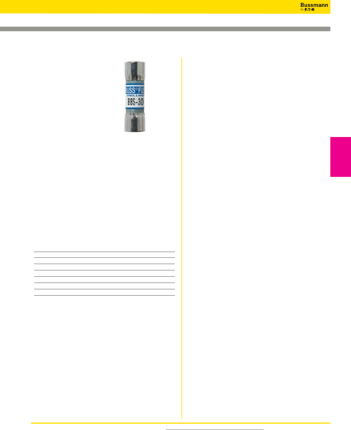
For product data sheets, visit www.cooperbussmann.com/DatasheetsEle 77
Low Voltage Supplementary Fuses
Low Voltage
Supplementary
Fuses
Specifications
Class: Supplemental
Description: Fast-acting
supplementary fuse.
Dimensions: 13⁄32˝ x 13⁄8˝
(10.3 x 34.9mm).
Construction: Fiber cartridge.
Ratings:
Volts — 600Vac (1⁄10-5A)
— 250Vac (6 - 10A)
— 48Vac (12-30A)
Amps — 1⁄10-30A
IR — 10kA RMS Sym.
Agency Information: CE, Std. 248-14, UL Listed,
0-5A/600V, Guide JDYX, File E19180, CSA Certified,
0-5A/600V, Class 1422-01, File 53787.
Features and Benefits
• Low cost supplemental protection of non-inductive circuits
• Reduced interchangeability with other supplemental fuses
minimizes misapplication
Typical Applications
• Control Circuits
• Lighting Ballasts
• Meter Circuits
Catalog Numbers (Amps)
BBS-1⁄10 BBS-8⁄10 BBS-4 BBS-15
BBS-2⁄10 BBS-1 BBS-5 BBS-20
BBS-1⁄4BBS-1-1⁄2BBS-6 BBS-25
BBS-4⁄10 BBS-1-6⁄10 BBS-7 BBS-30
BBS-1⁄2BBS-1-8⁄10 BBS-8
BBS-6⁄10 BBS-2 BBS-10
BBS-3⁄4BBS-3 BBS-12
13⁄32˝ x 1 3⁄8˝ Fast-acting Fuses
Data Sheet: 2010 (0-30A)
Recommended fuse blocks/fuse holders for 13⁄32˝ x 1 3⁄8˝ fuses
• Page 73
BBS
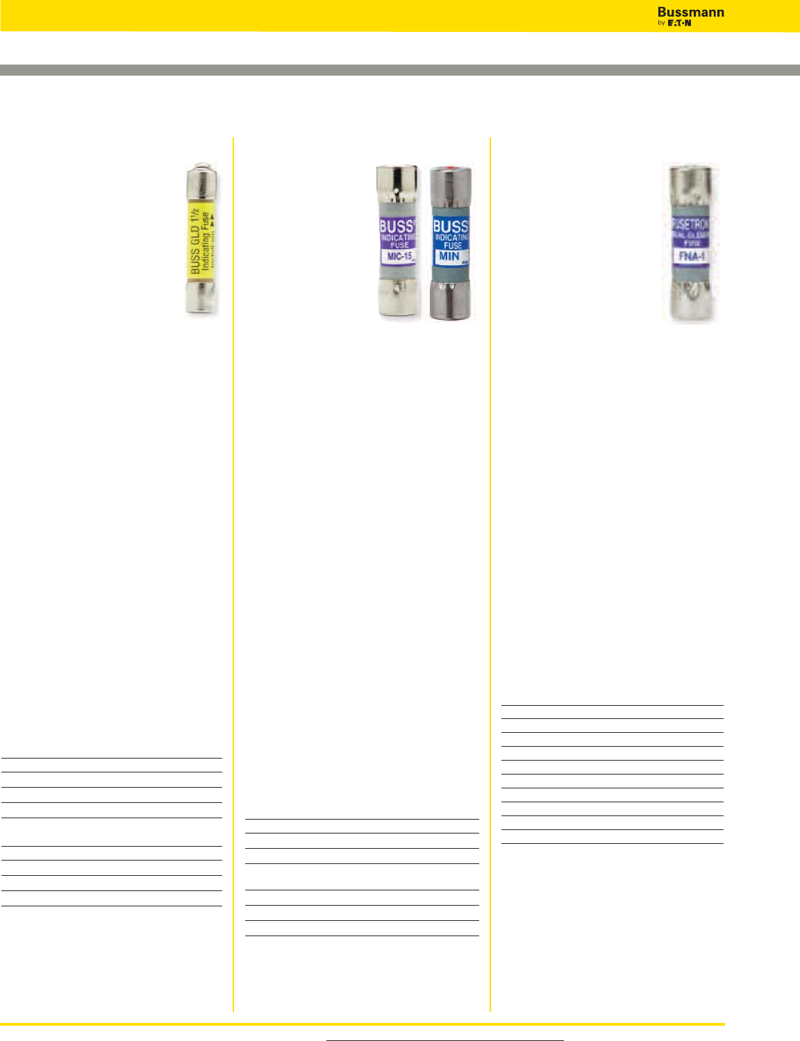
For product data sheets, visit www.cooperbussmann.com/DatasheetsEle
78
Low Voltage Supplementary Fuses
Specifications
Class: Supplemental
Description: Time-delay,
pin indication fuse.
Dimensions: 13⁄32˝ x 1 1⁄2˝
(10.3 x 38.1mm).
Ratings:
Volts — 250Vac (1⁄10-8⁄10A)
— 125Vac (1-15A)
— 32Vac (20-30A)
Amps — 1⁄10-30A
IR — 35A (1⁄10-8⁄10A @ 250Vac)
— 10kA (1⁄10-15A @ 125Vac)
— 1kA (20-30A @ 32V)
Agency Information: CE, Std. 248-
14, UL Listed 1⁄10-8⁄10A, IR 35A@ 250V,
IR 10kA@ 125V , 1-15A, IR 10kA@
125V, Guide JDYX, File 19180, CSA
Certified, 0-8⁄10A/250V, 1-10A/125V,
Class 1422-01, File 53787.
Features and Benefits
• FNA has a pin indicator providing
visual identification of failed circuits,
resulting in reduced circuit downtime.
• Time-delay response allows close
sizing on control transformers and
relays
Typical Applications
• Control Circuits
• Electronic Circuits
Catalog Numbers (Amps)
FNA-1⁄10 FNA-8⁄10 FNA-2-1⁄2FNA-6-1⁄4
FNA-1⁄8FNA-1 FNA-2-8⁄10 FNA-7
FNA-15⁄100 FNA-1-1⁄8FNA-3 FNA-8
FNA-2⁄10 FNA-1-1⁄4FNA-3-2⁄10 FNA-9
FNA-1⁄4FNA-1-4⁄10 FNA-3-1⁄2FNA-10
FNA-3⁄10 FNA-1-1⁄2FNA-4 FNA-12*
FNA-4⁄10 FNA-1-6⁄10 FNA-4-1⁄2FNA-15*
FNA-1⁄2FNA-1-8⁄10 FNA-5 FNA-20*
FNA-6⁄10 FNA-2 FNA-5-6⁄10 FNA-25*
FNA-3⁄4FNA-2-1⁄4FNA-6 FNA-30
*12-30A versions are dual-tube construction
MIC & MIN
Specifications
Class: Supplemental
Description: Fast-
acting, pin indication
fuse.
Dimensions:
13⁄32˝ x 1 1⁄2˝ (10.3 x
38.1mm) 5AG.
Ratings:
Volts — 250Vac
(1-15A)
— 32Vac (20-30A)
Amps — 1-30A
IR — 35A (1A @250Vac)
— 100A (2-3A @250Vac)
— 200A (5-10A @250Vac)
— 750A (15A @250Vac)
— 10kA (20-30A @32V)
— 35A (1A @250Vac)
Agency Information: CE, Std. 248-14,
MIC—0-15A UL Listed, 125Vac/10kA IR
Guide JDYX, File E19180, MIN—1-5A
CSA Certified, Class 1422-01, File
53787.
Features and Benefits
•Type MIN has a “red” pin indicator
providing visual identification of failed
circuits, resulting in faster trouble
shooting (reduced circuit downtime).
•Type MIC has silver-plated pin
transmitting an electrical signal indicating
location of a failed circuit, resulting in
faster troubleshooting (reduced circuit
downtime).
Typical Applications
•Control Circuits
•PLC Circuits
•Electronic Circuits
MIC Catalog Numbers (Amps)
MIC-1 MIC-5 MIC-20
MIC-2 MIC-10 MIC-25
MIC-3 MIC-15 MIC-30
MIN Catalog Numbers (Amps)
MIN-1 MIN-5 MIN-20
MIN-2 MIN-10 MIN-25
MIN-3 MIN-15 MIN-30
Specifications
Class: Supplemental
Description: Fast-acting, pin
indication fuse.
Dimensions: 1⁄4˝ x 1 1⁄4˝
(6.6 x 31.7mm) 3AG.
Ratings:
Volts — See Agency Info
below
Amps — 1⁄2-15A
IR — See Agency Info below
Agency Information: CE, Std. 248-
14, UL Listed, 0-5A/125Vac, 10,000
AIC, Guide JDYX, File E19180, UL
Recognized, 6A/125Vac, 1000AIC
8-15A/50Vac/dc, 300 AIC Guide
JDYX2, File E19180, CSA Certified:
0-5A/125Vac, 10,000 AIC Class
1422-01, File 53787.
Features and Benefits
• Type GBA has a “red” pin indicator
providing visual identification of failed
circuits, resulting in faster
troubleshooting (reduced circuit
downtime).
• Type GLD has a plated pin to
activate transmitting a electrical
signal to indicate the location of
opened circuits, resulting in reduced
downtime.
Typical Applications
• Control Circuits
• Electronic Circuits
GLD Catalog Numbers (Amps)
GLD-1⁄2GLD-2 GLD-6
GLD-3⁄4GLD-3 GLD-10
GLD-1 GLD-4 GLD-12
GLD-1-1⁄2GLD-5 GLD-15
GBA Catalog Numbers (Amps)
GBA-1⁄2GBA-2 GBA-8
GBA-3⁄4GBA-3 GBA-10
GBA-1 GBA-4 GBA-15
GBA-1-1⁄2GBA-5
Pin Indication Fuses
Data Sheet: 2029
Data Sheet: 2012 Data Sheet: 2047
GBA
GLD
FNA
Recommended fuse blocks/fuse
holders for 1⁄4˝ x 1 1⁄4˝ indicating fuses
• Page 73
Recommended signal block for
13⁄32˝ x 1 1⁄2˝ indicating fuses
• Page 73
Recommended signal block for
13⁄32˝ x 1 1⁄2˝ indicating fuses
• Page 73
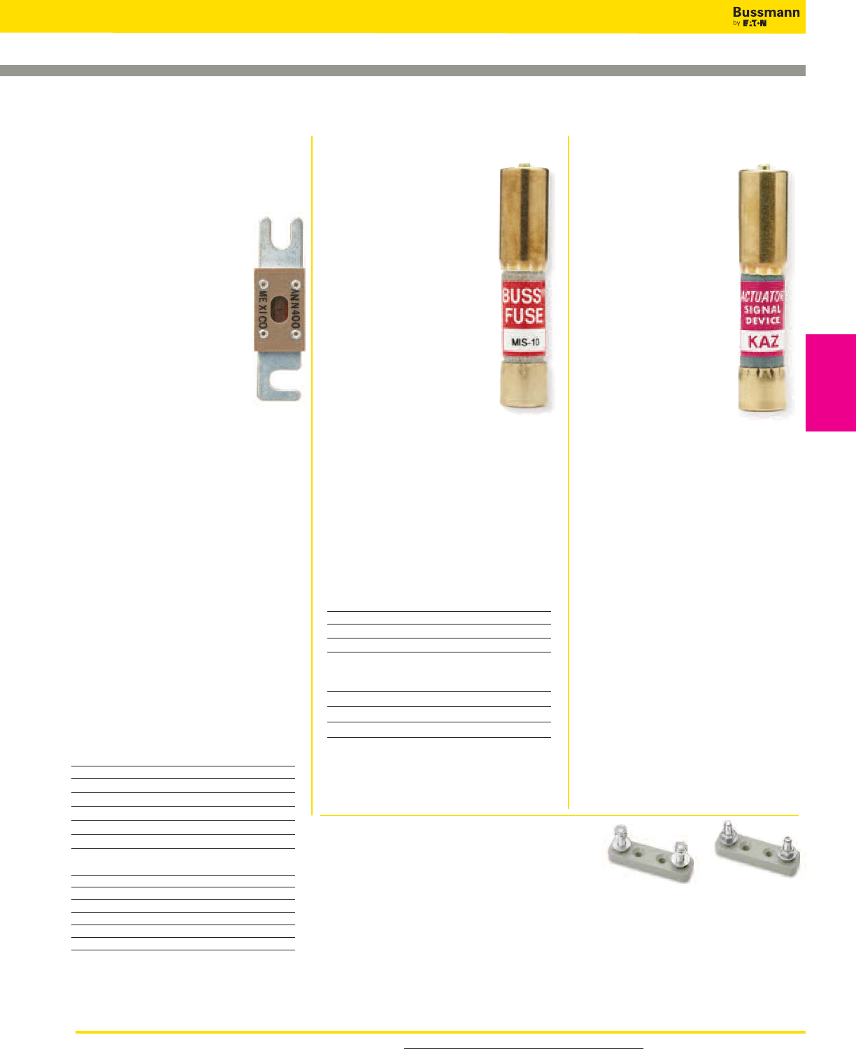
For product data sheets, visit www.cooperbussmann.com/DatasheetsEle 79
Low Voltage Supplementary Fuses
Low Voltage
Supplementary
Fuses
Data Sheet: 2133
ANN & ANL Limiters
Specifications
Description: Circuit limiters.
ANN: Very fast-acting limiter.
ANL: Non-time delay limiter.
Dimensions: 7⁄8˝ x 3 3⁄16˝
(22.2 x 81.0mm).
Ratings:
ANN:
Volts — 125Vac
— 80Vdc
Amps — 10-800A
IR — 2500A @ 125Vac
— 2700A @ 80Vdc
ANL:
Volts — 80Vdc
Amps — 35-750A
IR — 2700A @ 80Vdc
Agency Information:
ANN: 35-400A @ 125Vac, IR=2500A
and 500A @ 80Vdc, IR=2700A: UL
Recognized Guide JFHR2, File
E56412; CSA Certified Class 1422-30,
File 53787, CE for 35-400A.
ANL: UL Recognized, CSA Certified,
35-750A @ 80Vdc, IR = 2700A, Guide
JFHR2, File E56412, Class 1422-30,
File 53787, SAE J1171.
Features and Benefits
• Fast-acting circuit protection (ANN).
• Time-delay sizing for inductive circuits (ANL).
• Window shows limiter status.
Typical Applications
• Fork lifts, Marine, Aviation
ANN Catalog Numbers (Amps)
ANN-10 ANN-90 ANN-225 ANN-400
ANN-35 ANN-100 ANN-250 ANN-500
ANN-40 ANN-125 ANN-275 ANN-600
ANN-50 ANN-150 ANN-300 ANN-700
ANN-60 ANN-175 ANN-325 ANN-800
ANN-80 ANN-200 ANN-350
ANL Catalog Numbers (Amps)
ANL-35 ANL-125 ANL-250 ANL-500
ANL-40 ANL-130 ANL-275 ANL-600
ANL-50 ANL-150 ANL-300 ANL-675
ANL-60 ANL-175 ANL-325 ANL-750
ANL-80 ANL-200 ANL-350
ANL-100 ANL-225 ANL-400
4164 & 4164-FR Limiter Blocks
Specifications
Description: Limiter fuse blocks for ANL
& ANN.
• 4164 furnished with nylon inserted locknuts
• 4164-FR furnished with standard hex nuts
Dimensions: Length: 3.38˝
Width: 0.95˝
Height: 1.62˝
Studs center to center: 2.43˝
Ratings:
Volts — 125Vac
— 80Vdc
— 32Vdc (Self Certified)
Amps — 10-800A
Poles: 1 - stud terminal
KAZ
Specifications
Description: Non-fuse
actuator.
Dimensions: 13⁄32˝ x 2˝
(10.3 x 50.8mm).
Ratings:
Volts — 600Vac
Amps — N/A
IR — 200kA
Agency Information:
CE, UL Listed, Guide
JDVS, File E58836.
Features and Benefits
• Bussmann signal blocks
2778, 2837
or 2838 with KAZ actua-
tors mounted in parallel with fuses hav-
ing a rating of 50A or larger to provide
blown fuse dropout of shunt-trip fused
switches.
• Type KAZ can be used in circuits rated
600V or less.
• Type KAZ has an interrupting rating of
200kA.
Typical Applications
• Large, Shunt-Trip Fused Switches
• Fuse Protected Circuits Rated 50A or
Larger With Shunt-Trip Devices.
Catalog Number: KAZ
MIS
Specifications
Class: Supplemental
Description: Non time-
delay pin indication fuse.
Dimensions: 13⁄32˝ x 2˝
(10.3 x 50.8mm).
Ratings:
Volts — 600Vac
Amps — 1-12A
IR — 200kA
Features and Benefits
• Type MIS has a pin
indicator providing visual
identification of failed cir-
cuits,
resulting in faster trou-
bleshooting (reduced circuit down-
time).
• Type MIS can be used in circuits
rated 600V or less.
• Type MIS has an interrupting
rating of 200kA.
Typical Applications
• 480V Control Circuits
• PLC Circuits
Catalog Numbers (Amps)
MIS-1 MIS-4 MIS-10
MIS-2 MIS-5 MIS-12
MIS-3 MIS-8
Test Specifications
Fuse Load Opening Time
All 110% 0 4 hrs. (min.)
1-5A 150% 0 6 min. (max.)
6-12A 150% 12 min. (max.)
Pin Indication Fuse and Actuator, and Limiters
Data Sheet: 2021
Data Sheets: 2023 (ANN), 2024 (ANL)
Recommended signal block for
13⁄32˝ x 2˝ indicating fuses
• Page 73
Recommended signal block for
13⁄32˝ x 2˝ indicating fuses
• Page 73
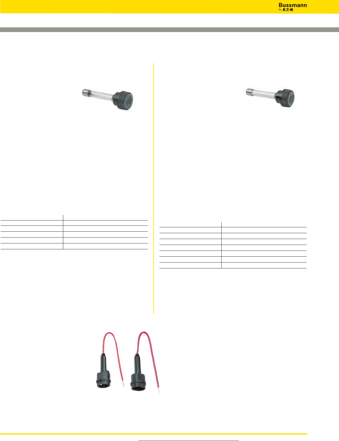
For product data sheets, visit www.cooperbussmann.com/DatasheetsEle
80
Low Voltage Supplementary Fuses
In-line Size Rejecting Fuses and Fuse Holders
Data Sheet: 2030Data Sheet: 2033
HLQ3Fuse Holders
for both GLQ & GMQ fuses.
GLQ
Specifications
Class: Supplemental
Description: Fast-acting,
size-rejecting in-line fuse.
Construction: Glass tube.
Ratings:
Volts — 300Vac (or less)
Amps — 1-10A
IR — 10kA
Agency Information: CE, Std. 248-14, UL Listed (Guide
JDYX, File E19180), CSA Certified, (Class 1422-01,
File 53787).
Features and Benefits
• In-Line, fast-acting circuit protection.
• Rejection feature prevents overfusing.
Typical Applications
• In-line Lighting Ballast Protection
Catalog Numbers (Amps) and Rejection Holders
Fuse Holder1, 2 Fuse Holder1, 2
GLQ-1 HLQ-1-6⁄10 GLQ-3 HLQ-3 -2⁄10
GLQ-1-1⁄2HLQ-1-6⁄10 GLQ-4 HLQ-5
GLQ-1-6⁄10 HLQ-1-6⁄10 GLQ-5 HLQ-5
GLQ-2 HLQ-3-2⁄10 GLQ-9 HLQ-10
GLQ-2-1⁄2HLQ-3 -2⁄10 GLQ-10 HLQ-10
1) Carrier is UL Recognized, Guide IZLT2, File E14853 and CSA Certified, Class 6225-01, File 47235
10A, 300Vac.
2) Units can be panel-mounted either in a knockout hole with a separate steel clip (BK/A-104) or in a
keyhole punch using separate mounting clip #6374 for panels of thickness 0.043”to 0.062” or #4909
for thickness 0.030” to 0.042”.
• Do not put tension on line (rear) terminal of fuse holder.
GMQ
Specifications
Class: Supplemental
Description: Time-delay,
size-rejecting in-line fuse.
Construction: Ceramic tube.
Ratings:
Volts — 300Vac (or less)
Amps —
1
⁄
2
-6
1
⁄
4
A
IR — 10kA
Agency Information: CE, Std. 248-14, UL Listed (Guide
JDYX, File E19180), CSA Certified, (Class 1422-01, File
53787)
Features and Benefits
• In-line, fast-acting circuit protection.
• Rejection feature prevents overfusing.
Typical Applications
• In-Line Lighting Ballast Protection
Catalog Numbers (Amps) and Rejection Holders
Fuse Holders1, 2 Fuse Holders3, 4
GMQ-1⁄2HLQ-1⁄2GMQ-2-1⁄2HLQ-3 -2⁄10
GMQ-6⁄10 HLQ-1-6⁄10 GMQ-3 HLQ-3 -2⁄10
GMQ-8⁄10 HLQ-1-6⁄10 GMQ-3 -2⁄10 HLQ-3 -2⁄10
GMQ-1 HLQ-1-6⁄10 GMQ-4 HLQ-5
GMQ-1-1⁄4HLQ-1-6⁄10 GMQ-6 HLQ-8
GMQ-1-6⁄10 HLQ-1-6⁄10 GMQ-6 -1⁄4
GMQ-2 HLQ-3-2⁄10
1) Carrier is UL Recognized, Guide IZLT2, File E14853 and CSA Certified, Class 6225-01, File 47235
10A, 300Vac.
2) Units can be panel-mounted either in a knockout hole with a separate steel clip (BK/A-104) or in a
keyhole punch using separate mounting clip #6374 for panels of thickness 0.043”to 0.062” or #4909
for thickness 0.030” to 0.042”
• Do not put tension on line (rear) terminal of fuse holder.
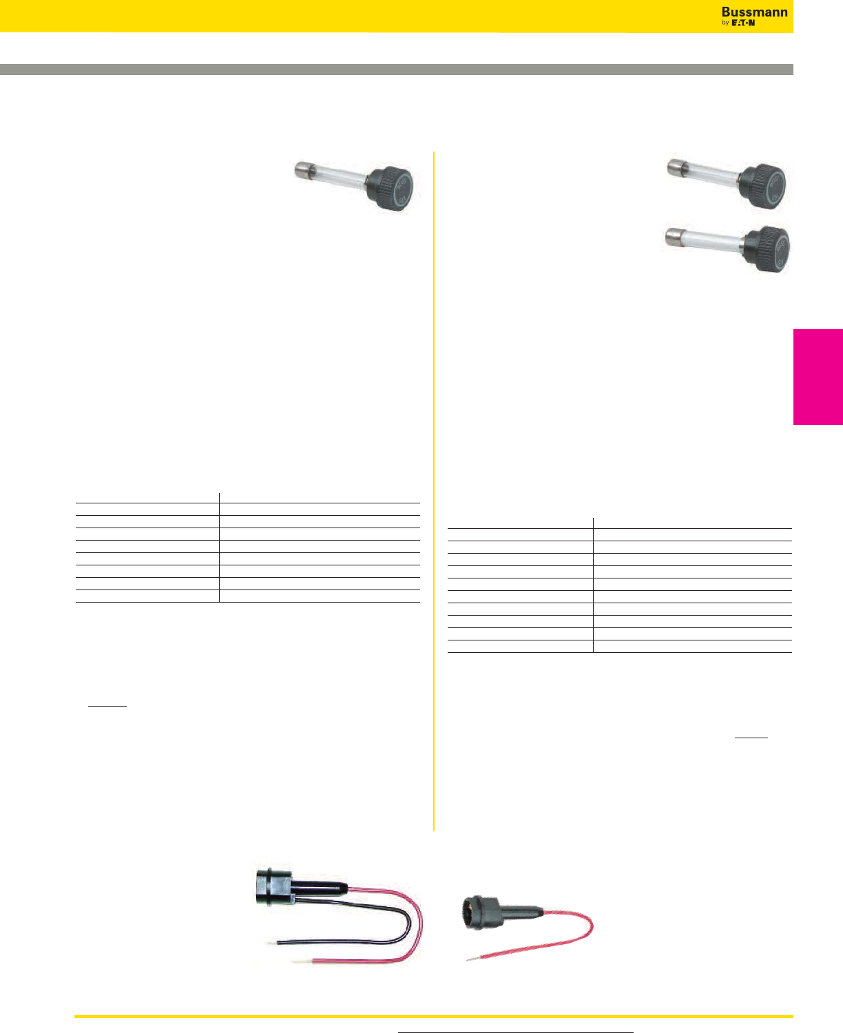
For product data sheets, visit www.cooperbussmann.com/DatasheetsEle 81
Low Voltage Supplementary Fuses
Low Voltage
Supplementary
Fuses
GLR
Specifications
Class: Supplemental
Description: Fast-acting,
non-rejection, in-line fuse.
Construction: Glass tube.
Ratings:
Volts — 300Vac (or less)
Amps — 3⁄16-15A
IR — 10kA
Agency Information: CE, Std. 248-14, UL Listed,
0-15A/300Vac (Guide JDYX, File E19180), CSA Certified,
0-10A/300V (Class 1422-01, File 53787).
Features and Benefits
• In-line, fast-acting circuit protection.
Typical Applications
• In-Line Lighting Ballast Protection
Catalog Numbers (Amps) and Non-Rejection Holders
Fuse Holder1, 2* Fuse Holder1, 2*
GLR-1⁄2HLR GLR-6 HLR
GLR-1 HLR GLR-7 HLR
GLR-1-1⁄2HLR GLR-8 HLR
GLR-1-6⁄10 HLR GLR-9 HLR
GLR-2 HLR GLR-10 HLR
GLR-3 HLR GLR-12 HLR
GLR-4 HLR GLR-15 HLR-2A
GLR-5 HLR
1) Carrier is UL Recognized, Guide IZLT2, File E14853 and CSA Certified, Class 6225-01,
File 47235 12A, 300Vac.
2) Units can be panel-mounted either in a knockout hole with a separate steel clip
(BK/A-104) or in a keyhole punch using separate mounting clip #6374 for panels of
thickness 0.043”to 0.062” or #4909 for thickness 0.030˝ to 0.042˝.
* For two leads (one each for line and loadside) order HLR-2A,
15A, 300V
• An alternative to the HLR fuse holder is the A fuse holder. The A fuse holder comes
WITHOUT leads. The customer inserts #18 insulated solid copper wire into the line side
receptacle as well as into the load side receptacle. It has the same body dimensions,
utilizes the same mounting hole, and takes the same mounting clips as the HLR. The A
fuse holder is UL Recognized, 10A, 300Vac, Guide IZLT2, File E14853 and CSA
Certified, 10A, 300Vac, Class 6225-01, File 47235.
• Do not put tension on line (rear) terminal of fuse holder.
GMF
GRF
Specifications
Class: Supplemental
Description: Time-delay,
non-rejection, in-line fuse.
Construction: Glass tube.
Ratings:
Volts — 300Vac (or less)
Amps — 3⁄10-10A
IR — 10kA
Agency Information: CE, Std. 248-14 0-10A, UL Listed
(Guide JDYX, File E19180), CSA Certified, (Class 1422-01,
File 53787).
Features and Benefits
• In-line, time-delay circuits protection.
Typical Applications
• In-Line Lighting Ballast Protection
Catalog Numbers (-Amps) and Non-Rejection Holders
Fuse Holder1, 2* Fuse Holder1, 2*
GMF-3⁄10 HLR GMF-3 HLR
GMF-1⁄2HLR GMF-3 -2⁄10 HLR
GMF-6⁄10 HLR GMF-4 HLR
GMF-8⁄10 HLR GMF-5 HLR
GMF-1 HLR GMF-6-1⁄4HLR
GMF-1-1⁄4HLR GMF-10 HLR
GMF-1-6⁄10 HLR GRF-7 HLR
GMF-2 HLR GRF-8 HLR
GMF-2-1⁄2HLR GRF-10 HLR
GMF-2-8⁄10 HLR
1) Carrier is UL Recognized, Guide IZLT2, File E14853 and CSA Certified, Class 6225-01, File 47235
12A, 300Vac.
2) Units can be panel-mounted either in a knockout hole with a separate steel clip (BK/A-104) or in a
keyhole punch using separate mounting clip #6374 for panels of thickness 0.043”to 0.062” or #4909
for thickness 0.030˝ to 0.042˝.
*For two leads order HLR-2A, 15A, 300V
• An alternative to the HLR fuse holder is the A fuse holder. The A fuse holder comes WITHOUT leads.
The customer inserts #18 insulated solid copper wire into the line side receptacle as well as into the
load side receptacle. It has the same body dimensions, utilizes the same mounting hole, and takes
the same mounting clips as the HLR. The A fuse holder is UL Recognized, 10A, 300Vac, Guide
IZLT2, File E14853 and CSA Certified, 10A, 300Vac, Class 6225-01, File 47235.
• Do not put tension on line (rear) terminal of fuse holder.
In-line Non-rejecting Fuses and Fuse Holders
Data Sheet: 2032 Data Sheet: 2031
HLR Fuse Holder
HLR-2A Fuse Holder
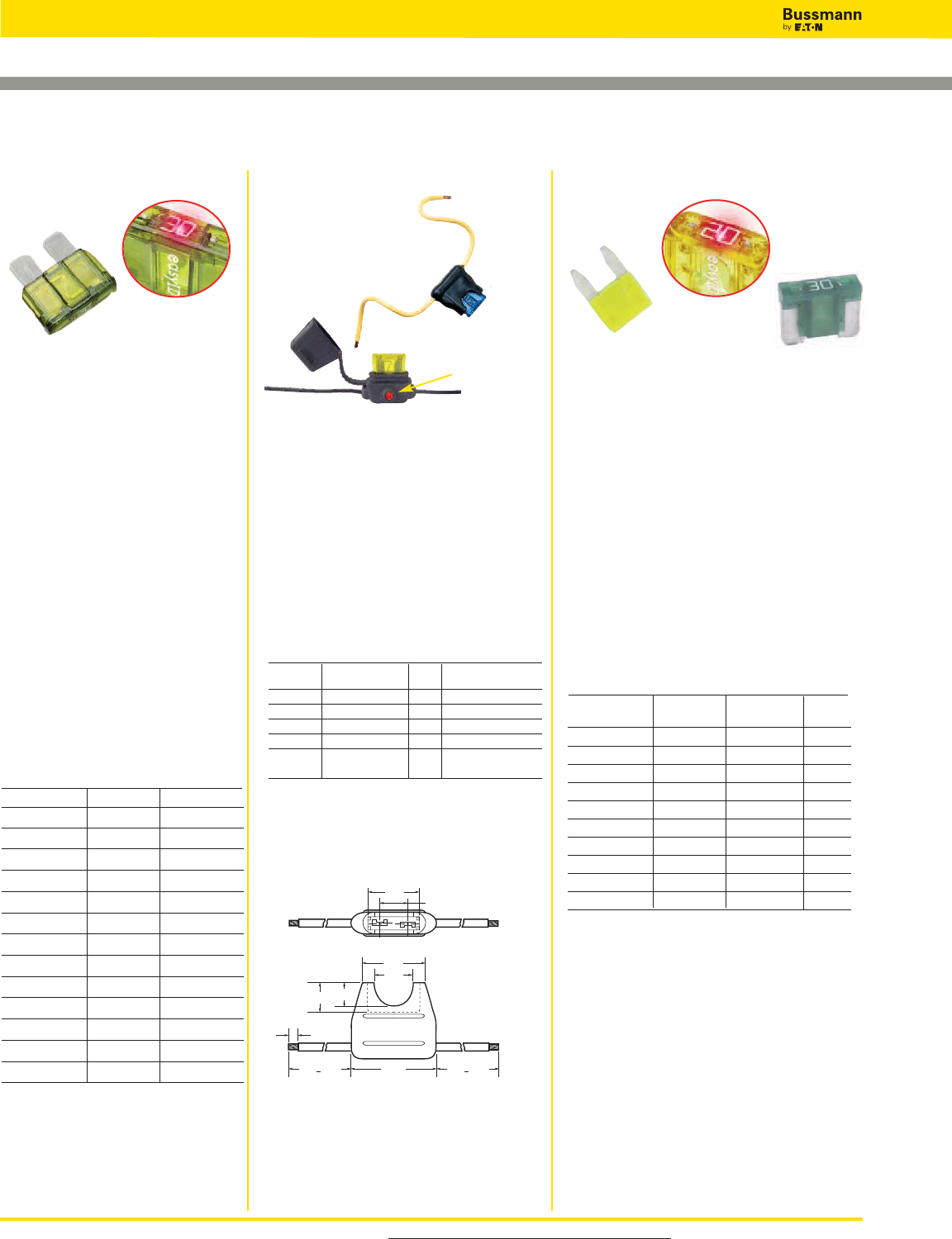
For product data sheets, visit www.cooperbussmann.com/DatasheetsEle
82
Low Voltage Supplementary Fuses
Specifications
Description: Fast-acting
blade fuse.
Construction: Colored plastic
housing with zinc fuse element.
Ratings:
Volts — 32Vdc
Amps — 1-40A
IR — 1000A
Agency Information: UL
Recognized, (3-40A) (Guide
JFHR2, File E56412), SAE
Standard J1284.
Features and Benefits
• Color coded plastic housing for
easy identification of fuse ratings
Typical Applications
• Automotive
Catalog Numbers (Amps)
Automotive Blade-type Fuses & Holders
Data Sheet: 2048
Data Sheet: 2009
(Actual Size)
ATC Fuse ATM Fuse
Specifications
Description: Fast-acting blade fuse.
Construction: Colored plastic housing
with zinc fuse element.
Ratings:
Volts — 32Vdc
Amps — 2-30A
IR — 1000A
Features and Benefits
• Color coded plastic housing for easy
identification of fuse ratings
Typical Applications
• Automotive
Catalog Numbers (Amps)
ATM
(Actual Size) ATM-LP
Non-Indicating *Indicating Color
ATC-1 Black
ATC-2 Gray
ATC-3 ATC-3ID Violet
ATC-4 Pink
ATC-5 ATC-5ID Tan
ATC-7-1/2 ATC-7-1/2ID Brown
ATC-10 ATC-10ID Red
ATC-15 ATC-15ID Blue
ATC-20 ATC-20ID Yellow
ATC-25 ATC-25ID Clear
ATC-30 ATC-30ID Green
ATC-35 ATC-35ID Blue-Green
ATC-40 ATC-40ID Orange
Available
With
Indication
Available
With
Indication
Non-Indicating *Indicating Low-Profile Color
ATM-2 Gray
ATM-3 ATM-3ID Violet
ATM-4 Pink
ATM-5 ATM-5ID ATM-5LP Tan
ATM-7-1/2ATM-7-1/2ID ATM-7-1/2LP Brown
ATM-10 ATM-10ID ATM-10LP Red
ATM-15 ATM-15ID ATM-15LP Blue
ATM-20 ATM-20ID ATM-20LP Yellow
ATM-25 ATM-25ID ATM-25LP Clear
ATM-30 ATM-30ID ATM-30LP Green
0.78"
0.91"
0.5"
0.38" 0.30"
4.0" + 0.25" 4.0" + 0.25"1.125"
0.364"
0.25"
Data Sheet: 2107
Specifications
Description: In-line fuse holders for
ATC™Blade-Type fuses.
Dimensions: See Dimensions
illustration.
Ratings:
Volts: — 32Vdc
Amps:— 80% continuous of fuse
rating. See Catalog Numbers
table for individual fuses sizes.
Catalog Numbers
Catalog Fuse Holder Fuse Electrical
Numbers Description Amps Connection
HHC Yellow 1-20 #16 black leadwire
HHD Black 1-30 #12 yellow leadwire
HHF Black w/ cover 1-20 #16 yellow leadwire
HHG Black w/ cover 1-30 #12 yellow leadwire
ATC-FHID Indicating Holder 1-20 #16 black leadwire
Black w/ cover
A fuse must be properly and fully inserted into the holder to
provide a solid connection. Poor or improper insertion of the
fuse can result in failure of the fuse and holder, thus not
protecting the device for which it was intended.
HHC & HHD Dimensions - in
HHC, HHD, HHF, HHG &
ATC-FHID
easy
ID™ LED Indicating Holder
LED Indicator
*Call Bussmann Customer Satisfaction for ordering information.
*Call Bussmann Customer Satisfaction for ordering information.
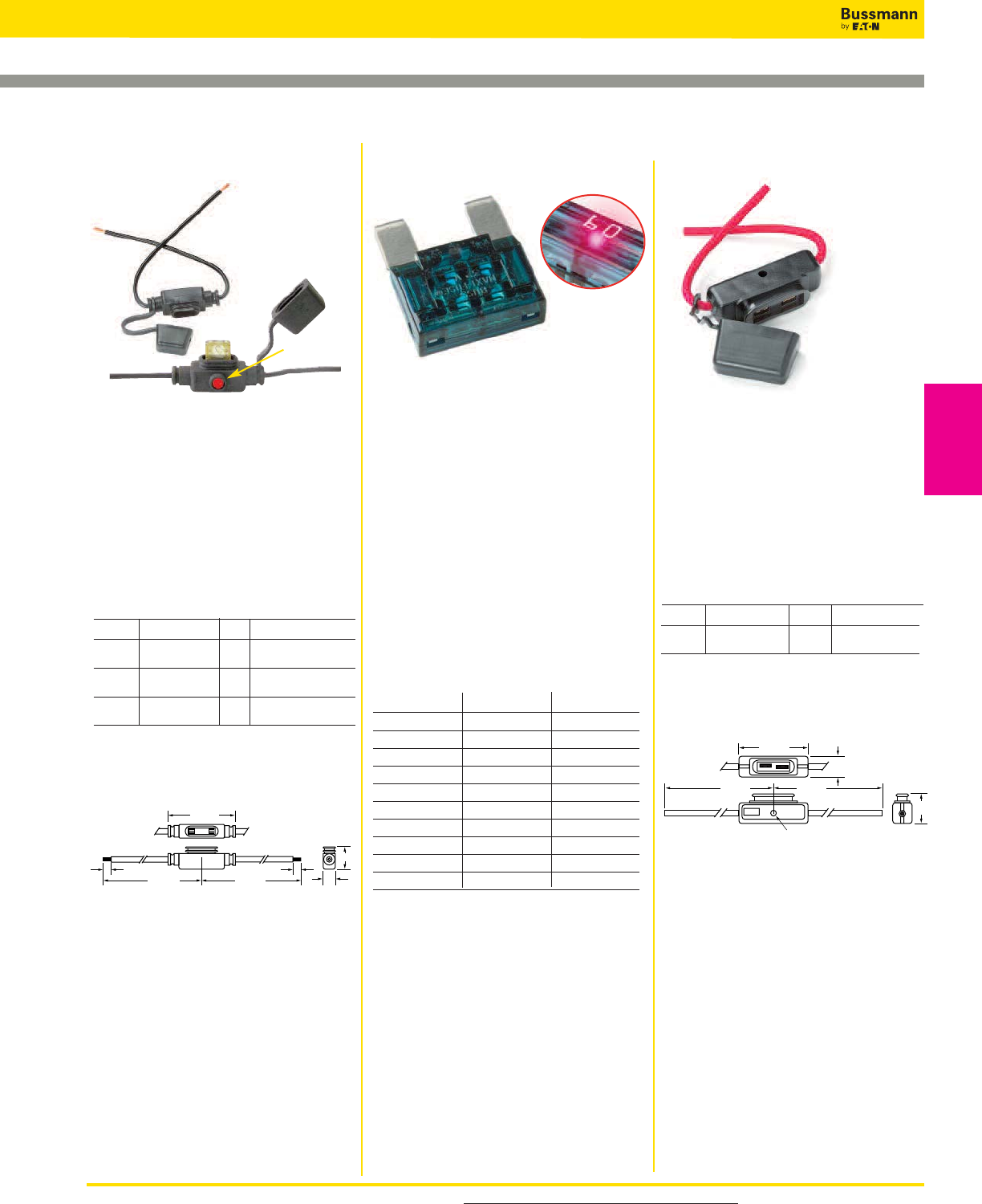
For product data sheets, visit www.cooperbussmann.com/DatasheetsEle 83
Low Voltage Supplementary Fuses
Automotive Blade-type Fuses & Holders
Data Sheet: 2129
Data Sheet: 2128
Specifications
Description: In-line fuse holders for
ATM Fuses.
Ratings:
Volts: — 32Vdc
Amps: — 80% continuous of fuse
rating. See Catalog Numbers
table for individual fuses
sizes.
Catalog Numbers
Catalog Fuse Holder Fuse Electrical
Numbers Description Amps Connection
HHL Black w/ cover 2-20 #16 black leadwire,
4˝ length stripped to 1/4˝
HHM Black w/ cover 2-30 #12 red leadwire,
4˝ length stripped to 1/4˝
ATM-FHID Indicating Holder 2-20 #16 black leadwire
Black w/ cover
A fuse must be properly and fully inserted into the holder to
provide a solid connection. Poor or improper insertion of the
fuse can result in failure of the fuse and holder, thus not
protecting the device for which it was intended.
HHL & HHM Dimensions - in
Specifications
Description: In-line fuse holders for
MAXI Fuses.
Ratings:
Volts: — 32Vdc
Amps: — 80% continuous of fuse
rating. See Catalog Numbers
table for individual fuses
sizes.
Catalog Numbers
Catalog Fuse Holder Fuse Electrical
Numbers Description Amps Connection
HHX Black w/ cover 20-60 #6 red leadwire,
5˝ with blunt ends
A fuse must be properly and fully inserted into the holder to
provide a solid connection. Poor or improper insertion of the
fuse can result in failure of the fuse and holder, thus not
protecting the device for which it was intended.
Dimensions - in
HHXHHL, HHM & ATM-FHID
1.56"
4.75" 4.75"
.25"
.25"
.59"
.41"
3.35"
6.70" 6.70"
1.37"
.265" DIA. HOLE
easy
ID™ LED Indicating Holder
LED Indicator
Data Sheet: 2049
(Actual Size)
MAX Maxi–Fuse
Specifications
Description: Fast-acting blade fuse.
Construction: Colored plastic housing
with zinc fuse element.
Ratings:
Volts — 32Vdc
Amps — 20-80A (non-indicating)
20-100A (indicating)
IR — 1000A
Features and Benefits
• Color coded plastic housing for easy
identification of fuse ratings
Typical Applications
• Automotive
Catalog Numbers (Amps)
Recommended in-line fuse holder for
blade type fuses
• Page 83
Available
With
Indication
Non-Indicating *Indicating Color
MAX-20 MAX-20ID Yellow
MAX-25 Gray
MAX-30 MAX-30ID Green
MAX-35 Brown
MAX-40 MAX-40ID Orange
MAX-50 MAX-50ID Red
MAX-60 MAX-60ID Blue
MAX-70 MAX-70ID Tan
MAX-80 MAX-80ID Clear
MAX-100ID Purple
Low Voltage
Supplementary
Fuses
*Call Bussmann Customer Satisfaction for ordering information.
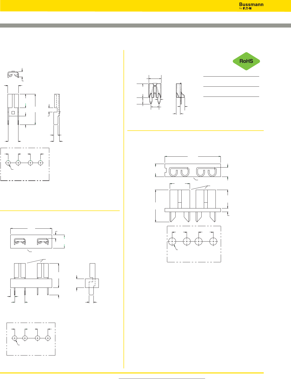
For product data sheets, visit www.cooperbussmann.com/DatasheetsEle
84
Low Voltage Supplementary Fuses
Automotive Blade-type PCB Fuseclips
Data Sheet: 2131
Data Sheet: 2131
Data Sheet: 2131
Catalog Clip
Number Mat.* Finish
1A5600 Cart. Satin
Brass Finish Tin
ATC Fuses (0 to 20 Amps)
1A5600 Series
Dimensional Data
ATM Fuses
1A5778 Series
Dimensional Data
1A5779 Series
1A5780 Series
Dimensional Data
.150"
(3.81mm)
.330"
(8.38mm)
.295"
(7.49mm)
.200"
(5.08mm)
.053"
(1.35mm)
0.08" ± 0.01"
(2.03 ± 0.25mm)
.090"
(2.29mm)
MOUNTING LAYOUT FOR 2 CLIPS
0.012
0.30
MATERIAL: BRASS, NICKEL PLATED, THICK
1.90
0.075
0.156
3.96
0.440
11.18
4.98
0.196
0.125
3.18
1.57
0.062
0.062
1.57
2.18
0.086
3.66
0.144
(TYP-4)
1.65 ± 0.05
0.065 ± 0.002 DIA. HOLE
0.144
3.66
0.176
4.47 3.66
0.144
SPECIFICATIONS
. .
. . . . .
. . . . .
. . . . .
. . . . . . . .
MOUNTING LAYOUT
UL RATED 94V-0
BRASS, NICKEL PLATED
GLASS FILLED NYLON,
500V AC
15 AMPS
145ºC
292ºF
TO
-50ºC
-58ºF
TEMPERATURE RATING
VOLTAGE RATING
CURRENT RATING
FUSECLIPS
BASE MATERIAL
BASE
FUSECLIPS
14.68
0.578
4.75
0.187
1.45
0.057
3.18
0.125
1.24
0.049
0.340
8.64
0.100
2.54
0.062
1.57
3.66
0.144
(TYP-4)
1.65 ± 0.05
0.065 ± 0.002 DIA. HOLE
0.144
3.66
0.176
4.47 3.66
0.144
292ºF-58ºF
SPECIFICATIONS
. .
. . . . .
. . . . .
. . . . .
. . . . . . . .
MOUNTING LAYOUT
UL RATED 94V-0
BRASS, NICKEL PLATED
GLASS FILLED NYLON,
500V AC
15 AMPS
145ºC
TO
-50ºC
TEMPERATURE RATING
VOLTAGE RATING
CURRENT RATING
FUSECLIPS
BASE MATERIAL
19.30
0.760
3.18
0.125
5.08
0.200
BASE
FUSECLIPS
4.45
0.175
6.35
0.250
0.271
6.88
0.437
11.10
0.050
1.27
(TYP-4)
2.54 ± 0.05
0.100 ± 0.002 DIA. HOLE
0.200
5.08
0.160
4.06
*Spg. Br. - Spring Bronze; BeCu - Beryllium Copper; Cart. Brass - Cartridge Brass
***For RoHS compliant version add “-R” option code suffix to part number.
Data Sheet: 2131
85
Electronic
Fuses
Electronic - PC Board
and Small Dimension
Fuses & Accessories
Section Contents
Page
5 x 15mm ferrule fuses . . . . . . . . . . . . . . . . . . . . . . 86
5 x 20mm European (IEC) ferrule fuses . . . . . . . . 87-88
5 x 20mm North American (UL) ferrule fuses . . . . . 89
1⁄4˝ Dia. x 5⁄8˝ to 1˝ length ferrule fuses . . . . . . . . . . . 90
1⁄4˝ Dia. x 1 1⁄4˝ length fast-acting ferrule fuses . . . . . . 91
1⁄4˝ Dia. x 1 1⁄4˝ length time-delay ferrule fuses . . . . . . 92
PCB mount fuse holders . . . . . . . . . . . . . . . . . . . 93-94
PCB fuseclips for 5mm dia. fuses . . . . . . . . . . . . . . 95
PCB fuseclips for 1⁄4˝ dia. fuses . . . . . . . . . . . . . . . 96-97
PCB fuseclips for 1⁄4˝, 9⁄32˝, 13⁄32˝ & 9⁄16˝ fuses . . . . . . . . 98
Scan this tag to get the
latest product information for
Electronic Fuses and Accessories.
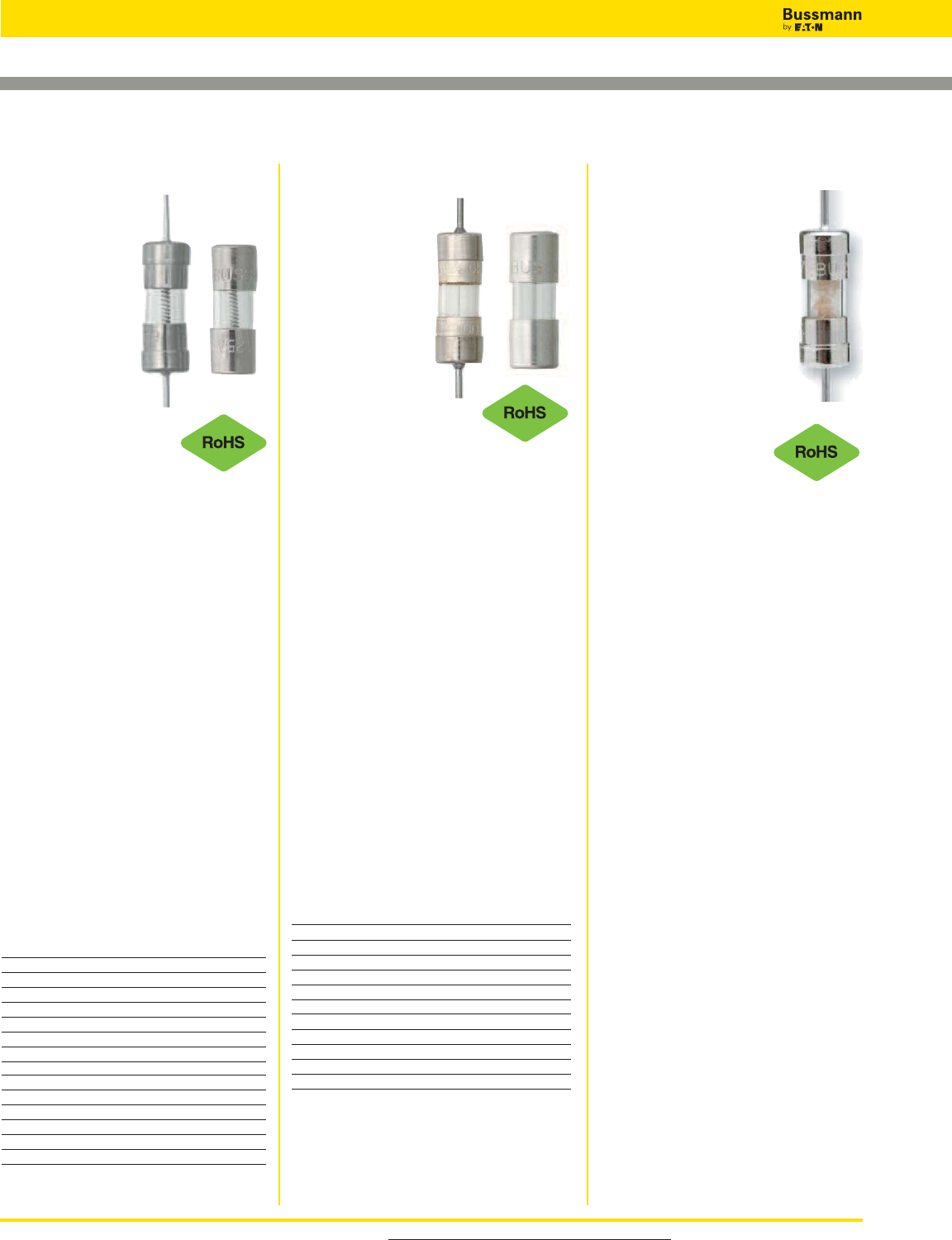
C517 (axial leads)
Specifications
Description: Fast-acting
fuse.
Construction: Glass tube.
Ratings:
Volts — 350Vac*
— 32Vdc (Self
Certified)
Amps — 3A
IR — 100A @ 350Vac
— 100A @
250Vac
— 10kA @
125Vac
*350Vac/100A IR is UL Recognized
Agency Information: CE, UL Listing
File E19180, Guide JDYX, CSA
Certification File 53787, Class
1422-01, UL Recognized, File
E19180, Guide JDYX2.
• Small footprint saves space in
equipment.
• Fast-acting for maximum component
protection.
• 350Vac rating for 277V ballast circuit
protection.
Typical Applications
• Electronic Circuits
• Printed Circuit Boards
• Electronic Ballast Protection
Catalog Number (Amps)
With Axial Leads
C517-3-R
C518 (axial leads)
C520
Specifications
Description:
Fast-acting fuse.
Dimensions:
5 x 15mm
(0.197” X 0.591”).
Construction:
Glass tube.
Ratings:
Volts — 250Vac
— 32Vdc (Self
Certified)
Amps — 100mA-5A
IR — 35A (100mA-750mA @
250Vac)
— 10kA (100mA-5A @ 125Vac)
— 100A (1.5-3.5A @ 250Vac)
— 200A (4-5A @ 250Vac)
Agency Information: CE,
UL Recognized File E19180, Guide
JDYX2CSA Certification File 53787,
Class 1422-01.
Features and Benefits
• Small footprint saves space in
equipment.
• Fast-acting for maximum component
protection.
• Available in ferrule and axial leaded
configurations
Typical Applications
• Electronic Circuits
• Printed Circuit Boards
Catalog Numbers (Amps)
With Axial Leads
C518-100-R C518-750-R C518-4-R
C518-125-R C518-2-R C518-5-R
C518-250-R C518-2.5-R
C518-375-R C518-3-R
C518-500-R C518-3.5-R
Without Axial Leads
C520-100-R C520-750-R C520-3.5-R
C520-125-R C520-1.5-R C520-4-R
C520-250-R C520-2-R C520-5-R
C520-375-R C520-2.5-R
C520-500-R C520-3-R
C515 (axial leads)
C519
Specifications
Description:
Time-delay fuse.
Dimensions:
5 x 15mm
(0.197” X 0.591”).
Construction:
Glass tube.
Ratings:
Volts — 125Vac (3.5-
7A)
— 250Vac
(125mA-3A)
— 32Vdc (Self Certified)
Amps — 125mA-7A
IR — 25A (350mA @ 600Vac)
— 35A (125mA-1A @ 250Vac)
— 100A (1.25-3A @ 250Vac)
— 400A (3.5-7A @ 125Vac)
— 10kA (125mA-3A @ 125Vac)
Agency Information: CE, UL Listed
File E19180, Guide JDYX
125mA-250mA and 375mA-3A, UL
Recognized, File E19180, Guide
JDYX2, 350mA and 3.5A-7A, CSA
Certification File 53787, Class
1422-01, 125mA-250mA and
375mA-3A.
Features and Benefits
• Time-delay for closer sizing on
inductive circuits.
Typical Application
• Electronic Circuits
• Printed Circuit Boards
Catalog Numbers (Amps)
With Axial Leads
C515-125-R C515-800-R C515-2.5-R
C515-250-R C515-1-R C515-3-R
C515-350-R C515-1.25-R C515-3.5-R
C515-375-R C515-1.5-R C515-4-R
C515-500-R C515-1.6-R C515-5-R
C515-600-R C515-2-R C515-6-R
C515-750-R C515-2.25-R C515-7-R
Without Axial Leads
C519-125-R C519-750-R C519-2.25-R
C519-250-R C519-1-R C519-2.5-R
C519-350-R C519-1.25-R C519-3-R
C519-375-R C519-1.5-R C519-3.5-R
C519-500-R C519-1.6-R C519-4-R
C519-600-R C519-2-R C519-5-R
For product data sheets, visit www.cooperbussmann.com/DatasheetsEle
86
Electronic — PCB & Small Dimension Fuses
5 x 15mm Ferrule Fuses
Data Sheet: 2025
Data Sheet: 2026 (C518) & 2027 (C520)
Data Sheet: 2006 (C515) & 2007 (C519)
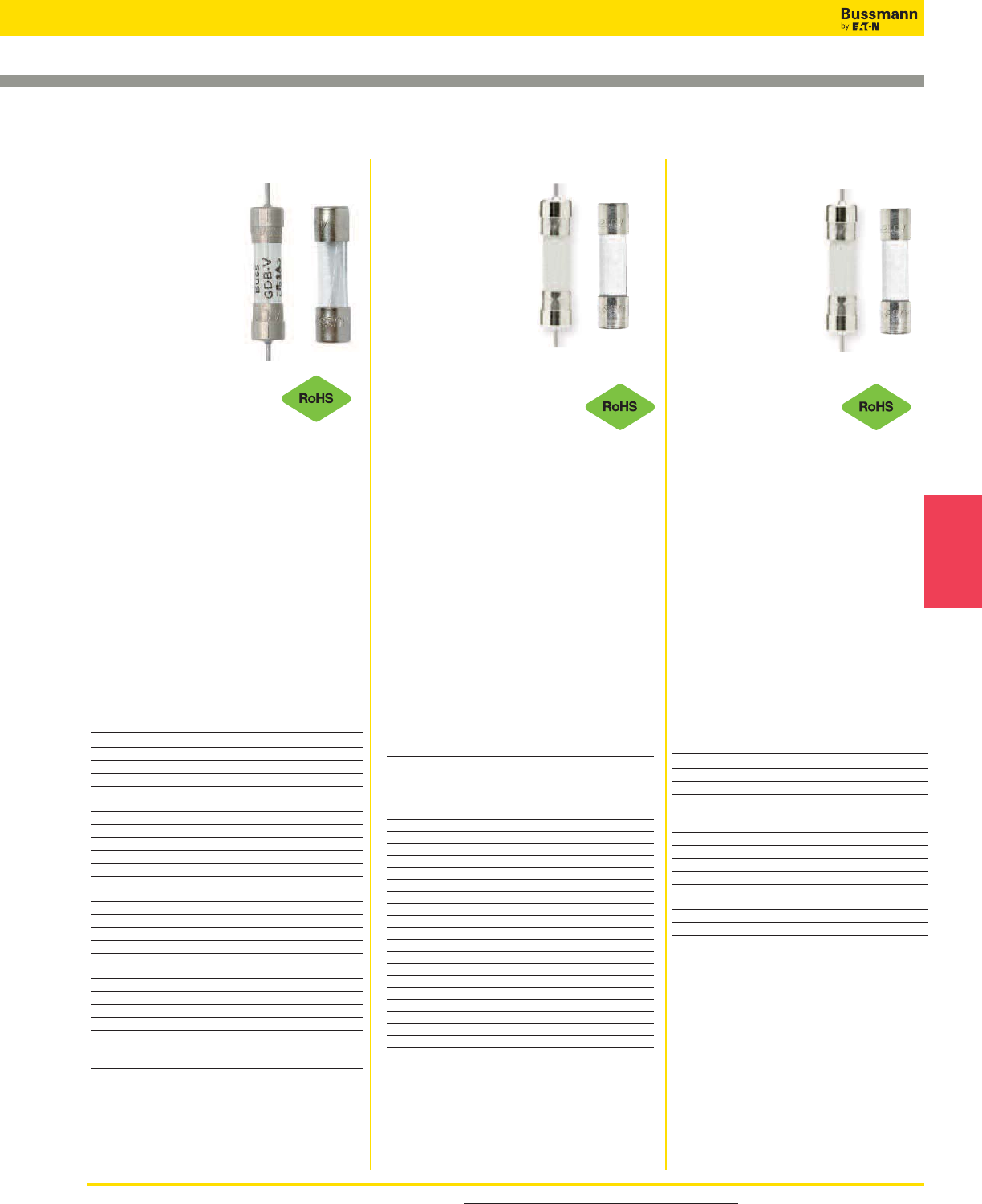
For product data sheets, visit www.cooperbussmann.com/DatasheetsEle 87
Electronic
Fuses
5 x 20mm European (IEC) Ferrule Fuses
S500-V (GDB-V)* (axial leads)
S500 (GDB)*
Specifications
Description: Fast-
acting, low-breaking
capacity fuse.
Construction:
Glass tube, nickel-
plated brass endcaps
(silver-plated end-
caps, 32-125mA).
Ratings:
Volts — 250Vac (or less)
— 32Vdc (Self Certified)
Amps — 32mA-10A
IR — See catalog table
Agency Information: CE,
cURus,
SEMKO, VDE, BSI, IMQ, CCC.
See data sheet for complete agency
information. Not all approvals apply to all
ratings.
Features and Benefits
• Fast-acting for maximum protection,
conforms to IEC 60127-2 (160mA-10A).
Typical Applications
• Electronic Circuits
Catalog Numbers (Amps)
Catalog IR Max Voltage
Numbers (Amps) I2t Drop (mV)
S500-32-R 35 0.000047 3200
S500-40-R 35 0.00011 2500
S500-50-R 35 0.00020 2400
S500-63-R 35 0.00057 2000
S500-80-R 35 0.0012 1200
S500-100-R 35 0.003 1100
S500-125-R 35 0.005 1000
S500-160-R 35 0.008 2000
S500-200-R 35 0.016 1700
S500-250-R 35 0.028 1400
S500-315-R 35 0.058 1300
S500-400-R 35 0.018 1100
S500-500-R 35 0.018 220
S500-630-R 35 0.035 220
S500-800-R 35 0.067 190
S500-1-R 35 0.60 200
S500-1.25-R 35 0.84 200
S500-1.6-R 35 1.6 190
S500-2-R 35 4.2 150
S500-2.5-R 35 6.1 150
S500-3.15-R 35 13 130
S500-4-R 40 22 130
S500-5-R 50 42 120
S500-6.3-R 63 69 120
S500-8-R 80 - 120
S500-10-R 100 —- 120
Options
Axial leads, put “V” in P/N,
*When ordering GDB version, do not
add “-R” suffix to part number.
S501-V (GDA-V)*
(axial leads)
S501 (GDA)*
Specifications
Description: Fast-
acting, high-breaking
capacity fuse.
Construction:
Ceramic tube,
nickel-plated brass
endcaps (silver-
plated endcaps 50mA-400mA).
Ratings:
Volts — 250Vac (or less)
— 32Vdc (Self Certified)
Amps — 50mA-10A**
IR — 1500A @ 250Vac
Agency Information:
CE, cURus,
SEMKO, VDE, IMQ, CCC, CSA, BSI.
See data sheet for complete agency infor-
mation. Not all approvals apply to all ratings.
Features and Benefits
• Fast-acting for maximum protection.
• High break capacity for use in higher
fault energy electronic circuitry.
• Conforming to IEC standards.
Typical Applications
• Electronic Circuits
Catalog Numbers (Amps)
Catalog Typical Voltage
Numbers I2t Drop (mV)
S501-50-R 0.0017 9000
S501-63-R 0.0005 3300
S501-80-R 0.0011 2600
S501-100-R 0.0018 2300
S501-125-R 0.0037 1900
S501-160-R 0.008 1600
S501-200-R 0.020 1350
S501-250-R 0.027 1300
S501-315-R 0.010 1400
S501-400-R 0.018 1200
S501-500-R 0.038 1050
S501-630-R 0.064 1200
S501-800-R 0.097 490
S501-1-R 0.146 330
S501-1.25-R 0.313 297
S501-1.6-R 0.748 239
S501-2-R 2.0 205
S501-2.5-R 3.9 190
S501-3.15-R 8.1 160
S501-4-R 14 160
S501-5-R 25 155
S501-6.3-R 48 150
S501-8-R N/A N/A
S501-10-R N/A N/A
Options
Axial leads, put “V” in P/N.
*When ordering GDA version, do not
add “-R” suffix to part number.
**GDA is not available above 6.3A.
Data Sheet: 2052 (S500), 2015 (GDB) Data Sheet: 2051 (S501), 2014 (GDA)
S505-V
(axial leads)
S505
Specifications
Description: Time-
delay, high-breaking
capacity fuse.
Construction:
Ceramic tube, silver-
plated brass endcaps.
Ratings:
Volts — 250Vac (or less)
— 32Vdc (Self
Certified)
Amps — 500mA-12A
IR — 1500A @ 250Vac
Agency Information: UL, CSA,
SEMKO, VDE, BSI, IMQ, PSE/JET,
CCC, EK, FIMKO.
See data sheet for complete agency
information. Not all approvals apply
to all ratings.
Features and Benefits
• Time-delay performance ideal for
inductive circuits.
• Conforming to IEC standards.
Typical Applications
• Electronic Circuits
Catalog Numbers (Amps)
Catalog Typical Max Voltage
Numbers I2t Drop (mV)
S505-500-R 0.188* 295
S505-800-R 0.632* 189
S505-1-R 1.28 152.5
S505-1.25-R 2.22 150
S505-1.6-R 6.78 125
S505-2-R 9.60 118.5
S505-2.5-R 16.60 115
S505-3.15-R 36.60 102.5
S505-4-R 38.45* 86.5
S505-5-R 71.30* 77.5
S505-6.3-R 197 75
S505-8-R 311 75
S505-10-R 397 72
S505-12-R 713.7* 77
*The typical I2t value was measured at 10 times of rated
current under DC.
Options
Axial leads, put “V” in P/N.
Data Sheet: 2037
Electronic — PCB & Small Dimension Fuses
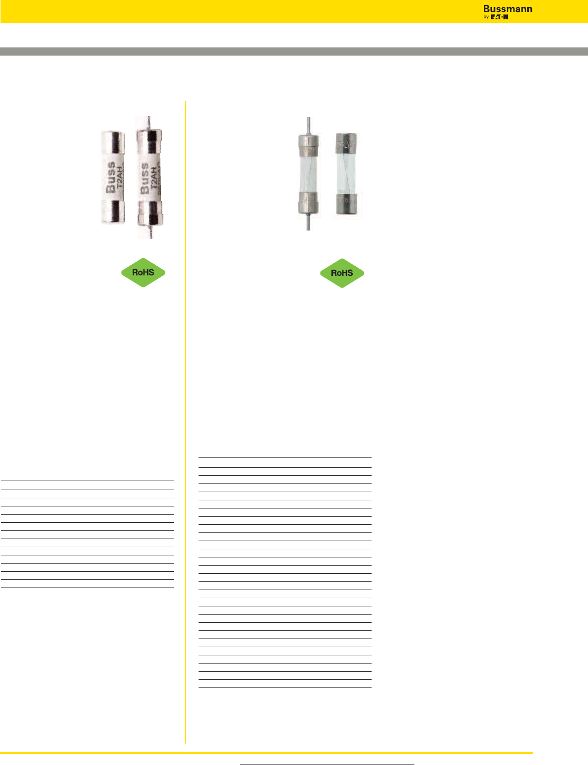
For product data sheets, visit www.cooperbussmann.com/DatasheetsEle
88
Electronic — PCB & Small Dimension Fuses
5 x 20mm European (IEC) Ferrule Fuses
S506-V (GDC-V)* (axial leads)
S506 (GDC)*
Specifications
Description: Time-
delay, low-breaking
capacity fuse.
Construction: Glass
tube, nickel-plated
brass endcaps.
Ratings:
Volts — 250Vac (or less)
— 32Vdc (Self Certified)
Amps — 32mA-15A**
IR — 35A @ 250Vac
Agency Information: UR, CSA,
cURus, SEMKO, VDE, BSI, IMQ,
PSE/JET, CCC.
See data sheet for complete agency
information. Not all approvals apply to all
ratings.
Features and Benefits
• Time-delay compatibility for inductive circuits
• Conforming to IEC standards
Typical Applications
• Electronic Circuits
Catalog Numbers (Amps)
Catalog Typical Max Voltage
Numbers I2t Drop (mV)
S506-32-R 0.0051 1050
S506-40-R 0.0072 920
S506-50-R 0.0095 800
S506-63-R 0.021 760
S506-80-R 0.038 580
S506-100-R 0.045 490
S506-125-R 0.063 390
S506-160-R 0.093 320
S506-200-R 0.114 340
S506-250-R 0.265 270
S506-315-R 0.621 250
S506-400-R 0.872 210
S506-500-R 0.827 140
S506-630-R 1.33 150
S506-800-R 2.78 75
S506-1-R 6.45 87.5
S506-1.25-R 10.05 86
S506-1.6-R 21.7 82
S506-2-R 31.6 77
S506-2.5-R 59.4 72.5
S506-3.15-R 96.4 68.5
S506-4-R 71.8 67
S506-5-R 142.5 60.5
S506-6.3-R 237.6 54
S506-8-R 255.8 55
S506-10-R 450 54
S506-12.5-R 1019.5 45
S506-15-R 1091.7 65.5
Options
Axial leads, put “V” in P/N.
*When ordering GDC version, do not add
“-R” suffix to part number.
**GDC series is not available above 6.3A.
Data Sheet: 2016 (GDC), 4332 (S506)
S505H (S505H-V)*
(axial leads)
Specifications
Description: Time-
delay, high-breaking
capacity fuse.
Construction:
Ceramic tube, nickel-
plated brass endcaps.
Ratings:
Volts — 600Vac/400Vdc
— 500mA-5A
— 6.3A-10A
— 500Vac/400Vdc
Amps — 500mm-10A
IR — 35A @ 250Vac
Agency Information: cURus, CCC,
CQC, TUV, PSE/JET.
See data sheet for complete agency
information. Not all approvals apply to all
ratings.
Features and Benefits
• Time-delay, high breaking capacity
• Conforming to IEC standards
Typical Applications
• Power supplies - adapters
• Desktops/notebooks
Catalog Numbers (Amps)
Catalog Typical Max Voltage
Numbers I2t (A2s)1Drop (mV)3
S505H-500-R 0.188 295
S505H-800-R 0.632 189
S505H-1-R 1.28 153
S505H-1.25-R 2.22 150
S505H-1.6-R 6.78 125
S505H-2-R 11.44 128
S505H-2.5-R 24.23 126
S505H-3.15-R 43.55 121
S505H-4-R 38.45 90
S505H-5-R 71.3 89
S505H-6.3-R 111.4 80
S505H-8-R 228.2 76
S505H-10-R 349.5 72
1. Typical Pre-Arc I2t: Measured at 10InDC.
2. - Breaking Capacity of 250VAC/1500A is tested by all agency
approvals, test condition is 250Vac, PF: 0.7-0.8.
- Breaking Capacity of Max. voltage is tested by UL, PF:1.
- Breaking Capacity Test of DC is tested by UL under Capacitor Bank
4800mF (for 400V, 1500A) 2400mF (for 400V, 500A).
3. Typical Voltage Drop: Voltage drop is measured under ambient 20°C
with rated current.
Options
Axial leads, put “V” in P/N.
Data Sheet: 4406
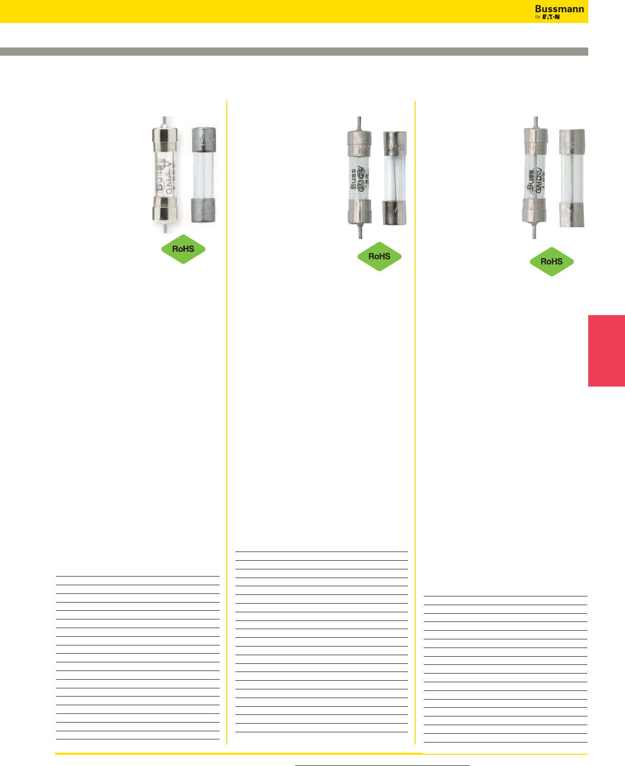
For product data sheets, visit www.cooperbussmann.com/DatasheetsEle 89
Electronic
Fuses
GMD-V (axial leads)
GMD
Specifications
Description: Time-
delay fuse.
Dimensions:
5 x 20mm
(0.197” x 0.788”).
Construction:
Glass tube, nickel-
plated brass
endcaps.
Ratings:
Volts — 250Vac
— 32Vdc (Self Certified)
Amps — 125mA-4A
IR — 10kA (125mA-3A @ 125Vac,
p.f. = 0.7-0.8)
— 10kA (4A @ 125Vac,
p.f. = 1.0)
— 35A (125mA-1A @ 250Vac,
p.f. = 0.7-0.8)
— 100A (1.2A-3.A @ 250Vac,
p.f. = 0.7-0.8)
— 200A (4A @ 250Vac,
p.f. = 1.0)
Agency Information: CE, UL Listed
Guide JDYX, File E19180, 125mA-3A,
UL Recognized, Guide JDYX2, File
E19180, 4A, CSA Certified, Class
1422-01, File 53787, 0-4A, PSE/JET.
File 1641-31003-1001, 1.2A-4A.
Features and Benefits
• Time-delay compatibility for inductive circuits.
• Conforming to UL standards.
Typical Applications
• Electronic Circuits
Catalog Numbers (Amps)
With Axial Leads
GMD-V-125-R GMD-V-500-R GMD-V-1.5-R
GMD-V-150-R GMD-V-600-R GMD-V-1.6-R
GMD-V-200-R GMD-V-630-R GMD-V-2-R
GMD-V-250-R GMD-V-750-R GMD-V-2.5-R
GMD-V-300-R GMD-V-800-R GMD-V-3-R
GMD-V-315-R GMD-V-1-R GMD-V-4-R
GMD-V-375-R GMD-V-1.2-R
GMD-V-400-R GMD-V-1.25-R
Without Axial Leads
GMD-125-R GMD-500-R GMD-1.5-R
GMD-150-R GMD-600-R GMD-1.6-R
GMD-200-R GMD-630-R GMD-2-R
GMD-250-R GMD-750-R GMD-2.5-R
GMD-300-R GMD-800-R GMD-3-R
GMD-315-R GMD-1-R GMD-4-R
GMD-375-R GMD-1.2-R
GMD-400-R GMD-1.25-R
GMC-V (axial leads)
GMC
Specifications
Description: Medium
time-delay fuse.
Dimensions: 5 x 20mm
(0.197” x 0.788”).
Construction: Glass
tube, nickel-plated brass
endcaps.
Ratings:
Volts — 250Vac (63mA-
3.15A)
— 125Vac (3.5-10A)
— 32Vdc (Self Certified)
Amps — 63mA-10A
IR — 35A (63mA- 1A @ 250Vac,
p.f. = 0.7-0.8)
— 10kA (63mA-6A @ 125Vac, p.f.
= 0.7-0.8)
— 100A (1.25-3.15A @ 250Vac,
p.f. = 0.7-0.8)
— 200A (6.3-10A @ 125Vac, p.f.
= 1.0)
Agency Information: CE, Std. 248-14,
UL Listed Guide JDYX, File E19180,
0-6.3A, UL Recognized, Guide JDYX2,
File E19180, 7-8A, CSA Certified, Class
1422-01, File 53787, 0-6.3A.
Features and Benefits
• Conforming to UL standards.
Typical Applications
• Electronic Circuits
Catalog Numbers (Amps)
With Axial Leads
GMC-V-63-R GMC-V-500-R GMC-V-2.5
GMC-V-80-R GMC-V-600-R GMC-V-3.15
GMC-V-100-R GMC-V-630-R GMC-V-3.5
GMC-V-125-R GMC-V-750-R GMC-V-4
GMC-V-150-R GMC-V-800-R GMC-V-5
GMC-V-200-R GMC-V-1-R GMC-V-6
GMC-V-250-R GMC-V-1.25-R GMC-V-6.3
GMC-V-300-R GMC-V-1.5-R GMC-V-7
GMC-V-315-R GMC-V-1.6-R GMC-V-8
GMC-V-400-R GMC-V-2-R GMC-V-10
Without Axial Leads
GMC-63mA GMC-500-R GMC-2.5-R
GMC-80mA GMC-600-R GMC-3.15-R
GMC-100mA GMC-630-R GMC-3.5-R
GMC-125mA GMC-750-R GMC-4-R
GMC-150mA GMC-800-R GMC-5-R
GMC-200mA GMC-1-R GMC-6-R
GMC-250mA GMC-1.25-R GMC-6.3-R
GMC-300mA GMC-1.5-R GMC-7-R
GMC-315mA GMC-1.6-R GMC-8-R
GMC-400mA GMC-2-R GMC-10-R
GMA-V (axial leads)
GMA
Specifications
Description:
Fast-acting fuse.
Dimensions:
5 x 20mm
(0.197” x 0.788”).
Construction:
Glass tube,
nickel-plated brass
endcaps.
Ratings:
Volts — 250Vac (63mA-2.5A)
— 125Vac (3.15-15A)
— 32Vdc (Self Certified)
Amps — 63mA-15A
IR — 35A (63mA- 1A @ 250Vac,
p.f. = 0.7-0.8)
— 10kA (63mA-6A @ 125Vac,
p.f. = 0.7-0.8)
— 100A (1.25-2.5A @ 250Vac,
p.f. = 0.7-0.8)
— 200A (7-8A @ 125Vac, p.f. = 1.0)
— 150A (10-15A @ 125Vac,
p.f. = 1.0)
Agency Information:
CE, Std.
248-14 UL Listed Guide JDYX, File
E19180, 0-6A, UL Recognized, Guide
JDYX2, File E19180, 7-15A, CSA
Certified, Class 1422-01,File 53787, 0-6.
Features and Benefits
• Fast-acting for maximum protection.
Typical Applications
• Electronic Circuits
Catalog Numbers (Amps)
With Axial Leads
GMA-V-63-R GMA-V-800-R GMA-V-4-R
GMA-V-100-R GMA-V-1-R GMA-V-5-R
GMA-V-125-R GMA-V-1.25-R GMA-V-6-R
GMA-V-200-R GMA-V-1.5-R GMA-V-7-R
GMA-V-250-R GMA-V-1.6-R GMA-V-8-R
GMA-V-300-R GMA-V-2-R GMA-V-10-R
GMA-V-500-R GMA-V-2.5-R GMA-V-15-R
GMA-V-600-R GMA-V-3.15-R
GMA-V-750-R GMA-V-3.5-R
Without Axial Leads
GMA-63-R GMA-800-R GMA-4-R
GMA-100-R GMA-1-R GMA-5-R
GMA-125-R GMA-1.25-R GMA-6-R
GMA-200-R GMA-1.5-R GMA-7-R
GMA-250-R GMA-1.6-R GMA-8-R
GMA-300-R GMA-2-R GMA-10-R
GMA-500-R GMA-2.5-R GMA-15-R
GMA-600-R GMA-3.15-R
GMA-750-R GMA-3.5-R
5 x 20mm North American (UL) Ferrule Fuses
Data Sheet:2019
Data Sheet: 4395
Data Sheet: 2017
GMC-10A GMD
Electronic — PCB & Small Dimension Fuses
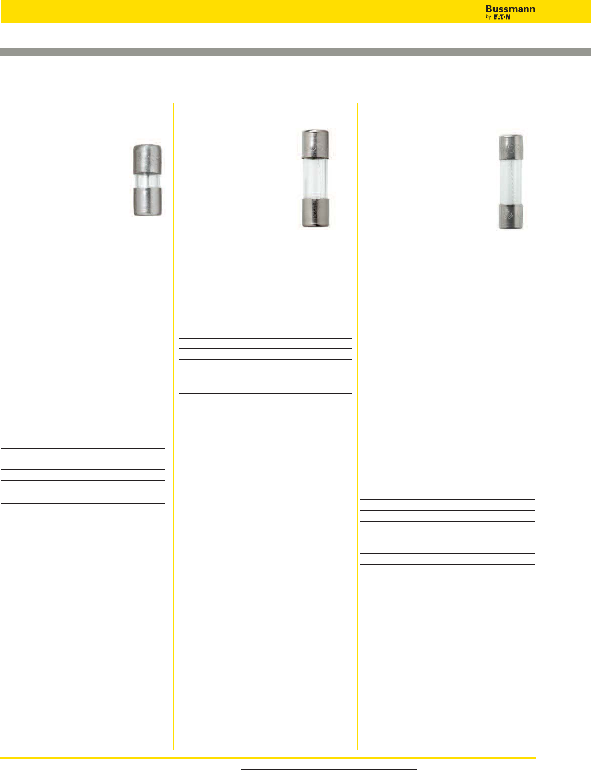
For product data sheets, visit www.cooperbussmann.com/DatasheetsEle
90
Electronic — PCB & Small Dimension Fuses
1⁄4˝ Dia. x 5⁄8˝ to 1˝ Length Ferrule Fuses
AGX
Specifications
Description: Fast-acting
fuse.
Dimensions: 1⁄4˝ x 1˝
(6.4 x 25.4mm).
Construction: Glass tube.
Ratings:
Volts — 250Vac (1⁄16-20A)
— 125Vac (25-30A)
— 32Vdc (1⁄16-30A)
Amps — 1⁄16-30A
IR — 35A (1⁄16-1A @ 250Vac)
— 10kA (1⁄16-10A @ 125Vac)
— 200A (15-20A @ 125Vac)
— 100A (25-30A @ 125Vac)
— 1000A (8-30A @ 32Vac)
Agency Information: cULus: AGX
0-10A (Guide JDYX, File E 19180 and
Guide JDYX7, File E19180), UL
Recognized Card: AGX 15-30A (Guide
JDYX2, File E19180), CSA Component
Acceptance Card : AGX 15-30A (Class
No. 1422-01, File 53787)
Features and Benefits
• Size rejects insertion of other fuse types.
Typical Applications
• Electronic Circuits
Catalog Numbers (Amps)
AGX-1⁄4AGX-1-1⁄2AGX-8
AGX-3⁄10 AGX-2 AGX-10
AGX-3⁄8AGX-2-1⁄2AGX-15
AGX-4⁄10 AGX-3 AGX-20
AGX-1⁄2AGX-4 AGX-25
AGX-3⁄4AGX-5 AGX-30
AGX-1 AGX-6
AGX-1-1⁄4AGX-7
AGA
Specifications
Description: Fast-acting
fuse.
Dimensions:
1⁄4˝ x 5⁄8˝
(6.4 x 15.9mm).
Construction: Glass tube.
Ratings:
Volts — 125Vac (or less)
— 32Vdc (Self Certified)
Amps — 1-30A
IR — 10kA (1-11⁄2A @ 125Vac)
— 200A (2-5A @ 125Vac)
— 1000A (6-30A @ 32Vac)
Agency Information: CE, Std. 248-
14, UL File E19180, UL Listed, Guide
JDYX 0-31⁄2A UL Recognized, Guide
JDYX2 12-30A.
Features and Benefits
• Fast-acting for maximum protection.
• Size rejects insertion of other fuse
types.
Typical Applications
• Electronic Circuits
Catalog Numbers (Amps)
AGA-1 AGA-5 AGA-15
AGA-1-1⁄2AGA-6 AGA-20
AGA-2 AGA-7 AGA-25
AGA-2-1⁄2AGA-7-1⁄2AGA-30
AGA-3 AGA-10
AGW
Specifications
Description: Fast-acting
fuse.
Dimensions: 1⁄4˝ x 7⁄8˝
(6.4 x 22.2mm).
Construction: Glass
tube.
Ratings:
Volts — 32Vac
— 32Vdc (Self Certified)
Amps — 1-30A
Features and Benefits
• Fast-acting for maximum protection.
Typical Applications
• Electronic Circuits
Catalog Numbers (Amps)
AGW-1 AGW-4 AGW-15
AGW-1-1⁄2AGW-5 AGW-20
AGW-2 AGW-6 AGW-25
AGW-2-1⁄2AGW-7-1⁄2AGW-30
AGW-3 AGW-10
Data Sheet: 2040Data Sheet: 2039 Data Sheet: 2041
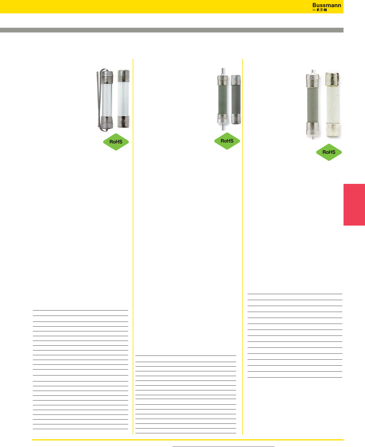
For product data sheets, visit www.cooperbussmann.com/DatasheetsEle 91
GBB (GBB-V axial leads)
Specifications
Description: Very
fast-acting fuse.
Dimensions:
1⁄4˝ x 1 1⁄4˝
(6.4 x 31.7mm).
Construction:
Ceramic cartridge with
nickel-plated brass
endcaps.
Ratings:
Volts — 250Vac/125Vdc
Amps — 1-30A
IR — 200A @ 250Vac
— 200A (20-30A @ 125Vac/dc)
— 10,000A (1A -15A @
125Vac/dc)
Agency Information:
CE, Std. 248-14, UL Recognized,
1-30,125Vdc/250Vac, File E56412,
Guide JFHR2, CSA Accepted, 1-30,
125Vdc/250Vac, File 53787, Class
1422-30.
Features and Benefits
• Very fast-acting performance allows
protection of highly sensitive
electronic circuitry.
Typical Applications
• Electronic Circuits
Catalog Numbers (Amps)
With Axial Leads
GBB-V-1-R GBB-V-6-R GBB-V-15-R
GBB-V-1-1⁄4-R GBB-V-7-R GBB-V-20-R
GBB-V-2-R GBB-V-8-R GBB-V-25-R
GBB-V-3-R GBB-V-9-R GBB-V-30-R
GBB-V-4-R GBB-V-10-R
GBB-V-5-R GBB-V-12-R
Without Axial Leads
GBB-1-R GBB-6-R GBB-15-R
GBB-1-1⁄4-R GBB-7-R GBB-20-R
GBB-2-R GBB-8-R GBB-25-R
GBB-3-R GBB-9-R GBB-30-R
GBB-4-R GBB-10-R
GBB-5-R GBB-12-R
Data Sheet: 2013
ABC (ABC-V axial leads)
Specifications
Description: Fast-acting fuse.
Dimensions:
1⁄4˝ x 1 1⁄4˝ (6.4 x 31.7mm).
Construction: Ceramic tube
with nickel-plated brass endcaps.
Ratings:
Volts — 250Vac/125Vdc
(1⁄4-15A, 20-30A)*
— 250Vac (18A)
— 32Vdc (Self Certified)
Amps — 1⁄4-30A
IR** — 35A (1⁄4-1A @ 250Vac)
— 100A (11⁄2-3A @ 250Vac)
— 200A (4-10A @ 250Vac)
— 750A (12-15A @ 250Vac)
— 400A (18-20A @ 250Vac)
— 10kA (1⁄4-15A @ 125Vac)
— 1kA (18-30A @ 125Vac)
— 10kA (1⁄4-15, 20A @ 125Vdc)
— 400A (25-30A @ 125Vdc)
— 200A (25-30A @ 250Vac)
*CSA approvals for 25A and 30A are at 125Vac – IR 1000A and Vdc – IR 400A
(IR 1000A at 75Vdc)
**Interrupting ratings measured at 70% – 80% power factor on AC. The
interrupting ratings for 18A and 20A were measured at 85%-95% power factor
on AC. The interrupting ratings for 25A and 30A were measured at 89% power
factor on AC.
Agency Information: CE, Std. 248-14
UL Listed, Guide JDYX File E19180,
1⁄4-15A; UL Recognized, Guide JDYX2,
File E19180, 18-30A; CSA Certification,
Class 1422-01 & 1422-30, File 53787,
1⁄4-30A.
Features and Benefits
• Ceramic body allows for higher
amp/volt rating combinations.
Typical Applications
• Electronic Circuits
Catalog Numbers (Amps)
With Axial Leads
ABC-V-1⁄4-R ABC-V-3-R ABC-V-12-R
ABC-V-1⁄2-R ABC-V-4-R ABC-V-15-R
ABC-V-3⁄4-R ABC-V-5-R ABC-V-18-R
ABC-V-1-R ABC-V-6-R ABC-V-20-R
ABC-V-1-1⁄2-R ABC-V-7-R ABC-V-25-R
ABC-V-2-R ABC-V-8-R ABC-V-30-R
ABC-V-2-1⁄2-R ABC-V-10-R
Without Axial Leads
ABC-1⁄4-R ABC-3-R ABC-12-R
ABC-1⁄2-R ABC-4-R ABC-15-R
ABC-3⁄4-R ABC-5-R ABC-18-R
ABC-1-R ABC-6-R ABC-20-R
ABC-1-1⁄2-R ABC-7-R ABC-25-R
ABC-2-R ABC-8-R ABC-30-R
ABC-2-1⁄2-R ABC-10-R
AGC (AGC-V axial leads)
Specifications
Description:
Fast-acting fuse.
Dimensions: 1⁄4˝ x 1 1⁄4˝
(6.4 x 31.7mm).
Construction: Glass
tube with nickel-plated
brass endcaps.
Ratings:
Volts — 250Vac (1⁄20-10A)
— 32Vac (12-30A)
— 32Vdc (Self Certified)
Amps — 1⁄20-30A
IR — 35A (1⁄20-1A @ 250Vac)
— 100A (11⁄4-3A @ 250Vac)
— 200A (4-10A @ 250Vac)
— 10kA (1⁄20-10A @ 125Vac)
— 1000A (12-30A @ 32Vac)
Agency Information: CE, UL Listed,
Guide JDYX, File E19180, 0-10A UL
Recognized, Guide JDYX2, File
E19180, 12-30A CSA Certification,
Class 1422-01, File 053787, 1⁄20-30A.
Features and Benefits
• Original electronic glass tube fuse.
• Fast-acting for maximum protection.
• Wide amp/volt ratings allow versatility
of protecting electronic circuits.
Typical Applications
• Electronic Circuits
Catalog Numbers (Amps)
With Axial Leads
AGC-V-1⁄20-R AGC-V-1-1⁄4-R AGC-V-8-R
AGC-V-1⁄10-R AGC-V-1-1⁄2-R AGC-V-9-R
AGC-V-1⁄8-R AGC-V-2-R AGC-V-10-R
AGC-V-3⁄16-R AGC-V-2-1⁄4-R AGC-V-12-R
AGC-V-2⁄10-R AGC-V-2-1⁄2-R AGC-V-14-R
AGC-V-1⁄4-R AGC-V-3-R AGC-V-15-R
AGC-V-3⁄10-R AGC-V-4-R AGC-V-20-R
AGC-V-3⁄8-R AGC-V-5-R AGC-V-25-R
AGC-V-1⁄2-R AGC-V-6-R AGC-V-30-R
AGC-V-3⁄4-R AGC-V-7-R
AGC-V-1-R AGC-V-7-1⁄2-R
Without Axial Leads
AGC-1⁄20-R AGC-1-1⁄4-R AGC-8-R
AGC-1⁄10-R AGC-1-1⁄2-R AGC-9-R
AGC-1⁄8-R AGC-2-R AGC-10-R
AGC-3⁄16-R AGC-2-1⁄4-R AGC-12-R
AGC-2⁄10-R AGC-2-1⁄2-R AGC-14-R
AGC-1⁄4-R AGC-3-R AGC-15-R
AGC-3⁄10-R AGC-4-R AGC-20-R
AGC-3⁄8-R AGC-5-R AGC-25-R
AGC-1⁄2-R AGC-6-R AGC-30-R
AGC-3⁄4-R AGC-7-R
AGC-1-R AGC-7-1⁄2-R
1⁄4˝ Dia. x 1 1⁄4˝ Length Fast-acting Ferrule Fuses
Data Sheet: 2000
Data Sheet: 2001
Electronic
Fuses
Electronic — PCB & Small Dimension Fuses
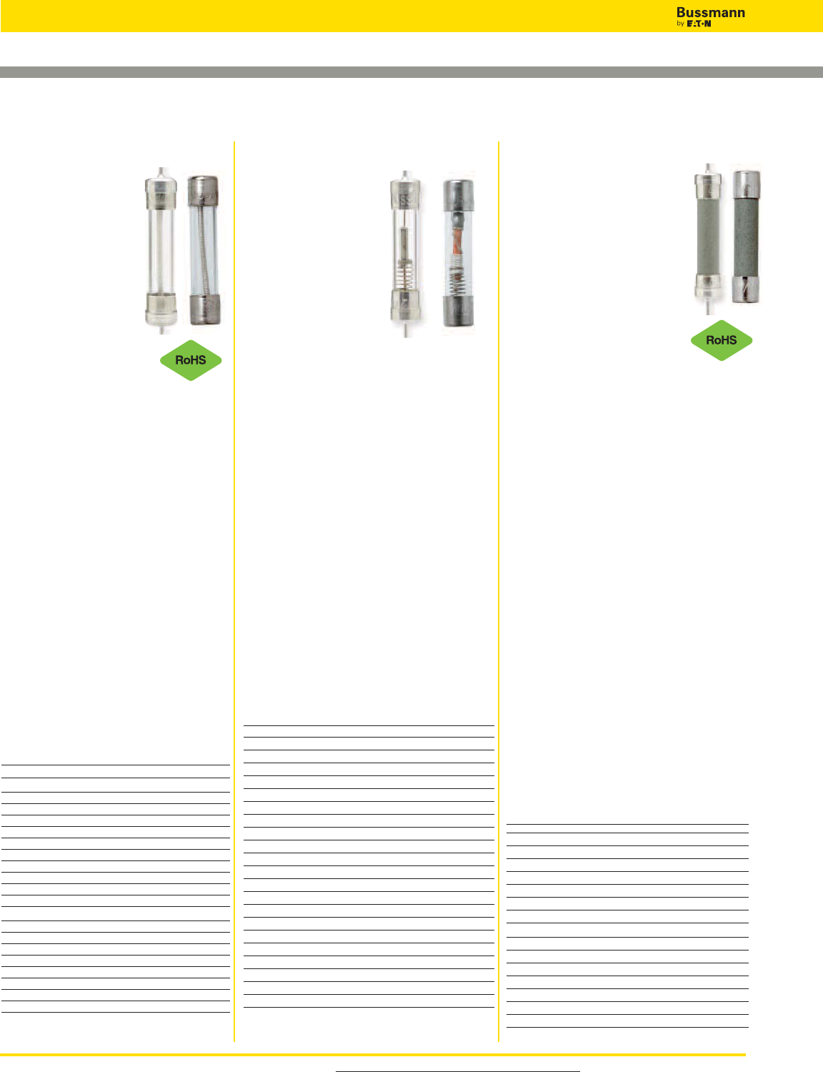
For product data sheets, visit www.cooperbussmann.com/DatasheetsEle
92
Electronic — PCB & Small Dimension Fuses
MDL-V (axial leads)
MDL
Specifications
Description:
Time-delay fuse.
Dimensions: 1⁄4˝ x 1 1⁄4˝
(6.4 x 31.7mm).
Construction: Glass
tube with nickel-plated
brass endcaps.
Ratings:
Volts — 250Vac (1⁄16-8A)
— 32Vac (9-30A)
— 32Vdc (Self Certified)
Amps — 1⁄16-30A
IR* — 35A (1⁄16-1A @ 250Vac)
— 100A (11⁄4-3A @ 250Vac)
— 200A (4-8A @ 250Vac)
— 10000A (1⁄16-8A @ 125Vac)
— 1000A (9-30A @ 32Vac)
*Interrupting ratings were measured at 70% – 80% power
factor on AC, and at a time constant described in UL 198L.
Agency Information: CE, UL Listed,
Guide JDYX, File E19180, 1⁄16-8A; CSA
Certification Class 1422-01, 1⁄16-8A; UL
Recognized, Guide JDYX2, File
E19180, 9-30A; CSA Component
Acceptance, Class 142230, 9-30A.
Features and Benefits
• Time-delay allows close sizing on
inductive circuits.
Typical Applications
• Electronic Circuits
Catalog Numbers (Amps)
With Axial Leads
MDL-V-1⁄16-R MDL-V-1-R MDL-V-7-R
MDL-V-1⁄10-R MDL-V-1-1⁄4-R MDL-V-8-R
MDL-V-1⁄8-R MDL-V-1-1⁄2-R MDL-V-9-R
MDL-V-2⁄10-R MDL-V-2-R MDL-V-10-R
MDL-V-3⁄16-R MDL-V-2-1⁄4-R MDL-V-12-R
MDL-V-1⁄4-R MDL-V-2-1⁄2-R MDL-V-15-R
MDL-V-3⁄10-R MDL-V-3-R MDL-V-20-R
MDL-V-3⁄8-R MDL-V-4-R MDL-V-25*
MDL-V-1⁄2-R MDL-V-5-R MDL-V-30*
MDL-V-3⁄4-R MDL-V-6-R
Without Axial Leads
MDL-1⁄16-R MDL-1-R MDL-7-R
MDL-1⁄10-R MDL-1-1⁄4-R MDL-8-R
MDL-1⁄8-R MDL-1-1⁄2-R MDL-9-R
MDL-2⁄10-R MDL-2-R MDL-10-R
MDL-3⁄16-R MDL-2-1⁄4-R MDL-12-R
MDL-1⁄4-R MDL-2-1⁄2-R MDL-15-R
MDL-3⁄10-R MDL-3-R MDL-20-R
MDL-3⁄8-R MDL-4-R MDL-25*
MDL-1⁄2-R MDL-5-R MDL-30*
1⁄4˝ Dia. x 1 1⁄4˝ Length Time-delay Ferrule Fuses
Data Sheet:2004
MDA-V (axial leads)
MDA
Specifications
Description: Time-delay fuse.
Dimensions: 1⁄4˝ x 1 1⁄4˝ (6.35 x
31.75mm).
Construction: Ceramic tube
with nickel-plated brass
endcaps.
Ratings:
Volts — 250Vac (or less)
— 125Vdc (20A- 30A)
— 32Vdc (Self Certified)
Amps — 1⁄4-30A
IR** — 35A (1⁄4-1A @ 250Vac)
— 100A (11⁄2-2A @ 250Vac)
— 200A (21⁄2-10A @ 250Vac)
— 750A (12-15A @ 250Vac)
— 1500A (20-30A @ 250Vac)
— 10kA (1⁄4-30A @ 125Vac)
— 10kA (20-30A @ 125Vdc)
**Interrupting ratings were measured at 70% – 80% power
factor on AC, and at a time constant described in UL 248.
Agency Information: CE, Std. 248-14,
UL Listed, Guide JDYX, File E19180,
0-20A CSA Certification, Class 1422-01,
File 53787, 0-20A. UL Recognized,
Guide JDYX2, File E19180, 25-30A,
CSA Component Acceptance, Class
1422-30, 25-30A
Features and Benefits
• Ceramic body allows for higher
amp/volt rating combinations.
• Inventory consolidation by replacing
MDL fuses allows for reduced SKU
investment and minimizing potential for
misapplying fuse.
Typical Applications
• Electronic Circuits
Catalog Numbers (Amps)
With Axial Leads
MDA-V-1⁄4-R MDA-V-3-R MDA-V-12-R
MDA-V-1⁄2-R MDA-V-4-R MDA-V-15-R
MDA-V-3⁄4-R MDA-V-5-R MDA-V-20-R
MDA-V-1-R MDA-V-6-R MDA-V-25-R
MDA-V-1-1⁄2-R MDA-V-7-R MDA-V-30-R
MDA-V-2-R MDA-V-8-R
MDA-V-2-1⁄2-R MDA-V-10-R
Without Axial Leads
MDA-1⁄4-R MDA-3-R MDA-12-R
MDA-1⁄2-R MDA-4-R MDA-15-R
MDA-3⁄4-R MDA-5-R MDA-20-R
MDA-1-R MDA-6-R MDA-25A-R
MDA-1-1⁄2-R MDA-7-R MDA-30A-R
MDA-2-R MDA-8-R
MDA-2-1⁄2-R MDA-10-R
MDQ-V (axial leads)
MDQ
Specifications
Description:
Dual-element,
time-delay fuse.
Dimensions: 1⁄4˝ x 1 1⁄4˝
(6.4 x 31.7mm).
Construction: Glass
tube with nickel-plated
brass endcaps.
Ratings:
Volts — 250Vac (1⁄100-7A)
— 32Vac (71⁄2-15A)
— 32Vdc (Self Certified)
Amps — 1⁄100-15A
IR — 35A (1⁄100-1A @ 250Vac)
— 100A (11⁄4-3A @ 250Vac)
— 200A (4-7A @ 250Vac)
— 1000A (71⁄2-12A @ 32Vac)
Agency Information: Std. 248-14, UL
Listed, File E19180; Guide JDYX, 1⁄16-7A
CSA Certification, File 47233, Class
1422-01, 1⁄16 -7A, UL Recognized, Guide
JDYX2, File E19180, 7.1-30A.
Features and Benefits
• Dual-element design allows closer sizing
to inductive circuits than any other fuses.
Typical Applications
• Electronic Relay and Control Circuits
Catalog Numbers (Amps)
With Axial Leads
MDQ-V-1⁄100 MDQ-V-3⁄10 MDQ-V-1-1⁄2MDQ-V-5
MDQ-V-1⁄32 MDQ-V-3⁄8MDQ-V-1-6⁄10 MDQ-V-6
MDQ-V-1⁄16 MDQ-V-4⁄10 MDQ-V-1-8⁄10 MDQ-V-6-1⁄4
MDQ-V-1⁄10 MDQ-V-1⁄2MDQ-V-2 MDQ-V-7
MDQ-V-1⁄8MDQ-V-6⁄10 MDQ-V-2-1⁄4MDQ-V-7-1⁄2
MDQ-V-15⁄100 MDQ-V-3⁄4MDQ-V-2-1⁄2MDQ-V-8
MDQ-V-175⁄1000 MDQ-V-8⁄10 MDQ-V-2-8⁄10 MDQ-V-9
MDQ-V-3⁄16 MDQ-V-1 MDQ-V-3 MDQ-V-10
MDQ-V-2⁄10 MDQ-V-1-2⁄10 MDQ-V-3-2⁄10 MDQ-V-12
MDQ-V-1⁄4MDQ-V-1-1⁄4MDQ-V-4 MDQ-15
Without Axial Leads
MDQ-1⁄100 MDQ-3⁄10 MDQ-1-1⁄2MDQ-5
MDQ-1⁄32 MDQ-3⁄8MDQ-1-6⁄10 MDQ-6
MDQ-1⁄16 MDQ-4⁄10 MDQ-1-8⁄10 MDQ-6-1⁄4
MDQ-1⁄10 MDQ-1⁄2MDQ-2 MDQ-7
MDQ-1⁄8MDQ-6⁄10 MDQ-2-1⁄4MDQ-7-1⁄2
MDQ-15⁄100 MDQ-3⁄4MDQ-2-1⁄2MDQ-8
MDQ-175⁄1000 MDQ-8⁄10 MDQ-2-8⁄10 MDQ-9
MDQ-3⁄16 MDQ-1 MDQ-3 MDQ-10
MDQ-2⁄10 MDQ-1-2⁄10 MDQ-3-2⁄10 MDQ-12
MDQ-1⁄4MDQ-1-1⁄4MDQ-4 MDQ-15
Data Sheet: 2002
Data Sheet: 2044
*MDL-25 & MDL-30 are not available in RoHS compliant
construction.
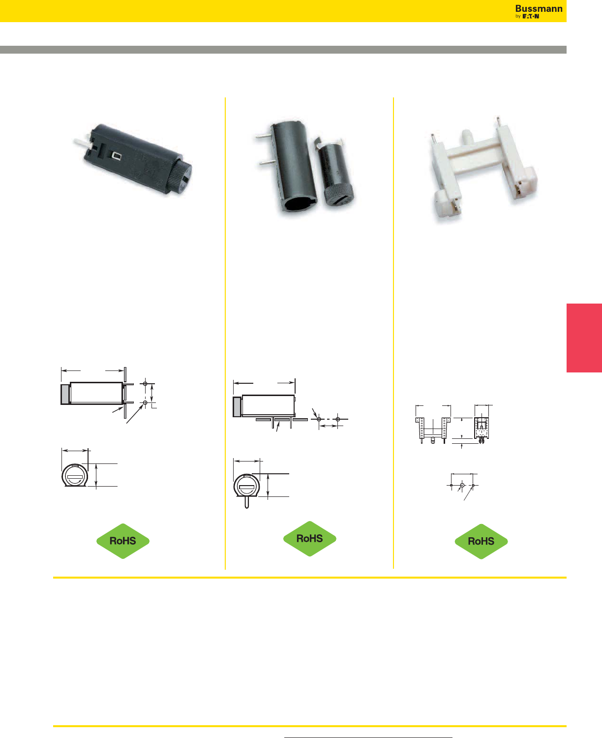
For product data sheets, visit www.cooperbussmann.com/DatasheetsEle 93
Electronic
Fuses
HTC-60M
PCB Stand-Off Mount
Specifications
Description: Four-leg PCB stand-off
fuse holder.
Dimensions: See Dimensions
illustration.
Ratings:
Volts: — 250V
Amps: — 6.3A
Agency Information:
See Specifications table notes 1, 4.
Dimensions - in (mm)
HTC-50M
PCB Horizontal Mount
Specifications
Description: PCB horizontal mount
bayonet cap and fuse holder.
Dimensions: See Dimensions
illustration.
Ratings:
See Specifications table.
Agency Information:
See Specifications table notes 1, 2.
Dimensions - in (mm)
HTC-45M
PCB Vertical Mount
Specifications
Description: PCB vertical mount
bayonet cap and fuse holder.
Dimensions: See Dimensions
illustration.
Ratings:
See Specifications table.
Agency Information:
See Specifications table notes 1, 2, 5.
Dimensions - in (mm)
PC Board Mount Fuse Holders
F
U
S
E
0.461"
(11.7mm)
1.303"
(33.1mm)
0.512"
(13.0mm)
Printed Circuit
Board Dia. (Typ.)0.051"
+ 0.002"
_
(1.30 + 0.05mm)
_
0.394"
(10.0mm)
Mounting Holes
F
U
S
E
0.461"
(11.7mm)
1.303"
(33.1mm)
0.512"
(13.0mm)
Printed Circuit
Board
0.394"
(10.0mm)
Mounting Holes
" 0.002"
+
_
(1.30 + 0.05mm)
_
Dia. (Typ.)
0.051
Data Sheet 2110 Data Sheet 2110
HTC-65M (4-Leg)
Data Sheet 2110
Electronic — PCB & Small Dimension Fuses
Specifications
Terminals — Tin-plated brass with 3mm (HTC-35M, -55M)
and 4.8mm (HTC-70M).
Molded Materials — High temperature thermoplastic that
meets the flammability ratings of UL 94VO; Glow Wire Test:
960°C per IEC 695-2-1.
Solderability — In accordance with IEC 68-2-20.
Electrical — Contact Resistance: _<10mW; Insulation
Resistance: _>10MW; Dielectric Strength _>2000Vac.
Shock Safety — PC2 (fuse holders).
Agency Information:
1) cURus: Guide 1ZLT2 & IZLT8, File E14853
2) VDE: 40004457
3) VDE: 40004458
4) VDE: 40004459
5) VDE: 40004463
.886"
(22.5mm)
.1
0
.138"
(3.5mm)
.354"
(9.0mm)
.551"
(3.5mm)
.102" Dia. Hole
(2.6mm) .051" Dia. Hole
(1.3mm)
.591"
(15.0mm)
4
m
m)
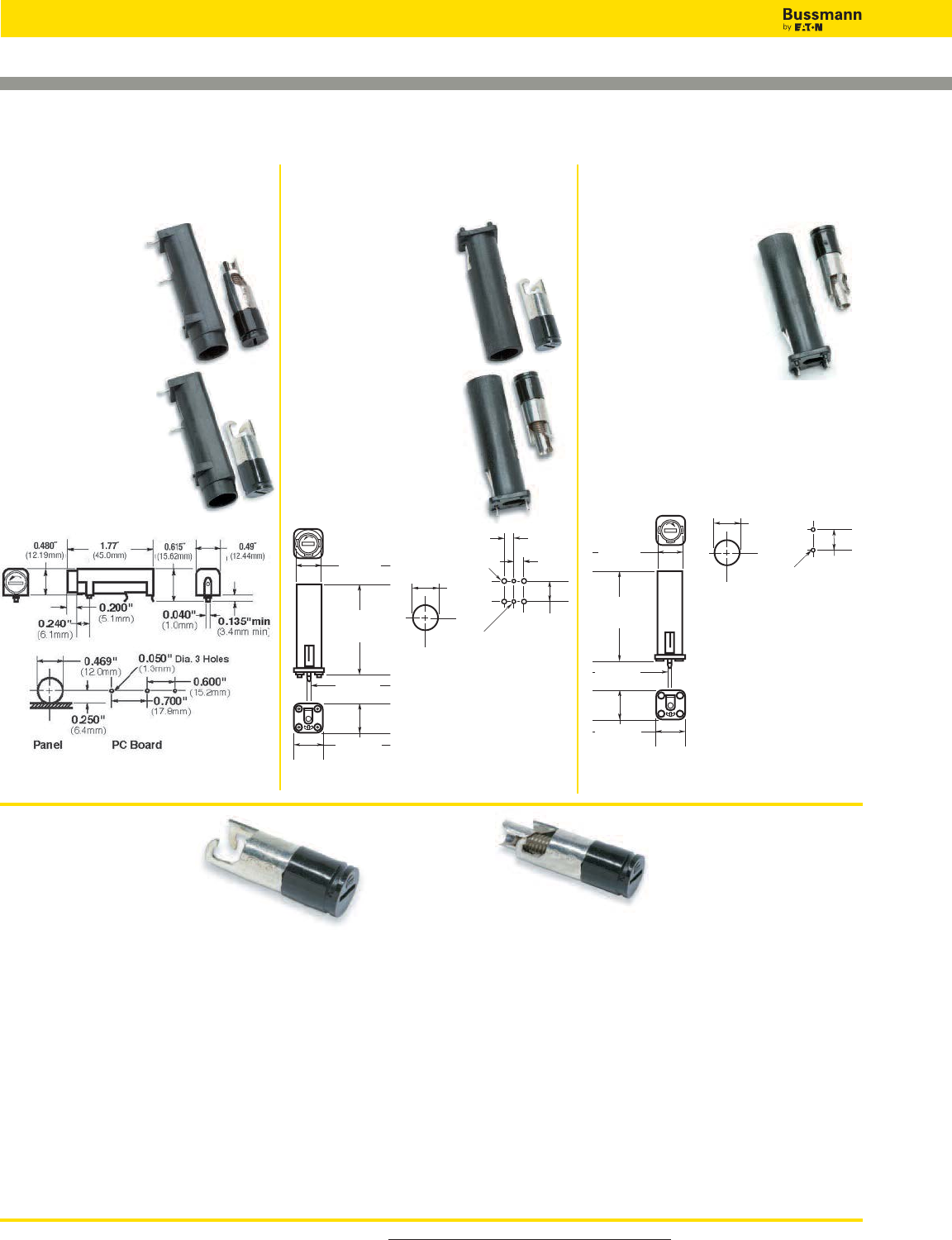
For product data sheets, visit www.cooperbussmann.com/DatasheetsEle
94
Electronic — PCB & Small Dimension Fuses
HBH-I (for 1⁄4˝ x 1 1⁄4˝ fuses)
HBH-M (for 5 x 20mm fuses)
PCB Horizontal
Mount
Specifications
Description: PCB
horizontal mount
fuse holder.
Dimensions: See
Dimensions
illustration.
Ratings:
See Specifications table.
Dimensions - in (mm)
HBV-I (for 1⁄4˝ x 1 1⁄4˝ fuses)
HBV-M (for 5 x 20mm fuses)
PCB Vertical Mount
with Stability Pins
Specifications
Description: PCB
vertical mount fuse
holder with stability
pins.
Dimensions: See
Dimensions illustration.
Ratings:
See Specifications
table.
Dimensions - in (mm)
HBW-I (for 1⁄4˝ x 1 1⁄4˝ fuses)
HBW-M (for 5 x 20mm fuses)
PCB Vertical Mount
without Stability
Pins
Specifications
Description: PCB
vertical mount fuse
holder without stability
pins.
Dimensions: See Dimensions
illustration.
Ratings:
See Specifications table.
Dimensions - in (mm)
PC Board Mount Fuse Holders
HBV
0.510"
(13.0mm)
1.855"
(47.0mm)
0.040"
(1.05mm)
0.580"
(14.9mm)
0.200"
(5.0mm)
0.200"
(5.0mm)
0.100" Dia. 4 Holes
(2.54mm)
Panel PC Board
0.531"
(13.5mm)
0.400"
(10.0mm)
0.050" Dia. 2 Holes
(1.3mm)
HBW
0.510"
(13.0mm)
1.855"
(47.0mm)
0.040"
(1.05mm)
0.580"
(14.9mm)
Panel PC Board
0.531"
(13.5mm)
0.400"
(10.0mm)
0.050"
Dia. 2 Holes
(1.3mm)
Data Sheet: 2118 Data Sheet: 2118 Data Sheet: 2118
FBI FBM
Fuse Holder Caps (Fit all three shown above)
Specifications
Electrical Ratings: UL — 16A @ 250V; CSA — 12A @ 250V; VDE — 6.3A @ 250V; SEMKO — 10A @ 250V
Insulation resistance — 10 megohm at 500Vdc. Contact resistance — less than 0.005 ohms
@ 200mV. Dielectric strength — over 200V/mil.
Molded Material: High dielectric molded phenolic with a UL 94V0 flammability rating.
Fuse Carrier & Knob: Spring-loaded, bayonet-type. Tin plated brass. Screwdriver slotted.
Mounting: “Kicked” terminals (all models) and stabilizer pins on HBV & HBW models for increased stability.
Temperature Rating (RTI): Body: 150ºC, Knob: 130ºC
Agency Information: CE, UL Recognized — Guide IZLT2, File EI4853;
CSA Certified — Class 6225-01, File 47235
VDE — 4009241 (HBV, HBW)
SEMKO — 800444
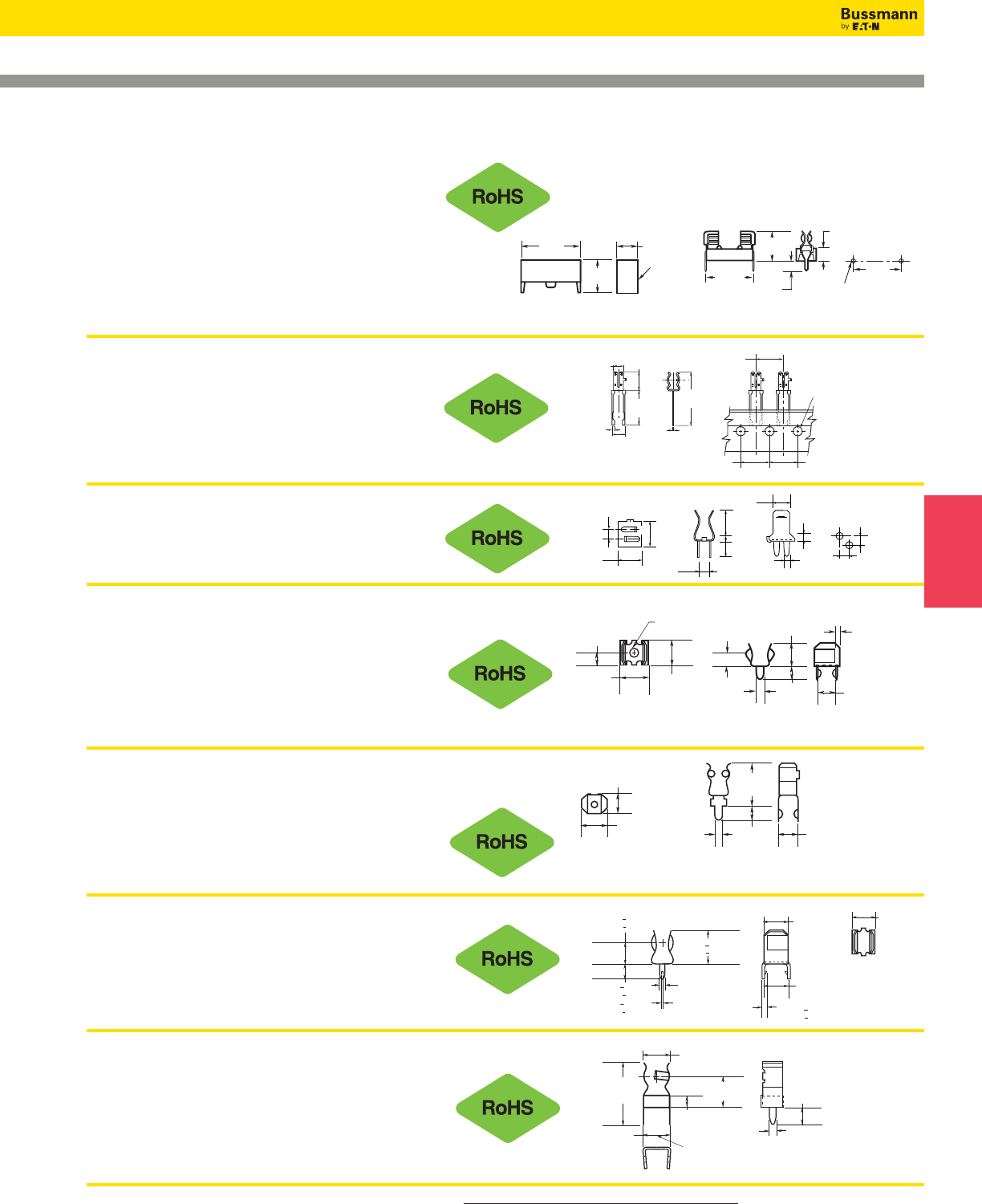
For product data sheets, visit www.cooperbussmann.com/DatasheetsEle 95
Electronic
Fuses
PC Board Fuseclips for 5mm Diameter Fuses
0.031"
(0.79mm) 0.217"
(5.5mm)
0.012"
(0.3mm)
0.177"
(4.5mm)
0.319"
(8.1mm)
BUSS
0.61"
(15.5mm)
0.929"
(23.6mm)
BUSS
BUSS
0.50"
(12.7mm)
0.50"
(12.7mm)
0.50"
(12.7mm)
0.157"
(3.99mm)
2.54mm
1.46mm
2.29mm
4.32mm
8.73mm
3.91mm
2.85mm
6.26mm
6.22mm
2.54mm 2.54mm
0.180"
(4.57mm)
0.230"
(5.84mm)
HTC-210M
PCB Mounted Fuseclip with End Stops
Data Sheet: 2110
HTC-15M, HTC-140M
PCB Mounted Fuse Holder & Snap-On Cover
Voltage Rating: 250V, 6.3A, 1.6W
HTC-15M (fuse holder), HTC-140M (natural cover),
HTC-150M* (transparent cover)
Agency Information: See Specifications table notes 1, 3
on bottom of page 65
*Available in bulk only. Use this format: BK/HTC-150M
Data Sheet: 2110
HTC-200M
PCB Mounted Fuseclip
Construction: Tin-plated bronze
Tape and Fan Fold packed
Ammo Pack (AP/HTC-200M) 1000 pieces per box
Data Sheet: 2110
1A3399 Series
PCB Fuseclips with End Stops & Straight Leads
Catalog Numbers Clip Material* Finish
1A3399-01 Beryllium copper* Silver
1A3399-04-R Beryllium copper* Bright tin
1A3399-10-R Spring bronze Bright tin
*Beryllium copper recommended for amps higher than 15 amps.
Data Sheet: 2131
1A5601 Series
PCB Fuseclips (0-7A)
Catalog Number Clip Material Finish
1A5601 Cartridge brass Bright tin
Data Sheet: 2131
1A5602 Series
PCB Fuseclips (0-7A)
Catalog Number Clip Material Finish
1A5602 Cartridge brass Bright tin
Data Sheet: 2131
1A5018 Series
PCB High Profile Fuseclips with End Stops & Straight Leads
Catalog Numbers Clip Material* Finish
1A5018-7 Spring bronze Silver
1A5018-10-R Spring bronze Bright tin
*Beryllium copper recommended for amps higher than 15 amps.
Data Sheet: 2131
0.115"
(2.9mm)
0.062"
(1.6mm)
0.254"
(6.5mm) 0.237"
(6.0mm)
0.125"
(3.2mm)
0.225"
(5.7mm)
0.125"
(3.2mm)
0.060"
(1.5mm) 0.188"
(4.8mm)
0.030"
(1.6mm)
0.440"
(11.2mm)
0.140"
(3.7mm)
0.047"
(1.2mm)
0.180"
(4.6mm)
0.250"
(6.35mm)
0.060"
(1.5mm)
0.246"
(6.3mm)
0.344"
+ 0.015"
(8.73mm + 0.38mm)
0.266"
(6.75mm)
0.344" + 0.015"
(8.73mm + 0.38mm)
0.141" +
0.015"
(3.58mm + 0.38mm)
0.022" +
0.002"
(0.56mm + 0.05mm) 0.032" 0.002"
(0.81mm 0.05mm)
+
+
0.216"
(5.48mm) LEGS TO FIT
IN 0.052" (1.3mm) DIA.
HOLES ON CENTER
0.219"
(5.57mm)
0.047"
(1.19mm)
0.093"
(2.36mm)
0.500"
(12.70mm) 0.250"
(6.35mm) 0.140"
(3.56mm)
HTC-140M
Cover
1.047"
(26.6mm) 0.345"
(9.0mm)
0.571"
(14.5mm)
0.866"
(22.0mm)
0.217"
(5.5mm)
0.177"
(4.5mm)
0.890"
(22.60mm)
Mounting Holes
0.059"
+ 0.002" Dia. (Typ.)
_
(1.50 + .05mm)
_
0.531"
(13.5mm)
Electronic — PCB & Small Dimension Fuses
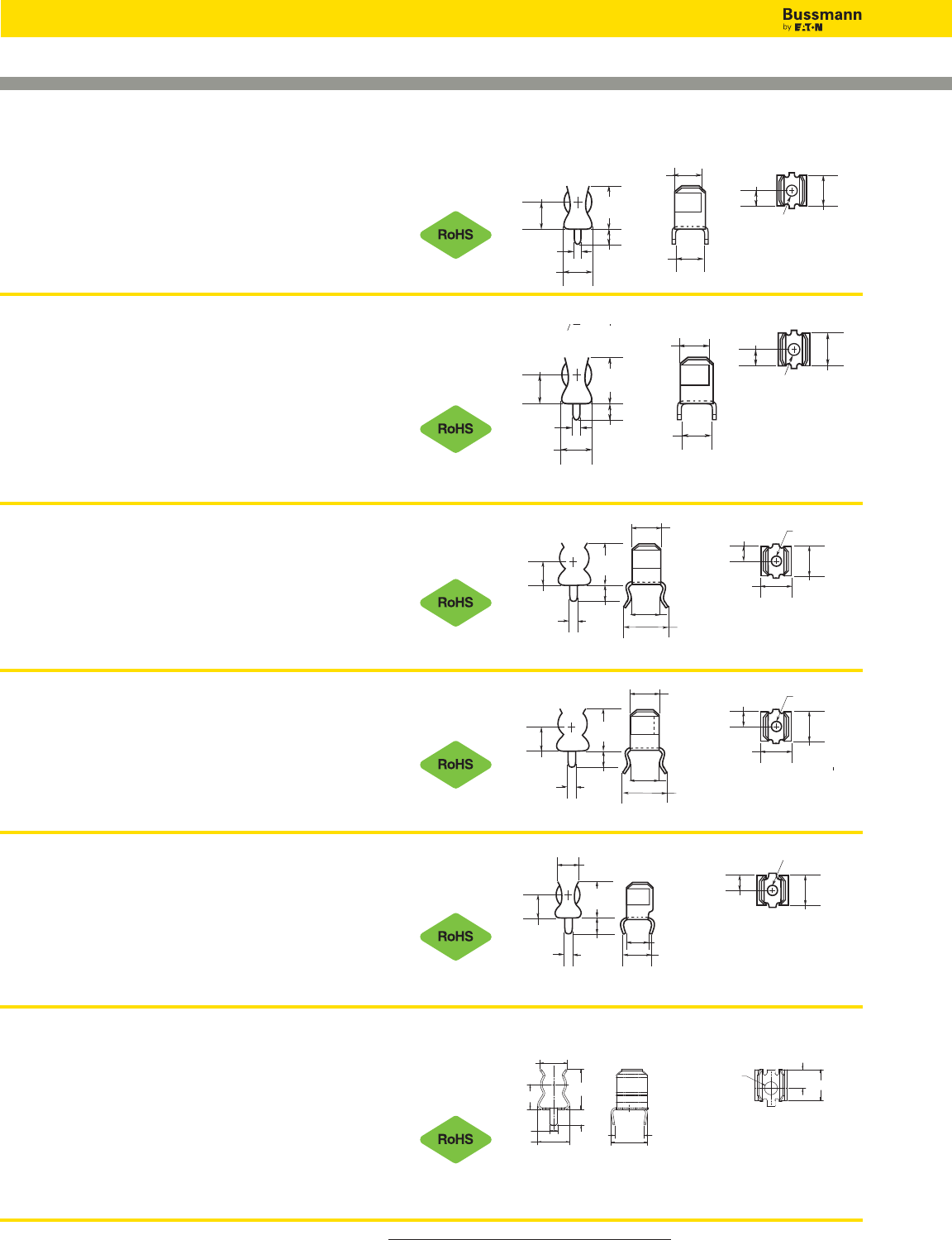
For product data sheets, visit www.cooperbussmann.com/DatasheetsEle
96
Electronic — PCB & Small Dimension Fuses
PC Board Fuseclips for 1⁄4˝ Diameter Fuses
0.245"
(6.2mm)
0.280"
(7.1mm)
(7.1mm)
0.410"
(10.4mm)
0.140"
(3.6mm)
0.060"
(1.5mm)
0.320"
(8.13mm)
(2.6mm)
0.250"
(6.35mm)
0.280"
(7.1mm)
0.155"
(3.94mm)
0.102" Dia.
(2.6mm)
0.245"
(6.2mm)
0.280"
(7.1mm)
0.280"
(7.1mm)
0.410"
(10.4mm)
0.140"
(3.6mm)
0.060"
(1.5mm)
0.320"
(8.13mm)
0.102" Dia.
(2.6mm)
0.255"
(6.5mm) 0.280"
(7.1mm)
0.155"
(3.94mm)
0.102" Dia.
(
2.6mm
)
0.255"
(6.5mm)
0.410"
(10.4mm)
0.060"
(1.5mm)
0.150"
(3.81mm)
0.245"
(6.2mm)
0.228"
(5.79mm)
0.323"
(8.20mm)
0.280"
(7.11mm)
0.102"
(2.6mm)
0.155"
(3.94mm)
0.320"
(8.13mm)
C
L
[6.35]
0.250”
[6.91]
0.272”
[8.13]
0.320”
[2.03]
0.080”
[10.16±0.25]
0.400”±.010
0.155”±.010
[3.94±0.25]
0.290”±.010
[7.37±0.25]
0.363”±.003
[9.22±0.08]
[4.75]
0.187”
0.312”
[7.92]
Ø 0.130”±.003
[3.3mm±0.08]
0.312"
(7.9mm)
0.132"
(3.4mm)
0.187"
(4.8mm)
0.250"
(6.5mm)
0.420"
(10.67mm)
0.080"
(2.03mm)
0.285"
(7.24mm)
0.155"
(3.9mm)
0.290"
(7.4mm)
0.360"
(9.14mm)
1A3398 Series
PCB Fuseclips without End Stops with Straight Leads
Catalog Numbers Clip Material Finish
1A3398-07-R Cartridge brass Bright tin
Data Sheet: 2131
1A1907 Series
PCB Fuseclips with End Stops & Straight Leads
Catalog Numbers Clip Material* Finish
1A1907-02 Cartridge brass None/bright dipped
1A1907-03-R High Performance Copper* Bright tin
1A1907-05 High Performance Copper* Silver
1A1907-06-R Cartridge brass Bright tin
*High Performance Copper recommended for amps higher than 15A.
Data Sheet: 2131
1A1120 Series
PCB Fuseclips without End Stops or Angled In Leads
Catalog Numbers Clip Material* Finish
1A1120-02 Cartridge brass None/bright dipped
1A1120-05 High Performance Copper* Silver
1A1120-06-R High Performance Copper* Bright tin
1A1120-09-R Cartridge brass Bright tin
*High Performance Copper recommended for amps higher than 15A.
Data Sheet: 2131
1A1119 Series
Fuseclips with End Stops & Angled In Leads
Catalog Numbers Clip Material* Finish
1A1119-04-R High Performance Copper* Bright tin
1A1119-05 High Performance Copper* Silver
1A1119-10-R Cartridge brass Bright tin
*High Performance Copper recommended for amps higher than 15A.
Data Sheet: 2131
1A4534 Series
PCB Fuseclips with End Stops & Angled Out Leads
Catalog Numbers Clip Material* Finish
1A4534-01-R High Performance Copper* Bright tin
1A4534-06-R Cartridge brass Bright tin
*High Performance Copper recommended for amps higher than 15A.
Data Sheet: 2131
1A4533 Series
PCB Fuseclips without End Stops or Angled Out Leads
Catalog Numbers Clip Material* Finish
1A4533-01-R High Performance Copper* Bright tin
1A4533-06-R Cartridge brass Bright tin
*High Performance Copper recommended for amps higher than 15A.
Data Sheet: 2131
0.255"
(6.5mm)
0.410"
(10.4mm)
0.060"
(1.5mm)
0.150"
(3.81mm)
0.245"
(6.2mm)
0.228"
(5.79mm)
0.323"
(8.20mm)
0.280"
(7.11mm)
0.102"
(2.6mm)
0.155"
(3.94mm)
0.320"
(8.13mm)
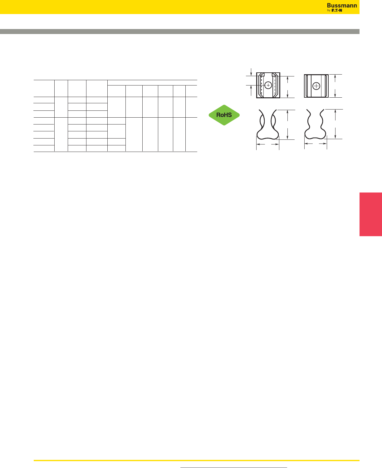
For product data sheets, visit www.cooperbussmann.com/DatasheetsEle 97
Electronic
Fuses
PC Board Fuseclips for 1⁄4˝ Diameter Fuses
5681 & 5682 Series
PCB Fuseclips with Mounting Holes For 1⁄4˝ Diameter Fuses B
C
D
E
Figure 1
Dimensions (Inches)
Catalog End Clip B (To C D E Hole
Number Stop Mat.** Finish End Stop) (Contact) (Height) (Width) Dia. Ref.
5681-01 BeCu Silver
5681-08 No Spg. Br. Nickel † 0.265 0.41 0.32 0.132 Fig. 2
5681-15-R Spg. Br. Bright Tin
5682-01 BeCu Silver 0.108
5682-02 BeCu Silver
5682-11-R Yes BeCu Bright Tin 0.131 0.262 0.41 0.32 0.132 Fig. 1
5682-41-R Spg. Br. Bright Tin 0.106
5682-44-R Spg. Br. Bright Tin 0.132
C
D
E
Figure 2
Electronic — PCB & Small Dimension Fuses
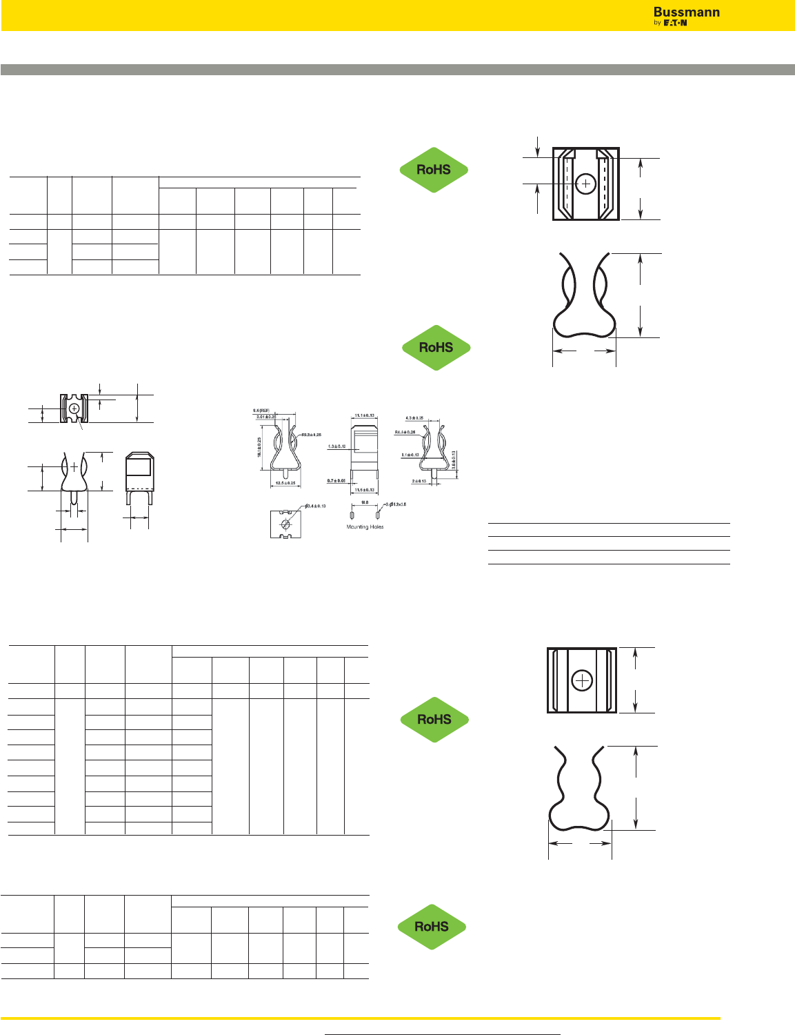
For product data sheets, visit www.cooperbussmann.com/DatasheetsEle
98
Electronic — PCB & Small Dimension Fuses
PCB Fuseclips with Mounting Holes For 13⁄32˝ Diameter Fuses
PC Board Fuseclips for 9⁄32˝, 13⁄32˝ and 9⁄16˝ Diameter Fuses
5591 & 5592 Series
PCB Fuseclips with Mounting Holes For 9⁄16˝ Diameter Fuses
5672 & 5674 Series
PCB Fuseclips with Mounting Holes For 9⁄32˝ Diameter Fuses
5956 & 5960 Series
Dimensions (Inches)
Catalog End Clip B (To C D E Hole
Number Stop Mat.** Finish End Stop) (Contact) (Height) (Width) Dia. Ref.
5591-42 Yes Spg. Br. Bright Dip* 0.26 0.51 0.89 0.60 0.172 Fig. 1
5591-52-R Spg. Br. Bright Tin
5592-01 No BeCu Silver 0.252 0.56 0.875 0.60 0.20 Fig. 2
B
C
D
E
Figure 1
C
D
E
Figure 2
Dimensions (Inches)
Catalog End Clip B (To C D E Hole
Number Stop Mat.** Finish End Stop) (Contact) (Height) (Width) Dia. Ref.
5672-11 No Spg. Br. Bright Tin † 0.362 0.52 0.38 0.172 Fig. 2
5674-01 BeCu Silver
5674-10 Yes BeCu Bright Tin 0.168 0.356 0.52 0.38 0.172 Fig. 1
5674-41 Spg. Br. Bright Tin
* Bright Dip is actually treated bare metal with no plating.
** Spg. Br. — Spring Bronze; BeCu — Beryllium Copper.
† Hole in center of both clip and contact area.
Dimensions (Inches)
Catalog End Clip B (To C D E Hole
Number Stop Mat.** Finish End Stop) (Contact) (Height) (Width) Dia. Ref.
5956-16 No Spg. Br. Bright Tin † 0.312 0.71 0.47 0.172 Fig. 2
5960-07 BeCu Silver 0.168 0.196
5960-09 BeCu Silver 0.20 0.172
5960-44 Spg. Br. Nickel 0.20 0.197
5960-51 Yes Spg. Br. Bright Dip* 0.168 0.387 0.71 0.47 0.196 Fig. 1
5960-53 Spg. Br. Bright Dip* 0.20 0.172
5960-61-R Spg. Br. Bright Tin 0.168 0.196
5960-62-R Spg. Br. Bright Tin 0.168 0.132
5960-63-R Spg. Br. Bright Tin 0.20 0.172
5960-64-R Spr. Br. Bright Tin 0.20 0.128
Data Sheet: 2132
1A3400 Series***
For 13/32˝ Diameter Fuses
With End Stops & Straight Leads
0.218"
(5.54mm)
0.710"
(18.03mm)
0.080"
(2.03mm)
0.470"
(11.94mm)
0.142" Dia.
(3.61mm)
0.050"
(1.27mm)
0.437"
(11.1mm)
0.470"
(11.94mm)
0.380"
(9.65mm)
***For RoHS compliant version add “-R” option code suffix to part number.
Specifications:
Catalog Clip Amp
Number Material Finish Rating
1A3400-09 Spring Bronze Bright Tin 20A Max.
1A3400-10 Beryllium Copper Silver 30A Max.
1A3400-12 Spring Brass Bright Tin 15A Max.
1A3400-09 & 1A3400-10 1A3400-12
Dimensional Data
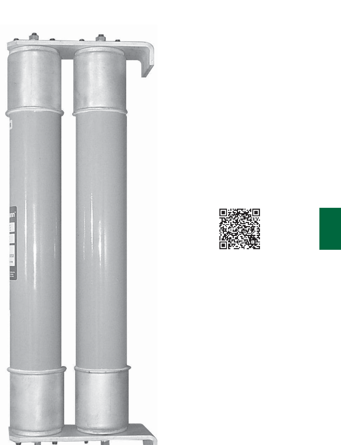
99
Medium Voltage
Fuses
Section Contents
Page
Introduction . . . . . . . . . . . . . . . . . . . . . . . . . . . . .100
E-Rated Fuses
For transformers & feeders . . . . . . . . . . . . . . . . . . 101-104
CL-14 & bolt-in . . . . . . . . . . . . . . . . . . . . . . . . . . . .105-107
For potential & small power transformers . . . . . . . . 108-110
PT fuses . . . . . . . . . . . . . . . . . . . . . . . . . . . . . . . .111
R-Rated fuses for motor circuit protection . .112-114
British IEC fuses for motor circuit protection . . . 115
DIN IEC fuses for transformer protection . . . . . . 116
Expuision Fuse Links . . . . . . . . . . . . . . . . . . 117-118
EEI-NEMA Type K & T and Type H & N fuses . . . 119
Fuseclips for medium and high voltage fuses . . .120
Medium Voltage Fuses
Scan this tag to get the
latest product information for
Medium Voltage Fuses.

For detailed information, visit the Electrical IEC section at www.cooperbussmann.com
100
Medium Voltage Fuses
Medium Voltage Fuses
Worldwide Circuit Protection Solutions
Bussmann is a world-leading supplier of medium voltage
fuses. Each product is backed by an efficient worldwide
distribution network with unrivaled service and technical
support. Bussmann circuit protection solutions comply with
major international standards: ANSI, BS, DIN, IEC and UL.
Fuse Types
Medium voltage fuses generally fit into two categories –
expulsion fuses and current limiting fuses. The definitions per
ANSI C37.40 are:
Expulsion Fuse: “A vented fuse in which the expulsion effect
of the gases produced by internal arcing, either alone or
aided by other mechanisms results in current interruption.”
Expulsion fuses will limit the duration of an overcurrent
event, but they will not limit the magnitude of fault current.
Current Limiting Fuse: “A fuse unit that, when in its current-
responsive element is melted by a current within the fuse’s
specified current-limiting range, abruptly introduces a high
resistance to reduce current magnitude and duration,
resulting in subsequent current interruption.” A current
limiting fuse will reduce the magnitude a fault current as well
as limit the duration of the overcurrent event when operating
in its current limiting range. Bussmann offers a broad range
of current limiting fuses for protection of feeders,
transformers and motor circuits designed to ANSI, BS, DIN
and IEC standards.
Medium Voltage Current Limiting Fuses
Current limiting fuses are classified into three categories:
1. Full Range – defined by ANSI C37.40 as “a fuse capable
of interrupting all currents from the maximum rated
interrupting current down to the minimum continuous current
that causes the melting of the fusible element(s), when the
fuse is applied at the maximum ambient temperature
specified by the manufacturer.” It is able to interrupt any
current that will melt its element.
2. General Purpose – defined by ANSI C37.40 as “a fuse
capable of interrupting all currents from the maximum rated
interrupting current down to the current that causes melting
of the fusible element(s) in one hour.” Not all currents fall
within this range. It is possible for the fuse to be exposed to
an overcurrent lower than the value given by the one hour
criteria. In that case, a different overcurrent protection device
would be required to interrupt the overcurrent.
3. Back-up – defined by ANSI C37.40 as “a fuse capable of
interrupting all currents from the maximum interrupting rating
current down to the minimum interrupting current.”
The minimum interrupting current is the lowest current that
the fuse will be able to clear properly. This creates a need to
place a low current interrupting device, such as motor
overloads, in series with the back-up rated fuse.
E- and R-Rated Fuses
In North America, current limiting fuses typically fall into the
category of E-Rated fuses and R-Rated fuses. Bussmann
also offers a wide range of current limiting fuses designed to
BS, DIN and IEC standards.
E-Rated fuses are used to protect feeder circuits, power
transformers and potential transformers. E-Rated fuses have
defined current response times specified by ANSI C37.46.
E-Rated fuses 100A and below must melt in 300sec at an
rms current within the range of 200% to 240% of the
continuous current rating. E-Rated fuses above 100A must
melt in 600sec at an rms current within the range of 240% to
264% of the continuous current rating of the fuse.
Bussmann offers a wide variety of full range and general
purpose E-Rated fuses from 2.4kV up to 38kV.
R-Rated fuses are back-up fuses that provide short-circuit
protection for motor circuits. They are applied with MV motor
starters which provide the overload protection for the circuit.
R-Rated fuses also have defined current response times
specified by ANSI C37.46. R-Rated fuses will melt in a range
of 15 – 35sec at a current equal to 100 times the “R” rating.
Bussmann offers 2.4kV, 5.08kV, 7.2kV and 8.3kV R-Rated
fuses for motor circuit protection.
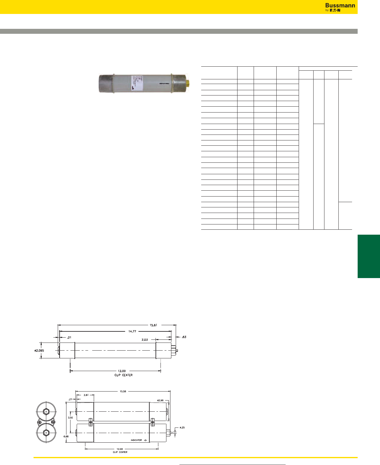
For product data sheets, visit www.cooperbussmann.com/DatasheetsEle 101
Medium Voltage
Fuses
E-Rated Fuses for Transformers and Feeders
MV055
Specifications
Description: E-rated
medium, voltage
current-limiting fuses for
transformer and feeder
protection.
Dimensions: See Catalog Numbers table.
Construction: Silver ribbon element surrounded by silica
filler housed in a fiberglass tube and plated endcaps. An
epoxy paint protects the fuse tube from the surrounding
environment.
Ratings:
Volts: — 5.5kV (10-450A)
Amps: — 5-450A (5.5kV)
IR: — 50kA Sym. Max
Agency Information: Meets E requirements per ANSI
C37.46, Meets full range requirements per ANSI C37.40.
Features and Benefits
• MV055 Standard clip center distance of 12 inches with 2
and 3 inch barrel diameters for retrofitting in existing
hardware
• Open fuse indicator for ease in troubleshooting
• Full range rating with 50KA Interrupting Rating
• Double pulsed at 90% of minimum I2t to establish
manufacturing reliability
MV055 Typical Applications
• 5.0kV Transformer Primary Protection
• 5.0kV Feeder Circuit Protection
• 5.0kV Voltage Switches
• 5.0kV Metal-enclosed Switchgear
Data Sheet: 6700
5.5kV Catalog Numbers
Min Max Dimensions (in)*
Catalog Amp Melt Clear Clip
Numbers Rating I2tI
2t Length Dia. Center Barrels
MV055F1CAX10E 10 850 8,000
MV055F1CAX15E 15 2,070 11,000
MV055F1CAX20E 20 2,370 23,000
MV055F1CAX25E 25 4,650 31,000
MV055F1CAX30E 30 9,490 45,000
MV055F1CAX40E 40 9,490 45,000
MV055F1CAX50E 50 13,600 90,000
MV055F1CAX65E 65 30,700 181,000
MV055F1DAX10E 10 850 8,000 15.75 3 12 1
MV055F1DAX15E 15 2,070 12,000
MV055F1DAX20E 20 2,370 23,000
MV055F1DAX25E 25 4,650 31,000
MV055F1DAX30E 30 9,490 45,000
MV055F1DAX40E 40 9,490 45,000
MV055F1DAX50E 50 13,600 90,000
MV055F1DAX65E 65 30,700 181,000
MV055F1DAX80E 80 54,600 270,000
MV055F1DAX100E 100 116,200 580,000
MV055F1DAX125E 125 167,400 600,000 15.75 3 12 1
MV055F1DAX150E 150 218,700 786,000
MV055F1DAX175E 175 227,900 1,100,000
MV055F1DAX200E 200 297,600 1,520,000
MV055F2DAX250E 250 669,600 2,400,000 15.75 3 12 2
MV055F2DAX300E 300 874,800 3,149,000
MV055F2DAX350E 350 911,600 4,376,000
MV055F2DAX400E 400 1,190,400 6,071,000
MV055F2DAX450E 450 1,555,000 9,796,000
1” = 25.4mm
Recommended Fuse Clips - see page 120
15.75 12
1
1
2
2
Dimensions - in
Diagram 1
Diagram 2
Medium Voltage Fuses
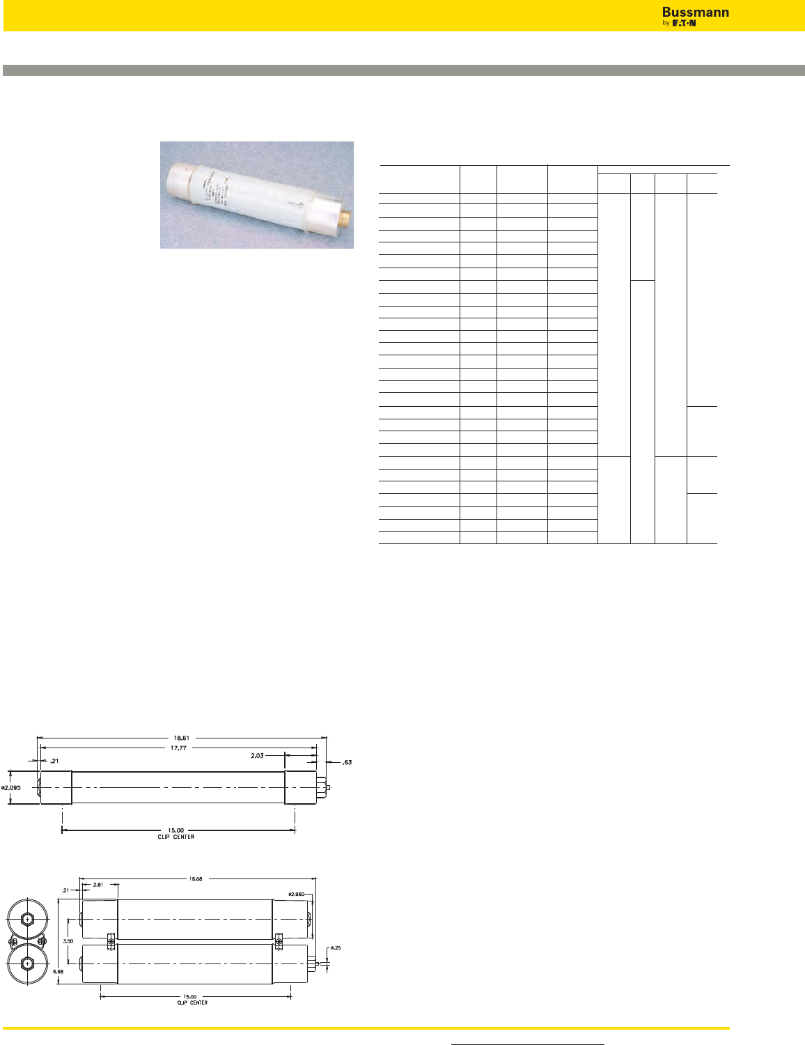
For detailed information, visit the Electrical IEC section at www.cooperbussmann.com
102
Medium Voltage Fuses
E-Rated Fuses for Transformers and Feeders
MV155
Specifications
Description: E-rated
medium, voltage
current-limiting fuses for
transformer and feeder
protection.
Dimensions: See Catalog Numbers table.
Construction: Silver ribbon element surrounded by silica
filler housed in a fiberglass tube and plated endcaps. An
epoxy paint protects the fuse tube from the surrounding
environment.
Ratings:
Volts: — 15.5kV (5-200A)
Amps: — 5-200A (15.5kV)
IR: — 50kA Sym. Max
Agency Information: Meets E requirements per ANSI
C37.46, Meets full range requirements per ANSI C37.40.
Features and Benefits
• MV155 Standard clip center distance of 15 and 18 inches
with 2 and 3 inch barrel diameters for retrofitting in existing
hardware
• Open fuse indicator for ease in troubleshooting
• Full range rating with 50kA Interrupting Rating
• Double pulsed at 90% of minimum I2t to establish
manufacturing reliability
MV155 Typical Applications
• 15.0kV Transformer Primary Protection
• 15.0kV Feeder Circuit Protection
• 15.0kV Voltage Switches
• 15.0kV Metal-enclosed Switchgear
15.5kV Catalog Numbers
Min Max Dimensions*
Catalog Amp Melt Clear Clip
Numbers Rating I2tI
2t Length Dia. Center Barrels
MV155F1CBX5E 5 180 2,900 18.75 15 1
MV155F1CBX7E 7 850 8,000
MV155F1CBX10E 10 850 8,000
MV155F1CBX15E 15 2,070 12,000 1
MV155F1CBX20E 20 2,370 23,000
MV155F1CBX25E 25 4,650 31,000
MV155F1CBX30E 30 9,490 45,000
MV155F1DBX10E 10 850 8,000 18.75 3 15 1
MV155F1DBX15E 15 2,070 12,000
MV155F1DBX20E 20 2,370 23,000
MV155F1DBX25E 25 4,650 31,000
MV155F1DBX30E 30 9,490 45,000
MV155F1DBX40E 40 9,490 45,000
MV155F1DBX50E 50 13,600 90,000
MV155F1DBX65E 65 30,700 181,000
MV155F1DBX80E 80 54,600 270,000
MV155F1DBX100E 100 116,200 600,000
MV155F2DBX125E 125 123,000 677,000 18.75 3 15 2
MV155F2DBX150E 150 218,700 1,287,000
MV155F2DBX175E 175 314,700 1,689,000
MV155F2DBX200E 200 465,100 2,405,000
MV155F1DCX65E 65 30,700 181,000 21.75 3 18 1
MV155F1DCX80E 80 54,600 270,000
MV155F1DCX100E 100 116,200 600,000
MV155F2DCX125E 125 123,000 677,000 21.75 3 18 2
MV155F2DCX150E 150 218,700 1,287,000
MV155F2DCX175E 175 314,700 1,689,000
MV155F2DCX200E 200 465,100 2,405,000
*1” = 25.4mm.
Data Sheet: 6700
Data Sheet: 6701
18.75
2
15
1
2
2
1
18
21.75
Recommended Fuse Clips - see page 120
Dimensions - in
Diagram 1
Diagram 2
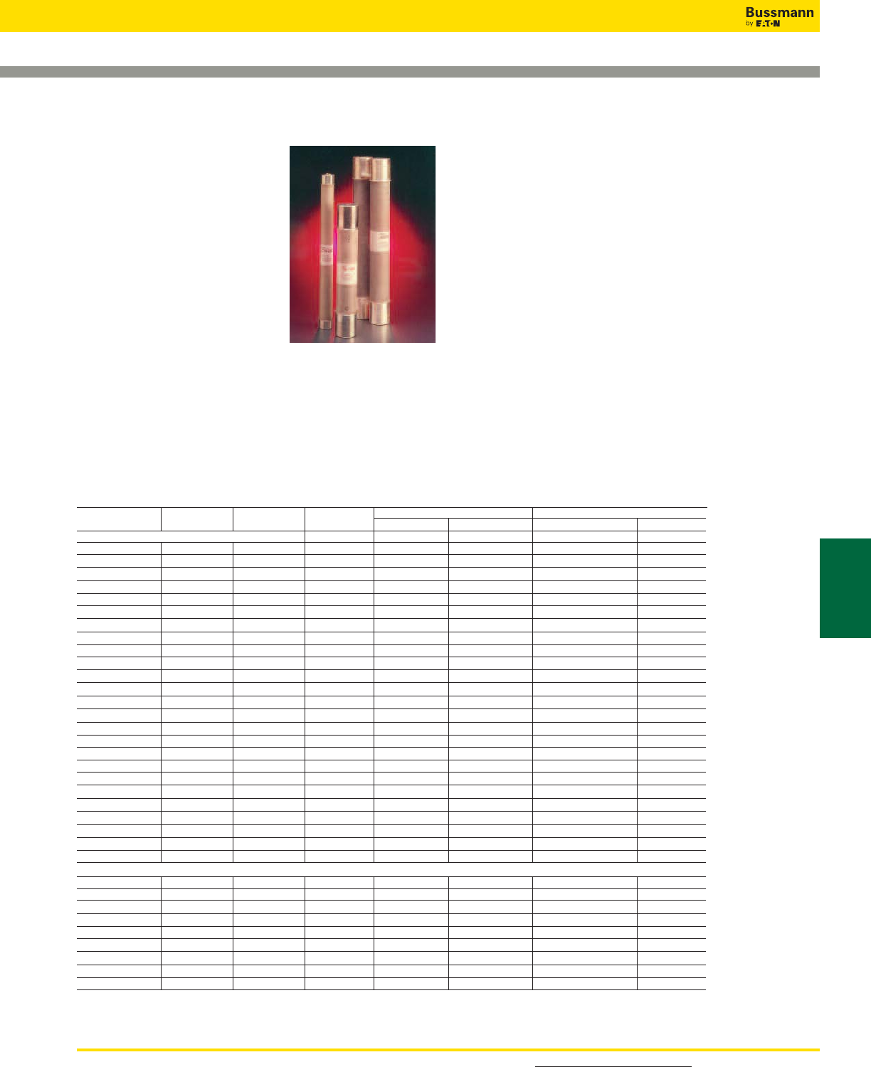
For detailed information, visit the Electrical IEC section at www.cooperbussmann.com 103
Medium Voltage
Fuses
Medium Voltage Fuses
JCX, JCY, JCU, JCZ
and JDZ
Specifications
Description: Indoor/enclosure
E-rated medium voltage, current-
limiting fuses for feeders and
power transformers with blown fuse
indication.
Dimensions: See Catalog
Numbers table.
Construction: plated ferrules.
Ratings:
Volts: — 2750-8300V - See Catalog Numbers table for
details
Amps: — 1⁄2-750A
IR: — 40-63kA Sym
— 60-100kA ASYM
— See Catalog Numbers table for details
E-Rated Fuses for Transformer & Feeders
Catalog Numbers
Catalog Amp Maximum Maximum Interrupting Capacity Dimensions - in (mm)
Numbers Rating Design Voltage Construction Amps (Asym.) Amps (Sym.) Length Diameter
2400V; E-Rated; Indoor/Enclosure
JCX-1E 1 2750 Single 60,000 40,000 9.19 (233.38) 2 (50.8)
JCX-2E 2 2750 Single 60,000 40,000 9.19 (233.38) 2 (50.8)
JCX-3E 3 2750 Single 60,000 40,000 9.19 (233.38) 2 (50.8)
JCX-5E 5 2750 Single 60,000 40,000 9.19 (233.38) 2 (50.8)
JCX-7E 7 2750 Single 60,000 40,000 9.19 (233.38) 2 (50.8)
JCX-10E 10 2750 Single 60,000 40,000 9.19 (233.38) 2 (50.8)
JCX-15E 15 2750 Single 80,000 50,000 9.5 (241.3) 2.1 (53.34)
JCX-20E 20 2750 Single 80,000 50,000 9.5 (241.3) 2.1 (53.34)
JCX-25E 25 2750 Single 80,000 50,000 9.5 (241.3) 2.1 (53.34)
JCX-30E 30 2750 Single 80,000 50,000 10.81 (276.35) 3 (76.2)
JCX-40E 40 2750 Single 80,000 50,000 10.81 (276.35) 3 (76.2)
JCX-50E 50 2750 Single 80,000 50,000 10.81 (276.35) 3 (76.2)
JCX-65E 65 2750 Single 80,000 50,000 10.81 (276.35) 3 (76.2)
JCX-80E 80 2750 Single 80,000 50,000 10.81 (276.35) 3 (76.2)
JCX-100E 100 2750 Single 80,000 40,000 10.81 (276.35) 3 (76.2)
JCX-125E 125 2750 Single 80,000 50,000 10.81 (276.35) 3 (76.2)
JCX-150E 150 2750 Single 80,000 50,000 10.81 (276.35) 3 (76.2)
JCX-200E 200 2750 Single 80,000 50,000 10.81 (276.35) 3 (76.2)
JCX-225E 225 2750 Single 80,000 50,000 10.81 (276.35) 3 (76.2)
JCX-250E/280X 250/280 2750 Double 80,000 50,000 10.81 (276.35) 3 (76.2)
JCX-300E/325X 300/325 2750 Double 80,000 50,000 10.81 (276.35) 3 (76.2)
JCX-350X 350 2750 Double 80,000 50,000 10.81 (276.35) 3 (76.2)
JCX-400X 400 2750 Double 80,000 50,000 10.81 (276.35) 3 (76.2)
JCX-450X 450 2750 Double 80,000 50,000 10.81 (276.35) 3 (76.2)
5500V; E-Rated; Indoor/Enclosure
JCY-1⁄2E 0.5 5500 Single 60,000 40,000 11.19 (284.18) 2 (50.8)
JCY-1E 1 5500 Single 60,000 40,000 11.19 (284.18) 2 (50.8)
JCY-2E 2 5500 Single 60,000 40,000 11.19 (284.18) 2 (50.8)
JCY-3E 3 5500 Single 60,000 40,000 11.19 (284.18) 2 (50.8)
JCY-5E 5 5500 Single 60,000 40,000 11.19 (284.18) 2 (50.8)
JCY-7E 7 5500 Single 60,000 40,000 11.19 (284.18) 2 (50.8)
JCY-10E 10 5500 Single 60,000 40,000 11.19 (284.18) 2 (50.8)
JCY-15E 15 5500 Single 60,000 40,000 11.19 (284.18) 2 (50.8)
JCY-20E 20 5500 Single 60,000 40,000 11.19 (284.18) 2 (50.8)
JCY-25E 25 5500 Single 60,000 40,000 11.19 (284.18) 2 (50.8)
Contact Bussmann for the latest product information on E-Rated fuses for transformer and feeder protection.
Recommended fuseclips: see page 120 - 1A0065, 9078A67G04, A3354730
Features and Benefits
• Physically dimensioned for retrofitting in existing hardware
• Open fuse indicator for ease in troubleshooting
• Full range ANSI classification
Typical Applications
• Medium Voltage Transformer Primary Protection
• Medium Voltage Feeder Circuit Protection
• Medium Voltage Switches
• Medium Voltage Metal-enclosed Switchgear
For product data sheets, visit www.cooperbussmann.com/DatasheetsEle
104
Medium Voltage Fuses
E-Rated Fuses for Transformer & Feeders
Catalog Numbers: E-Rated; Indoor/Enclosure
Catalog Amp Maximum Maximum Interrupting Capacity Dimensions - in (mm)
Numbers Rating Design Voltage Construction Amps. (Asym.) Amps. (Sym.) Length Diameter
5500V; E-Rated; Indoor/Enclosure
JCU-10E 10 5500 Single 80,000 50,000 17.81 (452.4) 3 (76.2)
JCU-15E 15 5500 Single 80,000 50,000 12.88 (327.0) 2.1 (53.34)
JCU-20E 20 5500 Single 80,000 50,000 12.88 (327.0) 2.1 (53.34)
JCU-25E 25 5500 Single 80,000 50,000 12.88 (327.0) 2.1 (53.34)
JCU-30E 30 5500 Single 100,000 63,000 17.88 (454.15) 3 (76.20)
JCU-40E 40 5500 Single 100,000 63,000 17.88 (454.15) 3 (76.20)
JCU-50E 50 5500 Single 100,000 63,000 17.88 (454.15) 3 (76.20)
JCU-65E 60 5500 Single 100,000 63,000 17.88 (454.15) 3 (76.20)
JCU-80E 80 5500 Single 100,000 63,000 17.88 (454.15) 3 (76.20)
JCU-100E 100 5500 Single 100,000 63,000 17.88 (454.15) 3 (76.20)
JCU-125E 125 5500 Single 100,000 63,000 17.88 (454.15) 3 (76.20)
JCU-150E 150 5500 Single 100,000 63,000 17.88 (454.15) 3 (76.20)
JCU-175E 175 5500 Single 100,000 63,000 17.88 (454.15) 3 (76.20)
JCU-200E 200 5500 Single 100,000 63,000 17.88 (454.15) 3 (76.20)
JCU-250E 250 5500 Single 100,000 63,000 17.88 (454.15) 3 (76.20)
JCU-300E 300 5500 Double 100,000 63,000 17.88 (454.15) 3 (76.20)
JCU-350E 350 5500 Double 100,000 63,000 17.88 (454.15) 3 (76.20)
JCU-400E 400 5500 Double 100,000 63,000 17.88 (454.15) 3 (76.20)
JCU-450E 450 5500 Double 100,000 63,000 17.88 (454.15) 3 (76.20)
JCU-600E 600 5500 * 80,000 50,000 28.81 (731.77) 4 (101.60)
JCU-750E 750 5500 * 80,000 50,000 28.81 (731.77) 4 (101.60)
8300V; E-Rated; Indoor/Enclosure
JCZ-15E 15 8300 Single 80,000 50,000 15.51 (393.95) 2.1 (53.34)
JCZ-20E 20 8300 Single 80,000 50,000 15.51 (393.95) 2.1 (53.34)
JCZ-25E 25 8300 Single 80,000 50,000 15.51 (393.95) 2.1 (53.34)
JCZ-30E 30 8300 Single 80,000 50,000 17.88 (454.15) 3 (76.2)
JCZ-40E 40 8300 Single 80,000 50,000 17.88 (454.15) 3 (76.2)
JCZ-50E 50 8300 Single 80,000 50,000 17.88 (454.15) 3 (76.2)
JCZ-65E 65 8300 Single 80,000 50,000 17.88 (454.15) 3 (76.2)
JCZ-80E 80 8300 Single 80,000 50,000 17.88 (454.15) 3 (76.2)
JCZ-100E 100 8300 Single 80,000 50,000 17.88 (454.15) 3 (76.2)
JCZ-125E 125 8300 Single 80,000 50,000 17.88 (454.15) 3 (76.2)
JCZ-150E 150 8300 Single 80,000 50,000 17.88 (454.15) 3 (76.2)
JCZ-200E 200 8300 Double 80,000 50,000 17.88 (454.15) 3 (76.2)
JDZ-20E 20 8300 Single 80,000 50,000 15.88 (403.2) 3 (76.2)
JDZ-25E 25 8300 Single 80,000 50,000 15.88 (403.2) 3 (76.2)
JDZ-30E 30 8300 Single 80,000 50,000 15.88 (403.2) 3 (76.2)
JDZ-40E 40 8300 Single 80,000 50,000 15.88 (403.2) 3 (76.2)
JDZ-50E 50 8300 Single 80,000 50,000 15.88 (403.2) 3 (76.2)
JDZ-65E 65 8300 Single 80,000 50,000 15.88 (403.2) 3 (76.2)
JDZ-80E 80 8300 Double 80,000 50,000 15.88 (403.2) 3 (76.2)
JDZ-100E 100 8300 Double 80,000 50,000 15.88 (403.2) 3 (76.2)
JDZ-125E 125 8300 Double 80,000 50,000 15.88 (403.2) 3 (76.2)
Recommended fuseclips: see page 120 - 1A0065, 9078A67G04, A3354730
General Notes:
1. All fuses are fitted with a striker pin which can be used for indication or tripping purposes.
2. The fuses are suitable for use either indoors or outdoors.
3. These fuses are interchangeable with corresponding fuses produced by most other leading North American manufacturers.
Contact Bussmann for the latest product information on E-Rated fuses for transformer and feeder protection.
*Bolt on mounting
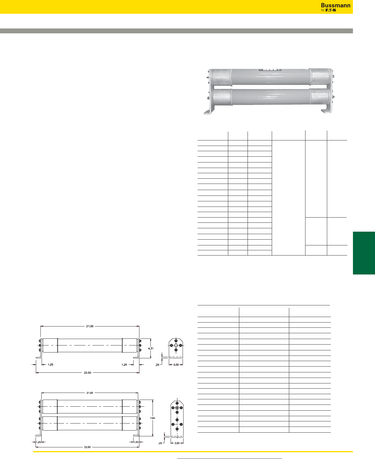
For product data sheets, visit www.cooperbussmann.com/DatasheetsEle 105
Medium Voltage
Fuses
Medium Voltage Fuses
E-Rated Fuses: CL-14 & Bolt-In
Data Sheet: 9002
Catalog Number Cross Reference
Bussmann Mersen Mersen
Catalog Numbers New Catalog # Old Catalog #
ECL055-10E A055C1DORO-10E 225-007-937
ECL055-15E A055C1DORO-15E 225-007-938
ECL055-20E A055C1DORO-20E 225-007-939
ECL055-25E A055C1DORO-25E 225-007-940
ECL055-30E A055C1DORO-30E 225-007-941
ECL055-40E A055C1DORO-40E 225-007-942
ECL055-50E A055C1DORO-50E 225-007-943
ECL055-65E A055C1DORO-65E 225-007-944
ECL055-80E A055C1DORO-80E 225-007-945
ECL055-100E A055C1DORO-100E 225-007-946
ECL055-125E A055C1DORO-125E 225-007-947
ECL055-150E A055C1DORO-150E 225-007-948
ECL055-200E A055C1DORO-200E 225-007-949
ECL055-250E A055C1DORO-250E 225-007-950
ECL055-300E A055C1DORO-300E 225-007-951
ECL055-400E A055C1DORO-400E 225-007-952
ECL055-450E A055C2DORO-450E 225-007-953
ECL055-500E A055C2DORO-500E 225-007-954
ECL055-600E A055C2DORO-600E 225-007-955
ECL055-750E A055B3DORO-750E A055X750E-4
ECL055-900E A055B3DORO-900E A055X900E-4
ECL055
Specifications
Description: E-rated medium voltage, current-limiting fuses
for transformer and feeder protection.
Construction: Filament wound, glass epoxy fuse tube, with
silica filler, and silver-plated copper terminals and endcaps
containing a silver element in a double concentric helical
configuration.
Ratings:
Volts: — 5.5kV
Amps: — 10-900A
IR: — 63kA Sym. Max
Agency Information: Meets E requirements per ANSI
C37.46, Meets General Purpose requirements per ANSI
C37.40.
Features and Benefits
• Clip-lock and bolt-in style available in double and triple
barrel fuse designs for application flexibility
• The filament wound, glass epoxy fuse tube provides
moisture protection for the fuse. This makes Cooper
Bussmann medium voltage fuses suitable for both indoor
and outdoor application (outdoor applications require
installation inside an appropriate enclosure)
• Open fuse indication (indicator travel distance is 16mm)
easily integrates into automation schemes
• 50/60Hz operating frequency make these fuses applicable
world-wide
Typical Applications
• 5.0kV Transformer Primary Protection
• 5.0kV Feeder Circuit Protection
• 5.0kV Voltage Switches
• 5.0kV Metal-enclosed Switchgear
Catalog Numbers
Catalog Amp IR # of
Numbers Rating Voltage Max Sym. Barrels Style
ECL055-10E 10 5.5kV 63kA 1 Clip-Lock
ECL055-15E 15 –
ECL055-20E 20 –
ECL055-25E 25 –
ECL055-30E 30 –
ECL055-40E 40 –
ECL055-50E 50 –
ECL055-65E 65 –
ECL055-80E 80 –
ECL055-100E 100 –
ECL055-125E 125 –
ECL055-150E 150 –
ECL055-200E 200 –
ECL055-250E 250 –
ECL055-300E 300 – 2
ECL055-400E 400 –
ECL055-450E 450 –
ECL055-500E 500 –
ECL055-600E 600 –
ECL055-750E 750 – 3 Bolt-In
ECL055-900E 900 –
1Clip-Lock
Clip-Lock
Bolt-In
2
3
63kA
Catalog Number Construction (Example)
Catalog Number Voltage Rating Amp Rating
ECL 055 500E
055 = 5.5 kV
Dimensions - in
Single Barrel
Double Barrel
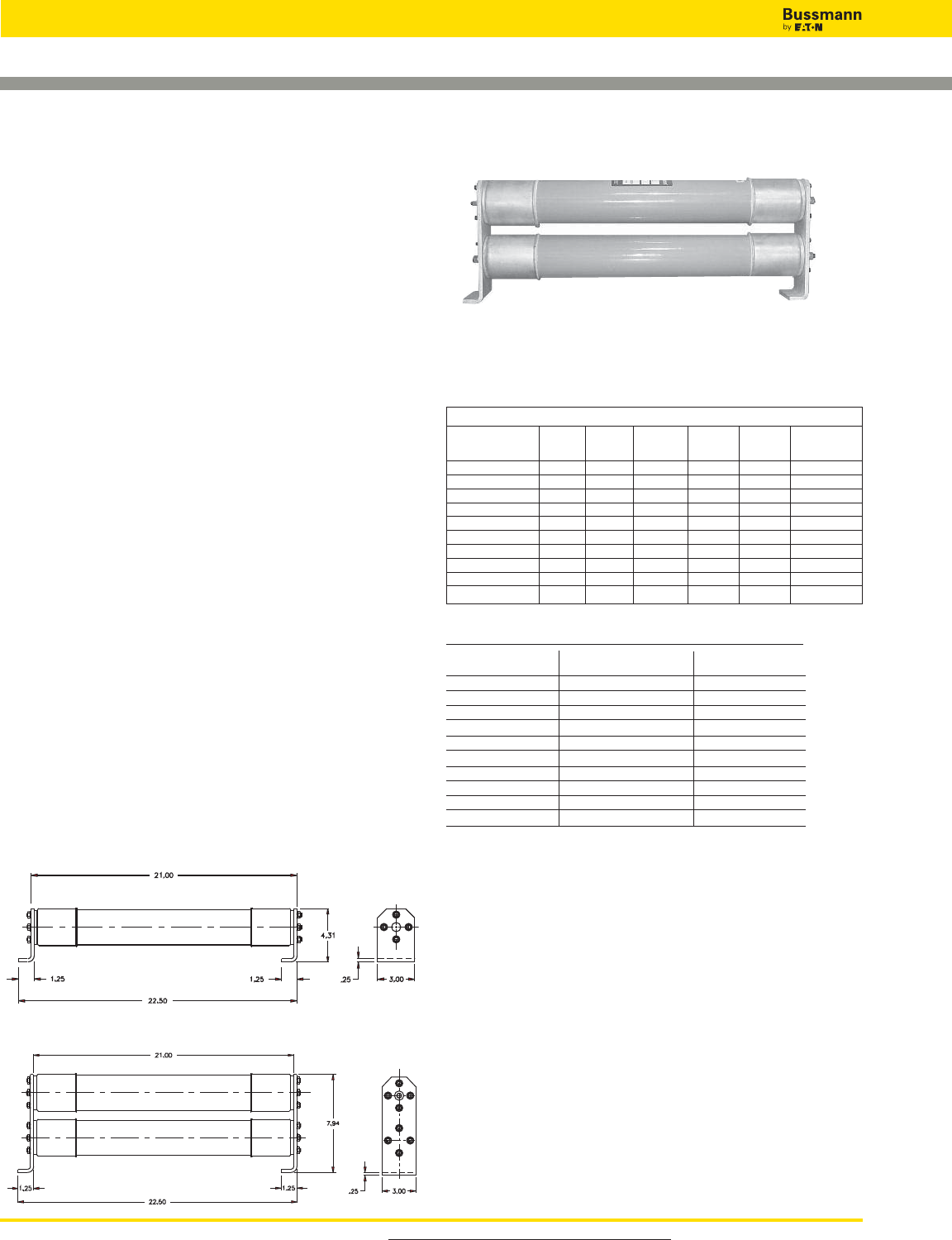
For product data sheets, visit www.cooperbussmann.com/DatasheetsEle
106
Medium Voltage Fuses
E-Rated Fuses: CL-14 & Bolt-In
ECL083
Specifications
Description: E-rated medium voltage, current-limiting fuses
for transformer and feeder protection.
Construction: Filament wound, glass epoxy fuse tube, with
silica filler, and silver-plated copper terminals and endcaps
containing a silver element in a double concentric helical
configuration.
Ratings:
Volts: — 8.3kV
Amps: — 65-350A
IR: — 50kA
Agency Information: Meets E requirements per ANSI
C37.46, Meets General Purpose requirements per ANSI
C37.40.
Features and Benefits
• Clip-lock and bolt-in style available in double and triple
barrel fuse designs for application flexibility
• The filament wound, glass epoxy fuse tube provides
moisture protection for the fuse. This makes Cooper
Bussmann medium voltage fuses suitable for both indoor
and outdoor application (outdoor applications require
installation inside an appropriate enclosure)
• Open fuse indication (indicator travel distance is 16mm)
easily integrates into automation schemes
• 50/60Hz operating frequency make these fuses applicable
world-wide
Typical Applications
• 8.0kV Transformer Primary Protection
• 8.0kV Feeder Circuit Protection
• 8.0kV Voltage Switches
• 8.0kV Metal-enclosed Switchgear
Data Sheet: 9007
Catalog Number Cross Reference
Bussmann Mersen Mersen
Catalog Numbers New Catalog # Old Catalog #
ECL083-65E N/A N/A
ECL083-80E N/A N/A
ECL083-100E N/A N/A
ECL083-125E N/A N/A
ECL083-150E N/A N/A
ECL083-175E N/A N/A
ECL083-200E N/A N/A
ECL083-250E N/A N/A
ECL083-300E N/A N/A
ECL083-350E N/A N/A
Catalog Number Construction (Example)
Catalog Number Voltage Rating Amp Rating
ECL 083 300E
083 = 8.3 kV
Electrical Characteristics
IR Max # of Figure
Part Number Amps Volts Sym. Barrels # Style
ECL083-65E 65 8.3kV 50kA 1 1 Clip-Lock
ECL083-80E 80 8.3kV 50kA 1 1 Clip-Lock
ECL083-100E 100 8.3kV 50kA 1 1 Clip-Lock
ECL083-125E 125 8.3kV 50kA 1 1 Clip-Lock
ECL083-150E 150 8.3kV 50kA 1 1 Clip-Lock
ECL083-175E 175 8.3kV 50kA 1 1 Clip-Lock
ECL083-200E 200 8.3kV 50kA 2 2 Clip-Lock
ECL083-250E 250 8.3kV 50kA 2 2 Clip-Lock
ECL083-300E 300 8.3kV 50kA 2 2 Clip-Lock
ECL083-350E 350 8.3kV 50kA 2 2 Clip-Lock
Dimensions - in
Single Barrel
Double Barrel
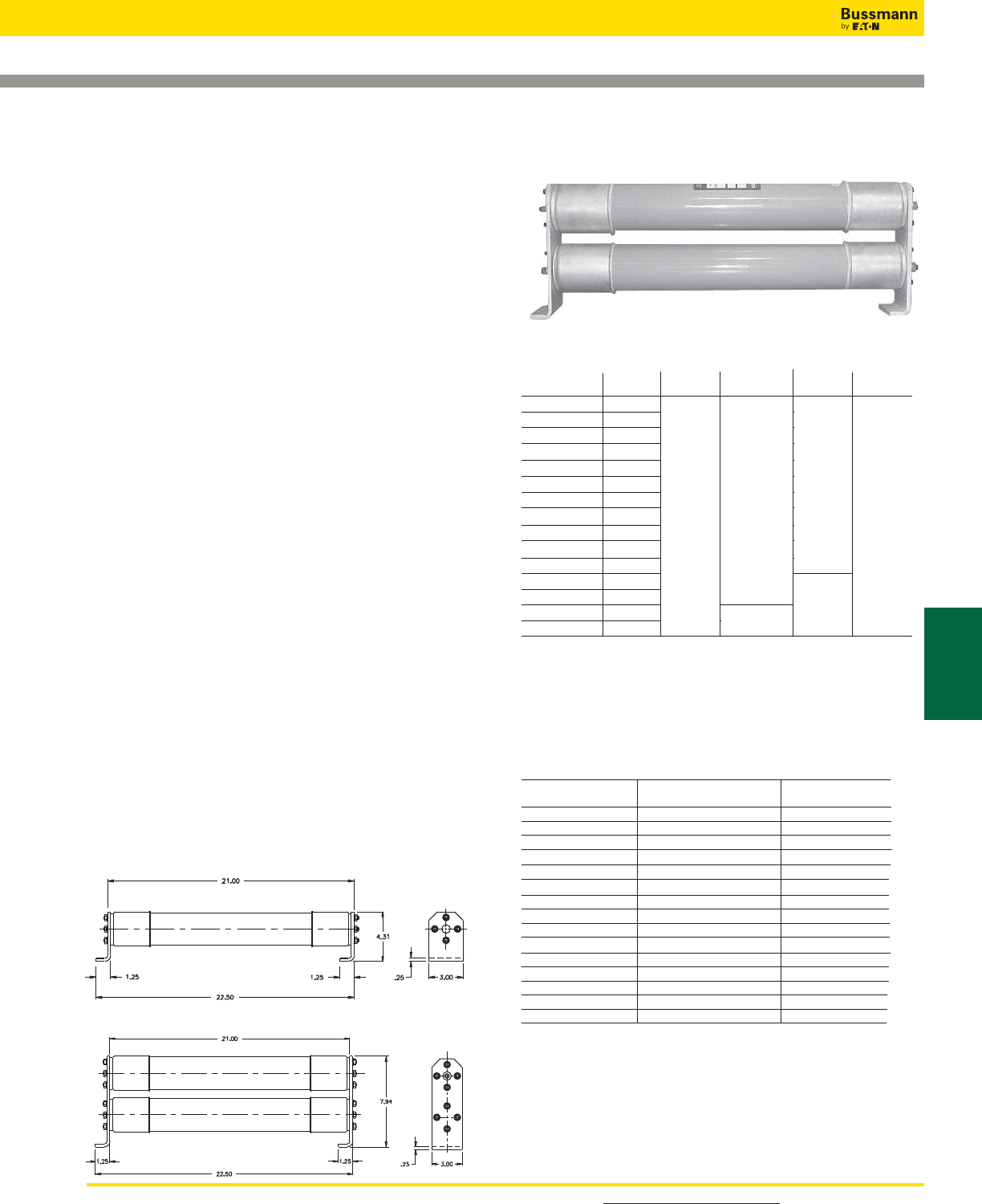
For detailed information, visit the Electrical IEC section at www.cooperbussmann.com 107
Medium Voltage
Fuses
Medium Voltage Fuses
E-Rated Fuses: CL-14
Catalog Number Cross Reference
Bussmann Mersen Mersen
Catalog Numbers New Catalog # Old Catalog #
ECL155-10E A155C1DORO-10E 225-007-967
ECL155-15E A155C1DORO-15E 225-007-968
ECL155-20E A155C1DORO-20E 225-007-969
ECL155-25E A155C1DORO-25E 225-007-970
ECL155-30E A155C1DORO-30E 225-007-971
ECL155-40E A155C1DORO-40E 225-007-972
ECL155-50E A155C1DORO-50E 225-007-973
ECL155-65E A155C1DORO-65E 225-007-974
ECL155-80E A155C1DORO-80E 225-007-975
ECL155-100E A155C1DORO-100E 225-007-976
ECL155-125E A155C2DORO-125E 225-007-977
ECL155-150E A155C3DORO-150E 225-007-978
ECL155-200E A155C3DORO-200E 225-007-979
ECL155-250E A155C3DORO-250E 225-007-980
ECL155-300E A155C3DORO-300E 225-007-981
Data Sheet: 9004
Catalog Numbers
Catalog Amp IR Voltage # of
Numbers Rating Voltage Max Sym. Barrels Style
ECL155-10E 10 15.5kV 63KA 1 Clip-Lock
ECL155-15E 15
ECL155-20E 20
ECL155-25E 25
ECL155-30E 30
ECL155-40E 40
ECL155-50E 50
ECL155-65E 65
ECL155-80E 80
ECL155-100E 100
ECL155-125E 125
ECL155-150E 150 2
ECL155-200E 200
ECL155-250E 250 50kA
ECL155-300E 300
Catalog Number Construction (Example)
Catalog Number Voltage Rating Amp Rating
ECL 155 300E
155 = 15.5 kV
ECL155
Specifications
Description: E-rated medium voltage, current-limiting fuses
for transformer and feeder protection.
Construction: Filament wound, glass epoxy fuse tube, with
silica filler, and silver-plated copper terminals and endcaps
containing a silver element in a double concentric helical
configuration.
Ratings:
Volts: — 15.5kV
Amps: — 10-300A
IR: — 63kA Sym. (10-200A)
— 50kA Sym. (250-300A)
Agency Information: Meets E requirements per ANSI
C37.46, Meets General Purpose requirements per ANSI
C37.40.
Features and Benefits
• Clip-lock double barrel fuse design assures positive
installation
• The filament wound, glass epoxy fuse tube provides
moisture protection for the fuse. This makes Cooper
Bussmann medium voltage fuses suitable for both indoor
and outdoor application (outdoor applications require
installation inside an appropriate enclosure)
• Open fuse indication (indicator travel distance is 16mm)
easily integrates into automation schemes
• 50/60Hz operating frequency make these fuses applicable
world-wide
Typical Applications
• 15.0kV Transformer Primary Protection
• 15.0kV Feeder Circuit Protection
• 15.0kV Voltage Switches
• 15.0kV Metal-enclosed Switchgear
15.5kV
63kA
1
Clip-Lock
2
50kA
Dimensions - in
Single Barrel
Double Barrel
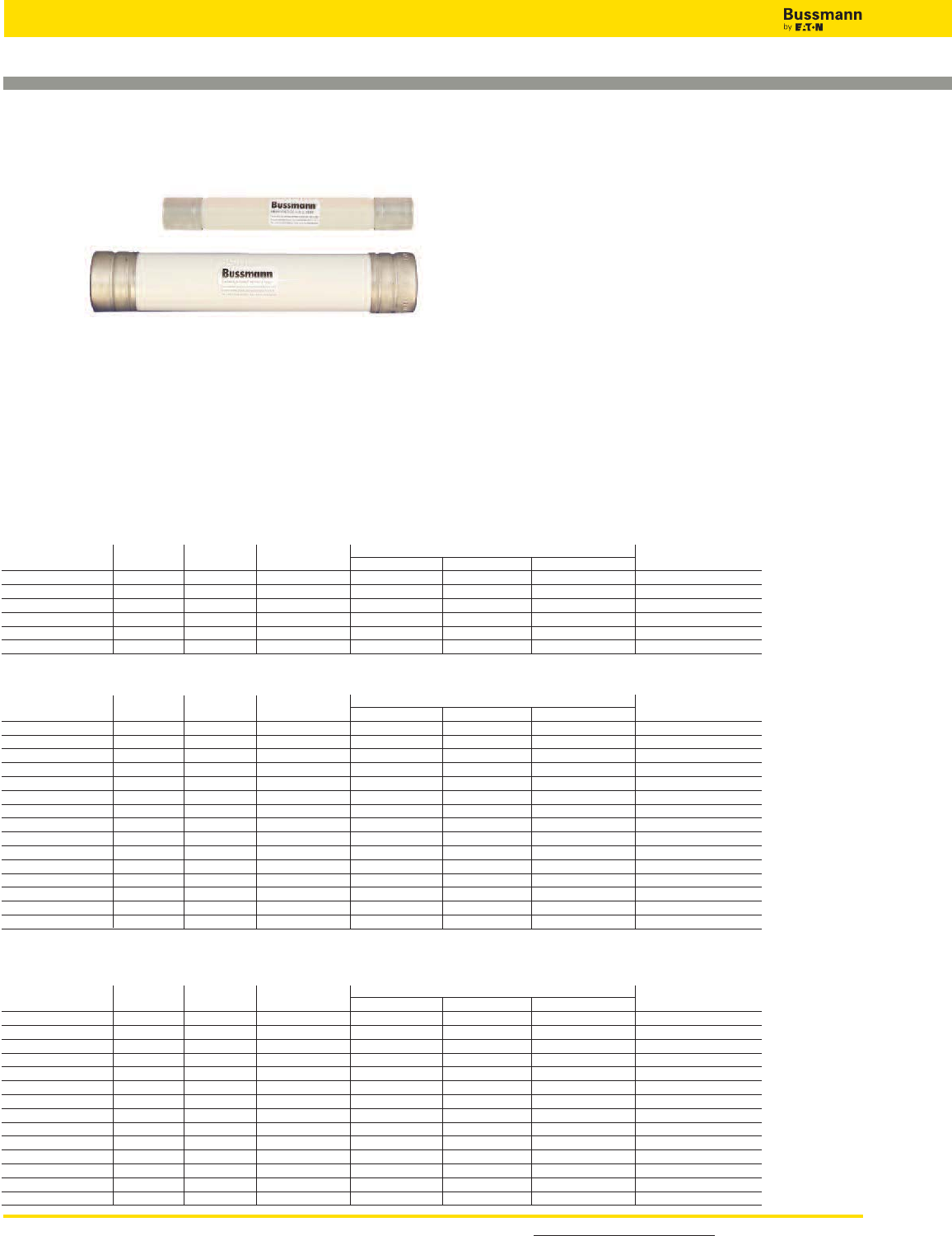
For detailed information, visit the Electrical IEC section at www.cooperbussmann.com
108
Medium Voltage Fuses
E-Rated Fuses for Potential & Small Power Transformers
AB, AD, AM
and CAV
Specifications
Description: Indicating and non-indicating E-Rated medium
voltage, current-limiting fuses for potential and small power
transformers.
Dimensions: See Catalog Numbers table.
Dimension Illustration on the following page
Ratings:
Volts: — 5.5-38kV
Amps: — 0.5-15A
IR: — 40kA-80kA Sym.
— See Catalog Numbers table for details
Features and Benefits
• Sized for retrofitting in existing hardware
• Space saving size
Typical Applications
• Primary protection of medium voltage potential
transformers
• Primary protection of small medium voltage service
transformers
• Primary protection of small medium voltage control
transformers
3.6kV; E-Rated PT Fuse; Non-indicating
Catalog Amp Rated Dimensions Spare Parts
Number Rating Voltage IR RMS Sym. Length Diameter Clip Centers (Clips)
3.6CAV2 2 3.6kV 50kA 8.66 (220) 1.63 (41.3) 7.46 (189.48) 1A0835
3.6ABWNA3.15 3.15 3.6kV 50kA 5.6 (142.2) 1 (25.4) 4.42 (112.2) A3354705
3.6ABWNA6.3 3.15 3.6kV 50kA 5.6 (142.2) 1 (25.4) 4.42 (112.2) A3354705
3.6ABCNA3.15 3.15 3.6kV 50kA 7.69 (195.3) 1 (25.4) 6.51 (165.3) A3354705
3.6ABCNA6.3 6.3 3.6kV 50kA 7.69 (195.3) 1 (25.4) 6.51 (165.3) A3354705
3.6ABCNA10 10 3.6kV 50kA 7.69 (195.3) 1 (25.4) 6.51 (165.3) A3354705
7.2kV; E-Rated PT Fuse; Non-indicating
Catalog Amp Rated Dimensions Spare Parts
Number Rating Voltage IR RMS Sym. Length Diameter Clip Centers (Clips)
7.2CAV2 2 7.2kV 63kA 8.66 (220) 1.63 (41.3) 7.46 (189.48) 1A0835
7.2CAV4 4 7.2kV 63kA 8.66 (220) 1.63 (41.3) 7.46 (189.48) 1A0835
7.2CAV6 6 7.2kV 63kA 8.66 (220) 1.63 (41.3) 7.46 (189.48) 1A0835
7.2CAV10 10 7.2kV 63kA 8.66 (220) 1.63 (41.3) 7.46 (189.48) 1A0835
7.2ABWNA3.15 3.15 7.2kV 45kA 5.6 (142.2) 1 (25.4) 4.42 (112.2) A3354705
7.2ABWNA6.3 6.3 7.2kV 45kA 5.6 (142.2) 1 (25.4) 4.42 (112.2) A3354705
7.2ABCNA3.15 3.15 7.2kV 45kA 7.69 (195.3) 1 (25.4) 6.51 (165.3) A3354705
7.2ABCNA6.3 6.3 7.2kV 45kA 7.69 (195.3) 1 (25.4) 6.51 (165.3) A3354705
7.2AMWNA0.5E 0.5 7.2kV 50kA 5.6 (142.2) 0.81 (20.6) 4.79 (121.6) 1A1837
7.2AMWNA1.0E 1 7.2kV 50kA 5.6 (142.2) 0.81 (20.6) 4.79 (121.6) 1A1837
7.2AMWNA2.0E 2 7.2kV 50kA 5.6 (142.2) 0.81 (20.6) 4.79 (121.6) 1A1837
7.2AMWNA3.0E 3 7.2kV 50kA 5.6 (142.2) 0.81 (20.6) 4.79 (121.6) 1A1837
7.2AMWNA4.0E 4 7.2kV 50kA 5.6 (142.2) 0.81 (20.6) 4.79 (121.6) 1A1837
7.2AMWNA5.0E 5 7.2kV 50kA 5.6 (142.2) 0.81 (20.6) 4.79 (121.6) 1A1837
5.5kV; E-Rated PT Fuse; Indicating & Non-indicating
Catalog Amp Rated Dimensions Spare Parts
Number Rating Voltage IR RMS Sym. Length Diameter Clip Centers (Clips)
5.5CAVH0.5E 0.5 5.5kV 63kA 7.375 (187.3) 1.63 (41.3) 6.18 (156.84) 1A0835
5.5CAVH1E 1 5.5kV 63kA 7.375 (187.3) 1.63 (41.3) 6.18 (156.84) 1A0835
5.5CAVH2E 2 5.5kV 63kA 7.375 (187.3) 1.63 (41.3) 6.18 (156.84) 1A0835
5.5CAV15E 15 5.5kV 63kA 7.375 (187.3) 1.63 (41.3) 6.18 (156.84) 1A0835
5.5ABWNA0.5E 0.5 5.5kV 50kA 5.6 (142.2) 1 (25.4) 4.42 (112.2) A3354705
5.5ABWNA1E 1 5.5kV 50kA 5.6 (142.2) 1 (25.4) 4.42 (112.2) A3354705
5.5ABWNA2E 2 5.5kV 50kA 5.6 (142.2) 1 (25.4) 4.42 (112.2) A3354705
5.5ABWNA3E 3 5.5kV 50kA 5.6 (142.2) 1 (25.4) 4.42 (112.2) A3354705
5.5ABWNA5E 5 5.5kV 50kA 5.6 (142.2) 1 (25.4) 4.42 (112.2) A3354705
5.5AMWNA0.5E 0.5 5.5kV 50kA 5.6 (142.2) 0.81 (20.6) 4.79 (121.6) 1A1837
5.5AMWNA1.0E 1 5.5kV 50kA 5.6 (142.2) 0.81 (20.6) 4.79 (121.6) 1A1837
5.5AMWNA2.0E 2 5.5kV 50kA 5.6 (142.2) 0.81 (20.6) 4.79 (121.6) 1A1837
5.5AMWNA3.0E 3 5.5kV 50kA 5.6 (142.2) 0.81 (20.6) 4.79 (121.6) 1A1837
5.5AMWNA4.0E 4 5.5kV 50kA 5.6 (142.2) 0.81 (20.6) 4.79 (121.6) 1A1837
5.5AMWNA5.0E 5 5.5kV 50kA 5.6 (142.2) 0.81 (20.6) 4.79 (121.6) 1A1837
Type CAVH are fitted with a striker pin for indication
Catalog Numbers: E-Rated PT Fuses, Indicating & Non-Indicating
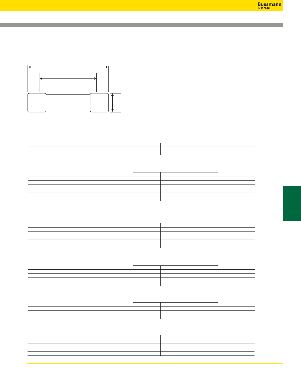
For product data sheets, visit www.cooperbussmann.com/DatasheetsEle 109
Medium Voltage
Fuses
Medium Voltage Fuses
12kV; E-Rated PT Fuse; Non-indicating
Catalog Amp Rated Dimensions Spare Parts
Number Rating Voltage IR RMS Sym. Length Diameter Clip Centers (Clips)
12CAV2 2 12kV 40kA 8.66 (220) 1.63 (41.3) 7.46 (189.48) 1A0835
12ABCNA3.15 3.15 12kV 45kA 7.69 (195.3) 1 (25.4) 6.51 (165.3) A3354705
17.5kV; E-Rated PT Fuse; Non-indicating
Catalog Amp Rated Dimensions Spare Parts
Number Rating Voltage IR RMS Sym. Length Diameter Clip Centers (Clips)
17.5CAV2 2 17.5kV 40kA 8.66 (220) 1.63 (41.3) 7.46 (189.48) 1A0835
17.5CAV4 4 17.5kV 40kA 8.66 (220) 1.63 (41.3) 7.46 (189.48) 1A0835
17.5CAV6 6 17.5kV 40kA 8.66 (220) 1.63 (41.3) 7.46 (189.48) 1A0835
17.5CAV10 10 17.5kV 40kA 8.66 (220) 1.63 (41.3) 7.46 (189.48) 1A0835
17.5ABGNA3.15 3.15 17.5kV 35kA 14.13 (358.9) 1 (25.4) 12.95 (328.9) A3354705
24kV; E-Rated PT Fuse; Non-indicating
Catalog Amp Rated Dimensions Spare Parts
Number Rating Voltage IR RMS Sym. Length Diameter Clip Centers (Clips)
24CAV2 2 24kV 40kA 13.39 (340.1) 1.63 (41.3) 12.19 (309.62) 1A0835
24CAV3 3 24kV 40kA 13.39 (340.1) 1.63 (41.3) 12.19 (309.62) 1A0835
24CAV4 4 24kV 40kA 13.39 (340.1) 1.63 (41.3) 12.19 (309.62) 1A0835
24ABGNA3.15 3.15 24kV 25kA 14.13 (358.9) 1 (25.4) 12.95 (328.9) A3354705
36kV; E-Rated PT Fuse; Non-indicating
Catalog Amp Rated Dimensions Spare Parts
Number Rating Voltage IR RMS Sym. Length Diameter Clip Centers (Clips)
36CAV2 2 36kV 40kA 17.32 (439.9) 1.63 (41.3) 16.12 (409.44) 1A0835
36CAV4 4 36kV 40kA 17.32 (439.9) 1.63 (41.3) 16.12 (409.44) 1A0835
36ABGNA3.15 3.15 36kV 31.5kA 14.13 (358.9) 1 (25.4) 12.95 (328.9) A3354705
38kV; E-Rated PT Fuse; Indicating & Non-indicating
Catalog Amp Rated Dimensions Spare Parts
Number Rating Voltage IR RMS Sym. Length Diameter Clip Centers (Clips)
38CAVH0.5E 0.5 38kV 40kA 17.32 (439.9) 1.63 (41.3) 16.12 (409.44) 1A0835
38CAVH1E 1 38kV 40kA 17.32 (439.9) 1.63 (41.3) 16.12 (409.44) 1A0835
38CAVH2E 2 38kV 40kA 17.32 (439.9) 1.63 (41.3) 16.12 (409.44) 1A0835
38CAV4E 4 38kV 40kA 17.32 (439.9) 1.63 (41.3) 16.12 (409.44) 1A0835
15.5kV; E-Rated PT Fuse; Indicating & Non-indicating
Catalog Amp Rated Dimensions Spare Parts
Number Rating Voltage IR RMS Sym. Length Diameter Clip Centers (Clips)
15.5CAV(H)0.5E 0.5 15.5kV 80kA 12.87 (326.9 1.63 (41.3) 1.2 (30.5) 1A0835
15.5CAV(H)1E 1 15.5kV 80kA 12.87 (326.9 1.63 (41.3) 1.2 (30.5) 1A0835
15.5CAV(H)2E 2 15.5kV 80kA 12.87 (326.9 1.63 (41.3) 1.2 (30.5) 1A0835
15.5CAV3E 3 15.5kV 80kA 12.87 (326.9 1.63 (41.3) 1.2 (30.5) 1A0835
15.5CAV5E 5 15.5kV 80kA 12.87 (326.9 1.63 (41.3) 1.2 (30.5) 1A0835
15.5CAV7E 7 15.5kV 80kA 12.87 (326.9 1.63 (41.3) 1.2 (30.5) 1A0835
Type CAVH are fitted with a striker pin for indication
E-Rated Fuses for Potential & Small Power Transformers
Catalog Numbers: E-Rated PT Fuses, Indicating & Non-Indicating
Length
Clip Centers
Diameter
Dimension Illustration

For product data sheets, visit www.cooperbussmann.com/DatasheetsEle
110
Medium Voltage Fuses
E-Rated, PT Fuses for Potential & Small Power
Transformers
Data Sheet: 6002
JCD, JCW, JCQ, JCI &
JCT
Specifications
Description: Indicating and non-
indicating E-rated medium voltage,
current-limiting fuses for potential
and small power transformers.
Dimensions: See Catalog
Numbers table.
Construction: Plated ferrules.
Ratings:
Volts: — 2.4-15.5kV (See Catalog Numbers table for details)
Amps: — 1⁄2-10A
IR: — 25-80kA Sym
— 40-130kA ASYM
— See Catalog Numbers table for details
Features and Benefits
• Sized for retrofitting in existing hardware
• Space saving size
Typical Applications
• Primary protection of medium voltage potential
transformers
• Primary protection of small medium voltage service
transformers
• Primary protection of small medium voltage control
transformers
2.4kV; E-Rated PT Fuse; Non-indicating
Catalog Amp Rated Dimensions Spare Parts
Number Rating Voltage IR RMS Sym. Length Diameter Clip Centers (Clips)
JCD-1-2E 0.5 2.4kV 63kA 4.49 (114) 0.8 (20) 3.86 (98) 1A1837
JCD-1E 1 2.4kV 40kA 4.49 (114) 0.8 (20) 3.86 (98) 1A1837
JCD-2E 2 2.4kV 40kA 4.49 (114) 0.8 (20) 3.86 (98) 1A1837
JCD-5E 5 2.4kV 25kA 4.49 (114) 0.8 (20) 3.86 (98) 1A1837
2.4/5.5kV; E-Rated PT Fuse; Non-indicating
Catalog Amp Rated Dimensions Spare Parts
Number Rating Voltage IR RMS Sym. Length Diameter Clip Centers (Clips)
JCW-1/2E 0.5 2.4kV/5.5kV 40kA 7.31 (185) 1.56 (39.7) 5.93 (150.6) 1A0835
JCW-1E 1 2.4kV/5.5kV 40kA 7.31 (185) 1.56 (39.7) 5.93 (150.6) 1A0835
JCW-2E 2 2.4kV/5.5kV 40kA 7.31 (185) 1.56 (39.7) 5.93 (150.6) 1A0835
JCW-3E 3 2.4kV/5.5kV 40kA 7.31 (185) 1.56 (39.7) 5.93 (150.6) 1A0835
JCW-4E 4 2.4kV/5.5kV 40kA 7.31 (185) 1.56 (39.7) 5.93 (150.6) 1A0835
JCW-5E 5 2.4kV/5.5kV 40kA 7.31 (185) 1.56 (39.7) 5.93 (150.6) 1A0835
5.5kV; E-Rated PT Fuse; Indicating
Catalog Amp Rated Dimensions Spare Parts
Number Rating Voltage IR RMS Sym. Length Diameter Clip Centers (Clips)
JCQ-3E 3 5.5kV 130kA 9.5 (241.3) 1.6 (40.6) 8.12 (206) 1A0835
JCQ-5E 5 5.5kV 130kA 9.5 (241.3) 1.6 (40.6) 8.12 (206) 1A0835
JCQ-10E 10 5.5kV 130kA 9.5 (241.3) 1.6 (40.6) 8.12 (206) 1A0835
8.3kV; E-Rated PT Fuse; Indicating
Catalog Amp Rated Dimensions Spare Parts
Number Rating Voltage IR RMS Sym. Length Diameter Clip Centers (Clips)
JCI-3E 3 8.3kV 80kA 12.88 (327) 1.6 (40.6) 11.5 (292) 1A0835
JCI-5E 5 8.3kV 80kA 12.88 (327) 1.6 (40.6) 11.5 (292) 1A0835
JCI-10E 10 8.3kV 80kA 12.88 (327) 1.6 (40.6) 11.5 (292) 1A0835
15.5kV; E-Rated PT Fuse; Indicating
Catalog Amp Rated Dimensions Spare Parts
Number Rating Voltage IR RMS Sym. Length Diameter Clip Centers (Clips)
JCT-3E 3 15.5kV 80kA 17.5 (444.5) 1.6 (40.6) 16.12 (409.4) 1A0835
JCT-5E 5 15.5kV 80kA 17.5 (444.5) 1.6 (40.6) 16.12 (409.4) 1A0835
JCT-10E 10 15.5kV 80kA 17.5 (444.5) 1.6 (40.6) 16.12 (409.4) 1A0835
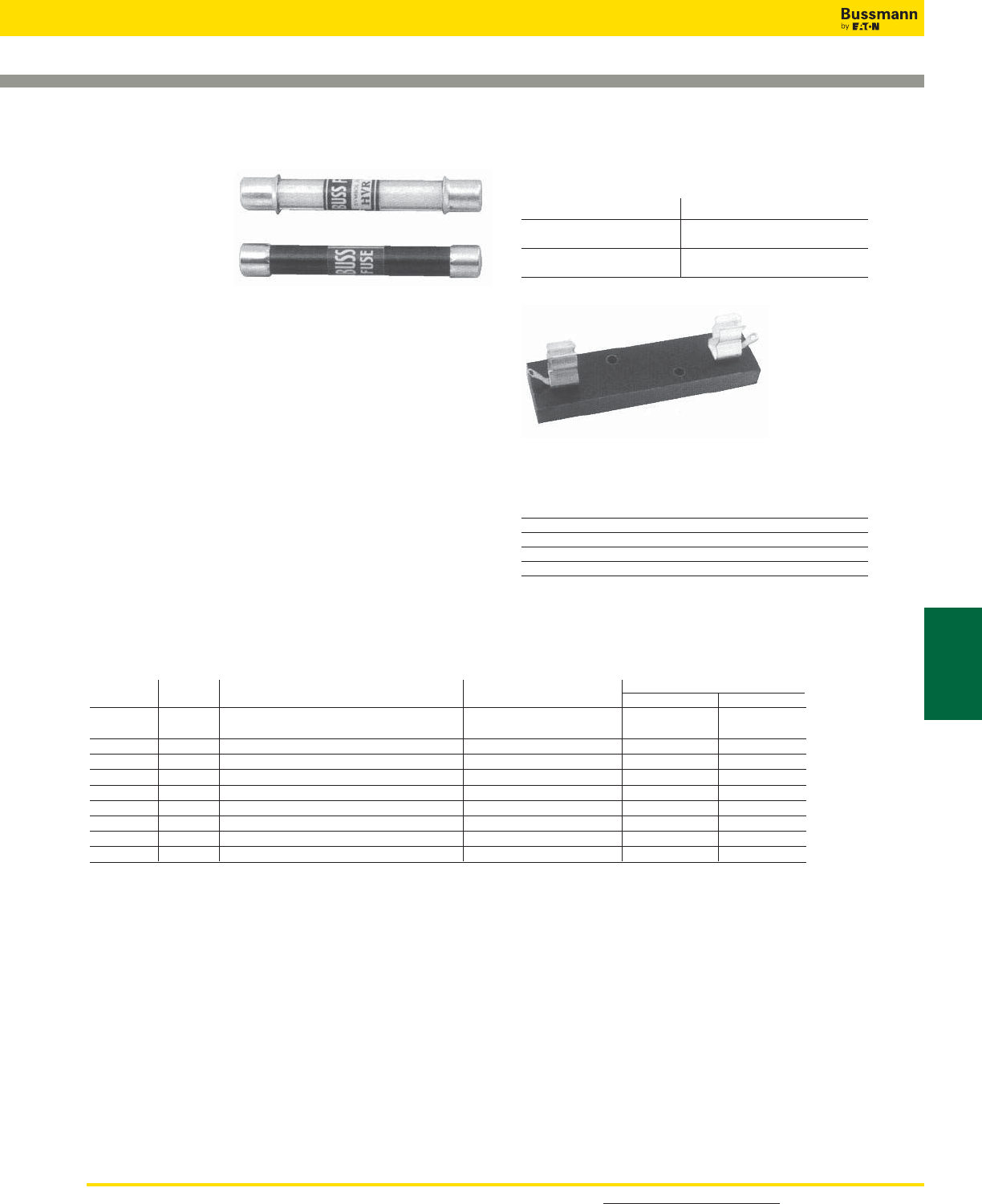
For detailed information, visit the Electrical IEC section at www.cooperbussmann.com 111
Medium Voltage
Fuses
Medium Voltage Fuses
PT Fuses
Data Sheet: 6003
Fuse blocks: 4528, 4529
Voltage Rating: 1000 to 10,000V
Basic Catalog Fuse Block Fuse Clip
Numbers Catalog Number Catalog Number
HVA, HVR 4528 5960
HVB, HVT 4529 5960
HVJ, HVU N/A 4180
HVL, HVX N/A 4180
Use #8 screws on blocks 4528 and 4529.
Test Specifications
Basic Catalog
Numbers Load / Opening Time
HVA, HVB, HVJ, HVL 110% / 4 Hours (min)
135% / 1 Hour (max)
HVR, HVT, HVU, HVW, HVX 100% / 4 Hours (min)
150% / 1 Hour (max)
HVA, HVB,
HVJ, HVL,
HVR, HVT,
HVU, HVW &
HVX
Specifications
Description: Medium voltage, non-time delay, fast-acting
fuses.
Dimensions: See Basic Catalog Numbers table.
Ratings:
Volts: — 1-10kV (See Basic Catalog Numbers table)
Amps: — 1⁄16-10A (See Basic Catalog Numbers table)
Features and Benefits
• Physical size varies with electrical rating of fuse to prevent
over-fusing.
• Space saving size.
Typical Applications
• Medium Voltage Instrument Protection
• Medium Voltage Circuit Protection
Basic
Catalog Dimensions - in (mm)
Number kV Amp Ratings Maximum S.C. Diameter Length
HVA 1 1⁄16, 1⁄10, 1⁄8, 2⁄10, 1⁄4, 3⁄10, 3⁄8, 1⁄2, 20kW DC/30kVA AC 0.41 (10.4) 3 (76.1)
3⁄4, 1, 1 1⁄2, 2, 3, 4, 6, 10
HVB 2.5 1⁄2, 3⁄4, 1, 1 1⁄2, 2, 3 20kW DC/30kVA AC 0.41 (10.4) 4.5 (114.2)
HVJ 5 1⁄16, 1⁄8, 1⁄4, 1⁄2, 3⁄4, 1 1⁄2, 2, 4, 6, 10 20kW DC/30kVA AC 0.81 (20.6) 5 (126.9)
HVL 10 1⁄16, 1⁄8, 1⁄4, 1⁄2, 1, 1 1⁄2, 2, 3 20kW DC/30kVA AC 0.81 (20.6) 10 (254)
HVR 1 1⁄2, 1, 2, 3, 4, 5 kVA-500 AC only 0.41 (10.4) 3 (76.2)
HVW 1.2 1, 2, 3, 4, 5, 8 kVA-12,000 AC only 0.41 (10.4) 2.25 (57.1)
HVT 2.5 1⁄2, 1, 2, 3, 5 kVA-1250 AC only 0.41 (10.4) 4.5 (114.2)
HVU 5 1⁄2, 1, 2, 3, 4, 5 kVA-2500 AC only 0.81 (20.6) 5 (126.9)
HVX 10 1⁄2, 1, 3, 5 kVA-5,000 AC only 0.41 (10.4) 10.0 (253.8)
Catalog Number Build-A-Code
Basic Catalog Number Amps
_ _ _ _ _ _ _ _
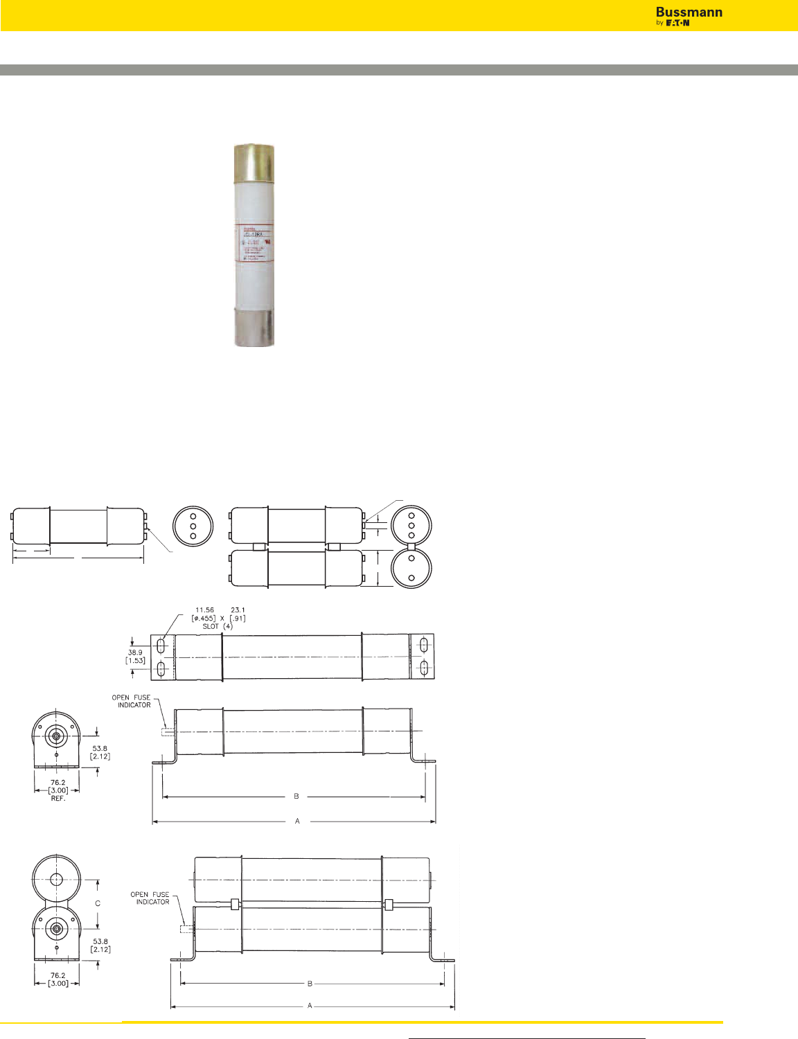
For product data sheets, visit For product data sheets, visit www.cooperbussmann.com/DatasheetsEle
112
Medium Voltage Fuses
JCG, JCH, JCK,
JCK-A, JCK-B, JCL,
JCL-A, JCL-B, JCR-A,
& JCR-B
Specifications
Description: Indoor/enclosure
R-Rated medium voltage,
current-limiting fuses for motor
circuit protection.
Dimensions: See Dimensions
illustrations.
Ratings:
Volts: — 2.4-7.2kV (See Catalog Numbers table for details)
Amps: — 25-450A (See Catalog Numbers table for details)
IR: — 50kA Sym
— 80kA ASYM
— See Catalog Numbers table for details
R-Rated Fuses for Motor Circuit Protection
0.38"
(9.5mm)
B
INDICATOR
Showing Fuse is Open
INDICATOR
Showing Fuse
is Open
A
C
Dimensions - mm (in)
Figure 1
Figure 2
Figure 3
Data Sheet 6001
Agency Information: UL Recognized: 2540Vac — JCK,
JCK-A, 5080Vac — JCL, JCL-A, UL Recognized (Guide
#MSSS2, File #E96676).
Features and Benefits
• Physically dimensioned for retrofitting in existing hardware
• Open fuse indicator for ease in troubleshooting
• Available with optional Cutler Hammer®hookeye for ease of
insertion and removal
• Classified as back-up fuses for current-limited protection of
medium voltage motor controllers
Typical Applications
• Medium Voltage Motor Controllers
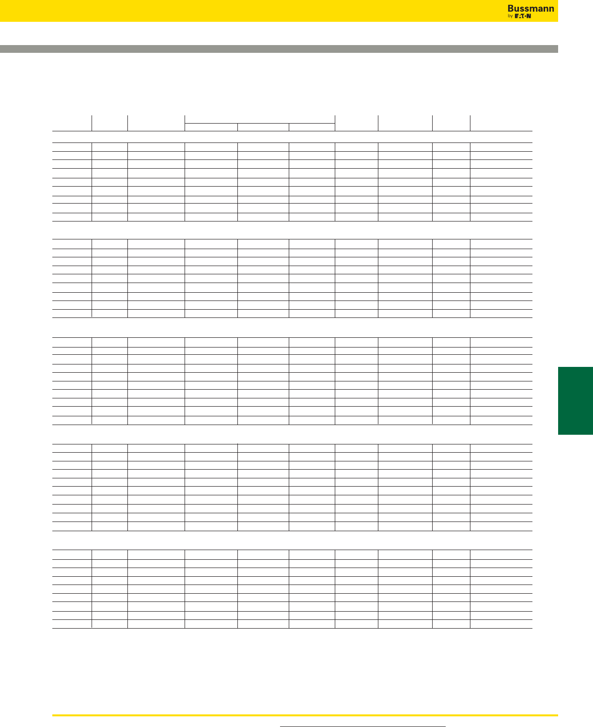
For product data sheets, visit www.cooperbussmann.com/DatasheetsEle 113
R-Rated Fuses for Motor Circuit Protection
Catalog Numbers: R-Rated; Indoor/Enclosure
Catalog Amp Maximum Dimensions - in (mm)* Max Int. Cap. Amps Min Int. Cap.
Numbers Ratings Design Voltage A B C
Construction
Amps (Asym.) (Sym.) Amps (Sym.)
2400V (See Figure 1)
JCK-2R 70 2540 11.24 (285.5) 3.0 (76.2) 3.0 (76.2) Single 80,000 50,000 165
JCK-3R 100 2540 11.24 (285.5) 3.0 (76.2) 3.0 (76.2) Single 80,000 50,000 220
JCK-4R 130 2540 11.24 (285.5) 3.0 (76.2) 3.0 (76.2) Single 80,000 50,000 320
JCK-5R 150 2540 11.24 (285.5) 3.0 (76.2) 3.0 (76.2) Single 80,000 50,000 410
JCK-6R 170 2540 11.24 (285.5) 3.0 (76.2) 3.0 (76.2) Single 80,000 50,000 480
JCK-9R 200 2540 11.24 (285.5) 3.0 (76.2) 3.0 (76.2) Single 80,000 50,000 720
JCK-12R 230 2540 11.24 (285.5) 3.0 (76.2) 3.0 (76.2) Single 80,000 50,000 970
JCK-18R 390 2540 11.24 (285.5) 3.0 (76.2) 3.0 (76.2) Double 80,000 50,000 1,430
JCK-24R 450 2540 11.24 (285.5) 3.0 (76.2) 3.0 (76.2) Double 80,000 50,000 1,880
2400V — With Westinghouse Ampguard Hookeye (See Figure 1)
JCK-A-2R 70 2540 11.24 (285.5) 3.0 (76.2) 3.0 (76.2) Single 80,000 50,000 165
JCK-A-3R 100 2540 11.24 (285.5) 3.0 (76.2) 3.0 (76.2) Single 80,000 50,000 220
JCK-A-4R 130 2540 11.24 (285.5) 3.0 (76.2) 3.0 (76.2) Single 80,000 50,000 320
JCK-A-5R 150 2540 11.24 (285.5) 3.0 (76.2) 3.0 (76.2) Single 80,000 50,000 410
JCK-A-6R 170 2540 11.24 (285.5) 3.0 (76.2) 3.0 (76.2) Single 80,000 50,000 480
JCK-A-9R 200 2540 11.24 (285.5) 3.0 (76.2) 3.0 (76.2) Single 80,000 50,000 720
JCK-A-12R 230 2540 11.24 (285.5) 3.0 (76.2) 3.0 (76.2) Single 80,000 50,000 970
JCK-A-18R 390 2540 11.24 (285.5) 3.0 (76.2) 3.0 (76.2) Double 80,000 50,000 1,430
JCK-A-24R 450 2540 11.24 (285.5) 3.0 (76.2) 3.0 (76.2) Double 80,000 50,000 1,880
2400V — Bolt-On (See Figures 2 & 3)
JCK-B-30 25 2540 14.18 (360.2) 12.81 (325.4) - Single 80,000 50,000 90
JCK-B-2R 70 2540 14.18 (360.2) 12.81 (325.4) - Single 80,000 50,000 170
JCK-B-3R 100 2540 14.18 (360.2) 12.81 (325.4) - Single 80,000 50,000 245
JCK-B-4R 130 2540 14.18 (360.2) 12.81 (325.4) - Single 80,000 50,000 340
JCK-B-5R 150 2540 14.18 (360.2) 12.81 (325.4) - Single 80,000 50,000 430
JCK-B-6R 170 2540 14.18 (360.2) 12.81 (325.4) - Single 80,000 50,000 500
JCK-B-9R 200 2540 14.18 (360.2) 12.81 (325.4) - Single 80,000 50,000 1,000
JCK-B-12R 230 2540 14.18 (360.2) 12.81 (325.4) - Single 80,000 50,000 1,250
JCK-B-18R 390 2540 14.18 (360.2) 12.81 (325.4) 3.56 (90.4) Double 80,000 50,000 1,700
JCK-B-24R 450 2540 14.18 (360.2) 12.81 (325.4) 3.56 (90.4) Double 80,000 50,000 1,210
2400V — Hermetically Sealed, For Use with Ampguard Motor Starters (See Figure 1)
JCH-30 25 2540 10.81 (275.6) 3.0 (76.2) 3.0 (76.2) Single 80,000 50,000 90
JCH-2R 70 2540 10.81 (275.6) 3.0 (76.2) 3.0 (76.2) Single 80,000 50,000 170
JCH-3R 100 2540 10.81 (275.6) 3.0 (76.2) 3.0 (76.2) Single 80,000 50,000 245
JCH-4R 130 2540 10.81 (275.6) 3.0 (76.2) 3.0 (76.2) Single 80,000 50,000 340
JCH-5R 150 2540 10.81 (275.6) 3.0 (76.2) 3.0 (76.2) Single 80,000 50,000 430
JCH-6R 170 2540 10.81 (275.6) 3.0 (76.2) 3.0 (76.2) Single 80,000 50,000 500
JCH-9R 200 2540 10.81 (275.6) 3.0 (76.2) 3.0 (76.2) Single 80,000 50,000 1,000
JCH-12R 230 2540 10.81 (275.6) 3.0 (76.2) 3.0 (76.2) Single 80,000 50,000 1,250
JCH-18R 390 2540 10.81 (275.6) 3.0 (76.2) 3.0 (76.2) Double 80,000 50,000 1,700
JCH-24R 450 2540 10.81 (275.6) 3.0 (76.2) 3.0 (76.2) Double 80,000 50,000 2,100
4800V (See Figure 1)
JCL-2R 70 5080 15.76 (400.3) 3.0 (76.2) 3.0 (76.2) Single 80,000 50,000 165
JCL-3R 100 5080 15.76 (400.3) 3.0 (76.2) 3.0 (76.2) Single 80,000 50,000 220
JCL-4R 130 5080 15.76 (400.3) 3.0 (76.2) 3.0 (76.2) Single 80,000 50,000 320
JCL-5R 150 5080 15.76 (400.3) 3.0 (76.2) 3.0 (76.2) Single 80,000 50,000 410
JCL-6R 170 5080 15.76 (400.3) 3.0 (76.2) 3.0 (76.2) Single 80,000 50,000 480
JCL-9R 200 5080 15.76 (400.3) 3.0 (76.2) 3.0 (76.2) Single 80,000 50,000 720
JCL-12R 230 5080 15.76 (400.3) 3.0 (76.2) 3.0 (76.2) Single 80,000 50,000 970
JCL-18R 390 5080 15.76 (400.3) 3.0 (76.2) 3.0 (76.2) Double 80,000 50,000 1,430
JCL-24R 450 5080 15.76 (400.3) 3.0 (76.2) 3.0 (76.2) Double 80,000 50,000 1,880
• See previous page Figure 2 for single construction and Figure 3 for double construction information.
Recommended fuseclips: see page 120 - 1A0065, A3354730, 9078A67G04.
Data Sheet: 6001
Medium Voltage
Fuses
Medium Voltage Fuses
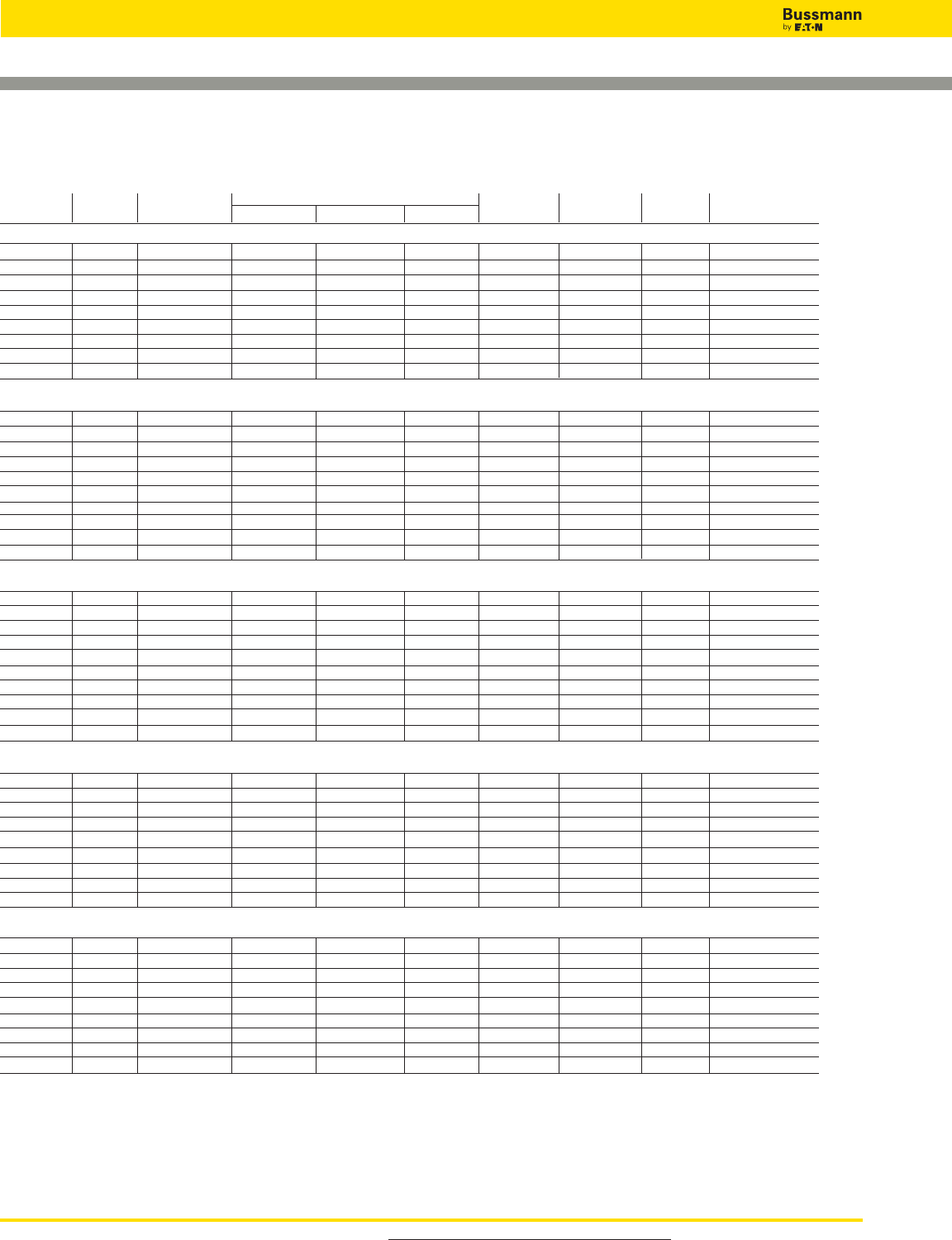
For product data sheets, visit www.cooperbussmann.com/DatasheetsEle
114
Medium Voltage Fuses
R-Rated Fuses for Motor Circuit Protection
Catalog Numbers: R-Rated; Indoor/Enclosure
Catalog Amp Maximum Dimensions - in (mm) Max Int. Cap. Amps Min Int. Cap.
Numbers Ratings Design Voltage A B C Construction Amps (Asym. (Sym.) Amps (Sym.)
4800V — With Westinghouse Ampguard Hookeye (See Figure 1)
JCL-A-2R 70 5080 15.76 (400.3) 3.0 (76.2) 3.0 (76.2) Single 80,000 50,000 165
JCL-A-3R 100 5080 15.76 (400.3) 3.0 (76.2) 3.0 (76.2) Single 80,000 50,000 220
JCL-A-4R 130 5080 15.76 (400.3) 3.0 (76.2) 3.0 (76.2) Single 80,000 50,000 320
JCL-A-5R 150 5080 15.76 (400.3) 3.0 (76.2) 3.0 (76.2) Single 80,000 50,000 410
JCL-A-6R 170 5080 15.76 (400.3) 3.0 (76.2) 3.0 (76.2) Single 80,000 50,000 480
JCL-A-9R 200 5080 15.76 (400.3) 3.0 (76.2) 3.0 (76.2) Single 80,000 50,000 720
JCL-A-12R 230 5080 15.76 (400.3) 3.0 (76.2) 3.0 (76.2) Single 80,000 50,000 970
JCL-A-18R 390 5080 15.76 (400.3) 3.0 (76.2) 3.0 (76.2) Double 80,000 50,000 1,430
JCL-A-24R 450 5080 15.76 (400.3) 3.0 (76.2) 3.0 (76.2) Double 80,000 50,000 1,880
4800V — Bolt-On (See Figures 2 & 3)
JCL-B-30 30 5080 19.25 (488.9) 17.88 (454.1) - Single 80,000 50,000 95
JCL-B-2R 70 5080 19.25 (488.9) 17.88 (454.1) - Single 80,000 50,000 180
JCL-B-3R 100 5080 19.25 (488.9) 17.88 (454.1) - Single 80,000 50,000 270
JCL-B-4R 130 5080 19.25 (488.9) 17.88 (454.1) - Single 80,000 50,000 350
JCL-B-5R 150 5080 19.25 (488.9) 17.88 (454.1) - Single 80,000 50,000 450
JCL-B-6R 170 5080 19.25 (488.9) 17.88 (454.1) - Single 80,000 50,000 540
JCL-B-9R 200 5080 19.25 (488.9) 17.88 (454.1) - Single 80,000 50,000 700
JCL-B-12R 230 5080 19.25 (488.9) 17.88 (454.1) - Single 80,000 50,000 1,000
JCL-B-18R 390 5080 19.25 (488.9) 17.88 (454.1) 3.31 (84.1) Double 80,000 50,000 1,450
JCL-B-24R 450 5080 19.25 (488.9) 17.88 (454.1) 3.31 (84.1) Double 80,000 50,000 2,000
4800V — Hermetically Sealed, For Use with Ampguard Motor Starters (See Figure 1)
JCG-30 30 5080 15.91 (404.1) 3.0 (76.2) 3.0 (76.2) Single 80,000 50,000 95
JCG-2R 70 5080 15.91 (404.1) 3.0 (76.2) 3.0 (76.2) Single 80,000 50,000 180
JCG-3R 100 5080 15.91 (404.1) 3.0 (76.2) 3.0 (76.2) Single 80,000 50,000 270
JCG-4R 130 5080 15.91 (404.1) 3.0 (76.2) 3.0 (76.2) Single 80,000 50,000 350
JCG-5R 150 5080 15.91 (404.1) 3.0 (76.2) 3.0 (76.2) Single 80,000 50,000 450
JCG-6R 170 5080 15.91 (404.1) 3.0 (76.2) 3.0 (76.2) Single 80,000 50,000 540
JCG-9R 200 5080 15.91 (404.1) 3.0 (76.2) 3.0 (76.2) Single 80,000 50,000 700
JCG-12R 230 5080 15.91 (404.1) 3.0 (76.2) 3.0 (76.2) Single 80,000 50,000 1,000
JCG-A-18R 390 5080 15.91 (404.1) 3.0 (76.2) 3.0 (76.2) Double 80,000 50,000 1,450
JCG-A-24R 450 5080 15.91 (404.1) 3.0 (76.2) 3.0 (76.2) Double 80,000 50,000 2,000
7200V — With Ampguard Hookeye (See Figure 1)
JCR-A-2R 70 8300 15.85 (402.6) 3.0 (76.2) 3.0 (76.2) Single 80,000 50,000 160
JCR-A-3R 100 8300 15.85 (402.6) 3.0 (76.2) 3.0 (76.2) Single 80,000 50,000 250
JCR-A-4R 130 8300 15.85 (402.6) 3.0 (76.2) 3.0 (76.2) Single 80,000 50,000 325
JCR-A-5R 150 8300 15.85 (402.6) 3.0 (76.2) 3.0 (76.2) Single 80,000 50,000 390
JCR-A-6R 170 8300 15.85 (402.6) 3.0 (76.2) 3.0 (76.2) Single 80,000 50,000 500
JCR-A-9R 200 7200 15.85 (402.6) 3.0 (76.2) 3.0 (76.2) Single 80,000 50,000 750
JCR-A-12R 230 7200 15.85 (402.6) 3.0 (76.2) 3.0 (76.2) Single 80,000 50,000 1,000
JCR-A-18R 390 7200 15.85 (402.6) 3.0 (76.2) 3.0 (76.2) Double 80,000 50,000 1,450
JCR-A-24R 450 7200 15.85 (402.6) 3.0 (76.2) 3.0 (76.2) Double 80,000 50,000 2,500
7200V — Bolt-On (See Figures 2 & 3)
JCR-B-2R 70 8300 19.25 (488.9) 17.88 (454.1) - Single 80,000 50,000 160
JCR-B-3R 100 8300 19.25 (488.9) 17.88 (454.1) - Single 80,000 50,000 250
JCR-B-4R 130 8300 19.25 (488.9) 17.88 (454.1) - Single 80,000 50,000 325
JCR-B-5R 150 8300 19.25 (488.9) 17.88 (454.1) - Single 80,000 50,000 390
JCR-B-6R 170 8300 19.25 (488.9) 17.88 (454.1) - Single 80,000 50,000 500
JCR-B-9R 200 7200 19.25 (488.9) 17.88 (454.1) - Single 80,000 50,000 750
JCR-B-12R 230 7200 19.25 (488.9) 17.88 (454.1) - Single 80,000 50,000 1,000
JCR-B-18R 390 7200 19.25 (488.9) 17.88 (454.1) 3.31 (84.1) Double 80,000 50,000 1,450
JCR-B-24R 450 7200 19.25 (488.9) 17.88 (454.1) 3.31 (84.1) Double 80,000 50,000 2,500
Recommended fuseclips: see page 120 - 1A0065, A3354730, 9078A67G04.
Data Sheet: 6001

For detailed information, visit the Electrical IEC section at www.cooperbussmann.com 115
Medium Voltage
Fuses
Table of Ratings
Basic Cat. Breaking Dimensions - in (mm)
Number Volts Capacity Amp Ratings Length Diameter Dimensional Standard
3.6WJON6 3.6kV 50kA 5, 6.3, 10, 16, 20, 25, 31.5, 40, 50 7.56 (192) 1.4 (35.6) BS 2692 (TA1) Interchangeable with GEC Type K2 PA
3.6WDOH6 3.6kV 50kA 50, 63, 80, 100, 125 7.56 (192) 2 (50.8) BS 2692 (TA1) or DIN 43625
3.6WFOH6 3.6kV 50kA 160, 200 7.56 (192) 3 (76.2) BS 2692 (TA1) or DIN 43625
3.6WDLSJ 3.6kV 50kA 50, 63, 80, 100, 125 11.5 (292.1) 2 (50.8) DIN 43625
3.6WFLSJ 3.6kV 50kA 160, 200 11.5 (292.1) 3 (76.2) DIN 43625
3.6WDFHO 3.6kV 50kA 50, 63, 80, 100, 125 10 (254) 2 (51) BS 2692 (TA2)
3.6WFFHO 3.6kV 50kA 160, 200 10 (254) 3 (76.2) BS 2692 (TA2)
3.6WKFHO 3.6kV 50kA 250, 315, 355, 400 10 (254) 3 (76.2) BS 2692 (TA2)
5.5VFNHA 5.5kV 60kA 2R-6R 15.86 (402.8) 3 (76.2) ANSI R-Rated
5.5VKNHA 5.5kV 60kA 9R-24R 15.86 (402.8) 3 (76.2) ANSI R-Rated
7.2WFNHO 7.2kV 40kA 25, 31.5, 40, 50, 63, 80, 100, 125, 160 15.86 (402.8) 3 (76.2) BS 2692 (TA4)
7.2WKNHO 7.2kV 40kA 200, 224, 250, 315 15.86 (402.8) 3 (76.2) BS 2692 (TA4)
7.2WFMSJ 7.2kV 63kA 25, 31.5, 40, 50, 63, 80, 125, 160 17.40 (442) 3 (76.2) DIN 43625
7.2WKMSJ 7.2kV 63kA 200, 224, 250, 315, 355 17.40 (442) 3 (76.2) DIN 43625
British Standard Dimensioned IEC Fuses for
Motor Circuit Protection
Catalog Number Build-A-Code
kV Basic Catalog Number Amps
_ _ _ _ _ _ _ _ _ _ _
The Bussmann range of motor fuses are designed to meet
the specific requirements necessary for motor protection.
During the starting cycle of direct on-line motors, the fuse
elements will reach a considerably higher temperature than
during normal operation; (this is due to the high amount of
current the motor will draw as it starts, typically, six times its
normal load current value). This results in expansion and
contraction of the fuse elements and could cause premature
operation of the fuse.
Bussmann motor fuses encompass an advanced design to
minimize this effect. This therefore, negates the need to over
specify the fuse rating due to high values of motor starting
current.
Bussmann motor fuses operate extremely quickly under
heavy fault currents, resulting from the time / current
characteristic. Low power dissipation ensures low
temperature rise, important in multi-tier starters for example.
Switching (arc), voltages are lower than permitted values,
therefore, 5.5kV fuses are also suitable for 4.8kV and
2.4kV circuits.
Medium Voltage Fuses
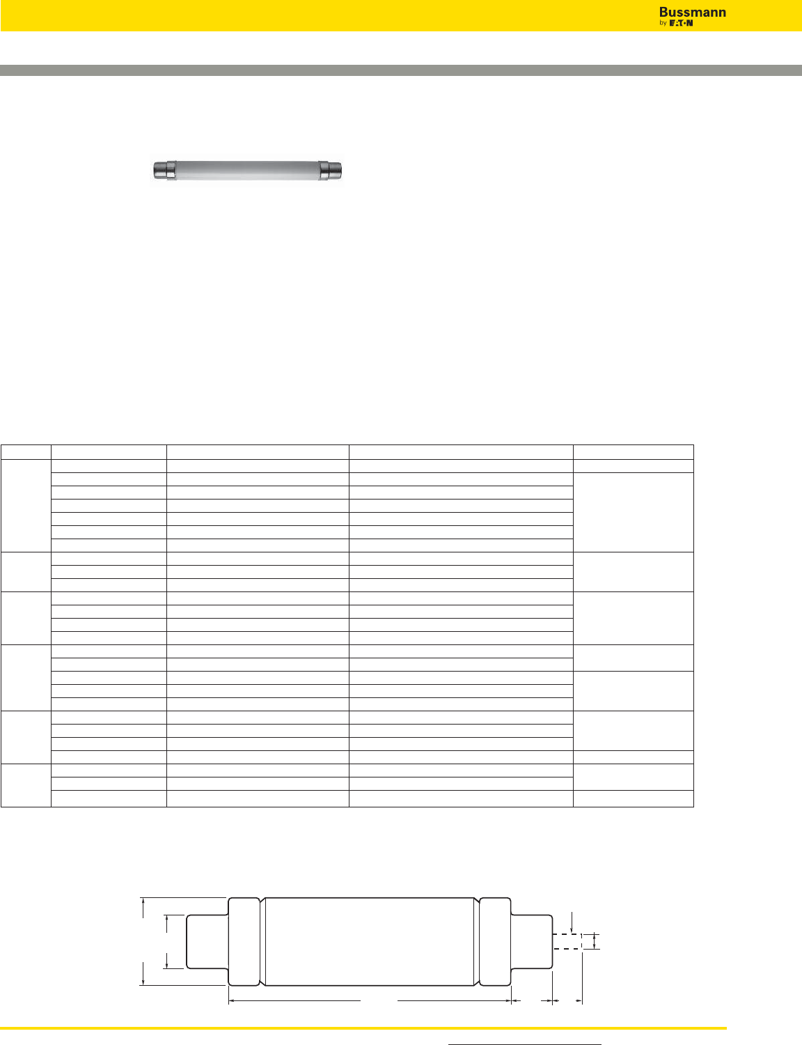
For detailed information, visit the Electrical IEC section at www.cooperbussmann.com
116
Medium Voltage Fuses
DIN Dimension Fuses
To Spec. DIN 43625
Specifications
Catalog Symbol: See Basic Catalog Numbers table.
Description: DIN dimension fuses to Specification DIN
43625 covering current-limiting fuses with performance in
compliance with IEC 60282-1. These are in accordance with
the R10 and, in some cases, the R20 series of preferred
numbers.
Dimensions: See Catalog Numbers table.
DIN Dimensioned IEC Fuses for Transformer Protection
Volts: — See voltage associated with the Basic Catalog
Numbers in the table.
Amps: — See amp rating associated with the Basic Catalog
Numbers in the table.
IR: — See IR associated with the Basic Catalog Numbers
in the table.
Agency Information: Comply with DIN dimensional
standard DIN 43625, VDE 0670 part 4, VDE 0670 part 40Z
and with IEC 60282-1 (2005).
Features and Benefits
• DIN dimensioned for retrofitting in existing hardware
• Open fuse indicator for ease in troubleshooting
• Designed for use in IEC equipment
Typical Applications
• Medium Voltage IEC designed equipment
Catalog Number Build-A-Code
kV Basic Catalog Number Amps
_ _ _ _ _ _ _ _ _ _ _
kV Catalog Numbers Amp Ratings Dimensions - in (mm) Diameter x Length IR RMS Sym
3.6ADOSJ(amp) 6.3, 10, 16, 20, 25, 31.5, 40 2.00 x 7.56 (51 x 192) 40kA
3.6WDOSJ(amp) 50, 63, 80, 100, 125 2.00 x 7.56 (51 x 192)
3.6WFOSJ(amp) 160, 200 3.00 x 7.56 (76 x 192
3.6 3.6ADLSJ(amp) 25, 40 2.00 x 11.50 (51 x 292) 50kA
3.6WDLSJ(amp) 50, 63, 80, 100, 125 2.00 x 11.50 (51 x 292)
3.6WFLSJ(amp) 160, 200 3.00 x 11.50 (76 X 292)
3.6WKLSJ(amp) 250, 315, 400 3.00 x 11.50 (76 X 292)
7.2TDLSJ(amp) 6.3, 10, 16, 20, 25, 31.5, 40, 50, 63 2.00 x 11.50 (51 x 292)
7.2 7.2TFLSJ(amp) 80, 100, 125, 160 3.00 x 11.50 (76 x 292) 40kA
7.2WKMSJ(amp) 200, 225, 250, 315, 355 3.00 x 17.41 (76 x 442)
12TDLEJ(amp) 6.3, 10, 16, 20, 25, 31.5, 40, 50, 63 2.00 x 11.50 (51 x 292)
12 12THLEJ(amp) 80, 100 2.52 x 11.50 (64 x 292) 63kA
12TKLEJ(amp) 125 3.00 x 11.50 (76 x 292)
12TXLEJ(amp)* 160, 200 3.50 x 11.50 (88 x 292)
17.5TDLSJ(amp)* 6.3, 10, 16, 20, 25, 31.5, 40 2.00 x 11.50 (51 x 292)
17.5TFLSJ(amp)* 50 3.00 x 11.50 (76 x 292) 35.5kA
17.5 17.5TDMEJ(amp) 6.3, 10, 16, 20, 25, 31.5, 40, 50, 63 2.00 x 17.41 (51 x 442)
17.5THMEJ(amp) 80, 100 2.52 x 17.41 (64 x 442) 50kA
17.5TKMEJ(amp) 125 3.00 x 17.41 (76 x 442)
24TDMEJ(amp) 6.3, 10, 16, 20, 25, 31.5, 40, 50 2.00 x 17.41 (51 x 442)
24 24THMEJ(amp) 63 2.52 x 17.41 (64 x 442) 50kA
24TFMEJ(amp) 80, 100*13.00 x 17.41 (76 x 442)
24TXMEJ(amp)* 1252, 160 3.46 x 17.41 (88 x 442) 31.5kA
36TDQSJ(amp) 3.153, 6.3, 10, 16, 20, 25 2.00 x 21.16 (51 x 537) 35.5kA
36 36TFQSJ(amp) 31.5, 40, 50 3.00 x 21.16 (76 x 537)
36TXQEJ(amp)* 63 3.46 x 21.16 (88 x 537) 20kA
Catalog Numbers
For Diameter and Length Dimensions See Table Above
1.77"
45.0mm
Diameter
0.59"
15.0mm
Striker In
Operated Position
Length 1.34"
34.0mm
1.02"
26.0mm
Dimensions - In (mm)
Recommended fuseclips for DIN style fuses – 270303, A3354745 see page 120.
*Not compliant with VDE 0670, part 402.
1-IR RMS Sym is 63kA
2-IR RMS Sym is 40kA
3-IR RMS Sym is 20kA
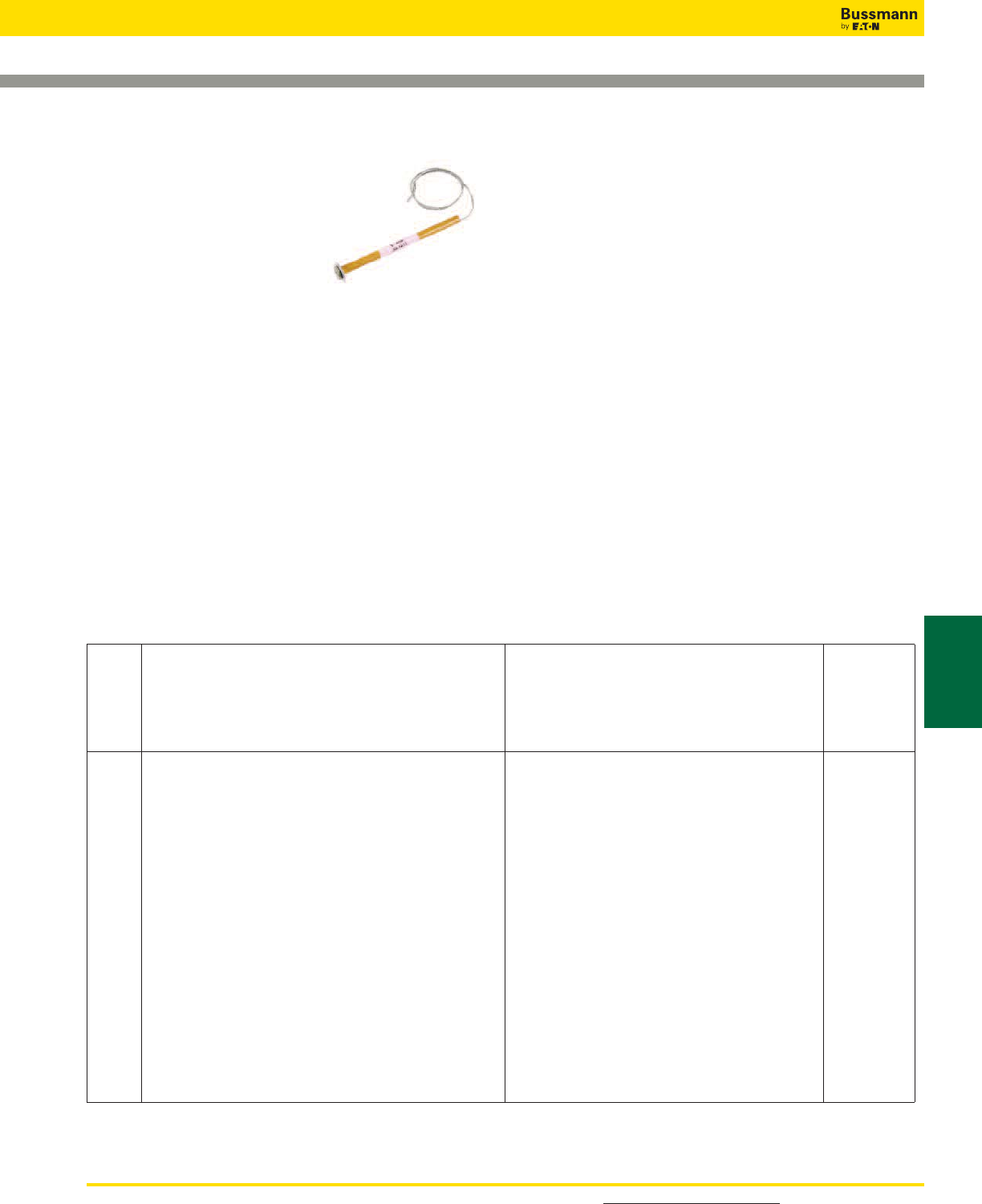
For detailed information, visit the Electrical IEC section at www.cooperbussmann.com 117
Medium Voltage
Fuses
Medium Voltage Fuses
Expulsion Fuse Links for Use in High Voltage Distribution
Cut-Outs
Rated
Voltage
(kV)
1st Letter
Type of Current Characteristics
2nd Letter
Type of Termination
Rated
Current
(A)
15
25
46
72
T= complies with ANSI C 37-42 requirements for slow
acting T characteristics
K= complies with ANSI C 37-42 requirements for fast
acting K characteristics
XA = this type of expulsion fuse link has an extra rapid
characteristic. It is suitable for applications where a
high degree of system protection is required at the
expense of discrimination
S= Solid links rated at 100A are also available in both
button head and universal versions for fitting into
expulsion fuse carriers where required. These can be
ordered in a similar way using the abbreviation S, e.g.
15SB, etc
B= a fixed NEMA button head link
U= a universal link, with double tail and slip off
NEMA button head
D= double tailed link without NEMA button
head
BR = as pattern B but the button head is
attached via a 1/4 UNF thread to allow use of
an extension rod.
See outline drawings opposite page for
reference
1, 2, 3, 4, 5,
6, 7.5, 8, 10,
12, 15, 20,
25, 30, 40,
50, 60, 65,
75, 80, 100
Specifications
Description: Expulsion fuse links
available in a wide range of
options from 15kV to 72kV in
ANSI T&K characteristics.
Ratings:
Volts: — 15 to 72kV
Amps: — 1 to 100A
Breaking Capacity: depends on voltage but is approximately 8kA
Agency Information:
Type T: complies with ANSI C37-42
Type K: complies with ANSI C37-42
Features and Benefits
•Wide range of options available from 15kV to 72kV in ANSI
T & K characteristics.
• Extra rapid option also available.
Packaging:
Up to and including 50A: 25 in a carton
From 60A to 100A: 10 in a carton
To avoid incorrect replacement the fuse links have colour
coded labels:
Pink label: Type XA
Yellow label: Type K
Green label: Type T
Typical Applications:
•Primary side transformer protection
•Feeder protection
•Capacitor bank protection
Use of Application
Expulsion fuse links current ratings should be selected on the
basis of maximum expected transient no damage currents
rather than on full load current. In addition, the selection of
higher current ratings will reduce the possibility of supply
interruption due to transient surges such as those due to
lightning strikes.
Links should be handled with a reasonable degree of care
when installing. Excessively rough handling may damage the
element.
It is normal, under certain fault conditions, for arc
extinguishing material and/or metal particles to be expelled
from the fuse assembly. It is therefore recommended that
reasonable precautions be taken to prevent the installation
being approached by unauthorised persons.
How to order - Parts Referencing System
Thus a typical ordering reference for a 15kV NEMA Type K,
button head 30A fuse link would be 15KB30 expulsion fuse
link.
The fuse link assembly for a given range is standard to all
rated voltages. The exception is that the tail length is varied
to suit the dimensions of expulsion carrier of different ratings.
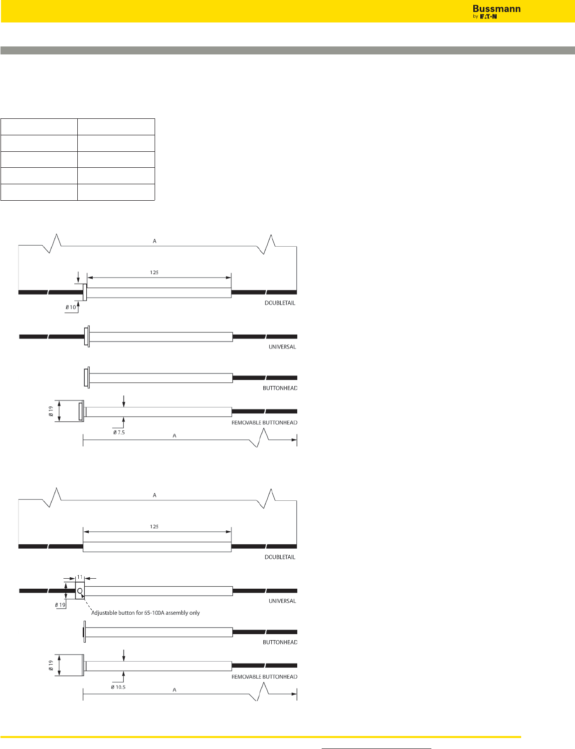
For detailed information, visit the Electrical IEC section at www.cooperbussmann.com
118
Medium Voltage Fuses
1-50A
60-100A
Type kV A
15kV 533 (21”)
25kV 660 (26”)
46kV 787 (31”)
72kV 1016 (40”)
Notes: Type BR is similar to button
head shown, except that the button
head is attached via a 1⁄4UNF thread.
Tails can be cut to any length.
Dimensions - mm (in)
Expulsion Fuse Links for Use in High Voltage Distribution
Cut-Outs
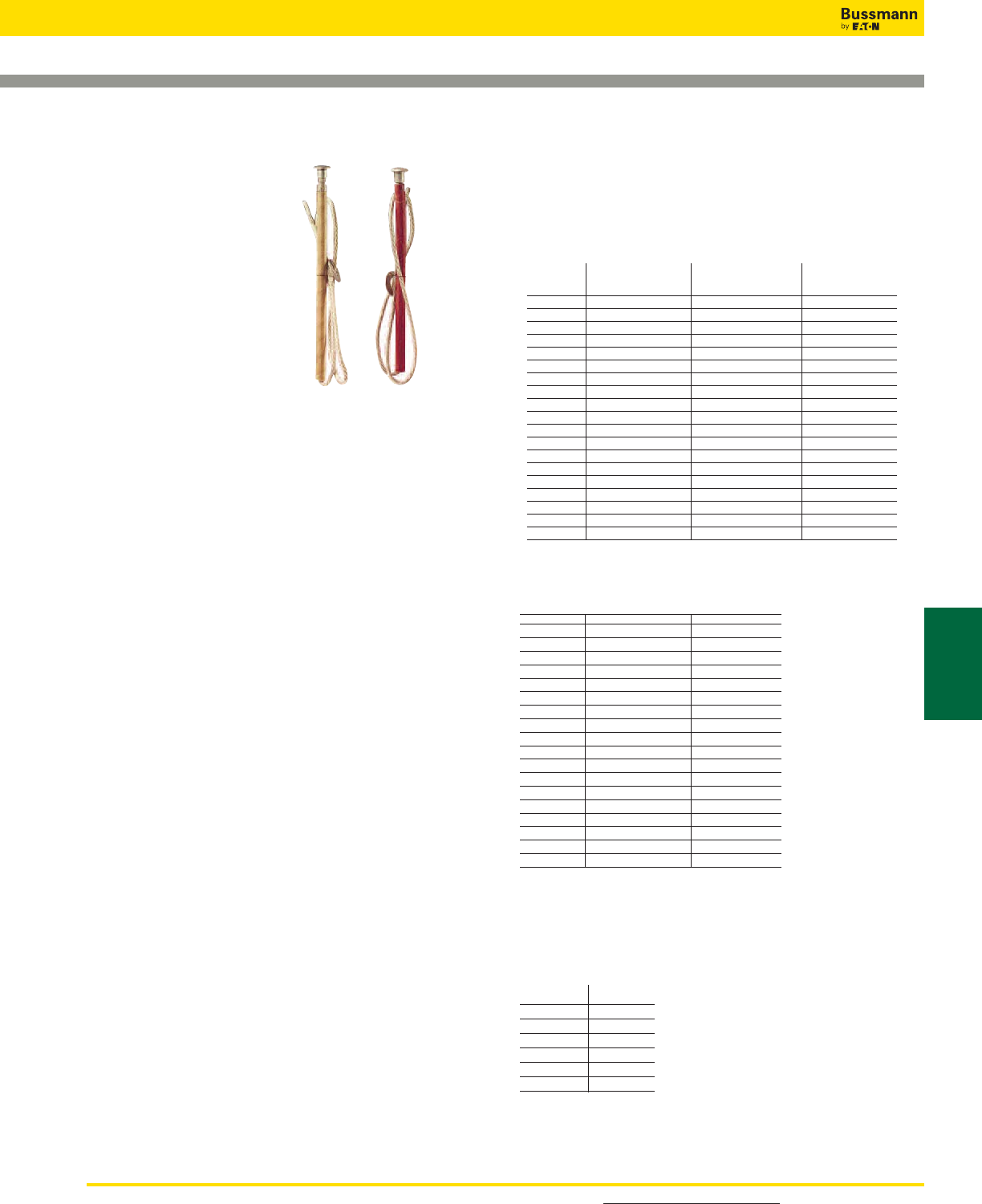
For detailed information, visit the Electrical IEC section at www.cooperbussmann.com 119
Medium Voltage
Fuses
EEI-NEMA Type K & T and Type H & N
Catalog Numbers
EEI-NEMA and High-Surge Universal Tin Element
Fuses for Cutouts — Rated to 27kV
Non-Removable Button-Head For Standard Open or Enclosed Cutouts
Catalog Numbers
Type H EEI-NEMA EEI-NEMA
(High Type K Type T
Surge) (Fast) (Slow) Amps
FL11H1 FL11K1 FL11T1 1
FL11H2 FL11K2 FL11T2 2
FL11H3 FL11K3 FL11T3 3
FL11H5 FL11K5 FL11T5 5
— FL11K6 FL11T6 6
FL11H8 FL11K8 FL11T8 8
— FL11K10 FL11T10 10
— FL11K12 FL11T12 12
— FL11K15 FL11T15 15
— FL11K20 FL11T20 20
— FL11K25 FL11T25 25
— FL11K30 FL11T30 30
— FL11K40 FL11T40 40
— FL11K50 FL11T50 50
— FL11K65 FL11T65 65
— FL11K80 FL11T80 80
— FL11K100 FL11T100 100
— FL11K140 FL11T140 140
— FL11K200 FL11T200 200
Removable Button-Head For Cutouts Requiring Removable-Button Links
Catalog Numbers
EEI-NEMA EEI-NEMA
Type K Type T
(Fast) (Slow) Amps
FL3K1 FL3T1 1
FL3K2 FL3T2 2
FL3K3 FL3T3 3
FL3K5 FL3T5 5
FL3K6 FL3T6 6
FL3K8 FL3T8 8
FL3K10 FL3T10 10
FL3K12 FL3T12 12
FL3K15 FL3T15 15
FL3K20 FL3T20 20
FL3K25 FL3T25 25
FL3K30 FL3T30 30
FL3K40 FL3T40 40
FL3K50 FL3T50 50
FL3K65 FL3T65 65
FL3K80 FL3T80 80
FL3K100 FL3T100 100
FL3K140 FL3T140 140
FL3K200 FL3T200 200
Adapter-type removable-button links with ferrule adapter to convert to double-leader
links are available in K and T types. Order by description.
EEI-NEMA Type K Universal Silver-Element Fuses
for Cutouts — Rated through 27kV
Non-Removable Button-Head For Standard Open or Enclosed Cutouts
Catalog Numbers
EEI-NEMA
Type K Amps
FL12K8 8
FL12K10 10
FL12K12 12
FL12K15 15
FL12K25 25
FL12K50 50
FL: Type H and
EEI-NEMA Type K
& T Fuses
Specifications
Description: Medium
voltage fuses: Type H
(high surge), EEI-NEMA
Type K (fast-acting),
EEI-NEMA Type T
(slow-acting).
Ratings:
Amps: — 1-200A
(See Catalog
Numbers tables)
Features and Benefits
• Wide range of EEI-NEMA type fuse links for use in open
fuse cutouts
• Voltage ratings up to 27kV.
• Can be coordinated with other overcurrent protective
devices for sectionalizing to isolate feeder branches.
Typical Applications
• Medium Voltage Fused Cutouts
High-Surge Type H Fuses
High-surge, Type H fuses are manufactured in ratings of 1, 2,
3, 5, and 8A. They have been developed principally for
primary fusing of small-sized transformers. Type H links are
manufactured in the universal buttonhead design.
Type N Fuses
Type N fuses conform to previous NEMA standards and have
been superseded by Type K and T links. Type N fuses are
manufactured in the universal button design in ratings of 5
through 200A for use in NEMA standard dimensioned cutouts
rated through 27kV.
Medium Voltage Fuses
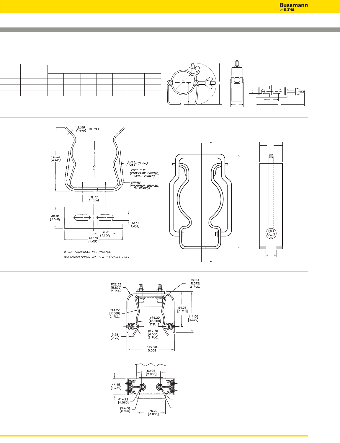
For detailed information, visit the Electrical IEC section at www.cooperbussmann.com
120
Medium Voltage Fuses
Fuseclips for Medium & High Voltage Fuses
1A0065
3˝ Diameter Clip
270303
DIN Fuseclip
C
B
A
G
E
F
D
9078A67G04
3˝ Diameter Clip
2 Cup assemblies per package.
Dimensions shown are for reference only.
Recommended Fuseclips for Medium Voltage Fuses
Fuse
Catalog Diameter - Clip Dimensions (in)
Numbers in (mm) A B C D E F G
A3354710 2 (50.8) 3.749 1.979 2.009 1.189 4.539 1.509 0.399
A3354730 3 (76) 4.139 2.449 3.009 1.189 5.639 1.509 0.399
A3354745 1.77 (45) 3.50 2.50 1.77 1.19 4.50 1.50 0.38
Fuseclips are for single barrel applications only. Are not sold in pairs.
A
A
0.43"
10.8mm
0.99"
25.0mm
4.06"
103mm
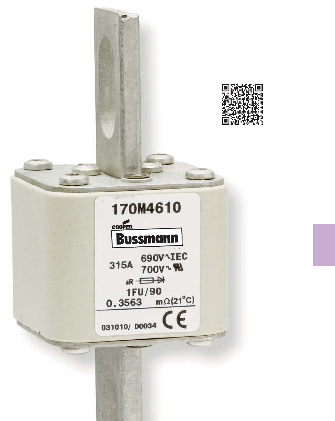
121
High Speed
Fuses
High Speed Fuses
Section Contents
Page
General Applications . . . . . . . . . . . . . . . . . . . . . . .122-123
North American fuses & accessories . . . . . . . . . . .124-141
DFJ - High speed Class J fuse . . . . . . . . . . . . . . . . . . 125
Square Body fuses & accessories . . . . . . . . . . . . 142-213
BS 88 fuses & accessories . . . . . . . . . . . . . . . . . .214-222
Ferrule fuses & accessories. . . . . . . . . . . . . . . . . .223-243
TM
Scan this tag to get the
latest product information for
High Speed Fuses.
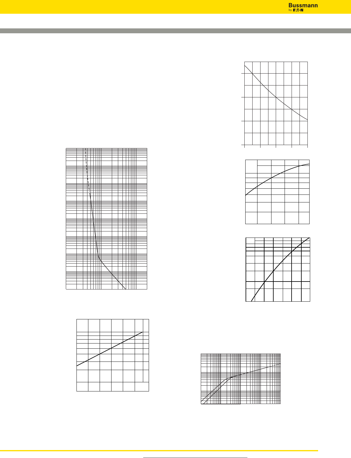
Power Factor
For other power factor
values, the total clearing
integral can be
calculated as a multiple
of the clearing integrals,
the correction factor K
and the correction factor
X.
Arc Voltage
This curve gives the
peak arc voltage, UL,
which may appear
across the fuse during its
operation as a function
of the applied working
voltage, Eg, (rms) at a
power
factor of 15%.
Power Losses
Watts loss at rated
current is given in the
electrical characteristics.
The curve allows the
calculation of the power
losses at load currents
lower than the rated
current. The correction
factor, Kp, is given as a
function of the RMS load
current, Ib, in % of the
rated current .
Cut-Off Current
A fuse operation relating to short-circuits only. When a fuse
operates in its current-limiting range, it will clear a short-
circuit in less than 1⁄2cycle. Also, it will limit the instantaneous
peak let-through current to a value substantially less than
For product data sheets, visit www.cooperbussmann.com/DatasheetsEle
122
High Speed Fuses
Prospective Current in Amps RMS
Peak Let-Through Current
10
2 ≈ 10 2
2
103
104
105
103104105106
A
B
General Applications
Rated Voltage
The AC voltage rating of Bussmann fuses is given in volts
rms. Fuses tested to IEC are tested at 5% above their rated
voltage. British Style BS 88 fuses are tested at 10% above
its rated voltage. UL recognition tests are performed at the
rated voltage.
Rated Current
Rated current is given in amps rms. Bussmann fuses can
continuously carry the rated current.
Melting Characteristic
The melting
characteristic
shows the virtual
melting time in
seconds as a
function of the
prospective current
in amps rms. The
fuses are specially
constructed for
short-circuit
protection against
high level fault
currents. Loading
and operation of
the fuse in the non-
continuous/dashed
section of the melt
curve must be
avoided. The curve
can also be read
as the real melting
time as a function
of the RMS value
of the pre-arc current.
Clearing Integrals
The total clearing I2t at
rated voltage and at
power factor of 15% are
given in the electrical
characteristics. For
other voltages, the
clearing I2t is found by
multiplying by correction
factor, K, given as a
function of applied
working voltage, Eg,
(rms).
104
103
102
10122468 2
1022468
103
2
4
6
2
6
4
100
2
6
4
101
2
6
4
2
6
4
2
6
4
6
4
2
6
2
4
Prospective Current In Amperes RMS
Virtual Pre-Arcing Time In Seconds
10–4
10–3
10–2
10–1
K
1.5
1.0
0.5
0.4
0.3
0.2
100 200 300 400 500 600 660
Eg
1.0
0.9
0.8
0.7
0.1 0.2 0.3 0.4 0.5
COS
X
UL
1.4
1.2
103
6
8
7
9
5
4
3
200 300 400 500 600 660
Eg
Kp
1.0
0.8
0.4
0.5
0.6
0.3
0.2
0.1
30 40 50 60 70 80 90 100%
Ib
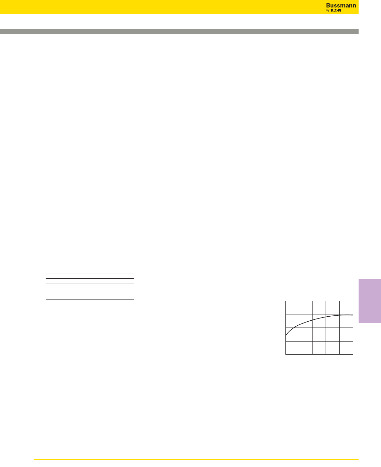
For product data sheets, visit www.cooperbussmann.com/DatasheetsEle 123
High Speed
Fuses
General Applications
that obtainable in the same circuit if that fuse were replaced
with a solid conductor of equal impedance.
A asymmetrical current
B symmetrical current
Parallel Connection
When fuses are connected in parallel it is recommended that
the applied voltage does not exceed 0.9 UN(the rated
voltage of the fuse). This is due to the fact that the energy
released within the fuses may be unevenly shared between
the parallel connected barrels.
When fuses are connected in parallel, one must take into
account that the current sharing is not necessarily equal. And
it must be checked, that the maximum load current is not
exceeded.
Series Connection
Fuses in series may not equally divide the applied voltage. It
is recommended that series connected fuses should only be
operated at fault currents that yield melting times less than
10 ms and a recovery voltage per fuse of less than or equal
to 0.9 UN(the rated voltage of the fuse).
Mounting Guidance
The recommendations below have to be followed when
mounting a Bussmann fuse with end plate threaded holes.
1. Screw in studs: 5 N•m Max, 3 N•m Min
2. Attachment of the fuse to bussbar by means of nut and
washer:
Thread Torque (N•m)*
Configuration Max Min
5⁄16” – 18, M8 25 20
3⁄8” – 16, M10 45 40
3⁄8” – 24 45 40
1⁄2” – 13, M12 65 50
1⁄2” – 20 65 50
*1 N•m = 0.7375 lb-ft
Overloads
The design of Bussmann fuses is such that they can be
operated under rather severe operating conditions imposed
by overloads (any load current in excess of the maximum
permissible load current).
In applications, there will be a maximum overload current,
Imax, which can be imposed on the fuse with a
corresponding duration and frequency of occurrence.
Time durations fall into two categories:
1. Overloads longer than one second
2. Overloads less than one second termed “impulse” loads.
The following table gives general application guidelines
which, in the expression Imax < (% factor) x It. Itis the
melting current corresponding to the time “t” of the overload
duration as read from the time-current curve of the fuse. The
guidelines in the table below determine the acceptability of
the selected fuses for a given Imax.
Frequency of Occurrence Overloads (> 1 sec) Impulse Loads (< 1 sec)
Less than once per month Imax < 80% x ItImax < 70% x It
Less than twice per week Imax < 70% x ItImax < 60% x It
Several times per day Imax < 60% x It—
When impulse loads are an intrinsic/normal parameter of the
load current either as single pulse or in trains of pulses or
when their level is higher than the melting current at 0.01
seconds (per time-current curve), contact Bussmann for
application assistance.
In addition to the parameters set forth in the preceding table,
the RMS value of the load current as calculated for any
period of 10 minutes or more should not exceed the
maximum permissible load current.
Furthermore, it is important that a fuse should not be applied
in the non-continuous/dashed portion of the associated
time-current curve.
Any time-current combination point which falls in the
non-continuous/dashed portion of the time-current curve is
beyond the capability of the fuse to operate properly.
DC Operation
Depending upon the short-circuit time constant and the
magnitude of the prospective short-circuit current, the dc
voltage at which a fuse can be applied may be less than its
ac rating. Long time constants require a lower dc voltage.
Conversely, however, higher available prospective short-
circuit currents result in faster fuse openings and thus permit
a fuse to be operated at a higher DC voltage.
Consult Bussmann for
additional information and
application assistance
when fuses have to
operate under DC
conditions.
Load Current Versus
Conductor Cross
Section
Reduction of permissible
load current when the conductor cross section is less than
that given in IEC Publication 269-1 & 4 valid for Bussmann
high speed fuses.
Application Assistance
If you have application problems or need a fuse outside our
standard program, please contact the nearest Bussmann
representative. Phone numbers are shown on the back
cover.
1.0
0.9
0.8
0.5 0.6 0.7 0.8 0.9 1.0
≈ (IEC cross section)
Reduction Factor
High Speed Fuses
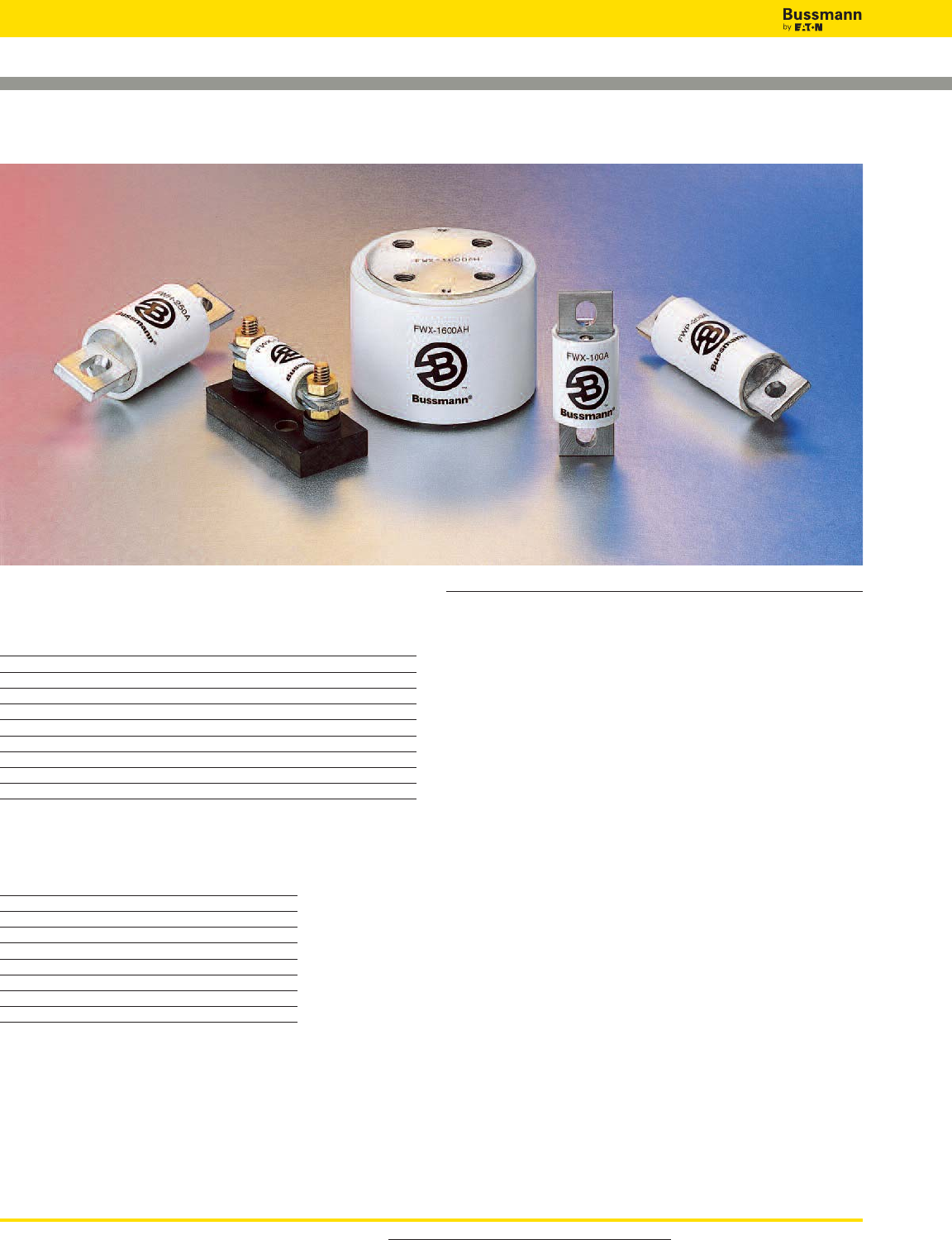
Introduction
North American Contents
Catalog Amp
Number Volts Range Page
DFJ 600 1-600 125
FWA 130 1000-4000 126-127
FWA 150 70-1000 128-129
FWX 250 35-2500 130-131
FWH 500 35-1600 132-133
KAC 600 1-1000 134
KBC 600 35-800 135
FWP 700 5-1200 136-138
FWJ 1000 35-2000 139-140
Accessories
Fuse Bases 141
North American Fuse Ranges
Amps Volts AC DC
1000-4000 130 X X
70-1000 150 X X
35-2500 250 X X
35-1600 500 X X
1-1000 600 X —
5-1200 700 X X
40-600 800 — X
35-2000 1000 X —
For product data sheets, visit www.cooperbussmann.com/DatasheetsEle
124
High Speed Fuses
North American Fuses
General Information
Bussmann offers a complete range of North American blade
and flush-end style fuses and accessories. Their design and
construction were optimized to provide:
• Low energy let-through (I2t)
• Low watts loss
• Superior cycling capability
• Low arc voltage
• Excellent DC performance
North American style fuses provide an excellent solution for
medium power applications. While there are currently no
published standards for these fuses, the industry has
standardized on mounting centers that accept Bussmann
fuses.
Voltage Rating
All Bussmann North American style fuses are tested at their
rated voltage. Bussmann should be consulted for applications
exceeding those values.
Accessories
External and internal open fuse indication is available for
selected portions of the North American line. Fuse blocks are
available for most applications.
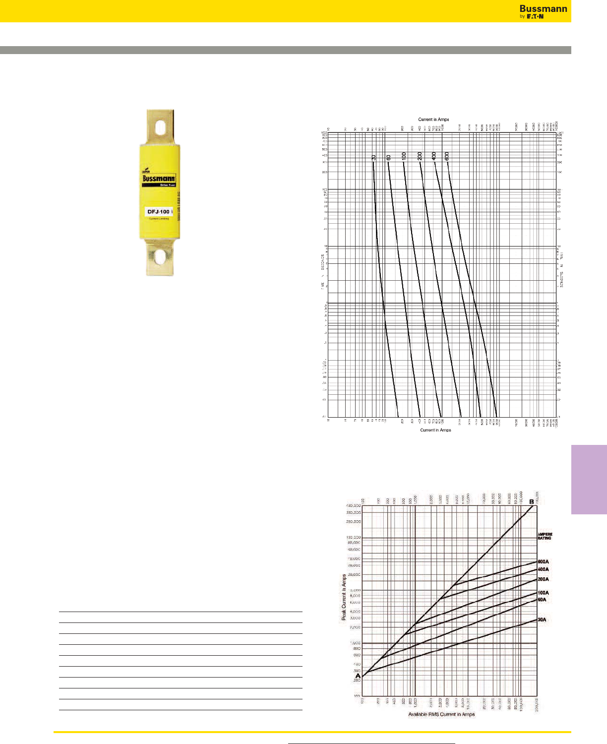
For product data sheets, visit www.cooperbussmann.com/datasheetsele 125
High Speed
Fuses
High Speed Fuses
Specifications
Description: High speed, current-limiting fuse. The
Bussmann Drive Fuse will provide maximum protection for
AC and DC drives and controllers and meet NEC®branch
circuit protection requirements. The Drive Fuse has the
lowest I2t of any branch circuit fuse to protect power
semiconductor devices that utilize diodes, GTOs, SCRs and
SSRs.
Dimensions: See page 21 for Class J dimensions.
Construction: Melamine tube with silver fuse element.
Ratings:
Volts — 600Vac (or less), 450Vdc (or less)
Amps — 1-600A
IR — 200kA RMS Sym., 100kA DC
Agency Information: CE, Std. 248-8, Class J, UL Listed,
Guide JDDZ, File E4273, CSA Certified, Class 1422-02, File
53787.
Features and Benefits
• Easily coordinated with existing and new variable speed
drives and electric controllers.
• Standard Class J dimensions allowing the use of readily
available fuse blocks, holders, and switches.
• Allows the lowest let-thru energy of any branch circuit
overcurrent protective device.
Typical Applications
• Protection of AC and DC drives
• Equipment using power semiconductor devices
Catalog Numbers (Amps)
DFJ-1 DFJ-15 DFJ-70 DFJ-225
DFJ-2 DFJ-20 DFJ-80 DFJ-250
DFJ-3 DFJ-25 DFJ-90 DFJ-300
DFJ-4 DFJ-30 DFJ-100 DFJ-350
DFJ-5 DFJ-35 DFJ-110 DFJ-400
DFJ-6 DFJ-40 DFJ-125 DFJ-450
DFJ-8 DFJ-45 DFJ-150 DFJ-500
DFJ-10 DFJ-50 DFJ-175 DFJ-600
DFJ-12 DFJ-60 DFJ-200
Data Sheet: 1048
DFJ Class J
Drive Fuse High Speed Fuses
Time-Current Characteristic Curves—Average Melt
Current Limitation Curves
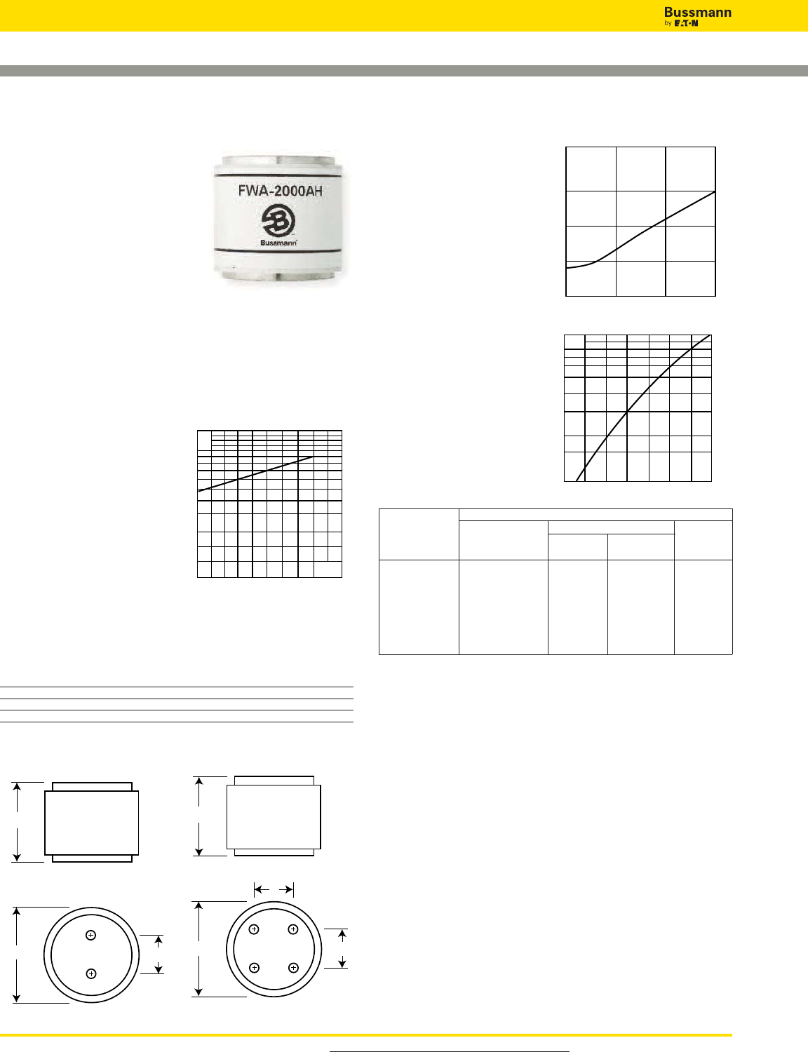
For product data sheets, visit www.cooperbussmann.com/DatasheetsEle
126
High Speed Fuses
Dimensions - in
Catalog Number Fig. B C D Thread Depth
FWA-1000AH-2000AH 1 2.0 1.0 — Tapped 3⁄8”-24 x 1⁄2”
FWA-2500AH-3000AH 1 3.0 1.5 — Tapped 1⁄2”-20 x 1⁄2”
FWA-4000AH 2 3.5 1.5 1.5 Tapped 1⁄2”-20 x 1⁄2”
1mm = 0.0394˝ / 1˝ = 25.4mm
Fig. 1: 1000-3000A Fig. 2: 4000A
1.875
BC
1.875
C
B
D
Arc Voltage
This curve gives the peak
arc voltage, UL, which
may appear across the
fuse during its operation
as a function of the
applied working voltage,
Eg, (rms) at a power
factor of 15%.
Power Losses
Watts loss at rated current
is given in the electrical
characteristics. The curve
allows the calculation of
the power losses at load
currents lower than the
rated current. The
correction factor, Kp, is
given as a function of the
RMS load current, Ib, in %
of the rated current.
Catalog Numbers Electrical Characteristics
I2t (A2Sec)
Catalog Rated Current Clearing Watts
Numbers RMS-Amps Pre-arc at 130V Loss
FWA-1000AH 1000 170000 460000 60
FWA-1200AH 1200 270000 730000 70
FWA-1500AH 1500 520000 1400000 78
FWA-2000AH 2000 860000 2400000 108
FWA-2500AH 2500 1500000 4100000 130
FWA-3000AH 3000 2100000 5700000 150
FWA-4000AH 4000 3400000 9200000 257
• Watts loss provided at rated current.
• See accessories on page 141.
Features and Benefits
• Excellent DC performance
• Low arc voltage and low energy let-through (I2t)
• Low watts loss
• Superior cycling capability
Typical Applications
• DC Common bus
• DC Drives
• Power converters/rectifiers
• Reduced voltage starters
North American — FWA 130V: 1000-4000A
FWA
Specifications
Description: North American
style flush-end high speed fuses.
Dimensions: See Dimensions
illustrations.
Ratings:
Volts: — 130Vac
Amps: — 1000-4000A
IR: — 200kA RMS Sym.
— 50kA @130Vdc
Agency Information: CE, UL Recognized JFHR2.E91958
on 1000-2000A fuses
Electrical Characteristics
Total Clearing I2t
The total clearing I2t at
rated voltage and at power
factor of 15% are given in
the electrical
characteristics. For other
voltages, the clearing I2t is
found by multiplying by
correction factor, K, given
as a function of applied
working voltage, Eg, (rms). 1301046526
1.5
1.0
0.5
0.3
0.2
0.15 Eg
K
UL
Eg
200
100
100 15050
300
Kp
1.0
0.8
0.4
0.5
0.6
0.3
0.2
0.1
30 40 50 60 70 80 90 100%
Ib
Data Sheet: 720001
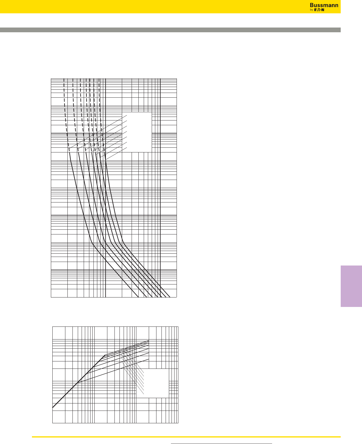
For product data sheets, visit www.cooperbussmann.com/DatasheetsEle 127
High Speed
Fuses
North American — FWA 130V: 1000-4000A
FWA 1000-4000A: 130V
Time-Current Curve
10322468 2
1042468
105
Prospective Current In Amps RMS
2
4
6
2
6
4
100
2
6
4
101
2
6
4
2
6
4
2
6
4
Virtual Pre-Arcing Time In Seconds
6
4
2
6
2
4
10–1
10–2
10–3
10–4
102
103
104
FWA-4000AH
FWA-3000AH
FWA-2500AH
FWA-2000AH
FWA-1500AH
FWA-1200AH
FWA-1000AH
FWA-4000AH
FWA-3000AH
FWA-2500AH
FWA-2000AH
FWA-1500AH
FWA-1200AH
FWA-1000AH
Prospective Short-Circuit Current Symmetrical RMS
Peak Let-Through Current
2
6
4
2
6
4
2
246 246 246
104105
103
104
105
103
Peak Let-Through Curve
Data Sheet: 35785301
High Speed Fuses
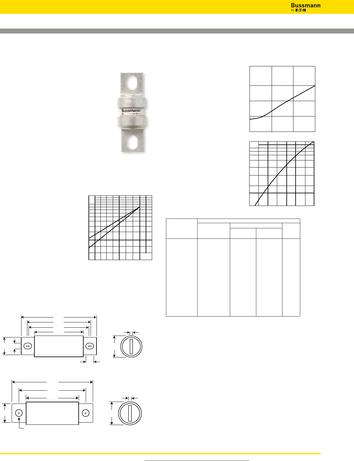
For product data sheets, visit www.cooperbussmann.com/DatasheetsEle
128
High Speed Fuses
2.656
1.936
2.188
1.156
0.312
0.438
0
.750 1.000
0.125
Dimensions - in
Fig. 1: 70-400A
1.500
0.250
3.500
2.438
1.250
1
.000
0.406
Fig. 2: 500-1000A
1mm = 0.0394” / 1” = 25.4mm
North American — FWA 150V: 70-1000A
FWA
Specifications
Description: North American style
stud-mount fuses.
Dimensions: See Dimensions
illustrations.
Ratings:
Volts:— 150Vac/dc*
Amps:— 70-1000A
IR:— 100kA Sym. (70-400A)
— 200kA Sym. (450-1000A)
— 20kA @150Vdc (70-800A)
— 100kA @ 80Vdc (70-1000A)
*1000A rated @ 80Vdc.
Agency Information: CE, UL Recognized JFHR2.E91958
Electrical Characteristics
Total Clearing I2t
The total clearing I2t at rated
voltage and at power factor
of 15% are given in the
electrical characteristics. For
other voltages, the clearing
I2t is found by multiplying by
correction factor, K, given as
a function of applied working
voltage, Eg, (rms).
Arc Voltage
This curve gives the peak
arc voltage, UL, which may
appear across the fuse
during its operation as a
function of the applied
working voltage, Eg, (rms)
at a power factor of 15%.
Power Losses
Watts loss at rated current
is given in the electrical
characteristics. The curve
allows the calculation of
the power losses at load
currents lower than the
rated current. The
correction factor, Kp, is
given as a function of the
RMS load current, Ib, in %
of the rated current.
Catalog Numbers Electrical Characteristics
Rated I2t (A2Sec)
Catalog Current Clearing Watts
Number RMS-Amps Pre-arc at 150V Loss
FWA-70B 70 470 4000 6.9
FWA-80B 80 670 6000 7.7
FWA-100B 100 1200 12000 9.0
FWA-125B 125 1870 18000 11.2
FWA-150B 150 2700 26000 13.5
FWA-200B 200 4780 45000 17.6
FWA-250B 250 7470 70000 22.5
FWA-300B 300 10760 100000 27.0
FWA-350B 350 15700 140000 30.6
FWA-400B 400 20300 180000 35.2
FWA-500A 500 39000 120000 35.0
FWA-600A 600 46000 140000 47.0
FWA-700A 700 75000 220000 49.0
FWA-800A 800 92000 280000 58.0
FWA-1000A 1000 170000 510000 60.0
• Watts loss provided at rated current.
• See accessories on page 141.
Features and Benefits
• Excellent DC performance
• Low arc voltage and low energy let-through (I2t)
• Low watts loss
• Superior cycling capability
Typical Applications
• DC Common bus
• DC Drives
• Power converters/rectifiers
• Reduced voltage starters
1501027022
1.5
1.0
0.5
0.3
0.2
0.15 Eg
K
1)
2)
Kp
1.0
0.8
0.4
0.5
0.6
0.3
0.2
0.1
30 40 50 60 70 80 90 100%
Ib
UL
Eg
200
100
100 15050
300
1) 500-1000A Range
2) 70-400A Range
Data Sheet: 720002
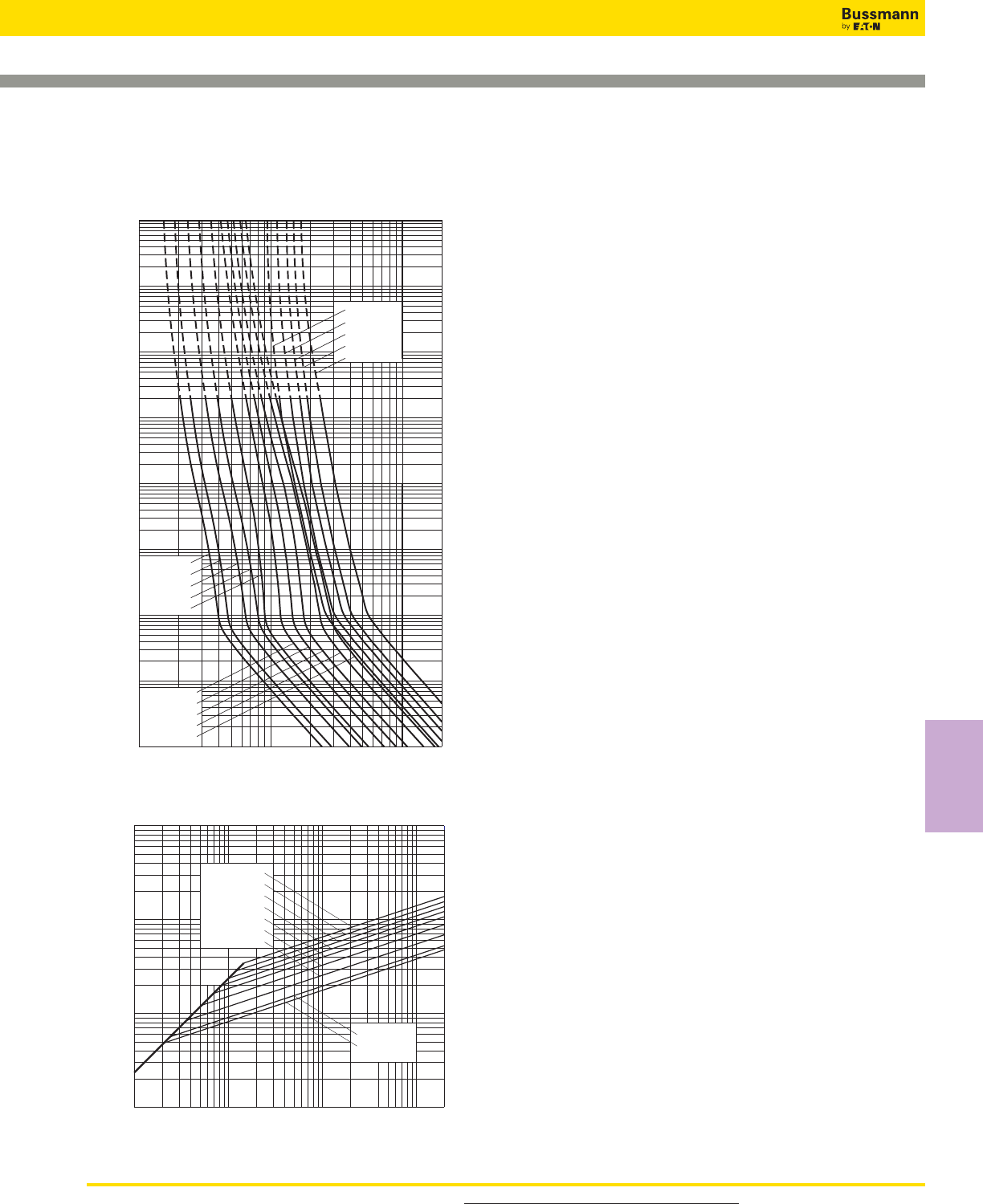
For product data sheets, visit www.cooperbussmann.com/DatasheetsEle 129
High Speed
Fuses
North American — FWA 150V: 70-1000A
Prospective Current In Amps RMS
Virtual Pre-Arcing Time In Seconds
1022468
1032468
104
2
4
6
2
6
4
100
2
6
4
101
2
6
4
2
6
4
2
6
4
6
4
2
6
2
4
10–1
10–2
10–3
10–4
102
103
104
FWA-1000A
FWA-800A
FWA-700A
FWA-600A
FWA-500A
FWA-200A
FWA-400A
FWA-350A
FWA-300A
FWA-250A
FWA-150A
FWA-70A
FWA-80A
FWA-100A
FWA-125A
FWA 70-1000A: 150V
Time-Current Curve
Prospective Short-Circuit Current Symmetrical RMS
Peak Let-Through Current
2
6
4
2
6
4
2
6
4
246 246 246
102
103
104
106
102103104105
2
FWA-400A
FWA-350A
FWA-300A
FWA-250A
FWA-200A
FWA-150A
FWA-100A
FWA-80A
FWA-70A
Peak Let-Through Curve
Data Sheet: 35785310
High Speed Fuses
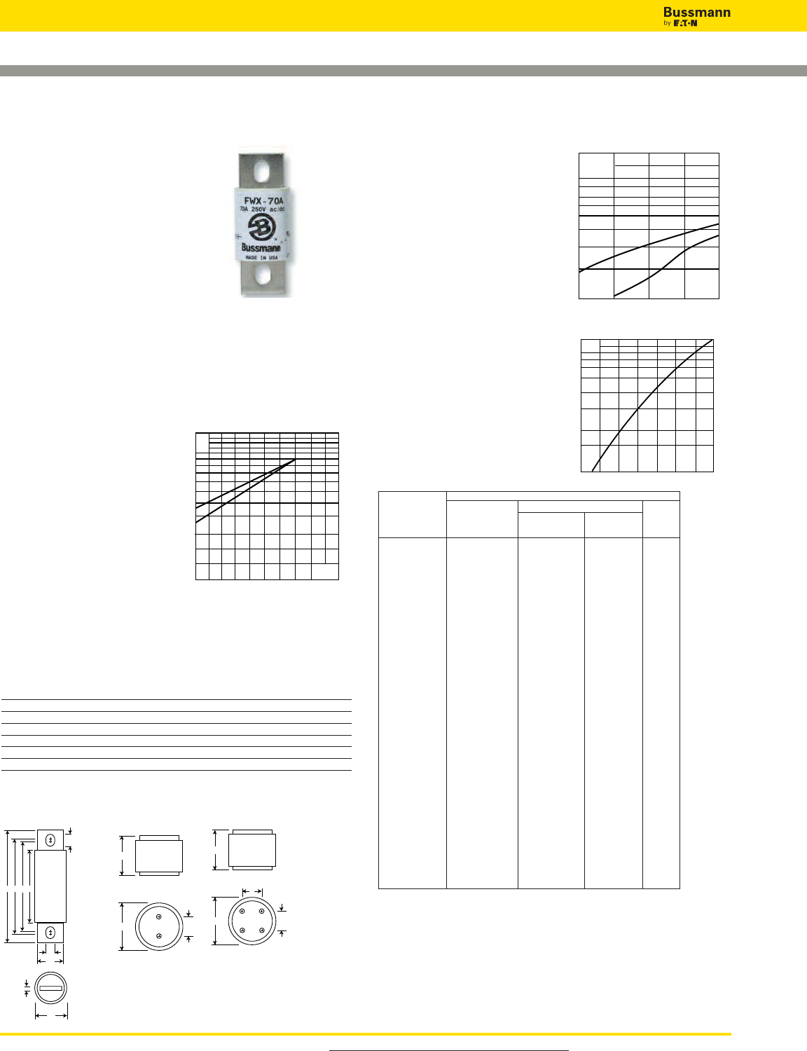
For product data sheets, visit www.cooperbussmann.com/DatasheetsEle
130
High Speed Fuses
North American — FWX 250V: 35-2500A
FWX
Specifications
Description: North American
style stud-mount and flush-end
fuses.
Dimensions: See Dimensions
illustrations.
Ratings:
Volts:— 250Vac/dc
Amps:— 35-2500A
IR:— 200kA RMS Sym.
50kA@250Vdc (35-800A)
Agency Information: CE, UL Recognized JFHR2.E56412
& CSA Component Acceptance file Class 1422-30, (53787)
on 35-800A fuses (50kA IR @250Vdc).
Electrical
Characteristics
Total Clearing I2t
The total clearing I2t at rated
voltage and at power factor
of 15% are given in the
electrical characteristics.
For other voltages, the
clearing I2t is found by
multiplying by correction
factor, K, given as a
function of applied working
voltage, Eg, (rms).
Arc Voltage
This curve gives the peak
arc voltage, UL, which may
appear across the fuse
during its operation as a
function of the applied
working voltage, Eg, (rms)
at a power factor of 15%.
Power Losses
Watts loss at rated current is
given in the electrical char
acteristics. The curve allows
the calculation of the power
losses at load currents lower
than the rated current. The
correction factor, Kp, is
given as a function of the
RMS load current, Ib, in %
of the rated current .
Catalog Numbers Electrical Characteristics
Rated I2t (A2Sec)
Catalog Current Clearing Watts
Number RMS-Amps Pre-arc at 250V Loss
FWX-35A 35 50 230 4.2
FWX-40A 40 60 310 5.2
FWX-45A 45 80 390 5.7
FWX-50A 50 100 520 6.0
FWX-60A 60 140 740 8.1
FWX-70A 70 330 1400 7.2
FWX-80A 80 430 1850 8.1
FWX-90A 90 570 2450 9.0
FWX-100A 100 740 3150 10.0
FWX-125A 125 1130 4850 12.5
FWX-150A 150 1620 6950 15.7
FWX-175A 175 2170 9300 18.5
FWX-200A 200 2790 12000 22
FWX-225A 225 3210 14700 24
FWX-250A 250 3960 18100 27
FWX-275A 275 4720 21600 31
FWX-300A 300 6000 27300 32
FWX-350A 350 10600 48600 39
FWX-400A 400 14500 66100 44
FWX-450A 450 22100 101000 49
FWX-500A 500 28000 128000 54
FWX-600A 600 41100 188000 62
FWX-700A 700 48800 190000 72
FWX-800A 800 59000 230000 84
FWX-1000AH 1000 44000 360000 100
FWX-1200AH 1200 92000 750000 103
FWX-1500AH 1500 120000 880000 140
FWX-1600AH 1600 160000 1200000 140
FWX-2000AH 2000 320000 2300000 151
FWX-2500AH 2500 670000 4700000 163
• Watts loss provided at rated current. • See accessories on page 141.
Features and Benefits
• Excellent DC performance
• Low arc voltage and low
energy let-through (I2t)
• Superior cycling capability
Kp
1.0
0.8
0.4
0.5
0.6
0.3
0.2
0.1
30 40 50 60 70 80 90 100%
Ib
1.5
1.0
0.5
0.3
0.2
0.15
75 125 300200 250
Eg
K
1)
2)
UL
1.4
1.2
103
800
600
500
400
300
200
50 100 150 200 250
Eg
1)
2)
1) 35-800A Range
2) 1000-2500A Range
1) 35-800A Range
2) 1000-2500A Range
AEDC
F
J
G
B
H
A
BC
A
BC
D
Fig. 1:
35-800A
Fig. 2:
1000-1200A
Fig. 3:
1500-2500A
Dimensions - in Tapped
Amp Thread
Range Fig. A B C D E F G H J Depth
35-60 1 3.19 0.81 1.59 2.59 2.25 0.34 0.63 0.13 0.52 —
70-200 1 3.13 1.22 1.59 2.44 2.19 0.34 1.00 0.19 0.47 —
225-600 1 3.84 1.50 1.59 2.94 2.25 0.41 1.00 0.25 0.75 —
700-800 1 3.84 2.00 1.59 3.03 2.28 0.41 1.50 0.25 0.78 —
1000-1200 2 2.59 3.00 1.50 — — — — — — 3⁄8”-24 x 1⁄2”
1500-2500 3 2.59 3.50 1.50 1.50 — — — — — 3⁄8”--24 x 1⁄2”
1mm = 0.0394” / 1” = 25.4mm
Typical Applications
• DC Common bus
• DC Drives
• Power converters/rectifiers
• Reduced voltage starters
Data Sheet: 720005
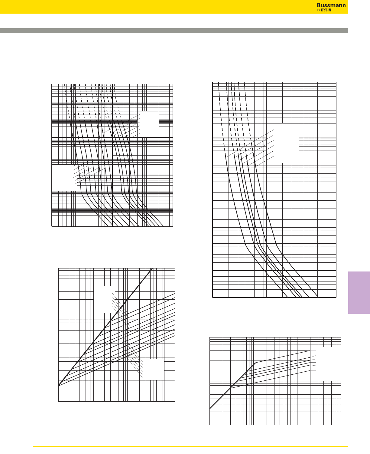
For product data sheets, visit www.cooperbussmann.com/DatasheetsEle 131
High Speed
Fuses
North American — FWX 250V: 35-2500A
104
103
102
102103104
101
100
10–1
10–2
10–3
10–4
2
Prospective Current In Amps RMS
Virtual Pre-arcing Time In Seconds
FWX-800A
FWX-600A
FWX-500A
FXW-400A
FWX-350A
FWX-200A
FWX-150A
FWX-70A
FWX-60A
FWX-40A
FWX-35A
FWX-100A
10322468 2
1042468
105
2
4
6
2
6
4
100
2
6
4
2
6
4
2
6
4
2
6
4
6
4
2
6
2
4
10–1
10–2
10–3
10–4
102
101
103
104
FWX-2500AH
FWX-2000AH
FWX-1600AH
FWX-1500AH
FWX-1200AH
FWX-1000AH
Prospective Current In Amps RMS
Virtual Pre-Arcing Time In Seconds
FWX 1000-2500A(H): 250V
Time-Current Curve
FWX 35-800A: 250V
Time-Current Curve
FWX-150A
FWX-100A
FWX-70A
FWX-60A
FWX-45A
FWX-35A
FWX-200A
FWX-300A
FWX-400A
FWX-600A
FWX-800A
102103104105
102
103
104
105
Prospective Short-Circuit Current Symmetrical RMS
Peak Let-Through Current
A
B
Prospective Short-Circuit Current Symmetrical RMS
Peak Let-Through Current
2
6
4
2
6
4
246 246 246
103
104
105
FWX-2000AH
FWX-1600AH
FWX-1500AH
FWX-1200AH
FWX-1000AH
103104105
FWX-2500AH
Peak Let-Through Curve
Peak Let-Through Curve
Data Sheet: 359 Data Sheet: 35785299
High Speed Fuses
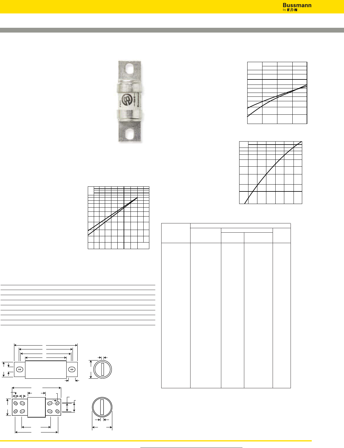
For product data sheets, visit www.cooperbussmann.com/DatasheetsEle
132
High Speed Fuses
North American — FWH 500V: 35-1600A
FWH
Specifications
Description: North American style
stud-mount fuses.
Dimensions: See Dimensions
illustration.
Ratings:
Volts: — 500Vac/dc (35-800A only)
Amps: — 35-1600A
IR: — 200kA Sym.
— 50kA @ 500Vdc (35-800A)
Agency Information: CE, UL Recognition JFHR2.E91958
FWH-_B (35-200A, 1000-1200A), JFHR2.E56412
FWH-_A (225-600A), CSA Component Acceptance Class
1422-30, File 53787 (35-1600A).
Electrical Characteristics
Total Clearing I2t
The total clearing I2t at rated
voltage and at power factor of
15% are given in the electrical
characteristics. For other
voltages, the clearing I2t is
found by multiplying by
correction factor, K, given as a
function of applied working
voltage, Eg, (rms).
Arc Voltage
This curve gives the peak
arc voltage, UL, which
may appear across the
fuse during its operation
as a function of theapplied
working voltage, Eg, (rms)
at a power
factor of 15%.
Power Losses
Watts loss at rated
current is given in the
electrical characteristics.
The curve allows the
calculation of the power
losses at load currents
lower than the rated
current. The correction
factor, Kp, is given as a
function of the RMS load
current, Ib, in % of the
rated current.
Catalog Numbers Electrical Characteristics
Rated I2t (A2Sec)
Catalog Current Clearing Watts
Numbers RMS-Amps Pre-arc at 500V Loss
FWH-35B 35 34 150 8
FWH-40B 40 76 320 7.5
FWH-45B 45 105 450 7.5
FWH-50B 50 135 670 7.5
FWH-60B 60 210 900 9.9
FWH-70B 70 210 900 10.6
FWH-80B 80 305 1400 12.7
FWH-90B 90 360 1600 15
FWH-100B 100 475 2000 17
FWH-125B 125 800 3500 25
FWH-150B 150 1100 4600 30
FWH-175B 175 1450 6200 35
FWH-200B 200 1900 8500 40
FWH-225A 225 4600 23300 39
FWH-250A 250 6300 32200 41
FWH-275A 275 7900 40300 46
FWH-300A 300 9800 49800 51
FWH-325A 325 13700 63800 53
FWH-350A 350 14500 72900 58
FWH-400A 400 19200 96700 65
FWH-450A 450 24700 127000 74
FWH-500A 500 29200 149000 84
FWH-600A 600 41300 206000 108
FWH-700A 700 55000 298000 120
FWH-800A 800 76200 409000 129
FWH-1000A 1000 92000 450000 145
FWH-1200A 1200 122000 600000 180
FWH-1400A 1400 200000 1000000 210
FWH-1600A 1600 290000 1400000 230
• Watts loss provided at rated current. • See accessories on page 141.
Features and Benefits
• Excellent DC performance
• Low arc voltage and low
energy let-through (I2t)
• Superior cycling capability
500400250100
1.5
1.0
0.5
0.3
0.2
0.15 Eg
K
1)
2)
UL
2.0
1.6
1.2
103
800
600
500
400
300
100 400300200 500
Eg
1
2)
1)
1) 35-200 & 1000-1600A Range
2) 225-800A Range
A
E
D
C
F
J
GB
H
10.219
3.219 0.625
4.25
0.75
3.5
6.219
0.125 0.5
1.625
1.750
8.969
Fig. 1: 35-1200A
Fig. 2: 1400-1600A
Dimensions - in
Amp
Range Fig. A B C D E F G H J
35-60 1 3.188 0.813 1.593 2.541 2.193 0.344 0.719 0.125 0.518
70-100 1 3.625 0.947 1.736 2.853 2.807 0.352 0.750 0.125 0.375
125-200 1 3.625 1.156 1.836 2.892 2.768 0.344 1.000 0.188 0.406
225-400 1 4.340 1.500 2.090 3.440 2.750 0.410 1.000 0.250 0.750
450-600 1 4.340 2.000 2.090 3.530 2.780 0.410 1.500 0.250 0.780
700-800 1 6.340 2.500 2.090 4.970 3.440 0.530 2.000 0.380 1.300
1000-1200 1 6.969 3.000 3.219 5.465 4.475 0.625 2.375 0.438 1.120
1400-1600 2 See Drawing
1mm = 0.0394” / 1” = 25.4mm
Kp
1.0
0.8
0.4
0.5
0.6
0.3
0.2
0.1
30 40 50 60 70 80 90 100%
Ib
1) 35-800A Range
2) 1000-1600A Range
Typical Applications
• DC Common bus
• DC Drives
• Power converters/rectifiers
• Reduced voltage starters
Data Sheet: 720007
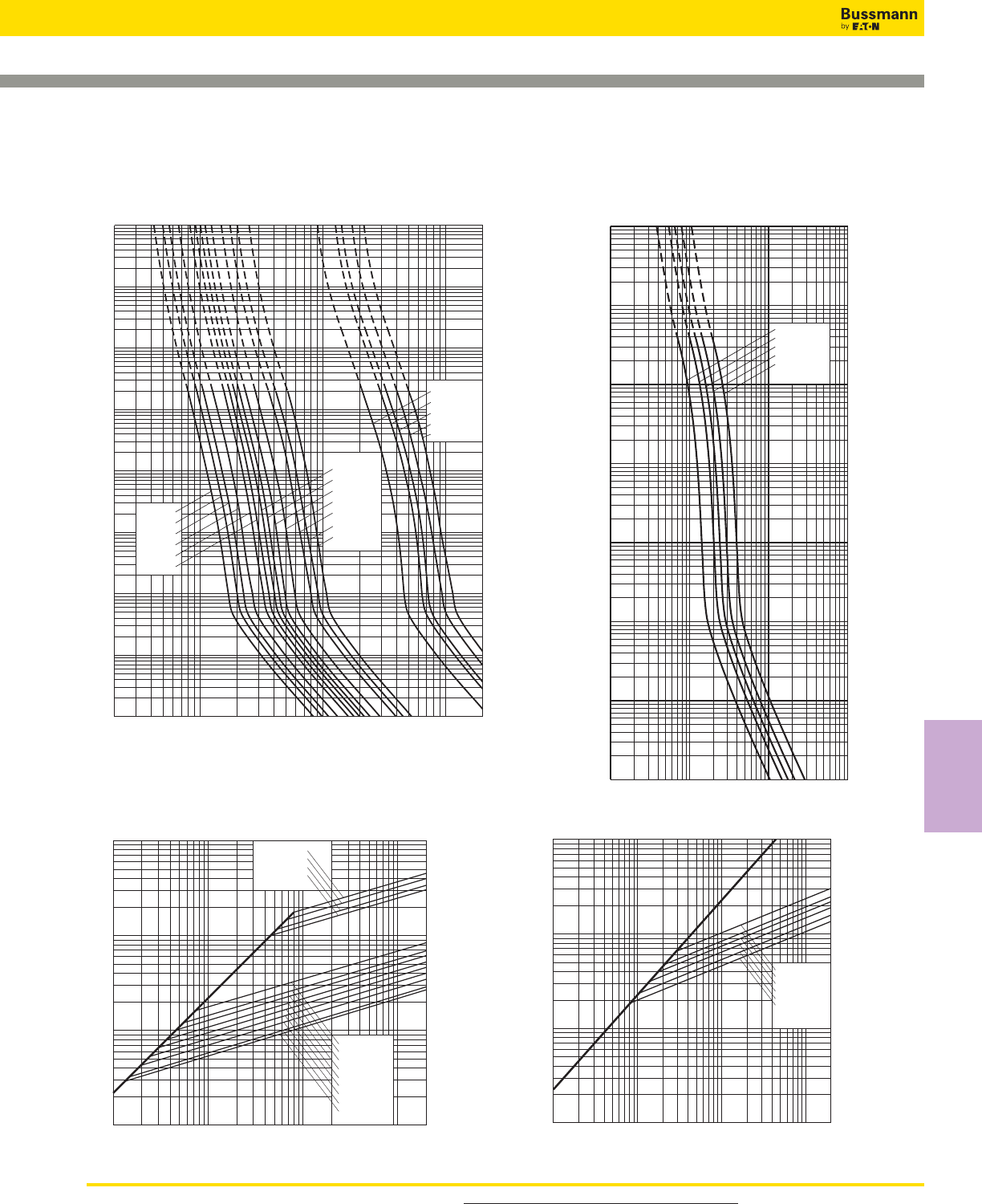
For product data sheets, visit www.cooperbussmann.com/DatasheetsEle 133
High Speed
Fuses
North American — FWH 500V: 35-1600A
2468
10222468 2
1032468
104
2
4
6
2
6
4
2
6
4
2
6
4
2
6
4
2
6
4
6
4
2
6
2
4
100
101
10–1
10–2
10–3
10–4
102
103
104
FWH-90B
FWH-80B
FWH-125B
FWH-100B
FWH-175B
FWH-200B
FWH-150B
FWH-60B
FWH-70B
FWH-50B
FWH-45B
FWH-40B
FWH-35B
FWH-1200A
FWH-1400A
FWH-900A
FWH-1000A
FWH-1600A
Prospective Current In Amps RMS
10–3
10–2
10–1
100
101
102
103
10–4
FWH-300A
FWH-400A
FWH-500A
FWH-600A
FWH-800A
Prospective Current In Amps RMS
Virtual Pre-Arcing Time In Seconds
102103104105
FWH 250-800A: 500V
Time-Current Curve
FWH 35-200A(B) & 900-1600A(A): 500V
Time-Current Curve
FWH-200B
FWH-150B
FWH-125B
FWH-100B
FWH-80B
FWH-60B
FWH-50B
FWH-35B
FWH-40B
FWH-1000A
FWH-1200A
FWH-1400A
FWH-1600A
Prospective Short-Circuit Current Symmetrical RMS
Peak Let-Through Current
2
4
2
6
6
4
2
6
4
2462462462
102
103
104
105
102103104105
FWH-800A
FWH-600A
FWH-500A
FWH-400A
FWH-300A
FWH-250A
102
105
104
103
103104105
102
Prospective Short-Circuit Current Symmetrical RMS
Peak Let-Through Current
A
B
Peak Let-Through Curve
Peak Let-Through Curve
Data Sheet: 35785304 Data Sheet: 360
High Speed Fuses
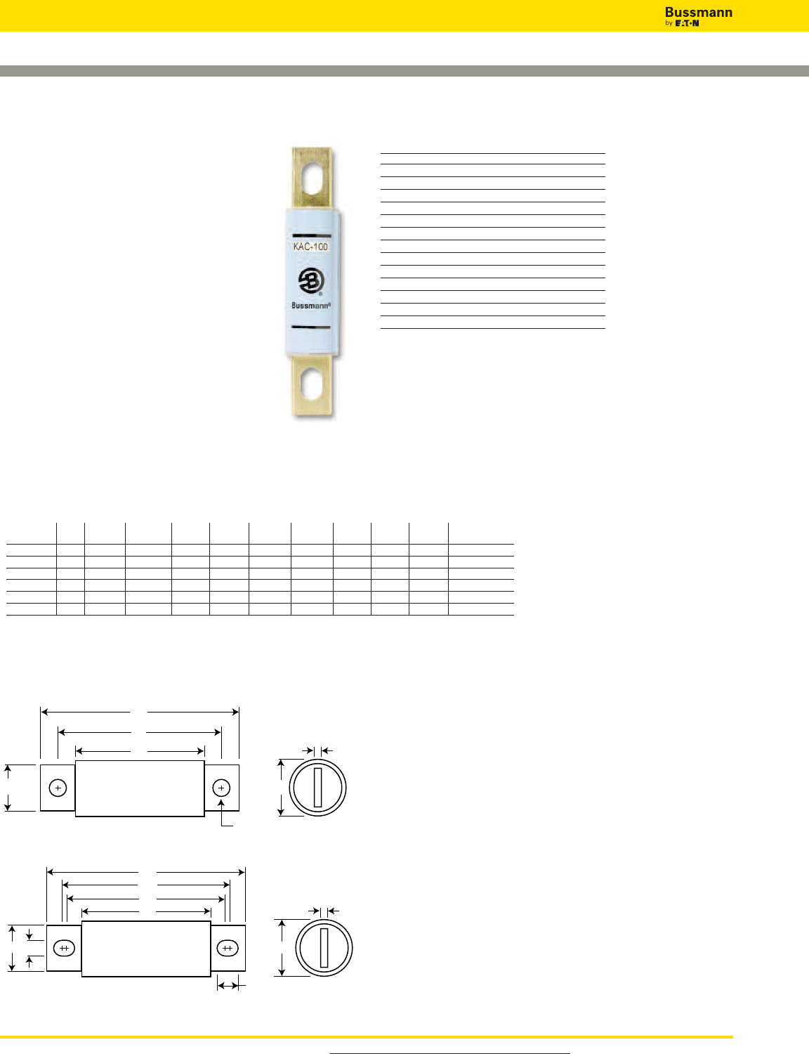
For product data sheets, visit www.cooperbussmann.com/DatasheetsEle
134
High Speed Fuses
North American — KAC 600V: 1-1000A
F
G
A
C
B1
H
D
Fig. 1: 1-30 & 450-1000A
A
B3
B2
C
E
DF
H
G
Fig. 2: 35-400A
Dimensions - in
KAC
Specifications
Description: North American style
stud-mount fuses. These 600V fuses are
supplied as replacements only. For new
installations, Bussmann recommends the
700V FWP Series fuse.
Dimensions: See Dimensions illustrations.
Ratings:
Volts:— 600Vac
Amps:— 1-1000A
IR:— 200kA RMS Sym.
Agency Information: CE, UL Recognition
JFHR2.E56413 on 1-600A only.
Catalog Numbers (Amps)
KAC-1 KAC-25 KAC-175
KAC-2 KAC-30 KAC-200
KAC-3 KAC-35 KAC-225
KAC-4 KAC-40 KAC-250
KAC-5 KAC-45 KAC-300
KAC-6 KAC-50 KAC-350
KAC-7 KAC-60 KAC-400
KAC-8 KAC-70 KAC-450
KAC-9 KAC-80 KAC-500
KAC-10 KAC-90 KAC-600
KAC-12 KAC-100 KAC-700
KAC-15 KAC-110 KAC-800
KAC-17.5 KAC-125 KAC-1000
KAC-20 KAC-150
• See accessories on page 141.
Features and Benefits
• Low arc voltage and low energy let-through (I2t)
• Low watts loss
• Superior cycling capability
Typical Applications
• Power converters/rectifiers
• Reduced voltage starters
Data Sheet: 720009
Amp
Range Fig. A B1 B2 B3 C D E F G H
1-30A 1 2.875 2.500 – – 1.875 0.406 – 0.563 0.063 0.257
35-60A 2 4.375 – 3.750 3.500 2.750 0.625 0.343 0.813 0.094 0.468
70-100A 2 5.000 – 4.063 3.656 2.750 0.750 0.406 1.000 0.125 0.609
110-200A 2 5.140 – 4.390 3.766 2.906 1.000 0.406 1.500 0.188 0.718
225-400A 2 6.182 – 4.815 4.565 3.000 1.625 0.562 2.000 0.250 0.687
450-800A 1 6.250 4.750 – – 3.063 2.000 – 2.500 0.250 0.563
1000A 1 7.250 4.750 – – 3.063 2.750 – 3.500 0.375 0.563
1mm = 0.0394˝ / 1˝ = 25.4mm
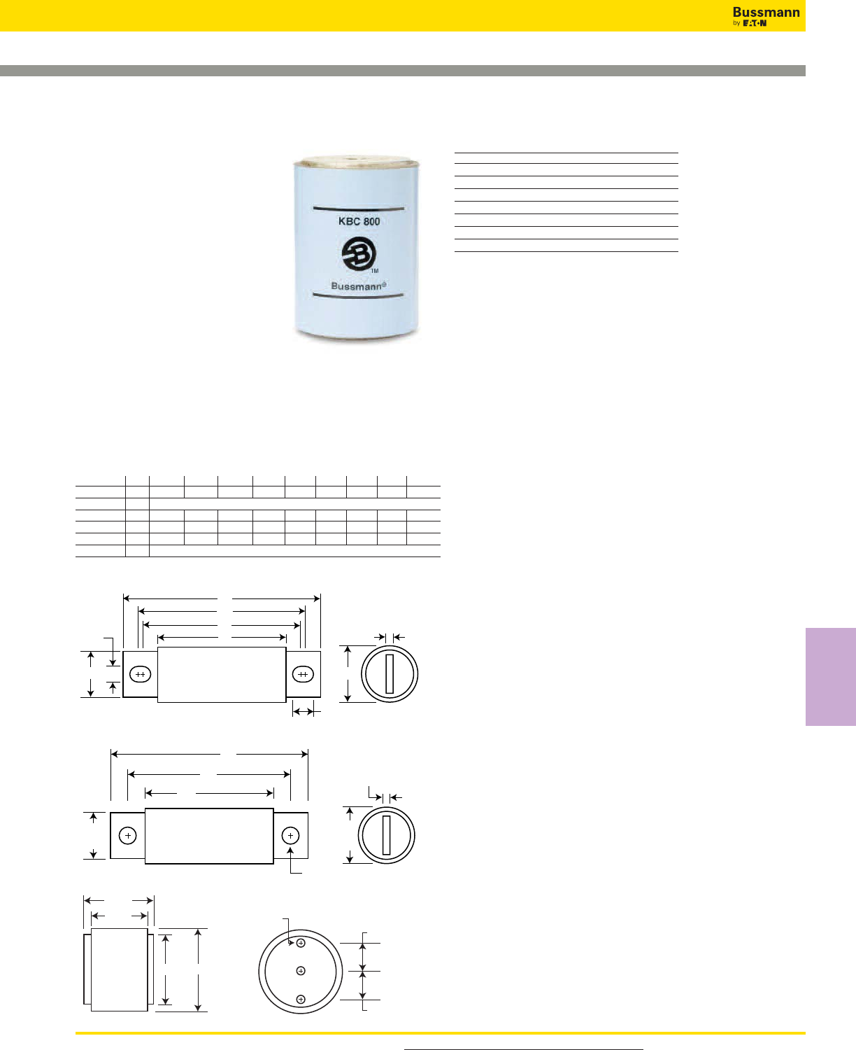
For product data sheets, visit www.cooperbussmann.com/DatasheetsEle 135
High Speed
Fuses
North American — KBC 600V: 35-800A
Dimensions - in
Amp
Range Fig. A B C D E F G H I
35-60A 1 4.375 3.750 3.500 2.750 0.343 0.625 0.813 0.094 0.468
70-100A 2 See Drawing
110-200A 1 4.406 3.719 3.594 2.906 0.312 0.875 1.219 0.187 0.375
225-400A 1 5.125 4.188 3.563 2.906 0.406 1.000 1.500 0.250 0.719
450-600A 1 5.125 4.389 3.687 2.875 0.406 1.500 2.000 0.250 0.757
800A 3 See Drawing
1mm = 0.0394” / 1” = 25.4mm
KBC
Specifications
Description: North American
style stud-mount and flush-end
fuses. These 600V fuses are
supplied as replacements only.
For new installations, Bussmann
recommends the 700V FWP
Series fuse.
Dimensions: See Dimensions
illustrations.
Ratings:
Volts: — 600Vac
Amps: — 35-800A
IR: — 200kA RMS Sym.
Agency Information: CE, UL Recognition JFHR2.E56412
on 35-600A only.
A
C
B
DE
FG
I
H
Fig. 1: 35-60 and 110-600A
Fig. 2: 70-100A
4.000
3.750
2.859
2.500
0.750
0.750
‹/•" - 24 ≈ ⁄/™"
Fig. 3: 800A
0.750
3.656
4.406
2.906
0.312
1.000
0.125
Catalog Numbers (Amps)
KBC-35 KBC-100 KBC-300
KBC-40 KBC-110 KBC-350
KBC-45 KBC-125 KBC-400
KBC-50 KBC-150 KBC-450
KBC-60 KBC-175 KBC-500
KBC-70 KBC-200 KBC-600
KBC-80 KBC-225 KBC-800
KBC-90 KBC-250
• See accessories on page 141.
Features and Benefits
• Low arc voltage and low energy let-through (I2t)
• Low watts loss
• Superior cycling capability
Typical Applications
• Power converters/rectifiers
• Reduced voltage starters
Data Sheet: 720010
High Speed Fuses
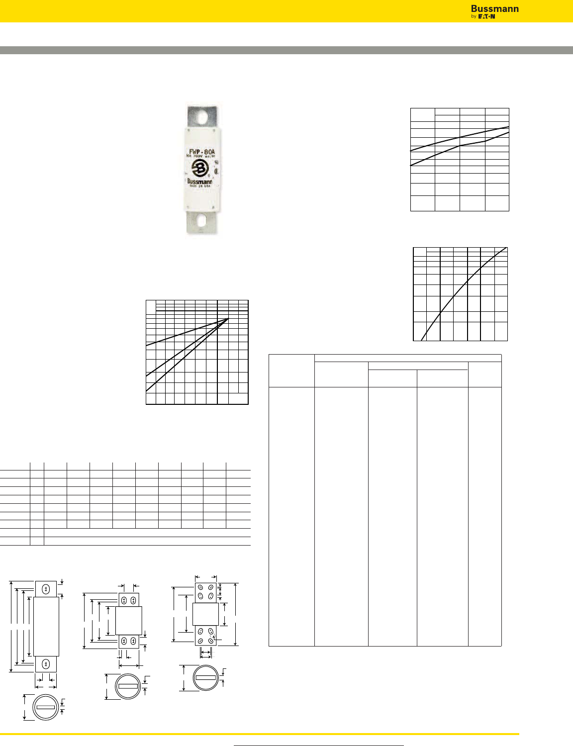
For product data sheets, visit www.cooperbussmann.com/DatasheetsEle
136
High Speed Fuses
North American — FWP 700V: 5-1200A
FWP
Specifications
Description: North American
style stud-mount fuses.
Dimensions: See Dimensions
illustrations.
Ratings:
Volts: — 700Vac/dc
Amps: — 5-1200A
IR: — 200kA RMS Sym.
— 50kA @700Vdc
Agency Information: CE, UL Recognition JFHR2.E91958
FWP-_B (5-100A, 700-1200A), JFHR2.E56412 FWP-_A
(125-600A) & CSA Component Acceptance file Class
1422-30, (53787) on 5-800A
Electrical Characteristics
Total Clearing I2t
The total clearing I2t at rated
voltage and at power factor of
15% are given in the electrical
characteristics. For other
voltages, the clearing I2t is
found by multiplying by
correction factor, K, given as
a function of applied working
voltage, Eg, (rms).
Arc Voltage
This curve gives the peak arc
voltage, UL, which may
appear across the fuse
during its operation as a
function of the applied
working voltage, Eg, (rms) at
a power factor of 15%.
Power Losses
Watts loss at rated current is
given in the electrical
characteristics. The curve
allows the calculation of the
power losses at load
currents lower than the rated
current. The correction factor,
Kp, is given as a function of
the RMS load current, Ib, in
% of the rated current.
Catalog Numbers Electrical Characteristics
Rated I2t (A2Sec)
Catalog Current Clearing Watts
Numbers RMS-Amps Pre-arc at 700V Loss
FWP-5B 5 1.6 10 1.5
FWP-10B 10 3.6 20 4
FWP-15B 15 10 75 5.5
FWP-20B 20 26 180 6
FWP-25B 25 44 340 7
FWP-30B 30 58 450 9
FWP-35B 35 34 160 12
FWP-40B 40 76 320 12
FWP-50B 50 135 600 12
FWP-60B 60 210 950 15.5
FWP-70B 70 305 2000 18
FWP-80B 80 360 2400 21
FWP-90B 90 415 2700 25
FWP-100B 100 540 3500 27
FWP-125A 125 1800 7300 28
FWP-150A 150 2900 11700 32
FWP-175A 175 4200 16700 35
FWP-200A 200 5500 22000 43
FWP-225A 225 7700 31300 45
FWP-250A 250 10500 42500 48
FWP-300A 300 17600 71200 58
FWP-350A 350 23700 95600 65
FWP-400A 400 31000 125000 78
FWP-450A 450 36400 137000 94
FWP-500A 500 45200 170000 107
FWP-600A 600 66700 250000 122
FWP-700A 700 54000 300000 125
FWP-800A 800 78000 450000 140
FWP-900A 900 91500 530000 150
FWP-1000A 1000 120000 600000 170
FWP-1200A 1200 195000 1100000 190
• Watts loss provided at rated current. • See accessories on page 141.
Features and Benefits
• Excellent DC performance
• Low arc voltage and low
energy let-through (I2t)
• Superior cycling capability
700604460316
1.5
1.0
0.5
0.3
0.2
0.15 Eg
K
1)
3)
2)
UL
2
1.6
1.4
1.2
103
8
6
5
4
3
400300 500 600 700
Eg
1)
2)
Kp
1.0
0.8
0.4
0.5
0.6
0.3
0.2
0.1
30 40 50 60 70 80 90 100%
Ib
1) 125-600A Range
2) 35-100 & 700-1200A Range
1) 35-100A Range
2) 125-600A Range
3) 700-1200A Range
AEDC
F
J
G
B
H
Fig. 1: 5-800A
Dimensions - in
Amp
Range Fig. A B C D E F G H I
5-30 1 2.870 0.563 1.855 2.477 2.477 0.250 0.405 0.063 0.250
35-60 1 4.375 0.813 2.750 3.708 3.312 0.344 0.725 0.125 0.542
70-100 1 4.406 0.947 2.594 3.625 3.563 0.344 0.750 0.125 0.375
125-200 1 5.090 1.500 2.840 4.190 3.500 0.410 1.000 0.250 0.750
225-400 1 5.090 2.000 2.840 4.280 3.530 0.410 1.500 0.250 0.780
450-600 1 7.090 2.500 2.840 5.720 4.190 0.530 2.000 0.380 1.300
700-800 1 6.630 2.000 2.844 5.562 5.062 0.625 1.500 0.250 0.875
900-1000 2 See Drawing
1200 3 See Drawing
1mm = 0.0394” / 1” = 25.4mm
7.594
0.
5
3.500
3.844
1.031
0.625
2.750
5.966
5.154
1.375
Fig. 2: 900-1000A Fig. 3: 1200A
10.844
3.844
0.625
4.250
0.750
3.500
6.840
0.125
0.500
1.625
1.750
9.590
Typical Applications
• DC Common bus
• DC Drives
• Power converters/rectifiers
• Reduced voltage starters
Data Sheet: 720012
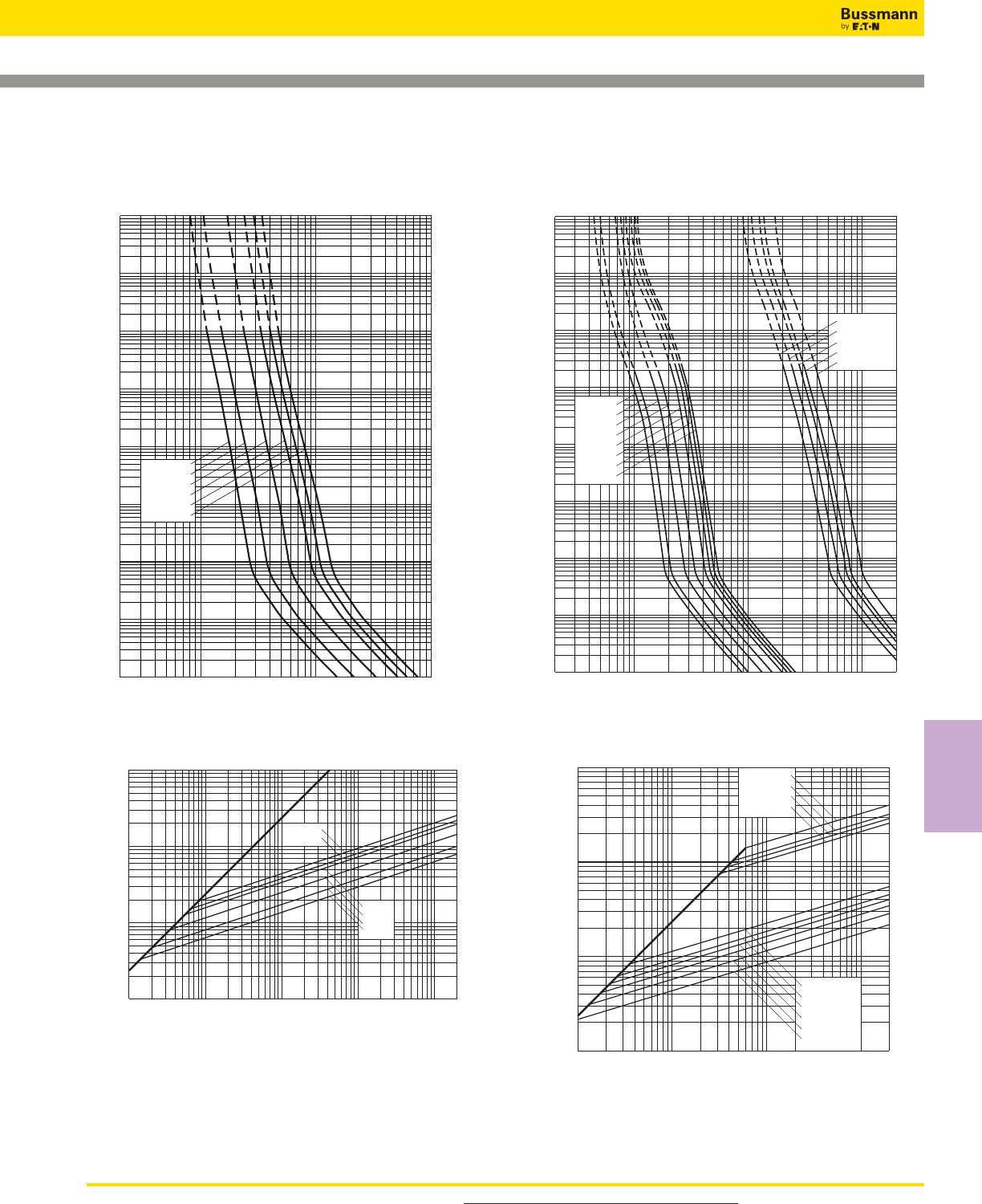
For product data sheets, visit www.cooperbussmann.com/DatasheetsEle 137
High Speed
Fuses
North American — FWP 700V: 5-1200A
2468
10222468 2
1032468
104
2
4
6
2
6
4
2
6
4
101
100
2
6
4
2
6
4
2
6
4
6
4
2
6
2
4
10–1
10–2
10–3
10–4
102
103
104
FWP-35B
FWP-80B
FWP-90B
FWP-100B
FWP-60B
FWP-70B
FWP-40B
FWP-50B
FWP-900A
FWP-1200A
FWP-1000A
FWP-800A
FWP-700A
Prospective Current In Amps RMS
Virtual Pre-Arcing Time In Seconds
FWP 35-100A(B) & 700-1200A(A): 700V
Time-Current Curve
Prospective Short-Circuit Current
Peak Let-Through Current
2
6
4
2
6
4
2
6
4
246 246 246
102
103
104
106
102103104105
2
FWP-700A
FWP-800A
FWP-1000A
FWP-100B
FWP-35B
FWP-70B
FWP-40B
FWP-50B
FWP-60B
FWP-1200A
Peak Let-Through Curve
2468
10122468 2
1022468
103
2
4
6
2
6
4
2
6
4
2
6
4
2
6
4
2
6
4
6
4
2
6
2
4
10–1
10–2
10–3
10–4
102
101
100
103
104
Prospective Current In Amps RMS
Virtual Pre-Arcing Time In Seconds
FWP-10B
FWP-15B
FWP-20B
FWP-5B
FWP-30B
FWP-25B
FWP 5-30A(B): 700V
Time-Current Curve
Prospective Short-Circuit Current
Peak Let-Through Current
2
4
2
6
6
4
2
6
4
246 246 246 246
101
102
103
104
101102103104105
FWP- 5B
FWP-10B
FWP-15B
FWP-20B
FWP-25B
FWP-30B
2
Peak Let-Through Curve
Data Sheet: 35785308Data Sheet: 35785316
High Speed Fuses
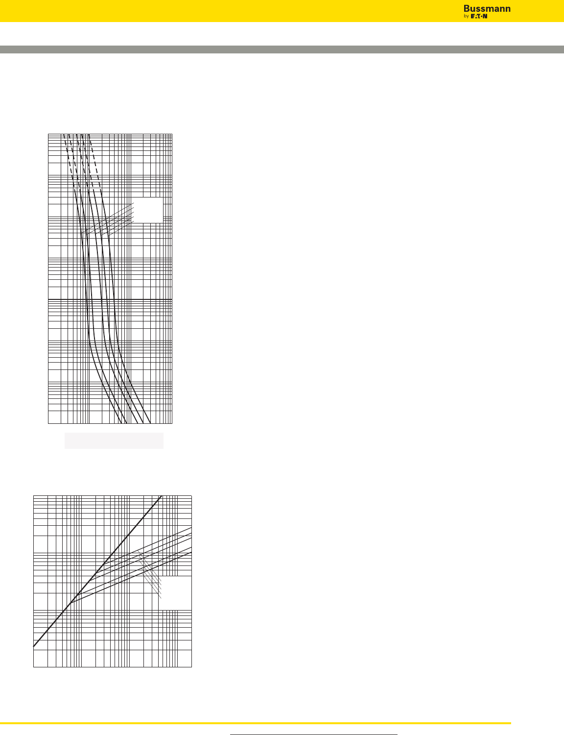
For product data sheets, visit www.cooperbussmann.com/DatasheetsEle
138
High Speed Fuses
North American — FWP 700V: 5-1200A
10–4
10–3
10–2
10–1
100
101
102
103
FWP-150A
FWP-200A
FWP-300A
FWP-400A
FWP-600A
Prospective Current In Amperes RMS
Virtual Pre-Arcing Time In Seconds
102103104105
Prospective Current In Amps RMS
FWP 150-600A: 700V
Time-Current Curve
FWP-600A
FWP-400A
FWP-300A
FWP-200A
FWP-150A
102103104105
102
103
104
105
Prospective Short-Circuit Current Symmetrical RMS
Peak Let-Through Current
A
B
Peak Let-Through Curve
Data Sheet: 361
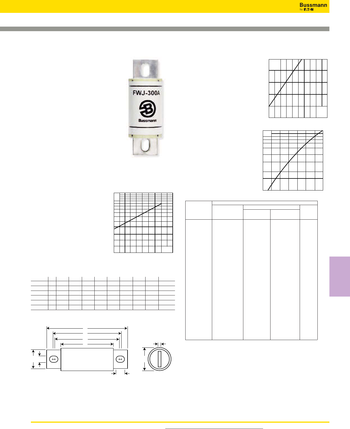
For product data sheets, visit www.cooperbussmann.com/DatasheetsEle 139
High Speed
Fuses
North American — FWJ 1000V: 35-2000A
FWJ
Specifications
Description: North American
style stud-mount fuses.
Dimensions: See Dimensions
illustration.
Ratings:
Volts: — 1000Vac/800Vdc
Amps: — 35-2000A
IR: — 25kA (35-200A)
— 100kA (250-2000A)
— 50kA @ 800Vdc
(35-200A, 450-600A)
Agency Information: CE, UL
Recognition JFHR8.E91958 on
35-600A only.
Electrical Characteristics
Total Clearing I2t
The total clearing I2t at rated
voltage and at power factor of
15% are given in the electrical
characteristics. For other
voltages, the clearing I2t is
found by multiplying by
correction factor, K, given as
a function of applied working
voltage, Eg, (rms).
Arc Voltage
This curve gives the peak arc
voltage, UL, which may
appear across the fuse
during its operation as a
function of the applied
working voltage, Eg, (rms)
at a power factor of 15%.
Power Losses
Watts loss at rated current is
given in the electrical
characteristics. The curve
allows the calculation of the
power losses at load
currents lower than the
rated current. The
correction factor, Kp, is
given as a function of the
RMS load current, Ib, in %
of the rated current.
Catalog Numbers
Electrical Characteristics
Rated I2t (A2 Sec)
Catalog Current Clearing Watts
Numbers RMS-Amps Pre-arc at 1000V Loss
FWJ-35A 35 210 2000 7
FWJ-40A 40 300 2500 8
FWJ-50A 50 470 3500 10
FWJ-60A 60 670 5000 11
FWJ-70A 70 1100 6900 12
FWJ-80A 80 1550 9700 13
FWJ-90A 90 1900 12000 14
FWJ-100A 100 2800 17500 15
FWJ-125A 125 4800 35000 16
FWJ-150A 150 6300 45000 25
FWJ-175A 175 7500 65000 30
FWJ-200A 200 11700 80000 32
FWJ-250A 250 16000 112000 50
FWJ-300A 300 23500 164000 56
FWJ-350A 350 33000 231000 62
FWJ-400A 400 47000 330000 67
FWJ-500A 500 39500 329000 95
FWJ-600A 600 61000 520000 105
FWJ-800A 800 87000 500000 182
FWJ-1000A 1000 190000 1100000 206
FWJ-1200A 1200 370000 2100000 240
FWJ-1400A 1400 470000 2700000 248
FWJ-1600A 1600 700000 4000000 267
FWJ-1800A 1800 925000 5300000 239
FWJ-2000A 2000 1330000 7600000 244
• Watts loss provided at rated current.
• See accessories on page 141.
Features and Benefits
• Excellent DC performance
• Low arc voltage and low energy let-through (I2t)
• Low watts loss
• Superior cycling capability
Typical Applications
• DC Common bus
• DC Drives
• Power converters/rectifiers
• Reduced voltage starters
2000
1600
1200
800
400
200 600 1000 1400 1800
UL
Eg
Kp
1.0
0.8
0.4
0.5
0.6
0.3
0.2
0.1
30 40 50 60 70 80 90 100%
Ib
1000800500200
1.5
1.0
0.5
0.3
0.2
0.15 Eg
K
A
E
D
C
F
J
GB
H
Fig. 1: 35-2000A
Dimensions - in
Amp
Range Fig. A B C D E F G H I
35-60 1 5.000 0.940 3.110 4.235 4.180 0.352 0.750 0.125 0.380
70-100 1 4.932 1.125 3.085 4.266 4.156 0.352 1.000 0.188 0.407
125-200 1 5.685 1.526 3.261 4.803 4.055 0.445 1.000 0.250 0.819
250-400 1 5.768 2.000 3.500 4.811 4.150 0.433 1.500 0.250 0.764
500-600 1 7.201 2.500 3.465 5.984 4.706 0.562 2.000 0.375 1.201
800-2000 1 6.811 3.500 3.312 5.472 4.962 0.625 2.750 0.500 0.880
1mm = 0.0394” / 1” = 25.4mm
Data Sheet: 720027
High Speed Fuses
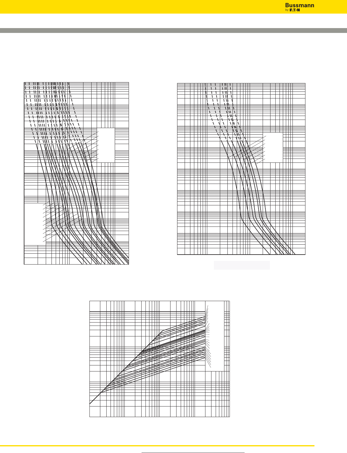
For product data sheets, visit www.cooperbussmann.com/DatasheetsEle
140
High Speed Fuses
North American — FWJ 1000V: 35-2000A
2468
10322468 2
1042468
105
2
4
6
2
6
4
100
2
6
4
101
2
6
4
2
6
4
2
6
4
6
4
2
6
2
4
10–1
10–2
10–3
10–4
102
103
104
FWJ-1800A
FWJ-2000A
FWJ-800A
FWJ-1000A
FWJ-1200A
FWJ-1400A
FWJ-1600A
Prospective Current In Amperes RMS
Virtual Pre-Arcing Time In Seconds
Prospective Current in Amps
FWJ 800-2000A: 1000V
Time-Current Curve
Prospective Current In Amps RMS
Virtual Pre-Arcing Time In Seconds
10222468 2
1032468
104
2
4
6
2
6
4
100
2
6
4
2
6
4
2
6
4
2
6
4
6
4
2
6
2
4
10–1
10–2
10–3
10–4
102
103
104
FWJ-125A
FWJ-150A
FWJ-60A
FWJ-100A
FWJ-90A
FWJ-80A
FWJ-70A
FWJ-50A
FWJ-40A
FWJ-600A
FWJ-200A
FWJ-250A
FWJ-300A
FWJ-350A
FWJ-400A
FWJ-500A
FWJ-175A
101
FWJ 35-600A: 1000V
Time-Current Curve
Prospective Short-Circuit Current Symmetrical RMS
Peak Let-Through Current
2
4
2
6
6
4
2
6
4
2
246 246 246 246
102
103
104
105
102103104105
FWJ-40A
FWJ-50A
FWJ-60A
FWJ-70A
FWJ-80A
FWJ-90A
FWJ-100A
FWJ-125A
FWJ-150A
FWJ-175A
FWJ-200A
FWJ-500A
FWJ-350A
FWJ-300A
FWJ-250A
FWJ-600A
FWJ-800A
FWJ-2000A
FWJ-1800A
FWJ-1600A
FWJ-1400A
FWJ-1250A
FWJ-1000A
FWJ-400A
Peak Let-Through Curve
Data Sheet: 35785303
Data Sheet: 35785309
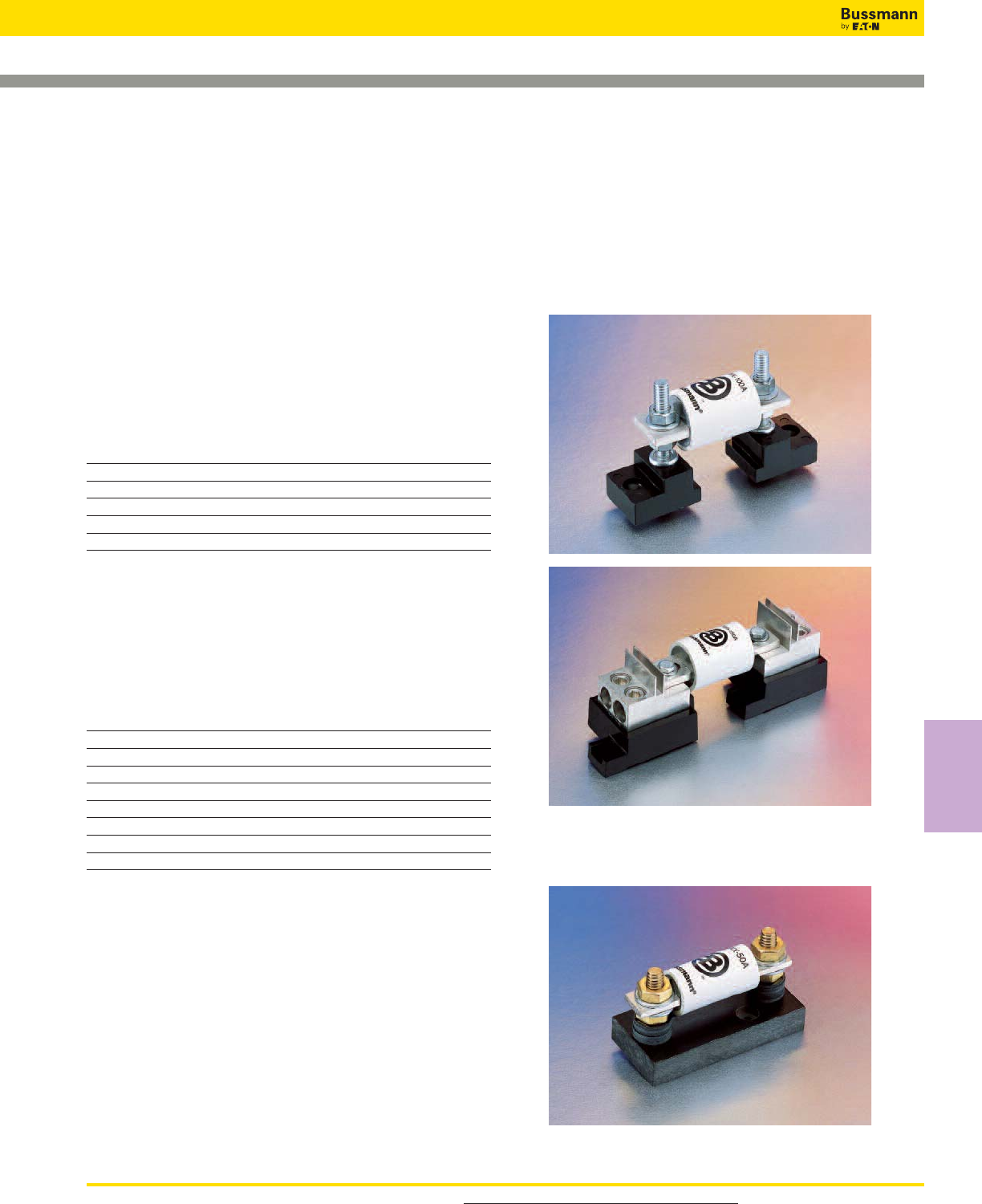
For product data sheets, visit www.cooperbussmann.com/DatasheetsEle 141
High Speed
Fuses
North American Fuse Accessories
Stud TypeC5268 Series
BS Style Connector Type
Fixed Center
Fuse Bases (Blocks)
Modular Style
Bussmann offers a comprehensive line of fuse bases that
provide the user with design and manufacturing flexibility.
Two identical half bases make up a Bussmann modular fuse
base. These “split” units can be panel mounted any distance
apart to accommodate any length fuse.
Stud Type (Not sold in pairs)
The simpler design is the C5268 Series modular fuse base.
With this design, the fuse terminal and cable (with
termination) are mounted on the same stud, minimizing labor
needed for installation. The stud type base is available in the
configuration shown in the table below.
Catalog Max Fuse Stud Stud Dia.
Number Amp Rating Height (in) & Threads
C5268-1 200 1.00 5⁄16˝-18
C5268-2 200 1.75 5⁄16˝-18
C5268-3 200 0.75 5⁄16˝-18
C5268-4 100 1.00 1⁄4˝-20
C5268-5 100 1.75 1⁄4˝-20
Connector Type
Bussmann also offers a modular style fuse base that utilizes
a tin-plated connector (for wire termination and heat
dissipation) and a plated-steel stud (for fuse mounting). The
connector type fuse base is available in the configurations
shown below. Consult Bussmann for additional product
details.
Modular Max Max Fuse Data Sheet
Base Style Voltage Amp Rating Number
1BS101 600 100 1206
1BS102 600 400 1207
1BS103 600 400 1208
1BS104 600 600 1209
BH-0xxx 700 100 1200
BH-1xxx 2500 400 1201
BH-2xxx 5000 400 1202
BH-3xxx 1250 700 1203
Fixed Center Base Style
Bussmann offers a comprehensive line of fixed mount style
fuse bases under the trademark TRON™rectifier fuse blocks.
The cable and fuse connections are similar to the stud type
fuse base — both are mounted on the same stud. Consult
Bussmann for complete product details.
Refer to page 306 for BH style holders.
High Speed Fuses
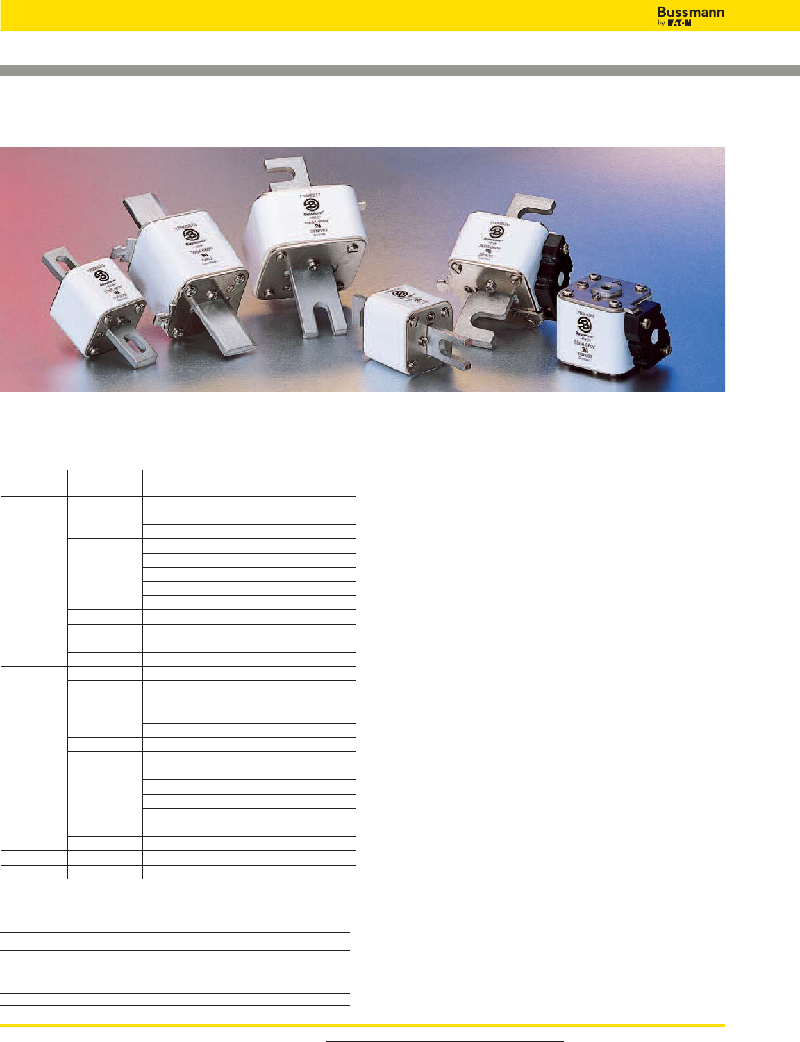
For product data sheets, visit www.cooperbussmann.com/DatasheetsEle
High Speed Fuses
142
Square Body Fuses
General Information
Designed and tested to:
• IEC 60269: Part 4
• UL Recognized
Bussmann offers a complete range of square body style
fuses and accessories. Their unique design and
construction provide:
• Minimal energy let-through (I2t)
• Low operating temperature
• Low watts loss
Square body style fuses are a very attractive solution for high
power applications which require a compact design with
superior performance. The construction and design of square
body style fuses make it easy for Bussmann to manufacture
custom products. Our cataloged offering provides only a
sample of the wide variety of product which
is available.
Each square body style fuse is available with a number of
different end fittings. Options include:
• DIN 43 653
• DIN 43 620
• Flush End (Metric/US)
• French Style
• US Style
Voltage Rating
All Bussmann square body style fuses are tested to IEC
60269: Part 4. This standard requires a test voltage which is
5% higher than the rated voltage. In North America, fuses are
required to clear only their rated voltage.
Accessories
Square Body style fuses are available with three different
open fuse indicator systems. Options include visual
indication and indication utilizing a microswitch. Fuse
blocks are also available for most applications.
Introduction
Square Body Contents Page
Application Information 143-144
Accessories Page
Indicator System 212
Fuse Bases 213
Square Body Fuse Ranges
Amps Volts AC DC
10-7500 690 X —
50-1400 1250 X —
Volts
(IEC/UL) Size Class Fuse Style Page
aR DIN 43 653 145-147
000,00 aR Flush End Contact 145-147
aR DIN 43 620 148-149
aR DIN 43 653 150-151
aR Flush End Contact 152-153
690/700 1*, 1, 2, 3 aR US Style 154-155
aR French Style 156-157
aR Fuse Curves 158-159
1*, 2, 3 aR DIN 43 620 160-162
4 aR Flush End Contact 163-164
23, 24 aR Flush End Contact 165-166
00, 1, 2, 3 aR DIN 43 620 168-171
00 aR DIN 43 653 172-173
aR DIN 43 653 174-175
1*, 1, 2, 3 aR Flush End Contact 176-177
1000 aR US Style 178-179
aR Fuse Curves 180-181
4 aR Flush End Contact 182-184
24 aR Flush End Contact 185-186
aR DIN 43 653 187-188
1*, 1, 2, 3 aR Flush End Contact 189-190
aR US Style 191-192
1250/1300 aR Fuse Curves 193-194
4 aR Flush End Contact 195-197
23 aR Flush End Contact 198-199
1000-2000 5 aR Flush End Contact 200
DC Fuses 201-211
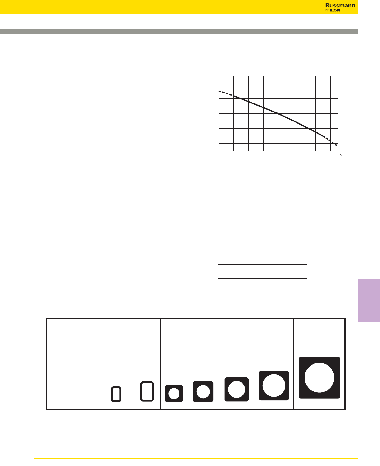
143
Square Body Applications
Maximum Permissible Load Current
The rated current value of Bussmann fuses is based on the
ambient temperature in the space immediately below the fuse
of 20°C. The following graph gives correction factors (k) for a
range of temperatures (–40°C to +80°C). Maximum
permissible continuous load currents can be calculated by
applying the following formula:
Ib≤In≈ k ≈ (1 + 0.05 V) x Kb
where
Ib= Maximum permissible continuous load current
In= Rated current of fuse
k = Temperature correction factor
v = Velocity of cooling air in m/s (max. 5 m/s).
Kb= Fuse load constant 1.0
Temperature Correction Curve
The maximum permissible continuous load current Ib of a
fuse can be checked empirically (i.e., by satisfying the
formula below) by making simple voltage and temperature
measurements under actual operating conditions after the
fuse has been installed in its operating location and loaded
at the calculated Ib value:
E2≈ (0.92 + 0.004t) ≤ N
E1
where
E1= Voltage drop across fuse after 5 seconds
E2= Voltage drop across fuse after 2 hours
t = Air temperature at start of test (°C)
N = Constant
Fuse Rated Voltage (IEC) N
690 1.5
1250 1.6
Body Cross Section
Standard fuse program includes barrels with different cross sections.
Size 000 00 1 1 2 3 4
Maximum
Cross-section
(mm)
21 ≈ 36 30 ≈ 47 45 ≈ 45 53 ≈ 53 61 ≈ 61 76 ≈ 76 105 ≈ 105
1.4
1.2
1
0.8
0.6
k
–40 –20 0 4020 60 80 C
For product data sheets, visit www.cooperbussmann.com/DatasheetsEle
High Speed
Fuses
High Speed Fuses
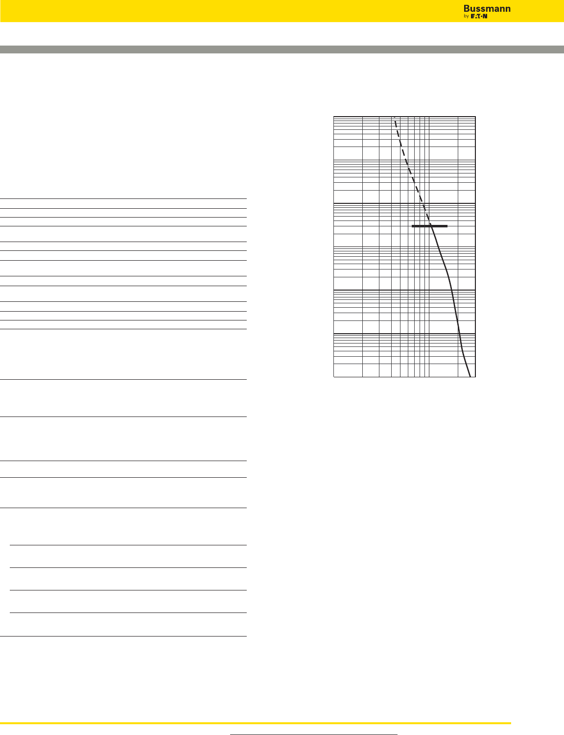
For product data sheets, visit www.cooperbussmann.com/DatasheetsEle
High Speed Fuses
144
Square Body Applications
Example Application of Square Body High Speed
Fuses Subject to Overload and Impulse Loading
Select a short-blade indicating fuse with indicator/adapter to
permit the use of a single-pole microswitch for remote
indication and determine if the fuse selected will meet the
following application parameters.
Application Parameters
Load Currents Expected
Load Type Duration Frequency of Occurrence Amps
(1) Normal Continuous — 300A
(2) Overload 60 Seconds Once Per Hour 500A
(3a) 10 Seconds 2-3 Times Per Week
(3b)Overload 20 Seconds (max.) Once Per Month 700A
(4) Impulse 0.5 Seconds Less Than Once Per Month 1100A
Voltage Data
(5) Voltage Applied to Fuse During Fault Conditions 400V
(+10%)
Temperature Data
(6) Temperature Inside Cubicle in Which Fuse is Located (Natural Convection Cooling Only)
60°C
Thyrister Data
(7) Thyrister Peak Voltage Withstand 1000V
(8) Thyrister I2t Withstand at 10 Milliseconds* 90,000A2s
*Note: The I2t withstand of the thyrister may be given for other impulse durations (i.e., 1.5 ms,
3.5 ms, or 8.3 ms); however, the stated fuse I2t is valid for all impulse durations of 10 ms or
less.
Application Procedure
Step Procedure Remarks
(1) Select a short-blade fuse to permit 1.1 Taking into consideration only the
mounting of microswitch 170H0069 continuous load current and ambient
temperature, from Table on page 127 —
tentatively select fuse 170M3669
400A, 690V).
(2) Determine I
2
t (total clearing) at 440V. 2.1 See Table, page 127. Note I2t is
105,000A2s at rated voltage of 690V.
2.2 From the figure on page 126, note that OK
correction factor K = 0.65.
2.3 I2t660V ≈K = I2t440V
105,000 ≈0.65 = 68,250
(3) Determine maximum arc voltage 3.1 From the figure on page 126, note that
at 440V maximum voltage at 440V is 900V OK
(4) Determine maximum permissible 4.1 Per page 115 data,
continuous load current Ib.Ib= In≈ k ≈ (1 + 0.05V) ≈ Kb—
Ib= 400A ≈ 0.8 ≈ (1 + 0) ≈ 1
Ib= 320A
(5) Plot a “line profile” showing the 5.0 Calculate Imax per Table,
expected load and overload currents. High Speed Fuse Application Guide —
Determine that overload and impulse page 16, for each overload and impulse
load currents do not exceed their load.
maximum permissible values.
(Item 2) 5.1 Imax < 60% ≈ It
500A < 60% ≈950A OK
500A < 570A
(Item 3a) 5.2 Imax < 60% ≈ It
700A < 60% ≈ 1360A OK
700A < 780A
(Item 3b) 5.3 Imax < 70% ≈ It
700A < 70% ≈ 1150A OK
700A < 805A
(Item 4) 5.4 Imax < 70% ≈ It
1100A < 70% ≈ 1800A OK
1100A < 1260A
The tentatively selected fuse 170M3669 with microswitch 170H0069 meets all application parameters; no further
selection would be necessary.
102103
10–2
10–1
100
101
102
103
Current In Amperes
Time In Seconds
AA
170M3669 (400A)
Profile Line
Calculation of Watt Loss
From the Table on page 127, watt loss at 400 amps is 60
watts. The continuous load current of 300A is 75% of rated
current (400A). From page 126, the correction factor
Kp= 0.5.
Watt Loss 75% = Watt Loss 100% ≈ Kp
= 60W ≈0.5
= 30 watts
Special Fuses
Other high speed fuses are available from Bussmann with
voltage ratings of 380 to 10,000V and current ratings up to
10,000A in a single unit configuration. Fuses can be
supplied with open fuse, “pin” indicators. Various types of
microswitches are also available (see page 212).

145
Square Body DIN 43 653 — 690V/700V (IEC/UL): 10-400A
working voltage, Eg,
(rms).
Arc Voltage
This curve gives the
peak arc voltage, UL,
which may appear
across the fuse during
its operation as a
function of the applied
working voltage, Eg,
(rms) at a power factor of 15%.
Power Losses
Watts loss at rated
current is given in the
electrical characteristics.
The curve allows the
calculation of the power
losses at load currents
lower than the rated
current. The correction
factor, Kp, is given as a
function of the RMS load current, Ib, in % of the rated
current.
Features and Benefits
• Excellent DC performance
• Low arc voltage and low energy let-through (I2t)
• Low watts loss
• Superior cycling capability
Typical Applications
• DC Common bus
• DC Drives
• Power converters/rectifiers
*
690V/700V (IEC/UL) 10-400A
Specifications
Description: Square body DIN
43-653 stud mount high speed
fuses.
Dimensions: See dimensions
illustration.
Ratings:
Volts: — 690Vac (IEC)
— 700Vac (UL)
Amps: — 10-400A
IR: — 200kA RMS Sym.
Agency Information: CE,
Designed and tested to IEC
60269: Part 4. UL Recognized
E125085.JFHR2, CSA Certified:
Class 53787, File 1422-30 on
Size 000.
Electrical
Characteristics
Total Clearing I2t
The total clearing I2t at
rated voltage and at power
factor of 15% are given
in the electrical
characteristics. For other
voltages, the clearing I2t is
found by multiplying by
correction factor, K, given
as a function of applied 100 200 300 400 500 600
K
1.5
1.0
0.5
0.4
0.3
0.2 Eg
690
UL
1.4
1.2
103
6
8
7
9
5
4
3Eg
200 300 400 500 600 690
Kp
30 40 50 60 70 80 90 100%
Ib
1.0
0.8
0.4
0.5
0.6
0.3
0.2
0.1
F
100
78
D
E
G
H
K
54
Indicator
Dimensions - mm
Type -U/80, -/80, -TN/80
Size D E F G H K
000 40 21 20 51 8 2
00 51 30 28 67 10 2
1mm = 0.0394” / 1” = 25.4mm
* Indication for Size 00 fuses is a red pin.
54 Max
64
30
48
62
M8
6
Indicator
Dimensions (mm)
Type 00B/60, 00BTN/60
1mm = 0.0394” / 1” = 25.4mm
For Other Voltage Ratings in This Body Style
• See page 172 (1000V)
For product data sheets, visit www.cooperbussmann.com/DatasheetsEle
High Speed
Fuses
High Speed Fuses
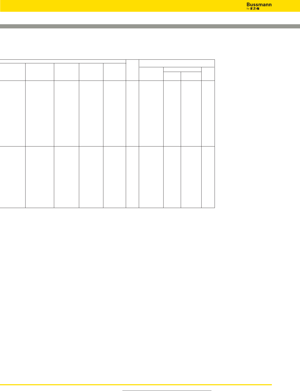
For product data sheets, visit www.cooperbussmann.com/DatasheetsEle
High Speed Fuses
146
Square Body DIN 43 653 — 690V/700V (IEC/UL): 10-400A
Catalog Numbers
Catalog Numbers
-TN/80 00BTN/60 Electrical Characteristics
-U/80 -/80 Type T 00B/60 Type T Rated I2t (A2Sec)
Without Visual Indicator Visual Indicator Current Clearing Watts
Indicator Indicator for Micro Indicator for Micro Size RMS-Amps Pre-arc at 660V Loss
170M1308 170M1358 170M1408 10 3.8 25.5 3.0
170M1309 170M1359 170M1409 16 7.2 48 5.5
170M1310 170M1360 170M1410 20 11.5 78 7
170M1311 170M1361 170M1411 25 19 130 9
170M1312 170M1362 170M1412 32 40 270 10
170M1313 170M1363 170M1413 40 69 460 12
170M1314 170M1364 170M1414 50 115 770 15
170M1315 170M1365 170M1415 000 63 215 1450 16
170M1316 170M1366 170M1416 80 380 2550 19
170M1317 170M1367 170M1417 100 695 4650 24
170M1318 170M1368 170M1418 125 1200 8500 28
170M1319 170M1369 170M1419 160 2300 16000 32
170M1320 170M1370 170M1420 200 4200 28000 37
170M1321 170M1371 170M1421 250 7750 51500 42
170M1322 170M1372 170M1422 315 12000 80500 52
170M2608 170M2658 170M2708 170M2758 25 19 130 6
170M2609 170M2659 170M2709 170M2759 32 28.5 195 7
170M2610 170M2660 170M2710 170M2760 40 50 360 9
170M2611 170M2661 170M2711 170M2761 50 95 640 10
170M2612 170M2662 170M2712 170M2762 63 170 1200 12
170M2613 170M2663 170M2713 170M2763 80 310 2100 15
170M2614 170M2664 170M2714 170M2764 00 100 620 4150 20
170M2615 170M2665 170M2715 170M2765 125 1000 6950 25
170M2616 170M2666 170M2716 170M2766 160 1900 13000 30
170M2617 170M2667 170M2717 170M2767 200 3400 23000 35
170M2618 170M2668 170M2718 170M2768 250 6250 42000 45
170M2619 170M2669 170M2719 170M2769 315 10000 68500 55
170M2620 170M2670 170M2720 170M2770 350 13500 91500 60
170M2621 170M2671 170M2721 170M2771 400 18000 125000 70
• Watts loss provided at rated current.
• Microswitch indicator ordered separately.
• See accessories on pages 212-213.
• For fuse curves see page 147.
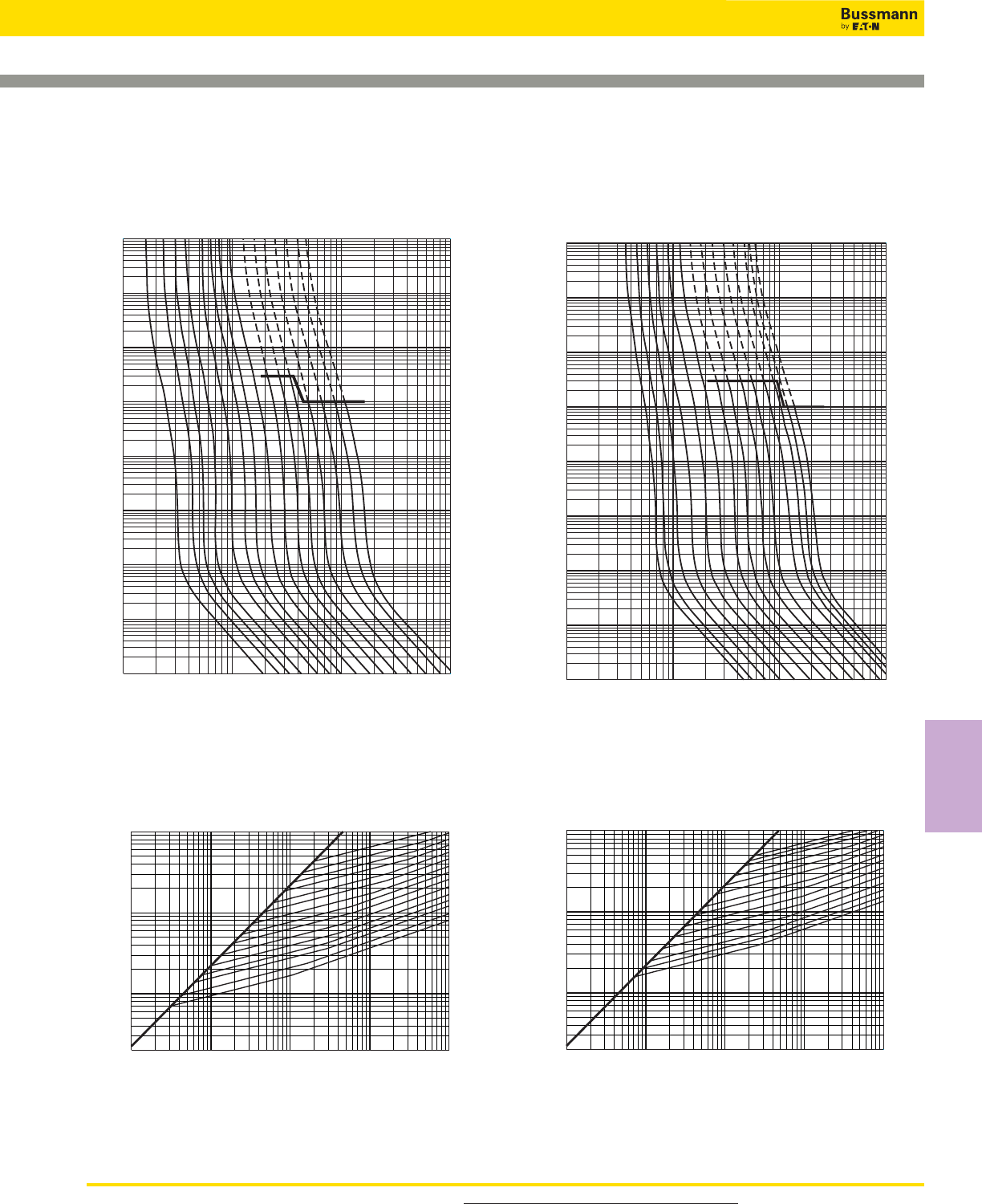
Square Body Size 000, 00 — 690V/700V (IEC/UL): 10-400A
1x101102103104
1x10⁻⁴
10–3
10–2
10–1
100
101
102
103
104
Prospective Current In Amps RMS
Virtual Pre-Arcing Time In Seconds
10A
16A
20A
25A
32A
40A
50A
63A
80A
100
A
125
A
160
A
200
A
250
A
315
A
A
A
1x101102103104
1x10⁻⁴
10–3
10–2
10–1
100
101
102
103
104
Prospective Current in Amps RMS
Virtual Pre-Arcing Time In Seconds
25A
32A
40A
50A
63A
80A
100
A
125
A
160
A
200
A
250
A
315
A
350
A
400
A
A
A
Size 00 — 25-400A: 690V
Time-Current Curve
Size 000 — 10-315A: 690V
Time-Current Curve
1x101102103104105
2x101
102
103
104
Prospective Short-Circuit Current Symmetrical RMS
Peak Let-Through Current
10A
16A
20A
25A
32A
40A
50A
63A
80A
100A
125A
160A
200A
250A
A
B
315A
1x101102103104105
2x101
102
103
104
Prospective Short-Circuit Current Symmetrical RMS
Peak Let-Through Current
25A
32A
40A
50A
63A
80A
100A
125A
160A
200A
250A
315A350A400A
A
B
Peak Let-Through CurvePeak Let-Through Curve
Data Sheet: 17056310 Data Sheet: 172056312
For product data sheets, visit www.cooperbussmann.com/DatasheetsEle 147
High Speed
Fuses
High Speed Fuses
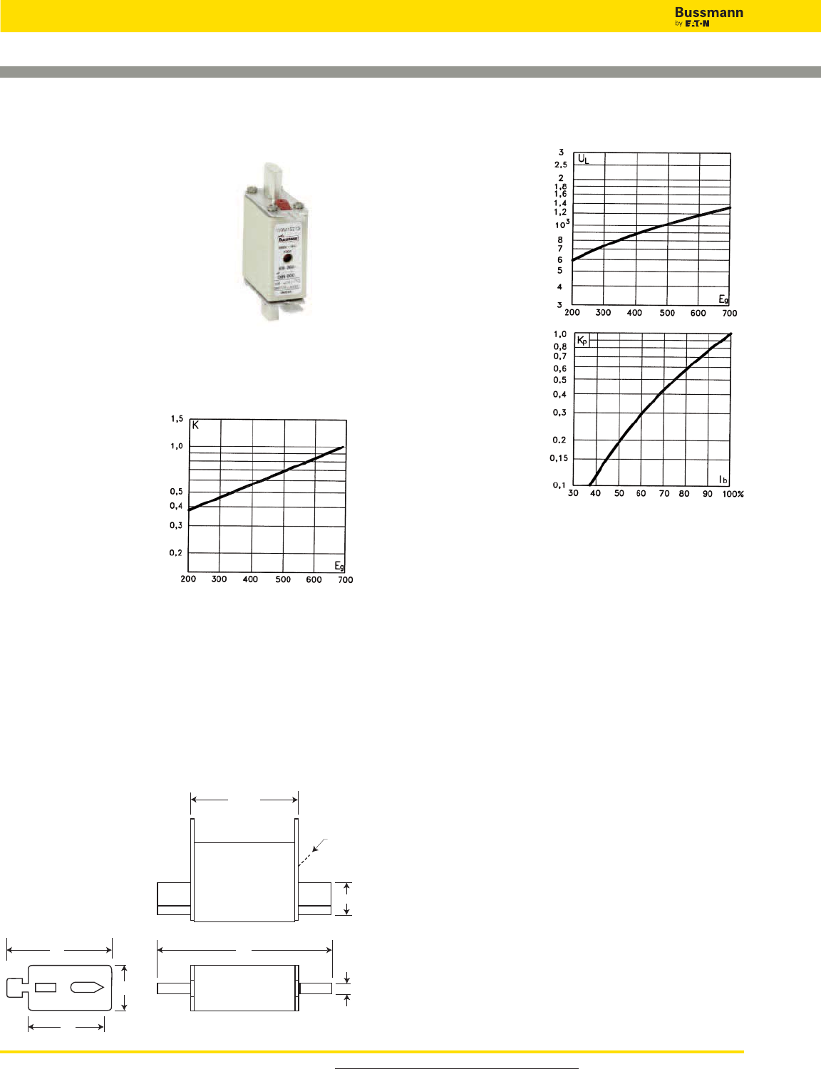
For product data sheets, visit www.cooperbussmann.com/DatasheetsEle
148
High Speed Fuses
Square Body DIN 43 620 — 690V (IEC/UL): 10-315A
690V (IEC/UL) 10-315A
Specifications
Description: Square body DIN 43
620 blade style high speed fuses.
Dimensions: See dimensions
illustration.
Ratings:
Volts: — 690Vac
Amps: — 10-315A
IR: — 200kA RMS Sym.
Agency Information: CE, Designed and tested to IEC
60269: Part 4. UL Recognized E125085.JFHR2. & CSA
Component Acceptance file Class 1422-30, (53787)
Electrical
Characteristics
Total Clearing I2t
The total clearing I2t at
rated voltage and at power
factor of 15% are given in
the electrical characteris-
tics. For other voltages,
the clearing I2t is found by
multiplying by correction
factor, K, given as a func-
tion of applied working
voltage, Eg, (rms).
54 Max
79
48
21 6
35
15
Indicator
Dimensions - mm
DIN 000 Type T
1mm = 0.0394” / 1” = 25.4mm
Arc Voltage
This curve gives the peak
arc voltage, UL, which
may appear across the
fuse during its operation
as a function of theapplied
working voltage, Eg, (rms)
at a power factor of 15%.
Power Losses
Watts loss at rated current
is given in the electrical
characteristics. The curve
allows the calculation of
the power losses at load
currents lower than the
rated current. The correc-
tion factor, Kp, is given as
a function of the RMS load
current, Ib, in % of the
rated current.
Features and Benefits
• Excellent DC performance
• Low arc voltage and low energy let-through (I2t)
• Low watts loss
• Superior cycling capability
Typical Applications
• DC Common bus
• DC Drives
• Power converters/rectifiers
• Reduced voltage starters
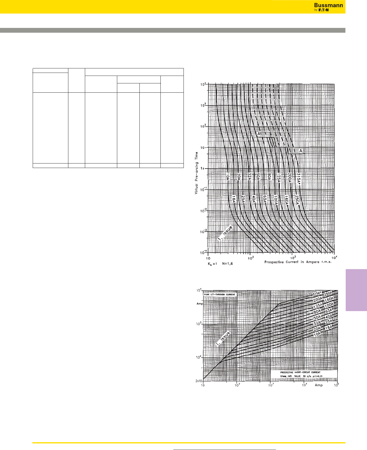
For product data sheets, visit www.cooperbussmann.com/DatasheetsEle 149
Catalog Numbers
Catalog Numbers
DIN Electrical Characteristics
Type T Rated I2t (A2Sec)
Indicator Current Clearing Watts
for Micro Size RMS-Amps Pre-arc at 660V Loss
170M1558D 10 4 27 2.5
170M1559D 16 7 51 4
170M1560D 20 11.5 82.5 5
170M1561D 25 19 140 6
170M1562D 32 40 285 7
170M1563D 40 65 490 8.5
170M1564D 000 50 115 815 9.5
170M1565D 63 215 1550 11.5
170M1566D 80 380 2700 15
170M1567D 100 695 4950 16.5
170M1568D 125 1180 8250 21.5
170M1569D 160 2300 16500 25
170M1570D 200 4350 31000 29.5
170M1571D 250 7900 56000 35.5
170M1572D 00 315 12000 84500 45
• Watts loss provided at rated current.
• Microswitch indicator ordered separately. See accessories on pages 212-213.
Rated Current
The rated current of this fuse range has been given with
copper conductors that have a current density of 1.3A/mm2
(IEC 60269-4). For conductor cross section according to IEC
60269-1, the fuses with a rated current higher than 125A
must be derated. Please contact Bussmann for
application assistance.
Square Body DIN 43 620 — 690V (IEC/UL): 10-315A
Size 000 — 10-315A: 690V
Time-Current Curve
Peak Let-Through Curve
Data Sheet: 72056310
High Speed
Fuses
High Speed Fuses
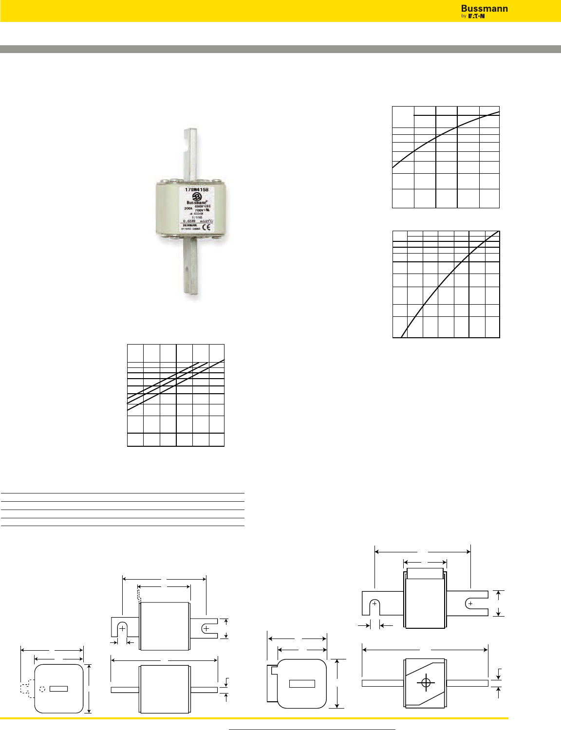
For product data sheets, visit www.cooperbussmann.com/DatasheetsEle
High Speed Fuses
150
Square Body DIN 43 653 — 690V/700V (IEC/UL):
40-2000A
690V/700V (IEC/UL) 40-2000A
Specifications
Description: Square body DIN 43
653 stud-mount high speed fuses.
Dimensions: See dimensions
illustration.
Ratings:
Volts: — 690Vac (IEC)
— 700Vac (UL)
Amps: — 40-2000A
IR: — 200kA RMS Sym.
Agency Information: CE,
Designed and tested to IEC
60269: Part 4. UL Recognized
E125085.JFHR2, CSA Certified:
Class 53787, File 1422-30.
Electrical
Characteristics
Total Clearing I2t
The total clearing I2t at
rated voltage and at power
factor of 15% are given in
the electrical
characteristics. For other
voltages, the clearing I2t is
found by multiplying by
correction factor, K, given
as a function of applied
working voltage, Eg, (rms).
Arc Voltage
This curve gives the peak
arc voltage, UL, which
may appear across the
fuse during its operation
as a function of theapplied
working voltage, Eg, (rms)
at a power factor of 15%.
Power Losses
Watts loss at rated current
is given in the electrical
characteristics. The curve
allows the calculation of
the power losses at load
currents lower than the
rated current. The
correction factor, Kp, is
given as a function of the
RMS load current, Ib, in %
of the rated current.
Features and Benefits
• Excellent DC performance
• Low arc voltage and low energy let-through (I2t)
• Low watts loss
• Superior cycling capability
Typical Applications
• DC Common bus
• DC Drives
• Power converters/rectifiers
• Reduced voltage starters
UL
1.4
1.2
103
6
8
7
9
5
4
3Eg
200 300 400 500 600 690
Kp
1.0
0.8
0.4
0.5
0.6
0.3
0.2
0.1
30 40 50 60 70 80 90 100
%
Ib
100 200 300 400 500 600 690
K
1.5
1.0
0.5
0.4
0.3
0.2
Eg
1)2)
1) Rated voltage 600V
2) Rated voltage 550V
A
B
C
D
E
E
6
11
H
Dimensions - mm
Size A B B** C C** D*** E H
1* 50 104 134 78 108 58 45 22
1 50 108 138 78 108 66 53 25
2 50 108 138 78 108 75 61 25
3 51 109 139 78 108 90 76 30
**Valid for fuses type -/110, -TN/110.
***Microswitch.
1mm = 0.0394” / 1” = 25.4mm
Type -KN/80, -KN/110
Type -/80, -TN/80, -/110, -TN/110.
C
B
A
H
11
6
E
E
D
For Other Voltage Ratings in This Body Style
• See pages 174 (1000V) and 187 (1250V/1300V)
Square Body DIN 43 653 — 690V/700V (IEC/UL):
40-2000A
151
Catalog Numbers
-/80 -TN/80 -KN/80 -TN/110 -KN/110 Electrical Characteristics
Visual Type T Type K -/110 Type T Type K I2t (A2Sec)
Watts Indicator Indicator Visual Indicator Indicator Rated Current Clearing
Indicator for Micro for Micro for Micro for Micro -KN/80 Size RMS-Amps Pre-arc at 660V Loss
170M3008 170M3058 170M3108 170M3158 170M3208 170M3258 40 40 270 9
170M3009 170M3059 170M3109 170M3159 170M3209 170M3259 50 77 515 11
170M3010 170M3060 170M3110 170M3160 170M3210 170M3260 63 115 770 14
170M3011 170M3061 170M3111 170M3161 170M3211 170M3261 80 185 1250 18
170M3012 170M3062 170M3112 170M3162 170M3212 170M3262 100 360 2450 21
170M3013 170M3063 170M3113 170M3163 170M3213 170M3263 125 550 3700 26
170M3014 170M3064 170M3114 170M3164 170M3214 170M3264 160 1100 7500 30
170M3015 170M3065 170M3115 170M3165 170M3215 170M3265 200 2200 15000 35
170M3016 170M3066 170M3116 170M3166 170M3216 170M3266 1* 250 4200 28500 40
170M3017 170M3067 170M3117 170M3167 170M3217 170M3267 315 7000 46500 50
170M3018 170M3068 170M3118 170M3168 170M3218 170M3268 350 10000 68500 55
170M3019 170M3069 170M3119 170M3169 170M3219 170M3269 400 15000 105000 60
170M3020 170M3070 170M3120 170M3170 170M3220 170M3270 450 21000 140000 65
170M3021 170M3071 170M3121 170M3171 170M3221 170M3271 500 27000 180000 70
170M3022 170M3072 170M3122 170M3172 170M3222 170M3272 550 34000 230000 75
170M3023 170M3073 170M3123 170M3173 170M3223 170M3273 630 48500 325000 80
170M4008 170M4058 170M4108 170M4158 170M4208 170M4258 200 1650 11500 45
170M4009 170M4059 170M4109 170M4159 170M4209 170M4259 250 3100 21000 55
170M4010 170M4060 170M4110 170M4160 170M4210 170M4260 315 6200 42000 58
170M4011 170M4061 170M4111 170M4161 170M4211 170M4261 350 8500 59000 60
170M4012 170M4062 170M4112 170M4162 170M4212 170M4262 400 13500 91500 65
170M4013 170M4063 170M4113 170M4163 170M4213 170M4263 450 17000 120000 70
170M4014 170M4064 170M4114 170M4164 170M4214 170M4264 1 500 25000 170000 72
170M4015 170M4065 170M4115 170M4165 170M4215 170M4265 550 34000 230000 75
170M4016 170M4066 170M4116 170M4166 170M4216 170M4266 630 52000 350000 80
170M4017 170M4067 170M4117 170M4167 170M4217 170M4267 700 69500 465000 85
170M4018 170M4068 170M4118 170M4168 170M4218 170M4268 800 105000 725000 95
170M4019 170M4069 170M4119 170M4169 170M4219 170M4269 ‡900 155000 ‡850000 100
170M5008 170M5058 170M5108 170M5158 170M5208 170M5258 400 11000 74000 65
170M5009 170M5059 170M5109 170M5159 170M5209 170M5259 450 15500 105000 70
170M5010 170M5060 170M5110 170M5160 170M5210 170M5260 500 21500 145000 75
170M5011 170M5061 170M5111 170M5161 170M5211 170M5261 550 28000 190000 80
170M5012 170M5062 170M5112 170M5162 170M5212 170M5262 630 41000 275000 90
170M5013 170M5063 170M5113 170M5163 170M5213 170M5263 2 700 60500 405000 95
170M5014 170M5064 170M5114 170M5164 170M5214 170M5264 800 86000 575000 105
170M5015 170M5065 170M5115 170M5165 170M5215 170M5265 900 125000 840000 110
170M5016 170M5066 170M5116 170M5166 170M5216 170M5266 1000 180000 1250000 115
170M5017 170M5067 170M5117 170M5167 170M5217 170M5267 1100 245000 1600000 120
170M5018 170M5068 170M5118 170M5168 170M5218 170M5268 1250 365000 2400000 130
170M6008 170M6058 170M6108 170M6158 170M6208 170M6258 500 14000 95000 95
170M6009 170M6059 170M6109 170M6159 170M6209 170M6259 550 19500 135000 100
170M6010 170M6060 170M6110 170M6160 170M6210 170M6260 630 31000 210000 105
170M6011 170M6061 170M6111 170M6161 170M6211 170M6261 700 44500 300000 110
170M6012 170M6062 170M6112 170M6162 170M6212 170M6262 800 69500 465000 115
170M6013 170M6063 170M6113 170M6163 170M6213 170M6263 900 100000 670000 120
170M6014 170M6064 170M6114 170M6164 170M6214 170M6264 3 1000 140000 945000 125
170M6015 170M6065 170M6115 170M6165 170M6215 170M6265 1100 190000 1300000 130
170M6016 170M6066 170M6116 170M6166 170M6216 170M6266 1250 290000 1950000 140
170M6017 170M6067 170M6117 170M6167 170M6217 170M6267 1400 370000 2450000 155
170M6018 170M6068 170M6118 170M6168 170M6218 170M6268 1500 460000 3100000 160
170M6019 170M6069 170M6119 170M6169 170M6219 170M6269 1600 580000 3900000 160
170M6020 170M6070 170M6120 170M6170 170M6220 170M6270 †1800 880000 †5250000 165
170M6021 170M6071 170M6121 170M6171 170M6221 170M6271 ‡2000 1150000 ‡6350000 175
†Rated voltage (IEC) 600V.
‡Rated voltage (IEC) 550V.
• Watts loss provided at rated current.
• Microswitch indicator ordered separately. See accessories on pages 212-213.
• For fuse curves see pages 158 and 159.
For product data sheets, visit www.cooperbussmann.com/DatasheetsEle
High Speed
Fuses
Catalog Numbers
High Speed Fuses
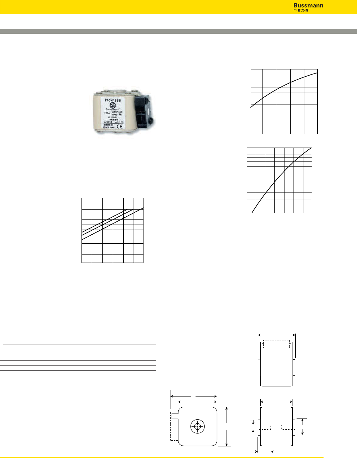
For product data sheets, visit www.cooperbussmann.com/DatasheetsEle
High Speed Fuses
152
Arc Voltage
This curve gives the peak
arc voltage, UL, which
may appear across the
fuse during its operation
as a function of theapplied
working voltage, Eg, (rms)
at a power factor of 15%.
Power Losses
Watts loss at rated current
is given in the electrical
characteristics. The curve
allows the calculation of
the power losses at load
currents lower than the
rated current. The
correction factor, Kp, is
given as a function of the
RMS load current, Ib, in %
of the rated current.
Features and Benefits
• Excellent DC performance
• Low arc voltage and low energy let-through (I2t)
• Low watts loss
• Superior cycling capability
Typical Applications
• DC Common bus
• DC Drives
• Power converters/rectifiers
• Reduced voltage starters
Square Body Flush End Contact — 690V/700V (IEC/UL):
40-2000A
Kp
30 40 50 60 70 80 90 100%
Ib
1.0
0.8
0.4
0.5
0.6
0.3
0.2
0.1
690V/700V (IEC/UL) 40-2000A
Specifications
Description: Square body flush
end contact high speed fuses.
Dimensions: See dimensions
illustrations.
Ratings:
Volts: — 690Vac (IEC)
— 700Vac (UL)
Amps: — 40-2000A
IR: — 200kA RMS Sym.
Agency Information: CE, Designed and tested to IEC
60269: Part 4. UL Recognized E125085.JFHR2, CSA
Certified: Class 53787, File 1422-30.
Electrical
Characteristics
Total Clearing I2t
The total clearing I2t at
rated voltage and at power
factor of 15% are given in
the electrical
characteristics. For other
voltages, the clearing I2t is
found by multiplying by
correction factor, K, given
as a function of applied
working voltage, Eg, (rms).
A
B
D
E
EH
G
F
Dimensions - mm
Type -B/-, -BKN/-, -G/-, -GKN/-
Size A B D E F F** (in) G H
1* 50 51 59 45 M8 5⁄16” - 18 UNC-2B 5 ø17
150516953M8
5⁄16” - 18 UNC-2B 8 ø20
250517761M10
3⁄8” - 16 UNC-2B 10 ø24
351539276M12
1⁄2” - 13 UNC-2B 10 ø30
**Valid for fuses type -G/- & -GKN/-.
NB: B = 65 for: Size 2, 1100-1250A
Size 3, 1600-2000A
1mm = 0.0394” / 1” = 25.4mm
UL
1.4
1.2
103
6
8
7
9
5
4
3
Eg
200 300 400 500 600 690
K
1.5
1.0
0.5
0.4
0.3
0.2
Eg
1)2)
100 200 300 400 500 600 690
1) Rated voltage 600V.
2) Rated voltage 550V
For Other Voltage Ratings in This Body Style
• See pages 176 (1000V) and 189 (1250V/1300V)
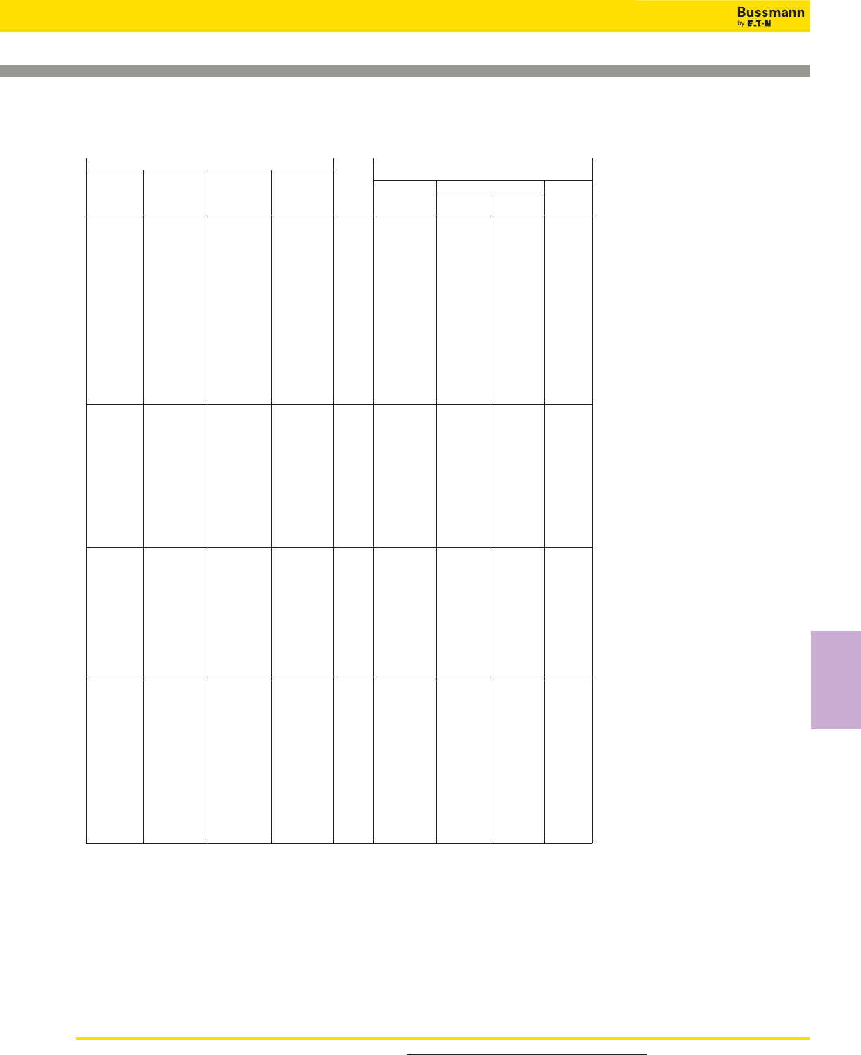
153
Square Body Flush End Contact — 690V/700V (IEC/UL):
40-2000A
Catalog Numbers
-BKN/- -GKN/- Electrical Characteristics
-B/- Type K -G/- Type K Rated I2t (A2Sec)
Visual Indicator Visual Indicator Current Clearing Watts
Indicator for Micro Indicator for Micro Size RMS-Amps Pre-arc at 660V Loss
170M3408 170M3458 170M3508 170M3558 40 40 270 9
170M3409 170M3459 170M3509 170M3559 50 77 515 11
170M3410 170M3460 170M3510 170M3560 63 115 770 14
170M3411 170M3461 170M3511 170M3561 80 185 1250 18
170M3412 170M3462 170M3512 170M3562 100 360 2450 21
170M3413 170M3463 170M3513 170M3563 125 550 3700 26
170M3414 170M3464 170M3514 170M3564 160 1100 7500 30
170M3415 170M3465 170M3515 170M3565 200 2200 15000 35
170M3416 170M3466 170M3516 170M3566 1* 250 4200 28500 40
170M3417 170M3467 170M3517 170M3567 315 7000 46500 50
170M3418 170M3468 170M3518 170M3568 350 10000 68500 55
170M3419 170M3469 170M3519 170M3569 400 15000 105000 60
170M3420 170M3470 170M3520 170M3570 450 21000 140000 65
170M3421 170M3471 170M3521 170M3571 500 27000 180000 70
170M3422 170M3472 170M3522 170M3572 550 34000 230000 75
170M3423 170M3473 170M3523 170M3573 630 48500 325000 80
170M4408 170M4458 170M4508 170M4558 200 1650 11500 45
170M4409 170M4459 170M4509 170M4559 250 3100 21000 55
170M4410 170M4460 170M4510 170M4560 315 6200 42000 58
170M4411 170M4461 170M4511 170M4561 350 8500 59000 60
170M4412 170M4462 170M4512 170M4562 400 13500 91500 65
170M4413 170M4463 170M4513 170M4563 450 17000 120000 70
170M4414 170M4464 170M4514 170M4564 1 500 25000 170000 72
170M4415 170M4465 170M4515 170M4565 550 34000 230000 75
170M4416 170M4466 170M4516 170M4566 630 52000 350000 80
170M4417 170M4467 170M4517 170M4567 700 69500 465000 85
170M4418 170M4468 170M4518 170M4568 800 105000 725000 95
170M4419 170M4469 170M4519 170M4569 ‡900 155000 ‡850000 100
170M5408 170M5458 170M5508 170M5558 400 11000 74000 65
170M5409 170M5459 170M5509 170M5559 450 15500 105000 70
170M5410 170M5460 170M5510 170M5560 500 21500 145000 75
170M5411 170M5461 170M5511 170M5561 550 28000 190000 80
170M5412 170M5462 170M5512 170M5562 630 41000 275000 90
170M5413 170M5463 170M5513 170M5563 2 700 60500 405000 95
170M5414 170M5464 170M5514 170M5564 800 86000 575000 105
170M5415 170M5465 170M5515 170M5565 900 125000 840000 110
170M5416 170M5466 170M5516 170M5566 1000 180000 1250000 115
170M5417 170M5467 170M5517 170M5567 1100 245000 1600000 120
170M5418 170M5468 170M5518 170M5568 1250 365000 2400000 130
170M6408 170M6458 170M6508 170M6558 500 14000 95000 95
170M6409 170M6459 170M6509 170M6559 550 19500 135000 100
170M6410 170M6460 170M6510 170M6560 630 31000 210000 105
170M6411 170M6461 170M6511 170M6561 700 44500 300000 110
170M6412 170M6462 170M6512 170M6562 800 69500 465000 115
170M6413 170M6463 170M6513 170M6563 900 100000 670000 120
170M6414 170M6464 170M6514 170M6564 3 1000 140000 945000 125
170M6415 170M6465 170M6515 170M6565 1100 190000 1300000 130
170M6416 170M6466 170M6516 170M6566 1250 290000 1950000 140
170M6417 170M6467 170M6517 170M6567 1400 370000 2450000 155
170M6418 170M6468 170M6518 170M6568 1500 460000 3100000 160
170M6419 170M6469 170M6519 170M6569 1600 580000 3900000 160
170M6420 170M6470 170M6520 170M6570 †1800 880000 †5250000 165
170M6421 170M6471 170M6521 170M6571 ‡2000 1150000 ‡6350000 175
†Rated voltage (IEC) 600V.
‡Rated voltage (IEC) 550V.
• Watts loss provided at rated current.
• Microswitch indicator ordered separately. See accessories on pages 212-213.
• For fuse curves see pages 158 and 159.
For product data sheets, visit www.cooperbussmann.com/DatasheetsEle
High Speed
Fuses
Catalog Numbers
High Speed Fuses
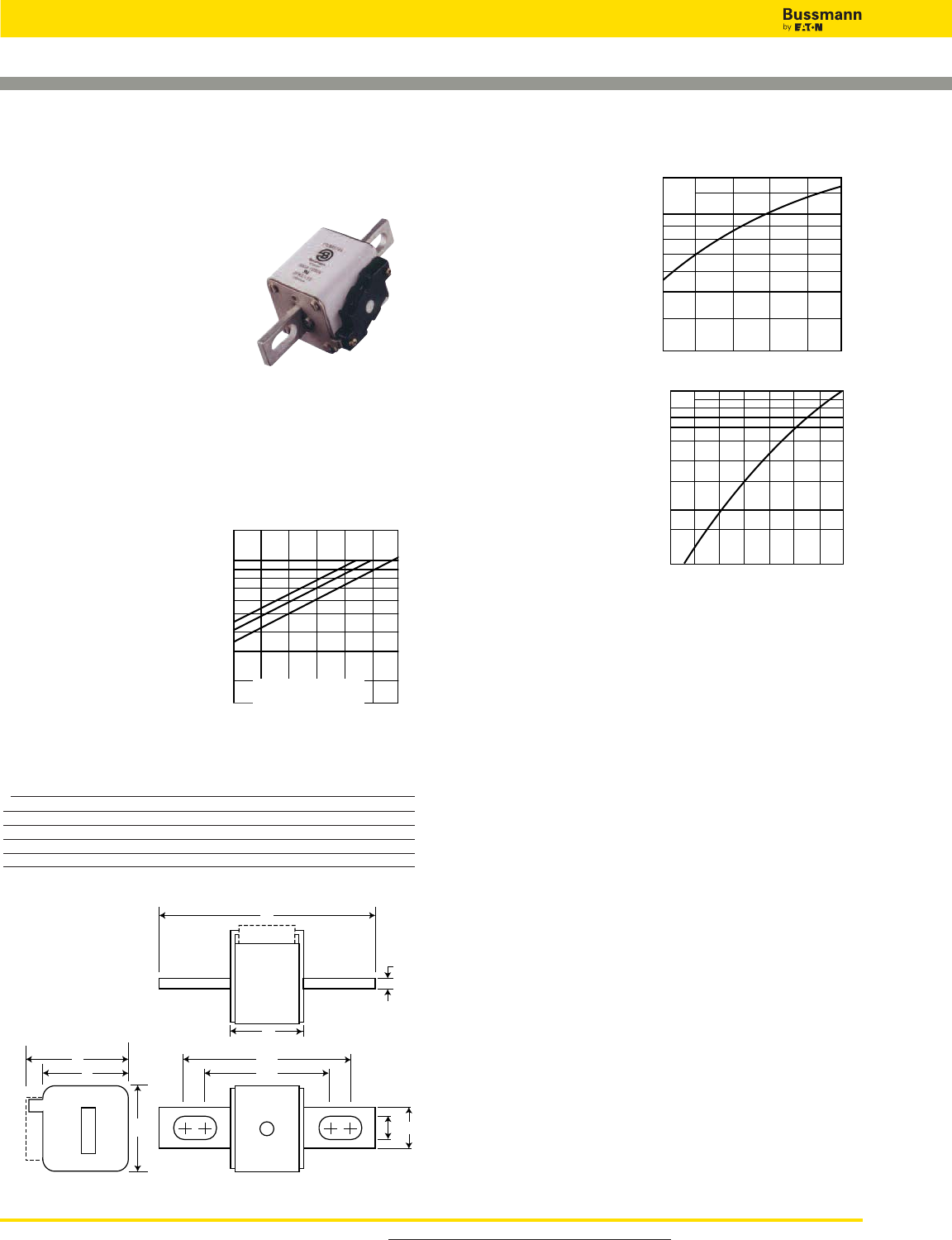
For product data sheets, visit www.cooperbussmann.com/DatasheetsEle
High Speed Fuses
154
Arc Voltage
This curve gives the peak
arc voltage, UL, which
may appear across the
fuse during its operation
as a function of theapplied
working voltage, Eg, (rms)
at a power factor of 15%.
Power Losses
Watts loss at rated current
is given in the electrical
characteristics. The curve
allows the calculation of
the power losses at load
currents lower than the
rated current. The
correction factor, Kp, is
given as a function of the
RMS load current, Ib, in %
of the rated current.
Features and Benefits
• Excellent DC performance
• Low arc voltage and low energy let-through (I2t)
• Low watts loss
• Superior cycling capability
Typical Applications
• DC Common bus
• DC Drives
• Power converters/rectifiers
• Reduced voltage starters
Square Body US Style — 690V/700V (IEC):
40-2000A
690V/700V (IEC) 40-2000A
Specifications
Description: Square body US
style high speed fuses.
Dimensions: See dimensions
illustration.
Ratings:
Volts: — 690Vac (IEC)
— 700Vac (UL)
Amps: — 40-200A
IR: — 200kA RMS Sym.
Agency Information: CE, Designed and tested to IEC
60269: Part 4. UL Recognized E125085.JFHR2, CSA
Certified: Class 53787, File 1422-30.
Electrical
Characteristics
Total Clearing I2t
The total clearing I2t at rated
voltage and at power factor
of 15% are given in the
electrical characteristics. For
other voltages, the clearing
I2t is found by multiplying by
correction factor, K, given as
a function of applied working
voltage, Eg, (rms).
B
C2
D
E
E
6
H I
C1
A
Dimensions - mm
Type -FU/-, -FKE/-, FU/115-, -FKE/115
Size A B B** C1 C1** C2 C2** D E H I
1* 50 110 148 85 123 72 110 59 45 20 10
1 50 136 157 104 126 78 100 69 53 25 14
2 50 135 159 105 125 78 99 77 61 25 14
3 51 135 155 106 125 77 97 92 76 36 16
**Valid for fuses type -FU/115 & -FKE/115.
1mm = 0.0394” / 1” = 25.4mm
K
1.5
1.0
0.5
0.4
0.3
0.2
1)2)
100 200 300 400 500 600 690
UL
1.4
1.2
103
6
8
7
9
5
4
3
Eg
200 300 400 500 600 690
Kp
1.0
0.8
0.4
0.5
0.6
0.3
0.2
0.1
30 40 50 60 70 80 90 100%
Ib
1) Rated voltage 600V.
2) Rated voltage 550V
For Other Voltage Ratings in This Body Style
• See pages 178 (1000V) and 191 (1250V/1300V)

155
Square Body US style — 690V/700V (IEC): 40-2000A
Catalog Numbers
-FKE/- -FKE/115 Electrical Characteristics
-FU/- Type K -FU/115 Type K Rated I2t (A2Sec)
Without Indicator Without Indicator Current Clearing Watts
Indicator for Micro Indicator for Micro Size RMS-Amps Pre-arc at 660V Loss
170M3608 170M3658 170M3708 170M3758 40 40 270 9
170M3609 170M3659 170M3709 170M3759 50 77 515 11
170M3610 170M3660 170M3710 170M3760 63 115 770 14
170M3611 170M3661 170M3711 170M3761 80 185 1250 18
170M3612 170M3662 170M3712 170M3762 100 360 2450 21
170M3613 170M3663 170M3713 170M3763 125 550 3700 26
170M3614 170M3664 170M3714 170M3764 160 1100 7500 30
170M3615 170M3665 170M3715 170M3765 200 2200 15000 35
170M3616 170M3666 170M3716 170M3766 1* 250 4200 28500 40
170M3617 170M3667 170M3717 170M3767 315 7000 46500 50
170M3618 170M3668 170M3718 170M3768 350 10000 68500 55
170M3619 170M3669 170M3719 170M3769 400 15000 105000 60
170M3620 170M3670 170M3720 170M3770 450 21000 140000 65
170M3621 170M3671 170M3721 170M3771 500 27000 180000 70
170M3622 170M3672 170M3722 170M3772 550 34000 230000 75
170M3623 170M3673 170M3723 170M3773 630 48500 325000 80
170M4608 170M4658 170M4708 170M4758 200 1650 11500 45
170M4609 170M4659 170M4709 170M4759 250 3100 21000 55
170M4610 170M4660 170M4710 170M4760 315 6200 42000 58
170M4611 170M4661 170M4711 170M4761 350 8500 59000 60
170M4612 170M4662 170M4712 170M4762 400 13500 91500 65
170M4613 170M4663 170M4713 170M4763 1 450 17000 120000 70
170M4614 170M4664 170M4714 170M4764 500 25000 170000 72
170M4615 170M4665 170M4715 170M4765 550 34000 230000 75
170M4616 170M4666 170M4716 170M4766 630 52000 350000 80
170M4617 170M4667 170M4717 170M4767 700 69500 465000 85
170M4618 170M4668 170M4718 170M4768 800 105000 725000 95
170M4619 170M4669 170M4719 170M4769 ‡900 155000 ‡850000 100
170M5608 170M5658 170M5708 170M5758 400 11000 74000 65
170M5609 170M5659 170M5709 170M5759 450 15500 105000 70
170M5610 170M5660 170M5710 170M5760 500 21500 145000 75
170M5611 170M5661 170M5711 170M5761 550 28000 190000 80
170M5612 170M5662 170M5712 170M5762 630 41000 275000 90
170M5613 170M5663 170M5713 170M5763 2 700 60500 405000 95
170M5614 170M5664 170M5714 170M5764 800 86000 575000 105
170M5615 170M5665 170M5715 170M5765 900 125000 840000 110
170M5616 170M5666 170M5716 170M5766 1000 180000 1250000 115
170M5617 170M5667 170M5717 170M5767 1100 245000 1600000 120
170M5618 170M5668 170M5718 170M5768 1250 365000 2400000 130
170M6608 170M6658 170M6708 170M6758 500 14000 95000 95
170M6609 170M6659 170M6709 170M6759 550 19500 135000 100
170M6610 170M6660 170M6710 170M6760 630 31000 210000 105
170M6611 170M6661 170M6711 170M6761 700 44500 300000 110
170M6612 170M6662 170M6712 170M6762 800 69500 465000 115
170M6613 170M6663 170M6713 170M6763 900 100000 670000 120
170M6614 170M6664 170M6714 170M6764 1000 140000 945000 125
170M6615 170M6665 170M6715 170M6765 3 1100 190000 1300000 130
170M6616 170M6666 170M6716 170M6766 1250 290000 1950000 140
170M6617 170M6667 170M6717 170M6767 1400 370000 2450000 155
170M6618 170M6668 170M6718 170M6768 1500 460000 3100000 160
170M6619 170M6669 170M6719 170M6769 1600 580000 3900000 160
170M6620 170M6670 170M6720 170M6770 †1800 880000 †5250000 165
170M6621 170M6671 170M6721 170M6771 ‡2000 1150000 ‡6350000 175
†Rated voltage (IEC) 600V.
‡Rated voltage (IEC) 550V.
• Watts loss provided at rated current.
• Microswitch indicator ordered separately. See accessories on pages 212-213.
• For fuse curves see pages 158 and 159.
For product data sheets, visit www.cooperbussmann.com/DatasheetsEle
High Speed
Fuses
Catalog Numbers
High Speed Fuses
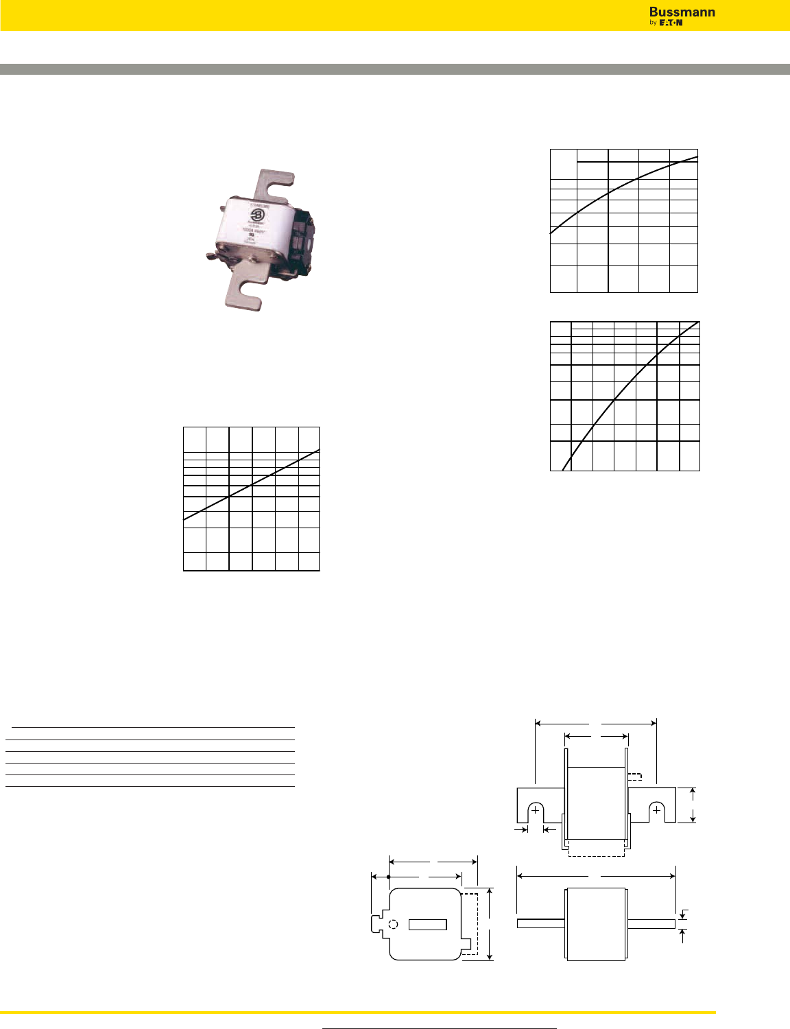
For product data sheets, visit www.cooperbussmann.com/DatasheetsEle
High Speed Fuses
156
Arc Voltage
This curve gives the peak
arc voltage, UL, which
may appear across the
fuse during its operation
as a function of theapplied
working voltage, Eg, (rms)
at a power factor of 15%.
Power Losses
Watts loss at rated current
is given in the electrical
characteristics. The curve
allows the calculation of
the power losses at load
currents lower than the
rated current. The
correction factor, Kp, is
given as a function of the
RMS load current, Ib, in %
of the rated current.
Features and Benefits
• Excellent DC performance
• Low arc voltage and low energy let-through (I2t)
• Low watts loss
• Superior cycling capability
Typical Applications
• DC Common bus
• DC Drives
• Power converters/rectifiers
• Reduced voltage starters
Square Body French Style — 690V/700V (IEC/UL):
40-1500A
690V/700V (IEC/UL) 40-1500A
Specifications
Description: Square body French
style high speed fuses.
Dimensions: See dimensions
illustration.
Ratings:
Volts: — 690Vac (IEC)
— 700Vac (UL)
Amps: — 40-1500A
IR: — 200kA RMS Sym.
Agency Information: CE, Designed and tested to IEC
60269: Part 4. UL Recognized E125085.JFHR2 & CSA
Component Acceptance file Class 1422-30, (53787) on Sizes
(1, 2, 3) only
Electrical
Characteristics
Total Clearing I2t
The total clearing I2t at
rated voltage and at power
factor of 15% are given in
the electrical
characteristics. For other
voltages, the clearing I2t is
found by multiplying by
correction factor, K, given
as a function of applied
working voltage, Eg, (rms).
A
B
C
D
E
J
E
6
H
I
Dimensions - mm
Type -E/-, -EKN/-
Size A B C D E H I J
1* 50 102 76 59 45 18 9 13
1 50 111 86 69 53 25 11 11
2 50 126 91 77 61 30 13 12
3 51 126 91 92 76 36 13 13
1mm = 0.0394” / 1” = 25.4mm
K
1.5
1.0
0.5
0.4
0.3
0.2
Eg
100 200 300 400 500 600 690
UL
1.4
1.2
103
6
8
7
9
5
4
3
Eg
200 300 400 500 600 690
Kp
1.0
0.8
0.4
0.5
0.6
0.3
0.2
0.1
30 40 50 60 70 80 90 100%
Ib

Square Body French Style — 690V/700V (IEC/UL): 40-1500A
157
1x102103104105
1x10⁻⁴
10–3
10–2
10–1
100
101
102
103
104
Prospective Current In Amperes RMS
Virtual Pre-Arcing Time In Seconds
400A 450A
500A 550A
630A 700A
800A 900A
1000A1100A
1250A
AA
Catalog Numbers
-E/ -EKN/- Electrical Characteristics
Type T Type K Rated I2t (A2 Sec)
Indicator Indicator Current Clearing Watts
For Micro for Micro Size RMS-Amps Pre-arc at 660V Loss
170M3308 170M3358 40 40 270 9
170M3309 170M3359 50 77 515 11
170M3310 170M3360 63 115 770 14
170M3311 170M3361 80 185 1250 18
170M3312 170M3362 100 360 2450 21
170M3313 170M3363 125 550 3700 26
170M3314 170M3364 160 1100 7500 30
170M3315 170M3365 1* 200 2200 15000 35
170M3316 170M3366 250 4200 28500 40
170M3317 170M3367 315 7000 46500 50
170M3318 170M3368 350 10000 68500 55
170M3319 170M3369 400 15000 105000 60
170M3320 170M3370 450 21000 140000 65
170M3321 170M3371 500 27000 180000 70
170M4308 170M4358 200 1650 11500 45
170M4309 170M4359 250 3100 21000 55
170M4310 170M4360 315 6200 42000 58
170M4311 170M4361 350 8500 59000 60
170M4312 170M4362 400 13500 91500 65
170M4313 170M4363 1 450 17000 120000 70
170M4314 170M4364 500 25000 170000 72
170M4315 170M4365 550 34000 230000 75
170M4316 170M4366 630 52000 350000 80
170M4317 170M4367 700 69500 465000 85
170M4318 170M4368 800 105000 725000 95
170M5308 170M5358 400 11000 74000 65
170M5309 170M5359 450 15500 105000 70
170M5310 170M5360 500 21500 145000 75
170M5311 170M5361 550 28000 190000 80
170M5312 170M5362 2 630 41000 275000 90
170M5313 170M5363 700 60500 405000 95
170M5314 170M5364 800 86000 575000 105
170M5315 170M5365 900 125000 840000 110
170M5316 170M5366 1000 180000 1250000 115
170M6308 170M6358 500 14000 95000 95
170M6309 170M6359 550 19500 135000 100
170M6310 170M6360 630 31000 210000 105
170M6311 170M6361 700 44500 300000 110
170M6312 170M6362 800 69500 465000 115
170M6313 170M6363 3 900 100000 670000 120
170M6314 170M6364 1000 140000 945000 125
170M6315 170M6365 1100 190000 1300000 130
170M6316 170M6366 1250 290000 1950000 140
170M6317 170M6367 1400 370000 2450000 155
170M6318 170M6368 1500 460000 3100000 160
• Watts loss provided at rated current.
• Microswitch indicator ordered separately. See accessories on pages 212-213.
• For fuse curves see pages 158 and 159.
For product data sheets, visit www.cooperbussmann.com/DatasheetsEle
High Speed
Fuses
Catalog Numbers
High Speed Fuses
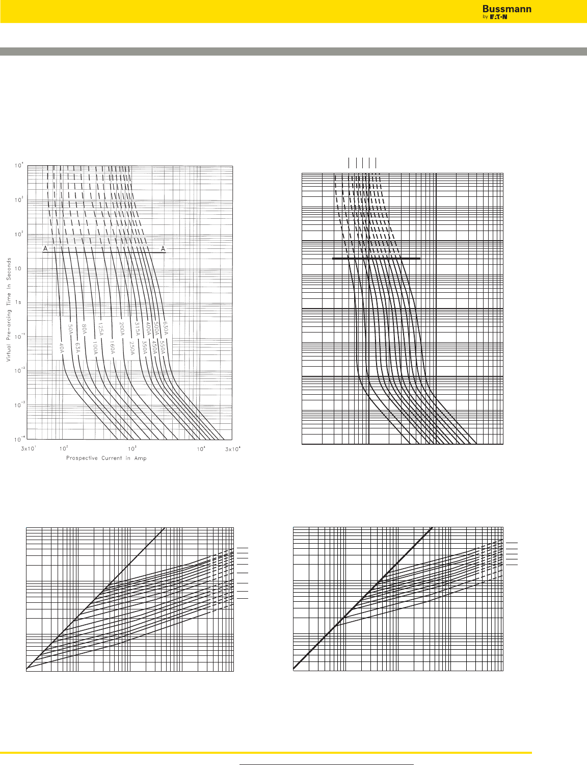
For product data sheets, visit www.cooperbussmann.com/DatasheetsEle
High Speed Fuses
158
Square Body, French Style - Size 1*, 1 — 690V/700V
(IEC/UL): 40-2000A
1x102103104105
1x10⁻⁴
10–3
10–2
10–1
100
101
102
103
104
Prospective Current In Amps
Virtual Pre-Arcing Time In Seconds
200A
250A
315
A
350A 400
A
450A 500
A
550A 630
A
700A 800
A
900A
AA
Size 1 — 200-900A: 690V
Time-Current Curve
Size 1* — 40-630A: 690V
Time-Current Curve
1x102103104105106
2x10²
103
104
105
Prospective Short-Circuit Current Symmetrical RMS
Peak Let-Through Current
50A
40A
63A 80A
100A 125A
160A
200A
250A 315A
350A 400A
450A 500A
550A 630A
A
B
1x102103104105106
2x10²
103
104
105
Peak Let-Through Current
200A
250A
315A
350A 400A
450A 500A
550A 630A
700A 800A
900A
A
B
Peak Let-Through Curve
Peak Let-Through Curve
900 amp fuse is derated to 550V (IEC).
Data Sheet: 17056316Data Sheet: 17056314
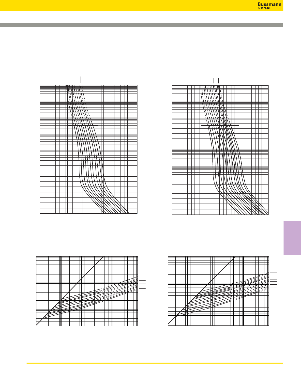
159
Square Body, French Style - Size 2, 3 — 690V/700V
(IEC/UL): 40-2000A
1x102103104105
1x10⁻⁴
10–3
10–2
10–1
100
101
102
103
104
Prospective Current In Amps RMS
Virtual Pre-Arcing Time In Seconds
400A 450A
500A 550A
630A 700A
800A 900A
1000A1100
A
1250A
AA
1x102103104105
1x10⁻⁴
10–3
10–2
10–1
100
101
102
103
104
Prospective Current In Amps RMS
Virtual Pre-Arcing Time In Seconds
500A
550A 630A
700A 800A
900A 1000
A
1100A 1250
A
1400A 1500
A
1600A 1800
A
2000A
AA
Size 3 — 500-2000A: 690V
Time-Current Curve
Size 2 — 400-1250A: 690V
Time-Current Curve
1x103104105106107
2x10³
104
105
106
Prospective Short-Circuit Current Symmetrical RMS
Peak Let-Through Current
400A 450A
500A 550A
630A 700A
800A 900A
1000A 1100A
1250A
A
B
1x103104105106107
2x10³
104
105
106
Prospective Short-Circuit Current Symmetrical RMS
Peak Let-Through Current
500A 550A
630A 700A
800A 900A
1000A 1100A
1250A 1400A
1500A 1600A
1800A 2000A
A
B
Peak Let-Through CurvePeak Let-Through Curve
1800A fuse is derated to 600V (IEC).
2000A fuse is derated to 550V (IEC).
Data Sheet: 17056318 Data Sheet: 17056320
For product data sheets, visit www.cooperbussmann.com/DatasheetsEle
High Speed
Fuses
High Speed Fuses
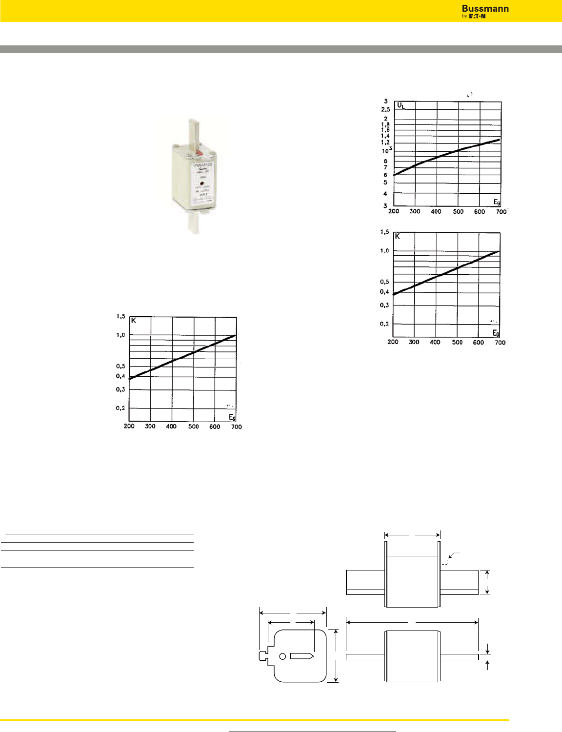
For product data sheets, visit www.cooperbussmann.com/DatasheetsEle
High Speed Fuses
160
Arc Voltage
This curve gives the peak
arc voltage, UL, which
may appear across the
fuse during its operation
as a function of theapplied
working voltage, Eg, (rms)
at a power factor of 15%.
Power Losses
Watts loss at rated current
is given in the electrical
characteristics. The curve
allows the calculation of
the power losses at load
currents lower than the
rated current. The
correction factor, Kp, is
given as a function of the
RMS load current, Ib, in %
of the rated current.
Features and Benefits
• Excellent DC performance
• Low arc voltage and low energy let-through (I2t)
• Low watts loss
• Superior cycling capability
Typical Applications
• DC Common bus
• DC Drives
• Power converters/rectifiers
• Reduced voltage starters
Square Body DIN 43 620 — 690V/700V (IEC/UL):
40-1000A
690V/700V (IEC/UL) 40-1000A
Specifications
Description: Square body DIN
43 620 blade style high speed
fuses.
Dimensions: See dimensions
illustration.
Ratings:
Volts:— 690Vac (IEC)
— 700Vac (UL)
Amps:— 40-1000A
IR:— 200kA RMS Sym.
Agency Information: CE, Designed and tested to IEC
60269: Part 4. UL Recognized E125085.JFHR2.
Electrical
Characteristics
Total Clearing I2t
The total clearing I2t at
rated voltage and at power
factor of 15% are given in
the electrical
characteristics. For other
voltages, the clearing I2t is
found by multiplying by
correction factor, K, given
as a function of applied
working voltage, Eg, (rms).
A
B
D
E
F
6
H
Indicator
Dimensions (mm)
Type DIN 1*, DIN 2, DIN 3
Size A B D E F H
1* 69 135 58 45 40 20
2 69 150 71 55 48 26
3 68 150 88 76 60 33
1mm = 0.0394” / 1” = 25.4mm
For Full Range Fuses in This Body Style
• See page 168
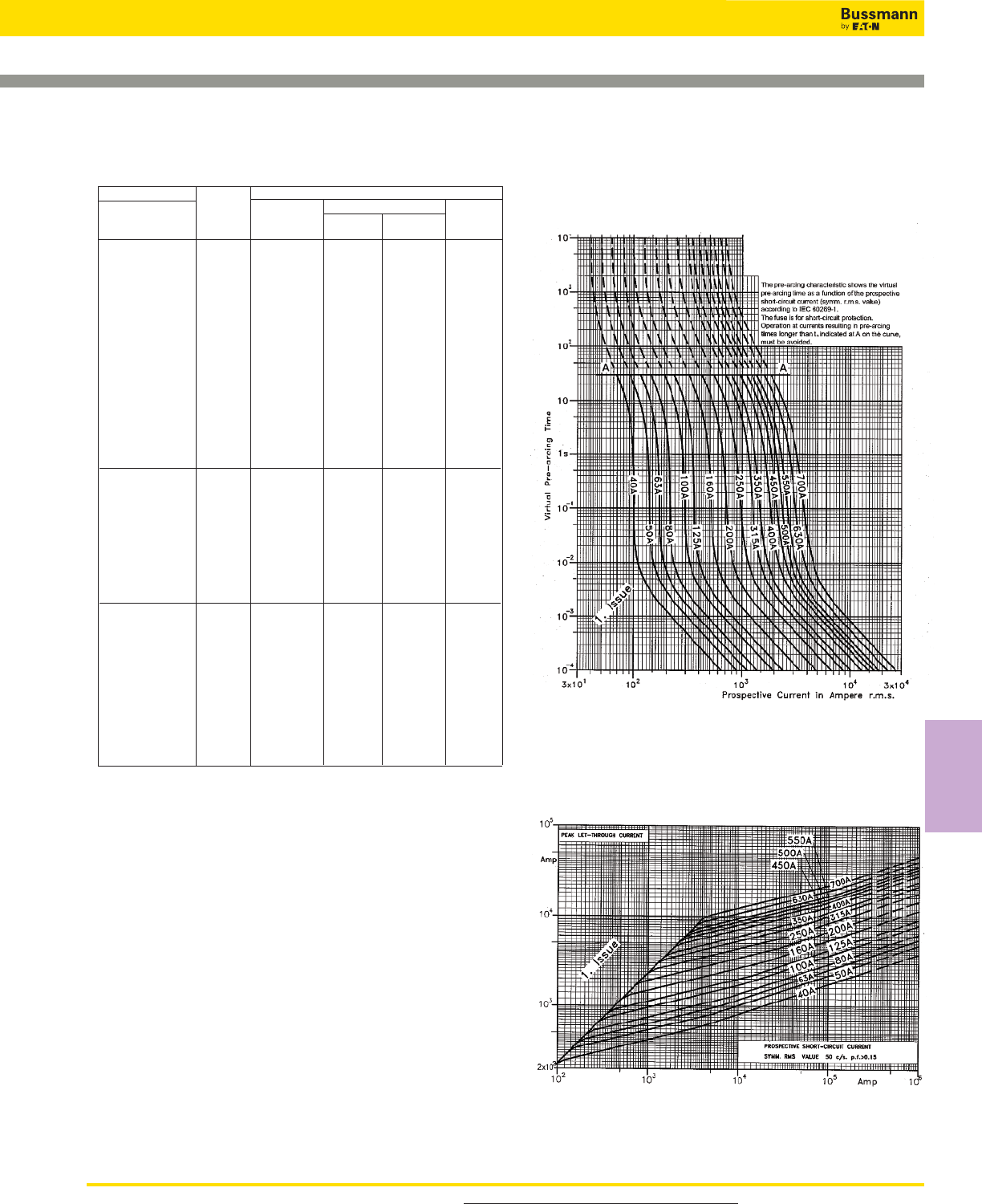
161
Square Body DIN 43 620 — 690V/700V (IEC/UL):
40-600A
Catalog Numbers Electrical Characteristics
DIN Type T Rated I2t (A2Sec)
Indicator Current Clearing Watts
for Micro Size RMS-Amps Pre-arc at 660V Loss
170M3808D 40 40 285 4
170M3809D 50 78 550 4.5
170M3810D 63 120 850 6.5
170M3811D 80 185 1350 8.5
170M3812D 100 360 2600 10
170M3813D 125 550 3900 11
170M3814D 160 1150 8250 12
170M3815D 200 2300 16500 12.5
170M3816D 1* 250 4350 31000 16
170M3817D 315 7300 52000 20
170M3818D 350 10000 73000 21.5
170M3819D 400 16000 115000 60
170M4863D 450 21500 155000 26.3
170M4864D 500 27000 190000 28.5
170M4865D 550 33500 240000 33
170M4866D 630 48500 345000 37.5
170M4867D 700 69500 495000 39
170M5808D 400 11000 79000 29
170M5809D 450 16000 115000 32
170M5810D 500 21500 155000 34
170M5811D 550 29000 215000 36
170M5812D 2 630 41000 295000 42
170M5813D 700 60500 430000 43
170M5814D 800 86000 610000 48
170M5820D 900 125000 895000 52
170M5816D 1000 180000 1300000 53
170M5817D 1100 245000 1750000 56
170M6808D 500 14000 99500 43
170M6809D 550 19500 140000 44
170M6810D 630 31000 220000 45
170M6811D 700 45000 320000 46
170M6812D 800 69500 490000 48
170M6813D 3 900 100000 720000 50
170M6814D 1000 140000 985000 56
170M6892D 1100 190000 1400000 57
170M8554D 1250 300000 2150000 61
170M8555D 1400 380000 2700000 70
170M8556D 1500 470000 3350000 72
170M8557D 1600 585000 4150000 74
• Watts loss provided at rated current.
• Microswitch indicator ordered separately. See accessories on pages 212-213.
• For fuse curves see page 162.
Rated Current
The rated current of this fuse range has been given with
copper conductors that have a current density of 1.3A/mm2
(IEC 60269-4). For conductor cross section according to IEC
60269-1, the fuses must be derated. Please contact
Bussmann for application assistance.
Size 1* — 40-630A: 690V
Time-Current Curve
Peak Let-Through Curve
Data Sheet: 17056314
For product data sheets, visit www.cooperbussmann.com/DatasheetsEle
High Speed
Fuses
Catalog Numbers
High Speed Fuses
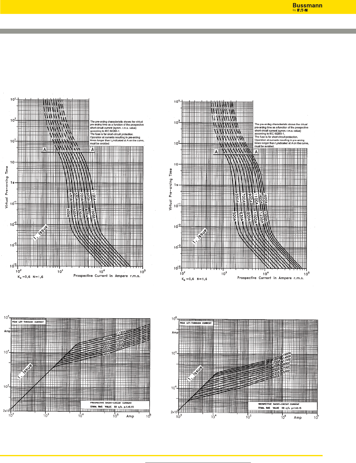
For product data sheets, visit www.cooperbussmann.com/DatasheetsEle
High Speed Fuses
162
Square Body DIN 43 620 — 690V/700V (IEC/UL):
40-1000A
Size 3 — 500-2000A: 690V
Time-Current Curve
Peak Let-Through Curve
Size 2 — 400-1250A: 690V
Time-Current Curve
Peak Let-Through Curve
Data Sheet: 17056318 Data Sheet: 17056320
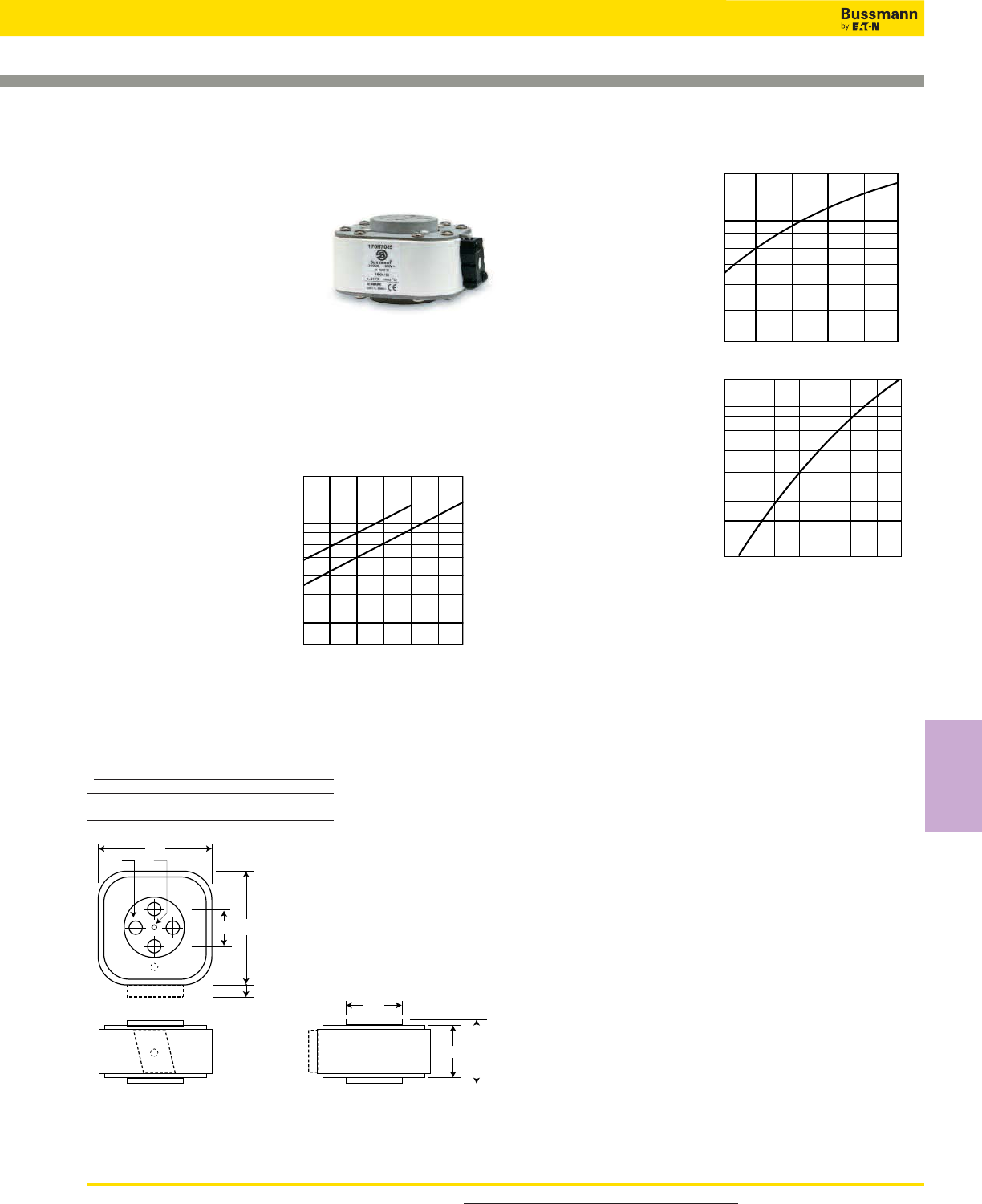
163
Arc Voltage
This curve gives the peak
arc voltage, UL, which
may appear across the
fuse during its operation
as a function of the
applied working voltage,
Eg, (rms) at a power
factor of 15%.
Power Losses
Watts loss at rated
current is given in the
electrical characteristics.
The curve allows the
calculation of the power
losses at load currents
lower than the rated
current. The correction
factor, Kp, is given as a
function of the RMS load
current, Ib, in % of the
rated current.
Features and Benefits
• Excellent DC performance
• Low arc voltage and low energy let-through (I2t)
• Low watts loss
• Superior cycling capability
Typical Applications
• DC Common bus
• DC Drives
• Power converters/rectifiers
• Reduced voltage starters
Square Body Flush End Contact — 690/700V (IEC/UL):
1000-4000A
690V (IEC) 1000-4000A
Specifications
Description: Square body flush
end contact high speed fuses.
Dimensions: See dimensions
illustrations.
Ratings:
Volts: — 690Vac
Amps: — 1000-4000A
IR: — 200kA RMS Sym.
Agency Information: CE, Designed and tested to IEC
60269: Part 4. UL Recognized E125085.JFHR2.
Electrical
Characteristics
Total Clearing I2t
The total clearing I2t at
rated voltage and at power
factor of 15% are given in
the electrical
characteristics. For other
voltages, the clearing I2t is
found by multiplying by
correction factor, K, given
as a function of applied
working voltage, Eg, (rms).
K
1.5
1.0
0.5
0.4
0.3
0.2
Eg
1)
100 200 300 400 500 600 690
Kp
30 40 50 60 70 80 90 100%
Ib
1.0
0.8
0.4
0.5
0.6
0.3
0.2
0.1
1) Rated voltage 500V
UL
1.4
1.2
103
6
8
7
9
5
4
3
Eg
200 300 400 500 600 690
53
105
67
15
F
G
105
Ø4
Ø56
Dimensions - mm
Type 4B/-, 4BKN/-, 4G/-, 4GKN/-
Size F (in) G
4B M10 10 deep 33
4G 1⁄2” -13 UNC-2B 10 deep 38
1mm = 0.0394” / 1” = 25.4mm For Other Voltage Ratings in This Body Style
• See pages 182 (1000V) and 195 (1250V)
For product data sheets, visit www.cooperbussmann.com/DatasheetsEle
High Speed
Fuses
High Speed Fuses
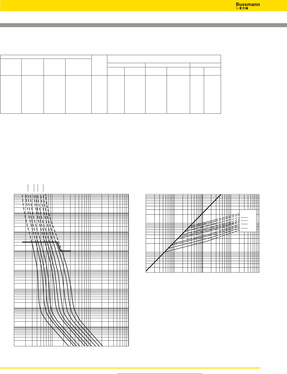
For product data sheets, visit www.cooperbussmann.com/DatasheetsEle
High Speed Fuses
164
Square Body Flush End Contact — 690V (IEC):
1000-4000A
1x103104105106
1x10⁻⁴
10–3
10–2
10–1
100
101
102
103
104
Prospective Current in Amps RMS
Virtual Pre-Arcing Time In Seconds
1000A
1250A 1400
A
1600A
2000
A
2200A 2500
A
3000A 3500
A
4000A
A
A
Size 4 — 1000-4000A: 690V
Time-Current Curve
1x103104105106107
2x10³
104
105
106
Prospective Short-Circuit Current Symmetrical RMS
Peak Let-Through Current
1000A 1250A
1400A 1600A
2000A 2200A
2500A 3000A
3500A
4000A
A
B
Peak Let-Through Curve
4000A fuse is derated to 500V (IEC).
Catalog Numbers
-BKN/- -GKN/- Electrical Characteristics
-B/- Type K -G/- Type K Rated Current RMS I2t (A2Sec) Watts Loss
Visual Indicator Visual Indicator Norm. Liquid Clearing Norm. Liquid
Indicator for Micro Indicator for Micro Size Cool. Cool. Pre-arc at 660V Cool. Cool.
170M7058 170M7078 170M7098 170M7118 1000 1350 76000 505000 175 315
170M7059 170M7079 170M7099 170M7119 1250 1700 145000 965000 195 355
170M7060 170M7080 170M7100 170M7120 1400 1900 205000 1400000 205 375
170M7061 170M7081 170M7101 170M7121 1600 2200 305000 2050000 220 405
170M7062 170M7082 170M7102 170M7122 4 2000 2700 600000 3950000 245 445
170M7063 170M7083 170M7103 170M7123 2500 3400 1200000 7800000 275 495
170M7064 170M7084 170M7104 170M7124 3000 4100 2000000 13500000 305 555
170M7065 170M7085 170M7105 170M7125 3500 4700 3250000 22000000 325 585
170M7066 170M7086 170M7106 170M7126 †4000 †5400 4700000 †28000000 355 640
†Rated voltage (IEC) 500V.
• Watts loss provided at rated current.
• Liquid Cool. = Liquid cooling. Temperature on the terminals not to exceed 60°C.
• Microswitch indicator ordered separately. See accessories on pages 212-213.
Data Sheet: 17056328
Catalog Numbers
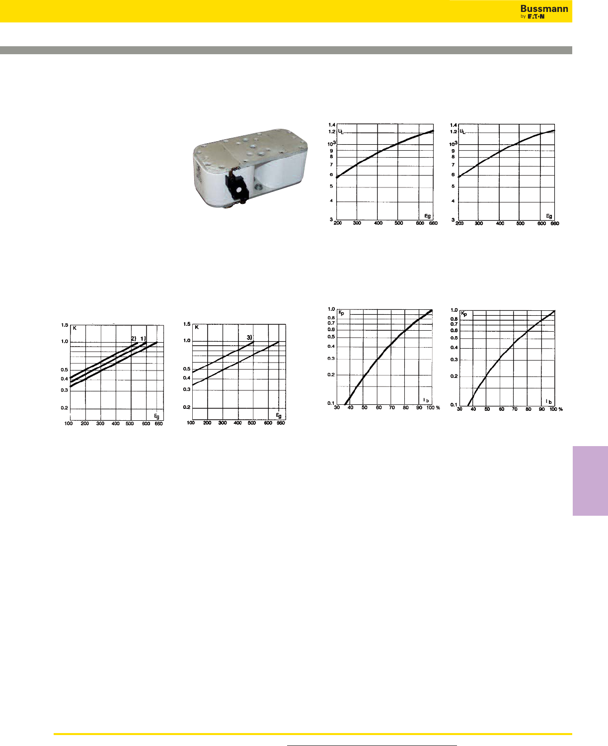
165
Square Body Flush End Contact Size 23, 24 — 660V
(IEC): 1000-7500A
660V (IEC) 1000-7500A
Specifications
Description: High speed
square body fuses, for the
protection of the power rectifier
section of the equipment.
Dimensions: See dimensions
illustrations.
Ratings:
Volts: — 660Vac
Amps: — 1000-4000A
IR: — 300kA RMS Sym.
Agency Information: CE, Designed and tested to IEC
60269: Part 4. UL Recognized E125085.JFHR2.
Electrical Characteristics
Total clearing I2t
The total clearing I2t at rated voltage and at power factor of
15% are given in the electrical characteristics. For other
voltages, the clearing I2t is found by multiplying by correction
factor, K, given as a function of applied working voltage,
Eg, (rms).
Arc Voltage
This curve gives the peak arc voltage, UL, which may
appear across the fuse during its operation as a function of
the applied working voltage Eg, (rms) at a power factor of
15%.
Power Losses
Watts loss at rated current is given in the electrical
characteristics. The curve allows the calculation of the power
losses at load currents lower than the rated current. The
correction factor, Kp, is given as a function of the RMS load
current, Ib, in % of the rated current.
Features and Benefits
• Low watts loss
• Superior cycling capability
For Other Voltage Ratings in This Body Style
• See pages 185 (1000V) and 198 (1250V)
Size 24
Size 23
Size 24
Size 24
Size 23
Size 23
Typical Applications
• Power converters/rectifiers
• Reduced voltage starters
For product data sheets, visit www.cooperbussmann.com/DatasheetsEle
High Speed
Fuses
High Speed Fuses
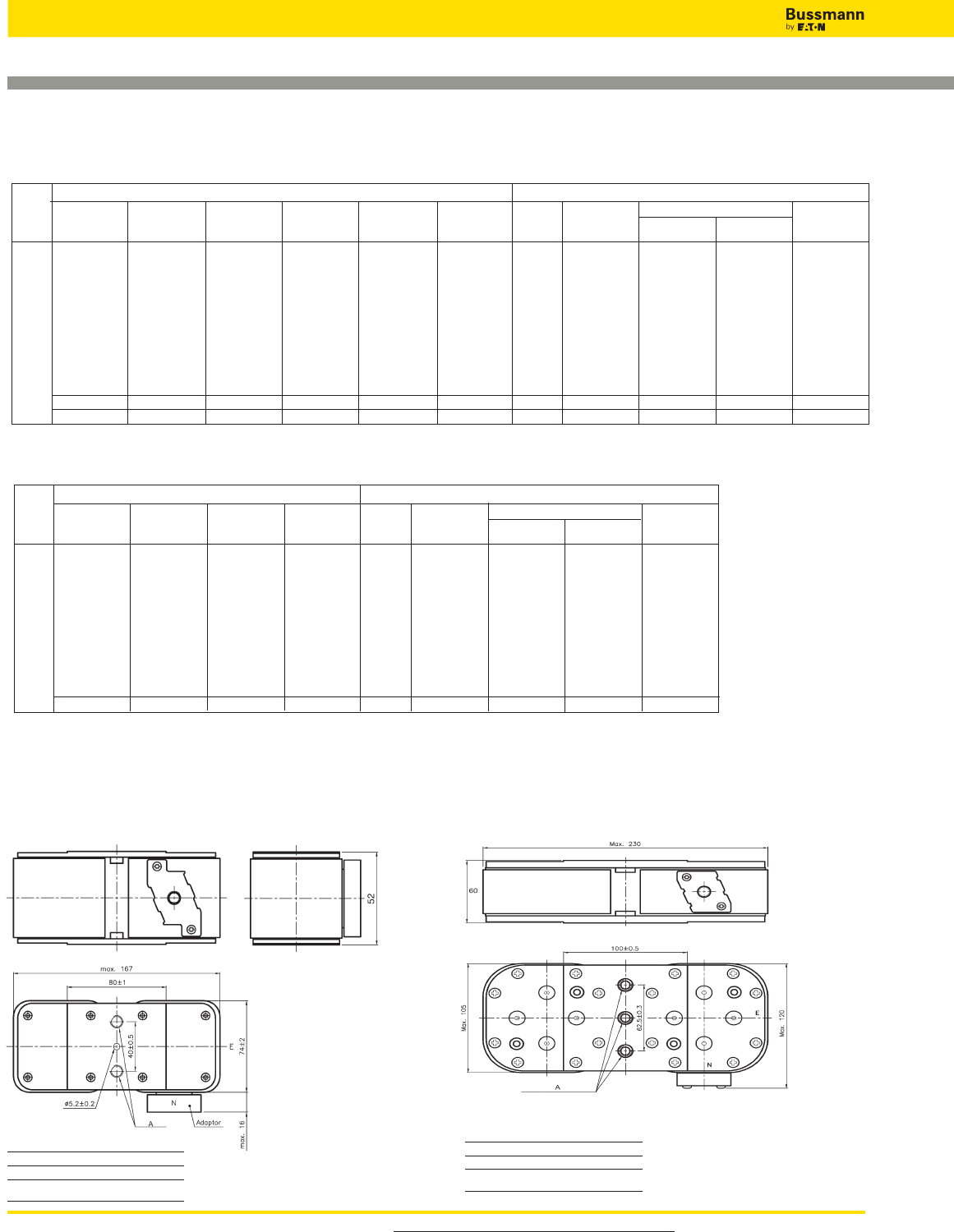
For product data sheets, visit www.cooperbussmann.com/DatasheetsEle
High Speed Fuses
166
Square Body Flush End Contact Size 23, 24 — 660V
(IEC): 1000-7500A
-BU/55
Visual
Indicator
Catalogue Number Electrical Characteristics
I2t (A2Sec)
-BKE/55
Type K
Indicator
-BKN/55
Type K
Indicator
-GU/55
Visual
Indicator
-GKE/55
Type K
Indicator
-GKN/55
Type K
Indicator
Watt
Loss
(W)
Rated
Voltage
(V)
Rated
Current
RMS-Amp
Fuse
Size Pre-arc Clearing
at 660V
Data Sheet: 170K6326
170M6858 170M6898 170M6878 170M6918 170M6958 170M6938 1000 79,000 530,000 170.0
170M6859 170M6899 170M6879 170M6919 170M6959 170M6939 1100 95,000 635,000 185.0
170M6860 170M6900 170M6880 170M6920 170M6960 170M6940 1250 155,000 1,050,000 190.0
170M6861 170M6901 170M6881 170M6921 170M6961 170M6941 1400 200,000 1,350,000 210.0
170M6862 170M6902 170M6882 170M6922 170M6962 170M6942 1500 240,000 1,650,000 215.0
23 170M6863 170M6903 170M6883 170M6923 170M6963 170M6943 660 1600 315,000 2,150,000 220.0
170M6864 170M6904 170M6884 170M6924 170M6964 170M6944 1800 450,000 3,050,000 230.0
170M6865 170M6905 170M6885 170M6925 170M6965 170M6945 2000 625,000 4,200,000 240.0
170M6866 170M6906 170M6886 170M6926 170M6966 170M6946 2200 805,000 5,400,000 255.0
170M6867 170M6907 170M6887 170M6927 170M6967 170M6947 2500 1,250,000 8,350,000 265.0
170M6868 170M6908 170M6888 170M6928 170M6968 170M6948 3000 2,250,000 15,500,000 285.0
170M6869 170M6909 170M6889 170M6929 170M6969 170M6949 600 3500 3,450,000 21,000,000 315.0
170M6870 170M6910 170M6890 170M6930 170M6970 170M6950 550 4000 5,000,000 27,500,000 340.0
170M7138 170M7158 170M7198 170M7218 2000 340000 2300000 340
170M7139 170M7159 170M7199 170M7219 2500 650000 4350000 390
170M7140 170M7160 170M7200 170M7220 3000 1100000 7300000 430
170M7141 170M7161 170M7201 170M7221 3500 1800000 12000000 460
170M7142 170M7162 170M7202 170M7222 4000 2700000 18000000 490
24 170M7143 170M7163 170M7203 170M7223 690 4500 3800000 25500000 520
170M7144 170M7164 170M7204 170M7224 5000 5450000 36500000 540
170M7145 170M7165 170M7205 170M7225 5500 7400000 49500000 560
170M7146 170M7166 170M7206 170M7226 6000 9600000 64000000 580
170M7147 170M7167 170M7207 170M7227 6500 12500000 83000000 600
170M7148 170M7168 170M7208 170M7228 7000 15000000 100000000 630
170M7149 170M7169 170M7209 170M7229 500 7500 18500000 †93000000 660
-BU/60
without
Indicator
Catalogue Number Electrical Characteristics
I2t (A2Sec)
-BKN/60
Type K
Indicator
-GU/60
without
Indicator
-GKN/60
Type K
Indicator
Watts
Loss
(W)
Rated
Voltage
(V)
Rated
Current
RMS-Amp
Fuse
Size Pre-arc
Clearing at
660V
† A2s @ 500V
Data Sheet: 170K6332
Catalog Numbers:
Size A
24BKN 2x3 M12
24GKN 2x3 1/2” 16UNC-2B
Size 23
Type – BU/ 55, - BKE/ 55, - BKN/ 55, - GU/ 55, - GKE/ 55, - GKN/ 55
Size 24
Type – BU/ 55, - BKE/ 55, - BKN/ 55, - GU/ 55, - GKE/ 55, - GKN/ 55
Dimensions - mm
Size A
23G 2x2 M10
23B 3/8” 16UNC-2B
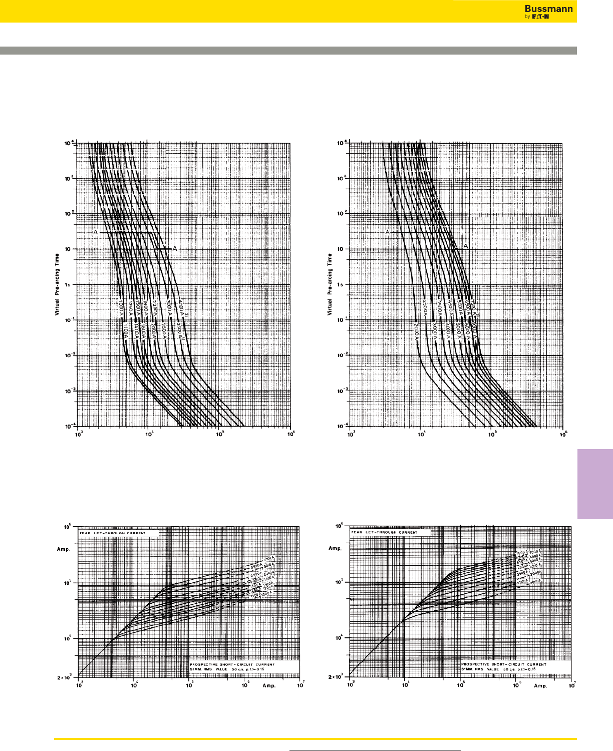
167
Square Body Flush End Contact Size 23, 24 — 660V
(IEC): 1000-7500A
Size 24 — 2000-7500A: 660V
Time-Current Curve
Size 23 — 10000-4000A: 660V
Time-Current Curve
Peak Let-Through CurvePeak Let-Through Curve
Data Sheet: Available upon request Data Sheet: Available upon request
Prospective Current in Amps RMS Prospective Current in Amps RMS
For product data sheets, visit www.cooperbussmann.com/DatasheetsEle
High Speed
Fuses
High Speed Fuses
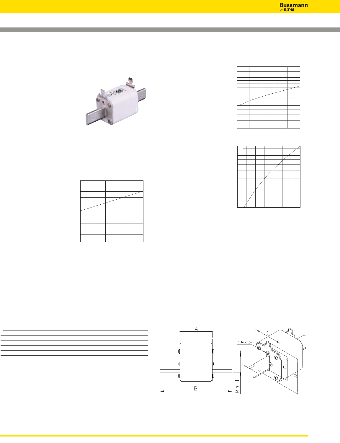
For product data sheets, visit www.cooperbussmann.com/DatasheetsEle
High Speed Fuses
168
Square Body DIN 43 620 — 690V (IEC): 10-800A
Class gR — Full Range Fuses
690V (IEC) 10-800A
Specifications
Description: Square body DIN 43
620 blade style high speed fuses.
Dimensions: See dimensions
illustration.
Ratings:
Volts: — 690Vac (IEC)
Amps: — 10-800A
IR: — 300kA RMS Sym.
Agency Information: CE, Designed and tested to IEC
60269: Part 4. UL Recognized E125085.JFHR2.
Electrical
Characteristics
Total clearing I2t
The total clearing I2t at
rated voltage and at power
factor of 15% are given in
the electrical
characteristics. For other
voltages, the clearing I2t is
found by multiplying by
correction factor, K, given
as a function of applied
working voltage, Eg, (rms).
Arc Voltage
This curve gives the
peak arc voltage, UL,
which may appear
across the fuse during
its operation as a
function of the applied
working voltage Eg,
(rms) at a power factor
of 15%.
Power Losses
Watts loss at rated current
is given in the electrical
characteristics. The curve
allows the calculation of
the power losses at load
currents lower than the
rated current. The
correction factor, Kp, is
given as a function of the
RMS load current, Ib, in %
of the rated current.
Features and Benefits
• Excellent DC performance
• Low arc voltage and low energy let-through (I2t)
• Low watts loss
• Superior cycling capability
Typical Applications
• DC Common bus
• DC Drives
• Power converters/rectifiers
• Reduced voltage starters
Dimensions - mm
Type DIN 00, DIN 1, DIN 2, DIN 3
Size A B Max D Max E F Min H
00 49 78.5 60 30 35 15
1 68 135 66 52 40 20
2 68 150 74 60 48 25
3 68 150 89 75 60 32
1 mm = 0.0394” 1” = 25.4 mm
1,5
1,0
0,5
0,4
0,3
0,2
K
Eg
200 300 400 500 600 700
3
2,5
2
1,8
1,6
1,4
1,2
103
8
7
6
5
4
3
UL
Eg
200 300 400 500 600 700
1,0
0,8
0,7
0,6
0,5
0,4
0,3
0,2
0,15
0,1
Kp
Ib
30 40 50 60 70 80 90 100%
For Operating Class aR Fuses in This Body Style
• See page 160
169
Square Body DIN 43 620 — 690V (IEC): 10-800A
Class gR — Full Range Fuses
Catalog
Numbers Electrical Characteristics
Type T RMS I2t (A2Sec)
Indicator Amp Clearing Watts
For Micro Size Rating* Pre-arc at 600V Loss
170M2691 10 3.8 20 3.5
170M2692 16 7.2 38 5.5
170M2693 20 13 70 6
170M2694 25 24 125 8
170M2695 32 53 275 9
170M2696 40 95 490 10
170M2697 00 50 185 1000 11
170M2698 63 345 1800 14
170M2699 80 695 3600 16
170M2700 100 1250 6650 19
170M2701 125 2300 12000 23
170M2702 160 4350 22500 29
170M4176 50 135 705 12
170M4177 63 245 1300 15
170M4178 80 500 2600 17
170M4179 100 950 4850 20
170M4180 125 1850 9500 23
170M4181 1 160 3450 18000 28
170M4182 200 6750 34500 31
170M4183 250 13500 70500 35
170M4184 315 26000 135000 41
170M4185 350 34000 175000 45
170M4186 400 48500 250000 48
170M5881 200 5650 29000 33
170M5882 250 10000 52500 40
170M5883 315 19500 105000 46
170M5884 350 26000 135000 50
170M5885 2 400 39500 205000 53
170M5886 450 55500 290000 59
170M5887 500 73000 375000 66
170M5888 550 100000 515000 70
170M5889 630 150000 770000 79
170M6080 350 23000 120000 55
170M6081 400 34000 175000 59
170M6082 450 48500 250000 62
170M6083 500 64000 330000 67
170M6084 3 550 84500 435000 70
170M6085 630 125000 645000 85
170M6086 700 160000 840000 93
170M6087 800 245000 1300000 99
*The RMS amp rating of this fuse range is given with open fuse bases connected to copper
conductors according to IEC 60269, Part 1, table 10. When used in enclosed fuse bases/
disconnects, derating factors have to be observed.
Please contact Bussmann for application assistance.
• Watts loss provided at rated current.
• Microswitch ordered separately. See accessories on page 212-213.
• For fuse curves see pages 170 and 171.
For product data sheets, visit www.cooperbussmann.com/DatasheetsEle
High Speed
Fuses
Catalog Numbers
High Speed Fuses
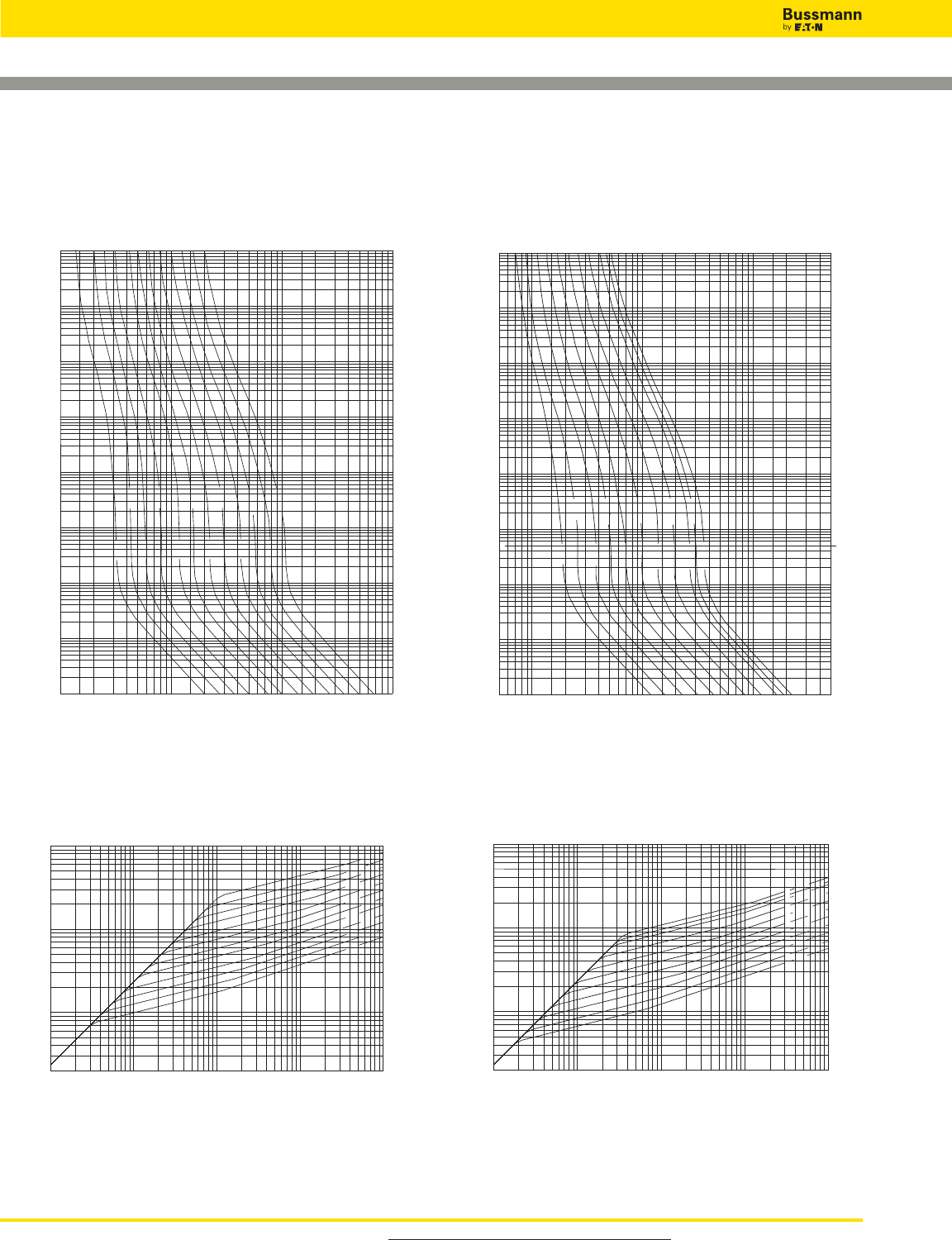
For product data sheets, visit www.cooperbussmann.com/DatasheetsEle
High Speed Fuses
170
Square Body, DIN 43 620 - Size 00, 1 — 690V (IEC):
10-800A Class gR — Full Range Fuses
104
103
102
10
1s
10-1
10-2
10-3
10-4
Virtual Pre-arcing Time In Seconds
Prospective Current In Amp RMS
10 102103104
16A
25A
40A
63A
100A
160A
125A
20A
80A
10A
50A
32A
105
104
103
2x10²
Peak Let-Through Current In Amperes
Prospective Short-Circuit Current Symmetrical RMS
10 102103104Amp 105
160A
125A
100A
80A
63A
50A
40A
32A
25A
20A16A
10A
104
103
102
10
1s
10-1
10-2
10-3
10-4
Virtual Pre-arcing Time In Seconds
Prospective Current In Amp RMS
5x1011021031045x104
63A
100A
160A
250A
350A 400A
80A
315A
50A
200A
125A
105
104
103
2x10²
Peak Let-Through Current In Amperes
Prospective Short-Circuit Current Symmetrical RMS
10 102103104Amp 105
400A350A
315A
250A
200A
160A
125A
100A
80A
63A
50A
Size 00 — 10-160A: 690V
Time-Current Curve
Size 1 — 50-400A: 690V
Time-Current Curve
Peak Let-Through Curve Peak Let-Through Curve
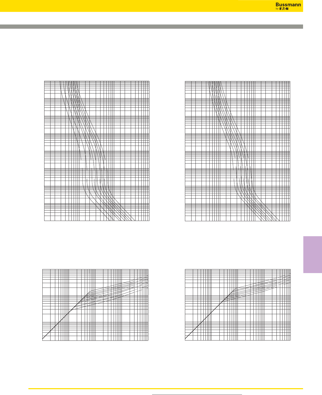
171
Square Body, DIN 43 620 - Size 2, 3 — 690V (IEC):
10-800A Class gR
— Full Range Fuses
104
103
102
10
1s
10-1
10-2
10-3
10-4
Virtual Pre-arcing Time In Seconds
Prospective Current In Amp RMS
102103104105
200A
315A
400A
500A
630A
350A
250A
550A
450A
105
104
103
2x10²
Peak Let-Through Current In Amperes
Prospective Short-Circuit Current Symmetrical RMS
102103104105Amp 106
630A
550A 500A
450A 100A
350A 315A
250A
200A
104
103
102
10
1s
10-1
10-2
10-3
10-4
Virtual Pre-arcing Time In Seconds
Prospective Current In Amp RMS
102103104105
450A
350A
700A
550A
800A
630A
500A
400A
105
104
103
2x10²
Peak Let-Through Current In Amperes
Prospective Short-Circuit Current Symmetrical RMS
102103104105Amp 106
800A
700A 630A
550A 00A
450A 400A
350A
Size 2 — 200-630A: 690V
Time-Current Curve
Size 3 — 350-800A: 690V
Time-Current Curve
Peak Let-Through CurvePeak Let-Through Curve
For product data sheets, visit www.cooperbussmann.com/DatasheetsEle
High Speed
Fuses
High Speed Fuses
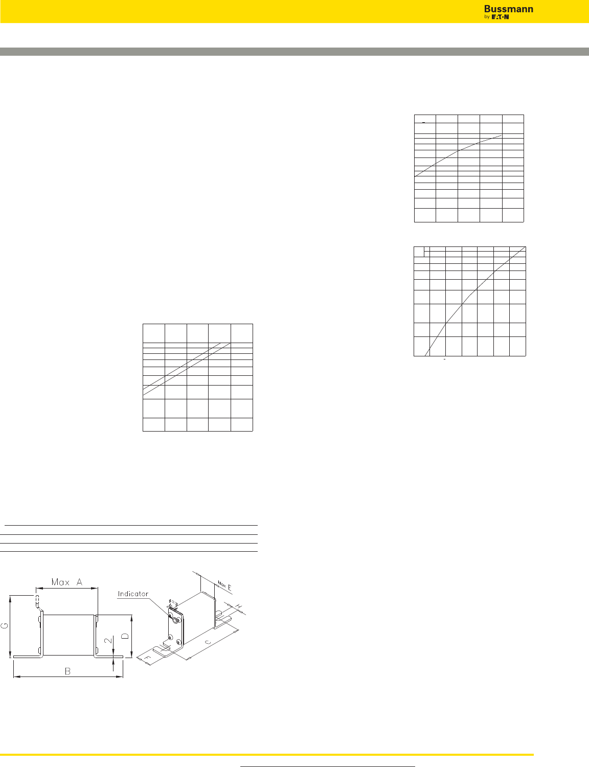
For product data sheets, visit www.cooperbussmann.com/DatasheetsEle
High Speed Fuses
172
1000V (IEC) 20-315A
Specifications
Description: Square body DIN 43
653 stud-mount high speed fuses.
Dimensions: See dimensions
illustration.
Ratings:
Volts: — 1000Vac (20-250A)
— 900Vac (315A)
Amps: — 20-315A
IR: — 150kA RMS Sym.
Agency Information: CE, Designed and tested to
IEC 60269: Part 4. UL Recognized E125085.JFHR2.
Electrical
Characteristics
Total clearing I2t
The total clearing I2t at rated
voltage and at power factor
of 15% are given in the
electrical characteristics. For
other voltages, the clearing
I2t is found by multi-plying by
correction factor, K, given as
a function of applied working
voltage, Eg, (rms).
Square Body DIN 43 653 — 1000V (IEC): 20-315A
1,5
1,0
0,5
0,4
0,3
0,2
K
Eg
200 400 600 800 1000
*Rated voltage 900V
*
Arc Voltage
This curve gives the peak
arc voltage, UL, which may
appear across the fuse
during its operation as a
function of the applied
working voltage Eg, (rms)
at a power factor of 15%.
Power Losses
Watts loss at rated current
is given in the electrical
characteristics. The curve
allows the calculation of
the power losses at load
currents lower than the
rated current. The
correction factor, Kp, is
given as a function of the
RMS load current, Ib, in %
of the rated current.
Features and Benefits
• Excellent DC performance
• Low arc voltage and low energy let-through (I2t)
• Low watts loss
• Superior cycling capability
Typical Applications
• DC Common bus
• DC Drives
• Power converters/rectifiers
• Reduced voltage starters
3
2,5
2
1,8
1,6
1,4
1,2
103
8
7
6
5
4
3
UL
Eg
200 400 600 800 1000
1,0
0,8
0,7
0,6
0,5
0,4
0,3
0,2
0,15
0,1
Kp
Ib
30 40 50 60 70 80 90 100
%
Dimensions - mm
Type 00TN/80 – 00/80
Size Max A B C D Max E F G H
00/80 54 98 78 51 30 28 10
00TN/80 54 98 78 51 30 28 67 10
1mm = 0.0394” / 1” = 25.4mm
For Other Voltage Ratings in This Body Style
• See page 145 (690V/700V)
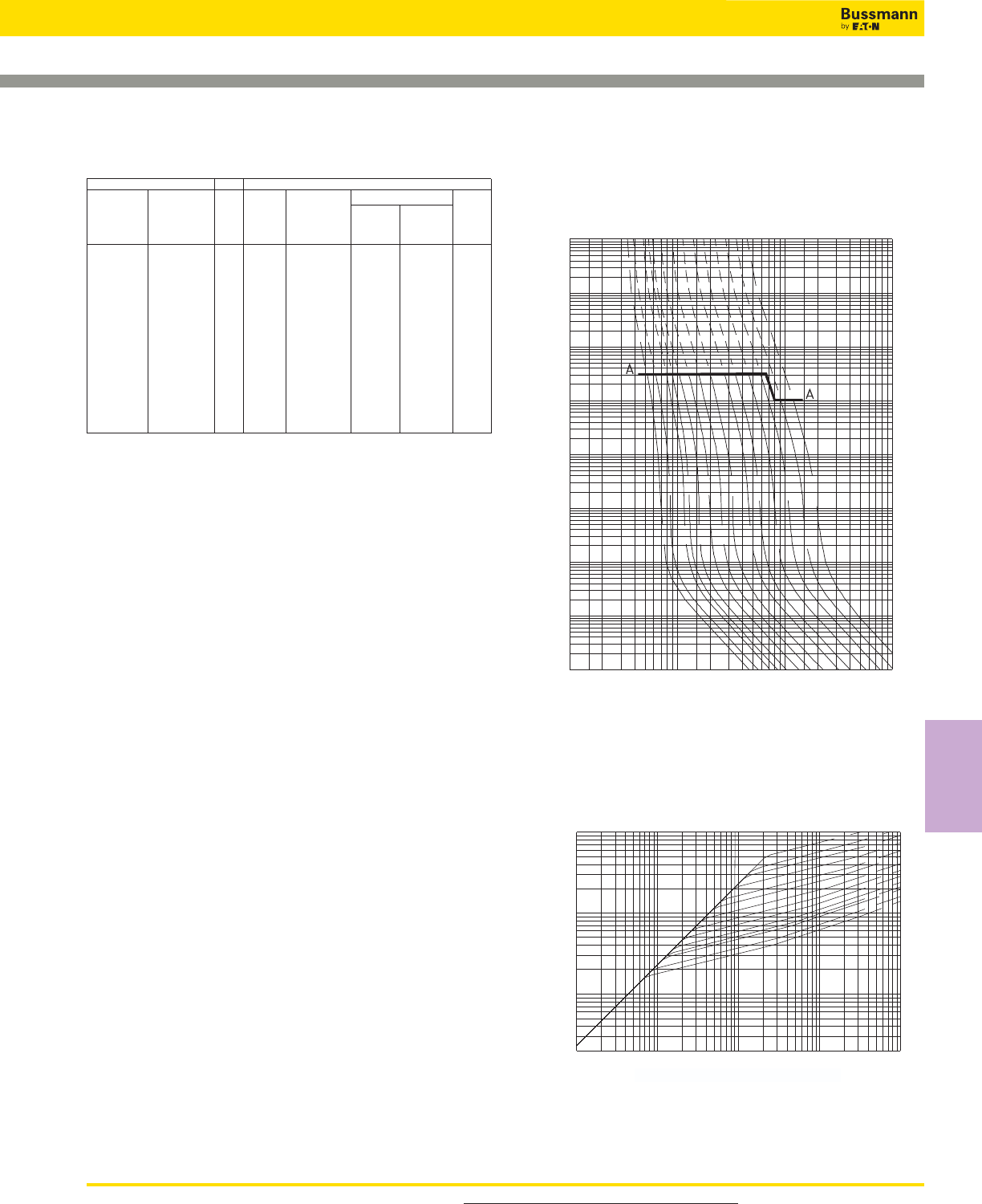
173
Catalog Numbers Electrical Characteristics
00/80 00TN/80 I2t (A2Sec)
Visual Type T Rated Clearing
Indicator for Indicator for Rated Current at Rated Watts
Micro Micro Size Voltage RMS Amps Pre-arc Voltage Loss
170M4802 170M4822 1000 20 20 140 5
170M4803 170M4823 1000 25 30 210 7
170M4804 170M4824 1000 32 55 390 9
170M4805 170M4825 1000 35 69 500 10
170M4806 170M4826 1000 40 100 690 11
170M4807 170M4827 1000 50 170 1200 13
170M4808 170M4828 1000 63 280 2000 18
170M4809 170M4829 00 1000 80 500 3500 22
170M4810 170M4830 1000 100 950 6850 25
170M4811 170M4831 1000 125 1500 11500 33
170M4812 170M4832 1000 160 3000 22000 37
170M4813 170M4833 1000 200 5600 40500 40
170M4814 170M4834 1000 250 10000 74000 48
170M4815 170M4835 900 315 18000 115000 58
• Watts loss provided at rated current.
• Microswitch ordered separately. See accessories on page 212-213.
Square Body DIN 43 653 — 1000V (IEC): 20-315A
104
103
102
10
1s
10-1
10-2
10-3
10-4
Virtual Pre-arcing Time In Seconds
Prospective Current In Amp RMS
10 102 103 104
25A
35A
50A
80A
125A
200A
315A*
250A
63A
40A
32A
20A
100A
160A
104
103
102
2x10
Peak Let-Through Current In Amperes
Prospective Short-Circuit Current symmetrical RMS
10 102 103 104 Amp 105
315A
250A
200A
160A
125A
100A
80A 63A
50A 40A
35A 32A
25A 20A
Prospective Short-Circuit Current Symmetrical RMS
Size 00 — 20-315A: 1000V
Time-Current Curve
Peak Let-Through Curve
* 315A fuse is derated to 900V
For product data sheets, visit www.cooperbussmann.com/DatasheetsEle
High Speed
Fuses
Catalog Numbers
High Speed Fuses
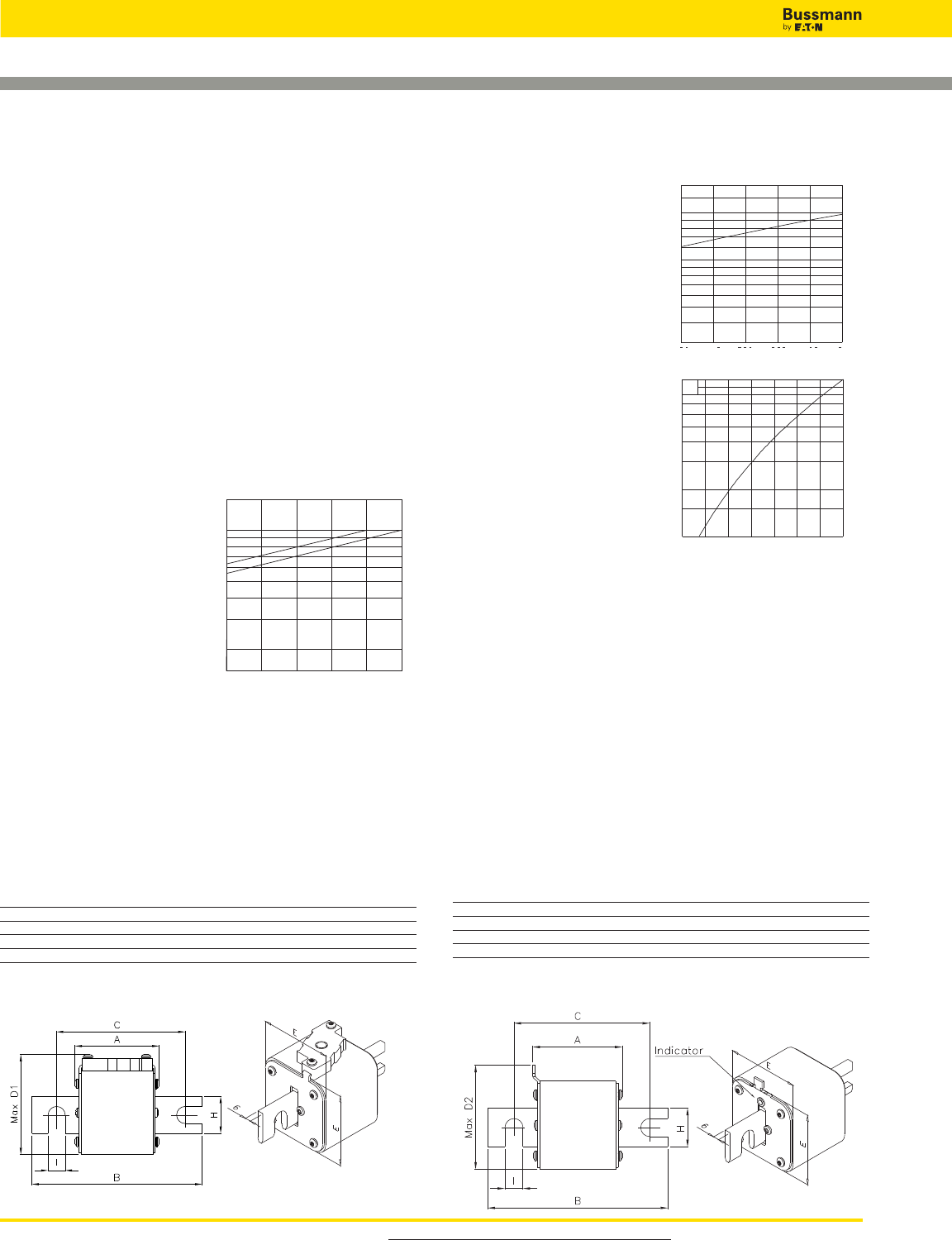
For product data sheets, visit www.cooperbussmann.com/DatasheetsEle
High Speed Fuses
174
Square Body DIN 43 653 — 1000V (IEC): 50-1400A
1000V (IEC) 50-1400A
Specifications
Description: Square body mount
high speed fuses.
Dimensions: See dimensions
illustrations.
Ratings:
Volts: — 1000Vac.
Amps:— 50-1400A
IR: — 125kA RMS Sym.
Agency Information: CE, Designed and tested to IEC
60269: Part 4. UL Recognized E125085.JFHR2.
Electrical
Characteristics
Total clearing I2t
The total clearing I2t at
rated voltage and at power
factor of 15% are given in
the electrical
characteristics. For other
voltages, the clearing I2t is
found by multiplying by
correction factor, K, given
as a function of applied
working voltage, Eg, (rms).
Arc Voltage
This curve gives the peak
arc voltage, UL, which
may appear across the
fuse during its operation
as a function of the
applied working voltage
Eg, (rms) at a power factor
of 15%.
Power Losses
Watts loss at rated current
is given in the electrical
characteristics. The curve
allows the calculation of
the power losses at load
currents lower than the
rated current. The
correction factor, Kp, is
given as a function of the
RMS load current, Ib, in %
of the rated current.
Features and Benefits
• Excellent DC performance
• Low arc voltage and low energy let-through (I2t)
• Low watts loss
• Superior cycling capability
Typical Applications
• DC Common bus
• DC Drives
• Power converters/rectifiers
• Reduced voltage starters
1,5
1,0
0,5
0,4
0,3
0,2
K
Eg
500 600 700 800 900 1000
*Rated voltage 900V
*
3
2,5
2
1,8
1,6
1,4
1,2
103
8
7
6
5
4
3
UL
Eg
500 600 700 800 900 1000
1,0
0,8
0,7
0,6
0,5
0,4
0,3
0,2
0,15
0,1
Kp
Ib
30 40 50 60 70 80 90 100%
Type-TN/110
Type-KN/110
Dimensions - mm
Type –KN/110
Size A B C Max D1 E G H I
1*KN/110 80 138 108 61 43 6 22 11
1KN/110 80 138 108 69 51 6 25 11
2KN/110 80 138 108 77 59 6 25 11
3KN/110 81 139 108 92 74 6 30 11
Type –TN/110
Size A B C Max D2 E G H I
1*TN/110 80 138 108 61 43 6 22 11
1TN/110 80 138 108 69 51 6 25 11
2TN/110 80 138 108 75 59 6 25 11
3TN/110 81 139 108 90 74 6 30 11
1mm = 0.0394” / 1” = 25.4mm
For Other Voltage Ratings in This Body Style
• See pages 150 (690V/700V) and 187 (1250V/1300V)
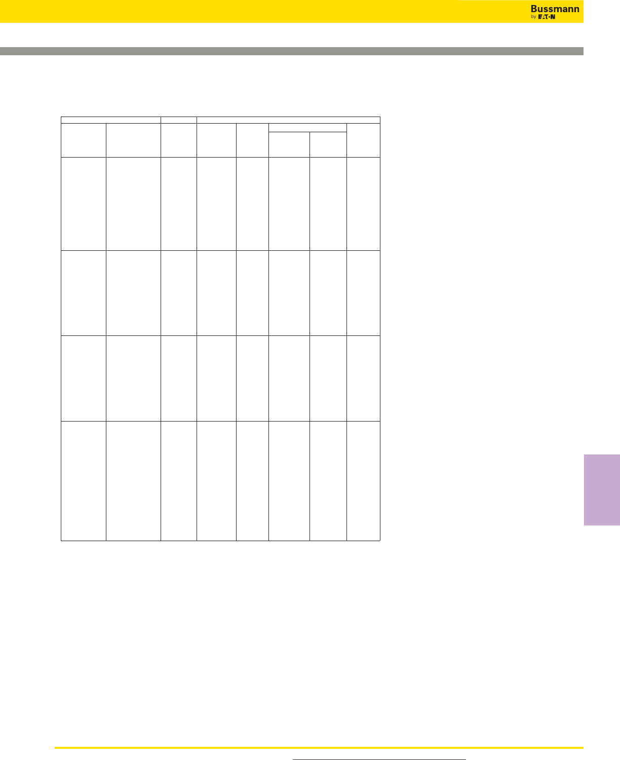
175
Square Body DIN 43 653 — 1000V (IEC): 50-1400A
Catalog Numbers Electrical Characteristics
-KN/110 -TN/110 Rated I2t (A2Sec)
Type K Type T Current Clearing
Indicator for Indicator for Rated RMS at Rated Watts
Micro Micro Size Voltage Amps Pre-arc Voltage Loss
170M3965 170M3981 1000 50 135 815 20
170M3966 170M3982 1000 63 215 1300 25
170M3967 170M3983 1000 80 460 2750 30
170M3968 170M3984 1000 100 860 5100 35
170M3969 170M3985 1000 125 1450 8600 40
170M3970 170M3986 1* 1000 160 2850 17500 45
170M3971 170M3987 1000 200 4950 29500 48
170M3972 170M3988 1000 250 9550 57000 50
170M3973 170M3989 1000 315 21500 130000 60
170M3974 170M3990 1000 350 29000 175000 65
170M3975 170M3991 1000 400 42000 250000 70
170M4965 170M4980 1000 160 2200 13500 40
170M4966 170M4981 1000 200 4150 24500 45
170M4967 170M4982 1000 250 7750 46000 52
170M4968 170M4983 1000 315 16500 98500 60
170M4969 170M4984 1 1000 350 21500 130000 65
170M4970 170M4985 1000 400 31000 185000 70
170M4971 170M4986 1000 450 44500 265000 80
170M4972 170M4987 1000 500 63000 375000 85
170M4973 170M4988 1000 550 84500 500000 90
170M4974 170M4989 1000 630 125000 755000 98
170M5966 170M5981 1000 250 6750 40000 65
170M5967 170M5982 1000 315 13500 81500 75
170M5968 170M5983 1000 350 16500 99000 80
170M5969 170M5984 1000 400 26000 155000 85
170M5970 170M5985 1000 450 35500 210000 90
170M5971 170M5986 2 1000 500 49500 295000 95
170M5972 170M5987 1000 550 66000 390000 100
170M5973 170M5988 1000 630 93500 555000 110
170M5974 170M5989 1000 700 130000 770000 115
170M5975 170M5990 1000 800 195000 1200000 125
170M8614 170M8629 1000 315 9200 54500 90
170M8615 170M8630 1000 350 13000 77500 95
170M8616 170M8631 1000 400 19000 115000 105
170M8617 170M8632 1000 450 27000 160000 107
170M8618 170M8633 1000 500 37500 225000 110
170M8619 170M8634 1000 550 52000 310000 115
170M8620 170M8635 3 1000 630 82500 490000 120
170M8621 170M8636 1000 700 115000 700000 125
170M8622 170M8637 1000 800 170000 1050000 135
170M8623 170M8638 1000 900 250000 1500000 145
170M8624 170M8639 1000 1000 340000 2050000 150
170M8625 170M8640 1000 1100 460000 2750000 155
170M8626 170M8641 1000 1250 575000 3400000 175
170M8627 170M8642 900 1400 795000 4200000 185
• Watts loss provided at rated current.
• Microswitch ordered separately. See accessories on page 212-213.
• For fuse curves see pages 180 and 181.
For product data sheets, visit www.cooperbussmann.com/DatasheetsEle
High Speed
Fuses
Catalog Numbers
High Speed Fuses
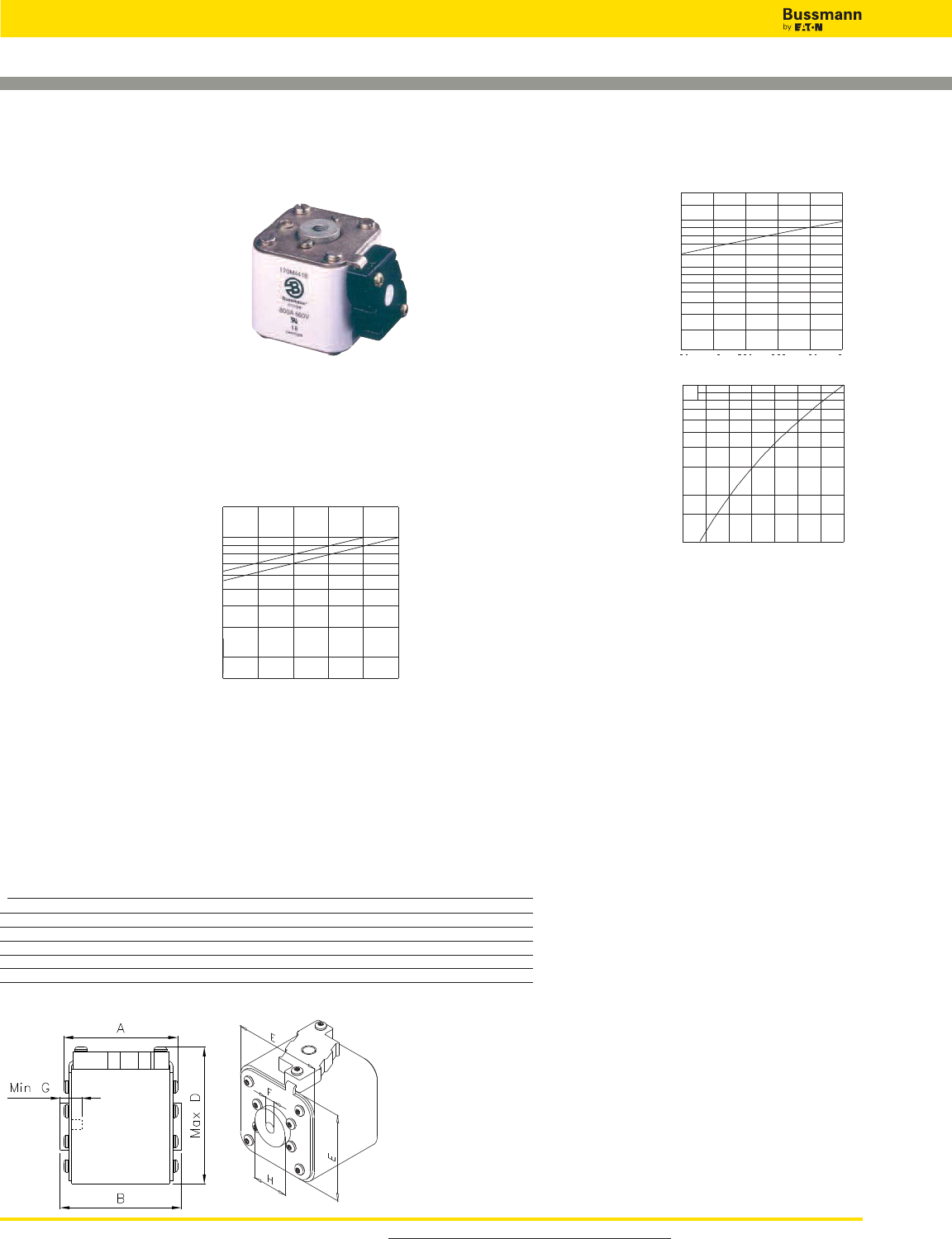
For product data sheets, visit www.cooperbussmann.com/DatasheetsEle
High Speed Fuses
176
Arc Voltage
This curve gives the peak
arc voltage, UL, which may
appear across the fuse
during its operation as a
function of the applied
working voltage Eg, (rms)
at a power factor of 15%.
Power Losses
Watts loss at rated current
is given in the electrical
characteristics. The curve
allows the calculation of
the power losses at load
currents lower than the
rated current. The
correction factor, Kp, is
given as a function of the
RMS load current, Ib, in %
of the rated current.
Features and Benefits
• Excellent DC performance
• Low arc voltage and low energy let-through (I2t)
• Low watts loss
• Superior cycling capability
Typical Applications
• DC Common bus
• DC Drives
• Power converters/rectifiers
• Reduced voltage starters
Square Body Flush End Contact — 1000V (IEC):
50–1400A
1000V (IEC) 50–1400A
Specifications
Description: Square body flush
end contact high speed fuses.
Dimensions: See dimensions
illustration.
Ratings:
Volts: — 1000Vac.
Amps: — 50-1400A
IR: — 150kA (Est. 300kA) RMS Sym.
Agency Information: CE, Designed and tested to IEC
60269: Part 4. UL Recognized E125085.JFHR2.
Electrical
Characteristics
Total clearing I2t
The total clearing I2t at
rated voltage and at power
factor of 15% are given in
the electrical
characteristics. For other
voltages, the clearing I2t is
found by multiplying by
correction factor, K, given
as a function of applied
working voltage, Eg, (rms).
1,5
1,0
0,5
0,4
0,3
0,2
K
Eg
500 600 700 800 900 1000
*Rated voltage 900V
*
3
2,5
2
1,8
1,6
1,4
1,2
103
8
7
6
5
4
3
UL
Eg
500 600 700 800 900 1000
Dimensions - mm
Type –BKN/- and –GKN/-
Size A B Max D E F F* (in) Min G H
1*BKN/75+GKN/75 72.5 74 61 43 M8 5⁄16” – 18 UNC-2B 5 ø17.5
1BKN/75+GKN/75 73.2 74 69 52 M8 5⁄16” – 18 UNC-2B 8 ø20
2BKN/75+GKN/75 73.2 74.4 77 59 M10 3⁄8” – 16 UNC-2B 10 ø24
3BKN/75+GKN/75 73.3 75.4 92 74 M12 1⁄2” – 13 UNC-2B 10 ø30
3BKN/90+GKN/90 80.3 91.4 92 74 M12 1⁄2” – 13 UNC-2B 10 ø30
* Valid for fuses type –GKN/-.
1mm = 0.0394” / 1” = 25.4mm
1,0
0,8
0,7
0,6
0,5
0,4
0,3
0,2
0,15
0,1
Kp
Ib
30 40 50 60 70 80 90 100%
For Other Voltage Ratings in This Body Style
• See pages 152 (690V/700V) and 189 (1250V/1300V)
177
Square Body Flush End Contact — 1000V (IEC):
50–1400A
Catalog Numbers Electrical Characteristics
-BKN/- -GKN/- I2t (A2Sec)
Type K Type K Rated Clearing
Indicator for
Indicator for Rated Current at Rated Watts
Micro Micro Size Voltage RMS-Amps Pre-arc Voltage Loss
170M3951 170M3921 1000 50 135 815 20
170M3952 170M3922 1000 63 215 1300 25
170M3953 170M3923 1000 80 460 2750 30
170M3954 170M3924 1000 100 860 5100 35
170M3955 170M3925 1000 125 1450 8600 40
170M3956 170M3926 1* 1000 160 2850 17500 45
170M3957 170M3927 1000 200 4950 29500 48
170M3958 170M3928 1000 250 9550 57000 50
170M3959 170M3929 1000 315 21500 130000 60
170M3960 170M3930 1000 350 29000 175000 65
170M3961 170M3931 1000 400 42000 250000 70
170M4951 170M4921 1000 160 2200 13500 40
170M4952 170M4922 1000 200 4150 24500 45
170M4953 170M4923 1000 250 7750 46000 52
170M4954 170M4924 1000 315 16500 98500 60
170M4955 170M4925 1 1000 350 21500 130000 65
170M4956 170M4926 1000 400 31000 185000 70
170M4957 170M4927 1000 450 44500 265000 80
170M4958 170M4928 1000 500 63000 375000 85
170M4959 170M4929 1000 550 84500 500000 90
170M4960 170M4930 1000 630 125000 755000 98
170M5952 170M5922 1000 250 6750 40000 65
170M5953 170M5923 1000 315 13500 81500 75
170M5954 170M5924 1000 350 16500 99000 80
170M5955 170M5925 1000 400 26000 155000 85
170M5956 170M5926 1000 450 35500 210000 90
170M5957 170M5927 2 1000 500 49500 295000 95
170M5958 170M5928 1000 550 66000 390000 100
170M5959 170M5929 1000 630 93500 555000 110
170M5960 170M5930 1000 700 130000 770000 115
170M5961 170M5931 1000 800 195000 1200000 125
170M8600 170M8500 1000 315 9200 54500 90
170M8601 170M8501 1000 350 13000 77500 95
170M8602 170M8502 1000 400 19000 115000 105
170M8603 170M8503 1000 450 27000 160000 107
170M8604 170M8504 1000 500 37500 225000 110
170M8605 170M8505 1000 550 52000 310000 115
170M8606 170M8506 3 1000 630 82500 490000 120
170M8607 170M8507 1000 700 115000 700000 125
170M8608 170M8508 1000 800 170000 1050000 135
170M8609 170M8509 1000 900 250000 1500000 145
170M8610 170M8510 1000 1000 340000 2050000 150
170M8611 170M8511 1000 1100 460000 2750000 155
170M8612** 170M8512** 1000 1250 575000 3400000 175
170M8613** 170M8513** 900 1400 795000 4200000 185
**Overall length is 90mm, for all other fuses the overall length is 75mm.
• Watts loss provided at rated current.
• Microswitch ordered separately. See accessories on page 212-213.
• For fuse curves see pages 180 and 181.
For product data sheets, visit www.cooperbussmann.com/DatasheetsEle
High Speed
Fuses
Catalog Numbers
High Speed Fuses
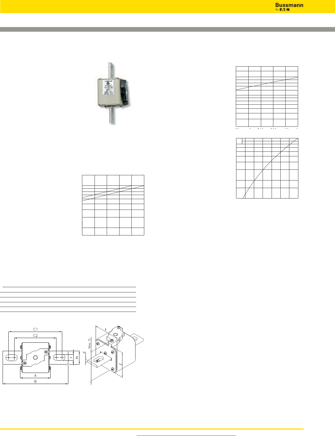
For product data sheets, visit www.cooperbussmann.com/DatasheetsEle
High Speed Fuses
178
Arc Voltage
This curve gives the peak
arc voltage, UL, which
may appear across the
fuse during its operation
as a function of the applied
working voltage Eg, (rms)
at a power factor of 15%.
Power Losses
Watts loss at rated current
is given in the electrical
characteristics. The curve
allows the calculation of
the power losses at load
currents lower than the
rated current. The
correction factor, Kp, is
given as a function of the
RMS load current, Ib, in %
of the rated current.
Features and Benefits
• Excellent DC performance
• Low arc voltage and low energy let-through (I2t)
• Low watts loss
• Superior cycling capability
Typical Applications
• DC Common bus
• DC Drives
• Power converters/rectifiers
• Reduced voltage starters
Square Body US style — 1000V (IEC): 50-1400A
1000V (IEC) 50-1400A
Specifications
Description: Square body US
style high speed fuses.
Dimensions: See dimensions
illustration.
Ratings:
Volts: — 1000Vac.
Amps: — 50-1400A
IR: — 150kA RMS Sym.
Agency Information: CE, Designed and tested to IEC
60269: Part 4. UL Recognized E125085.JFHR2.
Electrical
Characteristics
Total clearing I2t
The total clearing I2t at rated
voltage and at power factor
of 15% are given in the
electrical characteristics. For
other voltages, the clearing
I2t is found by multiplying by
correction factor, K, given as
a function of applied
working voltage, Eg, (rms).
1,5
1,0
0,5
0,4
0,3
0,2
K
Eg
500 600 700 800 900 1000
*Rated voltage 900V
*
3
2,5
2
1,8
1,6
1,4
1,2
103
8
7
6
5
4
3
UL
Eg
500 600 700 800 900 1000
1,0
0,8
0,7
0,6
0,5
0,4
0,3
0,2
0,15
0,1
Kp
Ib
30 40 50 60 70 80 90 100%
Dimensions - mm
Type –FKE/115
Size B C1 C2 D E H I
1*FKE/115 156 130 101 59 45 20 10
1FKE/115 160 127 102 69 53 25 14
2FKE/115 160 127 102 77 61 25 14
3FKE/115 159 128 101 92 76 36 16
1mm = 0.0394” / 1” = 25.4mm
For Other Voltage Ratings in This Body Style
• See pages 154 (690V/700V) and 191 (1250V/1300)

179
Square Body US style — 1000V (IEC): 50-1400A
Catalog Numbers
-FKE/115 Electrical Characteristics
Type K Rated I2t (A2Sec)
Indicator for Current Clearing Watts
Micro Size RMS-Amps Pre-arc at 1000V Loss
170M3531 50 135 815 20
170M3532 63 215 1300 25
170M3533 80 460 2750 30
170M3534 100 860 5100 35
170M3535 125 1450 8600 40
170M3536 1* 160 2850 17500 45
170M3537 200 4950 29500 48
170M3538 250 9550 57000 50
170M3539 315 21500 130000 60
170M3540 350 29000 175000 65
170M3541 400 42000 250000 70
170M4531 160 2200 13500 40
170M4532 200 4150 24500 45
170M4533 250 7750 46000 52
170M4534 315 16500 98500 60
170M4535 350 21500 130000 65
170M4536 1 400 31000 185000 70
170M4537 450 44500 265000 80
170M4538 500 63000 375000 85
170M4539 550 84500 500000 90
170M4540 630 125000 755000 98
170M5531 250 6750 40000 65
170M5532 315 13500 81500 75
170M5533 350 16500 99000 80
170M5534 400 26000 155000 85
170M5535 450 35500 210000 90
170M5536 2 500 49500 295000 95
170M5537 550 66000 390000 100
170M5538 630 93500 555000 110
170M5539 700 130000 770000 115
170M5540 800 195000 1200000 125
170M8531 315 9200 54500 90
170M8532 350 13000 77500 95
170M8533 400 19000 115000 105
170M8534 450 27000 160000 107
170M8535 500 37500 225000 110
170M8536 550 52000 310000 115
170M8537 3 630 82500 490000 120
170M8538 700 115000 700000 125
170M8539 800 170000 1050000 135
170M8540 900 250000 1500000 145
170M8541 1000 340000 2050000 150
170M8542 1100 460000 2750000 155
170M8543 1250 575000 3400000 175
170M8544* 1400 795000 4200000* 185
* Rated voltage 900V.
• Watts loss provided at rated current.
• Microswitch ordered separately. See accessories on pages 212-213.
• For fuse curves see pages 180 and 181.
For product data sheets, visit www.cooperbussmann.com/DatasheetsEle
High Speed
Fuses
Catalog Numbers
High Speed Fuses
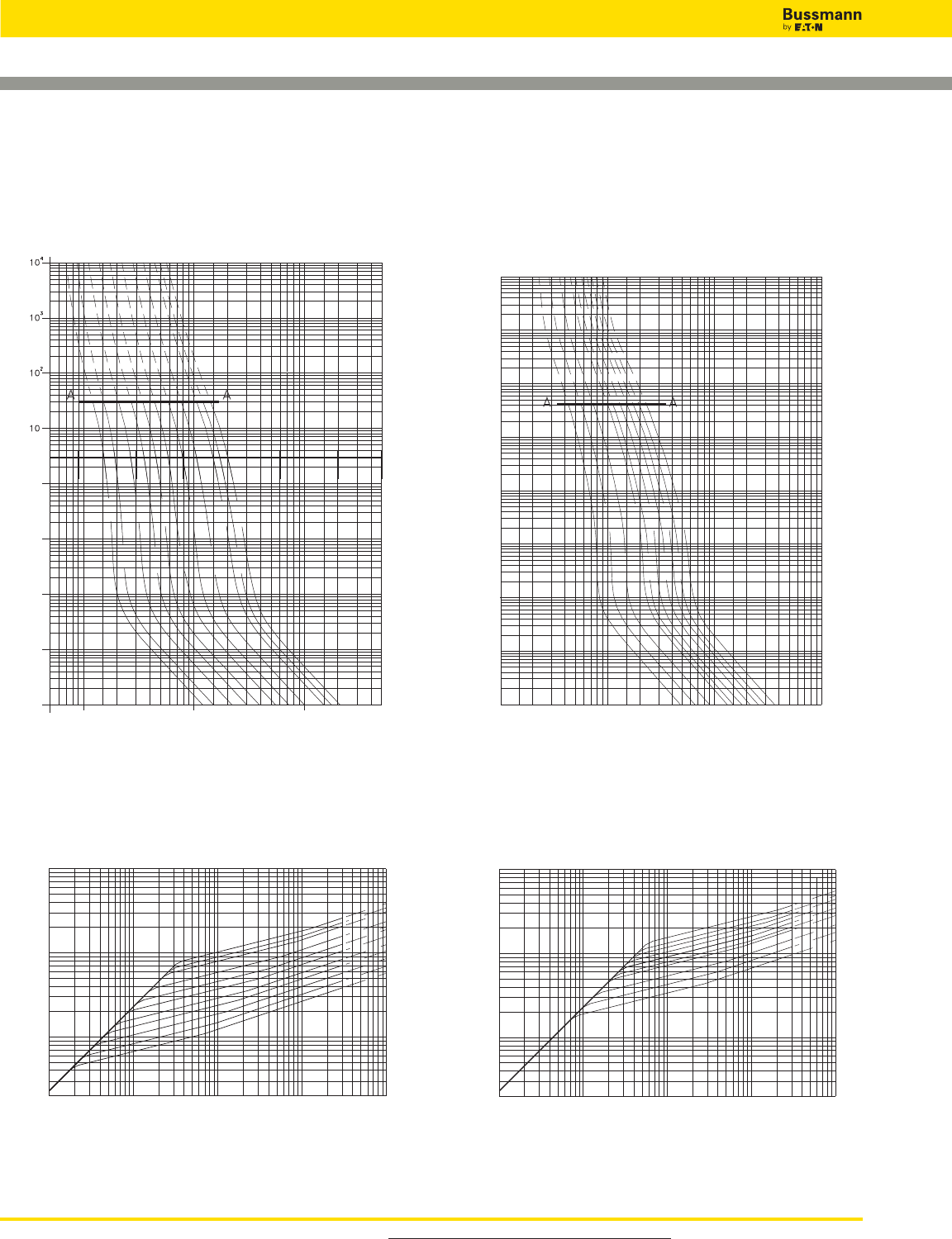
For product data sheets, visit www.cooperbussmann.com/DatasheetsEle
High Speed Fuses
180
Square Body, US style - Size 1*, 1 — 1000V (IEC):
50-1400A
1s
10-1
10-2
10-3
10-4
Virtual Pre-arcing Time In Seconds
Prospective Current In Amp RMS
5x101 102 103 104 5x10⁴
50A
80A
125A
200A
315A
400A
350A
63A
160A
250A
100A
105
104
103
2x10²
Peak Let-Through Current In Amperes
Prospective Short-Circuit Current Symmetrical RMS
102 103 104 105 Amp 106
400A
350A
315A
250A
200A
160A
50A
630A
80A
100A
125A
Size 1* — 50-400A: 1000V
Time-Current Curve
Peak Let-Through Curve
104
103
102
10
1s
10-1
10-2
10-3
10-4
Virtual Pre-arcing Time In Seconds
Prospective Current In Amp RMS
102 103 104 105
200A
315A
400A
500A
630A
160A
350A
250A
450A
550A
105
104
103
2x10²
Peak Let-Through Current In Amperes
Prospective Short-Circuit Current Symmetrical RMS
102 103 104 105 Amp 106
550A
500A
450A
400A
350A
315A
630A
160A
200A
250A
Size 1 — 160-630A: 1000V
Time-Current Curve
Peak Let-Through Curve
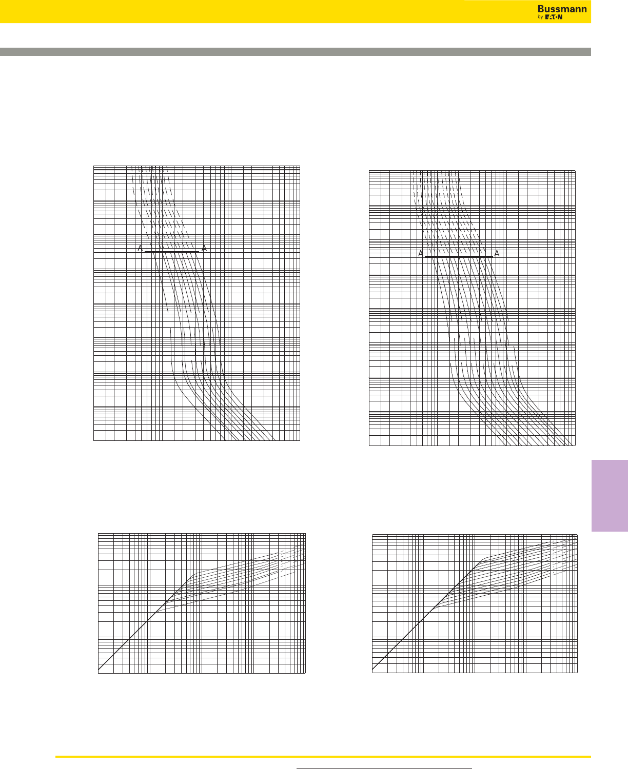
181
Square Body, US style - Size 2, 3 — 1000V (IEC):
50-1400A
Size 2 — 250-800A: 1000V
Time-Current Curve
Peak Let-Through Curve
104
103
102
10
1s
10-1
10-2
10-3
10-4
Virtual Pre-arcing Time In Seconds
Prospective Current In Amp RMS
102 103 104 105
250A
350A
550A
700A
315A
500A
400A
630A
800A
450A
105
104
103
2x10²
Peak Let-Through Current In Amperes
Prospective Short-Circuit Current Symmetrical RMS
102 103 104 105 Amp 106
700A
800A
630A
500A 550A
450A
250A
315A 350A
400A
104
103
102
10
1s
10-1
10-2
10-3
10-4
Virtual Pre-arcing Time In Seconds
Prospective Current In Amp RMS
102 103 104 105
350A
450A
700A
900A
315A
500A
400A
630A
800A
550A
1100A
1400A*
1000A
1250A
105
104
103
2x10²
Peak Let-Through Current In Amperes
Prospective Short-Circuit Current Symmetrical RMS
102 103 104 105 Amp 106
1250A
1400A
*
1100A
900A 1000A
800A
500A
550A 630A
700A
450A 400A
350A 315A
Size 3 — 315-1400A: 1000V
Time-Current Curve
Peak Let-Through Curve
For product data sheets, visit www.cooperbussmann.com/DatasheetsEle
High Speed
Fuses
High Speed Fuses
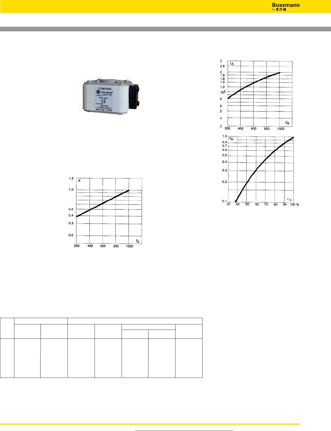
For product data sheets, visit www.cooperbussmann.com/DatasheetsEle
High Speed Fuses
182
Square Body Flush End Contact Size 4 — 1000V (IEC):
1000-2700A
1000V (IEC) 1000-2700A
Specifications
Description: Square body DIN
43 620 blade style high speed
fuses.
Dimensions: See dimensions
illustration.
Ratings:
Volts: — 1000Vac (IEC)
Amps: — 1000-2700A
IR: — 125kA RMS Sym.
Agency Information: CE, Designed and tested to IEC
60269: Part 4. UL Recognized E125085.JFHR2.
Electrical
Characteristics
Total clearing I2t
The total clearing I2t at
rated voltage and at power
factor of 15% are given in
the electrical
characteristics. For other
voltages, the clearing I2t is
found by multiplying by
correction factor, K, given
as a function of applied
working voltage, Eg, (rms).
Arc Voltage
This curve gives the
peak arc voltage, UL,
which may appear
across the fuse during
its operation as a
function of the applied
working voltage Eg,
(rms) at a power factor
of 15%.
Power Losses
Watts loss at rated current
is given in the electrical
characteristics. The curve
allows the calculation of
the power losses at load
currents lower than the
rated current. The
correction factor, Kp, is
given as a function of the
RMS load current, Ib, in %
of the rated current.
Features and Benefits
• Excellent DC performance
• Low arc voltage and low energy let-through (I2t)
• Low watts loss
• Superior cycling capability
Typical Applications
• DC Common bus
• DC Drives
• Power converters/rectifiers
• Reduced voltage starters
For Other Voltage Ratings in This Body Style
• See pages 163 (690V/700V) and 195 (1250V)
-BKN/95
Type K
Indicator
Catalog Number Electrical Characteristics
I2t (A2Sec)
-SBKN/90
Type K
Indicator
Watt
Loss
(W)
Rated
Voltage
(V)
Rated
Current
RMS-Amp
Fuse
Size Pre-arc
Clearing
at 1000V
— 170M7542 1000 180000 1100000 195
— 170M7031 1100 250000 1500000 200
170M7636 170M7548 1500 600000 3600000 250
170M7639 170M7034 1700 850000 5000000 260
4 170M7963 170M7544 1000 2000 1450000 8600000 270
170M7090 170M7035 2200 2000000 12000000 280
170M7640 170M7036 2500 3000000 18000000 295
170M7658 170M7037 2700 3700000 22000000 310
Catalog Numbers
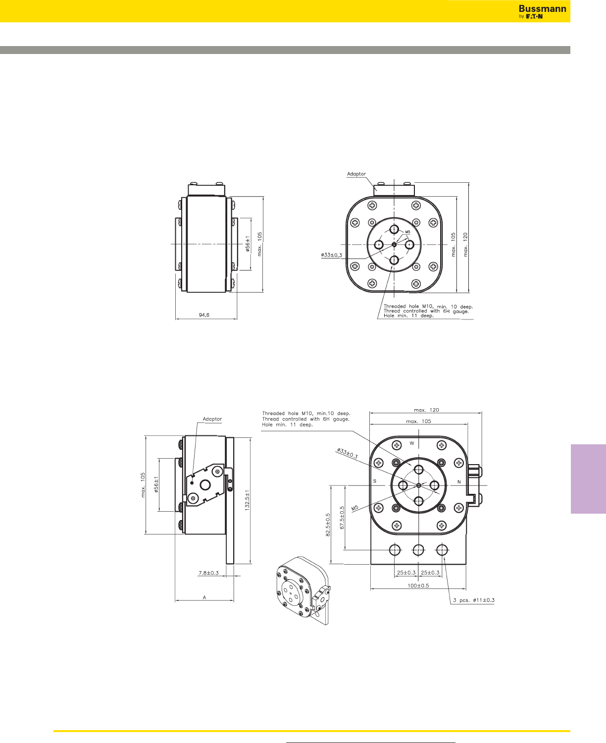
183
Square Body Flush End Contact Size 4 — 1000V (IEC):
1000-2700A
Dimensions - mm
Type 4BKN/ 95
Type 4SBKN/ 95
For product data sheets, visit www.cooperbussmann.com/DatasheetsEle
High Speed
Fuses
High Speed Fuses
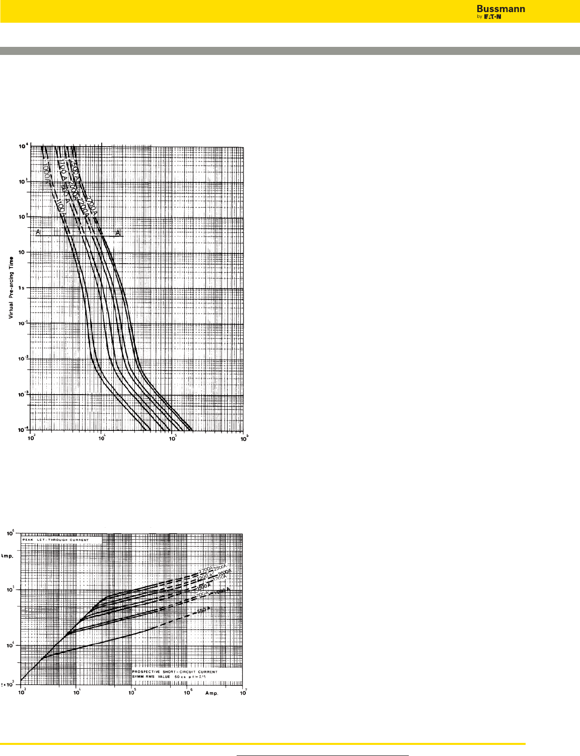
For product data sheets, visit www.cooperbussmann.com/DatasheetsEle
High Speed Fuses
184
Square Body Flush End Contact Size 4 — 1000V (IEC):
1000-2700A
Size 4 — 1000-2700A: 660V
Time-Current Curve
Peak Let-Through Curve
Data Sheet: Available upon request
Prospective Current in Amps RMS
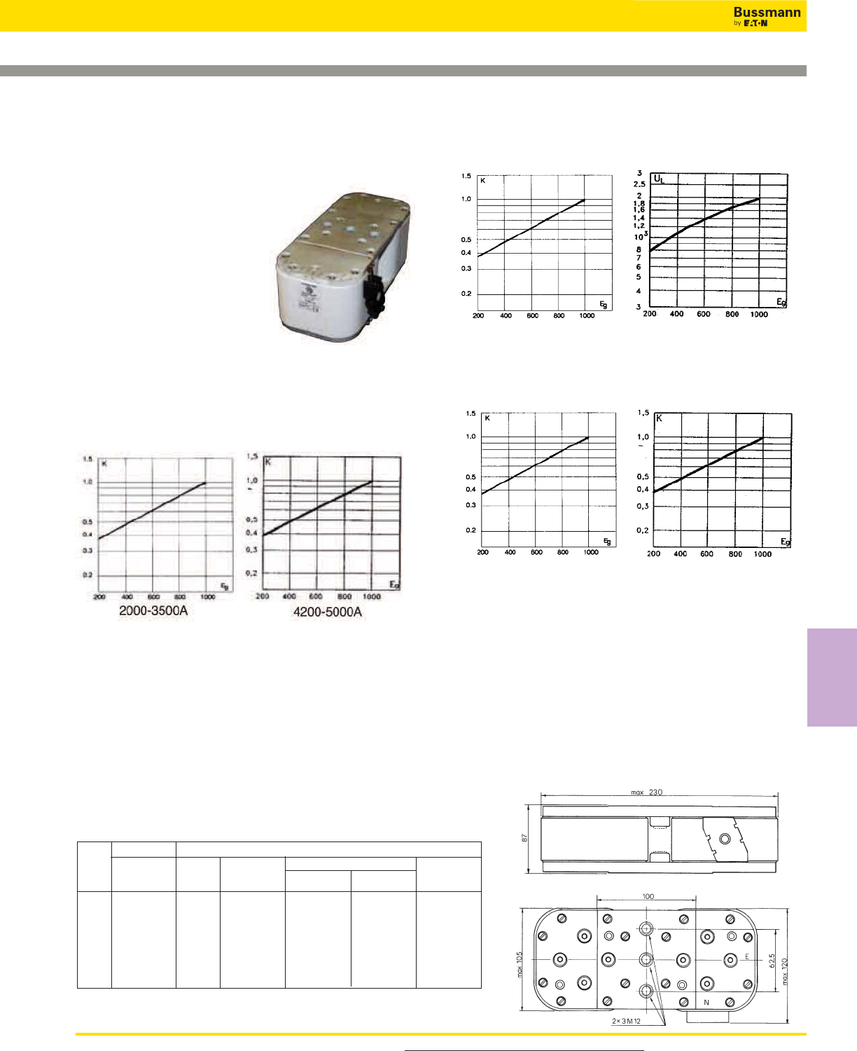
185
Square Body Flush End Contact Size 24 — 1000V (IEC):
2000-5000A
Arc Voltage
This curve gives the peak arc voltage, UL, which may
appear across the fuse during its operation as a function of
the applied working voltage Eg, (rms) at a power factor of
15%.
Power Losses
Watts loss at rated current is given in the electrical
characteristics. The curve allows the calculation of the power
losses at load currents lower than the rated current. The
correction factor, Kp, is given as a function of the RMS load
current, Ib, in % of the rated current.
Features and Benefits
• Low watts loss
• Superior cycling capability
For Other Voltage Ratings in This Body Style
• See pages 165 (660V) and 198 (1250V)
4200-5000A
4200-5000A
2000-3500A
2000-3500A
Typical Applications
• Power converters/rectifiers
• Reduced voltage starters
For product data sheets, visit www.cooperbussmann.com/DatasheetsEle
High Speed
Fuses
Catalog Numbers
170M7608 2000 885000 5700000 345
170M7680 3000 2900000 19000000 430
170M7567 3200 3300000 20000000 440
24 170M7568 1000 3500 4500000 27000000 450
170M7569 4000 6800000 40000000 475
170M7498 4200 8000000 47500000 485
170M7488 4500 10000000 59000000 495
170M7622 5000 14000000 82500000 540
-BKN/85
Type K
Indicator
Cat. Number Electrical Characteristics
I2t (A2Sec) Watt
Loss
(W)
Rated
Voltage
(V)
Rated
Current
RMS-Amp
Fuse
Size Pre-arc Clearing at
1000V
Data Sheet: 170K7540, 170K8514
Dimensions - mm
High Speed Fuses
1000V (IEC) 2000-5000A
Specifications
Description: High speed square
body fuses, for the protection of
the power rectifier section of the
equipment.
Dimensions: See dimensions
illustration.
Ratings:
Volts: — 1000Vac
Amps: — 2000-5000A
IR: — 300kA RMS Sym.
Agency Information: CE, Designed and tested to IEC
60269: Part 4. UL Recognized E125085.JFHR2.
Electrical Characteristics
Total clearing I2t
The total clearing I2t at rated voltage and at power factor of
15% are given in the electrical characteristics. For other
voltages, the clearing I2t is found by multiplying by correction
factor, K, given as a function of applied working voltage,
Eg, (rms).
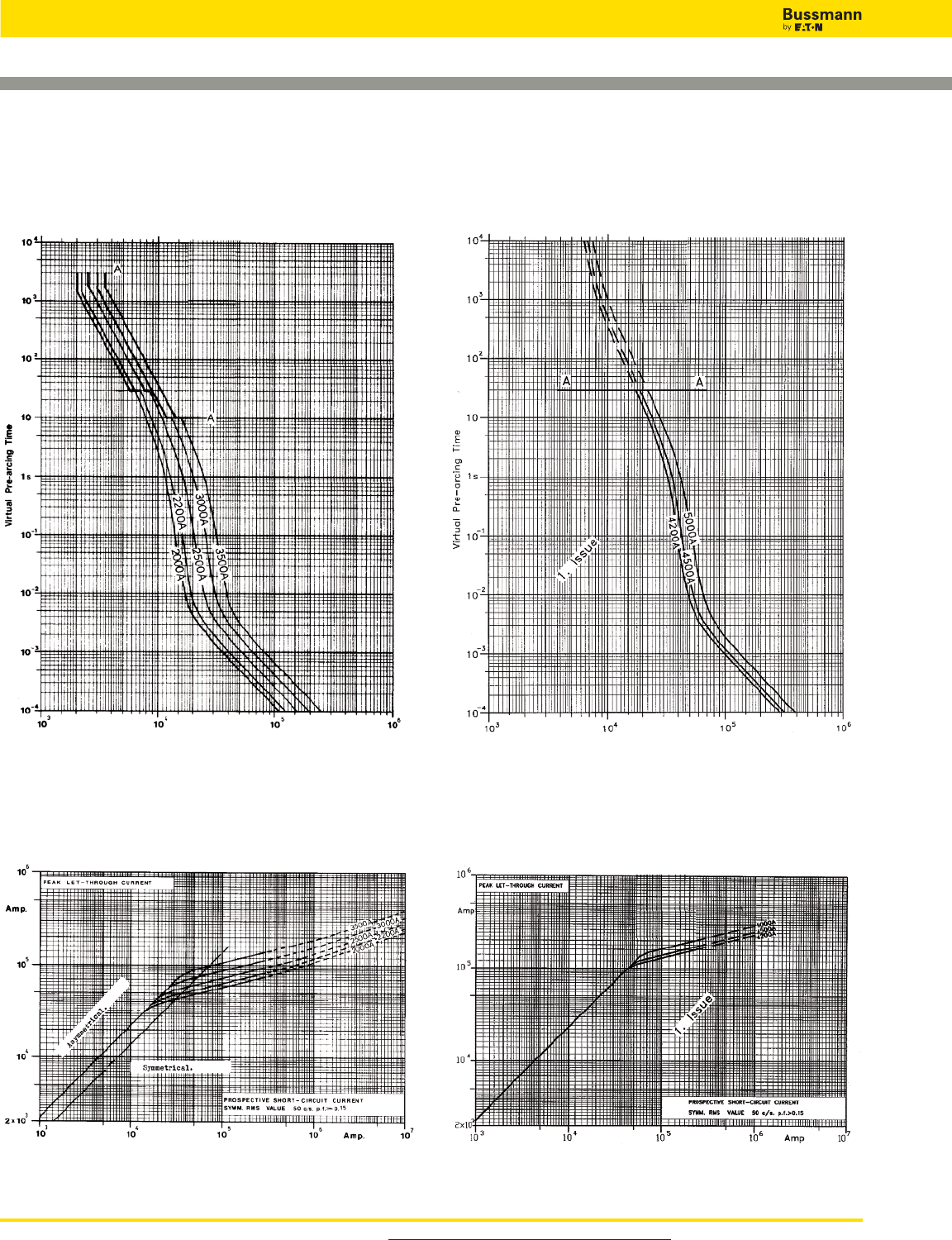
Square Body Flush End Contact Size 24 — 1000V (IEC):
2000-5000A
Size 24 — 4200-5000A: 1000V
Time-Current Curve
Size 24 — 2000-3500A: 1000V
Time-Current Curve
Peak Let-Through CurvePeak Let-Through Curve
Data Sheet: Available upon request Data Sheet: Available upon request
Prospective Current in Amps RMS Prospective Current in Amps RMS
For product data sheets, visit www.cooperbussmann.com/DatasheetsEle
High Speed Fuses
186
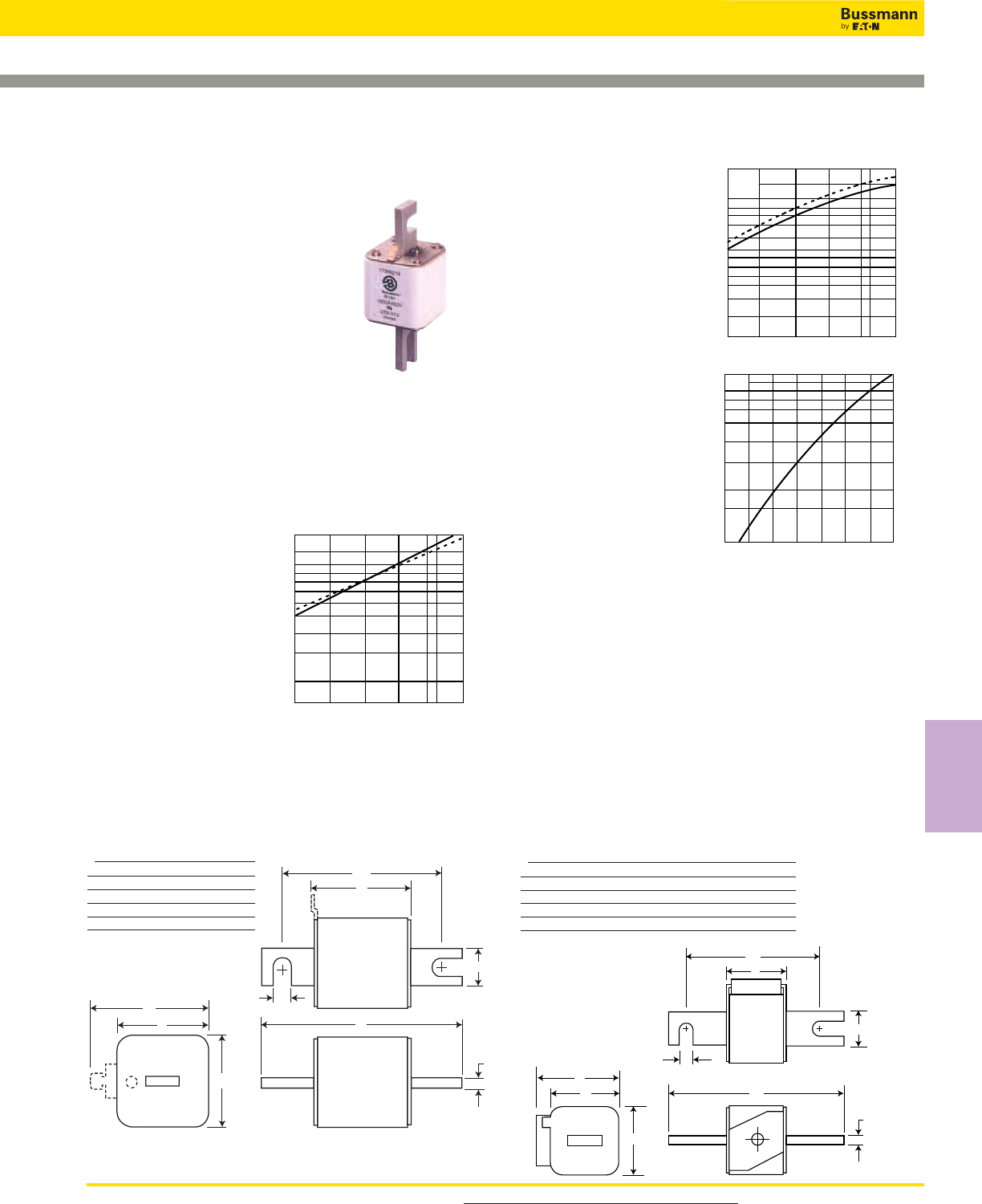
187
For product data sheets, visit www.cooperbussmann.com/DatasheetsEle
High Speed
Fuses
High Speed Fuses
Arc Voltage
This curve gives the peak
arc voltage, UL, which
may appear across the
fuse during its operation
as a function of theapplied
working voltage, Eg, (rms)
at a power factor of 15%.
Power Losses
Watts loss at rated current
is given in the electrical
characteristics. The curve
allows the calculation of
the power losses at load
currents lower than the
rated current. The
correction factor, Kp, is
given as a function of the
RMS load current, Ib, in %
of the rated current.
Features and Benefits
• Excellent DC performance
• Low arc voltage and low energy let-through (I2t)
• Low watts loss
• Superior cycling capability
Typical Applications
• DC Common bus
• DC Drives
• Power converters/rectifiers
• Reduced voltage starters
Square Body DIN 43 653 — 1250V/1300V (IEC/UL):
50-1400A
1250V/1300V (IEC/UL) 50-1400A
Specifications
Description: Square body DIN
43 653 stud-mount high speed
fuses.
Dimensions: See dimensions
illustration.
Ratings:
Volts: — 1250Vac (IEC)
— 1300Vac (UL)
Amps: — 50-1400A
IR: — 100kA RMS Sym.
Agency Information: CE, Designed and tested to IEC
60269: Part 4. UL Recognized E125085.JFHR2, CSA
Certified: Class 53787, File 1422-30.
Electrical
Characteristics
Total Clearing I2t
The total clearing I2t at
rated voltage and at
power factor of 15% are
given in the electrical
characteristics. For other
voltages, the clearing I2t
is found by multiplying by
correction factor, K,
given as a function of
applied working voltage,
Eg, (rms).
UL
3
2.5
8
103
1.4
1.8
6
4
5
3
400 600 800 1000 1200 1400
Eg
Dashed lines (- - - - - -) apply to the following
amperages:.
Size Amps.
1* 400A
1 500-630A
2 630-1000A
3 800-1400A
K
1.5
1.0
1.25
0.5
0.4
0.3
0.2
400 600 800 1000 1200 1400
Eg
Kp
30 40 50 60 70 80 90 100%
Ib
1.0
0.8
0.4
0.5
0.6
0.3
0.2
0.1
A
B
108
D
E
E
6
H
11
Dimensions - mm
Type -/110, -TN/110
Size A B D** E H
1* 80 138 58 45 20
1 80 138 66 53 25
2 80 138 75 61 25
3 81 139 90 76 30
**Microswitch.
1mm = 0.0394” / 1” = 25.4mm
For Other Voltage Ratings in This Body Style
• See pages 150 (690V/700V) and 176 (1000V)
C
B
A
H
11
6
E
E
D
Type -KN/110
Size A B D E H
1* 80 138 58 45 20
1 80 138 66 53 25
2 80 138 75 61 25
3 81 139 90 76 30
1mm = 0.0394” / 1” = 25.4mm
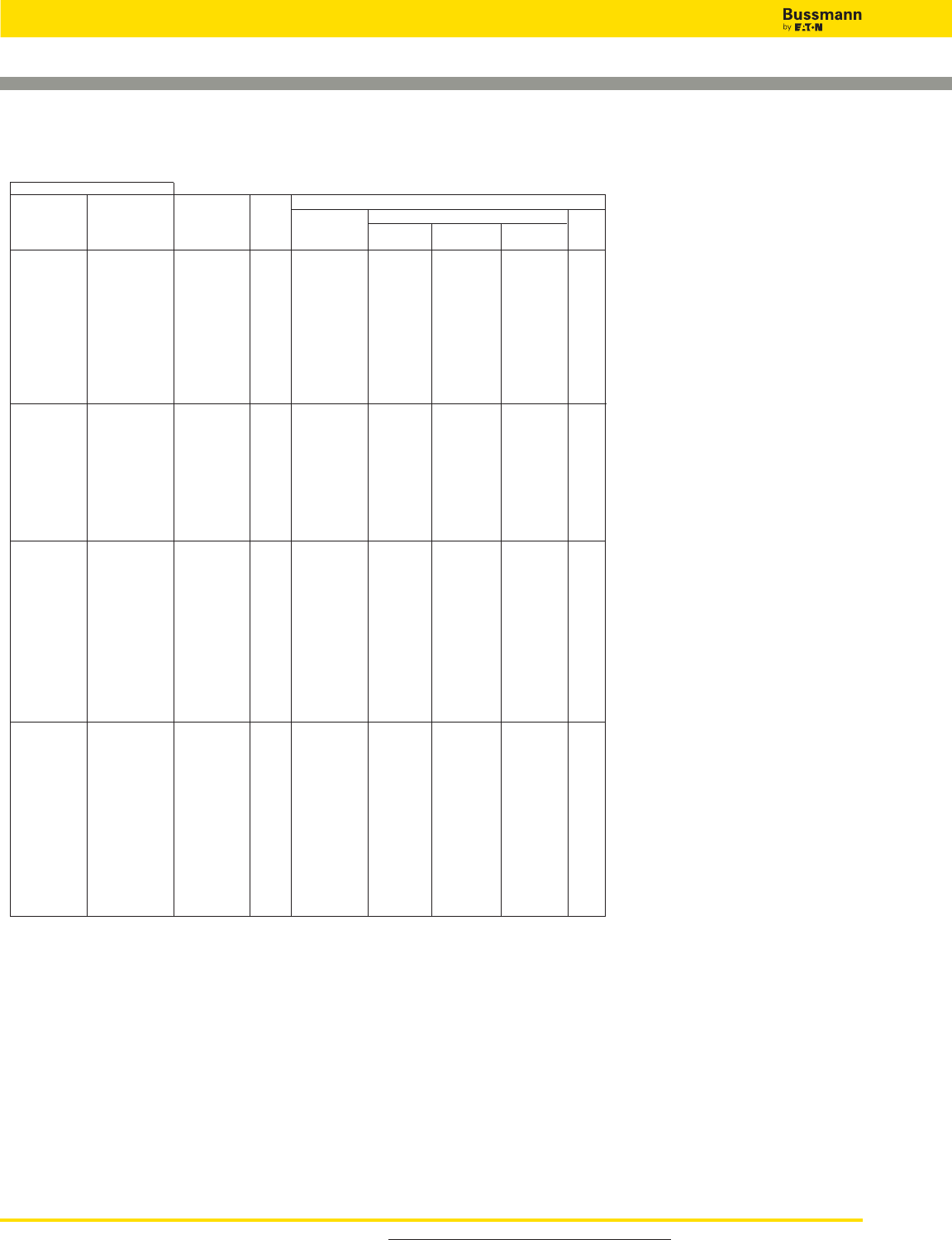
Square Body DIN 43 653 — 1250V/1300V (IEC/UL):
50-1400A
Catalog Numbers
-TN/110 -KN/110 Electrical Characteristics
-/110 Type T Type K Rated I2t (A2Sec)
Visual Indicator Indicator Current Clearing Clearing Watts
Indicator for Micro for Micro Size RMS-Amps Pre-arc at 1000V at 1250V Loss
170M3138 170M3188 170M3238 50 135 815 1100 15
170M3139 170M3189 170M3239 63 215 1300 1750 20
170M3140 170M3190 170M3240 80 420 2500 3350 25
170M3141 170M3191 170M3241 100 750 4450 5950 30
170M3142 170M3192 170M3242 125 1450 9000 11500 35
170M3143 170M3193 170M3243 1* 160 2600 16000 21000 40
170M3144 170M3194 170M3244 200 5150 31000 41000 45
170M3145 170M3195 170M3245 250 9200 54500 73000 55
170M3146 170M3196 170M3246 315 18500 115000 150000 60
170M3147 170M3197 170M3247 350 27000 165000 220000 65
170M3148 170M3198 170M3248 400 53000 265000 335000 70
170M4138 170M4188 170M4238 160 1900 11500 15500 45
170M4139 170M4189 170M4239 200 3800 22500 30000 50
170M4140 170M4190 170M4240 250 7750 46000 61500 60
170M4141 170M4191 170M4241 315 15000 90000 120000 65
170M4142 170M4192 170M4242 1 350 20000 125000 165000 70
170M4143 170M4193 170M4243 400 29500 175000 235000 75
170M4144 170M4194 170M4244 450 42000 250000 335000 80
170M4145 170M4195 170M4245 500 69500 340000 435000 85
170M4146 170M4196 170M4246 550 95000 465000 590000 95
170M4147 170M4197 170M4247 630† 130000 660000 100
170M5138 170M5188 170M5238 250 6500 38500 51500 65
170M5139 170M5189 170M5239 280 9350 55500 74500 70
170M5140 170M5190 170M5240 315 13000 77500 105000 75
170M5141 170M5191 170M5241 350 16500 97500 135000 80
170M5142 170M5192 170M5242 400 23000 140000 180000 85
170M5143 170M5193 170M5243 450 34000 205000 270000 90
170M5144 170M5194 170M5244 2 500 48000 285000 380000 95
170M5145 170M5195 170M5245 550 62000 370000 495000 100
170M5146 170M5196 170M5246 630 115000 575000 730000 110
170M5147 170M5197 170M5247 700 160000 795000 1050000 115
170M5148 170M5198 170M5248 800 245000 1200000 1550000 120
170M5149 170M5199 170M5249 900† 360000 1750000 125
170M5150 170M5200 170M5250 1000† 480000 2350000 135
170M6138 170M6188 170M6238 315 9500 58000 77500 85
170M6139 170M6189 170M6239 350 13500 81500 110000 90
170M6140 170M6190 170M6240 400 19500 120000 160000 95
170M6141 170M6191 170M6241 450 31000 185000 245000 100
170M6142 170M6192 170M6242 500 39000 235000 310000 105
170M6143 170M6193 170M6243 550 55000 325000 435000 110
170M6144 170M6194 170M6244 3 630 83500 495000 665000 115
170M6145 170M6195 170M6245 700 115000 705000 940000 120
170M6146 170M6196 170M6246 800‡ 205000 995000 1300000 125
170M6147 170M6197 170M6247 900‡ 305000 1500000 1900000 130
170M6148 170M6198 170M6248 1000‡ 450000 2150000 2750000 135
170M6149 170M6199 170M6249 1100‡ 575000 2800000 3600000 140
170M6150 170M6200 170M6250 1250† 810000 3950000 145
170M6151 170M6201 170M6251 1400† 1250000 6000000 150
†Rated voltage (IEC) 1100V.
‡Rated voltage (IEC) 1250V.
• Watts loss provided at rated current.
• Microswitch indicator ordered separately. See accessories on pages 212-213.
• For fuse curves see pages 193 and 194.
For product data sheets, visit www.cooperbussmann.com/DatasheetsEle
High Speed Fuses
188
Catalog Numbers
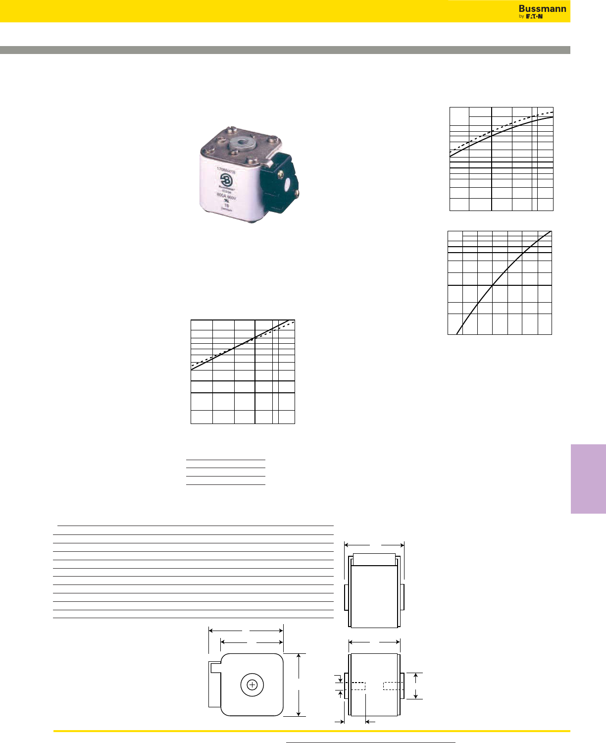
189
For product data sheets, visit www.cooperbussmann.com/DatasheetsEle
High Speed
Fuses
High Speed Fuses
Arc Voltage
This curve gives the peak
arc voltage, UL, which
may appear across the
fuse during its operation
as a function of theapplied
working voltage, Eg, (rms)
at a power factor of 15%.
Power Losses
Watts loss at rated current
is given in the electrical
characteristics. The curve
allows the calculation of
the power losses at load
currents lower than the
rated current. The
correction factor, Kp, is
given as a function of the
RMS load current, Ib, in %
of the rated current.
Features and Benefits
• Excellent DC performance
• Low arc voltage and low energy let-through (I2t)
• Low watts loss
• Superior cycling capability
Typical Applications
• DC Common bus
• DC Drives
• Power converters/rectifiers
• Reduced voltage starters
Square Body Flush End Contact — 1250V/1300V (IEC/UL):
50-1400A
1250V/1300V (IEC/UL) 50-1400A
Specifications
Description: Square body flush
end contact high speed fuses.
Dimensions: See dimensions
illustrations.
Ratings:
Volts: — 1250Vac (IEC)
— 1300Vac (UL)
Amps: — 50-1400A
IR: — 100kA RMS Sym.
Agency Information: CE, Designed and tested to IEC
60269: Part 4. UL Recognized E125085.JFHR2, CSA
Certified: Class 53787, File 1422-30.
Electrical
Characteristics
Total Clearing I2t
The total clearing I2t at rated
voltage and at power factor
of 15% are given in the
electrical characteristics. For
other voltages, the clearing
I2t is found by multiplying by
correction factor, K, given as
a function of applied working
voltage, Eg, (rms).
A
B
D
E
EH
G
F
Dimensions - mm
Type -BKN/-, -GKN/-
Size Type A B D E F F** (in) G H
1* BKN + GKN/75 74 75 59 45 M8 5⁄16” - 18 UNC-2B 5 Ø17
1* BKN/80 80 81 59 45 M8 5 Ø17
1 BKN + GKN/75 74 75 69 53 M8 5⁄16” - 18 UNC-2B 8 Ø20
1 BKN/80 80 81 69 53 M8 8 Ø20
2 BKN + GKN/75 74 75 77 61 M10 3⁄8” - 16 UNC-2B 10 Ø24
2 BKN/80 80 81 77 61 M10 10 Ø24
2 BKN + GKN/90 80 91 77 61 M10 3⁄8” - 16 UNC-2B 10 Ø24
3 BKN + GKN/75 74 76 92 76 M12 1⁄2” - 13 UNC-2B 10 Ø30
3 BKN/80 81 83 92 76 M12 10 Ø30
3 BKN + GKN/90 81 91 92 76 M12 1⁄2” - 13 UNC-2B 10 Ø30
**Valid for fuses type -GKN/-.
1mm = 0.0394” / 1” = 25.4mm
K
1.5
1.0
1.25
0.5
0.4
0.3
0.2
400 600 800 1000 1200 1400
Eg
UL
3
2.5
8
103
1.4
1.8
6
4
5
3
400 600 800 1000 1200 1400
Eg
Kp
30 40 50 60 70 80 90 100%
Ib
1.0
0.8
0.4
0.5
0.6
0.3
0.2
0.1
Dashed lines (- - - - - -) apply to the
following amperages:.
Size Amps.
1* 400A
1 500-630A
2 630-1000A
3 800-1400A For Other Voltage Ratings in This Body Style
• See pages 152 (690V/700V) and 176 (1000V)

Square Body Flush End Contact — 1250V/1300V (IEC/UL):
50-1400A
Catalog Numbers Electrical Characteristics
-BKN/75 -BKN/80 -BKN/90 -GKN/75 -GKN/90 Rated
Type K Type K Type K Type K Type K Current I2t (A2Sec)
Indicator Indicator Indicator Indicator Indicator RMS- Clearing Clearing Watts
for Micro for Micro for Micro for Micro for Micro Size Amps Pre-arc at 1000V at 1250V Loss
170M3388 170M3438 170M3488 50 135 815 1100 15
170M3389 170M3439 170M3489 63 215 1300 1750 20
170M3390 170M3440 170M3490 80 420 2500 3350 25
170M3391 170M3441 170M3491 100 750 4450 5950 30
170M3392 170M3442 170M3492 125 1450 9000 11500 35
170M3393 170M3443 170M3493 1* 160 2600 16000 21000 40
170M3394 170M3444 170M3494 200 5150 31000 41000 45
170M3395 170M3445 170M3495 250 9200 54500 73000 55
170M3396 170M3446 170M3496 315 18500 115000 150000 60
170M3397 170M3447 170M3497 350 27000 165000 220000 65
170M3448 400 53000 265000 335000 70
170M4388 170M4438 170M4488 160 1900 11500 15500 45
170M4389 170M4439 170M4489 200 3800 22500 30000 50
170M4390 170M4440 170M4490 250 7750 46000 61500 60
170M4391 170M4441 170M4491 315 15000 90000 120000 65
170M4392 170M4442 170M4492 350 20000 125000 165000 70
170M4393 170M4443 170M4493 1 400 29500 175000 235000 75
170M4394 170M4444 170M4494 450 42000 250000 335000 80
170M4395† 170M4445 170M4495† 500 69500 340000 435000 85
170M4396‡ 170M4446 170M4496‡ 550 95000 465000 590000 95
170M4397‡ 170M4447† 170M4497‡ 630 130000 660000 100
170M5388 170M5438 170M5588 250 6500 38500 51500 65
170M5389 170M5439 170M5589 280 9350 55500 74500 70
170M5390 170M5440 170M5590 315 13000 77500 105000 75
170M5391 170M5441 170M5591 350 16500 97500 135000 80
170M5392 170M5442 170M5592 400 23000 140000 180000 85
170M5393 170M5443 170M5593 450 34000 205000 270000 90
170M5394 170M5444 170M5494 170M5594 170M5644 2 500 48000 285000 380000 95
170M5395 170M5445 170M5495 170M5595 170M5645 550 62000 370000 495000 100
170M5396† 170M5446 170M5496 170M5596† 170M5646 630 115000 575000 730000 110
170M5397‡ 170M5447† 170M5497 170M5597‡ 170M5647 700 160000 795000 1050000 115
170M5398‡ 170M5448‡ 170M5498 170M5598‡ 170M5648 800 245000 1200000 1550000 120
170M5499 170M5649 900† 360000 1750000 125
170M5500 170M5650 1000† 480000 2350000 135
170M6338 170M6538 170M6588 315 9500 58000 77500 85
170M6339 170M6539 170M6589 350 13500 81500 110000 90
170M6340 170M6540 170M6590 400 19500 120000 160000 95
170M6341 170M6541 170M6591 450 31000 185000 245000 100
170M6342 170M6542 170M6592 500 39000 235000 310000 105
170M6343 170M6543 170M6593 550 55000 325000 435000 110
170M6344 170M6544 170M6494 170M6594 170M6644 630 83500 495000 665000 115
170M6345 170M6545 170M6495 170M6595 170M6645 3 700 115000 705000 940000 120
170M6346† 170M6546 170M6496¥ 170M6596† 170M6646¥ 800 205000 995000 1300000 125
170M6347‡ 170M6547† 170M6497¥ 170M6597‡ 170M6647¥ 900 305000 1500000 1900000 130
170M6348‡ 170M6548† 170M6498¥ 170M6598‡ 170M6648¥ 1000 450000 2150000 2750000 135
170M6349‡ 170M6549‡ 170M6499¥ 170M6599‡ 170M6649¥ 1100 575000 2800000 3600000 140
170M6500 170M6650 1250† 810000 3950000 145
170M6501 170M6651 1400† 1250000 6000000 150
†Rated voltage (IEC) 1100V.
‡Rated voltage (IEC) 1000V.
¥Rated voltage (IEC) 1250V.
• Watts loss provided at rated current.
• Microswitch indicator ordered separately. See accessories on pages 212-213.
• For fuse curves see pages 193 and 194.
For product data sheets, visit www.cooperbussmann.com/DatasheetsEle
High Speed Fuses
190
Catalog Numbers

191
For product data sheets, visit www.cooperbussmann.com/DatasheetsEle
High Speed
Fuses
High Speed Fuses
Arc Voltage
This curve gives the peak
arc voltage, UL, which
may appear across the
fuse during its operation
as a function of theapplied
working voltage, Eg, (rms)
at a power factor of 15%.
Power Losses
Watts loss at rated current
is given in the electrical
characteristics. The curve
allows the calculation of
the power losses at load
currents lower than the
rated current. The
correction factor, Kp, is
given as a function of the
RMS load current, Ib, in %
of the rated current.
Features and Benefits
• Excellent DC performance
• Low arc voltage and low energy let-through (I2t)
• Low watts loss
• Superior cycling capability
Typical Applications
• DC Common bus
• DC Drives
• Power converters/rectifiers
• Reduced voltage starters
Square Body US Style — 1250V/1300V (IEC/UL): 50-1400A
1250V/1300V (IEC/UL) 50-1400A
Specifications
Description: Square body US
style high speed fuses.
Dimensions: See dimensions
illustration.
Ratings:
Volts: — 1250Vac (IEC)
— 1300Vac (UL)
Amps: — 50-1400A
IR: — 100kA RMS Sym.
Agency Information: CE,
Designed and tested to IEC
60269: Part 4. UL Recognized
E125085.JFHR2, CSA Certified:
Class 53787, File 1422-30.
Electrical
Characteristics
Total Clearing I2t
The total clearing I2t at
rated voltage and at power
factor of 15% are given in
the electrical
characteristics. For other
voltages, the clearing I2t is
found by multiplying by
correction factor, K, given as
a function of applied working
voltage, Eg, (rms).
B
C2
D
E
E
6
H I
C1
A
Dimensions - mm
Type -FU/115, -FKE/115
Size B C1 C2 D E H I
1* 156 130 101 59 45 20 10
1 160 127 102 69 53 25 14
2 160 127 102 77 61 25 14
3 159 128 101 92 76 36 16
1mm = 0.0394” / 1” = 25.4mm
K
1.5
1.0
1.25
0.5
0.4
0.3
0.2
400 600 800 1000 1200 1400
Eg
UL
3
2.5
8
103
1.4
1.8
6
4
5
3
400 600 800 1000 1200 1400
Eg
Kp
30 40 50 60 70 80 90 100%
Ib
1.0
0.8
0.4
0.5
0.6
0.3
0.2
0.1
Dashed lines (- - - - - -) apply to the
following amperages:.
Size Amps.
1* 400A
1 500-630A
2 630-1000A
3 800-1400A
For Other Voltage Ratings in This Body Style
• See pages 153 (690V/700V) and 178 (1000V)
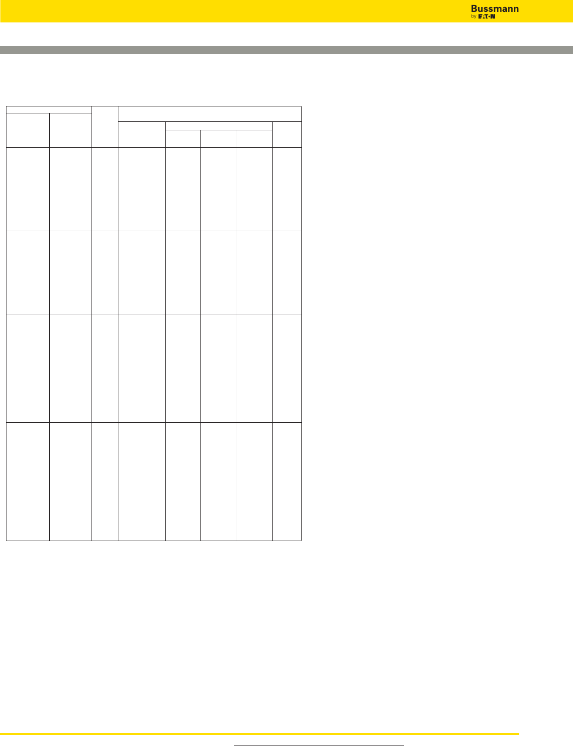
Square Body US Style — 1250V/1300V (IEC/UL): 50-1400A
Catalog Numbers
-FKE/115 Electrical Characteristics
-FU/115 Type K Rated I2t (A2Sec)
Without Indicator Current Clearing Clearing Watts
Indicator for Micro Size RMS-Amps Pre-arc at 1000V at 1250V Loss
170M3688 170M3738 50 135 815 1100 15
170M3689 170M3739 63 215 1300 1750 20
170M3690 170M3740 80 420 2500 3350 25
170M3691 170M3741 100 750 4450 5950 30
170M3692 170M3742 125 1450 9000 11500 35
170M3693 170M3743 1* 160 2600 16000 21000 40
170M3694 170M3744 200 5150 31000 41000 45
170M3695 170M3745 250 9200 54500 73000 55
170M3696 170M3746 315 18500 115000 150000 60
170M3697 170M3747 350 27000 165000 220000 65
170M4688 170M4738 160 1900 11500 15500 45
170M4689 170M4739 200 3800 22500 30000 50
170M4690 170M4740 250 7750 46000 61500 60
170M4691 170M4741 315 15000 90000 120000 65
170M4692 170M4742 1 350 20000 125000 165000 70
170M4693 170M4743 400 29500 175000 235000 75
170M4694 170M4744 450 42000 250000 335000 80
170M4695 170M4745 500† 69500 340000 85
170M4696 170M4746 550† 95000 465000 95
170M4697 170M4747 630‡ 130000 660000 100
170M5688 170M5738 250 6500 38500 51500 65
170M5689 170M5739 280 9350 55500 74500 70
170M5690 170M5740 315 13000 77500 105000 75
170M5691 170M5741 350 16500 97500 135000 80
170M5692 170M5742 400 23000 140000 180000 85
170M5693 170M5743 450 34000 205000 270000 90
170M5694 170M5744 2 500 48000 285000 380000 95
170M5695 170M5745 550 62000 370000 495000 100
170M5696 170M5746 630 115000 575000 730000 110
170M5697 170M5747 700† 160000 795000 115
170M5698 170M5748 800† 245000 1200000 120
170M5699 170M5749 900‡ 360000 1750000 125
170M5700 170M5750 1000‡ 480000 2350000 135
170M6688 170M6738 315 9500 58000 77500 185
170M6689 170M6739 350 13500 81500 110000 90
170M6690 170M6740 400 19500 120000 160000 95
170M6691 170M6741 450 31000 185000 245000 100
170M6692 170M6742 500 39000 235000 310000 105
170M6693 170M6743 550 55000 325000 435000 110
170M6694 170M6744 3 630 83500 495000 665000 115
170M6695 170M6745 700 115000 705000 940000 120
170M6696 170M6746 800 205000 995000 1300000 125
170M6697 170M6747 900 305000 1500000 1900000 130
170M6698† 170M6748† 1000¥ 450000 2150000 135
170M6699† 170M6749† 1100¥ 575000 2800000 140
170M6700‡ 170M6750‡ 1250¥ 810000 3950000 145
170M6701‡ 170M6751‡ 1400¥ 1250000 6000000 150
†Rated voltage (IEC) 1100.
‡Rated voltage (IEC) 1000V.
¥ UL Recognition at 1000V.
• Watts loss provided at rated current.
• Microswitch indicator ordered separately. See accessories on pages 212-213.
• For fuse curves see pages 193 and 194.
For product data sheets, visit www.cooperbussmann.com/DatasheetsEle
High Speed Fuses
192
Catalog Numbers
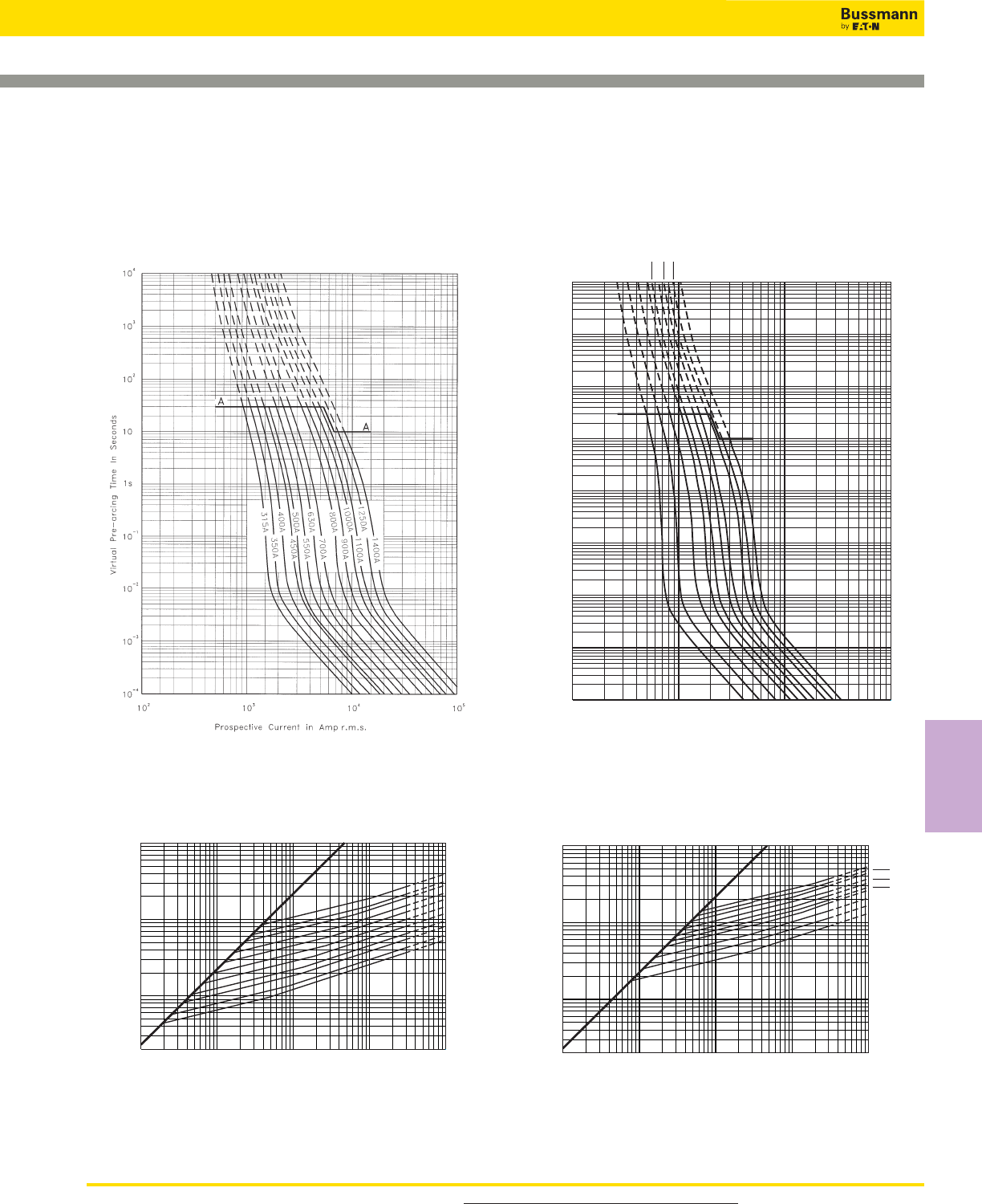
193
For product data sheets, visit www.cooperbussmann.com/DatasheetsEle
High Speed
Fuses
High Speed Fuses
Square Body Size 1*, 1 — 1250V/1300V (IEC/UL):
50-1400A
Size 1* — 50-400A:1250V
Time-Current Curve
1x102103104105106
2x10²
103
104
105
Prospective Short-Circuit Current Symmetrical RMS
Peak Let-Through Current
50A
63A
80A
100A
125A
160A
200A
250A
315A
350A
400A
A
B
1
Peak Let-Through Curve
1x10² 103 104 105
1x10⁻⁴
10–3
10–2
10–1
100
101
102
103
104
Prospective Current In Amp RMS
Virtual Pre-Arcing Time In Seconds
A
A
160A
200A
250A
315A 350A
400A 450A
500A 550A
630A
Size 1 — 160-630A: 1250V
Time-Current Curve
1x102103104105106
2x10²
103
104
105
Prospective Short-Circuit Current Symmetrical RMS
Peak Let-Through In Amperes
160A
200A
250A
315A 350A
400A 450A
500A 550A
630A
A
B
Peak Let-Through Curve
630A fuse is derated to 1100V (IEC).
Data Sheet: 17056630 Data Sheet: 17056632
Square Body Size 1*, 1 — 1250V/1300V (IEC/UL):
50-1400A
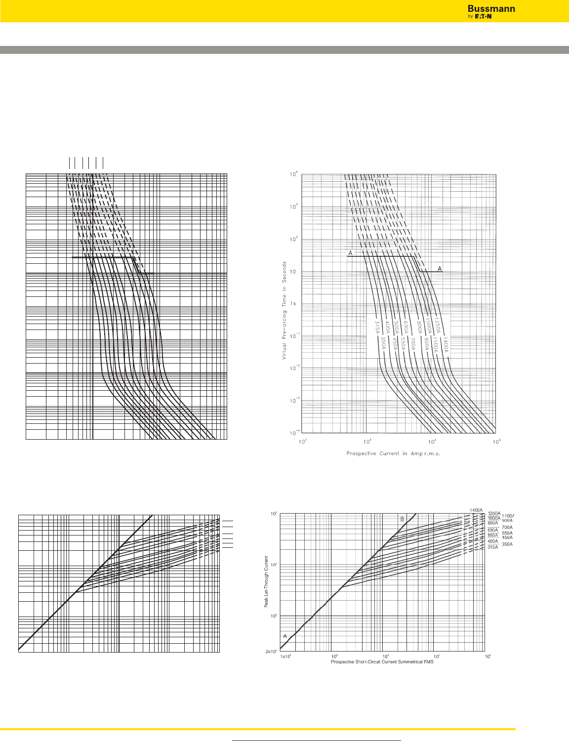
Square Body Size 2, 3 — 1250V/1300V (IEC/UL):
50-1400A
1x10² 103 104 105
1x10⁻⁴
10–3
10–2
10–1
100
101
102
103
104
Prospective Current In Amp RMS
Virtual Pre-Arcing Time In Seconds
250A 280A
315A 350A
400A 450A
500A 550A
630A 700A
800A 900A
1000A
A
A
Size 2 — 250-1000A: 1250V
Time-Current Curve
1x102103104 105 106
2x10²
103
104
105
Prospective Short-Circuit Current Symmetrical RMS
Peak Let-Through Current
250A 280A
315A 350A
400A 450A
500A 550A
630A 700A
800A 900A
1000A
A
B
Peak Let-Through Curve
900-1000A fuses are derated to 1100V (IEC).
Size 3 — 315-1400A: 1250V
Time-Current Curve
Peak Let-Through Curve
1250-1400A fuses are derated to 1100V (IEC).
Data Sheet: 17056634 Data Sheet: 17056636
For product data sheets, visit www.cooperbussmann.com/DatasheetsEle
High Speed Fuses
194
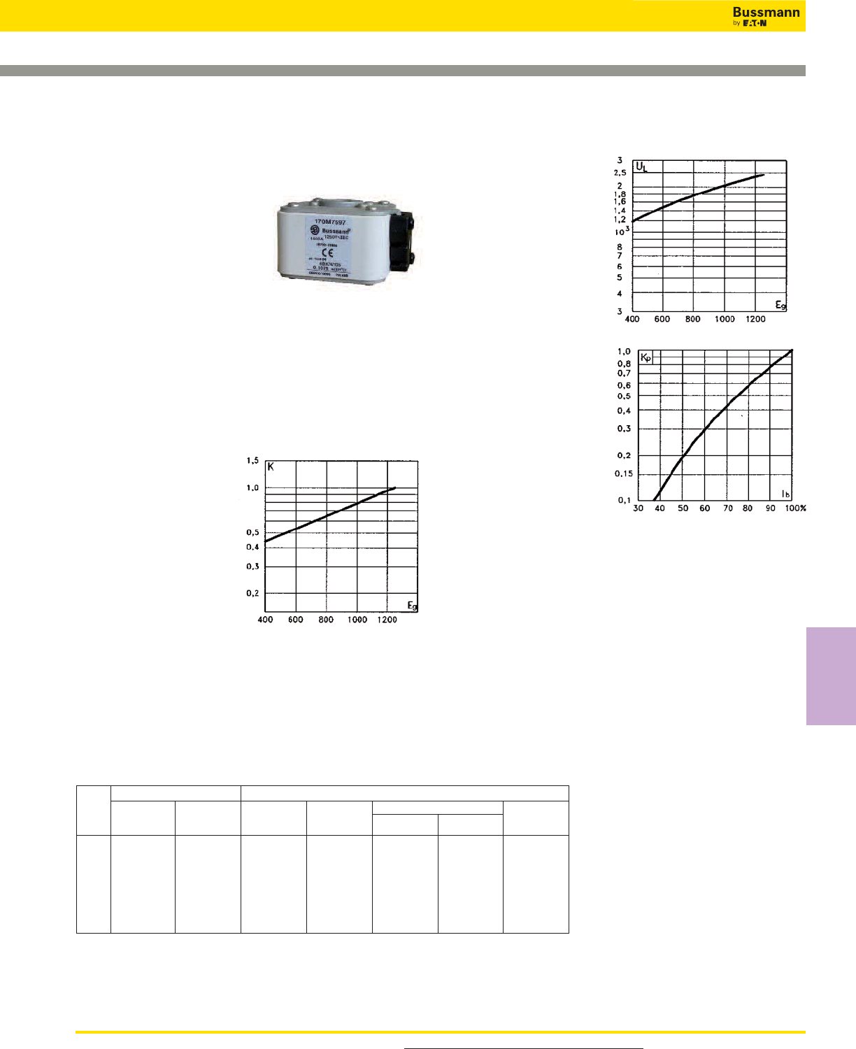
195
For product data sheets, visit www.cooperbussmann.com/DatasheetsEle
High Speed
Fuses
High Speed Fuses
Square Body Flush End Contact Size 4 — 1250V (IEC):
1400-2500A
1250V (IEC) 1400-2500A
Specifications
Description: High speed
square body fuses, for the
protection of the power rectifier
section of the equipment.
Dimensions: See dimensions
illustration.
Ratings:
Volts: — 1250Vac (IEC)
Amps: — 1400-2500A
IR: — 125kA RMS Sym.
Agency Information: CE, Designed and tested to IEC
60269: Part 4. UL Recognized E125085.JFHR2.
Electrical
Characteristics
Total clearing I2t
The total clearing I2t at
rated voltage and at power
factor of 15% are given in
the electrical
characteristics. For other
voltages, the clearing I2t is
found by multiplying by
correction factor, K, given
as a function of applied
working voltage, Eg, (rms).
Arc Voltage
This curve gives the
peak arc voltage, UL,
which may appear
across the fuse during
its operation as a
function of the applied
working voltage Eg,
(rms) at a power factor
of 15%.
Power Losses
Watts loss at rated current
is given in the electrical
characteristics. The curve
allows the calculation of
the power losses at load
currents lower than the
rated current. The
correction factor, Kp, is
given as a function of the
RMS load current, Ib, in %
of the rated current.
Features and Benefits
• Excellent DC performance
• Low arc voltage and low energy let-through (I2t)
• Low watts loss
• Superior cycling capability
Typical Applications
• DC Common bus
• DC Drives
• Power converters/rectifiers
• Reduced voltage starters
For Other Voltage Ratings in This Body Style
• See pages 163 (690V/700V) and 182 (1000V)
-BKN/105
Type K
Indicator
Catalog Number Electrical Characteristics
I2t (A2Sec)
-SBKN/105
Type K
Indicator
Watt
Loss
(W)
Rated
Voltage
(V)
Rated
Current
RMS-Amp
Fuse
Size
Pre-arc
Clearing
at 1250V
Data Sheet: 170K6640 , 170K6642
170M7217 170M7512 1400 800000 5000000 195
170M7597 170M7510 1500 1000000 6200000 200
170M7676 170M7511 1700 1400000 8700000 220
4 170M7532 170M7976 1250 1800 1700000 11000000 225
170M7633 170M7513 2000 2300000 14500000 235
170M7592 170M7546 2200 3100000 19500000 245
170M7107 170M7516 2400 4000000 25000000 255
170M7595 170M7978 2500 4500000 28000000 260
Catalog Numbers
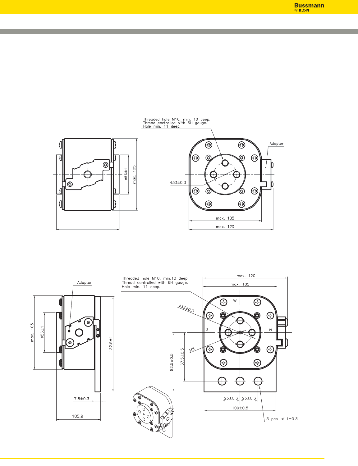
Square Body Flush End Contact Size 4 — 1250V (IEC):
1400-2500A
Dimensions - mm
Type 4BKN/ 105
Type 4SBKN/ 105
106.6
For product data sheets, visit www.cooperbussmann.com/DatasheetsEle
High Speed Fuses
196
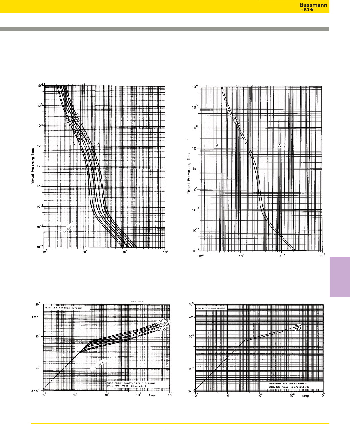
197
For product data sheets, visit www.cooperbussmann.com/DatasheetsEle
High Speed
Fuses
High Speed Fuses
Square Body Flush End Contact Size 4 — 1250V (IEC):
1400-2500A
Size 4 — 2300-2500A: 1250V
Time-Current Curve
Size 4 — 1400-2400A: 1250V
Time-Current Curve
Peak Let-Through CurvePeak Let-Through Curve
Data Sheet: Available upon request Data Sheet: Available upon request
Prospective Current in Amps RMS Prospective Current in Amps RMS
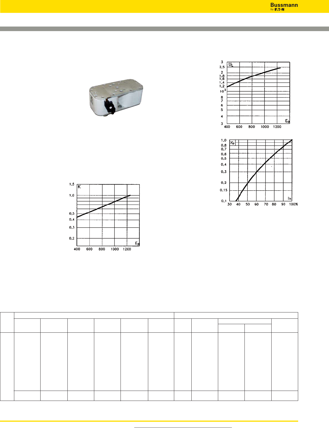
Square Body Flush End Contact Size 23— 1250V
(IEC/UL): 630-2800A
1250V (IEC) 630-2800A
Specifications
Description: High speed square
body fuses, for the protection of the
power rectifier section of the
equipment.
Dimensions: See dimensions
illustration.
Ratings:
Volts: — 1250Vac (IEC)
Amps: — 630-2800A
IR: — 125kA RMS Sym.
Agency Information: CE, Designed and tested to IEC
60269: Part 4. UL Recognized.
Electrical
Characteristics
Total clearing I2t
The total clearing I2t at
rated voltage and at power
factor of 15% are given in
the electrical
characteristics. For other
voltages, the clearing I2t is
found by multiplying by
correction factor, K, given
as a function of applied
working voltage, Eg, (rms).
Arc Voltage
This curve gives the
peak arc voltage, UL,
which may appear
across the fuse during
its operation as a
function of the applied
working voltage Eg,
(rms) at a power factor
of 15%.
Power Losses
Watts loss at rated current
is given in the electrical
characteristics. The curve
allows the calculation of
the power losses at load
currents lower than the
rated current. The
correction factor, Kp, is
given as a function of the
RMS load current, Ib, in %
of the rated current.
Features and Benefits
• Excellent DC performance
• Low arc voltage and low energy let-through (I2t)
• Low watts loss
• Superior cycling capability
Typical Applications
• DC Common bus
• DC Drives
• Power converters/rectifiers
• Reduced voltage starters
For Other Voltage Ratings in This Body Style
• See pages 165 (660V) and 185 (1000V)
Catalog Numbers
170M6775 170M6795 170M6785 630 38000 310000 170
170M6776 170M6796 170M6786 700 54000 440000 180
170M6777 170M6797 170M6787 800 78000 640000 190
170M6805 170M6807 170M6806 900 120000 980000 200
170M6778 170M6798 170M6788 1000 155000 1250000 210
23 170M6779 170M6799 170M6789 1250 1100 220000 1750000 220
170M6780 170M6800 170M6790 1250 330000 2700000 230
170M6781 170M6801 170M6791 1400 460000 3800000 240
170M6782 170M6802 170M6792 1600 820000 5200000 250
170M6783 170M6803 170M6793 1800 1200000 7600000 260
170M6784 170M6804 170M6794 2000 1800000 11000000 270
170M6815 170M6833 170M6827 2200 2300000 14500000 280
170M6816 170M6834 170M6828 1100 2500 3200000 †16000000 290
170M6817 170M6835 170M6829 2800 5000000 †24000000 300
-BU/75
without
Indicator
Catalog Number Electrical Characteristics
I2t (A2Sec)
-BKE/75
Type K
Indicator
-BKN/75
Type K
Indicator
-BU/80
without
Indicator
-BKE/80
Type K
Indicator
-BKN/80
Type K
Indicator
Watts
Loss
(W)
Rated
Voltage
(V)
Rated
Current
RMS-Amp
Fuse
Size Pre-arc Clearing at
1250V
† A2s @ 1000V
Data Sheet: 170K6638
For product data sheets, visit www.cooperbussmann.com/DatasheetsEle
High Speed Fuses
198
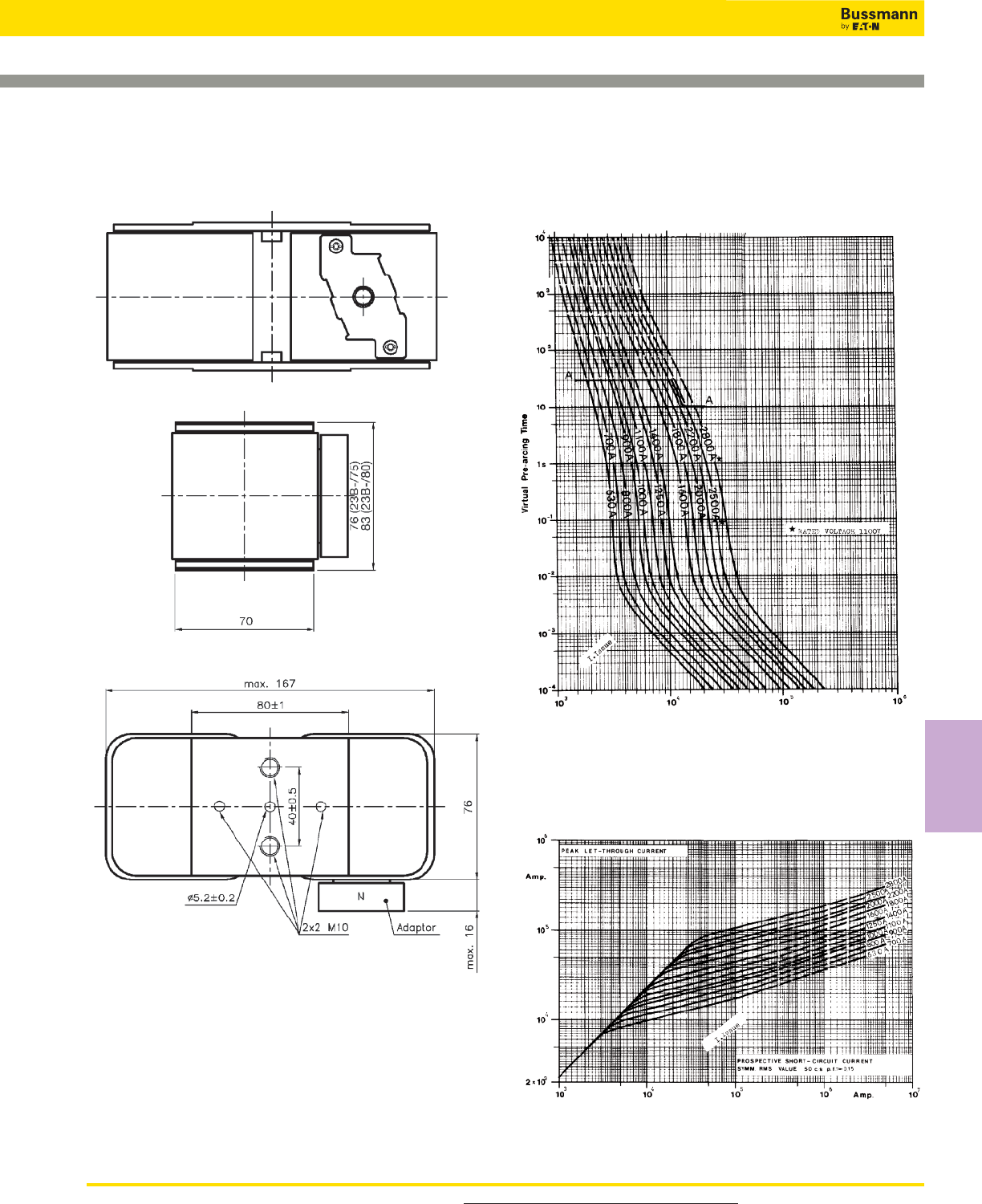
199
For product data sheets, visit www.cooperbussmann.com/DatasheetsEle
High Speed
Fuses
High Speed Fuses
Square Body Flush End Contact Size 23— 1250V
(IEC/UL): 630-2800A
Size 23 — 630-2800A: 1250V
Time-Current Curve
Peak Let-Through Curve
Prospective Current in Amps RMS
Dimensions - mm
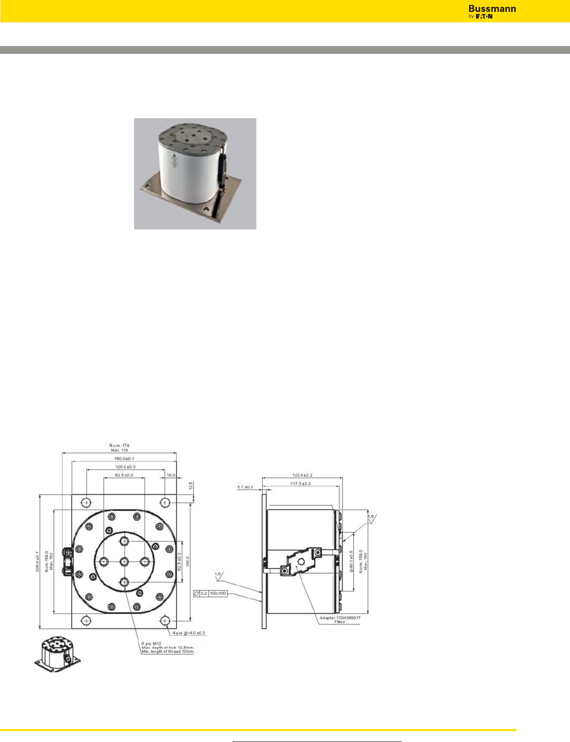
Square Body Flush End Contact Size 5— 1000V-2000V:
1800-5000A
1000V (IEC) 1800-5000A
Specifications
Description: High speed
square body fuses, for the
protection or isolation for
components such as diodes,
silicon controlled rectifiers
(SCRs), Gate torn-Off
Thyristors (GTOs) and IGBTs.
Dimensions: See dimensions
illustration.
Ratings:
Volts: — 1000-2000Vac (IEC)
Amps: — 1800-5000A
IR: — 300kA RMS Sym. estimated, 197kA tested
Agency Information: Consult Bussmann.
bulehighspeedtechnical@cooperindustries.com
Features and Benefits
• Excellent DC performance
• Low arc voltage and low energy let-through (I2t)
• Low watts loss
• Superior cycling capability
Typical Applications
• AC and DC drives
• High power converters/rectifiers
This dimension drawing is an example of the range of size 5 fuses available.
Dimensions - mm (in)
Contact Bussmann for available parts and technical information.
For product data sheets, visit www.cooperbussmann.com/DatasheetsEle
High Speed Fuses
200
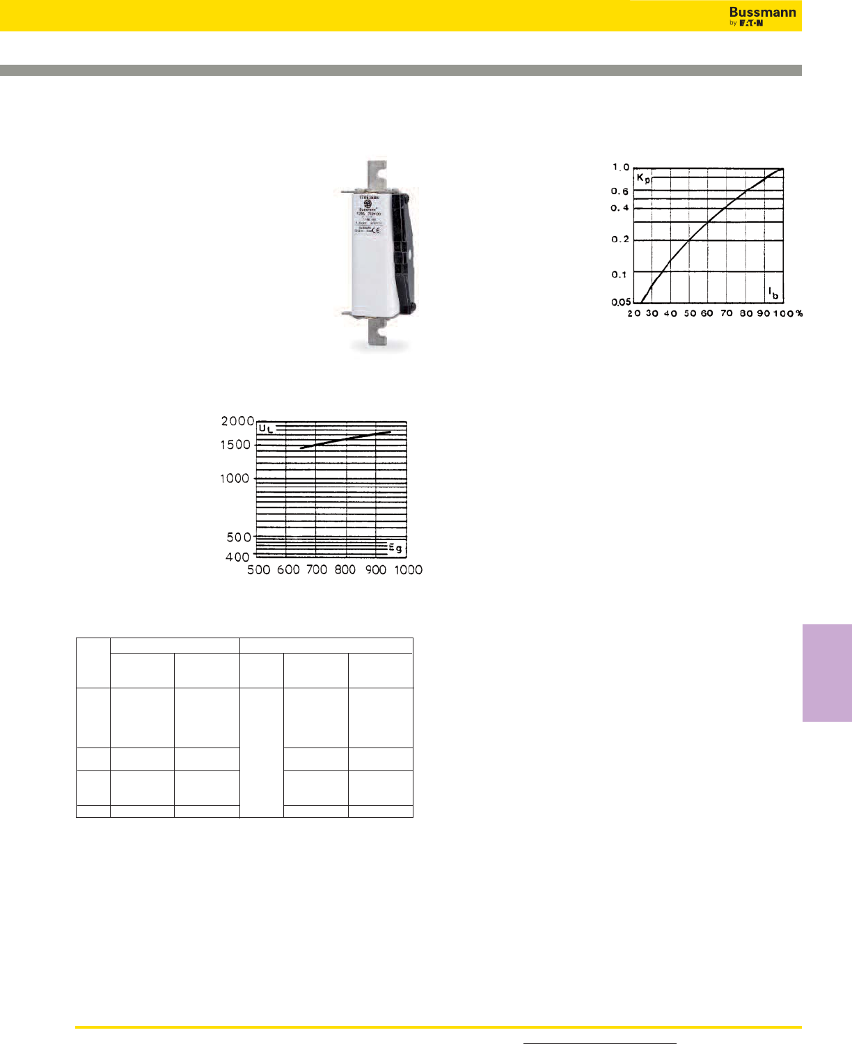
201
For detailed information, visit the Electrical IEC section at www.cooperbussmann.com
High Speed
Fuses
High Speed Fuses
Square Body DC Fuses — 750Vdc: 63-500A
750Vdc 63-500A
Specifications
Description: High speed fuses, for the
protection of DC circuits in equipment.
Dimensions: See dimensions
illustration.
Ratings:
Volts: — 750Vdc
Amps: — 63-500A
IR: — 750Vdc IR: 100kA, L/R = 100 ms.
— 1000Vdc IR: 100kA, L/R = 40 ms
Agency Information: Consult Cooper
Bussmann.
Electrical Characteristics
Arc Voltage
This curve gives the
peak arc voltage, UL,
which may appear
across the fuse during
its operation as a
function of the applied
working voltage Eg.
Power Losses
Watts loss at rated current
is given in the electrical
characteristics. The curve
allows the calculation of
the power losses at load
currents lower than the
rated current. The
correction factor, Kp, is
given as a function of the
RMS load current, Ib, in %
of the rated current.
Features and Benefits
• Excellent DC performance
• Low arc voltage and low energy let-through (I2t)
• Low watts loss
• Superior cycling capability
Typical Applications
• DC common bus
• DC drives
• Power converters/rectifiers
• Reduced voltage starters
Catalog Numbers
170E3577 170E3583 63 10.0
170E3578 170E3584 80 13.0
1* 170E3579 170E3585 100 16.0
170E3580 170E3586 125 21.0
170E3581 170E3587 160 26.0
1170E5417 170E5420 750 200 37.0
170E5418 170E5421 250 46.0
170E8335 170E8345 250 47.0
2 170E8336 170E8346 315 57.0
170E8337 170E8347 400 73.0
3 170E9681 170E9685 500 91.0
-BK/130 -EK/-
Catalog Numbers Electrical Characteristics
Watt
Loss
(W)
Rated
Voltage
(Vdc)
Rated
Current
RMS-Amp
Fuse
Size
Data Sheet: Size 1*: 170K3620
Size 1: 170K3622
Size 2: 170K3624
Size 3: 170K3626
Microswitch: 170H0069, 170H3027 (gold)
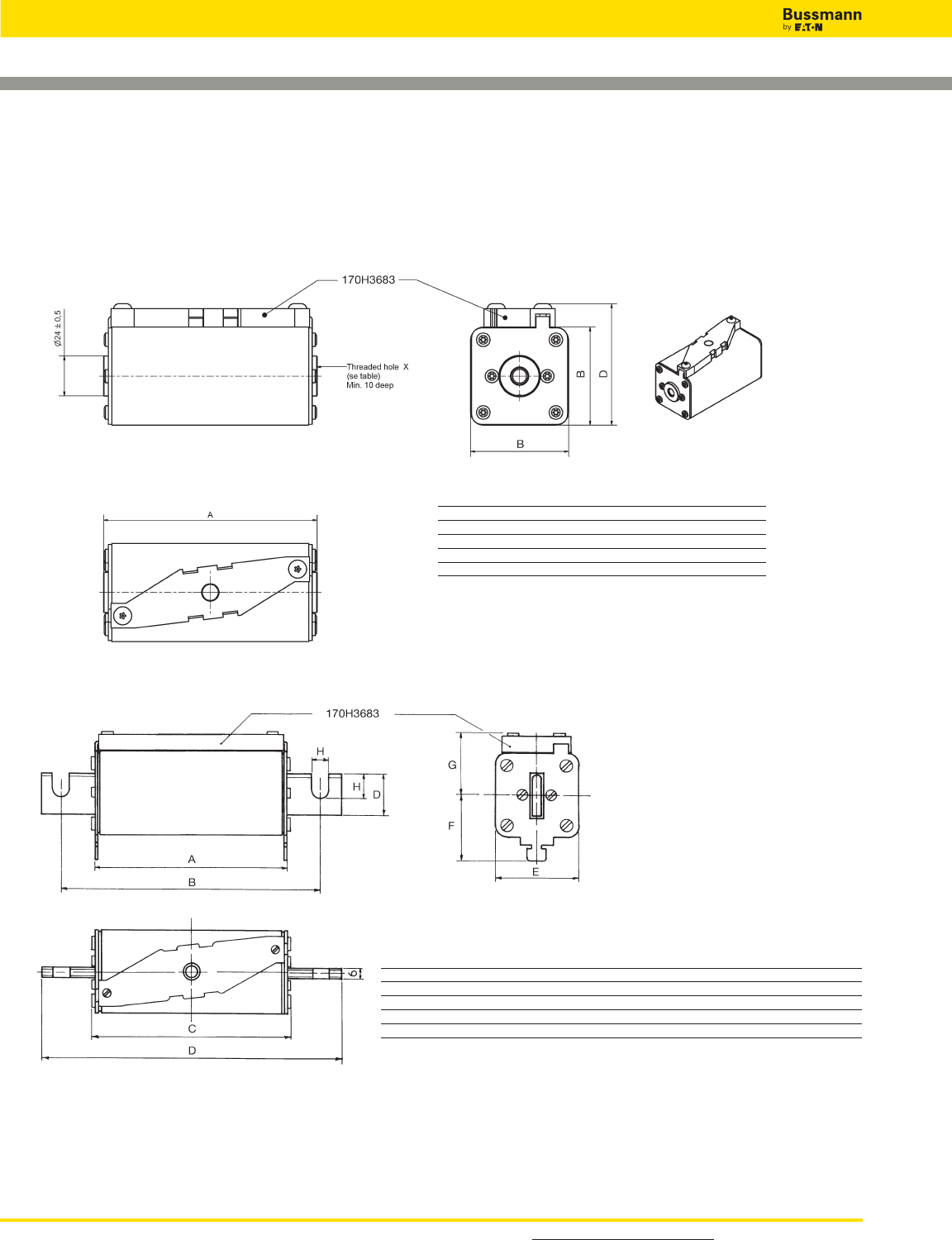
Square Body DC Fuses — 750Vdc: 63-500A
Dimensions - mm
Type –BK/ 130
Type –EK/ -
Size/Type A B D
1* BK/130 129 43 61
1 BK/130 130 51 69
2 BK/130 130 59 77
3 BK/130 131 74 90
Size/Type A B C D E F G H I J
1* EK/155 124 156 129 180 43 36 41 9 9 18
1 EK/165 124 166 129 191 51 37 41 11 14 25
2 EK/170 124 170 129 205 59 42 48 13 21 30
3 EK/170 125 170 130 206 74 51 56 13 20 36
For detailed information, visit the Electrical IEC section at www.cooperbussmann.com
High Speed Fuses
202
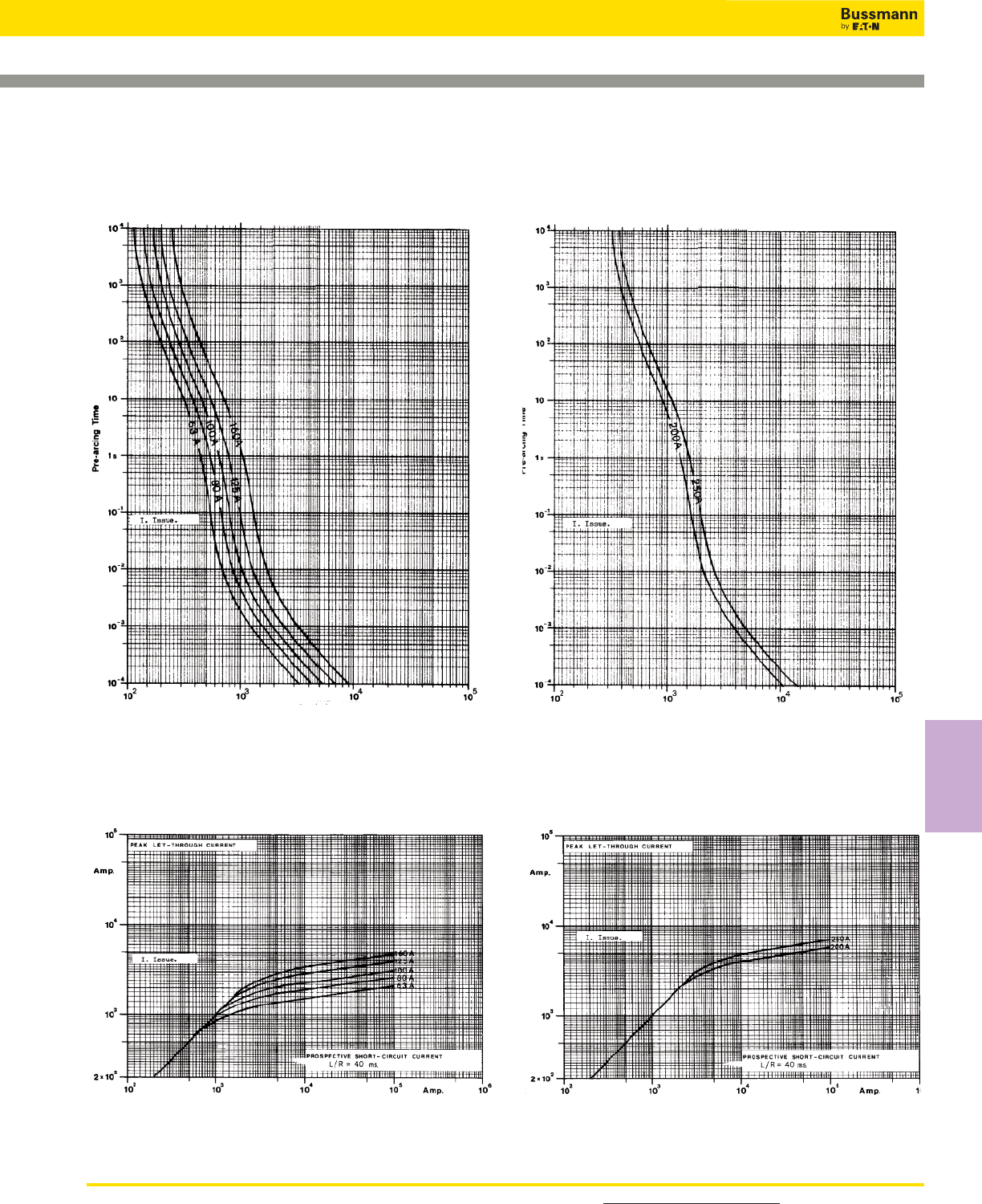
203
For detailed information, visit the Electrical IEC section at www.cooperbussmann.com
High Speed
Fuses
High Speed Fuses
Square Body DC Fuses — 750Vdc: 63-500A
Square Body DC Fuse — 200-250A: 750V
Time-Current Curve
Square Body DC Fuse — 63-160A: 750V
Time-Current Curve
Peak Let-Through CurvePeak Let-Through Curve
Data Sheet: Available upon request Data Sheet: Available upon request
Prospective Current in Amps RMS Prospective Current in Amps RMS
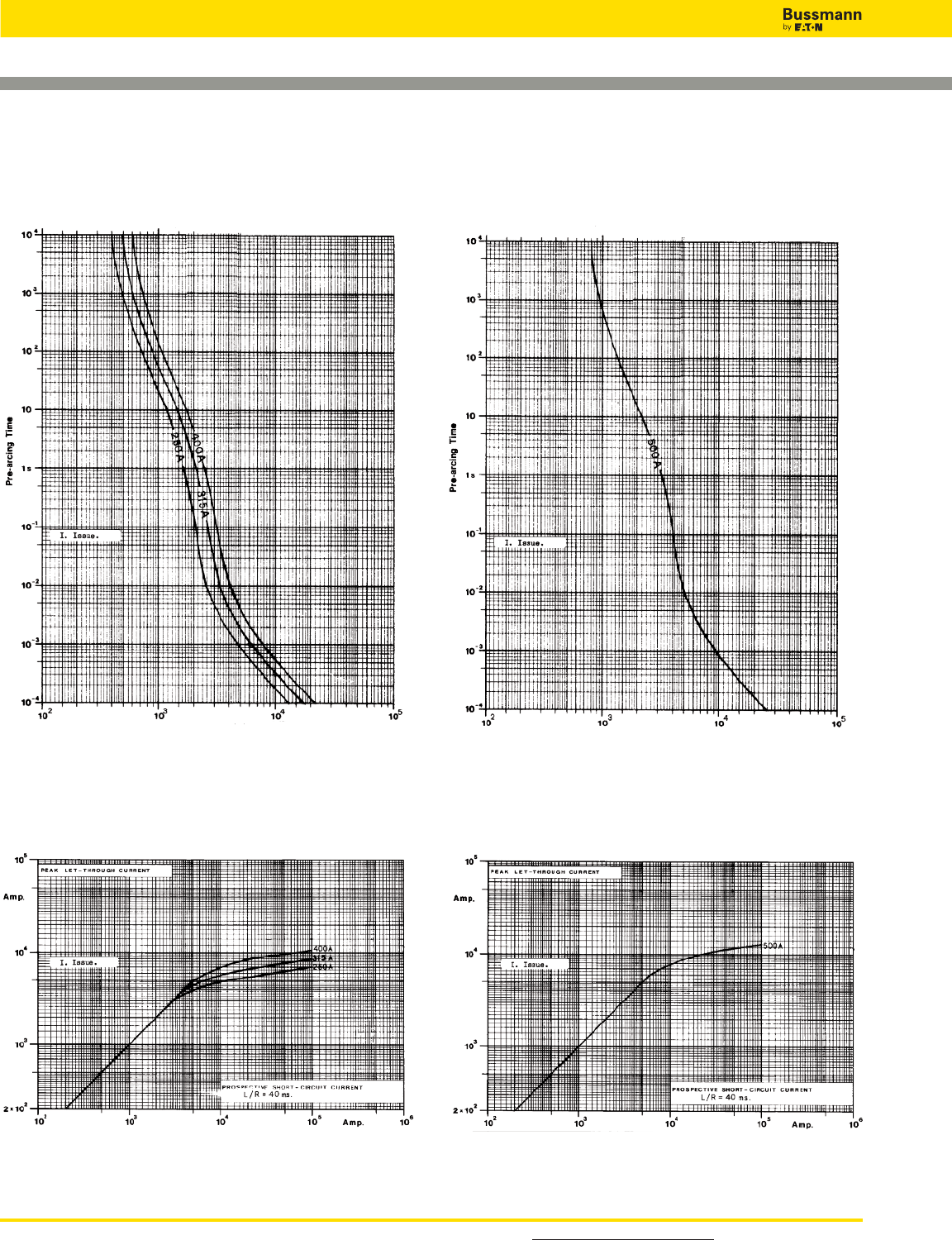
Square Body DC Fuses — 750Vdc: 63-500A
Square Body DC Fuse — 500A: 750V
Time-Current Curve
Square Body DC Fuse — 250-400A: 750V
Time-Current Curve
Peak Let-Through CurvePeak Let-Through Curve
Data Sheet: Available upon request Data Sheet: Available upon request
Prospective Current in Amps RMS Prospective Current in Amps RMS
For detailed information, visit the Electrical IEC section at www.cooperbussmann.com
High Speed Fuses
204

205
For detailed information, visit the Electrical IEC section at www.cooperbussmann.com
High Speed
Fuses
High Speed Fuses
Square Body DC Fuses — 1200Vdc: 160-420A
1200Vdc 160-420A
Specifications
Description: High speed fuses that
provide superior protection in light and
heavy harsh DC traction applications as
1200Vdc and below circuits, and as DC
link/power converters.
Dimensions: See dimensions
illustration.
Ratings:
Volts: — 1200Vdc
Amps: — 160-420A
IR: — 1200Vdc = 100kA L/R: 15 ms.
Agency Information: Consult Cooper Bussmann.
Electrical
Characteristics
Arc Voltage
This curve gives the
peak arc voltage, UL,
which may appear
across the fuse during
its operation as a
function of the applied
working voltage Eg.
Power Losses
Watts loss at rated current
is given in the electrical
characteristics. The curve
allows the calculation of
the power losses at load
currents lower than the
rated current. The
correction factor, Kp, is
given as a function of the
RMS load current, Ib, in %
of the rated current.
Features and Benefits
• Excellent DC performance
• Low arc voltage and low energy let-through (I2t)
• Low watts loss
• Superior cycling capability
Typical Applications
• DC Common bus
• DC Drives
• Power converters/rectifiers
• Reduced voltage starters
Catalog Numbers
Dimensions - mm
170F8230 160 12000 20000 75.0
170F8231 200 20000 35000 85.0
2SKN / 140 170F8232 1200 250 43000 75000 94.0
170F8233 315 87000 150000 104.0
170F8234 400 180000 310000 120.0
170F8235 420 215000 375000 122.0
-SKNB/140
Type K
Indicator
Electrical Characteristics
Max I2t (A2Sec) @ 1000Vdc Watts
Loss
(W)
Rated
Voltage
(Vdc)
Rated
Current
RMS-Amp
Fuse
Type
Cat. Numbers
L/R = 15ms L/R = 45ms
Data Sheet: 170K5520
Microswitch: 170H0069, 170H3027 (gold)

Square Body DC Fuses — 1200Vdc: 160-420A
Square Body DC Fuse — 160-420A: 1200V
Time-Current Curve
Data Sheet: Available upon request
Prospective Current in Amps RMS
For detailed information, visit the Electrical IEC section at www.cooperbussmann.com
High Speed Fuses
206
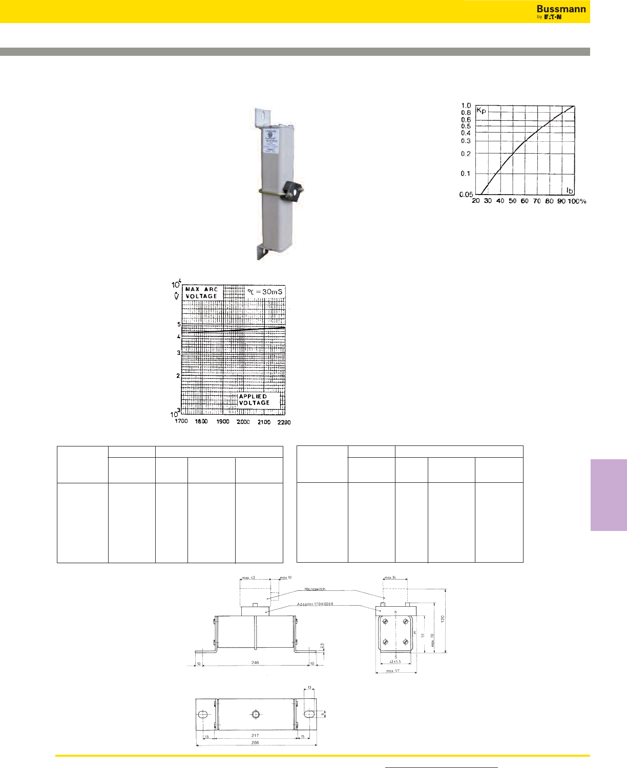
207
For detailed information, visit the Electrical IEC section at www.cooperbussmann.com
High Speed
Fuses
High Speed Fuses
Square Body DC fuses — 2000Vdc: 10-125A
2000Vdc 10-125A
Specifications
Description: High speed fuses for the
protection of DC circuits in equipment.
Dimensions: See dimensions
illustration.
Ratings:
Volts: — 1200Vdc
Amps: — 160-420A
IR: — 1200Vdc = 100kA L/R: 15 ms.
Agency Information: Consult Bussmann.
Electrical
Characteristics
Arc Voltage
This curve gives the
peak arc voltage, UL,
which may appear
across the fuse during
its operation as a
function of the applied
working voltage Eg.
Power Losses
Watts loss at rated current
is given in the electrical
characteristics. The curve
allows the calculation of
the power losses at load
currents lower than the
rated current. The
correction factor, Kp, is
given as a function of the RMS load current, Ib, in % of the
rated current.
Features and Benefits
• Excellent DC performance
• Low arc voltage and low energy let-through (I2t)
• Low watts loss
• Superior cycling capability
Typical Applications
• DC Common bus
• DC Drives
• Power converters/rectifiers
• Reduced voltage starters
Catalog Numbers
170E3976 10 7
170E3970 16 11
170E3950 20 13
170E3951 25 17
1*SKN/246 170E3952 2000 32 22
170E3953 40 27
170E3954 50 34
170E3955 63 43
170E3956 80 50
-SKN/246
Type K
Indicator
Rated
Current
RMS-Amp
Cat. Number Electrical Characteristics
Watt
Loss
(W)
Rated
Voltage
(Vdc)
Fuse
Type
170E3937 20 13
170E3938 25 16
170E3939 32 20
170E3940 40 25
1*SKN/246 170E3941 2000 50 32
170E3942 63 40
170E3943 80 51
170E3944 100 64
170E3945 125 80
-SKN/246
Type K
Indicator
Rated
Current
RMS-Amp
Cat. Number Electrical Characteristics
Watt
Loss
(W)
Rated
Voltage
(Vdc)
Fuse
Type
Dimensions - mm
Data Sheet: 170K4538
Microswitch: 170H0239, 170H3030 (gold)
Data Sheet: 170K4900
Microswitch: 170H0239, 170H3030 (gold)
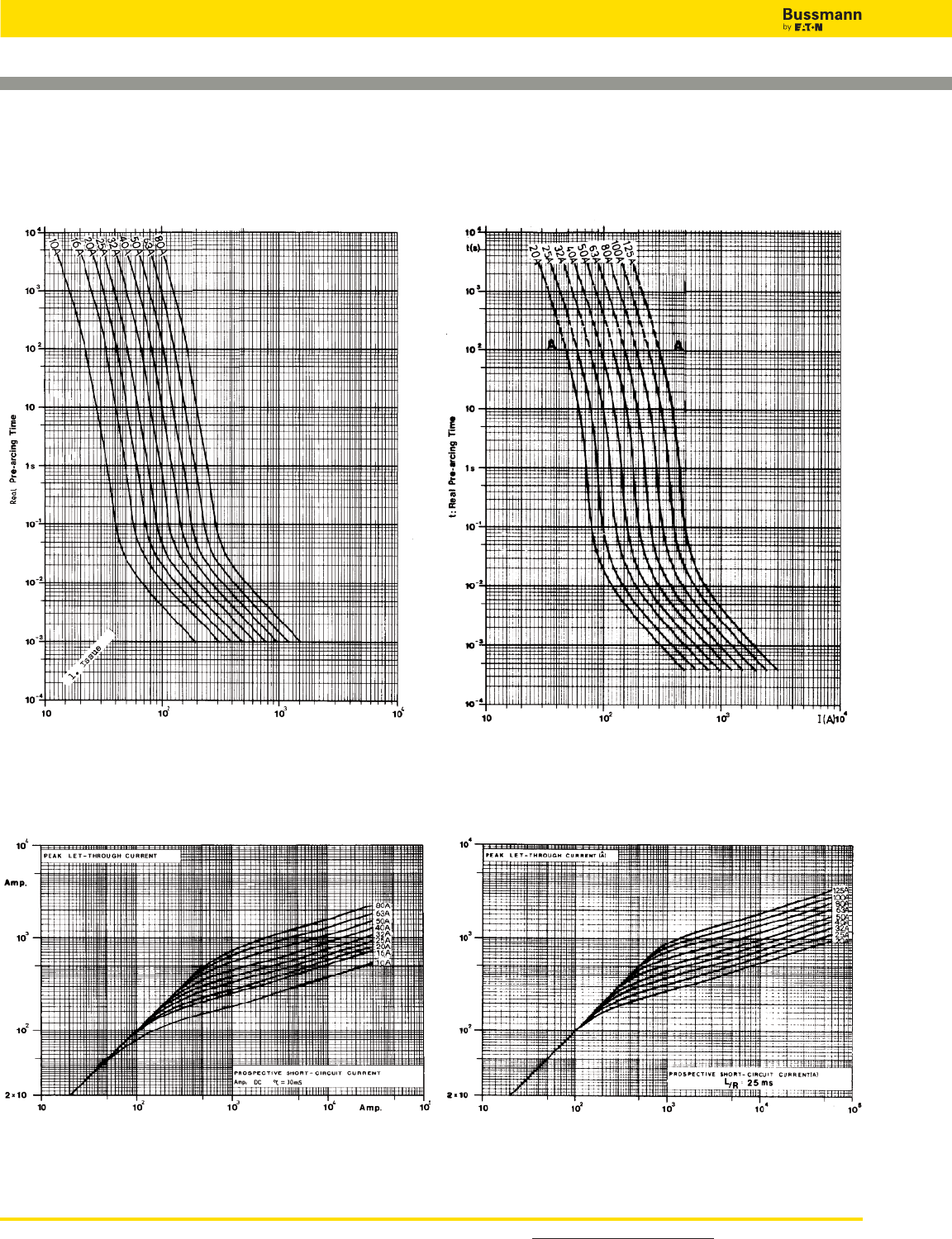
Square Body DC fuses — 2000Vdc: 10-125A
Square Body DC Fuses — 10-80A: 2000V
Time-Current Curve
Peak Let-Through Curve
Data Sheet: Available upon request
Prospective Current in Amps RMS
Square Body DC Fuses — 20-125A: 2000V
Time-Current Curve
Peak Let-Through Curve
Data Sheet: Available upon request
Prospective Current in Amps RMS
For detailed information, visit the Electrical IEC section at www.cooperbussmann.com
High Speed Fuses
208
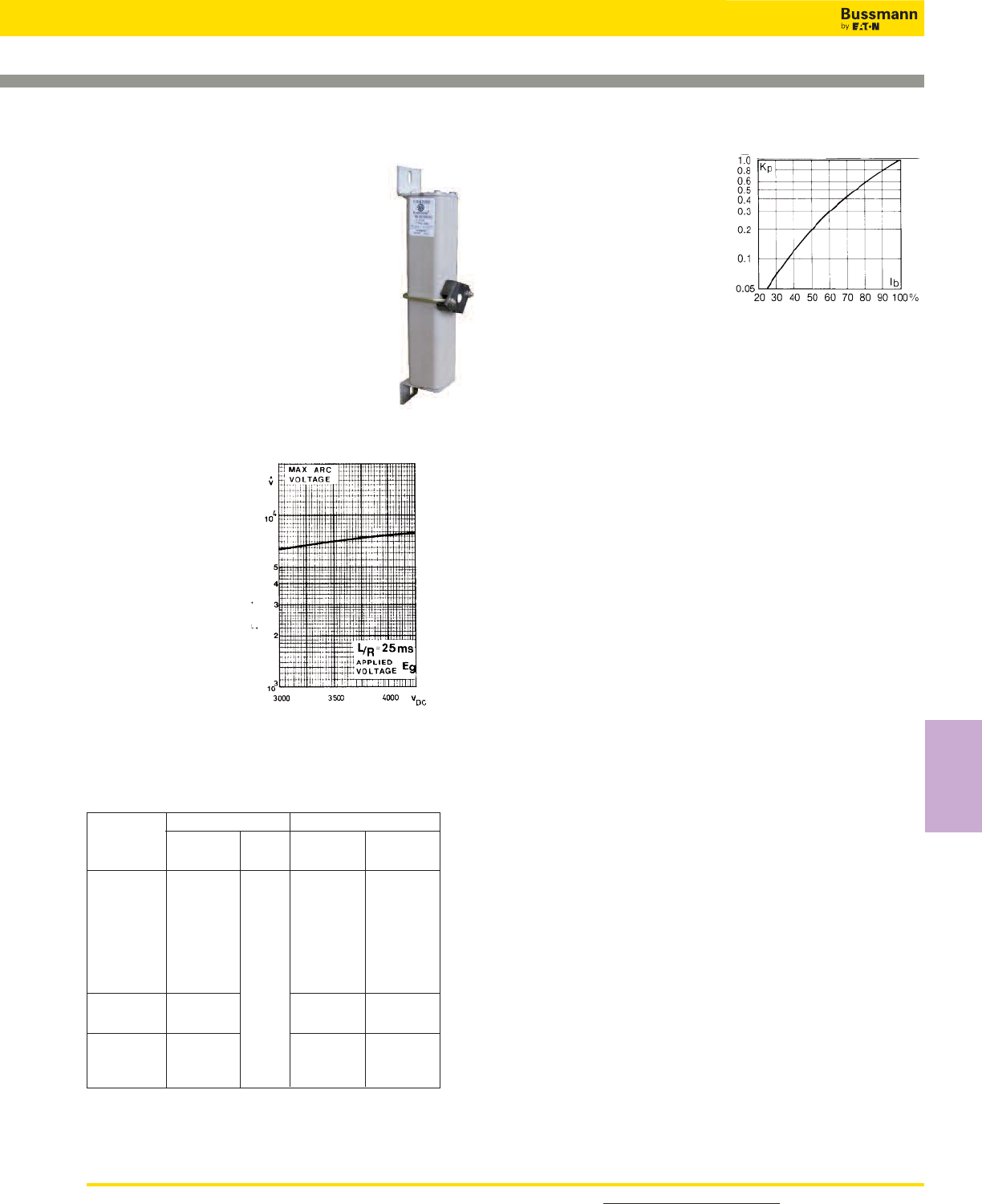
209
For detailed information, visit the Electrical IEC section at www.cooperbussmann.com
High Speed
Fuses
High Speed Fuses
Square Body DC Fuses — 4000Vdc: 20-450A
4000Vdc 20-450A
Specifications
Description: High speed fuses for the
protection of DC circuits in equipment.
Dimensions: See dimensions
illustration.
Ratings:
Volts: — 4000Vdc
Amps: — 20-450A
IR: — 60kA L/R: 25 ms.
Agency Information: Consult Bussmann.
Electrical
Characteristics
Arc Voltage
This curve gives the
peak arc voltage, UL,
which may appear
across the fuse during
its operation as a
function of the applied
working voltage Eg.
Power Losses
Watts loss at rated current is
given in the electrical charac-
teristics. The curve allows the
calculation of the power loss-
es at load currents lower than
the rated current. The
correction factor, Kp, is given
as a function of the RMS load
current, Ib, in % of the rated current.
Features and Benefits
• Excellent DC performance
• Low arc voltage and low
energy let-through (I2t)
• Low watts loss
• Superior cycling capability
Typical Applications
• DC Common bus
• DC Drives
• Power converters/rectifiers
• Reduced voltage starters
Catalog Numbers
170E3914 20 23
170E3915 25 28
170E3916 32 34
170E3917 40 45
1*SKN/394 170E3918 50 57
170E3919 63 72
170E3984 80 91
170E3933 4000 100 114
170E3922 125 143
170E8882 160 182
2 SKN/394 170E8883 200 228
170E8884 250 285
170E8885 315 360
2//2SKN/394 170E8886 350 400
170E8887 400 455
170E8888 450 515
-SKN/394
Type K
Indicator
Cat. Numbers Electrical Characteristics
Watts
Loss
(W)
Rated
Voltage
(Vdc)
Rated
Current
RMS-Amp
Fuse
Type
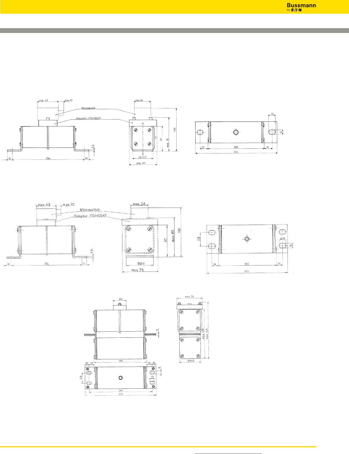
DC Fuses — 4000Vdc: 20-450A
Dimensions - mm
Type 1* SKN/ 394
Type 2SKN/ 394
Type 2//SKN/394
For detailed information, visit the Electrical IEC section at www.cooperbussmann.com
High Speed Fuses
210
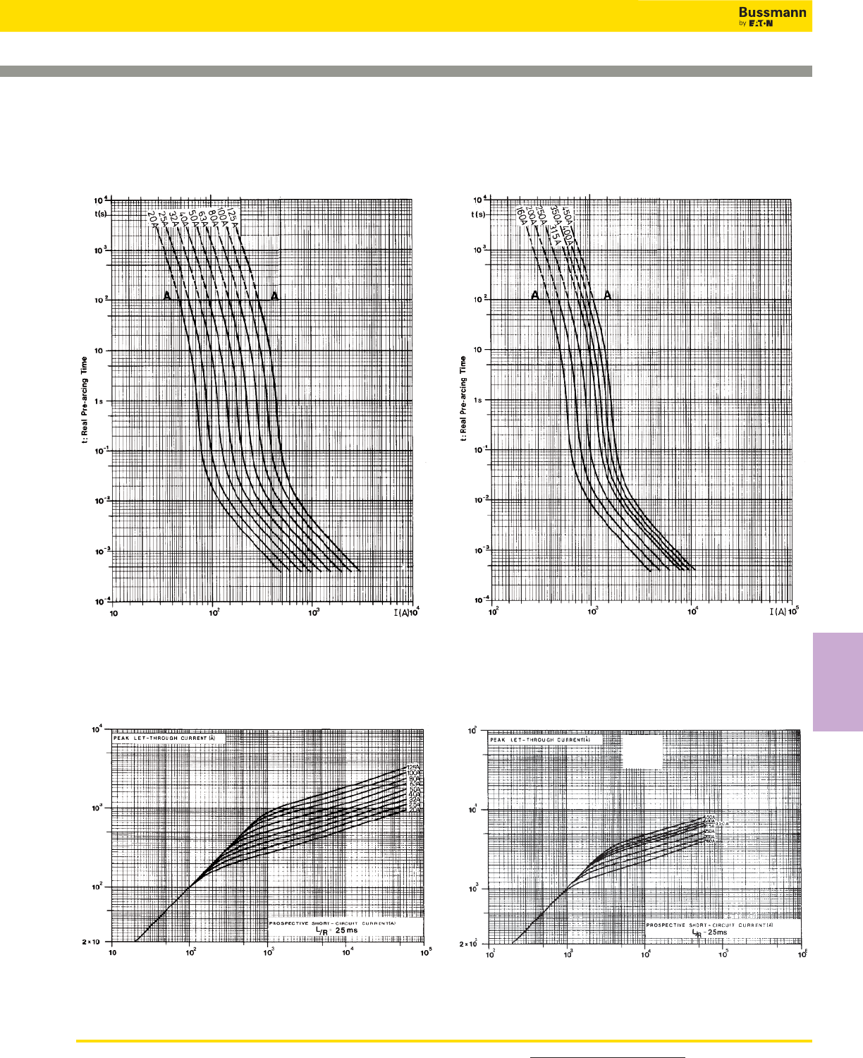
211
For detailed information, visit the Electrical IEC section at www.cooperbussmann.com
High Speed
Fuses
High Speed Fuses
Square Body DC Fuses — 4000Vdc: 20-450A
Square Body DC Fuses — 20-125A: 2000V
Time-Current Curve
Peak Let-Through Curve
Data Sheet: Available upon request
Prospective Current in Amps RMS
Square Body DC Fuses — 160-450A: 4000V
Time-Current Curve
Peak Let-Through Curve
Data Sheet: Available upon request
Prospective Current in Amps RMS
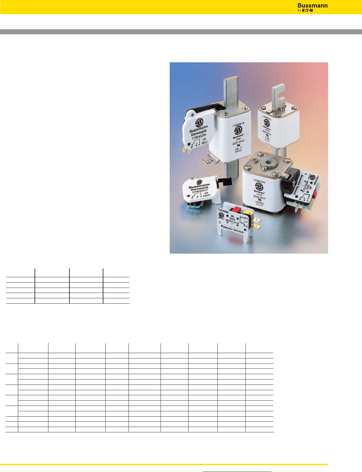
DIN 43 653 DIN 43 620 French Style Flush End US Style
Size Type T Type K Type T Type K Type T Type K Type T Type K Type K
000 170H0236 170H0236
170H0238 170H0238
00 170H0235 170H0235
170H0237 170H0237
1* 170H0235 170H0069 170H0235 170H0236 170H0069 170H0069 170H0069
170H0237 170H0237 170H0238
1170H0235 170H0069 170H0236 170H0069 170H0069 170H0069
170H0237 170H0238
2170H0235 170H0069 170H0235 170H0236 170H0069 170H0069 170H0069
170H0237 170H0237 170H0238
3170H0235 170H0069 170H0236 170H0236 170H0069 170H0069 170H0069
170H0237 170H0238 170H0238
4170H0069
23 170H0069
24 170H0069
Square Body Fuse Accessories
Indicator Systems
Typower ZILOX fuses are available with three different
indicator systems.
1. Visual Indicator
The indicator situated in one cover plate is clearly visible as
soon as the fuse has operated. The minimum voltage for
operating the indicator is 20V.
2. Type T Indicator
The indicator is situated on one cover plate with a cover
plate tag to accommodate an auxiliary switch. The minimum
voltage for operating the indicator is 20V. A special low
voltage indicator (1.5V) is available on request.
3. Type K Indicator
This indicator is situated on the fuse body. It is covered by
an adapter for snap-on mounting of an auxiliary switch. The
operating voltage of the indicator is 1.5V. As a matter of
safety, the factory mounted adapter must not be removed
from the fuse.
Microswitch
The Typower ZILOX fuses with either type T indicator or type
K indicator can be equipped with a microswitch for remote
electrical indication of fuse operations. All microswitches
have one normally open and one normally closed contact.
Ratings are 2A, 250Vac.
6.3 x 0.8mm 2.8 x 0.5mm Indicator
Microswitch Lugs Lugs Type
170H0235 X T
170H0236 X T
170H0237 X T
170H0238 X T
170H0069 X K
For detailed information, visit the Electrical IEC section at www.cooperbussmann.com
High Speed Fuses
212
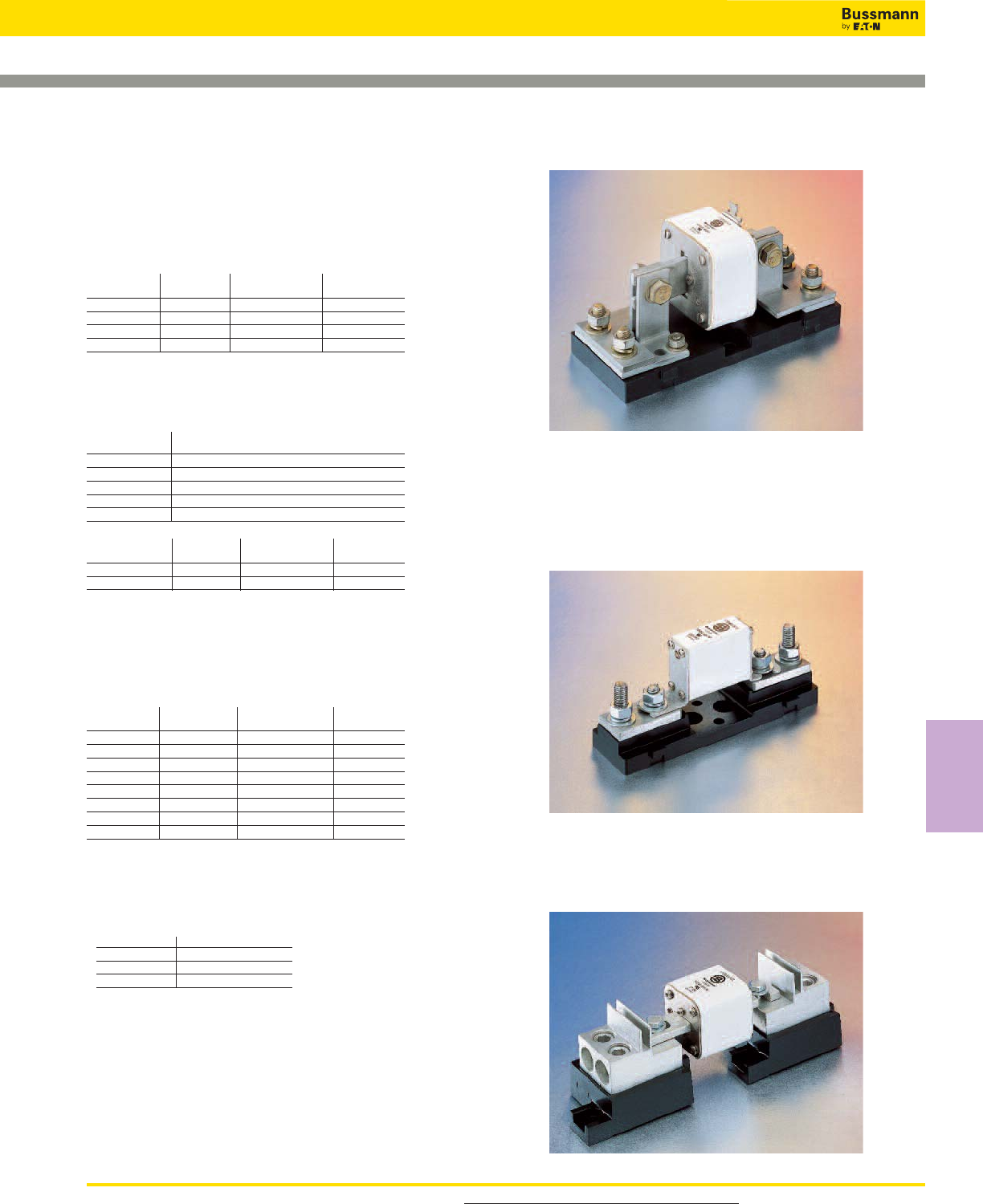
213
For product data sheets, visit www.cooperbussmann.com/DatasheetsEle
High Speed
Fuses
High Speed Fuses
Square Body Fuse Accessories
1BS Series Example
170H3004
170H1013
Fuse Bases (Blocks)
DIN 43 653 Fuse Bases
For the Typower ZILOX fuses according to DIN 43 653, the
following fuse bases are available:
Catalog Max Amp Center
Number Volts Rating Distance
170H3003 1000 630 80mm
170H3004 1000 1250 80mm
170H3005 1400 630 110mm
170H3006 1400 1250 110mm
The fuse bases rated 1250A can also be used for the fuses
with higher rated current if the maximum load current is
derated according to the table below:
Fuse Amp Max Amp Load
Rating In Fuse Base
1400 1325
1500 1400
1600 1500
1800 1650
2000 1800
Fixed Center Max Max. Fuse Fuse
Base Style Volts Amp Rating Size
170H1007 1000 400 00, 000
170H1013 660 200 0000,000
UL Recognized to UL 512.
Universal Fuse Bases
For the Typower ZILOX fuses according to DIN 43 653,
French style and North American style, the following fuse
bases are available:
Modular Max Max. Fuse
Base Style Volts Amp Rating Data Sheet
1BS101 600 100 1206
1BS102 600 400 1207
1BS103 600 400 1208
1BS104 600 600 1209
BH-0xxx 700 200 1200
BH-1xxx 2500 400 1201
BH-2xxx 5000 400 1202
BH-3xxx 1250 700 1203
Modular fuse bases are UL Recognized to UL 512 and meet
the spacing requirements of UL 347. Contact your Bussmann
sales representative for more complete ordering information.
DIN 43 620 Fuse Bases
Size Part Number
000-00 SB00-D
1*, 1 SB1-D
2,3 SB2-D
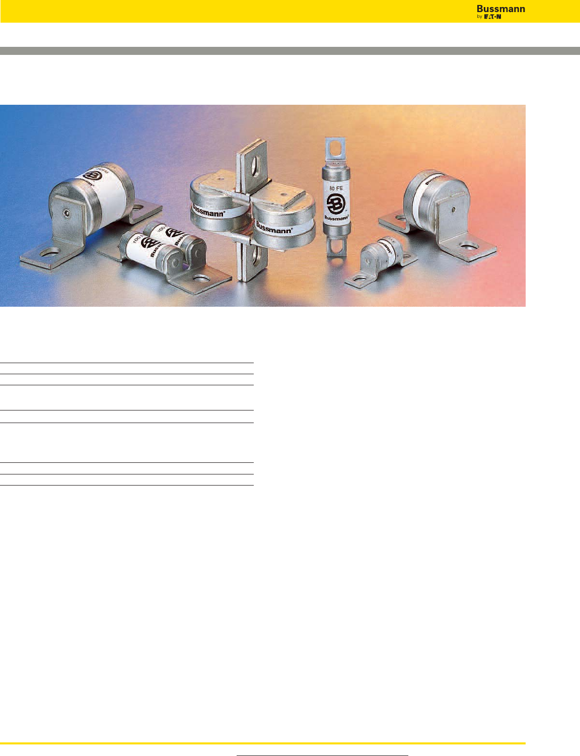
For product data sheets, visit www.cooperbussmann.com/DatasheetsEle
214
High Speed Fuses
British BS 88 Fuses
General Information
Designed and tested to:
• BS 88: Part 4
• IEC 269: Part 4
• UL Recognized
Bussmann offers the industry’s widest range of British style
semiconductor fuses and accessories.
Bussmann British style products use innovative arc
quenching techniques and high grade materials to provide:
• Minimal energy let-through (I2t)
• Excellent DC performance
• Good surge withstand profile
British style fuses are typically found in equipment
manufactured in the United Kingdom or British
Commonwealth countries. However, North American
manufacturers have begun to specify British style fuses —
particularly in UPS applications at 240V or less — to take
advantage of their size, performance and cost benefits.
Voltage Rating
All Bussmann British style fuses are tested to IEC 269: Part
4. This standard requires a test voltage which is 5% higher
than the rated voltage. In North America, fuses are required
to clear only their rated voltage.
Accessories
Trip-indicator fuses are available for use in parallel with the
main fuse. Indicator fuses can be attached to the associated
fuselink, or mounted separately in panel-mounted fuseclips.
In addition, a push-on adapter and microswitch attachment
are available, to provide remote indication. Fuse blocks are
also available for most applications.
Introduction
British BS 88 Contents
Fuse Amp
Volts Range Page
240 6-900 215-217
690 6-710 218-221
Accessories
Indicator System & Fuse Bases 222
British BS 88 Fuse Ranges
Amps Vac Vdc
6-900 240 150
6-710 690 500
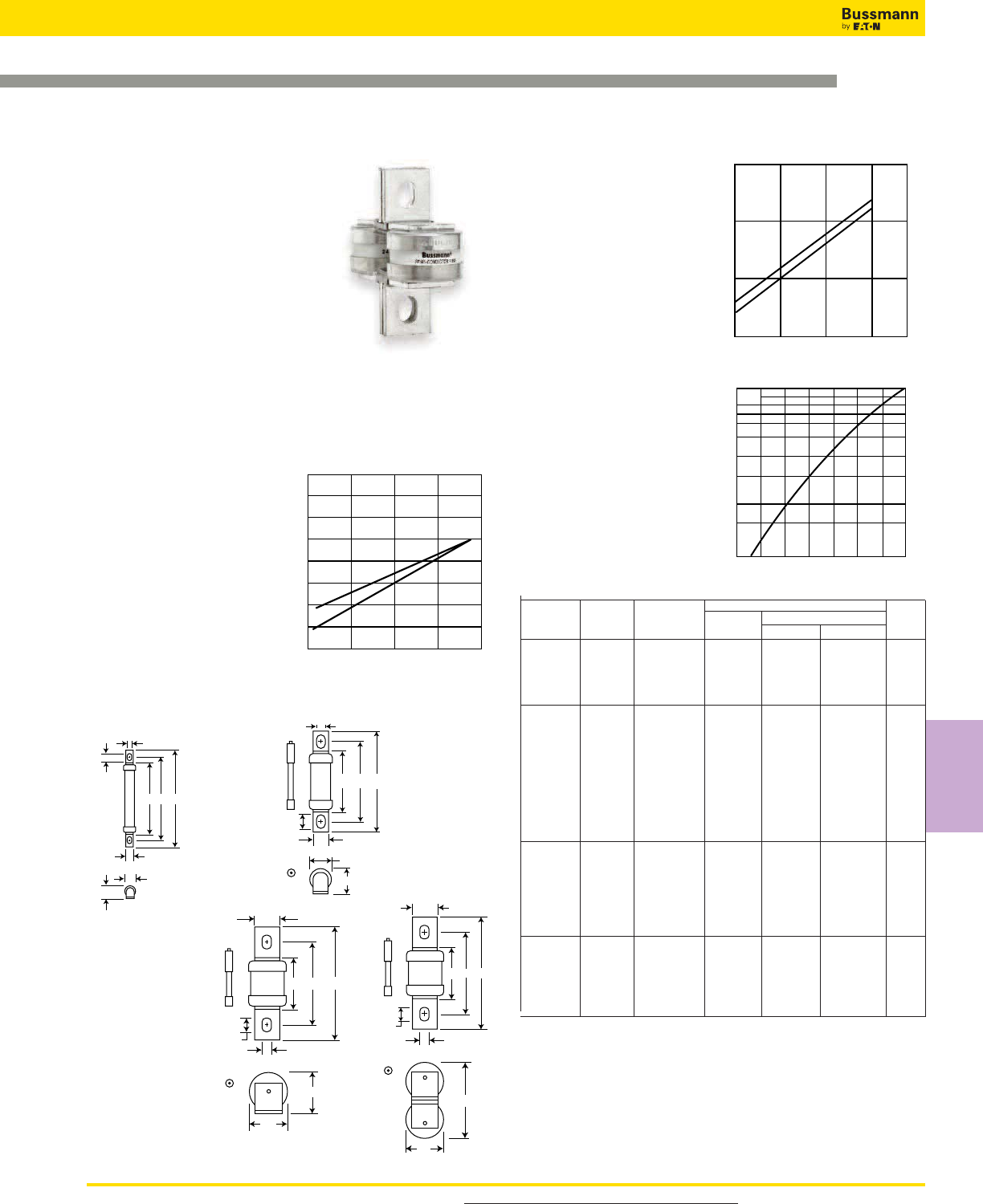
For product data sheets, visit www.cooperbussmann.com/DatasheetsEle
215
High Speed
Fuses
High Speed Fuses
Arc Voltage
This curve gives the peak
arc voltage, UL, which
may appear across the
fuse during its operation
as a function of theapplied
working voltage, Eg, (rms)
at a power factor of 15%.
Power Losses
Watts loss at rated current
is given in the electrical
characteristics. The curve
allows the calculation of
the power losses at load
currents lower than the
rated current. The correc-
tion factor, Kp, is given as
a function of the RMS load
current, Ib, in % of the
rated current.
Catalog Numbers
Electrical Characteristics
Rated I2t (A2Sec)
Catalog Current Clearing Clearing Watts
Numbers Type RMS-Amps Pre-arc at 120V at 240V Loss
6LCT 6 2 6 9 1.0
10LCT 10 3.8 12 22 2.5
12LCT LCT 12 7 22 32 2.5
16LCT 16 20 50 100 2.5
20LCT 20 25 80 160 4.0
25LET 25 18 120 250 4.0
32LET 32 32 200 450 5.0
35LET 35 50 320 600 5.0
50LET 50 100 500 1400 7.0
63LET LET 63 180 1100 2200 9.0
80LET 80 300 1900 3800 10.0
100LET 100 600 3800 7500 10.0
125LET 125 600 3800 7500 16.0
160LET 160 1100 7000 16000 20.0
180LETa 180 1600 12000 29000 21.0
160LMT 160 1100 7000 16000 17.0
200LMT 200 1500 10000 20000 28.0
250LMT 250 3200 20000 40000 28.0
315LMT LMT 315 6000 35000 75000 35.0
355LMT 355 8000 50000 100000 35.0
400LMT 400 14000 70000 160000 40.0
450LMT 450 18000 100000 220000 42.0
400LMMT 400 6000 35000 80000 60.0
500LMMT 500 14000 80000 170000 64.0
630LMMT LMMT 630 24000 150000 300000 75.0
710LMMT 710 32000 200000 460000 77.0
800LMMT 800 52000 300000 600000 82.0
900LMMT 900 75000 400000 800000 97.0
• Watts loss provided at rated current.
• Note: 7LET, 10LET, 12LET and 16LET are available for replacement purposes on existing
equipment.
• See accessories on page 222.
Features and Benefits
• Excellent cycling capability
• Excellent DC performance
• Low arc voltage and low
energy let-through (I2t)
British BS 88 — 240V: 6-900A
5641.8
26.2
17.7
19.1
12.7
7.1
9.7
Fig. 2: LET
473828
6.4
8.4
8.7
4
5.5
Dimensions - mm
Fig. 1: LCT
1mm = 0.0394” / 1” = 25.4mm
LCT, LET, LMT, LMMT
Specifications
Description: BS 88 style
stud-mount fuses.
Dimensions: See dimensions
illustrations.
Ratings:
Volts: — 240Vac/150Vdc
Amps: — 6-900A
IR: — 200kA RMS Sym.
Agency Information: CE, Designed and tested to: BS 88
Part 4, IEC 269 Part 4, UL Recognized. All fuses above have
been tested at 318Vac. Consult Bussmann for specific UL
Recognition status.
Electrical Characteristics
Total Clearing I2t
The total clearing I2t at rated
voltage and at power factor
of 15% are given in the
electrical characteristics. For
other voltages, the clearing
I2t is found by multiplying by
correction factor, K, given as
a function of applied working
voltage, Eg, (rms).
845931
83
38
25.4
13.5
10.3
0.2
0.4
0.6
0.8
1.0
1.2
1.4
1.6
10050 150 200 250
1)
2) Eg
K
845931
41
38.1
2
5.
4
10.3
13.5
Fig. 3: LMT
Fig. 4: LMMT
Indicator (Optional)
1) LCT
2) LET, LMT, LMMT
Kp
1.0
0.8
0.4
0.5
0.6
0.3
0.2
0.1
30 40 50 60 70 80 90 100%
Ib
750
500
250
100 200 300
1)
2)
Eg
UL
1) LCT
2) LET, LMT, LMMT
Typical Applications
• DC Common bus
• AC and DC drives
• Power converters/rectifiers
• Reduced voltage starters
Data Sheet: 720004
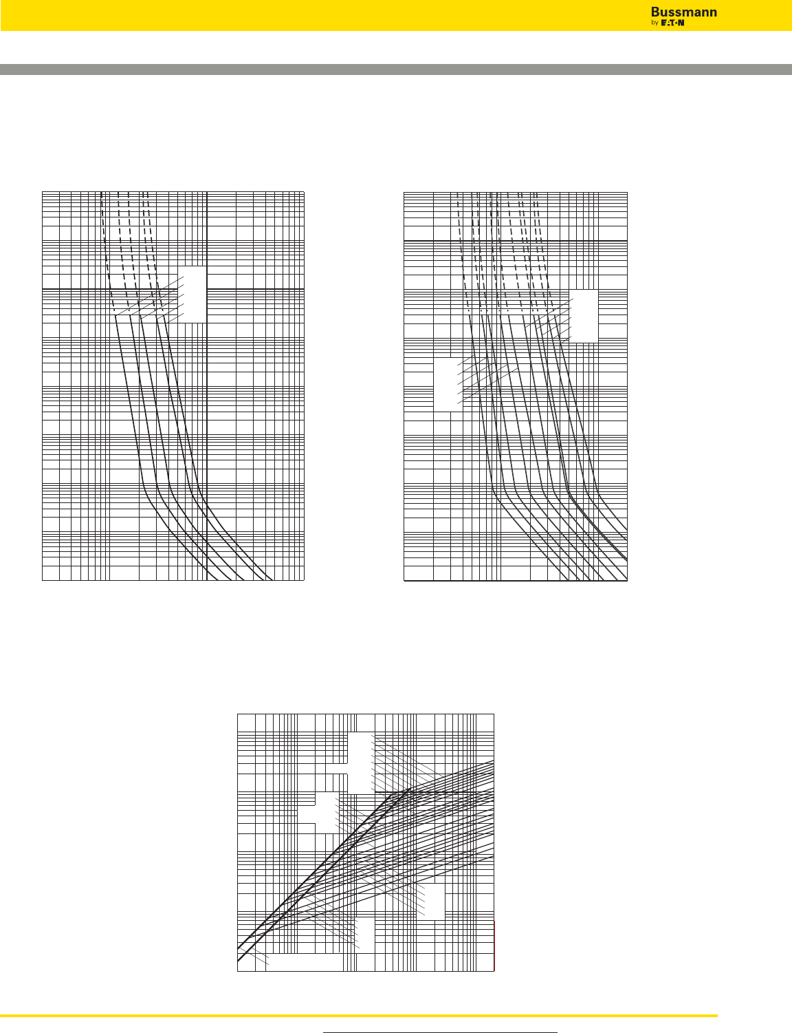
British BS 88 — 240V: 6-900A
Peak Let-Through Curve
LET 25-180A: 240V
Time-Current Curve
LCT 6-20A: 240V
Time-Current Curve
104
103
102
10–1
10–2
10–3
10–4
Prospective Current In Amps RMS
Virtual Pre-Arcing Time In Seconds
2468
10122468 2
1022468
103
2
4
6
2
6
4
100
2
6
4
101
2
6
4
2
6
4
2
6
4
6
4
2
6
2
4
20LCT
16LCT
12LCT
10LCT
6LCT
104
103
102
10122468 2
1022468
103
2
4
6
2
6
4
100
2
6
4
101
2
6
4
2
6
4
2
6
4
6
4
2
6
2
4
Prospective Current In Amps RMS
Virtual Pre-Arcing Time In Seconds
63LET
50LET
35LET
32LET
25LET
180LETa
160LET
125LET
100LET
80LET
10–4
10–3
10–2
10–1
Prospective Short-Circuit Current Symmetrical RMS
101102
264246
103246
104246
105
Peak Let-Through Current
101
6
2
4
2
102
4
6
2
103
6
4
104
6
4
2
2
105
SYMMETRICAL FAULT
FULLY ASYMMETRICAL FAULT
20LCT
16LCT
12LCT
10LCT
6LCT
25LET
32LET
35LET
50LET
63LET
80LET
125 & 100LET
160LET & LMT
200LMT
180LET
250LMT
315LMT
355LMT
400 & 500LMMT
450LMT
630LMMT
710LMMT
800LMMT
900LMMT
For product data sheets, visit www.cooperbussmann.com/DatasheetsEle
216
High Speed Fuses
Data Sheet: 35785296 Data Sheet: 35785293
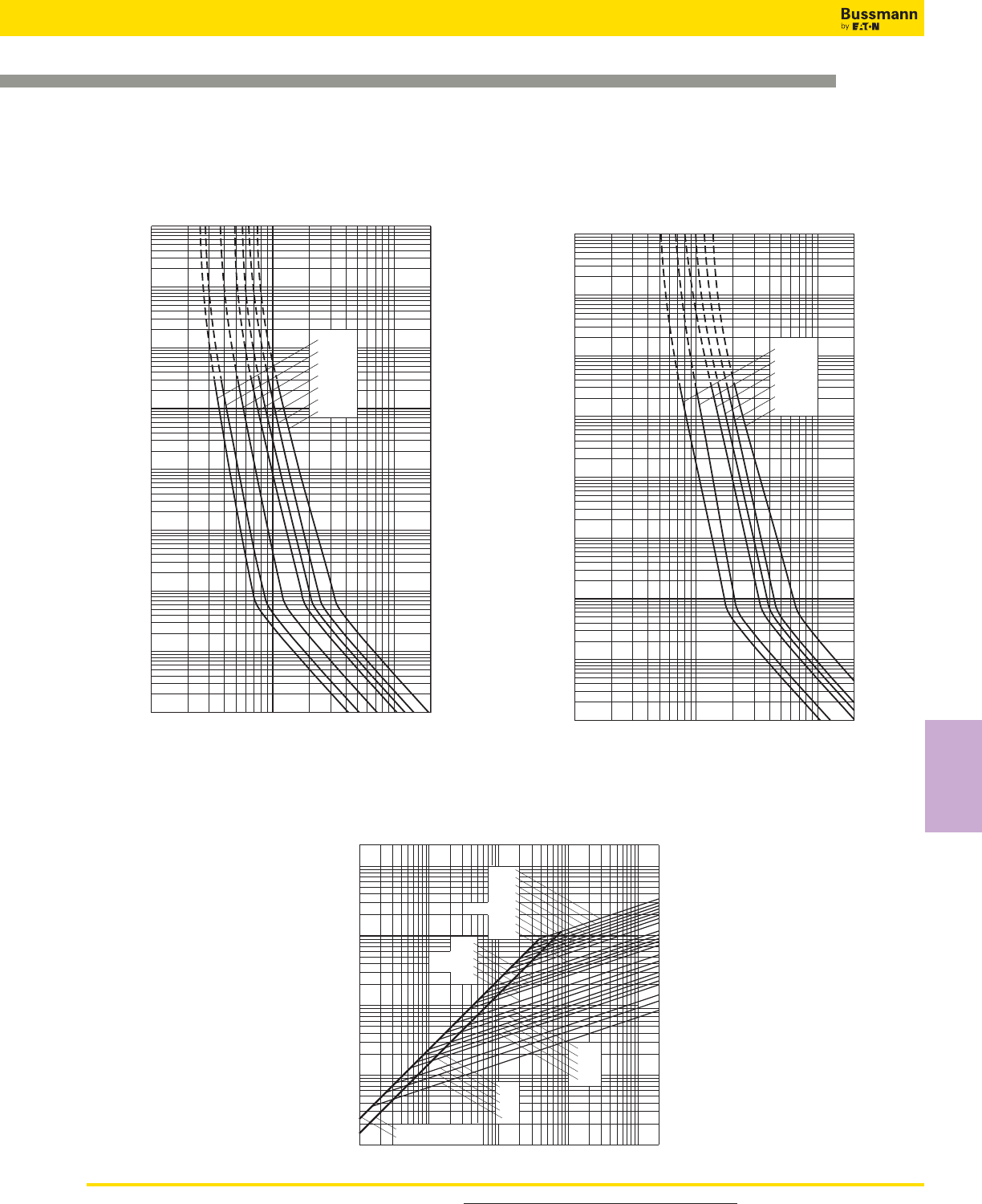
For product data sheets, visit www.cooperbussmann.com/DatasheetsEle 217
High Speed
Fuses
High Speed Fuses
British BS 88 — 240V: 6-900A
10–4
10–3
10–1
102
10222468 2
1032468
104
2
4
6
2
6
4
100
2
6
4
101
2
6
4
2
6
4
2
6
4
6
4
2
6
2
4
104
315LMT
450LMT
400LMT
355LMT
250LMT
200LMT
160LMT
Prospective Current In Amps RMS
Virtual Pre-Arcing Time In Seconds
103
10–2
10–1
10–3
10–2
102
103
104
10222468 2
1032468
104
2
4
6
2
6
4
100
2
6
4
101
2
6
4
2
6
4
2
6
4
6
4
2
6
2
4
Prospective Current In Amps RMS
Virtual Pre-Arcing Time In Seconds
10–4
710LMMT
900LMMT
800LMMT
630LMMT
500LMMT
400LMMT
Prospective Short-Circuit Current Symmetrical RMS
101102
264246
103246
104246
105
Peak Let-Through Current
101
6
2
4
2
102
4
6
2
103
6
4
104
6
4
2
2
105
SYMMETRICAL FAULT
FULLY ASYMMETRICAL FAULT
20LCT
16LCT
12LCT
10LCT
6LCT
25LET
32LET
35LET
50LET
63LET
80LET
125 & 100LET
160LET & LMT
200LMT
180LET
250LMT
315LMT
355LMT
400 & 500LMMT
450LMT
630LMMT
710LMMT
800LMMT
900LMMT
Peak Let-Through Curve
LMMT 400-900A: 240V
Time-Current Curve
LMT 160-450A: 240V
Time-Current Curve
Data Sheet: 35785294 Data Sheet: 35785295
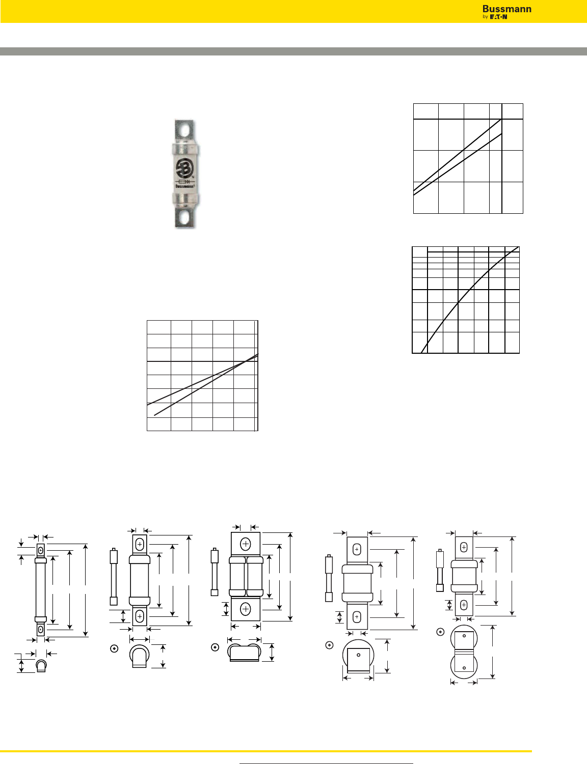
British BS 88 — 690V: 6-710A
For product data sheets, visit www.cooperbussmann.com/DatasheetsEle
218
High Speed Fuses
CT, ET, FE, EET, FEE, FM, FMM, MT, MMT
Specifications
Description: BS 88 style
stud-mount fuses.
Dimensions: See dimensions
illustrations.
Ratings:
Volts: — 690Vac/500Vdc
Amps: — 6-710A
IR: — 200kA RMS Sym.
Agency Information: CE, Designed and tested to: BS 88
Part 4, IEC 269 Part 4, UL Recognized. MT and MMT —
350Vdc (IEC) rating. Consult Bussmann for UL Recognition
status.
Electrical
Characteristics
Total Clearing I2t
The total clearing I2t at rated
voltage and at power factor
of 15% are given in the
electrical characteristics. For
other voltages, the clearing
I2t is found by multiplying by
correction factor, K, given as
a function of applied working
voltage, Eg, (rms).
Dimensions - mm
Fig. 1: CT
7763.5
48
17.1
19.1
12.7
7.1
9.7
947046
37
19
31.8
8.7
11.9
113
A50
41
38.1
25.4
10.3
13.5
113A50
83
38
25.4
10.3
14
Fig. 2: ET, FE
74.664.354.8
6.4
8.7
8.7
4
5.5
Fig. 3: EET, FEE Fig. 4: FM, MT Fig. 5: FMM, MMT
1mm = 0.0394” / 1” = 25.4mm Figs. 4 & 5 “A” Dimensions
Type “A”
FM 80-85mm
FMM 80-85mm
MT 85mm
MMT 85mm
Arc Voltage
This curve gives the
peak arc voltage, UL,
which may appear
across the fuse during its
operation as a function
of the applied working
voltage, Eg, (rms) at a
power factor of 15%.
Power Losses
Watts loss at rated
current is given in the
electrical characteristics.
The curve allows the
calculation of the power
losses at load currents
lower than the rated
current. The correction
factor, Kp, is given as a
function of the RMS load
current, Ib, in % of the
rated current.
Features and Benefits
• Excellent cycling capability
• Excellent DC performance
• Low arc voltage and low energy let-through (I2t)
• Low watts loss
Typical Applications
• DC Common bus
• DC Drives
• Power converters/rectifiers
• Reduced voltage starters
1500
1000
500
200 400 600 660
Eg
UL
1)
2)
1) CT
2) ET, FE, EET, FEE, FM, FMM
200 300 400 500 600 690
0.2
0.4
0.6
0.8
1.0
1.2
1.4
1.6
1) 2)
Eg
K
1) CT, ET, EET, FE, FEE, MT, MMT
2) FM, FMM
Kp
1.0
0.8
0.4
0.5
0.6
0.3
0.2
0.1
30 40 50 60 70 80 90 100%
Ib
Data Sheet: 720024
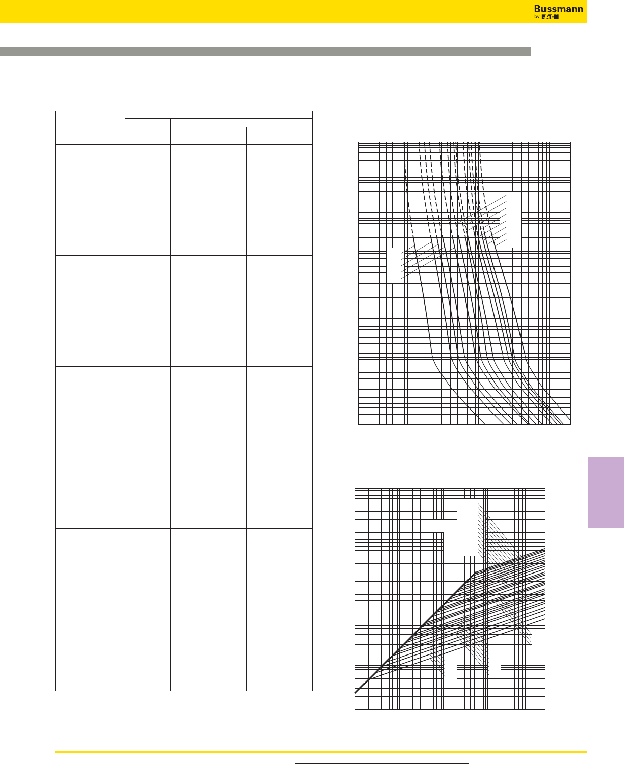
For product data sheets, visit www.cooperbussmann.com/DatasheetsEle 219
High Speed
Fuses
High Speed Fuses
British BS 88 — 690V: 6-710A
103
10–1
2468
10122468 2
1022468
103
2
4
6
2
6
4
100
2
6
4
101
2
6
4
2
6
4
2
6
4
6
4
2
6
2
4
10CT
12CT
16CT
20CT
6CT
32ET
25ET
Prospective Current In Amps RMS
Virtual Pre-Arcing Time In Seconds
56ET
80ET
63ET
45ET
40ET
35ET
10–4
10–3
10–2
102
104
Prospective Short-Circuit Current Symmetrical RMS
Peak Let-Through Current
2
4
2
6
6
4
2
4
6
4
2
6
4
2
6
246246246246
101
102
103
104
105
1011021031041052
20CT
16CT
12CT
10CT
6CT
80ET
63ET
56ET
45ET
40ET
35ET
32ET
25ET
710MMT
630MMT
560MMT
500MMT
450MMT
315MT 355MT 400MMT
280MT 355MMT
250MT 315MMT
280MMT
200MT
180MT 225MMT
160MT 200MMT
180MMT
160EET
140EET
110EET
90EET
Peak Let-Through Curve
CT 6-20, ET 25-80A: 690V
Time-Current Curve
Electrical Characteristics
Rated I2t (A2Sec)
Catalog Current Clearing Clearing Watts
Numbers Type RMS-Amps Pre-arc at 415V at 660V Loss
6CT 6 1.8 8.5 12 2
10CT 10 7 30 48 3
12CT CT 12 10 40 65 3
16CT 16 16 66 110 7
20CT 20 32 150 220 7
25ET 25 25 150 250 7
32ET 32 32 190 350 11
35ET 35 52 310 500 11
40ET ET 40 103 600 900 9
45ET 45 103 680 1100 11
56ET 56 135 950 1500 14
63ET 63 171 1200 2000 16
80ET 80 360 2500 4000 18
35FE 35 33 130 200 9
40FE 40 52 180 300 9
45FE 45 76 270 450 11
50FE 50 103 380 600 11
63FE FE 63 135 480 750 12
71FE 71 210 600 950 17
80FE 80 250 900 1500 20
90FE 90 360 1300 2100 20
100FE 100 470 1800 2800 23
90EET 90 490 3000 4500 19
110EET EET 110 600 4000 6500 27
140EET 140 1050 7000 12000 35
160EET 160 1500 10000 17000 39
100FEE 100 400 1600 2400 24
120FEE 120 540 1900 3100 32
140FEE FEE 140 850 2500 3800 36
160FEE 160 1000 3700 5700 46
180FEE 180 1400 5300 8400 46
200FEE 200 1900 7100 11400 52
180FM 180 1400 7500 13500 40
200FM 200 2600 10500 18500 40
225FM 225 3700 14500 26500 44
250FM FM 250 5200 20500 37500 48
280FM 280 7000 30500 55000 48
315FM 315 10000 40000 77000 55
350FM 350 15000 60000 105000 55
400FMM 400 10000 40000 72500 85
450FMM 450 15000 60000 105000 90
500FMM FMM 500 20000 82000 150000 100
550FMM 550 30000 120000 215000 100
630FMM 630 45000 180000 310000 100
700FMM 700 60000 245000 420000 120
160MT 160 2400 15000 25000 26
180MT 180 3800 25000 38000 26
200MT 200 6000 40000 58000 27
250MT MT 250 11500 80000 110000 32
280MT 280 16500 100000 150000 35
315MT 315 19000 125000 180000 42
355MT 355 22000 160000 200000 51
180MMT 180 1650 12000 18000 42
200MMT 200 2200 16000 23000 42
225MMT 225 3700 26000 40000 42
280MMT 280 6600 47000 70000 47
315MMT 315 8600 62000 91000 51
355MMT MMT 355 13500 97000 140000 54
400MMT 400 21000 150000 220000 60
450MMT 450 30000 220000 320000 57
500MMT 500 42000 300000 450000 64
560MMT 560 60000 430000 640000 64
630MMT 630 68500 500000 720000 86
710MMT 710 78000 600000 850000 105
• Watts loss provided at rated current.
• Note: FC, 8ET, 12ET, 15ET, 20ET, 65EET and 75EET are available for replacement
purposes on existing equipment.
• See accessories on page 222.
Data Sheet: 35785312
Catalog Numbers
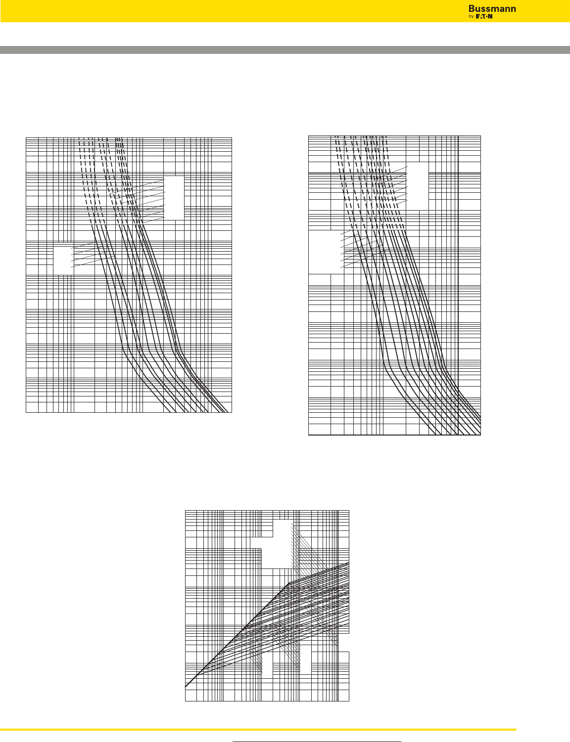
British BS 88 — 690V: 6-710A
For product data sheets, visit www.cooperbussmann.com/DatasheetsEle
220
High Speed Fuses
103
104
102
10–1
10–2
2468
10222468 2
1032468
104
2
4
6
2
6
4
100
2
6
4
101
2
6
4
2
6
4
2
6
4
6
4
2
6
2
4
Prospective Current In Amps RMS
Virtual Pre-Arcing Time In Seconds
160EET
140EET
110EET
90EET
200MT
355MT
315MT
280MT
250MT
180MT
160MT
10–4
10–3
Prospective Short-Circuit Current Symmetrical RMS
Peak Let-Through Current
2
4
2
6
6
4
2
4
6
4
2
6
4
2
6
246 246 246 246
101
102
103
104
105
1011021031041052
20CT
16CT
12CT
10CT
6CT
80ET
63ET
56ET
45ET
40ET
35ET
32ET
25ET
710MMT
630MMT
560MMT
500MMT
450MMT
315MT 355MT 400MMT
280MT 355MMT
250MT 315MMT
280MMT
200MT
180MT 225MMT
160MT 200MMT
180MMT
160EET
140EET
110EET
90EET
Peak Let-Through Curve
EET 90-160A, MT 160-355A: 690V
Time-Current Curve
104
103
102
10–1
10–3
Prospective Current In Amps RMS
Virtual Pre-Arcing Time In Seconds
10222468 2
1032468
104
2
4
6
2
6
4
100
2
6
4
101
2
6
4
2
6
4
2
6
4
6
4
2
6
2
4
280MMT
355MMT
315MMT
225MMT
200MMT
180MMT
630MMT
710MMT
560MMT
500MMT
450MMT
400MMT
10–4
10–2
MMT 180-710A: 690V
Time-Current Curve
Data Sheet: 35785313
Data Sheet: 35785311

For product data sheets, visit www.cooperbussmann.com/DatasheetsEle 221
High Speed
Fuses
High Speed Fuses
British BS 88 — 690V: 6-710A
104
103
102
10–1
10–2
10–3
10–4
10222468 2
1032468
104
2
4
6
2
6
4
100
2
6
4
101
2
6
4
2
6
4
2
6
4
6
4
2
6
2
4
120FEE
140FEE
160FEE
180FEE
200FEE
100FEE
550FMM
700FMM
630FMM
500FMM
450FMM
400FMM
Prospective Current In Amps RMS
Virtual Pre-Arcing Time In Seconds
FEE 100-200A & FMM 400-700A: 690V
Time-Current Curve
Prospective Short-Circuit Current Symmetrical RMS
Peak Let-Through Current
102246
2
4
6
103
8
2
8
4
6
104
2
4
6
8
103246
104246
1052
180FEE
100FEE
120FEE
140FEE
160FEE
200FEE
400FMM
450FMM
500FMM
550FMM
630FMM
700FMM
Peak Let-Through Curve
103
102
10–1
10–2
10–4
2468
10222468 2
1032468
104
2
4
6
2
6
4
100
2
6
4
101
2
6
4
2
6
4
2
6
4
6
4
2
6
2
4
100FE
35FE
40FE
45FE
50FE
63FE
71FE
80FE
90FE
350FM
315FM
280FM
250FM
220FM
200FM
180FM
Prospective Current In Amps RMS
Virtual Pre-Arcing Time In Seconds
10–3
104
FE 35-100A & FM 180-350A: 690V
Time-Current Curve
Prospective Short-Circuit Current Symmetrical RMS
Peak Let-Through Current
2
4
2
6
6
4
2
6
4
2
6
4
246246246246
101
102
103
104
105
1011021031041052
350FM
315FM
280FM
250FM
225FM
200FM
180FM
100FE
90FE
80FE
71FE
63FE
50FE
45FE
40FE
35FE
Peak Let-Through Curve
Data Sheet: 35785314 Data Sheet: 35785292
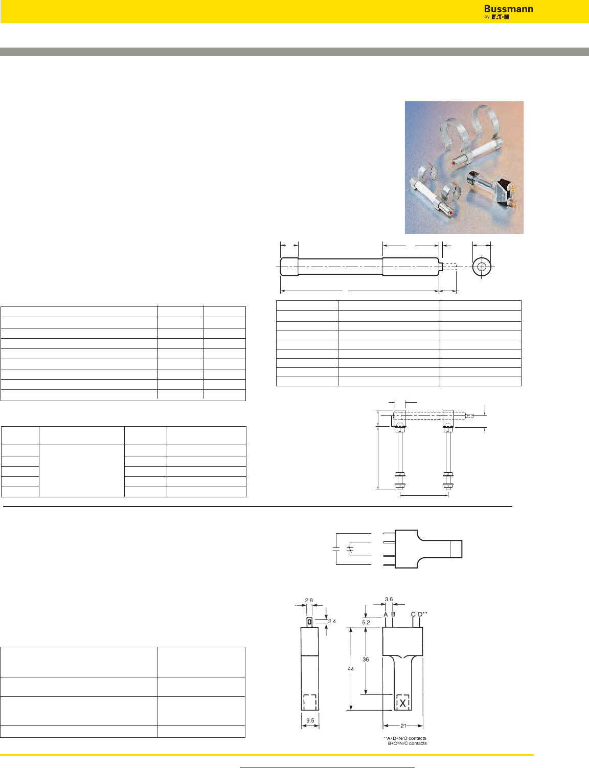
British BS 88 Fuse Accessories
For product data sheets, visit www.cooperbussmann.com/DatasheetsEle
222
High Speed Fuses
Indicator System
Trip-Indicators
Trip-indicators are available for use in parallel with the
main fuse. They can either be attached to the associated
fuse or mounted separately in panel mounted fuse clips,
reference CL1. A push-on adapter and microswitch
attachment is available for use with the trip indicator to
give the facility of remote indication, reference MAI.
Fuse ratings of 20A and below cannot usually
accommodate a trip-indicator.
When a trip-indicator is to be attached to the main fuse an
accessory pack comprising a pair of mounting clips and an
appropriate trip indicator would be required. The clips are
snapped onto the fuse end caps and the indicator is
pressed into clips as shown.
Electrical Specifications
Type TI500 TI700
Maximum RMS Voltage 500 700
Maximum Peak Voltage 700 1000
Maximum DC Voltage 130 350
Cold Resistance (ohms) 0.3 0.45
Maximum permissible steady-state current 1.5A 1.5A
Interrupting Capacity (RMS Symm.) 100,000 100,000
Pre-Arcing I2t2323
Total I2t (max volts) 46 46
Microswitch Adapter – MAI
We offer a microswitch, complete with adapter for
securing the indicator. The microswitch is provided with
double pole, single throw contacts, having both a normally
open and a normally closed position. A special material has
been employed in the construction of the adapter to
provide reliable operation in the range of temperatures
associated with standard operating conditions and during
fuse operation.
Microswitch and Adapter Type MAI
Current Rating:
AC 50/60Hz resistive load @ 250V RMS 4A
AC 50/60Hz resistive load @ 127V RMS 6A
DC, resistive load @ 110Vdc 0.7A DC
DC, resistive load @ 30Vdc 2A DC
Maximum Working Voltage:
Contact-to-contact (RMS) 1000V
Contact-to-contact (RMS) 1500V
Maximum DC Volts: 110Vdc
Ref. Dim. “A” (mm) RMS Volts
TI250 37.6 250
TI500 47.5 500
TI600 55.7 600
TI700 61.8 700
TI1100 98.4 1100
TI1500 120.6 1500
TI2000 147.5 2000
TI2500 198.3 2500
RMS For use
Kit. Ref. Details Volts with Fuse Ref.
EC-250 Fuse Mount 250 LET
MC250 Indicator Kits 250 LMT & LMMT
EC-600 (Includes one 660 FE, FEE & ET
MC600 indicator 660 FM & FMM
MC700 and two clips) 700 MT & MMT
E
C
A
B
D
F
6 21 0.8
6.8
6.35
NO
NC
NC
NO
Terminal Arrangement
Trip-Indicator
Dimensions - mm
Dimensions in mm
Fuse Indicator Kits
6.0 8.7
50.8
B
14
CL1 Panel Mount Clips
CL1 Panel mount fuse clips
are available for mounting a
trip-indicator when mounting
directly on the fuse is
impractical. Order part
number CL1.
CL1 Panel Mount Clip
Dimensions - mm
Trip
Indicator
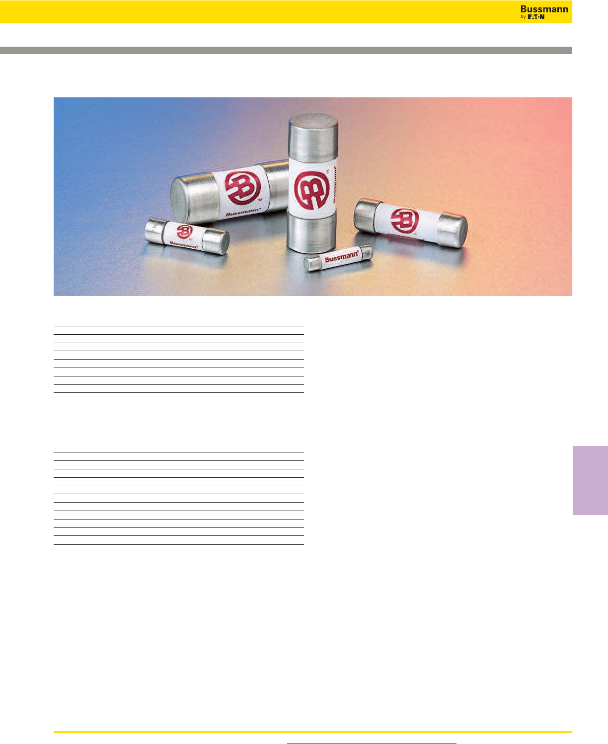
For product data sheets, visit www.cooperbussmann.com/DatasheetsEle 223
High Speed
Fuses
Table of Contents
Basic Catalog Amp
Number Volts Range Page
FWA 150 5-60 224-225
FWX 250 1-50 226-227
FWH 500 0.25-30 228-231
FWC 600 6-32 232-233
FWP 690V/700 1-100 234-237
FWK 750 5-60 238-239
FWJ 1000 20-30 240-241
FWL/FWS 1250/1500/2000 2-30 242
Accessories
Fuse Holders 241
Ferrule Fuse Ranges
Volts Amps AC DC
150 5-60 X X
250 1-50 X X
500 0.25-30 X X
600 6-32 X X
700 (22 x 58mm) 20-100 X —
700 (14 x 51mm) 1-50 X X
750 5-60 X X
1000 20-30 X X (800Vdc)
1250 20-30 X X (1000Vdc)
1500 8-15 X X (1000Vdc)
2000 2-6 X X (1000Vdc)
General Information
Bussmann offers a full line of ferrule style (cylindrical
clip-mounted) fuses, designed and tested to meet standards
and requirements in various locations around the world.
Their unique design and construction provide:
• Superior cycling capability
• Low energy let-through (I2t)
Ferrule fuses provide an excellent solution for small UPS,
small ac drives and other low power applications where
space is at a premium.
Voltage Rating
All Bussmann ferrule fuses — except 690V — have been
tested at their rated voltage. The 690V ferrule fuse has been
tested to the IEC 60269 standard, which requires clearing at
the rated voltage +5%.
Accessories
Ferrule fuses may be mounted in fuseclips, fuse holders,
fuse blocks or fused switches. A variety of products are
available. Please consult Bussmann Application Engineering
to discuss your requirement.
Ferrule Fuses
High Speed Fuses
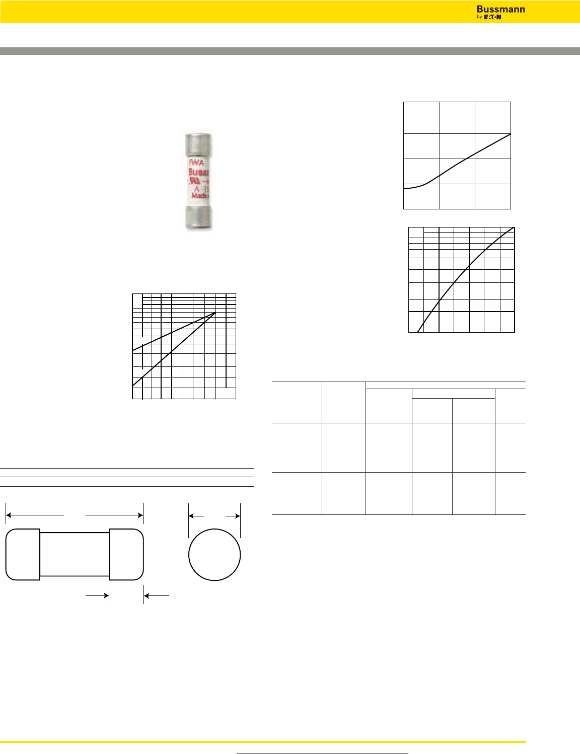
For product data sheets, visit www.cooperbussmann.com/DatasheetsEle
224
High Speed Fuses
Arc Voltage
This curve gives the peak
arc voltage, UL, which
may appear across the
fuse during its operation
as a function of theapplied
working voltage, Eg, (rms)
at a power factor of 15%.
Power Losses
Watts loss at rated current
is given in the electrical
characteristics. The curve
allows the calculation of
the power losses at load
currents lower than the
rated current. The
correction factor, Kp, is
given as a function of the
RMS load current, Ib, in %
of the rated current.
Catalog Numbers
Electrical Characteristics
I2t (A2Sec)
Rated
Catalog Current Clearing Watts
Numbers Size RMS-Amps Pre-arc at 150V Loss
FWA-5A10F 5 1.6 8 1
FWA-10A10F 10 3.6 16 2.7
FWA-15A10F 10 x 38mm 15 14 55 3.3
FWA-20A10F (13⁄32” x 11⁄2”) 20 33 130 3.8
FWA-25A10F 25 58 220 4.9
FWA-30A10F 30 100 400 4.9
FWA-35A21F 35 75 800 4.5
FWA-40A21F 21 x 51mm 40 100 1000 5.1
FWA-45A21F (13⁄16” x 2”) 45 130 1300 6
FWA-50A21F 50 170 1600 7.3
FWA-60A21F 60 250 2400 8.0
• Watts loss provided at rated current.
• See accessories on page 243.
Features and Benefits
• Excellent cycling capability and DC performance
• Low arc voltage and low energy let-through (I2t)
• Low watts loss in a compact size
• Used with finger-safe holders/blocks
Typical Applications
• DC Common bus
• DC Drives
• Power converters/rectifiers
• Reduced voltage starters
Ferrule — FWA 150V: 5-60A
Dimensions - in (mm)
Amp Dimensions
Range A B C
5-30 1.5 (38.1) 0.375 (9.5) 0.406 (10.3)
35-60 2.0 (50.8) 0.625 (15.9) 0.811 (20.6)
UL
Eg
200
100
100 15050
300
Kp
1.0
0.8
0.4
0.5
0.6
0.3
0.2
0.1
30 40 50 60 70 80 90 100%
Ib
A
B
C
FWA 5-30A (10 x 38mm)
35-60A (21 X 51mm)
Specifications
Description: Ferrule style high
speed fuses.
Dimensions: See dimensions
illustration.
Ratings:
Volts: — 150Vac/dc
Amps: — 5-60A
IR: — 100kA Sym.
Agency Information: CE, ULRecognition JFHR2.E91958
Electrical
Characteristics
Total Clearing I2t
The total clearing I2t at
rated voltage and at power
factor of 15% are given in
the electrical
characteristics. For other
voltages, the clearing I2t is
found by multiplying by
correction factor, K, given
as a function of applied
working voltage, Eg, (rms).
1501027022
1.5
1.0
0.5
0.3
0.2
0.15 Eg
K
1)
2)
1) 5-30A Range
2) 35-60A Range
Data Sheet: 720003
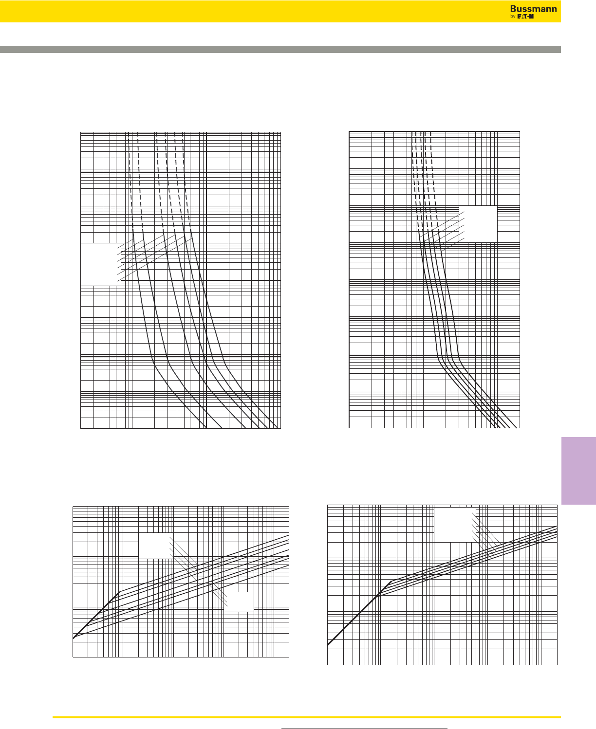
For product data sheets, visit www.cooperbussmann.com/DatasheetsEle 225
High Speed
Fuses
Ferrule — FWA 150V: 5-60A
10–4
2 4 6 8
101 2 2 4 6 8 2
102 2 4 6 8
103
2
4
6
2
6
4
100
2
6
4
101
2
6
4
2
6
4
2
6
4
6
4
2
6
2
4
10–1
10–2
10–3
102
103
104
FWA-10A10F
FWA-30A10F
FWA-25A10F
FWA-20A10F
FWA-15A10F
FWA-5A10F
Virtual Pre-Arcing Time In Seconds
Prospective Current In Amps RMS
10122468 2
1022468
103
2
4
6
2
6
4
100
2
6
4
101
2
6
4
2
6
4
2
6
4
6
4
2
6
2
4
10–1
10–2
10–3
10–4
102
103
104
FWA-45A21F
FWA-50A21F
FWA-60A21F
FWA-35A21F
FWA-40A21F
Virtual Pre-Arcing Time In Seconds
Prospective Current In Amps RMS
Prospective Short-Circuit Current Symmetrical RMS
Peak Let-Through Current
2
4
2
6
6
4
2
6
4
246 246 246 246
101
102
103
104
101102103104105
FWA-20A10F
FWA-25A10F
FWA-30A10F
FWA-15A10F
FWA-12A10F
FWA-5A10F
FWA-10A10F
2
Prospective Short-Circuit Current Symmetrical RMS
Peak Let-Through Current
2
4
2
6
6
4
2
6
4
246 246 246 246
101
102
103
104
101102103104105
FWA-35A21F
FWA-40A21F
FWA-45A21F
FWA-50A21F
FWA-60A21F
2
Peak Let-Through CurvePeak Let-Through Curve
FWA 35-60A: 150V (21 x 51mm)
Time-Current Curve
FWA 5-30A: 150V (10 x 38mm)
Time-Current Curve
Data Sheet: 35785317 Data Sheet: 35785305
High Speed Fuses
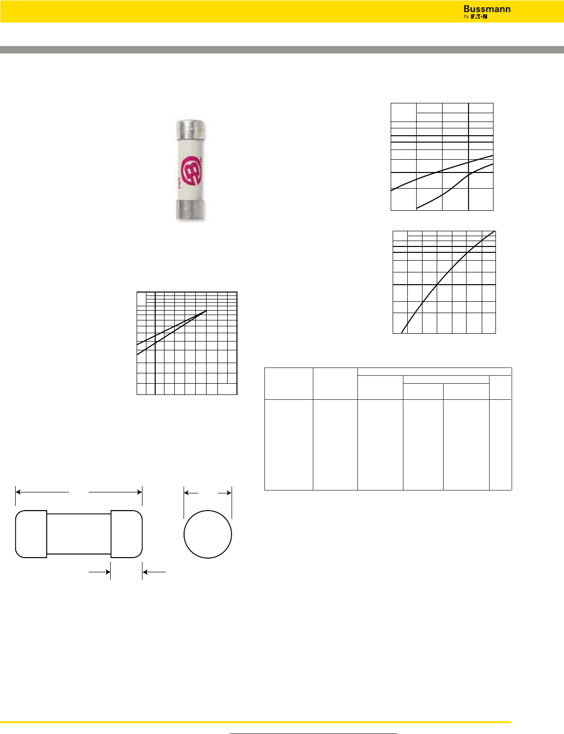
For product data sheets, visit www.cooperbussmann.com/DatasheetsEle
226
High Speed Fuses
Ferrule — FWX 250V (UL): 1-50A
FWX (14 x 51mm)
Specifications
Description: Ferrule style high
speed fuses.
Dimensions: See dimensions
illustration.
Ratings:
Volts: — 250Vac/dc
Amps: — 1-50A
IR: — 200kA RMS Sym.
— 50kA @ 250Vdc
Agency Information: CE, UL Recognition JFHR2.E91958
1-50A & CSA Component Acceptance file Class 1422-30,
1422-90 (53787) 5-30A
Electrical
Characteristics
Total Clearing I2t
The total clearing I2t at
rated voltage and at power
factor of 15% are given in
the electrical
characteristics. For other
voltages, the clearing I2t is
found by multiplying by
correction factor, K, given
as a function of applied
working voltage, Eg, (rms).
Dimensions - mm (in)
50.8
(2.000")
15.5
(0.610")
14.3
(0.563")
Arc Voltage
This curve gives the
peak arc voltage, UL,
which may appear
across the fuse during
its operation as a
function of the applied
working voltage, Eg,
(rms) at a power factor
of 15%.
Power Losses
Watts loss at rated current
is given in the electrical
characteristics. The curve
allows the calculation of
the power losses at load
currents lower than the
rated current. The
correction factor, Kp, is
given as a function of the
RMS load current, Ib, in %
of the rated current.
Catalog Numbers
Electrical Characteristics
Rated I2t (A2Sec)
Catalog Current Clearing Watts
Number Size RMS-Amps Pre-arc at 250V Loss
FWX-1A14F 1 — — —
FWX-2A14F 2 — — —
FWX-3A14F 3 — — —
FWX-4A14F 4 — — —
FWX-5A14F 14 x 51mm 5 1.6 13 1.3
FWX-10A14F (9⁄16” x 2”) 10 3.6 24 3.4
FWX-15A14F 15 14 83 3.8
FWX-20A14F 20 33 200 4.6
FWX-25A14F 25 58 300 5.3
FWX-30A14F 30 100 500 5.9
FWX-50A14F 50 200 1800 5.7
• Watts loss provided at rated current.
• (250Vdc/Interrupting rating 50kA) UL Recognition & CSA Component Acceptance on 5
through 30A only. Consult Bussmann for additional ratings.
• See accessories on page 243.
Features and Benefits
• Excellent cycling capability and DC performance
• Low arc voltage and low energy let-through (I2t)
• Low watts loss in a compact size
• Used with finger-safe holders/blocks
Typical Applications
• DC Common bus
• DC Drives
• Power converters/rectifiers
• Reduced voltage starters
1.5
1.0
0.5
0.3
0.2
0.15
75 125 300200 250
Eg
K
1)
2)
UL
1.4
1.2
103
800
600
500
400
300
200
50 100 150 200 250
Eg
1)
2)
Kp
1.0
0.8
0.4
0.5
0.6
0.3
0.2
0.1
30 40 50 60 70 80 90 100%
Ib
Data Sheet: 720006
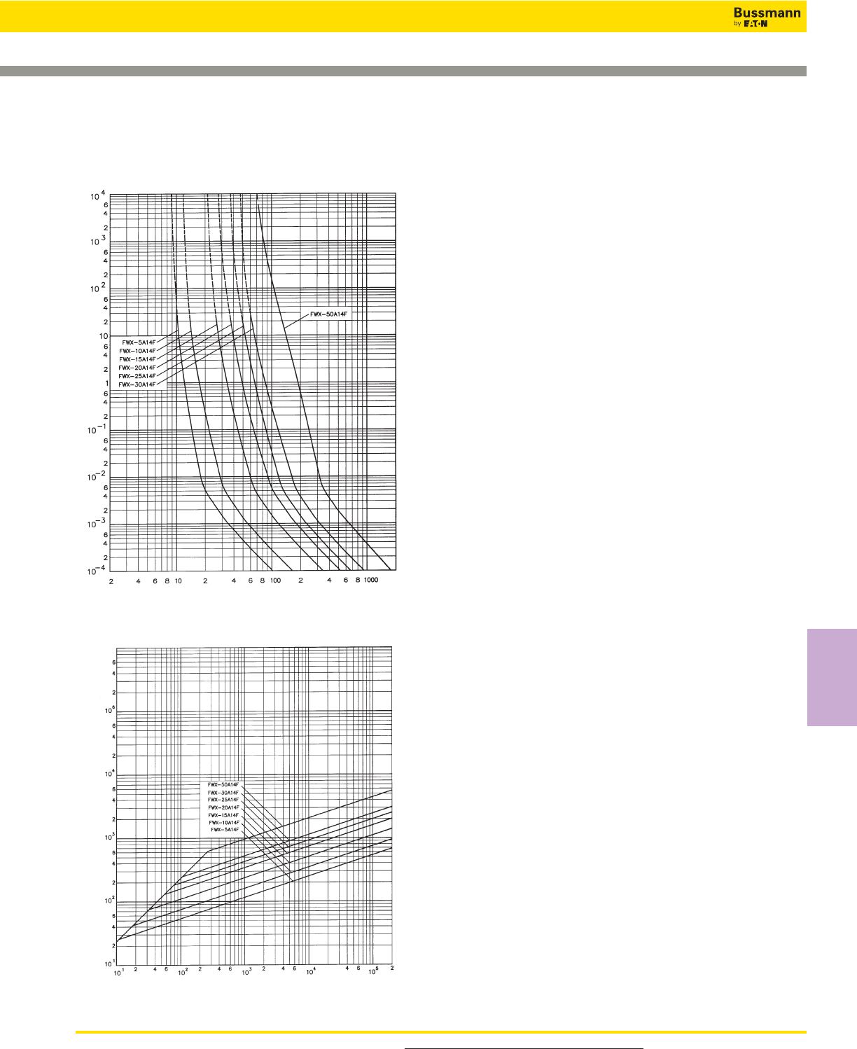
For product data sheets, visit www.cooperbussmann.com/DatasheetsEle 227
High Speed
Fuses
Ferrule — FWX 250V (UL): 1-50A
Prospective Current In Amps RMS
Prospective Current In Amps RMS
Peak Let-Through Curve
FWX 1-30A: 250V (14 x 51mm)
Time-Current Curve
Data Sheet: 35785302
High Speed Fuses
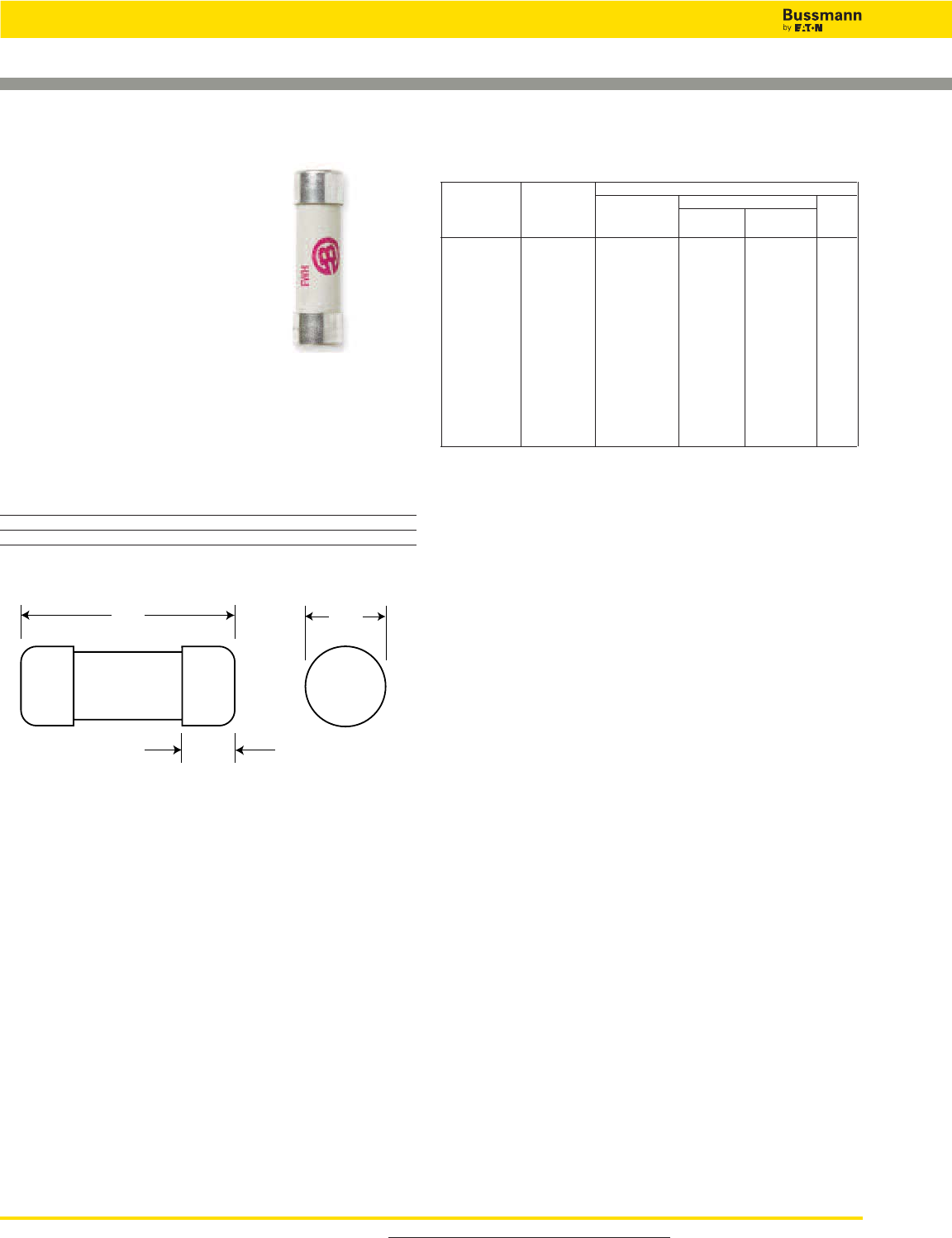
For product data sheets, visit www.cooperbussmann.com/DatasheetsEle
228
High Speed Fuses
Ferrule — FWH 500V: 0.25-30A
FWH (6 x 32mm)
Specifications
Description: Ferrule style high
speed fuses.
Dimensions: See dimensions
illustrations.
Ratings:
Volts: — 500Vac (0.25-6.3A)
500Vdc (2-5A)
Amps: — 0.25-30A
IR: — 50kA at ≥ 20% pf (0.25-20A)
— 20kA at ≥ 20% pf (25-30A)
Agency Information: CE, UL Recognition JFHR2.E91958
0.25-30A, CSA Component Acceptance file Class 1422-30,
1422-90 (53787) 0.25-7A
Opening Times
Amp Ratings 150% 200% 300%
0.25-7 > 30 min < 30 min ≤ 10 sec
10-30 < 30 min < 30 min ≤ 10 sec
31.8
(1.25")
3.2
(0.125")
6.4
(0.25")
Dimensions - mm (inches)
Catalog Numbers
Electrical Characteristics
Rated I2t (A2Sec)
Catalog Current Clearing Watts
Numbers Size RMS-Amps Pre-arc at 500V Loss
FWH-.250A6F 0.25* 0.01 0.05 2.7
FWH-.500A6F 0.5* 0.05 0.25 1.2
FWH-001A6F 1* 0.4 2 1.7
FWH-002A6F 2* 1.3 3.5 3.2
FWH-3.15A6F 3.15* 3.1 7.7 2.9
FWH-005A6F 5* 15 40 2.1
FWH-6.30A6F 6 x 32mm 6.3* 36 90 2.3
FWH-007A6F (1⁄4” x 11⁄4”) 7* 50 125 2.5
FWH-010A6F 10** 9.9 139 2.86
FWH-12.5A6F 12.5** 20 60 3.53
FWH-015A6F 15** 44 146 3.08
FWH-016A6F 16** 48 177 4.48
FWH-020A6F 20** 75 259 4.26
FWH-025A6F 25** 126 345 —
FWH-030A6F 30** 145 430 —
*300% minimum opening current at rated voltage.
**200% minimum opening current at rated voltage.
• Consult Bussmann for DC ratings.
• See accessories on page 243.
Features and Benefits
• Excellent cycling capability and DC performance
• Low arc voltage and low energy let-through (I2t)
• Low watts loss in a compact size
• Used with finger-safe holders/blocks
Typical Applications
• DC Common bus
• DC Drives
• Power converters/rectifiers
• Reduced voltage starters
Data Sheet: 720038
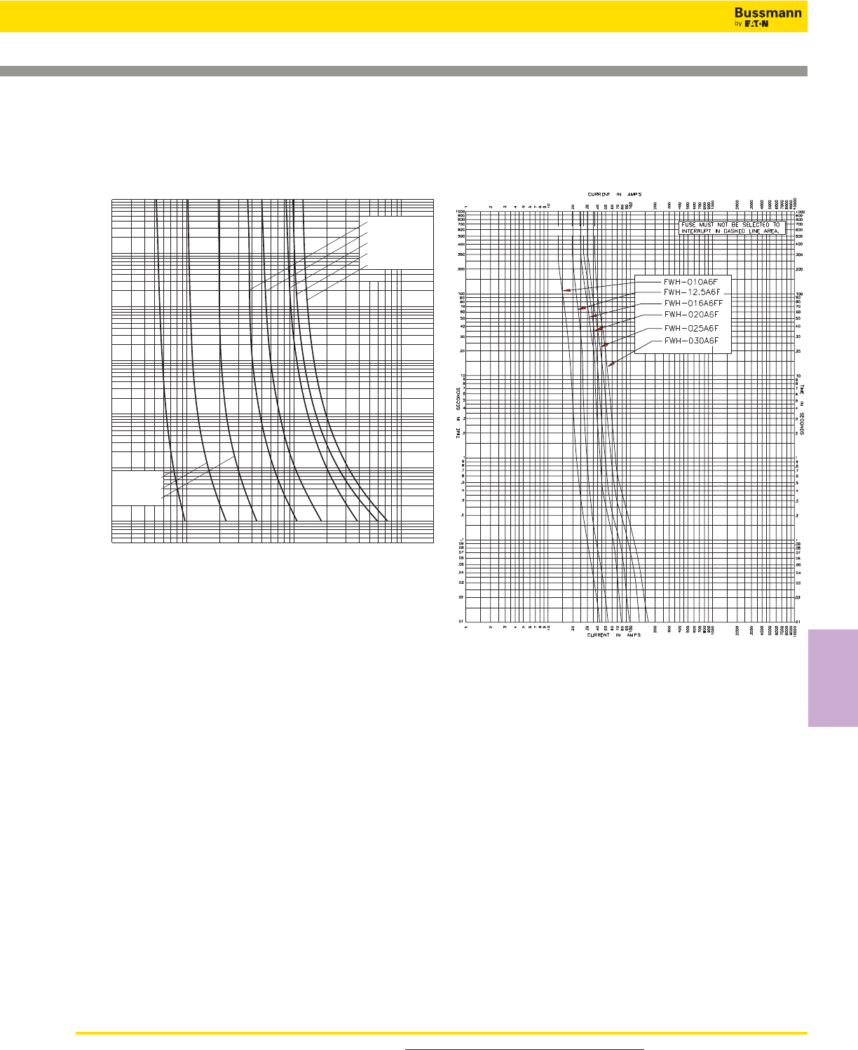
For product data sheets, visit www.cooperbussmann.com/DatasheetsEle 229
High Speed
Fuses
Ferrule — FWH 500V: 0.25-30A
.2 .4 .6 .8 10022468 2
1012468 2
102
Prospective Current In Amps RMS
2
4
6
2
6
4
2
6
4
2
6
4
2
6
4
2
6
4
10–1
10–2
4x10⁻³
100
101
102
103
104
Virtual Pre-Arcing Time In Seconds
FWH-002A6F
FWH-3.15A6F
FWH-005A6F
FWH-6.30A6F
FWH-001A6F
FWH-.500A6F
FWH-.250A6F
FWH-007A6F
FWH 0.25-7A: 500V (6 x 32mm)
Time-Current Curve
FWH 10-30A: 500V (6 x 32mm)
Time-Current Curve
Data Sheet: 35785256 Data Sheet: 50955
High Speed Fuses
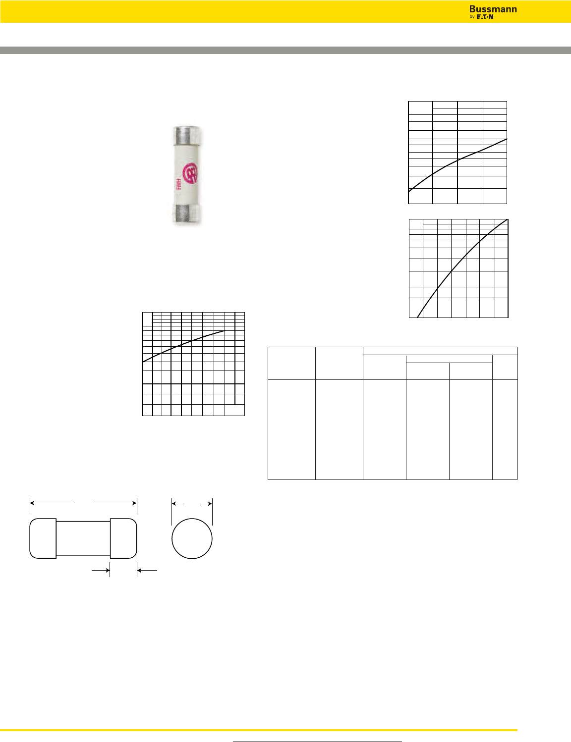
For product data sheets, visit www.cooperbussmann.com/DatasheetsEle
230
High Speed Fuses
Data Sheet: 720008
Dimensions - mm (inches)
50.8
(2.000")
15.5
(0.610")
14.3
(0.563")
FWH (14 x 51mm)
Specifications
Description: Ferrule style high
speed fuses.
Dimensions: See Dimensions
illustration.
Ratings:
Volts: — 500Vac
Amps: — 1-30A
IR: — 200kA RMS Sym.
— 50kA @500Vdc
Agency Information: CE, UL Recognition 1- 30A & CSA
Component Acceptance file Class 1422-30, (53787) on:
5 - 30A.
Electrical Characteristics
Total Clearing I2t
The total clearing I2t at rated
voltage and at power factor
of 15% are given in the
electrical characteristics. For
other voltages, the clearing
I2t is found by multiplying by
correction factor, K, given as
a function of applied working
voltage, Eg, (rms).
500400250100
1.5
1.0
0.5
0.3
0.2
0.15 Eg
K
Arc Voltage
This curve gives the peak
arc voltage, UL, which may
appear across the fuse
during its operation as a
function of the applied
working voltage, Eg, (rms)
at a power factor of 15%.
Power Losses
Watts loss at rated current
is given in the electrical
characteristics. The curve
allows the calculation of the
power losses at load
currents lower than the
rated current. The correction
factor, Kp, is given as a
function of the RMS load
current, Ib, in % of the rated
current.
Catalog Numbers
Electrical Characteristics
Rated I2t (A2Sec)
Catalog Current Clearing Watts
Numbers Size RMS-Amps Pre-arc at 500V Loss
FWH-1A14F 14 x 51mm 1 — — —
FWH-2A14F (9⁄16” x 2”) 2 — — —
FWH-3A14F 3 — — 2.3
FWH-4A14F 4 — — —
FWH-5A14F 5 1.6 6.4 1.5
FWH-6A14F 6 1.6 6.4 1.5
FWH-10A14F 10 3.6 13 4
FWH-12A14F 12 — — —
FWH-15A14F 15 10 40 5.5
FWH-20A14F 20 26 96 6
FWH-25A14F 25 49 191 7
FWH-30A14F 30 58 232 9
• Watts loss provided at rated current.
• See accessories on page 243.
Features and Benefits
• Excellent cycling capability and dc performance
• Low arc voltage and low energy let-through (I2t)
• Low watts loss in a compact size
• Used with finger-safe holders/blocks
Typical Applications
• DC common bus
• DC drives
• Power converters/rectifiers
• Reduced voltage starters
UL
2.0
1.6
1.2
103
800
600
500
400
300
100 400300200 500
Eg
-
Kp
1.0
0.8
0.4
0.5
0.6
0.3
0.2
0.1
30 40 50 60 70 80 90 100
%
Ib
Ferrule — FWH 500V: 1-30A
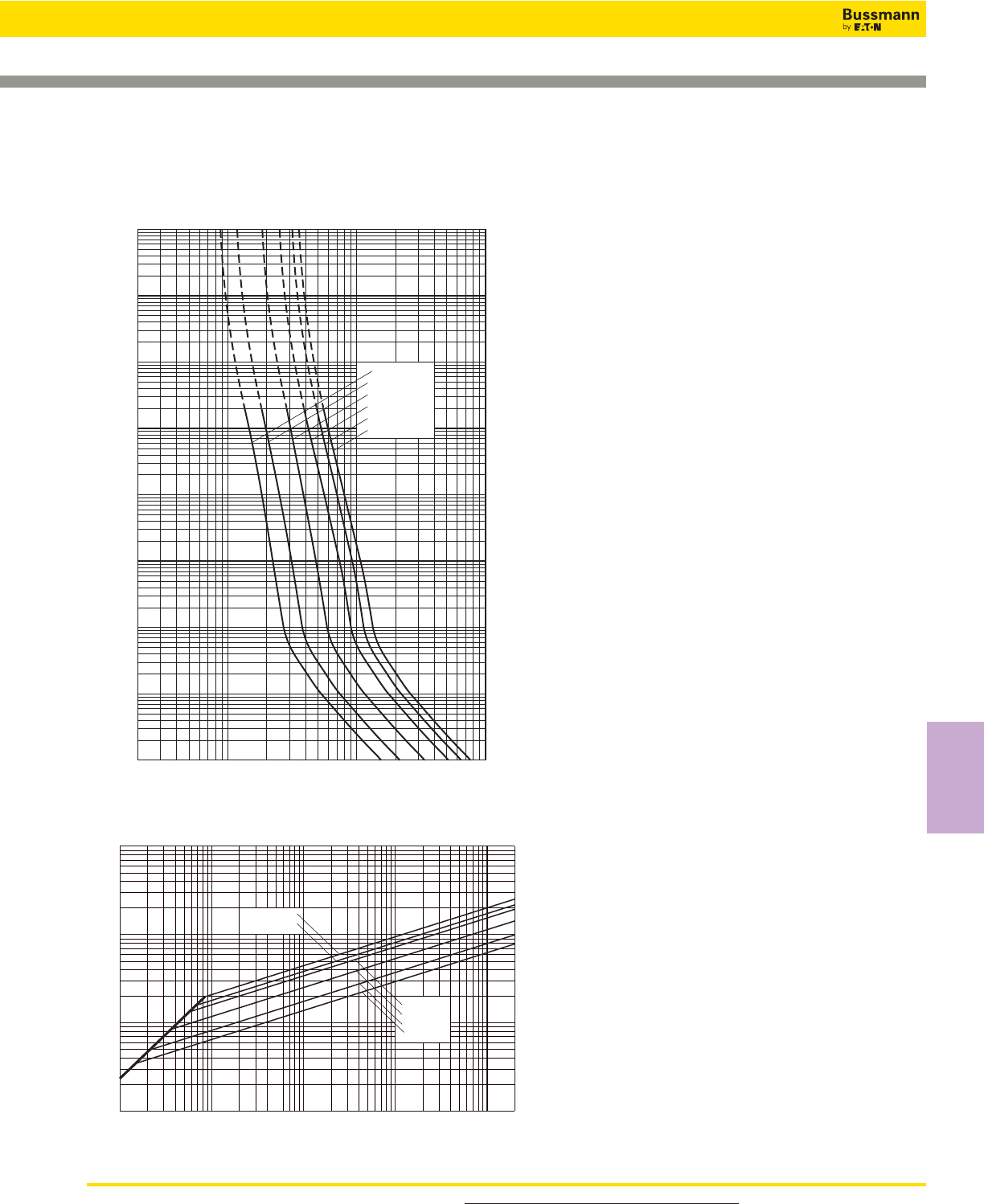
For product data sheets, visit www.cooperbussmann.com/DatasheetsEle 231
High Speed
Fuses
Ferrule — FWH 500V: 1-30A
Peak Let-Through Curve
2468
10
1
22468 2
10
2
2468
10
3
2
4
6
2
6
4
2
6
4
2
6
4
2
6
4
2
6
4
6
4
2
6
2
4
FWH-5A14F
FWH-10A14F
FWH-15A14F
FWH-20A14F
FWH-25A14F
FWH-30A14F
Virtual Pre-Arcing Time In Seconds
Prospective Current In Amps RMS
10
3
10
0
10
1
10
4
10
2
10–4
10–3
10–2
10–1
FWH 1-30A: 500V (14 x 51mm)
Time-Current Curve
Prospective Short-Circuit Current Symmetrical RMS
Peak Let-Through Current
2
4
2
6
6
4
2
6
4
246 246 246 246
101
102
103
104
101102103104105
FWH-5A14F
FWH-10A14F
FWH-15A14F
FWH-20A14F
FWH-25A14F
FWH-30A14F
2
Data Sheet: 35785298
High Speed Fuses
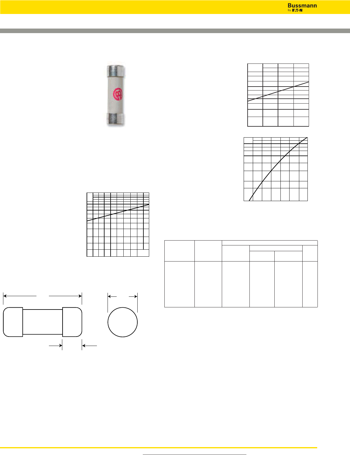
For product data sheets, visit www.cooperbussmann.com/DatasheetsEle
232
High Speed Fuses
Ferrule — FWC 600V: 6-32A
Dimensions - mm (in)
38.1
(1.500")
9.5
(0.375")
10.3
(0.406")
FWC (10 x 38mm)
Specifications
Description: Ferrule style high
speed fuses.
Dimensions: See dimensions
illustration.
Ratings:
Volts: — 600Vac/700Vdc (6-25A)
600Vac (30-32A)
Amps: — 6-32A
IR: — 200kA RMS Sym.
— 50kA @ 700Vdc (6-25A)
Agency Information: CE, UL Recognition JFHR8.E91958
6-32A. & CSA Component Acceptance file Class 1422-30,
(53787) on (6-32A)
Electrical Characteristics
Total Clearing I2t
The total clearing I2t at rated
voltage and at power factor
of 15% are given in the
electrical characteristics. For
other voltages, the clearing
I2t is found by multiplying by
correction factor, K, given as
a function of applied working
voltage, Eg, (rms).
Arc Voltage
This curve gives the peak
arc voltage, UL, which
may appear across the
fuse during its operation
as a function of theapplied
working voltage, Eg, (rms)
at a power
factor of 15%.
Power Losses
Watts loss at rated
current is given in the
electrical characteristics.
The curve allows the
calculation of the power
losses at load currents
lower than the rated
current. The correction
factor, Kp, is given as a
function of the RMS load
current, Ib, in % of the
rated current.
Catalog Numbers
Electrical Characteristics
Rated I2t (A2Sec)
Catalog Current Clearing Watts
Numbers Size RMS-Amps Pre-arc at 600V Loss
FWC-6A10F 6 4 30 1.5
FWC-8A10F 8 6 50 2.0
FWC-10A10F 10 9 70 2.5
FWC-12A10F 10 x 38mm 12 15 120 3.0
FWC-16A10F (13⁄32” x 11⁄2”) 16 25 150 3.5
FWC-20A10F 20 34 260 4.8
FWC-25A10F 25 60 390 6.0
FWC-30A10F 30 95 600 7.5
FWC-32A10F 32 95 600 7.5
• Watts loss provided at rated current.
• See accessories on page 243.
Features and Benefits
• Excellent cycling capability and DC performance
• Low arc voltage and low energy let-through (I2t)
• Low watts loss in a compact size
• Used with finger-safe holders/blocks
Typical Applications
• DC Common bus
• DC Drives
• Power converters/rectifiers
• Reduced voltage starters
500 600400250100
1.5
1.0
0.5
0.3
0.2
0.15 Eg
K
UL
2.0
1.6
1.2
103
800
600
500
400
300
400300200 500 600
Eg
Kp
1.0
0.8
0.4
0.5
0.6
0.3
0.2
0.1
30 40 50 60 70 80 90 100%
Ib
Data Sheet: 720011
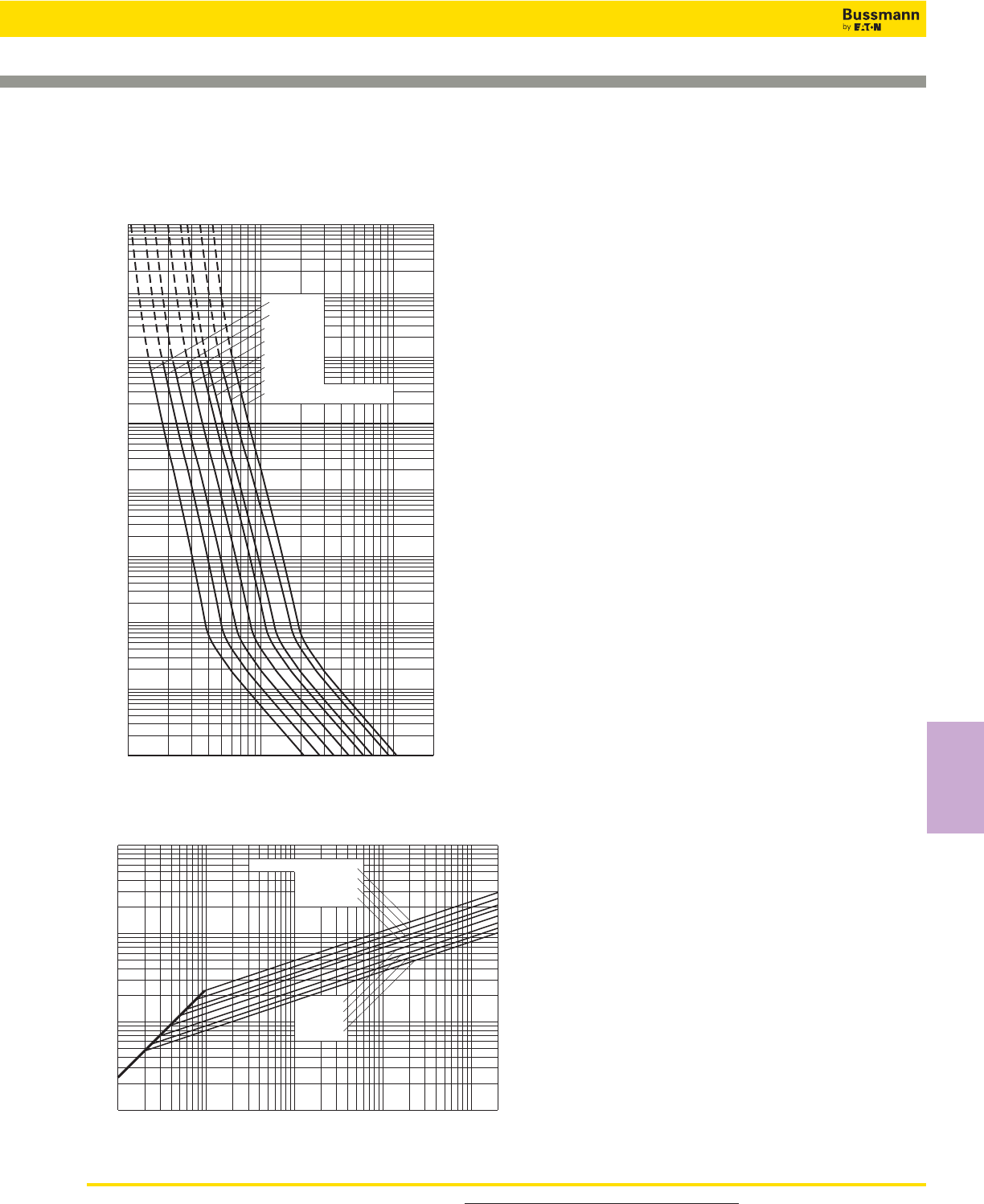
For product data sheets, visit www.cooperbussmann.com/DatasheetsEle 233
High Speed
Fuses
Ferrule — FWC 600V: 6-32A
103
104
102
10–1
10–2
10–3
10–4
10122468 2
1022468
103
2
4
6
2
6
4
100
2
6
4
101
2
6
4
2
6
4
2
6
4
6
4
2
6
2
4
Prospective Current In Amps RMS
Virtual Pre-Arcing Time In Seconds
FWC-10A10F
FWC-30A10F & FWC-32A10F
FWC-20A10F
FWC-25A10F
FWC-12A10F
FWC-16A10F
FWC-8A10F
FWC-6A10F
Prospective Short-Circuit Current Symmetrical RMS
Peak Let-Through Current
2
4
2
6
6
4
2
6
4
246 246 246 246
101
102
103
104
101102103104105
FWC-6A10F
FWC-8A10F
FWC-10A10F
FWC-12A10F
FWC-16A10F
FWC-20A10F
FWC-25A10F
FWC-30A10F & FWC-32A10F
Peak Let-Through Curve
FWC 6-32A: 600V (10 x 38mm)
Time-Current Curve
Data Sheet: 35785306
High Speed Fuses

For product data sheets, visit www.cooperbussmann.com/DatasheetsEle
234
High Speed Fuses
Ferrule — FWP 690V/700V (IEC/UL): 1-50A,
Striker Optional
Dimensions - mm (in)
51 (2.00")
59 (2.323")
13 (0.511")
14.3
(0.563")
5 (0.197")
FWP (14 x 51mm)
Specifications
Description: Ferrule style high
speed fuses with and without
indicating striker.
Dimensions: See dimensions
illustrations.
Ratings:
Volts: — 690Vac (IEC)
— 700Vac (UL)
— 800Vdc (5-50A)
Amps: — 1-50A
IR: — 200kA RMS Sym.
— 50kA @800Vdc
Agency Information: CE, UL Recognition JFHR2.E91958,
CSA Component Acceptance file Class 1422-30, 1422-90
(53787) for versions without indicator only. Designed and
tested to IEC 60269: Part 4.
Electrical
Characteristics
Total Clearing I2t
The total clearing I2t at
rated voltage and at power
factor of 15% are given in
the electrical
characteristics. For other
voltages, the clearing I2t is
found by multiplying by
correction factor, K, given
as a function of applied working
voltage, Eg, (rms).
Arc Voltage
This curve gives the peak
arc voltage, UL, which
may appear across the
fuse during its operation
as a function of theapplied
working voltage, Eg, (rms)
at a power factor of 15%.
Power Losses
Watts loss at rated current
is given in the electrical
characteristics. The curve
allows the calculation of
the power losses at load
currents lower than the
rated current. The
correction factor, Kp, is
given as a function of the
RMS load current, Ib, in %
of the rated current.
Catalog Numbers
Rated I2t (A2Sec)
Catalog Current Minimum Clearing At Watts
Numbers Size RMS-Amps Melting Rated Voltage Loss
Without Striker
FWP-1A14F 1 — — —
FWP-2A14F 2 — — —
FWP-2.5A14F 2.5 — — —
FWP-3A14F 3 — — —
FWP-4A14F 4 — — —
FWP-5A14F 14 x 51mm 5 1.6 11.0 1.5
FWP-10A14F (9⁄16" x 2") 10 3.6 38.5 4
FWP-15A14F 15 8.6 70 5.5
FWP-20A14F 20 26.0 230 6
FWP-25A14F 25 46.5 375 7
FWP-30A14F 30 58 485 9
FWP-32A14F 32 68 600 7.6
FWP-40A14F 40 84 750 8
FWP-50A14F 50 200 1800 9
With Striker*
FWP-10A14FI 10 3.6 38.5 4
FWP-15A14FI 15 8.6 70 5.5
FWP-20A14FI 14 x 51mm 20 26.0 230 6
FWP-25A14FI (9⁄16” x 2”) 25 46.5 375 7
FWP-30A14FI 30 58 485 9
FWP-32A14FI 32 68 600 7.6
FWP-40A14FI 40 84 750 8
FWP-50A14FI 50 200 1800 9
*Striker range is 600Vdc only
• Watts loss provided at rated current.
• See accessories on page 243.
Features and Benefits
• Excellent cycling capability and DC performance
• Low arc voltage and low energy let-through (I2t)
• Low watts loss in a compact size
• Used with finger-safe holders/blocks
UL
1.4
1.2
103
6
8
7
9
5
4
3
200 300 400 500 600 700
Eg
Kp
1.0
0.8
0.4
0.5
0.6
0.3
0.2
0.1
30 40 50 60 70 80 90 100%
Ib
K
1.4
1.2
1.0
0.6
0.8
0.7
0.9
0.5
0.4
0.3
200 300 400 500 600 700
Eg
1)
2)
1) 5-30A Range
2) 32-50A Range
50.8
(2.000")
15.5
(0.610")
14.3
(0.563")
With Striker
Without Striker
FWP with
striker option.
Electrical Characteristics
Data Sheet: 720025
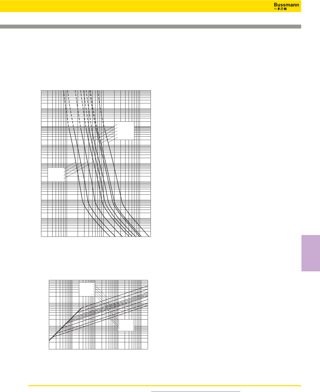
For product data sheets, visit www.cooperbussmann.com/DatasheetsEle 235
High Speed
Fuses
Ferrule — FWP 690V/700V (IEC/UL): 1-50A,
Striker Optional
103
102
10–1
10–2
10–3
10–4
FWP-10A14F
FWP-15A14F
FWP-20A14F
FWP-5A14F
FWP-50A14F
FWP-30A14F
FWP-32A14F
FWP-40A14F
FWP-25A14F
2468
10122468 2
1022468
103
2
4
6
2
6
4
100
2
6
4
101
2
6
4
2
6
4
2
6
4
6
4
2
6
2
4
Prospective Current In Amps RMS
Virtual Pre-Arcing Time In Seconds
104
Prospective Short-Circuit Current Symmetrical RMS
Peak Let-Through Current
2
4
2
6
6
4
2
6
4
246 246 246 246
101
102
103
104
101102103104105
FWP-5A14F
FWP-10A14F
FWP-15A14F
FWP-20A14F
FWP-25A14F
FWP-30A14F
FWP-32A14F
FWP-40A14F
FWP-50A14F
2
Peak Let-Through Curve
Without Striker
FWP 5-50A: 660V/700V (14 x 51mm)
Time-Current Curve
Data Sheet: 35785307
High Speed Fuses
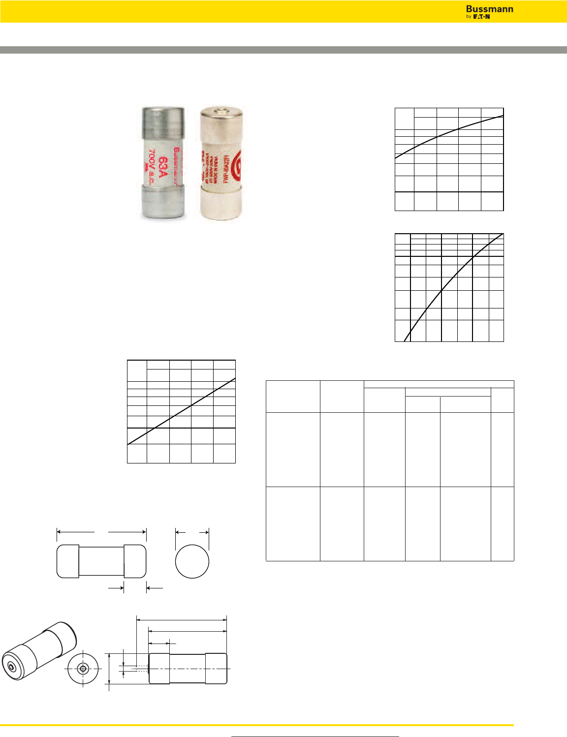
For product data sheets, visit www.cooperbussmann.com/DatasheetsEle
236
High Speed Fuses
Ferrule — FWP 690V/700V (IEC/UL):
20-100A, Striker Optional
Dimensions - mm (in)
66 (2.598")
58 (2.283")
16 (0.630"
22.2 (0.874")
5
(0.197")
FWP (22 x 58mm)
Specifications
Description: Ferrule style high
speed fuses with and without
indicating striker.
Dimensions: See dimensions
illustration.
Ratings:
Volts: — 690Vac (IEC)
— 700Vac (UL)
— 500Vac
— 500Vdc (20-100A)
Amps: — 20-100A
IR: — 200kA RMS Sym.
— 50kA @ 500Vdc
Agency Information: CE, UL Recognition JFHR2.E91958,
CSA Component Acceptance file Class 1422-30, 1422-90
(53787)
Electrical
Characteristics
Total Clearing I2t
The total clearing I2t at
rated voltage and at power
factor of 15% are given in
the electrical
characteristics. For other
voltages, the clearing I2t is
found by multiplying by
correction factor, K, given
as a function of applied
working voltage, Eg, (rms).
Arc Voltage
This curve gives the peak
arc voltage, UL, which
may appear across the
fuse during its operation
as a function of theapplied
working voltage, Eg, (rms)
at a power factor of 15%.
Power Losses
Watts loss at rated current
is given in the electrical
characteristics. The curve
allows the calculation of
the power losses at load
currents lower than the
rated current. The
correction factor, Kp, is
given as a function of the
RMS load current, Ib, in %
of the rated current.
Catalog Numbers
Electrical Characteristics
Rated I2t (A2Sec)
Catalog Current Minimum Clearing At Watts
Numbers Size RMS-Amps Melting Rated Voltage Loss
Without Striker
FWP-20A22F 20 19.0 260 5
FWP-25A22F 25 34.0 410 6
FWP-32A22F 22 x 58mm 32 53.5 605 8
FWP-40A22F (7⁄8" x 29⁄32") 40 68 750 9
FWP-50A22F 50 135 1600 9.5
FWP-63A22F 63 280 3080 11
FWP-80A22F 80 600 6600 13.5
FWP-100A22F 100* 1100 12500 16
With Striker
FWP-20A22FI 20 19.0 260 5
FWP-25A22FI 25 34.0 410 6
FWP-32A22FI 22 x 58mm 32 53.5 605 8
FWP-40A22FI (7⁄8" x 29⁄32") 40 68 750 9
FWP-50A22FI 50 135 1600 9.5
FWP-63A22FI 63 280 3080 11
FWP-80A22FI 80 600 6600 13.5
FWP-100A22FI 100* 1100 12500 16
*IEC/UL Voltage rating 690/700
Features and Benefits
• Excellent cycling capability and DC performance
• Low arc voltage and low energy let-through (I2t)
• Low watts loss in a compact size
• Used with finger-safe holders/blocks
Typical Applications
• DC Common bus
• DC Drives
• Power converters/rectifiers
• Reduced voltage starters
K
1.4
1.2
1.0
0.6
0.8
0.7
0.9
0.5
0.4
0.3
200 300 400 500 600 700
Eg
UL
1.4
1.2
103
6
8
7
9
5
4
3
200 300 400 500 600 700
Eg
Kp
1.0
0.8
0.4
0.5
0.6
0.3
0.2
0.1
30 40 50 60 70 80 90 100
%
Ib
Data Sheet: 720026
58.0
(2.283")
15.0
(0.591")
22.2
(0.875")
With Striker
Without Striker
FWP with
striker
option.
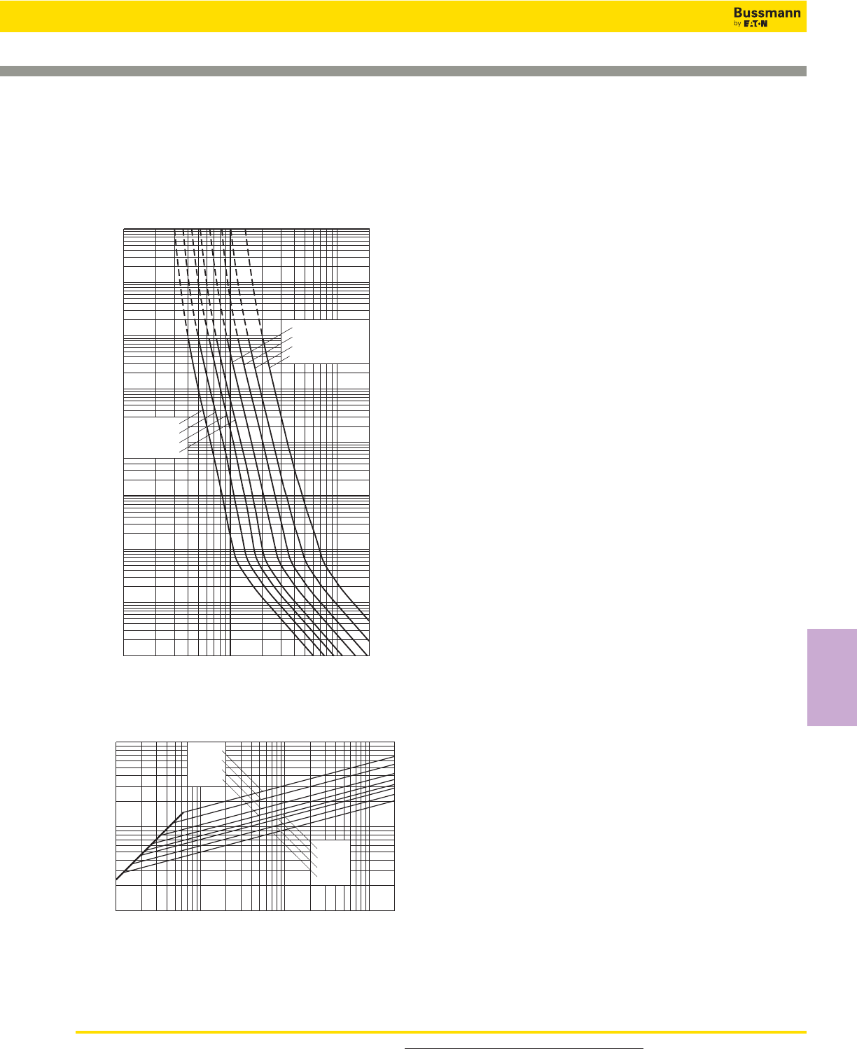
For product data sheets, visit www.cooperbussmann.com/DatasheetsEle 237
High Speed
Fuses
Ferrule — FWP 690V/700V (IEC/UL): 20-100A,
Striker Optional
10122468 2
1022468
103
2
4
6
2
6
4
2
6
4
2
6
4
2
6
4
2
6
4
6
4
2
6
2
4
101
100
10–1
10–2
10–3
10–4
102
103
104
Prospective Current In Amps RMS
Virtual Pre-Arcing Time In Seconds
FWP-20A22F
FWP-25A22F
FWP-32A22F
FWP-40A22F
FWP-50A22F
FWP-63A22F
FWP-80A22F
FWP-100A22F
104
Prospective Short-Circuit Current Symmetrical RMS
Peak Let-Through Current
2
6
4
2
6
4
246 246 246
102
103
102103104105
FWP-20A22F
FWP-25A22F
FWP-32A22F
FWP-40A22F
FWP-50A22F
FWP-63A22F
FWP-80A22F
FWP-100A22F
2
Peak Let-Through Curve
Without Striker
FWP 20-100A: 660V/700V (22 x 58mm)
Time-Current Curve
Data Sheet: 35785291
High Speed Fuses
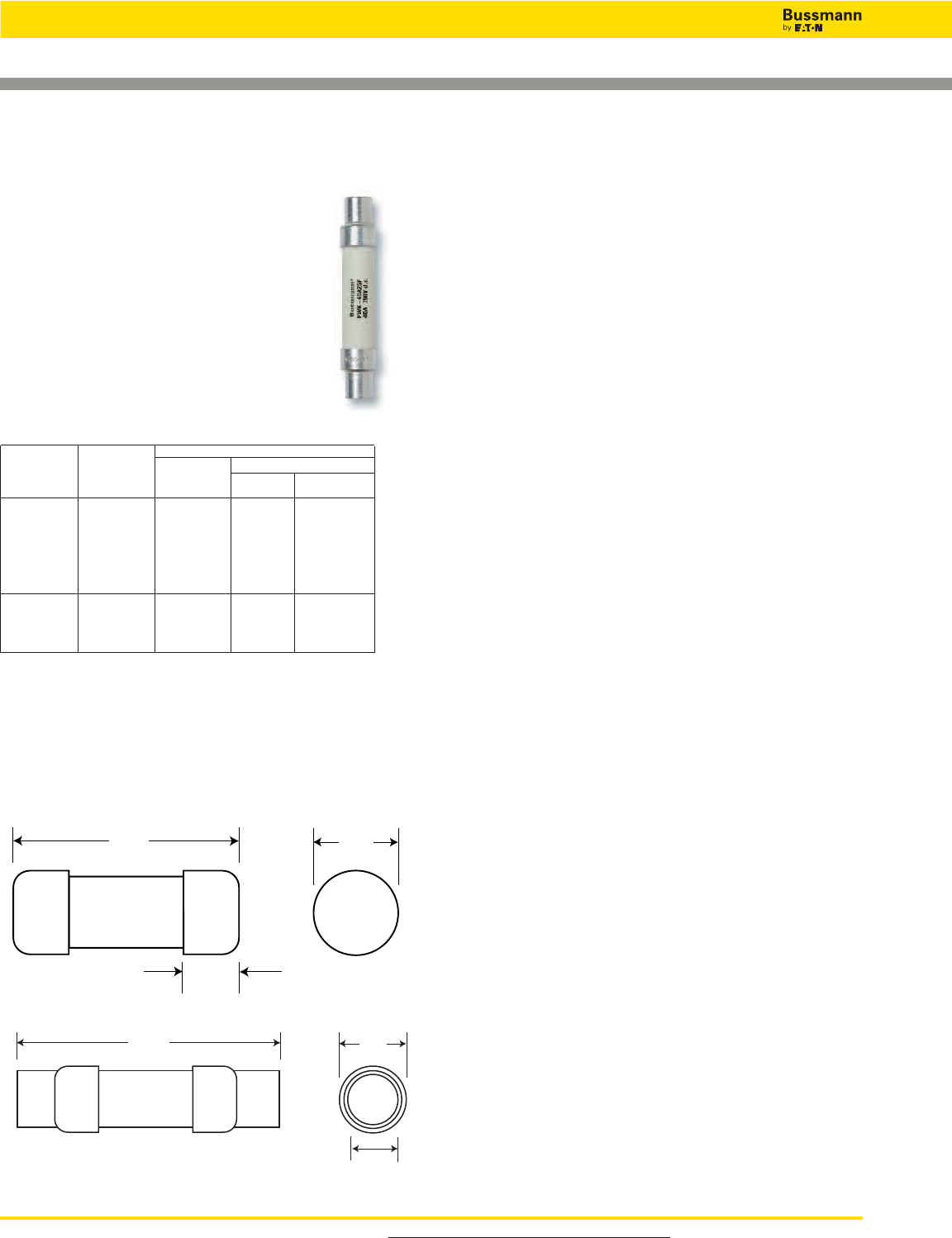
For product data sheets, visit www.cooperbussmann.com/DatasheetsEle
238
High Speed Fuses
Ferrule — FWK 750V: 5-60A
Dimensions - mm (in)
Fig. 1: 5-30A
146.05
(5.75")
25.4
(1")
20.64
(0.813")
Fig. 2: 35-60A
127.0
(5.000")
16.0
(0.630")
20.5
(0.807")
FWK 5-30A (20 x 127mm
35-60A (25 x 146mm)
Specifications
Description: Ferrule style high speed fuses.
Dimensions: See Dimensions illustrations.
Ratings:
Volts: — 750Vac
— 750Vdc (Time constant = 10-15mS)
Amps: — 5-60A
IR: — 45kA RMS Sym.
Agency Information: CE
Catalog Numbers
Electrical Characteristics
Rated I2t (A2Sec)
Catalog Current Clearing
Numbers Size RMS-Amps Pre-arc at 750Vdc
FWK-5A20F 5 8.5 16
FWK-8A20F 8 50 100
FWK-10A20F 10 95 200
FWK-15A20F 20 x 127mm 15 100 240
FWK-20A20F (13⁄16” x 5”) 20 125 315
FWK-25A20F 25 400 1100
FWK-30A20F 30 800 2600
FWK-35A25F 35 1300 4300
FWK-40A25F 25 x 146mm 40 1600 5300
FWK-50A25F (1” x 53⁄4”) 50 3100 12000
FWK-60A25F 60 5900 24000
Recommended fuseholders for 20x127, -2, -3
Recommended fuseclips for 20x127, 1A1837
Recommended fuseclips for 25x146, A3354705
Features and Benefits
• Excellent cycling capability and DC performance
• Low arc voltage and low energy let-through (I2t)
• Low watts loss in a compact size
• Used with finger-safe holders/blocks
Typical Applications
• DC Common bus
• DC Drives
• Power converters/rectifiers
• Reduced voltage starters
Data Sheet: 720039
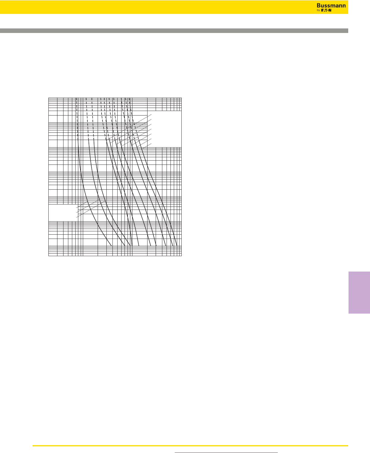
For product data sheets, visit www.cooperbussmann.com/DatasheetsEle 239
High Speed
Fuses
Ferrule — FWK 750V: 5-60A
2468
10122468 2
1022468
103
2
4
6
2
6
4
2
6
4
2
6
4
2
6
4
2
6
4
10±1
10±2
4x10±3
100
101
102
103
104
FWK-15A20F
FWK-20A20F
FWK-25A20F
FWK-30A20F
FWK-40A25F
FWK-50A25F
FWK-60A25F
FWK-5A20F
FWK-8A20F
FWK-10A20F
Prospective Current In Amps RMS
Virtual Pre-Arcing Time In Seconds
FWK 750V: 5-30A (20 x 127mm)
35-60A (25 x 146mm)
Time-Current Curve
High Speed Fuses
Data Sheet: 720028
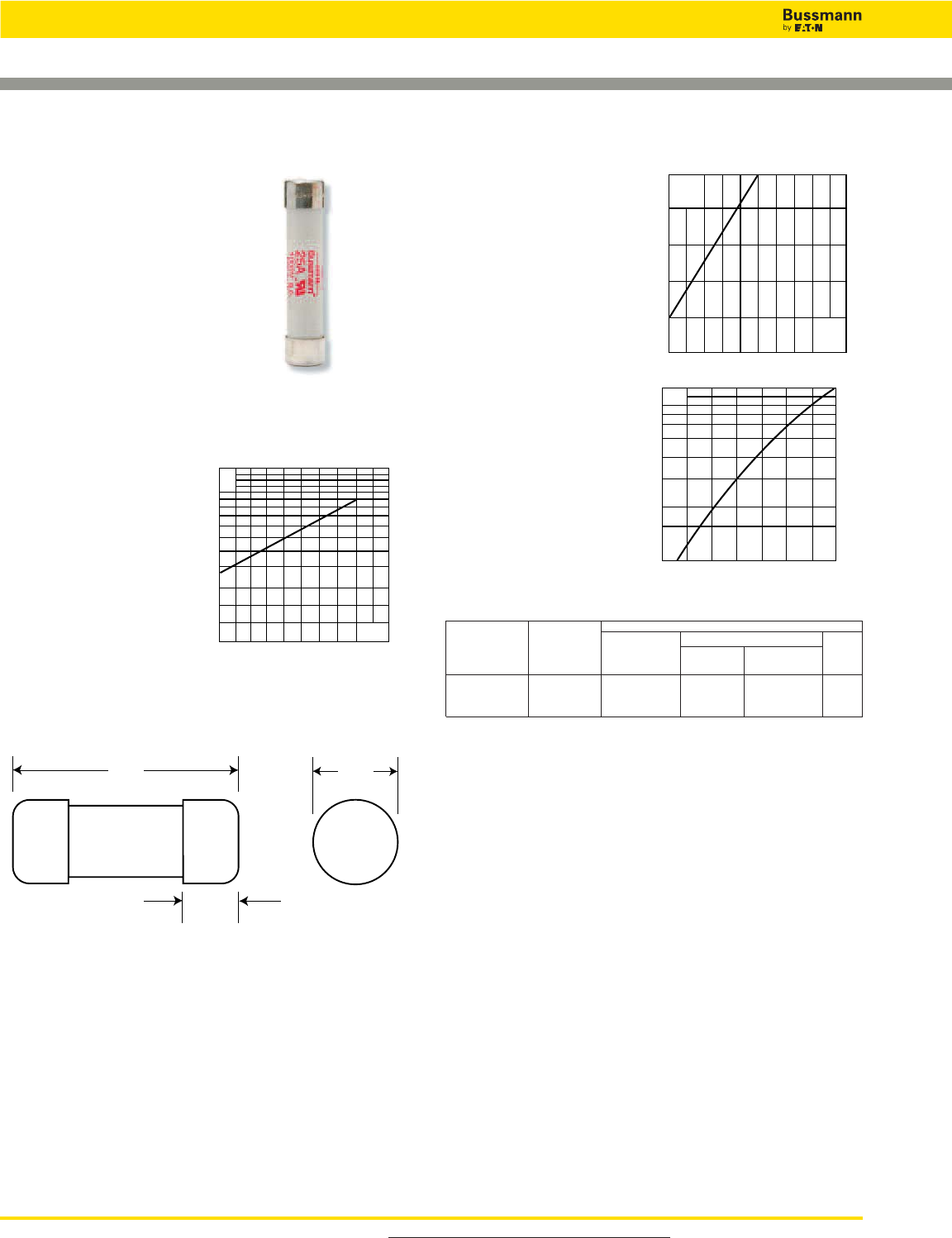
For product data sheets, visit www.cooperbussmann.com/DatasheetsEle
240
High Speed Fuses
Data Sheet: 35785031
Ferrule — FWJ 1000V: 20-30A
Dimensions - mm (in)
66.7
(2.626")
15.9
(0.625")
14.5
(0.571")
FWJ (14 x 67mm)
Specifications
Description: Ferrule style high
speed fuses.
Dimensions: See dimensions
illustration.
Ratings:
Volts: — 1000Vac/800Vdc
Amps: — 20-30A
IR: — 25kA RMS Sym.
— 20kA @ 800Vdc
Agency Information: CE, UL Recognized JFHR2.E91958
Electrical
Characteristics
Total Clearing I2t
The total clearing I2t at
rated voltage and at power
factor of 15% are given in
the electrical
characteristics. For other
voltages, the clearing I2t is
found by multiplying by
correction factor, K, given
as a function of applied
working voltage, Eg, (rms).
Arc Voltage
This curve gives the peak
arc voltage, UL, which
may appear across the
fuse during its operation
as a function of theapplied
working voltage, Eg, (rms)
at a power factor of 15%.
Power Losses
Watts loss at rated current
is given in the electrical
characteristics. The curve
allows the calculation of
the power losses at load
currents lower than the
rated current. The
correction factor, Kp, is
given as a function of the
RMS load current, Ib, in %
of the rated current.
Catalog Numbers
Electrical Characteristics
Rated I2t (A2Sec)
Catalog Current Clearing Watts
Numbers Size RMS-Amps Pre-arc at 1000V Loss
FWJ-20A14F 14 x 67mm 20 25 220 9
FWJ-25A14F (9⁄16” x 25⁄8”) 25 33 350 11
FWJ-30A14F 30 52 450 14
• Watts loss provided at rated current.
• See accessories on page 243.
Features and Benefits
• Excellent cycling capability and DC performance
• Low arc voltage and low energy let-through (I2t)
• Low watts loss in a compact size
• Used with finger-safe holders/blocks
Typical Applications
• DC Common bus
• DC Drives
• Power converters/rectifiers
• Reduced voltage starters
1000800500200
1.5
1.0
0.5
0.3
0.2
0.15 Eg
K
2000
1600
1200
800
400
200 600 1000 1400 1800
UL
Eg
Kp
1.0
0.8
0.4
0.5
0.6
0.3
0.2
0.1
30 40 50 60 70 80 90 100%
Ib
Fuseclips:
• Catalog Number: 5591 (see data sheet 2132)

For product data sheets, visit www.cooperbussmann.com/DatasheetsEle 241
High Speed
Fuses
Ferrule — FWJ 1000V: 20-30A
FWJ-20A14F
FWJ-25A14F
FWJ-30A14F
10122468 2
1022468
103
2
4
6
2
6
4
2
6
4
2
6
4
2
6
4
2
6
4
6
4
2
6
2
4
10–4
100
101
10–1
10–2
10–3
102
103
104
Prospective Current In Amps RMS
Virtual Pre-Arcing Time In Seconds
FWJ 20-30A: 1000V (14 x 67mm)
Time-Current Curve
Prospective Short-Circuit Current Symmetrical RMS
Peak Let-Through Current
2
4
2
6
6
4
2
6
4
2 46 2 46 2 46 2 46
101
102
103
104
101102103104105
FWJ-20A14F
FWJ-25A14F
FWJ-30A14F
2
Peak Let-Through Curve
Data Sheet: 35785315
High Speed Fuses

For product data sheets, visit www.cooperbussmann.com/DatasheetsEle
242
High Speed Fuses
Ferrule — FWS/FWL 1000Vdc: 2-30A
Dimensions - mm (in)
127.0
(5.000")
16.0
(0.630")
20.5
(0.807")
Indicating Version – Dimensions - mm (in)
127.0
(5.000")
16.0
(0.630")
20.5
(0.807")
2.0
(0.079")
2.0
8.0
(0.315")
FWL/FWS 2-30A: 1000Vdc 2-30A
(20 x 127mm)
Time-Current Curve
FWS 2-15A (20 x 127mm)
FWL 20-30A (20 x 127mm)
Specifications
Description: Ferrule style full range
fuses.
Dimensions: See dimensions
illustrations.
Ratings:
Volts: — 1200Vac (FWL 20-30A)
— 1400Vac (FWS 8-15A)
— 2100Vac (FWS 2-6A)
— 1000Vdc (FWL/FWS 2-30)
Amps: — 2-30A
IR: — 45kA RMS Sym.
— 30kA @ 1000Vdc
Agency Information: CE, IEC 60077
Catalog Numbers
Electrical Characteristics
Rated I2t (A2Sec)
Catalog Current Clearing Watts
Numbers Size RMS-Amps Pre-arc at 1000Vdc Loss
FWS-2A20F 2 0.8 2.4 4.4
FWS-6A20F 6 27 81 6.7
FWS-8A20F 20 x 127mm 8 64 192 7.6
FWS-10A20F (13⁄16” x 5”) 10 118 277 3.0
FWS-12A20F 12 170 380 3.4
FWS-15A20F 15 209 500 5.0
FWL-20A20F 20 x 127mm 20 675 1550 5.9
FWL-25A20F (13⁄16” x 5”) 25 1200 2760 6.5
FWL-30A20F 30 1850 4300 7.5
• ADD “I” to catalog number for indicating version.
• Enclosed finger-safe fuse holder – CH127
• See accessories on page 243.
• Watts loss provided at rated current.
Features and Benefits
• Excellent cycling capability and DC performance
• Low arc voltage and low energy let-through (I2t)
• Low watts loss in a compact size
• Used with finger-safe holders/blocks
Typical Applications
• DC Common bus
• DC Drives
• Power converters/rectifiers
• Reduced voltage starters
• Traction aux circuits
• Capacitor protection
Data Sheet: 720040
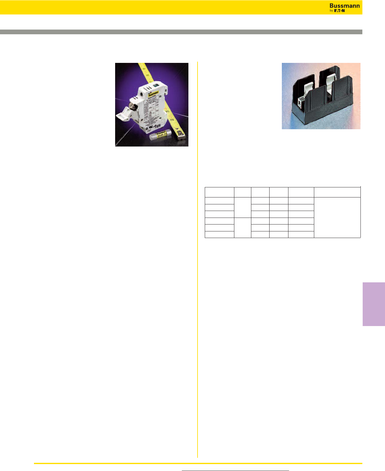
For product data sheets, visit www.cooperbussmann.com/DatasheetsEle 243
High Speed
Fuses
Ferrule Fuse Accessories
Data Sheet: 2053
Fuse Holders
Specifications
Catalog Symbol: CH Series
Description: DIN-Rail mount
fuse holders
Agency Information:
UL File E14853, Guide IZLT
Listed, IZLT2 Recognized
CSA: File 47235, CHPV and
CHM - Class 6225-30,
CHCC - Class 6225-01
Ratings: 600V/30A (UL)
690V/32A (IEC)
Features and Benefits
• Finger-safe design - No exposed contacts
• DIN-Rail mount (35mm) - Fits standard mounting rails
• Optional open fuse indication lights tells fuse status at a
glance
• Handle/fusepuller easily installs and removes fuses
• Available in single and multi-pole configurations
• Wire ready lugs and spade terminal connections save
installation time
• CE marking
• Available up to 1000Vdc
• PLC device available for remote monitoring
Typical Applications
• Switchboard panel, control consoles, small motors,
transformers, and similar applications
Recommended Cooper Bussmann Fuse Types
Class CC North American Class CC Fuses - LP-CC,
FNQ-R, KTK-R
10 x 38 North American Midget Fuses - FNQ, KTK, AGU,
BAF, BAN, FNM, FWA, FWC, & PV
14 x 51 FWX, FWH, FWP & NON
22 x 58 FWP
See pages 274-280 for CHSeries fuse holder information.
Fuse Blocks
Specifications
Catalog Symbol: J70100,
J70032
Description: Fuse blocks
for 22x58mm & 14x51mm
fuses.
Ratings:
Volts: — 700Vac/dc
Amps: — 32-100A
Withstand: — 200kA RMS Sym.
Agency Information: CE, UL Recognized, Guide IZLT2,
File E14853
Flammability Rating: UL 94V0
Catalog Numbers
Catalog Fuse Max Wire
Numbers Size Amps Poles Size Terminations
J70032-1CR 32 1 #2
J70032-2CR 32 2 #2 Box Lug w/
J70032-3CR 32 3 #2 Retaining Clip
J70100-1CR 100 1 #2
J70100-2CR 22x58 100 2 #2
J70100-3CR 100 3 #2
Data Sheet: 1211
Box Lug w/
Retaining Clip
14x51
22x58
High Speed Fuses
244
Faster lead-time.
Better protection.
More energy efficient.
High speed fuses

For product data sheets, visit www.cooperbussmann.com/DatasheetsEle 245
Application Data
The standard range of fuses for low voltage industrial and
general purpose applications meet the requirements of
BS 88 and IEC 60269. By using advanced fuse technology,
current ratings up to 400A have compact dimensions, but
retain standard dimensional and performance requirements.
These designs are for 315/240V systems. The standard
range of fuses are available from 2-1250A in the following
tag forms: Offset Blade - Offset Bolted - Center Bolted.
Supplementary ranges cover applications up to 660Vac and
500Vdc including those with nonstandard tag fixings.
Bussmann fuses are manufactured under quality systems
independently assessed to BS 5750 (ISO 9002) and
appropriate ratings carry the ASTA 20 endorsement.
Selecting fuses is relatively simple and effective. The
following notes cover the majority of applications. For further
information contact our Application Engineers at toll free
phone: 855-287-7626 (855-BUSSMANN).
Circuit Loading
The current rating of the fuse should not be less than the full
load current of the circuit. The circuit should be so designed
that small overloads of long duration will not be of frequent
occurrence.
Cable Ratings & Protection
There is an increasing move away from 70°C PVC insulation
to materials that are more environmentally friendly, for
example 90°C XLPE. The ratings of fusegear, switches,
accessories, etc. are generally based upon the equipment
being connected to conductors intended to be operated at a
temperature not exceeding 70°C in normal service.
In view of the above, it is recommended that the practice of
designs based upon conductor temperatures of 70°C be
regarded as the norm. The equipment manufacturer should
be consulted to ascertain the reduction of nominal current
rating of the equipment if conductor temperatures exceeding
70°C are used. In addition, an overriding factor is often
voltage drop.
Fuses with gG characteristics protect associated cables
against both overload and short-circuit current, provided that
the current rating of the fuse 1Nis equal or less than the
current carrying capacity of the cable 1z.
In motor circuits, the motor starter will provide the overload
protection and the fuses will provide the short-circuit
protection. The maximum fuse size that can be used
depends upon the type of cable used and is determined
using the appropriate K factor. The following table gives the
maximum sizes of fuses that are recommended for two
popular cables with copper conductors, 70°C PVC (K = 115)
and 90°C thermosetting (K = 143).
Section Contents
Page
Application Data . . . . . . . . . . . . . . . . . . . . . 245-246
CSA Type P and Type D fuses
(CDS, CDN & PON) . . . . . . . . . . . . . . . . . . . . . . . . . . . .247
Tron
™HRC Form II Class C fuses
(CGL Form II Class C) . . . . . . . . . . . . . . . . . . . . . . . . . . 248
HRCI Industrial ceramic body fuses (CIF21 HRCI-CA &
CIF06 HRCI-CB) . . . . . . . . . . . . . . . . . . . . . . . . . . . . . . 249
HRCI-J Fast-acting fuses (CJ HRCI-J) . . . . . . . . . . . . . . . 250
HRCI-Miscellaneous Type K fuses (CIH, CIK &
CIL HRCI-MISC) . . . . . . . . . . . . . . . . . . . . . . . . . . . . . . 251
HRC Form II current-limiting fuses . . . . . . . . . . . . . . . . . .252
BS 88 British Standard low voltage fuses (SSD, NSD,
ESD & STD, NITD, AAO, BAO, OSD, CEO,
DEO BS 88 Part 1) . . . . . . . . . . . . . . . . . . . . . . . . . . . . .253
BS 88 British Standard low voltage fuses (AC, AD, BC,
BD, CD, DD, ED, EFS & EF, FF, FG, GF, GG,
GH BS 88) . . . . . . . . . . . . . . . . . . . . . . . . . . . . . . . . . . .254
DIN Style Type D (D16, D27, D33, D125 Type D) . . . . . . 255
Neozed low voltage fuses (NZ01, NZ02 Type D0) . . . . . . 255
NH HRC Fuses . . . . . . . . . . . . . . . . . . . . . . . . . . . . 256-259
Class gG/gL IEC Industrial ferrule fuses (C08G, C08M,
C10G, C10M, C14G, C14M, C22G, C22M) . . . . . . . . . . 260
Class aM IEC Industrial ferrule fuses (C08M, C10M,
C14M, C22M) . . . . . . . . . . . . . . . . . . . . . . . . . . . . . . . . .261
Class aM & gG/gL IEC Industrial ferrule fuses with striker
(C14G_S, C22G_S, C14M_S, C22M_S) . . . . . . . . . . . . . 262
HRC fuse holders
CAMaster . . . . . . . . . . . . . . . . . . . . . . . . . . . . . . . . . . . . .263
SAFEloc . . . . . . . . . . . . . . . . . . . . . . . . . . . . . . . . . . . . . .263
IEC & British
Fuses
IEC & British Standard Fuses
IEC and British Standard Fuses
Scan this tag to get the
latest product information for
IEC and British Standard Fuses.
For product data sheets, visit www.cooperbussmann.com/DatasheetsEle
246
IEC & British Standard Fuses
Application Data for BS Low Voltage Fuses
Max. Fuse Rating (amps)
Cable Size (mm2) K = 115 K = 143
11616
1,5 20 25*
2.5 32* 32*
450*50*
663*63*
10 100* 125*
16 125* 160*
25 200* 250*
35 315* 355*
50 400* 500
70 560 630
95 710 800
120 800 1000
* Extended Motor Circuit dual ratings can be used.
Protection Against Electrical Shock
For a TN System, a disconnecting time not exceeding 5s is
permitted for a distribution circuit. The maximum values of
earth fault loop impedance (Zs) of 240V for Bussmann gG
fuses to BS 88: Parts 2 and 6 are:
Rating (A) Zs (Ohms) Rating (A) Zs (Ohms) Rating (A) Zs (Ohms)
6 14 50 1.1 250 0.16
10 7.7 63 0.86 315 0.13
16 4.3 80 0.60 400 0.096
20 3.0 100 0.44 500 0.073
25 2.4 125 0.35 630 0.054
32 1.9 160 0.27 800 0.044
40 1.4 200 0.20
Ambient Temperature
The derating, in terms of current, of 0.5% per °C above an
ambient of 35°C is recommended.
Interrupting Rating
The standardized interrupting rating values are 80kA for
voltages of 415Vac and above, and 40kA for DC
applications. The 240Vac designs have an interrupting rating
of 50kA.
Coordination Ratio
All fuses to BS 88 Parts 2 and 6 will give a coordination ratio
of 2:1; and for most practical situations a ratio of 1.6:1 (two
steps in the R10 series). Example: an upstream fuse rated at
160A will coordinate with a downstream fuse rated at 100A.
Current and Energy Limitation
The range of fuses have pre-arcing I2t values towards the
bottom limits of BS 88 Parts 2 and 6. This ensures excellent
current and energy limitation. They also have lower power
losses at rated current. This assists in the appropriate
interchangeability with other makes of fuses.
Transformers
When fuses are used on the primary side of transformers,
the normal fuse current rating should be at least twice the
nominal transformer primary current.
Fluorescent Lighting
The normal fuse current rating should be at least twice the
normal full load current of the maximum number of lights to
be simultaneously switched.
Capacitor Circuits
For power factor correction in capacitor circuits, the fuse
should be chosen with a current rating greater than 1.5 times
the rated capacitor current. This takes into account the high
inrush current, circuit harmonics and capacitor tolerances.
Motor Circuits
In motor circuits, the fuse has to withstand the motor's
starting current and often requires a higher rating than the
motor's full load current. Coordination recommendations are
made by the manufacturers of motor starters in accordance
with IEC 60947-4-1. To get Type 2 coordination with fuses,
tests are performed with the latest gG or gM fuses to BS 88
or IEC 60269 that have pre-arcing I2t values towards the
bottom of specified limits. This means that Bussmann fuses
are suitable to provide Type 2 coordination.
Extended dual ratings of motor circuit protection fuses with
gM characteristics are available in most popular fuse sizes to
extend the use of associated equipment with appropriate
economies. In the majority of applications, gG fuses are
used. It is not essential to use gM fuses for motor circuit
protection, they simply extend the utilization of standard
equipment.
Below is a table of recommended fuses at 415V. In most
applications, the run-up time is less than 5 seconds and duty
is infrequent - no more than twice per hour. The next larger
rating should be used for more demanding applications.
Direct On-line Asst. Start
Standard Motor Circuit Standard
Rating Motor (gG) (gM) (gG)
kW A A A A
0.25 0.8 4 - 2
0.37 1.1 4 - 2
0.55 1.5 6 - 4
0.75 2.0 6 - 4
1.1 3 0 10 - 6
1.5 3.6 16 - 0 1
2.2 5.0 16 - 0 1
3.0 6.5 20 - 6 1
4.0 8.4 20 - 6 1
5.5 11.0 25 20M25 2 20
7.5 15.0 40 32M40 25
11.0 20.0 50 32M50 32
15.0 27.0 63 32M63 40
18.5 33.0 80 63M80 50
22.0 38.0 80 63M80 50
30.0 54.0 100 63M100 80
37.0 66.0 125 100M125 80
45.0 79.0 160 100M160 100
55.0 98.0 160 100M160 100
75.0 135.0 250 200M250 160
90.0 155.0 250 200M250 160
110.0 185.0 315 200M315 200
132.0 220.0 355 315M400 250
150.0 250.0 355 315M400 315
185.0 310.0 450 400M500 355
200.0 335.0 500 4 00M500 400
225.0 375.0 560 - 400
250.0 415.0 560 - 450
280.0 460.0 630 - 500
335.0 562.0 710 - 630
355.0 596.0 800 - 710
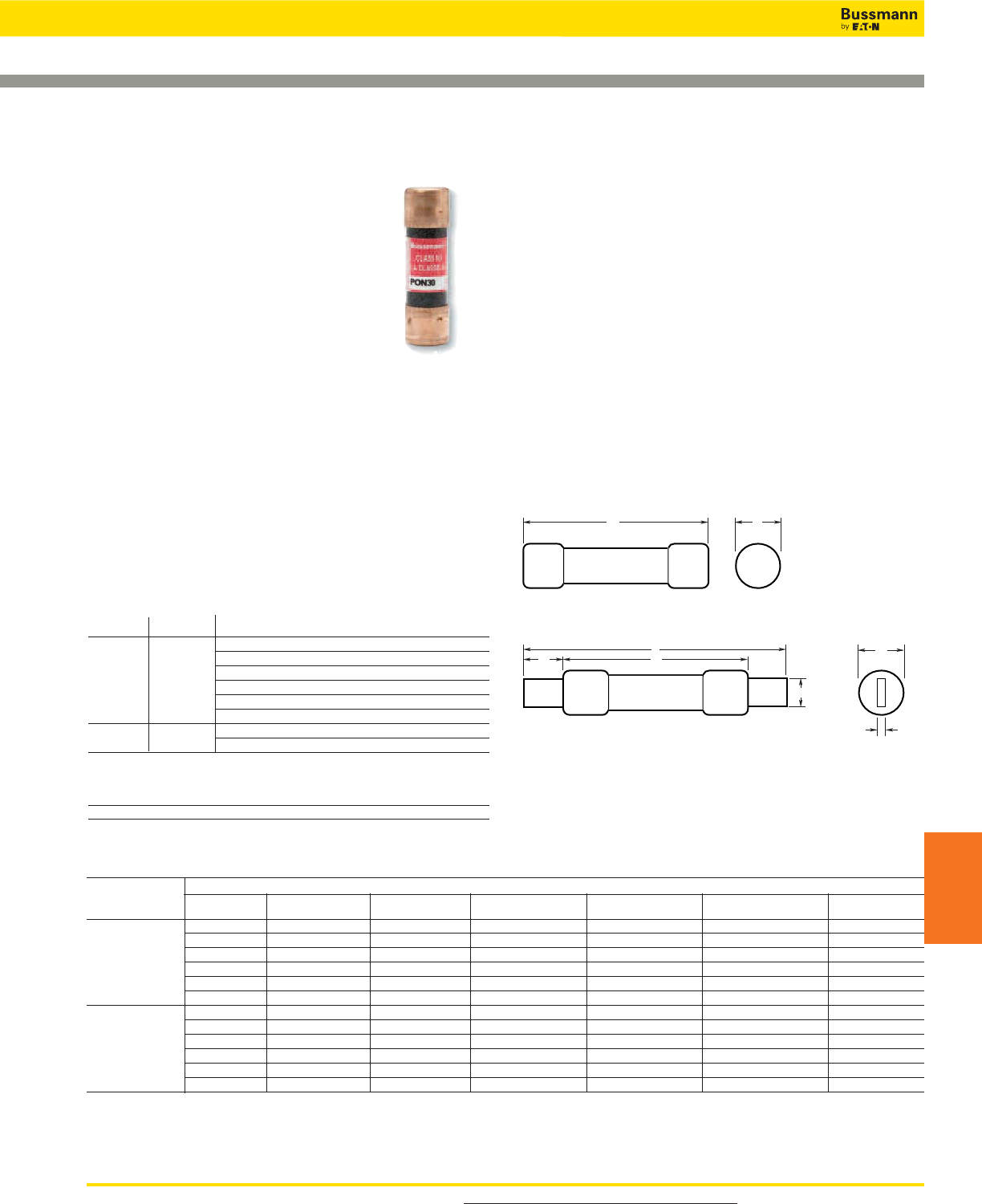
For product data sheets, visit www.cooperbussmann.com/DatasheetsEle 247
CSA Type P and Type D Fuses
IEC & British
Fuses
Catalog Numbers
Basic Catalog Dimensions in (mm)
Number Amp A B Max C Min D Min E F
and Volts Ratings Overall Diameter Blade Length Barrel Length Blade Thickness Blade Width
1-30 2.0 (50.8) 0.56 (14.3) — — — —
35-60 3.0 (76.2) 0.81 (20.6) — — — —
CDN/PON 250Vac 70-100 5.88 (149.4) — 1.0 (25.4) — 0.13 (3.2) 0.75 (19.1)
110-200 7.3 (185.4) — 1.38 (34.9) 4.13 (104.8) 0.19 (4.8) 1.13 (28.6)
225-400 8.63 (219.2) — 1.88 (47.6) 4.63 (117.5) 0.25 (6.4) 1.63 (41.3)
450-600 10.38 (263.7) — 2.25 (57.2) 5.19 (131.8) 0.25 (6.4) 2 (50.8)
1-30 5.0 (127.0) 0.81 (20.6) — — — —
35-60 5.5 (139.7) 1.06 (27.0) — — — —
CDS 600Vac 70-100 7.88 (200.2) — 1.0 (25.4) — 0.13 (3.2) 0.75 (19.1)
110-200 9.63 (244.6) — 1.38 (34.9) 6.13 (115.6) 0.19 (4.8) 1.13 (28.6)
225-400 11.63 (295.4) — 1.88 (47.6) 7.13 (118.1) 0.25 (6.4) 1.63 (41.3)
450-600 13.38 (339.9) — 2.25 (57.2) 8.19 (208.0) 0.25 (6.4) 2 (50.8)
To Order
To order, specify Basic Catalog Number and amp rating. Example: CDN-30
E
B
F
A
DC
Knife Blade—70 through 600A
AB
Ferrule Design—1 through 60A
Data Sheet: 4126
CDS, CDN & PON Type P & D
Specifications
Description: CSA time-delay Type D & P
fuses.
Dimensions: See Catalog Numbers table
and Dimensions illustration.
Ratings:
Volts: — 250Vac (CDN & PON)
— 600Vac (CDS)
Amps: — 10-600A
IR: — 10kA minimum
Agency Information: CE, CSA Certified to C22.2 No. 59.1.
Features and Benefits
• Economical fuse in a variety of ratings for applications not
requiring time-delay.
Typical Applications
• Lighting, heating and other circuits not subject to temporary
surges and where available short-circuit current are
relatively low.
Basic Catalog Numbers
Time-Delay CSA Type “D” Fuses
Catalog Amp
Numbers Volts Ratings
Below 10A use FRN-R 10, 12, 15, 20, 25, 30,
35, 40, 45, 50, 60, 70, 80, 90, 100
CDN 250Vac 110, 125, 150, 175, 200, 225, 250, 300, 350, 400,
450, 500, 600
Below 10A use FRS-R 10, 12, 15, 20, 25, 30,
35, 40, 45, 50, 60
CDS 600Vac 70, 80, 90, 100, 110, 125, 150, 175, 200,
225, 250, 300, 350, 400, 450, 500, 600
One-Time CSA Type “P” Fuses
Catalog Amp
Number Volts Ratings
PON 250Vac 15, 20, 25, 30, 35, 40, 45, 50, 60
Dimensions
IEC & British Standard Fuses
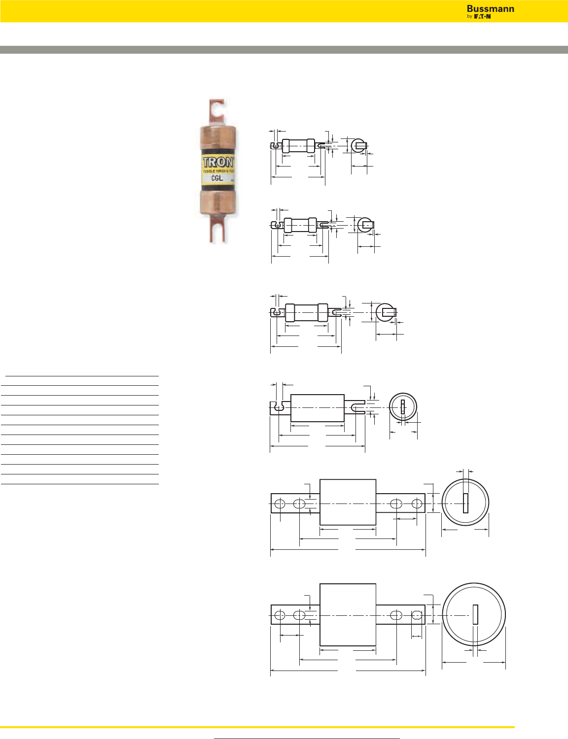
CGL Form II Class C
Specifications
Description: Current-limiting HRCII-C fuses
designed to withstand inrush currents on
typical motor start-ups while offering high
current limitation in the short-circuit region.
Dimensions: See Dimensions illustrations.
Ratings:
Volts: — 600Vac/250Vdc (1-30A)
Amps: — 1-600A
IR: — 200kA (40,000A DC)
Agency Information: CE, CSA Certified,
C22.2 No. 106.
Features and Benefits
• Close sizing to loads allows using smaller and less costly
switches
• Provides a higher degree of short-circuit protection
• Helps protect motors against burnout from overloads
Typical Applications
• For use in circuits subject to surge currents such as those
caused by motors, transformers and other inductive loads
Catalog Numbers (-Amps)
CGL-1 CGL-40 CGL-175
CGL-2 CGL-45 CGL-200
CGL-3 CGL-50 CGL-225
CGL-4 CGL-60 CGL-250
CGL-6 CGL-70 CGL-300
CGL-10 CGL-80 CGL-350
CGL-15 CGL-90 CGL-400
CGL-20 CGL-100 CGL-450
CGL-25 CGL-110 CGL-500
CGL-30 CGL-125 CGL-600
CGL-35 CGL-150
For product data sheets, visit www.cooperbussmann.com/DatasheetsEle
248
IEC & British Standard Fuses
Tron™HRC Form II Class C Fuses
Data Sheet: 4125
2.0"
(50.8mm)
2.80"
(71.04mm)
3.5"
(88.9mm)
0.94"
(23.81mm)
0.06"
(1.59mm)
2.0"
(50.8mm)
2.80"
(71.04mm)
3.31"
(84.14mm)
0.81"
(20.64mm)
0.22"
(5.56mm)
0.22"
(5.56mm)
0.34"
(8.73mm)
CGL 1-30
CGL 35-60
0.50"
(12.7mm)
0.81"
(20.64mm)
0.22"
(5.56mm)
0.22"
(5.56mm)
1.06"
(26.92mm)
0.06"
(1.59mm)
CGL 70-100
0.75"
(19.05mm)
1.34"
(34.04mm)
0.343"
(8.71mm)
0.343"
(8.71mm)
2.39"
(60.72mm)
3.64"
(92.47mm)
4.31"
(109.54mm)
1.375"
(34.93mm)
0.09"
(2.29mm)
CGL 110-200
0.75"
(19.05mm)
0.343
(8.71mm)
0.343"
(8.71mm)
3.00"
(76.2mm)
4.30"
(109.22mm)
5.31"
(134.87mm)
1.50"
(38.1mm)
0.125"
(3.18mm)
CGL 225-400
1.0"
(25.4mm)
0.38"
(9.53mm)
3.0"
(76.2mm)
5.25"
(133.35mm)
8.19"
(207.96mm)
2.38"
(60.33mm)
0.19"
(4.76mm)
1.0"
(25.4mm)
CGL 450-600
0.41"
(10.32mm)
3.00"
(76.2mm)
1.0"
(25.4mm)
1.0"
(25.4mm)
0.375"
(9.53mm)
3.0"
(76.2mm)
5.25"
(133.35mm)
8.19"
(207.96mm)
.60"
(15.24mm)
Dimensions
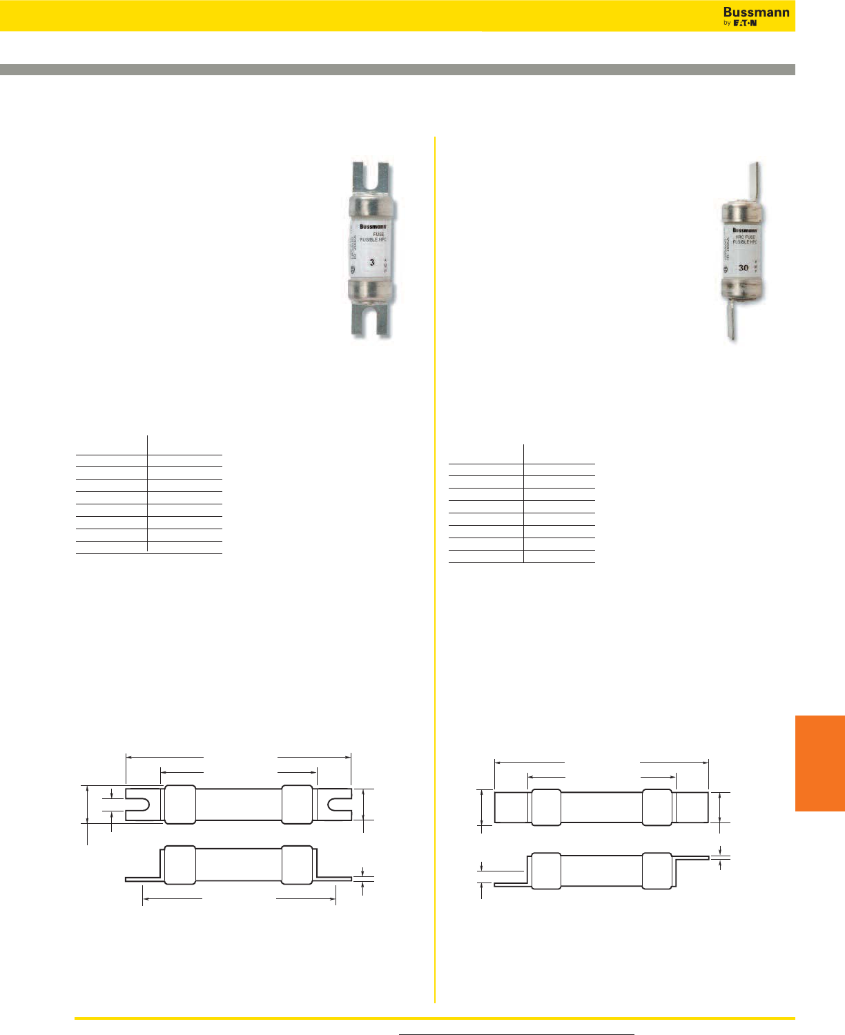
CIF21 HRCI-CA
Specifications
Description: The HRCI-CA fuse provides
both overload and short-circuit protection to
HRCI requirements. Offset blades for bolt-on
mounting. CIF21 fuse fits the Cooper
Bussmann CAMaster fuse holder (see data
sheet 4132).
Dimensions: See Dimensions illustration.
Construction: Ceramic body.
Ratings:
Volts: — 600Vac/250Vdc
Amps: — 1-30A
IR: — 200kA RMS Sym.
Agency Information: CE, CSA C22.2, No. 106-M92.
Mounting: Bolt-on.
Catalog Numbers
Catalog Amp
Numbers Ratings
1CIF21 1
3CIF21 3
6CIF21 6
10CIF21 10
15CIF21 15
20CIF21 20
25CIF21 25
30CIF21 30
CIF06 HRCI-CB
Specifications
Description: A miniature industrial fuse that
provides both short-circuit and overload
protection and the CIF06 fits the 30A
SAFEloc fuse holder.
Dimensions: See Dimensions illustration.
Construction: Ground ceramic body with
plated end caps.
Ratings:
Volts: — 600Vac/250Vdc
Amps: — 1-30A
IR: — 200kA RMS Sym.
Agency Information: CE, CSA C22.2 No. 106-M92 (3-30A
only).
Mounting: Clip-in offset blades.
Catalog Number
Catalog Amp
Numbers Ratings
1CIF06 1
3CIF06 3
6CIF06 6
10CIF06 10
15CIF06 15
20CIF06 20
25CIF06 25
30CIF06 30
For product data sheets, visit www.cooperbussmann.com/DatasheetsEle 249
HRCI Industrial Ceramic Body Fuses
IEC & British
Fuses
Data Sheet: 4128
Data Sheet: 4127
2.15 (54.5)
1.44 (35.5)
1.75 (44.5)
0.19 (4.7)
0.54 (13.8)
0.44 (11.1)
0.03 (0.81)
Features and Benefits
• Close sizing to loads allows using smaller and less costly
switches
• Provides a higher degree of short-circuit protection
• Helps protect motors against burnout from overloads
Typical Applications
• For use in circuits subject to surge currents such as those
caused by motors, transformers and other inductive loads
Dimensions - in (mm)
2.38 (60.4)
1.44 (35.5)
0.54 (13.8)
0.14
(
3.5
)
0.5 (12.7)
0.03 (3.5)
Features and Benefits
• Close sizing to loads allows using smaller and less costly
switches
• Provides a higher degree of short-circuit protection
• Helps protect motors against burnout from overloads
Typical Applications
• For use in circuits subject to surge currents such as those
caused by motors, transformers and other inductive loads
Dimensions - in (mm)
IEC & British Standard Fuses
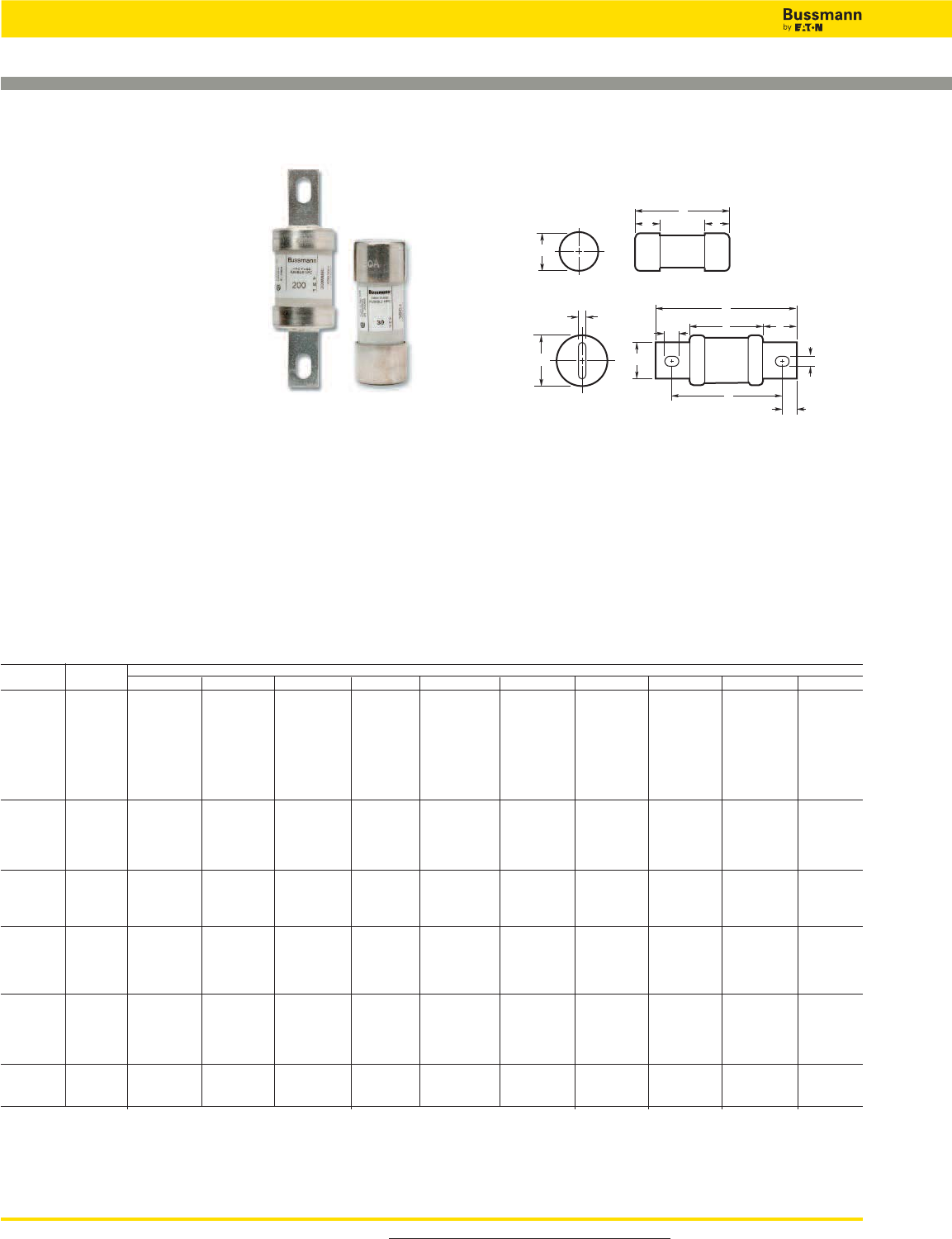
CJ HRCI-J
Specifications
Description: HRCI-J fast-acting
fuses are industrial duty fuses with
the excellent current-limiting
characteristics of fast-acting HRCI-J
fuses to limit damage to equipment
and installations by the thermal and
magnetic energy associated with a
large short-circuit fault current.
Overload characteristics limit cable
damage due to low overload currents.
Dimensions: See Catalog Numbers table and Dimensions
illustrations.
Construction: Ceramic body fuse.
Ratings:
Volts: — 600Vac (or less), 250Vdc
Amps: — 1-600A
IR: — 200kA
Agency Information: CSA C22.2 No. 106 M92; Designed
to BS 88:2, IEC 60269-2.
For product data sheets, visit www.cooperbussmann.com/DatasheetsEle
250
IEC & British Standard Fuses
HRCI-J Fast-acting Fuses
Data Sheet: 4129
Catalog Numbers
Catalog Amp Dimensions - in (mm)
Numbers Ratings A B C D E F G H J K
1CJ 1
3CJ 3
6CJ 6
10CJ 10
15CJ 15 2.25 (57) 0.5 (12.7) 0.81 (20.6) — — — — — — —
20CJ 20
25CJ 25
30CJ 30
35CJ 35
40CJ 40
45CJ 45 2.38 (60) 0.63 (16) 1.06 (27) — — — — — — —
50CJ 50
60CJ 60
70CJ 70
80CJ 80 4.63 (117) 3.63 (92) 1.13 (28) 0.75 (19) 0.13 (3.2) 1 (25.4) 0.5 (12.7) 0.28 (7.1) 0.38 (9.5) 2.63 (67)
90CJ 90
100CJ 100
110CJ 110
125CJ 125
150CJ 150 5.75 (146) 4.38 (111) 1.63 (41) 1.13 (28.6) 0.19 (4.8) 1.38 (35) 0.69 (17.5) 0.28 (7.1) 0.38 (9.5) 3 (76)
175CJ 175
200CJ 200
225CJ 225
250CJ 250
300CJ 300 7.13 (181) 5.25 (133) 2.13 (54) 1.63 (41) 0.25 (6.3) 1.88 (47.6) 0.94 (24) 0.41 (10.3) 0.53 (13.5) 3.38 (86)
350CJ 350
400CJ 400
450CJ 450
500CJ 500 8 (203) 6 (152) 2.63 (66) 2 (51) 0.38 (9.5) 2.13 (54) 1 (25.4) 0.53 (13.5) 0.69 (17.5) 3.75 (96)
600CJ 600
A
JF
K
B
H
DC
E
G
A
B B
C
Dimensions
1CJ to 60CJ
70CJ to 600CJ
Catalog Numbers
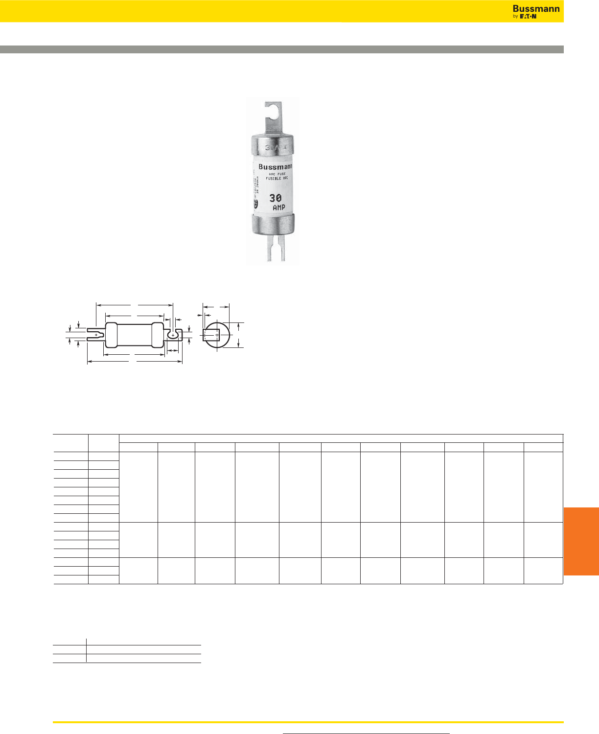
For product data sheets, visit www.cooperbussmann.com/DatasheetsEle 251
HRCI - Miscellaneous Type K Fuses
IEC & British
Fuses
Dimensions
Data Sheet: 4130
CIH, CIK & CIL HRCI-MISC
Specifications
Description: HRI fuses provide both overload
and short-circuit protection, featuring offset
blades for bolt down mounting.
Dimensions: See Catalog Numbers table and
Dimensions illustration.
Construction: Ceramic body.
Ratings:
Volts: — 600V
Amps: — 1-100A
IR: — 200kA@600V
Agency Information: CE, CSA C22.2 No.
106 M92.
E
G
G
H
D
K
F
A
L
C
J
B
(The CIL14 has a rejection hole, not a slot as shown above.)
Fuse Fuse Holder
1-30A CM30CF
35-60A CM60CF
Catalog Numbers
Catalog Amp Dimensions - in (mm)
Numbers Ratings A Max B Max C Max D Nom E Nom F Nom G Nom H Nom J Max K Nom L Max
1CIH07 1 2.25 (57) 0.94 (24) 3.38 (86) 0.38 (9.2) 0.04 (1.0) 2.88 (73) 0.21 (5.2) 0.31 (8) 1 (25.4) 0.10 (2.6) 2.38 (60)
3CIH07 3
6CIH07 6
10CIH07 10
15CIH07 15
20CIH07 20
25CIH07 25
30CIH07 30
35CIK07 35 2.28 (58) 1.06 (27) 3.56 (91) 0.5 (12.7) 0.05 (1.2) 2.88 (73) 0.21 (5.2) 0.41 (10.5) 1.09 (28) 0.13 (3.2) 2.38 (61)
40CIK07 40
50CIK07 50
60CIK07 60
80CIL14 80 2.75 (70) 1.44 (37) 4.38 (111) 0.75 (19) 0.09 (2.5) 3.69 (94) 0.34 (8.7) 0.41 (10.5) 1.5 (38.5) — 2.91 (74)
90CIL14 90
100CIL14 100
2.25 (57) 0.94 (24) 3.38 (86) 0.38 (9.2) 0.04 (1.0) 2.88 (73) 0.21 (5.2) 0.31 (8) 1 (25.4) 0.10 (2.6) 2.38 (60)
2.38 (61)
2.91 (74)
0.13 (3.2)
—
1.09 (28)
1.5 (38.5)
0.41 (10.5)
0.41 (10.5)
0.21 (5.2)
0.34 (8.7)
2.88 (73)
3.69 (94)
0.05 (1.2)
0.09 (2.5)
0.5 (12.7)
0.75 (19)
3.56 (91)
4.38 (111)
1.06 (27)
1.44 (37)
2.28 (58)
2.75 (70)
Recommended Fuse Holders
IEC & British Standard Fuses
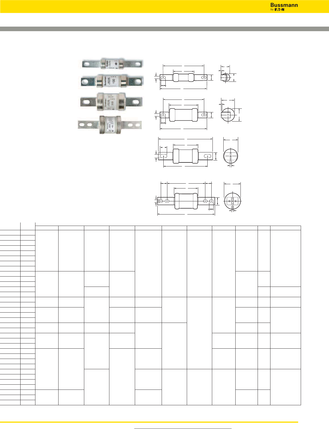
HRC Form II
Specifications
Description: HRC Form II
current-limiting fuses.
Dimensions: See Catalog
Numbers table and Dimensions
illustrations.
Construction: Ceramic body.
Ratings:
Volts: — 600Vac (or less)
— 250Vdc
Amps: — 2-600A
IR: — 200kA RMS Sym.
Agency Information: CE, CSA C22.2 No.106M1992;
BS 88:2, IEC 60269:2.
Typical Applications
• Used to protect motor control circuits, together with
contactors and overload protection relays to provide Type 2
coordination - per IEC 60947-4.
For product data sheets, visit www.cooperbussmann.com/DatasheetsEle
252
IEC & British Standard Fuses
HRC Form II Current-limiting Fuses
Data Sheet: 4131
Catalog Numbers
Catalog Amp Dimensions - in (mm)
Numbers Ratings A B C D E F G H J K CSA Category
2H07C 2 1.38 (35) 0.56 (14) 3.38 (85) 0.38 (9) 0.06 (1.2) 2.88 (73) 0.22 (5.6) 0.31 (8) 0.56 (14) — HRCII-C
4H07C 4
6H07C 6
10H07C 10
15H07C 15
20H07C 20
25H07C 25
30H07C 30
40K07C 40 2.19 (56) 0.88 (22) 3.44 (87) 0.5 (13) 0.06 (1.2) 2.88 (73) 0.22 (5.6) 0.31 (8) 0.88 (22) — HRCII-C
50K07C 50
60K07C 60
80K07CR 80 2.19 (56) 0.88 (22) 3.75 (95) 0.5 (13) 0.06 (1.2) 2.88 (73) 0.22 (5.6) 0.31 (8) 0.88 (22) — HRCII-MISC
100K07CR 100
80L14C 80 2.38 (60) 0.88 (21.4) 4.38 (111) 0.56 (14.3) 0.13 (3.2) 3.69 (94) 0.34 (8.7) 0.44 (11) 1 (25.4) — HRCII-C
100L14C 100
125M14C 125 2.56 (65) 1.5 (38) 4.38 (111) 0.75 (19) 0.09 (2.4) 3.69 (94) 0.34 (8.7) 0.44 (11) — — HRCII-MISC
150M14C 150
200M14C 200
80L09C 80 2.38 (60) 0.88 (21.4) 5 (127) 0.56 (14) 0.13 (3.2) 4.38 (111) 0.34 (8.7) 0.44 (11) — — HRCII-MISC
100L09C 100
125M09C 125 2.56 (65) 1.5 (38) 5.38 (136) 0.75 (19) 0.13 (3.2) 4.38 (111) 0.34 (8.7) 0.56 (14) — — HRCII-C
150M09C 150
200M09C 200
250P09C 250 3.06 (178) 2.31 (59) 5.38 (136) 1 (25.4) 0.19 (4.8) 4.38 (111) 0.34 (8.7) 0.5 (13) — — HRCII-MISC
300P09C 300
350P09C 350
400P09C 400
250P11C 250 3.06 (178) 2.31 (59) 8.25 (210) 1 (25.4) 0.19 (5) 5.25 (133) 0.41 (10) 0.63 (16) — 1 (25) HRCII-C
300P11C 300
350P11C 350
400P11C 400
450R11C 450 3.19 (81) 2.88 (73) 8.25 (210) 1 (25.4) 0.25 (6.3) 5.25 (133) 0.41 (10) 0.63 (16) — 1 (25) HRCII-C
500R11C 500
600R11C 600
E
D
G
F
A
H
C
J
B
E
D
G
F
A
H
C
J
B
D
G
C
A
F
B
E
H
FB
E
G
C
A
K
D
K
H
H07C
(Offset Blades)
K07C/K07CR/
L14C/M14C
(Offset Blades)
L09C/M09C/P09C
(Center Blades)
P11C/R11C
(Center Blades)
Dimensions
1.38 (35) 0.56 (14) 3.38 (85) 0.38 (9)
0.06 (1.2) 2.88 (73) 0.22 (5.6) 0.31 (8)
0.56 (14) —
HRCII-C
HRCII-MISC
HRCII-C
HRCII-C
HRCII-C
HRCII-MISC
HRCII-MISC
—
—
—
—
—
—
—
1 (25)
1 (25)
0.88 (22)
1 (25.4)
—
—
—
—
—
—
0.44 (11)
0.56 (14)
0.5 (13)
0.63 (16)
0.34 (8.7)
0.41 (10)
3.69 (94)
4.38 (111)
5.25 (133)
0.13 (3.2)
0.09 (2.4)
0.13 (3.2)
0.19 (4.8)
0.19 (5)
0.25 (6.3)
0.5 (13)
0.56 (14.3)
0.75 (19)
0.56 (14)
0.75 (19)
1 (25.4)
3.44 (87)
3.75 (95)
4.38 (111)
5 (127)
5.38 (136)
8.25 (210)
2.19 (56) 0.88 (22)
2.38 (60) 0.88 (21.4)
1.5 (38)
1.5 (38)
2.31 (59)
2.88 (73)
2.38 (60) 0.88 (21.4)
2.56 (65)
2.56 (65)
3.19 (81)
3.06 (178)
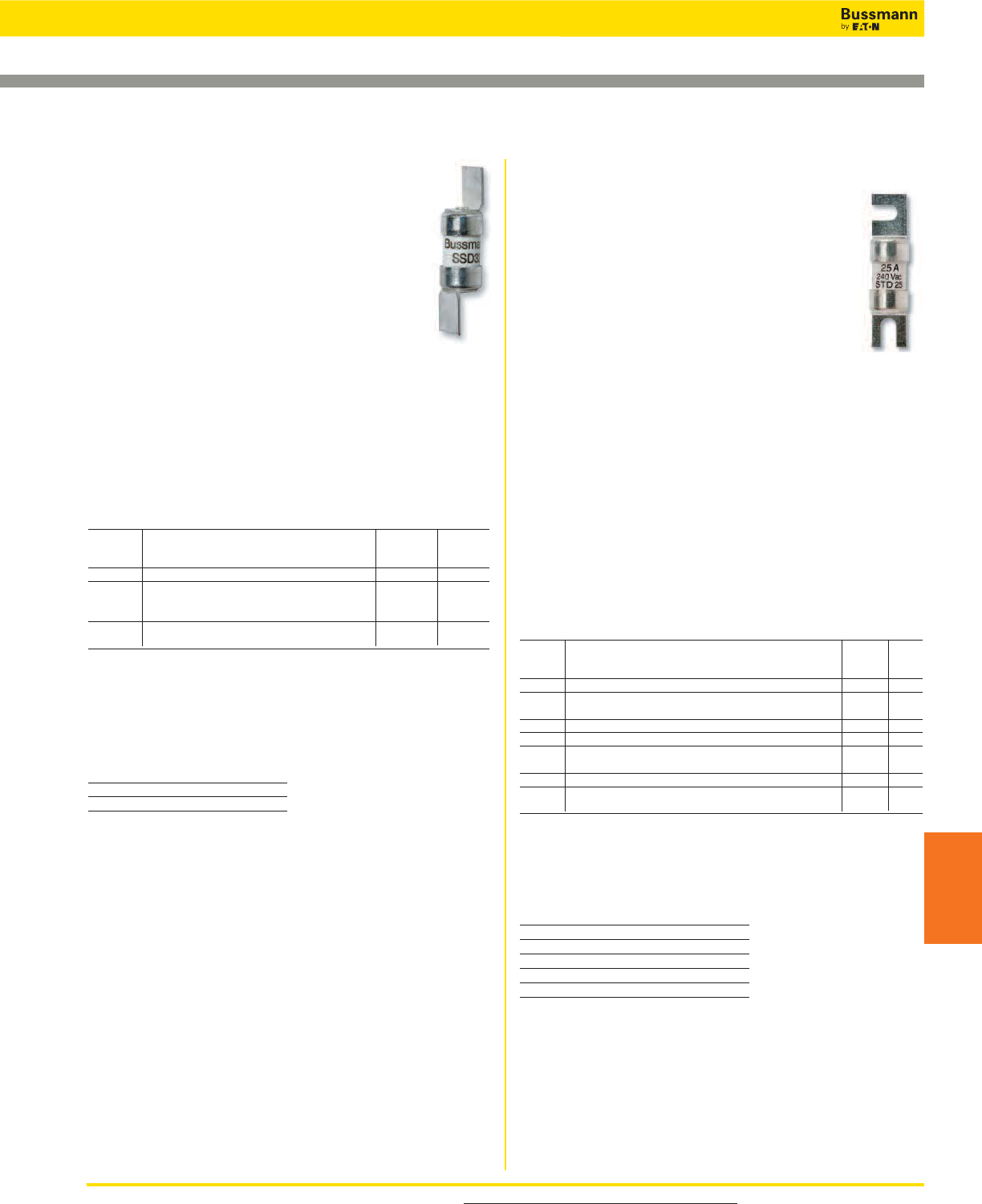
SSD, NSD, ESD BS 88 Part 1
Specifications
Description: The NSD and ESD are low voltage
fuses complying with general purpose gG
characteristics.
Construction: Ceramic body.
Ratings:
Volts: — 240-550Vac (See Catalog Numbers table)
Amps: — 2-63A (See Catalog Numbers table)
— 20M25-63M100A Motor Starter ratings
(See Catalog Numbers table)
IR: — 33kA (SSD)
— 80kA (NSD, ESD)
Agency Information: CE, Meets the requirements of
BS 88 Part 1 and IEC 60269-1.
Mounting: Offset blades.
Basic Catalog Numbers
Basic Max AC
Catalog Amp Voltage BS 88
Numbers Ratings Ratings Ref.
SSD 2, 4, 6, 10, 16, 20, 25, 32 240 E1
NSD 2, 4, 6, 10, 16, 20, 25, 32, 550 F1
20M25*, 20M32*, 20M36*, 32M36*, 32M40*, 415 F1
32M50*, 32M63* 415 F1
ESD 2, 4, 6, 10, 16, 25, 32 550 F2
40, 50, 63, 63M80, 63M100* 415 F2
*“M” indicates motor starter ratings.
To Order
To order, specify Basic Catalog Number and amp rating. Example: SSD-20
Recommended Fuse Holders
Basic Fuse Holder Catalog
Catalog Numbers Numbers
NSD 32NNSF
ESD 63ENSF
For product data sheets, visit www.cooperbussmann.com/DatasheetsEle 253
BS 88 British Standard Low Voltage Fuses
IEC & British
Fuses
STD, NITD, AAO, BAO, OSD, CEO, DEO
BS 88 Part 1
Specifications
Description: The STD to DEO types are low
voltage fuses complying with general purpose gG
characteristics.
Construction: Ceramic body.
Ratings:
Volts: — 240-550Vac (See Catalog Numbers
table)
Amps: — 2-200A (See Catalog Numbers table)
— 20M25-200M315A Motor Starter ratings
(See Catalog Numbers table)
IR: — 33kA (STD)
— 80kA (NITD, AAO, BAO, CEO, DEO)
Agency Information: CE, Meets the requirements of
BS 88 Part 1 and IEC 60269-1.
Mounting: Offset bolted blades.
Typical Applications
• The STD type are used in 240V street lighting cut-outs
• NITD to DEO types used for industrial and general purpose
applications
Basic Catalog Numbers
Basic Max AC
Catalog Amp Voltage BS 88
Numbers Ratings Ratings Ref.
STD 2, 4, 6, 10, 16, 20, 25, 32 240 —
NITD 2, 4, 6, 10, 16, 20, 25, 32 550 —
20M25*, 20M32*, 32M40*, 32M50*, 32M63* 415 —
AAO 2, 4, 6, 10, 16, 20, 25, 32, 32M40*, 32M50*, 32M63* 550 —
BAO 40, 50, 63, 63M80*, 63M100* 550 A3
CEO 32, 40, 50, 63, 80, 100 550 A4
100M125*, 100M160*, 100M200* 415 A4
DEO 125, 160, 200, 200M250*, 200M315* 415 —
OSD 80, 100 550 —
100M125*, 100M160* 415 —
*“M” indicates motor starter ratings.
To Order
To order, specify Basic Catalog Number and amp rating. Example: BAO-16
Recommended Fuse Blocks & Holders
Basic Fuse Block/Holder
Catalog Numbers Catalog Numbers
NITD CM32FC
AAO CM32F
BAO CM63F
OSD CM100F
CEO BH-0111
Data Sheets 4105 (SSD), 4100 (NSD) and 4101 (ESD)
Data Sheets 4123 (STD), 4106 (NITD), 4109 (AAO), 4112
(BAO), 4107 (OSD), 4115 (CEO) and 4117 (DEO)
IEC & British Standard Fuses
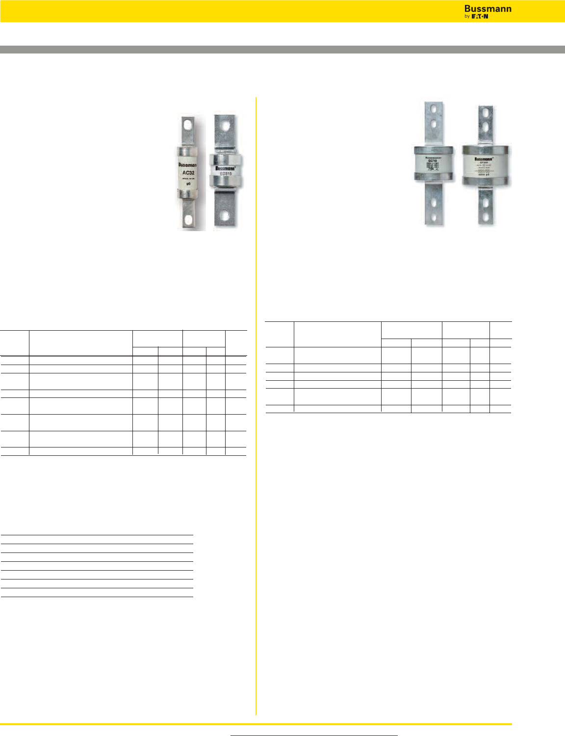
EF, FF, FG, GF, GG, GH
BS 88
Specifications
Description: Low voltage fuses
complying with general purpose gG
characteristics and available up to
400A with two hole mount and up
to 1250A with four hole mount.
Construction: Ceramic body.
Ratings:
Volts: — 415/550Vac, 250/400Vdc
(See Catalog Numbers table for details)
Amps: — 355-1250
IR: — See Catalog Numbers table
Agency Information: CE, Meets the requirements of
BS 88 Parts 1 and 2 and IEC269-1.
Mounting: Center bolted blades, four-hole mount.
Basic Interrupting Max Voltage
Catalog Amp Ratings Ratings BS 88
Numbers Ratings AC DC AC DC Ref.
EF 355, 400 80kA — 415 — C1
400M500* 80kA — 550 — —
FF 450, 500, 560, 630 80kA 40kA 550 400 C2
FG 450, 500, 560, 630 80kA 40kA 550 400 —
GF 710, 800 80kA 40kA 550 250 C3
GG 710, 800 80kA 40kA 550 250 —
1000, 1250 80kA — 550 — —
GH 710, 800, 1000, 1250 80kA — 550 — —
*“M” indicates motor starter ratings.*“M” indicates motor starter ratings.
To Order
To order, specify Basic Catalog Number and amp rating. Example: FG-450
AC, AD, BC, BD, CD, DD, ED, EFS BS 88
Specifications
Description: Low voltage fuses that
comply with general purpose gG
characteristics and available up to 400A
with two hole mount and up to 1250A
with four hole mount.
Construction: Ceramic body.
Ratings:
Volts: — 415/550Vac, 250Vdc (See
Catalog Numbers table)
Amps: — 2-400A (See Catalog Numbers table)
— 63M80-400M500A Motor Starter ratings (See
Catalog Numbers table)
IR: — See Catalog Numbers table
Agency Information: CE, Meets the requirements of
BS 88 Parts 1 and 2 and IEC 60269-1.
Mounting: Center bolted blades, two-hole mount.
Basic Catalog Numbers
Basic Interrupting Max Voltage
Catalog Amp Ratings Ratings BS 88
Numbers Ratings AC DC AC DC Ref.
AC 2, 4, 6, 10, 16, 20, 25, 32 80kA 40kA 550 250 —
AD 2, 4, 6, 10, 16, 20, 25, 32 80kA 40kA 550 250 —
BC 40, 50, 63 80kA 40kA 550 250 —
63M80*, 63M100* 80kA — 550 — —
BD 40, 50, 63 80kA 40kA 550 250 —
CD 80, 100, 100M125*, 100M160*, 80kA — 415 — B1
100M200*, 100M200*
DD 125, 160, 200, 80kA — 415 — B2
200M250*, 200M315*
ED 250, 315, 355, 400, 315M400* 80kA — 415 — B3
400M500* 80kA — 550 — B4
EFS 125, 160, 200, 250, 315 80kA 415 — —
*“M” indicates motor starter ratings.
To Order
To order, specify Basic Catalog Number and amp rating. Example: BC-40
Recommended Fuse Blocks & Holder
Basic Fuse Block/Holder
Catalog Numbers Catalog Numbers
AC BH-0111 Modular fuse block
AD 200DF Fuse holder
BC BH-0111 Modular fuse block
BD 200DF-L
CD 200DF-L
DD 200DF-L
ED BH-1131 Modular fuse block
For product data sheets, visit www.cooperbussmann.com/DatasheetsEle
254
IEC & British Standard Fuses
BS 88 British Standard Low Voltage Fuses
Data Sheets 4110 (AC), 4111 (AD), 4113 (BC), 4114 (BD),
4116 (CD), 4118 (DD), 4119 (ED) and 4121 (EFS)
Data Sheets 4120 (EF), 4102 (FF), 4122 (FG), 4103 (GF), 4104
(GG) and 4108 (GH)
Basic Catalog Numbers
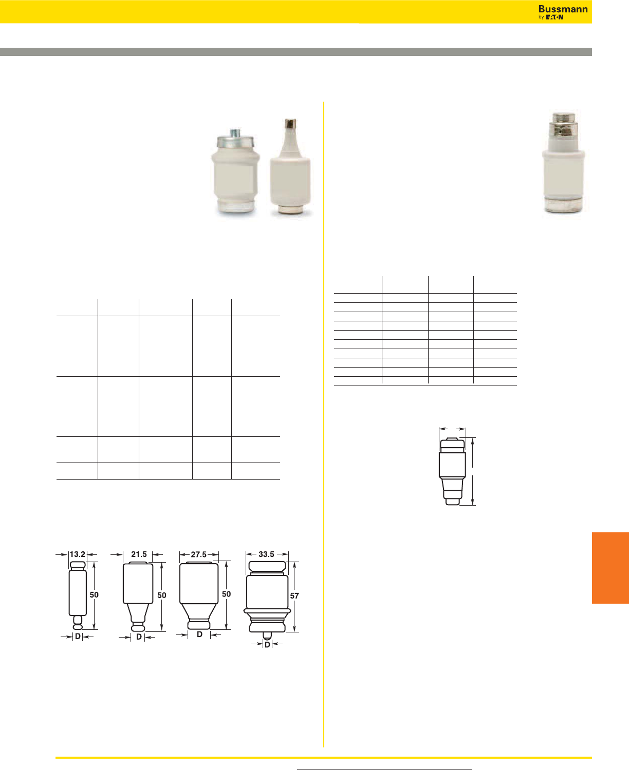
NZ01, NZ02 Type D0
Specifications
Description: Low voltage Neozed fuses
suitable for use on 250Vdc systems.
Dimensions: See Catalog Numbers table and
Dimensions illustration.
Construction: Ceramic body.
Ratings:
Volts: — 400Vac
Amps: — 2-63A
IR: — 100kA
Agency Information: CE
Catalog Numbers
Catalog Amp Dimension Color
Numbers Ratings “D” (mm) Code
2NZ01 2 11 Pink
4NZ01 4 11 Brown
6NZ01 6 11 Green
10NZ01 10 11 Red
16NZ01 16 11 Grey
20NZ02 20 15 Blue
25NZ02 25 15 Yellow
35NZ02 35 15 Black
50NZ02 50 15 White
63NZ02 63 15 Copper
Dimensions - mm
D16, D27, D33, D125 Type D
Specifications
Description: DIN style Type D
low voltage fuses.
Dimensions: See Catalog
Numbers table and Dimensions
illustrations.
Construction: Ceramic body.
Ratings:
Volts: — 500Vac
Amps: — 2-100A
IR: — 100kA
Agency Information: CE, “D” type fuses complying with
DIN 49360 Part 2 and DIN 49515, operating class gL.
Catalog Numbers
Catalog Amp Dimension Color Figure
Numbers Ratings “D” (mm) Code Number
2D16 2 6 Pink
4D16 4 6 Brown
6D16 6 6 Green
10D16 10 8 Red 1
16D16 16 10 Grey
20D16 20 12 Blue
25D16 25 14 Yellow
2D27 2 6 Pink
4D27 4 6 Brown
6D27 6 6 Green
10D27 10 8 Red 2
16D27 16 10 Grey
20D27 20 12 Blue
25D27 25 14 Yellow
35D33 35 16 Black
50D33 50 18 White 3
63D33 63 20 Copper
80D125 80 5 Silver 4
100D125 100 7 Red
Additional Fuse links: Quick acting fuselinks in body sized D16, D27, D33 and
D125 rated 2-100A. Reference number suffixed Q, i.e. 10D27Q. Voltage rating 500V.
Gauge rings and keys can also be supplied.
Dimensions - mm
For product data sheets, visit www.cooperbussmann.com/DatasheetsEle 255
DIN Style Type D and Neozed Low Voltage Fuses
IEC & British
Fuses
Data Sheet: 4124
D
36
Data Sheet: 4124
Figure 1 Figure 2 Figure 3 Figure 4
IEC & British Standard Fuses
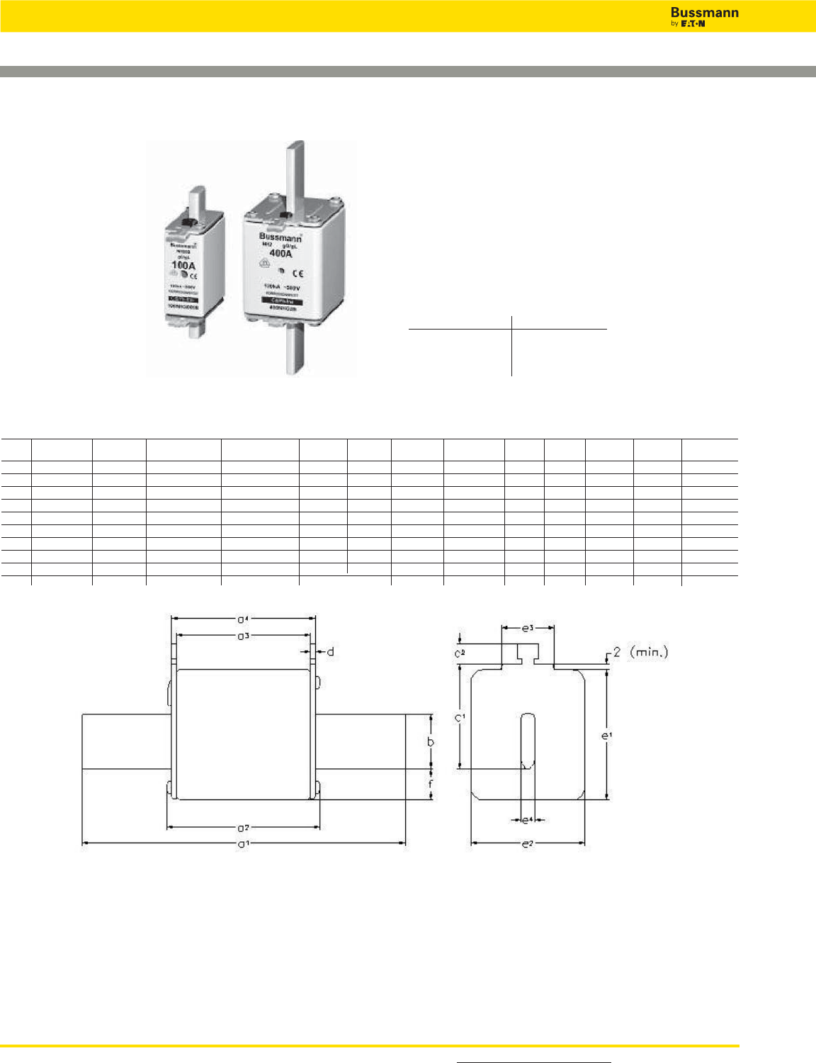
For detailed information, visit the Electrical IEC section at www.cooperbussmann.com
256
IEC & British Standard Fuses
NH HRC Fuses
___NHG___B
Specifications
Class: gG/gL
Description: DIN
square bodied, dual
indication industrial
fuses.
Construction: Steatite
insulator, corrosion-
proof (aluminum) metal
parts with full-contact,
silver-plated copper
blades.
Sizes: DIN 000 to 4.
Selectivity Ratio: 1:1.6 up to 500Vac.
Dimensions - mm
Fuse a2bc
1c2De
1e2e3e4f
Size a1(max) a3a4(nom) (± 8) (nom) (nom) (max) (max) (max) (nom) (max)
000 78.5 ± 1.5 54 45 ± 1.5 49 ± 1.5 15 35 10 2 ± 0.5 41 21 16 6 8
00 78.5 ± 1.5 54 45 ± 1.5 49 ± 1.5 15 35 11 7.0 ± 0.5 48 30 25 6 15
0 125 ± 2.5 68 62 +3/-1.5 68 +1.5/-3 15 35 11 2.5 ± 0.5 48 30 25 6 15
01 135 ± 2.5 75 62 ± 2.5 68 ± 2.5 15 40 11 2.5 ± 0.5 48 30 25 6 15
1 135 ± 2.5 75 62 ± 2.5 68 ± 2.5 20 40 11 2.5 ± 0.5 53 52 25 6 15
02 150 ± 2.5 75 62 ± 2.5 68 ± 2.5 20 48 11 2.5 ± 0.5 53 52 25 6 15
2 150 ± 2.5 75 62 ± 2.5 68 ± 2.5 25 48 11 2.5 ± 0.5 61 60 25 6 15
03 150 ± 3 75 62 ± 2.5 68 ± 2.5 25 60 11 2.5 ± 0.5 61 60 25 6 15
3 150 ± 3 75 62 ± 2.5 68 ± 2.5 32 60 11 3.0 ± 0.5 75 70 25 6 18
4 200 84 80 90 50 85 11 3 120 87 — 8 30
Ratings:
Volts: — 500Vac/250Vdc
— 690Vac/250Vdc
Amps: — 2-1250A
IR: — 120kA
Frequency: — 50Hz
Operating Frequency: — 45-62Hz
Agency Information: IEC 60269, VDE0636, DIN 43620
Part 1 to 4, VDE Mark and CE.
Data Sheet 4173
Fuse Blocks Size
SB00-D 000-00
SB1-D 1*, 1
SB2-D 02, 2, 03, 3
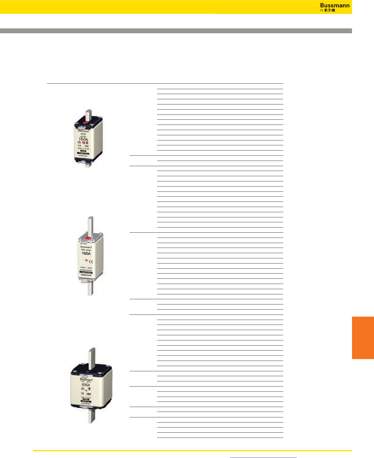
For detailed information, visit the Electrical IEC section at www.cooperbussmann.com 257
NH HRC Fuses
IEC & British
Fuses
Rated gG/gL Dual Indicator
Current Voltage Conducting Carton
500Vac / 250Vdc Size (Amps) Metal Gripping Lugs Quantity
2 2NHG000B 3
4 4NHG000B 3
6 6NHG000B 3
10 10NHG000B 3
16 16NHG000B 3
20 20NHG000B 3
25 25NHG000B 3
000 32 32NHG000B 3
35 35NHG000B 3
40 40NHG000B 3
50 50NHG000B 3
63 63NHG000B 3
80 80NHG000B 3
100 100NHG000B 3
00 125 125NHG00B 3
160 160NHG00B 3
10 10NHG0B 3
16 16NHG0B 3
20 20NHG0B 3
25 25NHG0B 3
32 32NHG0B 3
35 35NHG0B 3
0 40 40NHG0B 3
50 50NHG0B 3
63 63NHG0B 3
80 80NHG0B 3
100 100NHG0B 3
125 125NHG0B 3
160 160NHG0B 3
10 10NHG01B 3
16 16NHG01B 3
20 20NHG01B 3
25 25NHG01B 3
32 32NHG01B 3
35 35NHG01B 3
01 40 40NHG01B 3
50 50NHG01B 3
63 63NHG01B 3
80 80NHG01B 3
100 100NHG01B 3
125 125NHG01B 3
160 160NHG01B 3
200 200NHG1B 3
1 224 224NHG1B 3
250 250NHG1B 3
35 35NHG02B 3
40 40NHG02B 3
50 50NHG02B 3
63 63NHG02B 3
80 80NHG02B 3
02 100 100NHG02B 3
125 125NHG02B 3
160 160NHG02B 3
200 200NHG02B 3
224 224NHG02B 3
250 250NHG02B 3
315 315NHG2B 3
2 355 355NHG2B 3
400 400NHG2B 3
250 250NHG03B 3
315 315NHG03B 3
03 355 355NHG03B 3
400 400NHG03B 3
3 500 500NHG3B 3
630 630NHG3B 3
500 500NHG4G 1
4 630 630NHG4G 1
Single Indicator 800 800NHG4G 1
Slotted End 1000 1000NHG4G 1
Tags 1250 1250NHG4G 1
IEC & British Standard Fuses
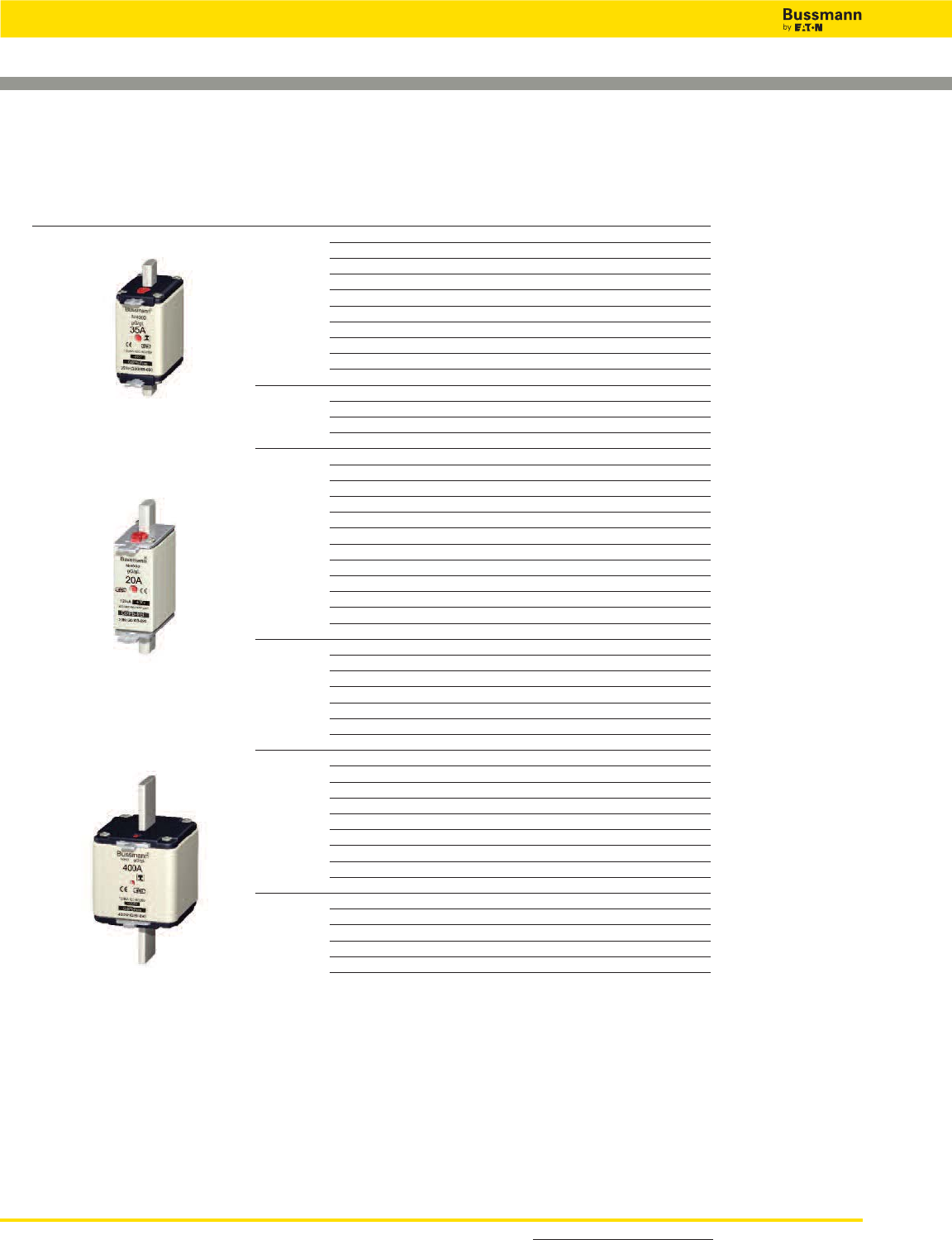
For detailed information, visit the Electrical IEC section at www.cooperbussmann.com
258
IEC & British Standard Fuses
NH HRC Fuses
Rated gG/gL Dual Indicator
Current Voltage Conducting Carton
690Vac / 250Vdc Size (Amps) Metal Gripping Lugs Quantity
2 2NHG000B-690 3
4 4NHG000B-690 3
6 6NHG000B-690 3
10 10NHG000B-690 3
000 16 16NHG000B-690 3
20 20NHG000B-690 3
25 25NHG000B-690 3
32 32NHG000B-690 3
35 35NHG000B-690 3
40 40NHG000B-690 3
50 50NHG00B-690 3
00 63 63NHG00B-690 3
80 80NHG00B-690 3
100 100NHG00B-690 3
6 6NHG0B-690 3
10 10NHG0B-690 3
16 16NHG0B-690 3
20 20NHG0B-690 3
25 25NHG0B-690 3
0 32 32NHG0B-690 3
35 35NHG0B-690 3
40 40NHG0B-690 3
50 50NHG0B-690 3
63 63NHG0B-690 3
80 80NHG0B-690 3
100 100NHG0B-690 3
50 50NHG1B-690 3
63 63NHG1B-690 3
80 80NHG1B-690 3
1 100 100NHG1B-690 3
125 125NHG1B-690 3
160 160NHG1B-690 3
200 200NHG1B-690 3
63 63NHG2B-690 3
80 80NHG2B-690 3
100 100NHG2B-690 3
125 125NHG2B-690 3
2 160 160NHG2B-690 3
200 200NHG2B-690 3
224 224NHG2B-690 3
250 250NHG2B-690 3
315 315NHG2B-690 3
250 250NHG3B-690 3
315 315NHG3B-690 3
3 355 355NHG3B-690 3
400 400NHG3B-690 3
425 425NHG3B-690 3
500 500NHG3B-690 3
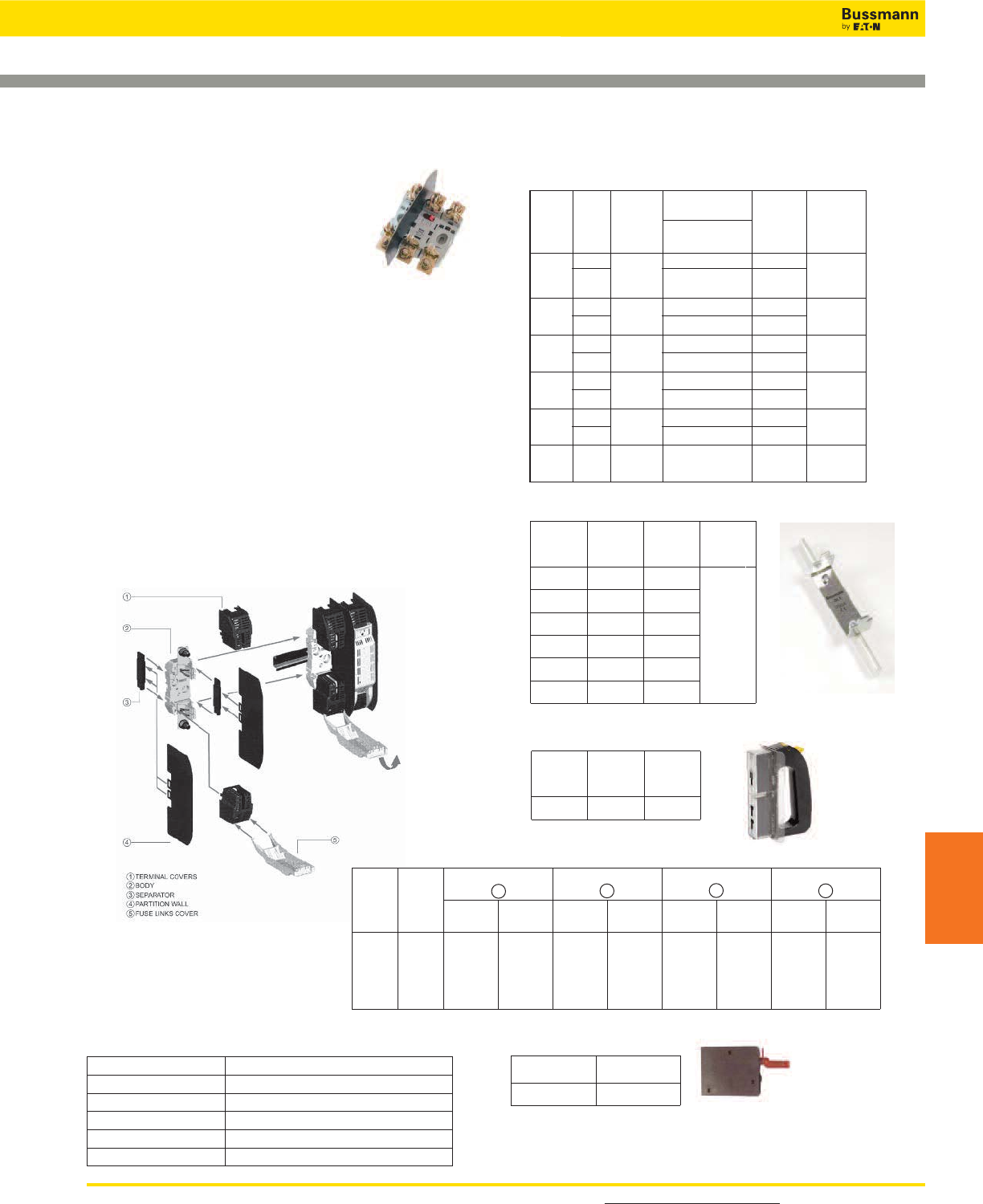
For detailed information, visit the Electrical IEC section at www.cooperbussmann.com 259
IEC & British
Fuses
NH Fuse Bases
SB*-D, SB*-S
Up to 690V / 160 - 1250A
Sizes 00, 0, 1, 2, 3, 4
Description: NH fuse bases with thermoplastic
bodies. DIN-Rail and screw mounting (siz e 4 screw
fix). Range of protection accesories for live parts in
order to obtain IP20 protection standard.
Ratings:
•Volts: up to 690Vac
•Amps: 2 to 1250A
Applications: Protection of industrial circuits and
electrical apparatus
Standards and Approvals: IEC 60269, DIN 43620
Part Numbers
Size Poles Current
(Amps)
Part Numbers Carton
Quantity
Compatible
Fuse Size
DIN Screw
00
1
3160A
SB00-D
TB00-D
TB00-D-IP20
3
1000 & 00
01
3160A SB0-D
TB0-D
3
10
11
3250A SB1-D
TB1-D
3
101 & 1
21
3400A SB2-D
TB2-D
3
102 & 2
31
3630A SB3-D
TB3-D
3
103 & 3
4 1 1250A SB4-S (Screw
Connection only) 3 4
Neutral
Size Current
(Amps) Part Ref Carton
Quantity
NH00 160 SL00
3
NH0 160 SL0
NH1 250 SL1
NH2 400 SL2
NH3 630 SL3
NH4 1000 SL4
Size Part Ref Carton
Quantity
C00-3 FEH 1
Fuse extraction handle
Protection accessories
Size Current
(Amps)
Separation Partition
4
Fuse Casing
5
Terminal Cover
1
Separator
3
Part
Ref
Carton
Quantity
Part
Ref
Carton
Quantity
Part
Ref
Carton
Quantity
Part
Ref
Carton
Quantity
NH00*
NH0
NH1
NH2
NH3
160A
160A
250A
400A
630A
SP00*
SP0
SP1-2
SP1-2
SP3
2
2
2
2
2
FC00*
FC0
FC1-2
FC1-2
FC3
3
3
3
3
3
CS00*
CS0
CS1
CS2
CS3
6
6
6
6
6
BC00*
BC0
BC1-2
BC1-2
BC3
2
2
2
2
2
IP Protection Kits
Part Reference Description
TB00-D-IP20 Complete triple pole fuse base IP20 rated
FPK0-3P IP20 kit for TB0-D fuse base
FPK1-3P IP20 kit for TB1-D fuse base
FPK2-3P IP20 kit for TB2-D fuse base
FPK3-3P IP20 kit for TB3-D fuse base
Part Ref Carton Quantity
BVL-50 1
Microswitch
Microswitch suitable for the following NH Fuse links:
- 400 Volts gG/gL
- 500 Volts gG/gL and aM
- 690 Volts gG/gL and aM
* For single pole only
IEC & British Standard Fuses
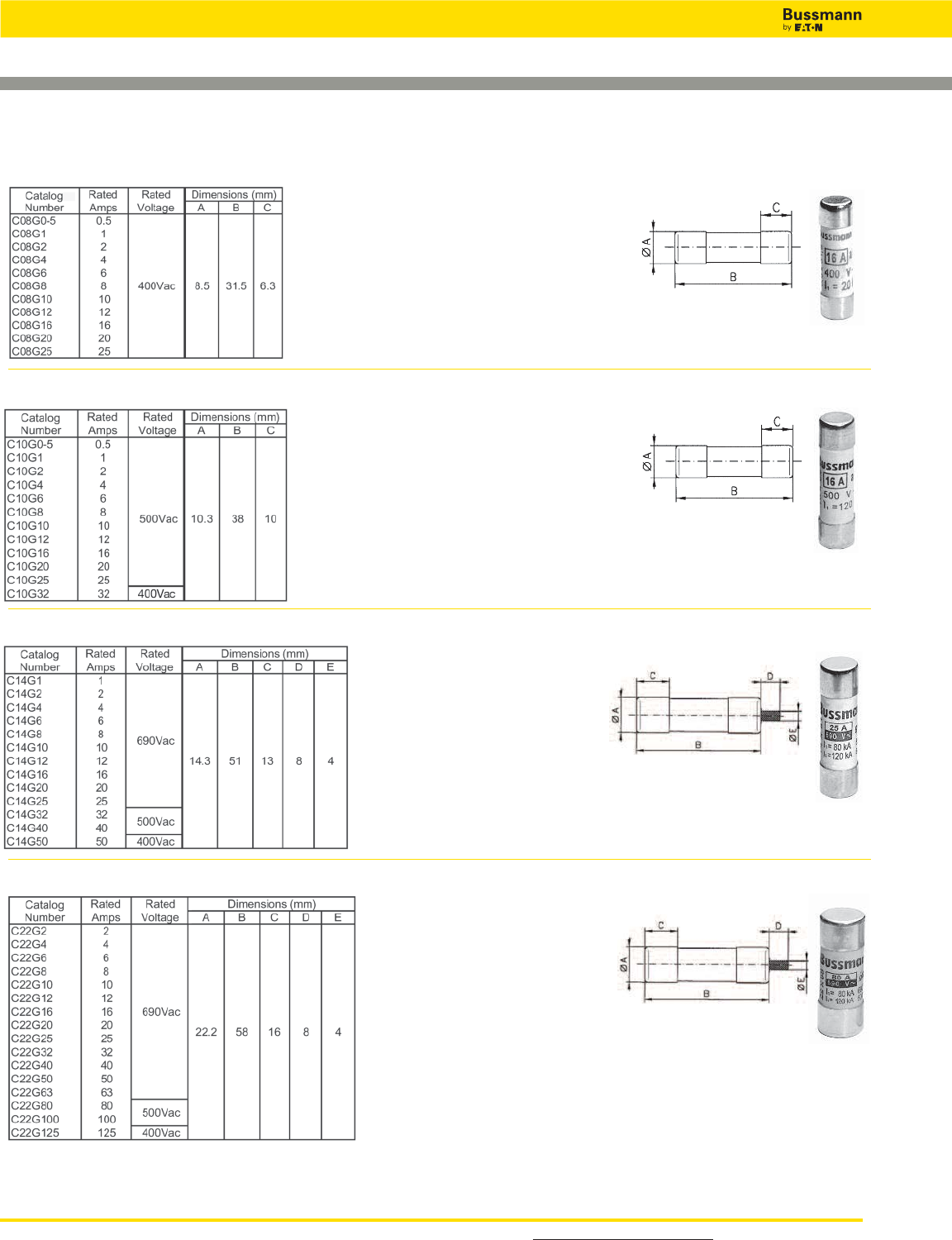
For detailed information, visit the Electrical IEC section at www.cooperbussmann.com
260
IEC & British Standard Fuses
Class gG/gL IEC 60269 Industrial Ferrule Fuses
8 x 31mm: 400Vac, 0.5 - 25A
10 x 38mm: 500Vac, 0.5 - 32A
14 x 51mm: 400Vac - 500Vac - 690Vac, 1 - 50A
22 x 58mm: 400Vac - 500Vac - 690Vac, 2 - 125A
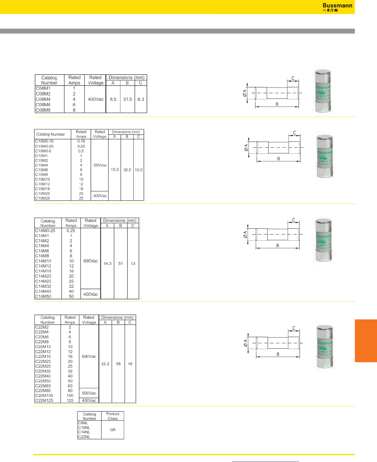
For detailed information, visit the Electrical IEC section at www.cooperbussmann.com 261
IEC & British
Fuses
Class aM IEC Industrial Ferrule Fuses - Class aM IEC
60269
8 x 31mm: 400Vac, 1 - 8A
10 x 38mm: 400Vac - 550Vac, 0.16 - 25A
14 x 51mm: 690Vac - 500Vac, 0.25 - 50A
22 x 58mm: 400Vac - 500Vac - 690Vac, 2 - 125A
Neutral Links
IEC & British Standard Fuses
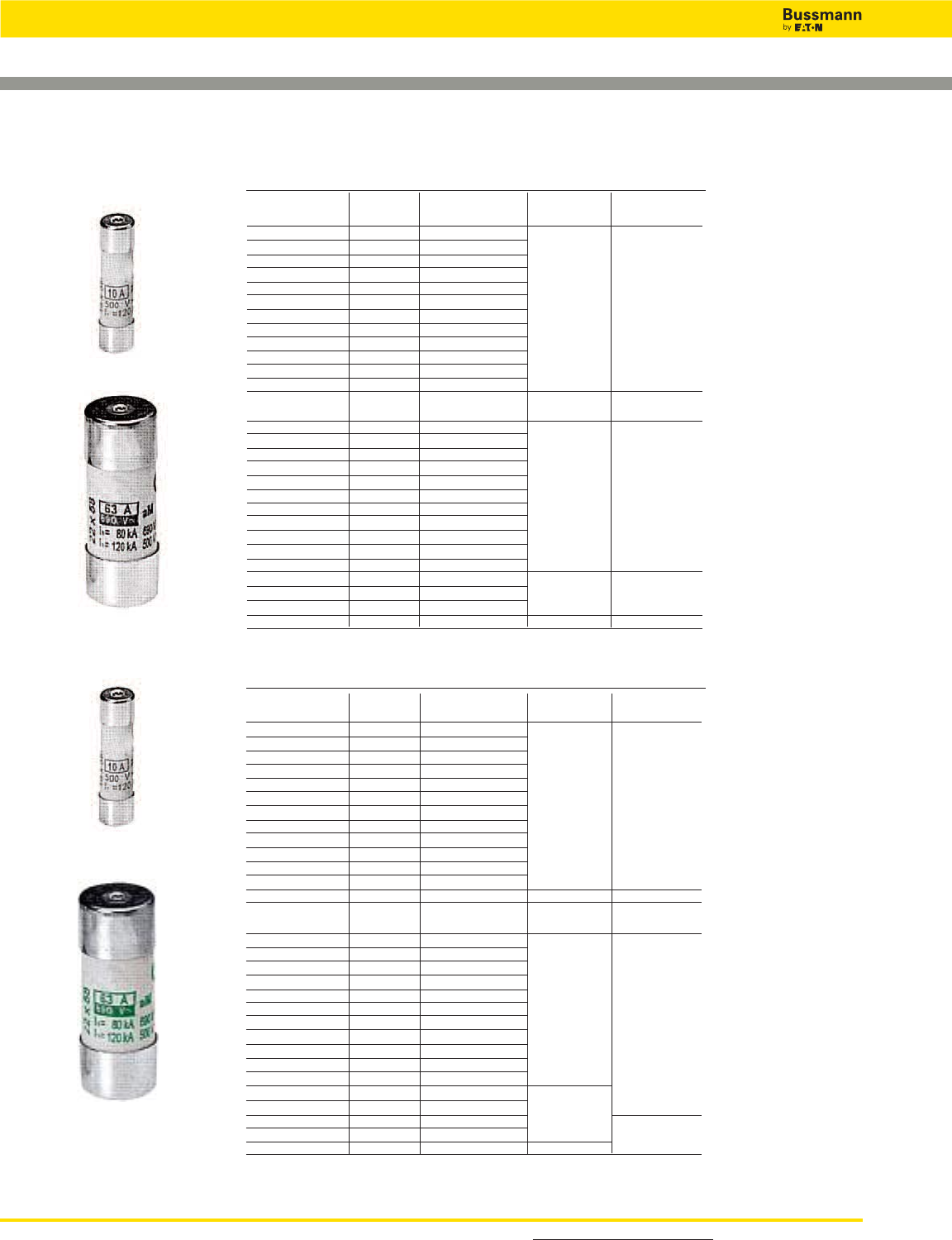
For detailed information, visit the Electrical IEC section at www.cooperbussmann.com
262
IEC & British Standard Fuses
Class aM & gG/gL IEC Industrial Ferrule Fuses with
Striker
Class gG/gL with Striker
Catalog Number Amp Watts Loss Voltage Interrupting
With Striker Rating (W) (AC) Rating (kA)
C14G2S 2 0.24 500 120
C14G4S 4 0.45
C14G6S 6 0.42
C14G8S 8 0.70
C14G10S 10 0.53
C14G12S 12 0.88
C14G16S 16 1.16
C14G20S 20 1.23
C14G25S 25 1.46
C14G32S 32 2.04
C14G40S 40 3.34
C14G50S 50 3.04 400
Catalog Number Amp Watts Loss Voltage Interrupting
With Striker Rating (W) (AC) Rating (kA)
C22G4S 4 0.48 690 80
C22G6S 6 0.47
C22G8S 8 0.73
C22G10S 10 0.74
C22G12S 12 0.83
C22G16S 16 1.21
C22G20S 20 1.29
C22G25S 25 1.53
C22G32S 32 2.13
C22G40S 40 3.40
C22G50S 50 3.48
C22G63S 63 4.46
C22G80S 80 5.86 500 120
C22G100S 100 6.61
C22G125S 125 8.42 400
Class aM with Striker
Catalog Number Amp Watts Loss Voltage Interrupting
With Striker Rating (W) (AC) Rating (kA)
C14M1S 1 0.14 500 120
C14M2S 2 0.24
C14M4S 4 0.45
C14M6S 6 0.42
C14M8S 8 0.70
C14M10S 10 0.53
C14M12S 12 0.88
C14M16S 16 1.16
C14M20S 20 1.23
C14M25S 25 1.46
C14M32S 32 2.04
C14M40S 40 3.34
C14M50S 50 3.04 400
Catalog Number Amp Watts Loss Voltage Interrupting
With Striker Rating (W) (AC) Rating (kA)
C22M2S 2 0.29 690 80
C22M4S 4 0.48
C22M6S 6 0.47
C22M8S 8 0.73
C22M10S 10 0.74
C22M12S 12 0.83
C22M16S 16 1.21
C22M20S 20 1.29
C22M25S 25 1.53
C22M32S 32 2.13
C22M40S 40 3.40
C22M50S 50 3.48
C22M63S 63 4.46
C22M80S 80 5.86 500 120
C22M100S 100 6.61
C22M125S 125 8.42 400
14 X 51
22 X 58
14 X 51
22 X 58
500 120
80
120
690
500
500 120
80
120
690
500
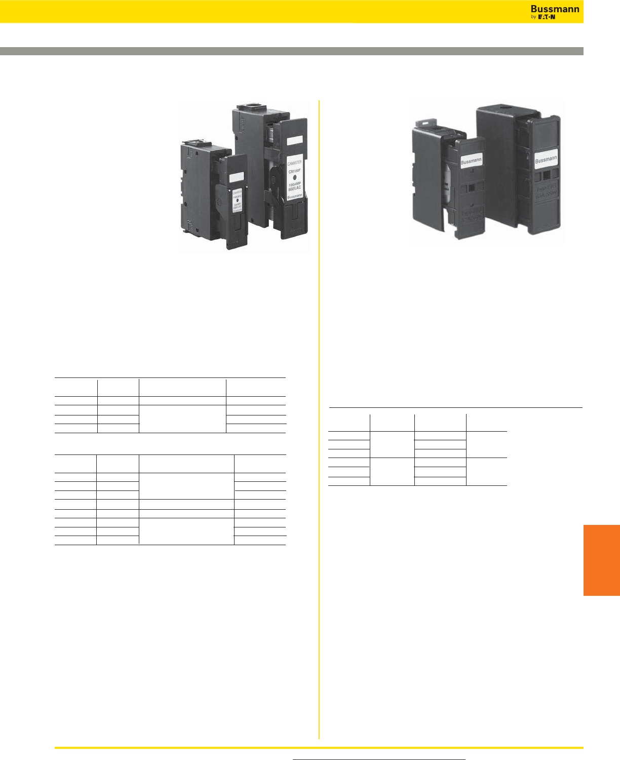
SAFEloc
Specifications
Catalog
Symbol:
See table below.
Description: The
SAFEloc HRC
fuse holders (for
use with HRCI-CB
fuses) provides a
positive, stress-
free fuse fitting
and locks it in position to ensure safe insertion and
withdrawal from the base. Base contacts are fully shrouded
to help protect against electric shock. Shrouds utilize
simple slide/snap action allowing access to the contact
terminal screws.
Ratings:
Volts: — 600V
Amps: — 30-60A (See Catalog Number table for details)
Agency Information: CE, Designed to accommodate the
compact range of offset blade fuse to CSA C22.2 No. 106,
HRCI-CB.
Mounting: 35mm DIN-Rail or single screw mounting.
Catalog Numbers*
Catalog Amp Fuse
Numbers Ratings Connection Accepted
C30F Front
C30BS 30 Back _CIF06
C30FBS Front-Back
C60F Front
C60BS 60 Back EK-Amp
C60FBS Front-Back
*For use with HRCI-CB Fuses.
For product data sheets, visit www.cooperbussmann.com/DatasheetsEle 263
CAMaster
Specifications
Catalog Symbol:
See table below.
Description: The
CAMaster HRC fuse holder
features a unique
cam-action for easy fuse
removal while allowing
significantly improved
contact pressure between
fuse carrier and base
contact that enhances
electrical performance. A range of lockable safety carriers for
the fuse holder (catalog reference: LSC), are available.
Ratings:
Volts: — 690V
Amps: — 30-100A (See Catalog Number table for details)
Agency Information: CE, CSA C22.2 No. 39; IEC 269
AND BS 88.
Mounting: 35mm DIN-Rail or single screw mounting.
Catalog Numbers
Catalog Amp Fuse
Numbers Ratings Details For: Accepted
CM20CF 30 HRCI-CA Applications _CIF21
CM30CF 30 _H07C
CM60CF 60 HRCII Applications _K07C
CM100CF 100 _K07CR
Accessory Catalog Numbers for CAMaster Units
Catalog Amp Fuse Holder
Numbers Ratings Details Accepted
20BS 30 CM20CF
32BS 30 Back Stud CM30CF
60/100BS 60/100 CM60/100CF
GLP All Ganging Link Kit 3-Pole
NI All 660V Neon Indicator —
20LSC 30 CM20CF
30LSC 30 Security Carrier with Clip CM30CF
60/100LSC 60/100A CM60/100CF
HRC Fuse Holders
Data Sheet: 4132 Data Sheet: 4133
IEC & British Standard Fuses
IEC & British
Fuses
264
The new Quik-Spec coordination
panelboard with a footprint up
to 40% smaller than other
fusible panelboards is now
available up to 1200A
Quik-Spec
coordination
panelboards
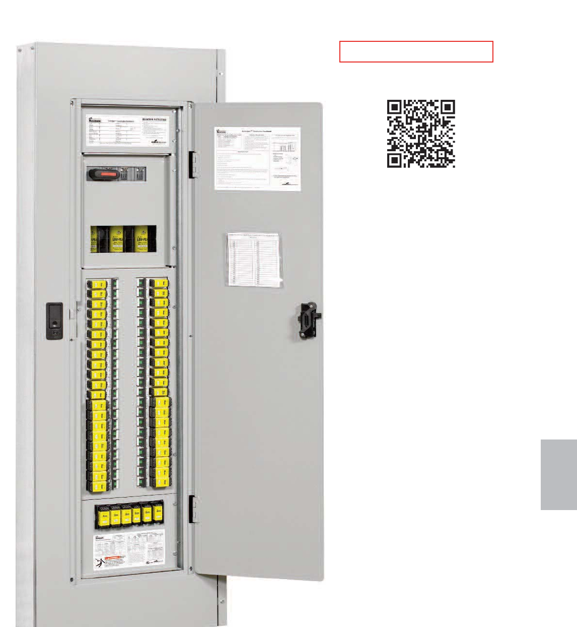
265
Quik-Spec™
Electrical
Gear
Quik-Spec™Electrical Gear
Section Contents
Page
Quik-Spec Coordination Panel Boards . . . . . . . . . 266-267
Quik-Spec Power Module Switches and Panels . . 268-269
Quik-Spec DC Safety Switches . . . . . . . . . . . . . . . . . . 270
Quik-Spec AC Safety Switches . . . . . . . . . . . . . . . . . . 271
A/C Disconnects - Fused and Non-Fused . . . . . . . . . . .272
RED indicates NEW information
Scan this tag to get the
latest product information for
Quik-Spec Coordination Panel Boards.
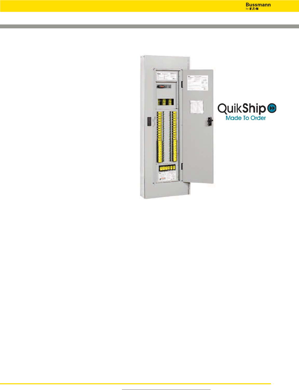
For product data sheets, visit www.cooperbussmann.com/DatasheetsEle
266
Quik-Spec™Electrical Gear
Specifications
Description: Configurable fusible panelboard with 30-400A
mains and branches from 1-100A rated 600Vac.
Ratings:
Volts:— 600Vac (or less), 125Vdc (or less)**
Bus Amps: — 30, 60, 100, 200, 225 or 400A
Options:
Main: — MLO (main lug only)
— Fused disconnect switch
— Non-fused disconnect switch
Enclosure: — NEMA 1 or 3R
— Standard size panelboard (20˝ W x 5˝ D x
various heights)*
— For other ratings consult factory
Panel: — Feed; Top & Bottom***
— Mounting; Surface or Flush****
— Door/Trim; Regular or Door-in-Door****
Branch: — Circuits; Up to 18, 30 and 42*
— Amps; Up to 100A
— Type; 1-, 2- and 3-Pole
Fuse: — Six-fuse spare fuse compartment
— Time-delay or UPS/critical applications
(fast-acting) CUBEFuse™
Assembly
SCCR:— 200kA, 100kA or 50kA AC,100kA or
20kA@125Vdc*
Through-Lugs
& Loadside
Disconnect:— Feed-Through - single and double
— Fused loadside disconnect, ≥100A-≤200A
(400A panels only)
Neutrals:— 200A and 400A Unbonded and Bonded
Ground:— Non-Isolated or Isolated
*Depending on configuration
**125Vdc rating applicable to 40 amp or less CCPBs on MLO
panels only.
***Top feed not available on NEMA 3R enclosure
****Flush mount and Door-in-Door not available with NEMA 3R
enclosure
Agency Information: UL Listed to UL 67, complies with
NFPA 70 (NEC®; National Electric Code),
Features and Benefits:
• UL and CSA listing makes it easy to address NEC®selective
coordination requirements in an all fused system
• Value-engineered for greater flexibility with up to 400A mains,
200kA SCCR, 100A branches with 18, 30 and 42 branch
positions
• Same size footprint as traditional circuit breaker panelboards
and 40% smaller than standard fusible panelboards:
20˝ W x 5 3⁄4˝ D x various heights (depending on
configuration)
• Increase safety with current-limiting finger-safe Low-Peak
CUBEFuse that reduces arc flash hazard levels
• Quik-Quote online configurator makes specifying and
ordering easy – delivers a full bill of material and
submittal drawings for an entire project
• Available for 10 day shipment with QuikShip™ service
Ordering:
The QSCP is factory configured to the specific electrical
system. Contact your Bussmann distributor or representative
to place your order. Have all relevant electrical and circuit
information on hand.
QuikShip – 10 Business Day Shipment
30-400A Quik-Spec™ Coordination Panelboard
Data Sheet: 1159
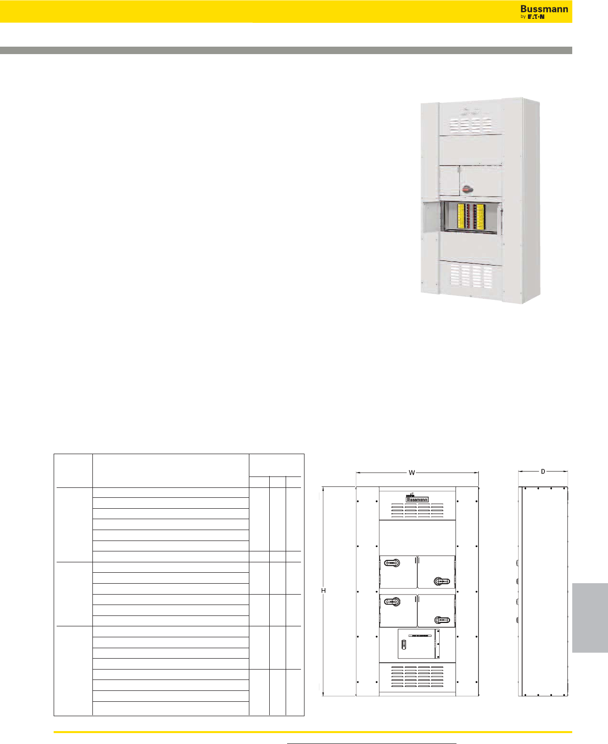
For product data sheets, visit www.cooperbussmann.com/DatasheetsEle 267
Quik-Spec™
Electrical
Gear
Quik-Spec™Electrical Gear
600-1200A Quik-Spec™ Coordination Panelboard
Panel Branch Configurations
Dimension
Ampacity (inches)
HWD
(18) 1-100A
(18) 1-100A + 200A single
(18) 1-100A + 200A twin
600A 200A single + 200A single 65 27 15
200A single + 200A twin
200A twin + 200A twin
(2) 300A single 89 38 15
(18) 1-100A + 200A single
(18) 1-100A + 200A twin 65 38 15
(2) 200A twin
800A (18) 1-100A + 400A single
200A twin + 400A single 89 38 15
(2) 400A single
(18) 1-100A + 600A single
(3) 200A twin 89 38 15
200A twin + 600A single
1200A (2) 200A twin + 400A single
(3) 400A single
600A single + 400A single + 200A single 102 38 15
600A single + 400A single + 200A twin
(2) 600A single
Data Sheet: 1171
• UL listing makes it simple to address NEC®selective
coordination system requirements in an all fused system
• Quik-Quote online configurator makes specifying and
ordering easy – delivers a full bill of material and submittal
drawings for an entire project
Ordering:
The QSCP is factory configured to the specific electrical
system. Contact your Bussmann distributor or representative
to place your order. Have all relevant electrical and circuit
information on hand.
QuikShip – 10 Business Day Shipment
Specifications
Description: Fusible panelboard with 600, 800 and 1200A
mains and branches from 1-600A, rated 600Vac.
Ratings:
Volts:— 600Vac (or less), 125Vdc
Amps:— 600, 800 and 1200A
Options:
Main: — Main lug only
Enclosure: — NEMA 1 floor mount
Branch: — 1-, 2- and 3-pole, 15-600A branch disconnect
Fuse: — Time-delay, non-indicating (Class CF TCF_R
and/or Class J LPJ_SP)
— Time-delay, indicating (Class CF TCF_ and/or
Class J LPJ_SPI)
— Fast-acting, non-indicating (Class CF TCF_RN
and/or Class J JKS)
— DFJ high speed Class J fuses
Agency Information: Complies with NFPA 70 (NEC®;
National Electrical Code®) UL Listed to UL 67,
Features and Benefits:
• Configurable panelboards with options for 600, 800 and
1200A mains and branches from 1-600A all rated 200kA
SCCR at 600Vac
• Smallest standard fusible panelboards in the industry
• Featuring the finger-safe UL Class CF CUBEFuse with
1-600A ampacity rejection features (1-100A)
• Available with time-delay or UPS/Critical application
fast-acting fuses
Configuration and Dimension Chart
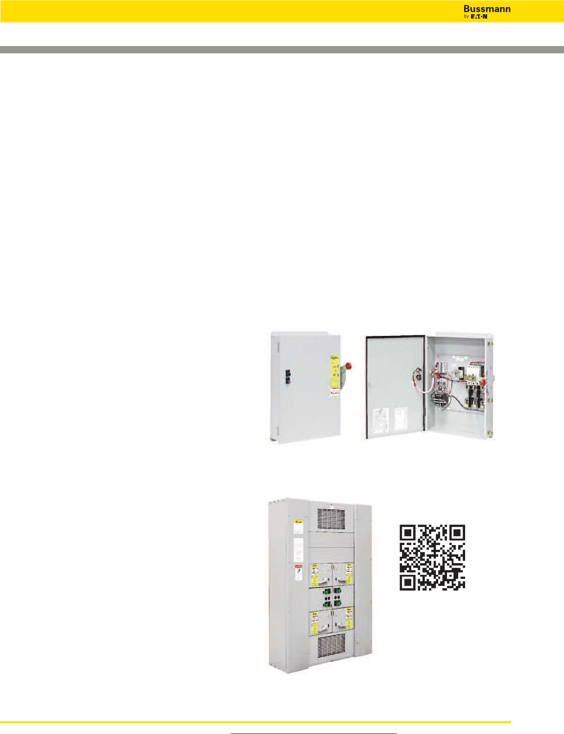
For product data sheets, visit www.cooperbussmann.com/DatasheetsEle
268
Quik-Spec
™
Power Module — All-in-one Elevator Disconnect
PMP*
Power Module™ Panel (PMP) for multiple elevator applications.
PS*
The Quik-Spec™ Power Module Switch (PS) for single
elevator applications.
PS & PMP
Bussmann Quik-Spec Power Module
Specifications
Description: Fusible power switch or panel with shunt trip
and fire safety interface to allow for single point tie in with fire
alarm system.
Ratings:
Volts:— 600Vac, 3Ø
Amps:— 30-400A (PS)
— 30-200A (PMP feeder switches)
— 400-800A (PMP main switches*)
Assembly
SCCR:— 200kA RMS
*Contact Bussmann for applications greater than 800A.
Agency Information: Complies with NFPA 70 (NEC®;
National Electrical Code®),
— Power Module Switch (PS); UL Listed (UL 98) Enclosed
and Dead front switch Guide 96NK3917, File
E182262, NEMA 1, UL 50 Listed enclosure**, cUL per
Canadian Standards C22.2, No. 0-M91-CAN/CSA
C22.2, No. 4-M89 Enclosed switch.
**NEMA 12, 3R, and 4 enclosures also available
— Power Module Panel (PMP); UL 98 Enclosed and
Deadfront Switches.
Features and Benefits:
• Internally powered, relay activated shunt trip system
• Mechanically interlocked auxiliary contact
• Self-contained adherence to elevator consensus standards,
NFPA 70 (NEC®). NFPA 72, ANSI/ASME 17.1
• Shunt trip capability
• Selective coordination
• Fire safety signal interface
• Shunt trip voltage monitoring
• Component protection via Bussmann Low-Peak™
Class J fuses
• UL 98 Listed for 200kA short-circuit current rating
• Lockable in the open position with three-lock capability
• Optional key-test switch and optional pilot light for easy
inspection
• No annual calibration or testing of overcurrent protection
required
• Padlockable for service-work safety and open-door
“override” for troubleshooting
*Fused main disconnect requires Class J fuses, not supplied with switch.
Typical Applications:
• Elevator Disconnects
• Computer Room Shunt Trip Disconnect
• Fire Safety Interface Relay
Accessories:
• For added safety, use the Bussmann SAMI™ fuse covers to
improve maintenance personnel protection (OSHA 1910.333,
paragraph C)
Ordering:
The Bussmann Quik-Spec™ Power Module Switch and
Panel are factory configured to the specific application.
Contact your Bussmann representative to place your order.
Have all relevant electrical and circuit information on hand.
• Elevator Shutdown – ANSI/ASME A17.1, 2.8.3.3.2
– NEC®620.51(B) (Elevator
Shutdown)
– NEC®240.12 (Orderly
Shutdown)
• Shunt Trip Voltage Monitoring – NFPA 72, 6.16.4.4
• Selective Coordination – NEC®620.62
• Auxiliary Contact (Hydraulic Elevator) – NEC®
620.91(C)
Quik-Spec™Electrical Gear
Scan this tag to get the
latest videos for the
Power Module.

For product data sheets, visit www.cooperbussmann.com/DatasheetsEle 269
Quik-Spec
™
Power Module — All-in-one Elevator Disconnect
Hydraulic Elevators
Hydraulic elevators need battery backup to help prevent
stranding passengers. To keep the elevator from moving
when it’s been manually shut down for maintenance, the
NEC®requires battery backup be connected to the elevator
disconnecting means through an auxillary contact.
However, an unintended consequence can be passengers
getting stranded because of devices that open
automatically (circuit breakers and disconnects utilizing a
molded case switch with a trailing fuse block) will operate
with a fault on their loadside. That operation also disables
the battery backup and strands passengers. That’s why the
Power Module has a non-automatic fusible shunt trip
switch. If the Power Module has a fault on its loadside, the
fuses open and the battery stays enabled. Thus the Power
Module ensures that battery power is enabled when the
passengers need it to exit - and disabled to allow safe
maintenance of the elevator and hoistway.
Battery Offered By Offered By
Lowering Power Other Elevator
Scenario Required Reason Module™ Disconnects
Power failure Yes Need to lower elevator to allow passengers to exit. Yes Yes
Fire in shaft or Recall is initiated by smoke detector and lowers elevator to
machine room No a safe floor. Battery not needed. Yes Yes
Disconnect manually Worker to perform maintenance. Elevator must remain
opened No stationary to prevent injury. Yes Yes
Fault on loadside of Need to lower elevator to allow passengers to exit. Yes No
disconnect Yes
Ship-direct service within three business days for Power Module Switches
(PS_) and 10 business days for Power Module Panels (PMP_).
* Three day PS_ shipment requires ordering from catalog numbers shown.
** 10 Day PMP_ shipment covers NEMA 1 enclosures with the ampacities shown and all requirements
for relay type (AC or DC), accessory options and number of switches. To order PMP_, contact your
Bussmann representative with all relevant electrical and circuit information, we do the rest.
Power Module Switch* Power Module Panel**
Cat Numbers Amps Volts Cat. Numbers Amps
PS6T48R1KGBF3-X 60A 480V PMP-400-X 400A
PS1T48R1KGBF3-X 100A 480V PMP-600-X 600A
PS1T20R1KGBF3-X 100A 208V PMP-800-X 800A
PS2T48R1KGBF3-X 200A 480V
PS2T20R1KGBF3-X 200A 208V
Quik-Spec™ Power Module Switch Catalog Numbering System
Quik-Spec™
Electrical
Gear
Quik-Spec™Electrical Gear
Power Module Switch Catalog Number System
PS = Power Module Switch
Amp Rating†
3 = 30A 1 = 100A 4 = 400A
6 = 60A 2 = 200A
Control Transformer*†
T20 = 208 Volt T48 = 480 Volt
T24 = 240 Volt T60 = 600 Volt
Fire Safety Interface Relay (3PDT, 10A, 12V)†
R1 = 120Vac Coil R2 = 24Vdc Coil
Optional Key Test Switch
K = Key
Optional Pilot Light ON
G = Green R = Red W = White
Optional Neutral Lug††
N6 = 30-60A N2 = 200A
N1 = 100A N4 = 400A
Auxiliary Contacts†
B = 2 NO/NC
Fire Alarm Voltage Monitoring Relay (To Monitor Shunt Trip Voltage)
F1 = Single-Pole F3 = Three-Pole**
Optional NEMA Enclosures (Type 1 Standard With No Suffix Designation Required)
U = Type 3R Z = Type 12 Y = Type 4
PS 1 T48 R1 K G N1 B F1 U
* 100Va with Primary and Secondary fusing (120V Secondary) ** Only for use with R1 option
† Required equipment. †† Neutral lug rating should be equal to or greater than the switch amp rating.
Quik-Ship Program: Switch - 3 Days, Panel - 10 Days!
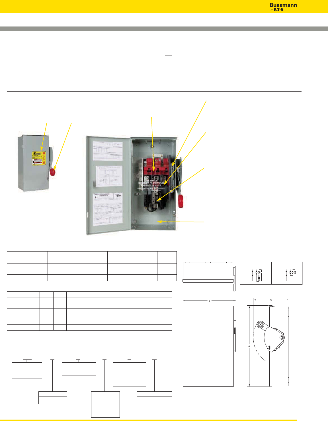
For product data sheets, visit www.cooperbussmann.com/DatasheetsEle
270
Quik-Spec™ DC Safety Switch
DC Safety Switch Catalog Numbering System
Use this build-a-code to specify the exact Quik-Spec DC Safety Switch you need.
BD 1 6 1 F R
Prefix
BD = Heavy Duty
DC Safety Switch
Poles
1= 1-Pole
Voltage
6= 600Vdc
Amps
1= 30A
2= 60A
3= 100A
4= 200A
Type
F= Fusible with
neutral
N= Non-fusible with
neutral
Enclosure Type
R= NEMA 3R
D= NEMA 12
W= NEMA 4X
Stainless
High Visibility Padlockable Handle
Easy to operate with gloves and up
to three padlocks to protect
maintenance personnel
NEC 690.17 Compliant
Label
Warns that the switch
terminals may be energized
in the open position
Visible Switch Contacts
Positive visual identification of
switch state
Door Interlock
Prevents opening door while energized, but can be
manually overridden for testing or inspection.
Clear Polycarbonate Deadfront
Covers energized parts to provide added
protection against electrical hazards. Lineside stays
in place during fuse servicing.
Fused Version For Added Protection
Fuse clips located on switch center pole to ensure
both clips are de-energized in OFF position. Meets
NEC®Article 690.16 that requires isolating the fuse
from all potential supply sources. Cooper Bussmann
recommends using the Limitron fast-acting, current
limiting PVS-R Class RK5 fuse (order separately.)
NEMA 3R, 12 & 4X Enclosures
Meet many application
requirements. 3R and 4X
stainless steel well suited for
isolating outdoor solar power
installations
Conduit Knockouts
For easy conductor installation
Typical Wiring Diagram
Fused Non-Fused
Neutral Neutral
Line Line
Load
Load
Dimensions - in
Amps A B C Main Lug Capacity Neutral Lug Capacity ISC
30 16.35 8.87 9.89 #2 AWG - #14 AWG Al/Cu #4 AWG - #14 AWG Al/Cu 19.2
60 16.35 8.87 9.89 #2 AWG- #14 AWG Al/Cu #4 AWG - #14 AWG Al/Cu 38.4
100 22.15 11.84 9.89 1/0 AWG- #14 AWG Al/Cu #4 AWG - #14 AWG Al/Cu 64.0
200 28.27 16.66 11.26 250kcmil - #6 AWG Al/Cu #2 AWG - #14 AWG Al/Cu 128.0
Amps A B C Main Lug Capacity Neutral Lug Capacity ISC
30 & 60 14.14 8.76 10.22 #2 AWG - #14 AWG Al/Cu #4 AWG - #14 AWG Al/Cu 19.2
Non-fusible
30 & 60 19.08 8.76 10.22 #2 AWG - #14 AWG Al/Cu #4 AWG - #14 AWG Al/Cu 19.2
Fusible
100 24.95 11.79 10.22 1/0 AWG- #14 AWG Al/Cu #4 AWG - #14 AWG Al/Cu 64.0
200 35.38 16.95 11.63 250kcmil - #6 AWG Al/Cu #2 AWG - #14 AWG Al/Cu 128.0
• Flange Handle Operation
• Current-Limiting Fuses Reduce Arc Flash Hazard
• Flexibility of Application
• Enhanced Finger-Safe Design
• Meets UL and NEC®Requirements
Isolating DC Circuits Has Never Been Easier or Safer
Type 3R Dimensions
Type 12 & 4X Dimensions
Quik-Spec™Electrical Gear
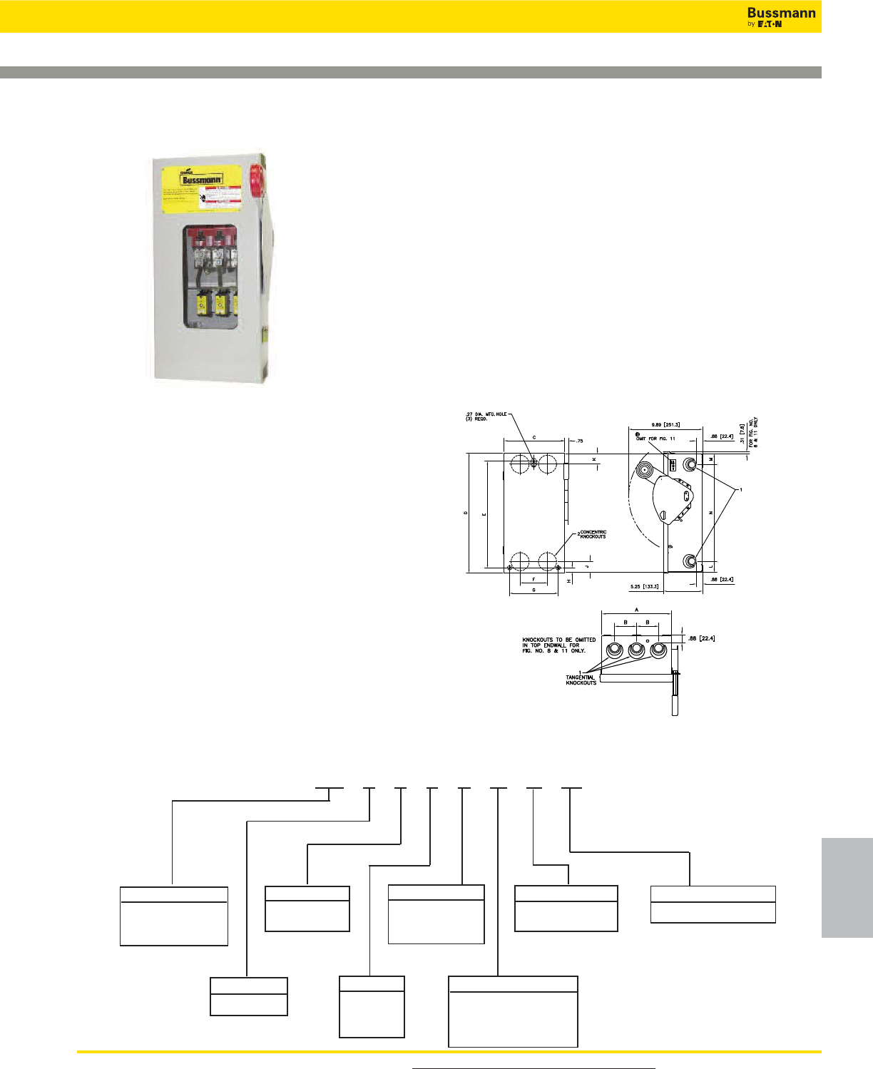
For product data sheets, visit www.cooperbussmann.com/DatasheetsEle 271
Quik-Spec™
Electrical
Gear
Quik-Spec™Electrical Gear
Quik-Spec™ Safety Switch
Bussmann Quik-Spec™ Safety Switch
Specifications
Description: The Bussmann Quik-Spec™ Safety Switch
equipped with finger-safe Low-Peak CUBEFuse provides
superior safety and reliability for industrial customers.
Utilizing the Bussmann Class CF Low-Peak CUBEFuse, the
Quik-Spec Safety Switch provides Class J fuse performance
characteristics that can help mitigate incident energy and
arc-flash hazard, and offers excellent component protection.
The Bussmann CUBEFuse requires no tools to install or
replace.
Agency Information:
• UL 98 standard for enclosed deadfront switches.
• UL 50 standard for enclosures for electrical equipment.
• NEMA KS 1.
• UL Listed, File E5239.
• cUL Listed to C22.2 No.4-M89.
Optional Features:
• Viewing window for visible blades and open fuse indication
• NEMA 1, 3R, 12, 4X (stainless)
• Suitable for use as service equipment (with neutral kit)
Dimensions - inches (mm)*
NEMA 1 & 3R
*See Data Sheet 1156 for 4X and 12
dimension information and maximum
horsepower ratings.
Standard Features:
• Extended line terminal shield and finger-safe 30, 60, or
100A Bussmann CUBEFuse
• 200kA short-circuit current rating
• Visible double break quick-make, quick-break rotary blade
mechanism
• Triple padlocking capability
• Mechanically interlocked door
• 600Vac/250Vdc maximum
Quik-Spec
™Safety Switch Catalog Numbering System
Switch Type Series Window (Optional)
CF =Heavy Duty
CUBEFuse™
Safety Switch
6=600Vac W= Window
K= Switch
Amp
1= 30A
2= 60A
3= 100A
Fusible
Voltage
Poles
3= 3-Pole
F= Fusible
N=Fusible with
Neutral*
Enclosure Type
G=NEMA 1
R= NEMA 3R
D= NEMA 12
W= NEMA 4X Stainless
CF 3 6 1 F G K W
*Suitable for service entrance use
with neutral kit installed.
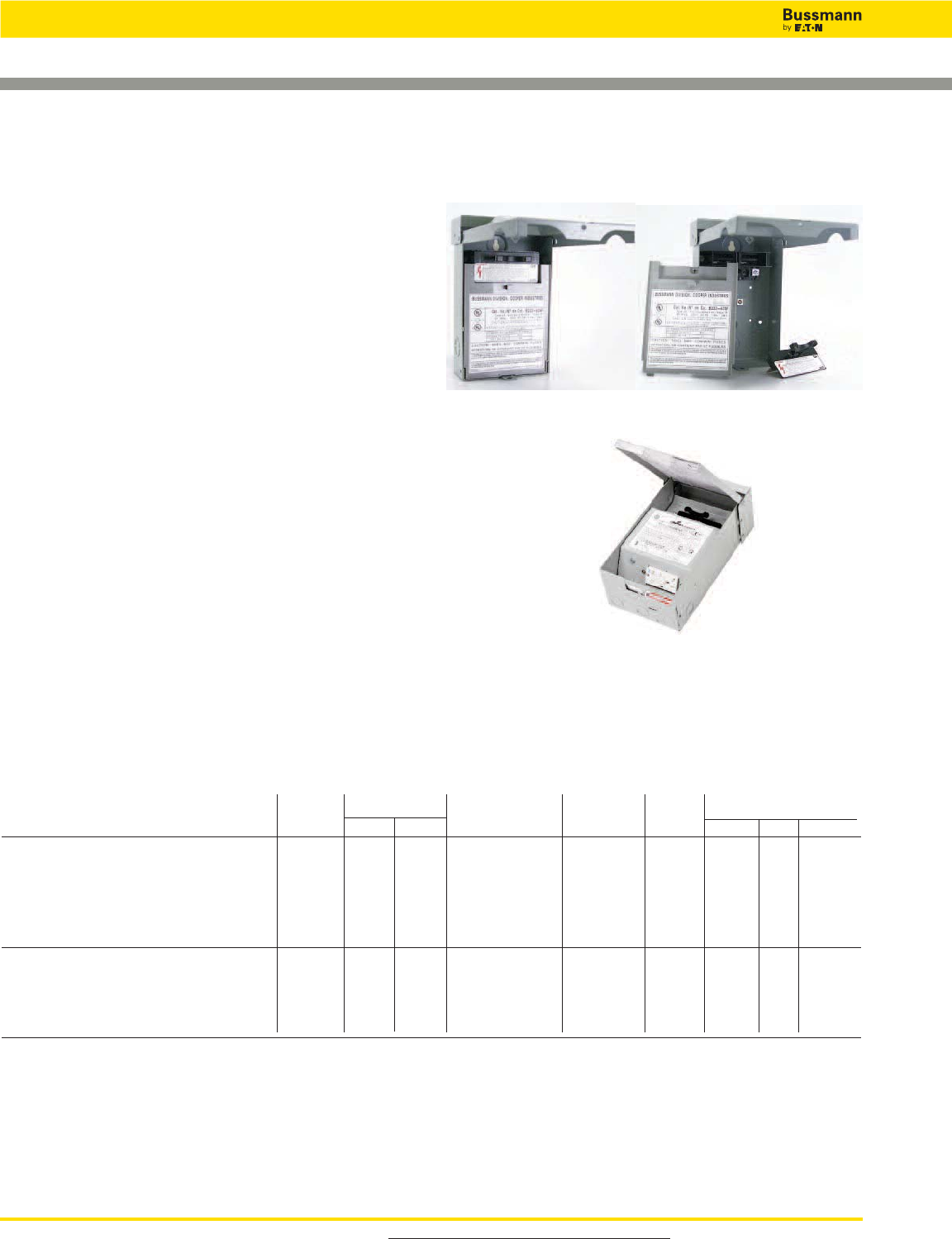
For product data sheets, visit www.cooperbussmann.com/DatasheetsEle
272
Quik-Spec™Electrical Gear
A/C Disconnects — Fused and Non-fused
Data Sheet: 1143
Metallic Fused Disconnect
Metallic Non-Fused Disconnect
Catalog Numbers
Fused
Disconnect Max Hp Rating Wire Range Enclosure Fuse Approx. Dimensions (in)
Catalog Numbers Description Rating 120V 240V 60 or 75°C Cu/Al Type Class Height Width Depth
B221-30F 30A, Pullout 30A 1.5 3 #14-3 NEMA 3R H or R 8 3⁄45 3⁄82 7⁄8
B221-30FGF 30A, Pullout w/ GFCI 30A 1.5 3 #14-3 NEMA 3R H or R 13 7 1⁄24 3⁄4
B221-30FGFWRTR
30A, Pullout w/ WRTR- 30A 1.5 3 #14-3 NEMA 3R H or R 13 7 1⁄24 3⁄4
Rated GFCI
B222-60F 60A, Pullout 60A 3 10 #14-3 NEMA 3R H or R 8 3⁄45 3⁄82 7⁄8
B222-60FGF 60A, Pullout w/ GFCI 60A 3 10 #14-3 NEMA 3R H or R 13 7 1⁄24 3⁄4
B222-60FGFWRTR
60A, Pullout w/ WRTR- 60A 3 10 #14-3 NEMA 3R H or R 13 7 1⁄24 3⁄4
Rated GFCI
Non-Fused
B222-60NF 60A, Pullout 60A 3 10 #14-3 NEMA 3R * 8 3⁄45 3⁄82 7⁄8
B222-60NFGF 60A, Pullout w/ GFCI 60A 3 10 #14-3 NEMA 3R * 11 3⁄46 1⁄24 1⁄2
B222-60NFGFWRTR
60A, Pullout w/ WRTR- 60A 3 10 #14-3 NEMA 3R * 11 3⁄46 1⁄24 1⁄2
Rated GFCI
B222-60NFNA 60A, Switch 60A * 10 #14-3 NEMA 3R * 8 3⁄45 3⁄83 5⁄8
30 and 60A pullout replacement handle: 96-3258-4.
*Upstream overcurrent protective device (OPCD) not to exceed 60A.
Metallic Non-Fused
Disconnect with
Weather Resistant-
Tamper Resistant
GFCI Receptacle.
Series B22__
Specifications
Description: Fused and non-fused rainproof pullout air
conditioner units.
Dimensions: See Catalog Numbers table.
Construction: NEMA 3R metal housing with weather resistant
coating.
Wire Range: 14-3 AWG, Al/Cu
Ratings:
Phase: — Single, 2-wire
Volts: — 240Vac
Amps: — 30-60A
Agency Information: UL Listed to UL 1429, cUL Certified,
UL Guide WGEW
Features and Benefits
• A/C disconnects meet NEC®Code Requirements under
articles 440.14. GFCI units meet NEC®Code Requirements
under articles 210.63, 210.8, and 406.8(B)(1).
• NEMA 3R rainproof enclosures withstand outdoor environment.
• Padlockable with two-position pullout handle to lock safety
shield when in the ON position. (Not available on GF or NA
units.) For added safety, pullout handle can be stored in the
compartment in the off position.
Typical Applications
• Residential, light industrial/commercial A/C and heat pump service.
• Spas/whirlpools, swimming pools, pump houses.
• Suitable for service entrance equipment applications with field
installable ground bar, kit number DPFG.
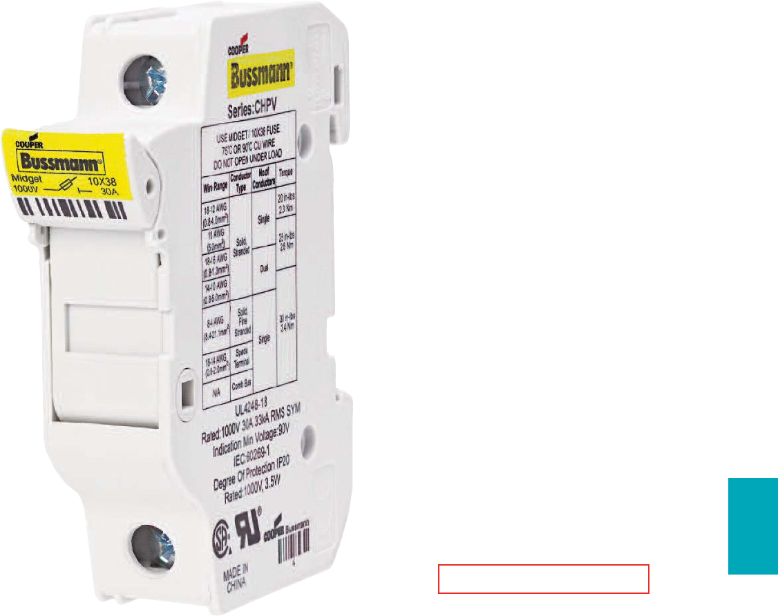
273
Fuse Holders
& Blocks
Fuse Holders and Blocks
Section Contents Page
CH Series Global Modular fuse holders
and accessories . . . . . . . . . . . . . . . . . . . . . 274-280
Remote Fuse Monitoring - CH-PLCCH . . . . . . . . . . . . 278
Comb-Bus bar specifications and selection guide . . . . 279
Comb-Bus bar features and installation guide . . . . . . 280
CH Series Class J modular fuse holders . . . . . . . . . . . . 281
OPM-1038 3-pole fuse holders with
disconnect switch . . . . . . . . . . . . . . . . . . . . . . . . . . . . 282
OPM-1038 3-pole fuse holders . . . . . . . . . . . . . . . . . . . 283
OPMNGA- 3-pole Class CC and 13⁄32˝ X 1 1⁄2˝
fuse overcurrent protection modules . . . . . . . . . . .284-285
JT(N)60030 & JT(N)600600 Safety J™ Class J
fuse holders . . . . . . . . . . . . . . . . . . . . . . . . . . . . .286-287
SAMI™ fuse covers . . . . . . . . . . . . . . . . . . . . . . . . . . . 288
Modular Knifeblade Fuse Holders 289-290
Class R, H(K), 250 & 600V . . . . . . . . . . . . . . . . . 291-292
Class J, 600V . . . . . . . . . . . . . . . . . . . . . . . . . . . . . . . 293
H250 & R250 Series 250V Class H (K) and
R fuse blocks . . . . . . . . . . . . . . . . . . . . . . . . . . . .294-295
H600 & R600 600V Class H (K) and
R fuse blocks . . . . . . . . . . . . . . . . . . . . . . . . . . . .296-297
J600 Series Class J fuse blocks . . . . . . . . . . . . . . . . . 298
JP Series Class J fuse blocks . . . . . . . . . . . . . . . . . . . . 299
T300 300V Class T fuse blocks . . . . . . . . . . . . . . . 300-301
T600 600V Class T fuse blocks . . . . . . . . . . . . . . . 302-303
BCA Series Class CC add-a-pole modular
fuse blocks . . . . . . . . . . . . . . . . . . . . . . . . . . . . . . . . . 304
BMA Series 13⁄32˝ X 1 1⁄2˝ fuse add-a-pole modular
fuse blocks . . . . . . . . . . . . . . . . . . . . . . . . . . . . . . . . . 304
BC Series Class CC fuse blocks . . . . . . . . . . . . . . . . . .305
BM Series Type M 13⁄32˝ X 1 1⁄2˝ fuse blocks . . . . . . . . . . . 305
BG & G Series Class G fuse blocks . . . . . . . . . . . . . . .305
BH Series high speed fuse modular fuse blocks . . . . . 306
Class H & J modular fuse blocks . . . . . . . . . . . . . . . . . .306
Plug fuse box cover units . . . . . . . . . . . . . . . . . . . . . . .307
HFB & HEB-10 in-line fuse holders
for 1⁄4˝ X 1 1⁄4˝ fuses . . . . . . . . . . . . . . . . . . . . . . . . . . . .308
HHB & HRK universal in-line fuse holders for
1⁄4˝ dia. fuses . . . . . . . . . . . . . . . . . . . . . . . . . . . . . . . . 308
HR & HM Series in-line fuse holders for 1⁄4˝ dia. fuses . . 309
HFA Series waterproof in-line fuse holders
for 1⁄4˝ X 1 1⁄4˝ fuses . . . . . . . . . . . . . . . . . . . . . . . . . . . .309
HHT Series in-line fuse holders for
5 X 15 to 20mm fuses . . . . . . . . . . . . . . . . . . . . . . . . .309
Tron™in-line fuse holders (New HEZ) . . . . . . . . . . . . 309-311
Panel mounted fuse holders for 5 X 20mm fuses . . . . . . .312
Panel mounted fuse holders for 1⁄4˝ X 1 1⁄4˝ fuses . . . . . . . . 313
Panel mounted fuse holders for 5 X 20mm and
1⁄4˝ X 1 1⁄4˝ fuses . . . . . . . . . . . . . . . . . . . . . . . . . . . . 314-315
Panel mounted fuse holders for indicating type fuses . . 316
Panel mounted fuse holders for
13⁄32˝ X 1 5⁄16˝ to 1 1⁄2˝ fuses . . . . . . . . . . . . . . . . . . . . . . . . .317
Panel mounted fuse holders for
13⁄32˝ X 1 1⁄2˝ fuses . . . . . . . . . . . . . . . . . . . . . . . . . . . . . . . 318
Fuse blocks for 1⁄4˝ X 1 1⁄4˝ fuses . . . . . . . . . . . . . . . . . . . . 319
Fuse blocks for 1⁄4˝ X 1˝ fuses . . . . . . . . . . . . . . . . . . . . . .320
Fuse blocks for 13⁄32˝ X 1 1⁄2˝ fuses . . . . . . . . . . . . . . . . . . . .321
Rail mount fuse holders . . . . . . . . . . . . . . . . . . . . . . . . . . 322
RED indicates NEW information
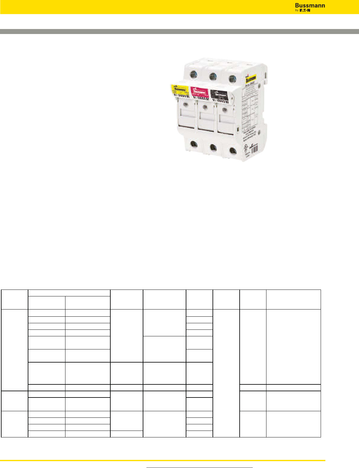
For product data sheets, visit www.cooperbussmann.com/DatasheetsEle
274
Fuse Holders and Blocks
Global Modular Fuse Holders
CH Series - 8x32, 10x38, 14x51, 22x58,
Class CC
Specifications
Description: The ‘CH’ line of modular fuse holders
accommodates many fuses from around the world, including
North American Class-CC, Midget, Class gR, aR HSF, and
IEC Industrial Ferrule (Class gG and aM) in four physical
sizes: 8x32, 10x38, 14x51 and 22x58mm.
With
Indicator
Without
Indicator
CHM1DIU CHM1DU 1
CHM2DIU CHM2DU 2
CHM3DIU CHM3DU 3
CHM4DIU CHM4DU 4
CHM1DNIU CHM1DNU 1 pole + 1
neutral
CHM3DNIU CHM3DNU 3 poles +
1 neutral
CHM1DI-48U
UL 48Vdc/30A;
IEC
48Vdc/32A
1
CHM1DNXU IEC 690V/32A IEC60269-2 1 neutral n/a n/a
CHPV1IU CHPV1U 1
CHPV2IU CHPV2U 2
CHCC1DIU CHCC1DU 1
CHCC2DIU CHCC2DU 2
CHCC3DIU CHCC3DU 3
CHCC1DI-48U UL 48Vdc/30
A
1
SCCR
Ratin
g
Cooper Bussmann
Fuses
Voltage &
Current
Catalo
g
Number
Agency
Markin
g
s
Number
of Poles
Terminal
Ratin
g
Series &
Size
CHPV
CHCC
Class CC
CHM
10x38
and
Midget
UL & IEC;
1000Vdc/30A
UR, CSA,
UL4248-18,
IEC60269-1
Solid,
Stranded,
Fine
Stranded,
Spade
Lug, Comb
Bus Bar;
Single and
Dual Wire;
75ºC and
90ºC Cu
wire
33kA rms
sym
UL 600V/30A 200kA
rms sym
UL
600V/30A;
IEC
690V/32A
cURus; IEC
60269-2
LP-CC, FNQ-R,
KTK-R
cULus
100kA
rms sym
FNQ, KLM, FNM,
KTK, BAF, FWA,
DCM, C10 SERIES,
AGU, BAN, FWC
Solar PV series
60269-2
Agency Information: UL File E14853
Guide IZLT Listed, IZLT2 Recognized
CSA: File 47235, CHPV and CHM - Class 6225-30,
CHCC - Class 6225-01
Ratings:
600V/30A (UL)
690V/32A (IEC)
Wire Range:
#18 to #4 (0.8mm2to 21.1mm2)
Torque Ratings:
30 Lb-In (3.4 N•m) maximum
Flammability Ratings:
UL 94V0, self-extinguishing
Storage & Operating Temperature Range:
-20ºC to +90ºC (indicating)
-20ºC to +120ºC (non-indicating)
Features/Benefits
• High SCCR rated, UL Listed Class CC holder with indicator
option for 600Vac/dc and 48Vdc.
• UL Recognized midget and 10 x 38 holders with factory
assembled neutral pole option.
• Agency ratings up to 1000Vdc for use with solar PV fuses.
• Available remote PLC indication with the CH-PLC module.
• Terminals rated for use with 75ºC or 90ºC wire, fine
stranded wire, spade terminals and comb-bus bars. Use
any higher temperature rated wire with appropriate
derating.
• Complete range of UL Listed and high SCCR rated
1-phase and 3-phase finger-safe comb-bus bars and
power feed lugs.
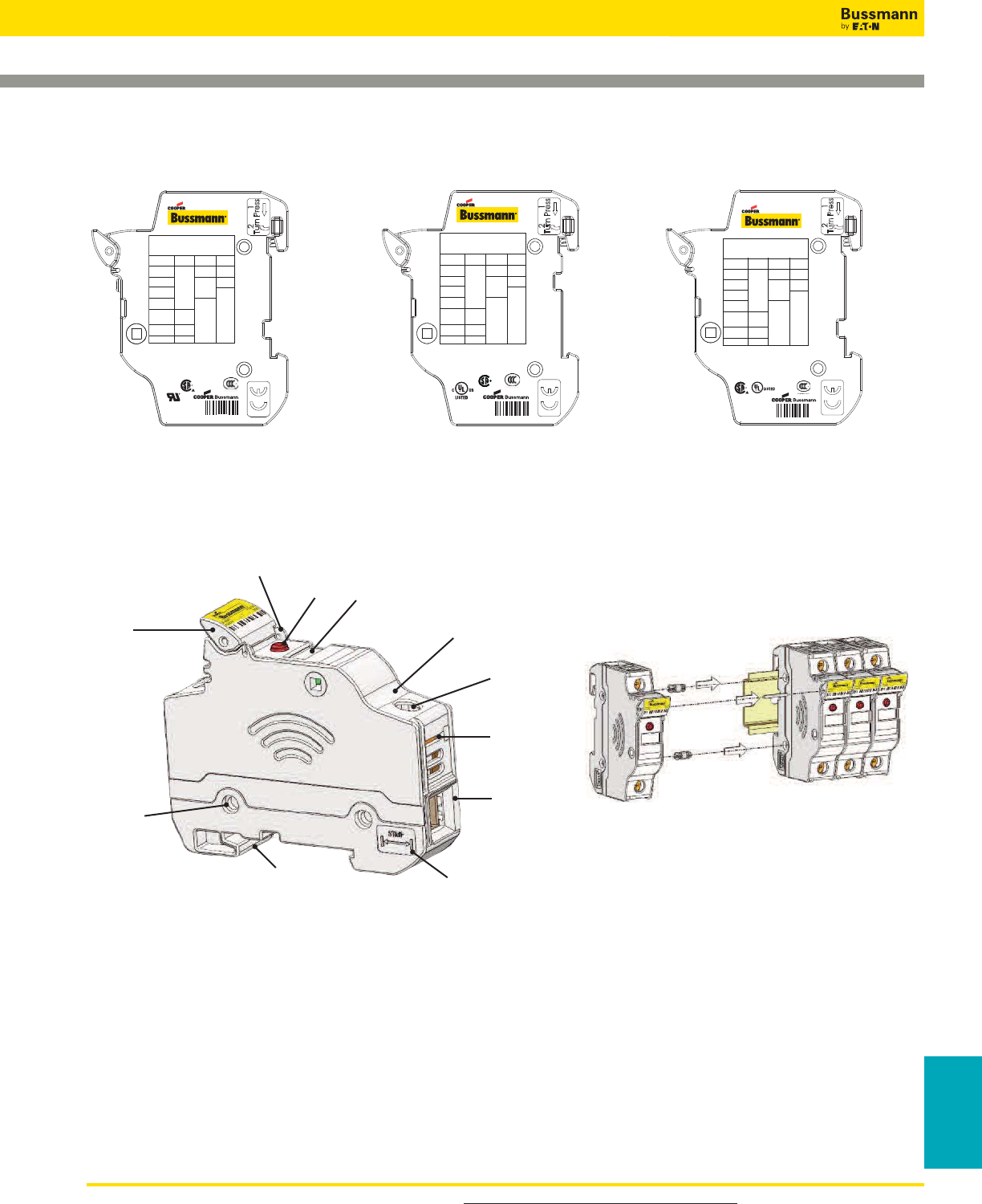
For product data sheets, visit www.cooperbussmann.com/DatasheetsEle 275
Fuse Holders
& Blocks
For additional information see reorder #3185
Fuse Holders and Blocks
CHPV & CHPVI
CHM & CHMI CHCC & CHCCI
Wire Range Conductor No. of Torque
Type Conductors
18-14 AWG 20 in-lbs
(0.8-2.0mm2)Single 2.3 Nm
18-16 AWG 25 in-lbs
(0.8-1.3mm2) Solid, Dual 2.8 Nm
14-10 AWG Stranded
(2.0-5.2mm2)
12-10 AWG
(3.3-5.2mm2)
8-4 AWG Stranded, 30 in-lbs
(8.3-21.1mm2)Fine 3.4 Nm
Stranded
18-14 AWG Spade Single
(0.8-2.0mm2) Terminal
N/A Comb Bus
USE MIDGET / 10X38 FUSE
75ºC OR 90ºC CU WIRE
DO NOT OPEN UNDER LOAD
Rated: 600V, 30A 50/60Hz
200kA RMS SYM 3W
Indication Min Voltage: 90V
IEC: 60269-2 32A
690Vac 120kA 3W
Degree of Protection IP20
Series: CHM
4
MADE IN
CHINA
R
GB13539
Rated: 600V, 30A 50/60Hz
200kA RMS SYM
Indication Min Voltage: 90V
Degree of Protection IP20
MADE IN
CHINA
Series: CHCC
430P
1
USE CLASS CC FUSE
75ºC OR 90ºC CU WIRE
DO NOT OPEN UNDER LOAD
Wire Range Conductor No. of Torque
Type Conductors
18-14 AWG 20 in-lbs
(0.8-2.0mm
2
)Single 2.3 Nm
18-16 AWG 25 in-lbs
(0.8-1.3mm
2
) Solid, Dual 2.8 Nm
14-10 AWG Stranded
(2.0-5.2mm
2
)
12-10 AWG
(3.3-5.2mm
2
)
8-4 AWG Stranded, 30 in-lbs
(8.3-21.1mm
2
)Fine 3.4 Nm
Stranded
18-14 AWG Spade Single
(0.8-2.0mm
2
) Terminal
N/A Comb Bus
GB13539
4GY1
UL4248-18
Rated: 1000Vdc, 30A 33kA RMS SYM
Indication Min Voltage: 90V
IEC: 60269-1 32A
1000Vdc 33kA 3.5W
Degree of Protection IP20
MADE IN
CHINA
Series: CHPV
5
R
Wire Range Conductor No. of Torque
Type Conductors
18-14 AWG 20 in-lbs
(0.8-2.0mm2)Single 2.3 Nm
18-16 AWG 25 in-lbs
(0.8-1.3mm2)Solid, Dual 2.8 Nm
14-10 AWG Stranded
(2.0-5.2mm2)
12-10 AWG
(3.3-5.2mm2)
8-4 AWG Stranded, 30 in-lbs
(8.3-21.1mm2)Fine 3.4 Nm
Stranded
18-14 AWG Spade Single
(0.8-2.0mm2) Terminal
N/A Comb Bus
USE PHOTOVOLTAIC 10X38 FUSE
75ºC OR 90ºC CU WIRE
DO NOT OPEN UNDER LOAD
GB13539
Rail Mount Fuse Blocks and Holders
Multi-Pole Ganging
Use multi-pole connection kit part number
JV-L to gang multiple poles together. One
JV-L kit is sufficient to gang up to 4 poles.
4mm
Lockout
Feature in
Fuse Carrier
Toolless
Ganging of
Multiple
Poles
Toolless DIN Rail
Mounting Wire Strip
Length
Indicator
6mm Wire
Clamp Lug and
open bus bar
connection
(#4 to #18)
Captive, Fully
Backed Out
Phil-Slot Screw
Spade lug
connection
Self-Extinguishing,
UL 94V0 Rated
Polyester
Material
Label Slot
Optional
Open Fuse
Indicator
Hole for Wire
Security Tag
Features
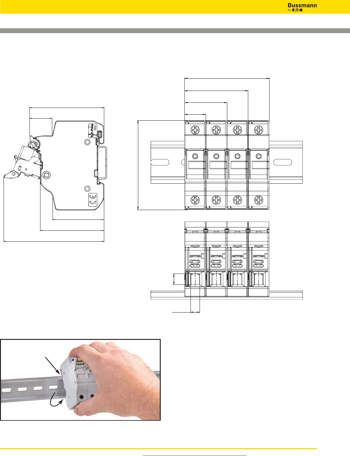
For product data sheets, visit www.cooperbussmann.com/DatasheetsEle
276
Fuse Holders and Blocks
Rail Mount Fuse Blocks and Holders
Dimensional Data - mm (in)
17.5
[ 0.689 ]
35
[ 1.378 ]
52.5
[ 2.067 ]
70
[ 2.756 ]
73.88
[ 2.909 ]
42.58
[ 1.676 ]
52.83
[ 2.080 ]
61.83
[ 2.434 ]
18.59
[ 0.732 ]
83.19
[ 3.275 ]
9
[ 0.354 ]
7.0
[ 0.276 ]
Removing Instructions
1. Press down on top
of DIN-Rail
2. Rotate out
on the bottom
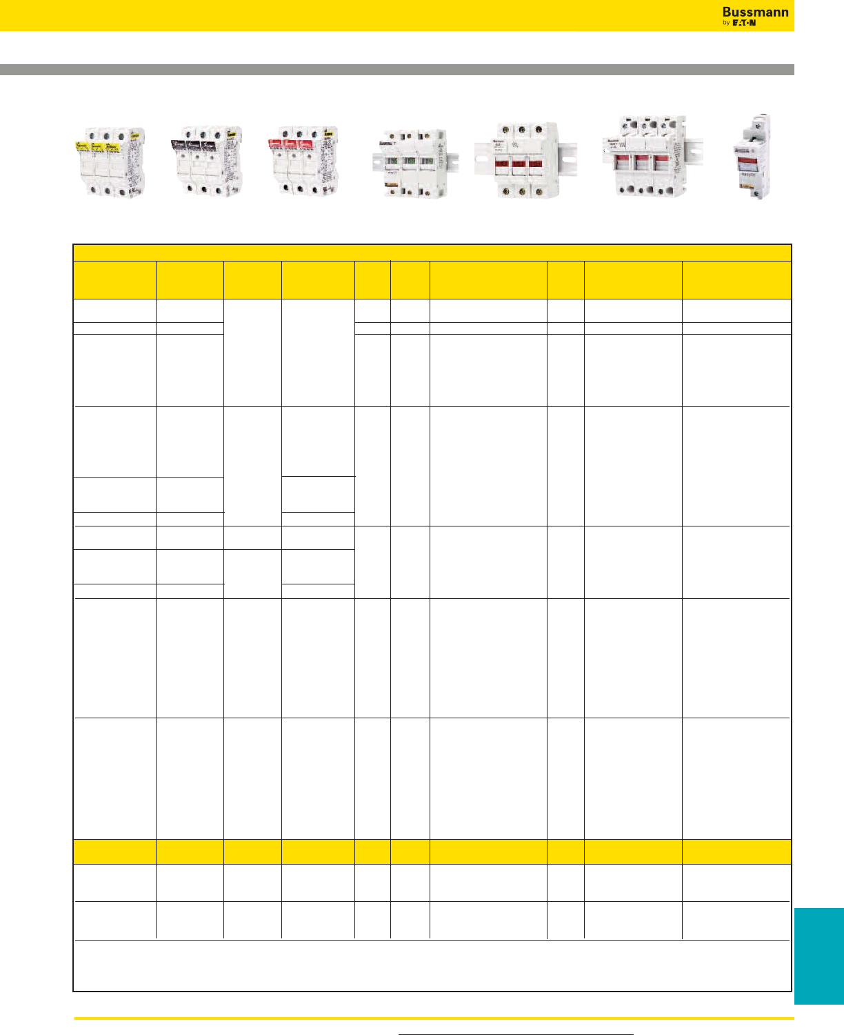
For product data sheets, visit www.cooperbussmann.com/DatasheetsEle 277
Fuse Holders
& Blocks
Global Modular Fuse Holders
For additional information see reorder #3185
Fuse Holders and Blocks
Catalog Numbers
Max No. of
Without With* Voltage 17.5mm
Indication Indication Size & Current IEC UL Phase Configuration Modules Wire Range Maximum Torque
CH081D CH081DI • 1-pole 1 1-16mm2(18-8 AWG) 2.5 N•m (22LB-In)
CH081DNX - • 1 Neutral Pole 1
CH081DNS CH081DNSI • 1-pole + Neutral 1 1-10mm2(18-8 AWG) 2.0 N•m (17.5LB-In)
CH081DN CH081DNI CH08 IEC • 1-pole + Neutral 2
CH082D CH082DI 8x32 400Vac • 2-pole 2
CH083D CH083DI 25A • 3-pole 3 1-16mm2(18-8 AWG) 2.5 N•m (22LB-In)
CH083DNS CH083DNSI • 3-pole + Neutral 3
CH083DN CH083DNI • 3-pole + Neutral 4
CH084D CH084DI • 4-pole 4
CHM1DU CHM1DIU • * 1-pole 1
CHM2DU CHM2DIU UL • * 2-pole 2
CHM3DU CHM3DIU CHM 600V/30A; • * 3-pole 3
CHM4DU CHM4DIU 10X38 IEC • * 4-pole 4
CHM1DNU CHM1DNIU and 690V/32A • * 1-pole + Neutral 2
CHM3DNU CHM3DNIU Midget • * 3-pole + Neutral 4 1-21mm2(18-4 AWG) 3.4 N•m (30LB-In)
UL 48Vdc/30A;
– CHM1DI-48U IEC • * 1-pole 1
48Vdc/32A
CHM1DNXU – IEC 690V32A • 1-pole + Neutral 2
CHPV1U CHPV1IU CHPV UL & IEC; • ††† 1-pole 1
CHPV2U CHPV2IU 1000Vdc/30A • ††† 2-pole 2
CHCC1DU CHCC1DIU ** 1-pole 1
CHCC2DU CHCC2DIU CHCC UL ** 2-pole 2 1-21mm2(18-4 AWG) 3.4 N•m (30LB-In)
CHCC3DU CHCC3DIU Class CC 600V/30A ** 3-pole 3
CHCC1DI-48U – UL 48Vdc/30A ** 1-pole 1
CH141D CH141DI • 1-pole 1.5
CH141DMS - UL • 1-pole + Microswitch 1.5
CH141DNX - 600Vac/dc • 1 Neutral Pole 1.5
CH141DN CH141DNI 40A • 1-pole + Neutral 3
CH142D CH142DI CH14 (5 Watt) • † 2-pole 3 2.5-16mm2(14-6 AWG) 3.0 N•m (26LB-In)
CH143D CH143DI 14x51 IEC • † 3-pole 4.5
CH143DMS - 690Vac, • 3-pole + Microswitch 4.5
CH143DN CH143DNI 50A • 3-pole + Neutral 6
CH143DNMS - • 3-pole + Neutral + Microswitch 6
CH144D CH144DI • 4-pole 6
CH221D Not • † 1-pole 2
CH221DMS Available • 1-pole + Microswitch 2
CH221DNX with UL • 1 Neutral Pole 2
CH221DN local 600Vac/dc, • 1-pole + Neutral 4
CH222D neon CH22 100A • † 2-pole 4 2.5-50mm2(14-1 AWG) 4.0 N•m (35LB-In)
CH223D indication 22x58 (9.5 Watt) • † 3-pole 6
CH223DMS (remote IEC • 3-pole + Microswitch 6
CH223DN microswitch 690Vac, • † 3-pole + Neutral 8
CH223DNMS only) 125A • 3-pole + Neutral + Microswitch 8
CH224D • 4-pole 8
Class J Neon
easyID™ Indication Indication
CH30J1 CH30J1I CH30J UL/CSA †† 1-pole — 1-50mm2(18-1 AWG) 1-8 AWG 4.0 N•m (35LB-In)
CH30J2 CH30J2I 30A 600Vac †† 2-pole —
10-18 AWG 2.7N•m (24LB-IN)
CH30J3 CH30J3I Class J †† 3-pole —
CH60J1 CH60J1I CH60J UL/CSA †† 1-pole — 1-50mm2(18-1 AWG) 1-8 AWG 4.0 N•m (35LB-In)
CH60J2 CH60J2I 60A 600Vac †† 2-pole — 10-18 AWG 2.7N•m (24LB-In)
CH60J3 CH60J3I Class J †† 3-pole —
† UL Recognized (cURus) †† UL LIsted (cULus) ††† UL Recognized, Standard 4248-18, CSA
For further details see Data Sheets 2053 (CH08, CHM, CHCC, CH14 AND CH22) and 2144 (CHJ Class J)
*90V miminum required for illumination
***12V mininum required for illumination
8x32 IEC 14x51 IEC 22x58 IEC
PV UL IEC Class J 30A
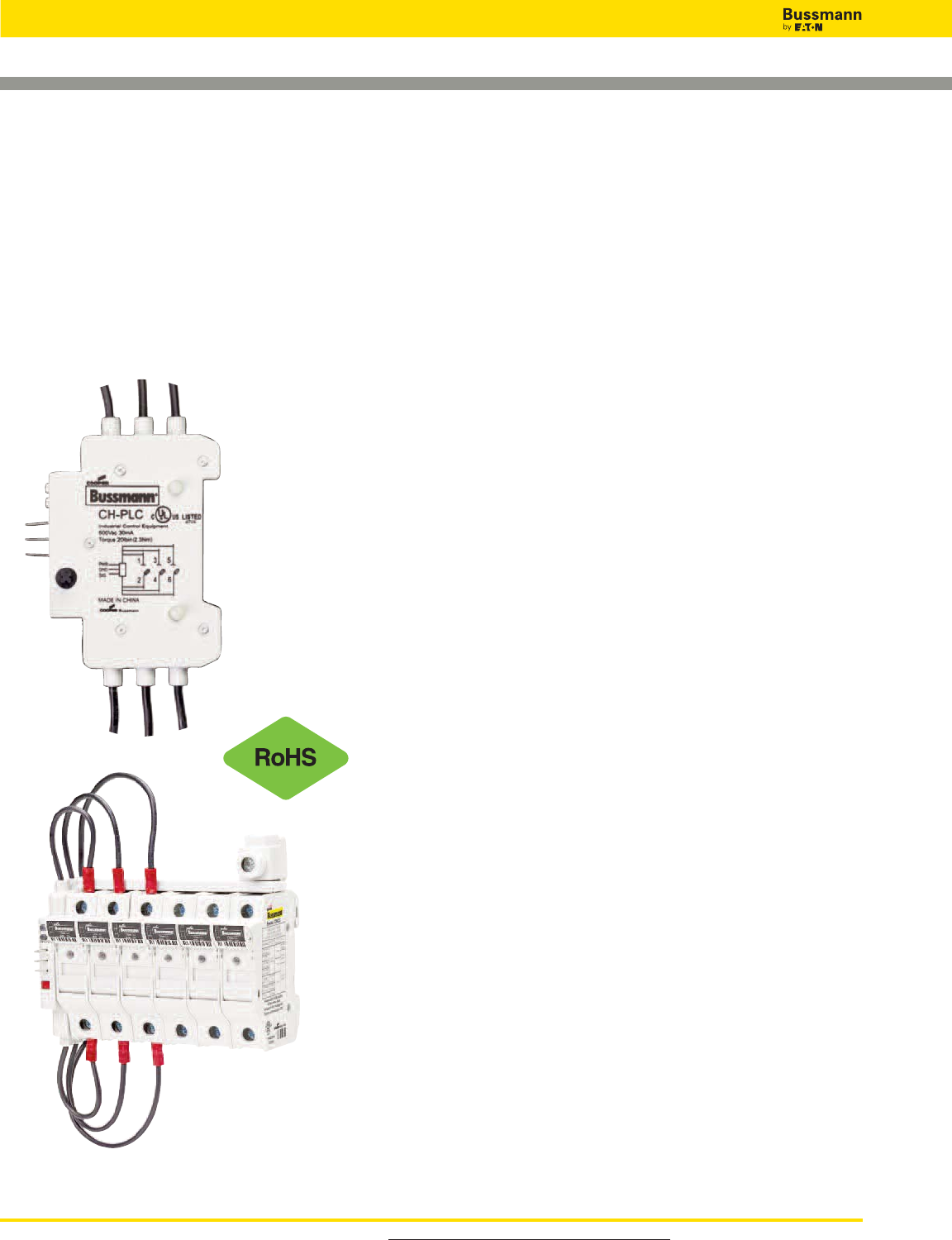
For product data sheets, visit www.cooperbussmann.com/DatasheetsEle
278
Global Modular Fuse Holders - Remote Fuse Monitoring
Accessory CH-PLC
Fuse Holders and Blocks
Specifications:
•Power Input: 24Vdc / 5mA
•Sensing Voltage: 600V/30mA
•Output Signals: Digital 0Vdc (Low), 24Vdc (High)
- 0Vdc Low – Fuse is good
- 24Vdc High – Fuse has opened
When the fuse opens, the output signal is sent high and will
remain high until the unit is reset
•Rated Impulse Voltage: 8kV
•Local Indication: Two distinct LEDs indicate unit power (green)
and open fuse (red). Upon the replacement of the fuse, the
actuation of the reset switch will reset the open
fuse LED
•Flammability Rating: UL 94V0
Wiring:
• For power, signal and ground connections use 22-24AWG
(0.25mm2) 300V rated wire
Emissions and Immunity Testing:
• Electrostatic Discharge IEC 61000-4-2
• Electrical Fast Transient/Burst IEC 6100-4-4
• Surge Immunity IEC61000-4-5
Packaging:
• The CH-PLC is packaged individually
• A single unit monitors up to three phases
• Package includes 0.11” (2.8mm) quick connects for power, signal
and ground connections
Minimum Circuit Voltage:
• Minimum circuit voltage required across the CH holder is 100Vac
for the remote indication device to operate
Installation Technique:
• Mounts on the left side of the fuse holder and mechanically
interlocks with the fuse holder switch handle with hardware
provided
IP20 Rating: Yes
Environmental Data:
• Storage and Operating Temperature: -20°C to 75°C
Agency Information:
• UL 508
• cULus to CSA Standard 22.2 No.14
PLC Programming:
• The CH-PLC signal line is designed to provide a digital input to a
PLC I/O card.
• Programmable Logic Control program must be written to properly
interpret the input signal to the PLC.
• The PLC program should check for consecutive high signals
before taking action on a critical process.
De-energize all circuits before installing or removing any CH-PLC devices and follow all prescribed safety procedures.
Make it Simple
with
Bussmann resettable
three-phase remote fuse monitor
that integrates with a
Programmable Logic Controller
(PLC) or other monitoring and
control equipment.
For additional information see reorder #3185
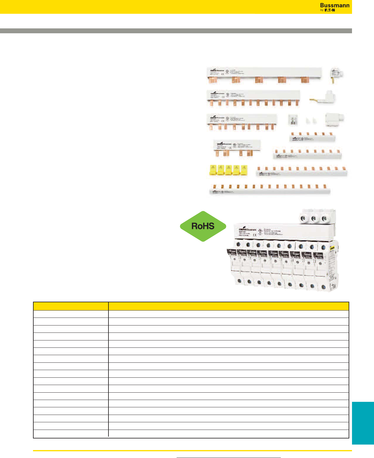
For product data sheets, visit www.cooperbussmann.com/DatasheetsEle 279
Fuse Holders
& Blocks
Fuse Holders and Blocks
Global Modular Fuse Holders - Comb-Bus Bar
Specifications and Selection Guide
Specifications
Agency Information: UL 508, File E195399
Pitch: 17.8mm
SCCR: 10kA (default)
100kA (with upstream Class J 200A fuses)
Max Current: 100A (power feed from end;
200A (power feed from center)
Max Voltage: 600Vac/dc (three phase)
1000Vdc/600Vac (single phase)
Features and Benefits
• Easily distribute power in single-phase or three-phase
configurations
• Flexible cut-to-length solutions without compromising on the
product’s finger-safe features
• 100kA SCCR (Short-Circuit Current Rating) when protected
by a 200A Class J fuse
• Single-phase bus bars rated to 1000Vdc and 100A in end-fed
configuration (200A for center-fed configuration)
• Three-phase bus bars rated to 600Vac/dc and 100A in
end-fed configuration (200A for center-fed configuration)
• Power feed terminals for single-phase and three-phase
service
Part Number Description
BB1P100M3 Single-phase 1000Vdc busbar, 100A, 3 pins, assembled endcap
BB1P100M6 Single-phase 1000Vdc busbar, 100A, 6 pins, assembled endcap
BB1P100M9 Single-phase 1000Vdc busbar, 100A, 9 pins, assembled endcap
BB1P100M12 Single-phase 1000Vdc busbar, 100A, 12 pins, assembled endcap
BB1P100M15 Single-phase 1000Vdc busbar, 100A, 15 pins, assembled endcap
BB1P100M57 Single-phase 1000Vdc cuttable busbar, 100A, 57 pins, without endcap
BB3P100M6 Three-phase 600V busbar, 100A, 6 pins, assembled endcap
BB3P100M9 Three-phase 600V busbar, 100A, 9 pins, assembled endcap
BB3P100M12 Three-phase 600V busbar, 100A, 12 pins, assembled endcap
BB3P100M15 Three-phase 600V busbar, 100A, 15 pins, assembled endcap
BB3P100M57 Three-phase 600V cuttable busbar, 100A, 57 pins, without endcap
ECAP1P Single-phase busbar endcap
ECAPMP Three-phase busbar endcap
PWR35MM 35mm2feeder terminal for three-phase busbar (115A, 1000Vac/dc)
FSCVR Spare contact safety protection covers
PWR1PLP Single-phase low-profile feeder terminal (115A, 1000Vac/dc)
PWR50MM 50mm2direct feed terminal (1000Vac/dc)
Selection Guide
For additional information see reorder #3185
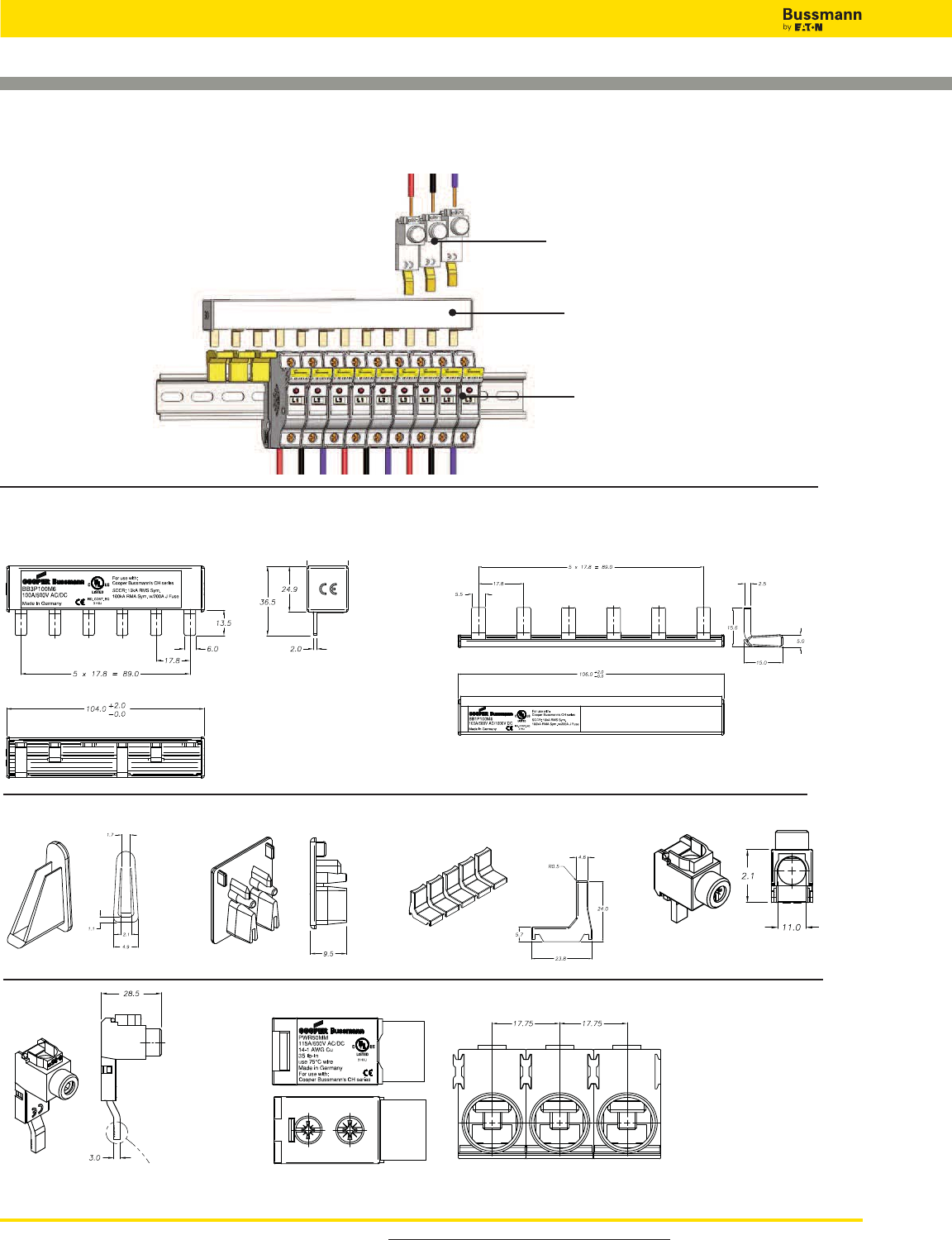
For product data sheets, visit www.cooperbussmann.com/DatasheetsEle
280
Fuse Holders and Blocks
Global Modular Fuse Holders - Comb-Bus Bar Features
and Installation Guide
For additional information see reorder #3185
Typical Dimensional Data
Three-phase Single-phase
ECAP1P ECAPMP FSCVR PWR1PLP
PWR35MM PWR50MM
Typical Installation Example
Power Feed Terminals
Comb-Bus Bar
Modular Fuse Holders
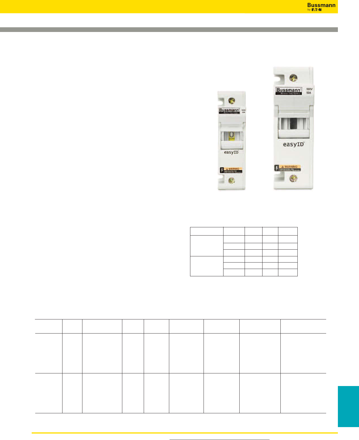
For product data sheets, visit www.cooperbussmann.com/DatasheetsEle 281
Fuse Holders
& Blocks
Fuse Holders and Blocks
Class J Modular Fuse Holders
CH _ _ J _
Specifications
Description: IP20 finger-safe, 1- to 3-pole Class J fuse
holder with DIN-Rail or panel mounting.
Ratings:
Volts: — 600Vac/dc (or less)
Amps: — 30A (30A version)
— 60A (60A version)
SCCR: — 200kA
Wire Range: Cu solid and stranded conductors with single
(1-18AWG) and dual (3-18AWG) wire ratings. See Catalog
Numbers table for details.
Torque Rating:10-18AWG 24 lb-in.
1-8AWG 35 lb-in.
Poles: 1-, 2- or 3-Pole.
Storage & Operating Temperature Range*:
-20°C to 75°C.
Agency Information: CE, UL 4248/CSA 22.2 No. 4248.P
UL Listed, Guide IZLT, File E14853.
Flammability Rating: UL 94V0.
Catalog Numbers
See Catalog Numbers table below.
Features and Benefits
• Choice of local fuse indication; easyID™ viewing window (for
seeing indicator on LPJ-SPI indicating fuse) or neon lamp.
• Versatile 1-, 2- and 3-pole versions for 0-30A and 35-60A
fuses with dual wire rated connections simplify wiring.
• Improved electrical safety with IP20 finger-safe construction
with lock-out/tag-out feature. 3-phase fuse extraction
assures all phases are opened for service work.
• Flexible panel/35mm DIN-Rail mounting mounting options
*For fuse selection on applications above or below 25ºC, consult derating charts in
Bussmann publication “Selecting Protective Devices” (SPD).
Catalog Numbers
Catalog # of Local Amp Volts IP20 AWG Single
Numbers Poles Indication Rating (AC/DC) Finger-Safe Wire Range Padlockable Mounting
CH30J1 1 easyID**
CH30J1I 1 Neon Lamp***
CH30J2 2 easyID** 30 600 Yes 1-18 Yes 35mm DIN/ Panel
CH30J2I 2 Neon Lamp***
CH30J3 3 easyID**
CH30J3I 3 Neon Lamp***
CH60J1 1 easyID**
CH60J1I 1 Neon Lamp***
CH60J2 2 easyID** 60 600 Yes 1-18 Yes 35mm DIN/ Panel
CH60J2I 2 Neon Lamp***
CH60J3 3 easyID**
CH60J3I 3 Neon Lamp***
** easyID™ viewing window, requires use of Bussmann LPJ_SPI permanent indication fuses.
*** Indication non-fuse dependent, minimum voltage 90Vac/115Vdc.
Dimensions (mm):
30 Amp Version 60 Amp Version
Data Sheet: 2144
Fuse Size Poles W D H
1 32 70 115
0-30A 2 64 70 115
3 96 70 115
1 40 83 125
35-60A 2 80 83 125
3 120 83 125
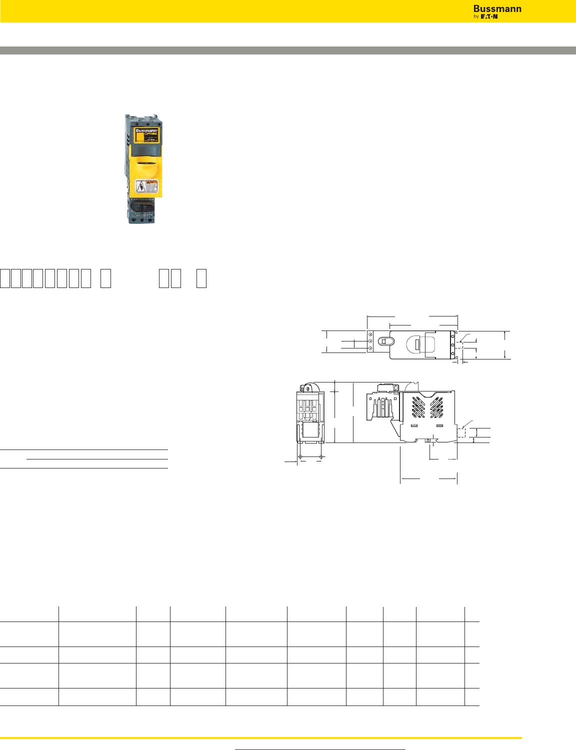
For product data sheets, visit www.cooperbussmann.com/DatasheetsEle
282
Fuse Holders and Blocks
Optima™Fuse Holder Module and Disconnect Switch
4.25∑ (± 0.03)
(108.0mm) (± 0.76)
(6.9mm)
(18.8mm)
(7.9mm)
BUSS
5.72∑ (± .045)
(145.3mm) (± 1.14)
0.43∑ (± 0.03)
(10.9mm) (± 0.76)
1.38∑
(35.0mm)
0.23
∑
1.86
∑
(5.8mm)
3.17∑
(80.5mm)
1.312∑
(± 0.01)
(33.3mm)
(± 0.25)
Panel Mounting
Hole Pattern
(47.2mm)
Panel Mounting
Hole Pattern
3.74∑ (± 0.03)
(95.0mm) (± 0.76)
0.57∑ (± 0.03)
(14.5mm) (± 0.76)
0.27∑
0.31∑
Communication
Port
0.74∑
0.50∑ (12.7mm)
Communication
Port
0.44∑ (11.2mm)
2T1 1L1
3L2
5L3
4T 2
6T3
1.76∑
3.60
∑
(91.4mm)
(44.7mm)
0.224∑
(5.6mm)
Data Sheet: 1103
Specifications
Description: 3-pole load break modular fuse holder and
disconnect switch for 13⁄32 x 11⁄2˝ (10 x 38mm) fuses.
Dimensions: See Dimensions illustration.
Poles: 3
Agency Information: CE, UL (see table), CSA Certified,
C22.2 No. 39, Class 6225-01, File 47235, IEC (see table).
Flammability Rating: UL 94V0.
Horsepower Rating of Switch
Volts 240 480 600
3-Phase HP 5 10 15
Recommended Fuse Types
Class CC Midget (Non-Rejection) European
LP-CC KTK C10M
KTK-R FNM C10G
FNQ-R FNQ
Physical Characteristics
• Small size matches 45mm IEC starter width
• Accepts #8-18 AWG stranded, #10-18 AWG solid wire
• 3-pole
• Handle and shaft required for through the door operation
Features/Benefits
• Padlockable with finger-safe terminals for safety. Qualified
as IP20 per IEC 60529.
• Cam-action handle for easy module removal, offered with
Class CC rejection clips or European 10 x 38mm clips to
meet global needs
• Wire ready with 35mm DIN-Rail or screw panel mounting
(#8 screw, 11⁄4” long) saves installation time
• Fuse indication lights with option for remote fuse status
available. See Data Sheet for additional wiring details.
Typical Applications
• Industrial Control
• Process Control Systems
• Automated Warehouse Systems
• Individual Control Circuits
Dimensions
Catalog Numbers
Catalog SCCR** Remote Open UL Information
Numbers Electrical Rating Rating Clips Fuse Indication Std. File Guide IEC CE
OPM-1038SW 30A, 600Vac UL/CSA Non-rejection, No Recognized
*10x38mm or
32A, 660Vac IEC 13⁄32” x 1 1⁄2” UL 508 E161278 NLRV2 IEC 60947-3 Yes
OPM-1038RSW 30A, 600Vac UL/CSA 100kA Rejection, No Listed
Class CC UL 508 E161278 NLRV Yes
OPM-1038SWC 30A, 600Vac UL/CSA Non-rejection, Yes Recognized
*10x38mm or
32A, 660Vac IEC 13⁄32” x 1 1⁄2” UL 508 E161278 NLRV2 IEC 60947-3 No
OPM-1038RSWC 30A, 600Vac UL/CSA 100kA Rejection, Yes Listed
Class CC UL 508 E161278 NLRV No
*Rating varies depending on fuse used in module; 100kA maximum
**Short-Circuit Current Rating
O P M - 1 0 3 8 S W
Series Fuse Type Communication
C=
Communication
Feature
Catalog Number Build-A-Code
OPM-1038 With Disconnect Switch
Blank = 10 x
38mm or 13⁄32” x 1-1⁄2”
R= Class CC
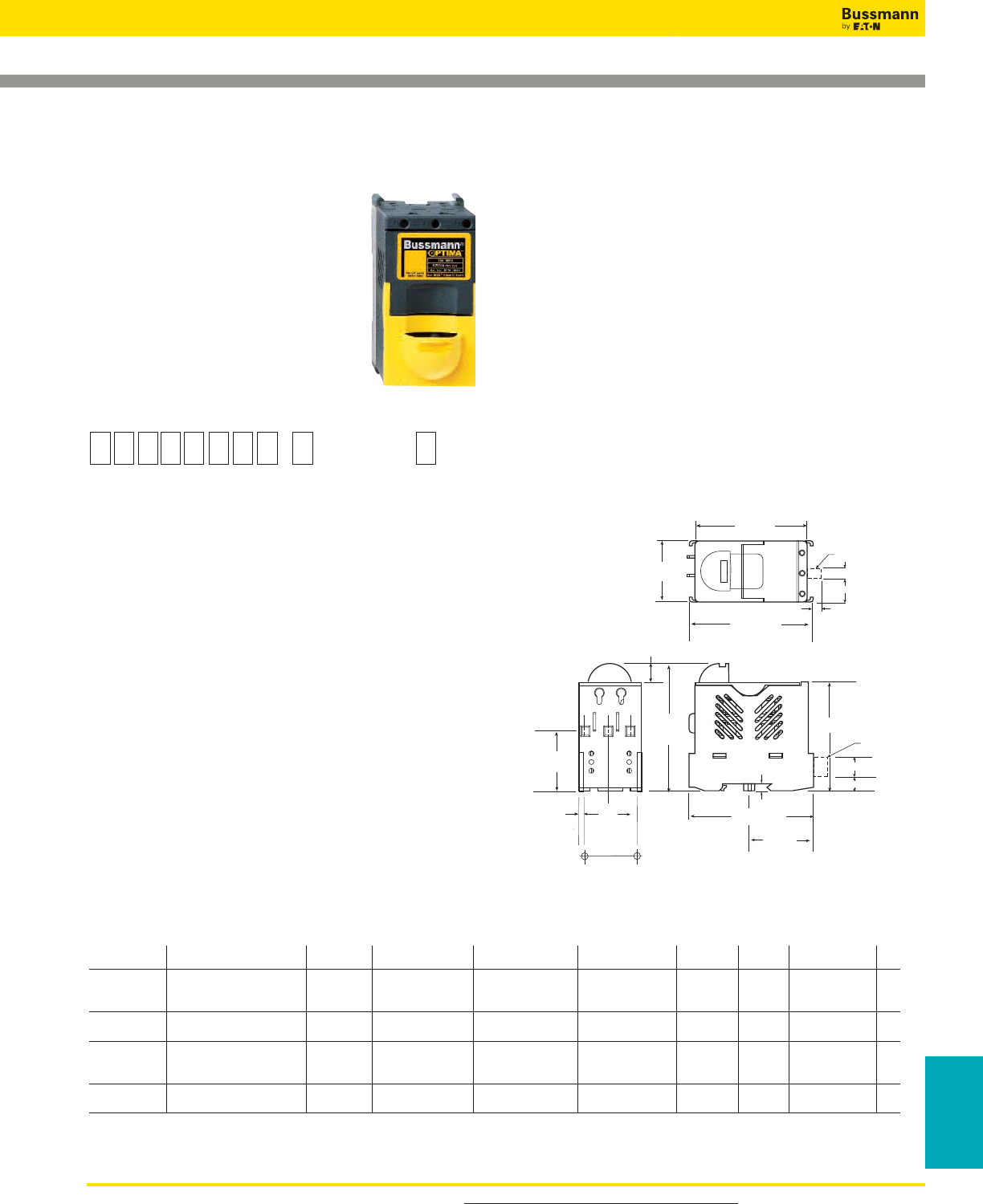
For product data sheets, visit www.cooperbussmann.com/DatasheetsEle 283
Fuse Holders
& Blocks
Fuse Holders and Blocks
Optima™Fuse Holder Module
BUSS
3.74∑ (± 0.03)
(95.0mm)
(± 0.76)
0.57∑
(14.5mm)
0.23∑
(5.8mm)
3.17∑
(80.5mm)
3.22∑ (± 0.03)
0.27∑
0.31∑
(81.8mm) (± 0.76)
3.60∑ (± 0.03)
(91.4mm) (± 0.76)
1.76∑ (± 0.03)
(44.7mm) (± 0.7 )
1.65∑ (± 0.03)
(41.9mm) (± 0.76)
1.312∑
(± 0.01)
(33.3mm)
(± 0.25)
Panel Mount
Hole Pattern
1.86∑ (± 0.03)
(47.2mm)
(± 0.76)
Panel Mount
Hole Pattern
3.60∑ (± 0.03)
(91.4mm) (± 0.76)
Communication
Port
0.74∑
Communication
Port
(6.9mm)
(18.8mm)
(7.9mm)
0.50∑ (12.7mm)
0.44∑ (11.2mm)
2T1
4T2
6T3
IL1
3L2
5L3
0.224"
(5.6mm)
Data Sheet: 1102
Specifications
Description: 3-pole modular fuse holder for 13⁄32” x 1 1⁄2”
(10 x 38mm) fuses.
Dimensions: See Dimensions illustration.
Poles: 3
Agency Information: CE, UL (see table), CSA Certified,
C22.2 No. 4248, Class 6225-01, File 47235, IEC (see table).
Flammability Rating: UL 94V0.
Recommended Fuse Types
Class CC Midget (Non-Rejection) European
LP-CC KTK C10M
KTK-R FNM C10G
FNQ-R FNQ
Physical Characteristics
• Small size matches 45mm IEC starter width
• Accepts #8-18 AWG stranded, #10-18 AWG solid wire
• 3-pole
Features/Benefits
• Padlockable with finger-safe terminals for safety. Qualified
as IP20 per IEC 529.
• Cam-action handle for easy module removal.
• Offered with Class CC rejection clips or European 10 x
38mm clips to meet global needs
• Wire ready with 35mm DIN-Rail or screw panel mounting
(#8 screw, 1 1⁄4˝ long) saves installation time
• Fuse indication lights with option for remote fuse status
indication. See Data Sheet for additional wiring details.
Typical Applications
• Industrial Control
• Process Control Systems
• Automated Warehouse Systems
• Individual Control Circuits
Dimensions
O P M - 1 0 3 8
Series Fuse Type Communication
C =
Communication
Feature
Blank = 10 x
38mm or
13⁄32˝ x 1 1⁄2˝
R= Class CC
Catalog Number Build-A-Code
OPM-1038
Catalog Numbers
Catalog SCCR** Remote Open UL Information
Numbers Electrical Rating Rating Clips Fuse Indication Std. File Guide IEC CE
OPM-1038 30A, 600Vac/dc UL/CSA Non-rejection, No Recognized E14853 IZLT2 IEC 60269-2-1 Yes
(Max 3 Watts per fuse) *10 x 38mm or UL 4248
32A, 660V IEC 13⁄32˝ x 1 1⁄2˝
OPM-1038R 30A, 600Vac/dc UL/CSA 200kA Rejection, No Listed E14853 IZLT Yes
Class CC UL 4248
OPM-1038C 30A, 600Vac/dc UL/CSA Non-rejection, Yes Recognized E14853 IZLT2 IEC 60269-2-1 No
(Max 3 Watts per fuse) *10 x 38mm or UL 4248
32A, 660V IEC 13⁄32˝ x 1 1⁄2˝
OPM-1038RC 30A, 600Vac/dc UL/CSA 200kA Rejection, Yes Listed E14853 IZLT No
Class CC UL 4248
*Rating varies depending on fuse used in module; 200kA maximum.
**Short-Circuit Current Rating
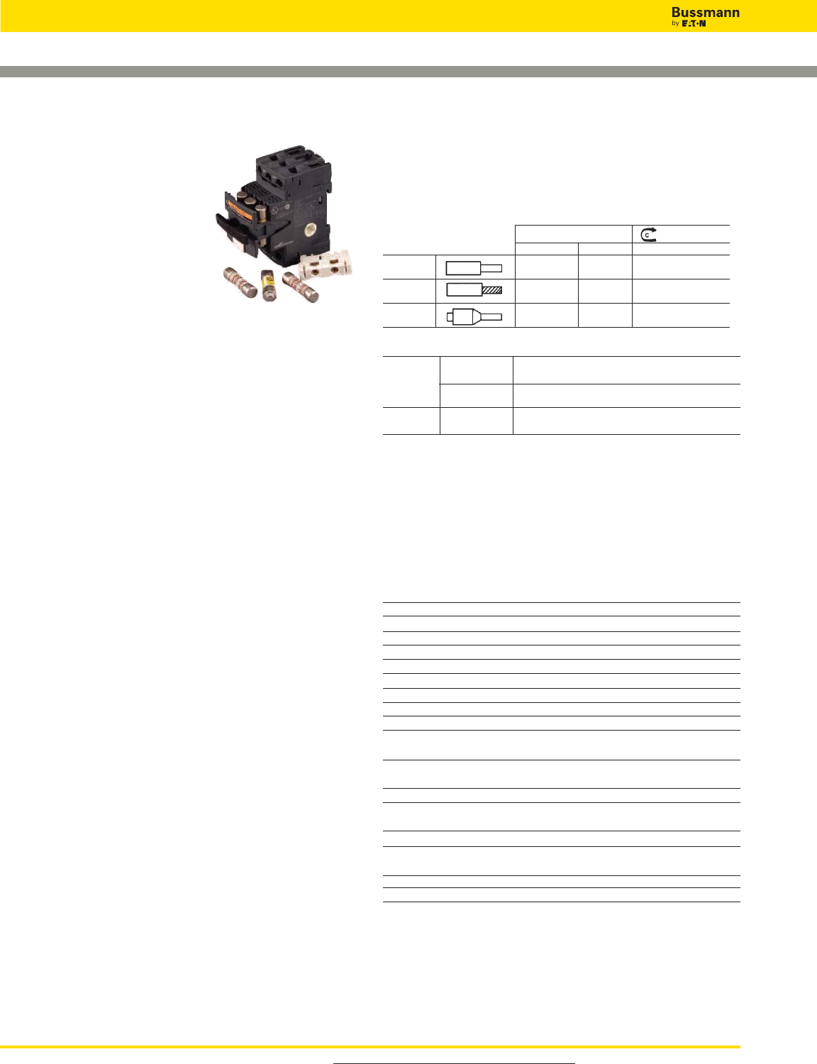
Fuse Holder Wire Range:
— 75°Cu Only
— #18-12 Single/Dual, torque 15lb-in
— #10-8 Single/Dual, torque 20lb-in
— Dual wire with same gauge and type
AWu [mm2] (N•m)/lb-in
Solid #18-8 x 1 1-6 x 1 18-12 Single/Dual
#18-8 x 2 1-6 x 2Strld #18-8 x 1
1-6 x 1
#18-8 x 2 1-6 x 2 10-8 Single/Dual
Ferrules 1-4 x 1 20in-lb (2.5 N•m)
1-4 x 2
Input Power Terminal Wire Range:
Wiring Solid (1) #14 to #2 (1.5 to 25mm2) conductor or
Conductor (2) #14 to #6 (1.5 to 10mm2) conductors
Stranded (1) #14 to #2 (1.5 to 25mm2) conductor or
Conductor (2) #12 to #6 (2.5 to 10mm2) conductors
Tightening Connector 20lb-in (2.2 N•m)
Torque: Screw Clamp 15lb-in (1.7 N•m)
Materials:
— Housing: Thermoplastic - ULV2
— Clip: Tin-plated copper alloy
— Contact lubricant: Fluoroether grease
— Saddle screw: Plated steel
— DIN rail springs: Stainless steel
Optional Accessories:
Comb Bar (Max current rating = 63A)
GV2G245A46 2 circuit, 45mm between same phases
GV2G254A46 2 circuit, 54mm between same phases
GV2G272A46 2 circuit, 72mm between same phases
GV2G345A46 3 circuit, 45mm between same phases
GV2G354A46 3 circuit, 54mm between same phases
GV2G445A46 4 circuit, 45mm between same phases
GV2G454A46 4 circuit, 54mm between same phases
GV2G472A46 4 circuit, 72mm between same phases
GV2G554A46 5 circuit, 54mm between same phases
Input Terminal Block (Max current rating = 63A)
GV2G05 Input/Feed Through Power Terminal, Supports feed through to
another system, DIN-Rail mount only
GVG09 Input Power Terminal
Cover
GV1G10 Protective Cover for unused terminals on comb bar
Auxiliary Contacts
GVAE11 NO/NC
GVAE20 NO/NO
For product data sheets, visit www.cooperbussmann.com/DatasheetsEle
284
Fuse Holders and Blocks
Optima™Three-pole Overcurrent Protection Module
Data Sheet: 1109
Specifications
Description:
OPM-NG-SC3: 3-pole Class CC fuse holder for use with
Class CC fuses (Bussmann Types LP-CC,
FNQ-R, KTK-R).
OPM-NG-SM3: 3-pole fuse holder for use with 13⁄32˝ x 11⁄2˝ and
10.3 x 38mm fuses (Bussmann Types:
13⁄32˝ x 11⁄2˝; KTK, FNQ, KLM, 10 x 38mm;
FWA, FWC, C10G_ _, C10M_ _).
Ratings:
Volts: — OPM-NG-SC3: 600Vac (or less)
— OPM-NG-SM3: 600Vac (or less) UL and CSA 30A
— OPM-NG-SM3: 690Vac (or less) IEC 32A
Amps: — OPM-NG-SC3: 0-30A
— OPM-NG-SM3: 0-30A
SCCR:— OPM-NG-SC3: 200kA
— OPM-NG-SM3: Same as fuse IR, 200kA maximum
Agency Information: CE, UL; OPM-NG-SC3 UL Listed, UL
4248, File E14853, Guide IZLT. OPM-NG-SM3, UL
Recognized, UL 4248, File E14853, Guide IZLT2. CSA
Certified, C22.2 No. 4248, Class 6225-01, File 47235. IEC
60947-3 Utilization Category AC20B.
Handling & Storage Temperature: -10° to 65°C.
Features/Benefits
• 45mm width matches IEC starters
• 35mm DIN-Rail or panel mounting feature. Maximum screw
size #8 (M4)
• Pressure plate terminations with dual-wire rated terminals
(see Wire Table) and optional auxiliary contacts
• Integrated collapsible handle and fuse carrier cannot be
removed from holder base
• Padlockable and IP20 finger-safe to IEC60529
Typical Applications
• Mass Produced Control Systems
• Process Control Systems
• Automated Warehouse Systems
• Individual Control Circuits
OPM-NG-
75º Cu Only
AWG [mm2] (N•m)/lb-in
Solid #18-8 x 1 1-6 x 1 18-12 Single/Dual
#18-8 x 2 1-6 x 2 15lb-in (1.7 N•m)
Stranded #18-8 x 1 1-6 x 1
#18-8 x 2 1-6 x 2 10-8 Single/Dual
Ferrules 1-4 x 1 20lb-in (2.5 N•m)
1-4 x 2
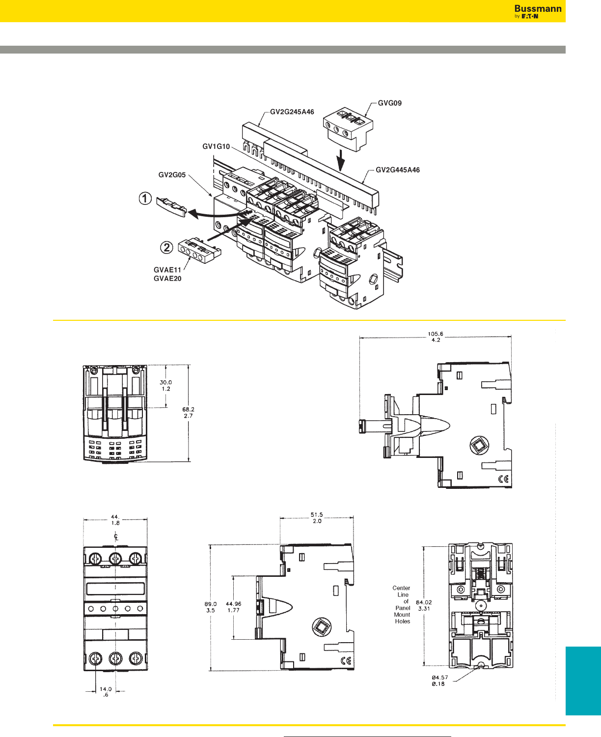
For product data sheets, visit www.cooperbussmann.com/DatasheetsEle 285
Optima™Three-pole Overcurrent Protection Module
Fuse Holders
& Blocks
Data Sheet: 1109
Optional Accessories
Dimensions - mm (± 0.38) / in (± .015)
Fuse Holders and Blocks

For product data sheets, visit www.cooperbussmann.com/DatasheetsEle
286
Fuse Holders and Blocks
Class J (Finger-safe) Fuse Holders
Data Sheet: 1152
30 Amp Version 60 Amp Version
• Short-Circuit Current Rating of 300kA with Bussmann
LPJ___SP fuses.
• Rapid, flexible 35 mm DIN-Rail mounting.
• One piece interlocking design for assembling multiple pole
blocks reduces inventory costs.
• Removable fuse carrier allows fuse replacement away from
base while maintaining finger-safe rating.
Typical Applications
• Industrial Controls
• Process Controls
• Small HP VFDs
Catalog Numbers
Catalog Numbers Amps Indication
JT60030 30 Non-indicating
JT60060 60 Non-indicating
JTN60030 30 Indicating (Neon)
JTN60060 60 Indicating (Neon)
Safety J™ — JT(N)60030 & JT(N)60060
Specifications
Description: Indicating and non-indicating finger-safe,
DIN-Rail mount fuse holders for use with Class J fuses -
(Bussmann LPJ, JKS).
Dimensions: See Dimensions illustrations.
Ratings:
Volts: — 600Vac
Amps: — 0-60A (JT(N)60060)
— 0-30A (JT(N)60030)
SCCR:— 200kA RMS Sym.
— 300kA self certified using Bussmann LPJ_SP fuses
Agency Information: CE, Listed to UL 4248: Guide IZLT,
File 14853, CSA Certified: Class 6225-01, File 47235. IP20
per IEC 60529.
Flammability Rating: UL 94V0.
Indication: Min voltage: 90Vac, 115Vdc; neon lamp “ON”
when fuse opens, voltage source and current path are
present.
Terminations: 30A dual port torque 20lb-in, 60A single port
torque 45lb-in, terminal construction, tin-plated copper alloy.
Wire Size: JT(N)60030 - rated for 75°C, AWG#18-#8; Cu
only, JT(N)60060 - rated for 75°C, AWG#14-#4; Cu only.
(Note: For JT(N)60030 use both stranded or solid, in a variety of dual wire combinations of
same wire size and type.)
Features and Benefits
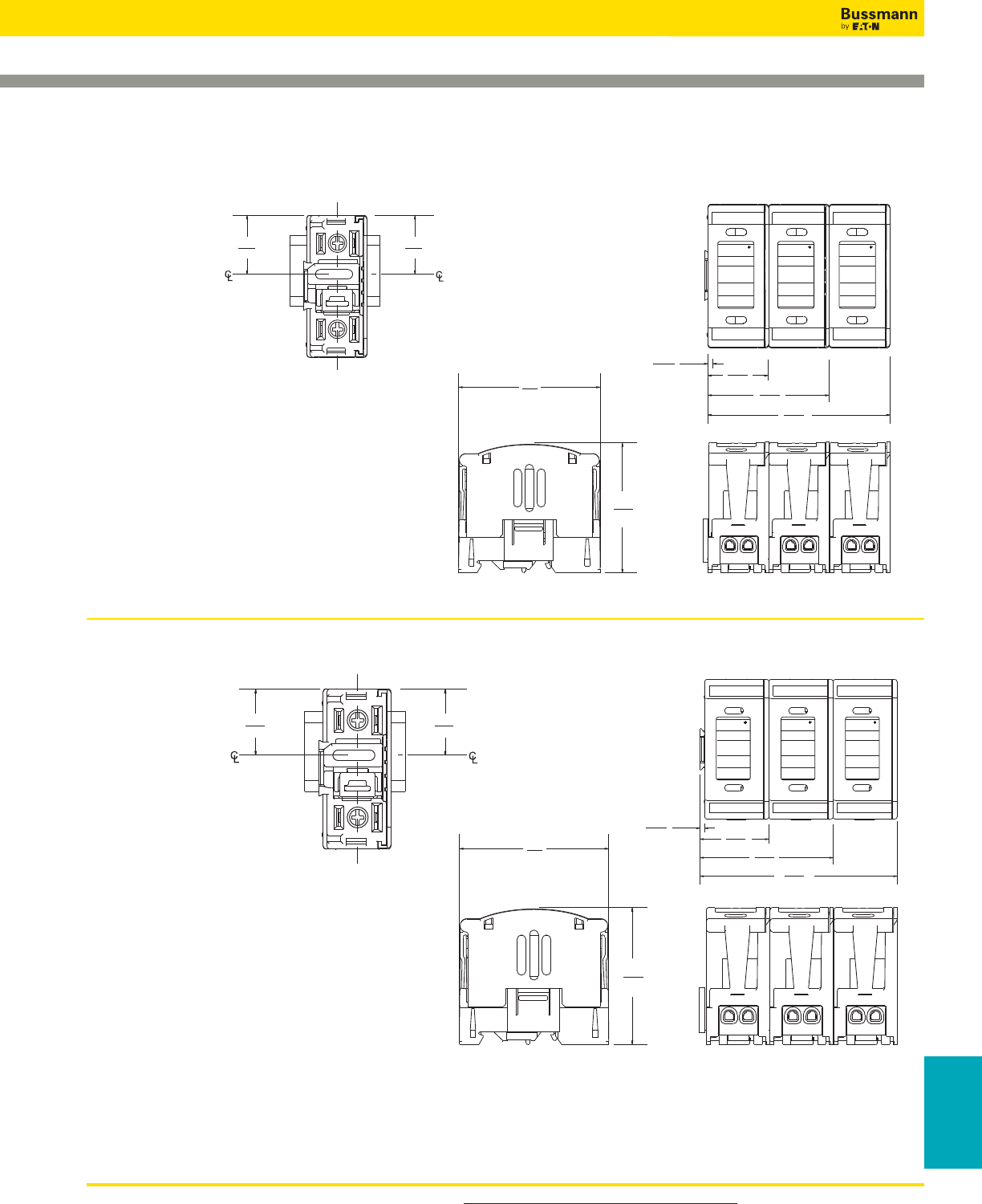
For product data sheets, visit www.cooperbussmann.com/DatasheetsEle 287
Fuse Holders
& Blocks
Class J (Finger-safe) Fuse Holders
JT(N)600 Series fuse blocks can be dovetailed together within the same current rating to provide multiple pole block
configurations.
NOTE: JT(N)60030 cannot be dovetailed to JT(N)60060.
3.10
(78.7)
3.06
(77.7)
1.31
(33.3)
1.25
(31.8)
Din-rail
Slot
MOUNTING
Shown without fuse
pullout cover
4.40
(111.7)
2.96
(75.2)
1.52
(38.1)
.10
(2.6)
BUSS
BUSS
35 – 60A
600VAC
USE CLASS J
FUSES
DO NOT REMOVE
UNDER LOAD
JT60060
BUSS
BUSS
35 – 60A
600VAC
USE CLASS J
FUSES
DO NOT REMOVE
UNDER LOAD
JT60060
BUSS
BUSS
35 – 60A
600VAC
USE CLASS J
FUSES
DO NOT REMOVE
UNDER LOAD
JT60060
1 pole
2 pole
3 pole
Data Sheet: 1152
Dimensions for JT60060 & JTN60060 — in (mm)
1.14
(29.0)
1.05
(26.7)
Slot
MOUNTING
Shown without fuse
pullout cover
BUSS
BUSS
0 – 30A
600VAC
USE CLASS J
FUSES
DO NOT REMOVE
UNDER LOAD
JT60030
BUSS
BUSS
0 – 30A
600VAC
USE CLASS J
FUSES
DO NOT REMOVE
UNDER LOAD
JT60030
BUSS
BUSS
0 – 30A
600VAC
USE CLASS J
FUSES
DO NOT REMOVE
UNDER LOAD
JT60030
3.60
(91.4)
2.42
(61.3)
1.23
(31.2)
.07
(1.8)
1 pole
2 pole
3 pole
2.75
(69.9)
2.52
(64.1)
Din-rail
Dimensions for JT60030 & JTN60030 — in (mm)
Fuse Holders and Blocks
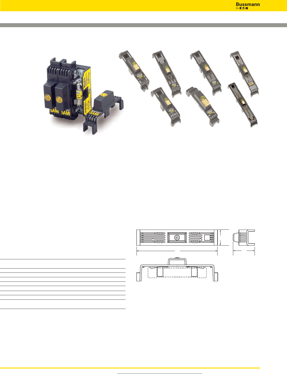
For product data sheets, visit www.cooperbussmann.com/DatasheetsEle
288
Fuse Holders and Blocks
SAMI™ Fuse Covers
Specifications
Description: Indicating and non-indicating fuse covers for
Class J, RK1, RK5, H, K5, CC, G (0-30A) and midget-type
fuses. Indicating feature requires a minimum of 90Vac or
115Vdc to illuminate lamp. One cover required for each pole.
WARNING: To avoid electrical shock, turn power off before
installing, removing or servicing.
Dimensions: See Dimensions illustration.
Ratings:
Volts: — Non-Indicating - 0-600Vac/dc
— Indicating - 90 to 600Vac
-115 to 600Vdc
Amps: — 0-100A
Agency Information: CE, UL Listed; SAMI-1I through
SAMI-6I, SAMI-8I and SAMI-9I, SAMI-1N through SAMI-6N,
SAMI-8N and SAMI-9N, UL Recognized; Guide JDVS2, File
E58836, SAMI-7I and SAMI-7N, CSA Certified,
File LR47235-93C.
Catalog Numbers
Catalog Dimensions - in
Numbers* Description A B C
SAMI-1_ 600V, J (0-30A) and 600V, T (35-60A)** 5.02 1.03 1.94
250V, RK, K5, H (35-60A)
SAMI-2_ 600V, RK, K5, H (0-30A) 7.03 1.30 2.07
SAMI-3_ 600V, J (65-100A) 7.03 1.30 2.33
SAMI-4_ 250V, RK, K5, H (65-100A) 8.20 1.30 2.18
SAMI-5_ 600V, RK, K5, H (35-60A) 8.20 1.30 2.18
SAMI-6_ 600V, J (35-60A) 4.98 1.17 2.14
SAMI-7_ 600V, Midget, Class CC, G (0-30A) 3.82 0.75 1.72
SAMI-8†_ 600V, RK††, K5, H (65-100A) 10.38 1.50 2.33
SAMI-9_ 250V, RK, K5, H (0-30A) and 600V, 3.82 0.75 1.72
T (0-30A)
*For indicating cover, add suffix “I”, for non-indicating cover, add suffix “N”.
Example: SAMI-7I = Indicating, SAMI-7N = Non-indicating.
**Available in non-indicating only.
†SAMI-8A adapter available for small Fusetron™body design. SAMI-8I and SAMI-8N come
standard with adapter (SAMI-8A).
††Not for use with KTS-R fuses.
Features and Benefits
• Insulated cover allows field conversion of fuses mounted in
open fuse blocks to dead front configuration.
• Optional open fuse indicating light aids in system
troubleshooting.
• Units are re-usable.
• Allows visual marking of line and load side of fuses.
Typical Applications
• Class H, R and J fuse blocks up to 100A
• Class T fuse blocks up to 60A
• Class CC, G and Midget, 30A fuse blocks
Dimensions
LINE
Buss
SAMI -2
LOAD
TEST PROBE TEST PROBE
C
B
A
FUSE
Data Sheet: 1204 (Trimming Guides: 12041, 12042, 12043, 12044, 12045, 12046, 12048, 12049)
SAMI-1I SAMI-3I SAMI-4ISAMI-2I
SAMI-6I SAMI-8I
SAMI-7I
SAMI™ Series
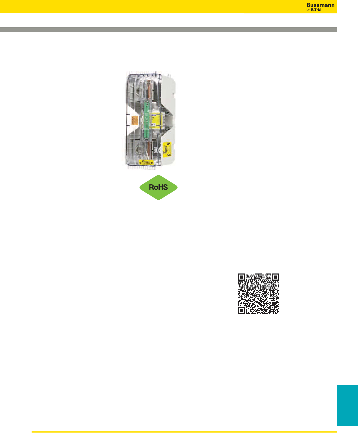
For product data sheets, visit www.cooperbussmann.com/DatasheetsEle 289
Fuse Holders
& Blocks
Fuse Holders and Blocks
Modular Knifeblade Fuse Blocks
Class R, H(K), & J Applications up to
600 Amps
Specifications
Ratings:
Volts: — 250V, 600V
Amps: — 70-600A
SCCR: — 200kA (Class R & J)
10kA (Class H & K)
Agency Information:
Blocks: UL - Listed cULus
E14853 – IZLT & IZLT7
CSA - Certified 47235 –
6225-01
Covers: UL - Listed UL
E58836 – JDVS2
CSA - Certified 47235 –
6225-01
Flammability Ratings:
Blocks: UL 94V0, self-extinguishing
Covers: UL 94HB, self-extinguishing
Operating & Storage Temperature Range:
Blocks -40ºC to 120ºC
Covers non-indicating covers -40ºC to 120ºC
indicating covers -20ºC to 90ºC
Materials:
Base – Thermoplastic
Box Lug – Tin-plated aluminum
Wire:*
Cu/Al – 75ºC/90ºC (100 - 200A)
Cu/Al – 75ºC only (400 - 600A)
*Higher temperature rated wire can be used with appropriate derating.
Features and Benefits
• Integral dovetails allow snapping together multiple poles at
point-of-use for greater application flexibility
• Factory assembled two- and three-pole configurations
available
• Up to four mounting holes per pole increase installation
flexibility
• Standard phase barriers between poles for additional safety
• Design meets UL creep and clearance requirements for
Industrial Control Circuits (UL 508 and UL 845)
• 200 to 600A blocks meet the higher UL creep and clearance
requirements for Industrial Power Distribution Standards
(UL 98, UL 69, UL 489, UL 891 and UL 869A)
• Optional IP20 finger-safe covers available on entire
knifeblade fuse block product line:
– High-clarity see-through covers allow for inspecting wire
terminations or thermography measurements without
removing cover
– Probe holes included for easy, safer testing and
troubleshooting
– Built-in lockout/tagout feature improves safety
• Standard fuse clip reinforcing springs enhance electrical
contact
Typical Applications
• Critical power, factory automation, renewable energy,
HVAC, building/elevator controls, building entrance,
process industries
Scan this tag to get the
latest product information for the
Modular Knifeblade Fuse Blocks.
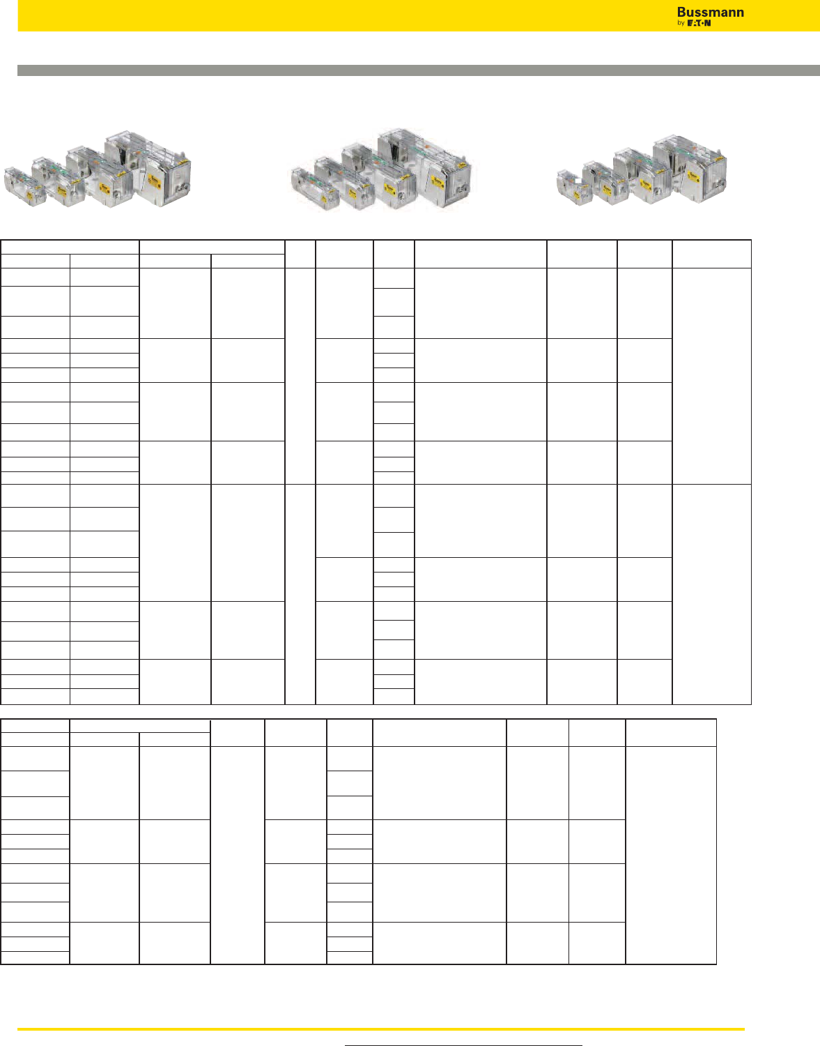
For product data sheets, visit www.cooperbussmann.com/DatasheetsEle
290
Fuse Holders and Blocks
Modular Knifeblade Fuse Blocks Part Number Table
Catalog Number Covers* Fuse Range Number Wire Range Wire Range Torque Cooper Bussmann
Class H(K) Class R w/o Indication w/ Indication Volts (amps) of Poles (solid and stranded)*** (fine stranded Cu) N•m (Lb-in) Fuses
HM25100-1CR RM25100-1CR 1 – 1-3 AWG 6.2 (55)
70- 1/0-3 AWG; (2) Cu 4-6 AWG 4-6 AWG 5.6 (50) Class H(K):
HM25100-2CR RM25100-2CR CVR-RH-25100 CVRI-RH-25100 100 2 4-6 AWG; (2) Cu 8 AWG 8 AWG 5.1 (45) NON
HM25100-3CR RM25100-3CR 3
8 AWG; (2) Cu 10-14 AWG – 4.5 (40)
Cu 10-14 AWG; Al 10-12 AWG – 4.0 (35)
HM25200-1CR RM25200-1CR 110- 1250 MCM-1 AWG 3/0-1 AWG 42 (375) Class R:
HM25200-2CR RM25200-2CR CVR-RH-25200 CVRI-RH-25200 200 22-6 AWG; (2) Cu 2-6 AWG 2-6 AWG 31 (275) LPN-RK_SP
HM25200-3CR RM25200-3CR 250 PN-RK_SPI**
HM25400-1CR RM25400-1CR 1 600kcmil 57 (500) FRN-R
HM25400-2CR RM25400-2CR CVR-RH-25400 CVRI-RH-25400 225- 2500kcmil-4 AWG N/A 51 (450) KTN-R
HM25400-3CR RM25400-3CR
400
3
(2) Cu 3/0 - 4 AWG 57 (500)
(2) Al 3/0 - 4 AWG 34 (300)
HM25600-1CR RM25600-1CR 450- 1
HM25600-2CR RM25600-2CR CVR-RH-25600 CVRI-RH-25600 600 2 (2) 500kcmil-4 AWG N/A 51 (450)
HM25600-3CR RM25600-3CR 3
HM60100-1CR RM60100-1CR 1–1-3 AWG 6.2 (55)
HM60100-2CR RM60100-2CR CVR-RH-60100 CVRI-RH-60100 70- 2
1/0-3 AWG; (2) Cu 4-6 AWG 4-6 AWG 5.6 (50) Class H(K):
100 4-6 AWG; (2) Cu 8 AWG 8 AWG 5.1 (45) NOS
HM60100-3CR RM60100-3CR 3 8 AWG; (2) Cu 10-14 AWG – 4.5 (40)
Cu 10-14 AWG; Al 10-12 AWG – 4.0 (35)
HM60200-1CR RM60200-1CR 110- 1250 MCM-1 AWG 3/0-1 AWG 42 (375) Class R:
HM60200-2CR RM60200-2CR CVR-RH-60200 CVRI-RH-60200 200 22-6 AWG; (2) Cu 2-6 AWG 2-6 AWG 31 (275) LPS-RK_SP
HM60200-3CR RM60200-3CR 600 PS-RK_SPI**
HM60400-1CR RM60400-1CR 1 600kcmil 57 (500) FRS-R
HM60400-2CR RM60400-2CR CVR-RH-60400 CVRI-RH-60400 225- 2500kcmil-4 AWG N/A 51 (450) KTS-R
HM60400-3CR RM60400-3CR
400
3
(2) Cu 3/0 - 4 AWG 57 (500) KWS-R
(2) Al 3/0 - 4 AWG 34 (300) PVS-R
HM60600-1CR RM60600-1CR 450- 1
HM60600-2CR RM60600-2CR CVR-RH-60600 CVRI-RH-60600 600 2 (2) 500kcmil-4 AWG N/A 51 (450)
HM60600-3CR RM60600-3CR 3
Catalog Number Covers* Fuse Range Number Wire Range Wire Range Torque Cooper Bussmann
Class J w/o Indication w/ Indication Volts (amps) of Poles (solid and stranded)
(fine stranded)
N•m (Lb-in) Fuses
JM60100-1CR 1 –1-3 AWG 6.2 (55)
2
1/0-3 AWG; (2) Cu 4-6 AWG 4-6 AWG 5.6 (50)
JM60100-2CR CVR-J-60100 CVRI-J-60100 70- 4-6 AWG; (2) Cu 8 AWG 8 AWG 5.1 (45)
JM60100-3CR
100 8 AWG; (2) Cu 10-14 AWG – 4.5 (40)
3Cu 10-14 AWG; Al 10-12 AWG – 4.0 (35)
JM60200-1CR 110- 1250 MCM-1 AWG 3/0-1 AWG 42 (375)
JM60200-2CR CVR-J-60200 CVRI-J-60200 200 22-6 AWG; (2) Cu 2-6 AWG 2-6 AWG 31 (275) LPJ_SP
JM60200-3CR 600 PJ_SPI**
JM60400-1CR 1 600kcmil 57 (500) JKS
JM60400-2CR CVR-J-60400 CVRI-J-60400 225- 2500kcmil-4 AWG N/A 51 (450) DFJ
JM60400-3CR
400
3
(2) Cu 3/0 - 4 AWG 57 (500)
(2) Al 3/0 - 4 AWG 34 (300)
JM60600-1CR 450- 1
JM60600-2CR CVR-J-60600 CVRI-J-60600 600 2 (2) 500kcmil-4 AWG N/A 51 (450)
JM60600-3CR 3
*Covers sold serarately. Blown fuse indication requires 90 volts minimum and closed circuit to operate.
**With
easy
ID™ blown fuse indication. ***Ratings for copper and aluminum wire except where otherwise noted.
250V Class R & H(K) 600V Class R & H(K) Class J
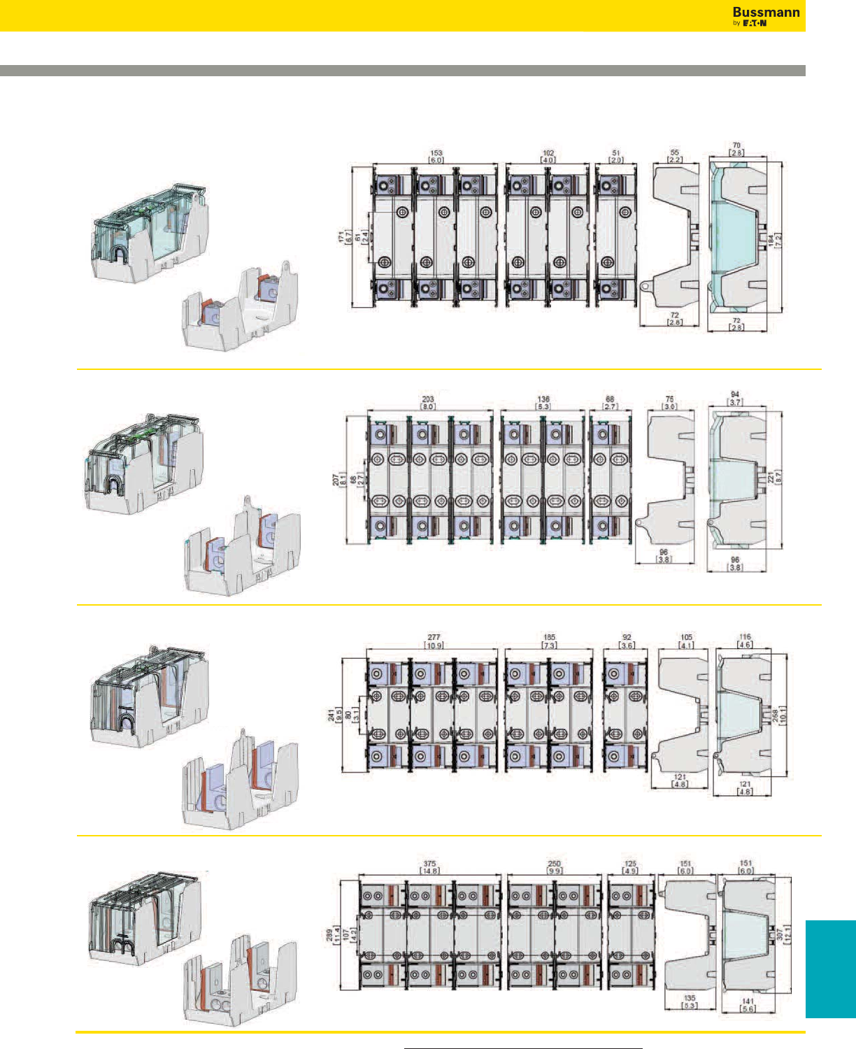
For product data sheets, visit www.cooperbussmann.com/DatasheetsEle 291
Fuse Holders
& Blocks
Fuse Holders and Blocks
250V Class R & H(K) Dimensional Specifications
Dimensions - mm (in)
70- 100A
110- 200A
225- 400A
450- 600A
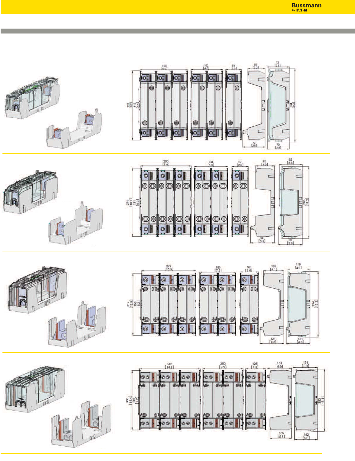
For engineering drawings, go to www.cooperbussmann.com/KnifebladeFuseBlocks
292
Fuse Holders and Blocks
600V Class R & H(K) Dimensional Specifications
Dimensions - mm (in)
70- 100A
110- 200A
225- 400A
450- 600A
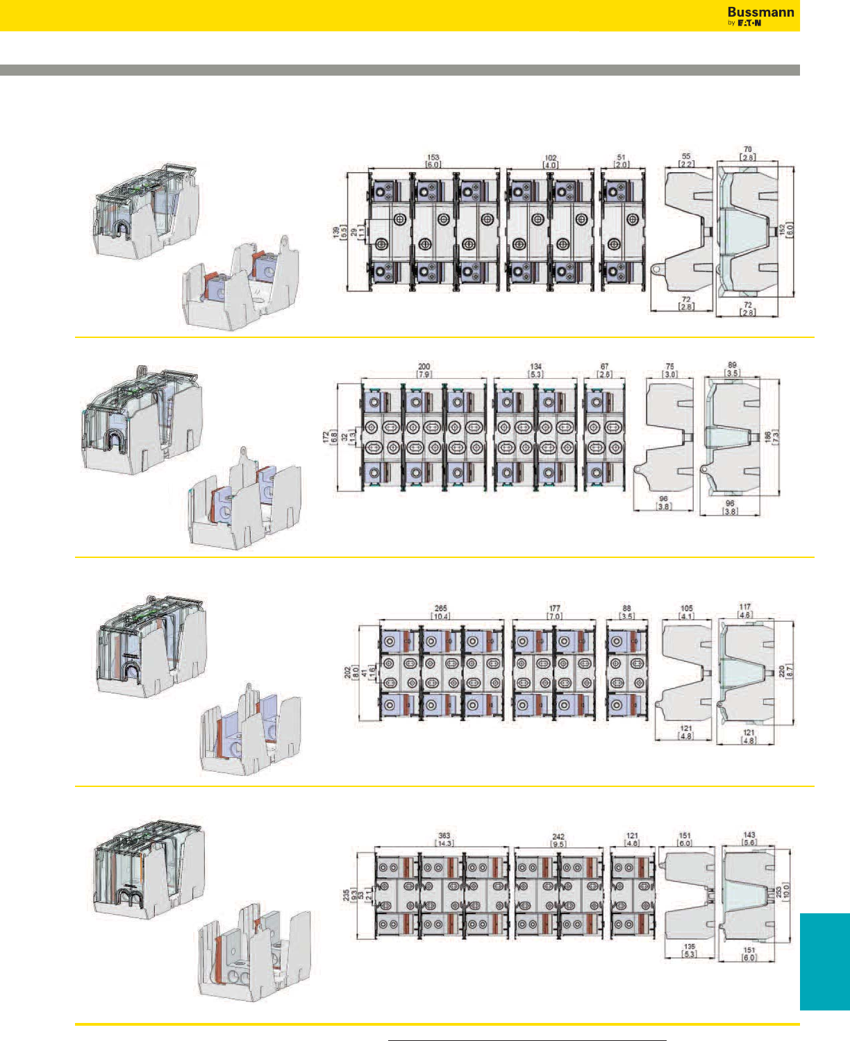
For engineering drawings, go to www.cooperbussmann.com/KnifebladeFuseBlocks 293
Fuse Holders and Blocks
Class J Dimensional Specifications
Dimensions - mm (in)
Fuse Holders
& Blocks
70- 100A
110- 200A
225- 400A
450- 600A
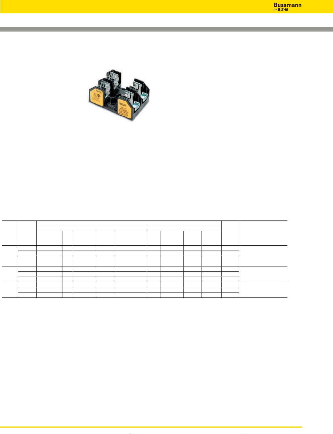
For engineering drawings, go to www.cooperbussmann.com/KnifebladeFuseBlocks
294
Fuse Holders and Blocks
Class H(K) and R Fuse Blocks – 250V
Data Sheet: H250 Series, 1112; R250 Series, 1110
H250 & R250 Series
Specifications
Descriptions:
H250 Series: 1-, 2- and 3-pole fuse
blocks for use with Class
H fuses.
R250 Series: 1-, 2- and 3-pole fuse
blocks for use with Class
R fuses (Bussmann LPN-
RK and FRN-R and KTN-R fuses).
Dimensions: See Dimensions illustrations.
Ratings:
Volts: — 250Vac/dc (H250 & R250 Series)
Amps: — 1⁄10-100A
SCCR: — H250 Series; 10kA RMS Sym.
— R250 Series; 200kA RMS Sym.
Agency Information: CE, UL Listed UL 4248, Guide IZLT,
File E14853; CSA Certified, Class 6225-01, File 47235.
Flammability Rating: UL 94V0.
Features and Benefits
• H250 fuse blocks provide one, two and three pole housing
for Class H, K and R fuses at 250Vac.
• H250 fuse blocks are listed with a Short-Circuit Current
Rating of 10kA RMS Sym.
• R250 fuse blocks provide 1-, 2- and 3-pole housing for Class
R fuses at 250Vac.
• R250 fuse blocks are listed with a Short-Circuit Current
Rating of 200kA RMS Sym.
Typical Applications
• 250Vac/dc or less Control Systems
• 250Vac/dc or less Industrial Control
• 250Vac/dc or less Industrial Control Circuits
Recommended DIN-Rail adapters for the 1⁄10-30A series
• see page 509.
Class H Fuseblocks (250V) Catalog Data (for NON and REN Fuses)
Terminal Type (Suffix No.)
Screw Box Lug w/
1⁄10 1 H25030-1 S SR P PR C CR — Q 1 C, CR #2-14 Cu, #2-12 Al
to 2 H25030-2 S SR P PR C CR — — 2 P, PR #10-18 Cu Only
30 3 H25030-3 S SR P PR C CR — — 3 Q N/A
S, SR #10-18 Cu Only
31 1 H25060-1 — — — — C CR CO — 4
C, CR #2-14 Cu, #2-8 Al
to 2 H25060-2 — — — — C CR CO — 5
CO #2-14 Cu Only
60 3 H25060-3 — — — — C CR CO — 6
61 1 H25100-1 — SR — — — CR — — 7
to 2 H25100-2 — SR — — — CR — — 8
CR #1/0-8 Cu/Al
100 3 H25100-3 — SR — — — CR — — 9
SR #8W/ Ring Terminal
Amps
Catalog
Number
Pressure
Plate
Pressure Plate
& Clip with
Reinforced Spring
Copper
Only
Wire
Range
0.25˝
Quick
Connect
Clip with
Reinforced
Spring
Clip with
Reinforced
Spring
——
Figure
Number
Poles
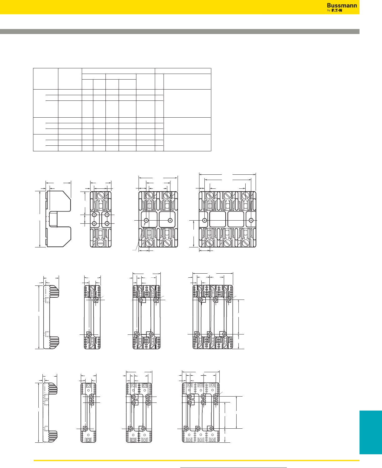
For product data sheets, visit www.cooperbussmann.com/DatasheetsEle 295
Fuse Holders
& Blocks
Fuse Holders and Blocks
Class H(K) and R Fuse Blocks – 250V
Data Sheet: H250 Series, 1112; R250 Series, 1110
1.41"
0.22"
1.09"
3.03"
0.5"
0.17" 0.75" 0.25"
1.25"
0.95"
0.22" DIAMETER
0.41"
2.05"
2 SPACES AT
0.95" - 1.91"
2.5"
3"
0.55"
1.27"
1.52"
0.55"
Dimensions – in
250V 1⁄10 to 30A
FIGURE 1. FIGURE 2. FIGURE 3.
4.25
0.27
1.73 1.5
0.5
2.81
0.5 1.31
0.5
1.31
4.125
G
1.5
0.5
1.310.5
1.25
0.22 x 0.41
0.22 x 0.41
0.22 x 0.41
250V, 31A to 60A
FIGURE 4. FIGURE 5. FIGURE 6.
Class R Fuseblocks (250V) Catalog Data (for LPN-RK, FRN-R and KTN-R Fuses)
Terminal Type (Suffix No.)
Screw w/ Box Lug w/ 0.25”
Catalog Pres. Clip Quick- Fig. Wire
Number — Plate — Cu Only Connect No. Range
1⁄10 1 R25030-1 SR PR CR COR QR* 1 COR #6-14 Cu Only
to 2 R25030-2 SR PR CR COR — 2 CR #2-14 Cu, #2-12 Al
30 3 R25030-3 SR PR CR COR — 3 PR #10-18 Cu Only
QR N/A
SR #10-18 Cu Only
31 1 R25060-1 — — CR — — 4
to 2 R25060-2 — — CR — — 5 CR #2-14 Cu, #2-8 Al
60 3 R25060-3 — — CR — — 6
61 1 R25100-1 — — CR — — 7
to 2 R25100-2 — — CR — — 8 CR 1/0-8 Cu/Al
100 3 R25100-3 — — CR — — 9
Poles
Amps
250V, 61A to 100A
FIGURE 7. FIGURE 8. FIGURE 9.
7.36"
0.25"
2.06" 1.81"
0.62"
3.38"
0.59"
0.62"
4.94"
2.38"
2.125"
0.62"
0.28" DIA. x
0.5" C'BORE
0.59"
1.56" 1.56"1.56"
3.125"
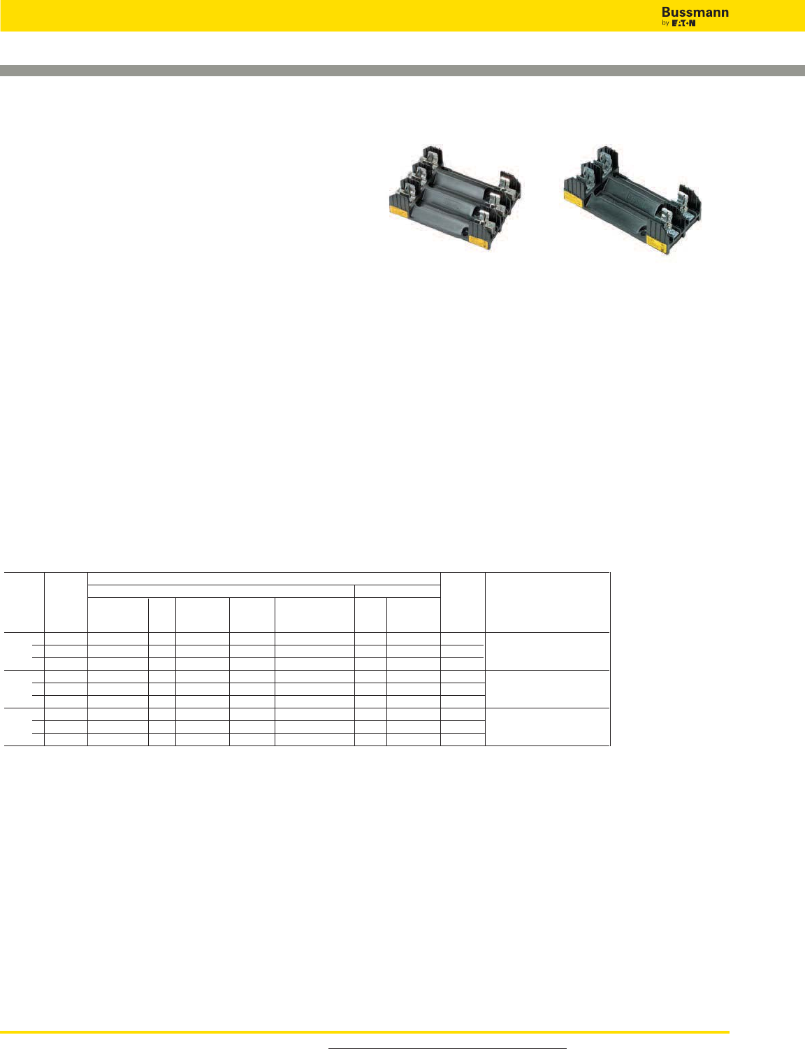
For product data sheets, visit www.cooperbussmann.com/DatasheetsEle
296
Fuse Holders and Blocks
Class H(K) and R Fuse Blocks – 600V
Data Sheet: H600 Series, 1113; R600 Series, 1111
H60030-2PR
H60030-3C
H600 & R600 Series
Specifications
Descriptions:
H600 Series: fuse blocks for use with 1-, 2- and 3-pole
Class H fuses.
R600 Series: fuse blocks for use with 1-, 2- and 3-pole
Class R fuses (Bussmann LPS-RK, FRS-R, PVS-R and
KTS-R fuses).
Dimensions: See Dimensions illustrations.
Ratings:
Volts: — 600Vac/dc (H600 & R600 Series)
Amps: — 1⁄10-100A
SCCR: — H600 Series; 10kA RMS Sym.
— R600 Series; 200kA RMS Sym.
Agency Information: CE, UL Listed UL 4248, Guide IZLT,
File E14853; CSA Certified, Class 6225-01, File 47235.
Flammability Rating: UL 94V0.
Features and Benefits
• H600 fuse blocks provide one-, two- and three-pole housing
for Class H, K and R fuses at 600Vac.
• H600 fuse blocks are listed with a Short-Circuit Current
Rating of 10kA RMS Sym.
• R600 fuse blocks provide one-, two- and three-pole housing
for Class R fuses at 600Vac.
• R600 fuse blocks are listed with a Short-Circuit Current
Rating of 200kA RMS Sym.
Typical Applications
• 600Vac/dc or less Control Systems
• 600Vac/dc or less Industrial Control
• 600Vac/dc or less Individual Control Circuits
Class H Fuseblocks (600V) Catalog Data (for NOS and RES Fuses)
Terminal Type (Suffix No.)
Screw Box Lug w/
1⁄10 1 H60030-1 S SR P PR C CR 1
C, CR #2-14 Cu, #2-12 Al
to 2 H60030-2 S SR P PR C CR 2 P, PR, S, SR #10-18 Cu Only
30 3 H60030-3 S SR P PR C CR 3
31 1 H60060-1 — — — — C CR 4
to 2 H60060-2 — — — — C CR 5 C, CR #2-14 Cu, #2-8 Al
60 3 H60060-3 — — — — C CR 6
61 1 H60100-1 — — — — — CR 7
to 2 H60100-2 — — — — — CR 8 CR #1/0-8 Cu/Al
100 3 H60100-3 — — — — — CR 9
Pressure
Plate
Pressure Plate
& Clip with
Reinforced Spring
Wire
Range
Clip with
Reinforced
Spring
—
Figure
Number
Amps
Catalog
Number
Clip with
Reinforced
Spring
—
Poles

For product data sheets, visit www.cooperbussmann.com/DatasheetsEle 297
Fuse Holders
& Blocks
Fuse Holders and Blocks
Class H(K) and R Fuse Blocks – 600V
Data Sheet: H600 Series, 1113; R600 Series, 1111
Class R Fuseblocks (600V) Catalog Data (for LPS-RK, FRS-R, PVS-R and KTS-R Fuses)
Terminal Type (Suffix No.)
Screw w/ Box Lug w/
Catalog Pres. Clip Fig. Wire
Number — Plate — Cu Only No. Range
1⁄10 1 R60030-1 SR PR CR — 1 COR #6-14 Cu Only
to 2 R60030-2 SR PR CR COR 2 CR #2-14 Cu, #2-12 Al
30 3 R60030-3 SR PR CR COR 3 PR, SR #10-18 Cu Only
31 1 R60060-1 — — CR — 4
to 2 R60060-2 — — CR — 5 CR #2-14 Cu, #2-8 Al
60 3 R60060-3 — — CR — 6
61 1 R60100-1 — — CR — 7
to 2 R60100-2 — — CR — 8 CR, 1/0-8 Cu/Al
100 3 R60100-3 — — CR — 9
6.25
0.26
1.73 1.54
0.62
2.90
0.25 1.56
0.62
1.56
4.25
3.13
1.56
0.62
1.560.25
0.28 x 0.5
0.28 x 0.5 0.28 x 0.5
7.36"
0.25"
2.06" 1.81"
0.62"
3.38"
0.59"
0.62"
4.94"
2.38"
2.125"
0.62"
0.28" DIA. x
0.5" C'BORE
0.59"
1.56" 1.56"1.56"
3.125"
Dimensionals – in
600V, 1⁄10 to 30A
600V, 31 to 60A
FIGURE 1. FIGURE 2. FIGURE 3.
FIGURE 4. FIGURE 5. FIGURE 6.
Amps
Poles
0.88
0.88
0.67 1.81
4.03
2.22
0.28 x 0.5
0.28 x 0.5
0.88
0.67 1.81 1.81
0.28 x 0.5
5.84
9.5
0.34
2.38
4.25
2.63
600V, 61 to 100A
FIGURE 7. FIGURE 8. FIGURE 9.
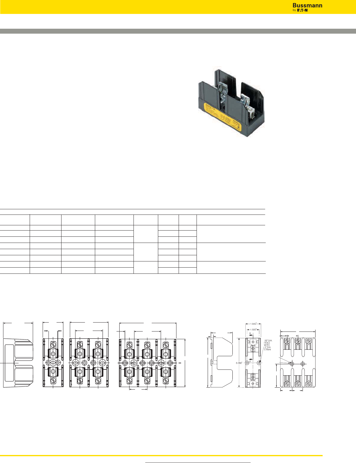
For product data sheets, visit www.cooperbussmann.com/DatasheetsEle
298
Fuse Holders and Blocks
J600 Series
Specifications
Description: 1-, 2- or 3-pole fuse blocks for use with Class
J fuses (Bussmann LPJ, DFJ and JKS).
Dimensions: See Dimensions illustrations.
Construction: Thermoplastic.
Poles: 1 to 3
Ratings:
Volts: — 600Vac/dc
Amps: — 1⁄2-100A
SCCR: — 200kA RMS Sym.
Agency Information: CE, UL Listed, UL 4248, Guide IZLT,
File E14853, CSA Certified, C22.2 No. 4248, Class 6225-01,
File 47235.
Flammability Rating: UL 94V0.
Mounting: Accepts DIN-Rail adapter DRA-1. See page 507.
Class J Fuse Blocks
Data Sheet: 1114
1⁄2- 60A
Dimensions - in (±0.015)
.30"
2.28"
6
.28"
.94"
.22"
Dia.
.5"
C'Bore
1.583"
5"
3.14"
1.75" 1.5"
FIGURE 4. FIGURE 5.
Catalog Numbers
Pressure Box Box Lug w/ Fig. Wire
Screw† Plate† Lug Retaining Clip Amps Poles No. Range
J60030-1S* J60030-1P J60030-1C J60030-1CR†† 1 1 C, CR #2-14 Cu, #2-8 Al
J60030-2S* J60030-2P J60030-2C J60030-2CR†† 1⁄2-30 2 2 COR #2-14 Cu Only
J60030-3S* J60030-3P J60030-3C J60030-3CR†† 3 3 P, PR, S, SR #10-14 Cu Only
— — J60060-1C J60060-1CR†† 1 1 C, CR, #2-14 Cu/Al
— — J60060-2C J60060-2CR†† 31-60 2 2 COR #4-14 Cu Only
— — J60060-3C J60060-3CR†† 3 3
— — — J60100-1CR 61-100 1 4 COR 1/0-8 Cu Only
— — — J60100-3CR†† 3 5 CR, CRQ 1/0-8 Cu/Al
†Clip reinforcing springs are standard on fuse blocks rated 100A and above. Available on 30A and 60A blocks by adding the letter “R” to the end of the part
number.
††Copper only connections available by changing “CR” suffix to “COR”.
*No UL, No CSA Certification
Features and Benefits
• J600 fuse blocks provide one-, two- and three-pole housing
for Class J fuses at 600Vac.
• J600 fuse blocks are listed with a Short-Circuit Current
Rating of 200kA RMS Sym.
Typical Applications
• 600Vac/dc or less Control Systems
• 600Vac/dc or less Industrial Control
• 600Vac/dc or less Individual Control Circuits
Catalog Numbers
61-100A
2.415"
.750
1.702
2.250
3.202
.750
4.702
2.250
C
L
L
1.500
4.005
C
FIGURE 1. FIGURE 2. FIGURE 3.
61-100
31-60
1⁄2-30
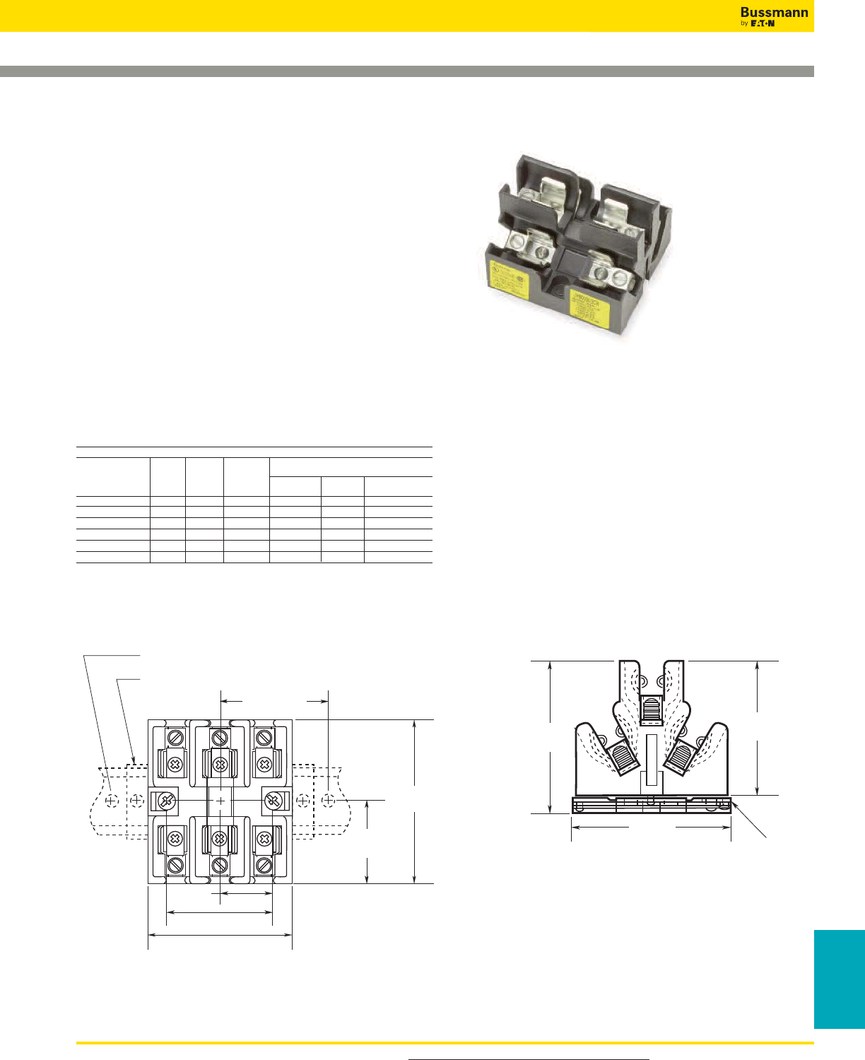
For product data sheets, visit www.cooperbussmann.com/DatasheetsEle 299
Fuse Holders
& Blocks
Fuse Holders and Blocks
Class J Fuse Blocks
JP Series
Specifications
Description: Pyramid style 3-pole fuse block for use with
Class J fuses (Bussmann LPJ, DFJ, JKS).
Dimensions: See Dimensions illustrations.
Ratings:
Volts: — 600Vac/dc
Amps: — 0-30A
SCCR: — 200kA RMS Sym.
Agency Information: CE, UL Listed, UL 4248, Guide IZLT,
File E14853, CSA Certified, C22.2 No. 39, Class 4225-04,
File 47235.
Flammability Rating: UL 94V0.
Mounting: Panel or 35mm DIN-Rail mount.
To order DIN-Rail: Part# NDNA 100 (1 meter) or NDNA 200
(2 meter).
Catalog Numbers
Mounting
With Screws
DIN with Box
Catalog Rail Pressure Copper
Numbers Panel Adapter* Plate Aluminum Only Wire Range
JP60030-3PR X X #10-14 Cu Only
JP60030-3CR X X #2-14 Cu/Al
JP60030-3COR X X #2-14 Cu Only
JP60030-3PRA X X #10-14 Cu Only
JP60030-3CRA X X #2-14 Cu/Al
JP60030-3CORA X X #2-14 Cu Only
*Adapter only for DIN-Rail - Cat No. JPA-3.
3.29"
(83.6mm)
END STOPS - PREVENT BLOCK MOVEMENT WHEN CHANGING FUSES
DIN-RAIL MOUNTING SCREW 8" (203.2mm) APART
4.00" MAX.
(101.6mm)
1.19"
(30.2mm)
3.75" (0.02)
(95.3mm (0.50)
1.88"
(47.6mm)
2.38"
(60.4mm)
2.78"
(70.6mm)
3.06"
(77.8mm)
3.13"
(79.5mm) ADAPTOR
FOR 35mm
SYMMETRICAL
DIN-RAIL
MOUNTING
Dimensions - in ± 0.015” (± 0.40mm)
Data Sheet:1108
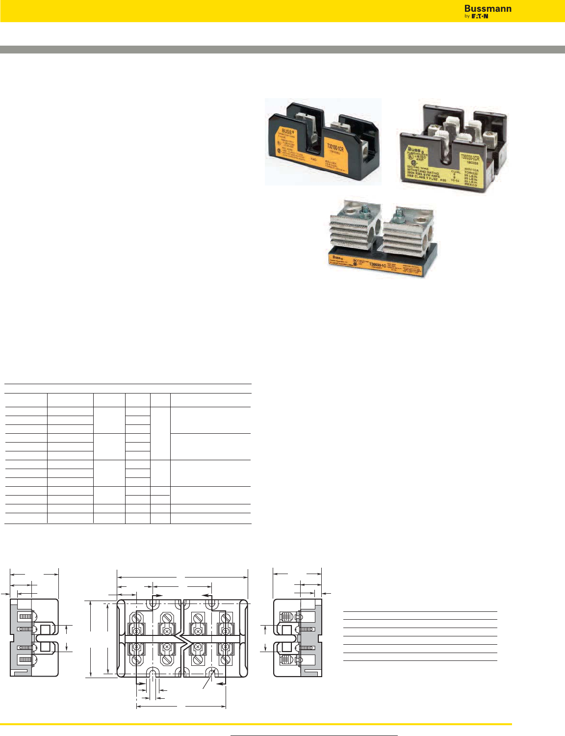
For product data sheets, visit www.cooperbussmann.com/DatasheetsEle
300
Fuse Holders and Blocks
Class T Fuse Blocks – 300V
Data Sheet: 1115
T30030-S
SECTION X-X
0.91"
1.63"
0.72"
0.16"
Z
XFull
Radius
ZX
0.44"
0.20"
C
B
1.20"
A
0.69"
2.5"
2.75"
T30060-C
SECTION Z-Z
0.91"
1.63"
0.72"
0.16"
Dimensions - in Figure 1. 1⁄2-60A
T300
Specifications
Description: T300 (300V) fuse blocks for use with Class T
fuses (Bussmann JJN).
Dimensions: See Dimensions illustrations.
Poles: 1 to 4
Ratings:
Volts: — 300Vac/dc
Amps: — 1⁄2- 600A
SCCR:— 200kA RMS Sym.
Agency Information: CE, UL Listed UL 4248, Guide IZLT,
File E14853, CSA Certified, Class 6225-01, File 47235.
Flammability Rating: UL 94V0.
Features and Benefits
• Provide 1-, 2- and 3-pole housing for 300Vac Class T fuses.
• Short-Circuit Current Rating of 200kA RMS Sym.
• Class T fuse blocks have a small foot print, providing
substantial space savings in equipment
Typical Applications
• 300Vac/dc or less Control Systems
• 300Vac/dc or less Individual Control Circuits
Catalog Numbers
T30100-1CR
T30030-2CR
T30600-1C
Catalog Dimensions - in
Number A B C
T30030-2 2.41 — 1.03
T30060-2 2.41 — 1.03
T30030-3 3.44 1.03 2.06
T30060-3 3.44 1.03 2.06
T30030-4 4.47 2.06 3.09
T30060-4 4.47 2.06 3.09
Catalog Numbers
Fig.
Screw Box Lug Amps Poles No. Wire Range
T30030-2SR T30030-2CR 1/2-30 2 1 SR #10-18 Cu
T30030-3SR T30030-3CR 3 CR #6-14 Cu/Al
T30030-4SR T30030-4CR 4
T30060-2SR T30060-2CR 31-60 2 1 CR #2-14 Cu/Al
T30060-3SR T30060-3CR 3 SR #10-18 Cu Only
T30060-4SR T30060-4CR 4
— T30100-1CR 61-100 1 2
— T30100-2CR 2 1/0-8 Cu/Al
— T30100-3CR 3
— T30200-1C 101-200 1 3 250kcmil-6 Cu/Al
— T30200-3C 3 4
— T30400-1C 201-400 1 5 600kcmil-2/0 Cu/Al
— T30600-1C 401-600 1 6 (2) 600kcmil-4/0 Cu/Al
1⁄2-30
1
2
31-60
61-100
101-200
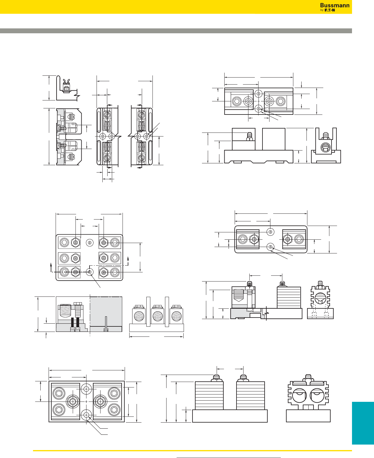
For product data sheets, visit www.cooperbussmann.com/DatasheetsEle 301
Fuse Holders
& Blocks
Fuse Holders and Blocks
Class T Fuse Blocks – 300V
Data Sheet: 1115
Z
Z
0.52" C'BORE
0.55" DEEP
0.22" DIA.
X
X
2.39"
2.25"
REF.
4.78"
2.06"
1.69" (1 POLE)
3.09" (2 POLE)
4.5" (3 POLE)
1.41" (2 POLE)
2.81" (3 POLE)
0.84"
0.38"
0.75"
0.625" C'BORE 0.438" DEEP
0.282" DIAMETER THRU HOLE
.996"
A
A2.75"
1.695"
4.87"
0.625"
2.375"
4.46"
Figure 2. 61 to 100A
3"
6"
0.28" DIAMETER
0.63" C'BORE 0.5" DEEP
1.125"
2.56"
1.94"
0.81"
3.06"
1.69"
0.05"
1.25" 2.25"
Figure 3. 101 to 200A
Figure 4. 200A
0.63" C'BORE 0.5" DEEP
6"
0.28" DIAMETER
1.125"
2.25"
0.63"
3"
1.25"
1.84"
0.81"
2.38"
3.06"
Figure 5. 201 to 400A
3.44"
0.75"
3"
2.03"
3"2"
1.5"
5.75"
2.88"
0.33" DIAMETER
0.75" C'BORE 0.5" DEEP
Figure 6. 401 to 600A
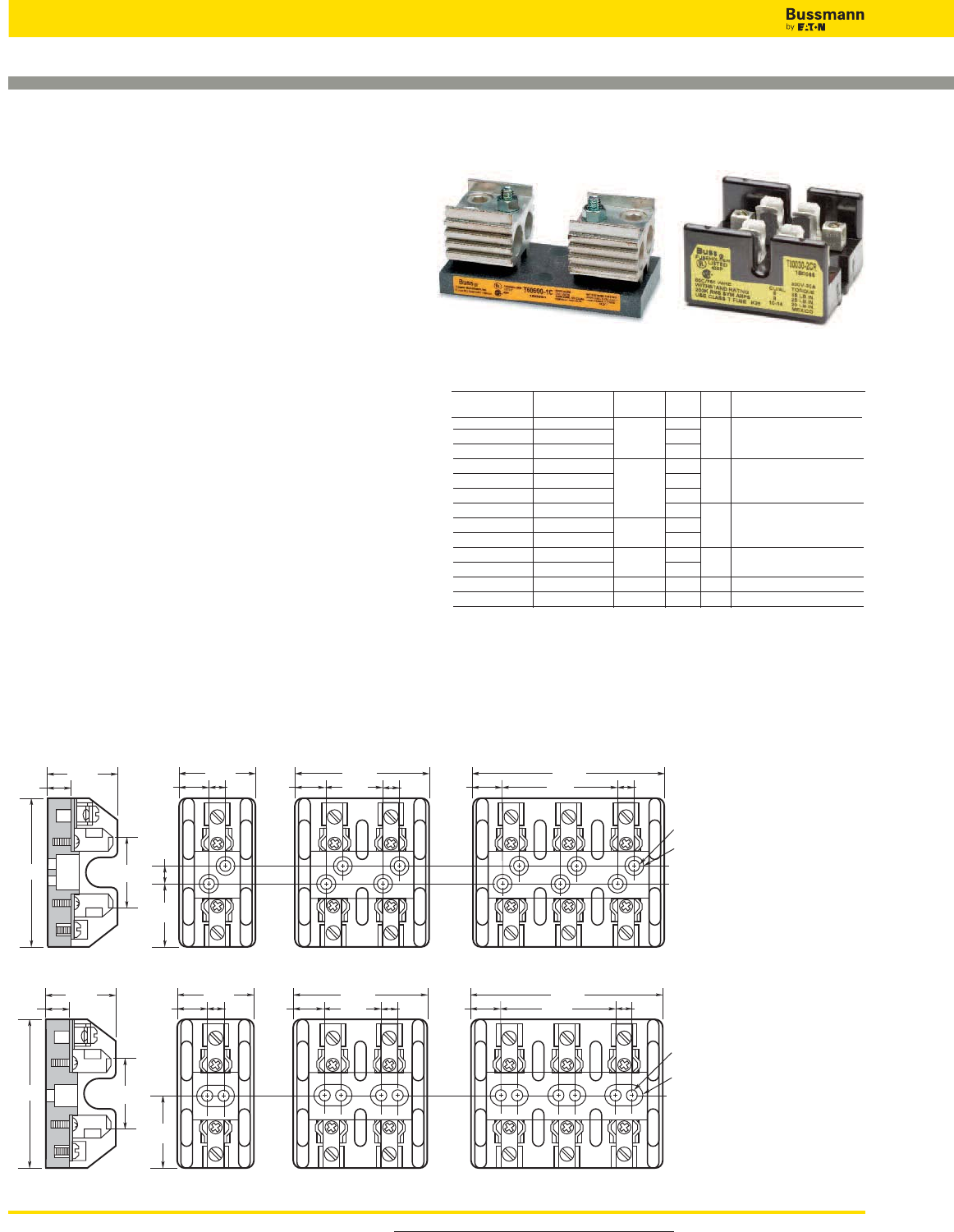
For product data sheets, visit www.cooperbussmann.com/DatasheetsEle
302
Fuse Holders and Blocks
Class T Fuse Blocks – 600V
Data Sheet: 1116
Figure 1. 1⁄2to 30A
3.19"
1.44"
1.563"
0.33"
1.42"
0.5"
1.44"
0.55" 0.33" 0.55"
2.59"
1.16" 0.33" 0.55"
3.75"
2.31" 0.33"
0.22" DIAMETER
0.5" C'BORE
2.94"
1.75"
1.63"
1.47"
0.5"
1.81"
0.59" 0.63" 0.59"
3.34"
1.53" 0.63" 0.59"
4.86"
3.06" 0.63"
0.22" DIAMETER
0.5" C'BORE
Figure 2. 31 to 60A
T600
Specifications
Description: T600 (600V) fuse blocks for use with Class T
fuses (Bussmann JJS).
Dimensions: See Dimensions illustrations.
Poles: 1 to 3
Ratings:
Volts: — 600Vac/dc
Amps: — 1⁄2- 600A
SCCR:— 200kA RMS Sym.
Agency Information: CE, UL Listed UL 4248, Guide IZLT,
File E14853, CSA Certified, Class 6225-01, File 47235.
Flammability Rating: UL 94V0.
Features and Benefits
• Provide 1-, 2- and 3-pole housing for 600Vac Class T fuses.
• Short-Circuit Current Rating of 200kA RMS Sym.
• Class T fuse blocks have a small foot print, providing
substantial space savings in equipment
Typical Applications
• 600Vac/dc or less Control Systems
• 600Vac/dc or less Individual Control Circuits
T30030-2CR
T60600-1C
Fig.
Screw Box Lug Amps Poles No. Wire Range
T60030-1SR T60030-1CR 1 1 SR #10-18 Cu
T60030-2SR T60030-2CR 1/2-30 2
T60030-3SR T60030-3CR 3 CR #2-14 Cu/Al
T60060-1SR T60060-1CR 1 2 CR #2-14 Cu/Al
T60060-2SR T60060-2CR 31-60 2
T60060-3SR T60060-3CR 3 SR #10-18 Cu Only
— T60100-1C 1 3
— T60100-2C 61-100 2 2/0-14 Cu/Al
— T60100-3C 3
— T60200-1C 101-200 1 4 250kcmil-6 Cu/Al
— 1B0089* 3
— T60400-1C 201-400 1 5 600kcmil-2/0 Cu/Al
— T60600-1C 401-600 1 6 (2) 600kcmil-4/0 Cu/Al
* UL Listed, Guide IZLT, File E14853, CSA Certified Class 6225-01, File 21455M18
Catalog Numbers
1⁄2-30 1
2
3
4
31-60
61-100
101-200
Dimensions - in
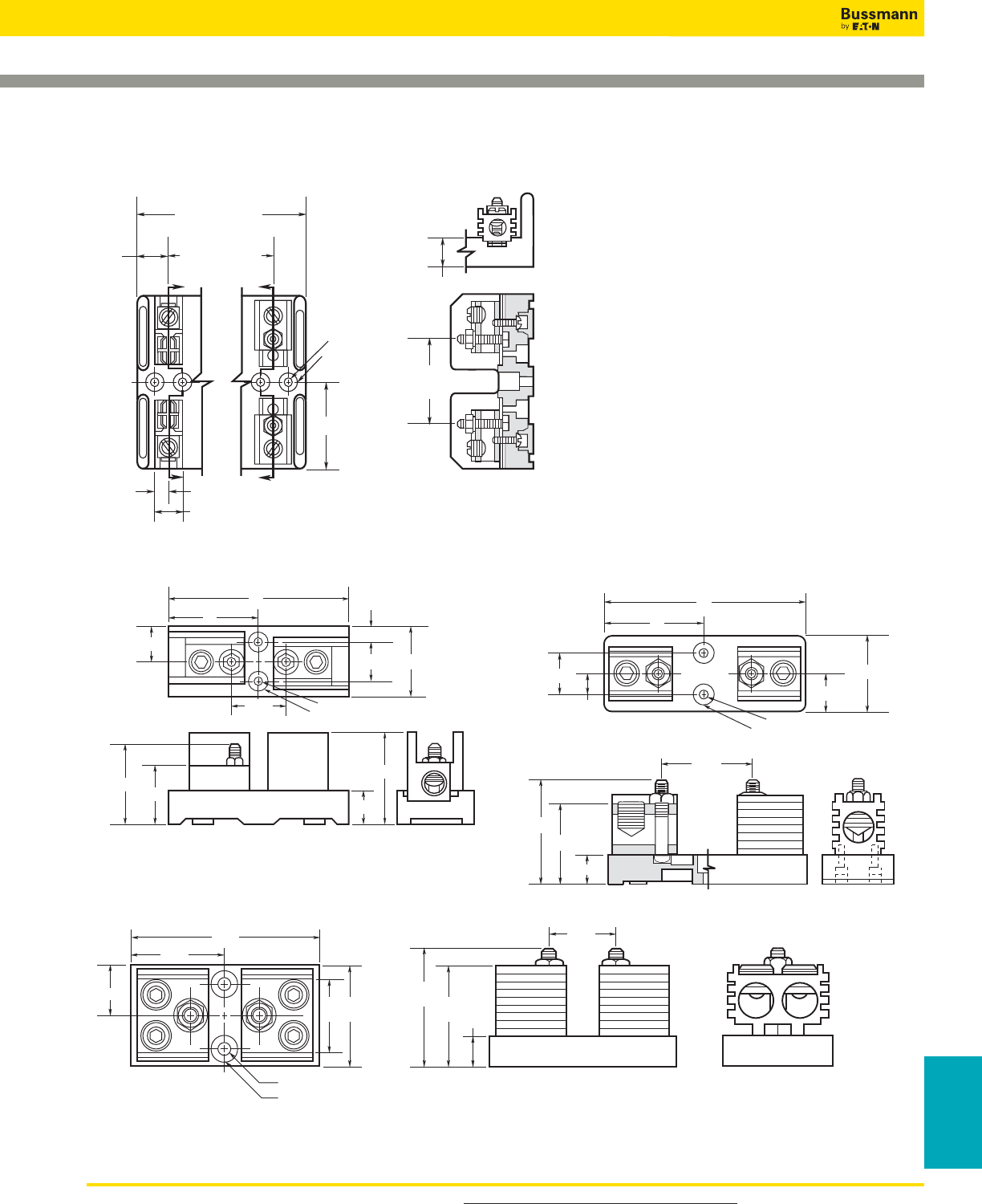
For product data sheets, visit www.cooperbussmann.com/DatasheetsEle 303
Fuse Holders
& Blocks
Fuse Holders and Blocks
Class T Fuse Blocks – 600V
Data Sheet: 1116
Figure 5. 201 to 400A
0.63" C'BORE 0.5" DEEP
6"
0.28" DIAMETER
1.125"
2.25"
0.63"
3"
1.25"
2.72"
0.81"
2.38"
3.06"
Figure 4. 101 to 200A
3"
6"
0.28" DIAMETER
0.63" C'BORE 0.5" DEEP
1.125"
2.56"
1.94"
0.81"
3.06"
2.5"
0.05"
1.25" 2.25"
Figure 3. 61 to 100A
Z
Z
0.52" C'BORE
0.55" DEEP
0.22" DIA.
X
X
2.39"
1.69" (1 POLE)
3.09" (2 POLE)
4.5" (3 POLE)
1.41" (2 POLE)
2.81" (3 POLE)
0.84"
0.38" SECTION Z-Z
0.78"
2.34"
REF.
0.75"
Figure 6. 401 to 600A
3.44"
0.75"
3"
2.95"
3"2"
1.5"
6.75"
3.38"
0.33" DIAMETER
0.75" C'BORE 0.5" DEEP
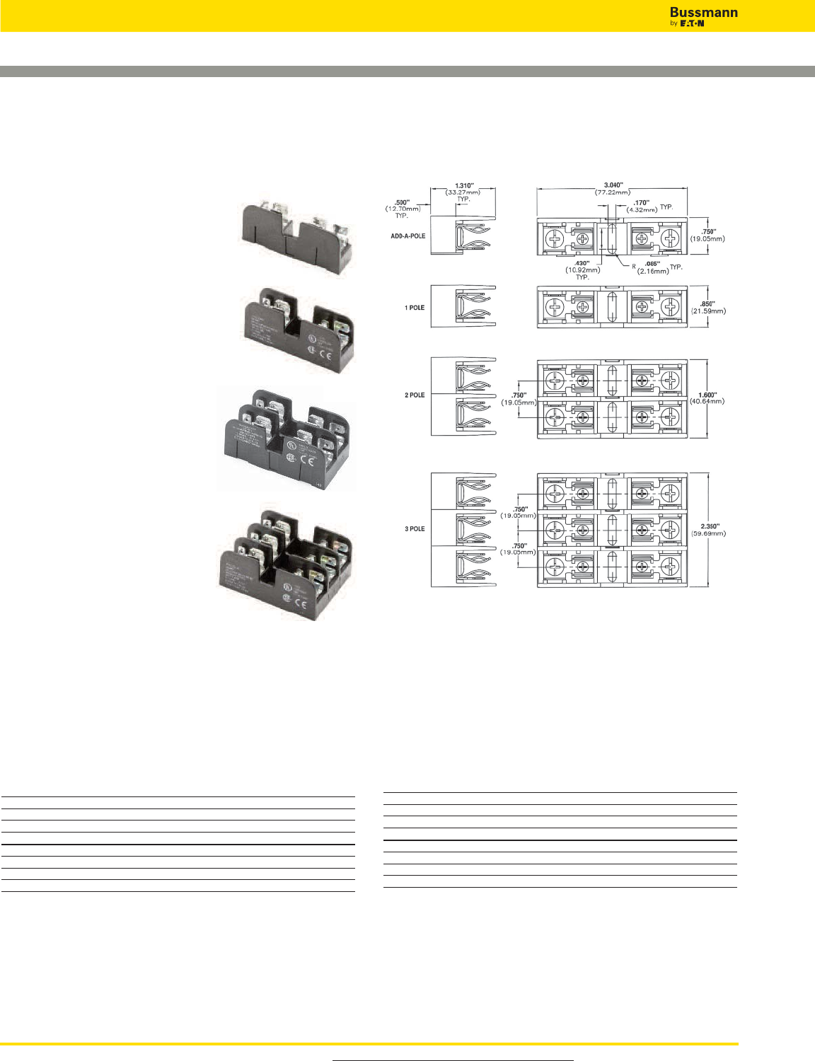
For product data sheets, visit www.cooperbussmann.com/DatasheetsEle
304
Fuse Holders and Blocks
BCA Series - Class CC fuses
BMA Series - 13⁄32" X 1 1⁄2" fuses
Specifications
Description: 1-, 2 and 3-pole fuse
blocks for use with Class CC fuses
(BCA Series use Bussmann
LP-CC, KTK-R, and FNQ-R), or with
standard 13⁄32" x 1 1⁄2" fuses (BMA Series
use Bussmann KTK, FNQ, PVN, FNM,
BAF, PV and AGU) Both Series use an
"adder block" to form multi-pole seg-
mented blocks to achieve the desired
number of poles.
Dimensions: See Dimensions
illustration.
Poles: 1 to 3.
Wire Range: #10-#18 Cu only.
Terminals: Screw/quick connect*
or pressure plate/quick connect*.
Ratings:
Volts: — 600Vac/dc
Amps: — 1⁄10-30A
SCCR: — BCA Series:
200kA RMS Sym.
BMA Series:
10kA RMS Sym.
Agency Information:
BCA Series: CE, UL Listed, UL
4248, Guide IZLT, File E14853.
CSA Certified, C22.2 No. 4248, Class 6225-01, File 47235.
BMA Series: CE, UL Recognized, UL 4248, Guide IZLT2,
File E14853. CSA Certified, C22.2 No. 4248, Class 6225-01,
File 47235.
Flammability Rating: UL 94V0
*Quick connect rated for 20A maximum.
Catalog Numbers
BCA Series
Catalog Numbers Poles Terminal Type
BCA603ASQ Adder Block Screw w/ quick connect
BCA6031SQ 1 Screw w/ quick connect
BCA6032SQ 2 Screw w/ quick connect
BCA6033SQ 3 Screw w/ quick connect
BCA603APQ Adder Block Pressure plate w/ quick connect
BCA6031PQ 1 Pressure plate w/ quick connect
BCA6032PQ 2 Pressure plate w/ quick connect
BCA6033PQ 3 Pressure plate w/ quick connect
Add-a-pole Fuse Blocks
Data Sheets: BCA Series 1154, BMA Series 1155
Dimensions in ± 0.015" (0.38mm)
Adder Block
1-Pole
2-Pole
3-Pole
BMA Series
Catalog Numbers Poles Terminal Type
BMA603ASQ Adder Block Screw w/ quick connect
BMA6031SQ 1 Screw w/ quick connect
BMA6032SQ 2 Screw w/ quick connect
BMA6033SQ 3 Screw w/ quick connect
BMA603APQ Adder Block Pressure plate w/ quick connect
BMA6031PQ 1 Pressure plate w/ quick connect
BMA6032PQ 2 Pressure plate w/ quick connect
BMA6033PQ 3 Pressure plate w/ quick connect
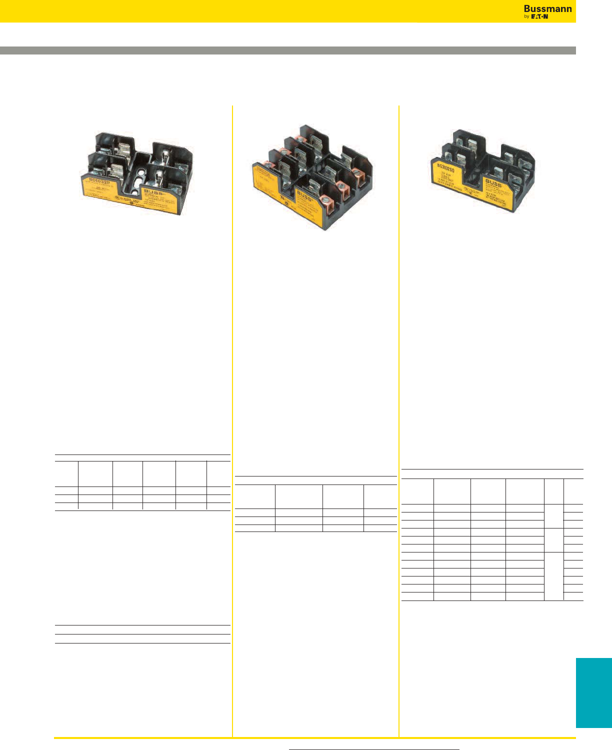
For product data sheets, visit www.cooperbussmann.com/DatasheetsEle 305
Fuse Holders
& Blocks
Fuse Holders and Blocks
Class CC, Type M and Class G Fuse Blocks
Data Sheet: 1106
Data Sheet: 1104
Data Sheet: 1105
Specifications
Description: Class CC fuse blocks for
use with Class CC fuses ( Bussmann
LP-CC, KTK-R, and FNQ-R).
Dimensions: See Data Sheet 1105
Poles: 1 to 3
Ratings:
Volts: — 600V
Amps: — 1⁄10-30A
SCCR:— 200kA RMS Sym.
Agency Information: CE, UL Listed
(Guide IZLT, File E14853), CSA (Class
6225-01, File 47235)
Flammability Rating: UL 94V0
DIN-Rail Adapters: See page 413 for
DRA-1 & DRA-2
Catalog Numbers
Terminal Type
Screw Pressure
with Plate w/
Quick Pressure Quick Box
Screw Connect* Plate Connect* Lug Poles
BC6031S BC6031SQ BC6031P BC6031PQ BC6031B 1
BC6032S BC6032SQ BC6032P BC6032PQ BC6032B 2
BC6033S BC6033SQ BC6033P BC6033PQ BC6033B 3
BCCM Series
Description: 3-pole fuse block for use
with (2) Class CC fuses and (1) 13⁄32” x 11⁄2”
fuse
Catalog Numbers
Catalog Terminal
Numbers Type
BCCM6033SQ Screw with Quick-Connect*
BCCM6033PQ Pressure Plate w/Quick-Connect*
*Quick-connect terminal rated for 20A max.
Specifications
Description: Supplementary fuse
blocks for use with any 13⁄32” x 11⁄2” fuses
(Bussmann KTK, PVM, FNQ, FNM,
BAF, PV, and AGU).
Dimensions: See Data Sheet 1104
Poles: 1 to 3
DIN-Rail Adapters: See page 413
for DRA-1 & DRA-2
Ratings:
Volts: — 600Vac/dc
Amps: — 1⁄10-30A
SCCR:— 10kA RMS Sym.
Agency Information: CE, UL
Recognized (Guide IZLT2, File
E14853), CSA (Class 6225-01, File
47235).
Flammability Rating: UL 94V0.
Catalog Numbers
Terminal Type
Screw Pressure
with Plate w/
Quick Quick Box
Connect* Connect* Lug Poles
BM6031SQ BM6031PQ BM6031B 1
BM6032SQ BM6032PQ BM6032B 2
BM6033SQ BM6033PQ BM6033B 3
Specifications
Description: Class G fuse blocks for use
with Class G fuses (Bussmann SC).
Dimensions: See Data Sheet 1106
Poles: 1 to 3
Ratings:
Volts: — 600Vac/dc (0-20A)
— 480Vac/dc (25-60A)
Amps: — 1-60A (See Catalog Numbers
table)
SCCR: — 100kA RMS Sym.
Agency Information: CE, UL Listed
35-60A (Guide IZLT, File E14853), UL
Recognized 1-30A, (Guide IZLT2, File
E14853), CSA (Class 6225-01, File 47235).
DIN-Rail Adapters: See page 413 for
DRA-1 & DRA-2.
Catalog Numbers
Terminal Type
Screw Pressure
with Plate w/ Box Lug
Quick Quick Box w/retaining
Connect* Connect* Lug clip Amps Poles
BG3011SQ BG3011PQ BG3011B — 1 1
BG3012SQ BG3012PQ BG3012B — to 2
BG3013SQ BG3013PQ BG3013B — 15 3
BG3021SQ BG3021PQ BG3021B — 20 1
BG3022SQ BG3022PQ BG3022B — 2
BG3023SQ BG3023PQ BG3023B — 3
BG3031S BG3031P BG3031B — 25 1
BG3032S BG3032P BG3032B — to 2
BG3033S BG3033P BG3033B — 30 3
— — — G30060-1CR 35 1
— — — G30060-2CR to 2
— — G30060-3C G30060-3CR 60 3
BC Series BM Series Type M BG & G Series
1-15
20
25-30
35-60
Recommended Cover Puller
• PF1-WH (White)
• PF1-BK (Black)
Recommended Cover Puller
• PF1-WH (White)
• PF1-BK (Black)
Recommended Cover Puller
• PF1-WH (White)
• PF1-BK (Black)
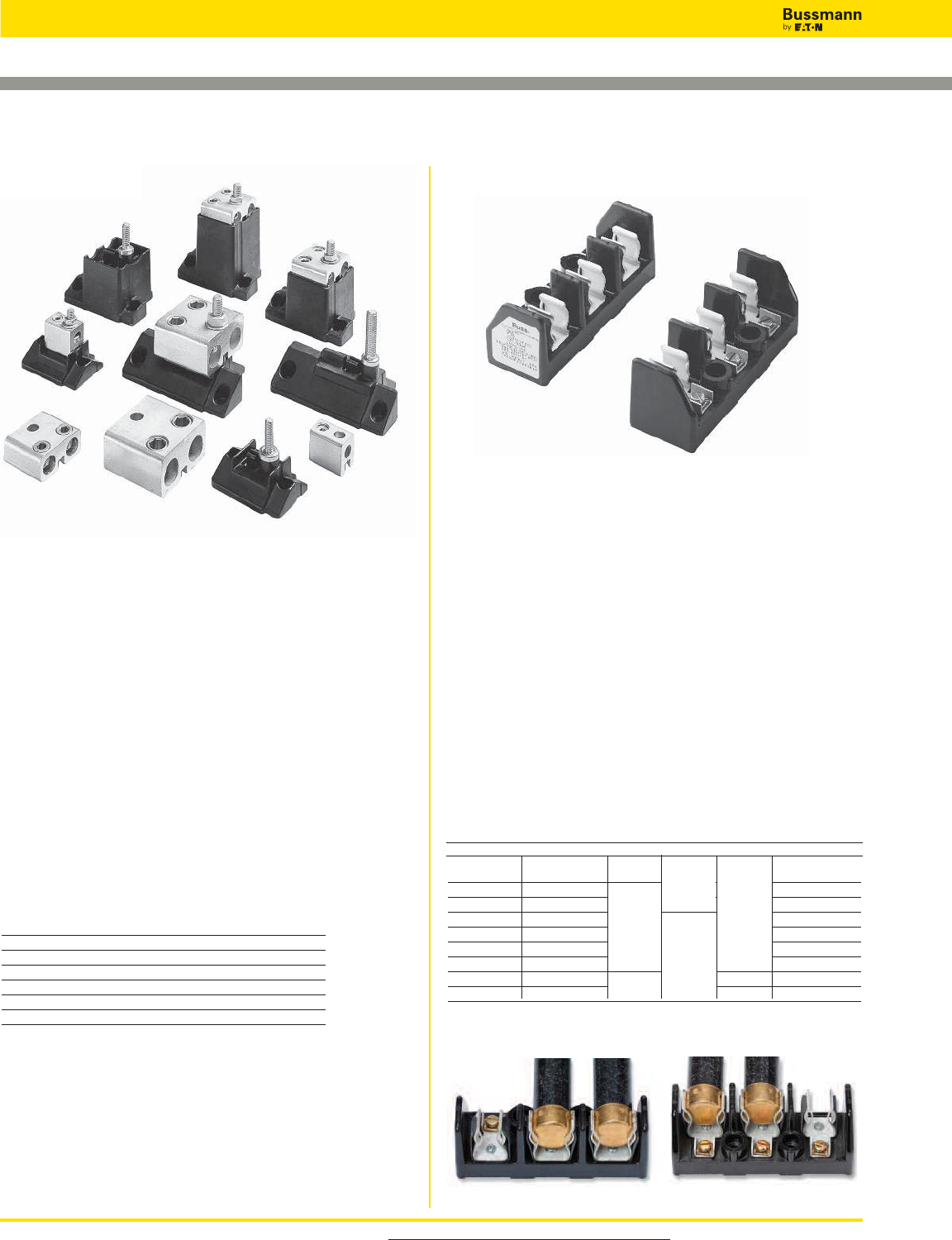
For product data sheets, visit www.cooperbussmann.com/DatasheetsEle
306
Fuse Holders and Blocks
Modular Fuse Blocks
Specifications
Description: For use with Bussmann high speed fuses.
Ratings:
SCCR: — 200kA RMS Sym. or fuse IR, whichever
is lower.
Agency Information: CE, UL Recognized, Guide EZLT2,
File No. E14853 up to 700V, CSA Certified, Class 6225-01,
File No. 47235 up to 700V.
BH Series Features and Benefits
• BH fuse blocks provide a wide range of mounting
configurations for Bussmann high speed fuses.
• BH fuse blocks have a Short-Circuit Current Rating of any
installed fuse up to 200kA RMS Sym.
Typical Applications
• Solid State Control Circuits
• VFDs
• UPS Systems
Catalog Numbers
BH-0001 BH-0122 BH-2001 BH-3004
BH-0002 BH-1001 BH-2002 BH-3033
BH-0003 BH-1002 BH-2003 BH-3144
BH-0111 BH-1003 BH-2031 BH-3145
BH-0112 BH-1131 BH-2032
BH-0113 BH-1132 BH-2033
BH-0121 BH-1133 BH-3003
Data Sheet: (BH-0) 1200; (BH-1) 1201; (BH-2) 1202;
(BH-3) 1203
Refer to the data sheet numbers below for the catalog code
description information.
Figure 1 Figure 2
BH Series Modular Type Fuse blocks for Class H &
J Fuses
Specifications
Description: 3-Pole only, modular type fuse blocks for
Class H & J fuses with standard reinforced retaining clips.
Ratings:
Volts: — 250V (0-60A See Catalog Numbers table)
— 600V (35-60A See Catalog Numbers table)
Amps: — 0-60A @ 250Vac/dc (See Catalog Numbers table)
— 35-60A@600V (See Catalog Numbers table)
SCCR: — Class J 200kA, Class H 10kA
Agency Information: CE, UL Recognized, Guide IZLT2,
File E14853, CSA Certified, Class 6225-01, File 47235.
Class H & J Features and Benefits
• H & J modular fuse blocks provide three pole 30 and 60
amp ratings for specific client requirements for separate line
and load fuse clip configurations.
Typical Applications
• Up to 60A, space confined, control circuits
Catalog Numbers
Fuse Fig.
Screw Pressure Plate Class Volts Amps No.
11241-3SR* 11241-3PR* H 250 60 1
11242-3SR 11242-3PR 2
11241-3SR 11241-3PR 600 35 1
11242-3SR** 11242-3PR** 2
11239-3SR 11239-3PR 60 1
11240-3SR** 11240-3PR** 2
11241-3SR 11241-3PR J 600 35 1
11239-3SR* 11239-3PR* 60 1
Note: Order two blocks per fuse (matched or mixed.)
*11239 and 11241 have wire terminals and mounting holes located under fuse. (Figure 1)
**11240 and 11242 have wire terminals and mounting holes located at end of fuse. (Figure 2)
H
J
250 60
60
35
600
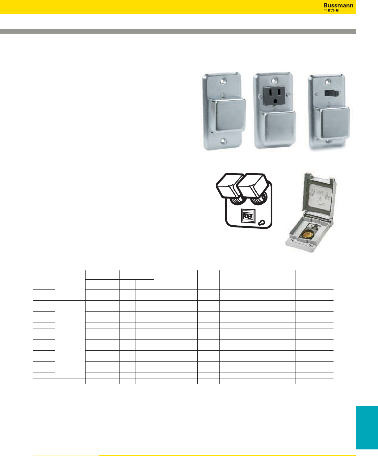
For product data sheets, visit www.cooperbussmann.com/DatasheetsEle 307
Fuse Holders
& Blocks
Fuse Holders and Blocks
SOU, SRU, SSN, SSU, SOW, SRW, SSW,
SOX, SRX, SSX, SOY, SRY, SSY, SSY-RL,
SSY-L, STY, SCY & SOY-B
Specifications
Description: Box covers for standard electrical boxes that
provide fused outlet, fused switch or circuit fuse protection.
Ratings:
Volts: — 125V/250V (See Catalog Numbers table)
Amps: — 0-15A (See Catalog Numbers table)
Agency Information: CE, See Catalog Numbers table.
Features/Benefits
• Bussmann Box Cover Units provide a low-cost method of
controlling and protecting small motors when used with
Bussmann Type T, Fusetron™, dual-element fuses.
• Provide low-cost supplementary protection and
disconnection of 125V or less, single phase circuits.
Typical Applications
• Fractional Horsepower, 125 Volt Single-Phase Motor Circuits
• General 125 Volt Supplemental Circuits
Box Cover Units for Plug Fuses
Data Sheet: 1129
Catalog Numbers
Receptacle Motor Agency4
Catalog Fuse holder3Outlet to Load Switch Switch Size Listing/
Numbers Type Box Single Double 125V 250V Control1Light2(Max) General Data Certification
SOU X 3⁄4hp 125V, 15A UL, CSA
SRU 21⁄4" Handy X X 1⁄2hp 125V, 15A UL
SSU X X 1⁄2hp 125Vac, (do not use on dc), 15A UL, CSA
SOW X 3⁄4hp 125V, 15A UL, CSA
SRW 23⁄4" Switch X X 1⁄2hp 125V, 15A UL
SSW X X 1⁄2HP 125Vac, (do not use on dc), 15A UL, CSA
SOX X 3⁄4hp 125V, 15A UL, CSA
SRX 4" Octagon X X 1⁄2hp 125V, 15A UL
SSX X X 1⁄2hp 125Vac, (do not use on dc), 15A UL, CSA
SOY X 3⁄4hp 125V, 15A UL, CSA
SRY X X 1⁄2hp 125V, 15A UL
SSY X X 1⁄2hp 125Vac, (do not use on dc), 15A UL, CSA
SSY-RL 4" Square X X X X 1⁄2hp 125Vac, (do not use on dc), 15A —
STY3XX
1⁄2hp 125Vac, (do not use on dc), 15A UL
SCY X X(2) 1⁄2hp (2) 125Vac, (do not use on dc),
can protect two motors, 15A UL
SOY-B X 3⁄4hp 125V, protects two motors, 15A UL
SSN Single Gang X X X 1⁄2hp Weatherproof model, 15A UL
1 Switch turns power to fused load OFF or ON.
2 Switch light indicates power to load (dark when switch OFF or fuse open).
3 Double pole switch opens both sides of circuit. Can be used for two separate motors with common switch or a single motor (3⁄4Hp, 250Vac max.).
4 UL Guide JAMZ, File IE6491; CSA Class 6225-01, File 47235.
21⁄4" Handy
23⁄4" Switch
4" Octagon
4" Square
YTS
SSU
SSN
SRUSOU
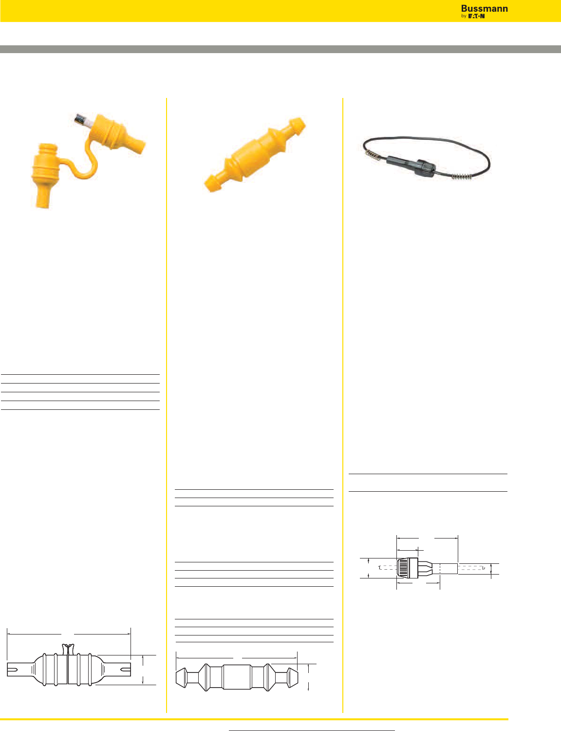
For product data sheets, visit www.cooperbussmann.com/DatasheetsEle
308
Fuse Holders and Blocks
Specifications
Description: Water-resistant in-line
fuse holder for 1⁄4" x 11⁄4" fuses.
Dimensions: See Dimensions
illustration.
Construction: Thermoplastic rubber
body with tin-plated, copper contacts.
Ratings:
Volts: — 32V
Amps: — 30A max
Catalog Numbers
Catalog
Numbers Description
HFB* Standard Pack (10-in)
BK/HFB Bulk Pack (100-in)
BK/1A2294 HFB Replacement Contact Clip
1A2294-01 HFB-10** Replacement Contact Clip
*HFB accepts #12 to #18 wire leads (not provided). See
Data Sheet for recommended crimp tools.
**HFB-10 accepts #10 wire leads (not provided). See Data
Sheet for recommended crimp tools.
Features/Benefits
• Simple assembly with one-piece
thermoplastic (important information
molded into body)
• High visibility yellow color for easy
identification in dark or hard-to-access
locations
• Ideal for shock and vibration
environments; withstands many
organic solvents; temperature range -
40/+150°C
Typical Applications
• Supplemental, Low Voltage, Low
Amperage Control Circuits
Dimensions - in (mm)
In-line Fuse Holders for 1⁄4" x 7⁄8" to 11⁄4" Fuses
0.75"
(19.1mm)
3"
(76.2mm)
Data Sheet: 2102 Data Sheet: 2111
Data Sheet: 2103
Specifications
Description: Universal in-line fuse
holder for 1⁄4" x 7⁄8" to 1 1⁄4" fuses.
Dimensions: See Dimensions
illustration.
Construction: 8" (203mm) #14 lead
wires.
Ratings:
Volts: — 32V
Amps: — 15A max
Features and Benefits
• HRK Universal in-line fuse holder for
1⁄4" x 7⁄8", 1" and 11⁄4" fuses with #14
lead wires.
• RoHS compliant
Typical Applications
• Supplemental, Low Voltage, Low
Amperage Control Circuits
Catalog Number
Catalog Amp
Number Rating Volts Fuse Description
HRK-R* 15 32 1⁄4" diameter fuses of
different lengths.
*Three springs furnished with fuse holder to accommodate
different length 1⁄4" fuses.
Dimensions - in (mm)
Specifications
Description: Universal in-line fuse
holder for 1⁄4" x 7⁄8", 1" and 11⁄4" fuses.
Dimensions: See Dimensions
illustration.
Construction: Nylon body with tin-
plated, copper contacts.
Ratings:
Volts: — 32V
Amps: — 30A max
Flammability Rating: UL 94V2.
Pull Force: 5lbs minimum to separate
fuse holder housing with fuse installed.
Features and Benefits
• HHB Universal in-line fuse holder for
1⁄4" x 7⁄8", 1" and 1 1⁄4" fuses.
Typical Applications
• Supplemental, Low Voltage, Low
Amperage Control Circuits
Catalog Numbers
Holder — without leads* - RoHS compliant
Catalog Numbers Description
HHB-R Standard Pack (10-in)
BK/HHB-R Bulk Pack (100-in)
*Accepts #12 to #16 wire leads (not provided with basic fuse
holder). See Data Sheet for recommended crimp tools.
Holder — with pre-attached #14 Insulated
lead wires - Not RoHS compliant unless
noted
Catalog Numbers Wire
19" Length 8" Length Color
BK/HHB-Y419 BK/HHB-Y408 Yellow
BK/HHB-R419 BK/HHB-R408** Red
BK/HHB-B419 BK/HHB-B408 Black
**RoHS compliant.
Dimensions - in (mm)
Fuse Length Fuse Holder Length “L”
7⁄8" (AGW) 2.100 Max
1" (AGX) 2.250 Max
11⁄4" (AGC, MDL) 2.420 Max
L
0.53"
(13.5mm)
0.75"
(19.1mm)
2.19"
(55.6mm)
1.56"
(39.7mm)
0.69"
(17.5mm)
0.38"
(9.5mm)
HFB & HFB-10 HHB HRK
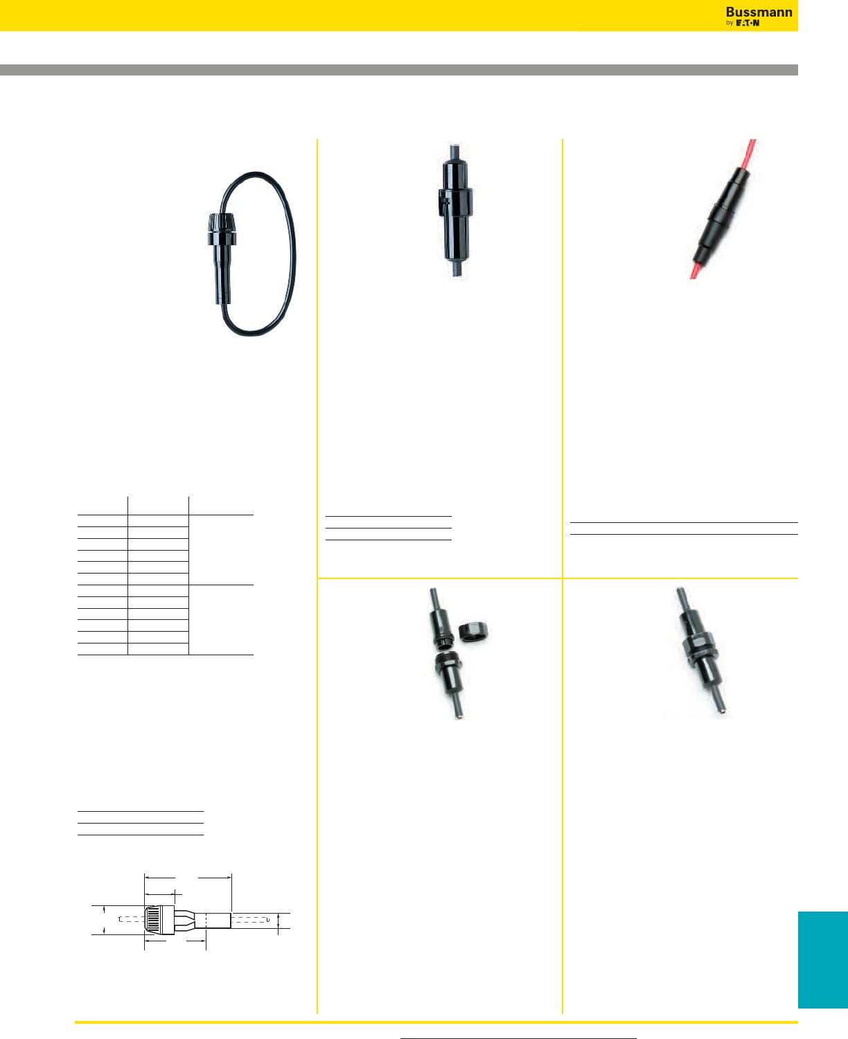
For product data sheets, visit www.cooperbussmann.com/DatasheetsEle 309
Fuse Holders
& Blocks
Fuse Holders and Blocks
HR and HM Series
Specifications
Description: In-line
fuse holders for SFE
and 1⁄4" dia. x various
length fuses.
Dimensions: See
Dimensions
illustration.
Ratings:
Volts: — 32V
Amps: — 20A
Features and Benefits
• HR and HM Universal in-line fuse
holder for SFE and various length 1⁄4"
diameter fuses with #14 lead wires.
Typical Applications
• Supplemental, Low Voltage, Low
Amperage Control Circuits
Catalog Numbers
Catalog Includes Wire Length
Numbers Fuse & Size
HRJ* SFE-20
HRI SFE-14
HRH SFE-9 19” of #14
HRE SFE-71⁄2
HRG SFE-6
HRF SFE-4
HMJ** SFE-20
HMI SFE-14
HMH SFE-9 8” of #14
HME SFE-71⁄2
HMG SFE-6
HMF SFE-4
* Also available as in-line fuse holder only with lead wire
contacts, HRJ-LESS-Fuse.
** Also available as in-line fuse holder only with lead wire
contacts, HMJ-LESS-Fuse.
HHJ-A For 1⁄4" x 11⁄4" fuse, no wire or fuse
included, accepts #18 - #22 wire.
HHJ-B For 1⁄4" x 11⁄4" fuse, no wire or fuse
included, accepts #12 - #16 wire.
HHI-B For 1⁄4" x 11⁄16" fuse, no wire or fuse
included, accepts #12 - #16 wire.
Replacement Contacts
Catalog
Number Symbol
9838 HHJ-A
9841 HHJ-B
Dimensions - in (mm)
In-line Fuse Holders
0.75"
(19.1mm)
2.19"
(55.6mm)
1.56"
(39.7mm)
0.69"
(17.5mm)
0.38"
(9.5mm)
Data Sheet: 2122
Specifications
Description: In-line water-resistent
fuse holders for 1⁄4" x 11⁄4" fuses.
Dimensions: See Dimensions
illustration.
Ratings:
Volts: — 250V
Amps: — 20A
Refer to data sheet for recommend
crimp tools
Catalog Numbers
Catalog
Numbers Terminals
HFA Crimp #12 - #16
HFA-HH* 1⁄4" Quick Connect
*No UL Recognition.
Specifications
Description: In-line fuse holders for
5 x 15mm or 5 x 20mm fuses.
Dimensions: See Dimensions
illustration.
Construction: Black thermoplastic
body with brass contacts, wire: 16
AWG, red.
Ratings:
Volts: — 32V
Amps: — 5A (5 x 15mm)
— 10A (5 x 20mm)
Catalog Numbers
Catalog Number Fuse Size
HHT 5 x 15mm & 5 x 20mm
HFA Series HHT Series
Data Sheet: 2115 Data Sheet: 2138
Specifications
Description: Single-pole, non-break-
away, in-line fuse holders for Type SC
fuses, 480V (or less).
Ratings:
Volts: — 600V
Amps: — 0-15A
Fuse Size: 13⁄32" x 1.31"
Catalog Number
HEG-AA
Optional Boots:
2A0660 Single Conductor
2A0661 Two Conductor
Specifications
Description: Single-pole, non-
breakaway, in-line fuse holders for
Type SC fuses (Also fuse types BBS
& KTQ, nominal size 13⁄32" x 1 3⁄8").
Ratings:
Volts: — 600V
Amps: — 0-20A
Agency Information: CSA - 15A.
Catalog Numbers
HEH-AA, HEH-AD
Optional Boots:
2A0660 Single Conductor
2A0661 Two Conductor
HEG Series HEH Series
Data Sheet: 2124 Data Sheet: 2124

For product data sheets, visit www.cooperbussmann.com/DatasheetsEle
310
Fuse Holders and Blocks
Tron™In-line Fuse Holders
Specifications
Description: Single-pole,
non-breakaway,
in-line fuse
holders for Type SC-25, &
SC-30 fuses,
size
13⁄32" x 1 5⁄8".
Ratings:
Volts: — 480V
Amps: — 0-30A
Catalog Numbers
HEC-AA, HEC-RW-RLB-R
Optional Boots:
2A0660 Single Conductor
2A0661 Two Conductor
Specifications
Description: Single-pole,
non-breakaway, in-line fuse
holders for Type SC and Type
HVW fuses, size 13⁄32" x 2 1⁄4".
Ratings:
Volts: — 480V
Amps: — 35-60A Type SC
— 1⁄2-6A Type HVW
Catalog Numbers
HEJ-AA, HEJ-AB, HEJ-AC, HEJ-BB,
HEJ-JJ, HEJ-JK, HEJ-LL, HEJ-LLB,
HEJ-CC, HEJ-DD, HEJ-WW, HEJ-PP,
HEJ-QQ
Optional Boots:
2A0660 Single Conductor
2A0661 Two Conductor
Specifications
Description: Single-pole
in-line fuse holders for any
13⁄32" x 1 1⁄2" fuses (typically
fuse types: BAF, FNM, FNQ,
and KTK 1⁄10 - 30A).
Ratings:
Volts: — 600V
Amps: — 0-30A
Catalog Numbers
See Page 311
Optional Boots:
2A0660 Single Conductor
2A0661 Two Conductor
Specifications
Description: Single-pole
in-line fuse holders for
13⁄32" x 1 1⁄2" fuses with a
permanently solid neutral
identified by white plastic
coupling nut.
Catalog Numbers
HET-AA, HET-AB, HET-AW, HET-
AW-RLC-A, HET-AW-RLC-B, HET-
AW-RLC-C, HET-AW-RLC-J, HET-
AW-RYC, HET-BB, HET-BW-RLC-B,
HET-BW-RYC, HET-JJ, HET-JK,
HET-JW, HET-JW-RLC-J, HET-JW-
RYC, HET-KK
Specifications
Description: Waterproof
(IPX7), single-pole Class
CC in-line fuse holders.
Holds Bussmann fuse
types: LP-CC, FNQ-R and
KTK-R.
Ratings:
Volts: — 600V (or less)
Amps: — Up to 30A*
Conductors: Lineside &
Loadside**
#12 to #8 Crimp terminal
#12 to #3 Setscrew terminal
*Amp rating limited by conductor size and fuse sizing
when used with insulating boots
**See details in non-breakaway and breakaway
specifications
Data Sheet: 2130
Specifications
Description: Double-pole in-
line fuse holders for 13⁄32" x 1 1⁄2"
fuses (typically fuse types
BAF, FNM, FNQ, and KTK
1⁄10 - 30A).
Ratings:
Volts: — 600V
Amps: — 0-30A
Catalog Numbers
HEX-AA, HEX-AB, HEX-AC, HEX-AD,
HEX-AE, HEX-AW, HEX-AW-DRLC-A,
HEX-AW-DRYC, HEX-AW-RLC-A,
HEX-AW-RYC, HEX-AY, HEX-BB,
HEX-CC, HEX-JJ, HEX-JK,
HEX-JW-DRYC, HEX-KK
HEB Series
HET Series
HEZ Series
Specifications
Description: Double-pole
in-line fuse holders for KTK-
R fuses with optional break-
away receptacle, polarized,
and accepting Class CC
branch circuit fuses
(Bussmann KTK-R, FNQ-R
& LP-CC; 600V or less,
200kA IR).
Ratings:
Volts: — 600V
Amps: — 0-30A
Catalog Numbers
HEY-AA, HEY-AB, HEY-AC, HEY-
AD, HEY-AE, HEY-AL, HEY-AW-
DRLC-A, HEY-AW-DRLC-B, HEY-
AW-DRYC, HEY-BB, HEY-JJ
Data Sheet: 2126
HEY Series
HEX SeriesHEC Series HEJ Series
Data Sheet: 2127
Data Sheet: 2125
Data Sheet: 2126
Data Sheet: 2124 Data Sheet: 2123
For product data sheets, visit www.cooperbussmann.com/DatasheetsEle 311
Fuse Holders
& Blocks
Fuse Holders and Blocks
For HEB Holders Only
Data Sheet: 2127
Copper #12 to #8 1 Y Y
Crimp #12 2 Y Y
Copper #12 to #8 1 Y Y
Crimp #12 2 Y Y
Copper #12 to #8 1 Y Y
Crimp #12 2 Y Y
Copper #12 to #8 1 Y Y
Crimp #12 2 Y Y
Copper #12 to #8 1 Y Y
Crimp #12 2 Y Y
Copper #12 to #8 1 Y Y
Crimp #12 2 Y Y
Copper #12 to #8 1 Y Y
Crimp #12 2 Y Y
Copper #12 to #8 1 Y Y
Crimp #12 2 Y Y
Copper #12 to #8 1 Y Y
Crimp #12 2 Y Y
Copper #12 to #8 1 Y Y
Crimp #12 2 Y Y
Copper #6 1 Y Y
Crimp #10 2 Y Y
Copper #6 1 Y Y
Crimp #10 2 Y Y
Copper #6 1 Y Y
Crimp #10 2 Y Y
Copper #6 1 Y Y
Crimp #10 2 Y Y
Copper #4 1 N Y
Crimp #8 2 Y Y
Copper #2 1 N Y
Crimp #6 2 Y Y
Copper #20, #18 1 Y Y
Crimp
Copper #12 to #3 1 Y Y
Setscrew
Copper #12 to #3 1 Y Y
Setscrew
Copper #12 to #3 1 Y Y
Setscrew
Copper #12 to #3 1 Y Y
Setscrew
Aluminum #12 to #2 1 Y Y
Setscrew
Aluminum #8 1 N Y
Crimp #6 1 Y N
Aluminum #6 1 N Y
Crimp #4 1 Y N
Aluminum #3, #4 1 N Y
Crimp #2 1 Y N
Aluminum #1, #2 1 N Y
Crimp
Aluminum 1/0 1 N Y
Crimp
SolidTerminal #8 to #12 1 Y N
for aluminum
connector #10 to #14 1 N Y
Copper #12 to #8 1 Y Y
Crimp #12 2 Y Y
Copper #6 1 Y Y
Crimp #10 2 Y Y
Copper #4 1 N Y
Crimp #8 2 Y Y
Copper #2 1 N Y
Crimp #6 2 Y Y
Copper 2/0 1 N Y
Crimp #3 2 N Y
Copper #12 to #3 1 Y Y
Setscrew
Copper #12 to #3 2 Y Y
Setscrew
Aluminum #12 to #2 1 Y Y
Setscrew
Aluminum #12 to #2 2 Y Y
Setscrew
Aluminum #1, #2 1 N Y
Crimp
Copper #12 to #8 1 Y Y
Crimp #12 2 Y Y
Copper #6 1 Y Y
Crimp #10 2 Y Y
Copper #4 1 N Y
Crimp #8 2 Y Y
Copper #2 1 N Y
Crimp #6 2 Y Y
Copper #4 1 N Y
Crimp #8 2 Y Y
Copper #2 1 N Y
Crimp #6 2 Y Y
Copper #12 to #8 1 Y Y
Crimp #12 2 Y Y
Copper #12 to #3 1 Y Y
Setscrew
Copper #12 to #3 2 Y Y
Setscrew
Aluminum #12 to #2 1 Y Y
Setscrew
Aluminum #12 to #2 2 Y Y
Setscrew
Aluminum #12 to #2 1 Y Y
Setscrew
Aluminum #8 1 N Y
Crimp #6 1 Y N
Aluminum #6 1 N Y
Crimp #4 1 Y N
Aluminum #3, #4 1 N Y
Crimp #2 1 Y N
Aluminum #1, #2 1 N Y
Crimp
Aluminum 1/0 1 N Y
Crimp
SolidTerminal #8 to #12 1 Y N
for aluminum
connector #10 to #14 1 N Y
Terminal No. of
Wire Size Wires per Solid Stranded
Type Terminal Wire Wire
Loadside Terminal
Directions: To select complete holder P/N, work from left to right starting with loadside terminal options and then lineside terminal options. Then determine breakaway or non-breakaway style.
Terminal No. of
Wire Size Wires per Solid Stranded
Type Terminal Wire Wire
Lineside Terminal Available P/N’s
Non-Breakaway Breakaway
P/N P/N
(Boots not included) (Boots included)
HEB-AA(1)(2)
HEB-AW-RLC-A(1)(2)
HEB-AB(2) HEB-AW-RLC-B
HEB-AC(2) HEB-AW-RLC-C(4)
HEB-AD(2) N/A
HEB-AE(2) N/A
HEB-AJ HEB-AW-RLC-J
HEB-AK HEB-AW-RYC
HEB-AL HEB-AW-RLA
HEB-AY HEB-AW-RYA
HEB-AR N/A
HEB-BA(2) HEB-BW-RLC-A
HEB-BB(2) HEB-BW-RLC-B
HEB-BC(2) N/A
HEB-BD(2) N/A
HEB-CC(2) N/A
HEB-DD(2) N/A
HEB-ZA N/A
HEB-JJ HEB-JW-RLC-J
HEB-JK HEB-JW-RYC
HEB-JL N/A
HEB-JY N/A
HEB-LL HEB-LW-RLA
HEB-NN N/A
HEB-PP(2) N/A
HEB-QQ(2) N/A
HEB-RR(2) N/A
HEB-TT(2) N/A
HEB-SS N/A
(3)(3)
(1)UL Recognized, Guide IZLT2, File E14853
(2)CSA Certified, Class 6225-01, File 47235
(3)CE
(4)HEB-AW-RLC-C is for (1) #4 stranded wire only. Contact your local Bussmann representative for other possible
terminations not listed.
Insulating boots for single conductor-2A0660
Dual conductor-2A0661
(4)
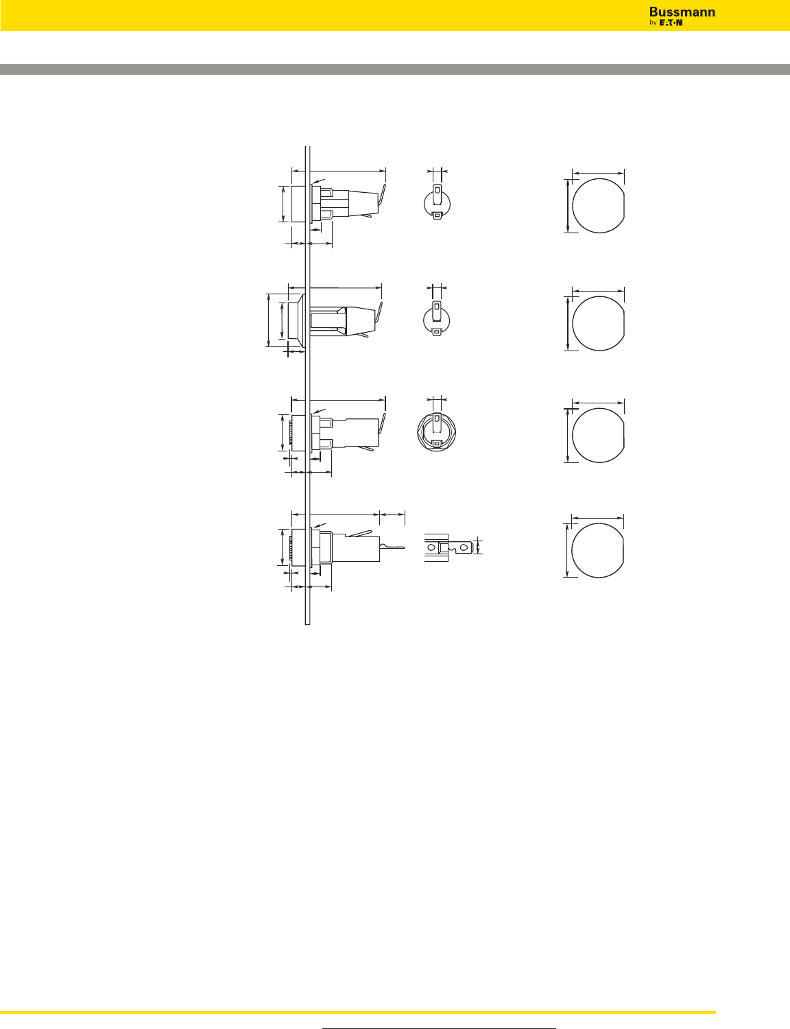
For product data sheets, visit www.cooperbussmann.com/DatasheetsEle
312
Fuse Holders and Blocks
Panel Mounted Fuse Holders for 5 x 20mm Fuses
Specifications
Terminals: Tin-plated brass.
Molded Materials: High temperature thermoplastic that meets the flammability ratings of UL 94V0; Glow Wire Test:
960°C per IEC 60695-2-1.
Solderability: In accordance with IEC 68-2-20.
Agency Information: cURus, VDE
Electrical: Contact Resistance: ≤ 10 megohm; Insulation Resistance: ≥ 10MΩ; Dielectric Strength ≥
2000Vac.
Shock Safety: PC2 (fuse holders).
Packaging: Standard Qty 10 (No Prefix), Bulk Qty 100 (Prefix Catalog Number with BK/).
3.0x0.51mm
12.00mm+0.0
–0.1
12.70mm+0.0
–0.1
12.00mm+0.0
–0.1
12.70mm+0.0
–0.1
12.00mm+0.0
–0.1
12.70mm+0.0
–0.1
12.00mm+0.0
–0.1
12.70mm+0.0
–0.1
3.0x0.51mm
3.0x0.51mm
4.8x0.51mm
37.5mm
4mm
Ø15mm
Ø16mm
11mm
5.5mm
Ø22mm
6.5mm
Ø15mm
37.5mm
36mm
4mm
Ø15mm
Ø16mm
11mm
5.5mm
0.5mm
35.5mm
4mm
Ø15mm
Ø16mm
11mm
5.5mm
0.5mm
10.2mm
Data Sheet: 2110
Data Sheet: 2110
Data Sheet: 2110
Data Sheet: 2110
HTC-35M
Ratings:
Volts: — 250Vac
Amps: — 10A UL, 6.3A VDE
Fuse Access: Threaded cap
HTC-55M
Ratings:
Volts: — 250Vac
Amps: — 10A UL, 6.3A VDE
Fuse Carrier: Bayonet type
HTC-40M
Ratings:
Volts: — 250Vac
Amps: — 10A UL, 6.3A VDE
Fuse Access: Screwdriver slot
HTC-70M
Ratings:
Volts: — 250Vac
Amps: — 10A UL, 6.3A VDE
Fuse Carrier: Bayonet type
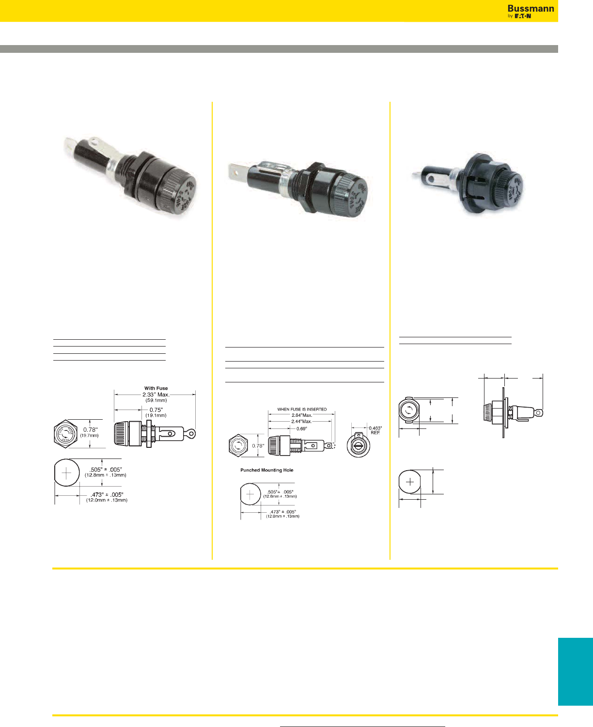
For product data sheets, visit www.cooperbussmann.com/DatasheetsEle 313
Fuse Holders
& Blocks
Fuse Holders and Blocks
Panel Mounted Fuse Holders for 1⁄4" x 11⁄4" Fuses
Specifications
Terminals: Bayonet-type knob.
Vibration resistant.
For panels up to 5⁄16" (7.9mm) thick.
Agency Information: CE (HKP, HKP-L, HKP-W, HKP-OO), UL Recognized — Guide IZLT2, File E14853, CSA
Certified — Class 6225-01, File 47235
Replacement Parts: Cap: 9435-1/2
Plastic Nut: BK/1A4287 (100 pieces minimum)
Metal Nut: BK/1A4806-2 (100 pieces minimum)
Washer: 9732
.800"
(20.3mm)
Punched Mounting Hole
.811"
(20.6mm)
.890"
(22.6mm)
1.56"
(39.7mm)
.75"
(19.1mm)
.855"
(21.7mm) 1.17"
F
U
S
E
F
U
S
E
F
U
S
E
Data Sheet: 2106 Data Sheet: 2106
Data Sheet: 2106
Specifications
Description: Standard fuse holders.
Dimensions: See Dimensions
illustration.
Ratings:
Volts: — 250V
Amps: — 30A
Catalog Numbers
Catalog Fuse
Numbers Description
HKP —
HKP-L HKP w/ 2250V stand-off barrier
HKP-W HKP w/ drip-proof knob
Dimensions - in (mm)
Specifications
Description: Fuse holders with 1⁄4"
quick-connects.
Dimensions: See Dimensions
illustration.
Ratings:
Volts: — 250V
Amps: — 15A
Catalog Numbers
Catalog Fuse
Numbers Description
HKP-BBHH HKP w/ 1⁄4" quick-connects, nut and washer
assembled.
HKP-HH HKP w/ 1⁄4" quick-connect.
HKP-LW-HH HKP w/ drip-proof knob, 2250V stand-off
barrier and 1⁄4" quick-connects.
Dimensions - in (mm)
Specifications
Description: Snap-lock fuse holders.
Dimensions: See Dimensions
illustration.
Ratings:
Volts: — 250V
Amps: — 30A
Catalog Numbers
Catalog Fuse
Number Description
HKP-OO HKP with snap-lock
Dimensions - in (mm)
HKP, HKP-L, HKP-W HKP-OOHKP-BBHH, HKP-HH and
HKP-LW-HH
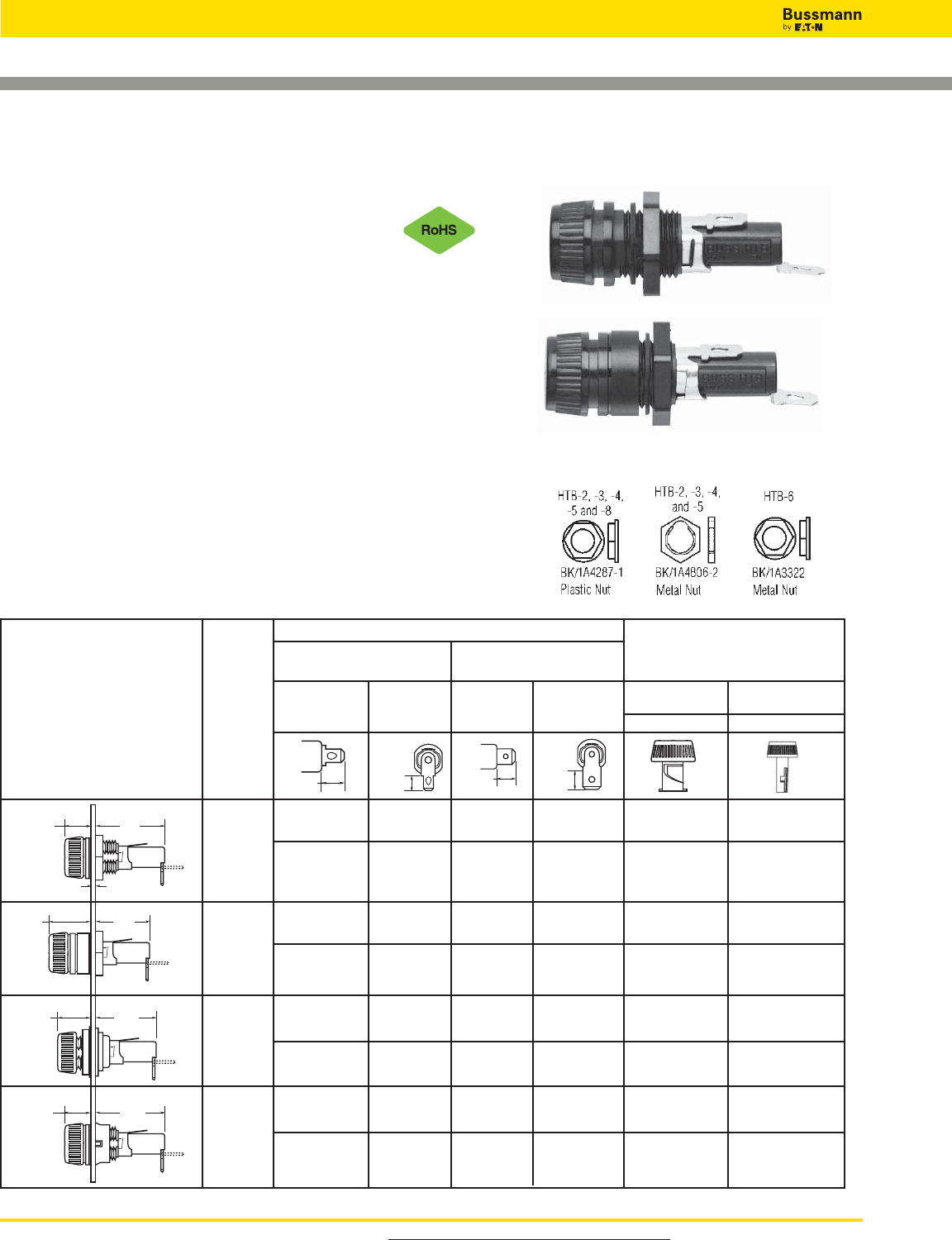
For product data sheets, visit www.cooperbussmann.com/DatasheetsEle
314
Fuse Holders and Blocks
Panel Mounted Fuse Holders for 5 x 20mm
and 1⁄4" x 1 1⁄4" Fuses
HTB Series
Specifications
Description: Fuse holders with knob-type carriers.
Dimensions: See Dimensions illustrations.
Construction: High temperature, flame retardant
thermoplastic; UL Component Recognized; UL 94V0;
mounting nut, spacer-black polycarbonate. Terminals:
tin-plated brass.
Electrical Data: Insulation resistance (per IEC #257) —
10,000 ohms @ 500Vdc; contact resistance (per IEC #257)
— 0.005 ohms Max @ 1A; standoff voltage (per IEC #257)
— 480V/Mil @ 0.125” thickness.
Agency Information: CE, UL Recognized — Guide IZLT2,
File E14853, 1⁄4˝ dia fuse @ 20A, 5mm dia fuse @16A @
250V, CSA — 16A @ 250V Class 6225-01 File 47235;
VDE
Certified: 136128, HTB-XXM, SEMKO Certification: Ref.
#0146149/01, HTB-XXM.
Mounting: Withstands 15 to 20 Lb-In torque to mounting
nut when mounting fuse holder to panel.
Environmental: Operating temperature range -55°C to
85°C.
Dimensional Data - in (mm)
Data Sheet: 2119
0.30” HTB-22I-R HTB-24I-R HTB-26I-R HTB-28I-R X
7.62mm HTB-22M-R HTB-24M-R HTB-26M-R HTB-28M-R X
0.125” HTB-42I-R HTB-44I-R HTB-46I-R HTB-48I-R X
3.18mm HTB-42M-R HTB-44M-R HTB-46M-R HTB-48M-R X
0.30” HTB-62I-R HTB-64I-R HTB-66I-R HTB-68I-R X
7.62mm HTB-62M-R HTB-64M-R HTB-66M-R HTB-68M-R X
0.125” HTB-82I-R HTB-84I-R HTB-86I-R HTB-88I-R X
3.18mm HTB-82M-R HTB-84M-R HTB-86M-R HTB-88M-R X
Fuse holders and fuse carriers may be ordered separately.
1.125"
(28.6mm)
0.47"
(11.9mm)
0.09" NOM.
(2.4mm)
1.125"
(28.6mm)
0.47"
(11.9mm)
0.92"
(23.4mm)
0.67"
(17.1mm)
0.91"
(23.0mm)
0.69"
(17.5mm)
Knob Type Carrier
Common Dimensions:
Length (Knob Type) - 1.69"
(42.9mm) Plus In-Line Terminal
NOTE: Plus In-Line Terminal
Maximum
Panel
Thickness
Solder/
3⁄16" Quick-Connect 1⁄4" Quick-Connect
Carrier Options
1⁄4" x 11⁄4" 5 x 20mm
(“I” Equals Inches) (“M” Equals Metric)
Knob Knob
In-Line Rt. Angle In-Line Rt. Angle
0.34"
(8.7mm) 0.33"
(8.3mm)
0.47"
(11.9mm) 0.45"
(11.5mm)
Terminal Options
Replacement Parts
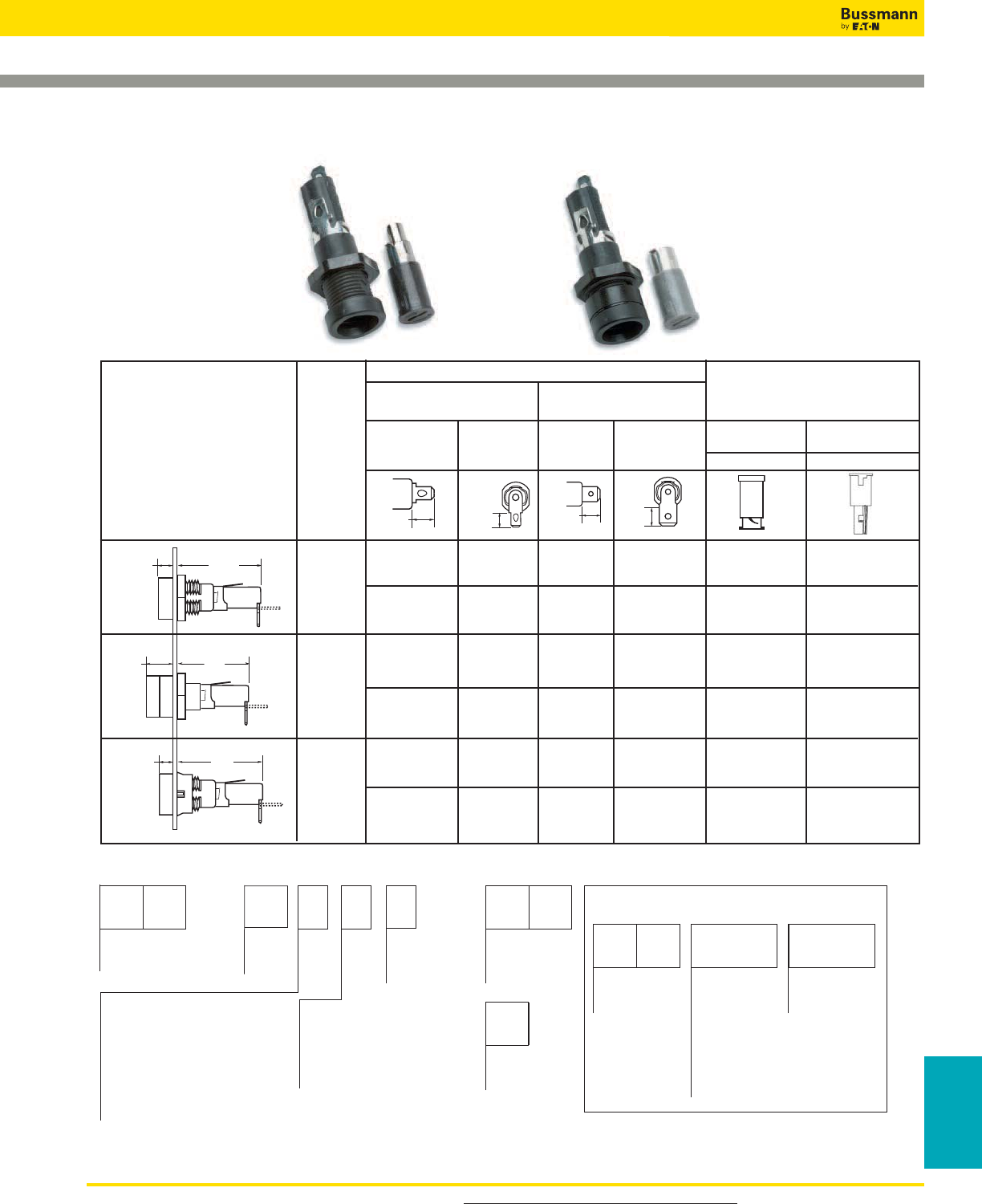
For product data sheets, visit www.cooperbussmann.com/DatasheetsEle 315
Fuse Holders
& Blocks
Fuse Holders and Blocks
Panel Mounted Fuse Holders for 5 x 20mm
and 1⁄4" x 1 1⁄4" Fuses
0.30” HTB-32I-R HTB-34I-R HTB-36I-R HTB-38I-R X
7.62mm HTB-32M-R HTB-34M-R HTB-36M-R HTB-38M-R X
0.125” HTB-52I-R HTB-54I-R HTB-56I-R HTB-58I-R X
3.18mm HTB-52M-R HTB-54M-R HTB-56M-R HTB-58M-R X
0.125” HTB-92I-R HTB-94I-R HTB-96I-R HTB-98I-R X
3.18mm HTB-92M-R HTB-94M-R HTB-96M-R HTB-98M-R X
0.17"
(4.37mm)
1.58"
(40.03mm)
0.17"
(4.37mm)
1.59"
(40.08mm)
0.41"
(10.31mm)
1.34"
(34.13mm)
S
Packing
Blank (Std.) – 10 fuse holders
in a carton
BK – 100 fuse holders in a
cardboard shelf package
Rear Terminal Configuration
2 — Solder / Quick-Connect
Solder / Quick-Connect
(In-Line)
4 —
(Right Angle)
6 — Quick-Connect (In-Line)
8 — Quick-Connect (Right Angle)
Fuse Carrier
I — /4˝ x 1
M — 5 x 20mm
Splash Proof
(Optional on Knob
Holders Only)
Body Configuration and Mounting
Knob Holders
2 — Low Profile (Rear Panel Hex-Nut)
4 — High Profile
*6 — (Front Panel Hex-Nut)
8 — Low Profile (Snap-In)
Screwdriver Slotted Holders
3 — Low Profile
5 — High Profile
9 — Low Profile (Snap-In)
Product
Symbol
HTB-
Packaging
(Blank) – Std.
BK/ – Bulk
Fuse Carrier
I —
M — 5 x 20mm
Product
Symbol
FT — Knob Type
(For 20, 40, 60,
and 80 Series
Only)
ST — Screwdriver
Slotted (For 30,
50, and 90 Series
Only)
P
-R
*Profile varies with panel thickness. Holder installs through rear of panel.
FUSE CARRIER ONLY
1 /4˝
1
/4˝
1
/4˝
1
/16˝
3
/16˝
3
Cap with O-Ring
/4˝ x 1
1 /4˝
1
RoHS
Compliant
Data Sheet: 2119
Catalog Number Build-A-Code
HTB Series
HTB-3
HTB-5
HTB-9
Screwdriver Type Carrier
Common Dimensions:
(Screwdriver Slotted)
1.75" (44.5mm)
NOTE: Plus In-Line Terminal
Maximum
Panel
Thickness
Solder/
3⁄16" Quick-Connect 1⁄4" Quick-Connect
Carrier Options
1⁄4" x 1 1⁄4" 5 x 20mm
(“I” Equals Inches) (“M” Equals Metric)
Screwdriver Screwdriver
In-Line Rt. Angle In-Line Rt. Angle
0.34"
(8.7mm) 0.33"
(8.3mm)
0.47"
(11.9mm) 0.45"
(11.5mm)
Terminal Options
Dimensional Data - in (mm)
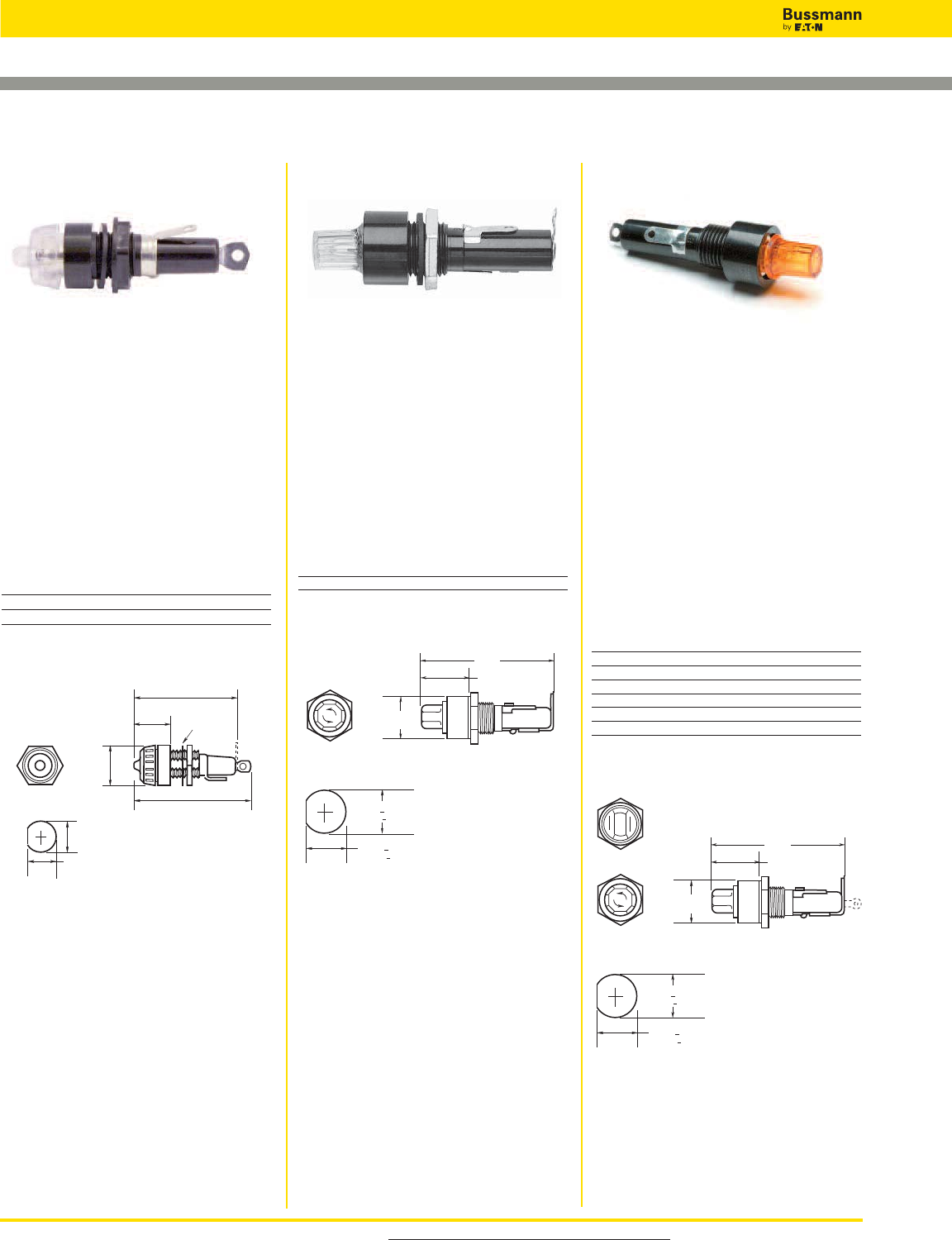
For product data sheets, visit www.cooperbussmann.com/DatasheetsEle
316
Fuse Holders and Blocks
Panel Mounted Fuse Holders for Indicating Type Fuses
.630" + .005"
(16.0mm + .13mm)
.573" + .003"
(14.6mm + .08mm)
Punched Mounting Hole
Octagonal Sides
0.81"
(20.6mm)
1.19"
(30.2mm)
2.81"
(71.4mm)
Flat-Sides
Data Sheet: 2120 Data Sheet: 2121 Data Sheet: 2105
Specifications
Description: Pin indicating for
1⁄4" x 11⁄4" fuses.
Dimensions: See Dimensions
illustration.
Ratings:
Volts: — 250V
Amps: — 15A
Agency Information: CE, UL
Recognized, File E14853, Guide IZLT2.
Catalog Numbers
Catalog
Numbers* Terminals
HLD Solder terminals
HLD-HH 1⁄4" quick-connect terminals
*Use w/GBA, GLD Fuses.
Dimensions - in (mm)
Specifications
Description: Neon lamp indicating for
1⁄4" x 1" fuses.
Dimensions: See Dimensions
illustration.
Ratings:
Volts: — 250V
Amps: — 15A
Agency Information: None
Catalog Number
Catalog Lamp Knob
Number* Volts Color Type
HJL 90 to 250 Clear Oct
*Use with AGX or MKB fuses, for panels up to 1⁄8" thick.
Dimensions - in (mm)
Specifications
Description: Neon and incandescent
lamp indicating for 1⁄4" x 11⁄4" fuses
Dimensions: See Dimensions
illustration.
Ratings:
Volts: — 250V
Amps: —15A (HKL, HKL-X)
— 20A (HKR, HKT, HKU, HKX)
Agency Information: CE, UL
Recognized, (Guide IZLT2, File
E14853), CSA Certified
(Class 6225-01, File 47235).
Catalog Numbers
Catalog Lamp
Numbers Volts Knob Color/Type
HKL* 90-250 Clear/Oct
HKL-X* 90-250 Clear/FS
HKR** 22-30 Amber/Oct
HKT** 13-22 Amber/Oct
HKU** 4-6 Red/Oct
HKX** 22-33 Amber/FS
* Neon lamp — UL Recognized and CSA Certified.
** Incandescent lamp.
HLD HK SeriesHJL
Octagonal Sides
0.505" ± 0.005”
(16.0mm ± 0.13mm)
0.473" ± 0.005”
(12.0mm ± 0.13mm)
Punched Mounting Hole
0.69"
(17.5mm)
2.5" Max. (HLD)
(63.5mm Max.)
2.75" Max. (HLD-HH)
(69.9mm Max.)
0.86"
(21.8mm) Washer
.630" + .005"
(16.0mm + .13mm)
.590" + .003"
(14.6mm + .08mm)
Punched Mounting Hole
Octagonal Sides
0.81"
(20.6mm)
1.19"
(30.2mm)
2.81"
(71.4mm)
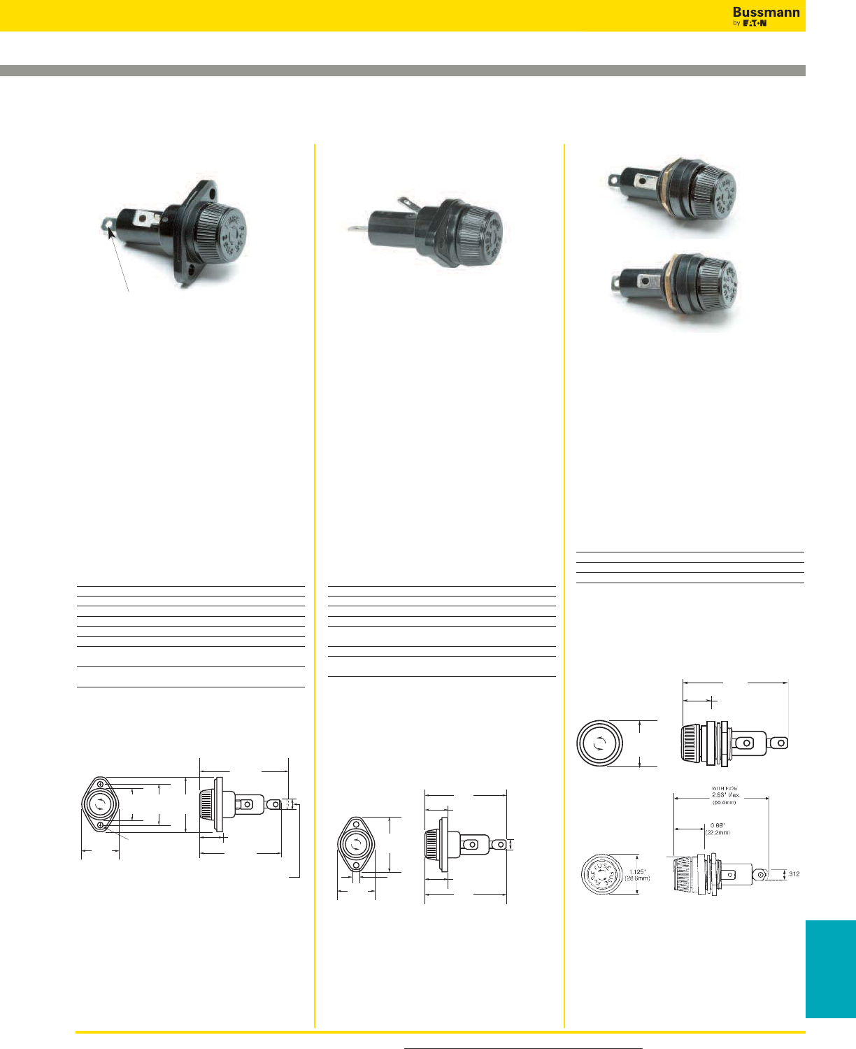
For product data sheets, visit www.cooperbussmann.com/DatasheetsEle 317
Fuse Holders
& Blocks
Fuse Holders and Blocks
Panel Mounted Fuse Holders for 13⁄32" x 1 5⁄16" to 1 1⁄2" Fuses
Data Sheet: 2114 Data Sheet: 2113 Data Sheet: 2108
0.180" DIA.
(4.6mm)
1.125"
(28.6mm)
1.00"
(25.4mm)
Without Fuse
2.69" Max.
(68.3mm)
0.88"
(22.2mm)
1.78"
(45.2mm)
1.31"
(33.3mm)
2.81" Max.
(71.4mm)
With Fuse
F
U
S
E
F
U
S
E
F
U
S
E
0.250" ± .003"
(6.35 ± .08mm)
(Typ.2)
0.88"
(22.2mm)
2.81"
(71.4mm)
With Fuse
Without Fuse
2.41"
(64.3mm)
0.80"
(20.2mm)
1.78"
(45.2mm)
0.180"
(4.6mm)
1.125"
(28.6mm)
0.250" ± 0.003"
(6.35 ± .08mm)
(Typ.2)
1.125"
(28.6mm)
0.88"
(22.2mm)
2.81"
(71.4mm)
Specifications
Description: Standard fuse holders
with screw-type knob for 13⁄32" x 15⁄16" to
11⁄2" Fuses.
Dimensions: See Dimensions
illustration.
Agency Information: CE, UL
Recognized, Guide IZLT2, File E14853;
CSA Certified, Class 6225-01, File
47235.
Flammability Rating: UL 94HB.
Terminals: Combination 1⁄4"
quick-connect/solder terminals.
Catalog Numbers
Catalog Amp
Numbers Ratings
Volts AC
Fuse Description
HPF 302600 1 1⁄2" (38.1mm)
HPF-C 30360031 1⁄2" (38.1mm) clear knob.
HPF-L 5 600 BBS, 13⁄32" x 1 3⁄8" fuses.
HPF-EE 15 600 SC 0-15, 13⁄32" x 1 5⁄16" fuses.
HPF-JJ 20 600 SC 20, 13⁄32" x 1 13⁄32" fuses.
HPF-FF1302480 SC 25 & 30, 13⁄32" x 1 5⁄8" fuses.
HPF-RR 302600 KTK-R, LP-CC & FNQ-R
Class CC fuses.
HPF-WT 302600 Splash-proof knob. 13⁄32" x 1 1⁄2"
(38.1mm)
1No CSA Certification
220A max when used with quick-connect terminals.
3HPF-C ratings for CSA-15A, 250V
Dimensions - in (mm)
Specifications
Description: Standard fuse holders
with bayonet-type knob for 13⁄32" x 15⁄16"
to 11⁄2" fuses.
Dimensions: See Dimensions
illustration.
Agency Information: CE, UL
Recognized, Guide IZLT2, File E14853;
CSA Certified, Class 6225-01, File
47235.
Flammability Rating: UL 94HB.
Terminals: Combination 1⁄4" quick-
connect/solder terminals.
Catalog Numbers
Catalog Amp
Symbol Ratings
Volts AC
Fuse Description
HPS 3023 600 13⁄32" x 1 1⁄2"
HPS-L 5 600 BBS, 13⁄32" x 1 3⁄8" fuses.
HPS-EE* 15 600 SC 0-15, 13⁄32" x 1 5⁄16" fuses.
HPS-JJ* 20 600 SC 20, 13⁄32" x 1 13⁄32" fuses.
HPS-F-EE115 600 Sleeve on body, leaded for
13⁄32" x 15⁄16" fuses.
HPS-FF*1302480 SC 25 & 30, 13⁄32" x 1 5⁄8" fuses.
HPS-RR*1302600 KTK-R, LP-CC, FNQ-R Class
CC fuses.
*-EE, -JJ, -FF and -RR versions are UL Recognized for
applications requiring branch circuit protection.
1No CSA Certification
220A max when used with quick-connect terminals.
3HPS rated at 250V for CSA
Dimensions - in (mm)
Specifications
Description: Standard fuse holders
with bayonet-type knob for 13⁄32" x 11⁄2"
fuses.
Dimensions: See Dimensions
illustrations.
Agency Information: CE, UL
Recognized, (Guide IZLT2, File
E14853).
Flammability Rating: UL 94V0 - fuse
holder body UL 94HB - Knob.
Catalog Numbers
Catalog Amp
Numbers Ratings Volts AC Fuse Description
HPG* 301600 13⁄32" x 1 1⁄2" fuses
HPG-EE* 15 600 SC 0-15, 13⁄32" x 1 5⁄16" fuses.
HPD** 301600 13⁄32" x 1 1⁄2" fuses
120A max when used with quick-connect terminals.
*HPG and HPG-EE has combination 1⁄4" quick-connect/solder
terminals on both side (load) and rear (line) terminals.
**HPD has combination 1⁄4" quick-connect/solder terminal on
side (load) terminal only. Rear (line) terminal is 3⁄16" shorter
than HPG. Rear terminal solder only.
Dimensions - in (mm)
HPG, HPG-EE
HPD
HPF
HPD
HPGHPS
#10 wire max
for solder connection
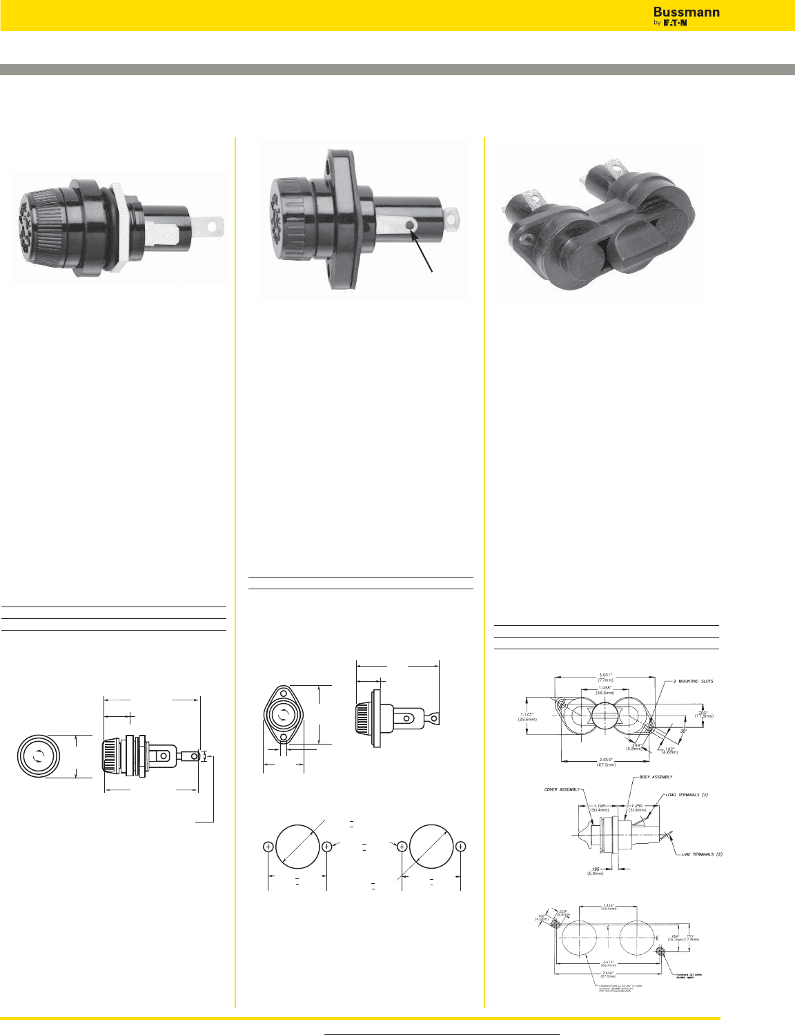
For product data sheets, visit www.cooperbussmann.com/DatasheetsEle
318
Fuse Holders and Blocks
Panel Mounted Fuse Holders for 13⁄32" x 1 1⁄2" Fuses
Data Sheet: 2112 Data Sheet: 2109 Data Sheet: 2140
Panel Mount Hole Dimensions
1.41"
(30.6mm)
0.94"
(23.8mm)
With Fuse
Without Fuse
2.73"
(69.5mm)
2.594"
(65.89mm)
0.250" ± 0.003"
(6.35 ± 0.08mm)
1.031" + 0.003"
(26.2mm + 0.08mm)
0.187" + 0.002"
(4.75mm + 0.05mm)
Mounting Hole
Flange Rear of Panel
Mounting Hole
Flange Front of Panel
0.890" + 0.003"
(22.6mm + 0.08mm)
1.312" + 0.003"
(33.3mm + 0.08mm)
1.312" + 0.003"
(33.3mm + 0.08mm)
1.775"
(45.1mm)
0.180"
(4.6mm)
1.120"
(30.5mm)
0.88"
(22.2mm)
2.48"
(63.1mm)
With Fuse
Specifications
Description: Standard fuse holder
with screw-type knob for 13⁄32" x 11⁄2"
fuses.
Dimensions: See Dimensions
illustration.
Ratings:
Volts: — 600Vac/dc
Amps: — 30A1
120A max when used with quick-connect terminals.
Agency Information: CE, UL
Recognized, Guide IZLT2, File E14853;
CSA Certified, Class 6225-01, File
47235.
Flammability Rating: UL 94HB.
Catalog Numbers
Catalog
Numbers Description
HPM 1⁄4" quick-connect/solder
HPM-D Splash-resistant knob2
2HPM-D has 1⁄4"quick-connect/solder terminal on rear (load)
terminal only. The side (line) terminal is 1⁄4" quick-
connect only.
Dimensions - in (mm)
Specifications
Description: Fuse holder with
screw-type knob for 13⁄32" x 11⁄2" fuses.
Supplied with O-ring and panel gasket.
Dimensions: See Dimensions
illustration.
Ratings:
Volts: — 600Vac/dc
Amps: — 30A1
120A max when used with quick-connect terminals.
Agency Information: CE, UL
Recognized, Guide IZLT2, File E14853.
Flammability Rating: UL 94HB.
Catalog Numbers
Catalog
Number Description
HPC-D Mount in panels up to 1⁄4" thick.
Replacement knob - BK/9987SA
Dimensions - in (mm)
Specifications
Description: For fuse size 13⁄32" x 11⁄2",
meeting UL 1598 requirement that both
poles be removed simultaneously.
Dimensions: See Dimensions
illustration.
Ratings:
Volts: — 600V@30A
Amps: — 0-30A 1
120A max when used with quick-connect terminals.
Agency Information: UL 4248
recognized, (Guide IZLT2, File
E14853), CSA certified:
(Class 6225-01, File 47235).
Flammability Rating: UL 94V0.
Terminals: 1⁄4” quick-connect/solder.
Catalog Numbers
Catalog
Numbers
HPS2 Standard 10-in carton
BK/HPS2 Bulk 100-in carton
Dimensions - in (mm)
HPM HPC-D HPS2
#10 wire max
for solder connection
Nut Torque: 30 lb-in.
Replacement Knob:
Catalog Number: BK/9789-Y2
(50 pieces)
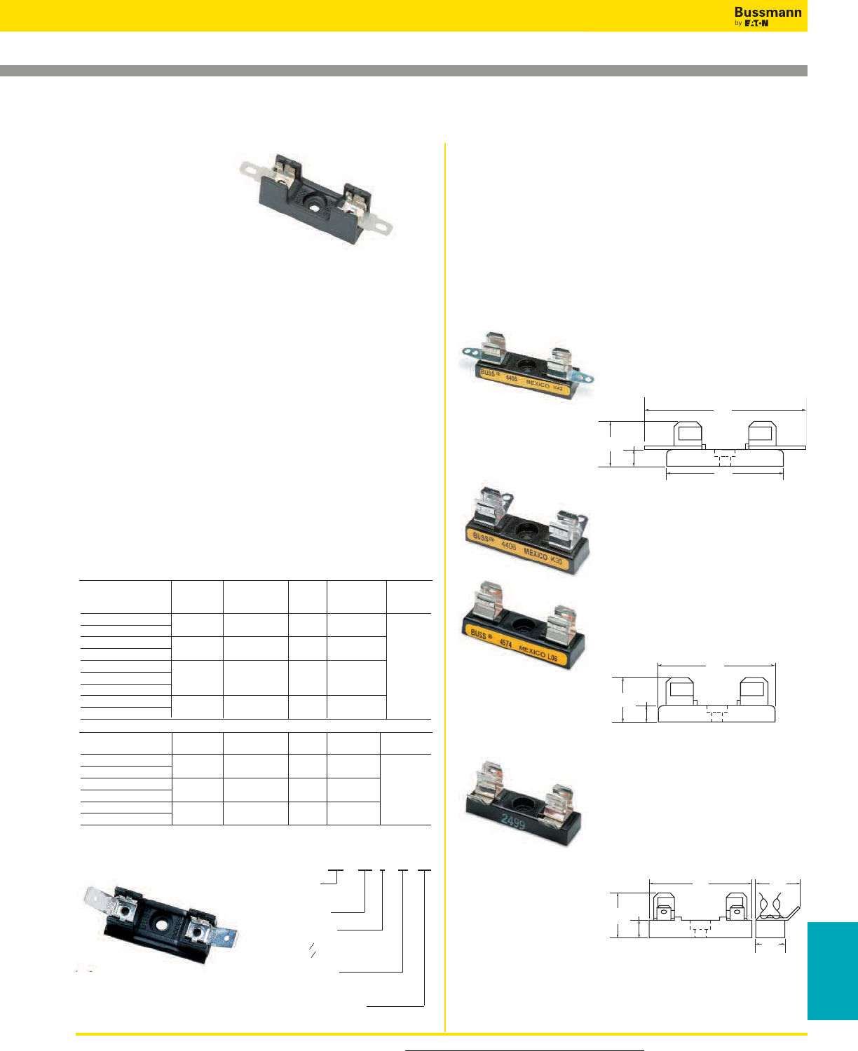
For product data sheets, visit www.cooperbussmann.com/DatasheetsEle 319
Fuse Holders
& Blocks
Fuse Holders and Blocks
Fuse Blocks for 1⁄4" x 1 1⁄4" Fuses
4405 - 0° Solder terminals
with integral terminal and clip
Dimensions - in (mm)
Note: Mounting screw hole diameter is 0.147" (3.7mm).
Counterbore diameter, 0.636" (8.0mm). Max Mounting
Screw No. 6.
Specifications
Description: Bolt-in and snap-in mounting for 1⁄4" x 11⁄4"
fuses.
Construction: Blocks are molded flame retarded
thermoplastic. Clips are spring-bronze.
Ratings:
Volts: — 300V
Amps: — 25A (See Catalog Numbers table)
Agency Information: CE, UL Recognized ; File E14853,
Guide IZLT2, CSA Certified Class 6225-01, File 47235.
Anti-Rotation Pin: Single-pole blocks may be ordered
without the anti-rotational pin simply by adding an “X” to the
number of poles (Example: BK/S-8000-1X).
Carton Quantity: 10; shelf package: 100.
Bulk Carton: Single-pole and 2-pole fuse blocks – 1,000;
Multiple-pole fuse blocks – 3- to 8-pole: 200; 9- to 12-pole:
50. When ordering bulk quantities, prefix “BK/” to catalog
number: (Example: BK/S-8001-1-SNP).
2.31"
(58.7mm)
1.63"
(41.3mm)
0.27"
(6.7mm)
0.69"
(17.5mm)
Catalog Numbers
Bolt-in Mounting
Basic
Catalog Agency Poles
Numbers Series Terminal Angle Maximums (Suffix)
S-8001- 8000 Solder 0° UL 25A 1 - 12
S-8002- 40° CSA 21A
S-8101- 8100 3⁄16" Quick 0° UL 20A
S-8102- Connect 40° CSA 13A
S-8201- 8200 1⁄4" Quick 0° UL 20A
S-8202- Connect 40° CSA 16A
S-8203- Side
S-8301- 8300 Screw — UL 30A
CSA 25A
Snap-in Mounting
Catalog Agency Poles
Numbers Series Terminal Angle Maximums (Suffix)
S-8001-1-SNP 8000 Solder 0° UL 25A Available
S-8002-1-SNP 40° CSA 21A only in
S-8101-1-SNP 8100 3⁄16" Quick 0° UL 20A single
S-8102-1-SNP Connect 40° CSA 13A pole
S-8201-1-SNP 8200 1⁄4" Quick 0° UL 20A
S-8203-1-SNP Connect Side CSA 16A
Catalog Number Build-A-Code
4406 - Side solder terminal
4574 - Spare fuse block
Dimensions - in (mm)
2499 - Side quick-connect
Agency Information: UL
Recognized, Guide IZLT2, File
E14853
Terminals: 1⁄4" (6.4mm); 15A, 250V
Dimensions - in (mm)
Series 8000
Data Sheet: 2101
1.63"
(41.3mm)
0.27"
(6.7mm)
0.69"
(17.5mm)
0.27"
(6.7mm)
0.75"
(19.1mm)
0.5"
(12.7mm)
0.72"
(18.3mm)
1.63"
(41.3mm)
Single-Pole Fuse Blocks
Specifications
Description: Single-pole fuse block for 1⁄4" x 11⁄4"
(6.4 x 31.8mm) size fuses.
Dimensions: See Dimensions illustrations.
Construction: Bakelite base width 1⁄2" (12.7mm); spring-
bronze, bright tin-lead plate clips.
Ratings:
Volts: — 250V
Amps: — 30A
8000
8000 Available
only in
single
pole
1 - 12
8100
8100
8300
8200
8200
Catalog Code
BK/ S-8 0 00 -00
Prefix for
Bulk
Packing
Series 8000
Product Line
Terminal Angle
“01” - straight (0,)
“02”- 40
“03” - side*
Type Terminal
“0”-Solder
“1”- ‹ ¡§∑
Quick Connect
“2” - ⁄ ¢∑ Quick Connect
“3” - Screw
Number of Poles (1-12)
*Available only in single pole
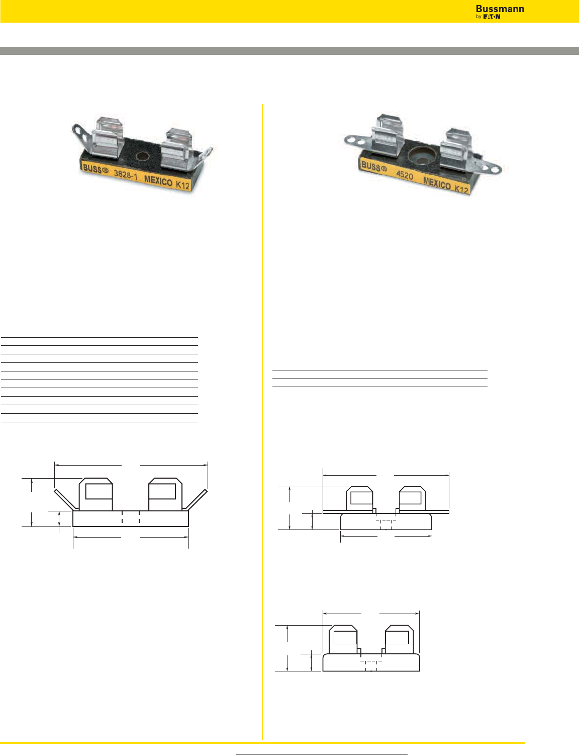
For product data sheets, visit www.cooperbussmann.com/DatasheetsEle
320
Fuse Holders and Blocks
No. 4520 - Integral clip and straight solder
terminals
Fuse Blocks for 1⁄4" x 1" Fuses
0.19"
(4.8mm)
0.63"
(15.9mm)
1.88"
(47.6mm)
1.38"
(34.9mm)
1.94"
(49.2mm)
1.38"
(34.9mm)
.188"
(4.8mm)
.598"
(15.2mm)
1.38"
(34.9mm)
0.188"
(4.8mm)
0.598"
(15.2mm)
No. 4393 - Spare fuse block
3828 Series 4520 and 4393
Specifications
Description: Fuse block for 1⁄4" x 1" (6.4 x 25.4mm) fuses
with solder terminals.
Dimensions: See Dimensions illustration.
Ratings:
Volts: — 250V
Amps: — 30A
Mounting: Mounting screw hole diameter is 0.147"
(3.7mm), diameter. Max mounting screw No. 6.
Catalog Numbers
Catalog Numbers Poles *Base Length - in (mm)
3828-1 1 1⁄2 (12.7)
3828-2 2 1 1⁄8(28.6)
3828-3 3 1 3⁄4(44.5)
3828-4 4 2 3⁄8(60.3)
3828-5 5 3 (76.2)
3828-6 6 3 5⁄8(92.1)
3828-7 7 4 1⁄4(108.0)
3828-8 8 4 7⁄8(123.8)
3828-10 10 6 1⁄8(155.6)
3828-12 12 7 3⁄8(187.3)
*Small phenolic base, base width 1 3⁄8" (34.9mm)
Dimensions - in (mm)
Specifications
Description: Single-pole fuse block for 1⁄4" x 1" fuses.
Dimensions: See Dimensions illustrations.
Construction: Bakelite with 1⁄2" (12.7mm) width base.
Spring-bronze, bright tin-lead plated clips.
Ratings:
Volts: — 250V
Amps: — 30A
Mounting: Mounting screw hole diameter is 0.147"
(3.7mm), counterbore 0.636" (8.0mm) diameter. Max
mounting screw No. 6.
Catalog Numbers
Catalog
Numbers Description
4520 Integral clip and straight solder terminals
4393 Spare fuse block
Dimensions - in (mm)
Dimensions - in (mm)
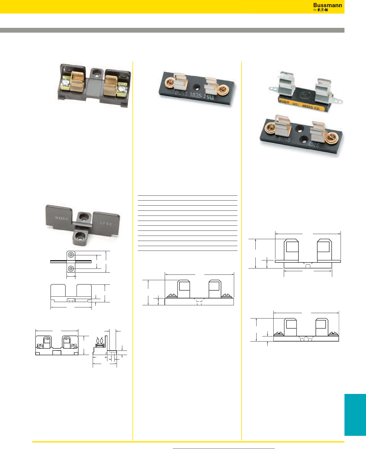
For product data sheets, visit www.cooperbussmann.com/DatasheetsEle 321
Fuse Holders
& Blocks
Fuse Holders and Blocks
Blocks for 13⁄32" X 11⁄2" Fuses
Specifications
Description: Add-on fuse blocks for
13⁄32" X 1 1⁄2" (10.3 X 38.1mm) fuses.
Single pole blocks lock into each other
and can be added at any time. Each
has a single end barrier.
Dimensions: See Dimensions
illustration.
Ratings:
Volts: — 600Vac/dc
Amps: — 30A
Agency Information: CE, UL
Recognized Guide IZLT2, File E14853.
3742—End Barrier Only
3723—Block and end barrier
marking strip. Length is 93⁄8"
(23.8cm).
Note: Mounting screw hole is 0.147"
(3.7mm) dia. Counterbore, 0.636"
(8mm) dia. Max. mounting screw No. 6.
Specifications
Description: Single pole fuse blocks
for 13⁄32" X 1 1⁄2" (10.3 X 38.1mm) fuses.
Dimensions: See Dimensions
illustration.
Ratings:
Volts: — 250Vac/dc (or less)
Amps: — 30A
Agency Information: CE
4421—Solder Terminals
Base width 5⁄8" (15.9mm)
4515—Screw Terminals
Base width 3⁄4" (19mm)
Note: Mounting screw hole diameter is
0.147" (3.7mm). Countersink, 0.312"
(7.9mm). Max. mounting screw No. 6.
Specifications
Description: Multiple pole fuse blocks
for 13⁄32" X 1 1⁄2" (10.3 X 38.1mm) fuses.
Dimensions: See Dimensions
illustration.
Ratings:
Volts: — 250Vac/dc
Amps: — 30A
Agency Information: CE
Catalog Numbers
Catalog Base* Width
Numbers Poles In (mm)
3835-1 1 27⁄32 (21.4)
3835-2 2 1 13⁄16 (46.0)
3835-3 3 2 25⁄32 (70.6)
3835-4 4 3 3⁄4(95.2)
3835-5 5 4 23⁄32 (119.9)
3835-6 6 5 11⁄16 (144.5)
3835-7 7 6 21⁄32 (169.0)
3835-8 8 7 5⁄8(193.7)
3835-9 9 8 19⁄32 (218.8)
3835-10 10 9 9⁄16 (242.9)
3835-12 12 11 1⁄2(292.1)
*Base length: 2 3⁄4" (69.9mm)
Dimensions - in (mm)
Note: Mounting screw hole diameter is
0.148" (3.7mm). Countersink, 0.313"
(7.9mm). Max. mounting screw No. 6.
3 7 4 2
0.25"
2.56"
1.125"
1.29"0.84"
0.500"
1.125"
(28.6mm)
2.56"
(65.1mm)
0.78"
(19.8mm)
1.34"
(34.1mm)
0.25"
(6.4mm)
0.323"
(8.2mm)
0.144"
0.19"
(4.8mm)
0.897"
(22.78mm)
2.5"
(63.5mm)
1.63"
(41.3mm)
2.56"
(65.1mm)
0.19"
(4.8mm)
0.897"
(22.78mm)
2.75"
(69.9mm)
0.25"
(6.4mm)
1.0"
(25.4mm)
3743 4421 and 45153835 Series
Data Sheet: 2104
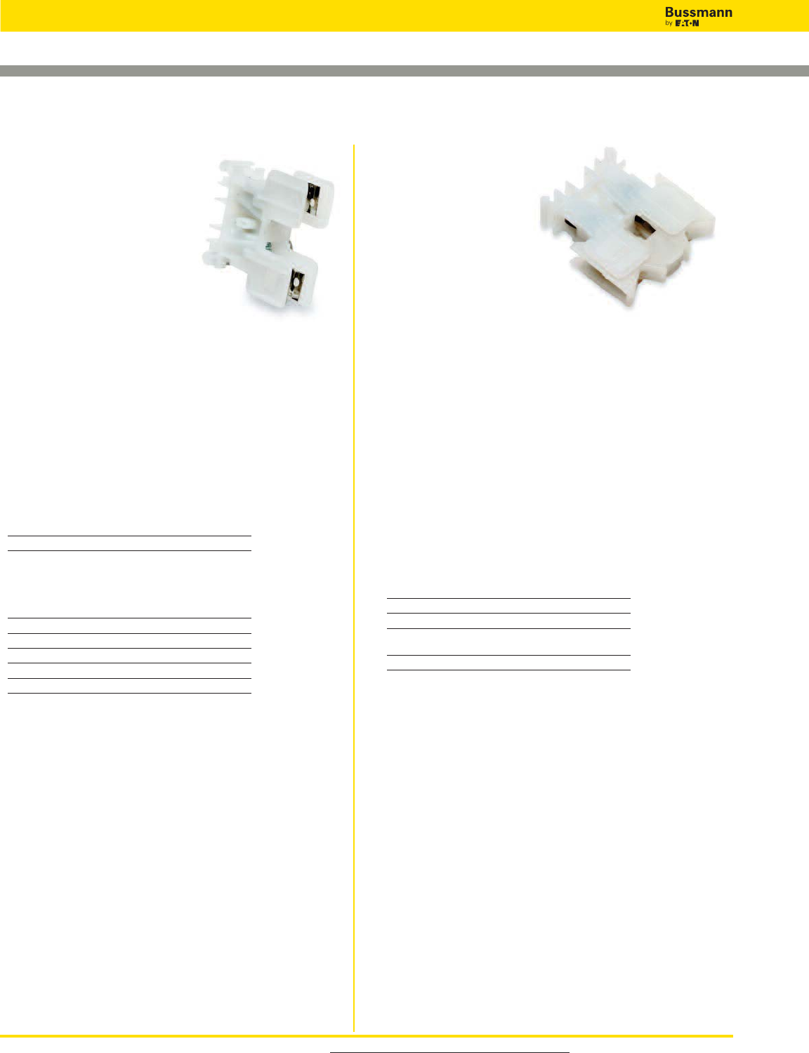
For product data sheets, visit www.cooperbussmann.com/DatasheetsEle
322
Fuse Holders and Blocks
NDNF1-WH
Specifications
Description: Fuse holding rail
mount terminal block.
Circuit Jumper: JF1,
2 circuits
Fuse Size: 13⁄32" X 11⁄2"*
(KTK, FNQ, PVM).
Poles: 1
Wire Range: AWG #8-22 Cu.
Ratings:
Volts: — 600V
Amps: — 30A
Mounting Options: 35mm DIN-Rail, C-rail
Fuse Pullers: • PF1 (standard)
• neon or incandescent bulb
*LPF1 (lighted neon or incandescent bulb).
Torque Rating: 18 lb-in
Operating Temperature: 105°C
Catalog Numbers
Catalog
Number Color
NDNF1-WH White
Fuse Pullers (Optional): PF1
Lighted neon or incandescent lamp:
Catalog
Numbers Voltage
LPF1-24 24
LPF1-120 120
LPF1-120-C 120
LPF1-220 220
LPF1-440 440
NDNLFD1-WH
Specifications
Description: Rail mount
fuse holder.
Circuit Jumper: JF1,
2 circuits.
Fuse Size: 1⁄4" X 11⁄4"
(Bussmann AGC, MDL or
equivalent).
Poles: 1
Wire Range: AWG #8-22 Cu.
Ratings:
Volts: — 600V
Amps: — 30A (NDND1 non-fused)
— 15A (NDNFD1, 600V/CSA, fused)
— 15A (NDNLFD1*fused, indicating)
*WH24 - 24V White, WH-90Vdc-600Vdc, 115Vac-600Vac White
Agency Information: CE
Mounting Options: 35mm DIN-Rail, C-rail
Marking Tape: MT12-1-2
Torque Rating: 18 lb-in
Operating Temperature: 105°C
Agency Information: CSA File 15364
Catalog Numbers
Catalog
Number Color Indicator
NDND1-WH White NO
NDNFD1-WH White NO
NDNLFD1-WH White 90Vdc-600Vdc
115Vac-600Vac
NDNLFD1-WH 24 White 24V
Rail Mount Fuse Blocks and Holders
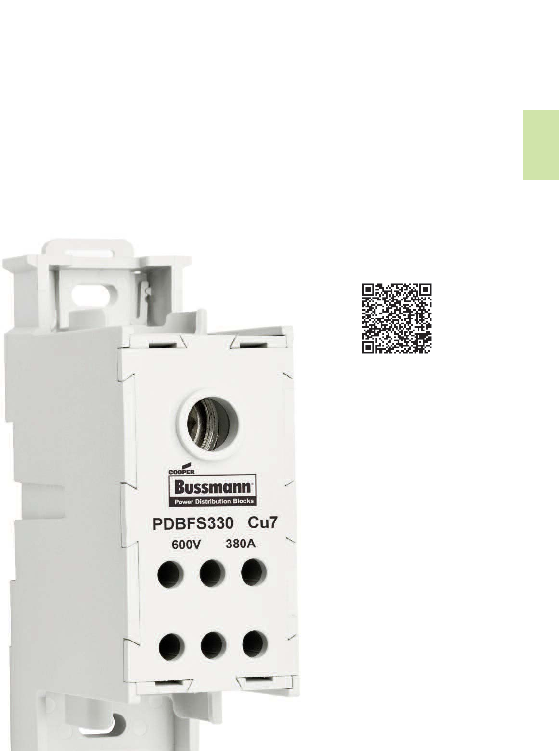
323
Power Distribution
& Terminal Blocks
Power Distribution &
Terminal Blocks
Section Contents Page
Selection table for SCCR PDBs & Power
terminal blocks . . . . . . . . . . . . . . . . . . . . . . . . . . . . . 324
Power distribution blocks
Series PDBFS enclosed, with high SCCR . . . . . . . . . . . .325
Series PDB with high SCCR . . . . . . . . . . . . . . . . . . . . . 326
Power terminal blocks
Series 163 . . . . . . . . . . . . . . . . . . . . . . . . . . . . . . . . 327-328
Series 11675 2- to 12-Pole quick-connect . . . . . . . . . . . 329
Series 11725 2- to 4-Pole quick-connect . . . . . . . . . . . . 329
Series 160, 162, 163 & 165 . . . . . . . . . . . . . . . . . . . . . . 329
Series 162, 163 & 165 power stud terminal blocks . . . 330
Series 160, 162, 163 & 165 power splicer blocks . . . . 330
Series 14002 Barrier terminal blocks . . . . . . . . . . . . . . 331
Series 14004 Dead front terminal block . . . . . . . . . . . .331
Scan this tag to get the
latest product information for the
Power Distribution Blocks.
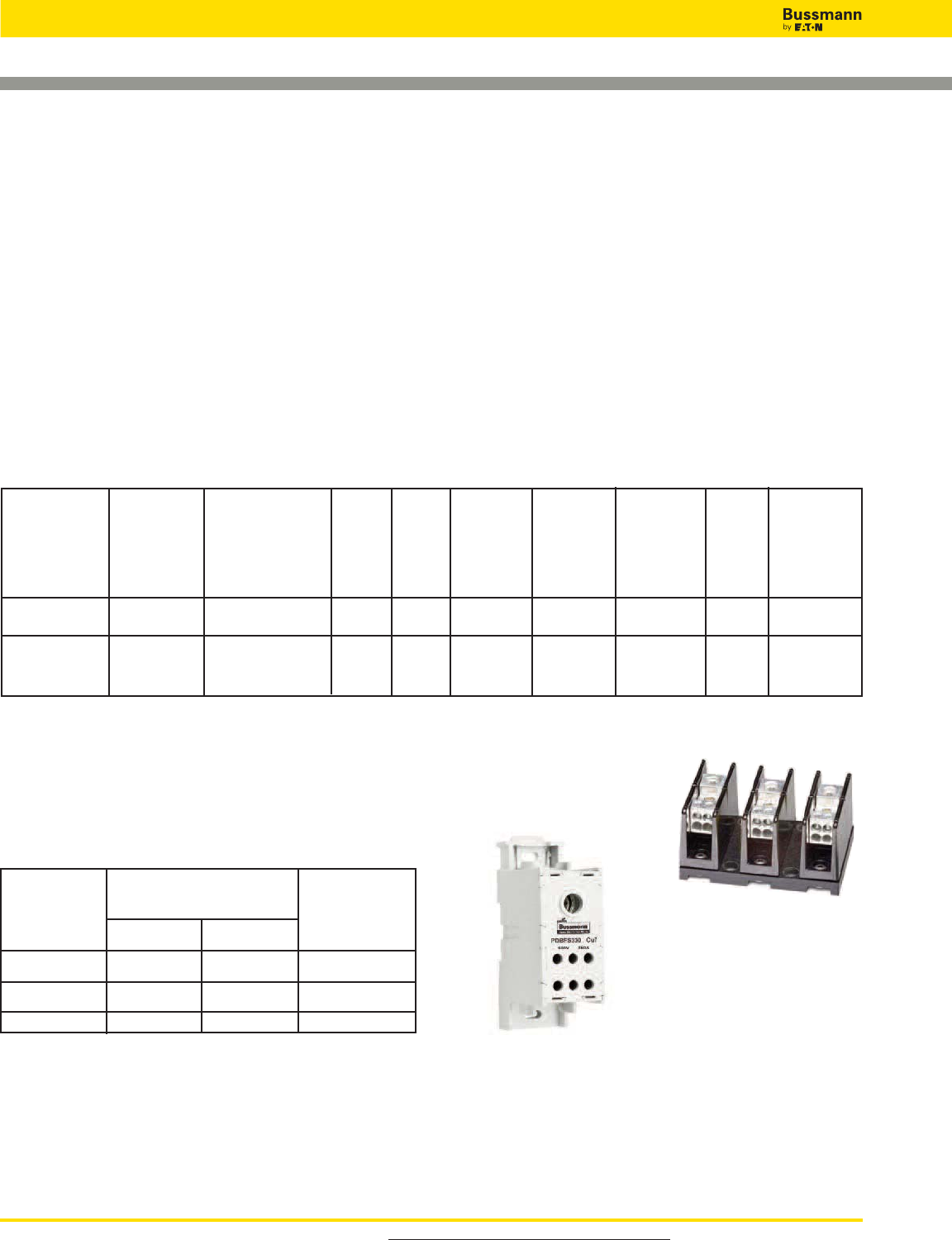
For product data sheets, visit www.cooperbussmann.com/DatasheetsEle
324
Power Distribution & Terminal Blocks
Selection Table for SCCR Power Distribution Blocks and
Power Terminal Blocks
Short-Circuit Current Rated Power Distribution
Blocks
Bussmann offers three distinctly different styles of short-
circuit current rated power distribution blocks (PDBs) and
power terminal blocks (PTBs) to match different
application needs. The differences are whether the power
distribution blocks are enclosed or not, and whether they are
UL 1953 Listed PDBs or UL 1059 Recognized PTBs, which
have different minimum spacing requirements. The table on
this page can assist in the selection of the right series for
your application requirements.
Why these are important?
Assembly short-circuit current ratings (SCCRs) are now
required in the 2011 NEC®and UL 508A Listed Industrial
Control Panels. Marking the SCCR on Industrial Control
Panels (NEC®409.110), Industrial Machinery Electrical
Panels (NEC®607.3(A)), and HVAC equipment (NEC®
440.4(B)) is required by the National Electrical Code. PDBs or
PTBs not marked with a SCCR, typically are the weakest link
and may limit an assembly to no more than 10kA SCCR. The
PDBFS and PDB Series have increased spacing required
where used in feeder circuits in equipment listed to UL508A
(UL1059 PTBs must be evaluated for proper spacings). Also,
for building wiring systems, the PDBFS Series and PDB
Series power distribution blocks can be used to meet the new
2013 NEC®requirements in section 376.56(B) for PDBs in
wireways.
Industrial Industrial
Control Control HVAC Wireways
Description Catalog High Spacing** Panels Panels UL NEC®
Page UL
Enclosed
SCCR* 1” Air UL 508A UL 508A 1995 376.56(B)
2” Surface Branch Feeder (Requires
Circuit Circuit UL 1953)
Series PDBFS 325 UL 1953 Listed Yes†Ye s Yes Ye s Yes Ye s Ye s
Yes
Series PDB 326 UL 1953 Listed No*** Yes Yes Yes Yes Yes w/optional
cover
Selection Table
† IP20 Finger-safe under specific conditions, see datasheet 1149.
*When protected by proper fuse class with maximum ampere rating specified or less.
**See PDB Spacing Requirements for Equipment table below.
***Optional covers are available. Not IP20, but provide a safety benefit.
****No, except: Yes, if single pole units installed with proper spacings.
Spacing between Spacing between
live parts of live parts and
UL Standard opposite polarity grounded parts
or enclosure
@600V
508A Feeder
Circuits
508A Branch
Circuits
1995 HVAC
Through air Over surface
@600V @600V
1˝2˝1˝
3⁄8˝1⁄2˝1⁄2˝
3⁄8˝1⁄2˝1⁄2˝
Note: Refer to Specific UL standards for complete spacing details.
PDB & PTB Minimum Spacing
Requirements for Equipment
Data Sheet: 1049
Series PDBFS
Series PDB
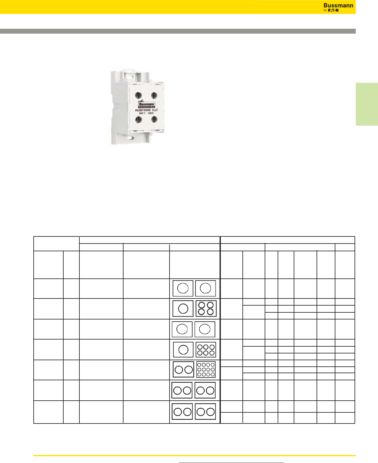
For product data sheets, visit www.cooperbussmann.com/DatasheetsEle 325
Power Distribution
& Terminal Blocks
Series PDBFS of Power Distribution Blocks
Feature/Benefits
•Enclosed, safer
installation; IP20
finger-safe under specific
conditions
• High short-circuit current
ratings up to 200kA:
PDBs do not have to be
the weak link in achieving
high SCCR for an
industrial control panel
• Small footprint saves
panel space
• Listed to UL 1953 which has minimum spacing
requirements at 600V of at least 1” through air and 2” over
surface required for feeders in UL 508A Industrial Control
Panels
• For 2D CAD drawings visit www.cooperbussmann.com
Agency/Standards
• UL Listed 1953, Guide QPQS, File E256146
• CSA Certified, Class 6228-01, File 47235
• IEC 60947-7-1
• IEC 60529, IP20 (finger-safe) under specific wiring
conditions
Electrical
• 600Vac/dc (UL 1953), 690Vac/dc (IEC)
• IP20 finger-safe under specific conditions
• Short-circuit current ratings up to 200kA, see table
• Ampacities up to 760 amps
• Cu wire range 14 AWG to 500 kcmil or 2.5 to 240 mm2
Mechanical
• DIN-Rail or panel mount; PDBFS330 & PDBFS504 panel
mount only
• Captive termination screws; screws do not get misplaced
• Wire ready: captive termination screws shipped backed out
to save time on conductor installations
• Sliding DIN-Rail latch for easy mounting
• Single pole, gang mountable for multiple pole applications
with interlocking dovetail accessory (optional)
• Flammability, UL 94V0
• Tin-plated Al connectors suitable for Cu conductors
• Elongated hole for panel mounting; easier mounting with
greater flexibility in matching up with drilled panel holes
• Part 2A1279: Interlocking dovetail pin accessory
One pin interlocks two units, two pins to interlock three units
• DIN-Rail end anchors required to prevent damage to block
when torquing
Data Sheet: 1049
Power Distribution & Terminal Blocks
Terminal Copper Conductor Capability Short-Circuit Current Rating Data
Line Load Configuration Conductors Max Fuse Class & Amp**
Catalog
Number Openings per Pole Line Load J T RK1 RK5
(All Single Amps Wire Range Wire Range AWG or AWG or LPJ JJS LPS-RK FRS-R SCCR
Pole) Line Load kcmil kcmil JJN LPN-RK FRN-R
PDBFS204 175A 2/0 to 8 AWG 2/0 to 8 AWG 2/0 to 8 2/0 to 8 200 200 100 60 200kA
70 to 10 mm270 to 10 mm2
2/0 to 8 AWG 4 to 14 AWG 4 to 12 200 200 100 60 200kA
PDBFS220 175A 70 to 10 mm225 to 2.5 mm22/0 to 8 4 to 14 175 175 100 30 100kA
200 200 100 60 50kA
350kcmil to 6 AWG 350kcmil to 6 AWG
PDBFS303 310A 185 to 16 mm2185 to 16 mm2350 to 6 350 to 6 400 400 200 100 200kA
500kcmil to 6 AWG 2 to 14 AWG 2 to 6 400 400 200 100 200kA
PDBFS330 380A 240 to 16 mm235 to 2.5 mm2500 to 6 2 to 14 200 200 100 60 50kA
175 175 100 30 100kA
300kcmil to 4 AWG 4 to 14 AWG 300 4 to 8 600 600 400 200 200kA
PDBFS377 570A 150 to 12 mm225 to 2.5 mm2300 to 4 4 400 400 200 100 100kA
4 to 14 200 200 100 60 50kA
PDBFS500 620A 350kcmil to 4 AWG 350kcmil to 4 AWG 350 to 4 350 to 4 600 600 400 200 200kA
185 to 12 mm2185 to 12 mm2
500kcmil to 6 AWG 500kcmil to 6 AWG 500 500 600 800* 600 200 200kA
PDBFS504 760A 240 to 16 mm2240 to 16 mm2500 to 6 500 to 6 600 600 400 200 100kA
Ampacities 75C per NEC® Table 310.16 and UL508A Table 28.1
*Class L 800A (KRP-C 800_SP) or less fuses suitable for this particular SCCR case.
** Class G 60A (SC-60) or less or Class CC 30A (LP-CC-30, FNQ-R-30, KTK-R-30) or less are suitable for all SCCRs in this table.
Series PDBFS
Electrical
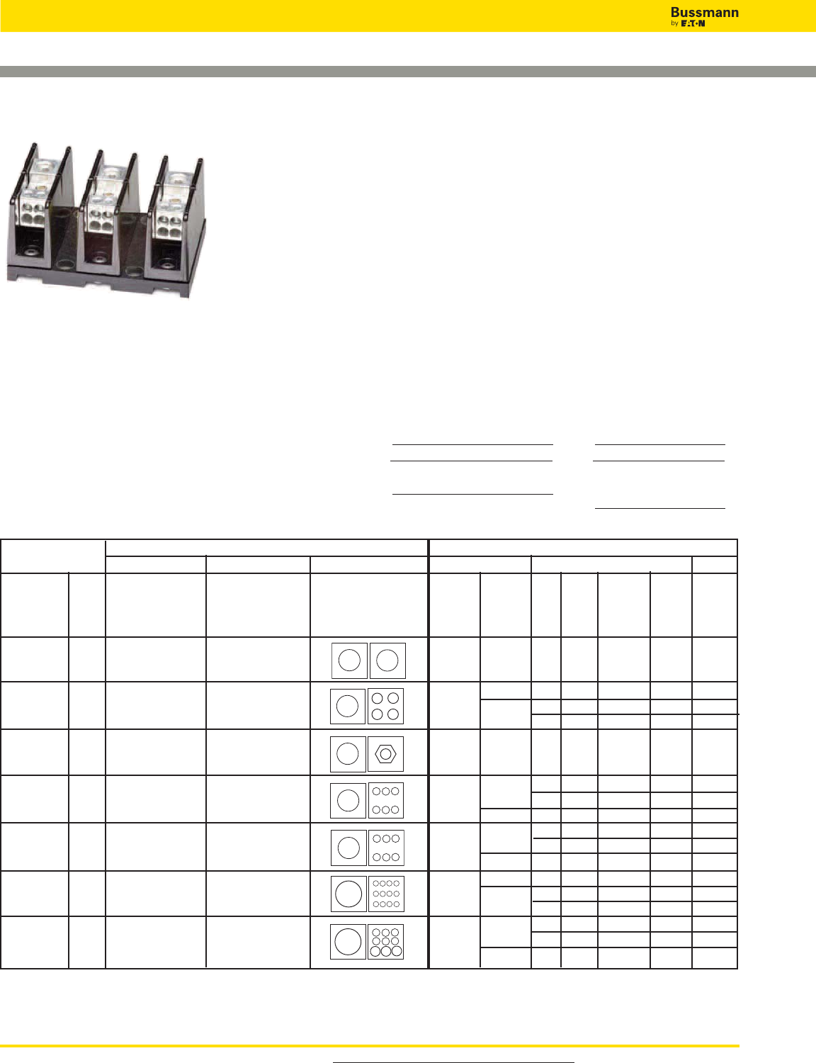
For product data sheets, visit www.cooperbussmann.com/DatasheetsEle
326
Power Distribution & Terminal Blocks
Series PDB of Power Distribution Blocks
Feature/Benefits
• High short-circuit current ratings up to 200kA. These
PDBs do not have to be the weak link in achieving high
SCCR for an industrial control panel
• Listed to UL 1953 which has minimum spacing
requirements at 600V of at least 1” through air and 2” over
surface required for feeder in UL 508A Industrial Control
Panels
• For 2D CAD drawings visit www.cooperbussmann.com
Agency/Standards
• UL Listed 1953, Guide QPQS, File E256146
Electrical
• 600Vac/dc (UL 1953)
• Short-circuit current ratings up to 200kA, see table
• Wire range 14 AWG to 350 kcmil Cu
• Spacing between uninsulated opposite polarities or ground
meets UL 1953 which requires at least 1” through air and
2” over surface
• Ratings available with circuit breakers
Mechanical
• Panel mount
• Flammability, UL 94V0
• Tin-plated Al connectors suitable for Cu conductors
Terminal Copper Conductor Capability Short-Circuit Current Rating Data
Line Load Configuration Conductors Max Fuse Class & Amp*
Catalog
Number Openings per Pole Line Load J T RK1 RK5
Amps Wire Range Wire Range AWG or AWG or LPJ JJS LPS-RK FRS-R SCCR
- Pole Line Load kcmil kcmil JJN LPN-RK FRN-R
PDB204-1
PDB204-3 175A 2/0 - 8 AWG 2/0 - 8 AWG 2/0 - 8 2/0 - 8 200 200 200 60 200kA
4 - 12 200 200 200†60†200kA
PDB220-1 175A 2/0 - 8 AWG 4 - 14 AWG 2/0 - 8 14 175†175†100†60†100kA
PDB220-3 200†200†100†60†50kA
PDB280-1 175A 2/0 - 8 AWG 1/4-20 X 3/4 STUD 2/0 - 8 Stud 200 200 100 60 200kA
PDB280-3
PDB321-1 4 -12 400 400 200†100†200kA
PDB321-2 175A 2/0 - 8 AWG 4 - 14 AWG 2/0 - 8 400†400†400†100†100kA
PDB321-3 14 175†175†100†60†100kA
PDB323-1 400 400 200†100†200kA
PDB323-3 310A 300kcmil - 4 AWG 4 - 12 AWG 300 - 4 4 - 8 400†400†400†100†100kA
10 - 12 175†175†100†60†100kA
PDB370-1 4 - 8 400 400 200†100†200kA
PDB370-3 310A 350kcmil - 4 AWG 4 - 14 AWG 350 - 4 10 - 14 400†400†400†100†100kA
175†175†100†60†100kA
PDB371-1 1/0 - 6 400 400 200†100†200kA
PDB371-3 310A 350kcmil - 4 AWG (6) 2 - 12 AWG 350 - 4 400†400†400†100†100kA
(3) 1/0-12 8 - 12 175†175†100†60†100kA
Ampacities 75ºC per NEC® Table 310.16 and UL508A Table 28.1
* Class G 60A (SC-60) or less or Class CC 30A (LP-CC-30, FNQ-R-30_SP, KTK-R-30) or less are suitable for all these SCCR in this table.
† Higher SCCR may be available, check data sheet 1049.
Series PDB
Data Sheet: 1049
Optional covers
Covers are ordered for each individual pole, i.e., three
1-pole covers for 3-pole block, see table A.
Except PDB321 blocks have one cover for 1-, 2- or 3-pole
versions, see table B.
Table A Table B
Block Cover Block Cover
PDB2XX-(pole): CPB162-1 PDB321-1 CPDB-1
PDB3XX-(pole): CPDB-1 PDB321-2 CPDB-2
PDB321-3 CPDB-3
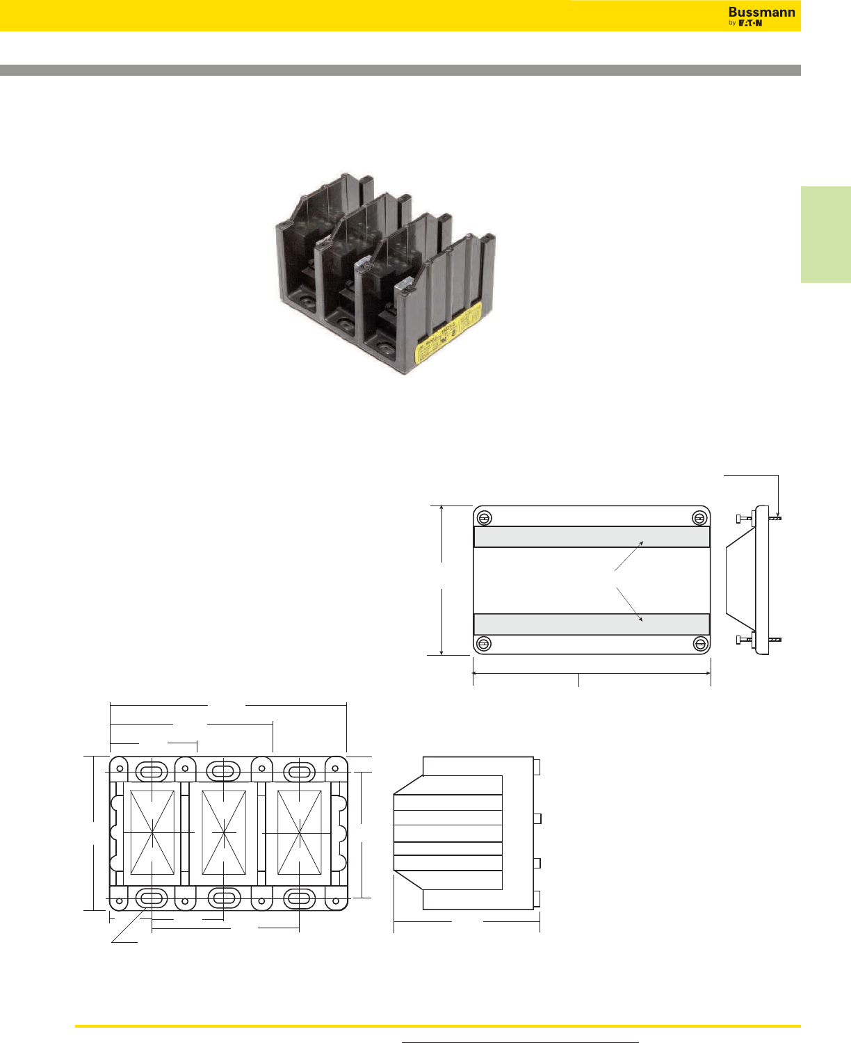
For product data sheets, visit www.cooperbussmann.com/DatasheetsEle 327
Power Distribution
& Terminal Blocks
163 Series
Replaces Bussmann 164 Series
Specifications
Description: Power terminal
block.
Dimensions: See Dimensions
illustrations.
Construction: Tin-plated
aluminum connectors.
Poles: 1- to 3-Poles, See
Catalog Numbers table on the
following page.
Wire Range: See Catalog
Numbers table on the following
page.
Ratings:
Volts: — 600Vac/dc
Amps: — See catalog Numbers table on the following page.
SCCR:— 10kA per UL 508A table SB4.1 (except for select
products noted in table)
Agency Information: CE, UL Recognized: Guide XCFR2,
UL E62622, General Industrial Class per UL1059, CSA
Certified: CSA 053787
Flammability Rating: UL 94V0
Dimensions
Series 163 Power Terminal Blocks
1-pole
1.96"
2-pole
3.58"
3-pole
5.20"
.31"
1.62"
3.25"
Mtg. hole 0.21 x 0.41,
c'bore 0.42 x 0.62 x 0.12 deep
3.32"
0.97"
4.00" 3.37"
Supplied with (4) #4 thread-cutting
screws assembled as shown
Textured surface for marking
CPDB-1 (single pole) 2.10"
CPDB-2 (two pole) 3.72"
CPDB-3 (three pole) 5.34"
4.14"
(See Following Page for Ratings)
Data Sheet: 1049
Power Distribution & Terminal Blocks
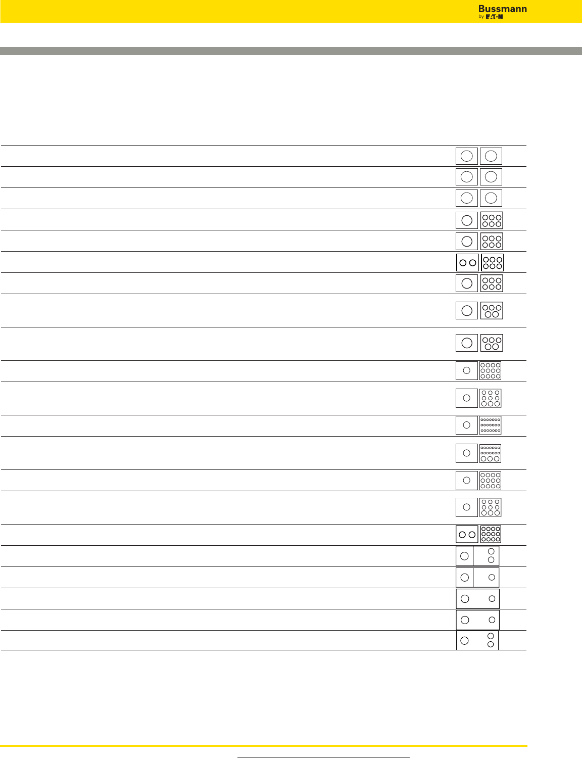
Series 163 Power Terminal Blocks
Catalog Numbers
Basic
Catalog Wire Size Amps/
Numbers (Poles) Lineside (Poles) Loadside Pole Line/Load
16301* 250kcmil-6 AWG Cu Only 250kcmil-6 AWG Cu Only 255
16303 350kcmil-6 AWG Cu-Al 350kcmil-6 AWG Cu-Al 310
16306 500kcmil-6 AWG Cu-Al 500kcmil-6 AWG Cu-Al 380
16321** 2/0-14 AWG CU, 2/0-8Al (6)4-14 AWG Cu, 4-8 AWG Al 175
16323** 350kcmil-6 AWG Cu-Al (6)4-14 AWG Cu, 4-12 AWG Al 310
16325 (2)2/0-14 AWG Cu, 2/0-8 AWG Al (6)4-14 AWG Cu, 4-8 AWG Al 350
16330 500kcmil-6 AWG Cu-Al (6) 2-14 AWG Cu, 2-12 AWG Al 380
16332 350kcmil-6 AWG Cu-Al (3) 2-14 AWG Cu, 2-8 AWG Al 310
(2) 1/0-14 AWG Cu, 1/0-8 AWG Al
16335 500kcmil-6 AWG Cu-Al (3) 2-14 AWG Cu, 2-8 AWG Al 380
(2) 1/0-14 AWG Cu, 1/0-8 AWG Al
16370** 350kcmil-6 AWG Cu-Al (12)4-14 AWG Cu, 4-12 AWG Al 310
16371** 350kcmil-6 AWG Cu-Al (6) 2-14 AWG Cu, 2-8 AWG Al 310
(3) 1/0-14 AWG Cu, 1/0-8 AWG Al
16372 350kcmil-6 AWG Cu-Al (21) 10-14 AWG Cu, 10 AWG Al 310
16373 350kcmil-6 AWG Cu-Al (14) 10-14 AWG Cu, 10 AWG Al 310
(3) 1/0-14 AWG Cu-Al
16375 600kcmil-2 AWG Cu-Al (12)4-14 AWG Cu, 4-12 AWG Al 420
16376 600kcmil-2 AWG Cu-Al (6) 2-14 AWG Cu, 2-8 AWG Al 420
(3) 1/0-14 AWG Cu, 1/0-8 AWG Al
16377 (2)300kcmil-4 AWG Cu-Al (12)4-14 AWG Cu, 4-12 AWG Al 570
16378 500kcmil-6 AWG Cu-Al Stud Size (2) 1/4-20 x 1 380
16383 500kcmil-6 AWG Cu-Al Stud Size (1) 3/8-16 x 1 380
16390 3⁄8-16 x 11⁄8Stud Size 3⁄8-16 x 11⁄8Stud Size 250
16394 1⁄2-13 x 11⁄16 Stud Size 1⁄2-13 x 11⁄16 Stud Size 400
16395 3⁄8-16 x 17⁄16 Stud Size (2) 1⁄4-20 x 9⁄16 Stud Size 310
*Copper connectors for use with copper wire only.
**SCCR up to 200kA
Ordering Information
163 Series blocks are available in 1-, 2- or 3-poles. To order: Basic Catalog Number + Number of poles.
Examples: 16301-1 = one-pole block
16301-3 = three-pole block
Data Sheet: 1049
For product data sheets, visit www.cooperbussmann.com/DatasheetsEle
328
Power Distribution & Terminal Blocks
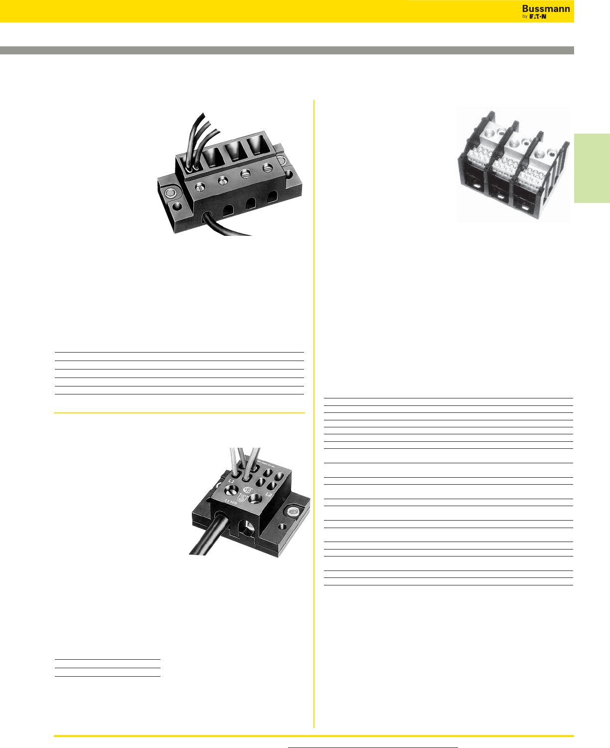
For product data sheets, visit www.cooperbussmann.com/DatasheetsEle 329
Power Distribution
& Terminal Blocks
Power Terminal Blocks
Series 11725
Specifications
Description: Screw
connection line side, (4) 0.250"
quick-connect load side power
terminal block.
Poles: 2-, 3- or 4-poles.
Wire Range: 2 – 14 AWG
Cu/8 AWG Al.
Ratings:
Volts: — 600Vac/dc
Amps: — Up to 70A
SCCR:— 10kA per UL 508A table SB4.1
Agency Information: CE, UL Guide XCFR2, E62622;
CSA 47235.
Torque Rating: 45 lb-in max.
Catalog Numbers
Catalog
Numbers Poles
11725-2 2
11725-3 3
11725-4 4
Series 11675
Specifications
Description: Screw
connection line side, (3)
0.250" quick-connect
load side power
terminal block.
Poles:
2- to 12-poles.
Wire Range:
8 – 14 AWG Cu.
Ratings:
Volts: — 250Vac/dc
Amps: — Up to 40A
SCCR:— 10kA per UL 508A table SB4.1
Agency Information: CE, Guide XCFR2, UL E62622;
CSA 47235.
Torque Rating: 9 lb-in max.
Catalog Numbers
Catalog Catalog
Numbers Poles Numbers Poles
11675-2 2 11675-8 8
11675-3 3 11675-9 9
11675-4 4 11675-10 10
11675-5 5 11675-11 11
11675-6 6 11675-12 12
11675-7 7
Data Sheets: 1117 (Series 160, 162, 165); 1148 (Series 163)
Series 160, 162, 163
& 165
Specifications
Description: Power
terminal blocks.
Construction: Molded black
thermoplastic.
Wire Range: See Catalog
Numbers table.
Poles:
Series 160: 2-, 3- or 4-poles
Series 162, 163 and 165: 1-, 2- or 3-poles
Ratings:
Volts: — 600Vac/dc
Amps: — Up to 1520A
SCCR:— 10kA per UL 508A table SB4.1 (except for select
products noted in table)
Agency Information: CE, Guide XCFR2, UL E62622
General Industrial Class per UL 1059; CSA Class 6228-01,
File 53787.
Flammability Rating: UL 94V0.
Catalog Numbers Connector
Catalog Line Load Material & Agency
Numbers Connection Connection Ampacity Information
16021* 2/0-#14Cu, 2/0-#8Al (6)#4-#14Cu, #4-#8Al 175A UL/CSA
16023* 350kcmil-#6Cu/Al (6)#4-#14Cu, #4-#12Al 310A UL/CSA
16220** 2/0-#14Cu, 2/0-#8Al (4)#4-#14Cu, #4-#8Al 175A UL/CSA
16321** 2/0-#14Cu, 2/0-#8Al (6)#4-#14Cu, #4-#8Al 175A UL/CSA
16323** 350kcmil-#6Cu/Al (6)#4-#14Cu, #4-#12Al 310A UL/CSA
16325 (2)2/0-#14Cu, 2/0-#8Al (6)#4-#14Cu, #4-#8Al 350A UL/CSA
16330 500kcmil-#6Cu/Al (6)#2-#14Cu, #2-#12Al 380A UL/CSA
16332 350kcmil-#6Cu/Al (3)#2-#14Cu, #2-#8Al 310A UL/CSA
(2)1/0-#14Cu, 1/0-#8Al
16335 500kcmil-#6Cu/Al (3)#2-#14Cu, #2-#8Al 380A UL/CSA
(2)1/0-#14Cu, 1/0-#8Al
16370** 350kcmil-#6Cu/Al (12)#4-#14Cu, #4-#12Al 310A UL/CSA
16371** 350kcmil-#6Cu/Al (6)#2-#14Cu, #2-#8Al 310A UL/CSA
(3)1/0-#14Cu, 1/0-#8Al
16372 350kcmil-#6Cu/Al (21)#10-#14Cu, #10Al 310A UL/CSA
16373 350kcmil-#6Cu/Al (3)1/0-#14Cu/Al 310A UL/CSA
(14)#10-#14Cu, #10Al
16375 600kcmil-#2Cu/Al (12)#4-#14Cu, #4-#12Al 420A UL/CSA
16376 600kcmil-#2Cu/Al (6)#2-#14Cu, #2-#8Al 420A UL/CSA
(3)1/0-#14Cu, 1/0-#8Al
16377 (2)300kcmil-#4Cu/Al (12)#4-#14Cu, #4-#12Al 570A UL/CSA
16400 (4)500kcmil-#6Cu/Al (22)#2-#14Cu/Al 1520A UL/CSA
16528 (2)600kcmil-#2Cu/Al (4)3/0-#6Cu/Al 840A UL/CSA
(4)#4-#14Cu/Al
16530 (2)500kcmil-#6Cu/Al (12)#4-#14Cu/Al 760A UL/CSA
16541 (1)500kcmil-#6Cu/Al (21)#6-#14Cu/Al 380A UL/CSA
*160 Series Bases have mounting holes outside the barriers. Other bases (162 through 165)
have mounting holes within barriers. See Data Sheet for dimensional drawings.
**SCCR up to 200kA
How To Order
Catalog Number + # of Poles
Example: 16021 – 3 (complete part number)
Optional Covers:
160 Series: CPB160 - (pole)
162 Series: CPB162 - (pole)
163 Series: CPDB- (pole)
165 Series: CPDB165 (1 for each pole)
Power Distribution & Terminal Blocks
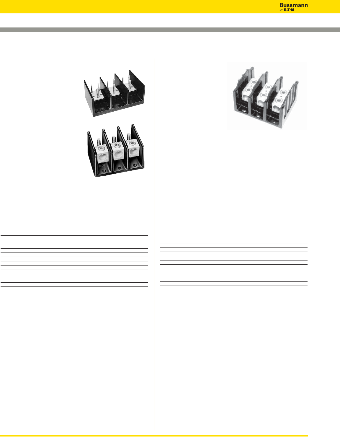
For product data sheets, visit www.cooperbussmann.com/DatasheetsEle
330
Power Distribution & Terminal Blocks
Power Terminal Blocks: Stud & Splicer
Data Sheets: 1117 (Series 162, 165); 1148 (Series 163)
Series 162, 163 & 165
Specifications
Description: Power stud
terminal blocks.
Construction: Molded black
thermoplastic.
Poles: 1-, 2- or 3-poles.
Wire Range: See Catalog
Numbers table.
Ratings:
Volts: — 600Vac/dc
Amps: — Up to 760A
SCCR:— 10kA per UL 508A
table SB4.1 (except
where noted)
Agency Information: CE,
Guide XCFR2, UL E62622
General Industrial Class per UL 1059; CSA Class 6228-01,
File 53787.
Flammability Rating:
UL 94V0.
Stud Block Catalog Numbers Connector
Catalog Line Load Material & Agency
Numbers Connection (Poles) Connection (Poles) Ampacity Information
Connector to Stud
16280* 2/0-#14Cu-Al 1⁄4-20 X 3⁄4Stud Al-175A UL —
16281 2/0-#14Cu-Al 1⁄4-20 Tapped hole Al-175A UL —
16378 500kcmil-#6Cu-Al (2)1⁄4-20 x 1 Stud Al-380A UL CSA
16383 500kcmil-#6Cu-Al (1)3⁄8-16 x 1 Stud Al-380A UL CSA
16582 (2)500kcmil-#6Cu-Al (2)3⁄8-16 x 15⁄8Stud Al-760A UL CSA
Stud to Stud
16290 1⁄4-20 x 3⁄4Stud 1⁄4-20 x 3⁄4Stud Cu-175A UL —
16390 3⁄8-16 x 11⁄8Stud 3⁄8-16 x 11⁄8Stud Cu-250A UL CSA
16394 1⁄2-13 x 11⁄16 Stud 1⁄2-13 x 11⁄16 Stud Cu-400A UL CSA
16395 3⁄8-16 x 17⁄16 Stud (2)1⁄4-20 x 9⁄16 Stud Cu-310A UL CSA
16591 3⁄8-16 x 17⁄16 Stud (2)3⁄8-16 x 17⁄16 Stud Cu-400A UL CSA
16593** 1⁄2-13 X 1 Stud 1⁄2-13 X 1 Stud Cu-600A UL CSA
Nuts are not supplied with blocks
*SCCR up to 200kA
** 1-Pole not available
How To Order
Catalog Number + # of Poles
Example: 16000 – 3 (complete part number)
Optional Covers:
160 Series: CPB160 - (pole)
162 Series: CPB162 - (pole)
163 Series: CPDB - (pole)
165 Series: CPDB165 (1 for each pole) - new style
CPB165 - (pole) - old style
Series 160, 162,
163 & 165
Specifications
Description: Power
splicer
terminal blocks.
Construction: Molded
black thermoplastic.
Wire Range: See
Catalog Numbers table.
Poles: Series 160: 2-, 3- or 4-poles
Series 162, 163 and 165: 1-, 2- or 3-poles
Ratings:
Volts: — 600Vac/dc
Amps: — Up to 760A
SCCR:— 10kA per UL 508A table SB4.1 (except for select
products noted in table)
Agency Information: CE, Guide XCFR2, UL E62622
General Industrial Class per UL 1059; CSA Class 6228-01,
File 53787.
Flammability Rating: UL 94V0.
Catalog Numbers Connector
Catalog Line Load Material & Agency
Numbers Connection Connection Ampacity Information
16000* 2/0-#8Cu/Al 2/0-#8Cu/Al Al-175A UL
16003* 250kcmil-#6Cu Only 250kcmil-#6Cu Only Cu-255A UL
16005* 350kcmil-#6Cu/Al 350kcmil-#6Cu/Al Al-310A UL
16200 #2-#14Cu, #2-#8Al #2-#14Cu, #2-#8Al Al-115A UL
16201 1/0-#14Cu Only 1/0-#14Cu Only Cu-150A UL
16204** 2/0-#8Cu/Al 2/0-#8Cu/Al Al-175A UL
16301 250kcmil-#6Cu Only 250kcmil-#6Cu Only Cu-255A UL/CSA
16303 350kcmil-#6Cu/Al 350kcmil-#6Cu/Al Al-310A UL/CSA
16306 500kcmil-#6Cu/Al 500kcmil-#6Cu/Al Al-380A UL/CSA
16500 (2)350kcmil-#4Cu/Al (2)350kcmil-#4Cu/Al Al-620A UL/CSA
16504 (2)500kcmil-#6Cu/Al (2)500kcmil-#6Cu/Al Al-760A UL/CSA
*160 Series Bases have mounting holes outside the barriers. Other bases (162 through 165)
have mounting holes within barriers. See Data Sheet for dimensional drawings.
**SCCR up to 200kA
How To Order
Catalog Number + # of Poles
Example: 16000 – 3 (complete part number)
Optional Covers:
160 Series: CPB160 - (pole)
162 Series: CPB162 - (pole)
163 Series: CPDB - (pole)
165 Series: CPDB165 (1 for each pole) - new style
CPB165 - (pole) - old style
Data Sheets: 1117 (Series 160, 162, 165); 1148 (Series 163)
For Short-circuit current rated stud power distribution
blocks, go to the Series PDB and Series 162 & 163
with high SCCR.
For Short-circuit current rated and/or finger-safe
splicer blocks, go to the Series PDBFS, Series PDB or
Series 162 & 163 with high SCCR.
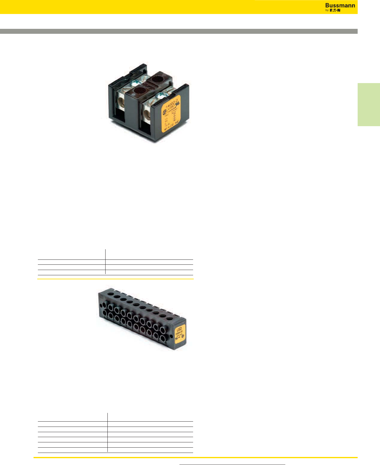
For product data sheets, visit www.cooperbussmann.com/DatasheetsEle 331
Power Distribution
& Terminal Blocks
Series 14004
Specifications
Description: Dead
front terminal block.
Poles: 2- to 12-poles.
Wire Range:
4 – 14 AWG Cu/
8 AWG Al.
Ratings:
Volts: — 600Vac/dc
Amps: — 90A
SCCR:— 10kA per UL 508A table SB4.1
Agency Information: CE, Guide XCFR2, UL E62622;
CSA 47235.
Marking: Marking strip optional, consult factory.
Catalog Numbers
Catalog Catalog
Numbers Poles Numbers Poles
14004-2 2 14004-8 8
14004-3 3 14004-9 9
14004-4 4 14004-10 10
14004-5 5 14004-11 11
14004-6 6 14004-12 12
14004-7 7
Series 14002
Specifications
Description: Barrier
terminal block.
Poles: 2- to 6-poles.
Wire Range: 2 – 14
AWG Cu/8 AWG Al.
Ratings:
Volts: — 600Vac/dc
Amps: — 115A
SCCR:— 10kA per
UL 508A table SB4.1
Agency Information: CE, Guide XCFR2, UL E62622;
CSA 47235.
Torque Ratings*: 2-3, 50 lb-in; 4-6, 45 lb-in; 8, 40 lb-in;
10-14, 35 lb-in.
*Consult factory for torque ratings for CP and Q options.
Marking: Marking strip optional, consult factory.
Options For Load Side Connector
CP: Sems pressure plate, rated 60A, 600V
Q: Quick-Connect, rated 50A, 600V
To order options, enter letter code in front of Catalog
Number: i.e., CP14002-2.
Catalog Numbers
Catalog Catalog
Numbers Poles Numbers Poles
14002-2 2 14002-5 5
14002-3 3 14002-6 6
14002-4 4
Power Terminal Blocks: Barrier & Dead Front
Power Distribution & Terminal Blocks
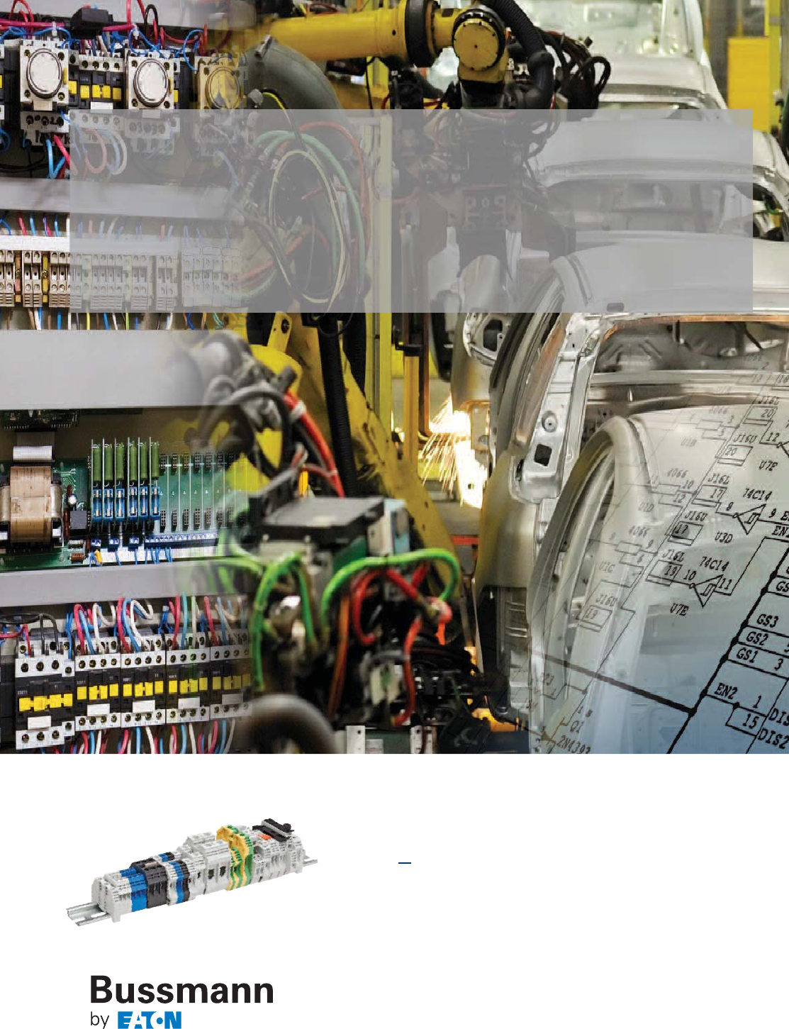
332
Ratings up to 200kA SCCR
feature multiple bridging options
for point of use configuration
DIN-Rail
terminal blocks
333
Connectors
Connectors
Section Contents
Page
DIN-Rail Terminal Blocks
Feed through blocks (DS series) . . . . . . . . . . . . . . . . . . 334
Feed through blocks (DP series) . . . . . . . . . . . . . . 335-336
Mini feed through blocks (DM series) . . . . . . . . . . . . . . 337
Double level blocks (DDP series). . . . . . . . . . . . . . . . . . 338
Disconnect blocks (DG series) . . . . . . . . . . . . . . . . 339-340
Fuse holder blocks (F520 series) . . . . . . . . . . . . . . 341-342
Internally jumpered blocks (DDNS series) . . . . . . . . . . . 343
Test blocks (DTST2 series) . . . . . . . . . . . . . . . . . . . . . . 343
Panel mount blocks. . . . . . . . . . . . . . . . . . . . . . . . . 344-345
Short-Circuit Current Ratings (SCCRs) . . . . . . . . . 346-347
Accessories
Top screw-on bridges . . . . . . . . . . . . . . . . . . . . . . . . . . . 348
End brackets . . . . . . . . . . . . . . . . . . . . . . . . . . . . . . . . . 349
Partition plates . . . . . . . . . . . . . . . . . . . . . . . . . . . . . . . . 349
Jumper slides . . . . . . . . . . . . . . . . . . . . . . . . . . . . . . . . . 350
Top insertion bridges . . . . . . . . . . . . . . . . . . . . . . . . . . . 350
Side insertion bridges . . . . . . . . . . . . . . . . . . . . . . . 351-352
Mounting rails and brackets . . . . . . . . . . . . . . . . . . . . . . 353
BussScribe Marking System
Marking system . . . . . . . . . . . . . . . . . . . . . . . . . . . . . . . 354
Marking labels . . . . . . . . . . . . . . . . . . . . . . . . . . . . . 355-357
Compact Blocks
Feed through blocks (NDN series) . . . . . . . . . . . . . 358-359
Feed through blocks (C-Rail series) . . . . . . . . . . . . 360-361
Depluggable blocks . . . . . . . . . . . . . . . . . . . . . . . . . 362-363
Multi-pole panel mount blocks . . . . . . . . . . . . . . . . . . . . 364
Quick connect blocks . . . . . . . . . . . . . . . . . . . . . . . . . . . 365
Double row terminal blocks
Series TB100 2- to 36-Pole blocks . . . . . . . . . . . . 366-367
Series TB200 & TB200HB 2- to 30-Pole blocks . . 368-369
Series TB300 & TB345 2- to 24-Pole blocks . . . . 370-371
Marking options and covers for double row
series . . . . . . . . . . . . . . . . . . . . . . . . . . . . . . . . 372
Top & bottom marking strips for terminal
blocks . . . . . . . . . . . . . . . . . . . . . . . . . . . . . . . 373
Series TB400 2- to 12-Pole blocks . . . . . . . . . . . 374
Series KU 2- to 12-Pole Panel mount blocks. . . . 375
Power feed through terminal blocks
Series C7021 1- to 6-Pole block . . . . . . . . . . . . . . . . . . 376
Series C7024 1- to 12-Pole block . . . . . . . . . . . . . . . . . 377
Scan this tag to get the
latest product information for the
New Family of Terminal blocks
and Accessories.
Scan this tag to get access to the
Terminal Blocks
Cross Reference Search.
RED indicates NEW information
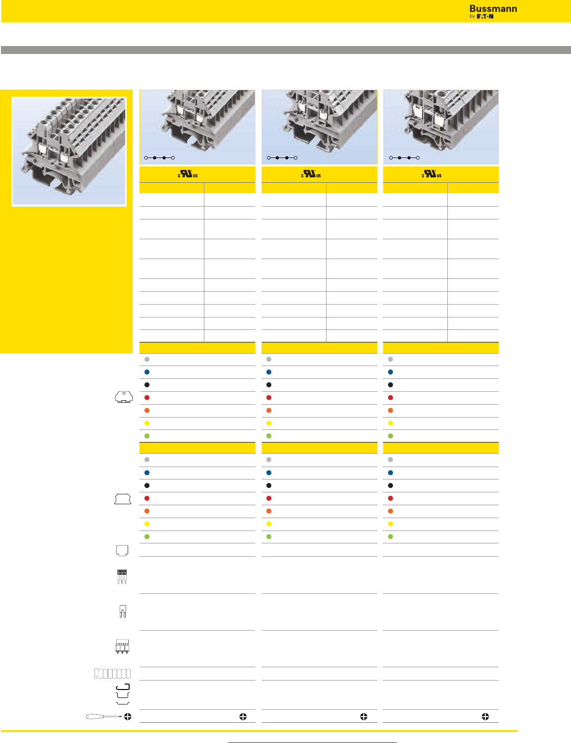
For more information, visit www.cooperbussmann.com/DatasheetsEle
334
Connectors
DS30 DS50
DS Series
The DS Series features a compact
design that saves wiring space
on the control panel. Accessories
include marking labels, partition
plates as well as side and top
insertion bridges. Designed for
35mm DIN and 32mm G-Type rails.
IEC60947-7-1 & UL 1059 compliant
.
DS20
End cover
Small partition
Top Insertion bridge
Side Insertion bridge
Top Screw-on bridge
Marking label
Mounting Rail
Tool
1234567
Block
Approval
Technical Data UL IEC
Rated voltage 600V
1000V
Rated current 20A 24A
Conductor cross section,
flexible(AWG/mm2)22~12 / 0.5~2.5
Conductor cross section,
flexible(AWG/mm2)22~12 / 0.5~2.5
Rated impulse
withstand voltage 6kV
Torque(N•m) 0.4
Torque(lb-in) 3.5
Screw M2.5
Wire strip length(mm) 9~11
WxHxD(mm) 5.1 x 39.6 x 40.5
Colors Cat. No.
Grey DS20-GY
Blue DS20-BU
Black DS20-LK
Red DS20-RD
Orange DS20-OR
Yellow DS20-YW
Green DS20-GN
Accessories Cat. No.
Grey DS20-GY-ND
Blue DS20-BU-ND
Black DS20-LK-ND
Red DS20-RD-ND
Orange DS20-OR-ND
Yellow DS20-YW-ND
Green DS20-GN-ND
DKNSPS-001
2-pole
3-pole
4-pole
10-pole
DSS2-5N-02P
DSS2-5N-03P
DSS2-5N-04P
DSS2-5N-10P
2-pole
3-pole
4-pole
10-pole
CSC-2-502PN
CSC-2-503PN
CSC-2-504PN
CSC-2-510PN
2-pole
3-pole
4-pole
10-pole
N/A
N/A
N/A
N/A
TM26CB
DRL32MMG
DRL35MMHI
DRL35MMLO
Approval
Technical Data UL IEC
Rated voltage 600V
1000V
Rated current 30A 32A
Conductor cross section,
flexible(AWG/mm2)22~10 / 0.5~4
Conductor cross section,
flexible(AWG/mm2)22~10 / 0.5~4
Rated impulse
withstand voltage 6kV
Torque(N•m) 0.6
Torque(lb-in) 5.3
Screw M3
Wire strip length(mm) 9~11
WxHxD(mm) 6.1 x 39.6 x 40.3
Colors Cat. No.
Grey DS30-GY
Blue DS30-BU
Black DS30-LK
Red DS30-RD
Orange DS30-OR
Yellow DS30-YW
Green DS30-GN
Accessories Cat. No.
Grey DS20-GY-ND
Blue DS20-BU-ND
Black DS20-LK-ND
Red DS20-RD-ND
Orange DS20-OR-ND
Yellow DS20-YW-ND
Green DS20-GN-ND
DKNSPS-001
2-pole
3-pole
4-pole
10-pole
DSS4N-02P
DSS4N-03P
DSS4N-04P
DSS4N-10P
2-pole
3-pole
4-pole
10-pole
CSC-402PN
CSC-403PN
CSC-404PN
CSC-410PN
2-pole
3-pole
4-pole
10-pole
N/A
N/A
N/A
N/A
TM27CB
DRL32MMG
DRL35MMHI
DRL35MMLO
Approval
Technical Data UL IEC
Rated voltage 600V
1000V
Rated current 50A 41A
Conductor cross section,
flexible(AWG/mm2)22~10 / 0.5~4
Conductor cross section,
flexible(AWG/mm2)20~8 / 0.5~6
Rated impulse
withstand voltage 8kV
Torque(N•m) 1.2
Torque(lb-in) 10.6
Screw M4
Wire strip length(mm) 12~14
WxHxD(mm) 8 x 45 x 41.7
Colors Cat. No.
Grey DS50-GY
Blue DS50-BU
Black DS50-LK
Red DS50-RD
Orange DS50-OR
Yellow DS50-YW
Green DS50-GN
Accessories Cat. No.
Grey DS50-GY-ND
Blue DS50-BU-ND
Black DS50-LK-ND
Red DS50-RD-ND
Orange DS50-OR-ND
Yellow DS50-YW-ND
Green DS50-GN-ND
DKNSPS-002
2-pole
3-pole
4-pole
10-pole
DSS6N-02P
DSS6N-03P
DSS6N-04P
DSS6N-10P
2-pole
3-pole
4-pole
10-pole
CSC-602PN
CSC-603PN
CSC-604PN
CSC-610PN
2-pole
3-pole
4-pole
10-pole
N/A
N/A
N/A
N/A
TM28CB
DRL32MMG
DRL35MMHI
DRL35MMLO
Feed Through Blocks
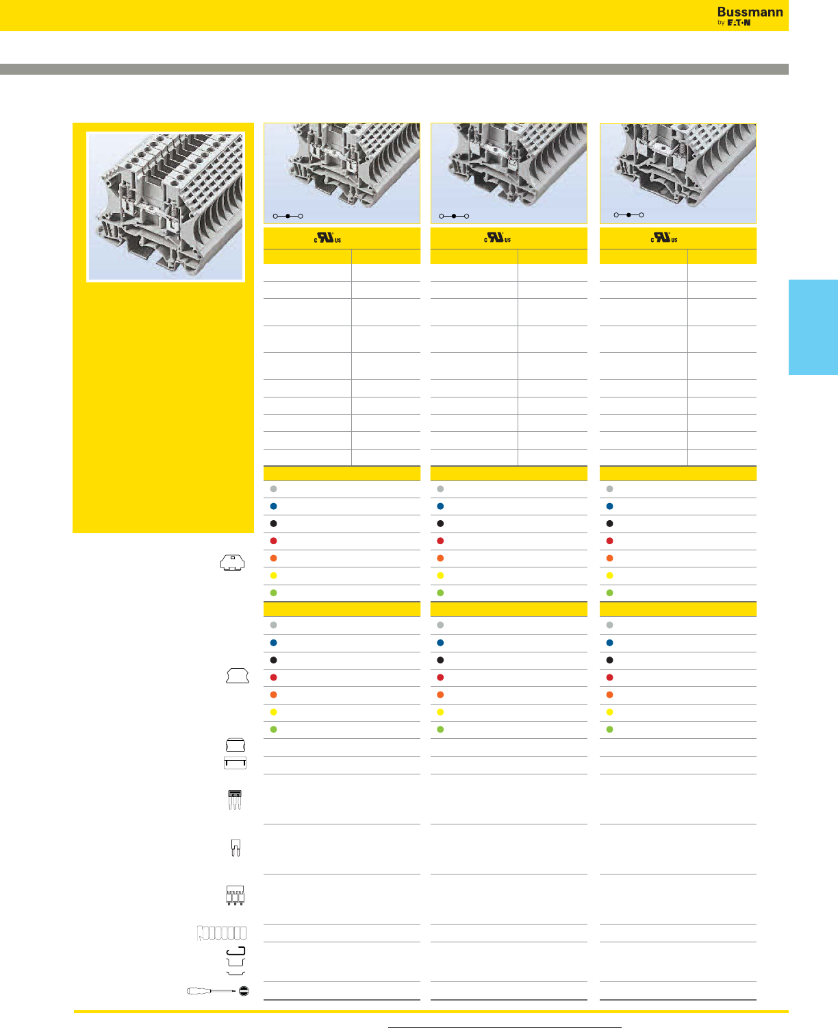
For more information, visit www.cooperbussmann.com/DatasheetsEle 335
Connectors
Feed Through Blocks
DP25 DP35 DP45
DP Series
The DP Series features a generous
design allowing for more wiring
space and access. Additionally, this
series features a larger wire contact
area and larger conducting elements.
Accessories include marking labels,
partition plates, side insertion bridge
and top screw-on bridge for
improved reliability. Comes with
matching shaped grounding blocks.
Designed for 35mm DIN and 32mm
G-Type rails.
IEC60947-7 and UL1059 compliant.
Approval
Technical Data UL IEC
Rated voltage 600V
500V
Rated current 45A 41A
Conductor cross section,
flexible(AWG/mm2)20~8 / 0.5~6
Conductor cross section,
flexible(AWG/mm2)20~8 / 0.5~6
Rated impulse
withstand voltage 8kV
Torque(N•m) 1.8
Torque(lb-in) 15.9
Screw M4
Wire strip length(mm) 12~14
WxHxD(mm) 8 x 47.6 x 58.9
Colors Cat. No.
Grey DP45-GY
Blue DP45-BU
Black DP45-LK
Red DP45-RD
Orange DP45-OR
Yellow DP45-YW
Green DP45-GN
Accessories Cat. No.
Grey DP25-GY-ND
Blue DP25-BU-ND
Black DP25-LK-ND
Red DP25-RD-ND
Orange DP25-OR-ND
Yellow DP25-YW-ND
Green DP25-GN-ND
DKSPS-001
DKSPS-002
2-pole
3-pole
4-pole
10-pole
N/A
N/A
N/A
N/A
2-pole
3-pole
4-pole
10-pole
CSC-602P
CSC-603P
CSC-604P
CSC-610P
2-pole
3-pole
4-pole
10-pole
DS6-02P
DS6-03P
DS6-04P
DS6-10P
TM28CB
DRL32MMG
DRL35MMHI
DRL35MMLO
0.8 x 4mm
Approval
Technical Data UL IEC
Rated voltage 600V
630V
Rated current 25A 24A
Conductor cross section,
flexible(AWG/mm2)22~12 / 0.5~2.5
Conductor cross section,
flexible(AWG/mm2)22~12 / 0.5~2.5
Rated impulse
withstand voltage 8kV
Torque(N•m) 0.8
Torque(lb-in) 7.1
Screw M3
Wire strip length(mm) 10~12
WxHxD(mm) 5.1 x 47.6 x 58.9
Colors Cat. No.
Grey DP25-GY
Blue DP25-BU
Black DP25-LK
Red DP25-RD
Orange DP25-OR
Yellow DP25-YW
Green DP25-GN
Accessories Cat. No.
Grey DP25-GY-ND
Blue DP25-BU-ND
Black DP25-LK-ND
Red DP25-RD-ND
Orange DP25-OR-ND
Yellow DP25-YW-ND
Green DP25-GN-ND
DKSPS-001
DKSPS-002
2-pole
3-pole
4-pole
10-pole
N/A
N/A
N/A
N/A
2-pole
3-pole
4-pole
10-pole
CSC-2-502P
CSC-2-503P
CSC-2-504P
CSC-2-510P
2-pole
3-pole
4-pole
10-pole
DS2-5-02P
DS2-5-03P
DS2-5-04P
DS2-5-10P
TM26CB
DRL32MMG
DRL35MMHI
DRL35MMLO
0.4 x 2.5mm
Approval
Technical Data UL IEC
Rated voltage 600V
630V
Rated current 35A 32A
Conductor cross section,
flexible(AWG/mm2)22~10 / 0.5~4
Conductor cross section,
flexible(AWG/mm2)22~10 / 0.5~4
Rated impulse
withstand voltage 8kV
Torque(N•m) 0.8
Torque(lb-in) 7.1
Screw M3
Wire strip length(mm) 10~12
WxHxD(mm) 6.1 x 47.6 x 58.9
Colors Cat. No.
Grey DP35-GY
Blue DP35-BU
Black DP35-LK
Red DP35-RD
Orange DP35-OR
Yellow DP35-YW
Green DP35-GN
Accessories Cat. No.
Grey DP25-GY-ND
Blue DP25-BU-ND
Black DP25-LK-ND
Red DP25-RD-ND
Orange DP25-OR-ND
Yellow DP25-YW-ND
Green DP25-GN-ND
DKSPS-001
DKSPS-002
2-pole
3-pole
4-pole
10-pole
N/A
N/A
N/A
N/A
2-pole
3-pole
4-pole
10-pole
CSC-402P
CSC-303P
CSC-404P
CSC-410P
2-pole
3-pole
4-pole
10-pole
DS4-02P
DS4-03P
DS4-04P
DS4-10P
TM27CB
DRL32MMG
DRL35MMHI
DRL35MMLO
0.5 x 3mm
End cover
Partition
Small partition
Top Insertion bridge
Side Insertion bridge
Top Screw-on bridge
Marking label
Mounting Rail
Tool
1234567
Block
Connectors
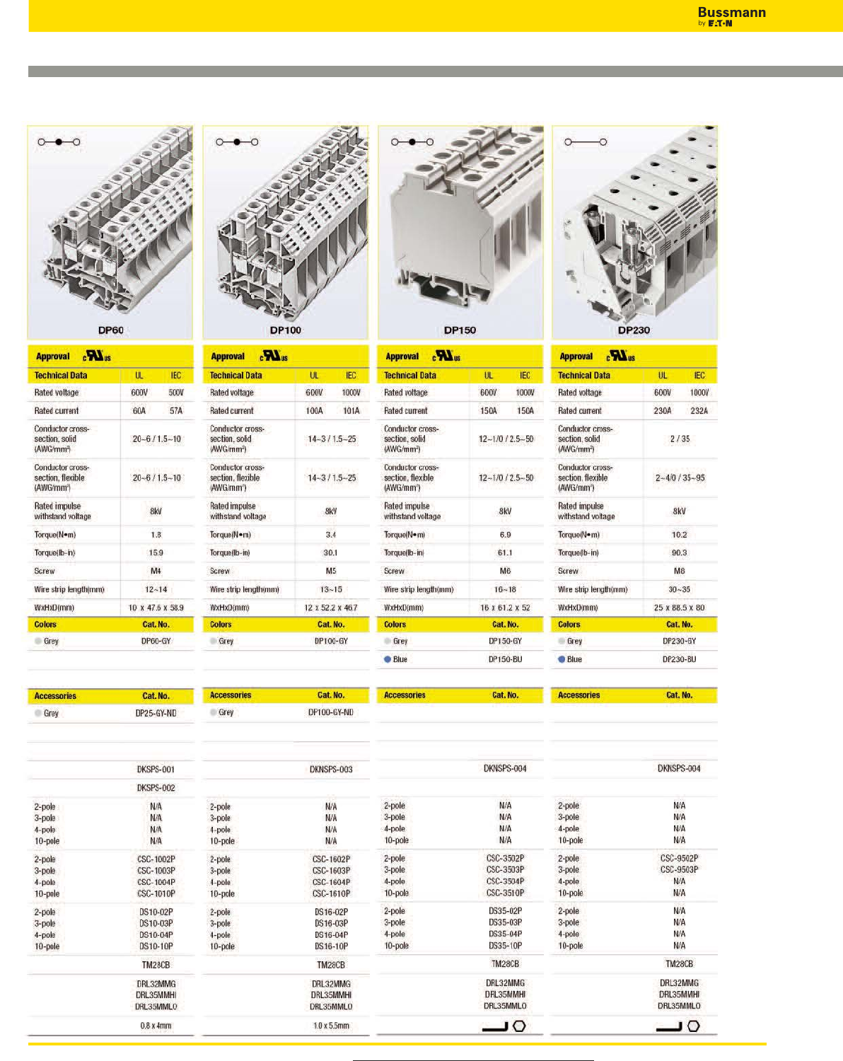
For more information, visit www.cooperbussmann.com/DatasheetsEle
336
Connectors
Feed Through Blocks
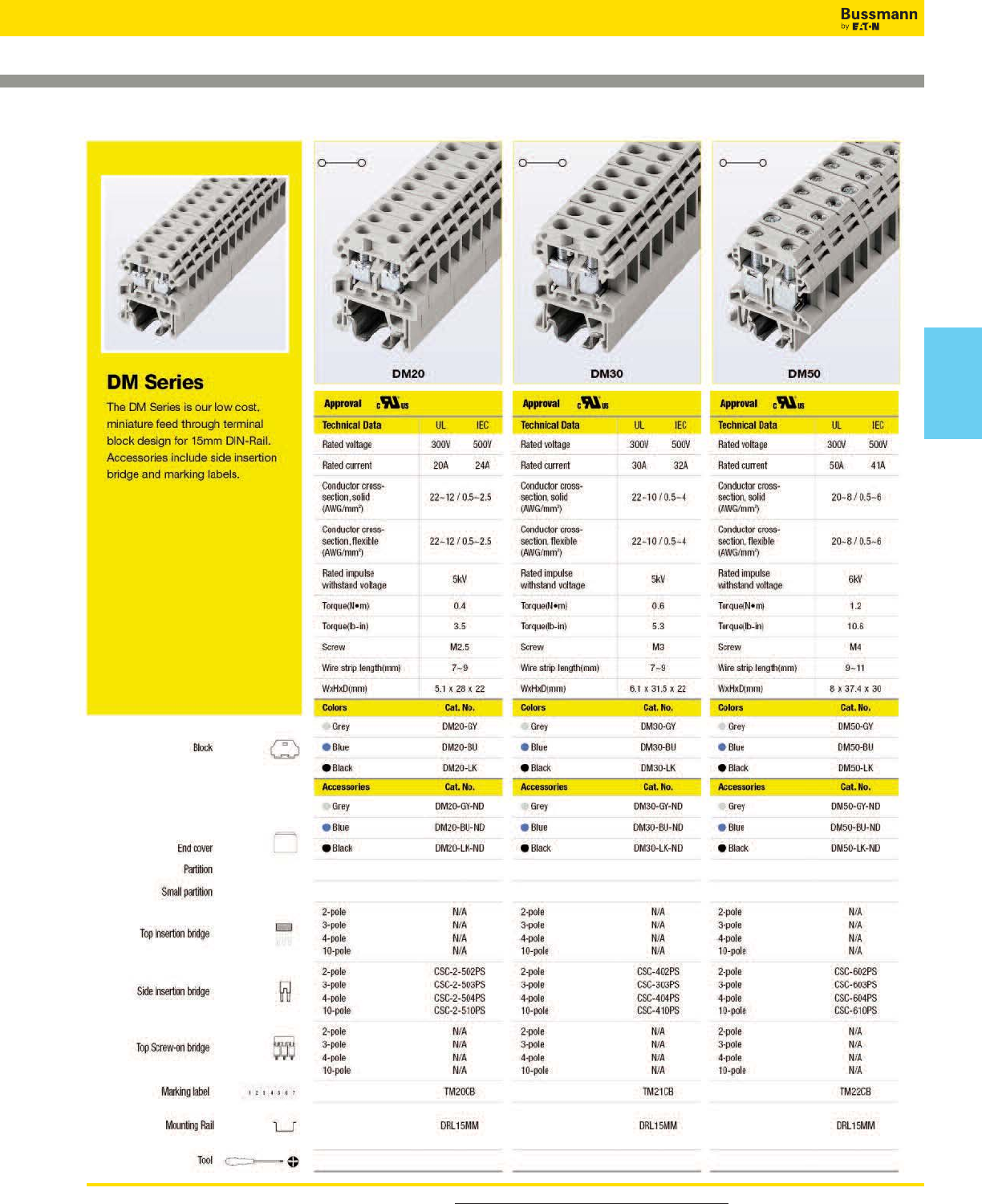
For more information, visit www.cooperbussmann.com/DatasheetsEle 337
Connectors
Mini Feed Through Blocks
Connectors
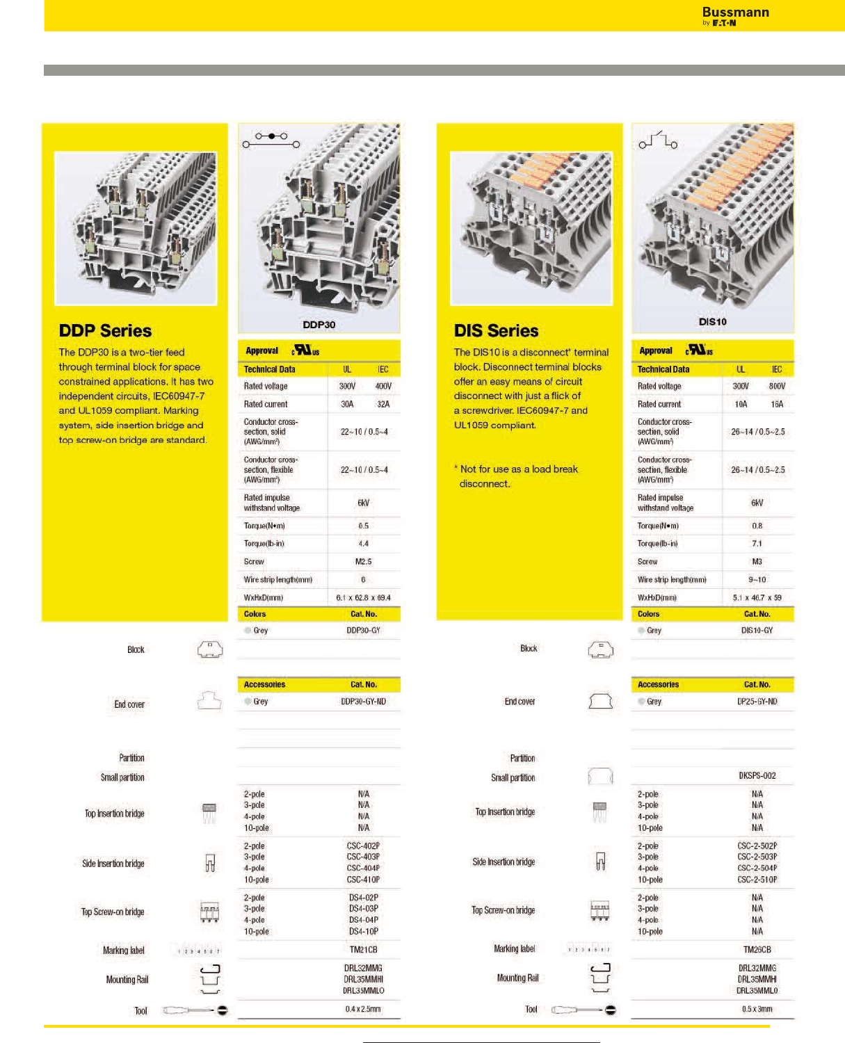
For more information, visit www.cooperbussmann.com/DatasheetsEle
338
Connectors
Double Level Blocks Disconnect Blocks
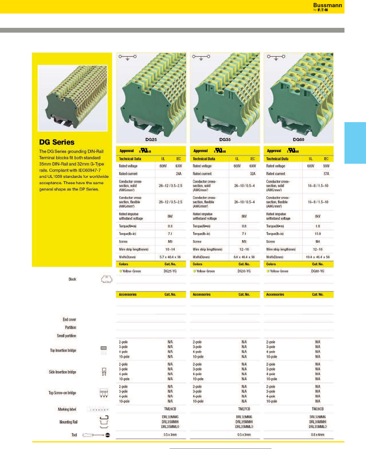
For more information, visit www.cooperbussmann.com/DatasheetsEle 339
Connectors
Grounding Blocks
Connectors
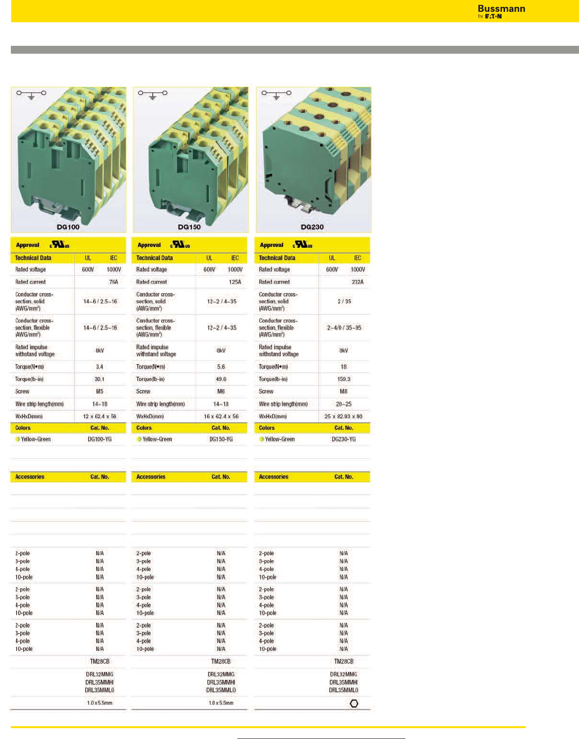
For more information, visit www.cooperbussmann.com/DatasheetsEle
340
Connectors
Grounding Blocks
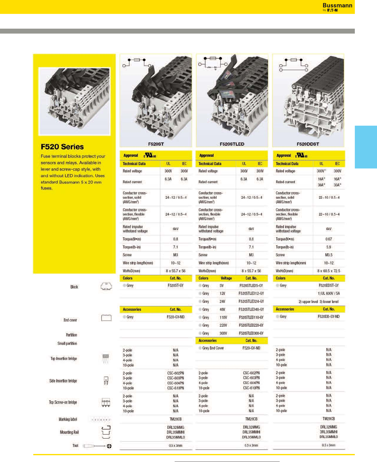
For more information, visit www.cooperbussmann.com/DatasheetsEle 341
Connectors
Fuse Holder Blocks
Connectors
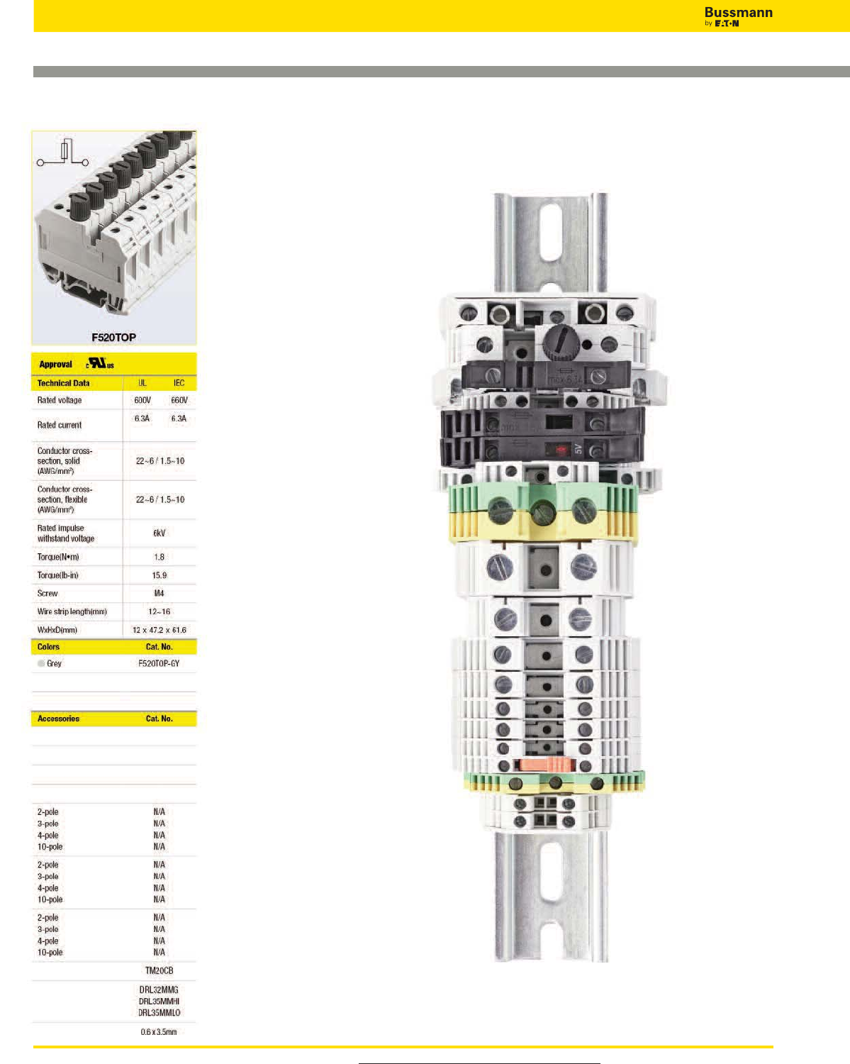
For more information, visit www.cooperbussmann.com/DatasheetsEle
342
Connectors
Fuse Holder Blocks
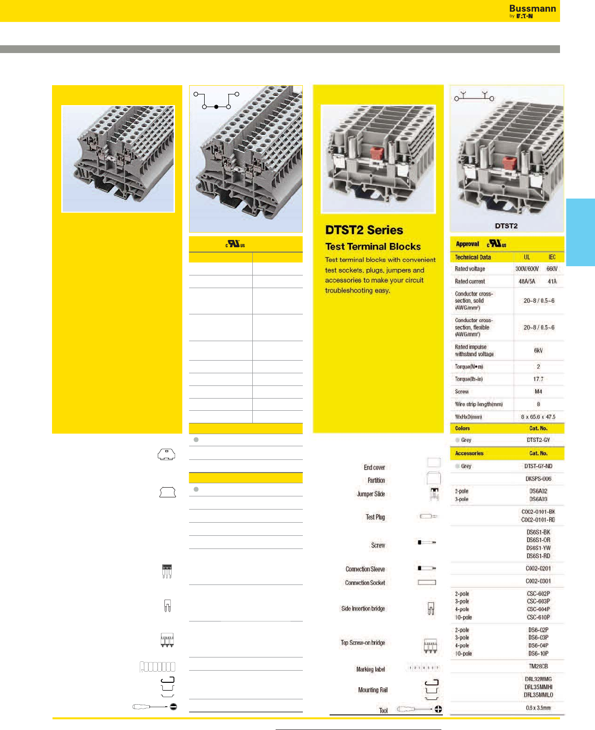
For more information, visit www.cooperbussmann.com/DatasheetsEle 343
Connectors
Connectors
Internally Jumpered Blocks Test Blocks
DDNS10
DDNS Series
The DDNS10 is an internally
jumpered terminal block. Internally
jumpered double-level terminal
blocks provide high-density power
distribution in 3-in/1-out or 2-in/2-out
or 1-in/3-out options with a single
block. Add top and side insertion
bridges to achieve any connection
topology. IEC60947-7 and UL1059
compliant.
Approval
Technical Data UL IEC
Rated voltage 300V 630V
Rated current 10A 17.5A
Conductor cross-
section, solid
(AWG/mm2)
22~14 / 0.5~1.5
Conductor cross-
section, flexible
(AWG/mm2)
22~14 / 0.5~1.5
Rated impulse
withstand voltage 8kV
Torque(N•m) 0.4
Torque(lb-in) 3.5
Screw M2.5
Wire strip length(mm) 6~7
WxHxD(mm) 5.1 x 46.8 x 58.9
Colors Cat. No.
Grey DDNS10-GY
Accessories Cat. No.
Grey DDNS10-GY-ND
2-pole
3-pole
4-pole
10-pole
N/A
N/A
N/A
N/A
2-pole
3-pole
4-pole
10-pole
CSC-2-502P
CSC-2-503P
CSC-2-504P
CSC-2-510P
2-pole
3-pole
4-pole
10-pole
DS2-5-02P
DS2-5-03P
DS2-5-04P
DS2-5-10P
TM26CB
DRL32MMG
DRL35MMHI
DRL35MMLO
0.4 x 2.5mm
End cover
Partition
Small partition
Top Insertion bridge
Side Insertion bridge
Top Screw-on bridge
Marking label
Mounting Rail
Tool
1234567
Block
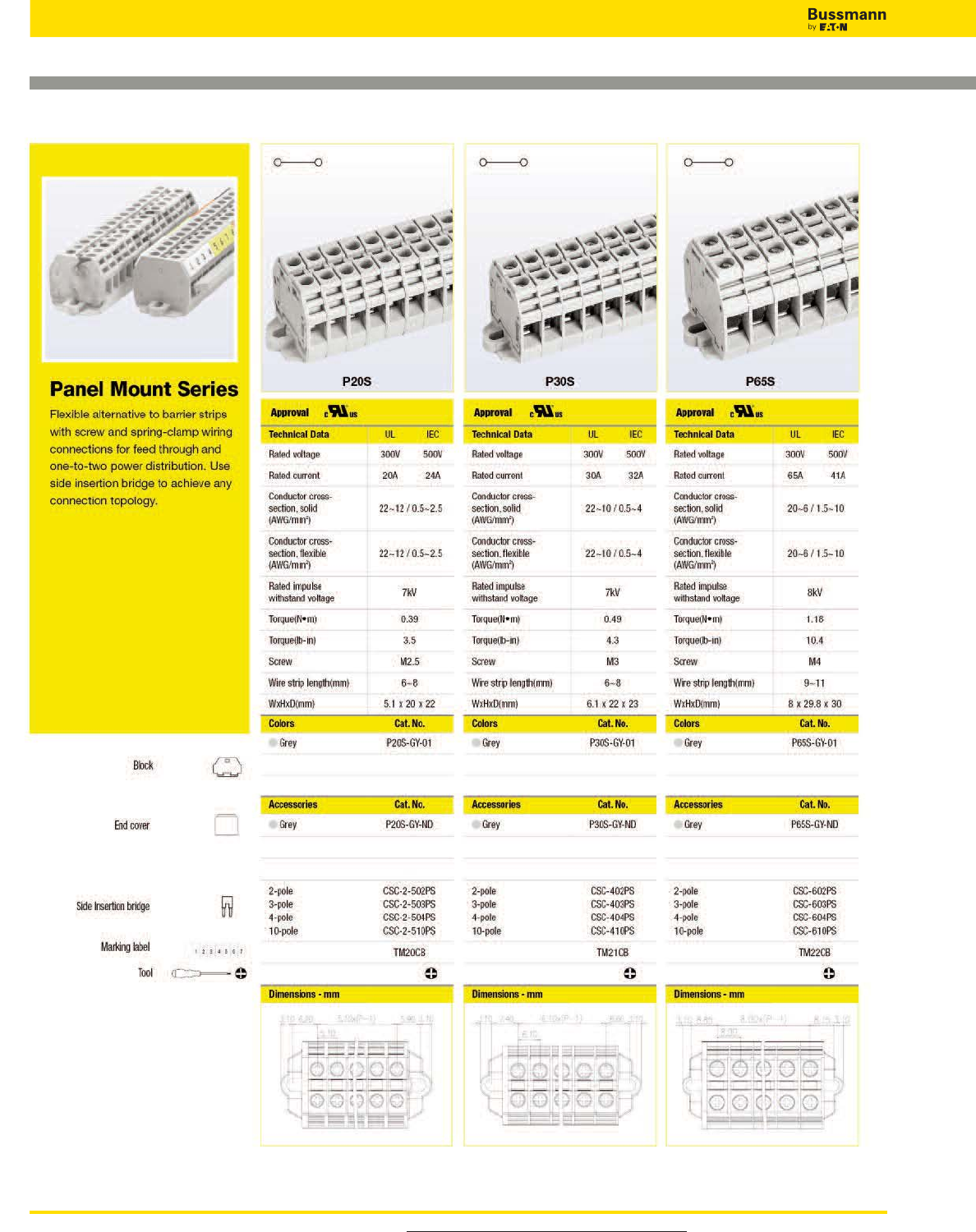
For more information, visit www.cooperbussmann.com/DatasheetsEle
344
Connectors
Panel Mount Blocks
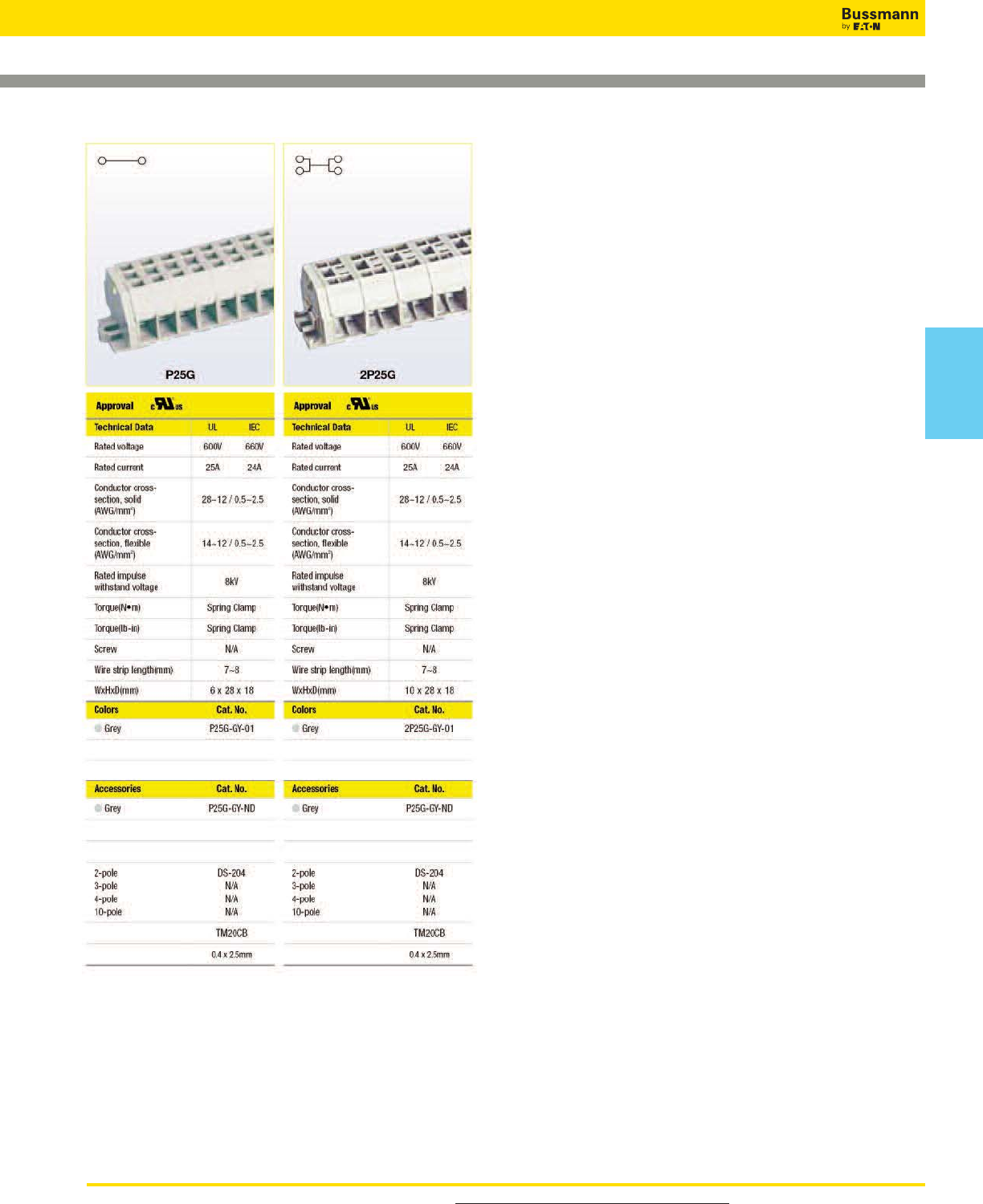
For more information, visit www.cooperbussmann.com/DatasheetsEle 345
Connectors
Panel Mount Blocks
Connectors
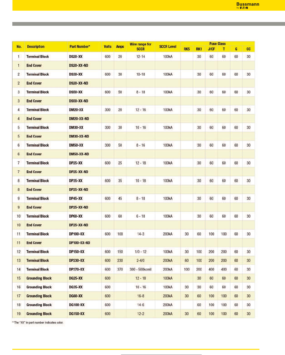
For more information, visit www.cooperbussmann.com/DatasheetsEle
346
Connectors
Short-Circuit Current Ratings (SCCRs)
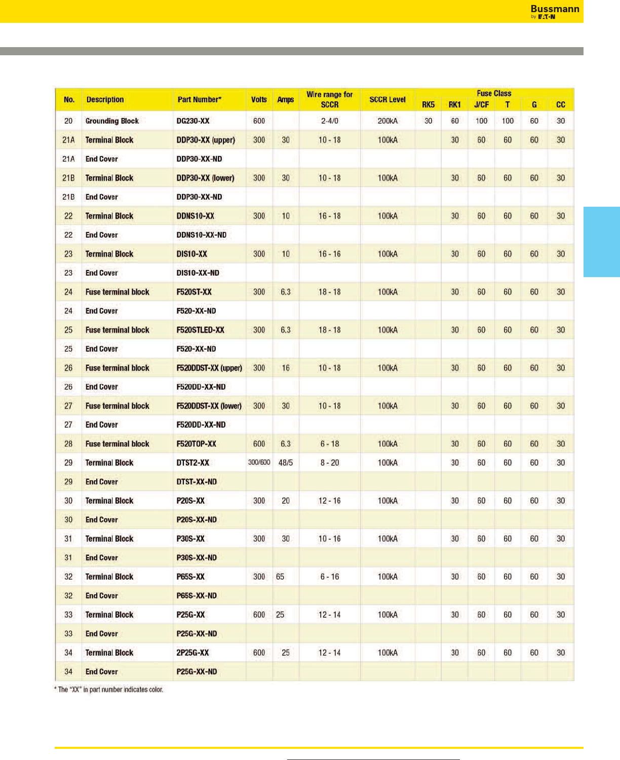
For more information, visit www.cooperbussmann.com/DatasheetsEle 347
Connectors
Short-Circuit Current Ratings (SCCRs)
Connectors
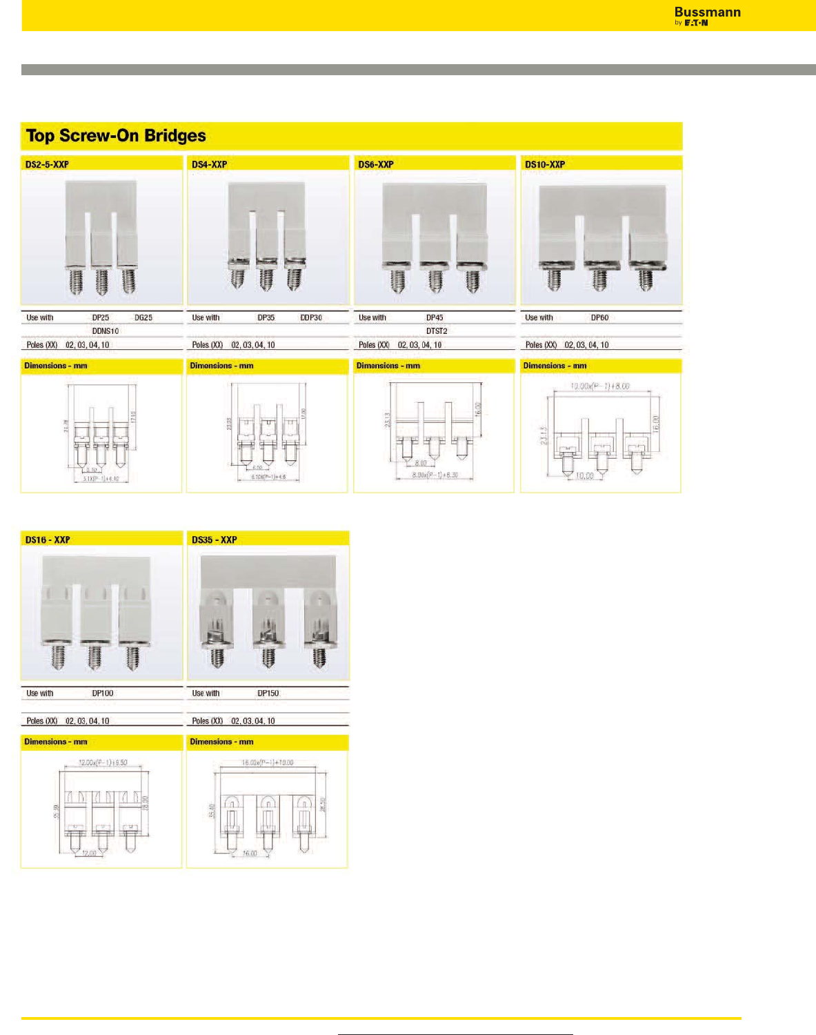
For more information, visit www.cooperbussmann.com/DatasheetsEle
348
Connectors
Accessories
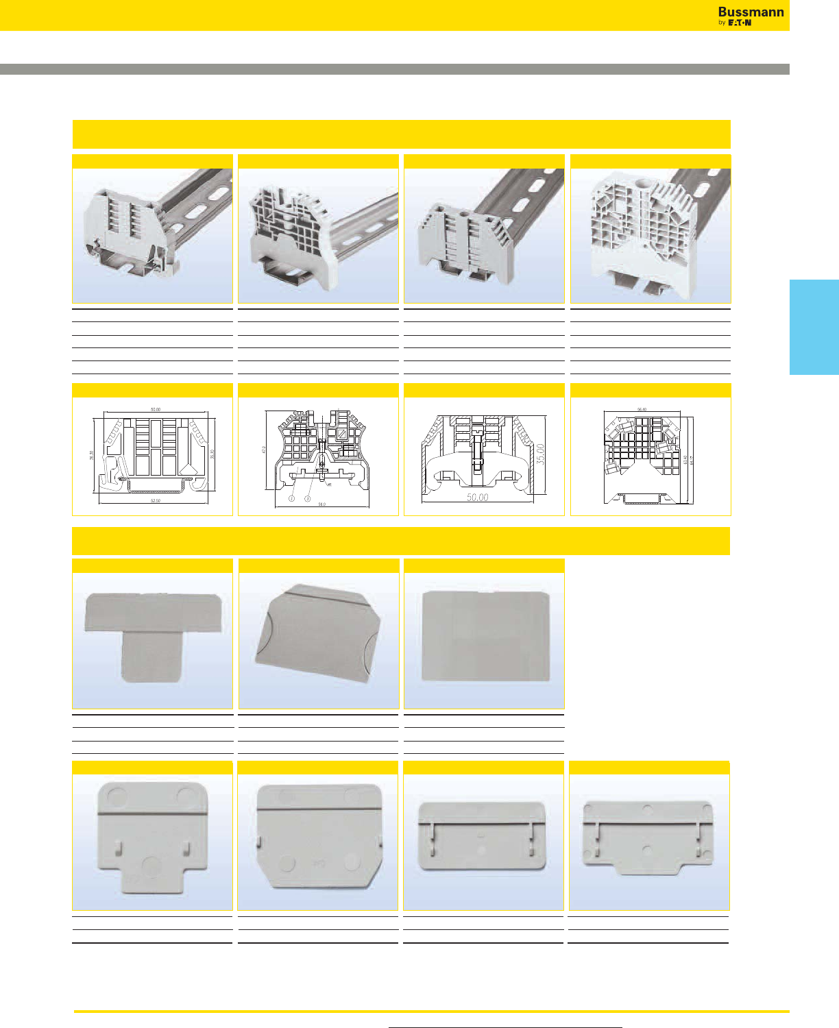
For more information, visit www.cooperbussmann.com/DatasheetsEle 349
Connectors
Accessories
End Brackets
DKSPS-001 DKSPS-002
DKNSPS-002
DKSPS-006
Partition Plates
BRKT-NDSCRW3BRKT-NDSCRW2
Use with
DRL35MMHI
DRL35MMLO
Torque(N•m)
0.78
Torque(lb-in)
6.9
Screw
M3
Dimensions - mm
BRKT-ND BRKT-NDSCRW
Use with
DRL35MMHI
DRL35MMLO
Torque(N•m)
N/A
Torque(lb-in)
N/A
Screw
N/A
Dimensions - mm
Use with
DRL35MMHI
DRL35MMLO
Torque(N•m)
0.5
Torque(lb-in)
4.4
Screw
M3
Dimensions - mm
Use with
DRL35MMHI
DRL35MMLO
Torque(N•m)
1.8
Torque(lb-in)
15.9
Screw
M4
Dimensions - mm
Use with DP25 DP35
DP45 DP60
DIS10
Use with DTST2
DKNSPS-001
Use with DS50
Use with DP25 DP35
DP45 DP60
Use with DS20 DS30
DKNSPS-003
Use with DP100
DKNSPS-004
Use with DP150
Connectors
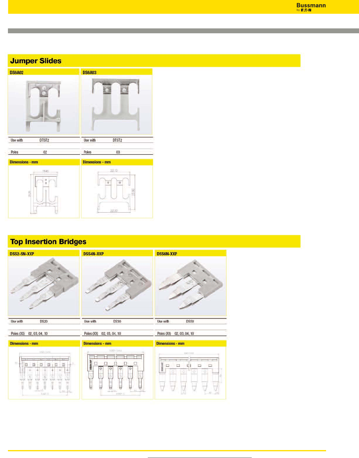
For more information, visit www.cooperbussmann.com/DatasheetsEle
350
Connectors
Accessories
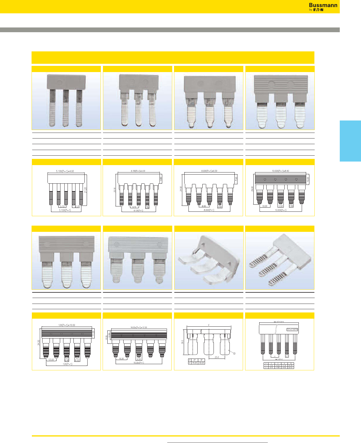
For more information, visit www.cooperbussmann.com/DatasheetsEle 351
Connectors
Accessories
CSC-2-5XXP CSC-4XXP CSC-6XXP CSC-10XXP
CSC-16XXP CSC-35XXP
Side Insertion Bridges
Use with DP25
DIS10 P20S
DDNS10
Dimensions - mm
Use with DP35
DDP30
Dimensions - mm
Use with DTST2 DP45
Dimensions - mm
Use with DP60
Dimensions - mm
Poles (XX) 02, 03, 04, 10 Poles (XX) 02, 03, 04, 10 Poles (XX) 02, 03, 04, 10
Use with DP100
Poles (XX) 02, 03, 04, 10
Dimensions - mm
Use with DP150
Poles (XX) 02, 03, 04, 10
Dimensions - mm
CSC-2-5XXPN
Use with DS20
Poles (XX) 02, 03, 04, 10
Dimensions - mm
Poles (XX) 02, 03, 04, 10
CSC-95XXP
Use with DP230
Poles (XX) 02, 03, 04, 10
Dimensions - mm
Connectors
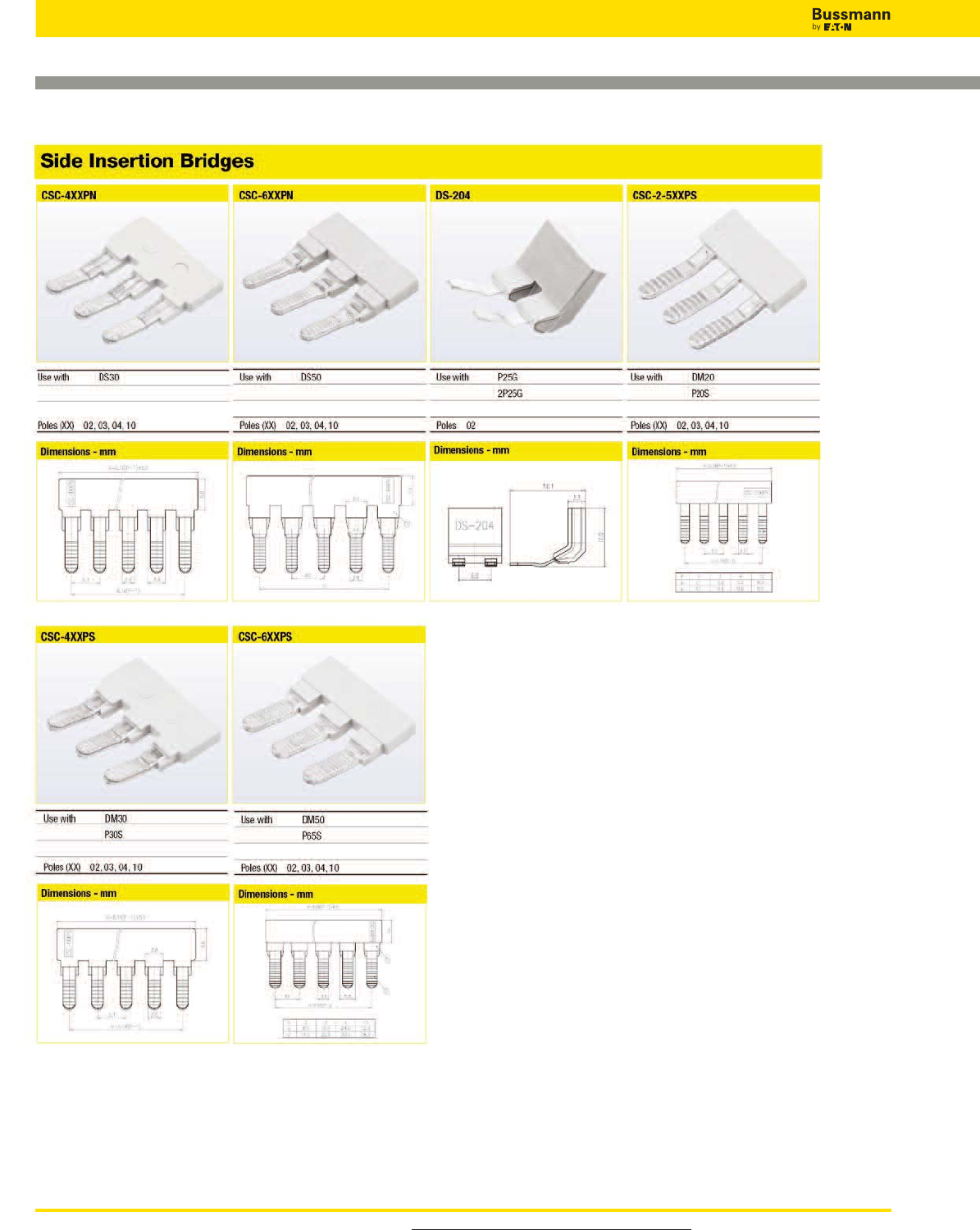
For more information, visit www.cooperbussmann.com/DatasheetsEle
352
Connectors
Accessories
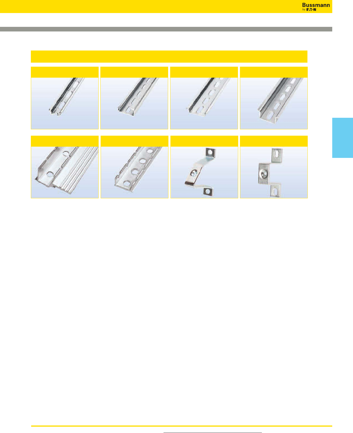
For more information, visit www.cooperbussmann.com/DatasheetsEle 353
Connectors
Accessories
DRL35MMLO*
(35mm DIN-Rail - Low Profile)
DRL35MMHI*
(35mm DIN-Rail - High Profile)
DRL15MM*
(15mm DIN-Rail)
DRL32MMG*
(32mm G-Type)
BRKT-FLT
(Flat Bracket)
BRKT-ANGL
(Angle Bracket)
NFTA Series**
(C-Rail)
NRA Series**
(C-Rail)
Mounting Rails and Brackets
*Available in 1 meter lengths only.
**Cut to length. Consult Bussmann for details.
Connectors
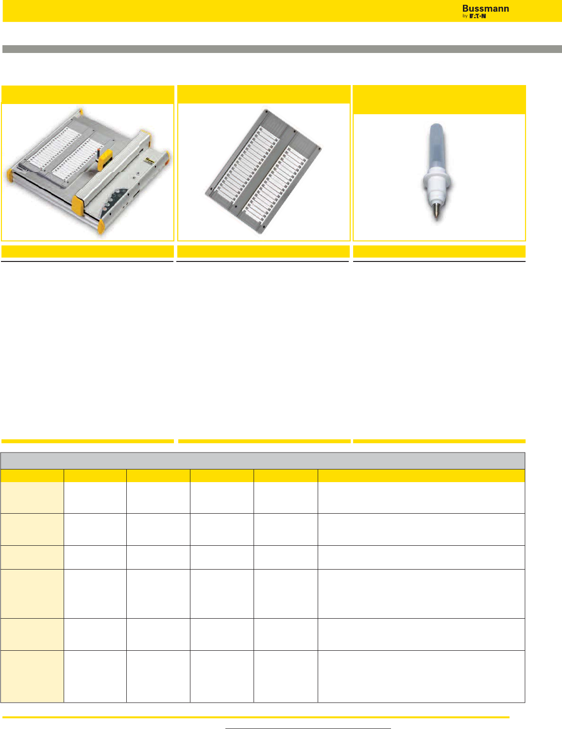
For more information, visit www.cooperbussmann.com/DatasheetsEle
354
Connectors
BussScribe Marking System
Description
• Pen is installed manually
• USB interface to PC
• 110-240Vac power supply
• WINDOWS® Operation System
Description
Support plate adjustable to accommodate various
sizes of marking labels. The support plate is
universal and suitable for TM2xCB marking
label series.
Each plotter set includes one support plate,
additional plates are available separately.
Description
Disposable black ink cartridge pen.
Single pen per pack.
System Kit Includes:
• Plotter Pens
• Support Plate
• Software
• Plotter
• Power Supplies
• USB Cable
DPLT-001SET
PLOTTER SET
PLOTTER PENS
DPLT-PEN (Tip 0.25mm)
DPLT-PEN2 (Tip 0.35mm)
DPLT-SPLT
SUPPORT PLATE
Marking Label Selection Chart
Part Number
DS50,
DP45, DP60, DP100, DP150, DP230,
DG60, DG100, DG150, DG230,
F520ST, F520STLED, F520DDST,
DTST2
Length (mm) Width (mm) Line x Row Number of Tags Applicable Block Part Numbers
TM20CB
TM21CB
TM22CB
TM26CB
TM27CB
TM28CB
5.8
5.8
5.8
12
12
12
5.1
6.1
8.0
5.1
6.1
8.0
20 x 10
20 x 10
20 x 8
12 x 12
12 x 10
12 x 7
200
200
160
144
120
84
F20T0P,
DM20,
P20S, P25G, 2P25G
DDP30,
DM30,
P30S
DM50,
P65S
DS20,
DP25,
DG25,
DDNS10,
DIS10
DS30,
DP35,
DG35
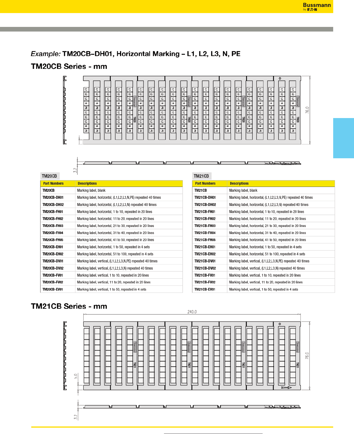
For more information, visit www.cooperbussmann.com/DatasheetsEle 355
Marking Label Ordering Method (typical)
Connectors
Connectors
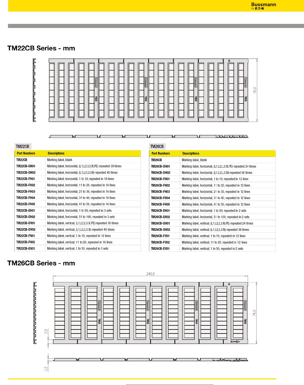
For more information, visit www.cooperbussmann.com/DatasheetsEle
356
Connectors
Marking Label Ordering Method (typical)
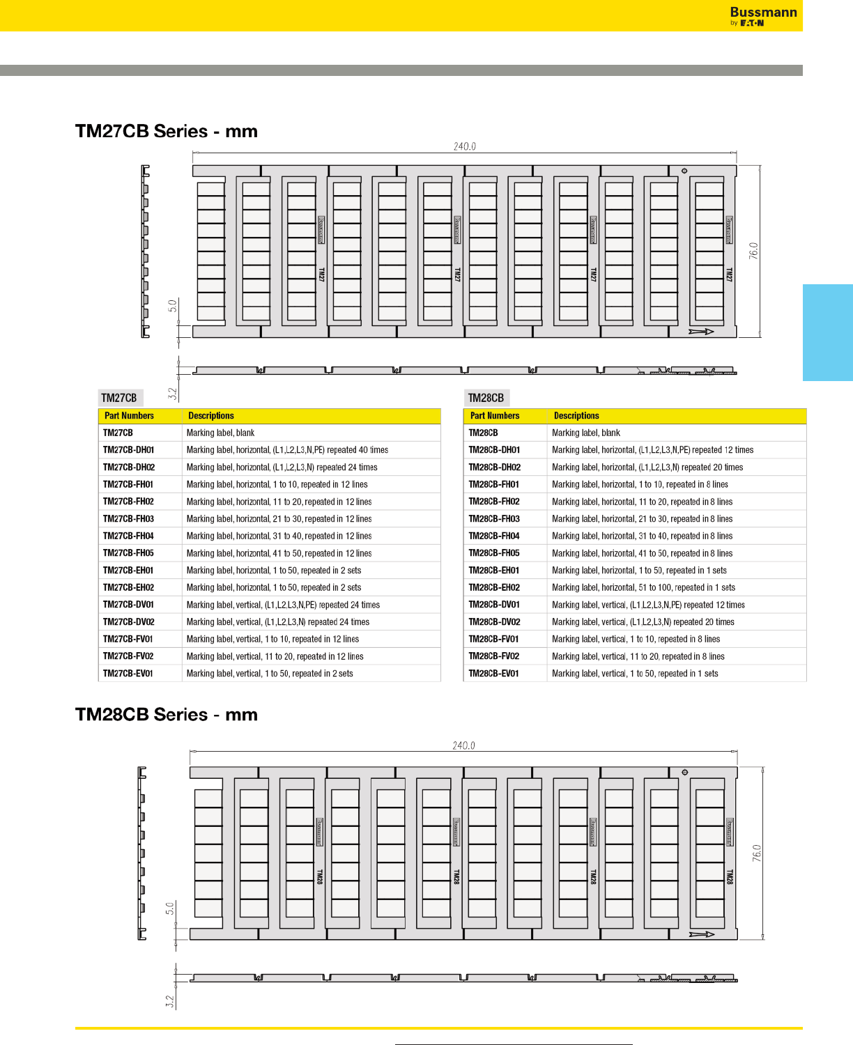
For more information, visit www.cooperbussmann.com/DatasheetsEle 357
Marking Label Ordering Method (typical)
Connectors
Connectors
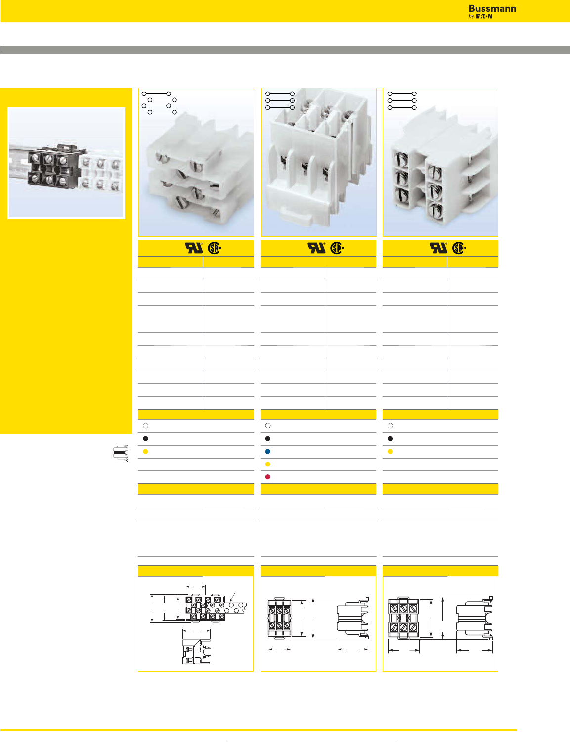
For more information, visit www.cooperbussmann.com/DatasheetsEle
358
Connectors
NDN Series Feed Through Blocks
NDNV4 NDN3 NDN63
NDN Series
The NDN Series features a compact
line of rail-mounted terminal blocks
suitable for both 35mm DIN-Rail or
C-Rail applications. Products easily
snap onto the mounting rail for a
quick, simple, low-cost solution.
Available accessories include
jumpers and marking tape.
UL E62622
CSA File 15364
CSA File 47235 (NDN1, NDN111)
Jumper
Approval
Technical Data
Rated voltage 600V
Rated Current 30A
Center spacing, in (mm) 0.25 / 6.35
Conductor cross-
section, flexible
(AWG/mm2)
22~10 / 0.5~6
Number of Poles 4
Circuits per foot 48
Torque(N•m) 2
Torque(lb-in) 18
Screw #6-32
WxHxD(mm) 25.4 x 34 x 42.4
Colors Cat. No.
White (Standard) NDNV4-WH
Black NDNV4-BK
Yellow NDNV4-YE
Accessories Cat. No.
4 circuits JN4
MTC6
35mm DIN-Rail
C-Rail
C-Rail (low profile)
DRL35MML0
DRL35MMHI
NFTA Series
NRA Series
Dimensions - in (mm)
Marking Tape
Mounting
Modular Option
Approval
Technical Data
Rated voltage 600V
Rated Current 30A
Center spacing, in (mm) 0.3 / 7.62
Conductor cross-
section, flexible
(AWG/mm2)
22~10 / 0.5~6
Number of Poles 3
Circuits per foot 38
Torque(N•m) 2
Torque(lb-in) 18
Screw #6-32
WxHxD(mm) 23.9 x 33.3 x 42.4
Colors Cat. No.
White (Standard) NDN3-WH
Black NDN3-BK
Blue NDN3-BL
Yellow NDN3-YE
Red NDN3-RE
Accessories Cat. No.
2 circuits JNDN3
MT12-1-2
35mm DIN-Rail
C-Rail
C-Rail (low profile)
DRL35MML0
DRL35MMHI
NFTA Series
NRA Series
Dimensions - in (mm)
1.47
(37.33)
1.67
(42.41)
1.31
(33.27)
0.94
(23.87)
Approval
Technical Data
Rated voltage 600V
Rated Current 65A
Center spacing, in (mm) 0.375 / 9.52
Conductor cross-
section, flexible
(AWG/mm2)
18~6 / 1~16
Number of Poles 3
Circuits per foot 30
Torque(N•m) 4
Torque(lb-in) 35
Screw #10-32
WxHxD(mm) 29.7 x 36.8 x 42.4
Colors Cat. No.
White (Standard) NDN63-WH
Black NDN63-BK
Yellow NDN63-YE
Accessories Cat. No.
2 circuits JN3
MT12-1-2
35mm DIN-Rail
C-Rail
C-Rail (low profile)
DRL35MML0
DRL35MMHI
NFTA Series
NRA Series
Dimensions - in (mm)
1.50
(38.10)
1.67
(42.41)
1.45
(36.83)
1.17
(29.71)
1.23
(31.24)
1.47
(37.33)
1.67
(42.41)
1.00
(25.40) Marking
Tape
1.34
(34.04)
Block
N/A N/A N/A
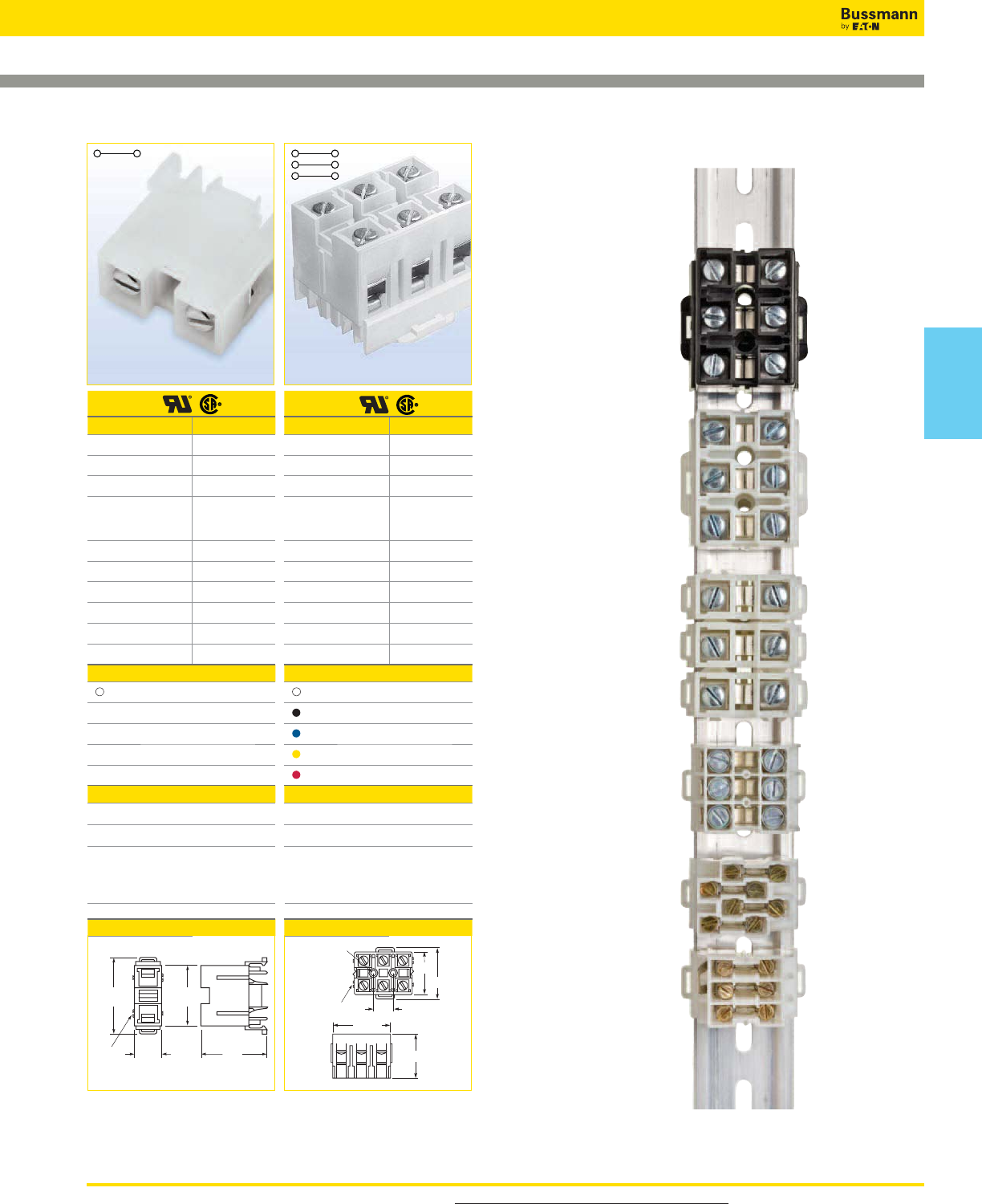
For more information, visit www.cooperbussmann.com/DatasheetsEle 359
Connectors
NDN Series Feed Through Blocks
NDN1 NDN111
Approval
Technical Data
Rated voltage 600V
Rated Current 90A
Center spacing in (mm) 0.635 / 16.31
Conductor cross-
section, flexible
(AWG/mm2)
18~2 / 1~35
Number of Poles 3
Circuits per foot 18
Torque(N•m) 3.6
Torque(lb-in) 32
Screw 1/4-28
WxHxD(mm) 47.5 x 36.6 x 43.5
Colors Cat. No.
White (Standard) NDN111-WH
Black NDN111-BK
Blue NDN111-BL
Yellow NDN111-YE
Red NDN111-RE
Accessories Cat. No.
2 circuits JN1
MT12-1-2
35mm DIN-Rail
C-Rail
C-Rail (low profile)
DRL35MML0
DRL35MMHI
NFTA Series
NRA Series
Dimensions - in (mm)
NDN111A-WH, NDN111A-BK, NDN111A-YE
0.62
(15.75)
1.71
(43.48)
1.46
(37.13)
Mt
g.
h
o
l
es
0.18 (4.57) dia.
0.28 (7.11) c'bores
Dovetail
Option
1.87
(47.50)
1.44
(36.57)
0.59
(14.99)
Dovetail
Option
1.43
(36.31)
1.71
(43.48)
1.32
(33.68)
Approval
Technical Data
Rated voltage 600V
Rated Current 90A
Center spacing in (mm) 0.635 / 16.31
Conductor cross-
section, flexible
(AWG/mm2)
18~2 / 1~35
Number of Poles 1
Circuits per foot 18
Torque(N•m) 3.6
Torque(lb-in) 32
Screw 1/4-28
WxHxD(mm) 15 x 30.3 x 43.5
Colors Cat. No.
White (Standard) NDN1-WH
Accessories Cat. No.
MT12-1-2
35mm DIN-Rail
C-Rail
C-Rail (low profile)
DRL35MML0
DRL35MMHI
NFTA Series
NRA Series
Dimensions - in (mm)
NDN1A-WH
Connectors
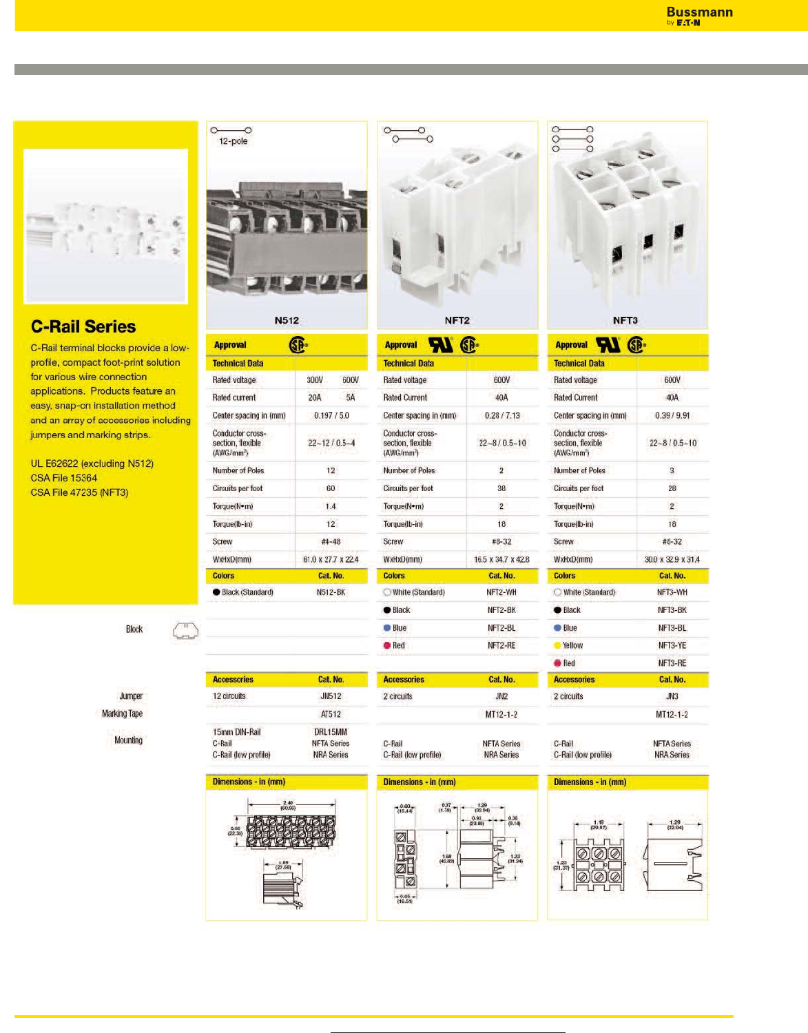
For more information, visit www.cooperbussmann.com/DatasheetsEle
360
Connectors
C-Rail Feed Through Blocks
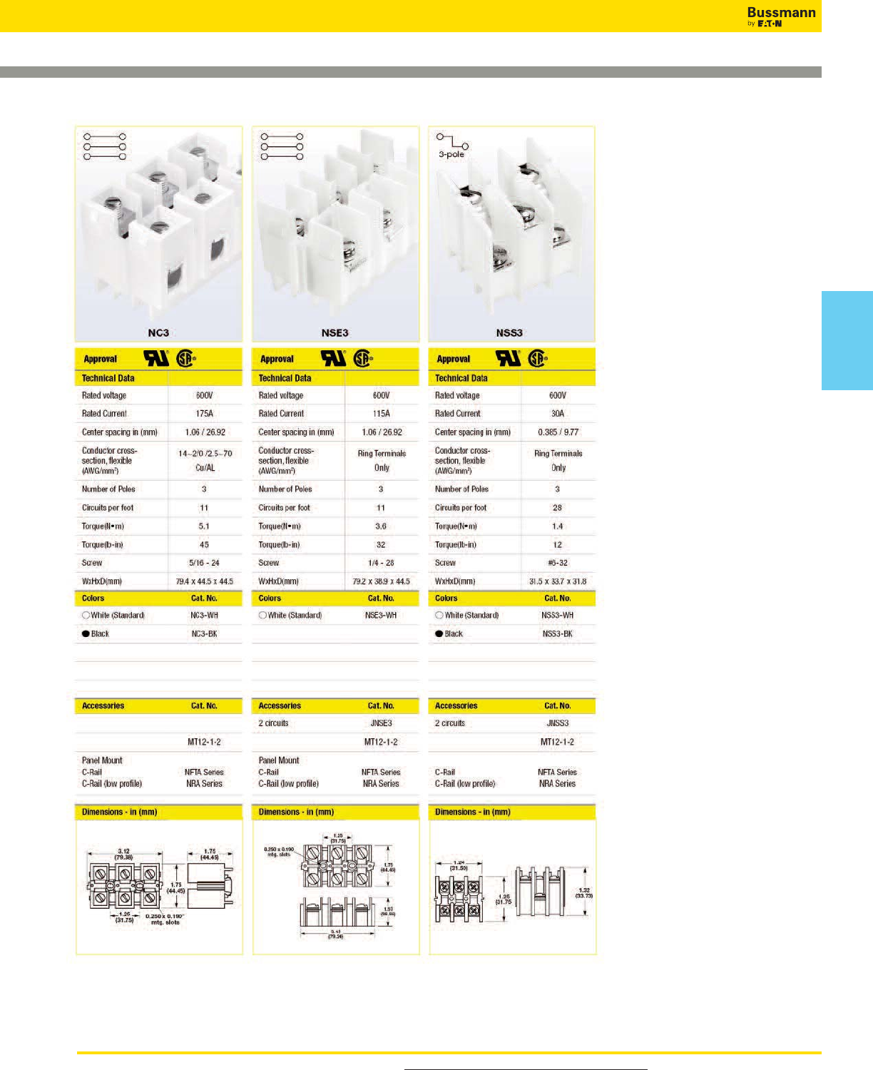
For more information, visit www.cooperbussmann.com/DatasheetsEle 361
Connectors
C-Rail Feed Through Blocks
Connectors
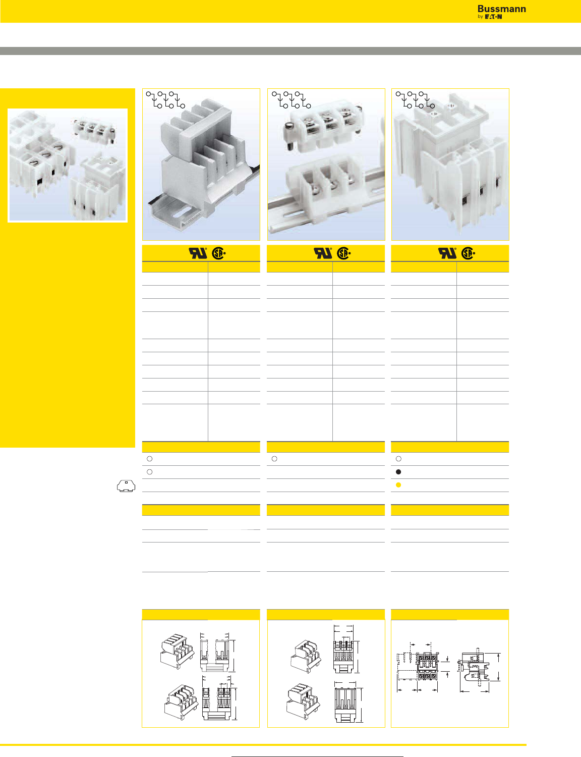
For more information, visit www.cooperbussmann.com/DatasheetsEle
362
Connectors
Depluggable Blocks
15188 15288 PLU3
Depluggable Blocks
Depluggable terminal blocks are
available for both 35mm DIN-Rail
and C-Rail applications. These
blocks provide a simple
depluggable* option for panel wiring
applications with the convenience
of quick, easy, snap-on installation.
Product accessories, such as
jumpers and marking tape, are
available for most products.
UL E62622
CSA File 15364
CSA File 47235 (15188 Series)
*Not for use as a load break
disconnect.
Approval
Technical Data
Rated voltage 600V
Rated Current 30A
Center spacing in (mm) 0.375 / 9.52
Conductor cross-
section, flexible
(AWG/mm2)
16~12 / 1.5~4
Number of Poles 3 or 4
Circuits per foot 32
Torque(N•m) 1.4
Torque(lb-in) 12
Screw #6-32
WxHxD(mm)
3-Pole
4-Pole
30.2 x 49.3 x 47.8
39.2 x 49.3 x 47.8
Colors Cat. No.
White (Standard) 15188-3
White (Standard) 15188-4
Accessories Cat. No.
2 circuits 15188J-2-J
35mm DIN-Rail DRL35MMLO
DRL35MMHI
Reverse Wiring
Locking
Reverse; Locking
15188-_R
15188-_S
15188-_RS
Dimensions - in (mm)
Options offered for both pole lengths
1.94
(49.27)
3 Pole = 1.19 (30.22)
4 Pole = 1.56 (39.62)
1.94
(49.27)
0.375
(9.52)
0.22
(5.58)
3 Pole = 1.19 (30.22)
4 Pole = 1.56 (39.62)
In-Line Wiring Direction
Reverse Wiring Direction
Approval
Technical Data
Rated voltage 600V
Rated Current 65A
Center spacing in (mm) 0.54 / 13.7
Conductor cross-
section, flexible
(AWG/mm2)
16~6 / 1.5~16
Number of Poles 3
Circuits per foot 22
Torque(N•m) 2.3
Torque(lb-in) 20
Screw #8-32
WxHxD(mm)
43.2 x 49.3 x 47.9
N/A
Colors Cat. No.
White (Standard) 15288
Accessories Cat. No.
35mm DIN-Rail DRL35MMLO
DRL35MMHI
Reverse Wiring
Screw Together
Locking
15288-R
15288-ST
15288-S
Dimensions - in (mm)
Options may be combined
1.94
(49.27)
0.54
(13.7)
2.30
(58.4)
for ST option
1.70
(43.2)
1.94
(49.27)
1.70
(43.2)
Reverse Wiring Direction
In-Line Wiring Direction
Approval
Technical Data
Rated voltage 600V
Rated Current 40A
Center spacing in (mm) 0.39 / 9.91
Conductor cross-
section, flexible
(AWG/mm2)
22~8 / 0.5~10
Number of Poles 3
Circuits per foot 28
Torque(N•m) 2
Torque(lb-in) 18
Screw #8-32
WxHxD(mm)
31.8 x 47.0 x 45.6
N/A
Colors Cat. No.
White (Standard) PLU3-WH
Black PLU3-BK
Yellow PLU3-YE
Accessories Cat. No.
2 circuits JN3
MT12-1-2
C-Rail (AL)
C-Rail (low profile)
NFTA Series
NRA Series
Dimensions - in (mm)
1.25
(31.75)
0.59
(14.98) 1.79
(45.64)
1.85
(46.99)
1.25
(31.75)
1.25
(31.75)
Jumper
Marking Tape
Mounting
Configurable Option
Block
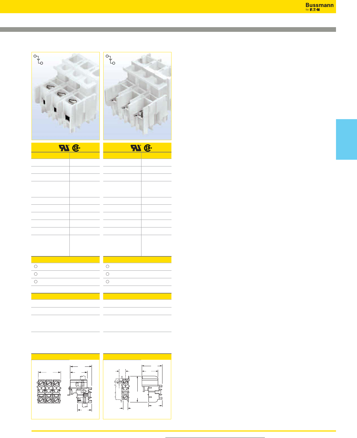
For more information, visit www.cooperbussmann.com/DatasheetsEle 363
Connectors
Depluggable Blocks
PLU1
Approval
Technical Data
Rated voltage 600V
Rated Current 70A
Center spacing in (mm) 0.625 / 15.88
Conductor cross-
section, flexible
(AWG/mm2)
18~4 / 1.0~25
Number of Poles 1 - 3
Circuits per foot 19
Torque(N•m) 3.6
Torque(lb-in) 32
Screw 1/4 - 28
WxHxD(mm)
1-Pole
2-Pole
3-Pole
18.5 x 47.0 x 45.6
34.0 x 47.0 x 45.6
49.5 x 47.0 x 45.6
Colors Cat. No.
White (1-Pole) PLU1-WH
White (2-Pole) PLU11-WH
White (3-Pole) PLU111-WH
Accessories Cat. No.
2 circuits JN1
MT12-1-2
C-Rail (AL)
C-Rail (low profile)
NFTA Series
NRA Series
Dimensions - in (mm)
PSU1
Approval
Technical Data
Rated voltage 600V
Rated Current 45A
Center spacing in (mm) 0.625 / 15.88
Conductor cross-
section, flexible
(AWG/mm2)
Ring Terminals
Only
Number of Poles 1 - 3
Circuits per foot 19
Torque(N•m) 2.7
Torque(lb-in) 24
Screw #10-32
WxHxD(mm)
1-Pole
2-Pole
3-Pole
18.5 x 49.1 x 62.1
34.4 x 49.1 x 62.1
50.3 x 49.1 x 62.1
Colors Cat. No.
White (1-Pole) PSU1-WH
White (2-Pole) PSU11-WH
White (3-Pole) PSU111-WH
Accessories Cat. No.
MT12-1-2
C-Rail (AL)
C-Rail (low profile)
NFTA Series
NRA Series
Dimensions - in (mm)
1.87
(47.49)
1.85
(46.99)
1.48
(37.59)
1.25
(31.75)
0.625
(15.88)
1.93
(49.12)
2.44
(62.10)
1.48
(37.64)
1.30
(33.00)
0.43
(
11.10
)
Connectors
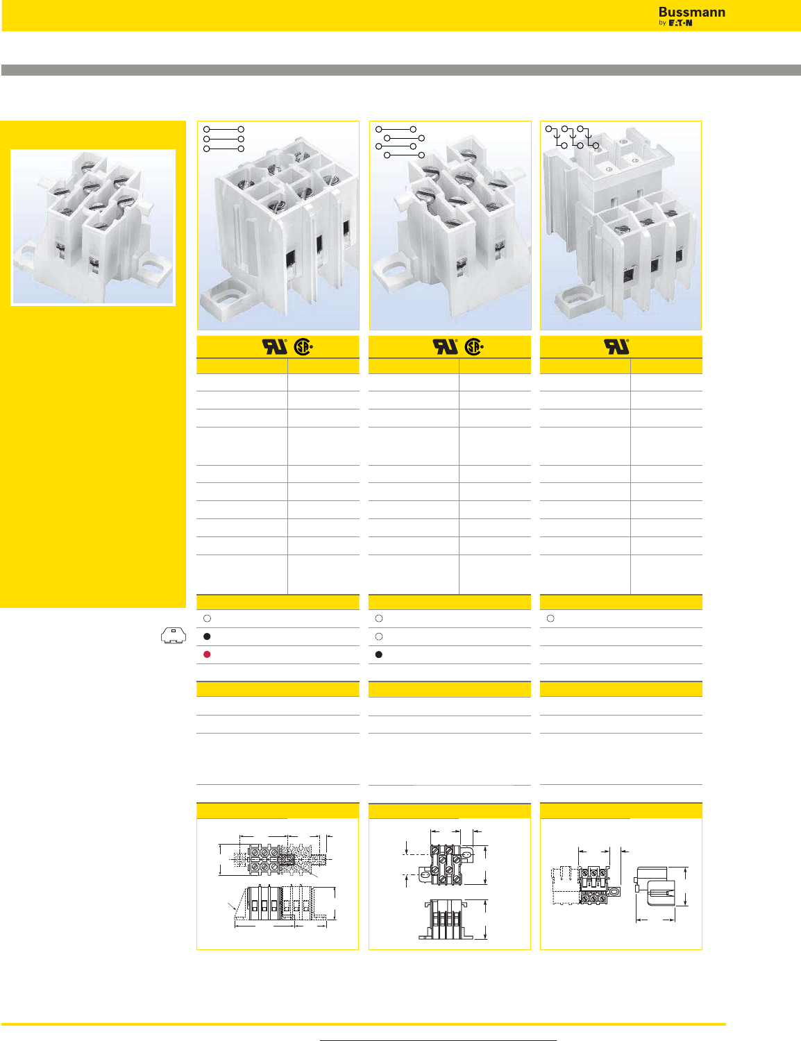
For more information, visit www.cooperbussmann.com/DatasheetsEle
364
Connectors
Multi-Pole Panel Mount Blocks
KT3 KT4 PLK3
Panel Mount Blocks
Multi-pole panel mount terminal
blocks provide a compact, high
density circuit connection solution
without the necessity of a mounting
rail. These products are designed to
be nested together to form one string
of circuit connections.
UL E62622
CSA 15364 (excluding PLK3)
Approval
Technical Data
Rated voltage 600V
Rated Current 40A
Center spacing in (mm) 0.39 / 9.91
Conductor cross-
section, flexible
(AWG/mm2)
22~8 / 0.5~10
Number of Poles 3
Circuits per foot 28
Torque(N•m) 2
Torque(lb-in) 18
Screw #8-32
WxHxD(mm) 59.5 x 31.8 x 31.0
Colors Cat. No.
White (Standard) KT3-WH
Black KT3-BK
Red KT3-RE
Accessories Cat. No.
2 circuits JN3
MT12-1-2
Mounting Foot KAD
Dimensions - in (mm)
#8 screw clearance
KAD
end mtg.
adapter
1.22
(31.04)
1.25
(31.75)
2.34
(59.51)
1.25
(31.75)
0.25
(6.35)
1.25
(31.75)
1.87
(47.63)
Approval
Technical Data
Rated voltage 600V
Rated Current 30A
Center spacing in (mm) 0.25 / 6.35
Conductor cross-
section, flexible
(AWG/mm2)
22~10 / 0.5~6
Number of Poles 4
Circuits per foot 48
Torque(N•m) 2
Torque(lb-in) 18
Screw #6-32
WxHxD(mm) 43.8 x 34.0 x 32.2
Colors Cat. No.
White* KT4-WH-A
White* KT4-WH-B
Black KT4-BK
Accessories Cat. No.
4 circuits JN4
MTC6
Dimensions - in (mm)
1.34
(34.04)
1.26
(32.23)
0.62
(15.88)
0.98
(24.99)
0.37
(9.40)
Approval
Technical Data
Rated voltage 600V
Rated Current 40A
Center spacing in (mm) 0.39 / 9.91
Conductor cross-
section, flexible
(AWG/mm2)
22~8 / 0.5~10
Number of Poles 3
Circuits per foot 28
Torque(N•m) 2
Torque(lb-in) 18
Screw #8-32
WxHxD(mm) 65.7 x 46.9 x 45.5
Colors Cat. No.
White (Standard) PLK3-WH
Accessories Cat. No.
2 circuits JN3
MT12-1-2
Mounting Foot KAD
Dimensions - in (mm)
1.46
(37.22)
0.56
(14.22)
1.79
(45.52)
1.84
(46.86)
Jumper
Marking Tape
Mounting
Block
*The KT4 products are designed to be nested
together to form one string of circuit
connections. When used in series, order
t b KT4 WH A d KT4 WH B
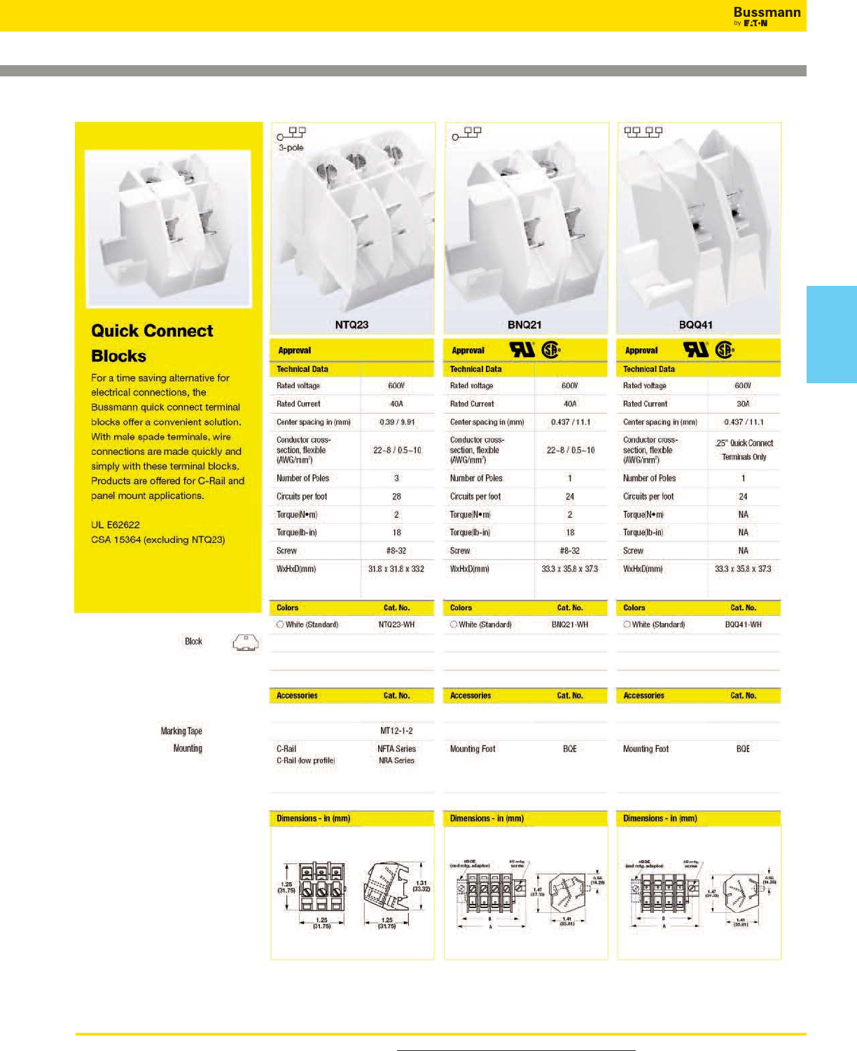
For more information, visit www.cooperbussmann.com/DatasheetsEle 365
Connectors
Quick Connect Blocks
Connectors
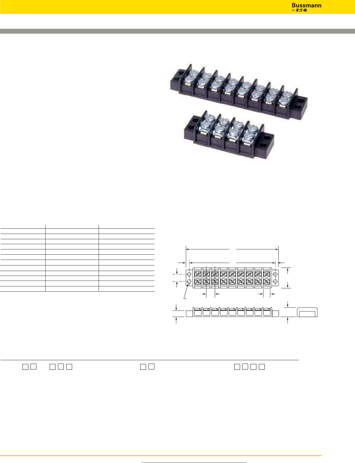
Catalog Number Build-A-Code
Series Poles Screw Options Marking/Cover Hardware Options
TB100 —
For more information, visit www.cooperbussmann.com/DatasheetsEle
366
Connectors
Double Row Terminal Blocks
0.14
(3.5)
0.375
(9.5)
0.30
(7.6)
0.17 dia.
(4.3)
0.14
(3.5)
0.88
(22.3)
0.41
(10.4)
0.31 (7.9)
A
B
0.25 (6.3)
TB100- in (mm)
Series TB100
Specifications
Rating: 30A, 300V*
Center Spacing: 0.375˝ or 3/8˝ (9.52mm)
Wire Range: #14 - 22 AWG Cu
Screw Size: #6-32 philslot screws
Torque Rating: 9 lb-in
Distance Between Barriers: 0.30˝ (7.62mm)
Mounting: #6 screws
Operating Temperature: 130°C (266°F) max.,
-40°C (-40°F) min.
Materials: Molded base: Black, UL rated 94V0
thermoplastic
Terminal plating: Tin over brass; Screws: Zinc-plated steel
Breakdown Voltage: 3600V
Agency Information: UL File E62622/CSA File 47235; IEC
Compliance; CE Certified
* Max rating shown; some options may be rated lower.
Dimensions - in
Poles A B Poles A B Poles A B
02 1.40 1.12 14 5.90 5.62 26 10.40 10.12
03 1.78 1.50 15 6.28 6.00 27 10.78 10.50
04 2.16 1.88 16 6.66 6.38 28 11.16 10.88
05 2.53 2.25 17 7.03 6.75 29 11.53 11.25
06 2.90 2.62 18 7.40 7.12 30 11.90 11.62
07 3.28 3.00 19 7.78 7.50 31 12.28 12.00
08 3.66 3.38 20 8.16 7.88 32 12.66 12.38
09 4.03 3.75 21 8.53 8.25 33 13.03 12.75
10 4.40 4.12 22 8.90 8.62 34 13.40 13.12
11 4.78 4.50 23 9.28 9.00 35 13.78 13.50
12 5.16 4.88 24 9.66 9.38 36 14.16 13.88
13 5.53 5.25 25 10.03 9.75
1” = 25.4mm.
TB100-08
TB100-04SP
02
to
36 Blank
- steel philslot, zinc-plated
L1
to
L6 QC1
to
QC20
- quick connects
00
- screws shipped bulk Marking Options (See page 318)
B
- brass philslot, nickel-plated Marker Strips (See page 319)
SP
- steel Sems philslot, zinc-plated Special Markings (See page 319)
Custom Options
**
Covers (See page 318)
J101
- flat slip-on jumper
(2 position only)
0J2
- over barrier jumpers
0J4
- over barrier jumpers
**
Contact factory for pole configuration.
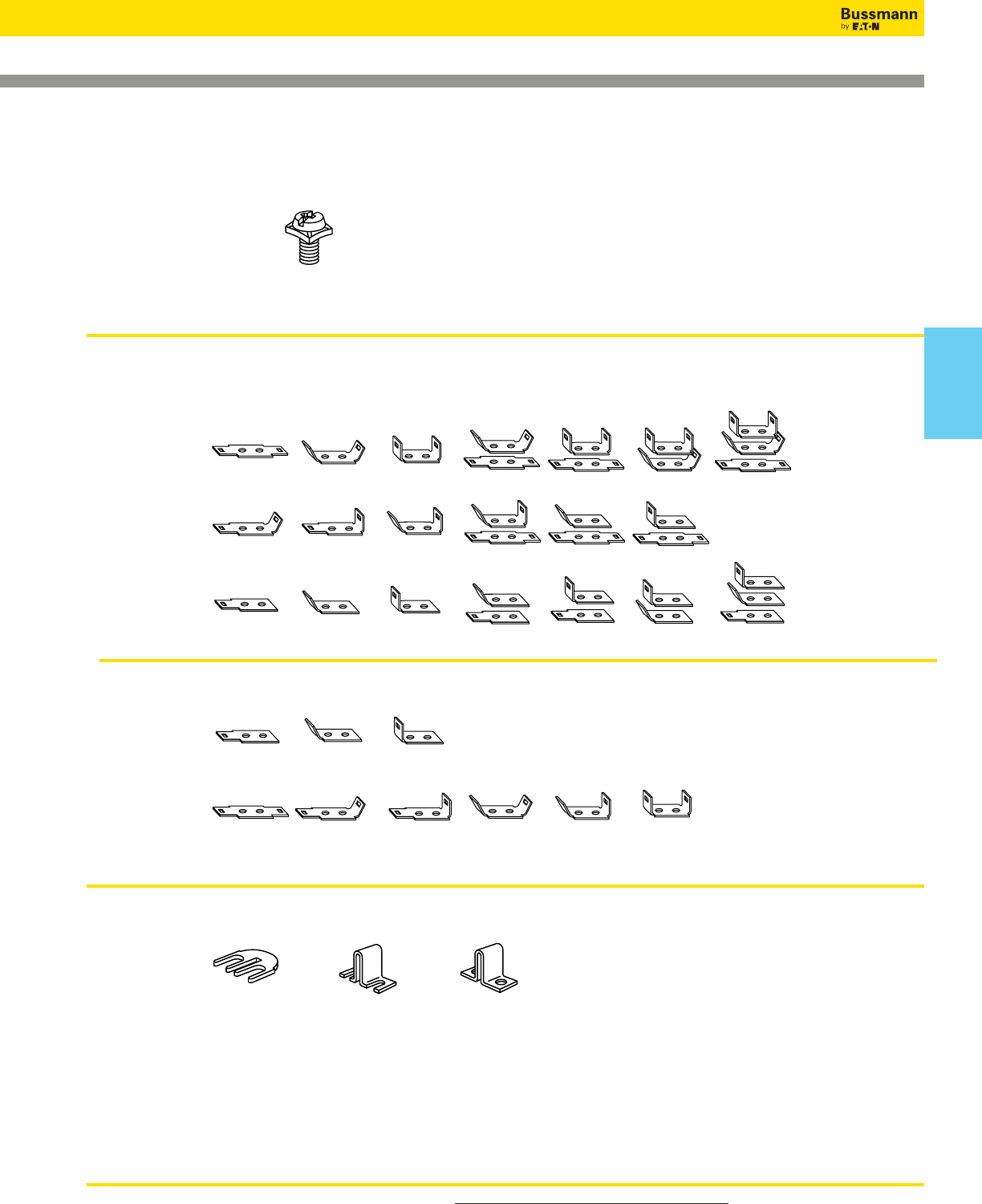
For more information, visit www.cooperbussmann.com/DatasheetsEle 367
Connectors
Double Row Terminal Blocks
Hardware Options
Quick Connects – Assembled: Terminals 0.187” x 0.020”. Maximum current rating 13 amps. For other orientations, contact Bussmann.
QC1 QC2 QC3 QC4 QC5 QC6 QC7
QC8 QC9 QC10 QC11 QC12 QC13
QC14 QC15 QC16 QC17 QC18 QC19 QC20
Quick Connects – Bulk: minimum order per part number – 100 pieces.
QC101-J QC102-J QC103-J
Flat – none QC 45° – none QC 90° – none
QC104-J QC105-J QC106-J QC107-J QC108-J QC109-J
Flat – Flat Flat – QC 45° Flat – QC 90°QC 45° – QC 45° QC 45° – QC 90°QC 90° – QC 90°
Jumpers – Bulk: minimum order per part number – 100 pieces. Contact Bussmann for jumper assembly.
J101 OJ2 OJ4
Flat slip-on Slip-on over barrier Closed over barrier
(Bulk: J101-J) (Bulk: OJ2-J) (Bulk: OJ4-J)
Screw Options
B
Brass Philslot
Nickel-Plated
SP
Steel SEMS
Philslot Zinc-Plated
Connectors
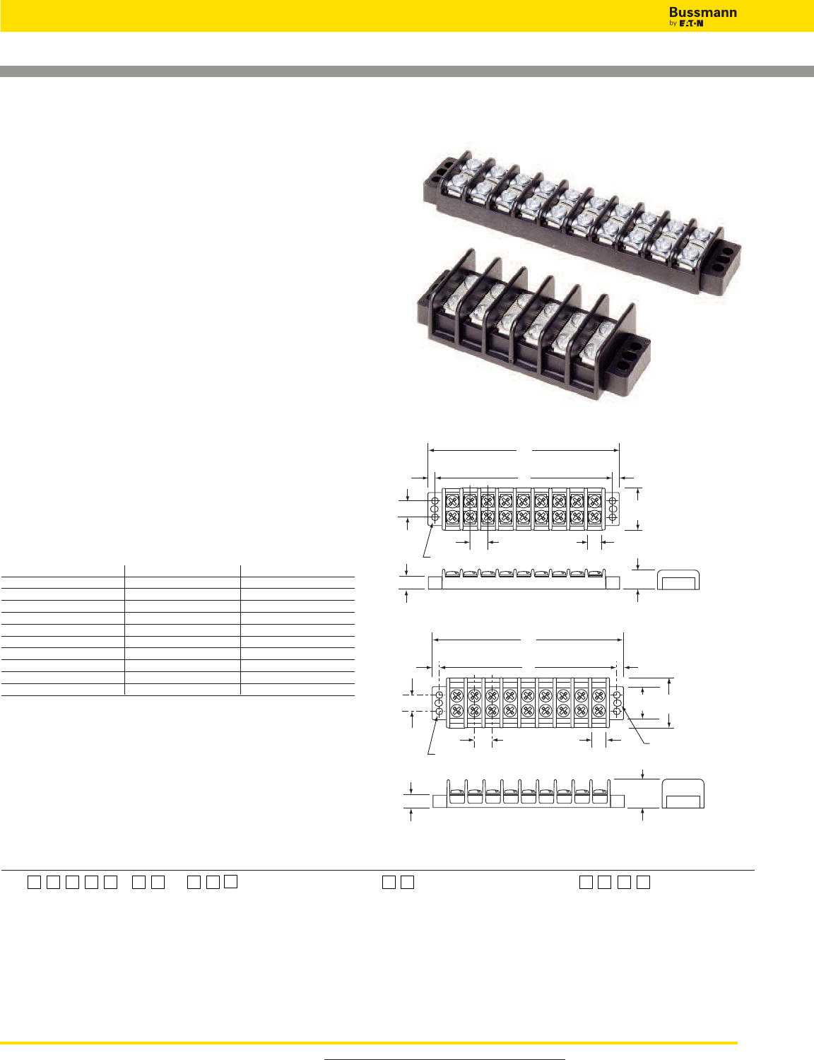
0.16
(4.0)
0.437
(11.1)
0.353
(8.9)
0.17 dia.
(4.3)
0.16
(4.0)
1.12
(28.4)
0.56
(14.2)
0.44 (11.2)
A
B
0.31 (7.8)
For more information, visit www.cooperbussmann.com/DatasheetsEle
368
Connectors
Double Row Terminal Blocks
Series TB200 & TB200HB
Specifications
Ratings:
Volts: — 300V* (TB200)
— 600V* (TB200HB)
Amps: — 30A*
Center Spacing: 0.437˝ or 7/16˝ (11.10mm)
Wire Range: #12 - 22 AWG Cu
Screw Size: #6-32 philslot screws
Torque Rating: 9 lb-in
Distance Between Barriers: 0.353˝ (8.97mm)
Mounting: #6 screws
Operating Temperature: 130°C (266°F) max.,
-40°C (-40°F) min.
Materials: Molded base: Black, UL rated 94V0
thermoplastic
Terminal plating: Tin over brass; Screws: Zinc-plated steel
Breakdown Voltage: 4800V
Agency Information: UL File E62622, CSA File 47235 &
15364; IEC Compliance; CE Certified
* Max rating shown; some options may be rated lower.
Dimensions - in
Poles A B Poles A B Poles A B
02 1.63 1.31 12 6.00 5.68 22 10.37 10.06
03 2.07 1.75 13 6.44 6.12 23 10.81 10.50
04 2.51 2.18 14 6.87 6.56 24 11.25 10.93
05 2.94 2.62 15 7.31 7.00 25 11.68 11.37
06 3.38 3.06 16 7.75 7.43 26 12.12 11.81
07 3.82 3.50 17 8.19 7.87 27 12.56 12.25
08 4.25 3.93 18 8.62 8.31 28 13.00 12.68
09 4.69 4.37 19 9.06 8.75 29 13.44 13.12
10 5.13 4.81 20 9.50 9.18 30 13.87 13.56
11 5.57 5.25 21 9.94 9.62
1” = 25.4mm.
TB200 - in (mm)
TB200HB
TB200-10SP
TB200HB-06
0.16
(4.0)
0.437
(11.1)
0.353
(8.9)
0.17 dia.
(4.3)
0.17 x 0.22 slots
(4.3 x 5.6)
0.16
(4.0)
1.37
(34.8)
0.90
(22.8)
0.75
(19.0)
0.44 (11.2)
A
B
0.33 (8.4)
Catalog Number Build-A-Code
Series Poles Screw Options Marking/Cover Hardware Options
TB —
200 - Standard
02
to
30 Blank
- Steel philslot, zinc-plated
L1
to
L6
- Marking Options (See page 318)
QC1
to
QC20
- Quick connects
200HB - High barrier
00
- Screws shipped bulk Special Markings (See page 318)
B
- Brass philslot, nickel-plated Covers (See page 318)
BS
- Brass Sems philslot, nickel-plated Marking Strips (See page 319)
Custom Options**
SP
- Steel Sems philslot, zinc-plated
J201
- Flat slip-on jumper
P
- Steel Sems (P-style) (2 position only)
ST
- Stainless steel, philslot
0J3
- Over barrier jumpers
SS
- Stainless steel Sems, philslot
0J5
- Over barrier jumpers
0J7
- Over barrier jumpers
**
Contact factory for pole configuration
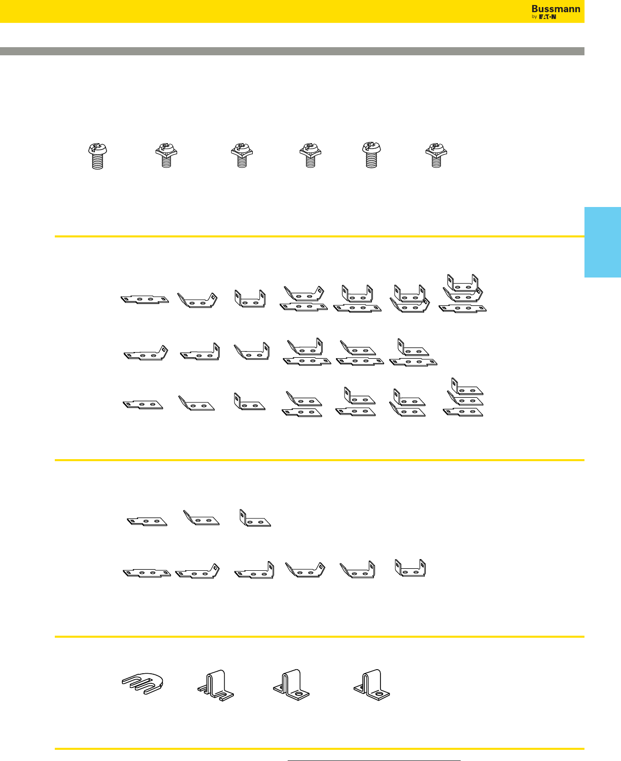
For more information, visit www.cooperbussmann.com/DatasheetsEle 369
Connectors
Double Row Terminal Blocks
Screw Options
BBS SP P ST SS
Brass Philslot Brass SEMS Steel SEMS Steel SEMS Stainless Steel Stainless Steel
Nickel-Plated Philslot Nickel-Plated Philslot Zinc-Plated (P-Style) Philslot SEMS Philslot
B001-7016-J B001-7019-J B001-7007-J B001-7000-J F507-J B001-7085-J
Hardware Options
Quick Connects – Assembled: Terminals 0.25” x 0.031”. Maximum current rating 20 amps. For other orientations, contact Bussmann.
QC1 QC2 QC3 QC4 QC5 QC6 QC7
QC8 QC9 QC11 QC10 QC12 QC13
QC14 QC15 QC16 QC17 QC18 QC19 QC20
Quick Connects – Bulk: minimum order per part no. – 100 pieces.
QC201-J QC202-J QC203-J
QC 45° – blank Flat – blank QC 90° – blank
QC204-J QC205-J QC206-J QC207-J QC208-J QC209-J
Flat – Flat Flat – QC 45° Flat – QC 90° QC 45° – QC 45° QC 45° – QC 90° QC 90° – QC 90°
Jumpers – Bulk: minimum. order per part no. – 100 pieces. Contact Bussmann for jumper assembly.
J201 OJ3 OJ5 OJ7
Flat slip-on Slip-on over Closed over Closed over
(not available on TB200HB) barrier for TB200HB barrier for TB200HB barrier for TB200
(Bulk: J201-J) (Bulk: OJ3-J) (Bulk: OJ5-J) (Bulk: OJ7-J)
Bulk:
Connectors
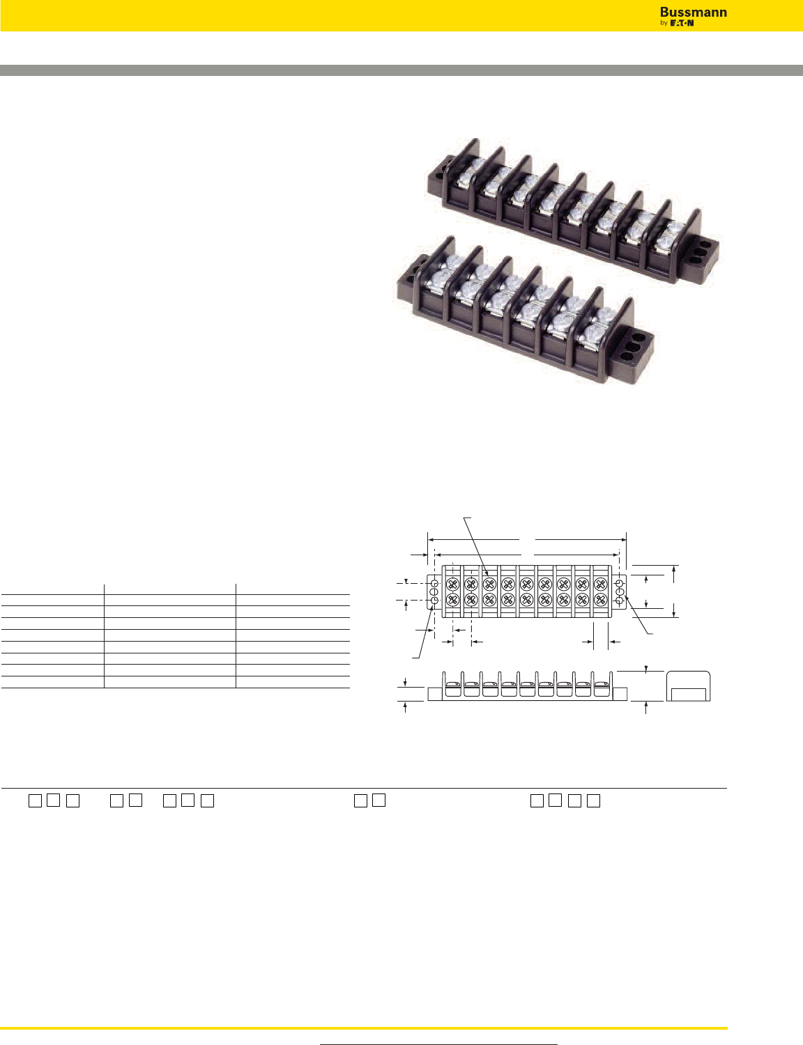
Catalog Number Build-A-Code
Series Poles Screw Options Marking/Cover Hardware Options
TB —
300 = 8-32 screw 02 to 24 Blank = Steel philslot, zinc-plated L1 to L6 Marking Options (pg 318) QC1 to QC20 = Quick connects (TB300 only)
345 = 10-32 screw 00 = Screws shipped bulk Special Markings (pg 318)
B= Brass philslot, nickel-plated Covers (pg 318)
BS = Brass Sems philslot, Marking Strips (pg 319)
nickel-plated (TB300 only)
SP = Steel Sems philslot, zinc-plated
(TB300 only)
ST = Stainless steel, philslot Custom Options
J301 = Flat slip-on jumper
OJ6 = Over barrier jumper
OJ11 = Over barrier jumper
For more information, visit www.cooperbussmann.com/DatasheetsEle
370
Connectors
Double Row Terminal Blocks
0.22
(5.6)
0.56
(14.2) 0.56
(14.2)
0.412
(10.4)
0.21dia.
(5.3)
0.21 x 0.25 slots
(5.3 x 6.3)
1.33
(33.8)
0.90
(22.8)
0.81
(20.5)
0.50 (12.7)
A
B
8-32 binding head screw - TB 300
10-32 binding head screw - TB 345
0.33 (8.4)
TB300 & TB345 - in (mm)
Series TB300 & TB345
Specifications
Ratings:
Volts: — 600V*
Amps: — 30A* (TB300)
— 45A (TB345)
Center Spacing: 0.562” or 9/16” (14.28mm)
Wire Range: #8 - 22 AWG Cu
Screw Size: TB300 – #8-32 philslot screws
TB345 – #10-32 philslot screws
Torque Rating: #8 screws - 16 lb-in;
#10 screws - 20 lb-in
Distance Between Barriers: 0.41” (10.5mm)
Mounting: TB300 – #8 screws; TB345 – #10 screws
Operating Temperature: 130°C (266°F) max., -40°C (-40°F)
min.
Material: Molded base: Black, UL rated 94V0 thermoplastic
Terminal plating: Tin over brass; Screws: Zinc-plated steel
Breakdown Voltage: 7500V
Agency Information: UL File E62622, CSA File 47235; IEC
Compliance; CE Certified
* Max rating shown; some options may be rated lower.
Dimensions - in
Poles A B Poles A B Poles A B
02 2.13 1.69 10 6.62 6.19 18 11.12 10.68
03 2.69 2.25 11 7.18 6.75 19 11.68 11.25
04 3.25 2.81 12 7.75 7.31 20 12.24 11.81
05 3.81 3.37 13 8.31 7.87 21 12.80 12.37
06 4.37 3.94 14 8.87 8.44 22 13.37 12.93
07 4.94 4.50 15 9.43 9.00 23 13.93 13.50
08 5.50 5.06 16 9.99 9.56 24 14.49 14.06
09 6.06 5.62 17 10.56 10.12
1” = 25.4mm.
TB300-08
TB345-06SP
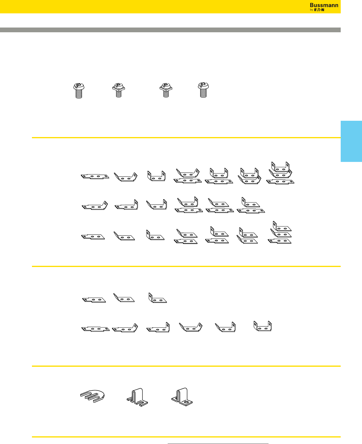
For more information, visit www.cooperbussmann.com/DatasheetsEle 371
Connectors
Double Row Terminal Blocks
Screw Options
BBS SPST
Brass Philslot Brass SEMS Steel SEMS Stainless Steel
Nickel-Plated Philslot Nickel-Plated Philslot Zinc-Plated Philslot
TB300 Blk: B001-7018-J B001-7015-J B001-7017-J B001-7063-J
TB345 Blk: B500-023-028-J B001-7064-J
Hardware Options
Quick Connects – Assembled: TB300 only. Terminals 0.25” x 0.031”. Maximum current rating 20 amps. For other orientations, contact Bussmann.
QC1 QC2 QC3 QC4 QC5 QC6 QC7
QC8 QC9 QC10 QC11 QC12 QC13
QC14 QC15 QC16 QC17 QC18 QC19 QC20
Quick Connects – Bulk: (*TB300 only) minimum order per part number. – 100 pieces.
QC201-J QC202-J QC203-J
Flat – blank QC 45° – blank QC 90° – blank
QC204-J QC205-J QC206-J QC207-J QC208-J QC209-J
Flat – Flat Flat – QC 45° Flat – QC 90° QC 45° – QC 45° QC 45° – QC 90° QC 90° – QC 90°
Jumpers – Bulk: minimum order per part number – 100 pieces. Contact Bussmann for jumper assembly.
J301 OJ6 OJ11
Flat slip-on(TB300 only) Closed over barrier Slip-on over barrier
(Bulk: J301-J) (Bulk: OJ6-J) (Bulk: OJ11-J)
Connectors
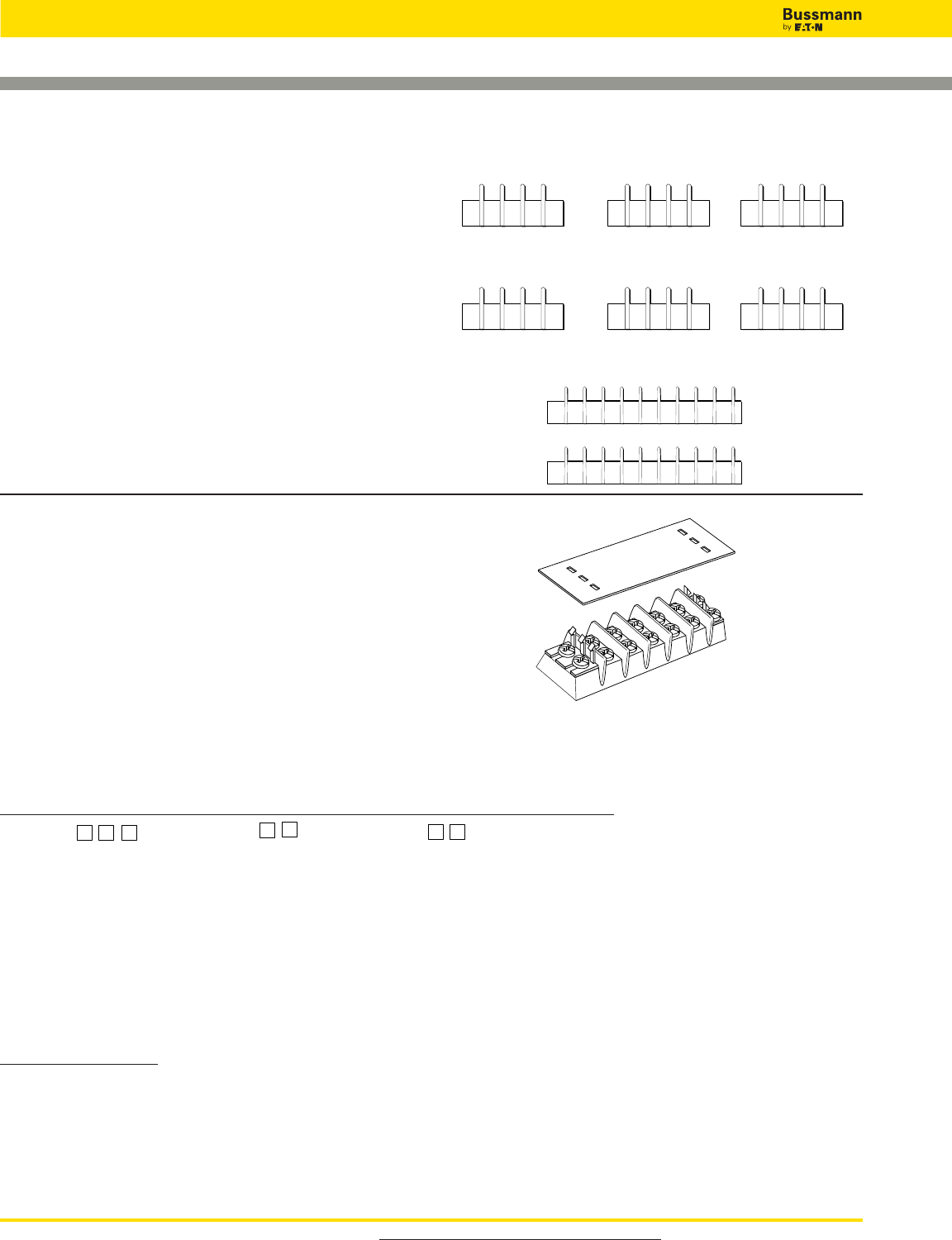
Catalog Number Build-A-Code
For more information, visit www.cooperbussmann.com/DatasheetsEle
372
Connectors
Marking Options and Covers for Double Row
Terminal Blocks
Standard Marking
Standard markings are applied directly to the side(s) of a
block. The standard marking color is white. The standard
numeral height is 0.125 inches (3.17mm).
Note: Blocks marked on both sides require a different code
for each side. Example: Style L1 on one side of the block
requires Style L2 on the other side to ensure common
terminal marking. To order, add appropriate suffix (L1, L2, L3,
L4, L5 and/or L6) to block catalog number in the proper
sequence.
Special Marking
Special markings are available at an additional charge
Drawing(s) must be submitted to ensure accuracy of part
required. Consult Bussmann for price and delivery.
Note: Marking is not available on TB400 Series
Covers
Covers prevent personnel, screws and foreign items from
contacting live terminals, and are available in white or clear
plastic. Two cover clips are supplied with each cover. The
cover width is 1.31 inches (33.3mm).
All covers must be ordered separately.
Example: 10 position cover, white, TB100 Series = Catalog
Number X12010.
1 2 3 3 2 1
3 2 1 1 2 3
1
2
3
1
2
3
L1 L2 L3
L4 L5 L6
K3
4
5
G
3AC
MAS
TER
300V
MAX
20A
INPUT
OUT
PUT 134
134
GND
MB
RED
BLK
BLU
A
M
Series Cover Strip Poles High Barrier Option Only
X
120
- TB100/white
02
to
36
(TB100)
HB = High Barrier
119
- TB100/clear
02
to
30
(TB200/TB200HB)
220
- TB200/TB200HB - white
02
to
24
(TB300/TB345)
219
- TB200/TB200HB - clear
320
- TB300 & TB345 - white
319
- TB300 & TB345 - clear
Cover Clips – Bulk
Part Number
DD1-J – TB100 Series
DD2-J – TB200 Series
DD2HB-J – TB200HB Series
DD3-J – TB300 Series
Note: Covers are not available on TB400 Series.
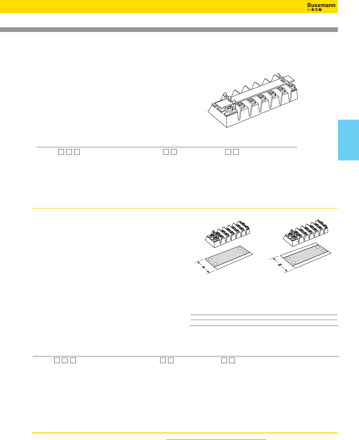
For more information, visit www.cooperbussmann.com/DatasheetsEle 373
Top & Bottom Marking Strips for Double Row
Terminal Blocks
Top Marker Strips
Top mounting marker strips are available in white (opaque)
plastic. Two cover clips are supplied with each marker strip.
All top marker strips must be ordered separately.
Example: 12 position cover, TB200, 0.032” x 0.312” =
Catalog Number X20312.
Example: 12 position cover, TB200HB, 0.06” x 0.50” =
Catalog Number X23312HB.
Bottom Marker Strips
Bottom mounting marker strips are made of black PVC,
0.030” thick. Space is available to handle most marking
situations. All marker strips must be ordered separately.
To order, specify part number and required marking
orientation: (BF) bottom forward, (BR) bottom reverse, (TF)
top forward, or (TR) top reverse. Consult factory for specials.
Example: 13 position strip, TB100 with no markings, space
for marking one side = Catalog Number X10513.
Standard numeral height is 0.125”. Standard markings are
0-99. Special markings are available on special order.
Drawing(s) must be submitted to ensure accuracy of part
required.
Dimensions (in)
Dim. TB100 TB200 TB200HB TB300 TB345 TB400
A 1.13 1.37 1.62 1.58 1.58 N/A
B 1.38 1.62 1.81 1.81 1.81 N/A
Connectors
Space for marking one side Space for marking two sides
Catalog Number Build-A-Code
Series Top Marker Strip Poles High Barrier Option Only
X
133 - TB100 (0.060 thk x 0.500 w) 02 to 36 (TB100) HB = High Barrier
103 - TB100 (0.032 thk x 0.312 w) 02 to 30 (TB200/TB200HB)
233 - TB200/TB200HB (0.060 thk x 0.500 w) 02 to 24 (TB300/TB345)
203 - TB200/TB200HB (0.032 thk x 0.312 w)
333 - TB300 & TB345 (0.060 thk x 0.500 w)
303 - TB300 & TB345 (0.032 thk x 0.380 w)
Note: Marking Strips are not available on TB400 Series
Catalog Number Build-A-Code
Series Bottom Marker Strip Poles Orientation
X
105 = TB100/marking one side 02 to 36 (TB100) BF = Bottom forward
101 = TB100/marking both sides 02 to 30 (TB200/TB200HB) BR = Bottom reverse
205 = TB200/marking one side 02 to 24 (TB300/TB345) TF = Top forward
201 = TB200/marking both sides TR = Top reverse
295 = TB200HB/marking one side
291 = TB200HB/marking both sides
305 = TB300 & TB345/marking one side
301 = TB300 & TB345/marking both sides
Note: Marking Strips are not available on TB400 Series.
Connectors
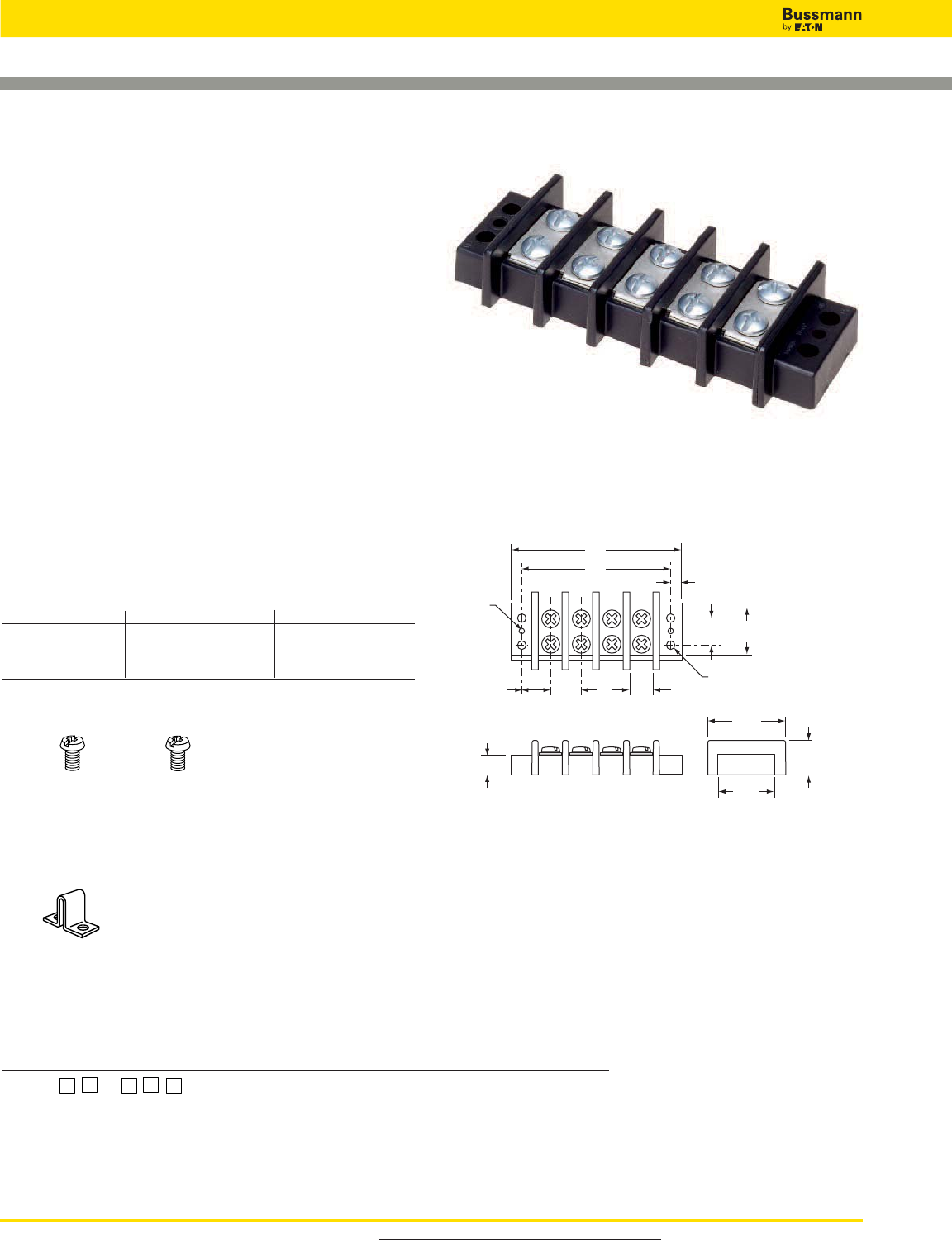
For more information, visit www.cooperbussmann.com/DatasheetsEle
374
Connectors
Screw Options
BST
Brass Philslot Stainless Steel
Nickel-Plated Philslot
Bulk: B500-023-028-J B001-7064-J
Hardware Options
OJ14: Closed over barrier
(Bulk:OJ14-J)
Double Row Terminal Blocks
Series TB400
Specifications
Ratings:
Volts: — 600V
Amps: — 75A
Center Spacing: 0.687˝ or 11/16˝ (17.45mm)
Wire Range: #6-14 AWG Cu
Screw Size: #10-32 philslot screws
Torque Rating: 20 lb-in
Distance Between Barriers: 0.56˝ (14.3mm)
Mounting: #10 screws
Operating Temperature: 130°C (266°F) max.,
-40°C (-40°F) min.
Material: Molded base: Black, UL rated 94V0 thermoplastic
Terminal plating: Tin over brass; Screws: Zinc-plated steel
Breakdown Voltage: 7500V
Agency Information: UL File E62622, CSA File 47235; IEC
Compliance; CE Certified
Dimensions - in
Poles A B Poles A B Poles A B
02 2.51 2.06 06 5.26 4.81 10 8.01 7.56
03 3.20 2.75 07 5.95 5.50 11 8.70 8.25
04 3.89 3.44 08 6.64 6.19 12 9.39 8.94
05 4.58 4.13 09 7.33 6.88
1” = 25.4mm.
0.15 dia.
(3.8)
0.687
(17.4)
0.22
(5.6)
A
B
0.625
(15.9)
1.12
(28.4)
0.687
(17.4)
0.562
(14.3)
1.81
(46.0)
0.76
(19.3)
0.46 (11.7)
1.34
(34.0)
0.22 dia. (5.6)
TB400 - in (mm)
TB400-05
Catalog Number Build-A-Code
Series Poles Screw Options Marking Custom Options
TB400 –
02 to 12 Blank = Steel philslot, zinc-plated Not available OJ14* - Jumper over barrier
00 = Screws shipped bulk
B = Brass philslot, nickel-plated
ST = Stainless steel, philslot
*Contact factory for pole configuration.
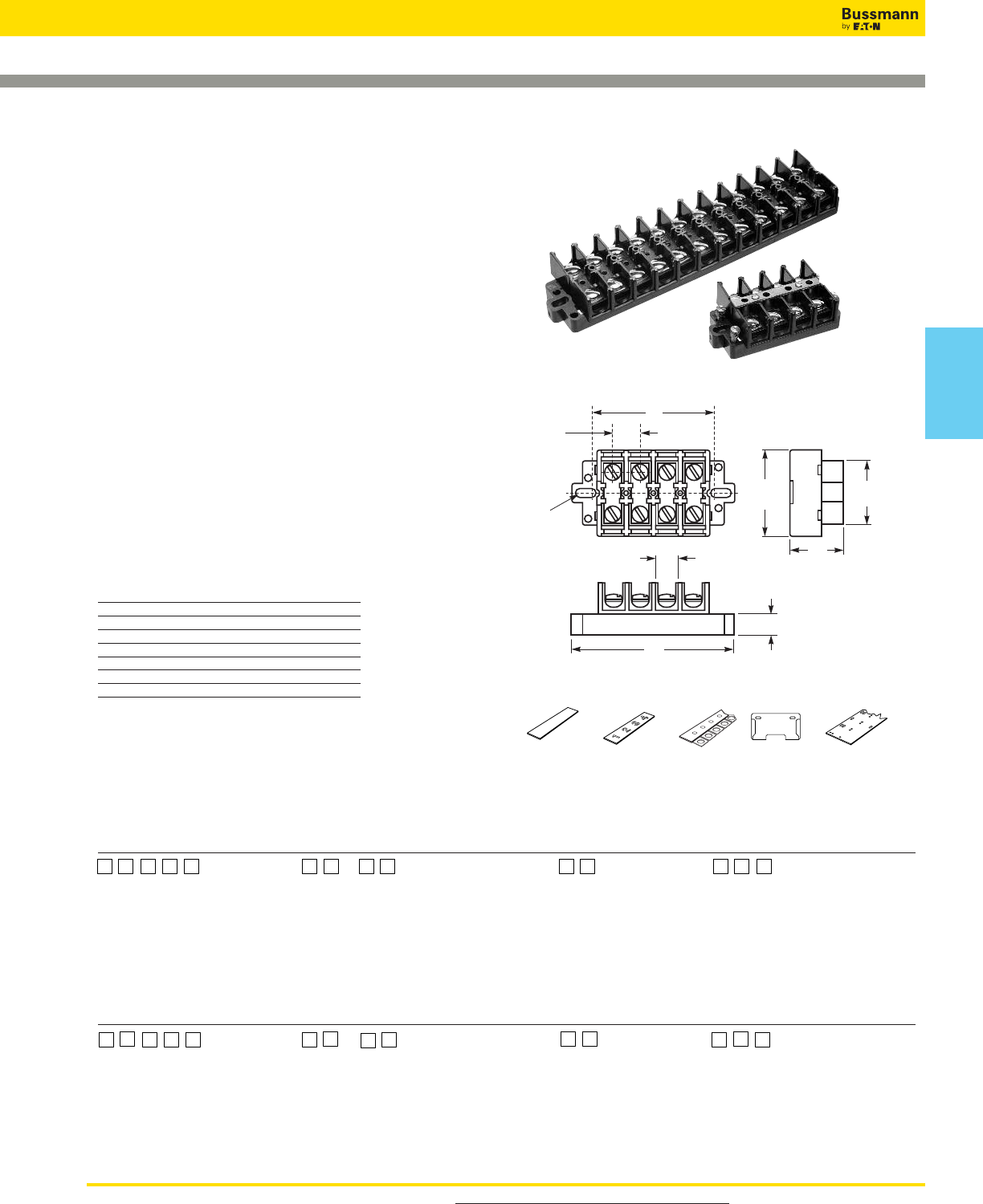
Catalog Number Build-A-Code - KU Series
Series Poles Screw Options Covers Marking Strip
KU = Standard block 02 to 12 00 = Screws shipped bulk WC = Top cover & MT = Matte finish
KUX = Short block W= Brass washer head, 2 end plates NU = Numbered 1 to 12, horizontal
KURL = Standard w/removable link nickel-plated NUV = Numbered 1 to 12, vertical
KUXRL = Short block w/removable link P= Steel screw w/pressure plate PT†= Marker strip for cover
zinc-plated
BP = Brass philslot, nickel-plated
Catalog Number Build-A-Code - KU__SC Series
Series Poles Screw Options Covers Marking Strip
KUSC = Standard w/shorting strap 02 to 12 00 = Screws shipped bulk WC = Top cover & PT†= Marker strip for cover
& 4 shorting screws W= Brass washer head, 2 end plates
KUXSC = Short block w/shorting strap nickel-plated
& 4 Shorting screws P= Steel screw w/pressure plate
zinc-plated
BP = Brass philslot, nickel-plated †Requires WC cover option
For more information, visit www.cooperbussmann.com/DatasheetsEle 375
Connectors
Double Row Terminal Blocks
Series KU
Specifications
Ratings:
Volts:— 600V
Amps:— 60A*
Center Spacing: 0.625˝ (15.88mm)
Number of Poles: 2- to 12-poles**
Wire Range: #6-22 AWG Cu
Screw Size: #10-32
Torque Rating: 20 lb-in
Distance Between Barriers: 0.437˝ (11.09mm)
Mounting: Panel Mount
Material: Molded base: Black, UL rated 94V1 Noryl
Terminal plating: Nickel over brass
Operating Temperature: 105°C max.
Agency Information: UL File E62622, CSA File 47235
* 60A rating achieved with #6 copper wire crimped to ring terminal.
** Only even number pole configurations (3-pole = exception).
Dimensions - in
KU KUX Only
Poles A B A
02 2.50 1.62 2.00
03 3.12 2.25 2.62
04 3.75 2.87 3.25
06 5.00 4.12 4.50
08 6.25 5.37 5.75
10 7.50 6.62 7.00
12 8.75 7.87 8.25
1” = 25.4mm.
MTMU## NUM## JU12 NUE NUC##
Molded Marking Tape Molded Marking Jumper End Piece for NUC Cover
Matte Finish Tape 12 Circuits
1.25
(31.8)
A
B
#10 screw
clearance
0.62
(15.9)
1.50
(38.1)
2.00
(50.8)
0.43
(11.1)
0.50
(12.7)
Series KU - in (mm)
–
Accessories***
***Accessories must be orderd seperately.
–
Connectors
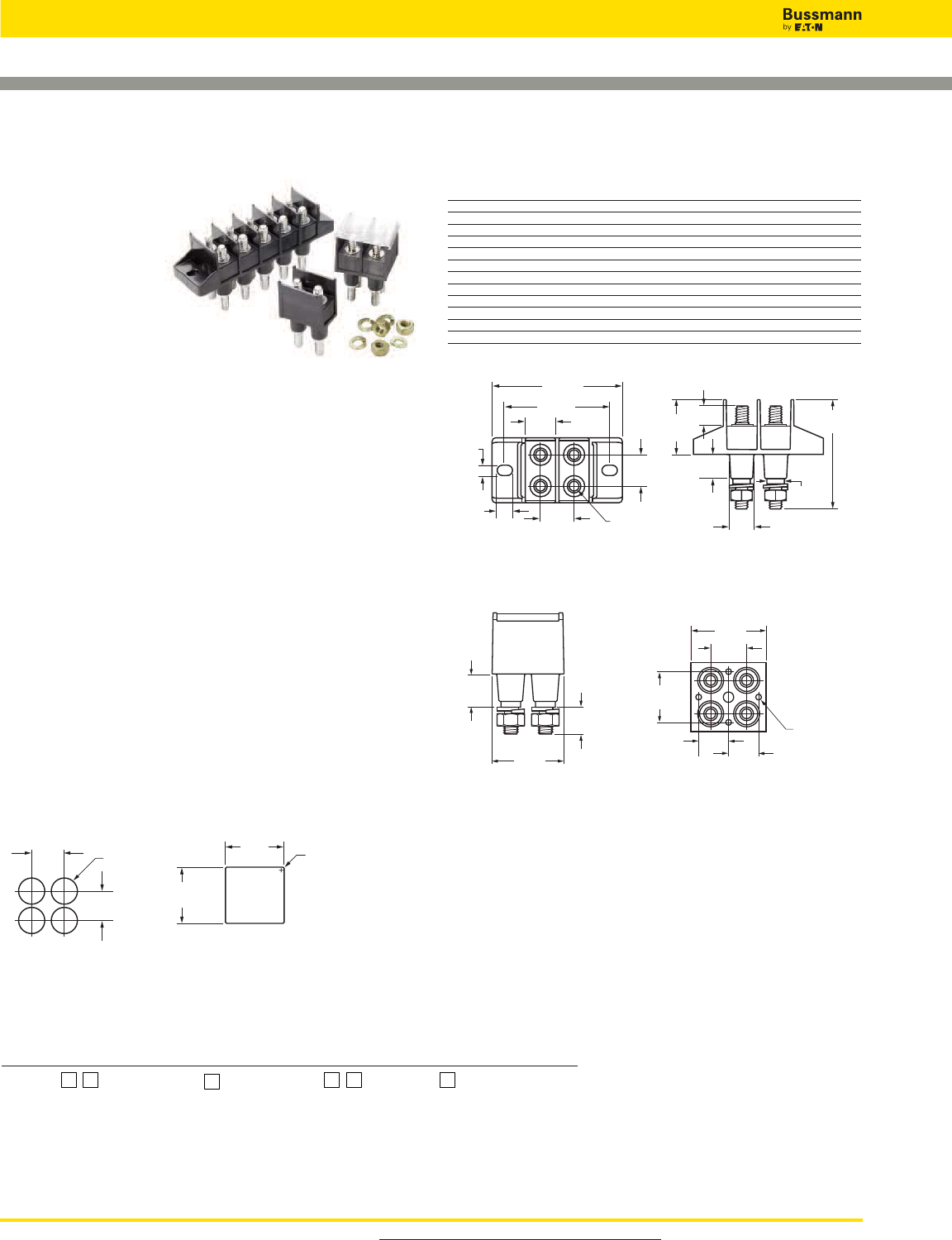
For more information, visit www.cooperbussmann.com/DatasheetsEle
376
Connectors
Power Feed Through Terminal Blocks
Series C7021
Specifications
Description: Power
feed through terminal
block with two rows
1⁄4-20 studs capable of
accommodating the
industry standard
two-hole compression
lugs on both studs in
parallel.
Ratings:
Volts: — 300V
Amps: — 115/175A* per pole
Center Spacing: 0.690" (17.5mm).
Wire Range: AWG #3/0-8.
Poles: 1- to 6-poles.
Bolt Hole Spacing: 0.625" or 5⁄8” (15.88mm).
Stud: Standard 1⁄4-20 stud (tin-plated brass) or optional M6
stud.
Mounting: #6 thread cutting screws (not included) or
optional mounting ears.
Torque Rating: 36 lb-in.
Operating Temperature: 130°C.
Agency Information: UL/CSA; CE Certified.
*175 achieved using both studs in parallel, 115A using a single stud per line.
Typical Applications
• Applications requiring up to 175A utilizing a 2-hole
compression lug on 5⁄8" centers
• Input/output block for telecommunications power panels
• Use to eliminate busbars
9.6
(0.38)
28.0
(1.10)
ø12.2 TYP
(0.48)
55.7
(2.19)
12.5
(0.49)
Ø 9.0 TYP
(0.35)
D
A
C
15.8
(0.62)
5.4
(0.21)
7.9
(0.31) 1/4-20 UNC-2A
Thread TYP
15.8
(0.62)
17.5 TYP
(0.69)
24.0
(0.94)
14.5 TYP
(0.57) 14.5 TYP
(0.57)
Blind Hole for #6
Thread Cutting
Screw
15.0 TYP
(0.59)
33.0
(1.30)
12.7
(0.50)
B
30.0
(1.18)
1.6
(R.06)
14.2
( ø.56)
E
A
Catalog Number Build-A-Code
Series Poles Mount Ends Studs Hardware
C7021 – –
01 = 1-Pole (2 studs) Blank = Mount ends Blank = Standard Blank = No hardware
02 = 2-Pole (4 studs) N = No mount ends M6 = M6 Studs 0 = Bulk pack, one set
03 = 3-Pole (6 studs) 1 = Bulk pack, two sets
04 = 4-Pole (8 studs) 2 = Assembled, bottom
05 = 5-Pole (10 studs) 3 = Assembled, top
06 = 6-Pole (12 studs) 4 = Assembled, both sets
Dimensions - mm (in)
Catalog
Numbers A B C D E
C7021-01-X
C7021-02-X 17.5 (0.69) - 54.4 (2.14) 67.3 (2.65) 31.8 (1.25)
C7021-03-X 34.9 (1.37) - 70.9 (2.83) 84.8 (3.34) 49.2 (1.94)
C7021-04-X 52.3 (2.06) - 89.3 (3.52) 102.2 (4.02) 66.7 (2.63)
C7021-05-X 69.8 (2.75) - 106.8 (4.20) 119.7 (4.71) 84.2 (3.31)
C7021-06-X 87.2 (3.44) - 124.2 (4.89) 134.1 (5.40) 101.7 (4.00)
C7021-01N-X
C7021-02N-X 17.5 (0.69) 36.1 (1.42) - - 31.8 (1.25)
C7021-03N-X 34.9 (0.69) 53.5 (2.11) - - 49.2 (1.94)
C7021-04N-X 52.3 (2.06) 71.0 (2.80) - - 66.7 (2.63)
C7021-05N-X 69.8 (2.75) 88.4 (3.48) - - 84.2 (3.31)
C7021-06N-X 87.2 (3.44) 105.9 (4.17) - - 101.7 (4.00)
Panel Cutouts
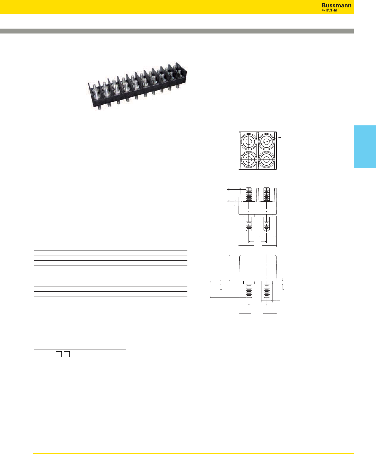
For more information, visit www.cooperbussmann.com/DatasheetsEle 377
Connectors
Power Feed Through Terminal Blocks
Series C7024
Specifications
Description: A
power feed through
terminal block with
two rows of 1⁄4-28
studs capable of
accommodating the industry standard two-hole compression
lugs on 3⁄4" centers.
Ratings:
Volts: — 600V
Amps: — 115A per pole
Center Spacing: 0.75" (19.1mm).
Wire Range: #2-8 AWG.
Poles: 1 to 12.
Bolt Hole Spacing: 0.75" (19.1mm).
Stud: Standard 1⁄4-28 stud (tin-plated bronze).
Torque Rating: 36 lb-in.
Operating Temperature: 130°C.
Agency Information: UL/C-UL, CSA; CE Certified.
Flammability Rating: UL 94V0.
Catalog Numbers
Catalog “A” Dimension- mm (in)
Number Poles ±0.4 (±0.02) “B” Dimension- mm (in)
C7024-01 01 21.6 (0.85) -
C7024-02 02 40.6 (1.60) 19.05 ±0.08 (0.750 ±0.003)
C7024-03 03 59.7 (2.35) 38.10 (1.500)
C7024-04 04 78.7 (3.10) 57.15 ±0.26 (2.250 ±0.010)
C7024-05 05 97.8 (3.85) 76.2 (3.00)
C7024-06 06 116.8 (4.60) 95.25 ±0.26 (3.750 ±0.010)
C7024-07 07 135.9 (5.35) 114.30 ±0.38 (5.250 ±0/015)
C7024-08 08 154.9 (6.10) 133.35 ±0.38 (5.25 ±0.015)
C7024-09 09 174.0 (6.85) 152.40 ±0.38 (6.00 ±0.015)
C7024-10 10 193.0 (7.60) 171.45 ±0.38 (6.750 ±0.015)
C7024-11 11 212.1 (8.35) 190.50 ±0.38 (7.500 ±0.015)
C7024-12 12 231.1 (9.10) 209.55 ±0.38 (8.250 ±0.015)
][0.106
2.70TYP
][0.02
0.5 TYP
][0.52
13.2TYP
B
][ 0.003
±
0.750 0.0819.06
][0.70
17.8TYP
][0.124
3.16TYP
16.53TYP
[0.651]
A
][1.60
40.6
][1.10
28.0
][0.700
17.780
MIN. AT STUD PAD
TYP
Ø
Ø14.4
[0.57]
Typical Applications
• Applications requiring up to 115A utilizing a 2-hole
compression lug on 3⁄4" centers
• Ideal as an input/output block for telecommunications power
panels
• Use to eliminate busbars
Dimensions - mm (in)
Catalog Number Build-A-Code
Series Poles
C7024 –
01-12
Connectors
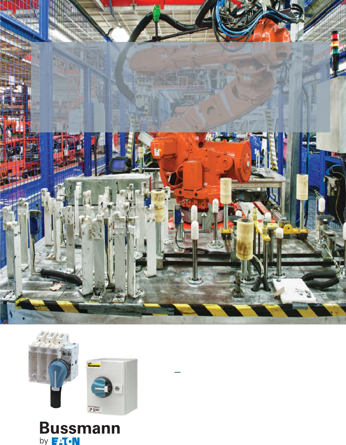
378
Full range of disconnect switches
with versatile options and
accessories that ship within
24 hours
Open and enclosed
disconnect switches
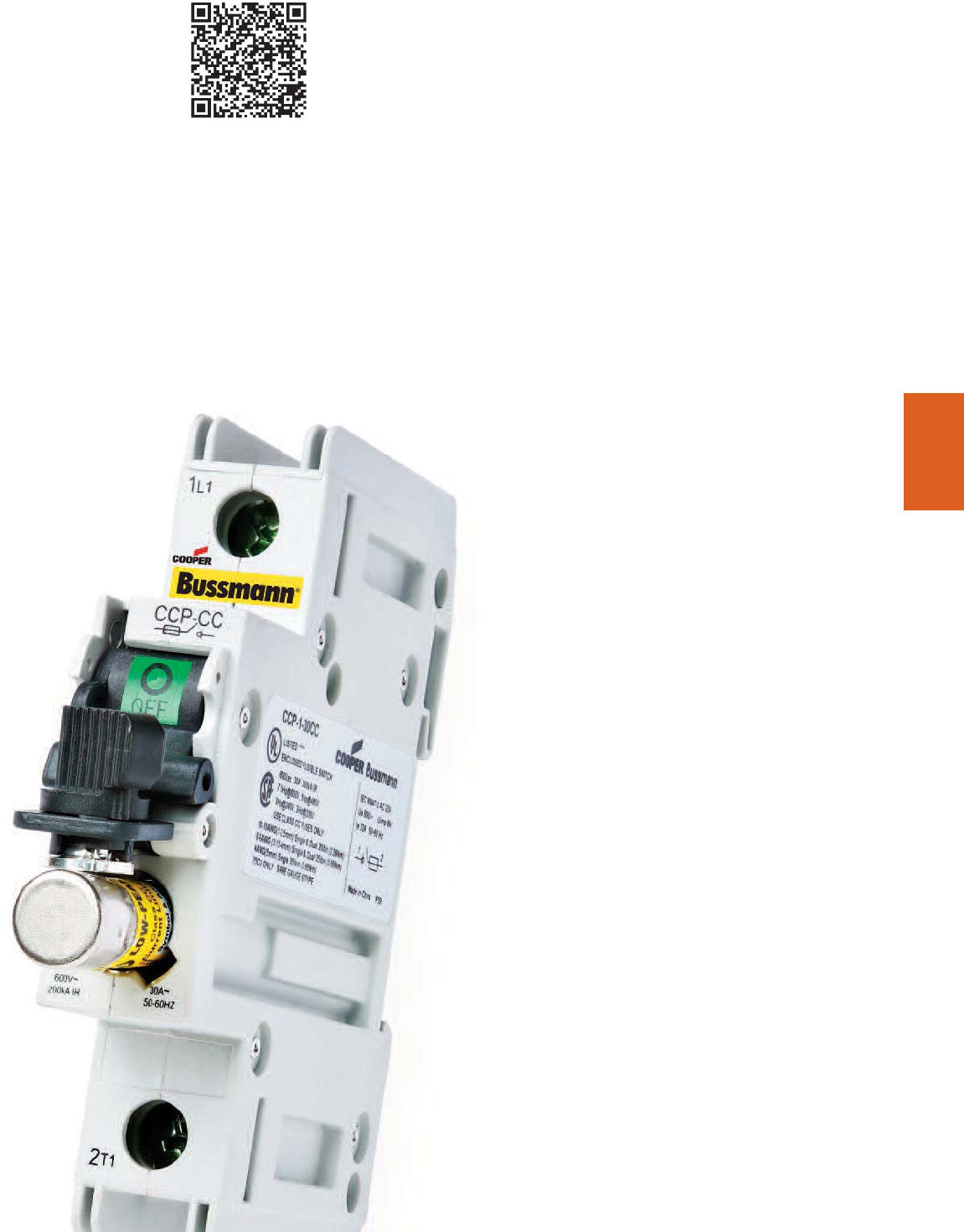
379
Disconnect
Switches
Compact Circuit Protector (CCP) disconnect switches
30A Class CC, Midget & 10x38 .............................380-381
30A 60A and 100A Class CF .................................382-383
CCPB - Compact Circuit Protector Base ..............384-385
UL 98 fused disconnect switches 30 to 800A
Introduction & Agency Information................................386
Product Line Summary..................................................387
30A Compact Class CC & Class J ........................388-389
30A Class J ............................................................390-391
60A Compact Class J ............................................392-393
60A Class J ............................................................394-395
100A Class J ..........................................................396-397
200A & 400A Class J .............................................398-400
600A Class J and 800A Class L ............................402-403
UL 98 non-fused disconnect switches 30 to 1200A
Introduction & Agency Information................................404
Product Line Summary..................................................405
30A, 60A and 100A Compact ................................406-407
100A, 200A and 400A Standard ............................408-409
600A, 800A, 1000A and 1200A Standard..............410-411
UL 508 non-fused disconnect switches 16 to 80A
Introduction and Agency Information............................412
Product Line Summary..................................................413
16A, 25A, 40A, 63A and 80A Standard .................414-416
Enclosed UL 98 & UL 508 disconnect switches
Introduction & Agency Information................................417
Fused UL 98
30A to 800A Enclosed Disconnects ......................418-419
Non-Fused UL 98
30 to 1200A Enclosed Disconnects.......................420-421
Non-Fused UL 508
16 to 80A Enclosed Disconnects...........................422-423
Fused, dead front disconnect switches .................424
Disconnect Switches
Section Contents
Page
Scan this tag to get the
latest product information for the
New Family of Disconnect Switches
and Accessories.
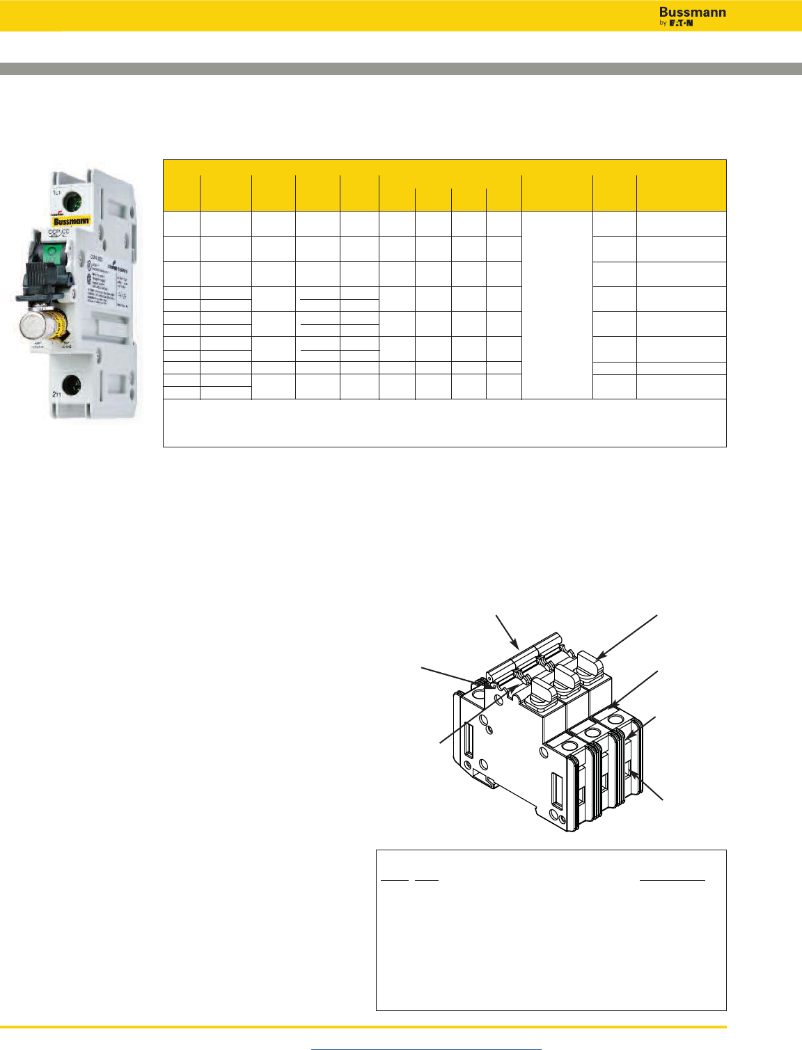
Disconnect Switches
Visit us on the web at www.cooperbussmann.com/Disconnects
380
Switch
Max Horsepower Rating
Amp Fuse Number 120 240 480 600 Wire Part
Rating Class of Poles Volts SCCR Vac Vac Vac Vac Wire Size Type* Number
30 CC 1 600Vac 200kA 0.5 — — — 75°C Cu CCP-1-30CC
30 CC 2 600Vac 200kA — 2 — — Single/Dual 75°C Cu CCP-2-30CC
#18-6 Sol/Str
30 CC 3 600Vac 200kA — 3 4 7.5 75°C Cu CCP-3-30CC
30 UL Midget 1240Vac†10kA†———— Single 75°C Cu CCP-1-30M
32** 10x38 IEC 400Vac†120kA†#4 Sol/Str
30 UL Midget 2240Vac†10kA†— — — — 75°C Cu CCP-2-30M
32** 10x38 IEC 400Vac†120kA†
30 UL Midget 3240Vac†10kA†— — — — 75°C Cu CCP-3-30M
32** 10x38 IEC 400Vac†120kA†Spade
30 CC 1 80Vdc†20kA†— — — — Terminal†† 75°C Cu CCP-1-30DCC
30 CC 180Vdc† 10kA† — — — — 75°C Cu CCP-1-30DCM
32** 10x38 IEC
* 75°C or higher.
** 32A Class aM, 25A Class gG.
† SCCR May be lower, refer to installed fuse data sheets.
†† Spade terminal, 30A max, insulated flange, wire size #12-10 for #8 stud.
Specifications
Agency Information
• CE Compliant
• RoHS Compliant
• For Class CC fuse version
- UL 98 Listed, File E302370, Guide WHTY
- cULus to CSA Standard 22.2 No. 4-04, File 302370,
Guide WHTY7
• For UL Midget and 10X38 IEC fuse version
- UL 508 Listed, File E161278, Guide 8R29
- cULus Certified 22.2 No. 14-05
- IEC 60947-3 AC23A
- IEC 60947-3 DC23A
Terminals
• Single/dual conductor box lug or spade terminal suitable
for line, load or accessory connection
• Torque: - #18-10 20Lb-In
- #8-4 35Lb-In
Storage and Operating Temperature
• -20ºC to 75ºC*
* For fuse performance under or above 25ºC, consult fuse performance derating charts
in the Bussmann publication titled Selecting Protective Devices (SPD), reorder #3002.
Flammability Rating UL 94V0
Lockout/Tagout Provisions
• 4mm shank lock or standard pin-out devices
Mounting
• 35mm DIN-Rail
Local Open Fuse Indication Minimum Voltage**
• 90Vac for AC versions
• 12Vdc for DC versions
** Circuit must be closed for indication light to illuminate.
Features
• IP20 Finger-safe construction with #10 or larger wire
• Switch interlock prohibits removing the fuse under load
Accessories
• Auxiliary contacts
• PLC Wired remote fuse indication
Switch Handle
Padlock Provision
Open Fuse
Indication Light
Fuse Holder
Knob
Spade Terminal
Circuit Marking
Area
Box Lug
Terminal
Compact Circuit Protector (CCP) Disconnect Switch—30A
1-, 2- & 3-Pole, Class CC, UL Midget & 10x38mm IEC
Available Bussmann Fuses
Class Type Data Sheet #
CC LP-CC Time-Delay, Current Limiting 1023
CC FNQ-R Time-Delay 1014
CC KTK-R Fast-Acting 1015
M FNM Time-Delay 2028
M FNQ Time-Delay 1012
M KTK Fast-Acting 1011
M BAF Fast-Acting 2011
M KLM Fast-Acting 600Vac/dc 2020
Data Sheet: 1157
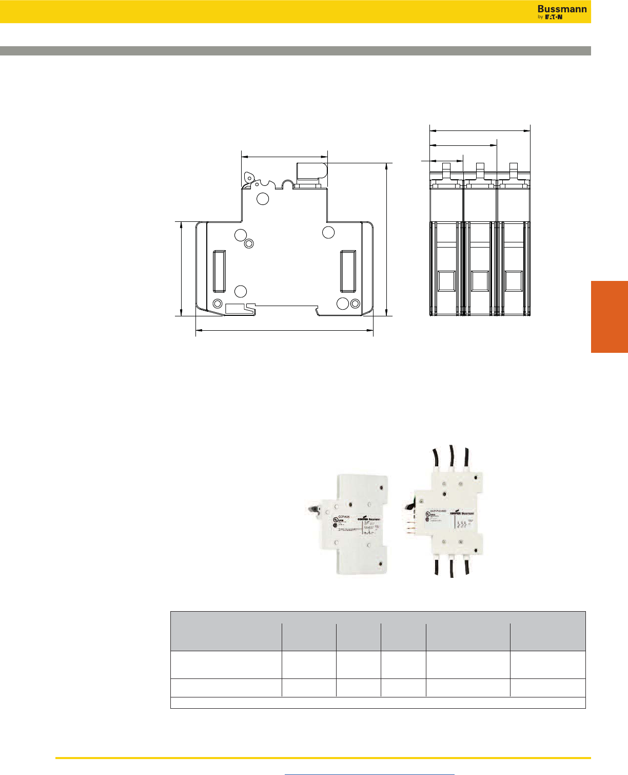
Disconnect Switches
Compact Circuit Protector (CCP) Disconnect Switch—30A
1-, 2- & 3-Pole, Class CC, UL Midget & 10x38mm IEC
Visit us on the web at www.cooperbussmann.com/Disconnects 381
Disconnect
Switches
CCP-_-30_ Accessories
Minimum
Signal Circuit Agency Part
Description Configuration Output Voltage Information Number
Auxiliary Contacts NO+NC UL 98 Recognized,
for Switch Status 1 per CCP 5A/240Vac – cURus 22.2 No. 4-04, CCP-AUX*
IEC 60947-5-1 AC15
Wired Remote Fuse Indication 1 per CCP 24Vdc 100Vac UL 98 Recognized, CCP-PLC-IND*
for PLC Applications cURus 22.2 No. 4-04
* Refer to Data Sheet # 1157 for details.
Dimensions – mm (in)
Class CC, UL Midget & I0x38 IEC
92.7
(3.7)
17.5
(0.7)
45
(1.8)
35
(1.4)
79.8
(3.1)
52.5
(2.1)
49.2
(1.9)
Auxiliary Contacts PLC Indicator
(Includes leads with spade terminals)
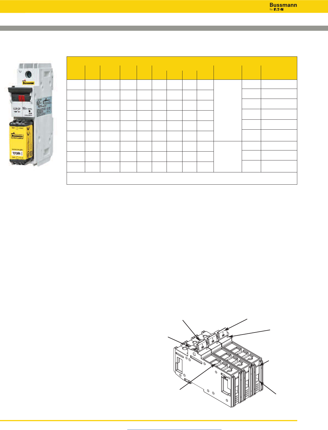
Disconnect Switches
Visit us on the web at www.cooperbussmann.com/Disconnects
382
Compact Circuit Protector (CCP) Disconnect Switch—30, 60 & 100A
1-, 2- & 3-Pole, Class CF CUBEFuse™
Switch
Max Horsepower Rating
Amp Fuse Number 120 240 480 600 Wire Part
Rating Class of Poles Volts SCCR Vac Vac Vac Vac Wire Size Type* Number
30 CF 1 600Vac 200kA 1.5 — — — 75°C Cu CCP-1-30CF
125Vdc
30 CF 2 600Vac 200kA — 3 — — Single/Dual 75°C Cu CCP-2-30CF
125Vdc #18-6 Sol/Str
30 CF 3 600Vac 200kA — 5 15 10 75°C Cu CCP-3-30CF
125Vdc Single
60 CF 1 600Vac 200kA 3 — — — #4 Sol/Str 75°C Cu CCP-1-60CF
125Vdc
60 CF 2 600Vac 200kA — 7.5 — — Spade 75°C Cu CCP-2-60CF
125Vdc Terminal**
60 CF 3 600Vac 200kA — 7.5 20 10 75°C Cu CCP-3-60CF
125Vdc
100 CF 1 600Vac 200kA 5 — — — Single 75°C Cu CCP-1-100CF
#8-10 Sol/Str
100 CF 2 600Vac 200kA — 10 — — #8-1 Str 75°C Cu CCP-2-100CF
Dual #6 Str
100 CF 3 600Vac 200kA — 20 50 50 Spade 75°C Cu CCP-3-100CF
Terminal**
* 75°C or higher.
** Spade terminal, 30A max, insulated flange, wire size #12-10 for #8 stud.
Specifications
Agency Information
• CE Compliant
• RoHS Compliant
• UL 98 Listed, File E302370, Guide WHTY
• cULus to CSA Standard 22.2 No. 4-04, File 302370,
Guide WHTY7
Terminals
• Single/dual conductor box lug or spade terminal suitable
for line, load or accessory connection
• Torque: 0-60A: - #18-10 20Lb-In
- #8-4 35Lb-In
70-100A: - #18-10 Single 25Lb-In
- #8-2 Single 35Lb-In
- #1 Single 40Lb-In
- #6 Dual 45Lb-In
Fuses
• Uses finger-safe Class CF CUBEFuse™ with
Class J performance
- Low-Peak™ dual-element, time-delay*
- Non-indicating 1-100A
- Indicating 6-100A
- Fast-Acting** 1-100A
* See Data Sheet # 9000
** See Data sheet # 2147
Storage and Operating Temperature
• -20ºC to 75ºC***
*** For fuse performance under or above 25ºC, consult fuse performance derating charts
in the Bussmann publication titled Selecting Protective Devices (SPD) reorder #3002.
Flammability Rating UL 94V0
Lockout/Tagout Provisions
• 4mm shank lock or standard pin-out devices
Mounting
• 35mm DIN-Rail
Local Open Fuse Indication Minimum Voltage†
• 90Vac/115Vdc
† Circuit must be closed for indication light to illuminate.
Features
• Ampacity rejecting disconnects will not accept
CUBEFuse amp ratings greater than switch rating
• IP20 Finger-safe construction with #10 or larger wire
• Switch interlock prohibits removing the fuse under load
Accessories
• Auxiliary contacts
• PLC Wired remote fuse indication (up to 60A)
Circuit
Marking Area
Lockout Provision Switch Handle
Spade Terminal
Box Lug
Terminal
Open Fuse
Indication Light
Fuse Holder
Data Sheet: 1157
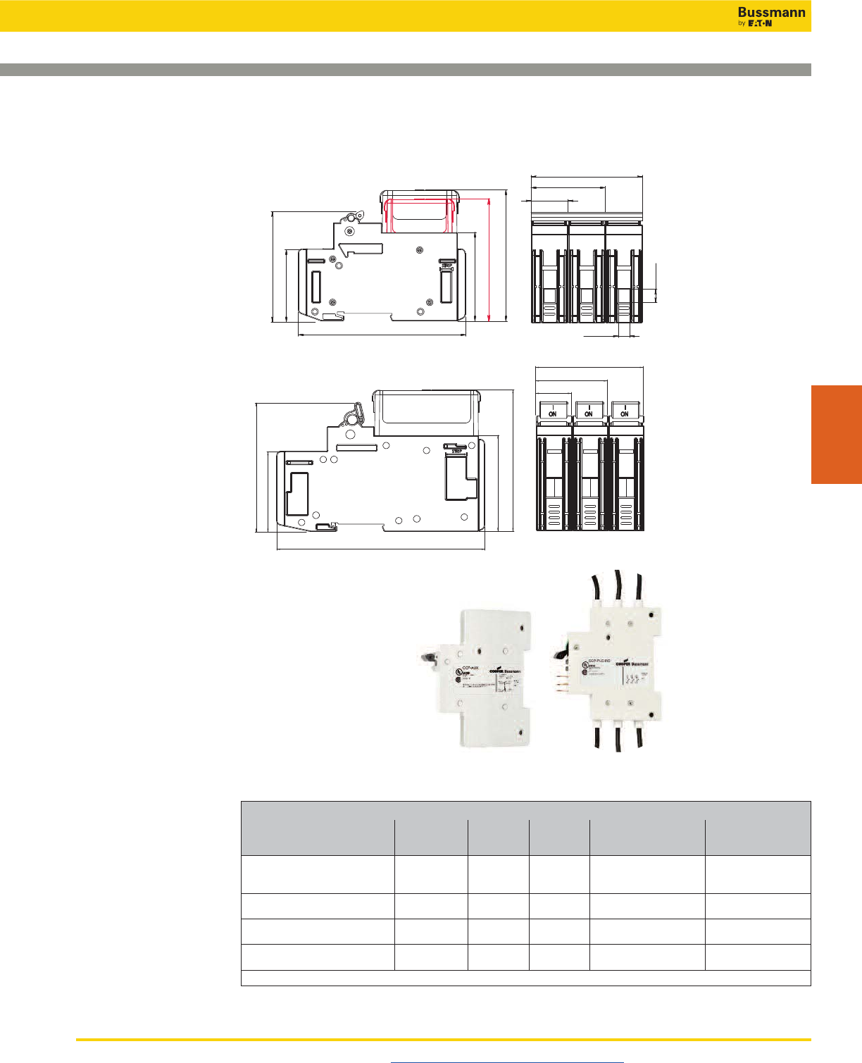
Disconnect Switches
Compact Circuit Protector (CCP) Disconnect Switch—30, 60 & 100A
1-, 2- & 3-Pole, Class CF CUBEFuse™
Visit us on the web at www.cooperbussmann.com/Disconnects 383
Disconnect
Switches
CCP-_-_CF Accessories
Minimum
Signal Circuit Agency Part
Description Configuration Output Voltage Information Number
Auxiliary Contacts NO+NC UL 98 Recognized,
for Switch Status up to 60A 1 per CCP 5A/240Vac – cURus 22.2 No. 4-04, CCP-AUX*
IEC 60947-5-1 AC15
Auxiliary Contacts NO+NC 1 per CCP 5A/240Vac – UL 98 Recognized, CCP-AUX-100*
for Switch Status 70 to 100A CSA C22.2 No. 4
Wired Remote Fuse Indication 1 per CCP 24Vdc 100Vac UL 98 Recognized, CCP-PLC-IND*
for PLC Applications cURus 22.2 No. 4-04
Wired Remote Fuse Indication 1 per CCP 8A/24Vdc 100Vac UL 98 Recognized, CCP-PLC-100*
for PLC Applications up to 60A CSA C22.2 No. 4
* Refer to Data Sheet # 1157 for details.
Auxiliary Contacts PLC Indicator
(Includes leads with spade terminals)
Dimensions – mm (in)
30 and 60 Amp
100 Amp
50.4
(2.0)
25.1
(1.0)
75.7
(3.0)
9.1
(0.4)
7.6
(0.3)
60.3 (2.4)
113.9
(4.5)
49.2
(1.9)
75.1
(3.0)
30A CUBEFuse
83.3 (3.3)
60A CUBEFuse
89.1 (3.5)
79.5
(3.0)
147.1
(5 8)
50.5
(2.0)
25.15
(1.0)
91.2
(3.6)
56.6
(2.2)
100.0
(3.9)
67.7
(2.7)
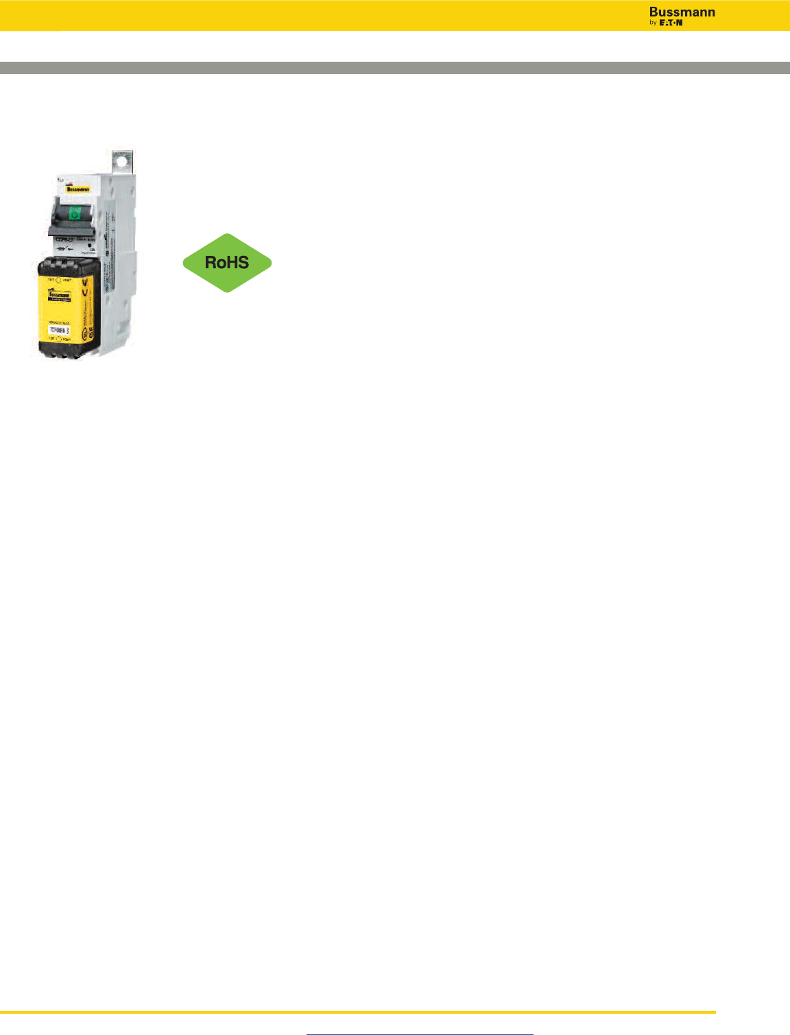
Disconnect Switches
Visit us on the web at www.cooperbussmann.com/Disconnects
384
Specifications:
• CCPB Ampacity rejection breaks: 15A, 20A, 30A, 40A,
50A, 60A, 70A, 90A and 100A.
• 1-, 2- and 3-Pole versions
• For systems 600Vac (or less)
• Box lug loadside terminal:
• 18-6AWG single & dual rated, solid or stranded –
75°C, Cu only
• 4AWG single – 75°C, Cu only
The revolutionary Bussmann CCPB with CUBEFuse™is
designed as a fused branch circuit disconnect with fuse
holder for the Bussmann Quik-Spec™ Coordination
Panelboard. The CCPB with CUBEFuse simplifies selective
coordination and allows for isolation of individual branch
circuit loads for safe work practices.
Agency Information:
UL 98 Listed, File E302370, Guide WHTY
cULus to CSA Standard 22.2 No. 4, File E302370,
Guide WHTY7
CE Compliant
Shipping Weight: 2.03 lbs per carton
Carton quantity: 6 poles
Environmental Data
Storage and operating temperature: -20ºC to 75ºC**
Product Features and Benefits
• Uses finger-safe Class CF Low-Peak™CUBEFuse with
current-limiting, time-delay Class J performance*
• High Short-Circuit Current Ratings at 200kA
• Disconnect rated to provide means for load isolation
• Full voltage rated at 600Vac
• UL 98 Listed and suitable for branch circuit disconnect
and branch circuit protection
• 1-, 2- and 3-pole versions are horsepower rated
• Patented rejection feature helps prevent overfusing
• Complies with UL and cULus
• Open fuse indication light per pole
• Additional open fuse indication can be provided by using
the indicating CUBEFuse version
• Built-in switch/fuse interlock prohibits removing the fuse
while energized
• Permanent lockout/tagout provisions
• Lock-ON provision
*See data sheet 9000 for CUBEFuse specifications.
**For fuse performance under or above 25ºC, consult fuse performance
derating charts.
• Box lug loadside terminal torque: 18-10AWG 20 Lb-In
(2.2 N•m), 8-4AWG 35 Lb-In (3.9 N•m)
• Spade terminal load connection:
Max. 30A suitable for use with #8-32UNC screw
• Bolt-on style bus connector, #10-32-UNC Hex flange
Phillips screw, torque to 25 Lb-In (2.8N•m)
• Lockout/tagout: 4mm shank lock
• Bolt-mounted design into Quik-Spec Coordination
Panelboard bus
• Local indication: illumination requires closed circuit and
minimum 90Vac operating voltage
• RoHS compliant
Compact Circuit Protector Base (CCPB)
CUBEFuse™
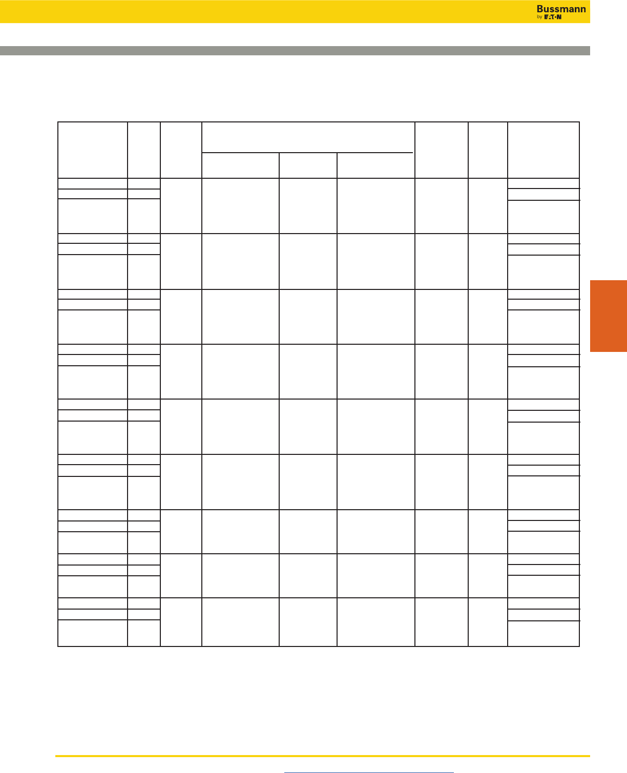
Visit us on the web at www.cooperbussmann.com/Disconnects 385
Compact Circuit Protector Base (CCPB)
CUBEFuse™
CCPB Part Poles Voltage Time-Delay Time-Delay Fast-Acting Max. Fuse** SCCR Hp Ratings***
Numbers Rating Non-Indicating Indicating* Non-Indicating Ampacity
CCPB-1-15CF 1 0.5Hp@120V
CCPB-2-15CF 2 TCF1RN, TCF3RN, TCF6, TCF10, FCF1RN, FCF3RN, 1.5Hp@240V
600Vac TCF6RN, TCF10RN, TCF15 FCF6RN, FCF10RN, 15A 200kA 3Hp@240V
CCPB-3-15CF 3 TCF15RN FCF15RN 5Hp@480V
7.5Hp@600V
CCPB-1-20CF 1 0.75Hp@120V
CCPB-2-20CF 2 2Hp@240V
600Vac TCF17-1/2RN, TCF17-1/2, FCF20RN 20A 200kA 3Hp@240V
CCPB-3-20CF 3 TCF20RN TCF20 7.5Hp@480V
10Hp@600V
CCPB-1-30CF 1 1.5Hp@120V
CCPB-2-30CF 2 3Hp@240V
600Vac TCF25RN, TCF25, TCF30 FCF25RN, 30A 200kA 5Hp@240V
CCPB-3-30CF 3 TCF30RN FCF30RN 15Hp@480V
10Hp@600V
CCPB-1-40CF 1 2.0Hp@120V
CCPB-2-40CF 2 3Hp@240V
600Vac TCF35RN, TCF35, TCF40 FCF35RN, 40A 200kA 7.5Hp@240V
CCPB-3-40CF 3 TCF40RN FCF40RN 20Hp@480V
10Hp@600V
CCPB-1-50CF 1 3.0Hp@120V
CCPB-2-50CF 2 5Hp@240V
600Vac TCF45RN, TCF45, TCF50 FCF45RN, 50A 200kA 7.5Hp@240V
CCPB-3-50CF 3 TCF50RN FCF50RN 20Hp@480V
10Hp@600V
CCPB-1-60CF 1 3.0Hp@120V
CCPB-2-60CF 2 7.5Hp@240V
600Vac TCF60RN TCF60 FCF60RN 60A 200kA 7.5Hp@240V
CCPB-3-60CF 3 20Hp@480V
10Hp@600V
CCPB-1-70CF 1 3.0Hp@120V
CCPB-2-70CF 2 7.5Hp@240V
600Vac TCF70RN TCF70 FCF70RN 70A 200kA 15Hp@240V
CCPB-3-70CF 3 30Hp@480V
CCPB-1-90CF 1 5.0Hp@120V
CCPB-2-90CF 2 FCF80RN, 10Hp@240V
600Vac TCF90RN TCF90 FCF90RN 90A 200kA 20Hp@240V
CCPB-3-90CF 3 40Hp@480V
CCPB-1-100CF 1 5.0Hp@120V
CCPB-2-100CF 2 10Hp@240V
600Vac TCF100RN TCF100 FCF100RN 100A 200kA 20Hp@240V
CCPB-3-100CF 3 50Hp@480V
CUBEFuse™
(Class J performance)
Technical Ratings
*1A and 3A indicating CUBEFuse not available. Correct fit with CCPB disconnect requires indicating CUBEFuse with date code R38 or later.
**Any fuse with an amp rating less than or equal to the max fuse rating may be used.Example: TCF15 may be used with CCPB-1-20CF.
***Do not use UPS/Critical Application fast-acting CF with motors.
Disconnect Switches
Disconnect
Switches
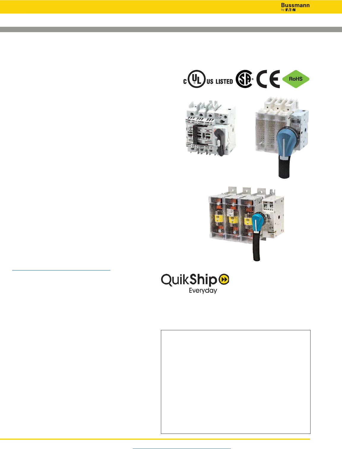
Disconnect Switches
UL 98 Fused Rotary Disconnect Switches—30 to 800A
Visit us on the web at www.cooperbussmann.com/Disconnects
386
Description
Bussmann UL 98 and UL 489 fused disconnect switches
“break” and “make” power circuits ON and OFF load.
The switches employ double break contacts per pole that
help ensure complete isolation of the fuse when the switch is
in the "OFF" position.
Features
• Make and break power under load
• Double break by pole
• DIN-Rail or panel mount (30-100A)
• Up to 200kA Short-Circuit Current Rating
• Finger-safe covers
• Compact footprints available
• Defeatable handles automatically re-latch when the panel
door is closed
• Most disconnect switches are front, right side, flange or
direct handle operable
• NFPA 79 Compliant handle kits
Agency Information
• UL 98, Guide WHTY, File E155130
• UL 489, Guide WJAZ, File E359801
• CSA 22.2 No. 4, File 257020
• Conforms with IEC 60947-3
• NFPA 79 (2002 Edition)
Online Resources
Visit www.cooperbussmann.com/Disconnects for:
• CAD Drawings
• Instruction Sheets
• UL Information
Available Bussmann Fuses
Class Type Data Sheet #
CC LP-CC Time-Delay, Current Limiting 1023
CC FNQ-R Time-Delay 1014
CC KTK-R Fast-Acting 1015
J LPJ Time-Delay, Current Limiting 1006 (0-60A)
J 1007 (70-600A)
J With easyID™ open fuse indication 1062 (6-60A)
J 1063 (70-600A)
J JKS Fast-Acting Fuses 1026 (0-60A)
J 1027 (70-600A)
J DFJ High Speed Drive Fuse 1048 (0-600A)
L KRP-C Time-Delay, Current Limiting 1008
L KTU Fast-Acting 1010
L KLU Time-Delay 1013
QuikShip Everyday Service ships the most common part
numbers within 24 hours. Contact your Bussmann
representative for details.
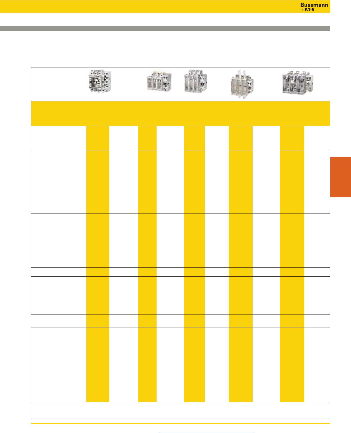
Disconnect Switches
UL 98 Fused Rotary Disconnect Switches—30 to 800A
Visit us on the web at www.cooperbussmann.com/Disconnects 387
Disconnect
Switches
Part Number
2-Pole — — RDF30J-2 RDF60J-2-COMP RDF60J-2 RDF100J-2 RDF200J-2 RDF400J-2 RDF600J-2 RDF800L-2
3-Pole RDF30CC-3 RDF30J-3-COMP RDF30J-3 RDF60J-3-COMP RDF60J-3 RDF100J-3 RDF200J-3 RDF400J-3 RDF600J-3 RDF800L-3
3-Pole + Neutral RDF30CC-3N RDF30J-3N-COMP — — — — — — — —
4-Pole — — RDF30J-4 RDF60J-4-COMP RDF60J-4 RDF100J-4 RDF200J-4 RDF400J-4 RDF600J-4 RDF800L-4
UL Standard UL 489 UL 489 UL 98 UL 98 UL 98 UL 98 UL 98 UL 98 UL 98 UL 98
Fuse Class CC JJJJJJ J J L
Max Fuse/Ampacity 30 30 30 60 60 100 200 400 600 800
Switch Type Compact Compact Standard Compact Standard Standard Standard Standard Standard Standard
Handle Operation Front Front Front/Side Front/Side Front/Side Front/Side Front/Side Front/Side Front Front
Flange Flange Flange Flange Flange
UL Electrical Ratings
Max AC Volts 600Vac 600Vac 600Vac 600Vac 600Vac 600Vac 600Vac 600Vac 600Vac 600Vac
Max DC Volts* — — 250Vdc 250Vdc 250Vdc 250Vdc — 250Vdc 600Vdc 600Vdc
Std AC Horsepower Ratings
1-Phase, 240Vac — — 3 10 10 10 10 10 — —
3-Phase, 240Vac 3 3 3 7.5 7.5 15 25 50 75 75
3-Phase, 480Vac 5.0 5.0 5.0 15 15 25 50 100 150 200
3-Phase, 600Vac 7.5 7.5 7.5 15 15 30 60 125 200 250
Max AC Horsepower Ratings
3-Phase, 240Vac 7.5 7.5 7.5 15 15 30 60 125 200 200
3-Phase, 480Vac 15 15 15 30 30 60 125 250 400 500
3-Phase, 600Vac 20 20 20 50 50 75 150 350 500 500
DC Horsepower Ratings
125Vdc — — 3 5 5 7.5 — 20 — —
250Vdc — — 5 10 10 20 — 50 — —
Electrical Characteristics
SCCR 100kA 100kA 200kA 100kA 200kA 200kA 200kA 200kA 200kA 200kA
Terminal Lugs/Kits Integral Integral Integral Integral Integral Integral • • • •
Mounting Torque - Lb-In (N•m) — — — — — — 160 (18) 310 (35) 310 (35) 310 (35)
Wire Type 75°C Cu 75°C Cu 75°C Cu 75°C Cu 75°C Cu 75°C Cu 75°C Cu/Al 75°C Cu/Al 75°C Cu/Al 75°C Cu/Al
Wire Range &
Torque - Lb-In (N•m)
Solid #14-10 #14-10 #14-10 #14-10 #12-10 #12-10 — — — —
27 (3.1) 27 (3.1) 31 (3.5) 31 (3.5) 35.4 (4) 35.4 (4) — — — —
Stranded #14-10 #14-10 #14-6 #14-6 #12-1 #12-1 #6-300MCM #4-600MCM (2) #2-600MCM (2) #2-600MCM
27 (3.1) 27 (3.1) 31 (3.5) 31 (3.5) 35.4 (4) 35.4 (4) 275 (31) 550 (62) 375 (42.4) 375 (42.4)
Dual 1/0-250MCM
550 (62)
Mechanical Characteristics
Endurances/Cycles 10,000 10,000 10,000 10,000 10,000 10,000 8000 6000 5000 5000
Physical Characteristics
Dimensions
See drawings on
product pages
Weight - Lbs (KG)
2-Pole — — 3.0 (1.3) 3.1 (1.4) 4.0 (1.8) 4.07 (1.8) 5.7 (2.6) 11.4 (5.2) 31.7 (14.4) 31.7 (14.4)
3-Pole 1.3 (0.6) 1.4 (0.6) 3.8 (1.7) 4.1 (1.8) 5.3 (2.4) 5.3 (2.4) 7.8 (3.5) 16.6 (7.6) 44.2 (20.1) 44.2 (20.1)
3-Pole + Neutral 1.4 (0.6) 1.5 (0.7) — — — — — — — —
4-Pole — — 4.7 (2.1) 4.8 (2.2) X.X (2.9) 6.49 (2.9) 10.8 (4.9) 21.8 (9.9) 56.8 (25.8) 56.8 (25.8)
Environmental
Operating Temp. Range -20°C to 70°C -20°C to 70°C -20°C to 70°C -20°C to 70°C -20°C to 70°C -20°C to 70°C -20°C to 70°C -20°C to 70°C -20°C to 70°C -20°C to 70°C
Flammability Rating UL 94-V0 UL 94-V0 UL 94-V0 UL 94-V0 UL 94-V0 UL 94-V0 UL 94-V0 UL 94-V0 UL 94-V0 UL 94-V0
Accessories
Lug Kit Integral Integral Integral Integral Integral Integral • • • •
Handles Direct • •••••• • • •
Front Selector • • — — — — — — — —
Front Pistol • •••••• • • •
Side Pistol — —••••• • ——
Flange
Cable — —••••• — ——
Shaft — —••••• — ——
NFPA Through Door Handle • •••••• • • •
Shafts c/s - mm 5x5 5x5 10x10 10x10 10x10 10x10 10x10 10x10 12X12 12X12
Terminal Shrouds Not Required Not Required Not Required Not Required Not Required Not Required • • • •
Auxiliary Contacts
(1) NO • •••••• • • •
(1) NC • •••••• • • •
AC Ratings
Volts 600 600 600 600 600 600 600 600 600 600
Amps 10 101010101010 10 10 10
• Available, see product page for details and part numbers.
— Not available.
* General purpose only, not photovoltaic rated.
Specifications
RDF30CC-3 RDF60J-3 RDF200J-3 RDF600J-3RDF30J-3 / RDF60J-3-COMP
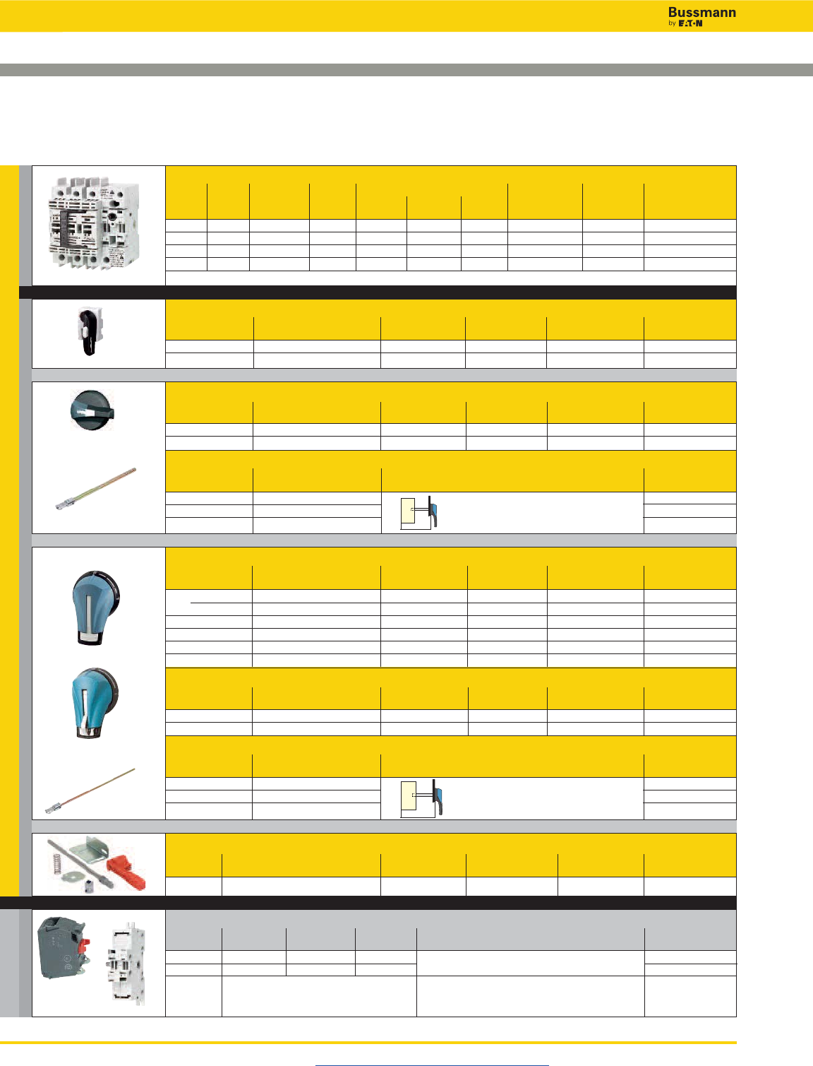
External Front Operated Pistol Handles - shaft required
NEMA Test Part
Type Color Function Padlockable Defeatable Number
1, 3R, 12 Black N Y Y H12-05B
1, 3R, 12 Red/Yellow N Y Y H12-05R
1, 3R, 4, 4X, 12 Black N Y Y H4X-05B
1, 3R, 4, 4X, 12 Red/Yellow N Y Y H4X-05R
1, 3R, 4, 4X, 12 Black Y Y Y H4X-05TB
1, 3R, 4, 4X, 12 Red/Yellow Y Y Y H4X-05TR
Metallic Hasp (Heavy Duty) External Front Operated Pistol Handles - shaft required
NEMA Test Part
Type Color Function Padlockable Defeatable Number
1, 3R, 4, 4X, 12 Black N Y Y H4X-05BHD
1, 3R, 4, 4X, 12 Red/Yellow N Y Y H4X-05RHD
Shafts for Pistol Handles
Length Mounting Depth Part
in (mm) (X) in (mm) Number
7.9 (200) 4.02~9.65 (102~245) SH2-200
12.6 (320) 4.02~14.37 (102~365) SH2-320
15.7 (400) 4.02~17.52 (102~445) SH2-400
Disconnect Switches
UL 98 Fused Rotary Disconnect Switches—30A
Compact Class CC & Class J
Visit us on the web at www.cooperbussmann.com/Disconnects
388
(1)
(2)
For a Complete Assembly, Please Select:
Select for Standard Applications
Accessories
Switch
Max Horsepower Rating, 3-Ph
Amp Fuse Number 220/ 440/ 600 Wire Wire Part
Rating Class of Poles SCCR 240Vac 480Vac Vac Size Type Number
30 CC 3 100kA 7.5 15 20 #14-10 Sol/Str 75°C Cu RDF30CC-3
30 CC 3 + Ntrl* 100kA 7.5 15 20 #14-10 Sol/Str 75°C Cu RDF30CC-3N
30 J 3 100kA 7.5 15 20 #14-10 Sol/Str 75°C Cu RDF30J-3-COMP
30 J 3 + Ntrl* 100kA 7.5 15 20 #14-10 Sol/Str 75°C Cu RDF30J-3N-COMP
* Neutral is switched.
Direct Mount Handle - mounts directly to switch, no shaft required
For Switch Test Part
Part Number Color Function Padlockable Number
RDF30CC-_ Black Y Y DIR-05
RDF30J-_-COMP Black Y Y DIR-06
External Front Operated Selector Handle - shaft required
NEMA Test Part
Type Color Function Padlockable Defeatable Number
1, 3R, 4, 4X, 12 Black N Y Y H4X-04B
1, 3R, 4, 4X, 12 Red/Yellow N Y Y H4X-04R
Shafts for Selector Handles
Length Mounting Depth Part
in (mm) (X) in (mm) Number
7.9 (200) 4.02~9.65 (102~245) SH1-200
12.6 (320) 4.02~14.37 (102~365) SH1-320
15.7 (400) 4.02~17.52 (102~445) SH1-400
NFPA Through the Door Handle Kit - to be used with selector handle or front pistol handle
Test Part
Color Function Padlockable Defeatable Number
Red N Y N H79-1
Auxillary Contacts
Contact Number of Continuous Voltage Maximum Number of Auxiliary Contacts Part
Type Contacts Amp Rating Rating per Disconnect Switch Part Number Number
NO 1 10A 600Vac RDF30CC-_: 4 / 8 with BAC-HOLDER2 BAC05(1)
NC 1 10A 600Vac RDF30J-_-COMP: 2 /6 with BAC-HOLDER2 BAC06(1)
Auxillary Accepts 4 Auxillary Contacts:
Contact BAC05 or BAC06 BAC-HOLDER2
(2)
Holder
or
or
or
or
SWITCH
AUXILIARY CONTACTS HANDLE
X
X
+
+
and…
+
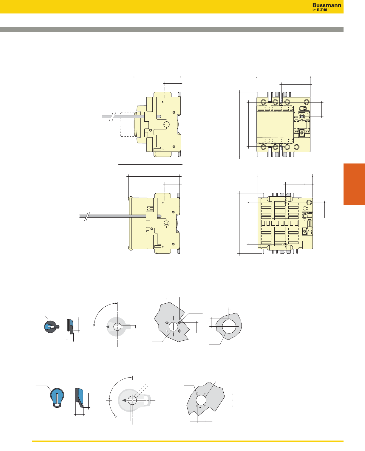
Disconnect Switches
UL 98 Fused Rotary Disconnect Switches—30A
Compact Class CC & Class J
Visit us on the web at www.cooperbussmann.com/Disconnects 389
Disconnect
Switches
3.28
83.3 1.12
28.5
5.19 (131.8)
4.56
116
3.3
84
1
25.5
3.78
96 1.47
37.5
0.59
15
Fuse Cover Fully Open
3.89
99 1.12
28.5
4.13
105 1.47
37.5
0.59
15
4.56
116
3.3
84
1
25.5
Dimensions – in (mm)
• RDF30CC-_
•RDF30J-_-COMP
External Front Pistol Handles
External Front Selector Handle
Door Drilling Layout
0.78
4 Ø 0.27
0.55
Ø 1.46
4 Ø 7
Ø 37
20
20
14 0.55
14
0.78
H4X-05__
H12-05__
Ø3.07
1.73
2.75
65°
TEST
90°
0
Direction of Front OperationPistol Handle Type
Ø78
70
44
I
Ø78
37
88
13.5
Ø
22.5
3
40
4 Ø 7
Ø 31
28
With Mounting Nu
t
With 4 Mounting Screws
Door Drilling LayoutSelector Handle Type
0
I
90°
Direction of Front Operation
Ø3.07
1.45
3.46
1.57
4 Ø 0.27
1.10
Ø 1.22
0.11
0.53
Ø
0.88
H4X-04_
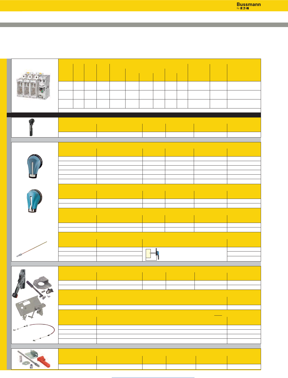
Disconnect Switches
UL 98 Fused Rotary Disconnect Switches—30A
Standard Class J
Visit us on the web at www.cooperbussmann.com/Disconnects
390
NFPA Through the Door Handle Kit - to be used with selector handle or front pistol handle
Test Part
Color Function Padlockable Defeatable Number
Red N Y N H79-2
For a Complete Assembly, Please Select:
Select for Standard Applications
Switch
Max Horsepower Rating
1-Phase 3-Phase DC*
Amp Fuse No. of 220/ 220/ 440/ 600 125 250 Wire Wire Part
Rating Class Poles SCCR 240Vac 240Vac 480Vac Vac Vdc Vdc Size Type Number
30 J 2 200kA 3 - - - 3 5 #14-10 Sol 75°C Cu RDF30J-2
#14-6 Str
30 J 3 200kA - 7.5 15 20 3 5 #14-10 Sol 75°C Cu RDF30J-3
#14-6 Str
30 J 4 200kA - 7.5 15 20 3 5 #14-10 Sol 75°C Cu RDF30J-4
#14-6 Str
* DC Ratings use two poles in series.
Direct Mount Handle - mounts directly to switch, no shaft required
For Switch Test Part
Part Number Color Function Padlockable Number
All Switches Black Y Y - On Switch DIR-07
+
(1)
(2)
(3)
(4)
or
or
or
SWITCH
HANDLE
X
or
External Front Operated Pistol Handles - shaft required
NEMA Test Part
Type Color Function Padlockable Defeatable Number
1, 3R, 12 Black N Y Y H12-05B
1, 3R, 12 Red/Yellow N Y Y H12-05R
1, 3R, 4, 4X, 12 Black N Y Y H4X-05B
1, 3R, 4, 4X, 12 Red/Yellow N Y Y H4X-05R
1, 3R, 4, 4X, 12 Black Y Y Y H4X-05TB
1, 3R, 4, 4X, 12 Red/Yellow Y Y Y H4X-05TR
Metallic Hasp (Heavy Duty) External Front Operated Pistol Handles - shaft required
NEMA Test Part
Type Color Function Padlockable Defeatable Number
1, 3R, 4, 4X, 12 Black N Y Y H4X-05BHD
1, 3R, 4, 4X, 12 Red/Yellow N Y Y H4X-05RHD
External Right Side Operated Pistol Handles - shaft required
NEMA Test Part
Type Color Function Padlockable Defeatable Number
1, 3R, 4, 4X, 12 Black N Y N/A H4X-05SB
1, 3R, 4, 4X, 12 Red/Yellow N Y N/A H4X-05SR
Shafts for Pistol Handles
Length Mounting Depth Part
in (mm) (X) in (mm) Number
7.9 (200) 5.30~9.06 (135~230) SH5-200
12.6 (320) 5.30~13.78 (135~350) SH5-320
15.7 (400) 5.30~16.93 (135~430) SH5-400
Flange Handle(1) - requires shaft operated mechanism or cable operated mechanism + cable
NEMA Flange Test Part
Type Style Function Padlockable Defeatable Number
1, 3R, 4, 12 Standard N Y Y FLH1
1, 3R, 4, 4X, 12 Chrome Plated N Y Y FLH2
Shaft Operated Flange Mechanism(2) - includes shaft
For Enclosure Part
Depth - in (mm) Number
6~24 (152~613) FLRM
Cable Operated Flange Mechanism and Cable - must select Mechanism(3) and Cable(4)
Part
Item / Length Number
Cable Mechanism FLCM
36” (900mm) Cable FLC36
60” (1500mm) Cable FLC60
120” (3000mm) Cable FLC120
+
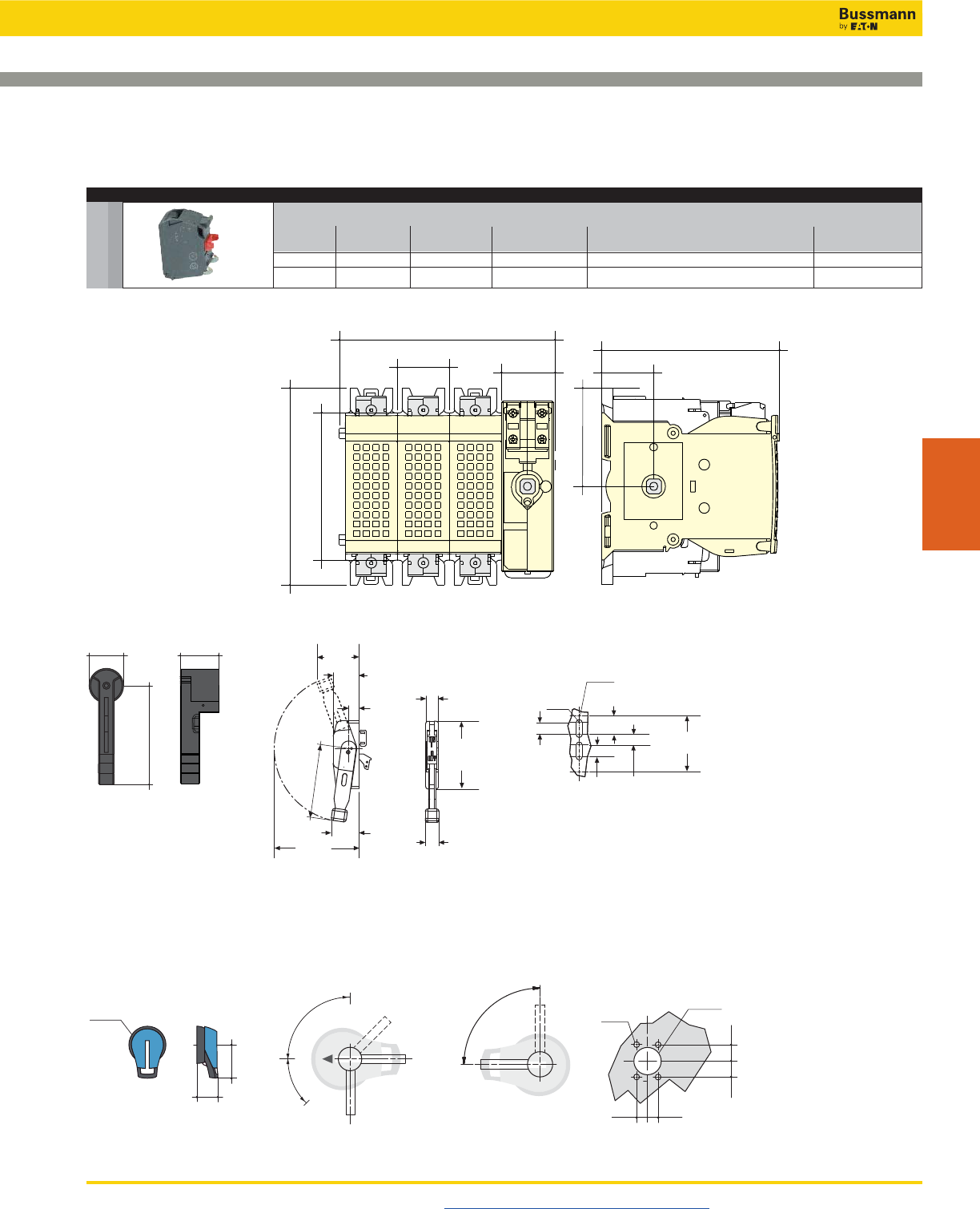
Disconnect Switches
UL 98 Fused Rotary Disconnect Switches—30A
Standard Class J
Visit us on the web at www.cooperbussmann.com/Disconnects 391
Disconnect
Switches
Acc.
Auxillary Contacts
Contact Number of Continuous Voltage Max Number of Aux Part
Type Contacts Amp Rating Rating Contacts per Switch Number
NO 1 10A 600Vac 4 BAC05
NC 1 10A 600Vac 4 BAC06
Dimensions – in (mm)
5.35
136
5.87
149.3
1.41
36 1.46
37.2
4.84
123
1.41
36
4.02
102.1
2.68
68.07
1.57
40
5.31
135
1.79
45.5
Direct Mount Handle
DIR-07
3.50
(88.9) 2.16
(54.9)
0.86
(21.8)
1.06
(26.9)
4.68
(118.9)
1.55
(39.4)
0.88
(22.3)
1.0 0
(25.4)
1.0 0
(25.4)
6.22
(158.0)
2.32
(58.9)
7. 1 0
(180.3)
Ø0.50
(Ø12.7)
Ø0.28
(Ø7.1)
2.70
(68.6)
5.66
(143.8)
Flange Handle
FLH_
External Front & Right Side Pistol Handle
H4X-05__
H12-05__
0
I
90°
Ø3.07
1.73
2.75
65°
TEST
90°
0
Direction of Front OperationHandle Type Direction of Right Side Operation Door Drilling Layout
Ø78
70
44
0.78
4 Ø 0.27
0.55
Ø 1.46
4 Ø 7
Ø 37
20
20
14 0.55
14
0.78
I
and …
AUX CONTACTS
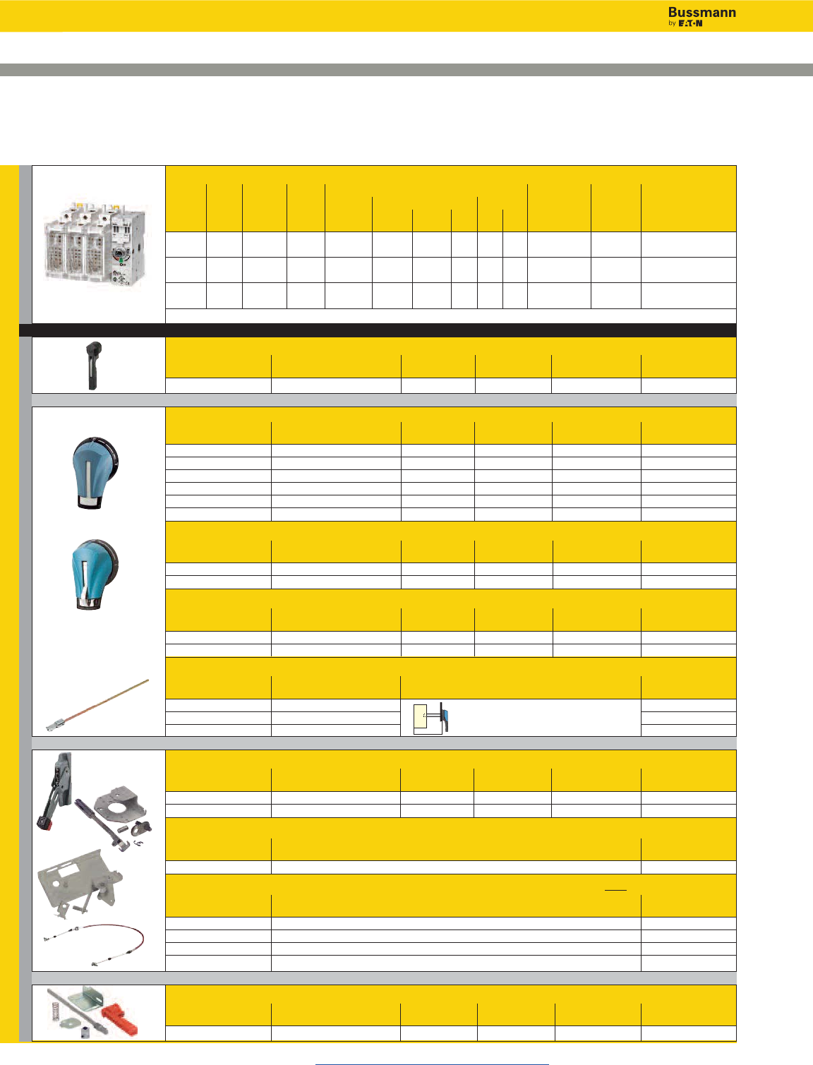
Disconnect Switches
UL 98 Fused Rotary Disconnect Switches—60A
Compact Class J
Visit us on the web at www.cooperbussmann.com/Disconnects
392
NFPA Through the Door Handle Kit - to be used with selector handle or front pistol handle
Test Part
Color Function Padlockable Defeatable Number
Red N Y N H79-2
For a Complete Assembly, Please Select:
Select for Standard Applications
Switch
Max Horsepower Rating
1-Phase 3-Phase DC*
Amp Fuse Number 220/ 220/ 440/ 600 125 250 Wire Wire Part
Rating Class of Poles SCCR 240Vac 240Vac 480Vac Vac Vdc Vdc Size Type Number
60 J 2 100kA 10 - - - 5 10 #14-10 Sol 75°C Cu RDF60J-2-COMP
#14-6 Str
60 J 3 100kA - 15 30 50 5 10 #14-10 Sol 75°C Cu RDF60J-3-COMP
#14-6 Str
60 J 4 100kA - 15 30 50 5 10 #14-10 Sol 75°C Cu RDF60J-4-COMP
#14-6 Str
* DC Ratings use two poles in series.
Direct Mount Handle - mounts directly to switch, no shaft required
For Switch Test Part
Part Number Color Function Padlockable Number
All Switches Black Y Y - On Switch DIR-07
External Front Operated Pistol Handles - shaft required
NEMA Test Part
Type Color Function Padlockable Defeatable Number
1, 3R, 12 Black N Y Y H12-05B
1, 3R, 12 Red/Yellow N Y Y H12-05R
1, 3R, 4, 4X, 12 Black N Y Y H4X-05B
1, 3R, 4, 4X, 12 Red/Yellow N Y Y H4X-05R
1, 3R, 4, 4X, 12 Black Y Y Y H4X-05TB
1, 3R, 4, 4X, 12 Red/Yellow Y Y Y H4X-05TR
Metallic Hasp (Heavy Duty) External Front Operated Pistol Handles - shaft required
NEMA Test Part
Type Color Function Padlockable Defeatable Number
1, 3R, 4, 4X, 12 Black N Y Y H4X-05BHD
1, 3R, 4, 4X, 12 Red/Yellow N Y Y H4X-05RHD
External Right Side Operated Pistol Handles - shaft required
NEMA Test Part
Type Color Function Padlockable Defeatable Number
1, 3R, 4, 4X, 12 Black N Y N/A H4X-05SB
1, 3R, 4, 4X, 12 Red/Yellow N Y N/A H4X-05SR
Shafts for Pistol Handles
Length Mounting Depth Part
in (mm) (X) in (mm) Number
7.9 (200) 5.30~9.06 (135~230) SH5-200
12.6 (320) 5.30~13.78 (135~350) SH5-320
15.7 (400) 5.30~16.93 (135~430) SH5-400
Flange Handle(1) - requires shaft operated mechanism or cable operated mechanism + cable
NEMA Flange Test Part
Type Style Function Padlockable Defeatable Number
1, 3R, 4, 12 Standard N Y Y FLH1
1, 3R, 4, 4X, 12 Chrome Plated N Y Y FLH2
Shaft Operated Flange Mechanism(2)- includes shaft
For Enclosure Part
Depth - in (mm) Number
6~24 (152~613) FLRM
Cable Operated Flange Mechanism and Cable - must select Mechanism(3) and Cable(4)
Part
Item / Length Number
Cable Mechanism FLCM
36” (900mm) Cable FLC36
60” (1500mm) Cable FLC60
120” (3000mm) Cable FLC120
+
(1)
(2)
(3)
(4)
SWITCH
HANDLE
X
or
or
or
or
+
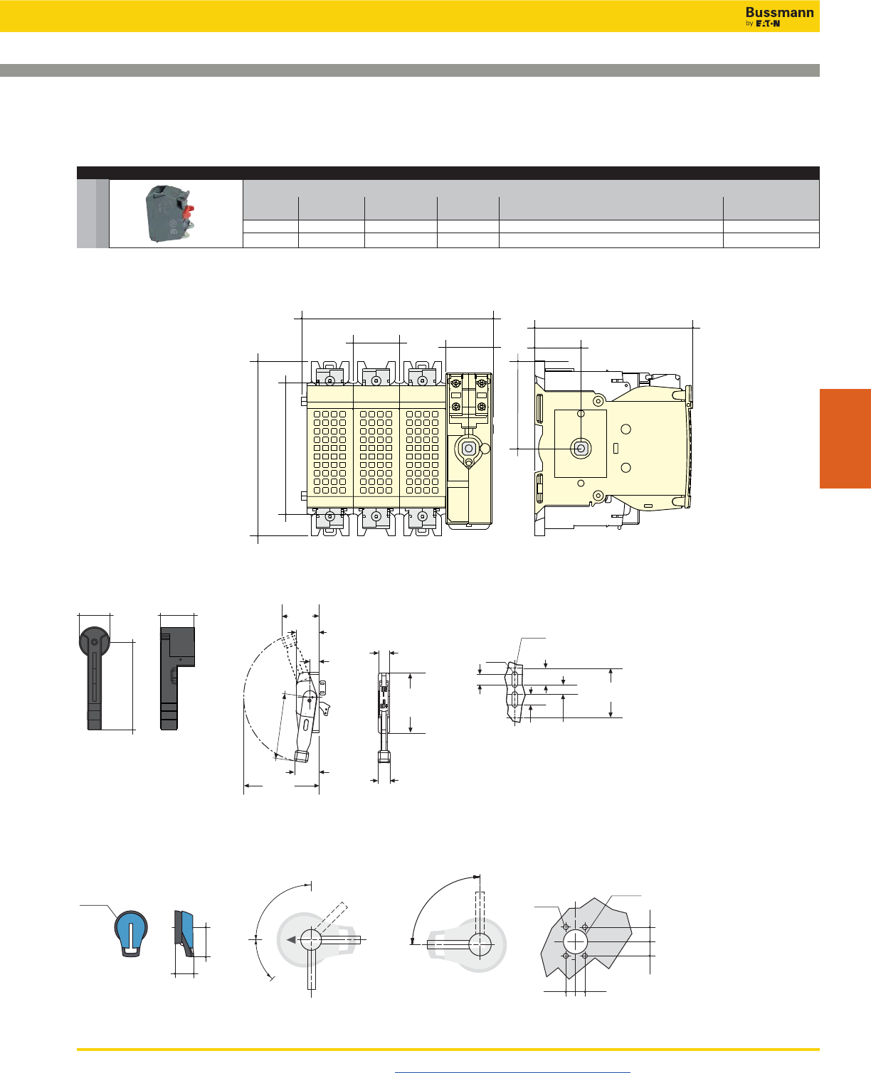
Disconnect Switches
UL 98 Fused Rotary Disconnect Switches—60A
Compact Class J
Visit us on the web at www.cooperbussmann.com/Disconnects 393
Disconnect
Switches
Dimensions – in (mm)
5.35
136
5.87
149.3
1.41
36 1.46
37.2
4.84
123
1.41
36
4.02
102.1
2.68
68.07
1.57
40
5.31
135
1.79
45.5
Direct Mount Handle
DIR-07
External Front & Right Side Pistol Handle
H4X-05__
H12-05__
0
I
90°
Ø3.07
1.73
2.75
65°
TEST
90°
0
Direction of Front OperationHandle Type Direction of Right Side Operation Door Drilling Layout
Ø78
70
44
0.78
4 Ø 0.27
0.55
Ø 1.46
4 Ø 7
Ø 37
20
20
14 0.55
14
0.78
I
3.50
(88.9) 2.16
(54.9)
0.86
(21.8)
1.06
(26.9)
4.68
(118.9)
1.55
(39.4)
0.88
(22.3)
1.0 0
(25.4)
1.0 0
(25.4)
6.22
(158.0)
2.32
(58.9)
7. 1 0
(180.3)
Ø0.50
(Ø12.7)
Ø0.28
(Ø7.1)
2.70
(68.6)
5.66
(143.8)
Flange Handle
FLH_
Acc.
Auxillary Contacts
Contact Number of Continuous Voltage Max Number of Aux Part
Type Contacts Amp Rating Rating Contacts per Switch Number
NO 1 10A 600Vac 4 BAC05
NC 1 10A 600Vac 4 BAC06
and …
AUX CONTACTS
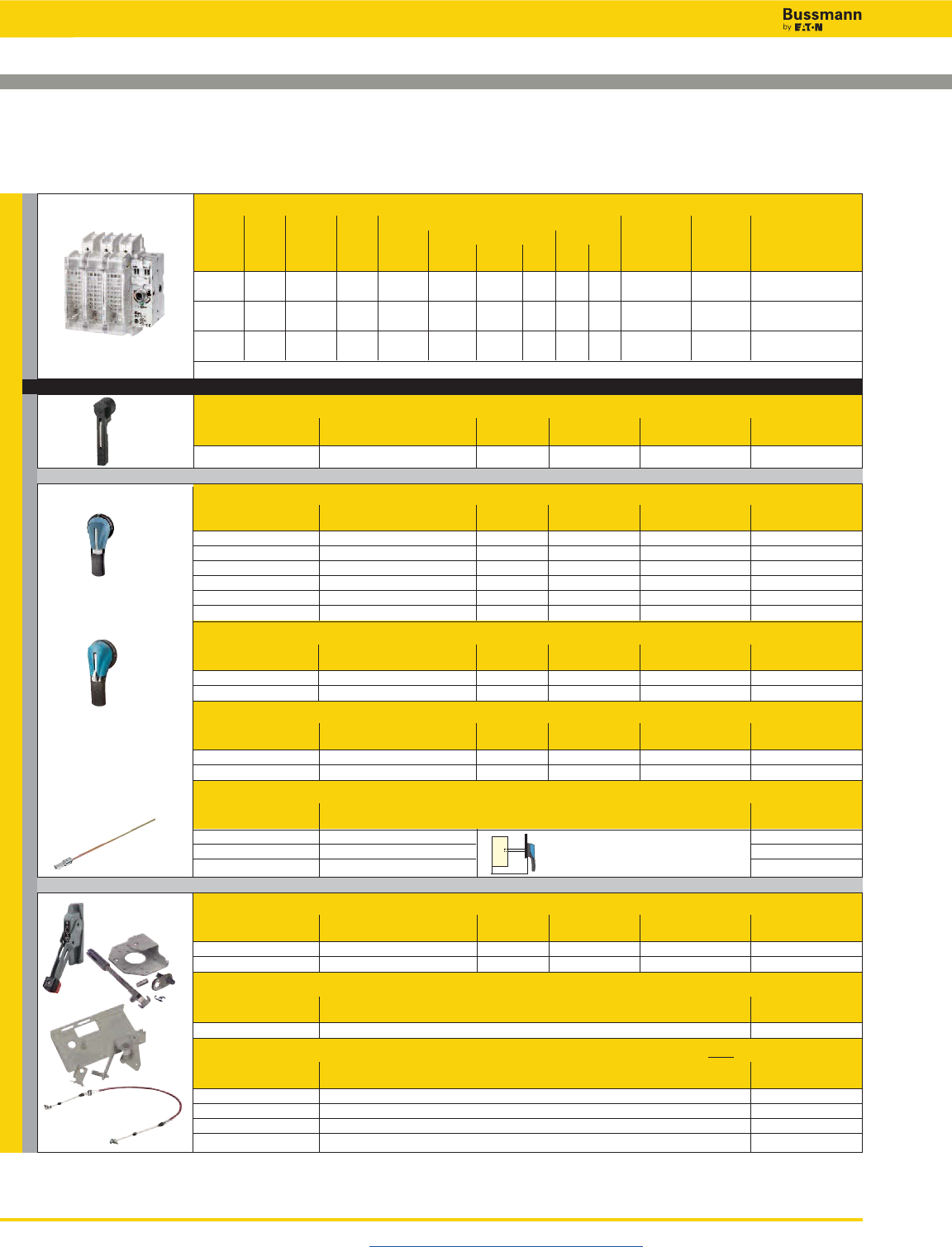
Disconnect Switches
UL 98 Fused Rotary Disconnect Switches—60A
Standard Class J
Visit us on the web at www.cooperbussmann.com/Disconnects
394
For a Complete Assembly, Please Select:
Select for Standard Applications
Switch
Max Horsepower Rating
1-Phase 3-Phase DC*
Amp Fuse Number 220/ 220/ 440/ 600 125 250 Wire Wire Part
Rating Class of Poles SCCR 240Vac 240Vac 480Vac Vac Vdc Vdc Size Type Number
60 J 2 200kA 10 - - - 5 10 #12-10 Sol 75°C Cu RDF60J-2
#12-1 Str
60 J 3 200kA - 15 30 50 5 10 #12-10 Sol 75°C Cu RDF60J-3
#12-1 Str
60 J 4 200kA - 15 30 50 5 10 #12-10 Sol 75°C Cu RDF60J-4
#12-1 Str
* DC Ratings use two poles in series.
Direct Mount Handle - mounts directly to switch, no shaft required
For Switch Test Part
Part Number Color Function Padlockable Number
All Switches Black Y Y DIR-07
External Front Operated Pistol Handles - shaft required
NEMA Test Part
Type Color Function Padlockable Defeatable Number
1, 3R, 12 Black N Y Y H12-03B
1, 3R, 12 Red/Yellow N Y Y H12-03R
1, 3R, 4, 4X, 12 Black N Y Y H4X-06B
1, 3R, 4, 4X, 12 Red/Yellow N Y Y H4X-06R
1, 3R, 4, 4X, 12 Black Y Y Y H4X-06TB
1, 3R, 4, 4X, 12 Red/Yellow Y Y Y H4X-06TR
Metallic Hasp (Heavy Duty) External Front Operated Pistol Handles - shaft required
NEMA Test Part
Type Color Function Padlockable Defeatable Number
1, 3R, 4, 4X, 12 Black N Y Y H4X-06BHD
1, 3R, 4, 4X, 12 Red/Yellow N Y Y H4X-06RHD
External Right Side Operated Pistol Handles - shaft required
NEMA Test Part
Type Color Function Padlockable Defeatable Number
1, 3R, 4, 4X, 12 Black N Y N/A H4X-06SB
1, 3R, 4, 4X, 12 Red/Yellow N Y N/A H4X-06SR
Shafts for Pistol Handles
Length Mounting Depth Part
in (mm) (X) in (mm) Number
7.9 (200) 5.30~9.06 (135~230) SH5-200
12.6 (320) 5.30~13.78 (135~350) SH5-320
15.7 (400) 5.30~16.93 (135~430) SH5-400
Flange Handle(1) - requires shaft operated mechanism or cable operated mechanism + cable
NEMA Flange Test Part
Type Style Function Padlockable Defeatable Number
1, 3R, 4, 12 Standard N Y Y FLH1
1, 3R, 4, 4X, 12 Chrome Plated N Y Y FLH2
Shaft Operated Flange Mechanism(2) - includes shaft
For Enclosure Depth Part
in (mm) Number
6~24 (152~613) FLRM
Cable Operated Flange Mechanism and Cable - must select Mechanism(3) and Cable(4)
Part
Item / Length Number
Cable Mechanism FLCM
36” (900mm) Cable FLC36
60” (1500mm) Cable FLC60
120” (3000mm) Cable FLC120
+
or
(1)
(2)
(3)
(4)
X
SWITCH
HANDLE
or
or
+
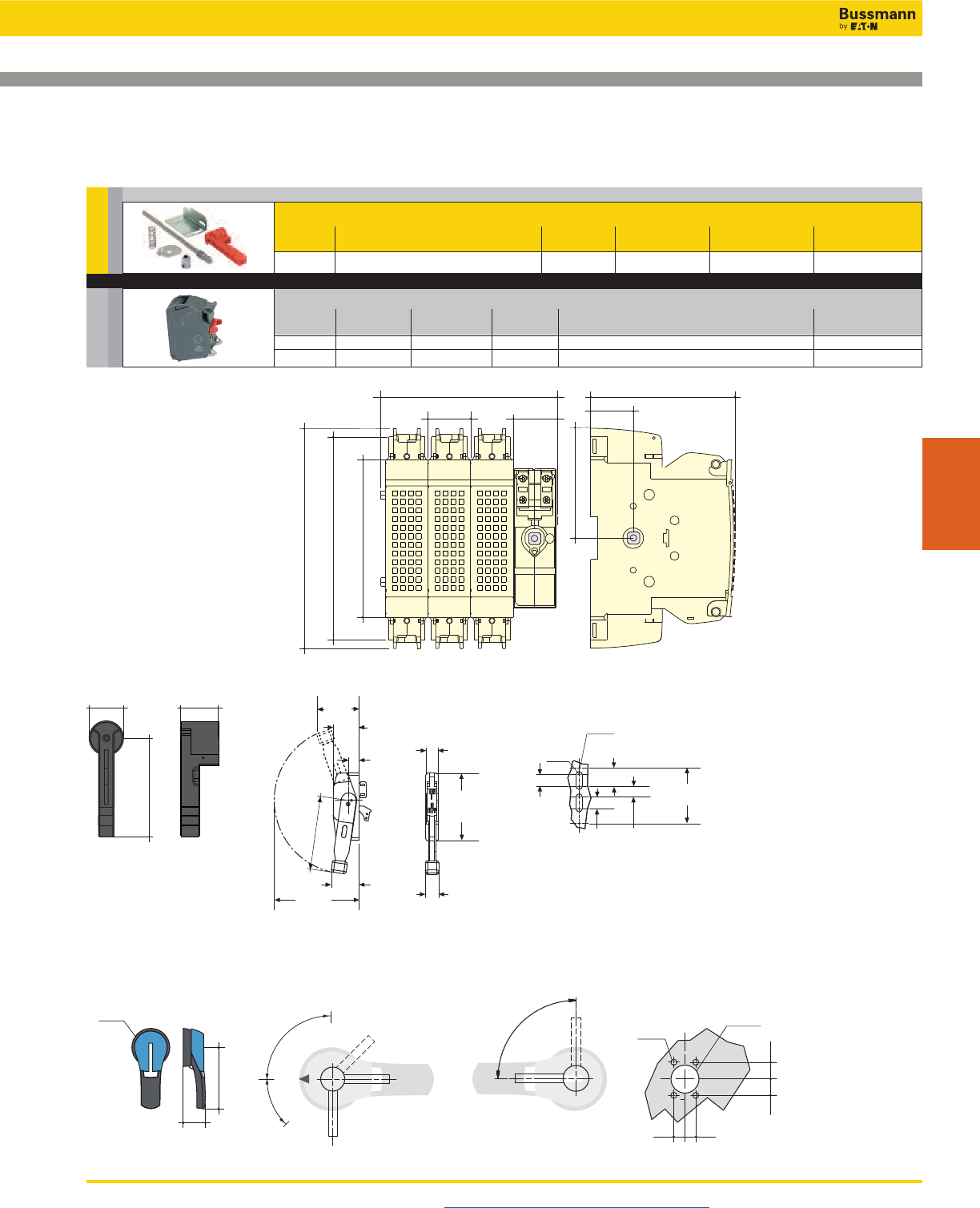
Disconnect Switches
UL 98 Fused Rotary Disconnect Switches—60A
Standard Class J
Visit us on the web at www.cooperbussmann.com/Disconnects 395
Disconnect
Switches
NFPA Through the Door Handle Kit - to be used with front pistol handle
Test Part
Color Function Padlockable Defeatable Number
Red N Y N H79-2
Dimensions – in (mm)
7.32
186
5.87
149.3
1.41
36
1.46
37.2
4.81
122.2
1.41
36
6.77
172
5.23
133
3.66
92.96
1.57
40
5.31
135
1.79
45.5
Direct Mount Handle
DIR-07
External Front and Right Side Pistol Handle
H4X-06__
H12-03__
0
I
90°
65°
TEST
90°
0
Ø78
1.77
4.92
Direction of Front OperationHandle Type Direction of Right Side Operation Door Drilling Layout
Ø3.07
0.78
4 Ø 0.27
0.55
Ø 1.46
4 Ø 7
Ø 37
20
20
14 0.55
14
0.78
45
125
I
3.50
(88.9) 2.16
(54.9)
0.86
(21.8)
1.06
(26.9)
4.68
(118.9)
1.55
(39.4)
0.88
(22.3)
1.0 0
(25.4)
1.0 0
(25.4)
6.22
(158.0)
2.32
(58.9)
7. 1 0
(180.3)
Ø0.50
(Ø12.7)
Ø0.28
(Ø7.1)
2.70
(68.6)
5.66
(143.8)
Flange Handle
FLH_
Select
NFPA HANDLE
or
Acc.
Auxillary Contacts
Contact Number of Continuous Voltage Max Number of Aux Part
Type Contacts Amp Rating Rating Contacts per Switch Number
NO 1 10A 600Vac 4 BAC05
NC 1 10A 600Vac 4 BAC06
and …
AUX CONTACTS
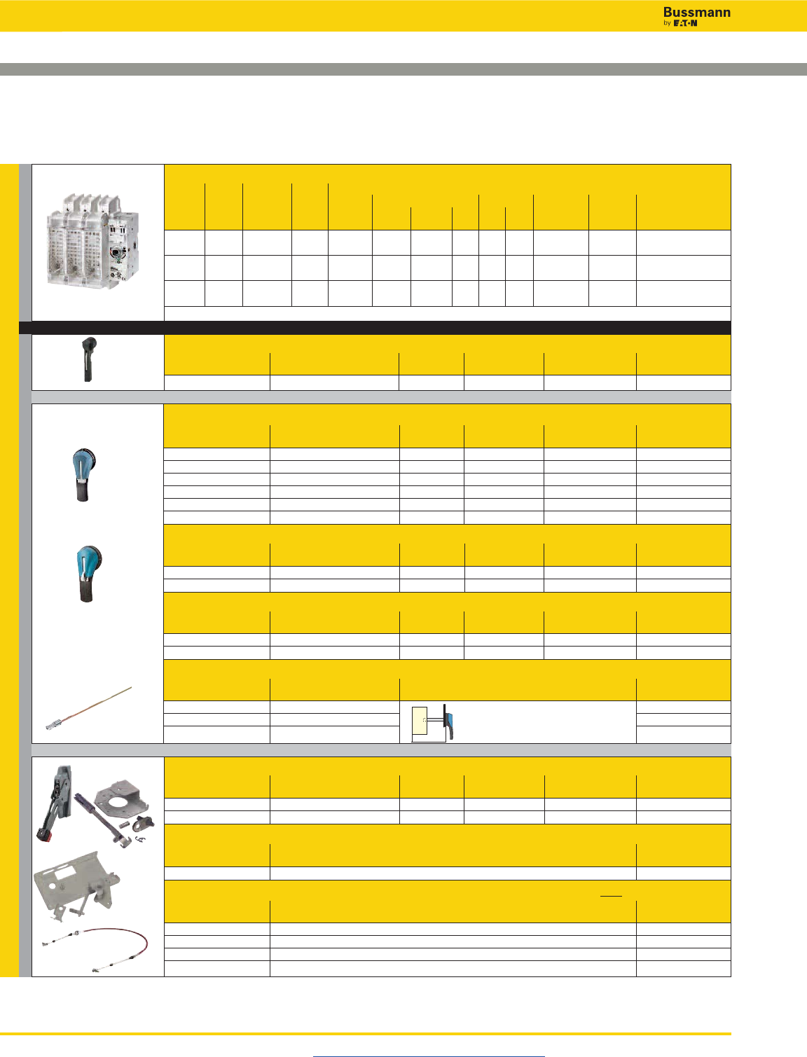
Disconnect Switches
UL 98 Fused Rotary Disconnect Switches—100A
Standard Class J
Visit us on the web at www.cooperbussmann.com/Disconnects
396
For a Complete Assembly, Please Select:
Select for Standard Applications
Switch
Max Horsepower Rating
1-Phase 3-Phase DC*
Amp Fuse Number 220/ 220/ 440/ 600 125 250 Wire Wire Part
Rating Class of Poles SCCR 240Vac 240Vac 480Vac Vac Vdc Vdc Size Type Number
100 J 2 200kA 10 - - - 7.5 20 #12-10 Sol 75°C Cu RDF100J-2
#12-1 Str
100 J 3 200kA - 30 60 75 7.5 20 #12-10 Sol 75°C Cu RDF100J-3
#12-1 Str
100 J 4 200kA - 30 60 75 7.5 20 #12-10 Sol 75°C Cu RDF100J-4
#12-1 Str
* DC Ratings use two poles in series.
Direct Mount Handle - mounts directly to switch, no shaft required
For Switch Test Part
Part Number Color Function Padlockable Number
All Switches Black Y Y DIR-07
External Front Operated Pistol Handles - shaft required
NEMA Test Part
Type Color Function Padlockable Defeatable Number
1, 3R, 12 Black N Y Y H12-03B
1, 3R, 12 Red/Yellow N Y Y H12-03R
1, 3R, 4, 4X, 12 Black N Y Y H4X-06B
1, 3R, 4, 4X, 12 Red/Yellow N Y Y H4X-06R
1, 3R, 4, 4X, 12 Black Y Y Y H4X-06TB
1, 3R, 4, 4X, 12 Red/Yellow Y Y Y H4X-06TR
Metallic Hasp (Heavy Duty) External Front Operated Pistol Handles - shaft required
NEMA Test Part
Type Color Function Padlockable Defeatable Number
1, 3R, 4, 4X, 12 Black N Y Y H4X-06BHD
1, 3R, 4, 4X, 12 Red/Yellow N Y Y H4X-06RHD
External Right Side Operated Pistol Handles - shaft required
NEMA Test Part
Type Color Function Padlockable Defeatable Number
1, 3R, 4, 4X, 12 Black N Y N/A H4X-06SB
1, 3R, 4, 4X, 12 Red/Yellow N Y N/A H4X-06SR
Shafts for Pistol Handles
Length Mounting Depth Part
in (mm) (X) in (mm) Number
7.9 (200) 5.30~9.06 (135~230) SH5-200
12.6 (320) 5.30~13.78 (135~350) SH5-320
15.7 (400) 5.30~16.93 (135~430) SH5-400
Flange Handle(1) - requires shaft operated mechanism or cable operated mechanism + cable
NEMA Flange Test Part
Type Style Function Padlockable Defeatable Number
1, 3R, 4, 12 Standard N Y Y FLH1
1, 3R, 4, 4X, 12 Chrome Plated N Y Y FLH2
Shaft Operated Flange Mechanism(2) - includes shaft
For Enclosure Depth Part
in (mm) Number
6~24 (152~613) FLRM
Cable Operated Flange Mechanism and Cable - must select Mechanism(3) and Cable(4)
Part
Item / Length Number
Cable Mechanism FLCM
36” (900mm) Cable FLC36
60” (1500mm) Cable FLC60
120” (3000mm) Cable FLC120
+
(1)
(2)
(3)
(4)
X
or
SWITCH
HANDLE
or
or
+
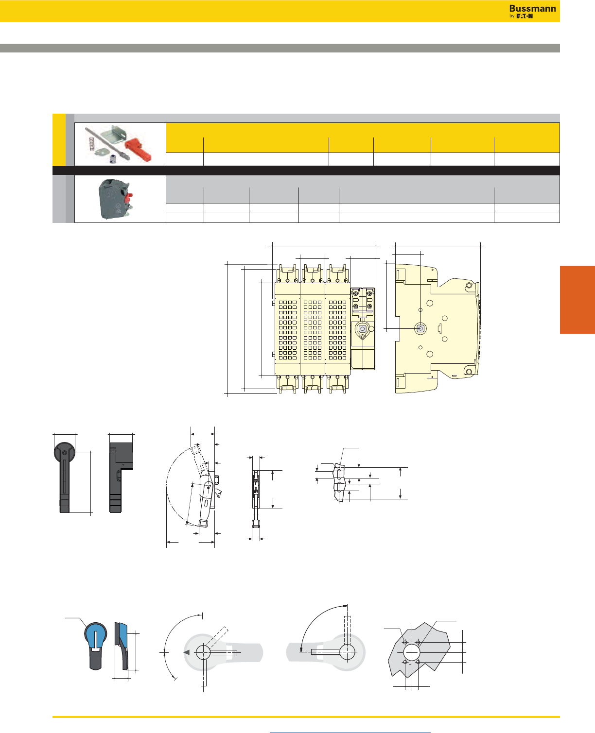
Disconnect Switches
UL 98 Fused Rotary Disconnect Switches—100A
Standard Class J
Visit us on the web at www.cooperbussmann.com/Disconnects 397
Disconnect
Switches
7.32
186
5.87
149.3
1.41
36
1.46
37.2
4.81
122.2
1.41
36
6.77
172
5.23
133
3.66
92.96
Dimensions – in (mm)
1.57
40
5.31
135
1.79
45.5
Direct Mount Handle
DIR-07
External Front & Right Side Pistol Handle
H4X-06__
H12-03__
0
I
90°
65°
TEST
90°
0
Ø78
1.77
4.92
Direction of Front OperationHandle Type Direction of Right Side Operation Door Drilling Layout
Ø3.07
0.78
4 Ø 0.27
0.55
Ø 1.46
4 Ø 7
Ø 37
20
20
14 0.55
14
0.78
45
125
I
3.50
(88.9) 2.16
(54.9)
0.86
(21.8)
1.06
(26.9)
4.68
(118.9)
1.55
(39.4)
0.88
(22.3)
1.0 0
(25.4)
1.0 0
(25.4)
6.22
(158.0)
2.32
(58.9)
7. 1 0
(180.3)
Ø0.50
(Ø12.7)
Ø0.28
(Ø7.1)
2.70
(68.6)
5.66
(143.8)
Flange Handle
FLH_
NFPA Through the Door Handle Kit - to be used with front pistol handle
Test Part
Color Function Padlockable Defeatable Number
Red N Y N H79-2
Select
NFPA HANDLE
or
Acc.
Auxillary Contacts
Contact Number of Continuous Voltage Max Number of Aux Part
Type Contacts Amp Rating Rating Contacts per Switch Number
NO 1 10A 600Vac 4 BAC05
NC 1 10A 600Vac 4 BAC06
AUX CONTACTS
and …
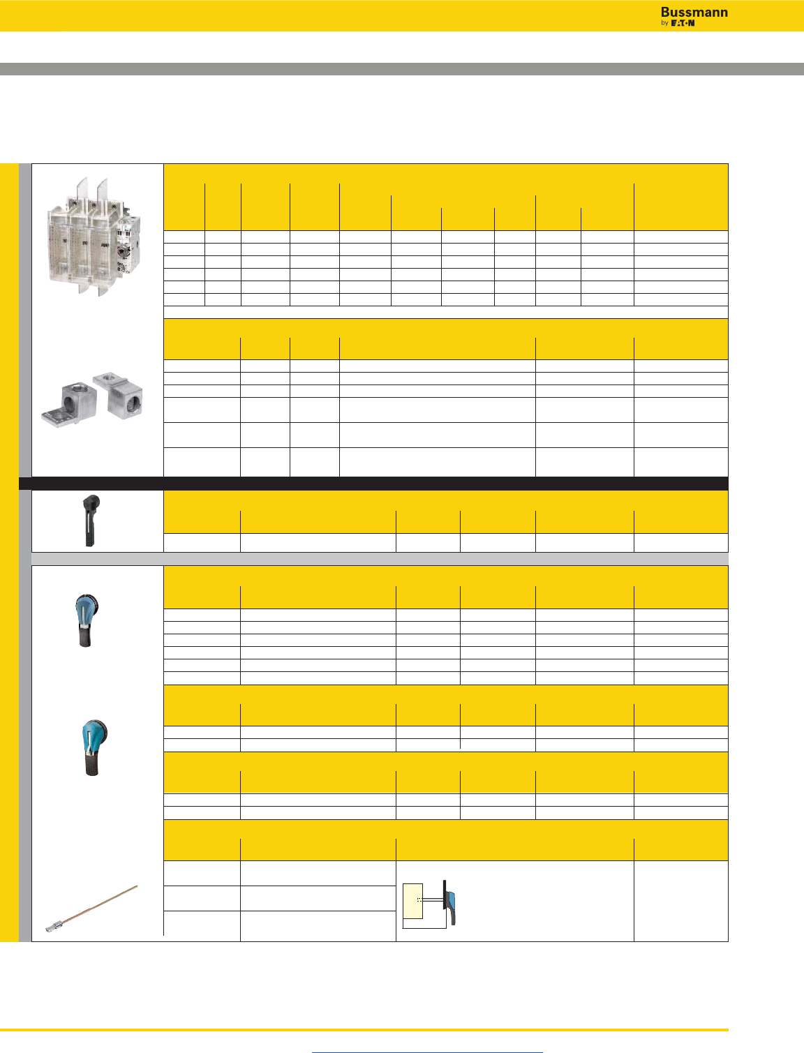
Disconnect Switches
UL 98 Fused Rotary Disconnect Switches—200 & 400A
Standard Class J
Visit us on the web at www.cooperbussmann.com/Disconnects
398
For a Complete Assembly, Please Select:
Select for Standard Applications
Switch
Max Horsepower Rating
1-Phase 3-Phase DC*
Amp Fuse Number 220/ 220/ 440/ 600 125 250 Part
Rating Class of Poles SCCR 240Vac 240Vac 480Vac Vac Vdc Vdc Number
200 J 2 200kA 10 - - - - - RDF200J-2
200 J 3 200kA - 60 125 150 - - RDF200J-3
200 J 4 200kA - 60 125 150 - - RDF200J-4
400 J 2 200kA 10 - - - 20 50 RDF400J-2
400 J 3 200kA - 125 250 350 20 50 RDF400J-3
400 J 4 200kA - 125 250 350 20 50 RDF400J-4
* DC Ratings use two poles in series.
Terminal Lug Kit
Switch Number Lugs Part
Amp Rating of Poles Per Kit Wire Range Wire Type Number
200 2 2 #6-300MCM 75°C Cu/Al LUG1-2
200 3 3 #6-300MCM 75°C Cu/Al LUG1-3
200 4 4 #6-300MCM 75°C Cu/Al LUG1-4
400 2 2 #4-600MCM or 75°C Cu/Al LUG2-2
Dual 1/0-250MCM
400 3 3 #4-600MCM or 75°C Cu/Al LUG2-3
Dual 1/0-250MCM
400 4 4 #4-600MCM or 75°C Cu/Al LUG2-4
Dual 1/0-250MCM
Direct Mount Handle - mounts directly to switch, no shaft required
For Switch Test Part
Part Number Color Function Padlockable Number
All Switches Black Y Y DIR-07
External Front Operated Pistol Handles - shaft required
NEMA Test Part
Type Color Function Padlockable Defeatable Number
1, 3R, 12 Black N Y Y H12-03B
1, 3R, 12 Red/Yellow N Y Y H12-03R
1, 3R, 4, 4X, 12 Black N Y Y H4X-06B
1, 3R, 4, 4X, 12 Red/Yellow N Y Y H4X-06R
1, 3R, 4, 4X, 12 Black Y Y Y H4X-06TB
1, 3R, 4, 4X, 12 Red/Yellow Y Y Y H4X-06TR
Metallic Hasp (Heavy Duty) External Front Operated Pistol Handles - shaft required
NEMA Test Part
Type Color Function Padlockable Defeatable Number
1, 3R, 4, 4X, 12 Black N Y Y H4X-06BHD
1, 3R, 4, 4X, 12 Red/Yellow N Y Y H4X-06RHD
External Right Side Operated Pistol Handles - shaft required
NEMA Test Part
Type Color Function Padlockable Defeatable Number
1, 3R, 4, 4X, 12 Black N Y N/A H4X-06SB
1, 3R, 4, 4X, 12 Red/Yellow N Y N/A H4X-06SR
Shafts for Pistol Handles
Length Mounting Depth Part
in (mm) (X) in (mm) Number
7.9 (200) 200A: 5.70-9.06 (145-230) SH5-200
400A: 7.87-10.24 (200-260)
12.6 (320) 200A: 5.70-13.78 (145-350) SH5-320
400A: 7.87-16.93 (200-380)
15.7 (400) 200A: 5.70-16.93 (145-430) SH5-400
400A: 7.87-18.10 (200-460)
+
+
X
or
SWITCH + LUGS
HANDLE
or
+
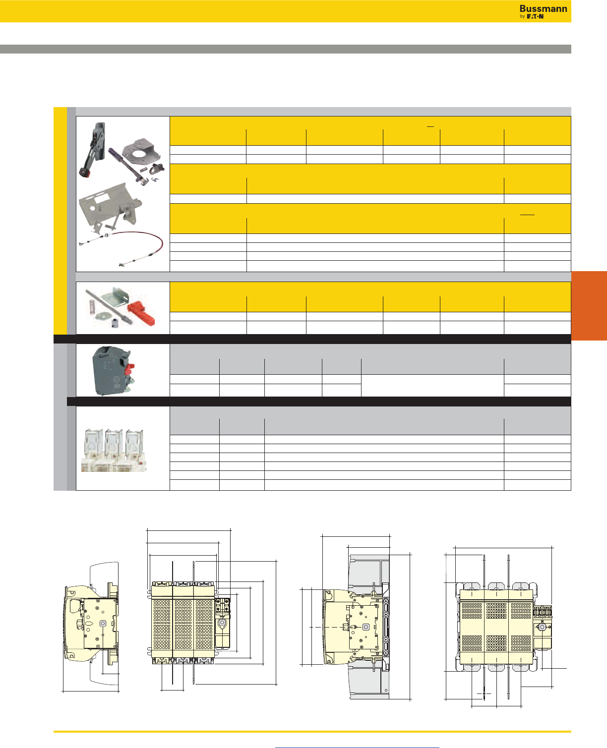
Disconnect Switches
UL 98 Fused Rotary Disconnect Switches—200 & 400A
Standard Class J
Visit us on the web at www.cooperbussmann.com/Disconnects 399
Disconnect
Switches
Select for Standard Applications
Flange Handle(1) 200A Only - requires shaft operated mechanism or cable operated mechanism + cable
NEMA Flange Test Part
Type Style Function Padlockable Defeatable Number
1, 3R, 4, 12 Standard N Y Y FLH1
1, 3R, 4, 4X, 12 Chrome Plated N Y Y FLH2
Shaft Operated Flange Mechanism(2) 200A Only - includes shaft
For Enclosure Depth Part
in (mm) Number
6~24 (152~613) FLRM
Cable Operated Flange Mechanism and Cable 200A Only - must select Mechanism(3) and Cable(4)
Part
Item Number
Cable Mechanism FLCM
36” (900mm) Cable FLC36
60” (1500mm) Cable FLC60
120” (3000mm) Cable FLC120
(1)
(2)
(3)
(4)
NFPA Through the Door Handle Kit - to be used with front pistol handle
Use with Test Part
Switch Color Function Padlockable Defeatable Number
RDF200J-_ Red N Y N H79-2
RDF400J-_ Red N Y N H79-3
Auxillary Contacts
Contact Number of Continuous Voltage Max Number of Aux Part
Type Contacts Amp Rating Rating Contacts per Switch Part Number Number
NO 1 10A 600Vac RDF200J-__: 4 BAC05
NC 1 10A 600Vac RDF400J-__: 8 BAC06
Terminal Shrouds - includes terminal shroud for lineside or loadside
Switch Amp Number Part
Rating of Poles Number
200 2 TSH8-2TB
200 3 TSH8-3TB
200 4 TSH8-4TB
400 2 TSH9-2TB
400 3 TSH9-3TB
400 4 TSH9-4TB
7.72
196.2
6.61
168
6.18
157
1.41
36
5.11
130
1.96
50
5.28
134.2
6.50
165.2
7.67
195
11.46
291.3
7.08
180
4.37
111.1
10.19 (3P) - 12.79 (4P)
259 (3P) - 325 (4P)
2.59
66
2.59
66
3.26
83
0.98
24.9
2.95
75
2.95
75
9.44
240
15.35
390
7.97
202.5
3.98
101.25
3.98
101.25
Dimensions – in (mm)
• RDF200J-3 • RDF400J-3
Accessories
AUX CONTACTS
SHROUDS HANDLE
or
or
and …
and …
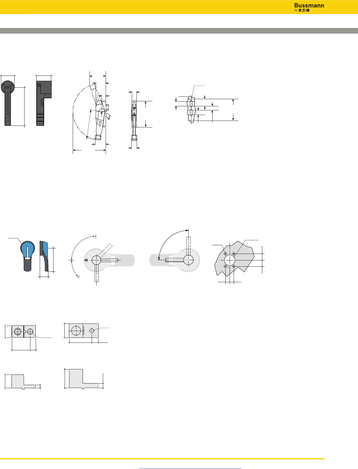
Disconnect Switches
UL 98 Fused Rotary Disconnect Switches—200 & 400A
Standard Class J
Visit us on the web at www.cooperbussmann.com/Disconnects
400
External Front & Right Side Pistol Handle
H4X-06__
H12-03__
0
I
90°
65°
TEST
90°
0
Ø78
1.77
4.92
Direction of Front OperationHandle Type Direction of Right Side Operation Door Drilling Layout
Ø3.07
0.78
4 Ø 0.27
0.55
Ø 1.46
4 Ø 7
Ø 37
20
20
14 0.55
14
0.78
45
125
I
1.57
40
5.31
135
1.79
45.5
Direct Mount Handle
DIR-07
Terminal Lugs
200A
LUG1-__
400A
LUG2-__
1.52
38.8
1
25
1.12
28.6
0.45
Ø11.6
0.46
11.68
0.25
6.35
2.8
71.5
Ø 0.4
Ø 4.7
1.3
35
1.8
46
0.44
11.13
0.63
15.88
3.50
(88.9) 2.16
(54.9)
0.86
(21.8)
1.06
(26.9)
4.68
(118.9)
1.55
(39.4)
0.88
(22.3)
1.0 0
(25.4)
1.0 0
(25.4)
6.22
(158.0)
2.32
(58.9)
7. 1 0
(180.3)
Ø0.50
(Ø12.7)
Ø0.28
(Ø7.1)
2.70
(68.6)
5.66
(143.8)
Flange Handle
FLH_
Disconnect Switches
Visit us on the web at www.cooperbussmann.com/Disconnects 401
Disconnect
Switches
Open & Enclosed Rotary Disconnect Switches
In-Stock and Ship Within 24 Hours
The Bussmann QuikShip Everyday Service
ensures the most common open and
enclosed rotary disconnect switches ship
within 24 hours to help you meet project
timelines.
Contact your Bussmann representative for
details.
www.cooperbussmann.com/Disconnects
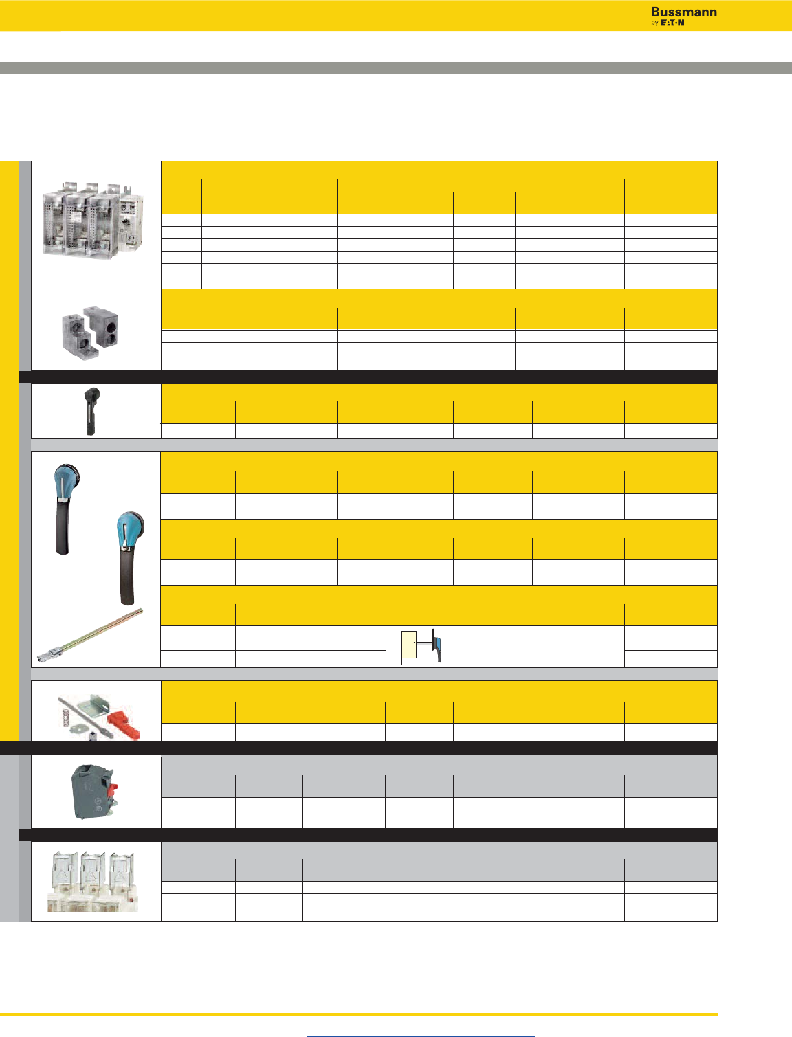
Disconnect Switches
UL 98 Fused Rotary Disconnect Switches—600 & 800A
Standard Class J & Class L
Visit us on the web at www.cooperbussmann.com/Disconnects
402
For a Complete Assembly, Please Select:
Select for Standard Applications
Switch
Max Horsepower Rating, 3-Phase
Amp Fuse Number 220/ 440/ Part
Rating Class of Poles SCCR 240Vac 480Vac 600Vac Number
600 J 2 200kA - - - RDF600J-2
600 J 3 200kA 200 400 500 RDF600J-3
600 J 4 200kA 200 400 500 RDF600J-4
800 L 2 200kA - - - RDF800L-2
800 L 3 200kA 200 500 500 RDF800L-3
800 L 4 200kA 200 500 500 RDF800L-4
Terminal Lug Kit
Switch Number Lugs Part
Amp Rating of Poles Per Kit Wire Range Wire Type Number
600-800 2 2 (2) #2-600MCM 75°C Cu/Al LUG5-2
600-800 3 3 (2) #2-600MCM 75°C Cu/Al LUG5-3
600-800 4 4 (2) #2-600MCM 75°C Cu/Al LUG5-4
Direct Mount Handle - mounts directly to switch, no shaft required
For Switch Test Part
Part Number Color Function Padlockable Number
All Switches Black Y Y DIR-08
+
or
+
NFPA Through the Door Handle Kit - to be used with front pistol handle
For Switch Test Part
Part Number Color Function Padlockable Defeatable Number
All Switches Red N Y N H79-4
Auxillary Contacts
Contact Number of Continuous Voltage Max Number of Aux Part
Type Contacts Amp Rating Rating Contacts per Switch Number
NO 1 10A 600Vac 8 BAC05
NC 1 10A 600Vac 8 BAC06
Terminal Shrouds - includes terminal shroud for lineside or loadside
Switch Amp Number Part
Rating of Poles Number
600-800 2 TSH10-2TB
600-800 3 TSH10-3TB
600-800 4 TSH10-4TB
Accessories
AUX CONTACTS
SHROUDS SWITCH + LUGS
HANDLE
or
or
External Front Operated Pistol Handles - shaft required
NEMA Test Part
Type Color Function Padlockable Defeatable Number
1, 3R, 4, 4X, 12 Black N Y Y H4X-07B
1, 3R, 4, 4X, 12 Red/Yellow N Y Y H4X-07R
Metallic Hasp (Heavy Duty) External Front Operated Pistol Handles - shaft required
NEMA Test Part
Type Color Function Padlockable Defeatable Number
1, 3R, 4, 4X, 12 Black N Y Y H4X-07BHD
1, 3R, 4, 4X, 12 Red/Yellow N Y Y H4X-07RHD
Shafts for Pistol Handles
Length Mounting Depth Part
in (mm) (X) in (mm) Number
7.9 (200) 10.63~11.97 (270~304) SH7-200
12.6 (320) 10.63~16.69 (270~424) SH7-320
15.7 (400) 10.63~19.84 (270~504) SH7-400
X
+
and …
and …
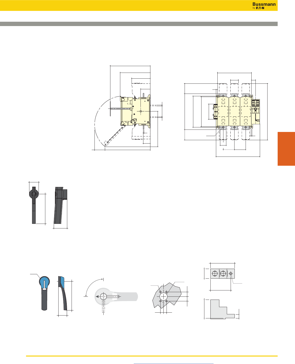
Disconnect Switches
UL 98 Fused Rotary Disconnect Switches—600 & 800A
Standard Class J & Class L
Visit us on the web at www.cooperbussmann.com/Disconnects 403
Disconnect
Switches
9.84
250 6.10
155
3.12
79.5
0.27
7
2.32
59
14.96
380
Fuse Cover Fully Open
min 10.43
min 265
Ø 0.51
Ø13
0.43
11
11.18 (3P) - 14.88 (4P)
284 (3P) - 378 (4P)
65 34
2.56 1.34
2
51
0.35
9
3.7 3.7
94
14.33 (3P) - 18.03 (4P)
364 (3P) - 458 (4P)
94
fix 9.84
fix 250
5
126.5
11.81
18.54
471
260
10.23
300
3.36
85.5
3.36
85.5
7
0.270.27
7
11.81
300
90
3.54
18.58
472
Dimensions – in (mm)
• RDF600J-3 • RDF800L-3
External Front Pistol Handle
H4X-07__
61
210
90°
I
0
Direction of Front Operation
Handle Type Door Drilling Layout
Ø3.07
Ø78
0.78
4 Ø 0.27
0.55
Ø 1.46
4 Ø 7
Ø 37
20
20
14 0.55
14
0.78
60
2.36
85
3.35
190
7.48
Direct Mount Handle
DIR-08
Terminal Lugs
600 to 800A
LUG5-__
3.15
80
1.49
38
2.87
73
0.40
Ø10.2
3.76
95.5
0.64
16.2
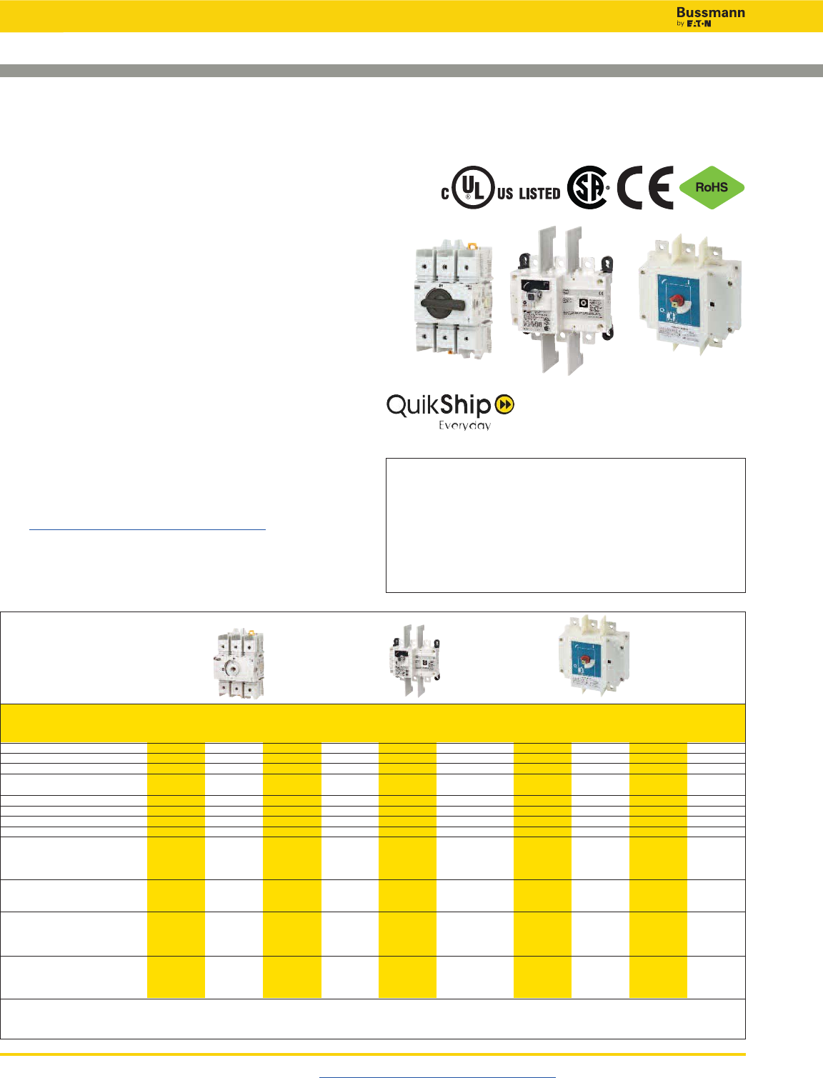
Disconnect Switches
Visit us on the web at www.cooperbussmann.com/Disconnects
404
UL 98 Non-Fused Rotary Disconnect Switches—30 to 1200A
QuikShip Everyday Service ships the
most common part numbers within
24 hours. Contact your Bussmann
representative for details.
Description
Bussmann UL 98 non-fused rotary disconnect switches are
versatile switches that “break” and “make” power circuits ON
and OFF load.
Features
• Make and break power under load
• Up to 200kA SCCR
• DIN-Rail or panel mount (30-100A)
• Disconnect switches are front, right side and direct
handle operable (30-100A)
• Finger-safe (30-100A)
• Fully visualized breaking (100-1200A)
Agency Information
• UL98, Guide WHTY, File E155130
• CSA 22.2 No. 4, File 257020
• Conforms with IEC 60947-3
Online Resources
Visit www.cooperbussmann.com/Disconnects for:
• CAD Drawings
• Instruction Sheets
• UL Information
Related Cooper Bussmann Products
Fuse Blocks Data Sheet #
Modular Knifeblade Fuse Blocks 100-600A 3192
Fuses Holders
CH Series Class CC, Midget & 10x38 0-30A 3185
Finger-Safe Optima Series 0-30A 1102
Optima™ Protection Modules 0-30A 1109
CH Series Class J 0-60A 2144
Part Number
3-Pole RD30-3 RD60-3 RD100-3 RD100-3-SCCR RD200-3 RD400-3 RD600-3 RD800-3 RD1000-3 RD1200-3
4-Pole — — — — RD200-4 RD400-4 RD600-4 RD800-4 RD1000-4 RD1200-4
Thermal Current Ith @ 40°C (A) 30 60 100 — — — — — — —
Rated insulation voltage Ui(V) 800 800 800 — — — 1000 1000 1000 1000
Rated impulse withstand voltage Uimp (kV) 8 8 8 — — — 12 12 12 12
Rated Operation Currents Ie (A)
Load Duty Category Rated Voltage A (1) A (1) A (1) —— — A
(1) A (1) A (1) A (1)
400Vac AC-22 A 32 63 100 — — — 630 800 1000 1200
400Vac AC-23 A 32 63 100 — — — 630 800 1000 1000
690Vac AC-22 A 32 63 80 — — — 500 630 630 630
690Vac AC-23 A 32 63 63 — — — 200 400 400 400
Operational Power (Vac) in AC-23 (kW)
400V w/o prebreak AC (1)(2) 15 30 45 — — — 355 450 560 560
500V w/o prebreak AC (1)(2) 15 30 45 — — — 450 560 560 560
690V w/o prebreak AC (1)(2) 18.5 30 45 — — — 185 400 400 400
Overload Capacity (Ue415Vac)
Rated short-time
making capacity Icm(kA peak) (3) 12 12 12 — — — 48 75 48 75
Fuse Protected Short-Circuit Withstand
(kA rms prospective)
Short-Circuit Current (kA) (3) 50 50 25 — — — 100 100 100 100
Associated Fuse Rating (A) (3) 32 63 100 — — — 630 800 1000 1250
Connection
Minimum Cu cable cross section (mm2) 2.5 2.5 10 — — — 2x150 2x185 2x240 —
Minimum Cu busbar section (mm2) — — — — — — 2x30x5 2x40x5 2x50x5 2x60x5
Maximum Cu cable section (mm2)70 7070—— — ————
(1) A/B: Category with index A = frequent operation; category with index B = infrequent operation.
(2) The power value is given for information only; the current values vary from one manufacturer to another.
(3) For a rated operating voltage, Ue= 400Vac.
IEC Electrical Specifications
RD30-3 RD200-3 RD600-3
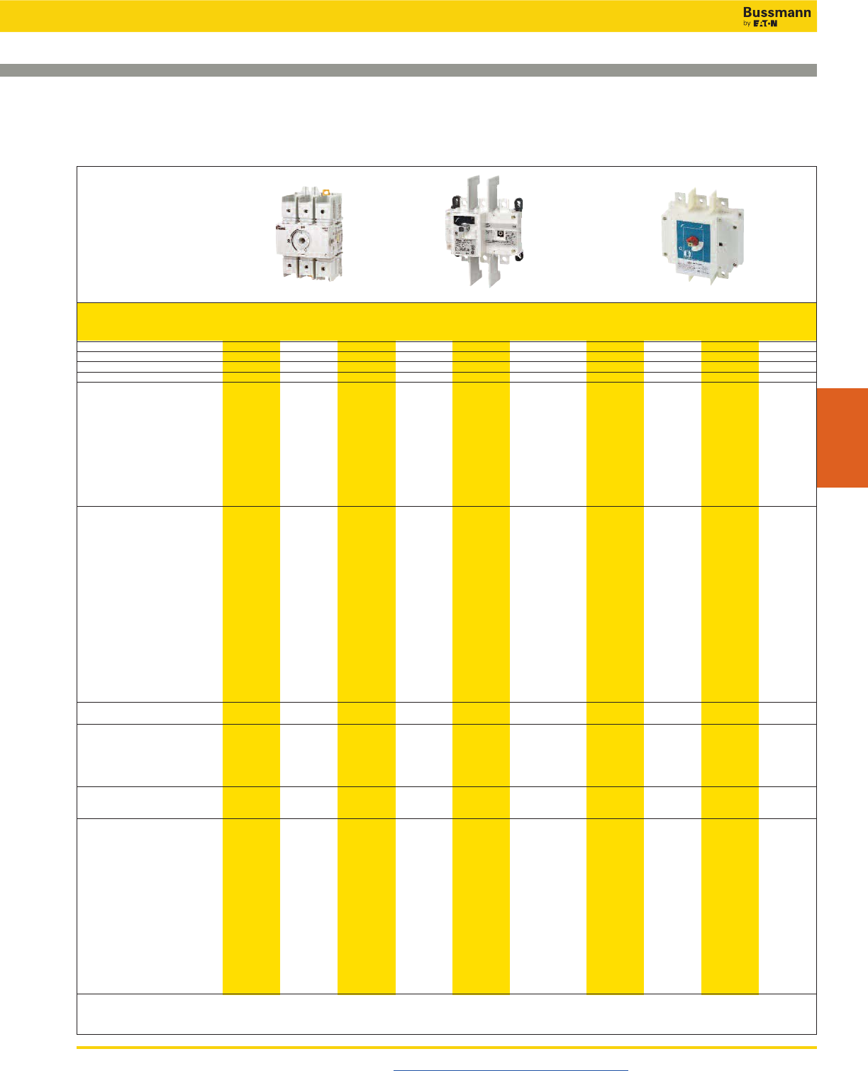
Disconnect Switches
UL 98 Non-Fused Rotary Disconnect Switches—30 to 1200A
Visit us on the web at www.cooperbussmann.com/Disconnects 405
Disconnect
Switches
Part Number
3-Pole RD30-3 RD60-3 RD100-3 RD100-3-SCCR RD200-3 RD400-3 RD600-3 RD800-3 RD1000-3 RD1200-3
4-Pole — — — — RD200-4 RD400-4 RD600-4 RD800-4 RD1000-4 RD1200-4
UL Standard UL 98 UL 98 UL 98 UL 98 UL 98 UL 98 UL 98 UL 98 UL 98 UL 98
Max Ampacity 30A 60A 100A 100A 200A 400A 600A 800A 1000A 1200A
Switch Type Compact Compact Compact Standard Standard Standard Standard Standard Standard Standard
Handle Operation Front/Side Front/Side Front/Side Front Front Front Front Front Front Front
UL Electrical Ratings
Max Voltage (AC) 600Vac 600Vac 600Vac 600Vac 600Vac 600Vac 600Vac 600Vac 600Vac 600Vac
Max Voltage (DC) — — — 250Vdc 250Vdc — 250Vdc — — —
Maximum AC Horsepower Ratings
1-Phase, 120Vac 2 3 5 — — — — — — —
1-Phase, 240Vac 5 10 10 10 10 — — — — —
3-Phase, 240Vac 10 20 20 30 75 125 200 200 200 200
3-Phase, 480Vac 20 40 50 75 150 250 400 500 500 500
3-Phase, 600Vac 25 50 50 100 200 350 350 500 500 500
DC Horsepower Ratings
125Vdc — — — — — — 20 — — —
250Vdc — — — — — — 50 — — —
Electrical Characteristics
SCCR with Fuse 100kA 100kA 25kA/100kA* 200kA 200kA 200kA 200kA 100kA 100kA 100kA
Fuse Class J J J J J J J L L L
Max. Fuse Rating 30A 60A 100A 100A 200A 400A 600A 800A 1000A 1200A
Terminal Lugs/Kits Integral Integral Integral • • • • • • •
Lug Mounting Torque - Lb-In (N•m) - - - 160 (18) 160 (18) LUG2-_ 310 (35) 310 (35) 310 (35) 310 (35) 310 (35)
LUG3-_ 398 (45)
Wire Type 75°C Cu 75°C Cu 75°C Cu 75°C Cu/Al 75°C Cu/Al 75°C Cu/Al 75°C Cu/Al 75°C Cu/Al 75°C Cu/Al 75°C Cu/Al
Wire Range & Torque - Lb-In (N•m)
Solid #12-10 #12-10 #12-10 — — — — — — —
35.4 (4) 35.4 (4) 35.4 (4) — — — — — — —
Stranded #10-1 #10-1 #10-1 #6-300MCM #6-300MCM LUG2-_ #4-600MCM (2) #2-600MCM (4) #2-600MCM (4) #2-600MCM (4) #2-600MCM
35.4 (4) 35.4 (4) 35.4 (4) 275 (31) 275 (31) 550 (62) 375 (42.4) 375 (42.4) 375 (42.4) 375 (42.4)
1/0 1/0 1/0 Dual 1/0-250MCM
39.8 (4.5) 39.8 (4.5) 39.8 (4.5) 550 (62)
2/0 2/0 2/0 LUG3-_:(2) #6-2
44.3 (5) 44.3 (5) 44.3 (5) 200 (22.6)
(2) #1-350MCM
375 (42.4)
Mechanical Characteristics
Endurances/Cycles 10,000 10,000 10,000 10,000 8000 6000 6000 3500 3500 3500
Physical Characteristics
Dimensions
See drawings on product pages
Weight - Lbs (KG)
3-Pole 1.3 (0.6) 1.3 (0.6) 1.3 (0.6) 4.2 (1.91) 4.2 (1.91) 10.0 (4.6) 18.1 (8.2) 19.6 (8.9) 19.6 (8.9) 19.6 (8.9)
4-Pole — — — — 5.0 (2.3) 12.3 (5.6) 23.9 (10.9) 25.3 (11.5) 25.3 (11.5) 25.3 (11.5)
Environmental
Operating Temperature -20°C to 70°C -20°C to 70°C -20°C to 70°C -20°C to 70°C -20°C to 70°C -20°C to 70°C -20°C to 70°C -20°C to 70°C -20°C to 70°C -20°C to 70°C
Flammability Rating UL 94-V0 UL 94-V0 UL 94-V0 UL 94-V0 UL 94-V0 UL 94-V0 UL 94-V0 UL 94-V0 UL 94-V0 UL 94-V0
Accessories
Lug Kit Part #
3-Pole Integral Integral Integral • • • • • • •
4-Pole — — — — • • • • • •
Handles
NEMA 1, 3R, 12 • • • • • • — — — —
NEMA 1, 3R, 4, 4X, 12 • • • • • • • • • •
Direct • • • • • • • • • •
Front Pistol — — — • • • • • • •
Front or Side Selector • • • — — — — — — —
Shaft c/s - mm 5x5 5x5 5x5 10x10 10x10 10x10 12x12 12x12 12x12 12x12
Shaft Guide • • • • • • • • •• •
Shrouds • • • • • • • • • •
Additional Pole Accessory • • • — — — — — — —
Auxiliary Contacts
NO + NC • • • • • • • • • •
(2) NO • • • — — — — — — —
• Available, see product page for details and part numbers.
— Not available.
* 25kA @ 600Vac, 100kA @ 480Vac.
Specifications
RD30-3 RD200-3 RD600-3
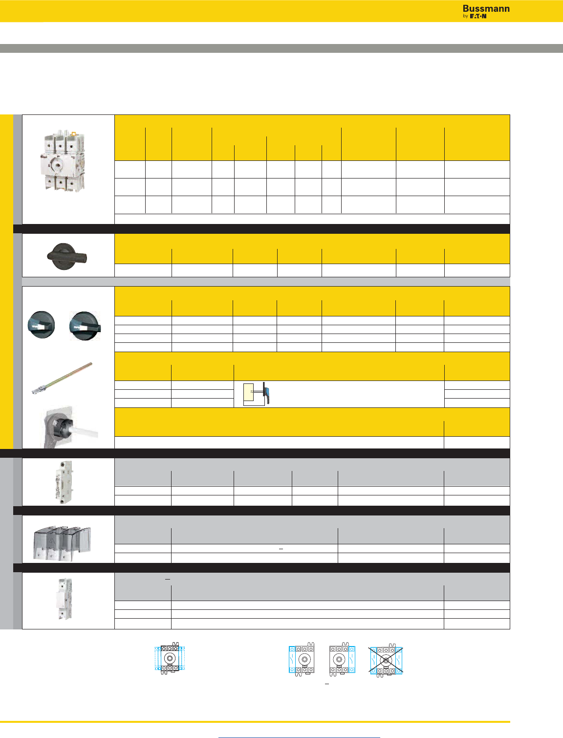
Disconnect Switches
UL 98 Non-Fused Rotary Disconnect Switches—30, 60 and Compact 100A
Visit us on the web at www.cooperbussmann.com/Disconnects
406
For a Complete Assembly, Please Select:
Select for Standard Applications
Switch
Max Horsepower Rating
Switch 1-Phase 3-Phase
Amp No. of 120 220/ 220/ 440/ 600 Wire Wire Part
Rating Poles SCCR Vac 240Vac 240Vac 480Vac Vac Size Type Number
30 3 100kA 2 5 10 20 25 #10-2/0 Str 75°C Cu RD30-3
#12-10 Sol
60 3 100kA 3 10 20 40 50 #10-2/0 Str 75°C Cu RD60-3
#12-10 Sol
100 3 25/100kA* 5 10 20 50 50 #10-2/0 Str 75°C Cu RD100-3
#12-10 Sol
*100kA @480Vac, 25kA @ 600Vac.
Direct Mount Handle - mounts directly to switch, no shaft required
For Switch Test Part
Part Number Color Function Padlockable Number
All Switches Black N Y - On Switch DIR-02
External Front or Right Side Operated Selector Handles - shaft required
NEMA Handle Test Part
Type Color Length Function Padlockable Defeatable Number
1, 3R, 4, 4X, 12 Black Short N Y Y H4X-01B(1)
1, 3R, 4, 4X, 12 Red/Yellow Short N Y Y H4X-01R(1)
1, 3R, 4, 4X, 12 Black Long N Y Y H4X-02B(2)
1, 3R, 4, 4X, 12 Red/Yellow Long N Y Y H4X-02R(2)
Shafts for Selector Handles
Length Mounting Depth Part
in (mm) (X) in (mm) Number
5.9 (150) 3.50~7.60 (89~193) SH4-150
7.9 (200) 3.50~9.50 (89~241) SH4-200
12.6 (320) 3.50~14.9 (89~378) SH4-320
Shaft Guide
Part
Number
Required for 12.6” (320mm) long shafts, optional for other lengths SH-GUIDE1
Auxillary Contacts
Contact Number of Continuous Voltage Max Number of Aux Part
Type Contacts Amp Rating Rating Contacts per Switch Number
NO + NC 1 of each 10A 240Vac 4 BAC01
NO 2 10A 240Vac 4 BAC02
+
+
Terminal Shrouds - includes terminal shroud for both lineside and loadside
Switch Amp Number Location on Part
Rating of Poles Switch Number
All Switches 1 (for switched 4th pole) Lineside and Loadside TSH3-1TB
All Switches 3 Lineside and Loadside TSH3-3TB
Switched 4th Pole - converts 3-pole switch to 4-pole
Switch Amp Part
Rating Number
30 POLE98-30
60 POLE98-60
100 POLE98-100
Auxiliary Contact Configurations Possible 4th Pole Configurations
X
Accessories
AUX CONTACTS
SHROUDS
SW. 4TH POLE SWITCH
HANDLES
or
+
and …
and …
and …
(2)(1)
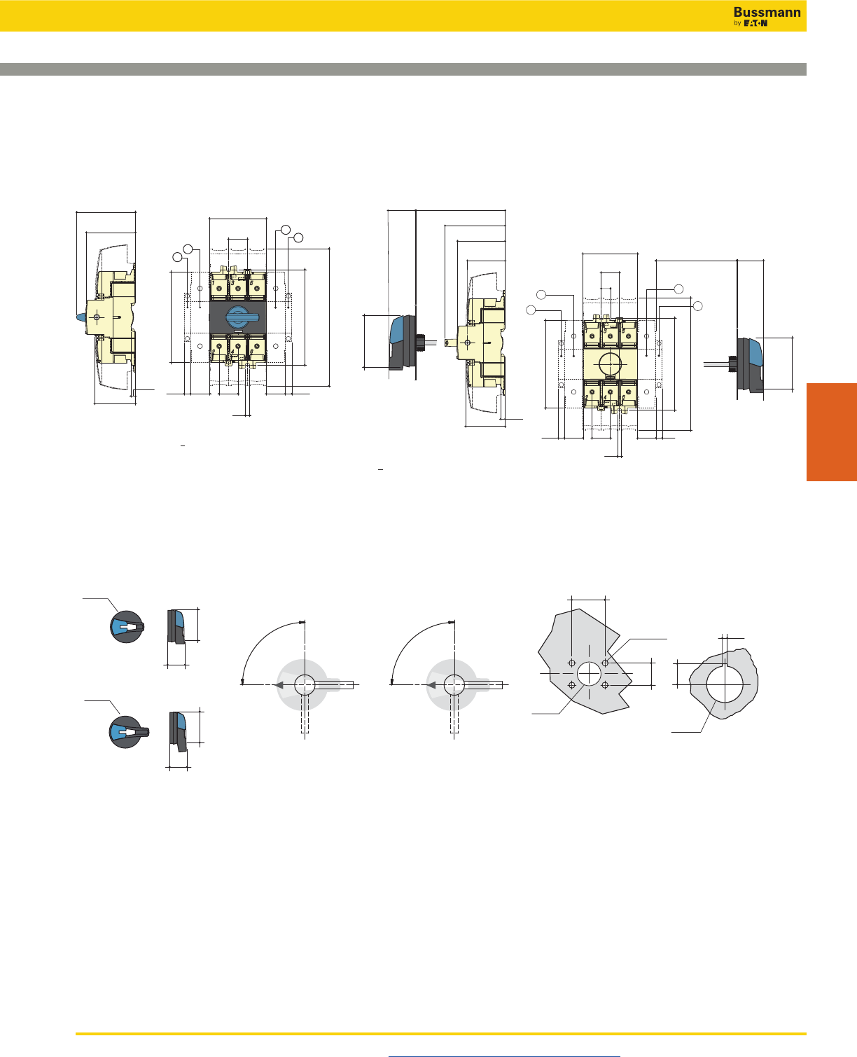
Disconnect Switches
UL 98 Non-Fused Rotary Disconnect Switches—30, 60 and Compact 100A
Visit us on the web at www.cooperbussmann.com/Disconnects 407
Disconnect
Switches
Dimensions - in (mm)
Direct Handle Operation
75
64
53
0.24
6
124.6
131.4
189
26
78
8.8 8.8
26 26 26
M5
2.95
2.52
2.09
4.91
0.35 0.351.021.02 1.02
5.17
7.44
1.02
3.07
21
2
1
36 100 min./372 max.
81
64
2.08
0.26
50.6
1.42 3.94 min./14.65 max.
3.19
2.52
1.99
53 6
2.79
71
13
124.6
131.4
189
26
78 36
8.8 8.8
26 26 26
M5
30 min./201 max.
3.07
1.02
0.51
1.18 min./7.91 max. 1.42
4.90
0.34 0.34
1.021.02
1.02
5.17
7.44
2.79
71
2
1
2
1
External Front Operation External Right Side Operation
13.5
Ø
22.5
3
40
4 Ø 7
Ø 31
28
With Mounting Nu
t
With 4 Mounting Screws
H4X-01_
Door Drilling LayoutsHandle Type
0
I
90°
Direction of Front Operation
0
I
90°
Direction of Right Side Operation
1.57
4 Ø 0.27
1.10
Ø 1.22
0.11
0.53
Ø
0.88
Ø3.07
1.42
2.79
Ø78
36
71
Ø78
37
88
Ø3.07
1.45
3.46
H4X-02_
1. Position for 1 switched 4th pole (1 per device max.) or 1 auxiliary contact.
2. Position for 1 auxiliary contact only.
Note: Maximum of 4 auxiliary contacts, or 3 auxiliary contacts + one switched 4th pole.
External Front or Right Side Operated Selector Handle
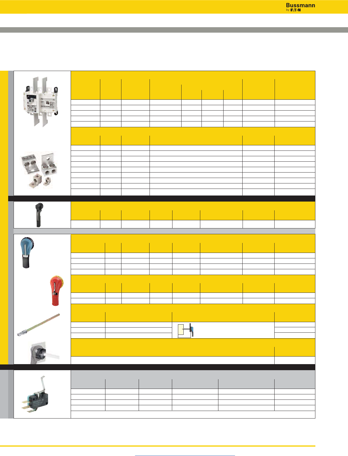
Disconnect Switches
UL 98 Non-Fused Rotary Disconnect Switches—100, 200 and 400A
Visit us on the web at www.cooperbussmann.com/Disconnects
408
For a Complete Assembly, Please Select:
Select for Standard Applications
Switch
Max Horsepower Rating
Switch 1-Phase 3-Phase
Amp No. of 220/ 220/ 440/ 600 Part
Rating Poles SCCR 240Vac 240Vac 480Vac Vac Number
100 3 200kA 10 30 75 100 RD100-3-SCCR
200 3 200kA 10 75 150 200 RD200-3
200 4 200kA 10 75 150 200 RD200-4
400 3 200kA - 125 250 350 RD400-3
400 4 200kA - 125 250 350 RD400-4
Terminal Lug Kit
Switch No. of Lugs Part
Amp Rating Poles Per Kit Wire Range Wire Type Number
100-200 2 2 #6-300MCM 75°C Cu/Al LUG1-2
100-200 3 3 #6-300MCM 75°C Cu/Al LUG1-3
100-200 4 4 #6-300MCM 75°C Cu/Al LUG1-4
400 2 2 #4-600MCM or Dual 1/0-250MCM 75°C Cu/Al LUG2-2
400 3 3 #4-600MCM or Dual 1/0-250MCM 75°C Cu/Al LUG2-3
400 4 4 #4-600MCM or Dual 1/0-250MCM 75°C Cu/Al LUG2-4
400 2 2 (2) #6-350MCM 75°C Cu/Al LUG3-2
400 3 3 (2) #6-350MCM 75°C Cu/Al LUG3-3
400 4 4 (2) #6-350MCM 75°C Cu/Al LUG3-4
Direct Mount Handle - mounts directly to switch, no shaft required
For Switch Test Part
Part Number Color Function Padlockable Number
All Switches Black N Y DIR-03
External Front Operated Pistol Handles - shaft required
NEMA Test Part
Type Color Function Padlockable Defeatable Number
1, 3R, 12 Black N Y Y H12-03B
1, 3R, 12 Red/Yellow N Y Y H12-03R
1, 3R, 4, 4X, 12 Black N Y Y H4X-06B
1, 3R, 4, 4X, 12 Red/Yellow N Y Y H4X-06R
Metallic Hasp (Heavy Duty) External Front Operated Pistol Handles - shaft required
NEMA Test Part
Type Color Function Padlockable Defeatable Number
1, 3R, 4, 4X, 12 Black N Y Y H4X-06BHD
1, 3R, 4, 4X, 12 Red/Yellow N Y Y H4X-06RHD
Shafts for Pistol Handles
Length Mounting Depth Part
in (mm) (X) in (mm) Number
7.9 (200) 5.31~10.43 (135~265) SH5-200
12.6 (320) 5.31~15.16 (135~385) SH5-320
15.7 (400) 5.31~18.31 (135~465) SH5-400
Shaft Guide
Part
Number
Required for 15.7” (400mm) long shafts, optional for other lengths SH-GUIDE2
Auxillary Contacts
Contact Number of Continuous Voltage Max Number of Aux Part
Type Contacts Amp Rating Rating Contacts per Switch Number
NO + NC 1 of each 10.1A 125-250Vac 2 BAC03*
NO + NC 1 of each 10.1A 125-250Vac 2 BAC04*
NO + NC 1 of each 1A 125Vac 2 BAC11*
NO + NC 1 of each 1A 125Vac 2 BAC12*
* For one auxiliary contact, install either BAC03 or BAC11. For two auxiliary contacts, install BAC03 + BAC04, or BAC11 + BAC12.
+
+
+
X
Accessories
and …
AUX CONTACTS SWITCH + LUGS
HANDLE
or
or
+
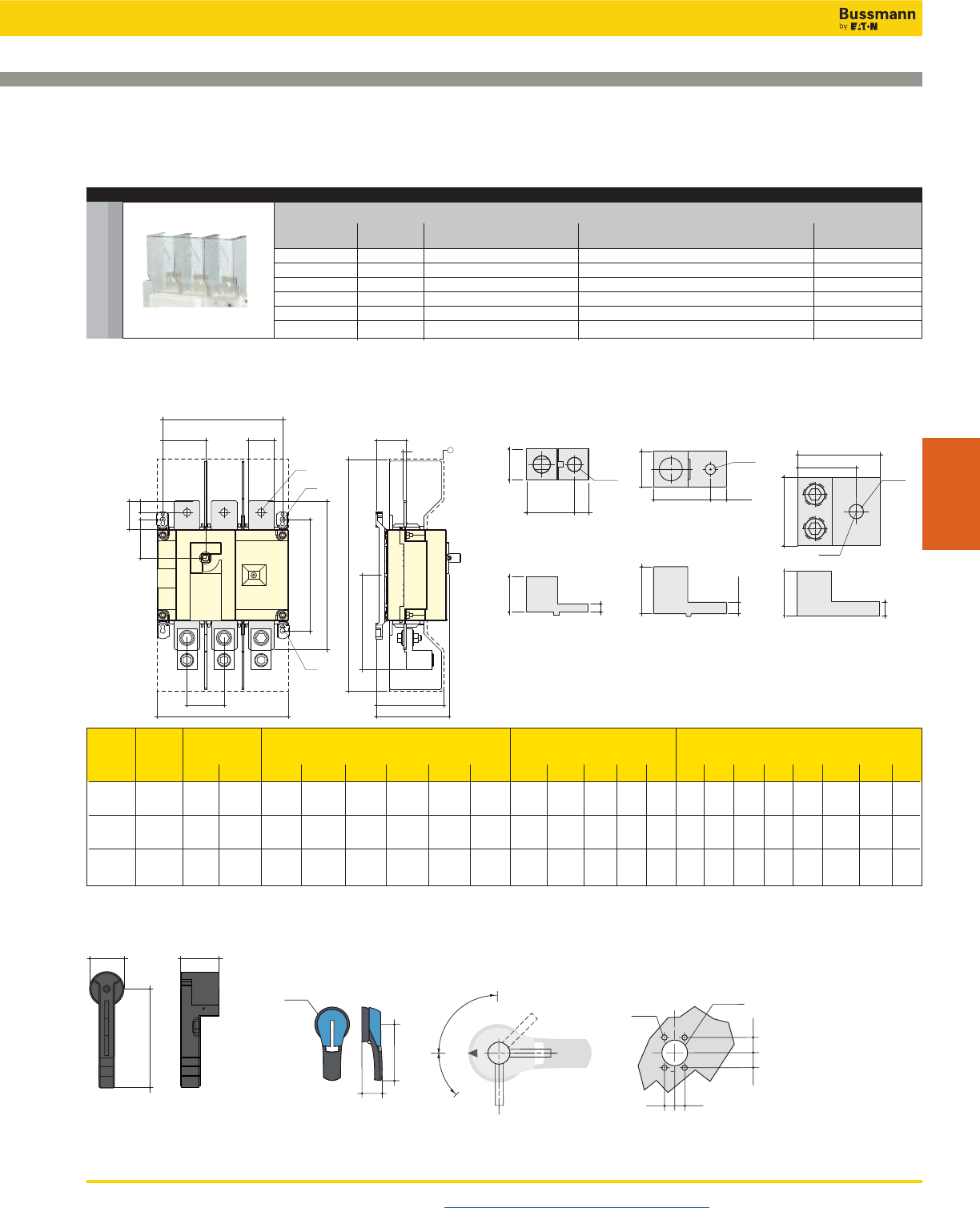
Disconnect Switches
UL 98 Non-Fused Rotary Disconnect Switches—100, 200 and 400A
Visit us on the web at www.cooperbussmann.com/Disconnects 409
Disconnect
Switches
Accessories
Terminal Shrouds - includes terminal shroud for lineside or loadside
Switch Amp Number Location on Part
Rating of Poles Switch Number
100-200A 3 Lineside TSH4-3T
100-200A 3 Loadside TSH4-3B
100-200A 4 Lineside or Loadside TSH4-4TB
400A 3 Lineside TSH5-3T
400A 3 Loadside TSH5-3B
400A 4 Lineside or Loadside TSH5-4TB
Y
AC
KCA
V
N
AA
H
ZJ1 U
R1
M
ADT
FC
1
R2
W
Switch Overall Terminal Switch Switch
Rating Dimen. Shrouds Body Mounting Connection
(A) C AC AD F 3p. F 4p. H J1 3p. J1 4p. K M 3p. M 4p. N R1 R2 T U V W Y Z AA AC
100 3.72 10.1 3.05 7.09 9.06 4.22 2.17 4.13 1.8 6.3 8.27 5.31 0.35 0.27 1.97 0.98 1.18 0.43 0.14 1.35 6.3 0.6
(94.6) (256) (77.5) (180) (230) (107) (55) (105) (45.6) (160) (210) (135) (9) (7) (50) (25) (30) (11) (3.5) (34.4) (160) (15)
200 3.72 10.1 3.05 7.09 9.06 4.22 2.17 4.13 1.8 6.3 8.27 5.31 0.35 0.27 1.97 0.98 1.18 0.43 0.14 1.35 6.3 0.6
(94.6) (256) (77.5) (180) (230) (107) (55) (105) (45.6) (160) (210) (135) (9) (7) (50) (25) (30) (11) (3.5) (34.4) (160) (15)
400 4.92 16 4.15 9.05 11.4 6.53 2.95 5.31 2.65 8.26 10.6 7.67 0.35 0.27 2.56 1.77 1.97 0.43 0.2 2.08 10.2 0.8
(128) (406) (115) (230) (290) (166) (75) (135) (67.5) (210) (270) (195) (9) (7) (65) (45) (50) (13) (5) (53) (260) (20)
Dimensions - in (mm)
1.57
40
5.31
135
1.79
45.5
Direct Mount Handle
H4X-06__
H12-03__
65°
TEST
90°
0
Ø78
1.77
4.92
Direction of Front Operation
Handle Type Door Drilling Layout
Ø3.07
0.78
4 Ø 0.27
0.55
Ø 1.46
4 Ø 7
Ø 37
20
20
14 0.55
14
0.78
45
125
I
External Front Handle
Terminal Lugs
400A
LUG2-__
100 to 200A
LUG1-__
400A
LUG3-__
1.52
38.8
1
25
1.12
28.6
0.45
Ø11.6
0.46
11.68
0.25
6.35
2.8
71.5
Ø 0.4
Ø 4.7
1.3
35
1.8
46
0.44
11.13
0.63
15.88
0.88
73.15
2.31
58.67 0.53
13.46
1.19
30.23
1.94
49.30
0.25
6.35
1.25
31.75
DIR-03
and …
SHROUDS
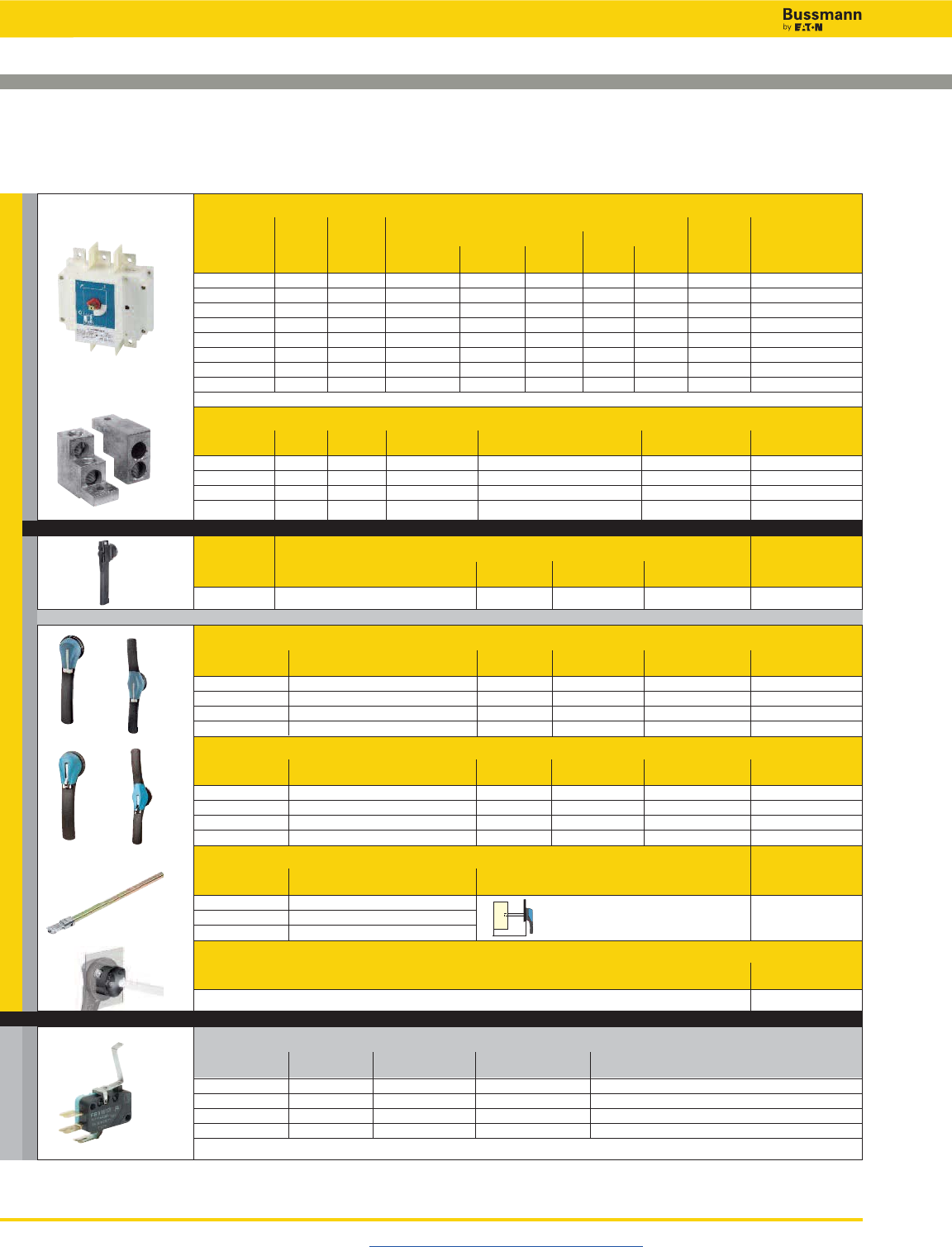
Disconnect Switches
UL 98 Non-Fused Rotary Disconnect Switches—600, 800, 1000 and 1200A
Visit us on the web at www.cooperbussmann.com/Disconnects
410
For a Complete Assembly, Please Select:
Select for Standard Applications
Switch
Max Horsepower Rating
Switch 3-Phase DC*
Amp No. of 220/ 440/ 600 125 250 Part
Rating Poles SCCR 240Vac 480Vac Vac Vdc Vdc Number
600A 3 200kA 240 400 350 20 50 RD600-3
600A 4 200kA 240 400 350 20 50 RD600-4
800A 3 100kA 200 500 500 - - RD800-3
800A 4 100kA 200 500 500 - - RD800-4
1000A 3 100kA 200 500 500 - - RD1000-3
1000A 4 100kA 200 500 500 - - RD1000-4
1200A 3 100kA 200 500 500 - - RD1200-3
1200A 4 100kA 200 500 500 - - RD1200-4
* DC Ratings use two poles in series.
Terminal Lug Kit
Switch No. of Lugs Lugs Required Wire Part
Amp Rating Poles Per Kit per Pole Range Wire Type Number
600 3 3 1 (2) #2-600MCM 75°C Cu/Al LUG5-3
600 4 4 1 (2) #2-600MCM 75°C Cu/Al LUG5-4
800-1200 3 6 2 (4) #2-600MCM 75°C Cu/Al LUG6-6
800-1200 4 8 2 (4) #2-600MCM 75°C Cu/Al LUG6-8
Direct Mount Handle - mounts directly to switch, no shaft required
For Switch Test Part
Part Number Color Function Padlockable Number
All Switches Black N Y DIR-04
External Front Operated Pistol Handles - shaft required
NEMA Test Part
Type Color Function Padlockable Defeatable Number
1, 3R, 4, 4X, 12 Black N Y Y H4X-07B(1)
1, 3R, 4, 4X, 12 Red/Yellow N Y Y H4X-07R(1)
1, 3R, 4, 4X, 12 Black N Y Y H4X-08B(2)
1, 3R, 4, 4X, 12 Red/Yellow N Y Y H4X-08R(2)
Metallic Hasp (Heavy Duty) External Front Operated Pistol Handles - shaft required
NEMA Test Part
Type Color Function Padlockable Defeatable Number
1, 3R, 4, 4X, 12 Black N Y Y H4X-07BHD(3)
1, 3R, 4, 4X, 12 Red/Yellow N Y Y H4X-07RHD(3)
1, 3R, 4, 4X, 12 Black N Y Y H4X-08BHD(4)
1, 3R, 4, 4X, 12 Red/Yellow N Y Y H4X-08RHD(4)
Shafts for Pistol Handles
Length Mounting Depth Part
in (mm) (X) in (mm) Number
7.9 (200) 8.70~13.50 (221~343) SH6-200
12.6 (320) 8.70~18.23 (221~463) SH6-320
15.7 (400) 8.70~21.38 (221~543) SH6-400
Shaft Guide
Part
Number
Required for 15.7” (400mm) long shafts, optional for other lengths SH-GUIDE2
Auxillary Contacts
Contact Number of Continuous Voltage Max Number of Aux Part
Type Contacts Amp Rating Rating Contacts per Switch Number
NO + NC 1 of each 10.1A 125-250Vac 2 BAC03*
NO + NC 1 of each 10.1A 125-250Vac 2 BAC04*
NO + NC 1 of each 1A 125Vac 2 BAC11*
NO + NC 1 of each 1A 125Vac 2 BAC12*
* For one auxiliary contact, install either BAC03 or BAC11. For two auxiliary contacts, install BAC03 + BAC04, or BAC11 + BAC12.
+
or
+
+
X
(1) (2)
(3) (4)
Accessories
AUX CONTACTS SWITCH + LUGS
HANDLE
or
+
and …
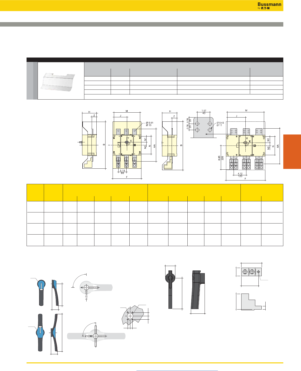
Disconnect Switches
UL 98 Non-Fused Rotary Disconnect Switches—600, 800, 1000 and 1200A
Visit us on the web at www.cooperbussmann.com/Disconnects 411
Disconnect
Switches
Accessories
Terminal Shrouds* - includes terminal shroud for lineside or loadside
Switch Amp Number Location on Part
Rating of Poles Switch Number
600A 3 Lineside or Loadside TSH6-3TB
600A 4 Lineside or Loadside TSH6-4TB
800-1200A 3 Lineside or Loadside TSH7-3TB
800-1200A 4 Lineside or Loadside TSH7-4TB
* Shroud for lineside included with switch.
600A
Switch Terminal Switch Switch
Rating Shrouds Body Mounting Connection
(A) B F 3p. F 4p. H J 3p. J 4p. M 3p. M 4p. N N1 N2 AA Z
600 18.12 11 14.17 5.5 5 6.59 10.03 13.19 6.88 2.34 1.10 12.6 1.85
(460) (280) (360) (140) (127.5) (167.5) (255) (335) (175) (59.5) (28) (320) (47)
800 18.12 14.64 19.37 5.5 6.83 9.19 13.66 18.38 6.88 2.34 1.10 13 1.85
(460) (372) (492) (140) (173.5) (233.5) (347) (467) (175) (59.5) (28) (330) (47)
1000 18.12 14.64 19.37 5.5 6.83 9.19 13.66 18.38 6.88 2.34 1.10 13 1.85
(460) (372) (492) (140) (173.5) (233.5) (347) (467) (175) (59.5) (28) (330) (47)
1200 18.12 14.64 19.37 5.5 6.83 9.19 13.66 18.38 6.88 2.34 1.10 13 1.85
(460) (372) (492) (140) (173.5) (233.5) (347) (467) (175) (59.5) (28) (330) (47)
800 to 1200A
H4X-07__
61
210
90°
0
Direction of Front Operation
Handle Type
Door Drilling Layout
Ø3.07
Ø78
0.78
4 Ø 0.27
0.55
Ø 1.46
4 Ø 7
Ø 37
20
20
14 0.55
14
0.78
8.27
2.4
H4X-08__ 2.36
13.78
Ø3.07
90°
I
0
Ø78
350
60
I
Terminal Lugs
600 to 1200A
LUG5-__, LUG6-__
3.15
80
1.49
38
2.87
73
0.40
Ø10.2
3.76
95.5
0.64
16.2
60
2.36
85
3.35
190
7.48
Direct Mount Handle
DIR-04
External Front Pistol Handles
Dimensions - in (mm)
and …
SHROUDS
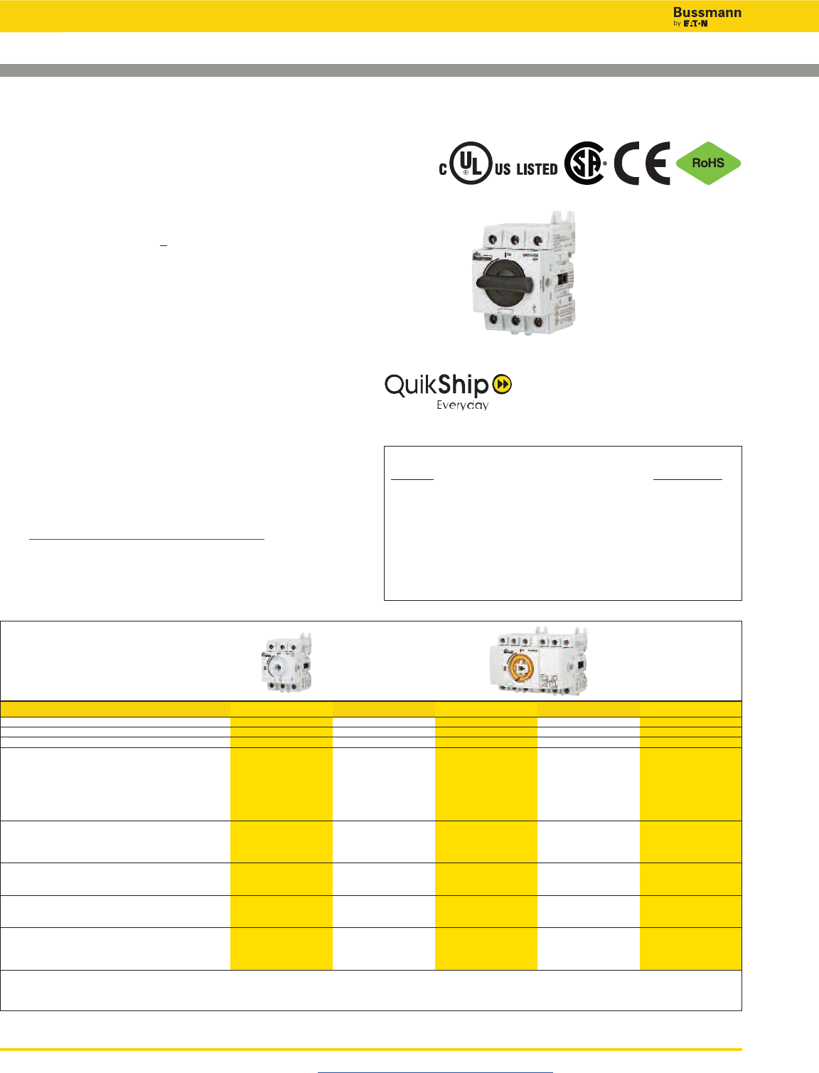
Disconnect Switches
UL 508 Non-Fused Rotary Disconnect Switches—16 to 80A
Visit us on the web at www.cooperbussmann.com/Disconnects
412
Description
Bussmann UL 508 load break disconnect switches allow safe
control and safe disconnection of any motor application or to
isolate a circuit within the panel.
These disconnect switches are compact and offer a wide
variety of accessories like 4th poles, auxiliary contacts, door
mounting and 6/8-Pole kits.
Features
• Suitable as motor disconnect
• DIN-Rail or panel mount
• Door mount option
• Disconnect switches are front, right side or
direct handle operable
• Finger-safe
Agency Information
• UL508, Guide NLRV, File E155129
• CSA C22.2 No. 14, File 257020
• Conforms with IEC 60947-3
Online Resources
Visit www.cooperbussmann.com/Disconnects for:
• CAD Drawings
• Instruction Sheets
• UL Information
Related Cooper Bussmann Products
Product Data Sheet #
Fuses Blocks
Modular Knifeblade Fuse Blocks 100-600A 3192
Fuses Holders
CH Series Class CC, Midget & 10x38 0-30A 3185
Finger-Safe Optima Series 0-30A 1102
Optima™ Protection Modules 0-30A 1109
CH Series Class J 0-60A 2144
Part Number RD16-3-508 RD25-3-508 RD40-3-508 RD63-3-508 RD80-3-508
Thermal Current Ith at 40°C (A) 16 25 40 63 80
Rated insulation voltage Ui(V) 800 800 800 800 800
Rated impulse withstand voltage Uimp (kV) 88888
Rated Operation Currents Ie(A)
Load Duty Category Rated Voltage A/B (1) A/B (1) A/B (1) A/B (1) A/B (1)
500Vac AC-22 A/AC-22 B 16/16 25/25 40/40 63/63 80/80
500Vac AC-23 A/AC-23 B 16/16 25/25 25/25 63/63 63/63
690Vac AC-21 A/AC-21 B 16/16 25/25 40/40 63/63 80/80
690Vac AC-22 A/AC-22 B 16/16 25/25 32/40 40/63 63/80
690Vac AC-23 A/AC-23 B 16/16 25/25 25/25 40/40 40/40
Operational Power in AC-23 (kW)
400Vac without prebreak AC (1)(2) 7.5 11 18.5 30 37
500Vac without prebreak AC (1)(2) 7.511153037
690Vac without prebreak AC (1)(2) 7.5 1518.530 37
Overload Capacity (Ue415 Vac)
Rated short-time withstand current 0.3 s. ICW (kA rms) (3) 2.5 2.5 2.5 3 3
Rated short-time making capacity Icm (kA peak) (3) 66699
Fuse Protected Short-Circuit Withstand (kA rms Prospective)
Prospective short-circuit current (kA rms) (3) 50 50 50 50 50
Associated fuse rating (A) (3) 16 25 40 63 80
Connection
Minimum Cu cable cross section (mm2) 1.5 1.5 1.5 2.5 2.5
Maximum Cu cable section (mm2) 1616163535
Tightening torque min/max (N•m) 2/2.2 2/2.2 2/2.2 3.5/3.85 3.5/3.85
(1) A/B: Category with index A = frequent operation; category with index B = infrequent operation.
(2) The power value is given for information only; the current values vary from one manufacturer to another.
(3) For a rated operating voltage, Ue= 400Vac.
IEC Electrical Specifications
RD16-3-508 RD16-3-508 with 6-Pole Conversion Kit
QuikShip Everyday Service ships the
most common part numbers within
24 hours. Contact your Bussmann
representative for details.
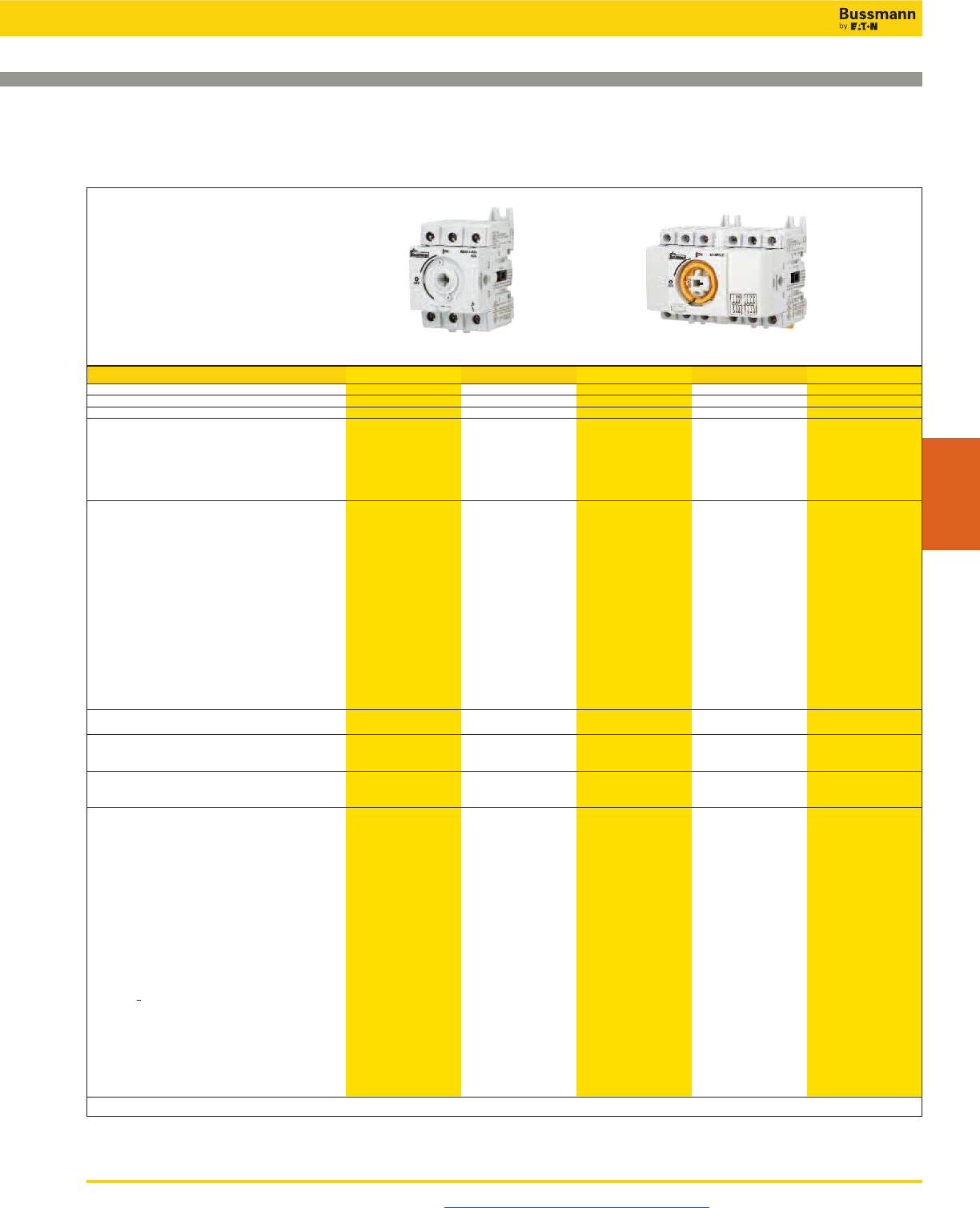
Disconnect Switches
UL 508 Non-Fused Rotary Disconnect Switches—16 to 80A
Visit us on the web at www.cooperbussmann.com/Disconnects 413
Disconnect
Switches
Part Number RD16-3-508 RD25-3-508 RD40-3-508 RD63-3-508 RD80-3-508
UL Standard UL 508 UL 508 UL 508 UL 508 UL 508
Max Ampacity 16A 25A 40A 63A 80A
Handle Operation Front/Side Front/Side Front/Side Front/Side Front/Side
UL Electrical Ratings
Max Voltage (AC) 600Vac 600Vac 600Vac 600Vac 600Vac
Maximum Horsepower Ratings
3-Phase, 208Vac 3 7.5 7.5 15 15
3-Phase, 240Vac 5 7.5 7.5 20 20
3-Phase, 480Vac 10 15 20 40 40
3-Phase, 600Vac 10 20 25 40 40
Electrical Characteristics
SCCR with Fuse 65kA 65kA 10/65kA 50/65kA 50/65kA
Recommended Upstream
Fuse Class JJJJJ
Max. Fuse Rating 30A 30A 60/30A 100/60A 100/60A
Terminals Integral Integral Integral Integral Integral
Wire Type 75°C Cu 75°C Cu 75°C Cu 75°C Cu 75°C Cu
Wire Range & Torque - Lb-IN (N•m)
Solid
Single #14-10 #14-10 #14-10 #14-10 #14-10
26.5 (3) 26.5 (3) 26.5 (3) 31.1 (3.5) 31.1 (3.5)
Dual #12 #12 #12 #12 #12
26.5 (3) 26.5 (3) 26.5 (3) 31.1 (3.5) 31.1 (3.5)
Stranded
Single #14-4 #14-4 #14-4 #14-1 #14-1
26.5 (3) 26.5 (3) 26.5 (3) 31.1 (3.5) 31.1 (3.5)
Dual #14-12 #14-12 #14-12 #10-6 #10-6
26.5 (3) 26.5 (3) 26.5 (3) 31.1 (3.5) 31.1 (3.5)
Mechanical Characteristics
Endurances/Cycles 10,000 10,000 10,000 10,000 10,000
Physical Characteristics
Dimensions - See drawings on product pages
Weight - Lb (KG) 0.5 (0.2) 0.5 (0.2) 0.5 (0.2) 0.7 (0.32) 0.7 (0.32)
Environmental
Operating Temperature -20°C to 70°C -20°C to 70°C -20°C to 70°C -20°C to 70°C -20°C to 70°C
Flammability Rating UL 94-V0 UL 94-V0 UL 94-V0 UL 94-V0 UL 94-V0
Accessories
Handles
Direct DIR-01 DIR-01 DIR-01 DIR-01 DIR-01
Short Selector/NEMA 1, 3R, 4, 4X, 12 H4X-01B H4X-01B H4X-01B H4X-01B H4X-01B
H4X-01R H4X-01R H4X-01R H4X-01R H4X-01R
Long Selector/NEMA 1, 3R, 4, 4X, 12 H4X-02B H4X-02B H4X-02B H4X-02B H4X-02B
H4X-02R H4X-02R H4X-02R H4X-02R H4X-02R
Shafts - 5x5mm
5.9”/150mm SH4-150 SH4-150 SH4-150 SH4-150 SH4-150
7.9”/200mm SH4-200 SH4-200 SH4-200 SH4-200 SH4-200
12.6”/320mm SH4-320 SH4-320 SH4-320 SH4-320 SH4-320
Shaft Guide SH-GUIDE1 SH-GUIDE1 SH-GUIDE1 SH-GUIDE1 SH-GUIDE1
Door Mount Kit DOOR-508 DOOR-508 DOOR-508 DOOR-508 DOOR-508
Shrouds/Switch Amps
1-Pole TSH1-1TB TSH1-1TB TSH1-1TB
3-Pole (Loadside and Lineside) TSH1-3TB TSH1-3TB TSH1-3TB TSH2-3TB TSH2-3TB
Switched 4th Pole/Switch Amps POLE-16 POLE-25 POLE-40 — —
Auxiliary Contacts
NO + NC (1 ea.) BAC01 BAC01 BAC01 BAC01 BAC01
(2) NO BAC02 BAC02 BAC02 BAC02 BAC02
AC Ratings
Volts 240Vac 240Vac 240Vac 240Vac 240Vac
Amps 10A 10A 10A 10A 10A
6-/8-Pole Conversion Kit
Gangs two switches of same rating, 16-80A switch amps KIT-6POLE KIT-6POLE KIT-6POLE KIT-6POLE KIT-6POLE
— Not available.
Specifications
RD16-3-508 RD16-3-508 with 6-Pole Conversion Kit
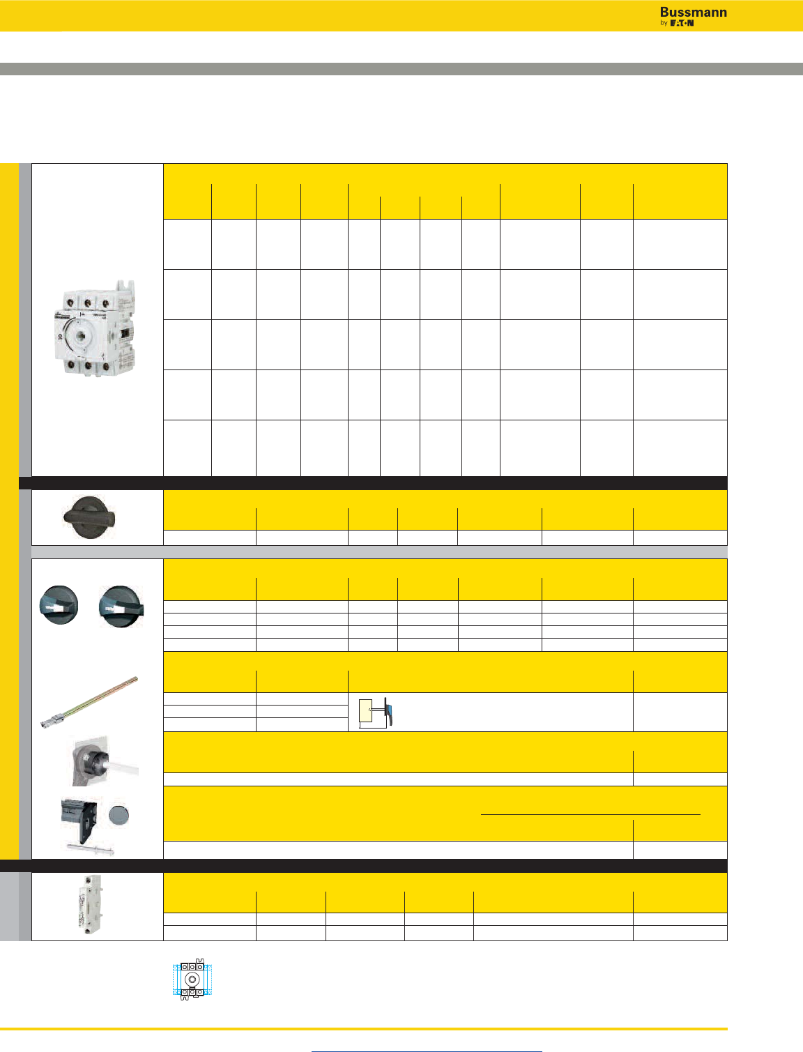
Disconnect Switches
UL 508 Non-Fused Rotary Disconnect Switches—16, 25, 40, 63 and 80A
Visit us on the web at www.cooperbussmann.com/Disconnects
414
For a Complete Assembly, Please Select:
Select for Standard Applications
Switch
Switch Max Max Horsepower Rating, 3-Ph
Amp No. of SCCR Class J 208 220/ 440/ 600 Part
Rating Poles @600V Fuse Vac 240Vac 480Vac Vac Wire Size Wire Type Number
#14-#10 Sol
16 3 65kA 30A 3 5 10 10 Dual #12 Sol 75°C Cu RD16-3-508
#14-#4 Str
Dual #14-#12 Str
#14-#10 Sol
25 3 65kA 30A 7.5 7.5 15 20 Dual #12 Sol 75°C Cu RD25-3-508
#14-#4 Str
Dual #14-#12 Str
#14-#10 Sol
40 3 10kA 60A 7.5 7.5 20 25 Dual #12 Sol 75°C Cu RD40-3-508
65kA 30A #14-#4 Str
Dual #14-#12 Str
#14-#10 Sol
63 3 50kA 100A 15 20 40 40 Dual #12 Sol 75°C Cu RD63-3-508
65kA 60A #14-#1 Str
Dual #10-#6 Str
#14-#10 Sol
80 3 50kA 100A 15 20 40 40 Dual #12 Sol 75°C Cu RD80-3-508
65kA 60A #14-#1 Str
Dual #10-#6 Str
Direct Mount Handle - mounts directly to switch, no shaft required
For Switch Test Part
Part Number Color Function Padlockable Number
All Switches Black N Y - On Switch DIR-01
External Front or Right Side Operated Selector Handles - shaft required
NEMA Handle Test Part
Type Color Length Function Padlockable Defeatable Number
1, 3R, 4, 4X, 12 Black Short N Y Y H4X-01B(1)
1, 3R, 4, 4X, 12 Red/Yellow Short N Y Y H4X-01R(1)
1, 3R, 4, 4X, 12 Black Long N Y Y H4X-02B(2)
1, 3R, 4, 4X, 12 Red/Yellow Long N Y Y H4X-02R(2)
Shafts for Selector Handles - required for 12.6” (320mm) shafts
Length Mounting Depth Part
in (mm) (X) in (mm) Number
5.9 (150) 3.50-7.60 (89-193) SH4-150
7.9 (200) 3.50-9.50 (89-241) SH4-200
12.6 (320) 3.50-14.9 (89-378) SH4-320
Shaft Guide
Part
Number
Required for 12.6” (320mm) long shafts, optional for other lengths. SH-GUIDE1
Door Mount Kit - for mounting switch on the right side of the enclosure or directly on the enclosure door
using switch side operation shaft location. Kit includes a shaft. Order switch and selector handle separately.
Switch Part
Rating Number
All Switches - kit includes shaft DOOR-508
Auxillary Contacts
Contact Number of Continuous Voltage Max Number of Aux Part
Type Contacts Amp Rating Rating Contacts per Switch Number
NO + NC 1 Ea 10A 240Vac 4 BAC01
NO 2 10A 240Vac 4 BAC02
+
+
+
(2)(1)
Auxiliary Contact
Configurations
X
Acc.
AUX CONTACTS SWITCH
HANDLE
or
+
and …
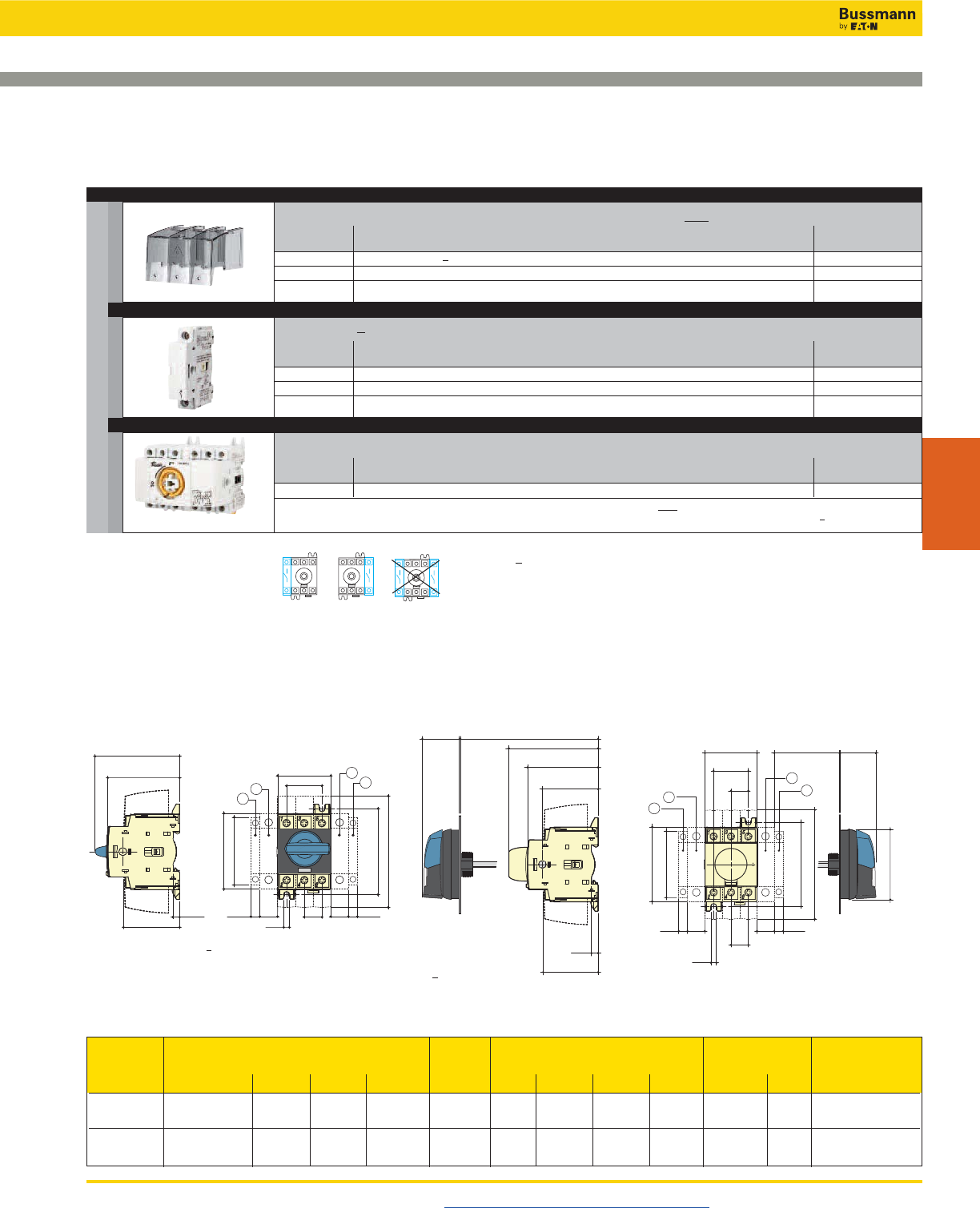
Disconnect Switches
UL 508 Non-Fused Rotary Disconnect Switches—16, 25, 40, 63 and 80A
Visit us on the web at www.cooperbussmann.com/Disconnects 415
Disconnect
Switches
Accessories
Switched 4th Pole - converts 3-pole switch to 4-pole switch
Switch Amp Part
Rating Number
16 POLE-16
25 POLE-25
40 POLE-40
6-Pole Conversion Kit - creates a 6-pole switch by ganging two 3-pole switches of equal rating
Switch Amp Part
Rating Number
All Switches KIT-6POLE*
* Kit ships with a direct handle. If external handle is needed order a selector handle and shaft for the UL 508 Rotary Disconnect Switches.
Note: To create an 8-pole switch from 16 to 40 amp switches, use two 3-pole switches of equal ratings plus two switched 4th poles (part # POLE-_).
Terminal Shrouds - includes terminal shroud for both lineside and loadside
Switch Amp Number Location on Part
Rating of Poles Switch Number
16-40A 1 (for switched 4th pole) Lineside and Loadside TSH1-1TB
16-40A 3 Lineside and Loadside TSH1-3TB
63-80A 3 Lineside and Loadside TSH2-3TB
Switched 4th Pole
Configurations.
Order switches separately.
Dimensions – in (mm)
Direct Handle Operation External Front Operation External Side Operation
Overall Terminal Switch Switch
Switch Dimensions Shroud Body Mounting Connection
Rating (A) D min D max E min E max AC F F1 G J M N T
16 to 40 1.18 9.25 3.94 14.64 4.33 1.77 0.59 2.67 0.59 1.18 2.95 0.59
(30) (235) (100) (372) (110) (45) (15) (68) (15) (30) (75) (15)
63 to 80 1.18 9.25 3.93 14.64 4.33 2.06 0.69 2.99 0.69 1.38 3.35 0.69
(30) (235) (100) (372) (110) (52.5) (17.5) (76) (17.5) (35) (85) (17.5)
2.67
F
T
M5
M
N
G
AC
2.52
0.24
1.97
2.95
F1F10.35
212
1
75
64
6
50
68
8.88.8 0.35
J
2.68
F
T
M5
M
1.42D
N
G
AC
E1.42 3.19
2.52
0.23
1.96
1.99
F10.35 F1
ø 2.79
36 81
64
50.6
6
50
8.8 8.8
68
ø 71
36
0.35
2
2
1
1
1. Position for 1 switched 4th pole (1 per device max.) or 1 auxiliary contact.
2. Position for 1 auxiliary contact only.
Note: Maximum of 4 auxiliary contacts, or 3 auxiliary contacts + one switched 4th pole.
and …
SHROUDS
SW. 4TH POLE
6-POLE KIT
and …
and …
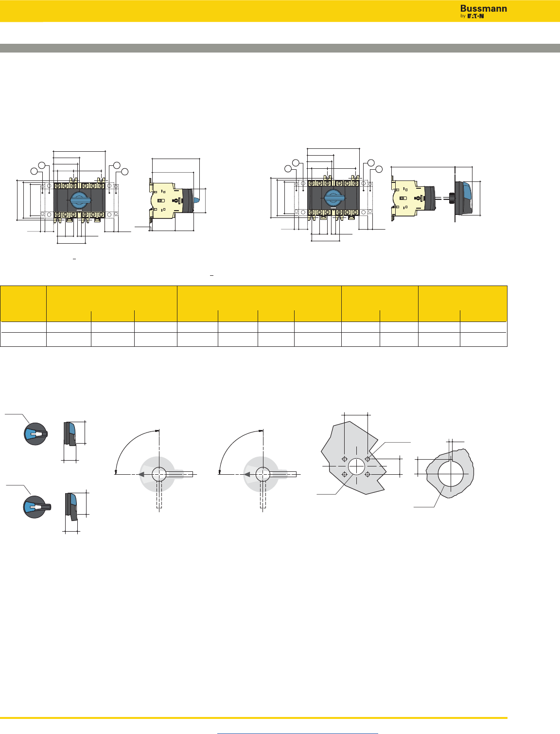
Disconnect Switches
UL 508 Non-Fused Rotary Disconnect Switches—16, 25, 40, 63
and 80A
Visit us on the web at www.cooperbussmann.com/Disconnects
416
External Selector Handles
13.5
Ø
22.5
3
40
4 Ø 7
Ø 31
28
With Mounting Nu
t
With 4 Mounting Screws
H4X-01_
Door Drilling LayoutsHandle Type
0
I
90°
Direction of Front Operation
0
I
90°
Direction of Right Side Operation
1.57
4 Ø 0.27
1.10
Ø 1.22
0.11
0.53
Ø
0.88
Ø3.07
1.42
2.79
Ø78
36
71
Ø78
37
88
Ø3.07
1.45
3.46
H4X-02_
1. Position for 1 switched 4th pole (1 per device max.) or 1 auxiliary contact.
2. Position for 1 auxiliary contact only.
Note: Maximum of 4 auxiliary contacts, or 3 auxiliary contacts + one switched 4th pole.
External Front Operation for 6/8-Pole Disconnects
1.77
3.07
1.361.69
0.24
3.50
X
N
G
2.67
TT 0.29
2.06
M
F2
2.06
F
J
F1F10.35
212
189
78
43 34.7
6
45
52.5
68
8.8
52.5
8.8
7.5
0.35
1.42E
ø 2.79
X
N
G
2.67
TT 0.29
2.06
M
F2
2.06
F
J
F1F10.35
212
1
36
ø 71
52.5
68
8.8
52.5
8.8
7.5
0.35
Overall Switch Switch
Switch Dimensions Body Mounting Connection
Rating (A) E min E max F F1 F2 G J M N T X
16 to 40 4.13 (105) 14.64 (372) 3.83 (97.5) 0.59 (15) 1.77 (45) 2.67 (68) 1.92 (48.75) 1.18 (30) 2.95 (75) 0.59 (15) 0.29 (7.5)
63 to 80 4.13 (105) 14.65 (372) 4.13 (105) 0.69 (17.5) 2.06 (52.5) 2.99 (76) 2.06 (52.5) 1.38 (3.5) 3.35 (85) 0.69 (17.5) 0.34 (8.75)
Dimensions – in (mm)
Direct Front Operation for 6/8-Pole Disconnects
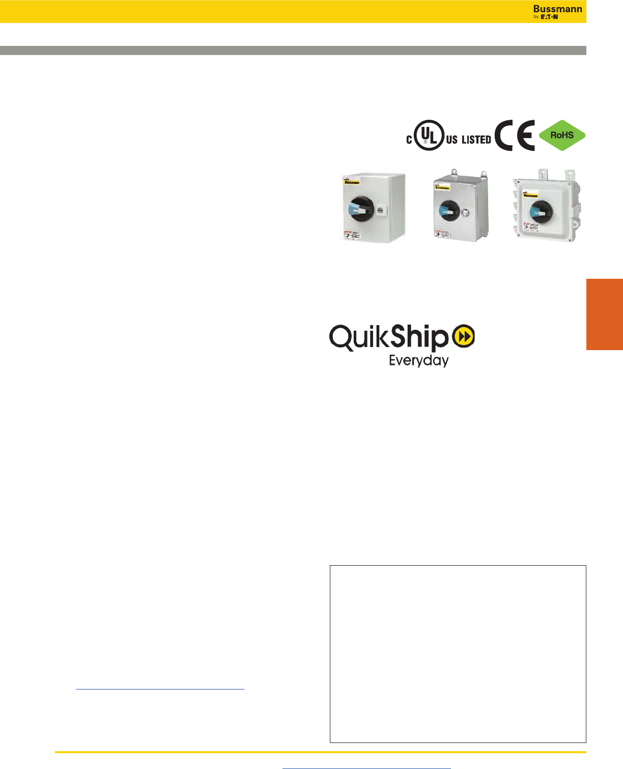
Disconnect Switches
UL 98 & UL 508 Enclosed Disconnect Switches
Visit us on the web at www.cooperbussmann.com/Disconnects 417
Disconnect
Switches
Description
Fused and non-fused enclosed Rotary Disconnect Switches
from 16 to 1200A in NEMA 1, 3R, 4, 4X, 12 enclosures.
Features
• UL 98 Listed for general purpose, main disconnect, or
branch circuit protection up to 600Vac/dc
• UL 508 Listed for motor disconnect applications up to
600Vac
• Multiple field installed accessories enhance the enclosed
disconnect switches to fit the desired application
• Lockout/tagout: Up to three 1⁄4˝ shank padlocks can be
installed on external handles
Ratings:
• Volts: 600Vac
250-600Vdc*
• Amps: 16-1200A
• Short-Circuit Current Ratings: UL 98: 25kA-200kA
UL 508: 10kA-65kA
*Some non-fused disconnect switches are not rated for DC applications.
Specifications
• Operating temperature: -20ºC to 70ºC
• 4X Plastic Enclosure Flammability Rating:
Polycarbonate UL 94-5VA-0
Fiberglass UL 94-5V
Agency Information
• UL 98 Listed: File E182262, Guide WIAX, WIAX7
• UL 508 Listed: File E155129, Guide NLRV, NLRV7
• cULus Listed to CSA Standard 22.2, No. 14
• cULus Listed to CSA Standard 22.2, No. 4
• Conforms with IEC 60947-3
• CE Compliant
• RoHS Compliant
Field Installed Accessories
• Auxiliary contacts
• Terminal shrouds
Online Resources
Visit www.cooperbussmann.com/Disconnects for:
• CAD Drawings
• Instruction Sheets
• UL Information
NEMA 1, 3R, 4 & 12 NEMA 4X
Polycarbonate
or Fiberglass
NEMA 4X
Stainless Steel
Available Bussmann Fuses
Class Type Data Sheet #
CC LP-CC Time-Delay, Current Limiting 1023
CC FNQ-R Time-Delay 1014
CC KTK-R Fast-Acting 1015
J LPJ Time-Delay, Current Limiting 1006 (0-60A)
J 1007 (70-600A)
J With easyID™open fuse indication 1062 (6-60A)
J 1063 (70-600A)
J JKS Fast-Acting Fuses 1026 (0-60A)
J 1027 (70-600A)
J DFJ High Speed Drive Fuse 1048 (0-600A)
L KRP-C Time-Delay, Current Limiting 1008
L KTU Fast-Acting 1010
L KLU Time-Delay 1013
QuikShip Everyday Service ships the most common part
numbers within 24 hours. Contact your Bussmann
representative for details.
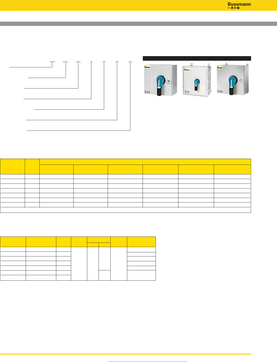
Disconnect Switches
UL 98 Enclosed Fused Disconnects—30 to 800A
Visit us on the web at www.cooperbussmann.com/Disconnects
418
UL General NEMA Enclosure Type & Part Number
Purpose Fuse
Amp Rating Type 1 3R 4 4X Plastic(1) 4X Stainless 12
30 J ER1-30J3PB ER3R-30J3PB ER4-30J3PB ER4P-30J3PB ER4X-30J3PB ER12-30J3PB
60 J ER1-60J3PB ER3R-60J3PB ER4-60J3PB ER4P-60J3PB ER4X-60J3PB ER12-60J3PB
100 J ER1-100J3PB ER3R-100J3PB ER4-100J3PB ER4P-100J3PB ER4X-100J3PB ER12-100J3PB
200 J ER1-200J3PB ER3R-200J3PB ER4-200J3PB ER4P-200J3PB ER4X-200J3PB ER12-200J3PB
400 J ER1-400J3PB ER3R-400J3PB ER4-400J3PB ER4P-400J3PB ER4X-400J3PB ER12-400J3PB
600 J ER1-600J3PB ER3R-600J3PB ER4-600J3PB ER4P-600J3PB ER4X-600J3PB ER12-600J3PB
800 L ER1-800L3PB ER3R-800L3PB ER4-800L3PB ER4P-800L3PB ER4X-800L3PB ER12-800L3PB
(1) Enclosures ≤100A are polycarbonate, flammability rating UL 94-5VA-V0, ≥200A are fiberglass, flammability rating UL 94-5V.
Switch Disconnect Fuse No. of Voltage SCCR Max Hp Rating
Amp Rating Switch Type Poles Vac Vdc @ Vac @ 600Vac
30 RDF30J-3 J 20
60 RDF60J-3 J 250 50
100 RDF100J-3 J 600 200kA 75
200 RDF200J-3 J 3 150
400 RDF400J-3 J 350
600 RDF600J-3 J 600 500
800 RDF800L-3 L
Switch Ratings - for wire types, ranges and tightening torques, see table on page 387
3-Pole UL 98 600Vac
Part Number System: ER 4X -60 J3 P B
ER
Enclosed Rotary Disconnect
NEMA Rating
1, 3R, 4, 4X (SST), 4P (4X Plastic), 12
Amp Rating
30, 60, 100, 200, 400, 600, 800
Fuse Class
J = Class J, L = Class L
Number of Poles
3 = 3-Pole
Handle Type
P = Pistol
Handle Color
B = Black, R = Red
NEMA 1, 3R, 4 & 12 NEMA 4X Plastic NEMA 4X Stainless
Part Numbers - All part numbers provided with integral or installed lugs and a black selector handle.
Order red/yellow handle by changing the suffix “B” to “R.”
30-800A
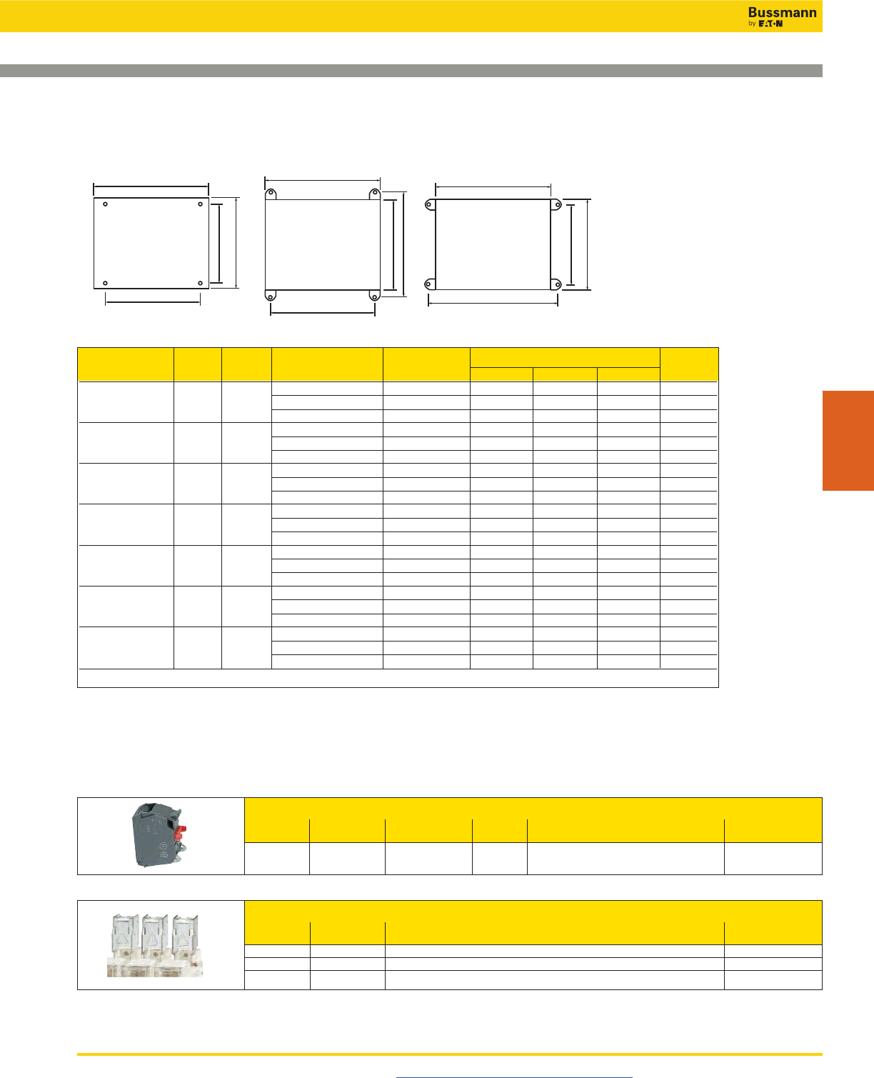
Disconnect Switches
UL 98 Enclosed Fused Disconnects—30 to 800A
Visit us on the web at www.cooperbussmann.com/Disconnects 419
Disconnect
Switches
Part Amp Fuse NEMA Mounting Centers H x W Weight
Number Family Rating Type Enclosure Type H x W x D A B C Lbs
1, 3R, 4, 12 10x10x6 8.3x8.3 15
ER_-30J 30 J 4X-SST 10x10x6 9.5x8.3 8.3x9.5 15
4X-Plastic(1) 12x10x6 12x5.6 7.64x10 8
1, 3R, 4, 12 12x10x6 10.3x8.3 19
ER_-60J 60 J 4X-SST 12x10x6 11.5x8.3 10.3x9.5 19
4X-Plastic(1) 13x13x6 14x7.6 9.6x12 11
1, 3R, 4, 12 14x12x6 12.3x10.3 21
ER_-100J 100 J 4X-SST 14x12x6 13.5x10.3 12.3x11.5 21
4X-Plastic(1) 13x13x6 14x7.6 9.6x12 12
1, 3R, 4, 12 24x20x8 22x18.1 55
ER_-200J 200 J 4X-SST 24x20x8 23.2x18.1 22x19.3 55
4X-Plastic(1) 27x21x10 25.75x14 39
1, 3R, 4, 12 48x36x12 45.75x34.9 188
ER_-400J 400 J 4X-SST 48x36x12 46.9x34.9 45.75x36.1 188
4X-Plastic(1) 51x37x14 50.1x28.5 186
1, 3R, 4, 12 48x36x12 45.75x34.9 216
ER_-600J 600 J 4X-SST 48x36x12 46.9x34.9 45.75x36.1 216
4X-Plastic(1) 51x37x14 50.1x28.5 214
1, 3R, 4, 12 48x36x12 45.75x34.9 216
ER_-800L 800 L 4X-SST 48x36x12 46.9x34.9 45.75x36.1 216
4X-Plastic(1) 51x37x14 50.1x28.5 214
(1) Enclosures ≤100A are polycarbonate, flammability rating UL 94-5VA-V0, ≥200A are fiberglass, flammability rating UL 94-5V.
Enclosure Weights - Lbs & Dimensions - in
Available Field-Installed Accessories - Order Separately
Auxiliary Contacts - for 30 to 800 Amp Switches
Contact Number of Continuous Voltage Max Number of Aux Part
Type Contacts Amp Rating Rating Contacts per Switch Number
NO 1 10A 600Vac 30 to 200A: 4 BAC05
NC 1 10A 600Vac 400 to 800A: 8 BAC06
Terminal Shrouds - for 200 to 800 Amp Switches - includes terminal shroud for lineside or loadside
Switch Number Part
Amp Rating of Poles Number
200 3 TSH8-3TB
400 3 TSH9-3TB
600-800 3 TSH10-3TB
W
W
W
MW
MW
MW
HHH
MH
MH MH
ABC
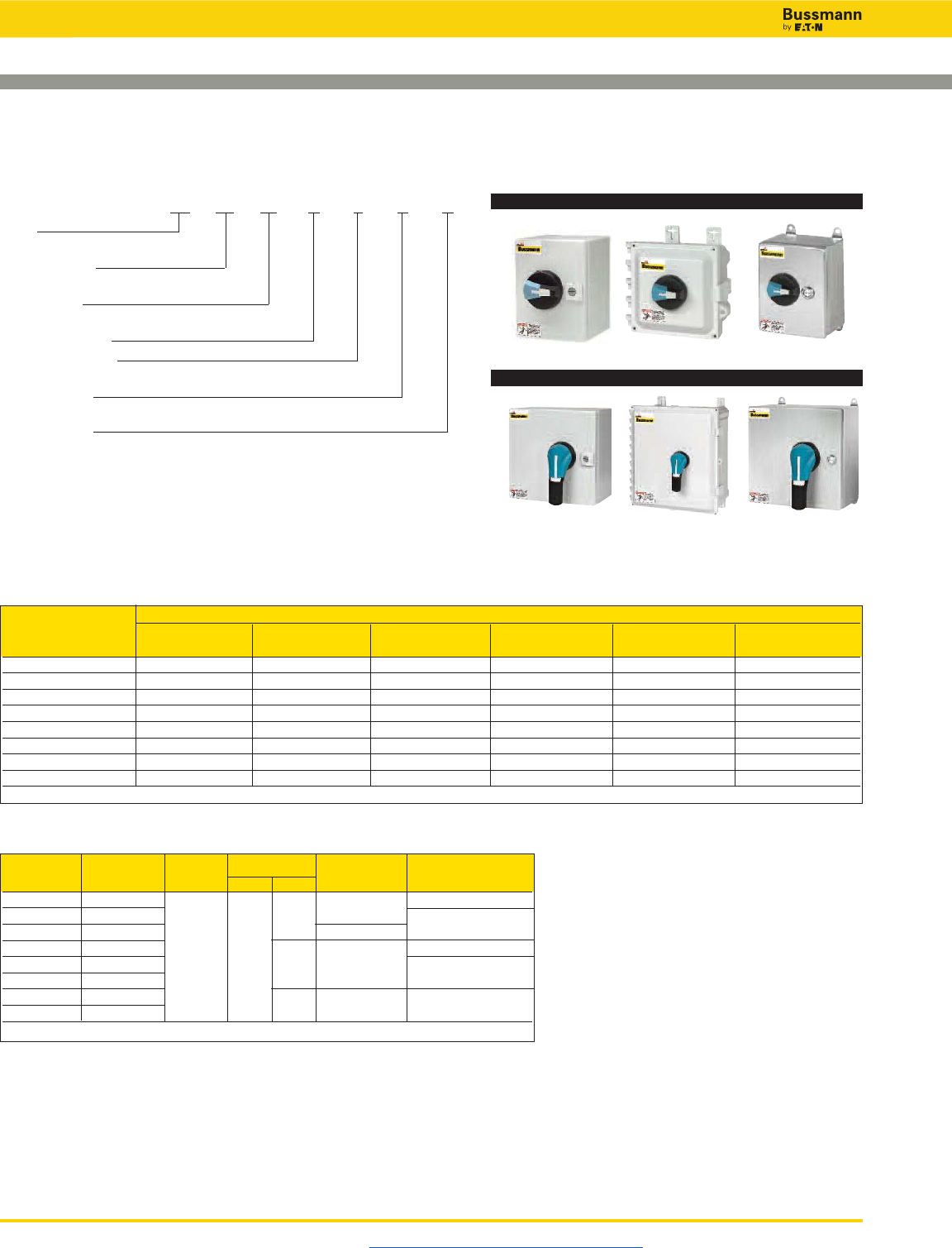
Disconnect Switches
UL 98 Enclosed Non-Fused Disconnects—30 to 1200A
Visit us on the web at www.cooperbussmann.com/Disconnects
420
Switch Disconnect No. of Voltage SCCR Max Hp Rating
Amp Rating Switch Poles Vac Vdc @ Vac @ 600Vac
30 RD30-3 100kA 25
60 RD60-3 N/A 50
100 RD100-3 25kA/100kA*
200 RD200-3 200
400 RD400-3 3 600 250 200kA 350
600 RD600-3
800 RD800-3 N/A 100kA 500
1200 RD1200-3
* 25kA @ 600Vac, 100kA @ 480Vac.
Switch Ratings - for wire types, ranges and tightening torques, see table on page 405
Part Numbers - All part numbers provided with integral or installed lugs and a black selector handle.
Order red/yellow handle by changing the suffix “B” to “R.”
3-Pole UL 98 600Vac
UL General NEMA Enclosure Type & Part Number
Purpose
Amp Rating 1 3R 4 4X Plastic(1) 4X Stainless 12
30 ER1-30N3SB ER3R-30N3SB ER4-30N3SB ER4P-30N3SB ER4X-30N3SB ER12-30N3SB
60 ER1-60N3SB ER3R-60N3SB ER4-60N3SB ER4P-60N3SB ER4X-60N3SB ER12-60N3SB
100 ER1-100N3SB ER3R-100N3SB ER4-100N3SB ER4P-100N3SB ER4X-100N3SB ER12-100N3SB
200 ER1-200N3PB ER3R-200N3PB ER4-200N3PB ER4P-200N3PB ER4X-200N3PB ER12-200N3PB
400 ER1-400N3PB ER3R-400N3PB ER4-400N3PB ER4P-400N3PB ER4X-400N3PB ER12-400N3PB
600 ER1-600N3PB ER3R-600N3PB ER4-600N3PB ER4P-600N3PB ER4X-600N3PB ER12-600N3PB
800 ER1-800N3PB ER3R-800N3PB ER4-800N3PB ER4P-800N3PB ER4X-800N3PB ER12-800N3PB
1200 ER1-1200N3PB ER3R-1200N3PB ER4-1200N3PB N/A ER4X-1200N3PB ER12-1200N3PB
(1) Enclosures ≤100A are polycarbonate, flammability rating UL 94-5VA-V0, ≥200A are fiberglass, flammability rating UL 94-5V.
NEMA 1, 3R, 4 & 12
30-100A
NEMA 4X
200-1200A
NEMA 1, 3R, 4 & 12 NEMA 4X
NEMA 4X Stainless
NEMA 4X Stainless
Part Number System: ER 4X -60 N3 S B
ER
Enclosed Rotary Disconnect
NEMA Rating
1, 3R, 4, 4X (SST), 4P (4X Plastic), 12
Amp Rating
30, 60, 100, 200, 400, 600, 800, 1200
N = Non-Fused
Number of Poles
3 = 3-Pole
Handle Type*
P = Pistol, S = Selector
Handle Color
B = Black, R = Red
* ≤100A = Selector only, ≥200A = Pistol only.
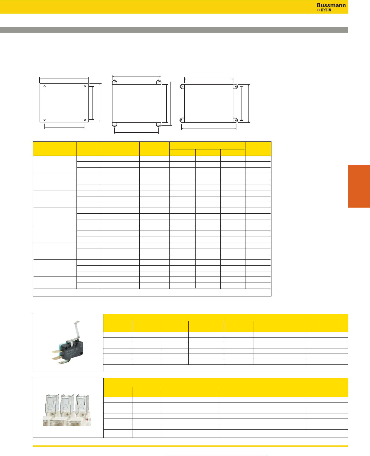
Disconnect Switches
UL 98 Enclosed Non-Fused Disconnects—30 to 1200A
Visit us on the web at www.cooperbussmann.com/Disconnects 421
Disconnect
Switches
Part Amp NEMA Mounting Centers H x W Weight
Number Family Rating Enclosure Type H x W x D A B C Lbs
1, 3R, 4, 12 10x8x6 8.3x6.3 11
ER_-30 30 4X-SST 10x8x6 9.5x6.3 8.3x7.5 11
4X-Plastic(1) 9x9x6 10x3.6 5.6x8 5
1, 3R, 4, 12 10x8x6 8.3x6.3 12
ER_-60 60 4X-SST 10x8x6 9.5x6.3 8.3x7.5 12
4X-Plastic(1) 9x9x6 10x3.6 5.6x8 5
1, 3R, 4, 12 12x10x6 10.3x8.3 12
ER_-100 100 4X-SST 12x10x6 11.5x8.3 0.3x9.5 12
4X-Plastic(1) 13x13x6 14x7.6 9.6x12 8
1, 3R, 4, 12 20x16x8 18.1x14.2 39
ER_-200 200 4X-SST 20x16x8 19.3x14.2 18.1x15.4 39
4X-Plastic(1) 23x17x12 21.5x10.1 31
1, 3R, 4, 12 36x30x8 33.9x28.3 122
ER_-400 400 4X-SST 36x30x8 35.1x28.3 33.9x29.5 122
4X-Plastic(1) 40x32x14 38.1x23.9 103
1, 3R, 4, 12 48x36x12 45.8x34.9 209
ER_-600 600 4X-SST 48x36x12 47x34.9 45.8x36.1 209
4X-Plastic(1) 51x37x 14 50.1x28.5 187
1, 3R, 4, 12 48x36x12 45.8x34.9 211
ER_-800 800 4X-SST 48x36x12 47x34.9 45.8x36.1 211
4X-Plastic(1) 51x37x 14 50.1x28.5 189
ER_-1200 1200 1, 3R, 4, 12 60x36x16 57.5x33.9 268
4X-SST 60x36x16 58.7x33.9 57.5x35.1 268
(1) Enclosures ≤100A are polycarbonate, flammability rating UL 94-5VA-V0, ≥200A are fiberglass, flammability rating UL 94-5V.
Enclosure Weights - Lbs & Dimensions - in
Available Field-Installed Accessories - Order Separately
Auxiliary Contacts - for 30 to 1200 Amp Switches
Switch Contact Number of Continuous Voltage Max Number of Aux Part
Amp Rating Type Contacts Amp Rating Rating Contacts per Switch Number
30-100 NO + NC 1 of each 10A 240Vac 4 BAC01
30-100 NC 2 10A 240Vac 4 BAC02
100-1200 NO + NC 1 of each 10.1A 125-250Vac 2 BAC03*
100-1200 NO + NC 1 of each 10.1A 125-250Vac 2 BAC04*
100-1200 NO + NC 1 of each 1A 125Vac 2 BAC11*
100-1200 NO + NC 1 of each 1A 125Vac 2 BAC12*
* For one auxiliary contact, install either BAC03 or BAC11. For two auxiliary contacts, install BAC03 + BAC04, or BAC11 + BAC12.
Terminal Shrouds - for 200 to 800 Amp Switches
Switch Number Location Part
Amp Rating of Poles on Switch Number
30-100 3 Lineside and Loadside TSH3-3TB
200A 3 Lineside TSH4-3T
200A 3 Loadside TSH4-3B
400A 3 Lineside TSH5-3T
400A 3 Loadside TSH5-3B
600A 3 Lineside or Loadside TSH6-3TB
800-1200A 3 Lineside or Loadside TSH7-3TB
W
W
W
MW
MW
MW
HHH
MH
MH MH
ABC
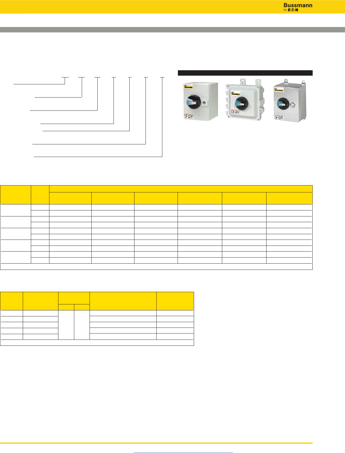
Disconnect Switches
UL 508 Enclosed Non-Fused Disconnects—16 to 80A
Visit us on the web at www.cooperbussmann.com/Disconnects
422
3-/6-Pole UL 508 600Vac
Switch SCCR with Max Hp
Amp Disconnect Voltage Max Upstream Rating
Rating Switch Vac Vdc Class J Fuse @ 600Vac
16 RD16-3-508 65kA / 30A 10
25 RD25-3-508 65kA / 30A 20
40 RD40-3-508 600 N/A 65kA / 30A — 10kA / 60A 25
63 RD63-3-508 65kA / 60A — 50kA / 100A 40
80 RD80-3-508 65kA / 60A — 50kA / 100A 40
Note: Voltage, SCCR and Horsepower ratings are the same for 3- and 6-pole UL 508 non-fused disconnect switches.
Switch Ratings - for wire types, ranges and tightening torques, see table on page 413
UL General NEMA Enclosure Type & Part Number
Purpose No. of
Amp Rating Poles 1 3R 4 4X Plastic(1) 4X Stainless 12
16 3 ER1-16N3SB ER3R-16N3SB ER4-16N3SB ER4P-16N3SB ER4X-16N3SB ER12-16N3SB
6 ER1-16N6SB ER3R-16N6SB ER4-16N6SB ER4P-16N6SB ER4X-16N6SB ER12-16N6SB
25 3 ER1-25N3SB ER3R-25N3SB ER4-25N3SB ER4P-25N3SB ER4X-25N3SB ER12-25N3SB
6 ER1-25N6SB ER3R-25N6SB ER4-25N6SB ER4P-25N6SB ER4X-25N6SB ER12-25N6SB
40 3 ER1-40N3SB ER3R-40N3SB ER4-40N3SB ER4P-40N3SB ER4X-40N3SB ER12-40N3SB
6 ER1-40N6SB ER3R-40N6SB ER4-40N6SB ER4P-40N6SB ER4X-40N6SB ER12-40N6SB
63 3 ER1-63N3SB ER3R-63N3SB ER4-63N3SB ER4P-63N3SB ER4X-63N3SB ER12-63N3SB
6 ER1-63N6SB ER3R-63N6SB ER4-63N6SB ER4P-63N6SB ER4X-63N6SB ER12-63N6SB
80 3 ER1-80N3SB ER3R-80N3SB ER4-80N3SB ER4P-80N3SB ER4X-80N3SB ER12-80N3SB
6 ER1-80N6SB ER3R-80N6SB ER4-80N6SB ER4P-80N6SB ER4X-80N6SB ER12-80N6SB
(1) Polycarbonate enclosure flammability rating UL 94-5VA-V0.
NEMA 1, 3R, 4 & 12 NEMA 4X Plastic NEMA 4X Stainless
Part Number System: ER 4X -63 N6 S B
ER
Enclosed Rotary Disconnect
NEMA Rating
1, 3R, 4, 4X (SST), 4P (4X Plastic), 12
Amp Rating
16, 25, 40, 63, 80
N = Non-Fused
Number of Poles
3 = 3-Pole, 6 = 6-Pole
Handle Type
S = Selector
Handle Color
B = Black, R = Red
Part Numbers - All part numbers provided with a black selector handle. Order red/yellow handle by changing the suffix “B” to “R.”
16-80A
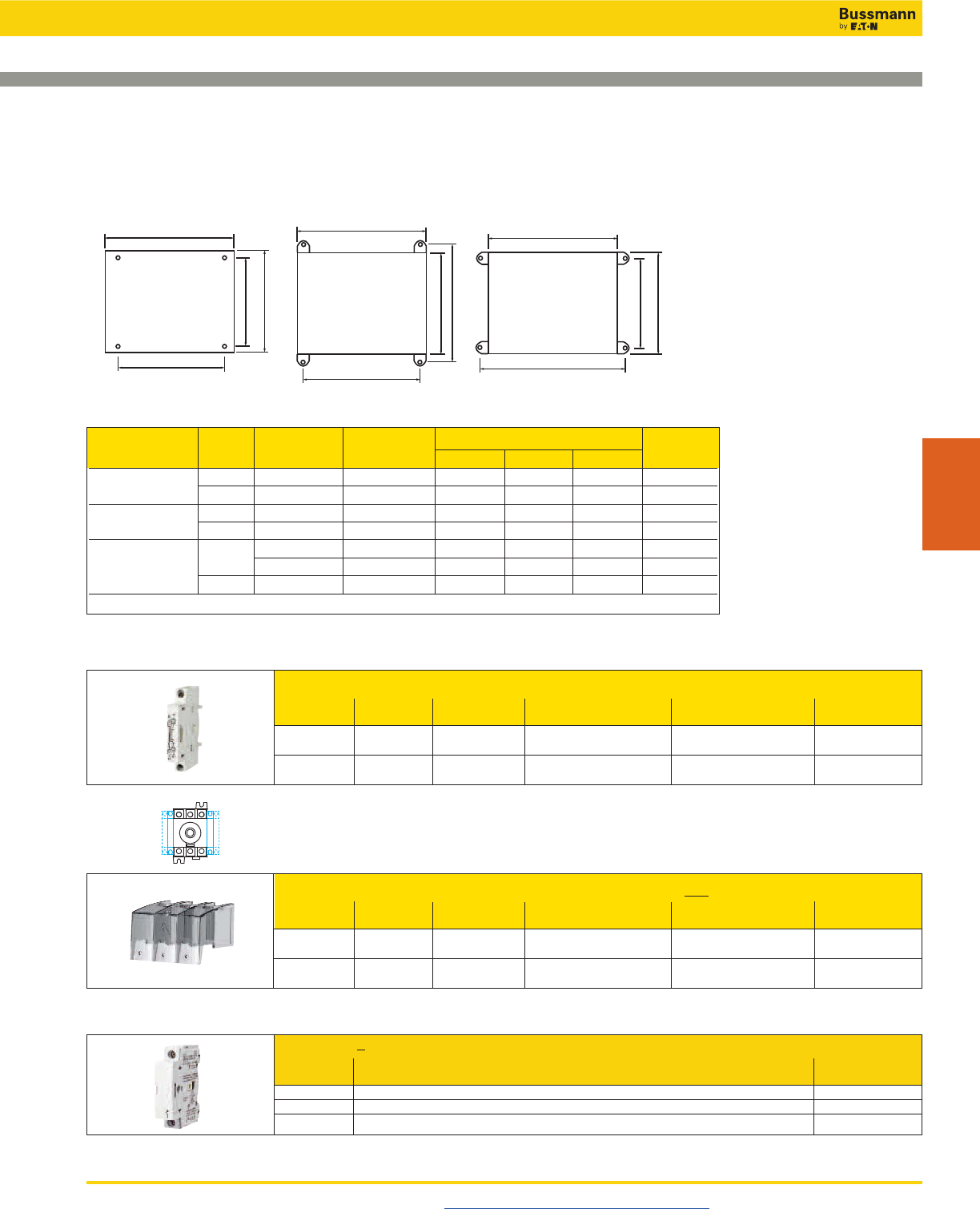
Disconnect Switches
UL 508 Enclosed Non-Fused Disconnects—16 to 80A
Visit us on the web at www.cooperbussmann.com/Disconnects 423
Disconnect
Switches
NEMA No. of Switch Amp Mounting Centers H x W Weight
Enclosure Type Poles Ratings H x W x D A B C Lbs
1, 3R, 4, 12 3 16-80A 8x6x6 6.3x4.3 8
6 16-80A 10x8x6 8.3x6.3 11
4X-SST 3 16-80A 8x6x6 7.5x4.3 6.3x5.5 8
6 16-80A 10x8x6 9.5x6.3 8.3x7.5 11
316-63A 7.4x8.7x5.8 8x3.6 3.6x8 4
4X-Plastic(1) 80A 9.4x8.7x5.9 10x3.6 5.6x8 5
6 16-80A 11.4x10.7x6.3 12x5.6 7.64x10 6
(1) Polycarbonate.
Enclosure Weights - Lbs & Dimensions - in
Auxillary Contacts
Contact Number of Continuous Voltage Max Number of Aux Part
Type Contacts Amp Rating Rating Contacts per Switch Number
NO + NC 1 Ea 10A 240Vac 4 BAC01
NO 2 10A 240Vac 4 BAC02
Auxiliary Contact Configurations
Terminal Shrouds - includes terminal shroud for both lineside and loadside
Switch Number Location on Part
Amp Rating of Poles Switch Number
16-40A 3 Lineside and Loadside TSH1-3TB
63-80A 3 Lineside and Loadside TSH2-3TB
Available Field-Installed Accessories - Order Separately
W
W
W
MW
MW
MW
HHH
MH
MH MH
ABC
Switched 4th Pole - converts 3-pole switch to 4-pole switch
Switch Amp Part
Rating Number
16 POLE-16
25 POLE-25
40 POLE-40
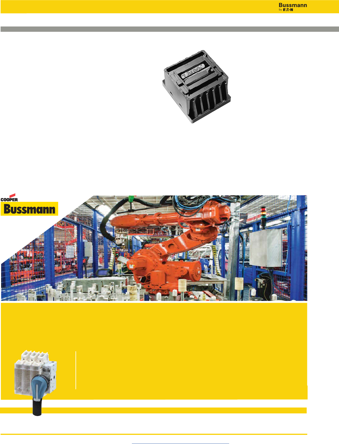
Disconnect Switches
Visit us on the web at www.cooperbussmann.com/Disconnects
424
15149 Series
Specifications
Description: Fused, dead front disconnect switches
Ratings:
Volts: — 600Vac
Amps: — 0-30A
SCCR: — 200kA RMS Sym.
Dielectric SCCR: 2200V
Motor Rating: 5Hp
Poles: 2 to 3
Agency Information: UL Recognized, file E120756 for
General Industrial installations. Guide WGEU2. CSA
certified, file LR37129-6. Examined under the new proposed
standard UL 1429 which imparts a stricter set of test
conditions than the former program that combined the
applicable portions for UL 512 (Fuse Holders) and UL 98
(Enclosed Switches).
Features and Benefits
• Fuse holders in the pull-out head eliminate possibility of
electric shock while changing fuse.
• Accepts Class J fuses
Ordering Information
To order, specify: 15149 + number of poles.
Example: 15149-2 = 2-pole device.
Flexibility and Convenience Make
Point-of-Use Configuration Easy
Full range of open disconnect switches with
versatile options and accessories that ship
within 24 hours
www.cooperbussmann.com
Fused, Dead Front Disconnect Switches
™
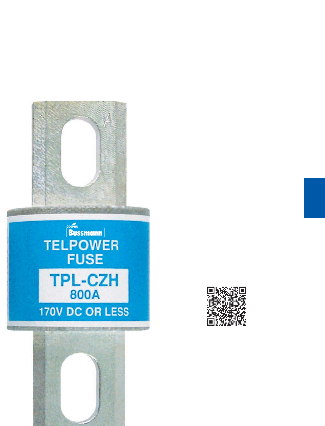
425
Telecom
Protection Products
Section Contents Page
Telpower compact fused disconnect switches . . . . .426
Telpower miniature fused disconnect switches . . . . 427
Fused disconnect switches for TPA fuses
TP15914 4-Pole disconnect switch . . . . . . . . . . . . . . . .428
TP11590-4 4-Pole disconnect switch . . . . . . . . . . . . .429
TPA & TPA-B Fuses . . . . . . . . . . . . . . . . . . . . . . . . . . .429
Fused disconnect switches for TPS fuses
15800 1-Pole fused disconnect switch . . . . . . . . . . . . 430
TPS Fuses . . . . . . . . . . . . . . . . . . . . . . . . . . . . . . . . . .430
Fused disconnect switches
TP158HC panel mount, rear access switch . . . . . . . . .431
15100 1-Pole switch for use with TPL fuses . . . . . . . . .432
TPHCS Telpower high-current switch . . . . . . . . . . . .433
TPL Telpower 70-600A: 170Vdc fuses . . . . . . . . . . . .434
TPN Telpower 1-600A: 170Vdc fuses . . . . . . . . . . . .435
70 Series Indicating fuses . . . . . . . . . . . . . . . . . . . . .436
15087 Fuse holders . . . . . . . . . . . . . . . . . . . . . . . . . . .436
HLS, HLT & PCT fuse holders . . . . . . . . . . . . . . . . . .437
GMT Fast acting fuses . . . . . . . . . . . . . . . . . . . . . . . .437
GMT-A Fast acting fuse . . . . . . . . . . . . . . . . . . . . . . . .437
Telpower specialty fuses
7 Type Fuses . . . . . . . . . . . . . . . . . . . . . . . . . . . . . . . .438
11 Type Fuse . . . . . . . . . . . . . . . . . . . . . . . . . . . . . . . . .438
24 & WER Type non-indicating, visible link fuses . . . . 438
74 Type Fast acting fuses . . . . . . . . . . . . . . . . . . . . . . .438
75 Type Cylindrical fuses with leads . . . . . . . . . . . . . . .439
76 Type Cylindrical fuses with leads . . . . . . . . . . . . . . .439
80 Type visual indicating fuses . . . . . . . . . . . . . . . . . . .439
Telecom Protection
Products
TM
Scan this tag to get the
latest product information for
Telecom Protection Products.
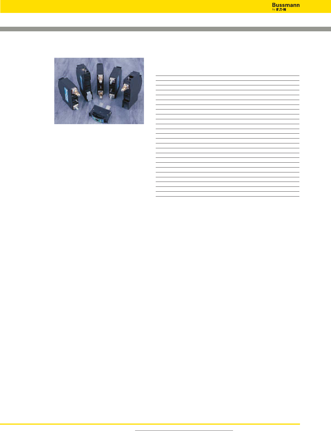
For product data sheets, visit www.cooperbussmann.com/DatasheetsEle
426
Telecom Protection Products
Telepower Compact Fused Disconnect Switches
Data Sheet: 5023
TPC & TPCDS
Specifications
Descriptions:
— TPC: Telepower
compact current-
limiting fuses.
— TPCDS:
Telepower compact
fused disconnect
switch available in
two disconnect switch profiles in addition to a variety of
terminal styles. Recommended 0.75” center-to-center
product spacing.
Dimensions: See Data Sheet 5023.
Ratings:
Volts: — 80Vdc
Amps: — 3-125A (See Catalog Numbers table for details)
IR: — 100kA
Agency Information: CE, UL Recognized (investigated to
UL 1801) as a disconnect switch for the interruption of load
current by means of withdrawing the fuse pullout.
Recognized to US and Canadian requirements under the
component recognition program of Underwriters Laboratories
Inc. Files E219046 and E56412.
Flammability Ratings: Fuse UL 94V0, 170°C RTI,
Housing UL 94V0, 120°C RTI.
Features and Benefits
• Highest interrupting rating (100kA) available and
complete system coordination for DC circuit protection for
compact footprint providing a superior protection solution
for replacement of existing DC telecom circuit breakers
• AmpColor ID™ System makes fuse replacement easy
• Local and remote open fuse indication. Local alarm
indication provided by LED on TPC fuse
• Remote alarm terminal available in three positions
common to DC circuit protection devices
Typical Applications
• Telecommunications DC power circuit protection
• Replacement of DC telecom circuit breakers
• Applications where venting of arc or molten metals and
gases during opening would pose a problem to surrounding
devices
Catalog Numbers
TPCS disconnect switch TPC Current-Limiting Fuse
Catalog Amp Catalog Amp
Numbers Range Numbers Rating
TPCDS-BBE-1 3-125 TPC-3 3
TPCDS-BBE-2 3-125 TPC-4 4
TPCDS-BBE-3 3-125 TPC-5 5
TPCDS-BBM-1 3-125 TPC-6 6
TPCDS-BBM-2 3-125 TPC-7 7
TPCDS-BBM-3 3-125 TPC-8 8
TPCDS-BSE-1 3-125 TPC-10 10
TPCDS-BSE-2 3-125 TPC-12 12
TPCDS-BSE-3 3-125 TPC-15 15
TPCDS-BSM-1 3-125 TPC-20 20
TPCDS-BSM-2 3-125 TPC-25 25
TPCDS-BSM-3 3-125 TPC-30 30
TPCDS-SSE-1 3-125 TPC-40 40
TPCDS-SSE-2 3-125 TPC-50 50
TPCDS-SSE-3 3-125 TPC-60 60
TPCDS-SSM-1 3-125 TPC-75 75
TPCDS-SSM-2 3-125 TPC-90 90
TPCDS-SSM-3 3-125 TPC-100 100
TPCDS-D-BC1* 3-125 TPC-125 125
TPCDS-D-BC2* 3-125
TPCDS-D-CC1* 3-125
TPCDS-D-SEC1* 3-125
TPCDS-D-SEC2* 3-125
TPCDS-D-SMC1* 3-125
TPCDS-D-SMC2* 3-125
*Not investigated to Canadian Requirements.
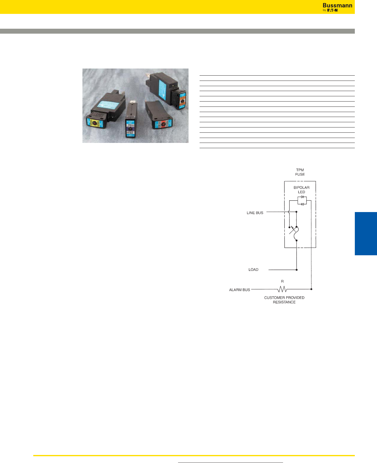
For product data sheets, visit www.cooperbussmann.com/DatasheetsEle 427
Data Sheet: 5022
Telepower Miniature Fused Disconnect Switches
Catalog Numbers
Catalog Amp
Numbers Description Rating
TPM-3 Fuse 3
TPM-4 Fuse 4
TPM-5 Fuse 5
TPM-6 Fuse 6
TPM-7 Fuse 7
TPM-8 Fuse 8
TPM-10 Fuse 10
TPM-12 Fuse 12
TPM-15 Fuse 15
TPM-20 Fuse 20
TPM-25 Fuse 25
TPM-30 Fuse 30
TPMDS-E Disconnect, English hardware 3-30
TPMDS-M Disconnect, Metric hardware 3-30
NOTES:
1. The resistance, R, must be provided by the end-user to
limit the alarm output current to a maximum of 20mA. The
value, R, should be calculated using the system voltage
value.
• If remote alarm functionality is not required, the
END-USER CIRCUITRY must still be supplied to provide a
resistive path to the return for the local alarm to properly
function.
2. The fuse is polarized to maintain proper orientation with
the switch housing. The line and load terminals are
identified on the switch housing.
TPM &
TPMDS
Specifications
Description:
— TPM:
Telepower
miniature current-
limiting fuses.
— TPMDS:
Telepower
miniature fused
disconnect switch.
Dimensions: See Data Sheet 5022.
Ratings:
Volts: — 80Vdc
Amps: — 3-30A
IR: — 20kA
Agency Information: CE, UL Recognized (investigated to
UL 1801) as a disconnect switch for the interruption of load
current by means of withdrawing the fuse pullout.
Recognized to US and Canadian requirements under the
component recognition program of Underwriters Laboratories
Inc. Files E219046 and E56412.
Flammability Ratings: Fuse UL 94V0, 170ºC RTI; Switch
UL 94V0, 140ºC RTI.
Features and Benefits
• Smallest and most versatile fused disconnect switch
available allowing for assembly into 1 U (1.75˝/44.5mm)
panel. Easy to connect; Load: 1⁄4˝ quick-connect or bolted
connection with 10-32 (M5) captive nut, Line: 1⁄4˝
quick-connect or screw connection with clearance hole for
#10 (M5) bolt.
• AmpColor ID™ System makes fuse replacement easy
• Switch design provides for easy panel mounting by single
captive 4-40 (M3) nut and panel notch integral to switch
footprint.
• Complete system coordination capability with local and
remote open fuse indication. Local alarm indication
provided by LED on TPM fuse (maximum alarm circuit
current: 20mA)
Typical Applications
• Telecommunications DC power circuit protection
• Applications with restricted space, or mounting in 1 U panels
TPM Alarm Schematic
Telecom Protection Products
Telecom
Protection Products
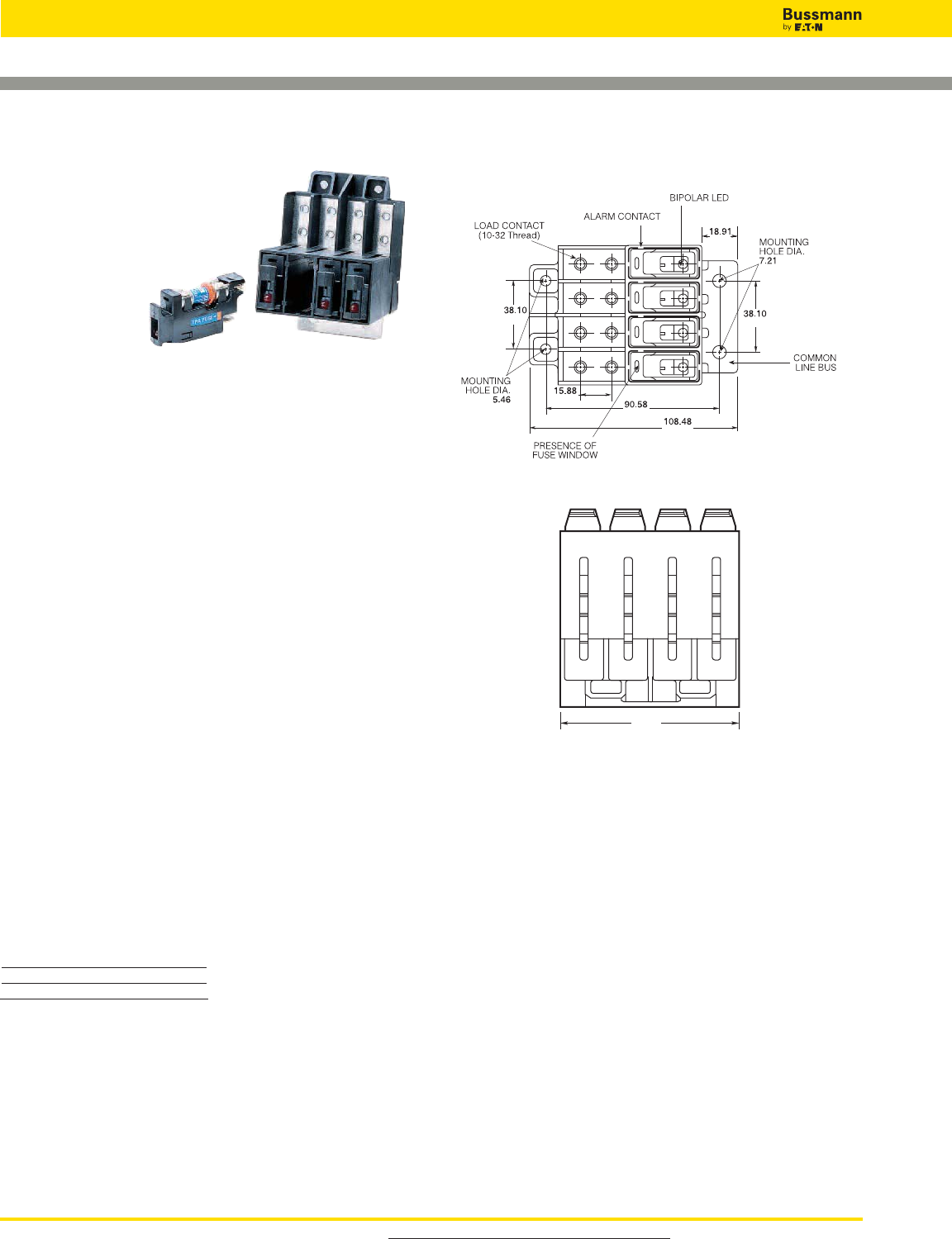
For product data sheets, visit www.cooperbussmann.com/DatasheetsEle
428
Telecom Protection Products
TP15914
Specifications
Description:
Modular 4-pole
disconnect switch
for TPASeries
fuses — 4-poles
per module up to
four modules
ganged together.
Features open fuse
indication and fuse presence indication along with fuse
orientation rejection feature.
Dimensions: See Dimensions illustrations.
Ratings:
Volts: — 145Vdc
Amps: — 50A per pole
Agency Information: CE, UL Recognized as a disconnect
switch for interruption of load current by means of
withdrawing the fuse carrier. UL Recognized as a component
for telecommunication power distribution equipment (UL
category QPQYZ), UL Recognized fuses for branch circuit
protection, CSA component acceptance for the system. UL
Recognized, Guide JFHR2, File E56412., CSA Certified,
Class 1422-30, File 53787.
Flammability Rating: UL 94V0, 140°C.
Features and Benefits
• Totally enclosed module directly connects to busbar for
reduced external wiring—per pole and easy installation
with front access load and line connection standard—
double lug load connections 8 AWG wire
• LED alarm signaling (LED current 30mA max)
• Remote alarm with alarm test probe point to allow on-site
checking of alarm circuitry
• Bi-polar LED provides capability for both –48Vdc and
+24Vdc applications
Typical Applications
• Telecommunications DC power circuit protection
Catalog Numbers
Catalog
Numbers Hardware
TP15914 English
TP15914-1 Metric
Fused Disconnect Switches for TPA Fuses
Data Sheet: 5011
Dimensions mm - (in)
Accessories
• Spare fuse holders:Catalog Numbers 5TPH and TPSFH-A
0.745
0.284
1.5
4.27
3.57
0.625
0.215
1.5
TOP
76.07
3.0
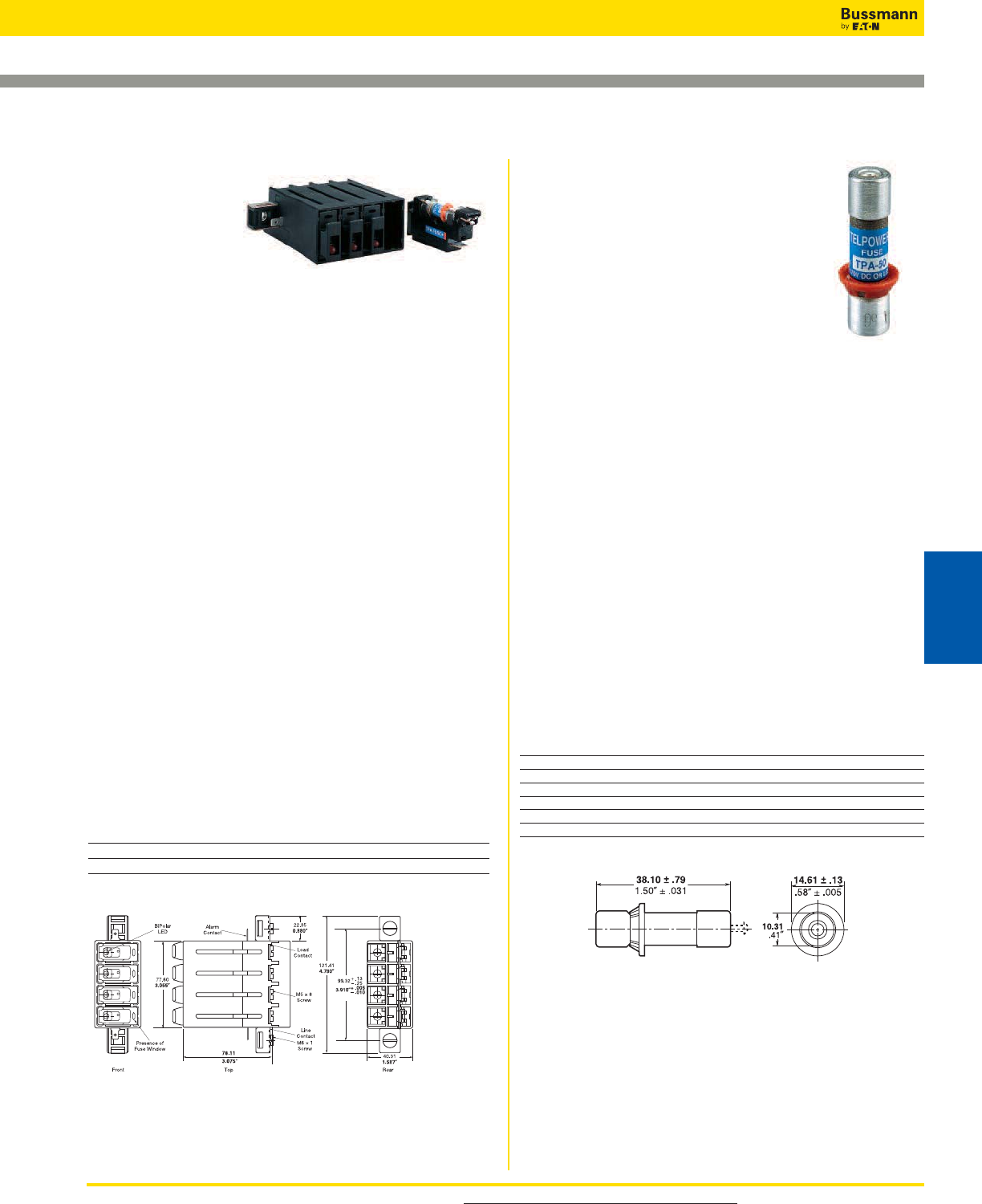
For product data sheets, visit www.cooperbussmann.com/DatasheetsEle 429
TP15900-4
Specifications
Description: 4-pole
disconnect switch for
use with Telepower
fuses Type TPA &
TPA-B.
Dimensions: See Dimensions illustrations.
Ratings:
Volts: — 145Vdc (40A)
— 80Vdc (50A)
Amps: — 40A@145Vdc
— 50A@80Vdc
Agency Information: CE, UL Recognized File E97649 as
a disconnect switch for interruption of load current by means
of withdrawing the fuse carrier. UL Recognized as a
component for telecommunication power distribution
equipment (UL category QPQY2). UL Recognized fuses for
branch circuit protection. CSA Component Acceptance for
the system.
Flammability Rating: UL 94V0, 140°C.
Features and Benefits
• Ease of installation - connection directly to busbar,
reduces external wiring per pole. Rear accessibility for line
and load terminations
• LED alarm signaling (LED current 30mA max)
• Local and remote open-fuse indication along with fuse
orientation rejection feature and fuse presence indication
• Alarm test probe point, to allow on-site checking of alarm
circuitry
Typical Applications
• Telecommunications DC power circuit protection
Catalog Numbers
Catalog
Numbers Description
TP15900-4 4-Pole common disconnect switch
TP15900-41 4-Pole common disconnect switch w/ Split Alarm, Split Line
Dimensions - mm (in)
Accessories
• Spare fuse holders:Catalog Numbers 5TPH and
TPSFH-AS.
Fused Disconnect Switches for TPA Fuses
Data Sheet: 5001
-
Data Sheet: 5012
TPA & TPA-B
Specifications
Description: DC power distribution
indicating fuses.
Dimensions: See Dimensions illustration.
Ratings:
Volts: — 170Vdc TPA
— 65Vdc TPA-B
Amps: — 3-50A TPA
— 20-30A TPA-B
IR: — 100kA TPA
— 20kA TPA-B
Agency Information: CE, UL Recognized, Guide JFHR2,
File E56412, CSA Certified, Class 1422-30, File 53787.
Features and Benefits
• Indication pin provides for local and remote indication when
used with Bussmann TP15900-4 and TP15914 disconnect
switches
• Patented “orange ring” fuse orientation features assures
correct fuse position
• The UL Recognized ratings and current-limiting capability
make this fuse ideal for cable protection on existing DC
power distribution systems
• A unique blue label is used on all Telepower fuses to
designate their DC capability
Typical Applications
• Telecommunications DC power circuit protection
Catalog Numbers (Amps)
Catalog Amp Catalog Amp
Numbers Rating Numbers Rating
TPA-3 3 TPA-30 30
TPA-5 5 TPA-40 40
TPA-10 10 TPA-50 50
TPA-15 15 TPA-B-20 20
TPA-20 20 TPA-B-25 25
TPA-25 25 TPA-B-30 30
Dimensions - mm (in)
Accessories
• Spare fuse holders: 5 position holder; 5TPH; 6 position
holder; TPSFH-AS
• Use with fused disconnect switches TP15900-4, TP15914
Telecom Protection Products
Telecom
Protection Products
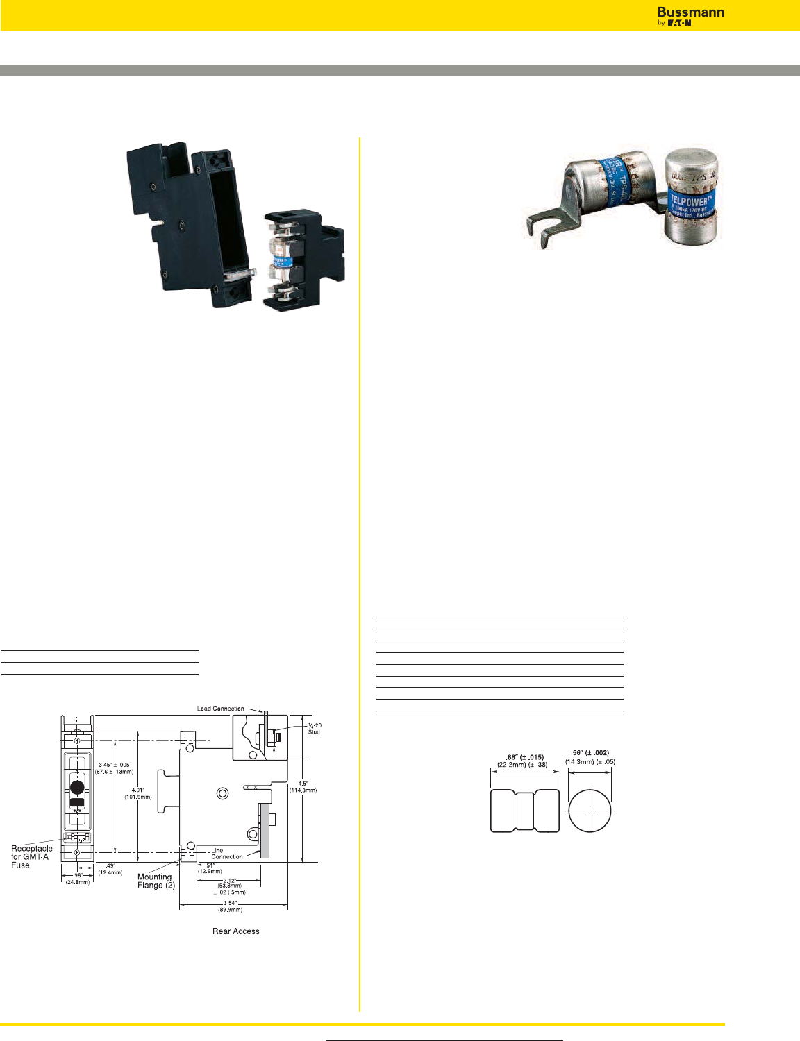
For product data sheets, visit www.cooperbussmann.com/DatasheetsEle
430
Telecom Protection Products
TPS
Specifications
Description: DC
power distribution
non-indicating fuses
specifically designed to
meet the unique needs
of DC power distribution systems. For use with Bussmann
fused disconnect switch 15800.
Dimensions: See Dimensions illustration.
Ratings:
Volts: — 170Vdc
Amps: — 1-70A
IR: — 100kA
Agency Information: CE, UL Recognized, Guide JFHR2,
File E56412.
Features/Benefits
• The UL Recognized ratings and current-limiting capability
make this fuse ideal for cable protection on existing DC
power distribution systems
• A unique blue label is used on all Telepower fuses to
designate their DC capability
• Printed circuit board variations available
Typical Applications
• Telecommunications DC power circuit protection
• Applications requiring printed circuit board mounting
Catalog Numbers (Amps)
TPS-1 TPS-6L TPS-30 TPS-50V
TPS-1L TPS-10 TPS-30L TPS-60
TPS-2 TPS-10L TPS-35 TPS-60L
TPS-2L TPS-15 TPS-35L TPS-70
TPS-3 TPS-15L TPS-40 TPS-70L
TPS-3L TPS-20 TPS-40L TPS-70LB
TPS-5 TPS-20L TPS-40V
TPS-5L TPS-25 TPS-50
TPS-6 TPS-25L TPS-50L
Dimensions - in (mm)
Accessories
• Spare fuse holder: TPSFH-AS, see page 510.
Fused Disconnect Switches for TPS Fuses
Data Sheet: 5009
15800
Specifications
Description:
Fused disconnect
switch for use only
with the following
fuses; Main: Telepower
TPS 3 to 70 Amp,
Alarm: Bussmann GMT-A
only (page 399).
Recommend GMT-X Cover
(page 437).
Dimensions: See Dimensions illustration.
Ratings:
Volts: — 60Vdc
Amps: — 3-70A
SCCR: — 100kA
Agency Information: CE, UL Recognized, Guide QPQY2,
File E97649.
Flammability Rating: UL 94V0, 150°C.
Features and Benefits
• Alarm output with wire wrap terminal or connection to 0.063”
thick common alarm bus
• Spare alarm and power fuse compartment
• Mounting hardware included
Typical Applications:
• Telecommunications DC power circuit protection
Catalog Numbers
Catalog
Numbers Access Panel Mounting
15800-R-200 Rear
15800-F-200 Front
Dimensions - in (mm)
Accessories
• Spare fuse holders:Catalog Numbers TPSFH-AS (TPS
fuses) and TPSFH-T (GMT fuses).
Data Sheet: 5002
72 lb-in
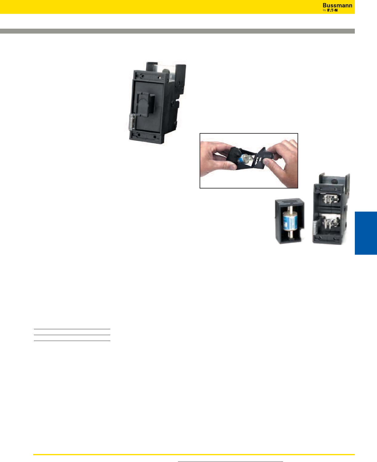
For product data sheets, visit www.cooperbussmann.com/DatasheetsEle 431
TP158HC
Specifications
Description: Panel mount, rear
access high amp version of
Bussmann 15800 series fused
disconnect switch for use only with
the following fuses; Main:
Telepower TPL-B 70-250 Amps,
Alarm: Bussmann GMT-A.
Dimensions: See Data Sheet
5021.
Ratings:
Volts: — 80Vdc
Amps: — 70-250A
SCCR: — 100kA
Agency Information: UL Recognized (investigated to UL
1801) as a disconnect switch for the interruption of load
current by means of withdrawing the fuse pullout. Guide
QPQY2, File E97649.
Flammability Rating: UL 94V0, 150°C.
Features and Benefits
• Similar profile, mounting method, and backplane
configuration as 15800 Series. The TP158HC can be
installed into existing 15800 Series panels using the space
of two 15800 disconnects
• Innovative new fuse pullout design eliminates need for
tools to replace the Telepower type TPL-B fuse
• Alarm output with wire wrap terminal or connection to
0.063 inch (1.6mm) thick common alarm bus
• Hardware included: Load: washer, split lockwasher, and
5⁄16 - 18 nut (metric-M8 x 1.25)
Typical Applications:
• Telecommunications DC power circuit protection
Catalog Numbers
Catalog
Numbers Hardware
TP158HC English
TP158HC-M Metric
Accessories
• Spare fuse holders:TPSFH-LB(TPL-B fuses) and TPSFH-T
(GMTfuses).
Application Notes
• The line connection uses a 1⁄4-20 bolt (metric – M6X1) that
threads into the line terminal. The line terminal is designed
with a float of ±0.02˝ (±0.50mm) to allow for variation in the
distance between the TP158HC mounting flange and the
line busbar (see Dimensions). Equipment should be
designed to eliminate any relative movement between the
TP158HC mounting flange and the line busbar.
• The alarm circuit is not intended for precharging of
capacitive circuits. Alarm circuit current 1A maximum.
Fused Disconnect Switches
Data Sheet: 5021
Easy Fuse Replacement
Telecom Protection Products
Telecom
Protection Products
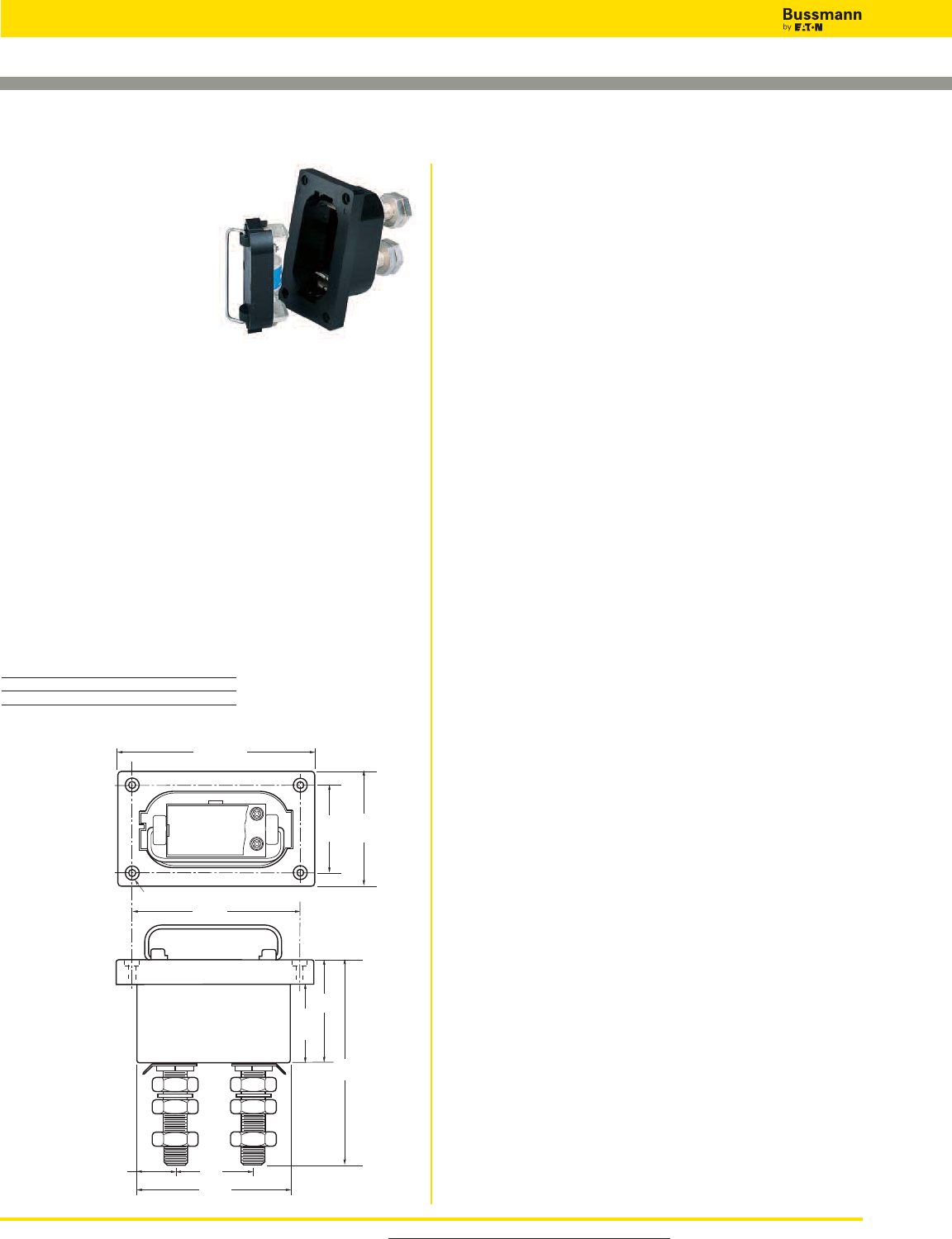
For product data sheets, visit www.cooperbussmann.com/DatasheetsEle
432
Telecom Protection Products
Fused Disconnect Switches
0.27" (6.75mm) Dia. Hole with 0.5" (12.7mm)
Dia. x 0.16" (3.97mm) Deep C'bore (4 Holes)
2.63"
(66.67mm)
1.31"
(33.33mm)
4"
(101.6mm)
3"
(76.2mm)
5.25"
(133.35mm)
7.13"
(181.10mm)
3.63"
(92.07mm)
2.75"
(69.85mm)
6.75"
(171.45mm)
5.75"
(146.05mm)
15100
Specifications
Description: Fused
disconnect system for use with
Telepower fuses Type TPL.
Dimensions: See Dimensions
illustrations.
Ratings:
Volts: — 60Vdc
Amps: — 70-800A
SCCR: — 100kA
Agency Information: CE, UL Recognized, Guide QPQY2,
File E97649.
Features and Benefits
• Single-pole fusible disconnect switch for primary DC power
distribution
• Robust housing and terminal construction for demanding
applications
• Panel mounting
• Easily connected to line or load bus
Typical Applications
• Telecommunications DC power circuit protection
Catalog Numbers
Catalog For Use With
Numbers TPL Series Fuses
15100-401 70-400A
15100-601 300-800A
Dimensions - in (mm)
Data Sheet: 5003
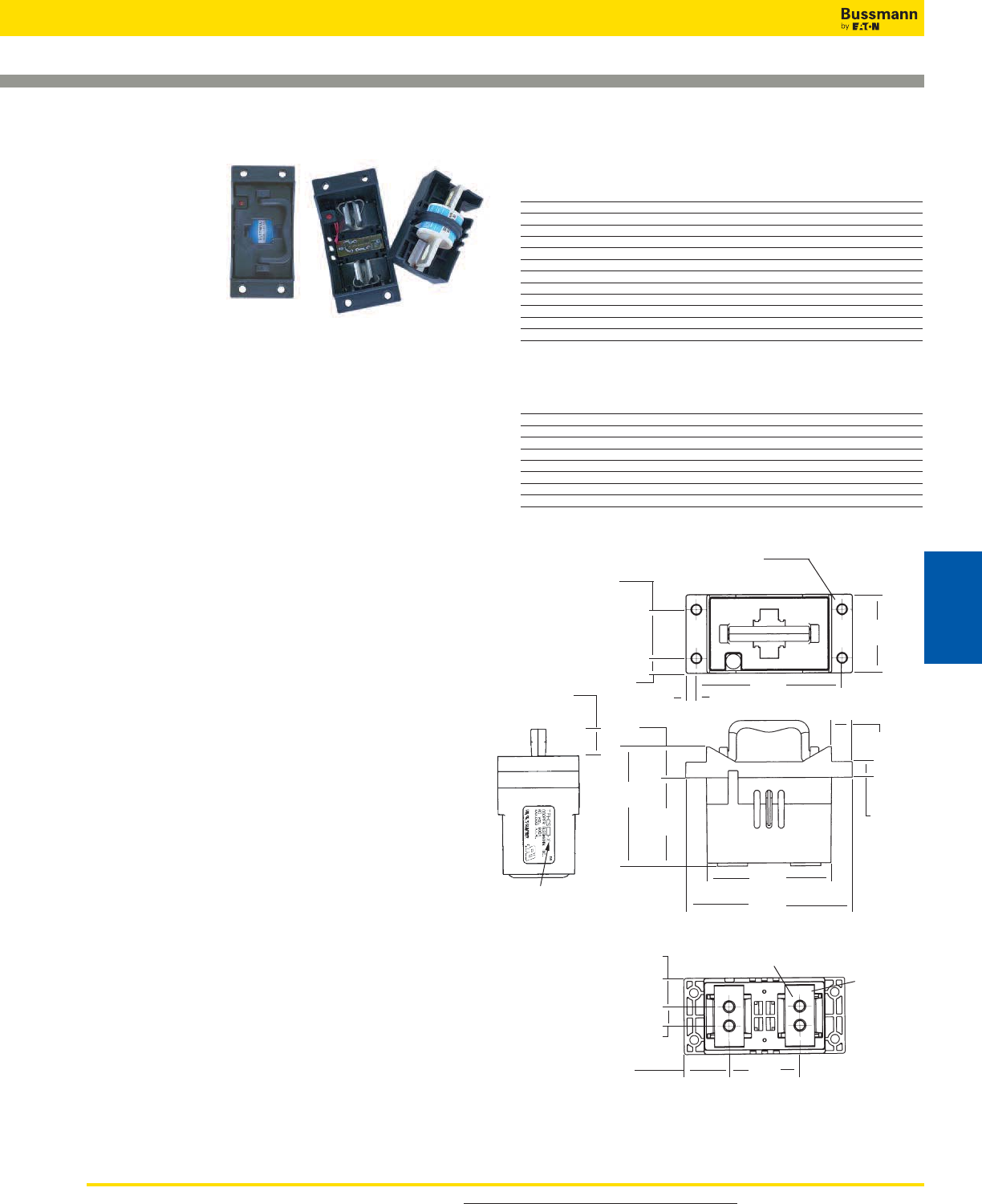
For product data sheets, visit www.cooperbussmann.com/DatasheetsEle 433
TPHCS
Specifications
Description: High
current switch for
use with Telepower
fuses Type TPL-B,
TPL-C and TPH.
Available as
complete switch or pullout.
Base may be purchased
separately.
Dimensions: See Dimensions illustrations.
Construction:
Ratings:
Volts:— 80Vdc
Amps:— 70-800A
SCCR: — 100kA
Agency Information: UL Recognized (investigated to UL
1801) as a disconnect switch for the interruption of load
current by means of withdrawing the fuse carrier. UL
Recognized to meet the requirements for Canadian
Standards.
Features and Benefits
• Innovative design eliminates need for tools to replace the
Telepower™Type TPL-B, TPL-C or TPH fuse
• Easy to install–captive fasteners allow for direct busbar
mounting (bolts not included). Standard 1⁄4” male quick-
connect terminal for effortless remote alarm connection.
• Optional new electronic alarm eliminates need for parallel
indicating fuses while providing local and remote open-
fuse indications (maximum remote alarm current: 20mA);
Bipolar alarm: designed for both Central Office and Radio
applications, Local LED alarm indication for
ease-of-viewing.
• Fuse presence window allows for easy viewing of installed
fuse amp rating
Typical Applications
• Telecommunications DC power circuit protection
• Compact design is ideal for today’s high power,
high-density cabinets
Telpower High-current Switch
Data Sheet: 5020
Catalog Numbers – Switches (Pullout and Base)
Catalog Hardware/ Fuse Amp
Numbers Option Series Rating
TPHCS250-M Metric TPL-B 70-250
TPHCS250-E English TPL-B 70-250
TPHCS250-ML Metric, LED TPL-B 70-250
TPHCS250-EL English, LED TPL-B 70-250
TPHCS250-MAV Metric, Alarm TPL-B 70-250
TPHCS250-EAV English, Alarm TPL-B 70-250
TPHCS800-M Metric TPL-C or TPH 300-800
TPHCS800-E English TPL-C or TPH 300-800
TPHCS800-ML Metric, LED TPL-C or TPH 300-800
TPHCS800-EL English, LED TPL-C or TPH 300-800
TPHCS800-MAV Metric, Alarm TPL-C or TPH 300-800
TPHCS800-EAV English, Alarm TPL-C or TPH 300-800
Catalog Numbers – Components
Catalog Description Fuse Amp
Numbers Rating/Hardware/Option Series Rating
TPHCS250-P Pullout only – 250A TPL-B 70-250
TPHCS800-P Pullout only – 800A TPL-C or TPH 300-800
TPHCS-B-M Base only, Metric — 800 Max
TPHCS-B-E Base only, English — 800 Max
TPHCS-B-ML Base only, Metric, LED — 800 Max
TPHCS-B-EL Base only, English, LED — 800 Max
TPHCS-B-MAV Base only, Metric, Alarm — 800 Max
TPHCS-B-EAV Base only, English, Alarm — 800 Max
Dimensions - mm (in)
TPHCS800-MAV (shown)
NOTES:
1. TPHCS250 and TPHCS800 pullouts and bases are the same with exception to the type of
fuse, TPL-B, TPL-C or TPH the pullout will carry.
2. Plastic rated UL 94V0, 140ºC RTI.
41.02
(1.615)
Ø
7.62
(0.300)
Type. 4
12.7
(0.50)
74.6
(2.94)
25.9
(1.02)
122.43
(4.820)
8.8
(0.34)
L
L
L
L
L
L
L
L
L
L
L
L
L
L
100.5 REF
(3.96)
L
L
L
L
L
L
L
66.4
(2.62)
L
L
105.2
(4.14)
L
L
Threaded Insert, 4 Places
M8x1.25 (-M Series) 5/16-18 (-E Series)
Recommended Torque 15N • m (11 Ft-lb)
Tin-Plated
Copper
Terminals
L
L
L
L
139.7
(5.50)
24.8 REF
(0.98)
39.2 REF
(1.54)
16.76
(0.660)
L
L
13.2
(0.52)
17.3
(0.68)
L
L
L
61.47
(2.420)
L
22.2
(0.88)
See table for part
number format
L
L
Telecom Protection Products
Telecom
Protection Products
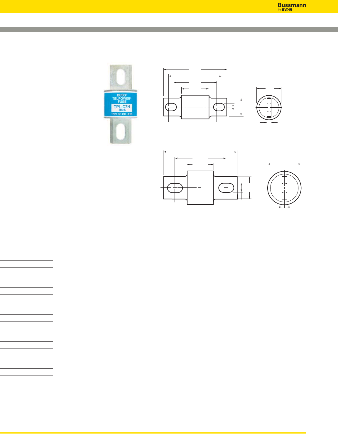
For product data sheets, visit www.cooperbussmann.com/DatasheetsEle
434
Telecom Protection Products
Telpower 70-600A: 170Vdc Fuses
Data Sheet: 5005
TPL
Specifications
Description: DC power distribution
fuses for use with Telepower 15100,
15200, TP158HC and TPHCS
disconnect systems. For replacement of
Bussmann UBO fuses a TPL-TA adapter
kit is necessary.
Dimensions: See Dimensions
illustrations.
Ratings:
Volts: — 170Vdc
Amps: — 70-800A
IR: — 100kA
Agency Information: CE, UL Recognized Guide JFHR2,
File E56412 Bellcore.
Features and Benefits
• Current-limiting capability designed for DC power
distribution systems
• Recognized branch circuit protection
• Complete system coordination capability
• Energy savings with low watts loss, low operating
temperatures, and minimum I2t levels
Typical Applications
• Telecommunications power circuit protection
Catalog Numbers
Catalog Amp
Numbers Rating
TPL-BA70
TPL-BB 80
TPL-BC90
TPL-BD100
TPL-BE125
TPL-BF150
TPL-BG175
TPL-BH200
TPL-BK225
TPL-BL250
TPL-CN 300
TPL-CO 350
TPL-CR 400
TPL-CU 450
TPL-CV 500
TPL-CZ 600
TPL-CZH 800
Accessories
• Spare fuse holders: TPSFH-LB (for TPL-B fuses)
TPSFH-LC (for TPL-C fuses)
Dimensions - in (mm)
0.33"
(8.3mm)
2.66"
(67.5mm)
2.19"
(55.6mm)
1.91"
(48.4mm)
1.16"
(29.4mm)
BUSS
TPL–B L
0.75"
(19.1mm)
0.19"
(4.8mm)
1.0"
(25.4mm)
0.25"
(6.4mm)
1.50"
(38.1mm)
TPL-BA, TPL-BD, TPL-BF , TPL-BH, TPL-BK, and TPL-BL
TPL-CN, TPL-CR, TPL-CV and TPL-CZ
3.50"
(88.9mm)
2.44"
(61.9mm)
1.25"
(31.8mm)
1.00"
(25.4mm)
0.41"
(10.3mm)
BUSS
TPL – CZ
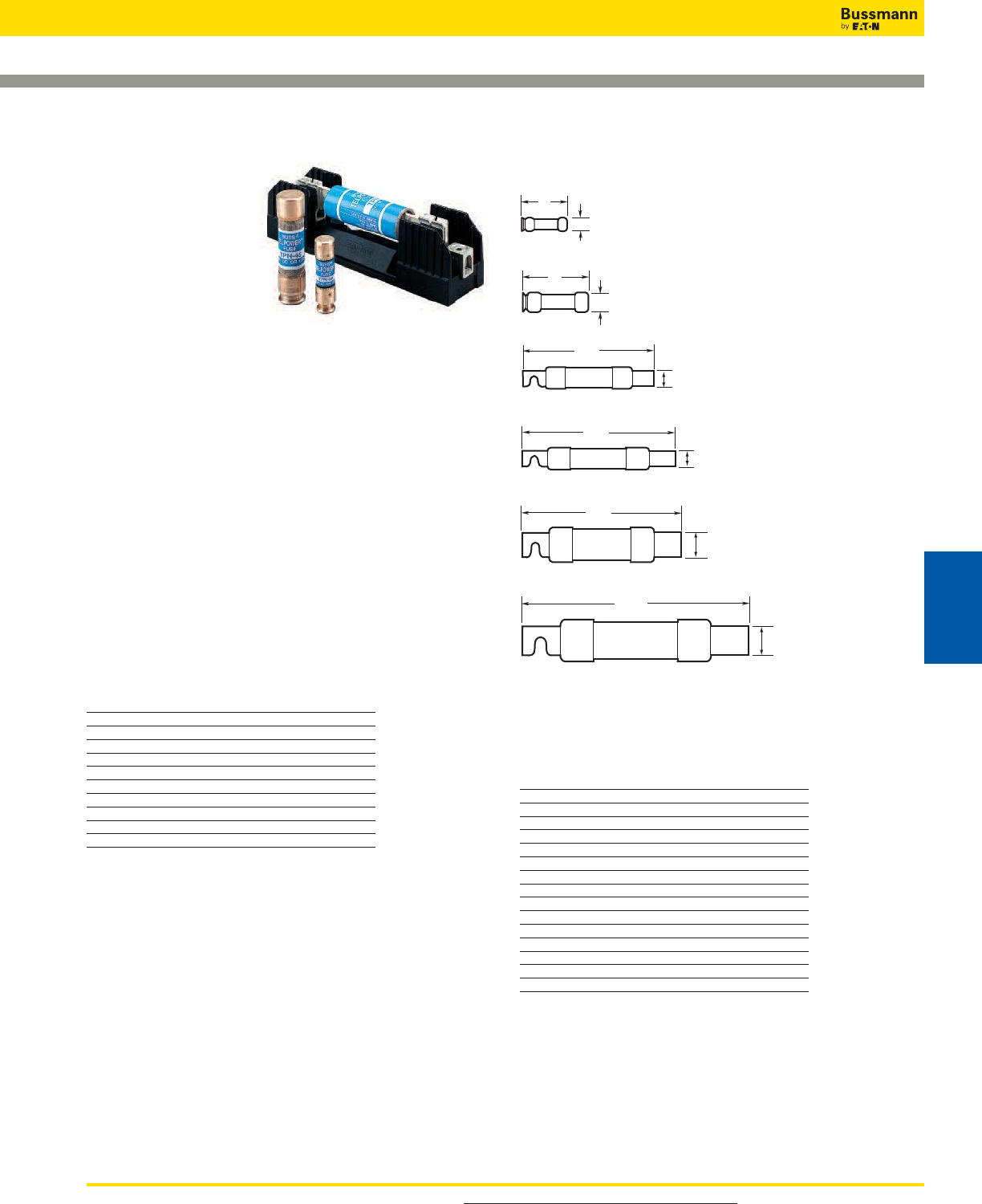
For product data sheets, visit www.cooperbussmann.com/DatasheetsEle 435
Telpower 1-600A, 170Vdc Fuses
Data Sheet: 5006
TPN
Specifications
Description: Current-
limiting DC power
distribution fuses. The
TPN fuse series is
dimensionally similar to
Class R fuses making it
easy to use standard
Class R fuse blocks.
Dimensions: See Dimensions illustrations.
Ratings:
Volts: — 170Vdc
Amps: — 1-600A
IR: — 100kA
Agency Information: UL Recognized, Guide JFHR2, File
E56412.
Features/Benefits
• Current-limiting capability designed for DC power
distribution systems
• Recognized branch circuit protection
• Complete system coordination capability
• Energy savings with low watts loss, low operating
temperatures, and minimum I2t levels
Typical Applications
• Telecommunications power circuit protection
Catalog Numbers (Amps)
TPN-1 TPN-45 TPN-200
TPN-3 TPN-50 TPN-225
TPN-5 TPN-60 TPN-250
TPN-6 TPN-70 TPN-300
TPN-10 TPN-80 TPN-350
TPN-15 TPN-90 TPN-400
TPN-20 TPN-100 TPN-450
TPN-25 TPN-110 TPN-500
TPN-30 TPN-125 TPN-600
TPN-35 TPN-150
TPN-40 TPN-175
Accessories
• Spare fuse holders:TPSFH-N30 (for TPN 1-30) TPSFH-N60
(for TPN 35-60)
Recommended Class R Fuse Blocks
Catalog
Amps Poles Number
1-30 1 R25030-1CR
1-30 2 R25030-2CR
1-30 3 R25030-3CR
35-60 1 R25060-1CR
35-60 2 R25060-2CR
35-60 3 R25060-3CR
70-100 1 R25100-1CR
70-100 2 R25100-2CR
70-100 3 R25100-3CR
110-200 1 R25200-1CR
110-200 3 R25200-3CR
225-400 1 R25400-1CR
225-400 3 R25400-3CR
450-600 1 R25600-1CR
450-600 3 R25600-3CR
0.81"
(20.6mm)
3"
(76.2mm)
35A to 60A
2"
(50.8mm)
0.56"
(14.3mm)
1A to 30A
5.88"
(149.2mm)
70A to 100A
7.13"
(181.0mm)
110A to 200A
225A to 400A
8.63"
(219.1mm)
450A to 600A
10.38"
(263.5mm)
2.50"
(63.5mm)
2.00"
(50.8mm)
1.50"
(38.1mm)
1.00"
(25.4mm)
Dimensions - in (mm)
Telecom Protection Products
Telecom
Protection Products
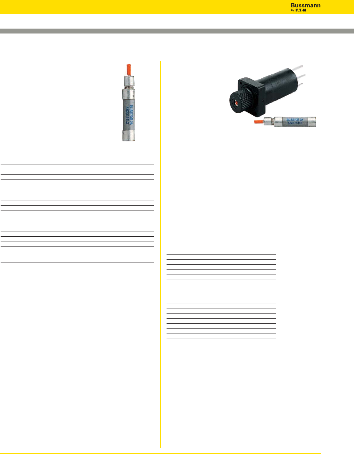
For product data sheets, visit www.cooperbussmann.com/DatasheetsEle
436
Telecom Protection Products
70 Series Fuses
Specifications
Description: Indicating type fuse.
Ratings:
Volts:— 125Vac/300Vdc
Amps:— 1⁄10-10A
IR:— 1kA @ 300Vdc
Agency Information: CE, UL Recognized,
Guide JDYX2, File E19180 Bellcore.
Catalog Numbers Lucent
Catalog Amp Color Comcode Code/
Numbers Rating Code Ref. No. List No.
70P-1⁄10A* 1⁄10 Gray/Wh 100203413 KS23751-L10
70R-15⁄100A* 15⁄100 Red/Wh 101384550 KS23751-L11
70E-18⁄100A* 18⁄100 Yellow 100203363 KS23751-L5
70X-2⁄10A2⁄10 Black — —
70F-1⁄4A* 1⁄4Violet 100203371 KS23751-L6
70K-1⁄4A* 1⁄4Violet/Wh 100203405 KS23751-L9
70G-1⁄2A* 1⁄2Red 100203389 KS23751-L7
70H-3⁄4A* 3⁄4Brown 100203397 KS23751-L8
70I-1A 1 Pink — —
70A-11⁄3A*†11⁄3White 100203322 KS23751-L1
70B-2A* 2 Orange 100203330 KS23751-L2
70C-3A* 3 Blue 100203348 KS23751-L3
70J-31⁄2A3
1⁄2Black/Wh — —
70D-5A* 5 Grn/Blk 100203355 KS23751-L4
70L-6A 6 Grn/Wh — —
70M-8A 8 Brown/Wh — —
70N-10A 10 Violet/Yel — —
GKB-10A 10 Violet/Yel — —
72A Plastic CaseDummy — 100203421 —
72B Blister PackDummy — 103757977 —
*Product designed to comply with Bellcore Technical Reference TR-TSY-000799 Issue 1,
December 1988.
†No longer UL Recognized.
Indicating Fuses and Holders
Data Sheet: 5007 Data Sheet: 5007
15087 Fuse Holder
Specifications
Description: Fuse holder
for 70 Series fuses.
Ratings:
Volts: — 300Vdc
Amps: — 12A
Agency Information: CE, UL
Recognized, Guide IZLT2, File
E14853.
Flammability Rating: UL 94V0.
Features and Benefits
• Panel mount fuse holder for 70 Type fuses supplied with
two screws
• Remote alarm capability
Typical Applications
• Telecommunications DC power circuit protection
Catalog Number — 15087
Accessories
Description: Optional color code eyelets used with fuse
holder to indicate fuse amp rating.
Eyelet Catalog Numbers
Catalog Amp Color
Numbers Indication Code
1A1706-01 18⁄100 Yellow
1A1706-02 2⁄10 Black
1A1706-03 1⁄4Violet
1A1706-04 1⁄4Violet/White
1A1706-05 1⁄2Red
1A1706-06 3⁄4Brown
1A1706-07 1 Pink
1A1706-08 11⁄3White
1A1706-09 2 Orange
1A1706-10 3 Blue
1A1706-11 5 Green/Black
1A1706-12 6 Green/White
1A1706-13 8 Brown/White
1A1706-14 10 Violet/Yellow
1A1706-15 1⁄10 Gray/White
1A1706-16 31⁄2Black/White
1A1706-17 15⁄100 Red/White
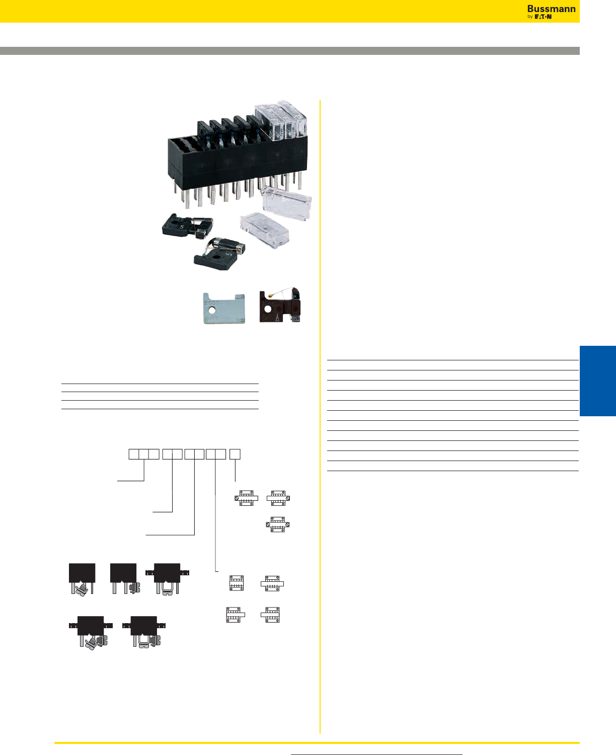
For product data sheets, visit www.cooperbussmann.com/DatasheetsEle 437
HLS, HLT, PCT
Specifications
Description: Fuse
holders for GMT Type
indicating fuses.
Poles: 01 to 25.
Ratings:
Volts: — 60Vdc/125Vac
Agency Information:
CE, UL Recognized,
Guide IZLT2, File
E14853, 15A (60Vdc).
Flammability Rating:
UL 94V0.
Features and Benefits
• Multiple configurations provide
application flexibility
• Compact size saves space
Typical Applications
• Telecommunications DC power circuit protection
Catalog Numbers
Catalog Numbers Poles
PCT 1
HLS See Build-A-Code
HLT See Build-A-Code
Indicating Fuses and Holders
Data Sheet: 5008
Data Sheet: 5010
Multiple Fuse holders with bus bars
Ordering Information— Catalog No.
T ype of bus bars used***
B1*, B2, B3,
B4, B5, SL** (Short Leads .135")
ML** (Medium Leads .250")
** Not available with bus bars
Bus Bar Position
P4
(Outside—
Left Only)
P3
(Outside—
Right Only)
P2
(Outside—
Both Sides)
P1†
(Inside—
Both Sides)
B3
(“U” Bar Only)
B2
(“L” Bar Only)
B1
(Angle Bar Only)*
B5
(“L” & “U” Bars)
B4
(Angle & “L” Bars)
Body Style HL T
HLS
(No flanges)
No. of Poles 01 thru 25
(Min. of 2 poles required for bus bars)
T ermination Location
B
(Both ends)
L
(Left only)
R
(Right only)
*Angle Bar mounts on common or center terminals only.
**SL Version is not available with bus bars.
†Minimum of 4 Poles Required.
***.38 max. leads if not specified.
GMT - Dummy GMT - A (Alarm)
GMT
Specifications
Description: Fast-acting fuses for use in HLT, HLS, and
PCT fuse holders.
Ratings:
Volts: — 60Vdc/125Vac
Amps: — 18⁄100-15A
IR: — 450A@60Vdc
— 300A@125Vac
Agency Information: CE, UL Recognized, Guide JFHR2,
File E56412.
Flammability Rating: UL 94V0.
Features and Benefits
• Local and remote indication capability
• Color coded for easy amp rating identification
Typical Applications
• Telecommunications DC power circuit protection
Catalog Numbers
Catalog Color Catalog Color
Numbers Code Numbers Code
GMT-18⁄100A Yellow GMT-3-1⁄2AWhite/Blue
GMT-1⁄4A Violet GMT-4A White/Brown
GMT-3⁄8A Green/Gray GMT-5A Green
GMT-1⁄2A Red GMT-7-1⁄2ABlack/White
GMT-65⁄100ABlack GMT-10A Red/White
GMT-3⁄4ABrown GMT-12A Yellow/Green
GMT-1A Gray GMT-15A Red/Blue
GMT-1-1⁄3A White GMT-Dummy Gray Body
GMT-1-1⁄2A White/Yellow GMT-X Clear Cover
GMT-2A Orange GMT-Y Clear Cover
GMT-3A Blue
Some GMT sizes may be sold in bulk pack only.
Accessories
• Spare fuse holder: Catalog Number TPSFH-T
GMT-A
Specifications
Description: Fast-acting fuse designed specifically for use
in the Telepower series 15800 fused disconnect switch
(page 430).
Agency Information: The GMT-A has the same ratings
and agency approvals as the standard GMT fuses as shown
above.
Catalog Numbers
Catalog Number Color Code
GMT-A Yellow
Telecom Protection Products
Telecom
Protection Products
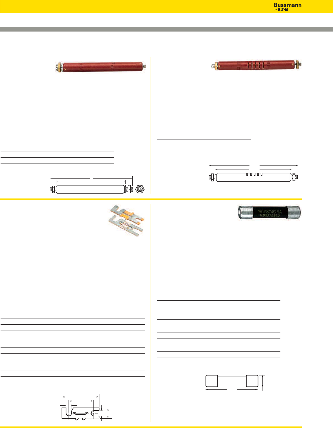
For product data sheets, visit www.cooperbussmann.com/DatasheetsEle
438
Telecom Protection Products
11 Type
Specifications
Description: Fiber tube, threaded ends, identical to 7 Type
except for vent slots in fiber tube.
Dimensions: See Dimensions illustration.
Ratings:
Amps: — 7A
Agency Information: CE
Catalog Number
Catalog Amp Lucent Comcode
Number Rating Ref. No.
11C-7 7 100863745
Dimensions - in
7 Type
Specifications
Description: Fiber tube, threaded ends. Typically used on
wall type main distribution frames and central battery
substations.
Dimensions: See Catalog Numbers table and Dimensions
illustration.
Ratings:
Amps: — 7A
Agency Information: CE
Catalog Numbers
Catalog Amp Lucent Comcode Dimension
Numbers Rating Ref. No. A Length (in)
7A-7 7 100863737 4.562
7T-7 7 100202753 4.828
Dimensions - in
24 and WER Type
Specifications
Description: Flat, non-indicating visible
link element mounted on 1 inch centers
using either No. 6 or No. 10 screws.
Dimensions: See Dimensions illustration.
Ratings:
Volts: — 32Vdc (1⁄4, 1, 3 1⁄2, 8, 10A)
— 60Vdc (1⁄2, 3⁄4, 1 1⁄2, 2, 3, 4, 5A)
Amps: — 1⁄4-10A
Agency Information: CE, UL Recognized File E56412.
Catalog Numbers
Catalog Amp DC Color Lucent Comcode A Length
Numbers Rating Volts Code Ref. No. Inches
WER-1⁄41⁄432 — — —
24E-1⁄2*1⁄260 Red 100202894 0.20
24D-3⁄4*3⁄460 Black 100202886 0.15
WER-1 1 32 — — —
24G-1-1⁄3*1 1⁄360 White 100202910 0.20
24C-2*2 60 Orange 100202878 0.20
24B-3*3 60 Blue 100202852 0.15
WER-3-1⁄23 1⁄232 — — —
24B-4*4 60 Yellow 100202860 0.15
24F-5*5 60 Green 100202902 0.15
WER-8 8 32 — — —
WER-10 10 32 — — —
*Designed to comply with Bellcore Technical Reference TR-TSY-000799 Issue 1, Dec. 1988.
Dimensions - in
Telpower Specialty Fuses
4.062"
4.625"
4.093"
A
A 0.375"
A
0.938"
1.406"
74 Type
Specifications
Description: Fast-acting 0.281˝ x 1.25˝ cylindrical fuse
designed to comply with Lucent specification KS23753. High
current companion to 70 Type Fuse.
Dimensions: See Dimensions illustration.
Ratings:
Volts: — 60Vdc
Amps: — 1 1⁄4-20A
Agency Information: CE, UL Recognized File E19180.
Catalog Numbers
Catalog Amp Lucent Comcode Code/
Numbers Rating Ref. No. List No.
74A-1-1⁄41 1⁄4102630290 KS23753-L1
74G-2 2 103064952 KS23753-L7
74B-3 3 102630308 KS23753-L2
74H-4 4 103264669 KS23753-L8
74C-5 5 102630316 KS23753-L3
74J-7-1⁄27 1⁄2103228425 KS23753-L9
74D-10 10 102630324 KS23753-L4
74E-15 15 102630332 KS23753-L5
74F-20 20 102630340 KS23753-L6
Dimensions - in (mm)
1.25"
(31.75mm) 0.281"
(7.14mm)
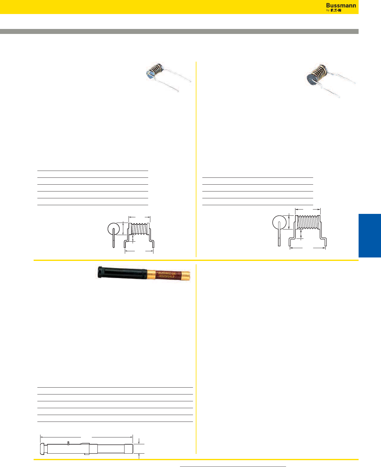
For product data sheets, visit www.cooperbussmann.com/DatasheetsEle 439
80 Type
Specifications
Description: A fuse designed for high reliability applications
where high ambient temperatures, low circuit voltages, low
power dissipation and low contact resistance are prime
considerations. The 80 Type is a visual indicating fuse with
remote electrical alarm capability. UL Recognized, Guide
JDYX2, File E19180.
Dimensions: See Dimensions illustrations.
Ratings:
Volts: — 160Vdc
Amps: — 1⁄2-5A
Agency Information: CE, UL Recognized File E19180.
Catalog Numbers
Catalog Amp Color Lucent Comcode Code/
Numbers Rating Code Ref. No. List No.
80G-1⁄21⁄2Red 103839916 KS23824-L6
80M-1-1⁄311⁄3White 408078657 KS23824-L8
80B-2 2 Orange 103752150 KS23824-L2
80C-3 3 Blue 103752168 KS23824-L3
80D-5 5 Green 103800637 KS23824-L4
Dimensions - in (mm)
75 Type
Specifications
Description: Cylindrical with leads,
designed to provide protection against
currents resulting from the application of foreign voltages.
Application for data sets and telephones.
Dimensions: See Dimensions illustration.
Ratings:
Volts: — 135Vac/220Vdc (440Vdc@0.007A)
Amps: — 0.007-0.230A
Agency Information: CE
Catalog Numbers
Catalog Amp Lucent Comcode Code/
Numbers Rating Ref. No. List No.
75C 0.007 103260816 KS23825-L3
75F 0.063 104172861 KS23825-L6
75B 0.115 102732112 KS23825-L2
75D 0.129 104013180 KS23825-L4
75A 0.200 102660008 KS23825-L1
76 Type
Specifications
Description: Cylindrical with leads,
designed to provide protection against
currents resulting from the application
of foreign voltages. Application for data
sets and telephones.
Dimensions: See Dimensions illustration.
Ratings:
Volts: — 135Vac/440Vdc
Amps: — 0.012-0.412A
Agency Information: CE
Catalog Numbers
Catalog Amp Lucent Comcode Code/
Numbers Rating Ref. No. List No.
76D 0.012 103798245 KS23825-L10
76B 0.191 102965688 KS23825-L8
76A 0.231 102810181 KS23825-L7
76C 0.412 103656625 KS23825-L9
Dimensions - in (mm)
Telpower Specialty Fuses
——A
0.445"
(11.30mm)
0.320"
(8.13mm)
1.125"
(28.58mm)
0.830"
(21.08mm)
0.280"
(7.11mm)
2.685"
(68.20mm)
0.190"
(4.83mm)
0.325"
(8.26mm)
0.620"
(15.75mm)
0.800"
(20.32mm)
——A
Telecom Protection Products
Telecom
Protection Products
440
Comprehensive UL 1449 3rd
Edition recognized surge
protection solutions for North
American applications.
Surge Protection
Made Simple™
UL 508A Applications
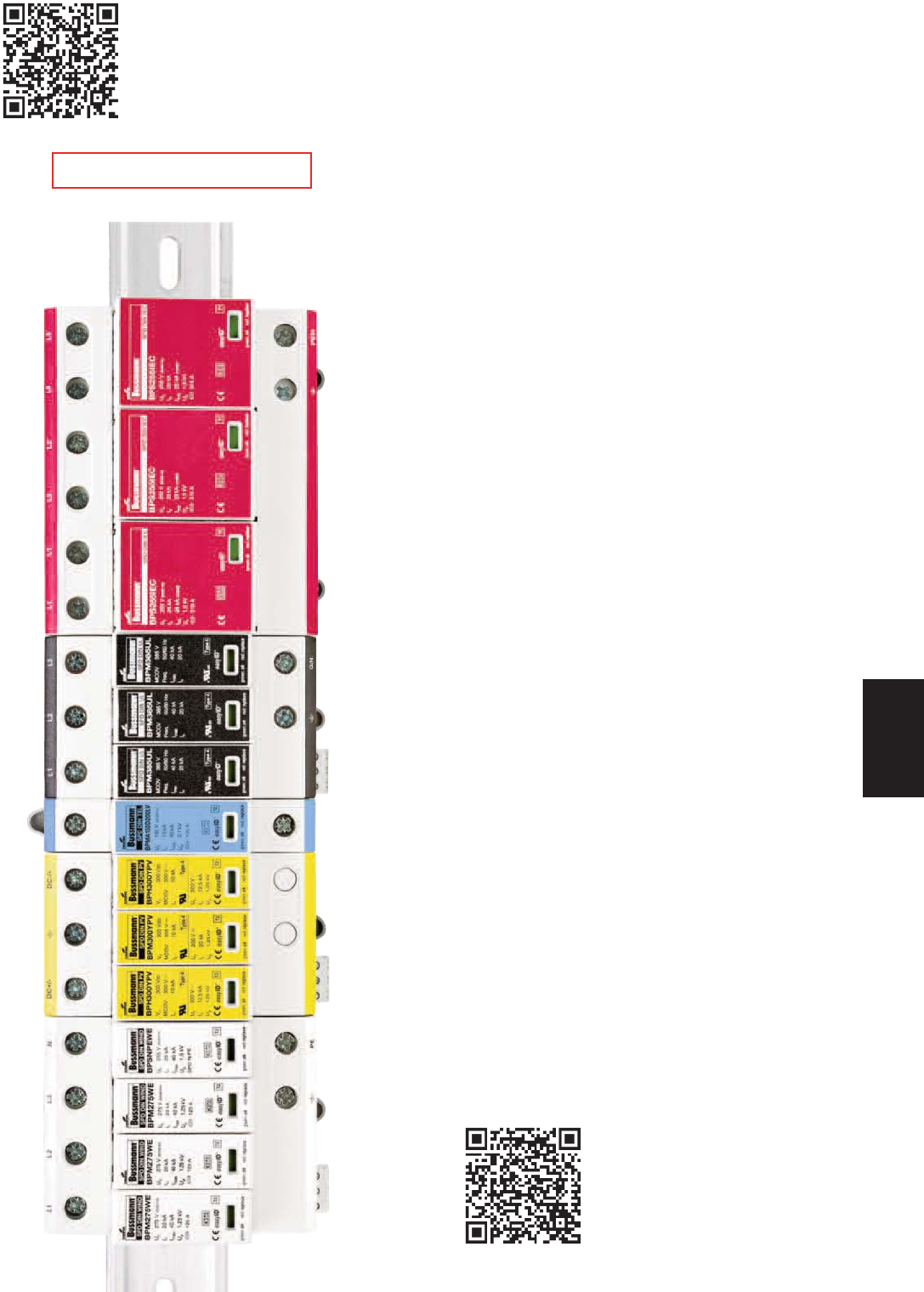
Surge Protective Devices
UL Type 1 NEMA 4X SPDs
SurgePOD HEAVY DUTY (Black Label) ...................442-445
SurgePOD PRO (Grey Label) ...................................446-448
UL DIN-Rail
High SCCR SPDs
1-Pole Type 2 BSPM_S2G ...............................449-450
2-Pole Type 2 BSPM_S3G ...............................451-452
3-Pole Type 2 BSPM_WYG/DLG......................453-454
4-Pole Type 2 BSPM_WYNG/HLG ...................455-456
Low Voltage AC/DC Power
1-Pole Type 2 BSPM_LV...................................457-458
Low-Voltage AC/DC Control
2-Pole Type 3 BSPH2A_LV...............................459-460
IEC DIN-Rail
Class I
2-Pole Class I BSPS_TN/TT .............................461-462
3-Pole Class I BSPS_TNC ................................463-464
4-Pole Class I BSPS_TNS/TT...........................465-466
Class II
1-Pole Class II BSPM_TN / BSPG_NPE............467-468
2-Pole Class II BSPM_TN / BSPH_TT...............469-470
3-Pole Class II BSPM_TNC ...............................471-472
4-Pole Class II BSPM_TNS / BSPH_TT ............473-474
Solar Power Photovoltaic (PV) DIN-Rail
Lightning Arrester
1-Pole PV Advance Lightning Arrester /
BSPS_PV ..................................................475-476
Overvoltage Surge Protective Devices
2-Module PV HEAVY DUTY SPD /
BSPH2_PV ................................477-478
3-Module PV HEAVY DUTY SPD /
BSPH_YPV ................................479-480
3-Module PV PRO SPD / BSPP_YPV........481-482
Wind Power IEC DIN-Rail
Class I
1-pole Class I BSPS_WE..................................483-484
Class II
1-Pole Class II BSPM_WE / BSPS_WE.............485-486
2-Pole Class II BSPM_WE / BSPH_WE ............487-488
3-Pole Class II BSPM_WE .................................489-490
4-Pole Class II BSPM_WE / BSPH_WE ............491-492
UL 4978 Data Signal SPDs
DIN-Rail BNC/Coaxial Cable BSPD5BNCD_ .......493-494
In-Line BNC/Coaxial Cable BSPD5BNCSI ........495-496
DIN-Rail RJ45/Ethernet Cable BSPD48RJ45 .........497-498
DIN-Rail Universal 4 Wire BSPD_DIN_............499-501
Surge Protective Overvoltage Device Modules
SurgePod™ Series, 150 to 550Vac MCOV ...........502-503
DIN-Rail TVS Series with Holder..................................504
441
Surge Protection
Devices
Overvoltage
Protective Devices
Scan this tag to get product information
about the New Bussmann Surge
Protection products for UL, PV, IEC, Wind
Power and Telecom applications.
Scan this tag to get access to the
Surge Protective Devices
Cross Reference Search.
RED indicates NEW information
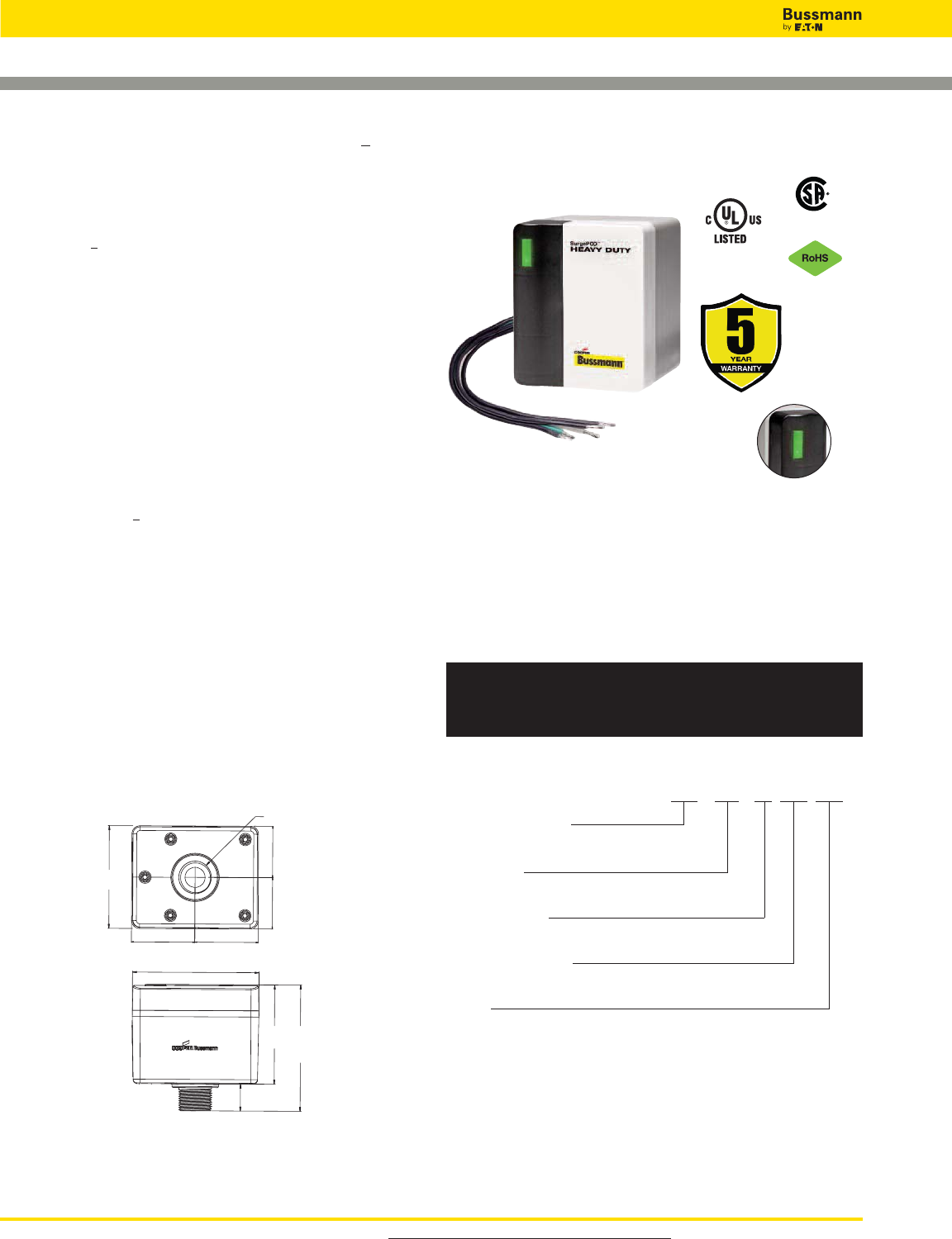
For product data sheets, visit www.cooperbussmann.com/DatasheetsEle
442
Overvoltage Devices
SURGE PROTECTION MADE SIMPLE™ FOR COMMERCIAL & INDUSTRIAL APPLICATIONS
SURGEPOD™ HEAVY DUTY SPD FOR UL 1449 3rd Edition Listed Loadside and Lineside Protection
2-1/16” 2-1/16”
1-11/16”
1-11/16”
4-1/8”
3-3/16”
4-1/16”
3-3/8”
7/8”
1-1/16” Dia.
NEMA 4X Rated Heavy Duty
Type 1 UL Listed SPD
Description
The Bussmann SurgePOD™ HEAVY DUTY is a Type 1 UL
Listed 1449 3rd Edition surge protective device suitable for
installation on both the loadside or lineside of the service
entrance overcurrent protective device.
Available in voltage and system specific versions to match
electrical system and equipment requirements. The SurgePOD
HEAVY DUTY delivers optimum surge protection using
advanced patent pending SurgePOD™ module featuring
thermal disconnect technology that eliminates the need for
additional overcurrent protection.
Parallel connection to the electrical system permits the
SurgePOD HEAVY DUTY SPD to be installed on any ampacity
panel.
• Type 1 UL 1449 3rd Edition Listed SPDs are easily selected
and installed on the loadside or lineside of the service
entrance overcurrent protective device
• Patented Bussmann SurgePOD module technology
eliminates the need for additional fusing
• Voltage specific models precisely match and protect
electrical systems and equipment up to 600Vac
• Compact UV resistant NEMA 4X for indoor or outdoor
applications
•easyID™ LED status indicator provides surge protection
status at a glance
Dimensions - in
SPH50SP1120SN
SPH50SP1240SN
SPH50SP1347SN
SPH50SP2120SNG
SPH50SP2240SNG
SPH50SP2347SNG
SPH50SP2240PN
SPH50SP2480PN
SPH50SP3240PNG
SPH50SP3480PNG
SPH50SP3240DLG
SPH50SP3480DLG
SPH50SP4240HLG
SPH50SP4480HLG
SPH50SP3208WYG
SPH50SP3480WYG
SPH50SP3600WYG
SPH50SP4208WYNG
SPH50SP4480WYNG
SPH50SP4600WYNG
easyID™ LED
Status Indicator
Type 1 SPD Part Number System
SPH 50S PX XXX XXX
SPH = Product Series
Surge Protection Heavy Duty
Surge Rating
50S = 50kA max discharge current
No of Wires/Poles
P1 = 1 P2 = 2 P3 = 3 P4 = 4
Rated System Voltage
120, 208, 240, 347, 480, 600Vac
System
SN = Single-Phase 2 Wire, 2 Connection Points
SNG = Single-Phase 2 Wire + G, 3 Connection Points
PN = Split-Phase 3 Wire , 3 Connection Points
PNG = Split-Phase 3 Wire + G, 4 Connection Points
DLG = Three-Phase Delta 3 Wire + G, 4 Connection Points
HLG = Three-Phase Highleg Delta 4 Wire + G, 5 Connection Points
WYG = Three-Phase Wye 3 Wire, 4 Connection Points
WYNG = Three-Phase Wye 3 Wire + G, 5 Connection Points
SPD Type 2
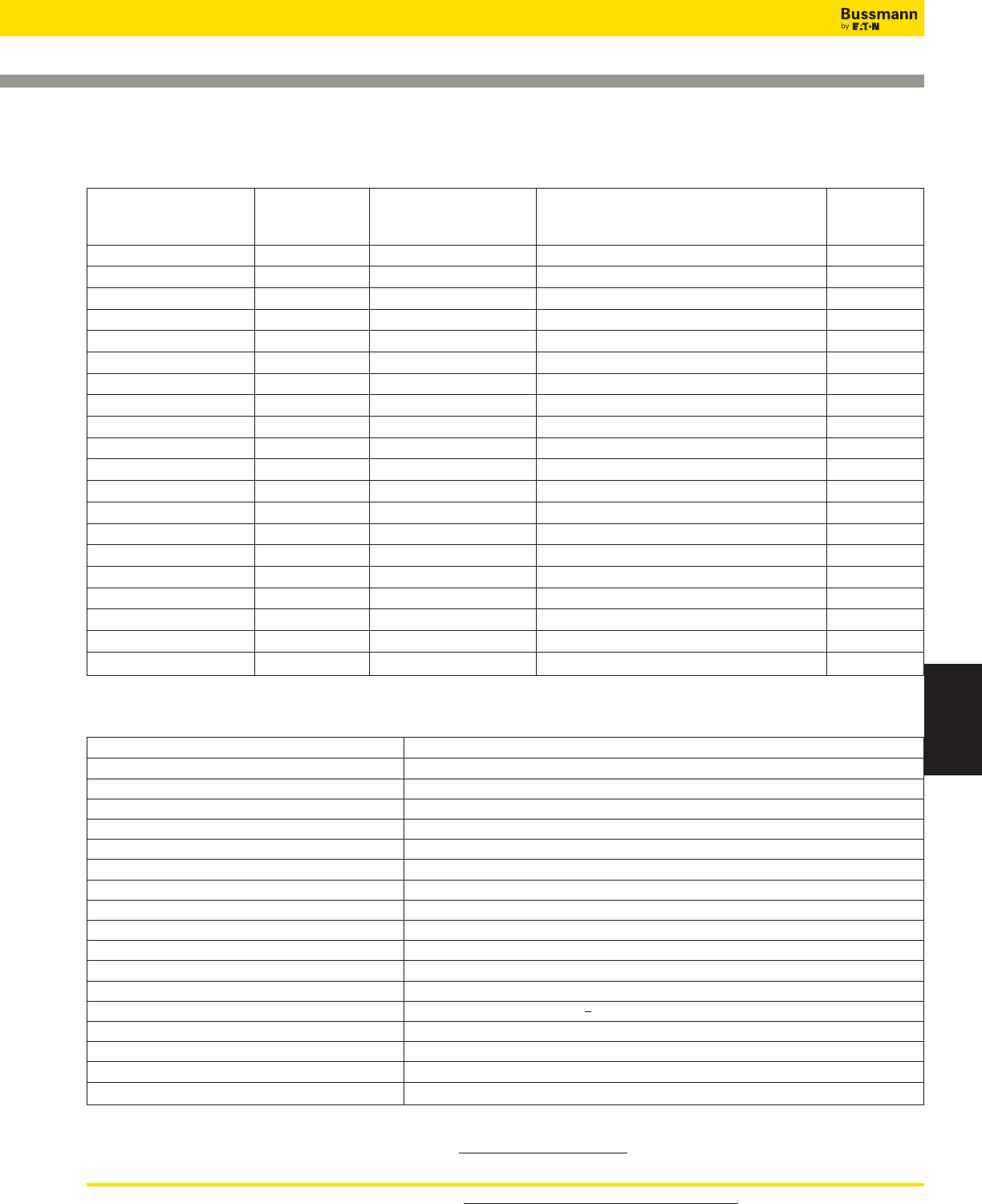
For product data sheets, visit www.cooperbussmann.com/DatasheetsEle 443
Surge Protection
Devices
SurgePOD™ HEAVY DUTY Technical Information
Nominal Max. Continuous
System Operating AC Connection
Catalog Number Voltage Voltage (MCOV) (VC) System Type Points
SPH50SP1120SN 120V 150V Single-Phase 2 Wire 2
SPH50SP1240SN 240V 320V Single-Phase 2 Wire 2
SPH50SP1347SN 347V 420V Single-Phase 2 Wire 2
SPH50SP2120SNG 120V 150V Single-Phase 2 Wire + G 3
SPH50SP2240SNG 240V 320V Single-Phase 2 Wire + G 3
SPH50SP2347SNG 347V 420V Single-Phase 2 Wire + G 3
SPH50SP2240PN 120/240V 150V Split-Phase 3 Wire 3
SPH50SP2480PN 240/480V 320V Split-Phase 3 Wire 3
SPH50SP3240PNG 120/240V 150V Split-Phase 3 Wire + G 4
SPH50SP3480PNG 240/480V 320V Split-Phase 3 Wire + G 4
SPH50SP3240DLG 240V 320V Three-Phase Delta 3 Wire + G 4
SPH50SP3480DLG 480V 550V Three-Phase Delta 3 Wire + G 4
SPH50SP4240HLG 120/240V 150/320V Three-Phase Highleg Delta 4 Wire + G 5
SPH50SP4480HLG 240/480V 320/550V Three-Phase Highleg Delta 4 Wire + G 5
SPH50SP3208WYG 208V 150V Three-Phase Wye 3 Wire + G 4
SPH50SP3480WYG 480V 320V Three-Phase Wye 3 Wire + G 4
SPH50SP3600WYG†600V 420V Three-Phase Wye 3 Wire + G 4
SPH50SP4208WYNG 208Y/120V 150V Three-Phase Wye 4 Wire + G 5
SPH50SP4480WYNG 480Y/277V 320V Three-Phase Wye 4 Wire + G 5
SPH50SP4600WYNG†600Y/347V 420V Three-Phase Wye 4 Wire + G 5
Specifications (for all SurgePOD HD units) Values
Short Circuit Current Rating (SCCR) 200kA
Nominal Discharge Current (8x20μs) In20kA
Max. Discharge Current (8x20μs) Imax 50kA
Response Time tA<25ns
Frequency 50/60Hz
Operating State/Fault Indication Bi-Color LED - Green (good) / Red (replace)
Conductor Length / Guage 18 inches, 10 AWG Stranded Tinned Copper
Mounting Chase Nipple / Bracket*
Enclosure / Flammability Ratings NEMA 4X - UL 94-5VA
Degree of Protection (Installed State) IP20 (finger-safe)
SPD Install Location Indoor/Outdoor
Circuit Location Lineside or Loadside of service entrance overcurrent protective device
Standard UL 1449 3rd Edition Type 1 Listed SPD
Agency Information cULus, CSA**, RoHS Compliant
Product Warranty 5 Years***
Operating Temperature -40˚C to +85˚C
Maximum Operating Altitude 16,000FT
* Customer-supplied bracket.
** 600V Wye versions not CSA Certified.
*** See Bussmann SPD Limited Warranty Statement (3A1502) for details at www.cooperbussmann.com/Surge.
SurgePOD™ HEAVY DUTY Technical Information
† 600V Wye versions are not CSA Certified.
Overvoltage Devices
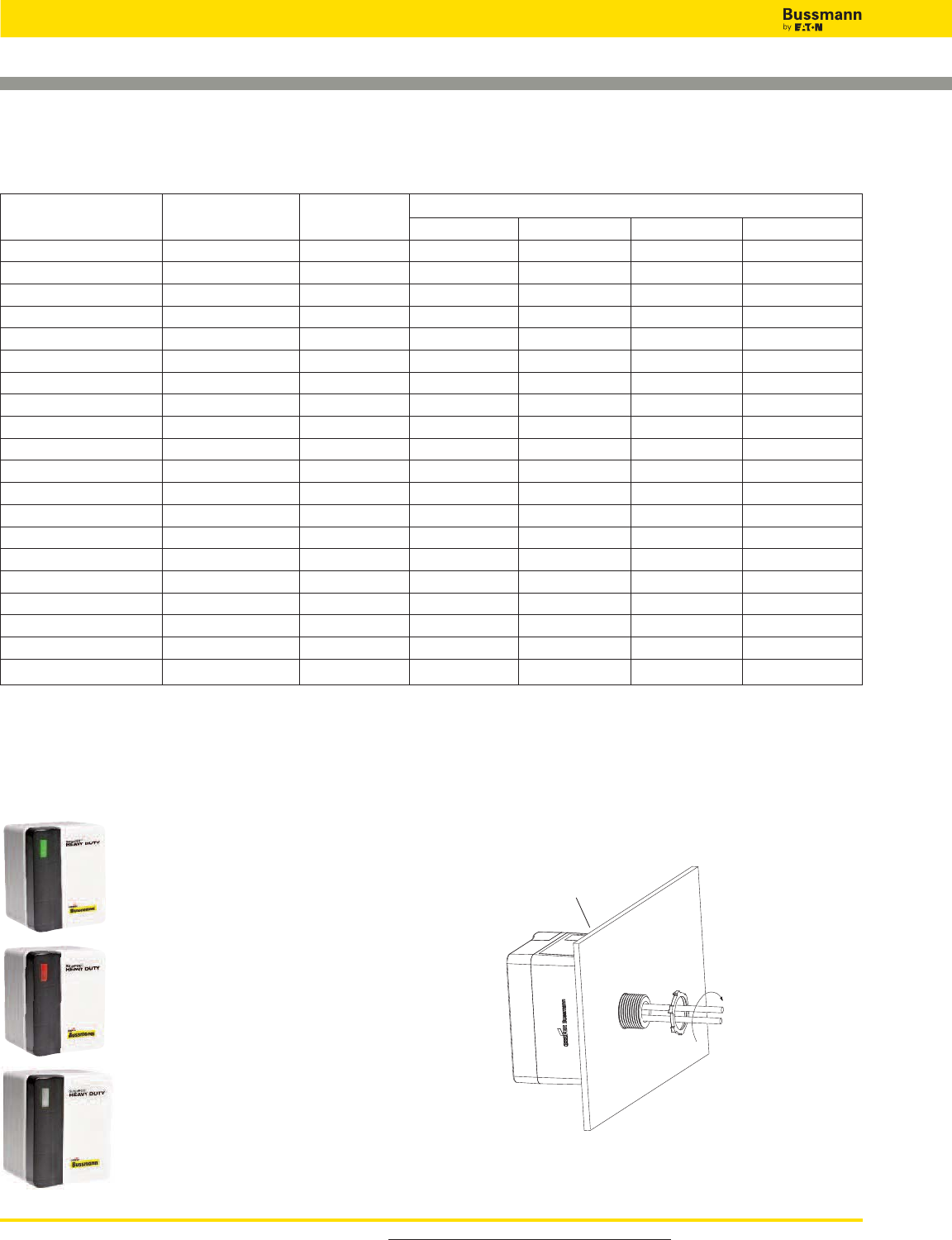
For product data sheets, visit www.cooperbussmann.com/DatasheetsEle
444
Overvoltage Devices
Rated System MCOV Voltage Protection Ratings (VPRs)
Catalog Number Voltage (Vo)(V
C) L-N L-L L-G N-G
SPH50SP1120SN 120V 150V 700 — — —
SPH50SP1240SN 240V 320V 1200 — — —
SPH50SP1347SN 347V 420V 1500 — — —
SPH50SP2120SNG 120V 150V 700 — 1200 700
SPH50SP2240SNG 240V 320V 1200 — 2500 1200
SPH50SP2347SNG 347V 420V 1500 — 2500 1500
SPH50SP2240PN 120V/240V 150V 700 1200 — —
SPH50SP2480PN 240V/480V 320V 1200 2500 — —
SPH50SP3240PNG 120V/240V 150V 700 1200 1200 700
SPH50SP3480PNG 240V/480V 320V 1200 2500 2500 1200
SPH50SP3240DLG 240V 320V — 2500 1200 —
SPH50SP3480DLG 480V 550V — 3000 1800 —
SPH50SP4240HLG 120/240V 150V/320V 700/1200 1200/2500 1200/2500 700/1200
SPH50SP4480HLG 240/480V 320V/550V 1200/1800 2500/3000 2500/3000 1200/1800
SPH50SP3208WYG 208V 150V — 1200 700 —
SPH50SP3480WYG 480V 320V — 2500 1200 —
SPH50SP3600WYG†600V 420V — 2500 1500 —
SPH50SP4208WYNG 208Y/120V 150V 700 1200 1200 700
SPH50SP4480WYNG 480Y/277V 320V 1200 2500 2500 1200
SPH50SP4600WYNG†600Y/347V 420V 1500 2500 2500 1500
Voltage Protection Ratings (VPRs)
easyID™ LED Status Indicator
The easyID™ LED status indicator will illuminate when the unit is
properly installed and the system or equipment being protected is
energized. The following LED color/status indicates:
GREEN LED = Good
The circuit is energized and protected.
RED LED = Replace
The circuit is energized and unprotected.
The unit needs replacing.
LED is Out / Unlit:
• The circuit is most likely deenergized
• The unit’s leads are disconnected
• The unit is damaged
Authorized personnel should follow all prescribed lockout/tagout and safety procedures in troubleshooting
the cause for the above conditions. Opening SurgePOD HEAVY DUTY enclosure will void UL listing and warranty.
Tighten locknut to
20.3 Lb-In (2.3N•m)
For NEMA 4X installation,
install appropriate customer
supplied gasket between
SurgePOD™ HEAVY DUTY
SPD and enclosure wall.
Mounting
SurgePOD HEAVY DUTY is a panel mount device. It may also
be mounted using a customer supplied bracket or directly
onto a female threaded conduit fitting.
† 600V Wye versions are not CSA Certified.
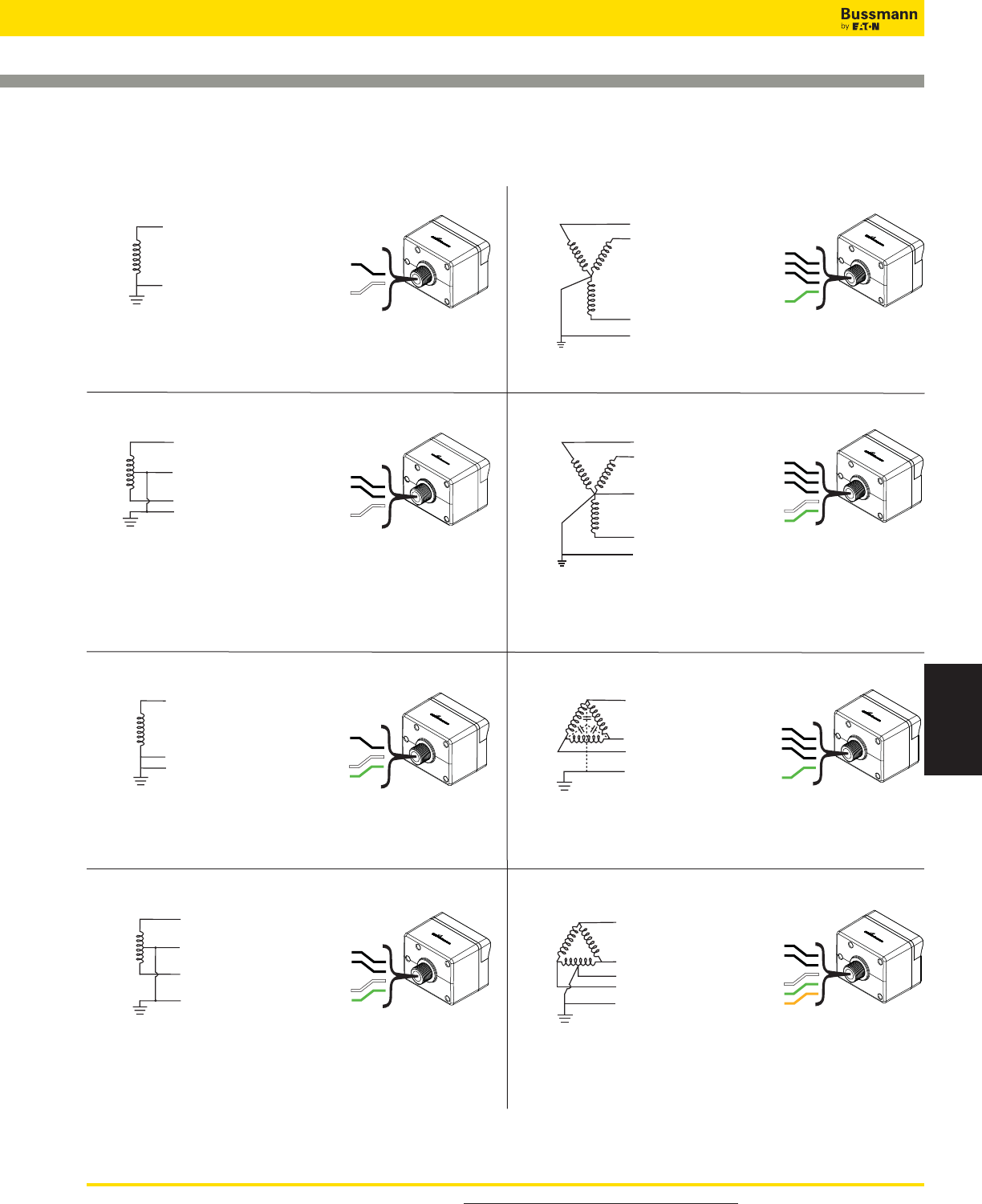
For product data sheets, visit www.cooperbussmann.com/DatasheetsEle 445
Surge Protection
Devices
Wiring Connections
Black
Black
White
L1 (Black)
L2 (Black)
N (White)
120V (L-N) / 240V (L1-L2),
240V (L-N) / 480V (L1-L2)
Single Phase (Split) Center Tap
SPH50SP2240PN,
SPH50SP2480PN
Black
Black
Green
White
Orange
L3 (Black)
L2 (Orange)
Highleg
L1 (Black)
N (White)
GND (Green)
120V (L1 / L3-N) / 240V (L-L),
240V (L1 / L3-N) / 480V (L-L)
4 Wire Highleg Delta + Ground
SPH50SP4240HLG,
SPH50SP4480HLG
L (Black)
N (White)
Black
White
120, 240, 347V (L-N)
2 Wire
120, 240, 347V (L-N)
2 Wire + Ground
SPH50SP1120SN,
SPH50SP1240SN,
SPH50SP1347SN
L (Black)
N (White)
GND (Green)
Black
Green
White
SPH50SP2120SNG,
SPH50SP2240SNG,
SPH50SP2347SNG
Black
Black
Black
Green
White
GND (Green)
L2 (Black)
N (White)
L3 (Black)
L1 (Black)
SPH50SP4208WYNG,
SPH50SP4480WYNG,
SPH50SP4600WYNG
120V (L-N) / 208V (L-L),
127V (L-N) / 220V (L-L),
277V (L-N) / 480V (L-L),
347V (L-N) / 600V (L-L)
4 Wire Wye + Ground
L1 (Black)
L2 (Black)
L3 (Black)
GND (Green)
SPH50SP3240DLG,
SPH50SP3480DLG
Black
Black
Black
Green
240, 480V (L-L)
3 Wire Delta + Ground
Black
Black
Black
Green
L1 (Black)
L3 (Black)
L2 (Black)
GND (Green)
SPH50SP3208WYG,
SPH50SP3480WYG,
SPH50SP3600WYG
208, 480, 600V (L-L)
3 Wire Wye + Ground
Black
Black
Green
White
L1 (Black)
L2 (Black)
N (White)
GND (Green)
120V (L-N) / 240V (L1-L2),
240V (L-N) / 480V (L1-L2)
Single Phase (Split) Center Tap + Ground
SPH50SP3240PNG,
SPH50SP3480PNG
Must be installed within 10 feet (3m) of a bonded
neutral-ground connection per IEEE C62.41-1991
For installations at or less than 10 feet (3m)
from the transformer.
For installation when located greater than 10 feet (3m) of a
bonded neutral-ground connection.
For installation when located greater than 10 feet (3m)
of a bonded neutral-ground connection.
Single-Phase
Two-Pole with Neutral
Two-Pole with Neutral + Ground
Wye + Ground
Wye with Neutral + Ground
Delta + Ground
Highleg Delta
Single-Phase + Ground
Overvoltage Devices
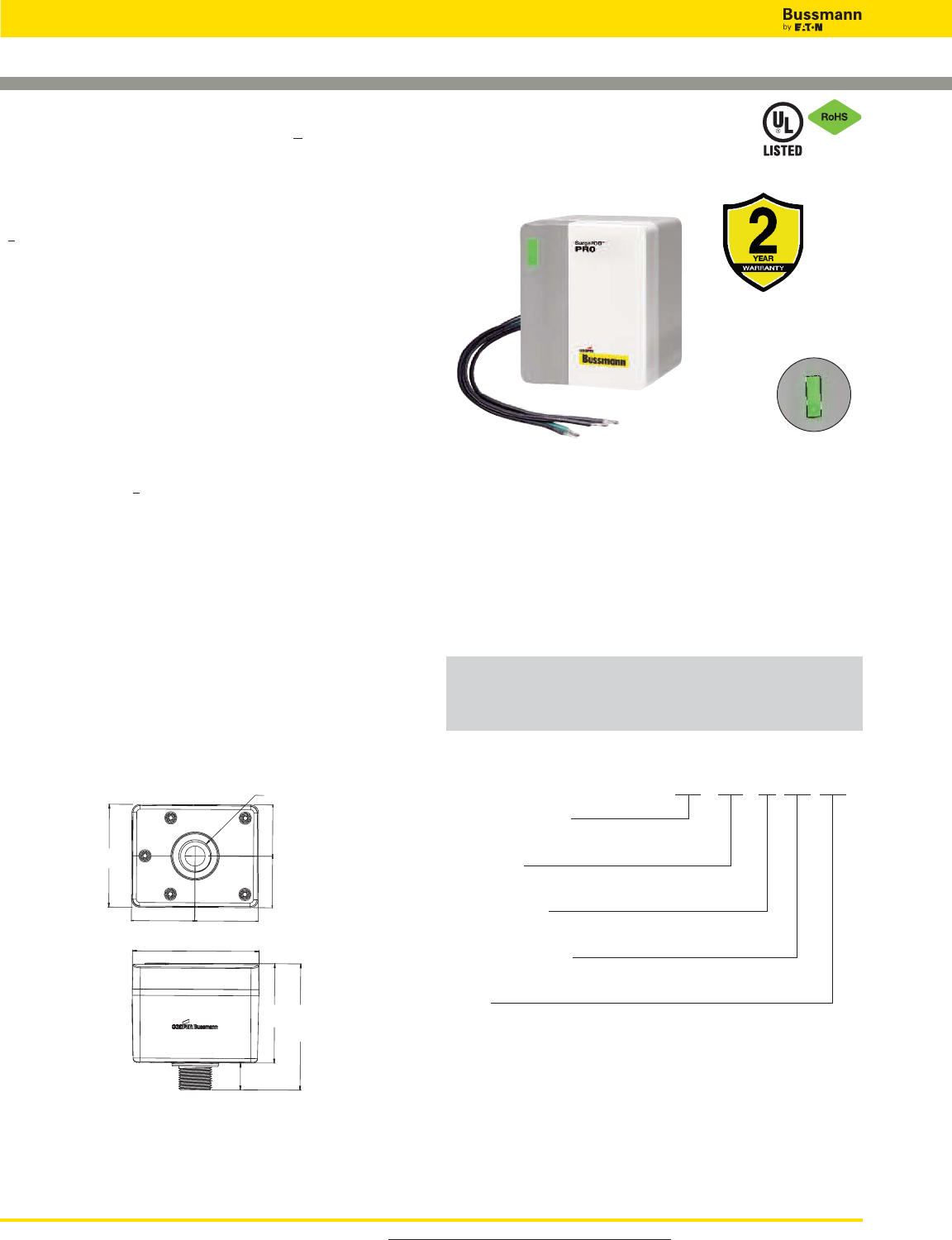
For product data sheets, visit www.cooperbussmann.com/DatasheetsEle
446
Overvoltage Devices
SURGE PROTECTION MADE SIMPLE™ FOR LIGHT COMMERCIAL & RESIDENTIAL APPLICATIONS
SURGEPOD™ PRO SPD FOR UL 1449 3rd Edition Listed Loadside and Lineside Protection
2-1/16” 2-1/16”
1-11/16”
1-11/16”
4-1/8”
3-3/16”
4-1/16”
3-3/8”
7/8”
1-1/16” Dia.
NEMA 4X Rated Pro
Type 1 UL Listed SPD
Description
The Bussmann SurgePOD™ PRO is a Type 1 UL Listed 1449
3rd Edition surge protective device suitable for installation on
both the loadside or lineside of the service entrance
overcurrent protective device.
Available in popular voltage and system specific versions to
match common residential and light commercial electrical
system and equipment requirements. The SurgePOD PRO
delivers superior surge protection using MOV thermal
disconnect technology that eliminates the need for additional
overcurrent protection.
Parallel connection to the electrical system permits the
SurgePOD PRO SPD to be installed on any ampacity panel.
• Type 1 UL 1449 3rd Edition Listed SPDs are easily selected
and installed on the loadside or lineside of the service
entrance overcurrent protective device
• Voltage specific models precisely match and protect
electrical systems and equipment better than
“one-size-fits-all” SPDs
• Thermal disconnect technology eliminates the need for
additional fusing
• Compact UV resistant NEMA 4X enclosure for indoor or
outdoor applications
•easyID™ LED status indicator provides surge protection
status at a glance
Dimensions - in
SPP40SP1120SN
SPP40SP2240PN
SPP40SP3240DLG
SPP40SP3480DLG
SPP40SP3208WYG
SPP40SP3480WYG
easyID™ LED
Status Indicator
Type 1 SPD Part Number System
SPP 40S PX XXX XXX
SPP = Product Series
Surge Protection PRO
Surge Rating
40S = 40kA max discharge current
No of Wires/Poles
P1 = 1 P2 = 2 P3 = 3 P4 = 4
Rated System Voltage
120, 208, 240, 480Vac
System
SN = Single-Phase 2 Wire, 2 Connection Points
PN = Split-Phase, 3 Wire, 3 Connection Points
DLG = Three-Phase Delta 3 Wire + G, 4 Connection Points
WYG = Three-Phase Wye 3 Wire, 4 Connection Points

For product data sheets, visit www.cooperbussmann.com/DatasheetsEle 447
Surge Protection
Devices
Nominal System MCOV Voltage Protection Ratings (VPRs)
Catalog Number Voltage (VC) L-N L-L L-G
SPP40SP1120SN 120V 150V 700 — —
SPP40SP2240PN 120V/240V 150V 700 1200 —
SPP40SP3240DLG 240V 320V — 2500 1200
SPP40SP3480DLG 480V 550V — 3000 1800
SPP40SP3208WYG 208V 150V — 1200 700
SPP40SP3480WYG 480V 320V — 2500 1200
Voltage Protection Ratings (VPRs)
Specifications (for all SurgePOD PRO units) Values
Short Circuit Current Rating (SCCR) 200kA
Nominal Discharge Current (8x20μs) In10kA
Max. Discharge Current (8x20μs) Imax 40kA
Response Time (ns) tA<25ns
Frequency 50/60Hz
Operating State/Fault Indication Bi-Color LED - Green (good) / Red (replace)
Conductor Length / Guage 18 inches, 10 AWG Stranded Tinned Copper
Mounting Chase Nipple / Bracket*
Enclosure / Flammability Ratings NEMA 4X - UL 94-5VA
Degree of Protection (Installed State) IP20 (finger-safe)
SPD Install Location Indoor/Outdoor
Circuit Location Lineside or Loadside of service entrance overcurrent protective device
Standard UL 1449 3rd Edition Type 1 Listed SPD
Agency Information cULus, RoHS Compliant
Product Warranty 2 Years**
Operating Temperature -40˚C to +65˚C
Maximum Operating Altitude 12000FT
* Customer-supplied bracket.
** See Bussmann SPD Limited Warranty Statement (3A1502) for details at www.cooperbussmann.com/Surge.
SurgePOD™ PRO Technical Information
Nominal Max. Continuous
System Operating AC Connection
Catalog Number Voltage Voltage (MCOV) (VC) System Type Points
SPP40SP1120SN 120V 150V Single-Phase 2 Wire 2
SPP40SP2240PN 120/240V 150V Split Phase 3 Wire 3
SPP40SP3240DLG 240V 320V Three-Phase Delta 3 Wire + G 4
SPP40SP3480DLG 480V 550V Three-Phase Delta 3 Wire + G 4
SPP40SP3208WYG 208V 150V Three-Phase Wye 3 Wire + G 4
SPP40SP3480WYG 480V 320V Three-Phase Wye 3 Wire + G 4
Overvoltage Devices
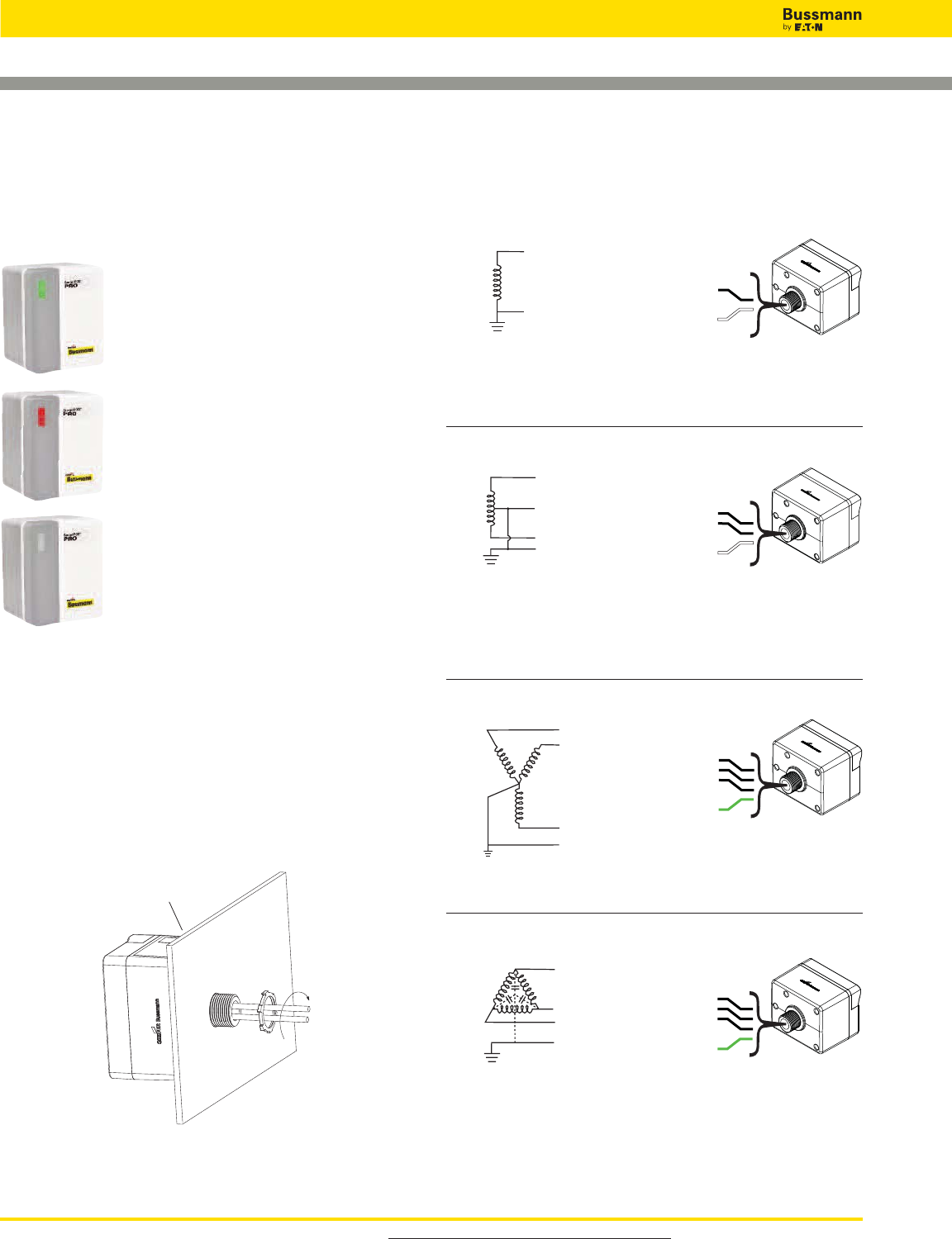
For product data sheets, visit www.cooperbussmann.com/DatasheetsEle
448
Overvoltage Devices
Wiring Connections
L (Black)
N (White)
Black
White
120V (L-N)
2 Wire
SPP40SP1120SN
L1 (Black)
L2 (Black)
L3 (Black)
GND (Green)
SPP40SP3240DLG,
SPP40SP3480DLG
Black
Black
Black
Green
240, 480V (L-L)
3 Wire Delta + Ground
Black
Black
Black
Green
L1 (Black)
L3 (Black)
L2 (Black)
GND (Green)
SPP40SP3208WYG,
SPP40SP3480WYG
208, 480V (L-L)
3 Wire Wye + Ground
Must be installed within 10 feet (3m) of a bonded
neutral-ground connection per IEEE C62.41-1991
Single-Phase
Wye + Ground
Delta + Ground
easyID™ LED Status Indicator
The easyID™ LED status indicator will illuminate when the unit is
properly installed and the system or equipment being protected is
energized. The following LED color/status indicates:
GREEN LED = Good
The circuit is energized and protected.
RED LED = Replace
The circuit is energized and unprotected.
The unit needs replacing.
LED is Out / Unlit:
• The circuit is most likely deenergized
• The unit’s leads are disconnected
• The unit is damaged
Authorized personnel should follow all
prescribed lockout/tagout and safety
procedures in troubleshooting the cause for
the above conditions. Opening SurgePOD
PRO enclosure will void UL listing and
warranty.
Tighten locknut to
20.3 Lb-In (2.3N•m)
For NEMA 4X installation,
install appropriate customer
supplied gasket between
SurgePOD™ PRO
SPD and enclosure wall.
Mounting
SurgePOD PRO is a panel mount device. It may also be
mounted using a customer supplied bracket or directly onto a
female threaded conduit fitting.
Black
Black
White
L1 (Black)
L2 (Black)
N (White)
120V (L-N) / 240V (L1-L2),
Single Phase (Split) Center Tap
SPP40SP2240PN,
For installations at or less than 10 feet (3m)
from the transformer.
Two-Pole with Neutral

For product data sheets, visit www.cooperbussmann.com/DatasheetsEle 449
Surge Protection
Devices
Overvoltage Devices
UL DIN-Rail SPD - High SCCR
BSPM_ _ _ _S2G
Specifications
Description
The Bussmann single pole UL modular surge arresters for
120, 240 and 347Vac single-phase systems feature local,
easyID™ visual indication and optional remote contact
signaling. The unique module locking system fixes the
protection module to the base part. Modules can be easily
replaced without tools by simply depressing the release
buttons. Integrated mechanical coding between the base and
protection module ensures against installing an incorrect
replacement module.
Features
• Surge arrester according to UL 1449 3rd Edition, Type 2
Component Assembly helps meet UL 508A requirements
• Heavy-duty zinc oxide varistors for high discharge capacity
• "Thermo Dynamic Control" SPD monitoring device ensures
high reliability against surge events
• Module locking system with module release button makes
module replacement easy without tools
• Up to 200kA Short-Circuit Current Rating (SCCR) makes
higher assembly SCCR ratings possible
• Optional remote signaling of all protection modules makes
status monitoring easy and accurate in any monitoring
scheme
• No upstream overcurrent protection necessary to make
installation easier and more economical
• Vibration and shock tested according to EN 60068-2 to
withstand harsh environments
Optional Remote Signaling Contact
The remote signaling contact versions have a floating
changeover contact for use as a break or make contact for
easy adoption in any monitoring application.
BSPM1120S2G, BSPM1240S2G, BSPM1347S2G*
Shown with optional remote contact signaling
Shown with optional remote contact signaling
Circuit Diagram
Dimensions - mm
Remote Signal
Contact Available
Visual Status Indication
*For remote signaling contact, add “R” suffix to the part number,
E.g., BSPM1347S2GR
12
11
14
L
Gnd/N
12
11
14
Thermal
Disconnector
Optional Remote
Signal Contact
MOV
Data Sheet: 2149
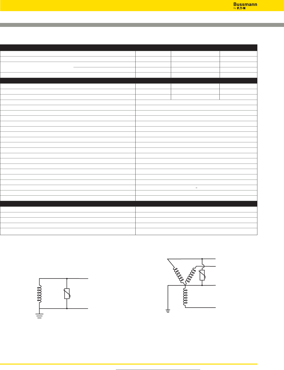
For product data sheets, visit www.cooperbussmann.com/DatasheetsEle
450
Overvoltage Devices
UL DIN-Rail SPD - High SCCR
Single Pole BSP UL Series Installation Instructions - Document 3A1636RevA
ORDERING INFORMATION
Nominal System Voltage 120Vac 240, 277 or 240 & 277Vac 347Vac
Max. Continuous Operating AC Voltage (MCOV) [VC] 275Vac 385Vac 600Vac
Catalog Numbers: Without Remote Signaling BSPM1120S2G BSPM1240S2G BSPM1347S2G
With Remote Signaling BSPM1120S2GR BSPM1240S2GR BSPM1347S2GR
Replacement Module MOV Technology BPM275UL BPM385UL BPM600UL
SPECIFICATIONS
Rated Voltage 120-127Vac 240-277Vac 347Vac
Voltage Protection Rating VPR 1kV 1.5kV 2kV
SCCR 200kA 200kA 125kA
Nominal Discharge Current In(kA) 20kA
Max. Discharge Current Imax (kA) 40kA
Response Time tA_<25 ns
Frequency 50/60Hz
Number of Poles 1
Number of Wires/Connection Points 2 Wires / 2 Connection Points
Operating State/Fault Indication Green (good) / Red (replace)
Cross-Sectional Area (min.) 14AWG - Cu Stranded, Solid or Fine
Cross-Sectional Area (max.) 2AWG - Cu Solid or Stranded / 4AWG - Cu Fine
Terminal Torque 45 lb-in
For Mounting On 35mm DIN Rail per to EN 60715
Enclosure Material Thermoplastic, UL 94V0
Degree of Protection IP20 (finger-safe)
Location Category Indoor
Capacity 1 Mods, DIN 43880
Application UL Type 2 Component Assembly
Standard UL 1449, 3rd Edition
Agency Information cURus, CSA, RoHS Compliant
Product Warranty Five Years*
REMOTE CONTACT SIGNALING
Remote Contact Signaling Type Changeover Contact
AC Switching Capacity (Volts/Amps) 250V/0.5A
DC Switching Capacity (Volts/Amps) 250V/0.1A; 125V/0.2A; 75V/0.5A
Conductor Ratings and Cross-Sectional Area for Remote Contact Signal Terminals 60/75°C Max. 1.5mm2/14AWG Solid/Flexible
Ordering Information Order from Catalog Numbers Above
* See Bussmann SPD Limited Warranty Statement (3A1502) for details at www.cooperbussmann.com/surge.
Part Numbers for all systems BSPM1120S2G, BSPM1240S2G, BSPM1347S2G
120, 277, 347Vac 2 Wire Wye Systems120, 240, 347Vac 2 Wire Systems
L
N
L1
L2
N
L3
Data Sheet: 2149

For product data sheets, visit www.cooperbussmann.com/DatasheetsEle 451
Surge Protection
Devices
Overvoltage Devices
UL DIN-Rail SPD - High SCCR
BSPM_ _ _ _S3G
Description
The Bussmann 2-pole UL modular surge arresters for
120/240, 120/208, 127/254, 240, 240/480, 277/480 and
480Vac (split-phase) systems feature local, easyID™ visual
indication and optional remote contact signaling. The unique
module locking system fixes the protection module to the base
part. Modules can be easily replaced without tools by simply
depressing the release buttons. Integrated mechanical coding
between the base and protection module ensures against
installing an incorrect replacement module.
Features
• Surge arrester according to UL 1449 3rd Edition, Type 2
Component Assembly helps meet UL 508A requirements
• Heavy-duty zinc oxide varistors for high discharge capacity
• "Thermo Dynamic Control" SPD monitoring device ensures
high reliability against surge events
• Module locking system with module release button make
module replacement easy without tools
• Up to 200kA Short-Circuit Current Rating (SCCR) make
higher assembly SCCR ratings possible
• Optional remote signaling of all protection modules make
status monitoring easy and accurate in any monitoring
scheme
• No upstream overcurrent protection necessary to make
installation easier and more economical
• Vibration and shock tested according to EN 60068-2 to
withstand harsh environments
Optional Remote Signaling Contact
The remote signaling contact versions have a floating
changeover contact for use as a break or make contact for
easy adoption in any monitoring application.
BSPM2240S3G, BSPM2480S3G*
Shown with optional remote contact signaling
Shown with optional remote contact signaling
Circuit Diagram
Dimensions - mm
Remote Signal
Contact Available
Visual Status Indication
*For remote signaling contact, add “R” suffix to the part number,
E.g., BSPM2480S3GR
L2L1
12
11
14
Gnd/N
Gnd/N
12
11
14
Thermal
Disconnector
Optional Remote
Signal Contact
MOV
Data Sheet: 2150
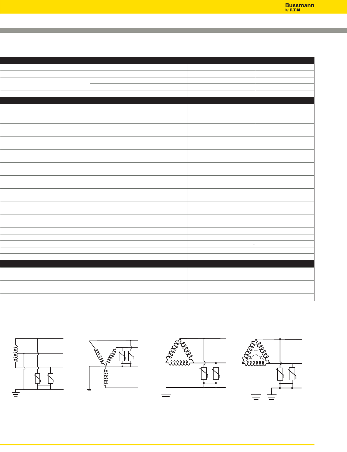
For product data sheets, visit www.cooperbussmann.com/DatasheetsEle
452
Overvoltage Devices
UL DIN-Rail SPD - High SCCR
ORDERING INFORMATION
Nominal System Voltage 120/240, 240Vac 240/480Vac
Max. Continuous Operating Voltage MCOV [L-G/L-L] 275/550Vac 385/770Vac
Catalog Numbers: Without Remote Signaling BSPM2240S3G BSPM2480S3G
With Remote Signaling BSPM2240S3GR BSPM2480S3GR
Replacement Module MOV Technology BPM275UL BPM385UL
SPECIFICATIONS
120-127Vac 240-480Vac
Rated Voltage 240-254Vac 480Vac
240Vac
Voltage Protection Rating VPR [L-G/L-L] 1kV/1.8kV 1.5kV/2.5kV
Nominal Discharge Current In(kA) 20kA
Max. Discharge Current Imax (kA) 40kA
Response Time tA_<25 ns
SCCR 200kA
Frequency 50/60Hz
Number of Poles 2
Number of Wires/Connection Points 2 Wires or 3 Wires / 3 Connection Points
Operating State/Fault Indication Green (good) / Red (replace)
Cross-Sectional Area (min.) 14AWG - Cu Stranded, Solid or Fine
Cross-Sectional Area (max.) 2AWG - Cu Solid or Stranded, 4AWG - Cu Fine
Terminal Torque 45 lb-in
For Mounting On 35mm DIN-Rail per EN 60715
Enclosure Material Thermoplastic, UL 94V0
Degree of Protection IP20 (finger-safe)
Location Category Indoor
Capacity 2 mods, DIN 43880
Application UL Type 2 Component Assembly
Standard UL 1449, 3rd Edition
Agency Information cURus, CSA, RoHS Compliant
Product Warranty Five Years*
REMOTE CONTACT SIGNALING
Remote Contact Signaling Type Changeover Contact
AC Switching Capacity (Volts/Amps) 250V/0.5A
DC Switching Capacity (Volts/Amps) 250V/0.1A; 125V/0.2A; 75V/0.5A
Conductor Ratings and Cross-Sectional Area for Remote Contact Signal Terminals 60/75°C Max. 1.5mm2/14AWG Solid/Flexible
Ordering Information Order from Catalog Numbers Above
* See Bussmann SPD Limited Warranty Statement (3A1502) for details at www.cooperbussmann.com/surge.
120/240V, 240/480Vac
Single Phase (Split) Center Tap
BSPM2240S3G, BSPM2480S3G
2 Wire Corner Grounded Delta 2 Wire Ungrounded Delta
240, 480Vac
BSPM2440S3G, BSPM2480S3G
L
N
L
120/208V, 277/480Vac
3 Wire Wye System
BSPM2240S3G, BSPM2480S3G
L
1
L2
N
L3
L1
L2
L1
L2
Data Sheet: 2150
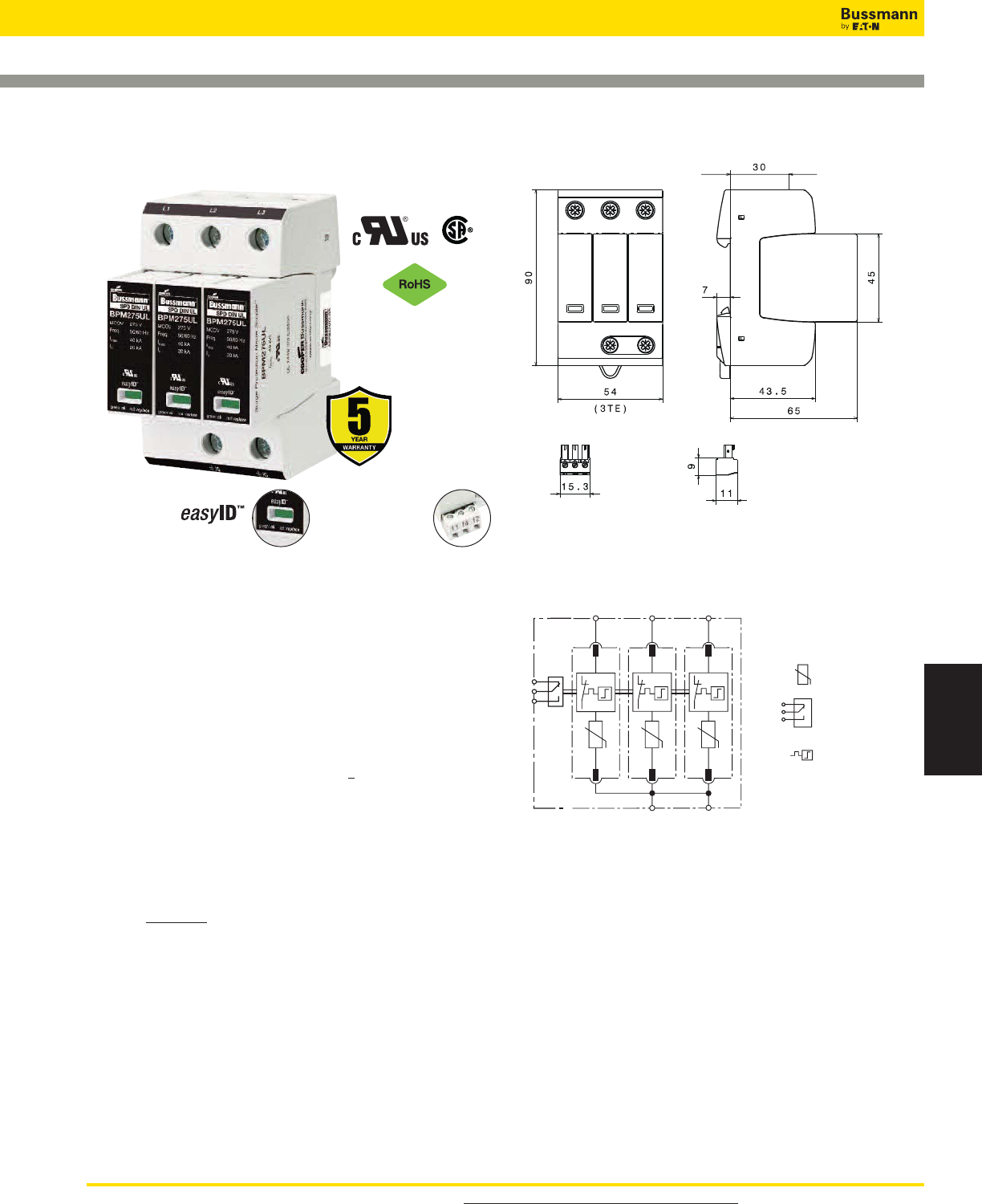
For product data sheets, visit www.cooperbussmann.com/DatasheetsEle 453
Surge Protection
Devices
Overvoltage Devices
UL DIN-Rail SPD - High SCCR
BSPM_ _ _ _WYG, BSPM_ _ _ _DLG
Description
The Bussmann 3-pole UL modular surge arresters for 240 and
480 3-phase Delta, and 120/208, 277/480 and 347/600Vac
3-phase Wye systems feature local, easyID™ visual indication
and optional remote contact signaling. The unique module
locking system fixes the protection module to the base part.
Modules can be easily replaced without tools by simply
depressing the release buttons. Integrated mechanical coding
between the base and protection module ensures against
installing an incorrect replacement module.
Features
• Surge arrester according to UL 1449 3rd Edition, Type 2
Component Assembly helps meet UL 508A requirements
• Heavy-duty zinc oxide varistors for high discharge capacity
• "Thermo Dynamic Control" SPD monitoring device ensures
high reliability against surge events
• Module locking system with module release button make
module replacement easy without tools
• Up to 200kA Short-Circuit Current Rating (SCCR) make
higher assembly SCCR ratings possible
• Optional remote signaling of all protection modules make
status monitoring easy and accurate in any monitoring
scheme
• No upstream overcurrent protection necessary to make
installation easier and more economical
• Vibration and shock tested according to EN 60068-2 to
withstand harsh environments
Optional Remote Signaling Contact
The remote signaling contact versions have a floating
changeover contact for use as a break or make contact,
according to circuit concept.
BSPM3208WYG, BSPM3480WYG), BSPM3600WYG,
BSPM3240DLG, BSPM3480DLG*
Shown with optional remote contact signaling
Shown with optional remote contact signaling
Circuit Diagrams
Dimensions - mm
Remote Signal
Contact Available
Visual Status Indication
*For remote signaling contact, add “R” suffix to the part number,
E.g., BSPM3480DLGR
12
11
14
L1 L2 L3
Gnd Gnd
12
11
14
Thermal
Disconnector
Optional Remote
Signal Contact
MOV
Data Sheet: 2151
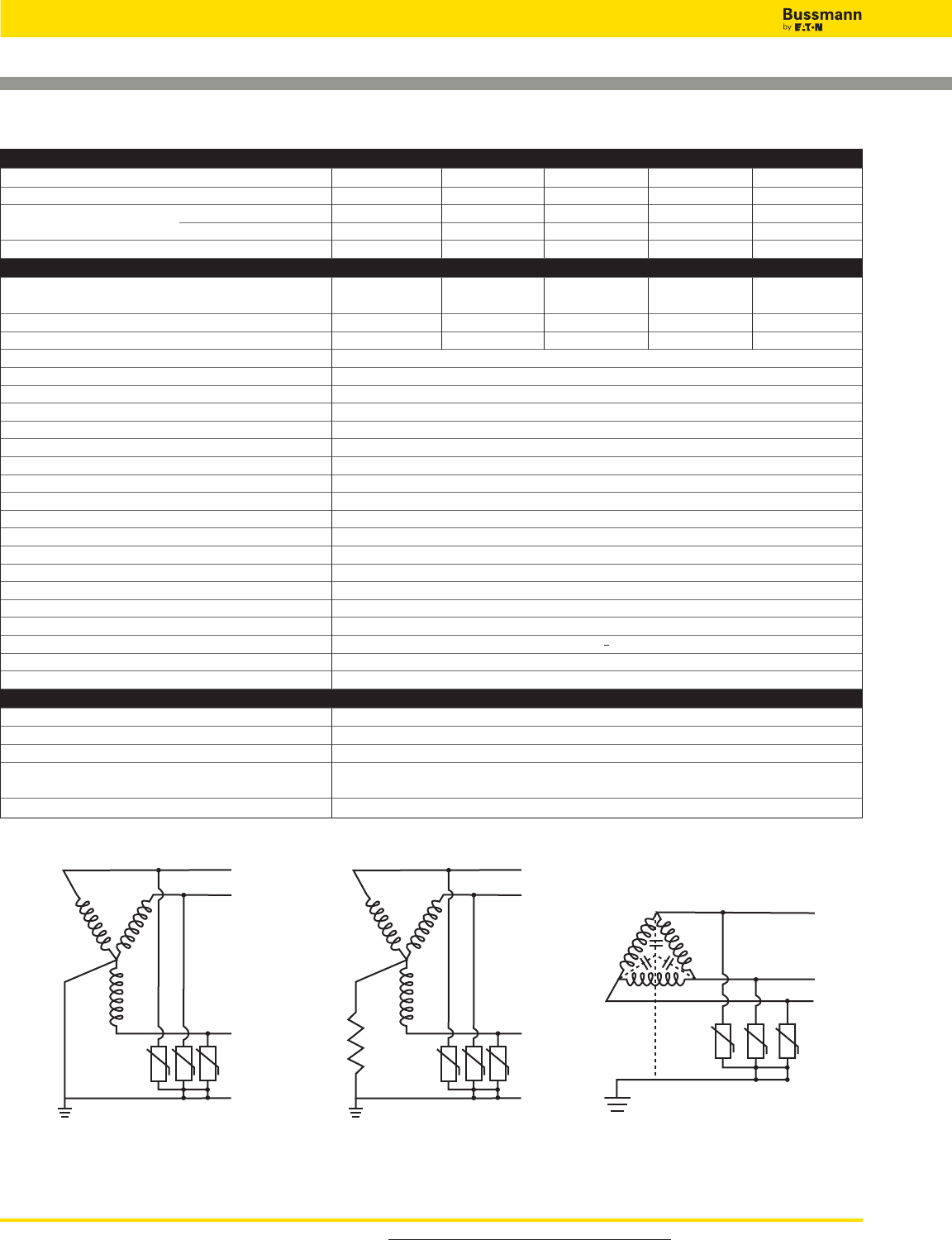
For product data sheets, visit www.cooperbussmann.com/DatasheetsEle
454
Overvoltage Devices
UL DIN-Rail SPD - High SCCR
ORDERING INFORMATION
Nominal System Voltage 120/208Vac 240Vac 277/480Vac 480Vac 347/600Vac
Max. Continuous Operating AC Voltage MCOV [L-G/L-L] 275/550Vac 275/550Vac 385/770Vac 600/1200Vac 600/1200Vac
Catalog Numbers: Without Remote Signaling BSPM3208WYG BSPM3240DLG BSPM3480WYG BSPM3480DLG BSPM3600WYG
With Remote Signaling BSPM3208WYGR BSPM3240DLGR BSPM3480WYGR BSPM3480DLGR BSPM3600WYGR
Replacement Module MOV Technology BPM275UL BPM275UL BPM385UL BPM600UL BPM600UL
SPECIFICATIONS
Rated Voltage 120-127Vac, 240Vac 277/480Vac 480Vac 347/600Vac
208-220Vac
Voltage Protection Rating VPR [L-G/L-L] 1kV/1.8kV 1kV/1.8kV 1.5kV/2.5kV 2kV/4kV 2kV/4kV
SCCR 200kA 200kA 200kA 125kA 125kA
Nominal Discharge Current In(kA) 20kA
Max. Discharge Current Imax (kA) 40kA
Response Time tA_<25 ns
Frequency 50/60Hz
Number of Poles 3
Number of Wires/Connection Points 3 Wires / 4 Connection Points
Operating State/Fault Indication Green (good) / Red (replace)
Cross-Sectional Area (min.) 14AWG - Cu Stranded, Solid or Fine
Cross-Sectional Area (max.) 2AWG - Cu Solid or Stranded, 4AWG - Cu Fine
Terminal Torque 45 lb-in
For Mounting On 35mm DIN-Rail per to EN 60715
Enclosure Material Thermoplastic, UL 94V0
Degree of Protection IP20 (finger-safe)
Location Category Indoor
Capacity 3 Mods, DIN 43880
Application UL Type 2 Component Assembly
Standard UL 1449, 3rd Edition
Agency Information cURus, CSA, RoHS Compliant
Product Warranty Five Years*
REMOTE CONTACT SIGNALING
Remote Contact Signaling Type Changeover Contact
AC Switching Capacity (Volts/Amps) 250V/0.5A
DC Switching Capacity (Volts/Amps) 250V/0.1A; 125V/0.2A; 75V/0.5A
Conductor Ratings and Cross-Sectional Area for 60/75°C Max. 1.5mm2/14AWG Solid/Flexible
Remote Contact Signal Terminals
Ordering Information Order from Catalog Numbers Above
* See Bussmann SPD Limited Warranty Statement (3A1502) for details at www.cooperbussmann.com/surge.
240, 480Vac
Delta 3-Phase, 3 Wire + Ground
BSPM3240DLG, BSPM3480DLG
208, 480, 600Vac 208V, 480V, 600Vac
Wye 3-Phase, 3 Wire + Ground
BSPM3208WYG, BSPM3480WYG, BSPM3600WYG
L1
L2
L3
L
1
L2
L3
L
1
L2
L3
Data Sheet: 2151
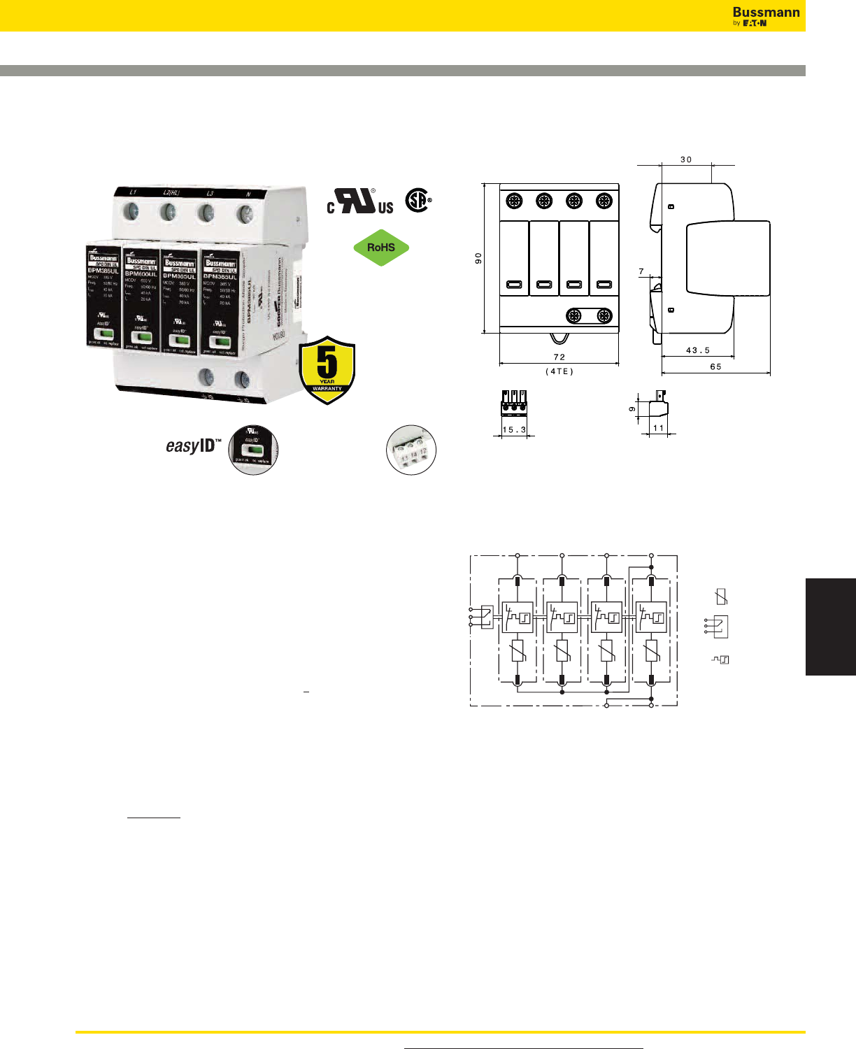
For product data sheets, visit www.cooperbussmann.com/DatasheetsEle 455
Surge Protection
Devices
Overvoltage Devices
UL DIN-Rail SPD - High SCCR
BSPM_ _ _ _WYNG, BSPM_ _ _ _HLG
Description
The Bussmann 4-pole UL modular surge arresters for
120/240, 240/480Vac 3-phase Highleg Delta and 120/208,
127/220, 277/480 and 347/600Vac 3-phase 4 wire Wye
systems feature local, easyID™ visual indication and optional
remote contact signaling. The unique module locking system
fixes the protection module to the base part. Modules can be
easily replaced without tools by simply depressing the release
buttons. Integrated mechanical coding between the base and
protection module ensures against installing an incorrect
replacement module.
Features
• Surge arrester according to UL 1449 3rd Edition, Type 2
Component Assembly helps meet UL 508A requirements
• Heavy-duty zinc oxide varistors for high discharge capacity
• "Thermo Dynamic Control" SPD monitoring device ensures
high reliability against surge events
• Module locking system with module release button make
module replacement easy without tools
• Up to 200kA Short-Circuit Current Rating (SCCR) make
higher assembly SCCR ratings possible
• Optional remote signaling of all protection modules make
status monitoring easy and accurate in any monitoring
scheme
• No upstream overcurrent protection necessary to make
installation easier and more economical
• Vibration and shock tested according to EN 60068-2 to
withstand harsh environments
Optional Remote Signaling Contact
The remote signaling contact versions have a floating
changeover contact for use as a break or make contact for
easy adoption in any monitoring
application.
BSPM4208WYNG, BSPM4480WYNG, BSPM4600WYNG,
BSPM4240HLG, BSPM4480HLG*
Shown with optional remote contact signaling
Shown with optional remote contact signaling
Circuit Diagram
Dimensions - mm
Remote Signal
Contact Available
Visual Status Indication
*For remote signaling contact, add “R” suffix to the part number,
E.g., BSPM4480HLGR
12
11
14
L2 NL1 L3
Gnd Gnd
12
11
14
Thermal
Disconnector
Optional Remote
Signal Contact
MOV
Data Sheet: 2152
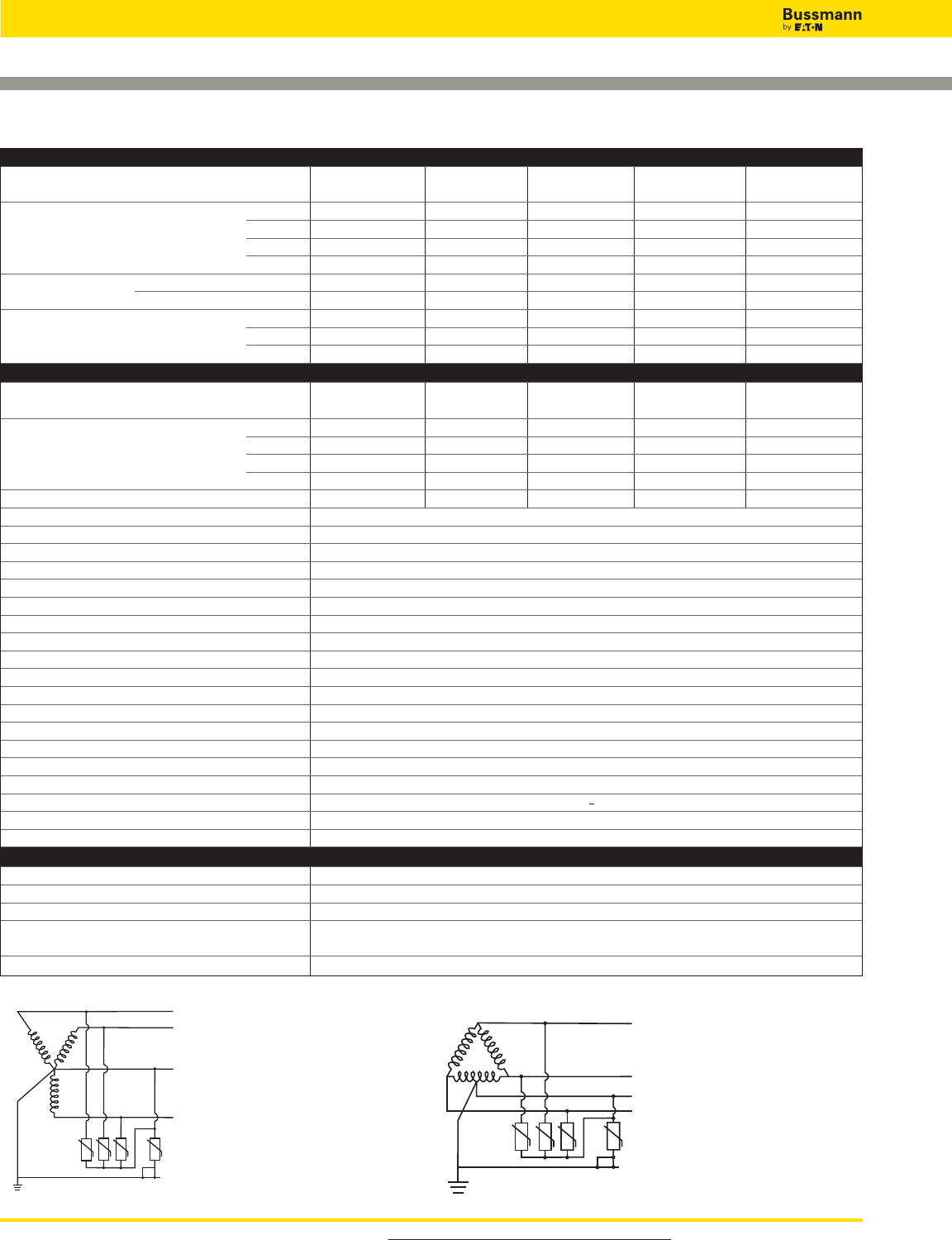
For product data sheets, visit www.cooperbussmann.com/DatasheetsEle
456
Overvoltage Devices
UL DIN-Rail SPD - High SCCR
* See Bussmann SPD Limited Warranty Statement (3A1502) for details at www.cooperbussmann.com/surge.
120/240V, 240/480Vac
Highleg Delta, 3-Phase, 4 Wire + Ground
BSPM4240HLG, BSPM4480HLG
120/208V, 127/220V, 277/480V, 347/600Vac
Wye 3-Phase, 4 Wire + Ground
BSPM4208WYNG, BSPM4480WYNG,
BSPM4600WYNG
L1
L
2
(Highleg)
L3
N
L
1
L2
N
L3
ORDERING INFORMATION
Nominal System Voltage 120/208Vac, 120/240Vac 240/480Vac 277/480Vac 347/600Vac
127/220Vac
Max. continuous operating AC voltage MCOV [L-N]/[L-G] 275/550Vac 275/550Vac 385/770Vac 385/660Vac 600/875Vac
[N-G]/[L-L] 275/550Vac 275/550Vac 385/770Vac 275/770Vac 275/1200Vac
[H-N]/[H-G] - - 275/550Vac 600/985Vac - - - -
[H-L] - - 550Vac 985Vac - - - -
Catalog Numbers: Without Remote Signaling BSPM4208WYNG BSPM4240HLG BSPM4480HLG BSPM4480WYNG BSPM4600WYNG
With Remote Signaling BSPM4208WYNGR BSPM4240HLGR BSPM4480HLGR BSPM4480WYNGR BSPM4600WYNGR
Replacement Modules Module Positions L1 or L3 BPM275UL BPM275UL BPM385UL BPM385UL BPM600UL
MOV Technology L2 BPM275UL BPM275UL BPM600UL BPM385UL BPM600UL
Four (4) Total Required N BPM275UL BPM275UL BPM385UL BPM275UL BPM275UL
SPECIFICATIONS
Rated Voltage 120/208Vac, 120/240Vac 240/480Vac 277/480Vac 347/600Vac
127/220Vac
[L-N/L-G] 1kV/1.8kV 1kV/1.8kV 1.5kV/2.5kV 1.5kV/2.5kV 2kV/3kV
Voltage Protection Rating VPR
[N-G/L-L] 1kV/1.8kV 1kV/1.8kV 1.5kV/2.5kV 1kV/2.5kV 1kV/4kV
[H-N/H-G] - - 1kV/1.8kV 2kV/3kV - - - -
[H-L] - - 1.8kV 3kV - - - -
SCCR 200kA 200kA 125kA 200kA 125kA
Nominal Discharge Current In(kA) 20kA
Max. Discharge Current Imax (kA) 40kA
Response Time tA_< 25 ns
Frequency 50/60Hz
Number of Poles 4
Number of Wires/Connection Points 4 Wires / 5 Connection Points
Operating State/Fault Indication Green (good) / Red (replace)
Cross-Sectional Area (min.) 14AWG - Cu Stranded, Solid or Fine
Cross-Sectional Area (max.) 2AWG - Cu Solid or Stranded, 4AWG - Cu Fine
Terminal Torque 45 lb-in
For Mounting On 35mm DIN-Rail per to EN 60715
Enclosure Material Thermoplastic, UL 94V0
Degree of Protection IP20 (finger-safe)
Location Category Indoor
Capacity 4 Mods, DIN 43880
Application UL Type 2 Component Assembly
Standard UL 1449, 3rd edition
Agency Information cURus, CSA, RoHS Compliant
Product Warranty Five Years*
REMOTE CONTACT SIGNALING
Remote Contact Signaling Type Changeover Contact
AC Switching Capacity (Volts/Amps) 250V/0.5A
DC Switching Capacity (Volts/Amps) 250V/0.1A; 125V/0.2A; 75V/0.5A
Conductor Ratings and Cross-Sectional Area for 60/75°C Max. 1.5mm2/14AWG Solid/Flexible
Remote Contact Signal Terminals
Ordering Information Order from Catalog Numbers Above
Data Sheet: 2152
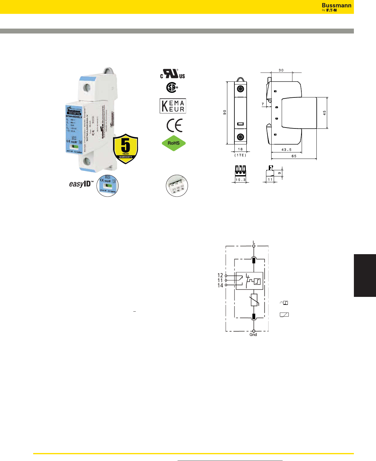
For product data sheets, visit www.cooperbussmann.com/DatasheetsEle 457
Surge Protection
Devices
Overvoltage Devices
UL DIN-Rail SPD - Low Voltage AC/DC Power
BSPM1A_ _ _ _LV
Shown with optional remote contact signaling
Module Circuit Diagrams - Shown with optional remote contact
signaling
Dimensions - mm
Remote Signal
Contact Available
Visual Status Indication
BSPM1A48D60LV, BSPM1A75D100LV,
BSPM1A150D200LV,
BSPM1A275D350LV, BSPM1A320D420LV,
BSPM1A385D500LV, BSPM1A440D585LV,
BSPM1A600D600LV*
Shown with optional remote contact signaling
*For remote signaling contact, add “R” suffix to the part number,
E.g., BSPM1A150D200LVR
Description
The Bussmann UL Type 2 48Vac/60Vdc, 75Vac/100Vdc,
120Vac/200Vdc, 275VAc/350Vdc, 320Vac/420Vdc,
385Vac/500Vdc, 440Vac/585Vdc and 600Vac/dc single pole,
modular surge arresters feature local, easyID™ visual
indication and optional remote contact signaling. The unique
module locking system fixes the protection module to the base
part. Modules can be easily replaced without tools by simply
depressing the release buttons. Integrated mechanical coding
between the base and protection module ensures against
installing an incorrect replacement module.
LV Power System Arresters
The features of these single-pole devices are for use as a
single device or in combination with other devices for AC and
DC voltage systems.
• Surge arrester according to UL 1449 3rd Edition, Type 2
Component Assembly helps meet UL 508A requirements*
• Proven MOV technology for reliable surge protection
• "Thermo Dynamic Control" SPD monitoring device ensures
high reliability against surge events
• Module locking system with module release button make
module replacement easy without tools
• Optional remote signaling of all protection modules make
status monitoring easy and accurate in any monitoring
scheme
• No upstream overcurrent protection necessary to make
installation easier and more economical
• Vibration and shock tested according to EN 60068-2 to
withstand harsh environments
Optional Remote Signaling Contact
The remote signaling contact versions have a floating
changeover contact for use as a break or make contact for
easy adoption in any monitoring application.
* Except as noted in data sheets.
Data Sheet: 2056
MOV
Thermal Disconnector
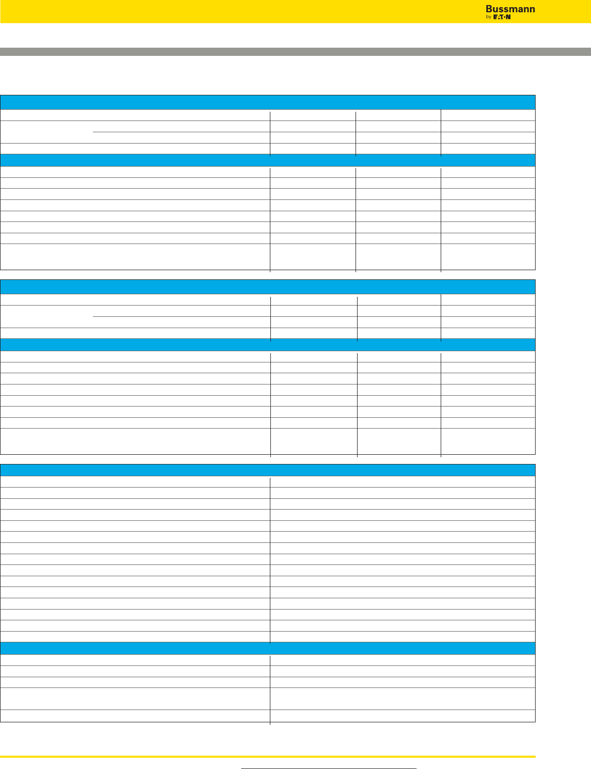
For product data sheets, visit www.cooperbussmann.com/DatasheetsEle
458
Overvoltage Devices
UL DIN-Rail SPD - Low Voltage AC/DC Power
Data Sheet: 2056
Ordering Information - All Models
SPD according to EN 61643-11 Type 2
SPD according to IEC 61643-1 Class II
Response time [tA]_< 25 ns
TOV characteristics Withstand
Operating temperature range [TU] -40°C to +80°C
Operating state/fault indication Green (good) / Red (replace)
Number of ports 1
Cross-sectional area (min.) 1.5mm2/14AWG solid/flexible
Cross-sectional area (max.) 35mm2/1AWG stranded/25mm2/2AWG flexible
For mounting on 35mm DIN-Rail per EN 60715
Enclosure material Thermoplastic, UL 94V0
Location category Indoor
Degree of protection IP20
Capacity 1 Mod., DIN 43880
Product Warranty Five Years**
Remote Contact Signaling
Remote Contact Signaling Type Changeover Contact
AC Switching Capacity (Volts/Amps) 250V/0.5A
DC Switching Capacity (Volts/Amps) 250V/0.1A; 125V/0.2A; 75V/0.5A
Conductor Ratings and Cross-Sectional Area for 60/75°C Max. 1.5mm2/14AWG Solid/Flexible
Remote Contact Signal Terminals
Ordering Information Order from Catalog Numbers Above
Ordering Information - 48Vac/60Vdc to 275Vac/350Vdc
System Voltage 48Vac/60Vdc 75Vac/100Vdc 120Vac/200Vdc 275Vac/350Vdc
Catalog Numbers: Without Remote Signaling BSPM1A48D60LV BSPM1A75D100LV BSPM1A150D200LV BSPM1A275D350LV
(Base + Modules) With Remote Signaling BSPM1A48D60LVR BSPM1A75D100LVR BSPM1A150D200LVR BSPM1A275D350LVR
Replacement Modules BPMA48D60LV BPMA75D100LV BPMA150D200LV BPMA275D350LV
Specifications
Max. continuous operating AC voltage [VC] 48Vac 75Vac 150Vac 275Vac
Max. continuous operating DC voltage [VC] 60Vdc 100Vdc 200Vdc 350Vdc
Nominal discharge current (8/20 μs) [In] 10kA 10kA 15kA 20kA
Max. discharge current (8/20 μs) [Imax] 25kA 40kA 40kA 40kA
Voltage protection level [VPR]_< 0.3 kV _< 0.4kV _< 0.7kV _< 1.25kV
Voltage protection level at 5 kA [VPR]_< 0.25kV _< 0.35kV _< 0.55kV _< 1kV
Temporary overvoltage (TOV) 70V / 5 sec. 90V / 5 sec. 175V / 5 sec. 335V / 5 sec
Agency Information* - - UL / cUL, UL / cUL, UL / cUL,
CSA, KEMA CSA, KEMA CSA, KEMA
Ordering Information - 320Vac/420Vdc to 600Vac/dc
System Voltage 320Vac/420Vdc 385Vac/500Vdc 440Vac/585Vdc 600Vac/600Vdc
Catalog Numbers: Without Remote Signaling BSPM1A320D420LV BSPM1A385D500LV BSPM1A440D585LV BSPM1A600D600LV
(Base + Modules) With Remote Signaling BSPM1A320D420LVR BSPM1A385D500LVR BSPM1A440D585LVR BSPM1A600D600LVR
Replacement Modules BPMA320D420LV BPMA385D500LV BPMA440D585LV BPMA600D600LV
Specifications
Max. continuous operating AC voltage [VC] 320Vac 385Vac 440Vac 600Vac
Max. continuous operating DC voltage [VC] 420Vdc 500Vdc 585Vdc 600Vdc
Nominal discharge current (8/20 μs) [In] 20kA 20kA 20kA 15kA
Max. discharge current (8/20 μs) [Imax] 40kA 40kA 40kA 30kA
Voltage protection level [VPR]_< 1.5kV _< 1.75kV _< 2kV _< 2.5kV
Voltage protection level at 5 kA [VPR]_< 1.2kV _< 1.35kV _< 1.7kV _< 2kV
Temporary overvoltage (TOV) 335V / 5 sec. 385V / 5 sec. 580V / 5 sec. 600V / 5 sec.
Agency Information* UL / cUL, UL / cUL, UL / cUL, UL / cUL,
CSA, KEMA CSA, KEMA CSA, KEMA CSA, KEMA
* Standards information not applicable to DC ratings.
** See Bussmann SPD Limited Warranty Statement (3A1502) for details at www.cooperbussmann.com/surge.
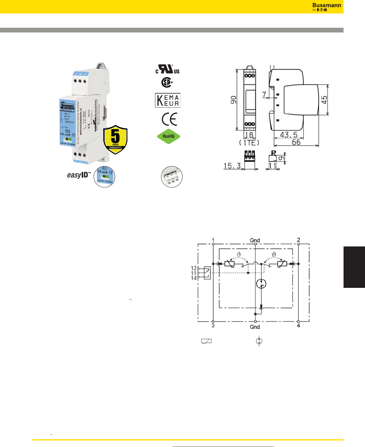
For product data sheets, visit www.cooperbussmann.com/DatasheetsEle 459
Surge Protection
Devices
Overvoltage Devices
UL DIN-Rail SPD - Low Voltage AC/DC Control
BSPH2A_ _ _ _LV(R)
BPH2A24D24LV BPH2A48D48LV BPH2A60D60LV
BPH2A150D150LV BPH2A230D230LV
Shown with optional remote contact signaling
Module Circuit Diagrams
Dimensions - mm
Remote Signal
Contact Available
Visual Status Indication
Data Sheet: 2057
Shown with optional remote contact signaling
*For remote signaling contact, add “R” suffix to the part number,
E.g., BSPH2A230D230LVR
Specifications
Description
The Bussmann UL Type 3 24Vac/dc, 48Vac/dc, 60Vac/dc,
120Vac/dc and 230Vac/dc, two-pole, modular surge arresters
feature local, easyID™ visual indication and optional remote
contact signaling. The unique module locking system fixes the
protection module to the base part. Modules can be easily
replaced without tools by simply depressing the release
buttons. Integrated mechanical coding between the base and
protection module ensures against installing an incorrect
replacement module.
LV System Arresters
The features of these two-pole devices are for use in
coordination with other upstream SPDs in UL 508A
Applications*.
• Surge arrester according to UL 1449 3rd Edition,
Type 3 Component Assembly helps meet UL 508A
requirements
• Proven MOV and GDT hybrid technology for reliable surge
protection
• "Thermo Dynamic Control" SPD monitoring device ensures
high reliability against surge events
• Module locking system with module release button make
module replacement easy without tools
• Optional remote signaling of all protection modules make
status monitoring easy and accurate in any monitoring
scheme
• No upstream overcurrent protection necessary to make
installation easier and more economical
• Vibration and shock tested according to EN 60068-2 to
withstand harsh environments
Optional Remote Signaling Contact
The remote signaling contact versions have a floating
changeover contact for use as a break or make contact for
easy adoption in any monitoring application.
* UL 1449 3rd Edition not applicable to DC voltages.
MOV
Gas Discharge Tube (single)
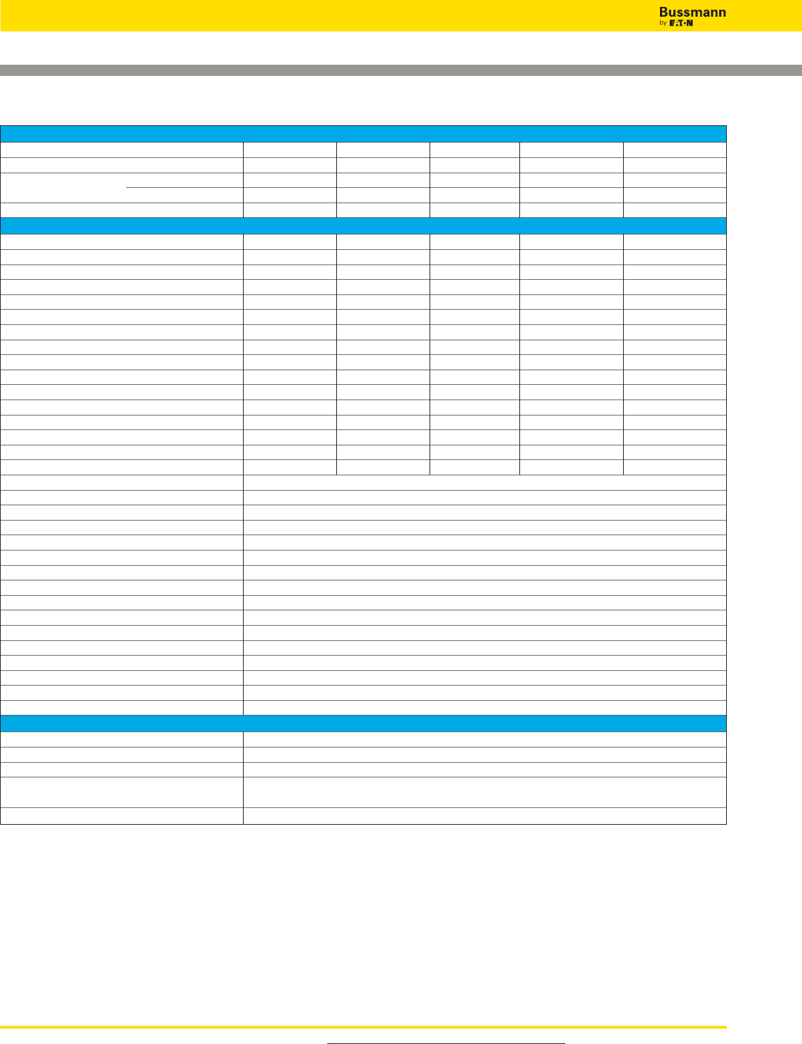
For product data sheets, visit www.cooperbussmann.com/DatasheetsEle
460
Overvoltage Devices
UL DIN-Rail SPD - Low Voltage AC/DC Power
Data Sheet: 2057
Ordering Information
System Voltage 24Vac/dc 48Vac/dc 60Vac/dc 120Vac/dc 230Vac/dc
Max. Continuous operating AC voltage (MCOV) [VC] 30Vac/dc 60Vac/dc 75Vac/dc 150Vac/dc 255Vac/dc
Catalog Numbers: Without Remote Signaling BSPH2A24D24LV BSPH2A48D48LV BSPH2A60D60LV BSPH2A150D150LV BSPH2A230D230LV
(Base + Modules) With Remote Signaling BSPH2A24D24LVR BSPH2A48D48LVR BSPH2A60D60LVR BSPH2A150D150LVR BSPH2A230D230LVR
Replacement Modules BPHA24D24LV BPHA48D48LV BPHA60D60LV BPHA150D150LV BPHA230D230LV
Specifications
Nominal AC voltage [Vo] 24V 48V 60V 120V 230V
Max. continuous operating AC voltage [VC] 30V 60V 75V 150V 255V
Max. continuous operating DC voltage [VC] 30V 60V 75V 150V 255V
Nominal load current AC [IL] 25A 25A 25A 25A 25A
Nominal discharge current (8/20 μs) [In] 1kA 1kA 2kA 2kA 3kA
Total discharge current (8/20 μs) [L+N-Gnd] [Itotal] 2kA 2kA 4kA 4kA 5kA
Combined impulse [UOC] 2kV 2kV 4kV 4kV 6kV
Combined impulse [L+N-Gnd] [UOC total] 4kV 4kV 8kV 8kV 10kV
Voltage protection level [L-N] [VPR]_< 180V _< 350V _< 400V _< 640V _< 1250V
Voltage protection level [L/N-Gnd] [VPR]_< 630V _< 730V _< 730V _< 800V _< 1500V
Temporary overvoltage (TOV) [L-N] -- -- -- -- 335V / 5 sec.
Temporary overvoltage (TOV) [L/N-Gnd] -- -- -- -- 400V / 5 sec.
Temporary overvoltage (TOV) [L+N-Gnd] -- -- -- -- 1200V + V0/ 20
TOV characteristics [L-N] -- -- -- -- Withstand
TOV characteristics [L/N-Gnd] -- -- -- -- Withstand
TOV characteristics [L+N-Gnd] -- -- -- -- Failure
SPD according to EN 61643-11 Type 3
SPD according to IEC 61643-1 Class III
Response time [L-N] [tA]_< 25 ns
Response time [L/N-Gnd] [tA]_< 100 ns
Operating temperature range [TU] -40°C to +80°C
Operating state/fault indication Green (good) / Red (replace)
Number of ports 1
Cross-sectional area (min.) 0.5mm2/18AWG solid/flexible
Cross-sectional area (max.) 4mm2/10AWG solid/2.5mm2/12AWG flexible
For mounting on 35mm DIN rail per EN 60715
Enclosure material Thermoplastic, UL 94V0
Location category Indoor
Degree of protection IP20
Capacity 1 Mod., DIN 43880
Agency Information* UL / cUL, CSA, KEMA
Product Warranty Five Years**
Remote Contact Signaling
Remote Contact Signaling Type Changeover Contact
AC Switching Capacity (Volts/Amps) 250V/0.5A
DC Switching Capacity (Volts/Amps) 250V/0.1A; 125V/0.2A; 75V/0.5A
Conductor Ratings and Cross-Sectional Area for 60/75°C Max. 1.5mm2/14AWG Solid/Flexible
Remote Contact Signal Terminals
Ordering Information Order from Catalog Numbers Above
* Standards information not applicable to DC ratings.
** See Bussmann SPD Limited Warranty Statement (3A1502) for details at www.cooperbussmann.com/surge.
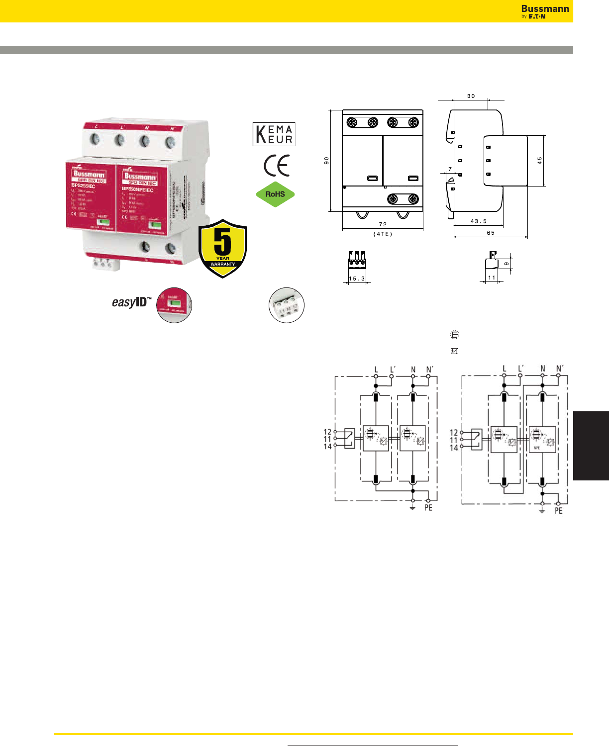
For product data sheets, visit www.cooperbussmann.com/DatasheetsEle 461
Surge Protection
Devices
Overvoltage Devices
IEC Class I DIN-Rail SPD
BSPS_ _ _ _TN, BSPS_ _ _ _TT
Description
The Bussmann IEC Class I 230V, two-pole, modular
combined lightning, current and surge arresters feature local,
easyID™ visual indication and optional remote contact
signaling. The unique module locking system fixes the
protection module to the base part. Modules can be easily
replaced without tools by simply depressing the release
buttons. Integrated mechanical coding between the base and
protection module ensures against installing an incorrect
replacement module.230V models are offered with MCOV
rating of 255V.
TN System Arresters
The features of these two-pole devices are for use as a
modular combined lightning and current arrester and surge
arrester for use in single TN- systems (“2-0” circuit).
TT System Arrester
Provides a current arresting means for use in single
TT- systems (“1-1” circuit).
Remote Signaling Contact
The three-pole terminal remote signaling contact versions
have a floating changeover contact for use as a break or
make contact, according to circuit concept.
Remote Signal
Contact Available
Visual Status Indication
BSPS2255TN
Shown with optional
remote contact signaling
Shown with optional remote contact signaling
BSPS2255TT
Shown with optional
remote contact signaling
Circuit Diagrams
Dimensions - mm
Spark Gap Trigger
Creepage Discharge Spark Gap
Data Sheet: 1163
*For remote signaling contact, add “R” suffix to the part number,
E.g., BSPS2255TNR
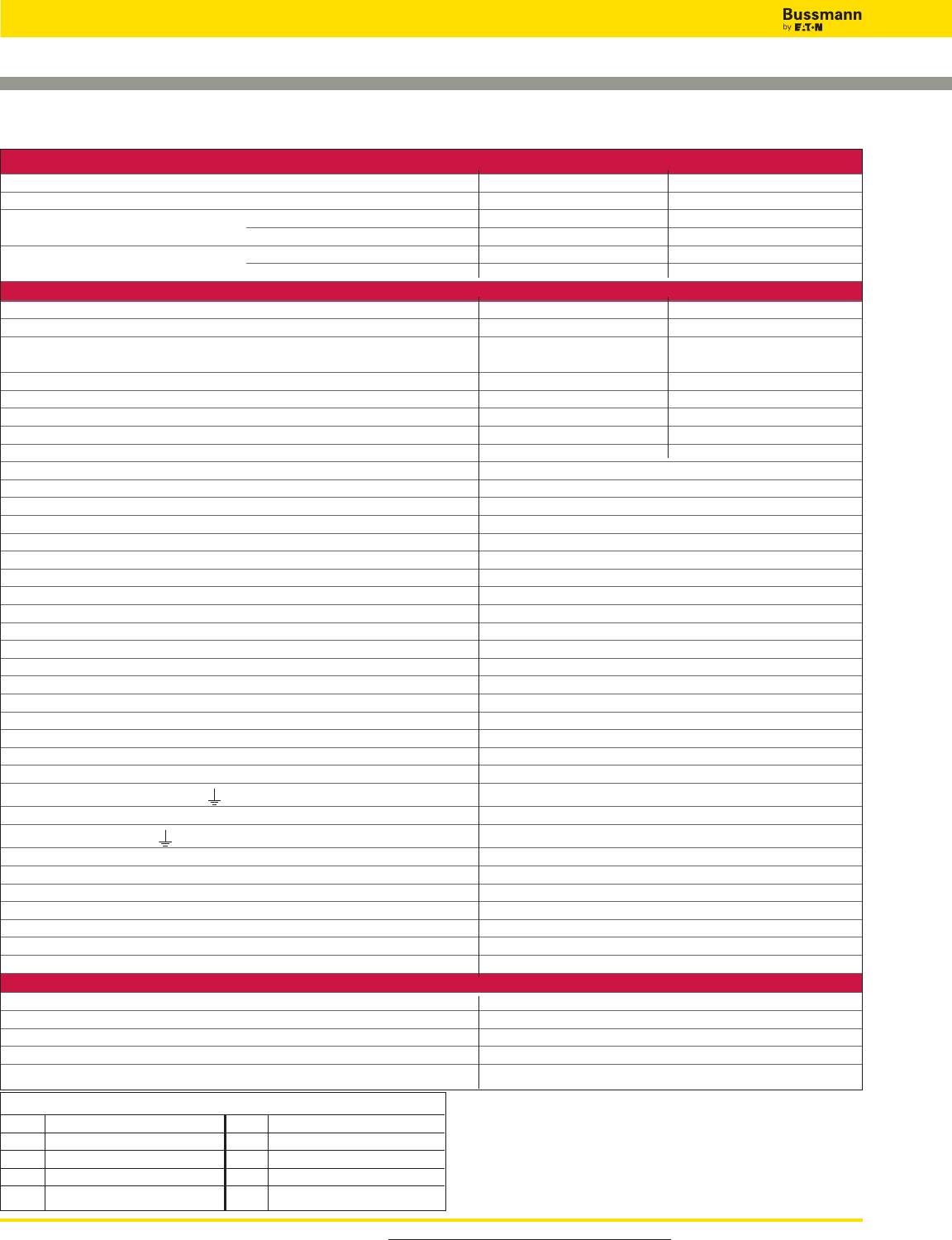
For product data sheets, visit www.cooperbussmann.com/DatasheetsEle
462
Overvoltage Devices
IEC Class I DIN-Rail SPD
Ordering Information
System Voltage/Poles 230V/2 230V/2
Max. Continuous operating AC voltage (MCOV) [UC] 255V 255V
Catalog Numbers: Without Remote Signaling BSPS2255TN BSPS2255TT
With Remote Signaling BSPS2255TNR BSPS2255TTR
Replacement Modules: MOV technology (2X) BPS255IEC (1X) BPS255IEC
Spark Gap technology - - (1X) BPS50NPEIEC*
Specifications
Specific energy [L+N-PE] [W/R] 625.00 kJ/ohms - -
Lightning impulse current (10/350 μs) [L, N-PE] [Iimp] 25kA 25/50kA Is[L-N]/[N-PE]
Specific energy [L,N-PE] [W/R] 156.25 kJ/ohms 156.25kJ/ohms/
625.00 kJ/ohms
Voltage protection level [L-PE]/[N-PE] [UP]<_ 1.5 kV/<_ 1.5 kV - -
Voltage protection level [L-N]/[N-PE] [UP]- -<_ 1.5kV/<_ 1.5kV
Follow current extinguishing capability AC [Ifi] 50kA rms - -
Follow current extinguishing capability [L-N]/[N-PE] [Ifi] - - 50kA rms/100A rms
Temporary overvoltage (TOV) [N-PE] [UT] - - 1200V/200 ms
SPD according to EN 61643-11/... IEC 61643-1 Type 1/Class I
Energy-coordinated protection effect with regard to the terminal equipment Type 1 + Type 2
Energy-coordinated protection effect with regard to the terminal equipment (<_ 5m) Type 1 + Type 2 + Type 3
Nominal AC voltage [UN] 230V
Lightning impulse current (10/350 μs) [L+N-PE] [Itotal] 50kA
Nominal discharge current (8/20 μs) [In] 25/50kA
Follow current limitation/Selectivity no tripping of a 20A gL/gG fuse up to 50kA rms (prosp.)
Response time [tA] <_ 100 ns
Max. Backup fuse (L) up to IK<_ 50kA rms 315A gL/gG
Max. Backup fuse (L) for IK> 50kA rms 200A gL/gG
Max. Backup fuse (L-L ) 125A gL/gG
Temporary overvoltage (TOV) [L-N] [UT] 440V/5 sec.
TOV characteristics withstand
Operating temperature range (parallel connection) [TUP] -40°C to +80°C
Operating temperature range (series connection) [TUS] -40°C to +60°C
Operating temperature range [parallel]/[continuity] [TU] -40°C to +80°C/-40°C to +60°C
Operating state/fault indication green (good)/red (replace)
Number of ports 1
Cross-sectional area (L, L , N, N , PE, ) [min.] 10mm2solid/flexible
Cross-sectional area (L, N, PE) [max.] 50mm2/1AWG stranded-35mm2/2AWG flexible
Cross-sectional area (L , N , ) [max.] 35mm2/2AWG stranded-25mm2/4AWG flexible
For mounting on 35mm DIN Rail per EN 60715
Enclosure material Thermoplastic, UL 94V0
Location category Indoor
Degree of protection IP20
Capacity 4 mods., DIN 43880
Standards Information KEMA
Product Warranty Five Years**
Remote Contact Signaling
Remote Contact Signaling Type Changeover Contact
AC Switching Capacity (Volts/Amps) 250V/0.1A
DC Switching Capacity (Volts/Amps) 250V/0.1A; 125V/0.2A; 75V/0.5A
Conductor Ratings and Cross-Sectional Area for Remote Contact Signal Terminals 60/75°C Max. 1.5mm2/14AWG Solid/Flexible
Ordering Information Order from Catalog Numbers Above
* N-PE Surge arrester for location between neutral conductor and protective conductor
in TT systems.
** See Bussmann SPD Limited Warranty Statement (3A1502) for details at www.cooperbuss-
mann.com/surge.
Recommended Bussmann NH DIN Size Back Up Fuses
Size NH Fuse Part Number Size NH Fuse Part Number
00 125NHG00B (max L-L) 02 125NHG02B (max L-L)
0 125NHG0B (max L-L) 02 200NHG02B (max L Ik >50kA)
01 125NHG01B (max L-L) 2 315NHG2B (max L _<50kA)
1 200NHG1B (max L Ik >50kA) 03 315NHG03B (max L _<50kA) Data Sheet: 1163
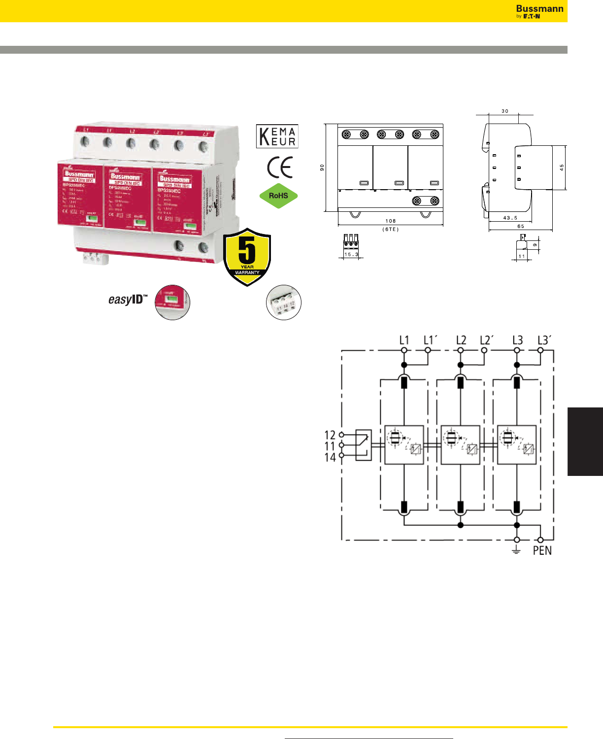
For product data sheets, visit www.cooperbussmann.com/DatasheetsEle 463
Surge Protection
Devices
Overvoltage Devices
IEC Class I DIN-Rail SPD
BSPS_ _ _ _TNC
Remote Signal
Contact Available
Visual Status Indication
Description
The Bussmann IEC Class I 230V, three-pole, modular
combined lightning, current and surge arresters feature local,
easyID™ visual indication and optional remote contact
signaling. The unique module locking system fixes the
protection module to the base part. Modules can be easily
replaced without tools by simply depressing the release
buttons. Integrated mechanical coding between the base and
protection module ensures against installing an incorrect
replacement module.
230V models are offered with a MCOV rating of 255V.
TNC System Arrester
The features of these three-pole devices are for use in
TN-C 230/400V systems (“3-0” circuit) against surges.
Remote Signaling Contact
The three-pole terminal remote signaling contact versions
have a floating changeover contact for use as a break or
make contact, according to circuit concept.
Shown with optional remote contact signaling
Dimensions - mm
BSPS3255TNC
Shown with optional remote contact signaling
Circuit Diagrams
Data Sheet: 1164
*For remote signaling contact, add “R” suffix to the part number,
E.g., BSPS3255TNCR
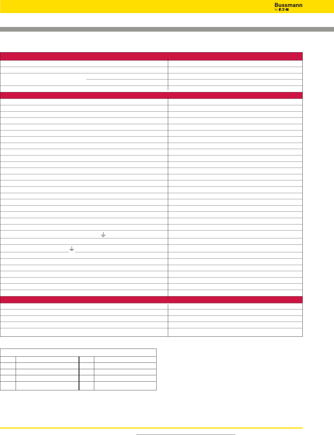
For product data sheets, visit www.cooperbussmann.com/DatasheetsEle
464
Overvoltage Devices
IEC Class I DIN-Rail SPD
Ordering Information
System Voltage/Poles 230/400V/3
Max. Continuous operating AC voltage (MCOV) [UC] 255V
Catalog Numbers: Without Remote Signaling BSPS3255TNC
With Remote Signaling BSPS3255TNCR
Replacement Module MOV technology BPS255IEC
Specifications
SPD according to EN 61643-11/... IEC 61643-1 Type 1/Class I
Energy-coordinated protection effect with regard to the terminal equipment Type 1 + Type 2
Energy-coordinated protection effect with regard to the terminal equipment (<_ 5m) Type 1 + Type 2 + Type 3
Nominal AC voltage [UN] 230/400V
Lightning impulse current (10/350 μs) [L1+L2+L3-PEN] [Itotal] 75kA
Specific energy [L1+L2+L3-PEN] [W/R] 1.40 MJ/ohms
Lightning impulse current (10/350 μs) [L-PEN] [Iimp] 25kA
Specific energy [L-PEN] [W/R] 156.25kJ/ohms
Nominal discharge current (8/20 μs) [In] 25/75kA
Voltage protection level [UP] <_ 1.5kV
Follow current extinguishing capability AC [Ifi] 50kA rms
Follow current limitation/Selectivity no tripping of a 20A gL/gG fuse up to 50kA rms (prosp.)
Response time [tA] <_ 100 ns
Max. Backup fuse (L) up to IK= 50kA rms 315A gL/gG
Max. Backup fuse (L) for IK> 50kA rms 200A gL/gG
Max. Backup fuse (L-L ) 125A gL/gG
Temporary overvoltage (TOV) [UT] 440V/5 sec.
TOV characteristics withstand
Operating temperature range [parallel]/[continuity] [TU] -40°C to +80°C/-40°C to +60°C
Operating state/fault indication green (good)/red (replace)
Number of ports 1
Cross-sectional area (L1, L1 , L2, L2 , L3, L3 , PEN, ) [min.] 10mm2solid/flexible
Cross-sectional area (L1, L2, L3, PEN) [max.] 50mm2/1AWG stranded-35mm2/2AWG flexible
Cross-sectional area (L1 , L2 , L3 , ) [max.] 35mm2/2AWG stranded-25mm2/4AWG flexible
Mounting 35mm DIN rail per to EN 60715
Enclosure material Thermoplastic, UL 94V0
Location category Indoor
Degree of protection IP20
Capacity 6 mods., DIN 43880
Standards Information KEMA
Product Warranty Five Years*
Remote Contact Signaling
Remote Contact Signaling Type Changeover Contact
AC Switching Capacity (Volts/Amps) 250V/0.1A
DC Switching Capacity (Volts/Amps) 250V/0.1A; 125V/0.2A; 75V/0.5A
Conductor Ratings and Cross-Sectional Area for Remote Contact Signal Terminals 60/75°C Max. 1.5mm2/14AWG Solid/Flexible
Ordering Information Order from Catalog Numbers Above
* See Bussmann SPD Limited Warranty Statement (3A1502) for details at www.cooperbussmann.com/surge.
Recommended Bussmann NH DIN Size Back Up Fuses
Size NH Fuse Part Number Size NH Fuse Part Number
00 125NHG00B (max L-L) 02 125NHG02B (max L-L)
0 125NHG0B (max L-L) 02 200NHG02B (max L Ik >50kA)
01 125NHG01B (max L-L) 2 315NHG2B (max L _<50kA)
1 200NHG1B (max L Ik >50kA) 03 315NHG03B (max L _<50kA)
Data Sheet: 1164
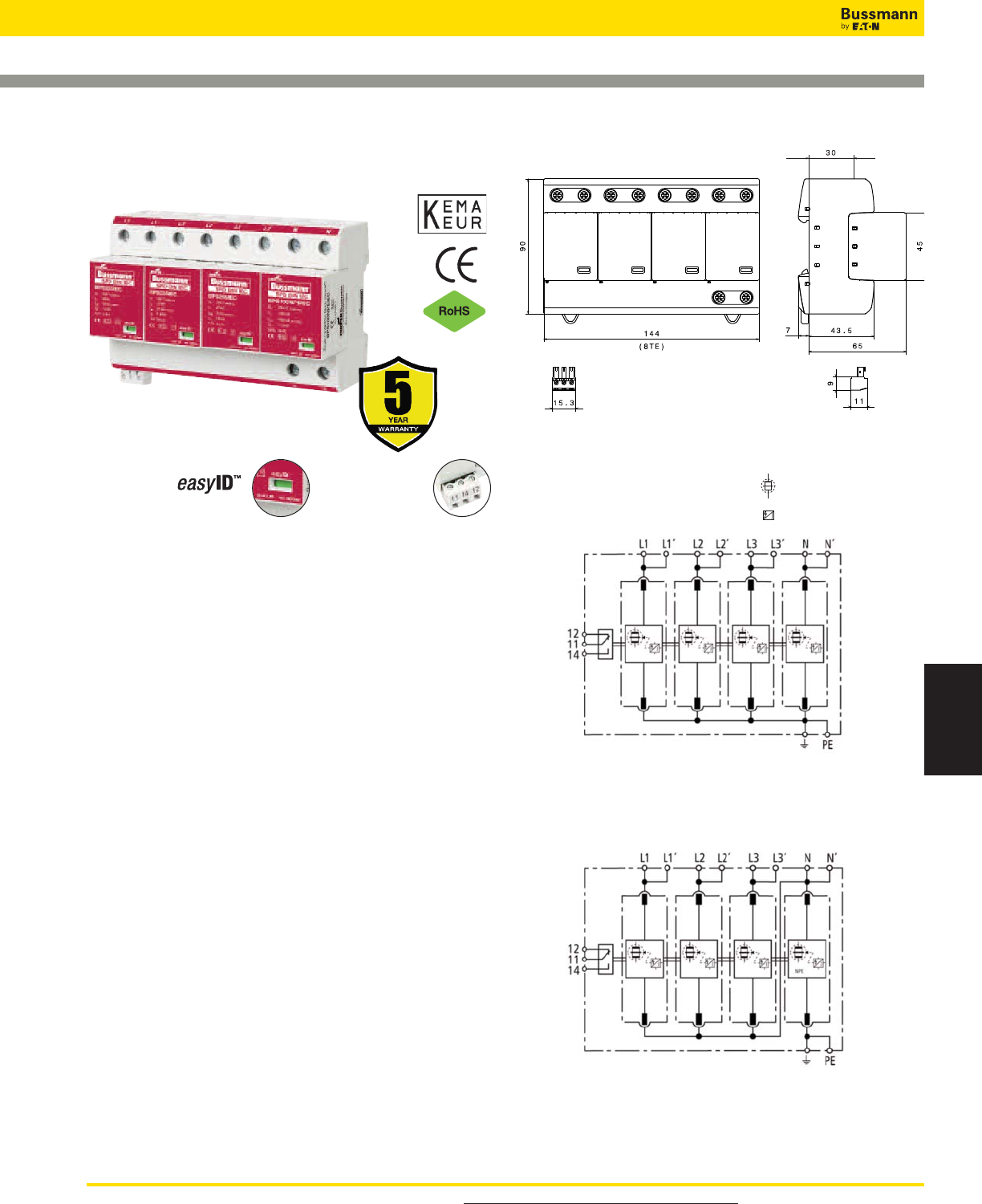
For product data sheets, visit www.cooperbussmann.com/DatasheetsEle 465
Surge Protection
Devices
Overvoltage Devices
IEC Class I DIN-Rail SPD
BSPS_ _ _ _TNS, BSPS_ _ _ _TT
Remote Signal
Contact Available
Visual Status Indication
Description
The Bussmann IEC Class I 230V, four-pole, modular
combined lightning, current and surge arresters feature local,
easyID™ visual indication and optional remote contact
signaling. The unique module locking system fixes the
protection module to the base part. Modules can be easily
replaced without tools by simply depressing the release
buttons. Integrated mechanical coding between the base and
protection module ensures against installing an incorrect
replacement module.
230V models are offered with MCOV ratings of 255V.
TNS System Arresters
The features of these four-pole devices are for use in TNS
230/400V systems (“4-0” circuit) against surges.
TT System Arrester
Provides a current arresting means between neutral
conductor and protective conductor in TT 230/400V systems
(“3+1” circuit) against surges.
Remote Signaling Contact
The three-pole terminal remote signaling contact versions
have a floating changeover contact for use as a break or
make contact, according to circuit concept.
Shown with optional remote contact signaling
Dimensions - mm
BSPS4255TNS
Shown with optional
remote contact signaling
Circuit Diagrams
BSPS4255TT
Shown with optional
remote contact signaling
Creepage Discharge Spark Gap
Spark Gap Trigger
Data Sheet: 1165 *For remote signaling contact, add “R” suffix to the part number,
E.g., BSPS4255TTR
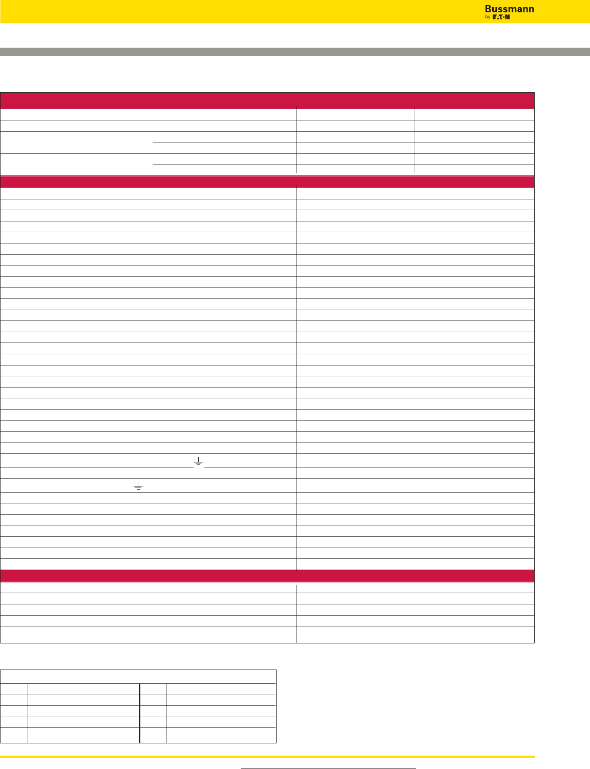
For product data sheets, visit www.cooperbussmann.com/DatasheetsEle
466
Overvoltage Devices
IEC Class I DIN-Rail SPD
Ordering Information
System Voltage/Poles 230/400V/4 230/400V/4
Max. Continuous operating AC voltage (MCOV) [UC] 255V 255V
Catalog Numbers: Without Remote Signaling BSPS4255TNS BSPS4255TT
With Remote Signaling BSPS4255TNSR BSPS4255TTR
Replacement Modules: MOV technology BPS255IEC BPS255IEC
Spark Gap technology - - BPS100NPEIEC*
Specifications
SPD according to EN 61643-11/... IEC 61643-1 Type 1/Class I
Energy-coordinated protection effect with regard to the terminal equipment Type 1 + Type 2
Energy-coordinated protection effect with regard to the terminal equipment (<_ 5m) Type 1 + Type 2 + Type 3
Nominal AC voltage [UN] 230/400V
Lightning impulse current (10/350 μs) [L1+L2+L3+N-PE] [Itotal] 100kA
Specific energy [L1+L2+L3+N-PE] [W/R] 2.50MJ/ohms
Lightning impulse current (10/350 μs) [L, N-PE] [Iimp]25kA
TNS system specific energy [L,N-PE] [W/R] 156.25kJ/ohms
TT system specific energy [L-N]/[N-PE] [W/R] 156.25kJ/ohms/2.50kJ/ohms
Nominal discharge current (8/20 μs) [In] 25/100kA
Voltage protection level [L-PE]/[N-PE] [UP]<_ 1.5kV/<_ 1.5kV
TNS system follow current extinguishing capability AC [Ifi] 50kA rms
TT system follow current extinguishing capability AC [Ifi] 50kA rms/100A rms
Follow current limitation/Selectivity No tripping of a 20A gL/gG fuse up to 50kA rms (prosp.)
Response time [tA] <_ 100 ns
Max. Backup fuse (L) up to IK<_ 50kA rms 315A gL/gG
Max. Backup fuse (L) for IK> 50kA rms 200A gL/gG
Max. Backup fuse (L-L ) 125A gL/gG
Temporary overvoltage (TOV) [L-N] [UT] 440V/5 sec.
Temporary overvoltage (TOV) [N-PE] [UT] 1200V/200mS
TOV characteristics Withstand
Operating temperature range [parallel]/[continuity] [TU] -40°C to +80°C/-40°C to +60°C
Operating state/fault indication green (good)/red (replace)
Number of ports 1
Cross-sectional area (L1, L1 , L2, L2 , L3, L3 , N, N , PE, ) [min.] 10mm2solid/flexible
Cross-sectional area (L1, L2, L3, N, PE) [max.] 50mm2/1AWG stranded-35mm2/2AWG flexible
Cross-sectional area (L1 , L2 , L3 , N , ) [max.] 35mm2/2AWG stranded-25mm2/4AWG flexible
Mounting 35mm DIN Rail per EN 60715
Enclosure material Thermoplastic, UL 94V0
Location category Indoor
Degree of protection IP20
Capacity 8 mods., DIN 43880
Agency Information KEMA
Product Warranty Five Years**
Remote Contact Signaling
Remote Contact Signaling Type Changeover Contact
AC Switching Capacity (Volts/Amps) 250V/0.1A
DC Switching Capacity (Volts/Amps) 250V/0.1A; 125V/0.2A; 75V/0.5A
Conductor Ratings and Cross-Sectional Area for Remote Contact Signal Terminals 60/75°C Max. 1.5mm2/14AWG Solid/Flexible
Ordering Information Order from Catalog Numbers Above
* N-PE Surge arrester for location between neutral conductor and protective conductor in TT systems.
** See Bussmann SPD Limited Warranty Statement (3A1502) for details at www.cooperbussmann.com/surge.
Recommended Bussmann NH DIN Size Back Up Fuses
Size NH Fuse Part Number Size NH Fuse Part Number
00 125NHG00B (max L-L) 02 125NHG02B (max L-L)
0 125NHG0B (max L-L) 02 200NHG02B (max L Ik >50kA)
01 125NHG01B (max L-L) 2 315NHG2B (max L _<50kA)
1 200NHG1B (max L Ik >50kA) 03 315NHG03B (max L _<50kA)
Data Sheet: 1165
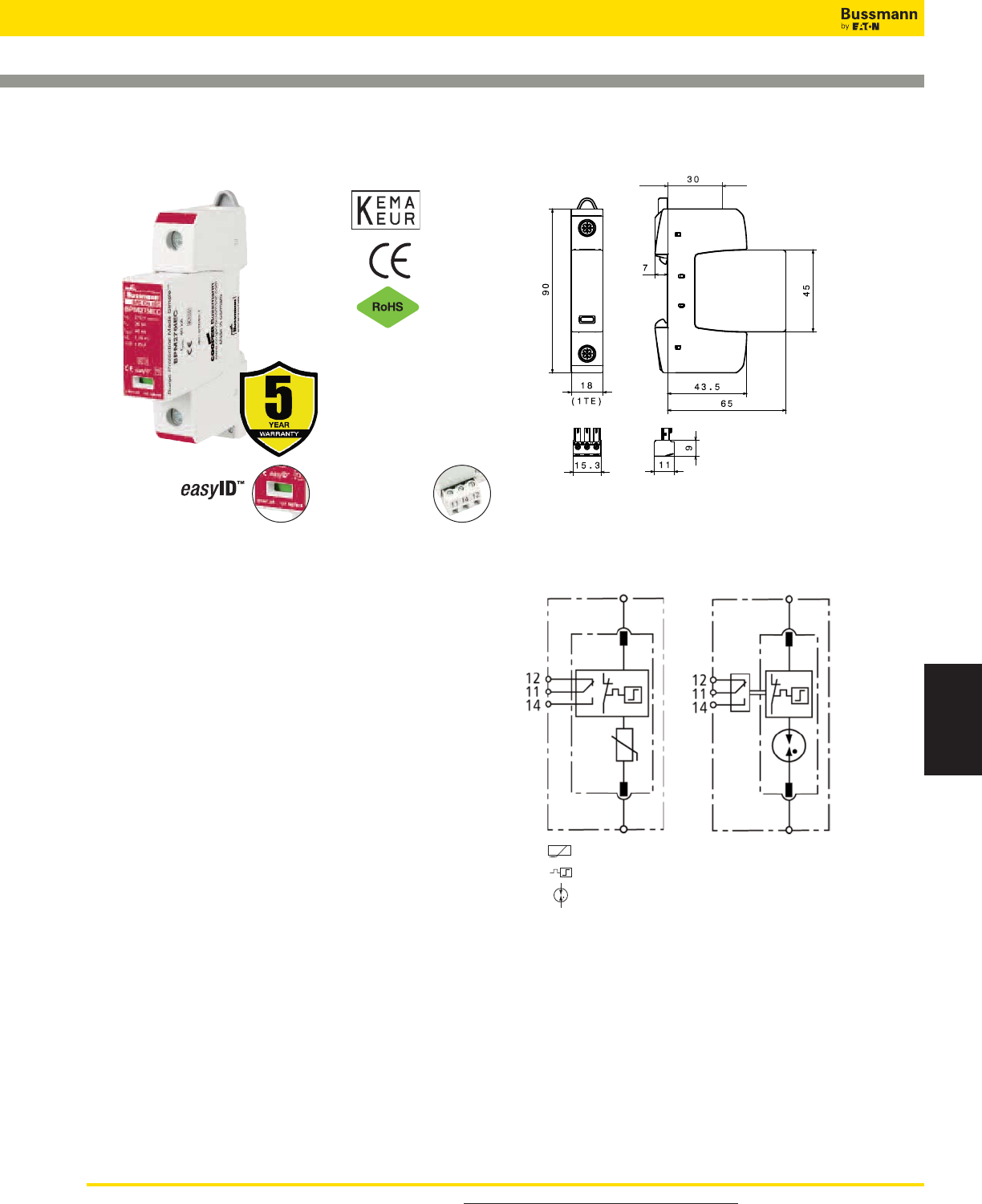
For product data sheets, visit www.cooperbussmann.com/DatasheetsEle 467
Surge Protection
Devices
Overvoltage Devices
IEC Class II DIN-Rail SPD
BSPM_ _ _ _TN, BSPG_ _ _ _NPE
Remote Signal
Contact Available
Visual Status Indication
Description
The Bussmann IEC Class II 275, 320, 385, 440 and 600V,
one-pole, modular surge arresters feature local, easyID™
visual indication and optional remote contact signaling. The
unique module locking system fixes the protection module to
the base part. Modules can be easily replaced without tools
by simply depressing the release buttons. Integrated
mechanical coding between the base and protection module
ensures against installing an incorrect replacement module.
Class II single-pole surge arrester models are offered with
MCOV ratings of 255, 275, 320, 385, 440 and 600V.
TN System Arresters
The features of these single-pole devices are for use as a
single device or in combination with other devices.
TT System Arrester
Provides a current arresting means between neutral
conductor and protective conductor in TT systems, this
device helps ensure fulfilling the requirements for protection
of personnel and equipment in “3+1” and “1+1” circuits.
Remote Signaling Contact
The three-pole terminal remote signaling contact versions
have a floating changeover contact for use as a break or
make contact, according to circuit concept.
BSPM1275TN
BSPM1320TN
BSPM1385TN
BSPM1440TN
BSPM1600TN
Shown with optional remote contact signaling
Module Circuit Diagrams -
Shown with optional remote contact signaling
Dimensions - mm
Data Sheet: 1166
*For remote signaling contact, add “R” suffix to the part number,
E.g., BSPM1275TNR
MOV
Thermal Disconnector
Gas Discharge Tube (single)
BSPG1255NPE(R)
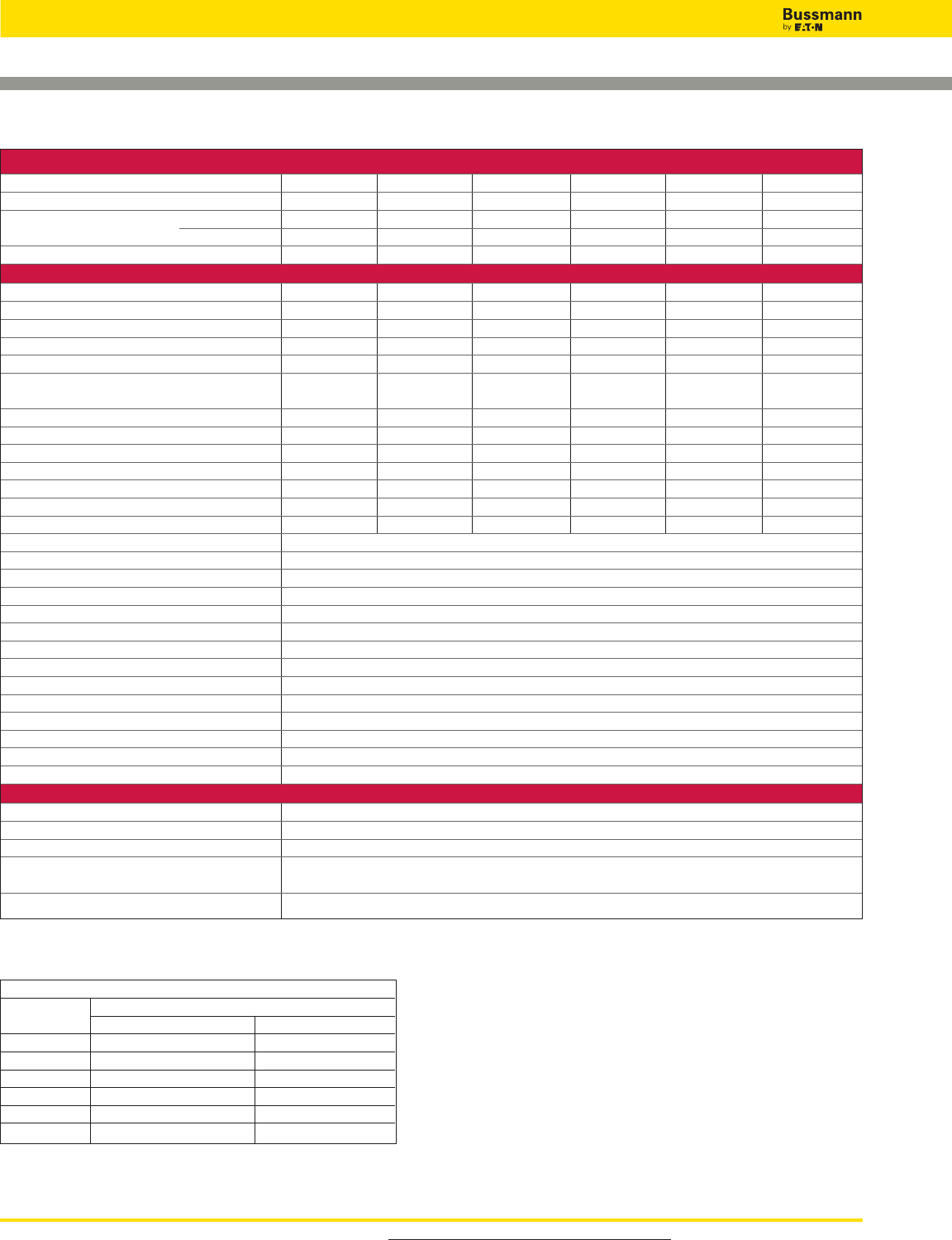
For product data sheets, visit www.cooperbussmann.com/DatasheetsEle
468
Overvoltage Devices
IEC Class II DIN-Rail SPD
* N-PE Surge arrester for location between neutral conductor and protective conductor in TT systems.
** See Bussmann SPD Limited Warranty Statement (3A1502) for details at www.cooperbussmann.com/surge.
Recommended Bussmann Back Up Fuses
DIN TT / TN System NH Fuse Part Numbers
Fuse Size 275, 320, 385, 440V 600V
00 125NHG00B 100NHG00B-690
0 125NHG0B 100NHG0B-690
01 125NHG01B - -
1 - - 100NHG1B-690
02 125NHG02B - -
2 - - 100NHG2B-690
Ordering Information
System Voltage/Poles 230V/1 230V/1 230V/1 400V/1 600V/1 230V/1*
Max. Continuous operating AC voltage (MCOV) [UC] 275V 320V 385V 440V 600V 255V
Catalog Numbers: Without Remote Signaling BSPM1275TN BSPM1320TN BSPM1385TN BSPM1440TN BSPM1600TN BSPG1255NPE
(Base + Modules) With Remote Signaling BSPM1275TNR BSPM1320TNR BSPM1385TNR BSPM1440TNR BSPM1600TNR BSPG1255NPER
Replacement Modules BPM275IEC BPM320IEC BPM385IEC BPM440IEC BPM600IEC BPG255NPE
Specifications
Line system type TN / TT TN / TT TN / TT TN TN TT
Max. Continuous operating DC voltage [UC] 350V 420V 500V 585V 600V - -
Voltage protection level [UP]<_ 1.25kV <_ 1.5kV <_ 1.75kV <_ 2kV <_ 2.5kV <_ 1.5kV
Voltage protection level at 5kA [UP]<_ 1kV <_ 1.2kV <_ 1.35kV <_ 1.7kV <_ 2kV - -
Max. mains-side overcurrent protection 125A gL/gG 125A gL/gG 125A gL/gG 125A gL/gG 100A gL-gG - -
Short-circuit withstand capability for max. 50kArms 25kArms 25kArms 25kArms 25kA rms - -
mains-side overcurrent protection
Temporary overvoltage (TOV) [UT] 335V/5 sec. 335V/5 sec. 385V/5 sec. 580V/5 sec. 600V/5 sec. 1200V/200 ms
Response time [tA]<_ 25 ns <_ 25 ns <_ 25 ns <_ 25 ns <_ 25 ns <_ 100 ns
Follow current extinguishing capability [Ifi] - - - - - - - - - - 100Arms
Lightning impulse current (10/350 μs) [Iimp] - - - - - - - - - - 12kA
Nominal discharge current (8/20 μs) [In] 20kA 20kA 20kA 20kA 15kA 20kA
Max. Discharge current (8/20 μs) [Imax] 40kA 40kA 40kA 40kA 30kA 40kA
Standards Information KEMA KEMA, CSA KEMA, CSA KEMA, CSA KEMA, CSA KEMA
Capacity 1 mod., DIN 43880
SPD according to EN 61643-11 Type 2
SPD according to IEC 61643-1 Class II
TOV characteristics Withstand
Operating temperature range [TU] -40°C to +80°C
Operating state/fault indication Green (good) / Red (replace)
Number of ports 1
Cross-sectional area (min.) 1.5mm2/14AWG solid/flexible
Cross-sectional area (max.) 35mm2/2AWG stranded-25mm2/4AWG flexible
Mounting 35mm DIN Rail per EN 60715
Enclosure material Thermoplastic, UL 94V0
Location category Indoor
Degree of protection IP20
Product Warranty Five Years**
Remote Contact Signaling
Remote Contact Signaling Type Changeover Contact
AC Switching Capacity (Volts/Amps) 250V/0.1A
DC Switching Capacity (Volts/Amps) 250V/0.1A; 125V/0.2A; 75V/0.5A
Conductor Ratings and Cross-Sectional Area for 60/75°C Max. 1.5mm2/14AWG Solid/Flexible
Remote Contact Signal Terminals
Ordering Information Order from Catalog Numbers Above
Data Sheet: 1166
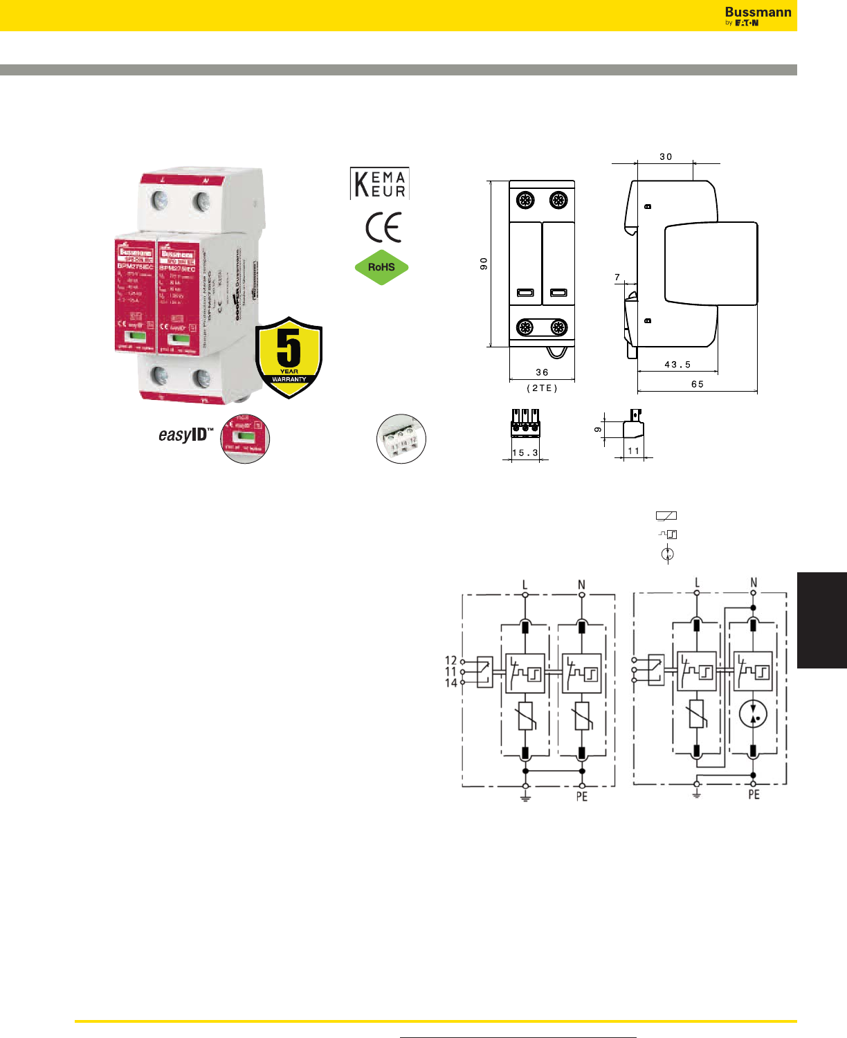
For product data sheets, visit www.cooperbussmann.com/DatasheetsEle 469
Surge Protection
Devices
Overvoltage Devices
IEC Class II DIN-Rail SPD
BSPM_ _ _ _TN, BSPH_ _ _ _TT
Remote Signal
Contact Available
Visual Status Indication
Description
The Bussmann IEC Class II 230V, two-pole, modular surge
arresters feature local, easyID™ visual indication and
optional remote contact signaling. The unique module locking
system fixes the protection module to the base part. Modules
can be easily replaced without tools by simply depressing the
release buttons. Integrated mechanical coding between the
base and protection module ensures against installing an
incorrect replacement module.230V models are offered with
MCOV ratings of 255 and 275V.
TN System Arresters
The features of these single-pole devices are for use in
single-phase 230V TN systems (“2-0” circuit).
TT System Arrester
The features of these single-pole devices are for use in
single-phase 230V TT and TNS systems (“1-1” circuit).
Remote Signaling Contact
The three-pole terminal remote signaling contact versions
have a floating changeover contact for use as a break or
make contact, according to circuit concept.
Shown with optional remote contact signaling
Circuit Diagrams
Dimensions - mm
BSPM2275TN
Shown with optional remote
contact signaling
BSPH2275TT
Shown with optional remote
contact signaling
MOV
Thermal Disconnector
Gas Discharge Tube (single)
Data Sheet: 1167
*For remote signaling contact, add “R” suffix to the part number,
E.g., BSPM2275TNR
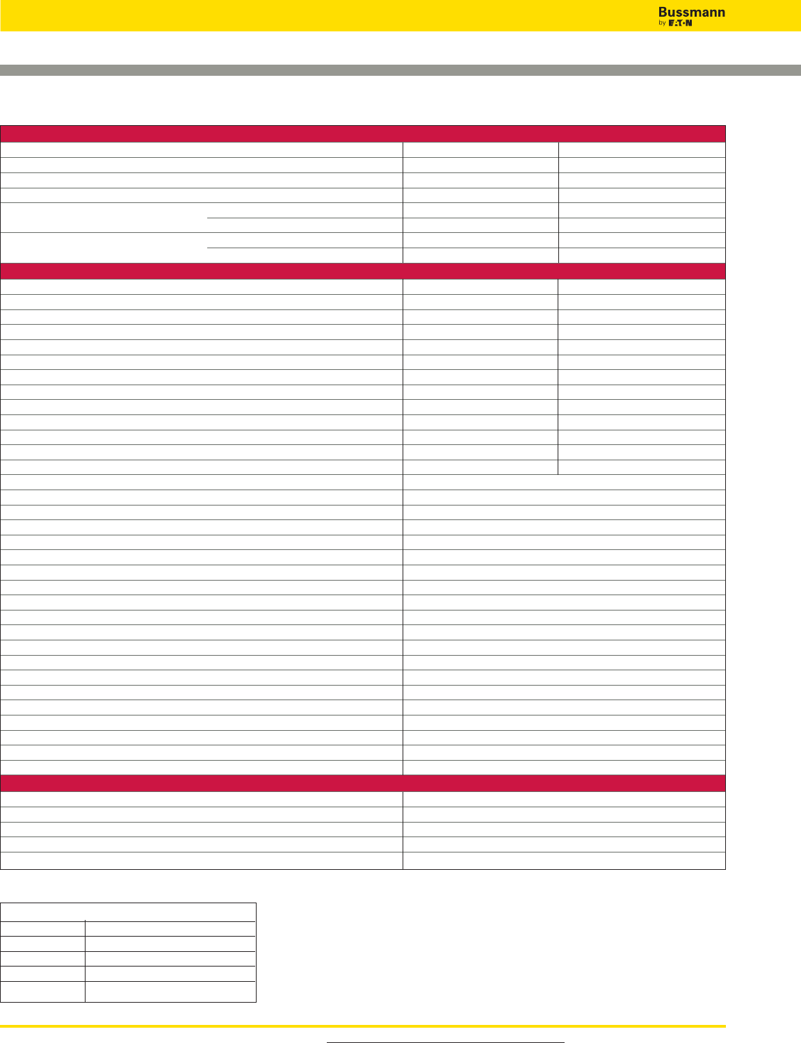
For product data sheets, visit www.cooperbussmann.com/DatasheetsEle
470
Overvoltage Devices
IEC Class II DIN-Rail SPD
Ordering Information
System Voltage/Poles 230V/2 230V/2
Max. continuous operating AC voltage (MCOV) [UC] 275V - -
Max. Continuous operating AC voltage (MCOV) [L-N] [UC]- -275V
Max. Continuous operating AC voltage (MCOV) [N-PE] [UC]- -255V
Catalog Numbers: Without Remote Signaling BSPM2275TN BSPH2275TT
With Remote Signaling BSPM2275TNR BSPH2275TTR
Replacement Modules: MOV Technology BPM275IEC BPM275IEC
Spark Gap technology - - BPSNPEIEC*
Specifications
Lightning impulse current (10/350 μs) [N-PE] [Iimp]- -12kA
Voltage protection level [UP]<_ 1.25kV - -
Voltage protection level at 5kA [UP]<_ 1kV - -
Voltage protection level [L-N] [UP]- -<_ 1.25kV
Voltage protection level [L-N] at 5kA [UP]- -<_ 1kV
Voltage protection level [N-PE] [UP]- -<_ 1.5kV
Follow current extinguishing capability [N-PE] [Ifi] - - 100A rms
Response time [tA]<_ 25 ns - -
Response time [L-N] [tA]- -<_ 25 ns
Response time [N-PE] [tA]- -<_ 100 ns
Temporary overvoltage (TOV) [UT] 335V/5 sec. - -
Temporary overvoltage (TOV) [L-N] [UT] - - 335V/5 sec.
Temporary overvoltage (TOV) [N-PE] [UT] - - 1200V/200 ms
SPD according to EN 61643-11 Type 2
SPD according to IEC 61643-1 Class II
Nominal discharge current (8/20 μs) [In] 20kA
Max. discharge current (8/20 μs) [Imax] 40kA
Max. mains-side overcurrent protection 125A gL/gG
Short-circuit withstand capability for max. mains-side overcurrent protection 50kA rms
Nominal AC voltage [UN] 230V
TOV characteristics withstand
Operating temperature range [TU] -40°C to +80°C
Operating state/fault indication green (good)/red (replace)
Number of ports 1
Cross-sectional area (min.) 1.5mm2/14AWG solid/flexible
Cross-sectional area (max.) 35mm2/2AWG stranded-25mm2/4AWG flexible
Mounting 35mm DIN rail per EN 60715
Enclosure material Thermoplastic, UL 94V0
Location category Indoor
Degree of protection IP20
Capacity 2 mods., DIN 43880
Standards Information KEMA
Product Warranty Five Years**
Remote Contact Signaling
Remote Contact Signaling Type Changeover Contact
AC Switching Capacity (Volts/Amps) 250V/0.1A
DC Switching Capacity (Volts/Amps) 250V/0.1A; 125V/0.2A; 75V/0.5A
Conductor Ratings and Cross-Sectional Area for Remote Contact Signal Terminals 60/75°C Max. 1.5mm2/14AWG Solid/Flexible
Ordering Information Order from Catalog Numbers Above
* N-PE Surge arrester for location between neutral conductor and protective conductor in TT systems.
** See Bussmann SPD Limited Warranty Statement (3A1502) for details at www.cooperbussmann.com/surge.
Recommended Bussmann Back Up Fuses
DIN Fuse Size NH Fuse Part Number
00 125NHG00B
0 125NHG0B
01 125NHG01B
02 125NHG02B
Data Sheet: 1167
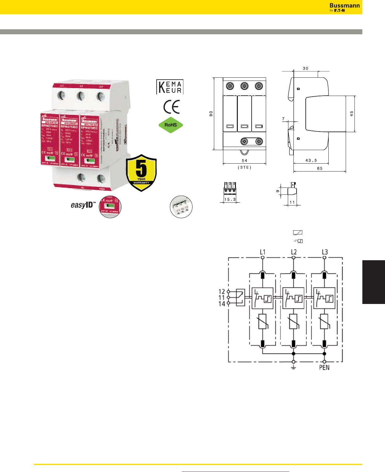
For product data sheets, visit www.cooperbussmann.com/DatasheetsEle 471
Surge Protection
Devices
Overvoltage Devices
IEC Class II DIN-Rail SPD
BSPM_ _ _ _TNC
Description
The Bussmann IEC Class II 120/240V and 230/400V,
three-pole, modular surge arresters feature local, easyID™
visual indication and optional remote contact signaling. The
unique module locking system fixes the protection module to
the base part. Modules can be easily replaced without tools
by simply depressing the release buttons. Integrated
mechanical coding between the base and protection module
ensures against installing an incorrect replacement module.
120V models are offered with a MCOV rating of 150V.
230V models are offered with a MCOV rating of 275 or 385V.
TNC System Arresters
The features of these three-pole devices are for use in TN-C
120/240V or 230/400V systems (“3-0” circuit) against surges.
Remote Signaling Contact
The three-pole terminal remote signaling contact versions
have a floating changeover contact for use as a break or
make contact, according to circuit concept.
BSPM3150TNC, BSPM3275TNC, BSPM3385TNC
Shown with optional remote contact signaling
Shown with optional remote contact signaling
Circuit Diagrams
Dimensions - mm
Remote Signal
Contact Available
Visual Status Indication
MOV
Thermal Disconnector
Data Sheet: 1168
*For remote signaling contact, add “R” suffix to the part number,
E.g., BSPM3150TNCR
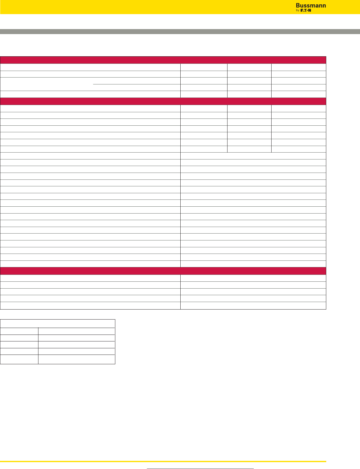
For product data sheets, visit www.cooperbussmann.com/DatasheetsEle
472
Overvoltage Devices
IEC Class II DIN-Rail SPD
ORDERING INFORMATION
System Voltage/Poles 120V/3 230V/3 230V/3
Max. Continuous operating AC voltage (MCOV) [UC] 150V 275V 385V
Catalog Numbers: Without Remote Signaling BSPM3150TNC BSPM3275TNC BSPM3385TNC
With Remote Signaling BSPM3150TNCR BSPM3275TNCR BSPM3385TNCR
Replacement Module MOV technology BPM150IEC BPM275IEC BPM385IEC
SPECIFICATIONS
Nominal AC voltage [UN] 120/240V 230/400V 230/400V
Voltage protection level [UP]_< 0.7kV <_ 1.25kV _< 1.75kV
Voltage protection level at 5kA [UP]_< 0.55kV <_ 1kV _< 1.35kV
Short-circuit withstand capability for max. mains-side overcurrent protection 50kArms 50kArms 25kArms
Temporary overvoltage (TOV) [UT] 175V/5 sec 335V/5 sec. 385V/5 sec
Nominal discharge current (8/20 μs) [In] 15kA 20kA 20kA
Max. Discharge current (8/20 μs) [Imax]40kA
SPD according to EN 61643-11 Type 2
SPD according to IEC 61643-1 Class II
Response time [tA] <_ 25 ns
Max. mains-side overcurrent protection 125A gL/gG
TOV characteristics withstand
Operating temperature range [TU] -40°C to +80°C
Operating state/fault indication Green (good)/Red (replace)
Number of ports 1
Cross-sectional area (min.) 1.5mm2/14AWG solid/flexible
Cross-sectional area (max.) 35mm2/2AWG stranded-25mm2/4AWG flexible
Mounting 35mm DIN rail per EN 60715
Enclosure material Thermoplastic, UL 94V0
Location category Indoor
Degree of protection IP20
Capacity 3 mods., DIN 43880
Standards Information KEMA
Product Warranty Five Years*
REMOTE CONTACT SIGNALING
Remote Contact Signaling Type Changeover Contact
AC Switching Capacity (Volts/Amps) 250V/0.1A
DC Switching Capacity (Volts/Amps) 250V/0.1A; 125V/0.2A; 75V/0.5A
Conductor Ratings and Cross-Sectional Area for Remote Contact Signal Terminals 60/75°C Max. 1.5mm2/14AWG Solid/Flexible
Ordering Information Order from Catalog Numbers Above
* See Bussmann SPD Limited Warranty Statement (3A1502) for details at www.cooperbussmann.com/surge.
Recommended Bussmann Back Up Fuses
DIN Fuse Size NH Fuse Part Number
00 125NHG00B
0 125NHG0B
01 125NHG01B
02 125NHG02B
Data Sheet: 1168
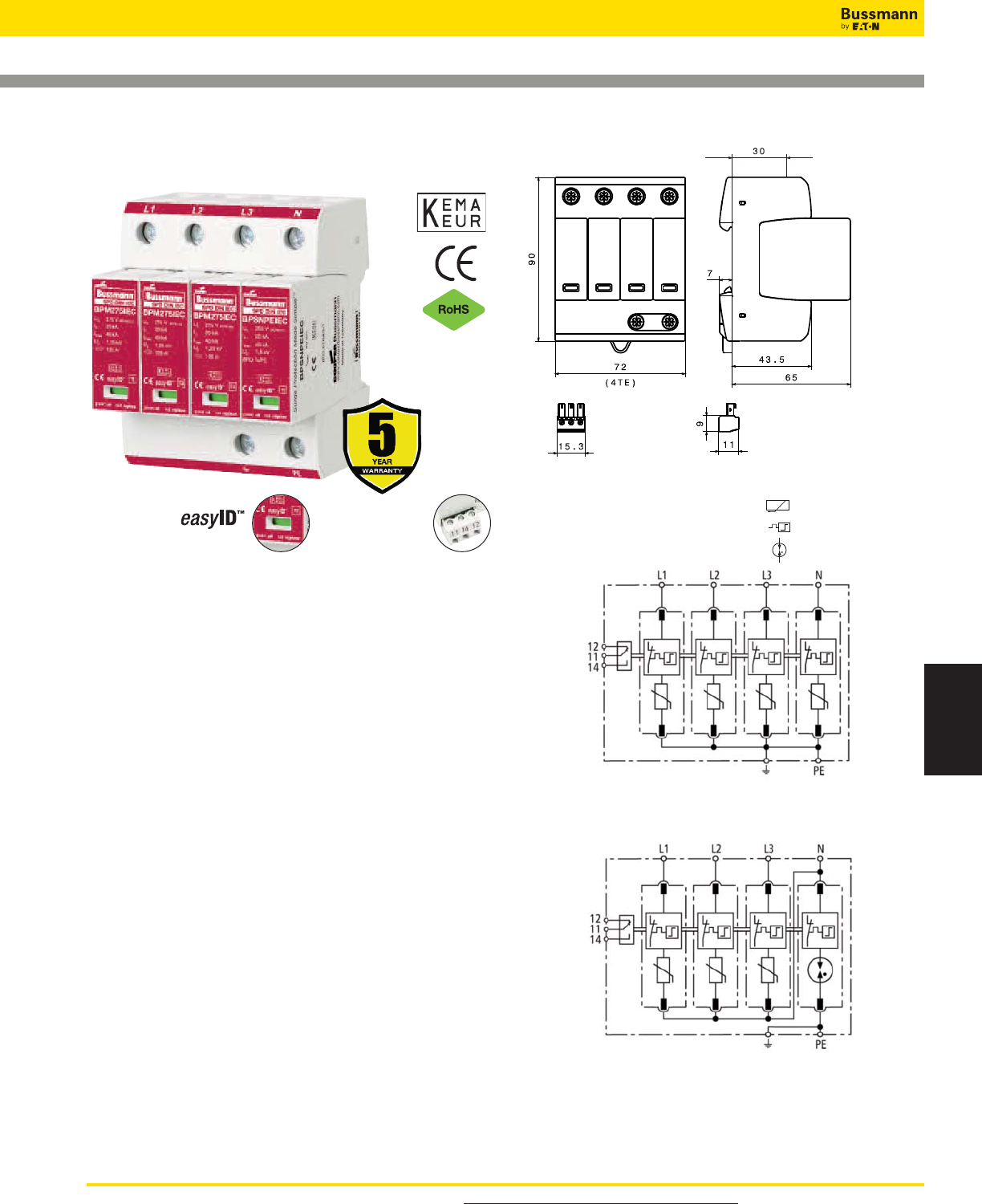
For product data sheets, visit www.cooperbussmann.com/DatasheetsEle 473
Surge Protection
Devices
Overvoltage Devices
IEC Class II DIN-Rail SPD
BSPH_TNS, BSPH_TT
BSPM4275TNS
Shown with optional remote contact signaling
BSPH4275TT, BSPH4320TT
BSPH4385TT
Shown with optional remote contact signaling
Shown with optional remote contact signaling
Circuit Diagrams
Dimensions - mm
Remote Signal
Contact Available
Visual Status Indication
Description
The Bussmann IEC Class II 230/400V, four-pole, modular
surge arresters feature local, easyID™ visual indication and
optional remote contact signaling. The unique module locking
system fixes the protection module to the base part. Modules
can be easily replaced without tools by simply depressing the
release buttons. Integrated mechanical coding between the
base and protection module ensures against installing an
incorrect replacement module.
These 230V models are offered with MCOV ratings of 275,
320 or 385V.
TNS System Arrester
The features of these four-pole devices are for use in TNS
230/400V systems (“4-0” circuit) against surges.
TT System Arrester
The features of these four-pole devices are for use in TT and
TN-S 230/400V systems (“3+1” circuit) against surges.
Remote Signaling Contact
The three-pole terminal remote signaling contact versions
have a floating changeover contact for use as a break or
make contact, according to circuit concept.
MOV
Thermal Disconnector
Gas Discharge Tube (single)
Data Sheet: 1169 *For remote signaling contact, add “R” suffix to the part number,
E.g., BSPH4275TTR
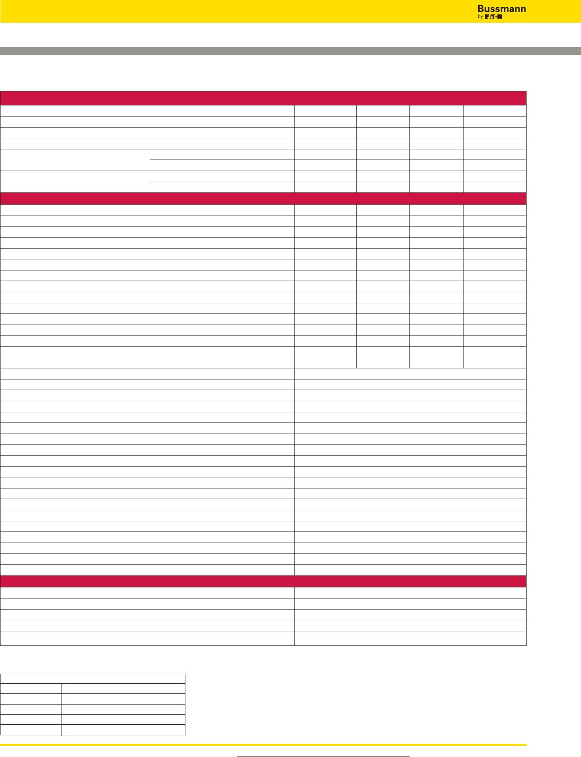
For product data sheets, visit www.cooperbussmann.com/DatasheetsEle
474
Overvoltage Devices
IEC Class II DIN-Rail SPD
ORDERING INFORMATION
System Voltage/Poles 230V/4 230V/4 230V/4 230V/4
Max. continuous operating AC voltage (MCOV) [UC] 275V- -- -- -
Max. continuous operating AC voltage (MCOV) [L-N] [UC] - - 275V 320V 385V
Max. continuous operating AC voltage [N-PE] [UC] - - 255V 255V 255V
Catalog Numbers: Without Remote Signaling BSPM4275TNS BSPH4275TT BSPH4320TT BSPH4385TT
With Remote Signaling BSPM4275TNSR BSPH4275TTR BSPH4320TTR BSPH4385TTR
Replacement Modules: MOV technology BPM275IEC BPM275IEC BPM320IEC BPM385IEC
Spark Gap technology - - BPSNPEIEC* BPSNPEIEC* BPSNPEIEC*
SPECIFICATIONS
Lightning impulse current (10/350 μs) [N-PE] [Iimp] - - 12kA 12kA 12kA
Voltage protection level [UP]<_ 1.25kV - - - - - -
Voltage protection level at 5kA [UP]<_ 1kV- -- -- -
Voltage protection level [L-N] [UP]- -<_ 1.25kV <_ 1.5kV <_ 1.75kV
Voltage protection level [L-N] at 5kA [UP]- -<_ 1kV <_ 1.2kV <_ 1.35kV
Voltage protection level [N-PE] [UP]- -<_ 1.5kV <_ 1.5kV <_ 1.5kV
Follow current extinguishing capability [N-PE] [Ifi] - - 100Arms 100Arms 100Arms
Response time [tA]<_ 25 ns - - - - - -
Response time [L-N] [tA]- -<_ 25 ns <_ 25 ns <_ 25 ns
Response time [N-PE] [tA]- -<_ 100 ns <_ 100 ns <_ 100 ns
Temporary overvoltage (TOV) [UT] 335V/5 sec. - - - - - -
Temporary overvoltage (TOV) [L-N] [UT] - - 335V/5 sec. 335V/5 sec. 385V/5 sec.
Temporary overvoltage (TOV) [N-PE] [UT] - - 1200V/200 ms 1200V/200 ms 1200V/200 ms
Short-circuit withstand capability for max. 50kArms 50kArms 25kArms 25kArms
mains-side overcurrent protection
SPD according to EN 61643-11 Type 2
SPD according to IEC 61643-1 Class II
Nominal AC voltage [UN] 230/400V
Nominal discharge current (8/20 μs) [In] 20kA
Max. discharge current (8/20 μs) [Imax] 40kA
Max. mains-side overcurrent protection 125A gL/gG
TOV characteristics withstand
Operating temperature range [TU] -40°C to +80°C
Operating state/fault indication green (good)/red (replace)
Number of ports 1
Cross-sectional area (min.) 1.5mm2/14AWG solid/flexible
Cross-sectional area (max.) 35mm2/2AWG stranded-25mm2/4AWG flexible
Mounting 35mm DIN rail per EN 60715
Enclosure material Thermoplastic, UL 94V0
Location category Indoor
Degree of protection IP20
Capacity 4 mods., DIN 43880
Standards Information KEMA
Product Warranty Five Years**
REMOTE CONTACT SIGNALING
Remote Contact Signaling Type Changeover Contact
AC Switching Capacity (Volts/Amps) 250V/0.1A
DC Switching Capacity (Volts/Amps) 250V/0.1A; 125V/0.2A; 75V/0.5A
Conductor Ratings and Cross-Sectional Area for Remote Contact Signal Terminals 60/75°C Max. 1.5mm2/14AWG Solid/Flexible
Ordering Information Order from Catalog Numbers Above
* N-PE Surge arrester module for location between neutral conductor and protective conductor in TT systems.
** See Bussmann SPD Limited Warranty Statement (3A1502) for details at www.cooperbussmann.com/surge.
Recommended Bussmann Back Up Fuses
DIN Fuse Size NH Fuse Part Number
00 125NHG00B
0 125NHG0B
01 125NHG01B
02 125NHG02B Data Sheet: 1169
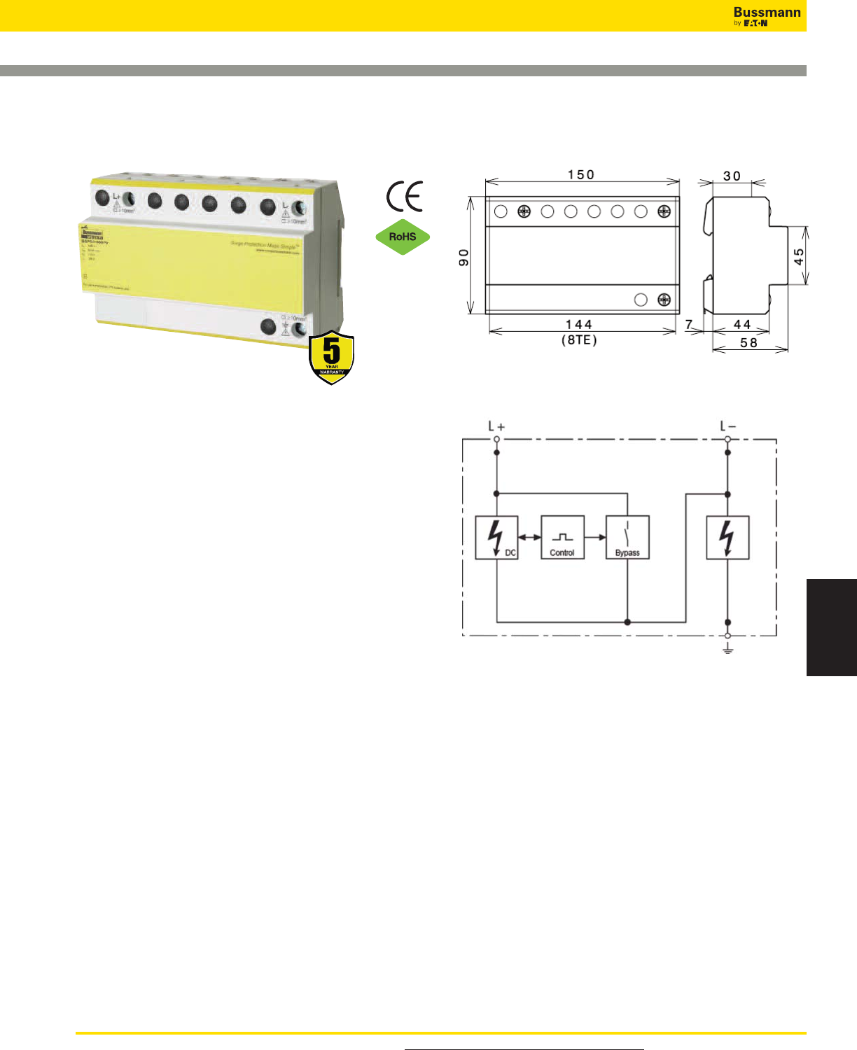
For product data sheets, visit www.cooperbussmann.com/DatasheetsEle 475
Surge Protection
Devices
Overvoltage Devices
Photovoltaic DIN-Rail Lightning SPD
BSPS_ _ _ _PV
Description
The Bussmann combined lightning current and surge arrester
(SPD Class I according to IEC 61643-1) is for use in
photovoltaic power supply systems.
• Prewired combined lightning current and surge arrester for
use in photovoltaic generator circuits
• For use in photovoltaic installations up to 1000V UCPV
• High lightning current discharge capacity using spark gap
technology
• Maximum system availability due to spark gap technology
with DC current extinction
Module Circuit Diagrams
Dimensions - mm
Data Sheet: 2148
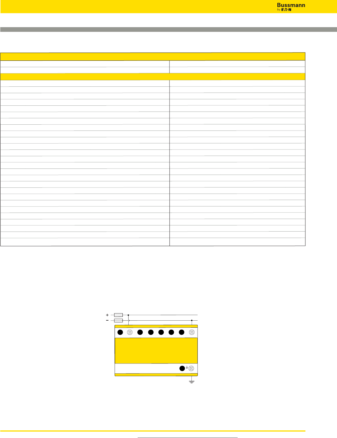
For product data sheets, visit www.cooperbussmann.com/DatasheetsEle
476
Overvoltage Devices
Photovoltaic DIN-Rail Lightning SPD
Data Sheet: 2148
Ordering Information
Max. PV System Voltage 1000Vdc
Catalog Number: BSPS31000PV
Specifications
SPD Classification according to EN 61643-11 Type 1
SPD Classification according to IEC 61643-1 Class I
Max. PV voltage [UCPV ] of the PV generator 1000V
Max. Continuous operating DC voltage [Umax DC] 1000V
Min. Continuous operating DC voltage [Umin DC] 100V
Follow current extinguishing capability DC [Ifi DC] 100A
Nominal discharge current (8/20 μs) [In] 100kA
Lightning impulse current (10/350 μs) [L+/L- -> PE] [Iimp] 50kA
Specific energy [L+/L- -> PE] [W/R] 625.00 kJ/ohms
Lightning impulse current (10/350 μs) [L+ -> L-] [Iimp]25kA
Specific energy [L+ -> L-] [W/R] 156.25 kJ/ohms
Voltage protection level [L+ -> L-] [Up]_< 3.3kV
Voltage protection level [(L+/L-) -> PE] [Up]_< 4kV
Operating current [IIN DC] _< 5mA
Response time [L+ -> L-] [tA]_< 20 ns
Protective conductor current [IPE]_< 1μA
Operating temperature range [Tu] -40°C to +60°C
Number of ports 1
Cross-sectional area (min.) 10mm
2
/6AWG solid/flexible
Cross-sectional area (max.) 50mm
2
/2AWG stranded/ 35mm
2
/1AWG flexible
Mounting 35mm DIN rail per EN 60715
Enclosure material Thermoplastic, UL 94V0
Place of installation Indoor
Degree of protection IP-20
Capacity 8 Mods., DIN 4
Product Warranty Five Years*
* See Bussmann document 3A1502 on the web at www.cooperbussmann.com.
L+L-

For product data sheets, visit www.cooperbussmann.com/DatasheetsEle 477
Surge Protection
Devices
Overvoltage Devices
Photovoltaic DIN-Rail SPD
BSPH2_ _ _ _PV
Description
The Bussmann modular Surge Protective Device (SPD) (with
two-step DC switching device) features easyID™ visual
indication and optional remote contact signaling (floating
changeover contact) for use in photovoltaic systems.
This complete surge protective device is suitable for all PV
systems in accordance with UL 1449 3rd Edition and IEC
60364-7-712. Includes a five year limited warranty.
This prewired solution consist of a base and locking modules
that feature a combined disconnection and short-circuiting
(shunting) device with safe electrical isolation to prevent fire
damage due to DC arcs. An integrated DC fuse allows safe
module replacement without arc formation.
In case of insulation faults in the generator circuit, a reliable
and tested fault-resistant circuit prevents damage to the surge
protective devices.
The green and red visual indicator flags show the module
protective status (green = good, red = replace). Apart from this
visual indication, the remote signaling option features a three
terminal floating changeover contact that can be used as a
make or break contact depending on the particular monitoring
system design employed.
Remote Signal
Contact Available
Visual Status Indication
Short-Circuit Interrupting (SCI) Technology
1. Original State 2. Disconnection Device
Response
3. Arc Extinguishes 4. Safe Electrical Isolation
1234
Module Circuit Diagrams
Dimensions - mm
BSPH2600PV*
Shown with optional remote contact signaling
Shown with optional remote contact signaling
Data Sheet: 2145
Fuse Open
Thermal Disconnector
MOV
Fuse Closed
Arc
*For remote signaling contact, add “R” suffix to the part number,
E.g., BSPH2600PVR
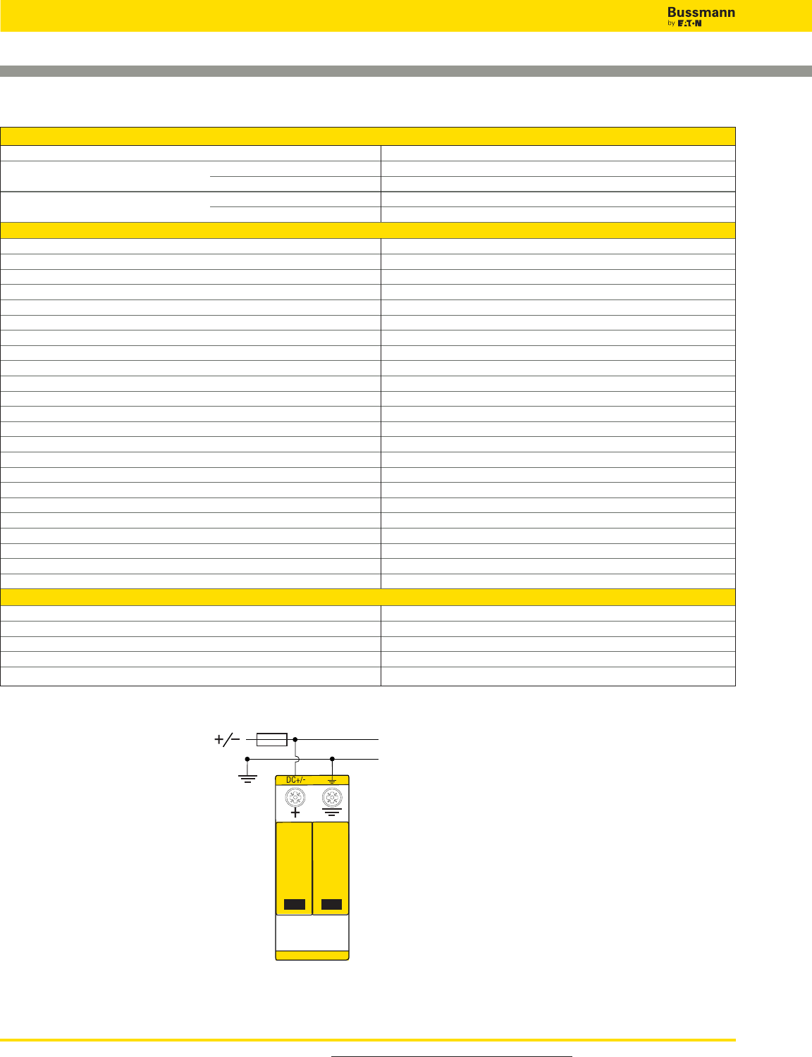
For product data sheets, visit www.cooperbussmann.com/DatasheetsEle
478
Overvoltage Devices
Photovoltaic DIN-Rail SPD
Data Sheet: 2145
Ordering Information
Nominal PV System Voltage 600Vdc
Catalog Numbers: Without Remote Signaling BSPH2600PV
(Base + Modules) With Remote Signaling BSPH2600PVR
Replacement Modules: Left BPH300YPV
Right BPM300YPV
Specifications
Conformity with prEN 50539-11 Yes
SPD Classification per EN 61643-11 Type 2
SPD Classification per IEC 61643-1 Class II
Max. PV voltage [UCPV] _< 600V
Short-circuit withstand capacity [ISCWPV] 1000A
MCOV [UCPV]700Vdc
Nominal discharge current (8/20 μs) [(DC+/DC-) --> PE] [In] 12.5kA
Max. Discharge current (8/20 μs) [(DC+/DC-) --> PE] [Imax]25kA
Voltage protection level [UP]_< 2.5kV
Voltage protection level at 5kA [UP]_< 2kV
Response time [tA] _< 25 ns
Operating temperature range [TU] -40°C to +80°C
Operating state/fault indication Green (good) / Red (replace)
Number of ports 1
Cross-sectional area (min.) 60/75°C 1.5mm2/14AWG Solid/Flexible
Cross-sectional area (max.) 60/75°C 35mm2/2AWG Stranded/25mm2/4AWG Flexible
For mounting on 35 mm DIN rail per EN 60715
Enclosure material Thermoplastic, UL 94V0
Place of installation Indoor
Degree of protection IP20
Capacity 2 Modules, DIN 43880
Standards Information UL
Product Warranty Five Years*
Remote Contact Signaling
Remote Contact Signaling Type Changeover Contact
AC Switching Capacity (Volts/Amps) 250V/0.1A
DC Switching Capacity (Volts/Amps) 250V/0.1A; 125V/0.2A; 75V/0.5A
Conductor Ratings and Cross-Sectional Area for Remote Contact Signal Terminals 60/75°C Max. 1.5mm2/14AWG Solid/Flexible
Ordering Information Order from Catalog Numbers Above
Typical Application Schematic
* See Bussmann SPD Limited Warranty Statement (3A1502) for details at www.cooperbussmann.com/surge.
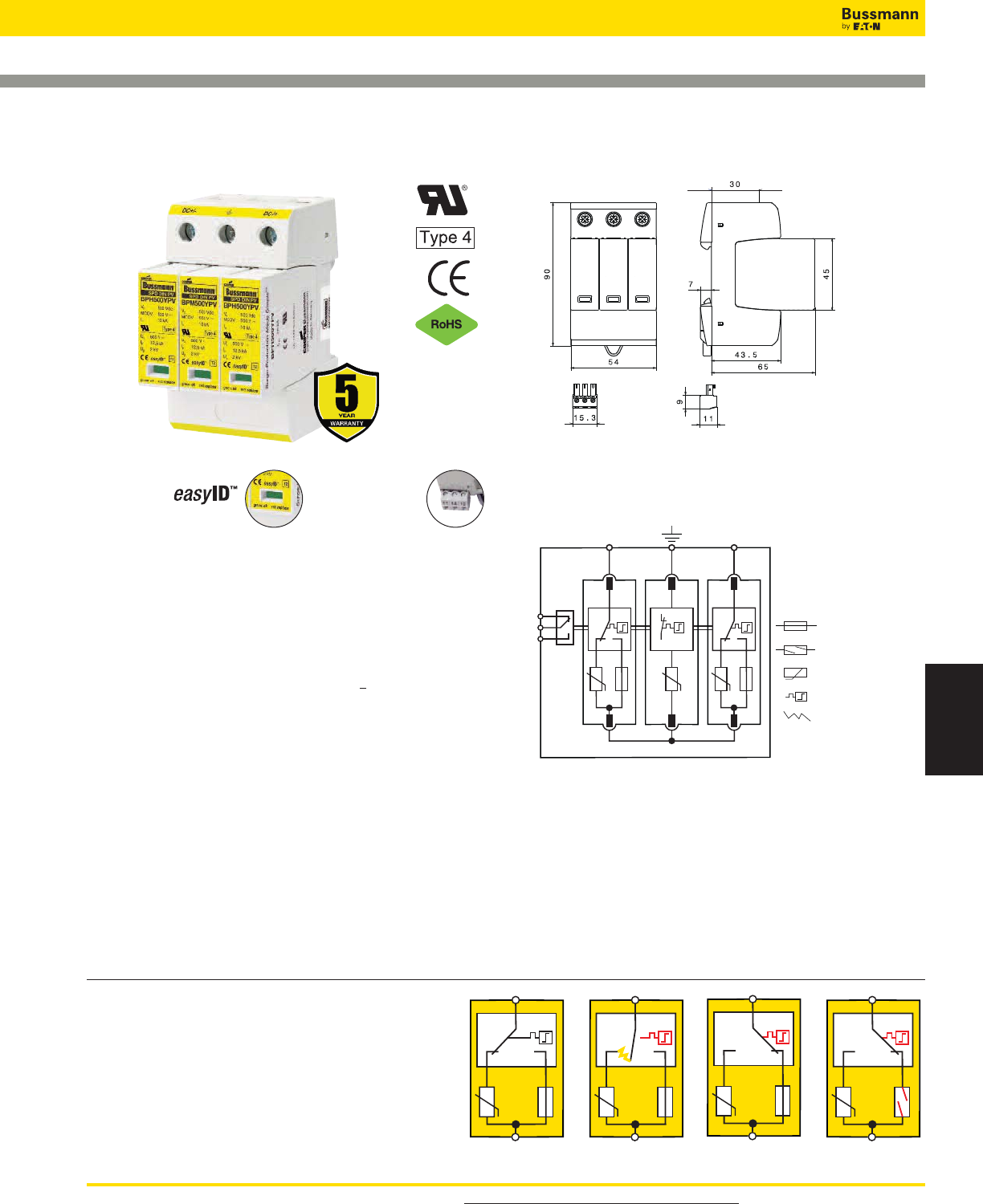
For product data sheets, visit www.cooperbussmann.com/DatasheetsEle 479
Surge Protection
Devices
Overvoltage Devices
Photovoltaic DIN-Rail SPD
BSPH_ _ _ _YPV
Description
The Bussmann three-module photovoltaic Surge Protective
Device (SPD) (with three-step DC switching device) features
easyID™ visual indication and optional remote contact
signaling (floating changeover contact) for use in PV
systems.
These complete surge protective devices are suitable for all
PV systems in accordance with UL 1449 3rd Edition and
IEC 60364-7-712. Includes a five year limited warranty.
These prewired solutions consist of a base and locking
modules that feature a combined disconnection and
short-circuiting (shunting) device with safe electrical isolation
to prevent fire damage due to DC arcs. An integrated DC fuse
allows safe module replacement without arc formation.
In case of insulation faults in the generator circuit, a reliable
and tested fault-resistant Y circuit prevents damage to the
surge protective devices.
The green and red visual indicator flags show the module
protective status (green = good, red = replace). Apart from
this visual indication, the remote signaling option features a
three terminal floating changeover contact that can be used
as a make or break contact depending on the particular
monitoring system design employed.
Remote Signal
Contact Available
Visual Status Indication Module Circuit Diagrams
Dimensions - mm
BSPH_____YPV*
Shown with optional remote contact signaling
Shown with optional remote contact signaling
Short-Circuit Interrupting (SCI) Technology
1. Original State 2. Disconnection Device
Response
3. Arc Extinguishes 4. Safe Electrical Isolation
1234
Data Sheet: 2055
12
11
14
DC+/– DC–/+
Fuse Open
Thermal Disconnector
MOV
Fuse Closed
Arc
*For remote signaling contact, add “R” suffix to the part number,
E.g., BSPH____YPVR
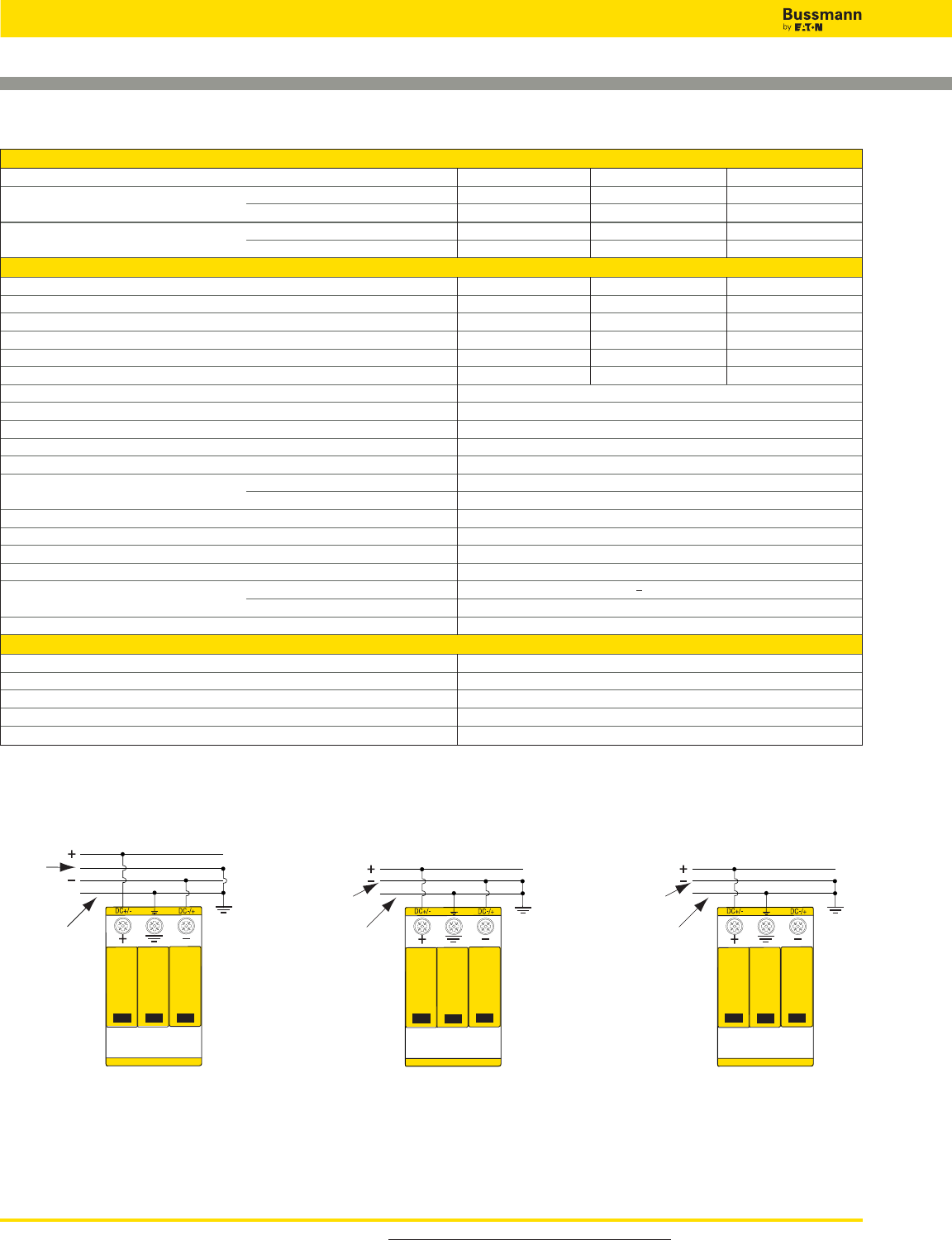
For product data sheets, visit www.cooperbussmann.com/DatasheetsEle
480
Overvoltage Devices
Photovoltaic DIN-Rail SPD
Data Sheet: 2055
Ordering Information
Nominal PV System Voltage 600Vdc 1000Vdc 1200Vdc
Catalog Numbers: Without Remote Contact Signaling BSPH3600YPV BSPH31000YPV BSPH31200YPV
(Base + Modules) With Remote Contact Signaling BSPH3600YPVR BSPH31000YPVR BSPH31200YPVR
Replacement Modules: Outer (2 modules installed) BPH300YPV BPH500YPV BPH600YPV
Center (1 module installed) BPM300YPV BPM500YPV BPM600YPV
Specifications
Nominal PV System Voltage 600V 1000V 1200V
MCOV [UCPV]700Vdc 1170Vdc 1200Vdc
Max System Discharge Current (8/20 μs) [Imax] 40kA 40kA 30kA
Voltage Protection Level [UP]<_2.5kV <_4.0kV <_4.5kV
Voltage Protection Level at 5kA [UP]<_2.0kV <_3.5kV <_4.0kV
Integrated Fuse Breaking Capacity/Interrupting Rating 30kA / 1000Vdc 30kA / 1000Vdc 30kA / 1200Vdc
Technology Short-Circuit Interruption (SCI) Overcurrent Protection
Operating Temperature Range [TU] -40°C to +80°C
Nominal Discharge Current (8/20 μs) [(DC+/DC-) --> PE] [In] 12.5kA
Response Time [tA] <_25ns
Operating State/Fault Indication Green (good) / Red (replace)
Conductor Ratings and Cross-Sectional Area: Minimum 60/75°C 1.5mm2 / 14AWG Solid/Flexible
Maximum 60/75°C 35mm2 / 2AWG Stranded / 25mm2 / 4AWG Flexible
Mounting 35mm DIN Rail per EN 60715
Enclosure Material UL 94V0 Thermoplastic
Degree of Protection IP20
Capacity 3 Modules, DIN 43880
Standards Information: UL UL 1449 3rd Edition (Type 2)*
IEC IEC 61643-11 Type 2, IEC 61643-1 Class II
Product Warranty Five Years**
Remote Contact Signaling
Remote Contact Signaling Type Changeover Contact
AC Switching Capacity (Volts/Amps) 250V / 0.1A
DC Switching Capacity (Volts/Amps) 250V / 0.1A; 125V / 0.2A; 75V / 0.5A
Conductor Ratings and Cross-Sectional Area for Remote Contact Signal Terminals 60/75°C Max. 1.5mm2 / 14AWG Solid/Flexible
Ordering Information Order from Catalog Numbers Above
* Does not apply to 1200Vdc.
** See Bussmann SPD Limited Warranty Statement (3A1502) for details at www.cooperbussmann.com/surge.
Typical Application Schematics
Equipment
Grounding
Conductor
Common
Equipment
Grounding
Conductor
Common
Equipment
Grounding
Conductor
Common
Application A
Two energized poles/modes
600, 1000 & 1200Vdc systems
Application B
One energized pole/mode
600Vdc & 1000Vdc systems only
Application C
One energized pole/mode
600Vdc & 1000Vdc systems only
(Max. system discharge current
(8/20 μs) [Imax] 25kA)
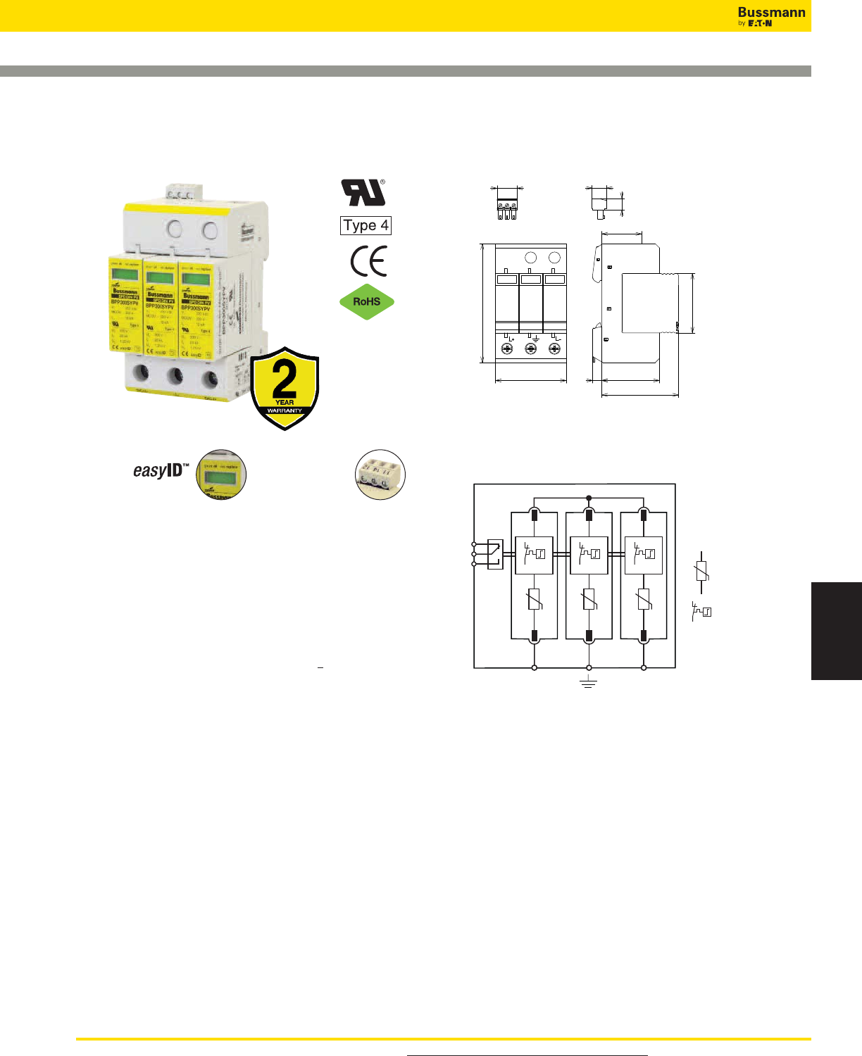
For product data sheets, visit www.cooperbussmann.com/DatasheetsEle 481
Surge Protection
Devices
Photovoltaic DIN-Rail SPD
15.3 11.0
30.0
54.0 43.5
58.0
7.0
9.0
90.0
45.0
(3TE)
Description
The Bussmann three-module photovoltaic Surge Protective
Device (SPD) features easy ID™ visual indication and optional
remote contact signaling (floating changeover contact) for use
in PV systems.
These complete surge protective devices are suitable for all
PV systems in accordance with UL 1449 3rd Edition,
EN 50539-11 and IEC 60364-7-712. Includes a two year
limited warranty.
These prewired solutions consist of a base and modules that
feature a disconnection device in the event of an overload.
In case of insulation faults in the generator circuit, a reliable
and tested fault-resistant Y circuit prevents damage to the
surge protective devices.
The green and red visual indicator flags show the module
protective status (green = good, red = replace). Apart from
this visual indication, the remote signaling option features a
three terminal floating changeover contact that can be used
as a make or break contact depending on the particular
monitoring system design employed.
Module Circuit Diagrams
12
11
14
DC+/– DC–/+
BSPP_____YPV*
Shown with optional remote contact signaling
* For remote signaling contact, add “R” suffix to the part number.
E.g., BSPP3600YPVR
Shown with optional
remote contact signaling
Remote Signal
Contact
Available
Visual Status
Indication
Thermal Disconnector
MOV
Overvoltage Devices
Dimensions - mm
BSPP_____YPV(R)
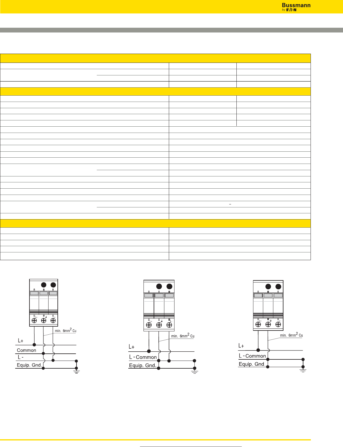
For product data sheets, visit www.cooperbussmann.com/DatasheetsEle
482
Overvoltage Devices
Wind IEC Class I DIN-Rail SPD
Ordering Information
Nominal PV System Voltage 600Vdc 1000Vdc
Catalog Numbers: Without Remote Contact Signaling BSPP3600YPV BSPP31000YPV
(Base + Modules) With Remote Contact Signaling BSPP3600YPVR BSPP31000YPVR
Replacement Modules: BPP300SYPV BPP500SYPV
Specifications
Nominal PV System Voltage [UCPV]600V 1000V
MCOV [UCPV]600Vdc 1000Vdc
Max System Discharge Current (8/20µs) [Imax] 40kA 40kA
Voltage Protection Level [UP] ≤2.5kV ≤4.0kV
Voltage Protection Level at 5kA [UP] ≤2.0kV ≤3.5kV
Short-Circuit Withstand Capability [ISCPV]125A
Technology Fault Resistant Y MOV Circuit
Operating Temperature Range [TU] -40°C to +80°C
Nominal Discharge Current (8/20µs) (DC+ DC-) (DC+/DC- PE) [In]20kA
Response Time [tA]≤25ns
Operating State/Fault Indication Green (good) / Red (replace)
Conductor Ratings and Cross-Sectional Area: Minimum 60/75°C 1.5mm
2
/ 14AWG Solid/Flexible
Maximum 60/75°C 35mm
2
/ 2AWG Stranded / 25mm
2
/ 4AWG Flexible
Mounting 35mm DIN-Rail per EN 60715
Enclosure Material UL 94V0 Thermoplastic
Degree of Protection IP20
Capacity 3 Modules, DIN 43880
Standards Information: UL UL 1449 3
rd
Edition (Type 2)
IEC EN 50539-11, IEC 61643-11 Type 2, IEC 61643-1 Class II
Product Warranty Two Years*
Remote Contact Signaling
Remote Contact Signaling Type Changeover Contact
AC Switching Capacity (Volts/Amps) 250V / 0.1A
DC Switching Capacity (Volts/Amps) 250V / 0.1A; 125V / 0.2A; 75V / 0.5A
Conductor Ratings and Cross-Sectional Area for Remote Contact Signal Terminals 60/75°C Max. 1.5mm
2
/ 14AWG Solid/Flexible
Ordering Information Order from Catalog Numbers Above
* See Bussmann SPD Limited Warranty Statement (3A1502) for details at www.cooperbussmann.com/surge.
** BSPP31000YPV(R) 1000Vdc one energized pole/mode requires the following:
1. Use a suitable electrical insulator to keep a 10mm min. safety distance from the PV-SPD and other grounded parts in the housing.
2. No metal covers are in the area of the module release buttons as shown.
Typical Application Schematics
Application A
Two energized poles/modes
600 & 1000Vdc systems
Application B
One energized pole/mode
600Vdc & 1000Vdc systems only
Application C
One energized pole/mode
600Vdc & 1000Vdc** systems
Data Sheet: 10091
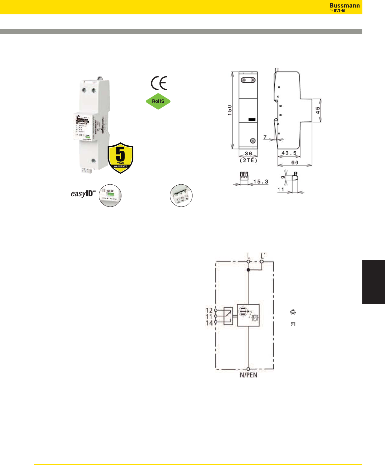
For product data sheets, visit www.cooperbussmann.com/DatasheetsEle 483
Surge Protection
Devices
Overvoltage Devices
Wind IEC Class I DIN-Rail SPD
BSPS_ _ _ _WE
Description
The Bussmann IEC Class I 400 and 690V, one-pole lightning
current arresters feature local, easyID™ visual indication and
optional remote contact signaling.
440V and 760V maximum continuous operating voltage
arresters protect installations against surges and direct
lightning strikes.
System & Application
TNC 400V/690V: 3x BSPS1400WE(R)
TNS 400/690V: 4x BSPS1400WE(R)
IT 690V: 3x BSPS1690WER
Remote Signaling Contact
The three-pole terminal remote signaling contact versions
have a floating changeover contact for use as a break or
make contact, according to circuit concept.
BSPS1400WE*
BSPS1690WE
Shown with optional remote contact signaling
Circuit Diagrams - Shown with optional remote contact
signaling
Dimensions - mm
Remote Signal
Contact Available
Visual Status Indication
Spark Gap Trigger
Creepage Discharge Spark Gap
Data Sheet: 2091
*For remote signaling contact, add “R” suffix to the part number,
E.g., BSPS1400WER
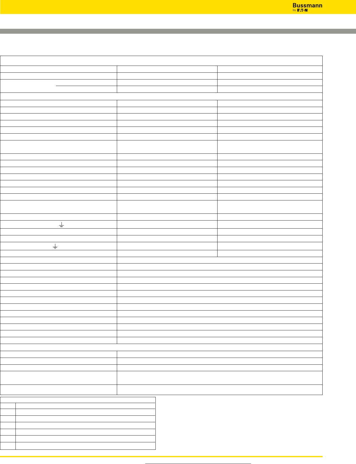
For product data sheets, visit www.cooperbussmann.com/DatasheetsEle
484
Overvoltage Devices
Wind IEC Class I DIN-Rail SPD
Ordering Information
System Voltage/Poles 400V/1 690V/1
Max. Continuous Operating AC voltage (MCOV) [UC] 440V 760V
Catalog Numbers: Without Remote Signaling BSPS1400WE - -
With Remote Signaling BSPS1400WER BSPS1690WER
Specifications
Line System Type TNC, TNS, IT TNC, TNS, IT
Lightning impulse current (10/350 μs) [Iimp] 35kA 25kA
Specific Energy [W/R] 306.25kJ/ohms 156.25kJ/ohms
Nominal Discharge Current (8/20 μs) [In] 35kA 25kA
Voltage Protection Level [UP]_< 2.5kV _< 4kV
Follow Current Extinguishing Capability AC [Ifi] 50kArms 25kArms
Follow Current Limitation / Selectivity no tripping of a 32 A gL/gG no tripping of a 32 A gL/gG
fuse up to 50 kArms (prosp.) fuse up to 25 kArms (prosp.)
Response Time [tA]_< 100 ns _< 100 ns
Max. Backup Fuse (L) up to IK= 25kArms (ta_< 5 s) - - 250A gL/gG
Max. Backup Fuse (L) up to IK> 25kArms - - 100A gL/gG
Max. Backup Fuse (L) up to IK= 50kArms (ta_< 0.2 s) 500A gL/gG - -
Max. Backup Fuse (L) up to IK= 50kArms (ta_< 5 s) 250A gL/gG - -
Max. Backup Fuse (L) for IK> 50kArms 160A gL/gG - -
Max. Backup Fuse (L-L ) 125A gL/gG 125A gL/gG
Short-Circuit Withstand Capability for
Max. Mains-Side Overcurrent Protection 50kArms 25kArms
Temporary Overvoltage (TOV) [UT] 690V / 5 sec. 1000V / 5 sec.
Cross-Sectional Area (L, L , ) [min.] - - 10mm2solid/flexible
Cross-Sectional Area (L, L , N/PEN) [min.] 10mm2solid/flexible - -
Cross-Sectional Area (L, N/PEN) [max.] 50mm2/1AWG stranded/35mm2/2AWG flexible - -
Cross-Sectional Area (L, ) [max.] - - 50mm2/1AWG stranded/35 mm2/2AWG flexible
Cross-Sectional Area (L ) [max.] 35mm2/2AWG stranded/25mm2/4AWG flexible 35mm2/2AWG stranded/25mm2/4AWG flexible
SPD According to EN 61643-11 Type 1
SPD According to IEC 61643-1 Class I
TOV Characteristics Withstand
Operating Temperature Range (parallel connection) [TUP] -40°C to +80°C
Operating Temperature Range (series connection) [TUS] -40°C to +60°C
Operating State/Fault Indication Green (good) / Red (replace)
Number of Ports 1
Mounting 35mm DIN rail per EN 60715
Enclosure Material Thermoplastic, UL 94V0
Place of Installation Indoor
Degree of Protection IP20
Capacity 2 Mods., DIN 43880
Product Warranty Five Years*
Remote Contact Signaling
Remote Contact Signaling Type Changeover Contact
AC Switching Capacity (Volts/Amps) 250V/0.5A
DC Switching Capacity (Volts/Amps) 250V/0.1A; 125V/0.2A; 75V/0.5A
Conductor Ratings and Cross-Sectional Area for Remote 60/75°C Max. 1.5mm2/
Contact Signal Terminals 14AWG Solid/Flexible
Ordering Information Order from Catalog Numbers Above
* See Bussmann SPD Limited Warranty Statement (3A1502) for details at
www.cooperbussmann.com/surge.
Recommended Bussmann NH DIN Size Back Up Fuses
Size NH Fuse Part Number
000 100NHG000B-690 (max L) up to IK> 25kArms
00 125NHG00B-690 (max L-L )
01 160NHG01B-690 (max L) for IK> 50kArms
02 250NHG02B-690 (max L) up to IK= 25kArms (ta_< 5 s)
02 250NHG02B-690 (max L) up to IK= 50kArms (ta_< 5 s)
3 500NHG3B-690 (max (L) up to IK= 50kArms (ta_< 0.2 s) Data Sheet: 2091
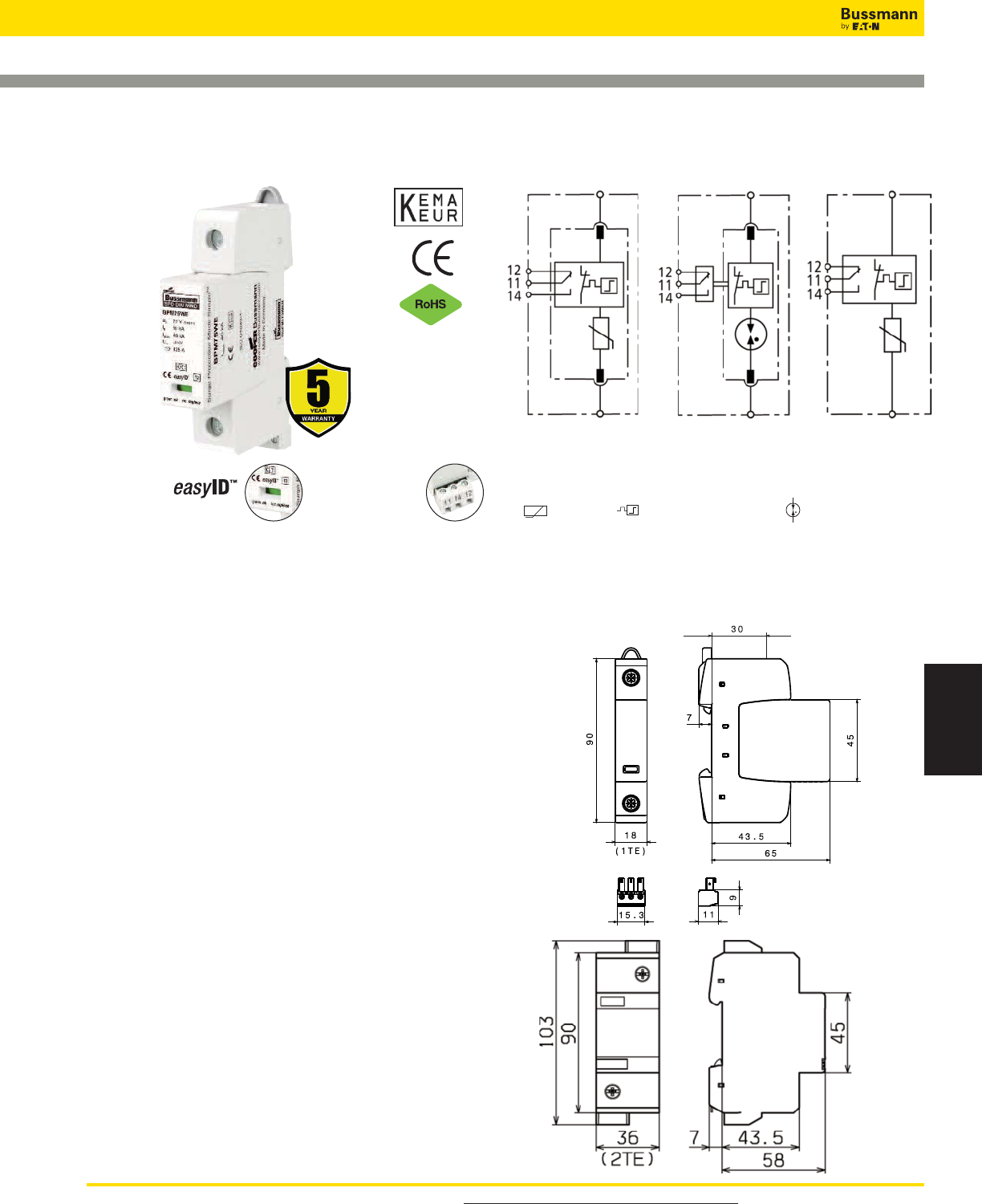
For product data sheets, visit www.cooperbussmann.com/DatasheetsEle 485
Surge Protection
Devices
Overvoltage Devices
Wind IEC Class II DIN-Rail SPD
BSPM_ _ _ _WE, BSPS_ _ _ _WE
Description
The Bussmann IEC Class II 75, 230, 400, 690 and 1000V, one-pole,
modular surge arresters feature local, easyID™ visual indication and
optional remote contact signaling. The unique module locking system
on the 75 to 690V arresters fixes the protection module to the base
part. Modules can be easily replaced without tools by simply
depressing the release buttons. Integrated mechanical coding
between the base and protection module ensures against installing
an incorrect replacement module.
TN System Arresters (also 1-Phase TT systems)
The features of these single-pole devices are for use as a single
device or in combination with other devices.
TT System Arrester
Provides a current arresting means between neutral conductor and
protective conductor in TT systems, this device helps ensure fulfilling
the requirements for protection of personnel and equipment in “3+1”
and “1+1” circuits.
Remote Signaling Contact
The three-pole terminal remote signaling contact versions have a
floating changeover contact for use as a break or make contact,
according to circuit concept.
BSPM175WE*
BSPM1400WE
BSPM1690WE
BSPM11000WE*BSPG1230WE*
Module Circuit Diagrams - Shown with optional remote
contact signaling
Dimensions - mm
Remote Signal
Contact Available
Visual Status Indication MOV Thermal Disconnector Gas Discharge Tube (single)
Shown with
optional remote
contact signaling
75 to 690V
Arresters
1000V Arrester
Data Sheet: 2092
*For remote signaling contact, add “R” suffix to the part number,
E.g., BSPM175WER
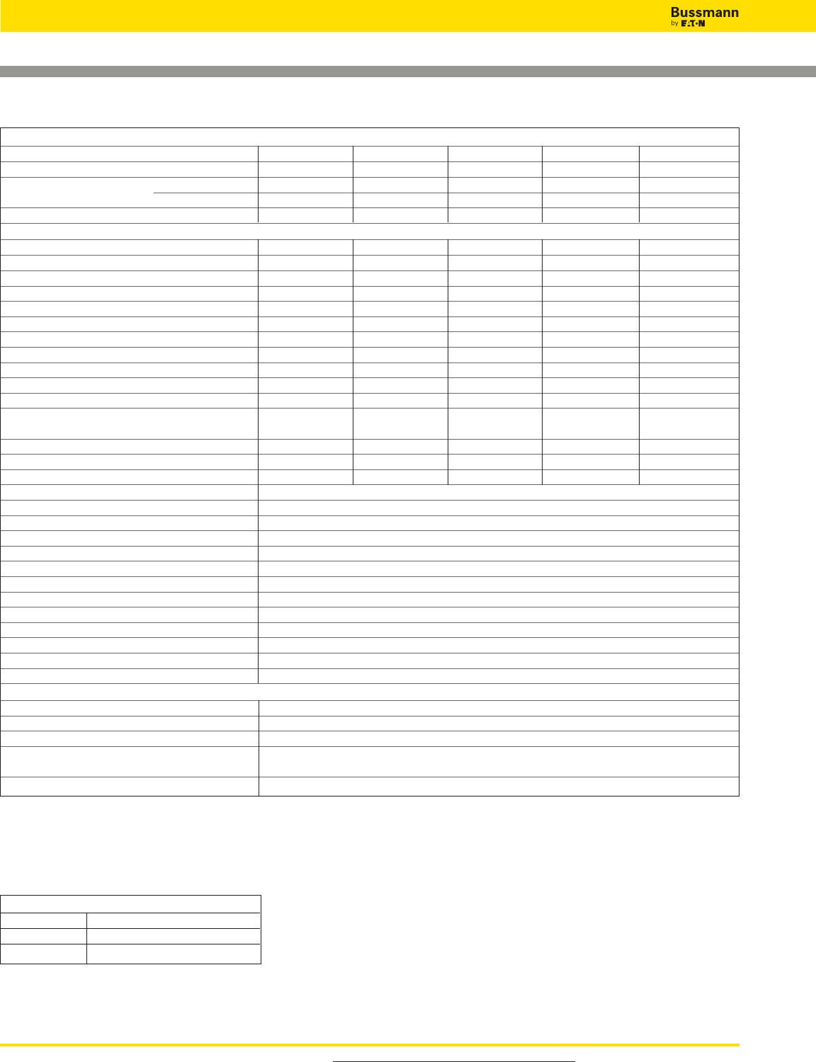
For product data sheets, visit www.cooperbussmann.com/DatasheetsEle
486
Overvoltage Devices
Wind IEC Class II DIN-Rail SPD
Ordering Information
System Voltage/Poles 75V/1 230V/1 400V/1 690V/1 1000V/1
Max. Continuous operating AC voltage (MCOV) [UC] 75V 255V 440V 600V 1000V
Catalog Numbers: Without Remote Signaling BSPM175WE BSPG1230WE BSPM1400WE BSPM1690WE BSPM11000WE
(Base + Modules) With Remote Signaling BSPM175WER BSPG1230WER BSPM1400WER BSPM1690WER BSPM11000WER
Replacement Modules BPM75WE BPG255NPEWE* BPM440WE BPM750WE N/A
Specifications
Line System Type TN / TT TT TN / TT TN / TT TN / TT
Max. Continuous Operating DC Voltage [UC] 100V - - 585 600V 1000V
Rated Varistor Voltage AC [Umov] - - - - - - 750V 1000V
Nominal Discharge Current (8/20 μs) [In] 10kA 20kA 20kA 15kA 15kA
Max. Discharge Current (8/20 μs) [Imax] 40kA 40kA 40kA 25kA 30kA
Follow Current Extinguishing Capability [Ifi] - - 100 Arms - - - - - -
Lightning Impulse Current (10/350 μs) [Iimp] - - 12kA - - - - - -
Voltage Protection Level [UP]_< 0.4kV _< 1.5kV _< 2.0kV _< 3kV _< 4.2kV
Voltage Protection Level at 5kA [UP]_< 0.35kV - - _< 1.7kV _< 2.5kV _< 3.5kV
Response Time [tA]_< 25 ns _< 100 ns _< 25 ns _< 25 ns _< 25 ns
Max. Mains-side Overcurrent Protection 125A gL/gG - - 125A gL/gG 100A gL/gG 100A aM**
Short-Circuit Withstand Capability for 50kArms - - 25kArms 25kArms 25kArms
Max. Mains-side Overcurrent Protection
Temporary Overvoltage (TOV) [UT] 90V / 5 sec. 1200V / 200ms 580V / 5 sec. 900V / 5 sec. 1000V / 5 sec.
Standards Information KEMA, CSA KEMA KEMA, CSA KEMA, CSA - -
Capacity 1 Mod., DIN 43880 1 Mod., DIN 43880 1 Mod., DIN 43880 1 Mod., DIN 43880 2 Mod., DIN 43880
SPD According to EN 61643-11 Type 2
SPD According to IEC 61643-1 Class II
TOV Characteristics Withstand
Operating Temperature Range [TU] -40°C to +80°C
Operating State/Fault Indication Green (good) / Red (replace)
Number of Ports 1
Cross-Sectional Area (min.) 1.5mm2/14AWG solid/flexible
Cross-Sectional Area (max.) 35mm2/2AWG stranded-25mm2/4AWG flexible
Mounting 35mm DIN rail per EN 60715
Enclosure Material Thermoplastic, UL 94V0
Location Category Indoor
Degree of Protection IP20
Product Warranty Five Years***
Remote Contact Signaling
Remote Contact Signaling Type Changeover Contact
AC Switching Capacity (Volts/Amps) 250V/0.5A
DC Switching Capacity (Volts/Amps) 250V/0.1A; 125V/0.2A; 75V/0.5A
Conductor Ratings and Cross-Sectional Area for 60/75°C Max. 1.5mm2/14AWG Solid/Flexible
Remote Contact Signal Terminals
Ordering Information Order from Catalog Numbers Above
* N-PE Surge arrester for location between neutral conductor and protective conductor in TT systems.
** 125A gL/gG @ 690Vac.
*** See Bussmann SPD Limited Warranty Statement (3A1502) for details at www.cooperbussmann.com/surge.
Recommended Bussmann Back Up Fuses
DIN Fuse Size NH Fuse Part Number
00 100NHG00B-690
00 125NHG00B-690
Data Sheet: 2092
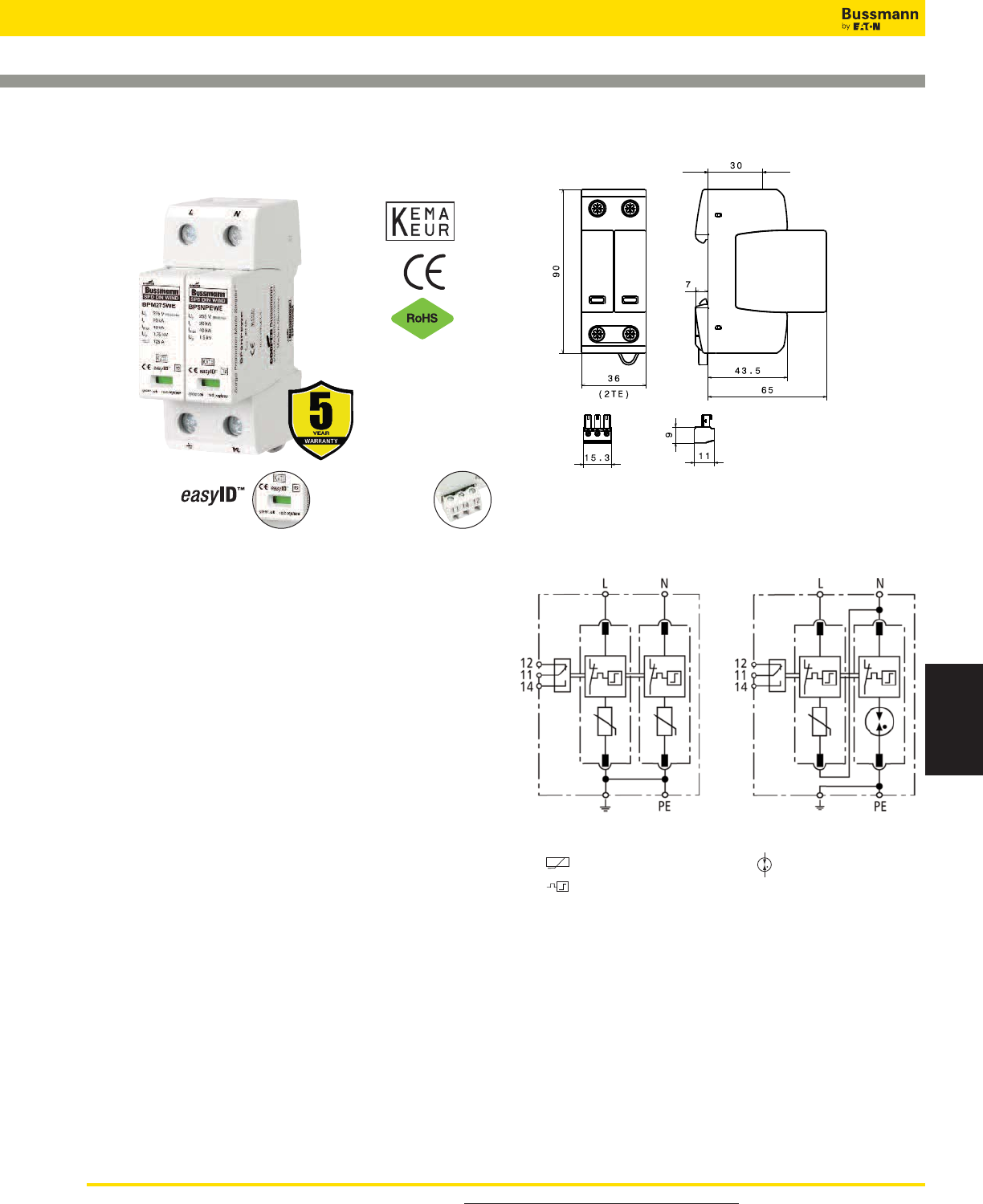
For product data sheets, visit www.cooperbussmann.com/DatasheetsEle 487
Surge Protection
Devices
Overvoltage Devices
Wind IEC Class II DIN-Rail SPD
BSPM_ _ _ _WE, BSPH_ _ _ _WE
Description
The Bussmann IEC Class II 230V, two-pole, modular surge
arresters feature local, easyID™ visual indication and
optional remote contact signaling. The unique module locking
system fixes the protection module to the base part. Modules
can be easily replaced without tools by simply depressing the
release buttons. Integrated mechanical coding between the
base and protection module ensures against installing an
incorrect replacement module.
TN System Arrester
The features of these two-pole device are for use as a single
device.
TT System Arrester
For use as a single device in a 1-phase TT system.
Remote Signaling Contact
The three-pole terminal remote signaling contact versions
have a floating changeover contact for use as a break or
make contact, according to circuit concept.
BSPM2230WE* BSPH2230WE*
Shown with optional remote contact signaling
Module Circuit Diagrams - Shown with optional remote
contact signaling
Dimensions - mm
Remote Signal
Contact Available
Visual Status Indication
MOV
Thermal Disconnector
Gas Discharge Tube (single)
Data Sheet: 2093
*For remote signaling contact, add “R” suffix to the part number,
E.g., BSPM2230WER
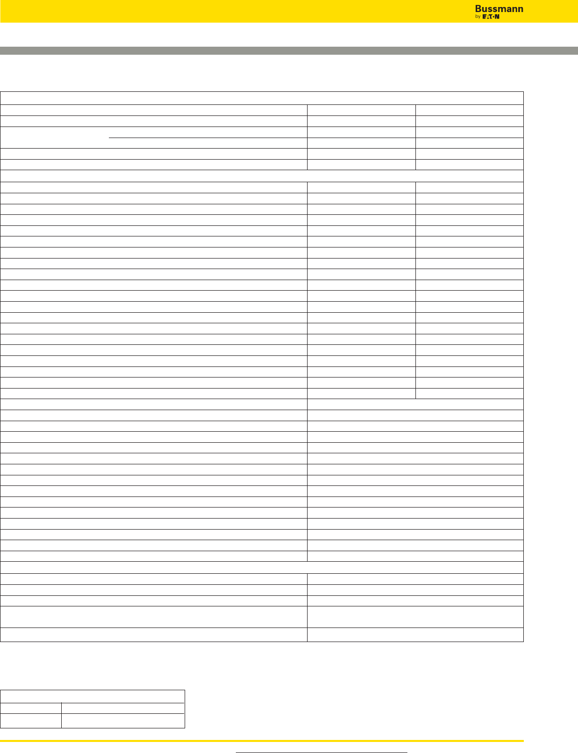
For product data sheets, visit www.cooperbussmann.com/DatasheetsEle
488
Overvoltage Devices
Wind IEC Class II DIN-Rail SPD
Ordering Information
System Voltage/Poles 230V/2 230V/2
Max. Continuous operating AC voltage (MCOV) [UC] 275V 275 / 255V
Catalog Numbers: Without Remote Signaling BSPM2230WE BSPH2230WE
(Base + Modules) With Remote Signaling BSPM2230WER BSPH2230WER
Replacement Modules MOV BPM275WE BPM275WE
Spark Gap - - BPSNPEWE*
Specifications
Line System Type TN TT
Max. Continuous Operating AC Voltage [L-N] [UC] - - 275V
Max. Continuous Operating AC Voltage [N-PE] [UC] - - 255V
Nominal Discharge Current (8/20 μs)[In] 20kA 20kA
Max. Discharge Current (8/20 μs)[Imax] 40kA 40kA
Lightning Impulse Current (10/350 μs) [N-PE] [Iimp] - - 12kA
Voltage Protection Level [UP]_< 1.25kV - -
Voltage Protection Level at 5kA [UP]_< 1kV - -
Voltage Protection Level [L-N] [UP]- -_< 1.25kV
Voltage Protection Level [L-N] at 5kA [UP]- -_< 1kV
Voltage Protection Level [N-PE] [UP]- -_< 1.5kV
Follow Current Extinguishing Capability [N-PE] [Ifi] - - 100Arms
Response Time [L-N] [tA]- -_< 25 ns
Response Time [N-PE] [tA]- -_< 100 ns
Response Time [tA]_< 25 ns - -
Max. Mains-side Overcurrent Protection 125A gL/gG 125A gL/gG
Short-circuit Withstand Capability for Max. Mains-side Overcurrent Protection 50kArms 50kArms
Temporary Overvoltage (TOV) [UT] 335 V / 5 sec. - -
Temporary Overvoltage (TOV) [L-N] [UT] - - 335V / 5 sec.
Temporary Overvoltage (TOV) [N-PE] [UT] - - 1200V / 200 ms
SPD According to EN 61643-11 Type 2
SPD According to IEC 61643-1 Class II
TOV Characteristics Withstand
Operating Temperature Rrange [TU] -40°C to +80°C
Operating State/Fault Indication Green (good) / Red (replace)
Number of Ports 1
Cross-sectional Area (min.) 1.5mm2/14AWG solid/flexible
Cross-sectional Area (max.) 35mm2/2AWG stranded-25mm2/4AWG flexible
Mounting 35mm DIN rail per EN 60715
Enclosure Material Thermoplastic, UL 94V0
Location Category Indoor
Degree of Protection IP20
Capacity 2 Mods., DIN 43880
Standards Information KEMA
Product Warranty Five Years**
Remote Contact Signaling
Remote Contact Signaling Type Changeover Contact
AC Switching Capacity (Volts/Amps) 250V/0.5A
DC Switching Capacity (Volts/Amps) 250V/0.1A; 125V/0.2A; 75V/0.5A
Conductor Ratings and Cross-Sectional Area for 60/75°C Max. 1.5mm2/
Remote Contact Signal Terminals 14AWG Solid/Flexible
Ordering Information Order from Catalog Numbers Above
* N-PE Surge arrester for location between neutral conductor and protective conductor in TT systems.
** See Bussmann SPD Limited Warranty Statement (3A1502) for details at www.cooperbussmann.com/surge.
Recommended Bussmann Back Up Fuse
DIN Fuse Size NH Fuse Part Number
00 125NHG00B Data Sheet: 2093
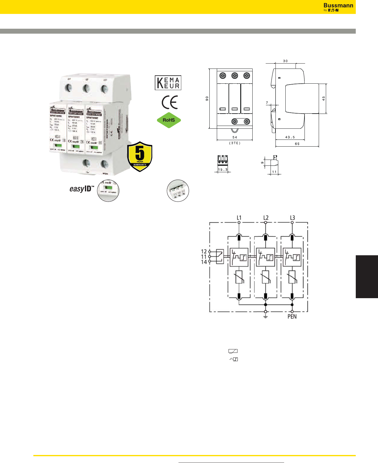
For product data sheets, visit www.cooperbussmann.com/DatasheetsEle 489
Surge Protection
Devices
Overvoltage Devices
Wind IEC Class II DIN-Rail SPD
BSPM_ _ _ _WE
Specifications
Description
The Bussmann IEC Class II 230, 400 and 690V three-pole,
modular surge arresters feature local, easyID™ visual
indication and optional remote contact signaling. The unique
module locking system fixes the protection module to the
base part. Modules can be easily replaced without tools by
simply depressing the release buttons. Integrated mechanical
coding between the base and protection module ensures
against installing an incorrect replacement module.
TNC System Arresters
The features of these three-pole devices are for use as a
single device.
Remote Signaling Contact
The three-pole terminal remote signaling contact versions
have a floating changeover contact for use as a break or
make contact, according to circuit concept. BSPM3230WE
BSPM3400WE
BSPM3690WE
Shown with optional remote contact signaling
Module Circuit Diagrams - Shown with optional remote
contact signaling
Dimensions - mm
Remote Signal
Contact Available
Visual Status Indication
MOV
Thermal Disconnector
Data Sheet: 2094
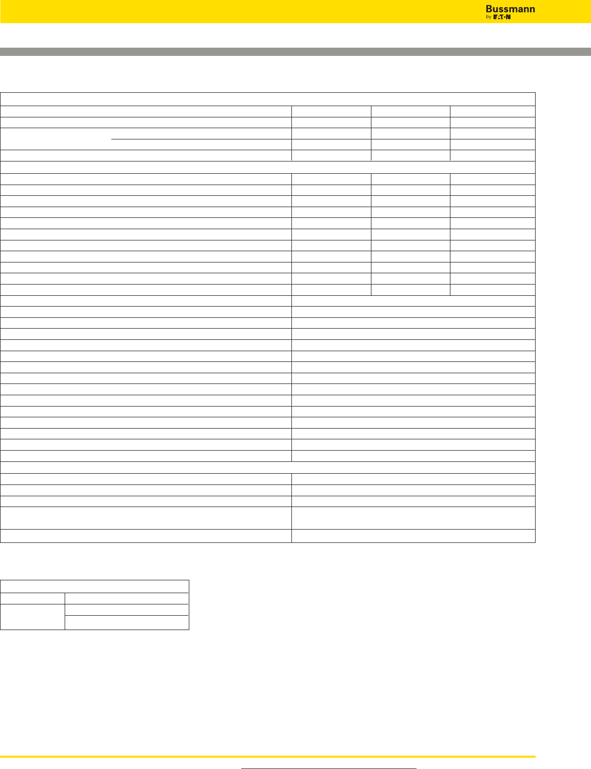
For product data sheets, visit www.cooperbussmann.com/DatasheetsEle
490
Overvoltage Devices
Wind IEC Class II DIN-Rail SPD
Ordering Information
System Voltage/Poles 230V/3 400V/3 690V/3
Max. Continuous operating AC voltage (MCOV) [UC] 275V 440V 600V
Catalog Numbers: Without Remote Signaling BSPM3230WE BSPM3400WE BSPM3690WE
(Base + Modules) With Remote Signaling BSPM3230WER BSPM3400WER BSPM3690WER
Replacement Modules BPM275WE BPM440WE BPM750WE
Specifications
Line System Type TNC TNC TNC
Nominal AC Voltage [UN] 230/400V 400/690V 600V
Rated Varistor Voltage [Umov] 275V 440V 750V
Nominal Discharge Current (8/20 μs) [In] 20kA 20kA 15kA
Max. Discharge Current (8/20 μs) [Imax] 40kA 40kA 25kA
Voltage Protection Level [UP]_<1.25kV _< 2kV _<3kV
Voltage Protection Level at 5kA [UP]_<1kV _< 1.7kV _<2.5kV
Response Time [tA]_<25 ns _< 25 ns _<25 ns
Max. Mains-side Overcurrent Protection 125A gL/gG 125A gL/gG 100A gL/gG
Short-circuit Withstand Capability for Max. Mains-side Overcurrent Protection 50kArms 25kArms 25kArms
Temporary Overvoltage (TOV) [UT] 335V / 5 sec. 580V / 5 sec. 900V / 5 sec.
SPD According to EN 61643-11 Type 2
SPD According to IEC 61643-1 Class II
TOV Characteristics Withstand
Operating Temperature Range [TU] -40°C to +80°C
Operating State/Fault Indication Green (good) / Red (replace)
Number of Ports 1
Cross-Sectional Area (min.) 1.5mm2/14AWG solid/flexible
Cross-Sectional Area (max.) 35mm2/2AWG stranded-25mm2/4AWG flexible
Mounting 35mm DIN rail per EN 60715
Enclosure Material Thermoplastic, UL 94V0
Location Category Indoor
Degree of Protection IP20
Capacity 3 Mods., DIN 43880
Standards Information KEMA
Product Warranty Five Years*
Remote Contact Signaling
Remote Contact Signaling Type Changeover Contact
AC Switching Capacity (Volts/Amps) 250V/0.5A
DC Switching Capacity (Volts/Amps) 250V/0.1A; 125V/0.2A; 75V/0.5A
Conductor Ratings and Cross-Sectional Area for 60/75°C Max. 1.5mm2/14AWG Solid/Flexible
Remote Contact Signal Terminals
Ordering Information Order from Catalog Numbers Above
* See Bussmann SPD Limited Warranty Statement (3A1502) for details at www.cooperbussmann.com/surge.
Recommended Bussmann Back Up Fuse
DIN Fuse Size NH Fuse Part Number
00 100NHG00B-690
125NHG00B-690
Data Sheet: 2094
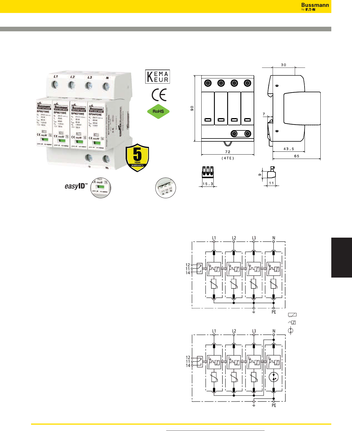
For product data sheets, visit www.cooperbussmann.com/DatasheetsEle 491
Surge Protection
Devices
Overvoltage Devices
Wind IEC Class II DIN-Rail SPD
BSPM_ _ _ _WE, BSPH_ _ _ _WE
BSPH4230WE
Shown with optional remote contact signaling
Circuit Diagrams - Shown with optional remote contact
signaling
Dimensions - mm
Remote Signal
Contact Available
Visual Status Indication
Specifications
Description
The Bussmann IEC Class II 230/400V, four-pole, modular
surge arresters feature local, easyID™ visual indication and
optional remote contact signaling. The unique module locking
system fixes the protection module to the base part. Modules
can be easily replaced without tools by simply depressing the
release buttons. Integrated mechanical coding between the
base and protection module ensures against installing an
incorrect replacement module.
These 230V models are offered with MCOV ratings of 275V.
TNS System Arrester
The features of these four-pole devices are for use in TNS
230/400V systems (“4-0” circuit) against surges.
TT System Arrester
The features of these four-pole devices are for use in TT and
TN-S 230/400V systems (“3+1” circuit) against surges.
Remote Signaling Contact
The three-pole terminal remote signaling contact versions
have a floating changeover contact for use as a break or
make contact, according to circuit concept.
MOV
Thermal Disconnector
Gas Discharge Tube
(single)
Data Sheet: 2095
BSPM4230WE
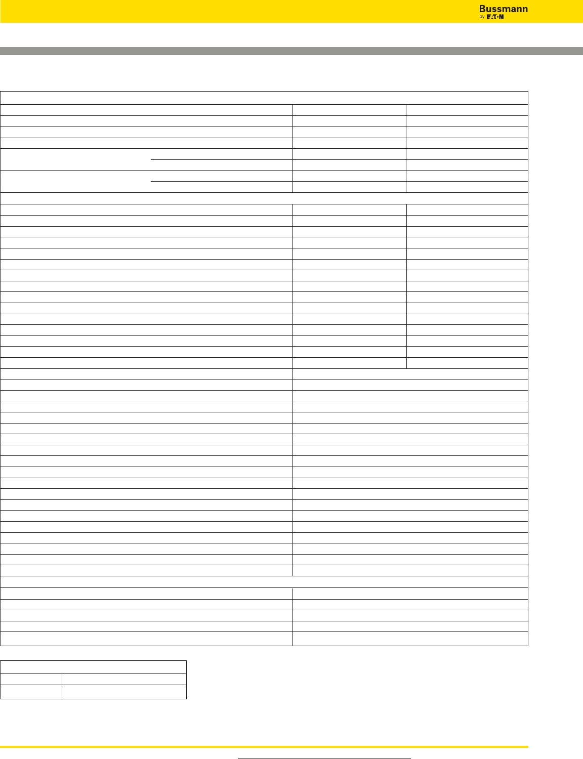
For product data sheets, visit www.cooperbussmann.com/DatasheetsEle
492
Overvoltage Devices
Wind IEC Class II DIN-Rail SPD
ORDERING INFORMATION
System Voltage/Poles 230/400V/4 230/400V/4
Max. continuous operating AC voltage (MCOV) [UC] 275V - -
Max. continuous operating AC voltage (MCOV) [L-N] [UC] - - 275V
Max. continuous operating AC voltage [N-PE] [UC] - - 255V
Catalog Numbers: Without Remote Signaling BSPM4230WE BSPH4230WE
With Remote Signaling BSPM4230WER BSPH4230WER
Replacement Modules: MOV technology BPM275WE BPM275WE
Spark Gap technology - - BPSNPEWE*
SPECIFICATIONS
Line System Type TNS TT / TNS
Nominal AC voltage [UN] 230/400V 230/400V
Lightning impulse current (10/350 μs) [N-PE] [Iimp] - - 12kA
Voltage protection level [UP]<_ 1.25kV - -
Voltage protection level at 5kA [UP]<_ 1kV - -
Voltage protection level [L-N] [UP]- -<_ 1.25kV
Voltage protection level [L-N] at 5kA [UP]- -<_ 1kV
Voltage protection level [N-PE] [UP]- -<_ 1.5kV
Follow current extinguishing capability [N-PE] [Ifi]- -100A
rms
Response time [tA]<_ 25 ns - -
Response time [L-N] [tA]- -<_ 25 ns
Response time [N-PE] [tA]- -<_ 100 ns
Temporary overvoltage (TOV) [UT] 335V / 5 sec. - -
Temporary overvoltage (TOV) [L-N] [UT] - - 335V / 5 sec.
Temporary overvoltage (TOV) [N-PE] [UT] - - 1200V / 200 ms
SPD according to EN 61643-11 Type 2
SPD according to IEC 61643-1 Class II
Nominal discharge current (8/20 μs) [In] 20kA
Max. discharge current (8/20 μs) [Imax] 40kA
Max. mains-side overcurrent protection 125A gL/gG
Short-circuit withstand capability for max. mains-side overcurrent protection 50kA rms
TOV characteristics withstand
Operating temperature range [TU] -40°C to +80°C
Operating state/fault indication green (good)/red (replace)
Number of ports 1
Cross-sectional area (min.) 1.5mm2/14AWG solid/flexible
Cross-sectional area (max.) 35mm2/2AWG stranded-25mm2/4AWG flexible
Mounting 35mm DIN rail per EN 60715
Enclosure material Thermoplastic, UL 94V0
Location category Indoor
Degree of protection IP20
Capacity 4 Mods., DIN 43880
Standards Information KEMA
Product Warranty Five Years**
REMOTE CONTACT SIGNALING
Remote Contact Signaling Type Changeover Contact
AC Switching Capacity (Volts/Amps) 250V/0.1A
DC Switching Capacity (Volts/Amps) 250V/0.1A; 125V/0.2A; 75V/0.5A
Conductor Ratings and Cross-Sectional Area for Remote Contact Signal Terminals 60/75°C Max. 1.5mm2/14AWG Solid/Flexible
Ordering Information Order from Catalog Numbers Above
* N-PE Surge arrester module for location between neutral conductor and protective conductor in TT systems.
** See Bussmann SPD Limited Warranty Statement (3A1502) for details at www.cooperbussmann.com/surge.
Recommended Bussmann Back Up Fuse
DIN Fuse Size NH Fuse Part Number
00 125NHG00B
Data Sheet: 2095
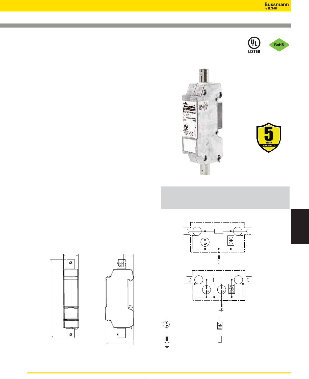
For product data sheets, visit www.cooperbussmann.com/DatasheetsEle 493
Surge Protection
Devices
Surge Protection Made Simple™ for Coaxial Data Cables
UL Listed 497B DIN-Rail Mount Surge Protective Device for BNC Connector Cable
Systems
BSPD5BNCDD
BSPD5BNCDI
Protected
side
Protected
side
100.08
19.00
35.50
12.70
Circuit Diagrams
DIN-Rail Mount SPD
for BNC Coax
Description
The Bussmann BSPD5BNCDD and BSPD5BNCDI two-stage
DIN-Rail mounted surge arresters are for protecting coaxial
cable-connected systems (such as video and camera
systems) from potential damage. The BSPD5BNCDD features
direct (VCD) shield connection while the BSPD5BNCDI
features indirect shield connection (VCID) to prevent leakage
pickups.
The BSPD5BNCDD and BSPD5BNCDI shielded surge
arresters are mounted on the supplied bracket with cable lug
or mounted on a rack mounted DIN-Rail with suitable
grounding. BNC connector terminated data or video signal
cables are plugged into surge arrester with the equipment
plugged into the protected side.
Common applications include protecting outdoor video
surveillance systems or video control centers or coaxial data
lines. For BSPD5BNCDI, the cable shield is indirectly
grounded via a gas discharge tube to avoid being influenced
by leakage pickups.
• UL 497B Listed
• Plug-in surge protective device for easy retrofitting
• The space-saving surge arrester with BNC socket is mounted
on supplied rail terminal lug or standard 35mm DIN-Rail
• Integrated direct or indirect shield grounding avoids leakage
pickups
• Easily adaptable due to BNC sockets
Dimensions-mm Direct Shield
BSPD5BNCDD
Indirect Shield
BSPD5BNCDI
Gas Discharge Tube Bi-Polar Suppressor Diode
Pluggable Earthing Contact Decoupling Resistor
Overvoltage Devices
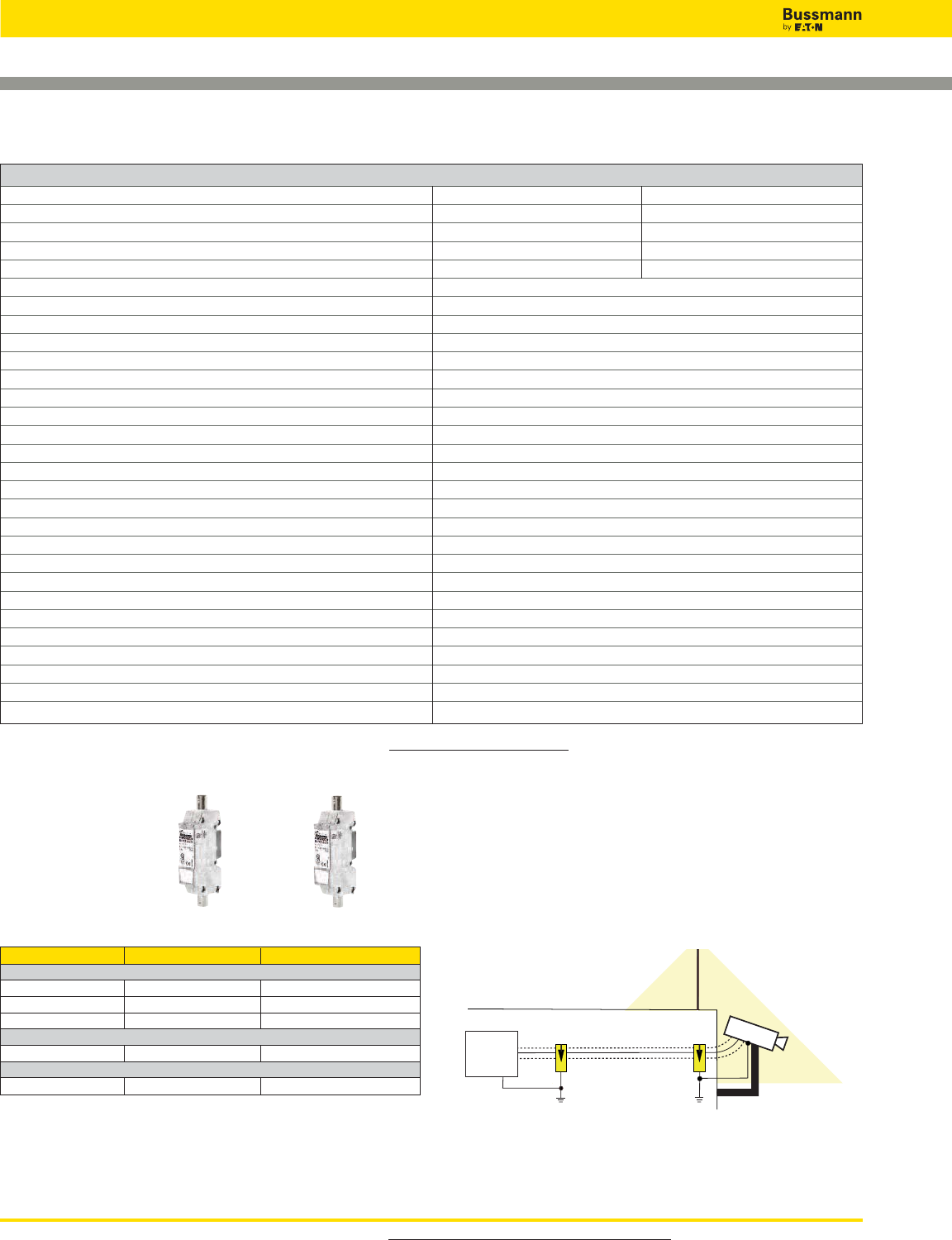
For product data sheets, visit www.cooperbussmann.com/DatasheetsEle
494
Overvoltage Devices
Technical Data
Catalog Number BSPD5BNCDD BSPD5BNCDI
Return loss at 300MHz ≥8dB≥10dB
Capacitance shield-PG (C) — ≤20pF
Voltage protection level shield-PG for InC2 (Up) — ≤650V
Voltage protection level shield-PG at 1kV/μs C3 (Up) — ≤600V
Nominal voltage (UN)5V
Max. continuous operating DC voltage (UC)6.4V
Nominal current (IL) 0.1A
C2 Nominal discharge current (8/20μs) shield-PG (In) 10kA
C2 Nominal discharge current (8/20μs) line-shield (In) 5kA
Voltage protection level line-shield for InC2 (Up) ≤35V
Voltage protection level line-shield at 1kV/μs C3 (Up) ≤13V
Frequency range 0-300MHz
Insertion loss at 160MHz ≤0.4dB
Insertion loss at 300MHz ≤3dB
Return loss at 130MHz ≥20dB
Impedance (Z) 50Ω
Series impedance per line 4.7Ω
Capacitance line-shield (C) ≤25pF
Operating temperature range -40°C to +80°C
Degree of protection IP10
For mounting on 35mm DIN-Rails per EN 60715
Connection (input / output) BNC Socket (female) / BNC Socket (female)
Grounding Via 35mm DIN-Rail per EN 60715
Enclosure material Zinc die casting
Color Bare surface
Test standards IEC 61643-21 / EN 61643-21
Agency Information UL 497B
Warranty 5 Years*
Part Numbers BSPD5BNCDD BSPD5BNCDI
Bus Systems and Measuring, and Control Technology
Control Net X X
Melsec Net 2 X X
N1 LAN X X
Data Networks
Arcnet X X
Video Systems
Video (coax) X X
DIN-Rail BNC SPD Applications
Direct vs. Indirect Shielding - Application Example
Apply the BSPD5BNCDD (direct shield) at the equipment
location and apply the BSPD5BNCDI (indirect shield) near
exterior protected equipment. The indirect shield grounding at
the exterior device will help avoid picking up leakage currents
that can degrade signal quality while providing surge
protection when needed. See illustration below for installation
locations.
* See Bussmann SPD Limited Warranty Statement (3A1502) for details at www.cooperbussmann.com/Surge.
LPZ 0B
LPZ 1
LPZ 2 coaxial
Video
system
IEC 62305-4
protective angle
protected
side
BSPD5BNCDI
BSPD5BNCDD
protected
side
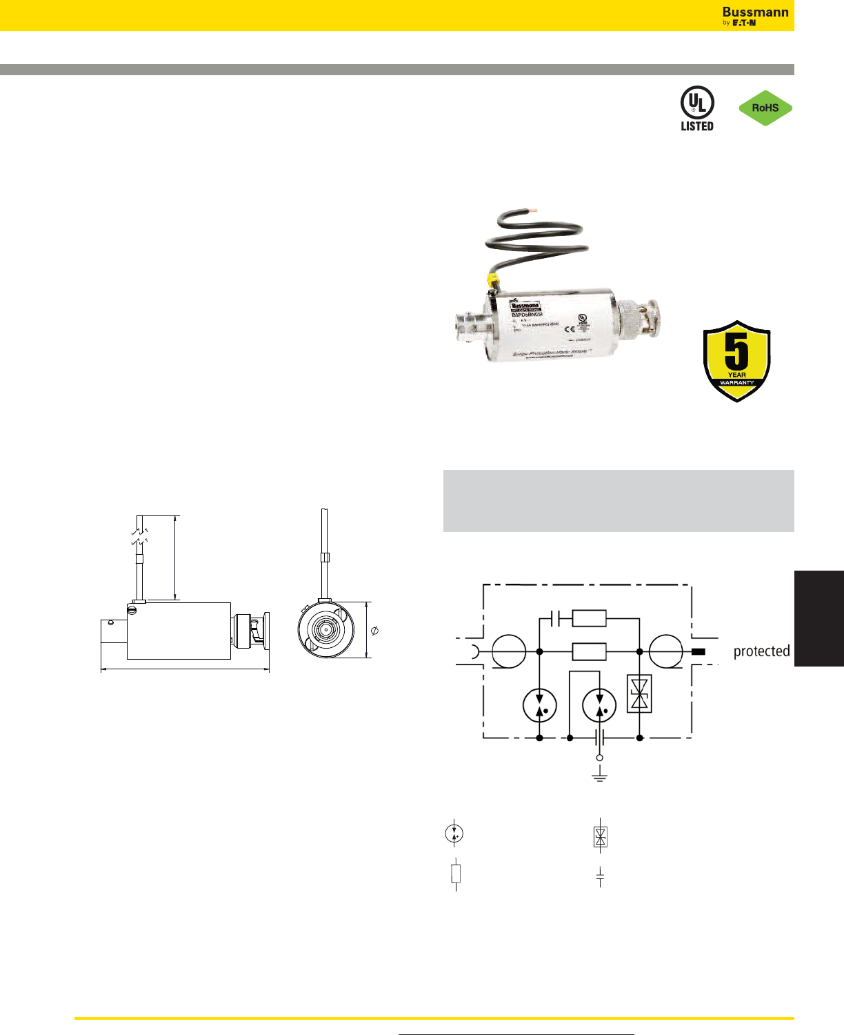
For product data sheets, visit www.cooperbussmann.com/DatasheetsEle 495
Surge Protection
Devices
Overvoltage Devices
Surge Protection Made Simple™ for Coaxial Data Cables
UL Listed 497B In-line Surge Protective Device for BNC Connector Cable Systems
BSPD5BNCSI
74.00
300.00 APPROX
24.00
Circuit Diagram
In-line SPD for BNC Coax
Description
The Bussmann BSPD5BNCSI two-stage in-line surge arrester
is for protecting coaxial cable-connected systems (such as
video and camera systems) from potential damage.
The BSPD5BNCSI shielded surge arrester is plugged into
coaxial terminal equipment or connections. Common
applications include protecting outdoor video surveillance
systems or video control centers. The cable shield is indirectly
grounded via a gas discharge tube to avoid being influenced
by leakage pickups. The arrester input is used as a socket and
the protected output as a plug.
• UL 497B Listed
• Plug-in surge protective device for easy retrofitting
• Directly plugs into terminal equipment with BNC coaxial
connections
• Integrated indirect shield grounding avoids leakage pickups
Dimensions-mm
Gas Discharge Tube Bi-Polar Suppressor Diode
Decoupling Resistor Capacitor
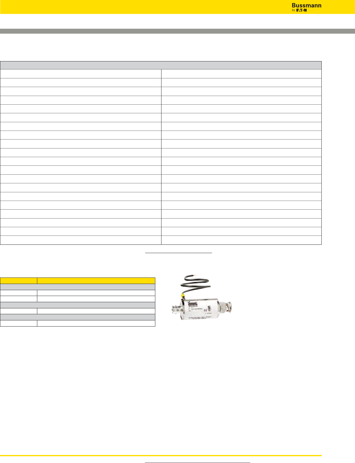
For product data sheets, visit www.cooperbussmann.com/DatasheetsEle
496
Overvoltage Devices
TECHNICAL DATA
Catalog Number BSPD5BNCSI
Nominal voltage (UN)5V
Max. continuous operating DC voltage (UC)8V
C2 Nominal discharge current (8/20μs) per line (In) 2.5kA
C2 Nominal discharge current (8/20μs) shield-PG (In) 10kA
Voltage protection level line-shield for InC2 (Up) ≤25V
Voltage protection level line-shield at 1kV/μs C3 (Up) ≤15V
Voltage protection level shield-PG at 1kV/μs C3 (Up) ≤600V
Insertion loss at 265MHz ≤3dB
Return loss at 40MHz ≥20dB
Impedance (Z) 75Ω
Series impedance per line 10Ω
Capacitance line-shield (C) ≤50pF
Operating temperature range -40°C to +80°C
Connection (input / output) BNC Socket (female) / BNC Plug (male)
Grounding Via outgoing earth conductor 18AWG (0.75mm2)
Shield grounding Indirectly via an integrated spark gap element
Test standards IEC 61643-21 / EN 61643-21
Agency information UL 497B
Warranty 5 Years*
Part Number BSPD5BNCSI
Bus Systems and Measuring & Control Technology
Control Net X
Melsec Net 2 X
Data Networks
Arcnet X
Video Systems
Video (coax) X
In-line BNC SPD Applications
* See Bussmann SPD Limited Warranty Statement (3A1502) for details at www.cooperbussmann.com/Surge.
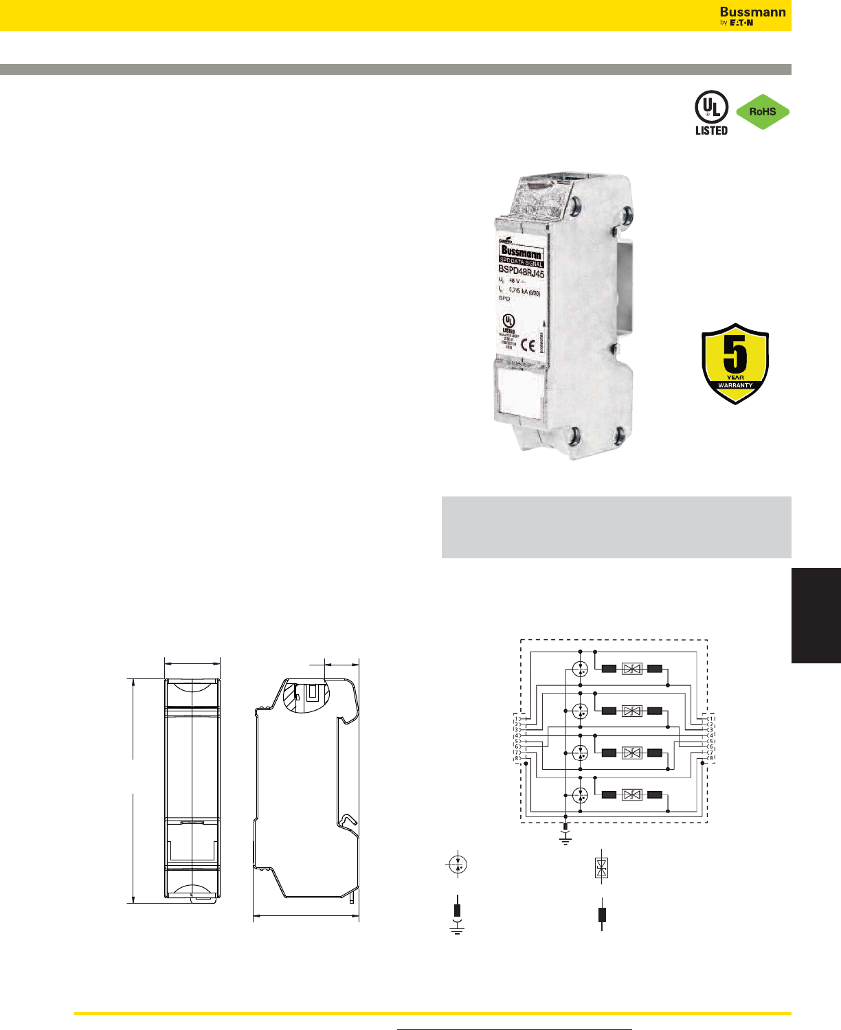
For product data sheets, visit www.cooperbussmann.com/DatasheetsEle 497
Surge Protection
Devices
BSPD48RJ45
76.91
19.00 11.72
36.15
Circuit Diagram
DIN-Rail Mount SPD
for RJ45 / Ethernet Connection
Description
The Bussmann DIN-Rail mount BSPD48RJ45 Surge
Protective Device (SPD) for Ethernet cable systems with RJ
connectors is easy to install in new, or retrofitting into
existing, installations.
The BSPD48RJ45 is installed between the patch panel and
the active component (a switch for example). The snap-in
mechanism of the supporting foot allows the SPD to be safely
grounded via the DIN-Rail. For single applications, the
BSPD48RJ45 comes with a supplied mounting bracket with
cable lug.
Fulfilling the requirements of Category 6, the BSPD48RJ45
can be universally used for all data services up to nominal
voltages of 48V. It is well suited for existing services such as
Gigabit Ethernet, ATM, ISDN, Voice over IP and Power over
Ethernet (PoE+ acc. to IEEE 802.3at up to 57V) and similar
applications in structured cabling systems according to Class
E up to 250MHz. Protection of all pairs by means of powerful
gas discharge tubes and one adapter filter matrix per pair.
• UL 497B Listed
• Easy to install or retrofit for protection of all lines
• CAT 6 according to ISO/IEC 11801
• CAT 6 in the channel (Class E)
• Power over Ethernet (PoE+ according to IEEE 802.3at)
Dimensions -mm
Balanced Gas
Discharge Tube Bipolar Suppressor Diode
Inductor
Surge Protection Made Simple™ for Ethernet Data Cables
UL Listed 497B Universal DIN-Rail Mount Surge Protective Device for RJ45/Ethernet Cable
Systems
Pluggable Earthing Contact
Overvoltage Devices
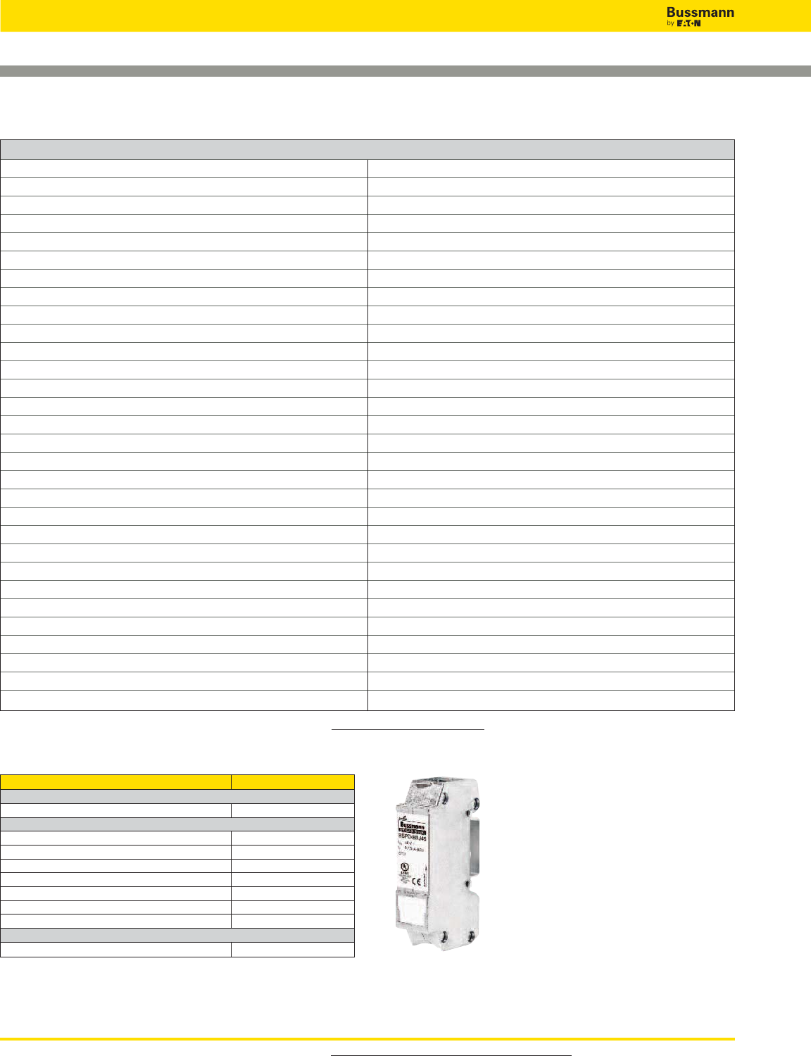
For product data sheets, visit www.cooperbussmann.com/DatasheetsEle
498
Overvoltage Devices
TECHNICAL DATA
Catalog Number BSPD48RJ45
Nominal voltage (UN) 48V
Max. continuous operating DC voltage (UC) 48V
Max. continuous operating AC voltage (UC) 34V
Max. continuous DC voltage pair-pair (PoE) (UC) 57V
Nominal current (IL)1A
C2 Nominal discharge current (8/20μs) line-line (In) 150A
C2 Nominal discharge current (8/20μs) line-PG (In)2.5kA
C2 Total nominal discharge current (8/20μs) line-PG (In) 10kA
C2 nominal discharge current (8/20μs) pair-pair (PoE) (In) 150A
Voltage protection level line-line for InC2 (UP) ≤190V
Voltage protection level line-PG for InC2 (UP) ≤600V
Voltage protection level line-line for InC2 (PoE) (UP) ≤600V
Voltage protection level line-line at 1kV/μs C3 (UP) ≤180V
Voltage protection level line-PG at 1kV/μs C3 (UP) ≤500V
Voltage protection level pair-pair at 1kV/μs C3 (PoE) (UP) ≤600V
Insertion loss at 250MHz ≤3dB
Capacitance line-line (C) ≤30pF
Capacitance line-PG (C) ≤25pF
Operating temperature range -40°C to +80°C
Degree of protection IP10
For mounting on 35mm DIN-Rails per EN 60715
Connection (input / output) RJ45 socket / RJ45 socket
Pinning 1 / 2, 3 / 6, 4 / 5, 7 / 8
Grounding Via 35mm DIN-Rails per EN 60715
Enclosure material Zinc die casting
Color Bare surface
Test standards IEC 61643-21 / EN 61643-21
Agency information UL 497B
Warranty 5 Years*
* See Bussmann SPD Limited Warranty Statement (3A1502) for details at www.cooperbussmann.com/Surge.
Part Number BSPD48RJ45
Bus systems and Measuring, and Control Technology
Industrial Ethernet X
Data Networks
ATM X
Ethernet 10/100/1000 X
FDDI, CDDI X
Industrial Ethernet X
Power over Ethernet (PoE) X
Token Ring X
VG Any LAN X
Video Systems
Video (2 wire) X
DIN-Rail RJ45 SPDs Applications
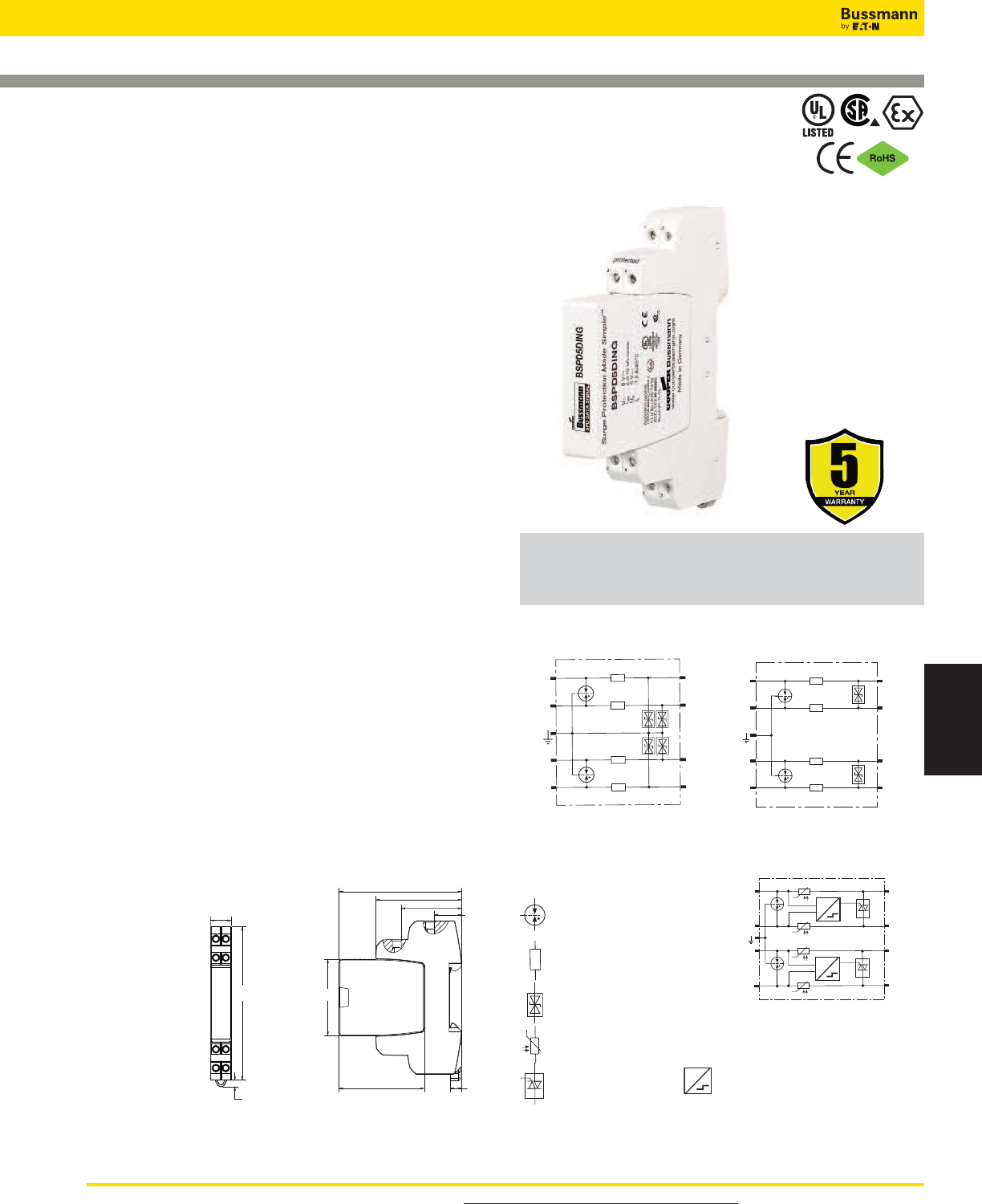
For product data sheets, visit www.cooperbussmann.com/DatasheetsEle 499
Surge Protection
Devices
Overvoltage Devices
Surge Protection Made Simple™ for Twisted Pair Data Cables
UL Listed 497B DIN-Rail Mount Universal Surge Protective Device for
Measuring and Control Circuits, and Bus Systems
Four-Pole DIN-Rail Mount Universal
SPD for Data Signal Applications
Description
The Bussmann universal four-pole, DIN-Rail mounted surge
arresters provide effective protection with minimum space
requirements and are designed for stringent requirements on the
availability of measuring and control circuits, and bus systems.
To ensure safe operation, the arresters provide protection against
vibration and shock up to a 30-fold acceleration of gravity. The
function-optimized design of the devices allows quick and easy
removal of protection modules via “make-before-break” terminals
that assure continuity of data signals in the protected and
unprotected state.
For IEC Applications - Instruction for Surge Protective Device Use
In Zone 2 Explosive Atmospheres per ATEX.
1. When installed in potentially explosive atmospheres, the Data
Signal DIN Series shall be installed into an enclosure which
meets the requirements of a recognized type of protection, in
accordance with EN 60079-0.
2. The Data Signal DIN Series as transient suppressor. This
approval applies to the following equipment types:
•BSPD5DING • BSPD12DING • BSPD24DING
•BSPD48DING • BSPD5DINLHF • BSPD24DINLHF
Ambient and Temperature Class
• -40°C to +80°C, T4:
DEKRA 12ATEX0254 X: II 3 G Ex nA IIC T4 Gc
• Standards used for:
ATEX: EN60079-0: 2009, EN 60079-15: 2005
• UL 497B Listed
• Function-optimized design for safe use and easy installation
• Four-pole and base mounts on grounded 35mm DIN-Rail
• Module removal without signal interruption via “make-before-
break” circuitry
• 0-180V BSPD0180DINL automatically adjusts to system
operating voltage and can protect data circuits of different
voltages up to 100mA load current.
Dimensions-mm
Circuit Diagrams
1
2
1´
2´
3
4
3‘
4‘
Protected
1
2
1´
2´
Protected
3
4
3´
4´
BSPD5DING
BSPD12DING
BSPD24DING
BSPD48DING
BSPD0180DINL
BSPD5DINLHF
BSPD24DINLHF
1‘
i
i
i
i
2‘
3‘
4‘
1
2
3
4
U>UN
U>UN
Protected
Bipolar Suppressor Diode
Decoupling Resistor
Transient Blocking Unit
i
Thyristor Surge Detection
U>UN
Balanced Gas
Discharge Tube
CUS
12.00
90.00
3.97
16.09
71.99
35.51
49.99 6.70
45.00
50.49
BSPD5DING
BSPD12DING
BSPD24DING
BSPD48DING
BSPD5DINLHF
BSPD24DINLHF
BSPD0180DINL
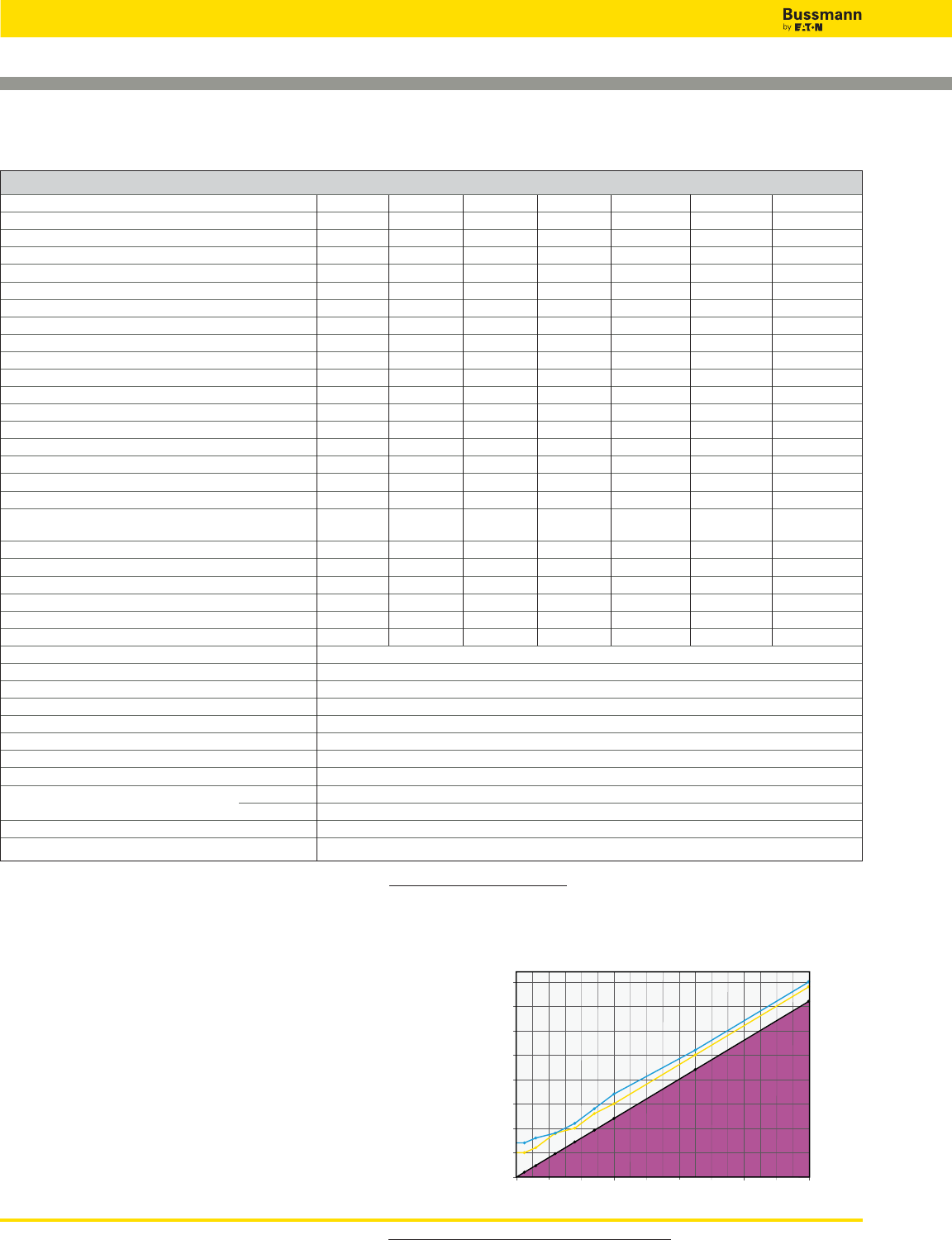
For product data sheets, visit www.cooperbussmann.com/DatasheetsEle
500
Overvoltage Devices
TECHNICAL DATA
Catalog number — Prefix: BSPD… …5DING …12DING …24DING …48DING …5DINLHF …24DINLHF …0180DINL
Nominal voltage (UN) 5V 12V 24V 48V 5V 24V 0-180V
Nominal current at 45°C (IL) 1.0A 0.75A 0.75A 0.75A 1.0A 1.0A ≤0.1A@80°C
VPL line-line for Iimp D1 (Up) ≤29V ≤50V ≤102V ≤160V ≤25V ≤65V ≤ UN+ 53V
VPL line-PG for Iimp D1 (Up) ≤27V ≤37V ≤66V ≤95V ≤550V ≤550V -
VPL line-line at 1kV/μs C3 (Up) ≤18V ≤38V ≤90V ≤140V ≤11V ≤47V see Note 1
VPL line-PG at 1kV/μs C3 (Up) ≤9V ≤19V ≤45V ≤70V ≤550V ≤550V -
VPL line-line for InC2 (Up) - - - - - - see Note 2
VPL line-PG for C2 / C3 / D1 - - - - - - ≤ 550V
D1 Total lightning impulse current (10/350μs) (Iimp) 10kA 10kA 10kA 10kA 10kA 10kA 10kA
D1 Lightning impulse current (10/350μs) per line (Iimp) 2.5kA 2.5kA 2.5kA 2.5kA 2.5kA 2.5kA 2.5kA
C2 Total nominal discharge current (8/20μs) (In) 20kA 20kA 20kA 20kA 20kA 20kA 20kA
C2 Nominal discharge current (8/20μs) per line (In) 10kA 10kA 10kA 10kA 10kA 10kA 10kA
Series impedance per line 1.0Ω 1.8Ω 1.8Ω 1.8Ω 1.0Ω 1.0Ω 10Ω/7.5Ω typ
Frequency of the operating voltage (fUN) - - - - - - 0-400Hz
Max. continuous operating DC voltage (UC) 6V 15V 33V 54V 6V 33V 180V
Max. continuous operating AC voltage (UC) 4.2V 10.6V 23.3V 38.1V 4.2V 23.3V 127V
Permissible superimposed signal voltage (USignal)± 5V
"Nominal current at 80°C (IL)— — — — — — 100mA
(corresponds to max. short-circuit current)"
Cut-off frequency line-PG (fG) 1.0MHz 2.7MHz 6.8MHz 8.7MHz 100MHz 100MHz -
Cut-off frequency line-line (USignal, balanced 100Ω) (fG)- - - - - - 50MHz
Capacitance line-line (C) ≤2.7nF ≤1.0nF ≤0.5nF ≤0.35nF ≤25pF ≤25pF ≤80pF
Capacitance line-PG (C) ≤5.4nF ≤2.0nF ≤1.0nF ≤0.7nF ≤16pF ≤16pF ≤16pF
ATEX Approvals † † † † † † —
Agency information †† †† †† †† †† †† ‡
IEC 61643-21 Test category D1, C2, C3
Operating temperature range -40°C to +80°C
Degree of protection IP20
For mounting on 35mm DIN-Rails per EN 60715
Grounding Via base part
Color / enclosure material Grey / Polyamide PA 6.6
Test standards IEC 61643-21 / EN 61643-21, UL 497B
Connection (input / output) Screw terminal
Conductors Solid 12-28AWG (4-0.08mm2)
Flexible 14-28AWG (2.5-0.08mm2)
Terminal torque 3.5 Lb-In (0.4 N•m)
Warranty 5 Years*
0-180V SPD Application and Mode of Operation
The BSPD0180DINL surge protective device automatically
adjusts to the operating voltage (from 0 to 180 volts) of the
protected device.
When an overvoltage event occurs, the SPD voltage
protection level adjusts itself based upon the output terminal
operating voltage of the base.
Diagram 1: Voltage Protection Level Up(V) (Line - Line)
20 V 40 V 60 V 100 V 140 V 180 V
50 V
100 V
150 V
200 V
0 V
UN
25 V
75 V
125 V
175 V
max. [V]
UN (Operating Voltage)
80 V 120 V 160 V
Up
C2 = Up line-line for In (8/20 μs)
C3 = Up line-line for 1kV/μs)
C2
C3
Un
* See Bussmann SPD Limited Warranty Statement (3A1502) for details at www.cooperbussmann.com/surge.
Note 1 - See Diagram 1 - VPL line-line graph line C3.
Note 2 - See Diagram 1 - VPL line-line graph line C2.
† DEKRA 12ATEX0254 X: II 3 G Ex nA IIC T4 Gc
†† ATEX, UL, CSA
‡ UL 497B
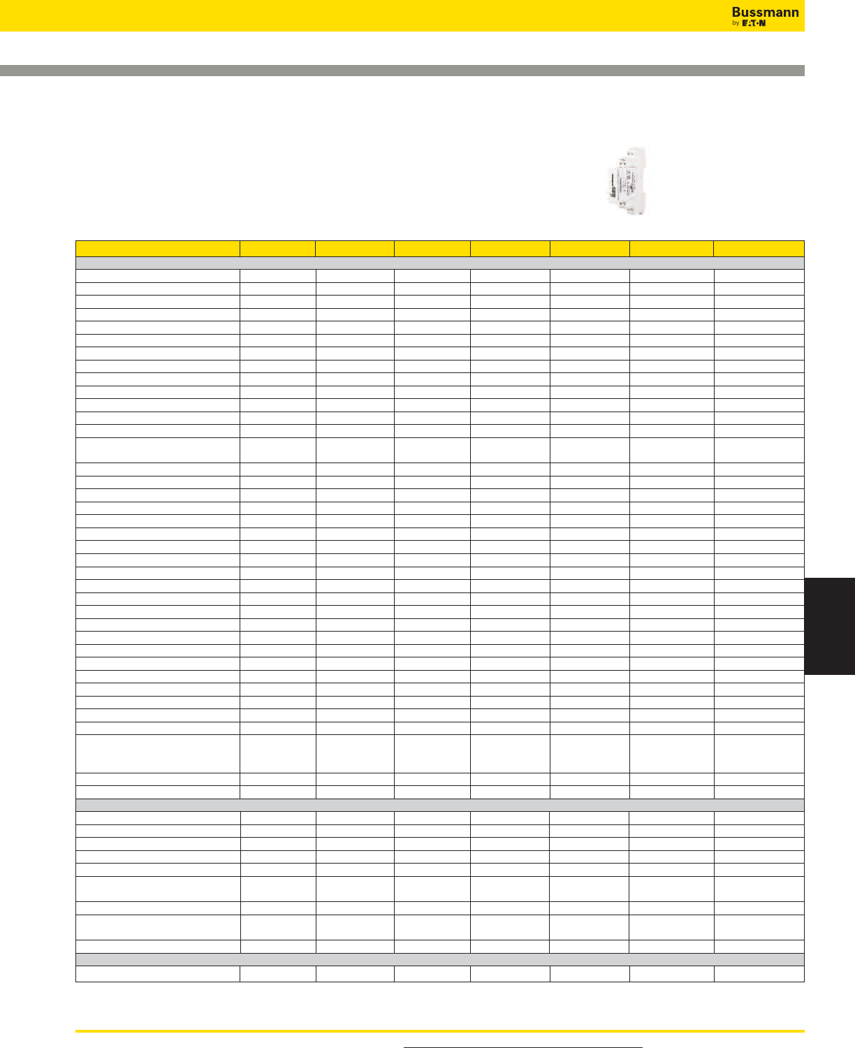
For product data sheets, visit www.cooperbussmann.com/DatasheetsEle 501
Surge Protection
Devices
Overvoltage Devices
Part Numbers BSPD5DING BSPD12DING BSPD24DING BSPD48DING BSPD5DINLHF BSPD24DINLHF BSPD0180DINL
BUS SYSTEMS AND MEASURING, AND CONTROL TECHNOLOGY
0-20 mA, 4-20 mA Signals X X (4-20mA only) X
Binary Signals X X X X
CAN-Bus (data line only) XX
C-Bus (Honeywell) XX
Data Highway Plus X
Device Net (data line only) XX
Dupline X
E-Bus (Honeywell) X
Fieldbus Foundation XX
FIPIO / FIPWAY X
FSK XX
IEC-Bus (RS485) XX
Interbus INLINE (I/O) X
Interbus INLINE, XX
Long-distance bus
K Bus X
LON - TP/XF 78 X
LUXMATE Bus XX
M Bus X
MODBUS XX
MPI Bus XX
Procontic CS31 (RS232) X
Procontic T200 (RS422) XX
PROFIBUS DP/FMS XX
PROFIBUS PA XX
PROFIBUS SIMATIC NET XX
PSM EG RS422 & RS485 XX
Rackbus (RS485) XX
R Bus XX
RS 485 XX
RS422, V11 XX
SafetyBUS p XX
Securilan LON Bus X
SIGMASYS X
SS97 SIN/X (RS 232) X
SUCONET XX
Resistance Temp. Measuring
Ni1000, PT100, PT1000 Wire X
NTC & PTC Thermistors
TTL X
TTY 4–20mA X
TELECOMMUNICATION, TELEPHONY
a/b Wires X
ADSL, ADSL 2+ X
ISDN S0, S2m/U2m, UKO/UPO X
Modem M1 X
SDSL, SHDSL XX
Telephony Systems X
(e.g., Siemens, HICOM, Alcatel)
T- D S L X
Telecommunication Systems X
(e.g., Siemens, HICOM, Alcatel)
VDSL X
DATA NETWORKS
V 24 (RS232 C) X
DIN-Rail Universal 4 Wire Data Signal SPDs and Applications
Universal 4 wire data signal SPD products are specified by
communication technology. The table below contains the
specific SPD product, by part number, and the applications to
which they are suited to be used.
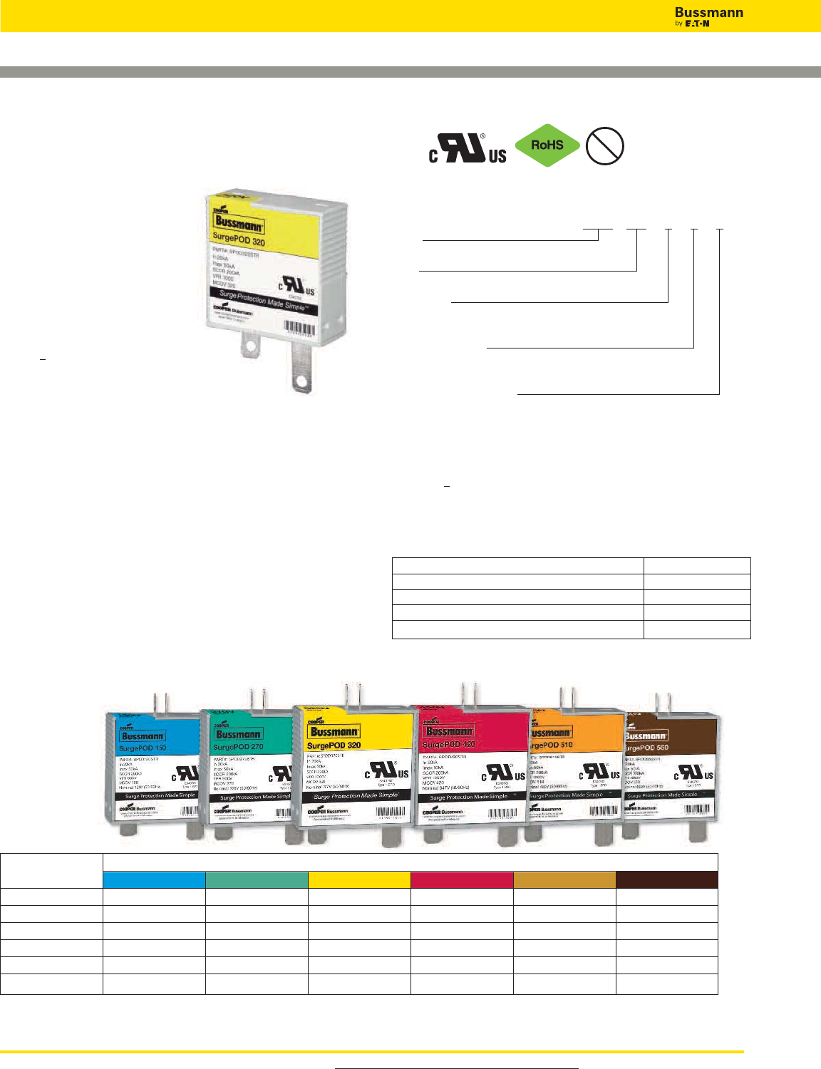
For product data sheets, visit www.cooperbussmann.com/DatasheetsEle
502
Overvoltage Devices
SurgePOD™ Series
Surge Protective Overvoltage Device Modules
Description
Bussmann SurgePOD surge
protective overvoltage device
modules are board-mounted.
Upon an overvoltage condition,
their voltage clamping feature
becomes conductive, safely
shunting the surge to ground.
All SurgePOD devices are UL
1449 3rd Edition Recognized Type
1 SPD and contain an internal
element that safely disconnects
the device upon reaching an
overvoltage breakdown condition.
Remote contact signaling is accomplished with an optional
Normally Open microswitch that closes upon reaching an
overvoltage breakdown condition.
Local visual indication is accomplished with optional visual
indicating tabs that protrude through the device’s top upon
reaching an overvoltage breakdown condition.
The SurgePOD’s MOV substrate material may be damaged by
excessive shock or rough handling. To ensure integrity of
finished device, do NOT install any SurgePOD devices that
are dropped or abused during assembly.
Suitability of SurgePOD devices for application to be
determined by end user.
Catalog Number System:
SPOD 320 S T R
Series:
SPOD
MCOV:
150, 270, 320, 420, 510, 550
Lead Length:
S = Short - 6.87mm
L = Long - 16.76mm
Visual Indicator Tab:
T = Yes
Blank = None
Remote Contact Signaling:
R = Yes (Normally Open)
Blank = None
Agency Information
UL 1449 3rd Edition Recognized Type 1 Surge Protective
Device; File E340782.
Electrical Specifications
Maximum Continuous Operating Voltage (MCOV) 150Vac to 550Vac
Short-Circuit Current Rating (SCCR) 200kA
Nominal Discharge Current (In) 8/20ms 20kA
Max Discharge Current Rating (Imax) 8/20ms 50kA
Remote Contact Signaling Microswitch 20mA@15Vdc
Pb
Data Sheet: 1170
SurgePOD Voltage / Color Code
Specifications 150V 270V 320V 420V 510V 550V
In20kA 20kA 20kA 20kA 20kA 20kA
Imax 50kA 50kA 50kA 50kA 50kA 50kA
SCCR 200kA 200kA 200kA 200kA 200kA 200kA
MCOV (Vrms) 150V 270V 320V 420V 510V 550V
VPR 600V 900V 1200V 1500V 1500V 1500V
Nominal Vrms* 120V 220V 277V 347V 480V 480V
* Nominal Vrms @ 50/60Hz.
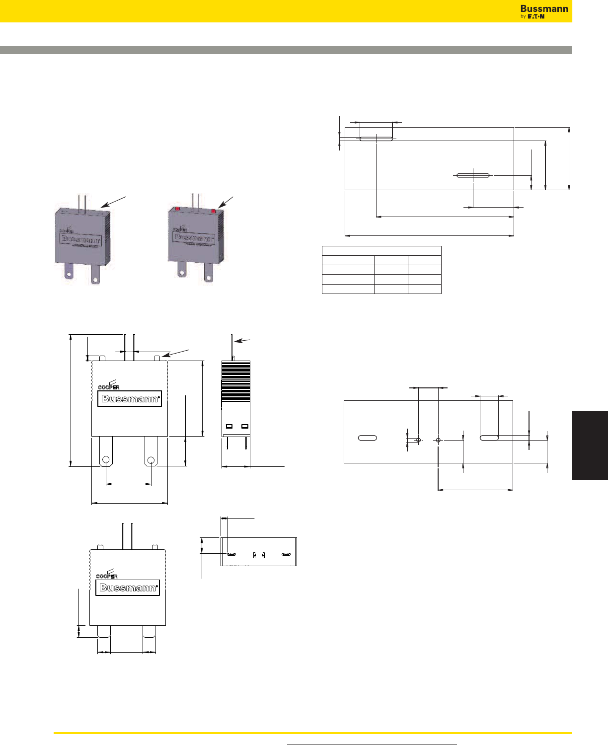
For product data sheets, visit www.cooperbussmann.com/DatasheetsEle 503
Surge Protection
Devices
SurgePOD™ Series
Data Sheet: 1170
Overvoltage Devices
1.687
[42.85]
2.930
Ref
[74.43]
0.195±0.01
[4.95±0.25]
0.660
[16.76]
1.000±0.01
[25.40±0.25]
1.684
[42.77]
0.100
[2.54]
Long
Terminals
0.349
[8.87]
0.143
[3.63]
Short
Terminals
0.627±0.01
[15.92±0.25]
0.22±0.05
[5.58±1.27]
Productivity Through Protection™
Productivity Through Protection™
0.280
[7.11]
Front View
Side View
Top View
Front View
Leads for optional
remote contact signaling.
Indication tab
deployed.
0.627
±0.01
[15.92
±0.25
]
1.687
[42.85]
2x 0.037
[0.94]
A
1.375
[34.93]
0.407
[10.34]
0.126
[3.20]
2x 0.325
[8.26]
Front
Terminal Dimensions / Pad Layout - in [mm]
Dimensions - in [mm]
Tolerance is ± 0.005” [0.13mm] unless otherwise stated. Terminal Information and Mounting
The SurgePOD surge protective overvoltage devices have nickel-plated copper
terminals for easy solder connection to printed circuit boards.
Recommended Pad Layout for Remote Contact Signaling - in [mm]
Packaging Information
• 200 units per master pack
0.195
[4.9]
2x ø 0.039
[0.99]
0.231
[5.87]
0.228
[5.79]
0.050
[1.27]
0.747
[18.97]
0.184
[4.67]
Local visual indication
tabs exposed upon
reaching an overvoltage
breakdown condition.
SurgePOD
device under
normal
operation.
Mechanical Specifications
All components are rated IP20 finger-safe in the installed state.
Environmental Specifications
Plastic Material: Polybutylene Terephthalate
Flammability Rating: UL 94V0
Storage Temperature: -25°C to 85°C
Operating Temperature: -25°C to 85°C
Local Visual Indication Tabs (Optional)
Dimension A
MCOV Rating Inches mm
150 0.431 10.95
270, 320 0.479 12.17
420, 510, 550 0.526 13.36
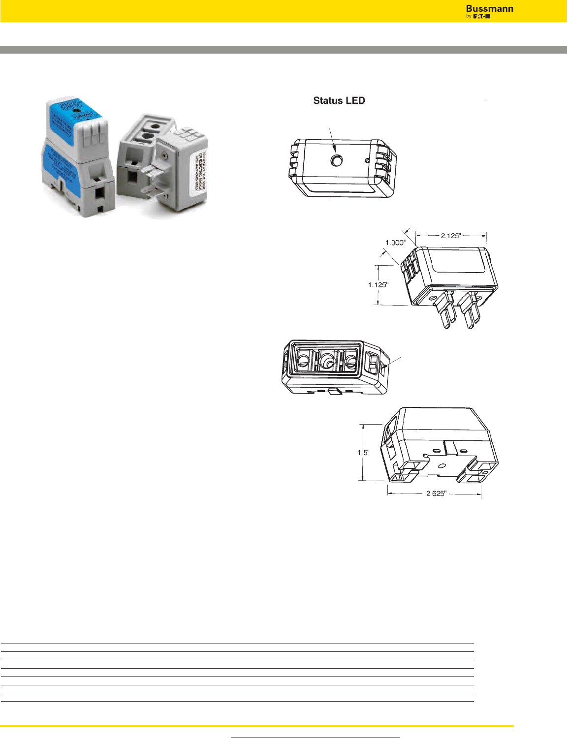
For product data sheets, visit www.cooperbussmann.com/DatasheetsEle
504
DIN-Rail TVS Series
Overvoltage Devices
Data Sheet: 9006
Specifications
Description: DIN-Rail mount voltage surge protection
system for AC or DC voltage using diode or MOV technology.
Construction:
Suppressor: Case: 20% glass filled PES (Polyethersulfone)
Terminals: 110 Copper
Terminal Plating: Electroless tin
Holder: Case: 15% glass filled PBT (Polybutylene
Terephthalate)
Interface Clips: CDA 7025
Interface Clip Plating: Electroless tin
Contact Lubricant: Fluoroether grease
Box Lug: Copper
DIN-Rail Springs: Stainless steel
Ratings*:
Volts: — 12Vdc (2kA surge current)
— 24Vdc (2kA surge current)
— 48Vdc (2kA surge current)
— 120Vac (7kA-18kA surge current)
— 240Vac (7kA-18kA surge current)
* See Catalog Numbers table for all specifications pertaining to specific voltage ratings.
Agency Information: UL Recognized (UL 1449) for AC
products, (UL 497B) for DC products, CSA Approved.
Catalog Numbers
Catalog Voltage SVR Surge Current Agency Label
Numbers Application MCOV Technology 500A, 8x20μs Rating Information Color
TVS12DCD 12Vdc 14Vdc SASD 36Vdc 2kA UL 497B Red
TVS24DCD 24Vdc 28Vdc SASD 58Vdc 2kA UL 497B White
TVS48DCD 48Vdc 57Vdc SASD 90Vdc 2kA UL 497B Black
TVS120ACD 120Vac 140Vac SASD 330Vac 7kA UL 1449 Blue
TVS120ACM 120Vac 140Vac MOV 500Vac 18kA UL 1449 Grey
TVS240ACD 240Vac 280Vac SASD 600Vac 7kA UL 1449 Blue
TVS240ACM 240Vac 280Vac MOV 800Vac 18kA UL 1449 Grey
Product Specifications:
1. All TVS devices have non-polarized electrical connections
as shown.
2. Suppressor voltage characteristics per chart.
3. Suppressor to provide non-interrupted service.
4. Enclosure material is 94V0 flame and explosion resistant.
5. Product markings show manufacturer, part number and safety
warnings as required.
6. Mechanical dimensions as noted.
7. Suppressor Status LED as shown.
8. AC units operate on either 50 or 60Hz.
OFF - Suppressor Non-Operational (power may be on)
GREEN - Suppressor Operational (power on)
Power Terminals
14AWG - 4AWG
Dual 10AWG
Dimensions -in

Accessories
Reduce Downtime
With Quick Access
to the Right
Replacement Fuse
Section Contents Page
Fuse Service Kits
Supplemental . . . . . . . . . . . . . . . . . . . . . . . . . . . . . 506-507
Branch circuit . . . . . . . . . . . . . . . . . . . . . . . . . . . . . 506-507
Premium branch circuit . . . . . . . . . . . . . . . . . . . . . . 506-507
Large electronic . . . . . . . . . . . . . . . . . . . . . . . . . . . . . . . 508
Small electronic . . . . . . . . . . . . . . . . . . . . . . . . . . . . . . . 508
Electrical & electronic . . . . . . . . . . . . . . . . . . . . . . . . . . . 508
Clips clamps & rail adapters (DIN & American) . . . . . 509
Spare fuse holders, pullers, testers & cabinets
Telepower spare fuse holders . . . . . . . . . . . . . . . . . . . . 510
5TPH . . . . . . . . . . . . . . . . . . . . . . . . . . . . . . . . . . . . . . . 510
Fuse pullers . . . . . . . . . . . . . . . . . . . . . . . . . . . . . . . . . . 510
FT-2 & FT-3 fuse testers . . . . . . . . . . . . . . . . . . . . . . . . 510
SFC spare fuse cabinet . . . . . . . . . . . . . . . . . . . . . . . . . 510
Fuse reducers & dummy “neutrals”
Class J fuses - LPJ, JKS . . . . . . . . . . . . . . . . . . . . . . . . 511
Class R fuses - FRN-R, LPN-RK, FRS-R
& LPS-RK . . . . . . . . . . . . . . . . . . . . . . . . . . . . . . . . . . 511
Class H & K fuses - NON, REN, NOS & RES . . . . . . . . 511
Dummy fuse “neutrals” . . . . . . . . . . . . . . . . . . . . . . . . . . 511
505
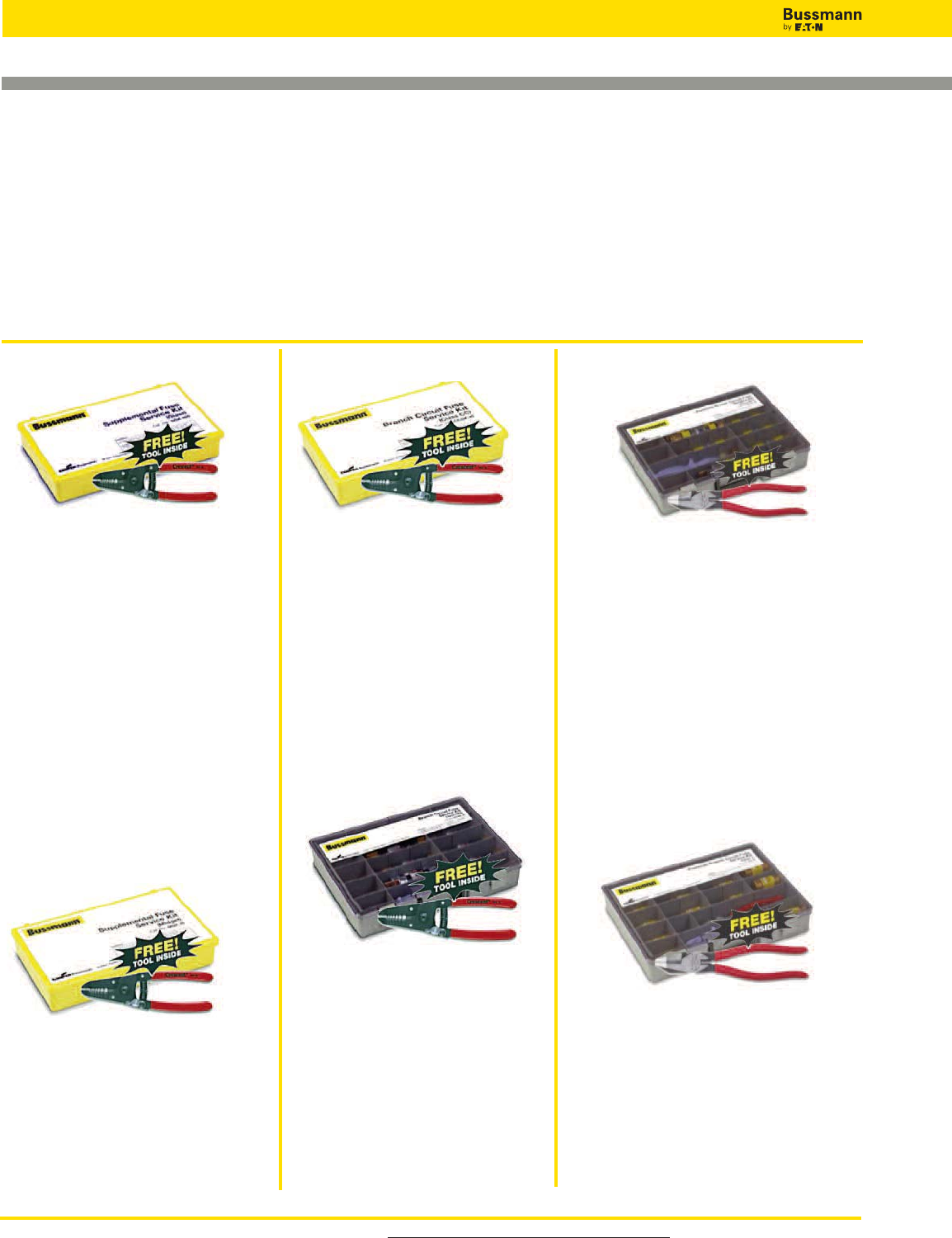
Fuse Service Kits
Glass Fuse Kit
Catalog Number: GSK-260
Kit Contents
(5) GMA-500mA (5) MDL-6 (5) AGC-10
(5) GMA-1A (5) MDL-7 (5) AGC-15
(5) GMA-2A (5) MDL-8 (5) AGC-20
(5) GMA-3A (5) MDL-10 (5) GMC-2A
(5) GMA-4A (5) MDL-15 (5) GMC-5A
(5) GMA-5A (5) MDL-20 (5) GMC-10A
(5) GMA-6A (5) AGC-1⁄4(5) MDA-5
(5) GMA-10A (5) AGC-1⁄2(5) MDA-10
(5) GMA-15A (5) AGC-1 (5) MDA-12
(5) MDL-1⁄4(5) AGC-11⁄2(5) MDA-15
(5) MDL-1⁄2(5) AGC-2 (5) MDA-20
(5) MDL-1 (5) AGC-21⁄2(5) ABC-5
(5) MDL-11⁄2(5) AGC-3 (5) ABC-10
(5) MDL-2 (5) AGC-4 (5) ABC-12
(5) MDL-21⁄2(5) AGC-5 (5) ABC-15
(5) MDL-3 (5) AGC-6 (5) ABC-20
(5) MDL-4 (5) AGC-7
(5) MDL-5 (5) AGC-8
(1) FT-3 Fuse tester/puller
(1) 6-inch Crescent®wire stripper
Midget Fuse Kit
Catalog Number: MSK-45
Kit Contents
(3) FNM-1 (3) KTK-20
(3) FNM-2 (3) KTK-30
(3) FNM-5 (3) FNQ-5
(3) FNM-10 (3) FNQ-10
(3) FNM-15 (3) FNQ-15
(3) KTK-5 (3) FNQ-20
(3) KTK-10 (3) FNQ-30
(3) KTK-15 (1) FT-3 Fuse tester/puller
(1) 6-inch Crescent®wire stripper
Class CC Fuse Kit
Catalog Number: CCSK-45
Kit Contents
(3) LP-CC-5 (3) KTK-R-15
(3) LP-CC-10 (3) KTK-R-20
(3) LP-CC-15 (3) KTK-R-30
(3) LP-CC-20 (3) FNQ-R-1⁄2
(3) LP-CC-30 (3) FNQ-R-3
(3) KTK-R-5 (3) FNQ-R-5
(3) KTK-R-10 (3) FNQ-R-10
(1) FT-3 Fuse tester/puller
(1) 6-inch Crescent®wire stripper
Branch Circuit
Supplemental
Fusetron™Class RK5
250/600V Fuse Kit
Catalog Number: RK5SK-39
Kit Contents
(3) FRN-R-10 (3) FRS-R-10
(3) FRN-R-15 (3) FRS-R-15
(3) FRN-R-20 (3) FRS-R-20
(3) FRN-R-25 (3) FRS-R-30
(3) FRN-R-30 (3) FRS-R-60
(3) FRN-R-60 (3) FRS-R-100
(3) FRN-R-100 (1) FP-2 Fuse puller
(1) NO.263-R (60 to 30A fuse reducer)
(1) NO.663-R (60 to 30A fuse reducer)
(1) 6-inch Crescent®wire stripper
Low-Peak™Class J Fuse Kit
Catalog Number: JSK-36
Kit Contents
(3) LPJ-3SP (3) LPJ-25SP
(3) LPJ-5SP (3) LPJ-30SP
(3) LPJ-6SP (3) LPJ-40SP
(3) LPJ-10SP (3) LPJ-50SP
(3) LPJ-15SP (3) LPJ-60SP
(3) LPJ-20SP (3) LPJ-100SP
(1) FP-2 Fuse puller
(1) 85⁄8-inch Crescent®lineman’s pliers
Premium Branch Circuit
Low-Peak™Class RK1
250/600V Fuse Kit
Catalog Number: RK1SK-39
Kit Contents
(3) LPN-RK-10SP (3) LPS-RK-10SP
(3) LPN-RK-15SP (3) LPS-RK-15SP
(3) LPN-RK-20SP (3) LPS-RK-20SP
(3) LPN-RK-25SP (3) LPS-RK-30SP
(3) LPN-RK-30SP (3) LPS-RK-60SP
(3) LPN-RK-60SP (3) LPS-RK-100SP
(3) LPN-RK-100SP
(1) NO.263-R (60 to 30A fuse reducer)
(1) NO.663-R (60 to 30A fuse reducer)
(1) FP-2 Fuse puller
(1) 85⁄8-inch Crescent®lineman’s pliers
Selection
These service kits are filled with the
most common fuse types and sizes for
the most common applications – no
need to search for the right fuse, it’s in
the kit.
Organization
The compact and sturdy carrying case
allows organizing and modifying the
fuses needed to assure a proper
supply is kept on hand.
Accessories
All kits come with a fuse puller for the
fuses it contains. As a bonus, all kits on
this page include a free wire stripper or
lineman’s pliers.
Save Time and Money with These Fuse Service Kits
Fuse Kits and Accessories
For product data sheets, visit www.cooperbussmann.com/DatasheetsEle
506
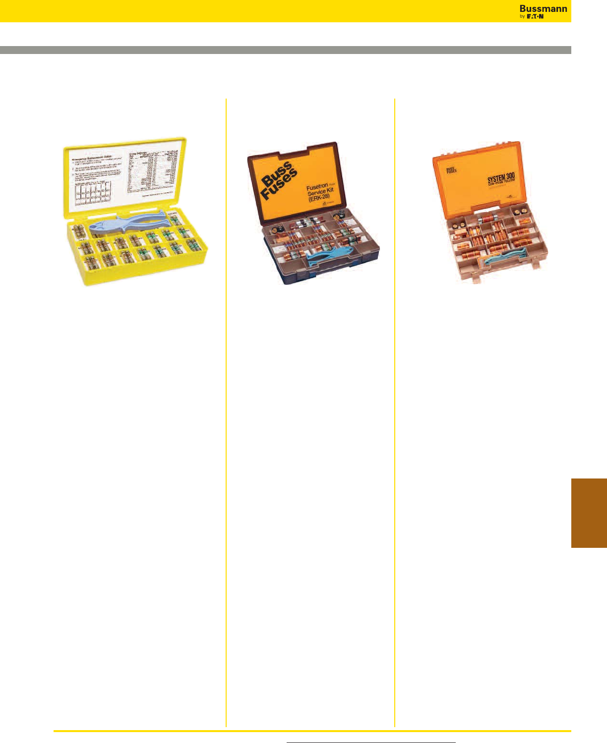
For product data sheets, visit www.cooperbussmann.com/DatasheetsEle 507
Accessories
Fuse Service Kits
Low-Peak™Class RK1 250V
Fuse Kit
Compact kit in a sturdy nylon box
rugged enough to withstand field use.
Extra spaces and changeable
compartments make it easy to
customize for your particular need.
Catalog Number: LPRK-28
Service Kit Contents
(2) LPN-RK-3-2⁄10SP (2) LPN-RK-40SP
(2) LPN-RK-6-1⁄4SP (2) LPN-RK-50SP
(2) LPN-RK-10SP (3) LPN-RK-60SP
(2) LPN-RK-15SP (2) LPN-RK-100SP
(3) LPN-RK-20SP (2) NO.263-R Reducers
(2) LPN-RK-25SP (2) NO.1 Clip Clamps
(4) LPN-RK-30SP (2) NO.2 Clip Clamps
(2) LPN-RK-35SP (1) FP-2 Fuse puller
Fusetron™Class RK5
250V Fuse Kit
Compact kit in a sturdy nylon box
rugged enough to withstand field use.
Extra spaces and changeable
compartments make it easy to
customize for your particular need.
Catalog Number: ERK-28
Service Kit Contents
(2) FRN-R-3-2⁄10 (2) FRN-R-40
(2) FRN-R-6-1⁄4(2) FRN-R-50
(2) FRN-R-10 (3) FRN-R-60
(2) FRN-R-15 (2) FRN-R-100
(3) FRN-R-20 (2) NO.263-R Reducers
(2) FRN-R-25 (2) NO.1 Clip Clamps
(4) FRN-R-30 (2) NO.2 Clip Clamps
(2) FRN-R-35
Class CC / Midget
Fuse Kit
Emergency fuse kit for replacement of
13⁄32˝ x 11⁄2˝ (Class CC and midget) fuses
in a sturdy nylon box. Cross reference
makes it easy to install the correct fuse
in any Class CC or midget application.
Kit Size: 107⁄8˝ W x 65⁄8˝ D x 13⁄4˝ H
Catalog Number: NO.36
Emergency Kit Contents
(2) FNQ-R-1⁄2(2) KTK-R-1
(2) FNQ-R-1 (2) KTK-R-2
(2) FNQ-R-2 (2) KTK-R-3
(2) FNQ-R-3 (2) KTK-R-5
(2) FNQ-R-4 (2) KTK-R-6
(2) FNQ-R-5 (2) KTK-R-10
(2) FNQ-10 (2) KTK-R-15
(2) FNQ-15 (2) KTK-R-20
(2) FNQ-20 (2) KTK-R-30
(1) FP-2 Fuse puller
Supplemental/Branch
Circuit
Branch Circuit Premium Branch Circuit
Fuse Kits and Accessories
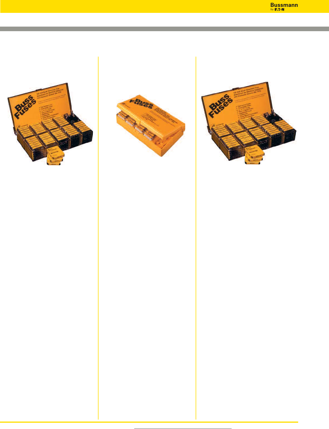
For product data sheets, visit www.cooperbussmann.com/DatasheetsEle
508
Fuse Kits and Accessories
Fuse Service Kits
Fuse Kit 270
Small dimension fuse assortment with
270 fuses, fuse holders, fuse blocks and
fuse clips to fit most electronic
equipment.
Ratings:
Volts: — 125V/250V
Catalog Number: NO.270
Assortment Contents
(5) MDL-1⁄8(5) AGC-1⁄2(5) GMA-1A
(5) MDL-1⁄4(5) AGC-3⁄4(5) GMA-2A
(5) MDL-1⁄2(5) AGC-1 (5) GMA-3A
(5) MDL-3⁄4(5) AGC-1-1⁄2(5) GMA-4A
(5) MDL-1 (5) AGC-2 (5) GMA-6A
(5) MDL-1-1⁄2(5) AGC-2-1⁄2(5) GMC-1A
(5) MDL-2 (5) AGC-3 (5) GMC-2A
(5) MDL-3 (5) AGC-4 (5) GMC-3A
(5) MDL-4 (5) AGC-5 (5) GMC-4A
(5) MDL-5 (5) AGC-6 (5) GMC-6A
(5) MDL-6 (5) AGC-7 (4) AGC-V-1⁄2
(5) MDA-8 (5) AGC-8 (4) AGC-V-1
(5) MDA-10 (5) ABC-10 (4) AGC-V-2
(5) MDA-15 (5) ABC-15 (4) AGC-V-3
(5) MDA-20 (5) ABC-20 (4) MDL-V-1⁄2
(5) MDA-30 (5) ABC-30 (4) MDL-V-1
(5) AGC-1⁄8(5) GMA-250mA (4) MDL-V-2
(5) AGC-1⁄4(5) GMA-500mA (4) MDL-V-3
(2) Pr. 4121 Fuse clips
(2) HHB Inline fuse holder
(1) HTB-26I panel mount fuse holder
(1) HTB-28M panel mount fuse holder
(1) S-8202-2 Two-pole fuse block
Fuse Kit 140
Small dimension fuse kit with 140
fuses, fuse holders, fuse blocks and
fuse clips to fit most electronic
equipment.
Ratings:
Volts: — 125V/250V
Catalog Number: NO.140
Assortment Contents
(5) MDL-1⁄2(5) AGC-1-1⁄2
(5) MDL-1 (5) AGC-2
(5) MDL-1-1⁄2(5) AGC-3
(5) MDQ-2 (5) MTH-4
(5) MDQ-3 (5) MTH-5
(5) MDQ-4 (5) MTH-6
(5) MDQ-5 (5) MTH-7
(5) MDQ-6 (5) MTH-8
(5) MDA-8 (5) ABC-10
(5) MDA-10 (5) ABC-15
(5) MDA-15 (5) ABC-20
(5) MDA-20 (5) ABC-30
(5) MDA-30 (2) Pr. #4121 Fuse clips
(5) AGC-1⁄4(2) HHB Inline fuse holder
(5) AGC-1⁄2(1) FP-A3 Fuse puller
(5) AGC-1
5 x 20mm Fuse Kit 220
A complete assortment of 125V and
250V 5 x 20mm fuses for the repair of
both electrical and electronic devices.
Ratings:
Volts: — 125V/250V
Catalog Number: NO.220
Assortment Contents
(5) GMA-250mA (5) GDA-6.3 (5) GMD-200mA
(5) GMA-500mA (5) GDB-630mA (5) GMD-500mA
(5) GMA-1 (5) GDB-2 (5) GMD-1
(5) GMA-1.5 (5) GDB-3.15 (5) GMD-1.6
(5) GMA-2 (5) GDB-4 (5) GMD-2
(5) GMA-2.5 (5) GMC-500mA (5) GMD-3
(5) GMA-3 (5) GMC-750mA (5) GDC-250mA
(5) GMA-4 (5) GMC-1 (5) GDC-500mA
(5) GMA-5 (5) GMC-2 (5) GDC-1
(5) GMA-10 (5) GMC-2.5 (5) GDC-1.6
(5) GDA-630mA (5) GMC-3 (5) GDC-2
(5) GDA-1 (5) GMC-3.15 (5) GDC-3.15
(5) GDA-2 (5) GMC-4 (5) GDC-4
(5) GDA-3.15 (5) GMC-5 (5) GDC-5
(5) GDA-5 (5) GMC-6.3
(1) HTB-28M panel mount fuse holder
(1) FP-A3 Fuse puller
Large Electronic Fuse Kit Small Electronic Fuse Kit Electrical and Electronic
Fuse Kit
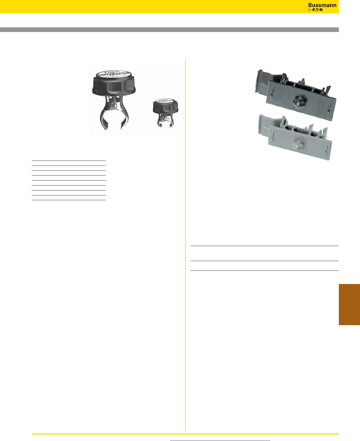
For product data sheets, visit www.cooperbussmann.com/DatasheetsEle 509
Accessories
Adapters for DIN and American Rails
Specifications
Description:
Bussmann DIN-Rail
adapters permit secure,
positive snap-on mounting
of Bussmann 0-30A fuse
blocks (one-, two-, or
three-pole) onto various
size rails to eliminate
costly and time consuming
drilling, tapping, and screw
mounting. Adapters
mechanically lock into
mounting holes of fuse blocks in
seconds to become an integral part of the block.
One adapter is required for one- and two-pole Bussmann
blocks. Two adapters are required for three-pole blocks.
With the exception of the 32mm DIN-Rail, all blocks with
adapters can be removed from a rail simply by pulling up its
release tab.
Use of rail end-stops on both sides of adapters is
recommended.
Construction: Molded from “Lexan™ 241” for high strength
and flexibility.
Catalog Numbers (For 0-30A Fuse Blocks)
Catalog Fuse Block Adapter
Numbers Class Rail Type Size Color
DRA-1 CC DIN 15mm (Sym.) Black
G 32mm (Asym.)
*H (250V) 35mm (Sym.)
DRA-2 *R (250) American 17⁄64˝ (Sym.) Gray
M Type (also 35mm DIN)
Package Quantities: standard—10; bulk—100 (Cat. No. BK/DRA-1 or BK/DRA-2.)
*Mounting on 15mm rails is not recommended.
NOTE—Newer Bussmann fuse blocks have elongated block-to-adapter mounting holes (old
style fuse blocks will not accept the rail adapters).
Clip Clamps and Rail Adapters (DIN & American)
TRON™ Clip-Clamps
Specifications
Description: Clamps
for ferrule and blade-
type cartridge fuse
clips. Provide tight
contacts between fuse
holder clips and fuse
ferrules/blades.
Construction:
Phenolic knob and
plated-steel jaws.
Catalog Numbers
Catalog Clamp Size
Numbers Volts Amps
NO.1 250 0-30
NO.2 250 35-60
NO.2 600 0-30
NO.4 600 35-60
NO.5 250/600 70-100
NO.6 250/600 110-200
NO.7 250/600 225-400
NO.8 250/600 450-600
Fuse Kits and Accessories
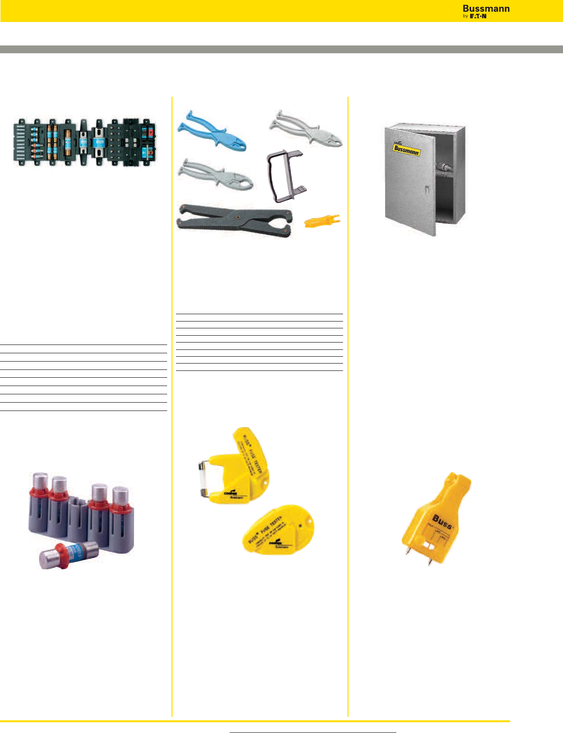
Fuse Pullers
Specifications
Description: Fuse pullers in various
sizes to safely and easily extract fuses
from blocks and holders.
Catalog Numbers
Catalog Numbers Application
FP-2 13⁄32˝ to 13⁄16˝ dia. fuses
FP-3 1˝ to 1 3⁄4˝ dia. fuses
FP-4 1 3⁄4˝ to 2 1⁄2˝ dia. fuses
FP-6 0-60A T-Tron fuses
FP-A3 Glass Tube & ATC fuses
CFP-30 CUBEFuse 1-30A
CFP-60 CUBEFuse 35-60A
CFP-100 CUBEFuse 70-100A
Fuse pullers are only to be used when the associated circuit
has been de-energized.
Spare Fuse Holders
Specifications
Description: Spare fuse holders
durably constructed using black
thermoplastic with common mounting
using #6 screws or bolts on 5-inch
centers. Dovetailed interlocking between
fuse holders simplifies installation and
reduces needed hardware. Common
footprint allows for any combination of
fuse holders to be mounted together.
Built-in retaining clips secure fuses.
Flammability Rating: UL 94V0.
Catalog Numbers
Catalog
Numbers Capacity For Use With:
TPSFH-CW 4-position TPC and/or TPW fuses
TPSFH-M 4-position TPM fuses
TPSFH-LC 1-position TPL-C series fuses
TPSFH-LB 1-position TPL-B series fuses
TPSFH-N60 1-position TPN (35-60A) fuses
TPSFH-N30 4-position TPN (1-30A) fuses
TPSFH-AS 6-position TPA & TPS fuses
TPSFH-T 10-position GMT fuses
Spare Fuse Holders, Pullers, Testers and Cabinets
Data Sheet: 1119
SFC Spare Fuse Cabinet
Specifications
Description: Spare fuse cabinet with
five cubic feet of storage space.
Constructed of heavy gauge steel with
durable baked ASA 61 grey enamel
finish. Cabinet door is equipped with
locking handle for security. Mounting
holes are 16 inches on center with key
slots.
Size: 24˝ W x 30˝ H x 12˝ D
Material: 0.062 sheet steel
Catalog Numbers:
SFC-FUSE-CAB
SFC-SHELF*
*Extra shelf for fuse cabinet.
5TPH
Specifications
Description: 5-position spare fuse
holder for midget size and Class CC
fuses (13⁄32˝ diameter) fuses. Constructed
of thermoplastic with adhesive tape on
back for easy mounting on cabinet doors.
Size: 2.98˝ W x 1.03˝ H x 0.63˝ D
Catalog Number: 5TPH
Data Sheet: 5014
FT-2 Fuse Tester
Specifications
Description: Fuse tester for automotive,
glass tube and ferrule fuses up to 17⁄8˝
length. Probe slides to appropriate fuse
length. Batteries are included and
replaceable.
WARNING: DO NOT test electrical
fuses in the fuse panel.
Catalog Number: FT-2
Replacement Battery:
Rayovac 364
FT-3 Fuse Tester
Specifications
Description: Fuse tester for
automotive, glass tube and ferrule
fuses up to 11⁄4˝ length. Probe slides
to appropriate fuse length. Batteries
are included and replaceable.
WARNING: DO NOT test electrical
fuses in the fuse panel.
Catalog Number: FT-3
FP-4 FP-A3
FP-6
FP-3
FP-2
For product data sheets, visit www.cooperbussmann.com/DatasheetsEle
510
Fuse Kits and Accessories
CFP-_ _ _A
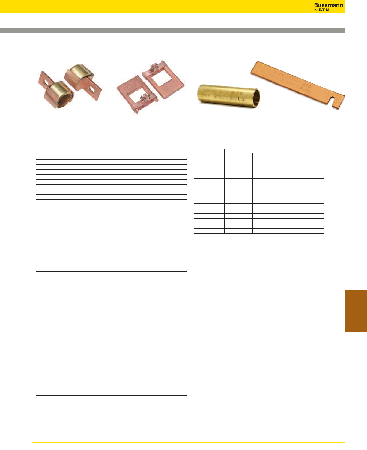
For product data sheets, visit www.cooperbussmann.com/DatasheetsEle 511
Accessories
Fuse Reducers and Dummy “Neutrals”
Data Sheet: 1118
Fuse Reducers for Class J Fuses:
LPJ, DFJ, JKS
Catalog Numbers
Catalog
Numbers (Pair) Fuse Equipment/Fuseblock
Reducer No. Amp Size Range Amp Size
J-63 1-30 60
J-13 1-30 100
J-16 35-60 100
J-26 35-60 200†
J-21 70-100 200†
J-41 70-100 400†
J-42 110-200 400†
J-62 110-200 600†
J-64 225-400 600†
†Not for Bolt-on Applications.
Fuse Reducers for Class R Fuses:
FRN-R, LPN-RK, FRS-R, LPS-RK
KTN-R, KTS-R
UL Listed File E12853
Catalog Numbers
Catalog Numbers (Pairs)
Voltages Fuse Equipment/Fuseblock
250V 600V Amp Size Range Amp Size
NO.263-R NO.663-R 1-30 60
NO.213-R NO.216-R 1-30 100
NO.216-R NO.616-R 35-60 100
NO.226-R NO.626-R 35-60 200
NO.2621-R NO.2621-R 70-100 200
NO.2641-R NO.2641-R 70-100 400
NO.242-R NO.642-R 110-200 400
NO.2661-R NO.2661-R 70-100 600
NO.2662-R NO.2662-R 110-200 600
NO.2664-R** NO.2664-R** 225-400 600
**Single reducer only (pair not required).
Fuse Reducers for Class H & K Fuses:
NON, REN, NOS, RES
UL Listed File E12853
Catalog Numbers
Catalog Numbers. (Pairs) Equipment/
250V 600V Fuse Fuseblock
Reducer Reducer Amp Size Range Amp Size
NO.263 NO.663 1-30 60
NO.213 NO.216 1-30 100
NO.216 NO.616 35-60 100
NO.226 NO.626 35-60 200
NO.2621 NO.2621 70-100 200
NO.2641 NO.2641 70-100 400
NO.2642 NO.2642 110-200 400
No. 2661 No. 2661 70-100 600
Dummy Fuse “Neutrals”
(These are not fuses)
Catalog Numbers
Fuse Equivalent
Catalog Fuse
Numbers Voltage Dimension Amp Size Range
NNB — 13⁄32˝ x 11⁄2˝—
NNB-R — Class CC —
NNC — 1⁄4˝ x 11⁄4”—
NTN-R-30 250 R/H 1-30
NTN-R-60 250 R/H 35-60
NTN-R-100 250 R/H 70-100
NTN-R-200 250 R/H 110-200
NTN-R-400 250 R/H 225-400
NTS-R-30 600 R/H 1-30
NTS-R-60 600 R/H 35-60
NTS-R-100 600 R/H 70-100
NTS-R-200 600 R/H 110-200
NTS-R-400 600 R/H 225-400
NTS-R-600 600 R/H 450-600
Fuse Kits and Accessories
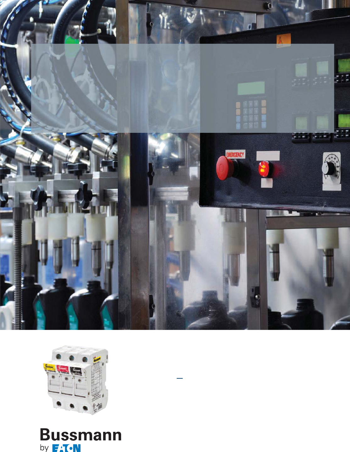
512
Finger-safe DIN-Rail mount fuse
holders protect your electrical
system & simplify installation
Compact modular
fuse holders
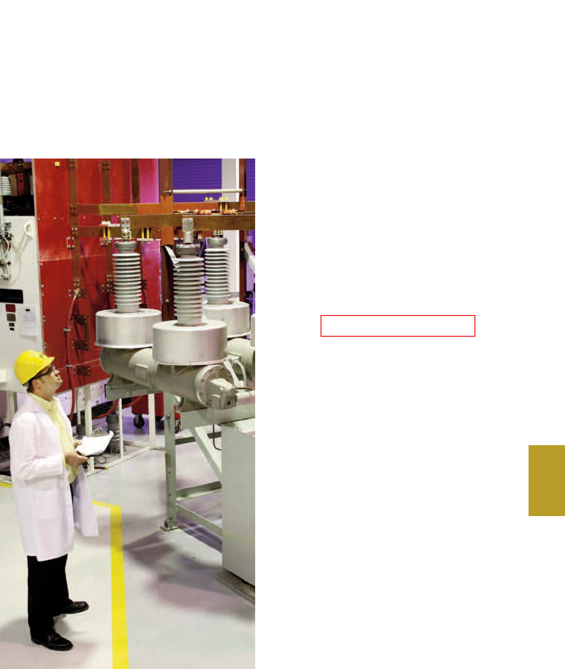
513
Services &
Application Guide
RED indicates NEW information
Bussmann
Services & Application
Guide
Section Contents
Bussmann Services
Testing . . . . . . . . . . . . . . . . . . . . . . . . . . . . . . . . . . . . . 514
Custom Products . . . . . . . . . . . . . . . . . . . . . . . . . 515
Application Guide
Fuse technology . . . . . . . . . . . . . . . . . . . . . . . . . . .516-522
Motor circuit branch circuit protection . . . . . . . . . . . . . . .523
Glossary . . . . . . . . . . . . . . . . . . . . . . . . . . . . . . . . 524-526
Out-of-stock substitution/upgrades . . . . . . . . . . . . . . . . 526
Industrial & commercial fuse applications . . . . . . . . . . . 527
Catalog number index . . . . . . . . . . . . . . . . . 528-???
Sales support . . . . . . . . . . . . . . . . . . . . . . . . . . . . . . . .???
Downtime Reduction, Workplace
Safety & Code Compliance
Services to Increase Your Productivity Through Protection
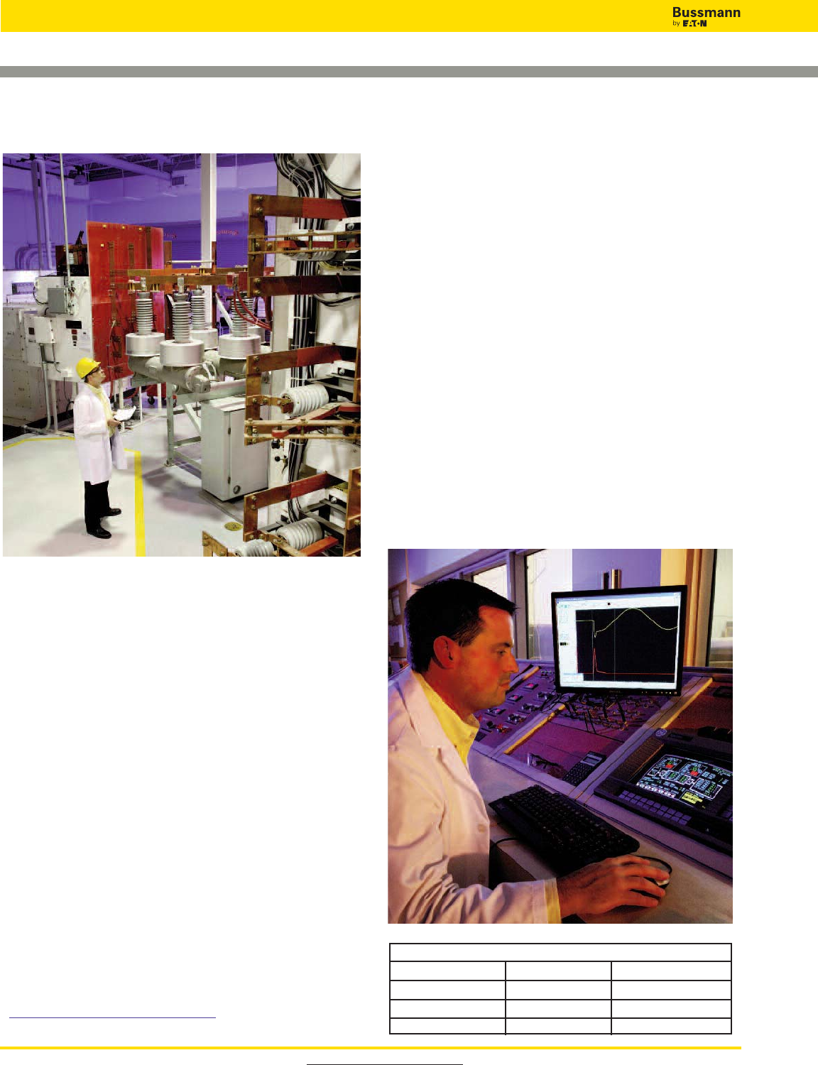
Visit www.cooperbussmann.com
514
Services
Testing
Performance and Compliance Certification for
Components and Assemblies
The Bussmann Paul P. Gubany Center for High Power
Technology at Bussmann is the electrical industry’s most
comprehensive facility for testing and certifying electrical
components and assemblies.
OEM customers make the Gubany Center their first choice in
testing equipment such as:
• Drives, both AC and DC
• Circuit breakers
• Motor control centers
• Soft starters
• Fuses
• Power distribution panels
• Surge suppressors
• Cables
Our technicians conduct tests to many global agency
standards including:
Wide Range of Capability
Built to exceed the short circuit capacity of today’s high power
electrical distribution systems, the Gubany Center performs:
• Ultra-high power testing from 200kA to 300kA at 600Vac,
three-phase
• Medium power testing from 5kA to 200kA at 600Vac,
single- and three-phase; to 100kA at 1450Vac single-phase;
to 100kA at 1000Vdc
• Low power testing up to 5kA at 600Vac, single-phase.
Description Catalog Number
High Power Testing Hourly Rate CBSV-ES-TEHP
Medium Power Testing Hourly Rate CBSV-ES-TEMP
Low Power Testing Hourly Rate CBSV-ES-TELP
Testing Catalog Numbers
To Order:
To find out more contact your local
Bussmann representative,
or visit us online at
www.cooperbussmann.com/services.
• ANCE
• ANSI
•CE
• CSA
•ETL
• IEC, and
• Underwriters
Laboratories
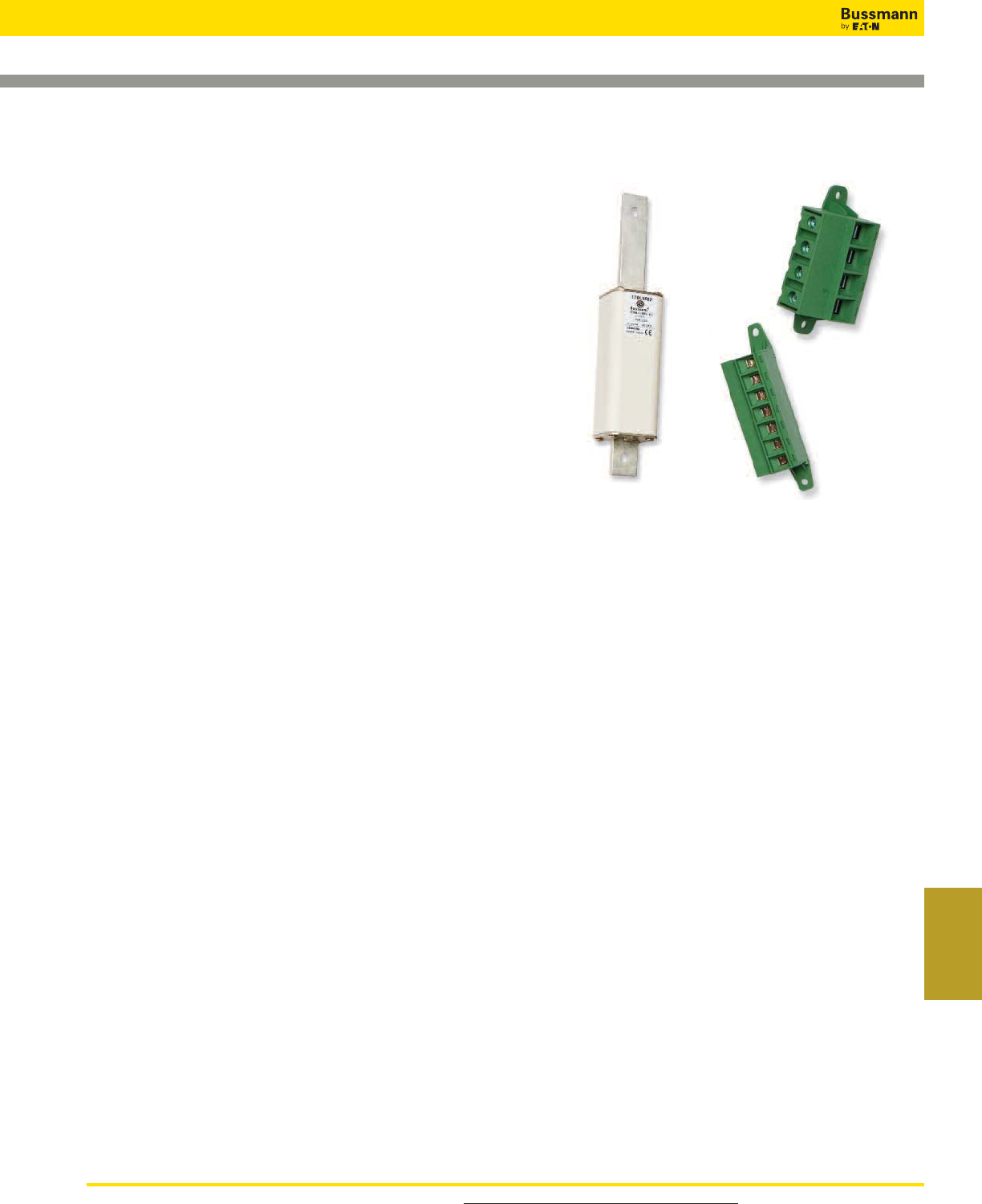
For product data sheets, visit www.cooperbussmann.com/DatasheetsEle 515
Services &
Application Guide
Custom Products
Creating the Right Answers to Unique or Demanding
Needs
When you wish to gain a competitive edge or improve your
product's performance, have Busmann provide a custom
product that can:
• Improve functionality and utility
• Fit unique design needs
• Reduce labor and component costs
Our Expertise Is Your Advantage
For almost 100 years, Bussmann has designed and
manufactured products that improve electrical safety and
performance. Whether it's modifying an existing product or
creating a new one, our experience effectively brings together
the skills to design, prototype, test, manufacture and secure
agency approvals to deliver a single component,
sub-assembly or finished product.
Busmann can design and manufacture products that
integrate:
• Fuses - with the right size and performance
characteristics
• Fuse holders and blocks - with the requisite terminations,
mounting options and safety features
• Wire connection products - that make wiring simpler,
safer and faster
• Molded products - that give the unique shape your
product needs
• Power distribution products - that meet prevailing agency
and Code requirements
In-House Testing
All electrical performance testing of your custom products
can be performed at the Bussmann Paul P. Gubany Center
for High Power Technology, an ASTA and CSA accredited,
and an ANCE Designated facility.
We're able to conduct electrical performance testing that
replicates any power system to be encountered in any
country, covering:
• Up to 300kA and 600Vac
• Up to 100kA and 1000Vdc
And our technicians conduct tests to many global agency
standards including:
• ANCE
• ANSI
•CE
• CSA
•ETL
• IEC, and
• Underwriters Laboratories
To Find Out More:
If you need a custom solution to a product problem, submit a
Request for Quotation to your local authorized Bussmann
distributor or sales representative.
Services

For product data sheets, visit www.cooperbussmann.com/DatasheetsEle
516
Application Guide
Fuse Technology
Circuit Protection
The following is a basic introduction to overcurrent protection
and fuse technology. In depth information on the selection and
application of overcurrent protective devices is available in the
Bussmann publication “Selecting Protective Devices” (SPD).
This publication is available free of charge as a PDF download
at www.cooperbussmann.com/spd.
Electrical distribution systems are often quite complicated.
They cannot be absolutely fail-safe. Circuits are subject to
destructive overcurrents. Harsh environments, general
deterioration, accidental damage, damage from natural
causes, excessive expansion, and/or overloading of the
electrical distribution system are factors which contribute to the
occurrence of such overcurrents. Reliable protective devices
prevent or minimize costly damage to transformers,
conductors, motors, and the other many components and
loads that make up the complete distribution system. Reliable
circuit protection is essential to avoid the severe monetary
losses which can result from power blackouts and prolonged
downtime of facilities. It is the need for reliable protection,
safety, and freedom from fire hazards that has made the fuse a
widely used protective device.
Overcurrents
An overcurrent is either an overload current or a short-circuit
current. The overload current is an excessive current relative to
normal operating current, but one which is confined to the
normal conductive paths provided by the conductors and other
components and loads of the distribution system. As the name
implies, a short-circuit current is one which flows outside the
normal conducting paths.
Overloads
Overloads are most often between one and six times the
normal current level. Usually, they are caused by harmless
temporary surge currents that occur when motors are
started-up or transformers are energized. Such overload
currents, or transients, are normal occurrences. Since they are
of brief duration, any temperature rise is trivial and has no
harmful effect on the circuit components. (It is important that
protective devices do not react to them.)
Continuous overloads can result from defective motors (such as
worn motor bearings), overloaded equipment, or too many loads
on one circuit. Such sustained overloads are destructive and
must be cut off by protective devices before they damage the
distribution system or system loads. However, since they are of
relatively low magnitude compared to short-circuit currents,
removal of the overload current within minutes will generally
prevent equipment damage. A sustained overload current results
in overheating of conductors and other components and will
cause deterioration of insulation, which may eventually result in
severe damage and short-circuits if not interrupted.
Short-Circuits
Whereas overload currents occur at rather modest levels, the
short-circuit or fault current can be many hundred times larger
than the normal operating current. A high level fault may be
50,000A (or larger). If not cut off within a matter of a few
thousandths of a second, damage and destruction can become
rampant—there can be severe insulation damage, melting of
conductors, vaporization of metal, ionization of gases, arcing,
and fires. Simultaneously, high level short-circuit currents can
develop huge magnetic-field stresses. The magnetic forces
between bus bars and other conductors can be many hun-
dreds of pounds per linear foot; even heavy bracing may not
be adequate to keep them from being warped or distorted
beyond repair.
Fuses
The fuse is a reliable overcurrent protective device. A “fusible”
link or links encapsulated in a tube and connected to contact
terminals comprise the fundamental elements of the basic
fuse. Electrical resistance of the link is so low that it simply
acts as a conductor. However, when destructive currents occur,
the link very quickly melts and opens the circuit to protect
conductors, and other circuit components and loads. Fuse
characteristics are stable. Fuses do not require periodic
maintenance or testing. Fuses have three unique performance
characteristics:
1. Modern fuses have an extremely “high interrupting rating”—can
withstand very high fault currents without rupturing.
2. Properly applied, fuses prevent “blackouts.” Only the fuse nearest a fault
opens without upstream fuses (feeders or mains) being affected—fuses
thus provide “selective coordination.” (These terms are precisely defined
in subsequent pages.)
3. Fuses provide optimum component protection by keeping fault currents
to a low value…They are said to be “current limiting.”
Voltage Rating
The voltage rating of a fuse must be at least equal to or
greater than the circuit voltage. It can be higher but never
lower. For instance, a 600V fuse can be used in a 208V circuit.
The voltage rating of a fuse is a function of its capability to
open a circuit under an overcurrent condition. Specifically, the
voltage rating determines the ability of the fuse to suppress the
internal arcing that occurs after a fuse link melts and an arc is
produced. If a fuse is used with a voltage rating lower than the
circuit voltage, arc suppression will be impaired and, under
some fault current conditions, the fuse may not clear the
overcurrent safely. Special consideration is necessary for
semiconductor fuse and medium voltage fuse applications,
where a fuse of a certain voltage rating is used on a lower
voltage circuit.
Amp Rating
Every fuse has a specific amp rating. In selecting the amp
rating of a fuse, consideration must be given to the type of load
and code requirements. The amp rating of a fuse normally
should not exceed the current carrying capacity of the circuit.
For instance, a continuous load current of 16 amperes typically
requires a conductor rated to carry 20A and a 20A fuse is the
largest that should be used. However, there are some
specific circumstances in which the amp rating is permitted to
be greater than the current carrying capacity of the circuit.
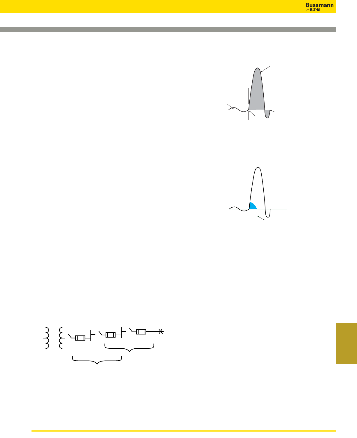
For product data sheets, visit www.cooperbussmann.com/DatasheetsEle 517
Services &
Application Guide
Application Guide
Fuse Technology
A typical example is the motor circuit; dual-element fuses
generally are permitted to be sized up to 175% and non-time-
delay fuses up to 300% of the motor full-load amps. As a rule,
the amp rating of a fuse and switch combination should be
selected at 125% of the continuous load current (this usually
corresponds to the circuit capacity, which is also selected at
125% of the load current). There are exceptions, such as when
the fuse-switch combination is approved for continuous
operation in an assembly at 100% of its rating.
Interrupting Rating
A protective device must be able to withstand the destructive
energy of short-circuit currents. If a fault current exceeds the
capability of the protective device, the device may actually
rupture, causing additional damage. Thus, it is important when
applying a fuse or circuit breaker to use one which can sustain
the largest potential short-circuit currents. The rating which
defines the capacity of a protective device to maintain its
integrity when reacting to fault currents is termed its
“interrupting rating”. The interrupting rating of most
branch-circuit, molded case, circuit breakers typically used in
residential service entrance panels is 10,000A. Larger, more
expensive circuit breakers may have interrupting ratings of
14,000A or higher. In contrast, most modern, current-limiting
fuses have an interrupting rating of 200,000 or 300,000A and
are commonly used to protect the lower rated circuit breakers.
The National Electrical Code, Section 110-9, and §OSHA 29
CFR 1910.303(b)(4) require equipment intended to break
current at fault levels to have an interrupting rating sufficient for
the current that must be interrupted.
Selective Coordination – Prevention of Blackouts
Coordination is isolation of an overloaded or faulted circuit by
the opening of only the nearest upstream protective device for
a specific overcurrent value. When only the nearest upstream
protective device of an overloaded or faulted circuit opens and
larger upstream fuses remain closed for the full range of
overcurrents on a system, the protective devices are
“selectively” coordinated (they discriminate). Selective
coordination of protective devices prevents unnecessary
system power outages or blackouts caused by overcurrent
conditions.
This diagram shows the minimum ratios of amp ratings of Low-Peak
Yellow fuses that are required to provide “selective coordination”
(discrimination) of upstream and downstream fuses.
It is a simple matter to selectively coordinate modern current-
limiting fuses. By maintaining a minimum ratio of fuse-amp
ratings between an upstream and downstream fuse, selective
coordination is assured.
Current Limitation – Component Protection
A non-current-limiting protective device, by permitting a short-
circuit current to build up to its full value, can let an immense
amount of destructive short-circuit heat energy through before
opening the circuit.
A current-limiting fuse has such a high speed of response that
it cuts off a short-circuit long before it can build up to its full
peak value, when the fault current is within the current-limiting
range of a fuse.
If a protective device cuts off a short-circuit current in less than
one-half cycle, before it reaches its total available (and highly
destructive) value, the device is a “current-limiting” device.
Most modern fuses are current-limiting. They restrict fault
currents to such low values that a high degree of protection is
given to circuit components against even very high short-circuit
currents. They permit breakers with lower interrupting ratings to
be used when series rated. They can reduce bracing of bus
structures. They minimize the need of other components to
have high short-circuit current “withstand” ratings. If not limited,
short-circuit currents can reach levels of 30,000 or 40,000A or
higher in the first half cycle (.008 seconds, 60Hz) after the start
of a short-circuit. The heat that can be produced in circuit
components by the immense energy of short-circuit currents
can cause severe insulation damage or even explosion. At the
same time, huge magnetic forces developed between
conductors can crack insulators and distort and destroy
bracing structures. Thus, it is important that a protective device
limit fault currents before they reach their full potential level.
KRP-C
1200SP
2:1 (or more)
LPS-RK
600SP
LPS-RK
200SP
2:1 (or more)
Initiation of
short-circuit
current
Normal
load current
Areas within waveform
loops represent destructive
energy impressed upon
circuit components
Circuit breaker trips
and opens short-circuit
in about 1 cycle
Fuse opens and clearsr
short-circuit in lessr
than ⁄Ω™ cycle
Not current-limiting
Current-limiting
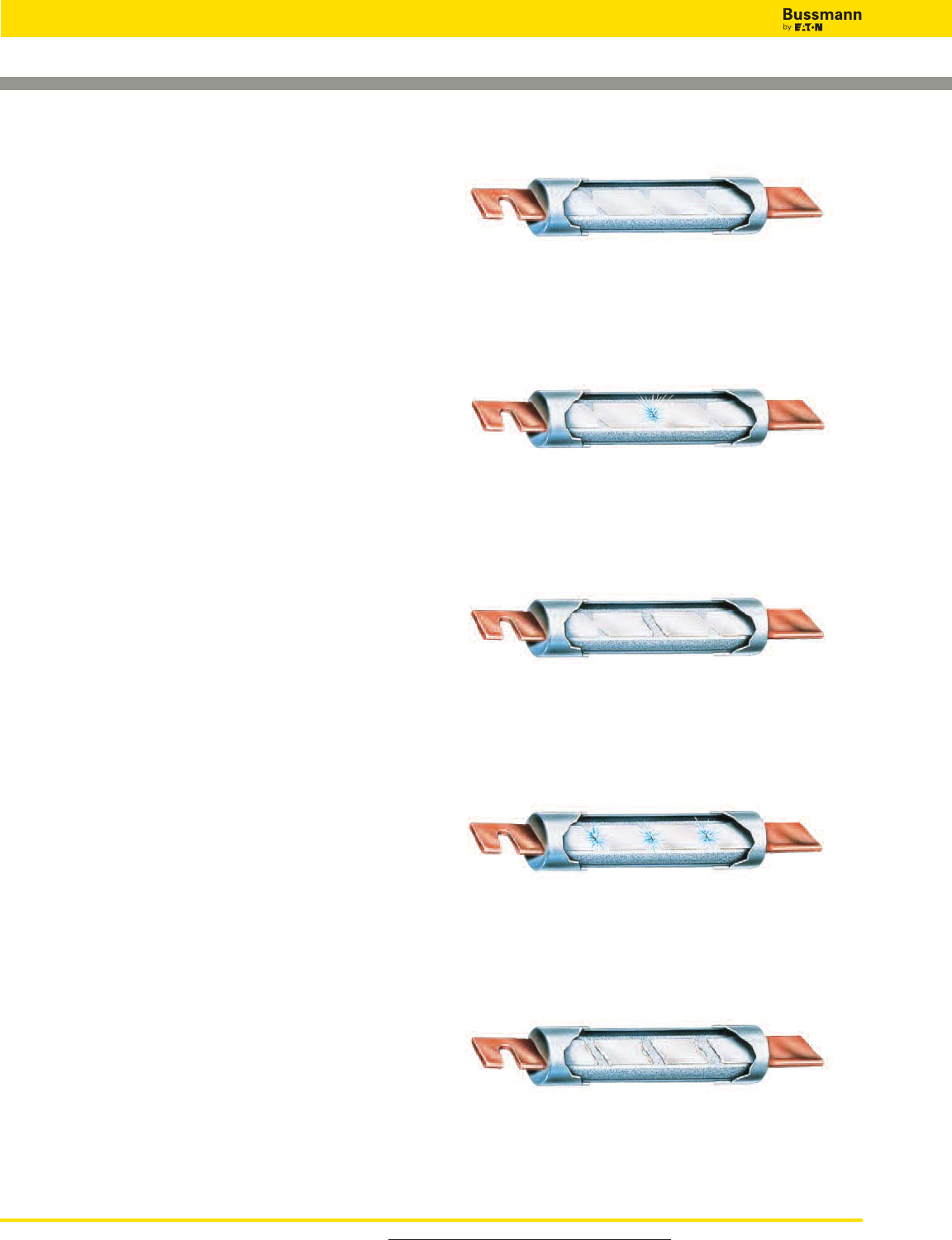
For product data sheets, visit www.cooperbussmann.com/DatasheetsEle
518
Application Guide
Fuse Technology
Operating Principles of Bussmann Fuses
The principles of operation of the modern, current-limiting
fuses are covered in the following paragraphs.
Non-Time-Delay Fuses
The basic component of a fuse is the link. Depending upon the
amp rating of the fuse, the single-element fuse may have one
or more links. They are electrically connected to the end
blades (or ferrules) (see Figure 1) and enclosed in a tube or
cartridge surrounded by an arc quenching filler material.
Bussmann Limitron™and T-Tron™fuses are both
single-element fuses.
Under normal operation, when the fuse is operating at or near
its amp rating, it simply functions as a conductor. However, as
illustrated in Figure 2, if an overload current occurs and
persists for more than a short interval of time, the temperature
of the link eventually reaches a level which causes a restricted
segment of the link to melt. As a result, a gap is formed and an
electric arc established. However, as the arc causes the link
metal to burn back, the gap becomes progressively larger.
Electrical resistance of the arc quickly reaches such a high
level that the arc cannot be sustained and is extinguished. The
fuse will have then completely cut off all current flow in the
circuit. Suppression or quenching of the arc is accelerated by
the filler material. (See Figure 3.)
Single-element fuses of present day design have a very high
speed of response to overcurrents. They provide excellent
short-circuit component protection. However, temporary,
harmless overloads or surge currents may cause nuisance
openings unless these fuses are oversized. They are best
used, therefore, in circuits not subject to heavy transient surge
currents and the temporary over-load of circuits with inductive
loads such as motors, transformers, solenoids, etc. Because
single-element, fast-acting fuses such as Limitron and
T-Tron fuses have a high speed of response to short-circuit
currents, they are particularly suited for the series rating
protection of circuit breakers with low interrupting ratings.
Whereas an overload current normally falls between one and
six times normal current, short-circuit currents are quite high.
The fuse may be subjected to short-circuit currents of 30,000
or 40kA or higher. Response of current limiting fuses to such
currents is extremely fast. The restricted sections of the fuse
link will simultaneously melt (within a matter of two or three-
thousandths of a second in the event of a high-level fault
current).
The high total resistance of the multiple arcs, together with the
quenching effects of the filler particles, results in rapid arc
suppression and clearing of the circuit. (Refer to Figures 4 & 5)
Short-circuit current is cut off in less than a half-cycle, long
before the short-circuit current can reach its full value (fuse
operating in its current limiting range).
Figure 2. Under sustained overload, a section of the link melts and an
arc is established.
Figure 3. The “open” single-element fuse after opening a circuit
overload.
Figure 4. When subjected to a short-circuit current, several sections
of the fuse link melt almost instantly.
Figure 5. The “open” single-element fuse after opening a short circuit.
Figure 1. Cutaway view of typical single-element fuse.
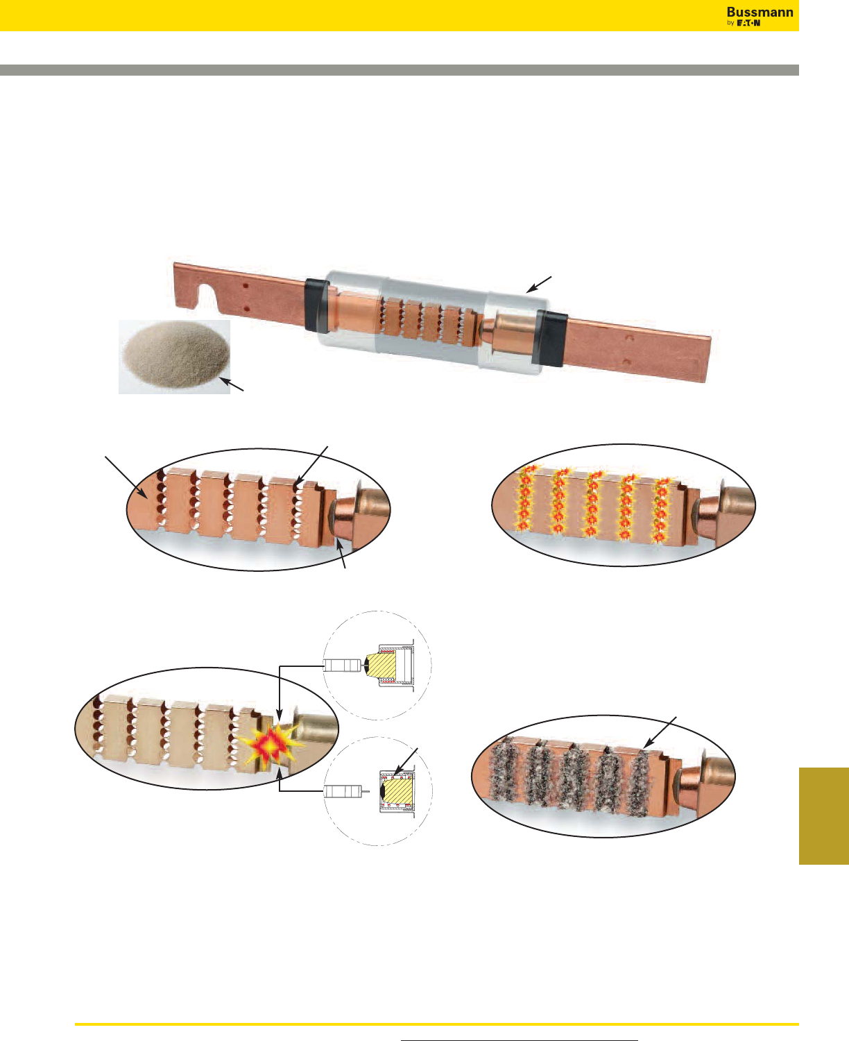
For product data sheets, visit www.cooperbussmann.com/DatasheetsEle 519
Services &
Application Guide
Application Guide
Fuse Technology
Bussmann Dual-Element Fuses
There are many advantages to using these fuses. Unlike single-element fuses, the Bussmann dual-element, time-delay fuses can be sized closer to provide both high
performance short-circuit protection and reliable overload protection in circuits subject to temporary overloads and surge currents. For ac motor loads, a single-element fuse
may need to be sized at 300% of an a.c. motor current in order to hold the starting current. However, dual-element, time delay fuses can be sized much closer to motor
loads. For instance, it is generally possible to size Fusetron Dual-Element Fuses, FRS-R and FRN-R and Low-Peak™Dual-Element Fuses, LPS-RK_SP and LPN-RK_SP, at
125% and 130% of motor full load current, respectively. Generally, the Low-Peak Dual-Element Fuses, LPJ_SP, and CUBEFuse™, TCF, can be sized at 150 to 175% of motor
full load amps. This closer fuse sizing may provide many advantages such as: (1) smaller fuse and block, holder or disconnect amp rating and physical size, (2) lower cost
due to lower amp rated devices and possibly smaller required panel space, (3) better short-circuit protection – less short-circuit current let-through energy, and (4) potential
reduction in the arc-flash hazard.
Figure 6. This is the LPS-RK100SP, a 100A, 600V Low-Peak, Class RK1, Dual-Element Fuse that has excellent time-delay, excellent current-limitation and a 300kA interrupting rating. Artistic
liberty is taken to illustrate the internal portion of this fuse. The real fuse has a non-transparent tube and special small granular, arc-quenching material completely filling the internal space.
Figure 7. The true dual-element fuse has distinct and separate overload element and short-
circuit element.
Short-circuit element
Overload element
Spring
Filler quenches the arcs
Small volume of metal to vaporize
Filler material
Insulated end-caps to help prevent
accidental contact with live parts.
Figure 8. Overload operation: Under sustained overload conditions, the trigger spring
fractures the calibrated fusing alloy and releases the “connector”. The insets represent a model
of the overload element before and after. The calibrated fusing alloy connecting the short-circuit
element to the overload element fractures at a specific temperature due to a persistent overload
current. The coiled spring pushes the connector from the short-circuit element and the circuit is
interrupted.
Figure 9. Short-circuit operation: Modern fuses are designed with minimum metal in the
restricted portions which greatly enhance their ability to have excellent current-limiting
characteristics – minimizing the short circuit let-through current. A short-circuit current causes
the restricted portions of the short-circuit element to vaporize and arcing commences. The arcs
burn back the element at the points of the arcing. Longer arcs result, which assist in reducing the
current. Also, the special arc quenching filler material contributes to extinguishing the arcing
current. Modern fuses have many restricted portions, which results in many small arclets – all
working together to force the current to zero.
Figure 10. Short-circuit operation: The special small granular, arc-quenching material plays
an important part in the interruption process. The filler assists in quenching the arcs; the filler
material absorbs the thermal energy of the arcs, fuses together and creates an insulating barrier.
This process helps in forcing the current to zero. Modern current-limiting fuses, under short-
circuit conditions, can force the current to zero and complete the interruption within a few
thousandths of a second.
When the short-circuit current is in the current-limiting range of a fuse, it is not possible for the full available short-circuit current to flow through the fuse – it’s a matter of
physics. The small restricted portions of the short-circuit element quickly vaporize and the filler material assists in forcing the current to zero. The fuse is able to “limit” the
short-circuit current.
Overcurrent protection must be reliable and sure. Whether it is the first day of the electrical system or thirty or more years later, it is important that overcurrent protective
devices perform under overload or short-circuit conditions as intended. Modern current-limiting fuses operate by very simple, reliable principles.
Before
After
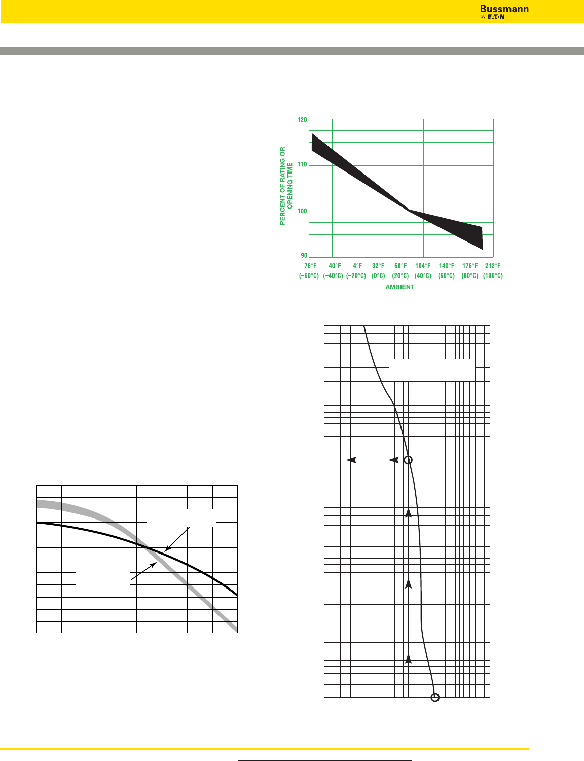
For product data sheets, visit www.cooperbussmann.com/DatasheetsEle
520
Application Guide
Fuse Technology
Fuse Time-Current Curves
When a low level overcurrent occurs, a long interval of time will
be required for a fuse to open (melt) and clear the fault. On the
other hand, if the overcurrent is large, the fuse will open very
quickly. The opening time is a function of the magnitude of the
level of overcurrent. Overcurrent levels and the corresponding
intervals of opening times are logarithmically plotted in graph
form as shown to the right. Levels of overcurrent are scaled on
the horizontal axis; time intervals on the vertical axis. The
curve is thus called a “time-current” curve.
This particular plot reflects the characteristics of a 200A, 250V,
Low-Peak™dual-element fuse. Note that at the 1,000A
overload level, the time interval which is required for the fuse
to open is 10 seconds. Yet, at approximately the 2,200A
overcurrent level, the opening (melt) time of a fuse is only 0.01
seconds. It is apparent that the time intervals become shorter
as the overcurrent levels become larger. This relationship is
termed an inverse time-to-current characteristic. Time-current
curves are published or are available on most commonly used
fuses showing “minimum melt,” “average melt” and/or “total
clear” characteristics. Although upstream and downstream
fuses are easily coordinated by adhering to simple amp ratios,
these time-current curves permit close or critical analysis of
coordination.
Better Motor Protection in Elevated Ambients
The derating of dual-element fuses based on increased
ambient temperatures closely parallels the derating curve of
motors in elevated ambient. This unique feature allows for
optimum protection of motors, even in high temperatures.
Affect of ambient temperature on operating characteristics of
Fusetron and Low-Peak dual-element fuses.
400
300
200
100
80
60
40
30
20
10
8
6
4
3
2
1
.8
.6
.4
.3
.2
.1
.08
.06
.04
.03
.02
.01
100
200
300
400
600
800
1,000
2,000
3,000
4,000
6,000
8,000
10,000
TIME IN SECONDS
CURRENT IN AMPS
LOW-PEAK
LPN-RK200 SP (RK1)
150
140
130
120
110
100
90
80
70
60
50
40
30
AMBIENT
PERCENT OF RATING OR
OPENING TIME
Affect on Carrying
Capacity Rating
Affect on
Opening Time
–76°F
(–60°C)
–40°F
(–40°C)
–4°F
(–20°C)
–32°F
(0°C)
68°F
(20°C)
104°F
(40°C)
140°F
(60°C)
176°F
(80°C)
212°F
(100°C)
Below is a rerating chart for single element fuses or non dual element fuses.
Ambient affect chart for non-dual-element fuses.
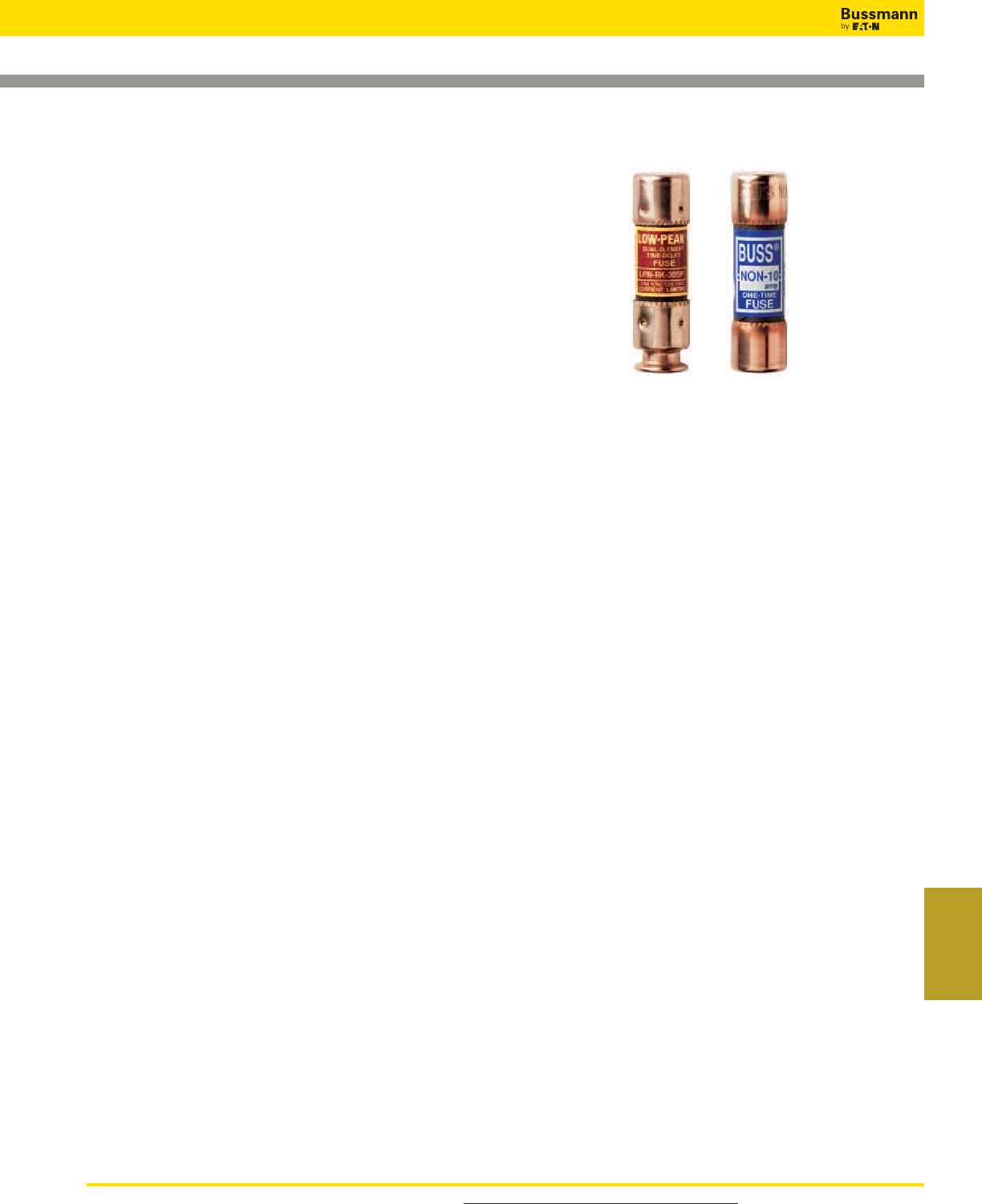
For product data sheets, visit www.cooperbussmann.com/DatasheetsEle 521
Services &
Application Guide
Application Guide
Fuse Technology
older type Class H, ONE-TIME and RENEWABLE fuses from
being installed. The use of Class R fuse holders is thus an
important safeguard. The application of Class R fuses in such
equipment as disconnect switches permits the equipment to
have a high interrupting rating. NEC®110-9 and §OSHA 29
CFR 1910.303(b)(4) require that protective devices have
adequate capacity to interrupt short-circuit currents. Article
240-60(b) requires fuse holders for current-limiting fuses to
reject non-current-limiting type fuses. In the above illustration,
a grooved ring in one ferrule provides the rejection feature of
the Class R fuse in contrast to the lower interrupting rating,
non-rejection type.
Branch-Circuit Listed Fuses
Branch-circuit listed fuses are designed to prevent the
installation of fuses that cannot provide a comparable level of
protection to equipment.
The characteristics of Branch-circuit fuses are:
1. They must have a minimum interrupting rating of 10kA
2. They must have a minimum voltage rating of 125V.
3. They must be size rejecting such that a fuse of a lower
voltage rating cannot be installed in the circuit.
4. They must be size rejecting such that a fuse with a current
rating higher than the fuse holder rating cannot be installed.
Better Protection Against Motor Single Phasing
When secondary single-phasing occurs, the current in the
remaining phases increases to approximately 200% rated full
load current. (Theoretically 173%, but change in efficiency and
power factor make it about 200%.) When primary single-
phasing occurs, unbalanced voltages occur on the motor circuit
causing currents to rise to 115%, and 230% of normal running
currents in delta-wye systems.
No overcurrent protective device sized only for motor branch
circuit short-circuit, ground fault protection will provide single-
phasing protection for 3-phase motors. Single-phasing causes
are numerous including the utility system that supplies the ser-
vice losing a phase. Single-phasing is not a serious concern
for 3-phase motors when properly protected by three properly
sized and calibrated overload protective devices. Many solid
state motor controllers will sense and cause the motor con-
troller to open for serious unbalanced voltage situations
caused by single-phasing. FRN-R, FRS-R, LPN-R_SP and
LPS-R_SP dual-element fuses sized for motor running over-
load protection will help to protect motors against the possible
damages of single-phasing. In addition, additional unbalanced
voltage protection can be incorporated into motor protection
schemes, if desired. For more information refer to the Cooper
Bussmann Selecting Protective Devices publication, section
Voltage Unbalance & Single-Phasing.
Classes of Fuses
Safety is the industry mandate. However, proper selection,
overall functional performance and reliability of a product are
factors which are not within the basic scope of listing agency
activities. In order to develop its safety test procedures, listing
agencies develop basic performance and physical
specifications or standards for a product. In the case of fuses,
these standards have culminated in the establishment of
distinct classes of low-voltage (600V or less) fuses; Classes
RK1, RK5, G, L, T, J, H and CC being the more important.
The fact that a particular type of fuse has, for instance, a
classification of RK1, does not signify that it has the identical
function or performance characteristics as other RK1 fuses. In
fact, the Limitron™non-time-delay fuse and the Low-Peak
dual-element, time-delay fuse are both classified as RK1.
Substantial differences in these two RK1 fuses usually requires
considerable difference in sizing. Dimensional specifications of
each class of fuse does serve as a uniform standard.
Class R Fuses
Class R (“R” for rejection) fuses are high performance, 1⁄10 to
600A units, 250V and 600V, having a high degree of current
limitation and a short-circuit interrupting rating of 200kA or
300kA (RMS Sym.). Bussmann Class R fuses include Class
RK1 Low-Peak™and Limitron™fuses, and RK5 Fusetron fuses.
They have replaced the K1 Low-Peak and Limitron fuses and
K5 Fusetron fuses. These fuses are identical, with the
exception of a modification in the mounting configuration called
a “rejection feature.” This feature permits Class R fuses to be
mounted in rejection type fuseclips. “R” type fuseclips prevent
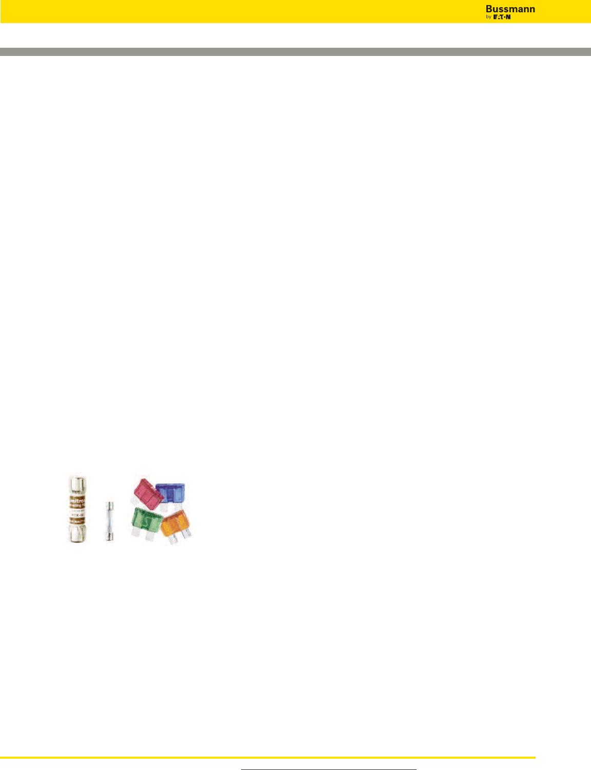
For product data sheets, visit www.cooperbussmann.com/DatasheetsEle
522
Application Guide
Fuse Technology
Reliability and Maintenance of
Overcurrent Protective Devices
Whether the first day of the electrical system or years later, it
is important that overcurrent protective devices perform under
overload and fault conditions as intended.
Modern current-limiting fuses operate by very simple, reliable
principles. Fuses do not have to be maintained. By their
inherent design, fuses do not have elements or mechanisms
to calibrate, adjust or lubricate. If and when fuses are called
upon to open on an overcurrent, installing the same type and
ampere rated fuses provides the circuit with new factory-
calibrated protection. The original design integrity can be
maintained throughout the life of the electrical system. One
last point on fuse systems; the terminations, clips and
disconnects should be maintained as necessary.
Supplementary Overcurrent Protective
Devices for use in Motor Control
Circuits
Branch Circuit vs. Supplemental Overcurrent
Protective Devices
Branch circuit overcurrent protective devices (OCPD) can be
used everywhere OCPD are used, from protection of motors
and motor circuits and group motor circuits, to protection of
distribution and utilization equipment. Supplemental OCPD
can only be used where proper protection is already being
provided by a branch circuit device, by exception [i.e.,
430.72(A)], or if protection is not required. Supplemental
OCPD can often be used to protect motor control circuits but
they cannot be used to protect motors or motor circuits. A very
common misapplication is the use of a supplementary
overcurrent protective device such as a UL 1077 mechanical
overcurrent device for motor branch circuit short-circuit and
ground fault protection. Supplementary OCPDs are incomplete
in testing compared to devices that are evaluated for branch
circuit protection. THIS IS A SERIOUS MISAPPLICATION
AND SAFETY CONCERN!! Caution should be taken to assure
that the proper overcurrent protective device is being used for
the application at hand. Below is a description of popular
supplementary overcurrent protective devices.
Most supplemental overcurrent protective devices have very
low interrupting ratings. Just as any other overcurrent
protective device, supplemental OCPDs must have an
interrupting rating equal to or greater than the available
short-circuit current.
Supplemental fuses as listed or recognized to the
UL/CSA/ANCE Trinational 248-14 Standard
These are fuses that can have many voltages and interrupting
ratings within the same case size. Examples of supplemental
fuses are 13⁄32'' X 1 1⁄2'', 5 x 20mm, and 1⁄4'' x 1 1⁄4'' fuses.
Interrupting ratings range from 35 to 100kA.

For product data sheets, visit www.cooperbussmann.com/DatasheetsEle 523
Services &
Application Guide
Application Guide
Motor Circuit Branch Circuit Protection
Motor Circuits – Choice of Overcurrent Protection
Motor circuits have unique characteristics and several
functions, such as short-circuit protection, overload protection
and automatic/ remote start/stop, that may be required.
Sometimes the comment is made that users prefer circuit
breakers because they can be reset. Let’s examine the choice
of either circuit breakers or current- limiting fuses for motor
branch circuit protection.
In the case to be examined, fuses and circuit breakers
(includes magnetic only circuit breakers which are called
MCPs or motor circuit protectors) are sized with the intent to
provide only short-circuit and ground fault protection for the
motor branch circuit protection per 430.52. Other means, such
as overload relays, provide the motor overload protection.
Typical thermal magnetic circuit breakers can only be sized for
motor branch circuit protection (typically 200% - 250% of
motor current) because if they are sized closer, the motor
starting current trips the circuit breaker’s instantaneous
mechanism. Magnetic only circuit breakers (MCPs) are
intentionally not provided with overload capability; they only
operate on short-circuit currents. There are some fuses such
as the FRS-R and LPS-RK fuses that can be sized close
enough for motor running overload protection or backup motor
running protection. But for the discussion in this section,
assume current-limiting fuses are sized only for motor
short-circuit and ground fault protection.
It is important to note that in this protection level being
discussed, a circuit breaker or fuses should only open if there
is a fault on the motor circuit. A separate overload protective
device, such as an overload relays, provides motor overload
protection per 430.32. Here are some important
considerations:
1. OSHA regulation 1910.334(b)(2) Use of Equipment states:
Reclosing circuits after protective device operation. After a circuit is
deenergized by a circuit protective device, the circuit may not be
manually reenergized until it has been determined that the equipment
and circuit can be safely energized. The repetitive manual reclosing of
circuit breakers or reenergizing circuits through replaced fuses is
prohibited. NOTE: When it can be determined from the design of the
circuit and the over-current devices involved that the automatic
operation of a device was caused by an overload rather than a fault
condition, no examination of the circuit or connected equipment is
needed before the circuit is reenergized.
So the speed of reclosing a circuit breaker after a fault is not an
advantage. The law requires that if the condition is a fault (that is the
only reason the circuit breaker or fuses should open on a motor circuit),
then the fault must be corrected prior to replacing fuses or resetting the
circuit breaker.
2. The typical level of short-circuit protection for the motor starter provided
by circuit breakers and MCPs is referred to as Type 1. This is because
most circuit breakers are not current-limiting. So, for a loadside fault,
the starter may sustain significant damage such as severe welding of
contacts and rupturing of the heater elements. Or the heater/overload
relay system may lose calibration. This is an acceptable level of
performance per UL 508, which is the product standard for motor
starters. Current-limiting fuses can be selected that can provide Type 2
“No Damage” short-circuit protection for motor starters.
Consequently, with circuit breaker protection, after a fault condition,
significant downtime and cost may be incurred in repairing or replacing
the starter. With properly selected fuses for Type 2 protection, after the
fault is repaired, only new fuses need to be inserted in the circuit; the
starter does not have to be repaired or replaced.
3. Circuit breakers must be periodically tested to verify they mechanical
operate and electrically tested to verify they still are properly calibrated
within specification. The circuit breaker manufacturers recommend this.
Typically circuit breakers should be mechanically operated at least every
year and electrically tested every 1 to 5 years, depending on the service
conditions. Modern current-limiting fuses do not have to be maintained
or electrically tested to verify they still will operate as intended. The
terminations of both circuit breakers and fusible devices need to be
periodically checked and maintained to prevent thermal damage. Plus
fuse clips should be periodically inspected and if necessary maintained.
4. After a circuit breaker interrupts a fault, it may not be suitable for further
service. UL 489, the product standard for molded case circuit breakers,
only requires a circuit breaker to interrupt two short-circuit currents at
its interrupting rating. Circuit breakers that are rated 100 amps or less
do not have to operate after only one short-circuit operation under “bus
bar” short-circuit conditions. If the fault current is high, circuit breaker
manufacturers recommend that a circuit breaker should receive a
thorough inspection with replacement, if necessary. How does one know
a circuit breaker’s service history or what level of fault current that a
circuit breaker interrupts? With modern current-limiting fuses, if the fuse
interrupts a fault, new factory calibrated fuses are installed in the circuit.
The original level of superior short-circuit protection can be there for the
life of the motor circuit.
5. After a fault, the electrician has to walk back to the storeroom to get new
fuses; that is if spare fuses are not stored adjacent to the equipment.
This does require some additional down time. However, if fuses opened
under fault conditions, there is a fault condition that must be remedied.
The electrician probably will be going back to the storeroom anyway for
parts to repair the fault. If properly selected current-limiting fuses are
used in the original circuit, the starter will not sustain any significant
damage or loss of overload calibration.
With circuit breaker protection on motor circuits, after a fault
condition, it may be necessary to repair or replace the starter,
so a trip to the storeroom may be necessary. And if the starter
is not significantly damaged, it may still need to be tested to
insure the let-through energy by the circuit breaker has not
caused the loss of starter overload calibration. Also, the circuit
breaker needs to be evaluated for suitability before placing it
back into service. Who is qualified for that evaluation? How
much time will that take?
In summary, resettability is not an important feature for motor
branch circuit (short-circuit) protection and resettability of the
branch circuit protective device is not a benefit for motor
circuits. As a matter of fact, resettability of the motor branch
circuit overcurrent protective device may encourage an unsafe
practice. The function of motor branch circuit protection is fault
protection: short-circuit and ground fault protection. Faults do
not occur on a regular basis. But when a fault does occur, it is
important to have the very best protection. The best motor
branch circuit protection can be judged by (1) reliability - its
ability to retain its calibration and speed of operation over its
lifetime, (2) current-limiting protection - its ability to provide
Type 2 “No Damage” protection to the motor starter, and (3)
safety - its ability to meet a facility’s safety needs. Modern
current-limiting fuses are superior to circuit breakers for motor
branch circuit protection.

For product data sheets, visit www.cooperbussmann.com/DatasheetsEle
524
Application Guide
Glossary
Ampere (Amp)
The measurement of intensity of rate of
flow of electrons in an electric circuit. An
ampere (amp) is the amount of current
that will flow through a resistance of one
ohm under a pressure of one volt.
Ampere is often abbreviated as “A.”
Amp Rating
The current-carrying capacity of a fuse.
When a fuse is subjected to a current
above its amp rating, it will open the
circuit after a predetermined period of
time.
Amp Squared Seconds, l2t
The measure of heat energy developed
within a circuit during the fuse’s
clearing. It can be expressed as
“melting l2t”, “arcing l2t” or the sum of
them as “Clearing l2t”. “l” stands for
effective let-through current (RMS),
which is squared, and “t” stands for time
of opening, in seconds.
Arcing I2t
Value of the I2t during the arcing time
under specified conditions.
Arcing Time
The amount of time from the instant
the fuse link has melted until the
overcurrent is interrupted, or cleared.
Breaking Capacity
(See Interrupting Rating)
Cartridge Fuse
A fuse consisting of a current
responsive element inside a fuse tube
with terminals on both ends.
Class CC Fuses
600V, 200kA interrupting rating, branch
circuit fuses with overall dimensions of
13⁄32” x 11⁄2”. Their design incorporates a
rejection feature that allows them to be
inserted into rejection fuse holders and
fuse blocks that reject all lower voltage,
lower interrupting rat ing 13⁄32” x 11⁄2” fuses.
They are available from 1⁄10A through
30A.
Class G Fuses
480V, 100kA interrupting rating branch
circuit fuses that are size rejecting to
eliminate overfusing. The fuse diameter
is 13⁄32˝ while the length varies from 15⁄16˝
to 21⁄4˝. These are available in ratings
from 1A through 60A.
Class H Fuses
250V and 600V, 10kA interrupting rating
branch circuit fuses that may be
renewable or non-renewable. These are
available in amp ratings of 1A through
600A.
Class J Fuses
These fuses are rated to interrupt a
minimum of 200kA AC. They are labeled
as “Current-Limiting,” are rated for
600Vac, and are not interchangeable
with other classes.
Class K Fuses
These are fuses listed as K-1, K-5, or
K-9 fuses. Each subclass has
designated I2t and lpmaximums. These
are dimensionally the same as Class H
fuses, and they can have interrupting
ratings of 50kA, 100kA, or 200kA.
These fuses are current-limiting.
However, they are not marked
“current-limiting” on their label since
they do not have a rejection feature.
Class L Fuses
These fuses are rated for 601 through
6000A, and are rated to interrupt a
minimum of 200kA AC. They are labeled
“Current-Limiting” and are rated for
600Vac. They are intended to be bolted
into their mountings and are not
normally used in clips. Some Class L
fuses have designed in time-delay
features for all purpose use.
Class R Fuses
These are high performance fuses rated
1⁄10-600A in 250V and 600V ratings. All
are marked “Current Limiting” on their
label and all have a minimum of 200kA
interrupting rating. They have identical
outline dimensions with the Class H
fuses but have a rejection feature which
prevents the user from mounting a fuse
of lesser capabilities (lower interrupting
capacity) when used with special Class
R Clips. Class R fuses will fit into either
rejection or non-rejection clips.
Class T Fuses
An industry class of fuses in 300V and
600V ratings from 1A through 1200A.
They are physically very small and can
be applied where space is at a
premium. They are fast-acting fuses
with an interrupting rating of 200kA
RMS.
Classes of Fuses
The industry has developed basic
physical specifications and electrical
performance requirements for fuses with
voltage ratings of 600V or less. These
are known as standards. If a type of
fuse meets the requirements of a
standard, it can fall into that class.
Typical classes are K, RK1, RK5, G, L,
H, T, CC, and J.
Clearing Time
The total time between the beginning of
the overcurrent and the final opening of
the circuit at rated voltage by an
overcurrent protective device. Clearing
time is the total of the melting time and
the arcing time.
Current Limitation
A fuse operation relating to short circuits
only. When a fuse operates in its
current-limiting range, it will clear a short
circuit in less than 1⁄2cycle. Also, it will
limit the instantaneous peak let-through
current to a value substantially less than
that obtainable in the same circuit if that
fuse were replaced with a solid
conductor of equal impedance.

For product data sheets, visit www.cooperbussmann.com/DatasheetsEle 525
Services &
Application Guide
Application Guide
Glossary
Dual Element Fuse
Fuse with a special design that utilizes
two individual elements in series inside
the fuse tube. One element, the spring
actuated trigger assembly, operates on
overloads up to 5-6 times the fuse
current rating. The other element, the
short circuit section, operates on short
circuits up to their interrupting rating.
Electrical Load
That part of the electrical system which
actually uses the energy or does the
work required.
Fast-Acting Fuse
A fuse which opens on overload and
short circuits very quickly. This type of
fuse is not designed to withstand
temporary overload currents associated
with some electrical loads.
Fuse
An overcurrent protective device with a
fusible link that operates and opens the
circuit on an overcurrent condition.
High Speed Fuses
Fuses with no intentional time-delay in
the overload range and designed to
open as quickly as possible in the
short-circuit range. These fuses are
often used to protect solid-state devices.
Inductive Load
An electrical load which pulls a large
amount of current—an inrush current—
when first energized. After a few cycles
or seconds the current “settles down” to
the full-load running current.
Interrupting Capacity
(See Interrupting Rating)
Interrupting Rating — IR
(Breaking Capacity)
The rating which defines a fuse’s ability
to safely interrupt and clear short
circuits. This rating is much greater than
the ampere rating of a fuse. The NEC®
defines Interrupting Rating as “The
highest current at rated voltage that an
overcurrent protective device is intend-
ed to interrupt under standard test
conditions.”
Melting I2t
Value of the I2t during the melting time
of the fuse link under specified
conditions.
Melting Time
The amount of time required to melt the
fuse link during a specified overcurrent.
(See Arcing Time and Clearing Time.)
“NEC®” Dimensions
These are dimensions once referenced
in the National Electrical Code. They are
common to Class H and K fuses and
provide interchangeability between
manufacturers for fuses and fusible
equipment of given ampere and
voltage ratings.
Ohm
The unit of measure for electric
resistance. An ohm is the amount of
resistance that will allow one ampere to
flow under a pressure of one volt.
Ohm’s Law
The relationship between voltage,
current, and resistance, expressed by
the equation E = IR, where E is the
voltage in volts, I is the current in amps,
and R is the resistance in ohms.
One Time Fuses
Generic term used to describe a Class
H non-renewable cartridge fuse, with a
single element.
Overcurrent
A condition which exists on an electrical
circuit when the normal load current is
exceeded. Overcurrents take on two
separate characteristics—overloads and
short-circuits.
Overload
Can be classified as an overcurrent
which exceeds the normal full load
current of a circuit. Also characteristic of
this type of overcurrent is that it does
not leave the normal current carrying
path of the circuit—that is, it flows from
the source, through the conductors,
through the load, back through the
conductors, to the source again.
Peak Let-Through Current, lp
The instantaneous value of peak current
let-through by a current-limiting fuse,
when it operates in its current-limiting
range.
Renewable Fuse (600V & below)
A fuse in which the element, typically a
zinc link, may be replaced after the fuse
has opened, and then reused. Renewable
fuses are made to Class H standards.
Resistive Load
An electrical load which is characteristic of
not having any significant inrush current.
When a resistive load is energized, the
current rises instantly to its steady-state
value, without first rising to a higher value.
RMS Current
The RMS (root-mean-square) value of
any periodic current is equal to the value
of the direct current which, flowing through
a resistance, produces the same heating
effect in the resistance as the periodic
current does.
SCCR
See Short-Circuit Current Rating
Semiconductor Fuses
Fuses used to protect solid-state devices.
See “High Speed Fuses.”
Short-Circuit
Can be classified as an overcurrent which
exceeds the normal full load current of a
circuit by a factor many times (tens,
hundreds or thousands greater). Also
characteristic of this type of overcurrent is
that it leaves the normal current carrying
path of the circuit—it takes a “short cut”
around the load and back to the source.
Short-Circuit Current Rating
(SCCR)
The maximum short-circuit current an
electrical component can sustain without
the occurrence of excessive damage
when protected with an overcurrent
protective device.
Short-Circuit Withstand Rating
Same definition as short-circuit current
rating.
For product data sheets, visit www.cooperbussmann.com/DatasheetsEle
526
Application Guide
Glossary
Single-Phasing
That condition which occurs when one-
phase of a three-phase system opens,
either in a low voltage (secondary) or
high voltage (primary) distribution
system. Primary or secondary single-
phasing can be caused by any number
of events. This condition results in
unbalanced currents in polyphase
motors and unless protective measures
are taken, causes overheating and
failure.
Threshold Current
The symmetrical RMS available current
at the threshold of the current-limiting
range, where the fuse becomes
current-limiting when tested to the
industry standard. This value can be
read off of a peak let-through chart
where the fuse curve intersects the A-B
line. A threshold ratio is the relationship
of the threshold current to the fuse’s
continuous current rating.
Time-Delay Fuse
A fuse with a built-in delay that allows
temporary and harmless inrush currents
to pass without opening, but is so
designed to open on sustained
overloads and short circuits.
Total Clearing I2t
Total measure of heat energy developed
within a circuit during the fuse’s clearing
of a fault current. Total Clearing I2t is the
sum of the melting I2t and arcing I2t.
Voltage Rating
The maximum open circuit voltage in
which a fuse can be used, yet safely
interrupt an overcurrent. Exceeding the
voltage rating of a fuse impairs its ability
to clear an overload or short-circuit
safely.
Withstand Rating
The maximum current that an
unprotected electrical component can
sustain for a specified period of time
without the occurrence of extensive
damage.
Bussmann # Upgrade # Description Data Sheet #
AGC-(AMP) ABC-(AMP) FAST-ACTING,
1
⁄
4
” X 1
1
⁄
4
” FUSE 2001
AGC-V-(AMP) ABC-V-(AMP) FAST-ACTING,
1
⁄
4
” X 1
1
⁄
4
” FUSE WITH LEADS 2001
AGU-(AMP) LP-CC-(AMP) FAST-ACTING,
13
⁄
32
” X 1
1
⁄
2
” FUSE 2008
BAF-(AMP) LP-CC-(AMP) FAST-ACTING,
13
⁄
32
” X 1
1
⁄
2
” FUSE 2011
BAN-(AMP) LP-CC-(AMP) FAST-ACTING,
13
⁄
32
” X 1
1
⁄
2
” FUSE 2046
DCM-(AMP) PVM-(AMP) SOLAR USE - FAST-ACTING,
13
⁄
32
” X 1
1
⁄
2
” FUSE 2153
DCM-(AMP) KLM-(AMP) INDUSTRIAL - FAST-ACTING,
13
⁄
32
” X 1
1
⁄
2
” FUSE 2020
DLS-(AMP)
ECNR-(AMP)
TIME-DELAY, 250Vac, CLASS RK5 1315
DLS-(AMP)
ECSR-(AMP)
TIME-DELAY, 600Vac, CLASS RK5 1318
FNM-(AMP) LP-CC-(AMP) TIME-DELAY,
13
⁄
32
” X 1
1
⁄
2
” FUSE 2028
FNQ-R-(AMP) LP-CC-(AMP)* TIME-DELAY, 500V,
13
⁄
32
” X 1
1
⁄
2
” FUSE 1012
FNR-R-(AMP) LPN-RK-(AMP)SP TIME-DELAY, 250V, CLASS RK5 FUSES 1019/1020
FRS-R-(AMP) LPS-RK-(AMP)SP TIME-DELAY, 600V, CLASS RK5 FUSES 1017/1018
JKS-(AMP) LPJ-(AMP)SP FAST-ACTING, 600V, CLASS J FUSE 1026/1027
KLU-(AMP) KRP-C-(AMP)SP TIME-DELAY, CLASS L FUSE 1013
KTK-(AMP) KTK-R-(AMP) FAST-ACTING, 600V,
13
⁄
32
” X 1
1
⁄
2
” FUSE 1011
KTK-R-(AMP) LP-CC-(AMP) FAST-ACTING, 600V, CLASS CC FUSE 1015
KTN-R-(AMP) LPN-RK-(AMP)SP FAST-ACTING, 250V, CLASS RK1 FUSE 1043
KTS-R-(AMP) LPS-RK-(AMP)SP FAST-ACTING, 600V, CLASS RK1 FUSE 1044
KTU-(AMP) KPR-C-(AMP)SP FAST-ACTING, 600V, CLASS L FUSE 1010
KWS-R-(AMP) LPS-RK-(AMP)SP FAST-ACTING, 600V, CLASS RK1 FUSE 1044
MDL-(AMP) MDA-(AMP) TIME-DELAY,
1
⁄
4
” X 1
1
⁄
4
” FUSE 2004
MDL-V-(AMP) MDA-V-(AMP) TIME-DELAY,
1
⁄
4
” X 1
1
⁄
4
” FUSE WITH LEADS 2004
MTH-(AMP) ABC-(AMP) FAST-ACTING,
1
⁄
4
” X 1
1
⁄
4
” FUSE
NON-(AMP) LPN-RK-(AMP)SP GENERAL PURPOSE, 250V, CLASS H FUSES 1030
NOS-(AMP) LPS-RK-(AMP)SP GENERAL PURPOSE, 600V, CLASS H FUSES 1030
REN-(AMP) LPN-RK-(AMP)SP 250V RENEWABLE FUSELINK 1028
RES-(AMP) LPS-RK-(AMP)SP 600V RENEWABLE FUSELINK 1028
SL-(AMP) S-(AMP) TIME-DELAY, 125V, PLUG FUSE 1033
TL-(AMP) T-(AMP) TIME-DELAY, 125V, PLUG FUSE 1035
W-(AMP) TL-(AMP) TIME-DELAY, 125V, PLUG FUSE 1035
Out-of-Stock
Substitution/Upgrades
*Not recommended for control transformer circuits.
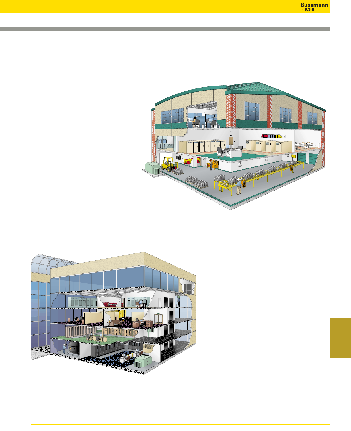
For product data sheets, visit www.cooperbussmann.com/DatasheetsEle 527
Services &
Application Guide
Application Guide
527
Industrial Fuse Applications
Industrial Applications
1. Interior Lighting
2. Computer Power
3. Switchboards
4. Motor Control Center
5. Emergency Lighting
6. UPS Backup Power Supplies
7. Transformer/Emergency Generator
8. Forklift Battery Charging Station
9. HVAC Chillers/Blowers
10. Welding Circuits
11. Plant Lighting
12. Distribution Panels
13. Disconnect Switches
14. Programmable Logic Circuits
15. Conveyor System
Commercial Applications
1. Interior Lighting
2. HVAC Blowers
3. Computer Power
4. Branch Circuits
5. Emergency Lighting
6. Load Centers
7. Disconnect/Distribution Panels
8. HVAC/Chillers
9. Switchboards/Motor Control Centers
10. UPS Backup Power Supplies
11. Elevator Control Centers
12. Transformer/Emergency Generator
For product data sheets, visit www.cooperbussmann.com/DatasheetsEle
528
FUSEFinder Quick Cross Reference Guide
Competitor
Fuse Family Bussmann
Competitor
Fuse Family
Competitor
Fuse Family
Bussmann Bussmann
Bussmann, the industry leader in critical circuit protection, power management and electrical safety offers an
extensive selection of fuses and fuse blocks to meet precise overcurrent protection needs.
Whether it’s glass tube, low voltage or high speed fuse ... or fuse blocks needed for an application, you can use
this FuseFinder Quick Cross Reference Guide to fi nd the Bussmann replacement. If you cannot fi nd a cross,
more extensive listings are available online at www.cooperbussmann.com/FuseFinder. Or contact our Application
Engineers at FuseTech@cooperindustries.com.
GMT-(AMP)A
GDC-(AMP)
GDB-(AMP)
GDC-(AMP)
S505-(AMP)
GDA-(AMP)
GDB-(AMP)
GDC-(AMP)
S505-V-(AMP)
GDA-V-(AMP)
GDB-V-(AMP)
GDC-V-(AMP)
BK/C515-(AMP)
GMA-(AMP)
GMA-V-(AMP)
GMD-V-(AMP)
GMD-(AMP)
MCRW-(AMP)
MCRW-(AMP)
MCRW-(AMP)
MCRW-(AMP)
ATC-(AMP)
MCRW-(AMP)
MCRW-(AMP)
ATM-(AMP)
MAX-(AMP)
BK/C517-(AMP)
BK/C515-(AMP)
AGA-(AMP)
AGW-(AMP)
SFE-(AMP)
AGC-(AMP)
AGC-(AMP)
MDL-(AMP)
ABC-(AMP)
MDL-V-(AMP)
AGC-V-(AMP)
GBB-(AMP)
MDA-(AMP)
ABC-V-(AMP)
MDA-V-(AMP)
MDA-(AMP)
GLD-(AMP)
GBA-(AMP)
AGX-(AMP)
AGX-(AMP)
SL-(AMP)
S-(AMP)
T-(AMP)
ABC-(AMP)
AGC-V-(AMP)
AGC-(AMP)
AGC-(AMP)
AGC-(AMP)
MDL-(AMP)
MDL-V-(AMP)
AGC-V-(AMP)
MDL-(AMP)
MDL-V-(AMP)
GMT-(AMP)A
ABS-(AMP)
ABS-(AMP)
413(AMP)
414(AMP)
417(AMP)
418(AMP)
429(AMP)
431(AMP)
5140(AMP)
5170(AMP)
523(AMP)
5HF(AMP)
5HFP(AMP)
5HT(AMP)
5MF(AMP)
5MFP(AMP)
5SF(AMP)
5ST(AMP)
6J(AMP)X
6R(AMP)D
702(AMP)
703(AMP)
81200(AMP)ST
A70P(AMP)-1 or Type 1
A70P(AMP)-4 or Type 4
A70Q(AMP)-4 or Type 4
A70QS(AMP)-14F
A70QS(AMP)-22F
A70QS[35-200]-4
A70QS[225-400]-4 or 4K
A70QS[450-600]-4K
A70QS[700-800]-4
A50P(AMP)-1
A50P(AMP)-4
A50QS(AMP)-4 or Type 4
A30QS(AMP)-1 or Type 1
A30QS[35-700]-4 or Type 4
A30QS[1000-1200]-128
A15QS[1-30]-2
A15QS[35-60]-1
A15QS[70-400]-4
A2D(AMP)R
A2K(AMP)
A3T(AMP)
A4BQ[225-600]
A4BQ[601-6000]
A4BT[601-4000]
A4BY(AMP)
A4J(AMP)
A6D(AMP)R
A6K(AMP)
A6T(AMP)
AG(AMP)
AJT(AMP)
AM10/(AMP)
AOK(AMP)
ATDR(AMP)
ATM(AMP)
ATMR(AMP)
ATQ(AMP)
ATQR(AMP)
BBC(AMP)
BDB(AMP)
BDC(AMP)
MDM-(AMP)
ABS-(AMP)
ABS-(AMP)
TR/3216FF-(AMP)
3216FF(AMP)
0603FA(AMP)
BAF-(AMP)
AGU-(AMP)
FNM-(AMP)
GDA-(AMP)
GDA-V-(AMP)
BK/S505-(AMP)A
GMA-(AMP)
GMA-V-(AMP)
GDB-(AMP)
GDC-(AMP)
KTK-(AMP)
LPS-RK-(AMP)SP
HVJ-(AMP)
HVL-(AMP)
CBS-(AMP)
FWP-(AMP)A14F
FWP-(AMP)A orB
FWP-(AMP)A or B
FWP-(AMP)A14F
FWP-(AMP)A22F
FWP-(AMP)A or B
FWP-(AMP)A or B
FWP-(AMP)A or B
FWP-(AMP)A or B
FWH-(AMP)A14F
FWH-(AMP)A or B
FWH-(AMP)A or B
FWX-(AMP)A14F
FWX-(AMP)A
FWX-(AMP)AH
FWA-(AMP)A10F
FWA-(AMP)A21F
FWA-(AMP)B
LPN-RK(AMP)SP
KTN-R(AMP)
JJN(AMP)
KRP-CL-(AMP)
KRP-C-(AMP)SP
KLU[601-4000]
KLU(AMP)
JKS(AMP)
LPS-RK(AMP)SP
KTS-R(AMP)
JJS(AMP)
SC(AMP)
LPJ(AMP)SP
LP-CC-(AMP)
ALS-(AMP)
LP-CC-(AMP)
KLM(AMP)
KTK-R(AMP)
FNQ-(AMP)
FNQ-R-(AMP)
ABC-(AMP)
GDB-(AMP)
GDC-(AMP)
BDL(AMP)
BGC(AMP)
BGX(AMP)
BLF(AMP)
BLN(AMP)
BLS(AMP)
BMA(AMP)
CBO(AMP) [4-160A]
CCK(AMP) [1-300A]
CCL(AMP) [30-100A]
CCLB(AMP) [20-250A]
CCLW(AMP) [1-300A]
CCMR[1-30A Only]
CDNC(AMP)
CDSC(AMP)
CNL(AMP)
CNN(AMP)
DCT[1-15A]
E(AMP)FC
E(AMP)FE
E(AMP)FET
E(AMP)FM
E(AMP)FMM
E(AMP)LCT [6-20A]
E(AMP)LET [25-180A]
E(AMP)LMMT [315-900A]
E(AMP)LMT [160-450A]
E100SF(AMP) [20-30A]
E100S(AMP) [40-2000A]
E15S(AMP) [35-3000A]
E15SF(AMP) [5, 10, 15, 20, 25, 30A]
E25S(AMP) [1000-2500A]
E25S(AMP) [35-800A]
E25SFX(AMP) [5-30A]
E50S(AMP)
E50SF(AMP) [5-30A]
E70S(AMP)
ECK(AMP) [1-300A]
ECL(AMP) [30-100A]
ECN(AMP)
ECNR(AMP)
ECS(AMP)
ECSR(AMP)
ELR(AMP)
ENLE(AMP)
ENNE(AMP)
ERN(AMP)
ERS(AMP)
ESA(AMP)
FA(AMP)
FII(AMP)
FIIC(AMP)
FIIM(AMP) [125-200A]
FIIM(AMP) [80-100A]
FLA(AMP)
FLM(AMP)
FLN(AMP)
FLNR(AMP)
FLQ(AMP)
FLS(AMP)
FLSR(AMP)
GFN(AMP)
MDL-(AMP)
AGC-(AMP)
AGX-(AMP)
BAF-(AMP)
BAN-(AMP)
BBS-(AMP)
GDA-(AMP)
HBO-(AMP)
ACK-(AMP)
ACL-(AMP)
KGJ-E-(AMP)
KGJ-(AMP)
LP-CC(AMP)
CDN(AMP)
CDS(AMP)
ANL-(AMP)
ANN-(AMP)
PV-(AMP)A10F
(AMP)FC
(AMP)FE
(AMP)FET
(AMP)FM
(AMP)FMM
(AMP)LCT
(AMP)LET
(AMP)LMMT
(AMP)LMT
FWJ-(AMP)A14F
FWJ-(AMP)
FWA-(AMP)A
FWA-(AMP)A10F
FWX-(AMP)AH
FWX-(AMP)A
FWX-(AMP)14F
FWH-(AMP)
FWH-(AMP)14F
FWP-(AMP)
ACK-(AMP)
ACL-(AMP)
FRN-R-(AMP)
FRN-R-(AMP)
FRS-R-(AMP)
FRS-R-(AMP)
GLR-(AMP)
ANL-(AMP)
ANN-(AMP)
REN-(AMP)
RES-(AMP)
S-(AMP)
SA(AMP)
CGL-(AMP)
CGL-(AMP)
(AMP)M14CB
(AMP)L09CB
FNA-(AMP)
FNM-(AMP)
FRN-R-(AMP)
FRN-R-(AMP)
FNQ-(AMP)
FRS-R-(AMP)
FRS-R-(AMP)
FNA-(AMP)
0481(AMP)
211(AMP)
212(AMP)
213(AMP)
215(AMP)
216(AMP)
217(AMP)
218(AMP)
221(AMP)
226(AMP)
227(AMP)
228(AMP)
230(AMP)
235(AMP)
236(AMP)
238(AMP)
239(AMP)
251(AMP)
252(AMP)
255(AMP) [1/16-5A]
256(AMP)
257(AMP)
275(AMP)
276(AMP)
297(AMP)[AUTOMOTIVEFUSE]
299(AMP)
2AG220
2AG230
301(AMP)
303(AMP)
307(AMP)
311(AMP)
312(AMP)
313(AMP)
314(AMP)
315(AMP)
318(AMP)
322(AMP)
323(AMP)
324(AMP)
325(AMP)
326(AMP)
334(AMP)
336(AMP)
361(AMP)
362(AMP)
3770(AMP)
3780(AMP)
3785(AMP)
3AB(AMP)
3ABP(AMP)
3AG(AMP)
3AG311(AMP)
3AG312(AMP)
3AG313(AMP)
3AG315(AMP)
3AG318(AMP)
3SB(AMP)
3SBP(AMP)
401(AMP)
411(AMP)
412(AMP)
For product data sheets, visit www.cooperbussmann.com/DatasheetsEle 529
FUSEFinder Quick Cross Reference Guide
Index by
Part Number
GGU(AMP)
GL10/(AMP)
HCLR(AMP)
HCTR(AMP)
HSJ(AMP)
IDSR[6-60A Only]
J(AMP)
JDL(AMP)
JFL(AMP)
JLLN(AMP)
JLLS(AMP)
JLS(AMP)
JTD(AMP)
KLA(AMP) [5, 10, 15, 20, 25, 30A]
KLB(AMP) [1-30A]
KLC(AMP)
KLDR (AMP)
KLH(AMP) [1-30A]
KLH(AMP) [225-600A]
KLH(AMP) [35-200A]
KLK(AMP)
KLKR(AMP)
KLLU(AMP)
KLMR(AMP)
KLNR(AMP)
KLPC(AMP)
KLSR(AMP)
KLW(AMP)
KON(AMP)
KOS(AMP)
L(AMP)TD
L15S(AMP) [1-30A]
L15S(AMP) [35-60A]
L15S(AMP) [70-400A]
L25S(AMP) [1-30A]
L50S(AMP) [1-30A]
L70S(AMP) [1-30A]
LCU(AMP)
LEN(AMP)
LENRK(AMP)
LES(AMP)
LESR(AMP)
LESRK(AMP)
LGR(AMP)
LHR(AMP)
LKU(AMP)
LLNRK(AMP)
LLSRK(AMP)
MEN(AMP)
MEQ(AMP)
MJS(AMP)
MOL(AMP)
MQ(AMP)
NCL(AMP)
NCLR(AMP)
NLN(AMP)
NLS(AMP)
OT(AMP)
OTM(AMP)
OTS(AMP)
PICO
R224(AMP)
R230(AMP)
R251(AMP)T1
AGU(AMP)
KTK-(AMP)
KTK-R-(AMP)
FNQ-R-(AMP)
DFJ(AMP)
FRS-R-(AMP)ID
JKS-(AMP)
LPJ-(AMP)SP
JKS-(AMP)
JJN-(AMP)
JJS-(AMP)
JKS-(AMP)
LPJ-(AMP)SP
FWA-(AMP)A10F
FWX-(AMP)A14F
KAC-(AMP)
FNQ-R-(AMP)
FWH-(AMP)A14F
FWH-(AMP)A
FWH-(AMP)B
KTK-(AMP)
KTK-R-(AMP)
KLU-(AMP)
LP-CC-(AMP)
KTN-R-(AMP)
KRP-C-(AMP)SP
KTS-R-(AMP)
FWA-(AMP)10F
NON-(AMP)
NOS-(AMP)
KRP-C-(AMP)SP
FWA-(AMP)A10F
FWA-(AMP)A21F
FWA-(AMP)A
FWX-(AMP)A14F
FWH-(AMP)A14F
FWP-(AMP)A14F
KTU-(AMP)
FRN-R-(AMP)
LPN-RK-(AMP)SP
FRS-R-(AMP)
FRS-R-(AMP)
LPS-RK-(AMP)SP
GLR-(AMP)
HLR(AMP)
KLU-(AMP)
LPN-RK-(AMP)SP
LPS-RK-(AMP)SP
FNM-(AMP)
FNQ-(AMP)
BK/C515-(AMP)
BAF-(AMP)
MCRW-(AMP)
KTN-R-(AMP)
KTN-R-(AMP)
NON-(AMP)
NOS-(AMP)
NON(AMP)
BAF-(AMP)
NOS(AMP)
MCRW-(AMP)
TR2/C518-(AMP)A
TR/C515-(AMP)A
TR/MCRW-(AMP)
RF(AMP)
RFS(AMP)
RLN(AMP)
RLS(AMP)
SAO(AMP)
SBS(AMP)
SCL(AMP)
SCLR(AMP)
SEC(AMP)
SLC(AMP)
SLO(AMP)
SOO(AMP)
TLO(AMP)
TOO(AMP)
TR(AMP)
TRM(AMP)
TRS(AMP)
WOO(AMP)
LFJ60030(X) / (X)ID
LFJ60060(X) / (X)ID
LFJ60100(X) / (X)ID
LFJ60200(X) / (X)ID
LFJ60400(X) / (X)ID
LFJ60600(X) / (X)ID
LFR25030(X) / (X)ID
LFR25060(X) / (X)ID
LFR25100(X) / (X)ID
LFR25200(X) / (X)ID
LFR25400(X) / (X)ID
LFR25600(X) / (X)ID
LFR60030(X) / (X)ID
LFR60060(X) / (X)ID
LFR60100(X) / (X)ID
LFR60200(X) / (X)ID
LFR60400(X) / (X)ID
LFR60600(X) / (X)ID
LFH25030(X) / (X)ID
LFH25060(X) / (X)ID
LFH25100(X) / (X)ID
LFH25200(X) / (X)ID
LFH25400(X) / (X)ID
LFH25600(X) / (X)ID
LFH60030(X) / (X)ID
LFH60060(X) / (X)ID
LFH60100(X) / (X)ID
LFH60200(X) / (X)ID
LFH60400(X) / (X)ID
LFH60600(X) / (X)ID
LFPSJ30(X) / (X)ID
LFPSJ60(X) / (X)ID
LPHV
LPSC00(X) / (X)ID
LPSM00(X) / (X)ID
6030(X)J
6060(X)J
610(XX)J
620(XX)J
640(XX)J
66(XX)J
203(XX)
206(XX)
210(XX)
220(XX)
240(XX)
26(XX)
603(XX)
606(XX)
610(XX)
620(XX)
640(XX)
66(XX)
203(XX)R
206(XX)R
210(XX)R
220(XX)R
240(XX)R
26(XX)R
603(XX)R
606(XX)R
610(XX)R
620(XX)R
640(XX)R
66(XX)R
US3J(X) / (X)I
US6J(X) / (X)I
USPV
USCC(X) / (X)I
USM(X) / (X)I
(R)6J30A(X)S
(R)6J60A(X)B
R6J100A(X)B
6J200A(X)BFBD
6J400A(X)BFBD
6J600A(X)BFBD
R30A(X)(XX)
R60A(X)(XX)
R100A(X)B
R200A(X)BE
R400A(X)B
R600A(X)B
6R30A(X)(XX)
6R60A(X)(XX)
6R100A(X)B
6R200A(X)BE
6R400A(X)B
6R600A(X)B
(R)F30A(X)(XX)
(R)F60A(X)(XX)
RF100A(X)B
F200A(X)BE
RF400A(X)B
F600A(X)B
(R)6F30A(X)(XX)
(R)6F60A(X)(XX)
R6F100A(X)B
6F200A(X)BE
R6F400A(X)B
6F600A(X)B
6SJ30A(X) / (X)I
6SJ60A(X) / (X)I
6SC30A(X)-C / (X)I-C
6SM30A(X)-C / (X)I-C
REN(AMP)
RES(AMP)
REN-(AMP)
RES(AMP)
SA-(AMP)
BBS-(AMP)
KTS-R-(AMP)
KTS-R-(AMP)
SC-(AMP)
SC-(AMP)
SL-(AMP)
S-(AMP)
TL-(AMP)
T-(AMP)
FRN-R-(AMP)
FNM-(AMP)
FRS-R(AMP)
W-(AMP)
J60030-(X)CR*
J60060-(X)CR*
JM60100-(X)CR**
JM60200-(X)CR**
JM60400-(X)CR**
JM60600-(X)CR**
R25030-(X)CR*
R25060-(X)CR*
RM25100-(X)CR**
RM25200-(X)CR**
RM25400-(X)CR**
RM25600-(X)CR**
R60030-(X)CR*
R60060-(X)CR*
RM60100-(X)CR**
RM60200-(X)CR**
RM60400-(X)CR**
RM60600-(X)CR**
H25030-(X)CR*
H25060-(X)CR*
HM25100-(X)CR**
HM25200-(X)CR**
HM25400-(X)CR**
HM25600-(X)CR**
H60030-(X)CR*
H60060-(X)CR*
HM60100-(X)CR**
HM60200-(X)CR**
HM60400-(X)CR**
HM60600-(X)CR**
CH30J(X) / (X)I
CH60J(X) / (X)I
CHPV
CHCC(X)DU / (X)DIU
CHM(X)DU / CHM(X)DIU
J60030-(X)CR*
J60060-(X)CR*
JM60100-(X)CR**
JM60200-(X)CR**
JM60400-(X)CR**
JM60600-(X)CR**
H25030-(X)CR*
H25060-(X)CR*
HM25100-(X)CR**
HM25200-(X)CR**
HM25400-(X)CR**
HM25600-(X)CR**
H60030-(X)CR*
H60060-(X)CR*
HM60100-(X)CR**
HM60200-(X)CR**
HM60400-(X)CR**
HM60600-(X)CR**
R25030-(X)CR*
R25060-(X)CR*
RM25100-(X)CR**
RM25200-(X)CR**
RM25400-(X)CR**
RM25600-(X)CR**
R60030-(X)CR*
R60060-(X)CR*
RM60100-(X)CR**
RM60200-(X)CR**
RM60400-(X)CR**
RM60600-(X)CR**
CH30J(X) / (X)I
CH60J(X) / (X)I
CHPV
CHCC(X)DU / (X)DIU
CHM(X)DU / CHM(X)DIU
J60030-(X)CR*
J60060-(X)CR*
JM60100-(X)CR**
JM60200-(X)CR**
JM60400-(X)CR**
JM60600-(X)CR**
R25030-(X)CR*
R25060-(X)CR*
RM25100-(X)CR**
RM25200-(X)CR**
RM25400-(X)CR**
RM25600-(X)CR**
R60030-(X)CR*
R60060-(X)CR*
RM60100-(X)CR**
RM60200-(X)CR**
RM60400-(X)CR**
RM60600-(X)CR**
H25030-(X)CR*
H25060-(X)CR*
HM25100-(X)CR**
HM25200-(X)CR**
HM25400-(X)CR**
HM25600-(X)CR**
H60030-(X)CR*
H60060-(X)CR*
HM60100-(X)CR**
HM60200-(X)CR**
HM60400-(X)CR**
HM60600-(X)CR**
CH30J(X) / (X)I
CH60J(X) / (X)I
CHCC(X)DU / (X)DIU
CHM(X)DU / CHM(X)DIU
Data Sheets are available online at www.cooperbussmann.com/DatasheetsEle. For technical assistance, contact the Bussmann Application Engineering
Team. Call 636-527-1270 between 8:00 AM and 5:00 PM Central Time, or e-mail FuseTech@cooperindustries.com.
For customer assistance, call the Customer Satisfaction Team toll-free 855-BUSSMANN (855-287-7626) or e-mail BussCustSat@cooperindustries.com.
Competitor
Fuse Family Bussmann
Competitor
Fuse Family
Competitor
Fuse Blocks 1, 2, 3
Bussmann Bussmann
Competitor
Fuse Blocks 1, 2, 3 Bussmann
* These Bussmann fuse blocks do not offer indication at this amperage, however a SAMI
cover can be used to offer protection against accidental contact and open fuse
indication.
** Finger-safe covers are available for this block along with optional open fuse indication.
1. Some competitor blocks are adder blocks and/or have multiple terminal offerings for
Cu/Al or Cu only conductors. Bussmann blocks are not adder blocks below 100A,
and all blocks are tin plated aluminum terminals to accommodate both Cu and
Al conductors.
2. Wire ranges are not always the same. Please assure wire range is suitable
for the application.
3. All blocks listed have a box lug for wire termination. Alternate connection
types are available in the 30 and 60 amp range. If an alternate type is
required, please see the appropriate Bussmann data sheet for part number
ordering information.
For product data sheets, visit www.cooperbussmann.com/FC2
530
FC2 Mobile App
FC2Mobile App Quickly Delivers
Fault Current Calculations in the
Palm of Your Hand
• Makes point-to-point calculations easy
• Calculate three-phase and single-phase faults
• Create and e-mail NEC®110.24 compliant labels and
one-line diagrams
• Fuse Sizing Guide assists with fuse and conductor sizing
• Works with or without a network connection
• Available for Apple and Android mobile devices
•FC
2also available on-line in a web-based version
Easily Calculate Available Fault
Current Anytime, Anywhere
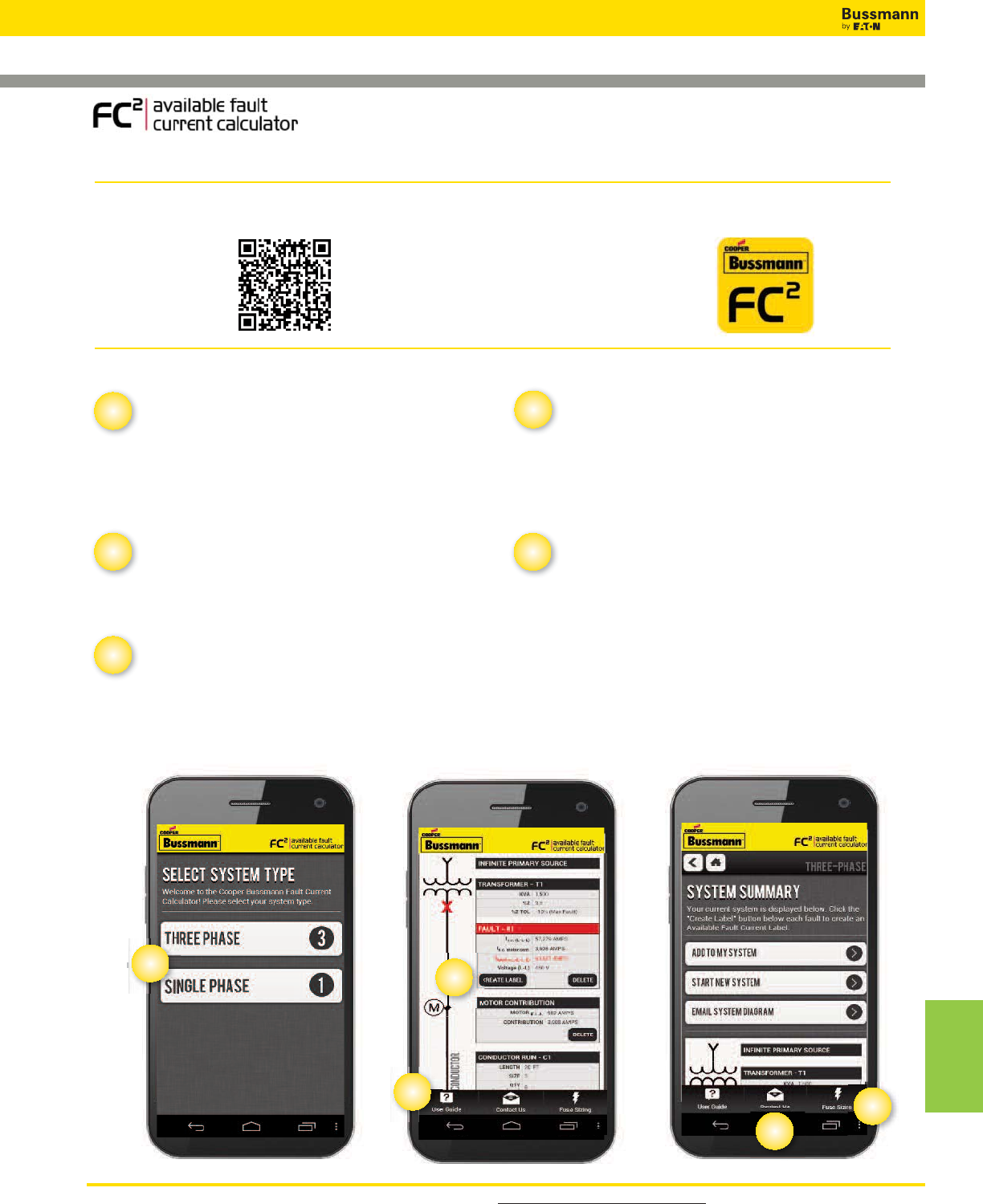
For product data sheets, visit www.cooperbussmann.com/FC2 531
FC2 Mobile App
Index by
Part Number
Calculator –
Calculate Available Fault Current
• Select either three-phase or single-phase
• Add components, calculate the system’s available fault
current and review a one-line diagram
• E-mail one-line diagram at anytime
User Guide –
Helpful Tips
• Click “User Guide” to view helpful user tips
• Each page has explanations for performing calculations
Contact Us –
Direct Contact to Industry Leading Support
• Click “Contact Us”
• For application inquiries, click “TECHNICAL SUPPORT”
• For all other questions, click “CUSTOMER SERVICE”
• The FC
2
app will automatically begin an e-mail to a Bussmann support representative
One Tool for Easy Available Fault Current Calculations
NEC®110.24 Label –
Helps Meet the Code
• Allows calculation of the maximum available fault current at
the service equipment and provides date of calculation
• Create and e-mail a label once a calculation is complete
• Print and use label to post the maximum available fault
current
Fuse Sizing Guide –
For Main, Feeder and Branch
Circuits
• Click “Fuse Sizing” and “VIEW FUSE SIZING DIAGRAM”
• Click each blue “HOT SPOT” link in the one-line
diagram for fuse and conductor sizing information
How to Use:
How to Install:
12
34
5
• Use the QR Code
with your device
to download the
mobile app
•Go to the Android or Apple App store
• Search for “Fault Current Calculator”
make sure to select the Bussmann FC
2
icon
• Click “install” and follow the instructions
2
1
4
3
5
OR
For product data sheets, visit www.cooperbussmann.com/DatasheetsEle
532
Index
532
Catalog Number Index
__NZ01 255
__NZ02 255
_BS 263
_D125 255
_D16 255
_D27 255
_D33 255
_LSC 263
_NHG _ _ _ B 256-258
1025 *
11 Type 438
11239 306
11240 306
11241 306
11242 306
11675- 329
11725- 329
11960 *
13195 *
13926 *
14002- 331
14004- 331
15087 436
15100-_ 432
15149 424
15188-3 362
15188-4 362
15242 *
15595 *
15600 *
15602 *
15660 *
15800 430
15900 *
15968 *
160___ 329, 330
162___ 329, 330
163__ 327-328, 329, 330
165___ 329, 330
170E_ _ _ _ 201-204, 207-211
170F_ _ _ _ 205-206
170H_ _ _ _ 212-213
170L *
170M_ _ _ _ 145-199
170N *
170R *
170T *
175GDMSJD *
175GXQNJD *
1976 *
1A0065 120
1A0835 *
1A1119- 96
1A1120- 96
1A1310 *
1A1360 *
1A1478 *
1A1706-_ 436
1A1837 *
1A1838 *
1A1853 *
1A1907- 96
1A2294 *
1A3398- 96
1A3399- 95
1A3400- 98
1A3746 *
1A4533- 96
1A4534- 96
1A4708 *
1A4806 *
1A5018- 95
1A5600- 84
1A5601- 95
1A5602- 95
1A5603 *
1A5778 84
1A5779 84
1A5780 84
1A5940 *
1A6049 *
1A8654 *
1B0048 *
1B0049 *
1BR021 *
1BR048 *
1BS1_ _ _ 141, 213
1CIF *
2004 *
2081 *
21010 *
2127 *
2178 *
2201 *
2245 *
2322 *
24 Type 438
2429 *
2430 *
2432 *
246B9949BG *
2487 *
2499 319
25499 *
2601 *
2604 *
2605 *
2607 *
2608 *
2610 *
2611 *
2650 *
2654 *
2698 *
270303 120
2714 *
2772 *
2778 *
2795 *
2834 *
2837 *
2838 *
2839 *
2860 *
2989 *
2992 *
2A066 *
2A8 *
2P25G 345
3356 *
3375 *
3411 *
3429 *
3434 *
3512 *
3513 *
3515 *
3519 *
3520 *
3521 *
3528 *
3531 *
3545 *
3552 *
3553 *
3554 *
3555 *
3556 *
3562 *
3569 *
3571 *
3572 *
3575 *
3576 *
3578 *
3591 *
3594 *
3595 *
3604 *
3723 321
3742 321
3743 321
3823 *
3828 320
3833 *
3835 321
3835 326
3839 *
3959 *
3998 *
39E *
4121 *
4164 79
4164-FR 79
4178 *
4180 111
4202 *
4261 *
4287 *
4386 *
4393 320
4399 *
4402 *
4405 319
4406 319
4407 *
4408 *
4410 *
4412 *
4413 *
4421 321
4422 *
4423 *
4427 *
4428 *
4482 *
4512 *
4513 *
4514 *
4515 321
4520 320
4522 *
4525 *
4528 111
4529 111
4532 *
4535 *
4537 *
4561 *
4567 *
4574 319
4909 *
51215 *
51235 *
5591- 98
5592- 98
5623 *
5672- 98
5674- 98
5678 *
5681- 97
5682- 97
5950 *
5956- 98
5958 *
5960- 98
5961 *
5TPH 510
6125TD *
6374 *
63A-DUMMY *
6415 *
6417 *
6418 *
6419 *
6420 *
64200 74
6422 *
6424 *
6427 *
64300 74
64913 *
64926 *
65372 *
65398 *
68100 *
68300 74
68600 74
7 Type 438
70 Series 436
74 Type 438
75 Type 439
76 Type 439
80 Type 439
8414677 *
8588A81H *
9078A67G04 120
9435 *
9483 *
9732 *
9789 *
9834 *
9835 *
9838 *
9841 *
9843 *
A3354705 *
A3354710 120
A3354720 *
A3354730 120
Catalog Page
Number
Catalog Page
Number
Catalog Page
Number
Catalog Page
Number
Catalog Page
Number
* Not listed in this catalog. Call Cooper Bussmann Customer Satisfaction for more information. Toll-free phone: 855-287-7626 (855-BUSSMANN)
For product data sheets, visit www.cooperbussmann.com/DatasheetsEle 533
Index
533
Catalog Number Index
A3354745 120
A404302 *
AAO 253
ABC 91
ABCNA 108-109
ABC-V 91
ABGNA 109
ABS *
ABU *
ABWNA 108
AC 254
ACB *
ACF *
ACH *
ACK *
ACL *
ACO *
AD 254
ADL *
ADLSJ 116
ADOSJ 116
AF *
AFS *
AFX *
AGA 90
AGC 91
AGC-V 91
AGU *
AGW 90
AGX 90
AGX-V *
AGY *
AL-D 279
ALS *
ALW *
AMG *
AMI *
AMWNA 108
ANL 79
ANN 79
ASZ350B3 *
AT *
AT512 360
ATC 82
ATC-_ID 82
ATC-FHID 82
ATF *
ATM 82
ATM-_ID 82
ATM-_LP 82
ATM-FHID 83
B221 272
B222 272
BAC_ 388, 391, 393, 395, 397
399, 402, 406, 408, 410
413-414, 419, 421, 423
BAF 75
BAN *
BAO 253
BB1P_ _ 279-280
BB3P_ _ 279-280
BBS 77
BBU-EFID *
BC (fuse blocks) 305
BC (fuses) 254
BC_(separator) 259
BCA603 304
BCC *
BCF *
BCPH2_PV 477-478
BD (fuses) 254
BFW *
BG 305
BGH *
BH- _ _ _ _ 213
BH-_ xxx 141
BH-_(fuseblocks) 306
BM 305
BMA603 304
BNQ21 365
BOOR-508 413-414
BPG_NPE 468
BPG_NPEWE 486
BPH_-D_LV 460
BPH_YPV 478, 480
BPM_IEC 468, 470, 472, 474
BPM_UL 450, 452, 454, 456
BPM_WE 486, 488, 490, 492
BPM_YPV 478, 480
BPMA_D_LV 458
BPP_SYPV 482
BPS_IEC 462, 464, 466
BPS_NPEIEC 466
BPSNPEIEC 470, 474
BPSNPEWE 488, 492
BQE 365
BQQ41 365
BRKT-_ 349,353
BRT *
BRW *
BSPD_DIN_ 499-501
BSPD48RJ45 497-498
BSPD5BNCD_ 493-494
BSPD5BNCSI 495-496
BSPG_NPE 467-468
BSPH_TNS 473-474
BSPH_TT 469-470
BSPH_TT 473-474
BSPH_WE 487-488, 491-492
BSPH_YPV 479-480
BSPH2A_D_LV 459-460
BSPM_ S2G 449-450
BSPM_HLG 455-456
BSPM_S3G 451-452
BSPM_TN 467-468, 469-470
BSPM_TNC 471-472
BSPM_WE 485-486
487-488, 489-490, 491-492
BSPM_WYG 453-454
BSPM_WYNG 455-456
BSPM1A_D_LV 457-458
BSPM-DLG 453-454
BSPP 481-482
BSPP_YPV 481-482
BSPS_PV 475-476
BSPS_TN 461-462
BSPS_TNC 463-464
BSPS_TNS 465-466
BSPS_TT 461-462, 465-466
BSPS_WE 483-484, 485-486
BVL- 259
C_NL 261
C002-0101-_ 343
C002-0201 343
C002-0301 343
C08G_ 260
C08M 261
C10G_ 260
C10M_ 261
C14G_ 260, 262
C14M_ 261, 262
C22G_ 260, 262
C22M_ 261, 262
C2617 *
C2791 *
C2909 *
C30BS 263
C30F 263
C30FBS 263
C4044 *
C4559 *
C515 86
C517 86
C518 86
C519 86
C520 86
C5237 *
C5268- 141
C5898 *
C60BS 263
C60F 263
C60FBS 263
C6344 *
C7018 *
C7019 *
C7021- 376
C7024- 377
CAV 108-109
CAVH 108-109
CBB *
CBC *
CBF *
CBP *
CBS *
CBT *
CBU *
CCB *
CCG *
CCP-_ 380-383
CCPB-_ 384-385
CCPHM-_ 381,383
CCSK-45 506
CD 254
CD100 *
CD27 *
CDB *
CDC *
CDN 247
CDS 247
CEO 253
CFP-_ 510
CGL 248
CH10CL *
CH10CM *
CH14 277
CH22 277
CH30J_ 277, 281
CH60J_ 277, 281
CH8 274-277
CHCC 274-277
CHM 274-277
CH-PLC 278
CHPV 274-277
CIF 249
CIH 251
CIK 251
CIL 251
CJ 250
CL1 222
CM__CF 263
CP14002 *
CS_ 259
CSC_ 334, 335, 336, 337
338,341,343,344,351,352
CT 218-219
CUG *
DD 254
DDNS10 343
DDP30 338
DEO 253
DFJ 125
DG100 340
DG150 340
DG230 340
DG25 339
DG35 339
DG60 339
DIA *
DIR-_ 388, 390, 392, 394
396, 398, 402, 406, 408, 410
413-414
DIS10 338
DKNSPS- 334,349
DKSPS_ 335, 336, 343, 349
DM20 337
DM30 337
DM50 337
DP100 336
DP150 336
DP230 336
DP25 335, 338
DP45 335
DP60 336
DPLT-_ 354
DRA-_ 509
DRL_ 334, 335, 336, 337, 338
339, 340, 341, 342, 343, 353
358, 359, 360, 362
DRLC-A *
DS_ 335, 336, 338, 343, 345
348, 350, 352
DS20 334
DS30 334
DS50 334
DSS_ 334, 350
DTST2 343
E-6188 *
EC-_ _ _ 222
ECAP_ 279-280
ECL055- 105
ECL083- 106
ECL155- 107
ED 254
EET 218, 220
EF 254
EFS 254
ENA *
ER1-_800L3PB 418
ER1-_J3PB 418
ER1-_N3SB 420, 422
Catalog Page
Number
Catalog Page
Number
Catalog Page
Number
Catalog Page
Number
Catalog Page
Number
* Not listed in this catalog. Call Cooper Bussmann Customer Satisfaction for more information. Toll-free phone: 855-287-7626 (855-BUSSMANN)
Index by
Part Number
For product data sheets, visit www.cooperbussmann.com/DatasheetsEle
534
Index
534
ER12-_J3PB 418
ER12-_N3SB 420,422
ER12-800L3PB 418
ER3R-_J3PB 418
ER3R-_N3SB 420, 422
ER3R-800L3PB 418
ER4-_J3JPB 418
ER4-_N3SB 420, 422
ER4-800L3PB 418
ER4P-_J3PB 418
ER4P-_N3SB 420, 422
ER4P-800L3PB 418
ER4X-_J3PB 418
ER4X-_N3SB 420, 422
ER4X-800L3PB 418
ERK-28 507
ERS2 *
ERS30 *
ESD 253
ET 218-219
ETF *
F01A *
F02A *
F02B *
F03A *
F03B *
F09A *
F09B *
F10A *
F15A *
F16A *
F520DDST 341
F520ST 341
F520STLED 341
F520T0P 342
F60C *
F61C *
F62C *
F63C *
F64C *
F65C *
FA02 *
FA2A *
FA4H *
FBP *
FC *
FC_(fuse casing) 259
FCB *
FCC *
FCF 28-29
FCU *
FDM *
FE 218, 221
FEE 218, 221
FEH 259
FF 254
FG 254
FHL *
FHN *
FL- *
FL11H_ 117-119
FL11K_ 117-119
FL11N *
FL11T__ 117-119
FL12K__ 117-119
FL1A5 *
FL3H *
FL3K__ 117-119
FL3T__ 117-119
FLB *
FLC_ 390, 392, 394, 396, 399
FLD *
FLF *
FLH_ 390, 392, 394, 396, 399
FLM *
FLN *
FLRM 390, 392, 394, 396, 399
FLS *
FM 218, 221
FM01A *
FM08A *
FM09A *
FM09B *
FMM 218, 221
FMX *
FNA 78
FNM 76
FNQ 76
FNQ-R 24
FNW *
FP-_ 510
FPK_-3P 259
FRN-R 46
FRN-R-__ID 46
FRS-R 47
FRS-R-__ID 47
FT-_ 510
FTI *
FTM *
FWA 126-129, 224-225
FWC 232-233
FWH 132-133, 228-231
FWJ 139-140, 240-241
FWK 238-239
FWL 242
FWP 136-138, 234-237
FWS 242
FWX 130-131, 226-227
GBA 78
GBB 91
GBB-V 91
GBC *
GF 254
GFA *
GG 254
GH 254
GKB 436
GLD 78
GLN *
GLP 263
GLQ 80
GLR 81
GLX *
GMA 89
GMA-V 89
GMC 89
GMC-V 89
GMD 89
GMD-V 89
GMF 81
GMQ 80
GMT-_ 437
GMW *
GRF 81
GSK-260 506
GV_ 284
H07C 252
H12-_
388,390,392,394,396,398,408
H25_ 294-295
H4X-_
388,390,392,394,396,398,402,4
06,408,410,413-414
H60_ 296-297
H79-_
388,390,392,395,397,399,402
HAS-R *
HBC *
HBH 94
HBH-I 94
HBH-M 94
HBM *
HBO *
HBP- *
HBS- *
HBV-I 94
HBV-M 94
HBW-I 94
HBW-M 94
HCM *
HEB 310-311
HEC 310
HEF *
HEG 309
HEH 309
HEJ 310
HET 310
HEX 310
HEY 310
HEZ 310
HFA 309
HFB 308
HGA *
HGB *
HGC *
HHB 308
HHC 82
HHD 82
HHF 82
HHG 82
HHL 83
HHM 83
HHT 309
HHX 83
HIF *
HJL 316
HJM *
HKA *
HKL 316
HKP 313
HKQ *
HKR 316
HKT 316
HKU 316
HKX 316
HLD 316
HLQ 80
HLQ-_ 80
HLR 81
HLS 437
HLT 437
HM25100 289-293
HM25200 289-293
HM25400 289-293
HM25600 289-293
HM60100 289-293
HM60200 289-293
HM60400 289-293
HM60600 289-293
HME 309
HMF 309
HMG 309
HMH 309
HMI 309
HMJ 309
HMK *
HMR *
HN-1 *
HN-5 *
HPC-D 318
HPD 317
HPF 317
HPG 317
HPL *
HPM 318
HPS 317
HPS2 318
HRE 309
HRF 309
HRG 309
HRH 309
HRI 309
HRJ 309
HRK 308
HSK *
HTB- 314-315
HTC-140M 95
HTC-15M 95
HTC-200M 95
HTC-210M 95
HTC-30M *
HTC-35M 312
HTC-40M 312
HTC-45M 93
HTC-50M 93
HTC-55M 312
HTC-70M 312
HVA 111
HVB 111
HVJ 111
HVL 111
HVR 111
HVT 111
HVU 111
HVW 111
HVX 111
HWA *
IXL70F *
J-_ _ 511
J101/J *
J201/J *
J301/J *
J60__ 298
J70032 243
J70100 243
JB1 *
JCA *
JCD- 110
JCG- 112
JCH- 112
Catalog Number Index
Catalog Page
Number
Catalog Page
Number
Catalog Page
Number
Catalog Page
Number
Catalog Page
Number
* Not listed in this catalog. Call Cooper Bussmann Customer Satisfaction for more information. Toll-free phone: 855-287-7626 (855-BUSSMANN)
For product data sheets, visit www.cooperbussmann.com/DatasheetsEle 535
Index
535
JCI- 110
JCK- 112-114
JCK-A- 112-114
JCK-B- 112-114
JCL- 112-114
JCL-A- 112-114
JCL-B- 112-114
JCM *
JCN *
JCP *
JCQ- 110
JCR-A 112-114
JCR-B- 112-114
JCT- 110
JCU- 104
JCW- 110
JCX- 103
JCY- 103
JCZ- 104
JDN *
JDZ- 104
JF1 *
JJN- 48
JJS- 49
JKS 36
JM60100 289-293
JM60200 289-293
JM60400 289-293
JM60600 289-293
JN_ 358, 359, 360, 361
362, 363, 364
JNDN3 358
JP600 299
JPA-3 *
JSK-36 506
JT 286-287
JTN 286-287
JU *
K07C 252
KAB *
KAC 134
KAD 364
KAD *
KAF *
KAJ *
KAL *
KAW *
KAX *
KAZ 79
KBC 135
KBD *
KBJ *
KBR *
KBT *
KBY *
KCF 74
KCH 74
KCJ 74
KCM 74
KCM-B 74
KCR 74
KCS 74
KCV 74
KCY 74
KCZ 74
KDA 74
KDB 74
KDC 74
KDD 74
KDE 74
KDF 74
KDH 74
KDJ 74
KDM 74
KDP 74
KDR 74
KDT 74
KDU 74
KDY 74
KEF *
KEM *
KER *
KEW 74
KEX 74
KFH-A 74
KFM 74
KFT 74
KFZ 74
KGC *
KGJ *
KGJ-A *
KGJ-E *
KGL *
KGO-E *
KGS *
KGS-A *
KGT *
KGX *
KIG 74
KIT-6POLE 413, 415
KJA *
KLC *
KLM 75
KLP *
KLU 40
KMH-C *
KPF 74
KQO 74
KQT 74
KQV 74
KQW-M *
KRP-C__SP 38-39
KRP-CL 39
KS-19392-L36 *
KT3 364
KT4 364
KTK 75
KTK-R 25
KTN-R 44
KTN-S *
KTS-R 45
KTS-S *
KTU 40
KU_(terminal blocks) 375
KWN-R *
L09C 252
L14C 252
LAA *
LAC *
LAG *
LAN *
LAR *
LCT 215-216
LEF *
LET 215-216
LKB *
LKC *
LKN *
LKS *
LMMT 215, 217
LMT 215, 217
LP-CC 23
LPJ__SP 35
LPJ__SPI 35
LPN-RK__SP 41-43
LPN-RK__SPI 41-43
LPRK-28 507
LPS-RK__SP 41-43
LPS-RK__SPI 41-43
LPT *
LUG1-_ 398, 408
LUG2-_ 398, 408
LUG3-_ 408
LUG5-_ 402, 410
M09C 252
MAI 222
MAS *
MAX- 83
MAX-__ID 83
MB- 52
MBO *
MC_ _ _ 222
MCRW *
MDA 92
MDA-V 92
MDL 92
MDL-V 92
MDM *
MDQ 92
MDQ-V 92
MFN *
MIC 78
MIJ *
MIN 78
MIS 79
MKB *
MMT 218, 220
MSK-45 506
MT 218, 220
MT12 *
MT12-1-2 358, 359, 360, 361
363, 364, 365
MTC6 358, 364
MTMU *
MV055- 101
MV155- 102
N512 360
NBB *
NBC *
NBE *
NC3 361
ND-1260 *
NDN1 359
NDN111 359
NDN3 358
NDN63 358
NDND1 *
NDNF1-WH 322
NDNFD1-WH 322
NDNLFD1-WH 322
NDNV4 358
NFA *
NFT2 360
NFT3 360
NFTA Series 353, 358, 359
360, 361, 362, 363, 365
NI 263
NITD 253
NNB 511
NNB-R 511
NNC 511
NO.1 409
NO.100 *
NO.140 508
NO.2 509
NO.201 *
NO.205 *
NO.213 511
NO.213-R 511
NO.216 511
NO.216-R 511
NO.220 508
NO.226 511
NO.226-R 511
NO.242-R 511
NO.2621 511
NO.2621-R 511
NO.263 511
NO.263-R 511
NO.2641 511
NO.2641-R 511
NO.2642 511
NO.2661-R 511
NO.2662-R 511
NO.2664-R 511
NO.270 508
NO.36 507
NO.4 509
NO.5 509
NO.6 509
NO.616 511
NO.616-R 511
NO.626 511
NO.626-R 511
NO.642-R 511
NO.663 511
NO.663-R 511
NO.7 509
NO.8 509
NON 37
NOS 37
NPL *
NRA Series 353, 358, 359
360, 361, 362, 363, 365
NSD 253
NSE3 361
NSS3 361
NTN-R-_ 511
NTQ23 365
NTS-R-_ 511
NUE *
NXA *
NXC *
OIA *
OJ *
OPM-1038 282-283
OPM-NG 284-285
OSD 253
P- 51
P09C 252
Catalog Number Index
Catalog Page
Number
Catalog Page
Number
Catalog Page
Number
Catalog Page
Number
Catalog Page
Number
* Not listed in this catalog. Call Cooper Bussmann Customer Satisfaction for more information. Toll-free phone: 855-287-7626 (855-BUSSMANN)
Index by
Part Number
For product data sheets, visit www.cooperbussmann.com/DatasheetsEle
536
Index
Catalog Number Index
P11C 252
P20S 344
P25G 345
P30S 344
P65S 344
PCB *
PCC *
PCD *
PCF *
PCG *
PCH *
PCI- *
PCT 437
PDB___ 324, 226
PDBFS___ 324-325
PLK3 364
PLU1 363
PLU3 362
PMP 268-269
POLE-_ 413, 415
POLE98-_ 406
PON 247
PS 268-269
PS1RPLSW *
PSU1 363
PV- 60
PV-_01XL 63
PV-_01XL15 67-69
PV-_10_ 60
PV-_14F 61
PV-_14LF 66
PV-_1XL 63-64
PV-_2XL 63-64
PV-_2XL-15 67-69
PV-_3L 63-64
PV-_3L-15 67-69
PV-_NH1 62
PVCF 57-58
PVM 56
PVS-R 59
PWR1PLP 279-280
PWR35MM 279-280
PWR50MM 279-280
QC202/J *
QC203/J *
Quik-Spe c AC Safety Switch
271
Quik-Spec Coordination
Panelboards 266-267
Quik-Spec DC Safety Switches
270
R11C 252
R25_ 294-295
R60_ 296-297
RD100_ 404-406, 420
RD1000_ 404-405, 410
RD100-3-SCCR 404-405, 408
RD1200_ 404-405, 410, 420
RD16_ 412-414, 422
RD200_ 404-405, 408, 420
RD25_ 412-414, 422
RD30_ 404-406, 420
RD40_ 412-414, 422
RD400_ 404-405, 408, 420
RD60_ 404-406, 420
RD600_ 404-405, 410, 420
RD63_ 412-414, 422
RD80_ 412-414, 422
RD800_ 404-405, 410, 420
RDF100_ 387, 396, 418
RDF200_ 387, 398, 418
RDF30_ 387-390, 418
RDF400_ 387, 398, 418
RDF60_ 387, 392-394, 418
RDF600_ 387, 402, 418
RDF800_ 387, 402, 418
REG *
REN *
RES *
RFL *
RK1SK-39 506
RK5SK-39 506
RLA *
RLC *
RYA *
RYC *
S- 51
S500 87
S500-V 87
S501 87
S501-V 87
S505 87
S505H 88
S505H-V 88
S505-V 87
S506 88
S506-V 88
S-8001 319
S-8002 319
S-8101 319
S-8102 319
S-8201 319
S-8202 219
S-8203 319
S-8301 319
SA- 52
SAMI- 288
SB_ 259
SC34
SCV15 *
SCV20 *
SCY 307
SD_-S 63, 67
SF25H *
SFB1030 *
SFC-_ 510
SFD27 *
SFE *
SFR *
SFR1 *
SH1-_ 388
SH2-_ 388
SH4-_ 406, 413-414
SH5-_ 390, 392, 394 ,396
398, 408
SH6-_ 410
SH7-_ 402
SH-GUIDE _ 406, 408, 410
413-414
SKA 307
SL- 50
SL_ 259
SNL-7K *
SOU 307
SOW 307
SOX 307
SOY 307
SP_ 259
SPH50SP_ PN442-445
SPH50SP_ PNG442-445
SPH50SP_ SN442-445
SPH50SP_ SNG442-445
SPH50SP_ WYG 442-445
SPH50SP_ WYGN 442-445
SPH50SP_ HLG 442-445
SPH50SP_DLG 442-445
SPJ *
SPOD_ 502-503
SPP *
SPP40SP_ DLG 446-448
SPP40SP_ PN 446-448
SPP40SP_ SN 446-448
SPP40SP_ WYG 446-448
SRD *
SRT-A *
SRU 307
SRU-BC *
SRW 307
SRX 307
SRY 307
SSD 253
SSN 307
SSU 307
SSW 307
SSX 307
SSY 307
STD 253
STI *
STM *
STY 307
T- 51
T30__ 300-301
T60__ 302-303
TB_-D 259
TB00_ 259
TB100- 366-367
TB200- 368-369
TB300- 370-371
TB345- 370-371
TB400- 374
TC 51
TCF 26-27
TCF__RN 26-27
TCFH_N 32-33
TCFH_NW 32-33
TCP *
TDC *
TDC10 *
TDC11 *
TDC180 *
TDC600 *
TDLEJ 116
TDLSJ 116
TDMEJ 116
TDQSJ 116
TFC *
TFF *
TFL *
TFLSJ 116
TFMEJ 116
TFQSJ 116
TGH *
THLEJ 116
THMEJ 116
TI_ 222
TIQ *
TJD *
TKLEJ 116
TKMEJ 116
TL- 50
TM2_ 334, 335, 336, 337
338, 341, 343, 344, 345
354-357
TP158HC 431
TP15900 *
TP15900-4_429
TP15914 428
TPA 429
TPA-B 429
TPB *
TPC 426
TPCDS 426
TPH *
TPHCS-_ 433
TPJ *
TPL-_ 434
TPM 427
TPMDS 427
TPN-_ 435
TPS 430
TPSFH-_ 510
TPW *
TPWDS *
TRF *
TSH_-_ 399, 402, 406, 409
411, 413, 415, 419, 421, 423
TVS_ 504
TVSS- *
TXLEJ 116
TXMEJ 116
TXQEJ 116
UHA *
UHC *
UHJ *
UHS *
UHT *
UHW *
ULR *
VFNHA 115
VKNHA 115
W- 50
WCF 30-31
WCF__RN 30-31
WDFHO 115
WDLSJ 115-116
WDOH6 115
WDOSJ 116
WER 438
WFFHO 115
WFLSJ 115-116
WFMSJ 115
WFNHO 115
WFOH6 115
WFOSJ 116
WGA *
WHA *
WHN *
WIE *
WJON6 115
WKB *
Catalog Page
Number
Catalog Page
Number
Catalog Page
Number
Catalog Page
Number
Catalog Page
NumberCatalog Pagember
* Not listed in this catalog. Call Cooper Bussmann Customer Satisfaction for more information. Toll-free phone: 855-287-7626 (855-BUSSMANN)
For product data sheets, visit www.cooperbussmann.com/DatasheetsEle 537
Index
Catalog Number Index
WKFHO 115
WKH *
WKJ *
WKK *
WKL *
WKLSJ 116
WKMSJ 115-116
WKNHO 115
WKS *
WKU *
WKV *
WLF *
WMB *
WMM *
WMQ *
WPQ *
WQN *
WQP *
WSE *
WSH *
WSL *
WSM *
WSQ *
WST *
WSU *
WTJ *
WTK *
WTT *
WTZ *
WUE *
WUG *
WUH *
WUI *
WUQ *
WUR *
WUU *
WUV *
WUW *
WUY *
WVA *
WVQ *
WVR *
WWD *
WWE *
WWG *
WWI *
WWK *
WWU *
WWV *
WWX *
WYM *
WZC *
WZJ *
WZK *
WZX *
XL25X *
XL50F *
Catalog Page
Number
Catalog Page
Number
Catalog Page
Number
Catalog Page
Number
Catalog Page
Number
* Not listed in this catalog. Call Cooper Bussmann Customer Satisfaction for more information. Toll-free phone: 855-287-7626 (855-BUSSMANN)
Index by
Part Number

For product data sheets, visit www.cooperbussmann.com/DatasheetsEle
538
North America
Bussmann Business Headquarters
114 Old State Road
Ellisville, Missouri 63021
Telephone: 636-527-3877
Fax: 800-544-2570
Email: fusebox@cooperindustries.com
Bussmann Mexico
Poniente 148 #933
Col. Industrial Vallejo
Azcapotzalco C.P. 02300,
Mexico D.F.
Telephone: +52-5587-0211 Ext.720
01-800-8-FUSEMX (387369)
Fax: +52-55-5567-1131
E-mail: ventasbussmannmexico@cooperindustries.com
Bussmann Transportation
10955 SW Avery St.
Tualatin, OR 97062
Telephone: 503-692-5360
Fax: 503-692-9091
E-mail: SurePower.Sales@cooperindustries.com
Bussmann Electronics
1225 F Broken Sound Parkway NW
Boca Raton, FL 33487
Telephone: 561-988-4100
Fax: 561-241-6640
E-mail: customerservice@cooperindustries.com
Asia
Cooper Electric (Shanghai) Co. Ltd.
955 Shengli Road Heqing Pudong, Shanghai 201201
China
Telephone: 8621-2899-3888
Fax: 8621-2899-3997
Bussmann India
Bussmann, India, Pvt. Ltd.
2, EVR Street,
Sedarpet Indl. Estate,
Pondicherry – 605 111
India
Telephone: 91-413-267-2005
Fax: 91-413-267-8182
E-mail: sales.india@cooperindustries.com
Europe
Cooper (UK) Ltd.
Melton Road
Burton-on-the-Wolds
Leicestershire LE12 5TH
England
Telephone: 44-1509-882737
Fax: 44-1509-882786
E-mail: bule.sales@cooperindustries.com
South America
Bussmann Brazil
Bussmann do Brasil Ltda.
Rodovia Santos Dumont, km 23
13.300-000, Caixa Postal 095
Itu Sao Paulo
Brazil
Telephone: 55-11-4024-8400
Fax: 55-11-40-24-8424
Sales Support & Manufacturing Facilities
Sales & Support
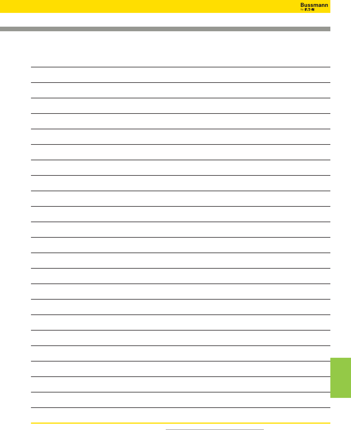
For product data sheets, visit www.cooperbussmann.com/DatasheetsEle 539
NOTES
Index by
Part Number
Notes

For product data sheets, visit www.cooperbussmann.com/DatasheetsEle
540
Notes
Notes
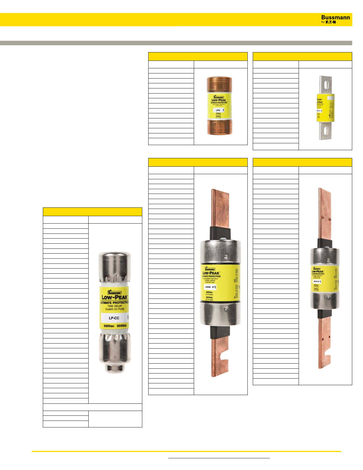
For product Data Sheets, visit www.cooperbussmann.com/DatasheetsEle
The comparative catalog numbers shown were derived from the latest available published information from various manufacturers.
Because competitors’ products may differ from Bussmann products, it is recommended that each application be checked for required
electrical and mechanical characteristics before substitutions are made. Bussmann is not responsible for misapplications of our products.
Overcurrent protection is application dependent. Consult the latest catalogs and application literature, or contact our Application
Engineering Department toll free at 855-287-7626 (855-BUSSMANN).
Bussmann Fuse Cross
Reference & Low-Peak™
Upgrade
The left column represents Bussmann and
competitors’ part numbers. The right column
represents the Bussmann upgrades.
The Bussmann fuse upgrade offers superior
performance while reducing the number of SKUs
that need to be in stock. Low-Peak™fuses feature a
high degree of current limitation, which will provide
the best component protection and may reduce the
arc flash hazard. Listings are alpha-numerical by
fuse class and fuse catalog symbol.
This list is only a consolidated cross reference to
some of our most common products. For a much
more extensive database please consult the
Product
Profiler
competitor cross-reference. Just visit
www.cooperbussmann.com and click on the
magnifying glass icon in the upper right corner.
Class CC and Midget
Existing Fuse Low-Peak™Upgrade
A6Y (type 2B) LP-CC
ABU
AGU
ATDR
ATM
ATMR
ATQ
BAF
BAN
BLF
BLN
CCMR
CM
CMF
CNM
CNQ
CTK
CTK-R
FLM
FLQ
FNM
FNQ
GGU
HCLR
KLK
KLK-R
KTK
KTK-R
MCL
MEN
MEQ
MOF
MOL
OTM
TRM
6JX LP-CC
*FNQ-R suggested on primary of control transformers.
ATQR
FNQ-R FNQ-R
KLDR
250 Volt Class R
Existing Fuse Low-Peak™Upgrade
A2D LPN-RK_SP
A2D-R
A2K
A2K-R
A2Y (type 1)
AT-DE
CHG
CRN-R (type 3)
CTN-R
DEN
DLN
DLN-R
ECN
ECN-R
ERN
FLN
FLN-R
FRN
FRN-R
FTN-R
GDN
HAC-R
HB
KLN-R
KON
KTN-R
LENRK
LKN
LLN-RK
LON-RK
NCLR
NLN
NON
NRN
OTN
REN
RFN
RHN
RLN
TR
655
660
10KOTN
50KOTN LPN-RK_SP
600 Volt Class R
Existing Fuse Low-Peak™Upgrade
A6D LPS-RK_SP
A6K-R
A6X (type 1)
ATS-DE
CHR
CTS-R
DES
DES-R
DLS
DLS-R
ECS-R
ERS
FLS
FLS-R
FRS
FRS-R
FTS-R
GDS
HA
KLS-R
KOS
KTS-R
LES
LES-R
LES-RK
LKS
LLS-RK
LOS-RK
NLS
NOS
NRS
OTS
RES
RFS
RHS
RLS
SCLR
TRS
TRS-R
656
10KOTS
50KOTS LPS-RK_SP
Class L
Existing Fuse Low-Peak™Upgrade
A4BQ KRP-C_SP
A4BT
A4BY
A4BY (type 55)
CLASS L
CLF
CLL
CLU
HRC-L
KLLU
KLPC
KLU
KTU
L
LCL
LCU KRP-C_SP
Class J
Existing Fuse Low-Peak™Upgrade
A4J LPJ_SP
AJT
CJ
CJS
GF8B
HRCXXJ
J
JA
JCL
JDL
JFL
JHC
JKS
JLS
JTD LPJ_SP
Cross Reference & Low-Peak™ Upgrade

Customer Assistance
Customer Satisfaction Team
Available to answer questions regarding Bussmann
products & services Monday-Friday, 7:00 a.m. – 6:00 p.m.
Central Time. Contact:
UÊ/vÀiiÊ«i\ÊnxxÓnÇÇÈÓÈÊnxx1-- ®
UÊ/vÀiiÊv>Ý\Ênääx{{ÓxÇä
UÊ>\ÊLÕÃÃVÕÃÌÃ>ÌJV«iÀ`ÕÃÌÀiðV
Emergency and After-Hours Orders
iÝÌÊv}ÌÊÕÌÊÀÊÜÊV>ÊëiÌÊvÀÊÌiVÀÌV>Êii`ðÊ
ÕÃÌiÀÃÊ«>ÞÊÞÊÃÌ>`>À`Ê«À`ÕVÌÊ«ÀVi]ÊÀÕÃÊvÀi}ÌÊ
V>À}iÃ]ÊEÊ`iÃÌÊiiÀ}iVÞÊÃiÀÛViÊvii°Ê*>ViÊÌiÃiÊ
À`iÀÃÊÌÀÕ}ÊÌiÊÕÃÌiÀÊ->ÌÃv>VÌÊ/i>Ê`ÕÀ}Ê
Ài}Õ>ÀÊLÕÃiÃÃÊÕÀðÊÊÀÊ>vÌiÀÕÀÃ]ÊVÌ>VÌ\
UÊvÌiÀÊÕÀÃÊΣ{x£Î{Ó
C3 – the Enhanced, Online Cooper Customer Center
*ÀÛ`iÃÊÀi>ÊÌiÊ«À`ÕVÌÊ>Û>>LÌÞ]ÊiÌÊ«ÀV}]ÊÀ`iÀÊ
ÃÌ>ÌÕÃÊEÊëiÌÊÌÀ>V}ÊvÀ\Êi]ÊÕÃÃ>]Ê
ÀÕÃi`Ã]Ê}Ì}]Ê*ÜiÀÊ-ÞÃÌiÃÊEÊ7À}ÊiÛViðÊ
>ÊnÇÇxxxxÊvÀÊ}Ê>ÃÃÃÌ>Vi°ÊÛ>>LiÊ>Ì\
UÊÜÜÜ°V«iÀVΰV
Application Engineering
/iVV>Ê>ÃÃÃÌ>ViÊÃÊ>Û>>LiÊÌÊ>ÊVÕÃÌiÀðÊ
Application support is available Monday-Friday,
Ç\ääÊ>°°ÊqÊx\ääÊ«°°ÊiÌÀ>Ê/i°ÊÌ>VÌ\
UÊ/vÀiiÊ«i\ÊnxxÓnÇÇÈÓÈÊnxx1-- ®
UÊ>\ÊvÕÃiÌiVJV«iÀ`ÕÃÌÀiðV
Online Resources
6ÃÌÊÜÜÜ°V«iÀLÕÃÃ>°VÊvÀÊÌiÊvÜ}Ê
resources:
UÊ*À`ÕVÌÊÃi>ÀVÊEÊVÀÃÃÀiviÀiVi
UÊ*À`ÕVÌÊEÊÌiVV>Ê>ÌiÀ>Ã
UÊ-ÕÌÃÊViÌiÀÃÊvÀÊvÀ>ÌÊÊÌ«V>ÊÃÃÕiÃÊ
ÊÊVÕ`}Ê>ÀVÊv>Ã]ÊÃiiVÌÛiÊVÀ`>ÌÊEÊÃÀÌVÀVÕÌÊ
current rating
UÊ/iVV>ÊÌÃ]ÊiÊÕÀÊ>ÀVÊv>ÃÊV>VÕ>ÌÀ
UÊ7iÀiÊÌÊ«ÕÀV>ÃiÊÕÃÃ>Ê«À`ÕVÌ
Eaton is a registered trademark.
All other trademarks are property
of their respective owners.
Eaton
1000 Eaton Boulevard
Cleveland, OH 44122
United States
Eaton.com
© 2013 Eaton
All Rights Reserved
Printed in USA
Publication No.1007
August 2013
Eaton’s Bussmann Business
PO Box 14460
St. Louis, MO 63178-44602
www.bussmann.com
Your authorized distributor is:
