CBT_Catalog__2011 2nd Edition 1000295420 Catalog
129841-Catalog 129841-Catalog 129841-Catalog Batch9 unilog cesco-content
2016-06-25
: Pdf 1000295420-Catalog 1000295420-Catalog B1 unilog
Open the PDF directly: View PDF ![]() .
.
Page Count: 92

Cooper Bussmann
Transportation Products

Table of Contents
Cooper Bussmann Transportation Products t1IPOFt'BYtXXXDPPQFSCVTTNBOODPN
Introduction to Cooper Bussmann Transportation Products 3
Conversion, Conditioning, Distribution,
Management & Controls
$POWFSUFST&RVBMJ[FST
%$%$$POWFSUFST
5SBJM$IBSHFS
%$$VSSFOU4FOTPS
4FQBSBUPST*OUFSDPOOFDUT
.VMUJ#BUUFSZ*TPMBUPST
.VMUJ#BUUFSZ*TPMBUPS"QQMJDBUJPO(VJEF
1PXFS.BOBHFNFOU
4PMJE4UBUF'MBTIFST
%BZUJNF3VOOJOH-JHIU$POUSPMT
Power Distribution & Circuit Protection
.VMUJQMFYFE7FIJDMF&MFDUSJDBM$FOUFST
4FWFSF4FSWJDF%VBM7FIJDMF&MFDUSJDBM$FOUFS
4FWFSF4FSWJDF7FIJDMF&MFDUSJDBM$FOUFS
4FSJFT7FIJDMF&MFDUSJDBM$FOUFS
7FIJDMF&MFDUSJDBM$FOUFS$POOFDUPST
7&$&MFDUSJDBM$PNQPOFOUT
4FSJFT3'3.3FBSGFE'VTF3FMBZ.PEVMF
4FSJFT1PTJUJPO35.3
4FSJFT35.3
4FSJFT-.(#PMUJO'VTF)PMEFSGPS.VMUJQMF".('VTFT
4FSJFT-.*#PMUJO'VTF)PMEFSGPS4JOHMFPS.VMUJQMF".*'VTFT
4FSJFT3FBS5FSNJOBM"5$'VTF1BOFM
4FSJFT"5$#MBEF5ZQF'VTF1BOFMT
4FSJFT13.1'.
).('VTFIPMEFS
'.('VTFIPMEFS
$')999$POOFDUPS'VTF)PMEFS
*OMJOF'VTF)PMEFST
(#991BTT5ISV%JTUSJCVUJPO#MPDL
4JOHMF4UVE5ZQF+VODUJPO#MPDLT
.VMUJQMF4UVE5ZQF+VODUJPO#MPDLT
1PXFS%JTUSJCVUJPO/PUFT
#BTJD0WFSDVSSFOU5FDIOPMPHZ
easy*%™*MMVNJOBUJOH#MBEF'VTFT'VTF)PMEFST
.*/*#MBEF'VTFT
4FSJFT9.JOJ$JSDVJU#SFBLFST
"5$®#MBEF'VTFT
4FSJFT9$JSDVJU#SFBLFST
4FSJFT"5$$JSDVJU#SFBLFSTMPXQSPmMF
."9*®#MBEF'VTFT
4FSJFT9."9*$JSDVJU#SFBLFST
4FSJFT*OTFSUJPO&YUSBDUJPO5PPM
4FSJFT94IPSUTUPQ$JSDVJU#SFBLFST
4FSJFT9.JESBOHF$JSDVJU#SFBLFS
4FSJFT'MBUQBL$JSDVJU#SFBLFS
4FSJFT9)J"NQ$JSDVJU#SFBLFS
4FSJFT.BSJOF3BUFE$JSDVJU#SFBLFS.3$#
".*4FSJFT
".(4FSJFT
.BSJOF3BUFE#BUUFSZ'VTF
4FSJFT#BUUFSZ%JTDPOOFDU4XJUDI
$JSDVJU1SPUFDUJPO/PUFT
Mobile Vehicle Controls
55SBOTNJUUFS
55SBOTNJUUFS
55SBOTNJUUFS
55SBOTNJUUFS
3%BUB4IFFU
3$"/CVT3FDJFWFS
3$"/CVT8BZ3FDJFWFS
3
%&YQBOTJPO.PEVMFT
%
Cooper Bussmann circuit protection solutions comply with major industrial standards and agency requirements such as: BS, IEC, DIN, UL, NEMA, SAE, CSA, CE, C-UL, etc. and are manufactured at facilities that
are ISO 9000 certified. This catalog is intended to present product data and provide technical information that will help the end user with design application. Cooper Bussmann reserves the right, without notice,
to change design or construction of any products and to discontinue or limit distribution of any products. Cooper Bussmann also reserves the right to change or update, without notice, any technical information
contained in this catalog. Once a product has been selected, it should be tested by the user in all possible applications. Further, Cooper Bussmann takes no responsibility for errors or omissions contained in
this catalog, or for misapplication of any Cooper Bussmann product. Extensive product information is available in the Cooper Bussmann product data sheets available online at www.cooperbussmann.com.
Printed in the USA ©2010 Cooper Bussmann
2

Cooper Bussmann Transportation Products t1IPOFt'BYtXXXDPPQFSCVTTNBOODPN
We’re experts on the effects of cold and heat, vibration, high moisture, harsh chemicals and transient power
uctuations. We know vehicle power and control systems from the smallest to largest platforms, and will
partner with you to develop reliable products and systems.
With combined industry history and experience reaching back more than 90 years, the engineering strength
and proven track record of the Cooper Bussmann®, Sure Power and OMNEX Control Systems brands
provide you the ability to accelerate product development in “smart” systems and create innovative,
industry-leading solutions. These solutions range from straightforward products from our catalog all the way
to next generation systems that will create efciencies not yet realized.
We are committed to continuous new product development and offer you a competitive advantage through
partnership R&D expertise and a technology portfolio that minimizes excessive tooling and time required to
produce OEM-specic solutions.
Cooper Bussmann, a division of Cooper Industries, has a global manufacturing footprint. Our facilities are
ISO 9000-2001 and TS16949 certied to meet the highest quality and environmental standards.
The Cooper Bussmann mission is to respond completely and uniquely to OEM
requirements for vehicle electronic products and control solutions that require
cost reduction and customization
Your Trusted Partner For Electrical Power Chain Safety, Efficiency, Reliability and Control
In a worldwide transportation marketplace Cooper Bussmann is your leading
source for safe and reliable electrical power and machine control solutions
3
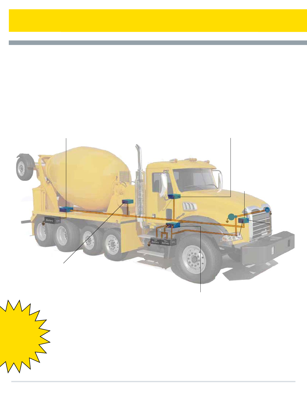
Conversion, Conditioning, Distribution, Management & Control
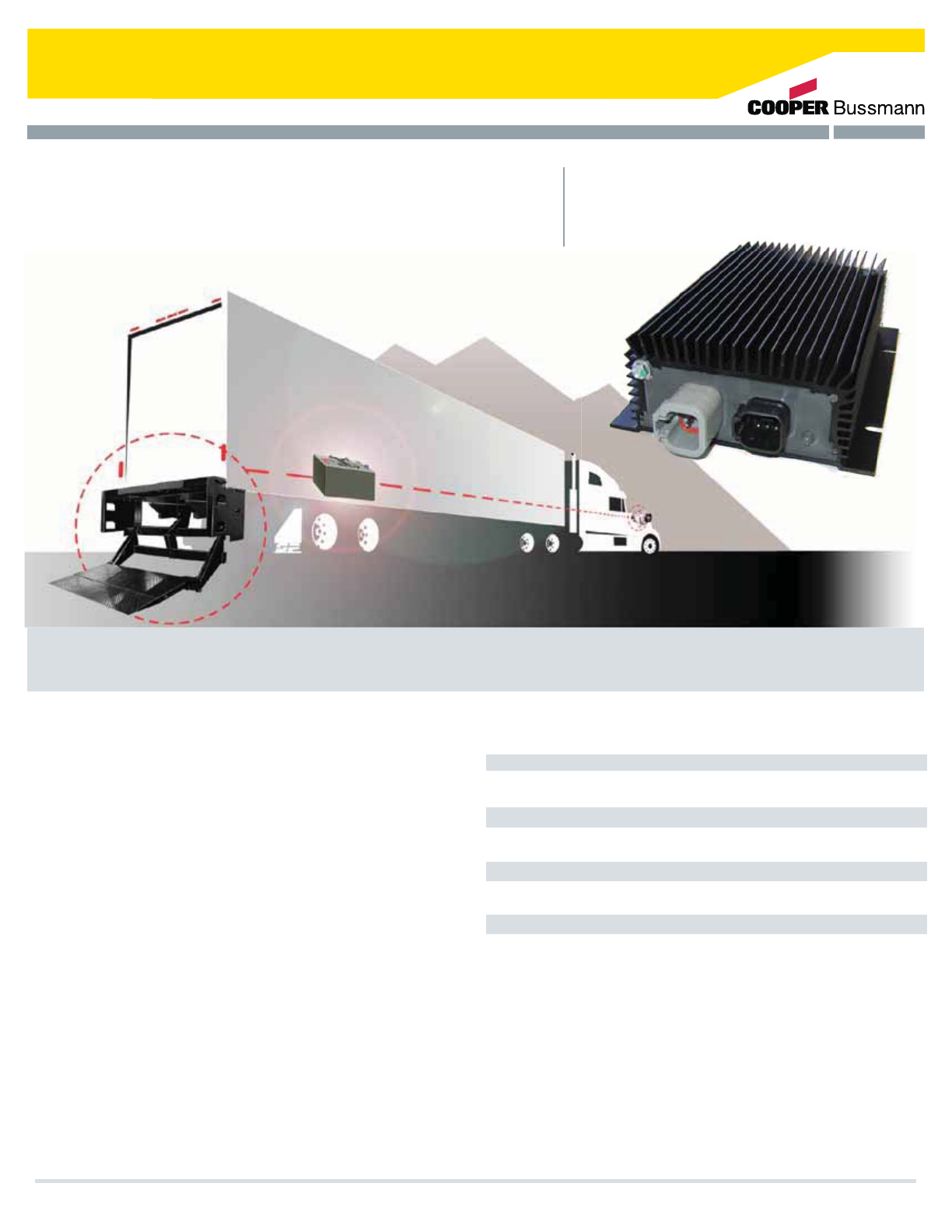
Off-the-shelf and custom-designed solid-
state products for power conditioning,
distribution, conversion and management,
and control of on-vehicle electrical systems
Smart Remote Battery Charging/Isolation
Intelligent Power Distribution
t.BJOUBJOBCBMBODFECBUUFSZTZTUFNCZ
QSJPSJUJ[JOHNVMUJWPMUBHFDIBSHJOH
t&GmDJFOUBOEPQUJNJ[FEBMMPDBUJPOPGQPXFS
UPFMFDUSPOJDEFWJDFT
Low Voltage Disconnection
t.PSFFGmDJFOUBOESFMJBCMFUIBO
NFDIBOJDBMPSTPMFOPJETZTUFNT
Battery Equalization &
DC-DC Voltage Conversion
t*OUFMMJHFOUQPXFSNBOBHFNFOU
BOECBUUFSZSVOEPXOQSPUFDUJPO
I
nte
llig
ent
P
ower
Di
str
ib
ut
i
o
n
t
&Gm
D
J
FOUBO
E
PQ
U
J
N
J
[F
E
B
MM
PDBU
J
POP
G
QP
XFS
UPF
M
FDUSPO
J
D
E
FW
J
DFT
Z
7FIJDMFMJHIUJOH
DPOUSPMnBTIFST
WTUBSU
DIBSHF
24v
Start
24v
Cooper Bussmann Transportation Products t1IPOFt'BYtXXXDPPQFSCVTTNBOODPN
CAN (J1939)
interfaces
4

Broad Range of Isolator Current Capacities
r"UISPVHI"
Wide Converter Input Voltage Range
r7EDUP7EDOFHBUJWFHSPVOE
Low Voltage Disconnect
r3BOHJOHGSPN7EDUP7ED
Versatile Battery Separators
r8PSLXJUIBOZUZQFPG7EDPS7ED
OFHBUJWFHSPVOEDIBSHJOHTZTUFN"PSMFTT
Other Accessories
r4PMJETUBUFáBTIFST7EDBOE7ED
r%BZUJNFSVOOJOHMJHIUT$.744
$"/$4"%5ZQF'.744
EMI/EMC Profiling
r4"&*40&NBSL$&BOE.JMJUBSZ4UBOEBSET
Solid-State Power Switching & Distribution
r6QUP"
$POWFSUFST&RVBMJ[FST
%$%$$POWFSUFST
5SBJM$IBSHFS
%$$VSSFOU4FOTPS
4FQBSBUPST*OUFSDPOOFDUT
.VMUJ#BUUFSZ*TPMBUPST
.VMUJ#BUUFSZ*TPMBUPS"QQMJDBUJPO(VJEF
1PXFS.BOBHFNFOU
4PMJE4UBUF'MBTIFST
%BZUJNF3VOOJOH-JHIU$POUSPMT 22
Cooper Bussmann Transportation Products t1IPOFt'BYtXXXDPPQFSCVTTNBOODPN 5
Special Design Features
t-PXTUBOECZDVSSFOUESBJOUZQJDBMMZN"PSMFTT
tUP˚$PQFSBUJOHUFNQFSBUVSFBUGVMMDVSSFOU
EFSBUFEBUIJHIFSUFNQFSBUVSFT
t5IFSNBMMZQSPUFDUFEGPSPWFSUFNQFSBUVSFDPOEJUJPOT
t4IPSUDJSDVJUBOEPWFSDVSSFOUQSPUFDUFE
t3FWFSTFQPMBSJUZQSPUFDUFE
t0WFSWPMUBHFMPXWPMUBHFQSPUFDUFE
t8JMMDPOUJOVPVTMZTUBOEPGGVQUP7ED
t3P)4VOJUTBWBJMBCMFXJUITFMFDU$POWFSUFST
BOE&RVBMJ[FST
t-PTTPGHSPVOEQSPUFDUFE
t&.*&.$$PNQMJBODF%FQFOEJOHVQPOUIF
SFRVJSFNFOUTXFPGGFSNPEFMTEFTJHOFEUPNFFUTQFDJmD
DVTUPNFS4"&*40&NBSL$&PSNJMJUBSZTUBOEBSET
t0QFSBUJOHJOQVUWPMUBHFSBOHFGSPN77EDOFHBUJWF
HSPVOE
t4IPDLBOEWJCSBUJPOSFTJTUBOU
t&OWJSPONFOUBMMZQSPUFDUFEBOETQMBTIQSPPGTFBMFE
NPEFMTBWBJMBCMF
t5ZQJDBMFGmDJFODZPG
t6OJUTDBOCFQBSBMMFMFEGPSHSFBUFSPVUQVUDBQBDJUZ
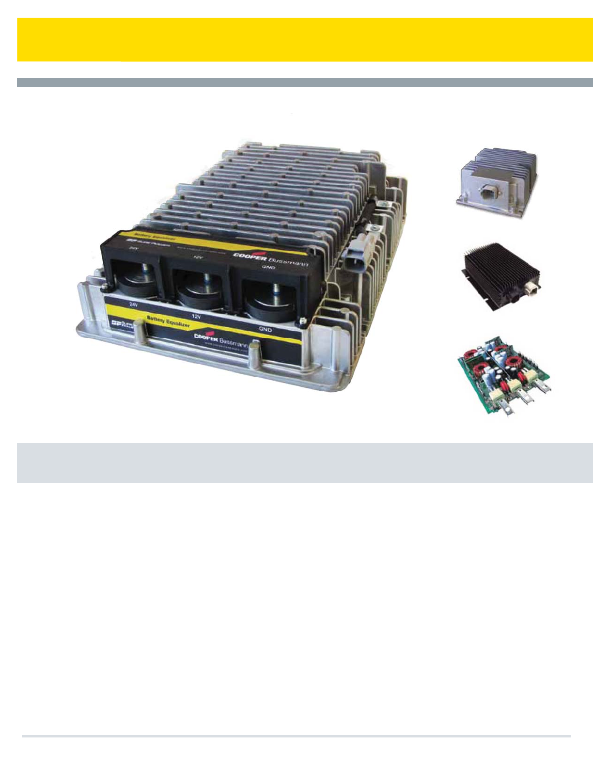
Converters / Equalizers
Cooper Bussmann Transportation Products t1IPOFt'BYtXXXDPPQFSCVTTNBOODPN
6

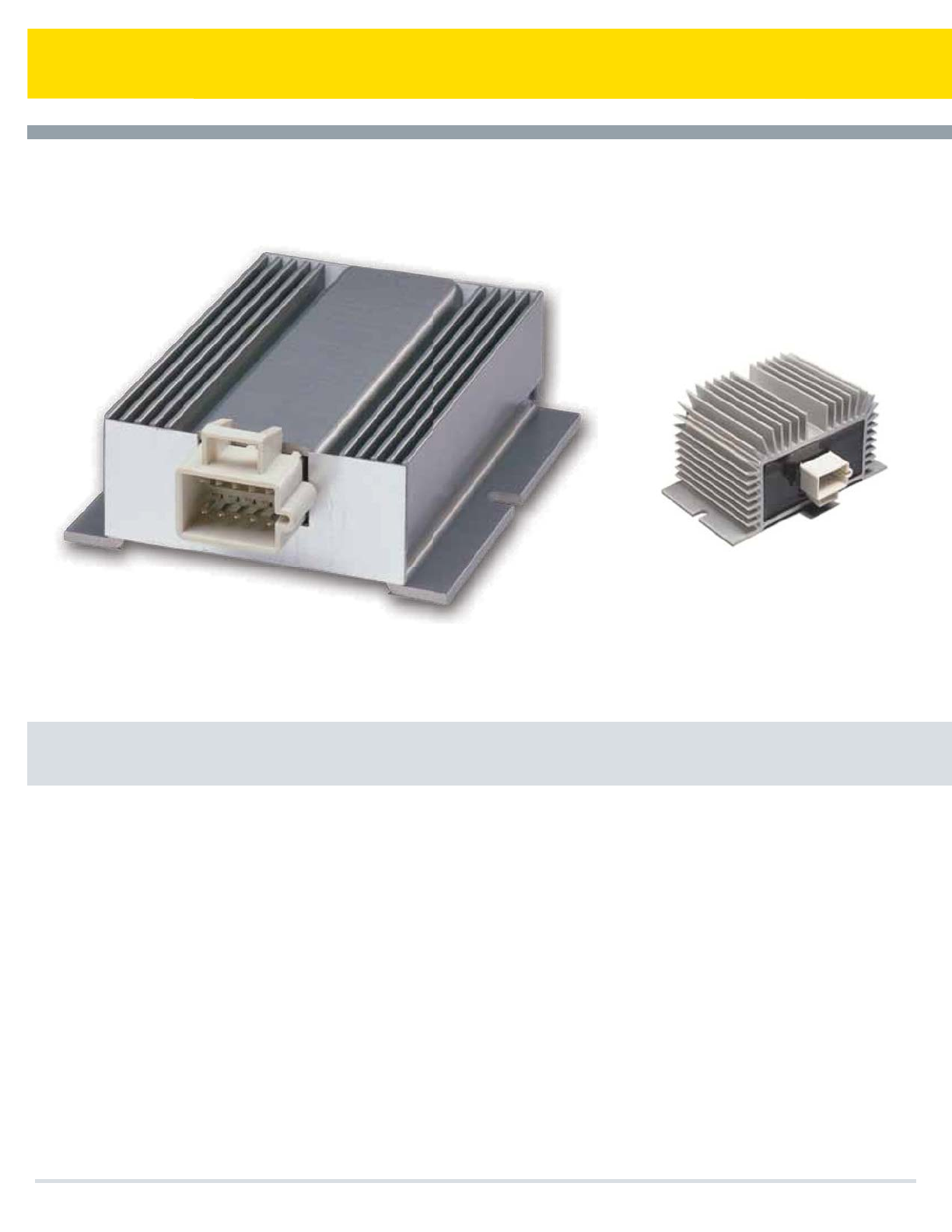
Pure Reliable Power
Sure Power Industries offers an expanded line of DC-DC Converters and Battery Equalizers
from low to high output current capabilities (2.5 amps to 100 amps). Sure Power is setting
the pace when it comes to the growing demands for dual voltage applications
5IF4VSF1PXFS#BUUFSZ&RVBMJ[FSNBJOUBJOTCBUUFSZCBMBODFPSiFRVBMJ[BUJPOwJOBQSFEPNJOBOUMZ7
TZTUFNUIBUSFRVJSFT7QPXFS5IF4VSF1PXFS#BUUFSZ&RVBMJ[FSDBOEFMJWFSVQUPBNQTPG
DPOUJOVPVT7DVSSFOUGPSQSBDUJDBMMZBOZ7MPBESBOHJOHGSPNGBSFCPYFTEFTUJOBUJPOCPBSETUXP
XBZSBEJPTBOEUSBOTNJTTJPODPOUSPMTUPFOHJOFDPOUSPMTBOEMJHIUJOH4VSF1PXFS%$%$
$POWFSUFSTDPOUJOVFUPQSPWJEFSFHVMBUFEQPXFSEJSFDUMZUPBDDFTTPSZPSNBJOMPBET4VSF1PXFS
PGGFST%$%$$POWFSUFSTQSPEVDJOHVQUPBNQTBU7GSPNB7TPVSDFBOEVQUPBNQTBU
7GSPNB7TPVSDF4VSF1PXFSPGGFSTBXJEFWBSJFUZPGGFBUVSFTBOENVMUJQMFMFWFMTPGQSPUFDUJPO
9
9
9
$
$POWFSUFS&RVBMJ[FS
$POWFSUFS&RVBMJ[FS
$POWFSUFS&RVBMJ[FS
$POWFSUFS
4XJUDIFE0VUQVU
4XJUDIFE0VUQVU"WBJMBCMF0GGTFU0VUQVU
4XJUDIFE0VUQVUX0GGTFU0VUQVU
7PS74FMFDUBCMF*OQVU
$
$
$
$
9
9
9
9
9
$
$-0
$
$POWFSUFS
$POWFSUFS
$POWFSUFS
$POWFSUFS
$POWFSUFS
$POWFSUFS&RVBMJ[FS
$POWFSUFS&RVBMJ[FS
$POWFSUFS&RVBMJ[FS
$POWFSUFS&RVBMJ[FS
$POWFSUFS&RVBMJ[FS
4XJUDIFE6OTXJUDIFE0VUQVU
*13PIT4XJUDIFE6OTXJUDIFE0VUQVU
*13PIT4XJUDIFE6OTXJUDIFE0VUQVU
4XJUDIFE6OTXJUDIFE0VQVU
4XJUDIFE6OTXJUDIFE0VQVU
4XJUDIFE6OTXJUDIFE0VQVU
)JHI$VSSFOU$POWFSUFS&RVBMJ[FS
)JHI$VSSFOU$POWFSUFS&RVBMJ[FS
)JHI$VSSFOU$POWFSUFS&RVBMJ[FS
)JHI$VSSFOU$POWFSUFS&RVBMJ[FS
7PMUBHF$POEJUJPOFS
7PMUBHF$POEJPOFS5SBJM$IBSHFS
5SBJM$IBSHFS
5SBJM$IBSHFS
$
$
J
$POWFSUFS
$POWFSUFS
$POWFSUFS
4XJUDIFE0VUQVU6OTXJUDIFE70VUQVU
4XJUDIFE0VUQVU6OTXJUDIFE70VUQVU
*TPMBUFE0VUQVU6OTXJUDIFE70VUQVU
-PDLPVUT
MODEL VOLTAGE
INPUT OUTPUT
OUTPUT
CURRENT FUNCTION SPECIAL FEATURES
Converters / Equalizers
Cooper Bussmann Transportation Products t1IPOFt'BYtXXXDPPQFSCVTTNBOODPN 7
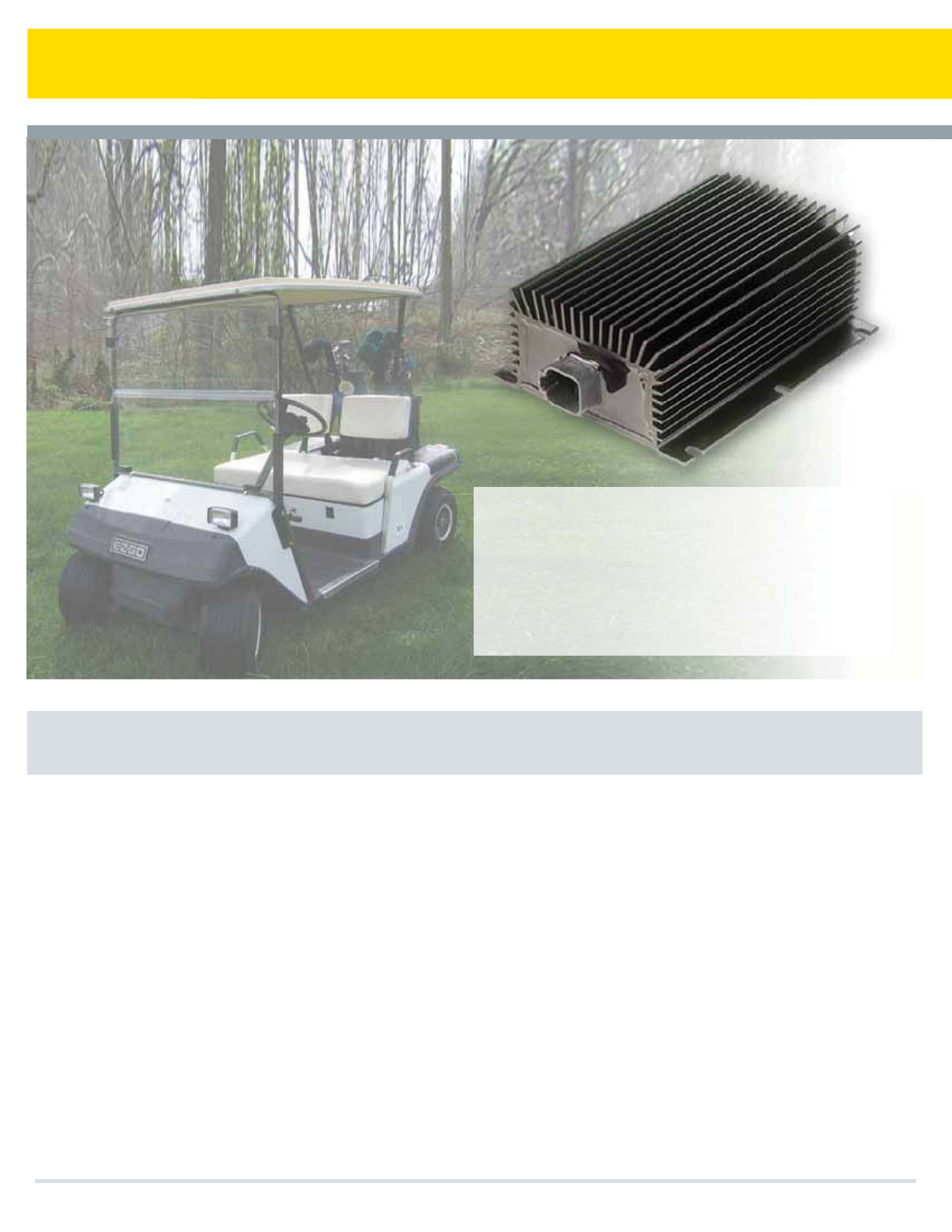
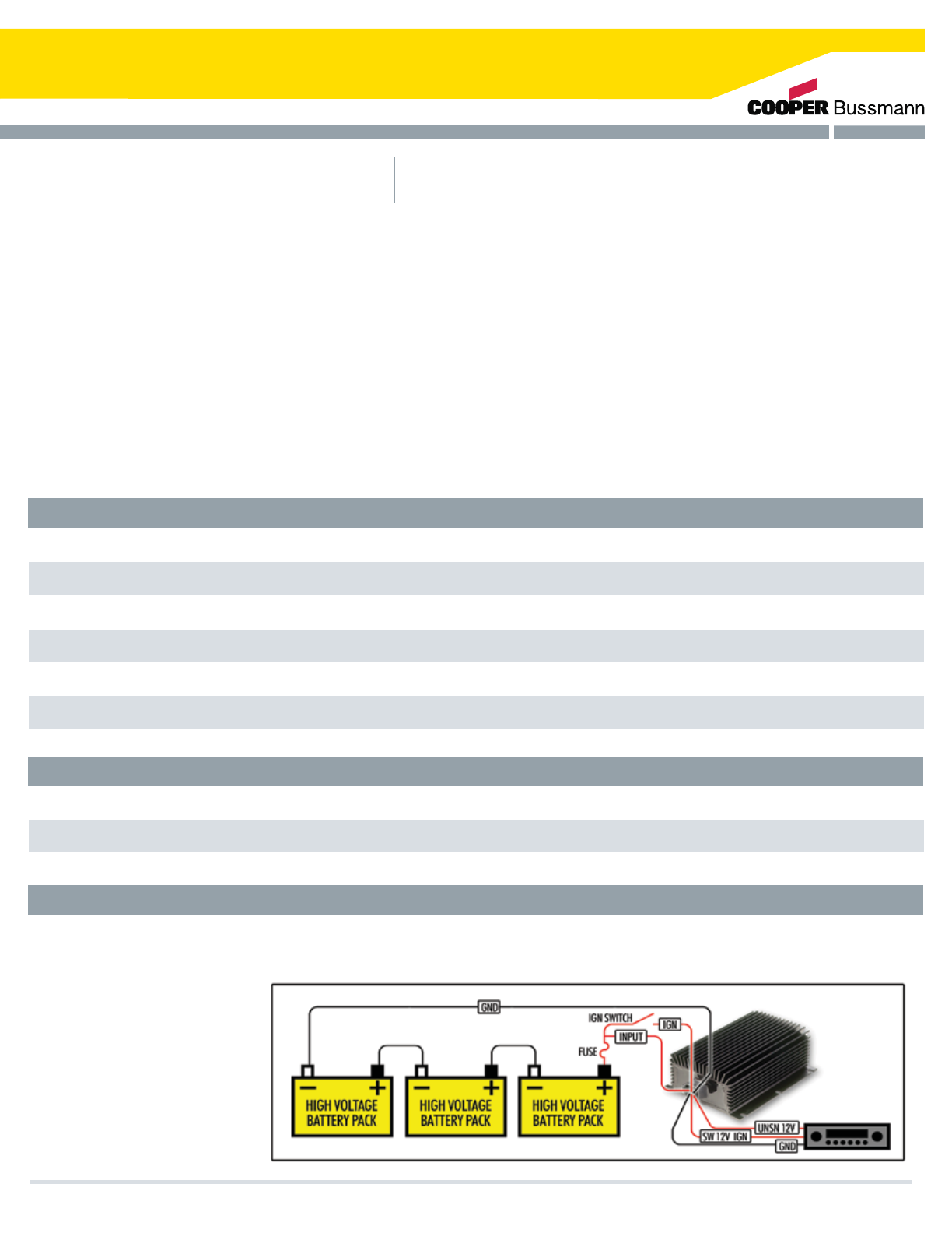
Benefits
t6TF7BDDFTTPSJFTXJUIPVUIBSNJOHUIFCBUUFSJFTBOEUIFQFSGPSNBODFPGUIFDBSU
t&YBNQMF"QQMJDBUJPOT
%$%$$POWFSUFS
5BQQJOHPGGPGUIFCBUUFSJFTPGB(PMG$BSUUP
QPXFS7BDDFTTPSJFTDBORVJFUMZDBVTF
EBNBHFUPUIFCBUUFSJFTCZDSFBUJOHB
DIBSHFEJTDIBSHFJNCBMBODF5IJTJNCBMBODF
SFTVMUTJOPWFSDIBSHJOHQBSUPGUIFTUSJOHPG
CBUUFSJFTBOEVOEFSDIBSHJOHUIFSFTU
A Sure Power DC-DC Converter solves this problem by powering 12V accessories from the entire battery string,
resulting in much longer battery life.
AM/FM CD Player
Cell phone or laptop charging
12V GPS
12V cooler
$PPQFS#VTTNBOO5SBOTQPSUBUJPO1SPEVDUTt1IPOFt'BYtXXXDPPQFSCVTTNBOODPN
8
1VSF3FMJBCMF1PXFS
4VSF1PXFS*OEVTUSJFTPGGFSTBOFYQBOEFEMJOFPG%$%$$POWFSUFSTGSPNMPXUPIJHIIJHIUP
MPXGPS999TFSJFTPVUQVUDVSSFOUDBQBCJMJUJFTBNQTUPBNQT4VSF1PXFSJTSFBEZUP
LFFQQBDFXJUIHSPXJOHEFNBOETGPSBWBSJFUZPGEVBMWPMUBHFBQQMJDBUJPOT
Sure Power’s DC-DC Converters continue to provide regulated, clean power directly to accessory or main
loads. Sure Power offers DC-DC Converters for 12V, 24V, 36V, 48V, 72V, 80V, and 96V systems. Sure
Power also offers a wide variety of features and multiple levels of protection.
Please contact Sure Power Industries for specifications, pricing, leadtime, or custom products.
21008C10
21015C10
21020C10
21030X00
21060X00
21080X00
7.5A
15A
20A
30A
60A
80A
24V
24V
24V
24V
24V
24V
13.7V
13.7V
13.5V
13.5V
13.5V
13.5V
.0%&-
77%$%$$0/7&35&3
065165
$633&/5
/0.*/"-
*/165
70-5"(&
065165
70-5"(& 41&$*"-'&"563&4 %*.&/4*0/4
%$%$$POWFSUFS
Switched Output, Unswitched 12V Output, Short-Circuit and
Overcurrent Protection, Thermal Protection, Sealed Connector
Switched Output, Unswitched 12V Output, Short-circuit and
Overcurrent Protection, Thermal Protection, Sealed Connector
Switched Output, Unswitched 12V Output, Short-circuit and
Overcurrent Protection, Thermal Protection, Sealed Connector
Switched Output, Unswitched 12V Output, Short-circuit and
Overcurrent Protection, Thermal Protection, Sealed Connector
Tightly Regulated 60A Output
Tightly Regulated 80A Output
3.0”L x 4.5”W x 2.35”H
5.75”L x 4.5”W x 2.35”H
5.75”L x 4.5”W x 2.35”H
8.25”L x 5.75”W x 2.35”H
10.5”L x 8.5”W x 3.17”H
10.5”L x 8.5”W x 3.17”H
41010C00
41020C00
10A
20A
27-70V
28-70V
13.5V
13.7V
77%$%$$0/7&35&3
Switched Output, Unswitched 12V Output, Short-circuit and
Overcurrent Protection, Thermal Protection
Switched Output, Unswitched 12V Output, Short-circuit and
Overcurrent Protection, Thermal Protection
3.0”L x 4.5”W x 2.35”H
5.75”L x 4.5”W x 2.35”H
71030i 30A 57-124V 13.5V
77%$%$$0/7&35&3
Isolated Output, Unswitched 12V Output, Short-circuit and
Over Limit Protection, Thermal Protection 7.125”L x 5.62”W x 2.35”H
1
1
1
2
2
Can also be used for 36V
battery systems.
Can also be used for 80V & 96
battery systems.
Specifications subject to
change without notice.
$PPQFS#VTTNBOO5SBOTQPSUBUJPO1SPEVDUTt1IPOFt'BYtXXXDPPQFSCVTTNBOODPN 9
About the Trail Charger
Do the Math, Give Yourself a Lift
Trail Charger
Cooper Bussmann Transportation Products t1IPOFt'BYtXXXDPPQFSCVTTNBOODPN
5IF4VSF1PXFS5SBJM$IBSHFSBMMPXTUIFPQFSBUPSUPDIBSHF
BSFNPUFCBUUFSZCBOLBUBSFHVMBUFE75IJTBQQSPBDI
FMJNJOBUFTWPMUBHFMPTTEVFUPMPOHXJSFMFOHUIT5IF5SBJM
$IBSHFSJTEFTJHOFEUPQSPWJEFBSFHVMBUFE7EDBUBGVMM
".1PS".1DIBSHJOHSBUF5IF5SBJM$IBSHFS
DIBSHFTUIFMJGUHBUFCBUUFSJFTBUUIFWPMUBHFUIFZOFFEJO
PSEFSUPUBLFBDIBSHFXPSLJOHUPLFFQUIFCBUUFSJFTJOB
DIBSHFETUBUFSFBEZGPSZPVSOFYUMJGU5IF5SBJM$IBSHFSBMTP
FMJNJOBUFTPSSFEVDFTUIFOFFEGPSBEEJUJPOBMDBCMFTFYDFQU
GPS$PSJGEVBMQPMFDBCMFJTSFRVJSFEGPS
BQQMJDBUJPO
Introduction to the Trail Charger
"MMUISFFNPEFMTPGUIF4VSF1PXFS5SBJM$IBSHFSBDUMJLFB
WPMUBHFBNQMJmFSTJNJMBSUPIPXBTUFSFPBNQMJmFSJODSFBTFT
TPVOEPVUQVUB5SBJM$IBSHFSBNQMJmFTWPMUBHF5IJOLPGJU
BTBCPPTUFSUIBUDPNQFOTBUFTGPSUIFWPMUBHFESPQJOUIF
XJSJOHUPUIFMJGUHBUFCBUUFSJFT8JUIUIF.PEFM$
$-0BOE$UIFMFWFMPGBNQMJmDBUJPO
EFQFOETPOUIFPVUTJEFUFNQFSBUVSF#BUUFSJFTSFRVJSF
IJHIFSWPMUBHFBUMPXFSUFNQFSBUVSFT5IF5SBJM$IBSHFS
BVUPNBUJDBMMZSBJTFTBOEMPXFSTUIFWPMUBHFUPPQUJNJ[FUIF
DIBSHFUPUIFBVYJMJBSZCBUUFSZCBOL
Trail Charger with Lock Outs
5IFNPEFM$-0NPOJUPSTUIFCSBLFMJHIUTJHOBMBOE
UVSOTUIFUSBJMDIBSHFSPGGXIFOUIFCSBLFTBSFBDUJWBUFE5IF
NPEFM$-0DBOBMTPNPOJUPSUIFUSBJMFSEPNFMBNQT
BOEXIFOUIFEPNFMBNQTBSFPOUIF5SBJM$IBSHFSSFEVDFT
UIFNBYJNVNPVUQVUDVSSFOUUPBNQT
Amps output
Lift Gate Motor Draw
Seconds of Lift
Run Time
Amp Hours Used
Lift During Daily
Operations
Total Amp/Hours
used During Day
Total Run Time Required to
fully charge the battery(s)
Voltage Regulation
20A
175A
25 Seconds
1.2A/Hours
50
60A/Hours
4 Hours
Temp. Compensated
20A
175A
25 Seconds
1.2A/Hours
100
120A/Hours
8 Hours
Temp. Compensated
50A
175A
25 Seconds
1.2A/Hours
100
120A/Hours
3 Hours
Temp. Compensated
Model 11020C01
11020CLO
11020C01
11020CLO 11050C00
10
DC Current Sensor
Cooper Bussmann Transportation Products t1IPOFt'BYtXXXDPPQFSCVTTNBOODPN
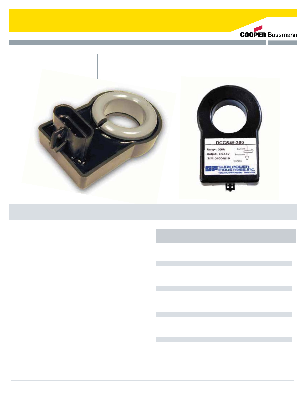
5IF4VSF1PXFS%$$4%$$VSSFOU4FOTPSTBSFBGBNJMZPG
EFWJDFTVTFEUPNFBTVSFUIFDVSSFOUnPXJOBXJSF
5IF%$$4BOE%$$4NPEFMTQSPWJEFEJGGFSFOUJBM
PVUQVUTJOUFOEFEUPCFEJSFDUMZDPOOFDUFEUPBOBOBMPH
NFUFSNPWFNFOU5IF%$$4NPEFMTQSPWJEFTJOHMF-
FOEFEPVUQVUTJOUFOEFEUPCFVTFEXJUIFMFDUSPOJD
JOTUSVNFOUBUJPO"MMNPEFMTNFBTVSFCJQPMBSDVSSFOUT
Theory of Operation
5IF$VSSFOU4FOTPSJTCBTFEPOB)BMMFGGFDUTFOTPS*$
5IJTTFOTPSNFBTVSFTDIBOHFTJOUIFNBHOFUJDmFME
DSFBUFECZDVSSFOUnPXJOUIFXJSFQBTTJOHUISPVHIUIF
BQFSUVSF5IJTOPODPOUBDUNFBTVSFNFOUFMJNJOBUFT
JTPMBUJPOBOEUIFSNBMJTTVFTUIBUFYJTUXIFOVTJOH
DPOWFOUJPOBMSFTJTUJWFTFOTPST
DCCS50-100
DCCS50-200
DCCS50-300
DCCS100-100
DCCS100-200
DCCS100-300
DCCS45-200
DCCS45-300
MODEL CURRENT RANGE SENSOR OUTPUT
Current Events
About the DC Current Sensor
"NQT
"NQT
"NQT
"NQT
"NQT
"NQT
"NQT
"NQT
N7
N7
N7
N7
N7
N7
UP7
UP7
11
Separators/Interconnects
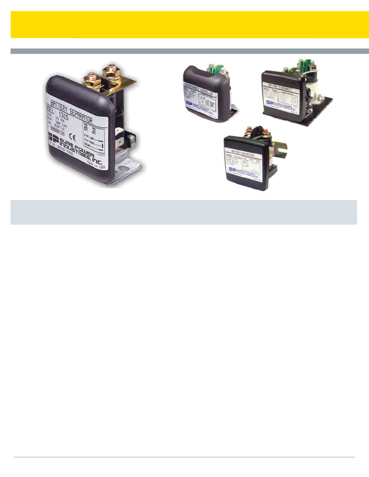
Features
Simple Installation
Connects to primary battery, auxiliary battery and ground. Absolutely no system modifications are necessary. Models
1314/1315 work with any type of 12V negative ground charging system 100 amps or less. 310X models work with nega-
tive ground 12V or 24V charging systems up to 300Amps.
Multiple Battery Charging
The Battery Separator allows multiple batteries to be charged from one charging source (usually, but not necessarily, an
alternator). When the batteries are not being charged, the Battery Separator separates or isolates the batteries.
Prioritized Charging
The Battery Separator waits until the battery connected to the active charging source reaches approximately 13.2V (26.4V)
before paralleling and charging the remaining batteries. The system disconnects at approximately 12.8V (25.6V).
Prevents Charging System Overload
If the current requirements are greater than the charging source can produce, the Battery Separator will automatically
separate the batteries, thus directing all available charge current to the battery directly connected to the charging source.
The system will then reset and re-attempt charging the auxiliary battery. A time delay prevents false switching.
Start Assist Feature
An optional input from the key switch or a manual switch will program the Battery Separator to parallel the batteries during
starting. This feature will only engage if the auxiliary battery has sufficient power available to assist in starting.
Universally Suited
For mounting on tow vehicle or towable.
Voltage Spikes
generated by the coil of the solenoid are absorbed by protective circuitry built into the Battery Separator.
Cooper Bussmann Transportation Products t1IPOFt'BYtXXXDPPQFSCVTTNBOODPN
12

Smart Charge Priority Systems
Separators/Interconnects
The Battery Separator is designed for use in multi-battery applications as a solenoid priority system to
protect the chassis charging system from excessive loading while allowing auxiliary batteries to be
charged. The Battery Separator has two basic operational characteristics.
Assist In Engine Starting
When the starter is activated the Battery Separator compares the voltage of both battery banks. If the
starting battery is lower than the auxiliary battery bank, the Battery Separator will engage, allowing the
auxiliary battery bank to aid in vehicle starting. The start signal must be at least three volts for this operation
to occur.
Protect The Charging System
Once the engine has started, the Battery Separator monitors the chassis battery and charging system.
When the charging system reaches 13.2 volts (26.4V), indicating a charged main battery and functioning
charging system, the Battery Separator will engage, connecting the auxiliary battery bank to the vehicle
charging system. If the drain on the charging system by the auxiliary battery bank reduces the system
voltage below 12.8 volts (25.6V), the Battery Separator will disconnect the auxiliary battery bank, thus
protecting the chassis charging system. The process is repeated until the charging system is turned off.
A delay function has been incorporated in the control circuit to prevent the Battery Separator from reacting
to momentary voltage fluctuations and chattering.
The priorites are to assist in engine starting, if required, and to protect the charging system from excessive
power drain.
Battery Separator - The Smart Solenoid
MODEL INPUT CURRENT DESCRIPTION
1314
1314-200
1315
1315-200
1318
1319
3103
3104
3105
3106
3113
12V
12V
12V
12V
24V
24V
24V
12V
12V
12V / 24V
12V/24V
100A
200A
100A
200A
100A
100A
300A
300A
300A
300A
300A
Battery Separator, Uni-Directional w/ Aux Start
Battery Separator, Uni-Directional w/ Aux Start
Battery Separator, Bi-Directional w/ Aux Start
Battery Separator, Bi-Directional w/ Aux Start
Battery Separator, Uni-Directional
Battery Separator, Bi-Directional
Interconnect/Controller
Interconnect/Controller
Interconnect/Controller
Battery Disconnect
Dual Voltage
Cooper Bussmann Transportation Products t1IPOFt'BYtXXXDPPQFSCVTTNBOODPN 13
Multi-Battery Isolators
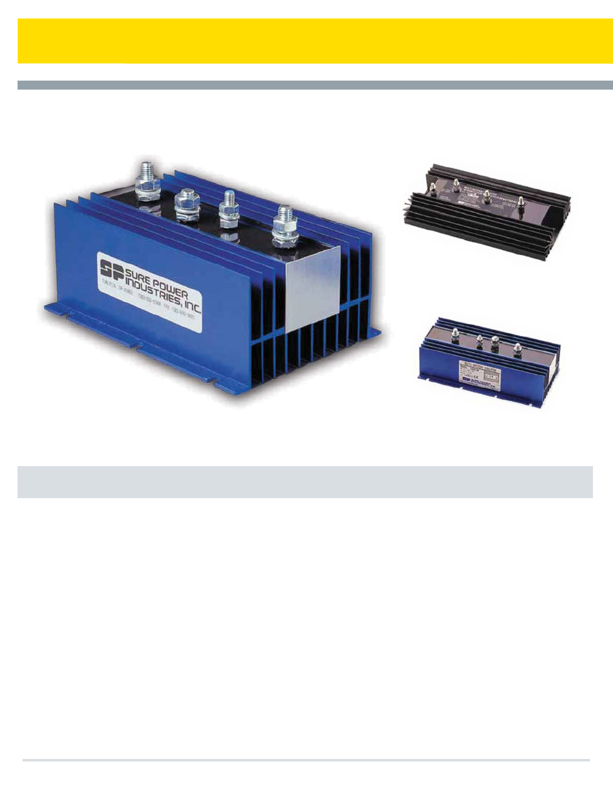
Sure Power Multi-Battery Isolators
t Eliminate multi-battery drain when two or more battery banks are in a charging system.
t Perform as well or better than existing factory installed components.
t Designed to exceed OEM specifications.
t Solid-State Electronics... Isolates each battery circuit and allows each battery to discharge and
charge according to its own needs.
t The original, not an imitation! The Battery Isolator was invented by Sure Power in 1959.
t More efficient and reliable than mechanical or solenoid systems.
t The most comprehensive line of Battery Isolators on the market. Isolators are available for most
application needs.
Cooper Bussmann Transportation Products t1IPOFt'BYtXXXDPPQFSCVTTNBOODPN
14
Why You Need to Isolate Your Batteries
Multi-Battery Isolators
Many vehicles and other types of equipment have multiple batteries: one to start the engine
and others to power accessories. To understand the problem of multi-battery drain and how
a Sure Power Battery Isolator prevents it, think of electricity as water. Electrical current is
equal to the flow of water and voltage is equal to the pressure. The alternator pumps current
(water) into the batteries (storage tanks). The current then flows through the wires (pipes) to
the accessories. It is important to think of batteries as storage tanks. If a fully charged
battery is connected directly parallel with a discharged or empty battery, the voltage
pressure in the full battery will force its current into the empty battery until the current stored
in both batteries reaches a common level. The discharged battery will always rob power
from a charged battery. So, no matter how many batteries you have on your vehicle, the
accessories connected to one will draw power from the other batteries in the circuit. This is
the problem of multi-battery drain. And if it is allowed to continue unchecked, it can leave
you stuck with dead batteries and an engine that will not start... all when you least expect it.
Solenoids
One of the “so-called” solutions for multi-battery drain is nothing more than a solenoid; a
switch that disconnects batteries one from another. With a solenoid, there is no multi-battery
drain while the batteries are disconnected. But, the second the solenoid reconnects the
batteries, the drained battery robs power from the starting battery. That isn’t all that
happens. This sudden,violent transfer of energy from one battery to another has been
known to damage batteries or shorten their life, overheat wires and connections, and worst
of all, cause fires. The Solenoid Is No Solution For Multi-battery Drain!
The Solenoid Is Not A Substitute For A Sure Power Battery Isolator
The Solution
To eliminate the multi-battery drain problem, a Sure Power Isolator acts as a check valve
between the batteries, preventing current from flowing from one battery to another. Each
battery is isolated and acts as an independent power source. So no matter how drained
your accessory batteries become, they will never drain power from the battery you’re
depending on to start your engine. When the current is used from battery #2, the check
valve (diode) stops current flow from battery #1. When the alternator is charging, current can
only flow in one direction, from the alternator to the batteries. Each battery then determines
the amount of current which flows into it by its own state of charge based on the voltage
regulator setting. With this system, the alternator is protected, the batteries are protected
and your family or passengers are protected. The balanced circuit electronic Isolator is
absolutely the only way that proper isolation and control can be accomplished, solving every
multi-battery problem.
Engineering Excellence
An Isolator is a simple and safe device. But, if it isn’t properly engineered, it can fail and
cause the entire electrical system to also fail. Sure Power Isolators are engineered with a
SAFETY MARGIN competitor models cannot match. From the quality heat sink to the finest
electrical components and materials, Sure Power enables you to install the best!
The Original
Sure Power Industries invented and has been producing Isolators since 1959. We build the
finest isolator products on the market for 6 through 48 volt systems, with one or two
charging systems, 2 or 3 battery banks, and current capacities of 25 through 350 amps. Our
Isolators are standard equipment on many boats, ships, RVs, trucks, police, fire, emergency
vehicles, industrial equipment and military vehicles.
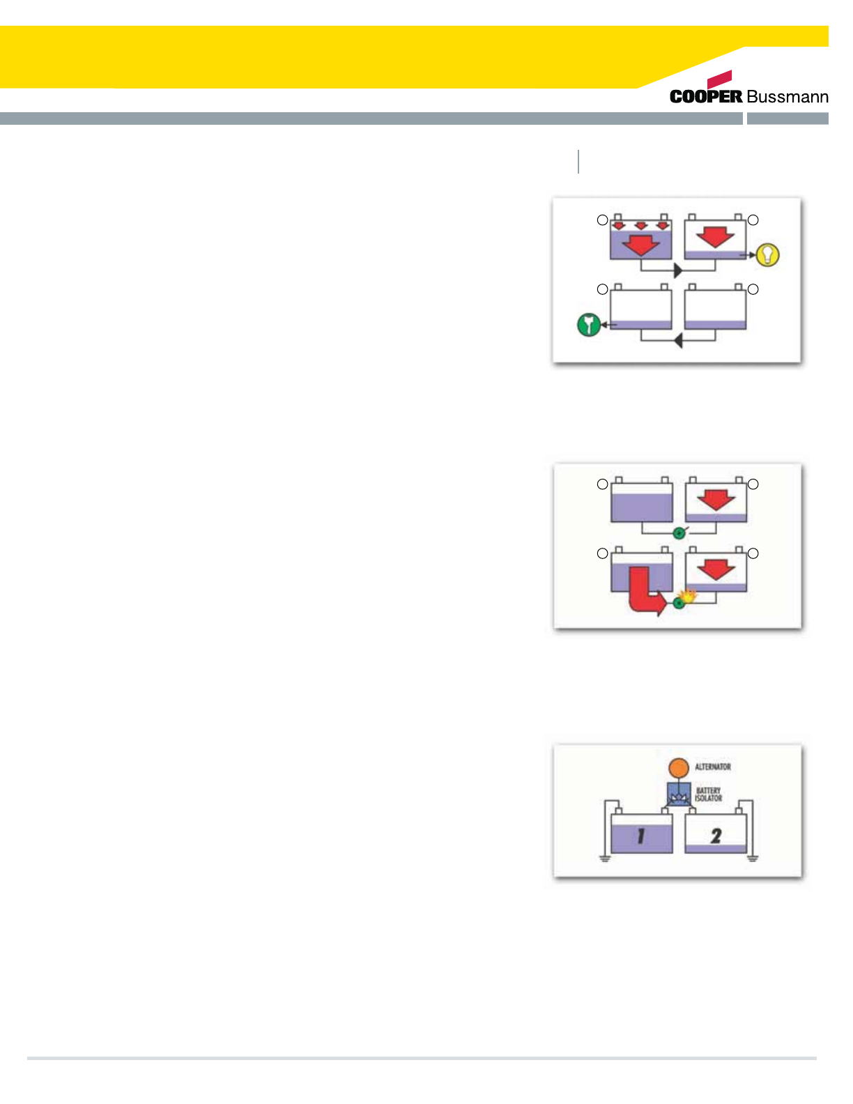
Accessories connected to battery #2 rob
power from battery #1, your starting battery,
leaving you with two dead batteries when you
least expect it.
Solenoids don’t prevent multi-battery drain,
only delay it. In fact, the current surge that
occurs when the batteries are reconnected
has been known to cause major electrical
system damage.
A Battery Isolator acts as a check valve
(through two diode legs), one on each line.
Both batteries receive current from the
alternator and the voltage will equalize
throughout the system while the alternator is
in operation.
Cooper Bussmann Transportation Products t1IPOFt'BYtXXXDPPQFSCVTTNBOODPN
1
1
2
2
1
1
2
2
15

Multi-Battery Isolator Application Guide
9523A
12023A
12033A
13023A
13033A
16023A
16033A
24023A
32033A
2703R
3203R
952R
702R
31322
3152
122P
702P
1602P
31622P
92061
60A
350A
25A
70A
160A
160A
300/160A
70A
120A
95A
70A
2
2
1
1
3
3
2
2
95A
120A
120A
130A
130A
160A
160A
240A
120A
1
1
1
1
1
1
1
1
2
2
2
3
2
3
2
3
2
3
GROUP 1
GROUP 2
GROUP 3
GROUP 4
SPECIAL
APPLICATIONS
1
1
1
1
1
1
1
2
2
2
2
2
2
2
MODEL INPUT
CURRENT OUTPUT
Cooper Bussmann Transportation Products t1IPOFt'BYtXXXDPPQFSCVTTNBOODPN
*GUIFBMUFSOBUPSJTOPUDPNQBUJCMFXJUICBUUFSZJTPMBUPSTB#BUUFSZ4FQBSBUPSXPVMECFUIFOFYUBMUFSOBUJWF"MUFSOBUPSTXJUI
JOUFSOBMWPMUBHFTFOTJOHFHTPNF.JUTVCJTIJBOE)JUBDIJPSTJOHMFXJSFTFMGFYDJUJOH%FMDP%FMQIJBMUFSOBUPSTTPNF)POEBT
BOETPNFTFMFDUFEJNQPSUT
122
702
703
704
2702
2703
952
1202
1203
3202
3203
1302
1602
1603
2002
2402
2403
3002
3003
3303
3603
31822
31922
25A
70A
70A
70A
70A
70A
95A
120A
120A
120A
120A
130A
160A
160A
200A
240A
240A
300A
300A
95/160A
120/160A
160A
240A
1
1
1
1
2
2
1
1
1
2
2
1
1
1
1
1
1
1
1
2
2
1
1
2
2
3
4
2
3
2
2
3
2
3
2
2
3
2
2
3
2
3
3
3
2
2
16

Multi-Battery Isolator Application Guide
VEHICLE APPLICATIONS
Except Delcotron/Delphi CS Series alternators (CS used
on most 1985 and newer GM vehicles)
General Motors (Delcotron/Delphi)
Ford
Chrysler
Jeep
Japanese Imports
Motorola
Equipped with Delcotron/Delphi CS series alternators (most 1985-1993) or CS
130-D Series alternators (most 1993 and newer)
Other than Load Handler Series
Requiring regulator sensing
Requiring regulator sensing
Vehicles equipped with Delcotron/Delphi CS Series alternator (most 1985-1980)
1985 and newer equipped with Nippondenso alternator with internal regulators
or alternators with an “S” (sense) terminal
Many 1998 and newer
General Motors (Delcotron/Delphi)
Jeep
Toyota, Honda, & Some Imports
Ford
Motorola
Bosch
Many European Style Alternators
All models, all years including Nippondenso externally
regulated alternators
Up to 1998
Equipped with Nippondenso externally regulated alternators
With alternators using external voltage regulator or external sensing
Load Handler Series or 8EM Remote Sense Series
1
2
3
4
Schottky Isolator
ISO/Start
Positive ground
isolators can be used
as charging source
combiners
Typical Isolator
Application
Typical Combiner
Application
The Original and Still the Best
Cooper Bussmann Transportation Products t1IPOFt'BYtXXXDPPQFSCVTTNBOODPN
2005 and newer General Motors applications using the Delphi alternators (may also be labeled Bosch) with two pin terminal
connectors will not work with Battery Isolators: use Battery Separator. NOTE: Dodge Sprinter classified under Group 4
(PUPXXXTVSFQPXFSDPNGPSBQQMJDBUJPOBOEJOTUBMMBUJPOJOTUSVDUJPOT
17
Special Design Features
t"VUPNBUJDBMMZEJTDPOOFDUTOPODSJUJDBMMPBETGSPNUIFCBUUFSZJFTUPQSFWFOUFYDFTTJWFCBUUFSZEJTDIBSHF
t"VUPNBUJDBMMZSFDPOOFDUTMPBETJGWFIJDMFJTTUBSUFEPSCBUUFSZJTSFDIBSHFE
t4UBSU4JHOBM*OQVUPWFSSJEFUPQSFWFOUUIFMPBETGSPNEJTDPOOFDUJOHEVSJOHTUBSUJOH
t.BOVBMPWFSSJEFGPSDPOOFDUJOHPSEJTDPOOFDUJOHEVSJOHFNFSHFODJFT
t4FMFDUBCMF1SFTFUNPEFMTBWBJMBCMFSBOHJOHGSPN7UP7
t"VEJCMFPSWJTVBMBMBSNPVUQVUBDUJWBUFTNJOVUFCFGPSFEJTDPOOFDU
t.BYJNVNMPBEDVSSFOUNPEFMTVQUPBNQTBOEUIFSNBMMZQSPUFDUFE
t4PMJE4UBUFMPHJDBOETXJUDIJOHDJSDVJUSZPONPTUNPEFMT
t'VMMZQSPUFDUFE
t-PXTUBOECZDVSSFOU
Power Management
Cooper Bussmann Transportation Products t1IPOFt'BYtXXXDPPQFSCVTTNBOODPN
18

Intelligent Battery Saving Devices
5IF4VSF1PXFSGBNJMZPG-PX7PMUBHF%JTDPOOFDUT-7%JTBTPMJETUBUFFMFDUSPOJDQSPUFDUJPO
NPEVMFXIJDIEJTDPOOFDUTQSFEFUFSNJOFEBVYJMJBSZMPBETGSPNUIFTUBSUJOHCBUUFSZCBOLUPFOTVSFFOPVHI
QPXFSJTMFGUJOUIFCBUUFSJFTGPSTUBSUJOH"NJDSPDPOUSPMMFSTFOTFTCBUUFSZWPMUBHF%VSJOHOPSNBMPQFSBUJPO
XIFOUIFCBUUFSZJTTVGmDJFOUMZDIBSHFEUIF-7%DPOOFDUTUIFMPBET0ODFUIFCBUUFSZWPMUBHFSFBDIFTUIF
TIVUPGGTFUQPJOUUIFBVYJMJBSZMPBETBSFBVUPNBUJDBMMZEJTDPOOFDUFEGSPNUIFCBUUFSZJFTQSFWFOUJOHGVSUIFS
CBUUFSZESBJO4VSF1PXFSIBTUBLFOTUFQTUPQSFWFOUGBMTFUSJHHFSJOHGSPNUSBOTJFOUDPOEJUJPOT5IF-7%XJMM
BVUPNBUJDBMMZSFDPOOFDUUIFMPBETPODFUIFCBUUFSZSFBDIFT7PSJGUIFTUBSUFSJOQVUPSUIFNBOVBM
PWFSSJEFJOQVUJTBDUJWBUFE
'PSMPXTUBOECZDVSSFOUESBJOUIF-7%TDPOTJTUPGTPMJETUBUFDJSDVJUSZXIJDIVTFTN"PSMFTT
TVQQPSUDVSSFOUDFSUBJOTZTUFNTVTFBTPMJETUBUFDPOUSPMXJUIBSFMBZPSTPMFOPJEGPSMPBETXJUDIJOHXIJDI
ESBXTBTNVDIBTUPN"UPLFFQUIFMPBETDPOOFDUFE5IJTXJMMSFEVDFUIFVTBCMFQPXFSGSPNUIF
CBUUFSZBTNVDIBTUPBNQIPVSTPWFSBUISFFEBZXFFLFOEKVTUUPTVQQPSUUIFEJTDPOOFDU
"EEJUJPOBMGFBUVSFTJODMVEFVQUPBTFDPOEUVSOPGGEFMBZTFDPOEUVSOPOEFMBZBOBMBSNPVUQVU
PQUJPOBMTUBSUPWFSSJEFPQUJPOBMNBOVBMPWFSSJEFTIPSUDJSDVJUQSPUFDUJPOPWFSDVSSFOUQSPUFDUJPOUSBOTJFOU
TVQQSFTTJPOUIFSNBMPWFSUFNQFSBUVSFQSPUFDUJPOBOEBNCJFOUUFNQFSBUVSFPQFSBUJPOPG˚$UP˚$
5IF4VSF1PXFSGBNJMZPG-7%TJTJEFBMMZTVJUFEGPSBQQMJDBUJPOTTVDIBT$MBTTIFBWZEVUZUSVDLJOH
TMFFQFSDBCMPBET*UJTBEBQUBCMFUPFYJTUJOHTZTUFNTPSJEFBMGPSPSTZTUFNTTJODFJUEPFTOPU
SFRVJSFEJGGFSJOHPSTQFDJBMUZQFTPGCBUUFSJFT"MMCBUUFSJFTDBOCFUJFEUPHFUIFSJOPOFDPNNPOCBOL0UIFS
BQQMJDBUJPOTJODMVEFNBSJOFDBCJOMPBET37BDDFTTPSJFTBOEPUIFSEFWJDFTSFRVJSJOHQSJPSJU[FEMPBETXJUDI
JOH
5IF4VSF1PXFSGBNJMZPG-PX7PMUBHF%JTDPOOFDUTJODPSQPSBUFTUIFTBNFMFWFMPGTPQIJTUJDBUFE
DPOUSPMCVUVTFTBIFBWZEVUZCJTUBCMFSFMBZGPSTXJUDIJOHNVDIIJHIFSDVSSFOU
"EKVTUBCMF7UP7
"EKVTUBCMF7UP7
7
7
/"
"
"
"
-PX#BUUFSZ"MBSN
-PX7PMUBHF4XJUDI
4PMJE4UBUF-PX7PMUBHF%JTDPOOFDU7JOBOE7PVU
$POOFDUJPOTXJUI%FVUTDI$POOFDUPST
7
7
"
"
4PMJE4UBUF-PX7PMUBHF%JTDPOOFDU
$POOFDUJPOTXJUINN4UVET
$"/$BQBCMF(BVHF8JSF
$"/$BQBCMF(BVHF8JSF
7
7
"
"
"
MODEL DISCONNECT
VOLTAGE CURRENT DESCRIPTION
Power Management
W-PX7PMUBHF%JTDPOOFDU
W-PX7PMUBHF%JTDPOOFDU
W%JTDPOOFDU8IS%JTDPOOFDU
Cooper Bussmann Transportation Products t1IPOFt'BYtXXXDPPQFSCVTTNBOODPN
"
"
"
7
7
7
19
Special Design Features
Sure Power offers a wide variety of fully solid-state 24V and 12V flashers for heavy-duty, off-highway, truck
and commercial applications.
The family of Sure Power flashers has been designed, tested and manufactured to outperform all other
flashers on the market. Independent testing, along with extended use of these flashers in the harshest
environments, has proven the durability and reliability of Sure Power’s family of flashers to be unsurpassed.
This 100% solid-state, completely environmentally sealed family of flashers is designed to surpass the
toughest OEM and SAE specifications, and provide a fully featured and fully protected dependable operation.
Solid State Flashers
t
t
t
Cooper Bussmann Transportation Products t1IPOFt'BYtXXXDPPQFSCVTTNBOODPN
20
Tough and Dependable
MODEL OPERATING VOLTAGE CURRENT DESCRIPTION
Solid State Flashers
More Flash...for Less
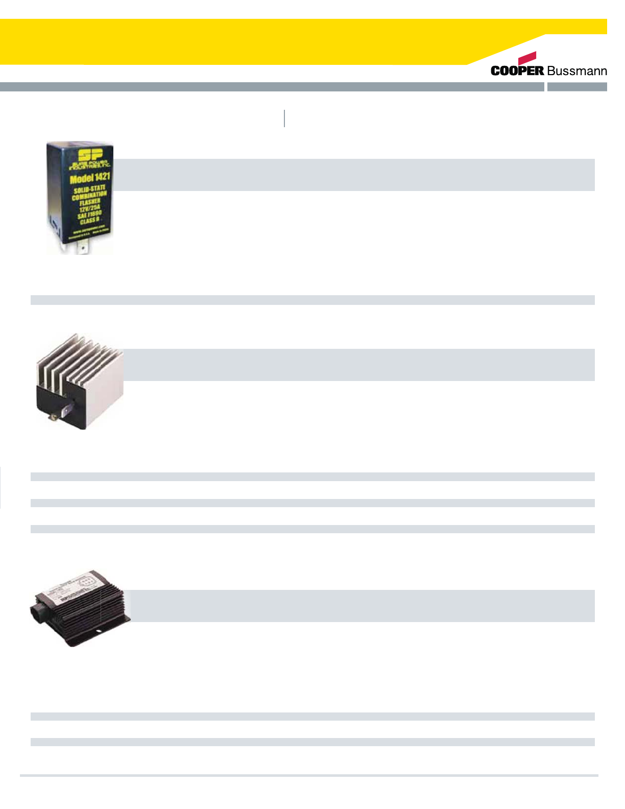
The 1421 Flasher is a smaller, lighter, 100% solid-state two-wire turn signal flasher with less footprint than its predecessor. The
turn signal indicators connected to the unit will flash on and off at a rate and duty cycle controlled by the unit. The rate and duty
cycle are independent of the number and type of turn signal indicators. The flasher can operate any number of both
incandescent and LED based turn signal indicators as long as the load current does not exceed 25A and the load is greater than
the minimum load requirements. (Contact Sure Power regarding minimum load requirements for LED compatibility.)
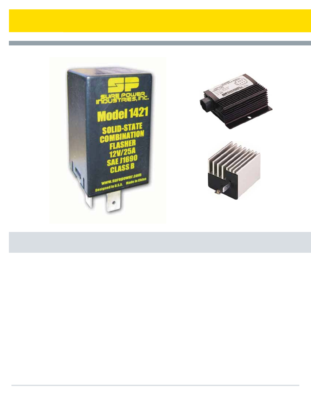
1421 12v 25A Solid-state 2-wire Hazard/Turn Signal Flasher Meets SAE J1690
MODEL OPERATING VOLTAGE CURRENT DESCRIPTION
Truck, Bus & Commercial
Used by many of the world’s leading truck and chassis manufacturers, this family of products has proven to provide one of the
industry’s most reliable and dependable flasher operations. Independent life cycle testing failed to find a failure before the test
was terminated at over 42 million flashes. Is it any wonder that both OEMs and fleets are using these to provide dependable
flasher operation and peace of mind?
1415
1417
1419
1419S
1425
1425MB
12V
12V
12V
12V
24V
24V
25A
38A
25A
25A
25A
25A
Solid-State 2-wire Hazard/Turn Signal Flasher
Solid-State 2-wire Hazard/Turn Signal Flasher
Solid-State 3-wire Remote Mount Hazard/Turn Signal Flasher
Solid-State 3-wire flasher with Audible Tone
Solid State 2-wire Hazard/Turn Signal Flasher
Solid-State 2-wire Hazard/Turn Signal Flasher w/ Mounting Bracket
MODEL OPERATING VOLTAGE CURRENT DESCRIPTION
Heavy-Duty Off-Highway
Sure Power Industries supplies the world’s leading manufacturers of heavy-duty equipment with the industry’s most durable and
reliable flashers. Capable of connecting to either 12V or 24V systems, these 100% solid-state units are completely
environmentally sealed and encapsulated as well as being shock and vibration resistant. Sure Power is continually designing new
models, including both North American and European versions.
1410
1412
1413
12V or 24V
12V or 24V
24V
12.6A
12.6A
7A
Solid-State 2-wire Remote Mount Hazard/Turn Signal Flasher
Solid-State with Deutsch 3-Pin Connector
Solid-State Flasher with Bulb Outage Indicator
Cooper Bussmann Transportation Products t1IPOFt'BYtXXXDPPQFSCVTTNBOODPN 21
Daytime Running Light Controls
Sure Power DRL Controls
Features
Quality
Automatically
turns on low-beam head lamps or DRL lamps at a reduced
voltage and significantly enhances vehicle safety
Simple
to install these readily adapt to existing electrical systems
Safe
protected against all failure modes, including loss of
ground, overcurrent and short-circuit conditions
Reliable
not affected by radio or electromagnetic interference
tTPMJETUBUF
t&OWJSPONFOUBMMZTQMBTIQSPPGPSTFBMFEEFQFOEJOHPONPEFM
t3FEVDFEQPXFSPQFSBUJPOUIVTNJOJNJ[JOHFBSMZMBNQGBJMVSF
BOENJOJNJ[FEFMDUSJDBMMPBE
t-PXGBJMVSFQPTTJCMJUZSFEVDFTWFIJDMFEPXOQPTTJCJMJUJFT
t4VQFSJPSQSPWJTJPOPG%BZUJNF3VOOJOH-JHIU$POUSPMT
DPNQMJFTXJUI$.744$"/$4"%5ZQF
'.744
t%FTJHOFEQFS4"&++
Cooper Bussmann Transportation Products t1IPOFt'BYtXXXDPPQFSCVTTNBOODPN
22

Reliable Operation, Increased Safety
Daytime Running Light Controls
Sure Power Daytime Running Light Controls adapt to existing systems, being designed to operate
IFBEMBNQTJOUIFMPXCFBNDJSDVJUBUSFEVDFEQPXFSXIJMFWFIJDMFJTJOPQFSBUJPO5IF4VSF1PXFSGBNJMZPG
%BZUJNF3VOOJOH-JHIU$POUSPMTBVUPNBUJDBMMZBDUJWBUFXIFOUIFJHOJUJPOJTUVSOFEPO)PXFWFSQBSLJOH
CSBLFSFMFBTFPSPUIFSNFUIPETPGBDUJWBUJPOBSFBMTPQPTTJCMF
FEATURE SURE POWER
LINEAR APPROACH
PULSE WIDTH
MODULATION*
SERIES
PARALLEL*
MODEL INPUT OUTPUT DIMENSIONS
Designed to eliminate radiated
or conducted interference
4JNQMFXJSJOHDIBOHF
1SPUFDUFEBHBJOTUMPTTPGHSPVOE
YES
YES
YES
YES
NO. .BZBGGFDU".'.PS
communications radios,
on-board computers, engine
& transmission controls.
NO. 4QMJDJOHJTSFRVJSFE
NO. .BKPSEBNBHFUPNPEVMF
can occur.
NO. Loss of ground may result in
loss of headlamps
NO. &YUFOTJWFXJSJOHSFRVJSFE
1SPUFDUFEBHBJOTUMPTT
over current YES (electronic) YES. 4PNFNPEFMT NO. Unless fuse added.
1SPUFDUFEBHBJOTUTIPSUDJSDVJU YES YES. 4PNFNPEFMT NO. Unless fuse added.
Both lamps protected against
FYUJOHVJTIJOHXIFOmMBNFOU
fails YES YES NO
Fully solid-state YES YES NO
Low voltage protected YES NO NO
Fail-safe operation YES YES NO
1SPUFDUFEBHBJOTUDPOUSPMGBJMVSF
which results in loss of both
headlamps YES YES NO
'
'
7
7
7
7
PGJOQVU
PGJOQVU
PGJOQVU
7XUVSOTJHOBMMPHJD
w-Yw8Yw)
w-Yw8Yw)
w-Yw8Yw)
w-Yw8Yw)
*Features and protection levels of these devices may vary by manufacturer
Cooper Bussmann Transportation Products t1IPOFt'BYtXXXDPPQFSCVTTNBOODPN 23
Power Distribution & Circuit Protection
Cooper Bussmann Transportation Products t1IPOFt'BYtXXXDPPQFSCVTTNBOODPN
Off-the-shelf and custom-designed
products that provide and protect
vehicle power distribution
t$VTUPNJ[FEEJTUSJCVUJPOPGNBJOBOE
BVYJMJBSZQPXFS
Power Distribution ModulesElectronic Device Protection
t'VTFTDJSDVJUCSFBLFSTBOEKVODUJPOCMPDLT
CAN (J1939) Bus Interface
t*OUFHSBUFQPXFSNBOBHFNFOUUP
DPOUSPMTZTUFNT
t/POGVTFEDVSSFOUEJTDPOOFDUJPO
CFUXFFOUIFCBUUFSZBOEFMFDUSJDBM
TZTUFNMPBE
Electrical Systems Protection
24

Cooper Bussmann Transportation Products t1IPOFt'BYtXXXDPPQFSCVTTNBOODPN
High Power Ratings
r$JSDVJUQSPUFDUJPOVQUP"
r*OUFSSVQUSBUJOHVQUPL"
r1PXFSEJTUSJCVUJPONPEVMFTVQUP"
r7PMUBHFSBUJOHTUP7EDBOECFZPOE
Multiplexing Capability
r+*OUFSGBDF
r4PMJE4UBUF0QUJPO
Flexible Configurations
r%FMQIJ".1UFSNJOBMDPOOFDUJPOT
r1PTJUJPOGVTFCMPDLT
Rugged Construction and Serviceable Design
r*1JOHSFTTQSPUFDUJPO
r)JHIUFNQFSBUVSFIVNJEJUZWJCSBUJPOSFTJTUBODF
Ignition Protected Options
r1FS4"&+
Agency Compliant
r4"&*40"#:$6-$&$4"
.VMUJQMFYFE7FIJDMF&MFDUSJDBM$FOUFS
4FWFSF4FSWJDF%VBM7FIJDMF&MFDUSJDBM$FOUFS
4FWFSF4FSWJDF7FIJDMF&MFDUSJDBM$FOUFS
4FSJFT7FIJDMF&MFDUSJDBM$FOUFST
7FIJDMF&MFDUSJDBM$FOUFS$POOFDUPST
7&$&MFDUSJDBM$PNQPOFOUT
4FSJFT3'3.3FBSGFE'VTF3FMBZ.PEVMF
4FSJFT1PTJUJPO35.3
4FSJFT35.3
4FSJFT-.(#PMUJO'VTF)PMEFSGPS.VMUJQMF".('VTFT
-.*#PMUJO'VTF)PMEFSGPS4JOHMFPS.VMUJQMF".*'VTFT
4FSJFT3FBS5FSNJOBM"5$'VTF1BOFM
4FSJFT"5$#MBEF5ZQF'VTF1BOFMT
4FSJFT13.1'.
).('VTFIPMEFS
'.('VTFIPMEFS
$')999$POOFDUPS'VTF)PMEFS
*OMJOF'VTFIPMEFST
(#991BTTUISPVHI%JTUSJCVUJPO#MPDL
4JOHMF4UVE5ZQF+VODUJPO#MPDLT
.VMUJQMF4UVE5ZQF+VODUJPO#MPDLT
1PXFS%JTUSJCVUJPO/PUFT
easy*%*MMVNJOBUJOH#MBEF'VTFT'VTF)PMEFST
.*/*#MBEF'VTFT
4FSJFT9.JOJ$JSDVJU#SFBLFST
"5$¡#MBEF'VTFT
4FSJFT9$JSDVJU#SFBLFST
4FSJFT"5$$JSDVJU#SFBLFSTMPXQSPàMF
."9*¡#MBEF'VTFT
4FSJFT9."9*¡$JSDVJU#SFBLFST
4FSJFT*OTFSUJPO&YUSBDUJPO5PPM
4FSJFT94IPSUTUPQ$JSDVJU#SFBLFST
4FSJFT9.JE3BOHF$JSDVJU#SFBLFS
4FSJFT'MBU1BL$JSDVJU#SFBLFS
4FSJFT9)J"NQ$JSDVJU#SFBLFS
4FSJFT.BSJOF3BUFE$JSDVJU#SFBLFS.3$#
".*4FSJFT
".(4FSJFT
.BSJOF3BUFE#BUUFSZ'VTF
4FSJFT
$JSDVJU1SPUFDUJPO/PUFT
Custom Solutions for Power Distribution
Circuit Protection
Page
Page
7&$1%.
'VTF1BOFMT'VTF)PMEFST+VODUJPO#MPDLT
25
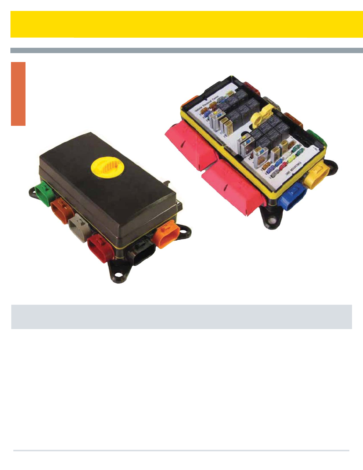
31M Series Multiplexed Power Distribution Module
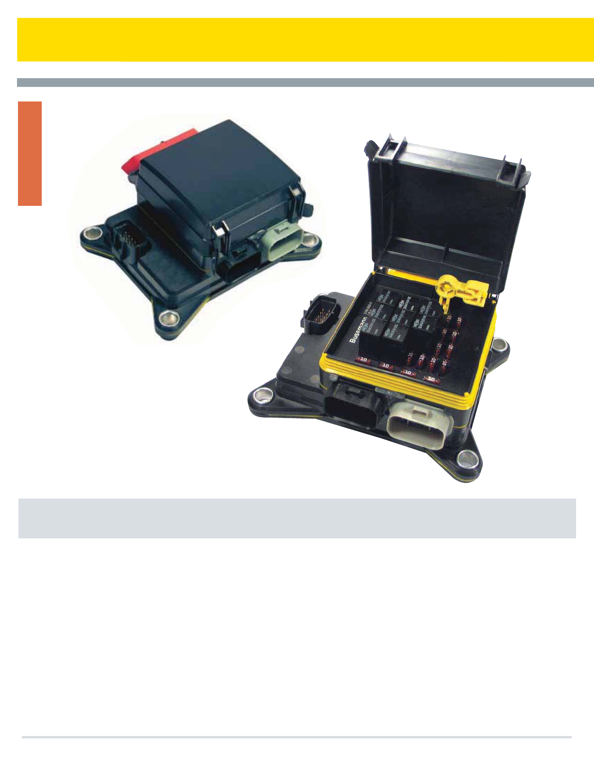
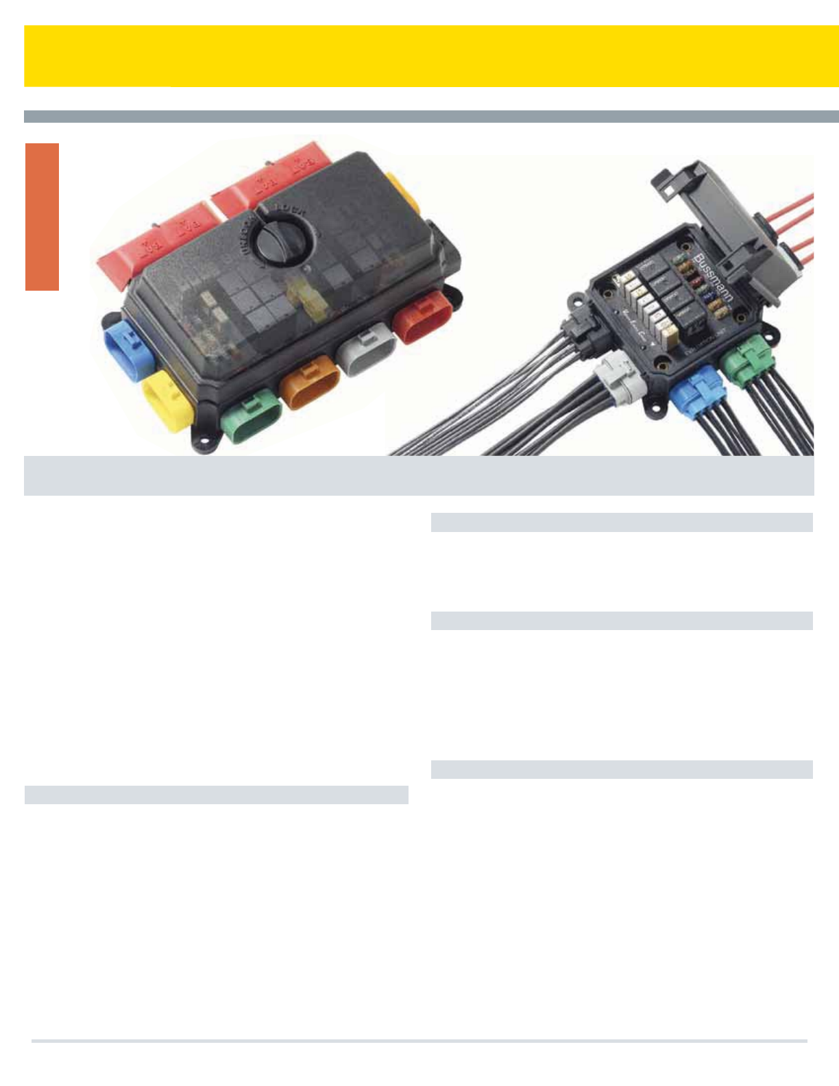
The multiplexed Vehicle Electrical Center (mVEC) offers economical CAN
Network oversight for high power circuits in vehicle power distribution.
Manufactured as a hardened and weather tight module, the mVEC is
rated at 200 Amps. The mVEC may be configured to provide various
OEM circuit protection and switching functions, using industry standard
fuses, relays and breakers, with the status and control of each circuit
accessible through J1939 CAN open messages. The mVEC is based on
proven and patented technology and is suited for the most demanding
transportation vehicle applications.
High Power: The mVEC uses patented Cooper Bussmann VEC 'power
grid' technology, ideal for high current circuits and Sure Power
networking electronics. Each mVEC is rated at 200 Amps, with individual
outputs rated up to 30A, and a maximum of 32 outputs possible with the
mVEC. 12 and 24 volt systems are supported.
Rugged: Waterproof to high pressure spraying (IP66 equivalent). The
mVEC is designed and manufactured with robust features such as a
heavy-duty housing, silicon and Gortex gasketing, and protective
conformal coated electronics, to operate in demanding vehicle
environments such as those found in construction, agriculture, heavy
truck, bus, RV, marine and specialty vehicle markets.
Flexible: The mVEC is offered in various standard and customized
versions, with custom versions being configured to OEM wiring
requirements. The two standard mVEC configurations include the 8-relay
31M-000-1 and the 12-relay 31M-300-0. The mVEC accepts relays,
fuses, circuit breakers, resistors, diodes, etc. based on the industry
standard 2.8mm footprint.
Multiplexed Vehicle Electrical Center (mVEC)
Cooper Bussmann Transportation Products t1IPOFt'BYtXXXDPPQFSCVTTNBOODPN
VEC
26
31M Series Multiplexed Power Distribution Module
The mVEC:
t"DUTBTBTMBWFNPEVMFPOB+$"/PQFOOFUXPSL
communicating via the vehicle data bus with the master
controller
t'VODUJPOTBTBOPEFJOBOFYJTUJOHWFIJDMF+$"/PQFO
multiplexing network
t$POUSPMTSFMBZTWJBEJSFDUJPOPG+$"/CVT
t3FQPSUTTUBUVTPGSFMBZTBOEGVTFTFBDITFDPOEUPUIF
J1939 CAN bus, indicating any blown fuse or failed relay
t4VQQPSUTCPUI7BOEPS7FMFDUSJDBMSFRVJSFNFOUT
t)BTUXPTUBOEBSEEFTJHOTBWBJMBCMF
.SFMBZTXJUIPSXP)4%
.SFMBZTXJUIPSXP)4%
t*TDBQBCMFPGDVTUPNEFTJHOTXJUIEJGGFSJOHDPOmHVSBUJPOTPG
relays, fuses, circuit breakers, etc. per customer
requirements
t"NQTNBYJNVNSBUJOH
t"NQTQFSPVUQVUQJO
t.BYJNVNPGSFMBZTBOEPSGVTFTPSWBSJPVT
combinations thereof (unique design configurations may be
required)
t)PVTJOHBOEDPOOFDUPSDBWJUJFT7SBUFEUIFSNPQMBTUJD
t*OUFSOBMQPXFSHSJEUJOQMBUFEDPQQFS
t$"/DJSDVJUCPBSEconformally coated
1. Mounting: compression limiters on mounting feet
2. Labeling to customer specifications
3.4UVGGFEXJUIXJUIPVUDPNQPOFOUTJODMVEJOHCVUOPU
limited to: fuses, relays, diodes, circuit breakers, fuse
puller)
4. Customized circuit layouts, standard and custom CAN
messages
Output: Standard Cooper Bussmann VEC connectors
tXBZDPMPSFELFZFETFBMFEDPOOFDUPST
t"NBYQFSUFSNJOBM
t"DDFQUT1BDLBSE.FUSJ1BDL4FSJFTUFSNJOBMT
UBOHFEUBOHMFTT
Input:
t4UVEEFEJOQVUPQUJPOTVQQPSUTUXP.JOQVUQPXFS
TUVETGPS%$QPXFSJOUPUIF7&$QPXFSHSJE"NBY
per stud)
t$POOFDUPSJ[FEBDDFQUTVQUP$PPQFS#VTTNBOO
7&$DPOOFDUPSTUFSNJOBMDPMPSFELFZFE
sealed connectors)
t"NBYQFSUFSNJOBMQSPWJEJOHQPXFSUPUIF7&$
Power Grid; uses Packard 800 series terminals
CAN:
t6TFT".144$QPTJUJPOTFBMFEDPOOFDUPS
t$"/DPOOFDUPSQSPWJEFT$"/TJHOBMJOHQPXFSHSPVOE
addressing, auxiliary relay control, and reserve
connections to mVEC 'smart' layer
Basic Features:
Capacity:
Options:
Materials:
Ratings:
Connections:
tOperating temperature ratings: -40°C to 85° C [Consult
factory for higher temp versions (up to 105°C)]
tIngress Protection; IP66 equivalent (direct high pressure spray)
t'PPUUPSRVFSBUJOHJOMCTXPVUDPNQSFTTJPOMJNJUFST
to 300 in-lbs with compression limiters
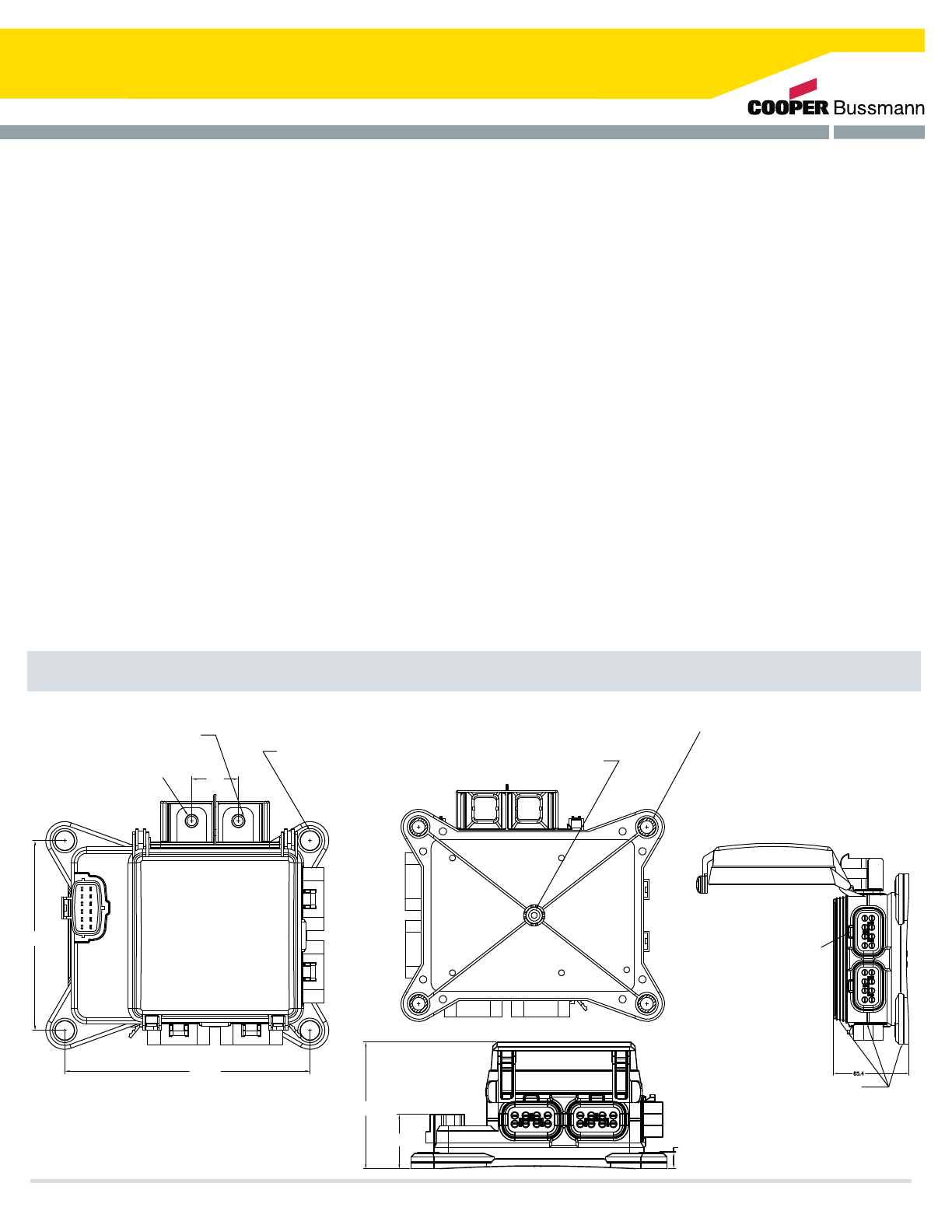
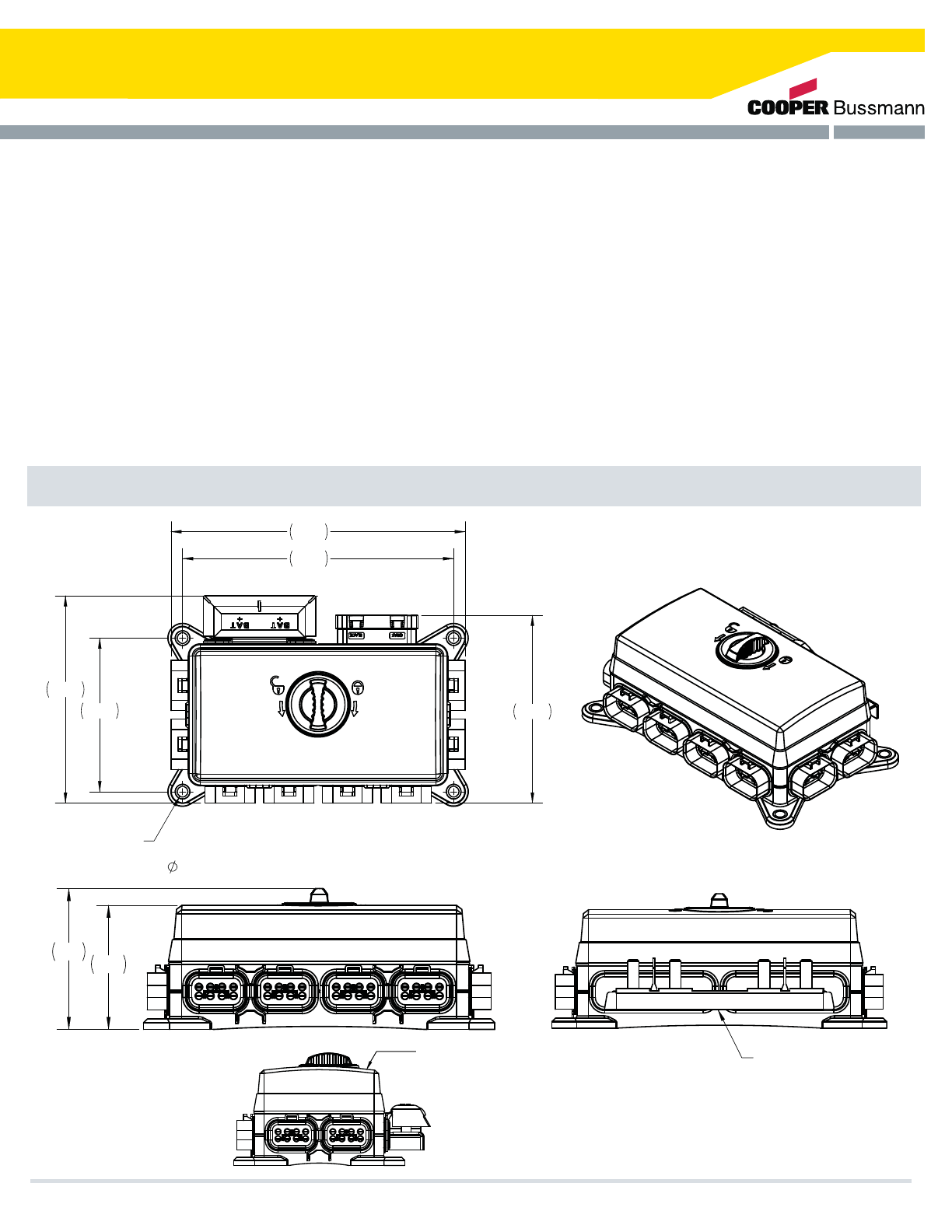
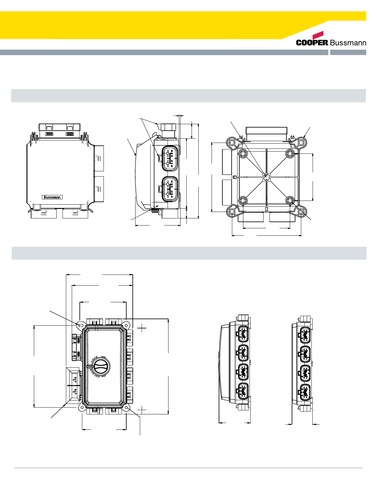
Dimensions - mm(in)
Cooper Bussmann Transportation Products t1IPOFt'BYtXXXDPPQFSCVTTNBOODPN
Assembly shown with standard
brass grommet. 11.8±*%
.PS'BTUFOFS4VHHFTUFE
.BYJNVN'BTUFOFS5PSRVF/tm or 60 ft-lbs
Studded input shown,
cover not shown
M6 or M8 input stud.
(Stainless or plated steel)
155.0
120 4IPXOXDPWFSJODMPTFEQPTJUJPO
29.5
Gasket Plug (optional)
Assembly shown with
stainless steel compression limiter (optional)
1-$4*%
NPSGBTUFOFSTVHHFTUFE
.BYJNVNNPVOUJOHUPSRVF/tN
or 300 ft-lbs
$POOFDUPS-PDL'FBUVSF
Yellow Silicone Gasket
90 max
38.6 12.8
27
32S Series Severe Service Power Distribution Module
Introducing the ruggedized version of the Cooper Bussmann Dual Vehicle
Electrical Center, the 'Severe Service' DVEC (ssDVEC). This version of the
DVEC features unequaled performance in power distribution in an IP66
compliant enclosure. The ssDVEC is capable of operating in various
environments such as those with high vibration and moisture, up to direct
high pressure spray. The ssDVEC provides efficient and compact power
distribution for OEMs with demanding applications in the transportation
industry including:
t$POTUSVDUJPO
t"HSJDVMUVSF
t)FBWZ5SVDLT
t#VT
t.BSJOF
t4QFDJBMUZ7FIJDMFT
As with all DVECs, the ssDVEC uses the patented Cooper Bussmann
'power grid' technology easily programmable to accommodate various
OEM wiring requirements. Cooper Bussmann DVECs all feature a unique
color-coded and keyed connector system, and accepts common plug-in
fuses, relays, circuit breakers, resistors, diodes, etc., based on the
industry standard 2.8mm footprint.
Additionally the ssDVEC has these new features:
t%VSBCMFQMBTUJDIPVTJOHGFBUVSJOHB(PSUFYWFOU
t*OUFSOBMTJMJDPOFHBTLFUJOHCFUXFFOBMMTFBNTBOEQMBTUJDUPUFSNJOBM
interfaces
t*OUFSOBMTQBSFGVTFIPMEFSBOETPDLFUGPSGVTFFYUSBDUJPOUPPM
4FWFSF4FSWJDF%VBM7FIJDMF&MFDUSJDBM$FOUFSTT%7&$
$PPQFS#VTTNBOO5SBOTQPSUBUJPO1SPEVDUTt1IPOFt'BYtXXXDPPQFSCVTTNBOODPN
7&$
28
32S Series Severe Service Power Distribution Module
%JNFOTJPOTNN
t"NQTNBYJNVNSBUJOH
t"NQTQFSPVUQVUQJOBOEBNQTQFS
output connector
t.BYJNVNPGSFMBZTBOEPSGVTFTPSWBSJPVT
combinations thereof (unique design configurations may be
required)
t)PVTJOHBOEDPOOFDUPSDBWJUJFT7SBUFEUIFSNPQMBTUJD
t*OUFSOBMQPXFSHSJEUJOQMBUFEDPQQFS
1. Labeling to customer specifications
2.4UVGGFEXJUIXJUIPVUDPNQPOFOUTJODMVEJOHCVUOPUMJNJUFE
to: fuses, relays, diodes, circuit breakers, fuse puller)
3. Customized circuit layouts, per customer standards
Output: standard Cooper Bussmann VEC connectors
tXBZDPMPSFELFZFETFBMFEDPOOFDUPST
t"NBYQFSUFSNJOBM
t"DDFQUT1BDLBSE.FUSJ1BDL4FSJFTUFSNJOBMT
UBOHFEUBOHMFTT
Input:
t4UVEEFEJOQVUPQUJPOTVQQPSUTGPVS.JOQVUQPXFS
studs "NBYQFSTUVEfor DC power into the VEC
power grid
t$POOFDUPSJ[FE"DDFQUTVQUP#VTTNBOO7&$
DPOOFDUPSTUFSNJOBMDPMPSFELFZFETFBMFE
connectors)
t"NBYQFSUFSNJOBMQSPWJEJOHQPXFSUPUIF7&$
1PXFS(SJEVTFT1BDLBSE4FSJFTUFSNJOBMT
$BQBDJUZ 0QUJPOT
.BUFSJBMT
3BUJOHT
$POOFDUJPOT
t0QFSBUJOHUFNQFSBUVSFSBUJOHT¡$UP¡$<$POTVMU
GBDUPSZGPSIJHIFSUFNQWFSTJPOTVQUP˚C)]
t*OHSFTTQSPUFDUJPO*1FRVJWBMFOUEJSFDUIJHIQSFTTVSFTQSBZ
tFoot torque rating: UPJOMCTXJUITUBOEBSE
compression limiters
CONNECTOR 10
2 ROTCENNOC21 ROTCENNOC
CONNECTOR 3
CONNECTOR 4
CONNECTOR 5
CONNECTOR 7
CONNECTOR 11 CONNECTOR 1
CONNECTOR 9
CONNECTOR 6
CONNECTOR 8
230
212
162
120 147
8.4
4X compression limiter
94 83
Optional bus bar
$PPQFS#VTTNBOO5SBOTQPSUBUJPO1SPEVDUTt1IPOFt'BYtXXXDPPQFSCVTTNBOODPN
Optional laser etching
29
31S Series Severe Service Power Distribution Module
Introducing the ruggedized version of the Cooper Bussmann Vehicle
Electrical Center, the 'Severe Service' VEC (ssVEC). This version of the
VEC features unequaled performance in power distribution in an IP66
compliant enclosure. The ssVEC is capable of operating in various
environments such as those with high vibration and moisture, up to direct
high pressure spray. The ssVEC provides efficient and compact power
distribution for OEMs with demanding applications in the transportation
industry including:
t$POTUSVDUJPO
t"HSJDVMUVSF
t)FBWZ5SVDLT
t#VT
t.BSJOF
t4QFDJBMUZ7FIJDMFT
As with all VECs, the ssVEC uses the patented Cooper Bussmann 'power
grid' technology that is easily programmed to accommodate various OEM
wiring requirements. Cooper Bussmann VECs all feature a unique color
coded and keyed connector system, and accepts common plug-in fuses,
relays, circuit breakers, resistors, diodes, etc., based on the industry
standard 2.8mm footprint.
Additionally the ssVEC has these new features:
t%VSBCMFQMBTUJDIPVTJOHGFBUVSJOHNVMUJQMFWFOUJOHDPOmHVSBUJPOT
including a Gortex vent
t*OUFSOBMTJMJDPOFHBTLFUJOHCFUXFFOBMMTFBNTBOEQMBTUJDUPUFSNJOBM
interfaces
t*OUFSOBMTQBSFGVTFIPMEFSBOETPDLFUGPSGVTFFYUSBDUJPOUPPM
4FWFSF4FSWJDF7FIJDMF&MFDUSJDBM$FOUFSTT7&$
$PPQFS#VTTNBOO5SBOTQPSUBUJPO1SPEVDUTt1IPOFt'BYtXXXDPPQFSCVTTNBOODPN
7&$
30
31S Series Severe Service Power Distribution Module
Various custom design versions supported
(differing relay, fuse, breaker, etc. configurations)
12V and 24V electrical (or combinations thereof)
ssVEC Rated at 200 amps maximum; 30 amps
per output connection, maximum 32 fuses /12
relays (size dependent) or various combinations
thereof (diverse design configurations supported)
Housing and connector cavities: 94V0 rated
thermoplastic; internal power grid tin-plated copper;
internal gaskets stud input covers: silicone
Mounting:
1. Compression limiters on mounting feet
2. Labeling to customer specifications
3. Stuffed (with/without components including but
not limited to: fuses, relays, diodes, circuit
breakers, fuse puller)
4. Customized circuit layouts
5. Power connector
Output: standard Cooper Bussmann VEC connectors
(8-way, colored/keyed, sealable connectors) - 30A
max per terminal - connectors accept Packard
Metri-Pack 280 Series terminals (tanged/tangless)
Input: studded input option - supports 2 M8 input
power studs (100A max per stud)GPS%$QPXFSJOUP
the VEC power grid connectorized -accepts up to 2
Cooper Bussmann VEC connectors (2 terminal,
colored/keyed, sealed connectors) 60A max per
terminal connects and supplies power to the VEC
power grid - accepts Packard 800 Series terminals
#BTJD'FBUVSFT
$BQBDJUZ
0QUJPOT
.BUFSJBMT
$POOFDUJPOT
3BUJOH Temperature ratings: -40°C to 105°C (operating).
Ingress protection ratings are application dependent
up to IP66 equivalent (direct high pressure spray); IP
rating is application design specific torque rating on
mounting is (without compression limiters) / with
ratings on stud inputs. Unit meets IP66 compliance.
%JNFOTJPOTNNJO
$PPQFS#VTTNBOO5SBOTQPSUBUJPO1SPEVDUTt1IPOFt'BYtXXXDPPQFSCVTTNBOODPN
120.2
120.00
3FDFTTGPS'VTF
Removal Tool. 90 Max
38.6
166.2
150.0
108.3
23.8
Yellow silicone gasket (seal)
51.69
50.67
(Post-stake
height)
12.8
Optional Laser Etching, Inside or Outside
31
Series 31000/32000 Vehicle Electrical Centers
The VEC/DVEC is ideal for distributed main power as well as auxiliary
“add-on” applications. Current VEC/DVEC applications include Class
3-8 trucks, buses, chassis and RV, Con-Ag equipment, marine
specialty vehicles, and automotive power distribution systems.
The customizable designs of the VEC/DVEC enable them to
incorporate many different devices and multiple design variations.
Splices in the harness can also be eliminated by internally
programming them into the grid matrix. The inputs (connector or stud)
and outputs (connector) of the VEC/DVEC are color-coded and keyed,
and provide quick installation. This makes the module easy to service.
The largest benefit of these modules are the reduced lead times and
zero tooling cost.
Cover: Vented (VEC), Solid domed cover with gasket (VEC/DVEC), or
no cover.
Cover Label: Inside cover, outside cover (VEC only), or none
provided.
Input Style: 8.0mm blade terminals or studs (M8/M6).
Mounting: External feet with mounting holes (VEC/DVEC) or internal
mounting holes (VEC only).
Components: Fuse, breaker, relay, etc. installation to be
specified by customer.
Severe Service: Added environmental protection available (see pg 30
& severe service VEC). Consult factory.
Fuse/breaker Extraction Tool: See page 67.
*Electrical terminals, cable seals & cavity plugs are NOT supplied by
Cooper Bussmann.
Each design is customer specific. Consult your sales rep today
for your application.
The Cooper Bussmann Single Vehicle Electrical Center (VEC) and Dual
Vehicle Electrical Center (DVEC) are widely used transportation industry
power distribution modules. The VEC & DVEC use patented
programmable 3D matrix technologies that can be easily modified to
accommodate changes to an electrical system. These can be customized
for each specific electrical system, but require no tooling for
implementation.
The VEC & DVEC accept automotive components including fuses, relays,
circuit breakers, diodes, and other devices that have 2.8mm wide
terminals on 8.1mm centerline spacing. (See page 35 for additional
available components.) The compact size of the VEC (about 4”x4”) and
larger size of the DVEC (approximately 8”x4”) provide for high component
density. VECs provide either 8.0mm bladed inputs or M8/M6 stud inputs.
The VEC can accommodate up to 2 input connectors - 4 bladed inputs or
2 studs - and 4 output connectors with up to 8 outputs each (32 total).
The DVEC can accommodate up to twice this amount. (Some designs
may limit the number of connectors available for use.)
Input Terminal Rating: 8.0mm blade terminals (60A max per terminal);
M8/M6 input studs (100A max per terminal). 200A max total for VEC,
400A max total for DVEC.
Output Terminal Rating: 2.8mm blade terminals (30A max per terminal).
Temperature Rating: –40°F (–40°C) to 260°F (125°C).
Materials: Thermoplastic housing and connectors;
tin-plated copper internal grid.
Termination: Delphi Packard Metri-Pack® 280 Series terminals
(sealed/unsealed & tanged/tangless) or AMP® terminals.* Delphi Packard
280 Series cavity plugs are installed where wires are not used.* Accepts
#10-22 AWG wire sizes.
Mounting Torque Rating: 24 in-lbs (2.7Ntm) max.
Mounting Orientation: Unit cannot be installed upsidedown. Consult
factory for proper mounting orientations. ingress protection Rating: IP55
About the Vehicle Electrical Center
Specifications
Applications
Benefits
Options
Cooper Bussmann Transportation Products t1IPOFt'BYtXXXDPPQFSCVTTNBOODPN
VEC
32
Series 31000/32000 Vehicle Electrical Centers
4X #10 INTERNAL
MOUNTING HOLES
MOUNTING TORQUE
RECOMMENDATIONS
6.56[.26] OPTIONAL
EXTERNAL MOUNTING FEET
(CONSULT FACTORY)
BUILT IN DRAINAGE
106.6
[4.20]
73.00
[2.87]
73.00
[2.87]
106.6
[4.20]
I/O #5I/O #6
I/O #4
I/O #3
I/O #2
CONNECTOR #1
INPUT/OUTPUT
SPLASHPROOF
ASSEMBLY
OPTIONAL COVER
(SPLASHPROOF &
VENTED VERSIONS)
CONNECTOR LOCK
69.64
[2.74]
1.90
[.07]
22.49
[.89]
15.23
[.60]
146.59
[5.77]
108.86
[4.29]
VEC 31000 Series VEC
32000 Series VEC
TYP. 3
Mounting Holes
Ø
6.5
(0.26)
Ø6.5
(0.26)
197.6
(7.78)
Optional
Stud Cover
111.4
(4.39)
106.4
(4.2)
160.8
(6.3) 146.5
(5.8)
229.7
(9.0)
I/O #4 I/O #3
I/O #2
I/O #1
I/O #12
I/O #11
I/O #9 I/O #10
I/O #8
I/O #7
I/O #6
I/O #5
79.4
(3.3)
(excluding text
height on cover)
Shown Without Cover
or Components
49.4
(1.95)
Dimensions - mm(in) (Dims. shown are for reference only. Consult factory for latest prints)
Cooper Bussmann Transportation Products t1IPOFt'BYtXXXDPPQFSCVTTNBOODPN 33
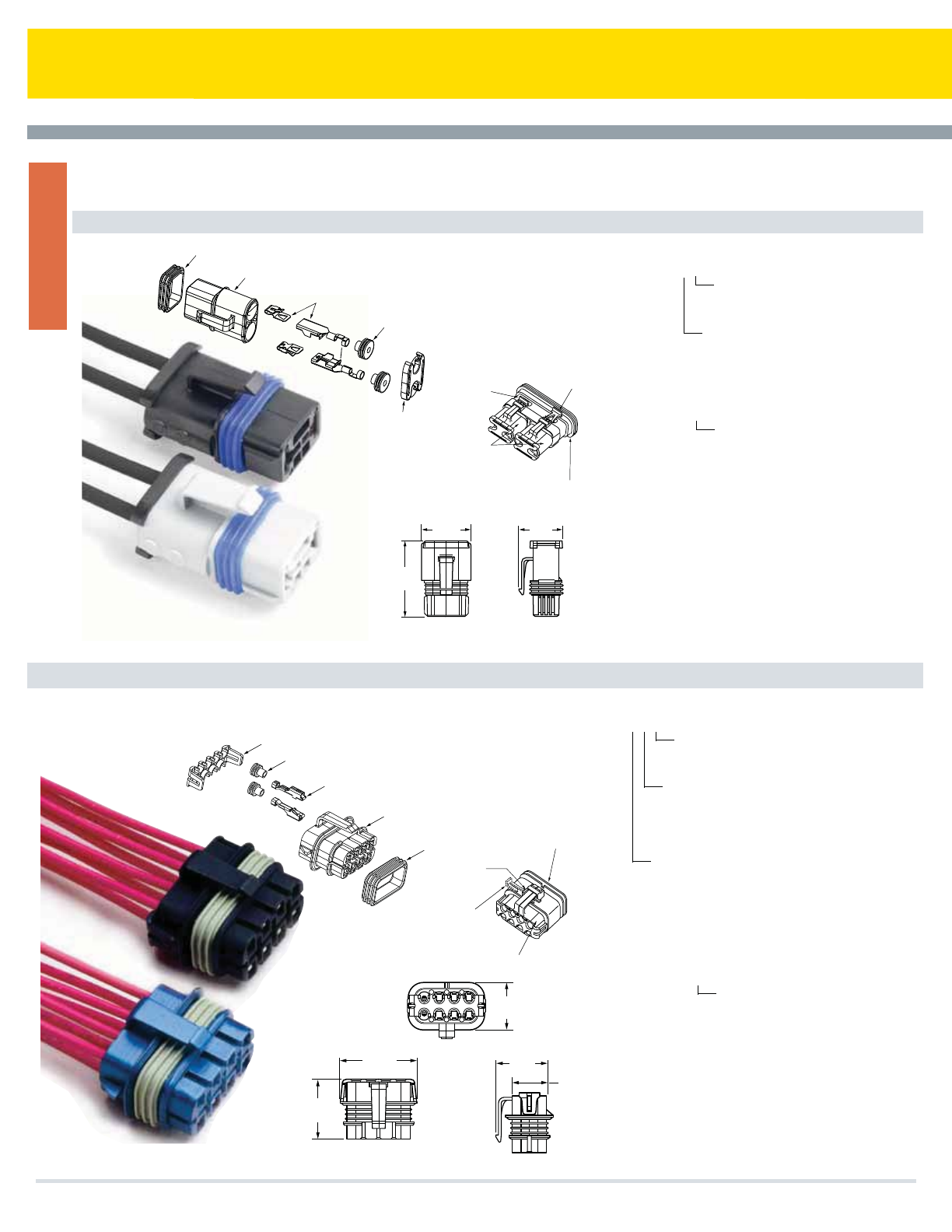
Vehicle Electrical Center Connectors
32006-XXX Output Connector
32004-XX Power Connector
Terminal position assurance
32004-TPX
Seal
Male Input Connector
32004-xx
Female Terminal*
Delphi Packard 800
Metri-Pack® series
shown Cable seal
Delphi Packard #12129381r
shown
32004-CP Shown
Assembled
In-Place
32004-CP Shown
Prior To Engagement
VEC Female Input Connector
(Shown For Reference Only)
Male Input
Connector
Assembly
MALE INPUT CONNECTOR
32004 - X X
Sealed / Non-Sealed Conguration
1= Non-Sealed Version
2= Sealed Version
Color of Part
A= Black
B= Gray
TERMINAL POSITION ASSURANCE
32004 -TPX
CONNECTOR POSITION ASSURANCE
32004 - CP (Ship in Bulk)
Sealed / Non-Sealed Conguration
1= Non-Sealed Version
2= Sealed Version
Note: Terminals and Terminal Seal
Components are not provided with connectors.
Available from Delphi Packard. Contact factory
for part list and terminal removal tool. Sealed
connector option includes outer body seal.
(Dims.shown are for reference only. Consult factory for latest prints)
(Dims.shown are for reference only. Consult factory for latest prints)
Terminal position assurance
32006-TPX
Seal
Male Output Connector
32006-xxx
Female Terminal*
Delphi Packard 280
Metri-Pack® series
shown
Cable Seal
Delphi Packard 280
Metri-Pack® series
shown
HGF
BCD
24.4
(0.96)
26.3
(1.04)
17.9
(0.71)
39.9
(1.57)
30.8
(1.21)
Male Output Connector Assembly
VEC Female Output Connector
(Shown For Reference Only)
32006-CP
Shown
Assembled
In-Place
32006-CP
Shown
Prior To
Engagement
TERMINAL POSITION ASSURANCE
32006 - TPX
Sealed / Non-Sealed Conguration
1= Non-Sealed Version
2= Sealed Version
CONNECTOR POSITION ASSURANCE
32006 - CP (Ship in Bulk)
Note: Terminals and Terminal Seal
Components are not provided with connectors, but
are available from Delphi Packard. Contact factory
for part list and terminal removal tool. Sealed
connector option includes outer body seal.
Sealed / Non-Sealed Conguration
1= Non-Sealed Version
2= Sealed Version
Connector Cavity Conguration
1= Tang-less Female Connector (Delphi 280)
2= with Tang Female Connector (Delphi 280)
P= all cavities plugged
Color of Part
A= Black E= Yellow
B= Gray F= Red
C= Green G= Orange
D= Blue H= Brown
J= Neutral (only available for -JP2 option)
MALE OUTPUT CONNECTOR
32006 - X X X
(Dims. shown are for reference only. Consult factory for latest prints)
(Dims. shown are for reference only. Consult factory for latest prints)
26.8
(1.06)
30.3
(1.19)
46.2
(1.82)
Dimensions - mm(in)
Cooper Bussmann Transportation Products t1IPOFt'BYtXXXDPPQFSCVTTNBOODPN
VEC
34
VEC Electrical Components
OPTIONAL
"WING"
FOR ADDITIONAL
DIODE KEYING
STANDARD
DIODE KEY
DIODE MARKING
SHOWN
][0.0902.29
][0.91
23.0
][0.36
9.2
][0.30
7.6
][0.35
8.9
][1.07
27.3
][0.25
6.4
][0.48
12.2
][0.153.8
][0.030.8
][ 0.112.8
][8.13
.32
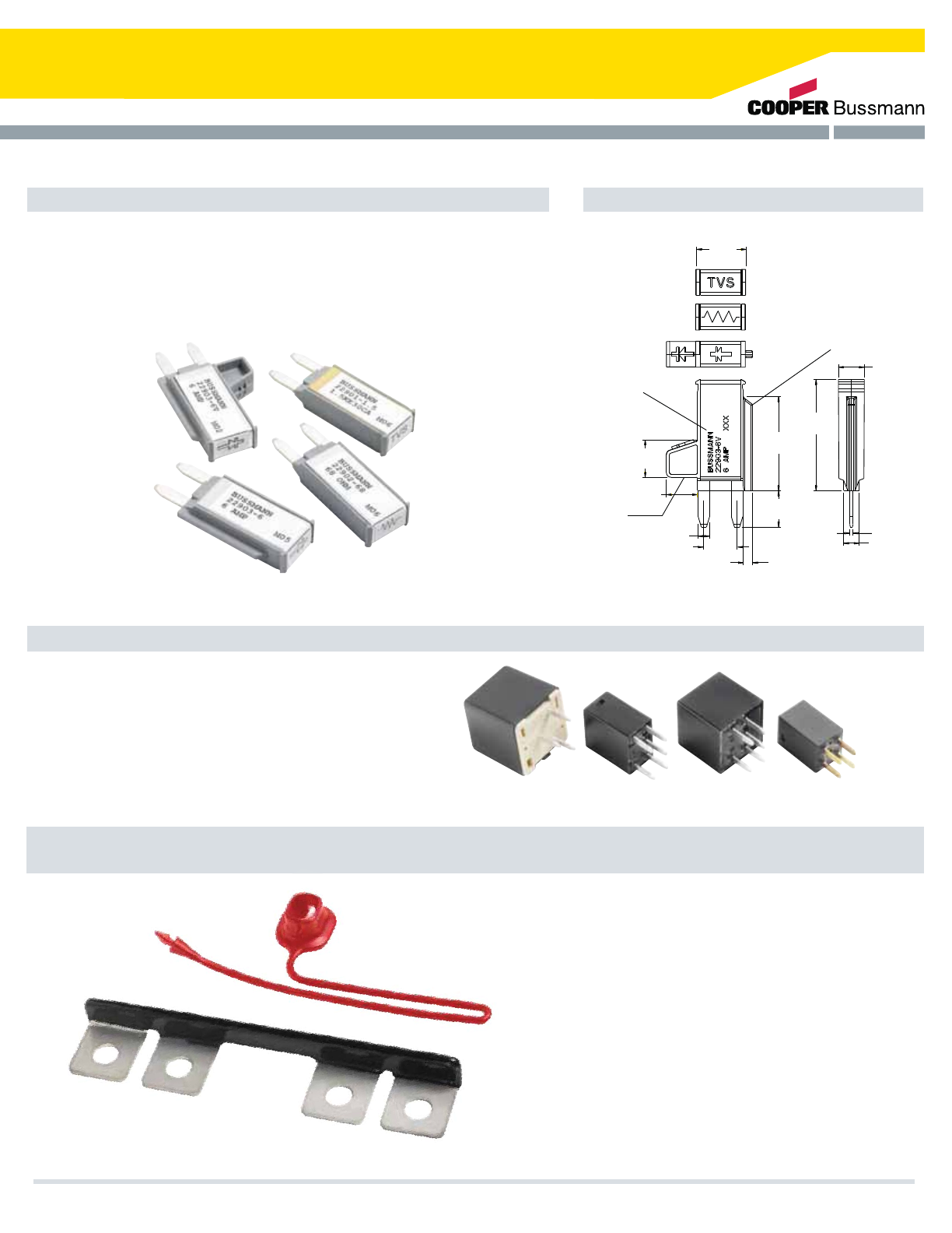
22901 Series
Transorb
22902 Series
Resistor
22903 Series
Diode
VEC Accessories
Series 229 Diode, Resistor, and Transorb
Specifications Dimensions - mm(in)
(Dims. shown are for reference only. Consult factory for latest prints)
Ratings: Consult factory for available ratings and part numbers
Materials: Grey 94V0 thermoplastic housing with metal cover.
Termination Type: Compatible with 280 Type fuse blocks using 8.1mm
centerline.
Diode Key Feature: Standard key denotes installation direction.
Extended key available for error-proof installation in VEC.
Types: 5-pin mini-relay, 12Vdc & 24Vdc
5-pin micro-relay, 12Vdc & 24Vdc
4-pin mini-micro relay, 12Vdc
Consult Factory for available amperage ratings
Termination Type: Compatible with 280 Type fuse
blocks using 8.1mm centerline.
Sealed versions of some relays also available.
Specifications
Relays (Only Available for VEC, DVEC, RFRM, or RTMR Applications.)
DVEC Cover Tether
Tether available for use with
Series 32000 DVECcover.
Consult factory.
Cooper Bussmann Transportation Products t1IPOFt'BYtXXXDPPQFSCVTTNBOODPN
Series B109-7031
(for use with Series 32000 DVEC)
External bus bar can be used with the Dual VEC to
bus together studded power inputs.
35
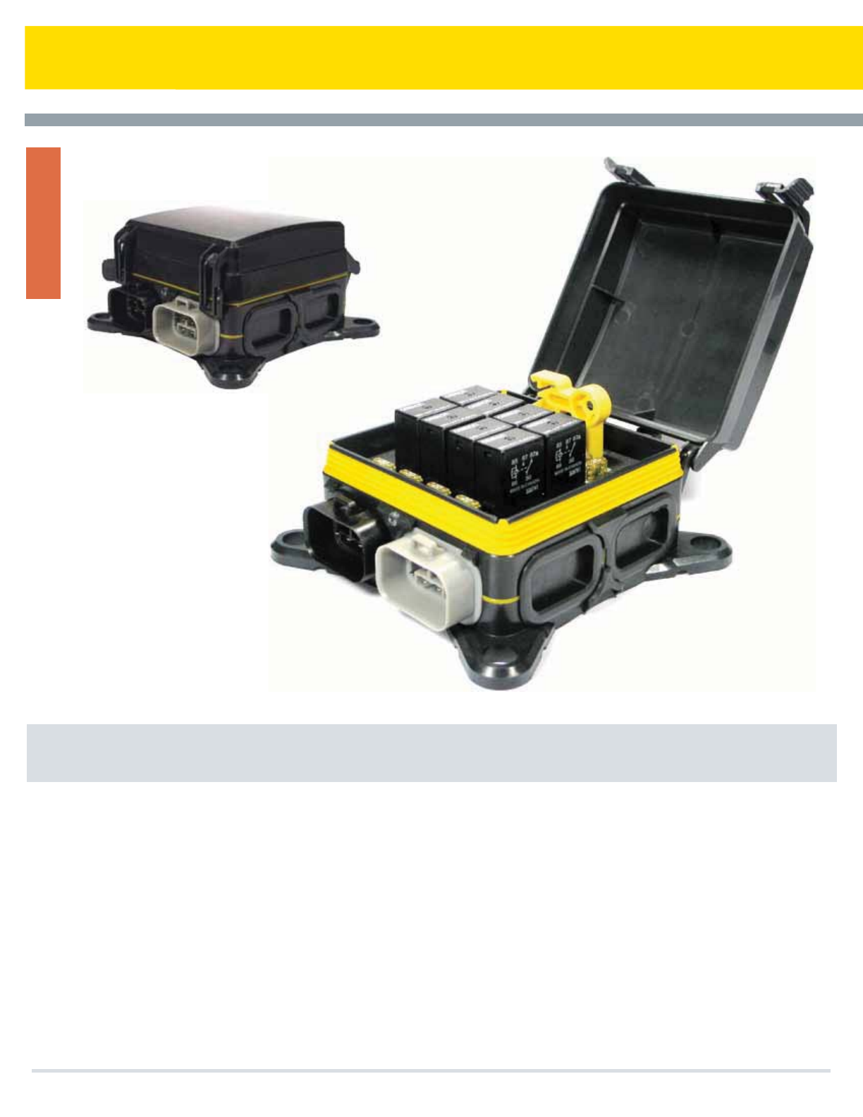
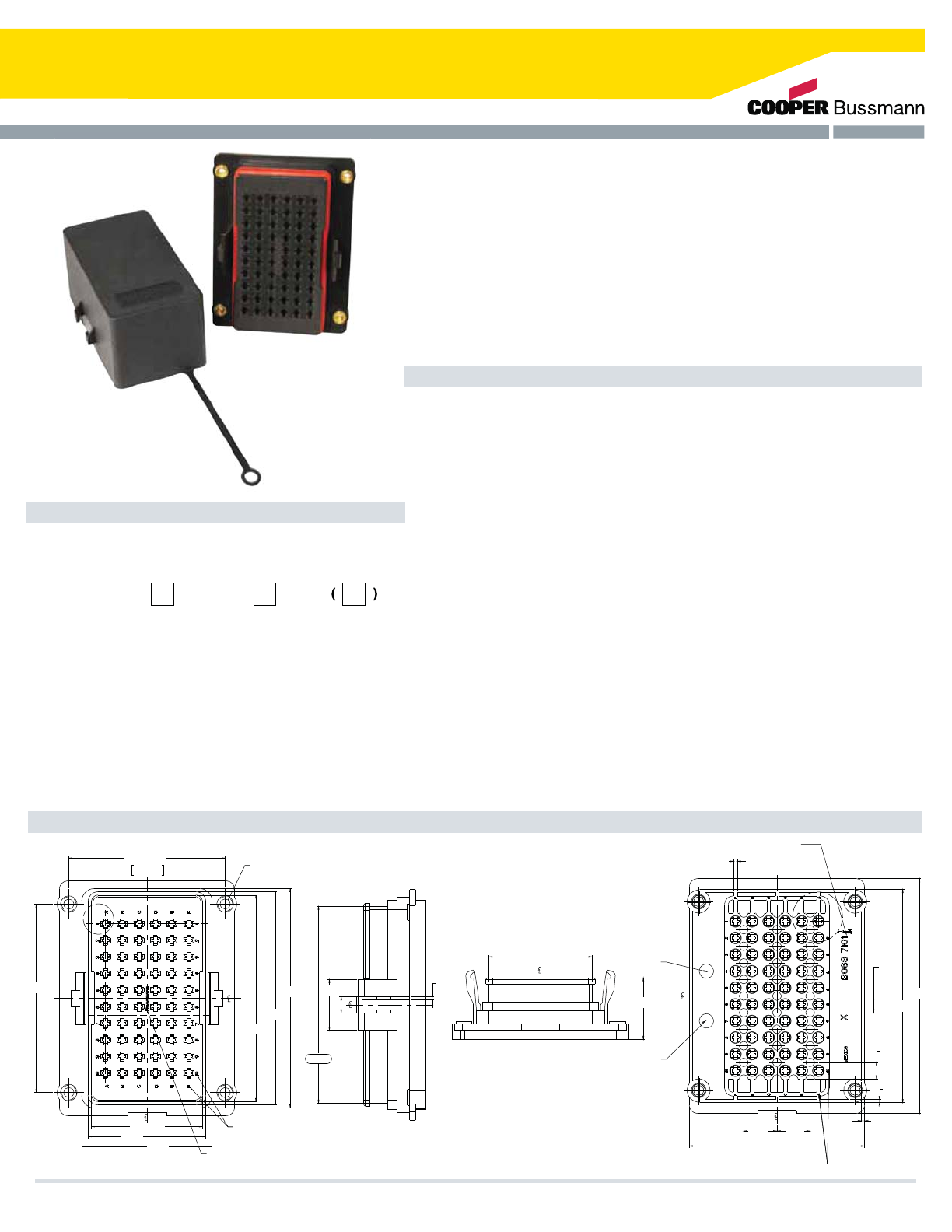
Series 15400 RFRM Rear-fed Fuse & Relay Module
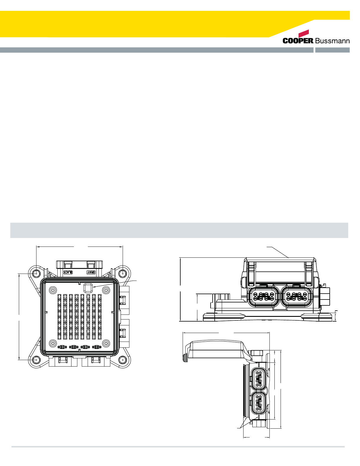
Dimension - mm
Specifications
Cooper Bussmann Transportation Products now offers a main power distribution
module capable of operating in harsh environment applications. Based on the
industry standard 2.8mm (mini) footprint, the RFRM can accept plug-in fuses,
relays, circuit breakers, resistors and diodes to meet numerous power
management requirements. The RFRM is available with multiple internal bussing
options, accommodating various OEM wiring requirements.
Material: UL-Rated 94V0 thermoplastic, plated copper bus bar, silicone rubber
gasket, EPDM – internal tether
Power Ratings: Nominal 12Vdc and 24Vdc systems, 100A per bus bar, 200A Max
Temperature Rating: -40˚ C to 85˚ C
Ingress Protection: IP66 (with use of cover and seal) 1
Plug-in Capacity: Up to 10 micro relays and a combination of 40 fuses/circuit
breakers (8.1mm CL)
Mounting: #10-32 or M5 x 0.8 available, 24 in-lbs max
Orientation mounting application intended for horizontal to vertical 2
Electrical Connectors: Output cavities (holes in back)
Wire Size: Accepts #12-22 AWG wire sizes 3
Terminals: Delphi Packard 280 Series Metri-Pack® sealed/tang style
terminals
Cavity Plugs: Delphi Packard 280 Series cavity plug (where output
wires are not used) Input Studs (for bussed version): M8 x 1.25 thread,
70 in-lbs max
Part Numbering System Notes
Notes: 1. Ingress Protection rating has been validated with approved panel mounting applications. Consult factory for testing procedures.
2. Consult factory for any other mounting orientation.
3. Cooper Bussmann does not supply wires, wire terminals, terminal seals, or cavity plugs.
- Consult factory for options including custom labels and replacement accessories.
124.4 REF
197.5
REF
Cable Managers-
Options shown on this
drawing only
1. Internal tether accessory not shown – it is included with Cover Option 1.
2. Photograph above shows RFRM with optional yellow fuse puller tool. Yellow Fuse
Puller (part #32013BS) tool sold separately.
3. Photograph above shows RFMR ‘stuffed’ with components such as fuses and relays.
RFRMs are sold without components.
4. Under side of RFRM has the wire harness position labeling details molded into the
part.
235.0 REF
216.0 REF
70.0 REF 4X THREADED
MOUNTING
INSERTS
#10-32 OR
M5X0.8
216.00
4X ø5.6 70.00 R1.0 TYP
4X R10.0
215.00
199.00
96.00
11.00
TYP
M8X 1.25 Thread
on input studs
Optional
Hardware 94.3 REF
2X Input Studs
M8 x 1.25
154X XXXX XX
A - Standard Bussmann Label
B-Z - Private Label
Label
0 - Standard Label
1 - 1st Non-Standard Label
2 - 2nd Non-Standard Label
Cover
0 - No Cover
1 - Standard Cover with Bussmann Logo
(Consult Factory for Special Options)
Hardware
0 - W/O Nuts
1 - Nuts Shipped Bulk
2 - Nuts Shipped Assembled
Base
1 - Base with English MTG Inserts and Cable Managers
2 - Base with English MTG Inserts w/o Cable Managers
3 - Base with Metric MTG Inserts and Cable Managers
4 - Base with Metric MTG Inserts w/o Cable Managers
Bus Bars
1 - Dual Bus Bars
2 - Bus Bar Left Hand Side Only
3 - Bus Bar Right Hand Side Only
4 - No Bus Bars
0 - Standard RFRM
Cooper Bussmann Transportation Products t1IPOFt'BYtXXXDPPQFSCVTTNBOODPN
PDM
36
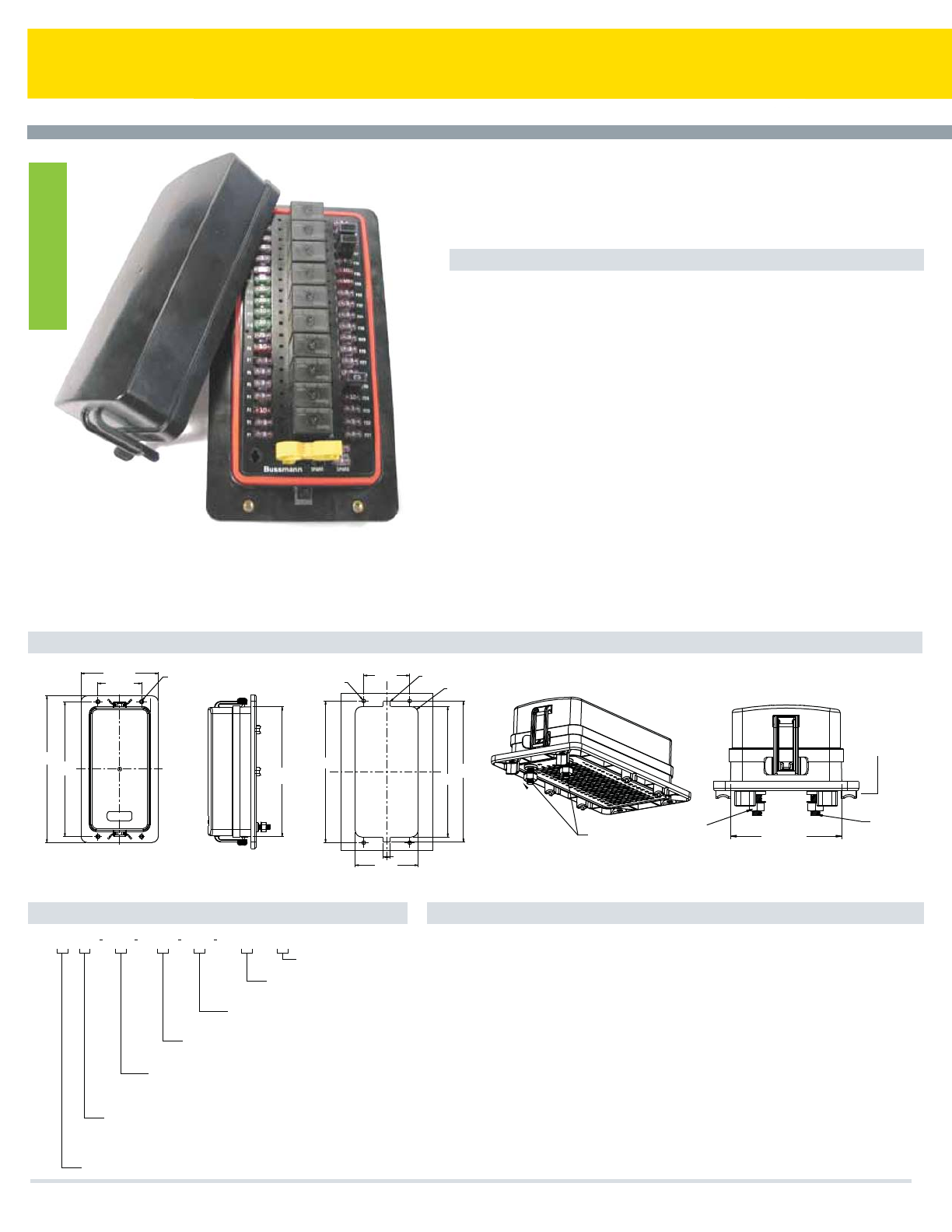
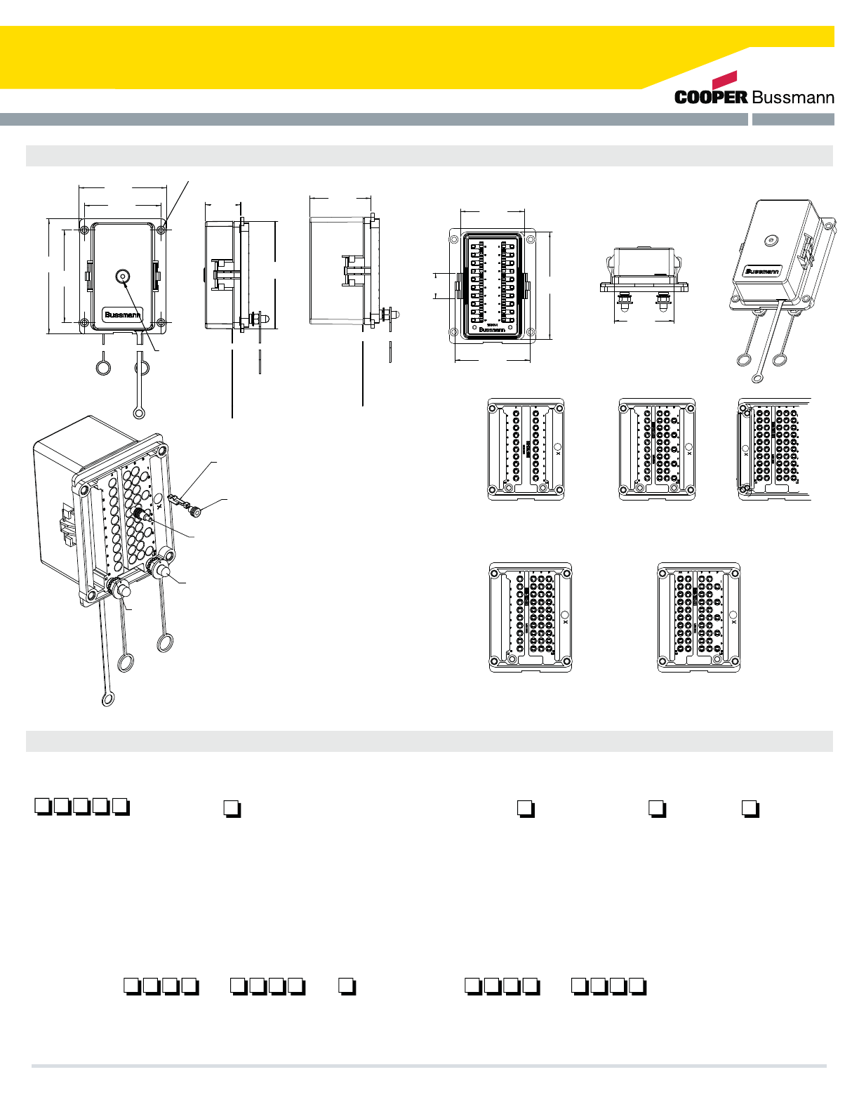
Series 15310 60-Position RTMR
RTMR Product Features
Dimensions - mm(in)
Blade Terminals: Accepts ATM (mini) blade fuses, circuit breakers as well as other
components such as relays, diodes, flashers, etc. with 2.8mm blades on 8.1mm centerline
spacing
Mounting: #10-32 or M5 Threaded inserts; 24 in-lbs (2.7Ntm) max torque
Material: Housing and cover: black thermoplastic
Labels: Component location IDs molded on top of housing; custom inside cover labels
available. Contact factory for information.
Ratings: 30A max per terminal; 12/24Vdc
Temperature Rating: -40°C (-40°F) to 125°C (260°F) (rating on PDM only)
Ingress Protection Rating: IP66–IEC 529 (valid when properly installed with cover, cable
seals and cavity plugs. Contact factory for specific IP test specifications applicable to
RTMR.
Electrical Connections: Output cavities (holes in back of unit):
Wire Size: #12-#20 AWG
Terminals: Tyco AMP® MCP2.8 Series
20-16 AWG (0.50-1.00mm2): Terminal #1-968855-1 Seal #828904-1
14-12 AWG (1.50-2.50mm2): Terminal #1-968857-1 Seal #828905-1
Cavity Plugs: Tyco AMP® MCP2.8 Series #828922-1 (where output wires are not
used)
Notes:
1. Cooper Bussmann does NOT supply wires, wire terminals, terminal seals or cavity
plugs.
2. Mounting brackets offered for surface mounts.
3. Consult factory for options including custom labels and replacement accessories.
4. 15310 series uses Tyco terminals vs. Delphi as commonly used with our standard
RTMR series
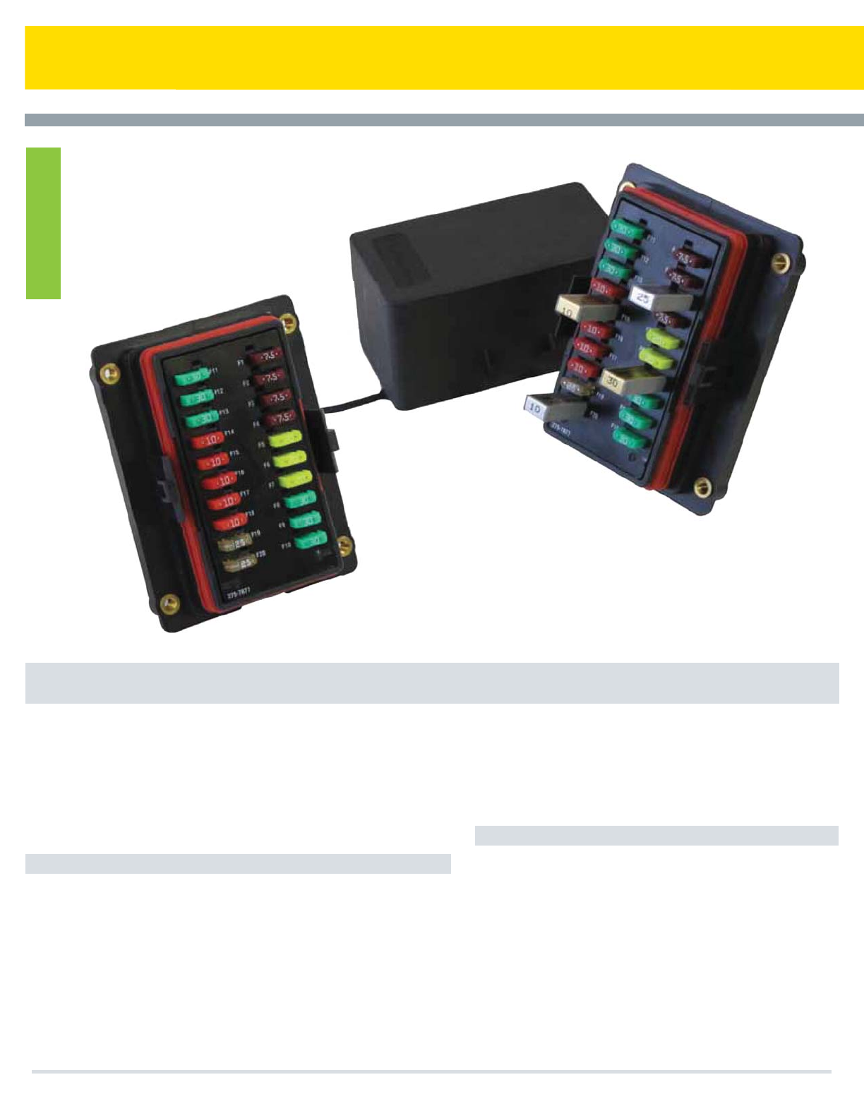
Non-Bussed Rear Terminal Mini Fuse & Relay
Cooper Bussmann Transportation Products offers a power distribution module called
the 60-Position Rear Terminal Mini-Fuse and Relay panel (15310 Series.) The 15310
offers the same benefits as the standard Cooper Bussmann RTMR, however, it has a
higher component density. There are 60 open cavity positions versus the 50 maximum
positions of the standard RTMR. This allows you to install more fuses, breakers,
diodes or relays without increasing any outer dimensions! The unit is non-bussed to
allow you to place components anywhere within the block. This makes the 15310
suitable for virtually any application in marine, construction, agriculture, heavy trucking,
and specialty vehicle industries. With cover, cable seals and cavity plugs installed, the
15310 is a weather tight enclosure (IP66) for power distribution. (The 15310 uses the
same covers and mounting as the standard RTMR.)
Part Numbering System
Marking
Options
Consult factory
for custom
marking options
Cover
Options
0 - No Cover
1 - Fuse Cover
2 - Relay/CB Cover
1 - #10-32 threaded insert
2 - M5 threaded insert
-
Mounting
OptionSeries
-
15310
Cooper Bussmann Transportation Products t1IPOFt'BYtXXXDPPQFSCVTTNBOODPN
75.40 +0.25
-0.13
2.969 +.009
-.005
2x ø6.35±0.05[.250±.001]
w/ 0.38 [.015] x 45° CHAMFER
BOTTOM SIDE, CLEARANCE HOLE
FOR THREADED INSERTS
105.83
[4.167]
102.83
[4.048]
99.58 ±0.15
[3.920 ±.005]
1.50[.060] HIGH CHARACTERS MOLDED
0.13/0.26[.005/.010] BELOW SURFACE
1.50[.060] HIGH CHARACTERS MOLDED
0.13/0.26[.005/.010] BELOW SURFACE
62.83
[2.474]
56.83
[2.237]
53.58 ±0.25
[2.109 ±.009]
90.78
[3.574]
1.50
[.059]
25.00
[.984]
8.00
[.315]
96.68
[3.806]
50.68
[1.995]
30.35
[1.195]
1.50[.050] HIGH CHARACTERS MOLDED
0.13/0.26[.005/.010] BELOW SURFACE
84.70±0.30
[3.335±.012]
16.00
[.630] 16.00
[.630]
1.50
[.059]
1.50
[.059]
8.00
[.315]
103.24
[4.065]
113.24
[4.458]
8.00
[.315]
TYP
CHANGEABLE INSERT FOR PART NO.
3.30[.118] HIGH CHARACTERS MOLDED
0.13/0.26[.005/.010] ABOVE SURFACE
1.90
[.075]
TYP
CHANGEABLE
INSERT FOR
YEAR/MONTH
DATE CODE
CHANGEABLE
INSERT FOR REVISION
NUMBER
37
Series 15300 RTMR
Torque Rating: 50 in-lbs (5.5Ntm) max.
Mounting Torque Rating: #10-32 or M5 threaded inserts; 24 in-lbs
(2.7Ntm) max torque.
Ingress Protection Rating: IP66-IEC 60529 (Valid when properly
installed with cover, sealed terminals, and cavity plugs.)
Options
End Caps: Protective silicone end caps available for studded versions.
Mounting: Mounting brackets available for surface-mounting RTMR.
(See page 39.)
Labels: Consult factory for custom label options.
Replacement Accessories: Consult factory for available service parts.
The Rear Terminal Mini Fuse and Relay panel (RTMR) provides efficient power
distribution in a rugged compact form for applications in marine, construction,
agriculture, heavy trucking, specialty vehicles, etc. This innovative product
offers a weather tight enclosure (IP66) for various MINI (2.8mm) blade
components when cover, cable seals, and cavity plugs are installed. It is
available with various degrees of internal electrical bussing. Additionally,
custom labels and multiple hardware configurations are available to solve any
application need.
Specifications
Input Terminal Rating: M6 input studs on bussed/partially bussed inputs: 80A
max input on bussed fuse side, 80A max input on bussed relay side.
Output Terminal Rating: 2.8mm blade terminals (30A max per terminal)
Temperature Rating: 2.8mm blade terminals (30A max per terminal)
Materials: Black thermoplastic housing; Tin-plated copper internal bussing;
Bright nickel-plated brass studs (on bussed versions).
Termination: Delphi Packard Metri-Pack® 280 Series terminals
(sealed/tangless) or AMP® terminals.* Delphi Packard 280 Series cavity plugs
are installed where wires are not used.* Accepts #12-22 AWG wire sizes.
*Electrical terminals, cable seals & cavity plugs are NOT supplied by
Cooper Bussmann
Rear Terminal Mini Fuse & Relay
Cooper Bussmann Transportation Products t1IPOFt'BYtXXXDPPQFSCVTTNBOODPN
PDM
38
Series 15300 RTMR
Dimensions - mm(in) (Dims. shown are for reference only. Consult factory for latest prints)
Part Numbering System
Mounting Brackets
–
–
RTMR Stud End Cap
–
Material
–
O – Plated steel
P– Stainless steel
B028 B066 70087012
0 - No Cover
3 - Fuse Cover
4 - Relay/c.b. Cover
0 - No Nuts
1 - Nuts (Shipped Bulk)
2 - Nuts (Shipped Assembled)
2 - Nuts (Shipped Assembled)
3 - Stud Caps (Shipped Bulk)
4 - Stud Caps (Shipped Assembled)
5 - Nuts And Stud Caps (Shipped Bulk)
6 - Nuts And Stud Caps (Shipped Assembled)
1 - Fuse/C.B. Base (For 20 Fuses/C.B.)
2 - Micro Relay Base (For 5 Micro Relays W/ 10 Fuses/C.B.)
3 - Mini Relay Base (For 3 Mini Relays W/10 Fuses/C.B.)
4 - Wired Base (Non Bussed) (No Input Studs) (For Fuses/C.B. And Relays)
5 - Wired Base (Input Stud Fuse Side Only) (For Fuses/C.B. And Relays)
6 - Wired Base (Input Stud Relay Side Only) (For Fuses/C.B. And Relays)
3 - #10-32 Insert (English
4 - M5x0.8 Insert (Metric)
Special Labels
Consult Factory
1530
Cooper Bussmann Transportation Products t1IPOFt'BYtXXXDPPQFSCVTTNBOODPN
59.3
(2.33)
62.8
(2.47)
105.4
(4.15)
73.3
(2.89)
25.0
(.98)
75.0
(2.95)
86.0
(3.39)
90.6
(3.57)
112.8
(4.44)
THREADED INSERT
15303-3 #10-32 INSERT
15304-4 M5 X 0.8 INSERT
GORE AUTOMOTIVE
VENT USED WITH
FUSE COVER ONLY
34.6
(1.36)
106.3
(4.19)
FUSE
COVER
SHOWN
60.3
(2.37)
RELAY/C.B.
COVER
SHOWN
/05&4
0651655&3.*/"-4$"#-&4&"-4"/%4&"-&%$0//&$503
1-6(4"3&/051307*%&%#:$001&3#644."//
.06/5*/(5)3&"%&%*/4&3546/'PS.9
*/-#4."950326&*/165456%4.9*/-#4."9
)064*/(705)&3.01-"45*$
*/5&3/"-#644*/(5*/1-"5&%$011&3
%*.&/4*0/41307*%&%"3&'033&'&3&/$&0/-:
*13"5*/(*11&3*&$7"-*%8)&/$07&3"/%4&"-&%
5&3.*/"-4"/%4&"-&%$0//&$5031-6(4"3&1301&3-:
*/45"--&%*/03%&350."*/5"*/"*13"5*/(*5*4
3&$0..&/%&%5)"55)&$6450.&31&3*0%*$"--:"11-:"
)&"7:%65:4*-*$0/&-6#3*$"/5JF$3$03&26"-
505)&35.3)064*/(("4,&5
5&3.*/"-3&.07"-500-%&-1)*1"35/0
ISOMETRIC VIEW
SCALE: 1:1
TANGLESS FEMALE TERMINAL
DELPHI PACKARD
280 METRI-PACK SERIES
12 GA. TO 20 GA.
(SEE NOTE 1)
CABLE SEAL
DELPHI PACKARD
280 METRI-PACK SERIES
(SEE NOTE 1)
SEAL CONNECTOR PLUG
DELPHI PACKARK
PART NO. 12010300
(SEE NOTE 1)
STUD CAPS
(OPTIONAL)
HEX NUTS
(OPTIONAL)
#0550.7*&8
999
FUSE BASE
#0550.7*&8
999
999
MICRO/MINI BASE
#0550.7*&8
999
8*3&%#"4&
/0108&3#644
#0550.7*&8
999
8*3&%#"4&
'64&4*%ʄ
#0550.7*&8
999
8*3&%#"4&
3&-":4*%ʄ
Base OptionsMounting
Hardware
Options
Cover
Options
Marking
OptionsSeries
39

Series LMG Bolt-in Fuse Holder for Multiple AMG Fuses
Cooper Bussmann Transportation Products now offers a heavy power
distribution module called the LMG (a.k.a “Big Block”). The LMG is
used for main branch primary fusing and accepts multiple (2, 3, or 5)
industry standard AMG fuses. Using a common input bus bar, the
LMG requires just one input connection to power all fuses.
Power Distribution Module
Marine
Construction
Agriculture
Heavy Trucking
Bus
Specialty Vehicles
The Big Block provides efficient power distribution suitable for many
“under the hood” applications such as:
Sizing:
Ratings:
Temperature:
Termination:
Torques:
Material:
2, 3 and 5 positions available
Maximum total combined rating is 300A continous*
.
-40˚C (-40˚F) to 85˚C (185˚F)
-18 or M8 studs, nuts, and lockwashers for fuse
and surface mountings
Mounting: 100 in-lbs (11.3Ntm) max; Power input/output:
120 in-lbs (13.6Ntm) max
Housing: Black UL-Rated 94V0 thermoplastic
Cover: Red EPDM cover for protection from accidental shorts
Studs: Plated steel
*Based on numerous variations possible between # of LMG poles, fuses selected, input wiring,
and output wiring, all applications should be tested by the installer to verify the product meets
their requirements. Housing must not exceed 130 degrees C.
516
Cooper Bussmann Transportation Products t1IPOFt'BYtXXXDPPQFSCVTTNBOODPN
Fuse Panels
40
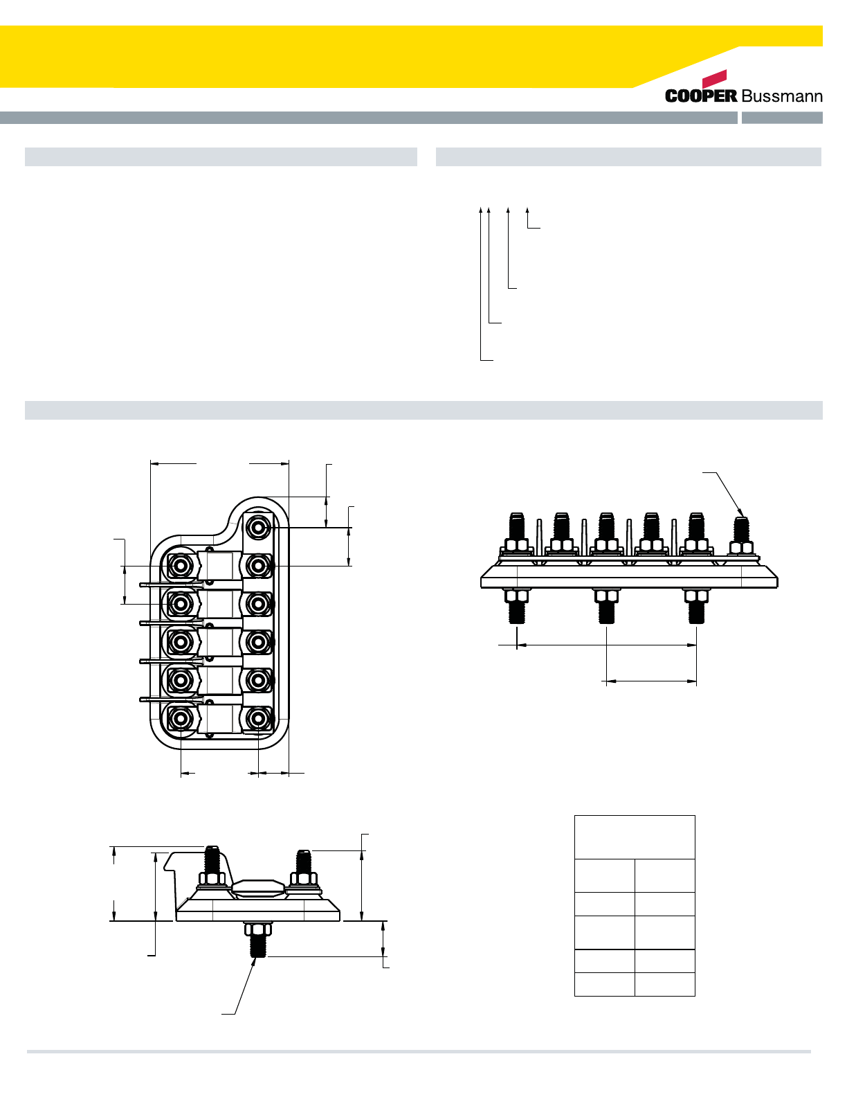
Hardware/Options LMG XX - X - XXXX
XXXX
X = 1 Standard mounting
(contact factory for custom options)
X = # of fuse positions
X = Hardware Type (M for metric, E for English)
Fuse: LMGs may be supplied with various fuse configurations (if
fuses selected, then input side of fuses torqued to specification at
Cooper Bussmann factory - custom part number)
Bus-bar: Sized to LMG (2,3,5) plated copper power stud
hardware only applies to output side of fuse. Supply side of fuses
torqued to spec at factory by default (English/metric available)
Mounting Hardware: Installed or in bulk (English/metric available)
Cover: Installed, in bulk, or no cover. Also available in hard cover.
= Unique Identifying number reecting fuse
congurations. (assigned by Cooper Bussmann; 0000
means no fuse and no cover, 0001 means no fuse with
cover, 0002 means no fuse, no cover, no bus bar)
Table 1
25.0
[.98]
TYP.
90.8
[3.57]
20.0
[.79]
TYP.
25.0
[.98]
20.0
[.79]
TYP.
50.8
[2.00]
TYP.
41.5
[1.63]
38.0
[1.50]
TYP. 20.0
[.79]
TYP.
39.1
[1.54]
TYP.
5/16 - 18 OR 8mm THD. (TYP.)
5/16 - 18 OR 8mm THD. (TYP.)
SEE 5 (ALT)
MOUNTING BOLT LOCATION
“X” (SEE TABLE 1)
POLE
2
3
5
5 (ALT)
“X”
MM
25
50
50
100
Specifications
Dimensions - mm(in)
Part Numbering System
Cooper Bussmann Transportation Products t1IPOFt'BYtXXXDPPQFSCVTTNBOODPN 41
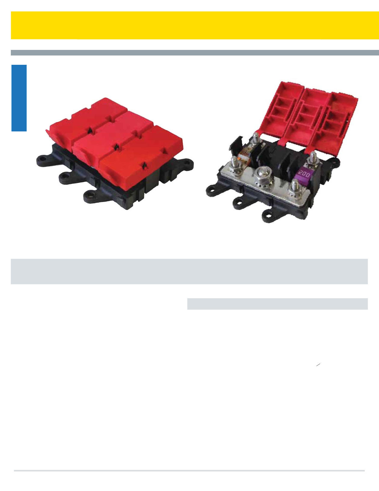
LMI Bolt-in Fuse Holder for Single or Multiple AMI Fuses
Cooper Bussmann Transportation Products now offers a heavy duty
fuse panel called the LMI “Little Block”. The LMI is used for main
branch primary fusing and accepts multiple (up to six) industry
standard AMI fuses. Sold by component or assembled, the LMI
uses a common input bus bar for assemblies of two or more fuses.
The LMI provides efficient power distribution suitable for many “under
the hood” applications such as:
tMarine
t$POTUSVDUJPO
t"HSJDVMUVSF
t)FBWZ5SVDLJOH
t#VT
t4QFDJBMUZ7FIJDMFT
4QFDJmDBUJPOT
Sizing: One Fuse Module per AMI fuse
One input module and bus bar required per LMI2 – LMI7 assembly
Maximum of seven modules per assembly
Ratings: Maximum total combined rating is 400 amps continuous*
5FNQFSBUVSF-40˚C (-40˚F) to 85˚C (185˚F)
5FSNJOBUJPO Input Module: Stainless Steel M8 or -18 stud and keps nut
Fuse Module: Stainless Steel M5 or #10-24 studs and keps nuts
5PSRVFTMounting: 22 in-lbs (2.5 Ntm)
Fuse Module: 39.8 in-lbs (4.5NtM)
Input Module: 75 in-lbs (8.5NtM)
Material: Housing: HTN black UL-rated 94V0 thermoplastic material
Cover: Red EPDM/Santoprene cover for protection from accidental
shorts
Studs: Stainless Steel
Power Distribution Module
516
$PPQFS#VTTNBOO5SBOTQPSUBUJPO1SPEVDUTt1IPOFt'BYtXXXDPPQFSCVTTNBOODPN
* Based on numerous variations possible between numbers of poles used, fuses selected, input
wiring, and output wiring, all applications should be tested by installer to verify the product meets
their requirements.
Fuse Panels
42
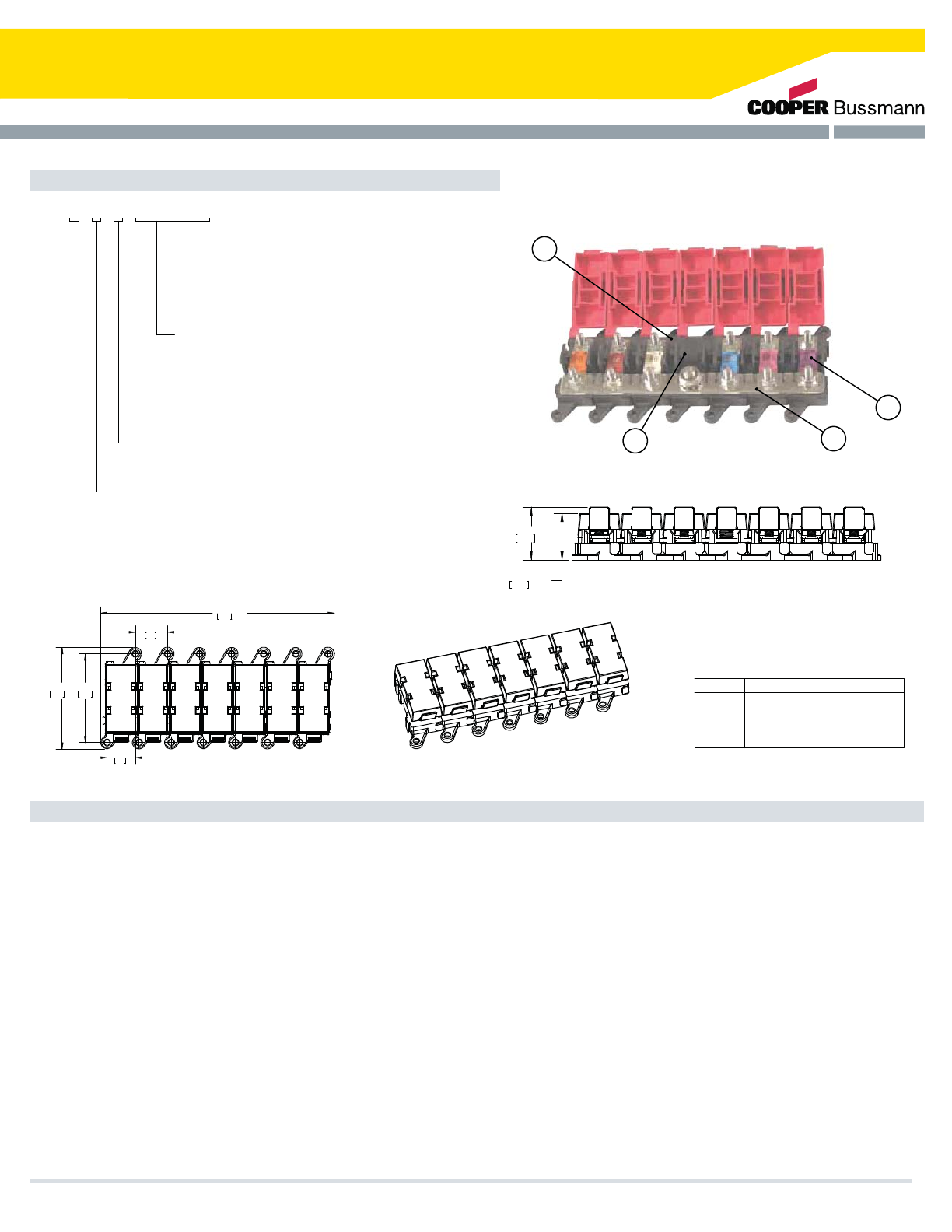
25.1
.99
182 REF
69
2.72
7.17
REF
3.11
79
22
.87
1.08
REF27.5
31.1 REF
1.22
H -- Fuse Module w/100a AMI Fuse
G -- Fuse Module w/80a AMI Fuse
1 -7 [Number of total modules (fuse modules and/or
M -- Metric
1 -- SS Keps Nut In Bulk (For individual components only)
J -- Fuse Module w/150a AMI Fuse
I -- Fuse Module w/125a AMI Fuse
input modules); 7 Max]
B -- Fuse Module w/40a AMI Fuse
Stud Option:
E -- English
2 -- SS Keps Nut Installed (Only for assembled LMI2-LMI7)
C -- Fuse Module w/50a AMI Fuse
F -- Fuse Module w/70a AMI Fuse
D -- Fuse Module w/60a AMI Fuse
LMI X -X -X -X(XXXXXX)
K -- Fuse Module w/175a AMI Fuse
HARDWARE OP5ION:
0 -- No Hardware (For individual components only)
L -- Fuse Module w/200a AMI Fuse
Up to 7 digit sequence representing each module
in assembly, from left to right, with Busbar in the
front/bottom, uses below code:
0 -- Fuse Module w/o Fuse (i.e. empty fuse module)
1 -- Input Module
A -- Fuse Module w/30a AMI Fuse
2
LMI FUSE MODULE
LMI INPUT MODULE
AMI FUSE4
BUSBAR
1
3
I5EM DES$RIP5ION
LMI7
1. All modules (input or fuse holder) will match same units in a given assembly, either all metric or all English as specified.
2. "E" Represents "10-32" stud for fuse module and "5/16-18" for input module. "M" represents M5 stud for fuse module and M8x1.25 size for input
module.
3. The largest an LMI should be is 7 modules total; 6 fuse modules and one input module. At most, 7 positions can be shown in suffix -X(XXXXXX).
4. Cooper Bussmann does not recommend more than 6 fuse modules being connected together (with one input module). The input module should
be located in the center of the assembly.
5. Bus bars are included for all assemblies greater than or equal to an LMI2.
6. Based on numerous variations possible between numbers of poles used, fuses selected, input wiring, and output wiring, all applications should be
tested by installer to verify the product meets their requirements.
7. All modules come with covers.
8. When ordering individual LMI modules for assembly by the customer, bus bars can be individually ordered using part # B109-7046-2/3/4/5/6/7,
with the last digit representing the number of total modules that the bus bar will connect.
9. When ordering LMI1 with fuse and/or nuts, both fuse and nuts will ship in bulk.
10. To order assembled units, the minimum order quantity is 100 units.
11. Attach all wire cables with the ring terminals in direct contact with the fuse or bus bar.
Notes
1BSU/VNCFSJOH4ZTUFN
3
4
2
1
$PPQFS#VTTNBOO5SBOTQPSUBUJPO1SPEVDUTt1IPOFt'BYtXXXDPPQFSCVTTNBOODPN 43
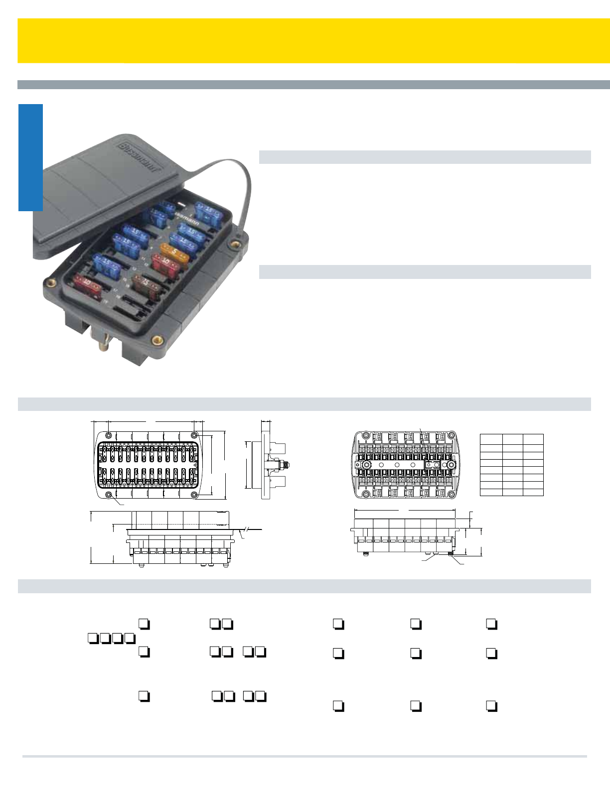
Series 15710 Rear Terminal ATC Fuse Panel
Specifications
Options
Dimensions - mm(in)
Part Numbering System
The Rear Terminal ATC® Fuse Panel (RTA) is a rear-fed panel with high component
retention, which makes it an ideal choice for high vibration environments including
construction, agriculture, bus, RV, heavy trucking equipment, etc. It is available in multiple
lengths and internal bussing configurations. This allows for up to three separate power input
circuits and 32 individual output circuits.
Input Terminal Rating: 1/4-20 stud; Quick-connect terminals provided on middle bus
(Series 15713). 200A max total input for unit
Output Terminal Rating: 30A max load per circuit
Temperature Rating: –40°F (–40°C) to 260°F (125°C)
Materials: Black thermoplastic
Termination: Delphi Packard Pack-Con® Series 3 & 5.* Input Wire Size: #4-6 AWG
Output Wire Size: #10-16 AWG
Torque Rating: 50 in-lbs (5.6Ntm) max
Mounting Torque Rating: #10-32 threaded inserts, 24 in-lbs (2.7Ntm) max torque
Positions: 8-32 Circuits available.
Split Power: Single, dual, or triple bus options
Cover: Splash-resistant covers available. Short cover for fuses only, and taller
cover for use with circuit breakers
Locks: Secondary locks available for securing of output terminals (#15710-TP).
(Comes in multiples of 8 positions. Must order multiple strips to cover length of
selected RTA.)
Tools: Output terminal removal tool (#HT15710-01). Secondary lock removal
tool (#HT15710-02).
*Electrical Terminals are NOT supplied by Cooper Bussmann.
®
QUICK-CONNECT TERMINALS
(Series 15713) 1/4-20 STUD (2 PLACES)
10-32 THREADED INSERTS (4 PLACES)
166.5147.032 POLE
146.5127.028 POLE
126.5107.024 POLE
107.087.520 POLE
87.067.816 POLE
67.048.012 POLE
47.528.08 POLE
VALUE
DIM 'B'
VALUE
DIM 'A'
][1.31
33.3
A
B
][ 1.38
35.0
][ 0.48
12.1
][ 0.41
10.5
][ 2.34
59.4
[2.94( .20]
74.7( 0.5
[3.38(.20]
85.8(0.50
][ 0.42
10.7
][ 0.74
18.8
Middle bus has quick-connect terminals
(series 15713 only)
COVER
TETHER
49.55
[1.95]
FUSE
COVER
66.28
[2.61]
BREAKER
COVER
Series
1571
1 – Single Stud, Single Supply Circuit
2 – Double Stud, Split Supply Circuit
3 – Triple Buss, Split Supply Circuit
Hardware
Options
0 – W/O nuts
1 – Nuts shipped bulk
2 – Nuts assembled
Cover
Option
0 – No cover
1 – w/ fuse cover
2 – w/ CB cover
Marking
Option
A-Standard
(consult factory for
special marking
No. of
Positions
– –
1
08-32
– – –
2
Left Side Right Side
06-28 04-28
(max. tot 32) (increments of 4)
– - –
3
Total Pos Left Side
14-32 06-24
(max. total of 32) (increments of 4)
Cooper Bussmann Transportation Products t1IPOFt'BYtXXXDPPQFSCVTTNBOODPN
Fuse Panels
44

Series 15600 ATC Blade-Type Fuse Panels
Dimensions - mm(in)
Part Numbering System
Positions: 4-20 circuits available.
Split Power: Single or dual buss options.
®
Specifications
Options
The 15600 ATC® fuse panel is a compact, yet rugged, power distribution module. It
is available in a single or dual internal buss electrical configuration featuring an
optional ground pad terminal strip. The 15600 fuse panel is surface mounted, uses
convenient quick-connect terminals, and is recommended as a supplemental
power distribution module. It can be used to accompany main PDMs such as the
Cooper Bussmann 31000/32000 Series VEC/DVEC, 15710 Series RTA, and the
1540X Series RFRM.
Input Terminal Rating: #10-32 Threaded studs (100A max).
Output Terminal Rating: 30A Max per circuit.
Temperature Rating: –20°F (0°C) to 150°F (65°C).
Materials: Black thermoplastic.
Termination: .250" x .032" quick-connect terminals. Ground terminal pad option
available. Input wire size: #4-6 AWG. Output wire size: #12-16 AWG.
Torque Rating: 20 in-lbs (2.25Ntm) max.
Mounting Torque Rating: 8 in-lbs (0.9Ntm) max.
"L"
"C"
(1.06")
26.92
(.62)
15.75
15.75 TYP (.62")
(.80)
20.32
.250" QC (COPPER ALLOY - TIN PLATED)
(15600 -10-20 SHOWN)
.22" DIA. HOLE WITH .41 x .12
DEEP C'BORE (4X)
(12) .250" QC TERMINALS W/COMMON
WIRING STUD, ADD 1.300" TO "L" FOR
OVERALL LENGTH
"L"
"C"
(3.37)
85.59
(2.50)
63.50
(1.06)
26.92
(1.22)
30.98
(15602-04/08-20 SHOWN)
15600 Series 15602 Series
Ground Terminal Base Option
No. of 15600 15602 No. of 15600 15602
Fuse
04 – 1.84 2.44 14 3.12 4.97 5.56
06 .62 2.47 3.06 16 3.76 5.59 6.19
08 1.25 3.09 3.68 18 4.37 6.22 6.81
10 1.87 3.75 4.32 20 5.00 6.84 7.43
12 2.50 4.34 4.94
Dimensions in inches. Multiply by 25.4 for metric.
“L”“L”“L” “C”“C” “L”
Fuses
No. of Fuses &/or Circuit
Breaker Positions
– –
0
04-20
– – –
2
Left Side Right Side
04-16 04-16
(max. combination of 20)
Series
1560
0 – Single Stud, Single Supply Circuit
2 – Double Stud, Split Supply Circuits
Hardware
Options
0 – W/O nuts
1 – Nuts shipped bulk
2 – Nuts assembled
Ground Terminal
Base
0 – None
1 – Include Ground Pad
Cooper Bussmann Transportation Products t1IPOFt'BYtXXXDPPQFSCVTTNBOODPN 45
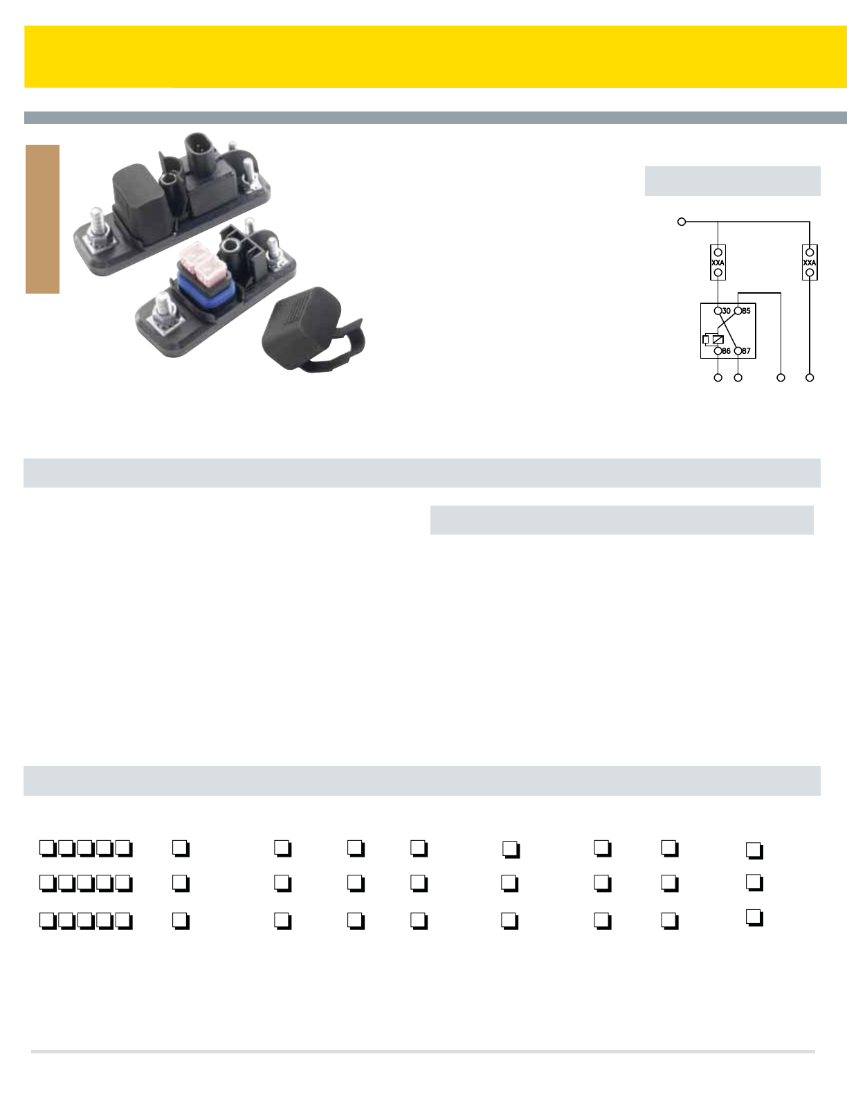
Series 37700 PRM/PFM
Specifications
Part Numbering System
Power Fuse Module &
Power Relay Module
Cooper Bussmann offers a sealed Power Relay
Module (PRM) along with an accompanying Power
Fuse Module (PFM). These compact power
distribution modules are designed for high current
applications, and are suitable for placement in
extreme moisture and high vibration environments.
The PRM contains a 70A relay and two female
fuse positions. One of these fuses protects the
relay and the other is a single-circuit inline fuse.
The PFM contains only two fuses - each a
separate circuit. A silicone seal and removable
cover offer a weather-tight enclosure for the fuse
positions. PRMs/PFMs also feature rugged M8
power input studs. Multiple units may be
connected together via a custom buss bar, or can
be bussed to any of the Cooper Bussmann PDMs
(i.e., 31000/32000 Series VEC/DVEC, 15300
Series RTMR, etc.)
PRM Rating: 70A, 12Vdc steady-state relay; 24Vdc relay also available.
Relay protection fuse: up to 60A; Nonswitched
Inline fuse: up to 60A.
PFM Rating: Each inline fuse rated up to 60A. Temperature Rating: –40°F
(–40°C) to 185°F (85°C).
Materials: UL-Rated 94V0 thermoplastic (excluding cover;) silicone seal;
tin-plated copper terminals; plated steel studs.
Input Termination: M8 threaded stud. PRM
Switching/trigger signal: Delphi Packard Metri-Pack® 150 Series;
AMPSEAL® 16.*
Output Termination Option: Cooper Bussmann Series 32004 sealed
connector (see page 34); Accepts Delphi Packard 800 series terminals.*
Two M6 threaded studs.
Torque Rating: Input stud: 144 in-lbs (16.3Ntm) max.;
Output stud: 48 in-lbs (5.4Ntm) max.
Mounting Torque Rating: 48 in-lbs (5.4Ntm) max.
Ingress Protection Rating: IP66 (excluding stud connections)
Compliances: SAE 31171 (ignition protected)
Mounting: Counter rotation feature (CRF) available to prevent rotation on
single bolt installations.
Bussing: Custom bussing available for joining multiple PRMs/PFMs.
options also available for bussing PRMs/PFMs to other Cooper Bussmann
power distribution modules.
Accessories: Buss bar, stud caps, separators, service components.
Consult factory for details.
Signal Connectors: Delphi- PN# 12052641 (Black) & 12052644 (Grey)
AMP- PN# 776427-1 (Red), 776427-2 (Grey),
776427-3 (Yellow) & 776427-4 (Green).
*Electrical terminals are NOT supplied by Cooper Bussmann.
Options
PRM Wiring
Series/
Module Type
–
PFM
Output/Signal
Connector Type
Signal Key
(PRM only)
Output
Key
Nonswitched
Value
Switched
Fuse
(Right Side)
Cover
Option
Hardware
Option
Private
Label
–
12V PRM
–
24V PRM
37701 1 N
37702
37703
*1 - Stud/Delphi
2 - Connector/Delphi
3 - Stud/AMP®
4 - Connector/AMP®
0 - None
2 - 20 amps
3 - 30 amps
4 - 40 amps
5 - 50 amps
6 - 60 amps
0 - None
2 - 20 amps
3 - 30 amps
4 - 40 amps
5 - 50 amps
6 - 60 amps
0 - No cover
1 - Cover (bulk)
2 - Cover (installed)
N - Stud Output
(no key)
A - Black
B - Grey
A - Black (Delphi
only)
B - Grey (AMP®
or Delphi)
C - Green (AMP®
only)
F - Red (AMP®
only)
Y - Yellow (AMP®
only)
0 - None
1 - Nuts (bulk)
2 - Nuts (installed)
3 - CRF
4 - CRF, nuts (bulk)
5 - CRF, nuts (installed)
X - Consult
Factory
Cooper Bussmann Transportation Products t1IPOFt'BYtXXXDPPQFSCVTTNBOODPN
Fuse Holders
Input Stud
Switched Fuse
Unswitched Fuse
Power Relay
Signal Connector
Output Stud
Signal Connector
Output Stud
46
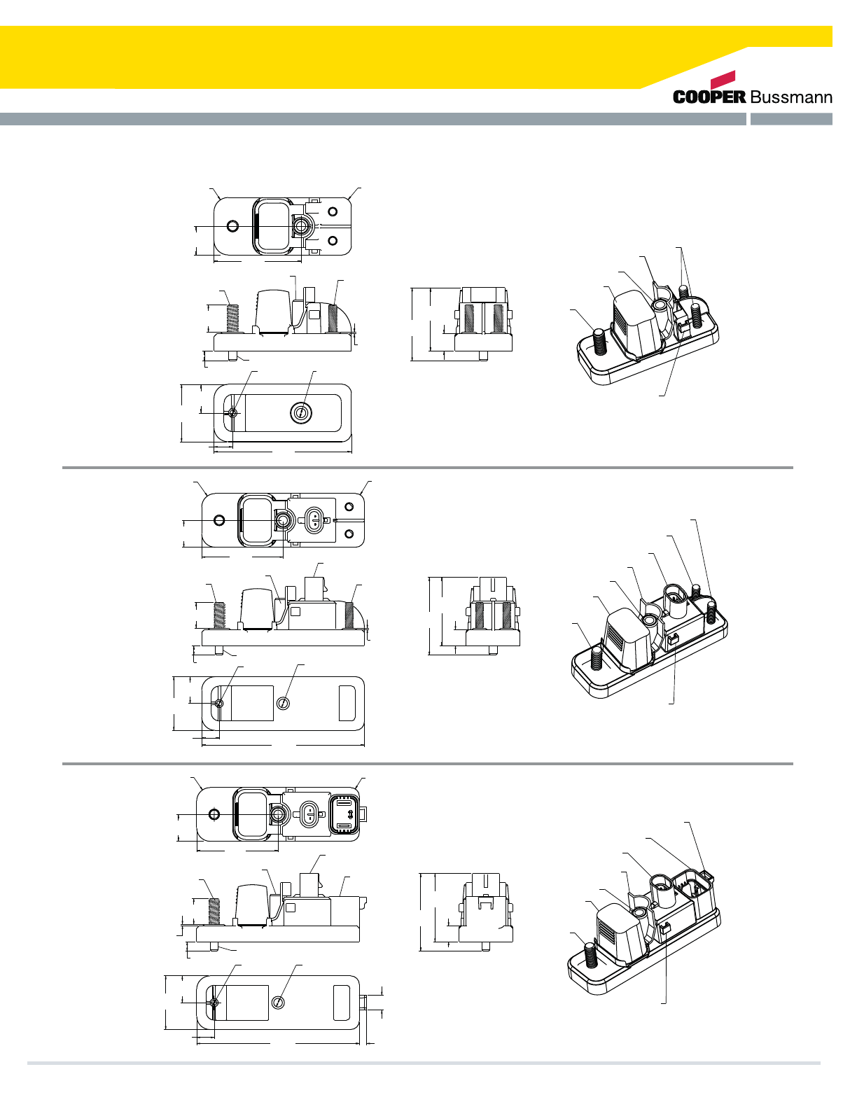
Series 37700 PRM/PFM
MULTIPLE UNIT JOINING LATCH
OUTPUT STUDS
FUSE COVER LOCK/UNLOCK TAB
MOUNTING HOLE
(2) FEMALE MAXI
FUSE COVER:
INPUT STUD
Counter Rotation Feature (CRF)
(2 PLS)
M6X20 STUD
6.5 X 35.4
MOUNTING HOLE
M8X20 STUD
][ 0.276
7.00
][ 0.039
1.00
][ 0.756
19.19
][ 0.472
12.00
][ 0.787
20.00
][ 0.513
13.04
][ 0.236
6.00Ø
”
][ 0.256
6.50Ø
”
][2.008
51.00
][ 1.732
44.00
][ 3.765
95.62
][ 1.575
40.00
MULTIPLE UNIT JOINING LATCH
BATTERY SIDE
OUTPUT STUD
SWITCHED SIDE
OUTPUT STUD
RELAY SIGNAL CONNECTOR
FUSE COVER LOCK/UNLOCK TAB
MOUNTING HOLE
(2) FEMALE MAXI
FUSE COVER
INPUT STUD
Counter Rotation Feature (CRF)
M6 X 20 STUD
SEALED, 2 WAY CONNECTOR
USE WITH DELPHI 150 SERIES,
RELAY SIGNAL CONNECTOR
M8 X 20 STUD 6.5 X 35.4
MOUNTING HOLE
][ 0.256
6.50Ø
”
][ 0.236
6.00Ø
”
][ 1.575
40.00
][ 0.787
20.00
][ 0.513
13.04
][ 4.772
121.21
][ 0.472
12.00
][ 2.004
50.90
][ 2.280
57.90
][ 0.039
1.00
][ 0.276
7.00
][ 0.756
19.19
][ 0.394
10.00
(2 PLS)
R][ 0.256
6.50
(2 PLS)
R
][ 0.787
20.00
][ 2.387
60.62
MULTIPLE UNIT JOINING LATCH
MOUNTING HOLE
OUTPUT CONNECTOR LOCKING TAB
OUTPUT CONNECTOR
RELAY SIGNAL CONNECTOR
FUSE COVER LOCK/UNLOCK TAB
(2) FEMALE MAXI
FUSE COVER
INPUT STUD
Counter Rotation Feature (CRF)
M8X20 STUD
P/N 32004
SEALED CONNECTOR
USE WITH BUSSMANN
OUPUT CONNECTOR
SEALED, 2 WAY CONNECTOR
USE WITH DELPHI 150 SERIES,
RELAY SIGNAL CONNECTOR
6.5 X 35.4
MOUNTING HOLE
][ 0.787
20.00
][ 0.276
7.00
][ 0.394
10.00
(2 PLS)
R
][ 0.256
6.50
(2 PLS)
R
][ 0.256
6.50Ø”
][ 0.236
6.00Ø”
][ 2.387
60.62
][ 0.437
11.09
][ 0.039
1.00
][ 0.756
19.19
][ 0.513
13.04
][ 1.575
40.00
][ 0.212
5.38
][ 4.772
121.21
][ 0.472
12.00
][ 2.004
50.90
][ 2.280
57.90
][ 0.787
20.00
(Dims, shown are for reference only. Consult factory for latest prints)
][2.387
60.62
][ 0.394
10.00
(2 PLS)
R][ 0.256
6.50
(2 PLS)
R
][ 0.787
20.00
Dimensions - mm(in)
Cooper Bussmann Transportation Products t1IPOFt'BYtXXXDPPQFSCVTTNBOODPN 47

HMG Fuse Holder
Specifications
Features
Dimensions - mm(in)
Part Numbering System
The HMG fuse holder accepts industry standard AMG fuses for primary fusing
applications. The narrow rugged body makes it ideal for demanding environments
such as ‘under the hood’ locations in construction, agriculture, heavy trucking and
specialty vehicle applications.
Rating: For use with AMG fuses from 100-300A. (see pg 75 for AMG fuse)
Temperature Rating: –40°F (–40°C) to 260°F (125°C)
Materials: Black thermoplastic with zinc-plated steel studs
Termination: M8 or 5/16-18 threaded studs and hex nuts for fuse mounting. Wire
sizes: #2-8 AWG
Torque Rating: 150 in-lbs (17Ntm) max
Mounting Torque Rating: Optional mounting hole
patterns, 44 in-lbs (5Ntm) max
t4JEFTUBDLBCMF
t#PUUPNTJEFJOTVMBUFEGSPNNPVOUJOHQBOFM
t4QMBTISFTJTUBOUDPWFS
BUSSMANN
use AMG fuse
Cover Tether
Tie-Wrap Pass Thru's
(.26)
Ø6.6 (.26)
Ø6.6
(1.11)
26.3
(4.80)
121.8
(1.44)
36.7
(3.65)
92.6
(1.51)
38.4 (0.81)
20.7
(4.94)
125.4
(4.94)
125.4)
(4.23)
107.4
(4.23)
107.4
(1.02)
25.8
Center Mount
Offset Mount
Tie Wrap Mount
(Dims.shown are for reference only. Consult factory for latest prints)
Automotive Bolt-In Fuse Holder for the AMG Fuse
Cooper Bussmann Transportation Products t1IPOFt'BYtXXXDPPQFSCVTTNBOODPN
Fuse Holders
48
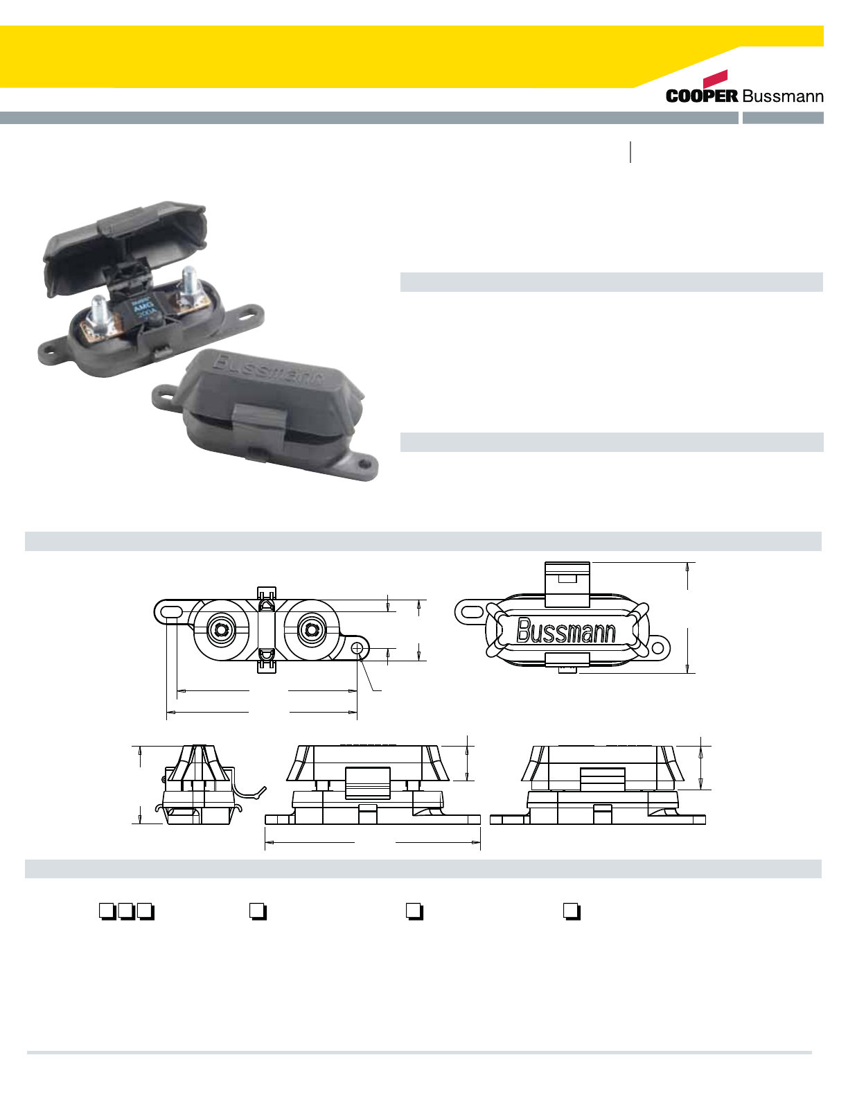
FMG Fuse Holder
Dimensions - mm(in)
Part Numbering System
Full access for cables. Can be routed to studs from nearly every direction.
Specifications
Features
The FMG fuse holder accepts industry standard AMG fuses for primary fusing
applications. The FMG is offered with a tough elastomer cover for fuse protection,
yet allows for cable input from various orientations. This fuse holder cover is available
JONVMUJQMFDPMPSTBOEMFOHUIT4JNJMBSUPUIF$PPQFS#VTTNBOO).(IPMEFSUIF
FMG is well suited for demanding environments such as ‘under the hood’ locations
in construction, agriculture, heavy trucking and specialty vehicle applications.
Rating: For use with AMG fuses from 100-500A. (see page 75 for AMG fuse)
Temperature Rating: –40°F (–40°C) to 260°F (125°C)
Materials: Black thermoplastic with zinc-plated steel studs; thermoplastic
elastomer cover (available in black or red, in normal or extended length)
Termination: M8 or 5/16-18 threaded studs and hex nuts for fuse mounting
Wire sizes: #2-8 AWG
Torque Rating: 120 in-lbs (13.5Ntm) max
Mounting Torque Rating: 1/4-20 screws with washers (recommended),
44 in-lbs (5Ntm) max
121.4
(4.78)
(2.46)
62.5
REF.
(1.73)
43.9
REF.
(4.00)
101.6
(4.23)
107.4
(.80)
20.4 (1.35)
34.4
(Ø.25)
Ø6.4
(.96)
24.5
(EXTENDED
COVER)
(.77)
19.5
(STANDARD
COVER)
Series
–
F M G
Base
1 – M8 studs
2 – 5/16-18 studs
3 - M8x1.25 Stainless studs
4. 5/16-18 UNC Stainless studs
Hardware
0 – No hardware installed
1 - Nuts installed
2 – Nuts bulk
3 - Stainless Nuts & Lockwashers
installed
4 - Stainless Nuts & Lockwashers
shipped bulk
Cover
0 – No cover
1 – Cover (black) installed
2 – Cover (black) bulk
4 – Cover (red) installed
5 – Cover (red) bulk
6 – Extended Cover (black) installed
7 – Extended Cover (black) bulk
8 – Extended Cover (red) installed
9 – Extended Cover (red) bulk
Full Access Automotive Bolt-In Fuse Holder for the AMG Fuse
Cooper Bussmann Transportation Products t1IPOFt'BYtXXXDPPQFSCVTTNBOODPN 49
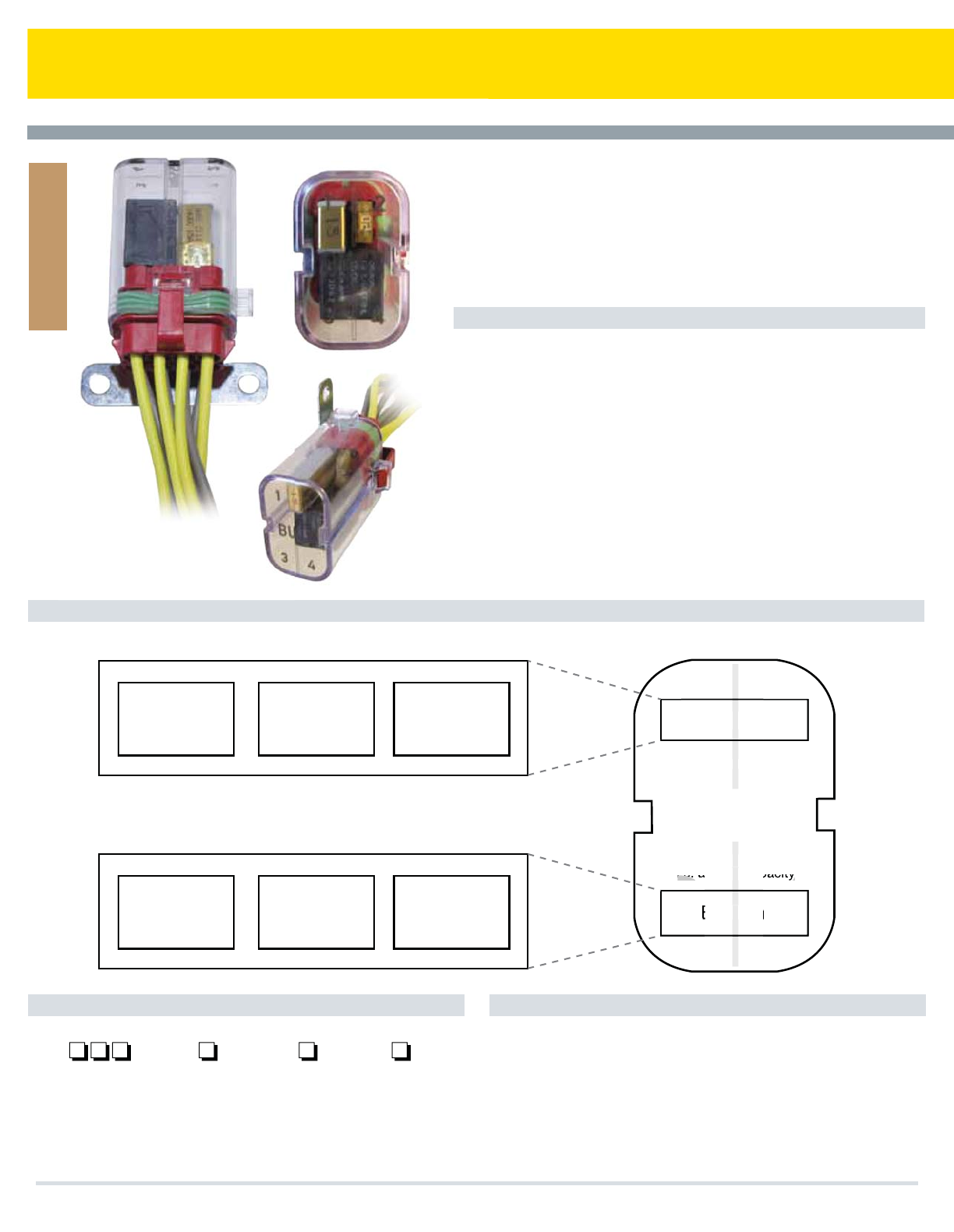
CFH-XXX Connector Fuse Holder
Cooper Bussmann Transportation Products t1IPOFt'BYtXXXDPPQFSCVTTNBOODPN
Specifications
Part Numbering System Notes
Temperature Rating: ¡$50¡$
Material: Cover: 7$MFBSQPMZDBSCPOBUF
Connector: 75IFSNPQMBTUJD
Brackets: 4JEFBOEFOEo[JODQMBUFETUFFMXDISPNBUFmOJTI
Pin: ;ZUFM'37QMBTUJD
Servicable Parts: $PWFS#YY4IPSUPS5BMM
#SBDLFUT#TJEFCSBDLFU#FOECSBDLFU
#QJOCSBDLFU
Max Amperage: 5IF$')JTMJNJUFEUPBUPUBMPGBNQTNBYJNVNSBUJOHXIFO
EFTJHOFEVOEFS4"&HVJEFMJOFT"i.BYJNVN"NQFSBHF
(VJEFMJOFwEJBHSBNJTTIPXOCFMPXGPSDMBSJmDBUJPOXJUIUIF
VOEFSTUBOEJOHUIBUFBDIBQQMJDBUJPOTIPVMECFWFSJmFEQSJPSUPVTF
Cover Option Color
"#MBDL
#(SBZ
$(SFFO
%#MVF
&:FMMPX
'3FE
(0SBOHF
)#SPXO
--POH
44IPSU
Bracket Option
44JEF
&&OE
11JO
CFH -
+
One 4-pin
relay
1 or 2 fuses;
max combined
rating = 60 A
1 or 2 circuit
breakers;
max combined
rating = 30A
or or
One 4-pin
relay
1 or 2 fuses;
max combined
rating = 60 A
1 or 2 circuit
breakers;
max combined
rating = 30A
or or
Top
Bottom
120A max
Operate per SAE standard,
i.e. at 80% capacity
Top
Bottom
3
3
B
i.e.
4
4
y
B
USS
o
A
to
S
%
1
1
2
2
5IF$POOFDUPS'VTF)PMEFS$')999JTBTNBMMFBTZUPVTFQPXFSEJTUSJCVUJPO
NPEVMFXIJDIDBOIPMEVQUPGPVSGPPUQSJOUQSPUFDUJWFEFWJDFT%FTJHOFEUP
IPMEQJOSFMBZTDJSDVJUCSFBLFSTGVTFTEJPEFTSFTJTUPSTBOEPSUSBOTPSCTUIF
$')999JTSFBEZUPTVQQPSUBMMPGZPVSTNBMMPSMBTUNJOVUFQPXFSEJTUSJCVUJPO
SFRVJSFNFOUT0QUJPOTJODMVEFDPMPSPGDPOOFDUPSMFOHUIPGDPWFSBOEUZQFPG
CSBDLFU5FTUFEUP*1GPSJOHSFTTQSPUFDUJPOUIJTQSPEVDUDBOCFJOTUBMMFE
XIFSFWFSSFRVJSFEUPFMJNJOBUFFYDFTTXJSJOH
5FSNJOBMTTFBMTBOEQMVHTBSFOPUJODMVEFE$POOFDUPSVTFT
%FMQIJ1BDLBSE.FUSJ1BDL4FSJFTUFSNJOBMTTFBMTBOEQMVHT
Max Amperage Guidelines
Fuse Holders
50
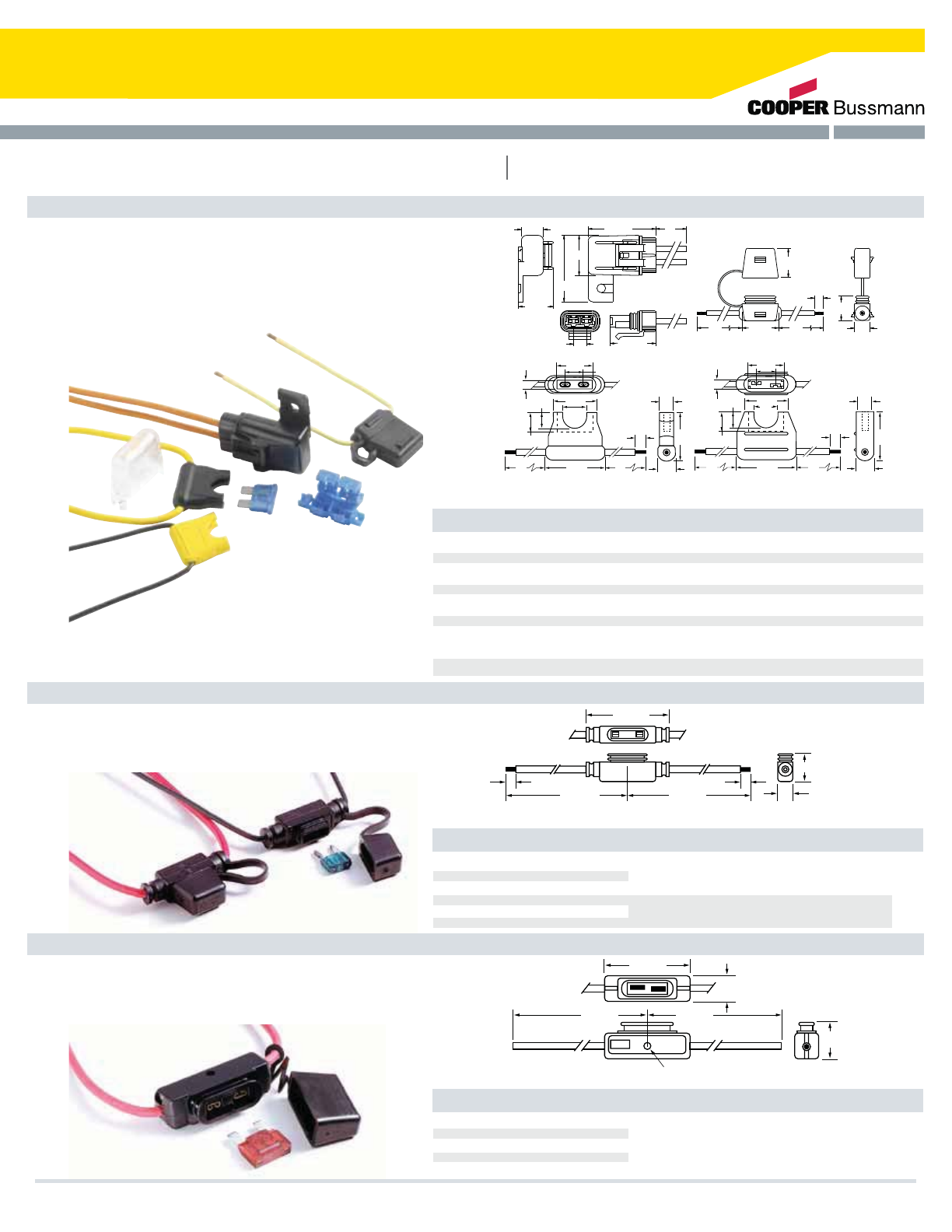
Inline Fuse Holders
Inline Fuse Holders for Blade-Type Fuses
HHC, HHD, HHF, HHG, HHR and HHS (For ATC® Fuse)
HHL and HHM (For ATM Fuse)
HHX (For MAXI® Fuse)
Inline Fuse Holders for ATC® Blade-Type Fuses
Rating: 32V, See table for max. amp.
“Write-in” space for circuit identification on HHC holder.
Plastic cover fits only HHD holder. HHR holder has a
locking cover and mounting hole. HHS is a self-stripping
holder.
In-Line Fuseholders for ATM MINI® Fuses.
Rating: 32V, See table for max. amp.
Body material withstands high temps. Protective cover has
removable straps.
.410"
1"
.290"
.250"
(TYP/ 2)
4"
4" 1.25"
.375"
.343"
.500"
.906"
.157"
.363"
.682"
.343"
1"
.140"
4"
(TYP/ 2)
4"
4" 1.12"
.375"
.296"
.500"
.906"
.140"
.364"
.781"
(Dims. Shown are for reference only. Contact factory for latest prints)
Multiply by 25.4 for metric.
4"
.250"
.430"
1.000" 4"
.670"
(TYP/2)
.810"
0.360" 1.250"
.920"
.606"
1.820"
1.100"
1.850" 5"
HHR
HHF / HHG
HHD HHC
1.56"
4.75" 4.75"
.25"
.25"
.59"
.41"
Multiply by 25.4 for metric.
(Dims. Shown are for reference only.
Contact factory for latest prints)
In-Line Fuseholder for MAXI™ Fuses.
Rating: 32V, 60A Max. Firewall mounting hole
permits two or more holders to be mounted
together. Cover comes with a removable strap.
3.35"
6.70" 6.70"
1.37"
.265" DIA. HOLE
Multiply by 25.4 for metric.
(Dims. Shown are for reference only.
Contact factory for latest prints)
ATC® Blade Type Holder
HHC
HHD
HHD-C
HHF
HHG
HHR
HHS
HHL
HHL-B
HHM
HHM-B
HHM-C
HHX
HHX-B
HHX-C
Fuseholder w/cover
Body only
Cover only
20-60 amps #6 lead wire;
5” length
Fuseholder w/cover
Body only
Fuseholder w/cover
Body only
Cover only
1-20A
1-30A
Fits only HHD
1-20A
1-30A
1-30A
1-20A
# AWG lead black wire
#12 AWG lead yellow wire
Clear polycarbonate
#16 AWG lead yellow wire
#12 AWG lead yellow wire
#12 AWG lead orange wire
5”length
Self-stripping; accepts #18-
#14 AWG copper wire only
Yellow fuseholder (body only)
Black fuseholder (body only)
Cover only
Black fuseholder w/cover
Black fuseholder w/cover
Flack waterproof fuseholder
w/locking cover & mounting hole
Blue Fuse holder
DescriptionCatalog No. Fuse Size Electrical Connection
DescriptionCatalog No. Fuse Size Electrical Connection
DescriptionCatalog No. Fuse Size Electrical Connection
MINI Fuse Blade Type Holder
MAXI® Fuse Blade Type Holder
2-20A #16 AWG lead black wire;
4” length
# 12 AWG lead red wire;
4” length
2-30A
Dimensions - in
Dimensions - in
Dimensions - in
Cooper Bussmann Transportation Products t1IPOFt'BYtXXXDPPQFSCVTTNBOODPN 51
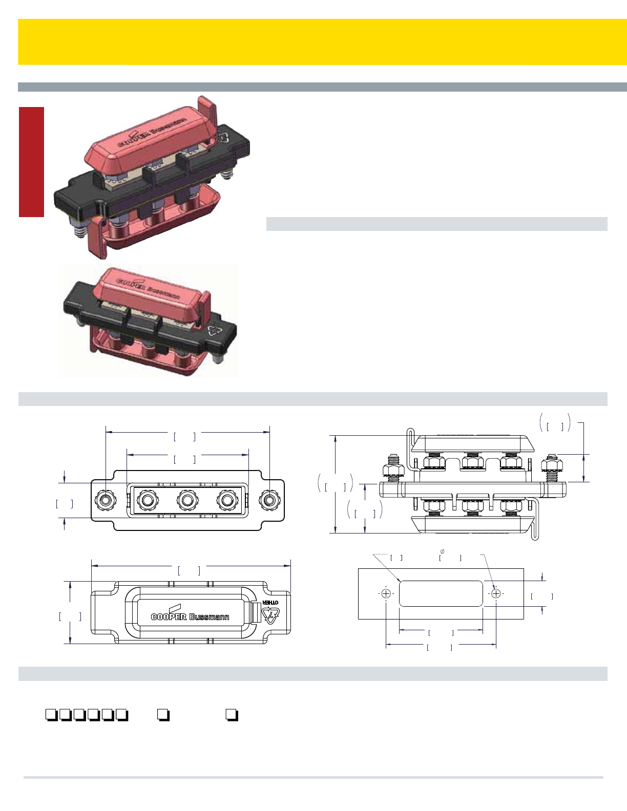
Cooper Bussmann Transportation Products t1IPOFt'BYtXXXDPPQFSCVTTNBOODPN
Specifications
Dimensions - mm(in)
Part Numbering System
Current: ".BY
Temperature Rating: ¡$UP¡$
Torque: .4UVEJOMCT/tNNBY
..PVOUJOHJOMCT/tNNBY
Termination: .OVUT
Material: Housing: #MBDL6-SBUFE7UIFSNPQMBTUJD
Cover: #MBDLPSSFETBOUPQSFOFDPWFSSBUFE7GPSQSPUFDUJPOGSPN
BDDJEFOUBMTIPSUT
Current Carrying Studs: ;JODQMBUFECSBTT
Mounting Studs:4UBJOMFTTTUFFM
Gasket: #MBDLTBOUPQSFOFHBTLFUSBUFE7
RoHS Compliant: :FT
Servicable Parts: Cover:#
Busbar:#
86.50
3.41
64
2.52
18.50
.73
SHOWN WITHOUT COVER
53.30
2.10
26.80
1.06
15.20
.60
102
4.02
32
1.26
86.50
±0.50
3.41
±.02
20
±1
.79
±.04
65.50
±1
2.58
±.04
R
3
(4X)
.12
7
±0.50
(2X)
.28
±.02
PANEL CUT-OUT RECOMMENDATION
Cover Color Option
/P/VU
/VUTJO#VML
33FE$PWFS
##MBDL$PWFS
GB30 00 -
5IF(#991BTTUISV%JTUSJCVUJPO#MPDLBMMPXTPOFHSPVOEPSQPXFSEFWJDFUPNFFU
NVMUJQMFHSPVOEQPXFSSFRVJSFNFOUTJOCPUIUIFDBCBOEFOHJOFDPNQBSUNFOUPGZPVS
WFIJDMF6TJOHIJHIRVBMJUZNBUFSJBMTUIJTDBQBCMFVOJUQSPWJEFTUISFFQBTTUISV.TUVET
GPSFBTZDBCMFBUUBDINFOUJOCPUIMPDBUJPOT*OTUBMMBUJPOJTFBTZBTUIFUXPPVUTJEF.
TUVETBSFTPMFMZEFTJHOFEUPTFDVSFMZBUUBDIUIFVOJUQFSNBOFOUMZ"HBTLFUJTJODMVEFEGPS
JOHSFTTQSPUFDUJPO%FTJHOFEUPNFFUBMMZPVSHSPVOEQPXFSOFFETUIF(#99
QSPWJEFTSPCVTUDPOOFDUJPOTFMJNJOBUFTUIFOFFEUPTUBDLDBCMFTBOESFEVDFTBTTPDJBUFE
XBSSBOUZDMBJNTCBTFEPOBGmMJBUFEQSPCMFNT5IF(#99BMTPQSPWJEFTQPXFS
EJTUSJCVUJPOTVJUBCMFGPSNBOZGFFEUISVBQQMJDBUJPOTJONBSJOFDPOTUSVDUJPOBHSJDVMUVSF
CVTNJMJUBSZ37BOETQFDJBMUZWFIJDMFT
GB3000-XX: Pass-Thru Distribution Block
Junction Blocks
52
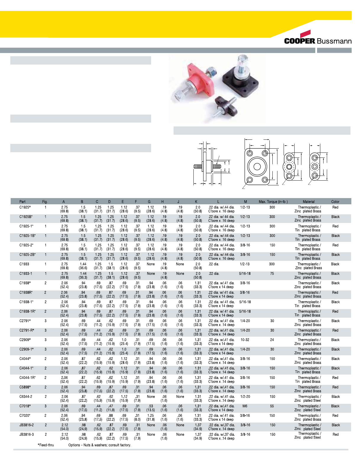
Single Stud Type Junction Blocks
Specifications
Features
Dimensions - mm(in)
Suggested Max. Termination Ratings
Applications: Heavy-duty ground or power connection
points in AC or DC circuits. Feed thru or stand alone mount
options available for transformers, communication and
computer power sections along with various vehicle
electrical systems.
Mounting Torque Rating: 48 in-lbs (5.4Ntm) max.
Modular design offers design and manufacturing
flexibility.
Thread/Stud Size Amperages
#10
#1/4 & M6
#5/16
#3/8
#1/2
50 amps
100 amps
200 amps
250 amps
400 amps
(Dims. shown are for reference only.
Consult factory for latest prints)
F
KA KA KA
JH
GED
CB
M (thread size)
(.75")
19.1
(.75)
19.1
(1.87)
47.6
(1.12)
28.6
L (4 MTG. HOLES)
L(2 MTG. HOLES) L(2 MTG. HOLES)
Fig. 1 Fig. 2 Fig. 3
200
200
100
100
-
-
-
-
-
-
-
-
-
-
-
-
-
-
-
-
-
-
-
-
-
-
-
-
-
s
Cooper Bussmann Transportation Products t1IPOFt'BYtXXXDPPQFSCVTTNBOODPN 53
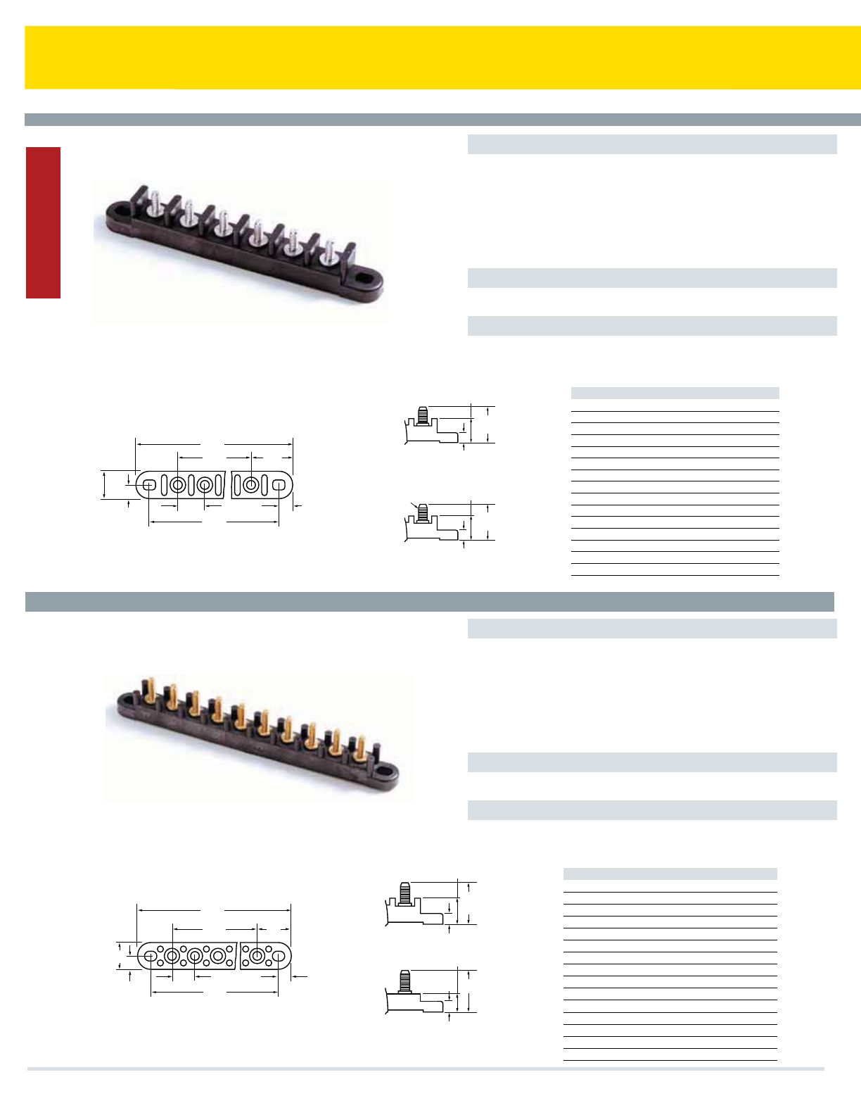
Multiple Stud Type Junction Blocks (Non Feed-Thru)
Specifications
Options
Features
Series C4559 & C6083
Series C5237 & JB1032
Rating: 30A, 600V
Temperature Rating: 250°F (120°C)
Materials: Black thermoplastic with zinc-plated steel studs
Termination: #10-24 Threaded studs on .750" centers. Studs
feature a “dog point” to guide nut onto thread
Torque Rating: 25 in-lbs (2.8Ntm) max
Mounting Torque Rating: 24 in-lbs (2.7Ntm) max
Positions: 2-16 positions available.
Numbers and arrows molded on top of barriers indicate terminals.
Compliances: E248514; UL/CSA; CE Certified
Specifications
Options
Features
Rating: UL: 30A, 300V; CSA: 30A, 600V
Temperature Rating: 250°F (120°C)
Materials: Black thermoplastic with brass studs
Termination: #10-32 Threaded studs on .625" centers. Studs
feature a “dog point” to guide nut onto thread
Torque Rating: 25 in-lbs (2.8Ntm) max
Mounting Torque Rating: 24 in-lbs (2.7Ntm) max
Positions: 1-15 positions available
Numbers and arrows molded on top of barriers indicate terminals.
Compliances: UL/CSA; CE Certified
A
C
B
(.75)
19.05
19.05
(.75")
.375"
(9.53)
9.53
(.375")
28.45
(1.12")
0ther series available with .750" centers:
#10-32 zinc plated
steel studs
7.87
(.31")
(.31")
7.87
21.34
(.84")
21.34
(.84")
27.69
(1.09)
C6083
C4559
26.67
(1.05")
Mtg. holes 9/32"x 3/8" slot
(A,B,C Dimensions are the same as C4559)
Part No. A B C
C4559-2 3.00 (76.2) 2.25 (57.1) 0.75 (19.0)
C4559-3 3.75 (95.2) 3.00 (76.2) 1.50 (38.1)
C4559-4 4.50 (114.3) 3.75 (95.2) 2.25 (57.1)
C4559-5 5.25 (133.3) 4.50 (114.3) 3.00 (76.2)
C4559-6 6.00 (152.4) 5.25 (133.3) 3.75 (95.2)
C4559-7 6.75 (171.4) 6.00 (152.4) 4.50 (114.3)
C4559-8 7.50 (190.5) 6.75 (171.4) 5.25 (133.3)
C4559-9 8.25 (209.5) 7.50 (190.5) 6.00 (152.4)
C4559-10 9.00 (228.6) 8.25 (209.5) 6.75 (171.4)
C4559-11 9.75 (247.6) 9.00 (228.6) 7.50 (190.5)
C4559-12 10.50 (266.7) 9.75 (247.6) 8.25 (209.5)
C4559-13 11.25 (285.7) 10.50 (266.7) 9.00 (288.6)
C4559-14 12.00 (308.4) 11.25 (285.7) 9.75 (247.6)
C4559-15 12.75 (323.8) 12.00 (308.4) 10.50 (266.7)
C4559-16 13.50 (342.9) 12.75 (323.8) 11.25 (285.7)
Dimensions - mm(in) (Dims. shown are for reference only.
Consult factory for latest prints)
A
C
B
.75"
.375"
.375"
.625"
1.0"
.31"
.81"
1.16"
.31"
.5"
1.16"
Mtg. holes 9/32"X3/8" slot
JB1032-120-XX
(No bosses between studs)
C5237
(A,B,C Dimensions ars the same as C5237)
Part No. A B C
C5237-1 2.00 (50.8) 1.25 (31.7) –
C5237-2 2.62 (66.7) 1.87 (47.5) .625 (15.9)
C5237-3 3.25 (82.5) 2.50 (63.4) 1.25 (31.7)
C5237-4 3.87 (98.4) 3.12 (79.4) 1.87 (47.5)
C5237-5 4.50 (114.3) 3.75 (95.2) 2.50 (63.4)
C5237-6 5.12 (130.8) 4.37 (111.1) 3.12 (79.4)
C5237-7 5.75 (146.0) 5.00 (127.0) 3.75 (95.2)
C5237-8 6.37 (161.9) 5.62 (142.9) 4.37 (111.1)
C5237-9 7.00 (177.8) 6.25 (158.7) 5.00 (127.0)
C5237-10 7.62 (193.7) 6.87 (174.6) 5.62 (142.9)
C5237-11 8.25 (209.5) 7.50 (190.5) 6.25 (158.7)
C5237-12 8.87 (225.4) 8.12 (206.4) 6.87 (174.6)
C5237-13 9.50 (241.3) 8.75 (222.2) 7.50 (190.5)
C5237-14 10.12 (257.2) 9.37 (238.1) 8.12 (206.4)
C5237-15 10.75 (273.0) 10.00 (254.0) 8.75 (222.2)
Dimensions - in (Dims. shown are for reference only.
Consult factory for latest prints)
Cooper Bussmann Transportation Products t1IPOFt'BYtXXXDPPQFSCVTTNBOODPN
Junction Blocks
54

Power Distribution Notes
Cooper Bussmann Transportation Products t1IPOFt'BYtXXXDPPQFSCVTTNBOODPN 55

Basic Overcurrent Technology
Options
Selecting Overcurrent Protection
Overcurrent Protection Devices
Overcurrent devices may serve several purposes in electrical circuits:
t5PQSPUFDUDPNQPOFOUTFRVJQNFOUBOEBTTPDJBUFEXJSJOHGSPNUIFFGGFDUTPG
FMFDUSJDDJSDVJUPWFSMPBETBOEPSTIPSUDJSDVJUT
t5PJTPMBUFCSBODIDJSDVJUTGSPNUIFNBJOQPXFSTVQQMZPODFBOPWFSMPBEPS
TIPSUDJSDVJUIBTPDDVSSFE
'VTFTBOEDJSDVJUCSFBLFSTBSFDPNNPOMZTFMFDUFEBTUIFQSFGFSSFE
PWFSDVSSFOUEFWJDF
"OPWFSDVSSFOUEFWJDFJTDPOTUSVDUFEUPSFBDUJOBQSFTDSJCFEGBTIJPOUPWBSZJOH
MFWFMTPGFMFDUSJDBMDVSSFOUXIFSFBUQSFEFUFSNJOFEMFWFMTUIFEFWJDFQSPWJEFT
JOUFSSVQUJPOPGUIFDVSSFOUnPXUISPVHIJU"OZDVSSFOUUIBUFYDFFETUIFBNQFSF
SBUJOHPGUIFGVTFPSDJSDVJUCSFBLFSJTBOPWFSDVSSFOU0WFSDVSSFOUTBSFHFOFSBMMZ
DMBTTJmFEBTFJUIFSTIPSUDJSDVJUTPSPWFSMPBETBOEBSFEFmOFEBTGPMMPXT
Short-circuit BDVSSFOUUIBUHSFBUMZFYDFFETUIFSBUJOHPGUIFEFWJDF*UJT
DBVTFEXIFOBNBMGVODUJPOPSBDDJEFOUDSFBUFTBCSFBLJOUIFOPSNBMQBUI
BMMPXJOHFMFDUSJDJUZUPnPXEJSFDUMZUPHSPVOEPSBOPUIFSQIBTF5IJTTIPSUFS
DVSSFOUQBUICZQBTTFTUIFSFTJTUBODFPGGFSFECZUIFDJSDVJUDPNQPOFOUTBOE
UIFMPBEDPOOFDUFEJOUIFOPSNBMDVSSFOUQBUI*OUIJTTJUVBUJPOUIFSFJTMJUUMF
SFTJTUBODFUPJNQFEFUIFDVSSFOUBOEUIFDVSSFOUXJMMCVJMEUPBMFWFMXIFSFUIF
IFBUHFOFSBUFEDBODBVTFJOTVMBUJPOEBNBHFBOEPSFRVJQNFOUCSFBLEPXO
Overload BOPWFSDVSSFOUUIBUJTXJUIJOUIFOPSNBMDVSSFOUQBUI0WFSMPBET
PDDVSXIFOUIFDVSSFOUFYDFFETUIFWBMVFGPSXIJDIUIFFRVJQNFOUPS
BTTPDJBUFEXJSJOHJTSBUFE5IJTUZQJDBMMZPDDVSTXIFOUPPNBOZEFWJDFTBSF
DPOOFDUFEUPUIFDJSDVJUPSXIFOBEFWJDFDPOOFDUFEUPUIFDJSDVJU
NBMGVODUJPOT0WFSMPBETBSFBMTPDBVTFECZIBSNMFTTUFNQPSBSZTVSHF
DVSSFOUTTVDIBTXIFONPUPSTBSFTUBSUFE5IFTFPWFSMPBEDVSSFOUTBSF
OPSNBMVTVBMMZCSJFGJOEVSBUJPOBOEIBWFOPIBSNGVMFGGFDUPOUIFDJSDVJU
DPNQPOFOUT*UJTJNQPSUBOUUIBUQSPUFDUJWFEFWJDFTEPOPUSFBDUUPTVDI
PWFSMPBET4VTUBJOFEPWFSMPBETIPXFWFSNBZTMPXMZDBVTFPWFSIFBUJOHPGUIF
XJSJOHBOEUIFDPNQPOFOUT1SPWJEFEUIFPWFSMPBEJTPGTVGmDJFOUNBHOJUVEF
BOEEVSBUJPOUPBDUJWBUFUIFEFWJDFUIFDJSDVJUQSPUFDUJPOEFWJDFTIBMMPQFO
CFGPSFUIFPWFSMPBEJOEVDFTTZTUFNDPNQPOFOUGBJMVSFT
%VSJOHOPSNBMDPOEJUJPOTBOPWFSDVSSFOUQSPUFDUJPOEFWJDFNVTUDBSSZUIF
DVSSFOUXJUIPVUOVJTBODFPQFOJOHT)PXFWFSXIFOBOPWFSMPBEPSTIPSUDJSDVJU
PDDVSTUIFEFWJDFJOUFSSVQUTUIFPWFSDVSSFOUBOEXJUITUBOETUIFWPMUBHFBDSPTT
UIFEFWJDF5PQSPQFSMZTFMFDUBOPWFSDVSSFOUEFWJDFUIFGPMMPXJOHJUFNTNVTU
CFDBSFGVMMZDPOTJEFSFE
tVoltage Rating SFQSFTFOUTUIFNBYJNVNTZTUFNWPMUBHFQSFTFOUJOUIF
DJSDVJUJOXIJDIUIFPWFSDVSSFOUEFWJDFJTJOTUBMMFE5IFTZTUFNWPMUBHFTIPVME
OPUFYDFFEUIJTWBMVFGPSQSPQFSPQFSBUJPOPGUIFEFWJDFEVSJOHBOPWFSDVSSFOU
FWFOU
tCurrent Rating UIFBNQFSBHFWBMVFNBSLFEPOUIFDJSDVJUQSPUFDUJPO
EFWJDF5IFDJSDVJUQSPUFDUJPOEFWJDFJTEFTJHOFEUPIBOEMFUIJTWBMVFVOEFS
TUFBEZPQFSBUJOHDPOEJUJPOTBOEBUSPPNBNCJFOUUFNQFSBUVSFT4JODFmFME
BQQMJDBUJPOTPGUFOEFMJWFSMPBEJOHDPOEJUJPOTBOEBNCJFOUUFNQFSBUVSFTUIBU
WBSZGSPNJEFBMOPNJOBMTFUUJOHTJUJTSFDPNNFOEFEUIBUDJSDVJUEFTJHOFST
TFMFDUEFWJDFSBUJOHTBCPWFUIFOPNJOBMDJSDVJUDVSSFOUDPOUJOVPVTMPBEUP
QSFWFOUOVJTBODFUSJQT"EEJUJPOBMMZUIFDPOUJOVPVTDVSSFOUnPXJOHUISPVHIUIF
PWFSDVSSFOUQSPUFDUJWFEFWJDFTIPVMEOPUCFNPSFUIBOPGUIFDVSSFOU
SBUJOH
tCharacteristics of Equipment to be Protected EVSJOHUIFPQFSBUJPOPG
QSPUFDUFEFRVJQNFOUTZTUFNDVSSFOUDBOTJHOJmDBOUMZWBSZ5IJTJTQBSUJDVMBSMZ
FWJEFOUXIFONPUPSPSPUIFSJOEVDUJWFMPBETJOUIFDJSDVJUDBVTFMBSHFDVSSFOU
TVSHFTEVSJOHTUBSUVQ$JSDVJUQSPUFDUJPOEFTJHOFSTTIPVMECFBXBSFPGUIFTF
TVSHFTBOEPSJOSVTIDIBSBDUFSJTUJDTBOETFMFDUUIFPWFSDVSSFOUQSPUFDUJPO
EFWJDFTBDDPSEJOHMZ
tAvailable Short-Circuit Current EVSJOHBGBVMUPSTIPSUDJSDVJUDPOEJUJPO
UIFGVTFPSDJSDVJUCSFBLFSNBZTFFBMBSHFBNPVOUPGDVSSFOU-BSHF%$CBUUFSZ
TVQQMJFTBOEIJHIDVSSFOUSBUFEFMFDUSJDEJTUSJCVUJPOCVTFTPGUFOIBWFUIJT
QPUFOUJBMGPSTFWFSFTIPSUDJSDVJUT*OUIFTFTJUVBUJPOTUIFDJSDVJUQSPUFDUJPO
EFWJDFTIPVMEIBWFBOJOUFSSVQUJOHSBUJOHUIBUJTFRVBMUPPSMFTTUIBOUIFTIPSU
DJSDVJUDVSSFOUUIBUDBOCFEFMJWFSFE
tAmbient Temperature UIFUJNFJUUBLFTUPJOUFSSVQUUIFDVSSFOUJT
EFQFOEFOUVQPOUIFBNCJFOUDVSSFOUUFNQFSBUVSFDIBSBDUFSJTUJDT"NCJFOU
UFNQFSBUVSFSFGFSTUPUIFUFNQFSBUVSFPGUIFBJSJNNFEJBUFMZTVSSPVOEJOHUIF
DJSDVJUQSPUFDUJPOEFWJDF5IFBNCJFOUUFNQFSBUVSFBSPVOEUIFGVTFPSDJSDVJU
CSFBLFSDBOCFBQQSFDJBCMZEJGGFSFOUUIBOUIFPVUTJEFSPPNPSMBSHFSFODMPTVSF
DPOUBJOJOHUIFEFWJDF5IJTDBOPDDVSXIFOUIFEFWJDFJTDPOUBJOFEJOBUJHIU
BSFBPSJUJTNPVOUFEJOPSOFBSBIFBUQSPEVDJOHDPNQPOFOUTVDIBTB
USBOTGPSNFSPSSFTJTUPS8IFOTFMFDUJOHBGVTFPSDJSDVJUCSFBLFSBUBNCJFOU
UFNQFSBUVSFTTJHOJmDBOUMZEJGGFSFOUGSPNUIFTUBUFEOPNJOBMUFNQFSBUVSFUIF
DJSDVJUEFTJHOFSTIPVMEBEKVTUUIFTFMFDUFEPWFSDVSSFOUQSPUFDUJPOSBUJOHCBTFE
POUIFQVCMJTIFEUFNQFSBUVSFSFSBUJOHDVSWFT
5XPDBUFHPSJFTPGPWFSDVSSFOUEFWJDFTBSFBWBJMBCMF
Fuses
5IFLFZDPNQPOFOUPGBGVTFJTUIFiFMFNFOUBTIPSUQJFDFPGNFUBMMJDXJSFPS
MJOLNBEFPGBNBUFSJBMXJUIBSFMBUJWFMZMPXBOEQSFEJDUBCMFNFMUJOHQPJOU
'VTFTBSFDVSSFOUTFOTJUJWFEFWJDFTBOEUIFSFTJTUBODFJTTPMPXUIBUUIFZ
TJNQMZBDUBTBDPOEVDUPS$JSDVJUQSPUFDUJPOJTQSPWJEFEXIFOUIFGVTF
FMFNFOUNFMUTBOEJOUFSSVQUTBOPWFSDVSSFOU5IFLFZDSJUFSJBVTFEUPKVEHFUIF
QFSGPSNBODFPGBGVTFJTUIFUJNFWFSTVTDVSSFOUDIBSBDUFSJTUJDDVSWF5IJT
DVSWFDBOCFVTFEUPNBUDIUIFGVTFXJUIUIFMPBE'VTFTNBZCFQSFGFSSFE
XIFOGBTUSFTQPOTFUPBTIPSUDJSDVJUDPOEJUJPOJTSFRVJSFEPSXIFOIJHI
BWBJMBCMFTIPSUDJSDVJUDVSSFOUTPDDVS'VTFDIBSBDUFSJTUJDDVSWFTDBOCFVTFE
UPDBSFGVMMZTJ[FUIFEFWJDFUPBDSJUJDBMPSTQFDJBMBQQMJDBUJPO
Cooper Bussmann Transportation Products t1IPOFt'BYtXXXDPPQFSCVTTNBOODPN
56

Basic Overcurrent Technology
Circuit Breaker Operational Characteristics
Circuit Breaker Application Notes
'PVSEJGGFSFOUNFUIPETGPSSFTFUBSFHFOFSBMMZBWBJMBCMF
Type I (automatic reset):UIFDJSDVJUCSFBLFSUSJQTBOESFTFUTJOSFTQPOTFUP
UIFPWFSDVSSFOUDPOEJUJPOJOBSFQFUJUJWFGBTIJPO5IJTWFSTJPOTIPVMECFVTFEJO
BQQMJDBUJPOTUIBUQSPWJEFGPSPUIFSTFMGMJNJUJOHPSOPOSFTFUUBCMFNFBOTTVDI
BTBGUFSBNBJOGVTFNBJONBOVBMSFTFUDJSDVJUCSFBLFSPSNPNFOUBSZTXJUDI
5IFTFEFWJDFTXIJMFBVUPNBUJDJOSFTFUGVODUJPOBSFOPUEFTJHOFEGPS
MPOHUFSNDZDMJOHDPOEJUJPOTJOBQQMJDBUJPOTXIFSFPQFSBUPSBXBSFOFTTPG
DJSDVJUGBVMUPSTFSWJDFBCJMJUZBDDFTTJTMJNJUFEMFBEJOHUPVOTBUJTGBDUPSZGBJMVSF
FWFOUT3FGFSUP4"&+PS+GPSBEEJUJPOBMEFUBJMT
Type II (modified reset):UIFDJSDVJUCSFBLFSDPOUBJOTBOBEEJUJPOBMSFTJTUJWF
DPNQPOFOUUIBUFOBCMFTUIFEFWJDFUPIBWFPOMZCSJFGUSJQBOESFTFUBDUJWJUZBOE
UIFOBGUFSXBSETNBJOUBJOTBOPQFODJSDVJUDPOEJUJPOFYDFQUGPSBMPXNJMMJBNQ
ESBXUISPVHIUIFSFTJTUPS3FRVJSFTNJOJNVNWPMUBHFDVSSFOUUPNBJOUBJOPQFO
DJSDVJUTFFTUBOEBSETGPSEFUBJMT4"&+
Type III (manual reset):UIFDJSDVJUCSFBLFSXJMMUSJQJOSFTQPOTFUPBO
PWFSDVSSFOUDPOEJUJPOBGUFSXIJDIBSFTFUCVUUPOPSMFWFSFYUFOETFYUFSOBMMZUP
JOEJDBUFUIBUUIFCSFBLFSIBTUSJQQFEBOEJTJOBOPODPOEVDUJOHTUBUF5IF
USJQJOEJDBUPSCVUUPOPSMFWFSNVTUCFNBOVBMMZBDUJWBUFEUPSFUVSOUIFEFWJDFUP
OPSNBMPQFSBUJPO
Type III (switchable): TBNFBTUIFNBOVBM5ZQF***NBOVBMSFTFUXJUIUIF
BEEJUJPOBMGFBUVSFPGBMMPXJOHUIFVTFSUPPQFOUIFDJSDVJUVTJOHBOFYUFSOBMMZ
BDDFTTJCMFUSJQNFDIBOJTN
Circuit Breaker Performance$PPQFS#VTTNBOOUIFSNBMDJSDVJUCSFBLFST
BSFEFTJHOFEUPDPOGPSNUPSFMFWBOUJOEVTUSZTUBOEBSETSFGFSUPJOEJWJEVBM
NPEFMTGPSTUBOEBSESFGFSFODFT5IFSFBSFTQFDJmDQFSGPSNBODFBTQFDUTUIBU
NBZOPUBMXBZTNBLFDJSDVJUCSFBLFSTTVJUBCMFGPSDFSUBJOBQQMJDBUJPOT
FTQFDJBMMZJODJSDVJUTUIBUBSFJODBQBCMFPGQSPWJEJOHFOPVHIDVSSFOUUPPQFSBUF
UIFDJSDVJUCSFBLFSJOBUJNFMZNBOOFSSFMBUJWFUPUIFBTTPDJBUFEDPNQPOFOUT
BOEXJSJOH*UJTPGVUNPTUJNQPSUBODFUIBUUIFDJSDVJUEFTJHOFSJOWFTUJHBUFT
DPNQPOFOUTUIBUIBWFmOJUFPWFSMPBEDBQBCJMJUJFTXIJDIBSFCFMPXUIF
UJNFDVSSFOUMFWFMTUPJOJUJBUFUJNFMZDJSDVJUCSFBLFSBDUJWBUJPO
Evaluation%FTJHOJOTJUVBUJPOTSFRVJSFUIBUUIFVTFSDPOTJEFSTBMMBQQMJDBUJPO
DPOEJUJPOTBOEDPOEVDUTPQFSBUJPOBMUFTUJOHUPFTUBCMJTIUIFDPSSFDUOFTTPG
BNQFSFWPMUBHFSBUJOHBTXFMMBTPWFSMPBEQSPUFDUJPOTVJUBCJMJUZ'VSUIFSSFWJFX
PGJOEVTUSZTUBOEBSETJTBEWJTFEUPVOEFSTUBOEBMMQFSGPSNBODFBTQFDUTUIBU
BGGFDUVTBHF
Wiring Considerations"EEJUJPOBMFWBMVBUJPOPGDJSDVJUDPOEJUJPOTJTFTTFOUJBM
UPBDIJFWFQSPQFSNBUDIJOHPGXJSFTJ[FTUPUIFDVSSFOUMPBEDPOEJUJPOT
BOUJDJQBUFEVOEFSOPSNBMPQFSBUJOHDPOEJUJPOTBOEFTUJNBUFEBCOPSNBM
PQFSBUJOHDPOEJUJPOTXIFOPWFSMPBETDPVMEPDDVS5IFSNBMDJSDVJUCSFBLFSTBOE
GVTFTJOUSPEVDFTPNFMFWFMPGSFTJTUBODFUPUIFDVSSFOUQBUIXIFSFJOTUBMMFE
5IFTFGBDUPSTTIPVMEBMTPCFDPOTJEFSFEXIFODIPPTJOHXJSFCPUIJOHBVHF
BTXFMMBTJOUFNQFSBUVSFSBUJOHPGJOTVMBUJPO
Installation Environment 5IFSNBMDJSDVJUCSFBLFSTBSFQSPEVDFEJOWBSJPVT
DPOmHVSBUJPOT*OTUBMMBUJPOFOWJSPONFOUBMDPOEJUJPOTOFFEUPCFDPOTJEFSFE
BOEDPNQBSFEUPUIFDBQBCJMJUZPGUIFQBSUJDVMBSQSPEVDUPGDIPJDF/PUBMM
DJSDVJUCSFBLFSEFTJHOTBSFTVJUBCMFGPSIBSTIDPOEJUJPOTTVDIBTNBZCF
FODPVOUFSFEVOEFSIPPEPSFYUFSOBMDBWJUJFT
Thermal Circuit Breakers
5IFCBTJDDPNQPOFOUTPGBUIFSNBMDJSDVJUCSFBLFSBSFUIFUIFSNBMBMMPZ
FMFNFOUFMFDUSJDBMDPOUBDUTBOEUIFUFSNJOBMTGPSFYUFSOBMDPOOFDUJPOT8IFO
BOPWFSMPBEPDDVSTIFBUJTHFOFSBUFEBTUIFDVSSFOUnPXTUISPVHIUIFUIFSNBM
BMMPZFMFNFOUDBVTJOHJUUPEFnFDUBOETFQBSBUFUIFFMFDUSJDBMDPOUBDUT
JOUFSSVQUJOHDVSSFOUnPX"OJNQPSUBOUQBSBNFUFSVTFEUPKVEHFUIF
QFSGPSNBODFPGBUIFSNBMDJSDVJUCSFBLFSJTUIFUJNFWFSTVTDVSSFOU
DIBSBDUFSJTUJDDVSWFXIJDIJTTJNJMBSUPUIBUPGBGVTF"UIFSNBMDJSDVJUCSFBLFS
JTHFOFSBMMZOPUBPOFFWFOUUZQFEFWJDFBTJTBGVTF5IFSFTFUUBCMFGFBUVSFTPG
DJSDVJUCSFBLFSTBSFPGUFOGPVOEBUUSBDUJWFGPSVTFJOFMFDUSJDBMDJSDVJUTXIFSF
OPOSFTFUUJOHJOUFSSVQUJPOPGDVSSFOUnPXJTVOEFTJSBCMFIt is important to note
that cycle life of a thermal circuit breaker is impacted both by the
operational characteristic of the circuit breaker as well as the relative
magnitude and duration of overcurrents or short circuits that the device
experiences. 5IFSFBSFEJGGFSFOUPQFSBUJPOBMDIBSBDUFSJTUJDTPGCooper
Bussmann UIFSNBMDJSDVJUCSFBLFSTXIJDIBSFEFTDSJCFECFMPX
Cooper Bussmann Transportation Products t1IPOFt'BYtXXXDPPQFSCVTTNBOODPN 57
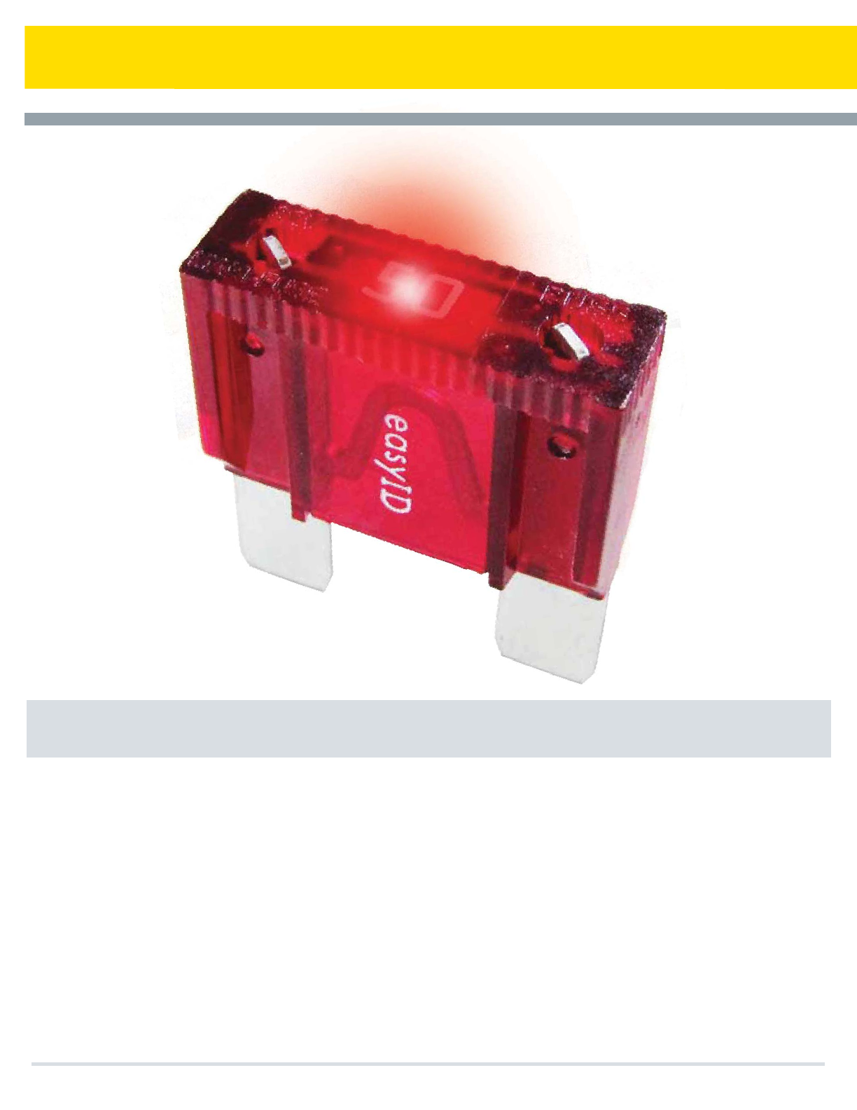
Now, a drop-in replacement is available for low-voltage applications up
to 100 amps that can benefit from open fuse indication. The Cooper
Bussmann line of easyID™ illuminating blade fuses and holders use Light
Emitting Diode (LED) technology to show that a fuse has opened, making
them easy to spot in fuse panels tucked up under darkdashboards.
Popular Sizes and Ratings
The ATM (3-30A), ATC® (3-40A) and Maxi® (20-100A) cover the most
common replacement fuse needs.
Inline Fuse Holders
Illuminating fuse holders with easyID™ use regular ATM and ATC blade
fuses and feature a red LED that glows when the fuse opens.
Universal Color Coding
The ATM, ATC® and MAXI® fuses all use the same universal color-coding
as traditional non-illuminating fuses, making it easier to match up an
indicating replacement for an open fuse.
Value Packs, Assortment and Service Kits
Provide popular packaging options to maximize retail sales. See next
page for details.
Finding Open Blade Fuses Is Now as easyID™
With the New Family of Cooper Bussmann® easyID™ Illuminating Blade Fuses and Fuse Holders
Cooper Bussmann Transportation Products t1IPOFt'BYtXXXDPPQFSCVTTNBOODPN
easyID™ Illuminating Blade Fuses & Fuse Holders
58
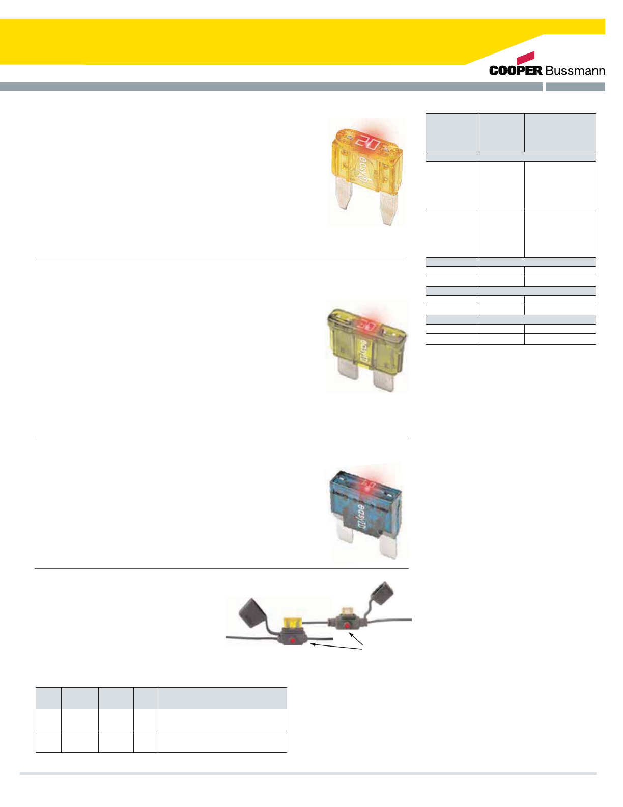
easyID™ ATM Illuminating Blade Fuses
Following on the popularity and wide application of ATM fuses for late-model
OEM vehicles, the easy ID illuminating ATM fuse line is available in popular ATM
amp ratings with packaging that’s designed for easy retail selling.
ATM-ID-SK Service Kit
Contains six each of 5, 10, 15, 20, 25 and 30 amp easy ID illuminating ATM
fuses. Ideal for fleet maintenance departments.
easyID™ ATC Illuminating Blade Fuses
Introduced in the late '70s, ATC blade fuses are widely used by automotive
OEMs. With a large installed base, the Cooper Bussmann® ATC easy ID
illuminating fuse line has great selling potential with popular ATC amp ratings in
packaging that’s designed for easy retail selling.
ATC-ID-SK Service Kit
Contains seven each of 5, 10, 15, 20, 25 and 30 amp easy ID illuminating
ATC fuses. Ideal for fleet maintenance departments.
easyID™ Maxi® (MAX) Illuminating Blade Fuses
Used for protecting circuits in wiring harnesses (usually found under the hood,
in a fuse panel or supplementary panel near the battery) Maxi Fuses are finding
increased popularity in domestic cars and some import models. Current OEM
applications range up to 60 amps, but some aftermarket accessories (such as
high-end stereos) require protection up to 80 amps. The Cooper Bussmann®
easy ID Maxi illuminating fuse line is a sure seller for the high amp circuit
protection market.
easyID™ Illuminating Holders for Blade Fuses
Now customers have a way to get open fuse
indication when adding circuits with easy ID
illuminating inline fuse holders for ATM and ATC
blade fuses. Attractive blister backs increase
impulse sales.
Ten Fuse Value Packs
Service Kits (see text for contents)
Fuse Assortments (five fuses - see text for contents)
In-Line Fuse Holders
Crossreference Guide
Cooper
Bussmann
Catalog
Number
Smart Glow
Catalog
Number
Smart Glow
Part
Number
VP-ATM-10ID
VP-ATM-15ID
VP-ATM-20ID
VP-ATM-25ID
VP-ATM-30ID
VP-ATC-10ID
VP-ATC-15ID
VP-ATC-20ID
VP-ATC-25ID
VP-ATC-30ID
09-1000
09-2000
09-3000
09-4000
09-5000
08-1000
08-2000
08-3000
08-4000
08-5000
0MIN010.TPGLO
0MIN015.TPGLO
0MIN020.TPGLO
0MIN025.TPGLO
0MIN030.TPGLO
0ATO010.TPGLO
0ATO015.TPGLO
0ATO020.TPGLO
0ATO025.TPGLO
0ATO030.TPGLO
ATM-ID-SK
ATC-ID-SK
15-0000
14-0000
00940462ZGLO
00940400ZGLO
BP-ATM-AID
BP-ATC-AID
11-1008
10-1008
00940362ZPGLO
00940202ZPGLO
BP-ATC-FHID
BP-ATM-FHID
20-1010
20-1020
0FHA0001XPGLO
0FHM0001XPGLO
LED Indicator
ATM
ATC
Fuse
Type
ATM
ATC
Part No.
ATM-FHID
ATC-FHID
32V/20A
32V/20A
Inline fuse holder with protective cap and
open fuse illuminating LED
Inline fuse holder with protective cap and
open fuse illuminating LED
Max Volts
/ Amps
Lead-
wire Description
Cooper Bussmann Transportation Products t1IPOFt'BYtXXXDPPQFSCVTTNBOODPN
#16
2x4”
#16
2x4”
easyID™ Illuminating Blade Fuses & Fuse Holders
59
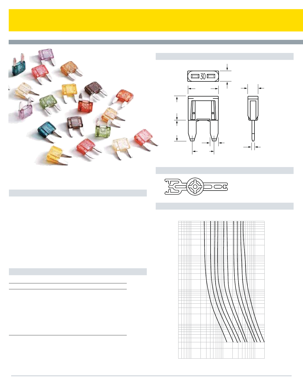
MINI Blade Fuses
Dimensions - mm(in)
Specifications
Color Coding and Amp Ratings
ATM Mini - Fuse
Fast-Acting
Current Rating: 2-30A
Voltage Rating: 32Vdc
Interrupt Rating: 1000A @ 32Vdc
Housing Material: UL-Rated 94V0 thermoplastic
Terminal Material: Silver-plated zinc alloy
Marking: Amperage marking is OCR compliant
Compliances: UL-Listed; SAE J2077; ISO 8820-3; SAE
31171 (Ignition protected)
Consult factory for higher voltage fuses.
Part No. Amp Rating Color
BK-ATM-2 2 Gray
BK-ATM-3 3 Violet
BK-ATM-4 4 Pink
BK-ATM-5 5 Tan
BK-ATM-7.5 7.5 Brown
BK-ATM-10 10 Red
BK-ATM-15 15 Lt. Blue
BK-ATM-20 20 Yellow
BK-ATM-25 25 Natural
BK-ATM-30 30 Green
(Dims. Shown are for reference only. Contact factory for latest prints)
Mini Fuse Puller - Part Number 32002
Time Current Curves
10.92
(.430)
3.81
(.15)
8.13
(.320)
REF.
7.49
(.295)
8.76
(.345)
2.79
(.110) .82
(.0325)
.150"
(3.81)
32V
.4
1
10
100
200
Current In Amps
100
10
.1
1
.01
Time In Seconds
Amp
Rating
2A
3A
4A
5A
7.5A
10A
15A
20A
25A
30A
MINI FUSE
MINI CB
See page 67 for
more information.
Cooper Bussmann Transportation Products t1IPOFt'BYtXXXDPPQFSCVTTNBOODPN
60
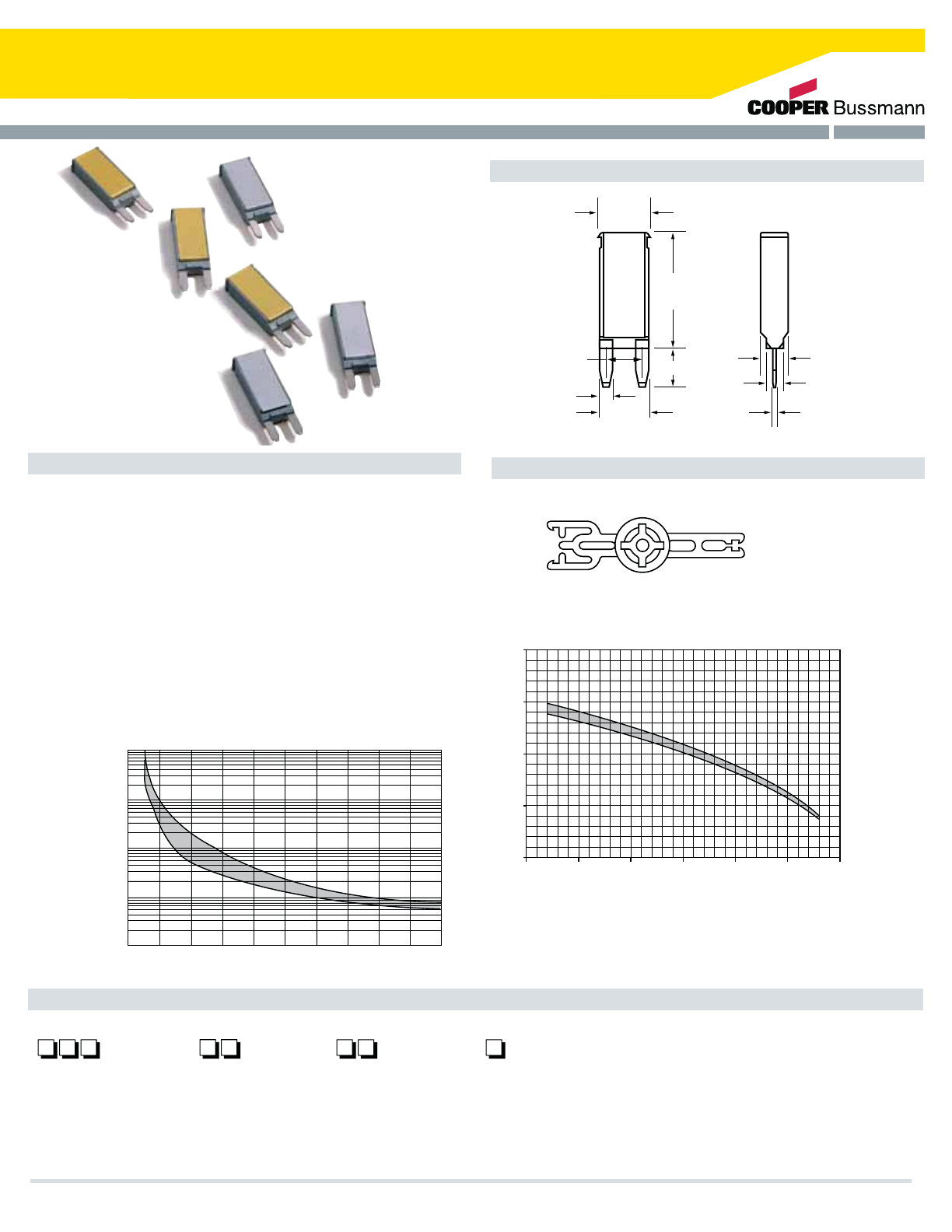
Series 21X Mini Circuit Breakers
Specifications
Part Numbering System
Mini Fuse Puller - Part Number 32002
Series 21X
Mini Circuit Breakers
Auto and Modified Reset
Single Pole Thermal Type Breakers
Rating: 5-30A; 14Vdc (28V for Type III)
Interrupt Rating: 150A @ 14Vdc (5-10A versions); 225A
@ 14Vdc (15A version); 300A @ 14Vdc (20A version);
450A @ 14Vdc (25-30A versions)
Operating Temperature Rating: –40°F (–40°C) to
185°F (85°C)
Storage Temperature Rating: –40°F (–40°C) to 260°F (125°C)
Materials: Grey UL-Rated 94V0 thermoplastic housing
with metal cover: gold (Type I) or silver (Type II)
Marking: Standard marking includes amp/voltage ratings,
part number, and date code. OCR marking is available.
Termination: Compatible with 280 Type fuse blocks using
0.32in. (8.1mm) centerline spacing
Compliances: SAE J553 Type I, Type II and Type III Circuit Breakers
Dimensions - mm(in) (Dims. Shown are for reference only. Contact factory for latest prints)
1000
100
10
1
0.1
100% 200% 300% 400% 500% 600%
TRIP TIME VS. PERCENT OF RATED CURRENT
% of Rated Current
Time in Seconds
-50
0
50
100
150
200
-25 0 25 50 75 100
TEMPERATURE DERATING CURVES
AMBIENT TEMPERATURE IN DEGREES C
Maximum % Hold Current
(.490)
12.45
(1.06)
26.92
8.99(.354)
(.435)
11.05
(.110)
2.79
(.32)
8.13
.81(.032)
3.81(.150)
6.35(.250)
MINI FUSE
MINI CB
See page 67 for
more information.
Series
21
211 – Type I, 14VDC
212 – Type II, 14VDC
213 - Type III, 14VDC
Rating
–
05 – 5 amps
75 – 7.5 amps
10 – 10 amps
15 – 15 amps
20 – 20 amps
25 – 25 amps
30 – 30 amps
Marking
00 – Std. Marking
(Consult Factory for
Special Marking
Options)
Special Options
(Consult Factory for
Special Options)
Cooper Bussmann Transportation Products t1IPOFt'BYtXXXDPPQFSCVTTNBOODPN 61
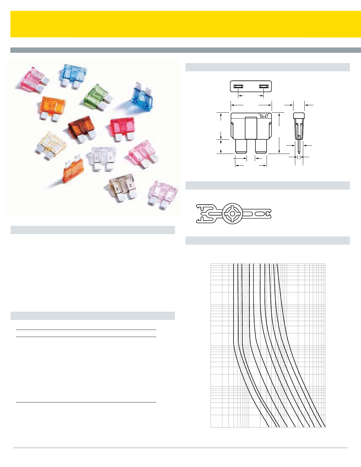
Part No. Amp Rating Color
BK-ATC-1 1 Black
BK-ATC-2 2 Gray
BK-ATC-3 3 Violet
BK-ATC-4 4 Pink
BK-ATC-5 5 Tan
BK-ATC-7.5 7.5 Brown
BK-ATC-10
BK-ATC-15
BK-ATC-20
BK-ATC-25
BK-ATC-30
BK-ATC-40
Red10
Lt. Blue15
Yellow20
Clear25
Green30
Amber40
ATC® Blade Fuses
Dimensions - mm(in)
Specifications
Color Coding and Amp Ratings
Current Rating: 1-40A
Voltage Rating: 32Vdc
Interrupt Rating: 1000A @ 32Vdc
Housing Material: UL-Rated 94V0 thermoplastic
Terminal Material: Tin-plated zinc alloy
Marking: Amperage marking is OCR compliant.
Compliances: UL-Recognized (3-40A); SAE J1284; ISO
8820-3; SAE J1171 (Ignition Protection)
Consult factory for higher voltage fuses.
(Dims. Shown are for reference only. Contact factory for latest prints)
Mini Fuse Puller - Part Number 32002
Time Current Curves
MINI FUSE
MINI CB
See page 67 for
more information.
BUSS
ATC
20
(.15)
3.80
(.03)
.69
(.46)
11.7
(.76)
19.30
(.49)
12.54
6.67(.26)
(.16)
4.13
(.57)
14.61
(.75)
19.05
(.21)
5.25
1
10
100
1000
Current In Amps
100
10
1
.1
.01
Time In Seconds
10
15
20
25
30
Amp
Rating
7.5
5
4
3
40
ATC® Blade - Type Fuse
Fast-Acting
Cooper Bussmann Transportation Products t1IPOFt'BYtXXXDPPQFSCVTTNBOODPN
62
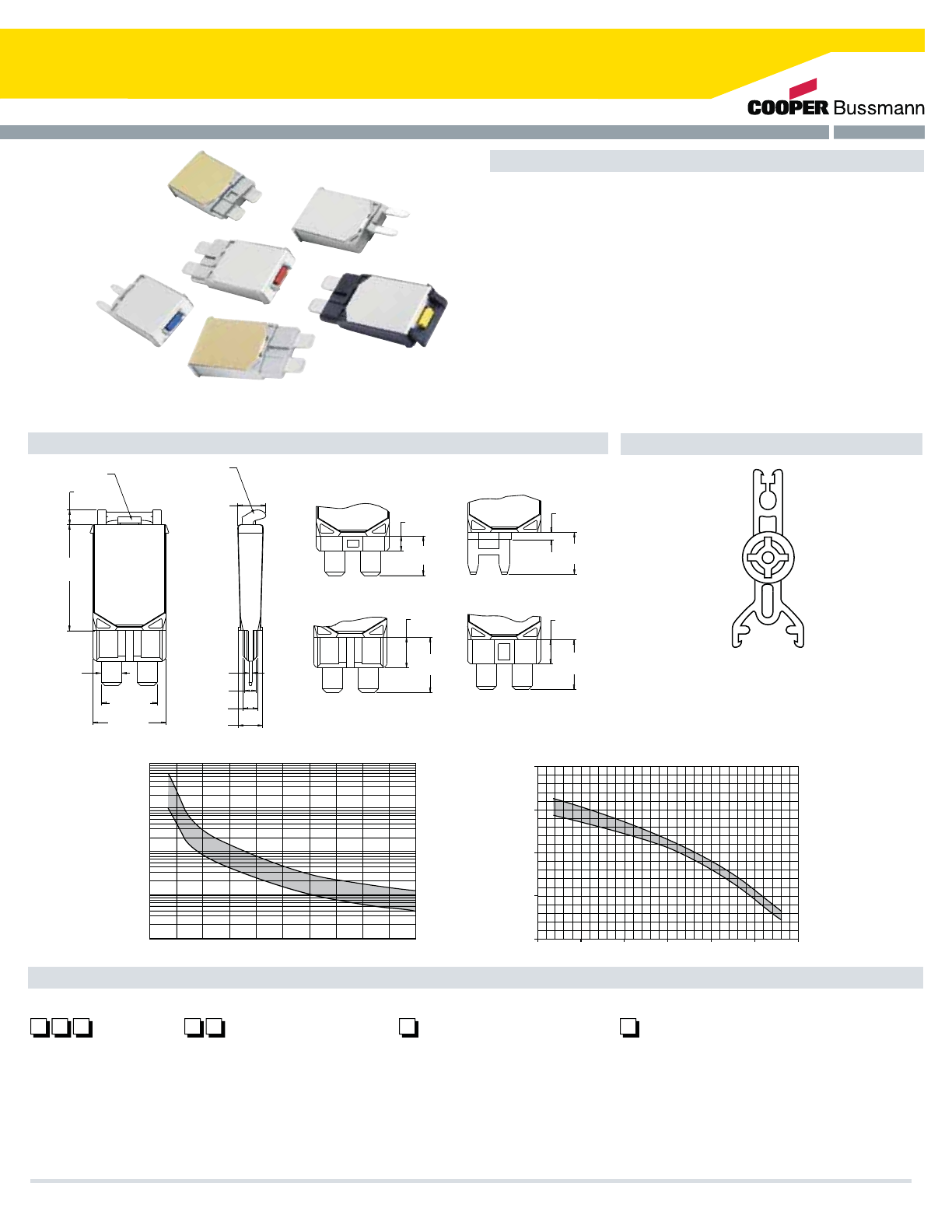
Series 22X Circuit Breakers
Specifications
Part Numbering System
Fuse Puller - Part Number 32003
ATC® Circuit Breakers
Auto, Modified, & Manual Reset
Single Pole Thermal Type Breakers
Rating: 5-30A, 14Vdc; 28Vdc (Series 223 & 226).
Interrupt Rating: 150A @ 14Vdc (5-10A versions); 225A @ 14Vdc
(15A version); 300A @ 14Vdc (20A version); 450A @ 14Vdc (25-30A
versions).
Operating Temperature Rating: –40°F (–40°C) to 185°F (85°C).
Storage Temperature Rating: –40°F (–40°C) to 260°F (125°C).
Materials: UL-Rated 94V0 thermoplastic housing with gold metal
cover (Type I) or silver metal cover (Type II & III).
Marking: Standard marking includes amp/volt ratings, part number,
and date code. Type III reset buttons are color-coded to amperage
ratings. Push-to-trip option is available on manual reset version. OCR
marking is available.
Termination: Compatible with 280 Type or ATC® fuse blocks.
Compliances: SAE J553, SAE J1171 (ignition protection)
Dimensions - mm(in) (Dims. Shown are for reference only. Contact factory for latest prints)
RESET BUTTON
(Series 223/226) TRIP LEVER
(Series 226)
43
2
0
][ 0.247
6.28
][ 0.508
12.91
][ 0.074
1.88
][ 0.428
10.88
][0.153
3.88
][ 0.405
10.28
][0.288
7.32
][ 0.310
7.88
][ 0.562
14.28
][0.032
0.80
][0.118
3.00
][0.150
3.80
][0.250
6.35
][0.571
14.50
][0.748
19.00
][1.084
27.54
][.206
5.24
][0.150
3.81
See page 67 for more
information.
ATC FUSE
ATC CB
1000
100
10
1
0.1
100% 200% 300% 400% 500% 600%
TRIP TIME VS. PERCENT OF RATED CURRENT
% of Rated Current
Time in Seconds
-50
0
50
100
150
200
-25 0 25 50 75 100
TEMPERATURE DERATING CURVES
AMBIENT TEMPERATURE IN DEGREES C
Maximum % Hold Current
Series
22
221 – Type I, 14VDC
222 – Type II, 14VDC
223 – Type III, 24VDC
226 – Type III w/Push-to-trip
option, 24VDC
Consult factory for
terminal option availability.
Rating
–
05 _amps [LT. Brown (Tan)]*
75 – 7.5 amps [Brown]*
10 – 10 amps [Red]*
15 – 15 amps [Blue]*
20 – 20 amps [Yellow]*
25 – 25 amps [White]*
30 – 30 amps [Green]*
Terminal
0 – ATC ®Fuse, 4mm Insertion Depth
2 – 8.1mm Centerline 280 (MINI)
3 – ATC®Fuse, Delphi Packard
Autofuse Block (e.g. 12004943)
4 – ATC®Fuse, Blocks with Raised
Shrouds, 6.4mm Insertion Depth
Marking
00 – Std. Marking
(Consult factory for
special marking options)
*Reset Button Color (223 & 226 only).
Cooper Bussmann Transportation Products t1IPOFt'BYtXXXDPPQFSCVTTNBOODPN 63
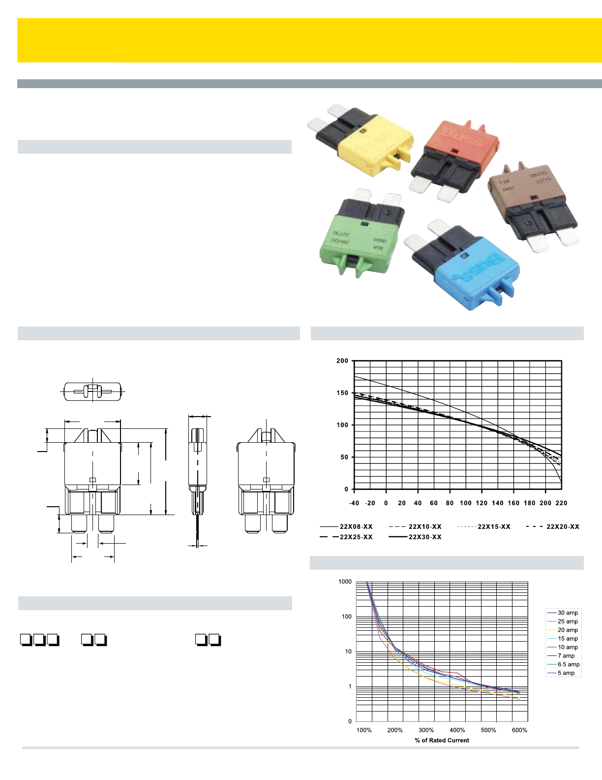
Series 227 ATC® Circuit Breakers (low profile)
Specifications
Part Numbering System
Trip Time vs. Percent of Rated Current
Dimensions - mm(in) Temperature Derating Curves
ATC® Circuit Breakers
Manual Reset
Single Pole Thermal Type Breakers
Rating: 5-30A, 28Vdc
Interrupt Rating: 2000A @ 28Vdc
Operating Temperature Rating: –40°F (–40°C) to 185°F (85°C)
Storage Temperature Rating: –40°F (–40°C) to 260°F (125°C)
Materials: UL-Rated 94V0 thermoplastic body. Tin-plated copper alloy
terminals
Marking: Cover is color-coded to amperage ratings
Termination: 5.2mm wide blades compatible with ATC® type fuse blocks
Compliances: SAEJ553; SAEJ1171 (ignition protected)
Consult factory for time characteristic curves
(Dims. Shown are for reference only. Contact factory for latest prints)
(0.26)
6.5
(0.57)
14.6
(0.16)
4.13
(0.18)
4.6
(0.76)
19.3
(0.99)
25.1
(1.18)
30
(0.57)
14.6
Rating
Series
2 2 7
Marking
–0 0
05 – 5 amps [LT. Brown (Tan)]
06 – 6 amps [Moss Green]
75 – 7.5 amps [Brown]
10 – 10 amps [Red]
15 – 15 amps [Blue]
20 – 20 amps [Yellow]
25 – 25 amps [White]
30 – 30 amps [Green]
00-Std. Marking
(Consult factory for special marking.)
(0.02)
0.6
(0.25)
6.4
28VDC
XXXXX
15A
XXXX
Time in Seconds Maximum % Hold Current
Abient Temperature in Degrees F
Cooper Bussmann Transportation Products t1IPOFt'BYtXXXDPPQFSCVTTNBOODPN
64
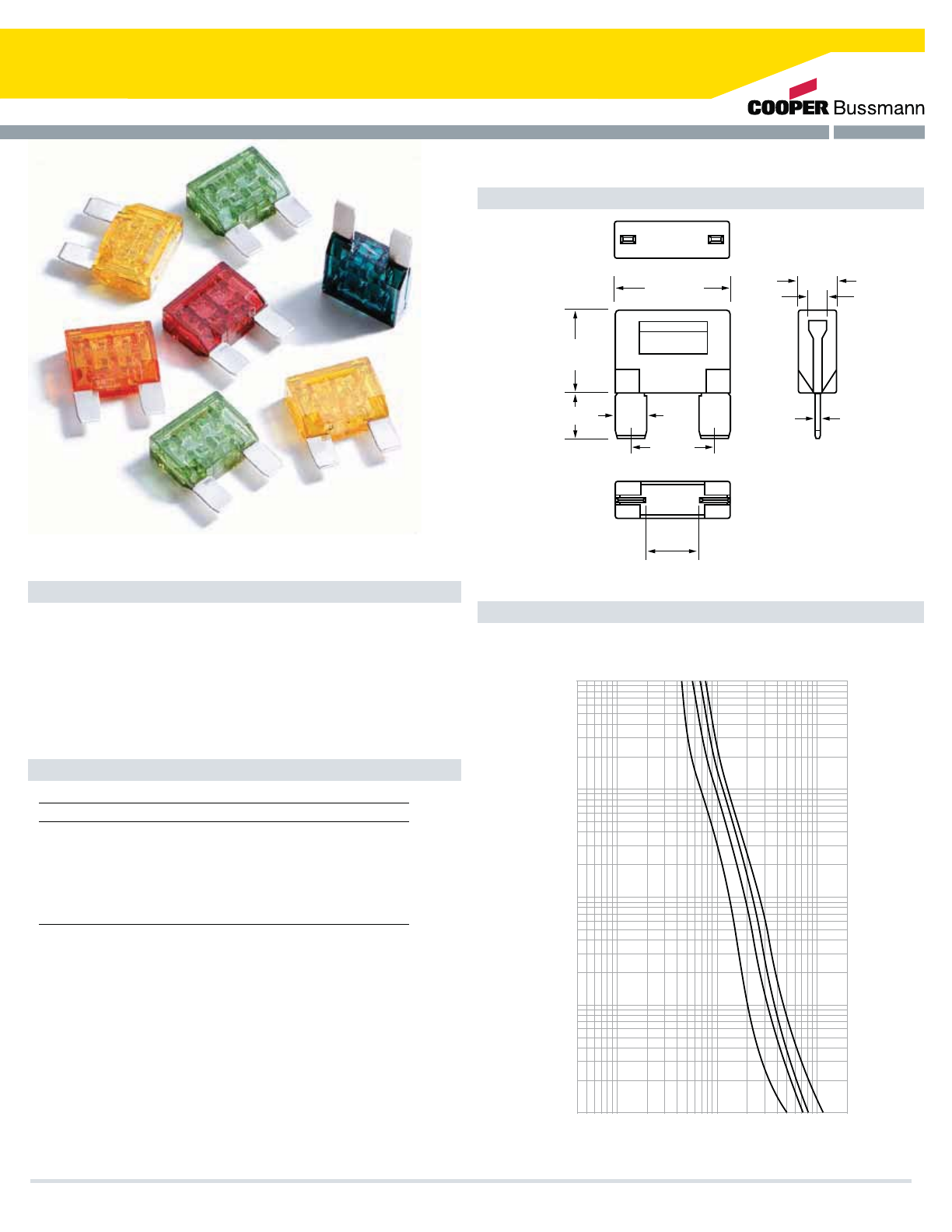
MAXI® Blade Fuses
Specifications
Color Coding and Amp Ratings
MAXI® - Fuse
Fast Acting
Current Rating: 20-80A
Voltage Rating: 32Vdc
Interrupt Rating: 1000A @ 32Vdc
Housing Material: UL-Rated 94V0 thermoplastic
Terminal Material: Silver-plated zinc alloy
Marking: Amperage marking is OCR compliant
Compliances: SAE J1888, ISO 8820-3, SAE J1171 (ignition protected)
Dimensions - mm(in)
Time-Current Curves
(Dims. Shown are for reference only. Contact factory for latest prints)
Part No. Amp Rating Color
BK-MAX-20 20 Yellow
BK-MAX-30 30 Green
BK-MAX-40 40 Orange
BK-MAX-50 50 Red
BK-MAX-60 60 Blue
BK-MAX-70 70 Tan
BK-MAX-80 80 Neutral
BUSS
MAXI-FUSE ®
32V
Z039
60
(.67)
17.02
(1.14)
29.2
(.85)
21.6
12.7(.50)
(.83)
21.21
(.31)
8.0
(.35)
8.9
(.18)
4.57
(.10)
2.54
4
10
100
1000
2000
CURRENT IN AMP
100
10
1
.1
.01
TIME IN SECONDS
30
AMP
RATING
40
50
60
Cooper Bussmann Transportation Products t1IPOFt'BYtXXXDPPQFSCVTTNBOODPN 65
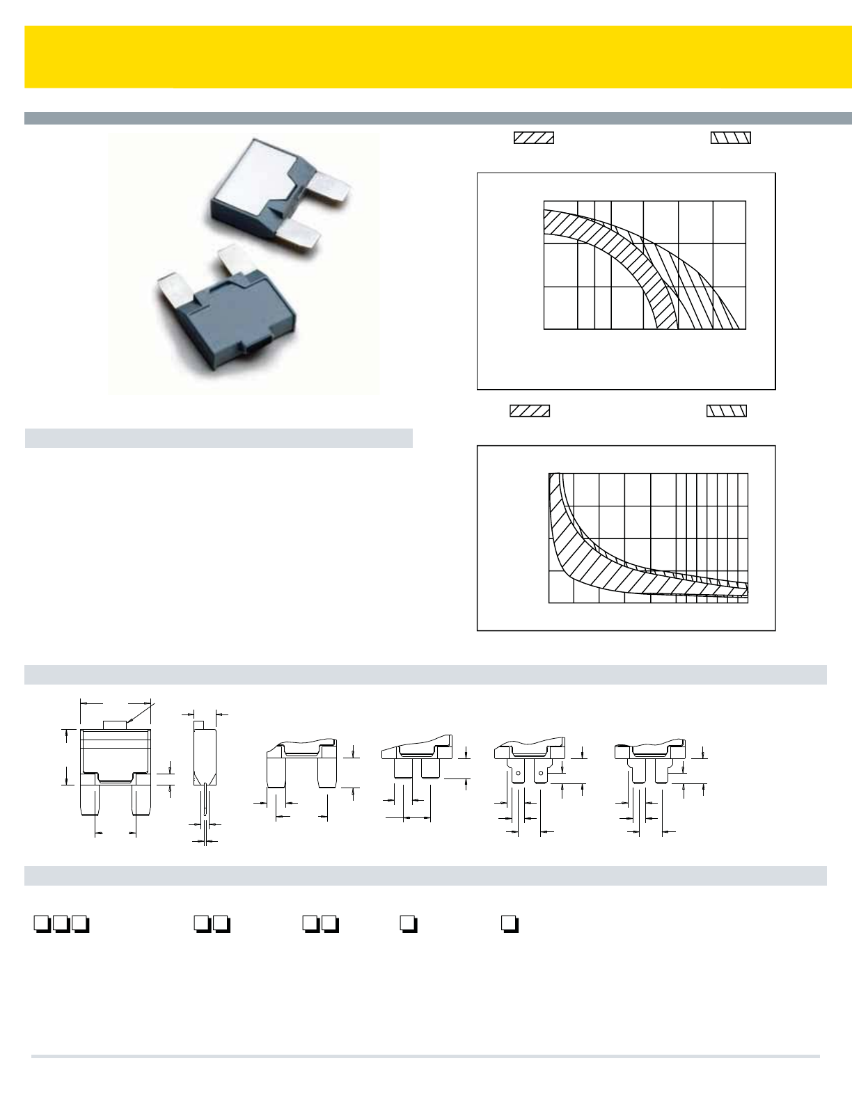
Series 19X MAXI® Circuit Breakers
Specifications
Single Pole Thermal Type Breakers
Rating: 8-50A; 14Vdc; 28Vdc (Series 193, 194, & 195)
Interrupt Rating: 150A @ 14Vdc (8-10A versions); 225A@ 14Vdc
(15A version); 300A @ 14Vdc (20A version); 450A@
14Vdc (25-30A versions); 600A @ 4Vdc (35-40A versions);
750A @ 14Vdc (50A version)
Operating Temperature Rating: –40°F (–40°C) to 185°F (85°C)
Storage Temperature Rating: –40°F (–40°C) to 260°F (125°C)
Materials: Grey UL-Rated 94V0 thermoplastic
Termination: Compatible with fuse blocks accepting MAXI® or
ATC® blade fuses
Compliances: SAE J553, SAE J1171 (ignition protected)
Dimensions - in(mm)
Part Numbering System
Terminal Options
(Dims. Shown are for reference only. Contact factory for latest prints)
Series 19X MAXI® Circuit Breakers
Auto, Manual & Modified Reset
500%
500200100403020151050
400%
300%
200%
100%
TIME VS. PERCENT OF RATED CURRENT
TIME IN SECONDS
% 0F RATED CURRENT
150%
100%
50%
0%
% 0F RATED CURRENT
50º 77º 100º 150º 200º 250º 300º0º
(10º)(25º)(38º) (65º) (93º) (121º) (149º)(-18º)
TEMPERATURE IN DEGREES F°
(TEMPERATURE IN DEGREES C°)
TEMPERATURE DERATING CURVES
10 AMPS & BELOW
TYPICAL CURVE
15 AMPS & ABOVE
TYPICAL CURVE
10 AMPS & BELOW
TYPICAL CURVE
15 AMPS & ABOVE
TYPICAL CURVE
04
03
02
01
(0.170)
4.32
(0.4100)
10.29
(0.4100)
10.29
(0.290)
7.37
(0.210)
5.33
(0.370)
9.40
(0.170)
4.32
(0.290)
7.37
(0.210)
5.33
(0.370)
9.40
(0.450)
11.43
(0.290)
7.37
(0.330)
8.38
(0.190)
4.83
(0.920)
23.37
(0.670)
17.02
(0.032)
0.81
(0.141)
3.57
(0.500)
12.70
(0.310)
7.87
(0.840)
21.34
(14VDC only)
(0.360)
9.14
1.150
(29.21)
Reset Button
(Series 193)
Series
19
191 – Type I, 14 VDC
192 – Type II, 14 VDC
193 – Type III, 12V/24 VDC
194 – Type I, 24 VDC
195 – Type II, 24 VDC
Rating
–
08 – 8 amps
10 – 10 amps
15 – 15 amps
20 – 20 amps
25 – 25 amps
30 – 30 amps
35 – 35 amps
40 – 40 amps
50 – 50 amps (191, 193, 194 only)
Terminal
01 – MAXI®
02 – Wide ATC ®
03 – Long ATC®
(w/dimple)
04 – Long ATC®
(no dimple)
Cover
–
M – Metal*
Marking
(Consult factory
for special markings.)
M
Cooper Bussmann Transportation Products t1IPOFt'BYtXXXDPPQFSCVTTNBOODPN
66
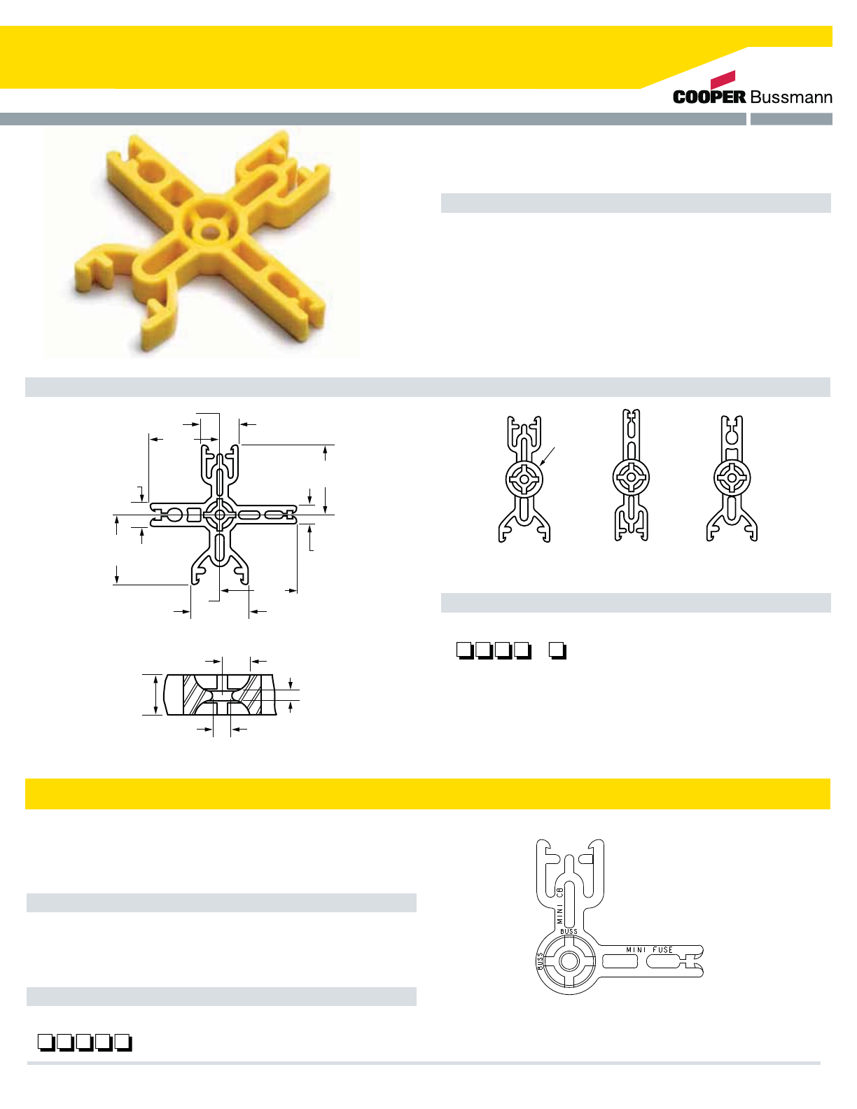
DIMENSIONS
Series 3200 Insertion/Extraction Tool
Features/benefits
Part Numbering System
t$VTUPN$POmHVSBCMF%FTJHO
Get only the extractors you need
t$PNNPO1MBUGPSNGPSBOZ4UZMF
Eliminates design changes when protection requirements change
t$FOUFS4OBQ-PDL.PVOUJOH)PMF
Easy mounting using simple split-ball snap-lock post
t1PTJUJWF4UPQ-PDLJOH"DUJPO
Tight grip allows devices to be removed and inserted
t)JHI5FNQFSBUVSF3FTJMJFOU/ZMPO¡$
(Dims. Shown are for reference only. Contact factory for latest prints)
Series 3200
Automotive Fuse and Circuit Breaker Insertion/Extraction Tool.
Features/Benefits
Dimensions - mm(in)
Part Numbering System
t1PTJUJWF4UPQ-PDLJOH"DUJPO
Tight grip allows devices to be removed and inserted.
t)JHI5FNQFSBUVSF3FTJMJFOU/ZMPO¡$
Series 32013
Automotive fuse and circuit breaker insertion/extraction tool
(to be used with Series 32000 Dual Vehicle Electrical Center).
MINI CB
ATC CB
.32"
(R8.25)
32001 32002 32003
ATC FUSE
ATC CB
MINI FUSE
MINI CB
MINI CB
MINI FUSE
ATC FUSE
ATC CB
(.67")
17.00
(.98)
25.00
(1.18)
30.00
(1.18)
30.00
(1.18)
30.00
(.31)
7.90
(1.30)
33.00
A
A
(R.24)
6.00
(.34)
8.6
(.39)
10.00
(.06)
1.60
(.16)
4.00
32000
SECTION A-A
Series
32 0 0
Configuration
Top Right Bottom Left
0 – MINI CB MINI FUSE ATC ®CB ATC®FUSE
1 – MINI CB BLANK ATC®CB BLANK
2 – MINI CB BLANK MINI FUSE BLANK
3 – ATC®CB BLANK ATC®FUSE BLANK
Series 32013
Series
32 0 1 3
Cooper Bussmann Transportation Products t1IPOFt'BYtXXXDPPQFSCVTTNBOODPN 67
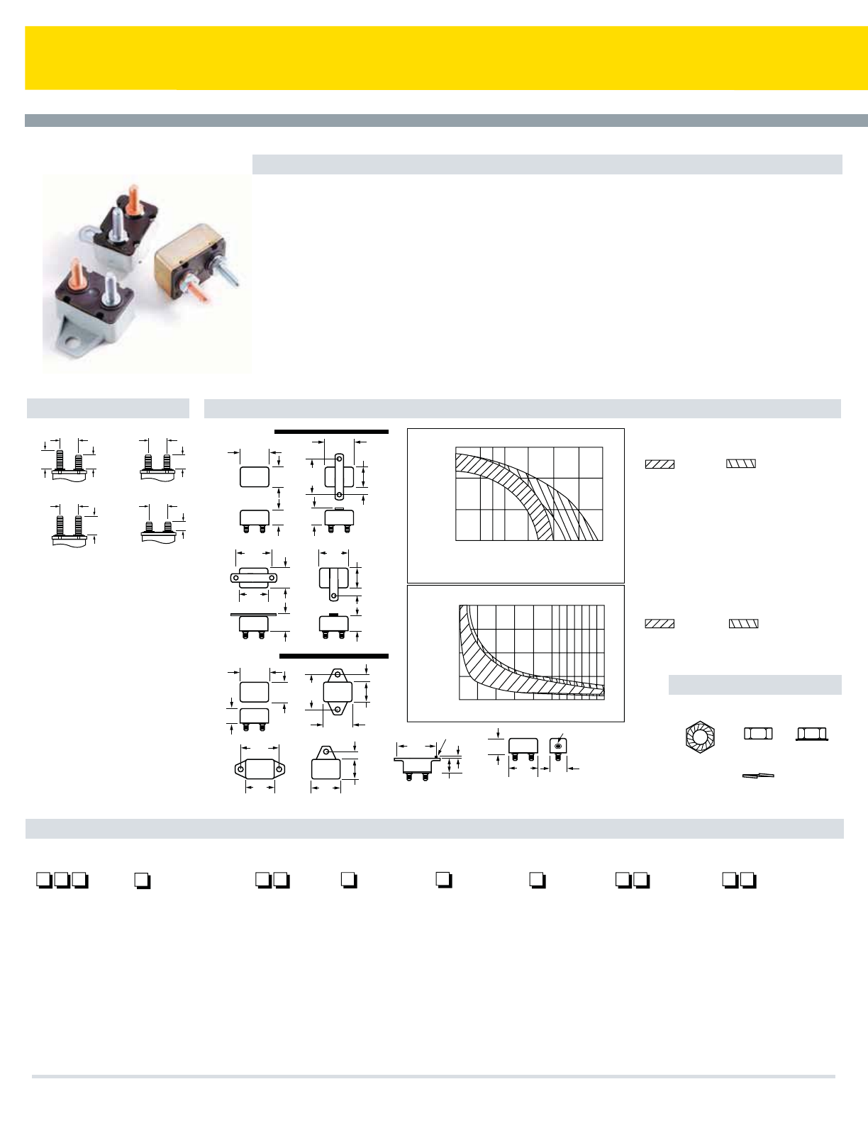
Series 12X Shortstop Circuit Breakers
Specifications
Single Pole Thermal Type Breakers
Applications: Battery chargers, trucks, buses, RVs, trolling motors, etc
Rating: 5-50A, 14Vdc; 28Vdc (Series 123, 124, & 125)
Interrupt Rating: Main Circuit Protection: 1.5kA @ 12Vdc (Series 193 w/plastic cover);
Branch Circuit Protection: 2.5kA @ 12Vdc (Series 121 & 124 -01 sealed & Series 123 w/plastic cover)
Operating Temperature Rating: –40°F (–40°C) to 185°F (85°C)
Storage Temperature Rating: –40°F (–40°C) to 260°F (125°C)
Materials: Black UL-Rated thermoplastic body (thermoset for Type II body & buttons). Cover is grey thermoplastic or
steel-Type l gold, Type ll silver
Marking: Custom marking available. Consult factory for options
Termination: #10-32 thread and quick-connect options available
Torque Rating: 24 in-lbs (2.7Ntm) max
Mounting Torque Rating: Plastic cover - 15 in-lbs (1.7Ntm); Metal cover - 30 in-lbs (3.4Ntm)
Ingress Protection Rating: IP66 On plastic cover version only (except for terminals)
Compliances: SAE J553; SAE J1171 (consult factory for ignition protection ratings)
Auto, Manual & Modified Reset Circuit Breakers
Terminal Options
Hardware
.69"
(17.5)
.69"
(17.5)
.69"
(17.5)
.56"
(14.2)
.37" (9.4)
.56"
(14.2)
.66"
(16.8)
.66"
(16.8)
Two 10-32 studs:
.66" (AUX); .56" (BAT)
A
Two 10-32 studs:
.56" (AUX & BAT)
B
Two 10-32 studs:
.66" (AUX & BAT)
C
.69"
(17.5)
Two 10-32 studs
(AUX & BAT)
L
Cover & Bracket Options
Part Numbering System
1.24"
(31.5)
1.27"
(32.3)
1.27"
(32.3)
1.24"
(31.5)
1.24"
(31.5)
1.24"
(31.5)
1.27"
(32.2) 1.27"
(32.2)
1.56"
(39.6)
1.56"
(39.6)
.79"
(20.1)
.79"
(20.1)
.69"
(17.5) .69"
(17.5)
.79"
(20.1)
1.56"
(39.6)
1.56"
(39.6)
.64"
(16.3)
.62"
(15.7)
.69"
(17.5)
.83"
(21.1)
O Bracket
O Bracket
A Bracket
A Bracket
B Bracket C Bracket
B Bracket C Bracket
.38" (9.6)
.37" (9.4)
.79"
(20.1)
.38" (9.6)
METAL COVER
PLASTIC COVER
.83"
(21.1)
.37" (9.4)
.83"
(21.1)
BAT AUX
BAT AUX
500%
500200100403020151050
400%
300%
200%
100%
TIME VS. PERCENT OF RATED CURRENT
TIME IN SECONDS
% 0F RATED CURRENT
150%
100%
50%
0%
% 0F RATED CURRENT
50º 77º 100º 150º 200º 250º 300º0º
(10º)(25º)(38º) (65º) (93º) (121º) (149º)(-18º)
TEMPERATURE IN DEGREES F °
(TEMPERATURE IN DEGREES C °)
TEMPERATURE DERATING CURVES
10 AMPS & BELOW
TYPICAL CURVE
15 AMPS & ABOVE
TYPICAL CURVE
10 AMPS & BELOW
TYPICAL CURVE
15 AMPS & ABOVE
TYPICAL CURVE
1.56"
(39.6)
E Bracket
Series 123
O Bracket w/reset
1.27"
(32.3) .83"
(21.1)
.62"
(15.7)
.06"
(1.5)
.12" (3.0)
dia. boss
.62" (15.7)
Ref. (Typ)
w/base attached
Reset button*
BATAUX
( * Reset on BAT side)
HA / HB
Hex Nut
#10-32
Keps Lock Nut
#10-32
Whiz Lock
#10-32
Lock Washer
WA / WB KA / KB
Series
12
121 – Type I,
12 VDC
122 – Type II,
12 VDC
123 – Type III,
24 VDC
124 – Type I,
24 VDC
125 – Type II,
24 VDC
Terminal
A – Two 10-32 studs;
.66 (Aux), .56 (Bat)
B – Two 10-32 studs;
.56 (Aux & Bat)
C – Two 10-32 studs;
.66 (Aux & Bat)
***D – Two .250 QC;
(Aux & Bat)
** H – One 10-32 stud
.56 (Bat), Double
.250 QC (Aux)
L – Two 10-32 studs; .37
(Aux & Bat)
Rating
–
05 – 5 amps
08 – 8 amps
10 – 10 amps
12 – 12 amps
15 – 15 amps
20 – 20 amps
25 – 25 amps
30 – 30 amps
35 – 35 amps
40 – 40 amps
50 – 50 amps
Bracket
0 – No bracket
A – Bracket
B – Bracket
C – Bracket
E – Bracket
(plastic only)
Mtg. Holes
0 – No bracket
1 – .140 dia.
2 – .196 dia.
3 – .237 dia.
(metal only)
4 – .265 dia.
(plastic only)
5 – .228 dia.
(plastic only)
6 – .221 dia.
(metal only)
Cover*
–
M – Metal*
P – Plastic*
Options
–
01 – Waterproof
(metal
covers only)
02 – Splashproof
(optional on
metal covers -
add 02 sufx;
std. on plastic
covers - omit
02 sufx.)
Hardware
WA – Whiz-lock nut
assembled
WB – Whiz-lock
nut bulk
HA – Nut & lock
washer
assembled
HB – Nut & lock
washer bulk
KA – Keps lock nut
assembled
KB – Keps lock
nut bulk
*Series 123 available in plastic cover only. Series 122 & 125 available in metal cover only. **40A maximum ***30A maximum
Cooper Bussmann Transportation Products t1IPOFt'BYtXXXDPPQFSCVTTNBOODPN
68
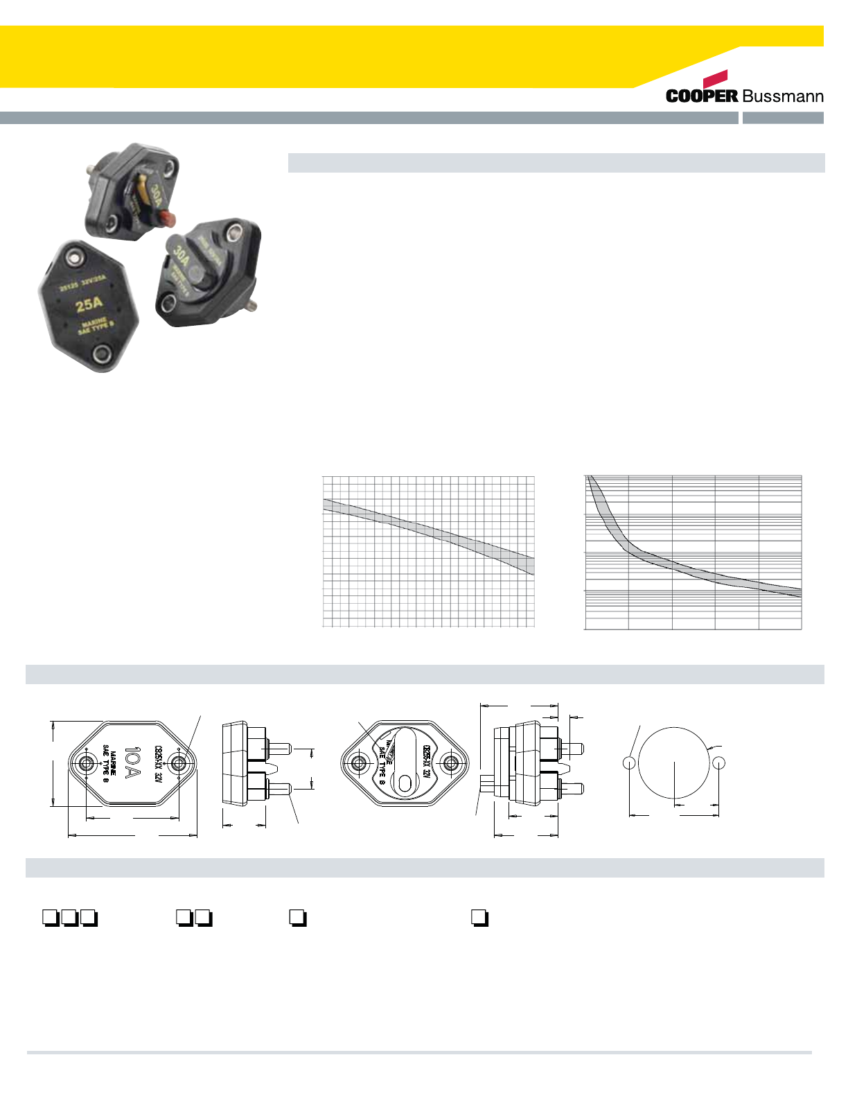
Series 25X Mid-Range Circuit Breaker
Specifications
Single Pole Thermal Type Breakers
Applications: This unit is external ignition protected and weatherproof. It is typically used in DC power
systems in marine applications (as a main or branch circuit breaker), truck, bus and RV systems, add-on
protection for accessories, etc
Rating: 10-50A, 32Vdc
Interrupt Rating: Circuit Protection (2.5kA) per ABYC E-11
Operating Temperature Rating: –40°F (–40°C) to 185°F (85°C)
Storage Temperature Rating: –40°F (–40°C) to 260°F (125°C)
Materials: Black UL-rated 94V0 thermoset plastic body. Cover, lever, and button are ULRated 94V0
thermoplastic. Cover has a black thermoplastic elastomer overmold
Marking: Standard marking includes amp/volt ratings, part numbers, and “SAE Type B”
Termination: #10-32 Threaded studs
Torque Rating: 24 in-lbs (2.7Ntm) max
Mounting Torque Rating: Panel mount with either #8-32 threaded inserts or #10 clearance holes. 18 in-lbs
(2.0Ntm) max
Ingress Protection Rating: IP66
Features / Options: Series 254 & 255 have a unique reset mechanism which provides a visual indication of
tripped condition. Series 255 also features a push-to-trip option
Compliances: SAE J553; ABYC E-11; SAE J1171 (ignition protected)
Auto, Manual & Modified Reset Circuit Breakers
Dimensions - mm(in)
Part Numbering System
TRIP TIME VS. PERCENT OF RATED CURRENT
% OF RATED CURRENT
100% 200% 300% 400% 500% 600%
1000
100
10
1
0.1
TIME IN SECONDS
-40 -20 0 20 40 60 80
AMBIENT TEMPERATURE IN DEGREE C
TEMPERATURE DERATING CURVE
200
150
100
50
0
MAXIMUM % HOLD CURRENT
(2) #10-32 CLEARANCE HOLE
OR #8-32 CLEARANCE HOLE
IF USING THREADED INSERTS
Ø31.75
[Ø1.25]
19.99
[0.787]
39.98
[1.574]
21.50
[0.85]
RESET LEVER
(series 254 & 255)
#10-32 EXTERNAL THREAD
MOUNTING OPTIONS
(255 series)
TRIP BUTTON
27.80
[1.09]
5.00
[0.20]
33.80
[1.33]
18.50
[0.73]
39.98
[1.57]
17.33
[0.68]
55.73
[2.19]
37.00
[1.46]
(Dims. shown are for reference only. Consult factory for latest prints)
Series
2 5
Rating
–
10 – 10 amps
15 – 15 amps
20 – 20 amps
25 – 25 amps
30 – 30 amps
35 – 35 amps
40 – 40 amps
50 – 50 amps
Mounting Holes
–
A – Thru-hole Insert (#10 Clearance)
B – #8-32 Threaded Inserts
Hardware
0 – No nuts
1 – Nuts Installed
2 – Nuts bulk
251 – Type I, 32V
254 – Type III, 32V
255 – Type III w/push-
to-trip option, 32V
Cooper Bussmann Transportation Products t1IPOFt'BYtXXXDPPQFSCVTTNBOODPN 69
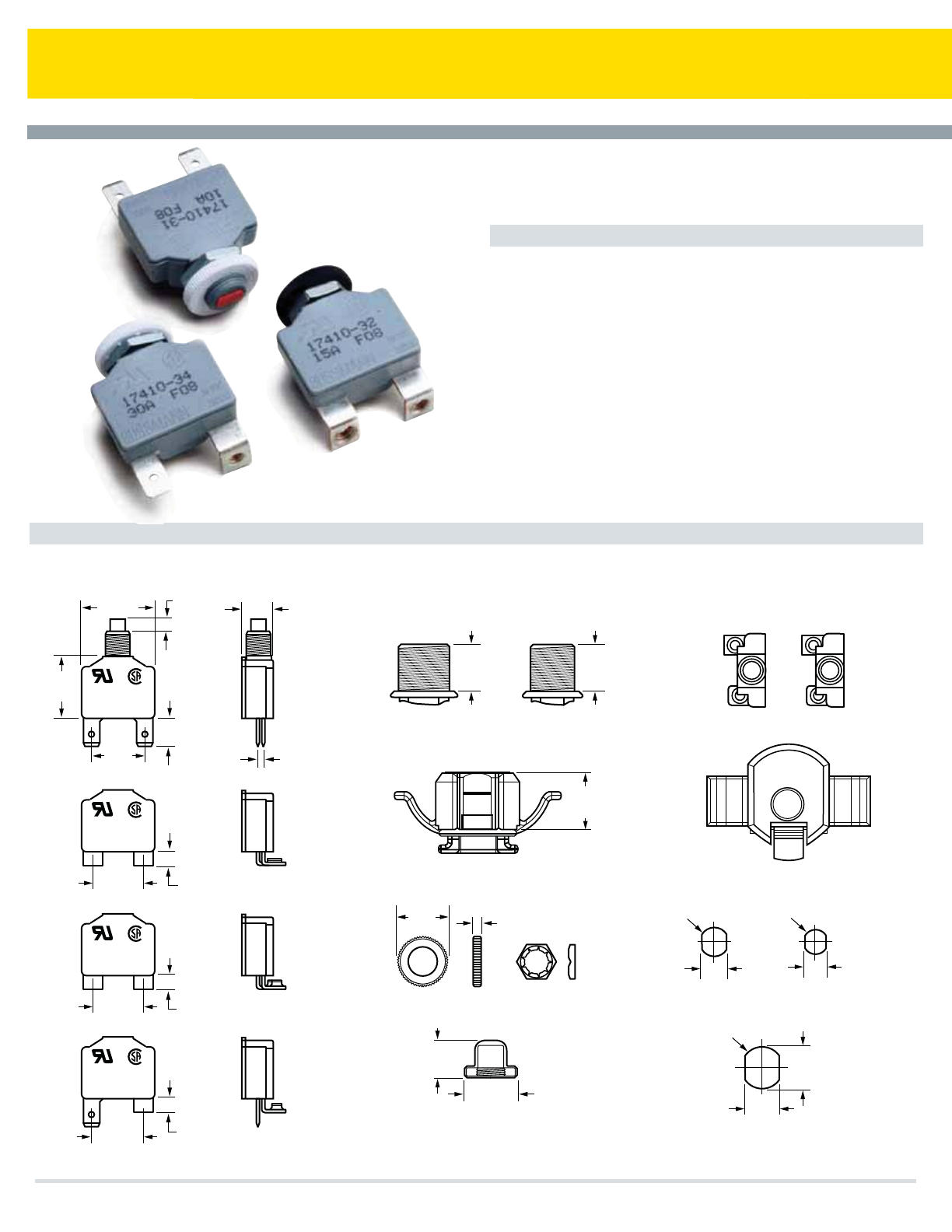
Series 174 Flat-Pak Circuit Breaker
Specifications
Single Pole Thermal Type Breakers
Applications: Branch circuit protection for multiple power outlet strips, trucks,
RVs, boats, buses, portable generators, building equipment, etc.
Rating: 5-40A; 250Vac/32Vdc
Interrupt Rating: 200A @ 250Vac
Operating Temperature Rating: –40°F (–40°C) to 185°F (85°C)
Storage Temperature Rating: –40°F (–40°C) to 260°F (125°C)
Materials: Grey UL-rated 94V0 thermoplastic
Termination: Threaded or quick-connect options available
Ingress Protection Rating: IP54 (except at terminals)
Compliances: UL 1077 & CSA 22.2 No. 235 (See individual
terminal styles for specific rating approvals); SAE J553; SAE
J1171 (ignition protected)
Manual Reset Circuit Breakers
(Dims. Shown are for reference only. Contact factory for latest prints)
Dimensions - in(mm)
®®
174XX-3X
XXA XXX
BUSSMANN 32 VDC
250 VAC
®®
174XX-3X
XXA XXX
BUSSMANN 32 VDC
250 VAC
®®
174XX-3X
XXA XXX
BUSSMANN 32 VDC
250 VAC
®®
174XX-3X
XXA XXX
BUSSMANN 32VDC
250 VAC
2
5
TERMINAL / BASE STYLES
BUSHING / NECK STYLES
FIGURE A
HARDWARE VARIATIONS
SNAP - ON
SNAP - ON
PLASTIC KNURL NUT
(STANDARD)
PALNUT
* PLASTIC BOOT
* ALSO AVAILABLE IN BULK
3/8-24 P/N B151-7135-3
7/16-28 P/N B151-7135-1
RECOMMENDED BUSHING PANEL CUTOUT
FIGURE B
31
UL & CSA
05 TO 30AMP
32
UL & CSA
05-40AMP
33
UL & CSA
05-15 (WIRE)
05-30 (RING)
34
UL & CSA
05-15 (WIRE)
05-30 (RING)
7/16 - 28 THREAD 3/8 - 24 THREAD
7/16 - 28
THREAD
3/8 - 24
THREAD
T
O
R
E
S
E
T
.75"
(19.04) .12"
(3.00)
9.91
(.390)
.44"
(Ø11.10)
.38"
(Ø9.52)
.34"
(8.51)
.32"
(R8.1)
.63"
(16.13)
.55"
(13.84)
.35"
(9.0)
.35"
(9.0)
.48"
(12.10)
.60"
(1.50)
TYP.
1.11"
(28.30)
.19"
(4.83)
.93"
(23.57)
.81"
(20.55)
.42"
(10.67)
.76"
(19.40)
.79"
(19.98)
.20"
(5.19)
.76"
(19.40)
.20"
(5.19)
.20"
(5.19)
P
U
S
H
.55"
(14.00)
.79"
(20.11)
PUSH
TO RESET
.40"
(9.00)
2
5
BUTTON MARKING OPTIONS
Cooper Bussmann Transportation Products t1IPOFt'BYtXXXDPPQFSCVTTNBOODPN
70

Series 174 Flat-Pak Circuit Breaker
TEMPERATURE IN DEGREES F °
(TEMPERATURE IN DEGREES C °)
TIME IN SECONDS
% 0F RATED CURRENT
% 0F RATED CURRENT
0°
0 5 10 15 20 30 40 50 100 150 200 400 600
50° 77° 100° 150° 200° 250° 300°
(-18°) (10 °) (25 °) (38 °) (65 °) (93 °) (121 °) (149 °)
0%
100%
200%
300%
400%
500%
50%
100%
150%
200%
Temperature Derating Curves for 5-40 Amp. Circuit Breakers
174 SERIES TEMP. VS. CURRENT CURVES
TIME vs. Percent of Rated Current Curves for 5-40 Amp. Circuit Breakers
174 SERIES TRIP CURVES
10 AMP & BELOW
TYPICAL CURVE
COMMON CURVE
ALL VALUES
15 AMP & BELOW
TYPICAL CURVE
Series
174
174 – Type III
250 VAC/
32VDC
Manual
Reset
Rating
–3
05 – 5 amps
06 – 6 amps
07 – 7 amps
08 – 8 amps
10 – 10 amps
15 – 15 amps
20 – 20 amps
25 – 25 amps
30 – 30 amps
35 – 35 amps*
40 – 40 amps*
Terminal/
Base
1 – .25" Quick
Connect
2 – 10-32 screw -
90° bend
3 – 6-32 screw -
90° bend
4 – .25" Quick
Connect with
6-32 screw -
90° bend
Bushing/
Neck
1 – 7/16-28
thread
2 – 3/8-24
thread
3 – Snap-on
Button
A – White w/no
marking
B – Red w/no
marking
C – Black w/no
marking**
D – White w/amp
marking
Fig. A
E – White w/amp
marking
Fig. B
F – Red w/amp
marking
Fig. A
G – Red w/amp
marking
Fig. B
Hdwr. Pkg.
1 – Pack bulk
(standard)
2 – Assemble to
bushing
3 – No hardware
included
Bushing Hdwr.
–
A – White plastic knurl nut,
anti-rotational
B – Black plastic knurl nut,
anti-rotational
C – White plastic knurl nut,
anti-rotational w/ palnut
D – Black plastic knurl nut,
anti-rotational w/ palnut
E – None required for bushing
F – Zinc plated steel palnut
G – Button boot (thread-on)
w/ palnut
P – Aluminum knurl nut
& palnut
R – Black aluminum knurl nut
& palnut
S – Alum. knurl nut, palnut, black plate
w/ white “push-to-reset”
T – Alum. knurl nut, palnut, white plate
w/ black “push-to-reset”
V – Alum. knurl nut & white plate w/
black “push-to-reset”
W – Alum. knurl nut & black plate w/
white “push-to-reset”
X – Aluminum knurl nut & internal tooth
lockwasher
Z – Hex nut & internal tooth lockwasher
Special
Options
0 – No hardware
1 – Bulk brass
screws for screw
terminals
2 – Bulk brass
screws and lock-
washers for
screw terminals
3 – Assembled brass
screws for screw
terminals
4 – Assembled brass
screws and lock-
washers for
screw terminals
**No marking available
on Black buttons
*2 or 3 Style
Terminal Only.
Part Numbering System
Cooper Bussmann Transportation Products t1IPOFt'BYtXXXDPPQFSCVTTNBOODPN 71
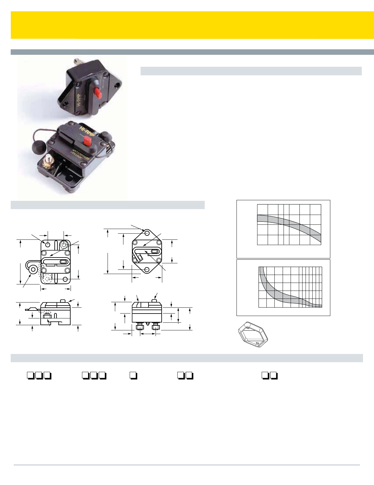
Series 18X Hi-Amp Circuit Breaker
Specifications
Single Pole Thermal Type Breakers
Applications: Typically used in auxiliary and accessory circuits in truck, bus’, RVs and marine systems.
Others include battery chargers and DC audio systems. Series 181, 184 & 185 are sealed for engine
compartment and bilge area applications.
Rating: 25-150A, 30Vdc; 42Vdc Nom (Series 184 & 185)
Interrupt Rating: 3000A @ 30Vdc
Operating Temperature Rating: -40˚C to +85˚C
Storage Temperature Rating: –30°F (–34°C) to 300°F (149°C)
Materials: Black UL-rated 94V0 thermoset plastic. Thermoplastic elastomer stud insulators are
provided on covered units with F-style (surface-mount) bases
Marking: Standard marking includes amp ratings and part numbers. Custom markings also available.
Termination: 1/4-28 threaded studs
Torque Rating: 50 in-lbs (5.6Ntm) max
Mounting Torque Rating: Panel or surface-mount options; 50 in-lbs (5.6Ntm) max. Threaded insert
option has a max torque of 25 in-lbs (2.8Ntm).
Ingress Protection Rating: IP67
Features / Options: Series 184 & 185 have a unique reset mechanism which provides visual indication
of tripped condition. Series 185 also features a push-to-trip option
Compliances: SAE J1625; ABYC E-11; CE; SAE J1171 (ignition protected)
Auto, Manual & Switchable Reset Circuit Breakers
Dimensions - in(mm) (Dims. shown are for reference only. Consult factory for latest prints)
RESET
1.05
(26.67)
2.23
(56.64)
2.89
(73.41)
1.44
(36.58) 1.79
(45.47)
.66
(16.76)
1.09*
(27.69)
.40
(10.16)
1.90
(48.26)
Stud insulators
.26 (6.60) dia.
Mtg.holes (2)
Reset lever
(Shown in
operating
position series
184/185)
.26 (6.60) dia.
Mtg.holes (2) Reset lever
(Shown tripped)
1/4-28 Studs
Molded
cover
Molded
cover
*Overall heights of
Series 181 &183
Trip button (Series 185)
.57
(14.49) 1.06
(26.92)
.31
(7.87)
.89 (22.61)
1.44*
(36.58)
Tamper proof
cover
1.90
(48.26)
2.91
(73.91) 2.41
(61.21)
1.54
(39.12)
Surface Mount Panel Mount
600%
500%
500200100403020151050
400%
300%
200%
200%
150%
100%
50%
0%
100%
TIME VS. PERCENT OF RATED CURRENT
TIME IN SECONDS
% 0F RATED CURRENT % 0F RATED CURRENT
-50º 50º 77º 100º 150º 200º 250º0º
(-45º) (10º)(25º)(38º) (65º) (93º) (121º)(-18º)
TEMPERATURE IN DEGREES F °
(TEMPERATURE IN DEGREES C °)
TEMPERATURE DERATING CURVES
Flange mount
gasket for
thru-wall
applications
(option 07)
Part Numbering System
Series
18
181 – Type I, 30V
183 – Type I*, 30V
184 – Type III, 42V
185 – Type III-PTT, 42V
Rating
025 – 25 amps
030 – 30 amps
035 – 35 amps
040 – 40 amps
050 – 50 amps
060 – 60 amps
070 – 70 amps
080 – 80 amps
090 – 90 amps
100 – 100 amps
110 – 110 amps
120 – 120 amps
135 – 135 amps
150 – 150 amps
Mounting
––
F – Surface Mount
P – Panel Mount
Terminal Hdwr.
00 – Ship w/o nuts
01 – Sems nuts installed
02 – Sems nuts shipped bulk
03 – Stainless Steel Std. nuts &
washers installed
04 – Stainless Steel Std. nuts &
washers shipped bulk
07 – Flange gasket & Sems nuts installed
(Panel Mount Only)
08 – Threaded insert and Sems nuts
installed
12 – Stainless steel nuts and lockwashers
installed
13 – Stainless steel Sems nut installed
Marking
0 – Blank cover
1 – Standard Marking; Part Number,
Amp Rating
181, 184, 185 Series - Top Surface
183 Series - Side Surface
S – Standard Ignition Protected
Marking
(Consult factory for special markings.)
*183 Available in Panel
Mount Only (Coverless)
Cooper Bussmann Transportation Products t1IPOFt'BYtXXXDPPQFSCVTTNBOODPN
72
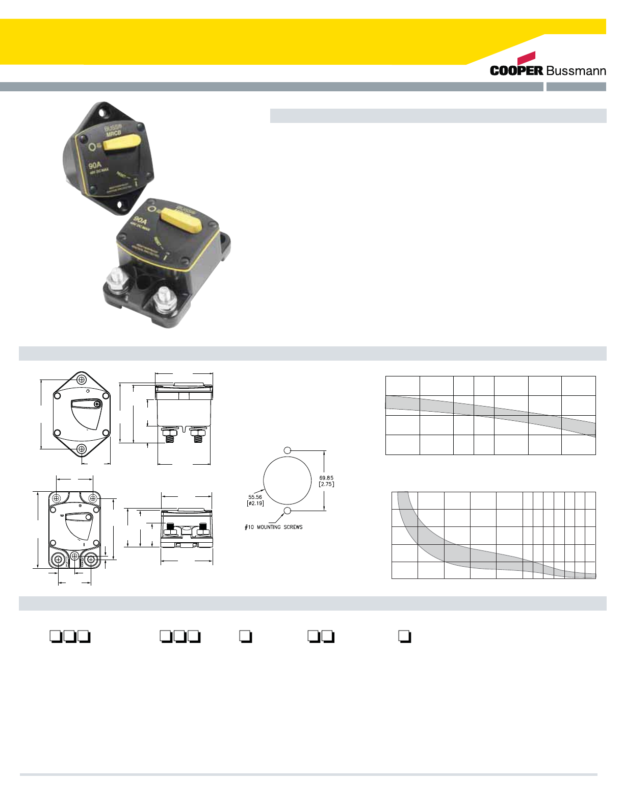
Series 187 Marine Rated Circuit Breaker (MRCB)
Specifications
Single Pole Thermal Type Breakers
Applications: Typically used in DC power systems in marine applications (as a main or
branch circuit breaker), truck and bus systems, RV systems, add-on protection for
accessories, lift gates, etc. This unit is external ignition protected and weatherproof.
Rating: 25-150A, 48Vdc
Interrupt Rating: Main Breaker Protection Interrupt Rating (5kA@ 12Vdc). (Consult factory for
higher voltage interrupt ratings.)
Operating Temperature Rating: –40°F (–40°C) to 185°F (85°C)
Storage Temperature Rating: –40°F (–40°C) to 260°F (125°C)
Materials: Black UL-rated 94V0 thermoset plastic body. Cover and lever are UL-rated 94V0
thermoplastic
Marking: Standard marking includes amp/volt ratings. Custom markings also available
Termination: 5/16-18 threaded studs
Torque Rating: 75 in-lbs (8.5Ntm) max
Mounting Torque Rating: Panel or surface-mount options; 50 in-lbs (5.6 Ntm) max
Ingress Protection Rating: IP66
Features / Options: A manual reset circuit breaker with On-Off switch capability
Compliances: ABYC E-11; CE; SAE J1171 (ignition protected)
Consult factory for time characteristic curves.
Manual Reset Circuit Breakers With Switch Function
Dimensions - mm(in)
Part Numbering System
(Dims. shown are for reference only. Consult factory for latest prints)
R
MRCB
BUSS
TRIP
OFF
RESET
48V DC MAX
25A
IGNITION PROTECTED
WEATHERPROOF
69.85
[2.750]
28.84
[1.135]
ON 16.76
[.660]
26.81
[1.056]
53.47
[2.105]
57.68
[2.271]
(2.24)
56.8
(2.32)
59.0
(1.06)
27.1
(1.64)
41.6
( .72)
43.8
( 2.72)
69.0
(.16)
3.9
(1.46)
37.1
(.73)
18.6
(3.44)
87.3
60.34
[2.375]
58.15
[2.289]
MRCB
25A
48V DC MAX
WEATHERPROOF
IGNITION PROTECTED
RESET
BUSS
OFF
ON
Panel Mount
Mounting Template
Firewall Mount
Series
18 7
187 – Manual Reset - Switching
Style Circuit Breaker
Rating
025 – 25 amps
030 – 30 amps
035 – 35 amps
040 – 40 amps
050 – 50 amps
060 – 60 amps
070 – 70 amps
080 – 80 amps
100 – 100 amps
110 – 110 amps
120 – 120 amps
135 – 135 amps
150 – 150 amps
200 – 200 amps
Mounting
–
F – Surface mount
P – Panel mount
Hardware
–
00 – No hardware
03 – Stainless nuts &
lockwashers - installed
on studs
04 – Stainless nuts &
lockwashers - supplied
bulk packed
Marking
1 – Standard marking; Part Number,
Amp Rating
(Consult factory for special marking options.)
0 5 10 15 20 30 40 50 100 150 200 400 600
600%
500%
400%
300%
200%
100%
Time vs Percent of Rated Current
Time in seconds
0
'
3
"
5
&
%
$
6
3
3
&
/
5
Temperature Derating Curves
Temperature in Degrees F.
0
'
3
"
5
&
%
$
6
3
3
&
/
5-50˚ F 0˚ F 50˚ F 77˚ F 100˚ F 150˚ F 200˚ F 250˚ F
0%
50%
100%
150%
200%
Cooper Bussmann Transportation Products t1IPOFt'BYtXXXDPPQFSCVTTNBOODPN 73
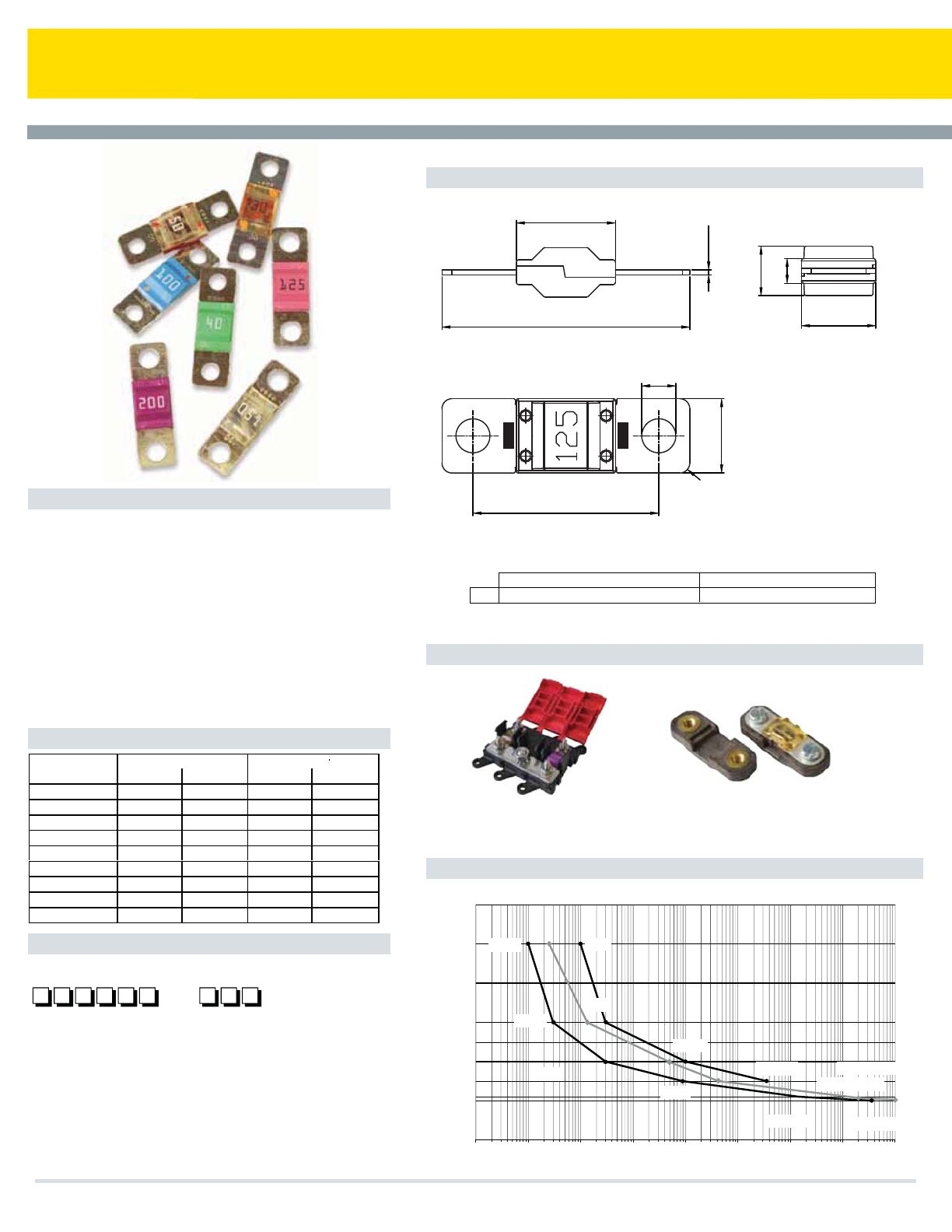
AMI Series
16
40
.84
8.2
4.1
12
12
R 1.6
30
Time-Current Specifications
30A …….. 125A 150A ……. 200A
% OF RATING Min. Max. Min. Max.
75% -- -- 360.000s
100% 360.000s
-- --
110% 14.400s
-- --
150% 90s 3.600s -- --
200% 3s 100s 1s 15s
300% 0.3 3s -- --
350% -- -- 0.3s 5s
500% 0.1 1s -- --
600% -- -- 0.1s 1s
[In% ]
100%In >
360.000s
110%In >14.400s
3.600 sec.
150%
3 sec.
360.000 sec.
1 sec.
14.400sec.
90 sec.
3 sec.
0,1 sec.
250%
0,3 sec.
100 sec.
0%
200%
300%
400%
500%
600%
0.01
110%
100%
0.1 1 10 100 1000 10000 100000 [s] 1000000
LMI3-M-2-A1L IFH-AMI-M5 (or M6)
Holders
Time-Current Curve
Series
–
B K - A M I
Rating
030 – 30 amps (orange)
040 – 40 amps (green)
050 – 50 amps (red)
060 – 60 amps (yellow)
070 – 70 amps (brown)
080 – 80 amps (white)
100 – 100 amps (blue)
125 – 125 amps (pink)
150 – 150 amps (gray)
175 - 175 amps (light brown)
200 - 200 amps (violet)
Dimensions - mm (Dims. shown are for reference only. Consult factory for latest prints)
Bolt In Automotive Fuses
Specifications
Applications: Power distribution protection for
automotive systems. Fuse holder shown on right.
Current Rating: 30-200A
Voltage Rating: 32Vdc
Interrupt Rating: 2000A @ 32Vdc; 5000A@ 16Vdc
Housing Material: UL-rated 94V0 thermoplastic
Terminal Material: Tin-plated brass
Mounting: Max torque of 35 in-lbs (4Ntm)
Marking: Color-coded housings for each amperage
Compliances: SAE J1171 (ignition protected); ISO 8820-5
Part Numbering System
A
≤125A >125A
Hole for a bolt diameter of M5 and/or M6 Hole for a bolt diameter of M6
A
(Available for up to 6 fuses) (Single Fuse Only)
Cooper Bussmann Transportation Products t1IPOFt'BYtXXXDPPQFSCVTTNBOODPN
74
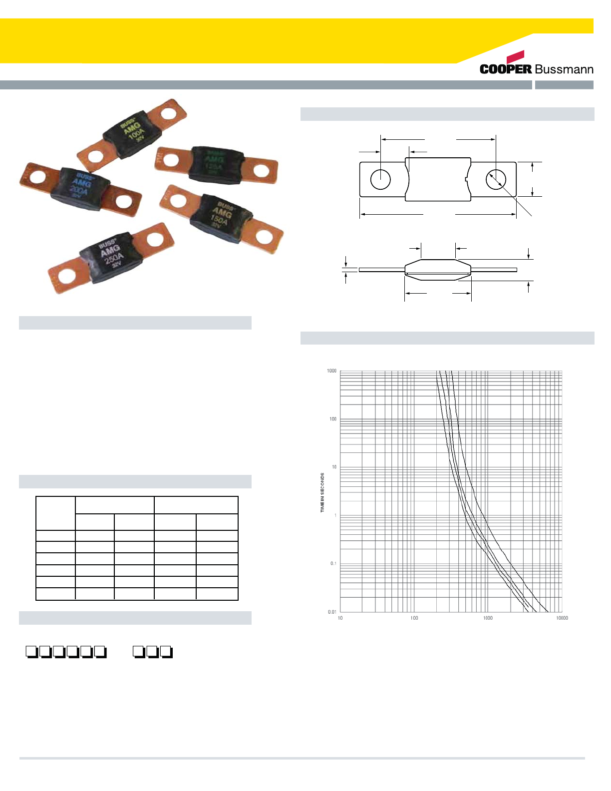
AMG Series
Dimensions - mm(in)
Time-Current Curves
Time-Current Specifications
Bolt In Automotive Fuses
Part Numbering System
Applications: For high current applications. Use with Cooper
Bussmann HMG or FMG fuseholders. (See pages 48-49.)
Current Rating: 100-300A.
Voltage Rating: 32Vdc*
Interrupt Rating: 1,000A @ 32Vdc
Housing Material: UL-rated 94V0 thermoplastic
Terminal Material: Copper
Mounting: M8 or 5/16-18 or less studs on 2.00 in (50.8mm) centers
Max torque of 8.1 to 9.6 ft-lbs (12 ±1Ntm)
Marking: Color-coded amperage ratings
Compliances: SAE J1171 (ignition protected), ISO 8820-5
*Consult factory for higher voltage fuses.
Series
–
B K - A M G
Rating
100 – 100 amps
125 – 125 amps
150 – 150 amps
175 – 175 amps
200 – 200 amps
225 – 225 amps
250 – 250 amps
300 – 300 amps
400 – 400 amps
68.40
(2.693)
29.20
(1.150)
1.52
(0.06)
9.00
(0.354)
29.20
(1.150)
15.40
(0.606)
50.80
(2.000)
12.18
(0.480)
Ø8.60
(0.339)
150
175
200
250
% of
Rating
80A-250A 300A-500A
Min. Max. Min. Max.
75%
100%
135%
200%
350%
600%
4 hrs
120s
1s
0.3x
0.1s
∞
1800s
15s
5s
1s
1s
0.5s
0.1s
15s
5s
1s
4 hrs ∞
- - - -
- - - -
- - - -
500 - 500 amps
Amp
Rating
Current in Amps
Cooper Bussmann Transportation Products t1IPOFt'BYtXXXDPPQFSCVTTNBOODPN 75
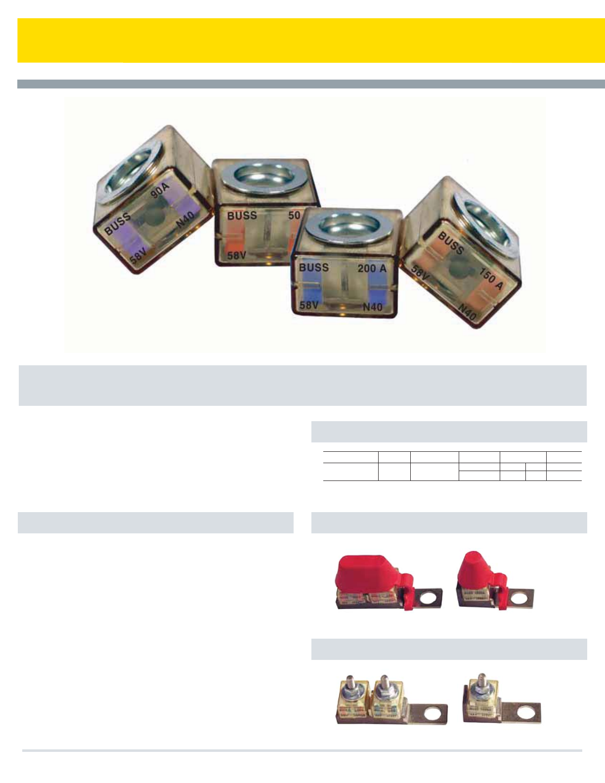
Marine Rated Battery Fuse
Specifications
Operating Times
CF Cover
CF Bar
Designed for the most demanding environment to provide high current
protection for the tightest space constraints. Suitable for main and
auxiliary circuit protection such as alternator outputs, starter motor
inputs and accessory circuits. The breaking capacity meets the
requirements of conventional vehicle batteries and 12V, 24V and 42V
electrical networks.
About MRBF-XXX Series Marine Rated Battery Fuse
Rating
30A - 300A
100%
> 100 h
135%
Max 900 sec
200%
max.
60s
350%
min. max.
0.1s 1 s
600%
< 0.2s
Applications: Full range circuit protection for automotive and marine
applications. Break in capacity meets the requirements of conventional
vehicle batteris and 42V electrical networks
Voltage Rating: 58Vdc Maximum
Amperage Rating: 30A - 300A
Ingress Protection: IP66
Ignition Protected: Per SAEJ1117
Interrupt Rating:
10000 AMP @ 14Vdc
5000 AMP @ 32Vdc
2000 AMP @ 58Vdc
Color Coded (see next page)
Torque Rating: Maximum 12 Ntm (106 in-lbs)
Material:
Body - Ceramic
Housing & Cover: UL-rated 94V0 Thermoplastic
Ring Terminals - Tin Plated
Compliances: ISO 8820-6
Cooper Bussmann Transportation Products t1IPOFt'BYtXXXDPPQFSCVTTNBOODPN
76
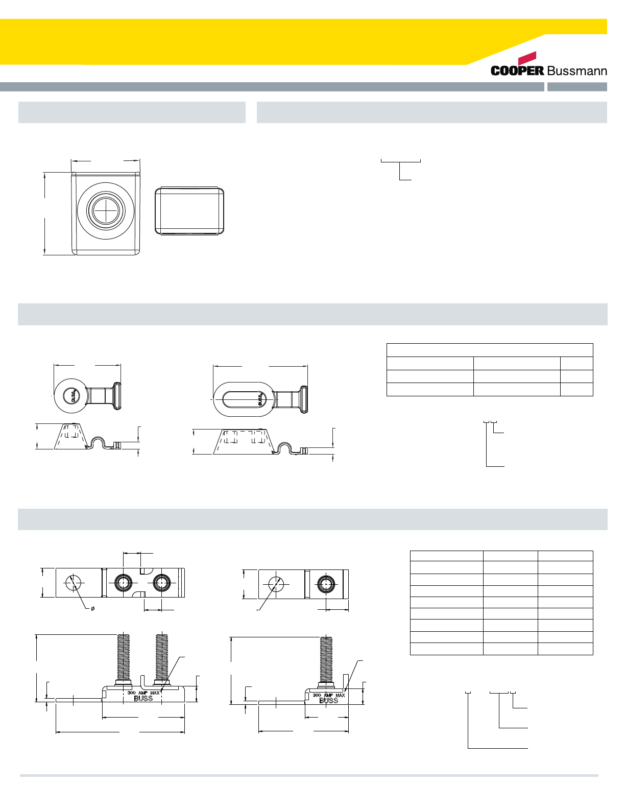
Marine Rated Battery Fuse
MRBF Dimensions - mm(in) Part Numbering System
CF Cover Dimensions - mm(in)
23.0 REF
(0.91)
27.8
(1.09)
BUSS
58V
XXXA
. XXX
Fuse Amperages
MRBF - X X X
030 - 30 AMPS [ LT GREEN ]
040 - 40 AMPS [ LT BLUE ]
050 - 50 AMPS [ RED ]
060 - 60 AMPS [ GOLD ]
075 - 75 AMPS [ BROWN ]
080 - 80 AMPS [ LIME ]
090 - 90 AMPS [ PURPLE ]
100 - 100 AMPS [ YELLOW ]
125 - 125 AMPS [ GREEN ]
150 - 150 AMPS [ ORANGE ]
175 - 175 AMPS [ WHITE ]
200 - 200 AMPS [ BLUE ]
225 - 225 AMPS [ TAN ]
250 - 250 AMPS [ PINK ]
300 - 300 AMPS [ GREY ]
58.3
(2.29)
22.0
(0.87)
6.0
(0.24)
BUS BAR STUD COVER-SINGLE BUS BAR STUD COVER-DOUBLE
22.0
(0.87)
6.0
(0.24)
82.2
(3.24)
CF Bar Dimensions - mm(in)
20.0
(.79)
12.0
(.47)
2.5
(0.10)
88.5
(3.48)
56.5
(2.22)
2.5
(.10)
61.9
(2.44)
30.0
(1.18)
11.0
(.43)
15.5
(.61)
20.0
(.79)
12.0
(.47)
“B”
“See Table”
“A”
“See Table”
Laser Marking
on Surface
“A”
“See Table”
Laser Marking
On Surface
Material and Finish Table
Part Number
CFCOVER-XB
CFCOVER-XR
MATERIAL
SANTOPRENE
SANTOPRENE
COLOR
BLACK
RED
Part #
CFBAR1 - 250SP
CFBAR1 - M8XSP
CFBAR1 - 250BP
CFBAR1 - M8XBP
CFBAR2 - 250SP
CFBAR2 - M8XSP
CFBAR2 - 250BP
CFBAR2 - M8XBP
DIM. “A”
44.5 [1.75]
46.5 [1.83]
44.5 [1.75]
46.5 [1.83]
44.5 [1.75]
46.5 [1.83]
44.5 [1.75]
46.5 [1.83]
DIM. Ø “B”
10.3 [0.405]
10.3 [0.405]
13.5 [0.531]
13.5 [0.531]
10.3 [0.405]
10.3 [0.405]
13.5 [0.531]
13.5 [0.531]
Table:
CFBARX - XXXXP
1 - Single Stud
2 - Double Stud
250 - 1/4-20 stud
M8X - M8 stud
S - 3/8” Mounting Hole
B - 1/2” Mounting Hole
CFCOVER-XX
Cover Color
B - Black
R - Red
Stud
1 - Single Stud
2 - Double Stud
Ø “B”
“See Table”
Cooper Bussmann Transportation Products t1IPOFt'BYtXXXDPPQFSCVTTNBOODPN 77
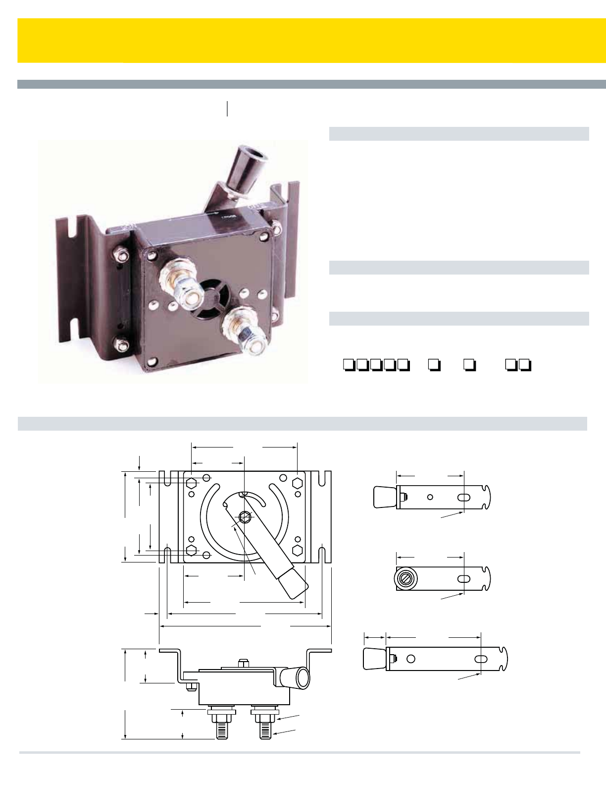
Series 15250
Dimensions - mm(in) (15250-1b Shown)
Specifications
Options
Part Numbering System
Battery Disconnect Switch
Applications: A non-fused current interrupt disconnect designed for
opening the circuit between a battery and the complete electrical load of a
battery-powered system.
Rating: 400A continuous,. 50Vac/Vdc. Vehicle cranking and max. surge
currents to 2000A (based on 20% duty cycle with ON times of 5 seconds
max.).
Temperature Rating: –40°F (–40°C) to 150°F (65°C).
Termination: 1/2-13 Copper alloy stud.
Torque Rating: 420 in-lbs (47.5Ntm) max.
Mounting Torque Rating: With mounting brackets: 48 in-lbs (5.4Ntm)
max; without mounting brackets: 10 in-lbs (1.1Ntm) max.
Handles: Three handle styles available.
Other: Lubricant-filled body with silicone sealant.
Series
–
15250
Bracket
Option
Lubricant
w/Sealant
LR
Handle
Option
1
2
3
B – Bracket (Grease Filled)
ON
ON
OFF
(3.81)
96.8
(1.56)
39.7
(1.12)
28.4
(.50)
12.7
(2.75)
69.8
Point A
(5.5)
139.7
(7.0)
177.8
(8.0)
203.2
(4.19)
106.4
(3.5)
88.9
(3.0)
76.2
(.59)
15.1
(4.87)
123.8
(2.44)
61.9
(1.25)
31.7
(3.12)
79.4
Ref. Point A
Ref. Point A
Ref. Point A
(3.00)
76.2
(4.50)
114.3
15250-1
15250-2
15250-3
1/2-13 Copper alloy stud
Stainless washers and locknuts supplied
Handle Variations
(Dims. shown are for reference only. Consult factory for latest prints)
Ref.
Cooper Bussmann Transportation Products t1IPOFt'BYtXXXDPPQFSCVTTNBOODPN
78

Circuit Protection Notes
Cooper Bussmann Transportation Products t1IPOFt'BYtXXXDPPQFSCVTTNBOODPN 79
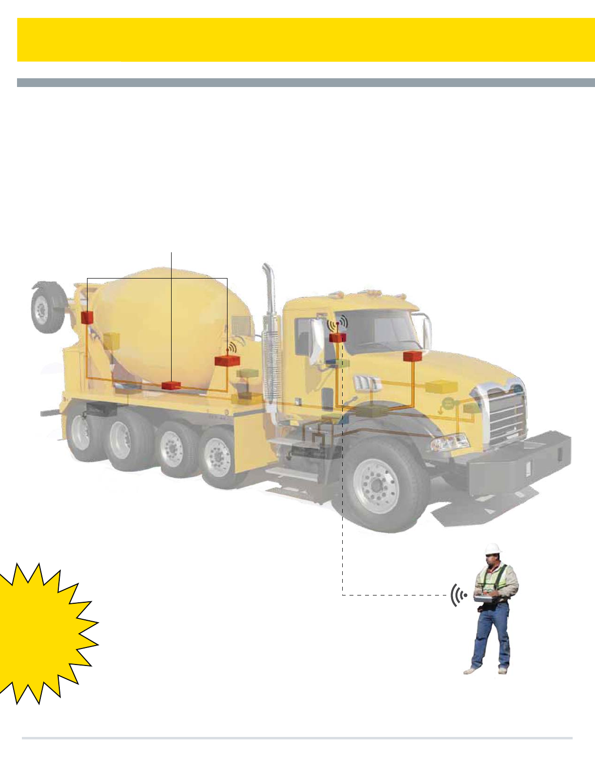
Mobile Vehicle Controls
Cooper Bussmann Transportation Products t1IPOFt'BYtXXXDPPQFSCVTTNBOODPN
Off-the-shelf and custom-designed
products for the distribution of I/O,
on-chassis communication and remote
vehicle control
Distributed I/O
Radio Remote Control
t8JSFEBOEXJSFMFTTEJTUSJCVUFE
NBDIJOFDPOUSPM
t3FMJBCMFNBOUPNBDIJOF
DPOUSPMTZTUFNT
CAN (J1939)
interfaces
80

Mobile Vehicle Controls
Cooper Bussmann Transportation Products t1IPOFt'BYtXXXDPPQFSCVTTNBOODPN
Proprietary Radio Technologies
r0./&953645&%8*3&-&44')44
Global Radio Certifications
r.)[()[
Wide Operating Temperature Range
r$UP$'UP'
Exceptional Battery Performance
rUPIPVSTDPOUJOVPVTUSBOTNJUUFSVTF
EFQFOEJOHPOBQQMJDBUJPOXJUISFDIBSHF
DBQBCJMJUZ
High Impact Product Construction
r-PXUFNQFSBUVSFQMBTUJDXFBUIFSQSPPG6-
"$%"45.%
Modular HW Designs and Customized SW
Control Algorithms
r*OIPVTFBQQMJDBUJPOTFOHJOFFSJOHEFEJDBUFEUP
OFX0&.QSPEVDUEFWFMPQNFOU
Certifications
r'$$*4$PUIFSTPOSFRVFTU
5
5
5
5
3
3
3
3
%
%
Transmitters
Recievers
Expansion Modules
Page
Page
Page
5
81
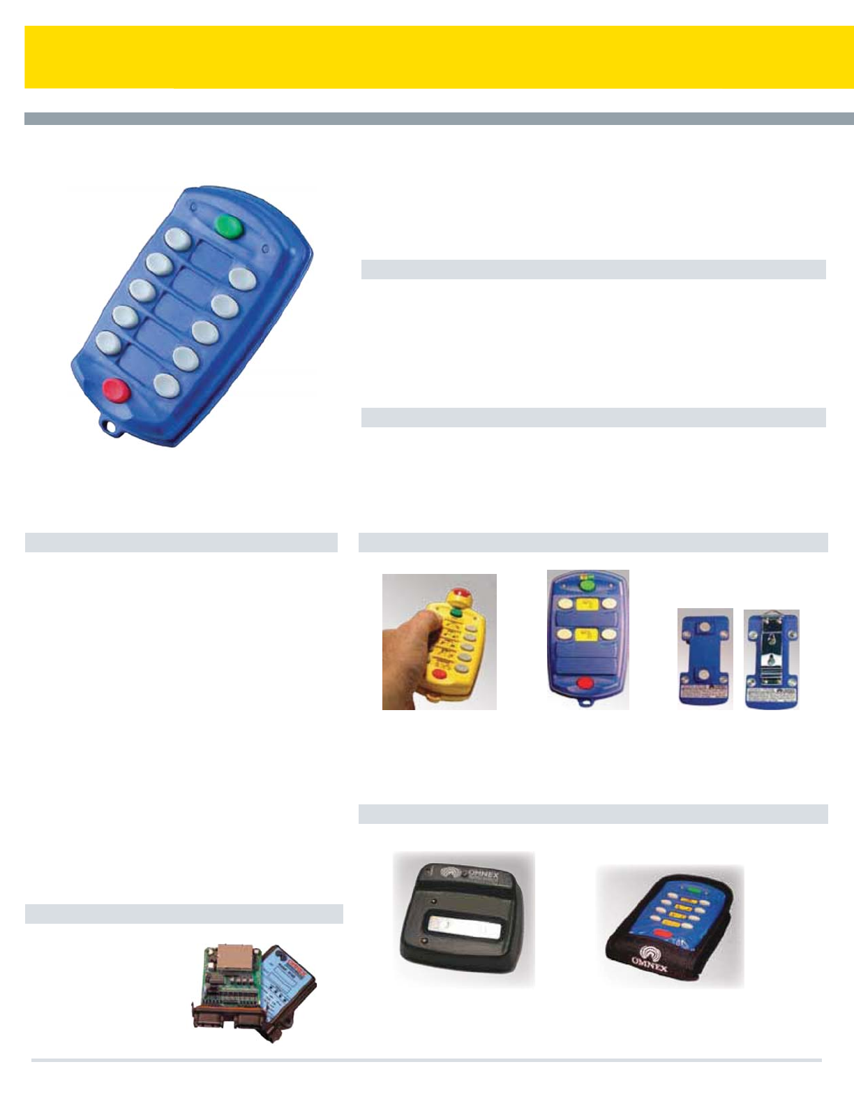
T110 Transmitter
Cooper Bussmann Transportation Products t1IPOFt'BYtXXXDPPQFSCVTTNBOODPN
Features
Applications
Specifications Options
Accessories
The T110 will work with the following recievers
5IF0./&903*("5USBOTNJUUFSJTBDPOmHVSBCMFHMPCBMMJDFOTFGSFFSBEJP
SFNPUFDPOUSPM6TJOH0./&9hT5SVTUFE'SFRVFODZ)PQQJOH4QSFBE4QFDUSVN
UFDIOPMPHZUIJTSFNPUFEFMJWFSTTVQFSJPSQFSGPSNBODFBOESFMJBCJMJUZVOEFSUIF
UPVHIFTUDPOEJUJPOT5IFIJHIJNQBDUQMBTUJDFYUFSJPSBMMPXTUIF5UPCFVTFEJO
FWFOUIFNPTUSVHHFEFOWJSPONFOUT%FWFMPQFEXJUIPQFSBUPSTBGFUZBOEFBTFPGVTF
JONJOEUIF03*("5mUTDPNGPSUBCMZJOZPVSIBOEIBOHTGSPNBMBOZBSEPSmUTJO
ZPVSQPDLFU
t'VODUJPODPOUSPMTXJUI4)*'5
t6OJRVF*%DPEFGPSFBDIUSBOTNJUUFS
SFDFJWFSQBJS
t)PVSTPO""BMLBMJOFCBUUFSJFT
tGUSBOHFBU.)[GU
!()[
t()[3BEJPBWBJMBCMFGPS(MPCBM
BQQMJDBUJPOT
t4FMGEJBHOPTUJDT
t'BDUPSZDPOmHVSBCMFGPSDVTUPNBQQMJDBUJPOT
t5SVDLNPVOUFEDSBOFT
t5PXUSVDLT
t8JODIFT
t7BDVVNUSVDLT
t4FSWJDFDSBOFT
t.JYFSUSVDLT
t.BUFSJBMIBOEMJOHFRVJQNFOU
t.BSJOF
Operator Keys: 1PXFS0/0''GVODUJPOLFZT
*OEJDBUPST%JBHOPTUJDT#"55&3:"$5*7&-&%
4UBUVT*OEJDBUPST
Security: 'BDUPSZQSPHSBNNFEXJUIVOJRVF*%DPEF
$3$FSSPSEFUFDUJPO
Input Power: ""BMLBMJOFCBUUFSJFT
Battery Life: )PVSTDPOUJOVPVTVTF
Operating Temperature Range: ¡'UP¡'
¡$UP¡$
Size: wYYwNNYNNYNN
Weight:MCTH
Construction:)JHIJNQBDUMPXUFNQFSBUVSFQMBTUJD
XFBUIFSQSPPG6-"$%*&$
Frequency:UP.)[*4.CBOE
()[*4.CBOE
Antenna:*OUFSOBM
Approvals/Certificates: 64"'$$1BSU
$BOBEB*4$344
&VSPQFBO6OJPO$&
3'"QQSPWBM&/
Specifications subject to change without notice
3*0
3$"/CVT+
&4UPQWFSTJPO "WBJMBCMFJO
PSCVUUPOWFSTJPOT
0QUJPOBMNBHOFUPS
CFMUDMJQCBDL
$$%PDL
$POUBDUMFTT$IBSHF%PDL
"MM8FBUIFS1PVDI
82
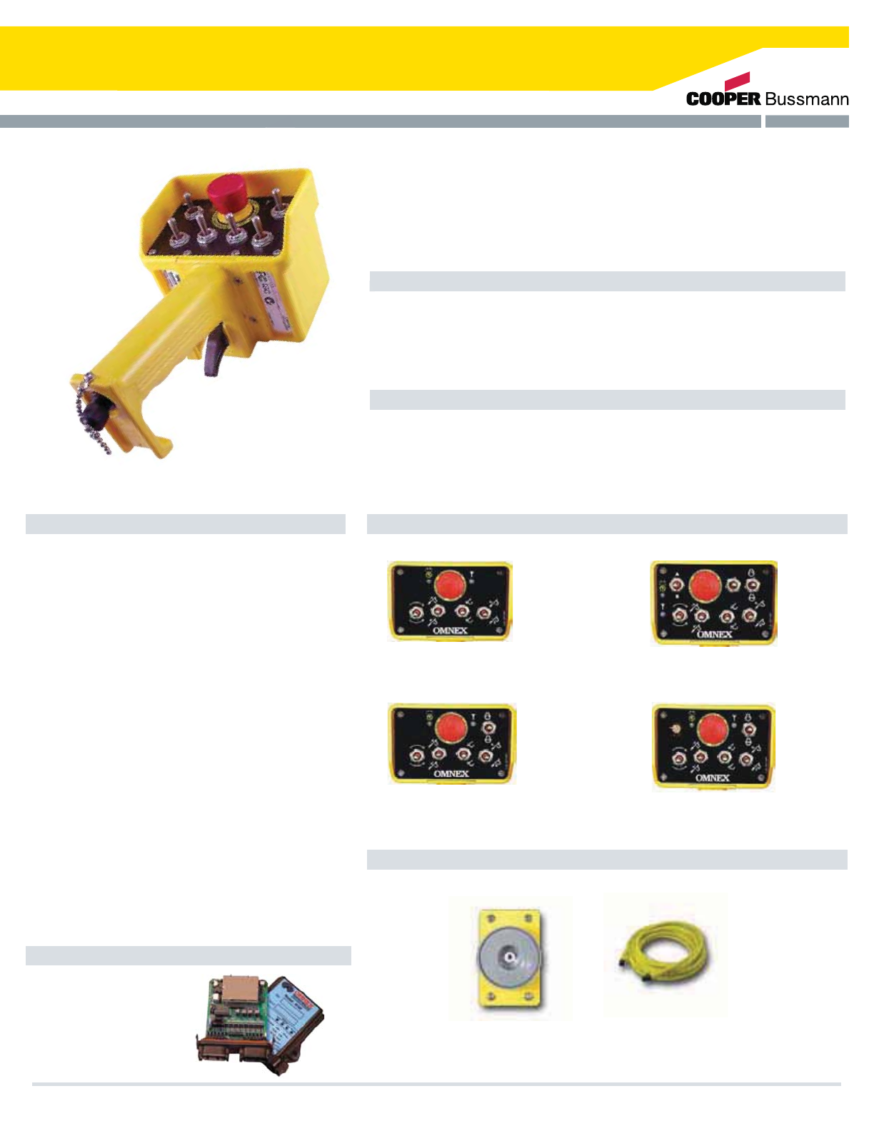
T150 Transmitter
Features
Applications
Specifications Options
Accessories
The T150 Will Work With The Following Recievers
The ORIGA T150 transmitter is a hand-held, user friendly radio remote control that
comes with a Hall Effect proportional trigger designed for smooth operation.
Weatherproof and lightweight, the ORIGA T150 can be configured to include a
resettable E-Stop switch. The T150 uses OMNEX's Trusted Frequency Hopping
Spread Spectrum technology to provide reliable performance even in the harshest
environments.
t5SVDLNPVOUFEDSBOFT
t5PXUSVDLT
t8JODIFT
t7BDVVNUSVDLT
t4FSWJDFDSBOFT
t.JYFSUSVDLT
t.BUFSJBMIBOEMJOHFRVJQNFOU
t.BSJOF
Operator Keys: 14 Functions + E-Stop One
proportional trigger
Indicators& Diagnostics: "$5*7&BOE-08#"55&3:
-&%4UBUVT*OEJDBUPST
Security: 'BDUPSZQSPHSBNNFEXJUIVOJRVF*%DPEF
CRC-16 error detection
Input Power: ""BMLBMJOFCBUUFSJFT
Battery Life: )PVSTDPOUJOVPVTVTF
Operating Temperature Range: -40 °F to 158 °F
¡$UP¡$
Size: wYYwNNYNNYNN
Weight:MCTH
Construction: HigHigh impact, low temperature plastic,
XFBUIFSQSPPG6-"$%*&$
Frequency:UP.)[*4.CBOE
()[*4.CBOE
Antenna: Internal
Approvals/Certificates: 64"'$$1BSU
$BOBEB*4$344
3'"QQSPWBM&/
Specifications subject to change without notice
R160 - 19 I/O
3$"/CVT+
Portable 14-Function Radio Remote Control
t0OFQSPQPSUJPOBMDPOUSPM)BMM&GGFDUUSJHHFS
t'VODUJPODPOUSPMTQMVTUXPQSPQPSUJPOBM
tGU3BOHFBU.)[GU!()[
t()[3BEJPBWBJMBCMFGPS
Global applications
t&4UPQ
t'BDUPSZDPOmHVSBCMFGPSDVTUPN
applications
t
t
t
4 switch - 8 digital outputs +
optional proportional trigger
5 switch - 10 digital outputs +
optional proportional trigger
7 switch - 14 digital outputs +
optional proportional trigger
5 switch - 10 digital outputs +
proportional dial + optional
proportional trigger
Magnet
Pendant Cable
Cooper Bussmann Transportation Products t1IPOFt'BYtXXXDPPQFSCVTTNBOODPN 83
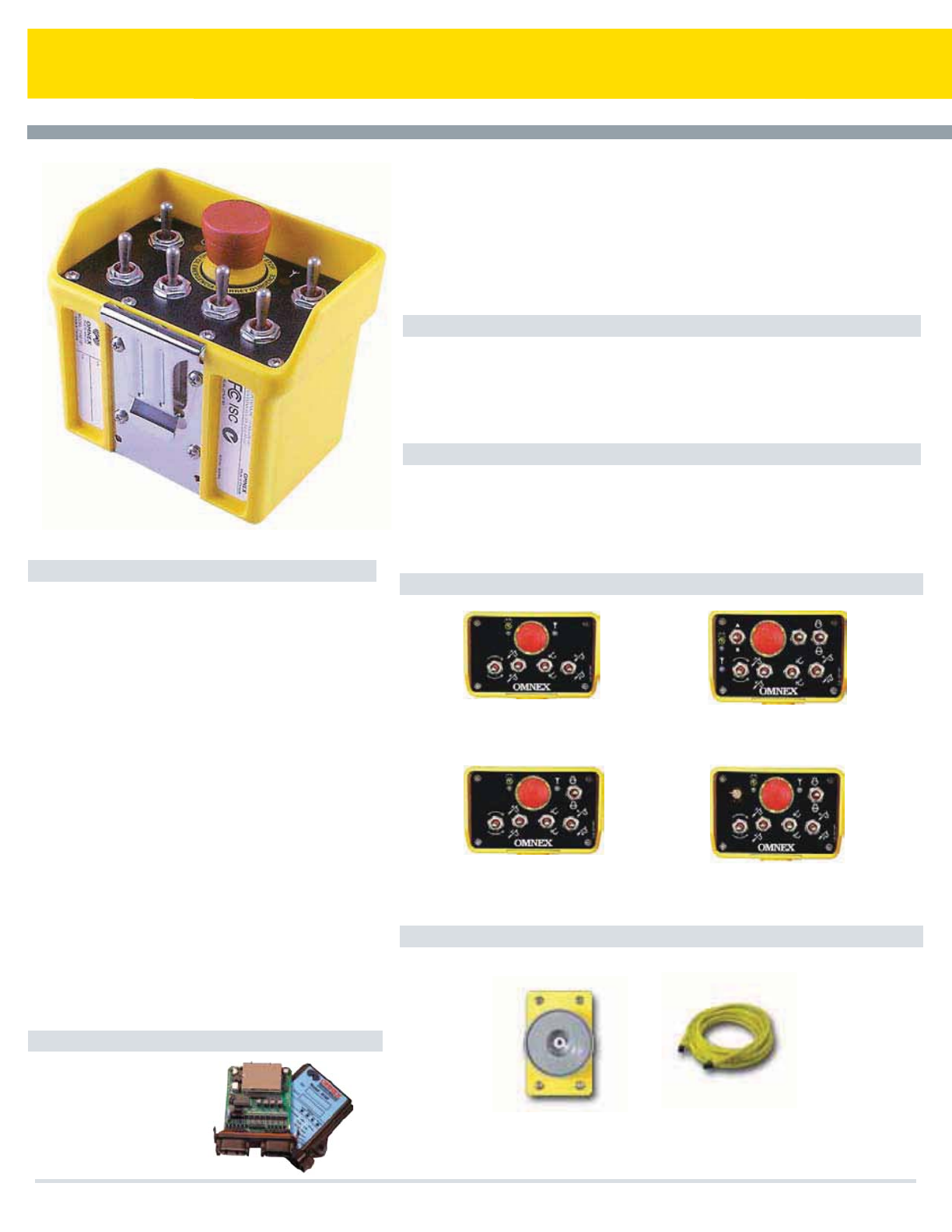
T151 Transmitter
Features
Applications
Specifications Options
Accessories
The T151 will work with the following recievers
The OMNEX ORIGA T151 transmitter is a configurable, license-free radio remote
control. With up to 5 switches and a potentiometer, this transmitter can accommodate
both digital and proportional controls. The ORIGA T151 is a flexible, compact, light
weight transmitter providing the user the ability to customize the remote for their
unique needs. Using OMNEX's Trusted Frequency Hopping Spread Spectrum
technology, this remote delivers superior performance and reliability under the
toughest conditions.
t5SVDLNPVOUFEDSBOFT
t5PXUSVDLT
t8JODIFT
t7BDVVNUSVDLT
t4FSWJDFDSBOFT
t.JYFSUSVDLT
t.BUFSJBMIBOEMJOHFRVJQNFOU
t.BSJOF
Operator Keys: 14 Functions + E-Stop one
proportional dial.
Indicators& Diagnostics: "$5*7&BOE-08#"55&3:
-&%4UBUVT*OEJDBUPST
Security: 'BDUPSZQSPHSBNNFEXJUIVOJRVF*%DPEF
CRC-16 error detection
Input Power: ""BMLBMJOFCBUUFSJFT
Battery Life: )PVSTDPOUJOVPVTVTF
Operating Temperature Range: -40 °F to 158 °F
¡$UP¡$
Size: wYYwNNYNNYNN
Weight:MCTH
Construction: High impact, low temperature plastic,
XFBUIFSQSPPG6-"$%*&$
Frequency: 902 to 928MHz - ISM band
2.4 - 2.483GHz - ISM band
Antenna: Internal
Approvals/Certificates: USA - FCC Part 15.247
Canada - ISC RSS 210
RF Approval EN 300 440
Specifications subject to change without notice
R160 - 19 I/O
3$"/CVT+
Portable 14-Function Radio Remote Control
t0OFQSPQPSUJPOBMDPOUSPM)BMM&GGFDUUSJHHFS
t%JHJUBMGVODUJPOT
tGU3BOHFBU.)[GU!()[
t()[3BEJPBWBJMBCMFGPS
Global applications
t&4UPQ
t'BDUPSZDPOmHVSBCMFGPSDVTUPN
applications
4 switch - 8 digital outputs +
optional proportional dial
5 switch - 10 digital outputs +
optional proportional dial
7 switch - 14 digital outputs +
optional proportional dial
5 switch - 10 digital outputs +
proportional dial + optional
proportional dial
Magnet
Pendant Cable
Cooper Bussmann Transportation Products t1IPOFt'BYtXXXDPPQFSCVTTNBOODPN
84
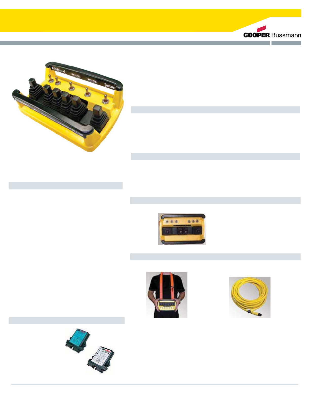
T300 Transmitter
Features
Applications
Specifications
Options
Accessories
The T300 will work with the following recievers
The ORIGA T300 is an easy to use weatherproof transmitter with up to 16 proportional
functions and 15 digital functions. The T300 can accommodate eight single axis
paddles or four dual axis joysticks; and up to eight three-position switches and a
re-settable E-Stop, giving the user a wide variety of customizable configurations to
choose from. A unique ID code is used by each T300 to ensure that no two systems
will conflict on a job site and the incorporation of OMNEX's Trusted Frequency
Hopping Spread Spectrum technology ensures that the T300 will provide reliable
performance even in the harshest environments.
t5SVDLNPVOUFEDSBOFT
t5PXUSVDLT
t6UJMJUZUSVDLT
t7BDVVNUSVDLT
t4FSWJDFDSBOFT
t.JYFSUSVDLT
t.BUFSJBMIBOEMJOHFRVJQNFOU
t.BSJOF
Operator Keys: 31 Functions + E-Stop up to eight
proportional paddles
Indicators & Diagnostics: BATTERY/PENDANT,
"$5*7&-&%&4501-&%4UBUVT*OEJDBUPST
Security: Factory programmed with unique ID code.
CRC-16 error detection
Input Power: 4C (alkaline) Batteries
Battery Life: 500 Hours
Operating Temperature Range: -40 °F to 158 °F
(-40 °C to 70 °C)
Size: 9.5” x 6.0" x 5.0”(240mm x 152mm x 127mm)
Weight: 3.5lbs (1.6kg)
Construction: High impact, low temperature plastic,
XFBUIFSQSPPG6-"$%
Frequency: 902 to 928MHz - ISM band
2.4 - 2.483GHz - ISM band
Antenna: Internal
Approvals/Certificates: 64"'$$1BSU
Canada - ISC RSS 210
Specifications subject to change without notice
R160 - 19 I/O
R170 - CANbus (J1939)
Portable 31-Function Radio Remote Control
t1SPQPSUJPOBMGVODUJPOT
t%JHJUBMGVODUJPOT
t)PVSTPOPOFTFUPG$
batteries
tGU3BOHFBU.)[
(900 ft. @ 2.4 GHz)
t()[3BEJPBWBJMBCMFGPS(MPCBM
applications
t3VHHFEBOEXFBUIFSQSPPG
t4FMGEJBHOPTUJDT
Expansion Modules:
D160 - 19 I/O
D180 - 14 proportional outputs
As shown:
6 switch - 11 digital funtions +
2 paddles - 4 proportional functions
2 joysticks - 8 proportional functions
Shoulder Strap Pendant Cable
Cooper Bussmann Transportation Products t1IPOFt'BYtXXXDPPQFSCVTTNBOODPN 85
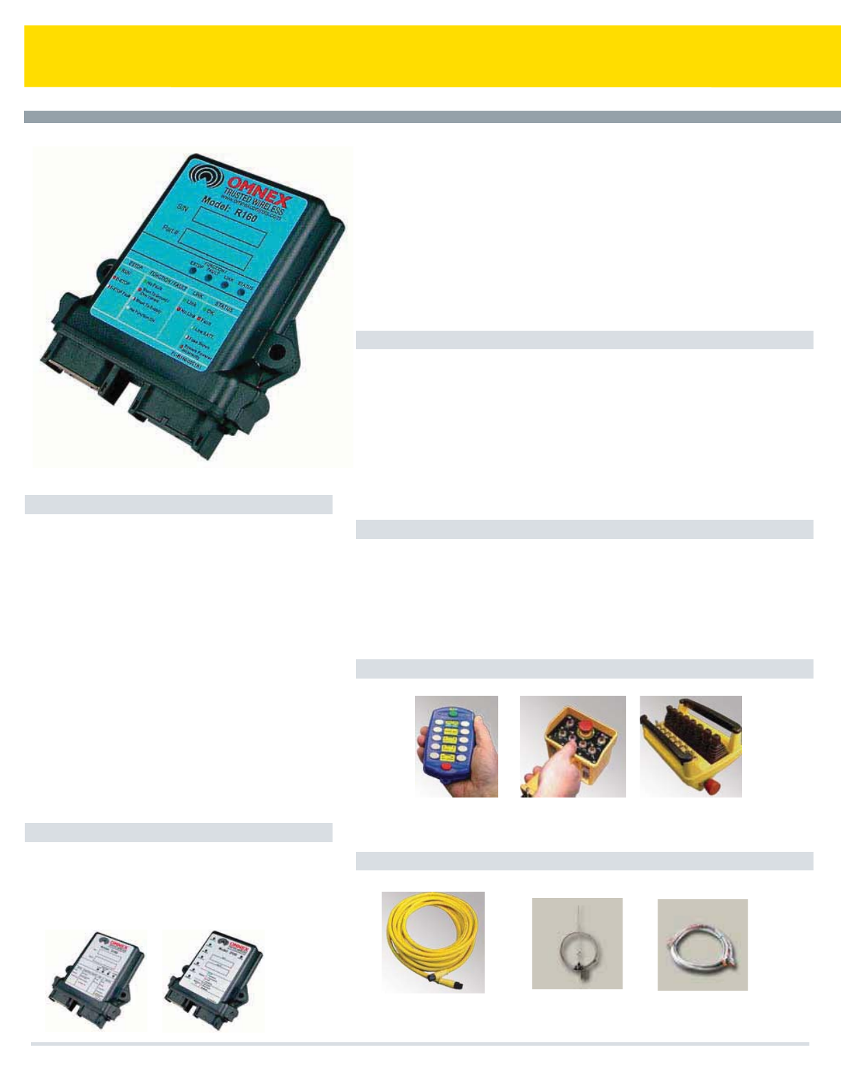
R160 Remote Control Reciever
Features
Applications
Compatible Transmitters
Accessories
Specifications
The OMNEX Trusted Wireless™ R160 receiver is a robust, license-free logic controller &
valve driver designed for smooth operation and precise control of industrial machinery in
global applications. The R160 receiver features 19 I/O combinations (more can be
achieved with expansion modules) and is fully customizable to operate momentary,
latched, toggled and interlocked functions. Depending on the application, the R160 can
provide digital and analog (current, voltage and PWM output) signals and an electronic
output for the safe shutdown of power to the outputs and external circuits. When used
with the T110C, the system is field configurable. Each R160 uses a unique ID code to
ensure no two systems will conflict on a job site and OMNEX trusted Frequency
Hopping Spread Spectrum technology to provide reliable performance and relentless
control even in the harshest environments.
t$PODSFUFQVNQUSVDLT
t-PBEIBVMEVNQ
t0GGSPBENBDIJOFT
t3PUBUPSUSVDLT
t.BUFSJBMIBOEMJOHFRVJQNFOU
t.BSJOFTUFFSJOHTUBUJPO
t5PXUSVDLT
t5SBDLUZQFNBDIJOFT
t-PDPNPUJWF
t.BOZNPSFBQQMJDBUJPOT
Outputs: 19 digital functions (with up to 4 proportional)
Inputs: 19 (outputs can act as inputs)
Indicators & Diagnostics: 'PVSTUBUVT-&%T*OUFSOBM
-&%T
Security: ID code programmed from transmitter,
CRC-16 error detection
Power: 9 - 32Vdc
Operating Temperature Range: -40 °F to 158 °F
(-40 °C to 70 °C)
Size: 5.1" x 4.7” x 1.4" (130mm x 119mm x 36mm)
Weight: .651bs (295g)
Construction: High impact plastic, weatherproof
Frequency: 902 to 928MHz - ISM band &
2.4 - 2.483GHz - ISM band
Antenna Connector: Internal or external (optional)
Approvals/Certificates:
R160 - USA - FCC Part 15 Class B
Canada - ISC RSS 210
European Union - CE
Specifications subject to change without notice - E&OE
19-Function Remote Controlled Reciever
t4UBOEBSE*0DPNCJOBUJPOTQSPQPSUJPOBMBOEEJHJUBM
t'JFMEDPOmHVSBCMFXJUIUIF5$
t*OUFSGFSFODFGSFFSFMFOUMFTTDPOUSPM
t&YDFMMFOUTFOTJUJWJUZGPSJODSFBTFEUSBOTNJUUFSSBOHF
t1FOEBOUDBQBCMF
t3VHHFEBOEXFBUIFSQSPPG
t'BDUPSZDPOmHVSBCMFGPSDVTUPNBQQMJDBUJPOT
The R160 will work with the following
Expansion Modules
D160 - 19 I/O
D180 - 14 proportional outputs
T110 - 10 (20) -Function
Hand-Held Radio
Remote Control
T150 - 14-Function
Hand-Held Radio
Remote Control
T300 - 31-Function Radio
Remote Control
Pendant Cable
(optional with T150 or T300)
External Antenna Output Cable
Cooper Bussmann Transportation Products t1IPOFt'BYtXXXDPPQFSCVTTNBOODPN
86
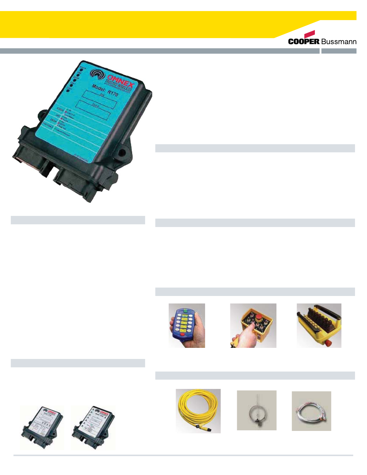
R170 CANbus Reciever
Features
Applications
Compatible Transmitters
Accessories
Specifications
The OMNEX Trusted Wireless™ R170 receiver is a robust, license-free logic controller and
valve driver designed for smooth operation and precise control of industrial machinery in
global applications. The R170 receiver is designed for CAN bus protocols and includes an
electronic output function, allowing for safe shutdown of power to the outputs and external
circuits. This receiver is compatible with SAE J1939 protocol and can be customized to
work with other CAN bus protocols. As well, it has an RS232 port for configuration,
diagnostics and firmware upgrades. Each R170 uses a unique ID code to ensure no two
systems will conflict on a job site and OMNEX trusted Frequency Hopping Spread
Spectrum technology to provide reliable performance and relentless control even in the
harshest environments.
t$PODSFUFQVNQUSVDLT
t-PBEIBVMEVNQ
t0GGSPBENBDIJOFT
t3PUBUPSUSVDLT
t.BUFSJBMIBOEMJOHFRVJQNFOU
t.BSJOF
t5PXUSVDLT
t5SBDLUZQFNBDIJOFT
t5SVDLDIBTJT
t.BOZNPSFBQQMJDBUJPOT
Outputs: $"/CVT+3434
Inputs: CAN bus (J1939)
Indicators & Diagnostics: 'JWFTUBUVT-&%T
Security: ID code programmed from transmitter.
CRC-16 error detection
Power: 9 - 32VDC
Operating Temperature Range: ¡'UP¡'
¡$UP¡$
Size: YwYNNYNNYNN
Weight:MCTH
Construction: High impact plastic, weatherproof
Frequency:UP.)[*4.CBOE
()[*4.CBOE
Antenna Connector: Internal or external (optional)
Approvals/Certificates:
364"'$$1BSU$MBTT#
Canada - ISC RSS 210
3#&VSPQFBO6OJPO$&
Specifications subject to change without notice - E&OE
The R170 will work with the following
Expansion Modules
%*0
%QSPQPSUJPOBMPVUQVUT
T110 - 10 (20) -Function
Hand-Held Radio
Remote Control
5'VODUJPO
Hand-Held Radio
Remote Control
T300 - 31-Function Radio
Remote Control
Pendant Cable
PQUJPOBMXJUI5PS5
t$"/CVT+$"/PQFOFUDDPNNVOJDBUJPO
t.)[BOE()[BWBJMBCMF
t*OUFSGFSFODFGSFFSFMFOUMFTTDPOUSPM
t&YDFMMFOUTFOTJUJWJUZGPSJODSFBTFEUSBOTNJUUFSSBOHF
t1FOEBOUDBQBCMF
t3VHHFEBOEXFBUIFSQSPPG
t%JBHOPTUJDJOEJDBUPST
External Antenna Output Cable
Cooper Bussmann Transportation Products t1IPOFt'BYtXXXDPPQFSCVTTNBOODPN 87
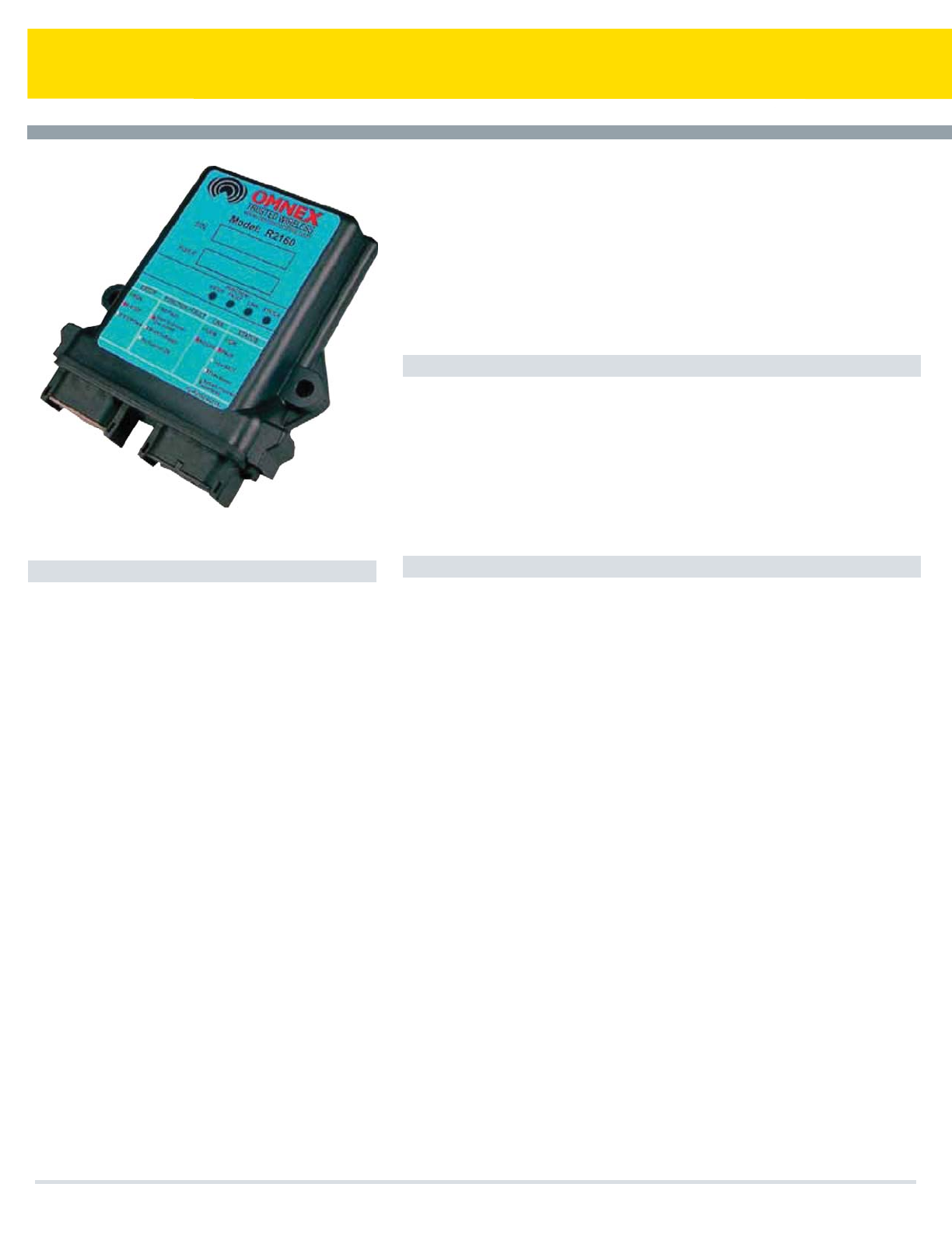
R2160 Two-Way Remote Control Receiver
FEATURES
APPLICATIONS
SPECIFICATIONS
The OMNEX Trusted Wireless™ R2160 receiver is a robust , license-free logic controller and
valve driver designed for smooth operation and precise control of industrial machinery in
global applications. The R2160 receiver features 19 1/0 combinations (more can be
achieved with expansion modules) and is fully customizable to operate momentary, latched,
toggled and interlocked functions. 2-Way communication provides the operator with
machine and diagnostic feedback. Depending on the application, the R2160 can provide
digital and analog (current, voltage and PWM output) signals and an electronic output for
the safe shutdown of power to the outputs and external circuits. Each R2160 uses a unique
ID code to ensure no two systems will conflict on a job site and OMNEX trusted Frequency
Hopping Spread Spectrum technology to provide reliable performance and relentless
control even in the harshest environments.
t$PODSFUFQVNQUSVDLT
t-PBEIBVMEVNQ
t0GGSPBENBDIJOFT
t3PUBUPSUSVDLT
t.BUFSJBMIBOEMJOHFRVJQNFOU
t.BSJOF
t5PXUSVDLT
t5SBDLUZQFNBDIJOFT
t5SVDLDIBTJT
t.BOZNPSFBQQMJDBUJPOT
Outputs: 19 digital functions (with up to 4 proportional)
Inputs: 19 (outputs can act as inputs)
Indicators & Diagnostics: 'PVSTUBUVT-&%T*OUFSOBM
-&%T
Security: *%$PEFQSPHSBNNFEGSPNUSBOTNJUUFS
$3$FSSPSEFUFDUJPO
Power: 9 - 32Vdc
Operating Temperature Range: -40 °F to 158 °F
¡$UP¡$
Size: YwYNNYNNYNN
Weight: .65 lbs (295g)
Construction: High impact plastic, weatherproof
Frequency: 902 to 928MHz - ISM band &
2.4 - 2.483GHz - ISM band
Antenna Connector: Internal or external (optional)
Approvals/Certificates:
3364"'$$1BSU$MBTT#
$BOBEB*4$344
3#&VSPQFBO6OJPO$&
Specifications subject to change without notice - E&OE
t4UBOEBSE*0DPNCJOBUJPOTQSPQPSUJPOBMBOEEJHJUBM
t8BZDPNNVOJDBUJPO
t*OUFSGFSFODFGSFFSFMFOUMFTTDPOUSPM
t&YDFMMFOUTFOTJUJWJUZGPSJODSFBTFEUSBOTNJUUFSSBOHF
t1FOEBOUDBQBCMF
t3VHHFEBOEXFBUIFSQSPPG
t'BDUPSZDPOmHVSBCMFGPSDVTUPNBQQMJDBUJPOT
Cooper Bussmann Transportation Products t1IPOFt'BYtXXXDPPQFSCVTTNBOODPN
88
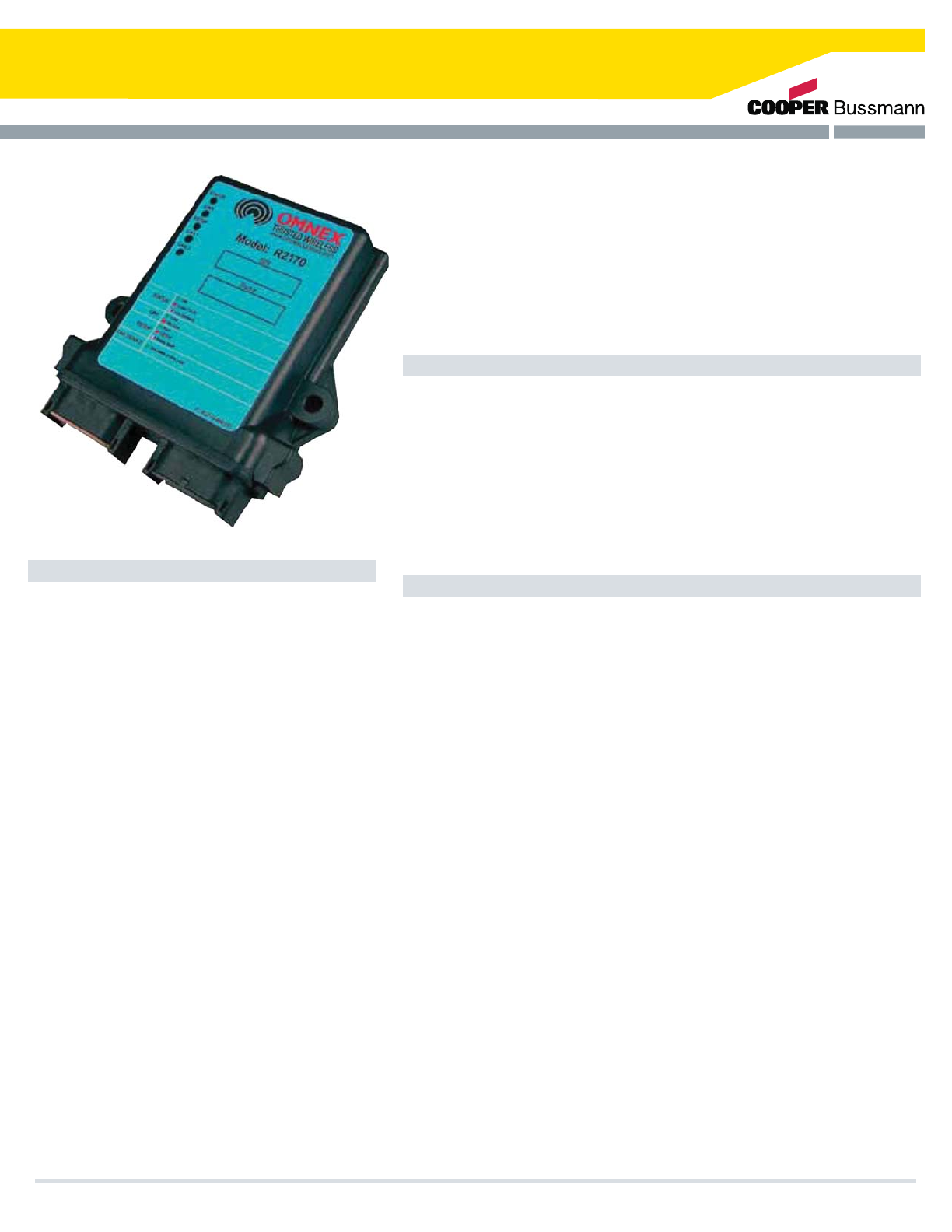
R2170 CANbus 2-Way Reciever
Features
Applications
Specifications
The OMNEX Trusted Wireless™ R2170 receiver is a robust, license-free logic controller and
valve driver designed for smooth operation and precise control of industrial machinery in
global applications. The R2170 receiver is designed for CAN bus protocols and includes an
electronic output function, allowing for the safe shutdown of power to the outputs and
external circuits. This receiver is compatible with SAE J1939 protocol and can be
customized to work with other CAN bus protocols. As well, it has an RS232 port for
configuration, diagnostics and firmware upgrades. This receiver can act as a CAN bridge
with 2-Way communication capabilities, providing the operator with machine and diagnostic
feedback. Each R2170 uses a unique ID code to ensure no two systems will conflict on a
job site and OMNEX trusted Frequency Hopping Spread Spectrum technology to provide
reliable performance and relentless control even in the harshest environments.
t$PODSFUFQVNQUSVDLT
t-PBEIBVMEVNQ
t0GGSPBENBDIJOFT
t3PUBUPSUSVDLT
t.BUFSJBMIBOEMJOHFRVJQNFOU
t.BSJOF
t5PXUSVDLT
t5SBDLUZQFNBDIJOFT
t5SVDLDIBTJT
t.BOZNPSFBQQMJDBUJPOT
Outputs: $"/CVT+3434
Inputs: CAN bus (J1939)
Indicators & Diagnostics: 'JWFTUBUVT-&%T
Security: ID code programmed from transmitter,
CRC-16 error detection
Power: 9 - 32Vdc
Operating Temperature Range: ¡'UP¡'
¡$UP¡$
Size: YwYNNYNNYNN
Weight:MCTH
Construction: High impact plastic, weatherproof
Frequency:UP.)[*4.CBOE
()[*4.CBOE
Antenna Connector: Internal or external (optional)
Approvals/Certificates:
3364"'$$1BSU$MBTT#
Canada - ISC RSS 210
3#&VSPQFBO6OJPO$&
Specifications subject to change without notice - E&OE
Cooper Bussmann Transportation Products t1IPOFt'BYtXXXDPPQFSCVTTNBOODPN
t$"/CVT+$"/PQFOFUDDPNNVOJDBUJPO
t.)[BOE()[BWBJMBCMF
t*OUFSGFSFODFGSFFSFMFOUMFTTDPOUSPM
t&YDFMMFOUTFOTJUJWJUZGPSJODSFBTFEUSBOTNJUUFSSBOHF
t1FOEBOUDBQBCMF
t3VHHFEBOEXFBUIFSQSPPG
t%JBHOPTUJDJOEJDBUPST
t5XP8BZ$PNNVOJDBUJPO
89
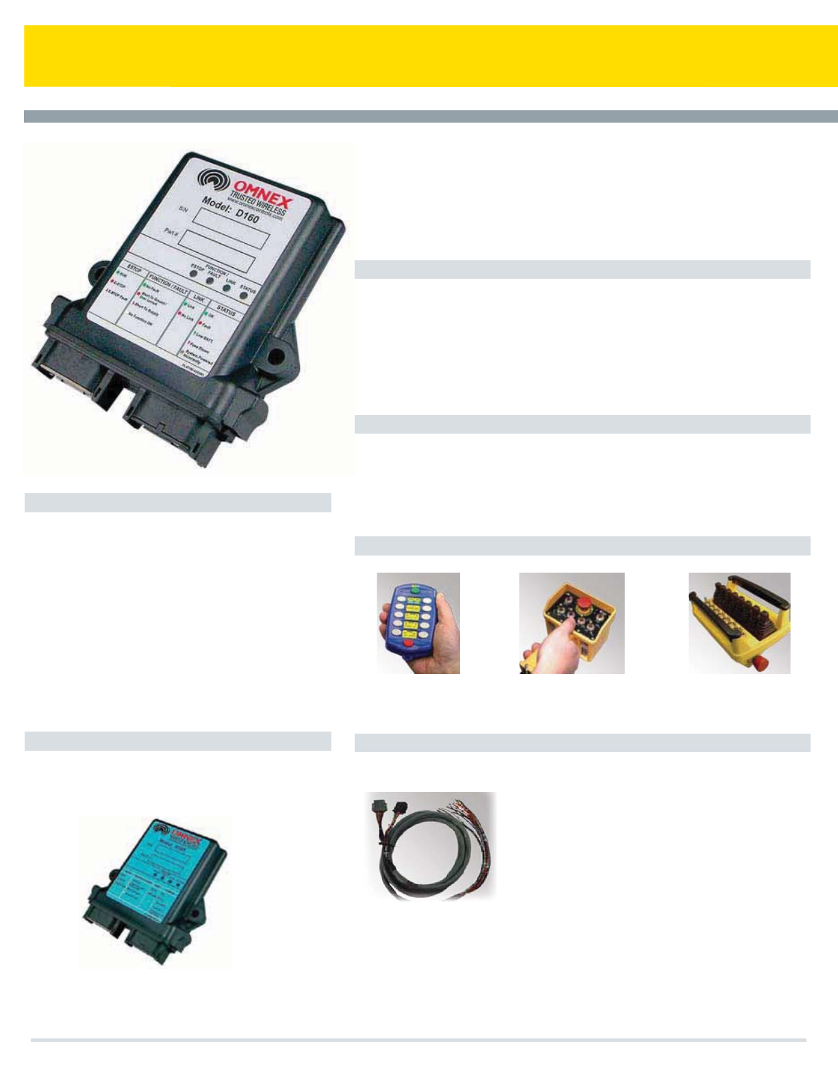
D160 Expansion Module
Features
Applications
OMNEX Transmitters
Accessories
Specifications
The OMNEX D160 expansion module for the R160 receiver features 19 I/O combinations
(19 digital or 17 digital + 2 proportional outputs). The D160 is designed to be powered from
a 12Vdc or a 24Vdc system and is fully customizable to operate momentary, latched,
toggled and interlocked functions. When combined with the R160, this pair will provide up
to 34 digital and 4 proportional outputs.
t5SVDLNPVOUFEDSBOFT
t5PXUSVDLT
t6UJMJUZUSVDLT
t7BDVVNUSVDLT
t4FSWJDFDSBOFT
t.JYFSUSVDLT
t.BUFSJBMIBOEMJOHFRVJQNFOU
t.BSJOF
Outputs: 19 digital functions (with up to 4 proportional)
Inputs: 19 (outputs can act as inputs)
Indicators & Diagnostics: Four status LEDs
Power: 9 - 32Vdc
Operating Temperature Range: -40 °F to 158 °F
(-40 °C to 70 °C)
Size: 5.1" x 4.7” x 1.4" (130mm x 119mm x 36mm)
Weight: .6lbs (270g)
Construction: High impact plastic, weatherproof,
6-"$%*&$
Specifications subject to change without notice - E&OE
19-Function Expansion Module
The D160 will work with the following
Reciever:
R160 - 19 I/O
T110 - 10 (20) -Function
Hand-Held Radio
Remote Control
T150 - 14-Function
Hand-Held Radio
Remote Control
T300 - 31-Function Radio
Remote Control
t*0DPNCJOBUJPOT
t%JBHOPTUJDJOEJDBUPST
t'BDUPSZDPOmHVSBCMFGPSDVTUPNBQQMJDBUJPOT
t%JHJUBMPVUQVUT
t1SPQPSUJPOBMPVUQVUTVQUPUXP
t8FBUIFSQSPPG
Output Cable
Cooper Bussmann Transportation Products t1IPOFt'BYtXXXDPPQFSCVTTNBOODPN
90
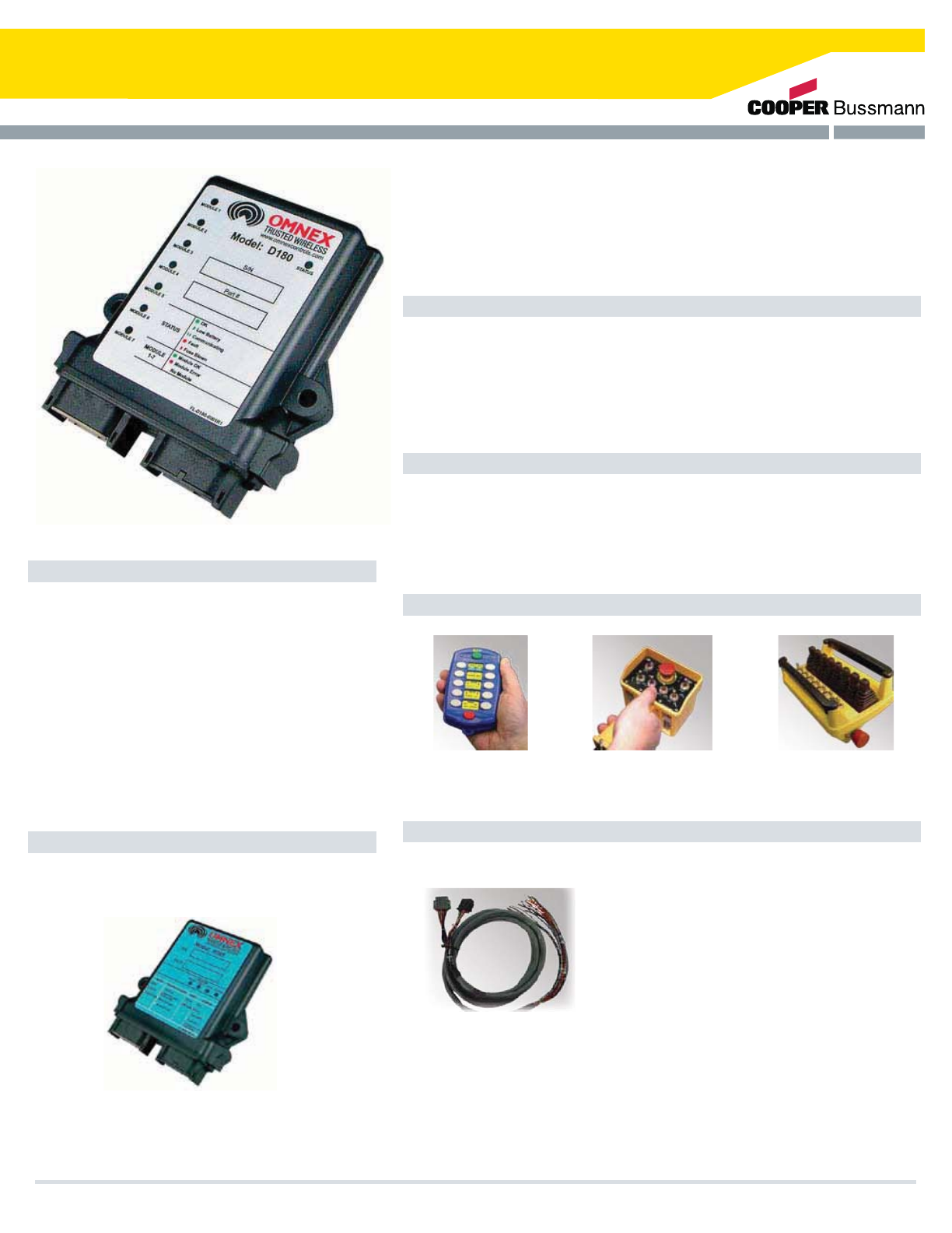
D180 Expansion Module
Features
Applications
OMNEX Transmitters
Accessories
Specifications
The OMNEX D180 expansion module for the R160 receiver features 14 proportional I/O
combinations (I/O can also be configured to operate digital functions). The D180 is designed
to be powered from a 12Vdc or a 24Vdc system. Depending on the application, the D180
can provide digital and analog (current, voltage or PWM output) signals. When combined
with the R160, this pair will provide up to 19 digital and up to 18 proportional functions.
t5SVDLNPVOUFEDSBOFT
t5PXUSVDLT
t6UJMJUZUSVDLT
t7BDVVNUSVDLT
t4FSWJDFDSBOFT
t.JYFSUSVDLT
t.BUFSJBMIBOEMJOHFRVJQNFOU
t.BSJOF
Outputs: 14 Proportional functions
Indicators & Diagnostics: Eight status LEDs
Power: 9 - 32Vdc
Operating Temperature Range: -40 °F to 158 °F
(-40 °C to 70 °C)
Size: 5.1" x 4.7” x 1.4" (130mm x 119mm x 36mm)
Weight: .65lbs (300g)
Construction: High impact plastic, weatherproof,
6-"$%*&$
Specifications subject to change without notice - E&OE
14 - Proportional Function Expansion Module
The D180 will work with the following
Reciever:
R160 - 19 I/O
T110 - 10 (20) -Function
Hand-Held Radio
Remote Control
T150 - 14-Function
Hand-Held Radio
Remote Control
T300 - 31-Function Radio
Remote Control
t1SPQPSUJPOBM*0DPOUSPMT
t%JBHOPTUJDJOEJDBUPST
t'BDUPSZDPOmHVSBCMFGPSDVTUPNBQQMJDBUJPOT
t%JHJUBMPVUQVUTPQUJPOBM
t8FBUIFSQSPPG
Output Cable
Cooper Bussmann Transportation Products t1IPOFt'BYtXXXDPPQFSCVTTNBOODPN 91

Printed in USA
Power Management
Cooper Bussmann
Sure Power
10189 SW Avery St
Tualatin, OR 97062
Tel: 800-845-6269
Fax: 503-692-9091
Tech Support: 503.612.7103
Cooper Bussmann
Transportation Products
10189 SW Avery St
Tualatin, OR 97062
Tel: 800-845-6269
Fax: 503-692-9091
Tech Support: 847.956.5558
Power Distribution
Circuit Protection Radio Remote Control
Cooper Bussmann
OMNEX Control Systems
74 - 1833 Coast Meridian Road
Port Coquitlam, BC
Canada V3C 6G5
Tel: 800-663-8806
Fax: 604-944-9267
Tech Support: 604.944.9247 #368
Cooper Bussmann Transportation Products Headquarters:
10189 SW Avery St.
Tualatin, OR 97062
Tel: 800-845-6269
www.cooperbussmann.com
Cooper Bussmann Transportation
is a part of the
Cooper Industries world.
Visit us online at www.cooperbussmann.com
#7047 3-11-2M
