0612CT0101R0712 1000296784 Catalog
109738-Catalog 109738-Catalog 109738-Catalog 785901 Batch5 unilog cesco-content
101205-Brochure 101205-Brochure 101205-Brochure 785901 Batch8 unilog cesco-content
2016-07-29
: Pdf 1000296784-Catalog 1000296784-Catalog B2 unilog
Open the PDF directly: View PDF ![]() .
.
Page Count: 152 [warning: Documents this large are best viewed by clicking the View PDF Link!]
™
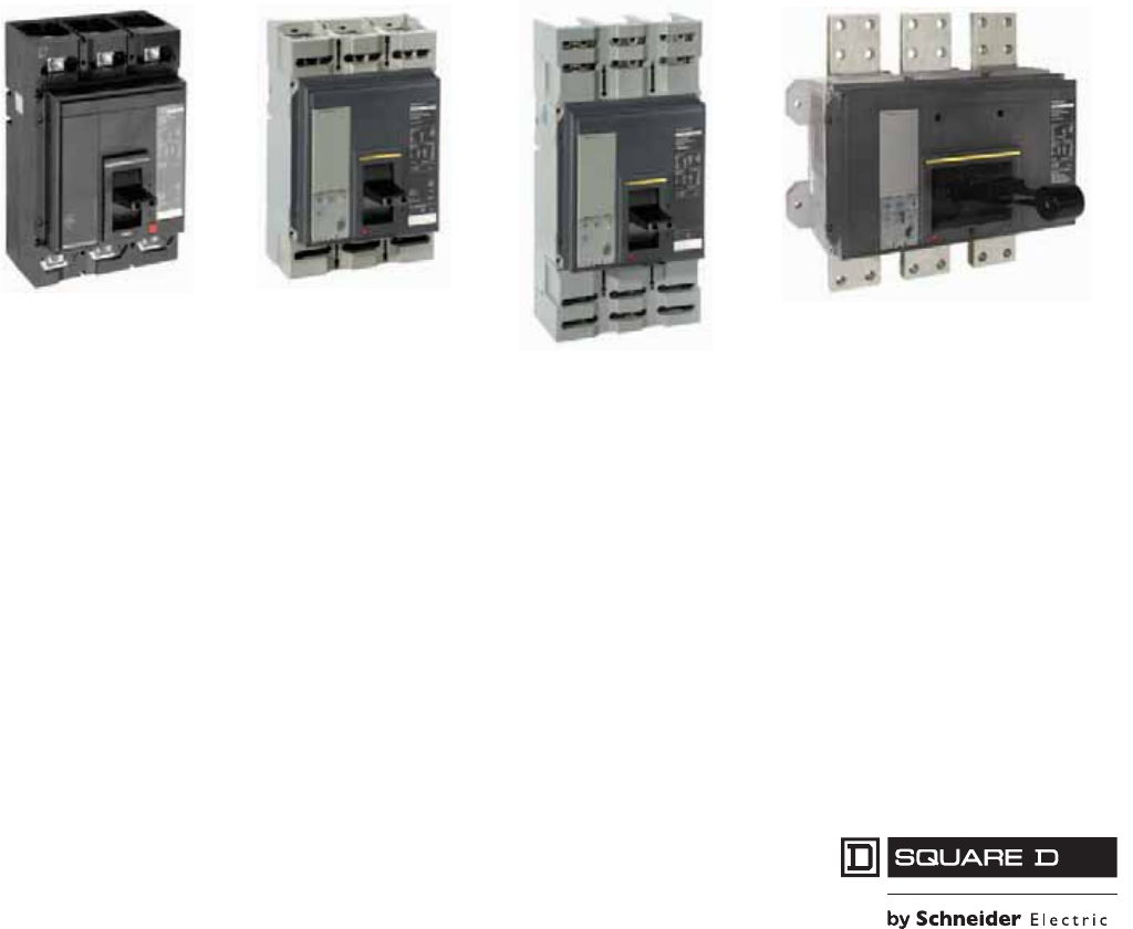
PowerPact™ M-, P- and R-Frame,
and Compact™ NS630b–NS3200
Circuit Breakers
Catalog
0612CT0101 R07/12
2012
Class 0612
CONTENTS
Description . . . . . . . . . . . . . . . . . . . . . . . . . . . . . . . . . . . . . . . . . . . . . Page
General Information . . . . . . . . . . . . . . . . . . . . . . . . . . . . . . . . . . . . . . . . . . 7
Electronic Trip Systems . . . . . . . . . . . . . . . . . . . . . . . . . . . . . . . . . . . . . . .22
PowerPact M-Frame Molded Case Circuit Breakers . . . . . . . . . . . . . . . . .38
PowerPact P-Frame Molded Case Circuit Breakers . . . . . . . . . . . . . . . . .41
PowerPact R-Frame Circuit Breakers . . . . . . . . . . . . . . . . . . . . . . . . . . . .52
Compact NS630b–NS1600 Circuit Breakers . . . . . . . . . . . . . . . . . . . . . .61
Compact NS1600b–NS3200 Circuit Breaker . . . . . . . . . . . . . . . . . . . . . .64
Accessories . . . . . . . . . . . . . . . . . . . . . . . . . . . . . . . . . . . . . . . . . . . . . . . .67
P-Frame Cradles and Cradle Accessories . . . . . . . . . . . . . . . . . . . . . . . .89
Dimensional Drawings . . . . . . . . . . . . . . . . . . . . . . . . . . . . . . . . . . . . . . . .95
Trip Curves . . . . . . . . . . . . . . . . . . . . . . . . . . . . . . . . . . . . . . . . . . . . . . .132
Catalog Numbers . . . . . . . . . . . . . . . . . . . . . . . . . . . . . . . . . . . . . . . . . .146

© 2001–2012 Schneider Electric
All Rights Reserved
PowerPact™ M-, P- and R-Frame, and Compact™ NS630b–NS3200 Circuit Breakers
—
2
07/2012
™
SECTION 1: GENERAL INFORMATION .......................................................................... 7
SECTION 2: ELECTRONIC TRIP SYSTEMS ................................................................. 22
SECTION 3: POWERPACT M-FRAME MOLDED CASE CIRCUIT BREAKERS .......... 38
SECTION 4: POWERPACT P-FRAME MOLDED CASE CIRCUIT BREAKERS ........... 41
SECTION 5: POWERPACT R-FRAME CIRCUIT BREAKERS ...................................... 52
SECTION 6: COMPACT NS630B–NS1600 CIRCUIT BREAKERS ............................... 61
SECTION 7: COMPACT NS1600B–NS3200 CIRCUIT BREAKER ................................ 64
SECTION 8: ACCESSORIES .......................................................................................... 67
SECTION 9: P-FRAME CRADLES AND CRADLE ACCESSORIES ............................. 89
SECTION 10: DIMENSIONAL DRAWINGS ...................................................................... 95
SECTION 11: TRIP CURVES .......................................................................................... 132
SECTION 12: CATALOG NUMBERS ............................................................................. 146

PowerPact™ M-, P- and R-Frame, and Compact™ NS630b–NS3200 Circuit Breakers
3
10/2012
© 2001–2012 Schneider Electric
All Rights Reserved
™
SECTION 1: GENERAL INFORMATION ...........................................................................7
Introduction ..................................................................................................................................... 7
Features and Benefits ..................................................................................................................... 7
Specifications .................................................................................................................................. 8
Codes and Standards ...................................................................................................................... 8
Circuit Breaker Ratings ................................................................................................................... 9
Enclosure Sizes ............................................................................................................................. 11
Operating Conditions ..................................................................................................................... 11
Trip System ................................................................................................................................... 12
Motor Circuit Protectors ................................................................................................................. 13
Automatic Molded Case Switches .................................................................................................13
Internal Operating Mechanism ...................................................................................................... 14
Push-to-Trip Button ....................................................................................................................... 14
Circuit Breaker Mounting and Connections ................................................................................... 14
Catalog Numbering System .......................................................................................................... 16
Testing Requirements ................................................................................................................... 20
SECTION 2: ELECTRONIC TRIP SYSTEMS ..................................................................22
Type ET Electronic Trip System .................................................................................................... 22
Micrologic™ Electronic Trip Systems ............................................................................................23
Protection Settings............................................................................................................. 27
Ammeter Measurements.................................................................................................... 27
Communication Network.................................................................................................... 27
Protection Settings............................................................................................................. 29
Maintenance Record.......................................................................................................... 29
Load Shedding and Reconnection Parameters ................................................................. 29
Indication Option Via Programmable Contacts .................................................................. 30
Real-Time Metering ........................................................................................................... 32
Demand Metering .............................................................................................................. 32
Metering ............................................................................................................................. 33
Waveform Capture............................................................................................................. 33
Customized Alarm Programming....................................................................................... 34
Event Logs......................................................................................................................... 34
Additional Characteristics for Type P and H Trip Units...................................................... 34
Long-time Trip Functions ................................................................................................... 35
Short-time Trip Functions................................................................................................... 35
Instantaneous Trip Function .............................................................................................. 35
Ground-fault Trip Functions ............................................................................................... 36
SECTION 3: POWERPACT M-FRAME MOLDED CASE CIRCUIT BREAKERS ...........38
Performance .................................................................................................................................. 38
Interrupting Ratings ....................................................................................................................... 39
Termination Information ................................................................................................................ 39
Accessories ................................................................................................................................... 39
Control Wiring ................................................................................................................................ 40
SECTION 4: POWERPACT P-FRAME MOLDED CASE CIRCUIT BREAKERS ............41
Performance .................................................................................................................................. 41
Catalog Numbers .......................................................................................................................... 42
Continuous Current Rating ............................................................................................................ 46
Interrupting Ratings ....................................................................................................................... 46
Automatic Molded Case Switches .................................................................................................47
Motor Circuit Protectors ................................................................................................................. 48
Electrically-Operated Circuit Breakers .......................................................................................... 49

© 2001–2012 Schneider Electric
All Rights Reserved
PowerPact™ M-, P- and R-Frame, and Compact™ NS630b–NS3200 Circuit Breakers
4
10/2012
™
Termination Information ................................................................................................................. 49
Control Wiring ................................................................................................................................ 49
SECTION 5: POWERPACT R-FRAME CIRCUIT BREAKERS ...................................... 52
Performance .................................................................................................................................. 52
Catalog Numbers ........................................................................................................................... 53
Interrupting Ratings ....................................................................................................................... 58
Automatic Molded Case Switches .................................................................................................58
Termination Information ................................................................................................................. 59
Continuous Current Rating ............................................................................................................ 59
Control Wiring ................................................................................................................................ 59
SECTION 6: COMPACT NS630B–NS1600 CIRCUIT BREAKERS ............................... 61
Performance .................................................................................................................................. 61
Catalog Numbers ........................................................................................................................... 62
Interrupting Ratings ....................................................................................................................... 63
Electrically-Operated Circuit Breakers ........................................................................................... 63
Automatic Molded Case Switches .................................................................................................63
Termination Information ................................................................................................................. 63
Accessories ................................................................................................................................... 63
Control Wiring ................................................................................................................................ 63
SECTION 7: COMPACT NS1600B–NS3200 CIRCUIT BREAKER ................................ 64
Performance .................................................................................................................................. 64
Catalog Numbers ........................................................................................................................... 65
Interrupting Ratings ....................................................................................................................... 65
Automatic Molded Case Switches .................................................................................................65
Termination Information ................................................................................................................. 66
Accessories ................................................................................................................................... 66
Control Wiring ................................................................................................................................ 66
SECTION 8: ACCESSORIES .......................................................................................... 67
Accessories ................................................................................................................................... 67
Electrical Accessories .................................................................................................................... 69
Auxiliary Switch (OF):......................................................................................................... 71
Alarm Switch (SD).............................................................................................................. 71
Overcurrent Trip Switch (SDE)........................................................................................... 71
Micrologic™ Trip Unit Accessories ................................................................................................ 74
Display Options ............................................................................................................................. 80
Test Equipment ............................................................................................................................. 82
Circuit Breaker Terminations ......................................................................................................... 83
External Accessories ..................................................................................................................... 86
Locking Accessories ...................................................................................................................... 87
Sub-Feed Lugs .............................................................................................................................. 88
SECTION 9: P-FRAME CRADLES AND CRADLE ACCESSORIES ............................. 89
Circuit Breaker and Cradle Design ................................................................................................ 89
Cradle Accessories ........................................................................................................................ 90
Cradle Locking and Interlocking .................................................................................................... 92
Open Door Racking Interlock ........................................................................................................ 92
Miscellaneous Accessories ........................................................................................................... 92
Wiring Diagrams ............................................................................................................................ 93

PowerPact™ M-, P- and R-Frame, and Compact™ NS630b–NS3200 Circuit Breakers
5
10/2012
© 2001–2012 Schneider Electric
All Rights Reserved
™
SECTION 10: DIMENSIONAL DRAWINGS .......................................................................95
Dimensions for M-Frame Circuit Breakers .................................................................................... 95
Dimensions for P-Frame and NS630b–NS1600 Circuit Breakers ................................................. 98
Dimensions for R-Frame and NS1600b–NS3200 Circuit Breakers ............................................. 121
SECTION 11: TRIP CURVES ...........................................................................................132
SECTION 12: CATALOG NUMBERS ..............................................................................146

© 2001–2012 Schneider Electric
All Rights Reserved
PowerPact™ M-, P- and R-Frame, and Compact™ NS630b–NS3200 Circuit Breakers
6
10/2012
™

PowerPact™ M-, P- and R-Frame, and Compact™ NS630b–NS3200 Circuit Breakers
Section 1—General Information
7
10/2012
© 2001–2012 Schneider Electric
All Rights Reserved
™
Section 1—General Information
Introduction
PowerPact™ M-frame, P-frame and R-frame and Compact™ NS630b–NS3200 electronic trip molded
case circuit breakers are designed to protect electrical systems from damage caused by overloads, short
circuits, and ground faults. All circuit breakers are designed to open and close a circuit by nonautomatic
means and to open the circuit automatically on a predetermined overcurrent. Electronic trip molded case
circuit breakers use an electronic trip system to signal the circuit breaker to open automatically.
The PowerPact M-frame (800 A frame size), P-frame (1200 A frame size) and R-frame (3000 A frame
size) circuit breakers are dual rated to UL489 and IEC 60947-2. The Compact NS630b–NS1600 (1600
A frame size) and NS1600b–NS3200 (3200 A frame) circuit breakers are rated to IEC 60947-2 only.
M-frame molded case circuit breakers are equipped with a basic ET1.0 electronic trip system, which has
a fixed long-time (overload) setting and an adjustable instantaneous (short-circuit) trip setting. P-frame,
R-frame and NS630b–NS3200 molded case circuit breakers are available with either a basic ET 1.0I
electronic trip system or with a more advanced Micrologic™ trip system. Electronic trip motor circuit
protectors (trip system ET 1.0M), which trip on short circuit only, and automatic molded case switches,
which trip at a predetermined self-protection level only, are also available for special applications. All of
these circuit breakers are available labeled as Square D™ or Schneider Electric™ (formerly Merlin
Gerin™, Federal Pioneer™, or Federal Pacific™).
For information on other Square D brand PowerPact molded case circuit breakers, see the Class 611
catalog PowerPact H-, J-, and L-Frame Circuit Breakers.
Features and Benefits
M-frame, P-frame, R-frame and NS630b–NS3200 electronic trip circuit breakers:
•Provide overload and short-circuit protection
•Are true RMS sensing devices
•Provide means to manually disconnect power to the circuit
•Provide enhanced coordination by their adjustability
•Provide high interrupting ratings and withstand ratings
Circuit breakers with Micrologic trip units can also:
•Provide integral equipment ground-fault protection or alarm
•Provide communications
•Provide power monitoring
•Provide protective relaying functions
•Provide zone-selective interlocking (ZSI), which can reduce damage in the event of a fault
© 2001–2012 Schneider Electric
All Rights Reserved
PowerPact™ M-, P- and R-Frame, and Compact™ NS630b–NS3200 Circuit Breakers
Section 1—General Information
8
10/2012
™
Specifications
Electronic trip molded case circuit breakers have a molded case made of a glass-reinforced insulating
material (thermal set composite resin) that provides high dielectric strength. These circuit breakers:
•Are available in either dual-rated UL/IEC or IEC-only constructions
•Are also CSA and ANCE certified (dual-rated UL/IEC circuit breakers only)
•Are manufactured in unit-mount, I-Line™ and drawout (P-frame and NS630b–NS1600) constructions
•Are available with either type ET or Micrologic electronic tripping systems
•Provide optional power monitoring, communications, protective relaying, integral ground-fault
protection for equipment and zone-selective interlocking functions
•Share common tripping of all poles
•Can be mounted and operated in any position
•Are equipped with an externally-accessible test port for use with hand-held and full-function test sets
•Are available in motor circuit protector and automatic molded case switch constructions
•Can be reverse connected, without restrictive LINE and LOAD markings
•Meet the requirements of National Electrical Code® (NEC®) Sections 240.6 by providing a means
to seal the rating plug and trip unit adjustments
Codes and Standards
M-, P- and R-frame, and NS630b–NS3200 electronic trip circuit breakers and switches are
manufactured and tested in accordance with the following standards:
Circuit breakers should be applied according to guidelines detailed in the NEC and other local
wiring codes.
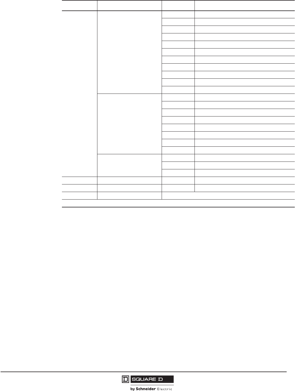
Table 1: Standards
M-Frame, P-Frame and
R-Frame Circuit Breakers P- and R-Frame Switches NS630b–NS3200
Circuit Breakers
NS630b–NS3200
Switches
UL 4891
IEC Standard 60947-2
CSA C22.2 No 5
Federal Specification
W-C-375B/GEN
NEMA AB1
NMX J-266
UTE, VDE, BS, CEI, UNE, CCC
1PowerPact M-frame circuit breaker is in UL File E10027.
PowerPact P-frame circuit breaker is in UL File E63335.
PowerPact R-frame circuit breaker is in UL FIle E10027.
UL 4892
IEC Standard 60947-3
CSA C22.2 No 5
Federal Specification
W-C-375B/GEN
NEMA AB1
NMX J-266
UTE, VDE, BS, CEI, UNE
2PowerPact P-frame switch is in UL File E103740.
PowerPact R-frame switch is in UL FIle E33117.
IEC Standard 60947-2
Federal Specification
W-C-375B/GEN
NEMA AB1
UTE, VDE, BS, CEI, UNE
IEC Standard 60947-3
Federal Specification
W-C-375B/GEN
NEMA AB1
UTE, VDE, BS, CEI, UNE
PowerPact™ M-, P- and R-Frame, and Compact™ NS630b–NS3200 Circuit Breakers
Section 1—General Information
9
10/2012
© 2001–2012 Schneider Electric
All Rights Reserved
™
Circuit Breaker Ratings
Interrupting Rating
The interrupting rating is the highest current at rated voltage the circuit breaker is designed to safely
interrupt under standard test conditions. Circuit breakers must be selected with interrupting ratings equal
to or greater than the available short-circuit current at the point where the circuit breaker is applied to the
system (unless it is a branch device in a series rated combination). Interrupting ratings are shown on the
front of the circuit breaker. For grounded B phase interrupting ratings, see Data Bulletin 2700DB0202.
Table 2: UL/IEC Circuit Breaker Interrupting Ratings
Circuit
Breaker1
1The K interrupting rating is recommended for applications having high inrush and/or non-linear loads such as large motors,
transformers, motors with soft starts, etc.
UL/CSA Rating (60 Hz) IEC 60947-2 Rating (50/60 Hz)
3 Phase
Grounded
B Phase
(1Ø-3Ø)
240 Vac 380/415 Vac
240 Vac 480 Vac 600 Vac 240 Vac 2P Icu Ics Icu Ics
MG 65 kA 35 kA 18 kA 65 kA 50 kA 25 kA 35 kA 20 kA
MJ 100 kA 65 kA 25 kA 65 kA 65 kA 35 kA 50 kA 25 kA
PG 65 kA 35 kA 18 kA 65 kA 50 kA 25 kA 35 kA 20 kA
PJ 100 kA 65 kA 25 kA 65 kA 65 kA 35 kA 50 kA 25 kA
PK 65 kA 50 kA 50 kA 65 kA 50 kA 25 kA 50 kA 25 kA
PL 125 kA 100 kA 25 kA 65 kA 125 kA 65 kA 85 kA 45 kA
RG 65 kA 35 kA 18 kA 35 kA 50 kA 25 kA 35 kA 20 kA
RJ 100 kA 65 kA 25 kA 100 kA 65 kA 35 kA 50 kA 25 kA
RK 65 kA 65 kA 65 kA 65 kA 85 kA 65 kA 70 kA 55 kA
RL 125 kA 100 kA 50 kA 125 kA 125 kA 65 kA 85 kA 45 kA
Table 3: IEC Only Circuit Breaker Interrupting Ratings (50/60 Hz)
Circuit Breaker Interrupting Rating
220/240 Vac 380/415 Vac 440 Vac 500/525 Vac 660/690 Vac
Icu Ics Icu Ics Icu Ics Icu Ics Icu Ics
Electrically Operated
NS630b–NS1600 N Interrupting Rating 50 kA 37 kA 50 kA 37 kA 50 kA 37 kA 40 kA 30 kA 30 kA 22 kA
NS630b–NS1600 H Interrupting Rating 70 kA 35 kA 70 kA 35 kA 65 kA 32 kA 50 kA 25 kA 42 kA 21 kA
NS630b–NS1000 L Interrupting Rating 150 kA 150 kA 150 kA 150 kA 130 kA 130 kA 100 kA 100 kA — —
Manually Operated
NS630b–NS1600 N Interrupting Rating 85 kA 50 kA 50 kA 50 kA 50 kA 50 kA 40 kA 40 kA 30 kA 30 kA
NS630b–NS1600 H Interrupting Rating 85 kA 52 kA 70 kA 52 kA 65 kA 48 kA 50 kA 37 kA 42 kA 31 kA
NS630b–NS1000 L Interrupting Rating 150 kA 150 kA 150 kA 150 kA 130 kA 130 kA 100 kA 100 kA — —
NS630b–NS800 LB (R) Interrupting Rating 200 kA 200 kA 200 kA 200 kA 200 kA 200 kA 100 kA 100 kA 75 kA 75 kA
NS1600b–NS3200 N Interrupting Rating 85 kA 65 kA 70 kA 52 kA 65 kA 65 kA 65 kA 65 kA 65 kA 65 kA
NS1600b–NS3200 H Interrupting Rating 125 kA 94 kA 85 kA 64 kA 85 kA 64 kA — — — —

© 2001–2012 Schneider Electric
All Rights Reserved
PowerPact™ M-, P- and R-Frame, and Compact™ NS630b–NS3200 Circuit Breakers
Section 1—General Information
10
10/2012
™
Application Ratings
The voltage rating is the highest voltage for the electrical system on which the circuit breaker can be
applied. The frequency rating indicates the system frequency for which the circuit breaker is intended.
The withstand rating is used to improve system coordination by maximizing the current level at which
the circuit breaker trips with no intentional delay. The withstand rating is the level of RMS symmetrical
current that a circuit breaker can carry in a closed position for a stated period of time.
Ampere Rating (Continuous Current Rating)
The ampere rating (or continuous current rating) (Ir) is the maximum current that a circuit breaker can
carry. The sensor size (In) is the maximum ampere rating for a specific circuit breaker and is based on
the size of the sensor plug inside the circuit breaker. This value is printed below the trip unit on the
sensor plug. See Sensor Plugs (page 76) for more information.
NOTE: The maximum ampere rating a circuit breaker family can carry is called the frame size. Sensor
size is less than or equal to frame size.
The ampere rating of a type ET electronic trip circuit breaker is equal to the current sensor size (In).
The ampere rating of a Micrologic™ electronic trip circuit breaker is determined by the mathematical
equation:
Ampere Rating = Sensor Size x Rating Plug Setting (Ir = In x Rating Plug Setting)
The rating plug varies the circuit breaker ampere rating as a function of its sensor size. Rating plugs
have nine dial settings; the multiplier values corresponding with each setting are printed on the rating
plug. The maximum setting range is 0.4–1.0 x In.
Table 4: Voltage, Frequency and Withstand Ratings
Circuit Breaker Voltage
Rating Frequency Rating1
1May also be used at 400 Hz with derating, see data bulletin 0100DB0101 Determining Current-Carrying Capacity in Special
Applications.
Withstand Rating at
480 Vac2
2A system coordination study should be done for optimum circuit breaker coordination.
MG, MJ 600 Vac 60 Hz (UL), 50/60 Hz (IEC) 10 kA (0.5 sec)
PG, PK 600 Vac 60 Hz (UL), 50/60 Hz (IEC) 25 kA (0.5 sec)
PJ 600 Vac 60 Hz (UL), 50/60 Hz (IEC) 10 kA (0.5 sec)
PL 480 Vac 60 Hz (UL), 50/60 Hz (IEC) 10 kA (0.5 sec)
R-frame (RG, RJ, RK, RL) 600 Vac 60 Hz (UL), 50/60 Hz (IEC) 32 kA (3 sec)
NS630b–NS1600 N Interrupting Rating 690 Vac 50/60 Hz (IEC) 25 kA (0.5 sec)
NS630b–NS1600 H Interrupting Rating 690 Vac 50/60 Hz (IEC) 25 kA (0.5 sec)
NS630b–NS1000 L Interrupting Rating 690 Vac 50/60 Hz (IEC) 10 kA (0.5 sec)
NS1600b–NS3200 N Interrupting Rating 690 Vac 50/60 Hz (IEC) 32 kA (3 sec)
NS1600b–NS3200 H Interrupting Rating 440 Vac 50/60 Hz (IEC) 32 kA (3 sec)
PowerPact™ M-, P- and R-Frame, and Compact™ NS630b–NS3200 Circuit Breakers
Section 1—General Information
11
10/2012
© 2001–2012 Schneider Electric
All Rights Reserved
™
Enclosure Sizes
All type ET electronic trip UL/IEC M-frame, P-frame and R-frame circuit breakers are available as
standard rated circuit breakers. Micrologic electronic trip UL/IEC circuit breakers are also available in
100% rated constructions. Because the additional heat generated when applying circuit breakers at
100% of continuous current rating, the use of specially designed enclosures and 90°C (194° F) rated
wire sized per the 75°C (167° F) NEC chart is required
Circuit breakers with 100% rating can also be used in applications requiring only 80% continuous loading.
Operating Conditions
Temperature
To meet the requirements of the UL489 Standard, molded case circuit breakers are designed, built and
calibrated for use on 50/60 Hz ac systems in a 40°C (104°F) ambient environment. Electronic trip
circuit breakers, however, are designed to react only to the magnitude of the current flowing through
the circuit breaker and are inherently ambient insensitive. Both UL/IEC and IEC-only circuit breakers
may be operated at temperatures between -25°C and +70°C (-13°F and 158°F). For temperatures
other than 40°C (104°F), the circuit breakers must be re-rated as shown.
Altitude
Circuit breakers are suitable for use at altitudes up to 13,100 ft. (4000 m). For altitudes higher than
6560 ft. (2000 m), circuit breakers must be derated as shown.
Table 5: Minimum Enclosure Sizes for Fixed-Mounted Circuit Breakers
Circuit Breaker Rating
Enclosure Dimensions (h x w x d) in/[mm] Ventilation Area
3P Circuit Breaker 4P Circuit Breaker Top Bottom
M-Frame, 800 A, Standard Rated 51.9 x 20.25 x 7.75
[1318.3 x 514.4 x 196.9]
51.9 x 23.01 x 7.75
[1318.3 x 584.4 x 196.9] — ———
P-Frame, 800 A, 100% Rated
P-Frame, 1200 A, Standard Rated
51.9 x 20.25 x 7.75
[1318.3 x 514.4 x 196.9]
51.9 x 23.01 x 7.75
[1318.3 x 584.4 x 196.9] — ———
P-Frame, 1200 A, 100% Rated 62.25 x 23 x 14.75
[1581.2 x 584.2 x 374.7]
62.25 x 25.76 x 14.75
[1581.2 x 654.2 x 374.7] 16.5 in. 10,645 mm 16.5 in. 10,645 mm
R-Frame, Standard Rated130 x 21 x 7
[762 x 533 x 178]
30 x 25.5 x 7
[762 x 648 x 178] — ———
R-Frame, 100% Rated130 x 21 x 7
[762 x 533 x 178]
30 x 25.5 x 7
[762 x 648 x 178] 40.25 in. 26,000 mm 40.25 in. 26,000 mm
1RLTB or RL3TB kits may extend beyond end of enclosure when using minimum enclosure size.
Table 6: Temperature Rerating Values per ANSI C37.20.1
Maximum Ambient Temperature
°F
°C
140
60
122
50
104
40
86
30
77
25
68
20
50
10
32
0
14
-10
-4
-20
-22
-30
Current 0.83 0.92 1.00 1.07 1.11 1.14 1.21 1.27 1.33 1.39 1.44
Table 7: Altitude Rerating Values Per ANSI C37.20.1 Table 10
Altitude d6,600 ft.
(d2,000 m)
8,500 ft.
(2,600 m)
13,000 ft.
(3,900 m)
Voltage 1.00 0.95 0.80
Current 1.00 0.99 0.96
© 2001–2012 Schneider Electric
All Rights Reserved
PowerPact™ M-, P- and R-Frame, and Compact™ NS630b–NS3200 Circuit Breakers
Section 1—General Information
12
10/2012
™
Extreme Atmospheric Conditions
PowerPact circuit breakers have successfully passed the tests defined below for extreme atmospheric
conditions.
Dry cold and dry heat:
•IEC 68-2-1—Dry cold at -55°C
•IEC 68-2-2—Dry heat at +85°C
Damp heat (tropicalization)
•IEC 68-2-30—Damp heat (temperature 55°C and relative humidity of 95%, condensing)
•IEC 68-2-52 level 2—Salt mist
The materials used in the PowerPact circuit breakers will not support the growth of fungus and mold.
Vibration
PowerPact circuit breakers meet IEC 60068-2-6 Standards for vibration.
•2 to 13.2 Hz and amplitude 0.039 in. (1 mm)
•13.2 to 100 Hz constant acceleration
Storage Temperature
Circuit breakers with trip units without LCD displays may be stored in the original packaging at
temperatures between -58°F (-50°C) and 185°F (85°C). For circuit breakers with trip units with LCD
displays, this range is -40°F (-40°C) to 185°F (85°C).
Trip System
The trip system causes the circuit breaker to open automatically under overload, short-circuit or
equipment ground-fault conditions. Electronic trip circuit breakers give the customer more versatility to
achieve coordination with features such as adjustable instantaneous pickup and high withstand ratings.
The type ET and the Micrologic trip systems consist of current sensors, a microprocessor-based trip
unit, and a tripping coil. The tripping coil is a flux transfer solenoid that requires no external power
source. All type ET and Micrologic protective functions are completely fault powered.
Micrologic Trip System
Features found in Micrologic™ electronic trip circuit breakers, such as universally interchangeable
rating plugs, adjustable long-time pickups and 100% ratings also provide capacity for future growth.
The integral equipment ground-fault sensing capabilities available with Micrologic trip systems mean
that there are fewer parts and pieces to purchase, mount and wire. These capabilities include integral
ground-fault protection for equipment, which causes the circuit breaker to trip when a ground fault is
detected, as well as integral ground-fault alarm, which does not trip the circuit breaker but sends an
alarm when a ground fault is detected.
Certain Micrologic trip systems also offer the customer true power management system solutions through
communication. These trip units can communicate with other circuit breakers in the system and also with a
power monitoring system. Communication is by Modbus® and does not require proprietary software.
Communication between trip units allows zone-selective interlocking (ZSI) between circuit breakers at
different levels in the system. ZSI reduces fault stress by allowing the upstream circuit breaker closest to the
fault to ignore its preset delay time and trip without any intentional delay on a short circuit or ground fault.
For more information on ZSI, see data bulletin Reducing Fault Stress with Zone-Selective Interlocking.
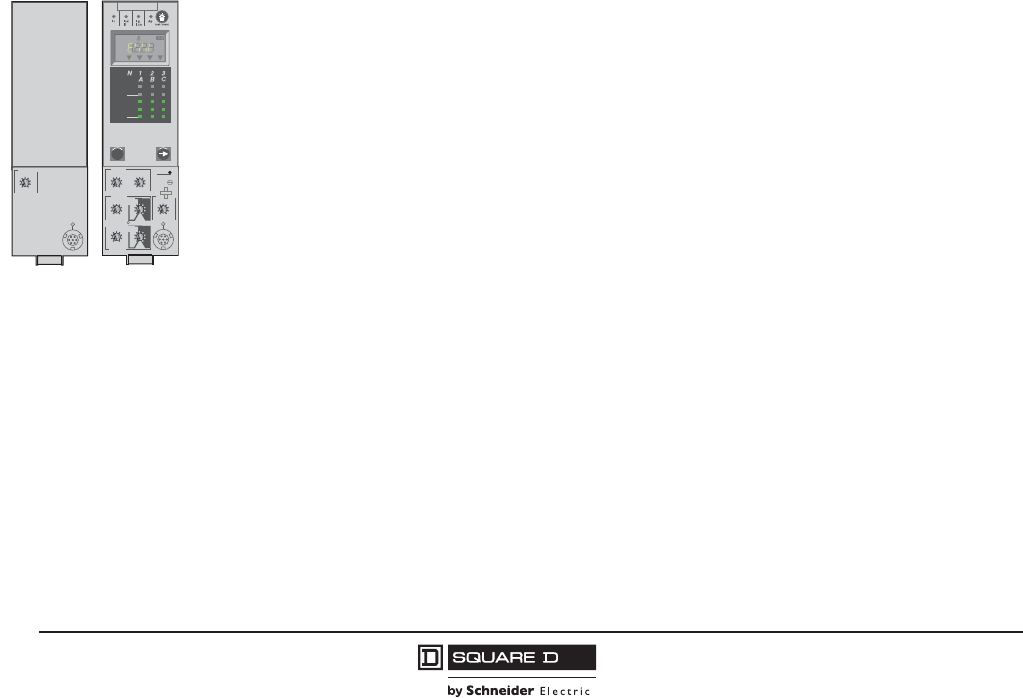
ET
Trip Unit
Micrologic
Trip Unit
Electronic
Electronic
ET1.0I
test
I i
instantaneous
x In
4
3
6810
12
15
off
2
setting
06123023
Micrologic 6.0A
40
100 %
%
menu
.4
.45
.5
.6 .63 .7
.8
.9
1
delay
short
I itsd
(s)
on I2t
.2
.3
.4.4
.1
.2
.3
.1
0
off
instantaneous
long time
alarm
Ir
x In
ground fault
B
C
DEF
G
H
J
Ig tg
(s)
on I2t
.2
.3
.4.4
.1
.2
.3
.1
0
off
A
.5
1
2
4812
16
20
tr
(s)
@ 6 Ir24
setting
x Ir
2
2.5345
6
8
10
Isd
1.5 x In
4
3
6810
12
15
off
2
test
06133245
kA
s
Ir=
Ii=
tr=
Isd=
Ig=
tsd=
Δt=
tg=
IΔn=
MAX

PowerPact™ M-, P- and R-Frame, and Compact™ NS630b–NS3200 Circuit Breakers
Section 1—General Information
13
10/2012
© 2001–2012 Schneider Electric
All Rights Reserved
™
Communication with a power monitoring system through a communications network allows a ground
fault to be reported without interrupting power to the system. It also allows the power monitoring
system to remotely report power usage, current flow, and trip history.
Instantaneous OFF Feature
Micrologic™ 5.0 and 6.0 Standard, A, P and H electronic trip units provide the unique ability to turn the
instantaneous tripping function OFF. Turning off the instantaneous trip function increases the current
level at which the circuit breaker will trip with no intentional delay to the level of the short-time
withstand rating. This current level is typically much higher than any of the pickup levels provided by
the adjustable instantaneous feature. Therefore, using the instantaneous OFF feature improves
coordination by allowing the user to take advantage of the circuit breaker withstand rating.
Motor Circuit Protectors
An instantaneous trip version of the electronic trip circuit breaker is also available for motor circuit
protection. These motor circuit protectors comply with NEC requirements for providing short-circuit
protection when installed as part of a Listed combination controller having motor overload protection.
Electronic trip motor circuit protectors are similar in construction to type ET electronic trip circuit
breakers.They are designed as disconnect devices for use in combination with motor starters. These
motor circuit protectors provide short-circuit protection only and have an adjustable amperage pickup
so they can be set to open instantaneously at current values slightly above the motor starting inrush
current. This setting coordinates the pickup time-current response of the motor circuit protector with
the overload relay of the motor starter to give the best possible protection.
Current interrupting ratings for these UL Recognized components are established in combination with
motor starters and properly-sized overload relays and contactors.
Automatic Molded Case Switches
P-frame, R-frame and NS630b–NS3200 circuit breakers are also available in automatic molded case
switch construction. Automatic switches are similar in construction to electronic trip circuit breakers,
except that the switches open instantaneously at a factory-set non-adjustable trip point calibrated to
protect only the molded case switch itself. Because of their molded case construction, they are more
compact than conventional disconnect switches and accept electrical accessories for added flexibility.
Molded case switches are intended for use as disconnect devices only. UL489 requires molded case
switches to be protected by a circuit breaker or fuse of equivalent rating. Molded case switches are
labeled with their appropriate withstand ratings. The withstand rating of a switch is defined as the
maximum current at rated voltage that the molded case switch will withstand without damage when
protected by a circuit breaker with an equal continuous current rating.
Table 8: P-, and R-Frame Withstand Ratings1
1The withstand rating is the fault current at rated voltage that the molded case switch will withstand
without damage when protected by a circuit breaker with an equal continuous current rating.
Voltage
Withstand Rating
GJ K L
240 Vac 65 kA 100 kA 65 kA 125 kA
480 Vac 35 kA 65 kA 50 kA 100 kA
600 Vac 18 kA 25 kA 50 kA 50 kA2
2Not available on P-frame circuit breakers.
© 2001–2012 Schneider Electric
All Rights Reserved
PowerPact™ M-, P- and R-Frame, and Compact™ NS630b–NS3200 Circuit Breakers
Section 1—General Information
14
10/2012
™
Internal Operating Mechanism
Manually-Operated Circuit Breakers
M-frame, P-frame, R-frame and NS630b–NS3200 manually-operated circuit breakers have a single
operating handle that acts directly through the operating mechanism against the contact blades. Multi-
pole circuit breakers have a common trip bar for positive action of all poles on manual and automatic
operation. These circuit breakers have a trip-free mechanism that allows them to trip even though the
operating handle may be restricted (by a handle operating mechanism or padlock attachment) in the
I/ON position. If not restricted, the operating handle moves to a position between I/ON and O/OFF
when the circuit breaker is tripped.
The face of the manually-operated circuit breaker is marked with standard ON/OFF and international
I/O markings to indicate handle position. In addition, the I/OFF portion of the circuit breaker handle is
color coded green.
Electrically-Operated Circuit Breakers
P-frame and NS630b–NS1600 circuit breakers are also available with a two-step stored-energy
mechanism which can be charged manually or using a motor. The closing time is less than five cycles.
Closing and opening operations can be initiated by remote control or by push buttons on the front cover.
An O-C-O (open-close-open) cycle is possible without recharging. Electrically-operated circuit breakers
include a motor, shunt trip, and shunt close of the same voltage plus an overcurrent trip switch (SDE).
The face of electrically-operated circuit breakers is also marked ON/OFF and I/O, and equipped with a
position indicator to show contact position.
Push-to-Trip Button
The push-to-trip button located on the face of each manually-operated circuit breaker is a standard
feature on these circuit breakers. This allows the user to manually trip the circuit breaker without
risking exposure to live parts. During normal on-off operation, the handle opens and closes the circuit
breaker contact but does not exercise the tripping mechanism.
Use the push-to-trip button to:
•Exercise the circuit breaker mechanism
•Check the auxiliary and alarm switch circuits
Circuit Breaker Mounting and Connections
Table 9: Circuit Breaker Mounting and Connections
Circuit Breaker
Unit-Mount Construction I-Line™
Construction
Drawout
Construction
Cable Connection Bus Connection
M-Frame X X X —
P-Frame X XXX
R-Frame X1
1Must use RLTB or RL3TB terminal pad kit.
XX
2
2Through 1200 A, 100% rated only.
—
NS630b–NS1250 X X — X
NS1600–NS3200 — X — —
PowerPact™ M-, P- and R-Frame, and Compact™ NS630b–NS3200 Circuit Breakers
Section 1—General Information
15
10/2012
© 2001–2012 Schneider Electric
All Rights Reserved
™
Unit-Mount Circuit Breakers
Unit-mount M-frame, P-frame, R-frame and NS630b–NS3200 circuit breakers are individually-mounted
using supplied mounting screws. The four mounting screws are inserted through mounting holes
molded into the circuit breaker case and threaded into the circuit breaker mounting enclosure. To
properly support the circuit breaker, all four mounting screws must be used.
Unit-mount M-frame, P-frame and NS630b–NS1250 circuit breakers can be ordered with mechanical line
and load side lugs. The standard lugs can be removed for the installation of compression-type lugs or
bus connections. All lugs are UL Listed for their proper application and marked for use with aluminum
and copper (Al/Cu) or copper only (Cu) conductors. Lugs suitable for copper and aluminum conductors
are made of tin-plated aluminum. Lugs suitable for use with copper conductors only are made of copper.
See individual frame sections for frame-specific connection information.
I-Line™ Circuit Breakers
M-frame circuit breakers through 800 A and P-frame and R-frame circuit breakers through 1200 A are
available in I-Line construction for easy installation and removal in I-Line panelboards and
switchboards. I-Line circuit breakers use “blow-on” type line side connectors. In case of a short circuit,
increased magnetic flux causes the plug-on connectors of the circuit breaker to tighten their grasp on
the panelboard or switchboard bus bars. The I-Line connectors and circuit breaker mounting bracket
are integral parts of I-Line circuit breakers and cannot be removed or replaced. I-Line circuit breakers
come with mechanical load side lugs.
Drawout Circuit Breakers
P-frame manually-operated circuit breakers and switches are also available in drawout construction.
The drawout assembly mechanism allows the circuit breaker to be racked in four positions (connected,
test, disconnect or withdrawn).
P-frame cradles are ordered separately and are available with factory and field-installed accessories.
See Section 9—P-Frame Cradles and Cradle Accessories for details.
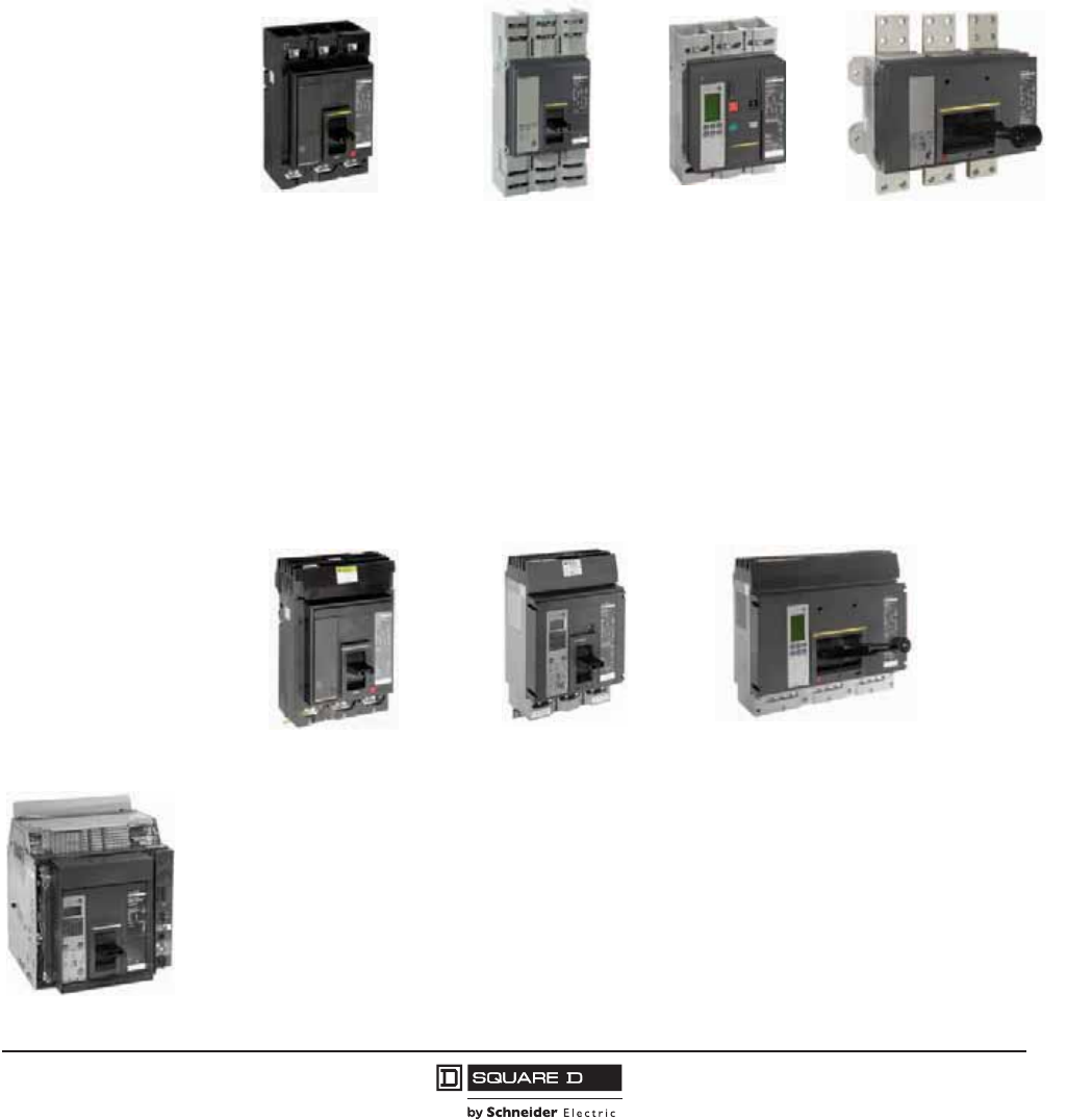
M-Frame Unit-Mount P-Frame Unit-Mount R-Frame Unit-Mount
Electrically Operated
P-Frame Unit-Mount
P-Frame I-LineM-Frame I-Line R-Frame I-Line
P-Frame Drawout
© 2001–2012 Schneider Electric
All Rights Reserved
PowerPact™ M-, P- and R-Frame, and Compact™ NS630b–NS3200 Circuit Breakers
Section 1—General Information
16
10/2012
™
Catalog Numbering System
The M-frame, P-frame, R-frame and NS630b–NS3200 circuit breakers and cradles follow a “smart”
catalog numbering system. The following tables are intended as a tool to decipher existing catalog
numbers. They are not intended for use in building catalog numbers, as some combinations
may not be available. To build a catalog number, please see the Digest, the Product Selector or
contact the local field office.
M-Frame, P-Frame and R-Frame Circuit Breaker Catalog Numbers
NOTE: Not all options are available on all frames.
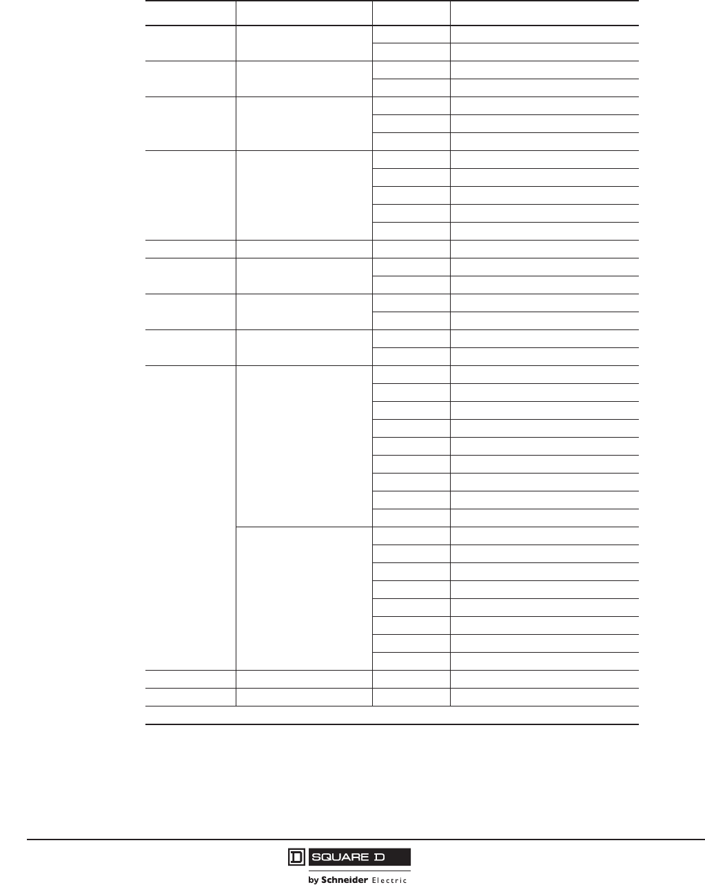
Table 10: Catalog Number for M-, P- and R-Frame (UL/IEC Dual-Rated) Circuit Breakers
Field Position Field Description Options Description
1 Brand Name (blank) Square D™
N Schneider Electric™ (Formerly Merlin Gerin brand)
2 Circuit Breaker Frame
M800 A Max.
P 1200 A Max.
R 3000 A Max.
3 Interrupting Rating
G 35 kA @ 480 Vac
J 65 kA @ 480 Vac
KP-Frame: 50 kA @ 600 Vac
R-Frame: 65 kA @ 600 Vac
L 100 kA @ 480 Vac
4 Connection
F No Lugs
L Lugs on Both Ends
M Lugs on I/ON End
P Lugs on O/OFF End
AI-Line
D Drawout (Not Available on M and R Frames)
5Poles
22P
33P
44P
6 Voltage Rating 4480 V
6600 V
7–9 Ampere Rating ### Circuit Breaker Rating (120 = 1200 A)
000 Automatic Switch Value
10 Standard or 100% Rated (none) Standard Rated
C100% rated
Continued on next page
PowerPact™ M-, P- and R-Frame, and Compact™ NS630b–NS3200 Circuit Breakers
Section 1—General Information
17
10/2012
© 2001–2012 Schneider Electric
All Rights Reserved
™
11–14
Circuit Breaker Trip System
(none) ET1.0 (M-Frame)
(none) ET1.0I (P-Frame, R-Frame)
U31 Micrologic™ 3.0 Trip Unit
U33 Micrologic 5.0 Trip Unit
U41 Micrologic 3.0A Trip Unit
U43 Micrologic 5.0A Trip Unit
U44 Micrologic 6.0A Trip Unit
U63 Micrologic 5.0P Trip Unit
U64 Micrologic 6.0P Trip Unit
U73 Micrologic 5.0H Trip Unit
U74 Micrologic 6.0H Trip Unit
Automatic Switch Trip System1
S60 600 A2
S80 800 A2
S10 1000 A2
S12 1200 A
S16 1600 A
S20 2000 A
S25 2500 A
S30 3000 A
Motor Circuit Protector Trip
System
M68 1200–10000 A2
M69 1500–10000 A2
M70 1800–10000 A2
15 Rating Plug A–H See Table 74
16-17 Modbus® Communication E1 Modbus BCM
18 I-Line™ Phasing See Digest, Product Selector
For Factory-Installed Accessories, See Product Selector
1For more information on P-frame switches, see page 47. For more information on R-frame switches, see page 58.
2Not available on R-frame.
Table 10: Catalog Number for M-, P- and R-Frame (UL/IEC Dual-Rated) Circuit Breakers
Field Position Field Description Options Description
© 2001–2012 Schneider Electric
All Rights Reserved
PowerPact™ M-, P- and R-Frame, and Compact™ NS630b–NS3200 Circuit Breakers
Section 1—General Information
18
10/2012
™
NS630b–NS3200 Circuit Breaker Catalog Numbers
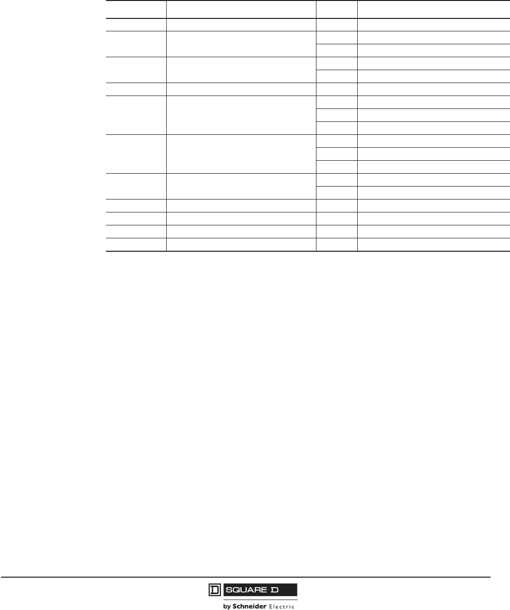
Table 11: Catalog Number for NS630b–NS3200 (IEC-Rated) Circuit Breakers
Field Position Field Description Options Description
1 Brand Name (Blank) Square D™
N Schneider Electric™
2 Circuit Breaker Frame R 3200 A Max.
P 1600 A Max.
3 Interrupting Rating
N Standard Interrupting Rating
H High Interrupting Rating
L Current Limiting
4 Connection
F No lugs
L Lugs on Both Ends
M Lugs on I/ON End
P Lugs on O/OFF End
D Drawout
5 Certification E IEC
6 Poles 33P
44P
7 Voltage Rating 4 440 Vac
6 690 Vac
8–10 Ampere Rating ### Circuit Breaker Rating (120 = 1200 A)
000 Automatic Switch Value
11–14
Circuit Breaker Trip System
U32 Micrologic™ 2.0 Trip Unit
U33 Micrologic 5.0 Trip Unit
U42 Micrologic 2.0A Trip Unit
U43 Micrologic 5.0A Trip Unit
U44 Micrologic 6.0A Trip Unit
U63 Micrologic 5.0P Trip Unit
U64 Micrologic 6.0P Trip Unit
U73 Micrologic 5.0H Trip Unit
U74 Micrologic 6.0H Trip Unit
Automatic Switch Trip System
S63 630 A
S80 800 A
S10 1000 A
S12 1250 A
S16 1600 A
S20 2000 A
S25 2500 A
S32 3200 A
15 Rating Plug R–T See Table 73
16–17 Modbus® Communications E1 Modbus BCM
For Accessories, See Product Selector
PowerPact™ M-, P- and R-Frame, and Compact™ NS630b–NS3200 Circuit Breakers
Section 1—General Information
19
10/2012
© 2001–2012 Schneider Electric
All Rights Reserved
™
Cradle Catalog Numbers
P-frame and NS630b–NS1600 manually-operated circuit breakers and switches are available in
drawout construction (factory installed only). The circuit breakers may be ordered using the circuit
breaker catalog numbering systems described above. The cradles must be ordered separately.
Table 12: Cradle Catalog Number
Field Position Field Description Options Description
1 Cradle C Cradle
2Frame Size S P-Frame 3P
D P-Frame 4P
3 Brand/Certification L Square D™ Brand UL/IEC Dual-Rated
G Schneider Electric™ IEC Rated Only
4 Circuit Breaker Interruption Rating E P-Frame “G”,“J”, “K”, or “L” Interrupting Rating
5 Cradle Connections Top Terminals
V Rear-Connected T Vertical (RCTV)
H Rear-Connected T horizontal (RCTH)
E Front-Connected Flat (FCF)
6 Cradle Connections Bottom Terminals
V Rear-Connected T Vertical (RCTV)
H Rear-Connected T Horizontal (RCTH)
E Front-Connected Flat (FCF)
7 Shutters and Associated Options 9 None (Standard for P-Frame Circuit Breakers)
3 Shutters with Padlocking Provision
8 Circuit Breaker Mismatch and Cradle Interlock A See Product Selector
9 Metering CT X Not Applicable on P-Frame Cradle
10 Cradle Secondary Disconnects Wiring X See Product Selector
11–18 Miscellaneous Cradle Options X See Product Selector
© 2001–2012 Schneider Electric
All Rights Reserved
PowerPact™ M-, P- and R-Frame, and Compact™ NS630b–NS3200 Circuit Breakers
Section 1—General Information
20
10/2012
™
Testing Requirements
UL, NEMA, CSA, and NMX requirements
The UL, NEMA, CSA and NMX labels on a circuit breaker indicate that the circuit breaker meets the
requirements of UL Standard 489, NEMA Standard AB-1, CSA Standard C22.2 No. 5 and NMX standard
J266. The labels also mean that the production procedure is monitored by UL, CSA and ANCE inspectors
to ensure continued compliance to these standards. These requirements include the following tests:
•200% Overload Calibration—each pole of the circuit breaker must trip within a specified time limit
when carrying 200% of its continuous current rating.
•135% Overload Calibration—with all poles connected in series, the circuit breaker must trip within a
specified time limit while carrying 135% of its continuous current rating.
•Overload—the circuit breaker must make and break 600% of its continuous current rating at rated
voltage. Circuit breaker frame sizes 125–1600 A must perform 50 operations at 600%. Circuit
breaker frame sizes 2000–2500 A must perform 25 operations at 600%.
•Temperature Rise—while carrying 100% of rated current and mounted in open air, temperature
rise on a wiring terminal must be within specified limits. For 100% rating, the circuit breaker is
mounted in an enclosure.
•Endurance—UL489 requires that the circuit breaker must complete, at minimum, the following
number of operations:
•Calibration—both the 200% and 135% overload calibration tests are repeated after endurance
testing.
•Short Circuit—the circuit breaker shall be subjected to test currents based on voltage rating and
frame size, with the type and number of operations based on the number of poles, frame rating and
voltage rating. Example: a 3P, 600 Vac, 2500 A frame circuit breaker is subjected to one 20 kA
single-phase closing of the circuit on the circuit breaker per pole and one 30 kA three-phase closing
of the circuit on the circuit breaker for a total of seven short circuit tests.
•Trip Out—the 200% thermal calibration test is repeated following the short-circuit tests.
•Dielectric—the circuit breaker must withstand, for one minute, twice its rated voltage plus 1000 V:
— Between line and load terminals with the circuit breaker in the open, tripped and OFF positions.
— Between terminals of opposite polarity with the circuit breaker closed.
— Between live parts and the overall enclosure with the circuit breaker both open and closed.
No conditioning of the circuit breaker can take place during or between tests. There can be no failure of
functional parts at the conclusion of the sequences.
After qualifying a set of circuit breakers to the standard tests, a manufacturer can have additional
circuit breaker samples tested on higher than standard available fault currents. The following
performance requirements apply:
•200% Overload Calibration—each pole of the circuit breaker must trip within a specified time limit
when carrying 200% of its continuous current rating.
•Short-circuit Test—with the load side terminals connected by 10-inch lengths of specified cable (or
a shorting bar), the circuit breaker is exposed to a short-circuit current for a set time interval. After
safe interruption, the circuit breaker is reset and closed again on the short circuit.
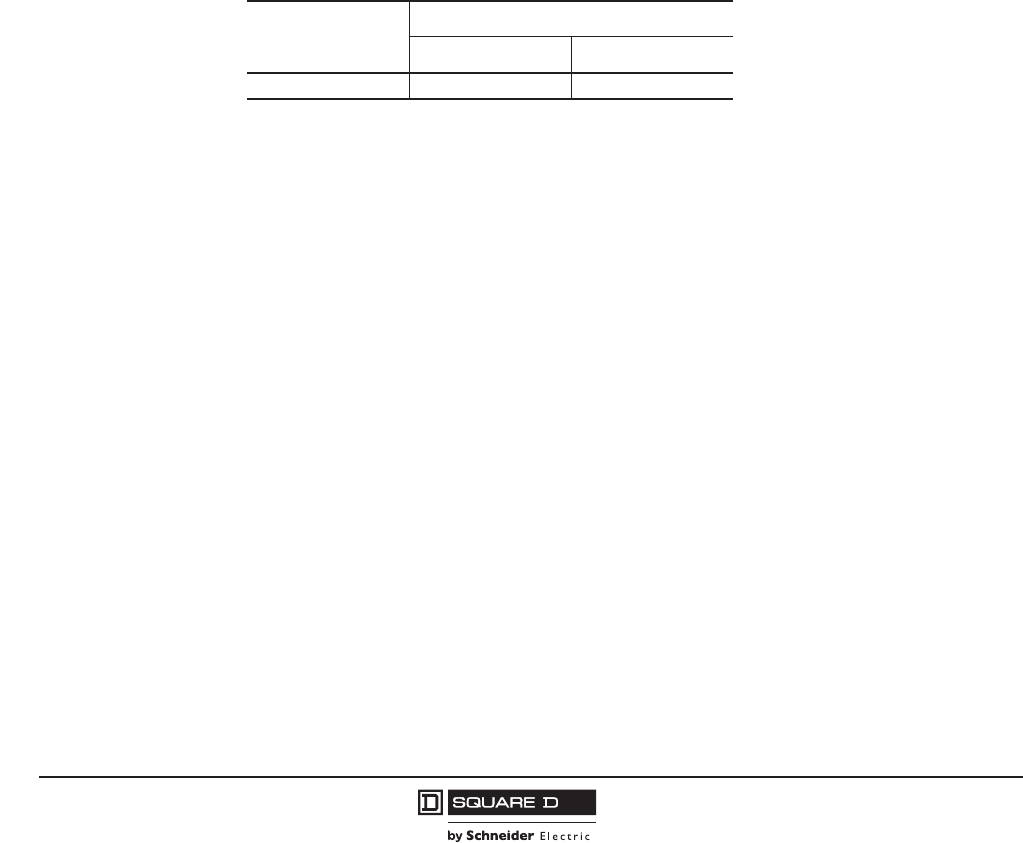
Table 13: Endurance Operations
Frame Size
Operations
With Current 1 Without Current
1200–2500 500 2000
1 UL requires the circuit breaker to operate 10% of the “with current”
operations with a shunt trip.

PowerPact™ M-, P- and R-Frame, and Compact™ NS630b–NS3200 Circuit Breakers
Section 1—General Information
21
10/2012
© 2001–2012 Schneider Electric
All Rights Reserved
™
•250% Overload Calibration—each pole of the circuit breaker must trip within a specified time limit
when carrying 250% of its continuous current rating.
•Dielectric Withstand—the circuit breaker is subjected to twice the voltage rating at which the
interrupting test was conducted, but not less than 900 V.
— Between line and load terminals with the circuit breaker in the tripped and in the OFF positions.
— Between terminals of opposite polarity with the circuit breaker closed.
— Between live parts and the overall enclosure with the circuit breaker both open and closed.
When the sample circuit breakers pass these tests, circuit breakers of the same construction can be
marked or labeled with the current interrupting rating for the higher fault currents.
IEC Requirements
The IEC markings on a circuit breaker indicates that the circuit breaker meets the requirements of IEC
Standard 60947-2 for circuit breakers and 60947-3 for automatic switches. These requirements
include the following tests:
Table 14: IEC Test Sequence
Sequence Category of Devices Tests
General
Performance
Characteristics
(Sequence 1)
All Circuit Breakers
• Tripping Limits and Characteristics
• Dielectric Properties
• Mechanical and Electrical Endurance
•Overload
• Dielectric Voltage Withstand
• Temperature Rise
• 145% Calibration (3 Poles in Series or 3-Phase Test)
Rated Service
Short-circuit
Breaking Capacity
(Ics)
(Sequence 2)
All Circuit Breakers
• Rated service short circuit breaking capacity (O-t-CO-t-CO)
• Electrical Endurance (5% of with Current Operations of
Sequence 1)
• Dielectric Voltage Withstand
• Temperature Rise
• 145% Calibration (3 poles in series or 3-phase test)
Rated Ultimate
Short-circuit
Breaking Capacity
(Icu)
(Sequence 3)
Circuit Breakers of Utilization Category A
Circuit Breakers of Utilization Category B
• 200% Calibration (Each Pole Separately)
• Rated Ultimate Short Circuit Breaking Capacity (O-t-CO)
• Dielectric Voltage Withstand
• 250% Calibration (Each Pole Separately)
Rated Short-time
Withstand Current
(Icw)
(Sequence 4)
Circuit Breakers of Utilization Category B
• 200% Calibration (Each Pole Separately)
• Rated Short-Time Withstand Current
• Temperature Rise
• Short-Circuit Breaking Capacity at Maximum Short-Time
Withstand Current (O-t-CO)
• Dielectric Voltage Withstand
• 200% Calibration (Each Pole Separately)
Combined
Sequence
Circuit Breakers of Utilization Category B:
When Icw = Ics Replaces Sequences 2 and 4
When Icw = Ics = Icu Replaces Sequences
2, 3 and 4
• 200% Calibration (Each Pole Separately)
• Rated Short-Time Withstand Current Icw
• Rated Service Short-Circuit Breaking Capacity at Ics
(O-CO-CO) at Maximum Relay Temp.
• 145% Calibration (3 Poles in Series or 3-Phase Test)
• Dielectric Voltage Withstand
• Temperature Rise
• 200% Calibration (Each Pole Separately)
Individual Pole
Short-Circuit Test
Sequence
(Annex H)
Circuit Breakers for Use in IT Systems
• Individual Pole Short-Circuit Breaking Capacity
• Dielectric Voltage Withstand
• 250% Calibration (Each Pole Separately)

© 2001–2012 Schneider Electric
All Rights Reserved
PowerPact™ M-, P- and R-Frame, and Compact™ NS630b–NS3200 Circuit Breakers
Section 2—Electronic Trip Systems
22
10/2012
™
Section 2—Electronic Trip Systems
M-frame circuit breakers are available with the type ET 1.0 electronic trip system. P-frame and R-frame
circuit breakers are available with either the ET1.0I basic electronic trip system or the Micrologic™
electronic trip system. The NS630b–NS3200 circuit breakers are available with the Micrologic
electronic trip system. The sensing system responds to the flow of current through the circuit breaker.
Thermal Imaging
The thermal imaging function protects the cables or bus bars from overheating in case of low
amplitude repetitive faults. Such overheating can be due to repetitive motor startings, fluctuating load,
intermittent ground faults, or subsequent closing after a fault. Traditional electronic protection does not
protect against repetitive faults because the duration of each overload above the pickup setting is too
short to achieve effective tripping. Nevertheless, each overload involves a temperature rise in the
installation, the cumulative effect of which could lead to overheating of the system.
The thermal imaging function remembers and integrates the thermal heating caused by each pickup
setting overrun. Before tripping, the integrated heating value will reduce the associated time delay and,
therefore, the reaction of the trip unit will be closer to the real heating of the power network system. After
tripping, the function will also reduce the time delay when closing the circuit breaker on an overload.
True RMS Current Sensing
The sensing system responds to the flow of current through the circuit breaker. The trip unit samples
the current waveform to provide true RMS protection through the fifteenth harmonic. This true RMS
sensing gives accurate values for the magnitude of a non-sinusoidal waveform. Therefore, the heating
effects of harmonically distorted waveforms are accurately evaluated.
The Micrologic H trip unit provides additional sampling of the waveforms to measure and provide
waveform capture of harmonic distortion to the thirty-first harmonic.
Type ET Electronic Trip System
Type ET trip units are available with M-frame, P-frame and R-frame UL/IEC circuit breakers. Circuit
breakers with type ET trip units have a fixed ampere rating. The trip units are not field-interchangeable
and will not accept any communications or other trip unit accessories. The trip system uses a set of
current transformers (called CTs or sensors) to sense current, a trip unit to evaluate the current, and a
tripping solenoid to trip the circuit breaker.
ET1.0 (M-Frame only)
The ET1.0 trip system is available on M-frame circuit breakers and is equipped with fixed long-time and
adjustable instantaneous tripping functions only. The long-time pickup is fixed at 1.0 x sensor rating (In),
while the instantaneous pickup is adjustable (dial settings from 2–10 x In) with no intentional time delay.
ET1.0I (P-Frame and R-Frame only)
The ET1.0I trip system is available on both P-frame and R-frame circuit breakers and is equipped with fixed
long-time and adjustable instantaneous tripping functions only. The long-time pickup is fixed at 1.0 x sensor
rating (In), while the instantaneous pickup is adjustable (dial settings from 1.5–12 x In) with no intentional
time delay.
ET1.0M (P-Frame only)
The ET1.0M trip system is only available on P-frame motor circuit protectors and provides protection for
short circuit conditions only. The trip unit has a single adjustment for instantaneous pickup that, if
PowerPact™ M-, P- and R-Frame, and Compact™ NS630b–NS3200 Circuit Breakers
Section 2—Electronic Trip Systems
23
10/2012
© 2001–2012 Schneider Electric
All Rights Reserved
™
exceeded, will trip the circuit breaker with no intentional delay. Instantaneous trip dial settings are
2–16 x In for 600 A circuit breakers and 1.5–12 x In for 800–1200 A circuit breakers.
Micrologic™ Electronic Trip Systems
The P-frame, R-frame and NS630b–NS3200 electronic trip circuit breakers can be equipped with the
optional Micrologic trip systems listed below:
Trip units are designed to protect power circuits and loads. Micrologic trip systems use a set of current
transformers (called CTs or sensors) to sense current, a trip unit to evaluate the current, and a tripping
solenoid to trip the circuit breaker. Adjustable rotary switches on the trip unit allow the user to set the
proper overcurrent or equipment ground-fault current protection required in the electrical system. If
current exceeds a set value for longer than its set time delay, the trip system opens the circuit breaker.
Alarms may be programmed for remote indications. Measurements of current, voltage, frequency,
power, and power quality optimize continuity of service and energy management.
Integration of protection functions in the Application Specific Integrated Circuit (ASIC) electronic
component used in all Micrologic trip units guarantees a high degree of reliability and immunity to
conducted or radiated disturbances. On Micrologic P and H trip units, advanced functions are
managed by an independent microprocessor.
Circuit breakers are shipped with the trip unit long-time pickup switch set at 1.0 and all other trip unit
adjustments set at their lowest settings. Actual settings required for a specific application must be
determined by a qualified consultant or plant engineer. A coordination study is recommended to
provide coordination between all circuit breakers in the distribution system.
Table 15: Micrologic Trip Systems
Model
(LS0)
Long-time +
Short-time +
Zero delay
(IEC Rated Only)
(LI)
Long-time +
Instantaneous
Protection
(UL Listed,
IEC Rated)
(LSI)
Long-time +
Short-time +
Instantaneous
Protection
(UL LIsted, IEC Rated)
(LSIG)
Long-time + Short-time
+ Instantaneous
Protection + Equipment
Ground-fault Protection
(UL LIsted, IEC Rated)
Micrologic Basic Trip Unit 2.0 3.0 5.0 —
Micrologic A Trip Unit 2.0A 3.0A 5.0A 6.0A
Micrologic P Trip Unit — — 5.0P 6.0P
Micrologic H Trip Unit — — 5.0H 6.0H
Table 16: Micrologic™ Trip Unit Features
Feature
Micrologic Trip Unit (X = Standard Feature O = Available Option)
Standard Ammeter Power Harmonics
2.0 3.0 5.0 2.0A 3.0A 5.0A 6.0A 5.0P 6.0P 5.0H 6.0H
Field-Installable XXXXXXXXXXX
LI X X
LS0 X X
LSI X X X X
LSIG/Ground-Fault Trip1XXX
Ground-Fault Alarm/No Trip1, 2 XX
Ground-Fault Alarm and Trip1, 2 XX
Adjustable Rating Plugs XXXXXXXXXXX
True RMS Sensing XXXXXXXXXXX
UL Listed XX XXXXXXX
Thermal Imaging XXXXXXXXXXX
Phase-Loading Bar Graph XXXXXXXX
© 2001–2012 Schneider Electric
All Rights Reserved
PowerPact™ M-, P- and R-Frame, and Compact™ NS630b–NS3200 Circuit Breakers
Section 2—Electronic Trip Systems
24
10/2012
™
LED for Long-Time Pick-Up X XXXXXXXXXX
LED for Trip Indication XXXXXXXX
Digital Ammeter XXXXXXXX
Zone-Selective Interlocking3X XXXXXX
Communications O O O O X X X X
LCD Dot Matrix Display XXXX
Advanced User Interface XXXX
Protective Relay Functions X X X X
Neutral Protection1XXXX
Contact Wear Indication XXXX
Incremental Fine Tuning of Settings X X X X
Selectable Long-Time Delay Bands X X X X
Power Measurement XXXX
Power Quality Measurements XX
Waveform Capture XX
13Ø, 4W circuits require either a neutral current transformer or a 4-pole breaker..
2Requires M6C Programmable Contact Module.
3Not available for 2.0A trip units as upstream devices.
Table 16: Micrologic™ Trip Unit Features (continued)
Feature
Micrologic Trip Unit (X = Standard Feature O = Available Option)
Standard Ammeter Power Harmonics
2.0 3.0 5.0 2.0A 3.0A 5.0A 6.0A 5.0P 6.0P 5.0H 6.0H
Micrologic 3.0
.4
.45
.5
.6 .63 .7
.8
.9
1
x Ir
2
3
456
8
10
12
1.5
setting
Im
.5
1
2
4812
16
20
instantaneous
long time
alarm
Ir tr
(s)
x In @ 6 Ir 24
06133332
Micrologic 5.0
.4
.45
.5
.6 .63 .7
.8
.9
1
delay
short I i
tsd
(s)
on I2t
.
2
.
3
.
4
.
4
.
1
.
2
.
3
.
1
0
off
instantaneous
long time
alarm
Ir
x In .5
1
2
4812
16
20
tr
(s)
@ 6 Ir24
setting
x Ir
2
2.5345
6
8
10
Isd
1.5 x In
3
4
6810
12
15
off
2
06133787
Micrologic 3.0A
40
100 %
%
menu
.4
.45
.5
.6 .63 .7
.8
.9
1
long time
alarm
Ir
x In .5
1
2
4812
16
20
tr
(s)
@ 6 Ir24
x Ir
2
3
456
8
10
101.5
setting
Iminstantaneous
06133477
kA
s
Ir=
Ii=
tr=
Isd=
Ig=
tsd=
Δt=
tg=
IΔn=
MAX
Micrologic 5.0A
40
100 %
%
menu
.4
.45
.5
.6 .63 .7
.8
.9
1
delay
short
I itsd
(s)
on I2t 0
off
instantaneous
long time
alarm
Ir
x In .5
1
2
4812
16
20
tr
(s)
@ 6 Ir24
setting
x Ir
2
2.5345
6
8
10
Isd
1.5 x In
2
2.5345
6
8
10
1.5
06133478
.2
.3
.4.4
.1
.2
.3
.1
kA
s
Ir=
Ii=
tr=
Isd=
Ig=
tsd=
t=
tg=
In=
MAX
Micrologic 6.0A
40
100 %
%
menu
.4
.45
.5
.6 .63 .7
.8
.9
1
delay
short I i
tsd
(s)
on I2t
.
2
.
3
.
4
.
4
.
1
.
2
.
3
.
1
0
off
instantaneous
long time
alarm
Ir
x In
ground fault
B
C
DEF
G
H
J
Ig tg
(s)
on I2t
.
2
.
3
.
4
.
4
.
1
.
2
.
3
.
1
0
off
A
.5
1
2
4812
16
20
tr
(s)
@ 6 Ir24
setting
x Ir
2
2.5345
6
8
10
Isd
1.5 x In
4
3
6810
12
15
off
2
test
06133481
kA
s
Ir=
Ii=
tr=
Isd=
Ig=
tsd=
t=
tg=
In=
MAX
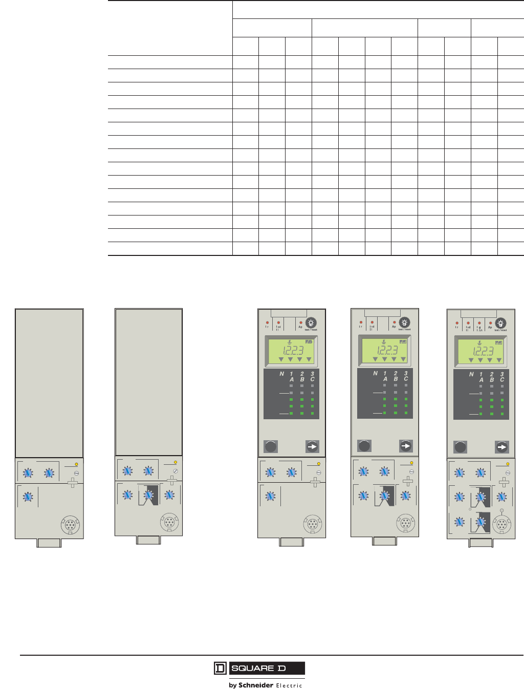
Micrologic 3.0A, 5.0A and 6.0A Trip Units
Micrologic 3.0 and 5.0 Basic Trip Units
PowerPact™ M-, P- and R-Frame, and Compact™ NS630b–NS3200 Circuit Breakers
Section 2—Electronic Trip Systems
25
10/2012
© 2001–2012 Schneider Electric
All Rights Reserved
™
•
Micrologic 5.0P
delaysetting
x Ir
2
2.5345
6
8
10
Isd
1.5
.4
.45
.5
.6 .63 .7
.8
.9
1
short
tsd
(s)
on I2t 0
off
instantaneous
long time
alarm
Ir
x In .5
1
2
4812
16
20
tr
(s)
@ 6 Ir24
06133480
85kA
30kA
24s
5000A
I(A)
Tr i p
0.4s
.2
.3
.4.4
.1
.2
.3
.1
I i
x In
2
4
10
3
68
12
15
off
Micrologic 6.0P
.4
.45
.5
.6 .63 .7
.8
.9
1
delay
short
tsd
(s)
on I2t
.
2
.
3
.
4
.
4
.
1
.
2
.
3
.
1
0
off
instantaneous
long time
alarm
Ir
x In
ground fault
B
C
DE
G
H
J
Ig tg
(s)
on I2t
.
2
.
3
.
4
.
4
.
1
.
2
.
3
.
1
0
off
A
setting
x Ir
2
2.5345
6
8
10
Isd
1.5
.5
1
2
4812
16
20
tr
(s)
@ 6 Ir24
test
06133483
85kA
30kA
24s
5000A
I(A)
Tr i p
0.4s
I i
x In
2
4
10
3
68
12
15
off
Micrologic 5.0H
delaysetting
x Ir
2
2.5345
6
8
10
Isd
1.5
.4
.45
.5
.6 .63 .7
.8
.9
1
short
tsd
(s)
on I2t
.
2
.
3
.
4
.
4
.
1
.
2
.
3
.
1
0
off
instantaneous
long time
alarm
Ir
x In .5
1
2
4812
16
20
tr
(s)
@ 6 Ir24
I(A)
V(V)
P(kW)
E(kWh)
Harmonics
06133479
I i
x In
2
4
10
3
68
12
15
off
Micrologic 6.0H
.4
.45
.5
.6 .63 .7
.8
.9
1
delay
short
tsd
(s)
on I2t
.
2
.
3
.
4
.
4
.
1
.
2
.
3
.
1
0
off
instantaneous
long time
alarm
Ir
x In
ground fault
B
C
DE
G
H
J
Ig tg
(s)
on I2t
.
2
.
3
.
4
.
4
.
1
.
2
.
3
.
1
0
off
A
setting
x Ir
2
2.5345
6
8
10
Isd
1.5
.5
1
2
4812
16
20
tr
(s)
@ 6 Ir24
test
06133482
I(A)
V(V)
P(kW)
E(kWh)
Harmonics
I i
x In
2
4
10
3
68
12
15
off
Micrologic 5.0H and 6.0H Trip UnitsMicrologic 5.0P and 6.0P Trip Units
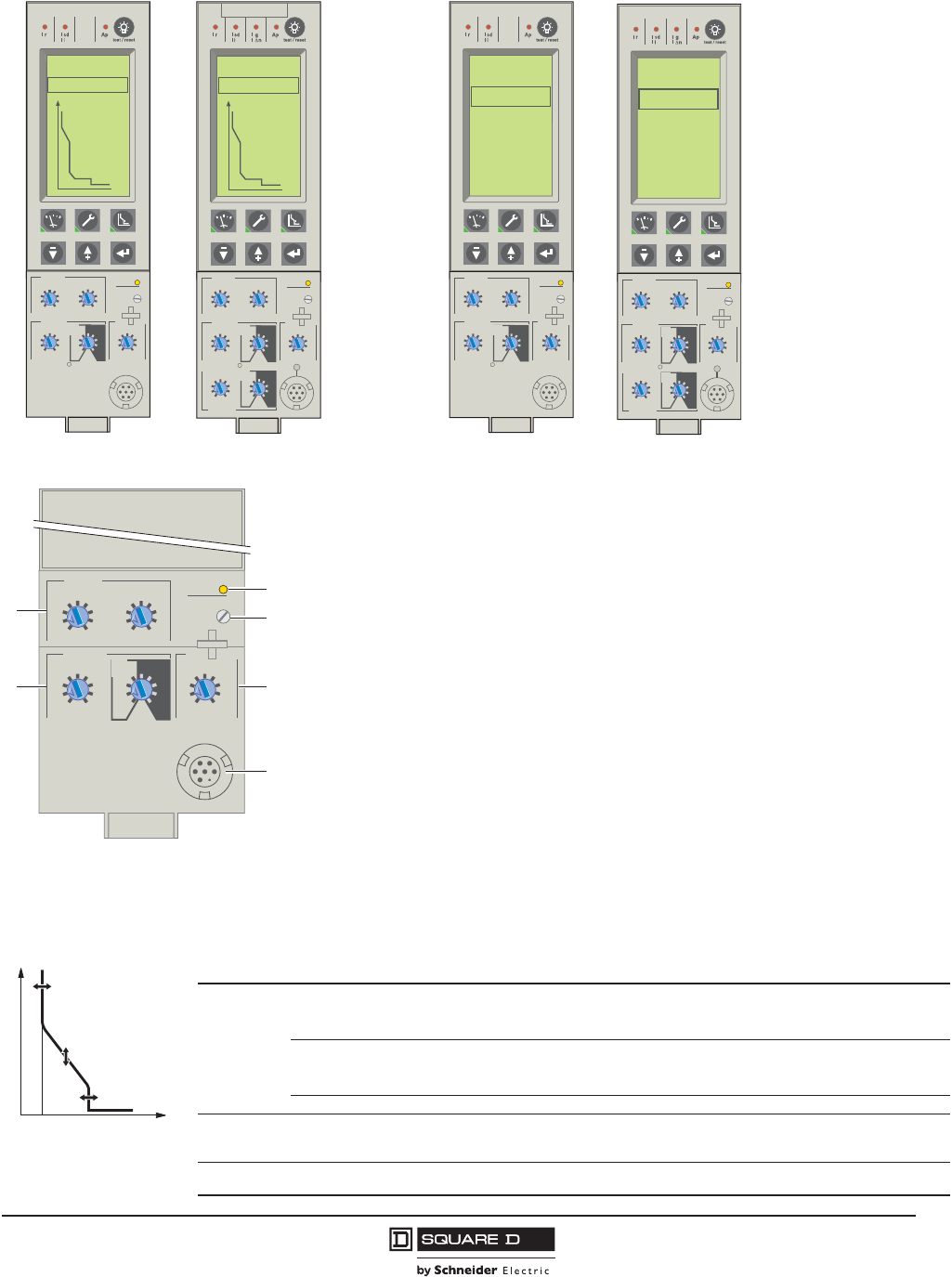
Micrologic™ 2.0, 3.0 and 5.0 Basic Trip Units
The Micrologic 2.0, 3.0, and 5.0 basic trip units protect power circuits.
Protection Settings
Protection thresholds and delays are set using the rotary switches. A full-range of long-
time settings are available via field-installable adjustable rating plugs.
• Overload protection
— True RMS long-time protection
— Thermal imaging: Active thermal imaging before and after
tripping
• Short-circuit protection
— Short-time RMS
— Selection of I2t type (ON or OFF) for short-time delay
• Instantaneous protection
• Neutral protection on four-pole circuit breakers
1
2
.4
.5
.6
.7 .8 .9
.95
.98
1
delay
short time
I i
tsd
(s)
on I2t
.2
.3
.4.4
.1
.2
.3
.1
0
off
instantaneous
long time
alarm
Ir
x In
4
5
6
.5
1
2
4812
16
20
tr
(s)
@
6 Ir 24
setting
x Ir
2
2.5345
6
8
10
Isd
1.5 x In
3
4
6810
12
15
off
2
3
Micrologic 5.0
06133253
1—Long-time current setting and tripping delay
2—Short-time pickup and tripping delay
3—Overload signal (LED)
4—Long-time rating plug screw
5—Instantaneous pickup
6—Test connector
0 I
t
Ir
tr
Ii
06133322
Table 17: Micrologic 2.0 and 3.0 Basic Trip Unit Settings
Long-time
Protection
Current setting (A)
Tripping between 1.05
and 1.20 x Ir
Ir = ln x ...
2.0: 0.40 0.50 0.60 0.70 0.80 0.90 0.95 0.98 1.00
3.0: 0.40 0.45 0.50 0.60 0.63 0.70 0.80 0.90 1.00
Other ranges are available by changing rating plug
Maximum Time Delay (s)
Accuracy: 0 to –20%
tr at 1.5 x Ir12.5 25 50 100 200 300 400 500 600
tr at 6 x Ir0.51 2 4 8 12162024
tr at 7.2 x Ir0.34 0.69 1.38 2.7 5.5 8.3 11 13.8 16.6
Thermal Imaging 20 minutes before or after tripping
Short-time
Protection
Current Setting (A)
Accuracy: ±10%
No delay
Isd = Ir x ...2.0:1.522.53456810
Instantaneous
Protection
Current Setting (A)
Accuracy: ±10% Ii = In x ...3.0:1.52345681012
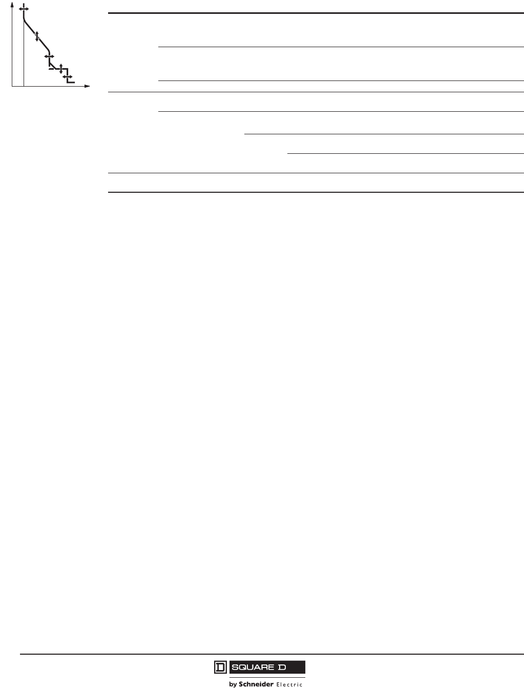
© 2001–2012 Schneider Electric
All Rights Reserved
PowerPact™ M-, P- and R-Frame, and Compact™ NS630b–NS3200 Circuit Breakers
Section 2—Electronic Trip Systems
26
10/2012
™
Ir
tr
lsd
tsd
li
0I
t
06133323
Table 18: Micrologic 5.0 Basic Trip Unit Settings
Long-time
Protection
Current Setting (A)
Tripping Between 1.05
and 1.20 x Ir
Ir = ln x ...
IEC: 0.40 0.50 0.60 0.70 0.80 0.90 0.95 0.98 1.00
UL: 0.40 0.45 0.50 0.60 0.63 0.70 0.80 0.90 1.00
Other Ranges are Available by Changing Rating Plug
Maximum Time Delay (s)
Accuracy: 0 to –20%
tr at 1.5 x Ir12.5 25 50 100 200 300 400 500 600
tr at 6 x Ir0.5 1 2 4 8 12 16 20 24
tr at 7.2 x Ir0.34 0.69 1.38 2.7 5.5 8.3 11 13.8 16.6
Thermal Imaging 20 Minutes Before or After Tripping
Short-time
Protection
Current Setting (A)
Accuracy: ±10% lsd = Ir x ... 1.5 2 2.5 3 4 5 6 8 10
Maximum Time Delay (s)
at 10 x Ir
Settings I2t OFF 0 0.1 0.2 0.3 0.4
I2t ON 0.1 0.2 0.3 0.4
tsd
Min. Trip
Time (ms) 20 80 140 230 350
Max. Trip
Time (ms) 80 140 200 320 500
Instantaneous
Protection
Current Setting (A)
Accuracy: ±10% Ii = In x ... 2 3 4 6 8 10 12 15 off
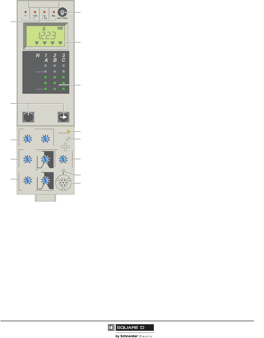
PowerPact™ M-, P- and R-Frame, and Compact™ NS630b–NS3200 Circuit Breakers
Section 2—Electronic Trip Systems
27
10/2012
© 2001–2012 Schneider Electric
All Rights Reserved
™
Micrologic™ 2.0A, 3.0A, 5.0A and 6.0A Trip Units with Ammeter
Micrologic A trip units protect power circuits and provide current measurements,
overload protection, and short-circuit protection. In addition, the 6.0A trip units also
provide ground-fault protection for equipment.
Protection Settings
Protection thresholds and delays are set using the rotary switches. The selected
values are momentarily displayed in amperes and in seconds. A full-range of
long-time settings are available via the field-installable rating plug.
• Overload protection (true RMS long-time protection).
• Thermal imaging (active thermal imaging before and after tripping).
• Short-circuit protection.
— Short-time RMS.
— I2t ON or OFF for short-time delay.
• Instantaneous protection.
• Ground-fault protection for equipment.
— Residual ground-fault protection for equipment.
— Source ground-return ground-fault protection for equipment.
— Modified differential ground-fault protection (MDGF) for equipment.
• Neutral protection on four-pole circuit breakers.
• ZSI: Zone-selective interlocking (a ZSI terminal block may be used to
interconnect a number of trip units to provide total discrimination for short-time
and equipment ground-fault protection, without delay for tripping). Not available
for 3.0A trip units or for 2.0A trip units installed as upstream device.
Ammeter Measurements
Micrologic A trip units measure the true RMS value of currents. They provide
continuous current measurement from 0.2 to 20 x In with an accuracy of 1.5%
(including sensors). No auxiliary source is needed where I > 0.2 x In. The optional
external power supply (24 Vdc) makes it possible to display currents where I < 0.2
x In and to store values of the interrupted current.
A digital LCD screen continuously displays the most heavily loaded phase (Imax)
or displays the IA, IB, IC, Ig, and (on 4P circuit breakers only) IN stored current and
setting values by successively pressing the navigation button.
Communication Network
In conjunction with an optional communication network, the trip unit transmits the
following parameters:
• Setting values
• All ammeter measurements
• Tripping causes.
Micrologic 6.0 A
40
100 %
%
menu
.4
.5
.6
.7 .8 .9
.95
.98
1
delay
short time
I itsd
(s)
on
I
2
t
.
2
.
3
.
4
.
4
.
1
.
2
.
3
.
1
0
off
instantaneous
long time
alarm
Ir
x In
ground fault
B
C
DEF
G
H
J
Ig tg
(s)
on
I
2
t
.
2
.
3
.
4
.
4
.
1
.
2
.
3
.
1
0
off
A
.5
1
2
4812
16
20
tr
(s)
@ 6 Ir
24
setting
x Ir
2
2.5345
6
8
10
Isd
1.5 x In
test
2
4
10
3
68
12
15
off
kA
s
Ir=
Ii=
tr=
Isd=
Ig=
tsd=
Δt=
tg=
IΔn=
MAX
1
12
4
5
10
3
2
11
9
7
8
6
13
06133254
1—Indication of tripping cause
2—Navigation buttons
3—Long-time current setting and tripping delay
4—Short-time pickup and tripping delay
5—Ground-fault pickup and tripping delay
6—Test lamp and reset
7—Digital display
8—Three-phase bar graph and ammeter
9—Overload signal (LED)
10—Long-time rating plug screw
11—Instantaneous pickup
12—Electronic push-to-trip
13—Test connector
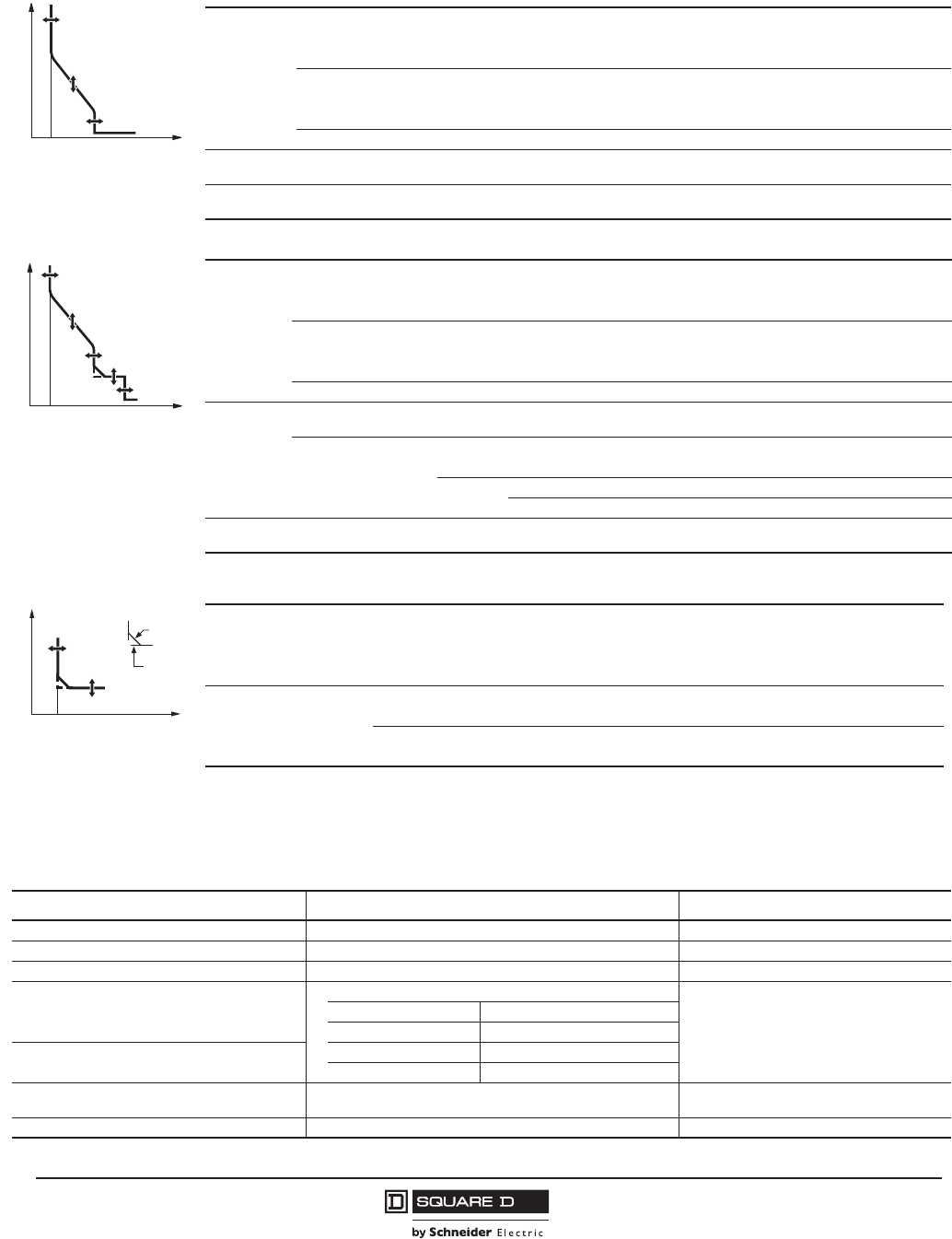
© 2001–2012 Schneider Electric
All Rights Reserved
PowerPact™ M-, P- and R-Frame, and Compact™ NS630b–NS3200 Circuit Breakers
Section 2—Electronic Trip Systems
28
10/2012
™
External Power Supplies for Micrologic Trip Units
Current-based protection functions require no auxiliary power source.
0 I
t
Ir
tr
Ii
06133324
Table 19: Micrologic 2.0A and 3.0A Trip Unit Settings
Long-time
Protection
Current Setting (A)
Tripping Between 1.05
and 1.20 x Ir
Ir = ln x...
2.0A: 0.40 0.50 0.60 0.70 0.80 0.90 0.95 0.98 1.00
3.0A: 0.40 0.45 0.50 0.60 0.63 0.70 0.80 0.90 1.00
Other Ranges are Available by Changing Rating Plug
Maximum Time Delay (s)
Accuracy: 0–20%
tr at 1.5 x Ir12.5 25 50 100 200 300 400 500 600
tr at 6 x Ir0.5124812162024
tr at 7.2 x Ir0.34 0.69 1.38 2.7 5.5 8.3 11 13.8 16.6
Thermal Imaging 20 Minutes Before or After Tripping
Short-time
Protection
Current Setting (A)
Accuracy: ±10%, No delay Isd = Ir x...2.0A:1.522.53456810
Instantaneous
Protection
Current Setting (A)
Accuracy: ±10% Ii = In x... 3.0A:1.52345681012
Ir
tr
lsd
tsd
li
0I
t
06133325
Table 20: Micrologic 5.0A and 6.0A Trip Unit Settings
Long-time
Protection
Current Setting (A)
Tripping Between 1.05
and 1.20 x Ir
Ir = ln x...
IEC: 0.40 0.50 0.60 0.70 0.80 0.90 0.95 0.98 1.00
UL: 0.400.450.500.600.630.700.800.901.00
Other ranges are available by changing rating plug
Maximum Time Delay (s)
Accuracy: 0–20%
tr at 1.5 x Ir12.5 25 50 100 200 300 400 500 600
tr at 6 x Ir0.51 2 4 8 12162024
tr at 7.2 x Ir0.34 0.69 1.38 2.7 5.5 8.3 11 13.8 16.6
Thermal Imaging 20 minutes before or after tripping
Short-time
Protection
Current Setting (A)
Accuracy: ±10% lsd = Ir x... 1.522.53456810
Maximum Time Delay (s)
at 10 x Ir
Settings I2t OFF 0 0.1 0.2 0.3 0.4
I2t ON 0.1 0.2 0.3 0.4
tsd
Min. trip time (ms) 20 80 140 230 350
Max. trip time (ms) 80 140 200 320 500
Instantaneous
Protection
Current Setting (A)
Accuracy: ±10% Ii = In x... 23468101215off
0 I
t
lg
tg
I2t off
I2t on
06133326
Table 21: Micrologic 6.0A Trip Unit Ground-Fault Settings
Ground-fault Pickup (A)
Accuracy: ±10%
Ig = ln x... A B C D E F G H J
ln d400 A 0.3 0.3 0.4 0.5 0.6 0.7 0.8 0.9 1.0
400 A < ln d1200 A 0.2 0.3 0.4 0.5 0.6 0.7 0.8 0.9 1.0
ln > 1200 A 500 640 720 800 880 960 1040 1120 1200
Maximum Time Delay (s) at
1 x Ig
Settings I2t OFF 0 0.1 0.2 0.3 0.4
I2t ON 0.1 0.2 0.3 0.4
tg
Minimum Trip Time (ms) 20 80 140 230 350
Maximum Trip Time (ms) 80 140 200 320 500
Table 22: Micrologic A Use of External 24 Vdc Power Supply
Function Without 24 Vdc Power Supply at F1 and F2 With 24 Vdc Power Supply at F1 and F2
Fault Protection for LSIG Functions Yes Yes
LED Trip Indication Yes Yes
Ammeter and bar graph displays Yes Yes
Trip setting and Max. Current Readings Can Be
Accessed on the Display by Using Navigation
Buttons
Yes, If Current Flow on One Phase is Equal To or Greater Than:
Yes
Sensor Plug Value (In) Minimum Ground-fault Pickup
100–250 A 30% of sensor rating
Ground-Fault Push-to-Trip Button Works for
Testing Ground Fault1
400–1200 A 20% of sensor rating
1600–6300 A 500 A
Modbus® Communications (Optional) No Yes, with separate 24 Vdc power supply for
the circuit breaker communication module
Back-lit Display No Yes
1Ground fault Push-to-trip button will also be functional if hand-held test kit or full-function test kit is powering the trip unit.
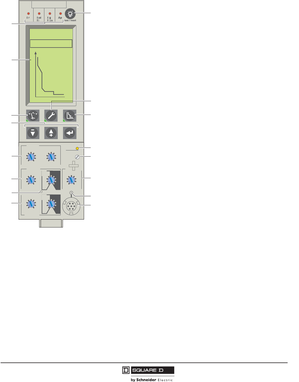
PowerPact™ M-, P- and R-Frame, and Compact™ NS630b–NS3200 Circuit Breakers
Section 2—Electronic Trip Systems
29
10/2012
© 2001–2012 Schneider Electric
All Rights Reserved
™
Micrologic™ 5.0P and 6.0P Trip Units with Power Metering
Load Shedding and Reconnection Parameters
Load shedding and reconnection parameters can be set according to the power or the current flowing
through the circuit breaker. Load shedding is carried out by a remote computer via the communication
network or by an M6C programmable contact.
Micrologic P trip units provide power metering and extended protection in addition
to the adjustable protection functions of the Micrologic A trip unit.
Protection Settings
The adjustable protection functions of the 5.0P and 6.0P trip units are identical to
those of Micrologic A trip unit (overloads, short circuits, equipment ground-fault
protection; see page 27). These units also feature:
• Fine adjustment
Within the range below the rotary switch setting, fine adjustments of
pickups/delays in steps of 1 A/s (except for short-time and ground-fault) are
possible on the keypad or remotely by the communication network.
• Inverse definite minimum time lag (IDMTL) setting.
Coordination with fuse-type or medium-voltage protection systems is
optimized by adjusting the long-time delay curve around 6 x Ir axis. This setting
ensures better coordination with certain loads.
• Neutral protection
On three-pole circuit breakers, neutral protection may be set using the keypad or
remotely using the communication network to one of four positions: OFF, 1/2N
(1/2 x In), 1N (1 x In), or 1.6N (2 x In).
NOTE: Neutral protection is disabled if long-time curve is set to one of the
IDMTL protection settings.
• Configuring Alarms and Other Protection Functions
When the cover is closed, the keypad may no longer be used to change the
protection settings, but it still provides access to the displays for
measurements, histories, indicators, etc. Depending on the thresholds and
time delays set, the Micrologic P trip unit monitors current, voltage, power,
frequency, and phase sequence. Each threshold overrun may be signalled
remotely via the communication network.
Each threshold overrun may be combined with tripping (protection) or an
indication carried out by an optional M6C programmable contact (alarm), or both
(protection and alarm).
Maintenance Record
The maintenance record can be consulted using the full-function test kit or
remotely via the communication network. It can be used as an aid in
troubleshooting and to assist scheduling for device maintenance operations.
Recorded indications include:
• Highest current measured
• Operation counter (cumulative total and total since last reset)
• Number of test kit connections
• Number of trips in operating mode
Micrologic 6.0 P
.4
.5
.6
.7 .8 .9
.95
.98
1
delay
short time
I itsd
(s)
on
I
2
t
.
2
.
3
.
4
.
4
.
1
.
2
.
3
.
1
0
off
instantaneous
long time
alarm
Ir
x In
ground fault
B
C
DEF
G
H
J
Ig tg
(s)
on
I
2
t
.
2
.
3
.
4
.
4
.
1
.
2
.
3
.
1
0
off
A
setting
x Ir
2
2.5345
6
8
10
Isd
1.5
.5
1
2
4812
16
20
tr
(s)
@ 6 Ir
24
x In
test
2
4
10
3
68
12
15
off
10
8
1
4
715
5
16
12
13
14
6
9
2
311
06133255a
85kA
30kA
24s
5000A
I(A)
Tr i p
0.4s
1—Indication of tripping cause
2—High resolution screen
3—Measurement display
4—Navigation buttons
5—Long-time current setting and tripping delay
6—Short-time pickup and tripping delay
7—Hole for settings lockout pin
8—Ground-fault pickup and tripping delay
9—Test lamp and indication reset
10—Maintenance indicators
11—Protection settings
12—Overload signal (LED)
13—Long-time rating plug screw
14—Instantaneous pickup
15—Electronic push-to-trip
16—Test connector
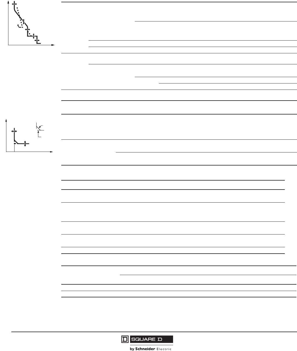
© 2001–2012 Schneider Electric
All Rights Reserved
PowerPact™ M-, P- and R-Frame, and Compact™ NS630b–NS3200 Circuit Breakers
Section 2—Electronic Trip Systems
30
10/2012
™
Indication Option Via Programmable Contacts
The M6C programmable contact may be used to signal threshold overruns or status changes. It can be
programmed using the keypad on the Micrologic P trip unit or remotely using the communication
network. The contact is required to obtain data from the protective relay functions on Type P and
Type H trip units.
Micrologic P trip units are designed to be used with an external 24 Vdc power supply. Current-based
protection functions require no auxiliary power source.
I0
t
tr
Ir
IDMTL
Isd
tsd
Ii
IrIsd Ii
06133327
Table 23: Micrologic 5.0P and 6.0P Trip Unit Settings
Long-Time
(RMS)
Protection
Current Setting (A)
Tripping Between 1.05
and 1.20 x Ir
Ir = ln x... IEC 0.40 0.50 0.60 0.70 0.80 0.90 0.95 0.98 1.00
Ir = ln x... UL 0.400.450.500.600.630.700.800.901.00
Other Ranges are Available by Changing Rating Plug
Maximum Time Delay (s)
Accuracy: 0 to –20%
tr at 1.5 x Ir12.5 25 50 100 200 300 400 500 600
tr at 6 x Ir0.51 2 4 8 12162024
tr at 7.2 x Ir0.34 0.69 1.38 2.7 5.5 8.3 11 13.8 16.6
IDMTL Setting Curve slope SIT VIT EIT HV Fuse DT
Thermal Imaging 20 Minutes Before or After Tripping
Short-Time
(RMS)
Protection
Current Setting (A)
Accuracy: ±10% lsd = Ir x... 1.522.53456810
Maximum Time Delay (s)
at 10 x Ir
Settings I2t OFF 0 0.1 0.2 0.3 0.4
I2t ON 0.1 0.2 0.3 0.4
tsd
Min. Trip Time (ms) 20 80 140 230 350
Max. Trip Time (ms) 80 140 200 320 500
Instantaneous
Protection
Current Setting (A)
Accuracy: ±10% Ii = IN x... 23468101215off
0 I
t
lg
tg
I2t off
I2t on
06133326
Table 24: Micrologic 6.0P Trip Unit Ground-Fault Settings
Ground-Fault Pickup (A)
Accuracy: ±10%
Ig = ln x... ABCDEFGHJ
ln d 400 A 0.3 0.3 0.4 0.5 0.6 0.7 0.8 0.9 1.0
400 A < ln d 1200 A 0.2 0.3 0.4 0.5 0.6 0.7 0.8 0.9 1.0
ln > 1200 A 500 640 720 800 880 960 1040 1120 1200
Maximum Time Delay (s) at
1 x Ig
Settings I2t OFF 0 0.1 0.2 0.3 0.4
I2t ON 0.1 0.2 0.3 0.4
tg
Min. Trip Time (ms) 20 80 140 230 350
Max. Trip Time (ms) 80 140 200 320 500
Table 25: Micrologic 5.0P and 6.0P Trip Unit Settings for Protection Functions
Threshold Time Delay
Current Current Imbalance 0.05 to 0.6 x Imax 1 to 40 s
Maximum Current Imax: IA, IB, IC, IN, Ig0.2 to 1.0 x In15 to 1500 s
Voltage
Voltage Imbalance 0.02 to 0.3 x Vn1 to 40 s
Minimum Voltage Vmin 100 to 725 V (Phase Total) 0.25 to 0.5 s
Maximum Voltage Vmax 100 to 1200 V (Between Phases) 0.20 to 5.0 s
Power Maximum Power Pmax 5 to 500 kW 0.2 to 20 s
Reverse Power Pr0.02 to 0.2 x Pn0.5 to 20 s
Frequency Minimum Frequency Fmin 45 to 65 Hz 0.2 to 5 s
Maximum Frequency Fmax 45 to 540 Hz 0.2 to 5 s
Phase Sequence 'Ø ØA-ØB-ØC or ØA-ØC-ØB Instantaneous
Table 26: Micrologic 5.0P and 6.0P Trip Unit Settings for Current and Power Load-Shedding
Pickup Drop-out
Threshold Time Delay Threshold Time Delay
Current I 0.5 to 1.0 x Ir Per Phase 20% to 80% x tr0.3 to 1.0 x Ir per phase 10 to 600 s
Power P 200 kW to 10 MW 10 to 3600 s 100 kW to 10 MW 10 to 3600 s
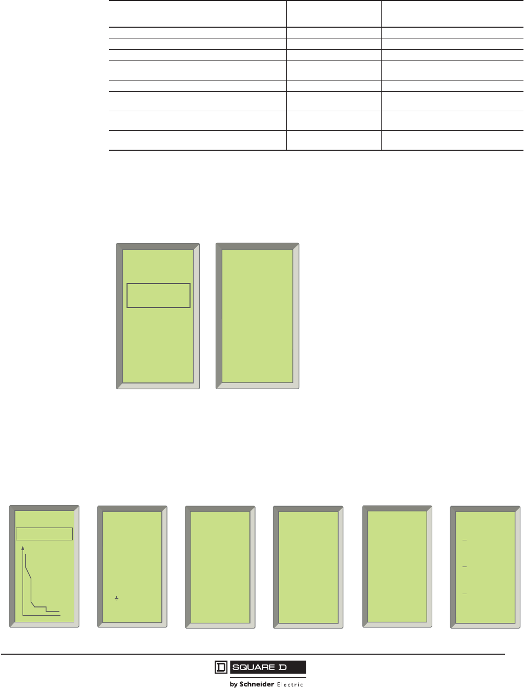
PowerPact™ M-, P- and R-Frame, and Compact™ NS630b–NS3200 Circuit Breakers
Section 2—Electronic Trip Systems
31
10/2012
© 2001–2012 Schneider Electric
All Rights Reserved
™
Tripping and Alarm Histories
The last ten trips and ten alarms are recorded in two separate history files that can be displayed on the
screen (sample displays are shown).
The following information is contained in these files:
Metering
The Micrologic P trip unit calculates in real time the electrical values V, A, W, VAR, VA, Wh, VARh,
VAh, Hz, power factor and crest factor. It also calculates demand current and power over an adjustable
time period.
Table 27: Micrologic P Use of External 24 Vdc Power Supply
Function Without 24 Vdc Power
Supply at F1 and F2
With 24 Vdc Power Supply at F1
and F2
Fault Protection for LSIG Functions Yes Yes
LED Trip Indication Yes Yes
LCD Display and Backlight are Functional Yes1Yes
Ground-Fault Push-to-Trip Button Works for Testing
Ground Fault2Yes1Yes
Metering, Monitoring, and History Logs are Functional Yes1Yes
Communications Between Trip Unit and M2C and
M6C Programmable Contact Modules No Yes
Operation of M6C Programmable Contact Module No Yes, with separate 24 Vdc power supply for
the module
Modbus® Communications No Yes, with separate 24 Vdc power supply for
the circuit breaker communication module
1 If circuit breaker has 100 Vac or more between two phases or phase to neutral and is bottom fed or closed in a top fed application.
2Ground-fault push-to-trip button will also be functional if hand-held test kit or full-function test kit is powering the trip unit.
Trip History Alarm History
• Type of fault • Type of alarm
• Date and time of fault • Date and time of alarm
• Interrupted current • Values measured at time of
alarm
06133263
I
1
= 4800 A
I
2
= 5600 A
I
3
= 4000 A
I
N
= 200 A
03/08/1999
I
r
= 4000 A
11:04:18 am
Trip
06133262
Trip
history
30/06/1999
V
max
27/07/1999
I
sd
03/08/1999
I
r
Trip History Alarm History
06133256
85kA
30kA
24s
5000 A
I
(A)
Tr i p
0.4s
06133257
I
max
IA = 4800 A
IB = 4600 A
IC = 4000 A
IN = 200 A
I = 13 A
instant.
Current Metering Maximum Current
06133258
V
inst.
V
AB
= 460 V
V
BC
= 464 V
V
CA
= 461 V
V
AN
= 270 V
V
BN
= 279 V
V
CN
= 273 V
06133259
P
inst.
P (kW)
2180
Q (kVAR)
- 650
S (kVA)
2280
Voltage Metering Power Metering
06133260
F
(Hz)
60.0
06133261
P
demand
P (kW)
2180
Q (kVAR)
- 650
S(kVA)
2280
Frequency Power Demand

© 2001–2012 Schneider Electric
All Rights Reserved
PowerPact™ M-, P- and R-Frame, and Compact™ NS630b–NS3200 Circuit Breakers
Section 2—Electronic Trip Systems
32
10/2012
™
Real-Time Metering
The value displayed on the screen is refreshed every second. Minimum and maximum measurement
values are stored in memory.
Demand Metering
The demand is calculated over a fixed or sliding time window that can be programmed from five to sixty
minutes. Depending on the contract signed with the power supplier, specific programming makes it
possible to avoid or minimize the cost of overrunning the subscribed power. Maximum demand values
are systematically stored and time stamped.
Communication Network
The communication network may be used to:
•Remotely read parameters for the protection functions.
•Transmit all the measurements and calculated values.
•Signal the causes of tripping and alarms.
•Consult the history files and the maintenance indicator record.
In addition, an event log of the last 100 events and a maintenance record, which is stored in the trip
unit memory but not available locally, may be accessed via the communication network.
This Modbus® communication system is compatible with the Powerlogic™ System Manager™
software (SMS).
Event Log
The event log may be accessed by a remote computer via the communication network. All events are
time stamped and include:
•Trips
•Beginning and end of alarms
•Modifications to settings and parameters
•Loss of time
•Test kit connections
•Counter resets
•System faults (thermal self-protection, major fault and minor fault alarms)
Table 28: Real-Time Metering
Type of Measurement Unit of
Measurement Measurement Source
Current
IRMS
IAVERAGE
IPEAK/2
A
A
A
ØA, ØB, ØC or N
(ØA + ØB + ØC) / 3
ØA, ØB, ØC or N
Voltage
VRMS
VRMS
'VIMBALANCE
V
V
%
(ØA–ØB), (ØB–ØC) and (ØC–ØA)
(ØA–N), (ØB–N) and (ØC–N)
VRMS
Power
P, Q and S
EP, EQ and ES
Power factor
W, VAR, VA
Wh, VARh, VAh
Total
Total
Total
Frequency F Hz 50/60
Table 29: Demand Metering
Type of Measurement Unit of Measurement Measurement Source
Current IDEMAND A ØA, ØB, ØC or N
Power P, Q and SDEMAND W, VAR, VA Total
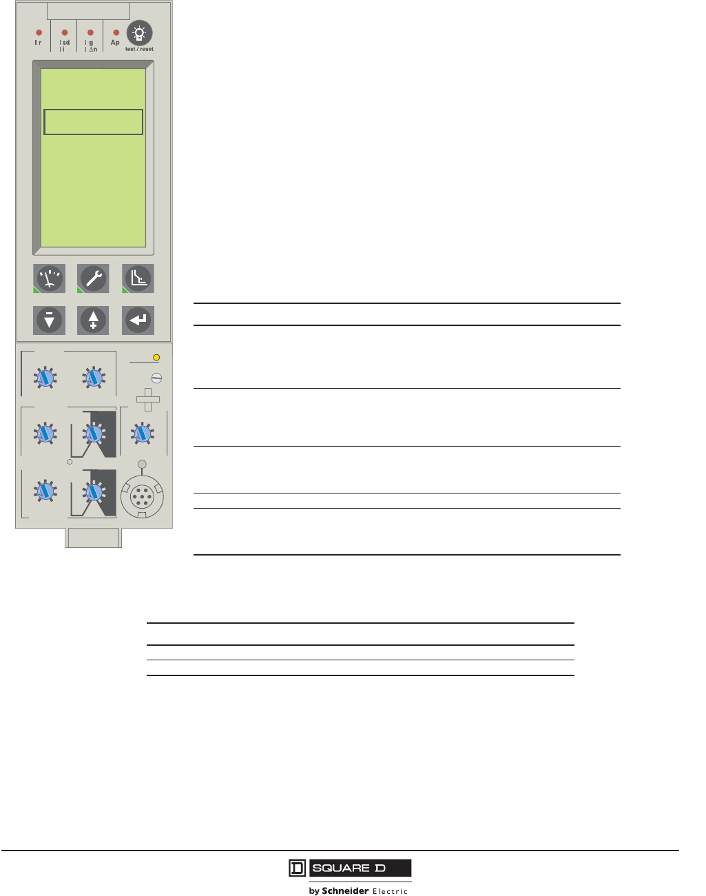
PowerPact™ M-, P- and R-Frame, and Compact™ NS630b–NS3200 Circuit Breakers
Section 2—Electronic Trip Systems
33
10/2012
© 2001–2012 Schneider Electric
All Rights Reserved
™
Micrologic™ 5.0H and 6.0H Trip Units with Harmonic Metering
•Demand Metering: Similar to the Micrologic P trip unit, demand values are calculated over a fixed
or sliding time window that can be set from five to sixty minutes.
Waveform Capture
The Micrologic H trip units can capture and store current and voltage waveforms using digital sampling
techniques similar to those used in oscilloscopes. Using the information available in the captured
waveform, it is possible to determine the level of harmonics as well as the direction and amplitude of
the flow of harmonic power.
The Micrologic™ H trip unit can record manually via the keypad the following waveforms:
•Currents IA, IB, IC and IN
•Phase-to-phase voltages VAB, VBC, and VCA
In addition to the P functions, the Micrologic H trip units offer:
•In-depth analysis of power quality including calculation of harmonics and the fundamentals
•Diagnostics aid and event analysis through waveform capture
•Customized alarm programming to analyze and track down a disturbance on the ac
power system
•Systematic time stamping of all events and creation of logs
Metering
The Micrologic H trip unit offers all the measurements carried out by the Micrologic P trip unit, with
the addition of phase-by-phase measurements of power and energy as well as calculation of:
•Current and voltage total harmonic distortion (THD, thd)
•Current, voltage and power fundamentals (50/60 Hz)
•Harmonic components (amplitude and phase) up to the 31st current and voltage
harmonic
•Real-time metering: The value displayed on the screen is refreshed every second. The
table below shows what is measured in real-time metering
Table 30: Measurements
Type of Measurement Unit of Measurement Measurement Source
Current
IRMS
IAVERAGE
IPEAK/2
'IIMBALANCE
A
A
A
%
ØA, ØB, ØC or N
(ØA + ØB + ØC) / 3
ØA, ØB, ØC or N
ØA, ØB, ØC or N
Voltage
VRMS
VRMS
'VIMBALANCE
V
V
%
(ØA–ØB), (ØB–ØC) and (ØC–
ØA)
(ØA–N), (ØB–N) and (ØC–N)
VRMS
Power
P, Q and S
EP, EQ and ES
Power factor
W, VAR, VA
Wh, VARh, VAh
Total
Total
Total
Frequency F Hz ØA, ØB, or ØC
Power Quality
Indicators
Fundamentals
THD
V and I harmonics
50/60 Hz component
%
Amplitude to phase
V, I, P, Q, and S
V/I
1, 2, 3, 4...50
06133811
Micrologic 6.0 H
.4
.5
.6
.7 .8 .9
.95
.98
1
delay
short time
I itsd
(s)
on
I
2
t
.
2
.
3
.
4
.
4
.
1
.
2
.
3
.
1
0
off
instantaneous
long time
alarm
Ir
x In
lg
(s)
on
I
2
t
.
2
.
3
.
4
.
4
.
1
.
2
.
3
.
1
0
off
setting
x Ir
2
2.5345
6
8
10
Isd
1.5
.5
1
2
4812
16
20
tr
(s)
@ 6 Ir
24
x In
test
I
(A)
V
(V)
P
(kW)
E
(kWh)
Harmonics
2
4
10
3
68
12
15
off
ground fault
B
C
DEF
G
H
J
A
Ig
Table 31: Demand Metering
Type of Measurement Unit of Measurement Measurement Source
Current IDEMAND A ØA, ØB, ØC or N
Power P, Q and SDEMAND W, VAR, VA Total
© 2001–2012 Schneider Electric
All Rights Reserved
PowerPact™ M-, P- and R-Frame, and Compact™ NS630b–NS3200 Circuit Breakers
Section 2—Electronic Trip Systems
34
10/2012
™
Waveforms may be displayed on the graphic screen of the control unit or communicated over a
networked system. The recording takes place over one cycle with a measurement range of 1 to 1.5 In
for current and 0 to 690 volts for voltage. Resolution is 64 points per cycle.
Customized Alarm Programming
The instantaneous value of each measurement can be compared to user-set high and low thresholds.
Overrun of a threshold generates an alarm. Programmable action can be linked to each alarm, including
circuit breaker opening, activation of an M6C contact, recording of measurements in a log, etc.
Event Logs
Each event is recorded with:
•The date, time, and name of the event
•The event characteristics
Micrologic H trip units are designed to be used with an external 24 Vdc power supply.Current-based
protection functions require no auxiliary power source.
Additional Characteristics for Type P and H Trip Units
•Setting the display language: System messages can be displayed in six different languages
(English - US, English - UK, French, German, Spanish, and Italian). The desired language is
selected via the keypad.
•Protection functions: All current-based protection functions require no auxiliary source. Voltage-
based protection functions are connected to ac power via a voltage measurement input built into
the circuit breaker on the bottom side. (Optional external voltage measurement is available as a
factory-installed option.)
•Accuracy of measurements (including sensors):
— Voltage (V) 1%
— Current (A) 1.5% (higher accuracy [1%] may be achieved with special calibration on the current
transformer [CT characterization option])
— Frequency (Hz) 0.1 Hz
— Power (W) and energy (Wh) 2.5%
— The Micrologic H trip unit uses a dedicated metering data chain separate from the protection
data chain so that a greater number of data samples can be used for metering. This increases
the number of samples taken per time period, which in turn gives the H trip unit a higher degree
of metering accuracy.
Table 32: Micrologic H Use of External 24 Vdc Power Supply
Function Without 24 Vdc Power
Supply at F1 and F2
With 24 Vdc Power Supply
at F1 and F2
Fault Protection for LSIG Functions Yes Yes
LED Trip Indication Yes Yes
LCD Display and Backlight are Functional Yes1
1 If circuit breaker has 100 Vac or more between two phases or phase to neutral and is bottom fed or closed in a top fed application.
Yes
Ground-Fault Push-to-Trip Button Works for Testing Ground Fault2
2Ground-fault push-to-trip button will also be functional if hand-held test kit or full-function test kit is powering the trip unit.
Yes1Yes
Metering, Monitoring, and History Logs are Functional Yes1Yes
Communications Between Trip Unit and M2C and M6C
Programmable Contact Modules No Yes
Operation of M6C Programmable Contact Module No Yes, with Separate 24 Vdc
Power Supply for the Module
Modbus™ Communications No
Yes, with Separate 24 Vdc
Power Supply for the Circuit
Breaker Communication Module
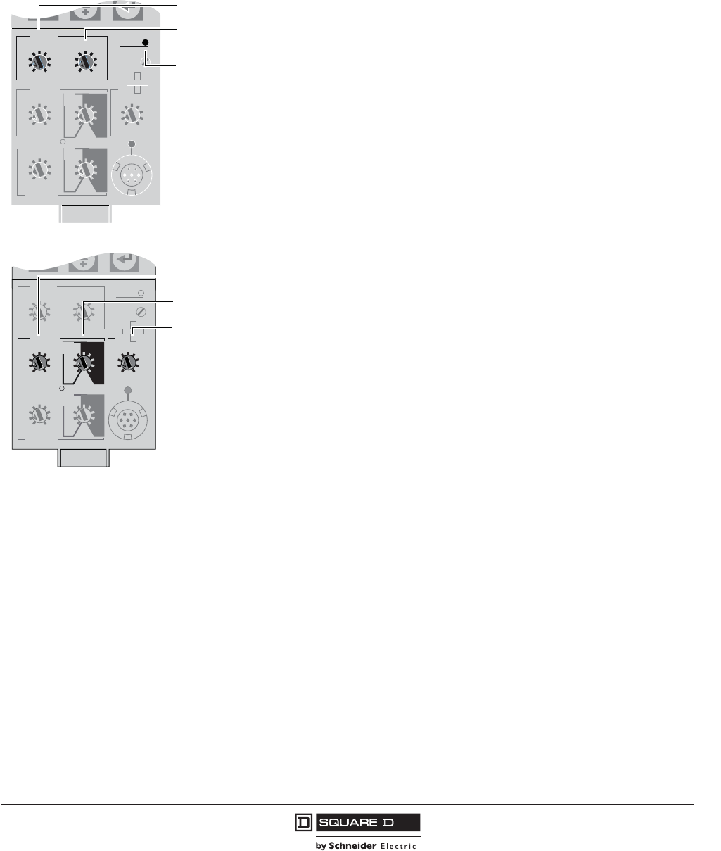
PowerPact™ M-, P- and R-Frame, and Compact™ NS630b–NS3200 Circuit Breakers
Section 2—Electronic Trip Systems
35
10/2012
© 2001–2012 Schneider Electric
All Rights Reserved
™
•Stored information: The fine setting adjustments, the last 100 events and the maintenance record
remain in the trip unit memory even when power is lost.
•Reset: An individual reset, via the keypad or remotely, will reset alarms, minimum and maximum
data, peak values, counters and indicators.
Micrologic™ Trip Unit Functions
Long-time Trip Functions
The long-time pickup switch sets the maximum current level the circuit breaker will
carry continuously. The maximum current level (Ir) is the long-time pickup setting
multiplied by the sensor plug amperage (In). If the current exceeds this value for longer
than the long-time delay time, the circuit breaker will trip.
The long-time delay switch sets the length of time that the circuit breaker will carry a
sustained overload before tripping. Delay bands are labeled in seconds of overcurrent
at six times the ampere rating. For maximum coordination, there are eight delay bands.
Long-time delay is an “inverse time” characteristic in that the delay time decreases as
the current increases.
The trip unit includes an alarm indicator that will be lit continuously when the current is
above 100% of the pickup setting.
Short-time Trip Functions
The short-time pickup switch sets the short-circuit current level at which the circuit
breaker will trip after the set short-time delay. The short-time current (Isd) equals the
short-time pickup setting multiplied by the long-time pickup (Ir).
The short-time delay switch sets the length of time the circuit breaker will carry a short
circuit within the short-time pickup range. The delay (based on 10 times the ampere
rating Ir) can be adjusted to four positions of I2t ramp operation (I2t ON) or five
positions of fixed time delays (I2t OFF). I2t ON delay is an “inverse time” characteristic
in that the delay time decreases as the current increases. Short-time delay for the 2.0
trip unit is fixed at a delay band of 20 to 80 ms.
Instantaneous Trip Function
The instantaneous pickup switch sets the short-circuit current level at which the circuit
breaker will trip with no intentional time delay. The instantaneous current (Ii) is equal to
the instantaneous pickup setting multiplied by the sensor plug amperage (In).
The instantaneous function will override the short-time function if the instantaneous
pickup is adjusted at the same or lower setting than the short-time pickup. In trip units
with both adjustable short-time and instantaneous trip functions, the adjustable
instantaneous trip can be disabled by setting Instantaneous pickup to OFF.
.4
.5
.6
.7 .8 .9
.95
.98
1
delay
short time
I itsd
(s)
on I
2
t
.2
.3
.4.4
.1
.2
.3
.1
0
off
instantaneous
long time
alarm
Ir
x In
ground fault
B
C
DEF
G
H
J
Ig tg
(s)
on I
2
t
.2
.3
.4.4
.1
.2
.3
.1
0
off
A
setting
x Ir
2
2.5345
6
8
10
Isd
1.5
.5
1
2
4812
16
20
tr
(s)
@ 6 Ir
24
x In
3
4
6810
12
15
off
2
test
Long-time
Pickup
Long-time
Delay
Alarm
Indicator
06135256
Long-time Trip Functions
.4
.5
.6
.7 .8 .9
.95
.98
1
delay
short time
I itsd
(s)
on I2t
.2
.3
.4.4
.1
.2
.3
.1
0
off
instantaneous
long time
alarm
Ir
x In
ground fault
B
C
DEF
G
H
J
Ig tg
(s)
on I2t
.2
.3
.4.4
.1
.2
.3
.1
0
off
A
setting
x Ir
2
2.5345
6
8
10
Isd
1.5
.5
1
2
4812
16
20
tr
(s)
@ 6 Ir24
x In
3
4
6810
12
15
off
2
test
Short-time
Pickup
Short-time
Delay
Instantaneous
06135257
Short-time Trip Functions
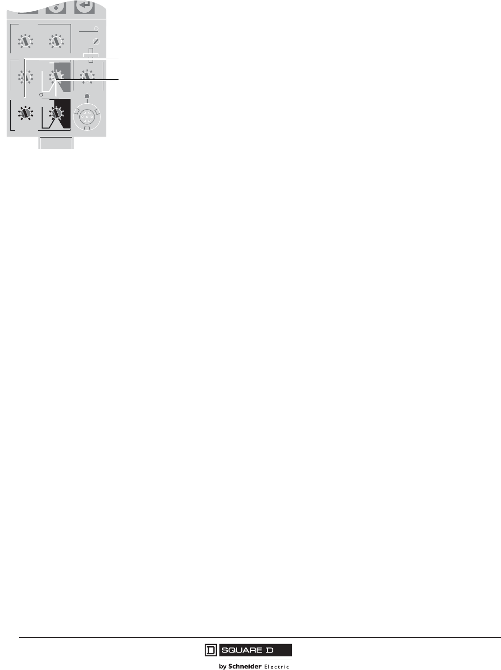
© 2001–2012 Schneider Electric
All Rights Reserved
PowerPact™ M-, P- and R-Frame, and Compact™ NS630b–NS3200 Circuit Breakers
Section 2—Electronic Trip Systems
36
10/2012
™
Ground-fault Trip Functions
The ground-fault pickup switch sets the current level at which the circuit breaker will trip
after the set ground-fault delay. Ground-fault pickup values (Ig) are based on circuit
breaker sensor plug (In) only, not on the rating plug multiplier (Ir). Changing the rating
plug multiplier has no effect on ground-fault pickup values.
The ground-fault delay switch sets the length of time the circuit breaker will carry
ground-fault current which exceeds the ground-fault pickup level before tripping. The
delay, based on the sensor plug amperage (In), can be adjusted to four positions of I2t
ramp operation (I2t ON) or five positions of fixed time delays (I2t OFF). I2t ON delay is
an “inverse time” characteristic in that the delay time decreases as the current
increases.
Communication Network
P-frame, R-frame and NS630b–NS3200 circuit breakers and Micrologic™ trip unit information is
available via a Modbus® communication network to Powerlogic™ System ManagerTM software (SMS)
or third party applications for reporting and recording.
Types of Information via Modbus communication network includes:
•Circuit breaker identification and status
•Remote control of circuit breaker operation
•View and set protection function parameters
•Real-time readings
•Trip indication
•Alarm reporting
•Historical files and maintenance records
The Modbus circuit breaker communication feature, standard on the Micrologic P and H trip units and
available for the Micrologic A trip unit, is made up of:
•A Modbus Circuit Breaker Communication Module (BCM) installed on the circuit breaker and
supplied with a kit for optional connection to the XF shunt close and MX shunt trip
•An optional Modbus Cradle Communication Module (CCM) installed adjacent to the circuit breaker
cradle. A set of cradle position switches is required for status of circuit breaker position (connected,
test, or disconnected). (Drawout circuit breaker only.)
Modbus Circuit Breaker Communication Module (BCM)
The Modbus Circuit Breaker Communication Module (BCM) is installed in the circuit breaker and
requires a separate, isolated 24 Vdc power source. The BCM is optically coupled to the Micrologic trip
unit to ensure a high level of isolation between the trip unit and the communication network. The
Modbus BCM provides circuit breaker status via dedicated OF (open or closed) and SDE (fault tripped)
switches and provides the capability of remotely controlling the circuit breaker. It also maintains an
event log of circuit breaker status containing the number of times the circuit breaker has experienced
each status position with the date and time of the last transition. This information and the remote
control capability are available to a Modbus supervisor system via a Modbus communication network.
Modbus Cradle Communication Module (CCM)
The optional Modbus Cradle Communication Module (CCM) (drawout circuit breakers only) is installed
adjacent to the circuit breaker cradle and is the gateway between the Modbus network and the Modbus
BCM. The Modbus CCM provides circuit breaker cradle status including connected position (CE),
disconnected position (CD) and cradle test position (CT). The CCM monitors the position of the
.4
.5
.6
.7 .8 .9
.95
.98
1
delay
short time
I itsd
(s)
on I2t
.2
.3
.4.4
.1
.2
.3
.1
0
off
instantaneous
long time
alarm
Ir
x In
ground fault
B
C
DEF
G
H
J
Ig tg
(s)
on I2t
.2
.3
.4.4
.1
.2
.3
.1
0
off
A
setting
x Ir
2
2.5345
6
8
10
Isd
1.5
.5
1
2
4812
16
20
tr
(s)
@ 6 Ir24
x In
3
4
6810
12
15
off
2
test
06135258
Ground-fault
Pickup
Ground-fault
Delay
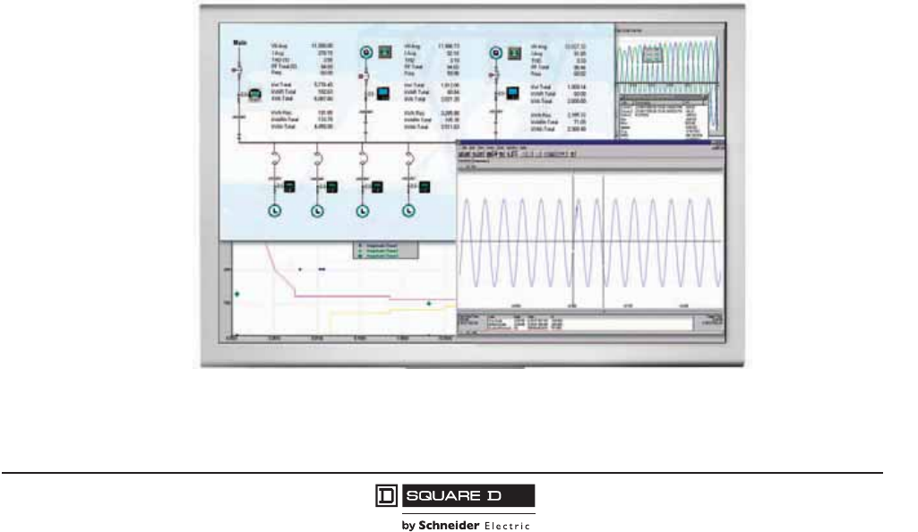
PowerPact™ M-, P- and R-Frame, and Compact™ NS630b–NS3200 Circuit Breakers
Section 2—Electronic Trip Systems
37
10/2012
© 2001–2012 Schneider Electric
All Rights Reserved
™
Modbus BCM and trip unit when it detects a circuit breaker being racked from the disconnected to the
test position. This capability allows a circuit breaker to be replaced without the need to manually
configure the communication parameters in the Modbus BCM. The CCM maintains an event log of the
date and time of the last circuit breaker transition. In order to aid system communication troubleshooting,
the CCM has visual indication of the module’s operating status by means of two LEDs.
Powerlogic™ System Manager Software (SMS)
System Manager Software (SMS), used for power systems and energy management, provides the
human-machine interface (HMI) for electrical system information on a PC. SMS displays circuit breaker
and trip unit information in several formats including:
•Graphical screens including real-time readings, circuit breaker status and remote control of circuit
breaker operation
•Tables displaying real-time readings, maintenance information and date and time of last operation
•Waveform captures including harmonic content
•Tabular displays of event logs and data logs
•Alarm annunciation and recording
Electrical Installation Supervision using ION-Enterprise Software
•PowerLogic™ ION-Enterprise software is ideally suited to the supervision needs of small system
applications, monitoring up to 32 devices.
•Installed on a PC under Windows, it represents a cost-effective and easy-to-implement power-
monitoring solution that offers:
— automatic detection of compatible devices
— real-time monitoring of data including power requirements
— a report generator with a number of pre-defined reports that can be exported to
— Excel
— cost allocation
— time-stamped data-logging possibilities
— Modbus serial and Modbus TCP/IP compatible communication.
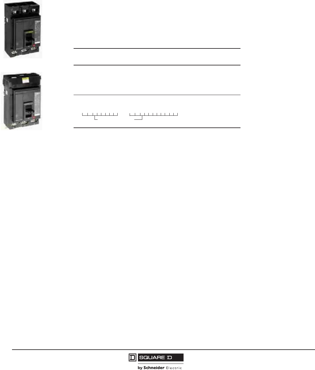
© 2001–2012 Schneider Electric
All Rights Reserved
PowerPact™ M-, P- and R-Frame, and Compact™ NS630b–NS3200 Circuit Breakers
Section 3—PowerPact M-Frame Molded Case Circuit Breakers
38
10/2012
™
Section 3—PowerPact M-Frame Molded Case Circuit Breakers
Performance
PowerPact M-frame molded case circuit breakers provide improved performance and a compact
solution for applications up to 800 A. They complement the existing PowerPact P- and R-frame circuit
breakers, and replace the traditional MA/MH circuit breakers with a smaller footprint and competitive
cost.
•Available in 300, 350, 400, 450, 500, 600, 700, and 800 A ratings.
•Available in 2- and 3-pole unit-mount and I-Line versions
•Built-in electronic trip unit type ET 1.0 provides better accuracy than standard thermal-magnetic trip
units. The ET 1.0 trip unit cannot be field replaced, nor does it allow adjustment of the trip point
setting. (It is considered an electronic equivalent of a thermal-magnetic circuit breaker.)
•FIxed long-time and adjustable instantaneous protection (2 to 10 times nominal ampere rating) is
standard.
•Same dimensions, common mounting, bussing, cabling and door cut-out as PowerPact P-frame
circuit breakers.
•Approximately 15% smaller installed volume than the MA/MH circuit breakers.
•A full range of electrical accessories are available:
— Shunt trip (various AC and DC voltages are available)
— Undervoltage trip (various AC and DC voltages are available)
— Time delayed undervoltage trip (various AC and DC voltages are available)
— Auxiliary switches (up to 3A/3B); low-level switches are also available (voltage and amperage)
— Alarm switch (1A/1B); low-level switches are also available (voltage and amperage)
— Overcurrent trip switch (SDE)
•A full range of mechanical accessories are available:
— Standard mechanical lugs (aluminum or copper)
— Crimp (compression) lugs (aluminum or copper)
— Power distribution lugs (aluminum only)
— Bus connector kit
— Inter-phase barriers
— Door escutcheons (for toggle or accessory cover)
— Padlocking device (removable or fixed version), complies with OSHA requirements
— Key-lock device (Kirk® or Schneider Electric™ keylocks)
M-Frame Unit-Mount
M-Frame I-Line
Table 33: Termination Options
Frame Termination
Letter Termination Option
M-Frame
F No Lugs
L Lugs both ends
M Lugs ON end Terminal Nut Kit Off end
P Lugs OFF end Terminal Nut Kit On end
M G L 3 6 4 0 0 or
For factory-installed termination, place termination letter
in the third block of the circuit breaker catalog number.
Termination
Letter
D G L 3 6 4 0 0 E 2 0
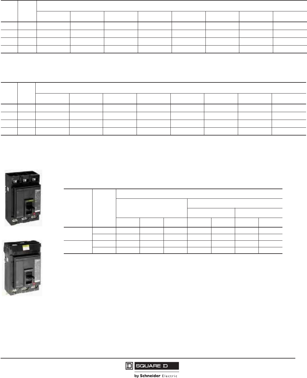
PowerPact™ M-, P- and R-Frame, and Compact™ NS630b–NS3200 Circuit Breakers
Section 3—PowerPact M-Frame Molded Case Circuit Breakers
39
10/2012
© 2001–2012 Schneider Electric
All Rights Reserved
™
Catalog Numbers
Interrupting Ratings
Termination Information
Unit-mount circuit breakers have mechanical lugs standard on both ends. I-Line circuit breakers have
lugs standard on the O/OFF end. These lugs accept aluminum or copper wire. See Table 87 on page
84 for more lug options.
Accessories
Accessories are available either factory- or field-installed. They can be installed in accessory
compartments behind the circuit breaker accessory cover. See Table 61 on page 68 for available
accessories.
Table 34: UL/IEC Rated, Unit-Mount, Manually-Operated, Standard-Rated Electronic Trip Circuit Breakers with
Non-Interchangeable 1.0 Electronic Trip (Fixed Long-Time and Adjustable Instantaneous Trip Settings)
Type Poles
Current Rating
300 A 350 A 400 A 450 A 500 A 600 A 700 A 800 A
MG 2 MGL26300 MGL26350 MGL26400 MGL26450 MGL26500 MGL26600 MGL26700 MGL26800
MJ 2 MJL26300 MJL26350 MJL26400 MJL26450 MJL26500 MJL26600 MJL26700 MJL26800
MG 3 MGL36300 MGL36350 MGL36400 MGL36450 MGL36500 MGL36600 MGL36700 MGL36800
MJ 3 MJL36300 MJL36350 MJL36400 MJL36450 MJL36500 MJL36600 MJL36700 MJL36800
Table 35: UL/IEC Rated, I-Line™, Manually-Operated, Standard-Rated Electronic Trip Circuit Breakers with
Non-Interchangeable 1.0 Electronic Trip (Fixed Long-Time and Adjustable Instantaneous Trip Settings)
Type Poles
Current Rating
300 A 350 A 400 A 450 A 500 A 600 A 700 A 800 A
MG12MGA263002 MGA263502 MGA264002 MGA264502 MGA265002 MGA266002 MGA267002 MGA268002
MJ12MJA263002 MJA263502 MJA264002 MJA264502 MJA265002 MJA266002 MJA267002 MJA268002
MG23MGA36300 MGA36350 MGA36400 MGA36450 MGA36500 MGA36600 MGA36700 MGA36800
MJ23MJA36300 MJA36350 MJA36400 MJA36450 MJA36500 MJA36600 MJA36700 MJA36800
1Suffix 2 is for AC phasing (standard offer), or use 5 for CA phasing (option).
2No suffix is for ABC phasing (standard offer), or use 6 for CBA phasing (option).
M-Frame Unit-Mount
M-Frame I-Line
Table 36: Interrupting Ratings
Mounting Circuit
Breaker
Interrupting Ratings
UL/CSA/NMX
IEC 60947-2
240 Vac 380/415 Vac
240 Vac 480 Vac 600 Vac Icu Ics Icu Ics
Individually-
Mounted
MG 65 kA 35 kA 18 KA 50 kA 25 kA 35 kA 20 kA
MJ 100 kA 65 kA 25 kA 65 kA 35 kA 50 kA 25 kA
I-Line MG 65 kA 35 kA 18 KA 50 kA 25 kA 35 kA 20 kA
MJ 100 kA 65 kA 25 kA 65 kA 35 kA 50 kA 25 kA
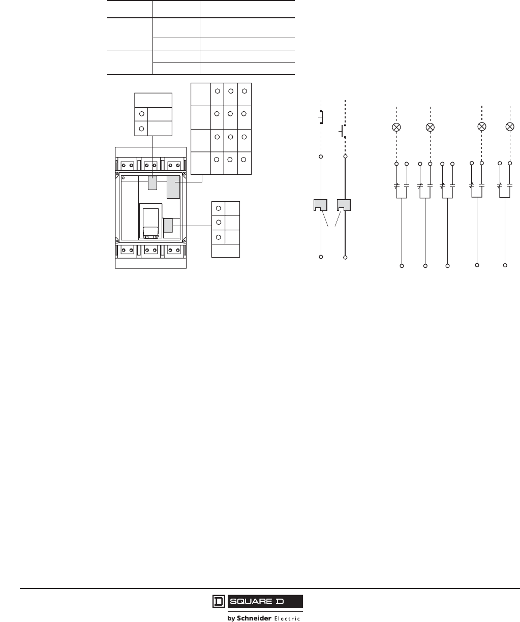
© 2001–2012 Schneider Electric
All Rights Reserved
PowerPact™ M-, P- and R-Frame, and Compact™ NS630b–NS3200 Circuit Breakers
Section 3—PowerPact M-Frame Molded Case Circuit Breakers
40
10/2012
™
Control Wiring
Control wiring is connected to terminals located under the circuit breaker accessory cover.
NOTE: All diagrams show circuit breaker in open position
Figure 1: Accessory Control Wiring Diagrams
Function Connector Description
Auxiliary
Contacts
OF Open/Closed Circuit Breaker
Position Contacts
SD Bell Alarm
Remote
Operation
MN Undervoltage Trip Device
MX Shunt Trip
or
D2
D1
MN MX
C2
C1
06133228
Remote Operation Alarm Contacts
22
24
21
OF2
Closed
06123033
OF3
32
34
31
Open
12
14
11
OF1
92
94
91
SD
Tripped
82
84
81
SDE
Fault
D1/C1
D2/C2
MN/MX OF1
OF2
OF3
SD
11
21
31
91
12
22
32
92
14
24
34
94
06123230
82
81
SDE
84
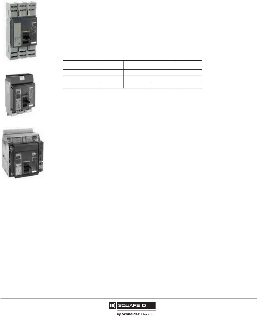
PowerPact™ M-, P- and R-Frame, and Compact™ NS630b–NS3200 Circuit Breakers
Section 4—PowerPact P-Frame Molded Case Circuit Breakers
41
10/2012
© 2001–2012 Schneider Electric
All Rights Reserved
™
Section 4—PowerPact P-Frame Molded Case Circuit Breakers
Performance
Providing unparalleled performance and control, the P-frame circuit breakers features the exclusive
Micrologic™ electronic trip units, which allow for a range of sophisticated applications for metering and
monitoring. In addition, trip units can be interchanged in the field to allow for maximum flexibility.
The compact size and small footprint of the P-frame circuit breaker permits high density installations in
I-Line™ panelboards and switchboards. These circuit breakers are available in 100% rated
construction for all unit-mount circuit breakers and up to 800 A in I-Line circuit breakers to meet a
broad range of commercial and industrial application needs.
•Both standard (80%) and 100% rated construction circuit breakers are available in 1200 A with a
sensor size range of 250–1200 A.
•Interrupting ratings (AIR):
•The P-frame circuit breakers with K interrupting rating are recommended for applications having
high inrush and/or non-linear loads such as large motors, transformers, motors with soft starts, etc.
•Compact circuit breaker size allows for small footprint installations using I-Line panelboards and
switchboards. Nine inch width provides increased density installation.
•Most field-installable accessories are common to all frame sizes for easier stocking and installation
•Selection of four interchangeable Micrologic trip units available, with Powerlogic™ power metering
and monitoring capabilities available in advanced trip units.
•Field-installable sensor plugs (after January 2007). See Table 73 on page 76.
•Compatible with Powerlogic systems and high amperage power circuit breakers.
•Built-in Modbus® protocol provides an open communications platform and eliminates the need to
purchase additional, proprietary network solutions.
•Connection options include bus, cable or I-Line for installation flexibility.
•Additional options are available for 5-cycle closing, stored energy mechanisms and drawout-
mounting.
P-Frame I-Line
P-Frame Unit-Mount
P-Frame Drawout
Voltage G J K L
240 Vac 65 kA 100 kA 65 kA 125 kA
480 Vac 35 kA 65 kA 50 kA 100 kA
600 Vac 18 kA 25 kA 50 kA 25 kA

© 2001–2012 Schneider Electric
All Rights Reserved
PowerPact™ M-, P- and R-Frame, and Compact™ NS630b–NS3200 Circuit Breakers
Section 4—PowerPact P-Frame Molded Case Circuit Breakers
42
10/2012
™
Catalog Numbers
Table 37: UL/IEC Rated, Unit-Mount1, Manually-Operated, Standard-Rated Electronic Trip Circuit Breakers with Basic
Electronic Trip and Micrologic™ Electronic Trip Unit
Trip Unit
Circuit Breaker Catalog Number2
Current Rating (Sensor Rating)
Type 250 A3400 A 600 A 800 A 1000 A 1200 A
Basic Electronic
Trip Unit
(Not
Interchangeable)
ET1.0I
2P4, 3P
Fixed
Long-time
——PGL36060 PGL36080 PGL36100 PGL36120
——PJL36060 PJL36080 PJL36100 PJL36120
——PKL36060 PKL36080 PKL36100 PKL36120
——PLL34060 PLL34080 PLL34100 PLL34120
Micrologic
Interchangeable
Standard Trip
Unit
3.0 (LI)
3P,
4P5 (G & K only)
PGL36025U31A PGL36040U31A PGL36060U31A PGL36080U31A PGL36100U31A PGL36120U31A
PJL36025U31A PJL36040U31A PJL36060U31A PJL36080U31A PJL36100U31A PJL36120U31A
PKL36025U31A PKL36040U31A PKL36060U31A PKL36080U31A PKL36100U31A PKL36120U31A
PLL34025U31A PLL34040U31A PLL34060U31A PLL34080U31A PLL34100U31A PLL34120U31A
5.0 (LSI)
3P
4P5 (G & K only)
PGL36025U33A PGL36040U33A PGL36060U33A PGL36080U33A PGL36100U33A PGL36120U33A
PJL36025U33A PJL36040U33A PJL36060U33A PJL36080U33A PJL36100U33A PJL36120U33A
PKL36025U33A PKL36040U33A PKL36060U33A PKL36080U33A PKL36100U33A PKL36120U33A
PLL34025U33A PLL34040U33A PLL34060U33A PLL34080U33A PLL34100U33A PLL34120U33A
Micrologic
Interchangeable
Ammeter Trip
Unit6
3.0A (LI)
3P
4P5 (G & K only)
PGL36025U41A PGL36040U41A PGL36060U41A PGL36080U41A PGL36100U41A PGL36120U41A
PJL36025U41A PJL36040U41A PJL36060U41A PJL36080U41A PJL36100U41A PJL36120U41A
PKL36025U41A PKL36040U41A PKL36060U41A PKL36080U41A PKL36100U41A PKL36120U41A
PLL34025U41A PLL34040U41A PLL34060U41A PLL34080U41A PLL34100U41A PLL34120U41A
5.0A (LSI)
3P
4P5 (G & K only)
PGL36025U43A PGL36040U43A PGL36060U43A PGL36080U43A PGL36100U43A PGL36120U43A
PJL36025U43A PJL36040U43A PJL36060U43A PJL36080U43A PJL36100U43A PJL36120U43A
PKL36025U43A PKL36040U43A PKL36060U43A PKL36080U43A PKL36100U43A PKL36120U43A
PLL34025U43A PLL34040U43A PLL34060U43A PLL34080U43A PLL34100U43A PLL34120U43A
6.0A (LSIG)
3P
4P5 (G & K only)
PGL36025U44A PGL36040U44A PGL36060U44A PGL36080U44A PGL36100U44A PGL36120U44A
PJL36025U44A PJL36040U44A PJL36060U44A PJL36080U44A PJL36100U44A PJL36120U44A
PKL36025U44A PKL36040U44A PKL36060U44A PKL36080U44A PKL36100U44A PKL36120U44A
PLL34025U44A PLL34040U44A PLL34060U44A PLL34080U44A PLL34100U44A PLL34120U44A
Micrologic
Interchangeable
Power Trip Unit
with Modbus®
Communications
5.0P (LSI)
3P
4P5 (G & K only)
PGL36025U63AE1 PGL36040U63AE1 PGL36060U63AE1 PGL36080U63AE1 PGL36100U63AE1 PGL36120U63AE1
PJL36025U63AE1 PJL36040U63AE1 PJL36060U63AE1 PJL36080U63AE1 PJL36100U63AE1 PJL36120U63AE1
PKL36025U63AE1 PKL36040U63AE1 PKL36060U63AE1 PKL36080U63AE1 PKL36100U63AE1 PKL36120U63AE1
PLL34025U63AE1 PLL34040U63AE1 PLL34060U63AE1 PLL34080U63AE1 PLL34100U63AE1 PLL34120U63AE1
6.0P (LSIG)
3P
4P5 (G & K only)
PGL36025U64AE1 PGL36040U64AE1 PGL36060U64AE1 PGL36080U64AE1 PGL36100U64AE1 PGL36120U64AE1
PJL36025U64AE1 PJL36040U64AE1 PJL36060U64AE1 PJL36080U64AE1 PJL36100U64AE1 PJL36120U64AE1
PKL36025U64AE1 PKL36040U64AE1 PKL36060U64AE1 PKL36080U64AE1 PKL36100U64AE1 PKL36120U64AE1
PLL34025U64AE1 PLL34040U64AE1 PLL34060U64AE1 PLL34080U64AE1 PLL34100U64AE1 PLL34120U64AE1
Micrologic
Interchangeable
Harmonic Trip
Unit with
Modbus
Communications
5.0H (LSI)
3P
4P5 (G & K only)
PGL36025U73AE1 PGL36040U73AE1 PGL36060U73AE1 PGL36080U73AE1 PGL36100U73AE1 PGL36120U73AE1
PJL36025U73AE1 PJL36040U73AE1 PJL36060U73AE1 PJL36080U73AE1 PJL36100U73AE1 PJL36120U73AE1
PKL36025U73AE1 PKL36040U73AE1 PKL36060U73AE1 PKL36080U73AE1 PKL36100U73AE1 PKL36120U73AE1
PLL34025U73AE1 PLL34040U73AE1 PLL34060U73AE1 PLL34080U73AE1 PLL34100U73AE1 PLL34120U73AE1
6.0H (LSIG)
3P
4P5 (G & K only)
PGL36025U74AE1 PGL36040U74AE1 PGL36060U74AE1 PGL36080U74AE1 PGL36100U74AE1 PGL36120U74AE1
PJL36025U74AE1 PJL36040U74AE1 PJL36060U74AE1 PJL36080U74AE1 PJL36100U74AE1 PJL36120U74AE1
PKL36025U74AE1 PKL36040U74AE1 PKL36060U74AE1 PKL36080U74AE1 PKL36100U74AE1 PKL36120U74AE1
PLL34025U74AE1 PLL34040U74AE1 PLL34060U74AE1 PLL34080U74AE1 PLL34100U74AE1 PLL34120U74AE1
1Catalog numbers are for circuit breakers with lugs on line and load ends. Consult the Product Selector for catalog numbers for circuit breakers with alternate terminations.
2The L interrupting rating at 600 Vac is 25 kA.
3250 A is not available as a 4 pole circuit breaker.
4For 2P, replace the leading 3 in the catalog number following the prefix with a 2 (PGL36025 becomes PGL26025.)
5For 4P (available in G and K interrupting levels only), replace the leading 3 in the catalog number following the prefix with a 4 (PGL36040U31A becomes PGL46040U31A).
6Add E1 suffix for Modbus communications.

PowerPact™ M-, P- and R-Frame, and Compact™ NS630b–NS3200 Circuit Breakers
Section 4—PowerPact P-Frame Molded Case Circuit Breakers
43
10/2012
© 2001–2012 Schneider Electric
All Rights Reserved
™
Table 38: UL/IEC Rated, Unit-Mount1, Manually-Operated, 100%-Rated Electronic Trip Circuit Breakers with
Micrologic™ Electronic Trip Units
Trip Unit,
Interchangeable
3P, 4P
Circuit Breaker Catalog Number2
Current Rating (Sensor Rating)
Type 250 A3400 A 600 A 800 A 1000 A 1200 A
Micrologic Interchangeable Standard Trip Unit
3.0 (LI)
3P
4P4 (G & K only)
PGL36025CU31A PGL36040CU31A PGL36060CU31A PGL36080CU31A PGL36100CU31A PGL36120CU31A
PJL36025CU31A PJL36040CU31A PJL36060CU31A PJL36080CU31A PJL36100CU31A PJL36120CU31A
PKL36025CU31A PKL36040CU31A PKL36060CU31A PKL36080CU31A PKL36100CU31A PKL36120CU31A
PLL34025CU31A PLL34040CU31A PLL34060CU31A PLL34080CU31A PLL34100CU31A PLL34120CU31A
5.0 (LSI)
3P
4P4 (G & K only)
PGL36025CU33A PGL36040CU33A PGL36060CU33A PGL36080CU33A PGL36100CU33A PGL36120CU33A
PJL36025CU33A PJL36040CU33A PJL36060CU33A PJL36080CU33A PJL36100CU33A PJL36120CU33A
PKL36025CU33A PKL36040CU33A PKL36060CU33A PKL36080CU33A PKL36100CU33A PKL36120CU33A
PLL34025CU33A PLL34040CU33A PLL34060CU33A PLL34080CU33A PLL34100CU33A PLL34120CU33A
Micrologic Interchangeable Ammeter Trip Unit5
3.0A (LI)
3P
4P4 (G & K only)
PGL36025CU41A PGL36040CU41A PGL36060CU41A PGL36080CU41A PGL36100CU41A PGL36120CU41A
PJL36025CU41A PJL36040CU41A PJL36060CU41A PJL36080CU41A PJL36100CU41A PJL36120CU41A
PKL36025CU41A PKL36040CU41A PKL36060CU41A PKL36080CU41A PKL36100CU41A PKL36120CU41A
PLL34025CU41A PLL34040CU41A PLL34060CU41A PLL34080CU41A PLL34100CU41A PLL34120CU41A
5.0A (LSI)
3P
4P4 (G & K only)
PGL36025CU43A PGL36040CU43A PGL36060CU43A PGL36080CU43A PGL36100CU43A PGL36120CU43A
PJL36025CU43A PJL36040CU43A PJL36060CU43A PJL36080CU43A PJL36100CU43A PJL36120CU43A
PKL36025CU43A PKL36040CU43A PKL36060CU43A PKL36080CU43A PKL36100CU43A PKL36120CU43A
PLL34025CU43A PLL34040CU43A PLL34060CU43A PLL34080CU43A PLL34100CU43A PLL34120CU43A
6.0A (LSIG)
3P
4P4 (G & K only)
PGL36025CU44A PGL36040CU44A PGL36060CU44A PGL36080CU44A PGL36100CU44A PGL36120CU44A
PJL36025CU44A PJL36040CU44A PJL36060CU44A PJL36080CU44A PJL36100CU44A PJL36120CU44A
PKL36025CU44A PKL36040CU44A PKL36060CU44A PKL36080CU44A PKL36100CU44A PKL36120CU44A
PLL34025CU44A PLL34040CU44A PLL34060CU44A PLL34080CU44A PLL34100CU44A PLL34120CU44A
Micrologic Interchangeable Power Trip Unit with Modbus® Communications
5.0P (LSI)
3P
4P4 (G & K only)
PGL36025CU63AE1 PGL36040CU63AE1 PGL36060CU63AE1 PGL36080CU63AE1 PGL36100CU63AE1 PGL36120CU63AE1
PJL36025CU63AE1 PJL36040CU63AE1 PJL36060CU63AE1 PJL36080CU63AE1 PJL36100CU63AE1 PJL36120CU63AE1
PKL36025CU63AE1 PKL36040CU63AE1 PKL36060CU63AE1 PKL36080CU63AE1 PKL36100CU63AE1 PKL36120CU63AE1
PLL34025CU63AE1 PLL34040CU63AE1 PLL34060CU63AE1 PLL34080CU63AE1 PLL34100CU63AE1 PLL34120CU63AE1
6.0P (LSIG)
3P
4P4 (G & K only)
PGL36025CU64AE1 PGL36040CU64AE1 PGL36060CU64AE1 PGL36080CU64AE1 PGL36100CU64AE1 PGL36120CU64AE1
PJL36025CU64AE1 PJL36040CU64AE1 PJL36060CU64AE1 PJL36080CU64AE1 PJL36100CU64AE1 PJL36120CU64AE1
PKL36025CU64AE1 PKL36040CU64AE1 PKL36060CU64AE1 PKL36080CU64AE1 PKL36100CU64AE1 PKL36120CU64AE1
PLL34025CU64AE1 PLL34040CU64AE1 PLL34060CU64AE1 PLL34080CU64AE1 PLL34100CU64AE1 PLL34120CU64AE1
Micrologic Interchangeable Harmonic Trip Unit with Modbus Communications
5.0H (LSI)
3P
4P4 (G & K only)
PGL36025CU73AE1 PGL36040CU73AE1 PGL36060CU73AE1 PGL36080CU73AE1 PGL36100CU73AE1 PGL36120CU73AE1
PJL36025CU73AE1 PJL36040CU73AE1 PJL36060CU73AE1 PJL36080CU73AE1 PJL36100CU73AE1 PJL36120CU73AE1
PKL36025CU73AE1 PKL36040CU73AE1 PKL36060CU73AE1 PKL36080CU73AE1 PKL36100CU73AE1 PKL36120CU73AE1
PLL34025CU73AE1 PLL34040CU73AE1 PLL34060CU73AE1 PLL34080CU73AE1 PLL34100CU73AE1 PLL34120CU73AE1
6.0H (LSIG)
3P
4P4 (G & K only)
PGL36025CU74AE1 PGL36040CU74AE1 PGL36060CU74AE1 PGL36080CU74AE1 PGL36100CU74AE1 PGL36120CU74AE1
PJL36025CU74AE1 PJL36040CU74AE1 PJL36060CU74AE1 PJL36080CU74AE1 PJL36100CU74AE1 PJL36120CU74AE1
PKL36025CU74AE1 PKL36040CU74AE1 PKL36060CU74AE1 PKL36080CU74AE1 PKL36100CU74AE1 PKL36120CU74AE1
PLL34025CU74AE1 PLL34040CU74AE1 PLL34060CU74AE1 PLL34080CU74AE1 PLL34100CU74AE1 PLL34120CU74AE1
1Catalog numbers are for circuit breakers with lugs on line and load ends. Consult the product selector for catalog numbers for circuit breakers with alternate
terminations.
2The L interrupting rating at 600 Vac is 25 kA.
3250 A is not available as a 4 pole circuit breaker.
4For 4P (available in G and K interrupting levels only), replace the leading 3 in the catalog number following the prefix with a 4 (PGL36040CU31A becomes
PGL46040CU31A).
5Add E1 suffix for Modbus communications.

© 2001–2012 Schneider Electric
All Rights Reserved
PowerPact™ M-, P- and R-Frame, and Compact™ NS630b–NS3200 Circuit Breakers
Section 4—PowerPact P-Frame Molded Case Circuit Breakers
44
10/2012
™
Table 39: UL/IEC Rated, I-Line, Manually-Operated, Standard-Rated Electronic Trip Circuit Breakers with Basic
Electronic Trip and Micrologic™ Electronic Trip Units
Trip Unit
Circuit Breaker Catalog Number1
Current Rating (Sensor Rating)
Type2250 A 400 A 600 A 800 A 1000 A 1200 A
Basic Electronic
Trip Unit
Not
Interchangeable
ET1.0I
2P3, 3P
Fixed
Long-time
——PGA36060 PGA36080 PGA36100 PGA36120
——PJA36060 PJA36080 PJA36100 PJA36120
——PKA36060 PKA36080 PKA36100 PKA36120
——PLA34060 PLA34080 PLA34100 PLA34120
Micrologic
Interchangeable
Standard Trip
Unit
3.0 (LI)
3P
PGA36025U31A PGA36040U31A PGA36060U31A PGA36080U31A PGA36100U31A PGA36120U31A
PJA36025U31A PJA36040U31A PJA36060U31A PJA36080U31A PJA36100U31A PJA36120U31A
PKA36025U31A PKA36040U31A PKA36060U31A PKA36080U31A PKA36100U31A PKA36120U31A
PLA34025U31A PLA34040U31A PLA34060U31A PLA34080U31A PLA34100U31A PLA34120U31A
5.0 (LSI)
3P
PGA36025U33A PGA36040U33A PGA36060U33A PGA36080U33A PGA36100U33A PGA36120U33A
PJA36025U33A PJA36040U33A PJA36060U33A PJA36080U33A PJA36100U33A PJA36120U33A
PKA36025U33A PKA36040U33A PKA36060U33A PKA36080U33A PKA36100U33A PKA36120U33A
PLA34025U33A PLA34040U33A PLA34060U33A PLA34080U33A PLA34100U33A PLA34120U33A
Micrologic
Interchangeable
Ammeter Trip
Unit4
3.0A (LI)
3P
PGA36025U41A PGA36040U41A PGA36060U41A PGA36080U41A PGA36100U41A PGA36120U41A
PJA36025U41A PJA36040U41A PJA36060U41A PJA36080U41A PJA36100U41A PJA36120U41A
PKA36025U41A PKA36040U41A PKA36060U41A PKA36080U41A PKA36100U41A PKA36120U41A
PLA34025U41A PLA34040U41A PLA34060U41A PLA34080U41A PLA34100U41A PLA34120U41A
5.0A (LSI)
3P
PGA36025U43A PGA36040U43A PGA36060U43A PGA36080U43A PGA36100U43A PGA36120U43A
PJA36025U43A PJA36040U43A PJA36060U43A PJA36080U43A PJA36100U43A PJA36120U43A
PKA36025U43A PKA36040U43A PKA36060U43A PKA36080U43A PKA36100U43A PKA36120U43A
PLA34025U43A PLA34040U43A PLA34060U43A PLA34080U43A PLA34100U43A PLA34120U43A
6.0A (LSIG)
3P
PGA36025U44A PGA36040U44A PGA36060U44A PGA36080U44A PGA36100U44A PGA36120U44A
PJA36025U44A PJA36040U44A PJA36060U44A PJA36080U44A PJA36100U44A PJA36120U44A
PKA36025U44A PKA36040U44A PKA36060U44A PKA36080U44A PKA36100U44A PKA36120U44A
PLA34025U44A PLA34040U44A PLA34060U44A PLA34080U44A PLA34100U44A PLA34120U44A
Micrologic
Interchangeable
Power Trip Unit
with Modbus®
Communications
5.0P (LSI)
3P
PGA36025U63AE1 PGA36040U63AE1 PGA36060U63AE1 PGA36080U63AE1 PGA36100U63AE1 PGA36120U63AE1
PJA36025U63AE1 PJA36040U63AE1 PJA36060U63AE1 PJA36080U63AE1 PJA36100U63AE1 PJA36120U63AE1
PKA36025U63AE1 PKA36040U63AE1 PKA36060U63AE1 PKA36080U63AE1 PKA36100U63AE1 PKA36120U63AE1
PLA34025U63AE1 PLA34040U63AE1 PLA34060U63AE1 PLA34080U63AE1 PLA34100U63AE1 PLA34120U63AE1
6.0P (LSIG)
3P
PGA36025U64AE1 PGA36040U64AE1 PGA36060U64AE1 PGA36080U64AE1 PGA36100U64AE1 PGA36120U64AE1
PJA36025U64AE1 PJA36040U64AE1 PJA36060U64AE1 PJA36080U64AE1 PJA36100U64AE1 PJA36120U64AE1
PKA36025U64AE1 PKA36040U64AE1 PKA36060U64AE1 PKA36080U64AE1 PKA36100U64AE1 PKA36120U64AE1
PLA34025U64AE1 PLA34040U64AE1 PLA34060U64AE1 PLA34080U64AE1 PLA34100U64AE1 PLA34120U64AE1
Micrologic
Interchangeable
Harmonic Trip
Unit with
Modbus
Communications
5.0H (LSI)
3P
PGA36025U73AE1 PGA36040U73AE1 PGA36060U73AE1 PGA36080U73AE1 PGA36100U73AE1 PGA36120U73AE1
PJA36025U73AE1 PJA36040U73AE1 PJA36060U73AE1 PJA36080U73AE1 PJA36100U73AE1 PJA36120U73AE1
PKA36025U73AE1 PKA36040U73AE1 PKA36060U73AE1 PKA36080U73AE1 PKA36100U73AE1 PKA36120U73AE1
PLA34025U73AE1 PLA34040U73AE1 PLA34060U73AE1 PLA34080U73AE1 PLA34100U73AE1 PLA34120U73AE1
6.0H (LSIG)
3P
PGA36025U74AE1 PGA36040U74AE1 PGA36060U74AE1 PGA36080U74AE1 PGA36100U74AE1 PGA36120U74AE1
PJA36025U74AE1 PJA36040U74AE1 PJA36060U74AE1 PJA36080U74AE1 PJA36100U74AE1 PJA36120U74AE1
PKA36025U74AE1 PKA36040U74AE1 PKA36060U74AE1 PKA36080U74AE1 PKA36100U74AE1 PKA36120U74AE1
PLA34025U74AE1 PLA34040U74AE1 PLA34060U74AE1 PLA34080U74AE1 PLA34100U74AE1 PLA34120U74AE1
1The L interrupting rating at 600 Vac is 25 kA.
2For 3P, no suffix is for ABC phasing (standard offer), or use 6 for CBA phasing (option).
3For 2P, replace the leading 3 in the catalog number following the prefix with a 2 (PGA36025 becomes PGA26025). Add the suffix 2 for AC phasing (standard offer),
or use 5 for CA phasing (option).
4Add E1 suffix for Modbus communications.
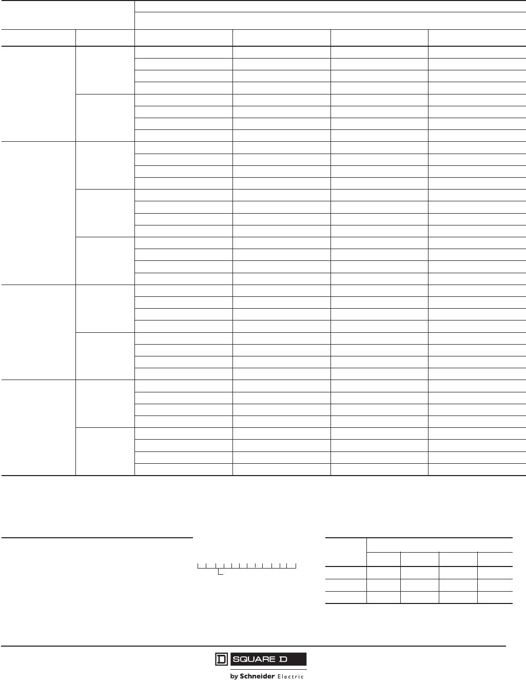
PowerPact™ M-, P- and R-Frame, and Compact™ NS630b–NS3200 Circuit Breakers
Section 4—PowerPact P-Frame Molded Case Circuit Breakers
45
10/2012
© 2001–2012 Schneider Electric
All Rights Reserved
™
Table 40: UL/IEC Rated, I-Line, Manually-Operated, 100%-Rated Electronic Trip Circuit Breakers with Micrologic™
Electronic Trip Units
Trip Unit,
Interchangeable
Circuit Breaker1
Current Rating (Sensor Rating)
Type2250 A 400 A 600 A 800 A
Micrologic
Interchangeable
Standard Trip Unit
3.0 (LI)
3P
PGA36025CU31A PGA36040CU31A PGA36060CU31A PGA36080CU31A
PJA36025CU31A PJA36040CU31A PJA36060CU31A PJA36080CU31A
PKA36025CU31A PKA36040CU31A PKA36060CU31A PKA36080CU31A
PLA34025CU31A PLA34040CU31A PLA34060CU31A PLA34080CU31A
5.0 (LSI)
3P
PGA36025CU33A PGA36040CU33A PGA36060CU33A PGA36080CU33A
PJA36025CU33A PJA36040CU33A PJA36060CU33A PJA36080CU33A
PKA36025CU33A PKA36040CU33A PKA36060CU33A PKA36080CU33A
PLA34025CU33A PLA34040CU33A PLA34060CU33A PLA34080CU33A
Micrologic
Interchangeable
Ammeter Trip Unit3
3.0A (LI)
3P
PGA36025CU41A PGA36040CU41A PGA36060CU41A PGA36080CU41A
PJA36025CU41A PJA36040CU41A PJA36060CU41A PJA36080CU41A
PKA36025CU41A PKA36040CU41A PKA36060CU41A PKA36080CU41A
PLA34025CU41A PLA34040CU41A PLA34060CU41A PLA34080CU41A
5.0A (LSI)
3P
PGA36025CU43A PGA36040CU43A PGA36060CU43A PGA36080CU43A
PJA36025CU43A PJA36040CU43A PJA36060CU43A PJA36080CU43A
PKA36025CU43A PKA36040CU43A PKA36060CU43A PKA36080CU43A
PLA34025CU43A PLA34040CU43A PLA34060CU43A PLA34080CU43A
6.0A (LSIG)
3P
PGA36025CU44A PGA36040CU44A PGA36060CU44A PGA36080CU44A
PJA36025CU44A PJA36040CU44A PJA36060CU44A PJA36080CU44A
PKA36025CU44A PKA36040CU44A PKA36060CU44A PKA36080CU44A
PLA34025CU44A PLA34040CU44A PLA34060CU44A PLA34080CU44A
Micrologic
Interchangeable
Power Trip Unit with
Modbus®
Communications
5.0P (LSI)
3P
PGA36025CU63AE1 PGA36040CU63AE1 PGA36060CU63AE1 PGA36080CU63AE1
PJA36025CU63AE1 PJA36040CU63AE1 PJA36060CU63AE1 PJA36080CU63AE1
PKA36025CU63AE1 PKA36040CU63AE1 PKA36060CU63AE1 PKA36080CU63AE1
PLA34025CU63AE1 PLA34040CU63AE1 PLA34060CU63AE1 PLA34080CU63AE1
6.0P (LSIG)
3P
PGA36025CU64AE1 PGA36040CU64AE1 PGA36060CU64AE1 PGA36080CU64AE1
PJA36025CU64AE1 PJA36040CU64AE1 PJA36060CU64AE1 PJA36080CU64AE1
PKA36025CU64AE1 PKA36040CU64AE1 PKA36060CU64AE1 PKA36080CU64AE1
PLA34025CU64AE1 PLA34040CU64AE1 PLA34060CU64AE1 PLA34080CU64AE1
Micrologic
Interchangeable
Harmonic Trip Unit
with Modbus
Communications
5.0H (LSI)
3P
PGA36025CU73AE1 PGA36040CU73AE1 PGA36060CU73AE1 PGA36080CU73AE1
PJA36025CU73AE1 PJA36040CU73AE1 PJA36060CU73AE1 PJA36080CU73AE1
PKA36025CU73AE1 PKA36040CU73AE1 PKA36060CU73AE1 PKA36080CU73AE1
PLA34025CU73AE1 PLA34040CU73AE1 PLA34060CU73AE1 PLA34080CU73AE1
6.0H (LSIG)
3P
PGA36025CU74AE1 PGA36040CU74AE1 PGA36060CU74AE1 PGA36080CU74AE1
PJA36025CU74AE1 PJA36040CU74AE1 PJA36060CU74AE1 PJA36080CU74AE1
PKA36025CU74AE1 PKA36040CU74AE1 PKA36060CU74AE1 PKA36080CU74AE1
PLA34025CU74AE1 PLA34040CU74AE1 PLA34060CU74AE1 PLA34080CU74AE1
1The L interrupting rating at 600 Vac is 25 kA.
2No suffix is for ABC phasing (standard offer), or use 6 for CBA phasing (option).
3Add E1 suffix for Modbus communications.
Table 41: P-Frame Termination Options Table 42: P-Frame Interrupting Ratings
F = No Lugs (Includes terminal nut kit on both ends)
L = Lugs both ends
M = Lugs I/ON end, terminal nut kit O/OFF end
P = Lugs O/OFF end, terminal nut kit I/ON end
D = Drawout
A = I-Line
Voltage P-Frame Interrupting Rating
GJ KL
240 Vac 65 kA 100 kA 65 kA 125 kA
480 Vac 35 kA 65 kA 50 kA 100 kA
600 Vac 18 kA 25 kA 50 kA 25 kA
P G L 3 6 0 4 0 U 4 1 A
For factory-installed termination, place
termination letter in the third block of
the circuit breaker catalog number.
Termination Letter

© 2001–2012 Schneider Electric
All Rights Reserved
PowerPact™ M-, P- and R-Frame, and Compact™ NS630b–NS3200 Circuit Breakers
Section 4—PowerPact P-Frame Molded Case Circuit Breakers
46
10/2012
™
Continuous Current Rating
All circuit breakers marked as 100% rated can be continuously loaded to 100% of their rating.
Because of additional heat generated when applying circuit breakers at 100% of continuous current rating,
the use of specially-designed enclosures and 90°C (194°F) wire is required. The 90°C (194°F) wire must be
sized according to the ampacity of the 75°C (167°F) wire column in the NEC. Minimum enclosure size and
ventilation specifications are indicated on the circuit breaker and in it’s instruction bulletin and in Table 5 on
page 11.
Circuit breakers with 100% rating can also be used in applications requiring only 80% continuous loading.
Interrupting Ratings
Table 43: Interrupting Ratings
Mounting Circuit
Breaker
Ampere Rating (A) Interrupting Ratings
Basic
Electronic
Trip Units
Micrologic
™ Trip Units
UL/CSA/NMX
IEC 60947-2
240 Vac 380/415 Vac
240
Vac
480
Vac
600
Vac Icu Ics Icu Ics
Individually-
Mounted
PG
600, 800,
1000, 1200
250, 400, 600,
800, 1000,
1200
65 kA 35 kA 18 kA 50 kA 25 kA 35 kA 20 kA
PJ 100 kA 65 kA 25 kA 65 kA 35 kA 50 kA 25 kA
PK 65 kA 50 kA 50 kA 50 kA 25 kA 50 kA 25 kA
PL 125 kA 100 kA 25 kA1
1Non-standard AIR.
125 kA 65 kA 85 kA 45kA
I-Line™
PG
600, 800,
1000, 1200
250, 400, 600,
800, 1000,
1200
65 kA 35 kA 18 kA 50 kA 25 kA 35 kA 20 kA
PJ 100 kA 65 kA 25 kA 65 kA 35 kA 50 kA 25 kA
PK 65 kA 50 kA 50 kA 50 kA 25 kA 50 kA 25 kA
PL 125 kA 100 kA 25 kA1125 kA 65 kA 85 kA 45 kA
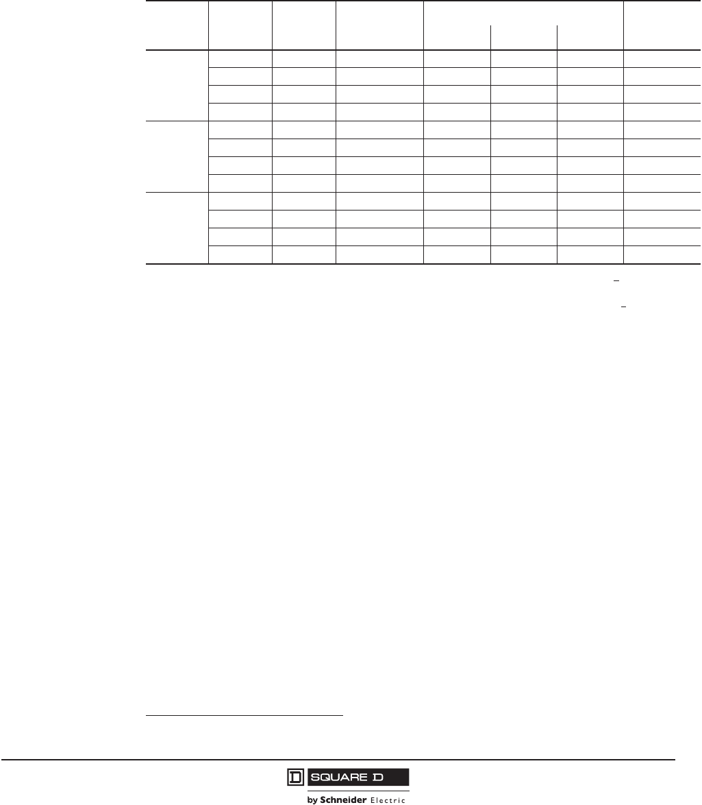
PowerPact™ M-, P- and R-Frame, and Compact™ NS630b–NS3200 Circuit Breakers
Section 4—PowerPact P-Frame Molded Case Circuit Breakers
47
10/2012
© 2001–2012 Schneider Electric
All Rights Reserved
™
Automatic Molded Case Switches1
Automatic molded case switches are available in individually-mounted and I-Line constructions from
600–1200 A. Automatic switches are similar in construction to electronic trip circuit breakers except
that long-time tripping is not present. The switches open instantaneously at a non-adjustable magnetic
trip point calibrated to protect only the molded case switch itself. They must be used in conjunction with
a circuit breaker or fuse of equivalent rating.
1Catalog numbers for automatic switches are designated by “000” in positions 7–9 (ampere rating) and S60, S80, S10, or S12 in
positions 11–14 (trip system). See Table 10.
Table 44: Automatic Switch Information
Circuit
Breaker
Ampere
Rating
Voltage
Rating
Catalog
Number
Withstand Rating Trip Point
(±10%)
240 Vac 480 Vac 600 Vac
PJ
2P1, 3P
1For 2P, replace the leading 3 in the catalog number following the prefix with a 2 (PJL36000S60 becomes PJL26000S60). Add the
suffix 2 for AC phasing (standard offer), or use 5 for CA phasing (option).
600 600 Vac PJL36000S60 100 kA 65 kA 25 kA 10 kA
800 600 Vac PJL36000S80 100 kA 65 kA 25 kA 10 kA
1000 600 Vac PJL36000S10 100 kA 65 kA 25 kA 10 kA
1200 600 Vac PJL36000S12 100 kA 65 kA 25 kA 10 kA
PK
2P, 3P, 4P2
2For 4P, replace the leading 3 in the catalog number following the prefix with a 4 (PJL36000S60 becomes PJL46000S60).
600 600 Vac PKL36000S60 65 kA 50 kA 50 kA 24 kA
800 600 Vac PKL36000S80 65 kA 50 kA 50 kA 24 kA
1000 600 Vac PKL36000S10 65 kA 50 kA 50 kA 24 kA
1200 600 Vac PKL36000S12 65 kA 50 kA 50 kA 24 kA
PL
2P, 3P
600 480 Vac PLL34000S60 125 kA 100 kA — 10 kA
800 480 Vac PLL34000S80 125 kA 100 kA — 10 kA
1000 480 Vac PLL34000S10 125 kA 100 kA — 10 kA
1200 480 Vac PLL34000S12 125 kA 100 kA — 10 kA
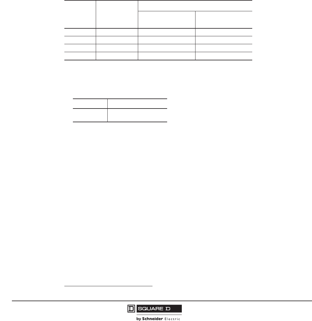
© 2001–2012 Schneider Electric
All Rights Reserved
PowerPact™ M-, P- and R-Frame, and Compact™ NS630b–NS3200 Circuit Breakers
Section 4—PowerPact P-Frame Molded Case Circuit Breakers
48
10/2012
™
Motor Circuit Protectors1
Motor circuit protectors are similar in construction to thermal-magnetic circuit breakers, but have only
instantaneous trip functions provided by the ET1.0M trip unit. These motor circuit protectors comply
with NEC requirements for providing short-circuit protection when installed as part of a listed
combination controller having motor overload protection. Interrupting ratings are determined by testing
the motor circuit protector in combination with a contactor and overload relay.
Motor circuit protectors are available in PJ and PL individually-mounted and I-Line™ construction.
According to the NEC, the instantaneous trip of the motor circuit protector may be set to a maximum of
8 to 17 times motor Full Load Amps (FLA), but a setting as close as possible to inrush current (without
nuisance tripping) results in the best protection. The instantaneous trip pickup level is adjustable within
the ranges shown below.
NOTE: Continuous currents larger than the ampere rating can damage the motor circuit protector.
Select motor circuit protectors as follows:
1. Determine motor horsepower (hp) rating from the motor nameplate. The selection table is suitable
for motors with locked-rotor indicating code letters per NEC Table 430-7 (b) as follows:
For other motors contact the field office.
2. Select a motor circuit protector with an ampere rating recommended for the hp and voltage
involved.
3. Select an adjustable trip setting of at least 800% but not to exceed 1300% (1700% for high-
efficiency motors) of the motor full load amperes (FLA).
4. The NEC 1300% maximum setting (1700% for high-efficiency motors) may be inadequate for
motor circuit protectors to withstand current surges typical of the magnetization current of auto-
transformer type reduced voltage starters or open transition wye-delta starters during transfer from
“start” to “run,” constant hp multi-speed motors and motors labeled “high efficiency”.
5. Part-winding motors, per NEC 430-3, should have two motor circuit protectors selected from the
above at not more than one-half the allowable trip setting for the horsepower rating. The two circuit
protectors should operate simultaneously as a disconnecting means per NEC 430-103.
1Catalog numbers for motor circuit protectors are designated by M68, M69, or M70 in positions 11–14 (trip system). See Table 10.
Table 45: Motor Circuit Protector Trip Range
Ampere
Rating
Adjustable Trip
Range
Catalog Number
J-Interrupting—600
Vac
L-Interrupting—480
Vac
600 A 1200–10,000 A PJL36060M68 PLL34060M68
800 A 1200–10,000 A PJL36080M68 PLL34080M68
1000 A 1500–10,000 A PJL36100M69 PLL34100M69
1200 A 1800–10,000 A PJL36120M70 PLL34120M70
Horsepower Motor Code Letters
30–150 A–G
150 or More A–F
PowerPact™ M-, P- and R-Frame, and Compact™ NS630b–NS3200 Circuit Breakers
Section 4—PowerPact P-Frame Molded Case Circuit Breakers
49
10/2012
© 2001–2012 Schneider Electric
All Rights Reserved
™
Electrically-Operated Circuit Breakers
Electrically-operated P-frame circuit breakers are available in I-Line™ and unit-mount construction up
to 1200 A and are denoted in the catalog number by an “M_” suffix. These come equipped with a two-
step stored energy mechanism and come standard with a motor assembly. These are available
factory-installed only.
Motor assemblies provide on and off control from remote locations. The assemblies contain a spring-
charging motor (MCH), a shunt trip (MX) and a shunt close (XF) and are available in standard or
communicating versions. An SDE overcurrent trip switch is also included for trip indication. When
remote indication of the circuit breaker status is required, use of a circuit breaker with an OF auxiliary
switch for on-off indication. See Table 69 on page 73 for details.
Termination Information
Unit-mount circuit breakers and switches have mechanical lugs standard on both ends. I-Line circuit
breakers have lugs standard on the O/OFF end. These lugs accept aluminum or copper wire.
Manually-operated P-frame circuit breakers are also available in drawout construction. See Table 87
on page 84 for more lug options.
Control Wiring
Control wiring for unit-mount and I-Line construction is connected to terminals located under the circuit
breaker accessory cover. Control wiring for drawout construction is connected to terminals located on
the cradle.
Table 46: Motors Assembly Voltage Ratings (Vn)
Voltage Type Voltage Ratings (Vn)
Vac 50/60 Hz 48, 100–130, 220–240, 380–415
Vdc 24–30, 48–60, 110–130, 200–250
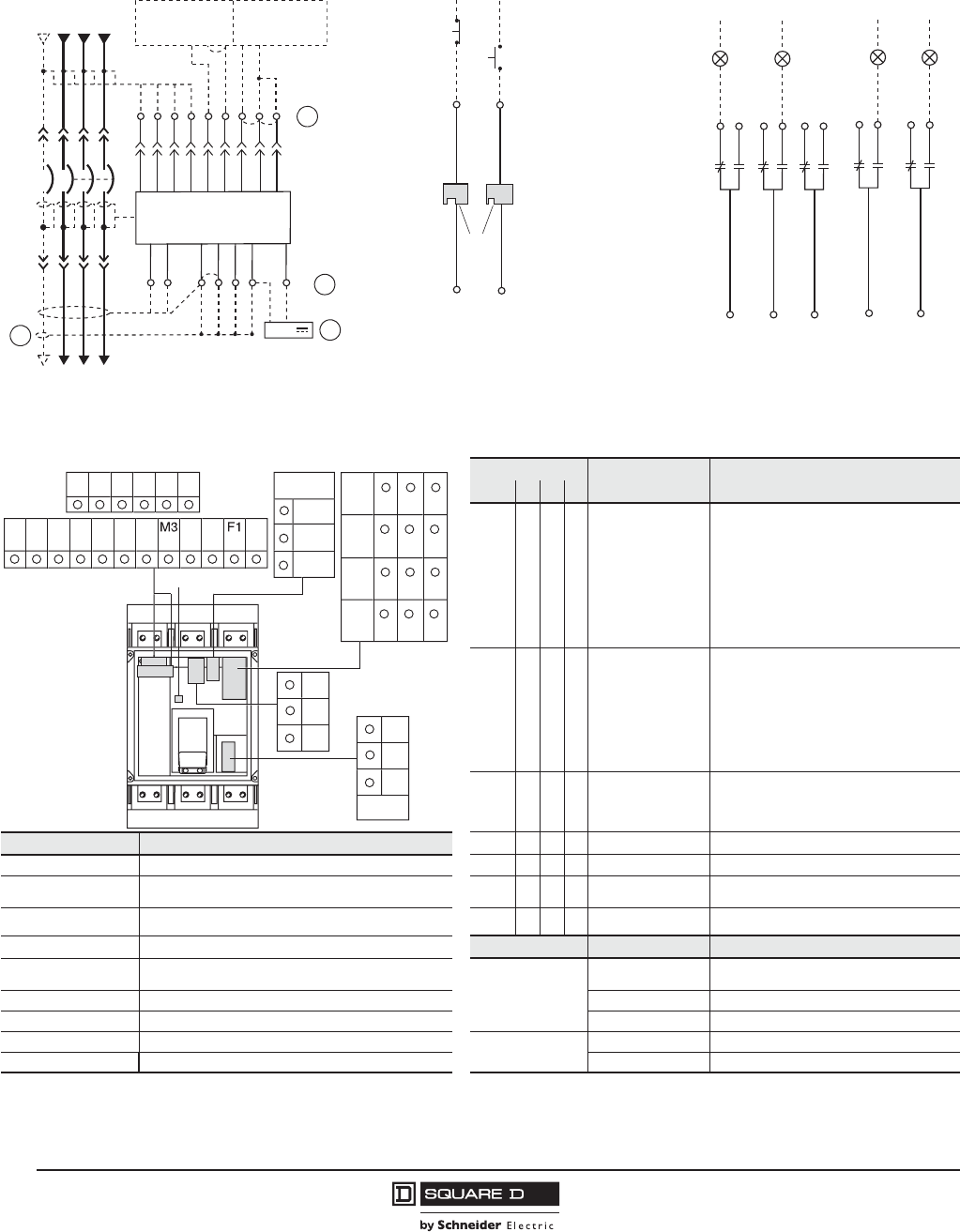
© 2001–2012 Schneider Electric
All Rights Reserved
PowerPact™ M-, P- and R-Frame, and Compact™ NS630b–NS3200 Circuit Breakers
Section 4—PowerPact P-Frame Molded Case Circuit Breakers
50
10/2012
™
Figure 2: Accessory Control Wiring Diagrams for Manually-Operated Circuit Breakers
Trip Unit Type
Basic A P H Connector Description
— • • • Com: E1-E6 Circuit breaker communication module
E1 = +24 Vdc
E2 = Common
E3 = Out -
E4 = Out +
E5 = In -
E6 = In +
— • • • Z Zone-selective interlocking (ZSI)
Z1 = ZSI OUT signal
Z2 = ZSI OUT
Z3 = ZSI IN signal
Z4 = ZSI IN short-time delay
Z5 = ZSI IN ground fault
— • • • T External neutral sensor
Connector Recommended Wire Size — • • • F 24 Vdc external power supply
V1, V2, V3, Vn 22–16 AWG (0.3–1.5 mm2)——••Vn
1External neutral voltage takeoff
E1–E2 22 AWG (0.3 mm2) MIN shielded pair cable or
twisted pair copper wires — — • • V1, V2, V3 External phase voltage takeoff
T 22 AWG (0.3 mm2) stranded shielded cable — — • • M6C2: Q1, Q2, Q3 6 programmable contacts
24 Vdc external power supply required
M Refer to MDGF instructions Function Connector Description
E3–E6, Q1, Q2, Q3 22 AWG (0.3 mm2) shielded twisted pairs with drain
(Belden 8723 or equal)3
Auxiliary Contacts
OF Open/Closed circuit breaker or switch
position contacts
OF, SD, SDE 18–16 AWG (0.8–1.5 mm2) SD Bell alarm
MN, MX 18–14 AWG (0.8–2.5 mm2) SDE Electrical fault alarm contact
F Size per aux 24 Vdc power supply Remote Operation MN Undervoltage trip device
Z1–Z5 22–18 AWG (0.3–0.8 mm2) MX Shunt trip
1Neutral voltage supplied with flying leads.
2Optional M6C programmable contacts are supplied with flying leads.
22
24
21
OF2
Closed
06123033
OF3
32
34
31
Open
12
14
11
OF1
92
94
91
SD
Tripped
82
84
81
SDE
Fault
T4
T3
T2
T1 Z3
Z4
T3
T2
Trip Unit
Z4
Z3
Z2
Z1 Z5
Z2
Z1
NCBA
Z5
VN
V1
V2
V3
M2
M1
F2+
Upstream Downstream
24 V
06123031
T1/M3
T4/F1-
06123107
or
D2
D1
MN MX
C2
C1
Power Trip Unit Remote Operation Alarm Contacts
NOTE: All diagrams show circuit breaker in open position.
A
D
C
B
A–Do not remove factory-installed jumpers between Z3, Z4 and Z5 unless ZSI is connected.
B–Do not remove factory-installed jumper between T1 and T2 unless neutral CT is connected. Do not install jumper between T3 and T4.
C–For proper wiring of neutral CT, refer to Instruction Bulletin 48041-082-01 shipped with it.
D–24 Vdc power supply for trip unit must be separate and isolated from 24 Vdc power supply for communication modules.
D1
/C1
C3
MN
/
M
X
O
F
1
O
F
2
O
F
3
SD
82
81
S
D
E
84
11
21
31
91
V
N
12
22
32
92
14
24
34
94
06
12
3
1
08
E1
E
6
Z2
T2
M2
F2
Z4
Z
3
Z1
Z
5
M1
T1
T4
T
3
E2
E
3
E4
E
5
D2
/C2
-
+
24 V
dc
V2
V1
V
3
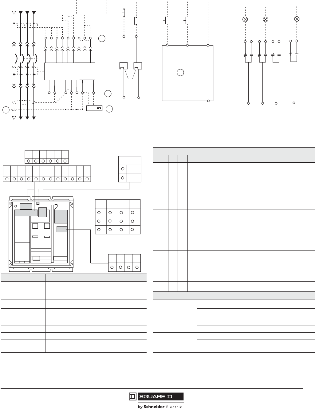
PowerPact™ M-, P- and R-Frame, and Compact™ NS630b–NS3200 Circuit Breakers
Section 4—PowerPact P-Frame Molded Case Circuit Breakers
51
10/2012
© 2001–2012 Schneider Electric
All Rights Reserved
™
Figure 3: Accessory Control Wiring Diagrams for Electrically-operated Circuit Breakers
Trip Unit Type
Basic A P H Connector Description
– • • • Com: E1-E6 Circuit breaker communication module
E1 = +24 Vdc
E2 = Common
E3 = Out -
E4 = Out +
E5 = In -
E6 = In +
– • • • Z Zone-selective interlocking (ZSI)
Z1 = ZSI OUT signal
Z2 = ZSI OUT
Z3 = ZSI IN signal
Z4 = ZSI IN short-time delay
Z5 = ZSI IN ground fault
– • • • T External neutral sensor
– • • • F 24 Vdc external power supply
––••Vn
1External voltage takeoff
Connector Recommended Wire Size – – • • V1, V2, V31External phase voltage takeoff
E1–E2 22 AWG (0.3 mm2) MIN shielded pair cable or
twisted pair copper wires ––••
M6C1:
Q1, Q2, Q3
6 programmable contacts
24 Vdc external power supply required
V1, V2, V3, Vn 22–16 AWG (0.3–1.5 mm2)Function Connector Description
T 22 AWG (0.3 mm2) stranded shielded cable
Auxiliary Contacts
OF Open/Closed circuit breaker or switch position
contacts
E3–E6, Q1, Q2, Q3 22 AWG (0.3 mm2) shielded twisted pairs with drain
(Belden 8723 or equal)3SDE Electrical fault alarm contact
M Refer to MDGF instructions Remote Operation MN Undervoltage trip device
OF, SD, SDE 18–16 AWG (0.8–1.5 mm2) MX Shunt trip
MN, MX 18–14 AWG (0.8–2.5 mm2)
Motor Mech Module
A4 Electrical opening
F Size per aux 24 Vdc power supply A2 Electrical closing
Z1–Z5 22–18 AWG (0.3–0.8 mm2) B4, A1 Power supply for control devices and gear motor
1Optional M6C and external voltage takeoff are supplied with flying leads.
T4
T3
T2
T1 Z3
Z4
T3
T2
Trip Unit
Z4
Z3
Z2
Z1 Z5
Z2
Z1
NCBA
Z5
VN
V1
V2
V3
M2
M1
F2+
Upstream Downstream
24 V
06123031
T1/M3
T4/F1-
06
12
3
1
5
2
or
D2
D1
MN
MX
C
2
C
1
O
p
e
n
A4
C
los
e
A2
B
4
Motor M
ec
h
a
ni
s
m
Mo
du
l
e
A1
Power Trip Unit Remote Operation Alarm Contacts
22
24
21
OF2
Closed
06123077
OF3
32
34
31 Open
12
14
11
OF1
82
84
81
SDE
Fault
NOTE: All diagrams show circuit breaker in open position.
A
D
C
B
A–Do not remove factory-installed jumpers between Z3, Z4 and Z5 unless ZSI is connected.
B–Do not remove factory-installed jumper between T1 and T2 unless neutral CT is connected. Do not install jumper between T3 and T4.
C–For proper wiring of neutral CT, refer to Instruction Bulletin 48041-082-01 shipped with it.
D–24 Vdc power supply for trip unit must be separate and isolated from 24 Vdc power supply for communication modules.
E–Motor mechanism includes opening and closing coils.
E
D1/C1
D2/C2
MN/MX
VN, V1, V2, V3
06123153
OF1
OF2OF3SDE
81
32
84 14
A1A2A4B4
112131
22 1282
34 24
E1 E6
Z2 T2
M2 F1 F2
Z4
Z3
Z1 Z5
M1
T1 T4T3
E2 E3 E4 E5
M3
24 Vdc
-+
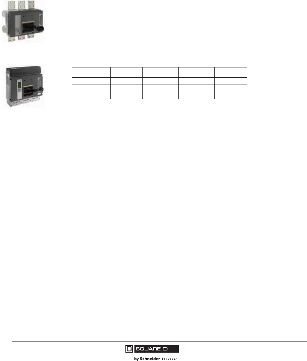
© 2001–2012 Schneider Electric
All Rights Reserved
PowerPact™ M-, P- and R-Frame, and Compact™ NS630b–NS3200 Circuit Breakers
Section 5—PowerPact R-Frame Circuit Breakers
52
10/2012
™
Section 5—PowerPact R-Frame Circuit Breakers
Performance
Providing unparalleled performance and control, the R-frame circuit breakers features the exclusive
Micrologic™ electronic trip units, which allow for a range of sophisticated applications for metering and
monitoring. In addition, trip units can be interchanged in the field to allow for maximum flexibility.
The compact size and smaller footprint of the R-frame circuit breaker permits higher density
installations using I-Line™ panelboards and switchboards. These circuit breakers are available in
100% rated construction up to 3000 A to meet a broad range of commercial and industrial application
needs.
•Both standard and 100% rated construction circuit breakers are available in 3000 A with a sensor
size range of 600–3000 A.
•Interrupting ratings (AIR):
•The K interrupting rating is recommended for applications having high inrush and/or non-linear
loads such as large motors, transformers, motors with soft starts, etc.
•Compact circuit breaker size allows for smaller footprint installations using I-Line panelboards and
switchboards. Fifteen-inch width provides increased density installation.
•Most field-installable accessories are common to all frame sizes for easier stocking and installation
•Selection of four interchangeable Micrologic trip units available, with Powerlogic™ power metering
and monitoring capabilities available in advanced trip units.
•Compatible with Powerlogic systems and high amperage power circuit breakers.
•Built-in Modbus® protocol provides an open communications platform and eliminates the need to
purchase additional, proprietary network solutions.
•Connection options include bus, cable or I-Line for installation flexibility.
R-Frame Unit-Mount
R-Frame I-Line
Voltage G J K L
240 Vac 65 kA 100 kA 65 kA 125 kA
480 Vac 35 kA 65 kA 65 kA 100 kA
600 Vac 18 kA 25 kA 65 kA 50 kA
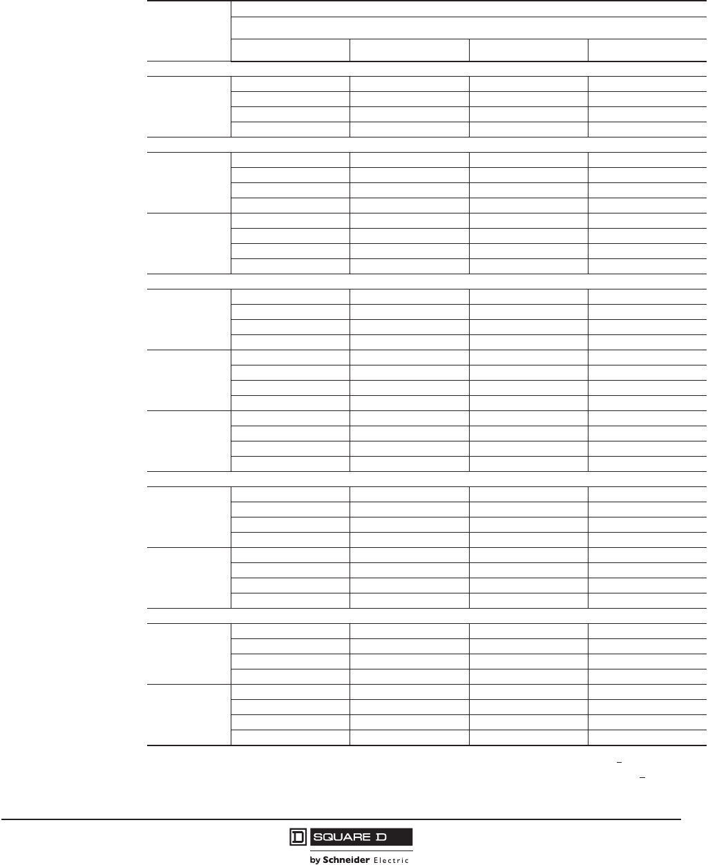
PowerPact™ M-, P- and R-Frame, and Compact™ NS630b–NS3200 Circuit Breakers
Section 5—PowerPact R-Frame Circuit Breakers
53
10/2012
© 2001–2012 Schneider Electric
All Rights Reserved
™
Catalog Numbers
Table 47: UL/IEC Rated, Unit-Mount, Manually-Operated, Standard-Rated Electronic Trip
Circuit Breakers with Basic Electronic Trip and Micrologic™ Electronic Trip
Units—600A to 1200A
Trip Unit
Type
Circuit Breaker Catalog Number
Current Rating (Sensor Rating)
600 A 800 A 1000 A 1200 A
Basic Electronic Trip Unit Not interchangeable
ET1.0I
2P1, 3P
Fixed Long-time
1For 2P, replace the leading 3 in the catalog number following the prefix with a 2 (RGF36060 becomes RGF26060.)
RGF36060 RGF36080 RGF36100 RGF36120
RJF36060 RJF36080 RJF36100 RJF36120
RKF36060 RKF36080 RKF36100 RKF36120
RLF36060 RLF36080 RLF36100 RLF36120
Micrologic Interchangeable Standard Trip Unit
3.0
(LI)
3P, 4P2
2For 4P, replace the leading 3 in the catalog number following the prefix with a 4 (RPF36060U31A becomes RGF46060U31A).
RGF36060U31A RGF36080U31A RGF36100U31A RGF36120U31A
RJF36060U31A RJF36080U31A RJF36100U31A RJF36120U31A
RKF36060U31A RKF36080U31A RKF36100U31A RKF36120U31A
RLF36060U31A RLF36080U31A RLF36100U31A RLF36120U31A
5.0
(LSI)
3P, 4P2
RGF36060U33A RGF36080U33A RGF36100U33A RGF36120U33A
RJF36060U33A RJF36080U33A RJF36100U33A RJF36120U33A
RKF36060U33A RKF36080U33A RKF36100U33A RKF36120U33A
RLF36060U33A RLF36080U33A RLF36100U33A RLF36120U33A
Micrologic Interchangeable Ammeter Trip Unit3
3Add E1 suffix for Modbus communications.
3.0A
(LI)
3P, 4P2
RGF36060U41A RGF36080U41A RGF36100U41A RGF36120U41A
RJF36060U41A RJF36080U41A RJF36100U41A RJF36120U41A
RKF36060U41A RKF36080U41A RKF36100U41A RKF36120U41A
RLF36060U41A RLF36080U41A RLF36100U41A RLF36120U41A
5.0A
(LSI)
3P, 4P2
RGF36060U43A RGF36080U43A RGF36100U43A RGF36120U43A
RJF36060U43A RJF36080U43A RJF36100U43A RJF36120U43A
RKF36060U43A RKF36080U43A RKF36100U43A RKF36120U43A
RLF36060U43A RLF36080U43A RLF36100U43A RLF36120U43A
6.0A (LSIG)
3P, 4P2
RGF36060U44A RGF36080U44A RGF36100U44A RGF36120U44A
RJF36060U44A RJF36080U44A RJF36100U44A RJF36120U44A
RKF36060U44A RKF36080U44A RKF36100U44A RKF36120U44A
RLF36060U44A RLF36080U44A RLF36100U44A RLF36120U44A
Micrologic Interchangeable Power Trip Unit with Modbus® Communications
5.0P
(LSI)
3P, 4P2
RGF36060U63AE1 RGF36080U63AE1 RGF36100U63AE1 RGF36120U63AE1
RJF36060U63AE1 RJF36080U63AE1 RJF36100U63AE1 RJF36120U63AE1
RKF36060U63AE1 RKF36080U63AE1 RKF36100U63AE1 RKF36120U63AE1
RLF36060U63AE1 RLF36080U63AE1 RLF36100U63AE1 RLF36120U63AE1
6.0P (LSIG)
3P, 4P2
RGF36060U64AE1 RGF36080U64AE1 RGF36100U64AE1 RGF36120U64AE1
RJF36060U64AE1 RJF36080U64AE1 RJF36100U64AE1 RJF36120U64AE1
RKF36060U64AE1 RKF36080U64AE1 RKF36100U64AE1 RKF36120U64AE1
RLF36060U64AE1 RLF36080U64AE1 RLF36100U64AE1 RLF36120U64AE1
Micrologic Interchangeable Harmonic Trip Unit with Modbus Communications
5.0H
(LSI)
3P, 4P2
RGF36060U73AE1 RGF36080U73AE1 RGF36100U73AE1 RGF36120U73AE1
RJF36060U73AE1 RJF36080U73AE1 RJF36100U73AE1 RJF36120U73AE1
RKF36060U73AE1 RKF36080U73AE1 RKF36100U73AE1 RKF36120U73AE1
RLF36060U73AE1 RLF36080U73AE1 RLF36100U73AE1 RLF36120U73AE1
6.0H (LSIG)
3P, 4P2
RGF36060U74AE1 RGF36080U74AE1 RGF36100U74AE1 RGF36120U74AE1
RJF36060U74AE1 RJF36080U74AE1 RJF36100U74AE1 RJF36120U74AE1
RKF36060U74AE1 RKF36080U74AE1 RKF36100U74AE1 RKF36120U74AE1
RLF36060U74AE1 RLF36080U74AE1 RLF36100U74AE1 RLF36120U74AE1
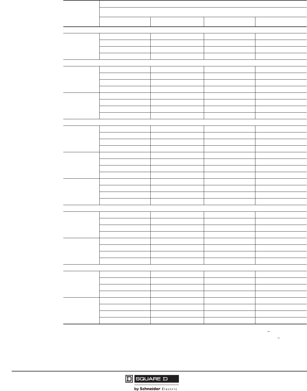
© 2001–2012 Schneider Electric
All Rights Reserved
PowerPact™ M-, P- and R-Frame, and Compact™ NS630b–NS3200 Circuit Breakers
Section 5—PowerPact R-Frame Circuit Breakers
54
10/2012
™
Table 48: UL/IEC Rated, Unit-Mount, Manually-Operated, Standard-Rated Electronic Trip
Circuit Breakers with Basic Electronic Trip and Micrologic™ Electronic Trip
Units—1600A to 3000A
Trip Unit
Type
Circuit Breaker Catalog Number
Current Rating (Sensor Rating)
1600 A 2000 A 2500 A 3000 A
Basic Electronic Trip Unit Not interchangeable
ET1.0I
2P1, 3P
Fixed Long-time
RGF36160 RGF36200 RGF36250 —
RJF36160 RJF36200 RJF36250 —
RKF36160 RKF36200 RKF36250 —
RLF36160 RLF36200 RLF36250 —
Micrologic Interchangeable Standard Trip Unit
3.0
(LI)
3P, 4P2
RGF36160U31A RGF36200U31A RGF36250U31A RGF36300U31A
RJF36160U31A RJF36200U31A RJF36250U31A RJF36300U31A
RKF36160U31A RKF36200U31A RKF36250U31A RKF36300U31A
RLF36160U31A RLF36200U31A RLF36250U31A RLF36300U31A
5.0
(LSI)
3P, 4P2
RGF36160U33A RGF36200U33A RGF36250U33A RGF36300U33A
RJF36160U33A RJF36200U33A RJF36250U33A RJF36300U33A
RKF36160U33A RKF36200U33A RKF36250U33A RKF36300U33A
RLF36160U33A RLF36200U33A RLF36250U33A RLF36300U33A
Micrologic Interchangeable Ammeter Trip Unit3
3.0A
(LI)
3P, 4P2
RGF36160U41A RGF36200U41A RGF36250U41A RGF36300U41A
RJF36160U41A RJF36200U41A RJF36250U41A RJF36300U41A
RKF36160U41A RKF36200U41A RKF36250U41A RKF36300U41A
RLF36160U41A RLF36200U41A RLF36250U41A RLF36300U41A
5.0A
(LSI)
3P, 4P2
RGF36160U43A RGF36200U43A RGF36250U43A RGF36300U43A
RJF36160U43A RJF36200U43A RJF36250U43A RJF36300U43A
RKF36160U43A RKF36200U43A RKF36250U43A RKF36300U43A
RLF36160U43A RLF36200U43A RLF36250U43A RLF36300U43A
6.0A (LSIG)
3P, 4P2
RGF36160U44A RGF36200U44A RGF36250U44A RGF36300U44A
RJF36160U44A RJF36200U44A RJF36250U44A RJF36300U44A
RKF36160U44A RKF36200U44A RKF36250U44A RKF36300U44A
RLF36160U44A RLF36200U44A RLF36250U44A RLF36300U44A
Micrologic Interchangeable Power Trip Unit with Modbus® Communications
5.0P
(LSI)
3P, 4P2
RGF36160U63AE1 RGF36200U63AE1 RGF36250U63AE1 RGF36300U63AE1
RJF36160U63AE1 RJF36200U63AE1 RJF36250U63AE1 RJF36300U63AE1
RKF36160U63AE1 RKF36200U63AE1 RKF36250U63AE1 RKF36300U63AE1
RLF36160U63AE1 RLF36200U63AE1 RLF36250U63AE1 RLF36300U63AE1
6.0P (LSIG)
3P, 4P2
RGF36160U64AE1 RGF36200U64AE1 RGF36250U64AE1 RGF36300U64AE1
RJF36160U64AE1 RJF36200U64AE1 RJF36250U64AE1 RJF36300U64AE1
RKF36160U64AE1 RKF36200U64AE1 RKF36250U64AE1 RKF36300U64AE1
RLF36160U64AE1 RLF36200U64AE1 RLF36250U64AE1 RLF36200U64AE1
Micrologic Interchangeable Harmonic Trip Unit with Modbus Communications
5.0H
(LSI)
3P, 4P2
RGF36160U73AE1 RGF36200U73AE1 RGF36250U73AE1 RGF36300U73AE1
RJF36160U73AE1 RJF363200U73AE1 RJF36250U73AE1 RJF36300U73AE1
RKF36160U73AE1 RKF363200U73AE1 RKF36250U73AE1 RKF36300U73AE1
RLF36160U73AE1 RLF36200U73AE1 RLF36250U73AE1 RLF36300U73AE1
6.0H (LSIG)
3P, 4P2
RGF36160U74AE1 RGF36200U74AE1 RGF36250U74AE1 RGF36300U74AE1
RJF36160U74AE1 RJF36200U74AE1 RJF36250U74AE1 RJF36300U74AE1
RKF36160U74AE1 RKF36200U74AE1 RKF36250U74AE1 RKF36300U74AE1
RLF36160U74AE1 RLF36200U74AE1 RLF36250U74AE1 RLF36300U74AE1
1For 2P, replace the leading 3 in the catalog number following the prefix with a 2 (RGF36060 becomes RGF26060.)
2For 4P, replace the leading 3 in the catalog number following the prefix with a 4 (RPF36060U31A becomes RGF46060U31A).
3Add E1 suffix for Modbus communications.

PowerPact™ M-, P- and R-Frame, and Compact™ NS630b–NS3200 Circuit Breakers
Section 5—PowerPact R-Frame Circuit Breakers
55
10/2012
© 2001–2012 Schneider Electric
All Rights Reserved
™
Table 49: UL/IEC Rated, Unit-Mount, Manually-Operated, 100%-Rated Electronic Trip Circuit
Breakers with Micrologic™ Electronic Trip Units—600 A to 1200 A
Trip
Unit
Type
Circuit Breaker Catalog Number1
1For 4P, replace the leading 3 in the catalog number following the prefix with a 4 (RPF36060CU31A becomes RGF46060CU31A).
Current Rating (Sensor Rating)
600 A 800 A 1000 A 1200 A
Micrologic Standard Trip Unit Interchangeable, 3P, 4P
3.0
(LI)
RGF36060CU31A RGF36080CU31A RGF36100CU31A RGF36120CU31A
RJF36060CU31A RJF36080CU31A RJF36100CU31A RJF36120CU31A
RKF36060CU31A RKF36080CU31A RKF36100CU31A RKF36120CU31A
RLF36060CU31A RLF36080CU31A RLF36100CU31A RLF36120CU31A
5.0
(LSI)
RGF36060CU33A RGF36080CU33A RGF36100CU33A RGF36120CU33A
RJF36060CU33A RJF36080CU33A RJF36100CU33A RJF36120CU33A
RKF36060CU33A RKF36080CU33A RKF36100CU33A RKF36120CU33A
RLF36060CU33A RLF36080CU33A RLF36100CU33A RLF36120CU33A
Micrologic Ammeter Trip Unit2 Interchangeable, 3P, 4P
2Add E1 suffix for Modbus communications.
3.0A
(LI)
RGF36060CU41A RGF36080CU41A RGF36100CU41A RGF36120CU41A
RJF36060CU41A RJF36080CU41A RJF36100CU41A RJF36120CU41A
RKF36060CU41A RKF36080CU41A RKF36100CU41A RKF36120CU41A
RLF36060CU41A RLF36080CU41A RLF36100CU41A RLF36120CU41A
5.0A
(LSI)
RGF36060CU43A RGF36080CU43A RGF36100CU43A RGF36120CU43A
RJF36060CU43A RJF36080CU43A RJF36100CU43A RJF36120CU43A
RKF36060CU43A RKF36080CU43A RKF36100CU43A RKF36120CU43A
RLF36060CU43A RLF36080CU43A RLF36100CU43A RLF36120CU43A
6.0A
(LSIG)
RGF36060CU44A RGF36080CU44A RGF36100CU44A RGF36120CU44A
RJF36060CU44A RJF36080CU44A RJF36100CU44A RJF36120CU44A
RKF36060CU44A RKF36080CU44A RKF36100CU44A RKF36120CU44A
RLF36060CU44A RLF36080CU44A RLF36100CU44A RLF36120CU44A
Micrologic Power Trip Unit with Modbus® Communications Interchangeable, 3P, 4P
5.0P
(LSI)
RGF36060CU63AE1 RGF36080CU63AE1 RGF36100CU63AE1 RGF36120CU63AE1
RJF36060CU63AE1 RJF36080CU63AE1 RJF36100CU63AE1 RJF36120CU63AE1
RKF36060CU63AE1 RKF36080CU63AE1 RKF36100CU63AE1 RKF36120CU63AE1
RLF36060CU63AE1 RLF36080CU63AE1 RLF36100CU63AE1 RLF36120CU63AE1
6.0P
(LSIG)
RGF36060CU64AE1 RGF36080CU64AE1 RGF36100CU64AE1 RGF36120CU64AE1
RJF36060CU64AE1 RJF36080CU64AE1 RJF36100CU64AE1 RJF36120CU64AE1
RKF36060CU64AE1 RKF36080CU64AE1 RKF36100CU64AE1 RKF36120CU64AE1
RLF36060CU64AE1 RLF36080CU64AE1 RLF36100CU64AE1 RLF36120CU64AE1
Micrologic Harmonic Trip Unit with Modbus Communications Interchangeable, 3P, 4P
5.0H
(LSI)
RGF36060CU73AE1 RGF36080CU73AE1 RGF36100CU73AE1 RGF36120CU73AE1
RJF36060CU73AE1 RJF36080CU73AE1 RJF36100CU73AE1 RJF36120CU73AE1
RKF36060CU73AE1 RKF36080CU73AE1 RKF36100CU73AE1 RKF36120CU73AE1
RLF36060CU73AE1 RLF36080CU73AE1 RLF36100CU73AE1 RLF36120CU73AE1
6.0H
(LSIG)
RGF36060CU74AE1 RGF36080CU74AE1 RGF36100CU74AE1 RGF36120CU74AE1
RJF36060CU74AE1 RJF36080CU74AE1 RJF36100CU74AE1 RJF36120CU74AE1
RKF36060CU74AE1 RKF36080CU74AE1 RKF36100CU74AE1 RKF36120CU74AE1
RLF36060CU74AE1 RLF36080CU74AE1 RLF36100CU74AE1 RLF36120CU74AE1
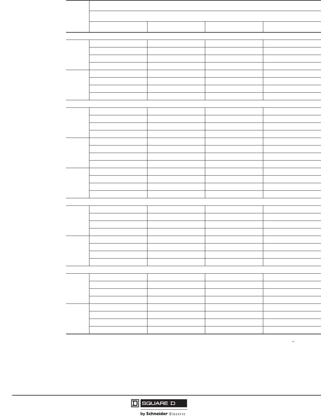
© 2001–2012 Schneider Electric
All Rights Reserved
PowerPact™ M-, P- and R-Frame, and Compact™ NS630b–NS3200 Circuit Breakers
Section 5—PowerPact R-Frame Circuit Breakers
56
10/2012
™
Table 50: UL/IEC Rated, Unit-Mount, Manually-Operated, 100%-Rated Electronic Trip Circuit
Breakers with Micrologic™ Electronic Trip Units—1600 A to 3000 A
Trip
Unit
Type
Circuit Breaker Catalog Number1
Current Rating (Sensor Rating)
1600 A 2000 A 2500 A 3000 A
Micrologic Standard Trip Unit Interchangeable, 3P, 4P
3.0
(LI)
RGF36160CU31A RGF36200CU31A RGF36250CU31A RGF36300CU31A
RJF36160CU31A RJF36200CU31A RJF36250CU31A RJF36300CU31A
RKF36160CU31A RKF36200CU31A RKF36250CU31A RKF36300CU31A
RLF36160CU31A RLF36200CU31A RLF36250CU31A RLF36300CU31A
5.0
(LSI)
RGF36160CU33A RGF36200CU33A RGF36250CU33A RGF36300CU33A
RJF36160CU33A RJF36200CU33A RJF36250CU33A RJF36300CU33A
RKF36160CU33A RKF36200CU33A RKF36250CU33A RKF36300CU33A
RLF36160CU33A RLF36200CU33A RLF36250CU33A RLF36300CU33A
Micrologic Ammeter Trip Unit2 Interchangeable, 3P, 4P
3.0A
(LI)
RGF36160CU41A RGF36200CU41A RGF36250CU41A RGF36300CU41A
RJF36160CU41A RJF36200CU41A RJF36250CU41A RJF36300CU41A
RKF36160CU41A RKF36200CU41A RKF36250CU41A RKF36300CU41A
RLF36160CU41A RLF36200CU41A RLF36250CU41A RLF36300CU41A
5.0A
(LSI)
RGF36160CU43A RGF36200CU43A RGF36250CU43A RGF36300CU43A
RJF36160CU43A RJF36200CU43A RJF36250CU43A RJF36300CU43A
RKF36160CU43A RKF36200CU43A RKF36250CU43A RKF36300CU43A
RLF36160CU43A RLF36200CU43A RLF36250CU43A RLF36300CU43A
6.0A
(LSIG)
RGF36160CU44A RGF36200CU44A RGF36250CU44A RGF36300CU44A
RJF36160CU44A RJF36200CU44A RJF36250CU44A RJF36300CU44A
RKF36160CU44A RKF36200CU44A RKF36250CU44A RKF36300CU44A
RLF36160CU44A RLF36200CU44A RLF36250CU44A RLF36300CU44A
Micrologic Power Trip Unit with Modbus® Communications Interchangeable, 3P, 4P
5.0P
(LSI)
RGF36160CU63AE1 RGF36200CU63AE1 RGF36250CU63AE1 RGF36300CU63AE1
RJF36160CU63AE1 RJF36200CU63AE1 RJF36250CU63AE1 RJF36300CU63AE1
RKF36160CU63AE1 RKF36200CU63AE1 RKF36250CU63AE1 RKF36300CU63AE1
RLF36160CU63AE1 RLF36200CU63AE1 RLF36250CU63AE1 RLF36300CU63AE1
6.0P
(LSIG)
RGF36160CU64AE1 RGF36200CU64AE1 RGF36250CU64AE1 RGF36300CU64AE1
RJF36160CU64AE1 RJF36200CU64AE1 RJF36250CU64AE1 RJF36300CU64AE1
RKF36160CU64AE1 RKF36200CU64AE1 RKF36250CU64AE1 RKF36300CU64AE1
RLF36160CU64AE1 RLF36200CU64AE1 RLF36250CU64AE1 RLF36300CU64AE1
Micrologic Harmonic Trip Unit with Modbus Communications Interchangeable, 3P, 4P
5.0H
(LSI)
RGF36160CU73AE1 RGF36200CU73AE1 RGF36250CU73AE1 RGF36300CU73AE1
RJF36160CU73AE1 RJF36200CU73AE1 RJF36250CU73AE1 RJF36300CU73AE1
RKF36160CU73AE1 RKF36200CU73AE1 RKF36250CU73AE1 RKF36300CU73AE1
RLF36160CU73AE1 RLF36200CU73AE1 RLF36250CU73AE1 RLF36300CU73AE1
6.0H
(LSIG)
RGF36160CU74AE1 RGF36200CU74AE1 RGF36250CU74AE1 RGF36300CU74AE1
RJF36160CU74AE1 RJF36200CU74AE1 RJF36250CU74AE1 RJF36300CU74AE1
RKF36160CU74AE1 RKF36200CU74AE1 RKF36250CU74AE1 RKF36300CU74AE1
RLF36160CU74AE1 RLF36200CU74AE1 RLF36250CU74AE1 RLF36300CU74AE1
1For 4P, replace the leading 3 in the catalog number following the prefix with a 4 (RPF36060CU31A becomes RGF46060CU31A).
2Add E1 suffix for Modbus communications.
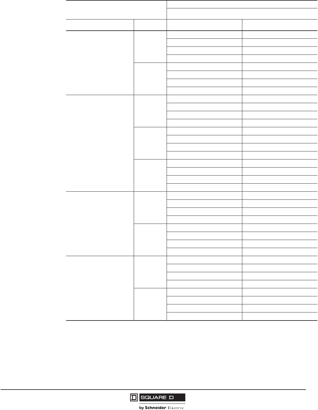
PowerPact™ M-, P- and R-Frame, and Compact™ NS630b–NS3200 Circuit Breakers
Section 5—PowerPact R-Frame Circuit Breakers
57
10/2012
© 2001–2012 Schneider Electric
All Rights Reserved
™
Table 51: UL/IEC Rated, I-Line, Manually-Operated, 100%-Rated Electronic Trip Circuit
Breakers with Micrologic™ Electronic Trip Units
Trip Unit, Interchangeable
Circuit Breaker Catalog Number
Current Rating
Type 1000 A 1200 A
Micrologic Standard Trip Unit
3.0 (LI)
RGA36100CU31A RGA36120CU31A
RJA36100CU31A RJA36120CU31A
RKA36100CU31A RKA36120CU31A
RLA36100CU31A RLA36120CU31A
5.0 (LSI)
RGA36100CU33A RGA36120CU33A
RJA36100CU33A RJA36120CU33A
RKA36100CU33A RKA36120CU33A
RLA36100CU33A RLA36120CU33A
Micrologic Ammeter Trip Unit1
3.0A (LI)
RGA36100CU41A RGA36120CU41A
RJA36100CU41A RJA36120CU41A
RKA36100CU41A RKA36120CU41A
RLA36100CU41A RLA36120CU41A
5.0A (LSI)
RGA36100CU43A RGA36120CU43A
RJA36100CU43A RJA36120CU43A
RKA36100CU43A RKA36120CU43A
RLA36100CU43A RLA36120CU43A
6.0A (LSIG)
RGA36100CU44A RGA36120CU44A
RJA36100CU44A RJA36120CU44A
RKA36100CU44A RKA36120CU44A
RLA36100CU44A RLA36120CU44A
Micrologic Power Trip Unit with
Modbus® Communications
5.0P (LSI)
RGA36100CU63AE1 RGA36120CU63AE1
RJA36100CU63AE1 RJA36120CU63AE1
RKA36100CU63AE1 RKA36120CU63AE1
RLA36100CU63AE1 RLA36120CU63AE1
6.0P (LSIG)
RGA36100CU64AE1 RGA36120CU64AE1
RJA36100CU64AE1 RJA36120CU64AE1
RKA36100CU64AE1 RKA36120CU64AE1
RLA36100CU64AE1 RLA36120CU64AE1
Micrologic Harmonic Trip Unit
with Modbus Communications
5.0H (LSI)
RGA36100CU73AE1 RGA36120CU73AE1
RJA36100CU73AE1 RJA36120CU73AE1
RKA36100CU73AE1 RKA36120CU73AE1
RLA36100CU73AE1 RLA36120CU73AE1
6.0H (LSIG)
RGA36100CU74AE1 RGA36120CU74AE1
RJA36100CU74AE1 RJA36120CU74AE1
RKA36100CU74AE1 RKA36120CU74AE1
RLA36100CU74AE1 RLA36120CU74AE1
1Add E1 suffix for Modbus communications.
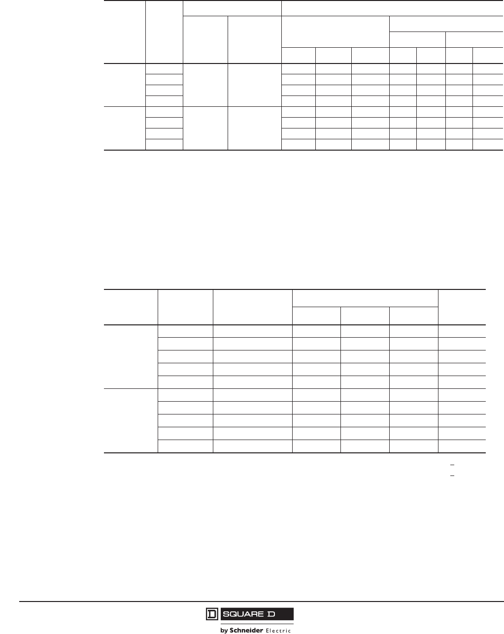
© 2001–2012 Schneider Electric
All Rights Reserved
PowerPact™ M-, P- and R-Frame, and Compact™ NS630b–NS3200 Circuit Breakers
Section 5—PowerPact R-Frame Circuit Breakers
58
10/2012
™
Interrupting Ratings
Automatic Molded Case Switches
Automatic molded case switches are available in unit-mount construction from 1200–3000 A.
Automatic switches are similar in construction to electronic trip circuit breakers except that long-time
protection is not present. The switches open instantaneously at a non-adjustable magnetic trip point
calibrated to protect only the molded case switch itself. They must be used in conjunction with a circuit
breaker or fuse of equivalent rating.
NOTE: Catalog numbers for automatic switches are designated by “000” in positions 7–9 (ampere
rating) and S12, S16, S20, S25, or S30 in positions 11–14 (trip system). See Table 10.
Table 52: Interrupting Ratings
Mounting Circuit
Breaker
Ampere Rating (A) Interrupting Ratings
Basic
Electronic
Trip Units
Micrologic™
Trip Units
UL/CSA/NMX
IEC 60947-2
240 Vac 380/415 Vac
240 Vac 480 Vac 600 Vac Icu Ics Icu Ics
Individually-
Mounted
RG
1200, 1600,
2000, 2500
600, 800, 1000,
1200, 1600,
2000, 2500,
3000
65 kA 35 kA 18 KA 50 kA 25 kA 35 kA 20 kA
RJ 100 kA 65 kA 25 kA 65 kA 35 kA 50 kA 25 kA
RK 65 kA 65 kA 65 kA 85 kA 65 kA 70 kA 55 kA
RL 125 kA 100 kA 50 kA 125 kA 65 kA 85 kA 45 kA
I-Line™
RG
NA 1000, 1200
65 kA 35 kA 18 KA 50 kA 25 kA 35 kA 20 kA
RJ 100 kA 65 kA 25 kA 65 kA 35 kA 50 kA 25 kA
RK 65 kA 65 kA 65 kA 85 kA 65 kA 70 kA 55 kA
RL 125 kA 100 kA 50 kA 125 kA 65 kA 85 kA 45 kA
Table 53: Automatic Switch Information
Circuit
Breaker
Ampere
Rating Catalog Number1, 2
Withstand Rating Trip Point
(±10%)
240 Vac 480 Vac 600 Vac
RK
2P1, 3P, 4P2
1For 2P, replace the leading 3 in the catalog number following the prefix with a 2 (RKP36000S12 becomes RKP26000S12).
2For 4P, replace the leading 3 in the catalog number following the prefix with a 4 (RKP36000S12 becomes RKP46000S12).
1200 RKF36000S12 65 kA 65 kA 65 kA 57 kA
1600 RKF36000S16 65 kA 65 kA 65 kA 57 kA
2000 RKF36000S20 65 kA 65 kA 65 kA 57 kA
2500 RKF36000S25 65 kA 65 kA 65 kA 57 kA
3000 RKF36000S30 65 kA 65 kA 65 kA 57 kA
RL
2P, 3P, 4P2
1200 RLF36000S12 125 kA 100 kA 50 kA 48 kA
1600 RLF36000S16 125 kA 100 kA 50 kA 48 kA
2000 RLF36000S20 125 kA 100 kA 50 kA 48 kA
2500 RLF36000S25 125 kA 100 kA 50 kA 48 kA
3000 RLF36000S30 125 kA 100 kA 50 kA 48 kA
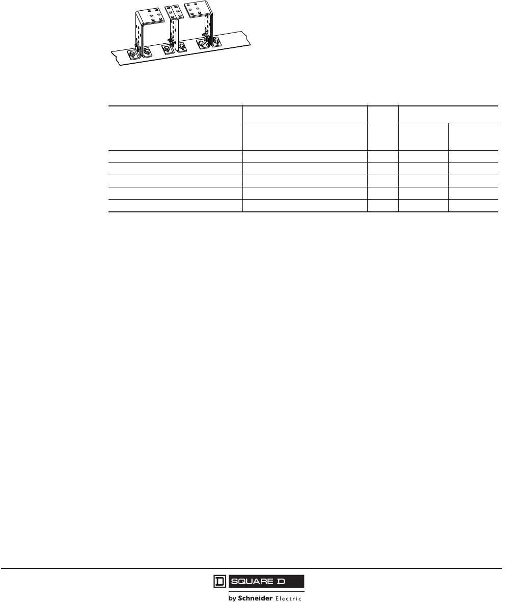
PowerPact™ M-, P- and R-Frame, and Compact™ NS630b–NS3200 Circuit Breakers
Section 5—PowerPact R-Frame Circuit Breakers
59
10/2012
© 2001–2012 Schneider Electric
All Rights Reserved
™
Termination Information
I-Line™ circuit breakers have lugs standard on the O/OFF end. Unit-mount circuit breakers and
switches are equipped for direct bus connection. For certain circuit breaker ratings and to connect
cable to R-frame circuit breakers, an RLTB terminal pad kit may be required. Refer to Section 10—
Dimensional Drawings for terminal pad kit dimensions.
For cable connection to RLTB, use AL2500RK lug. See page 84.
Continuous Current Rating
All circuit breakers marked as 100% rated can be continuously loaded to 100% of their rating.
100%-rated circuit breakers are available in unit-mount construction up to 3000 A and in I-Line
construction up to 1200 A.
Because of the additional heat generated when applying circuit breakers at 100% of continuous
current rating, the use of specially-designed enclosures and 90°C (194°F) wire is required. The 90°C
(194°F) wire must be sized according to the ampacity of the 75°C (167°F) wire column in the NEC.
Minimum enclosure size and ventilation specifications are indicated on a label on the circuit breaker, in
the circuit breaker instruction bulletin and in Table 5 on page 11.
Circuit breakers with 100% rating can also be used in applications requiring only 80% continuous
loading.
Control Wiring
Control wiring is connected to terminals located under the circuit breaker accessory cover.
Table 54: RLTB Terminal Pad Kit
Table 55: Terminal Pad Kits for R-Frame Circuit Breakers
R-Frame
Circuit Breaker
Terminal Pad Kit Lugs
per
Phase
Field-Installable Kits
Usage 3P (One
End Only)
4P (One
End Only)
3000 A, 100% Rated Required for Cable or Bus 9 RL3TB1
1Supplied as standard with the R-frame circuit breaker.
RL3TB4
3000 A, Standard (80% Rated) Required for Cable or Bus 8 RLTB1RLTB4
2500 A, 100% Rated Required for Cable or Bus 8 RLTB1RLTB4
2500 A, Standard (80% Rated) Required for Cable, Optional for Bus 8 RLTB RLTB4
All Other R-Frame CIrcuit Breakers Required for Cable, Optional for Bus 8 RLTB RLTB4
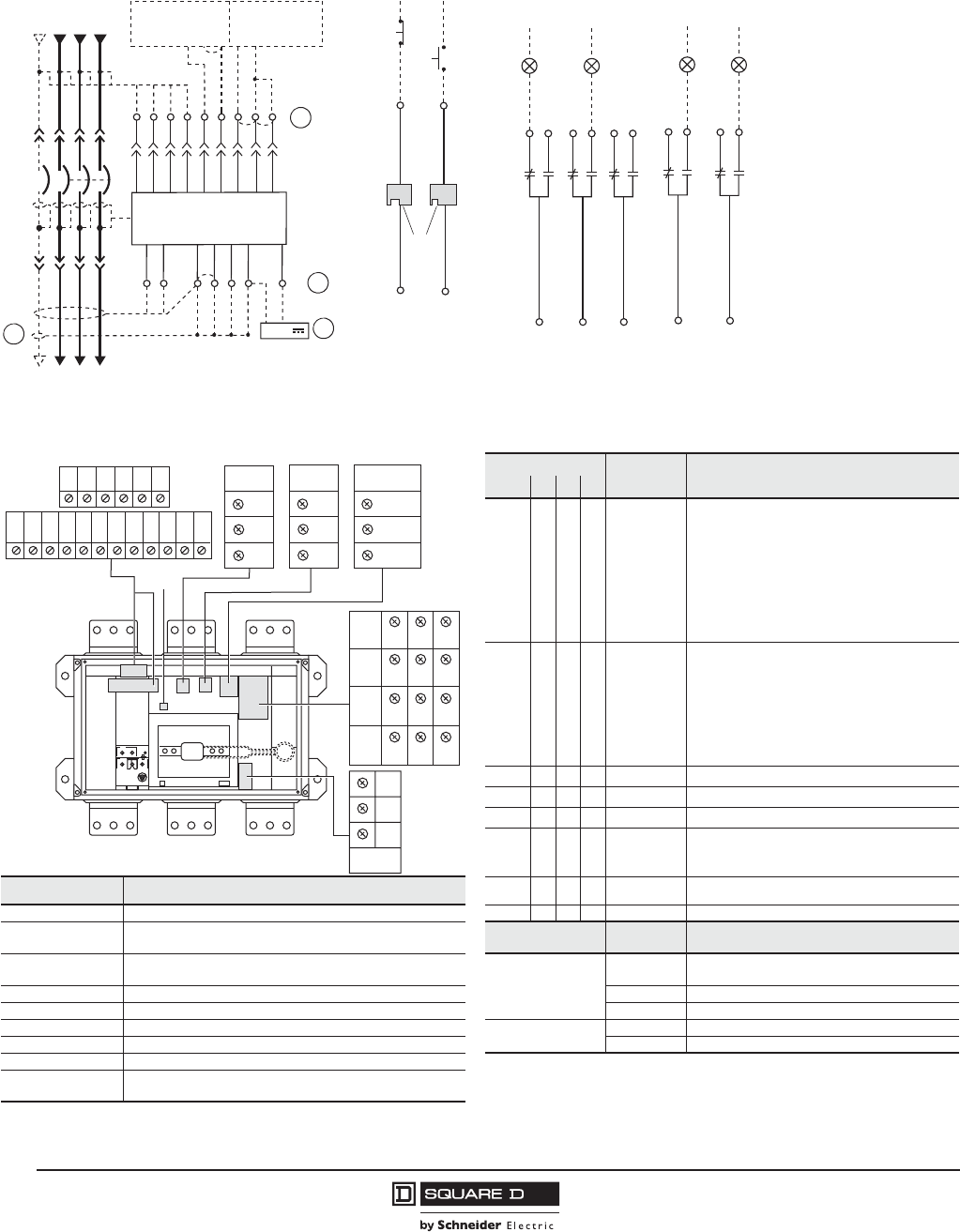
© 2001–2012 Schneider Electric
All Rights Reserved
PowerPact™ M-, P- and R-Frame, and Compact™ NS630b–NS3200 Circuit Breakers
Section 5—PowerPact R-Frame Circuit Breakers
60
10/2012
™
Figure 4: Accessory Control Wiring Diagrams
Trip Unit Type
Basic A P H Connector Description
— • • • Com: E1-E6 Circuit breaker communication module
E1 = +24 Vdc
E2 = Common
E3 = Out -
E4 = Out +
E5 = In -
E6 = In +
— • • • Z Zone-selective interlocking
Z1 = ZSI OUT signal
Z2 = ZSI OUT
Z3 = ZSI IN signal
Z4 = ZSI IN short-time delay
Z5 = ZSI IN ground fault
— • • • T External neutral sensor
— • • • M Modified differential ground fault (MDGF)
— • • • F 24 Vdc external power supply
——••Vn
2External neutral voltage takeoff
Connector Recommended Wire Size ——••
M6C:
Q1, Q2, Q3
6 programmable contacts
24 Vdc external power supply required
V1, V2, V3, Vn 22–16 AWG (0.3–1.5 mm2) — — • • V1, V2, V3 External phase voltage takeoff
E1–E2 22 AWG (0.3 mm2) MIN shielded pair cable or twisted pair
copper wires Function Connector Description
T 22 AWG (0.3 mm2) stranded shielded cable
Auxiliary Contacts
OF Open/Closed circuit breaker or switch position
contacts
M Refer to MDGF instructions SD Bell alarm
Z1–Z5 22–18 AWG (0.3–0.8 mm2) SDE Electrical fault alarm contact
OF, SD, SDE 18–16 AWG (0.8–1.5 mm2)Remote Operation MN Undervoltage trip device
MN, MX 18–14 AWG (0.8–2.5 mm2) MX Shunt trip
F Size per aux 24 Vdc power supply
E3–E6, Q1, Q2, Q3 22 AWG (0.3 mm2) shielded twisted pairs with drain
(Belden 8723 or equal)3
1 C3 terminal is not used.
2 Neutral voltage takeoff supplied as flying lead.
22
24
21
OF2
Closed
06123033
OF3
32
34
31
Open
12
14
11
OF1
92
94
91
SD
Tripped
82
84
81
SDE
Fault
T4
T3
T2
T1 Z3
Z4
T3
T2
Trip Unit
Z4
Z3
Z2
Z1 Z5
Z2
Z1
NCBA
Z5
VN
V1
V2
V3
M2
M1
F2+
Upstream Downstream
24 V
06123031
T1/M3
T4/F1-
06123107
or
D2
D1
MN MX
C2
C1
Power Trip Unit Remote Operation Alarm Contacts
NOTE: All diagrams show circuit breaker in open position.
A
D
C
B
A–Do not remove factory-installed jumpers between Z3, Z4 and Z5 unless ZSI is connected.
B–Do not remove factory-installed jumper between T1 and T2 unless neutral CT is connected. Do not install jumper between T3 and T4.
C–For proper wiring of neutral CT, refer to Instruction Bulletin 48041-082-01 shipped with it.
D–24 Vdc power supply for trip unit must be separate and isolated from 24 Vdc power supply for communication modules.
32 34
E1 E2 E3 E4 E5 E6
Z1 Z2 Z3 Z4 Z5
M1M2 M3
T1 T2 T3
F1
T4
F2
MN/MX
D2/C2
D1/C1
OF1 11 12 14
OF2 21 22 24
OF3 31
SD 91 92 94
84
SDE
82
81
VN
C3
M6C
Q1
Q3
Q2
Vext
V3
V1
V2
06123042
1
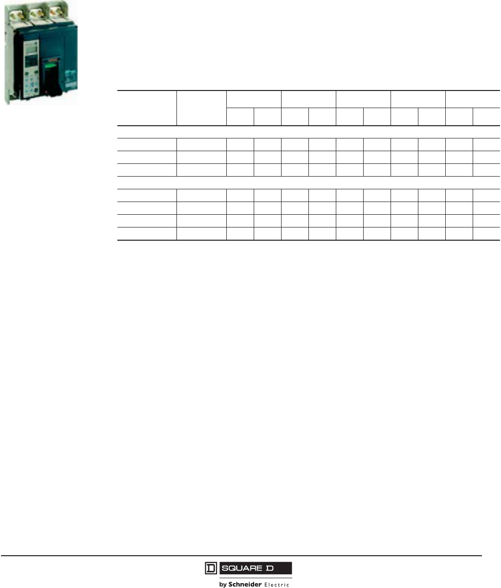
PowerPact™ M-, P- and R-Frame, and Compact™ NS630b–NS3200 Circuit Breakers
Section 6—Compact NS630b–NS1600 Circuit Breakers
61
10/2012
© 2001–2012 Schneider Electric
All Rights Reserved
™
Section 6—Compact NS630b–NS1600 Circuit Breakers
Performance
The Compact NS630b–NS1600 circuit breakers feature the exclusive Micrologic™ electronic trip units,
which allow for a range of sophisticated applications for metering and monitoring. In addition, trip units
can be interchanged in the field to allow for maximum flexibility.
The compact size and small footprint of the NS circuit breakers permit higher density installations.
These circuit breakers are available in ratings up to 1600 A to meet a broad range of commercial and
industrial application needs.
•Circuit breakers are available in 1600 A construction with a sensor size range of 250–1600 A.
•Interrupting ratings (AIR):
•Compact circuit breaker size allows for smaller footprint installations. Nine inch width provides
increased density installation.
•Most field-installable accessories are common to all frame sizes for easier stocking and installation
•Selection of four interchangeable Micrologic trip units available, with Powerlogic™ power metering
and monitoring capabilities available in advanced trip units.
•Compatible with Powerlogic systems and high amperage power circuit breakers.
•Built-in Modbus® protocol provides an open communications platform and eliminates the need to
purchase additional, proprietary network solutions.
•Connection options include bus or cable for installation flexibility.
•Additional options are available for five-cycle closing, stored energy mechanisms and drawout-
mounting.
Compact NS630b–NS1600
Circuit
Breaker
Interrupting
Rating
220/240 Vac 380/415 Vac 440 Vac 500/525 Vac 660/690 Vac
Icu Ics Icu Ics Icu Ics Icu Ics Icu Ics
Electrically Operated
NS630b–NS1600 N 50 kA 37 kA 50 kA 37 kA 50 kA 37 kA 40 kA 30 kA 30 kA 22 kA
NS630b–NS1600 H 70 kA 35 kA 70 kA 35 kA 65 kA 32 kA 50 kA 25 kA 42 kA 21 kA
NS630b–NS1000 L 150 kA 150 kA 150 kA 150 kA 130 kA 130 kA 100 kA 100 kA — —
Manually Operated
NS630b–NS1600 N 85 kA 50 kA 50 kA 50 kA 50 kA 50 kA 40 kA 40 kA 30 kA 30 kA
NS630b–NS1600 H 85 kA 52 kA 70 kA 52 kA 65 kA 48 kA 50 kA 37 kA 42 kA 31 kA
NS630b–NS1000 L 150 kA 150 kA 150 kA 150 kA 130 kA 130 kA 100 kA 100 kA — —
NS630b–NS800 LB (R) 200 kA 200 kA 200 kA 200 kA 200 kA 200 kA 100 kA 100 kA 75 kA 75 kA

© 2001–2012 Schneider Electric
All Rights Reserved
PowerPact™ M-, P- and R-Frame, and Compact™ NS630b–NS3200 Circuit Breakers
Section 6—Compact NS630b–NS1600 Circuit Breakers
62
10/2012
™
Catalog Numbers
Table 56: IEC-Rated, Unit-Mount, Manually-Operated, 3P Electronic Trip Circuit Breakers with Micrologic™ Electronic
Trip Units1
Trip Unit
Circuit Breaker
Current Rating
630 A 800 A 1000 A 1250 A 1600 A
Micrologic
Standard Trip
Unit
2.0
(LS0)
NPNLE36063U32R NPNLE36080U32R NPNLE36100U32R NPNLE36125U32R NPNFE36160U32R
NPHLE36063U32R NPHLE36080U32R NPHLE36100U32R NPHLE36125U32R NPHFE36160U32R
NPLLE34063U32R NPLLE34080U32R NPLLE34100U32R ——
NPRLE34063U32R NPRLE34080U32R ———
5.0
(LSI)
NPNLE36063U33R NPNLE36080U33R NPNLE36100U33R NPNLE36125U33R NPNFE36160U33R
NPHLE36063U33R NPHLE36080U33R NPHLE36100U33R PHLE36125U33RN NPHFE36160U33R
NPLLE34063U33R NPLLE34080U33R NPLLE34100U33R ——
NPRLE34063U33R NPRLE34080U33R ———
Micrologic
Ammeter Trip
Unit2
2.0A
(LS0)
NPNLE36063U42R NPNLE36080U42R NPNLE36100U42R NPNLE36125U42R NPNFE36160U42R
NPHLE36063U42R NPHLE36080U42R NPHLE36100U42R NPHLE36125U42R NPHFE36160U42R
NPLLE34063U42R NPLLE34080U42R NPLLE34100U42R ——
NPRLE34063U42R NPRLE34080U42R ———
5.0A
(LSI)
NPNLE36063U43R NPNLE36080U43R NPNLE36100U43R NPNLE36125U43R NPNFE36160U43R
NPHLE36063U43R NPHLE36080U43R NPHLE36100U43R NPHLE36125U43R NPHFE36160U43R
NPLLE34063U43R NPLLE34080U43R NPLLE34100U43R ——
NPRLE34063U43R NPRLE34080U43R ———
6.0A
(LSIG)
NPNLE36063U44R NPNLE36080U44R NPNLE36100U44R NPNLE36125U44R NPNFE36160U44R
NPHLE36063U44R NPHLE36080U44R NPHLE36100U44R NPHLE36125U44R NPHFE36160U44R
NPLLE34063U44R NPLLE34080U44R NPLLE34100U44R ——
NPRLE34063U44R NPRLE34080U44R ———
Micrologic Power
Trip Unit with
Modbus®
Communications
5.0P
(LSI)
NPNLE36063U63RE1 NPNLE36080U63RE1 NPNLE36100U63RE1 NPNLE36125U63RE1 NPNFE36160U63RE1
NPHLE36063U63RE1 NPHLE36080U63RE1 NPHLE36100U63RE1 NPHLE36125U63RE1 NPHFE36160U63RE1
NPLLE34063U63RE1 NPLLE34080U63RE1 NPLLE34100U63RE1 ——
NPRLE34063U63RE1 NPRLE34080U63RE1 ———
6.0P
(LSIG)
NPNLE36063U64RE1 NPNLE36080U64RE1 NPNLE36100U64RE1 NPNLE36125U64RE1 NPNFE36160U64RE1
NPHLE36063U64RE1 NPHLE36080U64RE1 NPHLE36100U64RE1 NPHLE36125U64RE1 NPHFE36160U64RE1
NPLLE34063U64RE1 NPLLE34080U64RE1 NPLLE34100U64RE1 ——
NPRLE34063U64RE1 NPRLE34080U64RE1 ———
Micrologic
Harmonic Trip
Unit with Modbus
Communications
5.0H
(LSI)
NPNLE36063U73RE1 NPNLE36080U73RE1 NPNLE36100U73RE1 NPNLE36125U73RE1 NPNFE36160U73RE1
NPHLE36063U73RE1 NPHLE36080U73RE1 NPHLE36100U73RE1 NPHLE36125U73RE1 NPHFE36160U73RE1
NPLLE34063U73RE1 NPLLE34080U73RE1 NPLLE34100U73RE1 ——
NPRLE34063U73RE1 NPRLE34080U73RE1 ———
6.0H
(LSIG)
NPNLE36063U74RE1 NPNLE36080U74RE1 NPNLE36100U74RE1 NPNLE36125U74RE1 NPNFE36160U74RE1
NPHLE36063U74RE1 NPHLE36080U74RE1 NPHLE36100U74RE1 NPHLE36125U74RE1 NPHFE36160U74RE1
NPLLE34063U74RE1 NPLLE34080U74RE1 NPLLE34100U74RE1 ——
NPRLE34063U74RE1 NPRLE34080U74RE1 ———
1For 4P, replace the 3 in the catalog number following the prefix with a 4 (NPNLE35053U43R becomes NPNLE46063U43R).
2Add E1 suffix for Modbus communications.
PowerPact™ M-, P- and R-Frame, and Compact™ NS630b–NS3200 Circuit Breakers
Section 6—Compact NS630b–NS1600 Circuit Breakers
63
10/2012
© 2001–2012 Schneider Electric
All Rights Reserved
™
Interrupting Ratings
See page 61.
Electrically-Operated Circuit Breakers
Electrically-operated NS630b–NS1600 circuit breakers are available in unit-mount construction up to
1600 A and are denoted in the catalog number by an “M_” suffix. These come equipped with a two-
step stored energy mechanism and come standard with a motor assembly.
Motor assemblies provide on and off control from remote locations. The assemblies contain a spring-
charging motor (MCH), a shunt trip (MX) and a shunt close (XF) and are available in standard or
communicating versions. An SDE overcurrent trip switch is also included for trip indication. When
remote indication of the circuit breaker status is required, use of a circuit breaker with an OF auxiliary
switch (for on-off indication).
For catalog numbers, see Table 69 on page 73.
Automatic Molded Case Switches
Automatic molded case switches are available in unit-mount constructions from 630–1600 A.
Automatic switches are similar in construction to electronic trip circuit breakers except that long-time
protection is not present. The switches open instantaneously at a non-adjustable magnetic trip point
calibrated to protect only the molded case switch itself. They must be used in conjunction with a circuit
breaker or fuse of equivalent rating.
Termination Information
Unit-mount circuit breakers and switches have mechanical lugs standard on both ends. These lugs
accept aluminum or copper wire. Manually operated circuit breakers are also available in drawout
construction.
Other terminations are available as accessories for non-standard applications. See Table 87 on page
84 for more lug options.
Accessories
Accessories are available either factory-installed or field-installable. They can be installed in accessory
compartments behind the circuit breaker accessory cover. See Table 61 on page 68 for available
accessories.
Control Wiring
Control wiring is connected to terminals located under the circuit breaker accessory cover.
Accessory Control Wiring Diagrams for Manually-Operated Circuit Breakers
See Figure 2 on page 50. (Same as PowerPact P-frame circuit breaker.)
Accessory Control Wiring Diagrams for Electrically-Operated Circuit Breakers
See Figure 3 on page 51. (Same as PowerPact P-frame circuit breaker.)
Table 57: Motor Assembly Voltage Ratings (Vn)
Voltage Type Voltage Ratings (Vn)
Vac 50/60 Hz 48, 100–130, 220–240, 380–415
Vdc 24–30, 48–60, 100–130, 200–250
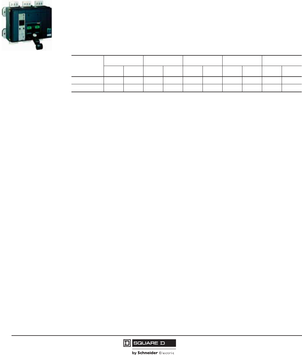
© 2001–2012 Schneider Electric
All Rights Reserved
PowerPact™ M-, P- and R-Frame, and Compact™ NS630b–NS3200 Circuit Breakers
Section 7—Compact NS1600b–NS3200 Circuit Breaker
64
10/2012
™
Section 7—Compact NS1600b–NS3200 Circuit Breaker
Performance
The Compact NS1600b–NS3200 circuit breakers feature the exclusive Micrologic™ electronic trip
units, which allow for a range of sophisticated applications for metering and monitoring. In addition, trip
units can be interchanged in the field to allow for maximum flexibility.
The compact size and smaller footprint of the NS circuit breaker permits higher density installations.
These circuit breakers are available in up to 3200 A construction to meet a broad range of commercial
and industrial application needs.
•Circuit breakers are available in 3200 A construction with a sensor size range of 600–3200 A.
•Interrupting ratings (AIR):
•The N interrupting rating is recommended for applications having high inrush and/or non-linear
loads such as large motors, transformers, motors with soft starts, etc.
•Compact circuit breaker size allows for smaller footprint installations. Fifteen-inch width provides
increased density installation.
•Most field-installable accessories are common to all frame sizes for easier stocking and installation
•Selection of four interchangeable Micrologic trip units available, with Powerlogic™ power metering
and monitoring capabilities available in advanced trip units.
•Compatible with Powerlogic systems and high amperage power circuit breakers.
•Built-in Modbus® protocol provides an open communications platform and eliminates the need to
purchase additional, proprietary network solutions.
•Connection options include bus or cable for installation flexibility.
Compact NS1600b–NS3200
Interrupting
Rating
220/240 Vac 380/415 Vac 440 Vac 500/525 Vac 660/690 Vac
Icu Ics Icu Ics Icu Ics Icu Ics Icu Ics
N 85 kA 65 kA 70 kA 52 kA 65 kA 65 kA 65 kA 65 kA 65 kA 65 kA
H 125 kA 94 kA 85 kA 64 kA 85 kA 64 kA — — — —
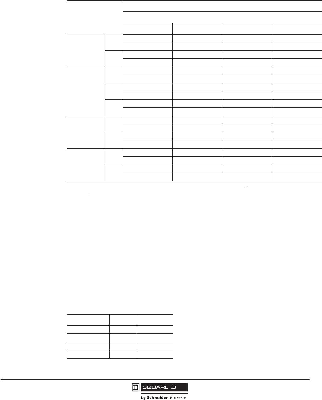
PowerPact™ M-, P- and R-Frame, and Compact™ NS630b–NS3200 Circuit Breakers
Section 7—Compact NS1600b–NS3200 Circuit Breaker
65
10/2012
© 2001–2012 Schneider Electric
All Rights Reserved
™
Catalog Numbers
Interrupting Ratings
See page 64.
Automatic Molded Case Switches
Automatic molded case switches are available in unit-mount constructions from 1600–3200 A.
Automatic switches are similar in construction to electronic trip circuit breakers except that long-time
protection is not present. The switches open instantaneously at a non-adjustable magnetic trip point
calibrated to protect only the molded case switch itself. They must be used in conjunction with a circuit
breaker or fuse of equivalent rating.
Table 58: IEC-Rated, Unit-Mount, Manually-Operated, 3P Electronic Trip Circuit Breakers
with Micrologic™ Electronic Trip Units
Trip Unit
Circuit Breaker
Current Rating1
1For 4P, replace the leading 3 in the catalog number following the prefix with a 4 (NRHFE36200U74RE1 becomes
NRHFE46200U74RE1).
1600 A 2000 A 2500 A 3200 A
Micrologic
Standard Trip
Unit
2.0
(LS0)
NRNFE36160U32R NRNFE36200U32R NRNFE36250U32R NRNFE36320U32R
NRHFE36160U32R NRHFE36200U32R NRHFE36250U32R NRHFE36320U32R
5.0
(LSI)
NRNFE36160U33R NRNFE36200U33R NRNFE36250U33R NRNFE36320U33R
NRHFE36160U33R NRHFE36200U33R NRHFE36250U33R NRHFE36320U33R
Micrologic
Ammeter Trip
Unit2
2Add E1 suffix for Modbus Communications.
2.0A
(LS0)
NRNFE36160U42R NRNFE36200U42R NRNFE36250U42R NRNFE36320U42R
NRHFE36160U42R NRHFE36200U42R NRHFE36250U42R NRHFE36320U42R
5.0A
(LSI)
NRNFE36160U43R NRNFE36200U43R NRNFE36250U43R NRNFE36320U43R
NRHFE36160U43R NRHFE36200U43R NRHFE36250U43R NRHFE36320U43R
6.0A
(LSIG)
NRNFE36160U44R NRNFE36200U44R NRNFE36250U44R NRNFE36320U44R
NRHFE36160U44R NRHFE36200U44R NRHLFE36250U44R NRHFE36320U44R
Micrologic Power
Trip Unit with
Modbus®
Communications
5.0P
(LSI)
NRNFE36160U63RE1 NRNFE36200U63RE1 NRNFE36250U63RE1 NRNFE36320U63RE1
NRHFE36160U63RE1 NRHFE36200U63RE1 NRHFE36250U63RE1 NRHFE36320U63RE1
6.0P
(LSIG)
NRNFE36160U64RE1 NRNFE36200U64RE1 NRNFE36250U64RE1 NRNFE36320U64RE1
NRHFE36160U64RE1 NRHFE36200U64RE1 NRHFE36250U64RE1 NRHFE36320U64RE1
Micrologic
Harmonic Trip
Unit with Modbus
Communications
5.0H
(LSI)
NRNFE36160U73RE1 NRNFE36200U73RE1 NRNFE36250U73RE1 NRNFE36320U73RE1
NRHFE36160U73RE1 NRHFE36200U73RE1 NRHFE36250U73RE1 NRHFE36320U73RE1
6.0H
(LSIG)
NRNFE36160U74RE1 NRNFE36200U74RE1 NRNFE36250U74RE1 NRNFE36320U74RE1
NRHFE36160U74RE1 NRHFE36200U74RE1 NRHFE36250U74RE1 NRHFE36320U74RE1
Table 59: Automatic Switch Information
Ampere Rating Icw Trip Point
1600 32 kA 57 kA
2000 32 kA 57 kA
2500 32 kA 57 kA
3200 32 kA 57 kA

© 2001–2012 Schneider Electric
All Rights Reserved
PowerPact™ M-, P- and R-Frame, and Compact™ NS630b–NS3200 Circuit Breakers
Section 7—Compact NS1600b–NS3200 Circuit Breaker
66
10/2012
™
Termination Information
NS1600b–NS3200 circuit breakers and switches are equipped for bus connection only. For certain
amperages, an RLTBE terminal pad kit may be required. (Same kit as the PowerPact R-frame circuit
breaker.) Refer to Section 10—Dimensional Drawings for terminal pad kit dimensions.
Accessories
Accessories are available either factory-installed or field-installable. They can be installed in accessory
compartments behind the circuit breaker accessory cover. (Same accessories as the R-frame circuit
breaker.)
Control Wiring
Control wiring is connected to terminals located under the circuit breaker accessory cover.
Accessory Control Wiring Diagrams
Refer to Wiring Diagrams on page 60. (Same as the R-frame circuit breaker.)
Table 60: Terminal Pad Kits for Compact NS1600b–NS3200 Circuit Breakers
Circuit Breaker
Terminal Pad Kit (One End Only)
Usage 3P Kit 4P Kit
3200 A Required Provided Provided
All Other Circuit Breakers Optional RLTBE RLTBE4

PowerPact™ M-, P- and R-Frame, and Compact™ NS630b–NS3200 Circuit Breakers
Section 8—Accessories
67
10/2012
© 2001–2012 Schneider Electric
All Rights Reserved
™
Section 8—Accessories
Accessories
M-frame, P-frame, R-frame and NS630b–NS3200 circuit breakers can be used with a variety of
internal and external accessories to increase application versatility and meet the demands of modern
electrical distribution systems.
Circuit breaker internal accessories are available either factory installed or field installable. They can
be installed in accessory compartments behind the circuit breaker accessory cover.
Factory-Installed Accessories
Factory-installed accessories are internally mounted by the factory. Accessories only available factory
installed cannot be removed or repaired in the field. Order factory-installed accessories by adding the
correct two-letter suffix to the standard circuit breaker catalog number. To build a catalog number, refer
to the product selector or contact a field office.
Field-Installable Accessories
FIeld-installable accessories can be installed or replaced in the field without affecting the circuit
breaker ratings. Field-installable accessories are shipped separately from the circuit breakers. Install
and wire field-installable accessories according to the instructions supplied with the circuit breaker and
particular accessory. Order field-installable accessories by the catalog number found in the Schneider
Electric Digest.

© 2001–2012 Schneider Electric
All Rights Reserved
PowerPact™ M-, P- and R-Frame, and Compact™ NS630b–NS3200 Circuit Breakers
Section 8—Accessories
68
10/2012
™
Table 61: Field/Factory-Installed Accessories
Accessory
M-Frame
Manually-Operated
Circuit Breakers
P-Frame and NS630b–NS1600
R-Frame and
NS1600b–NS3200
Circuit Breakers Page
No.
Manually-Operated
Circuit Breakers
Electrically-
Operated Circuit
Breakers
Field
Installable
Factory
Installed
Field
Installable
Factory
Installed
Field
Installable
Factory
Installed
Field
Installable
Factory
Installed
Shunt Trip (MX) Y Y Y Y Y Y Y Y 69
Undervoltage Trip (MN) Y Y Y Y Y Y Y Y 70
Adjustable Time Delay Module for
Undervoltage Trip YYYYYYYY71
Auxiliary Switch (OF) Y Y Y Y Y Y Y Y 71
Alarm Switch (SD) Y Y Y Y N/A N/A Y Y 71
Overcurrent Trip Switch (SDE) N N Y Y Y Y Y Y 71
Spring-Charging Motor N/A NA N/A N/A Y Y N/A N/A 73
Trip Unit Replacement Covers N N Y N Y N Y N 74
Neutral Current Transformer N N/A Y N Y N Y N 75
Ground-Fault Interface Module N N/A Y Y Y Y Y Y 75
External Sensor for SGR or MDGF
Protection NN/AYYY YYY75
Sensor Plugs N N Y Y Y Y Y Y 76
Rating Plugs N N Y Y Y Y Y Y 76
M2C and M6C Programmable Contacts N/A N/A Y Y Y Y Y Y 77
Circuit Breaker Communication Module N/A N/A Y Y Y Y Y Y 77
Restraint Interface Module N/A N/A Y N Y N Y N 79
External Power Supply Module N N/A Y Y Y Y Y Y 79
External Battery Backup Module N N/A Y Y Y Y Y Y 79
Hand-Held Test Kit N N/A Y Y Y Y Y Y 82
Full-Function Test Kit Y N/A Y Y Y Y Y Y 82
Mechanical Lug Y Y Y Y Y Y Y Y 83
Compression Lug Y Y Y Y Y Y Y Y 83
Terminal Pad Y Y Y Y Y Y Y Y 83
I-Line Jaws Y Y Y Y Y Y Y Y 83
Power Distribution Connectors Y Y Y Y Y Y Y Y 84
Control Wire Terminations Y Y Y Y Y Y Y Y 84
Phase Barriers Y N Y N Y N Y N 86
Electric Joint Compound Y Y Y Y Y Y Y Y 86
Door-Mounted Operating Mechanism Y Y Y Y Y Y N/A N/A 86
Rotary Handle N/A N/A N Y N/A N/A N/A N/A 87
Replacement Handles Y Y Y Y Y Y Y Y 87
Long Handle Extension Y Y Y Y N/A N/A N/A N/A 87
Accessory Cover Door Escutcheons Y N Y N Y N Y N 87
Padlock Attachment Y Y Y Y Y Y Y Y 87
Keylock N Y N Y N Y N Y 87
Keylock Provision N Y N Y N Y N Y 87
Sub-Feed Lugs N/A N/A Y Y Y Y Y Y 88
Y = Yes
N = No
N/A = Not Available
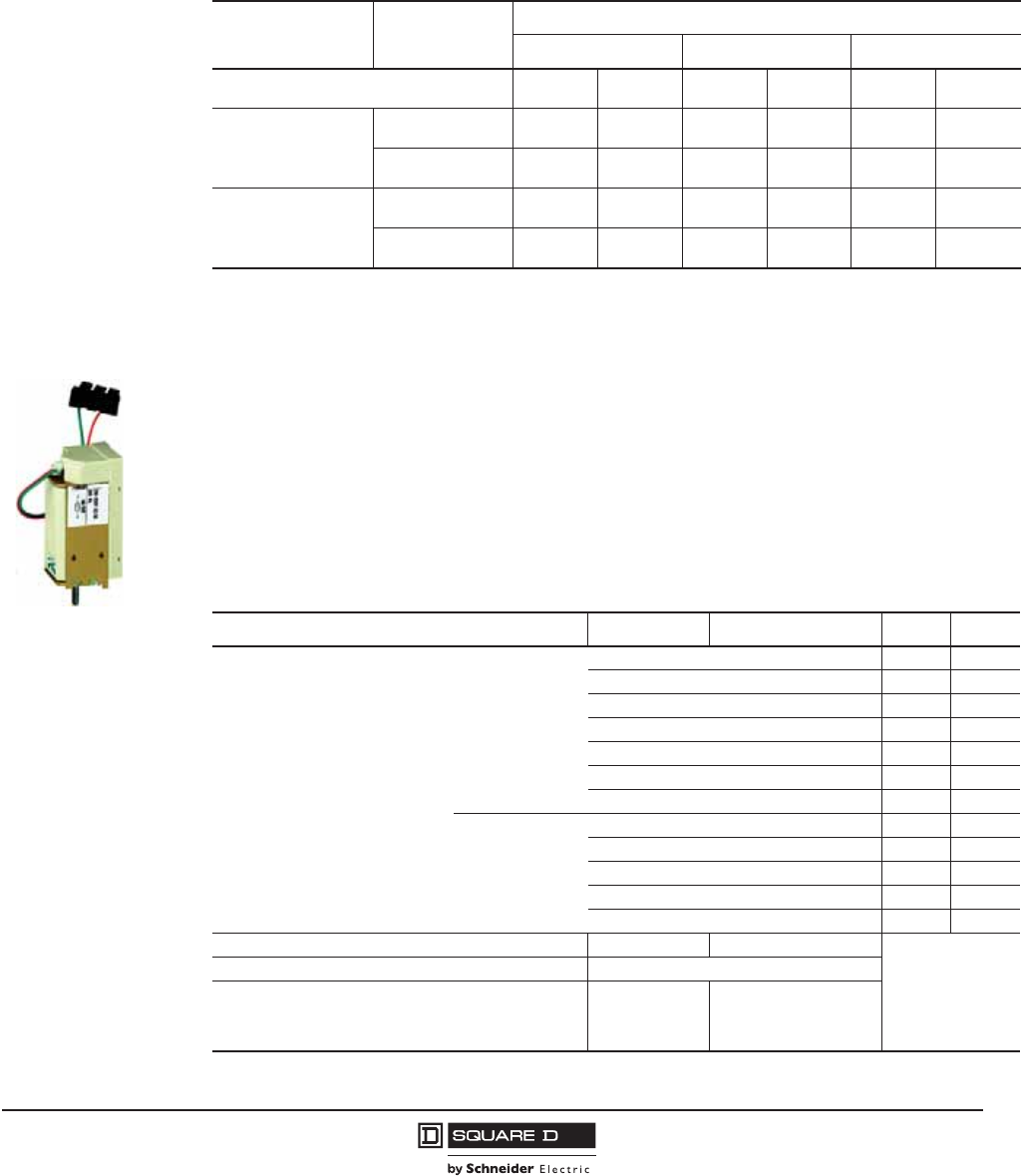
PowerPact™ M-, P- and R-Frame, and Compact™ NS630b–NS3200 Circuit Breakers
Section 8—Accessories
69
10/2012
© 2001–2012 Schneider Electric
All Rights Reserved
™
Electrical Accessories
Maximum Wire Length
Maximum Wire Length—The inrush currents for these devices are approximately 200 VA. When low
supply voltages (12, 24 or 48 V) are used, the maximum allowable wire length is dependent on the
voltage and the wire size.
Shunt Trip (MX1) and Shunt Close (XF)
Shunt Trip (MX1): When energized, the shunt trip instantaneously opens the circuit breaker. The
shunt trip may be energized continuously or intermittently.
Shunt Close (XF): Remotely closes the circuit breaker if the spring mechanism is charged. The shunt
close may be energized continuously or intermittently.This accessory is for electrically-operated
P-frame circuit breaker only.
Communication versions of the MX1 and XF are available for direct connection via the circuit breaker
communication module (BCM).
Table 62: Maximum Wire Length1
1The length shown in the table is for each of the two supply wires.
Device Percent of
Source Voltage
Source Voltage
12 Vdc 24 Vdc 48 Vdc
Wire Size 14 AWG
(2.08 mm2)
16 AWG
(1.31 mm2)
14 AWG
(2.08 mm2)
16 AWG
(1.31 mm2)
14 AWG
(2.08 mm2)
16 AWG
(1.31 mm2)
UVR (MN)
100% — — 159 ft
(48.5 m)
100 ft
(30.5 m)
765 ft
(233.2 m)
472 ft
(143.9 m)
85% — — 44 ft
(13.4 m)
29 ft
(8.8 m)
205 ft
(62.5 m)
129 ft
(39.3 m)
Shunt Trip (MX) and
Shunt Close (XF)
100% 57 ft
(17.4 m)
34 ft
(10.4 m)
314 ft
(95.7 m)
200 ft
(61.0 m)
1503 ft
(457.8 m)
944 ft
(287.7 m)
85% 27 ft
(8.2 m)
17 ft
(5.2 m)
205 ft
(62.5 m)
126 ft
(38.4 m)
957 ft
(291.7 m)
601 ft
(183.2 m)
06133834
Shunt Trip (MX1) and
Shunt Close (XF)
Table 63: Shunt Trip and Shunt Close Characteristics
Characteristics MX1 XF Min Max
Voltage Ratings (Vn)
Vac
50/60 Hz
24 Vac 17 Vac 26 Vac
48 Vac 34 Vac 52 Vac
120 Vac 60 Vac 132 Vac
240 Vac 168 Vac 264 Vac
277 Vac 194 Vac 304 Vac
380 Vac 266 Vac 418 Vac
480 Vac 336 Vac 528 Vac
Vdc
12 Vdc 8 Vdc 13 Vdc
24 Vdc 17 Vdc 26 Vdc
48 Vdc 34 Vdc 52 Vdc
125 Vdc 88 Vdc 137 Vdc
250 Vdc 175 Vdc 275 Vdc
Operating Threshold 0.7 to 1.1 Vn 0.85 to 1.1 Vn
Power Consumption (VA or W) Steady-State/Inrush 4.5/200
Circuit Breaker Response Time at Vn1
1Shunt trip (MX1) and shunt close (XF) circuits must be energized for minimum of 200 ms.
50 ms ±10
70 ms ±10 (NW d4000 A)
80 ms ±10 (NW > 4000 A)
55 ms (NT)
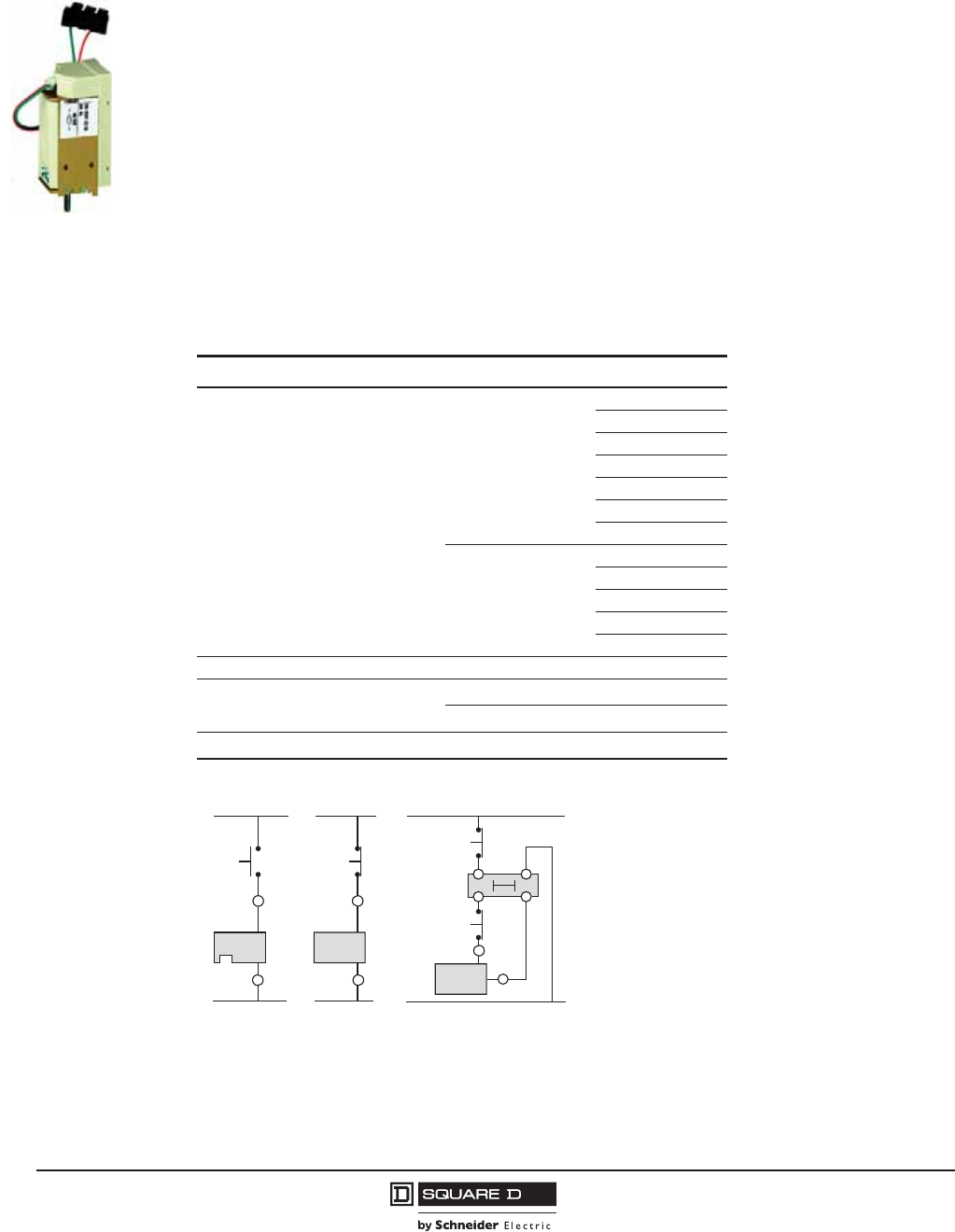
© 2001–2012 Schneider Electric
All Rights Reserved
PowerPact™ M-, P- and R-Frame, and Compact™ NS630b–NS3200 Circuit Breakers
Section 8—Accessories
70
10/2012
™
Undervoltage Trip (MN)
This function opens the circuit breaker via an electrical order.
It is made up of:
•Instantaneous trip
•Fixed undervoltage trip (time delayed) or,
•Adjustable undervoltage trip (time delayed)
As shown in the wiring diagram for the remote tripping function below, the delay unit (installed outside
the circuit breaker) may be disabled by an emergency off button to obtain non-delayed opening of the
circuit breaker.
The undervoltage trip (MN) instantaneously opens the circuit breaker when its supply voltage drops to
a value between 35% and 70% of its rated voltage.
If the undervoltage trip is not energized, it is impossible to close the circuit breaker, either manually or
electrically. An attempt to close the circuit breaker produces no movement of the main contacts.
Closing is allowed when the supply voltage of the undervoltage trip reaches 85% of rated voltage.
06133834
Undervoltage Trip (MN)
Table 64: Undervoltage Trip Characteristics
Characteristics MN
Voltage Ratings (Vn)
Vac
50/60 Hz
24 Vac
48 Vac
120 Vac
240 Vac
277 Vac
380 Vac
480 Vac
Vdc
12 Vdc
24 Vdc
48 Vdc
125 Vdc
250 Vdc
Power Consumption (VA or W) Constant/Inrush 4.5/200
Operating Threshold
Opening 0.35 to 0.70 Vn
Closing 0.35 Vn
Circuit Breaker Response Time at Vn90 ms ±5
Figure 5: Wire Diagram for the Remote Tripping Function
D1
10 12
36
MN
D2
D1
MN
D2
MX2
C12
C1
or
1
Opening
Order
Opening
Order
Delayed
Opening
Order
Instantane-
ous Opening
Order
Delayed
Unit
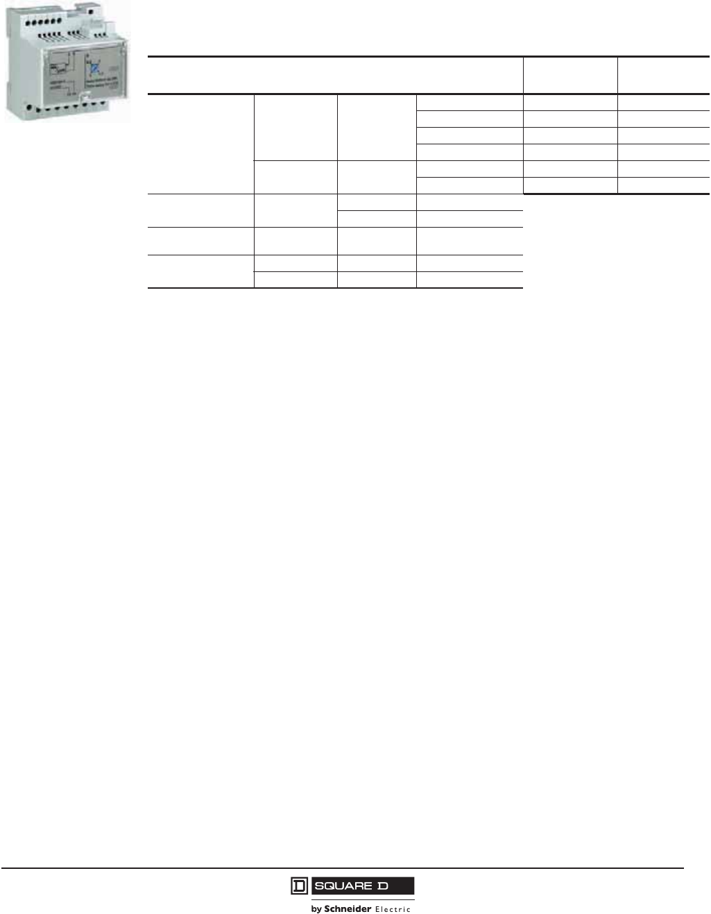
PowerPact™ M-, P- and R-Frame, and Compact™ NS630b–NS3200 Circuit Breakers
Section 8—Accessories
71
10/2012
© 2001–2012 Schneider Electric
All Rights Reserved
™
Time-Delay Module for Undervoltage Trip
To eliminate circuit breaker nuisance tripping during temporary voltage dips (micro-breaks), operation
of the undervoltage trip (MN) can be delayed by adding an external time-delay module to the
undervoltage trip circuit. Available as adjustable and non-adjustable module.
Indication Contacts
Changeover contacts are used to provide remote circuit breaker status information and can be used
for indications, electrical locking, relaying, etc. All the auxiliary contacts are also available in “low’level”
versions capable of switching very low loads (for the control of PLCs or electronic circuits).
Auxiliary Switch (OF):
•remotely indicates the position of the main circuit breaker contacts,
•can be used to operate indicator lights, relays or other accessories.
•circuit breaker can accommodate up to three 1A/1B auxiliary switches.
Alarm Switch (SD)
•indicates that the circuit breaker has tripped due to:
— an overload
— a short circuit
— an earth-leakage fault
— operation of a voltage release
— operation of the “push-to-trip” button
•Returns to de-energized state when the circuit breaker is reset.
Overcurrent Trip Switch (SDE)
•indicates that the circuit breaker has tripped due to:
— an overload
— a short circuit
— an earth-leakage fault
•Returns to de-energized state when the circuit breaker is reset.
06133786
Table 65: Time-Delay Module Characteristics
Characteristics Factory-Installed
Cat. No. Suffix
Field-Installable
Cat. No.
Voltage Ratings of
Time-delay Module
Adjustable Vac 50/60 Hz /
Vdc
48-60 FL S33680
100-130 FA S33681
200-250 FC S33682
380-480 FH S33683
Non-Adjustable Vac 50/60 Hz /
Vdc
100-130 KA S33684
200-250 KC S33685
Operating Threshold Opening 0.35 to 0.7 Vn
Closing 0.85 Vn
Power Consumption 4.5 VA/W (holding),
200 VA/W (inrush)
Time-Delay Settings Adjustable 0.5, 0.9, 1.5, and 3.0 s
Non-Adjustable 0.25 s
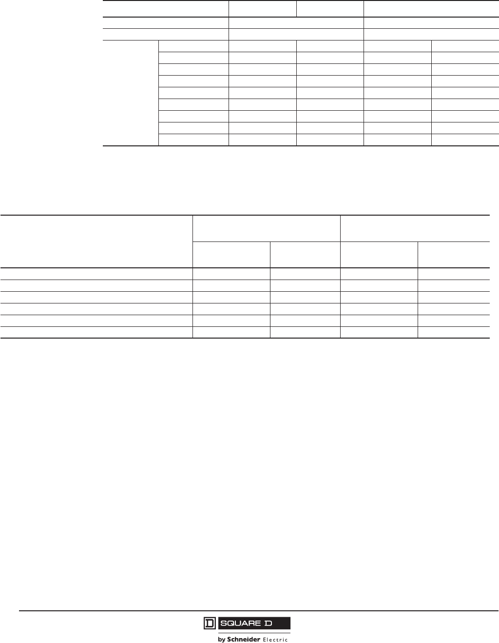
© 2001–2012 Schneider Electric
All Rights Reserved
PowerPact™ M-, P- and R-Frame, and Compact™ NS630b–NS3200 Circuit Breakers
Section 8—Accessories
72
10/2012
™
NOTE: If the maximum voltage and current is exceeded, the low-level functions of the switch will be
lost but the switch will continue to function as a standard switch.
Table 66: Electrical Characteristics of the OF/SD/SDE Auxiliary Contacts
Contacts Standard Low Level1
1SDE is not available in low level for electrically-operated P-frame circuit breakers.
Rated thermal current (A) 6 5
Minimum load 100 mA at 24 V 1 mA at 24 V
Operational
current (A)
Voltage AC DC AC DC
24 V6655
48 V 6 2.5 5 2.5
110 V 6 0.6 5 0.6
220/240 V 6 — 5 —
250 V — 0.3 5 0.3
380/440 V 6 — 5 —
480 V 6 — 5 —
660/690 V 6 — — —
Table 67: Catalog Numbers
Description
Standard
Min Load = 10 mA with 24 V
Low Level
Min Load = 1 mA with 24 V
Factory-Installed
Cat. No. Suffix
Field-Installable
Cat. No.
Factory-Installed
Cat. No. Suffix
Field-Installable
Cat. No.
1 Auxiliary Switch (OF) 1a1b AA S29450 AE S29452
2 Auxiliary Switch (OF) 1a1b AB 2x S29450 AF 2x S29452
3 Auxiliary Switch (OF) 1a1b AC 3x S29450 AG 3x S29452
Alarm Switch (SD) 1a1b BC S29450 BH S29452
Overcurrent Trip Switch (SDE) 1a1b BD S29450 BJ1S29452
Alarm Switch/Overcurrent Trip Switch (SD/SDE) 2a2b BE 2x S29450 BK12x S29452
1Not available on an electrically-operated P-frame circuit breaker.
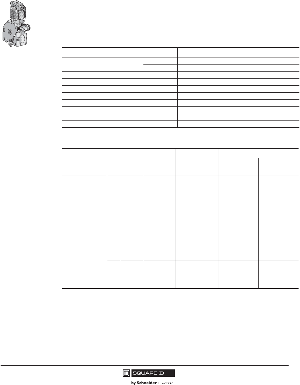
PowerPact™ M-, P- and R-Frame, and Compact™ NS630b–NS3200 Circuit Breakers
Section 8—Accessories
73
10/2012
© 2001–2012 Schneider Electric
All Rights Reserved
™
Spring-Charging Motors (MCH) for P-Frame Circuit Breakers
The spring-charging motor automatically charges the spring mechanism for closing the circuit breaker
and also recharges the spring mechanism when the circuit breaker is in the ON position.
Instantaneous reclosing of the circuit breaker is thus possible following circuit breaker opening. The
spring-mechanism charging handle is used only as a backup if auxiliary power is absent.
The spring-charging motor is equipped as standard with a limit switch contact (CH) that signals the
charged position of the mechanism (springs charged).
Table 68: Spring-Charging Motor Characteristics
Characteristics MCH
Voltage Ratings (Vn)Vac 50/60 Hz 48-60, 100-130, 200-250, 240-277, 380-415, 400-440, 480
Vdc 24-30, 48-60, 100-125, 200-250
Operating Threshold 0.85 to 1.1 Vn
Power Consumption 180 VA
Motor Overcurrent 2–3 x In for 0.1 s
Charging Time 4 s maximum on NW, 3 s maximum on NT
Duty Cycle 3 cycles per minute maximum
Endurance 10,000 cycles for NW < 4000 A
5000 cycles for NW t 4000 A
CH Contact 10 A at 240 V
Table 69: Spring-Charging Motors for Electrically-Operated P-Frame Circuit Breakers
Description Rated Voltage
(+10%/-15%)
Factory
Installed Cat.
No. Suffix
Field-
Replacement
Spring Charging
Motor Cat. No.
Replacement Coils
Factory Installed
Cat. No. Suffix
Opening/Closing
Coil Cat. No.
Standard Motor for
Electrically-Operated
Circuit Breakers
Vac
48 ML S47391 SL S33660
100-130 MA S47395 SA S33661
220-240 MC S47396 SC S33662
380-415 MF S47398 SH S33664
Vdc
24-30 MO S47390 SK S33659
48-60 MV S47391 SL S33660
110/130 MR S47392 SA S33661
200/250 MS S47393 SC S33662
Communicating Motor
Mechanism for
Electrically-Operated
Circuit Breakers
Vac
48 NL S47391 EL S33034
100-130 NA S47395 EA S33035
220-240 NC S47396 EC S33036
380-415 NF S47398 EH S33038
Vdc
24-30 NO S47390 EK S33033
48-60 NV S47391 EL S33034
110-130 NR S47392 EA S33035
200-250 NS S47393 EC S33036
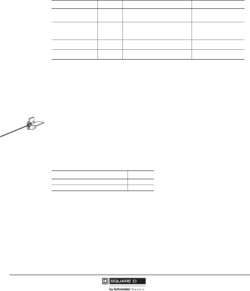
© 2001–2012 Schneider Electric
All Rights Reserved
PowerPact™ M-, P- and R-Frame, and Compact™ NS630b–NS3200 Circuit Breakers
Section 8—Accessories
74
10/2012
™
Micrologic™ Trip Unit Accessories
Circuit breakers are shipped with trip unit installed, but can have the trip units replaced in the field.
Actual trip units and settings required for specific applications must be determined by a qualified
consultant or plant engineer. A coordination study is recommended to provide coordination between all
circuit breakers in the distribution system.
Lead-Free Trip Unit Sealing Kit
The MICROTUSEAL lead-free trip unit seal was designed as a RoHS-compliant replacement for lead
seals. It may be used to seal Micrologic trip units and other devices. It is manufactured as a stainless
steel cable and polycarbonate locking mechanism which shows evidence of tampering. The seal is
individually numbered for control purposes.
Order kit number .
Replacement Covers
Table 70: Field-Installable Micrologic Trip Unit
Model Protection Additional Features Field-Installable Cat. No.1
1The standard rating plug supplied with a trip unit is the “A” rating plug. To specify an alternative adjustable rating plug, please
add the letter designation to the end of the catalog number. Please refer to Digest for a complete listing of adjustable settings
available with each plug. (Example: S143B would specify a “B” rating plug instead of the standard "A" plug.) Use suffix “N” if
no rating plug is required.
When replacing a Basic trip unit with Type A (Ammeter), P (Power metering) or H (Harmonic analysis) trip unit, order the 12-
pin connector kit S33101 for the PowerPact P-frame drawout circuit breakers or kit S33100 for PowerPact P-frame unit-mount
and R-frame circuit breakers.
2.0 (IEC only)
3.0 (UL/ANSI only)
5.0
LSO
LI
LSI
None
S132R
S131A
S133A
2.0A (IEC only)
3.0A (UL/ANSI only)
5.0A
6.0A
LSO
LI
LSI
LSIG
Ammeter
S142R
S141A
S143A
S144A
5.0P
6.0P
LSI
LSIG Metering, Advanced Protection S163A
S164A
2
2
2Requires Circuit Breaker Communications Module.
5.0H
6.0H
LSI
LSIG
Metering,
Advanced Protection & Harmonic Analysis
S173A
S174A
2
2
Table 71: Replacement Covers
Device Cat. No.
Micrologic A Trip Unit Cover, clear S33592
Micrologic P/H Trip Unit Cover, opaque gray S47067
MICROTUSEAL
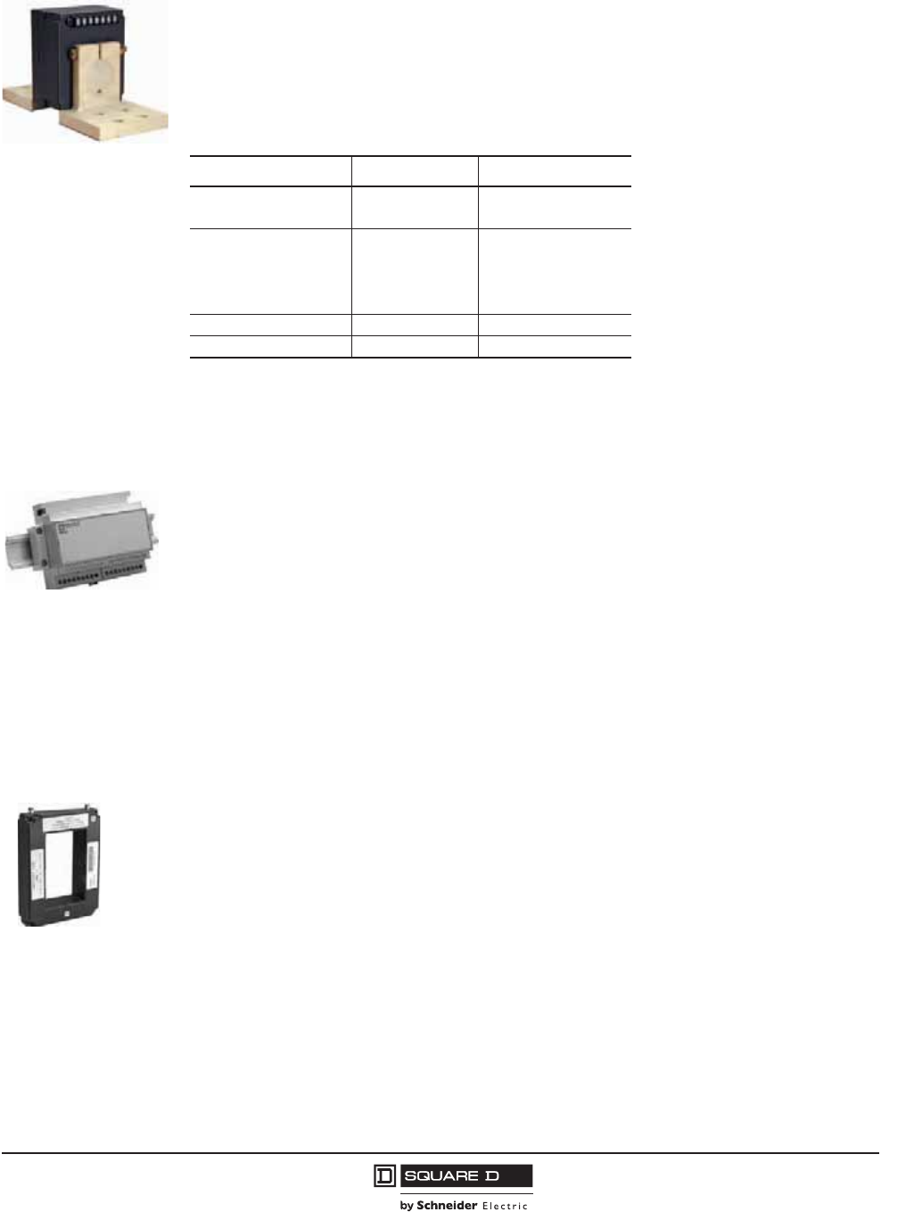
PowerPact™ M-, P- and R-Frame, and Compact™ NS630b–NS3200 Circuit Breakers
Section 8—Accessories
75
10/2012
© 2001–2012 Schneider Electric
All Rights Reserved
™
Neutral Current Transformer (CT)
Current transformers are available for applications requiring ground-fault protection on three-phase,
four-wire systems or for neutral protection and metering. Neutral current transformers are not required
on non-ground-fault circuit breakers, or on three-phase, three-wire systems. The rating of the external
neutral current transformer must be compatible with the rating of the circuit breaker.
NOTE: These neutral current transformers cannot be used for SGR (Source Ground-Return) or MDGF
(Modified Differential Ground Fault) applications.
Ground-Fault Interface Module
The ground-fault interface module (P-frame, R-frame and NS630b–NS3200 circuit breakers only) is
used to sum the current flow in three-phase, four-wire systems and multiple-sourced systems, using
one or more specially-designed external current sensors to measure current flow. The ground-fault
interface module is commonly used in two applications:
•For a ground-source return ground-fault sensing (SGR) system
•For a modified differential ground-fault (MDGF) system
More complex systems are possible, for information about these, contact a field sales representative.
Order kit number .
External Sensor for SGR or MDGF Protections
For use on 400 A sensor or higher.
In SGR applications, an external sensor is installed around the connection of the transformer neutral
point to ground. Its secondary is connected to the Micrologic™ 6.0A, 6.0P or 6.0H trip units.
In MDGF applications, a sensor is installed on each phase and neutral conductor. The sensors for
each circuit breaker are connected to an interface module. These, in turn, connect to the Micrologic
6.0A, 6.0P or 6.0H trip units.
Order kit number .
Table 72: Neutral Current Transformer Catalog Numbers
Circuit Breaker Sensor Cat. No.
P-Frame 250 S33575
400–1600 S33576
R-Frame
250 S48916
400–1600 S34036
2000 S48896
2500 S48182
All All NCTWIRING1
1Included with NCT.
12-pin Trip Unit Connector S33100
061337
S48891
061337
S33579

© 2001–2012 Schneider Electric
All Rights Reserved
PowerPact™ M-, P- and R-Frame, and Compact™ NS630b–NS3200 Circuit Breakers
Section 8—Accessories
76
10/2012
™
Sensor Plugs
Sensor plugs are used to set the current rating (In) of the PowerPact P- and R-frame circuit breakers.
Beginning in January 2007 (date code 07011), the sensor plugs are field-replaceable, down to 50% of
the original rating. Mechanical keying in the circuit breaker prevents changing a rating plug to a higher
rating than the original factory-installed sensor plug.
Rating Plugs
Interchangeable rating plugs are available to limit the long-time threshold setting range for greater
versatility.
0613384
Table 73: Sensor Plugs
Circuit Breaker Original Circuit
Breaker Amperage
Sensor Plug
Range
Sensor Plug
Catalog No.
UL P-Frame
250 A 250 A S47052
400 A 400 A S47053
600 A 600 A S48823
800 A 600–800 A S33092
1000 A 600–1000 A S33093
1200 A 600–1200 A S33824
IEC P-Frame
630 A 630 A S48823
800 A 600–800 A S33092
1000 A 600–1000 A S33093
1250 A 600–1250 A S33824
1600 A 600–1600 A S33095
UL R-Frame
600 A 600 A S48823
800 A 600–800 A S33092
1000 A 600–1000 A S33093
1200 A 600–1200 A S33824
1600 A 800–1600 A S33095
2000 A 1000–2000 A S33982
2500 A 1200–2500 A S33983
3000 A 1200–3000 A S48825
IEC R-Frame
1600 A 1600 A S33095
2000 A 1600–2000 A S33982
2500 A 1600–2500 A S33983
3200 A 1600–3200 A S48825
06133
Table 74: Rating Plug Settings
Rating Plug Switch Settings Ir = In x... Cat. No.
For P-Frame and
R-Frame Circuit
Breakers
Type A
Type B
Type C
Type D
0.4
0.4
0.42
0.4
0.45
0.44
0.50
0.48
0.5
0.5
0.53
0.64
0.6
0.56
0.58
0.7
0.63
0.63
0.67
0.8
0.7
0.75
0.75
0.9
0.8
0.88
0.83
0.93
0.9
0.95
0.95
0.95
1
1
1
1
S48818
S48819
S48820
S48836
Type E
Type F
Type G
Type H
0.6
0.84
0.66
0.48
0.7
0.86
0.68
0.5
0.75
0.88
0.7
0.52
0.8
0.9
0.72
0.54
0.85
0.92
0.74
0.56
0.9
0.94
0.76
0.58
0.93
0.96
0.78
0.6
0.95
0.98
0.8
0.62
1
1
0.82
0.64
S48837
S48838
S48839
S48840
For NS630b–
NS3200 Circuit
Breakers
Type R1
Type S
Type T
0.4
0.4
0.8
0.5
0.45
0.82
0.6
0.5
0.85
0.7
0.55
0.88
0.8
0.6
0.9
0.9
0.65
0.92
0.95
0.7
0.95
0.98
0.75
0.98
1
0.8
1
S33542
S33543
S33544
Type P (Off Plug) No Long-Time Protection. S33545
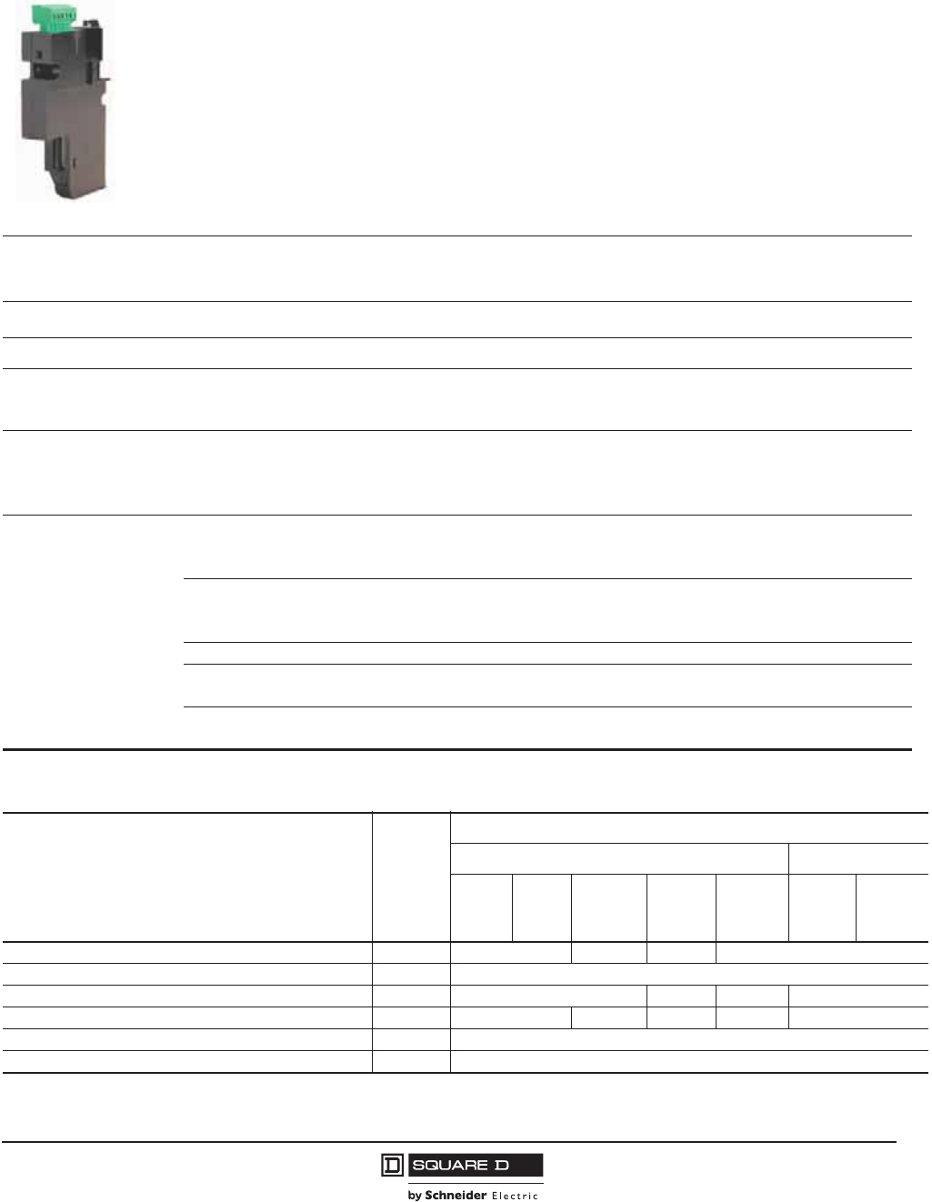
PowerPact™ M-, P- and R-Frame, and Compact™ NS630b–NS3200 Circuit Breakers
Section 8—Accessories
77
10/2012
© 2001–2012 Schneider Electric
All Rights Reserved
™
Modbus® Circuit Breaker Communication Module (BCM)
The circuit breaker communication module is independent of the trip unit. Installed on the circuit
breaker, behind the trip unit, it receives and transmits information on the communication network. An
optical link is used for communication with the Micrologic™ A, P, and H trip units. Power requirements
are 30 mA, 24 Vdc.
NOTE: The power supply for the circuit breaker communication module must be separate and isolated
from the power supply for the trip unit.
The following may be connected to this module:
•A set of dedicated switches which read the status of the circuit breaker.
•A set of “actuators” (MX shunt trip or motor mechanism) to control the circuit breaker.
.
06133786
Table 75: Circuit Breaker Communication Module Characteristics
Circuit Breaker
Identification
ID Code, Address
Size, Rating, Performance
Type of Trip Unit
Type of Long-time Rating Plug
Status Indication On/Off Indication
Fault Trip
Controls Opening/Closing
Circuit Breaker and Trip Unit
APH
Settings
Reading of Settings on Rotary Switches
Fine Settings in the Range Imposed by the Rotary Switches
Setting of Protection and Alarms
Customized Alarm Programming
XX
X
X
X
X
X
X
Operating and
Maintenance Aids
Reading of Protection and Alarms
Standard
Set
Customized
X
X
X
X
X
Reading of Measurements
Current
Voltages, Frequency, Power, etc.
Power Quality: Fundamentals and Harmonics
XX
X
X
X
X
Waveform Capture X
Histories History of Trips and Alarms1
Log of Trips and Alarms
XX
X
Indicators Contact Wear, Counters, Etc.
Maintenance Record
XX
X
1Up to 10 trips and 10 alarms.
Table 76: Trip Unit Field-Installable Accessories
Description
Factory-
Installed
Cat. No.
Suffix
Field-Installable Kit Cat. No.
P-Frame R-Frame
Unit
Mount
I-
Line™
Motor
Operated Drawout
With
Rotary
Handle
Unit
Mount I-Line
Circuit Breaker Communication Module (BCM) (Modbus) E1 S64205 S64207 S64206 S64205
Two Programmable Contacts Module (M2C) V S64273
Six Programmable Contacts Module (M6C) W S64204 S64202 S64204 S64201
External Voltage Sensing (EVS) YV S64203 S64210 S64209 S64210 S64208
Trip Unit Battery for Trip Indicator Lights — S33593
12-pin Trip Unit Connector for P- and R-Frame Circuit Breakers — S33100
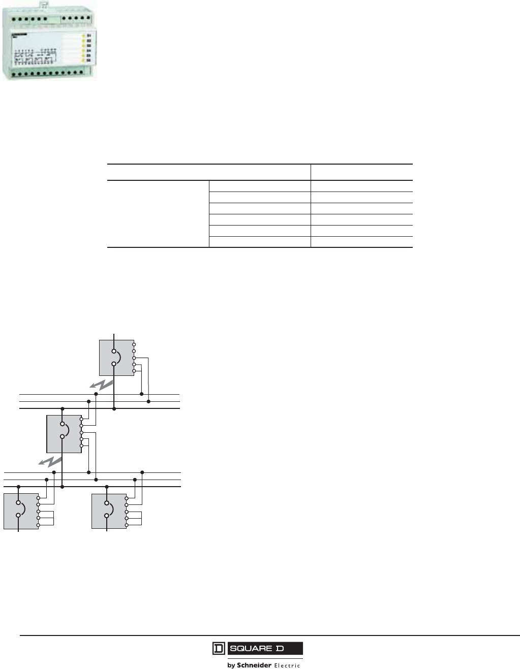
© 2001–2012 Schneider Electric
All Rights Reserved
PowerPact™ M-, P- and R-Frame, and Compact™ NS630b–NS3200 Circuit Breakers
Section 8—Accessories
78
10/2012
™
M2C and M6C Programmable Contacts
The M2C and M6C contacts are used with the Micrologic™ P and H control units, and indicate the type
of fault and instantaneous or delayed threshold overruns (i.e: trip unit protection pickup,
current/voltage unbalance, under/over voltage, reverse power, phase rotation, under/over frequency,
and load shedding). The M2C has two programmable contacts while the M6C has six. They require an
external 24 Vdc power supply (100 mA consumption).
NOTE: The M2C and M6C may use the same 24 V power supply as the trip unit. The M2C, M6C and
trip unit power supply must be separate and isolated from the power supply used for the BCM/CCM.
M6C contacts are programmed via the control unit using a keypad or via a supervisory station with the
COM communication option. They may be programmed:
•With instantaneous return to the initial state
•Without return to the initial state
•With return to the initial state following a delay
Zone-Selective Interlocking (ZSI)
Table 77: Characteristics for M2C and M6C Programmable Contacts
Minimum Load 100 mA/24 V
Breaking Capacity at a
Power Factor (p.f.) of 0.7
240 Vac 5 A
380 Vac 3 A
24 Vdc 1.8 A
48 Vdc 1.5 A
125 Vdc 0.4 A
250 Vdc 0.15 A
Table 78:
ZSI is used to reduce the stress on electrical distribution equipment during fault
conditions by reducing the time it takes to clear the fault, while maintaining
system coordination between overcurrent protective devices.
During a short-circuit or ground-fault condition on a ZSI system, the device
directly ahead of the fault sends a signal upstream via control wiring to restrain
upstream circuit breakers from tripping and then trips with no intentional time
delay to clear the fault. Upstream devices which receive a restraint signal obey
their short-time and/or ground-fault delay settings to maintain coordination in
other areas of the system. Upstream devices that do not receive a restraint
signal trip with no intentional time delay.
•Fault 1—The upstream circuit breaker (A) will clear the fault with no
intentional delay, regardless of its time-delay setting.
•Fault 2—Circuit breaker (B) will inform upstream circuit breaker (A) that it is
clearing the fault. This will prevent circuit breaker (A) from tripping
instantaneously. Circuit breaker (A) will trip at the end of its time delay setting
if the fault is not cleared during this time.
ZSI requires trip settings be coordinated so a downstream circuit breaker will trip
before an upstream circuit breaker under overload, short-circuit or ground-fault
conditions. Effective coordination requires a system coordination study. See data
bulletin 0100DB0501, Short Circuit Coordination for Low-Voltage Circuit Breakers.
Z1
Z2
Z3
Z4
Z5
Z1
Z2
Z3
Z4
Z5
Z1
Z2
Z3
Z4
Z5
Z1
Z2
Z3
Z4
Z5
Fault 1
Fault 2
06133801
Downstream
Circuit
Breakers
Upstream
Circuit
Breaker
A
B
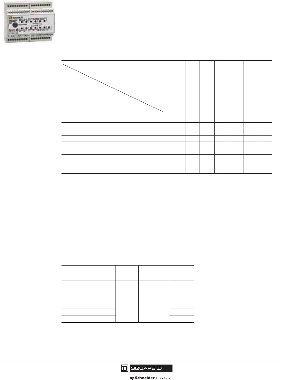
PowerPact™ M-, P- and R-Frame, and Compact™ NS630b–NS3200 Circuit Breakers
Section 8—Accessories
79
10/2012
© 2001–2012 Schneider Electric
All Rights Reserved
™
Restraint Interface Module (RIM)
The restraint interface module (RIM) is used to allow zone-selective interlocking communications
between circuit breakers with old Micrologic™, Merlin Gerin™, or Federal Pioneer™ trip units and GC
series ground-fault relays. For 120 Vac/24 Vdc systems, use catalog number S48890. For 240 Vac/24
Vdc systems, use catalog number S48895.
Downstream circuit breakers with Micrologic 2.0A, 5.0A, 5.0P, 5.0H, 6.0A, 6.0P, and 6.0H trip units can
restrain up to fifteen upstream circuit breakers with Micrologic 5.0A, 5.0P, 5.0H, 6.0A, 6.0P, and 6.0H
trip units without requiring a restraint interface module. If the number of upstream circuit breakers
exceeds fifteen, then a RIM is required.
External Power Supply Module
When used with the Micrologic™ A, P, and H trip units, a power supply module makes it possible to:
•Display currents less than 20% of sensor (In).
•Maintain display of tripping causes after opening of the circuit breaker.
•Store the value of the interrupted current (P and H trip units only).
•The modules are not UL Listed.
External Battery Backup Module
The external battery backup module (Catalog No. 685831) provides up to twelve hours of backup
power for the power supply module.
06133
Table 79: RIM Requirements1
1R= RIM is required.
Number denotes maximum number of upstream circuit breakers that can be restrained without requiring a RIM.
Micrologic
trip unit2
Micrologic
Series B trip unit
Square D
GC-100 relay
Square D
GC-200 relay
Merlin Gerin
STR58 trip units
Federal Pioneer
USRC and USRCM trip units
Micrologic Trip Unit2
2Includes 2.0A (as a downstream trip unit only), 5.0A, 5.0P, 5.0P, 5.0H, 6.0A, 6.0P, and 6.0H trip units.
15 R R 15 15 R
Square D Micrologic Series B Trip Units R 26 R R R 15
Square D GC-100 Relay RR7 RRR
Square D GC-200 Relay 15 R R 15 15 R
Merlin Gerin STR58 Trip Units 15 R R 15 15 R
Merlin Gerin STR53 Trip Units 15 R R 15 15 R
Federal Pioneer USRC and USRCM Trip Units R 15 R R R 15
Square D Add-on Ground Fault Module for Equipment Protection R 5 R R R R
Table 80: External Power Supply Module
Power Supply Input
(+10%, -15%)
Output
Voltage
Output
Power Cat. No.
24–30 Vdc Input
24 Vdc 5 VA/5 W
(Ripple < 5%)
685823
48/60 Vdc Input 685824
125 Vdc Input 685825
110–130 Vac Input 685826
200–240 Vac Input 685827
380–415 Vac Input 685829
Upstream Device
(Receives input from RIM)
Downstream Device
(Sends output to RIM)
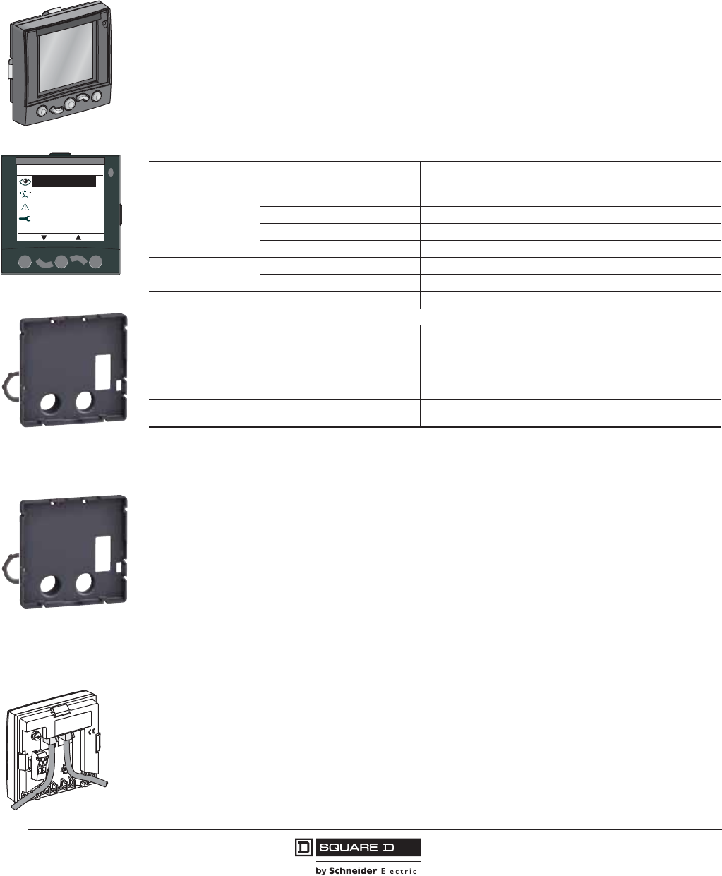
© 2001–2012 Schneider Electric
All Rights Reserved
PowerPact™ M-, P- and R-Frame, and Compact™ NS630b–NS3200 Circuit Breakers
Section 8—Accessories
80
10/2012
™
Display Options
Front Display Module Functions (FDM121)
(Micrologic A / P / H Trip Units Only)
The front display module (FDM121) can be integrated in the PowerPact P- and R-frame circuit breaker
system. It uses the sensors and processing capacity of the Micrologic trip unit to display
measurements, demand, power quality and maximum/minimum values along with alarms, histories,
and maintenance indicators.
It is easy to use and requires no special software or settings and is immediately operational when
connected to the PowerPact P- and R-frame circuit breakers by a simple cable.
The FDM121 is a large display, but requires very little depth. The anti-glare graphic display screen is
backlit for easy reading even under poor ambient lighting and at sharp angles.
Mounting
The FDM121 is easily installed in equipment.
•Standard door cut-out 3.62 x 3.62 in. (92 x 92 mm).
•Attached using clips.
To avoid a cut-out in the door, an accessory is available for surface mounting by drilling only two
0.87 in. (22 mm) diameter holes.
The FDM121 degree of protection is NEMA12 / IP54 in front. NEMA12 / IP54 is maintained after
mounting by using the supplied gasket during installation.
Electrical Connection
The FDM121 is equipped with:
•a 24 Vdc terminal block:
— plug-in type with 2 wire inputs per point for easy daisy-chaining
— power supply range of 24 V -20% (19.2 V) to 24 V +10% (26.4 V)
•two RJ45 jacks.
When the second connector is not used, it must be fitted with a line terminator TRV00880.
06114205
Main menu
Metering
Alarms
Quick view
ESC OK
Services
06114215
FDM121 Display
Surface Mount Accessory
Table 81: Characteristics
Screen
Size 96 x 96 x 30 mm
Installation Requires 10 mm behind the door (or 20 mm when the 24 Vdc power
supply connector is used).
Backlighting White
Viewing Angle Vertical ±60°, horizontal ±30°
Resolution High: excellent reading of graphic symbols.
Alarm LED Flashing orange Alarm pick-up
Steady orange after operator reset Alarm condition persists.
Operating temperature 14°F to 131°F (-10 °C to +55 °C).
Certifications UL, CSA, CE
24 Vdc power supply Tolerances 24 V -20% +10%
(19.2 V to 26.4 V)
When the FDM121 is connected to the communication network, the
24 Vdc is supplied by the communication network wiring.
Power Requirements 40 mA, 24 Vdc
Mounting Standard door cut-out 92 x 92 mm.
Attached using clips.
To avoid a cut-out in the door, a surface-mount accessory is
available for surface mounting by drilling two 22 mm diameter holes.
Degree of protection NEMA12 / IP54 in front. NEMA12 / IP54 is maintained after mounting by using the supplied
gasket during installation.
06114215
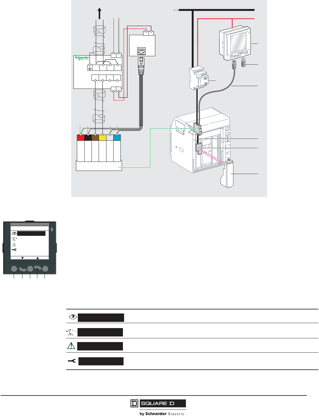
PowerPact™ M-, P- and R-Frame, and Compact™ NS630b–NS3200 Circuit Breakers
Section 8—Accessories
81
10/2012
© 2001–2012 Schneider Electric
All Rights Reserved
™
Navigation
Five buttons are used for intuitive and fast navigation.
The “Context” button may be used to select the type of display (digital [text], bargraph, analog).
The user can select the display language (Chinese, English, French, German, Italian, Portuguese,
Spanish, etc.) Other languages can be downloaded.
Screens
Main menu
When powered up, the FDM121 screen automatically displays the ON/OFF status of the device.
When not in use, the screen is not backlit. Backlighting can be activated by pressing one of the
buttons. It goes off after 3 minutes.
Figure 6: Communication Components and FDM121 Connections
DB128049
ModbusModbus
24 V DC24 V DC
8
3
7
6
5
1
4
2
FDM121
version > V2.0.2
E1 E2 E3 E4 E5 E6
customer terminal block
CCM
+-
B’ / Rx+D1
A’ / Rx-D0
B / Tx+D1
A / Tx-D0
0 V
24 V
+ -
ABA’B’
red black etihweulb
+-
Circuit
breaker
Network
ABA’B’
1 Modbus network
2 CCM (chassis module)
3 Breaker ULP cord
4 "Device" communication module (BCM ULP)
5 Prefabricated wiring
6 Micrologic trip unit
7 FDM121 display
8 Line terminator
Main menu
Metering
Alarms
Quick view
ESC OK
Services
06114141
ABCDE
Provides access to five screens that display a summary of essential operating information (I, U, f,
P, E, THD, circuit breaker On / Off).
Used to display the measurement data (I, U-V, f, P, Q, S, E, THD, PF) with the corresponding
min/max values.
Displays active alarms and the alarm history
Provides access to the operation counters, energy and maximum reset function, maintenance
indicators, identification of modules connected to the internal bus and FDM121 internal settings
(language, contrast, etc.)
Quick view
Metering
Alarms
Services
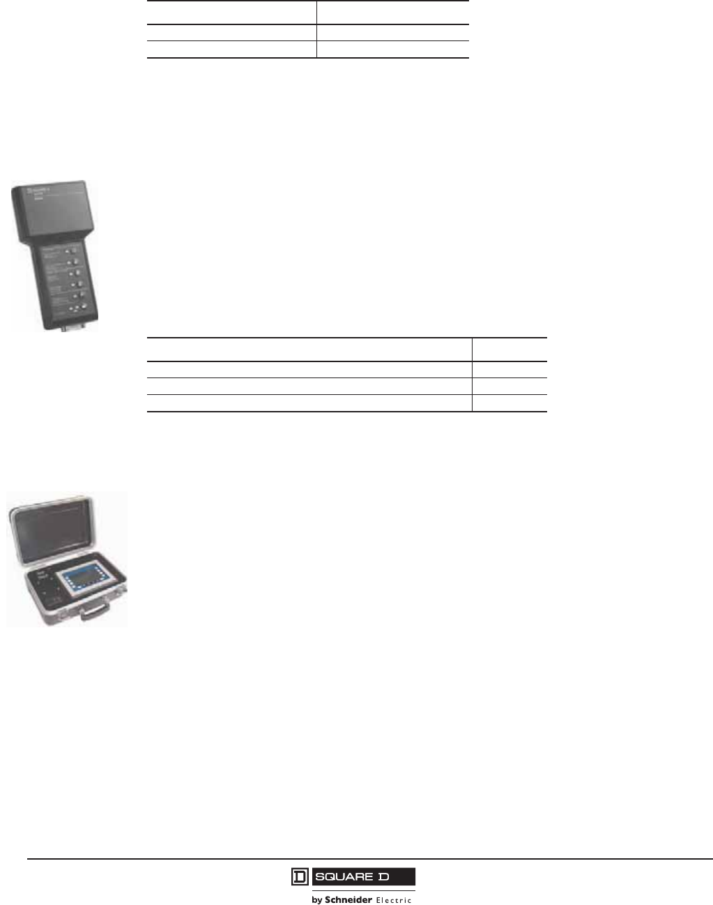
© 2001–2012 Schneider Electric
All Rights Reserved
PowerPact™ M-, P- and R-Frame, and Compact™ NS630b–NS3200 Circuit Breakers
Section 8—Accessories
82
10/2012
™
Catalog Numbers
Test Equipment
Hand-Held Test Kit
The hand held test kit may be used to:
•Verify trip unit operation, the mechanical operation of the circuit breaker, and the electrical
continuity of the connection between the tripping coil and the trip unit.
•Supply control power to the trip unit for settings via the keypad when the circuit breaker is open
(Micrologic P and H trip units).
•Inhibit thermal imaging for primary injection test (for Micrologic types A, P or H).
•Inhibit ground fault for primary injection test (for Micrologic types A, P or H).
•Self-restrain Zone-Selective Interlocking (ZSI) (for Micrologic types A, P or H).
Full-Function Test Kit
The full-function test kit consists of a signal-injection box which can be used alone or with a supporting
personal computer (PC). The optional test kit software is compatible with Windows® 95, 98 and
Windows NT® operating systems.
The test kit without a supporting PC may be used to check:
•The mechanical operation of the circuit breaker
•The electrical continuity of the connection between the tripping coil and the trip unit
•Trip unit operation — for example:
— Display of settings
— Operating tests on the electronic component
— Automatic and manual tests on protection functions (trip curve verification)
— Tests on the Zone-Selective Interlocking (ZSI) function
— Inhibition of the ground-fault protection for equipment
— Inhibition of the thermal imaging
•Save test data into test kit
The test kit with a supporting PC may be used to:
•Print test data
•Compare the real tripping curve with the curves available on the PC
Table 82: Front Display Module Catalog Numbers
Description Catalog No.
FDM121 STRV00121
FDM121 Mounting Accessory TRV00128
06133786
Table 83: Hand-held Test Kit Catalog Numbers
Device Cat. No.
Hand-held Test Kit S33594
Seven-pin Test Cable (for Connection Between Test Kit and Trip Unit)1
1Included in the test kit. Kit for replacement only.
S48907
Two-pin Test Cable (for Connection Between Test Kit and Trip Unit) S48908
06133851
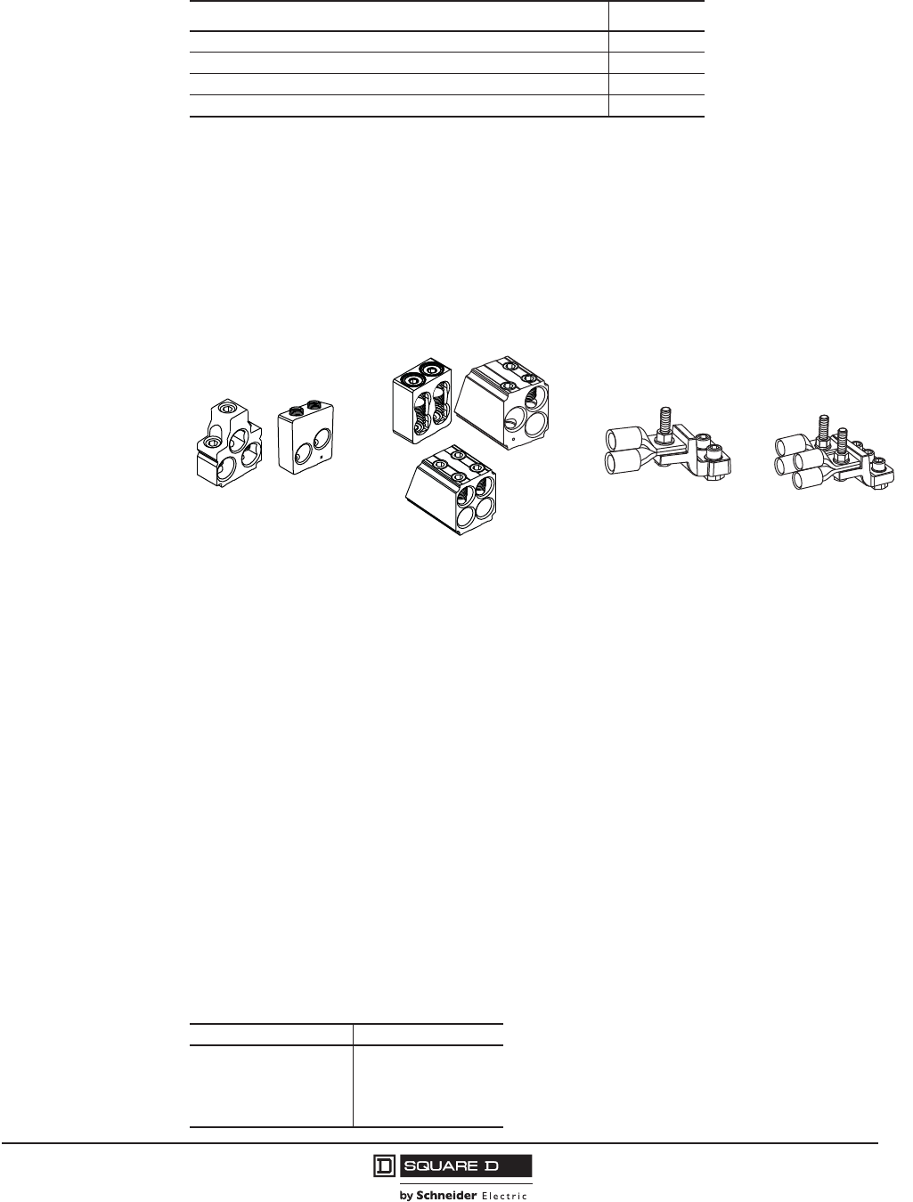
PowerPact™ M-, P- and R-Frame, and Compact™ NS630b–NS3200 Circuit Breakers
Section 8—Accessories
83
10/2012
© 2001–2012 Schneider Electric
All Rights Reserved
™
Circuit Breaker Terminations
Mechanical, Compression, and Distribution Lugs
The M-frame, P-frame and NS630b–NS1250 circuit breakers have mechanical lugs standard on both ends
of the unit-mounted circuit breakers. The M-frame and P-frame I-Line™ circuit breakers have mechanical
lugs standard on the O/OFF end only. These lugs are suitable for use with copper or aluminum wire. Rear
connectors, compression lugs and distribution lugs are available for special applications.
P-frame and NS630b–NS1600 circuit breakers are also available in drawout construction. See
Section 8 for drawout cradle details.
The R-frame and NS1600b–NS3200 circuit breakers have terminal pads only (no lugs) for bus
connections on both ends. Terminal pads are required for the use of lugs on R-frame circuit breakers,
lugs are not available for NS1600b–NS3200 circuit breakers. See the section on R-frame and
NS1600b–NS3200 circuit breakers for information on terminal pad requirements. R-frame I-Line circuit
breakers have mechanical lugs standard on the O/OFF end only (AL1200R53K).
Copper mechanical lugs are available for use with copper wire only. These lugs can be factory
installed by adding an LC suffix to the circuit breaker catalog number for standard copper lugs and LD
suffix for high-amp copper lugs (M-frame, P-frame and NS630b–NS1250 d800 A circuit breakers
only). See the Digest or product selector or contact the field office for more information.
I-Line™ Jaw Configurations
Standard 3P I-Line circuit breakers are supplied with an ABC phase jaw connection. In applications
where the jaw configuration must be reversed, specify a CBA jaw configuration by adding the digit 6 to
the phasing position of the circuit breaker catalog number.
I-Line 2P circuit breakers are available in AC or CA phasing. Add the digit of the desired phasing to the
phasing position of the circuit breaker catalog number.
Table 84: Full-Function Test Kit Catalog Numbers
Device Cat. No.
Full-function Test Kit S33595
Seven-pin Test Cable (for Connection Between Test Kit and Trip Unit)1
1Included in the test kit. Kit for replacement only.
S48907
230 Vac Filtered Power Cord1S48856
120 Vac Filtered Power Cord1S48855
Table 85: I-Line Phase Options
Phase Option Number Phase Connections
1
2
3
4
5
6
AB
AC
BA
BC
CA
CB
06123371
M-Frame Mechanical Lugs
P-Frame Mechanical Lugs
M-Frame
Compression Lug
R-Frame
Compression Lug
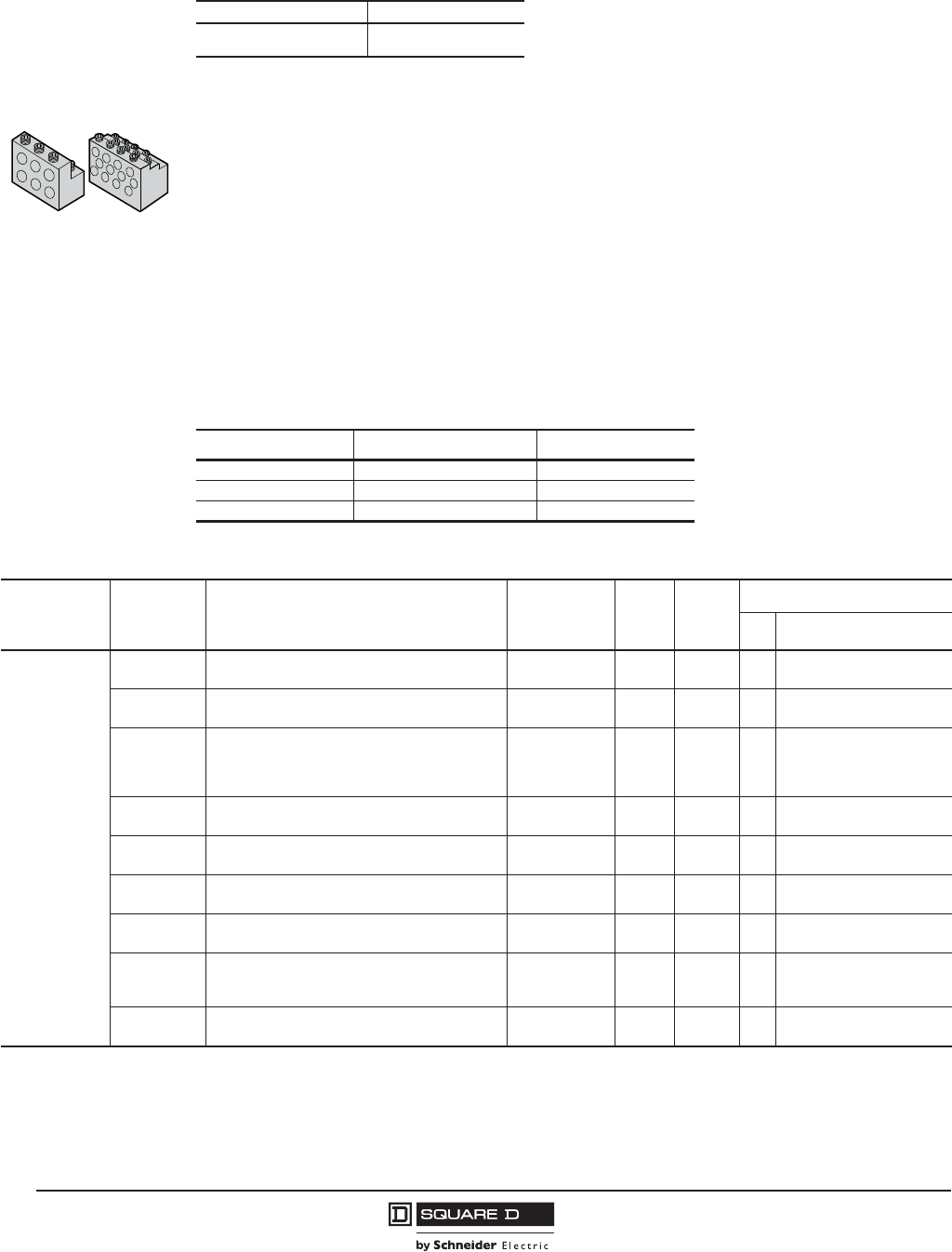
© 2001–2012 Schneider Electric
All Rights Reserved
PowerPact™ M-, P- and R-Frame, and Compact™ NS630b–NS3200 Circuit Breakers
Section 8—Accessories
84
10/2012
™
Power Distribution Connectors
Power distribution connectors (PDCs) are available for M-frame, P-frame and NS630b–NS1250 unit-
mount circuit breakers as field-installable kits. They can be used for multiple load wire connections on
one circuit breaker. Each is UL Listed for copper wire only. Power distribution connectors are for use
on the O/OFF end of the circuit breaker only, and the O/OFF end must be connected to the load. PDCs
are for use in UL508 applications only.
Control Wire Terminations
Mechanical lug kits are available with provisions for control wire terminations. The control wire is
crimped to a standard ring-type wire crimp terminal (not included) and secured to the lug using the #6-
32 screw included in the kit. These lugs are UL and CSA Recognized as a circuit breaker component.
These lugs are available factory installed or as field-installable kits. For factory-installed control wire
terminations, add the suffix from the table below in the lug option field of the catalog number.
Standard
6
ABC
CBA
Table 85: I-Line Phase Options
Phase Option Number Phase Connections
06123372
PDC6P20 PDC12P4
Table 86: Control Wire Termination
Termination Code Control Wire Location Control Wire Suffix
L Both ends LW
M ON end only LU
P OFF end only LV
Table 87: Lug Kits
Lug Type Catalog
Number Used On Circuit
Breaker Type
Lugs
Per
Kit1
Max.
Amp.
Rating
Conductors/Lug
No. Range
Aluminum
Mechanical Lug2
AL800M23K M-Frame, P-Frame d800 A,
NS630b–NS800
Unit-Mount,
I-Line 3, 4 800 3 3/0 AWG–500 kcmil
(95–250 mm2)
AL800P6K M-Frame, P-Frame d800 A3,
NS630b–NS800
Unit-Mount,
I-Line 3, 4 800 2 3/0 AWG–600 kcmil
(95–300 mm2)
AL800P7K M-Frame, P-Frame d800 A3,
NS630b–NS800
Unit-Mount,
I-Line 3770 2
3/0 AWG–750 kcmil
(95–400 mm2);
Compact AL 750 kcmil
(400 mm2) only
AL1200P24K M-Frame, P-Frame > 800 A, optional for d800 A,
NS630b–NS1200
Unit-mount,
I-Line 112004
3/0 AWG–500 kcmil
(95–250 mm2)
AL1200P25K P-Frame > 800 A, optional for d800 A,
NS630b–NS1200 Unit-Mount 3, 4 1200 4 3/0 AWG–500 kcmil
(95–250 mm2)
AL1200R53K R-Frame,
NS1600b–NS3200 I-Line 1 1200 4 3/0 AWG–600 kcmil
(95–300 mm2)
AL1200P6KU P-Frame > 800 A, optional for d 800 A,
NS630b–NS1200 Unit-Mount 3 1200 3 350-600 kcmil
(185-300 mm2)
AL1200P7KU P-Frame d 800 A3,
NS630b–NS800 Unit-Mount 3 1155 3
3/0 AWG–750 kcmil
(95–400 mm2);
Compact AL 750 kcmil only
AL2500RK R-Frame,
NS1600b–NS3200 Unit-Mount 2 2500 1 1/0 AWG–750 kcmil
(50–400 mm2)
Continued on next page

PowerPact™ M-, P- and R-Frame, and Compact™ NS630b–NS3200 Circuit Breakers
Section 8—Accessories
85
10/2012
© 2001–2012 Schneider Electric
All Rights Reserved
™
Copper
Mechanical Lugs
CU800M23K M-Frame, P-Frame d800 A,
NS630b–NS800
Unit-Mount,
I-Line 3, 4 800 3 3/0 AWG–500 kcmil
(95–250 mm2)
CU1200P24K M-Frame, P-Frame > 800 A, optional for d800 A,
NS630b–NS1200
Unit-Mount,
I-Line 1 1200 4 3/0 AWG–500 kcmil
(95–250 mm2)
CU1200P25K P-Frame > 800 A, optional for d800 A,
NS630b–NS1200 Unit-Mount 3, 4 800 4 3/0 AWG–500 kcmil
(95–250 mm2)
CU1200R53K R-Frame,
NS1600b–NS3200 I-Line 1 1200 4 3/0 AWG–600 kcmil
(95–300 mm2)
CU250P1K M-Frame, P-Frame d800 A,
NS630b–NS800 PJ 3 150 A 1 1–1/0 AWG
(50 mm2)
Aluminum
Compression
Lugs
YA250P3 M-Frame, P-Frame,
NS630b–NS1200
Unit-Mount,
I-Line 1 250 1 2/0 AWG–300 kcmil
(70–150 mm2)
YA400P3 M-Frame, P-Frame,
NS630b–NS1200
Unit-Mount,
I-Line 2 400 1 2/0 AWG–300 kcmil
(70–150 mm2)
YA1200R3 R-Frame,
NS1600b–NS3200 I-Line 4 1200 1 2/0 AWG–300 kcmil
(70–150 mm2)
YA300P5 M-Frame, P-Frame,
NS630b–NS1200
Unit-Mount,
I-Line 1 300 1 4/0 AWG–500 kcmil
(95–240 mm2)
YA600P5 M-Frame, P-Frame,
NS630b–NS1200
Unit-Mount,
I-Line 2 600 1 4/0 AWG–500 kcmil
(95–240 mm2)
YA1200R5 R-Frame,
NS1600b–NS3200 I-Line 4 1200 1 4/0 AWG–500 kcmil
(95–240 mm2)
YA400P7 M-Frame, P-Frame,
NS630b–NS1200
Unit-Mount,
I-Line 1 400 1 500–750 kcmil
(240–400 mm2)
YA800P7 M-Frame, P-Frame,
NS630b–NS1200
Unit-Mount,
I-Line 2 800 1 500–750 kcmil
(240–400 mm2)
YA1200R7 R-Frame,
NS1600b–NS3200 I-Line 4 1200 1 500–750 kcmil
(240–400 mm2)
YA2500R7 R-Frame,
NS1600b–NS3200 Unit-Mount 2 2500 1 500–750 kcmil
(240–400 mm2)
Copper
Compression
Lugs
CYA400P5 M-Frame, P-Frame,
NS630b–NS1200
Unit-Mount,
I-Line 1 400 1 4/0 AWG–500 kcmil
(95–240 mm2)
CYA600P5 M-Frame, P-Frame,
NS630b–NS1200
Unit-Mount,
I-Line 2 600 1 4/0 AWG–500 kcmil
(95–240 mm2)
CYA1200R5 R-Frame,
NS1600b–NS3200 I-Line 4 1200 1 4/0 AWG–500 kcmil
(95–240 mm2)
CYA800R7 M-Frame, P-Frame,
NS630b–NS1200 I-Line 2 800 1 500–750 kcmil
(240–400 mm2)
CYA1200R7 R-Frame,
NS1600b–NS3200 I-Line 4 1200 1 500–750 kcmil
(240–400 mm2)
Power
Distribution
Connectors
(Copper Only)
PDC12P4 M-Frame, P-Frame,
NS630b–NS1200
Unit-Mount,
I-Line 3 400 12 10–4 AWG
(6–25 mm2)
PDC12P44 M-Frame, P-Frame,
NS630b–NS1200
Unit-Mount,
I-Line 4 400 12 10–4 AWG
(6–25 mm2)
PDC6P20 M-Frame, P-Frame,
NS630b–NS1200
Unit-Mount,
I-Line 3 600 6 12–2/0 AWG
(25–70 mm2)
PDC6P204 M-Frame, P-Frame,
NS630b–NS1200
Unit-Mount,
I-Line 4 600 6 12–2/0 AWG
(25–70 mm2)
1For 4P circuit breakers, add “4” to kit catalog number (AL800M23K4 instead of AL800M23K).
2For version with tapped hole for control wire add a T before the K to the kit catalog number (AL800M23TK instead of AL800M23K).
3Does not fit onto I/ON end of unit-mount P-frame circuit breakers.
Table 87: Lug Kits (continued)
Lug Type Catalog
Number Used On Circuit
Breaker Type
Lugs
Per
Kit1
Max.
Amp.
Rating
Conductors/Lug
No. Range
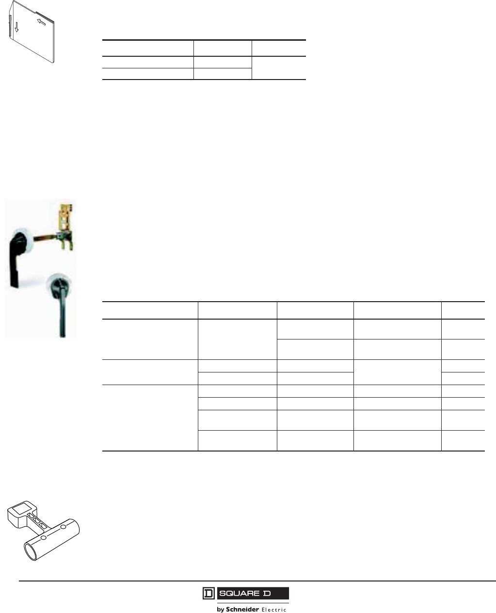
© 2001–2012 Schneider Electric
All Rights Reserved
PowerPact™ M-, P- and R-Frame, and Compact™ NS630b–NS3200 Circuit Breakers
Section 8—Accessories
86
10/2012
™
External Accessories
Phase Barriers
Phase barriers are available for M-frame, P-frame and NS630b–NS1600 unit-mount circuit breakers
with bus connections or with lugs d800 A. Phase barriers are also available for R-frame and
NS1600b–NS3200 unit-mount circuit breakers.
Electric Joint Compound
I-Line circuit breakers, I-Line busway plug-on units and I-Line panelboards and switchboards are
supplied with factory-applied joint compound on the plug-on connectors. The compound is especially
formulated for I-Line connections and contributes to the overall performance of the connection.
If the joint compound is removed, it must be reapplied. A two-ounce container of the compound
(Cat. No. PJC7201) is available.
Door-Mounted Operating Mechanisms
Door-mounted operating mechanisms are available for M- and P-frame circuit breakers. The Type L
door-mounted variable-depth operating mechanism feature heavy-duty, all-metal constructions. They
can be padlocked in the OFF position when the enclosure door is open. Handle assemblies can be
locked OFF with up to three padlocks, which also locks the door closed. Complete kits include a
handle assembly, operating mechanism, and shaft assembly, and are rated for NEMA Type 1, 3R and
12 enclosures. A door drilling template is supplied for ease of installation.
Handle Extension
Handle extensions are available for M- and P-frame circuit breakers. Order catalog number 33195.
06132160
Table 88: Phase Barriers
Used With Cat. No. Qty Per Kit
M-Frame and P-Frame S33646 3
R-Frame S33998
Operating
Mechanism
Handle
Assembly
Table 89: Door-Mounted Operating Mechanisms
Description Description Handle Assembly1
1Painted handles are painted flat black, with the base ring silver.
Shaft Mounting Depth Cat. No.
Circuit Breaker Mechanism Type L
Painted, 8 inch 7.2–11.625 in.
(182–295 mm) LW1
Painted, 8 inch 7.2–22.25 in.
(182–565 mm) LW4
Handle Assembly2
2Due to gasketing, NEMA 3 and 4 handle assemblies are NOT trip indicating.
Type 3, 4 Painted, 8 inch 7.2–11.625 in.
(182–295 mm)
LHP48
Type 3, 4, 4X Chrome Plated, 8 inch LCP48
Replacement Parts
Handle Assembly Painted, 8 inch — LHP8
Operating Mechanism — — LW7
Standard Shaft — 7.2–11.625 in.
(182–295 mm) LS8
Long Shaft — 7.2–22.25 in.
(182–565 mm) LS10
06123378
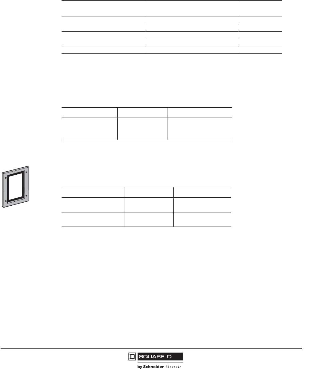
PowerPact™ M-, P- and R-Frame, and Compact™ NS630b–NS3200 Circuit Breakers
Section 8—Accessories
87
10/2012
© 2001–2012 Schneider Electric
All Rights Reserved
™
Rotary Operating Handles
P-frame and NS630b–NS1600 circuit breakers are available with standard black directly-mounted
(IP-40) or door-mounted / telescopic door-mounted (IP-55) rotary handles. The rotary handles are
factory-installed and available with two early-break or two early-make contacts.
Replacement Handles
Replacement handle assemblies are available for R-frame and NS1600b–NS3200 circuit breakers.
Replacement toggle handle extensions, including an optional longer handle extension, are available
for M-frame, P-frame, and NS630b–NS1600 circuit breakers.
Door Escutcheons
Accessory cover door escutcheons are available for all M-frame, P-frame, R-frame and NS630b–
NS3200 circuit breakers. Toggle door escutcheons are also available for fixed-mounted, P-frame,
manually-operated circuit breakers.
Locking Accessories
Field-installable handle padlock attachments are available for manually-operated circuit breakers. These
attachments will accommodate three padlocks with a shackle diameter of 3/16–5/16 in. (5–8 mm) and will
lock the circuit breaker in the O/OFF position only.
A handle padlock attachment is also available for locking manually-operated circuit breakers in either
the I/ON or O/OFF position. This attachment will accommodate three padlocks with a shackle diameter
of 3/16–5/16 in. (5–8 mm) and is available as factory or field installation.
Kirk® or Schneider Electric™ interlock brackets are also available for locking circuit breakers in the
O/OFF position only. Not available for drawout P-frame or NS630b–NS1600.
Circuit breakers with rotary handles come standard with provision for padlocking the handle in the O/OFF
position only. Key locks are also available for locking the circuit breaker in the I/ON or O/OFF positions.
Table 90: Rotary Operated Handles
Device Switches Factory-Installed
Cat. No. Suffix
Direct Mounted, Standard Black Handle —RD10
Two Early-Break and Two Early-Make Switches RD16
Door Mounted, Standard Black Handle —RE10
Two Early-Break and Two Early-Make Switches RE16
Rotary Handle Replacement Kit — S33875
Table 91: Replacement Handles for M-, P-, and R-Frame Circuit Breakers
Description Frame Field-Installed Cat. No.
Standard R-Frame S33997
Standard Short M-, P-Frame S46998
Long M-, P-Frame S46996
06133165
Table 92: Door Escutcheons for M-, P-, and R-Frame Circuit Breakers
Description Frame Field-Installed Cat. No.
Accessory Cover M-, P-Frame S33718
R-Frame S33929
Toggle Handle M-, P-Frame S33717
Drawout P-Frame S33857
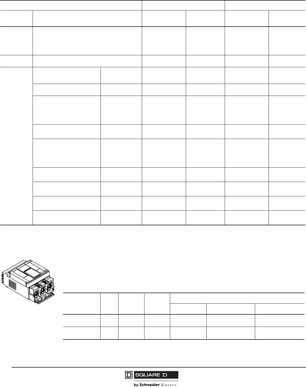
© 2001–2012 Schneider Electric
All Rights Reserved
PowerPact™ M-, P- and R-Frame, and Compact™ NS630b–NS3200 Circuit Breakers
Section 8—Accessories
88
10/2012
™
A keylock or padlock provision for padlocking the circuit breaker in the O/OFF position is optional on
electrically-operated P-frame and NS-630b–NS1600 circuit breakers.
Sub-Feed Lugs
Sub-feed lug kits are UL Listed for use on Listed equipment. They have plug-on jaw construction and
plug on to the I-Line™ bus stack in the same manner as branch circuit breakers. Lugs on these
devices accommodate the same wire sizes as the equivalent ampere rated circuit breakers.
Table 93: Locks and Interlocking
M- and P-Frame R-Frame
Device Description Factory-Installed
Cat. No. Suffix
Field-Installed
Cat. No.
Factory-Installed
Cat. No. Suffix
Field-Installed
Cat. No.
Handle
Padlocking
Device
Removable (Lock Off or On) — — — —
Removable (Lock Off Only) — S44936 —S33996
Fixed (Lock Off or On) YP S32631 YP S32631
Fixed (Lock Off Only) YQ MPRPAF YQ MPRPAF
Interlocking
(Not UL listed) Mechanical for Circuit Breakers with Rotary Handles — S338901——
Key Locking
Provision Only, Vertical Mount,
1 key interlock including padlock
provision, open position only
Kirk® or
Schneider Electric™ JE1—— —
Provision Only, Vertical Mount, 1 or
2 Locks
Kirk or
Schneider Electric JA — — —
Provision Only, Horizontal Mount
1 Lock, M- and P-Frame
1 or 2 Locks, R-Frame
Kirk JK — JK —
Schneider Electric JR — JR —
Ronis JB — JB —
Profalux JD — JD —
Provision and 1 Lock, Vertical
Mount
Kirk JG — — —
Schneider Electric JH — — —
Provision and 1 Lock, Horizontal
Mount
Kirk JL — JL —
Schneider Electric JS — JS —
Ronis JC — JC —
Profalux JF — JF —
Provision and 2 Locks Keyed Alike,
Vertical Mount
Kirk JN — — —
Schneider Electric JV — — —
Provision and 2 Locks Keyed Alike,
Horizontal Mount
Kirk — — JN —
Schneider Electric — — JV —
Provision and 2 Locks Keyed
Differently, Vertical Mount
Kirk JP — — —
Schneider Electric JW — — —
Provision and 2 Locks Keyed
Differently, Horizontal Mount
Kirk — — JP —
Schneider Electric — — JW —
1Not available on M-frame circuit breakers.
Table 94: I-Line Sub-Feed Lug Kit Terminations
Plug-On Lug
Kit Cat. No. Poles Mounting
Height
Ampere
Rating
Lug
Catalog No. Wire Size Conductors Per Lug
S33931 3 9 in. 1200 A AL1200P24K 3/0 AWG–500 kcmil
(95–240 mm2)4
S33930 3 15 in. 1200 A AL1200R53K 3/0 AWG–600 kcmil
(95–300 mm2)4
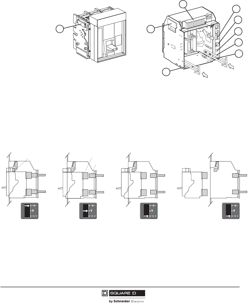
PowerPact™ M-, P- and R-Frame, and Compact™ NS630b–NS3200 Circuit Breakers
Section 9—P-Frame Cradles and Cradle Accessories
89
10/2012
© 2001–2012 Schneider Electric
All Rights Reserved
™
Section 9—P-Frame Cradles and Cradle Accessories
Circuit Breaker and Cradle Design
Drawout Mechanism
The drawout assembly mechanism allows the circuit breaker to be racked in four positions (connected,
test, disconnected, or withdrawn), as shown in the figure below.
06123146
A—Terminal Cover
B—Lifting Tabs
C—Extension Rail Handle
D—Padlock Provision
E—Position Indicator
F—Crank Insertion Opening
G—Stop Release Button
H—Crank Storage Space
B
Drawout Circuit Breaker
Cradle
B
A
C
H
G
F
E
D
NOTE: See page 19 for cradle catalog numbers.
06123073
06123074
06123075
06123076
06134683
06134685
06134686
06134686
Connected Position Test Position Disconnected Position Withdrawn Position
Secondary Contacts Clusters (UL)
Stabs
NOTE: For UL/CSA Listed devices, the clusters are mounted on the circuit breaker and the stabs are on the cradle.
For IEC devices, the clusters are mounted on the cradle and the stabs are mounted on the circuit breaker.
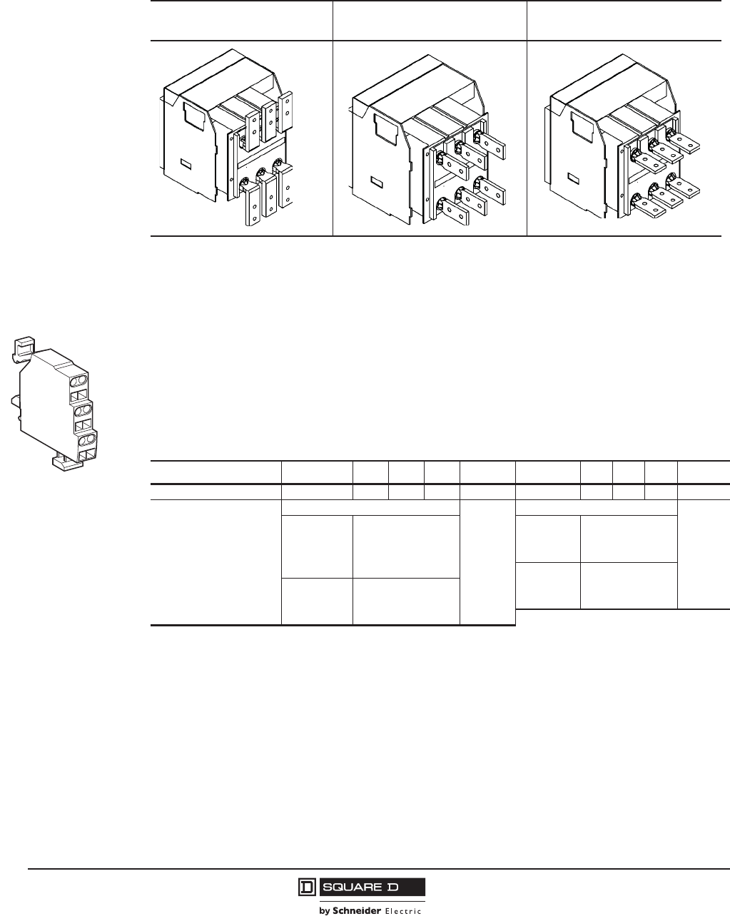
© 2001–2012 Schneider Electric
All Rights Reserved
PowerPact™ M-, P- and R-Frame, and Compact™ NS630b–NS3200 Circuit Breakers
Section 9—P-Frame Cradles and Cradle Accessories
90
10/2012
™
Connectors
Cradle Accessories
Cradle Position Switches
Three optional cradle position switches are available for the cradle:
•Cradle position switches (CE) to indicate the connected position.
•Cradle position switches (CD) to indicate the disconnected position. This position is indicated when
the required clearance for isolation of the power and auxiliary circuits is reached.
•Cradle position switches (CT) to indicate the test position. In this position, the power circuits are
disconnected and the auxiliary circuits are connected.
Table 95: Available Connectors
Front-Connected Flat (FCF) Rear-Connected “T” Vertical
(RCTV)
Rear-Connected “T” Horizontal
(RCTH)
06135261
06135263
06135265
06133180
Table 96: Cradle Position Switches
Switch Type CE CD CT Cat. No. CE CD CT Cat. No.
Maximum Push-In Switches 3 2 1 3 2 1
Breaking Capacity at a
Power Factor (pf) of 0.3
Standard: 10 mA/24 V Min. Load
S33170
Low-Level: 1 mA/4 V Min. Load1
1If the maximum voltage and current is exceeded, the low-level function of the switch will be lost but the switch will continue to
function as a standard switch with standard switch specifications.
S33171
240 Vac 8 A 24-48 Vac 5 A
380 Vac 8 A 240 Vac 5 A
480 Vac 8 A 380 Vac 5 A
600-690 Vac 6 A 24-48 Vdc 2.5 A
24-48 Vdc 2.5 A 125 Vdc 0.8 A
125 Vdc 0.8 A 250 Vdc 0.3 A
250 Vdc 0.3 A

PowerPact™ M-, P- and R-Frame, and Compact™ NS630b–NS3200 Circuit Breakers
Section 9—P-Frame Cradles and Cradle Accessories
91
10/2012
© 2001–2012 Schneider Electric
All Rights Reserved
™
Modbus® Cradle Communication Module (CCM)
The Cradle Communication Module (catalog number S33852) makes it possible to address the cradle
and to maintain the address when the circuit breaker or the BCM is replaced. Cradle position switches
connected to the module determine and communicate the position of the circuit breaker in the cradle.
Power requirements: 30 mA, 24 Vdc.
NOTE: The power supply for the circuit breaker communication module must be separate and isolated
from the power supply for the trip unit.
12345678
Address Sync.
Comm.
Fault
CCM Modbus
S48377
91011
12
In +
In -
Out +
Out -
In +
In -
Out +
Out -
Shield
06133866
Table 97: Cradle Communication Module Characteristics
Circuit Breaker
Identification
ID Code, Address
Size, Rating, Performance
Type of Trip Unit
Type of Long-Time Rating Plug
Status Indication
On/Off Indication
Connected/Disconnected/Test Position
Fault Trip
Controls
Opening/Closing
Trip Unit
Settings APH
Reading of Settings on Rotary Switches
Fine Settings in the Range Imposed by the Rotary Switches
Setting of Protection and Alarms
Customized Alarm Programming
XX
X
X
X
X
X
X
Operating and
Maintenance Aids
Reading of Protection and Alarms
Standard
Set
Customized
X
X
X
X
X
Reading of Measurements
Current
Voltages, frequency, power, etc.
Power quality: Fundamentals and harmonics
XX
X
X
X
X
Waveform Capture X
Histories History of trips and alarms1
Log of trips and alarms
1Up to ten trips and ten alarms.
XX
X
Indicators Contact wear, counters, etc.
Maintenance record
XX
X
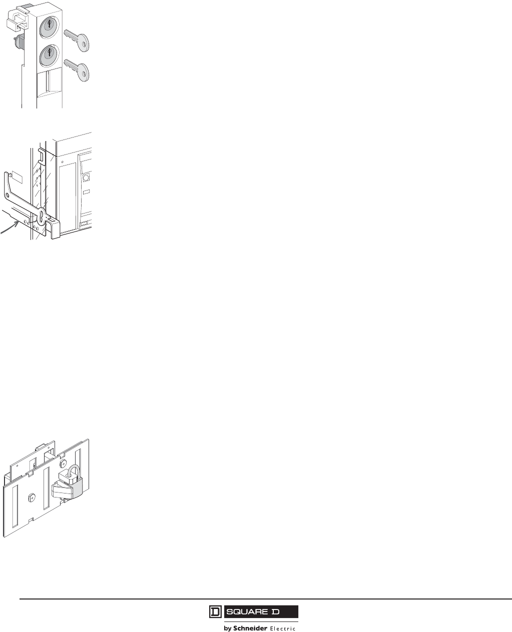
© 2001–2012 Schneider Electric
All Rights Reserved
PowerPact™ M-, P- and R-Frame, and Compact™ NS630b–NS3200 Circuit Breakers
Section 9—P-Frame Cradles and Cradle Accessories
92
10/2012
™
Cradle Locking and Interlocking
Disconnected Position Locking
The circuit breaker can be locked in the disconnected position by key interlock (optional, catalog
number ) or padlock (standard). The key interlock is on the cradle and accessible with the door
locked.
•Kirk® or Schneider Electric™ key interlocks are available for UL/CSA circuit breakers. Key is
captive when circuit breaker is closed.
•Locking in all positions (disconnected, test, and connected) is possible. Factory standard setting is
locking in disconnected position.
Door Interlock
The door interlock (catalog number S33786) prevents the compartment door from being opened when
the circuit breaker is in the connected or test position. If the circuit breaker is put into the connected
position with the door open, the door can be closed without disconnecting the circuit breaker. For
greater protection, this interlock can be used in conjunction with the open door racking interlock.
Open Door Racking Interlock
The racking interlock (catalog number ) prevents racking in the circuit breaker when the door is
open. (Insertion of the circuit breaker racking crank is not possible when the compartment door is
open.)
Cradle Rejection Kits
The cradle rejection feature (optional, catalog number ) ensures that only the properly
designated circuit breaker or switch is matched with the selected cradle assembly.
Miscellaneous Accessories
Shutter and Shutter Lock
The shutters automatically block access to the main disconnects when the circuit breaker is in the
disconnected, test, or fully withdrawn position. The shutter lock is used to prevent connection of the
circuit breaker or to lock the shutters in the closed position.
The optional shutter assembly (catalog number ) consists of shutter and padlock provision.
Door Escutcheon (CDP)
The door escutcheon (catalog number ) provides a frame and seal for the circuit breaker.
Transparent Cover for Door Escutcheon (CCP) (P-Frame Only)
The door escutcheon cover (catalog number ) is hinge-mounted and is designed to be installed
on the door escutcheon for the P-frame drawout circuit breaker.
RONIS RONIS
06134715
S33772
O
push OFF
O
OFF
06134711
S33788
S33767
06134870
S48933
S33857
S33859
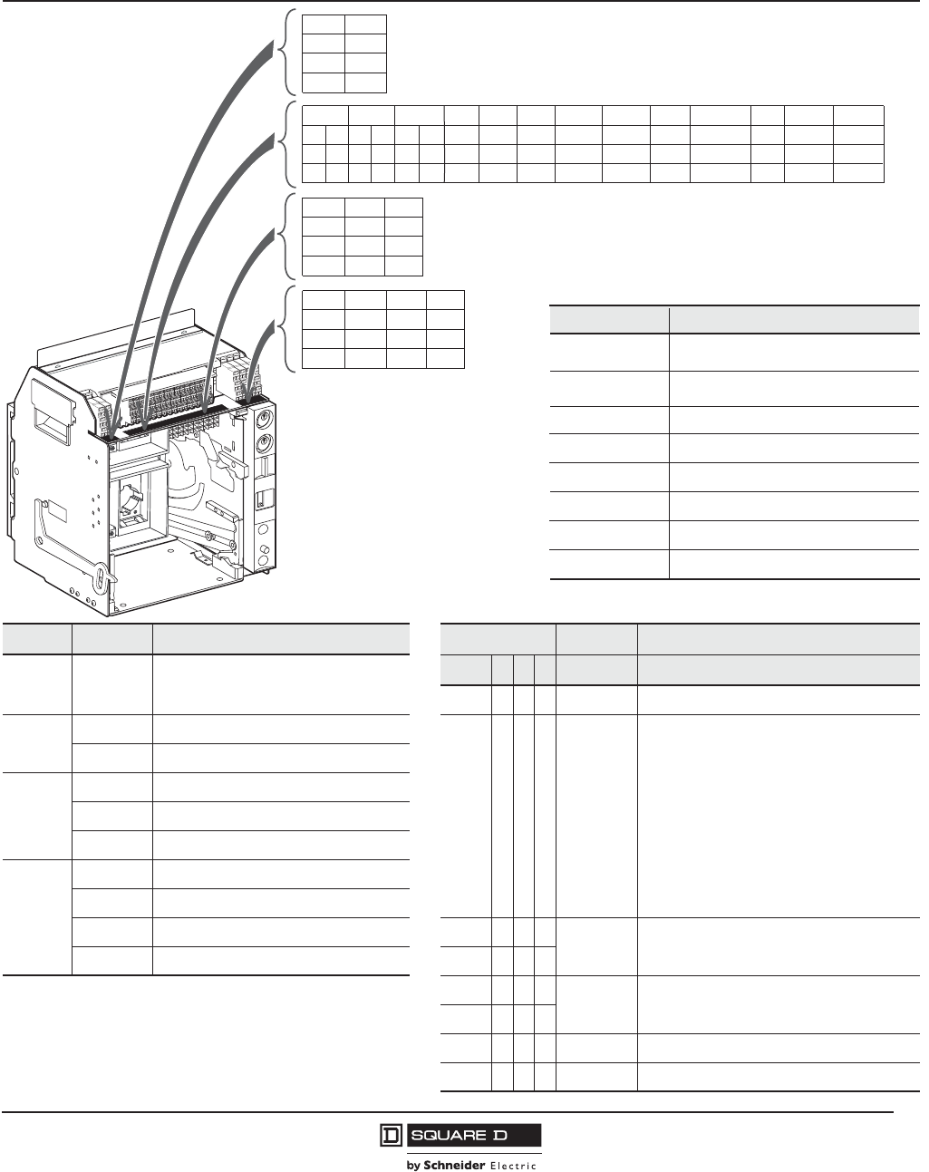
PowerPact™ M-, P- and R-Frame, and Compact™ NS630b–NS3200 Circuit Breakers
Section 9—P-Frame Cradles and Cradle Accessories
93
10/2012
© 2001–2012 Schneider Electric
All Rights Reserved
™
Wiring Diagrams
Figure 7: Terminal Layout for Push-In Connector Installation
Function Connector Description Trip Unit Type
Auxiliary
Contacts OF Open/Closed circuit breaker or switch
position contacts
Basic APHConnector Description
— X X X Com: E1-E6 Communication
Rotary
Handle
Contacts
CAO Early break contact — X X X UC1: Z Zone-selective Interlocking
CAF Early make contact Z1 = ZSI OUT signal
Cradle
Contacts
CD Disconnected position contacts Z2 = ZSI OUT
CE Connected position contacts Z3 = ZSI IN signal
CT Test position contacts Z4 = ZSI IN short time
Remote
Operation
SDE Electrical fault alarm contact Z5 = ZSI IN ground fault
SD Alarm contact — X X X UC1: M1 Modified differential ground fault (MDGF)
MN Undervoltage trip device — X X X UC2: T External neutral
MX1Shunt trip — X X X UC2: M Modified differential ground fault (MDGF)
1 When networked MXF coils are used, terminal C3 must be connected
to line even if the communication module is not installed. — X X X UC3: F 24 Vdc external power supply (F1 -, F2 +)
— — X X UC3: Vn External neutral plug
— — X X UC4 External phase voltage sensing
— — X X M6C Six programmable contacts
CD2
824
822
821
CD1
814
812
811
CE3
334
332
331
CE2
324
322
321
CE1 CT1
314 914
312 912
311 911
OF3
34
32
31
OF2 OF1
24 14
22 12
21 11
SD
94
92
91
CAO2
524
522
521
Com UC1 UC2 UC3 UC4 SDE
E5
E3
E1
E6
E4
E2
Z5
Z3
Z1
M1
Z4
Z2
M2
T3
T1
M3
T4
T2
F2+
VN
F1-
V3
V2
V1
544
542
541
84
82
81
MN/MX
D2/C12
C13
D1/C11
CAF2
06123198
534
532
531
CAF1 CAO1
514
512
511
M6C
Q3
Q2
Q1
Connector Recommended Wire Size
E1–E2 22 AWG (0.3 mm2) MIN shielded pair
cable or twisted pair copper wires
V1, V2, V3, Vn 22–16 AWG (0.3–1.5 mm2)
T22 AWG (0.3 mm2) stranded shielded cable
E3–E6, Q1, Q2, Q3 22 AWG (0.3 mm2) shielded twisted pairs
with drain (Belden 8723 or equal)3
OF, SD, SDE 18–16 AWG (0.8–1.5 mm2)
MN, MX 18–14 AWG (0.8–2.5 mm2)
FSize per aux 24 Vdc power supply
Z1–Z5 22 AWG (0.3 mm2)
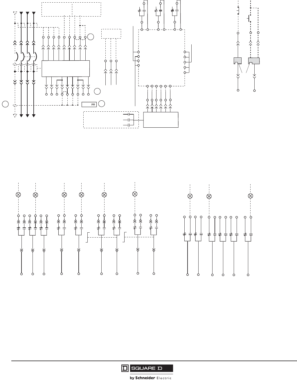
© 2001–2012 Schneider Electric
All Rights Reserved
PowerPact™ M-, P- and R-Frame, and Compact™ NS630b–NS3200 Circuit Breakers
Section 9—P-Frame Cradles and Cradle Accessories
94
10/2012
™
Figure 8: Wiring Diagrams for Auxiliary Connections
A–Do not remove factory-installed jumpers between Z3, Z4 and Z5 unless ZSI is connected.
B–Do not remove factory-installed jumper between T1 and T2 unless neutral CT is connected. Do not install jumper between T3 and T4.
C–For proper wiring of neutral CT, refer to Instruction Bulletin 48041-082-01 shipped with it.
D–24 Vdc power supply for trip unit must be separate and isolated from 24 Vdc power supply for communication modules.
E–For proper wiring of the FDM, refer to user guide 5100512864A-02.
T4
T3
T2
T1 Z3
Trip Unit
Z4
Z3
Z2
Z1 Z4 Z5
Z3
Z1
N CBA
Z5
VN
V1
V2
V3
M3
M2
M1
F2+
F1-
Upstream Downstream
Out +
24 Vdc
Common
Out -
Cradle
Communication
Module (CCM)
In +
In -
E6
E5
E4
E3
Circuit Breaker
Communications
Module (BCM)
E2
E1
+24 Vdc
+24 Vdc
Common
Common
In +
Out +
Shield
Out -
In -
MODBUS
-
Previous Circuit Breaker Next Circuit Breaker
T4
T3
T2
T1
24 V
OF
SDE
SD
Microswitches
connected to
BCM
06123199
811
CD1
812
311
CE1
314
CECDCT
911
CT1
914
Q1
Q2
Q3
M6C
**
*
or
D2
D1
MN MX
C12
C11
06123067
C13
Power Trip Unit Remote Operation
NOTE: All diagrams show circuit breaker in tripped position.
A
D
C
B
Auxiliary Contacts Cell Switches
822
824
821
812
814
811
Disconnected
CD2 CD1
331 332
334
CE3
Connected
321 322
324
CE2
311 312
314
CE1
914
912
911
CT1
Test
Position
06134281
12
14
11
22
24
32
34
31
21
OF3 OF2 OF1
Open
Closed
06123201
82
84
81
SDE
Fault
92
94
91
SD
Fault
542
544
541
CAF2
Closed
532
534
531
CAF1
522
524
521
CAO2
Open
512
514
511
CAO1
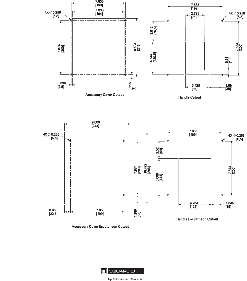
PowerPact™ M-, P- and R-Frame, and Compact™ NS630b–NS3200 Circuit Breakers
Section 10—Dimensional Drawings
95
10/2012
© 2001–2012 Schneider Electric
All Rights Reserved
™
Section 10—Dimensional Drawings
Dimensions for M-Frame Circuit Breakers
Figure 9: M-Frame Individually-Mounted Circuit Breaker Enclosure Mounting Holes and
Door Cutouts
48096-447-01
in.
[mm]
Dimensions:
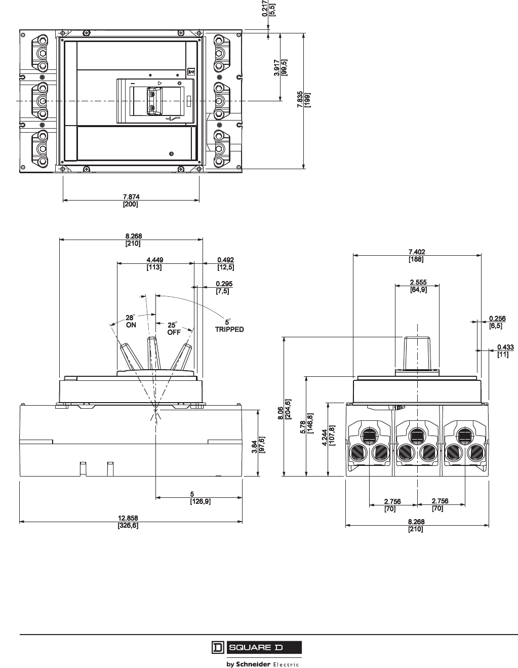
© 2001–2012 Schneider Electric
All Rights Reserved
PowerPact™ M-, P- and R-Frame, and Compact™ NS630b–NS3200 Circuit Breakers
Section 10—Dimensional Drawings
96
10/2012
™
Figure 10: M-Frame Individually-Mounted 3P 800 A Circuit Breaker with Lugs on Both Ends
48096-445-01
in.
[mm]
Dimensions:
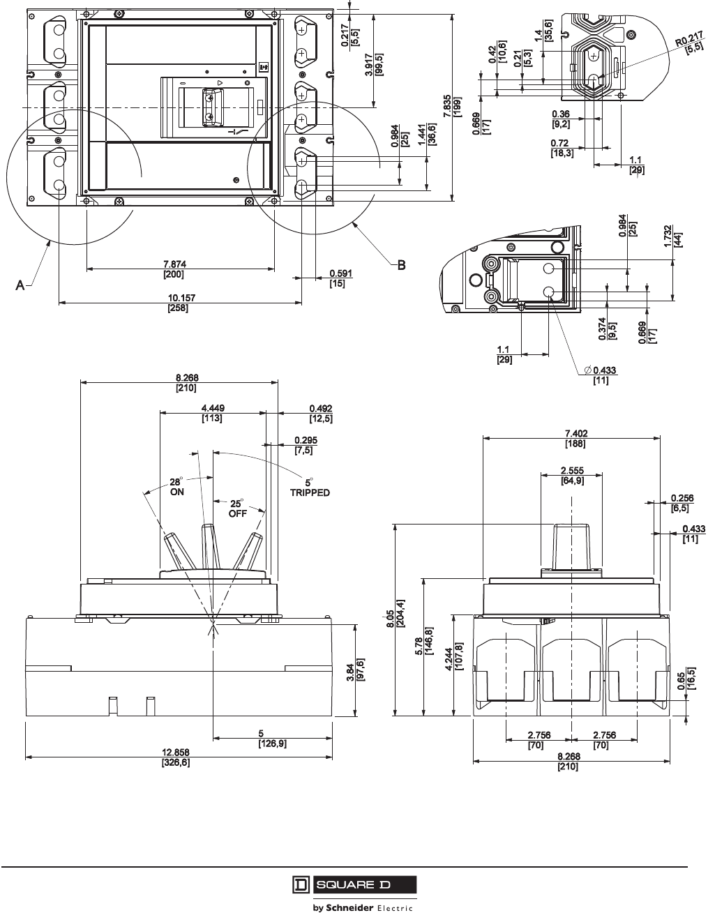
PowerPact™ M-, P- and R-Frame, and Compact™ NS630b–NS3200 Circuit Breakers
Section 10—Dimensional Drawings
97
10/2012
© 2001–2012 Schneider Electric
All Rights Reserved
™
Figure 11: M-Frame Individually-Mounted 3P 800 A Circuit Breaker without Lugs
48096-446-01
Partial View B
(opposite side)
Partial View A
(opposite side)
in.
[mm]
Dimensions:
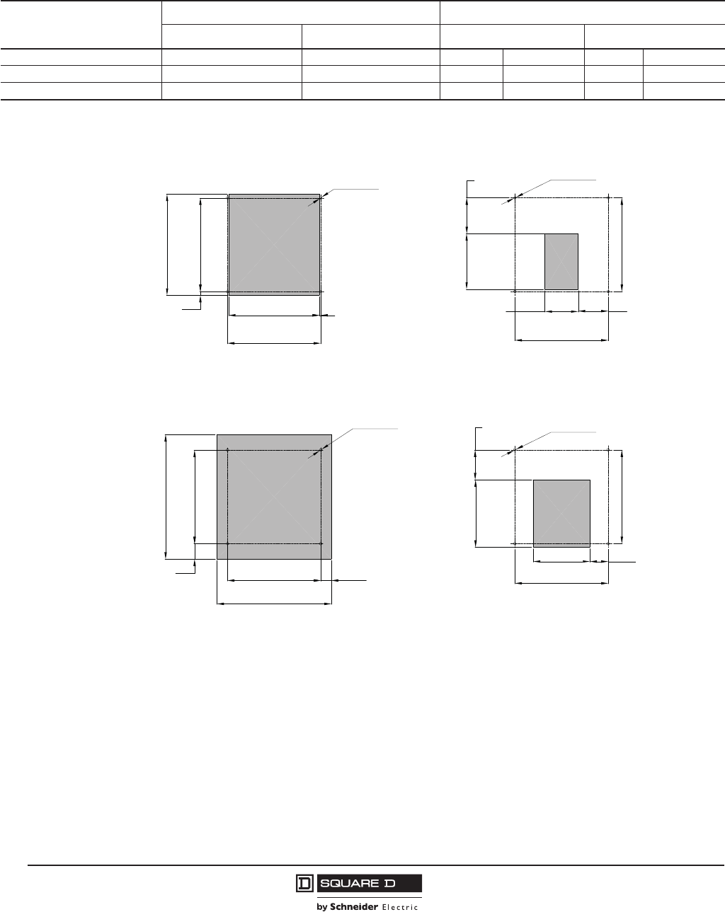
© 2001–2012 Schneider Electric
All Rights Reserved
PowerPact™ M-, P- and R-Frame, and Compact™ NS630b–NS3200 Circuit Breakers
Section 10—Dimensional Drawings
98
10/2012
™
Dimensions for P-Frame and NS630b–NS1600 Circuit Breakers
Figure 12: P-Frame and NS630b–NS1600 Individually-Mounted Circuit Breaker Enclosure
Mounting Holes and Door Cutouts
Table 98: Enclosure Dimensions
Circuit Breaker Rating
Circuit Breaker Enclosure Dimensions (H x W x D) Ventilation Area
in. mm Top Bottom
d800 A, 100% rated 51.9 x 20.25 x 7.75 1318.3 x 514.4 x 196.9 – – – –
d1200 A, standard rated 51.9 x 20.25 x 7.75 1318.3 x 514.4 x 196.9 – – – –
!800 A, 100% rated 62.25 x 23 x 14.75 1581.2 x 584.2 x 374.7 16.5 in.210,645 mm216.5 in.210,645 mm2
7.87
7.83
4X Ø 0.26 4X Ø 0.26
[6,5]
[6,5]
7.87
7.83
4X Ø 0.26 4X Ø 0.26
[6,5] [6,5]
10.47
7.87
9.61
7.83
1.30 0.89
7.64
7.83
7.87
8.50
0.31 0.10
4.69
2.80
5.67
4.76 1.54
2.52
3.01
2.52
[2,5]
[199,0]
[194,0]
[8,0]
[216,0]
[200,0]
[33,0] [199,0]
[244,0]
[22,5]
[200,0]
[266,0]
[64,0]
[199,0]
[121,0] [39,0]
[144,0]
[200,0]
[76,5]
[71,0]
[199,0]
[64,0]
[119,0]
[200,0]
Accessory Cover Cutout Handle Cutout
(Toggle Mech Only)
Accessory Cover Escutcheon Cutout (Toggle Mech Only)
Handle Escutcheon Cutout
48096-390-01
in.
[mm]
Dimensions:
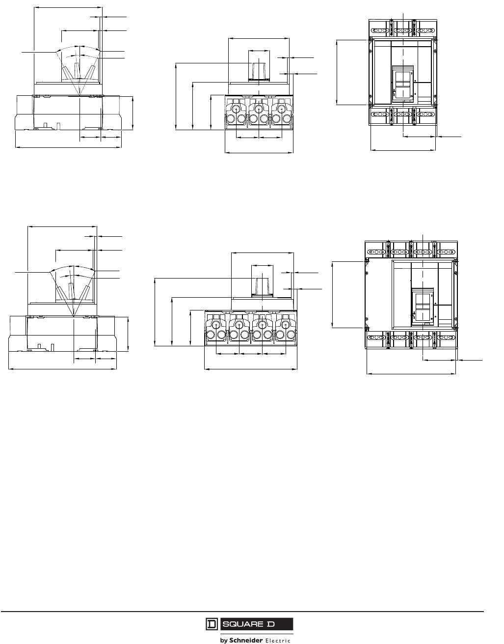
PowerPact™ M-, P- and R-Frame, and Compact™ NS630b–NS3200 Circuit Breakers
Section 10—Dimensional Drawings
99
10/2012
© 2001–2012 Schneider Electric
All Rights Reserved
™
Figure 13: P-Frame and NS630b–NS1600 Individually-Mounted 3P Circuit Breaker d800 A
with Lugs on Both Ends
Figure 14: P-Frame and NS630b–NS1600 Individually-Mounted 4P Circuit Breaker d800 A
with Lugs on Both Ends
12.86
2.492.50
[326,6]
[63,6] [63,3]
3.84
[97,6]
25°
5°
28°
Off
Tripped
On
4.45
[113,0]
0.30
0.49
[12,5]
[7,5]
8.27
[210,0]
Side View
8.27
2.762.76
[70,0][70,0]
[210,0]
4.23
5.77
8.07
[107,5]
[146,5]
[205,0]
At Max
2.56
0.43
0.26
7.40
[188,0]
[64,9]
[6,5]
[11,0]
Back View
7.87
7.83
3.92 0.22
[5,5]
[99,5]
[199,0]
[200,0] 48096-320-01
Top View in.
[mm]
Dimensions:
12.86
2.492.50
[326,6]
[63,6] [63,3]
3.84
[97,6]
25°
5°
28°
Off
Tripped
On
4.45
[113,0]
0.30
0.49
[12,5]
[7,5]
8.27
[210,0]
Side View
11.02
2.762.76
[70,0][70,0]
[280,0]
4.23
5.77
8.07
[107,5]
[146,5]
[205,0]
At Max
2.56
0.43
0.26
7.40
[188,0]
[64,9]
[6,5]
[11,0]
[70,0]
2.76
Back View
7.87
10.59
3.92 0.22
[5,5]
[99,5]
[269,0]
[200,0]
48096-353-01
Top View
in.
[mm]
Dimensions:
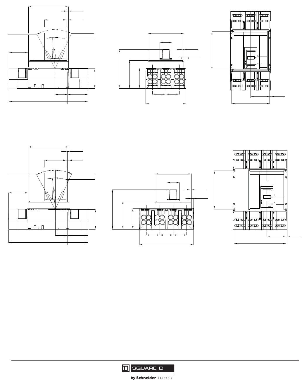
© 2001–2012 Schneider Electric
All Rights Reserved
PowerPact™ M-, P- and R-Frame, and Compact™ NS630b–NS3200 Circuit Breakers
Section 10—Dimensional Drawings
100
10/2012
™
Figure 15: P-Frame and NS630b–NS1600 Individually-Mounted 3P Circuit Breaker !800 A
with Lugs on Both Ends
Figure 16: P-Frame and NS630b–NS1600 Individually-Mounted 4P Circuit Breaker !800 A
with Lugs on Both Ends
2.50 4.19
16.26 [63,6] [106,5]
[413,0]
3.84
[97,6]
4.00
[101,5]
5°
25°
28°
Tripped
Off
On
4.45
[113,0]
0.30
0.49
[7,5]
[12,5]
8.27
[210,0]
Side View
2.762.76
8.27
[70,0][70,0]
[210,0]
4.23
5.77
8.07
[107,5]
[146,5]
[205,0]
2.56
0.43
0.26
7.40
[188,0]
[64,9]
[6,5]
[11,0]
At Max
Back View
3.92 0.22
7.83 [99,5] [5,5]
[199,0]
7.87
[200,0]
Top View
48096-321-01
in.
[mm]
Dimensions:
2.50 4.19
16.26 [63,6] [106,5]
[413,0]
3.84
[97,6]
4.00
[101,5]
5°
25°
28°
Tripped
Off
On
4.45
[113,0]
0.30
0.49
[7,5]
[12,5]
8.27
[210,0]
Side View
2.762.76
11.02
[70,0][70,0]
[280,0]
4.23
5.77
8.07
[107,5]
[146,5]
[205,0]
2.56
0.43
0.26
7.40
[188,0]
[64,9]
[6,5]
[11,0]
At Max
[70,0]
2.76
Back View
3.92 0.22
10.59
[99,5] [5,5]
[269,0]
7.87
[200,0]
Top View
48096-354-01
in.
[mm]
Dimensions:
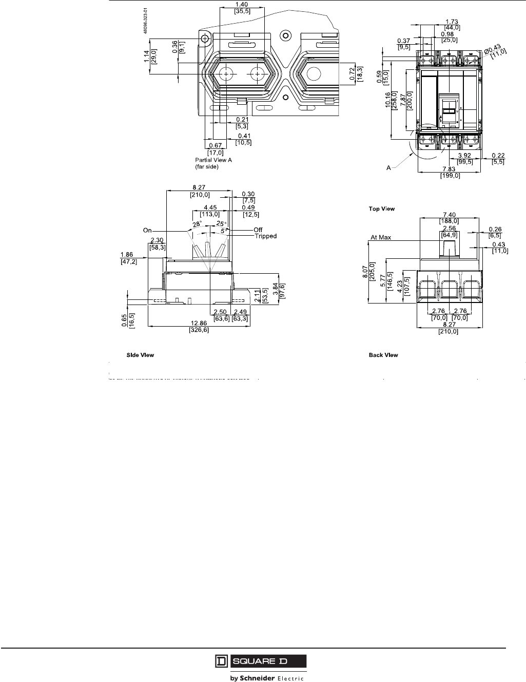
PowerPact™ M-, P- and R-Frame, and Compact™ NS630b–NS3200 Circuit Breakers
Section 10—Dimensional Drawings
101
10/2012
© 2001–2012 Schneider Electric
All Rights Reserved
™
Figure 17: P-Frame and NS630b–NS1600 Individually-Mounted 3P Circuit Breaker without Lugs
in.
[mm]
Dimensions:
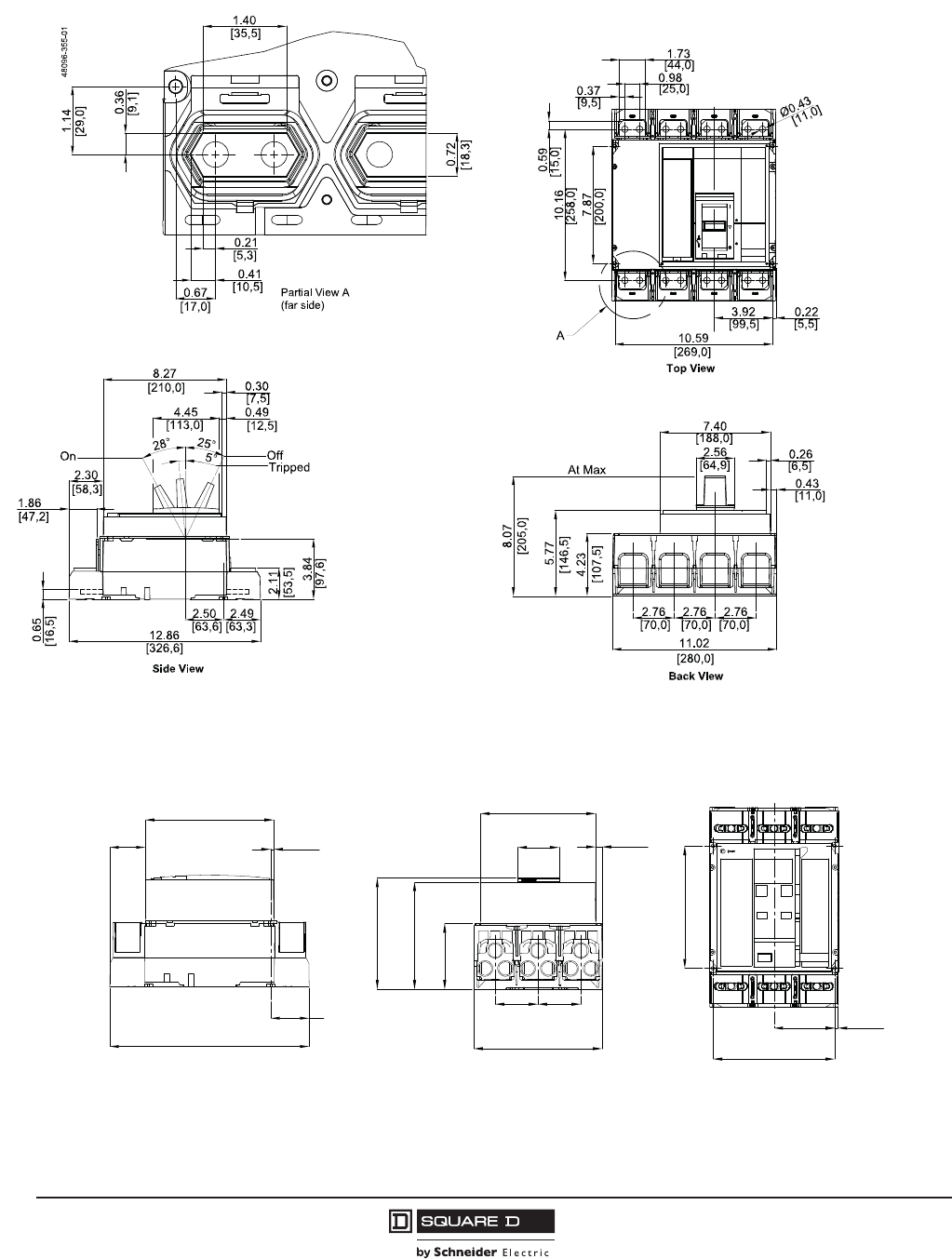
© 2001–2012 Schneider Electric
All Rights Reserved
PowerPact™ M-, P- and R-Frame, and Compact™ NS630b–NS3200 Circuit Breakers
Section 10—Dimensional Drawings
102
10/2012
™
Figure 18: P-Frame and NS630b–NS1600 Individually-Mounted 4P Circuit Breaker without Lugs
Figure 19: P-Frame and NS630b–NS1600 Individually-Mounted Electrically-Operated 3P
Circuit Breaker d800 Awith Lugs on Both Ends
in.
[mm]
Dimensions:
Side View
12.86
[326,6]
[63,3]
2.30
8.27
[7,5]
[210,0]
[58,3]
0.30
2.49
[11,0]
[67,6]
Back View
[188,0]
8.27
2.76 2.76
4.23
[70,0] [70,0]
[210,0]
6.91
[175,5]
[107,5]
7.17
[182,0]
2.66
7.40
0.43
Top View
[5,5]
48096-348-01
3.92
7.83
0.22
[99,5]
[199,0]
7.87
[200,0]
in.
[mm]
Dimensions:
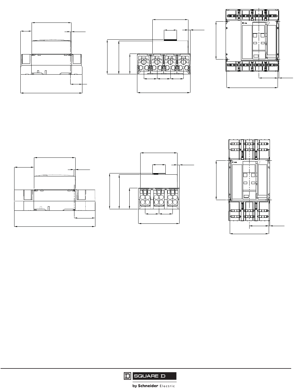
PowerPact™ M-, P- and R-Frame, and Compact™ NS630b–NS3200 Circuit Breakers
Section 10—Dimensional Drawings
103
10/2012
© 2001–2012 Schneider Electric
All Rights Reserved
™
Figure 20: P-Frame and NS630b–NS1600 Individually-Mounted Electrically-Operated 4P
Circuit Breaker d800 Awith Lugs on Both Ends
Figure 21: P-Frame and NS630b–NS1600 Individually-Mounted Electrically-Operated 3P
Circuit Breaker !800 Awith Lugs on Both Ends
Side View
12.86
[326,6]
[63,3]
2.30
8.27
[7,5]
[210,0]
[58,3]
0.30
2.49
[11,0]
[67,6]
Back View
[188,0]
11.02
2.76 2.76
4.23
[70,0] [70,0]
[280,0]
6.91
[175,5]
[107,5]
7.17
[182,0]
2.66
7.40
0.43
[70,0]
2.76
Top View
[5,5]
48096-356-01
3.92
10.59
0.22
[99,5]
[269,0]
7.87
[200,0]
in.
[mm]
Dimensions:
Side View
[413,0]
[101,5]
[106,5]
[7,5]
[210,0]
4.19
16.26
0.30
8.27
4.00
7.41
2.66 0.43
[210,0]
[67,6]
Back View
7.17
6.91
4.23
[182,0]
[188,0]
8.27
2.76 2.76
[70,0] [70,0]
[175,5]
[107,5]
[11,0]
7.87
[199,0]
7.83
3.92
Top View
0.22
[99,5] [5,5]
48096-249-01
[200,0]
in.
[mm]
Dimensions:

© 2001–2012 Schneider Electric
All Rights Reserved
PowerPact™ M-, P- and R-Frame, and Compact™ NS630b–NS3200 Circuit Breakers
Section 10—Dimensional Drawings
104
10/2012
™
Figure 22: P-Frame and NS630b–NS1600 Individually-Mounted Electrically-Operated 4P
Circuit Breaker !800 Awith Lugs on Both Ends\
Figure 23: P-Frame and NS630b–NS1600 Individually-Mounted Electrically-Operated 3P
Circuit Breaker without Lugs
Side View
[413,0]
[101,5]
[106,5]
[7,5]
[210,0]
4.19
16.26
0.30
8.27
4.00
7.41
2.66 0.43
[280,0]
[67,6]
Back View
7.17
6.91
4.23
[182,0]
[188,0]
11.02
2.76 2.76
[70,0] [70,0]
[175,5]
[107,5]
[11,0]
2.76
[70,0]
7.87
[269,0]
10.59
3.92
Top View
0.22
[99,5] [5,5]
48096-357-01
[200,0]
in.
[mm]
Dimensions:
2.49
12.86 [63,3]
[326,6]
2.30
8.27
0.30
[7,5]
[210,0]
[58,3]
2.76 2.76
8.27
[210,0]
[70,0] [70,0]
7.40
2.66
[188,0]
[67,6]
4.23
6.91
7.17
[107,5]
[175,5]
[182,0]
3.92
7.83
[99,5]
[199,0]
7.87
10.16
[200,0]
[258,0]
0.37
0.98
1.73
[44,0]
[25,0]
[9,5]
Ø0.43
[11,0]
A
0.22
[5,5]
0.59
[15,0]
0.21
0.67
0.41
0.36
1.40
[35,5]
1.14
0.72
[17,0]
[10,5]
[5,3]
[29,0]
[9,1]
[18,3]
Partial View A
(far side) scale1/1
Top View
Back ViewSide View
48096-352-1
in.
[mm]
Dimensions:
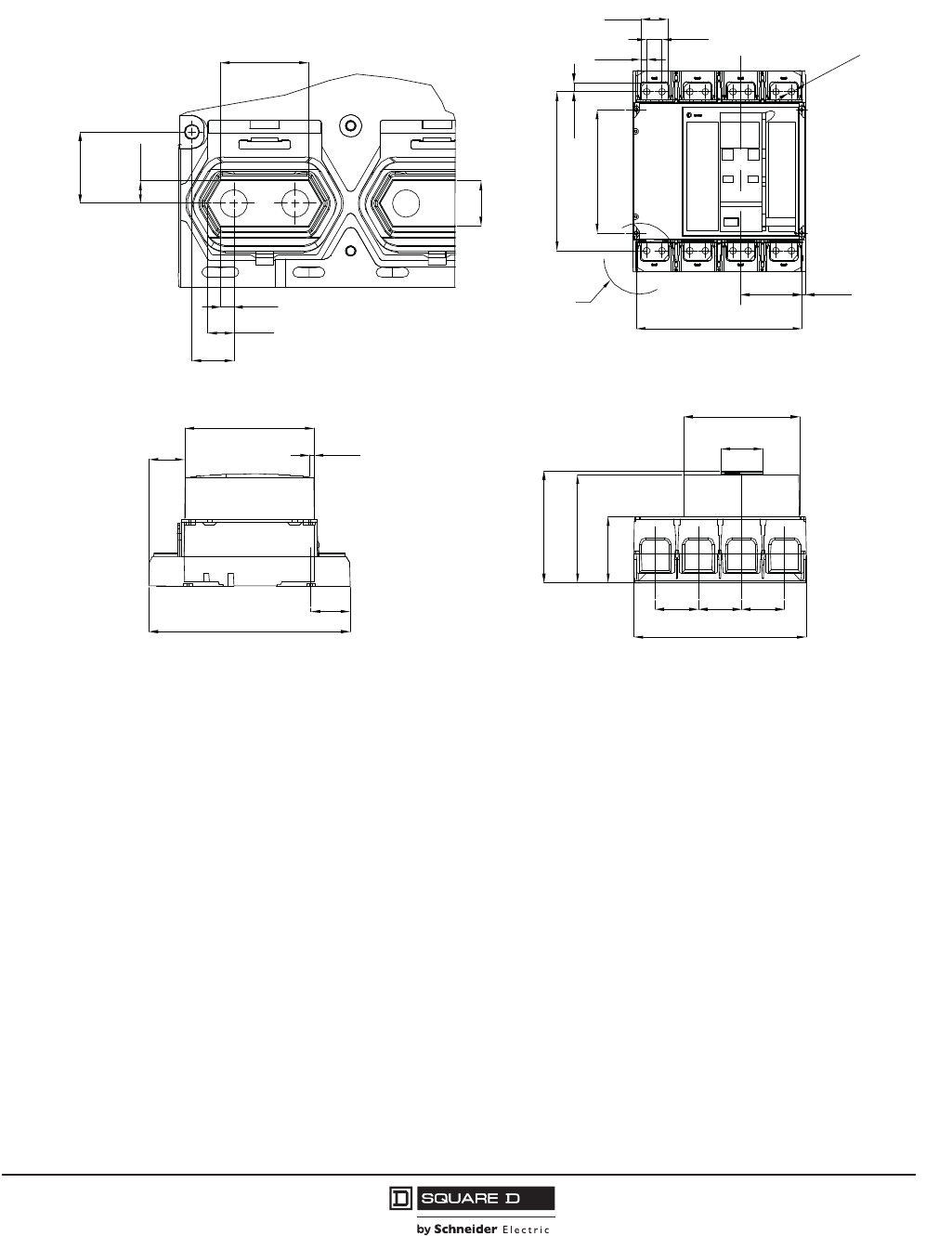
PowerPact™ M-, P- and R-Frame, and Compact™ NS630b–NS3200 Circuit Breakers
Section 10—Dimensional Drawings
105
10/2012
© 2001–2012 Schneider Electric
All Rights Reserved
™
Figure 24: P-Frame and NS630b–NS1600 Individually-Mounted Electrically-Operated 4P
Circuit Breaker without Lugs
2.49
12.86 [63,3]
[326,6]
2.30
8.27
0.30
[7,5]
[210,0]
[58,3]
2.76 2.76
11.02
[280,0]
[70,0] [70,0]
7.40
2.66
[188,0]
[67,6]
4.23
6.91
7.17
[107,5]
[175,5]
[182,0]
3.92
10.59
[99,5]
[269,0]
7.87
10.16
[200,0]
[258,0]
0.37
0.98
1.73
[44,0]
[25,0]
[9,5]
Ø0.43
[11,0]
A
0.22
[5,5]
0.59
[15,0]
0.21
0.67
0.41
0.36
1.40
[35,5]
1.14
0.72
[17,0]
[10,5]
[5,3]
[29,0]
[9,1]
[18,3]
Partial View A
(far side) scale1/1
2.76
[70,0]
Top View
Back ViewSide View
48096-359-01
in.
[mm]
Dimensions:
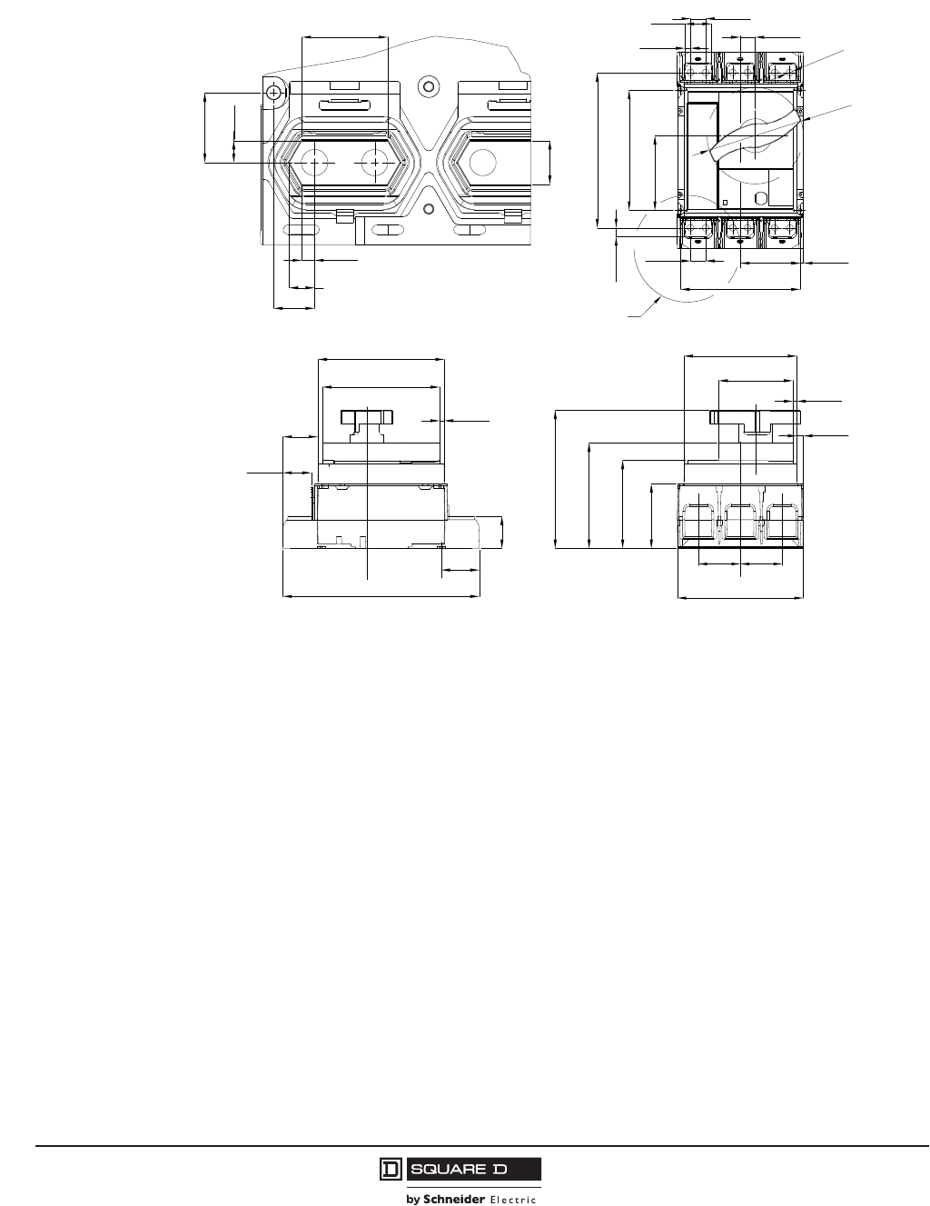
© 2001–2012 Schneider Electric
All Rights Reserved
PowerPact™ M-, P- and R-Frame, and Compact™ NS630b–NS3200 Circuit Breakers
Section 10—Dimensional Drawings
106
10/2012
™
Figure 25: P-Frame and NS630b–NS1600 Individually-Mounted 3P Circuit Breaker with
Rotary Handle
12.86
2.49
2.11
1.86
2.30
8.27
7.68
0.30
[326,6]
[63,3]
[7,5]
[195,0]
[210,0]
[58,3]
[47,2]
[53,5]
2.762.76
8.27
[70,0][70,0]
[210,0]
4.23
7.46
9.04
[160,5]
[189,5]
[229,5]
0.43
0.26
4.87
7.40
[11,0]
[6,5]
[123,6]
[188,0]
0.223.92
7.83
[5,5][99,5]
[199,0]
Ø0.43
Ø6.31
[11,0]
[160,2]
0.99
4.88
7.87
10.16
0.37
0.98
1.73
[9,5]
[44,0] [25,0]
[25,1]
0.98
[25,0]
[258,0]
[200,0]
[124,1]
0.59
[15,0]
A
1.14
0.36
0.41
0.21
0.67
0.72
[9,1]
[29,0]
[35,5]
[5,3]
[10,5]
[17,0]
[18,3]
1.40
6.32
[107,5]
48096-351-01
Top View
Side View Back View
(far side) scale 1/1
Partial View A
in.
[mm]
Dimensions:
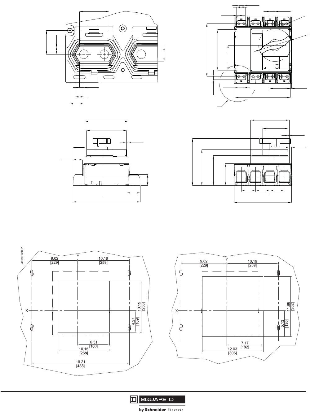
PowerPact™ M-, P- and R-Frame, and Compact™ NS630b–NS3200 Circuit Breakers
Section 10—Dimensional Drawings
107
10/2012
© 2001–2012 Schneider Electric
All Rights Reserved
™
Figure 26: P-Frame and NS630b–NS1600 Individually-Mounted 4P Circuit Breaker with
Rotary Handle
Figure 27: P-Frame and NS630b–NS1600 3P Drawout Circuit Breaker Door Cutout
12.86
2.49
2.11
1.86
2.30
8.27
7.68
0.30
[326,6]
[63,3]
[7,5]
[195,0]
[210,0]
[58,3]
[47,2]
[53,5]
2.762.76
11.02
[70,0][70,0]
[280,0]
4.23
7.46
9.04
[160,5]
[189,5]
[229,5]
0.43
0.26
4.87
7.40
[11,0]
[6,5]
[123,6]
[188,0]
0.223.92
10.59
[5,5][99,5]
[269,0]
Ø0.43
Ø6.31
[11,0]
[160,2]
0.99
4.88
7.87
10.16
0.37
0.98
1.73
[9,5]
[44,0] [25,0]
[25,1]
0.98
[25,0]
[258,0]
[200,0]
[124,1]
0.59
[15,0]
A
1.14
0.36
0.41
0.21
0.67
0.72
[9,1]
[29,0]
[35,5]
[5,3]
[10,5]
[17,0]
[18,3]
1.40
6.32
[107,5]
[70,0]
2.76
48096-358-01
Top View
Side View Back View
(far side) scale 1/1
Partial View A
in.
[mm]
Dimensions:
in.
[mm]
Dimensions:
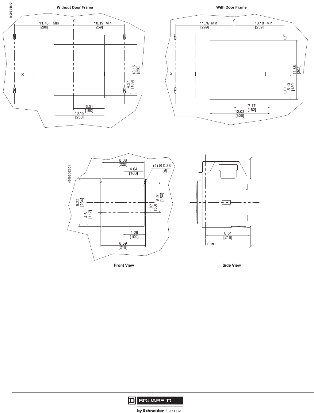
© 2001–2012 Schneider Electric
All Rights Reserved
PowerPact™ M-, P- and R-Frame, and Compact™ NS630b–NS3200 Circuit Breakers
Section 10—Dimensional Drawings
108
10/2012
™
Figure 28: P-Frame and NS630b–NS1600 4P Drawout Circuit Breaker Door Cutout
Figure 29: P-Frame and NS630b–NS1600 3P Drawout Circuit Breaker Rear Cutout
t
in.
[mm]
Dimensions:
in.
[mm]
Dimensions:

PowerPact™ M-, P- and R-Frame, and Compact™ NS630b–NS3200 Circuit Breakers
Section 10—Dimensional Drawings
109
10/2012
© 2001–2012 Schneider Electric
All Rights Reserved
™
Figure 30: P-Frame and NS630b–NS1600 4P Drawout Circuit Breaker Rear Cutout
t
Figure 31: P-Frame Drawout 3P Circuit Breaker d1200 A with Front-Connected Flat (FCF)
Connectors
in.
[mm]
Dimensions:
in.
[mm]
Dimensions:
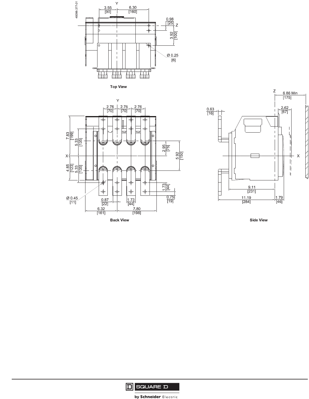
© 2001–2012 Schneider Electric
All Rights Reserved
PowerPact™ M-, P- and R-Frame, and Compact™ NS630b–NS3200 Circuit Breakers
Section 10—Dimensional Drawings
110
10/2012
™
Figure 32: P-Frame Drawout 4P Circuit Breaker d1200 A with Front-Connected Flat (FCF)
Connectors
in.
[mm]
Dimensions:
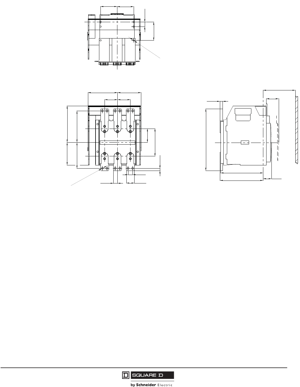
PowerPact™ M-, P- and R-Frame, and Compact™ NS630b–NS3200 Circuit Breakers
Section 10—Dimensional Drawings
111
10/2012
© 2001–2012 Schneider Electric
All Rights Reserved
™
Figure 33: NS630b–NS1600 Drawout 3P Circuit Breaker d1600 A with Front-Connected Flat
(FCF) Connectors
3.94
0.98
Ø0.33
3.54
3.54
[90,0] [90,0]
[25,0]
[100,0]
[8,5]
2.76 2.76
5.55 6.73
4.84 7.83
Ø0.43
0.98
0.49
1.73
0.87
5.046.34
2.95
5.91
[161,0] [128,0]
[70,0] [70,0]
[22,0] [44,0]
[25,0]
[75,0]
[150,0]
[12,5]
[199,0][123,0]
[141,0] [171,0]
[11,0]
9.09
9.25
13.23
0.59
6.89
2.64
1.79
[336,0]
[15,0]
[175,0]
[67,0]
[45,5]
[231,0]
[235,0]
Min
Top View
Back View
X
Z
Y
48096-368-01
X
Side View
Z
Y
in.
[mm]
Dimensions:
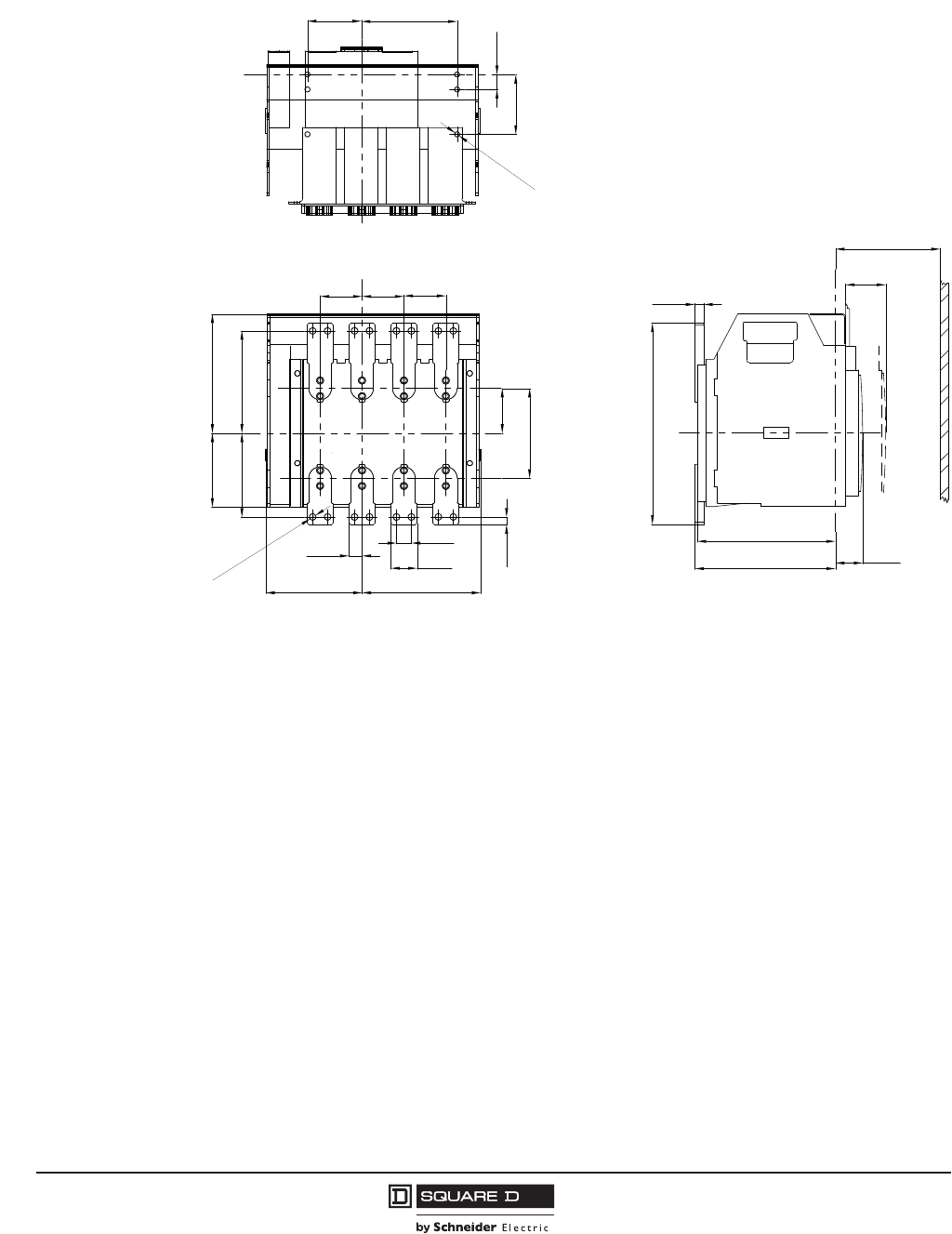
© 2001–2012 Schneider Electric
All Rights Reserved
PowerPact™ M-, P- and R-Frame, and Compact™ NS630b–NS3200 Circuit Breakers
Section 10—Dimensional Drawings
112
10/2012
™
Figure 34: NS630b–NS1600 Drawout 4P Circuit Breaker d1600 A with Front-Connected Flat
(FCF) Connectors
3.94
6.30
3.54
0.98
Ø0.33
[90,0] [160,0]
[25,0]
[100,0]
[8,5]
2.76 2.76 2.76
6.735.51
4.84 7.83
2.95
5.91
0.49
0.98
1.73
0.87
6.34 7.80
[70,0] [70,0] [70,0]
[22,0]
[25,0]
[44,0]
[161,0] [198,0]
[123,0] [199,0]
[171,0][140,0]
[12,5]
Ø0.43
[11,0]
[25,0]
[100,0]
9.09
9.25
0.59
13.23
1.79
6.89
2.64
[175,0]
[15,0]
[231,0]
[235,0] [45,5]
[67,0]
[336,0]
Min
Top View
Back View
X
Z
Y
48096-371-01
Z
X
Side View
Y
in.
[mm]
Dimensions:
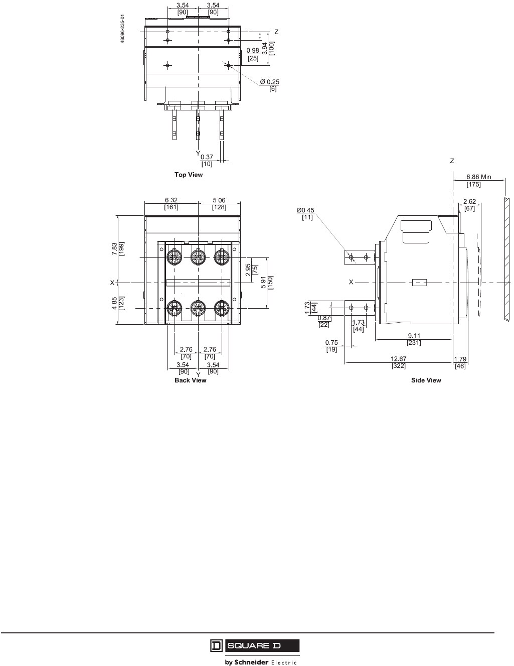
PowerPact™ M-, P- and R-Frame, and Compact™ NS630b–NS3200 Circuit Breakers
Section 10—Dimensional Drawings
113
10/2012
© 2001–2012 Schneider Electric
All Rights Reserved
™
Figure 35: P-Frame Drawout 3P Circuit Breaker d1200 A with Rear-Connected “T” Vertical
(RCTV) Connectors
in.
[mm]
Dimensions:
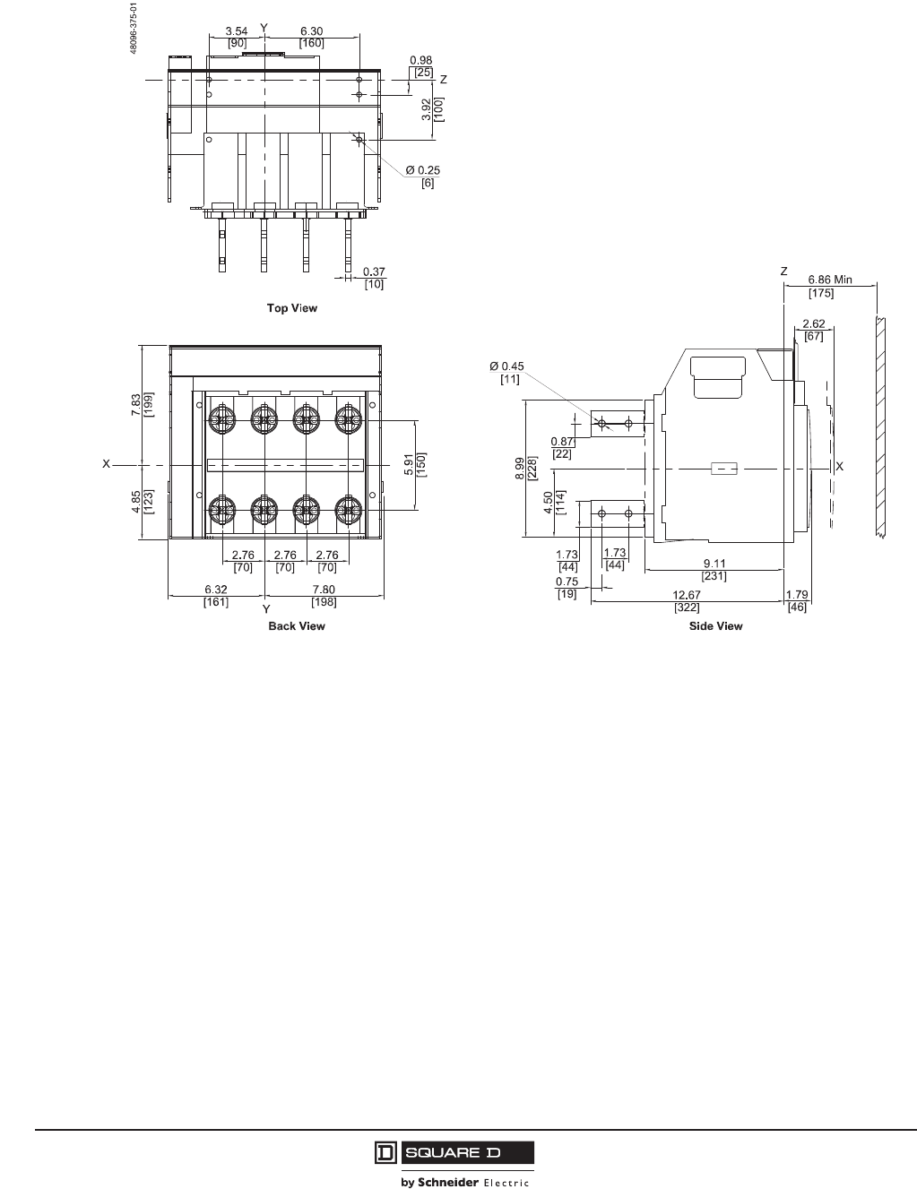
© 2001–2012 Schneider Electric
All Rights Reserved
PowerPact™ M-, P- and R-Frame, and Compact™ NS630b–NS3200 Circuit Breakers
Section 10—Dimensional Drawings
114
10/2012
™
Figure 36: P-Frame Drawout 4P Circuit Breaker d1200 A with Rear-Connected “T” Vertical
(RCTV) Connectors
in.
[mm]
Dimensions:
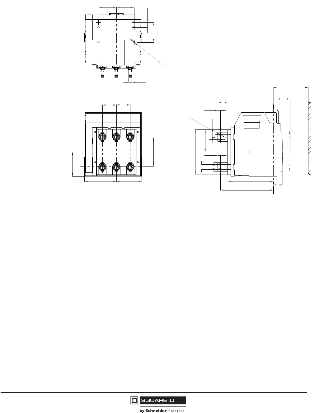
PowerPact™ M-, P- and R-Frame, and Compact™ NS630b–NS3200 Circuit Breakers
Section 10—Dimensional Drawings
115
10/2012
© 2001–2012 Schneider Electric
All Rights Reserved
™
Figure 37: NS630b–NS1600 Drawout 3P Circuit Breaker d1600 A with Rear-Connected “T”
Vertical (RCTV) Connectors
3.543.54
0.98
3.94
Ø0.33
0.59
[90,0] [90,0]
[15,0]
[25,0]
[100,0]
[8,5]
4.84
5.91
6.34 5.04
2.76 2.76
[123,0]
[150,0]
[70,0] [70,0]
[161,0] [128,0] 9.09
10.55
1.81
2.64
6.89
0.98
1.73
4.49
8.98
0.87
0.51
0.51
1.97
Ø0.43
[175,0]
[67,0]
[50,0]
[13,0]
[231,0] [46,0]
[268,0]
[11,0]
[228,0]
[114,0]
[22,0]
[25,0]
[44,0]
[13,0]
Min
Top View
Side View
X
Z
48096-366-01
Y
Z
Back View
in.
[mm]
Dimensions:
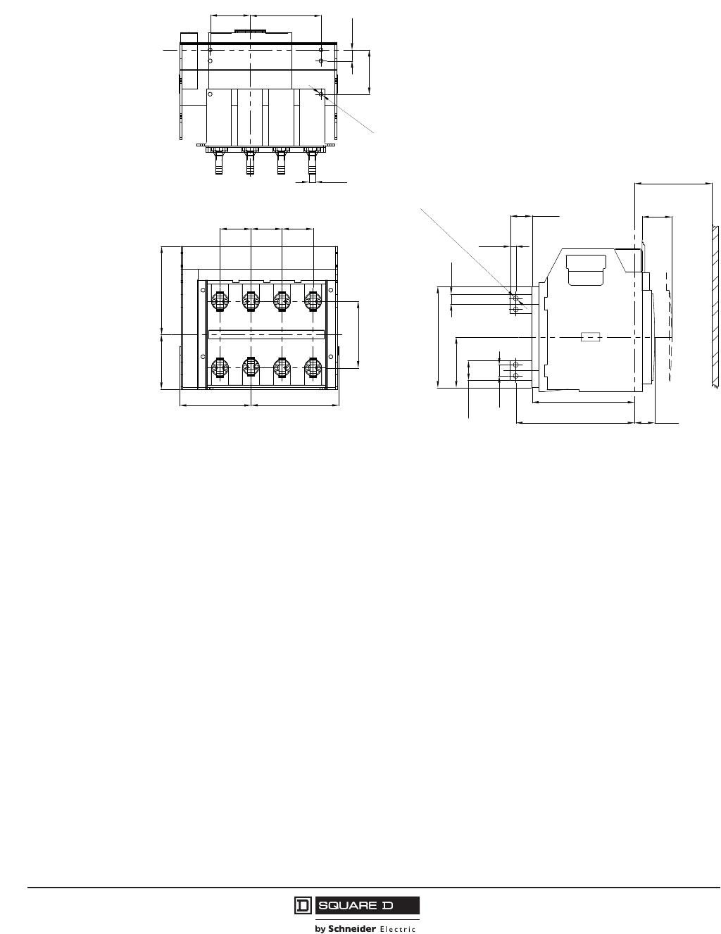
© 2001–2012 Schneider Electric
All Rights Reserved
PowerPact™ M-, P- and R-Frame, and Compact™ NS630b–NS3200 Circuit Breakers
Section 10—Dimensional Drawings
116
10/2012
™
Figure 38: NS630b–NS1600 Drawout 4P Circuit Breaker d1600 A with Rear-Connected “T”
Vertical (RCTV) Connectors
3.94
0.98
6.30
3.54
Ø0.33
0.59
[90,0] [160,0]
[15,0]
[25,0]
[100,0]
[8,5]
2.76 2.76 2.76
5.91
4.84 7.83
6.34 7.80
[150,0]
[199,0]
[123,0]
[70,0] [70,0] [70,0]
[161,0] [198,0]
0.98
1.73
0.87
0.49
1.93
8.98
4.49
10.53
9.09
1.79
2.64
6.89
[175,0]
[67,0]
[49,0]
[12,5]
[231,0]
[267,0] [45,5]
[228,0]
[114,0]
[44,0]
[25,0]
[22,0]
Min
Ø0.43
[11,0]
Top View
Back View
X
Z
Y
48096-369-01
X
Y
Side View
Z
in.
[mm]
Dimensions:
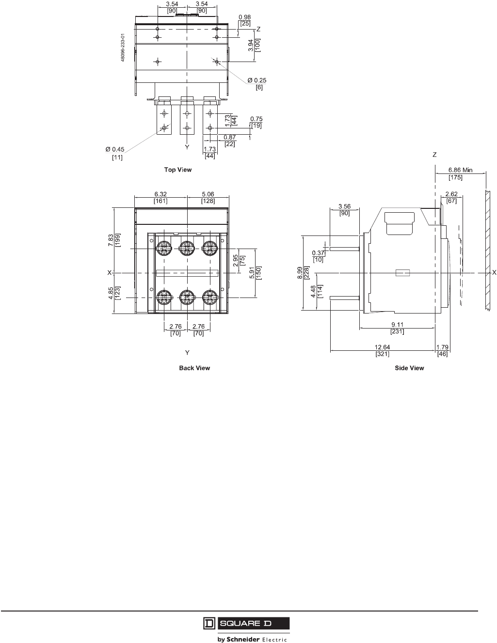
PowerPact™ M-, P- and R-Frame, and Compact™ NS630b–NS3200 Circuit Breakers
Section 10—Dimensional Drawings
117
10/2012
© 2001–2012 Schneider Electric
All Rights Reserved
™
Figure 39: P-Frame Drawout 3P Circuit Breaker d1200 A with Rear-Connected “T” Horizontal
(RCTH) Connectors
in.
[mm]
Dimensions:
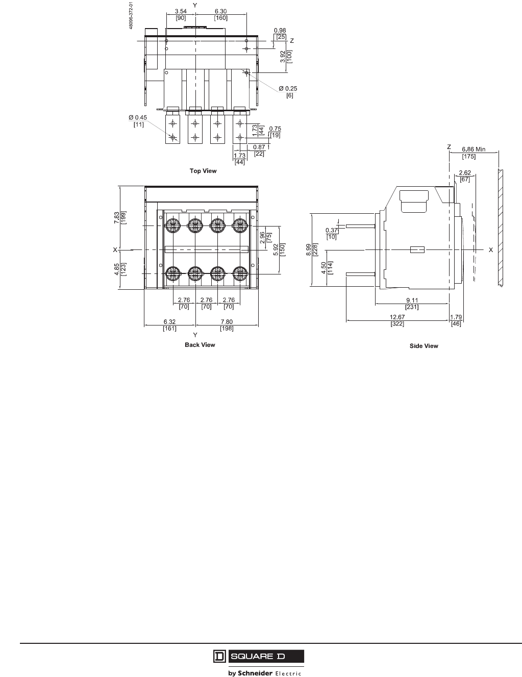
© 2001–2012 Schneider Electric
All Rights Reserved
PowerPact™ M-, P- and R-Frame, and Compact™ NS630b–NS3200 Circuit Breakers
Section 10—Dimensional Drawings
118
10/2012
™
Figure 40: P-Frame Drawout 4P Circuit Breaker d1200 A with Rear-Connected “T” Horizontal
(RCTH) Connectors
in.
[mm]
Dimensions:
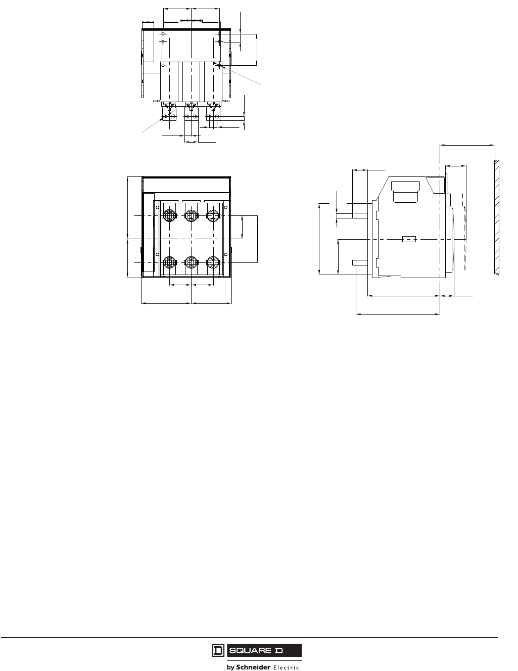
PowerPact™ M-, P- and R-Frame, and Compact™ NS630b–NS3200 Circuit Breakers
Section 10—Dimensional Drawings
119
10/2012
© 2001–2012 Schneider Electric
All Rights Reserved
™
Figure 41: NS630b–NS1600 Drawout 3P Circuit Breaker d1600 A with Rear-Connected “T”
Horizontal (RCTH) Connectors
3.94
0.98
3.54
3.54
0.98
0.51
0.87 1.73
Ø0.43
[90,0] [90,0]
[25,0]
[22,0]
[44,0]
[11,0]
[25,0]
[100,0]
[13,0]
Ø0.33
[8,5]
4.84 7.83
2.95
5.91
6.34 5.04
2.76 2.76
[75,0]
[150,0]
[199,0]
[123,0]
[161,0] [128,0]
[70,0] [70,0] 9.09
10.55
1.79
4.49
8.98
0.59
1.93 2.64
6.89 Min
[67,0]
[49,0]
[231,0]
[268,0]
[45,5]
[228,0]
[15,0]
[114,0]
[175,0]
Top View
Back View Side View
X
Z
Y
48096-367-01
X
Z
in.
[mm]
Dimensions:
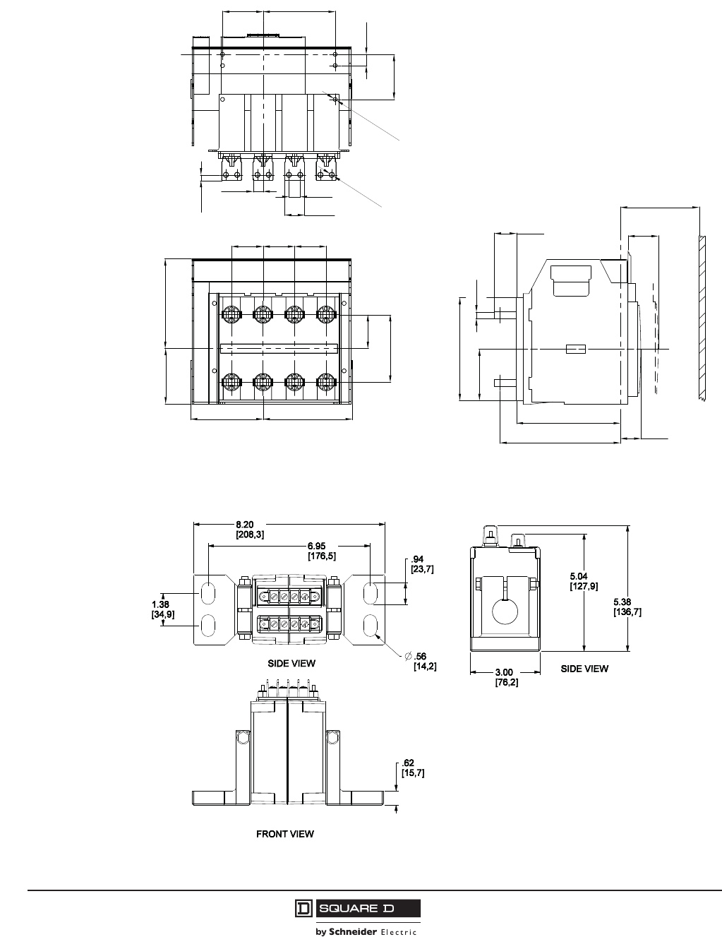
© 2001–2012 Schneider Electric
All Rights Reserved
PowerPact™ M-, P- and R-Frame, and Compact™ NS630b–NS3200 Circuit Breakers
Section 10—Dimensional Drawings
120
10/2012
™
Figure 42: NS630b–NS1600 Drawout 4P Circuit Breaker d1600 A with Rear-Connected “T”
Horizontal (RCTH) Connectors
Figure 43: P-Frame and NS630b–NS1600 100–1600 A External Neutral Current Transformers
3.94
0.98
6.303.54
Ø0.33
0.49
0.87 0.98
1.73
Ø0.43
[90,0] [160,0]
[22,0] [25,0]
[44,0]
[12,5]
[25,0]
[100,0]
[8,5]
[11,0]
2.762.762.76
4.84 7.83
6.34 7.80
2.95
5.91
[70,0] [70,0] [70,0]
[161,0] [198,0]
[123,0] [199,0]
[75,0]
[150,0]
8.98
9.09
10.53
0.59
4.49
1.93 2.64
6.89
1.79
[228,0]
[15,0]
[49,0]
[175,0]
[67,0]
[231,0]
[267,5] [45,5]
[114,0]
Min
Top View
Back View Side View
X
Z
Y
48096-370-01
X
Z
in.
[mm]
Dimensions:
in.
[mm]
Dimensions:
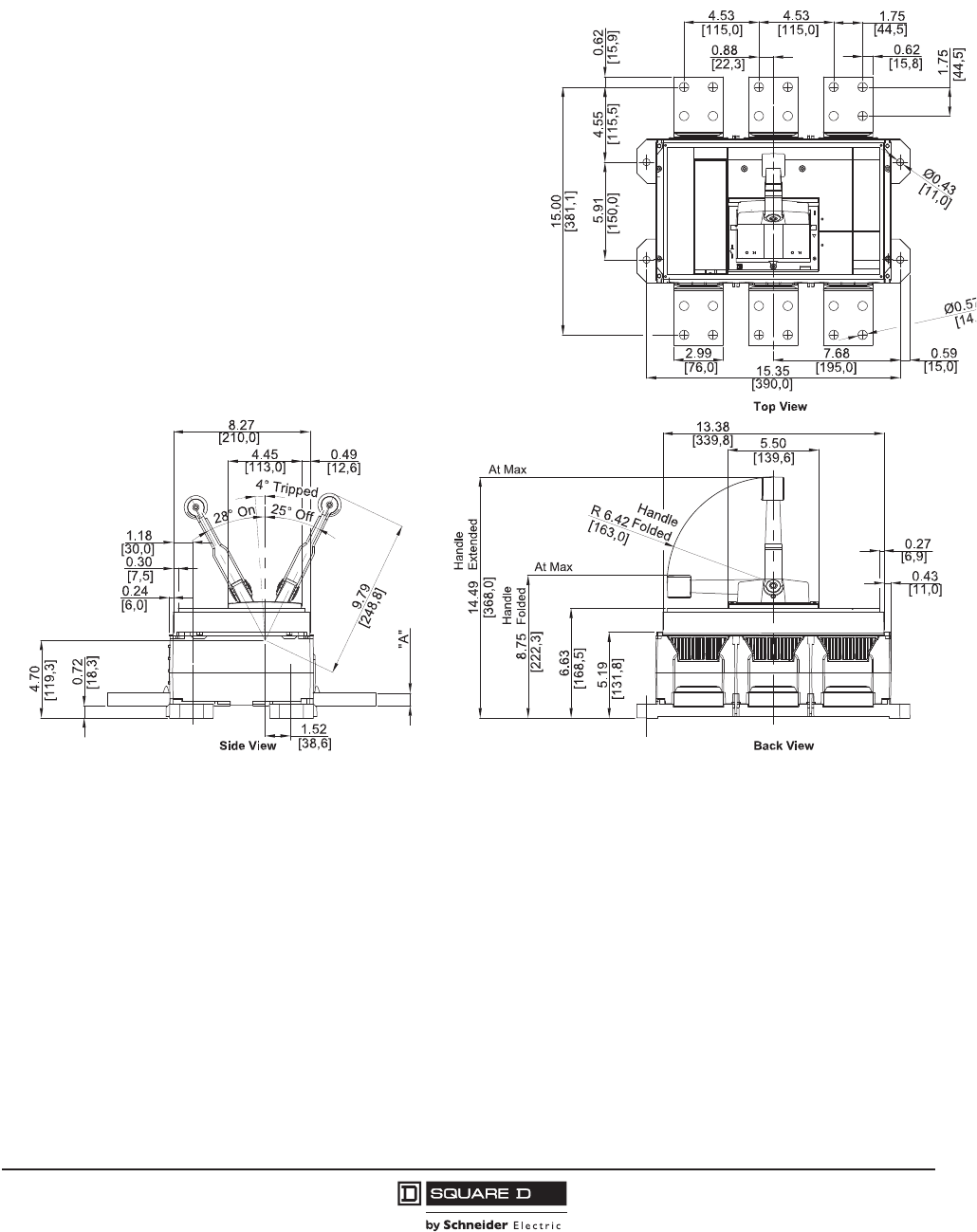
PowerPact™ M-, P- and R-Frame, and Compact™ NS630b–NS3200 Circuit Breakers
Section 10—Dimensional Drawings
121
10/2012
© 2001–2012 Schneider Electric
All Rights Reserved
™
Dimensions for R-Frame and NS1600b–NS3200 Circuit Breakers
Figure 44: R-Frame Individually-Mounted UL Listed 3P Circuit Breaker
Circuit Breaker
1600 A
2000 A
2500 A
3000 A
"A"
0.50 in. [12.8 mm]
0.63 in. [16 mm]
0.79 in. [20 mm]
0.79 in. [20 mm]
See Table
48096-208-01
in.
[mm]
Dimensions:
Minimum Enclosure Size
30 x 21 x 7
(762 x 533 x 178)
Minimum Ventilation
(100% Rated Circuit Breakers Only):
40.25 in.2 (250 cm2) on top and bottom of enclosure

© 2001–2012 Schneider Electric
All Rights Reserved
PowerPact™ M-, P- and R-Frame, and Compact™ NS630b–NS3200 Circuit Breakers
Section 10—Dimensional Drawings
122
10/2012
™
Figure 45: R-Frame Individually-Mounted UL Listed 4P Circuit Breaker
1.52
[38,6]
0.24
[6,0]
0.30
[7,5]
1.18
[30,0]
25˚ Off
28˚ On
4˚ Tripped
9.79
[248,8]
4.45
[113,0]
8.27
[210,0]
0.49
[12,6]
5.19
[131,8]
6.63
[168,5]
8.75
[222,3]
Handle
Extended
Handle
Folded
14.49
[368,0]
At Max
At Max
R6.42
Handle
Folded
[163,0]
5.50
[139,6]
13.38
[339,8]
0.43
0.27
[11,0]
[6,9]
7.68
[195,0]
19.88
[505,0]
0.59
[15,0]
Ø0.43
[11,0]
5.91
[150,0]
See Table
"A"
[119,3]
4.70
[18,3]
.72
0.62
[15.7]
4.53
[115.0]
4.53
[115.0]
15.00
[381.1]
4.55
[115.5]
4.53
[115.0]
0.62
[15.8]
0.88
[22.2]
1.75
[44.5]
Ø0.57
[Ø14.5]
1.75
[44.5]
2.99
[76.0]
48096-450-01
Top View
Back ViewSide View
Circuit Breaker "A"
1600 A 0.50 in. [12.8 mm]
2000 A 0.63 in. [16.0 mm]
2500 A 0.79 in. [20.0 mm]
3000 A 0.79 in. [20.0 mm]
in.
[mm]
Dimensions:
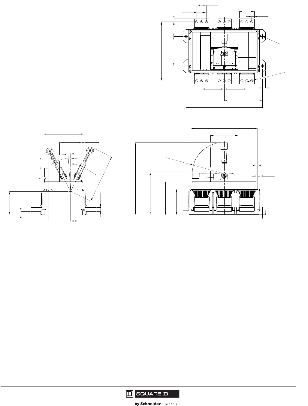
PowerPact™ M-, P- and R-Frame, and Compact™ NS630b–NS3200 Circuit Breakers
Section 10—Dimensional Drawings
123
10/2012
© 2001–2012 Schneider Electric
All Rights Reserved
™
Figure 46: NS1600b–NS3200 Individually-Mounted IEC Rated, 3P Circuit Breaker
0.72
4.70
[18,3]
[119,3]
0.24
[6,0]
0.30
[7,5]
1.18
[30,0]
4° Tripped
25° Off
4.45
[113,0]
1.52
[38,6]
0.79
[20,0]
9.79
[248,8]
0.49
8.27
[210,0]
[12,6]
28° On
5.19
[131,8]
6.63
[168,5]
8.75
[222,3]
14.49
[368,0]
R 6.42
[163,0]
Handle
Folded
5.50
[139,6]
13.38
[339,8]
0.43
[11,0]
0.27
[6,9]
Handle
Extended
Handle
Folded
At Max
At Max
0.59
[15,0]
7.68
[195,0]
15.35
[390,0]
Ø0.43
[11,0]
Ø0.49
[12,5]
0.51
2.99
[13,0]
[76,0]
0.98
1.97
[50,0]
[25,0]
0.59
[15,0]
2.95
[75,0]
5.91
[150,0]
11.81
[300,0]
4.534.53 [115,0][115,0]
48096-209-01
Top View
Back ViewSide View
in.
[mm]
Dimensions:
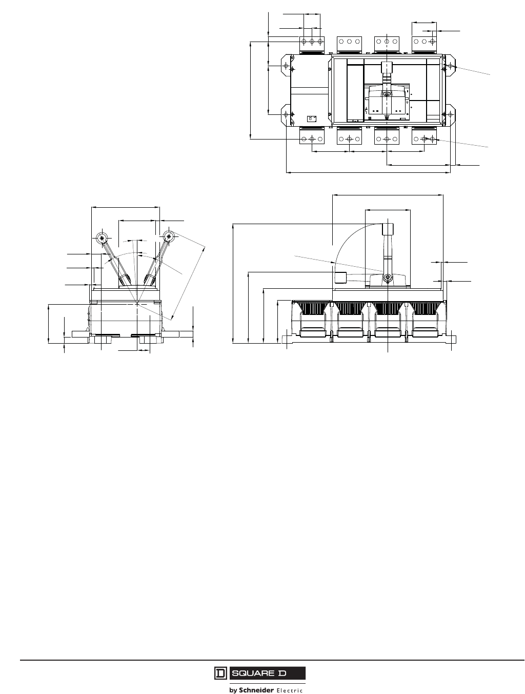
© 2001–2012 Schneider Electric
All Rights Reserved
PowerPact™ M-, P- and R-Frame, and Compact™ NS630b–NS3200 Circuit Breakers
Section 10—Dimensional Drawings
124
10/2012
™
Figure 47: NS1600b–NS3200 Individually-Mounted IEC Rated 4P Circuit Breaker
1.52
0.79
.72
4.70
[38,6]
[119,3]
[18,3]
[20,0]
0.24
[6,0]
0.30
[7,5]
1.18
[30,0]
25° Off
28° On
4° Tripped
9.79
[248,8]
4.45
[113,0]
8.27
[210,0]
0.49
[12,6]
5.19
[131,8]
6.63
[168,5]
8.75
[222,3]
Handle
Extended
Handle
Folded
14.49
[368,0]
At Max
At Max
R6.42
Handle
Folded
[163,0]
5.50
[139,6]
13.38
[339,8]
0.43
0.27
[11,0]
[6,9]
4.534.53 4.53
[115,0] [115,0] [115,0]
7.68
[195,0]
19.88
[505,0]
0.59
[15,0]
Ø0.49
[12,5]
Ø0.43
[11,0]
0.51
[13,0]
2.99
[76,0]
0.98
1.97
[25,0]
[50,0]
0.59
[15,0]
2.95
[75,0]
5.91
[150,0]
11.81
[300,0]
48096-245-01
Top View
Back ViewSide View
in.
[mm]
Dimensions:
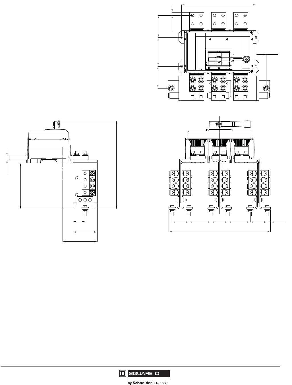
PowerPact™ M-, P- and R-Frame, and Compact™ NS630b–NS3200 Circuit Breakers
Section 10—Dimensional Drawings
125
10/2012
© 2001–2012 Schneider Electric
All Rights Reserved
™
Figure 48: R-Frame RLTB 3P Terminal Pad (UL)
0.79
[20,0]
9.40
[238,9]
18.16
[461,2]
2.50
[63,5]
5.00
[127,0]
7.05
[178,9]
3.50
[88,9]
4.53
[115,0]
3.50 4.53 3.50
[88,9] [115,0] [88,9]
20.99
[533,2]
0.72
[18,3]
2.11
[53,6]
4.53
[115,0]
5.91
[150,0]
4.55
[115,5]
0.62
[15,9]
15.35
[390,0]
Side View Back View
Top View
48096-378-01
in.
[mm]
Dimensions:
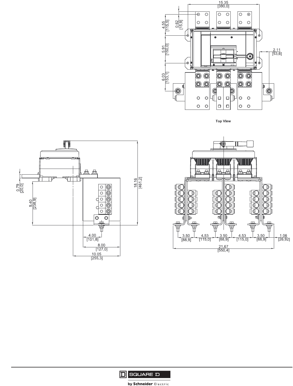
© 2001–2012 Schneider Electric
All Rights Reserved
PowerPact™ M-, P- and R-Frame, and Compact™ NS630b–NS3200 Circuit Breakers
Section 10—Dimensional Drawings
126
10/2012
™
Figure 49: R-Frame RL3TB 3P Terminal Pad (UL)
48096-383-01
in.
[mm]
Dimensions:
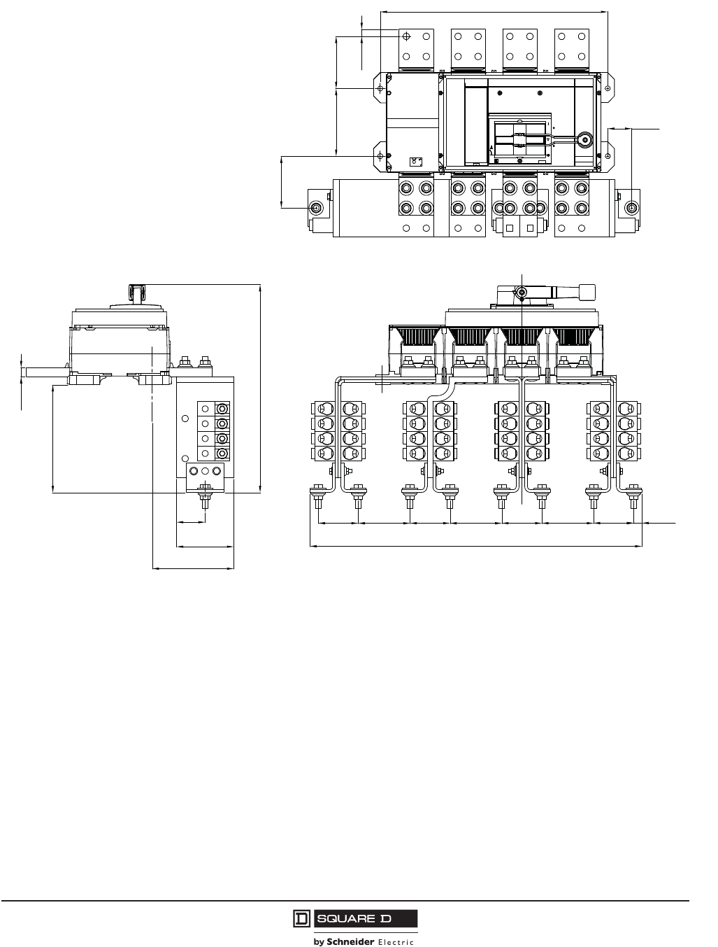
PowerPact™ M-, P- and R-Frame, and Compact™ NS630b–NS3200 Circuit Breakers
Section 10—Dimensional Drawings
127
10/2012
© 2001–2012 Schneider Electric
All Rights Reserved
™
Figure 50: R-Frame RLTB 4P Terminal Pad (UL)
0.79
[20,0]
9.40
[238,9]
18.16
[461,2]
2.50
[63,5]
5.00
[127,0]
7.05
[178,9]
3.50
[88,9]
4.53
[115,0]
3.50 4.53 3.50
[88,9] [115,0] [88,9]
29.02
[737,1]
0.72
[18,3]
2.11
[53,6]
4.53
[115,0]
5.91
[150,0]
4.55
[115,5]
0.62
[15,9]
19.88
[505,0]
4.533.50
[88,9] [115,0]
Side View Back View
Top View
48096-379-01
in.
[mm]
Dimensions:
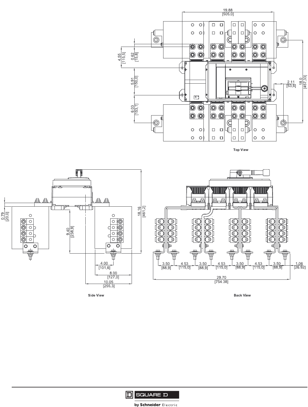
© 2001–2012 Schneider Electric
All Rights Reserved
PowerPact™ M-, P- and R-Frame, and Compact™ NS630b–NS3200 Circuit Breakers
Section 10—Dimensional Drawings
128
10/2012
™
Figure 51: R-Frame RL3TB 4P Terminal Pad (UL)
48096-383-01
in.
[mm]
Dimensions:
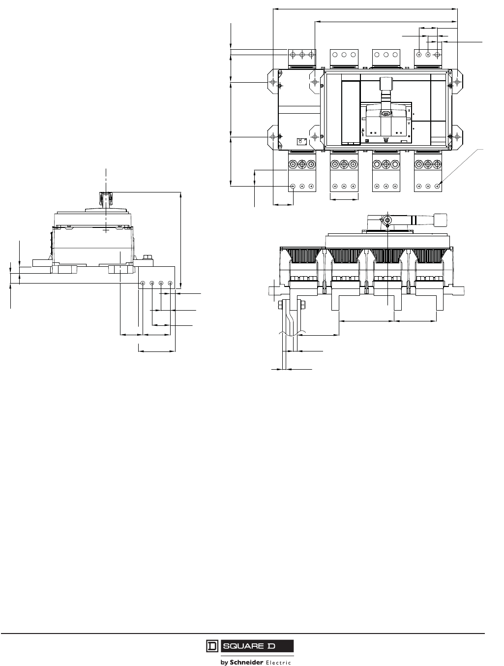
PowerPact™ M-, P- and R-Frame, and Compact™ NS630b–NS3200 Circuit Breakers
Section 10—Dimensional Drawings
129
10/2012
© 2001–2012 Schneider Electric
All Rights Reserved
™
Figure 52: NS1600b–NS3200 RLTBE Terminal Pad (IEC)
0.72
1.05
2.46
0.49
0.98
1.97
2.95
3.94
[12,5]
[25,0]
[50,0]
[75,0]
[100,0]
[62,5]
[26,7]
[18,3]
10.39
[264,0]
4.53
6.10 4.53
0.39
0.39
[115,0][155,0]
[115,0]
[10,0]
[10,0]
TYP
TYP
[13,0]
[25,0]
[50,0]
3.15
2.17 [80,0]
[55,0]
[35,0]
1.38
4.92 5.91
[150,0]
[125,0]
2.95 0.59
[75,0] [15,0]
19.88
[505,0]
M 10
0.51
0.98
1.97
15.35
[390,0]
4 Pole
3 Pole
Side View
Top View
Back View
48096-35-01
in.
[mm]
Dimensions:
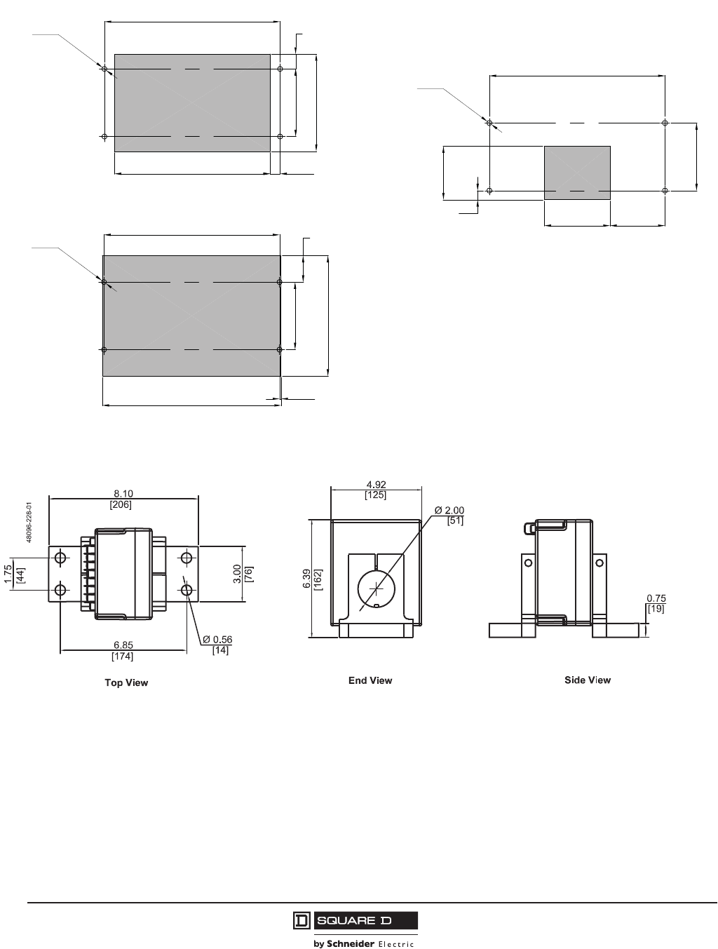
© 2001–2012 Schneider Electric
All Rights Reserved
PowerPact™ M-, P- and R-Frame, and Compact™ NS630b–NS3200 Circuit Breakers
Section 10—Dimensional Drawings
130
10/2012
™
Figure 53: R-Frame and NS1600b–NS3200 Enclosure Mounting Holes and Door Cutouts
Figure 54: R-Frame and NS1600b–NS3200 100–1600 A External Neutral Current Transformers
Ø0.43
[11,0]
15.35 3-pole
19.88
[505,0] 4-pole
4x
5.91
15.35
[390,0] 3-pole
19.88
[505,0] 4-pole
Ø0.43
[11,0]
4x
Ø0.43
[11,0]
15.35
[390,0] 3-pole
4x
5.91
13.62 0.87
8.50
1.30
2.30
10.51
15.63 0.14
[346,0] [22,0]
[33,0]
[216,0]
[150,0]
[390,0]
[58,5]
[3,5]
[397,0]
[267,0]
[150,0]
5.75 4.80
0.80
4.69
5.91
[146,0] [122,0]
[20,4]
[119,0]
[150,0]
Accessory Cover Cutout
Handle Cutout
Accessory Cover Escutcheon Cutout
48096-380-01
in.
[mm]
Dimensions:
in.
[mm]
Dimensions:
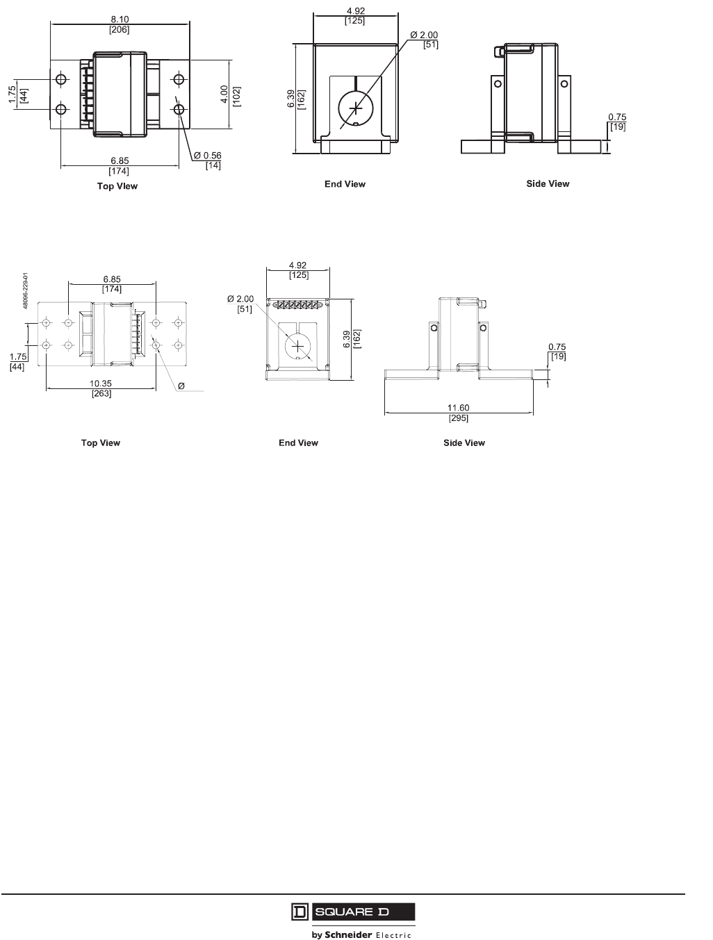
PowerPact™ M-, P- and R-Frame, and Compact™ NS630b–NS3200 Circuit Breakers
Section 10—Dimensional Drawings
131
10/2012
© 2001–2012 Schneider Electric
All Rights Reserved
™
Figure 55: R-Frame and NS1600b–NS3200 2000 A External Neutral Current Transformers
Figure 56: R-Frame and NS1600b–NS3200 2500–3200 A External Neutral Current
Transformers
48096-228-01
in.
[mm]
Dimensions:
0.56
[14]
in.
[mm]
Dimensions:
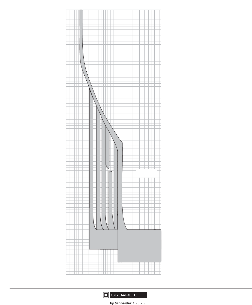
© 2001–2012 Schneider Electric
All Rights Reserved
PowerPact™ M-, P- and R-Frame, and Compact™ NS630b–NS3200 Circuit Breakers
Section 11—Trip Curves
132
10/2012
™
Section 11—Trip Curves
Basic Electronic Trip Unit ET 1.0I, M-Frame 800 A Characteristic Trip Curve
5
150
200
300
400
500
600
700
800
900
1000
1500
2000
3000
4000
5000
6000
7000
8000
9000
10000
TIME IN SECONDS
MULTIPLES OF SENSOR RATING (In)
150
200
300
400
500
600
700
800
900
1000
1500
2000
3000
4000
5000
6000
7000
8000
9000
10000
.005
.006
.007
.008
.009
.01
.015
.02
.03
.04
.05
.06
.07
.08
.09
.1
.15
.2
.3
.4
.5
.6
.7
.8
.9
1
1.5
2
3
4
6
7
8
9
10
15
20
30
40
50
60
70
80
90
100
MULTIPLES OF SENSOR RATING (In)
The time-current curve information is
to be used for application and
coordination purposes only.
Curves apply from -30°C to +60°C
ambient temperature.
CHARACTERISTIC TRIP CURVE NO. 613-14
ELECTRONIC TRIP 1.0
4
6
7
8
9
10
15
20
30
40
50
60
70
80
90
100
.005
.006
.007
.008
.009
.01
.015
.02
.03
.04
.05
.06
.07
.08
.09
.1
.15
.2
.3
.4
.5
.6
.7
.8
.9
1
1.5
2
3
Notes:
1. There is a memory effect that can act to
shorten the long-time delay. The memory
effect comes into play if a current above the
long-time delay pickup value exists for a
time and then is cleared by the tripping
of a downstream device or the circuit
breaker itself.
A subsequent overload will cause the
circuit breaker to trip in a shorter time
than normal.
The amount of time delay reduction is
inverse to the amount of time that has
elapsed since the previous overload.
Approximately 20 minutes is required
between overloads to completely
reset memory.
2. Total clearing times shown include the
response times of the trip unit, the circuit
breaker opening, and the extinction
of the current.
Long-Time Pickup and Delay
Instantaneous Pickup and Delay
2x – 10x
100
40
50
1.5
.5
.6
.7
.8
.9
1
2
3
4
5
6
7
8
9
10
15
20
30
60
70
80
90
100
40
50
1.5
.5
.6
.7
.8
.9
1
2
3
4
5
6
7
8
9
10
15
20
30
60
70
80
90
Instantaneous
Pickup
x In
4 x
8 x
6 x
3 x
5X
2 x
10 x
48095-613-14_elc_2
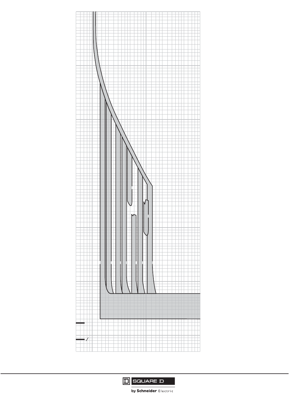
PowerPact™ M-, P- and R-Frame, and Compact™ NS630b–NS3200 Circuit Breakers
Section 11—Trip Curves
133
10/2012
© 2001–2012 Schneider Electric
All Rights Reserved
™
Basic Electronic Trip Unit 1.0I P- and R-Frame Characteristic Trip Curve
1.5
11
MULTIPLES OF SENSOR RATING (In)
MULTIPLES OF SENSOR RATING (In)
.5
.6
.7
.8
.9
1.5
2
3
4
5
6
7
8
9
10
15
20
30
40
50
60
70
80
90
100
.5
.6
.7
.8
.9
2
3
4
5
6
7
8
9
10
15
20
30
40
50
60
70
80
90
100
200
300
400
500
600
700
800
900
1000
1500
2000
3000
4000
6000
7000
8000
9000
5000
10000
.005
.006
.007
.008
.009
.01
.015
.02
.03
.04
.05
.06
.07
.08
.09
.1
.005
.006
.007
.008
.009
.01
.015
.02
.03
.04
.05
.06
.07
.08
.09
.1
.15
.2
.3
.4
.5
.6
.7
.8
.9
1
.15
.2
.3
.4
.5
.6
.7
.8
.9
1
1.5
2
3
4
5
6
7
8
9
10
1.5
2
3
4
5
6
7
8
9
10
15
20
30
40
50
60
70
80
90
100
15
20
30
40
50
60
70
80
90
100
150
200
300
400
500
600
700
800
900
1000
1500
2000
3000
4000
5000
6000
7000
8000
9000
10000
TIME IN SECONDS
CYCLE
2
1
1 CYCLE
150
1.5 x
INSTANTANEOUS
PICKUP
x In
LONG-TIME
PICKUP
LONG-TIME
DELAY
5 x
10 x
2 x 3 x 4 x 6 x 8 x 12 x
Basic Electronic Trip Unit 1.0I
Long-Time Pickup and Fixed Delay
Instantaneous Pickup 1.5 x to 12 x
The time-current curve information
is to be used for application and
coordination purposes only.
Curves apply from -30°C to +60°C
(-22°F to +140°F) ambient
temperature.
Instantaneous override values are
given on page 143
Notes:
1. There is a thermal-imaging effect that can act
to shorten the long-time delay. The thermal-
imaging effect comes into play if a current
above the long-time delay pickup value exists
for a time and then is cleared by the tripping of
a downstream device or the circuit breaker
itself. A subsequent overload will cause the
circuit breaker to trip in a shorter time than
normal. The amount of time delay reduction is
inverse to the amount of time that has elapsed
since the previous overload. Approximately 20
minutes is required between over.oads to
completely reset thermal-imaging.
2. Total clearing times shown include the
response times of the trip unit, the circuit
breaker opening, and the extinction of current.
B48095-613-12.eps
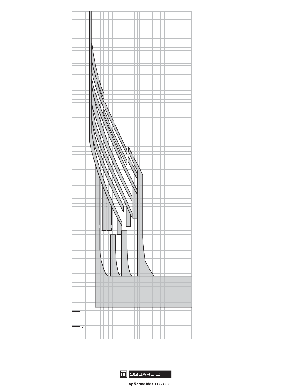
© 2001–2012 Schneider Electric
All Rights Reserved
PowerPact™ M-, P- and R-Frame, and Compact™ NS630b–NS3200 Circuit Breakers
Section 11—Trip Curves
134
10/2012
™
Micrologic 2.0A NS630b–NS3200 Trip Unit Characteristic Trip Curve
1.5
11
CURRENT IN MULTIPLES OF Ir (Ir = LONG-TIME SETTING x In)
CURRENT IN MULTIPLES OF Ir
(Ir = LONG-TIME SETTING x In)
.5
.6
.7
.8
.9
1.5
2
3
4
5
6
7
8
9
10
15
20
30
40
50
60
70
80
90
100
.5
.6
.7
.8
.9
2
3
4
5
6
7
8
9
10
15
20
30
40
50
60
70
80
90
100
200
300
400
500
600
700
800
900
1000
1500
2000
3000
4000
6000
7000
8000
9000
5000
10000
.005
.006
.007
.008
.009
.01
.015
.02
.03
.04
.05
.06
.07
.08
.09
.1
.005
.006
.007
.008
.009
.01
.015
.02
.03
.04
.05
.06
.07
.08
.09
.1
.15
.2
.3
.4
.5
.6
.7
.8
.9
1
.15
.2
.3
.4
.5
.6
.7
.8
.9
1
1.5
2
3
4
5
6
7
8
9
10
1.5
2
3
4
5
6
7
8
9
10
15
20
30
40
50
60
70
80
90
100
15
20
30
40
50
60
70
80
90
100
150
200
300
400
500
600
700
800
900
1000
1500
2000
3000
4000
5000
6000
7000
8000
9000
10000
TIME IN SECONDS
CYCLE
2
1
1 CYCLE
150
24
20
.5
16
12
8
2.51. 5 2
4
35
6
8
10
4
2
1
16
LONG-TIME PICKUP
x In = Ir
LONG-TIME
DELAY BANDS
SECONDS AT 6 x Ir
SHORT-TIME
PICKUP
x Ir
24
Curve No. 0613TC0009
Drawing No. B48095-613-09
Micrologic 2.0A Trip Unit
Long-Time Pickup and Delay
Short-Time Pickup with No Delay
Characteristic Trip Curve No. 613-9
The time-current curve information
is to be used for application and
coordination purposes only.
Curves apply from -30°C to +60°C
(-22°F to +140°F) ambient
temperature.
Notes:
1. There is a thermal-imaging effect that can
act to shorten the long-time delay. The
thermal-imaging effect comes into play if a
current above the long-time delay pickup
value exists for a time and then is cleared by
the tripping of a downstream device or the
circuit breaker itself. A subsequent overload
will cause the circuit breaker to trip in a
shorter time than normal. The amount of
time delay reduction is inverse to the amount
of time that has elapsed since the previous
overload. Approximately twenty minutes is
required between overloads to completely
reset thermal-imaging.
2. The end of the curve is determined by the
short-time setting.
3. Total clearing times shown include the
response times of the trip unit, the circuit
breaker opening, and the extinction of
current.
4. Overload indicator illuminates at 100%.
B48095-613-09.eps
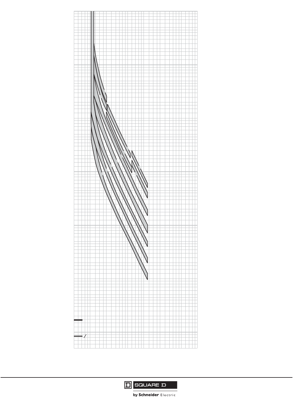
PowerPact™ M-, P- and R-Frame, and Compact™ NS630b–NS3200 Circuit Breakers
Section 11—Trip Curves
135
10/2012
© 2001–2012 Schneider Electric
All Rights Reserved
™
Micrologic 3.0A P-Frame and R-Frame Trip Unit Characteristic Trip Curve
1.5
11
CURRENT IN MULTIPLES OF Ir (Ir = LONG-TIME SETTING x In)
CURRENT IN MULTIPLES OF Ir
(Ir = LONG-TIME SETTING x In)
.5
.6
.7
.8
.9
1.5
2
3
4
5
6
7
8
9
10
15
20
30
40
50
60
70
80
90
100
.5
.6
.7
.8
.9
2
3
4
5
6
7
8
9
10
15
20
30
40
50
60
70
80
90
100
200
300
400
500
600
700
800
900
1000
1500
2000
3000
4000
6000
7000
8000
9000
5000
10000
.005
.006
.007
.008
.009
.01
.015
.02
.03
.04
.05
.06
.07
.08
.09
.1
.005
.006
.007
.008
.009
.01
.015
.02
.03
.04
.05
.06
.07
.08
.09
.1
.15
.2
.3
.4
.5
.6
.7
.8
.9
1
.15
.2
.3
.4
.5
.6
.7
.8
.9
1
1.5
2
3
4
5
6
7
8
9
10
1.5
2
3
4
5
6
7
8
9
10
15
20
30
40
50
60
70
80
90
100
15
20
30
40
50
60
70
80
90
100
150
200
300
400
500
600
700
800
900
1000
1500
2000
3000
4000
5000
6000
7000
8000
9000
10000
TIME IN SECONDS
CYCLE
2
1
1 CYCLE
150
24
20
12
.5
8
4
2
1
16
24
16
LONG-TIME PICKUP
x In = Ir
LONG-TIME DELAY
SECONDS AT 6 x Ir
Curve No. 0613TC0006
Drawing No. B48095-613-06
Micrologic 3.0A Trip Unit
Long-Time Pickup and Delay
Characteristic Trip Curve No. 613-6
The time-current curve information
is to be used for application and
coordination purposes only.
Curves apply from -30°C to +60°C
(-22°F to +140°F) ambient
temperature.
Notes:
1. There is a thermal-imaging effect that can
act to shorten the long-time delay. The
thermal-imaging effect comes into play if a
current above the long-time delay pickup
value exists for a time and then is cleared
by the tripping of a downstream device or
the circuit breaker itself. A subsequent
overload will cause the circuit breaker to trip
in a shorter time than normal. The amount
of time delay reduction is inverse to the
amount of time that has elapsed since the
previous overload. Approximately twenty
minutes is required between overloads to
completely reset thermal-imaging.
2. The end of the curve is determined by the
instantaneous setting of the circuit breaker.
3. Total clearing times shown include the
response times of the trip unit, the circuit
breaker opening, and the extinction of
current.
4. See trip curve 613-8 on page 136 for
instantaneous pickup trip curve.
B48095-613-06.eps
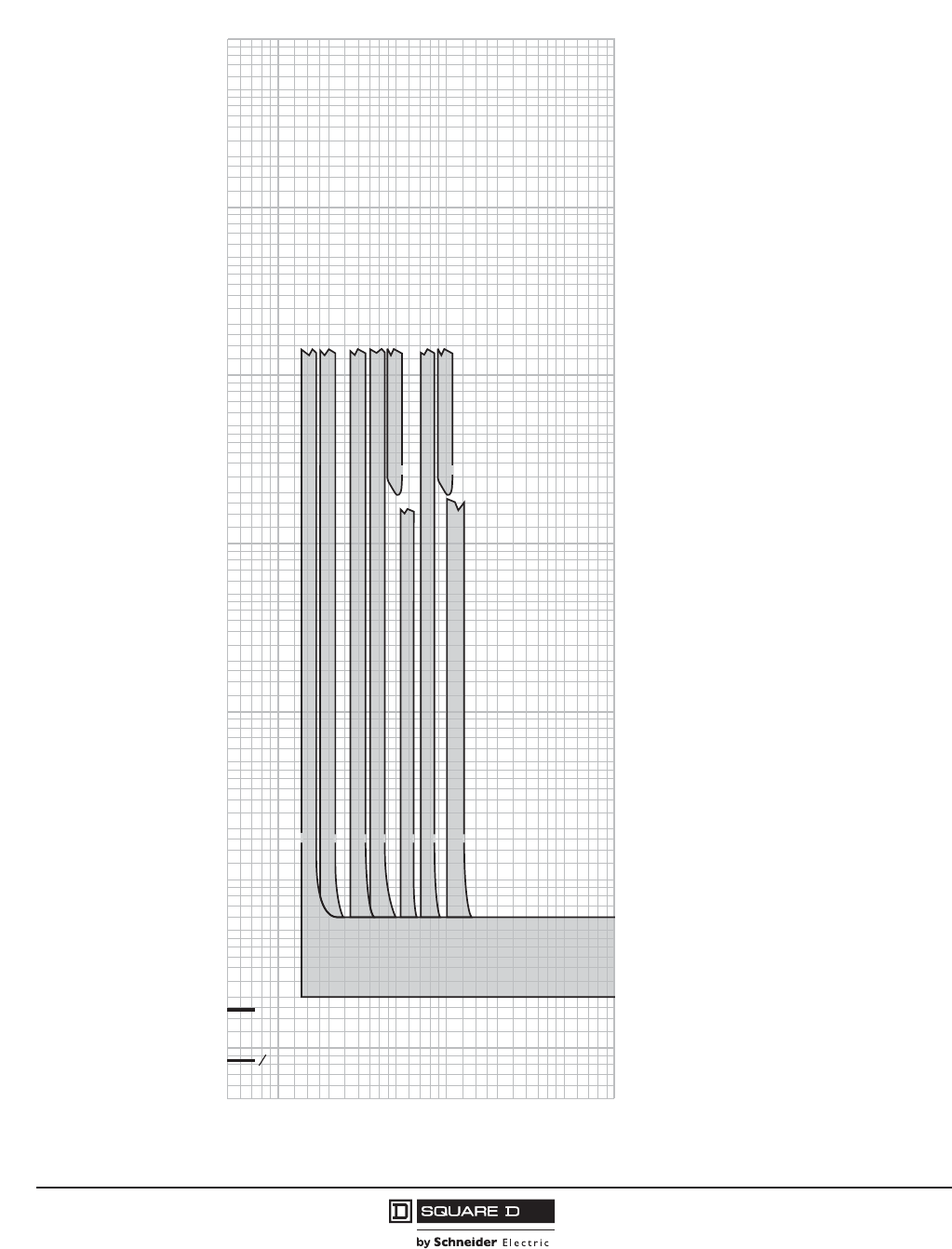
© 2001–2012 Schneider Electric
All Rights Reserved
PowerPact™ M-, P- and R-Frame, and Compact™ NS630b–NS3200 Circuit Breakers
Section 11—Trip Curves
136
10/2012
™
Micrologic 3.0A P-Frame and R-Frame Trip Unit Characteristic Trip Curve
1.5
11
MULTIPLES OF SENSOR RATING (In)
MULTIPLES OF SENSOR RATING (In)
.5
.6
.7
.8
.9
1.5
2
3
4
5
6
7
8
9
10
15
20
30
40
50
60
70
80
90
100
.5
.6
.7
.8
.9
2
3
4
5
6
7
8
9
10
15
20
30
40
50
60
70
80
90
100
200
300
400
500
600
700
800
900
1000
1500
2000
3000
4000
6000
7000
8000
9000
5000
10000
.005
.006
.007
.008
.009
.01
.015
.02
.03
.04
.05
.06
.07
.08
.09
.1
.005
.006
.007
.008
.009
.01
.015
.02
.03
.04
.05
.06
.07
.08
.09
.1
.15
.2
.3
.4
.5
.6
.7
.8
.9
1
.15
.2
.3
.4
.5
.6
.7
.8
.9
1
1.5
2
3
4
5
6
7
8
9
10
1.5
2
3
4
5
6
7
8
9
10
15
20
30
40
50
60
70
80
90
100
15
20
30
40
50
60
70
80
90
100
150
200
300
400
500
600
700
800
900
1000
1500
2000
3000
4000
5000
6000
7000
8000
9000
10000
TIME IN SECONDS
CYCLE
2
1
1 CYCLE
150
1.5 x
INSTANTANEOUS
PICKUP
x In
5 x 10 x
2 x 3 x 4 x 6 x 8 x 12 x
Curve No. 0613TC0008
Drawing No. B48095-613-08
Micrologic 3.0A Trip Unit
Instantaneous Pickup, 1.5X to 12X
Characteristic Trip Curve No. 613-8
The time-current curve information
is to be used for application and
coordination purposes only.
Curves apply from -30°C to +60°C
(-22°F to +140°F) ambient
temperature.
Notes:
1. The end of the curve is determined by the
interrupting rating of the circuit breaker.
2. Total clearing times shown include the
response times of the trip unit, the circuit
breaker opening, and the extinction of current.
3. The instantaneous region of the trip curve
shows maximum total clearing times. Actual
clearing times in this region can vary
depending on the circuit breaker mechanism
design and other factors. The actual clearing
time can be considerably faster than
indicated. Contact your local sales office for
additional information.
4. See trip curve 613-6 on page 135 for long-
time pickup and delay trip curves.
B48095-613-08,eps
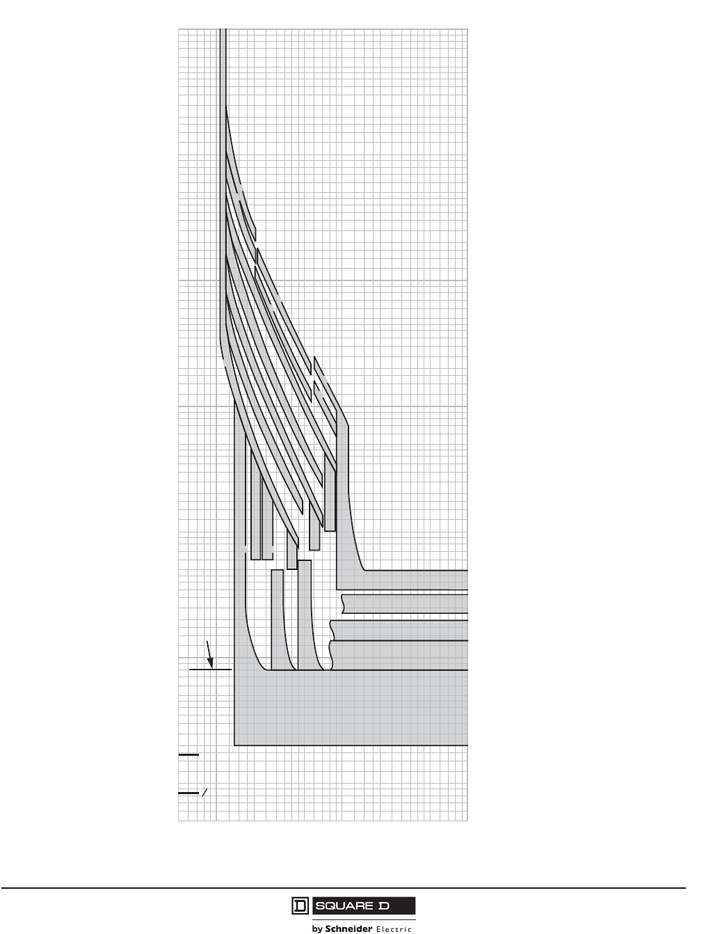
PowerPact™ M-, P- and R-Frame, and Compact™ NS630b–NS3200 Circuit Breakers
Section 11—Trip Curves
137
10/2012
© 2001–2012 Schneider Electric
All Rights Reserved
™
Micrologic 5.0/6.0 P-Frame, R-Frame and NS630b–NS3200 A/P/H Trip Unit Characteristic Trip Curve
1.5
11
CURRENT IN MULTIPLES OF Ir (Ir = LONG-TIME SETTING x In)
CURRENT IN MULTIPLES OF Ir
(Ir = LONG-TIME SETTING x In)
.5
.6
.7
.8
.9
1.5
2
3
4
5
6
7
8
9
10
15
20
30
40
50
60
70
80
90
100
.5
.6
.7
.8
.9
2
3
4
5
6
7
8
9
10
15
20
30
40
50
60
70
80
90
100
200
300
400
500
600
700
800
900
1000
1500
2000
3000
4000
6000
7000
8000
9000
5000
10000
.005
.006
.007
.008
.009
.01
.015
.02
.03
.04
.05
.06
.07
.08
.09
.1
.005
.006
.007
.008
.009
.01
.015
.02
.03
.04
.05
.06
.07
.08
.09
.1
.15
.2
.3
.4
.5
.6
.7
.8
.9
1
.15
.2
.3
.4
.5
.6
.7
.8
.9
1
1.5
2
3
4
5
6
7
8
9
10
1.5
2
3
4
5
6
7
8
9
10
15
20
30
40
50
60
70
80
90
100
15
20
30
40
50
60
70
80
90
100
150
200
300
400
500
600
700
800
900
1000
1500
2000
3000
4000
5000
6000
7000
8000
9000
10000
TIME IN SECONDS
CYCLE
2
1
1 CYCLE
150
24
20
.5
24
16
12
8
8
6
4
2.51. 5 2
35
10
4
2
1
16
0.4 OFF
0.3 OFF
0.2 OFF
0.1 OFF
0
LONG-TIME PICKUP
x In = Ir
LONG-TIME
DELAY BANDS
SECONDS AT 6 x Ir
MAXIMUM
UNRESTRAINED
SHORT-TIME
DELAY
SHORT-TIME
DELAY I
2
t OFF
(FIXED-TIME DELAY)
SECONDS AT 10 x Ir
SHORT-TIME
PICKUP
x Ir
Curve No. 0613TC0004
Drawing No. B48095-613-04
Micrologic 5.0/6.0 A/P/H Trip Units
Long-Time Pickup and Delay
Short-Time Pickup and I2t OFF
Delay
Characteristic Trip Curve No. 613-4
The time-current curve information
is to be used for application and
coordination purposes only.
Curves apply from -30°C to +60°C
(-22°F to +140°F) ambient
temperature.
Notes:
1. There is a thermal-imaging effect that can act
to shorten the long-time delay. The thermal-
imaging effect comes into play if a current
above the long-time delay pickup value exists
for a time and then is cleared by the tripping
of a downstream device or the circuit breaker
itself. A subsequent overload will cause the
circuit breaker to trip in a shorter time than
normal. The amount of time delay reduction
is inverse to the amount of time that has
elapsed since the previous overload.
Approximately twenty minutes is required
between overloads to completely reset
thermal-imaging.
2. The end of the curve is determined by the
interrupting rating of the circuit breaker.
3. With zone-selective interlocking ON, short-
time delay utilized, and no restraining signal,
the maximum unrestrained short-time delay
time band applies regardless of the setting.
4. Total clearing times shown include the
response times of the trip unit, the circuit
breaker opening, and the extinction of the
current.
5. For a withstand circuit breaker, instantaneous
can be turned OFF. See trip curve 613-7 on
page 139 for instantaneous trip curve. See
table on page 143 for instantaneous override
values.
6. Overload indicator illuminates at 100%.
B48095-613-04.eps
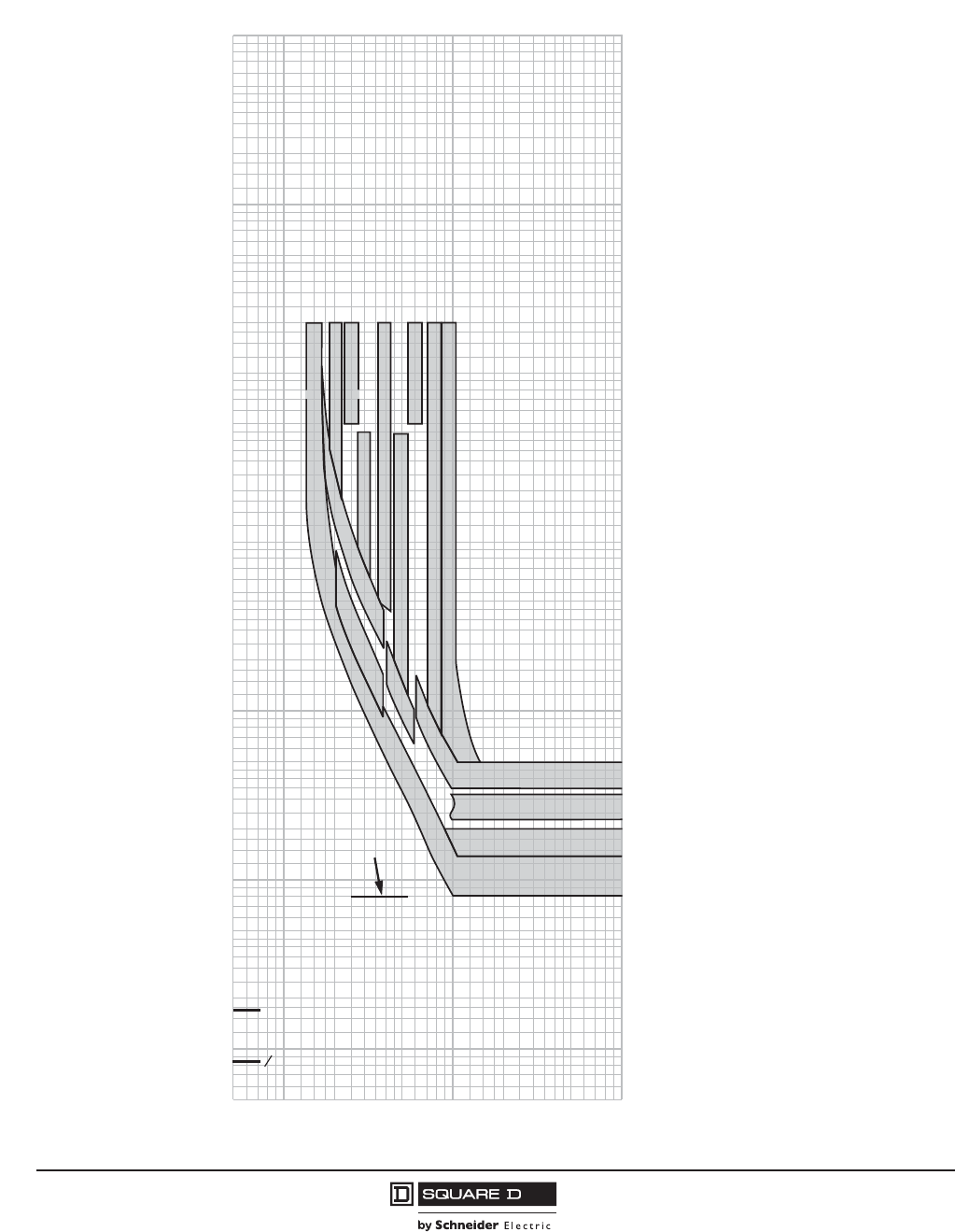
© 2001–2012 Schneider Electric
All Rights Reserved
PowerPact™ M-, P- and R-Frame, and Compact™ NS630b–NS3200 Circuit Breakers
Section 11—Trip Curves
138
10/2012
™
Micrologic 5.0/6.0 P-Frame, R-Frame and NS630b–NS3200 A/P/H Trip Units Characteristic Trip
Curve
1.5
11
CURRENT IN MULTIPLES OF Ir (Ir = LONG-TIME SETTING x In)
CURRENT IN MULTIPLES OF Ir
(Ir = LONG-TIME SETTING x In)
.5
.6
.7
.8
.9
1.5
2
3
4
5
6
7
8
9
10
15
20
30
40
50
60
70
80
90
100
.5
.6
.7
.8
.9
2
3
4
5
6
7
8
9
10
15
20
30
40
50
60
70
80
90
100
200
300
400
500
600
700
800
900
1000
1500
2000
3000
4000
6000
7000
8000
9000
5000
10000
.005
.006
.007
.008
.009
.01
.015
.02
.03
.04
.05
.06
.07
.08
.09
.1
.005
.006
.007
.008
.009
.01
.015
.02
.03
.04
.05
.06
.07
.08
.09
.1
.15
.2
.3
.4
.5
.6
.7
.8
.9
1
.15
.2
.3
.4
.5
.6
.7
.8
.9
1
1.5
2
3
4
5
6
7
8
9
10
1.5
2
3
4
5
6
7
8
9
10
15
20
30
40
50
60
70
80
90
100
15
20
30
40
50
60
70
80
90
100
150
200
300
400
500
600
700
800
900
1000
1500
2000
3000
4000
5000
6000
7000
8000
9000
10000
TIME IN SECONDS
CYCLE
2
1
1 CYCLE
150
2.52
345
68101. 5
0.4 ON
0.4 ON
0.2 ON
0.3 ON
0.1 ON
0.3 ON
0.2 ON
0.1 ON
SHORT-TIME
DELAY I
2
t ON
SECONDS AT 10 x Ir
SHORT-TIME
PICKUP
x Ir
MAXIMUM
UNRESTRAINED
SHORT-TIME
DELAY
Curve No. 0613TC0005
Drawing No. B48095-613-05
Micrologic 5.0/6.0 A/P/H Trip Units
Short-Time Pickup and I2t ON Delay
Characteristic Trip Curve No. 613-5
The time-current curve information
is to be used for application and
coordination purposes only.
Curves apply from -30°C to +60°C
(-22°F to +140°F) ambient
temperature.
Notes:
1. There is a thermal-imaging effect that can act
to shorten the long-time delay. The thermal-
imaging effect comes into play if a current
above the long-time delay pickup value exists
for a time and then is cleared by the tripping of
a downstream device or the circuit breaker
itself. A subsequent overload will cause the
circuit breaker to trip in a shorter time than
normal. The amount of time delay reduction is
inverse to the amount of time that has elapsed
since the previous overload. Approximately
twenty minutes is required between overloads
to completely reset thermal-imaging.
2. The end of the curve is determined by the
interrupting rating of the circuit breaker.
3. With zone-selective interlocking ON, short-
time delay utilized, and no restraining signal,
the maximum unrestrained short-time delay
time band applies regardless of the setting.
4. Total clearing times shown include the
response times of the trip unit, the circuit
breaker opening, and the extinction of current.
5. For withstand circuit breaker, instantaneous
can be turned OFF. See trip curve 613-7 on
page 139 for instantaneous trip curve. See
table on page 143 for instantaneous override
values.
6. See Trip Curve 613-4 on page 137 for long-
time pickup and delay trip curve.
B48095-613-05.eps
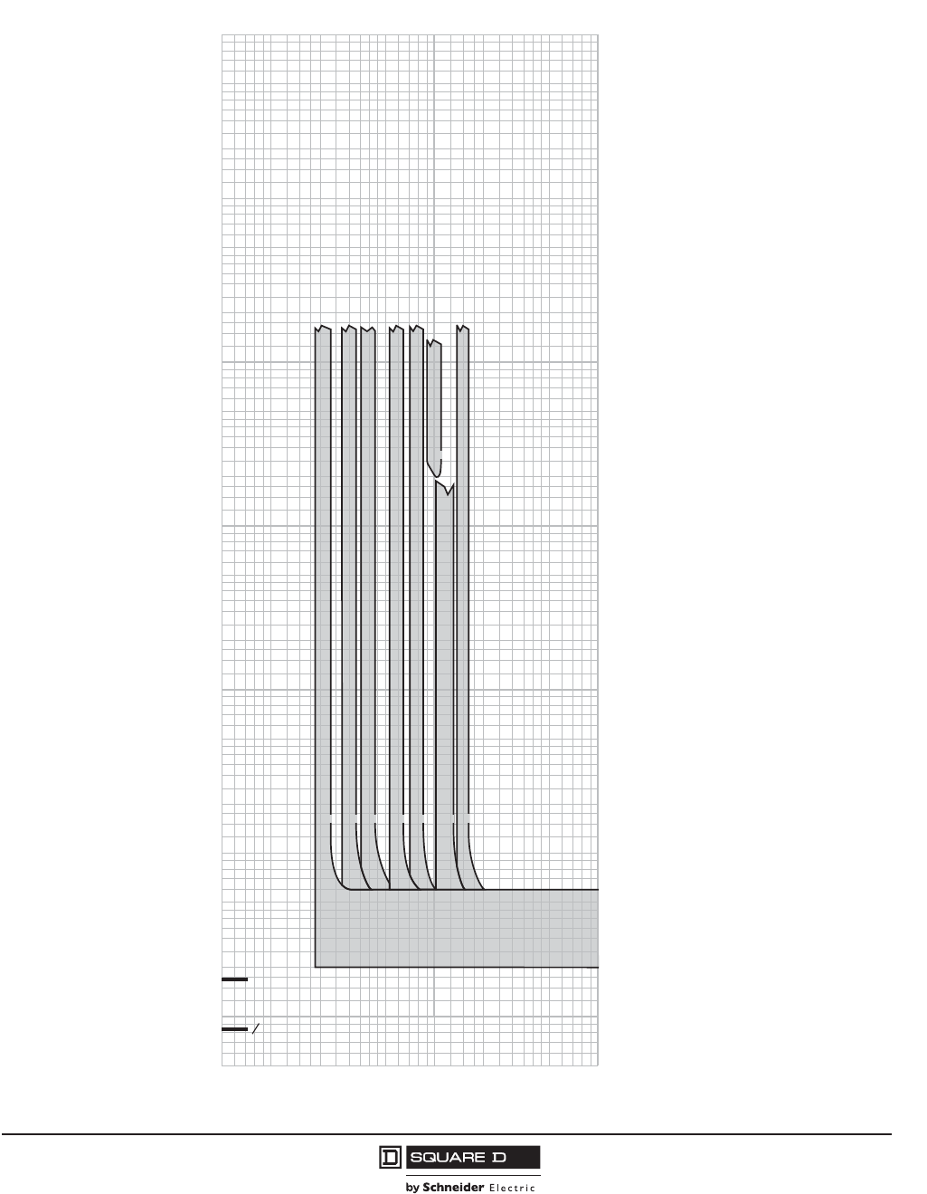
PowerPact™ M-, P- and R-Frame, and Compact™ NS630b–NS3200 Circuit Breakers
Section 11—Trip Curves
139
10/2012
© 2001–2012 Schneider Electric
All Rights Reserved
™
Micrologic 5.0/6.0 P-Frame, R-Frame and NS630b–NS3200 A/P/H Trip Units Characteristic Trip
Curve
1.5
11
MULTIPLES OF SENSOR RATING (In)
MULTIPLES OF SENSOR RATING (In)
.5
.6
.7
.8
.9
1.5
2
3
4
5
6
7
8
9
10
15
20
30
40
50
60
70
80
90
100
.5
.6
.7
.8
.9
2
3
4
5
6
7
8
9
10
15
20
30
40
50
60
70
80
90
100
200
300
400
500
600
700
800
900
1000
1500
2000
3000
4000
6000
7000
8000
9000
5000
10000
.005
.006
.007
.008
.009
.01
.015
.02
.03
.04
.05
.06
.07
.08
.09
.1
.005
.006
.007
.008
.009
.01
.015
.02
.03
.04
.05
.06
.07
.08
.09
.1
.15
.2
.3
.4
.5
.6
.7
.8
.9
1
.15
.2
.3
.4
.5
.6
.7
.8
.9
1
1.5
2
3
4
5
6
7
8
9
10
1.5
2
3
4
5
6
7
8
9
10
15
20
30
40
50
60
70
80
90
100
15
20
30
40
50
60
70
80
90
100
150
200
300
400
500
600
700
800
900
1000
1500
2000
3000
4000
5000
6000
7000
8000
9000
10000
TIME IN SECONDS
CYCLE
2
1
1 CYCLE
150
INSTANTANEOUS
PICKUP
x In
10 x
2 x 3 x 4 x 6 x 8 x 12 x 15 x
Curve No. 0613TC0007
Drawing No. B48095-613-07
Micrologic 5.0/6.0 Trip Units
Instantaneous Pickup, 2X to 15X
and OFF
Characteristic Trip Curve No. 613-7
The time-current curve information
is to be used for application and
coordination purposes only.
Curves apply from -30°C to +60°C
(-22°F to +140°F) ambient
temperature.
Notes:
1. The end of the curve is determined by the
interrupting rating of the circuit breaker.
2. Total clearing times shown include the
response times of the trip unit, the circuit
breaker opening, and the extinction of current.
3. The instantaneous region of the trip curve
shows maximum total clearing times. Actual
clearing times in this region can vary
depending on the circuit breaker mechanism
design and other factors. The actual clearing
time can be considerably faster than
indicated. Contact your local sales office for
additional information.
4. For a withstand circuit breaker, instantaneous
can be turned OFF. See trip curve 613-7 on
page 139 for the instantaneous trip curve. See
table on page 143 for the instantaneous
override values.
5. See trip curve 613-4 on page 137 and trip
curve 613-5 on page 138 for long-time pickup,
long-time delay, short-time pickup and short-
time delay trip curves.
B48095-613-07.eps
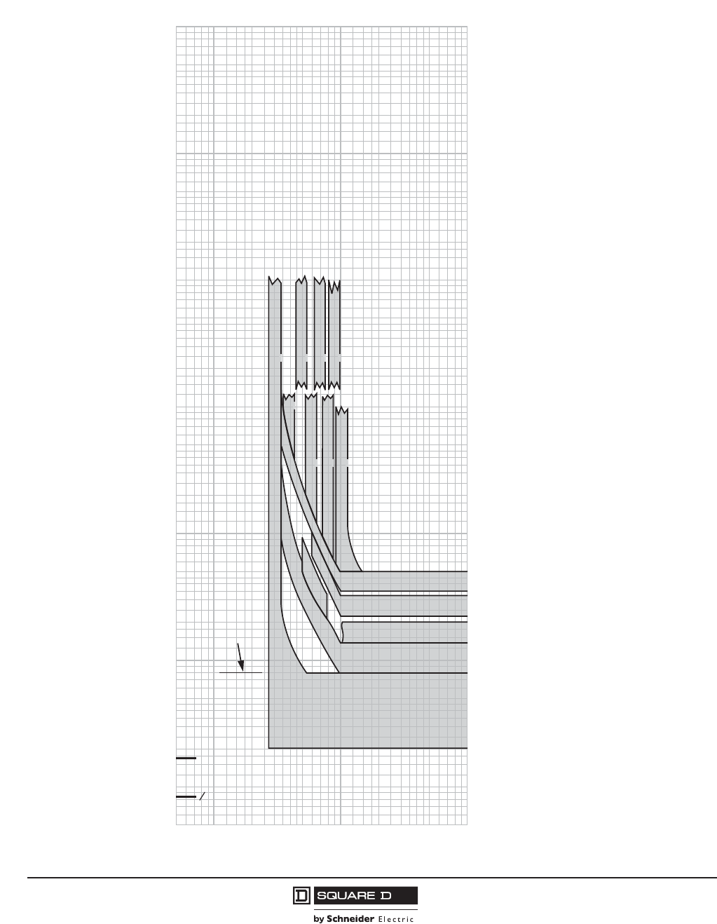
© 2001–2012 Schneider Electric
All Rights Reserved
PowerPact™ M-, P- and R-Frame, and Compact™ NS630b–NS3200 Circuit Breakers
Section 11—Trip Curves
140
10/2012
™
Micrologic 6.0 P-Frame, R-Frame and NS630b–NS3200 A/P/H Trip Units with Adjustable
Ground-fault Pickup and Delay Characteristic Trip Curve
.15
.1 .1
MULTIPLES OF SENSOR RATING (In)
MULTIPLES OF SENSOR RATING (In)
Curve No. 0613TC0001
Drawing No. B48095-613-01
.05
.06
.07
.08
.09
.15
.2
.3
.4
.5
.6
.7
.8
.9
1
1.5
2
3
4
5
6
7
8
9
10
.05
.06
.07
.08
.09
.2
.3
.4
.5
.6
.7
.8
.9
1
1.5
2
3
4
5
6
7
8
9
10
200
300
400
500
600
700
800
900
1000
1500
2000
3000
4000
6000
7000
8000
9000
5000
10000
.005
.006
.007
.008
.009
.01
.015
.02
.03
.04
.05
.06
.07
.08
.09
.1
.005
.006
.007
.008
.009
.01
.015
.02
.03
.04
.05
.06
.07
.08
.09
.1
.15
.2
.3
.4
.5
.6
.7
.8
.9
1
.15
.2
.3
.4
.5
.6
.7
.8
.9
1
1.5
2
3
4
5
6
7
8
9
10
1.5
2
3
4
5
6
7
8
9
10
15
20
30
40
50
60
70
80
90
100
15
20
30
40
50
60
70
80
90
100
150
200
300
400
500
600
700
800
900
1000
1500
2000
3000
4000
5000
6000
7000
8000
9000
10000
TIME IN SECONDS
CYCLE
2
1
1 CYCLE
150
0.4 ON
0.3 ON
0.2 ON
0.1 ON
0.4 OFF
0.3 OFF
0.2 OFF
0.1 OFF
0
GROUND-FAULT
DELAY BANDS
I
2
t ON
GROUND-FAULT
PICKUP
x In
GROUND-FAULT
DELAY BANDS
I
2
t OFF
(FIXED DELAY)
DELAY
SECONDS AT 1 x In
0.1
0.2
0.3
0.4
MAXIMUM
UNRESTRAINED
GROUND-FAULT
DELAY
0.5 0.7 0.9
0.4
0.6 0.8 1.0
0.3
B48095-613-01.eps
Micrologic 6.0 A/P/H Trip Units
with Adjustable Ground-Fault Pickup
and Delay
Ground Fault I2t OFF and ON
In d400 A
Characteristic Trip Curve No. 613-1
The time-current curve information
is to be used for application and
coordination purposes only.
Curves apply from -30°C to +60°C
(-22°F to +140°F) ambient
temperature.
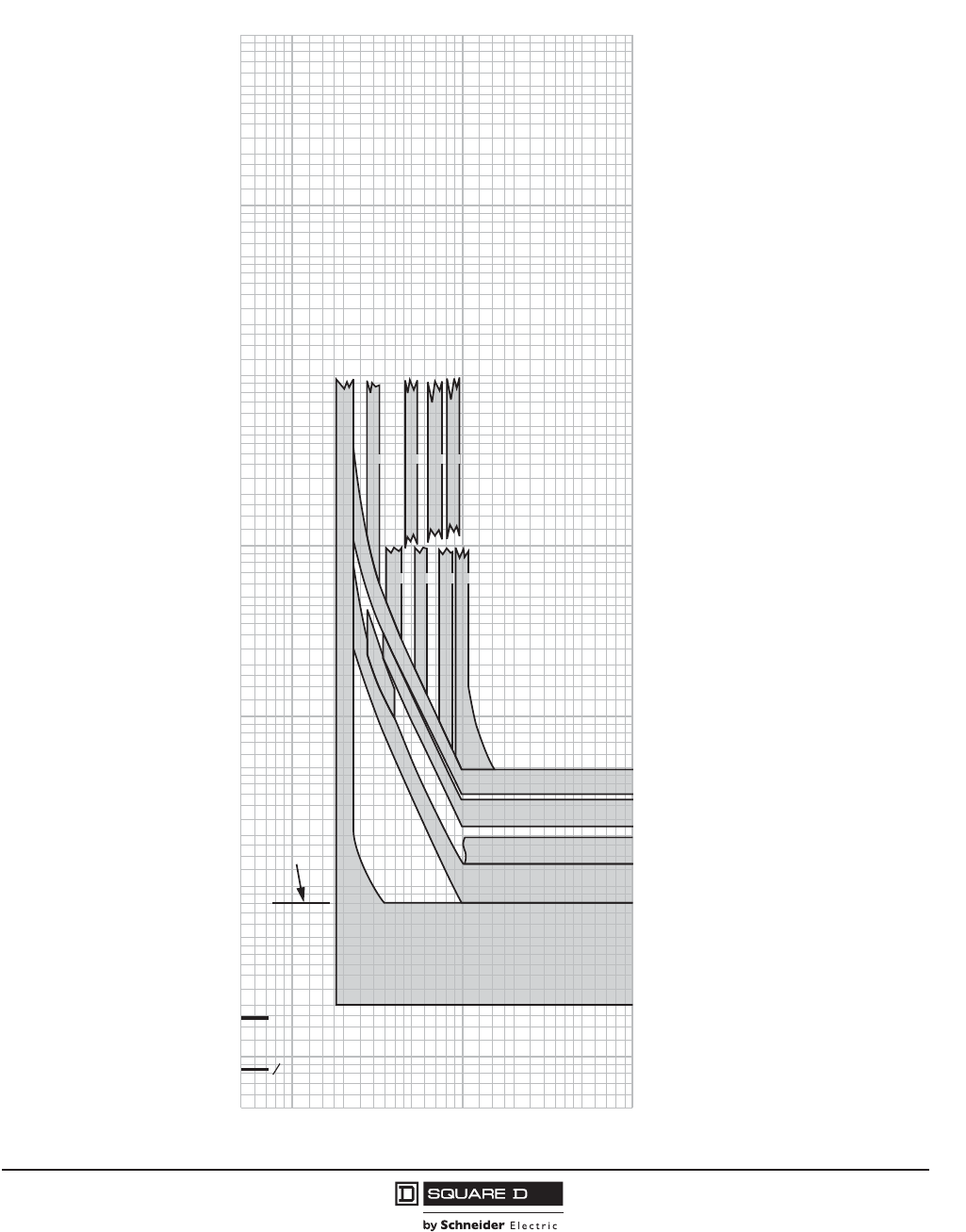
PowerPact™ M-, P- and R-Frame, and Compact™ NS630b–NS3200 Circuit Breakers
Section 11—Trip Curves
141
10/2012
© 2001–2012 Schneider Electric
All Rights Reserved
™
Micrologic 6.0 P-Frame, R-Frame and NS630b–NS3200 A/P/H Trip Units with Adjustable
Ground-fault Pickup and Delay Characteristic Trip Curve
.15
.1 .1
MULTIPLES OF SENSOR RATING (In)
MULTIPLES OF SENSOR RATING (In)
.05
.06
.07
.08
.09
.15
.2
.3
.4
.5
.6
.7
.8
.9
1
1.5
2
3
4
5
6
7
8
9
10
.05
.06
.07
.08
.09
.2
.3
.4
.5
.6
.7
.8
.9
1
1.5
2
3
4
5
6
7
8
9
10
200
300
400
500
600
700
800
900
1000
1500
2000
3000
4000
6000
7000
8000
9000
5000
10000
.005
.006
.007
.008
.009
.01
.015
.02
.03
.04
.05
.06
.07
.08
.09
.1
.005
.006
.007
.008
.009
.01
.015
.02
.03
.04
.05
.06
.07
.08
.09
.1
.15
.2
.3
.4
.5
.6
.7
.8
.9
1
.15
.2
.3
.4
.5
.6
.7
.8
.9
1
1.5
2
3
4
5
6
7
8
9
10
1.5
2
3
4
5
6
7
8
9
10
15
20
30
40
50
60
70
80
90
100
15
20
30
40
50
60
70
80
90
100
150
200
300
400
500
600
700
800
900
1000
1500
2000
3000
4000
5000
6000
7000
8000
9000
10000
TIME IN SECONDS
CYCLE
2
1
1 CYCLE
150
0.2
0.2 ON
0.4 ON
0.3 ON
0.1 ON
0.4 OFF
0.3 OFF
0.2 OFF
0.1 OFF
0
GROUND-FAULT
DELAY BANDS
I2t ON
GROUND-FAULT
PICKUP
x In
GROUND-FAULT
DELAY BANDS
I2t OFF
(FIXED DELAY)
DELAY
SECONDS AT 1 x In
0.1
0.2
0.3
0.4
MAXIMUM
UNRESTRAINED
GROUND-FAULT
DELAY
0.3 0.5 0.7 0.9
0.4 0.6 0.8 1.0
Curve No. 0613TC0002
Drawing No. B48095-613-02
Micrologic 6.0 A/P/H Trip Units
with Adjustable Ground-Fault Pickup
and Delay
Ground Fault I2t OFF and ON
400 A In d1200 A
Characteristic Trip Curve No. 613-2
The time-current curve information
is to be used for application and
coordination purposes only.
Curves apply from -30°C to +60°C
(-22°F to +140°F) ambient
temperature.
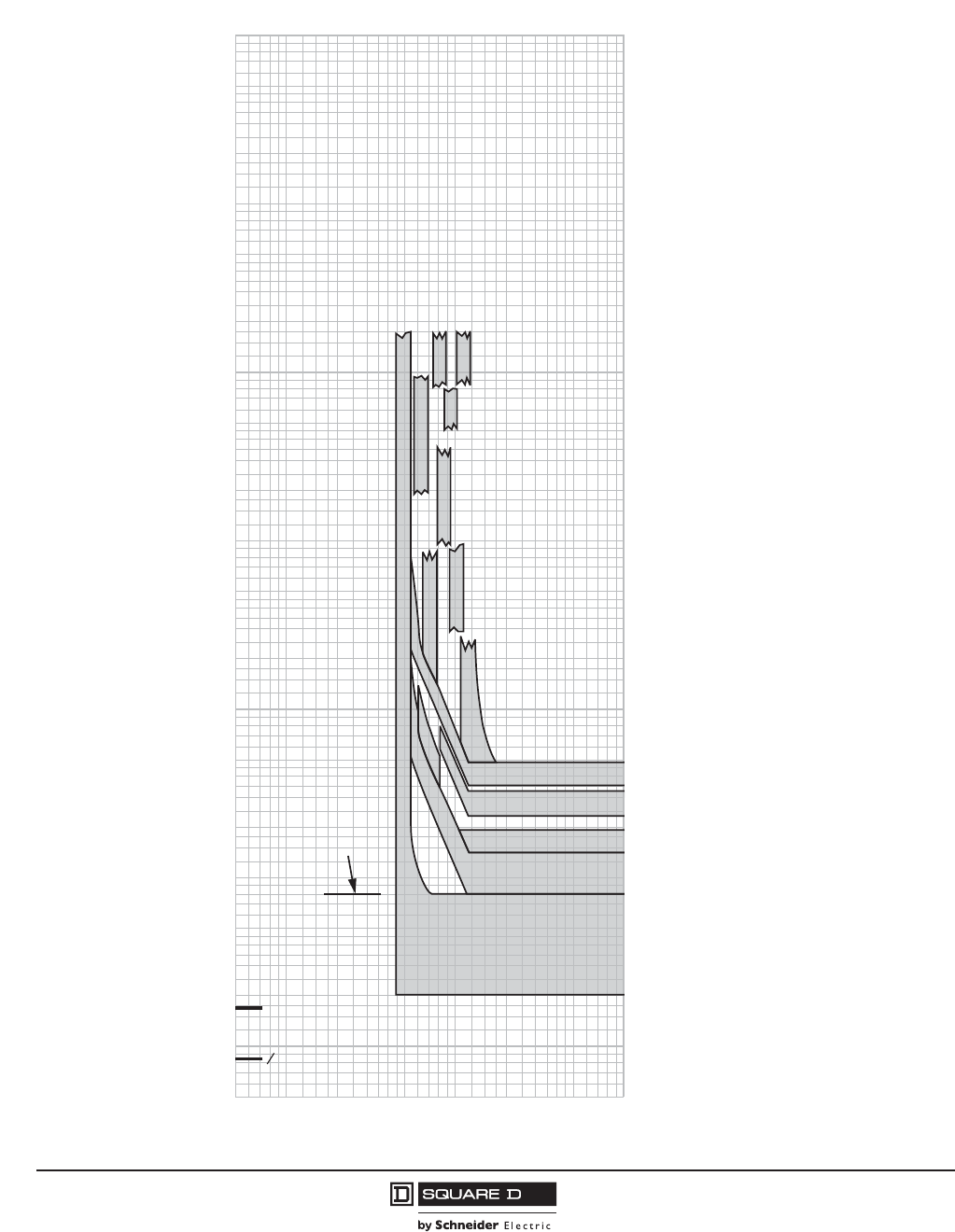
© 2001–2012 Schneider Electric
All Rights Reserved
PowerPact™ M-, P- and R-Frame, and Compact™ NS630b–NS3200 Circuit Breakers
Section 11—Trip Curves
142
10/2012
™
Micrologic 6.0 P-Frame, R-Frame and NS630b–NS3200 A/P/H Trip Units with Adjustable
Ground-fault Pickup and Delay Characteristic Trip Curve
.15
.1 .1
AMPERES x 10
3
AMPERES x 10
3
.05
.06
.07
.08
.09
.15
.2
.3
.4
.5
.6
.7
.8
.9
1
1.5
2
3
4
5
6
7
8
9
10
.05
.06
.07
.08
.09
.2
.3
.4
.5
.6
.7
.8
.9
1
1.5
2
3
4
5
6
7
8
9
10
200
300
400
500
600
700
800
900
1000
1500
2000
3000
4000
6000
7000
8000
9000
5000
10000
.005
.006
.007
.008
.009
.01
.015
.02
.03
.04
.05
.06
.07
.08
.09
.1
.005
.006
.007
.008
.009
.01
.015
.02
.03
.04
.05
.06
.07
.08
.09
.1
.15
.2
.3
.4
.5
.6
.7
.8
.9
1
.15
.2
.3
.4
.5
.6
.7
.8
.9
1
1.5
2
3
4
5
6
7
8
9
10
1.5
2
3
4
5
6
7
8
9
10
15
20
30
40
50
60
70
80
90
100
15
20
30
40
50
60
70
80
90
100
150
200
300
400
500
600
700
800
900
1000
1500
2000
3000
4000
5000
6000
7000
8000
9000
10000
TIME IN SECONDS
CYCLE
2
1
1 CYCLE
150
0.1 ON
0.3 ON
0.4 ON
0.2 ON
0.4 OFF
500 A
720 A
1040 A
1200 A
880 A
640 A
800 A
960 A
1120 A
0.3 OFF
0.2 OFF
0.1 OFF
0
GROUND-FAULT
DELAY BANDS
I
2
t ON
GROUND-FAULT
PICKUP
x In
GROUND-FAULT
DELAY BANDS
I
2
t OFF
(FIXED DELAY)
DELAY
SECONDS AT 1 x In
0.1
0.2
0.3
0.4
MAXIMUM
UNRESTRAINED
GROUND-FAULT
DELAY
Curve No. 0613TC0003
Drawing No. B48095-613-03
Micrologic 6.0 A/P/H Trip Units
with Adjustable Ground-Fault Pickup
and Delay
Ground Fault I2t OFF and ON
In !1200 A
Characteristic Trip Curve No. 613-3
The time-current curve information is
to be used for application and
coordination purposes only.
Curves apply from -30°C to +60°C
(-22°F to +140°F) ambient
temperature.
B48095-613-03.eps
PowerPact™ M-, P- and R-Frame, and Compact™ NS630b–NS3200 Circuit Breakers
Section 11—Trip Curves
143
10/2012
© 2001–2012 Schneider Electric
All Rights Reserved
™
Table 99: Instantaneous Override Values Characteristic Trip Curve
UL/IEC Circuit Breaker Instantaneous Override1
(kA RMS)
1Faults at or above instantaneous override value will be cleared at 25 msec or less.
UL/IEC Circuit Breaker Instantaneous Override1
(kA RMS)
RG 600 57 ± 10% MG300 12 ± 15%
RG 800 57 ± 10% MG350 12 ± 15%
RG 1000 57 ± 10% MG400 12 ± 15%
RG 1200 57 ± 10% MG450 12 ± 15%
RG 1600 57 ± 10% MG500 12 ± 15%
RG 2000 57 ± 10% MG600 12 ± 15%
RG 2500 57 ± 10% MG700 12 ± 15%
RJ 600 48 ± 15% MG800 12 ± 15%
RJ 800 48 ± 15% MJ300 12 ± 15%
RJ 1000 48 ± 15% MJ350 12 ± 15%
RJ 1200 48 ± 15% MJ400 12 ± 15%
RJ 1600 48 ± 15% MJ450 12 ± 15%
RJ 2000 48 ± 15% MJ500 12 ± 15%
RJ 2500 48 ± 15% MJ600 12 ± 15%
RK 600 57 ± 15% MJ700 12 ± 15%
RK 800 57 ± 15% MJ800 12 ± 15%
RK 1000 57 ± 15%
IEC Circuit Breaker Instantaneous Override1
(kA RMS)
RK 1200 57 ± 15%
RK 1600 57 ± 15%
RK 2000 57 ± 15% NS 630b H 24 ± 10%
RK 2500 57 ± 15% NS 800 H 24 ± 10%
RL 600 48 ± 15% NS 1000 H 24 ± 10%
RL 800 48 ± 15% NS 1250 H 24 ± 10%
RL 1000 48 ± 15% NS 1600 H 24 ± 10%
RL 1200 48 ± 15% NS 1600b H 48 ± 15%
RL 1600 48 ± 15% NS 2000 H 48 ± 15%
RL 2000 48 ± 15% NS 2500 H 48 ± 15%
RL 2500 48 ± 15% NS 3200 H 48 ± 15%
PG 250 24 ± 10% NS 630b L 24 ± 10%
PG 400 24 ± 10% NS 800 L 24 ± 10%
PG 600 24 ± 10% NS 1000 L 24 ± 10%
PG 800 24 ± 10% NS 630b N 24 ± 10%
PG 1000 24 ± 10% NS 800 N 24 ± 10%
PG 1200 24 ± 10% NS 1000 N 24 ± 10%
PJ 250 7 ± 10% NS 1250 N 24 ± 10%
PJ 400 10 ± 10% NS 1600 N 24 ± 10%
PJ 600 10 ± 10% NS 1600b N 57 ± 10%
PJ 800 10 ± 10% NS 2000 N 57 ± 10%
PJ 1000 10 ± 10% NS 2500 N 57 ± 10%
PJ 1200 10 ± 10% NS 3200 N 57 ± 10%
PK 250 24 ± 10%
PK 400 24 ± 10%
PK 600 24 ± 10%
PK 800 24 ± 10%
PK 1000 24 ± 10%
PK 1200 24 ± 10%
PL 250 7 ± 10%
PL 400 10 ± 10%
PL 600 10 ± 10%
PL 800 10 ± 10%
PL 1000 10 ± 10%
PL 1200 10 ± 10%
© 2001–2012 Schneider Electric
All Rights Reserved
PowerPact™ M-, P- and R-Frame, and Compact™ NS630b–NS3200 Circuit Breakers
Section 11—Trip Curves
144
10/2012
™
Basic Electronic Trip Unit 1.0M, P-Frame 600 A MDP Characteristic Trip Curve
1.5
11
MULTIPLES OF SENSOR RATING (In)
MULTIPLES OF SENSOR RATING (In)
.5
.6
.7
.8
.9
1.5
2
3
4
5
6
7
8
9
10
15
20
30
40
50
60
70
80
90
100
.5
.6
.7
.8
.9
2
3
4
5
6
7
8
9
10
15
20
30
40
50
60
70
80
90
100
200
300
400
500
600
700
800
900
1000
1500
2000
3000
4000
6000
7000
8000
9000
5000
10000
.005
.006
.007
.008
.009
.01
.015
.02
.03
.04
.05
.06
.07
.08
.09
.1
.005
.006
.007
.008
.009
.01
.015
.02
.03
.04
.05
.06
.07
.08
.09
.1
.15
.2
.3
.4
.5
.6
.7
.8
.9
1
.15
.2
.3
.4
.5
.6
.7
.8
.9
1
1.5
2
3
4
5
6
7
8
9
10
1.5
2
3
4
5
6
7
8
9
10
15
20
30
40
50
60
70
80
90
100
15
20
30
40
50
60
70
80
90
100
150
200
300
400
500
600
700
800
900
1000
1500
2000
3000
4000
5000
6000
7000
8000
9000
10000
TIME IN SECONDS
CYCLE
2
1
1 CYCLE
150
INSTANTANEOUS
PICKUP
x In
4 x
5.5 x2.5 x 10.5 x
13.5 x8 x
6.5 x 16 x
2 x
Basic Electronic Trip Unit 1.0M, 600 A
Instantaneous Pickup, 2X to 16X
Characteristic Trip Curve No. 613-13
The time-current curve information
is to be used for application and
coordination purposes only.
Curves apply from -30°C to +60°C
(-22°F to +140°F) ambient
temperature.
Instantaneous override values are
given on page 143.
Notes:
1. The end of the curve is determined by the
interrupting rating of the circuit breaker.
2. Total clearing times shown include the
response times of the trip unit, the circuit
breaker opening, and the extinction of
current.
3. The instantaneous region of the trip curve
shows maximum total clearing times. Actual
clearing times in this region can vary
depending on the circuit breaker mechanism
design and other factors. The actual clearing
time can be considerably faster than
indicated. Contact your local sales office for
additional information.
B48095-613-13.eps
PowerPact™ M-, P- and R-Frame, and Compact™ NS630b–NS3200 Circuit Breakers
Section 11—Trip Curves
145
10/2012
© 2001–2012 Schneider Electric
All Rights Reserved
™
Basic Electronic Trip Unit 1.0M P-Frame 800–1200A MCP Characteristic Trip Curve
1.5
11
MULTIPLES OF SENSOR RATING (In)
MULTIPLES OF SENSOR RATING (In)
.5
.6
.7
.8
.9
1.5
2
3
4
5
6
7
8
9
10
15
20
30
40
50
60
70
80
90
100
.5
.6
.7
.8
.9
2
3
4
5
6
7
8
9
10
15
20
30
40
50
60
70
80
90
100
200
300
400
500
600
700
800
900
1000
1500
2000
3000
4000
6000
7000
8000
9000
5000
10000
.005
.006
.007
.008
.009
.01
.015
.02
.03
.04
.05
.06
.07
.08
.09
.1
.005
.006
.007
.008
.009
.01
.015
.02
.03
.04
.05
.06
.07
.08
.09
.1
.15
.2
.3
.4
.5
.6
.7
.8
.9
1
.15
.2
.3
.4
.5
.6
.7
.8
.9
1
1.5
2
3
4
5
6
7
8
9
10
1.5
2
3
4
5
6
7
8
9
10
15
20
30
40
50
60
70
80
90
100
15
20
30
40
50
60
70
80
90
100
150
200
300
400
500
600
700
800
900
1000
1500
2000
3000
4000
5000
6000
7000
8000
9000
10000
TIME IN SECONDS
CYCLE
2
1
1 CYCLE
150
1.5 x
INSTANTANEOUS
PICKUP
x In
5 x 10 x
2 x 3 x 4 x 6 x 8 x 12 x
Basic Electronic Trip Unit 1.0M
Instantaneous Pickup, 1.5X to 12X
Characteristic Trip Curve No. 613-11
The time-current curve information
is to be used for application and
coordination purposes only.
Curves apply from -30°C to +60°C
(-22°F to +140°F) ambient
temperature.
Instantaneous override values are
given on page 143.
B48095-613-11.eps
Notes:
1. The end of the curve is determined by the
interrupting rating of the circuit breaker.
2. Total clearing times shown include the
response times of the trip unit, the circuit
breaker opening, and the extinction of current.
3. The instantaneous region of the trip curve
shows maximum total clearing times. Actual
clearing times in this region can vary
depending on the circuit breaker mechanism
design and other factors. The actual clearing
time can be considerably faster than
indicated. Contact your local sales office for
additional information.

PowerPact™ M-, P- and R-Frame, and Compact™ NS630b–NS3200 Circuit Breakers
Section 12—Catalog Numbers
© 2001–2012 Schneider Electric
All Rights Reserved
146
10/2012
™
Section 12—Catalog Numbers
685823 .............................79
685824 .............................79
685825 .............................79
685826 .............................79
685827 .............................79
685829 .............................79
AL1200P24K .................... 84
AL1200P24K .................... 88
AL1200P25K .................... 84
AL1200P6KU ...................84
AL1200P7KU ...................84
AL1200R53K ................... 84
AL1200R53K ................... 88
AL2500RK ....................... 84
AL800M23K ..................... 84
AL800P6K ........................ 84
AL800P7K ........................ 84
CU1200P24K ...................85
CU1200P25K ...................85
CU1200R53K ...................85
CU250P1K ....................... 85
CU800M23K .................... 85
CYA1200R5 ..................... 85
CYA1200R7 ..................... 85
CYA400P5 ....................... 85
CYA600P5 ....................... 85
CYA800R7 ....................... 85
LCP48 .............................. 86
LHP48 .............................. 86
LHP8 ................................ 86
LS10 ................................ 86
LS8 .................................. 86
LW1 ................................. 86
LW4 ................................. 86
LW7 ................................. 86
MGA263002 .....................39
MGA263502 .....................39
MGA264002 .....................39
MGA264502 .....................39
MGA265002 .....................39
MGA266002 .....................39
MGA267002 .....................39
MGA268002 .....................39
MGA36300 .......................39
MGA36350 .......................39
MGA36400 .......................39
MGA36450 .......................39
MGA36500 .......................39
MGA36600 .......................39
MGA36700 .......................39
MGA36800 .......................39
MGL26300 .......................39
MGL26350 .......................39
MGL26400 .......................39
MGL26450 .......................39
MGL26500 .......................39
MGL26600 .......................39
MGL26700 .......................39
MGL26800 .......................39
MGL36300 .......................39
MGL36350 .......................39
MGL36400 .......................39
MGL36450 .......................39
MGL36500 .......................39
MGL36600 .......................39
MGL36700 .......................39
MGL36800 .......................39
MICROTUSEAL ............... 74
MJA263002 ......................39
MJA263502 ......................39
MJA264002 ......................39
MJA264502 ......................39
MJA265002 ......................39
MJA266002 ......................39
MJA267002 ......................39
MJA268002 ......................39
MJA36300 ........................39
MJA36350 ........................39
MJA36400 ........................39
MJA36450 ........................39
MJA36500 ........................39
MJA36600 ........................39
MJA36700 ........................39
MJA36800 ........................39
MJL26300 ........................39
MJL26350 ........................39
MJL26400 ........................39
MJL26450 ........................39
MJL26500 ........................39
MJL26600 ........................39
MJL26700 ........................39
MJL26800 ........................39
MJL36300 ........................39
MJL36350 ........................39
MJL36400 ........................39
MJL36450 ........................39
MJL36500 ........................39
MJL36600 ........................39
MJL36700 ........................39
MJL36800 ........................39
MPRPAF ..........................88
MPRPAF ..........................88
NCTWIRING .................... 75
NPHFE36160U32R .........62
NPHFE36160U33R .........62
NPHFE36160U42R .........62
NPHFE36160U43R .........62
NPHFE36160U44R .........62
NPHFE36160U63RE1 .....62
NPHFE36160U64RE1 .....62
NPHFE36160U73RE1 .....62
NPHFE36160U74RE1 .....62
NPHLE36063U32R ..........62
NPHLE36063U33R ..........62
NPHLE36063U42R ..........62
NPHLE36063U43R ..........62
NPHLE36063U44R ..........62
NPHLE36063U63RE1 .....62
NPHLE36063U64RE1 .....62
NPHLE36063U73RE1 .....62
NPHLE36063U74RE1 .....62
NPHLE36080U32R ..........62
NPHLE36080U33R ..........62
NPHLE36080U42R ..........62
NPHLE36080U43R ..........62
NPHLE36080U44R ..........62
NPHLE36080U63RE1 .....62
NPHLE36080U64RE1 .....62
NPHLE36080U73RE1 .....62
NPHLE36080U74RE1 .....62
NPHLE36100U32R ..........62
NPHLE36100U33R ..........62
NPHLE36100U42R ..........62
NPHLE36100U43R ..........62
NPHLE36100U44R ..........62
NPHLE36100U63RE1 .....62
NPHLE36100U64RE1 .....62
NPHLE36100U73RE1 .....62
NPHLE36100U74RE1 .....62
NPHLE36125U32R ..........62
NPHLE36125U42R ..........62
NPHLE36125U43R ..........62
NPHLE36125U44R ..........62
NPHLE36125U63RE1 .....62
NPHLE36125U64RE1 .....62
NPHLE36125U73RE1 .....62
NPHLE36125U74RE1 .....62
NPLLE34063U32R ..........62
NPLLE34063U33R ..........62
NPLLE34063U42R ..........62
NPLLE34063U43R ..........62
NPLLE34063U44R ..........62
NPLLE34063U63RE1 ......62
NPLLE34063U64RE1 ......62
NPLLE34063U73RE1 ......62
NPLLE34063U74RE1 ......62
NPLLE34080U32R ..........62
NPLLE34080U33R ..........62
NPLLE34080U42R ..........62
NPLLE34080U43R ..........62
NPLLE34080U44R ..........62
NPLLE34080U63RE1 ......62
NPLLE34080U64RE1 ......62
NPLLE34080U73RE1 ......62
NPLLE34080U74RE1 ......62
NPLLE34100U32R ..........62
NPLLE34100U33R ..........62
NPLLE34100U42R ..........62
NPLLE34100U43R ..........62
NPLLE34100U44R ..........62
NPLLE34100U63RE1 ......62
NPLLE34100U64RE1 ......62
NPLLE34100U73RE1 ......62
NPLLE34100U74RE1 ......62
NPNFE36160U32R .........62
NPNFE36160U33R .........62
NPNFE36160U42R .........62
NPNFE36160U43R .........62
NPNFE36160U44R .........62
NPNFE36160U63RE1 .....62
NPNFE36160U64RE1 .....62
NPNFE36160U73RE1 .....62
NPNFE36160U74RE1 .....62
NPNLE36063U32R ..........62
NPNLE36063U33R ..........62
NPNLE36063U42R ..........62
NPNLE36063U43R ..........62
NPNLE36063U44R ..........62
NPNLE36063U63RE1 .....62
NPNLE36063U64RE1 .....62
NPNLE36063U73RE1 .....62
NPNLE36063U74RE1 .....62
NPNLE36080U32R ..........62
NPNLE36080U33R ..........62
NPNLE36080U42R ..........62
NPNLE36080U43R ..........62
NPNLE36080U44R ..........62
NPNLE36080U63RE1 .....62
NPNLE36080U64RE1 .....62
NPNLE36080U73RE1 .....62
NPNLE36080U74RE1 .....62
NPNLE36100U32R ..........62
NPNLE36100U33R ..........62
NPNLE36100U42R ..........62
NPNLE36100U43R ..........62
NPNLE36100U44R ..........62
NPNLE36100U63RE1 .....62
NPNLE36100U64RE1 .....62
NPNLE36100U73RE1 .....62
NPNLE36100U74RE1 .....62
NPNLE36125U32R ..........62
NPNLE36125U33R ..........62
NPNLE36125U42R ..........62
NPNLE36125U43R ..........62
NPNLE36125U44R ..........62
NPNLE36125U63RE1 .....62
NPNLE36125U64RE1 .....62
NPNLE36125U73RE1 .....62
NPNLE36125U74RE1 .....62
NPRLE34063U32R ..........62
NPRLE34063U33R ..........62
NPRLE34063U42R ..........62
NPRLE34063U43R ..........62
NPRLE34063U44R ..........62
NPRLE34063U63RE1 .....62
NPRLE34063U64RE1 .....62
NPRLE34063U73RE1 .....62
NPRLE34063U74RE1 .....62
NPRLE34080U32R ..........62
NPRLE34080U33R ..........62
NPRLE34080U42R ..........62
NPRLE34080U43R ..........62
NPRLE34080U44R ..........62
NPRLE34080U63RE1 .....62
NPRLE34080U64RE1 .....62
NPRLE34080U73RE1 .....62
NPRLE34080U74RE1 .....62
NRHFE36160U32R .........65
NRHFE36160U33R .........65
NRHFE36160U42R .........65
NRHFE36160U43R .........65
NRHFE36160U44R .........65
NRHFE36160U63RE1 .....65
NRHFE36160U64RE1 .....65
NRHFE36160U73RE1 .....65
NRHFE36160U74RE1 .....65
NRHFE36200U32R .........65
NRHFE36200U33R .........65
NRHFE36200U42R .........65
NRHFE36200U43R .........65
NRHFE36200U44R .........65
NRHFE36200U63RE1 .....65
NRHFE36200U64RE1 .....65
NRHFE36200U73RE1 .....65
NRHFE36200U74RE1 .....65
NRHFE36250U32R .........65
NRHFE36250U33R .........65
NRHFE36250U42R .........65
NRHFE36250U43R .........65
NRHFE36250U63RE1 .....65
NRHFE36250U64RE1 .....65
NRHFE36250U73RE1 .....65
NRHFE36250U74RE1 .....65
NRHFE36320U32R .........65
NRHFE36320U33R .........65
NRHFE36320U42R .........65
NRHFE36320U43R .........65
NRHFE36320U44R .........65
NRHFE36320U63RE1 .....65
NRHFE36320U64RE1 .....65
NRHFE36320U73RE1 .....65
NRHFE36320U74RE1 .....65
NRHLFE36250U44R .......65
NRNFE36160U32R .........65
NRNFE36160U33R .........65
NRNFE36160U42R .........65
NRNFE36160U43R .........65
NRNFE36160U44R .........65
NRNFE36160U63RE1 .....65
NRNFE36160U64RE1 .....65
NRNFE36160U73RE1 .....65
NRNFE36160U74RE1 .....65
NRNFE36200U32R .........65
NRNFE36200U33R .........65
NRNFE36200U42R .........65
NRNFE36200U43R .........65
NRNFE36200U44R .........65
NRNFE36200U63RE1 .....65
NRNFE36200U64RE1 .....65
NRNFE36200U73RE1 .....65
NRNFE36200U74RE1 .....65
NRNFE36250U32R .........65
NRNFE36250U33R .........65
NRNFE36250U42R .........65
NRNFE36250U43R .........65
NRNFE36250U44R .........65
NRNFE36250U63RE1 .....65
NRNFE36250U64RE1 .....65
NRNFE36250U73RE1 .....65
NRNFE36250U74RE1 .....65
NRNFE36320U32R .........65
NRNFE36320U33R .........65
NRNFE36320U42R .........65
NRNFE36320U43R .........65
NRNFE36320U44R .........65
NRNFE36320U63RE1 .....65
NRNFE36320U64RE1 .....65
NRNFE36320U73RE1 .....65
NRNFE36320U74RE1 .....65
PDC12P4 .........................85
PDC12P44 .......................85
PDC6P20 .........................85
PDC6P204 .......................85
PGA36025CU31A ............ 45
PGA36025CU33A ............ 45
PGA36025CU41A ............ 45
PGA36025CU43A ............ 45
PGA36025CU44A ............ 45
PGA36025CU63AE1 .......45
PGA36025CU64AE1 .......45
PGA36025CU73AE1 .......45
PGA36025CU74AE1 .......45
PGA36025U31A ..............44
PGA36025U33A ..............44
PGA36025U41A ..............44
PGA36025U43A ..............44
PGA36025U44A ..............44
PGA36025U63AE1 ........... 44
PGA36025U64AE1 ........... 44
PGA36025U73AE1 ........... 44
PGA36025U74AE1 ........... 44
PGA36040CU31A ............ 45
PGA36040CU33A ............ 45
PGA36040CU41A ............ 45
PGA36040CU43A ............ 45
PGA36040CU44A ............ 45
PGA36040CU63AE1 .......45
PGA36040CU64AE1 .......45
PGA36040CU73AE1 .......45
PGA36040CU74AE1 .......45
PGA36040U31A ..............44
PGA36040U33A ..............44
PGA36040U41A ..............44
PGA36040U43A ..............44
PGA36040U44A ..............44
PGA36040U63AE1 ........... 44
PGA36040U64AE1 ........... 44
PGA36040U73AE1 ........... 44
PGA36040U74AE1 ........... 44
PGA36060 .......................44
PGA36060CU31A ............ 45
PGA36060CU33A ............ 45
PGA36060CU41A ............ 45
PGA36060CU43A ............ 45
PGA36060CU44A ............ 45
PGA36060CU63AE1 .......45
PGA36060CU64AE1 .......45
PGA36060CU73AE1 .......45
PGA36060CU74AE1 .......45
PGA36060U31A ..............44
PGA36060U33A ..............44
PGA36060U41A ..............44
PGA36060U43A ..............44
PGA36060U44A ..............44
PGA36060U63AE1 ........... 44
PGA36060U64AE1 ........... 44
PGA36060U73AE1 ........... 44
PGA36060U74AE1 ........... 44
PGA36080 .......................44
PGA36080CU31A ............ 45
PGA36080CU33A ............ 45
PGA36080CU41A ............ 45
PGA36080CU43A ............ 45
PGA36080CU44A ............ 45
PGA36080CU63AE1 .......45
PGA36080CU64AE1 .......45
PGA36080CU73AE1 .......45
PGA36080CU74AE1 .......45
PGA36080U31A ..............44
PGA36080U33A ..............44

PowerPact™ M-, P- and R-Frame, and Compact™ NS630b–NS3200 Circuit Breakers
Section 12—Catalog Numbers
© 2001–2012 Schneider Electric
All Rights Reserved
147
10/2012
™
PGA36080U41A ..............44
PGA36080U43A ..............44
PGA36080U44A ..............44
PGA36080U63AE1 ........... 44
PGA36080U64AE1 ........... 44
PGA36080U73AE1 ........... 44
PGA36080U74AE1 ........... 44
PGA36100 ....................... 44
PGA36100U31A ..............44
PGA36100U33A ..............44
PGA36100U41A ..............44
PGA36100U43A ..............44
PGA36100U44A ..............44
PGA36100U63AE1 ........... 44
PGA36100U64AE1 ........... 44
PGA36100U73AE1 ........... 44
PGA36100U74AE1 ........... 44
PGA36120 ....................... 44
PGA36120U31A ..............44
PGA36120U33A ..............44
PGA36120U41A ..............44
PGA36120U43A ..............44
PGA36120U44A ..............44
PGA36120U63AE1 ........... 44
PGA36120U64AE1 ........... 44
PGA36120U73AE1 ........... 44
PGA36120U74AE1 ........... 44
PGL36025CU31A ............43
PGL36025CU33A ............43
PGL36025CU41A ............43
PGL36025CU43A ............43
PGL36025CU44A ............43
PGL36025CU63AE1 ......... 43
PGL36025CU64AE1 ......... 43
PGL36025CU73AE1 ......... 43
PGL36025CU74AE1 ......... 43
PGL36025U31A ...............42
PGL36025U33A ...............42
PGL36025U41A ...............42
PGL36025U43A ...............42
PGL36025U44A ...............42
PGL36025U63AE1 ............ 42
PGL36025U64AE1 ............ 42
PGL36025U73AE1 ............ 42
PGL36025U74AE1 ............ 42
PGL36040CU31A ............43
PGL36040CU33A ............43
PGL36040CU41A ............43
PGL36040CU43A ............43
PGL36040CU44A ............43
PGL36040CU63AE1 ......... 43
PGL36040CU64AE1 ......... 43
PGL36040CU73AE1 ......... 43
PGL36040CU74AE1 ......... 43
PGL36040U31A ...............42
PGL36040U33A ...............42
PGL36040U41A ...............42
PGL36040U43A ...............42
PGL36040U44A ...............42
PGL36040U63AE1 ............ 42
PGL36040U64AE1 ............ 42
PGL36040U73AE1 ............ 42
PGL36040U74AE1 ............ 42
PGL36060 ....................... 42
PGL36060CU31A ............43
PGL36060CU33A ............43
PGL36060CU41A ............43
PGL36060CU43A ............43
PGL36060CU44A ............43
PGL36060CU63AE1 ......... 43
PGL36060CU64AE1 ......... 43
PGL36060CU73AE1 ......... 43
PGL36060CU74AE1 ......... 43
PGL36060U31A ...............42
PGL36060U33A ...............42
PGL36060U41A ...............42
PGL36060U43A ...............42
PGL36060U44A ...............42
PGL36060U63AE1 ............ 42
PGL36060U64AE1 ............ 42
PGL36060U73AE1 .............42
PGL36060U74AE1 .............42
PGL36080 ........................42
PGL36080CU31A ............43
PGL36080CU33A ............43
PGL36080CU41A ............43
PGL36080CU43A ............43
PGL36080CU44A ............43
PGL36080CU63AE1 ..........43
PGL36080CU64AE1 ..........43
PGL36080CU73AE1 ..........43
PGL36080CU74AE1 ..........43
PGL36080U31A ...............42
PGL36080U33A ...............42
PGL36080U41A ...............42
PGL36080U43A ...............42
PGL36080U44A ...............42
PGL36080U63AE1 .............42
PGL36080U64AE1 .............42
PGL36080U73AE1 .............42
PGL36080U74AE1 .............42
PGL36100 ........................42
PGL36100CU31A ............43
PGL36100CU33A ............43
PGL36100CU41A ............43
PGL36100CU43A ............43
PGL36100CU44A ............43
PGL36100CU63AE1 ..........43
PGL36100CU64AE1 ..........43
PGL36100CU73AE1 ..........43
PGL36100CU74AE1 ..........43
PGL36100U31A ...............42
PGL36100U33A ...............42
PGL36100U41A ...............42
PGL36100U43A ...............42
PGL36100U44A ...............42
PGL36100U63AE1 .............42
PGL36100U64AE1 .............42
PGL36100U73AE1 .............42
PGL36100U74AE1 .............42
PGL36120 ........................42
PGL36120CU31A ............43
PGL36120CU33A ............43
PGL36120CU41A ............43
PGL36120CU43A ............43
PGL36120CU44A ............43
PGL36120CU63AE1 ..........43
PGL36120CU64AE1 ..........43
PGL36120CU73AE1 ..........43
PGL36120CU74AE1 ..........43
PGL36120U31A ...............42
PGL36120U33A ...............42
PGL36120U41A ...............42
PGL36120U43A ...............42
PGL36120U44A ...............42
PGL36120U63AE1 .............42
PGL36120U64AE1 .............42
PGL36120U73AE1 .............42
PGL36120U74AE1 .............42
PHLE36125U33RN ..........62
PJA36025CU31A .............45
PJA36025CU33A .............45
PJA36025CU41A .............45
PJA36025CU43A .............45
PJA36025CU44A .............45
PJA36025CU63AE1 ........45
PJA36025CU64AE1 ........45
PJA36025CU73AE1 ........45
PJA36025CU74AE1 ........45
PJA36025U31A ...............44
PJA36025U33A ...............44
PJA36025U41A ...............44
PJA36025U43A ...............44
PJA36025U44A ...............44
PJA36025U63AE1 .............44
PJA36025U64AE1 .............44
PJA36025U73AE1 .............44
PJA36025U74AE1 .............44
PJA36040CU31A .............45
PJA36040CU33A .............45
PJA36040CU41A ............. 45
PJA36040CU43A ............. 45
PJA36040CU44A ............. 45
PJA36040CU63AE1 ........ 45
PJA36040CU64AE1 ........ 45
PJA36040CU73AE1 ........ 45
PJA36040CU74AE1 ........ 45
PJA36040U31A ...............44
PJA36040U33A ...............44
PJA36040U41A ...............44
PJA36040U43A ...............44
PJA36040U44A ...............44
PJA36040U63AE1 .............44
PJA36040U64AE1 .............44
PJA36040U73AE1 .............44
PJA36040U74AE1 .............44
PJA36060 ........................ 44
PJA36060CU31A ............. 45
PJA36060CU33A ............. 45
PJA36060CU41A ............. 45
PJA36060CU43A ............. 45
PJA36060CU44A ............. 45
PJA36060CU63AE1 ........ 45
PJA36060CU64AE1 ........ 45
PJA36060CU73AE1 ........ 45
PJA36060CU74AE1 ........ 45
PJA36060U31A ...............44
PJA36060U33A ...............44
PJA36060U41A ...............44
PJA36060U43A ...............44
PJA36060U44A ...............44
PJA36060U63AE1 .............44
PJA36060U64AE1 .............44
PJA36060U73AE1 .............44
PJA36060U74AE1 .............44
PJA36080 ........................ 44
PJA36080CU31A ............. 45
PJA36080CU33A ............. 45
PJA36080CU41A ............. 45
PJA36080CU43A ............. 45
PJA36080CU44A ............. 45
PJA36080CU63AE1 ........ 45
PJA36080CU64AE1 ........ 45
PJA36080CU73AE1 ........ 45
PJA36080CU74AE1 ........ 45
PJA36080U31A ...............44
PJA36080U33A ...............44
PJA36080U41A ...............44
PJA36080U43A ...............44
PJA36080U44A ...............44
PJA36080U63AE1 .............44
PJA36080U64AE1 .............44
PJA36080U73AE1 .............44
PJA36080U74AE1 .............44
PJA36100 ........................ 44
PJA36100U31A ...............44
PJA36100U33A ...............44
PJA36100U41A ...............44
PJA36100U43A ...............44
PJA36100U44A ...............44
PJA36100U63AE1 .............44
PJA36100U64AE1 .............44
PJA36100U73AE1 .............44
PJA36100U74AE1 .............44
PJA36120 ........................ 44
PJA36120U31A ...............44
PJA36120U33A ...............44
PJA36120U41A ...............44
PJA36120U43A ...............44
PJA36120U44A ...............44
PJA36120U63AE1 .............44
PJA36120U64AE1 .............44
PJA36120U73AE1 .............44
PJA36120U74AE1 .............44
PJL36000S10 ..................47
PJL36000S12 ..................47
PJL36000S60 ..................47
PJL36000S80 ..................47
PJL36025CU31A ............. 43
PJL36025CU33A ............. 43
PJL36025CU41A .............43
PJL36025CU43A .............43
PJL36025CU44A .............43
PJL36025CU63AE1 ........... 43
PJL36025CU64AE1 ........... 43
PJL36025CU73AE1 ...........43
PJL36025CU74AE1 ...........43
PJL36025U31A ................42
PJL36025U33A ................42
PJL36025U41A ................42
PJL36025U43A ................42
PJL36025U44A ................42
PJL36025U63AE1 .............42
PJL36025U64AE1 .............42
PJL36025U73AE1 .............42
PJL36025U74AE1 .............42
PJL36040CU31A .............43
PJL36040CU33A .............43
PJL36040CU41A .............43
PJL36040CU43A .............43
PJL36040CU44A .............43
PJL36040CU63AE1 ........... 43
PJL36040CU64AE1 ........... 43
PJL36040CU73AE1 ...........43
PJL36040CU74AE1 ...........43
PJL36040U31A ................42
PJL36040U33A ................42
PJL36040U41A ................42
PJL36040U43A ................42
PJL36040U44A ................42
PJL36040U63AE1 .............42
PJL36040U64AE1 .............42
PJL36040U73AE1 .............42
PJL36040U74AE1 .............42
PJL36060 .........................42
PJL36060CU31A .............43
PJL36060CU33A .............43
PJL36060CU41A .............43
PJL36060CU43A .............43
PJL36060CU44A .............43
PJL36060CU63AE1 ........... 43
PJL36060CU64AE1 ........... 43
PJL36060CU73AE1 ...........43
PJL36060CU74AE1 ...........43
PJL36060M68 ..................48
PJL36060U31A ................42
PJL36060U33A ................42
PJL36060U41A ................42
PJL36060U43A ................42
PJL36060U44A ................42
PJL36060U63AE1 .............42
PJL36060U64AE1 .............42
PJL36060U73AE1 .............42
PJL36060U74AE1 .............42
PJL36080 .........................42
PJL36080CU31A .............43
PJL36080CU33A .............43
PJL36080CU41A .............43
PJL36080CU43A .............43
PJL36080CU44A .............43
PJL36080CU63AE1 ........... 43
PJL36080CU64AE1 ........... 43
PJL36080CU73AE1 ...........43
PJL36080CU74AE1 ...........43
PJL36080M68 ..................48
PJL36080U31A ................42
PJL36080U33A ................42
PJL36080U41A ................42
PJL36080U43A ................42
PJL36080U44A ................42
PJL36080U63AE1 .............42
PJL36080U64AE1 .............42
PJL36080U73AE1 .............42
PJL36080U74AE1 .............42
PJL36100 .........................42
PJL36100CU31A .............43
PJL36100CU33A .............43
PJL36100CU41A .............43
PJL36100CU43A .............43
PJL36100CU44A .............43
PJL36100CU63AE1 ........... 43
PJL36100CU64AE1 ........... 43
PJL36100CU73AE1 .......... 43
PJL36100CU74AE1 .......... 43
PJL36100M69 ..................48
PJL36100U31A ................42
PJL36100U33A ................42
PJL36100U41A ................42
PJL36100U43A ................42
PJL36100U44A ................42
PJL36100U63AE1 ............. 42
PJL36100U64AE1 ............. 42
PJL36100U73AE1 ............. 42
PJL36100U74AE1 ............. 42
PJL36120 ......................... 42
PJL36120CU31A .............43
PJL36120CU33A .............43
PJL36120CU41A .............43
PJL36120CU43A .............43
PJL36120CU44A .............43
PJL36120CU63AE1 ........... 43
PJL36120CU64AE1 ........... 43
PJL36120CU73AE1 .......... 43
PJL36120CU74AE1 .......... 43
PJL36120M70 ..................48
PJL36120U31A ................42
PJL36120U33A ................42
PJL36120U41A ................42
PJL36120U43A ................42
PJL36120U44A ................42
PJL36120U63AE1 ............. 42
PJL36120U64AE1 ............. 42
PJL36120U73AE1 ............. 42
PJL36120U74AE1 ............. 42
PKA36025CU31A ............45
PKA36025CU33A ............45
PKA36025CU41A ............45
PKA36025CU43A ............45
PKA36025CU44A ............45
PKA36025CU63AE1 ........45
PKA36025CU64AE1 ........45
PKA36025CU73AE1 ........45
PKA36025CU74AE1 ........45
PKA36025U31A ...............44
PKA36025U33A ...............44
PKA36025U41A ...............44
PKA36025U43A ...............44
PKA36025U44A ...............44
PKA36025U63AE1 ............ 44
PKA36025U64AE1 ............ 44
PKA36025U73AE1 ............ 44
PKA36025U74AE1 ............ 44
PKA36040CU31A ............45
PKA36040CU33A ............45
PKA36040CU41A ............45
PKA36040CU43A ............45
PKA36040CU44A ............45
PKA36040CU63AE1 ........45
PKA36040CU64AE1 ........45
PKA36040CU73AE1 ........45
PKA36040CU74AE1 ........45
PKA36040U31A ...............44
PKA36040U33A ...............44
PKA36040U41A ...............44
PKA36040U43A ...............44
PKA36040U44A ...............44
PKA36040U63AE1 ............ 44
PKA36040U64AE1 ............ 44
PKA36040U73AE1 ............ 44
PKA36040U74AE1 ............ 44
PKA36060 ........................44
PKA36060CU31A ............45
PKA36060CU33A ............45
PKA36060CU41A ............45
PKA36060CU43A ............45
PKA36060CU44A ............45
PKA36060CU63AE1 ........45
PKA36060CU64AE1 ........45
PKA36060CU73AE1 ........45
PKA36060CU74AE1 ........45

PowerPact™ M-, P- and R-Frame, and Compact™ NS630b–NS3200 Circuit Breakers
Section 12—Catalog Numbers
148
10/2012
© 2001–2012 Schneider Electric
All Rights Reserved
™
PKA36060U31A ...............44
PKA36060U33A ...............44
PKA36060U41A ...............44
PKA36060U43A ...............44
PKA36060U44A ...............44
PKA36060U63AE1 .............44
PKA36060U64AE1 .............44
PKA36060U73AE1 .............44
PKA36060U74AE1 .............44
PKA36080 ........................44
PKA36080CU31A ............45
PKA36080CU33A ............45
PKA36080CU41A ............45
PKA36080CU43A ............45
PKA36080CU44A ............45
PKA36080CU63AE1 ........45
PKA36080CU64AE1 ........45
PKA36080CU73AE1 ........45
PKA36080CU74AE1 ........45
PKA36080U31A ...............44
PKA36080U33A ...............44
PKA36080U41A ...............44
PKA36080U43A ...............44
PKA36080U44A ...............44
PKA36080U63AE1 .............44
PKA36080U64AE1 .............44
PKA36080U73AE1 .............44
PKA36080U74AE1 .............44
PKA36100 ........................44
PKA36100U31A ...............44
PKA36100U33A ...............44
PKA36100U41A ...............44
PKA36100U43A ...............44
PKA36100U44A ...............44
PKA36100U63AE1 .............44
PKA36100U64AE1 .............44
PKA36100U73AE1 .............44
PKA36100U74AE1 .............44
PKA36120 ........................44
PKA36120U31A ...............44
PKA36120U33A ...............44
PKA36120U41A ...............44
PKA36120U43A ...............44
PKA36120U44A ...............44
PKA36120U63AE1 .............44
PKA36120U64AE1 .............44
PKA36120U73AE1 .............44
PKA36120U74AE1 .............44
PKL36000S10 ..................47
PKL36000S12 ..................47
PKL36000S60 ..................47
PKL36000S80 ..................47
PKL36025CU31A ............43
PKL36025CU33A ............43
PKL36025CU41A ............43
PKL36025CU43A ............43
PKL36025CU44A ............43
PKL36025CU63AE1 ...........43
PKL36025CU64AE1 ...........43
PKL36025CU73AE1 ..........43
PKL36025CU74AE1 ..........43
PKL36025U31A ...............42
PKL36025U33A ...............42
PKL36025U41A ...............42
PKL36025U43A ...............42
PKL36025U44A ...............42
PKL36025U63AE1 .............42
PKL36025U64AE1 .............42
PKL36025U73AE1 .............42
PKL36025U74AE1 .............42
PKL36040CU31A ............43
PKL36040CU33A ............43
PKL36040CU41A ............43
PKL36040CU43A ............43
PKL36040CU44A ............43
PKL36040CU63AE1 ...........43
PKL36040CU64AE1 ...........43
PKL36040CU73AE1 ..........43
PKL36040CU74AE1 ..........43
PKL36040U31A ...............42
PKL36040U33A ...............42
PKL36040U41A ...............42
PKL36040U43A ...............42
PKL36040U44A ...............42
PKL36040U63AE1 .............42
PKL36040U64AE1 .............42
PKL36040U73AE1 .............42
PKL36040U74AE1 .............42
PKL36060 ........................42
PKL36060CU31A ............43
PKL36060CU33A ............43
PKL36060CU41A ............43
PKL36060CU43A ............43
PKL36060CU44A ............43
PKL36060CU63AE1 ..........43
PKL36060CU64AE1 ..........43
PKL36060CU73AE1 ..........43
PKL36060CU74AE1 ..........43
PKL36060U31A ...............42
PKL36060U33A ...............42
PKL36060U41A ...............42
PKL36060U43A ...............42
PKL36060U44A ...............42
PKL36060U63AE1 .............42
PKL36060U64AE1 .............42
PKL36060U73AE1 .............42
PKL36060U74AE1 .............42
PKL36080 ........................42
PKL36080CU31A ............43
PKL36080CU33A ............43
PKL36080CU41A ............43
PKL36080CU43A ............43
PKL36080CU44A ............43
PKL36080CU63AE1 ..........43
PKL36080CU64AE1 ..........43
PKL36080CU73AE1 ..........43
PKL36080CU74AE1 ..........43
PKL36080U31A ...............42
PKL36080U33A ...............42
PKL36080U41A ...............42
PKL36080U43A ...............42
PKL36080U44A ...............42
PKL36080U63AE1 .............42
PKL36080U64AE1 .............42
PKL36080U73AE1 .............42
PKL36080U74AE1 .............42
PKL36100 ........................42
PKL36100CU31A ............43
PKL36100CU33A ............43
PKL36100CU41A ............43
PKL36100CU43A ............43
PKL36100CU44A ............43
PKL36100CU63AE1 ..........43
PKL36100CU64AE1 ..........43
PKL36100CU73AE1 ..........43
PKL36100CU74AE1 ..........43
PKL36100U31A ...............42
PKL36100U33A ...............42
PKL36100U41A ...............42
PKL36100U43A ...............42
PKL36100U44A ...............42
PKL36100U63AE1 .............42
PKL36100U64AE1 .............42
PKL36100U73AE1 .............42
PKL36100U74AE1 .............42
PKL36120 ........................42
PKL36120CU31A ............43
PKL36120CU33A ............43
PKL36120CU41A ............43
PKL36120CU43A ............43
PKL36120CU44A ............43
PKL36120CU63AE1 ..........43
PKL36120CU64AE1 ..........43
PKL36120CU73AE1 ..........43
PKL36120CU74AE1 ..........43
PKL36120U31A ...............42
PKL36120U33A ...............42
PKL36120U41A ...............42
PKL36120U43A ...............42
PKL36120U44A ...............42
PKL36120U63AE1 .............42
PKL36120U64AE1 .............42
PKL36120U73AE1 .............42
PKL36120U74AE1 .............42
PLA34025CU31A ............ 45
PLA34025CU33A ............ 45
PLA34025CU41A ............ 45
PLA34025CU43A ............ 45
PLA34025CU44A ............ 45
PLA34025CU63AE1 ........ 45
PLA34025CU64AE1 ........ 45
PLA34025CU73AE1 ........ 45
PLA34025CU74AE1 ........ 45
PLA34025U31A ...............44
PLA34025U33A ...............44
PLA34025U41A ...............44
PLA34025U43A ...............44
PLA34025U44A ...............44
PLA34025U63AE1 .............44
PLA34025U64AE1 .............44
PLA34025U73AE1 .............44
PLA34025U74AE1 .............44
PLA34040CU31A ............ 45
PLA34040CU33A ............ 45
PLA34040CU41A ............ 45
PLA34040CU43A ............ 45
PLA34040CU44A ............ 45
PLA34040CU63AE1 ........ 45
PLA34040CU64AE1 ........ 45
PLA34040CU73AE1 ........ 45
PLA34040CU74AE1 ........ 45
PLA34040U31A ...............44
PLA34040U33A ...............44
PLA34040U41A ...............44
PLA34040U43A ...............44
PLA34040U44A ...............44
PLA34040U63AE1 .............44
PLA34040U64AE1 .............44
PLA34040U73AE1 .............44
PLA34040U74AE1 .............44
PLA34060 ........................44
PLA34060CU31A ............ 45
PLA34060CU33A ............ 45
PLA34060CU41A ............ 45
PLA34060CU43A ............ 45
PLA34060CU44A ............ 45
PLA34060CU63AE1 ........ 45
PLA34060CU64AE1 ........ 45
PLA34060CU73AE1 ........ 45
PLA34060CU74AE1 ........ 45
PLA34060U31A ...............44
PLA34060U33A ...............44
PLA34060U41A ...............44
PLA34060U43A ...............44
PLA34060U44A ...............44
PLA34060U63AE1 .............44
PLA34060U64AE1 .............44
PLA34060U73AE1 .............44
PLA34060U74AE1 .............44
PLA34080 ........................44
PLA34080CU31A ............ 45
PLA34080CU33A ............ 45
PLA34080CU41A ............ 45
PLA34080CU43A ............ 45
PLA34080CU44A ............ 45
PLA34080CU63AE1 ........ 45
PLA34080CU64AE1 ........ 45
PLA34080CU73AE1 ........ 45
PLA34080CU74AE1 ........ 45
PLA34080U31A ...............44
PLA34080U33A ...............44
PLA34080U41A ...............44
PLA34080U43A ...............44
PLA34080U44A ...............44
PLA34080U63AE1 .............44
PLA34080U64AE1 .............44
PLA34080U73AE1 .............44
PLA34080U74AE1 .............44
PLA34100 ........................44
PLA34100U31A ...............44
PLA34100U33A ...............44
PLA34100U41A ...............44
PLA34100U43A ...............44
PLA34100U44A ...............44
PLA34100U63AE1 ............ 44
PLA34100U64AE1 ............ 44
PLA34100U73AE1 ............ 44
PLA34100U74AE1 ............ 44
PLA34120 ........................44
PLA34120U31A ...............44
PLA34120U33A ...............44
PLA34120U41A ...............44
PLA34120U43A ...............44
PLA34120U44A ...............44
PLA34120U63AE1 ............ 44
PLA34120U64AE1 ............ 44
PLA34120U73AE1 ............ 44
PLA34120U74AE1 ............ 44
PLL34000S10 ..................47
PLL34000S12 ..................47
PLL34000S60 ..................47
PLL34000S80 ..................47
PLL34025CU31A .............43
PLL34025CU33A .............43
PLL34025CU41A .............43
PLL34025CU43A .............43
PLL34025CU44A .............43
PLL34025CU63AE1 .......... 43
PLL34025CU64AE1 .......... 43
PLL34025CU73AE1 .......... 43
PLL34025CU74AE1 .......... 43
PLL34025U31A ...............42
PLL34025U33A ...............42
PLL34025U41A ...............42
PLL34025U43A ...............42
PLL34025U44A ...............42
PLL34025U63AE1 ............. 42
PLL34025U64AE1 ............. 42
PLL34025U73AE1 ............. 42
PLL34025U74AE1 ............. 42
PLL34040CU31A .............43
PLL34040CU33A .............43
PLL34040CU41A .............43
PLL34040CU43A .............43
PLL34040CU44A .............43
PLL34040CU63AE1 .......... 43
PLL34040CU64AE1 .......... 43
PLL34040CU73AE1 .......... 43
PLL34040CU74AE1 .......... 43
PLL34040U31A ...............42
PLL34040U33A ...............42
PLL34040U41A ...............42
PLL34040U43A ...............42
PLL34040U44A ...............42
PLL34040U63AE1 ............. 42
PLL34040U64AE1 ............. 42
PLL34040U73AE1 ............. 42
PLL34040U74AE1 ............. 42
PLL34060 ........................42
PLL34060CU31A .............43
PLL34060CU33A .............43
PLL34060CU41A .............43
PLL34060CU43A .............43
PLL34060CU44A .............43
PLL34060CU63AE1 .......... 43
PLL34060CU64AE1 .......... 43
PLL34060CU73AE1 .......... 43
PLL34060CU74AE1 .......... 43
PLL34060M68 .................48
PLL34060U31A ...............42
PLL34060U33A ...............42
PLL34060U41A ...............42
PLL34060U43A ...............42
PLL34060U44A ...............42
PLL34060U63AE1 ............. 42
PLL34060U64AE1 ............. 42
PLL34060U73AE1 ............. 42
PLL34060U74AE1 ............. 42
PLL34080 ........................42
PLL34080CU31A .............43
PLL34080CU33A .............43
PLL34080CU41A .............43
PLL34080CU43A .............43
PLL34080CU44A .............43
PLL34080CU63AE1 .......... 43
PLL34080CU64AE1 .......... 43
PLL34080CU73AE1 .......... 43
PLL34080CU74AE1 .......... 43
PLL34080M68 .................48
PLL34080U31A ...............42
PLL34080U33A ...............42
PLL34080U41A ...............42
PLL34080U43A ...............42
PLL34080U44A ...............42
PLL34080U63AE1 ............. 42
PLL34080U64AE1 ............. 42
PLL34080U73AE1 ............. 42
PLL34080U74AE1 ............. 42
PLL34100 ........................42
PLL34100CU31A .............43
PLL34100CU33A .............43
PLL34100CU41A .............43
PLL34100CU43A .............43
PLL34100CU44A .............43
PLL34100CU63AE1 .......... 43
PLL34100CU64AE1 .......... 43
PLL34100CU73AE1 .......... 43
PLL34100CU74AE1 .......... 43
PLL34100M69 .................48
PLL34100U31A ...............42
PLL34100U33A ...............42
PLL34100U41A ...............42
PLL34100U43A ...............42
PLL34100U44A ...............42
PLL34100U63AE1 ............. 42
PLL34100U64AE1 ............. 42
PLL34100U73AE1 ............. 42
PLL34100U74AE1 ............. 42
PLL34120 ........................42
PLL34120CU31A .............43
PLL34120CU33A .............43
PLL34120CU41A .............43
PLL34120CU43A .............43
PLL34120CU44A .............43
PLL34120CU63AE1 .......... 43
PLL34120CU64AE1 .......... 43
PLL34120CU73AE1 .......... 43
PLL34120CU74AE1 .......... 43
PLL34120M70 .................48
PLL34120U31A ...............42
PLL34120U33A ...............42
PLL34120U41A ...............42
PLL34120U43A ...............42
PLL34120U44A ...............42
PLL34120U63AE1 ............. 42
PLL34120U64AE1 ............. 42
PLL34120U73AE1 ............. 42
PLL34120U74AE1 ............. 42
RD10 ................................87
RD16 ................................87
RE10 ................................87
RE16 ................................87
RGA36100CU31A ...........57
RGA36100CU33A ...........57
RGA36100CU41A ...........57
RGA36100CU43A ...........57
RGA36100CU44A ...........57
RGA36100CU63AE1 .......57
RGA36100CU64AE1 .......57
RGA36100CU73AE1 .......57
RGA36100CU74AE1 .......57
RGA36120CU31A ...........57
RGA36120CU33A ...........57
RGA36120CU41A ...........57
RGA36120CU43A ...........57
RGA36120CU44A ...........57
RGA36120CU63AE1 .......57
RGA36120CU64AE1 .......57
RGA36120CU73AE1 .......57
RGA36120CU74AE1 .......57

PowerPact™ M-, P- and R-Frame, and Compact™ NS630b–NS3200 Circuit Breakers
Section 12—Catalog Numbers
© 2001–2012 Schneider Electric
All Rights Reserved
149
10/2012
™
RGF36060 .......................53
RGF36060CU31A ............. 55
RGF36060CU33A ............. 55
RGF36060CU41A ............. 55
RGF36060CU43A ............. 55
RGF36060CU44A ............. 55
RGF36060CU63AE1 ......... 55
RGF36060CU64AE1 ......... 55
RGF36060CU73AE1 ......... 55
RGF36060CU74AE1 ......... 55
RGF36060U31A ................ 53
RGF36060U33A ................ 53
RGF36060U41A ................ 53
RGF36060U43A ................ 53
RGF36060U44A ................ 53
RGF36060U63AE1 ............ 53
RGF36060U64AE1 ............ 53
RGF36060U73AE1 ............ 53
RGF36060U74AE1 ............ 53
RGF36080 .......................53
RGF36080CU31A ............. 55
RGF36080CU33A ............. 55
RGF36080CU41A ............. 55
RGF36080CU43A ............. 55
RGF36080CU44A ............. 55
RGF36080CU63AE1 ......... 55
RGF36080CU64AE1 ......... 55
RGF36080CU73AE1 ......... 55
RGF36080CU74AE1 ......... 55
RGF36080U31A ................ 53
RGF36080U33A ................ 53
RGF36080U41A ................ 53
RGF36080U43A ................ 53
RGF36080U44A ................ 53
RGF36080U63AE1 ............ 53
RGF36080U64AE1 ............ 53
RGF36080U73AE1 ............ 53
RGF36080U74AE1 ............ 53
RGF36100 .......................53
RGF36100CU31A ............. 55
RGF36100CU33A ............. 55
RGF36100CU41A ............. 55
RGF36100CU43A ............. 55
RGF36100CU44A ............. 55
RGF36100CU63AE1 ......... 55
RGF36100CU64AE1 ......... 55
RGF36100CU73AE1 ......... 55
RGF36100CU74AE1 ......... 55
RGF36100U31A ................ 53
RGF36100U33A ................ 53
RGF36100U41A ................ 53
RGF36100U43A ................ 53
RGF36100U44A ................ 53
RGF36100U63AE1 ............ 53
RGF36100U64AE1 ............ 53
RGF36100U73AE1 ............ 53
RGF36100U74AE1 ............ 53
RGF36120 .......................53
RGF36120CU31A ............. 55
RGF36120CU33A ............. 55
RGF36120CU41A ............. 55
RGF36120CU43A ............. 55
RGF36120CU44A ............. 55
RGF36120CU63AE1 ......... 55
RGF36120CU64AE1 ......... 55
RGF36120CU73AE1 ......... 55
RGF36120CU74AE1 ......... 55
RGF36120U31A ................ 53
RGF36120U33A ................ 53
RGF36120U41A ................ 53
RGF36120U43A ................ 53
RGF36120U44A ................ 53
RGF36120U63AE1 ............ 53
RGF36120U64AE1 ............ 53
RGF36120U73AE1 ............ 53
RGF36120U74AE1 ............ 53
RGF36160 .......................... 54
RGF36160CU31A ............. 56
RGF36160CU33A ............. 56
RGF36160CU41A ............. 56
RGF36160CU43A ..............56
RGF36160CU44A ..............56
RGF36160CU63AE1 ..........56
RGF36160CU64AE1 ..........56
RGF36160CU73AE1 ..........56
RGF36160CU74AE1 ..........56
RGF36160U31A .................54
RGF36160U33A .................54
RGF36160U41A .................54
RGF36160U43A .................54
RGF36160U44A .................54
RGF36160U63AE1 ............54
RGF36160U64AE1 ............54
RGF36160U73AE1 ............54
RGF36160U74AE1 ............54
RGF36200 ..........................54
RGF36200CU31A ..............56
RGF36200CU33A ..............56
RGF36200CU41A ..............56
RGF36200CU43A ..............56
RGF36200CU44A ..............56
RGF36200CU63AE1 ..........56
RGF36200CU64AE1 ..........56
RGF36200CU73AE1 ..........56
RGF36200CU74AE1 ..........56
RGF36200U31A .................54
RGF36200U33A .................54
RGF36200U41A .................54
RGF36200U43A .................54
RGF36200U44A .................54
RGF36200U63AE1 ............54
RGF36200U64AE1 ............54
RGF36200U73AE1 ............54
RGF36200U74AE1 ............54
RGF36250 ..........................54
RGF36250CU31A ..............56
RGF36250CU33A ..............56
RGF36250CU41A ..............56
RGF36250CU43A ..............56
RGF36250CU44A ..............56
RGF36250CU63AE1 ..........56
RGF36250CU64AE1 ..........56
RGF36250CU73AE1 ..........56
RGF36250CU74AE1 ..........56
RGF36250U31A .................54
RGF36250U33A .................54
RGF36250U41A .................54
RGF36250U43A .................54
RGF36250U44A .................54
RGF36250U63AE1 ............54
RGF36250U64AE1 ............54
RGF36250U73AE1 ............54
RGF36250U74AE1 ............54
RGF36300CU31A ..............56
RGF36300CU33A ..............56
RGF36300CU41A ..............56
RGF36300CU43A ..............56
RGF36300CU44A ..............56
RGF36300CU63AE1 ..........56
RGF36300CU64AE1 ..........56
RGF36300CU73AE1 ..........56
RGF36300CU74AE1 ..........56
RGF36300U31A .................54
RGF36300U33A .................54
RGF36300U41A .................54
RGF36300U43A .................54
RGF36300U44A .................54
RGF36300U63AE1 ............54
RGF36300U64AE1 ............54
RGF36300U73AE1 ............54
RGF36300U74AE1 ............54
RJA36100CU31A ............ 57
RJA36100CU33A ............ 57
RJA36100CU41A ............ 57
RJA36100CU43A ............ 57
RJA36100CU44A ............ 57
RJA36100CU63AE1 ........57
RJA36100CU64AE1 ........57
RJA36100CU73AE1 ........57
RJA36100CU74AE1 ........57
RJA36120CU31A ............ 57
RJA36120CU33A ............ 57
RJA36120CU41A ............ 57
RJA36120CU43A ............ 57
RJA36120CU44A ............ 57
RJA36120CU63AE1 ........ 57
RJA36120CU64AE1 ........ 57
RJA36120CU73AE1 ........ 57
RJA36120CU74AE1 ........ 57
RJF36060 ........................53
RJF36060CU31A ...............55
RJF36060CU33A ...............55
RJF36060CU41A ...............55
RJF36060CU43A ...............55
RJF36060CU44A ...............55
RJF36060CU63AE1 ...........55
RJF36060CU64AE1 ...........55
RJF36060CU73AE1 ...........55
RJF36060CU74AE1 ...........55
RJF36060U31A ..................53
RJF36060U33A ..................53
RJF36060U41A ..................53
RJF36060U43A ..................53
RJF36060U44A ..................53
RJF36060U63AE1 .............53
RJF36060U64AE1 .............53
RJF36060U73AE1 .............53
RJF36060U74AE1 .............53
RJF36080 ........................53
RJF36080CU31A ...............55
RJF36080CU33A ...............55
RJF36080CU41A ...............55
RJF36080CU43A ...............55
RJF36080CU44A ...............55
RJF36080CU63AE1 ...........55
RJF36080CU64AE1 ...........55
RJF36080CU73AE1 ...........55
RJF36080CU74AE1 ...........55
RJF36080U31A ..................53
RJF36080U33A ..................53
RJF36080U41A ..................53
RJF36080U43A ..................53
RJF36080U44A ..................53
RJF36080U63AE1 .............53
RJF36080U64AE1 .............53
RJF36080U73AE1 .............53
RJF36080U74AE1 .............53
RJF36100 ........................53
RJF36100CU31A ...............55
RJF36100CU33A ...............55
RJF36100CU41A ...............55
RJF36100CU43A ...............55
RJF36100CU44A ...............55
RJF36100CU63AE1 ...........55
RJF36100CU64AE1 ...........55
RJF36100CU73AE1 ...........55
RJF36100CU74AE1 ...........55
RJF36100U31A ..................53
RJF36100U33A ..................53
RJF36100U41A ..................53
RJF36100U43A ..................53
RJF36100U44A ..................53
RJF36100U63AE1 .............53
RJF36100U64AE1 .............53
RJF36100U73AE1 .............53
RJF36100U74AE1 .............53
RJF36120 ........................53
RJF36120CU31A ...............55
RJF36120CU33A ...............55
RJF36120CU41A ...............55
RJF36120CU43A ...............55
RJF36120CU44A ...............55
RJF36120CU63AE1 ...........55
RJF36120CU64AE1 ...........55
RJF36120CU73AE1 ...........55
RJF36120CU74AE1 ...........55
RJF36120U31A ..................53
RJF36120U33A ..................53
RJF36120U41A ..................53
RJF36120U43A ..................53
RJF36120U44A .................. 53
RJF36120U63AE1 ............. 53
RJF36120U64AE1 ............. 53
RJF36120U73AE1 ............. 53
RJF36120U74AE1 ............. 53
RJF36160 ........................... 54
RJF36160CU31A ............... 56
RJF36160CU33A ............... 56
RJF36160CU41A ............... 56
RJF36160CU43A ............... 56
RJF36160CU44A ............... 56
RJF36160CU63AE1 ..........56
RJF36160CU64AE1 ..........56
RJF36160CU73AE1 ..........56
RJF36160CU74AE1 ..........56
RJF36160U31A .................. 54
RJF36160U33A .................. 54
RJF36160U41A .................. 54
RJF36160U43A .................. 54
RJF36160U44A .................. 54
RJF36160U63AE1 ............. 54
RJF36160U64AE1 ............. 54
RJF36160U73AE1 ............. 54
RJF36160U74AE1 ............. 54
RJF36200 ........................... 54
RJF36200CU31A ............... 56
RJF36200CU33A ............... 56
RJF36200CU41A ............... 56
RJF36200CU43A ............... 56
RJF36200CU44A ............... 56
RJF36200CU63AE1 ..........56
RJF36200CU64AE1 ..........56
RJF36200CU73AE1 ..........56
RJF36200CU74AE1 ..........56
RJF36200U31A .................. 54
RJF36200U33A .................. 54
RJF36200U41A .................. 54
RJF36200U43A .................. 54
RJF36200U44A .................. 54
RJF36200U63AE1 ............. 54
RJF36200U64AE1 ............. 54
RJF36200U74AE1 ............. 54
RJF36250 ........................... 54
RJF36250CU31A ............... 56
RJF36250CU33A ............... 56
RJF36250CU41A ............... 56
RJF36250CU43A ............... 56
RJF36250CU44A ............... 56
RJF36250CU63AE1 ..........56
RJF36250CU64AE1 ..........56
RJF36250CU73AE1 ..........56
RJF36250CU74AE1 ..........56
RJF36250U31A .................. 54
RJF36250U33A .................. 54
RJF36250U41A .................. 54
RJF36250U43A .................. 54
RJF36250U44A .................. 54
RJF36250U63AE1 ............. 54
RJF36250U64AE1 ............. 54
RJF36250U73AE1 ............. 54
RJF36250U74AE1 ............. 54
RJF36300CU31A ............... 56
RJF36300CU33A ............... 56
RJF36300CU41A ............... 56
RJF36300CU43A ............... 56
RJF36300CU44A ............... 56
RJF36300CU63AE1 ..........56
RJF36300CU64AE1 ..........56
RJF36300CU73AE1 ..........56
RJF36300CU74AE1 ..........56
RJF36300U31A .................. 54
RJF36300U33A .................. 54
RJF36300U41A .................. 54
RJF36300U43A .................. 54
RJF36300U44A .................. 54
RJF36300U63AE1 ............. 54
RJF36300U64AE1 ............. 54
RJF36300U73AE1 ............. 54
RJF36300U74AE1 ............. 54
RJF363200U73AE1 ...........54
RKA36100CU31A ............ 57
RKA36100CU33A ............ 57
RKA36100CU41A ............ 57
RKA36100CU43A ............ 57
RKA36100CU44A ............ 57
RKA36100CU63AE1 ....... 57
RKA36100CU64AE1 ....... 57
RKA36100CU73AE1 ....... 57
RKA36100CU74AE1 ....... 57
RKA36120CU31A ............ 57
RKA36120CU33A ............ 57
RKA36120CU41A ............ 57
RKA36120CU43A ............ 57
RKA36120CU44A ............ 57
RKA36120CU63AE1 ....... 57
RKA36120CU64AE1 ....... 57
RKA36120CU73AE1 ....... 57
RKA36120CU74AE1 ....... 57
RKF36000S12 .................58
RKF36000S16 .................58
RKF36000S20 .................58
RKF36000S25 .................58
RKF36000S30 .................58
RKF36060 ........................53
RKF36060CU31A .............. 55
RKF36060CU33A .............. 55
RKF36060CU41A .............. 55
RKF36060CU43A .............. 55
RKF36060CU44A .............. 55
RKF36060CU63AE1 .......... 55
RKF36060CU64AE1 .......... 55
RKF36060CU73AE1 .......... 55
RKF36060CU74AE1 .......... 55
RKF36060U31A ................. 53
RKF36060U33A ................. 53
RKF36060U41A ................. 53
RKF36060U43A ................. 53
RKF36060U44A ................. 53
RKF36060U63AE1 ............ 53
RKF36060U64AE1 ............ 53
RKF36060U73AE1 ............ 53
RKF36060U74AE1 ............ 53
RKF36080 ........................53
RKF36080CU31A .............. 55
RKF36080CU33A .............. 55
RKF36080CU41A .............. 55
RKF36080CU43A .............. 55
RKF36080CU44A .............. 55
RKF36080CU63AE1 .......... 55
RKF36080CU64AE1 .......... 55
RKF36080CU73AE1 .......... 55
RKF36080CU74AE1 .......... 55
RKF36080U31A ................. 53
RKF36080U33A ................. 53
RKF36080U41A ................. 53
RKF36080U43A ................. 53
RKF36080U44A ................. 53
RKF36080U63AE1 ............ 53
RKF36080U64AE1 ............ 53
RKF36080U73AE1 ............ 53
RKF36080U74AE1 ............ 53
RKF36100 ........................53
RKF36100CU31A .............. 55
RKF36100CU33A .............. 55
RKF36100CU41A .............. 55
RKF36100CU43A .............. 55
RKF36100CU44A .............. 55
RKF36100CU63AE1 .......... 55
RKF36100CU64AE1 .......... 55
RKF36100CU73AE1 .......... 55
RKF36100CU74AE1 .......... 55
RKF36100U31A ................. 53
RKF36100U33A ................. 53
RKF36100U41A ................. 53
RKF36100U43A ................. 53
RKF36100U44A ................. 53
RKF36100U63AE1 ............ 53
RKF36100U64AE1 ............ 53
RKF36100U73AE1 ............ 53
RKF36100U74AE1 ............ 53

PowerPact™ M-, P- and R-Frame, and Compact™ NS630b–NS3200 Circuit Breakers
Section 12—Catalog Numbers
150
10/2012
© 2001–2012 Schneider Electric
All Rights Reserved
™
RKF36120 ........................53
RKF36120CU31A ...............55
RKF36120CU33A ...............55
RKF36120CU41A ...............55
RKF36120CU43A ...............55
RKF36120CU44A ...............55
RKF36120CU63AE1 ..........55
RKF36120CU64AE1 ..........55
RKF36120CU73AE1 ..........55
RKF36120CU74AE1 ..........55
RKF36120U31A .................53
RKF36120U33A .................53
RKF36120U41A .................53
RKF36120U43A .................53
RKF36120U44A .................53
RKF36120U63AE1 .............53
RKF36120U64AE1 .............53
RKF36120U73AE1 .............53
RKF36120U74AE1 .............53
RKF36160 ...........................54
RKF36160CU31A ...............56
RKF36160CU33A ...............56
RKF36160CU41A ...............56
RKF36160CU43A ...............56
RKF36160CU44A ...............56
RKF36160CU63AE1 ..........56
RKF36160CU64AE1 ..........56
RKF36160CU73AE1 ..........56
RKF36160CU74AE1 ..........56
RKF36160U31A .................54
RKF36160U33A .................54
RKF36160U41A .................54
RKF36160U43A .................54
RKF36160U44A .................54
RKF36160U63AE1 .............54
RKF36160U64AE1 .............54
RKF36160U73AE1 .............54
RKF36160U74AE1 .............54
RKF36200 ...........................54
RKF36200CU31A ...............56
RKF36200CU33A ...............56
RKF36200CU41A ...............56
RKF36200CU43A ...............56
RKF36200CU44A ...............56
RKF36200CU63AE1 ..........56
RKF36200CU64AE1 ..........56
RKF36200CU73AE1 ..........56
RKF36200CU74AE1 ..........56
RKF36200U31A .................54
RKF36200U33A .................54
RKF36200U41A .................54
RKF36200U43A .................54
RKF36200U44A .................54
RKF36200U63AE1 .............54
RKF36200U64AE1 .............54
RKF36200U74AE1 .............54
RKF36250 ...........................54
RKF36250CU31A ...............56
RKF36250CU33A ...............56
RKF36250CU41A ...............56
RKF36250CU43A ...............56
RKF36250CU44A ...............56
RKF36250CU63AE1 ..........56
RKF36250CU64AE1 ..........56
RKF36250CU73AE1 ..........56
RKF36250CU74AE1 ..........56
RKF36250U31A .................54
RKF36250U33A .................54
RKF36250U41A .................54
RKF36250U43A .................54
RKF36250U44A .................54
RKF36250U63AE1 .............54
RKF36250U64AE1 .............54
RKF36250U73AE1 .............54
RKF36250U74AE1 .............54
RKF36300CU31A ...............56
RKF36300CU33A ...............56
RKF36300CU41A ...............56
RKF36300CU43A ...............56
RKF36300CU44A ...............56
RKF36300CU63AE1 ..........56
RKF36300CU64AE1 ..........56
RKF36300CU73AE1 ..........56
RKF36300CU74AE1 ..........56
RKF36300U31A .................54
RKF36300U33A .................54
RKF36300U41A .................54
RKF36300U43A .................54
RKF36300U44A .................54
RKF36300U63AE1 .............54
RKF36300U64AE1 .............54
RKF36300U73AE1 .............54
RKF36300U74AE1 .............54
RKF363200U73AE1 ...........54
RL3TB ..............................59
RL3TB4 ............................59
RLA36100CU31A ............57
RLA36100CU33A ............57
RLA36100CU41A ............57
RLA36100CU43A ............57
RLA36100CU44A ............57
RLA36100CU63AE1 ........57
RLA36100CU64AE1 ........57
RLA36100CU73AE1 ........57
RLA36100CU74AE1 ........57
RLA36120CU31A ............57
RLA36120CU33A ............57
RLA36120CU41A ............57
RLA36120CU43A ............57
RLA36120CU44A ............57
RLA36120CU63AE1 ........57
RLA36120CU64AE1 ........57
RLA36120CU73AE1 ........57
RLA36120CU74AE1 ........57
RLF36000S12 ..................58
RLF36000S16 ..................58
RLF36000S20 ..................58
RLF36000S25 ..................58
RLF36000S30 ..................58
RLF36060 ........................53
RLF36060CU31A ...............55
RLF36060CU33A ...............55
RLF36060CU41A ...............55
RLF36060CU43A ...............55
RLF36060CU44A ...............55
RLF36060CU63AE1 ..........55
RLF36060CU64AE1 ..........55
RLF36060CU73AE1 ..........55
RLF36060CU74AE1 ..........55
RLF36060U31A ..................53
RLF36060U33A ..................53
RLF36060U41A ..................53
RLF36060U43A ..................53
RLF36060U44A ..................53
RLF36060U63AE1 .............53
RLF36060U64AE1 .............53
RLF36060U73AE1 .............53
RLF36060U74AE1 .............53
RLF36080 ........................53
RLF36080CU31A ...............55
RLF36080CU33A ...............55
RLF36080CU41A ...............55
RLF36080CU43A ...............55
RLF36080CU44A ...............55
RLF36080CU63AE1 ..........55
RLF36080CU64AE1 ..........55
RLF36080CU73AE1 ..........55
RLF36080CU74AE1 ..........55
RLF36080U31A ..................53
RLF36080U33A ..................53
RLF36080U41A ..................53
RLF36080U43A ..................53
RLF36080U44A ..................53
RLF36080U63AE1 .............53
RLF36080U64AE1 .............53
RLF36080U73AE1 .............53
RLF36080U74AE1 .............53
RLF36100 ........................53
RLF36100CU31A ...............55
RLF36100CU33A ...............55
RLF36100CU41A ...............55
RLF36100CU43A ...............55
RLF36100CU44A ...............55
RLF36100CU63AE1 ..........55
RLF36100CU64AE1 ..........55
RLF36100CU73AE1 ..........55
RLF36100CU74AE1 ..........55
RLF36100U31A .................53
RLF36100U33A .................53
RLF36100U41A .................53
RLF36100U43A .................53
RLF36100U44A .................53
RLF36100U63AE1 .............53
RLF36100U64AE1 .............53
RLF36100U73AE1 .............53
RLF36100U74AE1 .............53
RLF36120 ........................53
RLF36120CU31A ...............55
RLF36120CU33A ...............55
RLF36120CU41A ...............55
RLF36120CU43A ...............55
RLF36120CU44A ...............55
RLF36120CU63AE1 ..........55
RLF36120CU64AE1 ..........55
RLF36120CU73AE1 ..........55
RLF36120CU74AE1 ..........55
RLF36120U31A .................53
RLF36120U33A .................53
RLF36120U41A .................53
RLF36120U43A .................53
RLF36120U44A .................53
RLF36120U63AE1 .............53
RLF36120U64AE1 .............53
RLF36120U73AE1 .............53
RLF36120U74AE1 .............53
RLF36160 ........................... 54
RLF36160CU31A ...............56
RLF36160CU33A ...............56
RLF36160CU41A ...............56
RLF36160CU43A ...............56
RLF36160CU44A ...............56
RLF36160CU63AE1 ..........56
RLF36160CU64AE1 ..........56
RLF36160CU73AE1 ..........56
RLF36160CU74AE1 ..........56
RLF36160U31A .................54
RLF36160U33A .................54
RLF36160U41A .................54
RLF36160U43A .................54
RLF36160U44A .................54
RLF36160U63AE1 .............54
RLF36160U64AE1 .............54
RLF36160U73AE1 .............54
RLF36160U74AE1 .............54
RLF36200 ........................... 54
RLF36200CU31A ...............56
RLF36200CU33A ...............56
RLF36200CU41A ...............56
RLF36200CU43A ...............56
RLF36200CU44A ...............56
RLF36200CU63AE1 ..........56
RLF36200CU64AE1 ..........56
RLF36200CU73AE1 ..........56
RLF36200CU74AE1 ..........56
RLF36200U31A .................54
RLF36200U33A .................54
RLF36200U41A .................54
RLF36200U43A .................54
RLF36200U44A .................54
RLF36200U63AE1 .............54
RLF36200U64AE1 .............54
RLF36200U64AE1 .............54
RLF36200U73AE1 .............54
RLF36200U74AE1 .............54
RLF36250 ........................... 54
RLF36250CU31A ...............56
RLF36250CU33A ...............56
RLF36250CU41A ...............56
RLF36250CU43A ...............56
RLF36250CU44A ...............56
RLF36250CU63AE1 .......... 56
RLF36250CU64AE1 .......... 56
RLF36250CU73AE1 .......... 56
RLF36250CU74AE1 .......... 56
RLF36250U31A ................. 54
RLF36250U33A ................. 54
RLF36250U41A ................. 54
RLF36250U43A ................. 54
RLF36250U44A ................. 54
RLF36250U63AE1 ............. 54
RLF36250U64AE1 ............. 54
RLF36250U73AE1 ............. 54
RLF36250U74AE1 ............. 54
RLF36300CU31A ............... 56
RLF36300CU33A ............... 56
RLF36300CU41A ............... 56
RLF36300CU43A ............... 56
RLF36300CU44A ............... 56
RLF36300CU63AE1 .......... 56
RLF36300CU64AE1 .......... 56
RLF36300CU73AE1 .......... 56
RLF36300CU74AE1 .......... 56
RLF36300U31A ................. 54
RLF36300U33A ................. 54
RLF36300U41A ................. 54
RLF36300U43A ................. 54
RLF36300U44A ................. 54
RLF36300U63AE1 ............. 54
RLF36300U73AE1 ............. 54
RLF36300U74AE1 ............. 54
RLTB ................................59
RLTB ................................59
RLTB1 ..............................59
RLTB1 ..............................59
RLTB4 ..............................59
RLTB4 ..............................59
RLTB4 ..............................59
RLTB4 ..............................59
RLTBE .............................66
RLTBE4 ...........................66
S132R
S131A
S133A ..............................74
S142R
S141A
S143A
S144A ..............................74
S163A
S164A ..............................74
S173A
S174A ..............................74
S29450 ............................72
S29450 ............................72
S29450 ............................72
S29450 ............................72
S29450 ............................72
S29450 ............................72
S29452 ............................72
S29452 ............................72
S29452 ............................72
S29452 ............................72
S29452 ............................72
S29452 ............................72
S32631 ............................88
S32631 ............................88
S33033 ............................73
S33034 ............................73
S33034 ............................73
S33035 ............................73
S33035 ............................73
S33036 ............................73
S33036 ............................73
S33038 ............................73
S33092 ............................76
S33092 ............................76
S33092 ............................76
S33093 ............................76
S33093 ............................76
S33093 ............................76
S33095 ............................76
S33095 ............................76
S33095 ............................76
S33100 ............................75
S33100 ............................77
S33170 ............................90
S33171 ............................90
S33542 ............................76
S33543 ............................76
S33544 ............................76
S33545 ............................76
S33575 ............................75
S33576 ............................75
S33579 ............................75
S33592 ............................74
S33593 ............................77
S33594 ............................82
S33595 ............................83
S33646 ............................86
S33659 ............................73
S33660 ............................73
S33660 ............................73
S33661 ............................73
S33661 ............................73
S33662 ............................73
S33662 ............................73
S33664 ............................73
S33680 ............................71
S33681 ............................71
S33682 ............................71
S33683 ............................71
S33684 ............................71
S33685 ............................71
S33717 ............................87
S33718 ............................87
S33767 ............................92
S33772 ............................92
S33788 ............................92
S33824 ............................76
S33824 ............................76
S33824 ............................76
S33857 ............................87
S33857 ............................92
S33859 ............................92
S33875 ............................87
S33890 ............................88
S33929 ............................87
S33982 ............................76
S33982 ............................76
S33983 ............................76
S33983 ............................76
S33996 ............................88
S33997 ............................87
S33998 ............................86
S34036 ............................75
S44936 ............................88
S46996 ............................87
S46998 ............................87
S47052 ............................76
S47053 ............................76
S47067 ............................74
S47390 ............................73
S47390 ............................73
S47391 ............................73
S47391 ............................73
S47391 ............................73
S47391 ............................73
S47392 ............................73
S47392 ............................73
S47393 ............................73
S47393 ............................73
S47395 ............................73
S47395 ............................73
S47396 ............................73
S47396 ............................73
S47398 ............................73
S47398 ............................73
S48182 ............................75
S48818 ............................76
S48819 ............................76
S48820 ............................76

PowerPact™ M-, P- and R-Frame, and Compact™ NS630b–NS3200 Circuit Breakers
Section 12—Catalog Numbers
© 2001–2012 Schneider Electric
All Rights Reserved
151
10/2012
™
S48823 ............................76
S48823 ............................76
S48823 ............................76
S48825 ............................76
S48825 ............................76
S48836 ............................76
S48837 ............................76
S48838 ............................76
S48839 ............................76
S48840 ............................76
S48855 ............................83
S48856 ............................83
S48891 ............................75
S48896 ............................75
S48907 ............................82
S48907 ............................83
S48908 ............................82
S48916 ............................75
S48933 ............................92
S64201 ............................77
S64202 ............................77
S64203 ............................77
S64204 ............................77
S64204 ............................77
S64205 ............................77
S64205 ............................77
S64206 ............................77
S64207 ............................77
S64208 ............................77
S64209 ............................77
S64210 ............................77
S64210 ............................77
S64273 ............................77
STRV00121 .....................82
TRV00128 ........................82
YA1200R3 ....................... 85
YA1200R5 ....................... 85
YA1200R7 ....................... 85
YA2500R7 ....................... 85
YA250P3 ......................... 85
YA300P5 ......................... 85
YA400P3 ......................... 85
YA400P7 ......................... 85
YA600P5 ......................... 85
YA800P7 ......................... 85

0612CT0101 R07/2012 © 2001–2012 Schneider Electric All Rights Reserved
Replaces 0612CT0101R07/09
Schneider Electric USA, Inc.
3700 Sixth St. SW
Cedar Rapids, IA 52404 USA
1-888-778-2733
www.schneider-electric.us
Schneider Electric Canada, Inc.
5985 McLaughlin Road
Mississauga, ON L5R 1B8 Canada
Tel:1-800-565-6699
www.schneider-electric.ca
10/2012
Square D™, Schneider Electric™, PowerPact™ and Micrologic™ are trademarks or
registered trademarks of Schneider Electric. Other trademarks used herein are the property
of their respective owners.
