1000297817 Catalog
2016-07-29
: Pdf 1000297817-Catalog 1000297817-Catalog B2 unilog
Open the PDF directly: View PDF ![]() .
.
Page Count: 58
- BUILDING WIRE - Cover
- What’s New?
- General Cable Copper Building Wire
- Table of Contents - pg1
- Table of Contents -pg2
- Green Initiative
- General Cable - One Company Connecting the World
- Copper Building Wire
- SPEC 5290 - THHN/THWN-2 PVC, Low-Voltage Power 600 V, Type THHN/THWN-2, Single Conductor, Copper
- SPEC 5490 - T90 PVC, Low-Voltage Power 600 V, CSA Type T90/TWN75, Single Conductor, Copper
- SPEC 5280 - TFFN PVC, Low-Voltage Power 600 V, Type TFFN, Single Conductor, Copper
- SPEC 5175 - XHHW-2 CT XLPE, Low-Voltage Power, 600 V UL Type XHHW-2, CT Rated, Single Conductor, Copper
- SPEC 5150 - XHHW-2 VW-1 XLPE, Control and Low-Voltage Power, 600 V UL Type SIS/XHHW-2, VW-1 Rated, Single Conductor, Copper
- SPEC 5500 - RW90 XLPE, Low-Voltage Power 600 V, CSA Type RW90, Single Conductor, Copper
- SPEC 5600 - RWU90 XLPE, Low-Voltage Power 1000 V, CSA Type RWU90, Single Conductor, Copper
- SPEC 5250- Unicon® XLPE XLPE, Low-Voltage Power 600 V, UL Type RHH/RHW-2/USE-2, Single Conductor, Copper
- Sun Gen - Harnessing the Renewable Power of the Sun
- SPEC 5790 - SunGen®Global XLPE/LSZH XLPO, Photovoltaic Wire, TÜV 2 pfg 1169/08.2007 PV1-F AC Uo/U0.6/1 kV, UL 4703, PV Wire 2000 V
- SPEC 5800 - SunGen® Dual-Layer EPR/XL-CPE, Photovoltaic Wire, 600 V, UL Type PV/USE-2/RHH or RHW-2Single Conductor, Copper
- SPEC 5810 - SunGen® Dual-Layer EPR/XL-CPE, Photovoltaic Wire, 2000 V, UL Type PV/RHH or RHW-2 or 600 V USE-2Single Conductor, Copper
- SPEC 5840 - SunGen®XLPE, Photovoltaic Wire, 600 V, UL Type PV/USE-2 or 2000 V RHH or RHW-2 or CSA RPVU90, 1000 VSingle Conductor, Copper
- SPEC 5845 - SunGen®IC XLPE, Photovoltaic Wire, 600 V, UL Type PV/USE-2 or 2000 V RHH or RHW-2 or CSA RPVU901000 V, Single Conductor, Copper
- SPEC 5850 - SunGen®XLPE, Photovoltaic Wire, 2000 V, UL Type PV/RHH or RHW-2 or 600 V USE-2 or CSA RPVU90, 1000 VSingle Conductor, Copper
- SPEC 5855 - SunGen®IC XLPE, Photovoltaic Wire, 2000 V, UL Type PV/RHH or RHW-2 or 600 V USE-2 or CSA RPVU901000 V, Single Conductor, Copper
- SPEC 5900 - NM-B PVC, Low-Voltage Power 600 V, Type NM-B, Multi-Conductor, Copper
- SPEC 5910 - UF-B and NMC PVC, Low-Voltage Power 600 V, Type UF-B and NMC, Multi-Conductor, Copper
- SPEC 5920 - SE Style U PVC, Low-Voltage Power 600 V, Type SE Style U, Multi-Conductor, Copper
- SPEC 5930 - SE Style R PVC, Low-Voltage Power 600 V, Type SE Style R, Multi-Conductor, Copper
- Technical Information
- General Technical Information
- Conductor Data
- Cable Installation Guidelines
- SPEC A002 - Building Wire Types
- SPEC A003 - Glossary
- SPEC A150 - Metric Conversion Factors
- SPEC A200 - Reel Capacity Chart
- SPEC B027 - Class B and Class C Conductors for General Wiring
- SPEC D005 - Recommended Reel Handling Practices
- SPEC D025 - Recommended Cable Handling Practices
- SPEC D050 - Recommended Cable Storage Practices
- SPEC E005 - Pre-Installation Instructions
- SPEC E025 - Installation—Overview and Checklist
- SPEC E050 - Installation—Feed-In Setups
- SPEC E075 - Installation – Conductor Maximum Pulling Tensions Multi-Conductor Cables Having Equal-Sized Conductors; In Parallel or as Multiplexed Assemblies
- SPEC E075 - Installation – Conductor Maximum Pulling TensionsMulti-Conductor Cables Having Equal-Sized Conductors, without Subassemblies
- SPEC E100 - Installation—Training and Bending Limitations
- SPEC E125 - Installation—Maximum Sidewall Pressure
- Catalog Number Index
- We’ve Got You WiredGeneral
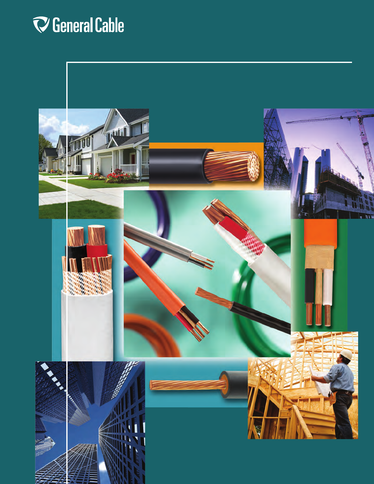
Building Wire
Servicing Commercial and
Residential Applications
This catalog contains in-depth
information on our full line of
building wire power cables
newly available today. It features
the latest information on
products, along with detailed
technical and specification data
in indexed sections — with an
easy-to-use “spec-on-a-page”
format.
The “spec-on-a-page” format
was developed to meet your
needs. It features up-to-the-
minute product information,
from applications and
constructions to detailed
technical and specification
data. There’s also a glossary of
technical terms for additional
assistance.
And, of course, if you need any
further data, General Cable’s
Customer Service staff provides
the answers you need quickly
and efficiently.
All information in this catalog is presented solely
as a guide to product selection and is believed
to be reliable. All printing errors are subject to
correction in subsequent releases of this catalog.
Although General Cable has taken precautions to
ensure the accuracy of the product specifications
at the time of publication, the specifications of all
products contained herein are subject to change
without notice.
GENERAL CABLE, BICC, BRAND REX, CAROL,
CAROLFLEX, CAROLPRENE, DURASHEATH,
FREP, SUNGEN, SUPER VU-TRON, UNIBLEND,
UNICON, UNISHIELD and WINDGEN are
trademarks of General Cable Technologies
Corporation.
© 2012. General Cable Technologies Corporation.
Highland Heights, KY 41076
All rights reserved. Printed in U.S.A.
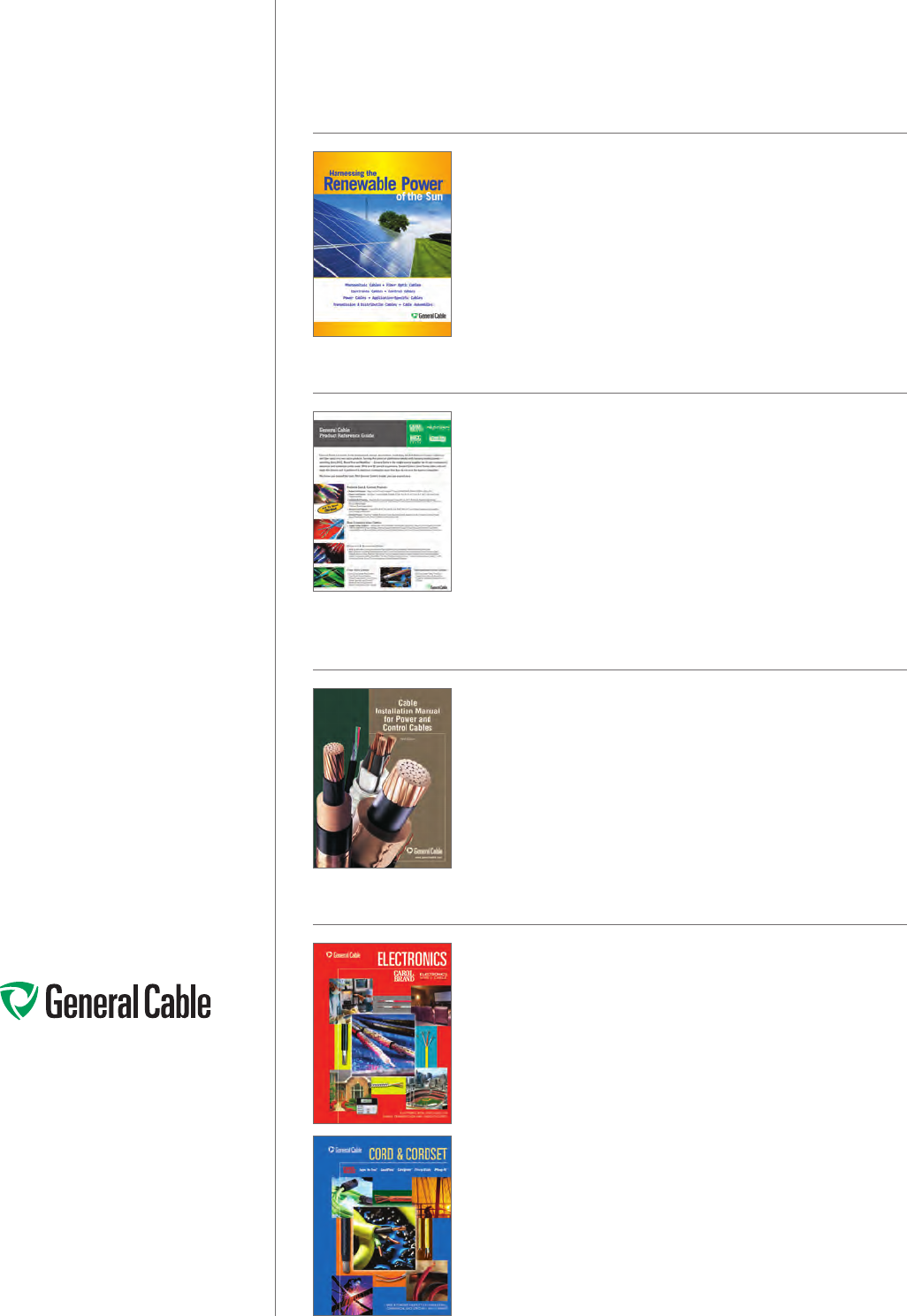
What’s New?
RENEWABLE POWER OF THE SUN
As a company committed to environmental stewardship and
renewable energy, General Cable has specifically designed its
SunGen® suite of cabling products to effectively and efficiently link
solar PV panels to the grid while being able to withstand the harsh
operating environments of solar power applications.
PRODUCT REFERENCE GUIDE
General Cable serves the electrical distribution market with industry-
leading brands, including Carol®, BICC® and Brand Rex Brands, for
all your industrial, commercial and residential building wire needs.
This is a helpful product reference guide which provides additional
information on our wide range of functionally equivalent products.
CABLE INSTALLATION MANUAL
NINTH EDITION
General Cable’s Cable Installation Manual for Power and Control Cables
provides installation information for power and control cables for
industrial applications. It covers 600 Volts through 46 kV insulated
copper conductors. The Cable Installation Manual is not a complete
representation of the entire line of wire and cable products that General
Cable manufactures. General Cable’s Customer Service and Technical
staff are available to provide answers you need quickly and efficiently.
FULL LINE CATALOGS
Electronics Cables
General Cable’s Carol® Brand products fulfill the complete wire and
cable requirements of the fast-changing electronics, sound and
security marketplaces. We offer hook-up wire; communications cable;
computer, coaxial and microphone cables; and special designs for
security systems, fire alarms and audio/video applications.
Cord & Cordset Products
General Cable's Carol® Brand is the most recognized name in flexible
cords for temporary power. The extensive line includes portable
cord, cordsets, portable power cable and premium-grade cable for
commercial and industrial applications.
Phone: 800-243-8020
www.generalcable.com
General Cable Copper Building Wire
General Cable is pleased to announce its new lineup of Copper
Building Wire products. When you partner with General Cable, you
get One Company that manufactures and delivers all of the wire and
cable products you need — from Carol® Brand cords, cordsets, and
electronics wire and cable that satisfy the fast-changing requirements
of the marketplace and communications cables for high-bandwidth
voice, data and video applications to General Cable’s industrial
instrumentation, power and control cables that serve an extensive
range of applications and environments. Now add to that a line of
Building Wire products.
General Cable has a rich history of experience and innovations with
roots dating back to the 1800s. In fact, General Cable invented NM-B
at its Rome, New York plant in 1922. As a global leader in the wire
and cable industry, General Cable focuses its worldwide resources
on providing outstanding quality and delivering maximum value to its
customers.
General Cable’s reintroduction of a Building Wire product line expands
and enhances its current industrial offering with a broader spectrum
of copper products that range from 600 to 2,000 volts. Our product
portfolio supports both commercial and residential construction
markets, while delivering the same product quality, manufacturing
expertise and service that our customers have always received from
General Cable.
General Cable’s building wire and cable products include copper
XHHW-2, tri-rated USE-2, and service entrance products. Canadian
constructions such as RW90, RWU90, and T90 are also readily
available. Our THHN copper products come in a variety of colors and
offer a low-friction jacket designed to improve installation even under
the most difficult conditions.
For today’s solar energy projects, General Cable offers a complete line
of SunGen® solar photovoltaic wire in copper constructions. These
specialty products are engineered to meet the rigorous environmental
conditions of long-term outdoor exposure to the sun while meeting the
needs of this increasingly popular energy source.
By maintaining inventory within a network of regional distribution
centers across the country, General Cable is able to ensure maximum
availability for our customers. Put us to work for you.
Phone: 800-243-8020
www.generalcable.com
Table of Contents
Date of Issue 1/13
Section 1 Copper Building Wire
PRODUCT
DESCRIPTION
SPECIFICATION
NUMBER
REVISION
DATE
PAGE
NUMBER
THHN/THWN-2
PVC, Low-Voltage Power
600 V, UL Type THHN/THWN-2, Single Conductor, Copper
5290 Oct. 2012 3-4
T90
PVC, Low-Voltage Power
600 V, CSA Type T90/TWN75, Single Conductor, Copper
5490 Jan. 2012 5
TFFN
PVC, Low-Voltage Power
600 V, UL Type TFFN, Single Conductor, Copper
5280 Oct. 2012 6
XHHW-2 CT
XHHW-2 CT XLPE, Low-Voltage Power
600 V, UL Type XHHW-2, CT Rated, Single Conductor, Copper
5175 Jan. 2013 7
XHHW-2 VW-1
XLPE, Control and Low-Voltage Power
600 V, UL Type SIS/XHHW-2, VW-1 Rated, Single Conductor, Copper
5150 Oct. 2012 8
RW90
XLPE, Low-Voltage Power
600 V, CSA Type RW90, Single Conductor, Copper
5500 Jan. 2012 9
RWU90
XLPE, Low-Voltage Power
1000 V, CSA Type RWU90, Single Conductor, Copper
5600 Jan. 2012 10
Unicon® XLPE
XLPE, Low-Voltage Power
600 V, UL Type RHH/RHW-2/USE-2, Single Conductor, Copper
5250 Oct. 2012 11
SunGen® Global
XLPE/LSZH XLPO, Photovoltaic Wire, TÜV 2 pfg
1169/08.2007 PV1-F AC Uo/U 0.6/1 kV, UL 4703, PV Wire 2000 V
5790 May 2012 14
SunGen®
Dual-Layer EPR/XL-CPE, Photovoltaic Wire
600 V, UL Type PV/USE-2/RHH or RHW-2
Single Conductor, Copper
5800 May 2012 15
SunGen®
Dual-Layer EPR/XL-CPE, Photovoltaic Wire
2000 V, UL Type PV/RHH or RHW-2 or 600 V USE-2
Single Conductor, Copper
5810 May 2012 16
SunGen®
XLPE, Photovoltaic Wire
600 V, UL Type PV/USE-2 or 2000 V RHH or RHW-2 or CSA RPVU90, 1000 V
Single Conductor, Copper
5840 May 2012 17
SunGen® IC
XLPE, Photovoltaic Wire
600 V, UL Type PV/USE-2 or 2000 V RHH or RHW-2 or CSA RPVU90, 1000 V
Single Conductor, Copper
5845 May 2012 18
SunGen®
XLPE, Photovoltaic Wire
2000 V, UL Type PV/RHH or RHW-2 or 600 V USE-2 or CSA RPVU90, 1000 V
Single Conductor, Copper
5850 May 2012 19
SunGen® IC
XLPE, Photovoltaic Wire
2000 V, UL Type PV/RHH or RHW-2 or 600 V USE-2 or CSA RPVU90, 1000 V
Single Conductor, Copper
5855 May 2012 20
NM-B
PVC, Low-Voltage Power
600 V, UL Type NM-B, Multi-Conductor, Copper
5900 Jan. 2012 21
UF-B and NMC
PVC, Low-Voltage Power
600 V, UL Type UF-B and NMC, Multi-Conductor, Copper
5910 Jan. 2012 22
SE Style U
PVC, Low-Voltage Power
600 V, UL Type SE Style U, Multi-Conductor, Copper
5920 Jan. 2012 23
SE Style R
PVC, Low-Voltage Power
600 V, UL Type SE Style R, Multi-Conductor, Copper
5930 Jan. 2012 24
Phone: 800-243-8020
www.generalcable.com
Table of Contents
Date of Issue 10/12
Section 2 Technical Information
General Technical Information
DESCRIPTION SPECIFICATION NUMBER REVISION DATE PAGE NUMBER
Building Wire Types A002 Jan. 2012 26
Glossary A003 Jan. 2012 27-33
Metric Conversion Factors A150 Sept. 2010 34
Reel Capacity Chart A200 Jan. 2012 35
Conductor Data
DESCRIPTION SPECIFICATION NUMBER REVISION DATE PAGE NUMBER
Class B and Class C Conductors for General Wiring B027 Jan. 2012 36
Handling and Storage Recommendations
DESCRIPTION SPECIFICATION NUMBER REVISION DATE PAGE NUMBER
Recommended Reel Handling Practices D005 Mar. 2012 37
Recommended Cable Handling Practices D025 Oct. 2011 38
Recommended Cable Storage Practices D050 Nov. 2011 39
Cable Installation Guidelines
DESCRIPTION SPECIFICATION NUMBER REVISION DATE PAGE NUMBER
Pre-Installation Instructions E005 Apr. 2010 40
Installation – Overview and Checklist E025 Jan. 2011 41
Installation – Feed-In Setups E050 Apr. 2010 42-43
Installation – Conductor Maximum Pulling Tensions E075 Oct. 2012 44-45
Installation – Training and Bending Limitations E100 Apr. 2010 46
Installation – Maximum Side Wall Pressure E125 Oct. 2012 47
Catalog Number Index 48-49

Our Green Initiative symbol recognizes our role
and responsibility in promoting sustainability.
The symbol also reflects our commitment to achieving
industry-leading standards and responding
proactively to environmental global issues.
Look for our products with the RoHS symbol
for your green building initiatives.
Visit www.generalcable.com
Select “COMPANY”, then select “Corporate Social Responsibility”
Building Bridges in the Sky
Making Contact with the World
Directing Traffic without Gridlock
General Cable is a leader in the
development, design, manufacture,
marketing and distribution of copper,
aluminum and fiber optic wire and cable
for the energy, industrial, specialty and
communications markets.
Our products inspire progress worldwide …
customers use our value-added products
to create global infrastructure that
improves the standard of living for
people everywhere.
Each day we’re building business
momentum — developing ideas into
innovative solutions and industry-leading
products, expanding geographic access and
furthering our investment in highly capable
associates, Lean Manufacturing, material
science and technology resources.
General Cable is influencing the world … with more than two-thirds
of our sales generated outside North America, 13,000 associates
worldwide and 57 manufacturing facilities throughout 26 countries.
As one of the largest wire and cable manufacturers, we are the
One Company Connecting the World.
Energy Cables
Our cables carry energy across the world — through the air,
underground and under the sea. Increasing demand for energy is
accelerating investment in exploration, extraction, power generation,
transmission and distribution — whether based on coal, natural gas,
oil, nuclear, wind, solar or water.
Industrial & Specialty Cables
Our cables channel the power and signals that make equipment hum
and engines run. From oil rigs and broadcast studios to cars and trains,
and in commercial buildings, public venues, factory floors and special
applications such as military, nuclear, marine and mining — we serve
an extensive range of markets.
Communications Cables
Our cables keep information flowing — facilitating a non-stop stream
of words and images around the world. We meet the high-speed
bandwidth needs of global communications networks, from fiber
optic submarine communications cables, copper and fiber aerial and
underground cables to copper and fiber optic enterprise cables and
system solutions.
World Headquarters
General Cable
4 Tesseneer Drive
Highland Heights, KY
41076-9753 U.S.A.
Phone: 800-243-8020
www.generalcable.com
1
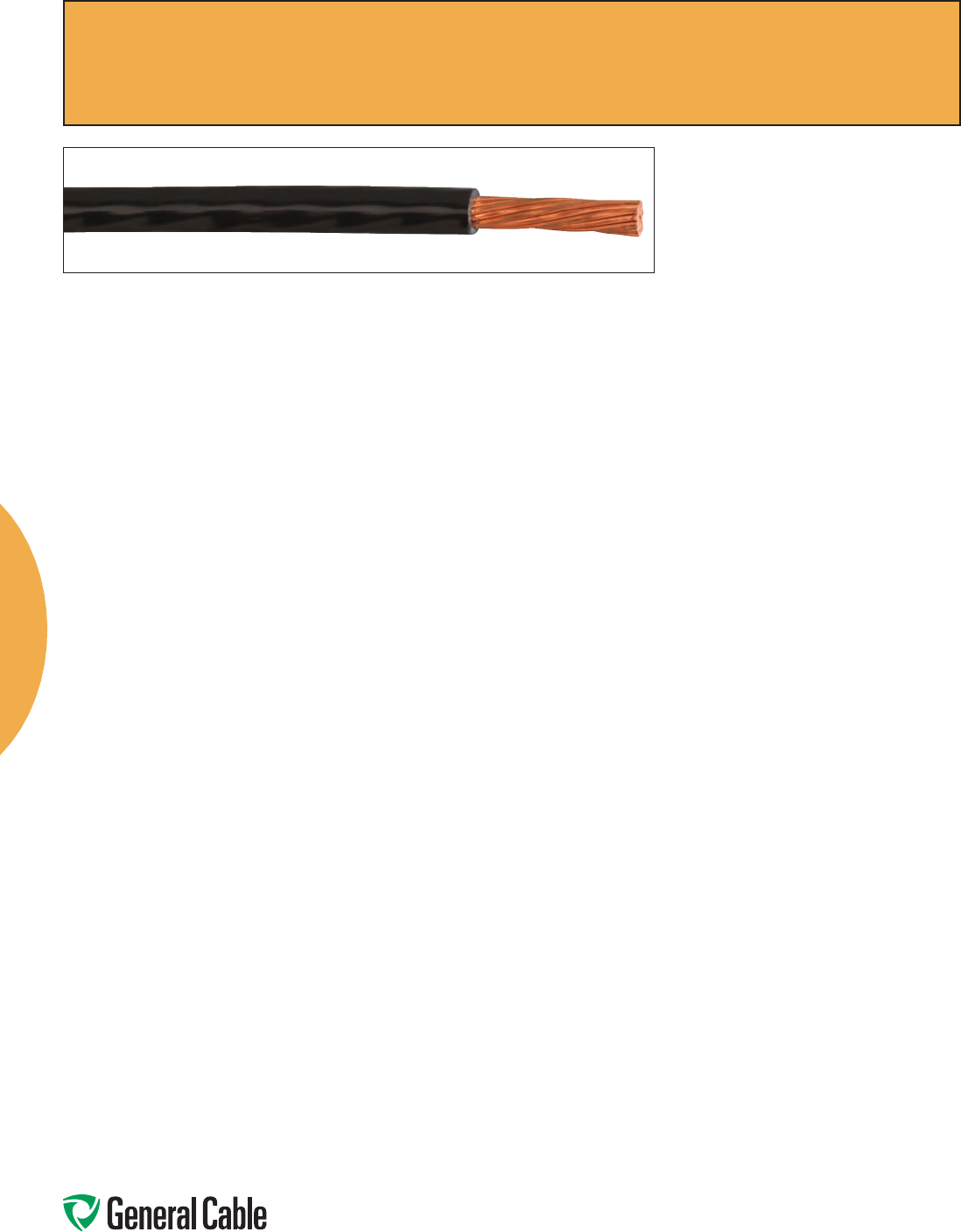
Copper Building Wire
Copper Building Wire
Copper Building Wire is the most frequently specified wiring solution
today for commercial and residential construction projects. General
Cable offers a complete line of Copper Building Wire to serve
virtually all the requirements of the electrical industry.
For commercial projects, General Cable’s THHN wire is widely
specified for power distribution. Available in a variety of colors to
accommodate customers’ needs, THHN can handle most electrical
wiring applications, from service entrance and feeders to branch
circuits.
For harsh industrial environments, Cross-linked Polyethylene (XLPE)
insulation is an ideally suited wiring solution. General Cable’s Type
XHHW-2 is well suited for building wire power distribution, and
our Unicon® XLPE wire and cable products can be direct buried in
accordance with the National Electric Code (NEC®). Both products
offer excellent electrical, thermal and physical properties.
For residential construction, contractors demand non-metallic (NM)
sheathed cable. Types NM and UF are very popular for branch
wiring. General Cable’s NM sheathed cable is lightweight and
easy to install, making it the perfect choice for home building and
remodeling.
Residential and commercial service entrance cables are also
available from General Cable. Type SE is ideal for carrying electric
power from service entrance equipment, and it can be used as
branch circuits.
General Cable Type TFFN wire can be utilized in a wide array of
applications, including fixture wire, machine tool wire and appliance
wiring material.
All General Cable’s copper building wire products are stocked in
our regional distribution centers along with other frequently used
Electrical Distribution core items, including portable cord, industrial
flex and datacom cabling.
Copper
Phone: 800-243-8020
www.generalcable.com
2
Copper Building Wire Date of Issue 1/13
PRODUCT SPECIFICATION REVISION PAGE
DESCRIPTION NUMBER DATE NUMBER
THHN/THWN-2
PVC, Low-Voltage Power 5290 Oct. 2012 3-4
600 V, UL Type THHN/THWN-2, Single Conductor, Copper
T90
PVC, Low-Voltage Power 5490 Jan. 2012 5
600 V, CSA Type T90/TWN75, Single Conductor, Copper
TFFN
PVC, Low-Voltage Power 5280 Oct. 2012 6
600 V, UL Type TFFN, Single Conductor, Copper
XHHW-2 CT
XHHW-2 CT XLPE, Low-Voltage Power 5175 Jan. 2013 7
600 V, UL Type XHHW-2, CT Rated, Single Conductor, Copper
XHHW-2 VW-1
XLPE, Control and Low-Voltage Power 5150 Oct. 2012 8
600 V, UL Type SIS/XHHW-2, VW-1 Rated, Single Conductor, Copper
RW90
XLPE, Low-Voltage Power 5500 Jan. 2012 9
600 V, CSA Type RW90, Single Conductor, Copper
RWU90
XLPE, Low-Voltage Power 5600 Jan. 2012 10
1000 V, CSA Type RWU90, Single Conductor, Copper
Unicon
®
XLPE
XLPE, Low-Voltage Power 5250 Oct. 2012 11
600 V, UL Type RHH/RHW-2/USE-2, Single Conductor, Copper
SunGen
®
Global
XLPE/LSZH XLPO, Photovoltaic Wire, TÜV 2 pfg 5790 May 2012 14
1169/08.2007 PV1-F AC Uo/U 0.6/1 kV, UL 4703, PV Wire 2000 V
SunGen
® Dual-Layer EPR/XL-CPE, Photovoltaic Wire 5800 May 2012 15
600 V, UL Type PV/USE-2/RHH or RHW-2
Single Conductor, Copper
SunGen
® Dual-Layer EPR/XL-CPE, Photovoltaic Wire 5810 May 2012 16
2000 V, UL Type PV/RHH or RHW-2 or 600 V USE-2
Single Conductor, Copper
SunGen
® XLPE, Photovoltaic Wire 5840 May 2012 17
600 V, UL Type PV/USE-2 or 2000 V RHH or RHW-2 or CSA RPVU90, 1000 V
Single Conductor, Copper
SunGen
®
IC
XLPE, Photovoltaic Wire 5845 May 2012 18
600 V, UL Type PV/USE-2 or 2000 V RHH or RHW-2 or CSA RPVU90, 1000 V
Single Conductor, Copper
SunGen
® XLPE, Photovoltaic Wire 5850 May 2012 19
2000 V, UL Type PV/RHH or RHW-2 or 600 V USE-2 or CSA RPVU90, 1000 V
Single Conductor, Copper
SunGen
®
IC
XLPE, Photovoltaic Wire 5855 May 2012 20
2000 V, UL Type PV/RHH or RHW-2 or 600 V USE-2 or CSA RPVU90, 1000 V
Single Conductor, Copper
NM-B
PVC, Low-Voltage Power 5900 Jan. 2012 21
600 V, UL Type NM-B, Multi-Conductor, Copper
UF-B and NMC
PVC, Low-Voltage Power 5910 Jan. 2012 22
600 V, UL Type UF-B and NMC, Multi-Conductor, Copper
SE Style U
PVC, Low-Voltage Power 5920 Jan. 2012 23
600 V, UL Type SE Style U, Multi-Conductor, Copper
SE Style R
PVC, Low-Voltage Power 5930 Jan. 2012 24
600 V, UL Type SE Style R, Multi-Conductor, Copper
Copper Building Wire 1
Copper
Phone: 800-243-8020
www.generalcable.com
Copper Building Wire
3
SPEC 5290
October, 2012
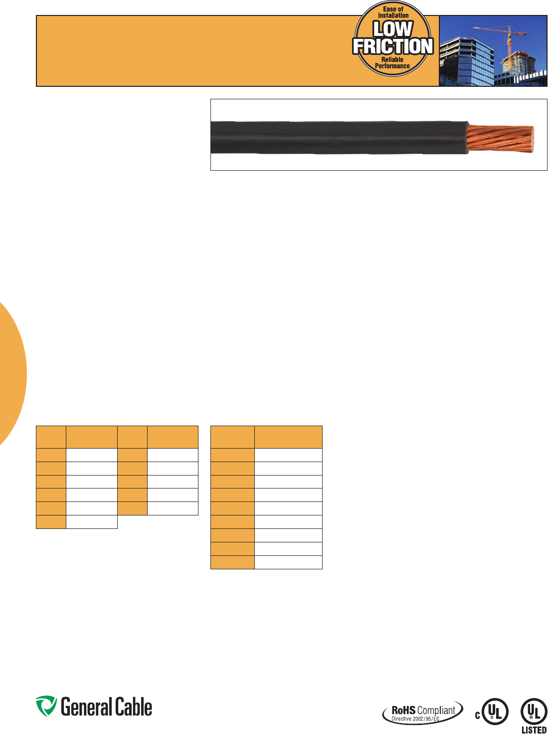
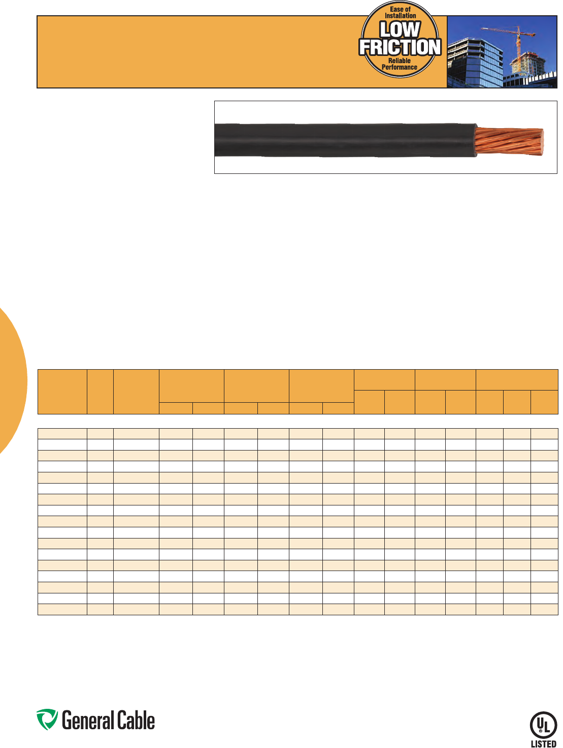
THHN/THWN-2
PVC, Low-Voltage Power
600 V, Type THHN/THWN-2, Single Conductor, Copper
Product Construction:
Conductor:
• 14AWGthru750kcmilbareannealedstranded
copper per ASTM B3 and ASTM B8
• 14AWGthru10AWGsolidplaincopperper
ASTM B3
Insulation:
• Color-codedpremium-gradeflame-retardant,
heat- and moisture-resistant Polyvinyl Chloride
(PVC)
Jacket:
• ToughPolyamide(Nylon)
Print:
For 14 AWG solid thru 10 AWG solid:
•GENERAL CABLE® (PLANT OF MFG) (YEAR OF
MFG) THHN/THWN (SIZE) AWG (SIZE mm²)
GAS AND OIL RES II 600V VW-1 (UL) E66903
C(UL)T90NYLON/TWN75FT1(-25°C)
For 14 AWG strand thru 10 AWG strand:
•GENERAL CABLE® (PLANT OF MFG) (YEAR OF
MFG) THHN/THWN (SIZE) AWG (SIZE mm²)
GAS AND OIL RES II 600V VW-1 OR AWM (UL)
E66903C(UL)T90NYLON/TWN75FT1(-25°C)
For 8 AWG thru 1 AWG:
•GENERAL CABLE® (PLANT OF MFG) (YEAR OF
MFG) LOW FRICTION THHN/THWN-2 (SIZE)
AWG (SIZE mm²) GAS AND OIL RES II 600V VW-1
ORAWM(UL)E66903C(UL)T90NYLON/TWN75
FT1(-25°C)
For 1/0 and larger, black only:
•GENERAL CABLE® (PLANT OF MFG) (YEAR OF
MFG) LOW FRICTION THHN/THWN-2 (SIZE)
AWG (SIZE mm²) GAS AND OIL RES II OR SUN
RES FOR CT USE 600V OR AWM (UL) E66903
C(UL)T90NYLON/TWN75FT1(-25°C)
Print (cont’d.):
For 1/0 and larger, all colors:
•GENERAL CABLE® (PLANT OF MFG) (YEAR OF
MFG) LOW FRICTION THHN/THWN-2 (SIZE)
AWG (SIZE mm²) CU GAS AND OIL RES II FOR
CT USE 600V OR AWM (UL) E66903 C(UL) T90
NYLON/TWN75FT1(-25°C)
Applications:
• Generalpurposebuildingwireforservices,
feeders and branch circuits
• Conduitandraceways
• 1/0andlargerforcabletrayuse
Features:
• LowFrictionNylonjacketprovideseasypullingfor
8 AWG and larger
• 1/0AWGandlargerareratedforcabletrayuse
• RatedGasolineandOil-ResistantII
• Resistanttoabrasion,acids,alkalines,ozone,and
water
• ForTHHNapplications,theconductoris
appropriate for use in dry locations not to exceed
90°C
• ForTHWN-2applications,theconductoris
appropriate for wet or dry locations not to exceed
90°C
Features (cont’d.):
• ForMTWapplications,theconductoris
appropriateforuseindrylocationsat90°Cornot
toexceed60°Cinwetlocationsorwhereexposed
to oil or coolants (with ampacity limited to that
for75°Cconductortemperature)asoutlined
inNFPA79ElectricalStandardsforIndustrial
Machinery
• Sequentialfootmarkingsevery2feeton8AWG
and larger for easy measuring
• Sunlight-resistantfor1/0andlarger,forblackonly
• Meetscoldbendandcoldimpacttestsat-25°C
Compliances:
Industry Compliances:
•ASTMB3andB8
•ULStandard83–THHN/THWN-2
•ULStandard1063formachinetoolwire(MTW)
•ICEAS-95-658/NEMAWC70
• N E C ® Article 310
•RoHSCompliant
•c(UL)–T90Nylon
Flame Test Compliances:
•UL2556VW-1ratedthrough1AWG
•UL2556CTUSE1/0andlarger
Packaging:
• Cut-to-lengthservicesavailablefor8AWG
and larger
THHN/THWN-2
COLOR CODE CHART
COLOR
CODE COLOR
COLOR
CODE COLOR
1Black 7Blue
2White 8Orange
3Red 9Gray
4Green APurple
5Yellow BPink
6Brown
PACKAGING CODE CHART
PACKAGING
CODE PACKAGE
10 2x500'
20 4x500'
32 500'Reel
33 1000'Reel
54 2000'Reel
34 2500'Reel
55 5000'Reel
00 Cut to order
XX Master Reel
Phone: 800-243-8020
www.generalcable.com
Copper Building Wire
4
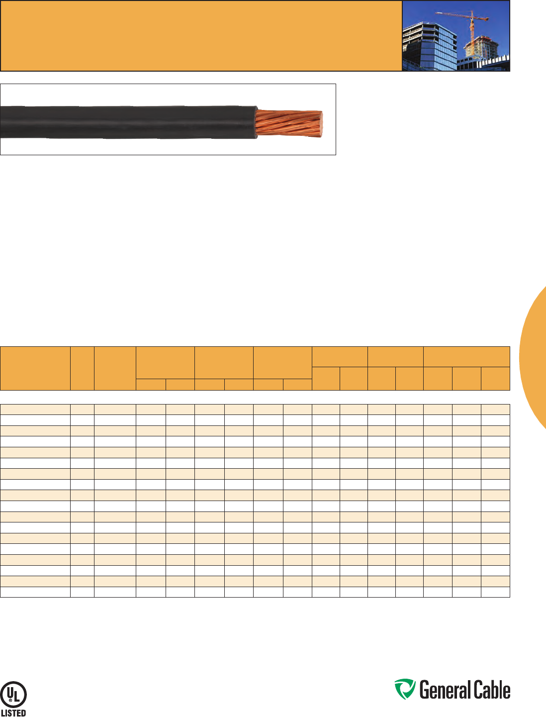
THHN/THWN-2
PVC, Low-Voltage Power
600 V, Type THHN/THWN-2, Single Conductor, Copper
SPEC 5290
October, 2012
CATALOG
NUMBER
SIZE
NO. OF
WIRES
INS. THKN. JACKET THKN.
NOMINAL
CABLE O.D. COPPER WEIGHT NET WEIGHT AMPACITY (1)
PACKAGING
PUT-UP
CODE
AWG OR
kcmil mm² INCHES mm INCHES mm INCHES mm
LBS/
1000 FT kg/km
LBS/
1000 FT kg/km 60°C 75°C 90°C
TYPE THHN 90°C DRY LOCATIONS/THWN 75°C WET LOCATIONS
23014 14 2.08 1 0.015 0.38 0.004 0.10 0.101 2.57 12 18 15 22 15 15 15 20,34
23012 12 3.31 1 0.015 0.38 0.004 0.10 0.120 3.05 20 29 23 34 20 20 20 20,34
23010 10 5.26 1 0.020 0.51 0.004 0.10 0.149 3.78 31 47 37 55 20 20 30 10,34
24014 14 2.08 19 0.015 0.38 0.004 0.10 0.109 2.77 13 19 16 25 15 15 15 20,34
24012 12 3.31 19 0.015 0.38 0.004 0.10 0.127 3.23 20 30 23 36 20 20 20 20,34
24010 10 5.26 19 0.020 0.51 0.004 0.10 0.160 4.07 32 48 38 57 30 30 30 10,34
TYPE THHN/THWN-2 90°C WET OR DRY LOCATIONS
25008 88.37 19 0.030 0.76 0.005 0.13 0.212 5.39 51 76 62 94 40 50 55 32, 33, XX, 00
25006 6 13.3 19 0.030 0.76 0.005 0.13 0.248 6.30 81 121 94 141 55 65 75 32, 33, XX, 00
25004 421.2 19 0.040 1.02 0.006 0.15 0.317 8.06 129 192 153 228 70 85 95 32,55,XX,00
25003 326.7 19 0.040 1.02 0.006 0.15 0.344 8.74 163 242 189 281 85 100 115 32,55,XX,00
25002 2 33.6 19 0.040 1.02 0.006 0.15 0.375 9.53 205 305 233 348 95 115 130 55,XX,00
25001 142.4 19 0.050 1.27 0.007 0.18 0.435 11.05 258 385 298 445 110 130 145 55,XX,00
26110 1/0 53.5 19 0.050 1.27 0.007 0.18 0.474 12.04 326 485 372 554 125 150 170 55,XX,00
26210 2/0 67.4 19 0.050 1.27 0.007 0.18 0.518 13.16 411 611 462 687 145 175 195 55,XX,00
26310 3/0 85 19 0.050 1.27 0.007 0.18 0.568 14.43 518 771 572 851 165 200 225 55,XX,00
26410 4/0 107 19 0.050 1.27 0.007 0.18 0.624 15.85 653 972 712 1059 195 230 260 55,XX,00
27250 250 124 37 0.060 1.52 0.008 0.20 0.678 17.23 772 1149 849 1266 215 255 290 55,XX,00
27300 300 152 37 0.060 1.52 0.008 0.20 0.730 18.54 926 1378 1010 1503 240 285 320 34,XX,00
27350 350 177 37 0.060 1.52 0.008 0.20 0.777 19.74 1081 1609 1170 1741 260 320 350 34,XX,00
27400 400 203 37 0.060 1.52 0.008 0.20 0.821 20.85 1235 1838 1330 1979 280 335 380 34,XX,00
27500 500 253 37 0.060 1.52 0.008 0.20 0.902 22.91 1544 2298 1650 2455 320 380 430 34,XX,00
27600 600 304 61 0.070 1.78 0.009 0.23 1.051 26.70 1853 2758 2019 3004 350 420 475 54,XX,00
27750 750 380 61 0.070 1.78 0.009 0.23 1.156 29.36 2316 3447 2466 3670 400 475 535 54,XX,00
Dimensions and weights are nominal; subject to industry tolerances.
(1)Temperature,sizeandampacityperNationalElectricCode,2011NECsections110.14(c)(1)(a)&(b).
60°C–Whenterminatedtoequipmentforcircuitsrated100amperesorlessormarkedfor14through1AWGconductors.
75°C–Whenterminatedtoequipmentforcircuitsratedover100amperesormarkedforconductorslargerthan1AWG.
90°C–Wetordrylocations.Forampacityderatingpurposes.
Dwelling–Fordwellingunits,conductorsshallbepermittedaslistedampacitiesat120/240-volt,3-wire,single-phaseservicesandfeeders.
THHN/THWN-2
Phone: 800-243-8020
www.generalcable.com
Copper Building Wire
5
SPEC 5490
January, 2012
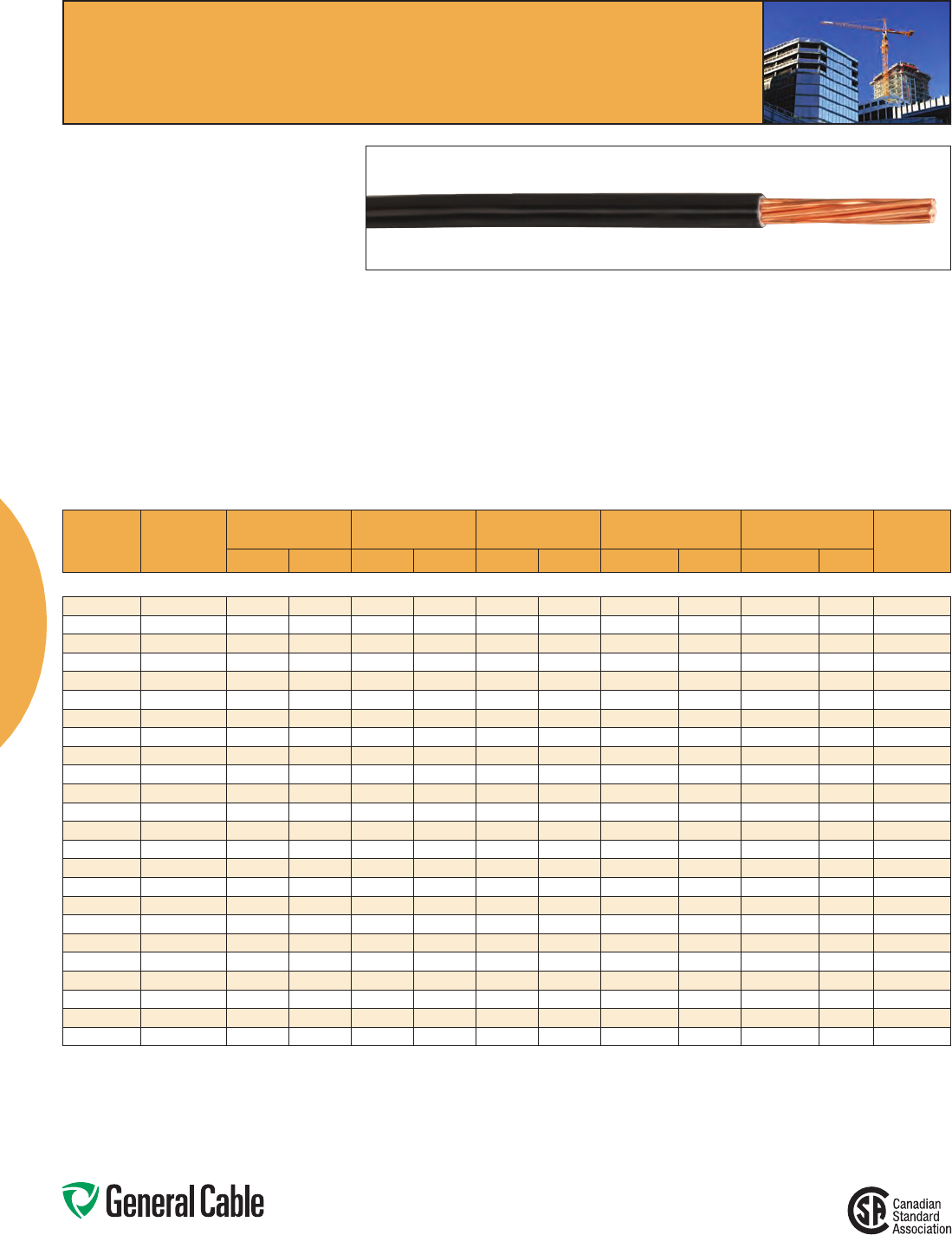
T90
PVC, Low-Voltage Power
600V,CSATypeT90/TWN75,SingleConductor,Copper
Product Construction:
Conductor:
• 14AWGthru10AWGstrandedbareannealed
copper
• 8AWGthru500kcmilcompressedstrandedbare
annealed copper
• 14AWGthru10AWGsolidplaincopper
Insulation:
• Color-codedpremium-gradeflame-retardant,
heat- and moisture-resistant Polyvinyl Chloride
(PVC)
Jacket:
• ToughPolyamide(Nylon)
Print:
For solids:
•GENERAL CABLE® (PLANT OF MFG) (YEAR
OF MFG) THHN/THWN SIZE (AWG OR KCMIL)
(MM2) CU GAS AND OIL RES II, 600 VOLTS,
VW-1 OR AWM (UL) E-66903 C(UL) T90 NYLON/
TWN75FT1(-25ºC)
For stranded:
•GENERAL CABLE® (PLANT OF MFG) (YEAR
OF MFG) THHN/THWN SIZE (AWG OR KCMIL)
(MM2) CU GAS AND OIL RES II, 600 VOLTS,
VW-1 OR AWM (UL) E-103886 C(UL) T90
NYLON/TWN75FT1(-25ºC)
Applications:
• Forexposedorconcealedwiringindryordamp
locations
• Maximumconductortemperature90ºCdry,75ºC
wetand60ºCwhenexposedtooil
• Foruseinracewaysindryordamplocations
• Notcabletrayrated
Features:
• Ratedat90ºCdryordamplocations,75ºCwet
• RatedGasolineandOil-ResistantII
• Meetscoldbendandcoldimpacttestsat-25ºC
• Suitableforinstallationat–10ºC
Compliances:
•c(UL)CSAstandardC22.2No.75
•RoHSCompliant
Packaging:
• 14AWGthru10AWG:300mreels
• 8AWGthru6AWG:300mor3,000mreels
• 4AWGthru4/0:300mor1,500mreels
• 250kcmilthru500kcmil:900mreels
SIZE
NO. OF
WIRES
INSULATION THKN. JACKET THKN. NOMINAL CABLE O.D. COPPER WEIGHT NET WEIGHT AMPACITY**
AWG OR
kcmil mm² INCHES mm INCHES mm INCHES mm
LBS/
1000 FT kg/km
LBS/
1000 FT kg/km
DAMP
OR DRY WET
14 AWG – 500 kcmil CONDUCTORS
14 2.08 1 0.015 0.38 0.004 0.10 0.104 2.63 12 18 15 22 25 20
14 2.08 19 0.015 0.38 0.004 0.10 0.112 2.85 12 18 16 23 25 20
12 3.31 1 0.015 0.38 0.004 0.10 0.120 3.06 20 29 23 34 30 25
12 3.31 19 0.015 0.38 0.004 0.10 0.131 3.33 19 29 23 35 30 25
10 5.26 1 0.020 0.51 0.004 0.10 0.152 3.86 31 46 36 54 40 35
10 5.26 19 0.020 0.51 0.004 0.10 0.166 4.21 31 46 37 55 40 35
88.37 19 0.030 0.76 0.005 0.13 0.219 5.56 49 73 61 91 55 50
6 13.3 19 0.030 0.76 0.005 0.13 0.257 6.52 78 116 93 138 95 65
421.2 13-6 0.040 1.02 0.006 0.15 0.322 8.17 125 186 148 221 95 85
326.7 13-6 0.040 1.02 0.006 0.15 0.350 8.88 157 234 184 273 115 100
2 33.6 13-6 0.040 1.02 0.006 0.15 0.382 9.69 198 295 228 339 130 115
142.4 13-6 0.050 1.27 0.007 0.18 0.440 11.16 249 371 290 432 145 130
1/0 53.5 13-6 0.050 1.27 0.007 0.18 0.479 12.16 314 468 361 537 170 150
2/0 67.4 13-6 0.050 1.27 0.007 0.18 0.523 13.27 396 590 448 667 195*** 175
3/0 85 13-6 0.050 1.27 0.007 0.18 0.573 14.54 499 743 557 829 225 200
4/0 107 13-6 0.050 1.27 0.007 0.18 0.629 15.97 630 938 695 1034 260 230
250 124 37 0.060 1.52 0.008 0.20 0.699 17.77 746 1111 829 1233 290 255
300* 152 3 0.060 1.52 0.008 0.20 0.752 19.11 895 1333 985 1467 320 285
350 177 37 0.060 1.52 0.008 0.20 0.802 20.38 1045 1555 1142 1700 350 310
400* 203 37 0.060 1.52 0.008 0.20 0.847 21.52 1194 1777 1297 1931 380 335
500 253 37 0.060 1.52 0.008 0.20 0.930 23.63 1492 2221 1608 2393 430 380
Dimensions and weights are nominal; subject to industry tolerances.
*Non-stockitem;minimumrunsapply.PleaseconsultCustomerServiceforpriceanddelivery.
**BasedonCECPart1Table2Allowableampacitiesfornotmorethanthreecopperconductorsinracewayorcable.
***For3-wire120/240Vand120/208Vserviceconductorsforsingledwellings,orforfeederconductorssupplyingsingledwellingunitsofrowhousingofapartmentandsimilarbuildings,
andsizedinaccordancewithRules8-200(1),8-200(2)and8-202(1),theallowableampacityforsizesNo.6andNo.2/0AWGshallbe60Aand200A,respectively.Inthiscase,the5%
adjustment of Rule 8-106 (1) cannot be applied.
T90
Phone: 800-243-8020
www.generalcable.com
Copper Building Wire
6
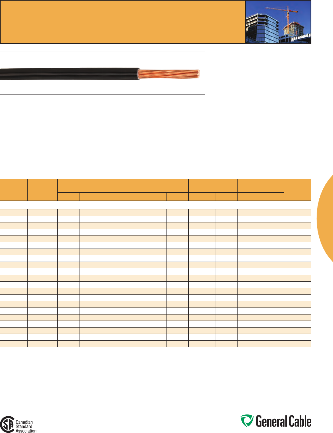
TFFN
PVC, Low-Voltage Power
600 V, Type TFFN, Single Conductor, Copper
SPEC 5280
October, 2012
Product Construction:
Conductor:
• 18AWGand16AWGfullyannealedbarecopper
perASTMB3andB174
Insulation:
• Color-codedpremium-gradeflame-retardant,
heat- and moisture-resistant Polyvinyl Chloride
(PVC)
Jacket:
• ToughPolyamide(Nylon)
Print:
•GENERAL CABLE® (PLANT OF MFG) (YEAR
OF MFG) TYPE TFFN (SIZE) GAS AND OIL RES II
600 V OR MTW OR AWM (UL)
Applications:
• Internalwiringoffixtures
• Fixtureraceways
• Firealarmcircuitsinraceways
Features:
• RatedGasolineandOil-ResistantII
• Resistanttoabrasion,acids,alkalines,ozone,
and water
• ForTFFNapplications,theconductoris
appropriate for use in dry locations not to
exceed90°C
• ForMTWapplications,theconductoris
appropriateforuseindrylocationsat90°Cor
nottoexceed60°Cinwetlocationsorwhere
exposed to oil or coolants
Compliances:
•ASTMB3andB174
•ULStandard66forfixturewire
•ULStandard1063formachinetoolwire(MTW)
•NFPA70(NEC®Article402)
•NFPA79asappliancewiringmaterial600V
Packaging:
• 4x500'inacarton
• 2500'reels
CATALOG
NUMBER
SIZE
NO. OF
WIRES
INSULATION THKN. JACKET THKN.
NOMINAL CABLE
O.D. COPPER WEIGHT NET WEIGHT
AMPACITY
(1)
AWG OR
kcmil mm² INCHES mm INCHES mm INCHES mm
LBS/
1000 FT kg/km
LBS/
1000 FT kg/km
18 AWG AND 16 AWG CONDUCTORS
28018 18 0.82 16 0.015 0.38 0.004 0.10 0.088 2.24 5 7 8 12 6
28016 16 1.31 26 0.015 0.38 0.004 0.10 0.101 2.57 8 12 11 16 8
Dimensions and weights are nominal; subject to industry tolerances.
(1)Allowableampacitiesshownareforgeneraluseasspecifiedbythe2011editionoftheNationalElectricCode,section402,Table402.5.
Adjustments and corrections may apply.
NOTE:ForMTWapplications,theconductorisappropriateforuseindrylocationsat90°Cornottoexceed60°Cinwetlocationsorwhenexposedtooilorcoolants(withampacitylimited
tothatfor75°Cconductortemperature)asoutlinedinNFPA79ElectricalStandardsforIndustrialMachinery.
TFFN
COLOR CODE CHART
COLOR
CODE COLOR
COLOR
CODE COLOR
1Black 7Blue
2White 8Orange
3Red 9Gray
4Green APurple
5Yellow BPink
6Brown
PACKAGING CODE CHART
PACKAGING
CODE PACKAGE
20 4x500'
34 2500'Reel
Phone: 800-243-8020
www.generalcable.com
Copper Building Wire
7
SPEC 5175
January, 2013
XHHW-2 CT
XLPE, Low-Voltage Power, 600 V
UL Type XHHW-2, CT Rated, Single Conductor, Copper
Product Construction:
Conductor:
• 14AWGthru750kcmilannealedbarecopper
perASTMB3
• ClassBstrandingperASTMB8
Insulation:
• Flame-retardantCross-linked
Polyethylene(XLPE)
Print:
•GENERALCABLE®(PLANTOFMFG)AWG/
KCMILLOWFRICTION*TYPEXHHW-2(UL)600V
SUNRESFORCTUSE**MONTH/YEAROFMFG
SEQUENTIALFOOTAGEMARK
*Sizes14AWG-10AWGdonotinclude“LOWFRICTION”
**Sizessmallerthan1/0AWGdonotinclude“SUNRESFOR
CT USE”
Options:
• Tinnedcopperconductor
• Fullcoloredinsulation
Applications:
• Generalpurposebuildingwireforuseprimarilyin
conduitorotherrecognizedracewaysasspecified
intheNationalElectricalCode
• Industrialenvironmentswheresuperiorinsulation
toughnessandchemicalresistancearerequired
• Maximumoperatingtemperaturenottoexceed
90˚Cindryorwetlocations
•Infreeair,racewaysorcabletraysinaccordance
withNEC
Features:
• LowFrictionforeasypullingon8AWGandlarger
• “FORCTUSE”on1/0AWGandlarger
• Sunlight-resistantfor1/0AWGandlarger,all
colors
• Ratedat90˚Cwetordry
• SmallercableO.D.
• Excellentelectrical,thermalandphysical
properties
• Excellentresistancetomoisture
• Excellentresistancetocrush,compressioncuts
andheatdeformation
Compliances:
Industry Compliances:
•NationalElectricCode(NEC)
•UL44StandardforRubberInsulatedWire
andCable
•ICEAS-95-658/NEMAWC70
•ULListedasTypeXHHW-2,ULFile#E90494
•OSHAAcceptable
Flame Test Compliances:
•UL1685,1/0AWGandlarger
Packaging:
• Materialcuttolengthandshippedon
non-returnablewoodreels
XHHW-2
CATALOG
NUMBER
COND.
SIZE
(AWG/
kcmil)
COND.
STRAND
NOMINAL COND.
DIAMETER
MINIMUM AVG.
INSULATION
THICKNESS
NOMINAL CABLE
O.D.
COPPER
WEIGHT NET WEIGHT AMPACITY (1)
LBS/
1000 FT kg/km
LBS/
1000 FT kg/km 60°C 75°C 90°CINCHES mm INCHES mm INCHES mm
14 AWG - 750 kcmil CONDUCTORS
391070 14 7/.0240 0.07 1.80 0.030 0.76 0.13 3.38 12 18 17 25 15 15 15
391080 12 7/.0305 0.09 2.26 0.030 0.76 0.15 3.84 20 30 26 39 20 20 20
391090 10 7/.0385 0.11 2.87 0.030 0.76 0.18 4.57 32 48 38 57 30 30 30
5175.008 8 7/.0486 0.14 3.56 0.045 1.14 0.24 6.10 51 76 65 97 40 50 55
5175.006 67/.0612 0.18 4.57 0.045 1.14 0.28 7.11 81 121 99 147 55 65 75
5175.004 4 7/.0772 0.23 5.84 0.045 1.14 0.33 8.38 129 192 152 226 70 85 95
5175.002 27/.0974 0.29 7.37 0.045 1.14 0.39 9.91 205 305 233 347 95 115 130
5175.001 1 19/.0664 0.32 8.13 0.055 1.40 0.44 11.18 256 381 293 437 110 130 145
5175.110 1/0 19/.0740 0.36 9.14 0.055 1.40 0.48 12.19 326 485 364 572 125 150 170
5175.210 2/0 19/.0837 0.41 10.41 0.055 1.40 0.53 13.46 411 612 453 674 145 175 195
5175.310 3/0 19/.0940 0.46 11.68 0.055 1.40 0.58 14.73 518 772 565 842 165 200 225
5175.410 4/0 19/.1055 0.51 12.95 0.055 1.40 0.63 16.00 653 972 706 1051 195 230 260
5175.250 250 37/.0822 0.56 14.22 0.065 1.65 0.70 17.78 722 1074 837 1246 215 255 290
5175.350 350 37/.0973 0.66 16.76 0.065 1.65 0.80 20.32 1081 1609 1157 1722 260 310 350
5175.500 500 37/.1162 0.79 20.07 0.065 1.65 0.93 23.62 1544 2298 1634 2432 320 380 430
5175.600 600 37/.1109 0.87 22.10 0.080 2.03 1.04 26.42 1853 2758 1972 2935 350 420 475
5175.750 750 61/.1280 0.98 24.89 0.080 2.03 1.15 29.21 2316 3447 2448 3643 400 475 535
Dimensionsandweightsarenominal;subjecttoindustrytolerances.
(1)AllowableampacitiesshownareforgeneraluseasspecifiedbytheNationalElectricCode,2011Edition,section310.15(B)(16).Adjustmentsandcorrectionsmayapply:
60°C–Whenterminatedtoequipmentforcircuitsrated100amperesorlessormarkedfor14through1AWGconductors.
75°C–Whenterminatedtoequipmentforcircuitsratedover100amperesormarkedforconductorslargerthan1AWG.
90°C–Wetordrylocations.Forampacityderatingpurposes.
Dwelling–Fordwellingunits,conductorsshallbepermittedaslistedampacitiesat120/240-volt,3-wire,single-phaseservicesandfeeders.
Phone: 800-243-8020
www.generalcable.com
Copper Building Wire
8
XHHW-2 VW-1
XLPE, Control and Low-Voltage Power, 600 V
UL Type SIS/XHHW-2, VW-1 Rated, Single Conductor, Copper
SPEC 5150
October, 2012
Product Construction:
Conductor:
• 18AWGthru1000kcmiltinned,annealed
copper per ASTM B33
• ClassBstrandingperASTMB8
Insulation:
• Flame-retardantCross-linkedPolyethylene
(XLPE)
Print:
For 18 AWG and 16 AWG:
• GENERAL CABLE® (PLANT OF MFG) 1C XXAWG
COPPER XLPE SIS TYPE 600V 90C YEAR OF
MFG
For 14 AWG thru 4 AWG:
• GENERAL CABLE® (PLANT OF MFG) 1C XXAWG
COPPER XLPE TYPE SIS/XHHW-2 VW-1 (UL)
600V 90C YEAR OF MFG
Print (cont’d.):
For 2 AWG and larger:
• GENERAL CABLE® (PLANT OF MFG) 1C XXAWG
COPPER XLPE TYPE XHHW-2 VW-1 SUN RES
FOR CT USE (UL) YEAR OF MFG SEQUENTIAL
FOOTAGE MARK
*Sizessmallerthan1/0AWGdonotinclude“FORCTUSE”
Applications:
• Foruseinpowerandcontrolcircuitsin
switchboards, control panels and raceways in
applications not exceeding 600 volts
• AcceptableforuseinOSHAregulated
installations
Features:
• Ratedat90
˚
C wet or dry
• ULListedasSIS/XHHW-2¥ and XHHW-2¥¥ for
general power or control wiring in accordance
withtheNationalElectricalCode,Section310.15,
Tables310.15(B)16or310.15(B)17
• Sizes1/0andlargerforCTuse
Features (cont’d.):
• Excellentflameresistance
• Sunlight-resistant
• Excellentphysical,thermalandelectrical
properties
Compliances:
Industry Compliances:
•ULTypeSIS/XHHW-2¥—600 V
•ULFile#E90494
•ULTypeXHHW-2¥¥—600 V
•ICEAS-95-658/NEMAWC70
•1/0andlargerarelisted“SUN RES FOR CT
USE”inaccordancewithNEC
Flame Test Compliances:
•UL44VW-1
Other Compliances:
•EPA40CFR,Part261forleachable
lead content per TCLP method
•OSHAAcceptable
Packaging:
• Materialtobeshippedonspoolsornon-
returnable wood reels
¥ ULTypeSIS/XHHW-2forsizes14AWGthru
4AWG
¥¥ UL Type XHHW-2 for sizes 2 AWG thru
1000 kcmil
XHHW-2 VW-1
CATALOG
NUMBER
COND.
SIZE
(AWG/
kcmil)
COND.
STRAND
NOMINAL COND.
DIAMETER
MINIMUM AVG.
INSULATION
THICKNESS
NOMINAL CABLE
O.D.
COPPER
WEIGHT NET WEIGHT AMPACITY (1)
LBS/
1000 FT kg/km
LBS/
1000 FT kg/km 60°C 75°C 90°CINCHES mm INCHES mm INCHES mm
18 AWG - 1000 kcmil CONDUCTORS
381500 18 7/.0152 0.05 1.27 0.030 0.76 0.11 2.74 5 8 9 14 ———
381510 16 7/.0192 0.06 1.47 0.030 0.76 0.12 3.05 8 12 13 20 — — —
381520 14 7/.0242 0.07 1.80 0.030 0.76 0.13 3.38 13 19 19 28 15 15 15
381530 12 7/.0305 0.09 2.29 0.030 0.76 0.15 3.86 20 30 27 41 20 20 20
381540 10 7/.0385 0.11 2.87 0.030 0.76 0.18 4.45 32 48 41 61 30 30 30
381550 87/.0486 0.14 3.56 0.045 1.14 0.24 6.05 51 76 69 102 40 50 55
381560 67/.0612 0.18 4.57 0.045 1.14 0.28 6.99 81 121 103 153 55 65 75
381570 4 7/.0772 0.23 5.84 0.045 1.14 0.32 8.18 129 192 156 232 70 85 95
06591.210200 27/.0974 0.29 7.37 0.045 1.14 0.38 9.68 205 305 239 355 95 115 130
06591.215100 1/0 19/.0745 0.36 9.14 0.055 1.40 0.48 12.14 326 485 373 556 125 150 170
06591.215200 2/0 19/.0837 0.41 10.41 0.055 1.40 0.52 13.28 411 612 464 691 145 175 195
06591.215300 3/0 19/.0940 0.46 11.68 0.055 1.40 0.57 14.55 518 771 579 862 165 200 225
06591.215400 4/0 19/.1055 0.51 12.95 0.055 1.40 0.63 15.98 653 972 722 1075 195 230 260
06591.216000 250 37/.0822 0.56 14.22 0.065 1.65 0.70 17.75 772 1149 860 1280 215 255 290
06591.216200 350 37/.0973 0.66 16.76 0.065 1.65 0.80 20.37 1081 1609 1185 1764 260 310 350
06591.216500 500 37/.1162 0.79 20.07 0.065 1.65 0.93 23.65 1544 2298 1669 2484 320 380 430
06591.217000 750 61/.1109 0.97 24.64 0.080 2.03 1.14 29.03 2316 3447 2520 3750 400 475 535
06591.217500 1000 61/.1280 1.13 28.70 0.080 2.03 1.30 33.02 3086 4593 3283 4886 445 545 615
Dimensions and weights are nominal; subject to industry tolerances.
(1)Temperature,sizeandampacityperNationalElectricCode,2011NECsections110.14(c)(1)(a)&(b).
60°C–Whenterminatedtoequipmentforcircuitsrated100amperesorlessormarkedfor14through1AWGconductors.
75°C–Whenterminatedtoequipmentforcircuitsratedover100amperesormarkedforconductorslargerthan1AWG.
90°C–Wetordrylocations.Forampacityderatingpurposes.
Dwelling–Fordwellingunits,conductorsshallbepermittedaslistedampacitiesat120/240-volt,3-wire,single-phaseservicesandfeeders.
Phone: 800-243-8020
www.generalcable.com
Copper Building Wire
9
COND.
SIZE
(AWG/
kcmil)
COND.**
STRAND
NOMINAL
COND. O.D.
MIN. AVG. INS.
THICKNESS
NOMINAL DIAMETER
(OVER) INSULATION
COPPER
WEIGHT
NET
WEIGHT AMPACITY***
30˚C
AMBIENTINCHES mm INCHES mm INCHES mm LBS/1000 FT kg/km LBS/1000 FT kg/km
14 AWG - 1000 kcmil CONDUCTORS
14 1 0.06 1.52 0.030 0.76 0.12 3.05 12 18 16 23 25
14 7/.0240 0.07 1.78 0.030 0.76 0.13 3.30 12 18 16 24 25
12 1 0.08 2.03 0.030 0.76 0.14 3.56 20 30 24 36 30
12 7/.0302 0.09 2.29 0.030 0.76 0.15 3.81 20 30 25 38 30
10 1 0.10 2.54 0.030 0.76 0.16 4.06 31 46 36 54 40
10 7/.0381 0.11 2.79 0.030 0.76 0.17 4.32 32 48 38 57 40
87/.0481 0.14 3.56 0.045 1.14 0.23 5.84 50 74 62 93 55
67/.0606 0.18 4.57 0.045 1.14 0.27 6.86 78 116 93 139 75
4 7/.0772 0.23 5.84 0.045 1.14 0.32 8.13 129 192 149 221 95
37/.0867 0.25 6.35 0.045 1.14 0.34 8.64 163 243 184 274 115
27/.0974 0.28 7.11 0.045 1.14 0.37 9.40 200 298 224 334 130
119/.0664 0.32 8.13 0.055 1.40 0.43 10.92 258 384 289 430 145
1/0 19/.0745 0.36 9.14 0.055 1.40 0.47 11.94 326 485 361 538 170
2/0 19/.0837 0.41 10.41 0.055 1.40 0.52 13.21 411 612 451 672 195****
3/0 19/.0940 0.46 11.68 0.055 1.40 0.57 14.48 507 754 553 823 225
4/0 19/.1055 0.51 12.95 0.055 1.40 0.62 15.75 635 945 686 1021 260
250 37/.0822 0.56 14.22 0.065 1.65 0.69 17.53 772 1149 836 1244 290
300 37/.0900 0.61 15.49 0.065 1.65 0.74 18.80 926 1378 996 1483 320
350 37/.0972 0.66 16.76 0.065 1.65 0.79 20.07 1063 1582 1140 1696 350
400* 37/.1040 0.71 17.93 0.065 1.65 0.84 21.23 1235 1838 1318 1961 380
500 37/.1162 0.79 20.07 0.065 1.65 0.92 23.37 1509 2245 1603 2386 430
600 61/.0992 0.87 22.10 0.080 2.03 1.03 26.16 1883 2802 2004 2982 425
750 61/.1109 0.97 24.64 0.080 2.03 1.13 28.70 2316 3446 2453 3650 535
1000* 61/.1280 1.12 28.45 0.080 2.03 1.28 32.51 3088 4595 3250 4835 615
Dimensions and weights are nominal; subject to industry tolerances.
*Non-stockitem;minimumrunsapply.PleaseconsultCustomerServiceforpriceanddelivery.
**Forcompact-strandedconstructions,thenumberofwiresmaybereducedasfollows:
19-Wire Constructions - 18 Wires Minimum
37-WireConstructions-35WiresMinimum
61-WireConstructions-58WiresMinimum
***BasedonCECPart1,Table2forthreeconductorsinraceway(conduit).Forundergroundinstallations,refertoCEC,Rule4-004forampacityrating.
****For3wires,120/240Vand120/208Vresidentialservicesorsubservices,theallowableampacityfor2/0AWGshallbe200A.Inthiscase,the5%adjustmentofRule8-106(1)cannotbe
applied.
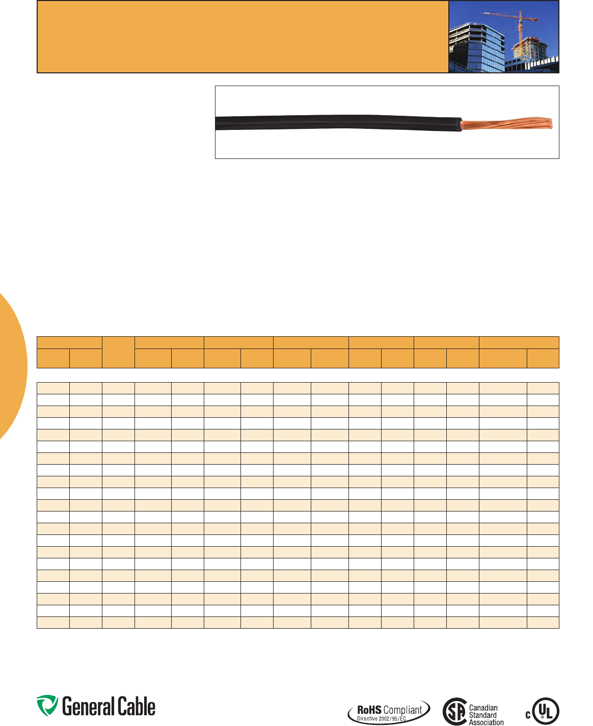
SPEC 5500
January, 2012
RW90
XLPE, Low-Voltage Power
600 V, CSA Type RW90, Single Conductor, Copper
Product Construction:
Conductor:
• 14AWGthru1000kcmilannealedClassB
compressed stranded soft drawn plain copper
• 14AWGthru10AWGsolidplaincopper
Insulation:
• Heat-andmoisture-resistant,low-temperature
Cross-linked Polyethylene (XLPE), Type RW90,
-40°C
• Colorcode:14AWG,12AWG,10AWG(solid)–
black, white, red, blue, green, yellow, orange,
brown;10AWG–black,white,red,blue,green;
8AWGthru2AWG–black,white,red,blue,
green;1AWGandlarger–black(othercolors
available subject to minimum order quantity)
Print:
• GENERALCABLE® (PLANT OF MFG) CSA RW90
XLPESIZE(AWGORKCMIL)CU600V(-40°C)
YEAR OF MFG SEQUENTIAL METER MARKING
NOTE:Forblackinsulation,add
–SR
Options:
• For1000voltapplications,useRWU90
• PVCjacket(FT1rating)
Applications:
• InaccordancewithCanadianElectricalCode
(CEC), Part 1
• Forwiringexposedtotheweather(black
color only)
• Foruseinraceways(exceptcabletrays)in
dry, damp or wet locations in accordance with
Canadian Electrical Code (CEC)
• RefertoCEC,Table19forconditionsofuse
Features:
• Ratedat90°Cwetordry
• Meetscoldbendandcoldimpacttests
at-40°C
Compliances:
• CSAStandardC22.2No.38
• CSAApprovalnumber:156400
Packaging:
• 14AWGthru10AWG:300mreels
• 8AWGthru350kcmil:300mor
1500mreels
• 500kcmil:300mor1200mreels
• 600kcmiland750kcmil:600mreels
RW90
Phone: 800-243-8020
www.generalcable.com
Copper Building Wire
10
COND.
SIZE
(AWG/
kcmil)
COND.**
STRAND
NOMINAL
COND. O.D.
MIN. AVG. INS.
THICKNESS
NOMINAL DIAMETER
(OVER) INSULATION
COPPER
WEIGHT
NET
WEIGHT AMPACITY***
30˚C
AMBIENTINCHES mm INCHES mm INCHES mm LBS/1000 FT kg/km LBS/1000 FT kg/km
14 AWG - 1000 kcmil CONDUCTORS
14 7/.0240 0.07 1.78 0.060 1.52 0.19 4.83 12 18 23 34 25
12 7/.0302 0.09 2.29 0.060 1.52 0.21 5.33 20 30 32 48 30
10 7/.0381 0.11 2.79 0.060 1.52 0.23 5.84 32 48 46 69 40
87/.0481 0.14 3.56 0.080 2.03 0.30 7.62 50 74 74 111 55
67/.0606 0.18 4.57 0.080 2.03 0.34 8.64 78 116 107 160 75
4 7/.0772 0.23 5.84 0.080 2.03 0.39 9.91 129 192 165 246 95
37/.0867 0.25 6.35 0.080 2.03 0.41 10.41 163 243 202 300 115
27/.0974 0.28 7.11 0.080 2.03 0.44 11.18 200 298 243 361 130
119/.0664 0.32 8.13 0.095 2.41 0.51 12.95 258 384 314 467 145
1/0 19/.0745 0.36 9.14 0.095 2.41 0.55 13.97 326 485 388 577 170
2/0 19/.0837 0.41 10.41 0.095 2.41 0.60 15.24 411 612 481 716 195****
3/0 19/.0940 0.46 11.68 0.095 2.41 0.65 16.51 507 754 585 870 225
4/0 19/.1055 0.51 12.95 0.095 2.41 0.70 17.78 635 945 721 1073 260
250 37/.0822 0.56 14.22 0.110 2.79 0.78 19.81 772 1149 880 1309 290
300 37/.0900 0.61 15.49 0.110 2.79 0.83 21.08 926 1378 1043 1552 320
350 37/.0972 0.66 16.76 0.110 2.79 0.88 22.35 1063 1582 1189 1770 350
400* 37/.1040 0.71 17.93 0.110 2.79 0.93 23.52 1235 1838 1370 2039 380
500 37/.1162 0.79 20.07 0.110 2.79 1.01 25.65 1509 2245 1661 2471 430
600 61/.0992 0.87 22.10 0.110 2.79 1.09 27.69 1883 2802 2046 3045 425
750 61/.1109 0.97 24.64 0.125 3.18 1.22 30.99 2316 3446 2522 3753 535
1000* 61/.1280 1.12 28.45 0.125 3.18 1.37 34.80 3088 4595 3328 4952 615
Dimensions and weights are nominal; subject to industry tolerances.
*Non-stockitem;minimumrunsapply.PleaseconsultCustomerServiceforpriceanddelivery.
**Forcompact-strandedconstructions,thenumberofwiresmaybereducedasfollows:
37-WireConstructions-35WiresMinimum
61-WireConstructions-58WiresMinimum
***BasedonCECPart1,Table2forthreeconductorsinraceway(conduit).Forundergroundinstallations,refertoCEC,Rule4-004forampacityrating.
****For3wires,120/240Vand120/208Vresidentialservicesorsubservices,theallowableampacityfor2/0AWGshallbe200A.
Inthiscase,the5%adjustmentofRule8-106(1)cannotbeapplied.
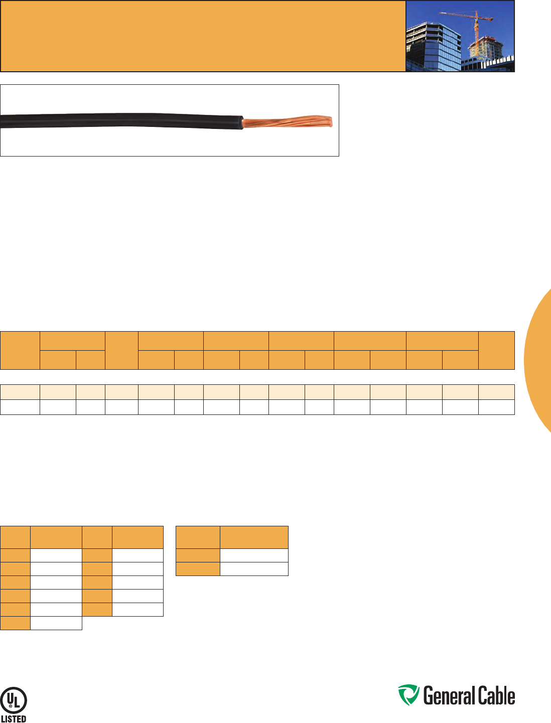
RWU90
XLPE, Low-Voltage Power
1000 V, CSA Type RWU90, Single Conductor, Copper
SPEC 5600
October, 2012
Product Construction:
Conductor:
• 14AWGthru1000kcmilannealedClassB
compressed stranded plain copper
Insulation:
• Heat-andmoisture-resistant,low-temperature
Cross-linked Polyethylene (XLPE), Type RWU90,
-40°C
• Colorcode:14AWG–black;12AWGthru
10AWG–black,white,red,blue,green;8AWG
thru2AWG–black,green,blackwithwhitestripe,
black with red stripe, black with blue stripe;
1AWGandlarger–black(othercolorsavailable
subject to minimum order quantity)
Print:
• GENERALCABLE® (PLANT OF MFG) CSA
RWU90 XLPE SIZE (AWG OR KCMIL)
CU1000V(-40°C)YEAROFMFGSEQUENTIAL
METER MARKING
NOTE:Forblackinsulationandblackwithcolored
stripes, add
–SR
Option:
• PVCjacket(FT1rating)
Applications:
• InaccordancewithCanadianElectricalCode
(CEC), Part 1
• Forwiringexposedtotheweather(blackorblack
with colored stripes)
Applications (cont’d):
• Foruseinraceways(exceptcabletrays)in
dry, damp or wet locations in accordance with
Canadian Electrical Code (CEC)
• ApprovedfordirectburialperCECRule
12-012
• Forserviceentrancebelowground
• RefertoCEC,Table19forconditionsofuse
Features:
• Ratedat90°Cwetordry
• Meetscoldbendandcoldimpacttests
at-40°C
Compliances:
• CSAStandardC22.2No.38
• CSAcertification(file)number:156400
Packaging:
• 14AWGthru10AWG:300mreels
• 8AWGthru350kcmil:300mor1500mreels
• 500kcmil:300mor1200mreels
• 600kcmiland750kcmil:600mor1200mreels
RWU90
Phone: 800-243-8020
www.generalcable.com
Copper Building Wire
11
SPEC 5250
October, 2012
Unicon® XLPE
XLPE, Low-Voltage Power
600 V, UL Type RHH/RHW-2/USE-2, Single Conductor, Copper
Product Construction:
Conductor:
• 14AWGthru1000kcmilstrandedannealedbare
copper compressed class B stranding per
ASTM B8
Insulation:
• Flame-retardantCross-linkedPolyethylene
(XLPE), black
Print:
For 14 AWG – 4 AWG:
•GENERALCABLE® (PLANT OF MFG) UNICON®-
XLP TYPE USE-2 OR RHH OR RHW-2 VW-1 SIZE
(AWG OR KCMIL) 600 VOLTS SUN RES (UL) DAY/
MONTH/YEAR OF MFG SEQUENTIAL FOOTAGE
MARK
For 2 AWG and larger:
•GENERALCABLE® (PLANT OF MFG) UNICON®-
XLP TYPE USE-2 OR RHH OR RHW-2 VW-1
(SIZE) 600 VOLTS SUN RES FOR CT USE (UL)
DAY/MONTH/YEAR OF MFG SEQUENTIAL
FOOTAGE MARK
*Sizessmallerthan1/0AWGdonotinclude“FORCTUSE”
Options:
• 2kVversion
• Tinnedcopperconductor
• ClassCstranding
• Variouscolorsavailable
• Unicon® FREP® — flame-retardant Ethylene
Propylene Rubber (EPR) insulation
• Otherconstructionsavailableuponrequest
Applications:
• Ideallysuitedforuseinabroadrangeof
commercial, industrial and utility applications
where reliability is a major concern, where
maximum performance will be demanded and
where space is limited
• Infreeair,racewaysordirectburialinaccordance
with NEC
Features:
• Ratedat90˚Cwetordry
• SmallercableO.D.
• Excellentelectrical,thermalandphysical
properties
• Excellentresistancetomoisture
• Excellentresistancetocrush,compressioncuts
and heat deformation
• Excellentflameresistance
• Excellentlowtemperturecoldbend
characteristics
• Meetscoldbendtestat-25˚C
Compliances:
Industry Compliances:
•NationalElectricalCode(NEC)
•ICEAS-95-658/NEMAWC70
•“FORCTUSE”on1/0AWGandlarger
in accordance with NEC
•UL44TypeRHH/RHW-2,ULFile#E90494
•UL854TypeUSE-2,ULFile#E90499
Flame Test Compliances:
•UL1581VW-1
•For1/0AWGandlarger:IEEE383,
IEEE1202/CSAFT4,ICEAT-29-520
Other Compliances:
•EPA40CFR,Part261forleachablelead
content per TCLP
•OSHAAcceptable
Packaging:
• Materialcuttolengthandshippedon
non-returnable wood reels
Unicon® XLPE
CATALOG
NUMBER
COND.
SIZE
(AWG/
kcmil)
COND.
STRAND
NOMINAL COND.
DIAMETER
MINIMUM AVG.
INSULATION
THICKNESS
NOMINAL CABLE
O.D.
COPPER
WEIGHT NET WEIGHT AMPACITY (1)
LBS/
1000 FT kg/km
LBS/
1000 FT kg/km 60°C 75°C 90°CINCHES mm INCHES mm INCHES mm
14 AWG - 1000 kcmil CONDUCTORS
364830* 14 7/.0242 0.07 1.78 0.045 1.14 0.17 4.32 13 19 24 36 15 15 15
364840* 12 7/.0305 0.09 2.29 0.045 1.14 0.19 4.83 20 30 33 49 20 20 20
364850* 10 7/.0385 0.12 3.05 0.045 1.14 0.21 5.33 32 48 48 71 30 30 30
16602.210800 87/.0486 0.15 3.81 0.060 1.52 0.27 6.86 50 75 78 116 40 50 55
16602.210600 67/.0612 0.18 4.57 0.060 1.52 0.31 7.87 81 121 114 170 55 65 75
16602.210400 4 7/.0772 0.23 5.84 0.060 1.52 0.36 9.14 129 192 169 252 70 85 95
16602.210200 27/.0974 0.29 7.37 0.060 1.52 0.42 10.67 205 305 254 378 95 115 130
16602.215100 1/0 19/.0740 0.37 9.40 0.080 2.03 0.53 13.46 326 485 403 600 125 150 170
16602.215200 2/0 19/.0837 0.41 10.41 0.080 2.03 0.58 14.73 411 612 501 746 145 175 195
16602.215400 4/0 19/.1055 0.52 13.21 0.080 2.03 0.69 17.53 653 972 760 1131 195 230 260
16602.216000 250 37/.0822 0.56 14.22 0.095 2.41 0.77 19.56 772 1149 906 1349 215 255 290
16602.216200 350 37/.0973 0.67 17.02 0.095 2.41 0.87 22.10 1081 1609 1237 1841 260 310 350
16602.216500 500 37/.1162 0.80 20.32 0.095 2.41 1.00 25.40 1542 2295 1730 2575 320 380 430
16602.217000 750 61/.1109 0.98 24.89 0.110 2.79 1.22 30.99 2316 3447 2576 3834 400 475 535
16602.217500* 1000 61/.1280 1.13 28.70 0.110 2.79 1.37 34.80 3086 4593 3405 5068 445 545 615
Dimensions and weights are nominal; subject to industry tolerances.
*Non-stockitem;minimumrunsapply.PleaseconsultCustomerServiceforpriceanddelivery.
(1)Temperature,sizeandampacityperNationalElectricCode,2011NECsections110.14(c)(1)(a)&(b).
60°C–Whenterminatedtoequipmentforcircuitsrated100amperesorlessormarkedfor14through1AWGconductors.
75°C–Whenterminatedtoequipmentforcircuitsratedover100amperesormarkedforconductorslargerthan1AWG.
90°C–Wetordrylocations.Forampacityderatingpurposes.
Dwelling–Fordwellingunits,conductorsshallbepermittedaslistedampacitiesat120/240-volt,3-wire,single-phaseservicesandfeeders.
Phone: 800-243-8020
www.generalcable.com
12
DEFORMATION-RESISTANT
DIRECT BURIAL
FLEXIBLE
MOISTURE-RESISTANT
COLD IMPACT
OIL-RESISTANT
UV/SUNLIGHT-RESISTANT
MECHANICALLY RUGGED
LOW SMOKE EMISSIONS
Key Performance Differences Between UL Type PV and UL Type USE-2 Wire
PV Wire
Applications/Compliances
SunGen® PV Wire -
UL Type PV/RHH/RHW-2/USE-2 UL Type USE-2
Voltage:600,1000and2000Volts
DirectBuried:600,1000and2000Volts
Conduit/Duct/Raceway
NECArticle690–PVSystems
UL4703PVWire
UL854USE-2
FlameTestRequirements:FT1&VW-1
MaximumOperatingTemperature:
90ºCWetorDry
ColdBend:-40ºC
WeatherometerSunlightResistance:
720Hour
Phone: 800-243-8020
www.generalcable.com
Harnessing the Renewable Power of the Sun
Solar Photovoltaic Wire: Why Choose SunGen
®
?
The SunGen® Difference
As a company committed to environmental stewardship and renewable energy, General Cable has
specifically designed its UL 4703 SunGen® suite of photovoltaic (PV) products to effectively and
efficiently connect solar panels and concentrated solar power technologies while being able to
withstand the harsh operating environments of solar power applications.
• ResistanttoUV/sunlight,ozoneandwaterabsorption
• Ratedfordirectburial
• Stableelectricalpropertiesoverabroadtemperaturerange(-40°Cto120°C)
• Excellentflexibilityandperformanceinlow-temperatureenvironments
• Highlyresistanttodeformation,eveninprolongedexposureathightemperatures
• Mechanicallyruggedconstructionresistscutting,tearingandabrasions
• CSARPVU90listed
• TÜVcertified,halogen-free,fire-retardantandlowcorrosivegasemissionprovide
added degree of safety
• Singleandmulti-conductorcableconstructions
• 18AWG–1000kcmilstrandedcopperand8AWG–1000kcmilaluminumconductors
PerNECArticle690,singleconductorcablelistedandlabeledasphotovoltaic(PV)wireand
singleconductorcableTypeUSE-2shallbepermittedinexposedoutdoorlocationsinphotovoltaic
sourcecircuitsforphotovoltaicmoduleinterconnectionswithinthephotovoltaicarray.Whenit
comes to the wire and cable for today’s solar energy projects with PV module interconnections
within the photovoltaic array, General Cable’s SunGen® UL Listed 4703 PV wire carries a quad
ratingandoffersfarmoresuperiorsunlightresistanceandlow-temperatureflexibilityformaximum
performanceandreliabilityforlong-termoutdoorexposuretothesun.
SunGen® — the obvious choice for solar photovoltaic applications. See for yourself.
SunGen®
NOW
AVAILABLE IN
SUN-RESISTANT

Phone: 800-243-8020
www.generalcable.com
13
The SunGen® Difference
Add true COLORS to your solar installations
with General Cable’s UL 4703 SunGen®
Brand of photovoltaic (PV) copper
products—nowinUV/sunlight-resistant
solidcolors,availablein-stockorby
special order and all manufactured with
thelatesttechnicalknowledgeandto
meet all relevant UL requirements.
WhenyouspecifyGeneralCable’s
SunGen®PVWire,wedeliveraproduct
engineeredwithexcellentflexibility
and toughness to withstand the harsh
operating environment of solar power
applications and provide high levels of
performance over the entire lifetime
of the installation.
New SunGen®UL4703PVWireintrue
COLORS is the perfect choice for critical
PV source, output and inverter circuit
identificationasrequiredbytheNEC.
Selecting a unique color further ensures a
standard-compliantsystem.
AskyourGeneralCablerepresentative
todayaboutournetworkofregional
distribution centers across the country
ready to service your order!
NOW
AVAILABLE IN
SUN-RESISTANT
CATALOG NUMBER AWG SIZE COLOR PUT-UP
SPEC 5800 — 600 V SunGen
®
UL 4703 PV Wire - EPR/XL-CPE, 19 Strand Tinned Copper
12211.711400 14AWG Black Long Length
12211.711200 12 AWG Black Long Length
12211.711100 10 AWG Black Long Length
SPEC 5810 — 2000 V SunGen
®
UL 4703 PV Wire - EPR/XL-CPE, 19 Strand Tinned Copper
12221.711400 14AWG Black Long Length
12221.711200 12 AWG Black Long Length
12221.711100 10 AWG Black Long Length
12221.710800 8 AWG Black Long Length
SPEC 5840 — 600 V SunGen
®
UL 4703 PV Wire or 1 kV CSA RPVU90 - XLPE, 19 Strand Tinned Copper
12411.711400 14AWG Black Long Length
12411.711200 12 AWG Black Long Length
12411.711100 10 AWG Black Long Length
SPEC 5840 — 600 V SunGen
®
UL 4703 PV Wire or 1 kV CSA RPVU90 - XLPE, 19 Strand Bare Copper
12411.711100B06 10 AWG Black 500ft
12411.711100B08 10 AWG Black 2500ft
12411.711109B06 10 AWG White 500ft
12411.711109B08 10 AWG White 2500ft
SPEC 5845 — 600 V SunGen
®
UL 4703 PV Wire or 1 kV CSA RPVU90 - XLPE, 7 Strand Bare Copper
12431.711100.06 10 AWG Black 500ft
12431.711100.07 10 AWG Black 1000 ft
12431.711100.08 10 AWG Black 2500ft
12431.711109.06 10 AWG White 500ft
12431.711109.07 10 AWG White 1000 ft
12431.711109.08 10 AWG White 2500ft
12431.711102.06 10 AWG Red 500ft
12431.711102.07 10 AWG Red 1000 ft
12431.711102.08 10 AWG Red 2500ft
12431.711106.06 10 AWG Blue 500ft
12431.711106.07 10 AWG Blue 1000 ft
12431.711106.08 10 AWG Blue 2500ft
SPEC 5850 — 2000 V SunGen
®
UL 4703 PV Wire or 1 kV CSA RPVU90 - XLPE, 19 Strand Tinned Copper
12421.711400 14AWG Black Long Length
12421.711200 12 AWG Black Long Length
12421.711100 10 AWG Black Long Length
SPEC 5850 —2000 V SunGen
®
UL 4703 PV Wire or 1 kV CSA RPVU90 - XLPE, 19 Strand Bare Copper
12421.711100B 10 AWG Black Long Length
SPEC 5855 — 2000 V SunGen
®
UL 4703 PV Wire or 1 kV CSA RPVU90 - XLPE, 7 Strand Bare Copper
12441.711400.07 14AWG Black 1000 ft
12441.711409.07 14AWG White 1000 ft
12441.711200.07 12 AWG Black 1000 ft
12441.711209.07 12 AWG White 1000 ft
12441.711100 10 AWG Black Long Length
12441.711100.07 10 AWG Black 1000 ft
12441.711109.07 10 AWG White 1000 ft
SunGen®
Phone: 800-243-8020
www.generalcable.com
14
SunGen®
Product Construction:
Conductor:
• 1,5mm² (16 AWG) thru 6,0 mm² (10 AWG) fully
annealed flexible stranded tinned copper with
Class5strandingperEN60228(IEC60228)
Composite Insulation/Jacket
(Sheath):
• Zero-HalogenCross-linkedPolyethylene
(ZH XLPE) with black Low-Smoke, Zero-Halogen
Cross-linked Polyolefin (LSZH XLPO)
Print
• GENERALCABLE® (PLANT OF MFG) SUNGEN®
GLOBAL XX MM² (XX AWG) TÜV PV1-F
600/1000 VAC (UL) PV WIRE 2000 V DIR BUR
90ºCWETORDRYVW-1SUNRES-40ºCROHS
MONTH/YEAR SEQ MARKING
Applications:
• TÜV2pfg1169/08.2007:Singleconductor,
sunlight-resistantphotovoltaicwire-40ºCto
+90ºC,maxtemperatureofconductor120ºCfor
20,000 hours
• RatedVoltage:ACU
O
/U 0,6/1 kV max voltage
1.8kVDC(conductor–conductor,non-earthed
system, circuit not under load)
• UL4703:Photovoltaicwirerated90ºCwetordry,
2000 V for use in photovoltaic system
Features:
• Rated90°Cwetanddry
• UV/sunlight-resistant
• Meetscoldbendandcoldimpacttests
at-40°C
• Directburial
Compliances:
Industry Compliances:
• UL4703PVWire
• TÜV2pfg1169/08.2007PV1-Fforusein
photovoltaic systems
• RoHSCompliant
Flame Test Compliances:
• UL2556VW-1
• EN60332-1-2verticalflame
Packaging:
• Materialcuttolengthandshippedonnon-
returnable wood reels
SPEC 5790
May, 2012
SunGen
®
Global
XLPE/LSZH XLPO, Photovoltaic Wire, TÜV 2 pfg
1169/08.2007PV1-FACUo/U
0.6/1kV,UL4703,PVWire2000V
CATALOG
NUMBER
COND.
SIZE
(mm2)
COND.
STRAND
COUNT
MINIMUM AVG.
INSULATION
THICKNESS
MINIMUM AVG.
JACKET (SHEATH)
THICKNESS
NOMINAL CABLE
DIAMETER
COPPER
WEIGHT NET WEIGHT
LBS/
1000 FT kg/km
LBS/
1000 FT kg/kmINCHES mm INCHES mm INCHES mm
1,5 mm2 (16 AWG) - 6,0 mm2 (10 AWG) CONDUCTORS
395400 1.5 28 0.045 1.14 0.030 0.76 0.216 5.49 9 13 28 42
395390 2.5 46 0.045 1.14 0.030 0.76 0.234 5.94 14 21 35 52
395380 4.0 56 0.045 1.14 0.030 0.76 0.263 6.68 24 36 49 73
395370 6.0 84 0.045 1.14 0.030 0.76 0.277 7.04 36 54 63 94
Dimensions and weights are nominal; subject to industry tolerances.
Phone: 800-243-8020
www.generalcable.com
15
SunGen
®
Dual-Layer EPR/XL-CPE, Photovoltaic Wire, 600 V, UL Type
PV/USE-2/RHH or RHW-2
Single Conductor, Copper
CATALOG
NUMBER
COND.
SIZE
(AWG/
kcmil)
COND.
STRAND
NOMINAL COND. O.D.
MINIMUM AVG.
INSULATION
THICKNESS
MINIMUM AVG.
JACKET THICKNESS
NOMINAL CABLE
DIAMETER
COPPER
WEIGHT NET WEIGHT
LBS/
1000 FT kg/km
LBS/
1000 FT kg/kmINCHES mm INCHES mm INCHES mm INCHES mm
14 AWG - 1000 kcmil CONDUCTORS
12211.711400 14 19/.0142 0.070 1.78 0.030 0.76 0.030 0.76 0.201 5.10 13 19 32 48
12211.711200 12 19/.0185 0.088 2.23 0.030 0.76 0.030 0.76 0.219 5.56 20 30 42 62
12211.711100 10 19/.0234 0.112 2.84 0.030 0.76 0.030 0.76 0.242 6.15 32 48 59 88
12211.710800* 819/.0295 0.143 3.63 0.045 1.14 0.030 0.76 0.310 7.87 50 74 89 132
12211.710600* 619/.0372 0.184 4.67 0.045 1.14 0.045 1.14 0.376 9.55 81 121 141 210
12211.710400* 4 19/.0469 0.234 5.94 0.045 1.14 0.045 1.14 0.420 10.67 129 192 202 301
12211.710200* 219/.0526 0.296 7.52 0.045 1.14 0.045 1.14 0.487 12.37 205 305 292 434
12211.710100* 119/.0664 0.323 8.20 0.055 1.40 0.060 1.52 0.539 13.69 258 384 408 607
12211.715100* 1/0 19/.0740 0.370 9.40 0.055 1.40 0.060 1.52 0.587 14.91 326 485 478 711
12211.715200* 2/0 19/.0837 0.410 10.41 0.055 1.40 0.060 1.52 0.632 16.05 411 611 590 878
12211.715300* 3/0 19/.0940 0.460 11.68 0.055 1.40 0.060 1.52 0.678 17.22 518 771 734 1092
12211.715400* 4/0 19/.1055 0.520 13.21 0.055 1.40 0.060 1.52 0.738 18.74 653 972 865 1287
12211.716250* 250 37/.0822 0.558 14.17 0.065 1.65 0.080 2.03 0.862 21.89 772 1149 995 1481
12211.716300* 300 37/.0900 0.611 15.52 0.065 1.65 0.080 2.03 0.915 23.24 926 1378 1167 1737
12211.716350* 350 37/.0972 0.661 16.79 0.065 1.65 0.080 2.03 0.965 24.51 1063 1582 1321 1966
12211.716400* 400 37/.1040 0.706 17.93 0.065 1.65 0.080 2.03 1.010 25.65 1235 1838 1508 2244
12211.716500* 500 37/.1159 0.789 20.04 0.065 1.65 0.080 2.03 1.093 27.76 1509 2246 1810 2694
12211.716600* 600 61/.0992 0.866 22.00 0.080 2.03 0.080 2.03 1.200 30.48 1883 2802 2237 3329
12211.716750* 750 61/.1109 0.968 24.59 0.080 2.03 0.080 2.03 1.302 33.07 2316 3447 2707 4028
12211.717000* 1000 61/.1280 1.117 28.37 0.080 2.03 0.080 2.03 1.451 36.86 3088 4595 3534 5259
Dimensions and weights are nominal; subject to industry tolerances.
*Non-stockitem;minimumrunsapply.PleasecontactCustomerServiceforpriceanddelivery.
SunGen®
Product Construction:
Conductor:
• 14AWGthru2AWGtinnedcoatedcompressed
copper. Class C stranding per ASTM B33 and B8
• 1AWGthru1000kcmiltinnedcoatedcompressed
copper. Class B stranding per ASTM B33 and B8
Insulation:
• Lead-freeEthylenePropyleneRubber(EPR)
colored for contrast with black jacket
Jacket:
• Black,lead-free,flame-retardant,oil-,chemical-
and sunlight-resistant Cross-linked Chlorinated
Polyethylene (XL-CPE)
Print:
• GENERALCABLE® (PLANT OF MFG) SUNGEN®
600 V PV WIRE DIR BUR OR RHH OR RHW-2
ORUSE-2(SIZE)90°CWETORDRYSUN
RES(UL)-40°CVW-1MONTH/YEAROFMFG
SEQUENTIAL FOOTAGE MARK
Options:
• Barecopperconductor
• Otherstrandingoptionsareavailableupon
request
• Nowavailableincolors
Applications:
• Singleconductor,sunlight-resistant,direct
burialphotovoltaicwirerated90°Cwetordry,
600 V for interconnection wiring of grounded
and ungrounded photovoltaic power systems
as described in Section 690.31(A) and other
applicable parts of the National Electrical Code
(NEC),NFPA70
Features:
• Rated90°Cwetanddry
• Ratedfordirectburial
• Deformation-resistantathightemperatures
• Excellentmoistureresistance,exceedsUL44
• Stableelectricalpropertiesoverabroad
temperature range
• Extratough,mechanicallyruggeddual-layer
construction
• Increasedflexibility
• Resistanttomostoilsandchemicals
• UV/sunlight-resistant
• Meetscoldbendandcoldimpacttestsat-40°C
Compliances:
Industry Compliances:
•UL4703TypePV,ULFile#E323451
•NationalElectricalCode(NEC)
•ICEAS-95-658/NEMAWC70
•UL44TypeRHHorRHW-2,ULFile#E90494
orE54260
•UL854TypeUSE-2,ULFile#E90499
orE86307
•LimitedSmokeRatingperUL
•RoHSCompliant
Flame Test Compliances:
•UL1581VW-1
•Forsizes1/0andlarger:IEEE383,
IEEE1202/CSAFT4
Other Compliances:
•EPA40CFR,Part261forleachablelead
content per TCLP
•OSHAAcceptable
Packaging:
• Materialcuttolengthandshippedon
non-returnable wood reels
SPEC 5800
May, 2012
NOW
AVAILABLE IN
SUN-RESISTANT
Phone: 800-243-8020
www.generalcable.com
16
CATALOG
NUMBER
COND.
SIZE
(AWG/
kcmil)
COND.
STRAND
NOMINAL COND. O.D.
MINIMUM AVG.
INSULATION
THICKNESS
MINIMUM AVG.
JACKET THICKNESS
NOMINAL CABLE
DIAMETER
COPPER
WEIGHT NET WEIGHT
LBS/
1000 FT kg/km
LBS/
1000 FT kg/kmINCHES mm INCHES mm INCHES mm INCHES mm
14 AWG - 1000 kcmil CONDUCTORS
12221.711400 14 19/.0142 0.070 1.78 0.045 1.14 0.030 0.76 0.232 5.89 13 19 36 54
12221.711200 12 19/.0185 0.088 2.23 0.045 1.14 0.030 0.76 0.250 6.35 20 30 46 68
12221.711100 10 19/.0234 0.112 2.84 0.045 1.14 0.030 0.76 0.273 6.93 32 48 64 95
12221.710800* 819/.0295 0.143 3.63 0.055 1.40 0.030 0.76 0.332 8.43 50 74 95 141
12221.710600* 619/.0372 0.184 4.67 0.055 1.40 0.045 1.14 0.398 10.11 81 121 148 220
12221.710400* 4 19/.0469 0.234 5.94 0.055 1.40 0.045 1.14 0.442 11.23 129 192 208 309
12221.710200* 219/.0526 0.296 7.52 0.055 1.40 0.045 1.14 0.507 12.88 205 305 306 455
12221.710100* 119/.0664 0.323 8.20 0.065 1.65 0.060 1.52 0.561 14.25 258 384 440 655
12221.715100* 1/0 19/.0740 0.370 9.40 0.065 1.65 0.060 1.52 0.607 15.42 326 485 505 751
12221.715200* 2/0 19/.0837 0.410 10.41 0.065 1.65 0.060 1.52 0.652 16.56 411 611 615 915
12221.715300* 3/0 19/.0940 0.460 11.68 0.065 1.65 0.060 1.52 0.700 17.78 518 771 747 1111
12221.715400* 4/0 19/.1055 0.520 13.21 0.065 1.65 0.060 1.52 0.760 19.30 653 972 891 1326
12221.716250* 250 37/.0822 0.558 14.17 0.075 1.91 0.080 2.03 0.882 22.40 772 1149 1012 1506
12221.716300* 300 37/.0900 0.611 15.52 0.075 1.91 0.080 2.03 0.935 23.75 926 1378 1184 1763
12221.716350* 350 37/.0972 0.661 16.79 0.075 1.91 0.080 2.03 0.985 25.02 1063 1582 1339 1993
12221.716400* 400 37/.1040 0.706 17.93 0.075 1.91 0.080 2.03 1.030 26.16 1235 1838 1527 2273
12221.716500* 500 37/.1159 0.789 20.04 0.075 1.91 0.080 2.03 1.113 28.27 1509 2246 1831 2725
12221.716600* 600 61/.0992 0.866 22.00 0.090 2.29 0.080 2.03 1.222 31.04 1883 2802 2262 3367
12221.716750* 750 61/.1109 0.968 24.59 0.090 2.29 0.080 2.03 1.324 33.63 2316 3447 2734 4069
12221.717000* 1000 61/.1280 1.117 28.37 0.090 2.29 0.080 2.03 1.473 37.41 3088 4595 3564 5303
Dimensions and weights are nominal; subject to industry tolerances.
*Non-stockitem;minimumrunsapply.PleasecontactCustomerServiceforpriceanddelivery.
SunGen®
Product Construction:
Conductor:
• 14AWGthru2AWGtinnedcoatedcompressed
copper. Class C stranding per ASTM B33 and B8
• 1AWGthru1000kcmiltinnedcoatedcompressed
copper. Class B stranding per ASTM B33 and B8
Insulation:
• Lead-freeEthylenePropyleneRubber(EPR)
colored for contrast with black jacket
Jacket:
• Black,lead-free,flame-retardant,oil-,chemical-
and sunlight-resistant Cross-linked Chlorinated
Polyethylene (XL-CPE)
Print:
•GENERALCABLE® (PLANT OF MFG) SUNGEN®
2000 V PV WIRE DIR BUR OR RHH OR RHW-2
OR600VUSE-2(SIZE)90°CWETORDRY
SUNRES(UL)-40°CVW-1c(UL)RWU90
1000 V MONTH/YEAR OF MFG SEQUENTIAL
FOOTAGE MARK
Options:
• Barecopperconductor
• Otherstrandingoptionsareavailableupon
request
• Nowavailableincolors
Applications:
• Singleconductor,sunlight-resistant,direct
burialphotovoltaicwirerated90°Cwetordry,
2000 V for interconnection wiring of grounded
and ungrounded photovoltaic power systems
as described in Section 690.31(A) and other
applicable parts of the National Electrical Code
(NEC),NFPA70
Features:
• Rated90°Cwetanddry
• Ratedfordirectburial
• Deformation-resistantathightemperatures
• Excellentmoistureresistance,exceedsUL44
• Stableelectricalpropertiesoverabroad
temperature range
• Extratough,mechanicallyruggeddual-layer
construction
Features (cont’d.):
• Increasedflexibility
• Resistanttomostoilsandchemicals
• UV/sunlight-resistant
• Meetscoldbendandcoldimpacttestsat-40°C
Compliances:
Industry Compliances:
•UL4703TypePV,ULFile#E323451
•NationalElectricalCode(NEC)
•ICEAS-95-658/NEMAWC70
•UL44TypeRHHorRHW-2,ULFile#E90494
orE54260
•UL854TypeUSE-2for600V,ULFile#E90499
orE86307
•LimitedSmokeRatingperUL
•RoHSCompliant
Flame Test Compliances:
•UL1581VW-1
•Forsizes1/0andlarger:IEEE383,
IEEE1202/CSAFT4
Other Compliances:
•EPA40CFR,Part261forleachablelead
content per TCLP
•OSHAAcceptable
Packaging:
• Materialcuttolengthandshippedon
non-returnable wood reels
SPEC 5810
May, 2012
SunGen
®
Dual-Layer EPR/XL-CPE, Photovoltaic Wire, 2000 V, UL Type PV/RHH
or RHW-2 or 600 V USE-2
Single Conductor, Copper
NOW
AVAILABLE IN
SUN-RESISTANT
Phone: 800-243-8020
www.generalcable.com
17
CATALOG
NUMBER
COND.
SIZE
(AWG/
kcmil)
COND.
STRAND
NOMINAL COND. O.D.
MINIMUM AVG.
INSULATION THICKNESS
NOMINAL CABLE
DIAMETER
COPPER
WEIGHT NET WEIGHT
LBS/
1000 FT kg/km
LBS/
1000 FT kg/kmINCHES mm INCHES mm INCHES mm
18 AWG - 1000 kcmil CONDUCTORS
12411.711800* 18 19/.0092 0.045 1.14 0.060 1.52 0.169 4.29 5 7 14 21
12411.711600* 16 19/.0117 0.056 1.42 0.060 1.52 0.180 4.57 8121827
12411.711400 14 19/.0142 0.070 1.78 0.060 1.52 0.194 4.93 13 19 27 40
12411.711200 12 19/.0185 0.088 2.23 0.060 1.52 0.214 5.43 20 30 36 54
12411.711100 10 19/.0234 0.112 2.84 0.060 1.52 0.238 6.04 32 48 51 76
12411.710800* 819/.0295 0.143 3.63 0.080 2.03 0.307 7.80 50 74 85 126
12411.710600* 619/.0372 0.184 4.67 0.080 2.03 0.348 8.84 81 121 123 183
12411.710400* 4 19/.0469 0.234 5.94 0.080 2.03 0.398 10.11 129 192 180 268
12411.710200* 219/.0526 0.296 7.52 0.080 2.03 0.460 11.68 205 305 267 397
12411.710100* 119/.0664 0.323 8.20 0.095 2.41 0.515 13.08 258 384 333 495
12411.715100* 1/0 19/.0740 0.370 9.40 0.095 2.41 0.563 14.30 326 485 410 610
12411.715200* 2/0 19/.0837 0.410 10.41 0.095 2.41 0.608 15.44 411 611 502 747
12411.715300* 3/0 19/.0940 0.460 11.68 0.095 2.41 0.658 16.71 518 771 620 922
12411.715400* 4/0 19/.1055 0.520 13.21 0.095 2.41 0.714 18.13 653 972 767 1141
12411.716250* 250 37/.0822 0.558 14.17 0.110 2.79 0.784 19.91 772 1149 923 1374
12411.716300* 300 37/.0900 0.611 15.52 0.110 2.79 0.837 21.26 926 1378 1090 1622
12411.716350* 350 37/.0972 0.661 16.79 0.110 2.79 0.887 22.53 1063 1582 1240 1845
12411.716400* 400 37/.1040 0.706 17.93 0.110 2.79 0.932 23.67 1235 1838 1423 2117
12411.716500* 500 37/.1159 0.789 20.04 0.110 2.79 1.015 25.78 1509 2246 1718 2557
12411.716600* 600 61/.0992 0.866 22.00 0.125 3.18 1.122 28.50 1883 2802 2136 3179
12411.716750* 750 61/.1109 0.968 24.59 0.125 3.18 1.224 31.09 2316 3447 2597 3865
12411.717000* 1000 61/.1280 1.117 28.37 0.125 3.18 1.373 34.87 3088 4595 3411 5076
Dimensions and weights are nominal; subject to industry tolerances.
*Non-stockitem;minimumrunsapply.PleasecontactCustomerServiceforpriceanddelivery.
SunGen®
Product Construction:
Conductor:
•18AWGthru2AWGtinnedcoatedcompressed
copper. Class C stranding per ASTM B33 and B8
•1AWGthru1000kcmiltinnedcoated
compressed copper. Class B stranding per
ASTM B33 and B8
Insulation:
•Flame-retardantCross-linkedPolyethylene
(XLPE), black
Print:
• 18AWGand16AWG:GENERALCABLE® (PLANT
OF MFG) SUNGEN® 600 V PV WIRE DIR BUR
90°CWETORDRYSUNRES(UL)-40°CVW-1
MONTH/YEAR OF MFG SEQUENTIAL FOOTAGE
MARK
• 14AWGthru1000kcmil:GENERALCABLE®
(PLANT OF MFG) SUNGEN® 600 V PV WIRE
DIR BUR OR 2000 V RHH OR RHW-2 OR 600 V
USE-2(SIZE)90°CWETORDRYSUNRES(UL)
-40°CVW-1(CSA)RPVU901000VMONTH/
YEAR OF MFG SEQUENTIAL FOOTAGE MARK
Options:
• Barecopperconductor
• Otherstrandingoptionsareavailableupon
request
• Nowavailableincolors
Applications:
• Singleconductor,sunlight-resistant,direct
burialphotovoltaicwirerated90°Cwetordry,
600 V for interconnection wiring of grounded
and ungrounded photovoltaic power systems
as described in Section 690.31(A) and other
applicable parts of the National Electrical Code
(NEC),NFPA70
Features:
• Rated90°Cwetanddry
• Ratedfordirectburial
• Deformation-resistantathightemperatures
• Excellentmoistureresistance,exceedsUL44
• Stableelectricalpropertiesoverabroad
temperature range
• Increasedflexibility
• Excellentresistancetocrushandcompression
cuts
• Resistanttomostoilsandchemicals
• UV/sunlight-resistant
• Meetscoldbendandcoldimpacttestsat-40°C
Compliances:
Industry Compliances:
•UL4703TypePV,ULFile#E323451
•NationalElectricalCode(NEC)
•ICEAS-95-658/NEMAWC70
•UL44TypeRHHorRHW-2,ULFile#E90494
•UL854TypeUSE-2,ULFile#E90499
•CSAC22.2No.271RPVU90
Flame Test Compliances:
•UL1581VW-1
•Forsizes1/0andlarger:IEEE383,
IEEE1202/CSAFT4
Other Compliances:
•EPA40CFR,Part261forleachablelead
content per TCLP
•OSHAAcceptable
Packaging:
• Materialcuttolengthandshippedon
non-returnable wood reels
SPEC 5840
May, 2012
SunGen
®
XLPE, Photovoltaic Wire, 600 V, UL Type PV/USE-2 or 2000 V RHH
or RHW-2 or CSA RPVU90, 1000 V
Single Conductor, Copper
NOW
AVAILABLE IN
SUN-RESISTANT
Phone: 800-243-8020
www.generalcable.com
18
CATALOG
NUMBER
COND.
SIZE
(AWG/
kcmil)
COND.
STRAND
NOMINAL COND. O.D.
MINIMUM AVG.
INSULATION THICKNESS
NOMINAL CABLE
DIAMETER
COPPER
WEIGHT NET WEIGHT
LBS/
1000 FT kg/km
LBS/
1000 FT kg/kmINCHES mm INCHES mm INCHES mm
18 AWG - 1000 kcmil CONDUCTORS
12431.711800* 18 7/.0152 0.045 1.14 0.060 1.52 0.169 4.29 5 7 14 21
12431.711600* 16 7/.0192 0.056 1.42 0.060 1.52 0.180 4.57 8121827
12431.711400* 14 7/.0240 0.070 1.78 0.060 1.52 0.194 4.93 13 19 27 40
12431.711200 12 7/.0305 0.088 2.23 0.060 1.52 0.214 5.43 20 30 36 54
12431.711100 10 7/.0385 0.112 2.84 0.060 1.52 0.238 6.04 32 48 51 76
12431.710800 87/.0486 0.143 3.63 0.080 2.02 0.313 7.95 50 74 88 131
12431.710600* 67/.0612 0.184 4.67 0.080 2.02 0.356 9.04 81 121 126 186
12431.710400* 4 7/.0772 0.234 5.94 0.080 2.02 0.405 10.29 129 192 183 272
12431.710200* 27/.0974 0.296 7.52 0.080 2.02 0.466 11.84 205 305 269 401
12431.710100* 119/.0664 0.323 8.20 0.095 2.41 0.515 13.08 258 384 333 495
12431.715100* 1/0 19/.0740 0.370 9.40 0.095 2.41 0.563 14.30 326 485 410 610
12431.715200* 2/0 19/.0837 0.410 10.41 0.095 2.41 0.608 15.44 411 611 502 747
12431.715300* 3/0 19/.0940 0.460 11.68 0.095 2.41 0.658 16.71 518 771 620 922
12431.715400* 4/0 19/.1055 0.520 13.21 0.095 2.41 0.714 18.13 653 972 767 1141
12431.716250* 250 37/.0822 0.558 14.17 0.110 2.79 0.784 19.91 772 1149 923 1374
12431.716300* 300 37/.0900 0.611 15.52 0.110 2.79 0.837 21.26 926 1378 1090 1622
12431.716350* 350 37/.0972 0.661 16.79 0.110 2.79 0.887 22.53 1063 1582 1240 1845
12431.716400* 400 37/.1040 0.706 17.93 0.110 2.79 0.932 23.67 1235 1838 1423 2117
12431.716500* 500 37/.1159 0.789 20.04 0.110 2.79 1.015 25.78 1509 2246 1718 2557
12431.716600* 600 61/.0992 0.866 22.00 0.125 3.18 1.122 28.50 1883 2802 2136 3179
12431.716750* 750 61/.1109 0.968 24.59 0.125 3.18 1.224 31.09 2316 3447 2597 3865
12431.717000* 1000 61/.1280 1.117 28.37 0.125 3.18 1.373 34.87 3088 4595 3411 5076
Dimensions and weights are nominal; subject to industry tolerances.
*Non-stockitem;minimumrunsapply.PleasecontactCustomerServiceforpriceanddelivery.
SunGen®
Product Construction:
Conductor:
•18AWGthru1000kcmilbarecompressed
copper. Class B per ASTM B8
Insulation:
•Flame-retardantCross-linkedPolyethylene
(XLPE), black
Print:
• 18AWGand16AWG:GENERALCABLE®
(PLANT OF MFG) SUNGEN® 600 V PV WIRE DIR
BUR90°CWETORDRYSUNRES(UL)-40°C
VW-1 MONTH/YEAR OF MFG SEQUENTIAL
FOOTAGE MARK
• 14AWGthru1000kcmil:GENERALCABLE®
(PLANT OF MFG) SUNGEN® 600 V PV WIRE
DIR BUR OR 2000 V RHH OR RHW-2 OR 600 V
USE-2(SIZE)90°CWETORDRYSUNRES(UL)
-40°CVW-1(CSA)RPVU901000VMONTH/
YEAR OF MFG SEQUENTIAL FOOTAGE MARK
Options:
• Tinnedcopperconductor
• Otherstrandingoptionsareavailableupon
request
• Nowavailableincolors
Applications:
•Singleconductor,sunlight-resistant,direct
burialphotovoltaicwirerated90°Cwetordry,
600 V for interconnection wiring of grounded
and ungrounded photovoltaic power systems
as described in Section 690.31(A) and other
applicable parts of the National Electrical Code
(NEC),NFPA70
Features:
• Rated90°Cwetanddry
• Ratedfordirectburial
• Deformation-resistantathightemperatures
• Excellentmoistureresistance,exceedsUL44
• Stableelectricalpropertiesoverabroad
temperature range
Features (cont’d.):
• Excellentresistancetocrushandcompression
cuts
• Resistanttomostoilsandchemicals
• UV/sunlight-resistant
• Meetscoldbendandcoldimpacttestsat-40°C
Compliances:
Industry Compliances:
•UL4703TypePV,ULFile#E323451
•NationalElectricalCode(NEC)
•ICEAS-95-658/NEMAWC70
•UL44TypeRHHorRHW-2,ULFile#E90494
•UL854TypeUSE-2,ULFile#E90499
•CSAC22.2No.271RPVU90
Flame Test Compliances:
•UL1581VW-1
•Forsizes1/0andlarger:IEEE383,
IEEE1202/CSAFT4
Other Compliances:
•EPA40CFR,Part261forleachablelead
content per TCLP
•OSHAAcceptable
Packaging:
• Materialcuttolengthandshippedon
non-returnable wood reels
SPEC 5845
May, 2012
SunGen
®
IC
XLPE, Photovoltaic Wire, 600 V, UL Type PV/USE-2 or 2000 V
RHH or RHW-2 or CSA RPVU90
1000 V, Single Conductor, Copper
NOW
AVAILABLE IN
SUN-RESISTANT

Phone: 800-243-8020
www.generalcable.com
19
CATALOG
NUMBER
COND.
SIZE
(AWG/
kcmil)
COND.
STRAND
NOMINAL COND. O.D.
MINIMUM AVG.
INSULATION THICKNESS
NOMINAL CABLE
DIAMETER
COPPER
WEIGHT NET WEIGHT
LBS/
1000 FT kg/km
LBS/
1000 FT kg/kmINCHES mm INCHES mm INCHES mm
18 AWG - 1000 kcmil CONDUCTORS
12421.711800* 18 19/.0092 0.045 1.14 0.075 1.90 0.199 5.05 5 7 16 24
12421.711600* 16 19/.0117 0.056 1.42 0.075 1.90 0.210 5.33 8 12 21 31
12421.711400 14 19/.0142 0.070 1.78 0.075 1.90 0.224 5.69 13 19 32 48
12421.711200 12 19/.0185 0.088 2.23 0.075 1.90 0.244 6.20 20 30 42 62
12421.711100 10 19/.0234 0.112 2.84 0.075 1.90 0.268 6.81 32 48 57 85
12421.710800* 819/.0295 0.143 3.63 0.085 2.16 0.326 8.28 50 74 87 129
12421.710600* 619/.0372 0.184 4.67 0.085 2.16 0.363 9.22 81 121 123 183
12421.710400* 4 19/.0469 0.234 5.94 0.085 2.16 0.406 10.31 129 192 181 269
12421.710200* 219/.0526 0.296 7.52 0.085 2.16 0.474 12.04 205 305 266 396
12421.710100* 119/.0664 0.323 8.20 0.105 2.67 0.538 13.66 258 384 350 521
12421.715100* 1/0 19/.0740 0.370 9.40 0.105 2.67 0.586 14.88 326 485 429 638
12421.715200* 2/0 19/.0837 0.410 10.41 0.105 2.67 0.631 16.03 411 611 527 784
12421.715300* 3/0 19/.0940 0.460 11.68 0.105 2.67 0.674 17.12 518 771 647 963
12421.715400* 4/0 19/.1055 0.520 13.21 0.105 2.67 0.737 18.72 653 972 796 1184
12421.716250* 250 37/.0822 0.558 14.17 0.120 3.05 0.804 20.42 772 1149 938 1396
12421.716300* 300 37/.0900 0.611 15.52 0.120 3.05 0.857 21.77 926 1378 1106 1646
12421.716350* 350 37/.0972 0.661 16.79 0.120 3.05 0.907 23.04 1063 1582 1257 1870
12421.716400* 400 37/.1040 0.706 17.93 0.120 3.05 0.952 24.18 1235 1838 1441 2144
12421.716500* 500 37/.1159 0.789 20.04 0.120 3.05 1.035 26.29 1509 2246 1737 2585
12421.716600* 600 61/.0992 0.866 22.00 0.135 3.43 1.142 29.01 1883 2802 2157 3211
12421.716750* 750 61/.1109 0.968 24.59 0.135 3.43 1.244 31.60 2316 3447 2620 3900
12421.717000* 1000 61/.1280 1.117 28.37 0.135 3.43 1.393 35.38 3088 4595 3437 5115
Dimensions and weights are nominal; subject to industry tolerances.
*Non-stockitem;minimumrunsapply.PleasecontactCustomerServiceforpriceanddelivery.
SunGen®
Product Construction:
Conductor:
• 18AWGthru2AWGtinnedcoatedcompressed
copper. Class C stranding per ASTM B33 and B8
• 1AWGthru1000kcmiltinnedcoated
compressed copper. Class B stranding per
ASTM B33 and B8
Insulation:
• Flame-retardant Cross-linked Polyethylene
(XLPE), black
Print:
• 18AWGand16AWG:GENERALCABLE®
(PLANT OF MFG) SUNGEN® 2000 V PV
WIREDIRBUR90°CWETORDRYSUNRES
(UL)-40°CVW-1MONTH/YEAROFMFG
SEQUENTIAL FOOTAGE MARK
• 14AWGthru1000kcmil:GENERALCABLE®
(PLANT OF MFG) SUNGEN® 2000 V PV WIRE
DIR BUR OR RHH OR RHW-2 OR 600 V USE-2
(SIZE)90°CWETORDRYSUNRES(UL)-40°C
VW-1 (CSA) RPVU90 1000 V MONTH/YEAR OF
MFG SEQUENTIAL FOOTAGE MARK
Options:
• Barecopperconductor
• Otherstrandingoptionsareavailableupon
request
• Nowavailableincolors
Applications:
• Singleconductor,sunlight-resistant,direct
burialphotovoltaicwirerated90°Cwetordry,
2000 V for interconnection wiring of grounded
and ungrounded photovoltaic power systems
as described in Section 690.31(A) and other
applicable parts of the National Electrical Code
(NEC),NFPA70
Features:
• Rated90°Cwetanddry
• Ratedfordirectburial
• Deformation-resistantathightemperatures
• Excellentmoistureresistance,exceedsUL44
• Stableelectricalpropertiesoverabroad
temperature range
• Increasedflexibility
• Excellentresistancetocrushandcompression
cuts
• Resistanttomostoilsandchemicals
• UV/sunlight-resistant
• Meetscoldbendandcoldimpacttestsat-40°C
Compliances:
Industry Compliances:
•UL4703TypePV,ULFile#E323451
•NationalElectricalCode(NEC)
•ICEAS-95-658/NEMAWC70
•UL44TypeRHHorRHW-2,ULFile#E90494
•UL854TypeUSE-2for600V,ULFile#E90499
•CSAC22.2No.271RPVU90
Flame Test Compliances:
•UL1581VW-1
•Forsizes1/0andlarger:IEEE383,
IEEE1202/CSAFT4
Other Compliances:
•EPA40CFR,Part261forleachablelead
content per TCLP
•OSHAAcceptable
Packaging:
• Materialcuttolengthandshippedon
non-returnable wood reels
SPEC 5850
May, 2012
SunGen
®
XLPE, Photovoltaic Wire, 2000 V, UL Type PV/RHH or RHW-2 or 600 V
USE-2 or CSA RPVU90, 1000 V
Single Conductor, Copper
NOW
AVAILABLE IN
SUN-RESISTANT
Phone: 800-243-8020
www.generalcable.com
20
CATALOG
NUMBER
COND.
SIZE
(AWG/
kcmil)
COND.
STRAND
NOMINAL COND. O.D.
MINIMUM AVG.
INSULATION THICKNESS
NOMINAL CABLE
DIAMETER
COPPER
WEIGHT NET WEIGHT
LBS/
1000 FT kg/km
LBS/
1000 FT kg/kmINCHES mm INCHES mm INCHES mm
18 AWG - 1000 kcmil CONDUCTORS
12441.711800* 18 7/.0152 0.045 1.14 0.075 1.90 0.199 5.05 5 7 16 24
12441.711600* 16 7/.0192 0.056 1.42 0.075 1.90 0.210 5.33 8 12 21 31
12441.711400* 14 7/.0240 0.070 1.78 0.075 1.90 0.224 5.69 13 19 32 48
12441.711200 12 7/.0305 0.088 2.23 0.075 1.90 0.244 6.20 20 30 42 62
12441.711100 10 7/.0385 0.112 2.84 0.075 1.90 0.268 6.81 32 48 57 85
12441.710800 87/.0486 0.143 3.63 0.085 2.16 0.326 8.28 50 74 87 129
12441.710600* 67/.0612 0.184 4.67 0.085 2.16 0.363 9.22 81 121 123 183
12441.710400* 4 7/.0772 0.234 5.94 0.085 2.16 0.406 10.31 129 192 181 269
12441.710200* 27/.0974 0.296 7.52 0.085 2.16 0.474 12.04 205 305 266 396
12441.710100* 119/.0664 0.323 8.20 0.105 2.67 0.538 13.66 258 384 350 521
12441.715100* 1/0 19/.0740 0.370 9.40 0.105 2.67 0.586 14.88 326 485 429 638
12441.715200* 2/0 19/.0837 0.410 10.41 0.105 2.67 0.631 16.03 411 611 527 784
12441.715300* 3/0 19/.0940 0.460 11.68 0.105 2.67 0.674 17.12 518 771 647 963
12441.715400* 4/0 19/.1055 0.520 13.21 0.105 2.67 0.737 18.72 653 972 796 1184
12441.716250* 250 37/.0822 0.558 14.17 0.120 3.05 0.804 20.42 772 1149 938 1396
12441.716300* 300 37/.0900 0.611 15.52 0.120 3.05 0.857 21.77 926 1378 1106 1646
12441.716350* 350 37/.0972 0.661 16.79 0.120 3.05 0.907 23.04 1063 1582 1257 1870
12441.716400* 400 37/.1040 0.706 17.93 0.120 3.05 0.952 24.18 1235 1838 1441 2144
12441.716500* 500 37/.1159 0.789 20.04 0.120 3.05 1.035 26.29 1509 2246 1737 2585
12441.716600* 600 61/.0992 0.866 22.00 0.135 3.43 1.142 29.01 1883 2802 2157 3211
12441.716750* 750 61/.1109 0.968 24.59 0.135 3.43 1.244 31.60 2316 3447 2620 3900
12441.717000* 1000 61/.1280 1.117 28.37 0.135 3.43 1.393 35.38 3088 4595 3437 5115
Dimensions and weights are nominal; subject to industry tolerances.
*Non-stockitem;minimumrunsapply.PleasecontactCustomerServiceforpriceanddelivery.
SunGen®
Product Construction:
Conductor:
• 18AWGthru1000kcmilbarecompressed
copper. Class B per ASTM B8
Insulation:
• Flame-retardant Cross-linked Polyethylene
(XLPE), black
Print:
• 18AWGand16AWG:GENERALCABLE®
(PLANT OF MFG) SUNGEN® 2000 V PV
WIREDIRBUR90°CWETORDRYSUNRES
(UL)-40°CVW-1MONTH/YEAROFMFG
SEQUENTIAL FOOTAGE MARK
• 14AWGthru1000kcmil:GENERALCABLE®
(PLANT OF MFG) SUNGEN® 2000 V PV WIRE
DIR BUR OR RHH OR RHW-2 OR 600 V USE-2
(SIZE)90°CWETORDRYSUNRES(UL)-40°C
VW-1 (CSA) RPVU90 1000 V MONTH/YEAR OF
MFG SEQUENTIAL FOOTAGE MARK
Options:
• Tinnedcopperconductor
• Otherstrandingoptionsareavailableupon
request
• Nowavailableincolors
Applications:
• Singleconductor,sunlight-resistant,direct
burialphotovoltaicwirerated90°Cwetordry,
2000 V for interconnection wiring of grounded
and ungrounded photovoltaic power systems
as described in Section 690.31(A) and other
applicable parts of the National Electrical Code
(NEC),NFPA70
Features:
• Rated90°Cwetanddry
• Ratedfordirectburial
• Deformation-resistantathightemperatures
• Excellentmoistureresistance,exceedsUL44
• Stableelectricalpropertiesoverabroad
temperature range
Features (cont’d.):
• Excellentresistancetocrushandcompression
cuts
• Resistanttomostoilsandchemicals
• UV/sunlight-resistant
• Meetscoldbendandcoldimpacttestsat-40°C
Compliances:
Industry Compliances:
•UL4703TypePV,ULFile#E323451
•NationalElectricalCode(NEC)
•ICEAS-95-658/NEMAWC70
•UL44TypeRHHorRHW-2,ULFile#E90494
orE54260
•UL854TypeUSE-2for600V,ULFile#E90499
orE86307
•CSAC22.2No.271RPVU90
Flame Test Compliances:
•UL1581VW-1
•Forsizes1/0andlarger:IEEE383,
IEEE1202/CSAFT4
Other Compliances:
•EPA40CFR,Part261forleachablelead
content per TCLP
•OSHAAcceptable
Packaging:
• Materialcuttolengthandshippedon
non-returnable wood reels
SPEC 5855
May, 2012
SunGen
®
IC
XLPE, Photovoltaic Wire, 2000 V, UL Type PV/RHH or RHW-2 or
600 V USE-2 or CSA RPVU90
1000 V, Single Conductor, Copper
NOW
AVAILABLE IN
SUN-RESISTANT
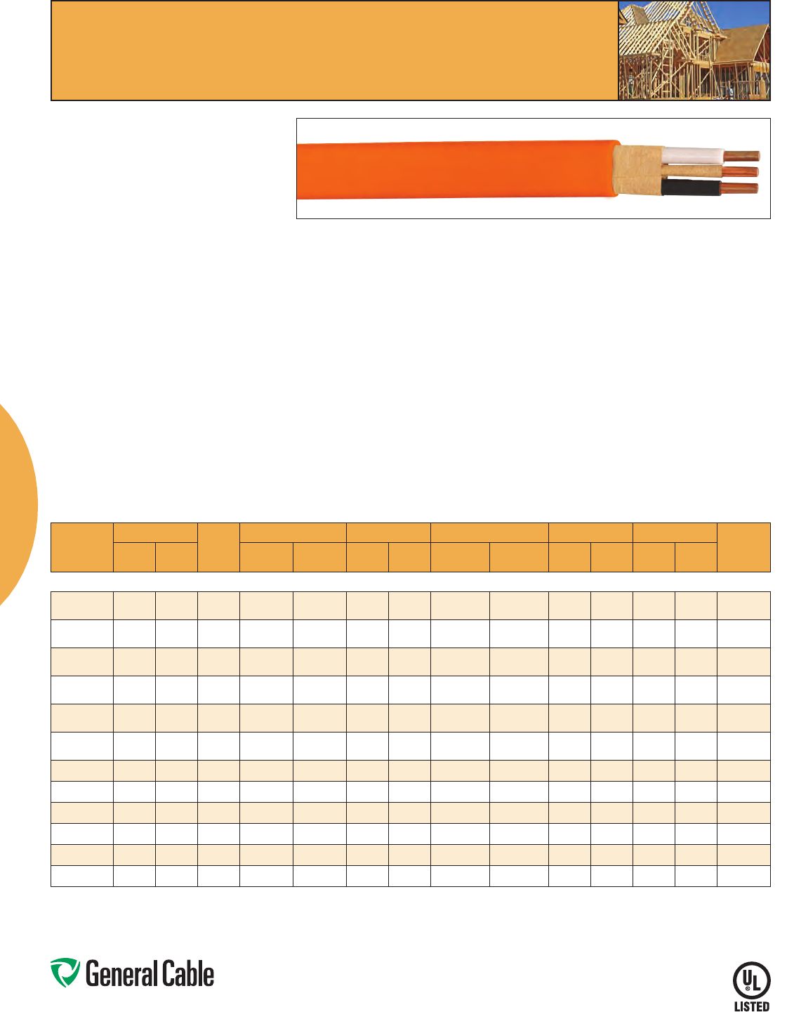
Phone: 800-243-8020
www.generalcable.com
Copper Building Wire
21
CATALOG
NUMBER
SIZE
NO. OF
WIRES
INSULATION THICKNESS JACKET THICKNESS NOMINAL CABLE O.D. COPPER WEIGHT TOTAL WEIGHT
AMPACITY
(1)
AWG OR
kcmil mm² INCHES mm INCHES mm INCHES mm
LBS/
1000 FT kg/km
LBS/
1000 FT kg/km
TYPE NM-B COPPER CONDUCTOR WITH GROUND
311422 14/2G 2.08 Solid 0.015 0.38 0.004 0.10 0.170x
0.390 4.318x
9.906 38 57 56 83 15
311222 12/2G 3.31 Solid 0.015 0.38 0.004 0.10 0.160 x
0.450 4.064x
11.430 60 90 82 122 20
311022 10/2G 5.26 Solid 0.020 0.51 0.004 0.10 0.210 x
0.493 5.334x
12.522 96 143 123 183 30
320822 8/2G 8.37 7 0.030 0.76 0.005 0.13 0.290 x
0.580 7.366x
14.732 133 199 185 275 40
320622 6/2G 13.3 70.030 0.76 0.005 0.13 0.330 x
0.695 8.382 x
17.653 193 288 256 381 55
321432 14/3G 2.08 Solid 0.015 0.38 0.004 0.10 0.170x
0.450 4.318x
11.430 51 76 74 110 15
321232 12/3G 3.31 Solid 0.015 0.38 0.004 0.10 0.345 8.76 81 121 107 159 20
321032 10/3G 5.26 Solid 0.020 0.51 0.004 0.10 0.430 10.92 127 189 165 246 30
320832 8/3G 8.37 7 0.030 0.76 0.005 0.13 0.555 14.10 187 278 251 374 40
320632 6/3G 13.3 70.030 0.76 0.005 0.13 0.612 15.54 277 412 352 524 55
320432 4/3G 21.2 7 0.040 1.02 0.006 0.15 0.820 20.83 442 658 565 841 70
320232 2/3G 33.6 7 0.040 1.02 0.006 0.15 0.945 24.00 672 1001 841 1252 95
Dimensions and weights are nominal; subject to industry tolerances.
(1)Maybeinstalledindrylocationswithtemperaturesupto90°C,butwiththeampacitylimitedtothatof60°Cconductors.The90°Cratingshallbepermittedtobeusedforampacity
adjustmentsandcorrectioncalculations,providedthefinalderatingampacitydoesnotexceedthatofa60°Cratedconductor(NEC®Article334).Allowableampacitiesshownarefor
generaluseasspecifiedbytheNationalElectricCode,section310.15,Table310.15(B)(16).Adjustmentsandcorrectionsmayapply.
SPEC 5900
January, 2012
NM-B
PVC, Low-Voltage Power
600 V, Type NM-B, Multi-Conductor, Copper
NM-B
Product Construction:
Conductor:
• 14AWGthru10AWGbareannealedsolidcopper
per ASTM B3
• 8AWGandlargerstrandedbareannealedcopper
per ASTM B8
Insulation:
• Premium-gradePolyvinylChloride(PVC)witha
Nylon jacket
• Color-coded:2conductor-black,white;
3 conductor - black, white, red
Grounding Conductor:
• BareannealedcopperperASTMB3orASTMB8
Assembly:
• TypeTHHNinners,rated90°Cindrylocations(1)
• 2-conductor–insulatedconductorslaidparallel
with a bare copper grounding conductor wrapped
in paper and laid parallel between the insulated
conductors
• 3-conductor–insulatedconductorslaidparallel
or twisted together with bare copper grounding
conductor wrapped in paper
• Theentireassemblyiswrappedwithapaper
separator prior to applying the Polyvinyl Chloride
(PVC) outer jacket
Outer Jacket:
• PolyvinylChloride(PVC)
• Color-coded:14AWG–white;12AWG–yellow;
10AWG–orange;8AWG–black;6AWG-black
Print:
• GENERALCABLE® (SIZE) WITH GROUND TYPE
NM-B 600 VOLTS (UL) MONTH/YEAR OF MFG
Applications:
• Residentialwiringasbranchcircuitsforoutlets,
switches, and other loads
• Exposedorconcealedwiring
• Mayberunthroughwalls,ceilingsandmasonry
blocks
• Newwiringorreplacementwiring
• Onlyforuseinnormallydrylocations
Features:
• Color-codedinnersforcircuitidentification
• Availablewithandwithoutground
• Ratedfor90°Cindrylocations(1)
• Ampacityislimitedtothatfor60°Cconductors
per NEC®Article334
Compliances:
• ULStandard83
• ULStandard719
• ASTMB3andB8
• NEC®Article334
• FederalSpecificationA-A-59544
Packaging:
• 250'or125'coilsor1000'reels
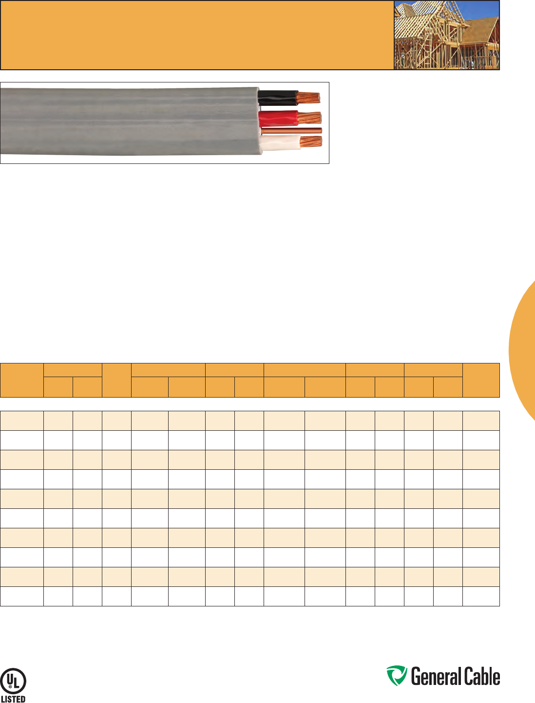
Phone: 800-243-8020
www.generalcable.com
Copper Building Wire
22
CATALOG
NUMBER
SIZE
NO. OF
WIRES
INSULATION THICKNESS JACKET THICKNESS NOMINAL CABLE O.D. COPPER WEIGHT TOTAL WEIGHT
AMPACITY
(1)
AWG OR
kcmil mm² INCHES mm INCHES mm INCHES mm
LBS/
1000 FT kg/km
LBS/
1000 FT kg/km
TYPE UF-B AND NMC COPPER CONDUCTOR WITH GROUND
341429 14/2 2.08 Solid 0.015 0.38 0.004 0.10 0.185x
0.385 4.699x
9.779 38 57 53 79 15
341229 12/2 3.31 Solid 0.015 0.38 0.004 0.10 0.195x
0.415 4.953x
10.541 60 90 75 112 20
341029 10/2 5.26 Solid 0.020 0.51 0.004 0.10 0.230 x
0.460 5.842x
11.684 96 143 140 208 30
340829 8/2 8.37 7 0.030 0.76 0.005 0.13 0.320 x
0.620 8.128 x
15.748 133 199 213 317 40
340629 6/2 13.3 70.030 0.76 0.005 0.13 0.385x
0.800 9.779x
20.32 193 288 305 454 55
341439 14/3 2.08 Solid 0.015 0.38 0.004 0.10 0.185x
0.575 4.699x
14.605 51 76 93 138 15
341239 12/3 3.31 Solid 0.015 0.38 0.004 0.10 0.195x
0.620 4.953x
15.748 81 121 134 199 20
341039 10/3 5.26 Solid 0.020 0.51 0.004 0.10 0.230 x
0.690 5.842x
17.526 127 189 194 289 30
340839 8/3 8.37 7 0.030 0.76 0.005 0.13 0.320 x
0.990 8.128 x
25.146 187 278 330 491 40
340639 6/3 13.3 70.030 0.76 0.005 0.13 0.385x
1.200 9.779x
30.48 277 412 449 668 55
Dimensions and weights are nominal; subject to industry tolerances.
(1)Maybeinstalledindrylocationswithtemperaturesupto90°C,orinwetlocationswithtemperaturesupto75°Cbutwiththeampacitylimitedtothatof60°Cconductors.The90°C
dryor75°Cratingshallbepermittedtobeusedforampacityadjustmentsandcorrectioncalculations,providedthefinalderatingampacitydoesnotexceedthatofa60°Crated
conductor (NEC®Article334TypeNMCorNEC®Article340TypeUF-B).AllowableampacitiesshownareforgeneraluseasspecifiedbytheNationalElectricCode,section310.15,
Table310.15(B)(16).Adjustmentsandcorrectionsmayapply.
UF-B and NMC
PVC, Low-Voltage Power
600 V, Type UF-B and NMC, Multi-Conductor, Copper
SPEC 5910
January, 2012
UF-B and NMC
Product Construction:
Conductor:
• 14AWGthru10AWGsolidbareannealedcopper
per ASTM B3
• 8AWGandlargerstrandedbareannealedcopper
per ASTM B8
Insulation:
• Premium-gradePolyvinylChloride(PVC)with
Nylon jacket
• Color-coded:2conductor-black,white;
3 conductor - black, white, red
Grounding Conductor:
• BareannealedcopperperASTMB3orB8
Assembly:
• TypeTHHNorTHWNinners,rated90°Cindryor
75°Cinwetlocations(1)
• 2and3conductor–insulatedconductorslaid
parallel
• Withgroundingconductor-laidinavalley
between the insulated conductors
Outer Jacket:
• Sunlight-resistantPolyvinylChloride(PVC),gray
Print:
• GENERALCABLE® (SIZE) WITH GROUND TYPE
UF-B OR NMC SUNLIGHT RESISTANT 600
VOLTS (UL) MONTH/YEAR OF MFG
Applications:
• Whereexposedtodirectraysofsunor
underground, including direct burial
• Undergroundfeedertooutdoorlightingor
apparatus
• Exposedorconcealedwiringindamp,moist,wet,
dry, and corrosive locations
• NMCapplicationsasspecifiedinArticle334.10B
of the NEC
Features:
• Color-codedinnersforcircuitidentification
• Availablewithgroundandwithoutground
• Sunlight-resistantjacket
• Suitablefordirectburial
• Ratedfor90°Cindryor75°Cinwetlocations(1)
• Ampacityislimitedtothatfor60°Cconductors
per NEC®Article340
Compliances:
• ULStandard83
• ULStandard493
• ASTMB3andB8
• NEC®Article340TypeUF-B
• NEC®Article334TypeNMC
• FederalSpecificationA-A-59544
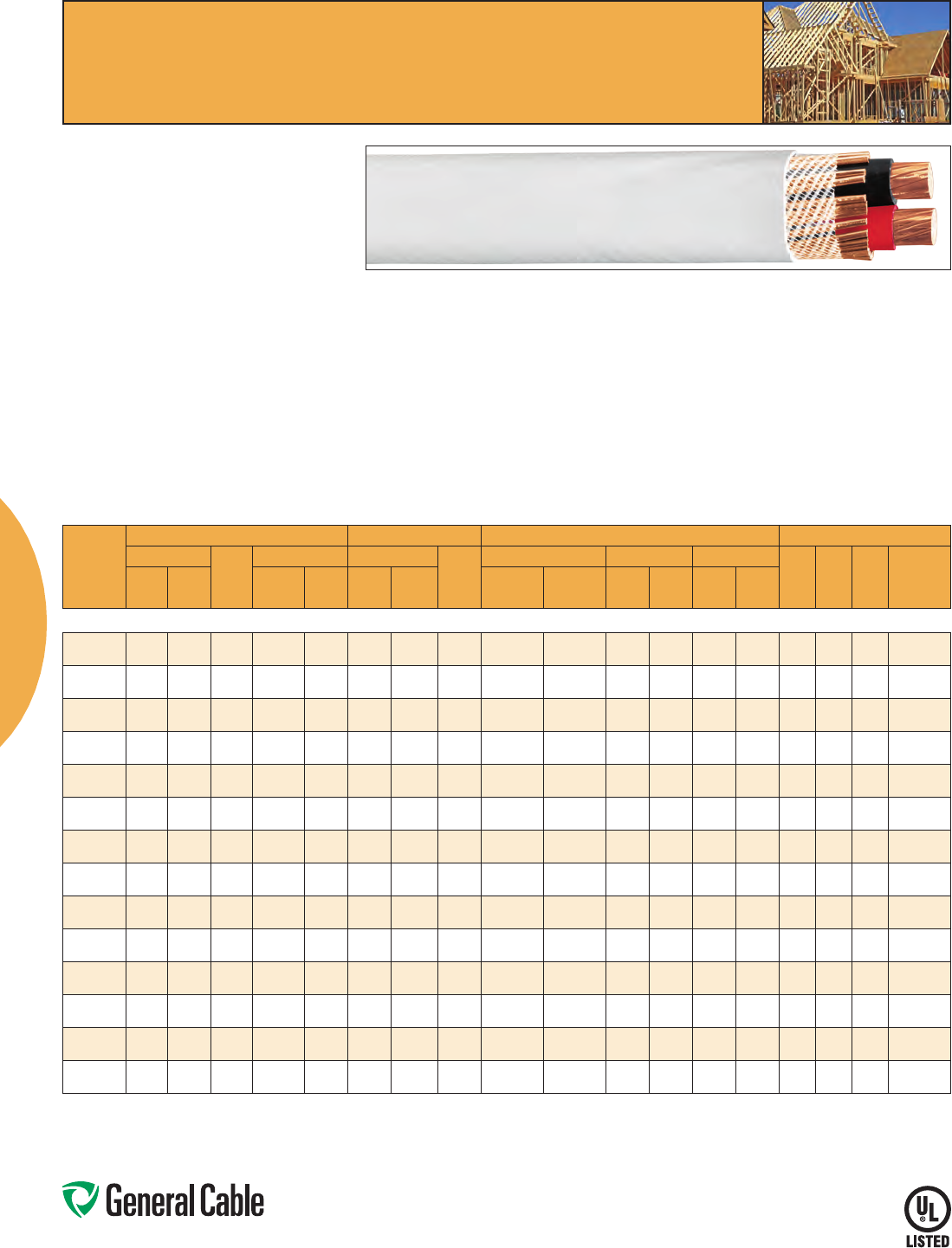
Phone: 800-243-8020
www.generalcable.com
Copper Building Wire
23
CATALOG
NUMBER
PHASE CONDUCTORS BARE GROUND OVERALL
AMPACITY(1)
SIZE
NO. OF
WIRES
INSULATION THKN. SIZE
NO. OF
WIRES
(1)
NOMINAL CABLE O.D. COPPER WEIGHT NET WEIGHT
60°C 75°C 90°C DWELLING
AWG OR
kcmil mm² INCHES mm
AWG OR
kcmil mm² INCHES mm
LBS/
1000 FT kg/km
LBS/
1000 FT kg/km
TYPE SE STYLE U COPPER CONDUCTOR WITH GROUND
371039 10/2 5.26 Solid 0.020 0.51 10 5.26 Solid 0.295x
0.455 7.493x
11.557 94 140 142 211 30 30 30 —
370839 8/2 8.37 7 0.030 0.76 88.37 7 0.400x
0.625 10.16 x
15.875 153 228 219 326 40 50 55 —
376289 6/2 13.30 70.030 0.76 88.4 7 0.440x
0.700 11.176x
17.78 213 317 290 432 55 65 75 —
370639 6/2 13.30 70.030 0.76 6 13.3 70.445x
0.705 11.303 x
17.907 243 362 319 475 55 65 75 —
374269 4/2 21.15 7 0.040 1.02 6 13.3 70.515x
0.850 13.081 x
21.59 339 504 445 662 70 85 95 100
370439 4/2 21.15 7 0.040 1.02 4 21.15 7 0.540x
0.870 13.716x
22.098 387 575 494 735 70 85 95 100
373259 3/2 26.67 7 0.040 1.02 5 16.77 12 0.570x
0.930 14.478x
23.622 428 636 547 814 85 100 110 110
370339 3/2 26.67 7 0.040 1.02 3 26.67 12 0.605x
0.970 15.367x
24.638 488 725 609 906 85 100 110 110
372249 2/2 33.63 7 0.040 1.02 4 21.15 12 0.600 x
1.000 15.24x
25.4 539 802 668 994 95 115 130 125
370239 2/2 33.63 7 0.040 1.02 2 33.63 12 0.640x
1.030 16.256x
26.162 615 915 745 1109 95 115 130 125
370139 1/1 42.41 19 0.050 1.27 142.41 12 0.720x
1.180 18.288 x
29.972 775 1154 941 1400 110 130 150 150
37A309 1/0-2 53.48 19 0.050 1.27 1/0 53.48 18 0.740x
1.240 18.796x
31.496 977 1455 1157 1722 125 150 170 175
37B309 2/0-2 67.43 19 0.050 1.27 2/0 67.43 18 0.810 x
1.350 20.574x
34.29 1233 1834 1431 2130 145 175 195 200
37C309 3/0-2 85.03 19 0.050 1.27 3/0 107.22 18 0.890 x
1.480 22.606 x
37.592 1554 2313 1775 2641 165 200 225 225
Dimensions and weights are nominal; subject to industry tolerances.
(1)Allowableampacitiesshownareforgeneraluseasspecifiedbythe2011editionoftheNationalElectricCode,section310.15,Table310.15(B)(16).Adjustmentsandcorrectionsmayapply:
60°C-Whenterminatedtoequipmentforcircuitsrated100amperesorlessormarkedfor14through1AWGconductors.
75°C-Whenterminatedtoequipmentforcircuitsratedover100amperesormarkedforconductorslargerthan1AWG.
90°C-Wetordrylocations.Forampacityderatingpurposes.
Dwelling-Fordwellingunits,conductorsshallbepermittedatlistedampacitiesas120/240-volt,3-wire,single-phaseservicesandfeeders.
SPEC 5920
January, 2012
SE Style U
PVC, Low-Voltage Power
600 V, Type SE Style U, Multi-Conductor, Copper
SE Style U
Product Construction:
Conductor:
• SolidbareannealedcopperperASTMB3
• 7-strandClassBconcentricallystrandedper
ASTM B8
• 19-strandcombinationunilayconductorsper
ASTMB787
Insulation:
• Premium-gradePolyvinylChloride(PVC)witha
Nylon jacket
• Color-coded:blackandred
Grounding Conductor:
• Bareannealedcopper,evenlydistributedand
helically applied over the insulated conductors so
as to produce the equivalent AWG size required
byUL854
Assembly:
• THHNorTHWNinnerconductorsmeetingthe
requirements of UL 83
• Insulatedconductorslaidparallelwithbare
grounding conductors helically wound around
core
• Glass-reinforcedtapeisappliedoverthecable
core
Jacket:
• Sunlight-resistantPolyvinylChloride(PVC),gray
Print:
• GENERALCABLE® TYPE SE STYLE U THHN
OR THWN CDRS, 600 VOLTS 2 CDRS (SIZE) CU
1CDR (SIZE) CU (UL) MONTH/YEAR
Applications:
• Above-groundserviceentranceandbranch
circuit
• Maximumoperatingtemperatureofphase
conductors not to exceed 90˚C for dry locations
or75˚Cforwetlocations
Features:
• Color-codedphaseconductors
• Fullorreducedneutralconstructions
Compliances:
• ULStandard83
• ULStandard854
• FederalSpecificationAA59544
• NEC® Articles 338 and 230
• NEMARV42009
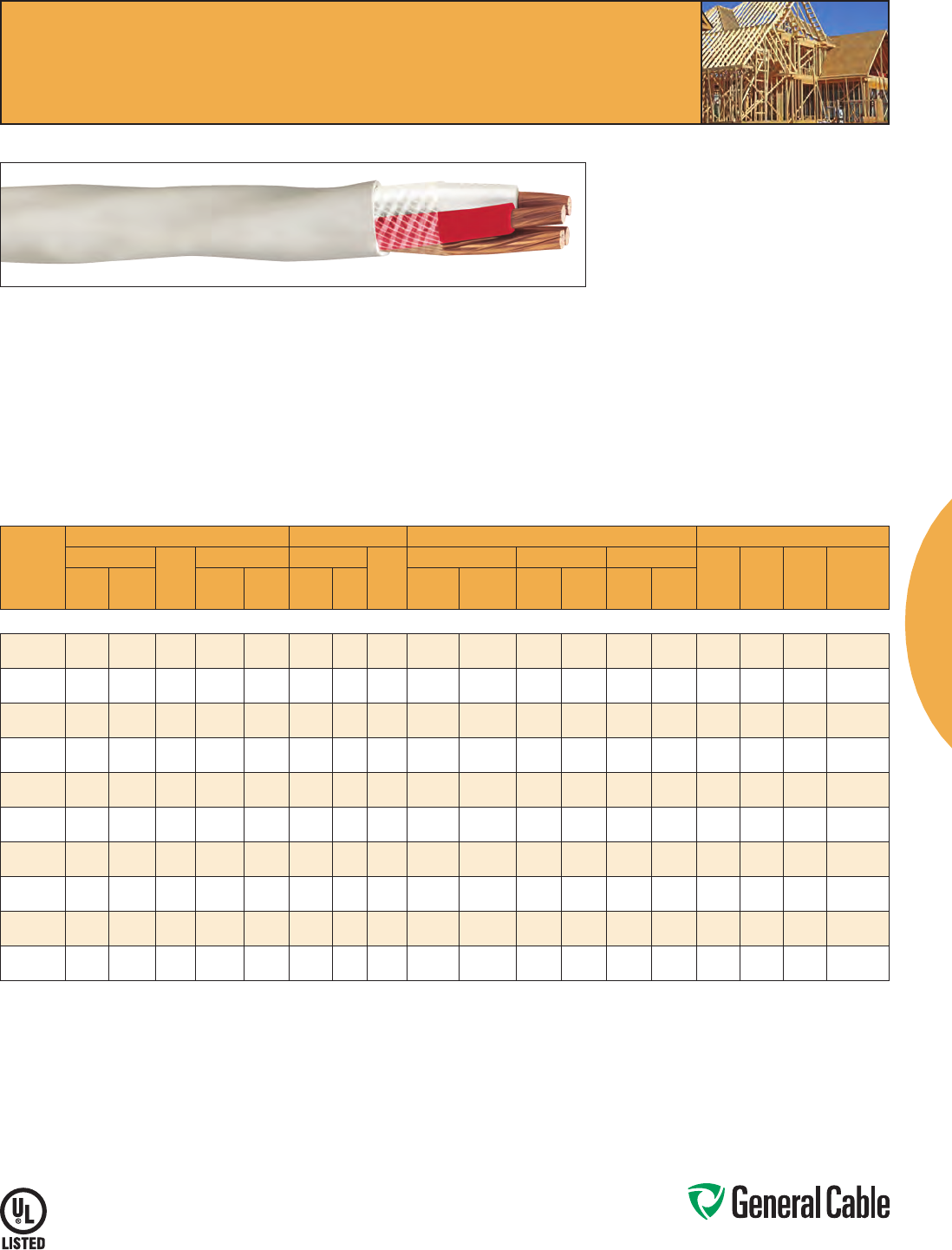
Phone: 800-243-8020
www.generalcable.com
Copper Building Wire
24
CATALOG
NUMBER
PHASE CONDUCTORS BARE GROUND OVERALL
AMPACITY(1)
SIZE
NO. OF
WIRES
INSULATION THKN. SIZE
NO. OF
WIRES
(1)
NOMINAL CABLE O.D. COPPER WEIGHT NET WEIGHT
60°C 75°C 90°C DWELLING
AWG OR
kcmil mm² INCHES mm
AWG OR
kcmil mm² INCHES mm
LBS/
1000 FT kg/km
LBS/
1000 FT kg/km
TYPE SE STYLE R COPPER CONDUCTOR WITH GROUND
388389 8/3 8.37 7 0.030 0.76 88.4 7 0.570 14.48 206 307 290 432 40 50 55 —
386369 6/3 13.30 70.030 0.76 88.4 7 0.665 16.89 288 429 432 643 55 65 75 —
384369 4/3 21.15 7 0.040 1.02 6 13.3 70.830 21.08 473 703 601 894 70 85 95 100
383359 3/3 26.67 7 0.040 1.02 516.8 7 0.895 22.73 596 886 737 1097 85 100 110 110
382349 2/3 33.63 7 0.040 1.02 421.1 7 0.970 24.64 751 1118 911 1356 95 115 130 125
381339 1/3 42.41 19 0.050 1.27 3 26.6 71.100 27.94 947 1409 1151 1713 110 130 150 150
38A329 1/0-3 53.58 19 0.050 1.27 2 33.6 71.200 30.48 1194 1777 1417 2109 125 150 170 175
38B319 2/0-3 67.43 19 0.050 1.27 142.4 19 1.310 33.27 1506 2241 1768 2631 145 175 195 200
38C309 3/0-3 85.03 19 0.050 1.27 1/0 53.6 19 1.430 36.32 1886 2807 2186 3253 165 200 225 225
38D300 4/0-3 107.22 19 0.050 1.27 2/0 67.4 19 1.610 40.89 2378 3539 2729 4061 195 230 260 250
Dimensions and weights are nominal; subject to industry tolerances.
(1)Allowableampacitiesshownareforgeneraluseasspecifiedbythe2011editionoftheNationalElectricCode,section310.15,Table310.15(B)(16).Adjustmentsandcorrectionsmayapply:
60°C-Whenterminatedtoequipmentforcircuitsrated100amperesorlessormarkedfor14through1AWGconductors.
75°C-Whenterminatedtoequipmentforcircuitsratedover100amperesormarkedforconductorslargerthan1AWG.
90°C-Wetordrylocations.Forampacityderatingpurposes.
Dwelling-Fordwellingunits,conductorsshallbepermittedatlistedampacitiesas120/240-volt,3-wire,single-phaseservicesandfeeders.
SE Style R
PVC, Low-Voltage Power
600 V, Type SE Style R, Multi-Conductor, Copper
SPEC 5930
January, 2012
SE Style R
Product Construction:
Conductor:
• 7-strandClassBconcentricallystrandedper
ASTM B8
• 19-strandcombinationunilayconductorsper
ASTMB787
Insulation:
• PolyvinylChloridePVCwithaNylonjacket
• Color-coded:black,white,red
Grounding Conductor:
• BareannealedcopperperASTMB3,ASTMB8or
ASTMB787
Assembly:
• THHNorTHWNinnerconductorsmeetingthe
requirements of UL 83
• Conductorsaretwistedtogetherwiththebare
copper grounding conductor in one interstice
• Glass-reinforcedtapeisappliedoverthecabled
core
Jacket:
• Sunlight-resistantPolyvinylChloride(PVC),gray
Print:
• GENERALCABLE® TYPE SE STYLE R THHN OR
THWN CDRS 600 VOLTS 3 CDRS (SIZE) CU 1
CDR (SIZE) CU (UL) MONTH/YEAR
Applications:
• Above-groundserviceentrance,panelfeederin
multiple dwellings, range, dryer and other branch
circuits
• Maximumoperatingtemperatureofphase
conductors not to exceed 90˚C for dry locations
or75˚Cforwetlocations
Features:
• Color-codedphaseconductors
Compliances:
• ULStandard83
• ULStandard854
• FederalSpecificationAA59544
• NEC® Articles 338 and 230
• NEMARV42009
Phone: 800-243-8020
www.generalcable.com
25
Date of Issue 10/12 Building Wire
Technical Information 2
General Technical Information
DESCRIPTION SPECIFICATION NUMBER REVISION DATE PAGE NUMBER
Building Wire Types A002 Jan. 2012 26
Glossary A003 Jan. 2012 27-33
Metric Conversion Factors A150 Sept. 2010 34
Reel Capacity Chart A200 Jan. 2012 35
Conductor Data
DESCRIPTION SPECIFICATION NUMBER REVISION DATE PAGE NUMBER
Class B and Class C Conductors for General Wiring B027 Jan. 2012 36
Handling and Storage Recommendations
DESCRIPTION SPECIFICATION NUMBER REVISION DATE PAGE NUMBER
Recommended Reel Handling Practices D005 Mar. 2012 37
Recommended Cable Handling Practices D025 Oct. 2011 38
Recommended Cable Storage Practices D050 Nov. 2011 39
Cable Installation Guidelines
DESCRIPTION SPECIFICATION NUMBER REVISION DATE PAGE NUMBER
Pre-Installation Instructions E005 Apr. 2010 40
Installation – Overview and Checklist E025 Jan. 2011 41
Installation – Feed-In Setups E050 Apr. 2010 42-43
Installation – Conductor Maximum Pulling Tensions E075 Oct. 2012 44-45
Installation – Training and Bending Limitations E100 Apr. 2010 46
Installation – Maximum Side Wall Pressure E125 Oct. 2012 47
Catalog Number Index 48-49
Technical
Phone: 800-243-8020
www.generalcable.com
Building Wire
26
Wire Types
SPEC A002
January, 2012
Building Wire Types
WIRE TYPE DESCRIPTION
NM-B
Non-Metallic Sheathed Cable, THHN Individual Conductors 90°C Overall PVC Jacket, Dry Locations only (Indoor) 600 V
NMC
Non-Metallic Sheathed Cable, THHN Individual Conductors 90°C Overall PVC Jacket, Dry, Damp and Corrosive Locations
(Indoor or Outdoor) 600 V
PV
Single Conductor, Insulated and Integrally or Non-Integrally Jacketed, Sunlight Resistant, Photovoltaic Wire Rated 90°C Dry
and Wet Locations, 600 V,1 kV, 2 kV, for Interconnection Wiring of Grounded and Ungrounded Photovoltaic Power Systems
(Solar)
RHH
Rubber (Thermoset) Insulation, High Heat Resistant, 90°C Dry and Damp Locations 600 V
RHW
Rubber (Thermoset) Insulation, Heat Resistant, 75°C Dry and Wet Locations 600 V
RHW-2*
Rubber (Thermoset) Insulation, Heat Resistant, 90°C Dry and Wet Locations 600 V
RW90
Cross-Linked Polyethylene Insulation (XLPE), 90°C Dry and Wet Locations (CSA Type) 600 V
RWU90
Cross-Linked Polyethylene Insulation (XLPE), 90°C Direct Burial (CSA Type) 1 kV
SE-R
Service Entrance Round Construction, THHN/THWN or XHHW Insulation, 90°C Dry and 75°Wet Locations 600 V
SE-U
Service Entrance Uninsulated Concentric Neutral, THHN/THWN or XHHW Insulation, 90°C Dry and 75°Wet Locations 600 V
T90
Thermoplastic Insulation, Nylon Jacket 90° Dry and Damp Locations (CSA Type) 600 V
TC
Multi-Conductor Tray Cable, Several Combinations of Insulation and Jacketing Compounds, Cable Tray Use 600 V
TFN
Thermoplastic Insulation, Fixture Wire, Nylon Jacket, 90° Dry Locations 600 V
TFFN
Thermoplastic Insulation, Flexible Fixture Wire, Nylon Jacket, 90° Dry Locations 600 V
THHN
Thermoplastic Insulation, High Heat Resistant, Nylon Jacket, 90°C Dry and Damp Locations 600 V
THW
Thermoplastic Insulation, Heat Resistant, 75°C Dry and Wet Locations 600V
THW-2*
Thermoplastic Insulation, Heat Resistant, 90°C Dry and Wet Locations 600V
THWN
Thermoplastic Insulation, Heat Resistant, Nylon Jacket, 75°C Dry and Wet Locations 600 V
THWN-2*
Thermoplastic Insulation, Heat Resistant, Nylon Jacket, 90°C Dry and Wet Locations 600 V
TWN75
Thermoplastic Insulation, Nylon Jacket 75°C Wet Locations (CSA Type) 600 V
UF-B
Underground Feeder, THHN or THWN Insulation, Overall PVC Jacket, 90°C Dry and 75°C Wet Locations and Corrosive
Locations 600 V
USE
Underground Service Entrance, Cross-Linked Polyethylene Insulation (XLPE), 75°C Direct Burial 600 V
USE-2*
Underground Service Entrance, Cross-Linked Polyethylene Insulation (XLPE), 90°C Direct Burial 600 V
XHHW
Cross-Linked Polyethylene Insulation (XLPE), High Heat Resistant, 90° Dry Locations and 75°C Wet Locations 600 V
XHHW-2*
Cross-Linked Polyethylene Insulation (XLPE), High Heat Resistant, 90° Dry and Wet Locations 600 V
* -2 is the UL designation for 90°C dry and wet locations.
Dry Location
A location not normally subject to dampness
or wetness. A location classified as dry may be
temporarily subject to dampness or wetness, as in the
case of a building under construction.
Damp Location
Locations protected from weather and not subject
to saturation with water or other liquids but subject
to moderate degrees of moisture. Examples of such
locations include partially protected locations under
canopies, marquees, roofed open porches, and like
locations, and interior locations subject to moderate
degrees of moisture, such as basements, some barns,
and some cold storage warehouses.
Wet Location
Installations underground or in concrete slabs or
masonry in direct contact with the earth; in locations
subject to saturation with waters or other liquids, such
as vehicle washing areas; and in unprotected locations
exposed to weather.
Location information based on National Electrical Code Book 2011, Article 100 Definitions

Phone: 800-243-8020
www.generalcable.com
Building Wire
27
SPEC A003
January, 2012
Glossary
Glossary
Abrasion Resistance: Ability of material
or cable to resist surface wear.
Accelerated Aging: A test performed on
material or cable meant to duplicate
long-time environmental conditions in a
relatively short space of time.
A.C. Resistance: The total resistance
offered by a device in an alternating
current circuit due to inductive and
capacitive effects, as well as the direct
current resistance.
Adhesion: The state in which two surfaces
are held together by interfacial forces
which may be chemical or mechanical
in nature.
Adjacent Conductor: Any conductor
next to another conductor either in the
same multi-conductor cable layer or in
adjacent layers.
AEIC: Association of Edison Illuminating
Companies.
Aging: The change in properties of a
material with time under specific
conditions.
AIA: Aluminum Interlocked Armor.
Alloy: A combination of two or more metals
to form a new or different metal, having
specific or desirable qualities.
Alternating Current (A.C.): An electric
current that continually reverses its
direction, giving a definite plus and
minus wave form at fixed intervals.
Alternating Voltage: The voltage
developed across a resistance or
impedance through which alternating
current is flowing.
Ambient Temperature:
Any all-encompassing temperature
within a given area.
American Wire Gauge: A standard used
in the determination of the physical
size of a conductor determined by its
circular mil area. Usually expressed as
AWG. Also referred to as Brown and
Sharpe (B&S) wire gauge.
Ampacity: The maximum current an
insulated wire or cable can safely carry
without exceeding either the insulation
or jacket material limitations. (Same as
Current Carrying Capacity.)
Ampere: The unit of current. One ampere
is the current flowing through one ohm
of resistance at one volt potential.
Anneal: To subject to high heat with
subsequent cooling. When annealing
copper, the act of softening the metal
by means of heat to render it less
brittle.
ANSI: The American National Standards
Institute.
Apparatus Wire and Cable: Apparatus
wire is an overall term used to
describe a number of specific wire
types including non-automotive
battery cables, defroster wire, electric
furnace cables, and gas tube sign
ignition cables. Also included under
this heading in AWG sizes 14 and
heavier are appliance wire, fixture
wire, machine tool wire, motor and
transformer lead wire, pump or
well cable, and switchboard and
control wire. The National Electrical
Manufacturers Association states that
apparatus wire is “insulated wire and
cable used in connecting electrical
apparatus to a power source, also
including wire and cable used in the
apparatus itself.”
Appliance Wire and Cable: Appliance
wiring material is a classification
of Underwriters’ Laboratories,
Inc., covering insulated wire and
cable intended for internal wiring of
appliances and equipment. Each
construction satisfies the requirements
for use in particular applications.
Area of Conductor: The size of a
conductor cross-section, measured in
circular mils, square inches, etc.
Armor: A braid or wrapping of metal,
usually steel or aluminum, used for
mechanical protection.
Armored Cable: A cable having a
metallic covering for protection against
mechanical injury. Also a specific cable
construction; Type AC defined by UL4
and NEC® Article 333.
ASA: The American Standards Association,
former name of ANSI.
ASME: The American Society of
Mechanical Engineers.
ASTM: The American Society for Testing
and Materials.
AWG: Abbreviation for American Wire
Gauge.
AWM: Designation for appliance wiring
material.
Balanced Circuit: A circuit so arranged
that the impressed voltages on each
conductor of the pair are equal in
magnitude but opposite in polarity with
respect to ground.
Bare Conductor: A conductor having no
covering. A conductor with no coating
or cladding on the copper.
Bedding: A layer of material applied to a
cable immediately below the armoring.
Bending Radius: Radius of curvature
that a cable can be safely bent without
any adverse effects.
Binder: A spirally served tape or thread
used for holding assembled cable
components in place awaiting
subsequent manufacturing operations.
Branch Circuits: The individual circuits
are served from the smaller electrical
panels by insulated conductors.
These conductors are run through
ducts, conduits or raceways. These
individual circuits are sometimes
referred to as branch circuits. The
conductors will provide power from
the final overcurrent device (fuse or
circuit breaker) protecting the load
served. General-use branch circuits
supply power to a number of outlets for
lighting and appliance loads. Branch
circuit conductors are usually #14, #12
or #10 AWG.
Breakdown of Insulation: Failure of an
insulation resulting in a flow of current
through the insulation. It may be
caused by the application of too high
voltage or by defects or decay.
Breakdown Voltage: The voltage at
which the insulation between two
conductors breaks down.
Building Wire: A general term used for
light and power wiring products, 1000
volts or less.
Bunch Strand: Any number of conductor
strands twisted together in one
direction with the same lay length.

Phone: 800-243-8020
www.generalcable.com
Building Wire
28
SPEC A003
January, 2012
Glossary
Glossary
Buried Cable: A cable installed directly in
the earth without use of underground
conduit. Also called “direct burial
cable.”
Cable: A group of individually insulated
conductors in twisted or parallel
configuration, with or without an overall
covering.
Cabling: The act of twisting together two
or more insulated components by
machine to form a cable.
Capacitance: Storage of electrically
separated charges between two plates
having different potentials. The value
depends largely on the surface area of
the plates and the distance between
them.
CE Code, CEC: Canadian Electrical
Code.
Certified Test Report (CTR): A report
providing actual test data on a cable.
Tests are normally run by a Quality
Control Department, which shows that
the product being shipped conforms to
test specifications.
Circuit Sizes: A popular term for building
wire sizes 14 through 10 AWG.
Circular Mil: A measurement used for the
area of wire, calculated by squaring the
diameter. 1 circular mil = (.001)2 x 10⁶
Cold Bend: Test procedure whereby
a sample of wire or cable is wound
around a mandrel of a specified size
within a cold chamber, at a specified
temperature for a given number of
turns at a given rate of speed. The
sample is then removed and examined
for defects or deterioration in the
materials or construction.
Color Code: A color system for circuit
identification by use of solid colors,
tracers, braids, surface printing, etc.
Compatibility: The ability of dissimilar
materials to exist in mutual proximity or
contact without changing their physical
or electrical properties.
Compound: A term used to designate an
insulating and jacketing material made
by mixing two or more ingredients. To
compound; the mixing together of two
or more different materials to make one
material.
Concentric Stranding: A central wire
surrounded by one or more layers
of helically wound strands in a fixed
round geometric arrangement. The
most common fixed installation type
conductors are:
1) Round – no diameter reduction
2) Compressed – approximately 3%
diameter reduction
3) Compact – approximately 10%
diameter reduction
Conductivity: A term used in describing
the capability of a material to carry an
electrical charge. Usually expressed as
a percentage of copper conductivity
copper being one hundred percent
(100%).
Conductor: Any material capable of
carrying an electrical charge easily.
Conduit: A tube or trough for protecting
electrical wires and cables. It may be a
solid or flexible tube in which insulated
electrical wires are run.
Connector: A device used to physically
and electrically connect two or more
conductors.
Continuity Check: A test to determine
whether electrical current flows
continuously throughout the length of
a single wire or individual wires in a
cable.
Continuous Vulcanization:
Simultaneous extrusion and
vulcanization of wire
coating materials in a continuous
process.
Core: In cables, a term used to denote
a component or assembly of
components, over which other
materials are applied,
such as additional components, shield,
sheath, or armor.
Corrosion: The process or result of a
material being eaten or worn away,
usually by chemical reaction.
Counterpoise: Bare copper, usually soft
drawn, buried around the perimeter
of a structure for grounding purposes
when grounding electrical transmission
towers – usually running parallel to the
overhead lines along the right-of-way.
A grounding installation employed
where deep ground rods cannot
effectively be used due to dry, rocky,
or poor soil.
Crazing: The minute cracks on the surface
of plastic materials.
Crimp Termination: A wire termination
that
is applied by physical pressure of
terminal
to wire.
Cross-Linked: Inter-molecular bonds
between long chain thermoplastic
polymers by chemical or electron
bombardment means. The properties
of the resulting thermosetting material
are usually improved.
Cross-Sectional Area: The area of the
cut surface of an object cut at right
angles to the length of the object.
C.S.A.: Abbreviation for Canadian
Standards Association. The Canadian
counterpart of Underwriters’
Laboratories.
Current: The rate of flow of electricity in a
circuit, measured in amperes.
Current, Alternating (A.C.): An electric
current that periodically reverses
direction of electron flow. The number
of full cycles occurring in a given unit
of time (one second) is called the
frequency of the current.
Current Carrying Capacity: The
maximum current an insulated
conductor or cable can continuously
carry without exceeding its
temperature rating. It is also called
ampacity.
Current, Direct (D.C.): Electrical current
whose electrons flow in one direction
only; it may be constant or pulsating as
long as their movement is in the same
direction.
Cut-Through Resistance: The ability
of a material to withstand mechanical
pressure, usually a sharp edge of
prescribed radius, without separation.
Cycle: The complete sequence of
alternation or reversal of the flow of an
alternating electric current. (See Hertz.)
D.C.: Abbreviation for “Direct Current.”
Phone: 800-243-8020
www.generalcable.com
Building Wire
29
SPEC A003
January, 2012
Derating Factor: A factor used to reduce
the current-carrying capacity of a
wire when used in environments other
than that for which the value was
established.
Dielectric: 1) Any insulating medium
which intervenes between two
conductors and permits electrostatic
attraction and repulsion to take
place across it. 2) A material having
the property that energy required to
establish an electric field is recoverable
in whole or in part, as electric energy.
Dielectric Breakdown: The voltage
at which a dielectric material is
punctured, which is divisible by
thickness to give dielectric strength.
Dielectric Constant (K): The ratio of
the capacitance of a condenser with
dielectric between the electrodes to
the capacitance when air is between
the electrodes. Also called Permittivity
and Specific Inductive Capacity.
Dielectric Strength: The voltage which
an insulation can withstand before
breakdown occurs. Usually expressed
as a voltage gradient (such as volts
per mil).
Dielectric Test: A test in which a higher
than the rated voltage is applied for
a specified time to determine the
adequacy of the insulation under
normal conditions.
Direct Burial Cable: A cable installed
directly in the earth.
Direct Current (D.C.): An electric
current which flows in only one
direction.
Direction of Lay: The direction, either
clock-wise or counterclockwise, of
a conductor or group of conductors
when looking axially down a cable
length.
Drawing: In the manufacturing of wire,
pulling the metal through a die or
series of dies for reduction of diameter
to a specified size.
Duct: An underground or overhead tube
used for carrying electrical conductors.
EEMAC: Electrical and Electronic
Manufacturers Association of Canada
(U.S. counterpart is NEMA).
EIA: Abbreviation for Electronic Industries
Association.
Elongation: The fractional increase in
length of a material stressed in tension.
Elongation at Break: The tensile strain
in a test piece stretched to breaking
point, the conditions being such that
the stress is substantially uniform over
the cross-section.
Embossing: A means of marker
identification by means of thermal
identification leaving raised lettering on
the sheath material or cable.
Emergency Overloads: Loads which
occur when larger than normal currents
are carried through a cable or wire over
a short period of time.
Extrusion: The process of continuously
forcing a plastic or elastomer and a
conductor core through a die, thereby
applying a continuous coating of
insulation or jacket to the core or
conductor.
FAA: Federal Aviation Administration.
Farad: A unit of electrical capacity.
Feeder Conductors: The power is
distributed from the main load center
into sub-panels via feeder cables. Each
panel contains over-current protection
devices for the circuits it serves.
Filler: (1) A material used in the cable to
fill large interstices between electrical
components; (2) A substance, often
inert, added to a compound to improve
properties and/or decrease cost.
Fixture Wire: Fixture wires according
to the National Electrical Code are
designed for installation in lighting
fixtures and in similar equipment where
enclosed or protected and not subject
to bending or twisting in use. They
also are used for connecting lighting
fixtures to the conductors of the circuit
that supplies the fixtures. Fixture
wires shall not be smaller than No.
18. Flexible stranding is used for most
fixture wire, but solid conductors may
be used in some applications.
Flame Resistance: Ability of the material
to extinguish flame once the source of
heat is removed.
Flame Retardance: Ability of a material
to prevent the spread of combustion by
a low rate of travel so the flame will not
be conveyed.
Flexibility: The ease with which a cable
may be bent.
FR-1: A flammability rating established
by Underwriters’ Laboratories for
wires and cables that pass a specially
designed vertical flame test. This
designation has been replaced by
VW-1.
FT1: One of several CSA flame test
designations for wires and cables
which pass the C22.2 No. 0.3 test
requirements (other designations
include FT2, FT4, etc.).
Gauge: A term used to denote the physical
size of a wire.
Ground: a) An electrical term meaning
to connect to the earth or other large
conducting body to serve as a ground,
thus making a complete electrical
circuit. b) A wire intended to be used
for grounding (also called grounding
conductor).
Ground Faults: Those conditions where
electric current flows to the earth and
thereby creates a neutral-to-earth
voltage.
Grounding Conductor: A conductor
used to connect equipment of the
grounded circuit of a wiring system to
a grounding electrode or electrodes.
GSIA: Galvanized Steel Interlock Armor.
Hard Drawn Copper Wire: Copper wire
that has been drawn to size and not
annealed.
Heat Distortion: Distortion or flow of
a material or configuration due to
application of heat.
Heat Resistance: Ability of a substance
to maintain physical and chemical
identity and electrical integrity under
specified temperature conditions.
Heat Seal: In cabling, a method of sealing
a tape wrap jacket by means of thermal
fusion.
Glossary
Glossary
Phone: 800-243-8020
www.generalcable.com
Building Wire
30
SPEC A003
January, 2012
Heat Shock: A test to determine stability
of a material by sudden exposure to
high temperature for a short period of
time.
Hertz (Hz): A term replacing cycles-per-
second as a unit of frequency.
Hi-Pot: A test designed to determine the
highest voltage that can be applied
to a conductor without electrically
breaking down the insulation.
High Temperature Wire and
Cable: Those electrical wires and
cables having thermal operating
characteristics of 150°C and higher.
Horizontal Stripe: A colored stripe
running horizontally with the axis
of a conductor, sometimes called a
longitudinal stripe, used as a means of
circuit identification.
Hygroscopic: Capable of absorbing and
retaining moisture.
Hz: Abbreviation for Hertz.
ICEA: Insulated Cable Engineers
Association (formerly IPCEA).
IEC: International Electrotechnical
Commission, similar to the ISO in
structure and scope.
IEEE: Institute of Electrical and Electronics
Engineers.
IMSA: International Municipal Signal
Association.
Induced Current: An electric current set
up in a circuit by cutting lines of force;
a current caused by electromagnetic
induction.
Inductance: The property of a circuit
or circuit element that opposes a
change in current flow, thus causing
current changes to lag behind voltage
changes. It is measured in henrys.
Insulated Wire: A conductor of electricity
covered with a non-conducting
material.
Insulation: A non-conductive material
usually surrounding or separating two
conductive materials. Often called the
dielectric in a radio frequency cable.
Insulation Resistance: That property
of an insulating material which resists
electrical current flow through the
insulating material when a potential
difference is applied.
Insulation Thickness: The wall
thickness of the applied insulation.
Interstice: In cable construction, the
space, valley or void left between or
around the cable’s components.
ISA: Instrument Society of America.
ISO: International Standards Organization.
Jacket: A material covering over a
wire insulation or an assembly of
components. An overall jacket on a
complex cable grouping is also often
referred to as a sheath.
kcmil: One thousand circular mils (MCM).
Kilohertz: 1,000 Hertz (cycles).
Kilovolt: A term denoting one thousand
volts.
Kilowatt: A term denoting one thousand
watts.
Lay: The axial distance required for one
cabled conductor or conductor strand
to complete one revolution about the
axis around which it is cabled.
Lay Direction: The direction in which the
strands of a conductor run over the top
of the conductor as they recede from
an observer looking along the axis of
the conductor.
Leakage Current: The undesirable flow
of current through or over the surface
of an insulation.
Limiting Oxygen Index: Percentage
of oxygen necessary to support
combustion of a specified material.
Line Drop (Voltage Drop): A voltage
loss occurring between any two points
in a power circuit. Such loss, or drop,
is due to resistance, reactance or
leakage of the circuit, type of cable
and configuration.
Line Voltage: The value of the potential
existing on a supply or power line.
Rated voltage of the cables.
Low-Voltage: 2 kV or less, most
applications for low voltage power are
1000 volts or less.
LS/NH: Low Smoke/Non Halogen.
LSZH: Low Smoke, Zero Halogen.
Lug: A term commonly used to describe a
terminal, usually crimped or soldered
to the conductor, with provision for
screwing down to a terminal.
Marker Tape: A tape laid parallel to
the conductors under the sheath
in a cable, imprinted with the
manufacturer’s name and the
specification to which the cable is
made. Other information such as date
of manufacture may also be included.
Marker Thread: A colored thread laid
parallel and adjacent to the strands of
an insulated conductor which identifies
the cable manufacturer. It may also
denote a temperature rating or the
specification to which the cable is
made.
MCM: One thousand circular mils.
Megohm: One million ohms.
Messenger: The linear supporting
member, usually a high strength steel
wire, used as the supporting element
of a suspended aerial cable. The
messenger may be an integral part of
the cable or exterior to it.
Mho: The unit of conductivity. The
reciprocal of an ohm.
Mil: A unit used in measuring diameter of
a wire or thickness of insulation over a
conductor. One one-thousandth of an
inch (.001”).
Moisture Absorption: The amount of
moisture, in percentage, that a material
will absorb under specified conditions.
Multi-Conductor: More than one
conductor within a single cable.
Multi-Plexed Conductors: Three or
more completed cables together
without filler or common jacket.
National Electrical Code (NEC):
A consensus standard published by
the National Fire Protection Association
(NFPA) and incorporated in OSHA
regulations.
Glossary
Glossary

Phone: 800-243-8020
www.generalcable.com
Building Wire
31
SPEC A003
January, 2012
Glossary
NBS: National Bureau of Standards.
NEMA: National Electrical Manufacturers
Association.
Neutral Conductor: The conductor
connected to the neutral point of a
system that is intended to carry current
under normal conditions.
Neutral Point: The common point on a
wye-connection in a polyphase system
or midpoint on a single phase, 3-wire
system of midpoint of a single phase
portion of a 3-phase delta system or
a midpoint of a 3 wire, direct current
system.
NFPA: National Fire Protection Association.
NM-B: Type NM, Non-Metallic Sheathed
Cable. A cable assembly consisting of
insulated conductors jacketed with a
non-metallic material.
Nylon: An abrasion-resistant thermoplastic
with good chemical resistance used for
wire and cable jacketings.
Ohm: Unit of resistance such that a
constant current of one ampere
produces a force of one volt.
OSHA: Abbreviation for Occupational
Safety and Health Act. Specifically the
Williams-Steiger law passed in 1970
covering all factors relating to safety in
places of employment.
Overall Diameter: Finished diameter over
wire or cable.
Overcurrent: Any current in excess of
the rated current of equipment or the
ampacity of a conductor. It may result
from overload, short circuit or ground
fault.
Overlap: The amount the trailing edge laps
over the leading edge of a tape wrap.
Overload: Operation of equipment in
excess of normal, full-load rating or a
conductor in excess of rated ampacity
that, when it persists for a sufficient
length of time, would cause damage or
dangerous overheating. A fault, such
as a short circuit or ground fault is not
an overload.
Parallel: A construction in which 2 or
more conductors are laid parallel
and surrounded and separated by an
insulating material.
Parallel Cable: Two or more cables used
to share the current in heavily loaded
power circuits which permits the use of
smaller conductors.
Percentage Conductivity: Conductivity
of a material expressed as a
percentage of that of copper. Also
used to indicate ratio of conductance
between phase conductor and neutral
in power cables.
Plastic: Also called thermoplastic, high
polymeric substances, including both
natural and synthetic products, but
excluding the rubbers, that are capable
of flowing under heat and pressure.
Plasticizer: A chemical agent added in
compounding plastics to make them
softer and more flexible.
Polyethylene: A family of insulating
materials derived from polymerization
of ethylene gas. They are basically
pure hydrocarbon resins, with excellent
dielectric properties.
Polymer: A substance made of many
repeating chemical units or molecules.
The term polymer is often used in
place of plastic, rubber, or elastomer.
Polyolefin: A family of thermoplastics
based upon the unsaturated
hydrocarbons known as olefins. When
combined with butylene or styrene
polymers, they form compounds such
as polyethylene and polypropylene.
Polypropylene: A thermoplastic polymer
of propylene.
Polyvinyl Chloride (PVC): A
thermoplastic material composed of
polymers of vinyl-chloride which may
be rigid or elastomeric, depending on
specific formulation.
Porosity: Multiple air voids in an insulation
or jacket wall.
Power Factor: The ratio of resistance
to impedance. The ratio of the actual
power of an alternating current to
apparent power. Mathematically,
the cosine of the angle between
the voltage applied and the current
resulting.
Pulling Eye: A device which may
be fastened to the conductor or
conductors of a cable or formed by
or fastened to the wire armor and to
which a hook or rope may be directly
attached in order to pull the cable into
or from a duct.
Put-Up: Refers to packaging of wire and
cable. The term itself refers to the
packaged product that is ready to be
stored or shipped.
Quadruplex Cable: Assembly of four
single conductors twisted together.
Rated Temperature: The maximum
temper-ature at which an electric
component can operate for extended
periods without loss of its basic
properties.
Rated Voltage: The maximum voltage
at which an electric component can
operate for extended periods without
undue degradation or safety hazard.
REA: Rural Electrification Administration.
Reel Drum Diameter: Diameter of the
drum (or hub) of the reel.
Reel Flange Diameter (Reel Height):
Diameter of the reel flanges.
Reel Traverse: Width of space between
reel flanges.
Reel Width: Overall width of reel.
Resistance: In D.C. circuits, the
opposition a material offers to current,
measured in ohms. In A.C. circuits,
resistance is the real component of
impedance and may be higher than the
value measured at D.C.
RHH: Rubber-insulated building wire, heat-
and moisture-resistant, 90°C dry or
75°C wet locations.
RHH-2: Ditto, 90°C, wet or dry.
RHW: Rubber-insulated building wire, heat-
and moisture-resistant, 90°C dry or
75°C wet locations.
RHW-2: Rubber-insulated building wire,
heat and moisture-resistant, 90°C dry
or wet locations.
Ridge Marker: One or more ridges
running laterally along the outer
surface of an insulated wire or cable
for purpose of identification.
Glossary

Phone: 800-243-8020
www.generalcable.com
Building Wire
32
SPEC A003
January, 2012
Glossary
Ringing Out: The process of locating or
identifying specific conductive paths
by means of passing current through
selected conductors.
Rip Cord: Two or more insulated
conductors in a parallel configuration
which may be easily separated, leaving
the insulation of each conductor intact.
Rope Strand: A conductor composed
of a center group of twisted strands
surrounded by one or more layers of
similar groups of twisted strands.
Rubber: A general term used to describe
wire insulation and jackets made of
thermosetting elastomers, such as
natural or synthetic rubbers, EPR,
neoprenes, Hypalon, butyl rubber and
others.
Separator: Pertaining to wire and cable,
a layer of insulating material such as
textile, paper, etc., which is placed
between a conductor and its dielectric,
between a cable jacket and the
components it covers, or between
various components of a multi-
conductor cable. It can be utilized
to improve stripping qualities and/
or flexibility, or can offer additional
mechanical or electrical protection to
the components it separates.
Serve: Any filament or group of filaments,
such as wires or fibers helically wound
around a central core.
Service Conductors: In commercial
and industrial applications, power
is typically wired into the building
to a main load center. Power is
carried directly from a step-down
transformer by a secondary service
cable. Depending on the application,
the step-down transformer may be
mounted on a utility pole or mounted
at ground level in enclosed box.
Service Drop: The overhead electric
service conductors from the last pole
or other aerial support to and including
the splices, if any connecting to the
service entrance conductors at the
building or other structure.
Sheath: The material, usually an extruded
plastic or elastomer, applied outermost
to a wire or cable. Very often referred
to as a jacket.
Short Circuit Current Rating: The
prospective symmetrical fault current
at a nominal voltage to which an
apparatus or system is able to be
connected without sustaining damage
exceeding defined acceptance criteria.
Shrink Tubing: Tubing which has
been extruded, cross-linked and
mechanically expanded which, when
reheated, will return to its original
diameter.
SIA: Steel Interlocked Armor.
SIC: Specific Inductive Capacity.
Side Wall Bearing Pressure (SWBP):
A term used in reference to the
pressure on a cable which is being
pulled around a curved surface under
tension. If excessive, SWBP can
damage cable components and reduce
the life of the cable.
Solid Conductor: A conductor consisting
of a single wire.
Spark Test: A test designated to locate
imperfections (usually pin-holes) in
a wire insulation by application of an
electrical potential across the material
for a very short period of time while the
wire is drawn through an electrode field
with one end of the wire grounded.
Specific Gravity: The ratio of the weight
of any volume of substance to a weight
of an equal volume of some substance
taken as a standard, usually water for
liquids and hydrogen for gases.
Strand: A single uninsulated wire.
Stranded Conductor: A conductor
composed of individual groups of wires
twisted together to form an entire unit.
Surge: A temporary and relatively large
increase in the voltage or current in an
electrical circuit or cable. Also called
transient.
Tank Test: A term used to describe
a voltage dielectric test where the
specimen to be tested is submerged
in a liquid (usually water) and a
voltage potential applied between the
conductor and the liquid as ground.
Temperature Rating: The maximum
temperature at which insulating
material may be used in continuous
operation without loss of its basic
properties.
Tensile Strength: A term denoting the
greatest longitudinal tensile stress a
substance can bear without tearing
apart or rupturing.
Thermoplastic: Material that will resoften
and distort from its formed shape by
heating above a critical temperature
peculiar to the material.
Thermosetting: Term describing
insulation that will not resoften or
distort from its formed shape by
heating until a destructive temperature
is reached.
THHN: 90°C, 600 volt, nylon jacketed
building wire for dry and damp
locations.
THHN-2: Incorrect reference commonly
misapplied when THWN-2 is called out.
THW: Thermoplastic, vinyl insulated
building wire. Flame-retardant,
moisture- and heat-resistant, 75°C, dry
and wet locations.
THWN: 75°C, 600 volt, nylon jacketed
building wire for dry and wet locations.
THWN-2: 90˚C, 600 volt, nylon jacketed
building wire for dry and wet locations.
Tinned Copper: Tin coating over
copper to aid in soldering and inhibit
corrosion.
Tinned Wire: Copper wire that has been
coated with a layer of tin or solder to
simplify soldering.
Tray : A cable tray is a unit or assembly
of units or sections and associated
fittings, made of noncombustible
materials, forming a rigid structural
system used to support cables.
Tray Cable: A factory-assembled multi-
conductor or multi-pair control, signal
or power cable specifically approved
under the National Electrical Code for
installation in trays.
Glossary

Phone: 800-243-8020
www.generalcable.com
Building Wire
33
SPEC A003
January, 2012
Glossary
Triplexed Cable: Three individual cables
twisted together without fillers or a
common jacket.
UD: Underground Distribution.
UF: Thermoplastic underground feeder and
branch circuit cable.
UL: Underwriters’ Laboratories. A non-
profit independent organization
which operates a listing service for
electrical and electronic materials and
equipment (Canadian counterpart is
CSA).
Ungrounded: Not connected to ground or
to a conductive body that extends the
ground connection.
Unidirectional Concentric Stranding:
Stranding where each successive
layer has a different lay length, thereby
retaining a circular form without
migration of strands from one layer to
another.
Unidirectional Stranding: A term
denoting that, in a stranded conductor,
all layers have the same direction of
lay.
Unilay: More than one layer of helically
laid wires with the direction of lay and
length of lay the same for all layers.
Unilay Stranding: A bunched
construction having 19, 27, 37, or any
number of strands which might be
found in a concentric stranding.
URD: Underground Residential
Distribution.
USE: NEC Type Underground Service
Entrance Cable, 90°C dry or 75°C wet
locations.
USE-2: NEC Type Underground Service
Entrance Cable, 90°C dry or wet
locations.
Valley: Any void between the insulated
conductors of a cable or between a
cable core and its covering. See also
interstice.
Volt: A unit of electrical pressure. One
volt is the amount of pressure that will
cause one ampere of current in one
ohm of resistance.
Voltage: The term most often used in
place of electromotive force, potential,
potential difference, or voltage drop, to
designate electric pressure that exists
between two points and is capable
of producing a flow of current when a
closed circuit is connected between
the two points.
Voltage Drop: The amount of voltage
loss from original input in a conductor
of given size and length or over a
connection such as a termination.
Voltage Rating: The highest voltage that
may be continuously applied to a wire
or cord in conformance with standards
or specifications.
VW-1: A flammability rating established
by Underwriters’ Laboratories for
wires and cables that pass a specially
designed vertical flame test, formerly
designated
FR-1.
Wall Thickness: The thickness of the
applied insulation or jacket.
Watt: A unit of electrical power. One watt
is equivalent to the power represented
by one ampere of current under a
pressure of one volt in a D.C. circuit.
Wicking: The longitudinal flow of a liquid
in a wire or cable construction due to
capillary action.
Wire: (1) A single piece of slender, flexible
metal ranging in approximate size from
a piece that is difficult to bend by hand
to a fine thread; (2) Several wires (as in
1) twisted together; (3) Wires (as in 1 or
2) that are insulated.
Wire Gauge: A measure of the diameter
or sizes of wires. The sizes are
expressed by numbers.
XHHW: Heat and moisture-resistant
Cross-linked Polyethylene insulated
building wire, 90°C dry, 75°C wet.
XHHW-2: Ditto, 90°C wet or dry.
XLP: Cross-linked Polyethylene.
XLPE: Also Cross-linked Polyethylene.
Glossary

Phone: 800-243-8020
www.generalcable.com
Building Wire
34
To Convert From To Multiply By
Inches Millimeters 25.4
Millimeters Inches 0.03937
Inches Centimeters 2.54
Centimeters Inches 0.3937
Length
Feet Meters 0.3048
Meters Feet 3.2808
Kilofeet (1000 feet) Kilometers 0.3048
Kilometers Kilofeet (1000 feet) 3.2808
Square Inches Square Millimeters 645.16
Square Millimeters Square Inches 0.00155
Square Inches Square Centimeters 6.4516
Square Centimeters Square Inches 0.155
Area Square Inches Circular Mils 1,273,240
Circular Mils Square Inches 7.854 x 10⁻⁷
Circular Mils Square Millimeters 5.066 x 10⁴
Square Millimeters Circular Mils 1973.51
Square Feet Square Meters 0.0929
Square Meters Square Feet 10.764
Pounds Kilograms 0.4536
Kilograms Pounds 2.2046
Weight
Pound/Kilofeet Kilograms/Kilometer 1.4882
Kilograms/Kilometer Pounds/Kilofeet 0.6720
Ohms/Kilofeet Ohms/Kilometer 3.2808
Ohms/Kilometer Ohms/Kilofeet 0.3048
Microfarads/Kilofeet Microfarads/Kilometer 3.2808
Electrical Microfarads/Kilometer Microfarads/Kilofeet 0.3048
Insulation Resistance:
Megohms—Kilofeet Megohms—Kilometer 0.3048
Megohms—Kilometer Megohms—Kilofeet 3.2808
Pounds/Square Inch Kilo Pascal* 6.895
Mechanical Kilo Pascal* Pounds/Square Inch 0.1432
Pounds (force) Newtons 4.448
* 1 Pascal = 1 Newton/square meters
Conversions
SPEC A150
September, 2010
Metric Conversion Factors
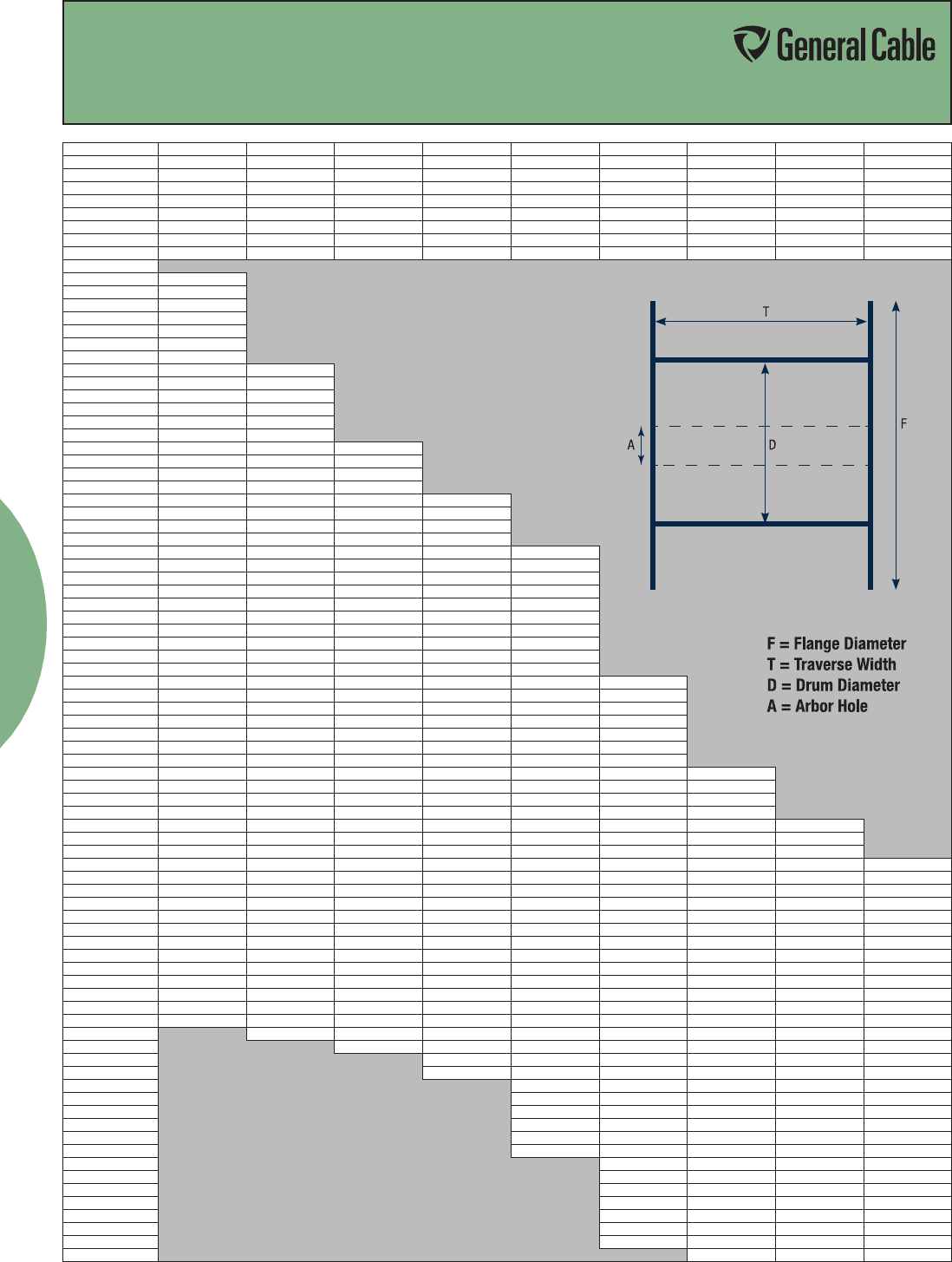
Building Wire
35
WOOD REELS
Reel (FxTxD) 30x18x12 36x24x17 40x24x17 45x28x21 50x32x24 58x32x28 72x36x36 84x36x48 90x36x48
RM Code 61-1215 61-1659 61-1808 61-2056 61-2253 61-2764 61-3655 61-4265 61-4366
Arbor Hole 2.75 3.06 3.06 3.06 3.06 3.06 3.06 3.5 3.5
Drive Hole 1 1 1 1.5 1.5 1.5 1.5 1.5 1.5
Drive Hole Radius 4.5 6 6 8.5 10 10 10 10 10
Clearance 1.5 2 2 2 2 2 2 2 3
Factor 509.3 1155.4 1582.8 2274.2 3227.7 4468.6 7847.4 9658.4 11205.2
Max Weight 750 1500 2000 3000 4800 6500 8000 9000 10,000
Net Weight 47 91 110 142 208 271 513 744 821
Cable OD
.241 - .250 11040
.251 - .260 10200
.261 - .270 9460
.271 - .280 8800
.281 - .290 8200
.291 - .300 7660
.301 - .310 7180
.311 - .320 6740 10790
.321 - .330 6330 10110
.331 - .340 5970 9610
.341 - .350 5630 9030
.351 - .360 6320 8490
.361 - .370 5040 8100
.371 - .380 4780 7620 10520
.381 - .390 4530 7300 9940
.391 - .400 4310 6880 9540
.401 - .410 4100 6600 9030
.411 - .420 3910 6230 8550 12580
.421 - .430 3730 6000 8220 11940
.431 - .440 3560 5660 7790 11330
.441 - .450 3410 5450 7510 10910
.451 - .460 3260 5250 7120 10370 15010
.461 - .470 3120 4970 6880 10000 14290
.471 - .480 2990 4700 6530 9510 13790
.481 - .490 2870 4630 6310 9180 13150
.491 - .500 2760 4390 6110 8880 12700
.501 - .525 2500 4040 5530 8050 11540
.526 - .550 2280 3650 5030 7330 10510
.551 - .575 2090 3310 4580 6680 9610
.576 - .600 1920 3080 4180 6110 8800
.601 - .625 1770 2810 3910 5590 8050
.626 - .650 1630 2630 3580 5240 7430 10420
.651 - .675 1510 2400 3280 4820 6970 9630
.676 - .700 1410 2260 3090 4530 6430 8900
.701 - .725 1310 2070 2840 4180 5940 8260
.726 - .750 1230 1950 2690 3950 5610 7800
.751 - .775 1150 1840 2480 3650 5190 7250
.776 - .800 1080 1690 2350 3460 4920 6870
.801 - .825 1010 1610 2230 3200 4670 6400 11530
.826 - .850 950 1530 2060 3040 4340 6090 10860
.851 - .875 900 1450 1970 2900 4130 5680 10250
.876 - .900 850 1340 1880 2690 3850 5420 9690
.901 - .925 810 1280 1735 2570 3670 5060 9170 11290
.926 - .950 760 1220 1660 2460 3510 4840 8700 10700
.951 - .975 730 1170 1590 2280 3270 4630 8250 10160
.976 - 1.000 690 1075 1525 2190 3130 4340 7850 9660 11210
1.001 - 1.050 630 990 1360 2010 2880 3990 7120 8760 10160
1.051 - 1.100 570 910 1260 1800 2590 3600 6490 7980 9260
1.101 - 1.150 520 810 1120 1670 2400 3250 5930 7300 8470
1.151 - 1.200 480 750 1040 1500 2160 3030 5450 6710 7780
1.201 - 1.250 440 700 980 1400 2020 2740 5020 6180 7170
1.251 - 1.300 410 650 870 1310 1820 2570 4640 5720 6630
1.301 - 1.350 380 580 820 1180 1710 2410 4320 5300 6150
1.351 - 1.400 350 550 770 1110 1610 2190 4000 4930 5720
1.401 - 1.450 330 520 690 1040 1460 2070 3730 4590 5330
1.451 - 1.500 310 490 650 990 1370 1950 3490 4290 4980
1.501 - 1.600 270 410 590 840 1230 1690 3070 3770 4380
1.601 - 1.700 240 370 500 760 1060 1520 2720 3340 3880
1.701 - 1.800 330 450 650 960 1325 2420 2980 3460
1.801 - 1.900 420 600 880 1210 2170 2680 3100
1.091 - 2.000 540 760 1060 1960 2410 2800
2.001 - 2.100 500 700 970 1740 2190 2540
2.101 - 2.200 650 900 1620 2000 2320
2.201 - 2.300 600 790 1480 1830 2120
2.301 - 2.400 520 740 1360 1680 1950
2.401 - 2.500 490 690 1260 1550 1790
2.501 - 2.600 460 640 1160 1430 1660
2.601 - 2.700 430 600 1080 1320 1540
2.701 - 2.800 530 1000 1230 1430
2.801 - 2.900 500 930 1150 1330
2.901 - 3.000 470 870 1070 1250
3.001 - 3.100 440 820 1010 1170
3.101 - 3.200 420 770 940 1090
3.201 - 3.300 400 720 890 1030
3.301 - 3.400 380 680 840 970
3.401 - 3.500 640 790 910
SPEC A200
January, 2012
Reel Capacity
Reel Capacity Chart
Phone: 800-243-8020
www.generalcable.com
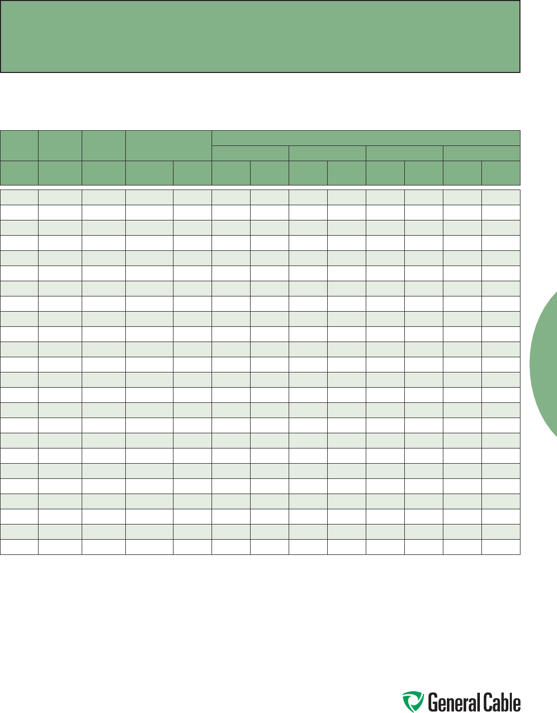
Phone: 800-243-8020
www.generalcable.com
Building Wire
36
Copper and Aluminum Conductors
ASTM CLASS B and CLASS C
SIZE
CLASS B
STRANDING
CLASS C
STRANDING NOMINAL AREA
NOMINAL O.D.
CLASS B CONCENTRIC CLASS C CONCENTRIC COMPRESSED COMPACT
AWG/kcmil INCHES INCHES
CIRCULAR
MILS mm² INCHES mm INCHES mm INCHES mm INCHES mm
22 7/.0096 19/.0058 640 0.324 0.0287 0.729 0.0290 0.737 ————
20 7/.0121 19/.0073 1,020 0.519 0.0362 0.919 0.0365 0.927 ————
18 7/.0152 19/.0092 1,620 0.823 0.0456 1.16 0.0460 1.168 ————
16 7/.0192 19 /.0117 2,580 1.31 0.0576 1.46 0.0585 1.486 ————
14 7/.0242 19/.0147 4,110 2.08 0.0727 1.85 0.0735 1.867 0.071 1.80 — —
12 7/.0305 19/.0185 6,530 3.31 0.0915 2.32 0.0925 2.350 0.089 2.26 0.085 2.16
10 7/.0385 19/.0234 10,380 5.261 0.116 2.95 0.116 2.95 0.113 2.87 0.107 2.72
87/.0486 19/.0295 16,510 8.367 0.146 3.71 0.146 3.71 0.142 3.61 0.134 3.40
67/.0612 19/.0372 26,240 13.30 0.184 4.67 0.184 4.67 0.178 4.52 0.169 4.29
47/.0772 19/.0469 41,740 21.15 0.232 5.89 0.232 5.89 0.225 5.72 0.213 5.41
27/.0974 19/.0591 66,360 33.62 0.292 7.42 0.292 7.42 0.283 7.19 0.268 6.81
119/.0664 37/.0476 83,690 42.41 0.332 8.43 0.332 8.43 0.322 8.18 0.299 7.59
1/0 19 /.0745 37/.0534 105,600 53.49 0.372 9.45 0.372 9.45 0.362 9.19 0.336 8.53
2/0 19/.0837 37/.0600 133,100 67.43 0.418 10.62 0.418 10.62 0.405 10.0 0.376 9.55
3/0 19/.0940 37/.0673 167,800 85.01 0.470 11.94 0.470 11.94 0.456 11.6 0.423 10.74
4/0 19 /.1055 37/.0756 211,600 107. 2 0.528 13.41 0.528 13.41 0.512 13.0 0.475 12.07
250 37/.0822 37/.0640 250,000 127 0.575 14.61 0.575 14.61 0.558 14.2 0.520 13.21
300 37/.0900 61/.0701 300,000 152 0.630 16.00 0.630 16.00 0.611 15.5 0.570 14.48
350 37/.0973 61/.0757 350,000 177 0.681 17.30 0.681 17.30 0.661 16.8 0.616 15.65
400 37/.1040 61/.0810 400,000 203 0.728 18.49 0.728 18.49 0.706 17.9 0.659 16.74
500 37/.1162 61/.0905 500,000 253 0.813 20.65 0.813 20.65 0.789 20.0 0.736 18.69
600 61/.0992 91/.0812 600,000 304 0.893 22.68 0.893 22.68 0.866 22.0 0.813 20.65
750 61/.1109 91/.0908 750,000 380 0.998 25.35 0.998 25.35 0.968 24.6 0.908 23.06
1000 61/.1280 91/.1048 1,000,000 507 1.152 29.26 1.152 29.26 1.117 28.4 1.060 26.92
Adapted from UL 1581 Reference Standard for Eletrical Wires, Cables, and Flexible Cords.
Class B and Class C Conductors
for General Wiring
Stranding
SPEC B027
January, 2012
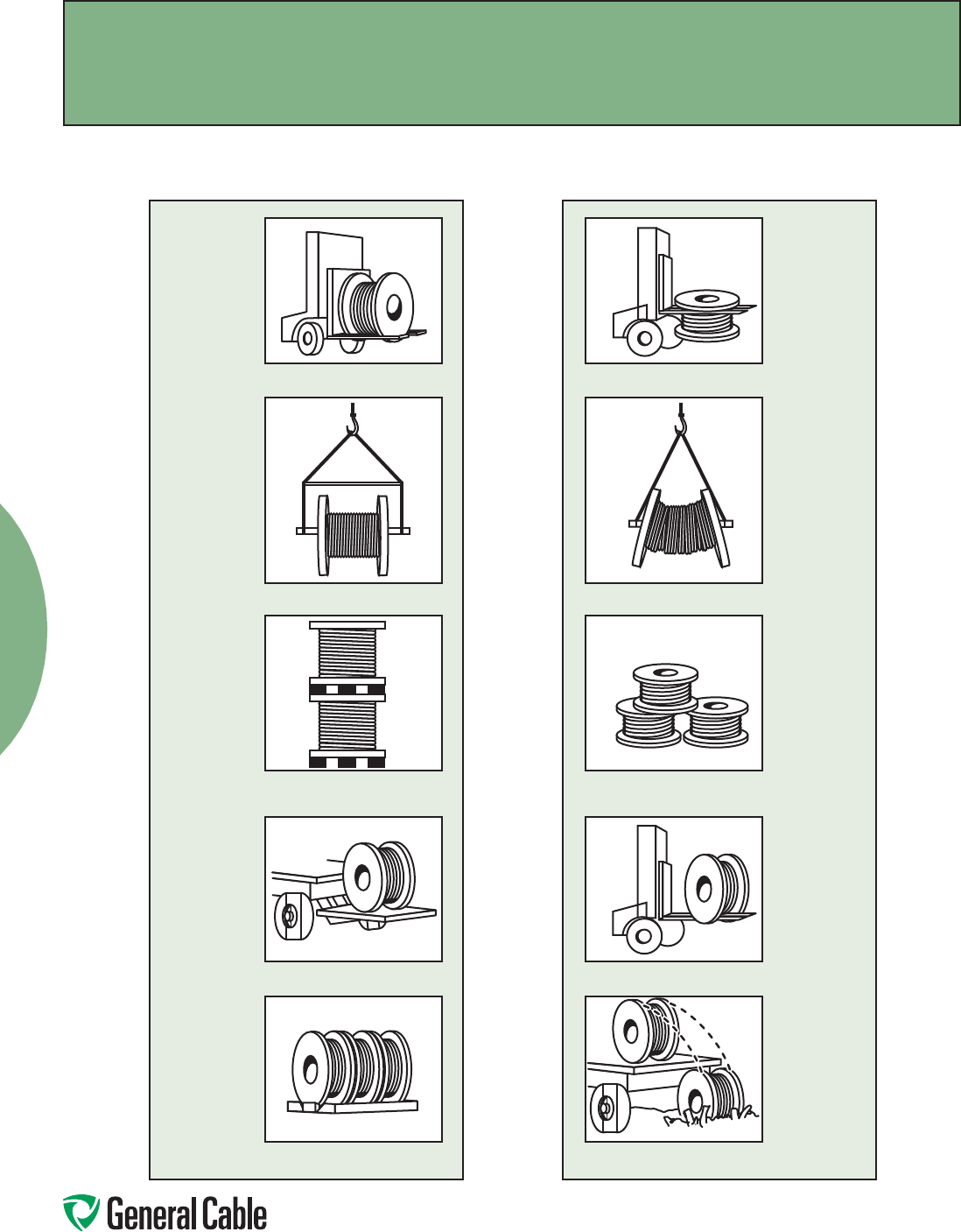
Phone: 800-243-8020
www.generalcable.com
Building Wire
37
How to Handle Cable Reels
YES
Cradle both reel flanges between forks.
Reels can be hoisted with a shaft
extended through both flanges.
Place spacers under the bottom flange
and between reels to create a space to
insert the forks. (36” reels max.)
Lower reels from truck using hydraulic
gate, hoist or fork lift. LOWER CAREFULLY.
Always load with flanges on edge and
chock and block securely.
Do not lift by top flange. Cable or reel
will be damaged.
Use a spreader bar to prevent bending
the reel flanges and mashing the cable.
Upended heavy reels will often arrive
damaged. Refuse or receive subject to
inspection for hidden damage.
Never allow forks to touch cable surface
or reel wrap.
Never drop reels.
NO
Handling
Recommended Reel Handling Practices
SPEC D005
March, 2012
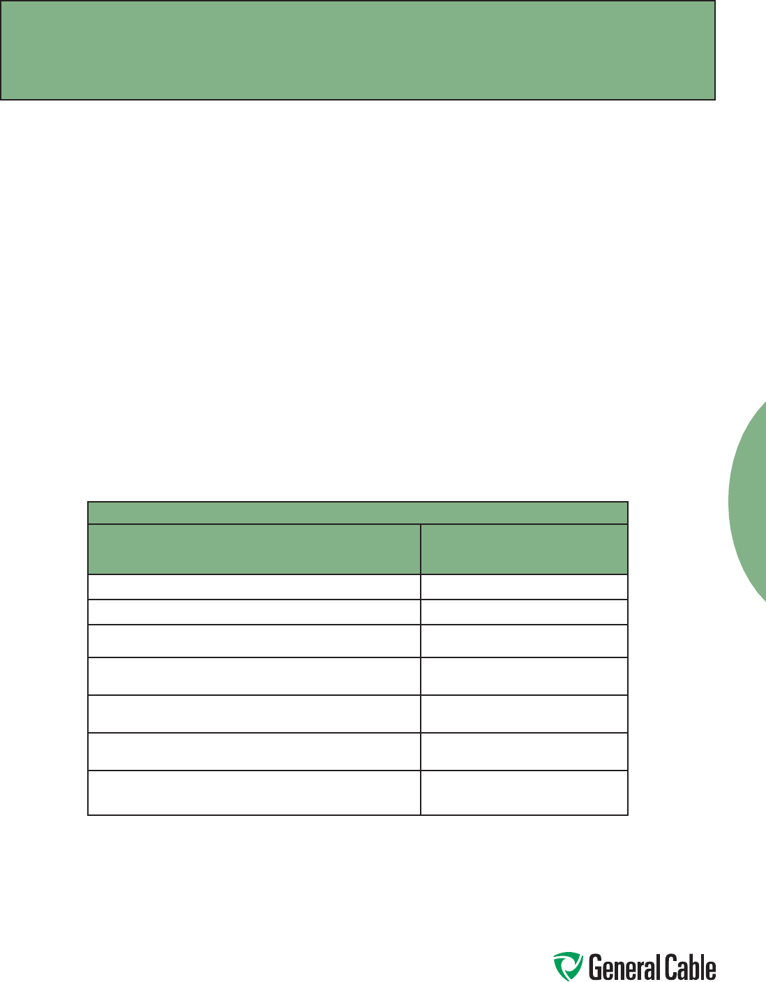
Phone: 800-243-8020
www.generalcable.com
Building Wire
38
Handling
Recommended Cable Handling Practices
SPEC D025
October, 2011
Unloading and Moving of Reels:
Cable reels are never shipped upended (flat side down). Cable reels that arrive in this manner should be rejected
or received only after a thorough inspection for damage.
See “Recommended Reel Handling Practices” page.
Upon receipt, a cable’s protective covering and/or lagging should be inspected for evidence of damage during
shipment. If evidence of damage is found, a report should immediately be made to the carrier.
Under no circumstances should reels be dropped from the delivering vehicle to the ground.
Unloading and reel handling should be accomplished so that the equipment used does not contact the cable
surface, and in the case of protective wrap, that the equipment does not contact the protective wrap.
If unloading and reel handling is accomplished by crane, either a cradle supporting the reel flanges or a shaft
through the arbor hole should be used. If a fork lift is utilized, the forks must lift the reel at 90˚ to the flanges
and the forks must be long enough to make complete lifting contact with both flanges. Under no circumstances
should the forks come into contact with the cable surface or the protective wraps.
When a reel of cable is rolled from one point to another, care must be taken to see that there are no objects on
the surface area which could contact or damage the cable surface or protective wrap.
If an inclined ramp is used for unloading, the ramp must be wide enough to contact both flanges completely.
The stopping of the reels at the bottom shall be accomplished by using the reel flanges and not the surface of
the cable.
Minimum Drum Diameters for Packaging Cables
Type of Cable Minimum Drum Diameter as a
Multiple of Outside
Diameter of Cable
1. Single and multiple conductor cable - unshielded 0-2000 V 10
2. Single and multiple conductor cable - unshielded 2400 V 12
3. Single and multiple conductor cable - wire shield (UniShield®)
5-35 kV
12
4. Single and multiple conductor cable - helically applied tape shield
(Uniblend®) 5-35 kV
14
5. Single and multiple conductor cable - longitudinally applied flat
tape shield (Type TC)
20
6.
Single and multiple conductor cable - Interlocked Armor (Duralox
®
)
600 V-35 kV
14
7. Triplexed single conductors cabled together. The circumscribing
overall diameter* shall be multiplied by the factor in 1 - 6 and then
by the reduction factor.
.75
*Single conductor times 2.155 times
NEMA WC26 EEMAC201-2007 Binational Wire and Cable Packaging Standard

Phone: 800-243-8020
www.generalcable.com
Building Wire
39
Storage and Storage Maintenance:
Finished cables have no established shelf-life. Moisture and atmospheric conditions can cause exposed
conductors to oxidize and discolor. Uncovered/unsheltered cable will degrade due to exposure to direct sunlight
and/or the elements. If the cables are protected, there should be no degradation of the insulation.
In general, any cable for use indoors should be stored indoors. Any cable suitable for installation outdoors is
suitable for storage outdoors. Cables stored outdoors should have the ends sealed to prevent moisture ingress
into the cable and should be used within two years or less.
Cables should be stored in a sheltered area.
Cables with a cold temperature marking, e.g. –10˚C, –25˚C, or –40˚C, may be stored outdoors. Cables without a
cold temperature marking must be stored indoors.
Cable reels must remain in the upright position. Cable reels must not be stored on their sides. Reels must not be
stacked.
Cable reels should be stored with the protective covering or lagging in place. If a length of cable has been cut
from the reel, the cable end should be immediately resealed to prevent the entrance of moisture. If a part length
is returned to storage, the reel’s protective covering should be restored.
Wooden reels should be stored off the ground to prevent rotting. Reels should be stored on a flat, hard surface
so that flanges do not sink into the earth. The weight of the reel and cable must be carried at all times by the reel
flanges.
Cable reels and lagging must not be stored for an extended time period sitting in direct contact with water or
dampness. Timbers or metal supports must be placed under the reel flanges to provide elevated storage of the
reels away from the direct contact with water or damp soil.
Reels should be stored in an area where construction equipment, falling or flying objects or other materials will
not contact the cable.
Cable should be stored in an area where chemicals or petroleum products will not be spilled or sprayed on the
cable.
Cable should be stored in an area away from open fires or sources of high heat.
If the reels are relocated, they should be handled as suggested in the “Recommended Reel Handling Practices”
section, and inspection made on each reel during the relocation.
If the cables are stored in a secure area and not exposed to the effects of the weather, an annual inspection
should be satisfactory.
Where the reels are exposed to the weather, a bimonthly inspection should be performed to observe any sign of
deterioration.
If the reels are exposed in a non-secure area, policing of the area at frequent intervals may be required
depending on circumstances.
Records of delivery date, manufacturer, installation date, any extenuating circumstances, along with all test
reports, should be kept on file.
Storage
Recommended Cable Storage Practices
SPEC D050
November, 2011

Phone: 800-243-8020
www.generalcable.com
Building Wire
40
Overview
To ensure safety during cable installation
and reliability once the cable is installed,
you should confirm the following prior to
installation:
• Thecableselectedisproperforyour
application
• Thecablehasnotbeendamagedin
transit or storage
Review all applicable state and national codes
to verify that the cable chosen is appropriate
for the job. Also, consult your local building
authority.
Next, you must identify any existing cable
damage and prevent any further damage
from occurring. This is done through proper
cable inspection, handling and storage.
Cable Inspection
Inspect every cable reel for damage before
accepting the shipment. Be particularly alert
for cable damage if:
• Areelislayingflatonitsside
• Severalreelsarestacked
• Otherfreightisstackedonareel
• Nailshavebeendrivenintoreelflangesto
secure shipping blocks
• Areelflangeisdamaged
• Acablecoveringisremoved,stainedor
damaged
• Acableendsealisremovedor
damaged
• Areelhasbeendropped
(hidden damage likely)
Cabling Handling
Remove all nails and staples from the reel
flanges before moving a reel, and avoid all
objects that could crush, gouge or impact
the cable when moving. NEVER use the
cable as a means to move a reel.
When unreeling, observe recommended
bending radii, use swivels to prevent
twisting and avoid overruns.
Pre-Installation
Installation
Pre-Installation Instructions
SPEC E005
April, 2010
Phone: 800-243-8020
www.generalcable.com
Building Wire
41
Installation
Installation —Overview and Checklist
SPEC E025
January, 2011
Overview
Most cables are subjected to more
mechanical stress during installation than
they ever experience in actual operation.
Needless to say, handling and pulling your
cable according to manufacturer’s recom-
mendations is extremely important.
There are six main considerations in any
cable installation:
• Ambienttemperature
• Equipment
• Conduitfill
• Mechanicalfitinraceway
• Physicallimitations
• Knowledgeableinstallers
For more information, reference
IEEE 1185 Recommended Practices for
Cable Installations in Generating Stations
and Industrial Facilities.
Installation Temperature
Low temperatures are a cause for
concern when installing cable. Cable
should not be installed when temperatures
are less than the cold bend temperature
rating of the cable product plus 15°C (i.e.,
minimum installation temperature = cold
bend temperature rating + 15°C). The cold
bend temperature rating is indicated on
the catalog spec sheet.
Prior to performing a low temperature
(less than 10°F or -12˚C) cable installation,
cable should be stored for a minimum of
24 hours at a temperature of 55°F (13˚C)
or higher.
Cable should be pulled more slowly
and trained in place the same day it is
removed from storage. Do not impact,
drop, kink or bend cable sharply in low
temperatures.
Equipment
The proper use of appropriate equipment
is crucial to a successful cable installation.
The equipment needed for most installa-
tions is detailed in the following checklist:
0-1/5/10 kip dynamometer
basket grip pullers
cable cutter
cable end seals
cable pulling lubricant
cable tray bend sheaves
cable tray rollers
capstan-type puller
diameter tape
duct cleaning mandrels
electric safety blankets and clamps
extension cords and GFCI protection
fish tape or string blower/vacuum
floodlights
gang rollers: with at least 4 ft.
effective radius
gloves
guide-in flexible tubing (elephant trunks)
hand winches (come-a-long)
HI-POT tester
lint-free rags
make-up air blower & hose
manhole edge sheave
measuring tape
personal protection equipment (PPE)
plywood sheets
portable electric generator
pre-lubing devices
pulling rope
pump, diaphragm
radios or telephones
reel arbor
reel brakes
reel jacks
several wire rope slings of various
lengths
shackles/clevis
short ropes for temp tie-offs
swivels
warning flags, signs
Installation
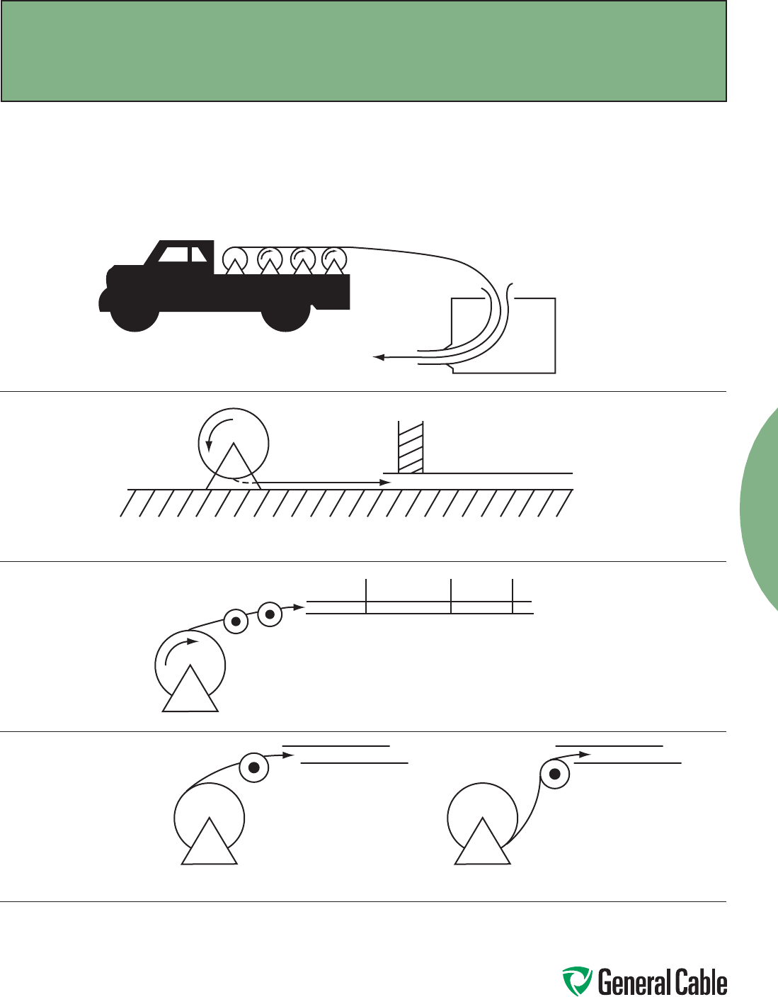
Phone: 800-243-8020
www.generalcable.com
Building Wire
42
The following diagrams illustrate various cable feed-in setups:
Cable Feed-In Setups
The feed-in setup should unreel the
cable with a natural curvature
(Figure 1) as opposed to a reverse
“S” curvature (Figure 2).
Reels on truck
Apply lube here
Guide-in tube
Setup for duct close to floor
Setup for overhead, into tray
IMPROPER
Figure 2
PROPER
Figure 1
Installation
Installation—Feed-In Setups
SPEC E050
April, 2010
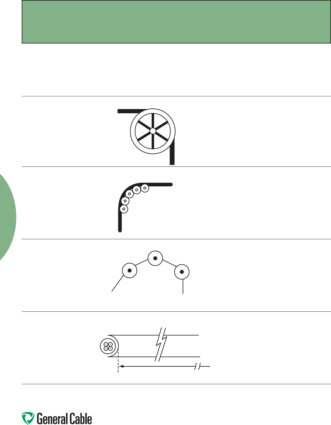
Phone: 800-243-8020
www.generalcable.com
Building Wire
43
Remember to use the radius of the
surface over which the cable is bent,
not the outside flange diameter of
the pulley. A “10 inch” cable sheave
typically has a 10 inch outside flange
diameter with a 6 inch inside diameter
that provides an inside (bending)
radius of 3 inches.
Single sheaves should only be
used for GUIDING cables. Arrange
multiple blocks to maintain bending
radii whenever cable changes
direction or elevation.
For pulling around bends,
use conveyor sheave
assemblies of the
appropriate radius series.
The pulleys must be positioned to ensure that
the effective curvature is smooth and changes
direction or elevation evenly at each pulley.
Never allow a polygon curvature to occur
(Figure 3).
The fit of a pulley around the cable is also
important when pulling heavy weights
(i.e. pulleys at the top of a vertical drop).
Cable Feed-In Setups (continued)
Single Sheave
Sheave Assembly
NEVER ALLOW
Figure 3
Radius
Installation
Installation—Feed-In Setups
SPEC E050
April, 2010
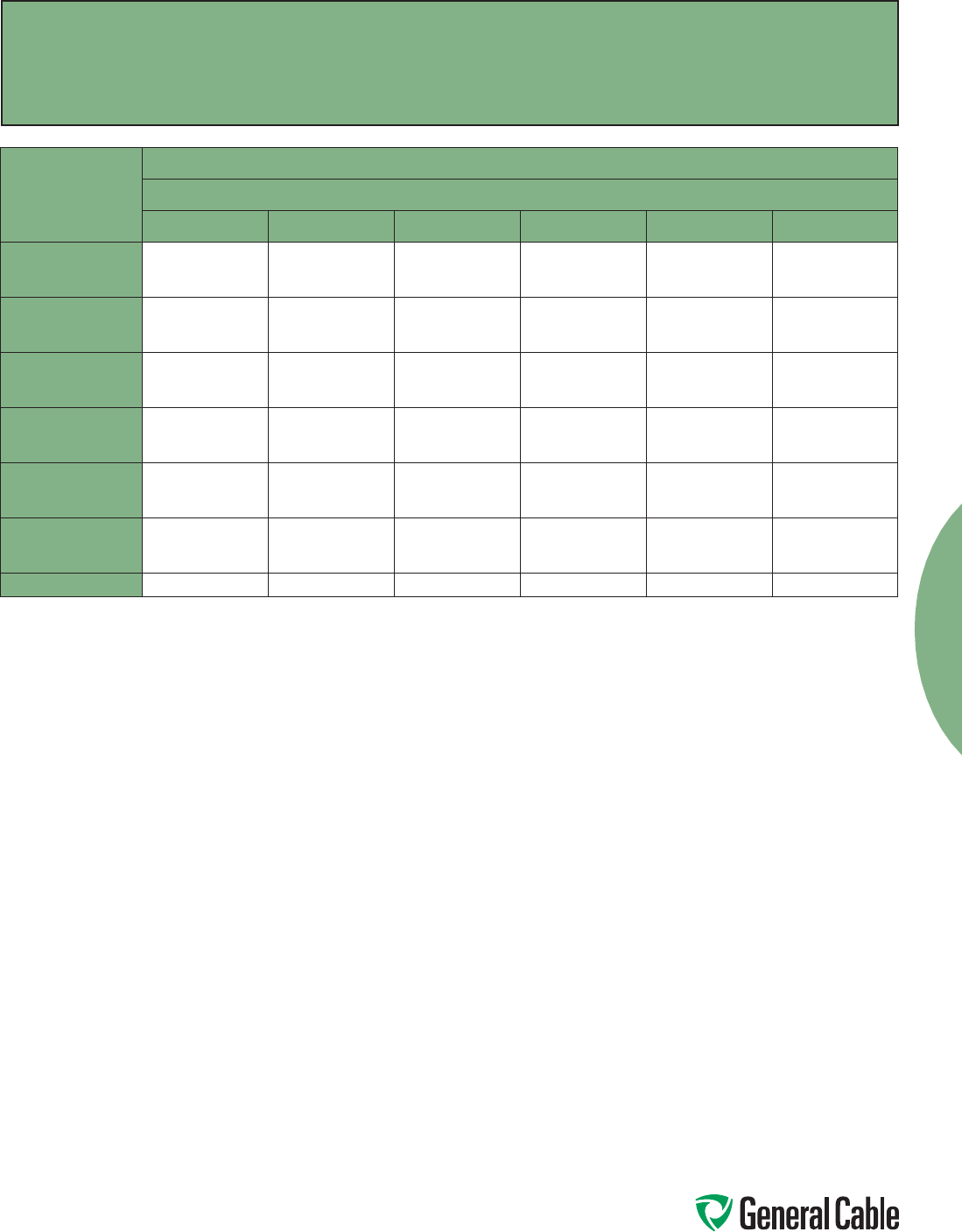
Phone: 800-243-8020
www.generalcable.com
Building Wire
44
Installation
Installation – Conductor Maximum Pulling Tensions
Multi-Conductor Cables Having Equal-Sized Conductors;
In Parallel or as Multiplexed Assemblies
SPEC E075
October, 2012
AWG/kcmil
MAXIMUM ALLOWABLE PULLING TENSION (LBS)
NUMBER OF CONDUCTORS
123456
18
16
14
13
20
33
26
40
66
39
60
99
41
65
105
52
81
132
62
97
158
12
10
8
52
83
132
104
166
264
157
249
396
167
266
423
209
332
528
251
399
634
6
4
2
210
334
531
420
668
1062
630
1002
1593
672
1069
1699
840
1336
2124
1008
1603
2548
1
1/0
2/0
670
845
1065
1339
1690
2130
2009
2534
3194
2142
2703
3407
2678
3379
4259
3214
4055
5111
3/0
4/0
250
1342
1693
2000
2685
3386
4000
4027
5078
6000
4296
5417
6400
5370
6771
8000
6444
8125
9600
350
500
750
2800
4000
6000
5600
8000
10000
8400
10000
10000
8960
10000
10000
10000
10000
10000
10000
10000
10000
1000 8000 10000 10000 10000 10000 10000
The maximum allowable pulling tensions are for direct attachment to the conductor.
T = 0.008 x cmil x n, if n ≤ 3
T = 0.008 x cmil x n x 0.8, if n > 3
When more than two conductors are pulled in parallel in an installation containing bends, the maximum allowable pulling tension is limited
to the two conductor column, regardless of the number of conductors that are being pulled.
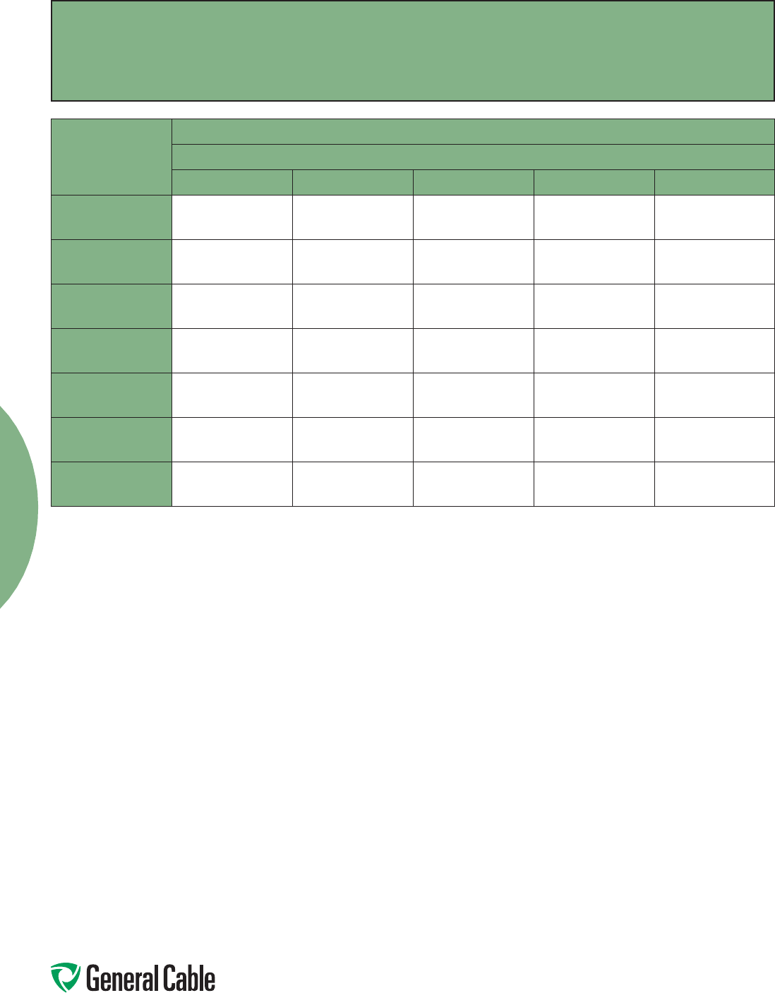
Phone: 800-243-8020
www.generalcable.com
Building Wire
45
Installation
Installation – Conductor Maximum Pulling Tensions
Multi-Conductor Cables Having Equal-Sized Conductors, without Subassemblies
SPEC E075
October, 2012
Number Of
Conductors
MAXIMUM ALLOWABLE PULLING TENSION (LBS)
CONDUCTOR SIZE (AWG/kcmil)
18 16 14 12 10
2
3
4
26
39
41
40
60
65
66
99
105
104
157
167
166
249
266
5
6
7
52
62
73
81
97
113
132
158
184
209
251
293
332
399
465
8
9
10
83
93
104
129
145
161
210
237
263
334
376
418
531
598
664
12
14
15
124
145
156
194
226
242
316
368
395
502
585
627
797
930
996
16
18
19
166
187
197
258
290
306
421
473
500
669
752
794
1000
1000
1000
20
22
24
207
228
249
323
355
387
526
549
631
836
919
1000
1000
1000
1000
25
30
37
259
311
383
403
484
596
658
789
974
1000
1000
1000
1000
1000
1000
The maximum allowable pulling tensions are for multi-conductor cables pulled into a raceway or cable tray using a basket grip or similar
device secured directly to the cable jacket. It is recommended that a combination of basket grips and pulling eyes be used whenever possible.
T = 0.008 x cmil x n, if n ≤ 3
T = 0.008 x cmil x n x 0.8, if n > 3
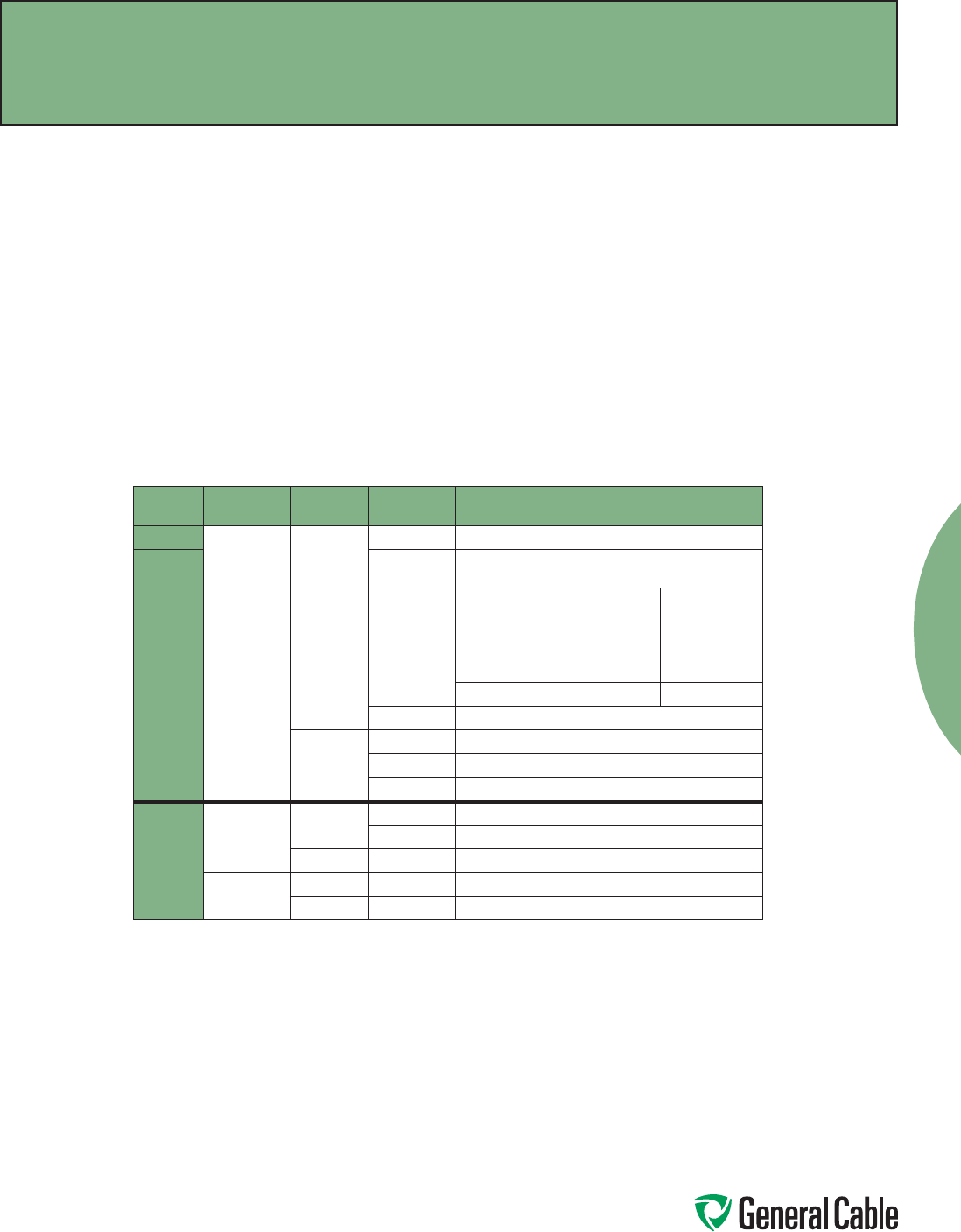
Phone: 800-243-8020
www.generalcable.com
Building Wire
46
Overview
Training is the positioning of cable when
it is not under tension. Bending is the
positioning of cable when it is under
tension. When installing cable, the object
is to limit the mechanical forces so that
the cable’s physical and electrical
characteristics are maintained for the
expected service life. Bends in conductors,
multi-conductor cables or assemblies of
conductors shall be made so that the cable
will not be damaged.
Physical Limitations Training and Bending
A nonshielded cable can tolerate a sharper
bend than a shielded cable. This is
especially true for cables having helically
applied metallic shielding tapes which,
when bent too sharply, can separate or
buckle and cut into the insulation.
Remember that offsets are bends.
The problem is compounded by the fact
that most tapes are under jackets that
conceal such damage. The extruded
polymers used for insulation shields have
sufficient conductivity and coverage
initially to pass acceptance testing, then
fail prematurely due to corona at the
shield/insulation interface.
Minimum Bending Radius in Accordance with National Electric Code
Voltage Conductors Shielding Cable Types Minimum Bending Radius as a Multiple
of Conductor/Assembly Diameter
600 V Single Nonshielded All 5X
601-
2000 V All 8X
600 V
or
2000 V
Multi-
conductor
or
Multiplexed
Nonshielded TC or TC-ER
1 in. (25 mm)
or less
Over 1 in. to 2 in.
(>25 mm to 50
mm)
Over 2 in.
(>50 mm)
4X 5X 6X
MC
3
7X
Shielded
All 12X
TC or TC-ER 12X
MC 12X/7X
1
Over
2000 V
Single Nonshielded MV 8X
MC37X
Shielded MC and MV 12X2
Multi-
conductor or
Multiplexed
Nonshielded MC and MV 8X
Shielded MC and MV 12X/7X1,2
1
12 times the diameter of an individual shielded conductor or 7 times the overall cable diameter, whichever is greater.
2
Since UniShield® is a unique construction, there are no applicable values for the bending radius in the NEC. However,
General Cable recommends 8 times for single conductors, and for multiplexed or multi-conductor cables, it is 8 times
the diameter of the individual conductors or 5 times the overall diameter, whichever is greater, in accordance with
ANSI/ICEA S-93-639 5-46 kV Shielded Power Cable for Use in the Transmission and Distribution of Electric Energy.
3
Per 330.24B Interlocked-Type Armor or Continuously Corrugated Metallic Sheath.
Installation
Installation—Training and Bending Limitations
SPEC E100
April, 2010
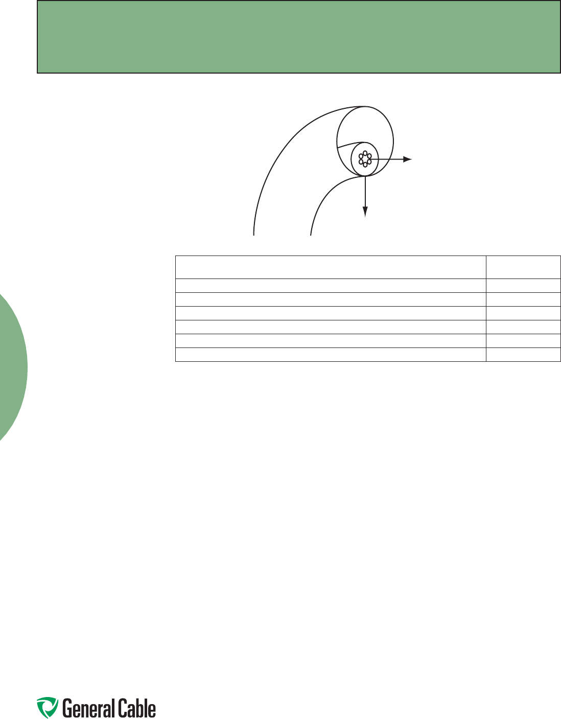
Phone: 800-243-8020
www.generalcable.com
Building Wire
47
Overview
Sidewall bearing pressure (SWBP), or sidewall
loading, is the radial force exerted on a cable
being pulled around a conduit bend or sheave.
Excessive SWBP can crush a cable and is,
therefore, one of the most restrictive factors in
installations having bends and requiring high
pulling tensions. SWBP is reduced by increasing
the radius of bends.
The maximum tension that can safely be applied
to the cable during installation can be calculated
using the maximum SWBP for the cable and the
radius of the bend it is traversing.
For example, a cable having a maximum SWBP
of 300 lb/ft that is being pulled around a bend
having a radius of 2 feet should have no more
than 300 lbs/ft x 2 ft or 600 lbs tension applied to
it as the cable exits the bend.
*Yellow 77 not recommended for use with UniShield
®
cables.
For LSZH jacketed cable, consult with pulling compound manufacturers.
Other wire pulling compounds may be suitable for use with General Cable constructions. Contact the wire pulling compound manufacturer regarding the
suitability of their products with specific General Cable products.
General Cable’s Approval List of Cable Pulling Lubricants
The following manufacturers, who are listed in the 2006 UL Electrical Construction Equipment Directory, provide wire pulling compounds intended for
use as lubricants in installing electrical conductors in raceways. These manufacturers have had some of their products evaluated by Underwriters
Laboratories (UL) to determine their compatibility with conductor insulation and coverings.
Since it is not feasible to test every possible combination of cable material with every wire pulling compound, the installer should check with the pulling
compound manufacturer or the cable manufacturer to determine compatibility between specific cable materials and the pulling compound.
The Listing Mark for these products includes the UL symbol, together with the word “LISTED,” a control number and the product name “Wire Pulling
Compound.” Refer to the latest edition of the UL Electrical Construction Equipment Directory for the current listing of manufacturers of wire pulling
compounds and their control numbers.
J.C. Whitlam Mfg. Co.
Klein Tools Inc.
Madison Electric Products Inc.
Rainbow Technology Corp.
Rectorseal
Thomas & Betts Corp.
3M Company
American Bentonite International Inc.
American Polywater Corp.
Arnco Corp.
Dura-Line Corp.
Greenlee Textron
Ideal Industries Inc.*
CABLE TYPE SWBP (LBS/FT)
300 V Nonshielded, 300 V and 600 V Shielded Control & Instrumentation 500
600 V Nonshielded Control & Instrumentation 500
600 V and 2400 V Nonshielded Power 1000
5 kV-35 kV Shielded Power 1000
Interlocked Armored Cable (all voltage) 300
CCW® MC-HL Armored Cable 500
Sidewall Load
Tension
Installation
Installation—Maximum Sidewall Pressure
SPEC E125
October, 2012
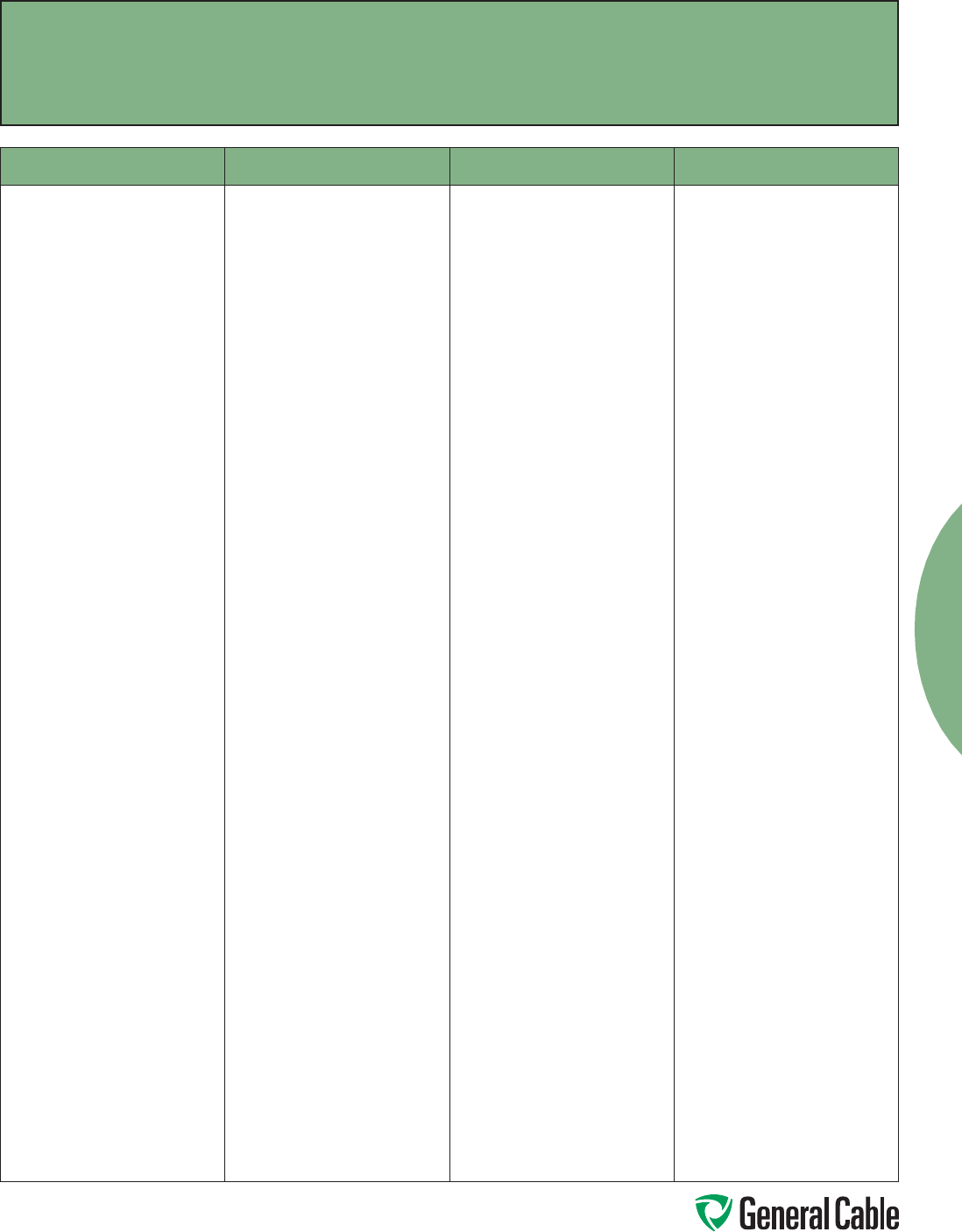
Phone: 800-243-8020
www.generalcable.com
Building Wire
48
Catalog Number Index
Index
NUMBER PAGE NUMBER PAGE NUMBER PAGE NUMBER PAGE
37A309 ........................ 23
37B309 ........................ 23
37C309 ........................ 23
38A329 ........................ 24
38B319 ........................ 24
38C309 ........................ 24
38D300 ........................ 24
06591.210200 ............... 8
06591.215100 ............... 8
06591.215200 ............... 8
06591.215300 ............... 8
06591.215400 ............... 8
06591.216000 ............... 8
06591.216200 ............... 8
06591.216500 ............... 8
06591.217000 ............... 8
06591.217500 ............... 8
12211.710100 ............. 15
12211.710200 ............. 15
12211.710400 ............. 15
12211.710600 ............. 15
12211.710800 ............. 15
12211.711100 ....... 13, 15
12211.711200 ....... 13, 15
12211.711400 ....... 13, 15
12211.715100 ............. 15
12211.715200 ............. 15
12211.715300 ............. 15
12211.715400 ............. 15
12211.716250 ............. 15
12211.716300 ............. 15
12211.716350 ............. 15
12211.716400 ............. 15
12211.716500 ............. 15
12211.716600 ............. 15
12211.716750 ............. 15
12211.717000 ............. 15
12221.710100 ............. 16
12221.710200 ............. 16
12221.710400 ............. 16
12221.710600 ............. 16
12221.710800 ....... 13, 16
12221.711100 ....... 13, 16
12221.711200 ....... 13, 16
12221.711400 ....... 13, 16
12221.715100 ............. 16
12221.715200 ............. 16
12221.715300 ............. 16
12221.715400 ............. 16
12221.716250 ............. 16
12221.716300 ............. 16
12221.716350 ............. 16
12221.716400 ............. 16
12221.716500 ............. 16
12221.716600 ............. 16
12221.716750 ............. 16
12221.717000 ............. 16
12411.710100 ............. 17
12411.710200 ............. 17
12411.710400 ............. 17
12411.710600 ............. 17
12411.710800 ............. 17
12411.711100 ....... 13, 17
12411.711100B06 ....... 13
12411.711100B08 ....... 13
12411.711109B06 ....... 13
12411.711109B08 ....... 13
12411.711200 ....... 13, 17
12411.711400 ....... 13, 17
12411.711600 ............. 17
12411.711800 ............. 17
12411.715100 ............. 17
12411.715200 ............. 17
12411.715300 ............. 17
12411.715400 ............. 17
12411.716250 ............. 17
12411.716300 ............. 17
12411.716350 ............. 17
12411.716400 ............. 17
12411.716500 ............. 17
12411.716600 ............. 17
12411.716750 ............. 17
12411.717000 ............. 17
12421.710100 ............. 19
12421.710200 ............. 19
12421.710400 ............. 19
12421.710600 ............. 19
12421.710800 ............. 19
12421.711100 ....... 13, 19
12421.711100B ........... 13
12421.711200 ....... 13, 19
12421.711400 ....... 13, 19
12421.711600 ............. 19
12421.711800 ............. 19
12421.715100 ............. 19
12421.715200 ............. 19
12421.715300 ............. 19
12421.715400 ............. 19
12421.716250 ............. 19
12421.716300 ............. 19
12421.716350 ............. 19
12421.716400 ............. 19
12421.716500 ............. 19
12421.716600 ............. 19
12421.716750 ............. 19
12421.717000 ............. 19
12431.710100 ............. 18
12431.710200 ............. 18
12431.710400 ............. 18
12431.710600 ............. 18
12431.710800 ............. 18
12431.711100 ............. 18
12431.711100.06 ........ 13
12431.711100.07 ........ 13
12431.711100.08 ........ 13
12431.711102.06 ........ 13
12431.711102.07 ........ 13
12431.711102.08 ........ 13
12431.711106.06 ........ 13
12431.711106.07 ........ 13
12431.711106.08 ........ 13
12431.711109.06 ........ 13
12431.711109.07 ........ 13
12431.711109.08 ........ 13
12431.711200 ............. 18
12431.711400 ............. 18
12431.711600 ............. 18
12431.711800 ............. 18
12431.715100 ............. 18
12431.715200 ............. 18
12431.715300 ............. 18
12431.715400 ............. 18
12431.716250 ............. 18
12431.716300 ............. 18
12431.716350 ............. 18
12431.716400 ............. 18
12431.716500 ............. 18
12431.716600 ............. 18
12431.716750 ............. 18
12431.717000 ............. 18
12441.710100 ............. 20
12441.710200 ............. 20
12441.710400 ............. 20
12441.710600 ............. 20
12441.710800 ............. 20
12441.711100 ....... 13, 20
12441.711100.07 ........ 13
12441.711109.07 ........ 13
Phone: 800-243-8020
www.generalcable.com
49
Copper Building Wire
Catalog Number Index
Index
NUMBER PAGE NUMBER PAGE NUMBER PAGE NUMBER PAGE
12441.711200 ............. 20
12441.711200.07 ........ 13
12441.711209.07 ........ 13
12441.711400 ............. 20
12441.711400.07 ........ 13
12441.711409.07 ........ 13
12441.711600 ............. 20
12441.711800 ............. 20
12441.715100 ............. 20
12441.715200 ............. 20
12441.715300 ............. 20
12441.715400 ............. 20
12441.716250 ............. 20
12441.716300 ............. 20
12441.716350 ............. 20
12441.716400 ............. 20
12441.716500 ............. 20
12441.716600 ............. 20
12441.716750 ............. 20
12441.717000 ............. 20
16602.210200 ............. 11
16602.210400 ............. 11
16602.210600 ............. 11
16602.210800 ............. 11
16602.215100 ............. 11
16602.215200 ............. 11
16602.215400 ............. 11
16602.216000 ............. 11
16602.216200 ............. 11
16602.216500 ............. 11
16602.217000 ............. 11
16602.217500 ............. 11
23010 ............................ 4
23012 ............................ 4
23014 ............................ 4
24010 ............................ 4
24012 ............................ 4
24014 ............................ 4
25001 ............................ 4
25002 ............................ 4
25003 ............................ 4
25004 ............................ 4
25006 ............................ 4
25008 ............................ 4
26110 ............................ 4
26210 ............................ 4
26310 ............................ 4
26410 ............................ 4
27250 ............................ 4
27300 ............................ 4
27350 ............................ 4
27400 ............................ 4
27500 ............................ 4
27600 ............................ 4
27750 ............................ 4
28016 ............................ 6
28018 ............................ 6
311022 ........................ 21
311222 ........................ 21
311422 ........................ 21
320232 ........................ 21
320432 ........................ 21
320622 ........................ 21
320632 ........................ 21
320822 ........................ 21
320832 ........................ 21
321032 ........................ 21
321232 ........................ 21
321432 ........................ 21
340629 ........................ 22
340639 ........................ 22
340829 ........................ 22
340839 ........................ 22
341029 ........................ 22
341039 ........................ 22
341229 ........................ 22
341239 ........................ 22
341429 ........................ 22
341439 ........................ 22
364830 ........................ 11
364840 ........................ 11
364850 ........................ 11
370139 ........................ 23
370239 ........................ 23
370339 ........................ 23
370439 ........................ 23
370639 ........................ 23
370839 ........................ 23
371039 ........................ 23
372249 ........................ 23
373259 ........................ 23
374269 ........................ 23
376289 ........................ 23
381339 ........................ 24
381500 .......................... 8
381510 .......................... 8
381520 .......................... 8
381530 .......................... 8
381540 .......................... 8
381550 .......................... 8
381560 .......................... 8
381570 .......................... 8
382349 ........................ 24
383359 ........................ 24
384369 ........................ 24
386369 ........................ 24
388389 ........................ 24
391070 .......................... 7
391080 .......................... 7
391090 .......................... 7
395370 ........................ 14
395380 ........................ 14
395390 ........................ 14
395400 ........................ 14
5175.001 ....................... 7
5175.002 ....................... 7
5175.004 ....................... 7
5175.006 ....................... 7
5175.008 ....................... 7
5175.110 ....................... 7
5175.210 ....................... 7
5175.310 ....................... 7
5175.410 ....................... 7
5175.250 ....................... 7
5175.350 ....................... 7
5175.500 ....................... 7
5175.600 ....................... 7
5175.750 ....................... 7
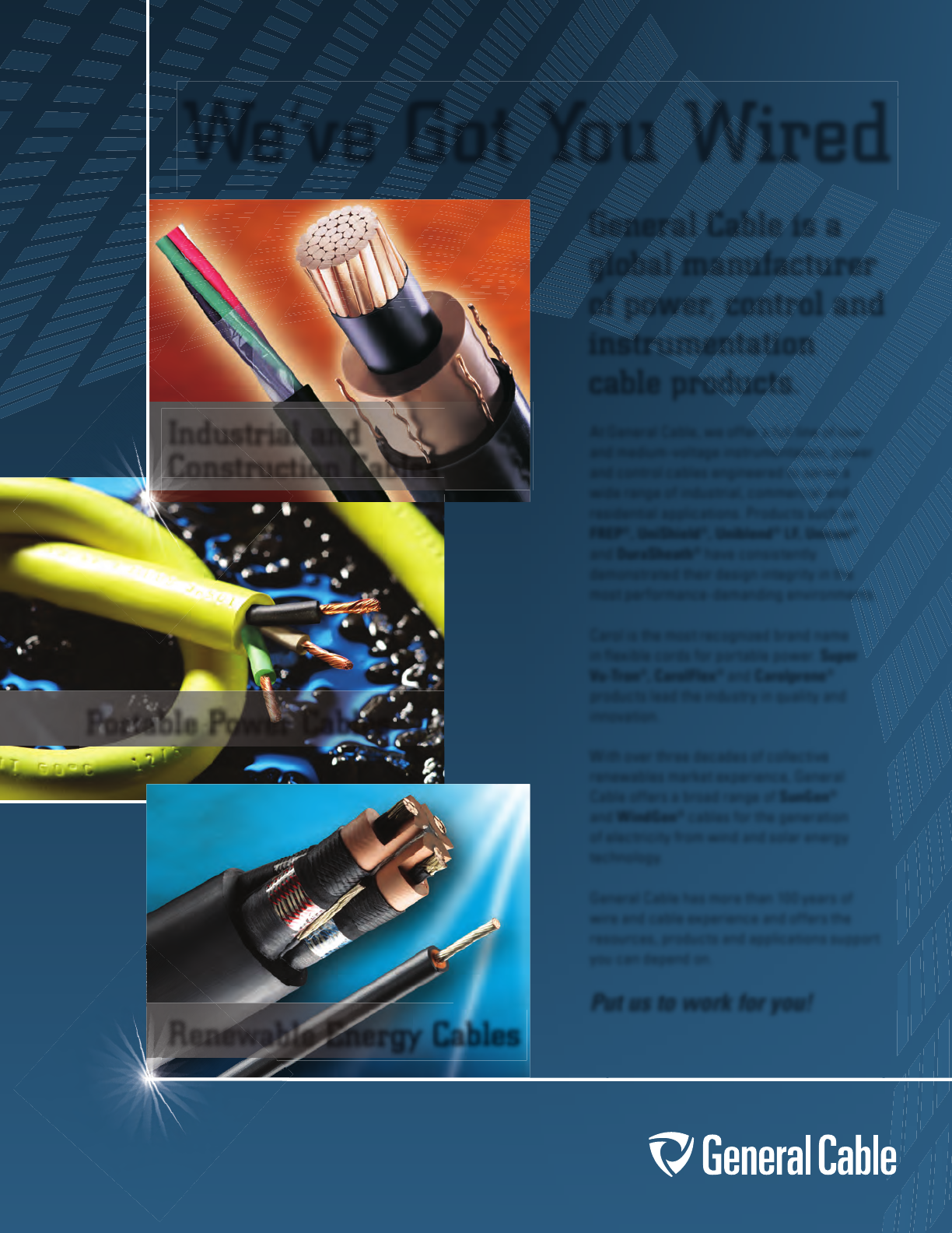
We’ve Got You Wired
General Cable is a
global manufacturer
of power, control and
instrumentation
cable products.
Industrial and
Construction Cables
Portable Power Cables
Renewable Energy Cables
At General Cable, we offer a full line of low-
and medium-voltage instrumentation, power
and control cables engineered to serve a
wide range of industrial, commercial and
residential applications. Products such as
FREP®, UniShield®, Uniblend® LF, Unicon®
and DuraSheath® have consistently
demonstrated their design integrity in the
most performance-demanding environments.
Carol is the most recognized brand name
in flexible cords for portable power. Super
Vu-Tron®, CarolFlex® and Carolprene®
products lead the industry in quality and
innovation.
With over three decades of collective
renewables market experience, General
Cable offers a broad range of SunGen®
and WindGen® cables for the generation
of electricity from wind and solar energy
technology.
General Cable has more than 100 years of
wire and cable experience and offers the
resources, products and applications support
you can depend on.
Put us to work for you!
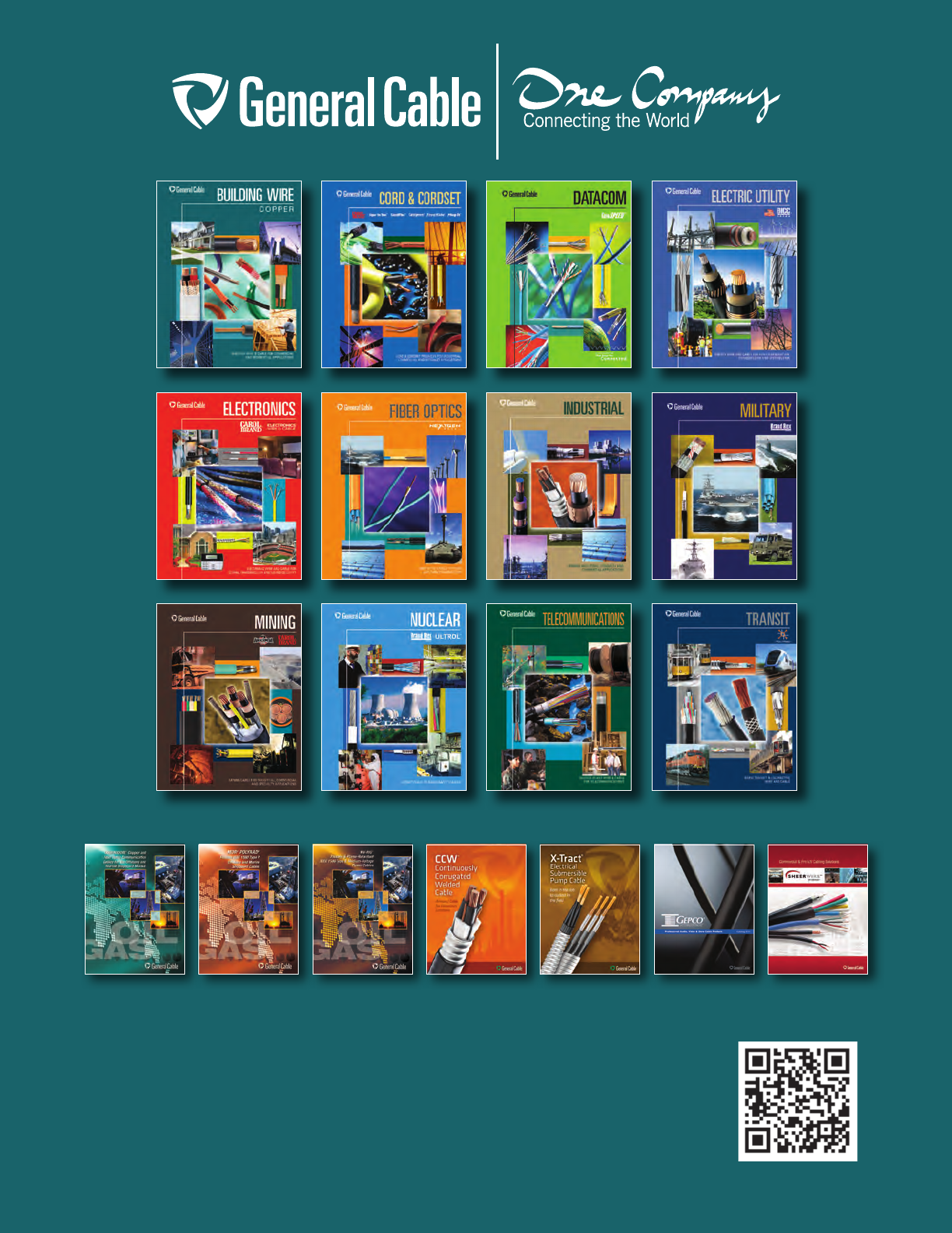
COMMODORE®
CATALOG
MOR® POLYRAD®
CATALOG
MV-RIG®
CATALOG
CCW®
CATALOG
X-TRACT® ESP
CATALOG
GEPCO®
CATALOG
Other General Cable Products Offered
Use your smartphone to view
Interactive Catalog online
SHEERWIRE™
CATALOG
General Cable
4 Tesseneer Drive
Highland Heights,
Kentucky 41076-9753
U.S.A.
info@generalcable.com
Form No. INS-0132-R1012
42681
Telephone (800) 243-8020
Fax (859) 572-9762
International Telephone +1 859 572 8000
International Fax +1 859 572 8058
www.generalcable.com
General Cable Canada
590 Barmac Drive
North York, Ontario M9L 2X8
Telephone (800) 561-0649
Fax (800) 565-2529
infoca@generalcable.com
