1000298892 Catalog
2016-09-04
: Pdf 1000298892-Catalog 1000298892-Catalog B4 unilog
Open the PDF directly: View PDF ![]() .
.
Page Count: 156 [warning: Documents this large are best viewed by clicking the View PDF Link!]
SQUARE D COMPANY CNInformation
SCHNEIDER ELECTRIC CHANGE NOTICE INFORMATION
PRODUCT GROUP: CHANGE CATEGORY: EFFECTIVITY DATE:
AC Drives RED FLAG July 15, 2004
MPG DRIV 12 -MONTH NOTICE FILE CONTROL NUMBER:
MPL EA4 RAL 03 0007
Description of Change:
The complete line of ALTIVAR 58 (ATV58) packaged drive controllers was
launched in July of 2003. This includes Class 8839 58M Enclosed as well
as Class 8998 MCC ATV58 Drive Controllers. With this recent launch and
with other product upgrades, the ATV58 Drive Controller is now a
functional replacement for the ALTIVAR 66 (ATV66) Drive Controller.
As a result, the ATV66 Drive Controller (Class 8839 Enclosed and Class
8998 MCC) will become obsolete and unavailable after July 15, 2004.
The entire ATV66 product line is affected, covering the following ranges:
1 - 50 HP @ 208/230V
1 - 400 HP @ 460V
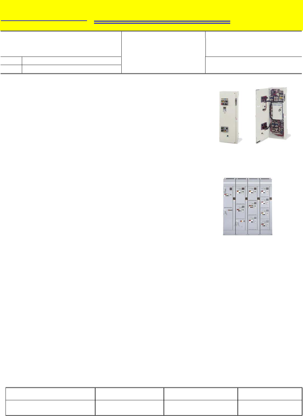
Class 8839 Enclosed
ATV66 Drive Controller
Objective of Change:
The objective of this change is to convert customers to our most current
product available, the ATV58 family of AC drives. The ATV58 product line
is a complete family of AC Drives, offering high-performance sensorless
vector control, a physical size reduction from the ATV66 AC drive line, and
a broad range of options including extensive serial communication
capabilities. The ATV58 TRX AC Drive product is the functional
replacement for the ATV66 AC Drive product line.
Class 8898 MCC
ATV66 Drive Controller
Transition Tools:
Refer to the Class 8839 58M Enclosed Drive Product Launch Zone (July 2003) on Square D’s Intranet for more
information on the replacement product for the Class 8839 Enclosed ATV66 Drive Controller.
Refer to the Class 8998 Motor Control Center Altivar 58 TRX AC Drives Pricing Guide for more information on the
replacement product for MCC ATV66 Drive Units.
Call Seneca Customer Support at 864-886-1400 (Enclosed) or 864-886-1633 (MCC) if you need assistance.
Date of New Product Availability:
Both Enclosed and MCC ATV58 Drive Controller products are available as of the June 2003 Quote To Cash
Product Selector Synch.
Disposition of Obsolete Product:
During the transition period, we will supply the ATV66 AC Drive if required for existing customers with extended
lead times. The ATV58 TRX AC Drive should be used for new applications and wherever possible.
Return Policy for Obsolete Product:
The return policy will be per Square D's latest published conditions of sale
Product Line Manager: Location: Product Line Director: Date Issued:
Ruben VanderDuim (Enclosed)
David Ray (MCC)
Raleigh, NC
Seneca, SC
Geoff Walker
Allen Breeze July 2003
This document provided by Barr-Thorp Electric Co., Inc. 800-473-9123 www.barr-thorp.com
SQUARE D COMPANY CNInformation
SCHNEIDER ELECTRIC CHANGE NOTICE INFORMATION
PRODUCT GROUP: CHANGE CATEGORY: EFFECTIVITY DATE:
AC Drives RED FLAG July 15, 2004
MPG DRIV 12 -MONTH NOTICE FILE CONTROL NUMBER:
MPL EA2 RAL 03 0006
Description of Change:
With the completion of the upgrades to the ALTIVAR 58 TRX (ATV58
TRX) AC Drive product line, it is now a functional replacement for the
ALTIVAR 66 (ATV66) AC Drive. The ATV66 AC Drive and all of its
catalogued options will become obsolete and unavailable after July 15,
2004.
The entire ATV66 product line is affected, covering the following ranges:
1 - 50 HP @ 208/230V
1 - 400 HP @ 460V
Objective of Change:
The objective of this change is to convert customers to our most current
product available, the ATV58 TRX family of AC drives. The ATV58 TRX
product line is a complete family of AC Drives, offering high-performance
sensorless vector control, a physical size reduction from the ATV66 AC
drive line, and a broad range of options including extensive serial
communication capabilities. The ATV58 TRX AC Drive product is the
functional replacement for the ATV66 AC Drive product line.
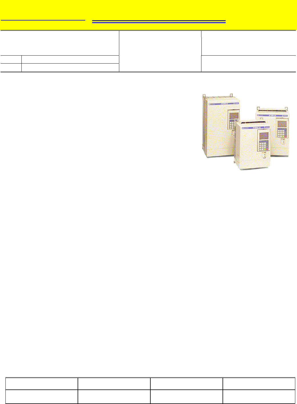
ATV66 AC Drive
Transition Tools:
To determine which ATV58 TRX AC Drive to use during the conversion process, refer to the cross-reference chart
on page 2.
Refer to the Product Launch Zone (October 2002) on Square D’s Intranet for more information.
Call the Product Support Group at 919-266-8600 if you need assistance.
Date of New Product Availability:
The ATV58 TRX AC Drive Product has been available since October 2002.
A replacement model for every ATV66 AC Drive (including options) is now in stock in Mechanicsburg.
Disposition of Obsolete Product:
During the transition period, we will supply the ATV66 AC Drive as required. The ATV58 TRX AC Drive should be
used for new applications and wherever possible.
Return Policy for Obsolete Product:
The return policy will be per Square D's latest published conditions of sale.
Any stock of products should be managed to minimize inventory through the transition.
Product Line Manager: Location: Product Line Director: Date Issued:
Ruben VanderDuim Raleigh, NC Geoff Walker July 2003
This document provided by Barr-Thorp Electric Co., Inc. 800-473-9123 www.barr-thorp.com

ATV66 to ATV58 TRX AC Drive Cross Reference
Constant Torque
Rating
Variable Torque
Rating
Variable Torque
Low-Noise Rating
ATV66 Model
Number 208/230V 460V 208/230V 460V 208/230V 460V
ATV58 TRX Model
Number [1]
1 1 1 ATV58HU18M2ZU
2 2 2 ATV58HU29M2ZU
ATV66U41M2U
3 3 3 ATV58HU41M2ZU
5 5 5 ATV58HU72M2ZU
ATV66U72M2U 7.5
7.5 7.5 ATV58HU90M2ZU
ATV66U90M2U 10
10 10 ATV58HD12M2ZU
ATV66D12M2U 15
ATV66D16M2U 15
15
20
ATV58HD16M2XZU
ATV66D23M2S264U 20 25 20 ATV58HD23M2XZU
25 30 25 ATV58HD28M2XZU
ATV66D33M2U 30 40 30 ATV58HD33M2XZU
ATV66D46M2U 40
50 40 ATV58HD46M2XZU
1 1 1 ATV58HU18N4ZU
2 2 2 ATV58HU29N4ZU
ATV66U41N4U
3 3 3 ATV58HU41N4ZU
ATV66U54N4U 5 ATV58HU72N4XZU
5 ATV58HU54N4XZU
5 ATV58HU72N4XZU
ATV66U72N4U
7.5 ATV58HU90N4XZU
7.5 ATV58HU72N4XZU
7.5 ATV58HU90N4XZU
ATV66U90N4U
10 ATV58HD12N4XZU
10 ATV58HU90N4XZU
10 ATV58HD12N4XZU
ATV66D12N4U
15 ATV58HD16N4XZU
15 ATV58HD12N4XZU
15 ATV58HD16N4XZU
ATV66D16N4U
20 ATV58HD23N4XZU
20 ATV58HD16N4XZU
20 ATV58HD23N4XZU
ATV66D23N4U
25 ATV58HD28N4XZU
25 ATV58HD23N4XZU
25 30 ATV58HD28N4XZU
ATV66D33N4U
30 40 30 ATV58HD33N4XZU
ATV66D46N4U 40 50 40 ATV58HD46N4XZU
ATV66D54N4U 50 60 50 ATV58HD54N4XZU
ATV66D64N4U 60 75 60 ATV58HD64N4XZU
ATV66D79N4U 75 100 75 ATV58HD79N4XZU
ATV66C10N4U 100 ATV58HC13N4XZU [2]
ATV66C10N4U 125 ATV58HC10N4XZU
ATV66C10N4BU 100 ATV58HC13N4XZU [2] [3]
ATV66C13N4U 125 ATV58HC15N4XZU [2]
ATV66C13N4U 150 ATV58HC13N4XZU
ATV66C13N4BU 125 ATV58HC15N4XZU [2] [3]
ATV66C15N4U 150 ATV58HC19N4XZU [2]
ATV66C15N4U 200 ATV58HC15N4XZU
ATV66C15N4BU 150 ATV58HC19N4XZU [2] [3]
ATV66C19N4U 200 ATV58HC23N4XZU [2]
ATV66C19N4BU 200 ATV58HC23N4XZU [2] [3]
ATV66C23N4U 250 ATV58HC25N4XZU [2] [3]
ATV66C23N4U 250 ATV58HC19N4XZU [3]
ATV66C23N4U 300 ATV58HC23N4XZU [3]
ATV66C28N4U 300 ATV58HC31N4XZU [2] [3]
ATV66C28N4U 350 ATV58HC25N4XZU [3]
ATV66C31N4U 350 ATV58HC33N4XZU [2] [3]
ATV66C31N4U 400 ATV58HC28N4XZU [3]
[1] Every ATV66 AC drive is factory supplied with a keypad. The ATV58 AC drive is not. Order one ATV58 keypad (field
installable kit number VW3A58101U) for every ATV58 AC drive for which a keypad is required. An optional I/O extension card
may be needed to match specific ATV66 I/O capability. Consult the ATV58 catalog 8806CT9901 for details.
[2] Consult Instruction Bulletin VVDED397048US for details on operation below 6 Hz.
[3] An internal dynamic braking transistor is not available with the ATV58 AC drive at this HP rating.
This document provided by Barr-Thorp Electric Co., Inc. 800-473-9123 www.barr-thorp.com
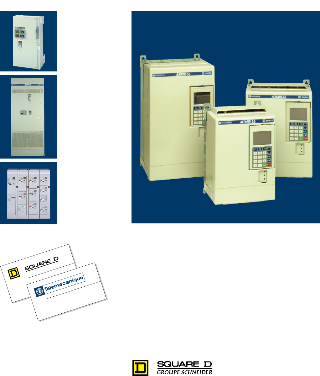
Class 8800 / 8839 / 8998
ALTIVAR
®
66 AC Drives
Enclosed AC Drives
Motor Control Centers
CONTENTS
Description . . . . . . . . . . . . . . . . . . . . . . . . . . . . . . . . . . . . . . . . . . . . . . . . . . . . .Page
ALTIVAR 66 AC Drives . . . . . . . . . . . . . . . . . . . . . . . . . . . . . . . . . . . . . . . . . . . . . . . . 3
Drives and Soft Start Overview. . . . . . . . . . . . . . . . . . . . . . . . . . . . . . . . . . . . . . . . . 97
Class 8839 Enclosed AC Drives. . . . . . . . . . . . . . . . . . . . . . . . . . . . . . . . . . . . . . . 101
Class 8998 Motor Control Centers . . . . . . . . . . . . . . . . . . . . . . . . . . . . . . . . . . . . . 145
This document provided by Barr-Thorp Electric Co., Inc. 800-473-9123 www.barr-thorp.com
Obsolete-See ATV58 TRX

ALTIVAR 66 AC Drives
Contents
3
2/98 © 1998 Square D All Rights Reserved
Description Pages
Introduction . . . . . . . . . . . . . . . . . . . . . . . . . . . . . . . . . . . . . . . . . . . . . . . . . . . . . . . . . . . . . . . . . . . . 4-7
Specifications. . . . . . . . . . . . . . . . . . . . . . . . . . . . . . . . . . . . . . . . . . . . . . . . . . . . . . . . . . . . . . . . . . . 8-9
Features. . . . . . . . . . . . . . . . . . . . . . . . . . . . . . . . . . . . . . . . . . . . . . . . . . . . . . . . . . . . . . . . . . . . . 10-13
Drive Configuration and Adjustments . . . . . . . . . . . . . . . . . . . . . . . . . . . . . . . . . . . . . . . . . . . . . . 14-23
Motor Thermal Overload Protection. . . . . . . . . . . . . . . . . . . . . . . . . . . . . . . . . . . . . . . . . . . . . . . . 23-24
Display and Keypad Configuration. . . . . . . . . . . . . . . . . . . . . . . . . . . . . . . . . . . . . . . . . . . . . . . . . 24-25
Application Functions. . . . . . . . . . . . . . . . . . . . . . . . . . . . . . . . . . . . . . . . . . . . . . . . . . . . . . . . . . . 25-31
Fault Management and Configuration . . . . . . . . . . . . . . . . . . . . . . . . . . . . . . . . . . . . . . . . . . . . . . . . .32
Diagnostic Mode . . . . . . . . . . . . . . . . . . . . . . . . . . . . . . . . . . . . . . . . . . . . . . . . . . . . . . . . . . . . . . . . .33
Recalling and Storing Adjustments . . . . . . . . . . . . . . . . . . . . . . . . . . . . . . . . . . . . . . . . . . . . . . . . . . .33
Input and Output Assignments . . . . . . . . . . . . . . . . . . . . . . . . . . . . . . . . . . . . . . . . . . . . . . . . . . . . . .34
I/O Extension Modules. . . . . . . . . . . . . . . . . . . . . . . . . . . . . . . . . . . . . . . . . . . . . . . . . . . . . . . . . . 35-39
Communication Options . . . . . . . . . . . . . . . . . . . . . . . . . . . . . . . . . . . . . . . . . . . . . . . . . . . . . . . . 40-45
Parameter Summary . . . . . . . . . . . . . . . . . . . . . . . . . . . . . . . . . . . . . . . . . . . . . . . . . . . . . . . . . . . 46-52
Drive Selection. . . . . . . . . . . . . . . . . . . . . . . . . . . . . . . . . . . . . . . . . . . . . . . . . . . . . . . . . . . . . . . . 53-56
Dimensions and Weights for Mounting . . . . . . . . . . . . . . . . . . . . . . . . . . . . . . . . . . . . . . . . . . . . . 57-60
Mounting in Enclosures . . . . . . . . . . . . . . . . . . . . . . . . . . . . . . . . . . . . . . . . . . . . . . . . . . . . . . . . . 61-62
Power Terminal Descriptions . . . . . . . . . . . . . . . . . . . . . . . . . . . . . . . . . . . . . . . . . . . . . . . . . . . . . . . .63
Control Terminal Descriptions . . . . . . . . . . . . . . . . . . . . . . . . . . . . . . . . . . . . . . . . . . . . . . . . . . . . . . .64
Wiring Diagrams . . . . . . . . . . . . . . . . . . . . . . . . . . . . . . . . . . . . . . . . . . . . . . . . . . . . . . . . . . . . . . 65-66
I/O Extension Module Terminal Descriptions . . . . . . . . . . . . . . . . . . . . . . . . . . . . . . . . . . . . . . . . . . . .67
I/O Extension Module Wiring Diagrams. . . . . . . . . . . . . . . . . . . . . . . . . . . . . . . . . . . . . . . . . . . . . . . .68
Dynamic Braking . . . . . . . . . . . . . . . . . . . . . . . . . . . . . . . . . . . . . . . . . . . . . . . . . . . . . . . . . . . . . . 69-71
Wiring Practices. . . . . . . . . . . . . . . . . . . . . . . . . . . . . . . . . . . . . . . . . . . . . . . . . . . . . . . . . . . . . . . 72-77
Equipment Recommendations. . . . . . . . . . . . . . . . . . . . . . . . . . . . . . . . . . . . . . . . . . . . . . . . . . . . 78-80
Special Applications. . . . . . . . . . . . . . . . . . . . . . . . . . . . . . . . . . . . . . . . . . . . . . . . . . . . . . . . . . . . 81-82
List of Catalog Numbers . . . . . . . . . . . . . . . . . . . . . . . . . . . . . . . . . . . . . . . . . . . . . . . . . . . . . . . . 83-89
Three Phase Line Reactors. . . . . . . . . . . . . . . . . . . . . . . . . . . . . . . . . . . . . . . . . . . . . . . . . . . . . . . . .90
Motor Protecting Output Filters . . . . . . . . . . . . . . . . . . . . . . . . . . . . . . . . . . . . . . . . . . . . . . . . . . . . . .91
Suggested Specifications . . . . . . . . . . . . . . . . . . . . . . . . . . . . . . . . . . . . . . . . . . . . . . . . . . . . . . . 92-96
This document provided by Barr-Thorp Electric Co., Inc. 800-473-9123 www.barr-thorp.com

ALTIVAR 66 AC Drives
Introduction
© 1998 Square D All Rights Reserved
4
2/98
Basic Drive
Factory Setting
The ALTIVAR 66 drive is factory preset for use in most common applications.
Introduction
The ALTIVAR 66 drive is designed for use with standard three-phase asynchro-
nous motors with a power range of 1 to 350 hp (constant torque) or 400 hp (vari-
able torque), 2.2 to 220 kw (constant torque) or 250 kw (variable torque). With its
modular design and extensive range of options and accessories, the ALTIVAR 66
drive can be used in all types of industrial environments, commercial construction,
and OEM applications.
Sensorless Flux
Vector Control
The ALTIVAR 66 basic drive incorporates flux vector control without encoder feed-
back, giving rated motor torque at 0.5 Hz without adjustment.
Reduction of
Motor Noise
For use with constant or variable torque, a high switching frequency (2 kHz, 4 kHz,
or 10 kHz) is available.
Drive Operator
Interface
A keypad display is mounted on front of the drive. It allows:
•
Choice of six languages
•
Drive identification, parameter and fault display
•
Recall of adjustments and drive configuration
•
Display of running values such as output frequency or a fault
•
Local control of the drive
Protection
The drive automatically protects itself against short circuits:
•
Between output phases
•
Between output phases and ground
•
On the outputs of internal supplies
•
On the logic and analog outputs
This document provided by Barr-Thorp Electric Co., Inc. 800-473-9123 www.barr-thorp.com
ALTIVAR 66 AC Drives
Introduction
5
2/98 © 1998 Square D All Rights Reserved
•
Maximum available torque at low speeds without adjustment
•
Automatic adjustment of acceleration and deceleration ramp times when torque
capabilities are exceeded
The drive can be configured for either constant or variable torque applications.
The ALTIVAR 66 drive benefits from a new concept, PRO System (Performance Regulation
Optimization), providing a solution for demanding drive applications. Features include:
•
New motor flux control algorithms
•
Automatic adaptation of motor parameters
•
Sensorless flux vector control without encoder
•
Transient overtorque necessary for starting
The switching frequency is randomly modulated to reduce audible motor noise while
limiting losses in the drive.
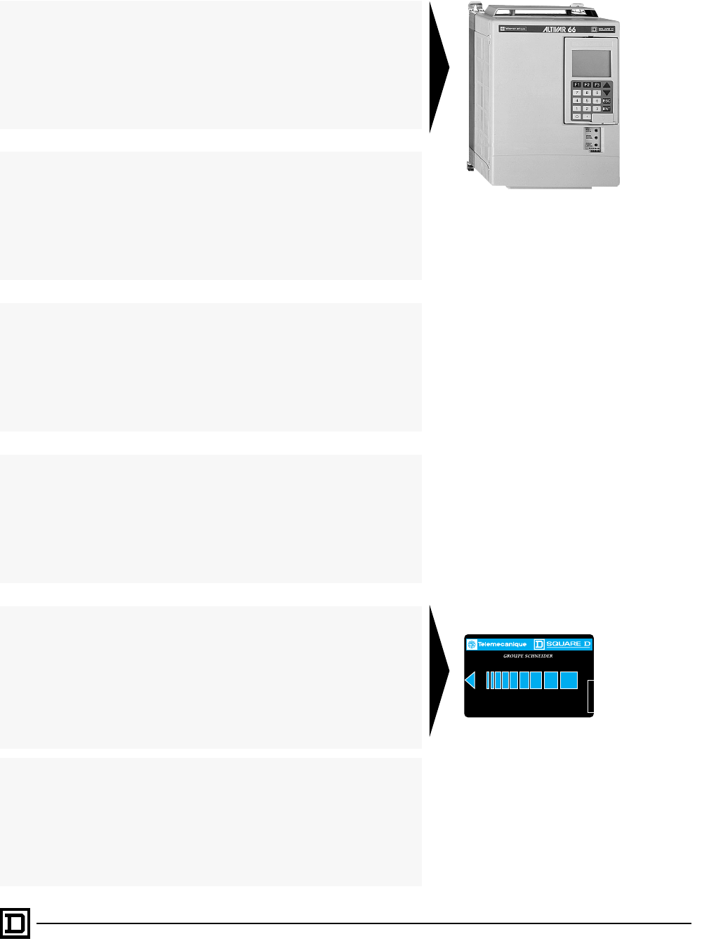
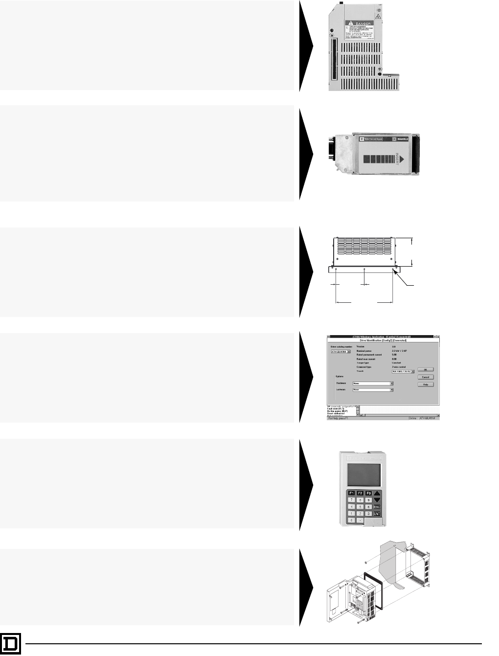
The LCD graphic screen displays graphs and has reverse video for enhancing text or
numerical values on the screen. An access locking switch on back of the keypad and
a software key allow partial or total access to parameters. Adjustments can be saved
on a PCMCIA card (Personal Computer Memory Card International Association) and
subsequently downloaded into other ALTIVAR 66 drives. Three LEDs on front of the
drive indicate status:
•
Red LED illuminated: Drive fault
•
Yellow LED illuminated: Current limit; flashing: Prealarm
•
Green LED illuminated: Drive powered
Memory Card
INSERT
This sensorless flux vector control provides:
•
Exceptional torque performance with a standard motor
•
Rapid dynamic response with digital speed regulation
•
Optimal performance for extruders, specialty machines, and material handling
applications
•
Economic solution for high torque and low speed
The drive provides UL rated electronic motor thermal protection. The drive also pro-
vides:
•
Thermal protection against excessive overheating
•
Protection against input line supply undervoltage and overvoltage
•
Protection against input and output phase loss
This document provided by Barr-Thorp Electric Co., Inc. 800-473-9123 www.barr-thorp.com

ALTIVAR 66 AC Drives
Introduction
© 1998 Square D All Rights Reserved
6
2/98
¬
Options
I/O Extension
Modules
(Pages 35-39)
When the ALTIVAR 66 drive is first powered up, it is ready for use in its standard
configuration for most applications. It is possible to add other functions by using an
optional Input/Output Extension Module.
Dynamic
Braking
(Pages 69-71)
PC Connection
Communication
(Pages 40-45)
Designed to be integrated into modern automated architectures, the ALTIVAR 66
drive can be connected to several different multidrop communication buses.
A braking transistor is integrated into the ALTIVAR 66 drive.
Accessories
The PC Connection option allows the drive to be connected to a personal comput-
er via RS 232C.
The keypad display can be remotely mounted with the use of a Keypad Door
Mounting Kit.
Keypad Door
Mounting Kit
(Page 62)
The heat sink on the drive can be mounted through the enclosure wall.
Recess
Mounting Kits
(Page 62)
This document provided by Barr-Thorp Electric Co., Inc. 800-473-9123 www.barr-thorp.com
ALTIVAR 66 AC Drives
Introduction
7
2/98 © 1998 Square D All Rights Reserved
The I/O Extension Module adds additional logic and analog inputs and outputs. Two
versions are available, for 24 VDC control and for 115 VAC control, allowing the drive
to be adapted to your configuration.
Communication is possible with the most common industrial protocols:
•
UNI-TELWAY
•
MODBUS RTU / ASCII
•
MODBUS Plus
Other interfaces are available through third party offerings.
The addition of an external resistor permits dissipation of excess braking energy,
allowing the drive to function in quadrants 2 and 4 of the speed/torque curve.
152.4
6.00
304.8
12.00
152.4
6.00
6.9
.27 DIA
MTG HOLES
5
.
68
The software provides the following advantages:
•
Prepare a drive configuration without connecting the drive to the computer.
•
Save configurations and adjustments on a floppy or hard disk.
•
Download configuration and adjustments into the drive.
•
Provide a printout of drive configuration for future reference.
The Keypad Door Mounting Kit allows the keypad to be mounted in the enclosure
door. It allows you to view the display and access the keypad.The kit also allows three
LEDs to be mounted in the enclosure door:
•
Red LED illuminated: Drive fault
•
Yellow LED illuminated: Current limit; flashing: Prealarm
•
Green LED illuminated: Drive powered
The Recess Mounting Kit can be used with Type 1 or Type 12 enclosures. Use of these
kits reduces heat dissipated in the enclosure, allowing a smaller enclosure to be used.
This document provided by Barr-Thorp Electric Co., Inc. 800-473-9123 www.barr-thorp.com

ALTIVAR 66 AC Drives
Specifications
© 1998 Square D All Rights Reserved
8
2/98
Environment
Drive Characteristics
Conformance to standards
NEMA, NEC, VDE and IEC
Conforms to ISO 9001 standards
Product certification
UL Listed per UL 508C as incorporating electronic overload protection
ATV66U41N4 to D79N4 UL File E164874
and ATV66U41M2 to D46M2 CCN NMMS
ATV66C10N4 to C31N41 UL File E138755
and ATV66U41M2 to D46M2 CCN NMMS
CSA certified
ATV66U41N4 to D79N4 CSA File LR96921
Class 3211-06
ATV66C10N4 to C31N41 CSA File LR60905
Class 3211-06
Degree of protection
NEMA Type 1 (IP30)
Resistance to vibrations
Conforming to IEC 68-2-6:
• ATV66U41N4 to D46N4 and ATN66U41M2 to D33M2: 1 mm peak to peak
from 5 to 22.3 Hz and 2 g peak from 22.3 to 150 Hz
• ATV66D54N4 to C31N41 and ATV66D46M2: 0.15 mm peak to peak from
10 to 58 Hz and 1 g peak from 58 to 150 Hz
Resistance to shock
Conforming to IEC 68-2-27:
• 15 g peak for 11 ms
Maximum ambient pollution
Pollution degree 3 per NEMA ICS-111A or ICS-1, and IEC 664-1
Maximum relative humidity
95% without condensing or dripping water
Temperature
Storage
°
F (
°
C) -13 to +158 (-25 to +70)
Operation
°
F (
°
C) +32 to +104 (0 to +40)
Maximum altitude
ft (m) ATV66U41N4/M2 through ATV66C19N4
≤
3300 (1000); above this derate by
1.2% for every 300 (100); max. 6600 (2000).
ATV66C23N41 through ATV66C31N41
≤
3300 (1000).
Mounting position
Vertical
Output frequency range
Hz
0.1 to 400 Hz for ATV66U41N4 to D79 drives (constant torque configuration)
0.1 to 200 Hz for ATV66C10N4 to C31N41 drives (constant torque configuration)
0.1 to 75/90 Hz for ATV66U41N4 to C31N41 drives (variable torque
configuration)
0.1 to 400 Hz for ATV66U41M2 to D46M2 drives (constant torque configuration)
0.1 to 75/90 Hz for ATV66U41M2 to D46M2 drives (variable torque configuration)
Speed range
1 to 100 (with constant torque)
Speed regulation
Volts/Hertz control type:
determined by motor slip, 3% typical for NEMA B motor
Normal or high torque (sensorless flux vector) control type:
1.0% without adjustments
0.5% with optional tachometer
Transient overtorque
150% of nominal motor torque (typical value
±
20%) for 60 s (constant torque)
110% of nominal motor torque for 60 s (variable torque)
Maximum transient current
200% of nominal motor current for 0.2 s at starting for constant torque configuration
150% of nominal motor current for 60 s for constant torque configuration
110% of nominal motor current for 60 s for variable torque configuration
Switching Frequency
4 kHz ATV66U41N4 to ATV66D46N4 constant or variable torque rating
10 kHz ATV66U41N4 to ATV66D46N4 variable torque low noise rating
2 kHz ATV66D54N4 to ATV66D79N4 constant or variable torque rating
4 kHz ATV66D54N4 to ATV66D79N4 variable torque low noise rating
2 kHz ATVC10N4 to ATV66C31N4 constant or variable torque rating
Efficiency
94.5% to 97.87% (load dependent)
Displacement power factor
Approximately 0.96
This document provided by Barr-Thorp Electric Co., Inc. 800-473-9123 www.barr-thorp.com

ALTIVAR 66 AC Drives
Specifications
9
2/98 © 1998 Square D All Rights Reserved
Electrical Characteristics
Input
Voltage V 200
±
10%, 230
±
15%
400
±
15%, 460
±
15%
Frequency Hz 47.5 to 63
Output voltage
Maximum output line voltage is equal to input line voltage
Available control voltage
3 outputs: 0 V common for all supplies
1 output: +10 V for the reference potentiometer (1-10 kΩ),10 mA maximum flow
1 output: +24 V for control inputs, 210 mA maximum flow
Analog inputs AI
Speed reference
1 analog voltage input AI1: 0-10 V, impedance 30 kΩ
1 analog current input AI2: 4-20 mA, impedance 250 Ω
AI2 can be modified to 0-5 V with a switch located on the control board or
reprogrammed from the keypad display for 0-20 mA, x-20 mA or 20-4 mA.
Frequency resolution: 0.1 Hz at 60 Hz for analog reference
Response time: 5 to 10 ms. AI1 and AI2 can be summed.
Frequency resolution for
digital reference (serial link) 0.015 Hz at 60 Hz
Logic inputs LI
4 logic inputs. 10 ms sample time.
+24 V at 10 mA (minimum 12 V, maximum 30 V)
State 0 if < 5 V; state 1 if >12 V
Factory preset assignments (LI3 and LI4 can be reassigned from the keypad
display):
LI1 = run enable
LI2 = run forward
LI3 = run reverse
LI4 = jog
Analog outputs AO
2 analog outputs
0-20 mA (4-20 mA programmable) recommended load impedance 250 Ω
Linearity: ± 0.1% maximum current
Accuracy: ± 0.5% full scale
Factory setting (AO1 and AO2 can be reassigned from the keypad display):
AO1 = output frequency
AO2 = output current
Logic outputs LO
2 logic outputs
PLC-compatible, open-collector
+24 V (minimum 12 V, maximum 30 V), maximum 200 mA
Factory preset assignments (LO1 and LO2 can be reassigned from keypad
display):
LO1 = at speed
LO2 = current limit attained
Relay outputs R
2 logic relay outputs
1 N.O. - 1 N.C. (contact protected against overvoltages by a varistor)
Minimum: 10 mA at 24 VDC
Maximum inductive load: 2 A at 120 VAC, 1 A at 220 VAC, 2 A at 24 VDC
Factory setting (R2 can be reassigned from the keypad display):
R1 = drive fault
R2 = drive running
Acceleration and
deceleration ramps
Factory preset to 3 s, linear ramp
Separately adjustable from 0.1 to 999.9 s (0.1 s resolution)
Ramp type: adjustable to linear, “S”, or “U”
Ramp times automatically adjusted in case of overtorque
Braking to standstill Automatic by DC injection for 0.5 s when frequency drops below 1.0 Hz
Amount of current, frequency threshold and injection time are programmable
from the keypad display
Dynamic braking By optional resistor
Drive protection
Protection against short circuits
• Between the output phases
• Between output phases and ground
• On outputs of internal supply
• On the logic and analog outputs
Thermal protection against excessive overheating
Protection against input line supply undervoltage and overvoltage
Protection against phase loss
Motor protection
Incorporated electronic thermal protection by I2t calculation taking speed into
account
Storage of motor thermal state
Phase loss protection
Function programmable from the keypad display
This document provided by Barr-Thorp Electric Co., Inc. 800-473-9123 www.barr-thorp.com
ALTIVAR 66 AC Drives
Features
© 1998 Square D All Rights Reserved
10 2/98
OVERVIEW
The ALTIVAR 66 drive uses the latest in AC drive
technology. The ALTIVAR 66 is a sensorless flux
vector drive. It has a six step diode front-end, and
uses IGBT (insulated gate bi-polar transistors) to
produce a PWM (pulse width modulated) output
waveform to the motor. The product has an input
power factor of near unity, and a typical efficiency
of 96% operating under full load. The ALTIVAR 66
drive is configurable for constant torque or
variable torque applications. In constant torque
mode, an auto-tune feature creates a motor model
to provide superior torque at low speed. The
ALTIVAR 66 drive is capable of providing 100% of
motor rated torque at 0.5 Hz, and 150% of motor
rated torque at 1 Hz. In variable torque mode, the
NOLD (No Load) feature (based on the NOLA
principle) can be enabled to automatically
optimize the volts/hertz pattern for a given load at
a given speed. This increases efficiency of the
system, and reduces audible motor noise. In
addition, the switching frequency is randomly
modulated to prevent a single tone pitch from
developing at the motor. If needed, the variable
torque low noise mode can be selected which
increases the switching frequency to reduce
audible motor noise.
DRIVE OPERATOR INTERFACE
The ALTIVAR 66 drive includes a keypad display
mounted on the front of the drive. The keypad
allows:
• Choice of language
• Drive identification
• Display of parameter values when drive is
running, or of fault type when drive is in fault
condition
• Adjustment and configuration of the drive
• Local command of the drive
Display
Liquid crystal display screen, 128 x 64 dot matrix:
• 6 lines of 21 characters
• Display of parameter values in bar graph form
and configuration information and diagnostics
• Back lit for ease of viewing
• Reverse video for enhancement of text and
numerical values
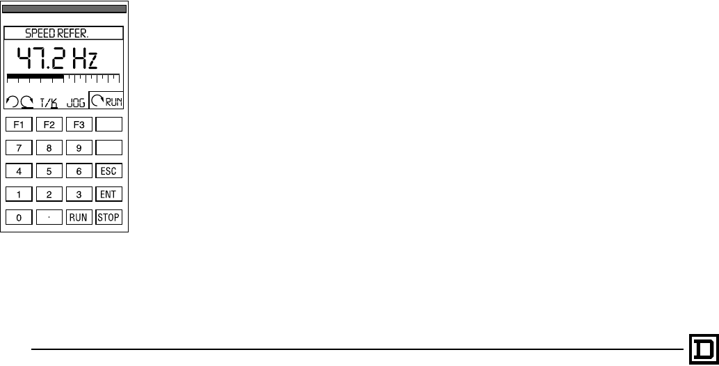
20-Key Keypad
• ENT (Enter) key: Confirms a typed value or
advances to next menu
• ESC (Escape) key: Cancels an adjustment or
returns to previous menu
• 2 direction keys ▲▼: Scroll up and down
through menus, increase or decrease numeric
parameters
• 11 number keys: Use to enter numerical values
(0 to 9) and decimal point
• 3 assignable function keys: F1, F2, and F3 for
programmable functions
• RUN key and STOP key: For local command of
drive. Plastic cover is factory-installed; remove
for access to keys.
Parameters are displayed in plain English, or one
of five other languages, including German, Italian,
Swedish, Spanish and French. There are no
numerical codes.
The function keys are used to jump to a menu (F3)
or display screen (F2), or to show a help screen
(F1). When the keypad is used to run the drive, the
function keys can be set for functions such as
jogging, changing direction, or switching between
terminal strip and keypad command. The “.” key
can be used to enter desired speed.
Hardware and software access locks provide
three levels of access to menus:
• Total Lock
• Partial Unlock
• Total Unlock
Total Lock allows display of analog input and
output and logic input and output status, as well as
fault history. Partial Unlock also gives access to
the drive configuration and parameters adjusted
most often. Total Unlock allows adaptation of the
drive to specific applications, configuration of the
display screen, and local command from the
keypad. When in Total Unlock, the drive can be
tested using the diagnostic mode and the settings
can be saved on a PCMCIA card to be
downloaded into another drive.
The keypad display can be removed and used as
a handheld terminal, using either an optional 3-
meter cable or 2-meter cable. It can also be
mounted in an enclosure door with a keypad door
mounting kit. When mounted in an enclosure with
the keypad door mounting kit, the keypad display
has a Type 12 rating.
▲
▼
This document provided by Barr-Thorp Electric Co., Inc. 800-473-9123 www.barr-thorp.com
ALTIVAR 66 AC Drives
Features
11
2/98 © 1998 Square D All Rights Reserved
START UP ASSISTANCE
The ALTIVAR 66 drives are factory set for:
• Constant torque applications
• 2-wire control
When the drive is powered up in constant torque
configuration, the drive performs an autotune to
maximize motor performance. Direct current
equal to the AC drive rated current is injected into
the motor, allowing the drive to determine the
resistance of the motor and set the motor
parameters.
At first power up, the language menu is displayed.
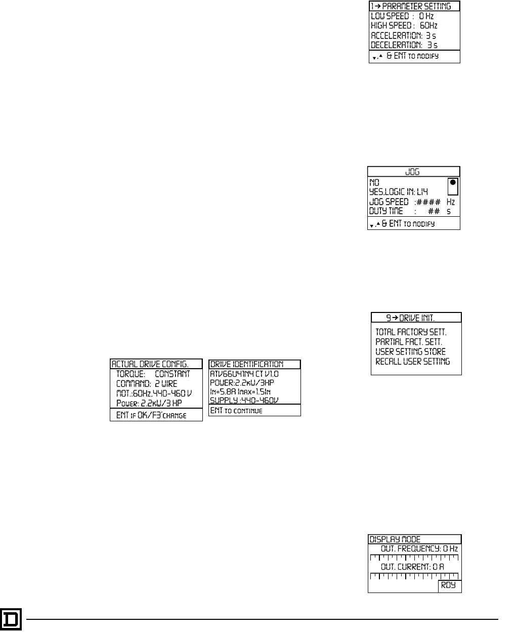
Once the language is selected, the display shows
the actual drive configuration. On subsequent
power ups, the display proceeds directly to the
Drive Identification screen which shows the
nameplate information: drive catalog number,
constant torque or variable torque configuration,
version of software, horsepower, and nominal and
maximum drive current.
Upon first power-up, the AC drive senses the
connected power system frequency. If this value is
50 Hz, Nominal Frequency is set to 50 Hz. If it is
60 Hz, Nominal Frequency is set to 60 Hz.
On 460 V units upon first power-up, if the input line
is 50 Hz, the AC drive is configured for 400 V
Nominal Voltage. If the input line is 60 Hz, the AC
drive is configured for 460 V Nominal Voltage.
On 230 V units upon first power-up, the AC drive
is configured for 230 V for 50 Hz and 60 Hz input
lines.
If the factory settings do not suit your application,
you can change the parameter settings. First
select the torque type: constant torque, variable
torque, or variable torque low noise. Then set the
type of command: 2-wire or 3-wire.
Motor parameters can be entered to match the
motor nameplate information and slip
compensation can be adjusted. Control
parameters such as high and low speeds,
acceleration and deceleration ramp times, ramp
types, selection of alternate ramps, and skip
frequencies can also be adjusted.
See pages 14-22 for drive configuration and
adjustments.
Application functions are built into the drive. The
ALTIVAR 66 drive can be configured for jogging,
+speed/-speed, preset speeds, manual/auto
switching, shutdown (stopping after dwelling at
low speed), and bypass. Logic and analog inputs
and outputs can be assigned to provide the
needed information.
A Drive Initialization menu can be used to return
to factory settings. This menu is also used to save
the configuration and adjustments onto a PCMCIA
card which can be used to download the settings
into other drives of equal horsepower.
ASSISTANCE WHEN RUNNING
The large display screen makes it easy to check
operating values while the drive is running.
Select from three ways to display operating values:
• 1 bar graph for reading the value at a distance
• 2 bar graphs (illustrated below)
• 4 tables in each mode contain a list of 14 operating
values which can be successively displayed by
pressing the arrow keys
This document provided by Barr-Thorp Electric Co., Inc. 800-473-9123 www.barr-thorp.com
ALTIVAR 66 AC Drives
Features
© 1998 Square D All Rights Reserved
12 2/98
The 1 bar graph display is shown below. If keypad
command mode has been selected, the
assignment of the F1-F2-F3 function keys is
shown on the screen, along with a status code
such as RUN, RDY or ACC, indicating drive state.
Choose from 14 display values. Two of these can be
user-defined application measurements such as
number of products per minute in a material handling
application. Other values include: output frequency,
current, voltage, power, line voltage, DC voltage,
motor and drive thermal state, speed reference,
motor torque, PI setpoint, and PI feedback.
MAINTENANCE ASSISTANCE
The ALTIVAR 66 drive has several menus which
aid in maintaining the drive.
The following menus are accessible at all times:
• I/O Map: the assignment of the logic and analog
inputs and outputs as well as their state or value
is shown. This is a very useful diagnostics tool.
• Fault History: this menu allows the display of up
to eight of the most recent faults.
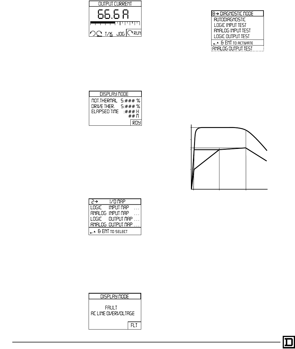
If a fault occurs, the type of fault is displayed in the
chosen language (code words are not used). Drive
status at the time of the fault is also stored, indicating
if the drive was accelerating, decelerating, or in the
ready state when the fault occurred.
The Diagnostic Mode helps to determine the failed
part in case of an internal fault:
• Test of the inputs/outputs with forcing of the
outputs
• Test of the control board
• Test of the power boards and components.
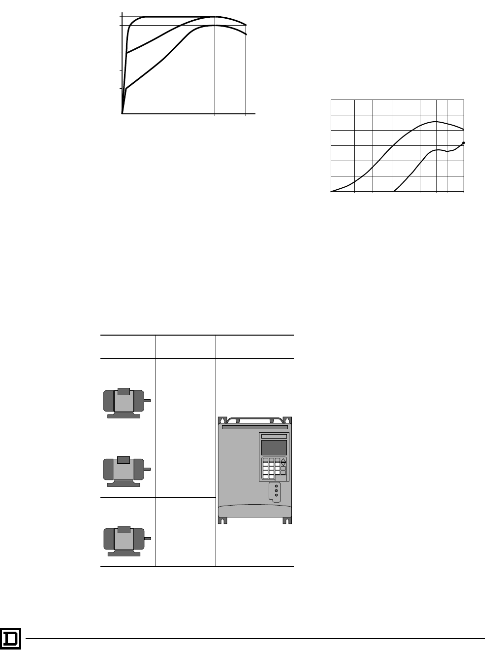
TORQUE CHARACTERISTICS
The curves below illustrate typical continuous
torque and transient overtorque capabilities for a
typical NEMA Design B, 1.0 service factor motor
with constant torque and variable torque loads.
Constant Torque
[1] Derate by 50% below half speed.
NOTE: Before running the drive above 50/60 Hz,
consult motor manufacturer for the overspeed
capability of the motor. For constant torque
operation, nominal and maximum frequency
are adjustable from 25 to 400 Hz for drives
ATV66U41N4 to C13N4, or from 25 to 200 Hz
for drives ATV66C15N4 to C19N4.
1.5
1.2
1
0.5
0.5 Fn Fn f
T/Tn
12
3
0.1 Fn
0.95
1.1
1
T/Tn
3
Variable Torque
0
1 Continuous useful torque: Self-ventilated motor [1]
2 Continuous useful torque: Force-cooled motor
3 Transient overtorque
Fn = nominal frequency (50/60 Hz)
This document provided by Barr-Thorp Electric Co., Inc. 800-473-9123 www.barr-thorp.com
ALTIVAR 66 AC Drives
Features
13
2/98 © 1998 Square D All Rights Reserved
Variable Torque
[1] Derate by 50% below half speed.
MOTOR-DRIVE COMBINATIONS
The drive can be used in constant torque, variable
torque, or variable torque low noise (higher
switching frequency) configuration. When set for
variable torque without increasing the switching
frequency, the drive can be used with a motor one
hp size larger than when it is set for constant
torque. However, when set for variable torque low
noise, the hp rating is the same as for a constant
torque drive. See pages 53-56 for ratings.
SWITCHING FREQUENCY
A high switching frequency allows the drive to
supply the motor with a waveform that reduces
motor noise. The ALTIVAR 66 is one of a few
drives available that randomly modulates the
switching frequency to prevent a single tone pitch
from developing.
The switching frequency is adaptable in variable
torque configuration. Two choices are possible:
variable torque or variable torque low noise. With
variable torque low noise, the drive has a higher
switching frequency.
MOTOR THERMAL
OVERLOAD PROTECTION
The motor thermal overload protection for the
ALTIVAR 66 drives was specifically designed for
self-ventilated motors running at adjustable
speeds. The calculation of I2t as a function of
speed takes into account motor current as well as
the derating necessary because of lack of motor
ventilation at low speed. Motor thermal overload
protection takes into account:
• Operating frequency
• Current absorbed by the motor
• Running time
• Assumed maximum ambient temperature ≤
+104 °F (+40 °C) around the motor
• Motor thermal time constant based on
assumed motor power
Nominal motor current is factory preset at 0.9
times continuous drive output current. Nominal
motor current is adjustable from the keypad
display. The drive is factory set for a self-ventilated
motor; however, it can be set for a force-ventilated
motor from the keypad display.
The motor overload function can replace a
conventional class 10 thermal overload relay for
single motor applications. However, if the ambient
temperature of the motor exceeds +104 °F (+40
°C) or if motors are run in parallel, provide external
thermal overload protection. The drive provides
UL rated electronic motor thermal protection.
1.1
1
0.7
0.5
0.3
0Fn Fmax
T/Tn
f
0.1 Fn
3
2
1
1 Continuous useful torque [1]
2 Transient overtorque
3 Transient overtorque during acceleration
Fn = nominal frequency (50/60 Hz)
Example:
Motor Type of
Configuration Drive
P = 7.5 hp (5.5
kW) Constant Torque
Switching
frequency =
4 kHz ATV66U90N4
P= 7.5 hp (5.5 kW)
P = 10 hp (7.5
kW) Variable Torque
Switching
frequency =
4 kHz
P = 7.5 hp (5.5
kW)Variable Torque
Low Noise
Switching
frequency =
10 kHz
70
50 160
1
2
Noise, db
4030201025
60
Frequency, Hz
3
Audible noise curves generated with a 5 hp, 460 V motor.
1 Variable Torque, switching at 4 kHz
2 Variable Torque, Low Noise, switching at 10 kHz
3 Motor connected directly to input supply.
NOTE: Before
running the drive
above 50/60 Hz,
consult motor
manufacturer for the
overspeed capability
of the motor. For
variable torque
operation, nominal
and maximum
frequency are
adjustable from 25 to
60/72 Hz.
This document provided by Barr-Thorp Electric Co., Inc. 800-473-9123 www.barr-thorp.com
ALTIVAR 66 AC Drives
Drive Configuration and Adjustments
© 1998 Square D All Rights Reserved
14 2/98
TORQUE TYPE
Function
This parameter allows you to customize torque
type for a specific application.
Applications
All constant or variable torque applications with or
without overspeed.
Adjustments
Possible settings are:
• Constant torque
• Variable torque
• Variable torque low noise (not available for
ATV66C10 to ATV66C31 drives)
Vn
f (Hz)
V
fn fmax
1
2
1 Constant torque configuration
2 Variable torque configuration
Vn: Nominal motor voltage
fn: Nominal motor frequency
fmax: Maximum output drive frequency
COMMAND TYPE
Function
Allows you to select between 2-wire or 3-wire
command. The selection affects the operation of
LI1 and the forward (LI2) and reverse (LI3, if
assigned) inputs. Factory setting is 2-wire
command.
2-wire command allows the AC drive to be
restarted without operator intervention after fault
reset or restoration of power provided that a run
command is present. For applications where
automatic restarting may pose a hazard to
personnel, the use of 2-wire command is not
recommended.
3-wire command requires operator intervention
after fault reset or restoration of power to restart
the AC drive.
1
0
1
0
1
0
1
0
LI1
Run
Enable
LI2
Fwd
LI3
Rev
LI4
Jog
- Speed Ref
+ Speed Ref
- Jog Ref
+ Jog Ref
Two Wire Command
1
0
1
0
1
0
1
0
LI1
Run
Enable
LI2
Fwd
LI3
Rev
LI4
Jog
- Speed Ref
+ Speed Ref
- Jog Ref
+ Jog Ref
Three Wire Command
This document provided by Barr-Thorp Electric Co., Inc. 800-473-9123 www.barr-thorp.com
ALTIVAR 66 AC Drives
Drive Configuration and Adjustments
15
2/98 © 1998 Square D All Rights Reserved
CONTROL TYPE:
CONSTANT TORQUE APPLICATIONS
Function
The control type affects the amount of available
motor torque and is set dependent on the type of
motor used and the application. For constant
torque applications, there are 3 choices:
• Normal: A closed loop, current regulated
control for most applications which require
normal torque at low speed
• High torque: A sensorless flux vector control for
machines requiring high torque at low speed
and rapid dynamic response.
• Special: Constant volts/hertz control for motors
in parallel or special motors such as
synchronous permanent magnet motors,
synchronous wound field motors, and
synchronous reluctance motors.
Normal Control Type
Typical maximum overtorque:
ATV66U41N4 to D12N4 & ATV66U41M2 to
D12M2: 150% over 50:1 speed range.
ATV66D16N4 to C31N41 & ATV66D16M2 to
D46M2: 150% over 50:1 speed range.
The Normal control type is the factory setting for
both constant and variable torque configurations.
Normal is a sensorless flux vector control. In order
to create high torque at low speeds, the AC drive
maintains a 90° phase relationship between the
rotor and stator electromagnetic fields by
continuously calculating the position of the rotor in
relation to the electrical position of the stator. It is
generally applicable on asynchronous motors and
provides good torque performance. Because
there are fewer parameters than with the High
Torque control type, the process requires less
tuning. When using Normal control, the motor
horsepower must be equal to or one horsepower
size less than the AC drive horsepower.
When Normal control type is used on a constant
torque configuration, self-tuning is active. When
the AC drive is powered up, a pulse of direct
current equal to drive rated current is injected into
the motor, allowing the AC drive to determine the
resistance of the motor to set the motor
parameters.
High Torque Control Type
Typical maximum overtorque:
ATV66U41N4 to D12N4 & ATV66U41M2 to
D12M2: 150% over 50:1 speed range.
ATV66D16N4 to C31N41 & ATV66D16M2 to
D46M2: 150% over 50:1 speed range.
High Torque control is also sensorless flux vector
control, available when the AC drive is configured
for constant torque. In order to create high torque
at low speeds, the AC drive maintains a 90° phase
relationship between the rotor and stator
electromagnetic fields by continuously calculating
the position of the rotor in relation to the electrical
position of the stator. High Torque provides more
flexible setup and optimization of parameters than
the Normal control type, therefore offering better
torque performance.
When High Torque control type is used, self-tuning
is active. When the AC drive is powered up, a
pulse of direct current equal to motor rated current
is injected into the motor, allowing the AC drive to
determine the resistance of the motor to set the
motor parameters.
1
Vn
f (Hz)
V
fn fmax
1 Zone within which the drive functions depending on the load
and the adjustment of IR Compensation which is used to adjust
low speed torque for optimal performance.
2
Vn
f (Hz)
V
fn fmax
1
1Zone within which the drive functions depending on the
load and the adjustments.
2Adjustment zone for voltage boost.
This document provided by Barr-Thorp Electric Co., Inc. 800-473-9123 www.barr-thorp.com
ALTIVAR 66 AC Drives
Drive Configuration and Adjustments
© 1998 Square D All Rights Reserved
16 2/98
Special Control Type
Typical maximum overtorque:
ATV66U41N4 to C31N41 & ATV66U41M2 to
D46M2: 150% over 10:1 speed range.
The Special control type, available when the AC
drive is configured for constant torque, maintains
a constant volts/frequency ratio throughout the
speed range. For example, if the voltage to the
motor is 460 V at 60 Hz, it will be 230 V at 30 Hz,
functioning as a current limited power supply.
Use Special control when controlling synchronous
permanent magnet motors, synchronous wound-
field motors, and synchronous reluctance motors.
CONTROL TYPE:
VARIABLE TORQUE APPLICATIONS
For variable torque (variable torque or variable
torque low noise configuration) applications, 2
choices are available:
• Normal: A closed loop, current regulated
control for all applications. With this choice the
profile setting may be adjusted. When Profile is
set between 0 and 100, a constant quadratic
volts/hertz ratio is implemented.
• NOLD (No Load): A constant volts/hertz control
which automatically adapts to the load to
minimize power consumption and audible
motor noise.
Normal Control Type
Typical maximum overtorque:
ATV66U41N4 to D12N4 & ATV66U41M2 to
D12M2: 110% over 50:1 speed range.
ATV66D16N4 to C31N41 & ATV66D16M2 to
D46M2: 110% over 50:1 speed range.
Profile Setting
Typical maximum overtorque:
ATV66U41N4 to C31N41 & ATV66U41M2 to
D46M2: 110% over 10:1 speed range.
NOLD Control Type
NOLD control is only available when the AC drive
is configured for variable torque. This function
maintains a constant volts/frequency ratio during
acceleration. Once the motor speed is stable,
however, voltage to the motor is automatically
reduced as a function of load. At reduced load, the
motor voltage is minimized, even at motor base
speed. This reduces audible motor noise without
reducing motor RPM. NOLD control should not be
used with motors in parallel.
2
Vn
f (Hz)
V
fn fmax
1
1Zone within which the drive functions depending on the
load and the adjustments.
2Adjustment zone for voltage boost.
Vn
f (Hz)
V
fn fmax
100
0
Vn
f (Hz)
V
fn fmax
1
1 Zone within which the drive functions when Profile is set
between 0 and 100.
Shaded area denotes zone within which the drive functions
when NOLD is configured.
Vn
f (Hz)
V
fn fmax
Load
This document provided by Barr-Thorp Electric Co., Inc. 800-473-9123 www.barr-thorp.com
ALTIVAR 66 AC Drives
Drive Configuration and Adjustments
17
2/98 © 1998 Square D All Rights Reserved
MAXIMUM FREQUENCY
Function
Maximum Frequency clamps the High Speed
setting.
Applications
All applications.
Adjustments
Adjustable ranges for Maximum Frequency are:
• Constant torque:
ATV66U41 to ATV66D79: Nominal Frequency
to 400 Hz
ATV66C10 to ATV66C31: Nominal Frequency
to 200 Hz
• Variable torque: Nominal Frequency to 90 Hz
Factory setting is 60 Hz if the input line frequency
is 50 Hz, or 72 Hz for an input line frequency of 60
Hz.
LOW SPEED AND HIGH SPEED
Function
The two frequency limits define the speed range
permitted under operating conditions.
Applications
All applications with or without overspeed.
Adjustments
Low Speed is adjustable from 0 to High Speed,
factory set to 0 Hz. High Speed is adjustable from
Low Speed to Maximum Frequency, factory set to
50 Hz if input frequency is 50 Hz, or 60 Hz if input
frequency is 60 Hz.
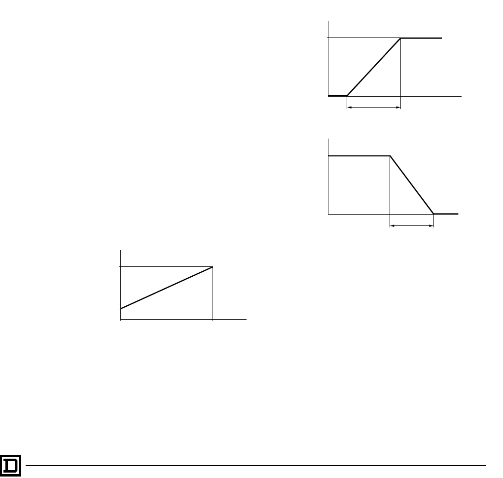
ACCELERATION AND
DECELERATION RAMP TIMES
Function
Determines the acceleration and deceleration
ramp times, set depending on the application and
the torque requirements of the machine. In the
case of overcurrent, the ramps will be extended to
accelerate or decelerate the connected load as
quickly as possible without causing a nuisance trip.
Deceleration ramp modification is disabled if the
dynamic braking option is installed.
Applications
All applications.
Adjustments
Acceleration and Deceleration times are
adjustable between 0.1 and 999.9 seconds, with
factory settings of 3 seconds.
10 V
HSP
f (Hz)
0 V
LSP
Reference
0 mA
4 mA 20 mA
20 mA
20 mA 4 mA
LSP: Low speed
HSP: High speed
fn
f (Hz)
t
t1
fn
f (Hz)
t
t1
Acceleration
Deceleration
This document provided by Barr-Thorp Electric Co., Inc. 800-473-9123 www.barr-thorp.com
ALTIVAR 66 AC Drives
Drive Configuration and Adjustments
© 1998 Square D All Rights Reserved
18 2/98
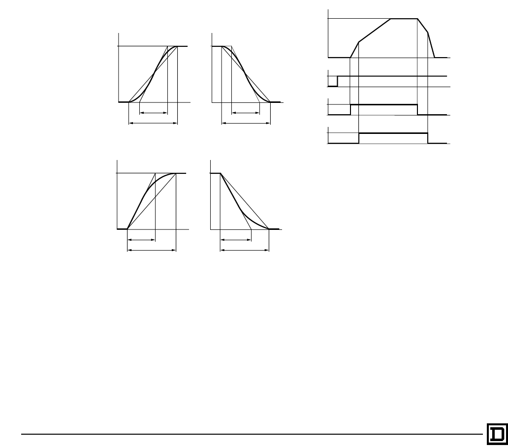
TYPE OF ACCELERATION
AND DECELERATION RAMPS
Function
These parameters determine the type of
acceleration and deceleration ramps the drive will
follow when a Run or Stop command is issued.
Applications
• Material handling and packaging: Use of “S”
ramp allows compensation for mechanical play
and the suppression of shocks. The “S” ramp
also allows the drive to follow the reference
during fast transient conditions in the case of
high inertia.
• Pumping (installation with centrifugal pump
and check valve): The use of the “U” ramp
improves control over closing of gravity
operated valves.
Adjustments
The acceleration and deceleration ramps can be
independently defined as linear (factory setting),
“S”, or “U”. A rounding factor adjusts the degree of
curvature of the ramp profile. Total ramp time (t1)
remains unchanged. If Alternate Ramps is
selected, all ramps will be linear.
ALTERNATE RAMPS
Function
This parameter allows switching between 2
acceleration and deceleration ramp times,
separately adjustable. When the Alternate Ramps
are used, all ramps are automatically linear. The
switch to the alternate ramp is made with a logic
input or at a defined frequency threshold.
Applications
• Material handling applications which require
smooth starting and stopping.
• High speed spindles with acceleration and
deceleration limits above certain speeds.
Example of ramp switching with LI4 input
configured for alternate ramp: Ll1 = enable,
Ll2 = start/stop
Adjustments
Both Acceleration 2 and Deceleration 2 are
adjustable between 0.1 and 999.9 seconds.
Factory setting for both is 5 seconds.
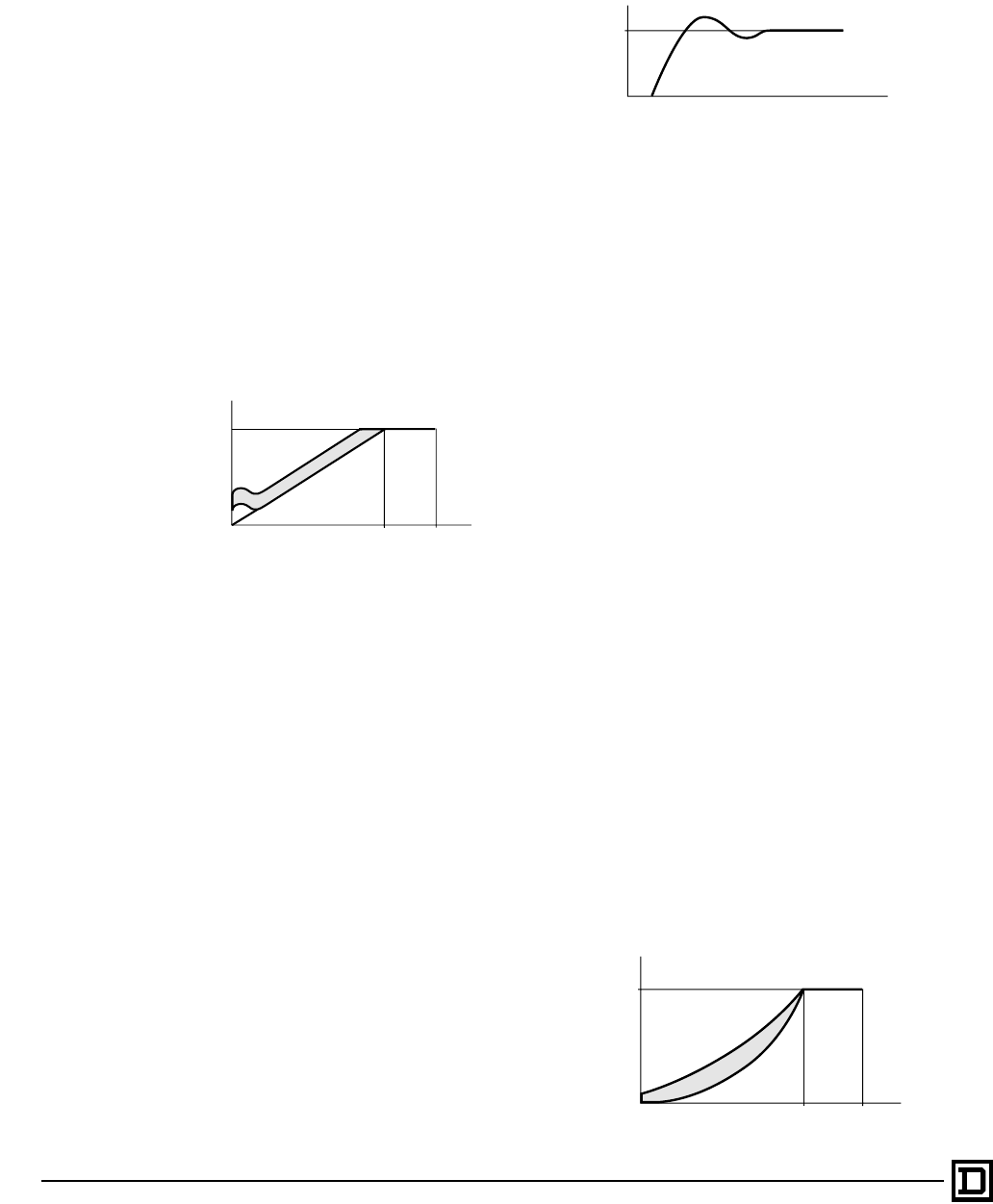
SKIP FREQUENCIES
Function
This parameter allows suppression of 1, 2, or 3
critical frequency bands to prevent mechanical
resonance in the equipment connected to the
motor. Each skip point (frequency) selected has a
hysteresis of 2 or 5 Hz (selectable) for each skip
frequency. The three skip points may overlap each
other.
fn
f (Hz)
t
t1
t2
fn
f (Hz)
t
t1
t2
S Ramp
fn
f (Hz)
t
t1
t2
fn
f (Hz)
t
1t
t2
U Ramp
t
t
t
LI1 0
1
fn
f (Hz)
LI2 0
1
LI4 0
1
t
ACC1
ACC2 DEC2
DEC1
ACC1: Acceleration ramp 1
ACC2: Acceleration ramp 2
DEC1: Deceleration ramp 1
DEC2: Deceleration ramp 2
This document provided by Barr-Thorp Electric Co., Inc. 800-473-9123 www.barr-thorp.com

ALTIVAR 66 AC Drives
Drive Configuration and Adjustments
19
2/98 © 1998 Square D All Rights Reserved
Applications
• Constant torque configuration: Machines with
light structure, unbalanced conveyors, handling
loose products.
• Variable torque configuration: Fans and
centrifugal pumps, in cooling towers and other
equipment with light structure.
Adjustments
• 0 Hz to 400 Hz (ATV66U41 to ATV66D79,
constant torque)
• 0 Hz to 200 Hz (ATV66C10 to ATV66C31,
constant torque)
• 0 Hz to 90 Hz (variable torque)
SLIP COMPENSATION
Function
Maintains a constant motor speed for a given
reference as the load changes, automatically
correcting the frequency. Normally, the factory
setting of automatic compensation is acceptable
for most applications.
Applications
Constant torque applications requiring a higher
degree of speed regulation.
For variable torque configuration, slip
compensation is inhibited.
For constant torque configuration, choose among
3 modes of slip compensation
Adjustments
• No slip compensation: For applications such as
high inertia machines and synchronous
reluctance motors.
• Automatic: For standard applications. The
amount of frequency added to the output is
dependent on the reference frequency.
• Manual: For applications such as a motor with
very low slip. A constant value entered by the
user is scaled according to motor load and is
added to the output frequency throughout the
speed range. Adjustable from 0.1 to 10 Hz,
factory set to 3 Hz.
IR COMPENSATION
Function
IR Compensation is used to adjust low speed
torque for optimal performance. IR Compensation
attempts to adjust or compensate for the resistive
voltage drops of the motor stator windings and the
conductors connecting the motor to the AC drive.
This ensures good torque performance
throughout the speed range of the AC drive.
Applications
IR compensation is only available for constant
torque applications.
Adjustments
• 0 to 100% for Normal control type, factory
preset at 100%
• 0 to 150% for High Torque control type, factory
preset at 100%
• 0 to 800% for Special control type, factory
preset at 100%
Normally the factory setting is adequate for most
applications.
f (Hz)
f3
f2
f1
Reference
This document provided by Barr-Thorp Electric Co., Inc. 800-473-9123 www.barr-thorp.com
ALTIVAR 66 AC Drives
Drive Configuration and Adjustments
© 1998 Square D All Rights Reserved
20 2/98
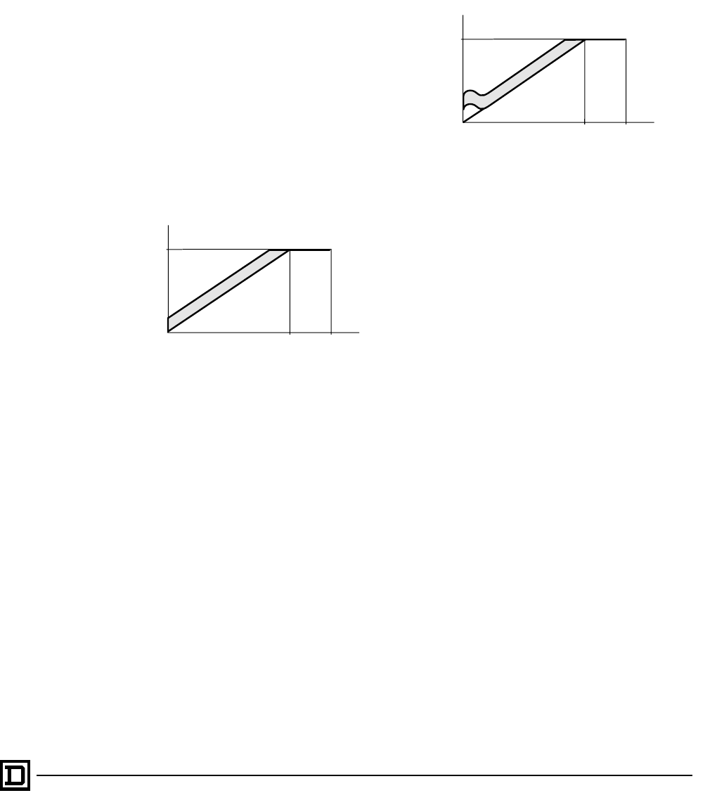
VOLTAGE BOOST
Function
Voltage Boost allows for optimal voltage and
torque boost during starting.
Applications
Voltage Boost is available when the AC drive is
configured for constant torque, with High Torque
and Special control types.
Adjustments
Voltage Boost can be set between 0 and 100% of
nominal voltage. Factory setting is 20%. Normally,
the factory setting of Voltage Boost is adequate for
most applications. For loads which require
moderate to high break-away torque to achieve
initial rotation, adjustment of Voltage Boost may
be required.
DAMPING
Function
Damping adapts the drive to different machine
torque demands by adjusting the integral gain of
the frequency loop to match the inertial response
of the load to the frequency response of the drive.
This gives optimal performance during transient
conditions. In constant torque configuration with
high torque control, a second frequency loop gain
adjustment is accessible to optimize dynamic
performance (see Bandwidth on page 21). It
increases speed response, causing the drive to
react faster to a change in speed or a load impact.
Applications
All constant or variable torque applications with or
without overspeed.
Example: A reduction of gain is used for
overspeed when in transient conditions.
Adjustments
• 1 to 100% for Normal and High Torque control
with constant torque configuration.
• 1 to 100% for NOLD control with variable
torque configuration
• 1 to 800% for Special control with constant
torque configuration
• 1 to 800% for Normal control with variable
torque configuration
Normally the factory setting is adequate for most
applications.
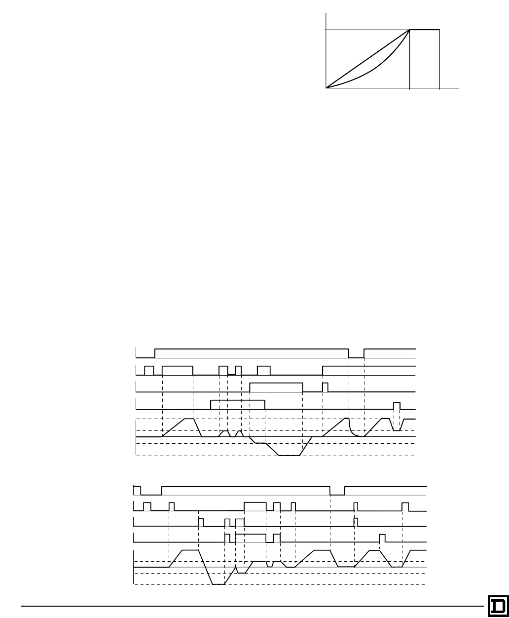
PROFILE
Function
This parameter shapes the V/Hz profile of the output.
Applications
Profile is used when the AC drive is configured for
variable torque, with Normal control type.
Adjustments
Profile can be set to a value between 0 and 100,
factory preset to 20. During changes in speed
command, the V/Hz profile becomes linear,
intersecting the Vn and fn points (see figure
below). As a result, there is no reduction in
available motor torque during speed changes.
2
Vn
f (Hz)
V
fn fmax
1
1 Zone within which the AC drive functions
depending on the load and adjustments (IR
Compensation)
2Adjustment zone for voltage boost
N
t
An increase in gain is used for machines with fast cycles and
low inertia.
A reduction in gain is used for machines with high resistant
torque or high inertia.
100
0
Vn
f (Hz)
V
fn fmax
1
Shaded area denotes zone within which drive functions
when Profile is set between 0 and 100.
This document provided by Barr-Thorp Electric Co., Inc. 800-473-9123 www.barr-thorp.com

ALTIVAR 66 AC Drives
Drive Configuration and Adjustments
21
2/98 © 1998 Square D All Rights Reserved
BANDWIDTH
Function
Bandwidth is a second frequency loop gain
available with Damping. Bandwidth increases
speed response, causing the AC drive to react
faster to a change in speed or a load impact.
Applications
Bandwidth is available for constant torque
applications with High Torque control type.
Adjustments
Bandwidth can be set to a value between 0 and
100%. Factory setting is 20%. For most applications,
no adjustment of Bandwidth should be required. For
applications where motor speed or load changes
occur rapidly, the Bandwidth setting can be adjusted
to optimize the AC drive response to these changes.
Increasing the Bandwidth setting allows the AC drive
to respond to rapid variations in speed or load.
Decreasing the Bandwidth setting lessens the AC
drive’s ability to respond. If set too high for a given
application, the AC drive output frequency can
exhibit instability or excessive sensitivity to load
disturbances at the commanded speed.
NOMINAL CURRENT
Function
Nominal Current is the motor nameplate value for
full load current.
Applications
All applications.
Adjustments
Adjustable from 45% to 105% of the AC drive’s
current rating, factory preset to 90%. Set Nominal
Current to equal the motor full load current. The
Nominal Current parameter does not affect the
maximum current that the AC drive can produce,
i.e. Current Limit. However, changing the Nominal
Current parameter can change the value of motor
overload current. Check and adjust, if necessary,
the value of motor overload if nominal current is
changed.
NOMINAL FREQUENCY
Function
Nominal Frequency corresponds to the point on
the V/Hz curve beyond which voltage remains
virtually constant and only frequency increases.
Nominal Frequency often corresponds to the base
frequency of the motor, which is usually the same
as the line frequency of the connected power
system. With special motors or applications,
Nominal Frequency may be different than the
connected power system line frequency.
Applications
All applications.
Adjustments
Upon first power-up, the AC drive senses the
connected power system frequency. If this value is
50 Hz, Nominal Frequency is set to 50 Hz. If it is
60 Hz, Nominal Frequency is set to 60 Hz. For
special motors and/or applications, select Special
and enter a value between 25 and 400 Hz
(ATV66U41 to ATV66C13, constant torque); 25
and 200 Hz (ATV66C15 to ATV66C31, constant
torque); or 25 and 90 Hz (variable torque).
NOMINAL VOLTAGE
Function
Nominal Voltage corresponds to the point on the
V/Hz curve beyond which voltage remains
virtually constant and only frequency increases.
Nominal Voltage is used with Nominal Frequency
to determine the V/Hz baseline. Nominal Voltage
often corresponds to the base voltage of the
motor, which is usually the same as the line
voltage of the connected power system. With
special motors or applications, Nominal Voltage
may be different than the connected power
system line voltage.
Applications
All applications.
Adjustments
On 400/460 V units, select the value of the motor
supply voltage from the following: 380-400-415-
440-460. Upon first power-up, if the input line is 50
Hz, the AC drive is configured for 400 V Nominal
Voltage. If the input line is 60 Hz, the AC drive is
configured for 460 V Nominal Voltage.
On 208/230 V units, select the value of the motor
supply voltage from the following: 208-220-230-
240. Upon first power-up, the AC drive is
configured for 230 V for 50 Hz and 60 Hz input
lines.
This document provided by Barr-Thorp Electric Co., Inc. 800-473-9123 www.barr-thorp.com

ALTIVAR 66 AC Drives
Drive Configuration and Adjustments
© 1998 Square D All Rights Reserved
22 2/98
ROTATION NORMALIZATION
Function
This parameter allows motor rotation direction to
be inverted (from ABC to ACB) so that the motor
shaft rotation agrees with the forward and reverse
logic inputs. No power wiring has to be changed to
correct rotation.
Applications
All applications.
TORQUE LIMIT MOTOR
AND TORQUE LIMIT GENERATOR
Function
These two parameters allow the limitation of
torque, independent of current limit, with separate
adjustment for the motor and generator (AC drive
with dynamic braking) quadrants. When using
generator torque limit, the overspeed function is
active. If the action of the generator torque limit
causes the actual motor frequency to be greater
than the desired motor frequency by ≈10 Hz, then
an overspeed trip will occur.
• By analog input: a 0-20 mA, 4-20 mA, or 20-4
mA input can be used as a drive torque
reference for simple motor torque control.
• By logic input: when the assigned logic input is
low, the torque limit value is the default setting.
When the logic input is high, the torque limit
value is the user-programmed value.
Applications
Applications where it is desirable to limit torque
output of the motor. Torque limit is only available in
constant torque control types.
Adjustments
Both parameters can be set to a value between 0
and 200% of nominal motor torque, factory preset
at 200%.
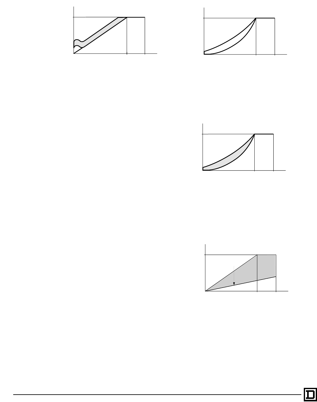
CURRENT LIMIT
Function
This parameter limits maximum drive current to an
adjustable level. Reduction is possible by three
methods:
• By frequency level: Current Limit is at reduced
level when drive exceeds a programmed
frequency.
• By analog input: a 0-20 mA, 4-20 mA, or 20-4
mA input can be used as a drive current
reference for simple motor torque control.
• By logic input: when the assigned logic input is
low, the current limit value is the default setting.
When the logic input is high, the current limit
value is the user-programmed value.
Applications
Constant torque:
• Machines which may frequently jam such as
conveyors, grinders, extruders
• Torque regulation or simple tension-controlled
applications
• Cut to length with stopping and holding against
a mechanical stop
• Constant torque or variable torque: When a
motor is used that has a power less than that of
the drive (in this case, set the activation method
to frequency level and set the frequency
threshold at zero).
Example:
Adjustments
Current Limit can be set to a value between 40
and 150% of AC drive output current for constant
torque applications, or from 40 to 110% of AC
drive output current for variable torque
configurations. Default values are:
• Constant torque: 150% of output current for
input frequency of 60 Hz, 136% for input
frequency of 50 Hz
• Variable torque: 110% of output current
Normal Current Limit
Reduced Current Limit
Threshold
LIx Input
Current Limit
AIx Input
Motor Frequency
Frequency Threshold
or
Logic Input activation
This document provided by Barr-Thorp Electric Co., Inc. 800-473-9123 www.barr-thorp.com
ALTIVAR 66 AC Drives
Motor Thermal Overload Protection
23
2/98 © 1998 Square D All Rights Reserved
BRAKE SEQUENCE
Function
Brake control sequencing is generated by the
drive in constant torque configuration to activate
and coordinate mechanical brake actuation. It
allows the sequencing of AC drive output,
mechanical brake actuation, and DC injection for
smooth starting and stopping.
Applications
• Material handling machines equipped with fail-
safe brakes, such as hoisting machines.
• Machines which need a holding brake, such as
an unbalanced machine.
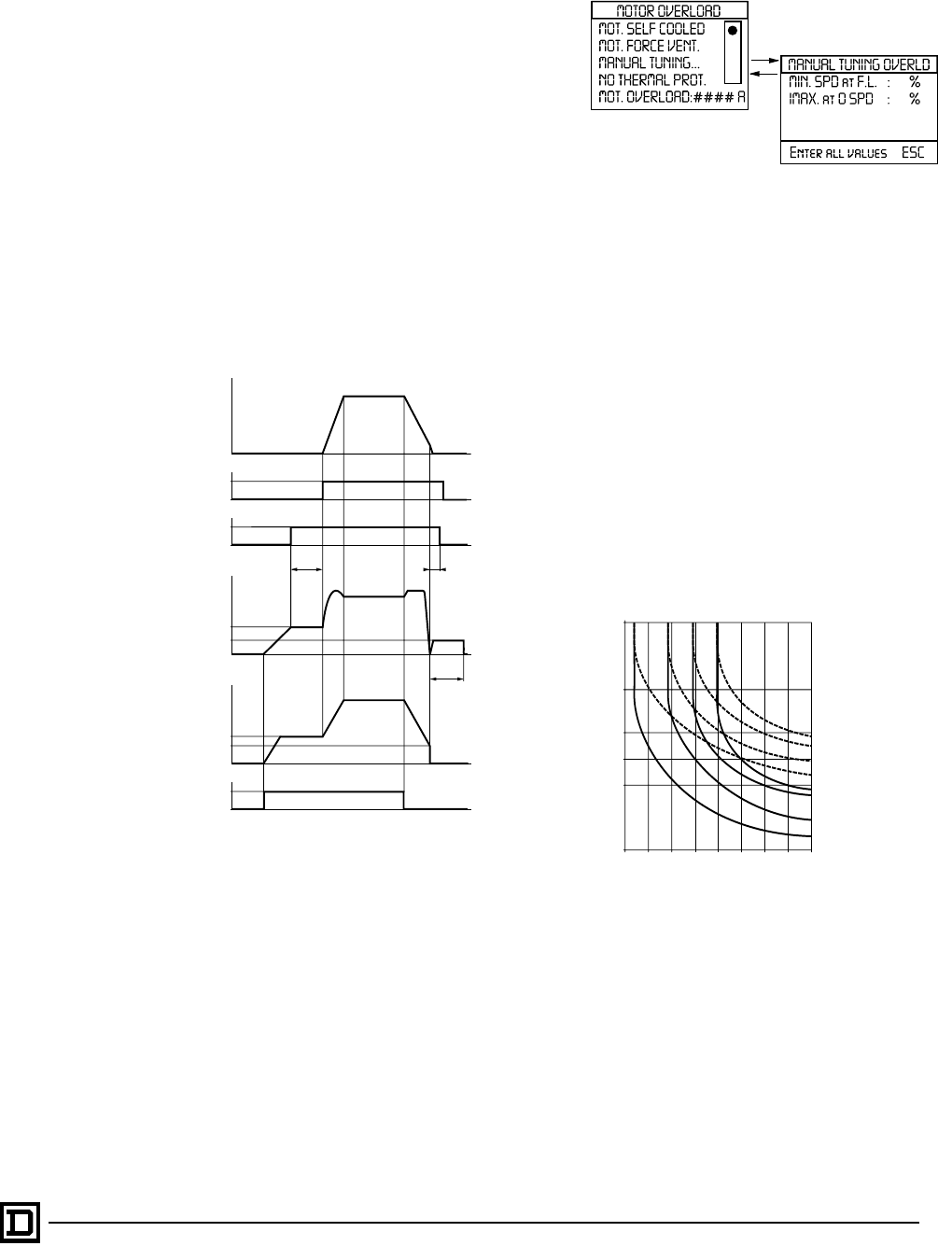
MOTOR THERMAL
OVERLOAD PROTECTION
Function
The ALTIVAR 66 drives provide indirect motor
thermal protection by continuously calculating the
theoretical thermal state of the motor. The drive will
trip if this state reaches 109% of nominal current.
Motor Overload enables the AC drive to protect a
standard asynchronous induction motor from
overload. This function can replace a conventional
class 10 thermal overload relay for single motor
applications; however, multi-motor applications
require individual external thermal overload motor
protection.
This function is effective in protecting a motor
operated from the ALTIVAR 66 drive because it
considers motor speed as well as time and current in
its protection algorithm. This is important since most
motors applied on AC drives are self-cooled, and
their cooling effectiveness declines at lower speeds.
This protection algorithm integrates motor current
over time, taking into account factors such as stop
time and idle time.
Applications
All applications with self-ventilated motor.
Types of Protection
Self-Cooled Motor
With this type of motor overload protection, the
motor base frequency is assumed to be the same
as the nominal rated frequency. Enter the motor
full load amps for Motor Overload current value.
1
0
1
R2 0
1
Ll2 0
I
N
t
t
t
t
t
t
t2
tdc
fr
t1
fe
Idc
Ir
t1: Adjustable brake release time
t2: Adjustable delay following the stop
tdc: DC injection time
Ir: Brake release current threshold
Idc: DC injection current level
fr: Frequency for releasing the brake
fe: Frequency for engaging the brake
ESC
ENT
The microprocessor calculates
the theoretical thermal state of
the motor from:
• Operating frequency
• Current absorbed by the
motor
• Running time
• Assumed maximum
ambient temperature of 40° C
around the motor.
• Motor thermal time
constant based on assumed
motor power
0.7
t6
524
20 36
30 60
50
0.8 0.9 1 1.1 1.2 1.3 1.4 1.5
1 h
10 min
4 min
2 min
1 min
10 s
cold
hot
I/In
Hz
Hz
Constant torque
configuration: See
thermal protection
trip curves at left.
Variable torque
configuration: Use
the same curves
but overload is
limited to I/In = 1.1.
This document provided by Barr-Thorp Electric Co., Inc. 800-473-9123 www.barr-thorp.com

ALTIVAR 66 AC Drives
Display and Keypad Configuration
© 1998 Square D All Rights Reserved
24 2/98
The overload time–current characteristic is set to
allow operation at motor rated current above 50%
of motor base speed. Below 50% of motor base
speed, the time-current characteristic is linearly
tapered so that at zero speed, the drive will trip on
overload at continuous operation above 25% of
the motor overload setting.
The I2t curve, which is used to determine when to
trip on a motor overheat condition, emulates a
class 10 thermal overload curve if nominal rated
frequency is 60 Hz. If nominal rated frequency is
50 Hz, it emulates the European standard curve.
Force-Ventilated Motor
This type of motor overload protection is the same
as that for a Self-Cooled Motor except that the
overload time-current characteristic is set to allow
operation at motor rated current throughout the
speed range. The drive will trip on overload if the
motor current exceeds the set level.
Manual Tuning
Manual Tuning works in the same way as the Self-
Cooled Motor except that minimum speed at full load
(MIN. SPD at F.L.) and maximum current at zero
speed (IMAX at 0 SPD) are both programmable, as
is the Motor Overload Current value.
No Thermal Protection
External thermal overload relays are required when
more than one motor is connected to the output or
when the motor connected to the AC drive is less
than half the AC drive rating, or with a permanent
magnet or wound field synchronous motor. When
external overload protection is provided, select “No
Thermal Protection”.
NOTE: When “No Thermal Protection” is selected
for the ATV66C23 to ATV66C31 AC drives, the
thermal protection is set to a level which limits the
maximum continuous current to prevent AC drive
damage.
Adjustments
Motor Overload Current is adjustable from 0.45 to
1.15 times nominal drive current, factory preset to
0.9 times nominal drive current.
DISPLAY CONFIGURATION
The keypad display can be configured to show:
• One parameter displayed in bar graph form
(factory setting)
• Two parameters displayed in bar graph form
• Four parameters displayed in tables
When the drive is running, the possible display
parameters are:
• Drive parameters: Frequency reference, output
frequency, output current, output power, output
voltage, input voltage, DC bus voltage, drive
thermal state, and elapsed run time
• Motor parameters: Motor torque, motor thermal
state, and motor speed
• User-defined parameters: Machine reference
and machine speed, set according to the
application by entering a scale factor and a
definition of units
When the drive is running and the keypad display
is configured for one bar graph, you can
successively display the other parameters by
scrolling with the ▲ and ▼ keys. If the keypad
display is configured for two bar graphs and you
scroll with the ▲ and ▼ keys, the first bar graph
remains fixed, while other parameters are
displayed successively on the second bar graph.
If the keypad display is configured for four
parameters, you can successively display the
other parameters by scrolling with the ▲ and ▼
keys.
KEYPAD CONFIGURATION
The keypad configuration menu allows:
Selection of Command Mode
• Terminal command: Command of the drive
from the terminal strip inputs
• Keypad command: Local command of the drive
by the keypad Run and Stop keys. In this
command mode, it is not necessary to wire the
analog and logic input terminals, except for LI1
to +24VDC.
• Switching between Terminal and Keypad
command:
- By a logic input (LI3 or LI4) reassigned to this
function or
- By using the F2 function key (not reassignable
in this case)
Programming the Function Keys
The three function keys can be assigned to
several different functions along with Terminal/
Keypad Switching. Possible assignments are:
• Direction: Forward or reverse direction
• Jog
• Fault Reset: Allows the drive to be reset after
certain faults if the cause of the fault has
disappeared.
This document provided by Barr-Thorp Electric Co., Inc. 800-473-9123 www.barr-thorp.com
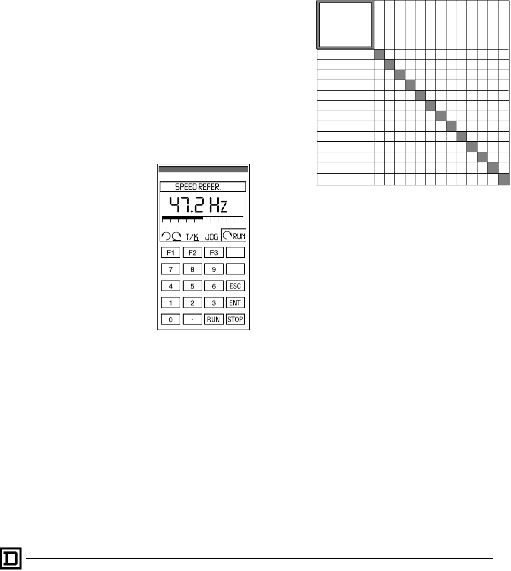
ALTIVAR 66 AC Drives
Application Functions
25
2/98 © 1998 Square D All Rights Reserved
• Scroll: Allows the successive display of values
when the drive is running.
• Preset Speeds 1 and 2: Running at Preset
Speed 1 or 2.
Use of Keypad Command
• When the drive is running, the codes for the
assignments of F1-F2-F3 are displayed on the
bottom line of the screen.
• The commands are activated by momentarily
pressing the function key, except in the case of
Jog and Scroll which are only active as long as
the function key is held.
• The Run and Stop keys are used to start and
stop the motor.
•▲ increases reference frequency, ▼ decreases
reference frequency; or reference frequency
can be entered by pressing decimal point key,
entering frequency and pressing the ENT key.
• Direction can be changed with an assigned
function key. If no function key is assigned to
direction, the direction is forward.
• A plastic cover is factory installed over the Run
and Stop keys. It can be removed to access the
Run and Stop keys and reinstalled.
APPLICATION FUNCTIONS
The ALTIVAR 66 drive incorporates application
functions so that a portion of the external control
typically found in drive systems can be eliminated.
Application functions use the drive logic inputs
and outputs.
The drive contains four logic inputs LI1, LI2, LI3
and LI4, two of which can be reassigned (LI3 and
LI4). LI3 is factory set for reverse direction and
therefore can be reassigned for applications
which only require running in one direction. LI4 is
factory set for Jog.
Choice of application functions is limited by:
• The number of reassignable logic inputs on the
drive. If necessary, an I/O Extension Module can
be used to increase the number of inputs
(catalog number VW3A66201T or
VW3A66202T, see page 35).
• The incompatibility between certain functions.
RUN REVERSE
Function
Requires one logic input. The drive runs in reverse
when the assigned logic input is high. The input is
a maintained signal if 2-wire control is selected, or
edge-triggered with 3-wire control. Logic input LI3
is factory preset for this function. If the application
has only one direction of rotation, input LI3 can be
reassigned to another function.
Applications
All applications with two directions of rotation.
JOG
Function
Jog requires one logic input. The drive runs at the
programmed jog speed as long as the assigned
logic input is high. Time between jog pulses is
determined by the programmed duty time. Logic
input LI4 is factory preset for this function. An
output can be assigned to indicate that the drive is
jogging.
▲
▼
RUN REVERSE
JOG
+ / – SPEED
SETPOINT MEMORY
PRESET SPEEDS
SPEED REFERNCE
AUTO / MANUAL
CONTROLLED STOP
SHUTDOWN
BYPASS
BRAKE SEQUENCE
MOT. SELECT SWITCH
PI REGULATOR
●
●
●
●
●
●
●
●●
●
●
●
RUN REVERSE
JOG
+ / – SPEED
SETPOINT MEMORY
PRESET SPEEDS
SPEED REFERENCE
AUTO / MANUAL
CONTROLLED STOP
SHUTDOWN
BYPASS
BRAKE SEQUENCE
MOT. SELECT SWITCH
PI REGULATOR
●
●
[1]
[1]
●●●●
●
●●● ●
●●
●●
●
●
●
●
●
●
●
●
●
●
●
●
●
[1] Shutdown is incompatible with Controlled Stop by Frequency Threshold
and Controlled Stop by Frequency Threshold/Logic Input.
Read up and across from
the ● to identify pairs of
incompatible functions.
Incompatibilities due to
the number of
I/O available for
reassignment are not
shown.
This document provided by Barr-Thorp Electric Co., Inc. 800-473-9123 www.barr-thorp.com
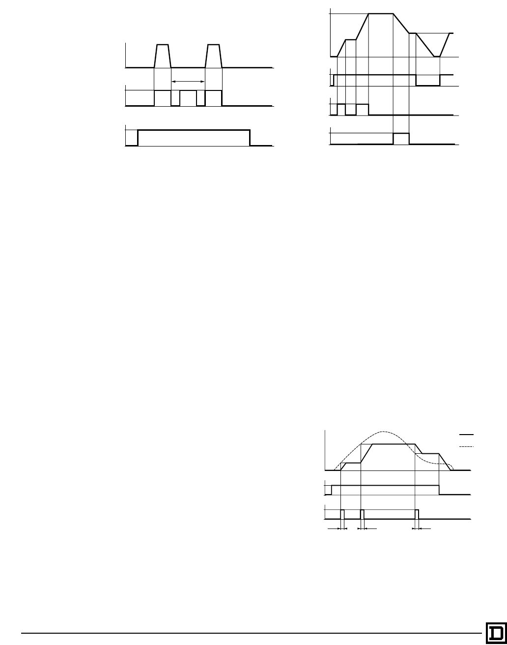
ALTIVAR 66 AC Drives
Application Functions
© 1998 Square D All Rights Reserved
26 2/98
Applications
All machines which require a slight move during
start up, positioning, threading, or maintenance.
Adjustments
Jog speed is adjustable from 0.2 to 10 Hz, factory
preset to 5 Hz. Duty Cycle is adjustable from 0.2
to 10 seconds, factory preset to 0.5 seconds.
+SPEED/-SPEED
Function
This function requires two logic inputs. When the
logic input assigned to +Speed is high, output
frequency is increased. When the input assigned
to -Speed is high, output frequency is decreased.
The function can be used with or without storing
the last reference. In this mode, if the drive is
stopped and then started again, it accelerates to
its last speed. This function is similar to a
motorized potentiometer.
Applications
• Speed command of a drive from several
pushbutton operating stations.
• Logic command of several drives requiring
coordinated speed changes.
Example with storing of last reference:
SETPOINT MEMORY
Function
Setpoint memory allows the speed of several
drives to be controlled by one analog reference
and a logic input for each drive.
This function requires one logic input. If the assigned
logic input goes high for longer than 0.1 seconds, the
drive will store the analog reference at that time and
run at that frequency. This frequency is maintained
until the next logic input pulse, the removal of the
direction input (2-wire command), or removal of the
run enable input.
Applications
• Slow process sectional line with several drives.
• Conveyor systems.
1
LI4 0
1
LI2 0
f (Hz)
t
t
t
tm
LI2: Forward direction
LI4: Jog
LI2: Forward Direction
LI3: + Speed
LI4: - Speed
f (Hz)
t
t
1
LI2 0
t
t
1
LI3 0
1
LI4 0
f (Hz)
t
t
1
LI2 0
t
1
LI4 0
0.1 s 0.1 s 0.1 s
Speed
Reference
LI2: Forward Direction
LI4: Setpoint Memory
This document provided by Barr-Thorp Electric Co., Inc. 800-473-9123 www.barr-thorp.com
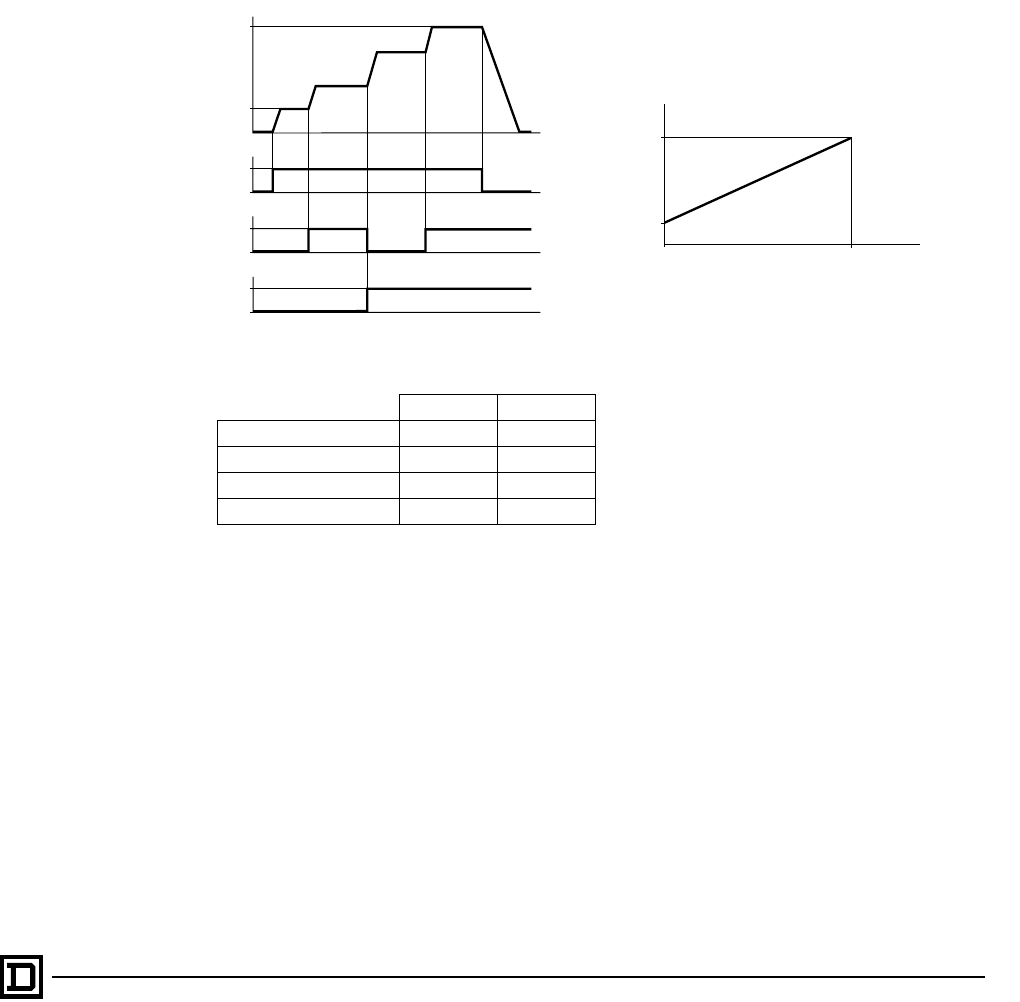
ALTIVAR 66 AC Drives
Application Functions
27
2/98 © 1998 Square D All Rights Reserved
PRESET SPEEDS
Function
This parameter allows switching between 1 or 3
Preset Speeds, with an additional speed obtained
when the assigned logic inputs are both low. 1 Preset
Speed requires one logic input. 3 Preset Speeds
requires two logic inputs. Use of an I/O Extension
Module allows 7 Preset Speeds (see page 36).
Applications
Material handling and machines with several
operating speeds.
Example with four speeds:
Adjustments
Preset Speeds are adjustable from 0.1 to 400 Hz
(ATV66U41 to ATV66D79, constant torque); 0.1 to
200 Hz (ATV66C10 to ATV66C13, constant
torque); or 0.1 to 90 Hz (variable torque). Factory
preset value for 1 Preset Speed is 5 Hz, for 3
Preset Speeds 5, 10, and 15 Hz.
SPEED REFERENCE
Function
This parameter allows assignment of the AI1 and
AI2 inputs as Speed Reference 1 or Speed
Reference 2. The characteristics of the analog
current input AI2 can be modified. Factory setting
is 4-20 mA. Other programmable values are: 0-20
mA, 20-4 mA, or x-20 mA where x is
programmable from 0 to 20 mA. A switch on the
control board also allows AI2 to be used as a 0-5
V voltage input. The voltage input AI1 (0-10 V)
cannot be modified.
The AI1 and AI2 inputs are summed as a factory
default, limited to High Speed. However, when
Auto/Manual is active, the inputs function
independently, and only one is active at a time. It
is possible to multiply AI2 by (-1) in which case AI2
is subtracted from AI1. If Clamp Sum is set to Yes
and (AI1-AI2) is zero or negative, the drive will run
at Low Speed. If Clamp Sum is set to No and (AI1-
AI2) is negative, the drive will change direction.
Applications
• Most all applications require a speed reference.
Logic Input a Logic Input b
Low Speed or Reference 0 0
Preset Speed 1 1 0
Preset Speed 2 0 1
Preset Speed 3 1 1
f (Hz)
t
t
1
LI2 0
t
t
1
LI3 0
1
LI4 0
LSP
LI2: Forward Direction
LI3: Logic Input a
LI4: Logic Input b
10 V
HSP
f (Hz)
0 V
LSP
Reference
0 mA
4 mA 20 mA
20 mA
20 mA 4 mA
LSP: Low speed
HSP: High speed
This document provided by Barr-Thorp Electric Co., Inc. 800-473-9123 www.barr-thorp.com
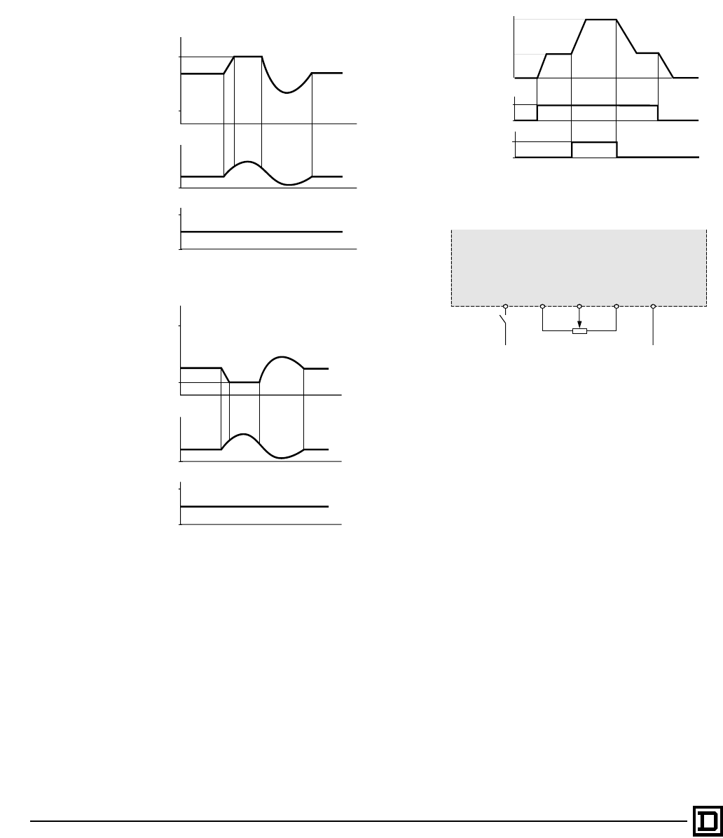
ALTIVAR 66 AC Drives
Application Functions
© 1998 Square D All Rights Reserved
28 2/98
Applications using the sum feature
• Applications with a current reference input
other than 4-20 mA.
• Machines where the speed is corrected by a
signal at the AI2 input.
AUTO/MANUAL
Function
Auto/Manual requires 1 or 2 logic inputs. It allows
switching between two analog references using a
logic input. This function eliminates the need for
mechanical switching of the low level analog
inputs and allows the speed references to be
independent.
Applications
All machines with automatic/manual operation.
Automatic speed command comes from a sensor
on input AI2 when the logic input is at state 1
(high). Manual speed command comes from a
potentiometer on input AI1 (local control) when
the logic input is at state 0 (low). A second logic
input can be used for an additional 2-wire remote
run command, only active when the drive is in
Auto mode.
CONTROLLED STOP
Function
Controlled stop requires zero or one logic inputs.
It allows frequency threshold and logic inputs to
work together to modify normal stopping. Three
types of stop modification are available:
• Freewheel: Motor coasts to a stop. Stopping
time depends on inertia and resistive torque.
• Fast stop: Braking to standstill with the
minimum deceleration ramp time acceptable
for the drive-motor combination without
tripping.
• DC injection braking: Adjustment of time and
current level.
Three ways to activate controlled stop:
• Assign one logic input and define its active
state as 0 or 1. When the logic input goes to its
f (Hz)
t
t
t
10 V
HSP
LSP
AI2
AI1
Adding References
Subtracting References
f (Hz)
t
t
t
10 V
HSP
LSP
AI2
AI1
LI2: Forward Direction
LI4: Automatic/manual
f (Hz)
t
t
1
LI2 0
t
1
LI4 0
Auto reference
Manual reference
Manual Auto Manual
LI4
COM
AI1
AI2
+ 24
+
–
+10
0-20 mA
4-20 mA
20-4 mA
Sensor
Wiring Schematic example
Manual
Potentiometer
This document provided by Barr-Thorp Electric Co., Inc. 800-473-9123 www.barr-thorp.com
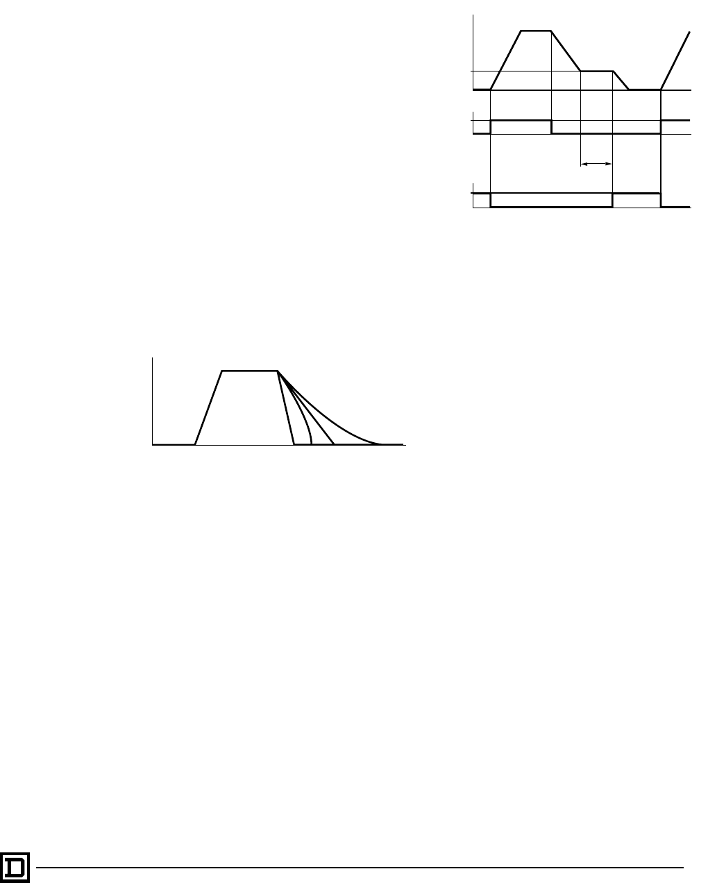
ALTIVAR 66 AC Drives
Application Functions
29
2/98 © 1998 Square D All Rights Reserved
active state, the drive stops, following the
controlled stop method.
• Set a frequency threshold. When a stop
command is received, the drive decelerates
following its programmed decel time. When the
frequency threshold is reached, the drive
switches to the controlled stop method.
• Assign a logic input, set a frequency threshold,
and choose a stopping method for both
command types.
When in Terminal Command mode, controlled
stop is active both at the frequency threshold and
with the logic input. When in Keypad Command
mode, controlled stop by frequency threshold is
active, but controlled stop by logic input is
disabled.
Applications
• Freewheel stop: if coast to stop is preferred.
• Fast stop: applications requiring rapid stopping.
• DC injection braking: Braking at low speed for
fans and material handling applications.
SHUTDOWN
Function
Maintains low speed for an adjustable amount of
time after deceleration. When the dwell state has
expired, the drive can activate a logic output to
indicate the end of running at dwell speed. No
logic inputs are required for shutdown. One logic
output can be used.
Applications
• Pumping station: Controlling the closing of a
check valve before completely stopping.
• Positioning which requires a great deal of
precision.
Adjustments
Dwell time is adjustable from 0.1 to 60 seconds,
factory preset to 1 second.
MOTOR SELECT SWITCH
Function
Motor Select Switch provides the capability to
program the AC drive with multiple sets of drive
and/or control parameters for use with 1, 2, or 3
motors. Motor Select Switch is useful for
applications in which a single AC drive is used to
control multiple motors individually, or for
applications in which multiple control parameter
sets are required for a single motor.
If multiple motors with different power, enclosure
types, or speed ratings are used with a single
controller, separate motor contactors, thermal
protection, and short circuit protection will be
required for each motor. When 2 motors or 3
motors are selected, logic input port(s) must be
selected for receiving motor switching logic inputs.
Applications
• Material handling with several movements, two
of which are not simultaneous.
• Machines with several sections, two of which
do not operate simultaneously.
• Machines with one motor and two different
fabrication processes.
t
123 4
f
(Hz)
1 Fast stop
2 DC injection braking
3 Normal stop following deceleration ramp
4 Freewheel stop
Dwell Time
t
t
t
LSP
1
LI2 0
1
LO1 0
f (Hz)
LI2: Forward Direction
LO1: Shutdown Complete
This document provided by Barr-Thorp Electric Co., Inc. 800-473-9123 www.barr-thorp.com
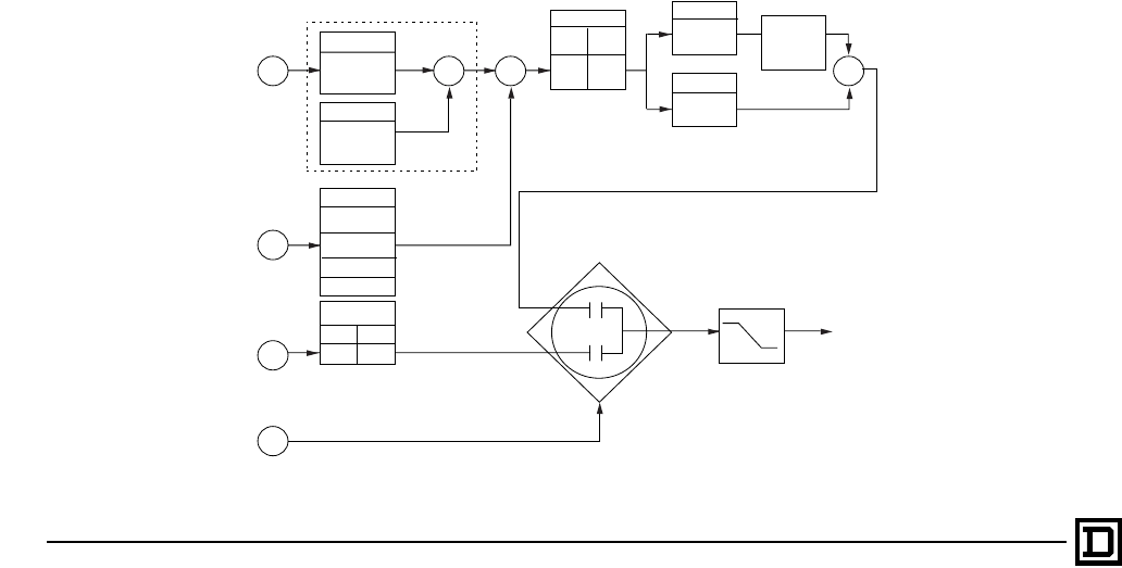
ALTIVAR 66 AC Drives
Application Functions
© 1998 Square D All Rights Reserved
30 2/98
PI REGULATOR
Function
PI Regulator makes it possible to control a
process by adjusting motor speed using a setpoint
input and a feedback input. PI Regulator requires,
at minimum, two analog input ports. Additional
analog and logic input ports are required for other
optional PI Regulator functions. PI Regulator can
only be used when the AC drive is configured for
2-wire control.
The following analog output signals are available
• Analog output reference proportional to PI set
point
• Analog output reference proportional to
feedback
• Analog output reference proportional to PI error
• Analog output reference to proportional to PI
integral error
The following logic outputs signals are available.
• Logic output indicating that “PI FLT ratio” has
been exceeded. “PI FLT ratio” is a user defined
error limit between desired setpoint and actual
process feedback.
• Logic output indicating that high level alarm
has been exceeded, which indicates the
process is above programmed level.
• Logic output indicating that the feedback is less
than low level alarm, which indicates the
process is below programmed level.
The set point may be entered at the keypad or via
an analog input, AI1, AI2, AI3, or AI4. The
feedback signal may be entered via any analog
input, AI1, AI2, AI3, or AI4. (AI3 and AI4 are
available only if extended I/O option board is
installed.) Refer to the block diagram for inputs.
Applications
• Control flow rate or pressure in a pumping
system.
• Maintain liquid level in a reservoir.
See the PI Regulator block diagram below.
-9999 to +9999
SP GAIN
-9999 to +9999
OFFSET
-9999 to +9999
-9999 to +9999
FB HIGH ALM
FB LOW ALM
REV. SPEED
LIx=1
-1 1
LIx=0
Setpoint
Feedback
Auto/Manual
LI3 - LI8
SPM Input
(Setpoint Manual)
AI1 - AI4,
or Keypad
AI1 - AI4,
Keypad
AI1 - AI4
ΣΣ Σ
REV. ACTION
Yes No
-1 1
0 to 9999
KI
0 to 9999
KP
∫
dt
Auto/Manual
HSP
LSP
Speed
Reference
Error
+
+
+
+-
LIx=0
Auto
LIx=1
Manual
+
NOTE:
An error value of 1 with KP set to 100% and KI
set to 0 will result in AC drive output of 61.8 Hz (if
HSP>61.8 Hz). An error value of 1 with KP set to 1% and
KI set to 140 will result in an AC drive output of 61.8
Hz
in 1
second.
This document provided by Barr-Thorp Electric Co., Inc. 800-473-9123 www.barr-thorp.com
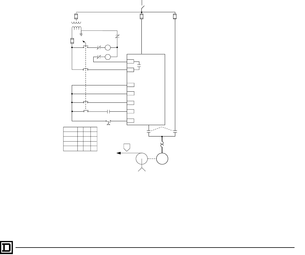
ALTIVAR 66 AC Drives
Application Functions
31
2/98 © 1998 Square D All Rights Reserved
BYPASS FUNCTION
Function
The Bypass function is used to sequence a drive
output isolation contactor, commonly used along
with a bypass contactor. The bypass contactor
and its associated power circuit components
permit starting, running, and stopping of the motor
directly from line power. The Bypass function
requires one or two logic inputs, and one relay
output.
Applications
Bypass requires a specific wiring scheme (see
figure below). Applications include machines
which must be run continuously because of the
manufacturing process, or when running the
motor at full speed is required when the drive must
be taken off line for service or repair.
Operation
A programmed delay time (ROC) allows for the
decay of residual motor voltage before restarting
the drive after operating in bypass. If the drive is
commanded to run and the delay time has
expired, the relay assigned to Run output
command goes high, energizing the isolation
contactor and enabling the motor to run.
A logic input is assigned as a Sequence input. If
this input does not go high within a programmable
amount of time, the drive faults on a Sequence
Time-out Fault and will not start.
A second logic input can be assigned as a
Process input. This verifies the occurrence of a
user-defined event after the acceleration ramp
has begun. If this input does not go high within a
programmable amount of time, the drive faults on
a Process Time-out Fault and stops.
LI1
LI2
LI3
+24
B
R2A
R2C
ROC
DRIVE CONTROLLER
RUN PERMISSIVE
FORWARD
SEQUENCE INPUT
PROCESS INPUT
I B
I
AS
OFF
BYP
B
I
SW
OL
A
B
LI4
PS
I
C
D
Pump
PS
Contact AS OFF BYP
A
B
C
D
X
XX
X
XX
OL
M
This document provided by Barr-Thorp Electric Co., Inc. 800-473-9123 www.barr-thorp.com

ALTIVAR 66 AC Drives
Fault Management and Configuration
© 1998 Square D All Rights Reserved
32 2/98
FAULT MANAGEMENT
Fault Stop
To protect internal circuitry, certain faults always
cause a freewheel stop. For other faults, the type
of stop can be programmed:
• Normal stop: Drive follows the active
deceleration ramp
• Fast stop: Drive stops as quickly as possible
without causing a trip
• Freewheel stop: Drive output is turned off,
causing the motor to coast to a stop
Only one choice is possible and it is applied to all
the programmable faults
Type of Reset
There are three methods for resetting the drive
after a fault:
• Automatic restart (available only when drive is
configured for 2-wire command). 1-5 restart
attempts and 1-600 second delays between
attempts can be selected.
• Manual restart: removal of power, correcting
the cause of the fault, then reapplication of
power
• Fault reset by logic input or function key
FAULT CONFIGURATION
Along with the type of stop and restart, there are
several other possibilities for fault configuration:
• At the loss of input power, the drive can either
freewheel stop or follow a ramp.
• Input phase failure. This can be inhibited if a
line contactor is used with the drive and control
power is supplied separately to CL1-CL2.
• Output phase failure. This can be inhibited for
troubleshooting or when the motor connected
to the drive is less than 45% of drive power.
• When the 4-20 mA or 20-4 mA reference input
is less than 3 mA, the drive can be programmed
to fault, run at a preset speed, or ignore the loss
of follower.
• Fault reset function allows the restart of the
drive after certain faults using an assigned logic
input.
• If the drive has dynamic braking, the drive can
check for a short circuit and issue a fault if the
rating of the dynamic brake resistor is
exceeded based on programmed resistor
characteristics.
• Motor thermal overload protection can be
configured and adjusted. See page 23.
• Catch on fly to regain control of a spinning load
after loss of power.
Fault Stop and Restart Methods
Resettable Only
By Manual Reset
(Removal Of Power)
Fault Reset by LI,
Function Key, or
Manual Reset
Can be Automatically
Reset
Non-
Latching
Faults
Faults Causing
Freewheel Stop
Short circuit
Ground fault
Precharge failure
Internal fault
Memory failure
Dynamic brake fault
Dynamic brake resistor fault
Auto-test failure
Transistor short circuit
Open transistor
Link Fault
AC line overvoltage
DC bus overvoltage
Sequence time-out fault
Overspeed
Output phase loss
AC line overvoltage
DC bus overvoltage
Sequence time-out fault
Overspeed
Output phase loss
Undervoltage
Programmable
Fault Stop
Drive overtemperature
Motor overload
Loss of follower
Process time-out fault
Serial link fault
Drive overtemperature
Motor overload
Loss of follower
Process time-out fault
Serial link fault
Input phase
failure
This document provided by Barr-Thorp Electric Co., Inc. 800-473-9123 www.barr-thorp.com
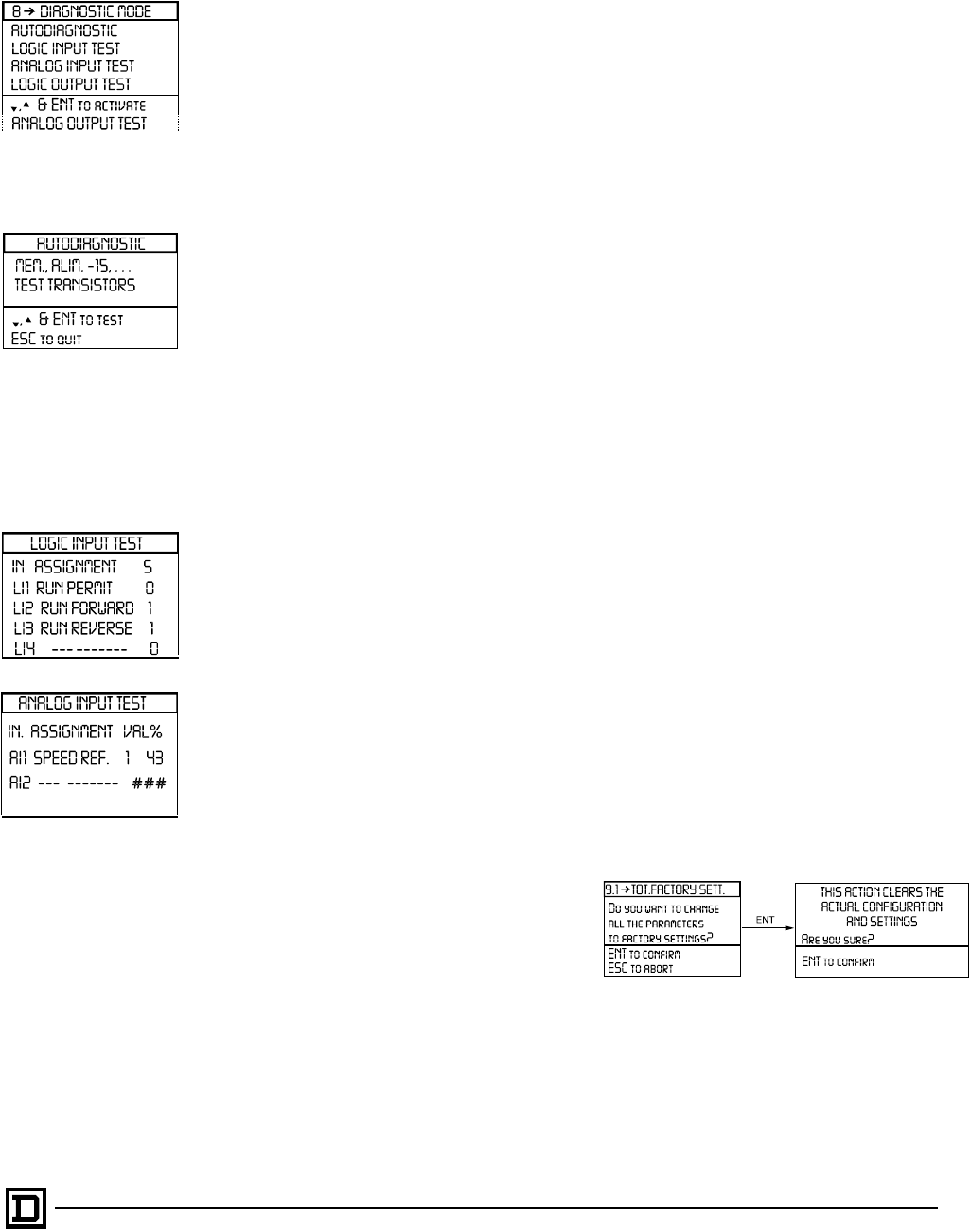
ALTIVAR 66 AC Drives
Diagnostic Mode
33
2/98 © 1998 Square D All Rights Reserved
DIAGNOSTIC MODE
The diagnostic mode allows access to various
tests:
• Drive autodiagnostics for locating failed
components in case of one of the following
faults: short circuit between phases, short
circuit to ground, internal fault, transistor in
short circuit, or transistor open.
• Testing of the inputs and outputs with forcing of
the outputs.
Autodiagnostics
Two tests are available in this menu. Selecting the
first line of the Autodiagnostic menu initiates a test
on the ROM memory, confirms the presence of ±
15 V, and confirms presence of supply frequency.
Selecting the second line initiates a test sequence
on the drive transistor bridge.
At the end of the test, each tested element is
displayed with its test result: “OK” indicates the
tested element is good; “X” indicates it is
defective.
Logic Input Test
This menu allows you to change the state of the
logic inputs to check for good wiring connections.
When the Logic Input Test screen is active,
changes made to the inputs will change input bit
status without affecting the state of the AC drive.
Analog Input Test
Analog Input Test is similar to Logic Input Test.
When this screen is active, you can change the
state of the analog inputs to check for good wiring
connections without affecting the state of the AC
drive.
Logic Output Test
This menu allows you to change the state of the
logic outputs to check for good wiring connections
without affecting AC drive operation.
When the Logic Output Test screen is active, all
outputs are forced to low (0) state regardless of
actual AC drive settings. Changes then made to
the outputs will alter bit status without affecting the
state of the AC drive. When you leave the
Diagnostic Mode and return to Main menu, the
logic outputs resume the programmed settings in
place before the test sequence.
Analog Output Test
This menu allows you to change the value of the
analog outputs to check for good wiring
connections without affecting AC drive operation.
When the Analog Output Test screen is active, all
output values are forced to 0 regardless of actual
AC drive settings. Changes then made to the
outputs will alter the setting without affecting the
state of the AC drive. When you leave the
Diagnostic Mode and return to Main menu, the
analog outputs resume the programmed settings
in place before the test sequence.
The use of diagnostic mode requires:
• Removal of power from L1, L2, L3
• Bus capacitors discharged
• Presence of control power at CL1 and CL2
• Motor connected and stopped
RECALLING AND
STORING ADJUSTMENTS
The ATV66 drive allows you to partially or totally
reset the drive to factory settings. If partial recall is
selected, only the parameters available from the
Display Configuration, Keypad Configuration, and
General Configuration menus are reset to their
factory conditions. If total recall is selected, all
parameters are reset to their factory settings.
Customer parameter settings can be stored on a
PCMCIA card installed in the drive (catalog
number VW3A66901T). This allows the drive
configurations and adjustments to be saved and
then downloaded in another drive of equal
horsepower.
Although only the size of a credit card, the
PCMCIA memory card with EEPROM allows very
fast access and transfer times. 16 different sets of
parameters can be stored on the PCMCIA card.
This document provided by Barr-Thorp Electric Co., Inc. 800-473-9123 www.barr-thorp.com

ALTIVAR 66 AC Drives
Input and Output Assignments
© 1998 Square D All Rights Reserved
34 2/98
INPUT AND OUTPUT ASSIGNMENTS
The ALTIVAR 66 basic drive has 2 analog inputs, 4
logic inputs, 2 analog outputs, and 4 logic outputs.
Some of these are fixed and cannot be reassigned.
If more inputs or outputs are required, the I/O
Extension Module can be used (see page 35).
Analog Inputs
The analog inputs AI1 and AI2 are assigned to
Speed Reference. They can be assigned to:
• Current limit input
• Torque limit input
• PI functions
Logic Inputs
The only logic inputs which can be reassigned are
LI3 and LI4. LI1 is fixed as Run Enable, and LI2 is
fixed as Run Forward. Logic inputs LI3 and LI4
can be assigned to:
• Run Reverse
• Auto/Manual
• Preset Speeds
• Jog
• Controlled Stop
• Terminal/Keypad Switching
• +Speed/-Speed (requires 2)
• Bypass
• 3 Preset Speeds (requires 2)
• Setpoint Memory
• Motor Select Switch
• PI Regulator
Analog Outputs
There are 2 analog outputs which can be
programmed as 0-20 mA or 4-20 mA outputs
assigned to:
• Motor Current
• PI Ref Output
• Motor Speed
• PI FB Output
• Motor Thermal state
• PI Err Output
• Motor Power
• PI Integral Error
• Motor Torque
Logic Outputs
The ALTIVAR 66 drive has 2 logic outputs (LO1
and LO2) and 2 relay outputs (R1 and R2). R1 is
fixed as the Fault Relay and cannot be reassigned.
LO1, LO2, and R2 can be assigned to indicate:
• Ready State
• Loss of Follower
• Running State
• Frequency Level Attained
• At Speed
• Current Level Attained
• Forward Direction
• Thermal Level Attained
• Reverse Direction
• Jog Enabled
• Terminal/Keypad
• FB Limit (PI FLT Ratio)
• Auto/Manual
• FB High Alarm
• Current Limit
• FB Low Alarm
• Fault State
• Brake Release
• Shutdown Complete
• Run Output Command
• Drive Thermal Alarm
(ATV66D16 to C31 drives only)
Factory Settings for Input/Outputs
Logic Inputs
LI1
LI2
LI3
LI4
Run Enable
Run Forward
Run Reverse
Jog
LI3 and LI4 can be reassigned
Analog Inputs AI1
AI2 Speed Reference 1
Speed Reference 2 AI2 can be programmed to be 0-20 mA,
4-20 mA, x-20 mA or 20-4 mA, or can be set to 0-5 V.
Logic and Relay
Outputs
LO1
LO2
R1
R2
At Speed
Current Limit
Fault
Running State
LO1, LO2, and R2 can be reassigned
Analog Outputs AO1 Motor speed
20 mA = 120% of high speed AO1 and AO2 can be reassigned
AO2 Motor current
20 mA = 200% of nominal drive current
This document provided by Barr-Thorp Electric Co., Inc. 800-473-9123 www.barr-thorp.com
ALTIVAR 66 AC Drives
I/O Extension Modules
35
2/98 © 1998 Square D All Rights Reserved
I/O EXTENSION MODULES
An I/O Extension Module can be installed in the
ALTIVAR 66 drive to adapt it to a specific
application. This module allows the expansion of
functionality by increasing the number of inputs
and outputs and requires no additional panel
space. At first power-up, the additional inputs and
outputs on the I/O Extension Module are assigned
to factory settings. They can be reassigned with
the keypad display.
The VW3A66201T card has four 24 VDC logic
inputs, two analog inputs, two relay outputs, and
one analog output.
The VW3A66202T card has eight 115 VAC logic
inputs, two analog inputs, two relay outputs, and
one analog output. An external 115 VAC power
supply is required to operate the logic inputs on
the VW3A66 202T module. When using the
VW3A66 202T module, LI2, LI3 and LI4 on the
main control board are ignored.
Both have a PCMCIA connector for addition of
optional serial communication. The I/O Extension
Module mounts inside the drive with two screws. It
has pull-apart terminal strips for easy wiring.
A Communication Carrier Module, VW3A66205, is
also available for the ALTIVAR 66 drive. The
Communication Carrier Module does not extend
AC drive functions, but provides a PCMCIA
connection for addition of optional serial
communication.
Extensions and Additional Functions
With the I/O Extension Module, additional
application functions are available for assignment
to the function keys. The I/O Extension Module
also extends certain drive functions and allows
access to additional supplementary functions.
Extensions to existing drive functions:
• Seven preset speeds
• Bipolar speed reference
Additional drive functions:
• Voltage reduction
• Speed feedback with tachogenerator
• Orient
• Process cycles
Compatibility
Not all application functions can be used at once.
The table below shows which functions are
compatible.
VW3A66201T
●
●●
●● ●
●
●
●
●
●
RUN REVERSE
JOG
+/- SPEED
SET POINT MEMORY
PRESET SPEEDS
SPEED REFERENCE
AUTO/MANUAL
CONTROLLED STOP
SHUTDOWN
BYPASS
BRAKE SEQUENCE
RUN REVERSE
JOG
+/- SPEED
SET POINT MEMORY
PRESET SPEEDS
SPEED REFERENCE
AUTO/MANUAL
CONTROLLED STOP
SHUTDOWN
BYPASS
BRAKE SEQUENCE
MOT. SELECT SWITCH
PI REGULATOR SWITCH
●
[1]
[1]
●
●
●●● ● ●● ●
●
●
●●
●●
●
●
●
●●
●
●
[1] Shutdown is incompatible with Controlled Stop by Frequency Threshold
and Controlled Stop by Frequency Threshold/Logic Input.
Read up and across from
the ● to identify pairs of
incompatible functions.
Incompatibilities due to
the number of I/O available
for reassignment are not
shown.
ORIENT
TACHOMETER FEEDBACK
CYCLES
FORCED LOCAL
ORIENT
TACHOMETER
FEEDBACK
CYCLES
FORCED LOCAL
MOT. SELECT
SWITCH
PI REGULATOR
SWITCH
●●●●
●
●●●●●● ●
●●
●
●
●
●
●
●
●
●
●
This document provided by Barr-Thorp Electric Co., Inc. 800-473-9123 www.barr-thorp.com
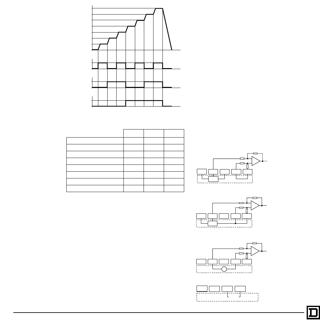
ALTIVAR 66 AC Drives
I/O Extension Module, Additional Functions
© 1998 Square D All Rights Reserved
36 2/98
SEVEN PRESET SPEEDS
Function
The I/O Extension Module extends the Preset
Speeds function available with the basic drive
(see page 27) to allow switching among one,
three, or seven preset speeds.
Applications
For material handling and machines which run at
several speeds. The figure below gives an
example with eight speeds.
Adjustments
The preset speeds are adjustable:
• ATV66U41 to D79 constant torque: 0.1 to 400 Hz
• ATV66C10 to C31 constant torque: 0.1 to 200 Hz
• Variable torque: 0.1 to 72 Hz
Programmed values must increase consecutively
from speeds 1 to 8. If all three logic inputs are low,
the speed will be the speed reference, if present,
or low speed. The factory preset values for seven
preset speeds are: 5, 10, 15, 20, 25, 30, and
35 Hz. LI5, LI6, and LI7 are factory set for Preset
Speeds; however, Preset Speeds can be
assigned to LI3-LI8.
BIPOLAR SPEED REFERENCE
Function
The I/O Extension Module allows extension of the
Speed Reference function available with the basic
drive (see page 27). It adds the ability to modify the
characteristics of the voltage analog input AI3.
Factory setting is ±10 V bipolar speed reference.
Other values are 0 to +10 V or 0 to -10 V unipolar
speed reference. This function also allows
modification of the characteristics of the current
analog input AI4. The factory setting is 4-20 mA
speed reference. Other possible values are 0-20
mA or 20-4 mA speed reference.
If AI3 or AI4 is assigned as Speed Reference 3,
the input is summed with input AI1 and AI2, limited
to high speed. However, when Auto/Manual is
active, the inputs assigned to Speed Reference 1
and Speed Reference 2 function independently,
and only one is active at a time.
When AI3 and AI4 are multiplied by (-1) the signal
is subtracted. If Clamp Sum is set to Yes (factory
setting) and the result is zero or negative, the
controller will run at Low Speed. If Clamp Sum is
set to No and the result is negative, the controller
output phase sequence will change, causing the
motor shaft to change direction. The directional
change affects both the forward and reverse inputs,
as well as the jog function. If Auto/Manual is active
and AI3 is set for bipolar speed reference, negative
polarity speed reference values are ignored and
the controller will run at Low Speed, regardless of
the setting of the clamp sum.
f (Hz)
t
t
t
t
LSP 0
LI6 0
LI7 0
LI8 0
1
1
1
Preset Speed 7
Preset Speed 6
Preset Speed 5
Preset Speed 4
Preset Speed 3
Preset Speed 2
Preset Speed 1
An eighth speed is obtained when all three inputs are at state
0. The eighth speed is Low speed or reference speed if there
is a signal at AI1 or AI2.
LIa LIb LIc
Low Speed or Reference 0 0 0
Preset Speed 1 1 0 0
Preset Speed 2 0 1 0
Preset Speed 3 1 1 0
Preset Speed 4 0 0 1
Preset Speed 5 1 0 1
Preset Speed 6 0 1 1
Preset Speed 7 1 1 1
+10 V -10 VAI3A AI3B COM
Customer
supplied
to A/D
Converter
V
10 k
10 k
20 k
20 k
+10 V -10 V AI4 COM
Customer
supplied
0-20
mA
0 to 10 V input referenced to COM
+/- 10 V input referenced to COM
+/- 10 V input not referenced to COM
AI4 input
+10 V -10 VAI3A AI3B COM
Customer
supplied
to A/D
Converter
R
10 k
10 k
20 k
20 k
+10 V -10 VAI3A AI3B COM
Customer
supplied
to A/D
Converter
R
10 k
10 k
20 k
20 k
This document provided by Barr-Thorp Electric Co., Inc. 800-473-9123 www.barr-thorp.com
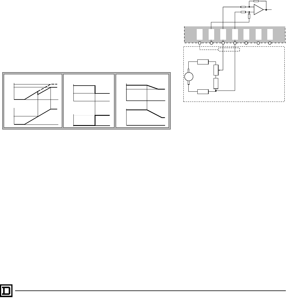
ALTIVAR 66 AC Drives
I/O Extension Modules, Additional Functions
37
2/98 © 1998 Square D All Rights Reserved
Applications
This function is suited to applications where a
positive and negative speed from a reference
potentiometer or an external speed reference are
used, or where three summed speed references
are used.
VOLTAGE REDUCTION
Function
Voltage Reduction is available only with the I/O
Extension Module. This parameter reduces motor
voltage when running at no or low load in either
forward or reverse. This reduces magnetism in the
motor as well as audible motor noise. The function is
activated at a frequency threshold, or by a logic or
analog input reassigned to the function. The voltage
can be limited to a value between 100 and 20% or
nominal motor voltage.
Applications
For constant torque applications only. Useful for
reduction of motor losses during continuous duty.
TACHOMETER FEEDBACK
Function
This function is available only with the I/O
Extension Module. A tachometer can be
connected to AI3 allowing speed feedback. A
feedback signal of 9 V corresponds to a maximum
frequency of High Speed (HSP). This improves
the speed regulation to the accuracy of the
tachometer (typically 0.5% of the motor base
speed).
Wiring Scheme
Applications
Machines requiring constant speed when there
are changes in the load.
t
Vn motor
t
1
LI 0
100%
X%
Voltage Reduction by Logic Input
t
AI 0
10 V
Vn motor
t
100%
X%
Voltage Reduction by Analog Input
Voltage Reduction by Frequency Level
t
Vn motor
f (Hz)
t
fx
100%
X%
A14
-10 V
AI3A
to A/D
Converter
+10 V
AI3B
S
COM
± 9V
R1
R4
R2
R3
1 kΩ
500 Ω
The AI3 differential input is used.
A resistor divider network must be provided to
obtain a ± 9 V signal corresponding to maximum
speed.
Note: Isolation between the input power and the
tachogenerator is ensured by the drive.
This document provided by Barr-Thorp Electric Co., Inc. 800-473-9123 www.barr-thorp.com
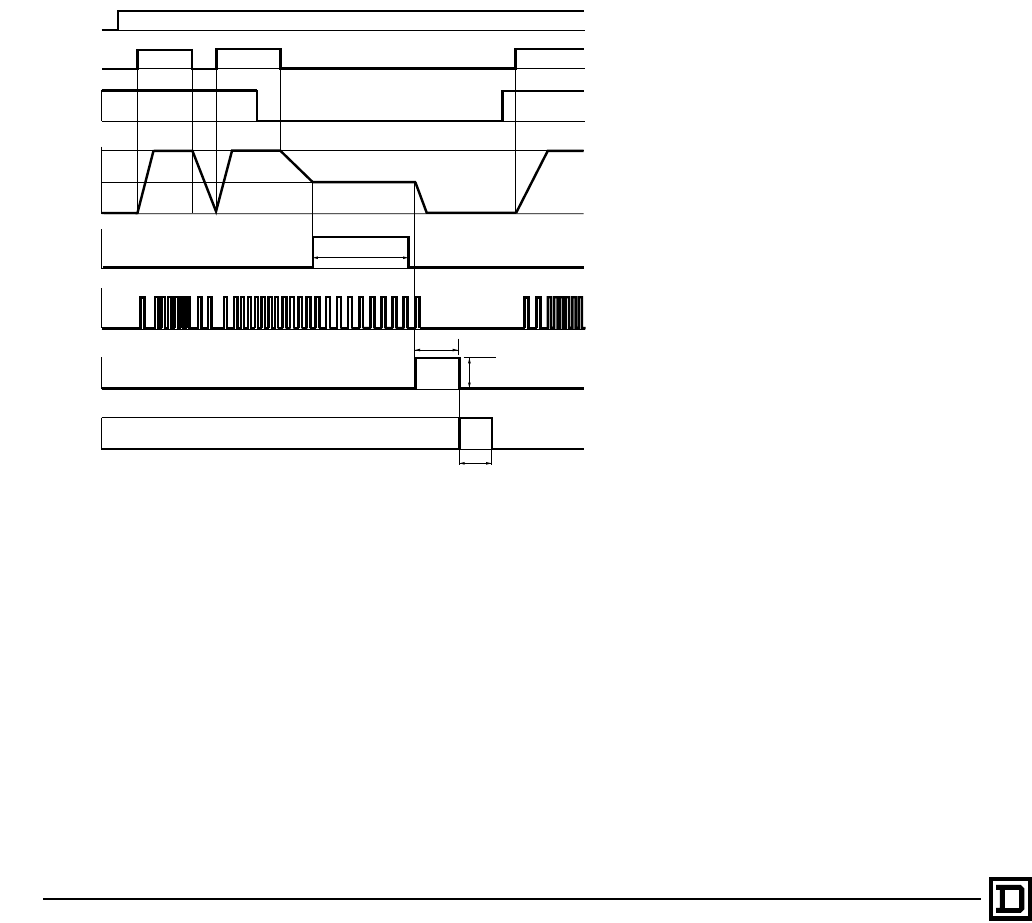
ALTIVAR 66 AC Drives
I/O Extension Modules, Additional Functions
© 1998 Square D All Rights Reserved
38 2/98
ORIENT
Function
This function is available only with the I/O
Extension Module. It is activated by two logic
inputs and one logic output, and requires a 3-wire,
PNP, normally-open type sensor. Orient allows the
drive to start and stop operation at the same rotor
position relative to the stator.
Application
Orient is used on machines such as washing
machines, centrifuges and mixers for positioning
at the end of the cycle.
The figure below shows an example using logic
inputs LI5 and LI6, and output R3:
In this example:
• Orient Command is assigned to LI5.
— If LI5 is high and a stop is commanded, the
AC drive follows its normal stop.
— If LI5 goes low, the AC drive follows an
Orient stop, decelerating to Low Speed.
• When Low Speed is reached, the AC drive runs
at Low Speed for the amount of time set by the
Dwell Time parameter.
• At the first sensor pulse received at LI6
(assigned to Pulse Input) after the dwell time,
DC is injected at the level, and for the amount
of time, adjusted.
• At the end of DC injection, R3 (assigned as the
Complete output) changes state for 1 s to
indicate that Orient is complete.
Adjustments
Dwell Time, the duration for which the drive dwells
at low speed after deceleration, is adjustable from
0 to 10 seconds, factory set for 1 second. DC
Injection Time, the duration for which DC is
injected at the first sensor pulse after the Dwell
Time, is adjustable from 0 to 30.1 seconds, factory
set for 5 seconds. DC Injection Level, the current
level at which DC is injected, is adjustable from 50
to 150% of nominal motor current, factory set to
50%.
PROCESS CYCLES
Function
Process Cycles is available only with the I/O
Extension Module. Process Cycles is a control
function that allows sequences of operations to be
programmed into the AC drive. Execution of the
program sequence can be controlled through the
Terminal Command Mode or Keypad Command
Mode.
Process Cycles allows up to 8 steps to be
programmed. Each step has a defined duration,
speed, and ramp time. One step can consist of
several substeps (subcycles), defined with only 1
ramp time and 1 speed. When operated from the
Terminal Command Mode, Process Cycles
requires 3 logic inputs. A fourth logic input can be
assigned to Step Locking, and 2 logic outputs can
be assigned to indicate Cycle Complete and
Cycle Fault. It is also possible to operate Process
Cycles in the Keypad Command Mode. Up to 3
keypad function keys may be assigned to Start
Cycle (SCY), Reset Cycle (RCY), and Next Step
(NCY), respectively. Step Locking is not available
when operating in the Keypad Command Mode.
f (Hz)
t
1
Speed Ref.
Low Speed
(LSP)
Drive Controller
Output
0
0
1
1
1 s
Dwell Time
Run Enable
(LI1)
FWD (LI2)
1
0
1
0
0
t
t
t
t
t
t
t
Orient
Command (LI5)
Low Speed
Command
Sensor
Pulses (LI6)
DC Injection
Orient
Complete (R3)
IDC
tDC
This document provided by Barr-Thorp Electric Co., Inc. 800-473-9123 www.barr-thorp.com
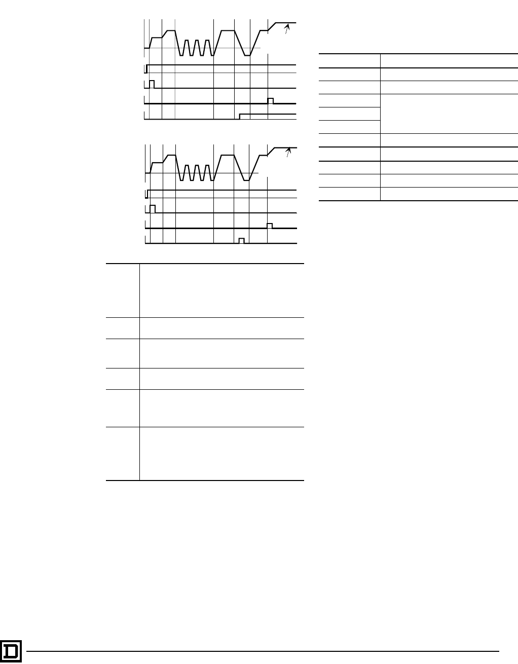
ALTIVAR 66 AC Drives
I/O Extension Modules, Additional Functions
39
2/98 © 1998 Square D All Rights Reserved
Example: Complete Cycle
Applications
Process Cycles applications include industrial
washing machines and mixers.
FACTORY SETTINGS OF INPUTS/
OUTPUTS WITH I/O EXTENSION MODULE
When a drive configured with an I/O Extension
Module is first powered up, the associated inputs/
outputs are automatically configured as follows:
The factory settings of the drive inputs and
outputs are not modified by the use of an I/O
Extension Module. Reconfiguration of all inputs
and outputs is possible with the keypad display.
OUTPUT ASSIGNMENTS WITH I/O
EXTENSION MODULE
The supplementary assignments of the logic
outputs available with the I/O Extension Module are
as follows:
FAULT CONFIGURATION WITH I/O
EXTENSION MODULE
The I/O Extension module allows you to assign a logic
input to a user-defined fault (i.e., a fault specific to an
installation). The logic input can be programmed to
detect the fault when at state 1 or state 0. Fault
stopping method is also programmable.
Step 1
When the logic input assigned to Start Cycle goes
high for at least 200 ms, the cycle starts. The AC
drive accelerates (Step 1 ramp) to the Step 1
frequency. It runs at that frequency for the duration
specified by the Step Time parameter (minus the
acceleration ramp time).
Step 2 When Step Time 1 expires, the AC drive ramps to
the Step 2 frequency and direction.
Step 3 The AC drive ramps to the Step 3 frequency and
direction, then changes direction. The direction change
repeats for the specified number of subcycles.
Step 4 The AC drive ramps to the Step 4 frequency and
direction.
Step 5
The AC drive ramps to the Step 5 frequency and
direction. A Run Forward command is activated.
The AC drive completes Step 5 before returning to
normal operation after Step 6.
Step 6
The AC drive ramps to the Step 6 frequency and
direction. When Step 6 is completed, the Cycle
Complete logic output goes high for 200 ms. The
AC drive ramps to the Terminal Command Mode
Speed Reference and direction (as commanded by
Run Forward in Step 5).
f (Hz)
Step
1Step
2Step 3
2-WIRE CONTROL
Step 4 Step
5Step 6
Run Enable
(LI1)
Cycle
Start
Cycle
Complete
Run Forward
(LI2)
1
0
1
0
1
0
1
0
Normal Drive
Set Speed and
Acceleration
3-WIRE CONTROL
f (Hz)Step
1Step
2Step 3 Step 4 Step
5Step 6
Stop
(LI1)
Cycle
Start
Cycle
Complete
Run Forward
(LI2)
1
0
1
0
1
0
1
0
Normal Drive
Set Speed and
Acceleration
Input Factory Settings
AI3 Speed Reference 3
AI4 Not Assigned
LI5
7 Preset SpeedsLI6
LI7
LI8 Fault Reset
Output Factory Settings
AO3 Motor Power
R3 Thermal Level 1
R4 Ready State
Frequency Level 2 Changes from state 0 to state 1 when
motor speed attains a second value.
Current Level 2 Changes from state 0 to state 1 when
motor current attains a second value.
Thermal Level 2 Changes from state 0 to state 1 when
motor thermal state attains a second value.
Ramp not Followed Changes from state 0 to state 1 when
the acceleration or deceleration does
not follow the adjusted ramp (used with
tachogenerator feedback).
Overspeed Changes from state 0 to state 1 when the
drive output frequency is greater than 20%
of the set maximum frequency for 250 ms.
Feedback Loss Changes from state 0 to state 1 when the
difference between reference frequency
and the feedback is greater than 10%
(used with tachogenerator feedback).
This document provided by Barr-Thorp Electric Co., Inc. 800-473-9123 www.barr-thorp.com
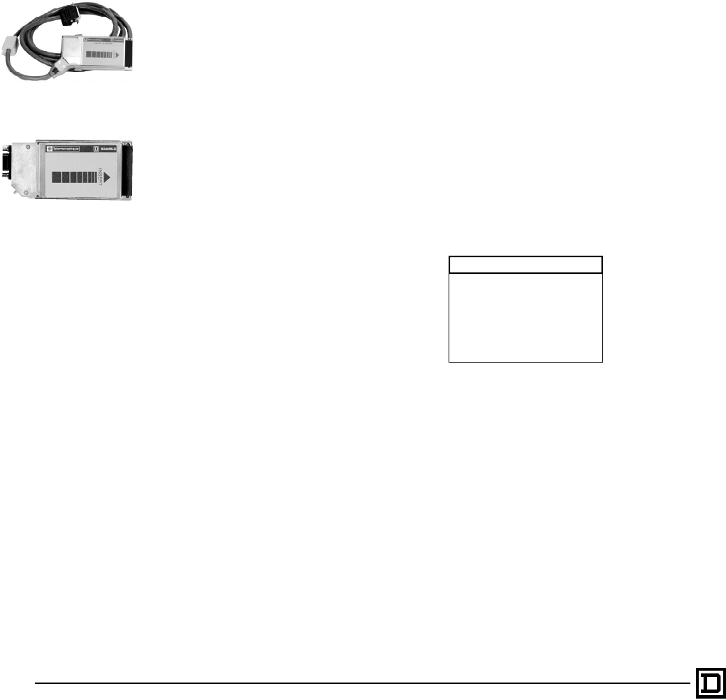
ALTIVAR 66 AC Drives
Communication Options
© 1998 Square D All Rights Reserved
40 2/98
COMMUNICATION OPTIONS
The communication options for the ATV66 are
designed for ease of installation and
configuration. They have also been designed such
that they can be added without taking additional
panel space. Installation is quick and easy. There
are no chips to replace or dip switches to set.
Address and configuration selections are made
via the keypad. Menu selections provide
adjustment value to select from, reducing
configuration time.
The following protocols are available for use with
the entire ATV66 family of drives:
• MODBUS® RTU/JBUS
• MODBUS ASCII
• UNI-TELWAY™
• MODBUS Plus
Two PCMCIA Communication Card Kits are
available for connecting ALTIVAR 66 AC drives to
multipoint networks:
• VW3A66301U UNI-TELWAY, MODBUS
Communication Card Kit
• VW3A66305U MODBUS Plus PCMCIA
Communication Card Kit
The VW3A66301U Kit allows you to connect an
ALTIVAR 66 AC drive to multipoint networks using
UNI-TELWAY, MODBUS RTU/JBUS and
MODBUS ASCII protocols. The VW3A66305U
MODBUS Plus Kit allows you to connect an
ALTIVAR drive to multipoint networks using
MODBUS Plus protocol and take advantage of the
exclusive peer cop feature. Peer cop reduces
programming by directly mapping memory
locations between the PLC and the drive.
Function
As a node on a network, the ALTIVAR 66 AC drive
can receive and respond to data messages. This
data exchange allows your network to access
ALTIVAR 66 functions such as:
• Downloading of adjustment parameters
• Command/control
• Monitoring
• Diagnostics
The communication card kit contains a Type 3
Personal Computer Memory Card International
Association (PCMCIA) card. The PCMCIA card
slides into a slot on the following modules.
The ATV66 drive must be equipped with one of the
following option modules:
• I/O Extension Module VW3A66201T (24 VDC)
• I/O Extension Module VW3A66202T
(115 VAC)
• Communications Carrier Module VW3A66205
Unless the application requires additional
hardwired I/O, the communications carrier module
is the recommend module. The PCMCIA card
slides into the communications carrier or I/O
extension module which is installed on the
ALTIVAR 66 drive without taking additional panel
space.
Applications
Applications requiring networked drives and
access to critical information.
Access to critical information
The communications option allows high speed
access to 13 adjustment parameters, 28
command and control parameters, 123 monitoring
parameters, and 19 diagnostic parameters.
Adjustments
Protocol selection and assignment of address.
11- COMMUNICATION
ADDRESS : 0
PROTOCOL : ---
TRAN.SPEED: 9.6
FORMAT :8B,1 stop
PARITY : ODD
This document provided by Barr-Thorp Electric Co., Inc. 800-473-9123 www.barr-thorp.com

ALTIVAR 66 AC Drives
Communication Options
41
2/98 © 1998 Square D All Rights Reserved
Command/Control Registers
Adjustment Registers
Address Bit Description
Wnnn
0
1
2
3
4
5
Drive reset
Assignment of logic commands over link (DLI)
Assignment of references over link (FLI)
Alternate ramps (Ramp 2)
Suppression of communication control (No time out)
Run/Stop command
6
7
8
9
Braking by DC injection (DCB)
Orient Stop
Freewheel stop
Fast stop
10 Command of voltage reduction
11
12 Multi-motors
Multi-parameters
14 External fault command
Wnnn — Reference frequency
Wnnn 1 – 2, 6 – 8 Command of LOx / ROx state
Wnnn — Command of AO1 level
Wnnn Current limit level
Wnnn Motoring torque limit level
Wnnn Regenerating torque limit level
Wnnn Voltage reduction level
Wnnn — Command of AO2 level
Wnnn — Command of AO3 level
Wnnn
0 Command of current limit
1 Run direction
3 Command of torque limit
8 Elapsed timer reset
Address Bit Description
Wnnn — High speed
Wnnn — Low speed
Wnnn — Accel 1
Wnnn — Decel 1
Wnnn — Accel 2
Wnnn — Decel 2
Wnnn — Slip compensation
Wnnn — IR compensation
Wnnn — Profile
Wnnn — Voltage boost
Wnnn — Damping
Wnnn — Bandwidth
Wnnn — Motor overload
This document provided by Barr-Thorp Electric Co., Inc. 800-473-9123 www.barr-thorp.com

ALTIVAR 66 AC Drives
Communication Options
© 1998 Square D All Rights Reserved
42 2/98
Monitoring Registers
Address Bit Description
Wnnn
0
1
2
3
4
5
6
7
8
9
10
11
12
14
15
Command mode of drive
AC drive ready (RDY or SLC)
Fault (FLT)
Reset authorized
Brake engage relay state
Forced local
NTO
Resettable fault
Motor running
Actual rotation direction
DC injection braking
Steady state
Motor thermal overload alarm
Current limit
No line power (NLP)
Wnnn — Output frequency
Wnnn — Output current
Wnnn 1 – 8
9 – 10
11 – 14
Display of logic input activation (LI1 – LI8)
Display of logic output activation (LO1 – LO2)
Display of relay activation (R1 – R4)
Wnnn — Value of analog input (AI1)
Wnnn — Motor torque
Wnnn — Speed reference
Wnnn
0
1
2
3
4
5
6
7
8
9
10
11
13
14
15
Local command mode T/K
Logic commands over link (DLI)
Reference commands over link (FLI)
Dynamic braking
Fast stop
Power loss, ramp stop
Gating state
Orient complete
Deceleration (DEC)
Acceleration (ACC)
Multi-motor or
Multi-parameter selected
AC drive thermal fault
Torque limit
Stopping by the keypad
Wnnn
0
1
2
3
4
5
6
7
8
9
10
11
12
13
Jog
Shutdown complete
Cycle complete
Alternate ramp
Auto/Manual
Frequency level 1 attained
Frequency level 2 attained
Current level 1attained
Current level 2 attained
Thermal level 1attained
Thermal level 2 attained
No ramp follow
Run output command (bypass)
Rotation direction
Wnnn — Output power
Wnnn — Output voltage
Wnnn — Line voltage
Wnnn — Bus voltage
Wnnn — Motor thermal state value
Wnnn — AC drive thermal state value
Wnnn — Elapsed time (hours)
Wnnn — Elapsed time (minutes)
Wnnn — Output speed (rpm)
Wnnn — Machine frequency reference (customer units)
Wnnn — Machine frequency (customer units)
Wnnn — Value of analog input AI2
Wnnn — Value of analog input AI3
Wnnn — Value of analog input AI4
This document provided by Barr-Thorp Electric Co., Inc. 800-473-9123 www.barr-thorp.com

ALTIVAR 66 AC Drives
Communication Options
43
2/98 © 1998 Square D All Rights Reserved
Wnnn — Value of AO1
Wnnn — Value of AO2
Wnnn — Value of AO3
Wnnn — Speed ramp output
Wnnn — Nominal motor voltage range
Wnnn — Number of motor or parameter set selected
Wnnn — Cycles step number in progress
Wnnn — Preset speed number in progress
Wnnn — Assignment of AI1
Wnnn — Assignment of AI2
Wnnn — Assignment of AI3
Wnnn — Assignment of AI4
Wnnn — Assignment of analog output AO1
Wnnn — Assignment of analog output AO2
Wnnn — Assignment of analog output AO3
Wnnn — Assignment of LO1
Wnnn — Assignment of LO2
Wnnn — Assignment of R1
Wnnn — Assignment of R2
Wnnn — Assignment of R3
Wnnn — Assignment of R4
Wnnn — Assignment of LI1
Wnnn — Assignment of LI2
Wnnn — Assignment of LI3
Wnnn — Assignment of LI4
Wnnn — Assignment of LI5
Wnnn — Assignment of LI6
Wnnn — Assignment of LI7
Wnnn — Assignment of LI8
Wnnn — AC drive horsepower (hardware rating)
Wnnn — AC drive horsepower (configured rating)
Wnnn — AC drive voltage range
Wnnn — Line frequency recognized
Wnnn — AC drive maximum rated frequency
Wnnn — AC drive nominal current
Wnnn — AC drive maximum current
Wnnn — Memory card option
Wnnn — Communication carrier option
Wnnn — Presence of keypad
Wnnn — I/O Extension option card
Wnnn — PCMCIA communication card
Wnnn — State of command node
Wnnn — Token rotation time
Wnnn — Token count
Wnnn — Messages received
Monitoring Registers (Continued)
Address Bit Description
This document provided by Barr-Thorp Electric Co., Inc. 800-473-9123 www.barr-thorp.com

ALTIVAR 66 AC Drives
Communication Options
© 1998 Square D All Rights Reserved
44 2/98
Diagnostic Registers
Address Bit Description
Wnnn 0
4
5
Drive faulted, stopped
State of Adjustment Semaphore
State of Command Semaphore
Wnnn — Display of fault causing trip
Wnnn — Display of present faults
Wnnn — Indicates the position of marker on 1 of 8 past faults
Wnnn — Past fault 1: AC drive state
Wnnn — Past fault 1: name of fault
Wnnn — Past fault 2: AC drive state
Wnnn — Past fault 2: name of fault
Wnnn — Past fault 3: AC drive state
Wnnn — Past fault 3: name of fault
Wnnn — Past fault 4: AC drive state
Wnnn — Past fault 4: name of fault
Wnnn — Past fault 5: AC drive state
Wnnn — Past fault 5: name of fault
Wnnn — Past fault 6: AC drive state
Wnnn — Past fault 6: name of fault
Wnnn — Past fault 7: AC drive state
Wnnn — Past fault 7: name of fault
Wnnn — Past fault 8: AC drive state
Wnnn — Past fault 8: name of fault
This document provided by Barr-Thorp Electric Co., Inc. 800-473-9123 www.barr-thorp.com

ALTIVAR 66 AC Drives
Communication Options
45
2/98 © 1998 Square D All Rights Reserved
MODBUS PLUS OVERVIEW
MODBUS Plus (MB+) is a synchronous network
that achieves peer-to-peer access through token
passing. The token rotation is a logical ring
sequence, with the node holding the token passing
it to the next highest node address on the network
(local network section only -- i.e. the token does not
cross a bridge boundary). When a node holds the
token, it may initiate point-to-point messages on the
link, gather network statistics, generate specific
transfers, etc.
Network nodes are identified by addresses
assigned by the user. Each node's address is
independent of its physical site location.
Addresses are within the range of 1... 64 decimal,
and do not have to be sequential.
While holding the token, a node initiates message
transactions with other nodes. Each message
contains routing fields that define its source and
destination, including its routing path through
bridges to a node on a remote network ring. When
passing the token, a node can write into a global
database that is broadcast to all nodes on the local
network ring. Global data is transmitted as a field
within the token frame. A PLC can extract global
data and use this information for control decisions.
Use of the global database allows rapid updating of
alarms, setpoints, and other data. Each network
maintains its own global database, as the token is
not passed through a bridge to another network
ring.
Peer Cop Capability
The MODBUS Plus communications option is
designed to take advantage of the MODBUS Plus
Peer Cop capability. This is an exclusive feature
not found with other drives using MODBUS
Plus communications. This can eliminate ladder
logic programming and improves register update
time significantly. Each command node can send
up to 32 words of peer cop data. This allows
mapping of the most commonly used command
and adjustment registers.
Peer Cop is the mechanism, or capability, to
automatically map, or assign, a set of registers
from one node on the network to another. The
MODBUS Plus network supports specific
transfers to enable this capability. Global data may
be peer-copped as well. A specific transfer is a
data transfer that sends data from one specific
node to another specific node on the same
network. In many ways this data resembles the
global data in that a transmitting node sends it
once every token rotation, and without first
encapsulating it in a MODBUS Command. The
peer cop data is always sent in the token frame
however, and specific transfer data is sent as a
separate frame, or series of frames, just prior to
the release of the token. Each drive can send up
to 32 words of specific data to the PLC on the
network ring, as long as the total number of words
does not exceed 500, prior to releasing the token.
Global Data Transmission
The MODBUS Plus Global Data Transmission
capability allows 32 display registers of the
ALTIVAR 66
drive to be broadcast to the PLC.
Parameters such as fault status, output frequency,
and output current can be read by other PLCs on
the network ring. Monitoring of the drive status
has never been easier. Each drive sends its global
data to all other PLCs on the network when it
passes the token. If the drive is not configured to
send global data then no data is sent with the
token.
Messaging
The Modicon MSTR Block function can be used to
communicate with the ALTIVAR 66
drive. As a node
on the network, the ALTIVAR 66
can respond to a
messaged request from a device such as a PLC or
an MMI. All adjustment and command parameters
can be read or written. Display and diagnostic
parameters can be read. Messaging is achieved on
MODBUS Plus via MODBUS Commands. This
application layer command structure is the same as
that used on MODBUS (see Modicon MODBUS
Protocol Reference Guide, PI-MBUS-300). In
addition, several new commands are defined for
gathering network statistics, etc.
Each MODBUS Command follows a Query-
Response model. The initiating node sends a
query to a specific node, and receives a response.
When MODBUS Commands are issued over
MODBUS Plus, the solicited node must send an
immediate acknowledgment. When the solicited
node holds the token, it may then send any data
that was requested to the requesting node.
This document provided by Barr-Thorp Electric Co., Inc. 800-473-9123 www.barr-thorp.com

ALTIVAR 66 AC Drives
Parameter Summary
© 1998 Square D All Rights Reserved
46 2/98
PARAMETER SUMMARY
The tables on pages 46 to 52 summarize the parameters accessible from the 11 menus available on the
ALTIVAR 66 drive along with their ranges and factory settings.
NOTE: Parameters available only with the I/O Extension Module are shaded.
Parameter Setting
Logic Input Map
Parameter Range Factory Setting Description
Low Speed 0–High Speed 0 Hz Low speed setting.
High Speed Low Speed to
Maximum Frequency
50 Hz if input freq.
is 50 Hz;
60 Hz if input freq.
is 60 Hz
High speed setting.
Acceleration 0.1–999.9 s 3 s Length of time to accelerate from zero speed to nominal
frequency.
Deceleration 0.1–999.9 s 3 s Length of time to decelerate from nominal frequency to
zero speed.
Acceleration 2 0.1–999.9 s 5 s Second acceleration ramp rate, used when alternate ramp
is selected (7.12→Control Parameters menu).
Deceleration 2 0.1–999.9 s 5 s Second deceleration ramp rate, used when alternate ramp
is selected (7.12→Control Parameters menu).
Slip
Compensation 0.1–10 Hz Depends on AC
drive horsepower
Improves steady state speed regulation by controlling
output frequency based on motor slip. Only available with
constant torque configuration and when set to Manual in
the 7.11→Motor Parameters menu.
IR Compensation Normal: 0–100%
High Torque: 0–150%
Special: 0–800% 100% Used to adjust low speed torque for optimal performance.
For constant torque only.
Damping
Normal, High Torque (CT), &
NOLD (VT): 1–100%;
Special (CT) and Normal
(VT): 1–800%
20% Matches the response of the load to the frequency
response of the AC drive by adjusting the integral gain of
the frequency loop.
Profile 0–100 20 Shapes the V/Hz profile of the output for variable torque
applications in normal control type.
Bandwidth 0–100% 20% Second frequency loop gain when AC drive is set for
constant torque, high torque control type.
Voltage Boost 0–100% of nominal voltage 20% Corresponds to a voltage level at 0 Hz, allowing for optimal
voltage and torque boost during starting in special and high
torque control types.
Motor Overload 0.45–1.15 times nominal AC
drive current 0.9 x nominal AC
drive current Accounts for speed, time and current when calculating
thermal overload state.
SP Gain -9999 to +9999 +9999 System gain in PI Regulator
Offset -9999 to +9999 +0 System offset in PI Regulator
KP 0–9999 100% Proportional gain in PI Regulator
KI 0–9999 0 Integral gain in PI Regulator
PI FLT Ratio 0–100% 100% Limitation of error between desired setpoint and actual
process feedback
PI Set Point -9999 to +9999 0 Setpoint in PI Regulator
PI SP Manual 0–High Speed 0 Hz Manual speed reference in PI Regulator
Logic Input Factory Setting Reassignable
LI1 Run permissive No
LI2 Run forward No
LI3 Run reverse Yes
LI4 Jog Yes
LI5
Seven Preset Speeds
Yes
LI6 Yes
LI7 Yes
LI8 Fault Reset Yes
This document provided by Barr-Thorp Electric Co., Inc. 800-473-9123 www.barr-thorp.com
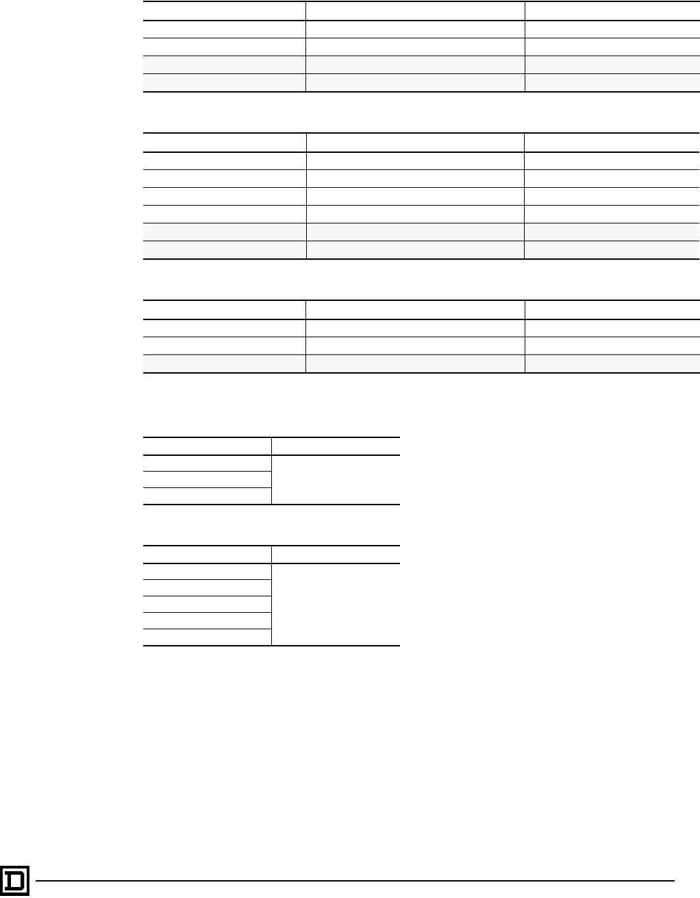
ALTIVAR 66 AC Drives
Parameter Summary
47
2/98 © 1998 Square D All Rights Reserved
Analog Input Map
Logic Output Map
Analog Output Map
NOTE: Parameters available only with the I/O Extension Module are shaded.
Display Configuration
Keypad Configuration
Analog Input Factory Setting Reassignable
AI1 Speed reference1 No
AI2 Speed reference 2 Yes
AI3 Speed reference 3 Yes
AI4 Not assigned Yes
Logic Output Factory Setting Reassignable
LO1 At speed Yes
LO2 Current limit Yes
R1 Fault No
R2 Running state Yes
R3 Thermal Level 1 Yes
R4 Ready State Yes
Analog Output Factory Setting Reassignable
AO1 Motor speed Yes
AO2 Motor current Yes
AO3 Motor power Yes
Selection Factory Setting
One Bar Graph, Scroll
One Bar GraphTwo Bar Graphs, Scroll
4 Tables, Scroll
Selection Factory Setting
Terminal Command
Terminal Command
Keypad Command
Ter/Key by LI
Ter/Key by F2
Program Function keys
This document provided by Barr-Thorp Electric Co., Inc. 800-473-9123 www.barr-thorp.com

ALTIVAR 66 AC Drives
Parameter Summary
© 1998 Square D All Rights Reserved
48 2/98
Display Mode Status Codes
Drive Configuration
Code Definition Code Definition
NLP No Line Power (control power supplied
separately) CLI Current Limit
RDY Drive Ready DCB DC Injection Braking
RUN Drive Running (at speed) JOG Jogging
Forward Direction NRP No Run Permissive (LI1 open)
Reverse Direction BRK Braking
ACC Accelerating SLC Serial LInk Command
DEC Deceleration FLT Fault
Parameter Range Factory Setting Description
Torque Type Constant
Variable
Variable Low Noise Constant Type of Torque.
Command Type 2-wire (maintained)
3-wire (impulse) 2-wire Type of control circuit which is wired into the AC drive, affecting
operation of the Forward and Reverse inputs.
Motor Power
(ATV66U41 only)
.75 kW / 1 hp
1.5 kW / 2 hp
2.2 kW / 3 hp 2.2 kW / 3 hp Used to select motor power for ATV66U41 AC drive.
General Configuration: Motor Parameters
Parameter Range Factory Setting Description
Nominal
Current 45–105% of AC drive current rating 90% Motor nameplate value for full load current.
Nominal
Frequency
50 Hz, 60 Hz 60 Hz if input freq. at
1st power up = 60 Hz
50 Hz if input freq. at
1st power up = 50 Hz
Point on the V/Hz curve beyond which voltage
remains virtually constant and only frequency
increases.
Special:
ATV66U41–D79, CT: 25–400 Hz;
ATV66C10–C31, CT: 25–200 Hz;
VT: 25–90 Hz
Nominal
Voltage
ATV66•••N4:
380- 400- 415- 440- 460 V
ATV66•••N4: 400 V if
input freq. at 1st
power up = 50 Hz;
460 V if input freq. at
1st power up = 60 Hz
Point on the V/Hz curve beyond which voltage
remains virtually constant and only frequency
increases.
ATV66•••M2:
208- 220- 230- 240 V ATV66•••M2: 230 V
IR
Compensation
Normal: 0–100%
High Torque: 0–150%
Special: 0–800% 100% Used to adjust low speed torque for optimal
performance. For constant torque only.
Voltage Boost 0–100% of nominal voltage 20% Corresponds to a voltage level at 0 Hz, allowing
for optimal voltage and torque boost during
starting in special and high torque control type.
Profile 0–100 20 Shapes the V/Hz profile of the output for variable
torque applications in normal control type.
Damping Normal, High Torque (CT) and
NOLD (VT): 1–100%;
Special (CT) and Normal (VT): 1-800% 20% Matches the response of the load to the
frequency response of the AC drive by adjusting
the integral gain of the frequency loop.
Bandwidth 0–100% 20% Second frequency loop gain when AC drive is set
for constant torque, high torque control type.
Rotation
Normalization ABC,
ACB ABC Inverts direction of motor rotation without
rewiring.
Torque Limit
Generator 0–200% of nominal motor torque 150% Allows the limitation of torque, independent of
current limit, in the generator quadrant (AC drive
with dynamic braking).
Torque Limit
Motor 0–200% of nominal motor torque 150% Allows the limitation of torque, independent of
current limit, in the motor quadrant.
This document provided by Barr-Thorp Electric Co., Inc. 800-473-9123 www.barr-thorp.com

ALTIVAR 66 AC Drives
Parameter Summary
49
2/98 © 1998 Square D All Rights Reserved
Current Limit
Default limit,
Alternate value,
CT: 40–150% of nominal drive
AC drive current if input freq. =
60 Hz, 40–150% of nominal
AC drive current if input freq. =
50 Hz
VT: 40–110% of nominal drive
AC drive current
By frequency level
CT, ATV66U41–D79: 0.1–400 Hz
CT, ATV66C10–C31: 0.1–200 Hz
VT: 0.1–90 Hz
CT: 150% if input
freq. = 60 Hz; 136% if
input freq. = 50 Hz
VT: 110%
Allows alternate current limit value by frequency
level, logic input or analog input.
Slip
Compensation
No,
Automatic,
Manual: 0.1–10 Hz Automatic Improves steady state speed regulation by
controlling output frequency based on motor slip.
Only available with constant torque configuration.
Brake Sequence Allows sequencing of AC drive output, mechanical brake actuation, and
DC injection for smooth starting and stopping.
Release
Frequency 0 Hz–Low Speed 0 Hz Release frequency and release current must be
reached before the brake output changes state.
Release
Current 0–100% of motor nominal current 0% Release current and release frequency must be
reached before the brake output changes state.
Release Time 0–5 s 0 s Delay between when brake output changes state
and AC drive begins its acceleration ramp.
Engage
Frequency 0 Hz–Low Speed 0 Hz Frequency at which, after a stop command is
received and the AC drive decelerates, DC
injection braking is activated.
Engage Time 0 to 5 s 0 s Delay between when Engage frequency is
reached and DC is injected, and when brake
output changes state initiating brake actuation.
DC Injection
Level 50–150% of motor nominal current 70% Level of DC injection braking current.
DC Brake Time 0–30.1 s 2 s Amount of time for which DC is injected.
General Configuration: Control Parameters
Parameter Range Factory Setting Description
Maximum
Frequency
CT, ATV66U41–D79:
Nominal Freq.–400 Hz
CT, ATV66C10–C31:
Nominal Freq. –200 Hz
VT: Nominal Freq.–90 Hz
60 Hz if input line
freq. = 50 Hz;
72 Hz if input line
freq. = 60 Hz
Maximum output frequency.
Low Speed 0–High Speed 0 Hz Low speed setting.
High Speed Low Speed to Maximum Frequency
50 Hz if input freq.
= 50 Hz;
60 Hz if input freq.
= 60 Hz
High speed setting.
Acceleration 0.1– 999.9 s 3 s Length of time to accelerate from zero speed to
nominal frequency.
Deceleration 0.1– 999.9 s 3 s Length of time to decelerate from nominal frequency
to zero.
Acceleration
Type
Linear,
S,
ULinear Type of acceleration ramp the AC drive follows.
Deceleration
Type
Linear,
S,
ULinear Type of deceleration ramp the AC drive follows.
Alternate
Ramps
No,
By Frequency level,
CT, ATV66U41–D79: 0.1–400 Hz
CT, ATV66C10–C31: 0.1–200 Hz
VT: 0.1–90 Hz
By Logic input
Acceleration 2: 0.1– 999.9 s
Deceleration 2: 0.1–999.9 s
No
5 s
5 s
Alternate acceleration and deceleration ramps
activated by either a frequency level or logic input.
General Configuration: Motor Parameters
Parameter Range Factory Setting Description
This document provided by Barr-Thorp Electric Co., Inc. 800-473-9123 www.barr-thorp.com

ALTIVAR 66 AC Drives
Parameter Summary
© 1998 Square D All Rights Reserved
50 2/98
NOTE: Parameters available only with the I/O Extension Module are shaded.
General Configuration: Control Type
Skip
Frequencies
Low speed to:
CT, ATV66U41–D79: 400 Hz
CT, ATV66C10–C31: 200 Hz
VT: 90 Hz
Skip bands: 2 or 5 Hz
None AC drive reference will not stop on the skip
frequency which causes mechanical resonance. Up
to 3 can be programmed.
Voltage
Reduction No, 100%-20% No Allows reduction of motor voltage when running at
no or low load in either forward or reverse.
Control Type Range Factory Setting
Constant Torque Normal, Special motors, High torque (SVC) Normal
Variable Torque Normal, NOLD Normal
Application Functions
Parameter Range Factory Setting Description
Run Reverse No
Yes, Logic input Ye s ,
Logic Input LI3 AC drive runs in reverse when assigned input is high.
Jog
No
Yes, Logic input
Jog speed: 0.2–10 Hz
Duty time: 0.2–10 s
Yes,
Logic Input LI4
5 Hz
0.5 s
AC drive jogs at programmed jog speed when assigned
input is high.
+/- Speed No
Yes, with memory
Yes, without memory No
Increase or decrease of the speed by using two logic
inputs, similar to a motorized potentiometer.
When input assigned to + speed is high, frequency
increases according to acceleration ramp, limited by the
reference frequency. When input goes low, speed is
maintained.
When input assigned to -speed is high, frequency
decreases according to deceleration ramp, limited by low
speed. When input goes low, speed is maintained.
With memory: AC drive stores speed.
Without memory: Last speed is not stored.
Set Point
Memory No
Yes, logic input No
When the assigned logic input goes high for longer than
0.1 s, the analog speed reference is stored and the AC
drive runs at that speed until the next time the input goes
high.
General Configuration: Control Parameters
Parameter Range Factory Setting Description
This document provided by Barr-Thorp Electric Co., Inc. 800-473-9123 www.barr-thorp.com

ALTIVAR 66 AC Drives
Parameter Summary
51
2/98 © 1998 Square D All Rights Reserved
NOTE: Parameters available only with the I/O Extension Module are shaded.
Preset
Speeds
No
1 Preset speed
3 Preset speeds
7 Preset speeds
Range: 0.1 Hz to:
CT, ATV66U41–D79: 400 Hz
CT, ATV66C10–C31: 200 Hz;
VT: 90 Hz
7 Preset speeds
(When preset
speeds are selected,
factory settings are
5, 10, 15, 20, 25, 30,
35 Hz)
AC drive runs at preset speed depending on settings of
assigned logic inputs.
Reference
Speed
0–20 mA
4–20 mA
20–4 mA
x–20 mA
4–20 mA Modification of AI2 for the type of signal.
Auto/Manual No
Yes, Logic input No Allows switching between AI1 and AI2 by logic command.
AI1 is manual reference. AI2 is automatic.
Tach.
Feedback No
Tach. FBK. IN: No Provides improved speed regulation by using feedback
from a user-supplied ±9 V tachogenerator.
Controlled
Stop
No
By Logic input
By Frequency level or by LI /
Frequency level
CT, ATV66U41–D79: 0.1–400 Hz
CT, ATV66C10–C31: 0.1–200 Hz
VT: 0.1–90 Hz
No Allows frequency threshold and Logic Input to work
together to tailor the stopping process.
Stopping Methods:
Freewheel stop
Fast stop
DC injection
Freewheel stop
Orient
No,
Yes, Define I/O
Dwell time: 0-10 s
DC injection time: 0-30 s
DC injection level: 50-150% of
nominal motor current
No
1 s
5 s
50%
A positioning function that allows the AC drive to start and
stop operation at the same rotor position relative to the
stator.
Shutdown No
Yes
Dwell time: 0.1–60 s
No
1 s
Allows AC drive to dwell at low speed before completely
stopping. Time adjustable between 1 and 30 s
Bypass
No
Yes, Define I/O
Delay time: 0.2–10 s
Sequence Time-out Fault:
0.2–300 s
Process Time-out Fault: 0.2–300 s
No
2 s
5 s
5 s
Used to run machine at full speed when the drive must be
taken off line for service or repair. Allows for isolation of the
motor by means of a contactor installed between the drive
and the motor with a special command sequence.
Process
Cycles
No,
Yes,
Define I/O
Define Step
No
For programming sequences of operations. Each
sequence can be programmed with a specific
acceleration/deceleration time, direction, set speed, and
duration.
Mot. Select
Switch
1 Motor
2 Motors
2 Parameters
3 Motors
3 Parameters
1 Motor
2 Motors and 3 Motors used to toggle between sets of
motor and control parameters for using two or three
motors with a single AC drive.
2 Parameters and 3 Parameters only toggle control
parameters, and are for use with one motor.
PI Regulator
No
Yes, Set Point
Feed Back
Set Point Manual
PI Parameters
No Used for controlling level or flow of a process with setpoint
and feedback inputs.
Forced Local No
Yes, Logic Input No Used to return control to the terminal strip or keypad if in
serial link (communication) mode.
Application Functions
Parameter Range Factory Setting Description
This document provided by Barr-Thorp Electric Co., Inc. 800-473-9123 www.barr-thorp.com

ALTIVAR 66 AC Drives
Parameter Summary
© 1998 Square D All Rights Reserved
52 2/98
NOTE: Parameters available only with the I/O Extension Module are shaded.
Fault History
Fault Designation Description
IN-PHASE LOSS Input Phase Loss: Loss of power or blown fuses. A brief loss of input supply phase (≤ 200
ms) is not detected
UNDERVOLTAGE Undervoltage: Input voltage to power supply too low or temporary voltage drop
AC-LIN.OVERVOL. AC line overvoltage: Input voltage to power supply too high
DRIVE OVERTEMP. Drive overtemperature: heat sink temperature too high
MOT. OVERLOAD Motor overload: Thermal trip because of prolonged overload, running in single phase on
the output, or motor power rating too low for the application
LOSS FOLLOWER Loss of follower: Loss of the 4-20 mA or 20-4 mA reference at AI2 input
OUT. PHASE LOSS Loss of an output phase
DC-BUS OVERVOL. DC bus overvoltage or overcurrent due to excessive braking or overhauling load
SHORT CIRCUIT or
SHORT CIRCUIT. Short circuit between phases or on the output of AC drive
GROUND FAULT Ground fault: short circuit to earth on the output of the AC drive
PRECHARGE FAIL Precharge failure: capacitor precharge relay fault
INTERNAL FAULT Internal fault or missing connection on CL1 and CL2
MEMORY FAILURE Error in storing to EEPROM
SERIAL LINK Bad connection of keypad display or communication fault on serial link
AUTO-TEST FAIL Main control board failure
OVERSPEED Without a tachometer, fault occurs when output frequency is 20% above Maximum
Frequency for 250 ms.
SEQUENCE T. OUT Sequence time-out: sequence input not received after Run command within programmed
time. Used with Bypass function.
PROCESS TIME OUT Process time-out: process input not received after Run command within programmed time.
Used with Bypass function.
DYNAMIC BRAKE Dynamic brake resistor lost or connection open.
DB RESISTOR Thermal overload of braking resistor.
TRANS. SHORT C. or GF Short circuit in transistor
OPEN TRANSISTOR Transistor has failed open
CONTROL SUPPLY CL1/CL2 not connected. Only recognized upon power-up.
--No Fault-- No fault recorded
CUSTOM. FAULT Customer-defined fault
This document provided by Barr-Thorp Electric Co., Inc. 800-473-9123 www.barr-thorp.com

ALTIVAR 66 AC Drives
Drive Selection
53
2/98 © 1998 Square D All Rights Reserved
460 V AC DRIVES
The following tables show power and current ratings for 460 V AC drives when set for constant torque (Table
1); variable torque (Table 2); and variable torque, low noise (Table 3). For 230 V AC drives, see page 56.
Table 1: Constant Torque AC drive Ratings 460 V
400 V ±15% and 460 V ±15%, 50/60 Hz ±5%
Switching Frequency: ATV66U41N4 to D46N4 = 4 kHz, ATV66D54N4 to C31N41 = 2 kHz
Motor Power Output
Current Max. Transient
Current (60 s) Total Dissipated
Power AC Drive Catalog No.
400 V
50 Hz 460 V
60 Hz
kw hp A A W
0.75
—
1.5
—
2.2
—
—
1
—
2
—
3
2.3
1.8
4.1
3.4
5.8
4.8
3.2
2.7
5.6
5.1
8.0
7.2
95.0
95.0
117
117
140
140
ATV66U41N4
3.0 — 7.8 10.7 165 ATV66U54N4
4.0
——
510.5
7.6 14.2
11.4 185 ATV66U72N4
5.5
——
7.5 13
11 17.7
16.5 225 ATV66U90N4
7.5
——
10 17.6
14.0 24.0
21.0 290 ATV66D12N4
11.0
——
15 24.2
21.0 33.0
31.5 380 ATV66D16N4
15.0
——
20 33.0
27.0 45.0
40.5 530 ATV66D23N4
22.0
——
30 48.4
40.0 66.0
60.0 655 ATV66D33N4
30.0
——
40 66.0
52.0 90.0
78.0 880 ATV66D46N4
37.0
——
50 79.2
65.0 108
97.5 885 ATV66D54N4
45.0
——
60 93.5
77.0 127.5
115.5 1055 ATV66D64N4
55.0
——
75 115.5
96.0 157.5
144.0 1270 ATV66D79N4
75
——
100 152
124 207
186 1605 ATV66C10N4
90
——
125 190
156 258
234 1952 ATV66C13N4
110
——
150 226
180 307
270 2251 ATV66C15N4
132
——
200 270
240 367
360 3067 ATV66C19N4
160
——
250 330
300 450
450 4483 ATV66C23N41
200
——
300 407
360 555
540 5246 ATV66C28N41
220
——
350 449
420 612
630 5966 ATV66C31N41
This document provided by Barr-Thorp Electric Co., Inc. 800-473-9123 www.barr-thorp.com

ALTIVAR 66 AC Drives
Drive Selection
© 1998 Square D All Rights Reserved
54 2/98
Table 2: Variable Torque AC Drive Ratings 460 V
400 V ±15% and 460 V ±15%, 50/60 Hz ±5%
Switching Frequency: ATV66U41N4 to D46N4 = 4 kHz, ATV66D54N4 to C31N41 = 2 kHz
Motor Power Output
Current Max. Transient
Current (60 s) Total Dissipated
Power AC Drive Catalog No.
400 V
50 Hz 460 V
60 Hz
kw hp A A W
0.75
—
1.5
—
2.2
—
3.0
—
1
—
2
—
3
—
2.0
1.8
3.7
3.4
5.3
4.8
7.1
2.2
2.0
4.0
3.7
5.8
5.3
7.8
90.0
90.0
110
110
130
130
150
ATV66U41N4
4.0
——
59.5
7.6 10.5
8.4 180 ATV66U54N4
5.5
——
7.5 11.8
11.0 13.0
12.1 205 ATV66U72N4
7.5
——
10 16.0
14.0 17.6
15.4 265 ATV66U90N4
11.0
——
15 22.0
21.0 24.2
23.1 350 ATV66D12N4
15.0
——
20 30.0
27.0 33.0
29.7 480 ATV66D16N4
18.5
——
25 37.0
34.0 40.7
37.4 560 ATV66D23N4
30.0
——
40 60.0
52.0 66.0
57.2 800
800 ATV66D33N4
37.0
——
50 72.0
65.0 79.2
71.5 910 ATV66D46N4
45.0
——
60 85.0
77.0 93.5
84.7 960 ATV66D54N4
55.0
——
75 105
96.0 115
105 1150 ATV66D64N4
75.0
——
100 143
124 151
136 1400 ATV66D79N4
90.0
——
125 170
156 187
171 2271 ATV66C10N4
110
——
150 205
180 226
198 2596 ATV66C13N4
132
——
200 245
240 270
264 3246 ATV66C15N4
200
——
300 370
360 407
396 5246 ATV66C23N41
220
——
350 408
420 449
462 5966 ATV66C28N41
250
——
400 460
477 506
525 6624 ATV66C31N41
This document provided by Barr-Thorp Electric Co., Inc. 800-473-9123 www.barr-thorp.com

ALTIVAR 66 AC Drives
Drive Selection
55
2/98 © 1998 Square D All Rights Reserved
Table 3: Variable Torque, Low Noise AC Drive Ratings 460 V
400 V ±15% and 460 V ±15%, 50/60 Hz ±5%
Switching Frequency: ATV66U41N4 to D46N4 = 10 kHz, ATV66D54N4 to D79N4 = 4 kHz
Motor Power Output
Current Max. Transient
Current (60 s) Total Dissipated
Power AC Drive Catalog No.
400 V
50 Hz 460 V
60 Hz
kw hp A A W
0.75
—
1.5
—
2.2
—
—
1
—
2
—
3
2.0
1.8
3.7
3.4
5.3
4.8
2.2
2.0
4.0
3.8
5.8
5.3
90.0
90.0
110
110
130
130
ATV66U41N4
3.0 — 7.1 7.8 150 ATV66U54N4
4.0
——
59.5
7.6 10.5
8.4 180 ATV66U72N4
5.5
——
7.5 11.8
11.0 13.0
12.1 205 ATV66U90N4
7.5
——
10 16.0
14.0 17.6
15.4 265 ATV66D12N4
11
——
15 22
21 24.2
23.1 350 ATV66D16N4
15
——
20 30
27 33.0
29.7 480 ATV66D23N4
22
——
30 44
40 48.4
44.0 600 ATV66D33N4
30
——
40 60
52 66.0
57.2 800 ATV66D46N4
37
——
50 72
65 79.2
71.5 910 ATV66D54N4
45
——
60 85
77 93.5
84.7 960 ATV66D64N4
55
——
75 105
96 115
105 1150 ATV66D79N4
This document provided by Barr-Thorp Electric Co., Inc. 800-473-9123 www.barr-thorp.com
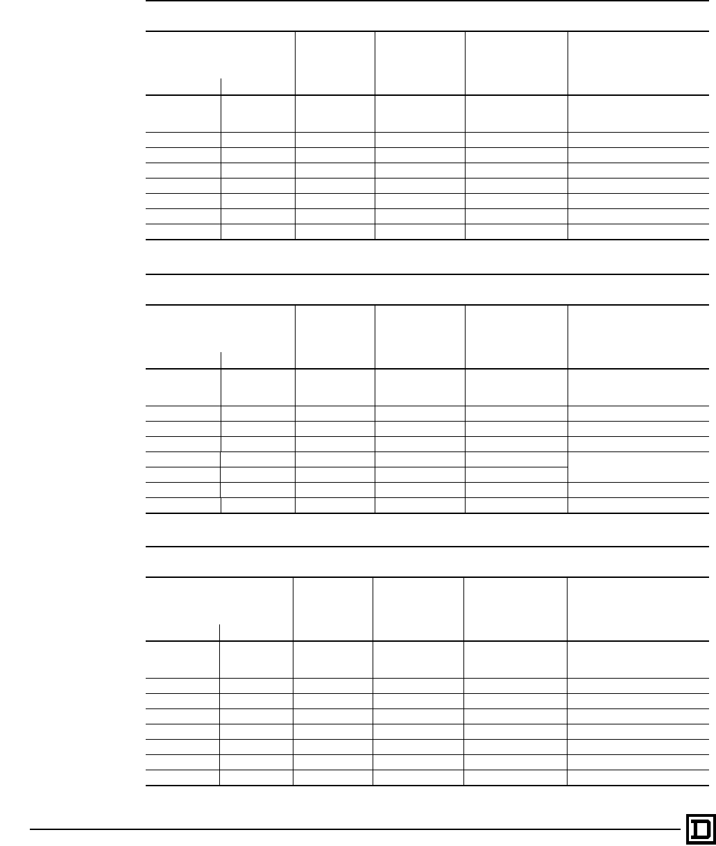
ALTIVAR 66 AC Drives
Drive Selection
© 1998 Square D All Rights Reserved
56 2/98
208 V AND 230 V AC DRIVES
Tables 4, 5, and 6 show the power and current ratings for 230 V AC drives when set for constant torque
(Table 4); variable torque (Table 5); and variable torque, low noise (Table 6).
Table 4: Constant Torque AC Drive Ratings, 208 V/230 V
208 V ±10% and 230 V ±15%, 50/60 Hz ±5%
Switching Frequency: ATV66U41M2 to D33M2 = 4 kHz, ATV66D46M2 = 2 kHz
Motor Power Output
Current Max. Transient
Current (60 s) Total Dissipated
Power AC Drive Catalog No.
208/230 V
50/60 Hz
kw hp A A W
.75
1.5
2.2
1
2
3
4.0
7.5
10.6
6.0
11.3
15.9
120
140
170 ATV66U41M2
4 5 16.7 25.1 239 ATV66U72M2
5.5 7.5 24.2 36.3 354 ATV66U90M2
7.5 10 30.8 46.2 437 ATV66D12M2
11 15 46.2 69.3 589 ATV66D16M2
15 20 59.4 89.1 728 ATV66D23M2
22 30 88.0 132 1052 ATV66D33M2
30 40 114 171 1439 ATV66D46M2
Table 5: Variable Torque AC Drive Ratings 208 V/230 V
208 V ±10% and 230 V ±15%, 50/60 Hz ±5%
Switching Frequency: ATV66U41M2 to D33M2 = 4 kHz, ATV66D46M2 = 2 kHz
Motor Power Output
Current Max. Transient
Current (60 s) Total Dissipated
Power AC Drive Catalog No.
208/230 V
50/60 Hz
kw hp A A W
.75
1.5
2.2
1
2
3
4.0
7.5
10.6
11.7
8.3
11.7
120
140
170 ATV66U41M2
5.5 7.5 24.2 26.6 302 ATV66U72M2
7.5 10 30.8 33.9 414 ATV66U90M2
11.0 15 46.2 50.8 559 ATV66D12M2
15.0 20 59.4 65.32 770 ATV66D23M2
18.5 25 74.8 82.3 831
30.0 40 114 125 1260 ATV66D33M2
37.0 50 143 157 1528 ATV66D46M2
Table 6: Variable Torque, Low Noise AC Drive Ratings 208 V/230 V
208 V ±10% and 230 V ±15%, 50/60 Hz ±5%
Switching Frequency: ATV66U41M2 to D33M2 = 10 kHz, ATV66D46M2 = 4 kHz
Motor Power Output
Current Max. Transient
Current (60 s) Total Dissipated
Power AC Drive Catalog No.
208/230 V
50/60 Hz
kw hp A A W
.75
1.5
2.2
1
2
3
4.0
7.5
10.6
4.4
8.3
11.7
125
150
181 ATV66U41M2
4.0 5 16.7 18.4 252 ATV66U72M2
5.5 7.5 24.2 26.6 375 ATV66U90M2
7.5 10 30.8 33.9 459 ATV66D12M2
11.0 15 46.2 50.8 619 ATV66D16M2
15.0 20 59.4 65.3 785 ATV66D23M2
22.0 30 88.0 96.8 1127 ATV66D33M2
30.0 40 114 125 1332 ATV66D46M2
This document provided by Barr-Thorp Electric Co., Inc. 800-473-9123 www.barr-thorp.com
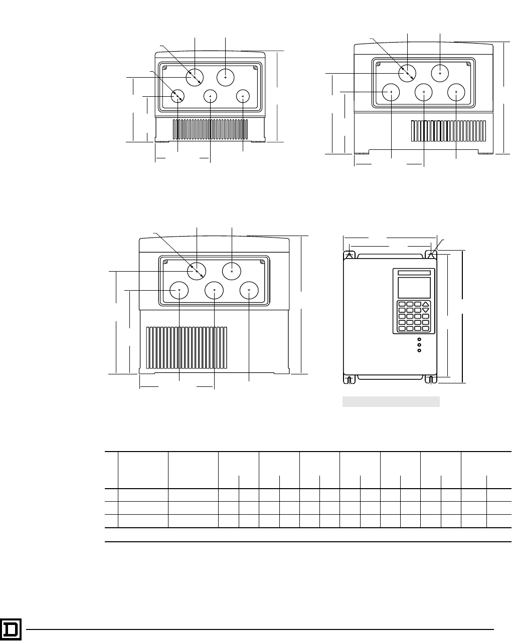
ALTIVAR 66 AC Drives
Dimensions and Weights for Mounting – Outlines 1, 2, 3
57
2/98 © 1998 Square D All Rights Reserved
Dimensions & Weights for Wall or Panel Mounting
Mounting Dimensions
NOTE: When metallic conduit is used with AC drives of Outlines 1–3, install a metal conduit entry plate
(kit VY1A66201 — separately ordered). Kit mounts in place of the existing plastic plate and has a
conduit hole pattern identical to those shown for Outlines 1–3.
Outline
AC Drive
ATV66•••N4 AC Drive
ATV66•••M2
H1 H2 W1 W2 Ø Weight Door Swing
Clearance[1]
in mm in mm in mm in mm in mm lb kg in mm
1 U41–U72 U41 11.6 295 10.9 280 7.8 200 6.9 175 0.22 5.5 10.4 4.7 7.8 200
2 U90, D12 U72, U90 12.8 325 12.2 310 9.2 234 8.2 209 0.22 5.5 16.1 7.3 9.2 234
3 D16, D23 D12, D16 16.3 415 15.7 400 9.2 234 8.2 209 0.22 5.5 30.9 14 9.2 234
[1]Door hinges on left-hand side of AC drive.
Conduit Entries - Bottom View
Outline 1 Outline 2
Outline 3
Mounting
Dimensions: in (mm)
4.61 (117)
2.28 (58)
4.17
(106)
7.68
(195)
2.28 (58)
5.28
(134)
2.28 (58)
5 x ø1.14 (29)
9.65
(245)
4.61 (117)
2.28 (58)
5.79
(147)
2.28 (58)
6.89
(175)
2.28 (58)
5 x ø1.14 (29)
W1
H1
W2
H2
4 x ø
0.22 (5.5)
3.94 (100)
1.77 (45)
3.11
(79)
2 x ø1.14 (29)
1.77 (45)
4.45
(113)
1.69 (43)
3 x ø0.87 (22)
6.50
(165)
This document provided by Barr-Thorp Electric Co., Inc. 800-473-9123 www.barr-thorp.com
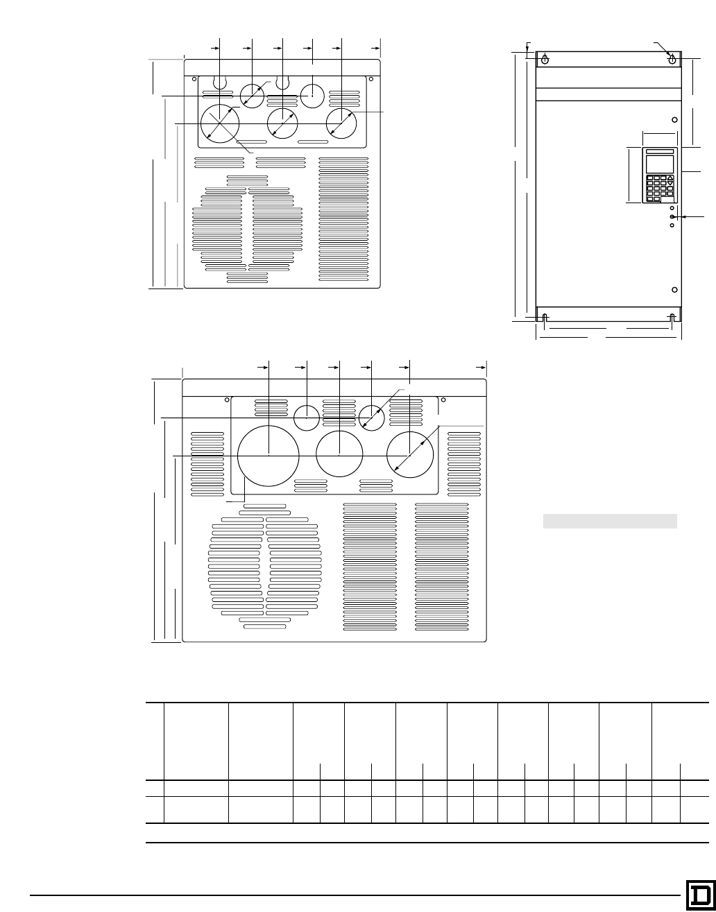
ALTIVAR 66 AC Drives
Dimensions and Weights for Mounting – Outlines 4 and 5
© 1998 Square D All Rights Reserved
58 2/98
Mounting Dimensions
Outline
AC Drive
ATV66•••N4 AC Drive
ATV66•••M2
H1 H2 W1 W2 Ø J Weight
Door
Swing
Clearance
[1]
in mm in mm in mm in mm in mm in mm lb kg in mm
4 D33, D46 D23, D33 23.6 600 22.8 580 9.5 240 8.1 205 0.28 7 3.19 81 59.5 27 9.5 240
5 D54–D79 D46 25.6 650 24.4 620 13.8 350 11.8 300 0.35 9 3.39 86 88.2
90.4 40
41 13.8 350
[1]Door hinges on left-hand side of AC drive.
2.12
(54)
0
REF 3.56
(90.5) 4.94
(125.5) 6.32
(160.5) 7.52
(191) 9.45
(240)
Depth 11.0 (280)
9.25 (235)
7.95 (202)
ø1.85 (47)
2 x ø1.14 (29)
2 x ø 1.46 (37)
Conduit Entries - Bottom View
Outline 5
Outline 4
Mounting
Dimensions: in (mm)
H1
H2
0.39 (10) 4 x ø
J
2.44
(62)
3.25
(82.5)
5.31
(135)
0.35
(9)
W2
W1
3.62
(92)
0 REF 5.32
(135) 6.77
(172) 8.23
(209) 9.92
(252) 13.54
(344)
Depth 11.8 (300)
10.0 (254)
8.36 (212)
2 x ø1.14 (29)
2 x ø2.01 (51)
2.52
(64)
This document provided by Barr-Thorp Electric Co., Inc. 800-473-9123 www.barr-thorp.com
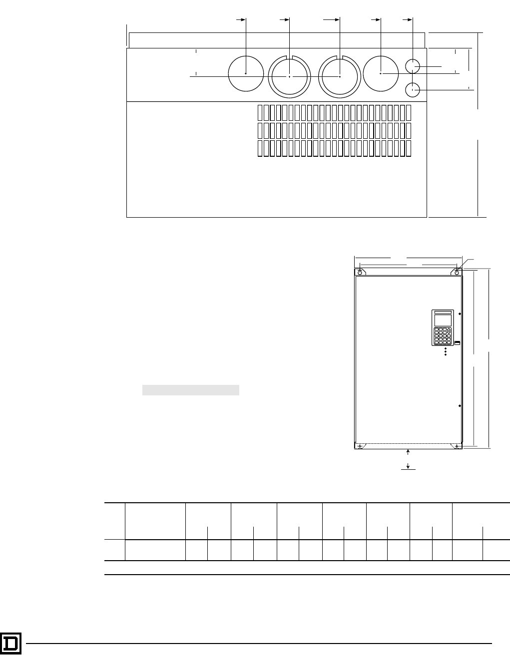
ALTIVAR 66 AC Drives
Dimensions and Weights for Mounting – Outline 6
59
2/98 © 1998 Square D All Rights Reserved
Mounting Dimensions
Outline
AC Drive
ATV66•••N4
H1 H2 W1 W2 Ø Weight Door Swing
Clearance [1]
in mm in mm in mm in mm in mm lb kg in mm
6C10
C13, C15, C19 38.6 980 37.7 960 23.0 585 20.8 528 .375 9.5 280
300 127
136 23 584
[1]Door hinges on left-hand side of AC drive.
Depth
14.76
(375)
3.33
(84.5)
2.34
(59.5)
6.88
(175) 10.6
(269)
15.0
(382) 19.1
(485) 21.8
(553)
2.14
(54.2)
1.60
(40.5)
[1] [2]
CONTROL
OUTPUT
(T1,T2,T3)
DB &
PARALLEL
(+,–,PA,PB)
INPUT
(L1,L2,L3)
INPUT
(L1,L2,L3)
M8 M8 M8
M4
M87 M87
M4
0 REF
M8
Conduit Entries - Bottom View
Mounting
Dimensions: in (mm)
KNOCKOUTS:
M4 = 2 x 1.00 (25.4) dia.
M7 = 2.00 (50.8) dia.
M8 = 2.50 (63.5) dia.
M87 = 3.00 (76.2) dia. w/ 2.50 (63.5) dia.
NOTES:
[1] Use 2 in (50.8 mm) knockout for parallel
cable runs.
[2] Use single 3 in (76.2 mm) knockout for
single cable run.
[3] Leave an area extending 13.5 in.
(343 mm) below drive free of obstructions
to allow access to ventilation fan.
Outline 6
W1
H1
H2
W2 4 x ø
12 (305) [3]
This document provided by Barr-Thorp Electric Co., Inc. 800-473-9123 www.barr-thorp.com
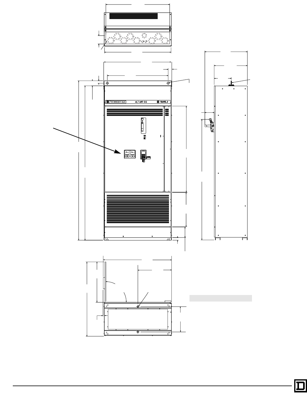
ALTIVAR 66 AC Drives
Dimensions and Weights for Mounting – Outline 6
© 1998 Square D All Rights Reserved
60 2/98
FRONT VIEW
37.94
(963.7)
4.28
(108.7)
Removable conduit plate
w/ suggested hole pattern
39.54
(1004.2)
39.98
(1015.5) 1.90
(48.3)
36.18
(919.0)
1.44
(36.6)
3.00
(76.20)
94.65
(2404.1)
91.65
(2327.9)
51.09
(1297.7)
1.38
(35.0)
Dia (2 places)
20.25
(514.3)
1.50
(38.1)6.17
(156.7)
25.26
(641.7)
20.00
(508.0)
10.00
(254.0)
5.54
(140.6)
Removable
Plate
71.59
(1818.3)
RIGHT SIDE VIEW
40.86
(1037.9)
20.00
(508.0)
.69
(17.5)
1.00
(25.4)
Dia (2 places)
90°
Both Sides
15.0
(381.0)
35.46
(900.7)
BOTTOM VIEW
Input Parallel Control Output
55.35
(1405.9)
DB
Dimensions:
in (mm)
WEIGHT: 1,400 lb (635 kg)
Outline 7
Control island for mounting
operators and/or meters.
This document provided by Barr-Thorp Electric Co., Inc. 800-473-9123 www.barr-thorp.com
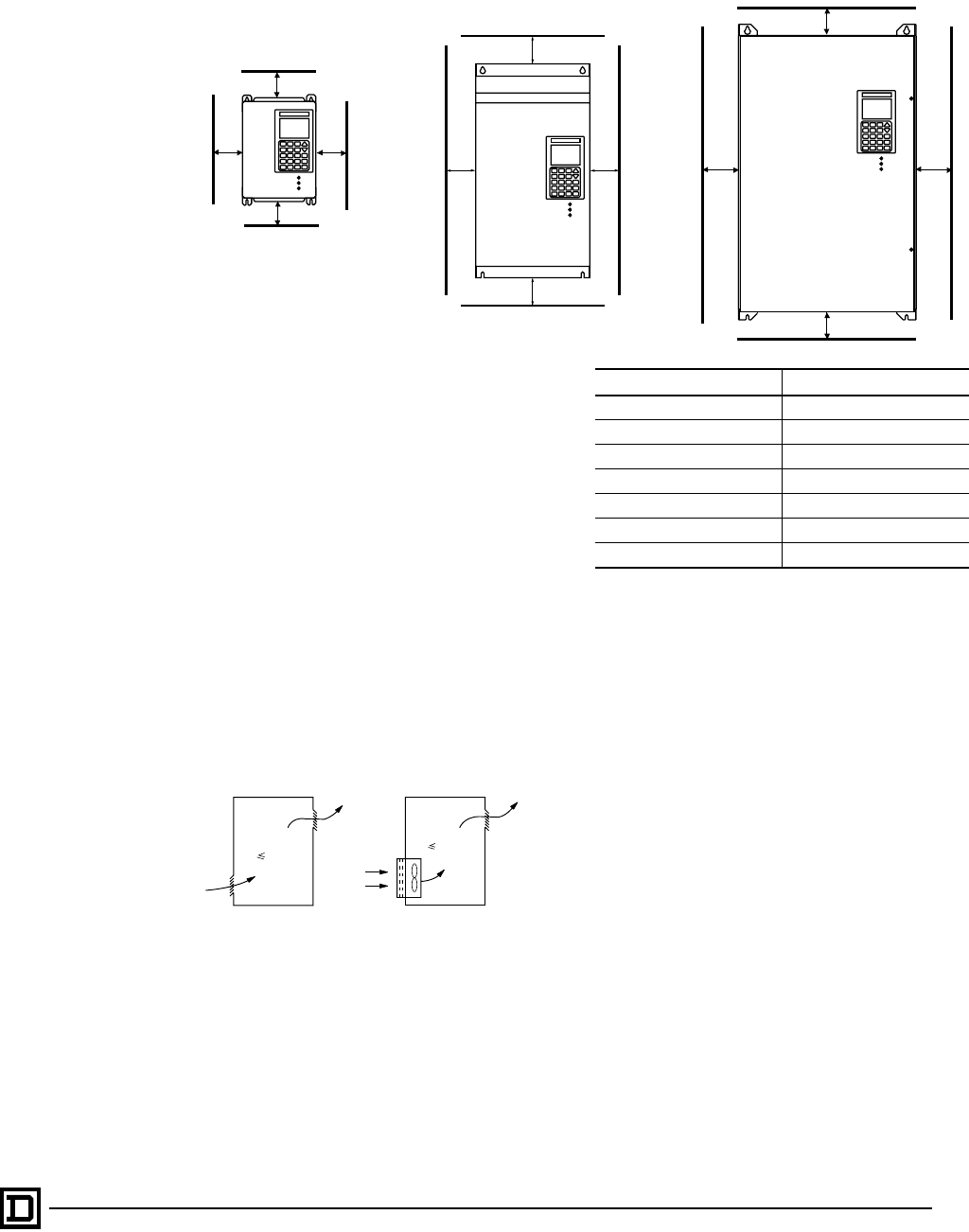
ALTIVAR 66 AC Drives
Mounting in Enclosures
61
2/98 © 1998 Square D All Rights Reserved
Mounting Precautions
When mounting the drive:
• To prevent thermal fault or equipment damage,
provide sufficient enclosure cooling and/or
ventilation to limit the ambient temperature
around the drive to a maximum of 40 °C. Air
should circulate from bottom to top.
• Install drive vertically.
• Avoid placing drive near heat producing
elements.
• When installation surface is uneven, put a
spacer behind the drive mounting pads to
eliminate gaps.
• The ALTIVAR 66 drive is Type 1. The
environment around the drive must not exceed
Pollution Degree 3 requirements as defined in
NEMA ICS 1-111A or IEC 664.
Mounting in General Purpose Enclosure
Mounting in Type 12 (IP54) Enclosure
Certain environmental conditions such as dust,
corrosive gas and high humidity with risk of
condensation require that the drive be mounted in
a Type 12 (IP54) enclosure. Follow the mounting
precautions given above and observe minimum
clearances shown. In addition, to avoid hot spots
in the drive, provide an auxiliary fan kit to stir the
air.
4
4
2 2
(50) (50)
(100)
(100)
8 (200)
8 (200)
2
(50)
2
(50)
(200)
(200)
(75) (75)
8
8
33
θ° 40 °C
θ° 40 °C
Follow the mounting precautions above. To
ensure sufficient air circulation in the drive:
• Provide air vents.
• Observe minimum clearances shown above.
• If necessary, install a fan with filter in the
enclosure with a flow rate greater than that
listed below.
Drives Fan Characteristics
ATV66U41N4 and U54N4 10 CFM (5 dm3/s)
ATV66U72N4 20 CFM (10 dm3/s)
ATV66U90N4-D12N4 44 CFM (22 dm3/s)
ATV66D16N4-D23N4 94 CFM (47 dm3/s)
ATV66D33N4-D79N4 200 CFM (100 dm3/s)
ATV66C10N4-C19N4 500 CFM (250 dm3/s)
ATV66C23N41-C31N41 1000 CFM (500 dm3/s)
This document provided by Barr-Thorp Electric Co., Inc. 800-473-9123 www.barr-thorp.com
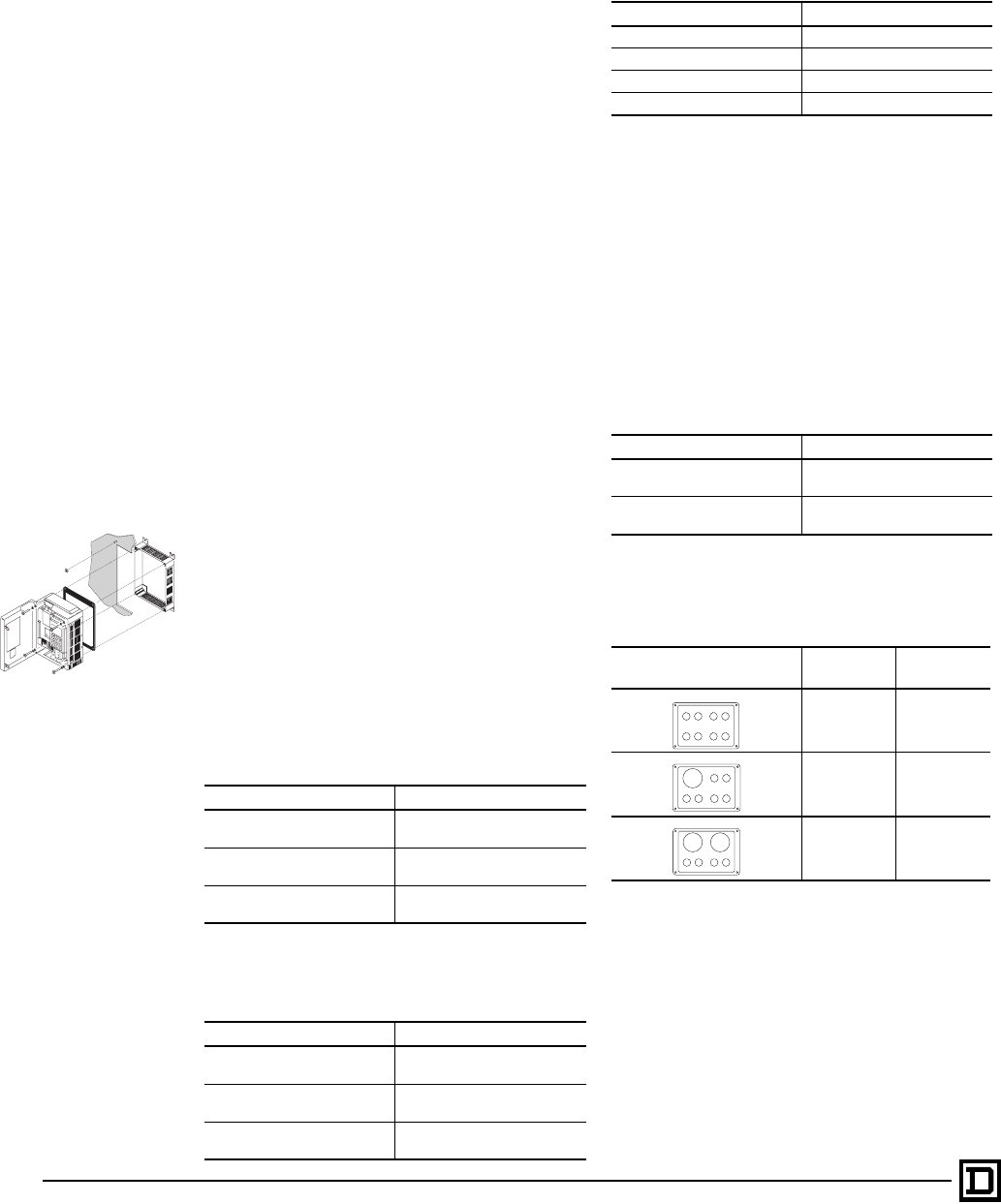
ALTIVAR 66 AC Drives
Mounting in Enclosures
© 1998 Square D All Rights Reserved
62 2/98
Calculation of Enclosure Dimensions
Maximum thermal resistance Rth (°C/W):
For power dissipated by the drive, see tables on
pages 53-56. Add power dissipated by other
components in enclosure. Useful heat exchange
surface area S (in2): Sides + top + front (if
enclosure is wall-mounted):
• Use only metallic enclosures.
• Do not install enclosures where external heat
sources can add to enclosure heat load.
• The mounting method must allow for free air
movement over all surfaces considered for
useful heat exchange surface area.
Recess Mounting Kit (Degree of Protection
Type 12, IP54)
To reduce power dissipated in the enclosure,
ATV66U41N4 to D23N4 drives may be recess
mounted in a wall of the enclosure with the heat
sink on the outside. This requires a cutout in the
enclosure and a recess mounting kit which
consists of gaskets, instructions, and cut-out
dimensions.
Gasket Kit
A kit similar to the gasket kit, but also including a
mounting adapter plate, is available.
Mounting Adapter Plate Kit
For this type of mounting, the heat sink and fan on
the outside of the enclosure is Type 12/IP54
degree of protection. Power dissipated by the
drive in an enclosure when recess mounted:
Risk of Condensation
If there is a possibility of condensation, keep the
control supply switched on during periods when
the motor is not running, or install
thermostatically-controlled strip heaters.
Keypad Door Mounting Kit
The keypad display can be mounted on the door
of the enclosure. The kit consists of a plastic key
holder, gasketing, and either a 2- or 3-meter cable.
Green, red, and yellow LEDs are also included for
mounting below the remote-mounted keypad.
Control Island Kit
Three control islands are available for ALTIVAR 66
drive controllers:
The VW3A66102-VW3A66104 Control Island Kits
are designed for use with the following operators
and meters: Telemecanique Type ZA2B
Operators, WINDO™ Series DW 2-1/2" surface
mount digital panel meters, and MODUTEC® S
Series 2-1/2" surface mount analog meters.
When used with compatible operators and meters
and the recommended panel gaskets, the control
island maintains Type 12/IP54 integrity of the
enclosure sidewall. The control island meets or
exceeds impact and flame resistance
requirements of UL 50
Drives Catalog Numbers
ATV66U41N4 to U72N4 and
U91M2 VW3A66801T
ATV66U90N4, D12N4,
U72M2 and U90M2 VW3A66802T
ATV66D16N4, D23N4,
D12M2 and D16M2 VW3A66803T
Drives Catalog Numbers
ATV66U41N4 to U72N4 and
U91M2 VW3A66806
ATV66U90N4, D12N4,
U72M2 and U90M2 VW3A66807
ATV66D16N4, D23N4,
D12M2 and D16M2 VW3A66808
Rth TiTo
–
P
------------------=
TiMax. internal ambient temp. (°C) around drive = 40 °C=
ToMax. external ambient temp. (°C) around enclosure=
P Total power dissipated in enclosure (W)=
S K
Rth
---------=
Rth Thermal resistance of enclosure (calculated above)=
K Area resistivity of enclosure material=
Drives Power in W
ATV66U41N4 to U72N4 70
ATV66U90N4 to D12N4 75
ATV66D16N4 110
ATV66D23N4 130
Catalog Number Description
VW3A66100 Keypad door mounting kit with
2-meter cable
VW3A66101 Keypad door mounting kit with
3-meter cable.
Control Island
(Front Views) Number of
Meters Number of
Operators
08
16
24
This document provided by Barr-Thorp Electric Co., Inc. 800-473-9123 www.barr-thorp.com

ALTIVAR 66 AC Drives
Power Terminal Descriptions
63
2/98 © 1998 Square D All Rights Reserved
Power Terminal Descriptions
The CL1 & CL2 terminals are connected with jumpers to L1 & L2 terminals. When using a line contactor, the jumpers must be removed
and CL1 & CL2 supplied separately to maintain control power. See circuit diagrams on page 66. CL1 & CL2 must be connected to
the same feeder conductors that supply L1, L2 & L3 of the AC drive.
The LI, L2, and L3 terminals on the ATV66C15N4 and C19N4 drive controllers are equipped with metric hex head bolts requiring a
13 mm socket. The other terminals (except PA & PB) require a 3/8 inch hex wrench, supplied with the drive controller. Terminals PA
and PB require a 3/16 inch hex wrench, supplied with the drive controller.
Terminal Function Characteristics
GND L2
L1 L3 3-phase power supply 400/460 VAC ±15% (ATV66•••N4 units)
208 V ±10% / 230 V ±15% (ATV66•••M2 units)
47–63 Hz
+
–Filtered
DC voltage 550–850 VDC (ATV66•••N4 units)
275–425 VDC (ATV66•••M2 units)
U/T1 W/T3
V/T2 GND Output connections to motor 0–400 VAC / 0–460 VAC
0–208 VAC / 0–230 VAC
CL1
CL2 Single-phase control supply 400/460 VAC ±15% (ATV66•••N4 units)
208 V ± 10% / 230 V ± 15% (ATV66•••M2 units)
47–63 Hz
PA
PB Dynamic braking resistor 550–850 VDC (ATV66•••N4 units)
275–425 VDC (ATV66•••M2 units)
CL21
CL22 Tap for CL1 & CL2
400/460 VAC ±15% (ATV66•••N4 units)
208 V ± 10% / 230 V ± 15% (ATV66•••M2 units)
47–63 Hz
ATV66D16N4 to C31N41 AC drives only
Power Terminal Wire Range
NOTE: All wire entries in AWG or Thousand Circular Mills (MCM) represent the maximum allowable
conductor size for the referenced field wiring terminal. All wire entries in square mm (mm
2
) represent the
recommended size of conductor based on IEC 364 conductor dimensioning criteria. Do not use the IEC
364 conductor selections for installations requiring dimensioning per NFPA 70 or CSA C22.
Terminals
Drive Controller (ATV66•••••)
U41N4
U54N4
U72N4
U41M2
[1]
U90N4
D12N4
U72M2U
90M2
[1]
D16N4
D23N4
D12M2
D16M2
[1]
D33N4
D46N4
D23M2
D33M2
[2]
D54N4
D64N4
D79N4
D46M2
[2]
C10N4
C13N4
[2]
C15N4
C19N4
[2]
C23N41
C28N41
C31N41
[2]
CL1, CL21
CL2 CL22
Max. Wire Size AWG
mm210
2.5 6
10 12
2.5 12
2.5 12
2.5 8
88
88
8
Terminal
Torque lb-in
N•m 6.73
0.76 35.4
46.73
0.76 6.73
0.76 6.73
0.76 20
2.3 20
2.3 20
2.3
L1
L2
L3
Max. Wire Size AWG
mm210
2.5 6
10 4
10 2/0
35 4/0
70 350 MCM
120 2 x 300 MCM
185 3 x 500 MCM
Terminal
Torque lb-in
N•m 6.73
0.76 35.4
417.7
288
10 170[4]
19 325
36.7 375
42.4 375
U/T1
V/T2
W/T3
Max. Wire Size AWG
mm210
2.5 6
10 4
10 2/0
35 4/0
70 350 MCM
120 350 MCM
185 3 x 500 MCM
Terminal
Torque lb-in
N•m 6.73
0.76 35.4
417.7
288
10 170[4]
19 325
36.7 325
36.7 375
+
–
Max. Wire Size AWG
mm210
2.5 6
10 4
10 2/0
35 4/0
70 350 MCM
120 350 MCM
185 3 x 500 MCM
Terminal
Torque lb-in
N•m 6.73
0.76 35.4
417.7
288
10 170[4]
19 325
36.7 325
36.7 375
PA
PB
Max. Wire Size AWG
mm210
2.5 6
10 8
64
16 2
35 2/0
35 2/0
35 3 x 500 MCM
Terminal
Torque lb-in
N•m 6.73
0.76 35.4
410.6
1.2 17.7
226.5
3120[3]
13.6 120[3]
13.6 375
GND
IN
Max. Wire Size AWG
mm26
66
10 4
10 4
16 2
35 350 MCM
70 350 MCM
95 3 x 350 MCM
Terminal
Torque lb-in
N•m 17.7
235.4
417.7
226.5
326.5
3325
36.7 325
36.7 325
GND OUT
Max. Wire Size AWG
mm26
66
10 4
10 4
16 2
35 350 MCM
70 350 MCM
95 3 x 350 MCM
Terminal
Torque lb-in
N•m 17.7
235.4
417.7
226.5
326.5
3325
36.7 325
36.7 325
[1] 60/75 °C copper.
[2] 75 °C copper.
[3] For 10 - 14 AWG (2.5 - 5 mm2) conductors, use 35.4 lb-in (4 N•m) torque; and for 8 AWG (8 mm2) conductors, use 40 lb-in (4.5 N•m) torque.
[4] For 2/0 AWG (35 mm2) and smaller conductors, use 88 lb-in (10 N•m) torque.
This document provided by Barr-Thorp Electric Co., Inc. 800-473-9123 www.barr-thorp.com

ALTIVAR 66 AC Drives
Control Terminal Descriptions
© 1998 Square D All Rights Reserved
64 2/98
Control Terminal Descriptions
Connector Terminal [1] Function Characteristics
J1 [2]
R1A [3]
R1B
R1C
N.O. contact [4]
N.C. contact
Common
Fault relay
output
Minimum: 10 mA, 24 VDC
Maximum: inductive load of:
2.0 A, 120 VAC; max: 0.10 J/operation, 80 operations/minute
1.0 A, 220 VAC; max: 0.25 J/operation, 25 operations/minute
2.0 A, 24 VDC; max: 0.10 J/operation, 80 operations/minute
Arc suppression provided by varistors in parallel with relay contacts
R2A
R2B
R2C
N.O. contact [4]
N.C. contact
Common
Program-
mable relay
output
J12 [2]
LI1
LI2
LI3
LI4
+24
LOP
LO1
LO2
COM
Logic input 1
Logic input 2
Logic input 3
Logic input 4
Control supply
LO supply input
Logic output 1
Logic output 2
Logic common
24 V, 10 mA; State 0: V < 5 V; State 1: V>12 V; Vmax = 30 V
24 V, 10 mA; State 0: V < 5 V; State 1: V>12 V; Vmax = 30 V
24 V, 10 mA; State 0: V< 5 V; State 1: V>12 V; Vmax = 30 V
24 V, 10 mA; State 0: V < 5 V; State 1: V>12 V; Vmax = 30 V
Is = 210 mA max. [5]
Minimum: 12 V, Maximum: 30 V, quiescent current: typical 15 mA
24 V, 200 mA max. [5]
24 V, 200 mA max. [5]
0 V
J13 [2]
S
COM
AI1
+10
AI2
Shield/Ground
Space, for isolation
Speed reference common
Input 1: Speed ref. voltage
Reference supply
Input 2: Speed ref. current
0 V
0–10 V, Z = 30 kΩ
10 V, Is = 10 mA max.
4–20 mA [6], Z = 250 Ω
AO1
AO2
COM
Analog output 1
Analog output 2
Analog common
0–20 mA, 12 V max. (programmable as 4–20 mA w/ keypad display)
0–20 mA, 12 V max. (programmable as 4–20 mA w/ keypad display)
0 V
[1] See circuit diagrams on pages 65 and 66.
[2] Max. wire size for all terminals: 14 AWG (2.5 mm2). Tightening torque: 3.5 lb-in (0.4 n•m).
[3] Relay coil deenergizes on fault.
[4] Contact state with AC drive deenergized.
[5] Total current of + 24 V internal supply is 210 mA. Available current of the two logic outputs can be calculated as follows: each
logic input requires 10 mA, each analog output requires 20 mA and the typical quiescent current of LOP is 15 mA. For example,
in an application where three logic inputs and one analog output are used, the total available current is 210 mA - (3 x 10 mA)
- (1 x 20 mA) - 15 mA = 145 mA to drive the logic output loads. If more current is required, an external supply must be used.
[6] 0–20 mA, x–20 mA, 20–4 mA programmable with keypad display. 0–5 V (Z = 30 kΩ) selectable with switch on control board.
This document provided by Barr-Thorp Electric Co., Inc. 800-473-9123 www.barr-thorp.com
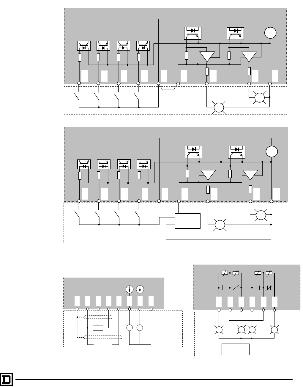
ALTIVAR 66 AC Drives
Wiring Diagrams
65
2/98 © 1998 Square D All Rights Reserved
Input/Output Wiring
LI1
LI2
LI3
LI4
+24
LOP
LO1
LO2
COM
24
VDC
+
-
12-30 VDC
Supply
LI1
LI2
LI3
LI4
+24
LOP
LO1
LO2
COM
24
VDC
+
-
+
-
Analog inputs and outputs
Relays
Logic inputs/outputs with external supply
Logic inputs/outputs with internal supply (210 mA maximum)
AI1
R
AI2
+10
S
COM
COM
4-20 mA
+
-A
Hz
250Ω250Ω
0-20 mA
AO1
AO2
0-20 mA
(1) Programmable
Outputs
(1) (1)
Customer Supplied
Voltage
+-
R1
R1 R2
R2
R1B
R1A
R2A
R2B
R1C
R2C
Customer Supplied
Customer Supplied
Customer Supplied
Customer Supplied
This document provided by Barr-Thorp Electric Co., Inc. 800-473-9123 www.barr-thorp.com
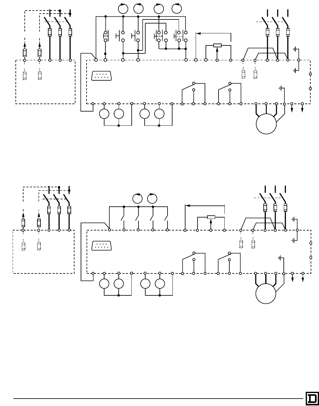
ALTIVAR 66 AC Drives
Wiring Diagrams
© 1998 Square D All Rights Reserved
66 2/98
3-Wire Control
2-Wire Control
The I/O Extension Module has three terminal strips for connections to external devices:
• J24: 4-pin terminal strip, 2 relay contacts
• J23: 10-pin terminal strip for analog I/O
• J22: 5-pin (VW3A66201T, 24 VDC) or 9-pin (VW3A66202T, 115 VAC) terminal strip for logic I/O
U1
W1 V1
COMAI1
+10
AI2LI4LI3LI2
STOP
LI1+24
R1
0-20 mA
4-20 mA
–
+
Hz
A
M1
3ø
PA
PB
U/T1
V/T2
W/T3
R1B
R1A
R1C
R2B
R2AR2C
COM
AO1
AO2
COM
LO1LO2
LOP
F11 F10
L1L2L3
CL1
CL2 L1L2L3CL1
CL2
–
+
External
Dynamic
Braking
Resistor
Equipment
Keypad
Connector
Internal
Control
Power
External
Control
Power
L1L2L3
FWD
REV
JOG FWD
JOG REV
L1
L2
L3
A1
F1-F3 F1-F3
F6 F5F6 F5
Add F10 and F11 fuses if tap conductor protection is required.
The CL1 and CL2 inputs of all ATV66 drive controllers are internally protected and require no external fusing.
[1]
F5 and F6 fuses are present only on ATV66C10 to ATV66C31 drive controllers.
[2]
[1]
[2] [2]
U1
W1 V1
COM
AI1
+10AI2
R1
0-20 mA
4-20 mA
–
+
Hz
A
M1
3ø
PA
PB
U/T1
V/T2
W/T3
R1B
R1A
R1C
R2B
R2AR2C
COM
AO1
AO2
COM
LO1LO2
LOP
F11 F10
L1
L2
L3
CL1
CL2 L1L2L3CL1
CL2
External
Dynamic
Braking
Resistor
Equipment
Keypad
Connector
Internal
Control
Power
External
Control
Power
L1L2L3
RUN/
JOG RUN
ENABLE
L1
L2
L3
A1
F1-F3 F1-F3
LI1
LI2
LI3LI4
+24
F6 F5
F6 F5
[1]
[2] [2]
[1]
F5 and F6 fuses are present only on ATV66C10 to ATV66C31 drive controllers.
[2]
Add F10 and F11 fuses if tap conductor protection is required.
The internally protected CL1 and CL2 inputs of all ATV66 drive controllers require no external fusing.
–
+
This document provided by Barr-Thorp Electric Co., Inc. 800-473-9123 www.barr-thorp.com

ALTIVAR 66 AC Drives
I/O Extension Module Terminal Descriptions
67
2/98 © 1998 Square D All Rights Reserved
The following table lists the characteristics of the I/O Extension Module inputs and outputs.
Connector Terminal Function Characteristics
J24
R3A
R3C
R4A
R4C
Relay output 3, N.O. contact
Relay 3 common
Relay output 4, N.O. contact
Relay 4 common
Minimum: 10 mA, 24 VDC
Maximum: inductive load of:
2 A, 120 VAC; max: 0.10 J/operation, 80 operations/minute
1 A, 220 VAC; max: 0.25 J/operation; 25 operations/minute
2 A, 24 VDC; max: 0.10 J/operation, 80 operations/minute
Arc suppression provided by varistors in parallel with relay
contacts.
J23
S
COM
AI3A
AI3B
+10
-10
AI4
AO3
COM
Analog shield
Space, for isolation
Analog common
Differential analog input 3A (+)
Differential analog input 3B (-)
Reference input supply
Reference input supply
Analog input 4
Analog output 3
Digital common
0 V
±10 V
0 V reference for AI3A
+10 VDC, Is = 10 mA maximum
-10 VDC, Is = 10 mA maximum
4-20 mA, z = 250 Ω
0 - 20 mA, z = 250 Ω
0 V
J22
24 VDC
VW3-
A66201T
LI5
LI6
LI7
LI8
Logic input 5
Logic input 6
Logic input 7
Logic input 8
LI5-LI8:
24 VDC, 10 mA, Vmax. = 30 V, state 0: V < 5 V,
state 1: V > 12V
+24 Logic inputs supply 24 VDC, Is = 80 mA max.
115 VAC
VW3-
A66202T
LI1
LI2
LI3
LI4
LI5
LI6
LI7
LI8
L2
Logic input 1
Logic input 2
Logic input 3
Logic input 4
Logic input 5
Logic input 6
Logic input 7
Logic input 8
Customer supply input
LI1-LI8:
115 VAC, Vmax = 140 V, Z = 30 kΩ, state 0: V < 30 V, state 1: V >
80 V
This document provided by Barr-Thorp Electric Co., Inc. 800-473-9123 www.barr-thorp.com
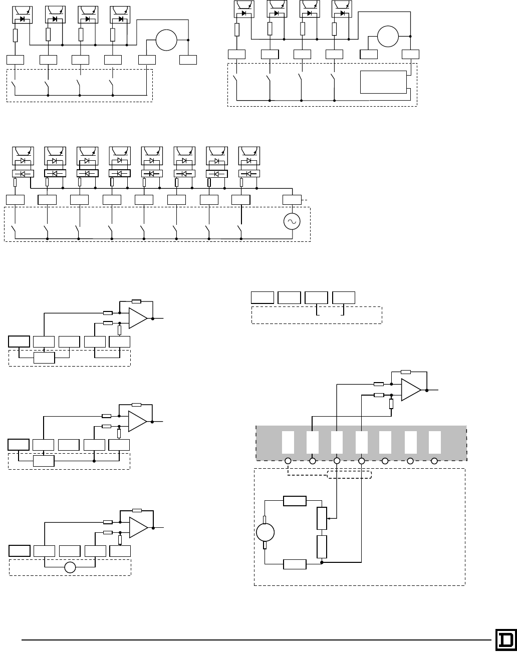
ALTIVAR 66 AC Drives
I/O Extension Module Wiring Diagrams
© 1998 Square D All Rights Reserved
68 2/98
24 VDC VW3A66201
Logic inputs with internal supply
115 VAC VW3A66202
LI8
LI6LI5 LI7 COM
Customer
supplied
24
VDC
+–
+24
115 VAC
+
–
LI4
LI2LI1 LI3 L2
30k
LI5 LI6 LI7 LI8
30k 30k 30k 30k 30k 30k 30k
Customer
supplied
Isolated
from
Common
0 to 10 V input referenced to COM
+/- 10 V input referenced to COM
Tachogenerator connections
AI4 input
+/- 10 V input not referenced to COM
+10 V -10 VAI3A AI3B COM
Customer
supplied
to A/D
Converter
R
10 k
10 k
20 k
20 k
+10 V -10 VAI3A AI3B COM
Customer
supplied
to A/D
Converter
R
10 k
10 k
20 k
20 k
+10 V -10 VAI3A AI3B COM
Customer
supplied
to A/D
Converter
V
10 k
10 k
20 k
20 k
+10 V -10 V AI4 COM
Customer
supplied
0-20
mA
A14
-10 V
AI3A
to A/D
Converter
+10 V
AI3B
S
COM
± 9V
R1
R4
R2
R3
1 kΩ
500 Ω
Customer Supplied
Logic inputs with external supply
LI8
LI6LI5 LI7 COM
Customer
supplied
12-30 VDC
Supply +
–
24
VDC
+–
+24
This document provided by Barr-Thorp Electric Co., Inc. 800-473-9123 www.barr-thorp.com
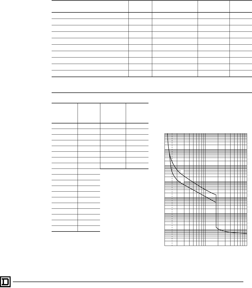
ALTIVAR 66 AC Drives
Dynamic Braking
69
2/98 © 1998 Square D All Rights Reserved
DYNAMIC BRAKING OPTION
The dynamic braking option allows the ALTIVAR 66 drive to function in quadrants 2 and 4 of the speed/
torque curve, dissipating the excess braking energy in an external resistor. The option consists of a resistor
and circuit protection. Applications include machines with high inertia and machines with fast cycles.
Automatic deceleration ramp modification is disabled when dynamic braking is installed.
Braking Resistor Kit Catalog Numbers
For Drives Ohmic
Value Continuous Current
Rating of Assembly a
Catalog
Number Qty of
Kits Used
Rdb Ir
ATV66U41N4, U54N4, U72N4 120 Ω1.0 A VW3A66711 1
ATV66U90N4, D12N4 56 Ω1.45 A VW3A66712 1
ATV66D16N4, D23N4 28 Ω2.7 A VW3A66713 1
ATV66D33N4, D46N4 14 Ω3.8 A VW3A66714 1
ATV66D54N4 10 Ω10.0 A VW3A66715 1
ATV66D64N4, D79N4 5 Ω14.0 A VW3A66716 1
ATV66C10N4, C13N4, C15N4, C19N4 2.5 Ω20.0 A VW3A66717 1
ATV66C23N41 2 Ω32.0 A VW3A66718 2
ATV66C28N41, C31N41 1.25Ω 40.0 VW3A66717 2
aCurrent rating of resistor assembly is calculated based on setting of internal overload protective device in assembly, overload
setting based on enclosure overtemperature protection, and resistor overload versus time characteristics. Resistors are rated
for stopping six times rotor inertia of 4-pole motor with drive at current limit.
Recommended Braking Resistance Values
460 V
AC Drive
Part No.
PA/PB
Minimum
Resistance
Ω
208/230 V
AC Drive
Part No.
PA/PB
Minimum
Resistance
Ω
ATV66U41N4 120 ATV66U41M2 47
ATV66U54N4 120 ATV66U72M2 18
ATV66U72N4 120 ATV66U90M2 18
ATV66U90N4 56 ATV66D12M2 12
ATV66D12N4 56 ATV66D16M2 9
ATV66D16N4 28 ATV66D23M2 6
ATV66D23N4 28 ATV66D33M2 4.5
ATV66D33N4 14 ATV66D46M2 3
ATV66D46N4 14
ATV66D54N4 10
ATV66D64N4 5.0
ATV66D79N4 5.0
ATV66C10N4 2.5
ATV66C13N4 2.5
ATV66C15N4 2.5
ATV66C19N4 2.5
ATV66C23N41 2.0
ATV66C28N41 1.25
ATV66C31N41 1.25
Current-Time Characteristic for Dynamic
Braking Resistor Assemblies
The curve below shows allowable time at 40 °C
according to multiple current settings.
Time (s)
10000
1000
100
10
1
0.1
0.01
0.00111.5 10 100
Multiples of current setting (lr)
(1) Cold state
(2) Hot state
2
1
This document provided by Barr-Thorp Electric Co., Inc. 800-473-9123 www.barr-thorp.com

ALTIVAR 66 AC Drives
Dynamic Braking
© 1998 Square D All Rights Reserved
70 2/98
CALCULATING RESISTOR SIZE
The dynamic braking kits listed on page 69 are
suitable for a wide variety of stopping applications.
However, precise calculation of the resistor is
essential for severe applications requiring high
braking power such as machines with high inertia
and overhauling loads. To determine whether the
dynamic braking kit is suitable, three parameters
must be calculated:
• The peak braking power required during speed
changes or stopping, Pi. The value of Pi
determines the maximum allowable value of
resistance.
• The amount of power which must be absorbed
for a given time by the resistors during stopping
or speed changes, Ps. These values of power
and time determine the required time-current
characteristic of the DB resistor.
• The average power which must be dissipated
by the DB resistor during a cycle, Pa. The value
of Pa determines the continuous current rating
of the DB resistor.
The following section is an example of sizing the
resistor.
CALCULATING RESISTOR SIZE:
AN EXAMPLE
The motor has the following characteristics:
• Power: 5 hp
• Rated speed: 1740 RPM
• Moment of inertia: 0.28 lb-ft2
The motor is driving a machine with inertia 10 times
that of the motor with no interposing speed changer
and resistive torque one tenth of the rated motor
torque. The requirement is to stop in 5 seconds from
rated speed at a rate of 2 cycles per minute.
The required motor braking torque must not
exceed the motor’s ability to produce torque. For
inertial loads such as in this example, the required
braking torque must be less than 1.5 times the
motor rated torque for constant torque
applications, or 1.1 times the motor rated torque
for variable torque applications.
For continuously overhauling loads, the value of
the overhauling torque (To) - the resistive torque
(Tr) must be less than the motor continuous torque
rating at any speed.
From this we see:
The peak braking power required during speed
changes or stopping:
The amount of power which must be absorbed for
a given time by the resistors during stopping or
speed changes:
The average power which must be dissipated by
the DB resistor during a cycle:
Therefore, the resistor selected must meet these
characteristics. For the VW3A66711 DB resistor
selected for the 5 hp drive:
The peak braking power is:
The braking power which can be absorbed for 5
seconds (td) based on the DB resistor hot state
current-time characteristic curve on page 69:
The average braking power:
For this example the VW3A66711 DB resistor kit
will work.
Pi
Tbrpm
×
7.04
----------------------- 1.97 1740
×
7.04
------------------------------- 487 W== =
Pd0.5 Pi
×243 W==
PaPd
td
tc
-----
×243 5
30
------
×40.5 W== =
Pi1.35 V
×()
2
Rdb
------------------------------ 1.35 460
×()
120
-------------------------------- 23212 W== =
PaRdb Ir
()
2
×120 12
×120 W===
Rated motor torque: Tnhp 5250×
rpmrated
-------------------------- 5 5250×
1740
----------------------- 15.1 lb-ft===
Cycle time: tc60 seconds
2 operations per minute
--------------------------------------------------------------- 30 s==
Machine speed change during deceleration: ∆rpm 1740 0–1740 rpm==
Machine deceleration time: td5 seconds=
Resistive (friction) torque: Tr15.1
10
----------- 1.51 lb-ft==
Overhauling torque: To0 lb-ft=
Total inertia: Jc0.28 10 0.28×()+ 3.08 lb-ft2
==
Braking torque: T Jc∆rpm×
308 td
×
-------------------------- 3.08 1740×
308 5×
------------------------------- 3.48 lb-ft== =
Required motor braking torque: TbTjToTr
–+ 3.48 0 1.51–+ 1.97 lb-ft== =
This document provided by Barr-Thorp Electric Co., Inc. 800-473-9123 www.barr-thorp.com
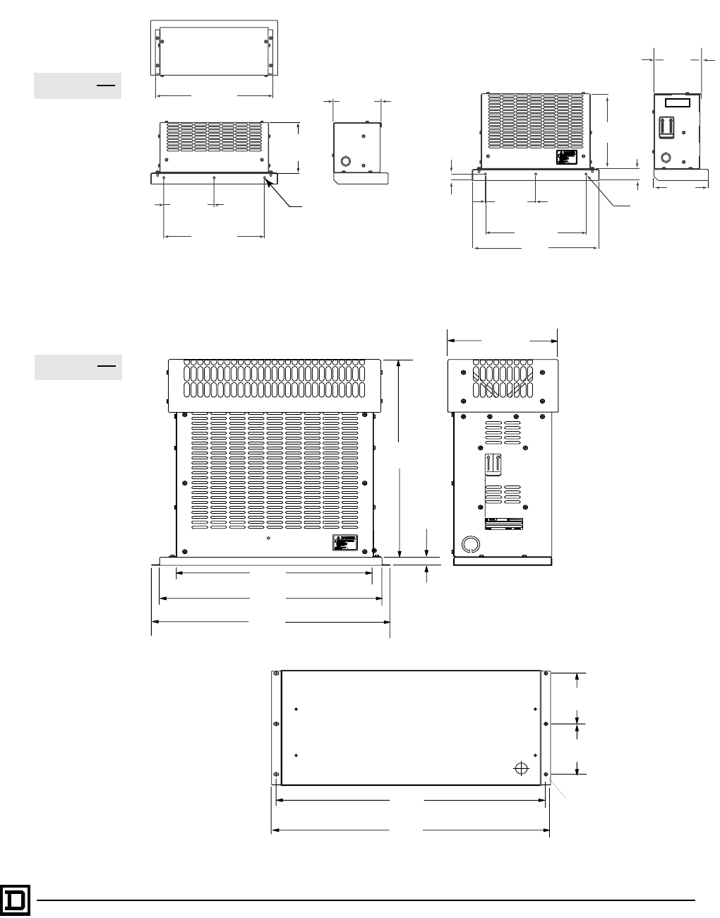
ALTIVAR 66 AC Drives
Dynamic Braking
71
2/98 © 1998 Square D All Rights Reserved
DYNAMIC BRAKING ENCLOSURE DIMENSIONS
VW3A66711 and VW3A66712 VW3A66713 and VW3A66714
VW3A66715, 716, 717, 718
355.6
14.00
152.4
6.00
304.8
12.00
152.4
6.00
6.9
.27 DIA
MTG HOLES
144.3
5.68
(6.9)
.27 DIA (3 Places)
(144.3)
5.68
(304.8)
12.00
(152.4)
6.00
(228.6)
9.00
(19.0)
0.75
(33.8)
1.33
6.50
(165.1)
(381.0)
15.00
18.63
(473.2)
20.00
(508)
10.38
(263.7)
0.84
(21.43)
20.64
(524.3)
22.29
(566.2)
4.36
(110.7)
4.36
(110.7)
.27
(6.9) Dia.
(6 places)
22.29
(566.2)
21.55
(547.4)
mm
in
in
(mm)
Dimensions:
Dimensions:
This document provided by Barr-Thorp Electric Co., Inc. 800-473-9123 www.barr-thorp.com

ALTIVAR 66 AC Drives
Wiring Practices
© 1998 Square D All Rights Reserved
72 2/98
WIRING PRACTICES
General Wiring Practices
Good wiring practice requires the separation of
control circuit wiring from all power (line and load)
wiring. Power wiring to the motor must have the
maximum possible separation from all other
power wiring, whether from the same drive or
other drives. Do not run in the same
conduit; this separation reduces the possibility
of coupling electrical noise between circuits.
When wiring ALTIVAR 66 drive controllers, follow
the wiring practices required by national and local
electrical codes in addition to the following:
• When using metallic conduit with ATV66U41N4
to D23N4 and ATV66U41M2 to D16M2 drive
controllers, you must also use a metal conduit
entry plate, kit VY1A66201. This kit mounts in
place of the existing plastic plate and is held in
place with two screws. A bond wire, which must
be connected to ground (GND) on the J2
terminal strip, is included.
• Use metallic conduit for all drive controller
wiring. Do not run control and power wiring in
the same conduit.
• Separate metallic conduits carrying power
wiring or low-level control wiring by at least 3 in
(8 cm).
• Separate non-metallic conduits or cable trays
used to carry power wiring from metallic
conduit carrying low-level control wiring by at
least 12 in (30.5 cm).
• Cross the metallic conduits and non-metallic
conduits at right angles whenever power and
control wiring cross.
• Attenuate conducted emissions to the line from
the drive controller in some installations to
prevent interference with telecommunication,
radio, and sensitive electronic equipment. Such
instances may require attenuating filters.
Consult catalog for selection and application of
these filters.
Branch Circuit Connections
All ALTIVAR 66 drive controllers require fuse
protection. ATV66U41N4 to D79N4 and
ATV66U41M2 to D46M2 drive controllers require
user-supplied external fuses as indicated on the
nameplate and in the Equipment
Recommendations on pages 78 to 80.
ATV66C10N4 to C19N4 drive controllers have
provisions for mounting the user-supplied fuses
internally (refer to the controller nameplate or the
Equipment Recommendations on pages 78 to 80
for recommended fuses). ATV66C23N41 to
C31N41 drive controllers are shipped with fuses.
See page 79 for information on replacing fuses in
ATV66C10N4 to ATV66C31N41 drive controllers.
Refer to NEC Article 430 for sizing branch circuit
conductors.
Input Line Currents for Selecting Branch Circuit Conductors, 460 V CT
NOTE: The input conductor ampacity rating should not be less than the ampacity rating selected,
based on the rated controller output current.
Motor
Power
Drive
Controller
Output
Current
Input Line Current
5,000 AIC
0.141 mH
10,000 AIC [1]
0.070 mH
18,000 AIC [2]
0.039 mH
22,000 AIC
0.032 mH
65,000 AIC
0.011 mH
With Line
Impedance of
kW
400 V
50 Hz
hp
460 V
60 Hz
3% 5%
AA A AAA
0.75
—
1.5
—
2.2
—
—
1
—
2
—
3
ATV66U41N4
2.3
1.8
4.1
3.4
5.8
4.8
—
2.7
—
4.7
—
6.5
4.0
3.2
3.5
5.7
9.0
8.0
—
3.5
—
6.4
—
8.8
—
1.6
—
3.0
—
4.2
—
1.5
—
2.7
—
3.9
3 — ATV66U54N4 7.8 — 12 — — —
4
—
—
5ATV66U72N4 10.5
7.6
—
9.8
15.0
11.9
—
13.2
—
6.7
—
6.2
5.5
—
—
7.5 ATV66U90N4 13
11
—
13.9
20.0
16.7
—
18.5
—
10.0
—
9.2
[1] 10,000 AIC denoted by asterisk (*).
[2] 18,000 AIC denoted by (✝).
This document provided by Barr-Thorp Electric Co., Inc. 800-473-9123 www.barr-thorp.com

ALTIVAR 66 AC Drives
Wiring Practices
73
2/98 © 1998 Square D All Rights Reserved
7.5
—
—
10 ATV66D12N4 17.6
14.0
—
17.6
26.0
21.4
—
24.7
—
13.0
—
12.0
11
—
—
15 ATV66D16N4 24.2
21.0
—
24.8
35.0
29.9
—
33.6
—
19.4
—
17.9
15
—
—
20 ATV66D23N4 33.0
27.0
—
31.9
45.0
38.7
—
44.8
—
26.0
—
23.6
22
—
—
30 ATV66D33N4 48.4
40.0
—
44.0
60.0
52.4
—
59.7
—
37.0
—
34.2
30
—
—
40 ATV66D46N4 66.0
52.0
—
57.1
78.0
67.6
—
76.6
—
49.0
—
45.6
37
—
—
50 ATV66D54N4 79.2
65.0
—
68.3
94.0
80.8
—
91.9
—
61.2
—
56.3
45
—
—
60 ATV66D64N4 93.5
77.0
—
86.4*
110
94.6
—
108
—
71.6
—
66.7
55
—
—
75 ATV66D79N4 115.5
96.0
—
106*
130
116
—
133
—
90.1
—
83.5
75
—
—
100 ATV66C10N4 157
124
—
138*
171
151
—
173
—
121
—
113
90
—
—
125 ATV66C13N4 190
156
—
166*
198
186
—
211
—
153
—
143
110
—
—
150 ATV66C15N4 226
180
—
191*
237
217
—
246
—
182
—
170
132
—
—
200 ATV66C19N4 270
240
—
242*
275
277
—
314
—
238
—
223
160
—
—
250 ATV66C23N41 330
300
—
318✝
326
333
—
379
—
295
—
276
200
—
—
300 ATV66C28N41 407
360
—
366✝
399
379
—
441
—
352
—
328
220
—
—
350 ATV66C31N41 449
420
—
419✝
421
431
—
506
—
410
—
383
Input Line Currents for Selecting Branch Circuit Conductors, 460 V CT (Continued)
NOTE: The input conductor ampacity rating should not be less than the ampacity rating selected,
based on the rated controller output current.
Motor
Power
Drive
Controller
Output
Current
Input Line Current
5,000 AIC
0.141 mH
10,000 AIC [1]
0.070 mH
18,000 AIC [2]
0.039 mH
22,000 AIC
0.032 mH
65,000 AIC
0.011 mH
With Line
Impedance of
kW
400 V
50 Hz
hp
460 V
60 Hz
3% 5%
AA A AAA
[1] 10,000 AIC denoted by asterisk (*).
[2] 18,000 AIC denoted by (✝).
This document provided by Barr-Thorp Electric Co., Inc. 800-473-9123 www.barr-thorp.com

ALTIVAR 66 AC Drives
Wiring Practices
© 1998 Square D All Rights Reserved
74 2/98
Input Line Currents for Selecting Branch Circuit Conductors, 460 V VT
NOTE: The input conductor ampacity rating should not be less than the ampacity rating selected,
based on the rated controller output current.
Motor
Power
Drive
Controller
Output
Current
Input Line Current
5,000 AIC 0.141
mH
10,000 AIC [1]
0.070 mH
18,000 AIC [2]
0.039 mH
22,000AIC
0.032 mH
65,000 AIC
0.011 mH
With Line
Impedance of
kW
400 V
50 Hz
hp
460 V
60 Hz
3% 5%
AAAAAA
0.75
—
1.5
—
2.2
—
3
—
1
—
2
—
3
—
ATV66U41N4
2.0
1.8
3.7
3.4
5.3
4.8
7.1
—
2.7
—
4.7
—
6.5
—
4.0
3.2
6.5
5.7
9.0
8.0
12.0
—
3.5
—
6.4
—
8.8
—
—
1.6
—
3.0
—
4.2
—
—
1.5
—
2.7
—
3.9
—
4
—
—
5ATV66U54N4 9.5
7.6
—
9.8
16.0
11.9
—
13.2
—
6.7
—
6.2
5.5
—
—
7.5 ATV66U72N4 11.8
11.0
—
14.0
20.0
17.0
—
18.4
—
10.0
—
9.2
7.5
—
—
10 ATV66U90N4 16.0
14.0
—
17.7
25.0
21.4
—
23.4
—
13.0
—
12.0
11
—
—
15 ATV66D12N4 22.0
21.0
—
25.1
36.0
30.6
—
35.3
—
19.4
—
17.9
15
—
—
20 ATV66D16N4 30.0
27.0
—
31.8
45.0
38.3
—
42.9
—
26.0
—
23.6
18.5
—
—
25 ATV66D23N4 37.0
34.0
—
38.7
57.0
47.0
—
54.6
—
31.1
—
30.1
30
—
—
40 ATV66D33N4 60.0
52.0
—
57.1
79.0
67.6
—
76.6
—
49.0
—
45.6
37
—
—
50 ATV66D46N4 72.0
65.0
—
68.6
94.0
81.2
—
91.9
—
61.2
—
56.3
45
—
—
60 ATV66D54N4 85.0
77.0
—
86.4*
112
94.6
—
108
—
71.6
—
66.7
55
—
—
75 ATV66D64N4 105
96.0
—
106*
130
116
—
133
—
90.1
—
83.5
75
—
—
100 ATV66D79N4 143
124
—
138*
176
150
—
171
—
121
—
113
90
—
—
125 ATV66C10N4 190
156
—
165*
199
185
—
210
—
153
—
143
110
—
—
150 ATV66C13N4 226
180
—
191*
238
217
—
246
—
182
—
170
132
—
—
200 ATV66C15N4 270
240
—
242*
278
277
—
314
—
238
—
223
160
—
200
—
—
250
—
300
ATV66C23N41
330
300
407
360
—
317✝
—
367✝
336
333
399
381
—
379
—
443
—
295
—
352
—
276
—
328
220
—
—
350 ATV66C28N41 449
420
—
419✝
428
431
—
506
—
410
—
383
250
—
—
400 ATV66C31N41 460
477
—
472✝
472
484
—
571
—
467
—
438
[1] 10,000 AIC denoted by asterisk (*).
[2] 18,000 AIC denoted by (✝).
This document provided by Barr-Thorp Electric Co., Inc. 800-473-9123 www.barr-thorp.com

ALTIVAR 66 AC Drives
Wiring Practices
75
2/98 © 1998 Square D All Rights Reserved
Input Line Currents for Selecting Branch Circuit Conductors, 460 V VTLN
NOTE: Note: The input conductor ampacity rating should not be less than the ampacity rating selected,
based on the rated controller output current.
Motor
Power Drive
Controller
Output
Current
Input Line Current
5,000 AIC 0.141
mH
10,000 AIC [1]
0.070 mH
22,000 AIC
0.032 mH
65,000 AIC
0.011 mH
With Line
Impedance of
kW
400 V
50 Hz
hp
460 V
60 Hz
3% 5%
AAAAAA
0.75
—
1.5
—
2.2
—
—
1
—
2
—
3
ATV66U41N4
2.0
1.8
3.7
3.4
5.3
4.8
—
2.7
—
4.7
—
6.5
4.0
3.2
6.5
5.7
9.0
8.0
—
3.5
—
6.4
—
8.8
—
1.6
—
3.0
—
4.2
—
1.5
—
2.7
—
3.9
3 — ATV66U54N4 7.1 — 12.0 — — —
4
—
—
5ATV66U72N4 9.5
7.6 —
9.8
15.0
11.9
—
13.2
—
6.7
—
6.2
5.5
—
—
7.5 ATV66U90N4 11.8
11.0
—
13.9
20.0
16.7
—
18.5
—
10.0
—
9.2
7.5
—
—
10 ATV66D12N4 16.0
14.0 —
17.6
26.0
21.4
—
24.7
—
13.0
—
12.0
11
—
—
15 ATV66D16N4 22
21
—
24.8
35.0
29.9
—
33.6
—
19.4
—
17.9
15
—
—
20 ATV66D23N4 30
27
—
31.9
45.0
38.7
—
44.8
—
26.0
—
23.6
22
—
—
30 ATV66D33N4 44
40
—
44.0
60.0
52.4
—
59.7
—
37.0
—
34.2
30
—
—
40 ATV66D46N4 60
52
—
57.1
78.0
67.6
—
76.6
—
49.0
—
45.6
37
—
—
50 ATV66D54N4 72
65
—
68.3
94.0
80.8
—
91.9
—
61.2
—
56.3
45
—
—
60 ATV66D64N4 85
77
—
86.4*
110
94.6
—
108
—
71.6
—
66.7
55
—
—
75 ATV66D79N4 105
96
—
106*
130
116
—
133
—
90.1
—
83.5
[1] 10,000 AIC denoted by asterisk (*).
This document provided by Barr-Thorp Electric Co., Inc. 800-473-9123 www.barr-thorp.com
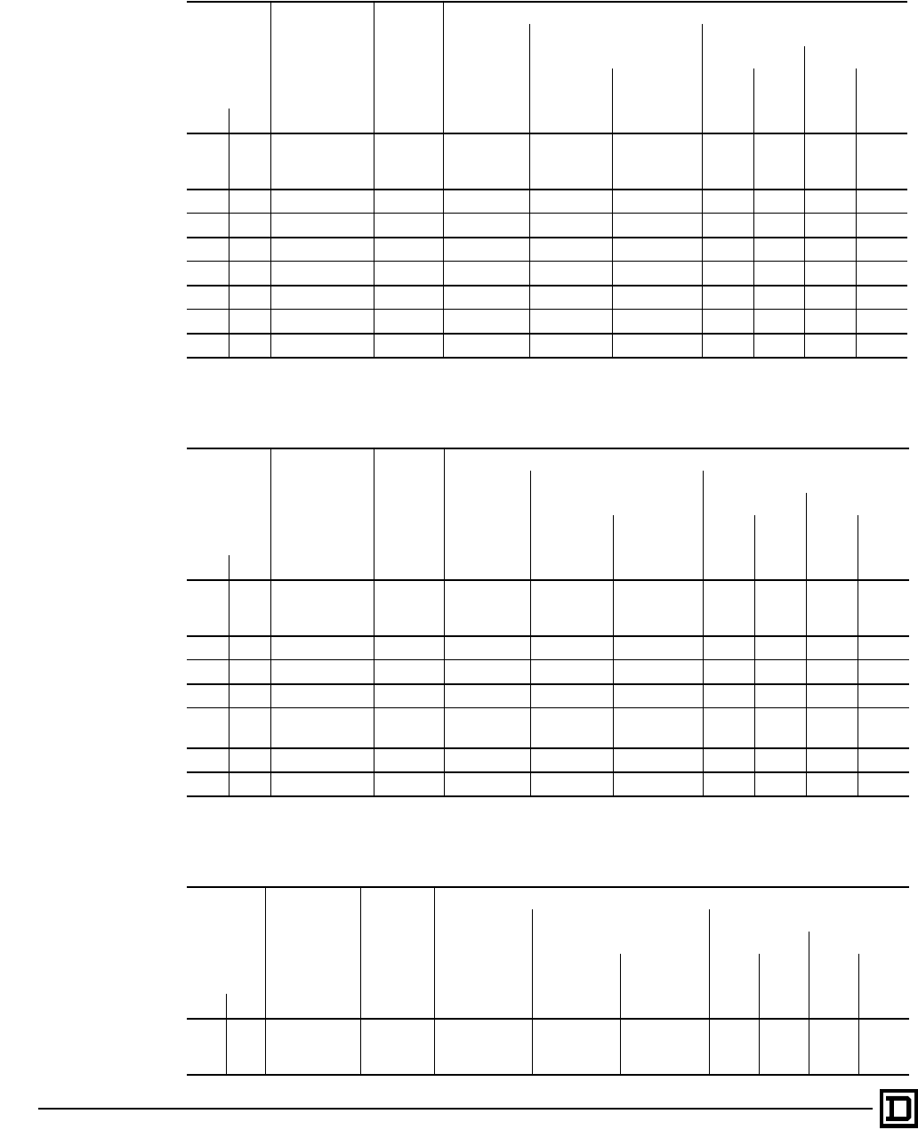
ALTIVAR 66 AC Drives
Wiring Practices
© 1998 Square D All Rights Reserved
76 2/98
Input Line Currents for Selecting Branch Circuit Conductors, 208-230 V CT
NOTE: The input conductor ampacity rating should not be less than the ampacity rating selected,
based on the rated controller output current.
Motor
Power
208/230 V
50/60 Hz
Drive
Controller
Output
Current
Input Line Current
208 V
8,800 AIC
0.036 mH
230 V With Line Impedance of
208 V 230 V
5,000 AIC
0.070 mH
22,000 AIC
0.016 mH 3% 5% 3% 5%
kW hp AA A A AAAA
0.75
1.5
2.2
1
2
3
ATV66U41M2
4.0
7.5
10.6
5.7
10.1
14.1
4.8
8.6
11.9
5.7
10.2
14.1
3.5
6.4
9.2
3.3
6.2
8.9
3.5
6.0
8.5
3.0
5.6
8.1
4 5 ATV66U72M2 16.7 21.4 18.0 21.5 14.7 14.3 14.0 12.9
5.5 7.5 ATV66U90M2 24.2 30.4 25.6 30.5 22.0 21.3 20.1 19.3
7.5 10 ATV66D12M2 30.8 38.6 32.6 38.7 29.0 27.8 26.5 25.2
11 15 ATV66D16M2 46.2 54.7 46.2 54.8 43.0 41.1 38.7 37.2
15 20 ATV66D23M2 59.4 69.4 58.8 69.5 57.0 54.1 50.4 49.0
20 30 ATV66D33M2 88.0 97.6 81.1 97.6 83.0 79.8 74.0 72.0
30 40 ATV66D46M2 114 124.2 102.1 125.4 109.1 105.4 98.7 95.6
Input Line Currents for Selecting Branch Circuit Conductors, 208-230 VT
NOTE: The input conductor ampacity rating should not be less than the ampacity rating selected,
based on the rated controller output current.
Motor
Power
208/230 V
50/60 Hz
Drive
Controller
Output
Current
Input Line Current
208 V
8,800 AIC
0.036 mH
230 V With Line Impedance of
208 V 230 V
5,000 AIC
0.070 mH
22,000 AIC
0.016 mH 3% 5% 3% 5%
kW hp AA A A AAAA
0.75
1.5
2.2
1
2
3
ATV66U41M2
4.0
7.5
10.6
5.7
10.1
14.1
4.8
8.6
11.9
5.7
10.2
14.1
3.5
6.4
9.2
3.3
6.2
8.9
3.5
6.0
8.5
3.0
5.6
8.1
5.5 7.5 ATV66U72M2 24.2 30.6 25.8 30.6 22.0 21.3 20.1 19.3
7.5 10 ATV66U90M2 30.8 38.8 32.7 38.8 29.0 27.8 26.5 25.2
11 15 ATV66D12M2 46.2 54.7 46.2 54.8 43.0 41.1 38.7 37.2
15
18.5
20
25 ATV66D23M2 59.4
74.8
69.3
84.4
58.7
71.5
69.4
84.4
57.0
69.2
54.1
67.2
50.4
64.0
49.0
60.9
30 40 ATV66D33M2 114 124.9 102.7 125.9 109.1 105.4 98.7 95.6
37 50 ATV66D46M2 143 149.3 122.6 151.1 134.0 129.6 121.0 117.4
Input Line Currents for Selecting Branch Circuit Conductors, 208/230 V VTLN
NOTE: The input conductor ampacity rating should not be less than the ampacity rating selected,
based on the rated controller output current.
Motor
Power
208/230 V
50/60 Hz
Drive
Controller
Output
Current
Input Line Current
208 V
8,800 AIC
0.036 mH
230 V With Line Impedance of
208 V 230 V
5,000 AIC
0.070 mH
22,000 AIC
0.016 mH 3% 5% 3% 5%
kW hp AA A A AAAA
0.75
1.5
2.2
1
2
3
ATV66U41M2
4.0
7.5
10.6
5.8
10.4
14.3
5.4
8.8
12.0
6.4
10.4
14.3
3.5
6.4
9.2
3.3
6.2
8.9
3.5
6.0
8.5
3.0
5.6
8.1
This document provided by Barr-Thorp Electric Co., Inc. 800-473-9123 www.barr-thorp.com

ALTIVAR 66 AC Drives
Wiring Practices
77
2/98 © 1998 Square D All Rights Reserved
Control Wiring
Although all control inputs and outputs of the drive
controller are isolated from the input lines, you
must follow certain control wiring precautions:
• Keep control wiring conductor runs short and
direct. Follow the conduit and circuit separation
requirements listed throughout this section.
• Make sure that the control contacts used with
the drive controller inputs are rated for
operation at open circuit voltages of 24 VDC
and closed circuit currents of 10 mADC.
• Analog inputs and outputs require twisted cable
with a pitch of 1 to 2 inches. Use of a cable
shield is recommended. The shield must be
terminated to ground at one end only. It is
recommended that the shield be terminated at
the drive controller. Shield connection
terminals are provided on the ALTIVAR 66 drive
controller for this purpose.
• Make sure that the coils of all relays and
solenoids connected to the output contacts of
the drive controller are equipped with
appropriate transient suppressors.
• For proper control wiring, route conductors to
avoid contact with other voltage potentials in
the drive controller. Wire insulation must have
the appropriate voltage rating for the voltage
present. The ATV66C10N4 to C31N41 drive
controllers are equipped with control wiring
channels to allow routing of control conductors
away from power circuit conductors. The
channels are located on the right side of
ATV66C10N4 to C19N4 controllers, and on the
left side of ATV66C23N41 to C31N41
controllers.
Output Wiring
The drive controller is sensitive to the amount of
capacitance (either phase-to-phase or phase-to-
ground) present on the output power conductors.
If excessive capacitance is present, the drive
controller may trip. Follow the guidelines below
when selecting output cable:
• Cable type: the cable selected must have a low
capacitance phase-to-phase and to ground. Do
not use mineral impregnated cable because it
has a very high capacitance. Immersion of
cables in water increases capacitance.
• Cable length: the longer the cable, the greater
the capacitance. Cable lengths greater than
320 ft (100 m) may require analysis to
determine if mitigation is required. Contact your
local ALTIVAR representative.
• Proximity to output cables from other drive
controllers: because of the high frequency
switching and increased capacitance, the drive
may fault under some conditions.
• Do not use lightning arrestors or power factor
correction capacitors on output of drive
controller.
• For installation where cable capacitances may
be a problem, an inductor can be installed
between the drive controller and the motor.
Consult factory for additional information.
Grounding
For safe, dependable operation, drives must be
grounded according to national and local codes.
Ground the drive as shown in the instruction
manual.
4 5 ATV66U72M2 16.7 21.8 18.3 21.8 14.7 14.3 14.0 12.9
5.5 7.5 ATV66U90M2 24.2 30.6 25.8 30.7 22.0 21.3 20.1 19.3
7.5 10 ATV66D12M2 30.8 38.9 32.8 39.0 29.0 27.8 26.5 25.2
11 15 ATV66D16M2 46.2 55.1 46.5 55.2 43.0 41.1 38.7 37.2
15 20 ATV66D23M2 59.4 70.3 59.6 70.3 57.0 54.1 50.4 49.0
22 30 ATV66D33M2 88.0 97.2 80.8 97.2 83.0 79.8 74.0 72.0
30 40 ATV66D46M2 114 124.2 102.0 125.4 109.1 105.4 98.7 95.6
Input Line Currents for Selecting Branch Circuit Conductors, 208/230 V VTLN (Continued)
NOTE: The input conductor ampacity rating should not be less than the ampacity rating selected,
based on the rated controller output current.
Motor
Power
208/230 V
50/60 Hz
Drive
Controller
Output
Current
Input Line Current
208 V
8,800 AIC
0.036 mH
230 V With Line Impedance of
208 V 230 V
5,000 AIC
0.070 mH
22,000 AIC
0.016 mH 3% 5% 3% 5%
kW hp AA A A AAAA
This document provided by Barr-Thorp Electric Co., Inc. 800-473-9123 www.barr-thorp.com

ALTIVAR 66 AC Drives
Equipment Recommendations
© 1998 Square D All Rights Reserved
78 2/98
Recommended Equipment for 1 to 400 hp 460 V Drive Controllers[1]
M1 A1 F1-F3 Input KM1 TS T1 F7, F8 F9
Motor Controller
ATV66•••N4 Line Power Fuses Ratings, Fuse Class
Fuse Carriers
Class T or CC Line
Contactor Transient
Suppressor Xfmr
[8]
Primary
Xfmr
Fuses
[3]
Sec. Xfmr
Fuses
[3]
kW hp CT, VT
low
noise VT CC
Fast
Acting TLittelfuse
JLS-
[9]
Gould-
Shawmut
A4J-
[9]
0.75 1 U41 U41 600 V
6 A 600 V
6 A 600 V
6 A —
9080-
FB3611CC[2] LC1-
D2510G6 LA4-DA2G 9070-
K50D20 FNQ-R-1/4 FNQ-R-1/2
T60060-3CR[3]
1.5 2 U41 U41 600 V
10 A 600 V
10 A 600 V
10 A —
9080-
FB3611CC[2] LC1-
D2510G6 LA4-DA2G 9070-
K50D20 FNQ-R-1/4 FNQ-R-1/2
T60060-3CR[3]
2.2 3 U41 U41 600 V
15 A 600 V
15 A 600 V
15 A —
9080-
FB3611CC[2] LC1-
D2510G6 LA4-DA2G 9070-
K50D20 FNQ-R-1/4 FNQ-R-1/2
T60060-3CR[3]
3 4 U54 U41 600 V
20 A 600 V
20 A 600 V
20 A —
9080-
FB3611CC[2] LC1-
D2510G6 LA4-DA2G 9070-
K50D20 FNQ-R-1/4 FNQ-R-1/2
T60060-3CR[3]
4 5 U72 U54 600 V
20 A 600 V
20 A 600 V
20 A —
9080-
FB3611CC[2] LC1-
D2510G6 LA4-DA2G 9070-
K50D20 FNQ-R-1/4 FNQ-R-1/2
T60060-3CR[3]
5.5 7.5 — U72 600 V
25 A 600 V
25 A 600 V
25 A —
9080-
FB3611CC[2] LC1-
D2510G6 LA4-DA2G 9070-
K50D20 FNQ-R-1/4 FNQ-R-1/2
T60060-3CR[3]
5.5 7.5 U90 — — 600 V
30 A 600 V
30 A 600 V
30 A T60060-3CR[3] LC1-
D2510G6 LA4-DA2G 9070-
K50D20 FNQ-R-1/4 FNQ-R-1/2
7.5 10 D12 U90 — 600 V
35 A 600 V
35 A 600 V
35 A T60060-3CR[3] LC1-
D2510G6 LA4-DA2G 9070-
K50D20 FNQ-R-1/4 FNQ-R-1/2
11 15 — D12 — 600 V
60 A 600 V
45 A 600 V
45 A T60060-3CR[3] LC1-
D2510G6 LA4-DA2G 9070-
K50D20 FNQ-R-1/4 FNQ-R-1/2
11 15 D16 — — 600 V
60 A 600 V
60 A 600 V
60 A T60060-3CR[3] LC1-
D2510G6 LA4-DA2G 9070-
K50D20 FNQ-R-1/4 FNQ-R-1/2
15 20 D23 D16 — 600 V
70 A 600 V
70 A 600 V
70 A T60100-3C[3] LC1-
D3210G6 LA4-DA2G 9070-
K50D20 FNQ-R-1/4 FNQ-R-1/2
18.5 25 — D23 — 600 V
90 A 600 V
90 A 600 V
80 A T60100-3C[3] LC1-
D4011G6 LA4-DA2G 9070-
K75D20 FNQ-R-3/
10 FNQ-R-6/10
22 30 D33 — — 600 V
90 A 600 V
90 A 600 V
90 A T60100-3C[3] LC1-
D5011G6 LA4-DA2G 9070-
K75D20 FNQ-R-3/
10 FNQ-R-6/10
30 40 D46 D33 — 600 V
125 A 600 V
125 A 600 V
110 A 3 ea.
T60200-1C[3] LC1-
D8011G6 LA4-DA2G 9070-
K75D20 FNQ-R-3/
10 FNQ-R-6/10
37 50 D54 D46 — 600 V
125 A 600 V
125 A 600 V
110 A[10] 3 ea.
T60200-1C[3] LC1-
D8011G6 LA4-DA2G 9070-
K75D20 FNQ-R-3/
10 FNQ-R-6/10
45 60 D64 D54 — 600 V
175 A 600 V
175 A 600 V
175 A 3 ea.
T60200-1C[3] LC1-
F115G6 LA9-F980 9070-
K200D20 FNQ-R-1-
1/4 FNQ-R-1-6/
10
55 75 D79 D64 — 600 V
200 A 600 V
200 A 600 V
200 A 3 ea.
T60200-1C[3] LC1-
F115G6 LA9-F980 9070-
K200D20 FNQ-R-1-
1/4 FNQ-R-1-6/
10
75 100 — D79 — 600 V
225 A 600 V
225 A 600 V
225 A 3 ea.
T60400-1C[3] LC1-
F150G6 LA9-F980 9070-
K200D20 FNQ-R-1-
1/4 FNQ-R-1-6/
10
[1] For F10 and F11, use Bussmann control fuse KTK-R-3. The recommended control fuse carrier is 9080-FB2611CC.
[2] Square D Class CC Fuse Block numbers.
[3] Bussmann part numbers.
[4] Gould-Shawmut part numbers.
[5] Ferraz part numbers.
[6] Fuse mounted inside drive controller.
[7] The power circuit configuration of the ATV66C23N4 to ATV66C31N4 drive controllers does not support the use of an input isolation contactor.
[8] T1 has been dimensioned to supply KM1 coil inrush and sealed VA requirements only. Any user control / pilot device additions may require re-
dimensioning of T1 VA capacity.
[9] Manufacturer-specific fuse selection. DO NOT SUBSTITUTE.
[10] 125 A rating allowable for ATV66D54N4 controller.
This document provided by Barr-Thorp Electric Co., Inc. 800-473-9123 www.barr-thorp.com

ALTIVAR 66 AC Drives
Equipment Recommendations
79
2/98 © 1998 Square D All Rights Reserved
Recommended Semiconductor Fuses for 1 - 400 hp 460 V Controllers
M1 A1 F1-F3 Input KM1 TS T1 F7, F8 F9
Motor Controller ATV66•••N4 Line Power
Fuses
Semiconductor
Fuse Class
Fuse
Carriers
[3]
Line
Contactor Transient
Suppressor Xfmr
[8]
Primary
Xfmr Fuses
[3]
Sec. Xfmr
Fuses
[3]
kW hp CT, VT low
noise VT
75 100 C10 — FWH400A[3] 6 ea.
BH-1133 LC1-F150G6 LA9-F980 9070-
K200D20 FNQ-R-1-1/4 FNQ-R-1-6/
10
A50P400[4]
90 125 C13 C10 FWH400A[3] 6 ea.
BH-1133 LC1-F265G7 LA9-F980 9070-
K350D20 FNQ-R-1-6/
10 FNQ-R-2-8/
10
A50P400[4]
110 150 C15 — FWH500A[3] 6 ea.
BH-3245 LC1-F265G7 LA9-F980 9070-
K350D20 FNQ-R-1-6/
10 FNQ-R-2-8/
10
A50P500[4]
110 150 — C13 FWH400A[3] 6 ea.
BH-1133 LC1-F265G7 LA9-F980 9070-
K350D20 FNQ-R-1-6/
10 FNQ-R-2-8/
10
A50P400[4]
132 200 C19 — FWH600A[3] 6 ea.
BH-3245 LC1-F330G7 LA9-F980 9070-
K250D20 FNQ-R-1-1/4 FNQ-R-2
A50P600 [4]
132 200 — C15 FWH500A[3] 6 ea.
BH-3245 LC1-F330G7 LA9-F980 9070-
K250D20 FNQ-R-1-1/4 FNQ-R-2
A50P500[4]
160 250 C23 C23
FWH700A[3]
[6] [7] [7] [7] [7] [7]170M6711[3]
N300231[5]
200 300 C28 C23
FWH800A [3]
[6] [7] [7] [7] [7] [7]170M6712[3]
P300232 [5]
220 350 C31 C28
FWH900A[3]
[6] [7] [7] [7] [7] [7]170M6713[3]
Q300233 [5]
250 400 — C31
FWH900A[3]
[6] [7] [7] [7] [7] [7]170M6713[3]
Q300233[5]
[1] For F10 and F11, use Bussmann control fuse KTK-R-3. The recommended control fuse carrier is 9080-FB2611CC.
[2] Square D Class CC Fuse Block numbers.
[3] Bussmann part numbers.
[4] Gould-Shawmut part numbers.
[5] Ferraz part numbers.
[6] Fuse mounted inside drive controller.
[7] The power circuit configuration of the ATV66C23N4 to ATV66C31N4 drive controllers does not support the use of an input isolation contactor.
[8] T1 has been dimensioned to supply KM1 coil inrush and sealed VA requirements only. Any user control / pilot device additions may require re-
dimensioning of T1 VA capacity.
Maximum Allowable Line Fuse (F1 to F3) for 460 V Drive Controllers
Controller ATV66•••N4 Class CC (Fast-Acting) Class T Littelfuse
JLS-
[4]
Gould-
Shawmut
A4J-
[4]
Semiconductor
U41, U54, U72 600 V, 25 A 600 V, 35 A 600 V, 30 A — —
U90, D12 — 600 V, 60 A 600 V, 45 A 600 V, 45 A —
D16, D23 — 600 V, 100 A 600 V, 100 A 600 V, 80 A —
D33, D46 — 600 V, 125 A 600 V, 125 A 600 V, 110 A —
D54, D64, D79 — 600 V, 225 A 600 V, 225 A 600 V, 225 A —
C10 — — — — FWH500A [1]
A50P500 [2]
C13, C15, C19 — — — — FWH600A [1]
A50P600 [2]
C23, C28, C31 — — — — FWH900A [1]
170M6713 [2]
Q300233 [3]
[1] Bussmann part numbers.
[2] Gould-Shawmut part numbers.
[3] Ferraz part numbers.
[4] Manufacturer-specific fuse selection. DO NOT SUBSTITUTE.
This document provided by Barr-Thorp Electric Co., Inc. 800-473-9123 www.barr-thorp.com
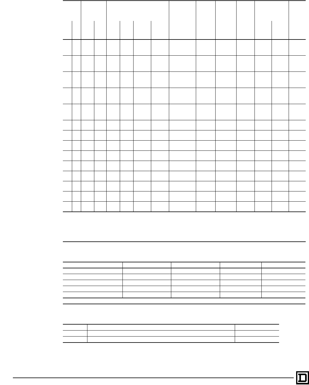
ALTIVAR 66 AC Drives
Equipment Recommendations
© 1998 Square D All Rights Reserved
80 2/98
Recommended Equipment for 1 to 50 hp 208/230 V Drive Controllers[1]
M1 A1 F1-F3 Input KM1 TS T1 F6, F7 F8
Motor Controller
ATV66•••M2
Line Power Fuses
Ratings,
Fuse Class Fuse Carriers
Class T or CC Line
Contactor
Transient
Suppresso
r
Xfmr
[3]
Primary Xfmr
Fuses
[2] Sec.
Xfmr
Fuses
[2]
kW hp CT, VT
low
noise VT CC
Fast
Acting TLittelfuse
JLS-
[5]
Gould-
Shawmut
A4J-
[5]
208 V 230 V
0.75 1 U41 U41 600 V
10 A 600 V
10 A 600 V
10 A —
9080-
FB3611CC [4] LC1-
D2510G6 LA4-DA2G 9070-
K50D20 FNQ-R-
1/2 FNQ-R-
1/2 FNQ-R-
1/2
T60030-3CR[2]
1.2 1.5 U41 U41 600 V
15 A 600 V
15 A 600 V
15 A —
9080-
FB3611CC[4] LC1-
D2510G6 LA4-DA2G 9070-
K50D20 FNQ-R-
1/2 FNQ-R-
1/2 FNQ-R-
1/2
T60030-3CR[2]
1.5 2 U41 U41 600 V
20 A 600 V
20 A 600 V
20 A —
9080
FB3611CC[4] LC1-
D2510G6 LA4-DA2G 9070-
K50D20 FNQ-R-
1/2 FNQ-R-
1/2 FNQ-R-
1/2
T60030-3CR[2]
2.2 3 U41 U41 600 V
25 A 600 V
25 A 600 V
25 A —
9080-
FB3611CC[4] LC1-
D2510G6 LA4-DA2G 9070-
K50D20 FNQ-R-
1/2 FNQ-R-
1/2 FNQ-R-
1/2
T60030-3CR[2]
34 —U41 600 V
25 A 600 V
25 A 600 V
25 A —
9080-
FB3611CC[4] LC1-
D2510G6 LA4-DA2G 9070-
K50D20 FNQ-R-
1/2 FNQ-R-
1/2 FNQ-R-
1/2
T60030-3CR[2]
4 5 U72 U72 — 600 V
35 A 600 V
35 A 600 V
35 A T60060-3C[2] LC1-
D2510G6 LA4-DA2G 9070-
K50D20 FNQ-R-
1/2 FNQ-R-
1/2 FNQ-R-
1/2
5.5 7.5 U90 U72 — 600 V
45 A 600 V
45 A 600 V
45 A T60060-3C[2] LC1-
D2510G6 LA4-DA2G 9070-
K50D20 FNQ-R-
1/2 FNQ-R-
1/2 FNQ-R-
1/2
7.5 10 D12 U90 — 600 V
60 A 600 V
60 A 600 V
60 A T60060-3C[2] LC1-
D3210G6 LA4-DA2G 9070-
K50D20 FNQ-R-
1/2 FNQ-R-
1/2 FNQ-R-
1/2
11 15 D16 D12 — 600 V
90 A 600 V
90 A 600 V
90 A 3 ea.
T60100-1C[2] LC1-
D4010G6 LA4-DA2G 9070-
K75D20 FNQ-R-1 FNQ-R-
3/4 FNQ-R-
6/10
15 20 D23 D23 — 600 V,
110 A 600 V
110 A 600 V
110 A 3 ea.
T60200-1C [2] LC1-
D8011G6 LA4-DA2G 9070-
K75D20 FNQ-R-1 FNQ-R-
3/4 FNQ-R-
6/10
18.5 25 D33 D23 — 600 V,
150 A 600 V
150 A 600 V
150 A 3 ea.
T60200-1C [2] LC1-
D8011G6 LA4-DA2G 9070-
K75D20 FNQ-R-1 FNQ-R-
3/4 FNQ-R-
6/10
22 30 D33 D33 — 600 V,
150 A 600 V
150 A 600 V
150 A 3 ea.
T60200-1C [2] LC1-
D8011G6 LA4-DA2G 9070-
K75D20 FNQ-R-1 FNQ-R-
3/4 FNQ-R-
6/10
30 40 D46 D33 — 600 V,
200 A 600 V
200 A 600 V
200 A 3 ea.
T60200-1C [2] LC1-
F115G6 LA9-F980 9070-
K200D20 FNQ-R-
2-1/4 FNQ-R-
1-6/10 FNQ-R-
1-6/10
37 50 —D46 — 600 V,
250 A 600 V
250 A 600 V
250 A 3 ea.
T60400-1C [2] LC1-
F115G6 LA9-F980 9070-
K200D20 FNQ-R-
2-1/4 FNQ-R-
1-6/10 FNQ-R-
1-6/10
[1] For F10 and F11, use Bussmann control fuse KTK-R-3. The recommended control fuse carrier is 9080-FB2611CC.
[2] Bussmann part numbers.
[3] T1 has been dimensioned to supply KM1 coil inrush and sealed VA requirements only. Any user control / pilot device additions may require re-
dimensioning of T1 VA capacity.
[4] Square D Class CC Fuse Block numbers.
[5] Manufacturer-specific fuse selection. DO NOT SUBSTITUTE.
Maximum Allowable Line Fuse (F1 to F3) for 208/230 V Drive Controllers
Controller ATV66•••M2 Class CC (Fast-Acting) Class T Littelfuse JLS- [1] Gould-Shawmut A4J- [1]
U41 600 V, 25 A 600 V, 45 A 600 V, 35 A 600 V, 35 A
U72, U90 — 600 V, 100 A 600 V, 100 A 600 V, 80 A
D12, D16 — 600 V, 125 A 600 V, 125 A 600 V, 100 A
D23, D33 — 600 V, 225 A 600 V, 225 A 600 V, 225 A
D46 — 600 V, 250 A 600 V, 250 A 600 V, 250 A
[1] Manufacturer-specific fuse selection. DO NOT SUBSTITUTE.
Recommended Equipment for all Drive Controllers
R1 Potentiometer 9001 K2106
—Push buttons 9001 KR1UH13
—Control station enclosure (accepts R1 and two push buttons) 9001 KYAF3
This document provided by Barr-Thorp Electric Co., Inc. 800-473-9123 www.barr-thorp.com
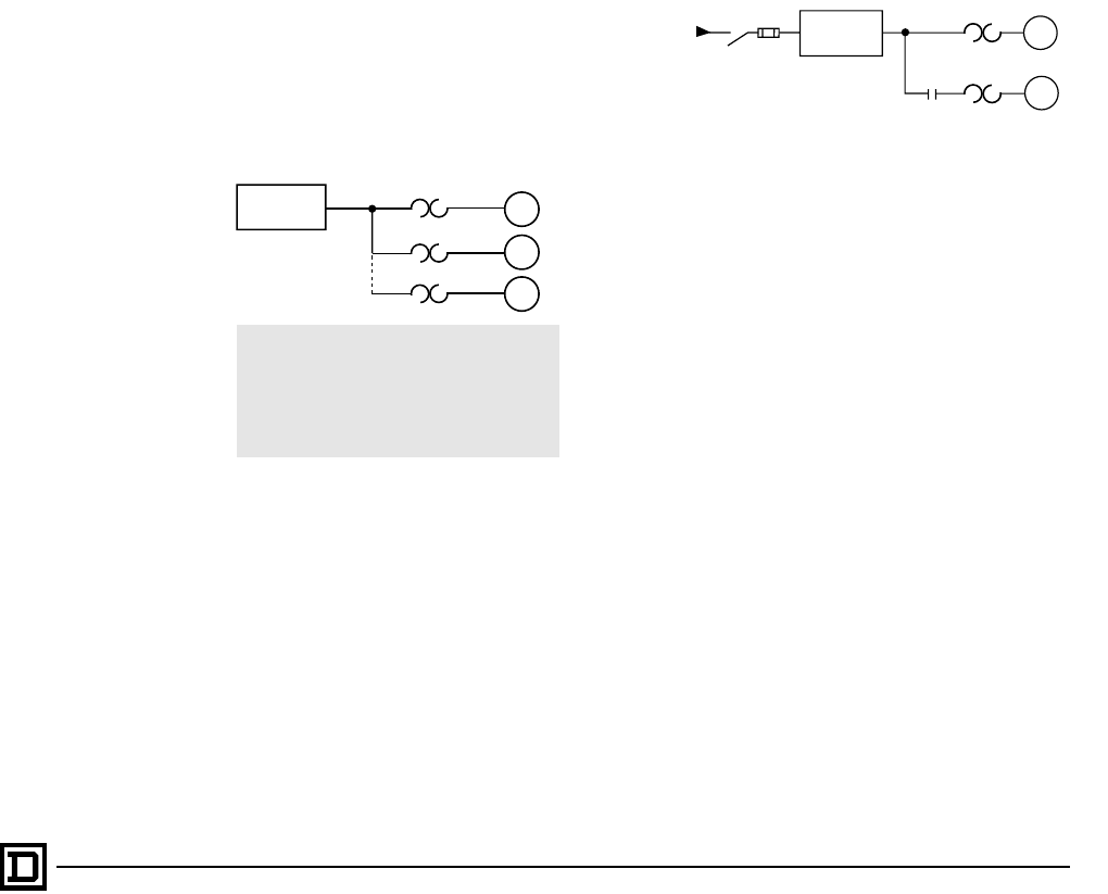
ALTIVAR 66 AC Drives
Special Applications
81
2/98 © 1998 Square D All Rights Reserved
Select the proper ALTIVAR 66 drive by comparing
the motor full load current to the nominal drive
current shown in the tables on page 53-56. The
drive current must be greater than or equal to the
motor full load current. The motor horsepower size
can be different than that of the drive; however, the
following guidelines must be followed.
Motor Power Less than Drive Power
The ALTIVAR 66 drive can be used with a motor of
lower power than that for which it was designed,
however, the drive should only be one horsepower
size greater than the motor. This association is a
solution for applications which require high
transient overtorque.
Motor Power Higher than Drive Power
An oversized motor can be used with the ALTIVAR
66 AC drive if the current absorbed by the motor is
less than or equal to the nominal drive current and
the motor is not operated continuously at a power
level greater than the power rating of the drive.
The motor should be no more than one
horsepower size greater than that of the drive, for
example a 2 hp drive with a 3 hp motor, where the
motor full load current is less than that for a 2 hp
drive.
Motors in Parallel
If several motors are run in parallel with one drive,
nominal drive current must be higher than or equal
to the sum of the currents of the motors connected
to the drive. In this case, external thermal overload
protection must be provided for each motor. In
addition, the total continuous power rating of the
connected motors must not exceed the power
rating of the drive. If there are three or more
motors in parallel, consult the factory.
When several motors are run in parallel:
• If the motors are of equal power, optimal torque
performance can be achieved after adjustment
of drive parameters.
• If the motors are of different power, the drive
parameters will not be correctly adjusted for the
lower power motors and overtorque at low
speed will be greatly reduced.
Overspeed Operation
It may be possible to run at speeds greater than
motor nameplate speed; however, the motor
manufacturer should be consulted before running
in overspeed. Above a nominal speed of 50/60 Hz,
the drive is incapable of producing additional
output voltage. The available continuous motor
torque will begin to decrease along with the motor
maximum overtorque capability. Consult the
motor manufacturer for continuous torque and
overtorque capabilities of the motor to be used.
Additional Motor Connected Downstream of
the Drive
If an additional motor is to be connected on the
drive while the drive is running (slamming the
motor), the sum of the running motor current(s)
plus the expected starting current of the switched
motor must not exceed 90% of the drive’s
transient output current rating. External thermal
overload protection must be provided for each
motor.
Use with Special Motors
The ALTIVAR 66 was designed for use with
asynchronous motors; however, it can be used
with other types of motors if certain conditions are
met.
Synchronous permanent magnet or wound-field
motors may be used if slip compensation is
disabled, external overload protection is provided,
the control type is set to Special, and appropriate
field excitation and protection is provided for
externally-excited motors.
Synchronous reluctance motors may be used; slip
compensation must be disabled and the control
type must be set to Special.
Ac drive selection:
• Ac drive In ≥ In1 + In2 + … Inx
• Ac drive Pn ≥ Pn1 + Pn2 + … Pnx
• Protect each motor with a thermal
overload relay
In: rated current Pn: rated power
Drive
Controller In1
In2
Inx
M1
M2
Mx
Drive
Controller
KM1
OL1
OL2
M2
M1
This document provided by Barr-Thorp Electric Co., Inc. 800-473-9123 www.barr-thorp.com
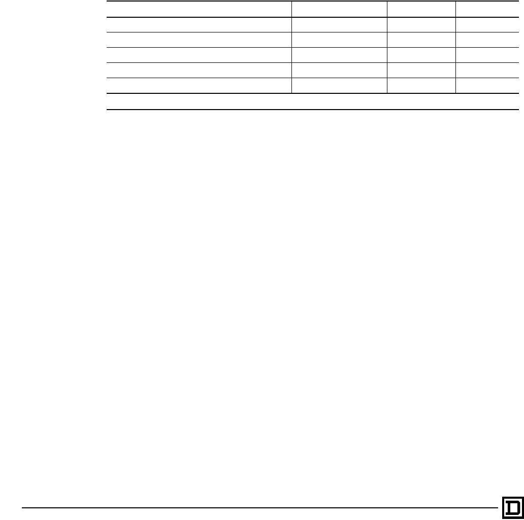
ALTIVAR 66 AC Drives
Special Applications
© 1998 Square D All Rights Reserved
82 2/98
Using a Synchronous Permanent Magnet or
Wound-Field Motor
It is possible to operate a synchronous permanent
magnet or synchronous wound-field motor as long
as the following conditions are met:
• Slip compensation is disabled.
• Internal overload protection is disabled and
external protection (overload relay or thermal
sensor) is used.
• Operation is only with Special control type with
constant torque setting.
• Appropriate field excitation and protection is
provided for externally-excited motors.
Using a Synchronous Reluctance Motor
It is possible to operate a synchronous reluctance
motor as long as slip compensation is disabled.
Operating Non-Standard Motors
Description Slip Compensation Overload Control Type
Motors in parallel Disable Disable [1] Special
Additional motor Enable Disable [1] Special
Synchronous permanent magnet Disable Disable [1] Special
Synchronous wound field Disable Disable [1] Special
Synchronous reluctance Disable Enable Special
[1] An external thermal overload relay is required if the AC drive protection is disabled.
This document provided by Barr-Thorp Electric Co., Inc. 800-473-9123 www.barr-thorp.com
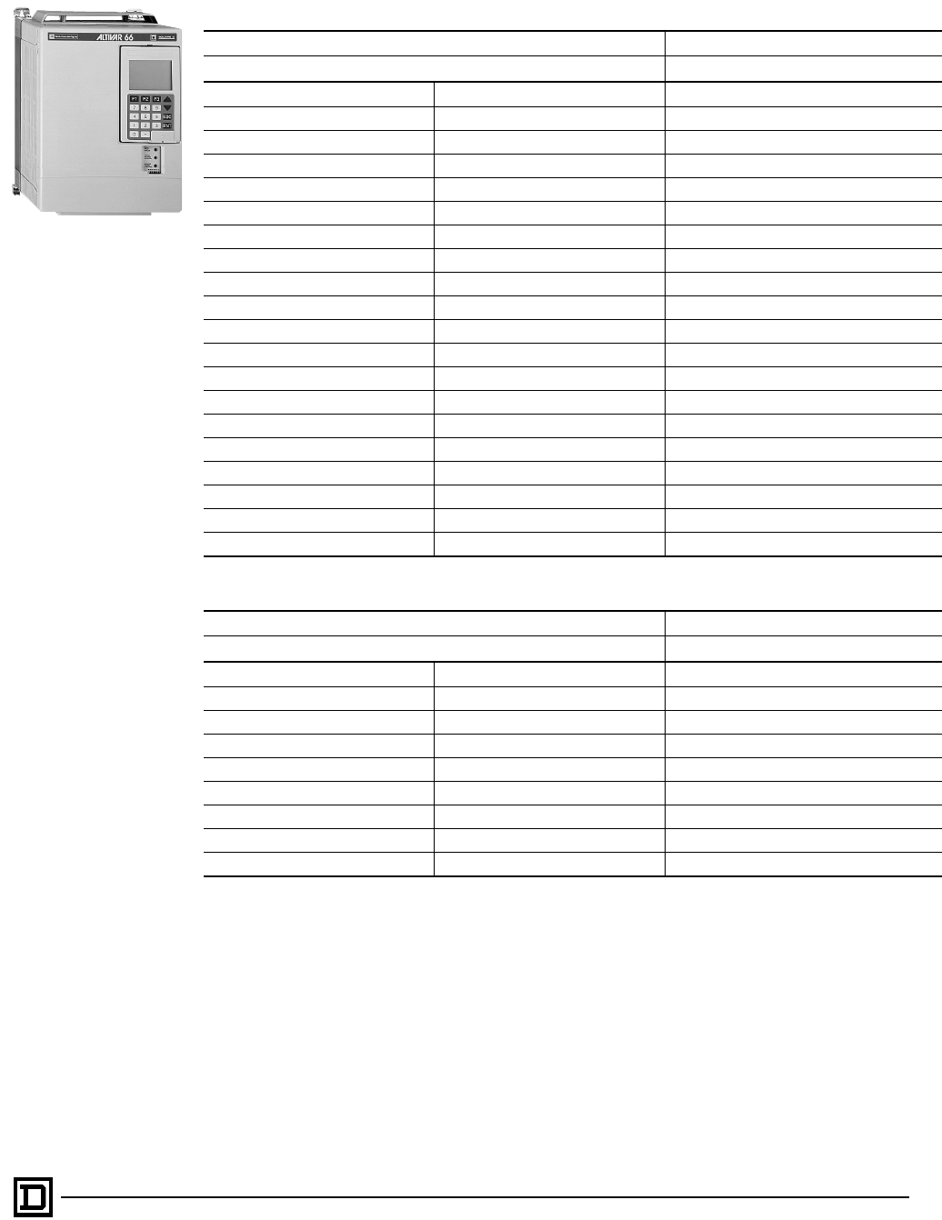
ALTIVAR 66 AC Drives
List of Catalog Numbers
83
2/98 © 1998 Square D All Rights Reserved
Drives 1 to 350 HP (0.75 - 132 kW), 400/460 V Three Phase Input - 50/60 Hz
Drives 1 to 40 HP (0.75 to 30 kw) 208/230 V Three Phase Input - 50/60 Hz
Motor ALTIVAR 66 Drive
Nameplate Power (constant torque application) Catalog Number
HP kW
1-2-3 0.75-1.5-2.2 ATV66U41N4U
- 3 ATV66U54N4U
5 4 ATV66U72N4U
7.5 5.5 ATV66U90N4U
10 7.5 ATV66D12N4U
15 11 ATV66D16N4U
20 15 ATV66D23N4U
30 22 ATV66D33N4U
40 30 ATV66D46N4U
50 37 ATV66D54N4U
60 45 ATV66D64N4U
75 55 ATV66D79N4U
100 75 ATV66C10N4U
125 90 ATV66C13N4U
150 110 ATV66C15N4U
200 132 ATV66C19N4U
250 160 ATV66C23N41
300 200 ATV66C28N41
350 220 ATV66C31N41
Motor ALTIVAR 66 Drive
Nameplate Power (constant torque application) Catalog Number
HP kW
1-2-3 0.75-1.5-2.2 ATV66U41M2
5 4 ATV66U72M2
7.5 5.5 ATV66U90M2
10 7.5 ATV66D12M2
15 11 ATV66D16M2
20 15 ATV66D23M2
30 22 ATV66D33M2
40 30 ATV66D46M2
This document provided by Barr-Thorp Electric Co., Inc. 800-473-9123 www.barr-thorp.com
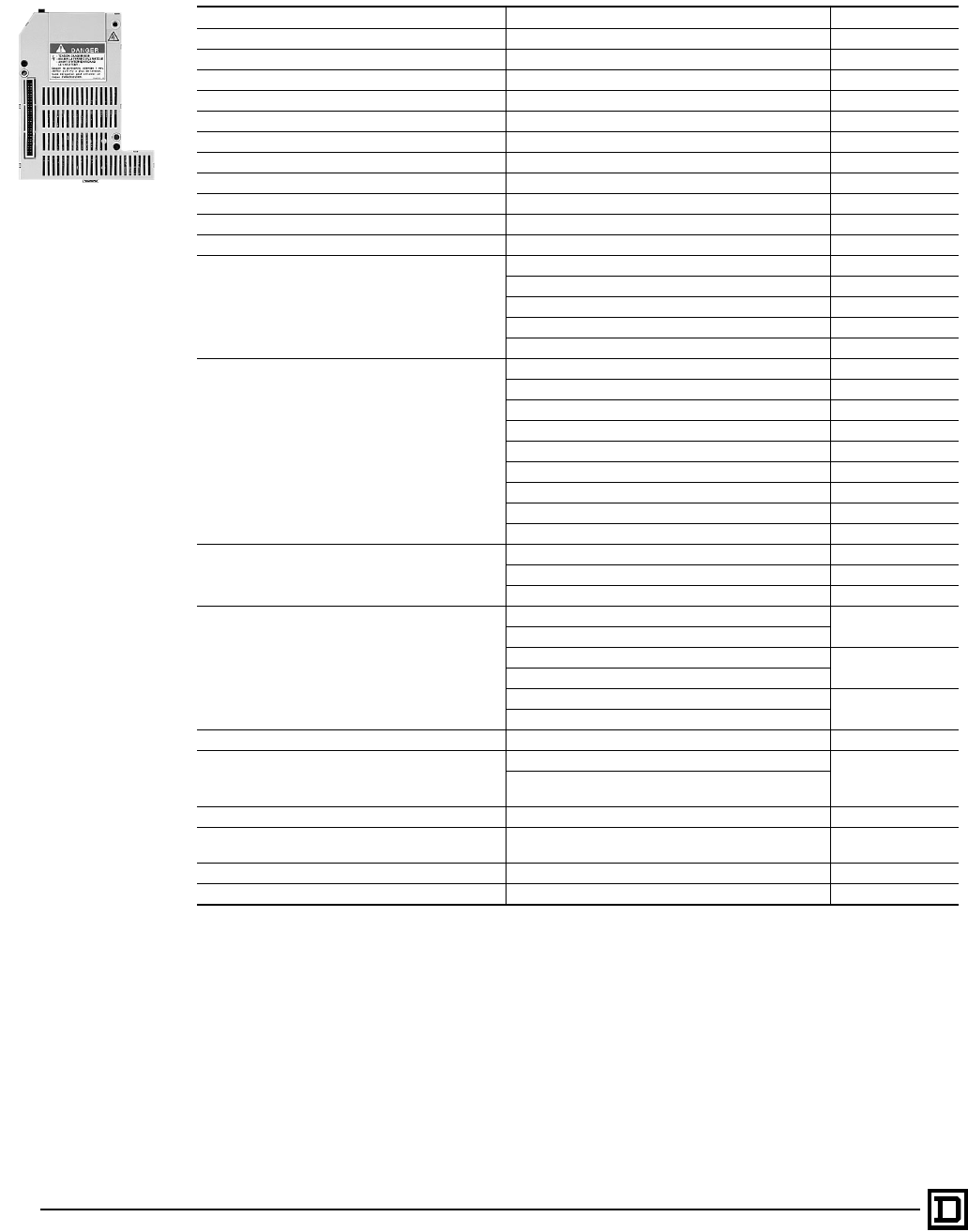
ALTIVAR 66 AC Drives
List of Catalog Numbers
© 1998 Square D All Rights Reserved
84 2/98
Options and Accessories
[1] Designed for use with Telemecanique Type ZA2B 22mm operators and 2-1/2”” surface mount meters. When used with compatible
operators and meters and the enclosed gasket, control island kit maintains Type 12 / IP54 integrity of enclosure sidewall.
[2] For use with an I/O extention module or communication card carrier.
[3] RFI filters are for use on equipment being designed for European power systems where CE compliance is required. Reference
catalog VVDED296034 for more information, and a larger selection of filters.
[4] Mounting the dynamic braking resistor assemblies on the ATV66C23N4 to C31N4 AC Drives requires the use of the Dynamic
Braking Resistor Mounting Plate Kit VY1A66202.
[5] Order quantity of 2. Two kits required on these units.
Description For Drives Catalog Number
Keypad door mounting kit with 2 m cable ATV66 all ranges VW3A66100
Keypad door mounting kit with 3 m cable ATV66 all ranges VW3A66101
Eight Operator Control Island [1] ATV66 all ranges VW3A66102
Six Operator, One Meter Control Island [1] ATV66 all ranges VW3A66103
Four Operator, Two Meter Control Island [1] ATV66 all ranges VW3A66104
I/O Extension Module, 24 V ATV66 all ranges VW3A66201T
I/O Extension Module, 115 V ATV66 all ranges VW3A66202T
3 m Cable for remote mounting of keypad display ATV66 all ranges VW3A66311
2 m Cable for remote mounting of keypad display ATV66 all ranges VW3A66312
PC Connection Option ATV66 all ranges VW3A66331U
Service and Troubleshooting Manual ATV66 all ranges VD0C06S701
RFI Filters [3]
ATV66U41N4 (1–2 HP) VW3A66401U
ATV66U41N4 (3 HP), U54N4 VW3A66402U
ATV66U72N4, U90N4, D12N4 VW3A66404U
ATV66D16N4, D23N4 VW3A66405U
ATV66D33N4, D46N4 VW3A66406U
Dynamic Braking Resistor with
Type 1 Enclosure
ATV66U41N4, U54N4, U72N4 VW3A66711
ATV66U90N4, D12N4 VW3A66712
ATV66D16N4, D23N4 VW3A66713
ATV66D33N4, D46N4 VW3A66714
ATV66D54N4 VW3A66715
ATV66D64N4, D79N4 VW3A66716
ATV66C10N4, C13N4, C15N4, C19N4 VW3A66717
ATV66C23N4 [4] VW3A66718 [5]
ATV66C28N4, C31N4 [4] VW3A66717 [5]
Gasket Kit for Recess Mounting
ATV66U41N4 to U72N4, ATV66U41M2 VW3A66801T
ATV66U90N4 to D12N4, U72M2, U90M2 VW3A66802T
ATV66D16N4 to D23N4, D12M2 to D16M2 VW3A66803
Mounting Adapter Plate for Recess Mounting
ATV66U41N4-U72N4 VW3A66806
ATV66U41M2
ATV66U90N4-D12N4 VW3A66807
ATV66U72M2, U90M2
ATV66D16N4-D23N4 VW3A66808
ATV66D12M2, D16M2
Memory Card All ATV66 drives VW3A66901T
Metal Conduit Entry Plate
ATV66U41N4-D23N4
VY1A66201
ATV66U41M2-D16M2
For wall-mounted drives when metallic conduit is used
Dynamic Braking Resistor Mounting Plate ATV66C23N4 to ATV66C31N4 VY1A66202
Communication Card for UNI-TELWAY MODBUS
RTU/JBUS, MODBUS ASCII Networks [2] All ATV66 drives VW3A66301U
Communication Card for MODBUS Plus Network[2] All ATV66 drives VW3A66305U
Communication Card Carrier ATV66 all ranges VW3A66205
VW3A6620•
This document provided by Barr-Thorp Electric Co., Inc. 800-473-9123 www.barr-thorp.com

ALTIVAR 66 AC Drives
List of Catalog Numbers
85
2/98 © 1998 Square D All Rights Reserved
Spare Parts List
Description Drive Controller Reference No. Note
ALTIVAR 66 Adjustable Frequency
Drive Controller Service and
Troubleshooting Manual
ATV66 all sizes VD0C06S701_
Control Kit — 460 V ATV66U41N4 to D79N4
ATV66C10N4 to C31N41 VX4A66CK1
VX4A66CK2 Matched keypad and control basket with
latest firmware
Control Kit — 208/230 V ATV66U41M2 to D46M2*
*ATV66D23M2S264U VX4A66CK1
VX4A66CK1S260 Matched keypad and control basket with
latest firmware
Keypad display (for drive controllers
with firmware level 3.0 and later — see
Chapter 4 section “Identifying the
Firmware Version”)
ATV66 all sizes VW3A66206U For drive controllers with firmware
earlier than 3.0, order the control kit
listed above
Removable Control Terminal Strips ATV66 all sizes VZ3N006 J1, J12 and J13 on control basket
Power Board — 460 V ATV66U41N4
(Serial number ends in code “A21” and
earlier — see Chapter 1 section
“Nameplates and Serial Numbers”)
VX5A66U41N4 Includes IGBT block, rectifier diode,
heatsink, and fan
ATV66U41N4
(Serial number ends in code “A22” and
later — see Chapter 1 section
“Nameplates and Serial Numbers”)
VX5A663U41N4 Includes IGBT block and rectifier diode
ATV66U54N4 VX5A662U54N4 Includes IGBT block and rectifier diode
ATV66U72N4 VX5A662U72N4 Includes IGBT block and rectifier diode
ATV66U90N4 VX5A662U90N4 Includes IGBT block and rectifier diode
ATV66D12N4 VX5A662D12N4 Includes IGBT block and rectifier diode
ATV66D16N4 VX5A66D16N4
ATV66D23N4 VX5A66D23N4
ATV66D33N4 VX5A66D33N4
ATV66D46N4 VX5A66D46N4
ATV66D54N4 VX5A66D54N4
ATV66D64N4 VX5A66D64N4
ATV66D79N4 VX5A66D79N4
ATV66C10N4 VX5A661C10N4
ATV66C13N4 VX5A661C13N4
ATV66C15N4 VX5A661C15N4
ATV66C19N4 VX5A661C19N4
ATV66C23N41 VX5A661C23N4
ATV66C28N41 VX5A661C28N4
ATV66C31N41 VX5A661C31N4
Power Board — 208/230 V ATV66U41M2 VX5A662U41M2 Includes IGBT block and rectifier diode
ATV66U72M2 VX5A662U72M2 Includes IGBT block and rectifier diode
ATV66U90M2 VX5A662U90M2 Includes IGBT block and rectifier diode
ATV66D12M2 VX5A66D12M2
ATV66D16M2 VX5A66D16M2
Power Board and Gate Driver Board —
208/230 V ATV66D23M2 VX5A66D234M2 Matched set
ATV66D33M2 VX5A66D335M2 Matched set
ATV66D46M2 VX5A66D466M2 Matched set
Gate Driver Board — 460 V ATV66D16N4 VX5A66103
ATV66D23N4 VX5A66104
ATV66D33N4 VX5A66105
ATV66D46N4 VX5A66106
ATV66D54N4 VX5A66107
ATV66D64N4 VX5A66108
ATV66D79N4 VX5A66109
Gate Driver Board — 208/230 V ATV66D12M2 VX5A66112
ATV66D16M2 VX5A66113
This document provided by Barr-Thorp Electric Co., Inc. 800-473-9123 www.barr-thorp.com

ALTIVAR 66 AC Drives
List of Catalog Numbers
© 1998 Square D All Rights Reserved
86 2/98
Inverter IGBT — 460 V ATV66D16N4 VZ3lM2050M1201 1 dual IGBT block
ATV66D23N4 VZ3lM2075M1201 1 dual IGBT block
ATV66D33N4 VZ3lM2100M1201 1 dual IGBT block
ATV66D46N4, D54N4 VZ3lM2150M1201 1 dual IGBT block
ATV66D64N4 VZ3lM2200M1201 1 dual IGBT block
ATV66D79N4 VZ3lM2300M1201 1 dual IGBT block
ATV66C10N4 VZ3IM2300M1202 2 dual IGBT blocks, snubber boards,
gate driver boards, 1 clamp module
ATV66C13N4 to C19N4 VZ3IM2400M1202 2 dual IGBT blocks, snubber boards,
gate driver boards, 1 clamp module
ATV66C23N41, C28N41 VZ3IM1400M1207 4 dual IGBT blocks, snubber boards,
gate driver boards
ATV66C31N41 VZ3IM1500M1207 4 dual IGBT blocks, snubber boards,
gate driver boards
Inverter IGBT — 208/230 V ATV66D12M2 VZ3IM2075M0601 1 dual IGBT block
ATV66D16M2 VZ3IM2100M0601 1 dual IGBT block
ATV66D23M2 VZ3IM2150M0601 1 dual IGBT block
ATV66D33M2 VZ3IM2200M0601 1 dual IGBT block
ATV66D46M2 VZ3IM2300M0601 1 dual IGBT block
Inverter IGBT Clamp Capacitor ATV66C23N41 to C31N41 VY1ADC610
Dynamic Braking IGBT — 460 V ATV66D14N4, D23N4 VZ3IM1025M1001
ATV66D33N4, D46N4 VZ3IM2050M1201
ATV66D54N4 VZ3IM2100M1201
ATV66D64N4, D79N4 VZ3IM2150M1201
ATV66C10N4 to C19N4 VZ3IM1300M1202 1 dual IGBT block, 1 dual diode block,
1 snubber board, 1 gate driver board
ATV66C23N41 VZ3IM1400M1208 1 dual IGBT block, 1 dual diode block,
1 snubber board, 1 gate driver board
ATV66C28N41, C31N41 VZ3IM1300M1208 2 dual IGBT blocks, 2 dual diode blocks,
2 snubber boards, 1 gate driver board
Dynamic Braking IGBT — 208/230 V ATV66D12M2, D16M2 VZ3IM1060M0601
ATV66D23M2 VZ3IM2075M0601
ATV66D33M2 VZ3IM2100M0601
ATV66D46M2 VZ3IM2150M0601
Dynamic Braking Clamp Capacitor ATV66C10N4 to C19N4 VY1ADC616
ATV66C23N41 to C31N41 VY1ADC614
Line Filter Board — 460 V ATV66D16N4, D23N4 VX4A66103
ATV66D33N4, D46N4 VX4A66104
ATV66D54N4 to D79N4 VX4A66105
ATV66C10N4 to C31N41 VX4A66106
Line Filter Board — 208/230 V ATV66D12M2, D16M2 VX4A66103
ATV66D23M2, D33M2 VX4A66104
ATV66D46M2 VX4A66105
Line Rectifier Diode — 460 V ATV66D16N4, D23N4 VZ3DM6075M1601 6-pack diode block
ATV66D33N4 VZ3DM2080M1606 1 dual diode block
ATV66D46N4 VZ3DM2100M1601 1 dual diode block
ATV66D54N4 to D79N4 VZ3DM2160M1606 1 dual diode block
ATV66C10N4, C13N4 VZ3DM2170M1602 1 dual diode block
ATV66C15N4 VZ3DM2260M1602 1 dual diode block
ATV66C19N4 VZ3DM2350M1602 1 dual diode block
ATV66C23N41 to C31N41 VZ3DM2600M1602 1 dual diode block
Line Rectifier Diode — 208/230 V ATV66D12M2, D16M2 VZ3DM6075M1601 6-pack diode block
ATV66D23M2 VZ3DM2080M1606 1 dual diode block
ATV66D33M2 VZ3DM2100M1601 1 dual diode block
ATV66D46M2 VZ3DM2160M1606 1 dual diode block
Spare Parts List (Continued)
Description Drive Controller Reference No. Note
This document provided by Barr-Thorp Electric Co., Inc. 800-473-9123 www.barr-thorp.com

ALTIVAR 66 AC Drives
List of Catalog Numbers
87
2/98 © 1998 Square D All Rights Reserved
DC Bus Capacitor — 460 V ATV66U41N4, U54N4 VY1ADC601 Assembly with capacitors
ATV66U72N4 VY1ADC602 Assembly with capacitors
ATV66U90N4 VY1ADC603 Assembly with capacitors
ATV66D12N4 VY1ADC604 Assembly with capacitors
ATV66D16N4, D23N4 VY1ADC152V450 One capacitor
ATV66D33N4, D46N4 VY1ADC472V450 One capacitor
ATV66D54N4 VY1ADC605 Assembly with capacitors and stirring
fan
ATV66D64N4, D79N4 VY1ADC606 Assembly with capacitors and stirring
fan
ATV66C10N4 to C19N4 VY1ADC615 Assembly with capacitors
ATV66C23N41 to C28N41 VY1ADC608 Assembly with capacitors
DC Bus Capacitor — 208/230 V ATV66U41M2 VY1ADC611 Assembly with capacitors
ATV66U72M2 VY1ADC612 Assembly with capacitors
ATV66U90M2 VY1ADC613 Assembly with capacitors
ATV66D12M2, D16M2 VY1ADC152V450 One capacitor
ATV66D23M2, D33M2 VY1ADC472V450 One capacitor
ATV66D46M2 VY1ADC605 Assembly with capacitors and stirring
fan
DC Bus Capacitor Bank Plexiglass
Shield ATV66C10N4 to C19N4 VY1ADV611
Discharge Resistor — 460 V ATV66D33N4 to D79N4 VZ3R5K0W040 One resistor
ATV66C10N4 to C19N4 VZ3R2K5W600 Two resistors
ATV66C23N41 to C31N41 VZ3R1K2W480 One resistor
Discharge Resistor — 208/230 V ATV66D23M2 to D46M2 VZ3R5K0W040 One resistor
Precharge Resistor — 460 V ATV66D16N4, D23N4 VZ3R033W009 One resistor
ATV66D33N4, D46N4 VZ3R010W025 One resistor
ATV66D54N4 to D79N4 VZ3R010W481 One resistor
ATV66C10N4 to C31N41 VZ3R010W270 Two resistors
Precharge Resistor — 208/230 V ATV66D12M2, D16M2 VZ3R033W009 One resistor
ATV66D23M2, D33M2 VZ3R010W025 One resistor
ATV66D46M2 VZ3R010W481 One resistor
Precharge Contactor — 460 V ATV66D16N4, D23N4 LP4D1801BW3
ATV66D33N4 LC1D1801P7
ATV66D46N4 LC1D2501P7
ATV66D54N4, D64N4 LC1D4011P7
ATV66D79N4 LC1D6511P7
ATV66C10N4, C13N4 VY1A661C1010
ATV66C15N4, C19N4 VY1A661C1510
ATV66C23N41 to C31N41 VY1A661C2310
Precharge Contactor — 208/230 V ATV66D12M2, D16M2 LP4D2500BW3
ATV66D23M2 LC1D3201P7
ATV66D33M2 LC1D5011P7
ATV66D46M2 LC1D4011P7
Precharge Contactor Auxiliary Contact
Block ATV66C10N4 to C31N41 LA1DN04
Precharge Circuit Protector ATV66C10N4 to C31N41 GV2M10
Heatsink Fan — 460 V ATV66U41N4, U54N4 VZ3V661
ATV66U72N4 VZ3V662
ATV66U90N4, D12N4 VZ3V663
ATV66D16N4, D23N4 VZ3V664
ATV66D33N4 to D79N4 VZ3V665
ATV66C10N4 to C19N4 VZ3V670
ATV66C23N41 to C31N41 VZ3V666
Spare Parts List (Continued)
Description Drive Controller Reference No. Note
This document provided by Barr-Thorp Electric Co., Inc. 800-473-9123 www.barr-thorp.com

ALTIVAR 66 AC Drives
List of Catalog Numbers
© 1998 Square D All Rights Reserved
88 2/98
Heatsink Fan — 208/230 V ATV66U41M2 VZ3V662
ATV66U72M2, U90M2 VZ3V663
ATV66D12M2, D16M2 VZ3V664
ATV66D23M2 to D46M2 VZ3V665
Stirring Fan — 460 V ATV66D33N4 to D79N4 VZ3V6654 Power board fan
ATV66D54N4 to D79N4 VZ3V6655 Capacitor bank fan
ATV66C10N4 to C19N4 VZ3V671
ATV66C23N41 to C31N41 VZ3V669
Stirring Fan — 208/230 V ATV66D23M2 to D46M2 VZ3V6654 Power board fan
ATV66D46M2 VZ3V6655 Capacitor bank fan
Fan Failure Detection Assembly ATV66C23N41 to C31N41 VY1ADR100 Resistor and temperature switch
Power Supply for Overtemperature
Detection Circuit ATV66C23N41 to C31N41 VY1A66200
Heatsink Temperature Sensor ATV66D16N4 to D79N4 VZ3GN006
ATV66C10N4 to C31N41 VZ3GN005
ATV66D12M2 to D46M2 VZ3GN006
Temperature Switch ATV66C10N4 to C19N4 VZ3G007 Switch mounted on fuse bar
ATV66C10N4 to C19N4 VZ3G008 Switch mounted on heatsink and motor
current sensor
ATV66C23N41 to C31N41 VZ3G004 One 68C switch, one 85C switch,
heatsink mounted
Motor Current Sensor — 460 V ATV66D33N4, D46N4 VY1A66104 2 sensors
ATV66D54N4 to D79N4 VY1A66105 2 sensors
ATV66C10N4, C13N4 VY1A66106
ATV66C15N4, C19N4 VY1A66107
ATV66C23N41 to C31N41 VY1A66108
Motor Current Sensor — 208/230 V ATV66D23M2 VY1A66104 2 sensors
ATV66D33M2, D46M2 VY1A66105 2 sensors
Ground Fault Sensor — 460 V ATV66D16N4, D23N4 VY1A66114
ATV66D33N4, D46N4 VY1A66115
ATV66D54N4 to D79N4 VY1A66116
ATV66C10N4 to C19N4 VY1A66109
ATV66C23N41 to C31N41 VY1A66110
Ground Fault Sensor — 208/230 V ATV66D12M2, D16M2 VY1A66114
ATV66D23M2, D33M2 VY1A66115
ATV66D46M2 VY1A66116
Control Power Transformer — 460 V ATV66D33N4 to D79N4 VY1ADA604
ATV66C10N4 to C19N4 VY1ADA606
ATV66C23N41 to C31N41 VY1ADA607
Control Power Transformer — 230 V ATV66D23M2 to D46M2 VY1ADA614
Control Power Fuses ATV66C10N4 to C31N41 DF3CF00501 Two fuses
DC Bus Fuse ATV66C10N4, C13N4 VY1ADF250V700 One fuse per kit
ATV66C15N4, C19N4 VY1ADF350V700
ATV66C23N41 to C31N41 VY1ADF400V700
AC Line Fuse ATV66C23N41 VY1ALF700V700 One fuse per kit
ATV66C28N41 VY1ALF800V700
ATV66C31N41 VY1ALF900V700
Power Terminal Blocks — 460 V ATV66D16N4, D23N4 VZ3N603
ATV66D33N4, D46N4 VZ3N604
ATV66D54N4 to D79N4 VZ3N605
Power Terminal Blocks — 208/230 V ATV66D12M2, D16M2 VZ3N603
ATV66D23M2, D33M2 VZ3N604
ATV66D46M2 VZ3N605
Box Lug Power Terminal ATV66C10N4 to C19N4 VZ3N008 C10 - C19 (L1-3, T1-3, +, -, GND)
C15 - 19 (T1-3, +, -, GND)
Clam Shell Power Terminal ATV66C10N4 to C19N4 VZ3N009 C15 - 19 (L1-3)
Power Terminal Plexiglass Shield ATV66C10N4 to C19N4 VY1ADV612
Spare Parts List (Continued)
Description Drive Controller Reference No. Note
This document provided by Barr-Thorp Electric Co., Inc. 800-473-9123 www.barr-thorp.com

ALTIVAR 66 AC Drives
List of Catalog Numbers
89
2/98 © 1998 Square D All Rights Reserved
Internal Power Cables — 460 V ATV66D16N4, D23N4 VZ3N623
ATV66D33N4, D46N4 VZ3N624
ATV66D54N4 to D79N4 VZ3N625
Internal Power Cables — 208/230 V ATV66D12M2, D16M2 VZ3N627
ATV66D23M2, D33M2 VZ3N628
ATV66D46M2 VZ3N625
Dynamic Braking Flexible Bus ATV66C23N41 to C31N41 VZ3N626 Connects capacitor bank to PA terminal
and DB IGBT module
Flex Cables — 460 V
(Control Board J3, 4, and 5) ATV66U41N4 to D12N4 VZ3N601
ATV66D16N4, D23N4 VZ3N613
ATV66D33N4 to D79N4 VZ3N615
ATV66C10N4 to C31N41 VZ3N616
Flex Cables — 208/230 V
(Control Board J3, 4, and 5) ATV66U41M2 to U90M2 VZ3N601
ATV66D12M2, D16M2 VZ3N613
ATV66D23M2 to D46M2 VZ3N615
Internal Hardware Kit — 460 V ATV66U41N4 to U72N4 VY1ADV601
ATV66U90N4, D12N4 VY1ADV602
ATV66D16N4, D23N4 VY1ADV603
ATV66D33N4, D46N4 VY1ADV604
ATV66D54N4 to D79N4 VY1ADV605
ATV66C10N4 to C19N4 VY1ADV613
ATV66C23N41 to C31N41 VY1ADV614
Internal Hardware Kit — 230 V ATV66U41M2 VY1ADV601
ATV66U72M2, U90M2 VY1ADV602
ATV66D12M2, D16M2 VY1ADV603
ATV66D23M2, D33M2 VY1ADV604
ATV66D46M2 VY1ADV605
Packaging Kits — 208/230/460 V
(Order this kit if control basket is NOT
mounted to a white metallic ground
plane within the drive)
ATV66U41N4 to U72N4 VY1A66101 All plastic sides, covers and front door
ATV66U90N4, D12N4 VY1A66102
ATV66D16N4, D23N4 VY1A66103
ATV66U41M2 VY1A66101
ATV66U72M2, U90M2 VY1A66102
ATV66D12M2, D16M2 VY1A66103
Packaging Kits — 208/230/460 V
(Order this kit if control basket is
mounted to a white metallic ground
plane within the drive)
ATV66U41N4 to U72N4 VY1A66111 All plastic sides, covers and front door
ATV66U90N4, D12N4 VY1A66112
ATV66D16N4, D23N4 VY1A66113
ATV66U41M2 VY1A66111
ATV66U72M2, U90M2 VY1A66112
ATV66D12M2, D16M2 VY1A66113
Clip Pliers
(Tool for removing voltage regulator
heatsink clips)
ATV66U41N4 to D23N4 VY1ADV608 Use when replacing power board, all
IGBTs, filter board, precharge
components, bus capacitors, diode
bridge, temperature sensor, and ground
fault sensor
ATV66U41M2 to D16M2 VY1ADV608
Spare Parts List (Continued)
Description Drive Controller Reference No. Note
This document provided by Barr-Thorp Electric Co., Inc. 800-473-9123 www.barr-thorp.com
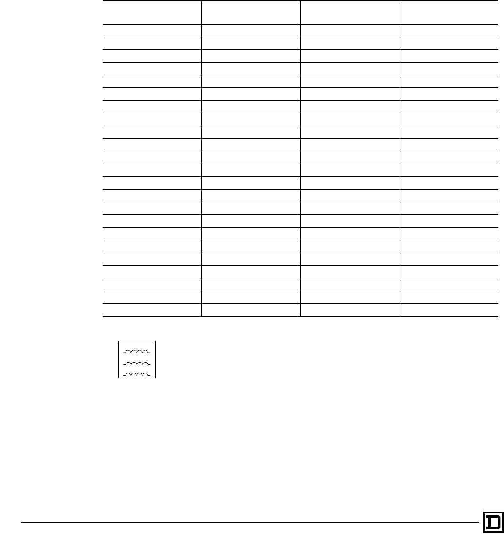
ALTIVAR 66 AC Drives
Three Phase Line Reactors
© 1998 Square D All Rights Reserved
90 2/98
The ALTIVAR 66 AC Drives are designed to
operate from industrial power systems with normal
AC line conditions without the need of additional
line impedance from either an isolation transformer
or a line reactor. However, when abnormal line
conditions exist, additional line impedance may be
required. Typically, line reactors are used for:
• Minimize the input rms current to the AC drive
ratings
• Lower the available fault current on high fault
distribution systems
• Limit the total harmonic voltage distortion from
the AC drive at the point of common coupling to
align with IEEE 519 guidelines
• Prevent AC drive nuisance tripping due to
transient overvoltages from power factor
correction capacitor switching
Line Reactors:
1. Part numbers are referenced and
manufactured by MTE, Inc.
2. Harmonic compensated up to 150% of
nominal current ratings
3. 5% nominal reactance
4. Offered in Type 1 general purpose enclosures
5. Intended for separate mounting and wired by
the user.
6. Refer to the following publications on the
subject of harmonics and benefits of drive
isolation transformers:
—8803PD9402–Power Systems Harmonics–
Cause and Effects of AC Drives.
—7460HO9501–Drive Isolation
Transformers-Application, Selection and
Specification Data
—7460PD9501– Drive Isolation
Transformers–Solutions to Power Quality
HP Rating 208 V Line Reactor
(separate mounted) 230 VAC Line Reactor
(separate mounted) 460 VAC Line Reactor
(separate mounted)
1RL–00412 RL–00412 RL–00212
1.5 RL–00812 RL–00812 –
2RL–00812 RL–00812 RL–00413
3RL–01212 RL–01212 RL–00413
5RL–01812 RL–01812 RL–00813
7.5 RL-02512 RL–02512 RL–01213
10 RL–03512 RL–03512 RL–01813
15 RL–04512 RL–04512 RL–02513
20 RL–05512 RL–05512 RL–03513
25 RL–08012 RL–08012 RL–03513
30 RL–10012 RL–08012 RL–04513
40 RL–13012 RL–10012 RL–05513
50 RL–16012 RL–13012 RL–08013
60 – – RL–08013
75 – – RL–10013
100 – – RL–13013
125 – – RL–16013
150 – – RL–20013
200 – – RL–25013
250 – – RL–32013
300 – – RL–40013
350 – – RL–50013
400 – – RL–50013
LoadLine
A1
B1
C1
A2
B2
C2
This document provided by Barr-Thorp Electric Co., Inc. 800-473-9123 www.barr-thorp.com

ALTIVAR 66 AC Drives
Motor Protecting Output Filters
91
2/98 © 1998 Square D All Rights Reserved
Low pass filters can be used on the output of the
ALTIVAR 66 AC Drive to decease the stress of
resonant frequencies on the attached motor.
While low pass filters are not necessary for most
installations, they do provide substantial benefits
in installations involving long motor leads:
• 460 V or higher rated AC drives
• 1–25 HP rated units, if cable lead lengths are in
excess of 75 feet
• 30–400 HP rated units, if cable lead lengths are
in excess of 300 feet.
• Use of a non–inverter duty rated motor(s)
• Existing general purpose motors subject to
retrofit to an AC drive
The motor protecting output filters combines
inductance, capacitance and resistance to form a
low pass filter. This filter will lower the dV/dt levels
to prevent exciting the natural resonant wire
frequency of the motor cables. Motors compliant
to NEMA MG–1 Part 31 guidelines do not require
the use of motor protecting output filters.
Motor Protecting Output Filters:
1. Part number references are per Trans-Coil, Inc.
2. KLC filters are designed for cable lead lengths
ranging from 50 to 1000 feet.
3. KLC filters include 1.5% nominal reactance at
480V
4. KLC filters are enclosed in Type 1 general
purpose enclosures
5. KLC filters are intended for separate mounting
and wiring by user
HP Rating
@ 460 V KLC Filter
(separate mounting)
1–2 KLC4BE
3KLC6BE
5KLC8BE
7.5 KLC12BE
10 KLC16BE
15 KLC25BE
20–25 KLC35BE
30 KLC45BE
40 KLC55BE
50-60 KLC80BE
75 KLC110BE
100 KLC130BE
125 KLC160BE
150 KLC200BE
200 KLC250BE
250 KLC300BE
300 KLC360BE
350 KLC420BE
400 KLC480BE
This document provided by Barr-Thorp Electric Co., Inc. 800-473-9123 www.barr-thorp.com

ALTIVAR 66 AC Drives
Suggested Specifications
© 1998 Square D All Rights Reserved
92 2/98
Note:
These specifications are for adjustable frequency
drive controllers or herein referred to as AC drives.
The Construction Specifications Institute (CSI)
format has been conformed with for project
compatibility. Copies of this specification are
available on IBM floppy disk or 100% IBM
compatible formats as well as Macintosh
configurations.
Application information directly affects the type
and size of AC drive that will be quoted. Brackets
are provided where such data should be included.
Please call your local Square D distributor or sales
engineer for specification assistance regarding a
particular application.
For better coordination, the AC drive specification
should be included in Division 16 for Electrical
Work.
PART 1: GENERAL
1.01
Scope of Work
a. This section provides specification
requirements for AC inverter type adjustable
frequency, variable speed drives or herein
identified as AC drives for use with [NEMA B,
NEMA A, NEMA C, NEMA E, synchronous]
design, AC motors.
1.02
Quality Assurance
a. The AC drive and all options shall be UL listed
according to Electric Industrial Control
Equipment Specification UL 508C. A UL label
shall be attached inside each enclosure as
verification.
b. The AC drive shall be designed, constructed
and tested in accordance with NEMA, NEC,
VDE, IEC standards and CSA certified.
c. The manufacturer of the AC drive shall be a
certified ISO 9002 facility.
d. The AC Drive manufacturer shall offer 24 hour
a day product and application response via a
nationwide network of factory certified
technical support personnel.
1.03
Warranty
a. A manufacturers warranty shall be provided on
all materials and work-manship of no less than
1 year from the date of start-up or 18 months
from date of shipment.
PART 2: PRODUCTS
2.01
Acceptable Manufacturers
a. The AC drive shall be an ALTIVAR 66 supplied
by the Schneider North America/Square D
Company or prior approved equal, no
substitutions are permitted.
b. Alternate control techniques other than pulse
width modulated technology (PWM), are not
acceptable.
2.02
General Description
a. The AC drive shall convert the input AC mains
power to an adjustable frequency and voltage
as defined in the following sections.
b. The rectifier stage shall convert fixed voltage,
fixed frequency, AC line power to fixed DC
voltage. The input power section shall utilize a
full wave bridge design incorporating diode
rectifiers. The rectifier shall be insensitive to
phase rotation of the AC line. The DC voltage
shall be filtered.
c. The DC bus shall offer external connections
for standby battery back-up or for linking
multiple, AC drive buses.
d. The inverter shall change fixed DC voltage to
variable frequency AC. The inverter section
shall utilize insulated gate bipolar transistors
(IGBTs) or intelligent power modules (IPMs)
as required by the current rating of the motor.
2.03
Motor Data
a. The AC drive shall be sized to operate a
[NEMA design B] AC motor with a nameplate
rating as defined in the National Electric Code,
table 430-149, for the applicable horsepower.
b. The service factor of the motor is 1.15 at the
rated voltage and frequency.
This document provided by Barr-Thorp Electric Co., Inc. 800-473-9123 www.barr-thorp.com

ALTIVAR 66 AC Drives
Suggested Specifications
93
2/98 © 1998 Square D All Rights Reserved
2.04
Application Data
a. The AC drive shall operate a [variable torque
load, constant torque load, constant
horsepower load, impact load].
b. The speed range shall be from a minimum
speed of 0.5 Hz @ 100% breakaway torque to
a maximum speed of 200 Hz.
2.05
Environmental Ratings
a. A.The AC drive construction shall be of Type 1
listed enclosure that allows operation in a
Pollution Degree 3 environment shall meet
NEMA Type 1/IP30 or NEMA Open/IP20. The
AC drive will meet IEC 664-1 and NEMA ICS
1-111A Part 3 standards. AC drives that are
only rated for Pollution Degree 2 environment
will not be allowed.
b. The AC drive will be designed to operate in an
ambient temperature from 0° to +40 °C (+32°
to +104 °F).
c. The storage temperature range shall be -25°
to +70 °C.
d. The maximum relative humidity shall be 95%
at 40 °C, non-condensing.
e. The AC drive will be rated to operate at
altitudes less than or equal to 1000 m (3,300
ft.). For altitudes above 1000 m, derate the AC
drive by 1.2% for every 100 m (330 ft.).
f. The AC drive will meet the IEC 68-2-6
vibration specification.
g. AC drives 75 hp and smaller will be designed
and constructed to be of finger safe
construction with the enclosure open to
operator access according to I P20 standards.
2.06
Ratings
a. The AC drive shall be designed to operate
from an input voltage of 400±15% Vac and
460±15% Vac.
b. The AC drive shall operate from an input
voltage frequency range from 47.5 to 63 Hz.
c. The displacement power factor shall not be
less than 0.95 lagging under any speed or
load condition.
d. The efficiency of the AC drive at 100% speed
and load shall not be less than 96%.
e. The constant torque overtorque capacity will
be 150% for 1 minute [The variable torque
overtorque capacity will be 110% for 1 minute].
f. The output carrier frequency of the drive will
be randomly modulated and selectable at
2 kHz, 4 kHz or 10 kHz depending on drive
rating for low noise operation. No AC drives
with an operable, carrier frequency above 10
kHz will be allowed.
g. The output frequency shall be from 0.1 to 400
Hz for AC drives up to 75 hp. At horsepowers
above 75 hp, the maximum output frequency
will be 200 Hz.
h. The AC drive will be able to provide rated
motor torque at 0.5 Hz in a Sensorless Flux
Vector mode using a standard motor and no
tachometer feedback.
2.07
Protection
a. The AC drive design and all hardware options
will meet IP20 standards and allow for finger
safe access with the front cover open for all AC
drives through 75 hp.
b. Upon power-up the AC drive shall
automatically test for valid operation of
memory, option module, loss of analog
reference input, loss of communication,
dynamic brake failure, DC to DC power supply,
control power, and the pre-charge circuit.
c. The AC drive shall be protected against short
circuits between output phases; between
output phases and ground; on the outputs; on
the internal supplies; and on the logic and
analog outputs.
d. The AC drive shall have a minimum of power
loss ride-through of 200 msec. The AC Drive
shall have the user defined option of frequency
fold-back to increase the duration of the
powerloss ride-through.
e. The AC drive will have a selectable ride
through function which will allow the logic to
maintain control for a minimum of one second
without faulting.
f. For a fault condition other than a ground fault,
short circuit or internal fault, an auto restart
function will provide up to 5 programmable
restart attempts. The programmable time
delay before restart attempts will range from 1
second to 600 seconds.
g. The deceleration mode of the AC drive shall
be programmable for normal and fault
conditions. The stop modes shall include free-
wheel stop, fast stop and DC injection braking.
h. A synchronized restart shall be provided that
will catch a spinning motor by sensing the
motor frequency and rotational direction and
synchronize the AC drive's output prior to
restarting.
This document provided by Barr-Thorp Electric Co., Inc. 800-473-9123 www.barr-thorp.com

ALTIVAR 66 AC Drives
Suggested Specifications
© 1998 Square D All Rights Reserved
94 2/98
i. Upon loss of the analog process follower
reference signal, the AC drive shall fault and/
or operate at a user defined speed set
between software programmed low speed and
high speed settings.
j. The AC drive shall have solid state I2t
protection that is UL listed and meets UL 508
C as a Class 10 overload protection and meets
IEC 947. The adjustment shall be from 0.45 to
1.05 percent of the current output of the AC
Drive.
k. The AC Drive shall have a thermal switch with
a user selectable prealarm that will provide a
minimum of 60 seconds delay before
overtemperature fault.
l. The AC Drive shall utilize bonded fin heatsink
construction for maximum heat transfer.
m. The AC drive shall have a programmable fold-
back function that will anticipate drive overload
condition and fold back the frequency to avoid
a fault condition.
n. The output frequency shall be software
enabled to fold back when the motor is
overloaded.
o. There shall be 3 skip frequency ranges that
can each be programmed with a selectable
bandwidth of 2 or 5 Hz. The skip frequencies
shall be programmed independently, back to
back or overlapping.
2.08
Adjustments and Configurations
a. The AC drive will self-configure to the main
operating supply voltage and frequency. No
operator adjustments will be required.
b. Upon power-up, the AC drive will automatically
send a signal to the connected motor and
store the resulting resistance data into
memory. The inductance data will be
measured during no-load operation when
operating at a frequency between 20-60 Hz.
The AC Drive will automatically optimize the
operating characteristics according to the
stored data.
c. The AC drive will be factory pre-set to operate
most common applications.
d. A choice of three types of acceleration and
deceleration ramps will be available in the AC
Drive software: linear, S curve and U curve.
e. The acceleration and deceleration ramp times
shall be adjustable from 0.1 to 999.9 seconds.
f. The volts per frequency ratios shall be user
selectable to meet quadratic torque loads,
normal and high torque machine applications.
g. The memory shall retain and record run status
and fault type of the past 8 faults.
h. Slip compensation shall be a software enabled
function.
i. The software shall have a NOLD (no load)
function that will reduce the voltage to the
motor when selected for variable torque loads.
A constant volts/Hz ratio will be maintained
during acceleration. The output voltage will
then automatically adjust to meet the torque
requirement of the load.
j. The AC drive shall offer programmable DC
injection braking that will brake the AC motor
by injecting DC current and creating a
stationary magnetic pole in the stator. The
level of current will be adjustable between 50-
150% of rated current and available from 0.0-
30 seconds continuously. For continuous
operation after 30 seconds, the current shall
be automatically reduced to 50% of the
nameplate current of the motor.
k. Sequencing logic will coordinate the engage
and release thresholds and time delays for the
sequencing of the AC drive output,
mechanical actuation and DC injection braking
in order to accomplish smooth starting and
stopping of a mechanical process.
2.09
Operator Interface
a. The operator interface terminal will offer the
modification of AC drive adjustments via a
touch keypad. All electrical values,
configuration parameters, I/O assignments,
parameter adjustments, application and
activity function access, faults, local control,
adjustment storage, self-test and diagnostics
will be in plain English. There will be a
standard selection of 5 additional languages
built-in to the operating software as standard.
b. The display will be a high resolution, LCD
backlighted screen capable of displaying
graphics such as bar graphs as well as six
lines of twenty-one alphanumeric characters.
c. The AC drive model number, torque type,
software revision number, horsepower, output
current, motor frequency and motor voltage
shall all be listed on the drive identification
display as viewed on the LCD display.
d. The display shall be configured to display one
or two bargraphs with numeric data that are
selectable and scalable by the operator. A
user defined label function shall be available.
As a minimum the selectable outputs shall
consist of speed reference, output frequency,
output current, motor torque, output power,
This document provided by Barr-Thorp Electric Co., Inc. 800-473-9123 www.barr-thorp.com

ALTIVAR 66 AC Drives
Suggested Specifications
95
2/98 © 1998 Square D All Rights Reserved
output voltage, line voltage, DC voltage, motor
thermal state, drive thermal state, elapsed
time, motor speed, machine speed reference
and machine speed.
e. A single keystroke scrolling function shall
allow dynamic switching between display
variables.
f. The terminal keypad will consist of
programmable function keys. The functions
will allow both operating commands and
programming options to be preset by the
operator. A hardware selector switch will allow
the terminal keypad to be locked out from
unauthorized personnel.
g. The operator terminal will offer a general menu
consisting of parameter setting, I/O map, fault
history, and drive configuration. A software
lock will limit access to the main menu. The
main menu will consist of keypad
configuration, drive configuration, general
configuration, diagnostic mode and drive
initialization screens.
h. There will be arrow keys that will provide the
ability to scroll through menus and screens,
select or activate functions or increase the
value of a selected parameter.
i. A data entry key will allow the user to confirm
a selected menu, numeric value or allow
selection between multiple choices.
j. An escape key will allow a parameter to return
the existing value if adjustment is not required
and the value is displayed. The escape
function will also return to a previous menu
display.
k. A RUN key and a STOP key will command a
normal starting and stopping as programmed
when the AC drive is in keypad control mode.
These keys will be shipped with a cover in the
event that control logic requires that these
commands be located away from the main
drive cabinet.
l. The AC drive shall have 3 LEDs mounted on
the front panel to indicate functional status. A
green LED will verify that the AC drive power
supply is on. A red LED indicator will indicate
an AC drive fault. A yellow LED indicator will
designate a pending fault condition.
m. The status LEDs shall be able to be remotely
mounted up to 3 meters from the AC drive.
n. A user interface shall be available that is a
Windows® 3.1 based personal computer,
serial communication link or detachable
operator interface.
2.10
CONTROL
a. External pilot devices shall be able to be
connected to a terminal strip for starting/
stopping the AC Drive, speed control and
displaying operating status. All control inputs
and outputs will be software assignable.
b. 2-wire or 3-wire control strategy shall be
defined within the software. External relays or
logic devices will not be allowed.
c. The control power for the digital inputs and
outputs shall be [24 Vdc or 115 Vac].
d. The internal power supply incorporates an
automatic current fold-back that protects the
internal power supply if incorrectly connected
or shorted. The transistor logic outputs will be
current limited and not be damaged if shorted
or excess current is pulled.
e. All logic connections shall be furnished on pull
apart terminal strips.
f. There will be 2 software assignable, analog
inputs. The analog inputs will be software
selectable and consist of the following
configurations: 0-20 ma, 4-20 ma, 20-4 ma, x-
20 ma (where x is user defined) 0-5 V, 1-5 V or
0-10 V.
g. There will be 4 software assignable, isolated
logic inputs that will be are selected and
assigned in the software. The selection of
assignments shall consist of run/reverse, jog,
plus/minus speed (2 inputs required), setpoint
memory, preset speeds (up to 2 inputs), auto/
manual control, controlled stop, terminal or
keypad control, by-pass (2 inputs required),
motor switching, and fault reset.
h. There will be two software assignable analog
outputs that can be selected and assigned in
the software. The analog output assignments
shall be proportional to the following motor
characteristics: frequency, current, power,
torque, voltage and thermal state. The output
signal will be selectable from 0-20 ma or 4-20
ma.
i. Two voltage-free Form C relay output contacts
will be provided. One of the contacts will
indicate AC drive fault status. The other
contact will be user assignable.
j. There shall be a hardware input/output
extension module which also provides
interlocking and sequencing capabilities. The
module shall be fully isolated and housed in a
finger safe enclosure with pull apart terminal
strips. The module will add 4 logic inputs, 2
analog inputs, 2 relay outputs and one analog
output. All of the I/O will be user assignable in
the software as previously defined.
This document provided by Barr-Thorp Electric Co., Inc. 800-473-9123 www.barr-thorp.com

ALTIVAR 66 AC Drives
Suggested Specifications
© 1998 Square D All Rights Reserved
96 2/98
2.11
Braking
(Application Dependent Option)
Note:
When braking certain types of loads, there is the
conversion of kinematic energy into electrical
energy by the motor which is returned to the AC
drive.
Dynamic braking can be chosen to absorb this
energy and avoid causing the AC drive to
inadvertently shut down. The energy is dissipated
across a resistor that is connected to the drive.
For constant torque AC drives, the dynamic
braking unit must be capable of stopping 1.5 per
unit motor torque from base frequency to 0.5 Hz
with sensorless flux vector control mode.
a. The dynamic brake resistor shall be provided
and connect to existing terminals on the AC
drive. The resistor shall mount externally to
the AC drive enclosure. A power transistor will
be provided in the AC drive to switch the
excess energy to the braking resistor. The
braking resistor will be of a size calculated to
stop 6 times motor inertia at 1.5 per unit motor
torque.
2.12
HARMONIC ANALYSIS
Note:
The amount of harmonic distortion at the point of
common coupling (PCC) is due to the distribution
system characteristics (impedance of the source)
and the power source size relative to the AC drive
load. The harmonic current magnitude and
voltage distortion values can be predicted through
computer modeling. If the resulting calculations
determine that the harmonic distortion will be
above the IEEE-519 specifications of 5%,
isolation transformers or line reactors can be
supplied to lower the harmonic levels. The
isolation transformers or line reactors are
mounted at the AC drive input to reduce the
current harmonics that are fed back into the
supply.
a. A harmonic analysis shall be performed and
priced as a separate line item by the AC drive
manufacturer based upon system
documentation consisting of but not limited to
one-line diagrams and specific distribution
transformer information consisting of X/R, %Z,
and kva data. The data shall consist of but not
be limited to total harmonic voltage distortion
and total rms current.
b. The maximum allowable input line unbalance
shall be [5% for 460 V input line short circuit
capacity of 15,000 amps] [2.5% for 460 V input
line short circuit capacity of 30,000 amps]
[.5% for 460 V input line short circuit capacity
of 65,000 amps]. If the resulting voltage
harmonic distortion exceeds 5%, three phase,
line reactor(s) shall be priced as a separate
line item.
c. The line reactor(s) if required shall be
provided in stand-alone Type 1 enclosures for
mounting separately from the AC drive.
PART 3: EXECUTION
3.01
Inspection
a. Verify that the location is ready to receive work
and the dimensions are as indicated.
b. Verify that power is available to the AC drives
prior to installation.
3.02
Protection
a. Before and during the installation, the AC drive
equipment shall be protected from site
contaminants.
3.03
Installation
a. Installation shall be in compliance with
manufacturer’s instructions, drawings and
recommendations.
b. The AC drive manufacturer shall provide a
factory certified technical representative to
supervise the contractor's installation, testing
and start-up of the AC drive(s) furnished
under this specification for a maximum total of
[ ] days. The start-up service shall be quoted
as a separate line item.
3.04
Training
a. An on-site training course of [ ] training days
shall be provided by a representative of the
AC drive manufacturer and quoted as a
separate line item.
This document provided by Barr-Thorp Electric Co., Inc. 800-473-9123 www.barr-thorp.com

Drives and Soft Start Overview
97
2/98 © 1998 Square D All Rights Reserved
Product Support Group – Troubleshooting
The Product Support Group is available 24 hours
a day, 365 days a year. They will work with you
over the phone to diagnose product problems and
advise the correct course of action.
Phone: 919-217-6535 press “3”
Fax: 919-217-6508
E-mail: drivespsg.raleigh@squared.com
Square D Field Service
The Square D Field Services division is
committed to providing quality on-site service that
consistently meets customer expectations. The
Field Services Coordination Center responds to
your requests, seven days a week, 24 hours a day.
Phone: 800-634-2003
Square D Product Training
Square D offers a variety of instructor-led skill
enhancing and technical product training
programs, as well as self-paced product training
programs. For a complete list of drives/soft start
training with dates and locations please call:
Phone: 847-925-3700
Fax: 847-925-7816
D-FAX Fax-On-Demand Service
The D-FAX™ service from Square D provides
immediate access to information. The automated
voice attendant will guide you through the process
and you will receive the information on your fax
machine within minutes. Please refer to the D-FAX
reference numbers in the catalog.
Phone: 800-557-4556
Literature Fulfillment Center
To obtain support literature for your product or
application needs, contact the Square D Literature
Fulfillment Center.
Phone: 800-392-8781
Fax: 800-824-7151
Square D Website
Visit the virtual work zone at the Square D
website. It offers a variety of solutions for your
drive and soft start applications. It also includes
software tools, new product information, and
product selection information.
Web Address: http://www.squared.com
Support
This document provided by Barr-Thorp Electric Co., Inc. 800-473-9123 www.barr-thorp.com
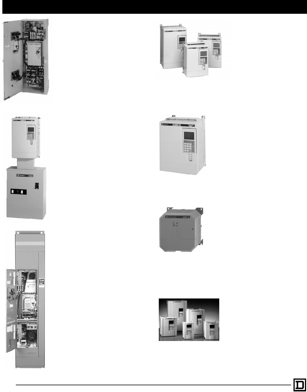
Drives and Soft Start Overview
© 1998 Square D All Rights Reserved
98
2/98
Class 8839 – ALTIVAR 66 Enclosed
The Class 8839 Enclosed ALTIVAR 66
packages are comprised of 13 separate
power circuit designs incorporated into
integrated, optimized, and barriered
enclosures (Type 1 and Type 12). These
Bypass Isolation and Combination power
circuits have been tested and rated for up
to 65,000 AIC withstand capability.
Catalog # 8800CT9701
Brochure # 8839BR9501
D-Fax # 18
ALTIVAR 56
The ALTIVAR 56 is based on our
popular ALTIVAR 66 drive and is
designed specifically for Fan and
Pump applications.
• 1 - 100 hp 460 V
• 1 - 50 hp 208 V/230 V
Class 8839 – ALTIVAR 56 “BELE Box”
The ALTIVAR 56 is also available in a
Class 8839 combination package
mounted on a back panel with a Type 1
“BELE” Box beneath the drive. There are
3 different configurations:
• Combo package
• Bypass package
• Remote Starter Bypass package
Catalog # 8839RL9701
Brochure # 8839CT9601
D-Fax # 18
ALTIVAR 16
The ALTIVAR 16 uses application
specific and communication option
modules to address OEM and
industrial drive challenges. Its
compact design and ease of
operation make it an excellent
choice for low horsepower drive
applications.
• 1 - 5 hp 460 V
• 0.5 - 3 hp 230 V
Class 8998 – ALTIVAR 66 and 56 in
Motor Control Centers
The Class 8998 Motor Control Center
drives incorporate ALTIVAR 66 and 56
drives in units fully compatible with
Square D Model 5 or 6 MCCs. Type 1,
Type 1A (gasketed), and Type 12 MCC
drives are available. The efficient thermal
management design of this product
provides the industry’s smallest space
requirements and high reliability. All units
are rated for a high fault withstand rating
of 65,000 A @ 480 Vac and are UL Listed
in full compliance with UL 845 standards.
A wide range of factory options for
controls and contactor circuits are offered.
• 1 - 400 hp @ 480 V
Catalog # 8998CT9701
Brochure # 8998BR9701
D-Fax # 08
Drives
ALTIVAR 66
The ALTIVAR 66 uses Sensorless
Vector Control, a modular design
and an extensive range of options
to satisfy the needs of industrial,
construction, and OEM
applications.
• 1 - 350 hp 460 V
(400 hp VT)
• 1 - 40 hp 208 V/230 V
(50 hp VT)
Catalog # 8800CT9701
Brochure # 8803HO9401R11/96
D-Fax # 18
Catalog # 8839RL9701
Brochure # 8800HO9601
D-Fax # 18
ALTIVAR 18
The ALTIVAR 18 is an open loop
vector drive that offers a compact
design and flexible capabilities to
meet a wide variety of
applications. It has built in filters to
meet the low voltage and EMC
directives for CE marking.
• 1 - 20 hp 460 V
• 0.5 - 10 hp 208 V/230 V
Catalog # 8802CT9301R2/96
Brochure # 8802BR9203
D-Fax # 18
Catalog #8805CT9701
Brochure # 8805HO9701
D-Fax # 18
This document provided by Barr-Thorp Electric Co., Inc. 800-473-9123 www.barr-thorp.com
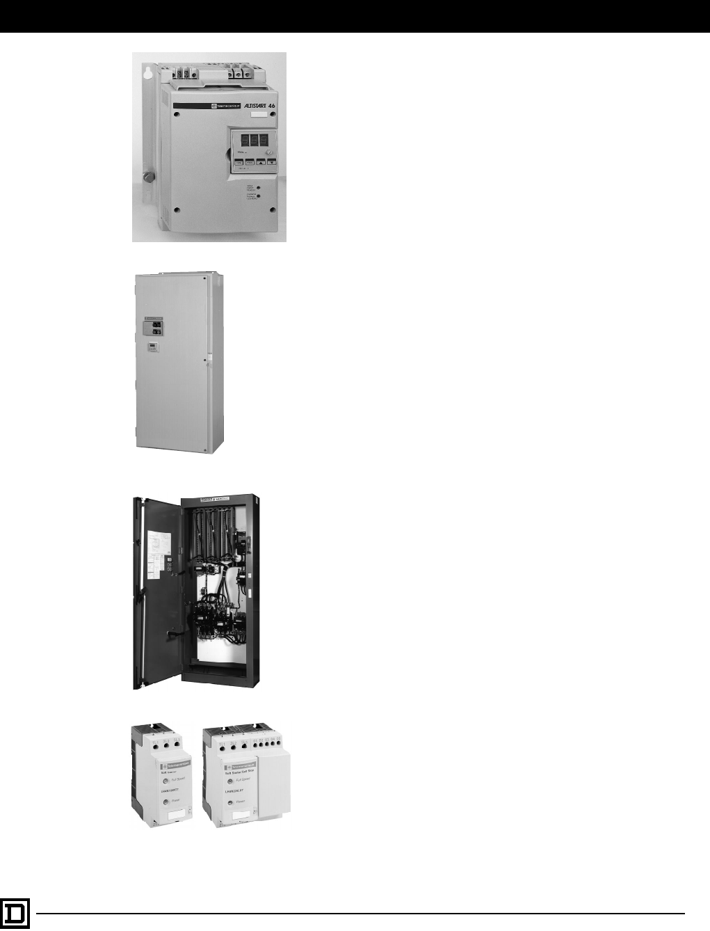
Drives and Soft Start Overview
99
2/98 © 1998 Square D All Rights Reserved
ALTISTART
®
46
The ALTISTART 46 soft start introduces the principal of “Torque Control
System” (TCS) ramping. Basing the acceleration on the motor rather
than applying a voltage ramp or maintaining a current limit (as used in
traditional soft starts) provides a linear speed ramp – independent of
motor loading – without tach feedback.
There are 21 power ratings from 17 to 1200 A
Each can be configured for 208/230/380/460 V, 50/60 Hz.
Catalog # 8636CT9701
Brochure # 8636HO9701
D-Fax # 23
Soft Starts
Class 8636 – ALTISTART 46 Non-Combination Enclosed
Class 8638 – ALTISTART 46 Combination Enclosed Fusible
Class 8639 – ALTISTART 46 Combination Enclosed Circuit
Breaker
A family of enclosed soft start controllers are available through 500 hp
for easy integration of the ALTISTART 46 into industrial facilities. The
Class 8638 and 8639 combination style soft starts combine the
requirements of motor overload and short circuit protection in a Type
12 enclosure, and are available for reversing and non-reversing
applications.
Catalog # 8636CT9701
D-Fax # 23
Electromechanical Reduced Voltage Starters
Class 8606 – Autotransformer Starter
Class 8630 – Wye Delta Starter
Class 8640 – Part Winding Starter
Square D offers a full line of Electromechanical Reduced Voltage
Starter products to minimize the electrical and mechanical stresses
caused by across the line starting.
Catalog # 8600CT9601
D-Fax # 23
LH4N
The LH4N soft starter module allows gradual starting and stopping of
single and three phase motors. Unlike conventional electromechanical
starting systems, the LH4N provides precise adjustment of the motor
torque which eliminates mechanical shocks. The LH4N is designed for
installation downstream from a motor starter circuit which includes a
power contactor and approved motor overload and short circuit
protection.
• 6 A to 25 A –208/240/380/460 V
Catalog # 8637CT9701
Brochure # 8637HO9701
D-Fax # 23
This document provided by Barr-Thorp Electric Co., Inc. 800-473-9123 www.barr-thorp.com

Drives and Soft Start Overview
© 1998 Square D All Rights Reserved
100
2/98
Warranty
Warranty to customers purchasing through
authorized Square D distributors and
customers purchasing directly from Square D.
Square D warrants equipment manufactured by it
to be free from defects in materials and
workmanship for eighteen months from date of
invoice from Square D or its authorized sales
channel. If within the applicable warranty period
purchaser discovers such item was not warranted
and promptly notifies Square D in writing, Square D
shall repair or replace the items or refund the
purchase price, at Square D’s option. This warranty
shall not apply (a) to equipment not manufactured
by Square D, (b) to equipment which shall have
been repaired or altered by others than Square D,
(c) to equipment which shall have been subjected
to negligence, accident, or damage by
circumstances beyond Square D’s control, or to
improper operation, maintenance or storage, or to
other than normal use or service. With respect to
equipment sold but not manufactured by Square D,
the warranty obligations of Square D shall in all
respects conform and be limited to the warranty
actually extended to Square D by its supplier.
The
foregoing warranties do not cover
reimbursement for labor, transportation,
removal, installation, or other expenses which
may be incurred in connection with repair or
replacement.
Except as may be expressly provided in an
authorized writing by Square D, Square D shall not
be subject to any other obligations or liabilities
whatsoever with respect to equipment manufactured
by Square D or services rendered by Square D.
The foregoing warranties are exclusive and in
lieu of all other express and implied warranties
except warranties of title, including but not
limited to implied warranties of merchantability
and fitness for a particular purpose.
This document provided by Barr-Thorp Electric Co., Inc. 800-473-9123 www.barr-thorp.com
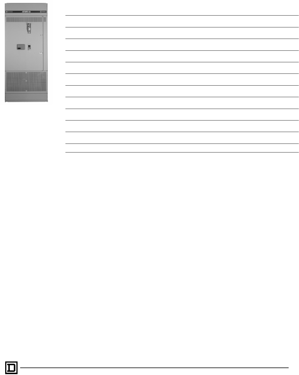
Class 8839 Enclosed AC Drives
Contents
101
2/98 © 1998 Square D All Rights Reserved
Description Pages
General Information . . . . . . . . . . . . . . . . . . . . . . . . . . . . . . . . . . . . . . . . . . . . . . . . . . . . . . . . . . 102-103
Drive Selection. . . . . . . . . . . . . . . . . . . . . . . . . . . . . . . . . . . . . . . . . . . . . . . . . . . . . . . . . . . . . . 104-105
Power Circuit Descriptions. . . . . . . . . . . . . . . . . . . . . . . . . . . . . . . . . . . . . . . . . . . . . . . . . . . . . 106-109
Control Modifications . . . . . . . . . . . . . . . . . . . . . . . . . . . . . . . . . . . . . . . . . . . . . . . . . . . . . . . . . 110-113
Engineered Features . . . . . . . . . . . . . . . . . . . . . . . . . . . . . . . . . . . . . . . . . . . . . . . . . . . . . . . . . 114-115
Recommended Spare Parts . . . . . . . . . . . . . . . . . . . . . . . . . . . . . . . . . . . . . . . . . . . . . . . . . . . 116-119
Three Phase Line Reactors. . . . . . . . . . . . . . . . . . . . . . . . . . . . . . . . . . . . . . . . . . . . . . . . . . . . . . . .120
Motor Protecting Output Filters . . . . . . . . . . . . . . . . . . . . . . . . . . . . . . . . . . . . . . . . . . . . . . . . . . . . .121
Three Phase Drive Isolation Transformers. . . . . . . . . . . . . . . . . . . . . . . . . . . . . . . . . . . . . . . . . . . . .122
Dimensions and Weights for Type 1 or 12 Enclosures. . . . . . . . . . . . . . . . . . . . . . . . . . . . . . . . 123-133
Application Information . . . . . . . . . . . . . . . . . . . . . . . . . . . . . . . . . . . . . . . . . . . . . . . . . . . . . . . 134-137
Specifications. . . . . . . . . . . . . . . . . . . . . . . . . . . . . . . . . . . . . . . . . . . . . . . . . . . . . . . . . . . . . . . 138-144
This document provided by Barr-Thorp Electric Co., Inc. 800-473-9123 www.barr-thorp.com
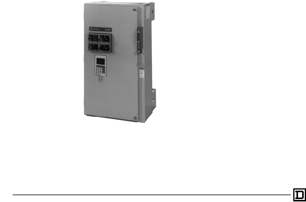
Class 8839 Enclosed AC Drives
General Information
© 1998 Square D All Rights Reserved
102
2/98
INTRODUCTION
The Class 8839 ALTIVAR AC drive is for adjustable speed operation of standard AC squirrel cage
motors. These AC Drives may be selected for constant or variable torque type loads and are enclosed
in Type 1 or Type 12 wall or floor mounted enclosures. This is a sensorless flux vector based AC drive
with Insulated Gate Bipolar Transistors (IGBT) and keypad as standard, that may be programmed to
configure the drive’s performance for wide variety of applications.
ALTIVAR 66 HP Ratings
1-400 hp, 460 Vac
1-50 hp, 208/230 Vac
This Class 8839 AC drive has been designed to offer Build To Order capabilities for the user to match
individual application requirements. Specific power and control circuit modifications may be selected
from this catalog by the user to customize an AC drive for his specific application. These modifications
are pre-engineered to satisfy the most demanding delivery requirements.
Also offered in this catalog are engineered features that allows the user to further customize an AC drive
beyond the standard modifications listed. This will provide the maximum flexibility for a user to select an
Build To Order AC drive for nearly any AC squirrel cage motor application requiring adjustable speed
operation.
ENCLOSURE TYPES
There are three enclosure designs that may be selected to meet Type 1 & 12 specifications. Enclosure
designs are dependent on the Power Circuit Type selected.
Optimized
Provides the most compact mounting space for
the ALTIVAR 66 with a disconnect device. Also for
configurations without a disconnect device or
bypass contactors.
This document provided by Barr-Thorp Electric Co., Inc. 800-473-9123 www.barr-thorp.com
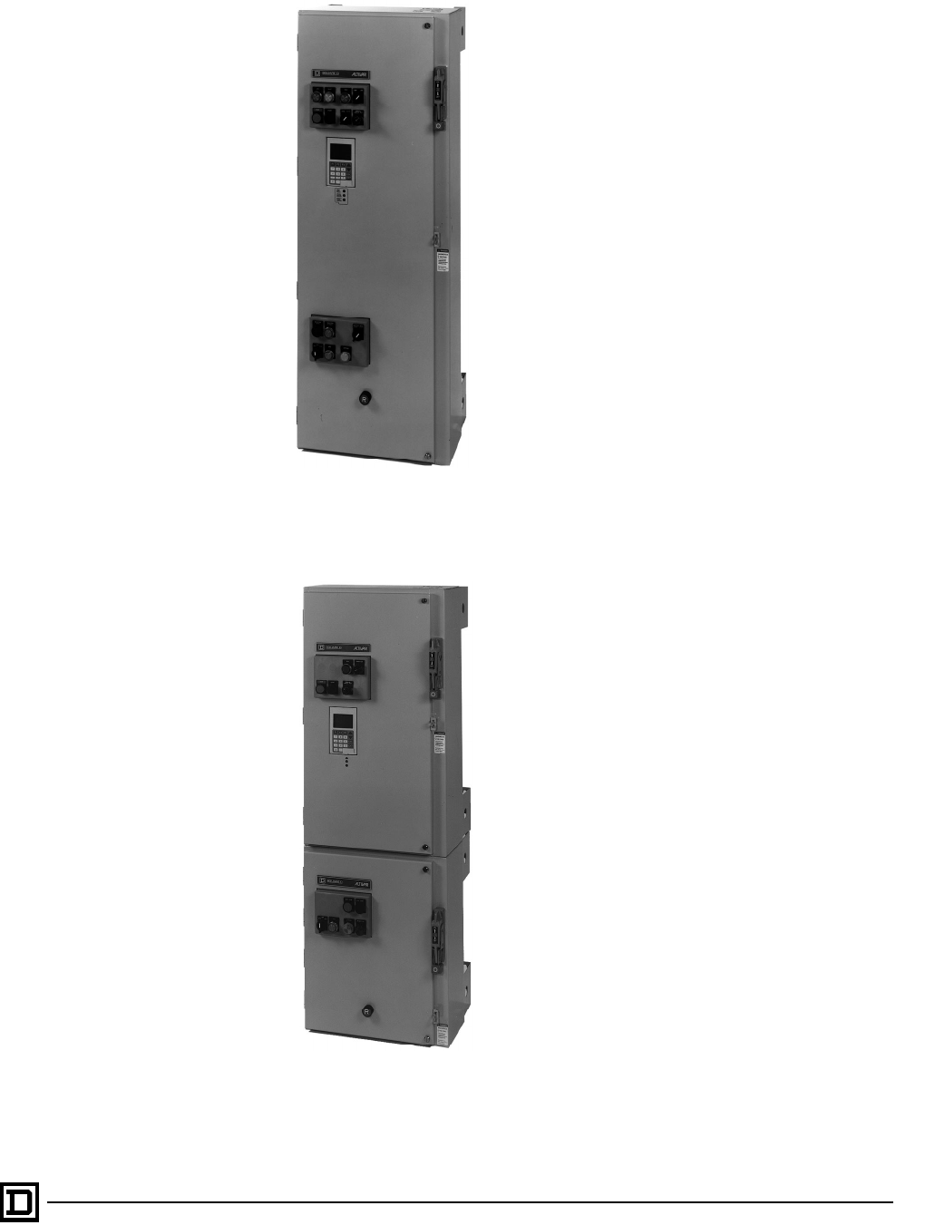
Class 8839 Enclosed AC Drives
General Information
103
2/98 © 1998 Square D All Rights Reserved
Integrated
Provides the best utilization of mounting space
when combining the ALTIVAR 66 with power
peripherals, such as line contactors, isolation &
bypass contactors within the same enclosure.
Barriered
Provides a compartmentalized AC drive and bypass
solution by separating isolation and bypass
contactors for the AC drive in separate com-
partments. This provides ultimate physical isolation
between the two separate motor controllers.
This document provided by Barr-Thorp Electric Co., Inc. 800-473-9123 www.barr-thorp.com
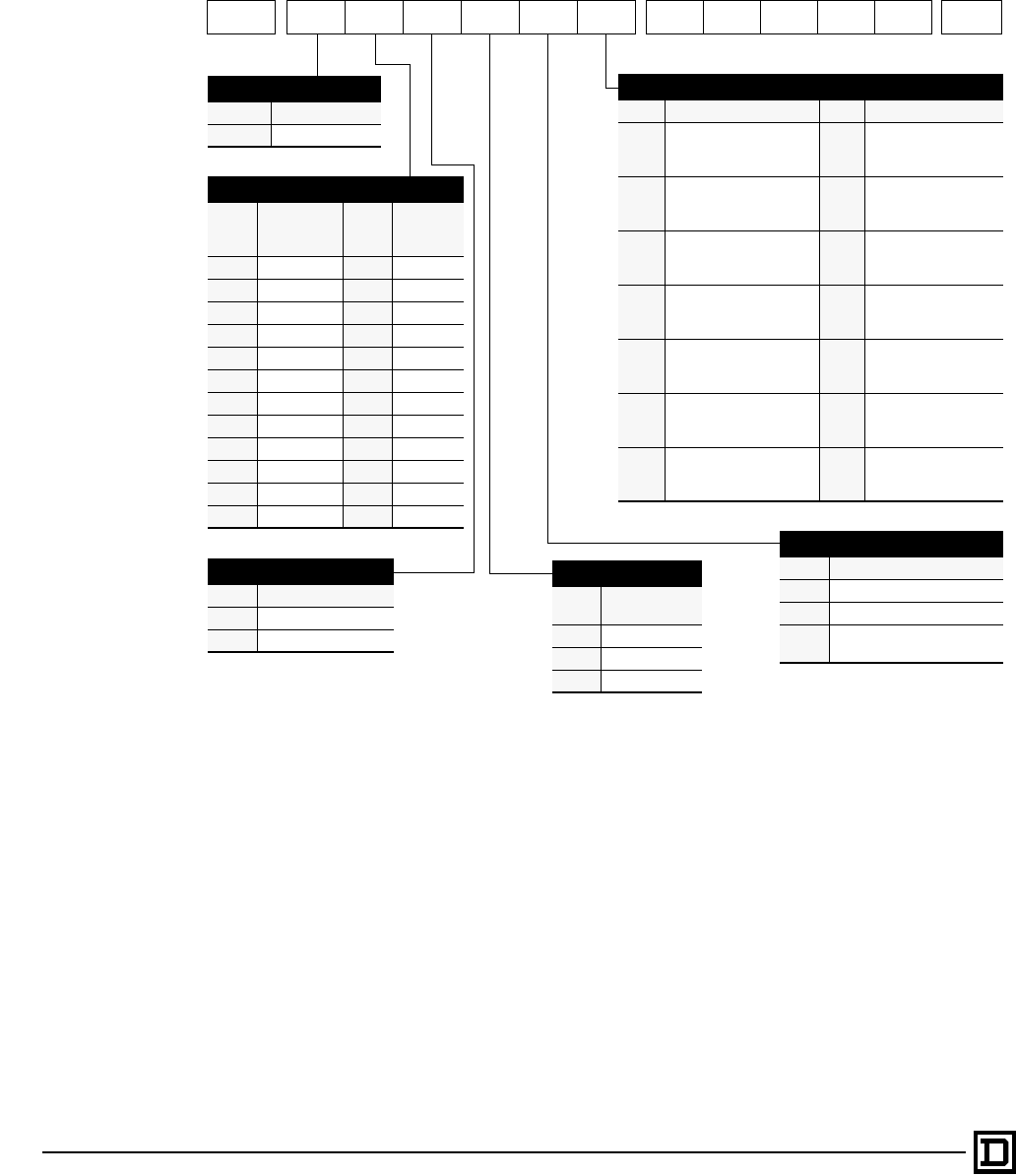
Class 8839 Enclosed AC Drives
Drive Selection
© 1998 Square D All Rights Reserved
104
2/98
The Class 8839 ALTIVAR 66 enclosed AC drives are designed for flexibility to meet applications
requiring additional enclosure space for features such as line disconnects, meters, pilot devices, or
isolation and bypass contactors. To select an AC drive, identify the catalog number by
Class, Type and
Modification number(s)
as shown below.
Class Type Number Modifications
8839 66U
❶❷❸❹❺➏ ❼
❶ Product
Code Enclosed Drive
66U ALTIVAR 66
❷ Horsepower
Code HP rating @
208/230V
460V Code HP rating
@ 460V
C1 hp Q60 hp
D2 hp R75 hp
E3 hp S100 hp
F5 hp T125 hp
G7.5 hp U150 hp
H10 hp W200 hp
J15 hp X250 hp
K20 hp Y300 hp
L25 hp Z350 hp
M30 hp 4400 hp
N40 hp
P50 hp
❸ Enclosure Type
Code Environment rating
GType 1
AType 12
❹ Voltage Rating
Code Utilization/
Distribution
2200/208 VAC
3230/240 VAC
4460/480 VAC
➏ Power Circuit Description
Code with Bypass Code without Bypass
CSingle Disconnect
Integrated 2-contactors
22,000 AIC rating ANo Disconnect
Optimized enclosure
65,000 AIC rating
DSingle Disconnect
Integrated 2-contactors
65,000 AIC rating BDisconnect
Optimized enclosure
65,000 AIC rating
EDual Disconnects
Barriered 2-contactors
22,000 AIC rating GOutput contactor
Integrated enclosure
65,000 AIC rating
FDual Disconnects
Barriered 2-contactors
22,000 AIC rating HLine contactor
Integrated enclosure
65,000 AIC rating
IIsolation & transfer
Integrated 2-contactors
65k,000 AIC rating
JSingle Disconnect
Integrated 3-contactors
22,000 AIC rating
KSingle Disconnect
Integrated 3-contactors
65,000 AIC rating
❺ Application Type
Code Applied rating
CConstant Torque
VVariable Torque
LLow Noise Variable Torque
(1- 75 hp @ 460 V)
Standard AC Drive Includes:
• Disconnect device with flange-mounted
external operator interlocked with the door
(except when Power Circuit A is selected)
• Sensorless Flux Vector Technology
• Insulated Gate Bipolar Transistor (IGBT) with
PWM output waveform
• 200,000 AIC current limiting line fuses installed
• Door mounted Keypad display with lock out
capability
• Door mounted status lights; red fault LED,
yellow caution LED and green drive ready LED
• Dry contacts for drive run and drive fail indication
• UL 508C listed with NEMA ICS 7.1 compliance
• Type 1 or 12 enclosure
Factory Modifications Include:
• Door mounted pilot devices and meters
• I/O extension module
• Line contactors
• Output contactors
• Isolation/bypass
• Factory engineered features
Engineered Specials “Build to Order”:
• Can also accommodate ‘job specific’
engineered specials; consult the Drives
Applications Group for details.
This document provided by Barr-Thorp Electric Co., Inc. 800-473-9123 www.barr-thorp.com

Class 8839 Enclosed AC Drives
Drive Selection
105
2/98 © 1998 Square D All Rights Reserved
These factory modifications offer maximum flexibility for the Class 8839 ALTIVAR 66 Enclosed AC Drives
to meet many complex job specifications.
The listing below defines all the available factory modifications. All modifications follow specific
interoperability rules for selection. Modification selection can be validated at time of quotation or order
entry by the Square D Quote to Cash Product Selector.
❼
Modifications
Mod Door mounted meter (1st selection) Mod Miscellaneous devices
A07
Analog percent speed
A16
Red ‘Power On’ pilot light
B07
Analog percent current
B16
Yellow ‘Fault’ pilot light
C07
Analog percent volts
C16
Green ‘Jog’ pilot light
D07
Analog percent power
D16
Green ‘Run’ pilot light
E07
Digital ammeter (amperes)
E16
Yellow ‘Hand & Auto’ pilot lights
F07
Digital voltmeter (voltage)
F16
Green ‘Forward & Reverse’ pilot lights
G07
Digital speed meter (frequency)
G16
Yellow ‘Fault’ pilot light & reset pushbutton
H07
Digital power meter (kilowatts)
H16
Bypass 3 Wire control
J07
Digital percent current
J16
Bypass Duty Cycle Timer
K07
Digital percent volts
K16
Automatic transfer to Bypass
L07
Digital percent speed
L16
Additional Control VA capacity
M07
Digital percent power
O16
Oversized Enclosure (Size 5 only)
Door mounted meter (2nd selection)
P16
Automatic Start Relay (remote control voltage source)
A08
Analog percent speed
Q16
3-15 psi input follower
B08
Analog percent current
R16
Convert to Push-to-Test pilot devices
C08
Analog percent volts
S16
24VDC Power Supply
D08
Analog percent power
T16
Motor Elapsed Time Meter
E08
Digital ammeter (amperes)
W16
Fast Stop pushbutton
F08
Digital voltmeter (voltage)
Y16
Omit Door Mounted Keypad
G08
Digital speed meter (frequency)
H08
Digital power meter (kilowatts)
J08
Digital percent current
K08
Digital percent volts
L08
Digital percent speed
Factory Engineered features
M08
Digital percent power
Q200
Auxiliary drive run contacts
General Purpose pilot devices
Q201
Auxiliary bypass run contacts
A09
Start & Stop pushbuttons
Q202
Auxiliary drive fail contacts
B09
Start & Stop pushbuttons and speed pot
Q203
Auxiliary auto mode contacts
C09
Start & Stop pushbuttons and Hand/Auto switch
Q204
Motor space heater
D09
Start & Stop, Hand/Auto switch and speed pot
Q205
Signal loss follower option board
E09
Stop, Forward and Reverse pushbuttons
Q206
Emergency power off pushbutton
F09 Stop, Forward and Reverse pushbuttons & speed pot Q207 Inhibit/shutdown sequence (instantaneous operation)
G09 Stop-Run switch Q208 Inhibit/shutdown sequence (timed operation)
H09 Stop-Run switch and speed pot Q209 Check valve sequence (gravity type)
J09 Forward-Off-Reverse switch Q210 Check valve sequence (motorized type)
K09 Forward-Off-Reverse switch and speed pot Q211 Seal water solenoid - without pressure switch feedback
L09 Hand-Off-Auto switch Q212 Seal water solenoid - with pressure switch feedback
M09 Hand-Off-Auto switch and speed pot Q213 Moisture detection relay circuit (without relay)
Special Purpose pilot devices
Q214 Moisture detection relay circuit (with relay)
A10 Run-Jog switch Q300 ID engraved nameplates
C10 Jog pushbutton Q301 Permanent wire markers
D10 Jog Forward and Jog Reverse pushbuttons Q302 Fan filter assembly
F10 Forward-Reverse switch Q303 ANSI# 49 enclosure paint
Option Board
Q304 ANSI# 61 enclosure paint
A11 24VDC I/O extension board Q400 Top mounted 5% line reactor
Dynamic Braking
Q401 Top mounted motor protecting filter
D15 Dynamic braking resistors (top mounted) Q402 NEMA rated contactors
This document provided by Barr-Thorp Electric Co., Inc. 800-473-9123 www.barr-thorp.com

Class 8839 Enclosed AC Drives
Power Circuit Descriptions
© 1998 Square D All Rights Reserved
106 2/98
POWER CIRCUITS
There are eleven Power Circuit configurations: six configurations that provide isolation/bypass capability
and five non-bypass types.
Isolation/bypass contactors provide emergency full speed operation with Class 10 overloads. The circuit
schemes consist of 2 and 3 contactors with 2 levels of short circuit ratings. The two contactor schemes
are available with single disconnect or dual disconnects.
The short circuit current rating should be coordinated with the available short circuit current from
connected power distribution.
Isolation/Bypass Contactors
2 - Contactor Isolation/Bypass 3 - Contactor Isolation/Bypass
Two contactor Isolation/Bypass configurations sequence
the contactors to provide true isolation of the motor when
it is not running. Both mechanical and electrical
interlocks eliminate the possibility of back feeding the AC
drive with incoming power. Auxiliary contact from the
isolation contactor provides positive indication that the
motor is connected to the AC drive before beginning a
run command. Time delays allow the residual voltage to
decay when transferring from drive control to bypass
thereby reducing the possibility of nuisance drive or
circuit breaker tripping.
Three contactor Isolation/Bypass configurations provide
the same functions as Two contactor Isolation/Bypass
but use a line contactor to remove line power form the
AC drive. These configurations use momentary POWER
ENABLE and POWER DISABLE push-buttons to control
operation of the line contactor. Operation of the line
contactor is a 3-wire control strategy which requires
operator intervention to re-apply power after a power
interruption. Three contactor Isolation/Bypass do not
allow for automatic restart capability.
The line contactor provides isolation of L1, L2, L3 with
control power remaining for using Auto-Diagnostics.
This document provided by Barr-Thorp Electric Co., Inc. 800-473-9123 www.barr-thorp.com
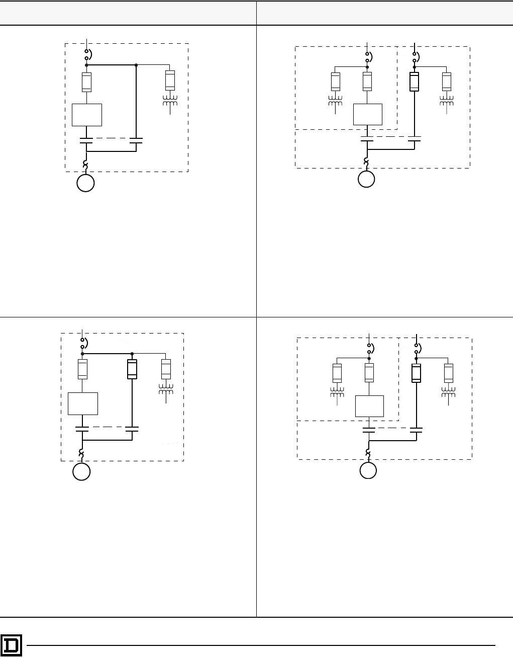
Class 8839 Enclosed AC Drives
Power Circuit Descriptions
107
2/98 © 1998 Square D All Rights Reserved
ISOLATION AND BYPASS SCHEMES
2-Contactor Isolation/Bypass
with Single Disconnect 2-Contactor Isolation/Bypass
with Dual Disconnect
Code C
Standard Iso/bypass features:
• IEC contactors with Class 10 overloads
• 22k AIC short circuit rating
• AFC (green lens) and BYPASS (amber lens) pilot lights door
mounted on bypass control island
• AFC-OFF-BYPASS selector switch door mounted on bypass control
island
Available with 1-200 hp AC drives only
Code E
Standard Iso/bypass features:
• IEC contactors with Class 10 overloads (1-200 hp)
• NEMA contactors with Class 20 overloads (250-400 hp)
• 22k AIC short circuit rating
• AFC (green lens) and BYPASS (amber lens) pilot lights door
mounted on bypass control island
• AFC-OFF-BYPASS selector switch door mounted on bypass control
island
Available with 1-400 hp AC drives only
Code D
Standard Iso/bypass features:
• IEC contactors with Class 10 overloads
• 65k AIC short circuit rating
• Bypass fuse not included. Class J or RK-1 required
• AFC (green lens) and BYPASS (amber lens) pilot lights door
mounted on bypass control island
• AFC-OFF-BYPASS selector switch door mounted on bypass control
island
Available with 1-200 hp AC drives only
Code F
Standard Iso/bypass features:
• IEC contactors with Class 10 overloads (1-200 hp)
• NEMA contactors with Class 20 overloads (250-400 hp)
• 65k AIC short circuit rating
• Bypass fuse not included. Class or RK-1 required
• AFC (green lens) and BYPASS (amber lens) pilot lights door
mounted on bypass control island
• AFC-OFF-BYPASS selector switch door mounted on bypass control
island
Available with 1-400 hp AC drives only
Fan &
Control
M
Overload
Motor Circuit Protector
BCIC
AC Drive Control
M
Overload
Motor Circuit
Protector
BCIC
AC Drive
Fan
AC Drive
Compart-
ment
Disconnect
Barriered
Bypass
Contactor
Compart-
ment
Fan &
Control
M
Overload
Disconnect
BC
IC
AC Drive
Control
M
Overload
Disconnect
BCIC
AC Drive
Fan
AC Drive
Compart-
ment
Disconnect
Barriered
Bypass
Contactor
Compart-
ment
This document provided by Barr-Thorp Electric Co., Inc. 800-473-9123 www.barr-thorp.com
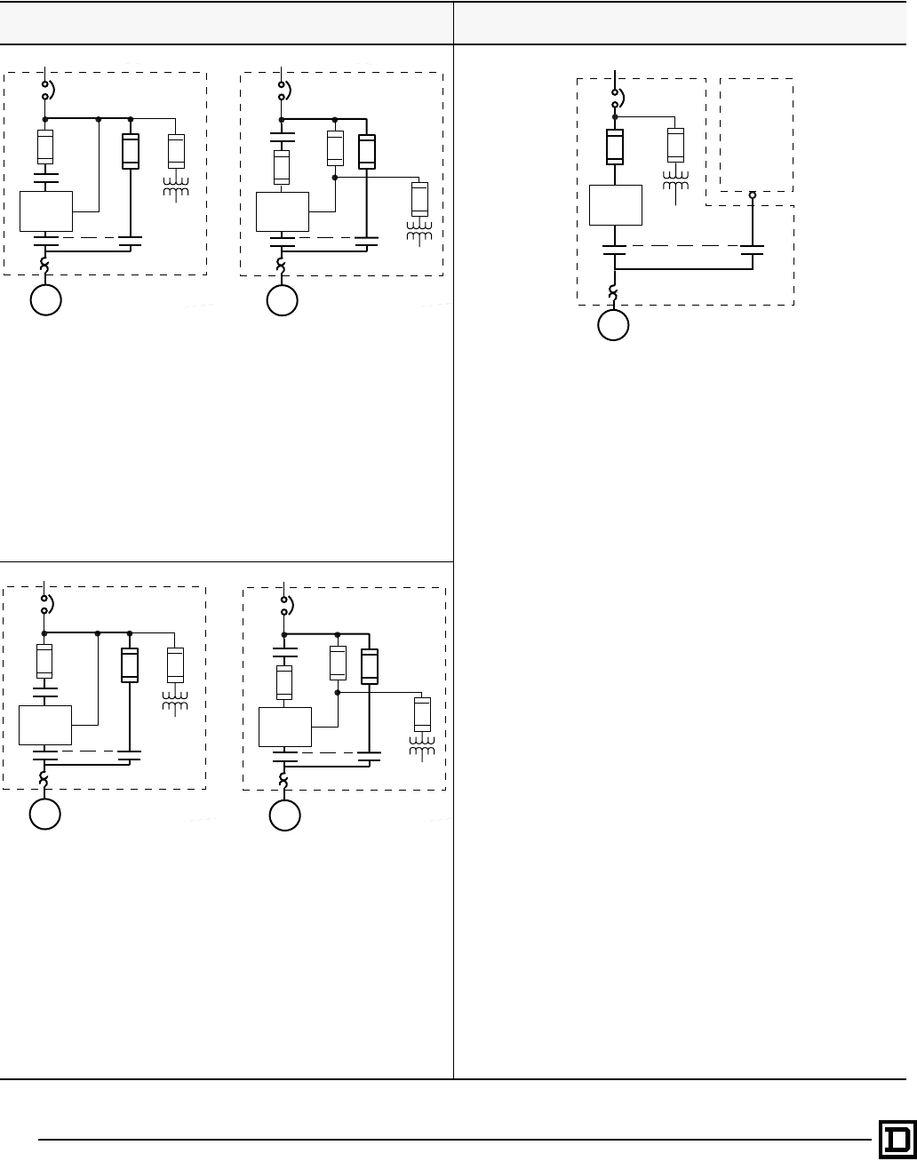
Class 8839 Enclosed AC Drives
Power Circuit Descriptions
© 1998 Square D All Rights Reserved
108 2/98
ISOLATION AND BYPASS SCHEMES
3-Contactor Isolation/Bypass
with Single Disconnect 2-Contactor Isolation/Transfer
with Single Disconnect
Code K
Standard Iso/bypass features:
• IEC contactors with Class 10 overloads
• 22k AIC short circuit rating
• AFC (green lens) and BYPASS (amber lens) pilot lights door
mounted on bypass control island
• AFC-OFF-BYPASS selector switch door mounted on bypass
control island
• Three wire control of line contactor
Available with 1-200 hp AC drives only
Code I
Standard Iso/transfer features:
• IEC contactors with Class 10 overloads (1-200 hp)
• NEMA contactors with Class 20 overloads (250-400 hp)
• Isolation and transfer allows for use of external combination starter,
reduced voltage starter or solid state reduced voltage starter as
emergency full speed bypass
• 22k AIC short circuit rating
• AFC (green lens) and BYPASS (amber lens) pilot lights door
mounted on bypass control island
• AFC-OFF-BYPASS selector switch door mounted on bypass
control island
Available with 1-400 hp AC drives only
Code J
Standard Iso/bypass features:
• IEC contactors with Class 10 overloads
• 65k AIC short circuit rating
• Bypass fuse not included. Class J or RK-1 required
• AFC (green lens) and BYPASS (amber lens) pilot lights door
mounted on bypass control island
• AFC-OFF-BYPASS selector switch door mounted on bypass control
island
• Three wire control of line contactor
Available with 1-200 hp AC drives only
Motor Circuit Protector
AC Drive
M
Fan &
Control
LC
IC
CL1
CL2
1-75HP CT/LN
(100HP VT) drives
Overload
BC
OR
(1) Fuse Present only on
100-200HP CT/LN and
125-200HP VT drives
Motor Circuit Protector
AC Drive
M
Fan &
Control
LC
IC
CL1
CL2
Overload
BC
(1)
Fan &
Control
M
Overload
Disconnect
BCIC
AC Drive
To
User’s
Remote
Starter
Motor Circuit Protector
AC Drive
M
Fan &
Control
LC
IC
CL1
CL2
1-75HP CT/LN
(100HP VT) drives
Overload
BC
(1) Fuse Present only on
100-200HP CT/LN and
125-200HP VT drives
Motor Circuit Protector
AC Drive
M
Fan &
Control
LC
IC
CL1
CL2
Overload
BC
(1)
OR
This document provided by Barr-Thorp Electric Co., Inc. 800-473-9123 www.barr-thorp.com
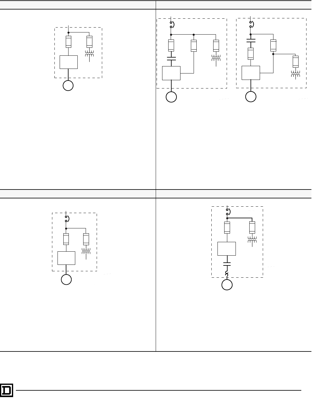
Class 8839 Enclosed AC Drives
Power Circuit Descriptions
109
2/98 © 1998 Square D All Rights Reserved
NON-BYPASS SCHEMES
No Contactors without Disconnect Line Isolation Contactor with Single Disconnect
Code A
Standard features:
• 65k AIC short circuit rating
Available with 1-200 hp AC drives only
Code H
Standard features:
• IEC line contactor
• 22k AIC short circuit rating: 100-200 hp CT; 125-200 hp VT
• 65k AIC short circuit rating: 1-75 hp CT;
• 1-100 hp VT
• Three wire control of line contactor
Available with 1-400 hp AC drives only
No Contactors with Single Disconnect Output Isolation Contactor with Single Disconnect
Code B
Standard features:
• 65k AIC short circuit rating
Available with 1-400 hp AC drives only
Code G
Standard features:
• IEC output contactor with Class 10 overloads
• 65k AIC short circuit rating
• Isolates motor for the AC drive
Available with 1-400 hp AC drives only
M
AC Drive Fan
Disconnect
AC Drive
M
Fan &
Control
LC
CL1
CL2
1-75HP CT/LN
(100HP VT) drives
Disconnect
AC Drive
M
Fan &
Control
LC
CL1
CL2
(1) Fuse Present only on
100-200HP CT/LN and
125-200HP VT drives
(1)
OR
Disconnect
AC Drive
M
Fan
M
Overload
Disconnect
AC Drive Fan
IC
This document provided by Barr-Thorp Electric Co., Inc. 800-473-9123 www.barr-thorp.com
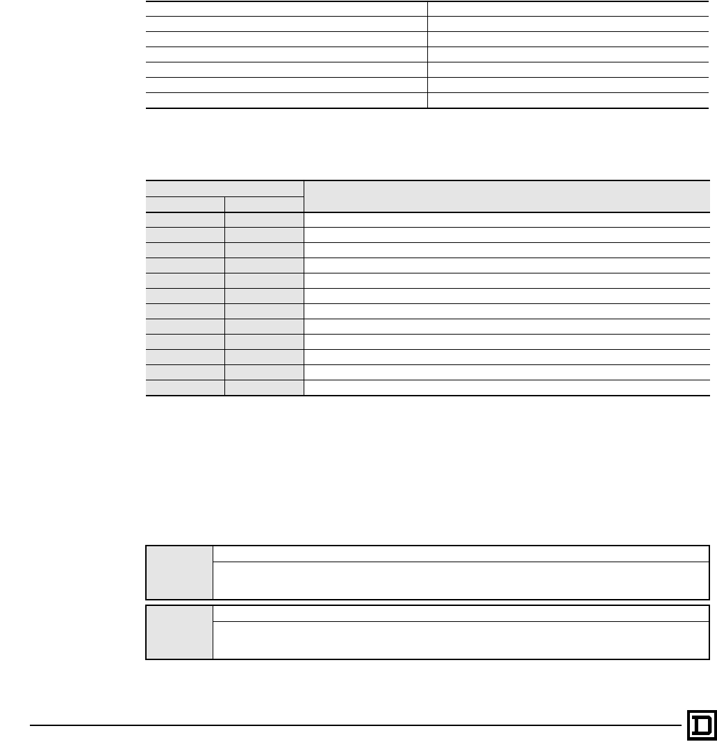
Class 8839 Enclosed AC Drives
Control Modifications
© 1998 Square D All Rights Reserved
110 2/98
Six categories of control modifications provide user flexibility
• Meters • Dynamic Braking
• General Purpose Control Devices • I/O Extension Module
• Special Purpose Control Devices • Miscellaneous Modifications
Meters
Digital and analog meters may be selected to provide indication of speed, amperes, volts or watts. These
meters are in addition to the door mounted keypad display. The keypad display has the following built in
metering functions.
Door Mounted Keypad Display Functions
The Digital and Analog meter functions along with their alpha-numeric modifications are listed. These
meters are door mounted on the control island with space for a maximum of two meters. When selecting
meter(s), use selection 1 column for the first meter and selection column 2 for the second meter.
General Purpose Control Devices
These door mounted operator controls provide digital and analog inputs for commanding drive speed
and start/stop functions. The digital and analog input terminals are active only when the keypad is
programmed for Terminal Mode of operation.
NOTE: Switching from terminal mode to keypad mode will inhibit all digital and analog inputs terminals.
The enclosed AC drive product door mounted keypad serves as a programmer of drive parameters and
display functions.
Speed Reference (Hz) DC Bus Voltage (volts)
Output Frequency (Hz) Motor Thermal State (%)
Output Current (amps) Drive Thermal State (%)
Motor Torque (%) Elapsed Time Indication (hours)
Output Power (%) Motor RPM (scalable)
Output Voltage (kw) Machine Speed Reference (scalable)
Line Voltage (volts) Machine Speed (scalable)
Modifications Digital & Analog
Meter Functions
Selection 1 Selection 2
A07 A08 Analog percent speed meter scaled 0 to 120% of base speed
B07 B08 Analog percent current scaled 0 to 200% of rated output current
C07 C08 Analog percent volts scaled 0 to 120% of rated output voltage
D07 D08 Analog percent power scaled 0 to 200% of rated output power
E07 E08 Digital ammeter (amperes) scaled 0 to 2 times rated output amperes
F07 F08 Digital voltmeter (voltage) scaled 0 to 1.1 times rated output voltage
G07 G08 Digital speed meter (frequency) scaled 0 to 72 Hz output frequency
H07 H08 Digital power meter (kilowatts/horsepower) scaled 0 to 2.0 times rated output horsepower
J07 J08 Digital percent current scaled 0 to 120 % rated output current
K07 K08 Digital percent volts scaled 0 to 110 % rated output voltage
L07 L08 Digital percent speed scaled 0 to 120 % of base speed
M07 M08 Digital percent power scaled 0 to 200 % rated output power
Mod
A09
Start/stop push buttons with out manual speed potentiometer
Provides Start/Stop push buttons mounted on the door mounted control island. These pushbuttons control the starting
and stopping of the connected motor. Speed may be adjusted by a remote manual speed potentiometer.
Note: Use of the keypad to adjust speed is not possible when the start/stop pushbuttons are active in the terminal mode.
Mod
B09
Start/stop push buttons with manual speed potentiometer
Provides Start/Stop push buttons and manual speed potentiometer mounted on the door mounted control island.
These pushbuttons control the starting and stopping of the connected motor. Speed may be adjusted by the door
mounted manual speed potentiometer.
This document provided by Barr-Thorp Electric Co., Inc. 800-473-9123 www.barr-thorp.com

Class 8839 Enclosed AC Drives
Control Modifications
111
2/98 © 1998 Square D All Rights Reserved
Mod
C09
Start/stop push buttons, Hand/auto selector switch with out manual speed potentiometer
Provides Start/Stop push buttons and a Hand/Auto selector switch mounted on the door mounted control island.
The Hand/Auto selector switch is used to select between the AI1 and AI2 analog inputs. In the Hand position the
start/stop push buttons are active (3 wire control) and speed may be adjusted by a remote manual speed
potentiometer. In the Auto position the AC drive may be started and stopped by a remote contact (user supplied) (2
wire control). The speed may be adjusted by a 4-20 madc signal to analog input reference AI2. The stop push button
is active for both Hand and Auto modes. Note: Use of the keypad to adjust speed is not possible when the start/stop
pushbuttons and Hand/auto switch are active in the terminal mode.
Mod
D09
Start/stop push buttons, Hand/auto selector switch with manual speed potentiometer
Provides Start/Stop push buttons, Hand/Auto selector switch and manual speed potentiometer mounted on the door
mounted control island. The Hand/Auto selector switch is used to select between the AI1 and AI2 analog inputs. In
the Hand position the start/stop push buttons are active (3 wire control) and speed may be adjusted by the manual
speed potentiometer. In the Auto position the AC drive may be started and stopped by a remote contact (user
supplied) (2 wire control). The speed may be adjusted by a 4-20 madc signal to analog input reference AI2. The stop
push button is active for both Hand and Auto modes
Mod
E09
Stop pushbutton and forward/reverse push buttons with out manual speed potentiometer
Provides Stop, Forward and Reverse push buttons door mounted on the control island. Depressing the forward or
reverse push button will start the motor in the desired direction. The stop push button will place the controller in the
normal stop mode. The motor speed may be adjusted by a remote manual speed potentiometer or an external
speed signal. Note: Use of the keypad to adjust speed is not possible when the stop push-button and forward/
reverse push-button is active in the terminal mode.
Mod
F09
Stop push button, forward and reverse push buttons with manual speed potentiometer
Provides Stop, Forward and Reverse push buttons and manual speed potentiometer door mounted on the control
island. Depressing the forward or reverse push button will start the motor in the desired direction. The stop push
button will place the controller in the normal stop mode. The motor speed may be adjusted by the door mounted
manual speed potentiometer.
Mod
G09
Run/stop selector switch with out manual speed potentiometer
Provides a two position selector switch door mounted on the control island. Setting the switch in the run position
will start the motor. Setting the switch to the stop position will stop the motor. The motor speed may be adjusted
by a remote manual speed potentiometer or an external speed signal. Note: Use of the keypad to adjust speed is
not possible when the run/stop selector switch is active in the terminal mode.
Mod
H09
Run/stop selector switch with manual speed potentiometer
Provides a two position selector switch and manual speed potentiometer door mounted on the control island.
Setting the switch in the run position will start the motor. Setting the switch to the stop position will stop the motor.
The motor speed may be adjusted by the door mounted manual speed potentiometer.
Mod
J09
Forward-off-reverse selector switch with out manual sped potentiometer
Provides a three position selector switch door mounted on the control island. Setting the switch either forward or
reverse will start the motor in the desired direction. The motor speed may be adjusted by a remote manual speed
potentiometer or an external speed signal. Note: Use of the keypad to adjust speed is not possible when the
forward-off-reverse selector switch is active in the terminal mode.
Mod
K09
Forward-off-reverse selector switch with manual speed potentiometer
Provides a three position selector switch and manual speed potentiometer door mounted on the control island.
Setting the switch to either forward or reverse will start the motor in the desired direction. The motor speed may be
adjusted by the door mounted manual speed potentiometer.
Mod
L09
Hand-off-auto selector switch with out manual speed potentiometer
Provides a three position selector switch door mounted on the control island. The Hand-Off-Auto selector switch is
used to select between the AI1 and AI2 analog inputs. In the Hand position the motor will start and speed may be
adjusted by a remote manual speed potentiometer. In the Auto position the motor may be started and stopped by
a user supplied remote contact. The speed may be adjusted by a 4-20 madc signal to analog input reference AI2.
The off position will stop the motor. Note: Use of the keypad to adjust speed is not possible when the Hand-Off-Auto
selector switch is active in the terminal mode.
Mod
M09
Hand-off-automatic selector switch with manual speed potentiometer
Provides a three position selector switch and manual speed potentiometer door mounted on the control island. The
Hand-Off-Auto selector switch is used to select between the AI1 and AI2 analog inputs. In the Hand position the
motor will start and speed may be adjusted by a remote manual speed potentiometer. In the Auto position the motor
may be started and stopped by a user supplied remote contact. The speed may be adjusted by a 4-20 madc signal
to analog input reference AI2 or the door mounted manual speed potentiometer. The off position will stop the motor
Mod
N09
No General Purpose Devices
Provides the door mounted control island with no general purpose control devices.
This document provided by Barr-Thorp Electric Co., Inc. 800-473-9123 www.barr-thorp.com
Class 8839 Enclosed AC Drives
Control Modifications
© 1998 Square D All Rights Reserved
112 2/98
Special Purpose Control Devices
These door mounted operator controls provide digital inputs for jog and reversing functions. The digital
input terminals are active only when the keypad is programmed for Terminal Mode of operation.
NOTE: Switching from terminal mode to keypad mode will inhibit all digital and analog inputs terminals.
The enclosed AC drive product door mounted keypad serves as a programmer of drive parameters and
display functions.
I/O Extension Module
When additional digital or analog inputs/outputs are required an I/O extension module may be selected.
Dynamic Braking
When the motor along with its connected mechanical load must be stopped faster than the normal coast
time, the dynamic braking modification should be selected.
Miscellaneous modifications
These modifications provide a variety of functions to meet certain application requirements. This extra
flexibility offers the ultimate in Build to Order capability of an AC Drive.
Mod
A10
Run-jog selector switch
Provides a two position selector switch for selection of the start push-button to be a monetary contact (run) (3-wire
control) or maintained contact (jog) (2-wire control). General purpose control Mods; A09 or B09 must be selected
for this Mod to function. This selector switch is door mounted on the control island
Mod
D10
Jog forward and Jog reverse push buttons
Provides push buttons for jogging the connected motor in the desired direction. Refer to Instruction Manual
VDOCO6S305 for information concerning the adjustment of jog speed and jog cycle timer. These pushbuttons are
door mounted on the control island.
Mod
F10
Forward/Reverse selector switch
Provides a two position selector switch to select the desired direction of motor rotation. Refer to Instruction Manual
VDOCO6S305_ for information concerning speed reference inputs for the purpose of adjusting motor speed. This
selector switch is door mounted on the control island.
Mod
A11
24V I/O extension module
Provides additional 24 V digital/analog inputs and outputs to the drive. The 24 V I/O Extension module has the
following inputs/outputs:
Four 24 Vdc digital logic inputs LI5, LI6, LI7 and LI8.
Two analog inputs AI3 (Differential) and AI4.
Two relay outputs R3 and R4 (programmable).
One current loop output A03 (0-20 ma or 20-4 ma, 250 W input impedance)
Mod
D15
Dynamic Braking
Provides a resistor and overload protection mounted in a self ventilated enclosure mounted on top of the drive
enclosure. This resistor will absorb the regenerative energy from an AC motor to provide internal braking action. For
additional information refer to the application section of this catalog.
Mod
A16
‘Power On’ Red Pilot Light
Provides a red pilot light that illuminates when power is applied to the drive. This pilot light is an LED type door
mounted on the control island.
Mod
B16
‘Fault’ Yellow Pilot Light
Provides a yellow pilot light that illuminates when the drive is faulted. This pilot light is an LED type door mounted
on the control island.
Mod
C16
‘Jog’ Green Pilot Light
Provides a green pilot light that illuminates when the jog push-button is depressed on the drive. This pilot light is an
LED type door mounted on the control island.
Mod
D16
‘Run’ Green Pilot Light
Provides a green pilot light that illuminates when the drive is supplying an output frequency to the connected motor.
This pilot light is an LED type door mounted on the control island. Note: When power circuits C through K are
selected an AFC Run (green)and Bypass Run (amber) pilot light is provided on the door mounted bypass control
island.
This document provided by Barr-Thorp Electric Co., Inc. 800-473-9123 www.barr-thorp.com

Class 8839 Enclosed AC Drives
Control Modifications
113
2/98 © 1998 Square D All Rights Reserved
Mod
E16
‘Hand & Auto’ Yellow Pilot Lights
Provides two yellow pilot lights that illuminate when HAND or AUTO mode have been selected. General purpose
control Mods; C09, D09, L09 or M09 must be selected for this Mod to function. These pilot lights are of the LED
type door mounted on the control island
Mod
F16
‘Forward & Reverse’ Green Pilot Lights
Provides two green pilot lights that illuminate when the FORWARD or REVERSE mode has be selected. These
pilot lights are of the LED type door mounted on the control island.
Mod
G16
‘Fault’ Yellow Pilot Light with Reset Push button
Provides a illuminated push-button with a yellow lens that illuminates when the drive is faulted. This illuminated
push-button is an LED type door mounted on the control island. Once the condition which initiated the fault has
been corrected, the drive may be reset by depressing the push button and the yellow light will extinguish. The faults
that are re-setable with this modification are:
* Undervoltage * Motor Overload * Input Phase Loss * Loss of Follower
* Drive Over temperature * DC Bus Overvoltage * Overvoltage
Mod
H16
Bypass 3 wire control
Provides start/stop pushbuttons (3-wire control) for bypass contactor operation. These pushbuttons are door
mounted on the bypass control island. Upon loss of power, the bypass operation must be restarted using the
momentary start push button.
Mod
J16
Bypass duty cycle timer
Prevents rapid cycling of line power to the motor when operating in bypass mode. When line power is removed from
the motor, line power cannot be reapplied in the bypass mode until the time delay set on the CTR relay timer. The
CTR relay timer is factory set for 10 seconds. It can be adjusted to meet user’s process requirements within the
range of 10 to 180 seconds.
Mod
K16
Automatic transfer to Bypass
Provides an automatic transfer to bypass for full speed operation , should a fault condition occur tripping the drive
off line.
Mod
L16
Additional Control VA
Increases the standard control transformer by 50 VA beyond that required for operation of the control functions.
Mod
M16
Power Isolator controls
Provides two pushbuttons (3-wire control) for manual operation of the line contactor. The two push buttons are
labeled CONVERTER PWR ENABLE and CONVERTER PWR DISABLE. These pushbuttons are door mounted on
the bypass control island.
Mod
O16
Oversized enclosure
(50-75 HP CT / 60-100 HP VT only)
Provides a 90” H x 32” W x 20” D free standing enclosure for substitution of the standard 42” H x 32” W x 20” D wall
mounted enclosure.
Mod
P16
Auto start relay
Provides an interface for remote contact (120 V rated) to start the drive or bypass and Hand/Auto selector switch
for the bypass. The Hand/Auto selector switch provides hand or auto operation in the bypass mode with extra
terminal points for user supplied float switches and other level alarm functions.
Mod
Q16
3-15 PSI input follower
Provides a 3-15 PSI follower from the users pneumatic source. The motor speed will be proportional to the 3-15 PSI
pneumatic signal.
Mod
R16
Convert Pilot Light(s) to Push-to-Test
Provides push-to-test of all pilot lights selected previously, except the Power On Pilot Light (A16).
Mod
S16
24VDC power supply
Provides an auxiliary 24 Vdc, 320 ma power supply, installed within the drive. May be used to power devices that
exceed the rating of the drive 24 Vdc supply.
Mod
T16
Motor Elapsed Time Meter (ETM)
Provides elapsed time indication of motor operation from both drive and bypass contactor functions. The Motor
Elapsed Time meter is a 0 to 99999.9 digit in HOURS, non-resettable display rated 120 Vac, 60 Hz with a Type 12
sealed face. This meter is door mounted on the control island.
Mod
W16
'Fast Stop' push button
Provides a pushbutton for modifying the set deceleration ramp rate to the minimum ramp rate of 0.1 seconds. This
pushbutton is door mounted on the control island. This function will allow the drive to decelerate the motor as quickly as
possible within the operating limits of the controller configuration (braking selection) without causing nuisance tripping.
Mod
Y16
Omit door mounted keypad
Removes the keypad and LED display from outside the enclosure door. The keypad will remain on the basic drive
unit within the enclosure.
This document provided by Barr-Thorp Electric Co., Inc. 800-473-9123 www.barr-thorp.com

Class 8839 Enclosed AC Drives
Engineered Features
© 1998 Square D All Rights Reserved
114 2/98
Control Options
Form modifications within the Q200 series will cover control circuit engineered features for the Class 8839
enclosed AC drives.
• Available on all configurations.
• Available only for Power Circuits C, D, E, F, I, J or K.
• Available on all configurations.
• Available on all configurations.
• Available on all configurations.
• Available on all configurations.
• Available on configurations except Power Circuit A.
• Available on all configurations. • Not available if option Q208 is selected.
• Available on all configurations. • Not available if option Q207 is selected.
• Available on all configurations. • Not available if option Q210 is selected.
• Available on all configurations. • Not available if option Q209 is selected.
• Available on all configurations. • Not available if option Q212 is selected.
Mod
Q200
Auxiliary Drive Run Contacts
Provides (3) Form ‘C’ contacts rated 5 A @ 120 Vac wired to terminal blocks (9080 GM6) for customer use.
Mod
Q201
Auxiliary Bypass Run Contacts
Provides (3) Form ‘C’ contacts rated 5 A @ 120 Vac wired to terminal blocks (9080 GM6) for customer use.
Mod
Q202
Auxiliary Drive Fail Contacts
Provides (3) Form ‘C’ contacts rated 5 A @ 120 Vac wired to terminal blocks (9080 GM6) for customer use.
Mod
Q203
Auxiliary auto mode contacts
Provides an auxiliary AFC mode (auto) contact which will energize a relay with (3) Form ‘C’ contacts rated 5 A
@ 120 Vac wired to terminal blocks (9080 GM6) for customer use.
Mod
Q204
Motor Space Heater
Provides control circuit contacts, 120 V, 150-500 VA supply and fusing wired to terminals for customer use.
Note: Specify VA requirements at time of order entry in the ‘Engineering Notes’ field within Q2C.
Mod
Q205
Signal loss follower option board
Provides the 52010-055-50 intended for 4-20 mAdc control loop applications where upon the loss of input signal
it is desired to retain the output signal at the last input signal level. The module provides isolated 4-20 mAdc to
0-10 Vdc conversion and a normally open alarm relay contact for signal loss alert. The module operates from
+24 Vdc power supply and is mounted on a standard 35 mm DIN rail within the drive enclosure.
Mod
Q206
Emergency power off push-button
Provides a shunt trip modified molded case switch or circuit breaker where a push-pull maintained mushroom
head push-button energizes the shunt trip coil and instantaneously opens to shut down power supplied to the
AC drive in the AFC mode and/or bypass mode, coasting to an uncontrolled stop.
Mod
Q207
Inhibit/shutdown sequence
(instantaneous operation)
Provides a relay circuit operating in the fail safe mode where a remote initiating contact opens the relay,
deenergizes and instantaneously shuts the AC drive down in the AFC mode (hand or auto) and/or in the bypass
mode (hand or auto).
Mod
Q208
Inhibit/shutdown sequence
(timed operation)
Provides a relay circuit operating in the fail safe mode where a remote initiating contact opens the relay,
deenergizes and after a specified time shuts the AC drive down in the AFC mode (hand or auto) and/or in the
bypass mode (hand or auto).
Mod
Q209
Check valve sequence (gravity type)
Provides relay circuitry sequenced from a check valve limit switch. A valve closed position limit switch will
energize the relay that will give a run permissive to the AC drive in the AFC mode (hand or auto) and/or in the
bypass mode (hand or auto). A valve closed position limit switch will deenergize a timer relay such that if this
relay is not deenergized within a specified time period, the AC drive will shut down in the AFC mode (hand or
auto) and/or in the bypass mode (hand or auto).
Mod
Q210
Check valve sequence (motorized type)
Provides relay circuitry sequenced from a check valve limit switch. A valve closed position limit switch will
energize relays that will initiate a remote valve operating solenoid limited to 50VA and give a run permissive to
the AC drive in the AFC mode (hand or auto) and/or in the bypass mode (hand or auto). A valve closed position
limit switch will deenergize a timer relay such that if this relay is not deenergized within a specified time period,
the AC drive will shut down in the AFC mode (hand or auto) and/or in the bypass mode (hand or auto).
Mod
Q211
Seal water solenoid - without pressure switch feedback
Provides relay which will energize a remote seal water solenoid limited to 50 VA during AC drive operation in the
AFC mode (hand or auto) and/or in the bypass mode (hand or auto).
This document provided by Barr-Thorp Electric Co., Inc. 800-473-9123 www.barr-thorp.com
Class 8839 Enclosed AC Drives
Engineered Features
115
2/98 © 1998 Square D All Rights Reserved
• Available on all configurations. • Not available if option Q211 is selected.
• Available on all configurations. • Not available if option Q214 is selected.
• Available on all configurations. • Not available if option Q213 is selected.
Enclosure & miscellaneous modifications
Form modifications within the Q300 series will cover enclosure and miscellaneous enclosed features for
the Class 8839 enclosed AC drive.
• Available on all configurations.
• Available on all configurations.
• Available only on 250-400 hp @ 460 V units.
• Available on all configurations • Not available if option Q304 is selected.
• Available on all configurations. • Not available if option Q303 is selected.
Power Options
Form modifications within the Q400 series will cover engineered power circuit configurations for the
Class 8839 enclosed AC drive.
• Not available if options D15 or Q401 is selected.
• Option Q400 available offering is up to 75 hp CT/LN (100 hp VT) for 460 V rated units. Line reactors are separately mounted and
wired by customer on 100 hp CT (125 hp VT) & up for 460 V rated units.
• Not available if option D15 or Q400 is selected.
• Q401 available offering is for 460 V rated units only up to 75 hp CT/LN (100 hp VT).
• Not available for 208 V and 230 V ratings.
Mod
Q212
Seal water solenoid - with pressure switch feedback
Provides relay which will energize a remote seal water solenoid limited to 50 VA during AC drive operation.
Additionally, the remote initiating contact will open the relay, deenergizing and after a specified time shuts the
AC drive down in the AFC mode (hand or auto) and/or in the bypass mode (hand or auto).
Mod
Q213
Moisture detection relay circuit (without relay)
Provides 24 V or 120 V control power to a moisture detection relay device, either electronic or electro-mechanical prewired
with socket or mounting space only. Note: Customer supplies relay. Details concerning type must also be provided at time
of order entry in the ‘Engineering Notes’ field within Q2C.
Mod
Q214
Moisture detection relay circuit (with relay)
Provides 24 V or 120 V control power to a moisture detection relay device, either electronic or electro-mechanical
mounted and prewired. Note: Details concerning type must be provided at time of order entry in the ‘Engineering
Notes’ field within Q2C.
Mod
Q300
ID Engraved Nameplates
Provides a lamacoid nameplate, engraved with equipment designation. Note: Specify legend, black letters/white
background or white letters/black background at time of order entry in ‘Engineering Notes’ field within Q2C.
Mod
Q301
Permanent wire markers
Provides permanent type wire markers on control wiring assemblies.
Mod
Q302
Fan Filter assembly
Provides fan filter assembly 52012-856-50 factory mounted on 250-400 hp @ 460 V units only.
Mod
Q303
ANSI #49 Enclosure paint
Provides option to configure enclosure paint to industry standard ANSI#49 gray paint in lieu of RAL 7032 (Beige).
Mod
Q304
ANSI #61 Enclosure paint
Provides option to configure enclosure paint to industry standard ANSI#61 light gray paint in lieu of RAL 7032 (Beige).
Mod
Q400
Top mounted 5% Line Reactor
Provides a factory mounted and wired 5% impedance line reactor to minimize harmonic distortion (IEEE 519)
back onto the ac line.
460 V Ratings:
1-75 hp
100 hp (VT only)
208/230 V Ratings:
1-50 hp (208 V/230 V)
Mod
Q401
Top mounted motor protecting filter
Provides a factory mounted and wired dv/dt filter on the drive output for long motor lead lengths considerations
in excess of our published guidelines, up to 1000 feet.
460 V Ratings only:
1-75 hp
100 hp (VT only)
This document provided by Barr-Thorp Electric Co., Inc. 800-473-9123 www.barr-thorp.com

Class 8839 Enclosed AC Drives
Recommended Spare Parts
© 1998 Square D All Rights Reserved
116 2/98
460 V Type CT and VTLN Recommended Spare Parts List
VTLN only available through 75 HP.
Description 1-5 HP 7.5-10 HP 15-20 HP 25-40 HP 50-75 HP 100-200 HP 250-350 HP
Standard:
Control Basket
w/Keypad VX4A66CK1 VX4A66CK1 VX4A66CK1 VX4A66CK1 VX4A66CK1 VX4A66CK2 VX4A66CK2
Power Board VX5A663U41N4 (1-3 hp)
VX5A662U72N4 (5 hp) VX5A662U90N4 (7.5 hp)
VX5A662D12N4 (10 hp) VX5A66D16N4 (15 hp)
VX5A66D23N4 (20 hp) VX5A66D33N4 (25-30 hp)
VX5A66D46N4 (40 hp)
VX5A66D54N4 (50 hp)
VX5A66D64N4 (60 hp)
VX5A66D79N4 (75 hp)
VX5A66C10N4(100 hp)
VX5A66C13N4(125 hp)
VX5A66C15N4 (150 hp)
VX5A66C19N4 (200 hp)
VX5A66C23N4 (250 hp)
VX5A66C28N4 (300 hp)
VX5A66C31N4 (350 hp)
IGBT Module Kit Included with
Power Board Included with
Power Board VZ3IM2050M1201(15 hp)
VZ3IM2075M1201(20 hp)
VZ3IM2100M1201
(25-30 hp)
VZ3IM2150M1201
(40 hp)
VZ3IM2150M1201(50 hp)
VZ3IM2200M1201(60 hp)
VZ3IM2300M1201(75 hp)
VZ3IM2300M1202
(100 hp)
VZ3IM2400M1202
(125-200 hp)
VZ3IM1400M1207
(250-300 hp)
VZ3IM1500M1207
(350 hp)
Gate Driver Board Included with
Power Board Included with
Power Board VX5A66103 (15 hp)
VX5A66104 (20 hp) VX5A66105 (25-30 hp)
VX5A66106 (40 hp)
VX5A66107(50 hp)
VX5A66108 (60 hp)
VX5A66109 (75 hp)
Included with
IGBT Module Kit Included with
IGBT Module Kit
Diode Rectifier Included with
Power Board Included with
Power Board VZ3DM6075M1601
VZ3DM2080M1606
(25-30 hp)
VZ3DM2100M1601
(40 hp)
VZ3DM2160M1606
VZ3DM2170M1602
(100-125 hp)
VZ3DM2260M1602
(150 hp)
VZ3DM2350M1602
(200 hp)
VZ3DM2600M1602
Heatsink Fan VZ3V661 (1-3 hp)
VZ3V662 (5 hp) VZ3V663 VZ3V664 VZ3V665 VZ3V665 VZ3V670 VZ3V666
Drive Cooling Fan N/A N/A N/A VZ3V6654 VZ3V6654
VZ3V6655 VZ3V671 VZ3V669
AC Line Fuse
25430-10500 (1 hp)
25430-11000 (2 hp)
25430-11500 (3 hp)
25430-12000 (5 hp)
25417-20350 (7.5 hp)
25417-20450 (10 hp) 25499-00653 (15 hp)
25499-00655 (20 hp) 25499-00655 (25-30 hp)
25417-21250 (40 hp)
25417-21250 (50 hp)
25417-21500 (60 hp)
25417-21750 (75 hp)
25418-62401(100-125 hp)
25418-62501 (150 hp)
25418-62600 (200 hp)
VY1ALF700V700(250hp)
VY1ALF800V700(300hp)
VY1ALF900V700(350hp)
Red "Run" LED 25501-03043 25501-03043 25501-03043 25501-03043 25501-03043 25501-03043 25501-03043
Green "On" LED 25501-03044 25501-03044 25501-03044 25501-03044 25501-03044 25501-03044 25501-03044
Yellow "Fault" LED 25501-03045 25501-03045 25501-03045 25501-03045 25501-03045 25501-03045 25501-03045
T1 Transformer
Primary Fuse 25430-20050 25430-20050 25430-20050 25430-20161 25430-20161 25430-20400 (Type 1)
25430-20281 (Type 12) N/A
T1 Transformer
Secondary Fuse 25430-20080 25430-20080 25430-20080 25430-20281 25430-20281 25430-20625 (Type 1)
25430-20400 (Type 12) N/A
T2 Transformer
Primary Fuse 25430-20050 25430-20050 25430-20074 25430-20281 25430-20281
25430-20400 (100 hp)
25430-20400
(125-200 hp Type 12)
25430-20500
(125-200 hp Type 1)
N/A
T2 Transformer
Secondary Fuse 25430-20080 25430-20080 25430-20126 25430-20400 25430-20400
25430-20625 (100 hp)
25430-20625
(125-200 hp Type
12) 25430-20900
(125-200 hp Type 1)
N/A
4.5" Enclosure Fan 26016-31531 26016-31531 26016-31531 26016-31531 N/A N/A N/A
7" Enclosure Fan N/A N/A N/A 26016-31100 26016-31100 26016-31100 N/A
10" Enclosure Fan N/A N/A N/A N/A N/A 52015-392-52 N/A
Modifications:
Bypass
Incandescent
Pilot Light Bulb 25501-01020 25501-01020 25501-01020 25501-01020 25501-01020 25501-01020 25501-01020
Option Board (MOD A11)
24 VDC I/O Extension VW3A66201T VW3A66201T VW3A66201T VW3A66201T VW3A66201T VW3A66201T VW3A66201T
Additional Control VA (MOD L16)
T1 Transformer
Primary Fuse 25340-20074 25340-20074 25430-20126 25430-20281 25430-20281 25430-20400 (Type 1)
25430-20281 (Type 12) N/A
T1 Transformer
Secondary Fuse 25430-20126 25430-20126 25430-20161 25430-20400 25430-20400 25430-20625 (Type 1)
25430-20400 (Type 12) N/A
T2 Transformer
Primary Fuse 25340-20074 25340-20074 25430-20126 25430-20281 25430-20281 (50 hp)
25430-20400 (60-75 hp)
25430-20400
(100-125 hp Type 12)
25430-20500
(100-125 hp Type 1)
25430-20500(150-200 hp)
N/A
T2 Transformer
Secondary Fuse 25430-20126 25430-20126 25430-20200 25430-20400 25430-20400 (50 hp)
25430-20625 (60-75 hp)
25430-20625
(100-125 hp Type 12)
25430-20900
(100-125 hp Type 1)
25430-20900(150-200 hp)
N/A
Dynamic Braking
DB Transistor Module Included with
Power Board Included with
Power Board VZ3IM1025M1001 VZ3IM2050M1201 VZ3IM2100M1201(50 hp)
VZ3IM2150M1201
(60-75 hp) VZ3IM1300M1202 VZ3IM1400M1208(250 hp)
VZ3IM1300M1208
(300-350 hp)
This document provided by Barr-Thorp Electric Co., Inc. 800-473-9123 www.barr-thorp.com

Class 8839 Enclosed AC Drives
Recommended Spare Parts
117
2/98 © 1998 Square D All Rights Reserved
460 V Type VT Recommended Spare Parts List
Description - 1-7.5 HP 10-15 HP 20-25 HP 30-50 HP 60-100 HP 125-200 HP 250-400 HP
Standard:
Control Basket
w/Keypad VX4A66CK1 VX4A66CK1 VX4A66CK1 VX4A66CK1 VX4A66CK1 VX4A66CK2 VX4A66CK2
Power Board VX5A663U41N4 (1-3 hp)
VX5A662U54N4 (5 hp)
VX5A662U72N4 (7.5 hp)
VX5A662U90N4 (10 hp)
VX5A662D12N4 (15 hp) VX5A66D16N4 (20 hp)
VX5A66D23N4 (25 hp) VX5A66D33N4 (30-40 hp)
VX5A66D46N4 (50 hp)
VX5A66D54N4 (60 hp)
VX5A66D64N4 (75 hp)
VX5A66D79N4 (100 hp)
VX5A66C10N4 (125 hp)
VX5A66C13N4 (150 hp)
VX5A66C15N4 (200 hp)
VX5-A66C23N4
(250-300 hp)
VX5-A66C28N4 (350 hp)
VX5-A66C31N4 (400 hp)
IGBT Module Kit Included with
Power Board Included with
Power Board VZ3IM2050M1201(20 hp)
VZ3IM2075M1201(25 hp)
VZ3IM2100M1201
(30-40 hp)
VZ3IM2150M1201(50 hp)
VZ3IM2150M1201(60 hp)
VZ3IM2200M1201(75 hp)
VZ3IM2300M1201
(100 hp)
VZ3IM2300M1202
(125 hp)
VZ3IM2400M1202
(150-200 hp)
VZ3IM1400M1207
(250-350 hp)
VZ3IM1500M1207
(400 hp)
Gate Driver Board Included with
Power Board Included with
Power Board VX5A66103 (20 hp)
VX5A66104 (25 hp) VX5A66105 (30-40 hp)
VX5A66106 (50 hp)
VX5A66107 (60 hp)
VX5A66108 (75 hp)
VX5A66109 (100 hp)
Included with
IGBT Module Kit Included with
IGBT Module Kit
Diode Rectifier Included with
Power Board Included with
Power Board VZ3DM6075M1601
VZ3DM2080M1606
(30-40 hp)
VZ3DM2100M1601
(50 hp)
VZ3DM2160M1606
VZ3DM2170M1602
(125-150 hp)
VZ3DM2260M1602
(200 hp)
VZ3DM2600M1602
Heatsink Fan VZ3V661 (1-5 hp)
VZ3V662 (7.5 hp) VZ3V663 VZ3V664 VZ3V665 VZ3V665 VZ3V670 VZ3V666
Drive Cooling Fan N/A N/A N/A VZ3V6654 VZ3V6654
VZ3V6655 VZ3V671 VZ3V669
AC Line Fuse
25430-10500 (1 hp)
25430-11000 (2 hp)
25430-11500 (3 hp)
25430-12000 (5-7.5 hp)
25417-20450 25499-00655 25499-00655 (30 hp)
25417-21250 (40-50 hp)
25417-21500 (60 hp)
25417-21750 (75 hp)
25417-22250 (100 hp)
25418-62401(125-150 hp)
25418-62501 (200 hp)
VY1ALF700V700
(250-300 hp)
VY1ALF800V700(350 hp)
VY1ALF900V700(400 hp)
Red "Run" LED 25501-03043 25501-03043 25501-03043 25501-03043 25501-03043 25501-03043 25501-03043
Green "On" LED 25501-03044 25501-03044 25501-03044 25501-03044 25501-03044 25501-03044 25501-03044
Yellow "Fault" LED 25501-03045 25501-03045 25501-03045 25501-03045 25501-03045 25501-03045 25501-03045
T1 Transformer
Primary Fuse 25430-20050 25430-20050 25430-20050 25430-20161 25430-20161 25430-20400 (Type 1)
25430-20281 (Type 12) N/A
T1 Transformer
Secondary Fuse 25430-20080 25430-20080 25430-20080 25430-20281 25430-20281 25430-20625 (Type 1)
25430-20400 (Type 12) N/A
T2 Transformer
Primary Fuse 25430-20050 25430-20050 (10 hp)
25430-20074 (15 hp) 25430-20074 (20 hp)
25430-20126 (25 hp) 25430-20281 25430-20281 25430-20500 (Type 1)
25430-20400 (Type 12) N/A
T2 Transformer
Secondary Fuse 25430-20080 25430-20080 (10 hp)
25430-20126 (15 hp) 25430-20126 (20 hp)
25430-20161 (25 hp) 25430-20400 25430-20400 25430-20900 (Type 1)
25430-20625 (Type 12) N/A
4.5" Enclosure Fan 26016-31531 26016-31531 26016-31531 26016-31531 N/A N/A N/A
7" Enclosure Fan N/A N/A N/A 26016-31100 26016-31100 26016-31100 N/A
10" Enclosure Fan N/A N/A N/A N/A N/A 52015-392-52 N/A
Modifications:
Bypass
Incandescent
Pilot Light Bulb 25501-01020 25501-01020 25501-01020 25501-01020 25501-01020 25501-01020 25501-01020
Option Board (MOD A11)
24 VDC I/O Extension VW3A66201T VW3A66201T VW3A66201T VW3A66201T VW3A66201T VW3A66201T VW3A66201T
Additional Control VA (MOD L16)
T1 Transformer
Primary Fuse 25340-20074 25340-20074 25430-20126 25430-20281 25430-20281 25430-20400 (Type 1)
25430-20281 (Type 12) N/A
T1 Transformer
Secondary Fuse 25430-20126 25430-20126 25430-20161 25430-20400 25430-20400 25430-20625 (Type 1)
25430-20400 (Type 12) N/A
T2 Transformer
Primary Fuse 25340-20074 25430-20074 (10 hp)
25430-20126 (15 hp) 25430-20126 25430-20281 25430-20400
25430-20400
(125 hp Type 12)
25430-20500
(150-200 hp Type
12) 25430-20500
(125-200 hp Type 1)
N/A
T2 Transformer
Secondary Fuse 25430-20126 25430-20126 (10 hp)
25430-20200 (15 hp) 25430-20200 25430-20400 25430-20625
25430-20625
(125 hp Type 12)
25430-20900
(150-200 hp Type 12)
25430-20900
(125-200 hp Type 1)
N/A
Dynamic Braking
DB Transistor Module Included with
Power Board Included with
Power Board VZ3IM1025M1001 VZ3IM2050M1201 VZ3IM2100M1201(60 hp)
VZ3IM2150M1201
(75-100 hp) VZ3IM1300M1202
VZ3IM1400M1208
(250-300 hp)
VZ3IM1300M1208
(350-400 hp)
This document provided by Barr-Thorp Electric Co., Inc. 800-473-9123 www.barr-thorp.com

Class 8839 Enclosed AC Drives
Recommended Spare Parts
© 1998 Square D All Rights Reserved
118 2/98
208/230 V Type CT and VTLN Recommended Spare Parts List
Description 1-3 HP 5-7.5 HP 10-15 HP 20-30 HP 40 HP
Standard:
Control Basket w/Keypad VX4A66CK1 VX4A66CK1 VX4A66CK1 VX4A66CK1 VX4A66CK1
Power Board VX5A662U41M2 (1-3 hp) VX5A662U72M2 (5 hp)
VX5A662U90M2 (7.5 hp) VX5A66D12M2 (10 hp)
VX5A66D234M2 (15 hp) VX5A66D234M2 (20 hp)
VX5A66D335M2 (25-30 hp) VX5A66D466M2
IGBT Module Kit Included with Power Board Included with Power Board VZ3IM2075M0601 (10 hp)
VZ3IM2150M0601 (15 hp) VZ3IM2150M0601 (20 hp)
VZ3IM2200M0601 (25-30 hp) VZ3IM2300M0601
Gate Driver Board Included with Power Board Included with Power Board VX5A66112 (10 hp)
Included with Power Board (15 hp) Included with Power Board Included with Power Board
Diode Rectifier Included with Power Board Included with Power Board VZ3DM6075M1601 (10 hp)
VZ3DM2080M1606 (15 hp) VZ3DM2080M1606 (20 hp)
VZ3DM2100M1601 (25-30 hp) VZ3DM2160M1606
Heatsink Fan VZ3V662 VZ3V663 VZ3V664 (10 hp)
VZ3V665 (15 hp) VZ3V665 VZ3V665
Drive Cooling Fan N/A N/A VZ3V6654 (15 hp) VZ3V6654 VZ3V6654
VZ3V6655
AC Line Fuse 25430-10800 (1 hp)
25430-11500 (2 hp)
25430-12000 (3 hp)
25430-13000 (5 hp)
25417-20400 (7.5 hp) 25417-20500 (10 hp)
25499-00654 (15 hp)
25417-20900 (20 hp)
25417-21100 (25 hp)
25417-21250 (30 hp) 25417-21750
Red "Run" LED 25501-03043 25501-03043 25501-03043 25501-03043 25501-03043
Green "On" LED 25501-03044 25501-03044 25501-03044 25501-03044 25501-03044
Yellow "Fault" LED 25501-03045 25501-03045 25501-03045 25501-03045 25501-03045
T1 Transformer Primary Fuse 25430-20126 25430-20126 25430-20126 (10 hp)
25430-20500 (15 hp/230V)
25430-20600 (15 hp/208V)
25430-20500 (230V)
25430-20600 (208V) 25430-20500 (230V)
25430-20600 (208V)
T1 Transformer
Secondary Fuse 25430-20080 25430-20080 25430-20080 (10 hp)
25430-20400 (15 hp) 25430-20400 25430-20400
T2 Transformer Primary Fuse 25430-20161 25430-20161
25430-20280 (10 hp/230V)
25430-20350 (10 hp/208V)
25430-20500 (15 hp/230V)
25430-20600 (15 hp/208V)
25430-20500 (20-25 hp/230V)
25430-20600 (20-25 hp/208V)
25430-20750 (30 hp) 25430-20750
T2 Transformer
Secondary Fuse 25430-20126 25430-20126 25430-20200 (10 hp)
25430-20400 (15 hp) 25430-20400 (20-25 hp)
25430-20625 (30 hp) 25430-20625
4.5" Enclosure Fan 26016-31531 (w/Bypass) 26016-31531 26016-31531 26016-31531 (20 hp) N/A
7" Enclosure Fan N/A N/A 26016-31100 (15 hp) 26016-31100 26016-31100
Modifications:
Bypass
Incandescent Pilot Light Bulb 25501-01020 25501-01020 25501-01020 25501-01020 25501-01020
Option Board (MOD A11)
24 VDC I/O Extension VW3A66201T VW3A66201T VW3A66201T VW3A66201T VW3A66201T
Additional Control VA (MOD L16)
T1 Transformer Primary Fuse 25430-20126 25430-20161
25430-20280 (10 hp/230V)
25430-20350 (10 hp/208V)
25430-20500 (15 hp/230V)
25430-20600 (15 hp/208V)
25430-20500 (230 V)
25430-20600 (208 V) 25430-20500 (230 V)
25430-20600 (208 V)
T1 Transformer
Secondary Fuse 25430-20080 25430-20126 25430-20200 (10 hp)
25430-20400 (15 hp) 25430-20400 25430-20400
T2 Transformer Primary Fuse 25430-20280 (230 V)
25430-20350 (208 V) 25430-20280 (230 V)
25430-20350 (208 V)
25430-20280 (10 hp/230V)
25430-20350 (10 hp/208V)
25430-20500 (15 hp/230V)
25430-20600 (15 hp/208V)
25430-20500 (20 hp/230V)
25430-20600 (20 hp/208V)
25430-20750 (25-30 hp) 25430-20750
T2 Transformer
Secondary Fuse 25430-20200 25430-20200 25430-20200 (10 hp)
25430-20400 (15 hp) 25430-20400 (20 hp)
25430-20625 (25-30 hp) 25430-20625
Dynamic Braking
DB Transistor Module Included with Power Board Included with Power Board VZ3IM1060M0601 (10 hp)
VZ3IM2075M0601 (15 hp) VZ3IM2075M0601 (20 hp)
VZ3IM2100M0601 (25-30 hp) VZ3IM2150M0601
This document provided by Barr-Thorp Electric Co., Inc. 800-473-9123 www.barr-thorp.com

Class 8839 Enclosed AC Drives
Recommended Spare Parts
119
2/98 © 1998 Square D All Rights Reserved
208/230 V Type VT Recommended Spare Parts List
DESCRIPTION 1-3 HP 5-10 HP 15-25 HP 30 HP 40-50 HP
Standard:
Control Basket w/Keypad U41
VX4A66CK1 U72 (5, 7.5) D12 (10)
VX4A66CK1 D23
VX4A66CK1S260 D33
VX4A66CK1 D46
VX4A66CK1
Power Board VX5A662U41M2 VX5A662U72M2 (5-7.5 hp)
VX5A66D12M2 (10 hp) VX5A66D234M2 VX5A66D335M2 VX5A66D466M2
IGBT Module Kit Included with Power Board Included with Power Board
(5-7.5 hp)
VZ3IM2075M0601 (10 hp) VZ3IM2150M0601 VZ3IM2200M0601 VZ3IM2300M0601
Gate Driver Board Included with Power Board Included with Power Board
(5-7.5 hp)
VX5A66112 (10 hp) Included with Power Board Included with Power Board Included with Power Board
Diode Rectifier Included with Power Board Included with Power Board
(5-7.5 hp)
VZ3DM6075M1601 (10 hp) VZ3DM2080M1606 VZ3DM2100M1601 VZ3DM2160M1606
Heatsink Fan VZ3V662 VZ3V663 (5-7.5 hp)
VZ3V664 (10 hp) VZ3V665 VZ3V665 VZ3V665
Drive Cooling Fan N/A N/A VZ3V6654 VZ3V6654 VZ3V6654
VZ3V6655
AC Line Fuse 25430-10800 (1 hp)
25430-11500 (2 hp)
25430-12000 (3 hp)
25430-13000 (5 hp)
25417-20400 (7.5 hp)
25417-20500 (10 hp)
25499-00654 (15 hp)
25417-20900 (20 hp)
25417-21100 (25 hp) 25417-21250 25417-21750 (40 hp)
25499-00657 (50 hp)
Red "Run" LED 25501-03043 25501-03043 25501-03043 25501-03043 25501-03043
Green "On" LED 25501-03044 25501-03044 25501-03044 25501-03044 25501-03044
Yellow "Fault" LED 25501-03045 25501-03045 25501-03045 25501-03045 25501-03045
T1 Transformer Primary Fuse 25430-20126 25430-20126 25430-20500 (230V)
25430-20600 (208V) 25430-20500 (230V)
25430-20600 (208V) 25430-20500 (230V)
25430-20600 (208V)
T1 Transformer
Secondary Fuse 25430-20080 25430-20080 25430-20400 25430-20400 25430-20400
T2 Transformer Primary Fuse 25430-20161 25430-20161 (5-7.5 hp)
25430-20280 (10 hp/230V)
25430-20350 (10 hp/208V)
25430-20500 (230V)
25430-20600 (208V) 25430-20750 25430-20750
T2 Transformer
Secondary Fuse 25430-20126 25430-20126 25430-20400 25430-20625 25430-20625
4.5" Enclosure Fan 26016-31531 (w/Bypass) 26016-31531 26016-31531 (15-20 hp) N/A N/A
7" Enclosure Fan N/A N/A 26016-31100 26016-31100 26016-31100
Modifications:
Bypass
Incandescent Pilot Light Bulb 25501-01020 25501-01020 25501-01020 25501-01020 25501-01020
Option Board (MOD A11)
24 VDC I/O Extension VW3A66201T VW3A66201T VW3A66201T VW3A66201T VW3A66201T
Additional Control VA (MOD L16)
T1 Transformer Primary Fuse 25430-20126 25430-20161 (5-7.5 hp)
25430-20280 (10 hp/230V)
25430-20350 (10 hp/208V)
25430-20500 (230V)
25430-20600 (208V) 25430-20500 (230 V)
25430-20600 (208 V) 25430-20500 (230 V)
25430-20600 (208 V)
T1 Transformer
Secondary Fuse 25430-20080 25430-20126 (5-7.5 hp)
25430-20200 (10 hp) 25430-20400 25430-20400 25430-20400
T2 Transformer Primary Fuse 25430-20280 (230 V)
25430-20350 (208 V) 25430-20280 (230 V)
25430-20350 (208 V)
25430-20500 (15-20 hp/230V)
25430-20600 (15-20 hp/208V)
25430-20750 (25 hp) 25430-20750 25430-20750
T2 Transformer
Secondary Fuse 25430-20200 25430-20200 25430-20400 (15-20 hp)
25430-20625 (25 hp) 25430-20625 25430-20625
Dynamic Braking
DB Transistor Module Included with Power Board Included with Power Board
(5-7.5 hp)
VZ3IM1060M0601 (10 hp) VZ3IM2075M0601 VZ3IM2100M0601 VZ3IM2150M0601
This document provided by Barr-Thorp Electric Co., Inc. 800-473-9123 www.barr-thorp.com
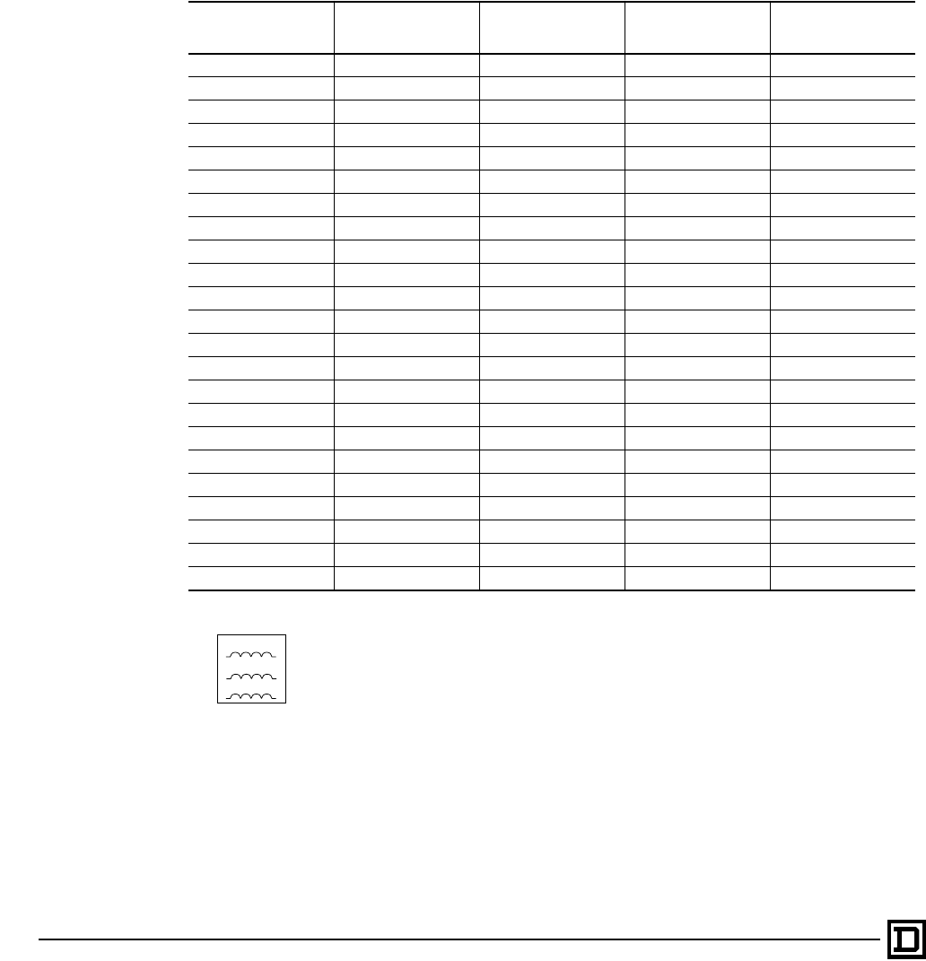
Class 8839 Enclosed AC Drives
Three Phase Line Reactors
© 1998 Square D All Rights Reserved
120 2/98
The Class 8839 ALTIVAR 66 Enclosed AC Drives
are designed to operate from industrial power
systems with normal AC line conditions without the
need of additional line impedance from either an
isolation transformer or a line reactor. However,
when abnormal line conditions exist, additional line
impedance may be required. Typically, line reactors
are used for:
• Minimize the input rms current to the AC drive
ratings
• Lower the available fault current on high fault
distribution systems
• Limit the total harmonic voltage distortion from
the AC drive at the point of common coupling to
align with IEEE 519 guidelines
• Prevent AC drive nuisance tripping due to
transient overvoltages from power factor
correction capacitor switching
Line Reactors:
1. Part numbers are referenced and
manufactured by MTE, Inc.
2. Harmonic compensated up to 150% of
nominal current ratings
3. 5% nominal reactance
4. Offered in Type 1 general purpose enclosures
5. Intended for separate mounting and wired by
the user with the exception of ratings offering
Q400 modification.
6. Refer to the following publications on the
subject of harmonics and benefits of drive
isolation transformers:
—8803PD9402–Power Systems Harmonics–
Cause and Effects of AC Drives.
—7460HO9501–Drive Isolation
Transformers-Application, Selection and
Specification Data
—7460PD9501– Drive Isolation
Transformers–Solutions to Power Quality
HP Rating 208 V Line Reactor
(separate mounted) 230 VAC Line Reactor
(separate mounted) 460 VAC Line Reactor
(separate mounted)
Enclosed Factory
Configured
Modification
1RL–00412 RL–00412 RL–00212 Q400
1.5 RL–00812 RL–00812 – Q400
2RL–00812 RL–00812 RL–00413 Q400
3RL–01212 RL–01212 RL–00413 Q400
5RL–01812 RL–01812 RL–00813 Q400
7.5 RL-02512 RL–02512 RL–01213 Q400
10 RL–03512 RL–03512 RL–01813 Q400
15 RL–04512 RL–04512 RL–02513 Q400
20 RL–05512 RL–05512 RL–03513 Q400
25 RL–08012 RL–08012 RL–03513 Q400
30 RL–10012 RL–08012 RL–04513 Q400
40 RL–13012 RL–10012 RL–05513 Q400
50 RL–16012 RL–13012 RL–08013 Q400
60 – – RL–08013 Q400
75 – – RL–10013 Q400
100 – – RL–13013 Q400 (VT only)
125 – – RL–16013 –
150 – – RL–20013 –
200 – – RL–25013 –
250 – – RL–32013 –
300 – – RL–40013 –
350 – – RL–50013 –
400 – – RL–50013 –
LoadLine
A1
B1
C1
A2
B2
C2
This document provided by Barr-Thorp Electric Co., Inc. 800-473-9123 www.barr-thorp.com

Class 8839 Enclosed AC Drives
Motor Protecting Output Filters
121
2/98 © 1998 Square D All Rights Reserved
Low pass filters can be used on the output of the
Class 8839 ALTIVAR 66 Enclosed AC Drive to
decease the stress of resonant frequencies on the
attached motor. While low pass filters are not
necessary for most installations, they do provide
substantial benefits in installations involving long
motor leads:
• 460 V or higher rated AC drives
• 1–25 hp rated units, if cable lead lengths are in
excess of 75 feet
• 30–400 hp rated units, if cable lead lengths are
in excess of 300 feet.
• Use of a non–inverter duty rated motor(s)
• Existing general purpose motors subject to
retrofit to an AC drive
The motor protecting output filters combine
inductance, capacitance and resistance to form a
low pass filter. This filter will lower the dV/dt levels
to prevent exciting the natural resonant wire
frequency of the motor cables. Motors compliant
to NEMA MG–1 Part 31 guidelines do not require
the use of motor protecting output filters.
Motor Protecting Output Filters:
1. Part number references are per Trans-Coil, Inc.
2. KLC filters are designed for cable lead lengths
ranging from 50 to 1000 feet.
3. KLC filters include 1.5% nominal reactance at
480V
4. KLC filters are enclosed in Type 1 general
purpose enclosures
5. KLC filters are intended for separate mounting
and wiring by user
HP Rating
@ 460 V KLC Filter
(separate mounting) Enclosed Factory Configured
Modification
1–2 KLC4BE Q401
3KLC6BE Q401
5KLC8BE Q401
7.5 KLC12BE Q401
10 KLC16BE Q401
15 KLC25BE Q401
20–25 KLC35BE Q401
30 KLC45BE Q401
40 KLC55BE Q401
50-60 KLC80BE Q401
75 KLC110BE Q401
100 KLC130BE Q401(VT only)
125 KLC160BE –
150 KLC200BE –
200 KLC250BE –
250 KLC300BE –
300 KLC360BE –
350 KLC420BE –
400 KLC480BE –
This document provided by Barr-Thorp Electric Co., Inc. 800-473-9123 www.barr-thorp.com

Class 8839 Enclosed AC Drives
Three Phase Drive Isolation Transformers
© 1998 Square D All Rights Reserved
122 2/98
Drive Isolation transformers are designed for
maximum benefit when applied to an AC drive.
In addition to the functional comparison of a line
reactor, drive isolation transformers are normally
used for one of the following reasons over a
standard line reactor:
1. Match system voltage to drive rating.
2. Meet local or plant codes that require isolation.
3. Capable of correcting line voltage unbalance
conditions commonly seen with open delta and
corner grounded delta distribution systems.
4. Provides continuity of service for nuisance
grounding.
5. Reduces drive induced currents in supply
feeder ground and limit ground fault currents.
6. Isolate the electrical common mode noise
generated in solid state controllers from the
distribution system.
The ALTIVAR 66 AC drives use a diode bridge
input stage which does not produce the electrical
switching transients common to converters using
SCRs such as DC drives. The Class 8839
ALTIVAR 66 Enclosed AC drives have a high fault
withstand capability (up to 65,000 A depending
upon configuration). For these reasons, Square D
does not suggest the use of a drive isolation
transformer for isolation purposes unless the
system requires one or more of the six functions
listed above.
Notes:
To complete catalog number:
Select the voltage required from chart. Insert the voltage code number in place of the ( ) in the catalog
number.
Three Phase 60 Hz Class B (IEEE 597-1983)
HP Rating kVA Catalog Number
1-5 7.5 7T( )HDIT
7.5 11 11T( )HDIT
10 15 15T( )HDIT
15 20 20T( )HDIT
20 27 27T( )HDIT
25 34 34T( )HDIT
30 40 40T( )HDIT
40 51 51T( )HDIT
50 63 63T( )HDIT
60 75 75T( )HDIT
75 93 93T( )HDIT
100 118 118T( )HDIT
125 145 145T( )HDIT
150 175 175T( )HDIT
200 220 220T( )HDIT
250 275 275T( )HDIT
300 440 440T( )HDIT
400 550 550T( )HDIT
Voltage Codes
Code Primary Secondary
142 230 Delta 230Y/132
143 230 Delta 460Y/265
144 460 Delta 230Y/132
145 460 Delta 460Y/265
146 575 Delta 230Y/132
147 575 Delta 460Y/265
This document provided by Barr-Thorp Electric Co., Inc. 800-473-9123 www.barr-thorp.com
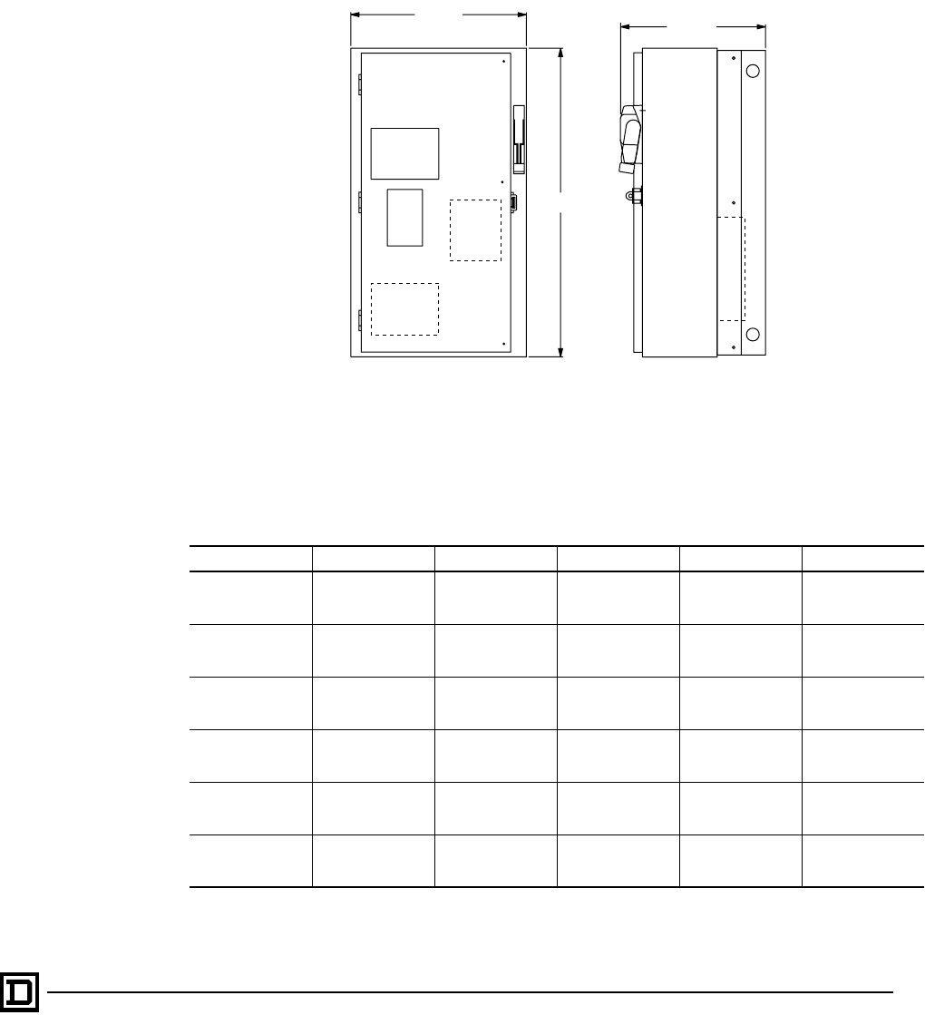
Class 8839 Enclosed AC Drives
Dimensions and Weights for Type 1 or 12 Enclosures
123
2/98 © 1998 Square D All Rights Reserved
Optimized and Integrated Construction (Wall Mount)
1–10 HP @ 208–230 V, and 1–20 HP (25 HP VT) @ 460 V
NOTE: CT = Constant Torque; LN = Low Noise Variable Torque; VT = Variable Torque
More detailed drawings available through quote to cash.
Horsepower Voltage Type Power Circuit A Weight
1–3 hp
1–5 hp
1–7.5 hp
208/230 V
460 V
460 V
CT, LN, VT
CT, LN
VT A, B 30.15"
765.8 mm 85 lbs.
5–7.5 hp
7.5–10 hp
10–15 hp
208/230 V
460 V
460 V
CT , LN, VT
CT, LN
VT A, B 30.15"
765.8 mm 100 lbs.
10 hp
15–20 hp
20–25 hp
208/230 V
460 V
460 V
CT, LN, VT
CT, LN
VT A, B 36.15"
918.2 mm 125 lbs.
1–3 hp
1–5 hp
1–7.5 hp
208/230 V
460 V
460 V
CT, LN, VT
CT, LN
VT C, D, G, H, I, J, K 44.15"
1121.4 mm 105 lbs
5–7.5 hp
7.5–10 hp
10–15 hp
208/230 V
460 V
460 V
CT, LN, VT
CT, LN
VT C, D, G, H, I, J, K 44.15"
1121.4 mm 120 lbs
10 hp
15–20 hp
20–25 hp
208/230 V
460 V
460 V
CT, LN, VT
CT, LN
VT C, D, G, H, I, J, K 48.15"
1223 mm 150 lbs
A
FRONT VIEW SIDE VIEW
17.15
435.6 14.18
360.2
This document provided by Barr-Thorp Electric Co., Inc. 800-473-9123 www.barr-thorp.com
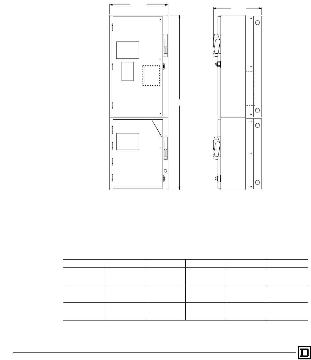
Class 8839 Enclosed AC Drives
Dimensions and Weights for Type 1 or 12 Enclosures
© 1998 Square D All Rights Reserved
124 2/98
Barriered Construction (Wall Mount)
1–10 HP @ 208/230 V, and 1–20 HP (25 HP VT) @ 460 V
NOTE: CT = Constant Torque; LN = Low Noise Variable Torque; VT = Variable Torque
More detailed drawings available through quote to cash.
Horsepower Voltage Type Power Circuit A Weight
1–3 hp
1–5 hp
1–7.5 hp
208/230 V
460 V
460 V
CT, LN, VT
CT, LN
VT E, F 51.36"
1304.5 mm 145 lbs.
5–7.5 hp
7.5–10 hp
10–15 hp
208/230 V
460 V
460 V
CT, LN, VT
CT, LN
VT E, F 51.36"
1304.5 mm 165 lbs.
10 hp
15–20 hp
20-25 hp
208/230 V
460 V
460 V
CT, LN, VT
CT, LN
VT E, F 57.36"
1456.9 mm 210 lbs.
14.18
360.2
17.15
435.6
A
FRONT VIEW SIDE VIEW
This document provided by Barr-Thorp Electric Co., Inc. 800-473-9123 www.barr-thorp.com
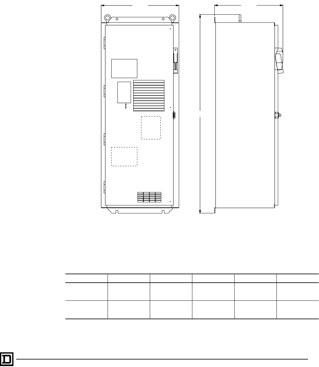
Class 8839 Enclosed AC Drives
Dimensions and Weights for Type 1 or 12 Enclosures
125
2/98 © 1998 Square D All Rights Reserved
Optimized and Integrated Construction (Wall Mount)
15–20 HP @ 208/230 V, and 25–40 HP (50 HP VT) @ 460 V
NOTE: CT = Constant Torque; LN = Low Noise Variable Torque; VT = Variable Torque
More detailed drawings available through quote to cash.
Horsepower Voltage Type Power Circuit A Weight
15–20 hp
25–40 hp
30–50 hp
208/230 V
460 V
460 V
CT, LN, VT
CT, LN
VT A, B 51.36"
1304.5 mm 200 lbs.
15-20 hp
25–40 hp
30–50 hp
208/230 V
460 V
460 V
CT, LN, VT
CT, LN
VT C, D, G, H, I, J, K 67.63"
1717.8 mm 320 lbs.
17.75
450.9
20.21
513.1
A
FRONT VIEW SIDE VIEW
This document provided by Barr-Thorp Electric Co., Inc. 800-473-9123 www.barr-thorp.com
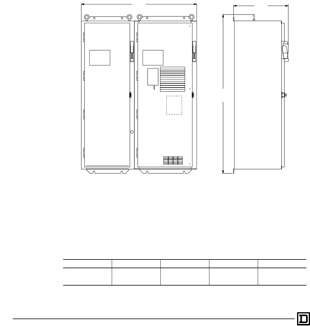
Class 8839 Enclosed AC Drives
Dimensions and Weights for Type 1 or 12 Enclosures
© 1998 Square D All Rights Reserved
126 2/98
Barriered Construction (Wall Mount)
15–20 HP @ 208/230 V, and 25–40 HP (50 HP VT) @ 460 V
NOTE: CT = Constant Torque; LN = Low Noise Variable Torque; VT = Variable Torque
More detailed drawings available through quote to cash.
Horsepower Voltage Type Power Circuit Weight
15–20 hp
25–40 hp
30–50 hp
208/230 V
460 V
460 V
CT, LN, VT
CT, LN
VT E, F 350 lbs.
17.75
450.9
51.63
1311.4
37.48
950.0
SIDE VIEWFRONT VIEW
This document provided by Barr-Thorp Electric Co., Inc. 800-473-9123 www.barr-thorp.com
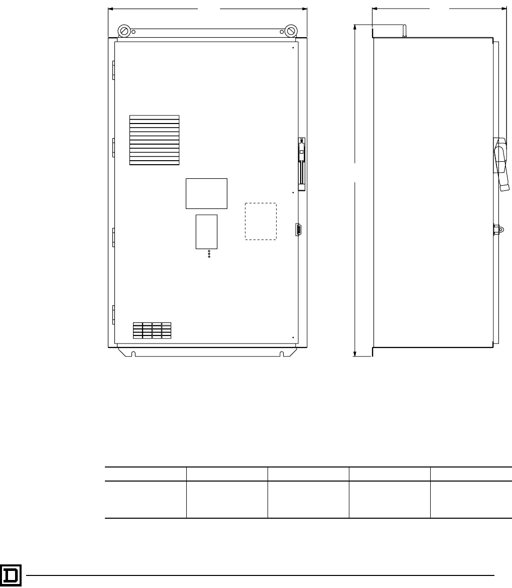
Class 8839 Enclosed AC Drives
Dimensions and Weights for Type 1 or 12 Enclosures
127
2/98 © 1998 Square D All Rights Reserved
Optimized Construction (Wall Mount)
25–40 HP (50 HP VT @ 208-230 V, and 50–75 HP (100 HP VT) @ 460 V
NOTE: CT = Constant Torque; LN = Low Noise Variable Torque; VT = Variable Torque
More detailed drawings available through quote to cash.
Horsepower Voltage Type Power Circuit Weight
25–40 hp
30–50 hp
50–75 hp
60–100 hp
208/230 V
208/230 V
460 V
460 V
CT, LN
VT
CT, LN
VT
A, B 450 lbs.
32.21
818.1
53.68
1363.5
21.75
552.5
FRONT VIEW SIDE VIEW
This document provided by Barr-Thorp Electric Co., Inc. 800-473-9123 www.barr-thorp.com
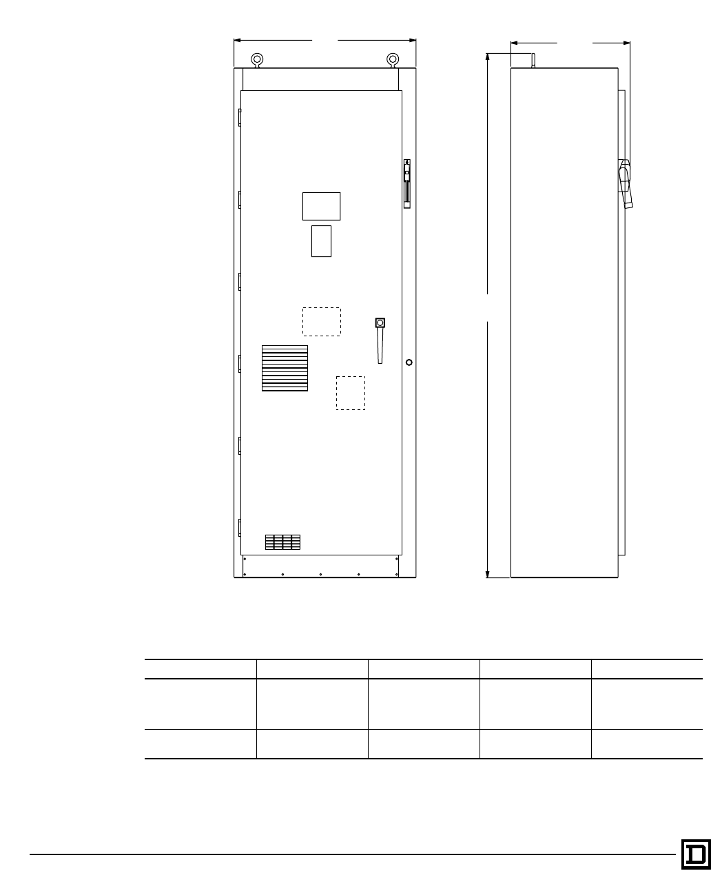
Class 8839 Enclosed AC Drives
Dimensions and Weights for Type 1 or 12 Enclosures
© 1998 Square D All Rights Reserved
128 2/98
Optimized and Integrated Construction (Floor Mount)
25-40 HP (50 HP VT) @ 208/230 V, and 50-75 HP (100 HP VT) @ 460 V
NOTE: CT = Constant Torque; LN = Low Noise Variable Torque; VT = Variable Torque.
Option O16 provides for floor mount oversized enclosure in lieu of wall mount configuration.
More detailed drawings available through quote to cash.
Horsepower Voltage Type Power Circuit Weight
25–40 hp
30–50 hp
50–75 hp
60–100 hp
208/230V
208/230V
460V
460V
CT, LN
VT
CT, LN
VT
A, B with
option O16
or
C, D, G, H, I, J, K
700 lbs.
100–200 hp
125–200 hp 460V
460V CT
VT A, B 800 lbs
93.02
2362.8
21.12
536.5
32.21
818.1
FRONT VIEW SIDE VIEW
This document provided by Barr-Thorp Electric Co., Inc. 800-473-9123 www.barr-thorp.com
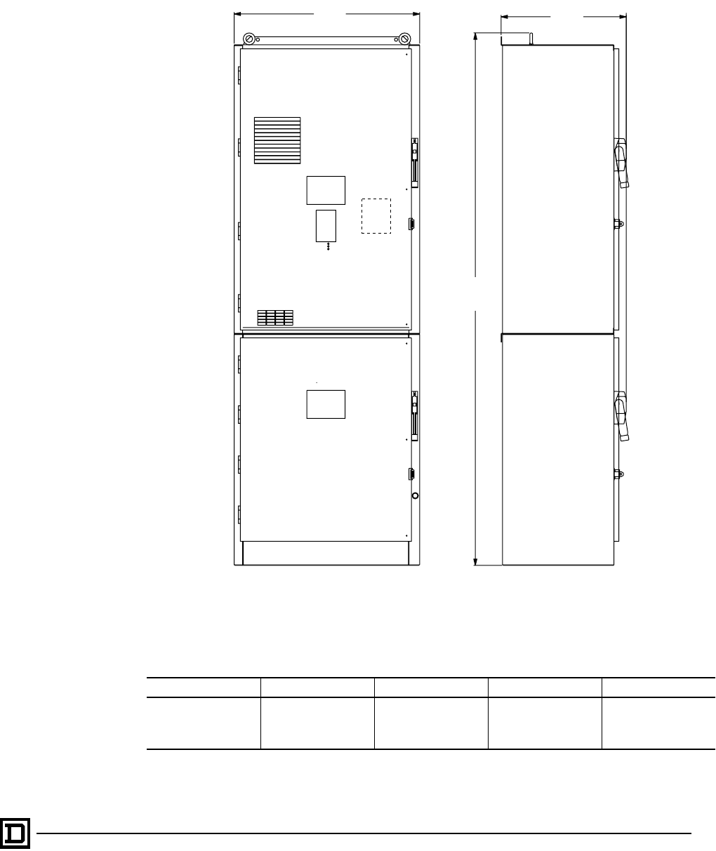
Class 8839 Enclosed AC Drives
Dimensions and Weights for Type 1 or 12 Enclosures
129
2/98 © 1998 Square D All Rights Reserved
Barriered Construction (Floor Mount)
25–40 HP (50 HP VT) @ 208/230 V, and 50–75 HP (100 HP VT) @ 460 V
NOTE: CT = Constant Torque; LN = Low Noise Variable Torque; VT = Variable Torque
More detailed drawings available through quote to cash.
Horsepower Voltage Type Power Circuit Weight
25–40 hp
30–50 hp
50–75 hp
60–100 hp
208/230 V
208/230 V
460V
460V
CT, LN
VT
CT, LN
VT
E, F 775 lbs.
32.21
818.1
92.49
2349.3
21.75
552.5
FRONT VIEW SIDE VIEW
This document provided by Barr-Thorp Electric Co., Inc. 800-473-9123 www.barr-thorp.com
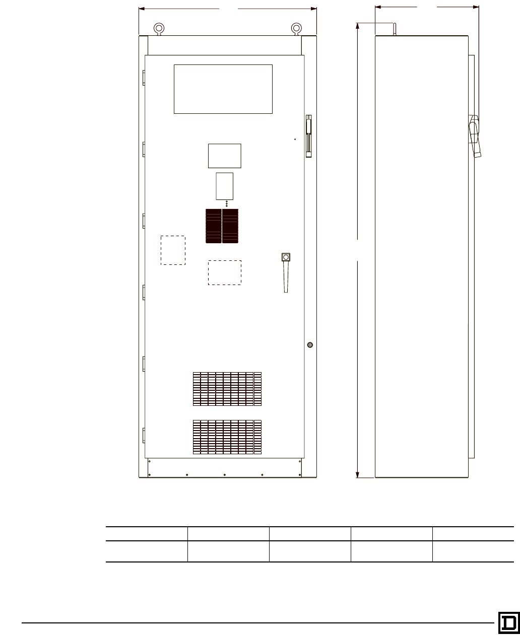
Class 8839 Enclosed AC Drives
Dimensions and Weights for Type 1 or 12 Enclosures
© 1998 Square D All Rights Reserved
130 2/98
Integrated Construction (Floor Mount)
100–200 HP CT and 125–200 HP VT @ 460 V
NOTE: CT = Constant Torque; LN = Low Noise Variable Torque; VT = Variable Torque
More detailed drawings available through quote to cash.
Horsepower Voltage Type Power Circuit Weight
100–200 hp
125–200 hp 460 V CT
VT C, D, G, H, I, J, K 980 lbs.
R
93.02
2362.8
FRONT VIEW SIDE VIEW
21.12
536.5
32.21
818.1
This document provided by Barr-Thorp Electric Co., Inc. 800-473-9123 www.barr-thorp.com
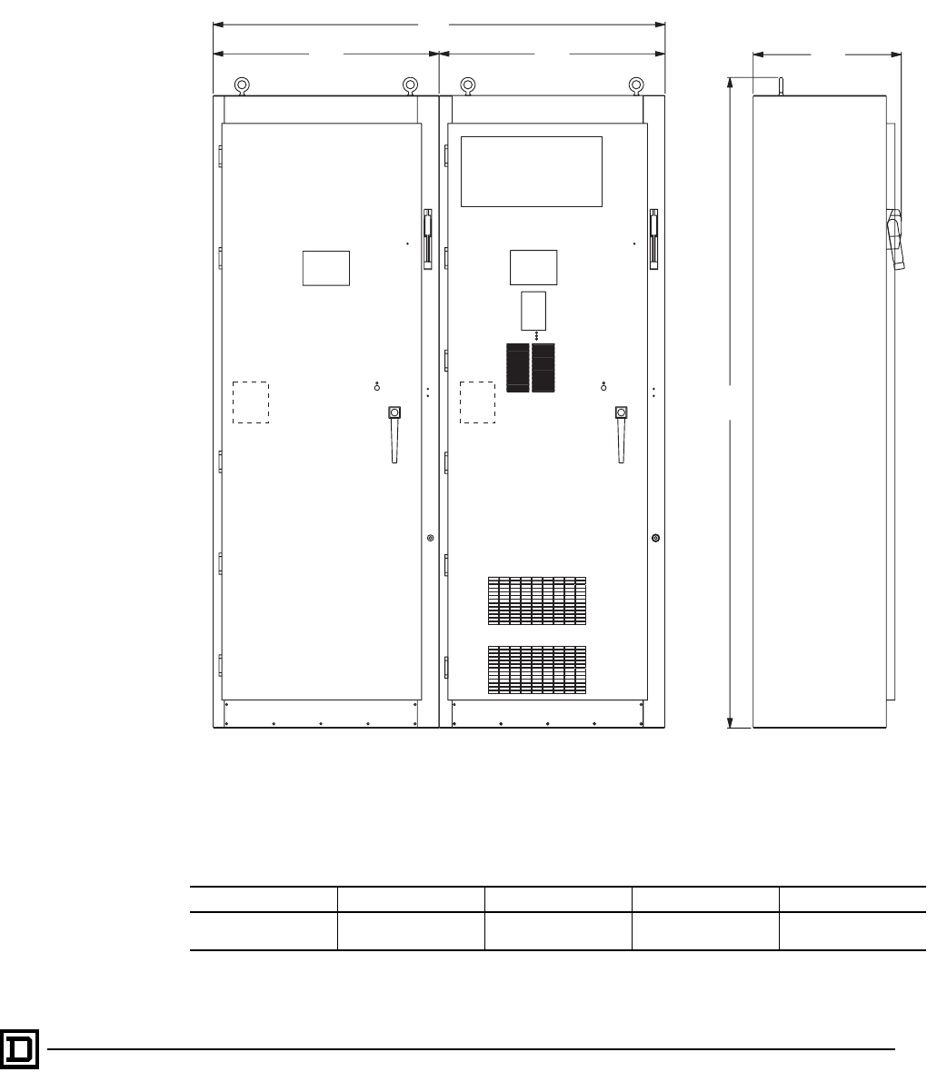
Class 8839 Enclosed AC Drives
Dimensions and Weights for Type 1 or 12 Enclosures
131
2/98 © 1998 Square D All Rights Reserved
Barriered Construction (Floor Mount)
100–200 HP CT and 125–200 HP VT @ 460 V
NOTE: CT = Constant Torque; LN = Low Noise Variable Torque; VT = Variable Torque
More detailed drawings available through quote to cash.
Horsepower Voltage Type Power Circuit Weight
100–200 hp
125–200 hp 460 V CT
VT E, F 1300 lbs.
32.21
818.1 32.21
818.1
R
64.42
1636.3
93.02
2362.8
21.12
536.5
FRONT VIEW SIDE VIEW
This document provided by Barr-Thorp Electric Co., Inc. 800-473-9123 www.barr-thorp.com
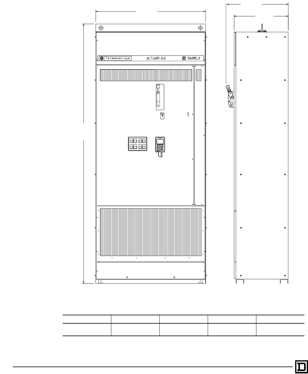
Class 8839 Enclosed AC Drives
Dimensions and Weights for Type 1 or 12 Enclosures
© 1998 Square D All Rights Reserved
132 2/98
Optimized Construction (Floor Mount)
250–350 CT and 250–400 HP VT @ 460 V
NOTE: CT = Constant Torque; LN = Low Noise Variable Torque; VT = Variable Torque
More detailed drawings available through quote to cash.
Horsepower Voltage Type Power Circuit Weight
250–350 hp
250–400 hp 460 V CT
VT B 1400 lbs.
1015.5
39.98
2404.1
94.65
FRONT VIEW RIGHT SIDE VIEW
DANGER
21.75
552.5
20.0
508.0
This document provided by Barr-Thorp Electric Co., Inc. 800-473-9123 www.barr-thorp.com
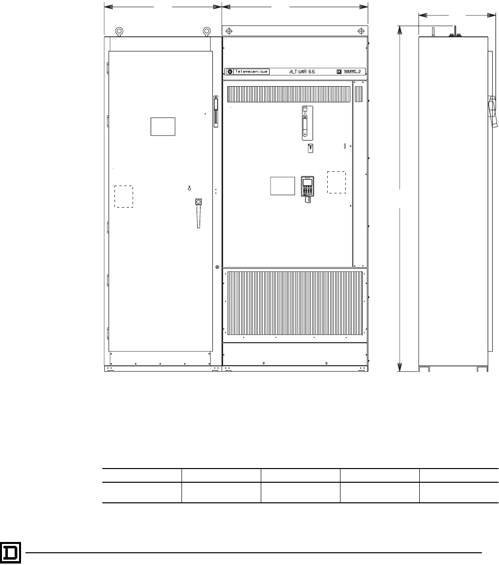
Class 8839 Enclosed AC Drives
Dimensions and Weights for Type 1 or 12 Enclosures
133
2/98 © 1998 Square D All Rights Reserved
Barriered Construction (Floor Mount)
250–350 HP CT and 250–400 HP VT @ 460 V
NOTE: CT = Constant Torque; LN = Low Noise Variable Torque; VT = Variable Torque
More detailed drawings available through quote to cash.
Horsepower Voltage Type Power Circuit Weight
250–350 hp
250-400 hp 460 V CT
VT F, G, I 2200 lbs.
32.0
812.8 39.98
1015.5 21.75
552.2
94.65
2404.1
FRONT VIEW SIDE VIEW
DANGER
This document provided by Barr-Thorp Electric Co., Inc. 800-473-9123 www.barr-thorp.com

Class 8839 Enclosed AC Drives
Application Information
© 1998 Square D All Rights Reserved
134 2/98
When selecting and applying AC Drives, the
following items should be considered where they
are applicable. Proper selection and application
of an AC Drive is essential to ensure reliable
operation and maximum performance of the
connected motor load. Please consult Product
Data Bulletin SC100 R5/95 “Adjustable Frequency
Controllers Application Guide” for further details.
1. AC Drive selection
2. Ambient temperature/altitude
3. AC Line & motor voltage
4. Power factor
5. Harmonics
6. Input currents with and without line reactors
7. Drive isolation transformer
8. Speed range & regulation
9. Accelerating torque
10. Dynamic braking
11. Follower signals
12. PI regulator
13. Bypass operation
14. Motor selection
15. Enclosure types
16. Relay contact ratings
AC Drive Selection
The ALTIVAR AC drive is selected based on the
connected motor full load current. AC drives in this
catalog are listed by horsepower, voltage and
maximum continuous output current ratings that
align to the latest NEC ratings. The motor
horsepower rating may be used to select the AC
drive, provided it’s full load current does not
exceed the maximum continuous output current
rating of the drive. When the motor full load current
does exceed the maximum continuous output
rating of the AC drive, a larger one must be
selected.
In multi-motor applications the sum of the motor
full load current, not horsepower must be used to
select the appropriate AC drive.
Ambient Temperature/Altitude
The AC Drive and connected motor is rated to
operate in an ambient temperature of 0-40 °C
(32-104 °F), and deliver full rated horsepower
nameplate data. When ambient temperatures
exceed the 40 °C (104 °F) operational ambient
environment, both the AC drive and motor must be
derated. For installations that require a higher
operating ambient, derate by one horsepower size
to a maximum of 50°C (122 °F).
The ALTIVAR AC drives are also rated for up to
3,300 feet (1,000 meters) altitude without
derating. Above these ratings, the AC drive must
be derated by 1.2% for every 300 feet (100
meters) up to a maximum of 6,600 feet (2,000
meters). For conditions where altitude exceeds
6,600 feet, special considerations apply.
Environment, application, loading, and ambient
operating conditions could extend altitude range.
AC Line & Motor Voltage
The Class 8839 ALTIVAR enclosed AC drives are
designed for operation under continuous rated
input power from 208 V, 230 V and 460 V line
voltages, ± 10% at 50/60 Hz. The selection tables
list the horsepowers available at the different
voltage ratings. Alternate line voltage
configurations are also available on a special
order basis. Consult the Drives Applications
Group for those applications.
Normally, input voltage and motor voltage will be
the same, however, certain applications requiring
constant torque above 60 Hz base speed will
involve connecting the AC drive to a 460 V supply
and connecting the motor for 230 V at 60 Hz. The
AC drive can be adjusted to provide 230 V out at
60 Hz and 460 V out at 120 Hz. If this mode of
operation is desired, the AC drive must be
selected based on the full load current at 230 V.
Power Factor
The ALTIVAR AC drive uses diode bridge rectifiers
which converts the fixed voltage and frequency
from the AC line to a fixed DC bus voltage.
Operation of the rectifiers does not cause any
additional displacement between the voltage and
current on the AC line feeding the AC drive.
This means that the displacement power factor
(power factor measured by the utility) will not be
degraded. Therefore, the AC drive power factor is
rated 0.95 or better (lagging) at all times.
Harmonics
Concerning the subject of harmonics, all types
of adjustable speed drives using power
semiconductors and switching power supplies will
produce harmonic currents, which will cause a
non-sinusoidal voltage in the power system. The
suggested guidelines for voltage and current
distortion are addressed in IEEE Standard 519-
1992 titled "IEEE Recommended Practices and
Requirements for Harmonic Control in Electrical
Power Systems", which suggests distortion limits
dependent upon the electric power distribution
system for industrial and commercial consumers.
This document provided by Barr-Thorp Electric Co., Inc. 800-473-9123 www.barr-thorp.com

Class 8839 Enclosed AC Drives
Application Information
135
2/98 © 1998 Square D All Rights Reserved
Collectively, all facility loads and the building
electrical distribution network determines the
harmonic levels at the user & electric utility
interface. Commonly misapplied, the Electrical
Power Research Institute (EPRI) recognizes the
'Point of Common Coupling' or PCC as the
interface between user and electric utility (energy
meter) in the electrical distribution network. This
position will also be supported in the forthcoming
Application Guide (P519A) being prepared by the
Harmonics Working Group of IEEE. Square D
Company will typically provide 'drive isolation
transformers' or 'line reactors' as the most cost
effective method of harmonic abatement.
For specifications that are regulated by utilities
to the IEEE 519 guidelines, there are alternate
methods of harmonic abatement that can be
suggested such as phase shifting transformer,
12-pulse designs and Broad-Band harmonic
filters but are not included within this catalog.
Consult the Drives Applications Group for
configurations and pricing.
Input Currents Ratings
(with and without Line Reactor)
Square D publishes input currents based on
distribution system impedance at various
available fault current ratings. Our literature
reflects multiple input current ratings based on
available fault currents
• 5,000 AIC (1-50 hp) or
10,000 AIC (60-200 hp) or
18,000 AIC (250-400 hp)
and
• 22,000 AIC
and
• 65,000 AIC
More common, line reactors are provided with the
majority of AC Drives today. The reasons
proliferate from abnormal line conditions, IEEE
519 guidelines, to power quality concerns. Line
reactors provide the most cost effective option to
minimize harmonic currents reflected back into
the distribution system. The use of line reactance
ahead of the AC drive will function best to:
1. Reduce line current harmonic injection into the
primary source, limiting the input ‘rms’
currents to less than or equal to motor full load
amps.
2. Reduce the available feeder short circuit
capacity.
3. Meet specified line impedance requirements.
A supplemental nameplate for all Class 8839
products now contains input current ratings for
both 3% and 5% rated line reactors. By listing the
alternate input currents when using a series
minimum line reactor rating, the user could benefit
in savings reflected in conductor and disconnect
selection, as required by the National Electric
Code.
Drive Isolation Transformer
Drive Isolation transformers are designed for
maximum benefit when applied to an AC drive. In
addition to the functional comparison of a line
reactor, drive isolation transformers are normally
used for one of the following reasons over a
standard line reactor:
1. Match system voltage to drive rating.
2. Meet local or plant codes that require isolation.
3. Capable of correcting line voltage unbalance
conditions commonly seen with open delta
and corner grounded delta distribution
systems.
4. Provides continuity of service for nuisance
grounding.
5. Reduces drive induced currents in supply
feeder ground and limit ground fault currents.
6. Isolate the electrical common mode noise
generated in solid state controllers from the
distribution system.
The ALTIVAR AC drive uses a diode bridge input
stage which does not produce the electrical
switching transients common to converters using
SCRs such as DC drives. The enclosed ALTIVAR
AC drives have a high fault withstand capability
(up to 65,000 A depending upon configuration).
For these reasons, Square D does not suggest the
use of a drive isolation transformer for isolation
purposes unless the system requires one or more
of the six functions listed above.
Speed Range & Regulation
The ALTIVAR 66 AC drives will operate within the
range of 0.1 to 400 Hz (up to 125 hp constant
torque) or 0.1 to 200 Hz (150 hp and 200 hp
constant torque) or 0.1 to 60/72 Hz (for variable
torque) and is dependent upon unit configuration.
Please note, if operating motors above base
speed, the motor manufacturer must approve
operation for the specified speed range. The
ALTIVAR 56 AC drive will operate within the range
of 0.1 to 60/72 Hz configurations optimized for
variable torque applications only.
This document provided by Barr-Thorp Electric Co., Inc. 800-473-9123 www.barr-thorp.com

Class 8839 Enclosed AC Drives
Application Information
© 1998 Square D All Rights Reserved
136 2/98
Speed regulation is determined by one of several
modes of configuration. Most AC drives utilize the
volts/hertz mode where speed regulation is
determined by the motor slip, typically 3% or less.
The ALTIVAR AC drive utilizes sensorless flux
vector mode (SLFV) as standard with 1% speed
regulation; with optional tachometer can be
improved to 0.5%.
Accelerating Torque
AC induction motors built to NEMA standards are
designed to provide starting torque which must
meet certain minimum ratings. This is normally
expressed as a percentage of full load torque.
These torque ratings are valid only for full voltage
starting where inrush current can be
approximately 600% of motor full load current.
The ALTIVAR AC Drive will limit starting current to
a value of usually not more than 150% (CT rated))
to 110% (VT rated) of drive full load current, which
provides approximately 150% starting torque for
CT loads and 110% for VT loads.
AC Drives provide better torque per ampere than
any other reduced inrush method, but the starting
torque available may be less than the starting
torque available with an across-the-line starter.
Applications with known high starting torque
requirements should be carefully evaluated. It
may be necessary to oversize the AC Drive, or the
motor to provide the necessary accelerating
torque.
Dynamic Braking
Dynamic braking directs the regenerative energy
from an AC induction motor dissipated in the form
of heat through a resistor. This condition presents
an electrical load, or retarding torque, to the
motor, which is acting as a generator. The thermal
capacity required for this resistor is determined by
the stopping duty cycle for the load and the energy
dissipated for each deceleration.
Dynamic braking requires the motor to remain
energized to maintain the rotating magnetic field.
Dynamic braking cannot operate during periods
where power is lost and cannot maintain holding
torque when the AC Drive is stopped. A
mechanical brake must be used when the
application requires a holding torque at zero speed.
A dynamic braking resistor configuration is
available as optional equipment. The dynamic
braking resistor is sized to be capable of
absorbing six times the stored energy of a motor
at maximum speed, which means it could make 6
consecutive stops from rated speed without
overheating. Applications with high inertia are
typical candidates for dynamic braking.
Follower Signals
The ALTIVAR series of AC drives are designed to
accept either a 0-10 Vdc, 4-20 mAdc, or 3-15 psig
(by option) analog input. Other follower signals
may be accommodated which will require
additional hardware or signal conditioners as
optional equipment.
PI Regulator
The ALTIVAR AC Drive has a build in PI regulator
to provide set-point control from the key pad or
remote analog signal. Selection parameters are
set via the key pad to automatically control a level,
pressure or flow process. This PI function does
not require any additional hardware, such as
options boards or separately mounted equipment.
Bypass Operation
Although the Class 8839 ALTIVAR AC drive is
designed for maximum reliability, it is possible that
a controller could be out of service when required
to operate. Critical operations which can tolerate
little or no down time should be considered as
candidates for bypass (full speed) operation.
This involves an isolation contactor to disconnect
the motor from the AC Drive and a full voltage
starter to bypass the controller and operate the
motor across-the-line or by an alternate starter
such as a reduced voltage autotransformer starter
or a solid state reduced voltage starter.
Motor Selection
ALTIVAR AC drives are designed to operate with
any three phase AC squirrel cage induction motor
or synchronous reluctance motor having voltage
and current ratings compatible with the drive.
It is recommended that all motors used with AC
Drives be equipped with thermostats in the stator
windings. This affords the ultimate motor overload
protection much better protection than overload
devices sensitive to motor current, because motor
temperature may rise due to loss of cooling
resulting from low speed operation and not
necessarily because of an overcurrent condition.
The motor should meet NEMA MG-1, Part 31
standards. This motor spec calls for 1600 volt
rated magnet wire, while the NEMA MG-1, Part 30
standard calls for 1000 volt rated magnet wire.
The higher voltage rated magnet wire will protect
against possible premature motor failures due to
voltage stress from fast dv/dt rise times commonly
seen with IGBT based AC Drives.
This document provided by Barr-Thorp Electric Co., Inc. 800-473-9123 www.barr-thorp.com

Class 8839 Enclosed AC Drives
Application Information
137
2/98 © 1998 Square D All Rights Reserved
Enclosure Types
The Class 8839 ALTIVAR Enclosed AC Drives are
available in Type 1 or Type 12 enclosures. If Type
3R, 4 or 4X enclosures are required, consult the
Drives Applications Group.
Outside installations requiring drives should be
quoted for installation in climate controlled Type
3R walk-in enclosures available separately from
our Power Zone Center group in Smyrna, TN.
Relay Contact Ratings
Relay contacts are available for customer use.
The maximum inductive load ratings of 120 Vac,
2A inductive, 220 Vac, 1 A inductive or 24 Vdc,
2 A inductive - normally open, normally closed
contacts for the annunciation of drive fault
(R1 relay) and run (R2 relay - programmable)
conditions. With the use of the I/O extension
module, there are (2) additional relay contacts
(R3 and R4 relays - programmable) available for
customer use.
Environment
Conformance to standards
UL, CUL, CSA, and IEC
UL File 105655 CCN NMMS
CSA File LR 584 Class 3211 06 & 3211 86
Conforms to ISO 9001 standards and NEC
Degree of protection Type 1 (IP30), and Type 12 (IP54)
Maximum ambient pollution Pollution degree 3 per NEMA ICS-111A and IEC 664-1
Maximum relative humidity 95% without condensing or dripping
Temperature Storage
Operation °F (°C) -13 to +158 (-25 to +70)
+32 to +104 (0 to +40)
Maximum altitude ft (m) 3300 (1000) without derating
For each additional 300 (100), derate by 1.2%, maximum 6600 (2000)
Mounting position Vertical
Drive Characteristics
Output frequency range Hz 0.1 to 400 for ATV66U41N4 to C13N4 drives (constant torque configuration)
0.1 to 200 for ATV66C15N4 to C19N4 drives (constant torque configuration)
0.1 to 60/72 for ATV66U41N4 to C19N4 drives (variable torque configuration)
Speed range 1 to 100 (with constant torque)
Maximum transient current 200% of nominal motor current for 0.2 s at starting for constant torque configuration
150% of nominal motor current for 60 s for constant torque configuration
110% of nominal motor current for 60 s for variable torque configuration
Electrical Characteristics
Input Voltage
Frequency V
Hz 460 ±10%
60 ±2%
Available control voltage 3 outputs: 0 V common for all supplies
1 output: +10 V for the reference potentiometer (2.2-2.5 kΩ),10 mA maximum flow
1 output: +24 V for control inputs, 210 mA maximum flow
Analog inputs AI
Speed reference
1 analog voltage input AI1: 0-10 V, impedance 30 kΩ
1 analog current input AI2: 4-20 mA, impedance 250 Ω
AI2 can be modified to 0-5 V with a switch located on the control board or
reprogrammed from the keypad display for 0-20 mA, x-20 mA or 20-4 mA.
Frequency resolution: 0.1 Hz at 60 Hz for analog reference
Response time: 5 to 10 ms
Frequency resolution for
digital reference (serial link) 0.015 Hz at 60 Hz
Acceleration and
deceleration ramps
Factory preset to 3 s, linear
Separately adjustable from 0.1 to 999.9 s (0.1 s resolution)
Ramp type: adjustable to linear, “S”, or “U”
Ramp times automatically adjusted in case of overtorque
Braking to standstill Automatic by DC injection for 0.5 s when frequency drops below 0.1 Hz
Amount of current, frequency threshold and injection time are programmable from
the keypad display
Converter Protection
Protection against short circuit, Class T fuse
Between the output phases
Between output phases and ground
On internal supply outputs
On the logic and analog outputs
Thermal protection against excessive overheating
Protection against input line supply undervoltage and overvoltage
Protection against phase loss
Motor protection Incorporated electronic thermal protection by I2t calculation taking speed into account
Storage of motor thermal state
Function programmable from the keypad display
This document provided by Barr-Thorp Electric Co., Inc. 800-473-9123 www.barr-thorp.com

Class 8839 Enclosed AC Drives
Specifications
© 1998 Square D All Rights Reserved
138 2/98
Note:
These specifications are for Enclosed Adjustable
Frequency Drive Controllers or herein referred to
as AC Drives. The Power Converter is a
component of the AC Drive. The Construction
Specifications Institute (CSI) format has been
conformed with for project compatibility.
Application information directly affects the type and
rating of AC Drive that will be quoted. Brackets{ }
are provided where such data should be included.
Please call your local Square D distributor or sales
representative for specification assistance
regarding a particular application.
The AC Drive specification should be included in
Division 16, Electrical for proper coordination with
the electrical distribution system.
PART 1: GENERAL
1.01
Scope of work
a. This section provides specification
requirements for adjustable frequency drives,
variable speed drives or herein identified as
AC Drives for use with {NEMA B, NEMA D,
NEMA A, NEMA E, Wound Rotor,
Synchronous} design AC motors.
b. The AC Drive manufacturer shall furnish, field
test, adjust and certify all installed AC Drives
for satisfactory operation.
c. Any exceptions/deviations to this specification
shall be indicated in writing and submitted with
the quotation.
1.02
References
a. ANSI/NFPA 70 - National Electrical Code
b. ANSI C84.1 - Voltages Tolerances for North
America
c. CSA C22.2 No. 14-M91 - Industrial Control
Equipment
d. IEC 68 Part 2-3 - Basic Environmental Testing
Procedures Part 2: tests - Test Ca: Damp Heat
e. IEC 146.1 - Semiconductor Converters-
General Requirements and Line Commutated
Converters Part 1-1: Specifications of Basic
Requirements
f. IEC 664 - Insulation Coordination for
Equipment Within Low-Voltage Systems
g. IEC 447 - Man-Machine Interface Actuating
Principles
h. IEC 439 Part 1 - Low Voltage Switchgear and
Controlgear Assemblies
i. IEC 947 - Low Voltage Switchgear and
Controlgear Components
j. IEC 364 - Electrical Installation of Buildings
k. IEC 204/NFPA 79 - Electrical Equipment of
Industrial Machines/Industrial Machinery
l. IEC 106 - Guide for Specifying Environmental
Conditions for Equipment Performance Rating
m. IEC 529 - Degrees of Protection Provided by
Enclosure
n. IEC 1000 - Electromagnetic Compatibility
o. IEC 721 - Classification of Environmental
Conditions
p. IEC 255-8 Overload Relays
q. IEC 801-2,-3,-4,-5 - Immunity Tests
r. NEMA ICS 6 - Industrial Control and Systems
Enclosures
s. NEMA ICS, Part 4 Overload Relays
t. NEMA 250 Enclosures for Electrical
Equipment
u. NEMA ICS 2-321 - Electrical Interlocks
v. NEMA ICS7 - Industrial Control and Systems
Adjustable Speed Drives
w. NEMA ICS 7.1 - Safety Standards for
Construction and Guide for Selection
Installation and Operation of Adjustable
Speed Drives
x. UL 50 - UL Standard for Safety Enclosures for
Electrical Equipment
y. UL 98 - UL Standard for Disconnect Switches
z. UL 507 - UL Standard for Safety Electric Fans
aa. UL 508 - UL Standard for Safety Industrial
Control Equipment
ab. UL 508C - UL Standard for Safety Power
Conversion Equipment
ac. UL 991 - UL Standard for Safety Tests for
Safety Related Controls employing Solid State
Devices
ad. OSHA 1910.95 - AC Drive Controller
Acoustical Noise
ae. Conforming to National Safe Transmit
Association and International Safe Transmit
Association Test for Packages Weighing 100
lbs or Over.
This document provided by Barr-Thorp Electric Co., Inc. 800-473-9123 www.barr-thorp.com

Class 8839 Enclosed AC Drives
Specifications
139
2/98 © 1998 Square D All Rights Reserved
1.03
Submittals
a. {6} - copies of approval drawings shall be
furnished for Engineer’s approval prior to
factory assembly of the AC Drives. These
drawings shall consist of elementary power
and control wiring diagrams and enclosure
outline drawings. The enclosure drawings
shall include front and side views of the
enclosures with overall dimensions and
weights shown, conduit entrance locations
and nameplate legends.
b. Standard catalog sheets showing voltage,
horsepower, maximum current ratings and
recommended replacement parts with part
numbers shall be furnished for each different
Horsepower rated AC Drive provided.
1.04
Warranty
a. 18 months parts warranty shall be provided on
materials and workmanship from the date of
invoice.
1.05
Quality Assurance
a. The manufacturer of the AC Drive shall be a
certified ISO 9001 facility.
b. The AC Drive and all associated optional
equipment shall be UL listed according to
Power Conversation Equipment UL 508C. A
UL label shall be attached inside each
enclosure as verification.
c. The AC Drive shall be designed, constructed
and tested in accordance with NEMA, NEC,
VDE, IEC standards and CSA certified.
d. Every Power Converter shall be tested with an
actual AC Induction Motor 100% loaded and
temperature cycled within an environment
chamber at 104 degrees. Documentation shall
be furnished to verify successful completion at
the request of the engineer.
e. All Drive door mounted pilot devices shall be
tested to verify successful operation.
Documentation shall be furnished upon the
request of the engineer.
f. The AC Drive shall be submitted to a Hi-Pot
test with all enclosed devices mounted and
wired, prior to shipment.
PART 2: PRODUCT
2.01
Manufacturers
a. The AC Drive shall be provided by Square D
Company, Class 8839, Type ATV66, or prior
approved equal. Substitutions must be
submitted in writing three weeks prior to
original bid date with supporting
documentation demonstrating that the
alternative manufacturer meets all aspects of
the specifications herein.
b. Alternate control techniques other than pulse
width modulated (PWM) are not acceptable.
2.02
General Description
a. The AC Drive shall convert the input AC mains
power to an adjustable frequency and voltage
as defined in the following sections.
b. The input power section shall utilize a full wave
bridge design incorporating diode rectifiers.
The diode rectifiers shall convert fixed voltage
and frequency, AC line power to fixed DC
voltage. This power section shall be
insensitive to phase rotation of the AC line.
c. The DC bus shall have external connections
for standby battery back-up or for linking
multiple, AC Drives DC buses for management
of regeneration power.
d. The output power section shall change fixed
DC voltage to adjustable frequency AC
voltage. This section shall utilize insulated
gate bipolar transistors (IGBTs) or intelligent
power modules (IPMs) as required by the
current rating of the motor.
2.03
Construction
a. The AC Drive shall be mounted in a {Type 1,
Type 12} enclosure {with, without} an external
operated disconnect device.
b. A mechanical interlock shall prevent an
operator from opening the AC Drive door when
the disconnect is in the
on
position. Another
mechanical interlock shall prevent an operator
from placing the disconnect in the
on
position
while the AC Drive door is open. It shall be
possible for authorized personnel to defeat
these interlocks.
c. Provisions shall be provided for locking all
disconnects in the
off
position with up to three
padlocks.
This document provided by Barr-Thorp Electric Co., Inc. 800-473-9123 www.barr-thorp.com

Class 8839 Enclosed AC Drives
Specifications
© 1998 Square D All Rights Reserved
140 2/98
d. Current limiting fuses shall be installed and
wired to the AC Drive input.
e. Provisions shall be made for accepting a
padlock to lock the enclosure door
2.04
Motor Data
a. The AC Drive shall be sized to operate the
following AC motor:
— Motor Horsepower { }
— Motor full load ampere { }
— Motor RPM {3600/3000,1800/1500,1200/
1000,900/750,720/600,600/500}(60/50 Hz)
— Motor voltage {200,230,380,415,460}
— Motor service factor {1.0,1.15,1.25}
2.05
Application Data
a. The AC Drive shall be sized to operate a
{Variable Torque, Variable Torque Low Noise,
Constant Torque, Constant Horsepower,
Impact} load.
b. The speed range shall be from a minimum
speed of 0.5 Hz to a maximum speed of 400
Hz.
2.06
Environmental Ratings
a. The AC Drive shall be of construction that
allows operation in a pollution Degree 3
environment. The AC Drive shall meet IEC
664-1 and NEMA ICS 1 Standards. AC Drives
that are only rated for Pollution Degree 2
environment shall not be allowed.
b. The AC Drive shall be designed to operate in
an ambient temperature from 0 to + 40
degrees C (+32 to 104 degrees F).
c. The storage temperature range shall be -25 to
+ 70 degrees C.
d. The maximum relative humidity shall be 95%
at 40 degrees C, non-condensing.
e. The AC Drive shall be rated to operate at
altitudes less than or equal to 3,300 ft (1000
m). For altitudes above 3,300 ft, de-rate the
AC Drive by 1.2% for every 300 ft (100m).
f. The AC Drive shall meet the IEC 68-2
Operational vibration specification.
2.07
Ratings
a. The AC Drive shall be designed to operate
from an input voltage of 400 ± 15% Vac and
460 ± 15% Vac.
b. The AC Drive shall operate from an input
voltage frequency range from 47.5 to 63 Hz.
c. The displacement power factor shall not be
less than 0.95 lagging under any speed or
load condition.
d. The efficiency of the AC Drive at 100% speed
and load shall not be less than 96%.
e. The {constant, variable} torque rated AC Drive
overcurrent capacity shall be {150%, 110%}
for 1 minute.
f. The output carrier frequency of the AC Drive
shall be randomly modulated and selectable
at 2, 4, or 10 kHz depending on Drive rating for
low noise operation. No AC Drive with an
operable carrier frequency above 10 kHz shall
be allowed.
g. The output frequency shall be from 0.1 to 400
Hertz for Drives up to 75 hp. At horsepower’s
above 75 hp, the maximum output frequency
will be 200 Hz.
h. The AC Drive will be able to develop rated
motor torque at 0.5 Hz (60 Hz base) in a
Sensorless Flux Vector mode using a
standard induction motor without an encoder
feedback signal.
2.08
Protection
a. Upon power-up the AC Drive shall
automatically test for valid operation of
memory, option module, loss of analog
reference input, loss of communication,
dynamic brake failure, DC to DC power supply,
control power and the pre-charge circuit.
b. The AC Drive shall be UL 508C listed for use
on distribution systems with {5,000A or
10,000A RMS, 22,000A RMS, 65,000A RMS}
available fault current. The Power Converter
shall meet short circuit withstandability of
65,000 RMS symmetrical amperes as defined
by NEMA ICS 7.1.09 and have the value listed
on the AC Drive nameplate.
c. The Power Converter shall be protected
against short circuits, between output phases
and ground; and the logic and analog outputs.
d. The AC drive shall have a minimum AC
undervoltage power loss ride-through of 200
msec. The AC Drive shall have the user
defined option of frequency fold-back to allow
motor torque production to continue to
increase the duration of the powerloss ride-
through.
e. The AC drive shall have a selectable ride
through function which will allow the logic to
maintain control for a minimum of one second
without faulting.
This document provided by Barr-Thorp Electric Co., Inc. 800-473-9123 www.barr-thorp.com

Class 8839 Enclosed AC Drives
Specifications
141
2/98 © 1998 Square D All Rights Reserved
f. For a fault condition other than a ground fault,
short circuit or internal fault, an auto restart
function will provide up to 5 programmable
restart attempts. The programmable time
delay before restart attempts will range from 1
second to 600 seconds.
g. The deceleration mode of the AC drive shall
be programmable for normal and fault
conditions. The stop modes shall include free-
wheel stop, fast stop and DC injection braking.
h. Upon loss of the analog process follower
reference signal, the AC drive shall fault and/
or operate at a user defined speed set
between software programmed low speed and
high speed settings.
i. The AC drive shall have solid state I2t
protection that is UL listed and meets UL 508
C as a Class 10 overload protection and
meets IEC 947. The minimum adjustment
range shall be from 0.45 to 1.05 percent of the
current output of the AC Drive.
j. The AC Drive shall have a thermal switch with
a user selectable prealarm that will provide a
minimum of 60 seconds delay before
overtemperature fault.
k. The AC Drive shall utilize bonded fin heatsink
construction for maximum heat transfer.
l. The AC drive shall have a programmable fold-
back function that will anticipate a controller
overload condition and fold back the
frequency to avoid a fault condition.
m. The output frequency shall be software
enabled to fold back when the motor is
overloaded.
n. There shall be 3 skip frequency ranges that
can each be programmed with a selectable
bandwidth of 2 or 5 Hz. The skip frequencies
shall be programmed independently, back to
back or overlapping.
o. The AC Drive shall include Metal Oxide
Varistors (MOVs) wired to the incoming AC
Mains.
2.09
Adjustments and Configurations
a. The AC drive shall self-configure to the main
operating supply voltage and frequency. No
operator adjustments will be required.
b. Upon power-up, the AC drive will
automatically send a signal to the connected
motor and store the resulting resistance data
into memory. The inductance data will be
measured during no-load operation when
operating at a frequency between 20-60 Hz.
The AC Drive will automatically optimize the
operating characteristics according to the
stored data.
c. The AC drive will be factory pre-set to operate
most common applications.
d. A choice of three types of acceleration and
deceleration ramps will be available in the AC
Drive software; linear, S curve and U curve.
e. The acceleration and deceleration ramp times
shall be adjustable from 0.1 to 999.9 seconds.
f. The volts per frequency ratios shall be user
selectable to meet variable torque loads,
normal and high torque machine applications.
g. The memory shall retain and record run status
and fault type of the past 8 faults.
h. Slip compensation shall be a software
enabled function.
i. The software shall have a NOLD (no load)
function that will reduce the voltage to the
motor when selected for variable torque loads.
A constant volts/Hz ratio will be maintained
during acceleration. The output voltage will
then automatically adjust to meet the torque
requirement of the load.
j. The AC drive shall offer programmable DC
injection braking that will brake the AC motor
by injecting DC current and creating a
stationary magnetic pole in the stator. The
level of current will be adjustable between 50-
150% of rated current and available from 0.0-
30 seconds continuously. For continuous
operation after 30 seconds, the current shall
be automatically reduced to 50% of the
nameplate current of the motor.
k. Sequencing logic will coordinate the engage
and release thresholds and time delays for the
sequencing of the AC Drive output,
mechanical actuation and DC injection
braking in order to accomplish smooth starting
and stopping of a mechanical process.
2.10
Operator Interface
a. The operator interface terminal will offer the
modification of AC drive adjustments via a
touch keypad. All electrical values,
configuration parameters, I/O assignments,
application and activity function access, faults,
local control, adjustment storage, self-test and
diagnostics will be in plain English. There will
be a standard selection of 4 additional
languages built-in to the operating software as
standard.
b. The display will be a high resolution, LCD
backlighted screen capable of displaying
graphics such as bar graphs as well as six
This document provided by Barr-Thorp Electric Co., Inc. 800-473-9123 www.barr-thorp.com

Class 8839 Enclosed AC Drives
Specifications
© 1998 Square D All Rights Reserved
142 2/98
lines of twenty-one alphanumeric characters.
c. The AC drive model number, torque type,
software revision number, horsepower, output
current, motor frequency and motor voltage
shall all be listed on the drive identification
display as viewed on the LCD display.
d. The display shall be configured to display one
or two bargraphs with numeric data that are
selectable and scalable by the operator. A
user defined label function shall be available.
As a minimum the selectable outputs shall
consist of speed reference, output frequency,
output current, motor torque, output power,
output voltage, line voltage, DC voltage, motor
thermal state, drive thermal state, elapsed
time, motor speed, machine speed reference
and machine speed.
e. A single keystroke scrolling function shall
allow dynamic switching between display
variables.
f. The terminal keypad will consist of
programmable function keys. The functions
will allow both operating commands and
programming options to be preset by the
operator. A hardware selector switch will allow
the terminal keypad to be locked out from
unauthorized personnel.
g. The operator terminal will offer a general menu
consisting of parameter setting, I/O map, fault
history, and drive configuration. A software
lock will limit access to the main menu. The
main menu will consist of keypad
configuration, drive configuration, general
configuration, diagnostic mode and drive
initialization screens.
h. There will be arrow keys that will provide the
ability to scroll through menus and screens,
select or activate functions or increase the
value of a selected parameter.
i. A data entry key will allow the user to confirm
a selected menu, numeric value or allow
selection between multiple choices.
j. An escape key will allow a parameter to return
the existing value if adjustment is not required
and the value is displayed. The escape
function will also return to a previous menu
display.
k. A RUN key and a STOP key will command a
normal starting and stopping as programmed
when the AC drive is in keypad control mode.
The STOP key must be active in all control
modes.
l. The AC drive shall have 3 LEDs mounted on
the front panel to indicate functional status. A
green LED will verify that the AC drive power
supply is on. A red LED indicator will indicated
an AC drive fault. A yellow LED indicator will
designate a pending fault condition.
m. The status LEDs shall be able to be remotely
mounted up to 3 meters from the AC drive.
n. A user interface shall be available that is a
Windows 3.1 based personal computer, serial
communication link or detachable operator
interface.
o. The Keypad and all door mounted controls
must be {Type 1,Type 12} rated.
2.11
Control
a. External pilot devices shall be able to be
connected to a terminal strip for starting/
stopping the AC Drive, speed control and
displaying operating status. All control inputs
and outputs will be software assignable.
b. 2-wire or 3-wire control strategy shall be
defined within the software. External relays or
logic devices will not be allowed.
c. The control power for the digital inputs and
outputs shall be 24 Vdc.
d. The internal power supply incorporates an
automatic current fold-back that protects the
internal power supply if incorrectly connected
or shorted. The transistor logic outputs will be
current limited and not be damaged if shorted
or excess current is pulled.
e. All logic connections shall be furnished on pull
apart terminal strips.
f. There will be 2 software assignable, analog
inputs. The analog inputs will be software
selectable and consist of the following
configurations: 0-20 ma, 4-20 ma, 20-4 ma, x-
20 ma (where x is user defined) 0-5 V, 1-5 V or
0-10 V.
g. There will be 4 software assignable, isolated
logic inputs that will be selected and assigned
in the software. The selection of assignments
shall consist of run/reverse, jog, plus/minus
speed (2 inputs required), setpoint memory,
preset speeds (up to 2 inputs), auto/manual
control, controlled stop, terminal or keypad
control, by-pass (2 inputs required), motor
switching, and fault reset.
h. There will be two software assignable analog
outputs that can be selected and assigned in the
software. The analog output assignments shall be
proportional to the following motor characteristics:
frequency, current, power torque, voltage and
thermal state. The output signal will be selectable
from 0-20 ma or 4-20 ma.
i. Two voltage-free Form C relay output contacts
will be provided. One of the contacts will
This document provided by Barr-Thorp Electric Co., Inc. 800-473-9123 www.barr-thorp.com

Class 8839 Enclosed AC Drives
Specifications
143
2/98 © 1998 Square D All Rights Reserved
indicate AC drive fault status. The other
contact will be user assignable.
j. There shall be a hardware input/output
extension module which also provides
interlocking and sequencing capabilities. The
module shall be fully isolated and housed in a
finger safe enclosure with pull apart terminal
strips. The module will add 4 logic inputs, 2
analog inputs, 2 relay outputs and one analog
output. All of the I/O will be user assignable in
the software as previously defined.
k. The AC Drive door mounted control island
shall include a power ON, Drive RUN, Drive
Fault Light and Hand-Off-Auto selector switch
with Manual Speed Potentiometer.
l. The AC Drive control island shall accept {%
indicating analog, absolete indicating digital}
meters to display {Power, Amperes, Voltage,
Hertz}.
2.11
Braking (Application Dependent Option)
NOTE: When braking certain types of loads, there
is the conversion of kinematic energy into
electrical energy by the motor which is returned to
the AC drive. Dynamic braking can be chosen to
absorb this energy and avoid causing the AC drive
to inadvertently shut down. The energy is
dissipated across a resistor that is connected to
the drive. For constant torque AC drives, the
dynamic braking unit must be capable of stopping
1.5 per unit motor torque from base frequency to
0.5 Hz with sensorless flux vector control mode.
Provisions shall be provided to protect the
Dynamic Braking Resistor against overload and
overcurrent due to DB switch failure. This
protection must be resettable without replacement
of fuses or other devices.
a. The dynamic brake resistor shall be provided
and connect to existing terminals on the AC
drive. The resistor shall mount externally to the
AC drive enclosure. An Insulated Gate Bi-
polar Transistor (IGBT) will be provided in the
AC drive to switch excess regenerative energy
to the braking resistor. The braking resistor will
be of a size calculated to stop 6 times motor
inertia at 1.5 per unit motor torque.
2.12
Isolation/Bypass Contactors
{Manual}
a. The AC Drive shall include IEC rated isolation
and bypass contactors complete with thermal
overload relay, {circuit breaker, molded case
switch} disconnect interlocked with the door,
control circuit transformer, motor flux decay
timer and AFC-OFF-BYPASS switch. The
operator shall have full control of the bypass
starter by operation of the door mounted
selector switch.
{Automatic}
a. The AC Drive shall include IEC rated isolation
and bypass contactors complete with thermal
overload relay, circuit breaker disconnect
interlocked with the door, control circuit
transformer, motor flux decay timer and AFC-
OFF-BYPASS selector switch. The operator
may select for manual bypass by setting the
switch in the BYPASS position or automatic
bypass by setting the switch in the AFC
position. In the AFC position the AC Drive will
provide adjustable speed control of the motor
under non-fault conditions of the Drive, when
the Drive is under a fault condition the bypass
contactor will be automatically energized upon
Drive shutdown (Drive fault contact operation)
to operate the motor on 60 Hz line power.
2.13
Harmonic Analysis
The harmonic distortion at the point of common
coupling (PCC) shall be predicted through
computer modeling of the distribution system and
connected AC drives as specified. The PCC for
voltage distortion shall be at the secondary of the
480 V distribution transformer and the PCC for the
current distortion shall be at the primary of the
480 V transformer. These harmonic distortion
values must not exceed 5% for voltage and those
as listed in IEEE 519-1992, table 10.3 for current
distortion. If the calculations determine that
harmonic distortion values are higher than the
voltage and current values specified, the drive
manufacturer shall provide either line reactors,
isolation transformers, multi-pulse input drives or
trap filters to meet the intent of IEEE 519-1992
guidelines. This harmonic analysis report shall be
part of the approval drawing process, submitted to
the engineer for approval.
This document provided by Barr-Thorp Electric Co., Inc. 800-473-9123 www.barr-thorp.com

Class 8839 Enclosed AC Drives
Specifications
© 1998 Square D All Rights Reserved
144 2/98
Normal operation is defined as follows:
1. Utility transformer kVA rating {specify kVA
rating}
2. Number of drives operating simultaneously:
{Specify individual load requirements}
3. Operating speed range: {50 to 100%} speed
range
4. Point of common coupling: Load side of
transformer (voltage), Line side of transformer
(current)
Under emergency operating conditions the
harmonic distortion at the point of common
coupling (PCC) shall be predicted through
computer modeling of the emergency generator
system and connected ac drives as specified. The
PCC for voltage distortion shall be at the
generator load terminals. The harmonic voltage
distortion value must not exceed the maximum
permissible value specified by the generator
manufacturer. The drive manufacturer shall
coordinate with the manufacturer of the
emergency generator specified in Section 11000
to obtain data for the harmonic analysis. If the
calculations determine that harmonic distortion
values are higher than the voltage specified, the
drive manufacturer shall provide either line
reactors, multi-pulse input drives or trap filters to
meet the generator manufacturer
recommendations.
Emergency operation is defined as follows:
1. Emergency Generator kW rating of: {Specify
kW rating}
2. Number of drives operating simultaneously:
{Specify individual load requirements}
3. Operating speed range: {50-to 100%} speed
range
4. Point of common coupling: Generator
terminals
PART 3: EXECUTION
3.01
Inspection
a. Verify that the location is ready to receive work
and the dimensions are as indicated.
b. Do not install AC Drive until the building
environment can be maintained within the
service conditions required by the
manufacturer.
3.02
Protection
a. Before and during the installation, the AC
Drive equipment shall be protected from site
contaminants.
3.03
Installation
a. Installation shall be in compliance with
manufacturer's instructions, drawings and
recommendations.
b. The AC Drive manufacturer shall provide a
factory certified technical representative to
supervise the contractor's installation, testing
and start-up of the AC drive(s) furnished under
this specification for a maximum total of { }
days. The start-up service shall be quoted as
a separate line item.
3.04
Training
An on-site training course of { } training days shall
be provided by a representative of the AC Drive
manufacturer to plant and/or maintenance
personnel and quoted as a separate line item.
This document provided by Barr-Thorp Electric Co., Inc. 800-473-9123 www.barr-thorp.com

145
2/98 © 1998 Square D All Rights Reserved
Class 8998 Motor Control Centers
Contents
Description Pages
General Information . . . . . . . . . . . . . . . . . . . . . . . . . . . . . . . . . . . . . . . . . . . . . . . . . . . . . . . . . . . . . .146
Benefits of ALTIVAR 66 AC Drives . . . . . . . . . . . . . . . . . . . . . . . . . . . . . . . . . . . . . . . . . . . . . . . . . .146
MCC Packaging. . . . . . . . . . . . . . . . . . . . . . . . . . . . . . . . . . . . . . . . . . . . . . . . . . . . . . . . . . . . . 147-148
Selection . . . . . . . . . . . . . . . . . . . . . . . . . . . . . . . . . . . . . . . . . . . . . . . . . . . . . . . . . . . . . . . . . . . . . .148
Basic Drive Power Circuit . . . . . . . . . . . . . . . . . . . . . . . . . . . . . . . . . . . . . . . . . . . . . . . . . . . . . . . . .148
Ratings. . . . . . . . . . . . . . . . . . . . . . . . . . . . . . . . . . . . . . . . . . . . . . . . . . . . . . . . . . . . . . . . . . . . . . . .149
Options . . . . . . . . . . . . . . . . . . . . . . . . . . . . . . . . . . . . . . . . . . . . . . . . . . . . . . . . . . . . . . . . . . . 150-153
This document provided by Barr-Thorp Electric Co., Inc. 800-473-9123 www.barr-thorp.com
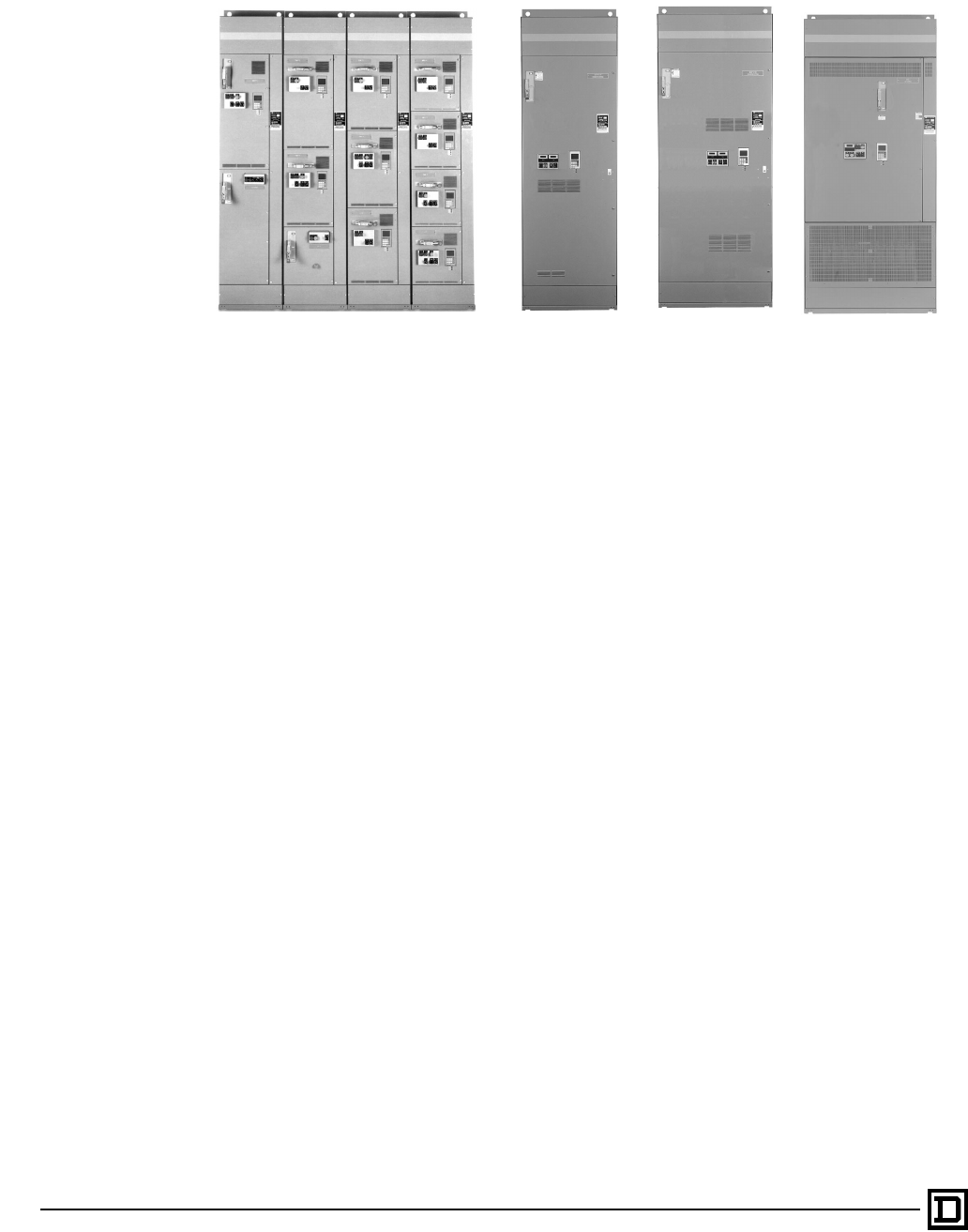
© 1998 Square D All Rights Reserved
146
2/98
Class 8998 Motor Control Centers
General Information
ALTIVAR 66 Drive Controller Units
Sizes 1–4 ALTIVAR 66 Drive Controller Units
Sizes 5–7
GENERAL INFORMATION
AC Drives have become common devices to vary
the speed of AC motors. Motor control center
packaging of AC Drives has become common as
more and more applications require accurate
control in an integrated solution. Square D
provides a flexible AC Drive in the industry’s most
flexible MCC drive units. Typical applications
include pumps, fans, conveyors, mixers and other
industrial process machinery. Varying the speed of
these applications can provide benefits in energy
savings, material flow rates, output quality and
process flexibility. The Square D MCC AC Drives
integrate a single family of ALTIVAR 66 Drives into
a combination drive package for MCCs.
MCC enclosed ALTIVAR 66 AC Drive units are
designed for use with standard three-phase
asynchronous motors with a power range of 3/4 to
400 hp (variable torque) or 3/4 to 350 hp (constant
torque). MCC AC Drive units can be applied to
480 V, three phase, 3-wire or 4-wire systems. The
MCC AC Drive units have been designed to
provide optimal protection in NEMA/EEMAC Type
1, Type 1 Gasketed (1A), and NEMA/EEMAC
Type 12 motor control center enclosures.
BENEFITS OF ALTIVAR 66 AC DRIVES
• Single Family Concept
— One control interface design for all ratings
— Consistent wiring for any application
— Interchangeable spare parts
— Common integration approach
• Unprecedented Modularity
— Optional I/O upgrades and extensions are
easily attached
— Plug-apart control terminals allow quick
installation/removal
— Multi-level programming menus are divided
for quick setup
• Clearly Displays Information
— 6 line X 21 character graphic LCD display
— Selectable bar graph or text display formats
of motor and drive information
— Fault information in complete statements,
not codes
• Adapts to your Requirements
— Multiple languages for worldwide
acceptance
— Keypad or terminal strip control
— Scaleable frequency and current to
indicated production levels
— User assignable function keys
— Menus expand as options are added
• Walks you through start-up
— User prompt, pull down menus and help
screens simplify user configuration
— Self-tuning upon power up based on input
mains voltage and frequency
— Automatic motor sensing and modeling at
start-up for self-tuning sensorless flux
vector control
— Help screens are available to answer start
up questions quickly
• Monitoring and Communication Capability
— Credit card style PCMCIA option cards
support various serial communication
protocols including MODBUS Plus
— Fault history for eight occurrences can help
diagnose system events.
— Auto-diagnostic and logic test routines
communicate drive conditions for
maintenance
This document provided by Barr-Thorp Electric Co., Inc. 800-473-9123 www.barr-thorp.com
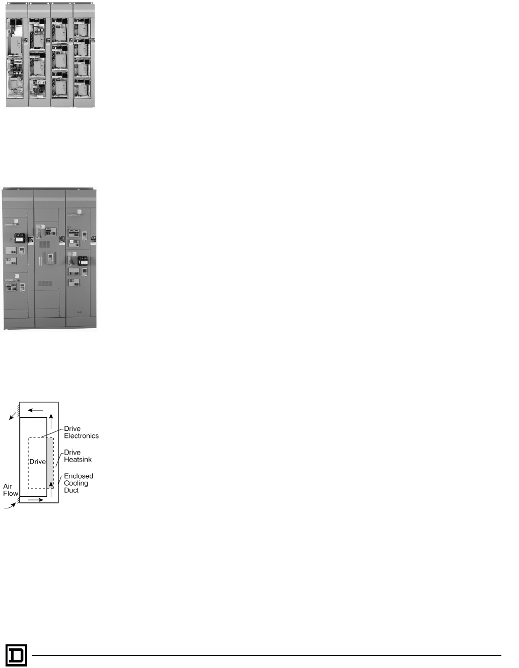
147
2/98 © 1998 Square D All Rights Reserved
Class 8998 Motor Control Centers
MCC Packaging
MCC PACKAGING
ALTIVAR AC Drives installed in Square D MCCs
are designed for harsh industrial environments in
order to promote long term reliability. Several key
features of the package design make Square D
AC Drive units more suitable for MCC
installations. MCC AC Drive units are plug-on
style saddle units up to 50 hp variable torque.
Units above 50 hp variable torque are mounted in
full height sections of varying width and depth.
There are no placement limitations for mounting
any AC drive or multiple AC Drives in an MCC
section.
Drive units are designed to incorporate standard
features of Model 6 MCC units such as:
• white interiors for greater visibility in
maintenance
• cast metal handle disconnect for ruggedness
• twin-handle cam racking mechanism for easy
installation/removal
• Unit nameplates are supplied as standard.
• Vertical and horizontal wireways are left
undisturbed by drive unit.
The thermal management system included in
NEMA/EEMAC Type 1 or 1A (Gasketed) AC Drive
units consists of a closed duct system to separate
outside air from electrical components. AC Drives
give off a large mount of heat relative to other
electro-mechanical devices in the MCC. This heat
must be removed from the MCC and AC Drive in
order to maintain temperature rise limits. The duct
system included with MCC ALTIVAR 66 AC Drive
units removes heat to allow maximum density and
does not allow outside air to contaminate the
electronics or other MCC units.
The thermal management system provides
superior protection for the AC Drive even in the
dirtiest NEMA/EEMAC Type 1 environments. The
system is self-powered and includes
overtemperature protection to shutdown the drive
in case of fan or duct blockage. Inlet and outlet
ducts allow airflow across the metal heatsink fins
of the AC Drive as shown in the Airflow figure.
The NEMA/EEMAC Type 12 MCC ALTIVAR 66 AC
Drive thermal management systems differ from
the systems used in NEMA/EEMAC Type 1/1A
(Gasketed). NEMA/EEMAC 12 units are totally
enclosed, non-ventilated (TENV) up to 20 hp. The
TENV design provides increased integrity and
does not allow air flow across the AC Drive
heatsinks. Units rated at 3/4–5 hp are totally
enclosed and include an internal stirring fan. Units
rated at 7.5–20 hp use a door mounted heat
exchanger and include an internal stirring fan.
Contaminants are not allowed inside the units for
environments where oil, dust, or other build-up
may occur. Units rated above 20 hp incorporate a
closed duct cooling system similar to NEMA/
EEMAC Type 1/1A (Gasketed).
All ALTIVAR MCC AC Drive units include a door
mounted graphical interface with a keypad.
Operator adjustments can be made and
diagnostics can be viewed without having to go
inside an energized unit. A control operator station
is also included on the door of each unit for the
addition of a wide range of pilot lights,
pushbuttons, selector switches and meters. Up to
eight pilot devices or four pilot devices and 2
meters can be mounted on the control station.
LEDs are brought out to the door to indicate the
drive power is on, the drive is in an alarm condition
or the drive is in a fault condition.
Each MCC AC Drive unit goes through complete
assembly and test procedures at the MCC facility.
The MCC facility is registered to ISO 9001. UL 845
Motor Control Center standards are used to list
each MCC drive unit in the product offering. The
unit UL 845 label and the structure UL 845 label
are attached at the MCC factory to maintain a
completely UL listed MCC. The MCC factory
provides a fully integrated package, which is
tested with an actual motor load before shipment.
All conductors, disconnects, fusing, lugs and other
electrical components are designed per MCC
standards as well as NEC 430-2 requirements for
AC Drive input currents.
All ALTIVAR MCC AC Drive units are UL 845 listed
for a 65,000 A short circuit rating at 480 V. To
accomplish this rating, current limiting fuses are
installed on the input to each AC Drive. Fuses
have a 200,000 A RMS symmetrical interrupting
rating. Both circuit breaker and fusible switch units
have the necessary current limiting fuses factory
installed.
ALTIVAR MCC AC Drive units can be selected
with circuit breaker input disconnect or fusible
switch input disconnects. Circuit breakers used in
the basic drive units are MAG-GARD
®
magnetic
only types up to 200 hp. Fusible switches used in
the basic drive units are switches with a separate
fuseblock to accommodate the current limiting
fuses. Above 200 hp both circuit breaker and
fusible switch units use an automatic molded case
switch as the input disconnect.
Several standardized power contactor options and
control device options are listed on the following
pages. Each option is fully tested and
documented at the MCC factory. Pilot devices
interface with 24 Vdc control as standard. LED
ALTIVAR Lineup
with Doors Open
NEMA/EEMAC Type 12 MCC
ALTIVAR AC Drive Lineup
Airflow of
NEMA/EEMAC
Type 1 or 1A (Gasketed)
AC Drive Unit
This document provided by Barr-Thorp Electric Co., Inc. 800-473-9123 www.barr-thorp.com
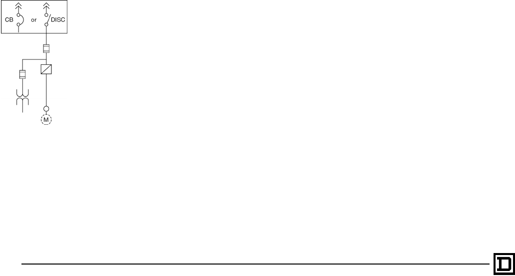
© 1998 Square D All Rights Reserved
148
2/98
Class 8998 Motor Control Centers
Selection
type pilot lights are used with the AC Drive.
Optional bypass controls use 120 Vac controls
and transformer type pilot lights. All pilot devices
are 22 mm Telemecanique components. The MCC
factory can also customize MCC ALTIVAR 66 AC
Drive units for virtually any application. Contact
your local Square D field office for requirements
not listed in this catalog.
SELECTION
1. Select all drives based on motor full load
amperes. Horsepower is provided for
convenience only.
2. Select the drive based on application (torque)
type i.e. variable torque, constant torque or
variable torque, low noise. The drive will be
factory programmed for the selected
application type. If you need assistance in
qualifying your opportunity or reviewing
specifications and drawings, application
support for this product can be obtained by
contacting your local Square D field office.
3. The ALTIVAR MCC AC Drive includes a basic
power circuit consisting of an input disconnect,
current limiting fuses and drive controller.
Select any optional contactors required for the
application by referring to “Power Contactor
Options.”
4. Select any control circuit devices by referring
to “Pilot Devices.”
5. Select any miscellaneous features such as
line reactors or extra control VA by referring to
“Miscellaneous Options.”
“BASIC” DRIVE POWER CIRCUIT
• Consist of disconnect switch and Drive pre-
programmed for Variable Torque, Variable
Torque Low Noise or Constant Torque
application.
• Includes current limiting power fuses.
• Unit is UL 845 Listed for 65,000 A Short Circuit
Current.
• Drive keypad and LEDs are door mounted.
• Includes door mounted operator control island
with up to eight spaces for user specified 22mm
Telemecanique XB2 pilot devices.
• Control power transformer (480 V/120 V) for
enclosure ventilation fans is included.
Power Circuit for “Basic”
Drive
This document provided by Barr-Thorp Electric Co., Inc. 800-473-9123 www.barr-thorp.com
149
2/98 © 1998 Square D All Rights Reserved
Class 8998 Motor Control Centers
Ratings
Variable Torque ALTIVAR 66 and 56 Drives with Circuit Breaker/Fusible Switch Disconnects
Nominal horsepower shown for convenience only. Size per actual motor full load amperes.
Motor Rated
Horsepower at 460 V Max. Cont. Output
Amps NEMA Type 1 and 1A
(Gasketed) Space NEMA Type 12
Space
3/4–5 7.6 18" 24"
7.5 11 18"
36"
10 14 24"
15 21 24"
20 27 36"
25 34 36" 45"
40 52 45"
50 65 45" 72" (25"W)
75 96 72" (25"W)
100 124 72" (25"W)
72" (35"W x 20"D)
125
200 156
240 72" (35"W x 20"D)
400 477 72" (40"W x 20"D) Not Available
Constant Torque ALTIVAR 66 Drives with Circuit Breaker or Fusible Switch Disconnects
Nominal horsepower shown for convenience only. Size per actual motor full load amperes.
Motor Rated
Horsepower @ 460 V Max. Cont. Output
Amps NEMA Type 1 and 1A
(Gasketed) Space NEMA Type 12 Space
3/4–5 7.6 18" 24"
10 14 24" 36"
20 27 36" 36"
40 52 45" 45"
75 96 72" (25"W) 72" (25"W)
200 240 72" (35"W x 20"D) 72" (35"W x 20"D)
350 420 72" (40"W x 20"D) Not Available
Low Noise Variable Torque ALTIVAR 66 and ALTIVAR 56 Drives with Circuit Breaker or Fusible
Switch Disconnects
Nominal horsepower shown for convenience only. Size per actual motor full load amperes.
Motor Rated
Horsepower @ 460 V Max. Cont. Output
Amps NEMA Type 1 and 1A
(Gasketed) Space NEMA Type 12 Space
3/4–5 7.6 18" 24"
10 14 24" 36"
20 27 36" 36"
40 52 45" 45"
75 96 72" (25"W) 72" (25"W)
This document provided by Barr-Thorp Electric Co., Inc. 800-473-9123 www.barr-thorp.com
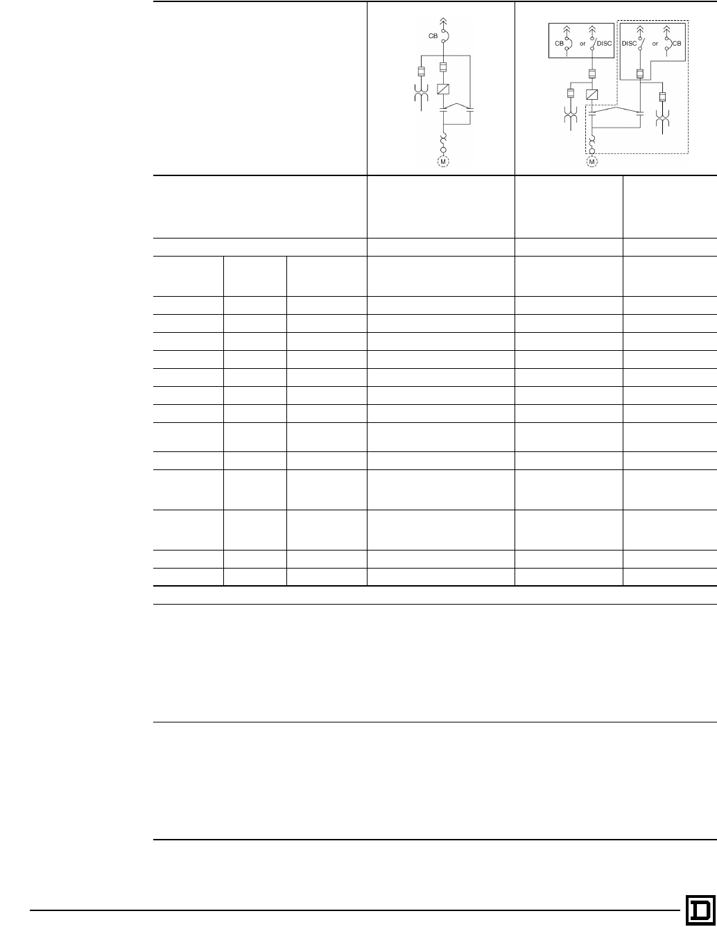
© 1998 Square D All Rights Reserved
150
2/98
Class 8998 Motor Control Centers
Options
Power Contactor Options (only 1 allowed)
Power Circuit Diagram
Description
Integrated Bypass
(Available with Circuit Breaker
Disconnect only.
Uses Telemecanique
contactors.)
Barriered Bypass
(Uses NEMA
contactors)
Barriered
Application Rated
COMPAC™ 6
Bypass
(14 A max.)
Power Circuit Type
➀
C
➁
U
➂
E
➂
Variable
Torque
Variable
Torque Low
Noise Constant Torque Space Adder Space Adder Space Adder
3/4–5 hp 3/4–5 hp 3/4–5 hp 9"(NEMA 1)/3"(NEMA 12) 18" 6"
7.5 hp — — 9"(NEMA 1)/0"(NEMA 12) 18" 6"
10 hp 7.5–10 hp 7.5–10 hp 6"(NEMA 1)/0"(NEMA 12) 18" 6"
15 hp — — 6"(NEMA 1)/9"(NEMA 12) 18" N/A
20–25 hp 15–20 hp 15–20 hp 3"(NEMA 1)/9"(NEMA12) 18" N/A
— 25 hp 25 hp 9"(NEMA 1/12) 18" N/A
30–40 hp 30–40 hp 30–40 hp 9"(NEMA 1/12) 27" N/A
50 hp — — 9"(NEMA 1)/5" added to width
(NEMA 12) 27" N/A
— 50 hp 50 hp 5" added to width (NEMA 1/12) 27" in adjacent section N/A
60–100 hp 60–75 hp 60–75 hp 5" added to width (NEMA 1/12) 33" in adjacent section
for CB. 39" in adjacent
section for FS. N/A
— — 100 hp 20" added to width (NEMA 1/12) 33" in adjacent section
for CB.39" in adjacent
section for FS. N/A
125–150 hp — 125 hp–150 hp 20" added to width (NEMA 1/12) 25" added to width N/A
200 hp — 200 hp 20" added to width (NEMA 1/12) 25" added to width N/A
➀
For Power Contactor Options above 200 hp contact the Square D Field Office.
➁
• Basic Drive features with isolation and bypass contactors for emergency full speed operation in same compartment.
• Telemecanique D or F line contactors are used.
• Only available as Circuit Breaker disconnect common to drive and bypass.
• Drive and bypass are UL 845 Listed for 65,000 A Short Circuit Current and coordinated for Type 1 protection.
• Includes AFC-Off-Bypass selector switch, Red Push-To-Test "AFC" Pilot Light and Yellow Push-To-Test "Bypass" Pilot Light
on bypass control island.
• Best use of space with bypass
• Approximately 1/2 the cost of Barriered Bypass
➂
• Basic Drive features with isolation and bypass contactors for emergency full speed operation.
• Barriered Application Rated COMPAC™ 6 Bypass uses Telemecanique contactors. NEMA contactors are used on
barriered NEMA bypass.
• Separate disconnect for drive and bypass can be operated independently
• Drive and bypass starter are enclosed in compartments separated by metal barriers.
• Drive and bypass are UL 845 Listed for 65,000 A Short Circuit Current and coordinated for Type 1 protection.
• Includes AFC-Off-Bypass selector switch, Red Push-To-Test "AFC" Pilot Light and Yellow Push-To-Test "Bypass" Pilot Light
on bypass control island. (Non-Push-To-Test used on COMPAC 6)
This document provided by Barr-Thorp Electric Co., Inc. 800-473-9123 www.barr-thorp.com
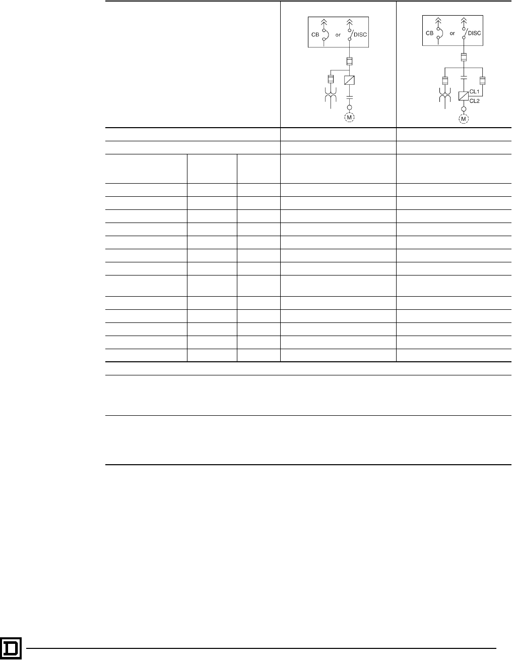
151
2/98 © 1998 Square D All Rights Reserved
Class 8998 Motor Control Centers
Options
Power Contactor Options (only 1 allowed)
Power Circuit Diagram
Description Output Contactor Input Contactor
Power Circuit Type
➀
G
➁
H
➂
Variable Torque Variable
Torque Low
Noise
Constant
Torque Space Adder Space Adder
3/4–5 hp 3/4–5 hp 3/4–5 hp 9"(NEMA 1)/3"(NEMA 12) 9"(NEMA 1)/3"(NEMA 12)
7.5 hp — — 9"(NEMA 1)/0"(NEMA 12) 9"(NEMA 1)/0"(NEMA 12)
10 hp 7.5–10 hp 7.5–10 hp 6"(NEMA 1)/0"(NEMA 12) 6"(NEMA 1)/0"(NEMA 12)
15 hp — — 6"(NEMA 1)/9"(NEMA 12) 6"(NEMA 1)/9"(NEMA 12)
20–25 hp 15–20 hp 15–20 hp 3"(NEMA 1)/9"(NEMA12) 3"(NEMA 1)/9"(NEMA12)
— 25 hp 25 hp 9"(NEMA 1/12) 9"(NEMA 1/12)
30–40 hp 30–40 hp 30–40 hp 9"(NEMA 1/12) 9"(NEMA 1/12)
50 hp — — 9"(NEMA 1)/
5" added to width (NEMA 12) 9"(NEMA 1)/
5" added to width (NEMA 12)
— 50 hp 50 hp 5" added to width (NEMA 1/12) 5" added to width (NEMA 1/12)
60–100 hp 60–75 hp 60–75 hp 5" added to width (NEMA 1/12) 5" added to width (NEMA 1/12)
— — 100 hp 0"(NEMA 1/12) 0"(NEMA 1/12)
125–150 hp — 125–150 hp 0"(NEMA 1/12) 0"(NEMA 1/12)
200 hp — 200 hp 0"(NEMA 1/12) 0"(NEMA 1/12)
➀
For Power Contactor Options above 200 hp contact the Square D Field Office.
➁
• Basic Drive features with output contactor for motor isolation. Contactor is open when drive is not running.
• Telemecanique D or F line contactors are used.
• Drive and output contactor are UL845 Listed for 65,000 A Short Circuit Current.
➂
• Basic Drive features with input contactor for isolating drive from input line.
• Allows auto diagnostic routine to be performed without wire changes.
• Telemecanique D or F line contactors are used.
• Drive and output contactor are UL845 Listed for 65,000 A Short Circuit Current.
This document provided by Barr-Thorp Electric Co., Inc. 800-473-9123 www.barr-thorp.com

© 1998 Square D All Rights Reserved
152
2/98
Class 8998 Motor Control Centers
Options
Drive Pilot Devices
Hand-Off-Auto Selector Switch and Manual Speed Potentiometer
Start-Stop Pushbuttons and Manual Speed Potentiometer
Stop-Forward-Reverse Push Buttons and Manual Speed Potentiometer
Stop-Run Selector Switch and Manual Speed Potentiometer
Forward-Off-Reverse Selector Switch and Manual Speed Potentiometer
Hand-Auto Selector Switch, Start-Stop Push Buttons, and Manual Speed Potentiometer
Special Purpose Pilot Devices (choose one)
Run-Jog Selector Switch
Jog Push Button
Jog Forward-Jog Reverse Push Buttons
Fast Stop Push Button
Forward-Reverse Selector Switch
Pilot Lights (Push-To-Test or Non-Push-To-Test)
Red “Power On” Light
Red “Run” Light
Green “Run” Light
Red “Stopped” Light
Green “Stopped” Light
Red “Jog” Light
Red “Forward” and “Reverse” Lights
Yellow “Fault” Light
Yellow “Fault” Light with integral Reset Push Button
Yellow “Hand” and “Auto” Lights
Green “Jog” Light
Green “Forward” and “Reverse” Lights
Wire Labels
Metering Options
Analog Speed, 0–120%
Analog Output, Current, 0–200%
Analog Output Volts, 0–150%
Analog Output Power, 0–150%
Digital Speed, 0–120%
Digital Output, Current, 0–200%
Digital Percent Volt
Digital Percent Power
This document provided by Barr-Thorp Electric Co., Inc. 800-473-9123 www.barr-thorp.com

153
2/98 © 1998 Square D All Rights Reserved
Class 8998 Motor Control Centers
Options
Miscellaneous Options Space Adder
Line Reactors (3% Impedance)
Each line reactor is mounted in the MCC cabinet as a separate unit above the drive unit and is factory wired to
the line side of the drive. Not available on NEMA/EEMAC Type 12 MCCs or drive units above 200 hp.
1–5 hp, 480 V 9"
7.5–40 hp, 480 V 12"
50 hp, 480 V, Variable Torque only 15"
50 hp, 480 V, Constant Torque or Variable Torque Low Noise only
0"
60–75 hp, 480 V
100 hp, 480 V,
125–150 hp, 480 V
200 hp, 480 V
100 VA Customer Capacity on Drive’s 120 V Control Transformer
1–20 hp, 480 V, All Types
25 hp, 480 V, Variable Torque
300 VA Customer Capacity on Drive’s 120 V Control Transformer
25–40 hp, 480 V, Constant Torque or Variable Torque Low Noise 9"
30–50 hp, 480 V, Variable Torque
500 VA Customer Capacity on Drive’s 120 V Control Transformer
50–200 hp, 480 V, Constant Torque or Variable Torque Low Noise
0"
60–200 hp, 480 V, Variable Torque
750 VA Customer Capacity on Drive’s 120 V Control Transformer
250–400 hp, 480 V, All Types
Dynamic Braking
3/4–15 hp, Variable Torque or 3/4–10 hp Constant Torque/Variable Torque Low Noise 6"
20–50 hp, Variable Torque or 15–40 hp Constant Torque/Variable Torque Low Noise 9"
Option Boards
I/O Extension Module, 24 Vdc
0"
I/O Extension Module, 115 Vac
Unit Extenders
Control and Timing Relays
Auto Start Relay for “auto” mode
1.5–30 second start delay for “auto” mode
Unwired D-line relay with 2N.O./2N.C. contacts
Unwired D-line relay with 2N.O./2N.C. untimed contacts and 1N.O./1N.C. 10–180 sec. off delay contacts.
Unwired D-line relay with 2N.O./2N.C. untimed contacts and 1N.O./1N.C. 10–180 sec. on delay contacts.
Miscellaneous Options
3–15 PSI Pneumatic Follower
24 Vdc Power Supply
Omit Control Station Plate
Power Contactor Control Circuits
3 Wire Control for Bypass
0"
Bypass Duty Cycle Timer
Auto-Bypass
Power Isolator Control
Elapsed Time Meter
This document provided by Barr-Thorp Electric Co., Inc. 800-473-9123 www.barr-thorp.com

Catalog No. 8800CT9701 2/98 © 1998 Square D All Rights Reserved.
Replaces VD0C06S201 dated 10/94.
Square D, , ALTIVAR, and MAG-GARD are registered trademarks and D-FAX is a trademark
of Square D Company. MODUTEC is a registered trademark and WINDO is a trademark of
Crompton Modutec, Inc. WINDOWS is a registered trademark of Microsoft, Inc. MODBUS is a
registered trademark and COMPAC is a trademark of Schneider Automation, Inc. ALTISTART is a
registered trademark and UNI-TELWAY is a trademark of Telemecanique S.A. or its successor-in-
interest, Schneider Electric S.A.
Square D Company
8001 Hwy 64 East
Knightdale, NC USA 27545-9023
(919) 266-3671
This document provided by Barr-Thorp Electric Co., Inc. 800-473-9123 www.barr-thorp.com
