1000300715 Catalog
2016-09-04
: Pdf 1000300715-Catalog 1000300715-Catalog B4 unilog
Open the PDF directly: View PDF ![]() .
.
Page Count: 136 [warning: Documents this large are best viewed by clicking the View PDF Link!]
- Condensation and Pressure Compensation
- Panels and Panel Accessories
- Panels for Enclosures
- Perforated Panels
- Panels for Junction Boxes
- Composite Panels for Junction Boxes and UL/NEMA Wall-Mount Enclosures
- Junction Box and Wall-Mount Enclosure Swing-Out Panel Kit
- Panels for Type 1 Enclosures and Small Type 3R Enclosures
- Panels for Medium Type 1 Enclosures
- Panels for Type 3R, 4, 4X, 12 and 13 Enclosures
- Panels for Large Bulletin A27, A28, A28S4 and A34 Multi-Door Enclosures
- Panels for Free-Stand Type 1 Large One-Door Enclosures
- Panels for Free-Stand Type 1 Large Two-Door Enclosures
- Panels for Free-Stand Type 4, 4X and 12 Single- and Dual-Access One-Door Enclosures with Mounting Channel
- Panels for Free-Stand Type 4, 4X and 12 Single- and Dual-Access Two-Door Enclosures with Mounting Channel
- Side-Mounted Panels
- Heavy Duty Panel Supports
- Center Panel Supports
- Swing-Out Panels for Free-Stand Type 4, 4X and 12 Enclosures with Mounting Channel
- Panels for WiFi Cabinets and Small Wall-Mount Enclosures
- Panels for Open Frame Racks
- Panel Accessories
- Panels for Enclosures
- Window Kits
- Door Accessories
- Shelves, Keyboard Trays and Gland Plates
- Folding Shelves
- Shelves for Open Frame Racks
- Double-Sided Solid Aluminum Shelf
- Double-Sided, Solid Aluminum, Heavy Duty Shelf
- Single-Sided Solid Aluminum Shelf
- Single-Sided Solid-Steel Shelf
- Single-Sided Steel Vented Shelf
- Double-Sided Solid-Steel Shelf
- Double-Sided Steel Vented Shelf
- Center-Mount Steel Shelves
- Rack-Mount Steel Shelf
- Adjustable Steel Vented Shelf
- Pullout Keyboard Tray with Monitor Shelf
- Pull-Out Shelf for Mini Keyboard
- Shelves for Racks and Cabinets
- Pivoting Keyboard Shelf with Mouse Tray
- Steel Keyboard/Monitor Shelf
- Pull-Out Shelf for Mini Keyboard
- Rack-Mount Adjustable Shelf
- Tool-less Shelf
- Single-Sided Shelf
- Sliding Equipment Shelf
- Cable Manager Arm for Sliding Equipment Shelf
- Keyboard Compartment for 19-in. Racks
- Writing Surface for Rack-Angle-Mounted Drawer
- Rack-Angle Mounted Drawer
- Fixed Shelf
- 19-in. Fixed Shelf
- Pull-Out Shelves
- Drawers
- Gland Plates
- Locks, Lockouts, Latches, Handles and Clamps
- Drip Shields
- Hole Seals
- Corrosion Inhibitors
- Electrical Accessories
- Terminal Block Kits
- Terminal Block Kit Assembly for Junction Boxes Overview
- Terminal Block Bracket Assemblies for Junction Boxes
- Terminal Box Straps for Junction Boxes
- Terminal Block Strips for Junction Boxes
- Bracket Assembly for Type 4, 12 and 13 Enclosures
- Terminal Block Kit Assembly for Type 4, 12 and 13 Enclosures Overview
- Terminal Straps for Type 4, 12 and 13 Enclosures
- Terminal Strap Support Kit
- DIN-Mounted Accessories
- Grounding
- Electrical Interlocks
- Lighting Packages
- PANELITE Enclosure Lights Overview
- PANELITE LED Enclosure Light
- PANELITE Fluorescent Enclosure Light
- Replacement Hardware Kit for PANELITE LED Enclosure Light
- PANELITE Power Cords
- PANELITE Power Cable with Leads
- PANELITE Ganging Cables
- PANELITE Door Switch Cable
- 230 VAC Fluorescent Enclosure Light
- PANELITE Wiring Options
- LED Light Kit
- LED Light Input Connector/Cable Assembly
- LED Light Extension Connector/Cable Assembly
- Remote Door Switches
- LED Puck Light
- Touch-Safe UL Light Switch
- Mounting Bracket Kit for Light Package
- Power Distribution Units
- Terminal Block Kits
- Mounting Accessories
- Mounting Kits
- Legs and Casters
- Fasteners
- Rack-Mount Accessories
- Guides
- Slides
- Fan Speed Control, Rack-Mount
- Joining Kit
- Panel Adapter
- Rack Unit Label
- Mobile Base for Open Frame Racks
- 19-in. Rack-Mount/Desktop Case, Type 1
- Swing-Out Rack Mounting Frames
- 19-in. and 23-in. Rack Angles
- Rack Mounting Angles - U Style (Type RA)
- Rack Mounting Angles - L Style (Type RP)
- Rack Mounting Angle Kit - L Style
- INTERSAFE Data Interface Ports
- INTERSAFE Data Interface Ports, Type 4/4X/12
- INTERSAFE Data Interface Ports, Type 4/4X/12
- INTERSAFE Data Ports for ControlNet Protocol
- INTERSAFE Data Interface Ports for Data Highway Plus Protocol
- INTERSAFE Data Interface Ports for DeviceNet Protocol
- INTERSAFE Data Interface Ports for DH+, ModBus Plus, Ethernet Protocol
- INTERSAFE Data Interface Ports for Ethernet Protocol
- INTERSAFE Data Interface Ports for Ethernet/ProfiNet Protocol
- INTERSAFE Data Interface Ports for Genius Protocol
- INTERSAFE Data Interface Ports for Micro Protocol
- INTERSAFE Data Interface Ports for Modbus Protocol
- INTERSAFE Data Interface Ports for Profibus Protocol
- INTERSAFE Data Interface Ports for SNP Protocol
- INTERSAFE Data Interface Ports for USB Protocol, 10-ft. Cable
- INTERSAFE Type 4/4X/12 Data Interface Port Disk Drive Enclosure
- To Order a Modified Configuration for INTERSAFE Type 4/4X/12 Data Interface Ports
- INTERSAFE Connector 8M
- INTERSAFE Connector 9FG
- INTERSAFE Connector 9FT
- INTERSAFE Connector 9M
- INTERSAFE Connector 9MT
- INTERSAFE Connector 15F
- INTERSAFE Connector 15FT
- INTERSAFE Connector 15H
- INTERSAFE Connector 15M
- INTERSAFE Connector 25F
- INTERSAFE Connector 25FT
- INTERSAFE Connector 25M
- INTERSAFE Connector 25MT
- INTERSAFE Connector BNC
- INTERSAFE Connector CN
- INTERSAFE Connector DH
- INTERSAFE Connector DNM
- INTERSAFE Connector DNP
- INTERSAFE Connector DPO
- INTERSAFE Connector DP3
- INTERSAFE Connector DP5
- INTERSAFE Connector ETH
- INTERSAFE Connector GEG
- INTERSAFE Connector GFO
- INTERSAFE Connector GF3
- INTERSAFE Connector GF5
- INTERSAFE Connector MCL
- INTERSAFE Connector MD6
- INTERSAFE Connector MD8
- INTERSAFE Connector PB
- INTERSAFE Connector R11
- INTERSAFE Connector RJS
- INTERSAFE Connector SNP
- INTERSAFE Connector SPO
- INTERSAFE Connector SP3
- INTERSAFE Connector SP5
- INTERSAFE Connector TMB
- INTERSAFE Connector TMM
- INTERSAFE Connector USB
- INTERSAFE Data Interface Ports, Type 4/4X/12
- EMC Accessories
- INLINE Accessories
- CONCEPT Accessories
- Hazardous Location

EQUIPMENT PROTECTIONSUBJECT TO CHANGE WITHOUT NOTICEACCESSORIES872
12
763.422.2211
763.422.2600
ACCESSORIES
CONDENSATION AND PRESSURE COMPENSATION
Intro Page
CHAPTER CONTENTS
CONDENSATION AND PRESSURE COMPENSATION
CONDENSATION AND PRESSURE COMPENSATION
DEVICES
H2OMIT Vent Drains, Type 4X ........................874
H2OMIT Thermoelectric Dehumidifier ..................876
Stainless Steel Pressure Compensation ...............878
Pressure Compensation Device ......................879
PANELS AND PANEL ACCESSORIES
PANELS FOR ENCLOSURES
Perforated Panels ................................880
Panels for Junction Boxes ..........................882
Composite Panels for Junction Boxes and UL/NEMA Wall-
Mount Enclosures ...............................883
Junction Box and Wall-Mount Enclosure Swing-Out Panel Kit ..
..............................................884
Panels for Type 1 Enclosures and Small Type 3R Enclosures ...
..............................................885
Panels for Medium Type 1 Enclosures .................885
Panels for Type 3R, 4, 4X, 12 and 13 Enclosures ..........886
Panels for Large Bulletin A27, A28, A28S4 and A34 Multi-Door
Enclosures .....................................888
Panels for Free-Stand Type 1 Large One-Door Enclosures ..889
Panels for Free-Stand Type 1 Large Two-Door Enclosures ..889
Panels for Free-Stand Type 4, 4X and 12 Single- and Dual-
Access One-Door Enclosures with Mounting Channel ....890
Panels for Free-Stand Type 4, 4X and 12 Single- and Dual-
Access Two-Door Enclosures with Mounting Channel ....891
Side-Mounted Panels ..............................892
Heavy Duty Panel Supports .........................892
Center Panel Supports .............................893
Swing-Out Panels for Free-Stand Type 4, 4X and 12 Enclosures
with Mounting Channel ...........................895
Panels for WiFi Cabinets and Small Wall-Mount Enclosures ...
..............................................895
PANELS FOR OPEN FRAME RACKS
Rack Panel for 19-in. Racks .........................896
Tool-less (Snap-in) Blanking Panels for 19-in. Racks .....896
Rack Panels .....................................897
PANEL ACCESSORIES
Threaded Panel Extenders ..........................898
Panel Lifting Hooks ...............................898
Panel Support Kit .................................898
WINDOW KITS
WINDOW KITS
Steel, Stainless Steel and Non-Metallic Window Kits .....899
Wing Knobs for CONCEPT Window Kits .................900
Frameless Window Kit .............................900
CONCEPT Fixed and Hinged Window Kits ...............900
Type 12 Hinged Window Kit ..........................901
CONCEPT Deep Hinged Window Kit ....................901
Type 4 and 4X Deep-Hinged Window Kits ...............902
IR Windows ......................................903
DOOR ACCESSORIES
DOOR STOPS
Door Stop Kit ....................................904
Type 316 Stainless Steel Door Stop Kit ................904
Large Enclosure Door Stop Kit .......................904
DATA POCKETS
Thermoplastic Data Pocket .........................905
Metal Data Pocket ................................905
External Data Pockets, Type 4/4X/12 .................906
GASKET KITS
Gasket Kits ......................................908
SHELVES, KEYBOARD TRAYS AND GLAND PLATES
FOLDING SHELVES
Stainless Steel Folding Shelf ........................909
Large Folding Shelf ...............................909
SHELVES FOR OPEN FRAME RACKS
Double-Sided Solid Aluminum Shelf ...................910
Double-Sided, Solid Aluminum, Heavy Duty Shelf ........910
Single-Sided Solid Aluminum Shelf ...................910
Single-Sided Solid-Steel Shelf .......................910
Single-Sided Steel Vented Shelf .....................911
Double-Sided Solid-Steel Shelf ......................911
Double-Sided Steel Vented Shelf .....................911
Center-Mount Steel Shelves .........................911
Rack-Mount Steel Shelf ............................912
Adjustable Steel Vented Shelf .......................912
Pullout Keyboard Tray with Monitor Shelf ..............912
Pull-Out Shelf for Mini Keyboard .....................912
SHELVES FOR RACKS AND CABINETS
Pivoting Keyboard Shelf with Mouse Tray ...............913
Steel Keyboard/Monitor Shelf .......................913
Pull-Out Shelf for Mini Keyboard .....................913
Rack-Mount Adjustable Shelf ........................914
Tool-less Shelf ...................................914
Single-Sided Shelf ................................915
Sliding Equipment Shelf ............................915
Cable Manager Arm for Sliding Equipment Shelf .........915
Keyboard Compartment for 19-in. Racks ...............916
Writing Surface for Rack-Angle-Mounted Drawer ........916
Rack-Angle Mounted Drawer ........................916
Fixed Shelf ......................................917
19-in. Fixed Shelf .................................917
Pull-Out Shelves .................................917
DRAWERS
Drawers ........................................918
CONCEPT Keyboard Box ............................918
GLAND PLATES
12 Gauge Gland Plate, Type 4 and Type 12 ..............919
16 Gauge Gland Plate ..............................919
12 Gauge Gland Plate ..............................919
CHAPTER 12
ACCESSORIES

PH 763.422.2211 • FAX 763.422.2600 • PENTAIRPROTECT.COMEQUIPMENT PROTECTION ACCESSORIES 873
LOCKS, LOCKOUTS, LATCHES, HANDLES AND
CLAMPS
LOCKS
Padlock Kit for Junction Boxes. . . . . . . . . . . . . . . . . . . . . . .920
Replacement Keys ................................920
Lock Kit for Clamp Cover Junction Boxes ...............920
Lock Kit for Type 3R and 12 Enclosures ................920
LOCKOUTS
Safety Lockouts ..................................921
Dual-Access Safety Lockouts .......................921
LATCHES
T-Handle Latch and Keyed Cylinder Lock Kits ...........922
Toggle Latch for Type 4 and 4X Floor-Mount and Free-Stand
Enclosures .....................................922
Latch Kit for One-Door Type 12 Enclosures .............922
Latch Kits for Type 4 and 12 Enclosures ................922
HANDLES
POWERGLIDE Handles .............................923
Handle Kit .......................................923
Handles ........................................923
CLAMPS
Fast-Operating Clamp-Cover Junction Box Clamp ........924
Fast-Operating Clamp Assembly .....................924
Clamp Kits ......................................924
Clamp Block Kit ..................................924
DRIP SHIELDS
DRIP SHIELDS
Drip Shield Kit for Type 12 Enclosures .................925
Drip Shield Kit for Type 12 Free-Standing and Floor-Mount
Enclosures With Concealed Hinges ..................925
Stainless Steel Drip Shield Kit for Type 4 and 4X Wall-Mount
Enclosures .....................................925
HOLE SEALS
HOLE SEALS
HOL-SEALERS Hole Seals ...........................926
HOL-SEALERS Non-Metallic Hole Seals ................928
CORROSION INHIBITORS
CORROSION INHIBITORS
Industrial Corrosion Inhibitors .......................930
Epoxy Patch Kit ..................................931
Touch-Up Paint ...................................931
Touch-Up Paint Pens ..............................931
ELECTRICAL ACCESSORIES
TERMINAL BLOCK KITS
Terminal Block Kit Assembly for Junction Boxes Overview .932
Terminal Block Bracket Assemblies for Junction Boxes ....933
Terminal Box Straps for Junction Boxes ................933
Terminal Block Strips for Junction Boxes ...............933
Bracket Assembly for Type 4, 12 and 13 Enclosures .......934
Terminal Block Kit Assembly for Type 4, 12 and 13 Enclosures
Overview ......................................934
Terminal Straps for Type 4, 12 and 13 Enclosures ........935
Terminal Strap Support Kit ..........................935
DINMOUNTED ACCESSORIES
DIN Type Rails ...................................936
NEMA 5-15R DIN-Mounted Outlets ....................936
DIN 3 Rail, Self-Adhesive ...........................937
GROUNDING
PROLINE Grounding Kit .............................938
Grounding Device .................................938
Grounding Bar System .............................938
Replacement Panel-Mount Hardware Kit ...............938
Grounding Kit ....................................938
ELECTRICAL INTERLOCKS
Electrical Interlocks ...............................939
Electrical Interlock Defeater ........................941
Panel Interface Connector ..........................941
LIGHTING PACKAGES
PANELITE Enclosure Lights Overview ..................942
PANELITE LED Enclosure Light .......................943
PANELITE Fluorescent Enclosure Light ................943
Replacement Hardware Kit for PANELITE LED Enclosure Light ..
..............................................943
PANELITE Power Cords .............................944
PANELITE Power Cable with Leads ....................944
PANELITE Ganging Cables ..........................944
PANELITE Door Switch Cable ........................944
230 VAC Fluorescent Enclosure Light ..................945
PANELITE Wiring Options ...........................945
LED Light Kit .....................................946
LED Light Input Connector/Cable Assembly .............946
LED Light Extension Connector/Cable Assembly .........946
Remote Door Switches .............................947
LED Puck Light ...................................947
Touch-Safe UL Light Switch .........................947
Mounting Bracket Kit for Light Package ................947
POWER DISTRIBUTION UNITS
Rack- and Panel-Mount Power Distribution Units (PDUs) ..948
Universal Power Strip Bracket .......................949
IEC Cord Sets ....................................949
IEC C-13 Retaining Clip .............................949
Rack-Mount PDU Bracket ...........................949
PDU Bracket Kit ..................................949
MOUNTING ACCESSORIES
MOUNTING KITS
Mounting Bracket Kits .............................950
ULTRX Mounting Bracket Kit ........................950
Pole-Mount Kit ...................................950
Bottom Support Kit ...............................951
Unistrut Mounting Kit ..............................951
Enclosure Stabilizers ..............................951
LEGS AND CASTERS
Floor Stand Kit ...................................952
Caster Kit .......................................954
Plate Casters ....................................954
Sanitary Leg Kits .................................955
Stainless Steel Legs. . . . . . . . . . . . . . . . . . . . . . . . . . . . . . .955
FASTENERS
UL-Recognized Hardware Kits ........................956
VELCRO® Cable Wrap ..............................956
Screw Packages ..................................957
Cage Nut Package ................................957
Clip Nut Package .................................957
Tamper-Resistant Screws ..........................957
Clamping Nut Package .............................957
PROLINE Fastener Packages ........................958
Fastener Package .................................958
RACKMOUNT ACCESSORIES
Guides. . . . . . . . . . . . . . . . . . . . . . . . . . . . . . . . . . . . . . . . . .959
Slides ..........................................959
Fan Speed Control, Rack-Mount ......................960
Joining Kit ......................................960
Panel Adapter ....................................960
Rack Unit Label ..................................961
Mobile Base for Open Frame Racks ...................961
19-in. Rack-Mount/Desktop Case, Type 1 ..............962
Swing-Out Rack Mounting Frames ....................963
19-in. and 23-in. Rack Angles .......................964
Rack Mounting Angles - U Style (Type RA) ..............964
Rack Mounting Angles - L Style (Type RP) ..............966
Rack Mounting Angle Kit - L Style ....................968
INTERSAFE DATA INTERFACE PORTS
INTERSAFE DATA INTERFACE PORTS, TYPE 4/4X/12
INTERSAFE Data Interface Ports, Type 4/4X/12 ..........970
INTERSAFE Data Ports for ControlNet Protocol ..........971
INTERSAFE Data Interface Ports for Data Highway Plus
Protocol .......................................972
INTERSAFE Data Interface Ports for DeviceNet Protocol ...973
INTERSAFE Data Interface Ports for DH+, ModBus Plus,
Ethernet Protocol ................................974
INTERSAFE Data Interface Ports for Ethernet Protocol ....975
INTERSAFE Data Interface Ports for Ethernet/ProfiNet
Protocol .......................................976
INTERSAFE Data Interface Ports for Genius Protocol ......977
INTERSAFE Data Interface Ports for Micro Protocol ......978
INTERSAFE Data Interface Ports for Modbus Protocol .....979
INTERSAFE Data Interface Ports for Profibus Protocol ....980
INTERSAFE Data Interface Ports for SNP Protocol ........981
INTERSAFE Data Interface Ports for USB Protocol, 10-ft. Cable
..............................................982
INTERSAFE Type 4/4X/12 Data Interface Port Disk Drive
Enclosure ......................................983
To Order a Modified Configuration for INTERSAFE Type 4/4X/12
Data Interface Ports .............................983
INTERSAFE Connector 8M ...........................984
INTERSAFE Connector 9FG ..........................984
INTERSAFE Connector 9FT ..........................984
INTERSAFE Connector 9M ...........................984
INTERSAFE Connector 9MT ..........................984
INTERSAFE Connector 15F ..........................985
INTERSAFE Connector 15FT .........................985
INTERSAFE Connector 15H ..........................985
INTERSAFE Connector 15M ..........................985
INTERSAFE Connector 25F ..........................985
INTERSAFE Connector 25FT .........................985
INTERSAFE Connector 25M ..........................986
INTERSAFE Connector 25MT .........................986
INTERSAFE Connector BNC ..........................986
INTERSAFE Connector CN ...........................986
INTERSAFE Connector DH ...........................986
INTERSAFE Connector DNM .........................987
INTERSAFE Connector DNP ..........................987
INTERSAFE Connector DPO ..........................987
INTERSAFE Connector DP3 ..........................987
INTERSAFE Connector DP5 ..........................988
INTERSAFE Connector ETH ..........................988
INTERSAFE Connector GEG ..........................988
INTERSAFE Connector GFO ..........................988
INTERSAFE Connector GF3 ..........................989
INTERSAFE Connector GF5 ..........................989
INTERSAFE Connector MCL ..........................989
INTERSAFE Connector MD6 .........................989
INTERSAFE Connector MD8 .........................990
INTERSAFE Connector PB ...........................990
INTERSAFE Connector R11 ..........................990
INTERSAFE Connector RJS ..........................990
INTERSAFE Connector SNP ..........................990
INTERSAFE Connector SPO ..........................991
INTERSAFE Connector SP3 ..........................991
INTERSAFE Connector SP5 ..........................991
INTERSAFE Connector TMB .........................991
INTERSAFE Connector TMM .........................992
INTERSAFE Connector USB ..........................992
EMC ACCESSORIES
EMC ACCESSORIES
Bonding Cable Clamps .............................993
EMC Cable Strain Reliefs ...........................993
Bonding Straps ...................................993
INLINE ACCESSORIES
INLINE ACCESSORIES
Lock Inserts .....................................994
Wing Knob Latch .................................994
Panel ..........................................994
INLINE Landscape Panels ...........................994
Mounting-Bracket Kit ..............................994
DIN3 Type Rails ..................................995
Grounding Kit ....................................995
DIN Rail or Panel-Mounting Brackets ..................995
CONCEPT ACCESSORIES
CONCEPT ACCESSORIES
CONCEPT Panel Conversion Kit. . . . . . . . . . . . . . . . . . . . . . .996
Swing-Out Rack Frame .............................996
CONCEPT Adjustable-Depth Mounting Kits .............996
Pole-Mount Kit ...................................996
Mounting Channels ................................997
Rack-Mount Angles ...............................997
DIN3 Rail Kits ....................................997
Door Bars .......................................997
CONCEPT Swing-Out Panels .........................998
CONCEPT Adapter Bracket ..........................998
Handles ........................................998
Door Stop Kit ....................................999
Data Pockets ....................................999
Lock Inserts .....................................999
Mounting-Bracket Kits .............................999
Hinge Pins ......................................999
CONCEPT Panels .................................1000
HAZARDOUS LOCATION
HAZARDOUS LOCATION ACCESSORIES
Hazardous Location Window Kits ....................1002
Hazardous Location LED Lights .....................1003
Hazardous Location Door Switch ....................1004
Replacement Hardware Kit for Hazardous Location LED Lights .
.............................................1004
Hazardous Location Breather Drains .................1005
Hazardous Location Hole Seals .....................1006
12
EQUIPMENT PROTECTIONSUBJECT TO CHANGE WITHOUT NOTICEACCESSORIES874
12
CONDENSATION AND PRESSURE COMPENSATION Condensation and Pressure ComPensation deviCes
CONDENSATION AND PRESSURE COMPENSATION DEVICES
H2OMIT VENT DRAINS, TYPE 4X
INDUSTRY STANDARDS
Maintains UL/cUL Type 4, 4X rating when properly installed on a UL/cUL
Type4 or 4X enclosure.
UL 508A Listed; Type 4, 4X; File No. E61997
cUL Listed per CSA C22.2 No 94; Type 4, 4X; File No. E61997
NEMA/EEMAC Type 4, 4X
IEC 60529, IP66
APPLICATION
H2OMIT Vent Drains allow accumulated water to drain out the
bottom of an enclosure. The UL-approved vent drains also function
as an air pressure equalizer, reducing the harmful effects of
temperature-induced vacuums that could pull water and moisture
into the enclosure.
FEATURES
• Uses gravity to remove collected liquids
• One-way mechanical shut-off when pressure is equalized
prevents water and contaminants from entering the enclosure
• Helps reduce corrosion that can limit the life of internal electrical
and electronic components
• Installs in a 7/8-in. hole in the bottom of enclosure with provided
nut or in a 1/2-in. NPT/NPS threaded conduit hub
• Installs in the bottom of mild steel, aluminum, stainless steel or
non-metallic enclosures
• Maintains enclosure’s UL Type rating when properly installed
SPECIFICATIONS
Stainless Steel Vent Drain
• Corrosion-resistant polyester material with a Type 304 stainless
steel sleeve
• 2.00-in. long x 1.38-in outside diameter
Non-Metallic Drain Vent
• Corrosion-resistant polyester material
• 2.00-in. long x 1.25-in. outside diameter
BULLETIN: H2O
Standard Product
Catalog Number Description D (in.) D (mm) Quantity
AVDR4NM Non-metallic Vent Drain 1.25 32 1
AVDR4SS4 Stainless Steel Vent Drain 1.38 35 1


EQUIPMENT PROTECTIONSUBJECT TO CHANGE WITHOUT NOTICEACCESSORIES876
12
CONDENSATION AND PRESSURE COMPENSATION Condensation and Pressure ComPensation deviCes
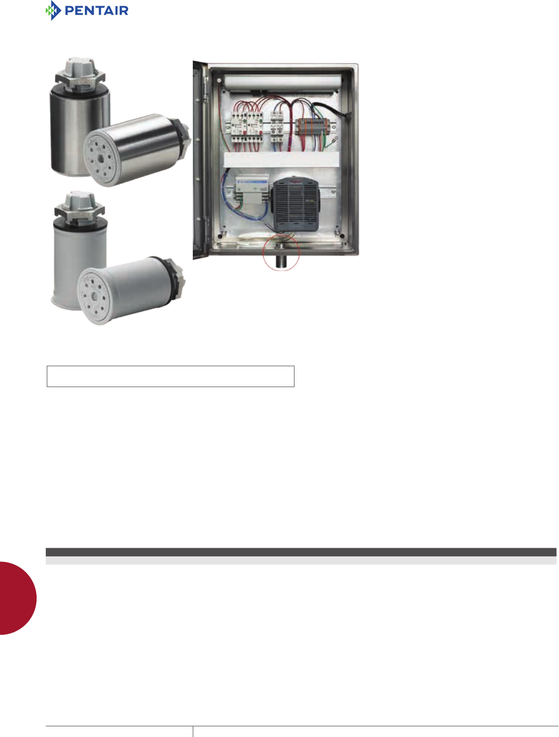
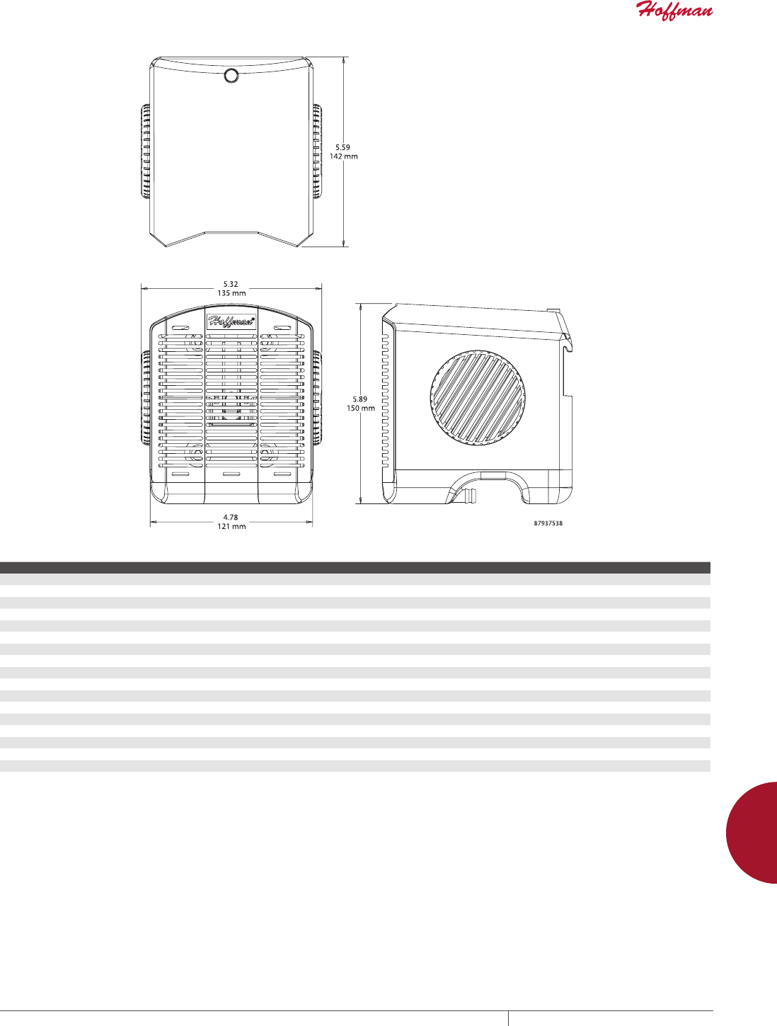
H2OMIT THERMOELECTRIC DEHUMIDIFIER
INDUSTRY STANDARDS
UL 508A Listed; File No. E61997
cUL Listed per C22.2 No. 14; File No. E61997
CE
APPLICATION
The H2OMIT Thermoelectric Dehumidifier removes moisture from
the air within an enclosure, providing an inexpensive yet highly
effective way to protect electronic and electrical components from
condensation.
FEATURES
• Reduces corrosion that can limit the life of internal electrical and
electronic components
• Condenses moisture from internal enclosure air and standing
liquids
• Built-in drain provision with plastic hose directs collected
moisture to the Vent Drain (sold separately)
• Rotating side air vents direct recirculating air away from critical
controls
• Mounts via DIN rail on internal panel or mounts directly onto the
inside bottom of enclosure above the Vent Drain (sold separately)
• Can be used in mild steel, aluminum, stainless steel and non-
metallic enclosures
SPECIFICATIONS
• High-impact ABS shell
• Operates on 24-Volt DC power
• 4.5 A max. (84 W)
• Runs continuously above 32 Fa (power supply not included)
• Removes 8 oz. of moisture in 24 hours
• Compact 6.00-in. x 5.50-in. x 5.75-in. design
• One Thermoelectric Dehumidifier includes:
- Four feet of plastic hose
- Two hose retainers
- One double-ended hose retainer
- Six inches of Velcro®
- Seven-inch strip of DIN rail
- Two mounting screws
Must be used with UL-certified drain to remove pooled liquid from
enclosure.
aIf continual operation is not desired, a Mechanical Hygrostat (AMHUM)
can be wired to the thermoelectric dehumidifier and then set to turn the
dehumidifier on at the desired relative humidity.
VELCRO is a trademark of Velcro Industries B.V.
BULLETIN: H2O
Standard Product
Catalog Number Description
H2OMITTER Thermoelectric Dehumidifier
PH 763.422.2211 • FAX 763.422.2600 • PENTAIRPROTECT.COMEQUIPMENT PROTECTION ACCESSORIES 877
12
CONDENSATION AND PRESSURE COMPENSATION Condensation and Pressure ComPensation deviCes
Dew Point Temperature Percent Relative Humidity
Temp. (° F) 100% 95% 90% 85% 80% 75% 70% 65% 60% 55% 50% 45% 40% 35% 30% 25% 20% 15% 10%
110 110 108 106 104 102 100 98 95 93 90 87 84 80 76 72 65 60 51 41
105 105 103 101 99 97 95 93 91 88 85 83 80 76 72 67 62 55 47 37
100 100 99 97 95 93 91 89 86 84 81 78 75 71 67 63 58 52 44 32
95 95 96 92 90 88 86 87 81 79 76 73 70 67 63 59 54 48 40 32
90 90 88 87 85 83 81 79 76 74 71 68 65 62 59 54 49 43 36 32
85 85 83 81 80 78 76 74 71 69 67 64 61 58 54 50 45 38 32 —
80 80 78 77 75 73 71 69 67 65 62 59 56 53 50 45 40 35 32 —
75 75 73 72 70 68 66 64 62 60 58 55 52 49 45 41 36 32 — —
70 70 68 67 65 63 61 59 58 55 53 50 47 44 40 37 32 — — —
65 65 63 62 60 59 57 55 53 50 48 45 42 40 36 62 — — — —
60 60 58 57 55 53 52 50 48 45 43 41 38 35 32 — — — — —
55 55 53 52 50 49 47 45 43 40 38 36 33 32 — — — — — —
50 50 48 46 45 44 42 40 38 36 34 32 — — — — — — — —
45 45 43 42 40 39 37 35 34 32 — — — — — — — — — —
40 40 39 37 35 34 32 — — — — — — — — — — — — —
35 35 3432—— ——————————————
32 32 ———— ——————————————
Definition: Dew Point is the temperature at which condensation forms. If the temperature of the enclosure is 85 F
and the relative humidity is 80 percent, Dew Point is reached at a temperature of 78 F or below.
This means that moisture vapor will condense on any surface that is below the Dew Point temperature of 78 F.
EQUIPMENT PROTECTIONSUBJECT TO CHANGE WITHOUT NOTICEACCESSORIES878
12
CONDENSATION AND PRESSURE COMPENSATION Condensation and Pressure ComPensation deviCes
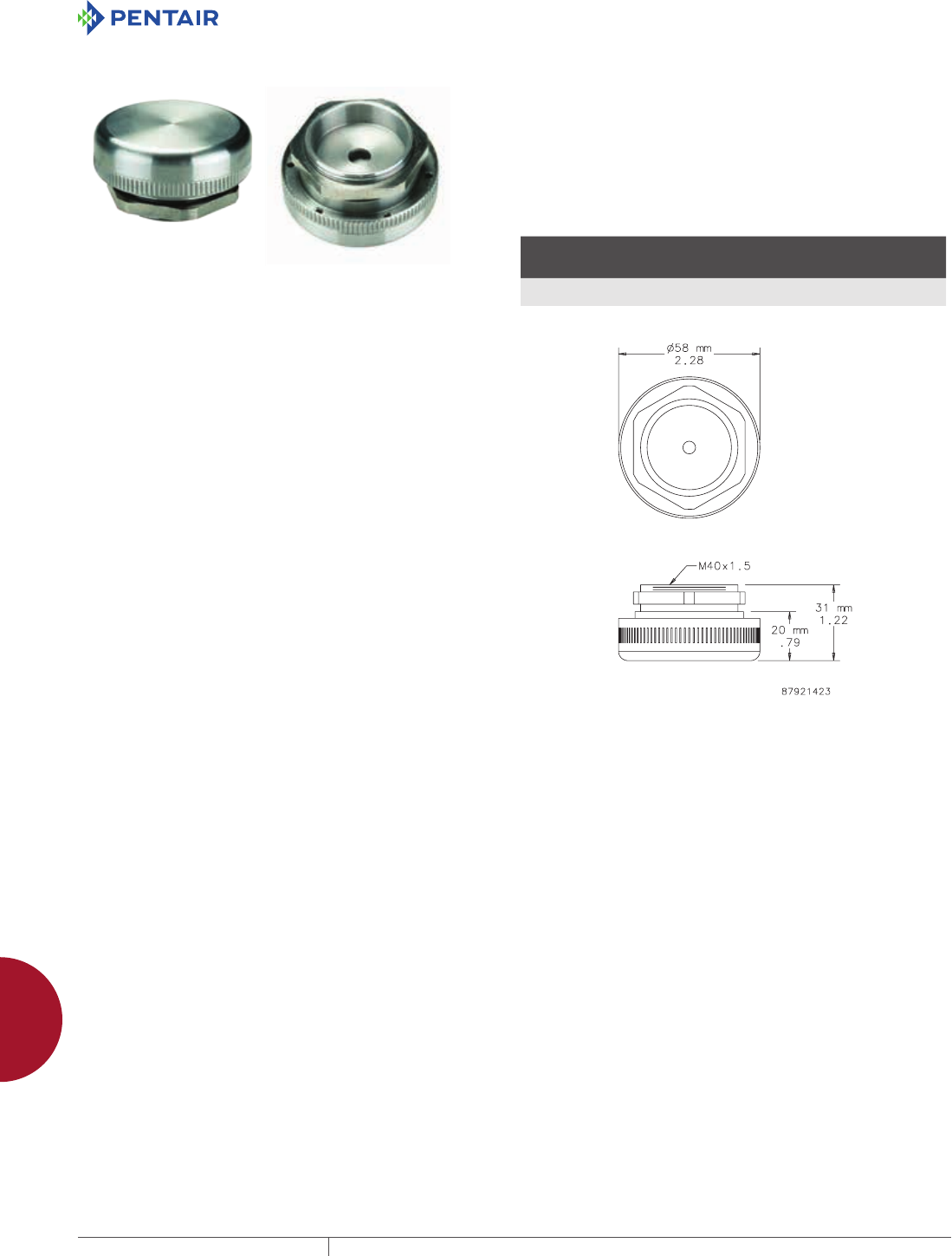
STAINLESS STEEL PRESSURE COMPENSATION
INDUSTRY STANDARDS
CE
NEMA Type 4X
IEC/EN 60529, IP66
APPLICATION
Pressure differentials in a tightly sealed enclosure result from
heat generated by electrical and electronic equipment within
the enclosure and fluctuations of outside ambient temperature.
Stainless steel pressure compensation devices provide IP66
protection in corrosive applications requiring slow pressure
equalization. For optimal performance, install two plugs diagonally
to each other.
FEATURES
• Air permeability = 42 cubic feet/hour (1,200 liters/hour) at a
pressure difference of min. 70 mbar
• Easy installation: drill one 1.60-in. (41-mm) diameter hole
• Sealing gasket (Nitrile Buna-N Rubber)
SPECIFICATIONS
• Type 316L stainless steel
• Semipermeable membrane inside the plug filters moisture and
dust
• Mounting thread M40 with union nut
FINISH
Machined Type 316L stainless steel
BULLETIN: D85
Standard Product
Catalog Number AxB in./mm
Depth in
Enclosure
in./mm
Operating/Storage
Temperature °F
Operating/Storage
Temperature °C
APCDSS6 2.28 x 1.22
58 x 31
0.35
9
-40 to 176 -40 to 80
A dimension = diameter
PH 763.422.2211 • FAX 763.422.2600 • PENTAIRPROTECT.COMEQUIPMENT PROTECTION ACCESSORIES 879
12
CONDENSATION AND PRESSURE COMPENSATION Condensation and Pressure ComPensation deviCes
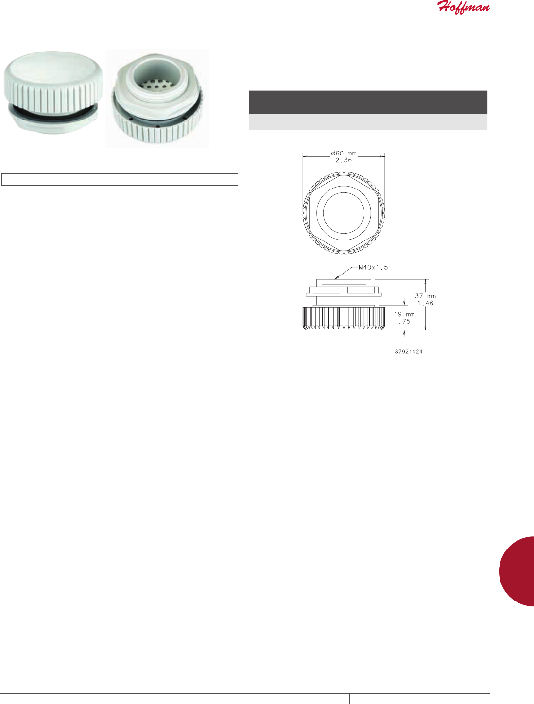
PRESSURE COMPENSATION DEVICE
INDUSTRY STANDARDS
UL Type 1, 4, 4X; File No. E234324
CE
IEC/EN 60529, IP66
APPLICATION
Pressure differentials in a tightly sealed enclosure result from
heat generated by electrical and electronic equipment within
the enclosure and fluctuations of outside ambient temperature.
Pressure compensation devices provide IP66 protection in
applications requiring slow pressure equalization. For optimal
performance, install two plugs diagonally to each other.
FEATURES
• Air permeability = 42 cubic feet/hour (1,200 liters/hour) at a
pressure difference of min. 70 mbar
• Easy installation: drill one 1.60-in. (41-mm) diameter hole
• Sealing gasket (Nitrile Buna-N Rubber)
SPECIFICATIONS
• Semipermeable membrane inside the plug to filter moisture and
dust
• Mounting thread M40 with union nut
• Plastic PA66
FINISH
Light-gray plastic. Polymeric material manufactured by DuPont™.
DuPont is the trademark of E. I. duPont de Nemours and Company.
BULLETIN: D85
Standard Product
Catalog Number
Depth in
Enclosure
in./mm
Operating/Storage
Temperature °F
Operating/Storage
Temperature °C
APCDABS 0.6
15
-49 to 158 -45 to 70
A dimension = diameter
EQUIPMENT PROTECTIONSUBJECT TO CHANGE WITHOUT NOTICEACCESSORIES880
12
PANELS AND PANEL ACCESSORIES Condensation and Pressure ComPensation deviCes
PANELS AND PANE L ACCESSORI ES
PANELS FOR ENC LOSURES
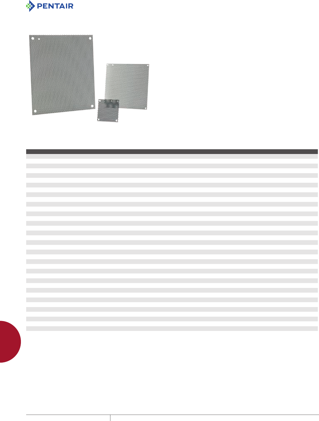
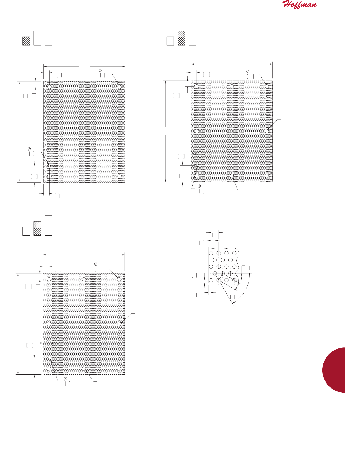
PERFORATED PANELS
Perforated panels are 16 gauge steel and accept self-tapping screws and eliminate the need to measure, mark and drill when mounting
components. Use for mounting lightweight control components.
BULLETIN: PNLP
Catalog Number Use in Panel Size D x E (in.) Panel Size D x E (mm)
A6N6PP Small Type 1 Panel Enclosures and Small Type 3R Boxes 4.25 x 4.25 108 x 108
A8N6PP Small Type 1 Panel Enclosures and Small Type 3R Boxes 6.25 x 4.25 159 x 108
A8N8PP Small Type 1 Panel Enclosures and Small Type 3R Boxes 6.25 x 6.25 159 x 159
A10N8PP Small Type 1 Panel Enclosures and Small Type 3R Boxes 8.25 x 6.25 210 x 159
A10N10PP Small Type 1 Panel Enclosures and Small Type 3R Boxes 8.25 x 8.25 210 x 210
A12N10PP Small Type 1 Panel Enclosures and Small Type 3R Boxes 10.25 x 8.25 260 x 210
A12N12PP Small Type 1 Panel Enclosures and Small Type 3R Boxes 10.25 x 10.25 260 x 260
A14N12PP Small Type 1 Panel Enclosures and Small Type 3R Boxes 12.25 x 10.25 311 x 260
A16N12PP Small Type 1 Panel Enclosures and Small Type 3R Boxes 14.25 x 10.25 362 x 260
A20N12PP Small Type 1 Panel Enclosures and Small Type 3R Boxes 18.25 x 10.25 464 x 260
A16N12MPP Medium Type 1 Panel Enclosures 13.00 x 10.50 330 x 267
A16N16MPP Medium Type 1 Panel Enclosures 13.00 x 14.50 330 x 368
A16N20MPP Medium Type 1 Panel Enclosures 13.00 x 18.50 330 x 470
A18N18MPP Medium Type 1 Panel Enclosures 15.00 x 16.50 381 x 419
A20N12MPP Medium Type 1 Panel Enclosures 17.00 x 10.50 432 x 267
A20N16MPP Medium Type 1 Panel Enclosures 17.00 x 14.50 432 x 368
A20N20MPP Medium Type 1 Panel Enclosures 17.00 x 18.50 432 x 470
A24N16MPP Medium Type 1 Panel Enclosures 21.00 x 14.50 533 x 368
A24N20MPP Medium Type 1 Panel Enclosures 21.00 x 18.50 533 x 470
A24N24MPP Medium Type 1 Panel Enclosures 21.00 x 22.50 533 x 572
A30N20MPP Medium Type 1 Panel Enclosures 26.00 x 18.50 660 x 470
A30N24MPP Medium Type 1 Panel Enclosures 26.00 x 22.50 660 x 572
A30N30MPP Medium Type 1 Panel Enclosures 26.00 x 28.50 660 x 724
A36N24MPP Medium Type 1 Panel Enclosures 32.00 x 22.50 813 x 572
A36N30MPP Medium Type 1 Panel Enclosures 32.00 x 26.50 813 x 724
A16P12PP Medium Type 3R Hinged-Cover Panel Enclosures 13.00 x 9.00 330 x 229
A16P16PP Medium Type 3R Hinged-Cover Panel Enclosures 13.00 x 13.00 330 x 330
A20P16PP Medium Type 3R Hinged-Cover Panel Enclosures 17.00 x 13.00 432 x 330
A18P18PP Medium Type 3R Hinged-Cover Panel Enclosures 15.00 x 15.00 381 x 381
A20P20PP Medium Type 3R Hinged-Cover Panel Enclosures 17.00 x 17.00 432 x 732
A24P20PP Medium Type 3R Hinged-Cover Panel Enclosures 21.00 x 17.00 533 x 432
A24P24PP Medium Type 3R Hinged-Cover Panel Enclosures 21.00 x 21.00 533 x 533
A30P24PP Medium Type 3R Hinged-Cover Panel Enclosures 27.00 x 21.00 686 x 533
A36P24PP Medium Type 3R Hinged-Cover Panel Enclosures 33.00 x 21.00 838 x 533
A30P30PP Medium Type 3R Hinged-Cover Panel Enclosures 27.00 x 27.00 686 x 686
A36P30PP Medium Type 3R Hinged-Cover Panel Enclosures 33.00 x 27.00 838 x 686
A36P36PP Medium Type 3R Hinged-Cover Panel Enclosures 33.00 x 33.00 838 x 838
PH 763.422.2211 • FAX 763.422.2600 • PENTAIRPROTECT.COMEQUIPMENT PROTECTION ACCESSORIES 881
12
PANELS AND PANEL ACCESSORIES Panels for enClosures
(
'
'
[
(
r
'
(
7\SH5
7\SH
,I(!
>@
,I'!
>@
,I'!
>@
,I(!
>@
EQUIPMENT PROTECTIONSUBJECT TO CHANGE WITHOUT NOTICEACCESSORIES882
12
PANELS AND PANEL ACCESSORIES Panels for enClosures
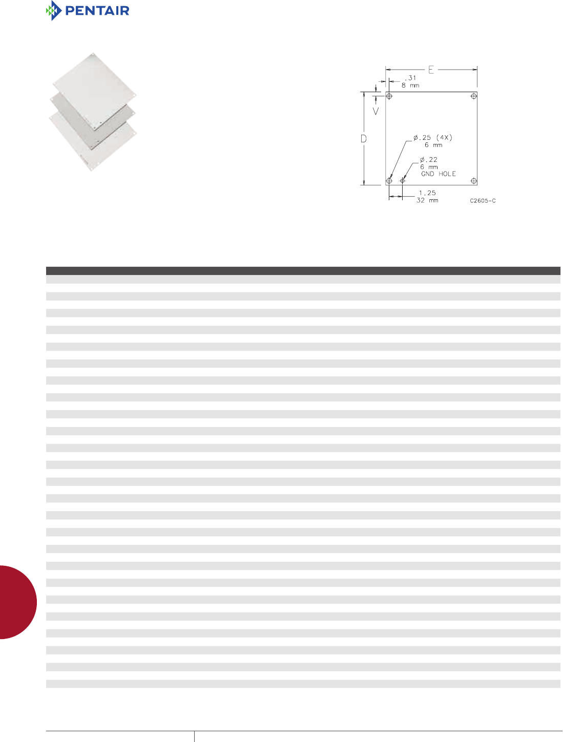
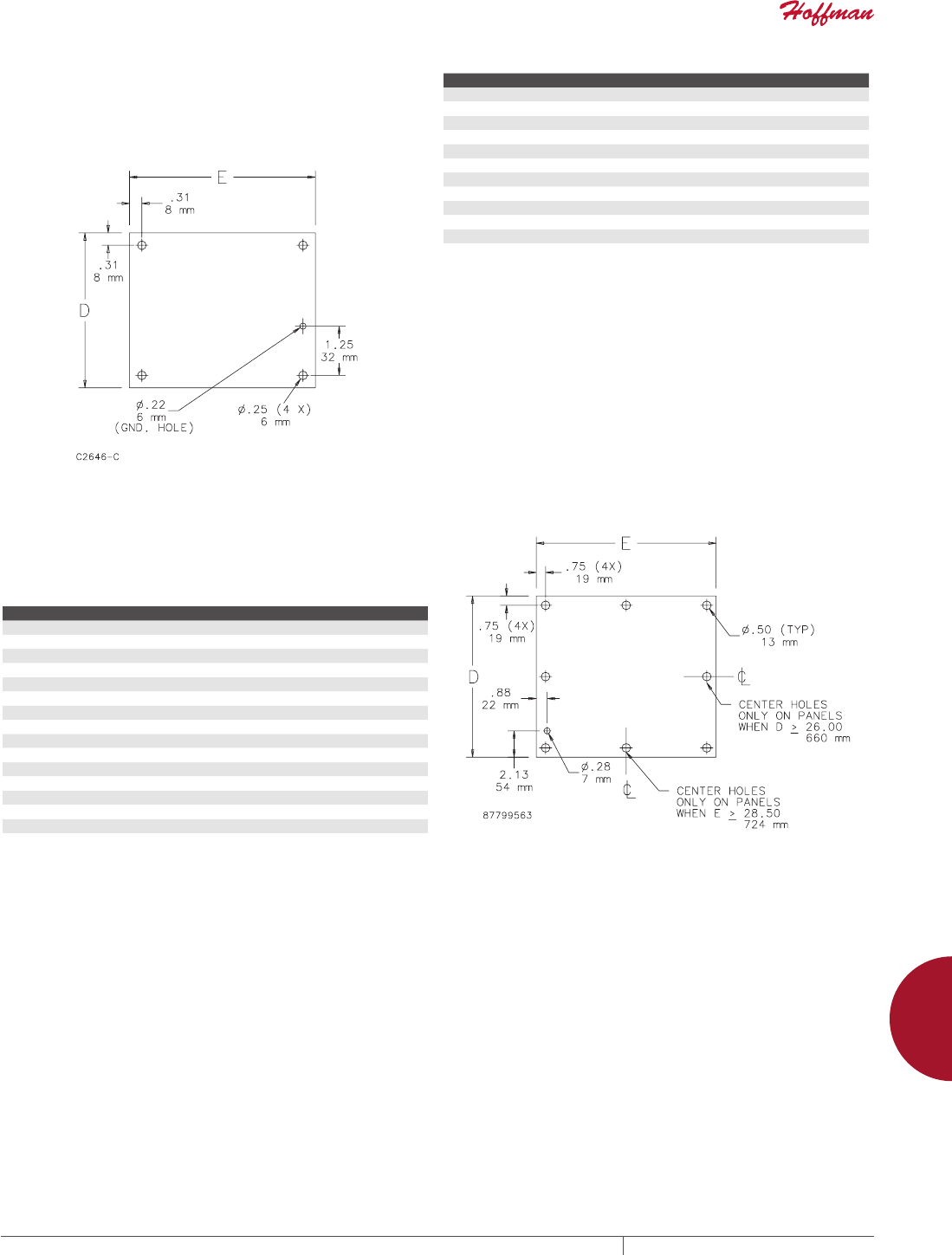
PANELS FOR JUNCTION BOXES
Steel panels are 14 gauge, finished with white polyester powder
paint or with a conductive, corrosion-resistant coating. Stainless
steel panels are 14 gauge Type 304 and have a commercial #2B
finish which is protected on one side with a plastic film. Aluminum
panels are 5052-H32 aluminum alloy 0.080-in. (2-mm) thick and
protected on one side with a plastic film. Panel mounting hardware
is furnished with all enclosures which accept these panels.
BULLETIN: PNLJ, PNLWM
Catalog Number Material Panel Size D x E (in.) Panel Size D x E (mm) V (in.) V (mm)
A4P4G Conductive 2.88 x 2.88 73 x 73 0.31 8
A6P4 Painted steel 4.88 x 2.88 124 x 73 0.31 8
A6P4G Conductive steel 4.88 x 2.88 124 x 73 0.31 8
A6P4SS Stainless Steel 4.88 x 2.88 124 x 73 0.31 8
A6P4AL Aluminum 4.88 x 2.88 124 x 73 0.31 8
A6P6 Painted steel 4.88 x 4.88 124 x 124 0.31 8
A6P6G Conductive steel 4.88 x 4.88 124 x 124 0.31 8
A6P6SS Stainless Steel 4.88 x 4.88 124 x 124 0.31 8
A6P6AL Aluminum 4.88 x 4.88 124 x 124 0.31 8
A7P7G Conductive 5.88 x 5.88 149 x 149 0.31 8
A8P6 Painted steel 6.75 x 4.88 171 x 124 0.25 6
A8P6G Conductive steel 6.75 x 4.88 171 x 124 0.25 6
A8P6SS Stainless Steel 6.75 x 4.88 171 x 124 0.25 6
A8P6AL Aluminum 6.75 x 4.88 171 x 124 0.25 6
A8P8 Painted steel 6.75 x 6.88 171 x 175 0.25 6
A8P8G Conductive Steel 6.75 x 6.88 171 x 175 0.25 6
A8P8AL Aluminum 6.75 x 6.88 171 x 175 0.25 6
A9P6G Conductive 7.38 x 4.63 187 x 118 0.31 8
A10P8 Painted steel 8.75 x 6.88 222 x 175 0.25 6
A10P8G Conductive steel 8.75 x 6.88 222 x 175 0.25 6
A10P8SS Stainless Steel 8.75 x 6.88 222 x 175 0.25 6
A10P8AL Aluminum 8.75 x 6.88 222 x 175 0.25 6
A10P10 Painted steel 8.75 x 8.88 222 x 226 0.25 6
A10P10G Conductive steel 8.75 x 8.88 222 x 226 0.25 6
A10P10AL Aluminum 8.75 x 8.88 222 x 226 0.25 6
A12P6 Painted steel 10.75 x 4.88 273 x 124 0.25 6
A12P6G Conductive steel 10.75 x 4.88 273 x 124 0.25 6
A12P10 Painted steel 10.75 x 8.88 273 x 226 0.25 6
A12P10G Conductive steel 10.75 x 8.88 273 x 226 0.25 6
A12P10SS Stainless Steel 10.75 x 8.88 273 x 226 0.25 6
A12P10AL Aluminum 10.75 x 8.88 273 x 226 0.25 6
A12P12 Painted steel 10.75 x 10.88 273 x 276 0.25 6
A12P12G Conductive steel 10.75 x 10.88 273 x 276 0.25 6
A12P12SS Stainless Steel 10.75 x 10.88 273 x 276 0.25 6
A14P8 Painted steel 12.75 x 6.88 324 x 175 0.25 6
A14P8G Conductive steel 12.75 x 6.88 324 x 175 0.25 6
A14P12 Painted steel 12.75 x 10.88 324 x 276 0.25 6
A14P12G Conductive steel 12.75 x 10.88 324 x 276 0.25 6
A14P12SS Stainless Steel 12.75 x 10.88 324 x 276 0.25 6
A14P12AL Aluminum 12.75 x 10.88 324 x 276 0.25 6
A16P10 Painted steel 14.75 x 8.88 375 x 226 0.25 6
A16P10G Conductive steel 14.75 x 8.88 375 x 226 0.25 6
A16P14 Painted steel 14.75 x 12.88 375 x 327 0.25 6
A16P14G Conductive steel 14.75 x 12.88 375 x 327 0.25 6
A16P14SS Stainless Steel 14.75 x 12.88 375 x 327 0.25 6
A16P14AL Aluminum 14.75 x 12.88 375 x 327 0.25 6
A18P16 Painted steel 16.75 x 14.88 425 x 378 0.25 6
A18P16G Conductive steel 16.75 x 14.88 425 x 378 0.25 6
A18P16SS Stainless Steel 16.75 x 14.88 425 x 378 0.25 6
A18P16AL Aluminum 16.75 x 14.88 425 x 378 0.25 6
PH 763.422.2211 • FAX 763.422.2600 • PENTAIRPROTECT.COMEQUIPMENT PROTECTION ACCESSORIES 883
12
PANELS AND PANEL ACCESSORIES Panels for enClosures
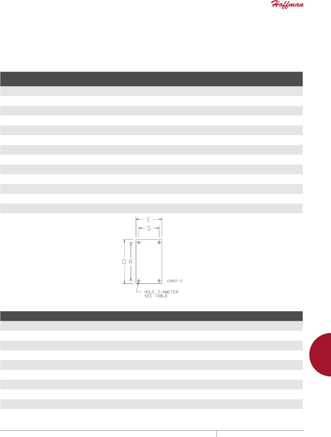
COMPOSITE PANELS FOR JUNCTION BOXES AND UL/NEMA WALLMOUNT ENCLOSURES
Manufactured from light-brown, reinforced phenolic laminate
sheet stock. This material has exceptional strength and chemical
resistance, which makes it ideally suited for the most corrosive
environments. Composite panels are intended for use in corrosion-
resistant enclosures. Panel sizes are available for junction boxes
and UL/NEMA size enclosures. Composite panels may be drilled
and tapped but work equally as well with self-threading or thread-
cutting screws. Refer to the table for recommended mounting
specifications.
BULLETIN: PNLC
Standard Product
Catalog Number
Panel Size
D x E
in./mm
R
in./mm
S
in./mm
Hole Dia.
in./mm
Panel
Thickness
in./mm
A6P4C 4.88 x 2.88
124 x 73
4.25
108
2.25
57
0.25
6
0.12
3
A6P6C 4.88 x 4.88
124 x 124
4.25
108
4.25
108
0.25
6
0.12
3
A8P6C 6.75 x 4.88
171 x 124
6.25
159
4.25
108
0.25
6
0.12
3
A10P8C 8.75 x 6.88
222 x 175
8.25
210
6.25
159
0.25
6
0.12
3
A12P10C 10.75 x 8.88
273 x 226
10.25
260
8.25
210
0.25
6
0.19
5
A14P12C 12.75 x 10.88
324 x 276
12.25
311
10.25
260
0.25
6
0.19
5
A16P14C 14.75 x 12.88
375 x 327
14.25
362
12.25
311
0.25
6
0.19
5
A18P16C 16.75 x 14.88
425 x 379
16.25
413
14.25
362
0.25
6
0.19
5
A20P16C 17.00 x 13.00
432 x 330
15.25
387
11.25
286
0.50
13
0.19
5
A20P20C 17.00 x 17.00
432 x 432
15.25
387
15.25
387
0.50
13
0.19
5
A24P20C 21.00 x 17.00
533 x 432
19.25
489
15.25
387
0.50
13
0.19
5
A24P24C 21.00 x 21.00
533 x 533
19.25
489
19.25
489
0.50
13
0.19
5
A30P24C 27.00 x 21.00
686 x 533
25.25
641
19.25
489
0.50
13
0.19
5
Composite Panel Mounting Recommendations
Screw Type Screw Size
Hole Size
in./mm
Max. Insertion Torque (lb.)
in 0.12 in. Material
Max. Insertion Torque (lb.)
in 0.19 in. Material
Max. Load (lb. per screw)
in 0.12 in. Material
Max. Load (lb. per screw)
in 0.19 in. Material
Machine (tapped hole) 8-32 .136
3
15 25 40 45
Machine (tapped hole) 10-32 .161
4
15 25 35 40
Machine (tapped hole) 1/4-20 .204
5
20 25 30 35
Thread Cutting Type T 8-32 .144
4
15 25 40 45
Thread Cutting Type T 10-32 .166
4
15 25 35 40
Thread Cutting Type T 1/4-20 .288
7
20 25 30 35
Sheet Metal A-B 8-32 .147
4
Not recommended 10 40 45
Sheet Metal A-B 10-32 .166
4
Not recommended 10 35 40
Sheet Metal A-B 1/4-20 .221
6
Not recommended 15 30 35
EQUIPMENT PROTECTIONSUBJECT TO CHANGE WITHOUT NOTICEACCESSORIES884
12
PANELS AND PANEL ACCESSORIES Panels for enClosures
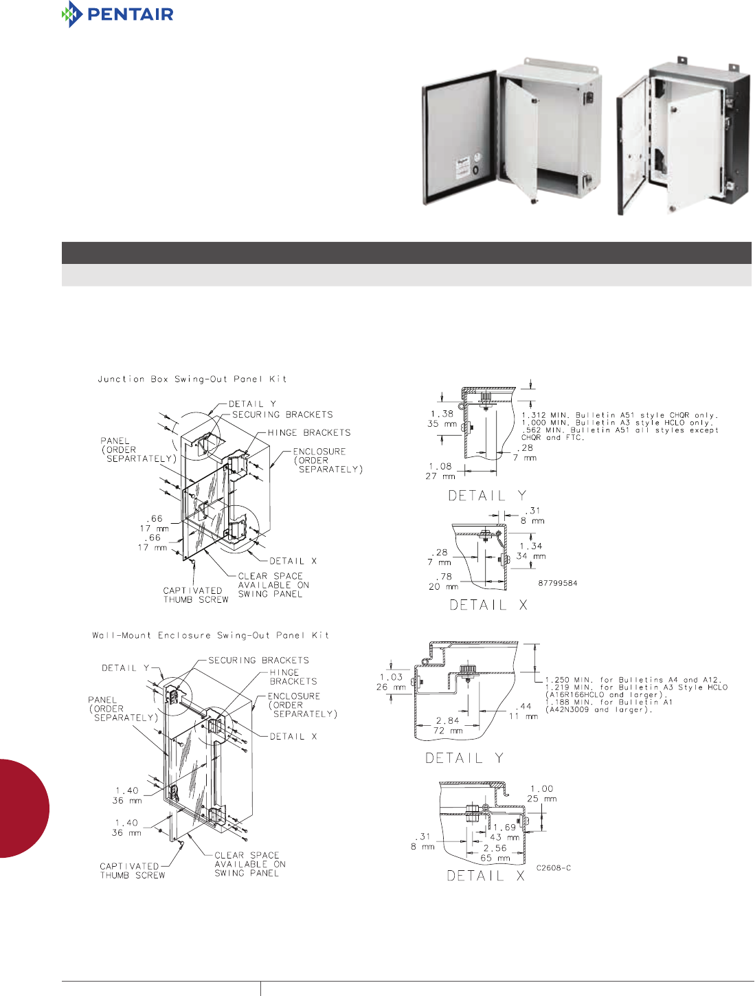
JUNCTION BOX AND WALLMOUNT ENCLOSURE
SWINGOUT PANEL KIT
Kits allow mounting standard Hoffman junction box and NEMA
style panels (purchase separately) near the front of the enclosure
for easy access to or reading of gauges, switches, pilot lights and
other components. Kits consist of heavy-gauge brackets and hinges
which are easily installed by drilling small holes in the sides of the
enclosure and bolting the brackets in place. External screws are
stainless steel; internal components are plated steel. All mounting
hardware and instructions are provided. Sealing washers ensure
the enclosure will meet original JIC or NEMA standards after
installation.
Swing-Out Panel Kits do not fit single-door disconnect enclosures.
BULLETIN: A80
Catalog Number Description
Maximum
Load (lb.)
Maximum
Load (kg) Use In
AJCDFK Junction Box Kit 25 11.3 - Junction boxes where A x B is 8.00 x 6.00 in. (203 x 152 mm) or larger
- HCLO Type 3R enclosures where A x B is 16.00 x 12.00 in. (406 x 305 mm) or smaller
ANADFK Wall-Mount Enclosure Kit 100 45.4 - One-door Type 4, 4X, 12 and 13 enclosures where A x B is 12.00 x 12.00 in. (305 x 305 mm) or larger
- HCLO Type 3R enclosures where A x B is 16.00 x 16.00 in. (406 x 406 mm) or larger
- HCR Type 3R enclosures where A x B is 16.00 x 12.00 (406 x 305 mm) or larger
- Type 1 enclosures where A x B is 42.00 x 30.00 in. (1067 x 762 mm) or larger
Both kits maintain UL Type 4 and Type 4X rating when properly installed in a Hoffman enclosure.
Maximum load includes the weight of the panel plus the weight of the components, with the weight of the components spread evenly over the panel.
PH 763.422.2211 • FAX 763.422.2600 • PENTAIRPROTECT.COMEQUIPMENT PROTECTION ACCESSORIES 885
12
PANELS AND PANEL ACCESSORIES Panels for enClosures
PANELS FOR TYPE 1 ENCLOSURES AND SMALL TYPE
3R ENCLOSURES
Steel panels are 14 gauge, finished with white polyester powder
paint. Panel mounting hardware is furnished with enclosure.
BULLETIN: PNLT1
Catalog Number Panel Size D x E (in.) Panel Size D x E (mm)
A6N4P 4.25 x 2.25 108 x 57
A6N6P 4.25 x 4.25 108 x 108
A8N6P 6.25 x 4.25 159 x 108
A8N8P 6.25 x 6.25 159 x 159
A10N8P 8.25 x 6.25 210 x 159
A10N10P 8.25 x 8.25 210 x 210
A12N10P 10.25 x 8.25 260 x 210
A12N12P 10.25 x 10.25 260 x 260
A14N12P 12.25 x 10.25 311 x 260
A16N12P 14.25 x 10.25 362 x 260
A20N12P 18.25 x 10.25 464 x 260
PANELS FOR MEDIUM TYPE 1 ENCLOSURES
Steel panels are 14 or 12 gauge with a white polyester powder paint
finish. Panel mounting hardware is furnished with enclosure.
BULLETIN: PNLT1
Catalog Number Panel Thickness (ga.) Panel Size D x E (in.) Panel Size D x E (mm)
A16N12MP 14 13.00 x 10.50 330 x 267
A20N12MP 14 17.00 x 10.50 432 x 267
A16N16MP 14 13.00 x 14.50 330 x 368
A20N16MP 14 17.00 x 14.50 432 x 368
A24N16MP 14 21.00 x 14.50 533 x 368
A18N18MP 14 15.00 x 16.50 381 x 419
A16N20MP 14 13.00 x 18.50 330 x 470
A20N20MP 14 17.00 x 18.50 432 x 470
A24N20MP 14 21.00 x 18.50 533 x 470
A30N20MP 14 26.00 x 18.50 660 x 470
A24N24MP 12 21.00 x 22.50 533 x 571
A30N24MP 12 26.00 x 22.50 660 x 571
A36N24MP 12 32.00 x 22.50 813 x 571
A30N30MP 12 26.00 x 28.50 660 x 724
A36N30MP 12 32.00 x 28.50 813 x 724

EQUIPMENT PROTECTIONSUBJECT TO CHANGE WITHOUT NOTICEACCESSORIES886
12
PANELS AND PANEL ACCESSORIES Panels for enClosures
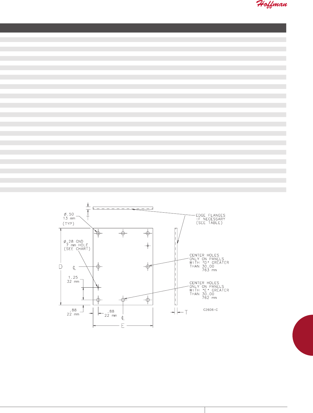
PANELS FOR TYPE 3R, 4, 4X, 12 AND 13 ENCLOSURES
Steel panels are 12 gauge, finished with white polyester powder paint or a conductive, corrosion-resistant coating. Larger panels have
flanges on two or four sides. Some larger steel panels are 10 gauge and include extra holes for panel lifting. Aluminum panels are 5052-
H32 aluminum alloy. Larger panels have flanges on four sides. Aluminum panels are protected on one side with a plastic film. Stainless
steel panels are Type 316 stainless steel. Panel mounting hardware is furnished with all enclosures which accept these panels.
BULLETIN: PNLFS, PNLJ, PNLWM
Catalog Number Material
Panel Size
D x E (in.)
Panel Size
D x E (mm)
Panel Gauge
or Thickness
Edge
Flanges T (in.) T (mm)
Number
of Holes
A12P24 Painted steel 9.00 x 21.00 229 x 533 12 ga. 0 — — 4
A12P24G Conductive steel 9.00 x 21.00 229 x 533 12 ga. 0 — — 4
A16P12 Painted steel 13.00 x 9.00 330 x 229 12 ga. 0 — — 4
A16P12G Conductive steel 13.00 x 9.00 330 x 229 12 ga. 0 — — 4
A16P12SS6 Stainless Steel 13.00 x 9.00 330 x 229 12 ga. 0 — — 4
A16P12AL Aluminum 13.00 x 9.00 330 x 229 0.10 in./3 mm 0 — — 4
A16P16 Painted steel 13.00 x 13.00 330 x 330 12 ga. 0 — — 4
A16P16G Conductive steel 13.00 x 13.00 330 x 330 12 ga. 0 — — 4
A16P16SS6 Stainless Steel 13.00 x 13.00 330 x 330 12 ga. 0 — — 4
A16P16AL Aluminum 13.00 x 13.00 330 x 330 0.10 in./3 mm 0 — — 4
A18P18 Painted steel 15.00 x 15.00 381 x 381 12 ga. 0 — — 4
A18P18G Conductive steel 15.00 x 15.00 381 x 381 12 ga. 0 — — 4
A20P12 Painted steel 17.00 x 9.00 432 x 229 12 ga. 0 — — 4
A20P12G Conductive steel 17.00 x 9.00 432 x 229 12 ga. 0 — — 4
A20P16 Painted steel 17.00 x 13.00 432 x 330 12 ga. 0 — — 4
A20P16G Conductive steel 17.00 x 13.00 432 x 330 12 ga. 0 — — 4
A20P16SS6 Stainless Steel 17.00 x 13.00 432 x 330 12 ga. 0 — — 4
A20P16AL Aluminum 17.00 x 13.00 432 x 330 0.10 in./3 mm 0 — — 4
A20P20 Painted steel 17.00 x 17.00 432 x 432 12 ga. 0 — — 4
A20P20G Conductive steel 17.00 x 17.00 432 x 432 12 ga. 0 — — 4
A20P20SS6 Stainless steel 17.00 x 17.00 432 x 432 12 ga. 0 — — 4
A20P20AL Aluminum 17.00 x 17.00 432 x 432 0.10 in./3 mm 0 — — 4
A24P16 Painted steel 21.00 x 13.00 533 x 330 12 ga. 0 — — 4
A24P16G Conductive steel 21.00 x 13.00 533 x 330 12 ga. 0 — — 4
A24P16SS6 Stainless Steel 21.00 x 13.00 533 x 330 12 ga. 0 — — 4
A24P20 Painted steel 21.00 x 17.00 533 x 432 12 ga. 2 0.75 19 4
A24P20G Conductive steel 21.00 x 17.00 533 x 432 12 ga. 2 0.75 19 4
A24P20SS6 Stainless Steel 21.00 x 17.00 533 x 432 12 ga. 2 0.75 19 4
A24P20AL Aluminum 21.00 x 17.00 533 x 432 0.10 in./3 mm 4 0.75 19 4
A24P24 Painted steel 21.00 x 21.00 533 x 533 12 ga. 2 0.75 19 4
A24P24G Conductive steel 21.00 x 21.00 533 x 533 12 ga. 2 0.75 19 4
A24P24SS6 Stainless Steel 21.00 x 21.00 533 x 533 12 ga. 2 0.75 19 4
A24P24AL Aluminum 21.00 x 21.00 533 x 533 0.10 in./3 mm 2 0.75 19 4
A30P16 Painted steel 27.00 x 13.00 686 x 330 12 ga. 2 0.75 19 4
A30P16G Conductive steel 33.00 x 27.00 838 x 686 12 ga. 2 0.75 19 4
A30P20 Painted steel 27.00 x 17.00 686 x 432 12 ga. 2 0.75 19 4
A30P20G Conductive steel 27.00 x 17.00 686 x 432 12 ga. 2 0.75 19 4
A30P20SS6 Stainless Steel 27.00 x 17.00 686 x 432 12 ga. 2 0.75 19 4
A30P24 Painted steel 27.00 x 21.00 686 x 533 12 ga. 2 0.75 19 4
A30P24G Conductive steel 27.00 x 21.00 686 x 533 12 ga. 2 0.75 19 4
A30P24SS6 Stainless Steel 27.00 x 21.00 686 x 533 12 ga. 2 0.75 19 4
A30P24AL Aluminum 27.00 x 21.00 686 x 533 0.10 in./3 mm 2 0.75 19 4
A30P30 Painted steel 27.00 x 27.00 686 x 686 12 ga. 4 0.75 19 4
A30P30G Conductive steel 27.00 x 27.00 686 x 686 12 ga. 4 0.75 19 4
A30P30SS6 Stainless Steel 27.00 x 27.00 686 x 686 12 ga. 4 0.75 19 4
A36P16 Painted steel 33.00 X 13.00 838 X 330 12 ga. 2 0.75 19 4
A36P16G Conductive steel 33.00 x 13.00 838 x 330 12 ga. 2 0.75 19 4
A36P24 Painted steel 33.00 x 21.00 838 x 533 12 ga. 2 0.75 19 6
A36P24G Conductive steel 33.00 x 21.00 838 x 533 12 ga. 2 0.75 19 6
A36P24SS6 Stainless Steel 33.00 x 21.00 838 x 533 12 ga. 2 0.75 19 6
A36P24AL Aluminum 33.00 x 21.00 838 x 533 0.10 in./3 mm 2 0.75 19 6
A36P30 Painted steel 33.00 x 27.00 838 x 686 12 ga. 4 0.75 19 6
A36P30G Conductive steel 33.00 x 27.00 838 x 686 12 ga. 4 0.75 19 6
A36P30SS6 Stainless Steel 33.00 x 27.00 838 x 686 12 ga. 4 0.75 19 6
A36P30AL Aluminum 33.00 x 27.00 838 x 686 0.10 in./3 mm 4 0.75 19 6
A36P36 Painted steel 33.00 x 33.00 838 x 838 12 ga. 4 0.75 19 8
A36P36G Conductive steel 33.00 x 33.00 838 x 838 12 ga. 4 0.75 19 8
A36P36SS6 Stainless Steel 33.00 x 33.00 838 x 838 12 ga. 4 0.75 19 8
A40P24 Painted steel 37.00 x 21.00 940 x 533 12 ga. 4 0.75 19 6
A40P24G Conductive steel 37.00 x 21.00 940 x 533 12 ga. 4 0.75 19 6
A40P30 Painted steel 37.00 x 29.00 940 x 737 12 ga. 4 0.75 19 4 (no D dim. center hole)
A40P30G Conductive steel 37.00 x 29.00 940 x 737 12 ga. 4 0.75 19 4 (no D dim. center hole)
A42P24 Painted steel 39.00 x 21.00 991 x 533 12 ga. 2 0.75 19 6
A42P24G Conductive steel 39.00 x 21.00 991 x 533 12 ga. 2 0.75 19 6
A42P30 Painted steel 39.00 x 27.00 991 x 686 12 ga. 4 0.75 19 6
A42P30G Conductive steel 39.00 x 27.00 991 x 686 12 ga. 4 0.75 19 6
A42P30SS6 Stainless Steel 39.00 x 27.00 991 x 686 12 ga. 4 0.75 19 6
A42P36 Painted steel 39.00 x 33.00 991 x 838 12 ga. 4 0.75 19 8
A42P36G Conductive steel 39.00 x 33.00 991 x 838 12 ga. 4 0.75 19 8
A42P36SS6 Stainless Steel 39.00 x 33.00 991 x 838 12 ga. 4 0.75 19 8
A42P42 Painted steel 39.00 x 39.00 991 x 991 12 ga. 4 0.75 19 8
PH 763.422.2211 • FAX 763.422.2600 • PENTAIRPROTECT.COMEQUIPMENT PROTECTION ACCESSORIES 887
12
PANELS AND PANEL ACCESSORIES Panels for enClosures
Catalog Number Material
Panel Size
D x E (in.)
Panel Size
D x E (mm)
Panel Gauge
or Thickness
Edge
Flanges T (in.) T (mm)
Number
of Holes
A42P42G Conductive steel 39.00 x 39.00 991 x 991 12 ga. 4 0.75 19 8
A48P24 Painted steel 45.00 x 21.00 1143 x 533 12 ga. 2 0.75 19 6
A48P24G Conductive steel 45.00 x 21.00 1143 x 533 12 ga. 2 0.75 19 6
A48P30 Painted steel 45.00 x 27.00 1143 x 686 12 ga. 4 0.75 19 6
A48P30G Conductive steel 45.00 x 27.00 1143 x 686 12 ga. 4 0.75 19 6
A48P36 Painted steel 45.00 x 33.00 1143 x 838 12 ga. 4 0.75 19 8
A48P36G Conductive steel 45.00 x 33.00 1143 x 838 12 ga. 4 0.75 19 8
A48P36SS6 Stainless Steel 45.00 x 33.00 1143 x 838 12 ga. 4 0.75 19 8
A48P36AL Aluminum 45.00 x 33.00 1143 x 838 0.10 in./3 mm 4 0.75 19 8
A48P42 Painted steel 45.00 x 39.00 1143 x 991 12 ga. 4 0.75 19 8
A48P42G Conductive steel 45.00 x 39.00 1143 x 991 12 ga. 4 0.75 19 8
A48P48 Painted steel 44.00 x 44.00 1118 x 1118 10 ga. 4 0.88 22 8
A48P48G Conductive steel 44.00 x 44.00 1118 x 1118 10 ga. 4 0.88 22 8
A54P42 Painted steel 50.00 x 38.00 1270 x 965 12 ga. 4 0.75 19 8
A54P42G Conductive steel 50.00 x 38.00 1270 x 965 10 ga. 4 0.75 19 8
A60P24 Painted steel 57.00 x 21.00 1448 x 533 12 ga. 4 0.75 19 6
A60P24G Conductive steel 57.00 x 21.00 1448 x 533 12 ga. 4 0.75 19 6
A60P30 Painted steel 57.00 x 27.00 1448 x 686 12 ga. 4 0.75 19 6
A60P30G Conductive steel 57.00 x 27.00 1448 x 686 12 ga. 4 0.75 19 6
A60P36 Painted steel 57.00 x 33.00 1448 x 838 12 ga. 4 0.75 19 8
A60P36G Conductive steel 57.00 x 33.00 1448 x 838 12 ga. 4 0.75 19 8
A60P36SS6 Stainless Steel 57.00 x 33.00 1448 x 838 12 ga. 4 0.75 19 8
A60P36AL Aluminum 57.00 x 33.00 1448 x 838 0.10 in./3 mm 4 0.75 19 8
A60BFP42 Painted steel 56.00 x 38.00 1422 x 965 10 ga. 4 0.88 22 10
A60BFP42G Conductive steel 56.00 x 38.00 1422 x 965 10 ga. 4 0.88 22 10
A60P48 Painted steel 56.00 x 44.00 1422 x 1118 10 ga. 4 0.88 22 12
A60P48G Conductive steel 56.00 x 44.00 1422 x 1118 10 ga. 4 0.88 22 12
A60P60 Painted steel 56.00 x 56.00 1422 x 1422 10 ga. 4 0.88 22 10
A60P60G Conductive steel 56.00 x 56.00 1422 x 1422 10 ga. 4 0.88 22 10
A72P36 Painted steel 69.00 x 33.00 1753 x 838 12 ga. 4 0.75 19 8
A72P36G Conductive steel 69.00 x 33.00 1753 x 838 12 ga. 4 0.75 19 8
A72P60 Painted steel 68.00 x 56.00 1727 x 1422 10 ga. 4 0.88 22 12
A72P60G Conductive steel 68.00 x 56.00 1727 x 1422 10 ga. 4 0.88 22 12
A72P72 Painted steel 68.00 x 68.00 1727 x 1727 10 ga. 4 0.88 22 10
A72P72G Conductive steel 68.00 x 68.00 1727 x 1727 10 ga. 4 0.88 22 10

EQUIPMENT PROTECTIONSUBJECT TO CHANGE WITHOUT NOTICEACCESSORIES888
12
PANELS AND PANEL ACCESSORIES Panels for enClosures
PANELS FOR LARGE BULLETIN A27, A28, A28S4 AND A34 MULTIDOOR ENCLOSURES
Extra panels for large enclosures (Bulletins A27, A28, A28S4 and A34) can be ordered for panel assembly prior to receiving the enclosures
(enclosures include panels). Panels are 10 gauge steel with .80-in. (20-mm) flanges on four sides. Finish is white polyester powder paint
or a conductive, corrosion-resistant coating. Two extra holes are provided for lifting and installing panels. Mounting hardware included
with enclosure.
BULLETIN: PNLFS
Catalog Number Finish
Panel Size
D x E (in.)
Panel Size
D x E (mm)
Number
of Holes
Fits
Enclosure
Height
A72PM28 Painted steel 60.00 x 21.75 1524 x 552 8 72 in.
A72PM28G Conductive 60.00 x 21.75 1524 x 552 8 72 in.
A72PM34 Painted steel 60.00 x 27.75 1524 x 705 8 72 in.
A72PM34G Conductive 60.00 x 27.75 1524 x 705 8 72 in.
A72PM40 Painted steel 60.00 x 33.75 1524 x 857 8 72 in.
A72PM40G Conductive 60.00 x 33.75 1829 x 857 8 72 in.
A72PM54 Painted steel 60.00 x 48.00 1524 x 1219 10 72 in.
A72PM54G Conductive 60.00 x 48.00 1524 x 1219 10 72 in.
A72PM66 Painted steel 60.00 x 60.00 1524 x 1524 10 72 in.
A72PM66G Conductive 60.00 x 60.00 1524 x 1524 10 72 in.
A72PM78 Painted steel 60.00 x 72.00 1524 x 1829 12 72 in.
A72PM78G Conductive 60.00 x 72.00 1524 x 1829 12 72 in.
A84PM40 Painted steel 72.00 x 33.75 1829 x 857 8 84 in.
A84PM40G Conductive 72.00 x 33.75 1829 x 857 8 84 in.
A84PM78 Painted steel 72.00 x 72.00 1829 x 1829 12 84 in.
A84PM78G Conductive 72.00 x 72.00 1829 x 1829 12 84 in.
A86PM37 Painted steel 78.00 x 34.00 1981 x 864 8 86 in.
A86PM37G Conductive 78.00 x 34.00 1981 x 864 8 86 in.
A86PM75 Painted steel 78.00 x 70.00 1981 x 1778 12 86 in.
A86PM75G Conductive 78.00 x 70.00 1981 x 1778 12 86 in.
A90PM40 Painted steel 78.00 x 33.75 1981 x 857 8 90 in.
A90PM40G Conductive 78.00 x 33.75 1981 x 857 8 90 in.
A90PM78 Painted steel 78.00 x 72.00 1981 x 1829 12 90 in.
A90PM78G Conductive 78.00 x 72.00 1981 x 1829 12 90 in.

PH 763.422.2211 • FAX 763.422.2600 • PENTAIRPROTECT.COMEQUIPMENT PROTECTION ACCESSORIES 889
12
PANELS AND PANEL ACCESSORIES Panels for enClosures
PANELS FOR FREESTAND TYPE 1 LARGE ONEDOOR ENCLOSURES
Panels for free-stand Type 1 large one-door standard and disconnect enclosures are 12 gauge steel. Panels have either polyester powder
paint finish or a conductive, corrosion-resistant coating.
BULLETIN: A26P, A38P
Catalog Number Finish
Panel Size
D x E (in.)
Panel Size
D x E (mm)
A37P21N Painted steel 37.16 x 21.50 944 x 546
A37P21NG Conductive 37.16 x 21.50 944 x 546
A49P21N Painted steel 49.16 x 21.50 1249 x 546
A49P21NG Conductive 49.16 x 21.50 1249 x 546
A61P21N Painted steel 61.16 x 21.50 1553 x 546
A73P21N Painted steel 73.16 x 21.50 1858 x 546
A73P21NG Conductive 73.16 x 21.50 1858 x 546
A49P32N Painted steel 49.16 x 32.00 1249 x 813
A49P32NG Conductive 49.16 x 32.00 1249 x 813
A61P32N Painted steel 61.16 x 32.00 1553 x 813
A61P32NG Conductive 61.16 x 32.00 1553 x 813
A73P32N Painted steel 73.16 x 32.00 1858 x 813
A73P32NG Conductive 73.16 x 32.00 1858 x 813
PANELS FOR FREESTAND TYPE 1 LARGE TWODOOR ENCLOSURES
Panels for free-stand Type 1 large two-door standard and disconnect enclosures are 10 gauge steel. Panels have either polyester powder
paint finish or a conductive, corrosion-resistant coating.
BULLETIN: A38P
Catalog Number Finish
Panel Size
D x E (in.)
Panel Size
D x E (mm)
A37P48N Painted steel 37.16 x 48.00 944 x 1219
A37P48NG Conductive 37.16 x 48.00 944 x 1219
A49P48N Painted steel 49.16 x 48.00 1249 x 1219
A49P48NG Conductive 49.16 x 48.00 1249 x 1219
A49P68N Painted steel 49.16 x 68.00 1249 x 1727
A49P68NG Conductive 49.16 x 68.00 1249 x 1727
A61P68N Painted steel 61.16 x 68.00 1553 x 1727
A61P68NG Conductive 61.16 x 68.00 1553 x 1727
A73P68N Painted steel 73.16 x 68.00 1858 x 1727
A73P68NG Conductive 73.16 x 68.00 1858 x 1727
EQUIPMENT PROTECTIONSUBJECT TO CHANGE WITHOUT NOTICEACCESSORIES890
12
PANELS AND PANEL ACCESSORIES Panels for enClosures
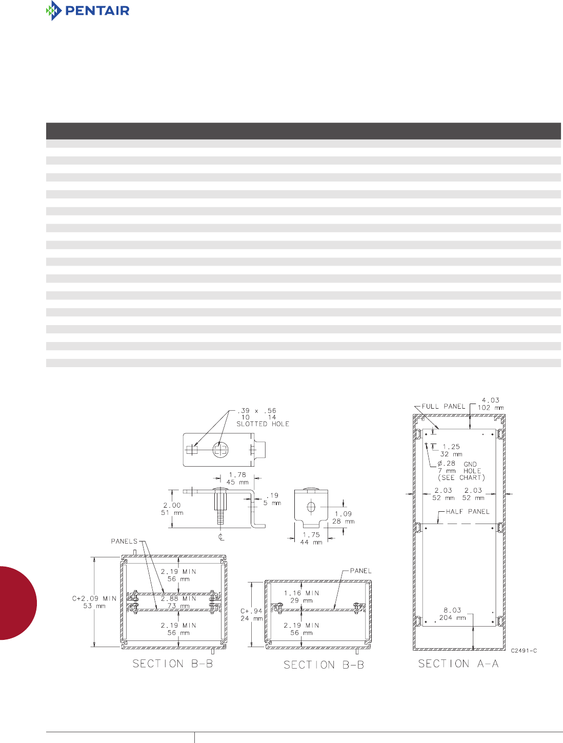
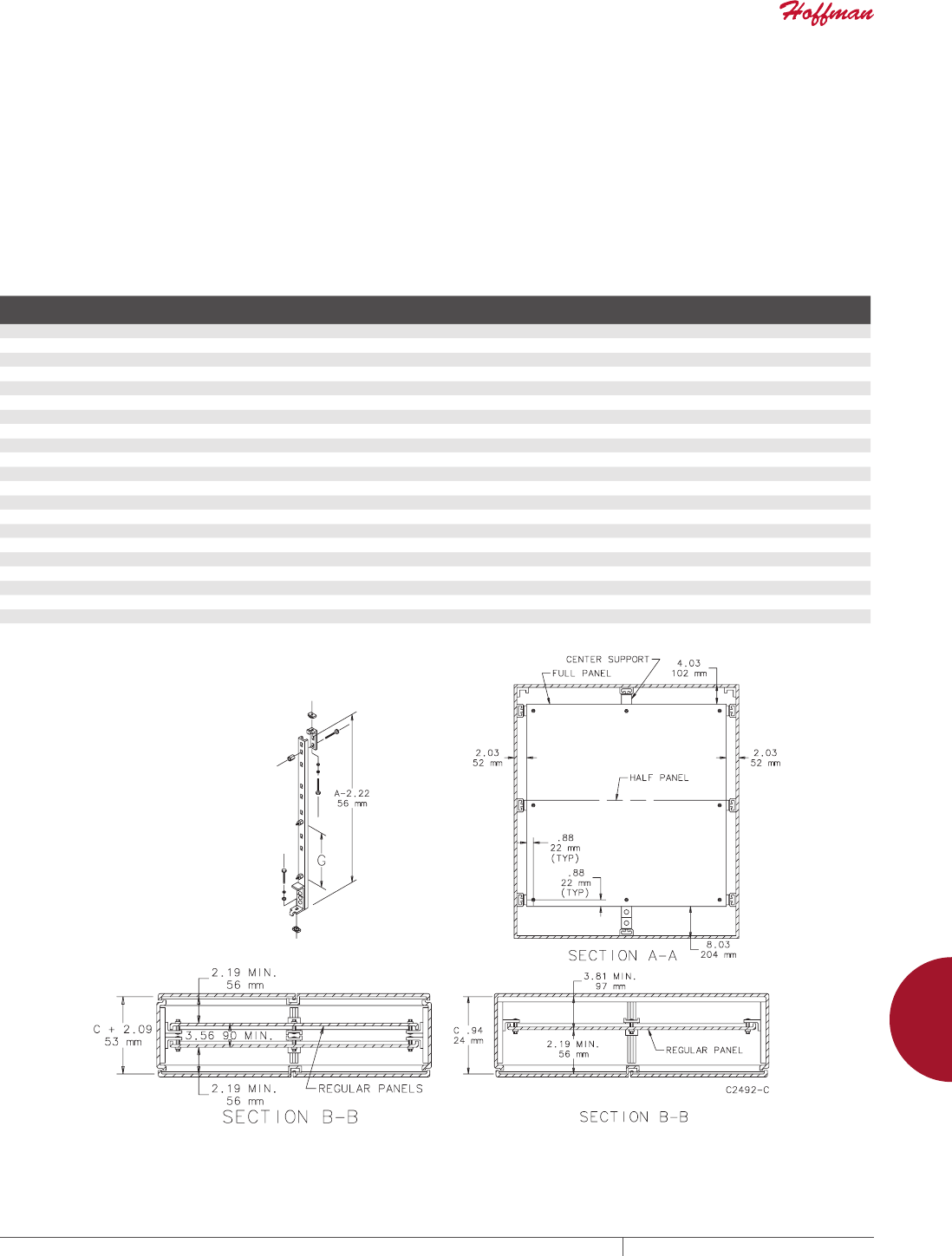
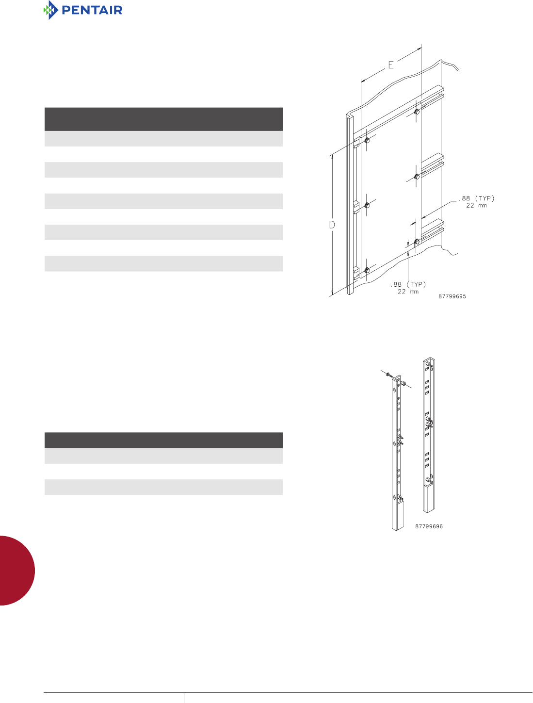
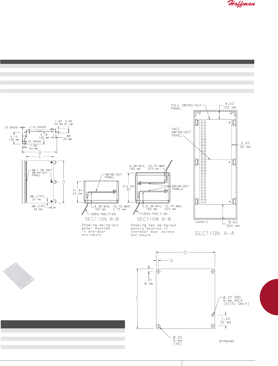
PANELS FOR FREESTAND TYPE 4, 4X AND 12 SINGLE AND DUALACCESS ONEDOOR ENCLOSURES WITH
MOUNTING CHANNEL
Panels for one-door, single-access and one-door, dual-access Free-Stand Type 12 Enclosures, Free-Stand Type 4 Enclosures and One-
Door Type 4X Free-Stand Fiberglass Enclosures. Panels are 12 gauge steel and can be positioned anywhere along horizontal mounting
channels (see dimension drawing Sections B-B for limitations). Half-length panels can be located in the upper or lower portion of the
enclosure. Panels are finished with white polyester powder paint or a conductive, corrosion-resistant coating and furnished with plated
mounting hardware.
BULLETIN: PNL30, PNLFS
Catalog Number Description Finish Panel Size (in.) Panel Size (mm)
Fits Enclosure
A x B (in.)
Fits Enclosure
A x B (mm)
A60P24F1 Full Panel Painted steel 48.00 x 20.00 1218 x 508 60.00 x 24.00 1524 x 610
A60P24F1G Full Panel Conductive 48.00 x 20.00 1218 x 508 60.00 x 24.00 1524 x 610
A60P24F2 Half Panel Painted steel 24.88 x 20.00 632 x 508 60.00 x 24.00 1524 x 610
A60P24F2G Half Panel Conductive 24.88 x 20.00 632 x 508 60.00 x 24.00 1524 x 610
A72P24F1 Full Panel Painted steel 60.00 x 20.00 1524 x 508 72.00 x 24.00 1829 x 610
A72P24F1G Full Panel Conductive 60.00 x 20.00 1524 x 508 72.00 x 24.00 1829 x 610
A72P24F2 Half Panel Painted steel 30.88 x 20.00 784 x 508 72.00 x 24.00 1829 x 610
A72P24F2G Half Panel Conductive 30.88 x 20.00 784 x 508 72.00 x 24.00 1829 x 610
A90P24F1 Full Panel Painted steel 78.00 x 20.00 1981 x 508 90.00 x 24.00 2286 x 610
A90P24F1G Full Panel Conductive 78.00 x 20.00 1981 x 508 90.00 x 24.00 2286 x 610
A90P24F2 Half Panel Painted steel 39.88 x 20.00 1013 x 508 90.00 x 24.00 2286 x 610
A90P24F2G Half Panel Conductive 39.88 x 20.00 1013 x 508 90.00 x 24.00 2286 x 610
A72P30F1 Full Panel Painted steel 60.00 x 26.00 1524 x 660 72.00 x 30.00 1829 x 762
A72P30F1G Full Panel Conductive 60.00 x 26.00 1524 x 660 72.00 x 30.00 1829 x 762
A72P30F2 Half Panel Painted steel 30.88 x 26.00 784 x 660 72.00 x 30.00 1829 x 762
A72P30F2G Half Panel Conductive 30.88 x 26.00 784 x 660 72.00 x 30.00 1829 x 762
A60P36F1 Full Panel Painted steel 48.00 x 32.00 1219 x 813 60.00 x 36.00 1524 x 914
A60P36F1G Full Panel Conductive 48.00 x 32.00 1219 x 813 60.00 x 36.00 1524 x 914
A60P36F2 Half Panel Painted steel 24.88 x 32.00 632 x 813 60.00 x 36.00 1524 x 914
A60P36F2G Half Panel Conductive 24.88 x 32.00 632 x 813 60.00 x 36.00 1524 x 914
A72P36F1 Full Panel Painted steel 60.00 x 32.00 1524 x 813 72.00 x 36.00 1829 x 914
A72P36F1G Full Panel Conductive 60.00 x 32.00 1524 x 813 72.00 x 36.00 1829 x 914
A72P36F2 Half Panel Painted steel 30.88 x 32.00 784 x 813 72.00 x 36.00 1829 x 914
A72P36F2G Half Panel Conductive 30.88 x 32.00 784 x 813 72.00 x 36.00 1829 x 914
A90P36F1 Full Panel Painted steel 78.00 x 32.00 1981 x 813 90.00 x 36.00 2286 x 914
A90P36F1G Full Panel Conductive 78.00 x 32.00 1981 x 813 90.00 x 36.00 2286 x 914
A90P36F2 Half Panel Painted steel 39.88 x 32.00 1013 x 813 90.00 x 36.00 2286 x 914
A90P36F2G Half Panel Conductive 39.88 x 32.00 1013 x 813 90.00 x 36.00 2286 x 914
Use combinations of panels for 3-5 door A 28 enclosures.
PH 763.422.2211 • FAX 763.422.2600 • PENTAIRPROTECT.COMEQUIPMENT PROTECTION ACCESSORIES 891
12
PANELS AND PANEL ACCESSORIES Panels for enClosures
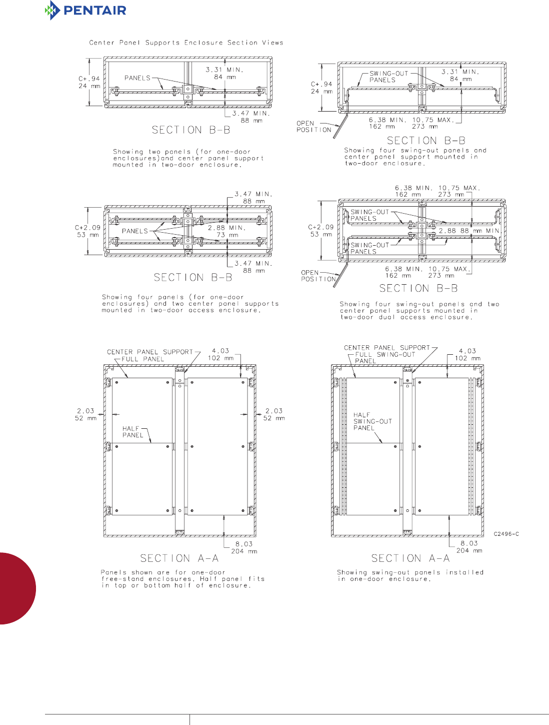
PANELS FOR FREESTAND TYPE 4, 4X AND 12 SINGLE AND DUALACCESS TWODOOR ENCLOSURES WITH
MOUNTING CHANNEL
Panels for two-door single access and two-door dual access Free-Stand Type 4, 4X and 12 Enclosures with mounting channel are 10 gauge
steel and can be positioned anywhere along horizontal mounting channels (see Sections B-B for limitations). Half-length panels can be
located in the upper or lower portion of the enclosure. Some assembly is required.
Panels are finished with white polyester powder paint or a conductive, corrosion-resistant coating and furnished with plated mounting
hardware.
Center support is furnished with each full panel or half panel for two-door enclosures. The center support attaches to the top and bottom
mounting channels and can be positioned from front to back in the enclosure. The center support can be used with heavy duty panel
supports to support panels of various heights.
BULLETIN: PNL30, PNLFS
Catalog Number Description
Fits Enclosure
A x B (in.)
Fits Enclosure
A x B (mm) Panel Size (in.) Panel Size (mm) G (in.) G (mm)
A60P48F1 Full Panel 60.00 x 48.00 1524 x 1219 48.00 x 44.00 1219 x 1118 23.12 587
A60P48F1G Full Panel 60.00 x 48.00 1524 x 1219 48.00 x 44.00 1219 x 1118 23.12 587
A72P48F1 Full Panel 72.00 x 48.00 1829 x 1219 60.00 x 44.00 1524 x 1118 29.12 740
A72P48F1G Full Panel 72.00 x 48.00 1829 x 1219 60.00 x 44.00 1524 x 1118 29.12 740
A72P48F2 Half Panel 72.00 x 48.00 1829 x 1219 30.88 x 44.00 784 x 1118 29.12 740
A72P48F2G Half Panel 72.00 x 48.00 1829 x 1219 30.88 x 44.00 784 x 1118 29.12 740
A90P48F1 Full Panel 90.00 x 48.00 2286 x 1219 78.00 x 44.00 1981 x 1118 38.12 968
A90P48F1G Full Panel 90.00 x 48.00 2286 x 1219 78.00 x 44.00 1981 x 1118 38.12 968
A90P48F2 Half Panel 90.00 x 48.00 2286 x 1219 39.88 x 44.00 1013 x 1118 38.12 968
A90P48F2G Half Panel 90.00 x 48.00 2286 x 1219 39.88 x 44.00 1013 x 1118 38.12 968
A72P60F1 Full Panel 72.00 x 60.00 1829 x 1524 60.00 x 56.00 1524 x 1422 29.12 740
A72P60F1G Full Panel 72.00 x 60.00 1829 x 1524 60.00 x 56.00 1524 x 1422 29.12 740
A72P60F2 Half Panel 72.00 x 60.00 1829 x 1524 30.88 x 56.00 784 x 1422 29.12 740
A72P60F2G Half Panel 72.00 x 60.00 1829 x 1524 30.88 x 56.00 784 x 1422 29.12 740
A72P72F1 Full Panel 72.00 x 72.00 1829 x 1829 60.00 x 68.00 1524 x 1727 29.12 740
A72P72F1G Full Panel 72.00 x 72.00 1829 x 1829 60.00 x 68.00 1524 x 1727 29.12 740
A72P72F2 Half Panel 72.00 x 72.00 1829 x 1829 30.88 x 68.00 784 x 1727 29.12 740
A72P72F2G Half Panel 72.00 x 72.00 1829 x 1829 30.88 x 68.00 784 x 1727 29.12 740
A90P72F1 Full Panel 90.00 x 72.00 2286 x 1829 78.00 x 68.00 1981 x 1727 38.12 968
A90P72F1G Full Panel 90.00 x 72.00 2286 x 1829 78.00 x 68.00 1981 x 1727 38.12 968
A90P72F2 Half Panel 90.00 x 72.00 2286 x 1829 39.88 x 68.00 1013 x 1727 38.12 968
A90P72F2G Half Panel 90.00 x 72.00 2286 x 1829 39.88 x 68.00 1013 x 1727 38.12 968
EQUIPMENT PROTECTIONSUBJECT TO CHANGE WITHOUT NOTICEACCESSORIES892
12
PANELS AND PANEL ACCESSORIES Panels for enClosures
SIDEMOUNTED PANELS
Panels provide extra mounting space on the sides of enclosures.
12 gauge steel side-mounting panels are painted white. Conductive
panels are steel with a conductive, corrosion-resistant coating.
Panels attach securely to mounting channels. Plated steel mounting
hardware is furnished.
BULLETIN: PNL30, PNLFS
Catalog Number Description
Panel Size
D x E
in./mm
Fits
Enclosure A
in./mm
A60SMP14 Painted steel 48.00 x 14.00
1219 x 356
60.00
1524
A60SMP14G Conductive 48.00 x 14.00
1219 x 356
60.00
1524
A72SMP14 Painted steel 60.00 x 14.00
1524 x 356
72.00
1829
A72SMP14G Conductive 60.00 x 14.00
1524 x 356
72.00
1829
A72SMP20 Painted steel 60.00 x 20.00
1524 x 508
72.00
1829
A72SMP20G Conductive 60.00 x 20.00
1524 x 508
72.00
1829
A90SMP14 Painted steel 78.00 x 14.00
1981 x 356
90.00
2286
A90SMP14G Conductive 78.00 x 14.00
1981 x 356
90.00
2286
A90SMP20 Painted steel 78.00 x 20.00
1981 x 508
90.00
2286
A90SMP20G Conductive 78.00 x 20.00
1981 x 508
90.00
2286
A90SMP14 and A90SMP14G will not fit 18.06-in.deep two-door enclosures (FSD style) if regular panel is also
installed.
A90SMP20 and A90SMP20G will not fit 20.12-in. deep enclosures. Will not fit 24.12-in. deep two-door
enclosures (FSD style) if regular panel is also installed.
HEAVY DUTY PANEL SUPPORTS
Heavy Duty Panel Supports, sold in pairs, are used in place of
the panel supports furnished with panels when heavy equipment
will be installed on the panels. They extend to the bottom of the
enclosure. Adjustable mounting studs allow mounting of different
height panels or a combination of panels. Use mounting hardware
furnished with panels.
BULLETIN: A80
Catalog Number
Fits Enclosure A
in./mm
Support Length
in./mm
A60FSHDPS 60.00
1524
57.25
1454
A72FSHDPS 72.00
1829
69.25
1759
A90FSHDPS 90.00
2286
87.25
2216
PH 763.422.2211 • FAX 763.422.2600 • PENTAIRPROTECT.COMEQUIPMENT PROTECTION ACCESSORIES 893
12
PANELS AND PANEL ACCESSORIES Panels for enClosures
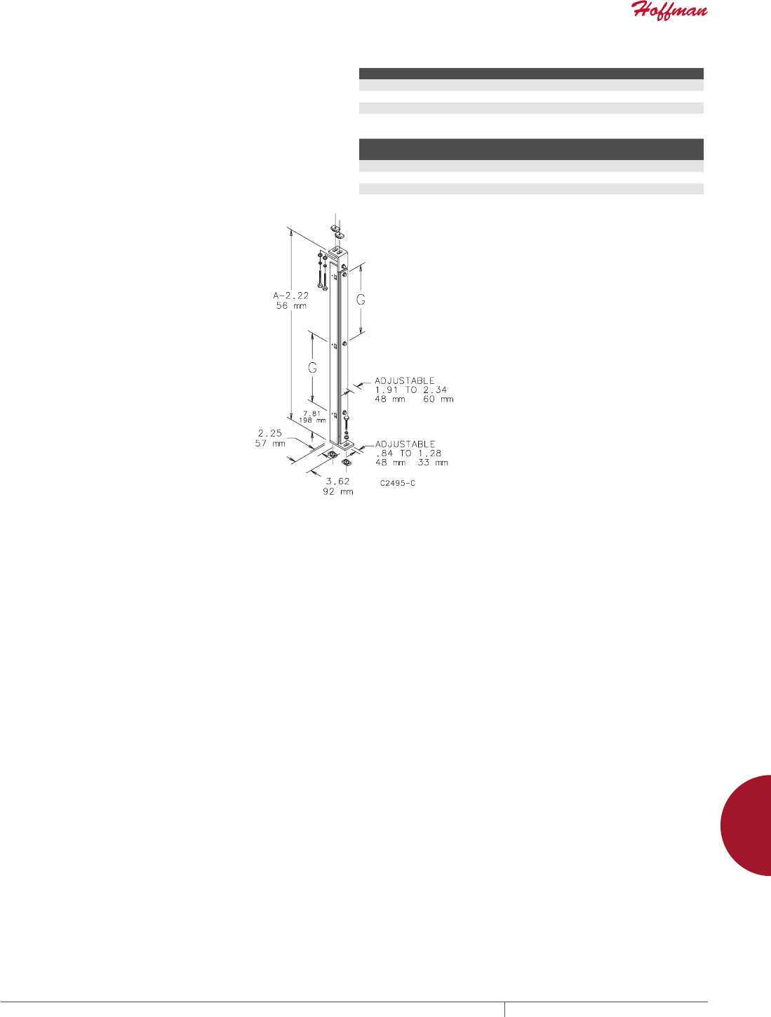
CENTER PANEL SUPPORTS
Center panel supports are used with Free-Stand Type 12 (Bulletin
A30) two-door enclosures. They permit the installation of panels,
swing-out panels and rack-mounting angles sized for one-door
enclosures. The Center Panel Support can be positioned from front
to back of the enclosure.
BULLETIN: A80
Standard Product Panel Supports
Catalog Number Fits Enclosure A (in.) Fits Enclosure A (mm) G (in.) G (mm)
A60FSCPS 60.00 1524 23.12 587
A72FSCPS 72.00 1829 29.12 740
A90FSCPS 90.00 2286 38.12 968
Accessory Width with Center Panel Supports
Two Door Enclosure Width
(in.)
Two Door Enclosure Width
(mm)
Accessory Width
(in.)
Accessory Width
(mm)
48.00 1219 24.00 610
60.00 1524 30.00 762
72.00 1829 36.00 914
EQUIPMENT PROTECTIONSUBJECT TO CHANGE WITHOUT NOTICEACCESSORIES894
12
PANELS AND PANEL ACCESSORIES Panels for enClosures
PH 763.422.2211 • FAX 763.422.2600 • PENTAIRPROTECT.COMEQUIPMENT PROTECTION ACCESSORIES 895
12
PANELS AND PANEL ACCESSORIES Panels for enClosures
SWINGOUT PANELS FOR FREESTAND TYPE 4, 4X AND 12 ENCLOSURES WITH MOUNTING CHANNEL
Panels for Free-Stand Type 12 Enclosures, Free-Stand Type 4 Enclosures and One-Door Type 4X Free-Stand Fiberglass Enclosures.
Full-length and half-length swing-out panels are available. Half-length panels can be located in the upper or lower portion of the
enclosures. Swing-out panels have a 10 gauge steel support frame and two heavy-gauge continuous hinges which permit the panel to
swing completely out of the enclosure if it is located within approximately 10.75 in. (273 mm) of the door. These panels are 12 gauge steel
and can be mounted on either side of the enclosure. Panels are finished with white polyester powder paint and furnished with plated
mounting hardware.
BULLETIN: PNL30
Catalog Number Description Panel Size D x E (in.) Panel Size D x E (mm) Fits Enclosure A x B (in.) Fits Enclosure A x B (mm) Q (in.) Q (mm)
A72SP24F3 Full Panel 60.00 x 18.81 1524 x 478 72.00 x 24.00 1829 x 610 21.84 555
A72SP24F4 Half Panel 30.88 x 18.81 784 x 478 72.00 x 24.00 1829 x 610 21.84 555
A72SP30F3 Full Panel 60.00 x 24.81 1524 x 630 72.00 x 30.00 1829 x 762 27.84 707
A72SP30F4 Half Panel 30.88 x 24.81 784 x 630 72.00 x 30.00 1829 x 762 27.84 707
A72SP36F3 Full Panel 60.00 x 30.81 1524 x 783 72.00 x 36.00 1829 x 914 33.84 860
A72SP36F4 Half Panel 30.88 x 30.81 784 x 783 72.00 x 36.00 1829 x 914 33.84 860
A90SP36F3 Full Panel 78.00 x 30.81 1981 x 783 90.00 x 36.00 2286 x 914 33.84 860
A90SP36F4 Half Panel 39.88 x 30.81 1013 x 783 90.00 x 36.00 2286 x 914 33.84 860
PANELS FOR WIFI CABINETS AND SMALL WALL
MOUNT ENCLOSURES
Panels are available in both steel and wood. Steel panels are 14
gauge steel with a white polyester powder paint finish. Wood panels
are 3/4-in. plywood and are unfinished. Wood panels are supplied
with Fiberglass Hinged-Cover and POLYPRO Type 4X WiFi Cabinets.
BULLETIN: DWS12, PNLJ, PNLWM
Catalog Number Material
Panel Size
D x E (in.)
Panel Size
D x E (mm) V (in.) V (mm)
A6P6 Steel 4.88 x 4.88 124 x 124 0.31 8
A6P6WD Wood 4.88 x 4.88 124 x 124 0.31 8
A16P14 Steel 14.75 x 12.88 375 x 327 0.25 6
A16P14WD Wood 14.75 x 12.88 375 x 327 0.25 6
A18P16 Steel 16.75 x 14.88 425 x 378 0.25 6
A18P16WD Wood 16.75 x 14.88 425 x 378 0.25 6
EQUIPMENT PROTECTIONSUBJECT TO CHANGE WITHOUT NOTICEACCESSORIES896
12
PANELS AND PANEL ACCESSORIES Panels for oPen frame raCks
PANELS FOR OPEN F RAME RACKS
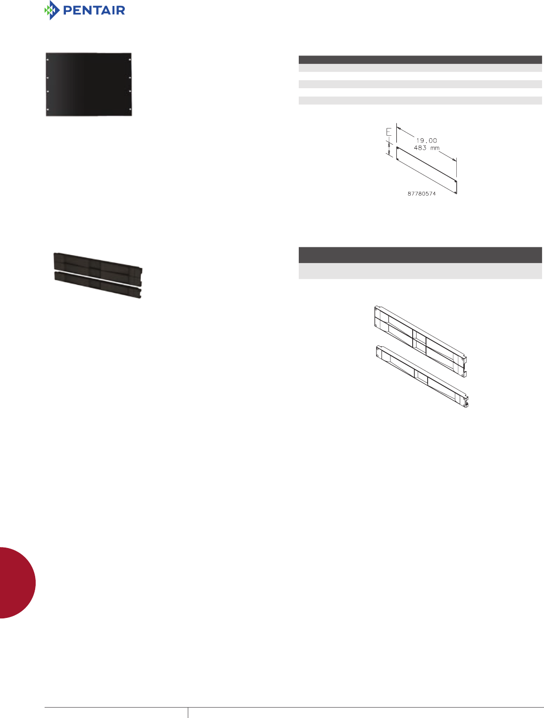
RACK PANEL FOR 19IN. RACKS
Used to cover unused rack space
in cabinets or open frame racks
for a finished appearance. Can
also be used for surface mounting
small devices. Panels are flat with
mounting slots spaced at 19-in. EIA
standard spacing. Made of 12 gauge
steel with RAL 9005 black polyester
powder paint finish. Mounting
hardware sold separately.
BULLETIN: DOFRY
Catalog Number Rack Units E (in.) E (mm)
P19RPP1UB 1 1.75 44
P19RPP2UB 2 3.50 89
P19RPP3UB 3 5.25 133
P19RPP4UB 4 7.00 178
P19RPP5UB 5 8.75 222
P19RPP6UB 6 10.50 267
TOOLLESS (SNAPIN) BLANKING PANELS FOR 19IN. RACKS
These Tool-less 19-in. Blanking
Panels provide easy tool-less
installation and ensure proper
airflow to equipment. Made of black
composite material and can be used
with tapped or square EIA universal
spaced rack mounting angles.
BULLETIN: DACCY
Catalog Number Description
Rack
Units Fits
Pkg.
Qty.
D19BPT1RU Blanking Panel, 19 in. 1 19 in., universal rack spacing,
tapped or square holes
10
D19BPT2RU Blanking Panel, 19 in. 2 19 in., universal rack spacing,
tapped or square holes
10
PH 763.422.2211 • FAX 763.422.2600 • PENTAIRPROTECT.COMEQUIPMENT PROTECTION ACCESSORIES 897
12
PANELS AND PANEL ACCESSORIES Panels for oPen frame raCks
RACK PANELS Rack Panels are available in aluminum and painted steel. Aluminum
Rack Panels are .125-in.-thick 5052-H32 alloy. Steel Rack Panels
are 12 gauge steel and finished in RAL 7035 textured light-gray
polyester powder paint. All panels are flat with oblong holes
positioned at EIA standard spacing. Mounting hardware is sold
separately.
BULLETIN: P20
Catalog Number Material Rack Angle Size Rack Units
P19RP1UA Aluminum 19 in. 1
P19RP1UP Steel 19 in. 1
P19RP2UA Aluminum 19 in. 2
P19RP2UP Steel 19 in. 2
P19RP3UA Aluminum 19 in. 3
P19RP3UP Steel 19 in. 3
P19RP4UA Aluminum 19 in. 4
P19RP4UP Steel 19 in. 4
P19RP5UA Aluminum 19 in. 5
P19RP5UP Steel 19 in. 5
P19RP6UP Steel 19 in. 6
P19RP6UA Aluminum 19 in. 6
P19RP7UA Aluminum 19 in. 7
P19RP7UP Steel 19 in. 7
P19RP8UP Steel 19 in. 8
P19RP8UA Aluminum 19 in. 8
P19RP9UA Aluminum 19 in. 9
P19RP9UP Steel 19 in. 9
P19RP10UA Aluminum 19 in. 10
P19RP10UP Steel 19 in. 10
P19RP11UA Aluminum 19 in. 11
P19RP11UP Steel 19 in. 11
P19RP12UA Aluminum 19 in. 12
P19RP12UP Steel 19 in. 12
P19RP16UA Aluminum 19 in. 16
P19RP16UP Steel 19 in. 16
P23RP1UA Aluminum 23 in. 1
P23RP1UP Steel 23 in. 1
P23RP2UP Steel 23 in. 2
P23RP3UA Aluminum 23 in. 3
P23RP3UP Steel 23 in. 3
P23RP4UA Aluminum 23 in. 4
P23RP4UP Steel 23 in. 4
P24RP2UA Aluminum 24 in. 2
P24RP2UP Steel 24 in. 2
P24RP3UP Steel 24 in. 3
P24RP4UA Aluminum 24 in. 4
P24RP4UP Steel 24 in. 4
P24RP5UA Aluminum 24 in. 5
P24RP5UP Steel 24 in. 5
P24RP6UP Steel 24 in. 6
P24RP8UA Aluminum 24 in. 8
P23RP2UA Aluminum 23 in. 2
P24RP8UP Steel 24 in. 8
P24RP3UA Aluminum 24 in. 3
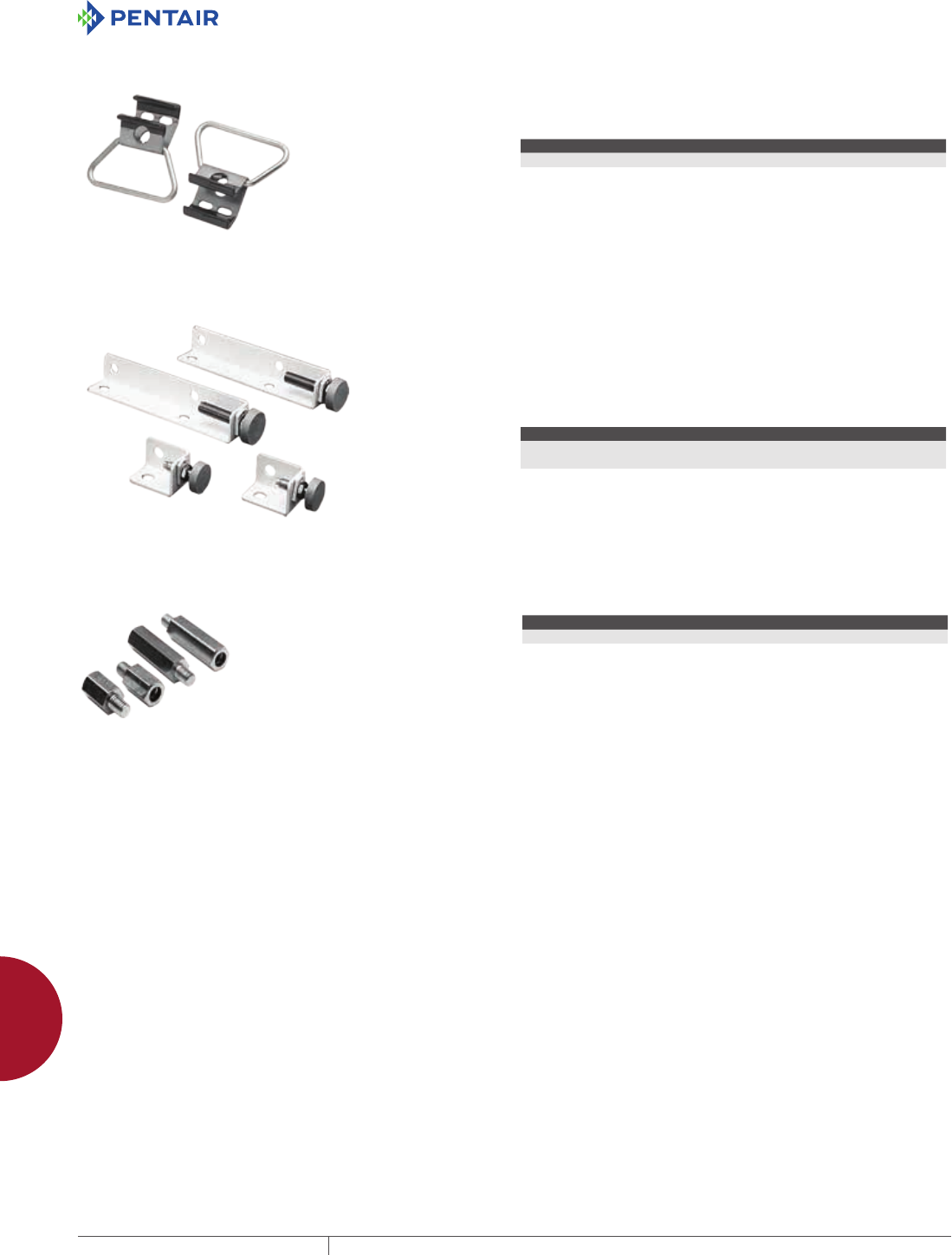
EQUIPMENT PROTECTIONSUBJECT TO CHANGE WITHOUT NOTICEACCESSORIES898
12
PANELS AND PANEL ACCESSORIES Panel aCCessories
PANEL ACCESSORIES
PANEL LIFTING HOOKS Used to lift a large interior panel to position it in an enclosure lying
on its back and to transport a panel from one location to another.
Comfortable hand grip. Plated finish.
BULLETIN: A80
Catalog Number Description
APLH Two lifting hooks with handles
PANEL SUPPORT KIT Provide additional support for panels on which heavy components
are mounted. Each panel support fits over a collar stud and is then
adjusted so the weight of the panel is partially supported by the
bottom of the enclosure. Locknuts prevent accidental change in
adjustment. A polyethylene-covered base on each panel support
distributes the panel weight and prevents damage to the interior
finish. Constructed of heavy-gauge steel. White finish.
BULLETIN: A80
Catalog Number Description
APS3 Two panel supports for 1-door or 2-door enclosures where distance from bottom
of panel to bottom of enclosure is less than 2.25 inches (57mm).
APS9 Two panel supports for free-standing or multi-door enclosures where distance
from bottom of panel to bottom of enclosure is between 2.88 inches (73mm)
and 8.50 inches (216mm).
THREADED PANEL EXTENDERS
Threaded Panel Extenders are
made of plated steel and designed
to raise the panel mounting surface.
Extenders attach to threaded
internal pads. Male and female
thread size is 10-32. Each kit
contains 4 extenders.
BULLETIN: A80
Catalog Number Length (in.) Length (mm)
APE050 0.50 13
APE100 1.00 25
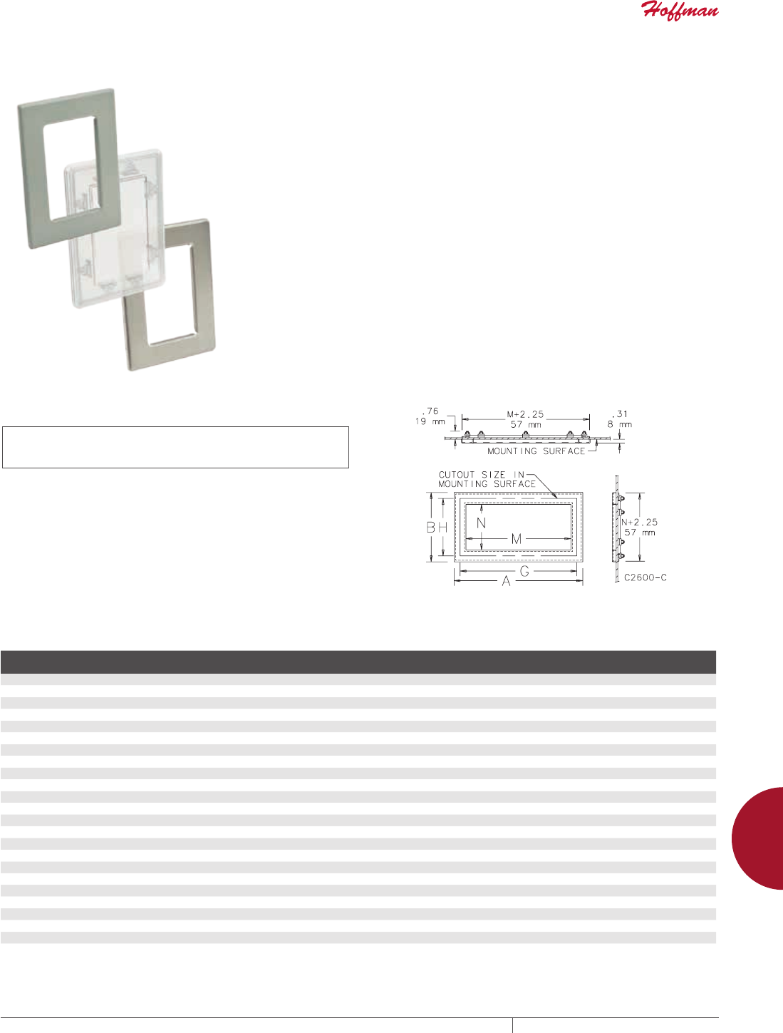
PH 763.422.2211 • FAX 763.422.2600 • PENTAIRPROTECT.COMEQUIPMENT PROTECTION ACCESSORIES 899
12
WINDOW KITS WindoW kits
WINDOW KITS
WINDOW KITS
STEEL, STAINLESS STEEL AND NONMETALLIC WINDOW KITS
INDUSTRY STANDARDS
UL 508A Component Recognized; Type 4, 4X (stainless steel and
nonmetallic versions only), 12, 13; File No. E61997.
UL 746C Component Recognized (nonmetallic version only).
CSA Type 4, 4X (stainless steel and nonmetallic versions only), 12,13;
File No. 42186
NEMA/EEMAC 4, 4X (stainless steel and nonmetallic versions only),
12, 13
IEC 60529, IP66
Steel Window Kits have a heavy gauge cold rolled steel formed
frame (cleaned and treated for paint endurance and adhesion),
painted ANSI 61 gray. The window is a clear acrylic .25-in. (16mm)
scratch-resistant material. They are ideal for indoor Type 12 and 13
applications.
Stainless Steel Window kits have a formed heavy gauge Type 304
stainless steel frame with a brushed finish. The clear window is
made of .25-in. (16mm) impact-resistant polycarbonate material.
They are ideal for indoor and outdoor Type 12, 13, 4, and 4X
applications.
Non-Metallic Window kits are made of a single piece special
polycarbonate blend, Makrolon, that has enhanced impact, UV,
water exposure, absorption, and saturation resistance. They are
ideal for indoor and outdoor Type 12, 13, 4, and 4X applications. They
are also ideal for non-metallic enclosures where exterior metallic
materials are not allowed and can accommodate up to .25-in.
enclosure material thickness.
All Window kits are easy to install and require a simple rectangular
enclosure cut-out. All required hardware is furnished, along with
assembly and cut- out instructions. The gasket material on all
windows is resistant to oils, cutting fluids and many other liquids.
Window kits of the same size use the same interchangeable cut-out.
Custom sizes for Steel and Stainless Steel Window Kits are
available along with different finishes and gasket materials.
Consult Hoffman for details.
BULLETIN: A80SW, A80W
Catalog Number AxBxC in. AxBxC mm Material
Window Size
M x N (in.)
Window Size
M x N (mm)
Required Cutout
Size G x H (in.)
Required Cutout
Size G x H (mm)
APWK53NF 7.50 x 5.50 x 0.31 191 x 140 x 8 Steel 5.00 x 3.00 127 x 76 6.78 x 4.78 172 x 121
APWK53NFSS 7.50 x 5.50 x 0.31 191 x 140 x 8 Stainless Steel 5.00 x 3.00 127 x 76 6.78 x 4.78 172 x 121
APWK53NFNM 7.62 x 5.62 x 0.63 194 x 143 x 16 Non-metallic 5.00 x 3.00 127 x 76 6.78 x 4.78 172 x 121
APWK711NFSS 9.50 x 13.50 x 0.31 241 x 343 x 8 Stainless Steel 11.00 x 7.00 279 x 178 8.78 x 12.78 223 x 325
APWK95NF 11.50 x 8.00 x 0.31 292 x 203 x 8 Steel 9.00 x 5.50 229 x 140 10.78 x 7.28 274 x 185
APWK95NFSS 11.50 x 8.00 x 0.31 292 x 203 x 8 Stainless Steel 9.00 x 5.50 229 x 140 10.78 x 7.28 274 x 185
APWK95NFNM 11.62 x 8.12 x 0.63 295 x 203 x 16 Non-metallic 9.00 x 5.50 229 x 140 10.78 x 7.28 274 x 185
APWK116NFNM 13.62 x 8.62 x 0.63 346 x 219 x 16 Non-metallic 11.00 x 6.00 279 x 152 12.78 x 7.78 325 x 198
APWK133NF 15.50 x 5.50 394 x 140 Steel 13.00 x 3.00 330 x 76 14.78 x 4.78 375 x 121
APWK138NF 15.50 x 10.50 x 0.31 394 x 267 x 8 Steel 13.00 x 8.00 330 x 203 14.78 x 9.78 375 x 248
APWK138NFSS 15.50 x 10.50 x 0.31 394 x 267 x 8 Stainless Steel 13.00 x 8.00 330 x 203 14.78 x 9.78 375 x 248
APWK138NFNM 15.62 x 10.62 x 0.63 397 x 270 x 16 Non-metallic 13.00 x 8.00 330 x 203 14.78 x 9.78 375 x 248
APWK715NFSS 17.50 x 9.50 445 x 241 Stainless Steel 15.00 x 7.00 381 x 178 8.78 x 16.78 223 x 426
APWK175NF 19.50 x 8.00 x 0.31 495 x 203 x 8 Steel 17.00 x 5.50 432 x 140 18.78 x 7.28 477 x 185
APWK1711NF 19.50 x 13.50 x 0.31 495 x 343 x 8 Steel 17.00 x 11.00 432 x 279 18.78 x 12.78 477 x 325
APWK1711NFSS 19.50 x 13.50 x 0.31 495 x 343 x 8 Stainless Steel 17.00 x 11.00 432 x 279 18.78 x 12.78 477 x 325
APWK720NFSS 22.50 x 9.50 572 x 241 Stainless Steel 20.00 x 7.00 508 x 178 8.78 x 21.78 223 x 553
APWK2315NF 25.50 x 17.50 x 0.31 648 x 445 x 8 Steel 23.00 x 15.00 584 x 381 24.78 x 16.78 629 x 426
APWK2315NFSS 25.50 x 17.50 x 0.31 648 x 445 x 8 Stainless Steel 23.00 x 15.00 584 x 381 24.78 x 16.78 629 x 426
APWK724NFSS 26.50 x 9.50 673 x 241 Stainless Steel 24.00 x 7.00 610 x 178 8.78 x 25.78 223 x 655
APWK729NFSS 31.50 x 9.50 800 x 241 Stainless Steel 29.00 x 7.00 737 x 178 8.78 x 30.78 223 x 782
APWK2919NF 31.50 x 21.50 800 x 546 Steel 29.00 x 19.00 737 x 483 30.78 x 20.78 782 x 528
APWK2919NFSS 31.50 x 21.50 800 x 546 Stainless Steel 29.00 x 19.00 737 x 483 30.78 x 20.78 782 x 528
APWK3523NF 37.50 x 25.50 953 x 648 Steel 35.00 x 23.00 889 x 584 36.78 x 24.78 934 x 629
When determining if a window kit will fit in a door or cover, be sure to allow for gaskets, data pockets, door handles, latch rods and other parts attached to the door or cover.
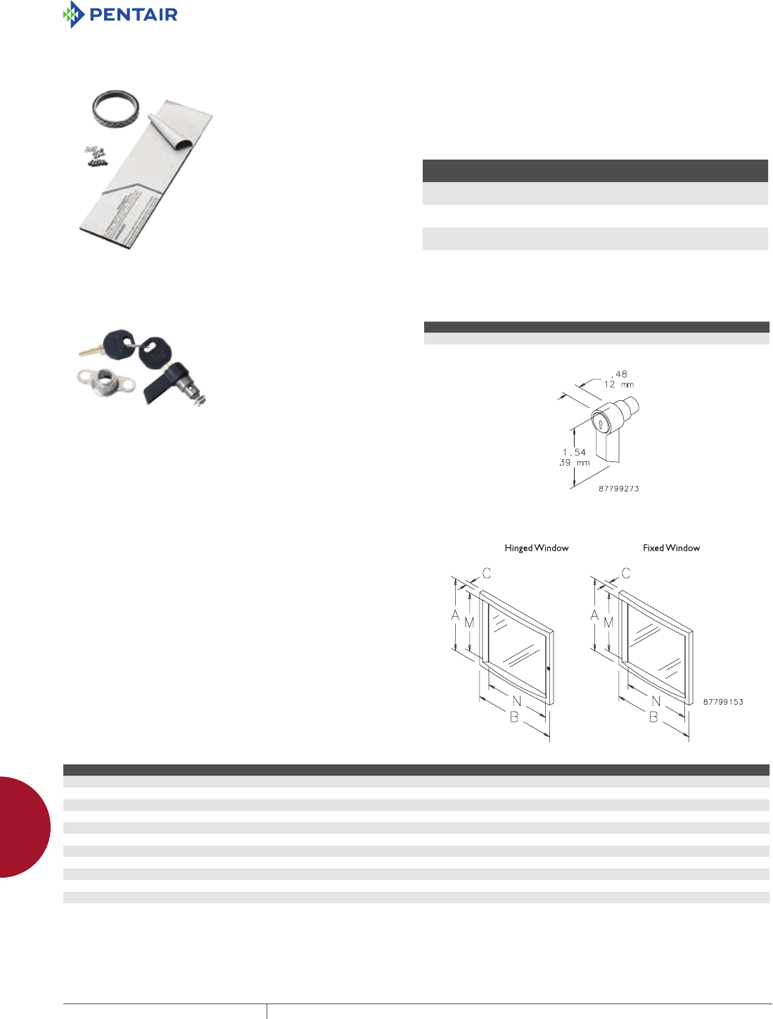
EQUIPMENT PROTECTIONSUBJECT TO CHANGE WITHOUT NOTICEACCESSORIES900
12
WINDOW KITS WindoW kits
FRAMELESS WINDOW KIT Designed for use on many Type 12 and 13 enclosures. These kits
are for indoor use in a temperature range of 55 F to 125 F (13 C to 52
C). For more severe conditions use Steel or Stainless Steel Window
Kits. The window is scratch-resistant .12-in. (3-mm) polycarbonate.
Special high-strength, double-sided tape is supplied as well as
screw fasteners. Windows can be cut to smaller sizes. Allow .50-in.
(13-mm) overlap on each side of window for tape.
BULLETIN: A80W
Catalog Number
Window Size
in./mm
Maximum Cutout Size
in./mm
APWKE52 5.50 x 3.00
140 x 76
4.50 x 2.00
114 x 51
APWKE96 9.62 x 7.19
244 x 183
8.62 x 6.19
219 x 157
APWKE133 13.88 x 3.88
353 x 99
12.88 x 2.88
327 x 73
WING KNOBS FOR CONCEPT WINDOW KITS
Knobs are optional latching for
hinged windows and hinged bezels.
Knobs are black and available in
locking and nonlocking versions.
Keylocking knob maintains Type 12
rating only.
BULLETIN: C2
Catalog Number Description
CWKL Wing Knob, locking
CWKN Wing Knob, nonlocking
CONCEPT FIXED AND HINGED WINDOW KITS
Aesthetic die-cast aluminum frame has .188-in. (5-mm) thick,
clear polycarbonate window. Pre-assembled kit is secured to front
opening of enclosure by four mounting screws. Furnished window
frame caps conceal mounting screws. Hinged window kit is hinged
on left side and has a single-point slotted latch (optional locking or
non-locking wing knob latch is also available). Textured finish, ANSI
61 gray or RAL 7035 light gray.
BULLETIN: C2
Catalog Number AxBxC in. AxBxC mm Finish Description Window Size M x N (mm) Window Size M x N (in.)
CWF3136 12.20 x 14.17 x 1.26 310 x 360 x 32 ANSI 61 Fixed window kit 253 x 276 9.96 x 10.86
CWF3136LG 12.20 x 14.17 x 1.26 310 x 360 x 32 RAL 7035 Fixed window kit 253 x 276 9.96 x 10.86
CWH3136 12.20 x 14.17 x 1.34 310 x 360 x 34 ANSI 61 Hinged window kit 253 x 276 9.96 x 10.86
CWH3136LG 12.20 x 14.17 x 1.34 310 x 360 x 34 RAL 7035 Hinged window kit 253 x 276 9.96 x 10.86
CWF4045 15.75 x 17.72 x 1.30 400 x 450 x 33 ANSI 61 Fixed window kit 343 x 366 13.50 x 14.40
CWF4045LG 15.75 x 17.72 x 1.30 400 x 450 x 33 RAL 7035 Fixed window kit 343 x 366 13.50 x 14.40
CWH4045 15.75 x 17.72 x 1.38 400 x 450 x 35 ANSI 61 Hinged window kit 343 x 366 13.50 x 14.40
CWH4045LG 15.75 x 17.72 x 1.38 400 x 450 x 35 RAL 7035 Hinged window kit 343 x 366 13.50 x 14.40
CWF5557 21.65 x 22.44 x 1.42 550 x 570 x 36 ANSI 61 Fixed window kit 493 x 486 19.40 x 19.13
CWF5557LG 21.65 x 22.44 x 1.42 550 x 570 x 36 RAL 7035 Fixed window kit 493 x 486 19.40 x 19.13
CWH5557 21.65 x 22.44 x 1.50 550 x 570 x 38 ANSI 61 Hinged window kit 493 x 486 19.40 x 19.13
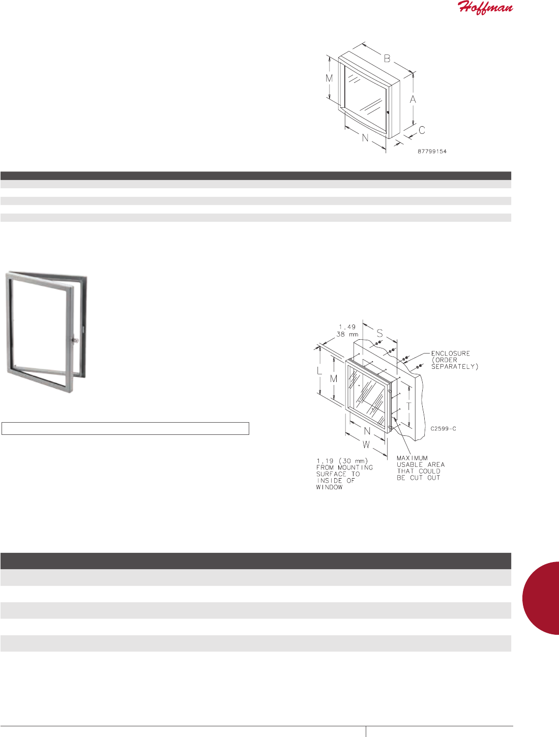
PH 763.422.2211 • FAX 763.422.2600 • PENTAIRPROTECT.COMEQUIPMENT PROTECTION ACCESSORIES 901
12
WINDOW KITS WindoW kits
CONCEPT DEEP HINGED WINDOW KIT
Kit is hinged on left side and has a single-point slotted latch
(optional locking or non-locking wing knob latch is also available).
Aesthetic die-cast aluminum frame has .188-in. (5-mm) thick,
clear polycarbonate window. Two-inch space between enclosure
front opening and window surface accommodates switches, lights,
meters and other components. This kit can be used as an accessory
window kit on larger standard Hoffman enclosure doors. Textured
finish, ANSI 61 gray or RAL 7035 light gray.
BULLETIN: C2
Catalog Number AxBxC in. AxBxC mm Finish Window Size M x N (mm) Window Size M x N (in.)
CWHD3136 12.20 x 14.17 x 3.31 310 x 360 x 84 ANSI 61 253 x 276 9.96 x 10.86
CWHD3136LG 12.20 x 14.17 x 3.31 310 x 360 x 84 RAL 7035 253 x 276 9.96 x 10.86
CWHD4045 15.75 x 17.72 x 3.39 400 x 450 x 86 ANSI 61 343 x 366 13.50 x 14.40
CWHD4045LG 15.75 x 17.72 x 3.39 400 x 450 x 86 RAL 7035 343 x 366 13.50 x 14.40
CWHD5557 21.65 x 22.44 x 3.50 550 x 570 x 89 ANSI 61 493 x 486 19.40 x 19.13
TYPE 12 HINGED WINDOW KIT
INDUSTRY STANDARDS
UL 508A Component Recognized; Type 12; File No. E61997
CSA Type 12; File No. 42186
NEMA/EEMAC Type 12
IEC 60529, IP55
For use as a viewing window where access to components mounted
behind the window is required. Window is .25-in. (6-mm) clear
acrylic. Easily mounted by drilling the appropriate mounting
holes. All mounting hardware is provided. Continuous gaskets on
all openings maintain UL Type 12 integrity. Finish is ANSI 61 gray
polyester powder paint.
BULLETIN: A80W
Catalog Number
Window Size M x N
in./mm
Overall L x W
in./mm
S
in./mm
T
in./mm
APWK1212H 10.28 x 10.28
261 x 261
12.00 x 12.00
305 x 305
10.44
265
10.44
265
APWK1612H 14.28 x 10.28
363 x 261
16.00 x 12.00
406 x 305
10.44
265
14.44
367
APWK2016H 18.28 x 14.28
464 x 363
20.00 x 16.00
508 x 406
14.44
367
18.44
468
APWK2020H 18.28 x 18.28
464 x 464
20.00 x 20.00
508 x 508
18.44
468
18.44
468
APWK2420H 22.28 x 18.28
566 x 464
24.00 x 20.00
610 x 508
18.44
468
22.44
570
APWK3024H 28.28 x 22.28
718 x 566
30.00 x 24.00
762 x 610
22.44
570
28.44
722
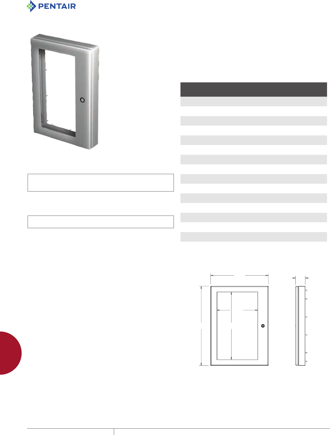
EQUIPMENT PROTECTIONSUBJECT TO CHANGE WITHOUT NOTICEACCESSORIES902
12
WINDOW KITS WindoW kits
TYPE 4 AND 4X DEEPHINGED WINDOW KITS
INDUSTRY STANDARDS
Stainless Steel
UL 508A Listed; Type 3R, 4, 4X, 12; File No. E61997
cUL Listed per CSA C22.2, No. 94; Type 3R, 4, 4X, 12; File No.
E61997
NEMA/EEMAC Type 3R, 4, 4X, 12
IEC 60529, IP66
Mild Steel
UL 508A Listed; Type 4, 12; File No. E61997
cUL Listed per CSA C22.2 No. 94; Type 4, 12; File No. E61997
NEMA/EEMAC Type 4, 12
APPLICATION
Deep-hinged window kits provide protection, visibility and easy
access to equipment and components installed behind the viewing
area. Window kits are conveniently sized to allow direct mounting in
the usable door area of Hoffman NEMA and CONCEPT® wall-mount
enclosures, as well as any Hoffman enclosure with a suitably sized
mounting surface. Deep-hinged window kits provide protection,
visibility and easy access to equipment and components installed
behind the viewing area. These kits have an aesthetic appearance,
quarter-turn latching for easy access, .25-in. (6-mm) thick, clear
polycarbonate material for viewing, 2.5-in. (64-mm) depth to allow
for deep controls and a built-in gasket compression stop to facilitate
flush mounting. Each kit comes with a mounting template and
hardware to allow for easy installation and can be mounted either
left or right hinged.
SPECIFICATIONS
• Manufactured from Type 316L stainless steel or painted mild
steel
• Quarter-turn latches for quick access
• 0.25-in. (6-mm) thick, clear polycarbonate windows for easy
viewing
• 2.5-in. (64-mm) deep to allow for deep controls
• Built-in gasket compression stop on back of window kit facilitates
flush mounting
• Designed for either left or right hinging
• Includes mounting template and mounting hardware
• Easy-to-remove clip-style hinge pin
FINISH
• Stainless steel: Enclosures are unpainted; door and body have a
smooth #4 brushed finish
• Mild steel: ANSI 61 gray polyester powder paint inside and out
ACCESSORIES
Touch-up Paint (ATPPY61)
OPTIONS
Optional Handles
CWHNL - Nonlocking
CWHK - Keylocking
CWHPTO - Padlocking
BULLETIN: A80SW, A80W
Standard Product
Catalog Number AxBxC in./mm Material
Window Size
M x N
in./mm
No. of
Latches
AWDH1418N4 12.19 x 14.56 x 2.73
310 x 370 x 69
Steel 8.68 x 9.83
220 x 250
1
AWDH1418N4SS 12.19 x 14.56 x 2.73
310 x 370 x 69
316L Stainless steel 8.68 x 9.83
220 x 250
1
AWDH1612N4 14.19 x 8.14 x 2.73
360 x 207 x 69
Steel 10.68 x 3.41
271 x 87
1
AWDH1612N4SS 14.19 x 8.14 x 2.73
360 x 207 x 69
316L Stainless steel 10.68 x 3.41
271 x 87
1
AWDH2016N4 18.19 x 12.14 x 2.73
462 x 308 x 69
Steel 14.68 x 7.41
373 x 188
1
AWDH2016N4SS 18.19 x 12.14 x 2.73
462 x 308 x 69
316L Stainless steel 14.68 x 7.41
373 x 188
1
AWDH2416N4 22.19 x 12.14 x 2.73
564 x 308 x 69
Steel 18.68 x 7.41
474 x 188
2
AWDH2416N4SS 22.19 x 12.14 x 2.73
564 x 308 x 69
316L Stainless steel 18.68 x 7.41
474 x 188
2
AWDH2420N4 22.19 x 16.14 x 2.73
564 x 410 x 69
Steel 18.68 x 11.41
474 x 290
2
AWDH2420N4SS 22.19 x 16.14 x 2.73
564 x 410 x 69
316L Stainless steel 18.68 x 11.41
474 x 290
2
AWDH2430N4 22.19 x 26.14 x 2.73
564 x 664 x 69
Steel 18.68 x 20.22
474 x 514
2
AWDH2430N4SS 22.19 x 26.14 x 2.73
564 x 664 x 69
316L Stainless steel 18.68 x 20.22
474 x 514
2
AWDH3024N4 28.19 x 20.14 x 2.73
716 x 512 x 69
Steel 24.68 x 14.22
627 x 361
2
AWDH3024N4SS 28.19 x 20.14 x 2.73
716 x 512 x 69
316L Stainless steel 24.68 x 14.22
627 x 361
2
AWDH3624N4 34.19 x 20.14 x 2.73
868 x 512 x 69
Steel 30.68 x 14.22
779 x 361
2
AWDH3624N4SS 34.19 x 20.14 x 2.73
868 x 512 x 69
316L Stainless steel 30.68 x 14.22
779 x 361
2
A
B
M
N
87948405
C
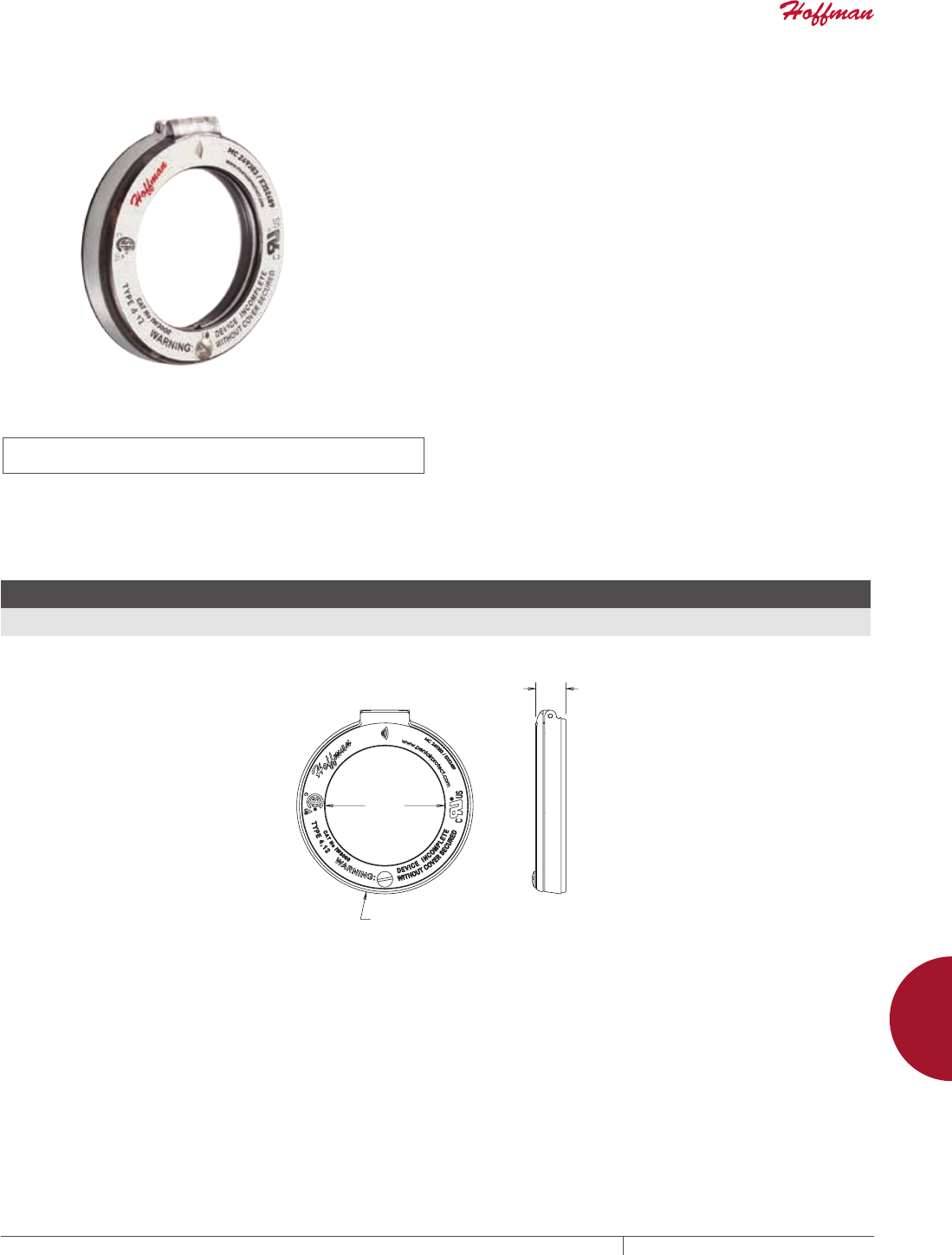
PH 763.422.2211 • FAX 763.422.2600 • PENTAIRPROTECT.COMEQUIPMENT PROTECTION ACCESSORIES 903
12
WINDOW KITS WindoW kits
IR WINDOWS
INDUSTRY STANDARDS
UL 50 Component Recognized; Type 4, 12. File No.: E362489
UL 50V Component Recognized. File No.: E362489
cCSAus Certified; Type 3, 4, 12. File No.: 249383
NEMA/EEMAC Type 3, 4, 12
IEC60529, IP65
APPLICATION
IR Windows provide a safe, efficient, and accurate way to perform
electrical inspections or predictive maintenance without removing
the panels or disturbing the electrical equipment.
Installing the IR Windows can help protect employees from
potential arc flash hazards and comply with NFPA70E safety
guidelines. The special design and feature enable quicker
inspections which save money and time. Made with durable
broadband crystal optic and aluminum housing materials, IR
Windows can be mounted to any enclosure.
Equipped with HYDROGARD lens moisture protection, IR Windows
can be installed both indoors and outdoors. IR Windows work with
any thermal imager, expanding the application to many industries.
Each kit comes with a self-adhesive drilling template, hardware,
and step-by-step instructions for easy installation or can be pre-
installed into Hoffman enclosures.
SPECIFICATIONS
• Spring-loaded cover opens and retains position. Clear cover
design allows for visual inspection when closed
• Arc flash tested against a 50kA short circuit for 1 second at 11kV
• Quarter-turn locking system for quick access
• Built-in silicone gaskets for protection against water and dust
ingress
• Gasket maximum temperature: 250 C/482 F; Body maximum
temperature: 659 C/1218 F; Optic maximum temperature: 1400
C/2552 F.
BULLETIN: A80RW
Standard Product
Catalog Number
X
in./mm
Y
in./mm
Z
in./mm Description
Crystal Thickness
in./mm Viewing Area
Free diameter space required for mounting
in./mm
IW3000 2.9
73
4.2
107
0.8
19
3-in. (75 mm) IR Window .08
2
6.49 sq. in. (4186 sq. mm) 4.50
115
IW4000 3.7
92
5.0
127
0.8
21
4-in. (100 mm) IR Window .16
4
10.53 sq. in (6794 sq. mm) 5.50
140
;
<
=
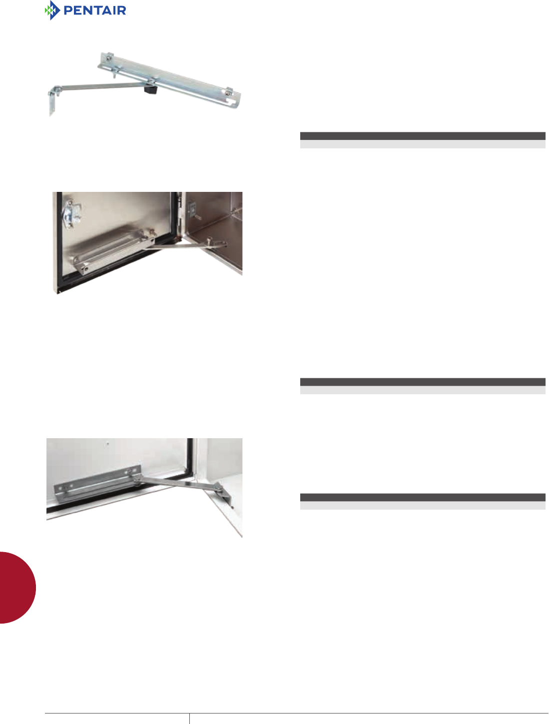
EQUIPMENT PROTECTIONSUBJECT TO CHANGE WITHOUT NOTICEACCESSORIES904
12
DOOR ACCESSORIES door stoPs
DOOR ACCESSORIES
DOOR STOPS
DOOR STOP KIT
Designed for use on most standard Hoffman Type 4 and 12
enclosures to secure the door in the open position. Enclosures
must have a “B” dimension of 16.00 in. (406 mm) or more and a door
which opens horizontally. Door Stop Kit can be mounted at the top
or bottom of the door opening after drilling two small holes in the
body of the enclosure and two small holes in the door. The angle of
the door is easily adjusted by means of a wingnut, and the stop arm
slides neatly out of the way when the door is closed. All parts are
plated. Maintains UL/CSA Type 4 and Type 12 if properly installed
in a Hoffman enclosure. Door Stop Kit is not intended for use on
CONCEPT window door enclosures, or enclosures configured with a
swing-out panel or swing-out rack frame.
BULLETIN: A80
Catalog Number Description
ADSTOPK Door Stop Kit
TYPE 316 STAINLESS STEEL DOOR STOP KIT APPLICATION
Type 316 stainless steel door stop kit is available for use in
applications that require the kind of corrosion protection that
only Type 316 stainless steel can provide. Typical applications
include water treatment, pulp, paper, petroleum, chemical, food
and pharmaceutical processing, and packaging. Kit includes all
mounting hardware. Secures doors in the open position. Can be
mounted at either top or bottom of door. Can be installed on either
left- or right-hinged doors. Maintains an enclosure’s Type 4X rating.
Easy to install. Mounting hardware is Type 316 stainless steel. This
door stop kit can be mounted in large and wall-mount enclosures.
FEATURES
• Can be mounted at either top or bottom of door
• Can be installed on either left- or right-hinged doors
• Maintains an enclosure’s Type 4X rating
• Easy to install
SPECIFICATIONS
• Kit, including mounting hardware, constructed of Type 316
stainless steel
BULLETIN: A4SY
Catalog Number Description
ADSTOPKSS6 Type 316 stainless steel door stop kit
LARGE ENCLOSURE DOOR STOP KIT Designed for use with most standard, large mild and stainless
steel enclosures to secure the door in the 90 degree open position.
Door Stop Kit can be mounted at the top or bottom of the door
opening after drilling two small holes in the door and enclosure. All
parts are plated. Maintains UL/CSA Type 4 and Type 12 if properly
installed in a Hoffman enclosure.
BULLETIN: A34Y
Catalog Number Description
ALGDSTOP2 Large Enclosure Door Stop Kit

PH 763.422.2211 • FAX 763.422.2600 • PENTAIRPROTECT.COMEQUIPMENT PROTECTION ACCESSORIES 905
12
DOOR ACCESSORIES data PoCkets
DATA POCKETS
THERMOPLASTIC DATA POCKET
Provides a convenient place to store wiring diagrams, operation
manuals and other documentation inside the enclosure. Adhesive-
backed pockets mount inside the solid enclosure cover. Mounting
hardware included. Thermoplastic pockets are dark gray and have
cut-away areas for easy inspection of contents.
BULLETIN: UX1Y
Catalog Number Description
Size L x W
in./mm
ADP1 Small pocket 6.00 x 6.00
152 x 152
ADP2 Large pocket 12.00 x 12.00
305 x 305
METAL DATA POCKET
Three-inch (76-mm) deep Metal Data Pocket provides a convenient
place to store wiring diagrams, operation manuals and other
documentation inside the enclosure. Large enough to store 3-ring
binders. Mounting hardware is included. Painted white and has cut-
away areas for easy inspection of contents.
BULLETIN: A34Y
Catalog Number
Fits A x B
in./mm
Size L x W
in./mm
ADP3 greater than or equal to
30.00 x 24.00
greater than or equal to
762 x 610
12.00 x 12.00
305 x 305
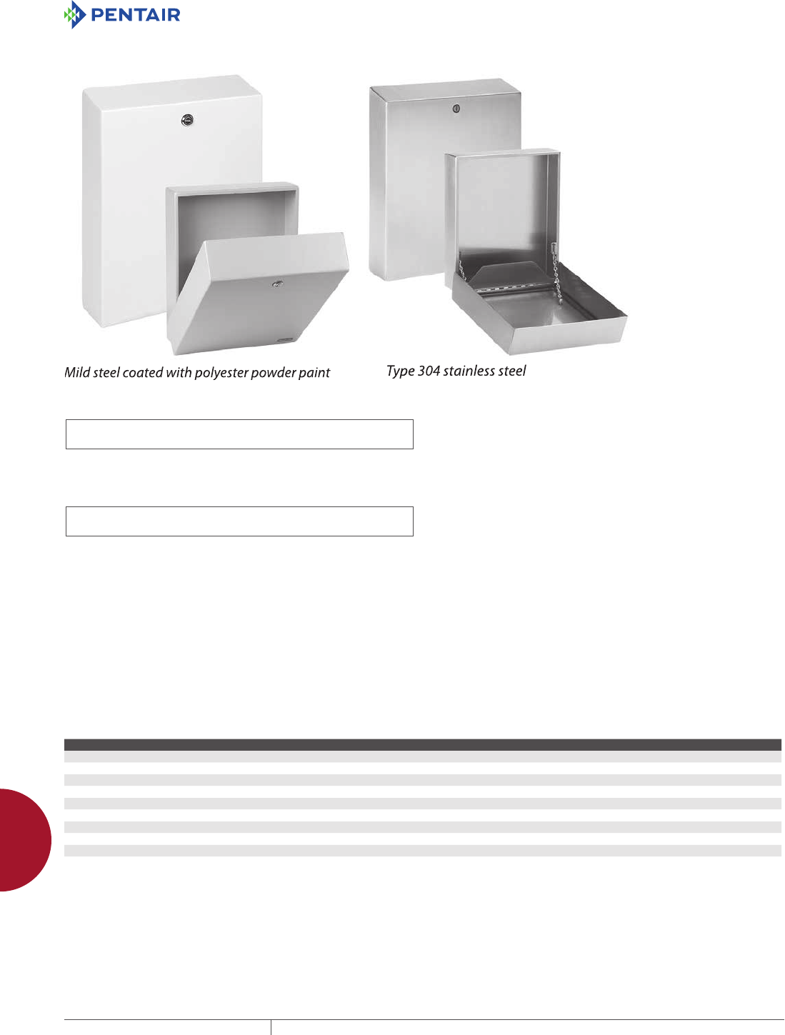
EQUIPMENT PROTECTIONSUBJECT TO CHANGE WITHOUT NOTICEACCESSORIES906
12
DOOR ACCESSORIES data PoCkets
EXTERNAL DATA POCKETS, TYPE 4/4X/12
INDUSTRY STANDARDS
Mild Steel Models:
UL 508A Listed; Type 4, 12; File No. E61997
cUL Listed per C22.2 No. 94; Type 4, 12; File No. E61997
NEMA/EEMAC Type 4, 12
IEC 60529, IP66
Stainless Steel Models:
UL 508A Listed; Type 4, 4X, 12; File No. E61997
cUL Listed per C22.2 No. 94; Type 4, 4X, 12; File No. E61997
NEMA/EEMAC Type 4, 4X, 12
IEC 60529, IP66
APPLICATION
Mounted on the exterior of an enclosure, Data Pockets allow access
to system documentation without having to open the enclosure door.
FEATURES
• Available in mild steel or stainless steel to match the enclosure
finish
• Foam-in-place gasket to protect documentation from harsh
environments
• Hinged front for easy access to contents
• Three sizes accommodate a wide variety of documents
• Sloped top sheds liquids and prevents accumulation of
extraneous material
• Optional wing knob and keylock inserts available for additional
security
SPECIFICATIONS
• 16 gauge steel or 16 gauge Type 304 stainless steel
• Front of pocket hinges away from frame
FINISH
Mild steel models are either ANSI 61 medium-gray or RAL 7035
light-gray polyester powder finish inside and out. Stainless steel
models have brushed finish.
ACCESSORIES
Key Inserts
Wing Knob Latch
BULLETIN: A70E
Standard Product
Catalog Number AxBxC in. AxBxC mm Finish G (in.) G (mm) H (in.) H (mm) J (in.) J (mm)
ADPX4A 15.10 x 12.25 x 3.18 384 x 311 x 81 ANSI 61 paint 12.00 305 10.00 254 14.25 362
ADPX4ALG 15.10 x 12.25 x 3.18 384 x 311 x 81 RAL 7035 paint 12.00 305 10.00 254 14.25 362
ADPX4ASS 15.10 x 12.25 x 3.18 384 x 311 x 81 Brushed stainless steel 12.00 305 10.00 254 14.25 362
ADPX4B 6.83 x 6.25 x 2.18 173 x 159 x 55 ANSI 61 paint 4.00 102 4.00 102 6.25 159
ADPX4BLG 6.83 x 6.25 x 2.18 173 x 159 x 55 RAL 7035 paint 4.00 102 4.00 102 6.25 159
ADPX4BSS 6.83 x 6.25 x 2.18 173 x 159 x 55 Brushed stainless steel 4.00 102 4.00 102 6.25 159
ADPX4C 12.96 x 18.25 x 2.68 329 x 484 x 68 ANSI 61 paint 10.00 254 16.00 406 12.25 311
ADPX4CLG 12.96 x 18.25 x 2.68 329 x 484 x 68 RAL 7035 paint 10.00 254 16.00 406 12.25 311
ADPX4CSS 12.96 x 18.25 x 2.68 329 x 484 x 68 Brushed stainless steel 10.00 254 16.00 406 12.25 311

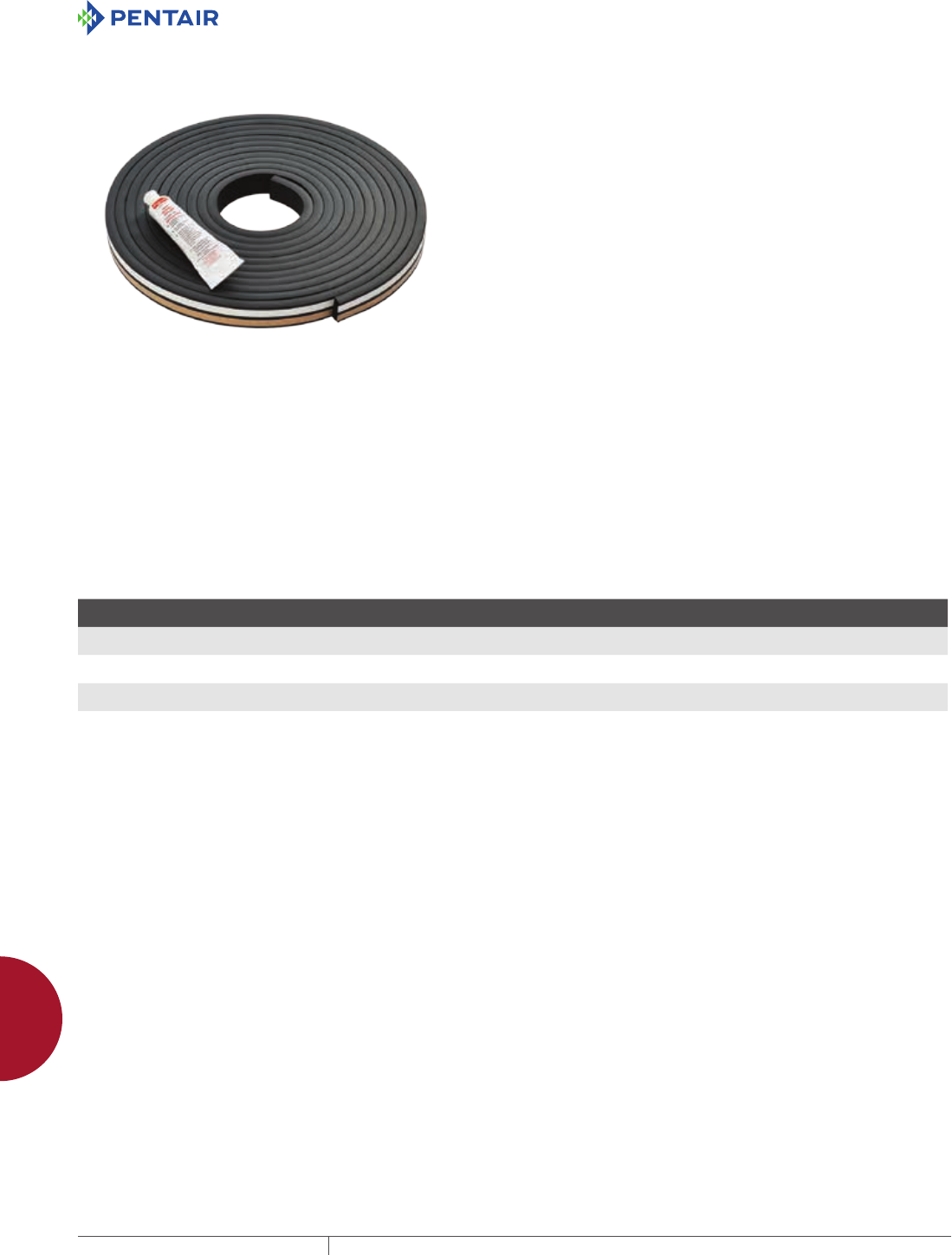
EQUIPMENT PROTECTIONSUBJECT TO CHANGE WITHOUT NOTICEACCESSORIES908
12
DOOR ACCESSORIES Gasket kits
GASKET KITS
GASKET KITS
INDUSTRY STANDARDS
Installed in accordance to the instructions, the replacement gasket
will maintain the current enclosure NEMA Type rating:
NEMA 250 Enclosures for Electrical Equipment (1000V max) Type
12, 4, 4X
EEMAC Electrical and Electronic Manufacturers Association of
Canada Type 12, 4, 4X
APPLICATION
Gasket kits are ideal to replace damaged or worn foam-in-place
or strip enclosure gaskets. Available in either EPDM and silicone
material, these gasket kits allows replacement of current gasket as
well as provides a solution to upgrade enclosure gasket for harsh
applications. Kits offered with different sized gaskets is suitable to
be used on either wall mount or large enclosures.
FEATURES
• Positioned inside enclosure door, providing a sealing barrier
between the enclosure housing and door
• EPDM gasket kits are ideal to replace damaged or worn
enclosure gasket
• Silicon gasket provides a secure sealing to protect against water
and dust ingress in extreme temperatures
• Silicone gaskets are ideal to replace current silicone gasket and
can be used to upgrade current gasket for harsh applications
• Strip gasket is field-installable with included sealant and
instructions
SPECIFICATIONS
• EPDM Gaskets available in 1/4 in. thick by 5/8 in. wide for wall-
mount enclosures
• EPDM Gaskets available in 3/8 in. thick by 1 in. wide for large
enclosures
• Silicone gaskets available in 1/4 in. thick by 1/2 in. wide for wall-
mount enclosures
• Silicone gaskets available in 3/8 in. thick by 1 in. wide for large
enclosures
• Each kit includes a 20-ft. roll of strip gasket
BULLETIN: A80
Standard Product
Catalog Number Description Material
Thickness
in./mm
Width
in./mm
GSKTKITE025 Gasket Kit EPDM 0.25x0.625 EPDM .25
6
.625
16
GSKTKITE375 Gasket Kit EPDM 0.375x1.00 EPDM .375
10
1.00
25
GSKTKITS025 Gasket Kit Silicone 0.25x0.50 Silicone .25
6
.50
13
GSKTKITS375 Gasket Kit Silicone 0.375x1.00 Silicone .375
10
1.00
25
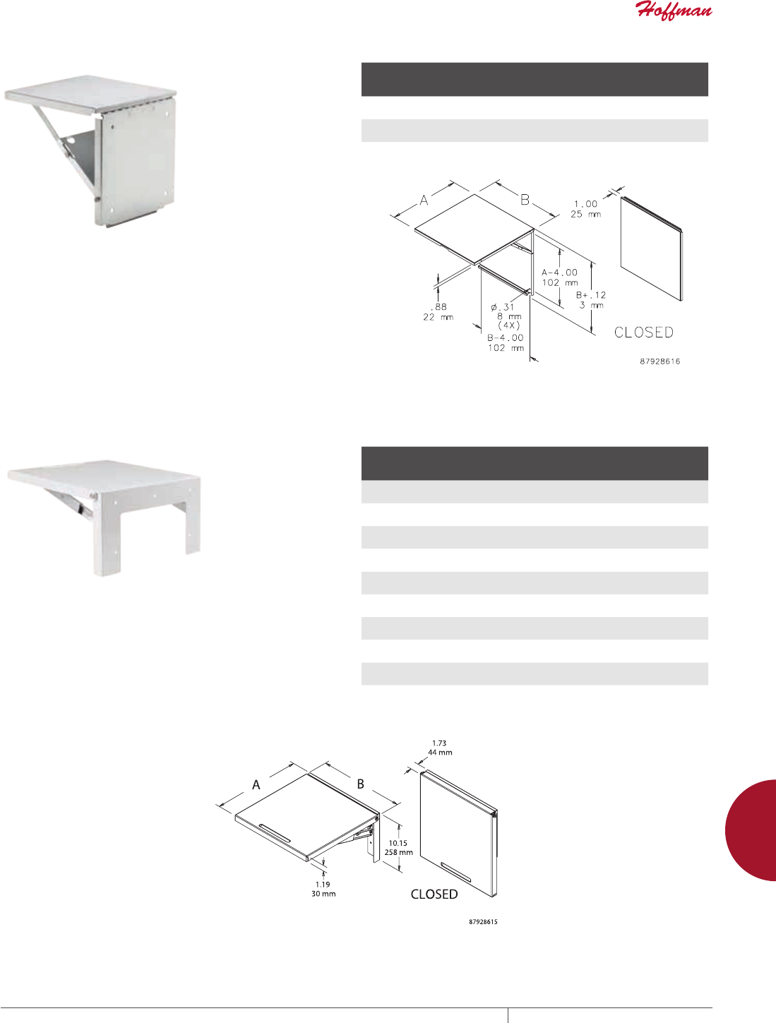
PH 763.422.2211 • FAX 763.422.2600 • PENTAIRPROTECT.COMEQUIPMENT PROTECTION ACCESSORIES 909
12
SHELVES, KEYBOARD TRAYS AND GLAND PLATES foldinG shelves
SHELVES, KEYB OARD TRAYS AND GL AND PLATES
FOLDING SHELVES
STAINLESS STEEL FOLDING SHELF
Supports instruments and test equipment used to install and
maintain electrical components in an enclosure. Also ideally
suited for supporting laptop computers, monitoring units and
other equipment used with programmable controllers. The shelf
can be installed on the inside or outside surface of larger Hoffman
industrial enclosures (except PROLINE ). Automatically locks in the
horizontal position when raised. When not in use, the shelf folds
down and projects only 1 in. (25 mm) from the mounting surface.
Constructed of 304 stainless steel with a brushed finish. Maintains
UL/CSA Type 4, 4X and 12 rating when properly installed on a
Hoffman enclosure.
BULLETIN: A80
Catalog Number
Size AxB
in./mm
Maximum
Distributed
Load Rating (lb.)
Maximum
Distributed
Load Rating (kg)
ACSHELF1212SS 12.00 x 12.00
305 x 305
150 68
ACSHELF1818SS 18.00 x 18.00
457 x 457
150 68
ACSHELF2424SS 24.00 x 24.00
610 x 610
150 68
LARGE FOLDING SHELF
Supports instruments and test equipment used to install and
maintain electrical components in an enclosure. Also ideally
suited for supporting laptop computers, monitoring units and
other equipment used with programmable controllers. The shelf
can be installed on the inside or outside surface of larger Hoffman
industrial enclosures (except PROLINE ). Automatically locks in the
horizontal position when raised. When not in use, the shelf folds
to 1.73 in. (44 mm) from the mounting surface. All parts are heavy
gauge steel. Maintains UL/CSA Type 4 and 12 when properly intalled
on a Hoffman enclosure.
BULLETIN: A34Y
Catalog Number
Size AxB
in./mm
Maximum
Distributed
Load Rating (lb.)
Maximum
Distributed
Load Rating (kg) Finish
AASHLF1218 18.00 x 12.00
457 x 305
150 68 White
AA61SHLF1218 18.00 x 12.00
457 x 305
150 68 Gray
AA35SHLF1218 18.00 x 12.00
457 x 305
150 68 Light gray
AASHLF1818 18.00 x 18.00
457 x 457
150 68 White
AA61SHLF1818 18.00 x 18.00
457 x 457
150 68 Gray
AA35SHLF1818 18.00 x 18.00
457 x 457
150 68 Light gray
AASHLF2424 24.00 x 24.00
610 x 610
150 68 White
AA61SHLF2424 24.00 x 24.00
610 x 610
150 68 Gray
AA35SHLF2424 24.00 x 24.00
610 x 610
150 68 Light gray
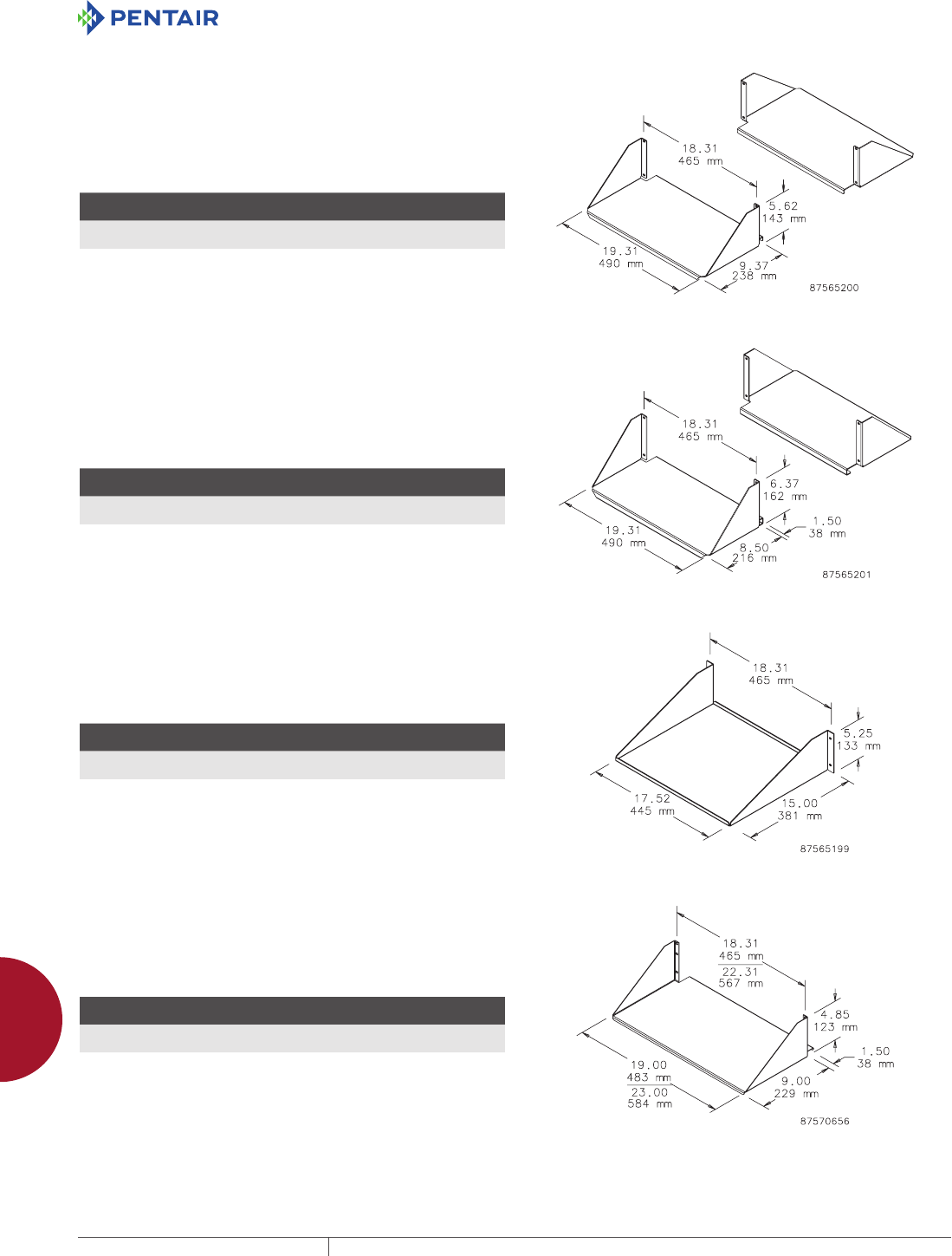
EQUIPMENT PROTECTIONSUBJECT TO CHANGE WITHOUT NOTICEACCESSORIES910
12
SHELVES, KEYBOARD TRAYS AND GLAND PLATES shelves for oPen frame raCks
SHELVES FOR OPEN FR AME RACKS
DOUBLESIDED SOLID ALUMINUM SHELF
Mounts on 19-in. open frame rack. Two shelves form double-sided
shelf. Uses 4U rack space. Made of 0.090-in. thick aluminum with
brushed finish.
Maximum load rating: 100 lb. (45.4 kg) per side, 200 lb. (90.7 kg)
total
BULLETIN: DACCY
Catalog Number
H x W x D
in./mm Fits Rack Includes Rack Units
ESHDA19 5.62 x 19.31 x 9.37
143 x 490 x 238
19 in. 2 shelves 4
DOUBLESIDED, SOLID ALUMINUM, HEAVY DUTY SHELF
Mounts on open frame rack. Two shelves form double-sided shelf.
Uses 4U rack space. Made of 0.090-in. thick aluminum with brushed
finish.
Maximum Load Rating: 150 lb. (68.0 kg) per side, 300 lb. (136.1 kg)
total
BULLETIN: DACCY
Catalog Number
H x W x D
in./mm Fits Rack Includes Rack Units
ESHDHDA19 6.37 x 19.31 x 10.00
162 x 490 x 254
19 in. 2 shelves 4
SINGLESIDED SOLID ALUMINUM SHELF
Mounts in a cabinet or on a 19-in. open-frame rack and can be wall
mounted. Made of 0.090-in. thick aluminum with brushed finish.
Maximum load rating: 100 lb. (45.4 kg)
BULLETIN: DACCY
Catalog Number
H x W x D
in./mm Fits Rack Rack Units
ESHA19 5.25 x 18.31 x 15.00
133 x 465 x 381
19 in. 3
SINGLESIDED SOLIDSTEEL SHELF
Solid shelf mounts to either front or rear flange of open-frame rack.
Uses 3U of rack space. Steel with textured black finish.
Load rating: 150 lb. (68.0 kg)
BULLETIN: DACCY
Catalog Number
H x W x D
in./mm Fits Rack Rack Units
ESH19S 4.85 x 19.00 x 10.50
123 x 483 x 267
19 in. 3
ESH23S 4.85 x 23.00 x 10.50
123 x 584 x 267
23 in. 3
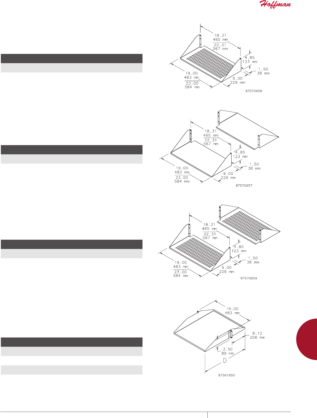
PH 763.422.2211 • FAX 763.422.2600 • PENTAIRPROTECT.COMEQUIPMENT PROTECTION ACCESSORIES 911
12
SHELVES, KEYBOARD TRAYS AND GLAND PLATES shelves for oPen frame raCks
SINGLESIDED STEEL VENTED SHELF
Vented shelf mounts to either front or rear flange of open-frame
rack. Steel with textured black polyester powder paint finish.
Load rating: 150 lb. (68.0 kg)
BULLETIN: DACCY
Catalog Number
H x W x D
in./mm Fits Rack Rack Units
ESH19V 4.85 x 19.00 x 10.50
123 x 483 x 267
19 in. 3
ESH23V 4.85 x 23.00 x 10.50
123 x 584 x 267
23 in. 3
DOUBLESIDED SOLIDSTEEL SHELF
Solid double-deep shelf mounts to both front and rear flanges of
open frame rack. Steel with textured black polyester powder paint
finish.
Load rating: 300 lb. (136.1 kg)
BULLETIN: DACCY
Catalog Number
H x W x D
in./mm Fits Rack Rack Units
ESHD19 4.85x 19.00 x 10.50
123 x 483 x 267
19 in. 3
ESHD23 4.85 x 23.00 x 10.50
123 x 584 x 267
23 in. 3
DOUBLESIDED STEEL VENTED SHELF
Vented, double-deep shelf mounts to both front and rear flanges of
open frame rack. Steel with textured black polyester powder paint
finish.
Load rating: 300 lb. (136.1 kg)
BULLETIN: DACCY
Catalog Number
H x W x D
in./mm Fits Rack Rack Units
ESHDV19 4.85 x 19.00 x 10.50
123 x 483 x 267
19 in. 3
ESHDV23 4.85 x 23.00 x 10.50
123 x 584 x 267
23 in. 3
CENTERMOUNT STEEL SHELVES
19-in. shelf mounts to the front of the rack. Ideal for supporting
monitors or computers. Designed to evenly distribute load across
the rack. Manufactured from 16 gauge steel. Black, low-gloss,
light-textured polyester powder paint finish on all surfaces.
Load rating: 100 lb. (45.4 kg)
BULLETIN: DOFRC
Catalog Number
H x W x D
in./mm Style Rack Units
ECMS1918 3.50 x 19.00 x 18.00
89 x 483 x 457
Solid 2
ECMS1922 3.50 x 19.00 x 22.00
89 x 483 x 559
Solid 2
ECMSV1918 3.50 x 19.00 x 18.00
89 x 483 x 457
Vented 2
ECMSV1922 3.50 x 19.00 x 22.00
89 x 483 x 559
Vented 2
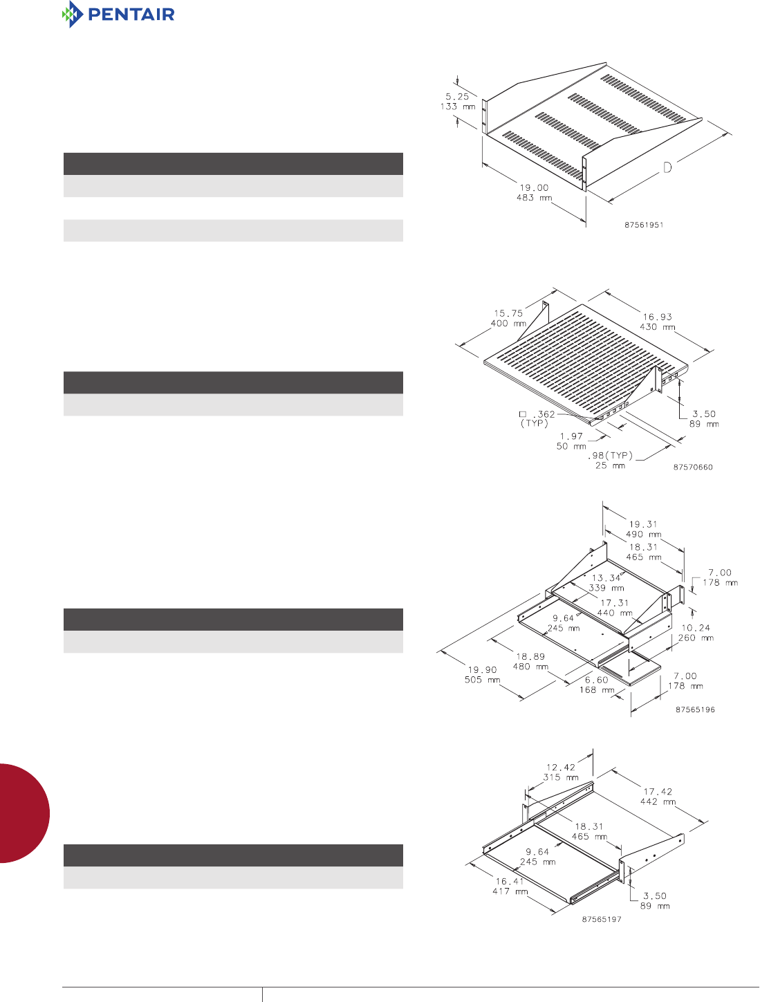
EQUIPMENT PROTECTIONSUBJECT TO CHANGE WITHOUT NOTICEACCESSORIES912
12
SHELVES, KEYBOARD TRAYS AND GLAND PLATES shelves for oPen frame raCks
RACKMOUNT STEEL SHELF
19-in. Rack-Mount Shelf mounts to the front of the rack. Ideal for
holding non-19-in. rack-mount equipment. Available with or without
vents. Manufactured from 16 gauge steel. Black, low-gloss, lightly
textured finish on all surfaces.
Load rating: 100 lb. (45.4 kg)
BULLETIN: DOFRC
Catalog Number
H x W x D
in./mm Style Rack Units
EMS1918 5.25 x 19.00 x 18.00
133 x 483 x 457
Solid 3
EMS1922 5.25 x 19.00 x 22.00
133 x 483 x 559
Solid 3
EMSV1918 5.25 x 19.00 x 18.00
133 x 483 x 457
Vented 3
EMSV1922 5.25 x 19.00 x 22.00
133 x 483 x 559
Vented 3
ADJUSTABLE STEEL VENTED SHELF
Vented shelf adjustable front to back in 25-mm increments. Shelf
mounts to either front or rear flange of open frame rack. Steel with
textured black polyester powder paint finish.
Load rating: 60 lb. (27.2 kg)
BULLETIN: DACCY
Catalog Number
H x W x D
in./mm Fits Rack Rack Units
ESHVA19 3.50 x 16.93 x 15.75
89 x 430 x 400
19 in. 2
ESHVA23 3.50 x 19.93 x 15.75
89 x 506 x 400
23 in. 2
PULLOUT KEYBOARD TRAY WITH MONITOR SHELF
Mounts to the front and back surfaces of a standard 3-in. open
frame rack. Fits full-size keyboard. Includes mouse tray. Extends
10.5 in. (267 mm) beyond front of open frame rack. Keyboard tray
slides out an additional 7 in. (178 mm). Uses 4U rack space. 16 gauge
steel with RAL 9005 black polyester powder paint finish.
Monitor shelf load rating: 100 lb. (45.4 kg)
BULLETIN: DACCY
Catalog Number
H x W x D
in./mm Fits Rack Rack Units
E19SKBM 7.00 x 19.90 x 10.24
178 x 505 x 260
19 in. 4
PULLOUT SHELF FOR MINI KEYBOARD
Pull-Out Shelf for Mini Keyboard mounts either in a cabinet or on a
19-in. open-frame rack and fits a 16.25-in. (413-mm) wide keyboard.
When closed, all parts slide between rack angles. Keyboard tray
slides out 8.94 in. (227 mm). 16 gauge steel with RAL 9005 black
polyester powder paint finish.
BULLETIN: DACCY
Catalog Number
H x W x D
in./mm Fits Rack Rack Units
P19KBSM 3.50 x 18.31 x 12.42
89 x 465 x 315
19 in. 2
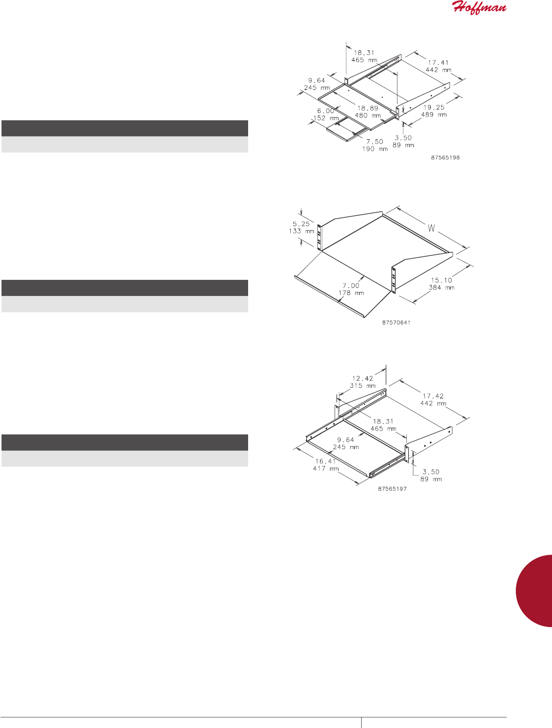
PH 763.422.2211 • FAX 763.422.2600 • PENTAIRPROTECT.COMEQUIPMENT PROTECTION ACCESSORIES 913
12
SHELVES, KEYBOARD TRAYS AND GLAND PLATES shelves for raCks and Cabinets
SHELVES FOR RACK S AND CABINE TS
PIVOTING KEYBOARD SHELF WITH MOUSE TRAY
Mounts either in a cabinet or on a 19-in. open-frame rack. Shelf
pulls out and pivots 90 degrees to access full-size keyboard. Shelf
allows keyboard to slide between standard rack angles and includes
mouse tray. 16 gauge steel with RAL 9005 black polyester powder
paint finish. Keyboard tray extends 9.75 in. (248 mm) beyond front of
rack angles or open-frame rack.
BULLETIN: DACCY
Catalog Number
H x W x D
in./mm Fits Rack Rack Units
P19KBPVT 3.50 x 18.89 x 19.25
89 x 480 x 489
19 in. 2
STEEL KEYBOARD/MONITOR SHELF
Designed to accommodate a monitor and keyboard in an
ergonomically engineered design. Shelf mounts to front flange of
open-frame rack. Can mount in a cabinet if rack angles are adjusted
back for door clearance. Uses 3U of rack space. 19-in. and 23-in.
rack versions. Steel with textured black finish.
Load rating: 200 lb. (91 kg)
BULLETIN: DACCY
Catalog Number
H x W x D
in./mm Fits Rack Rack Units
ESH19KBM 5.25 x 17.38 x 15.10
133 x 441 x 384
19 3
ESH23KBM 5.25 x 21.38 x 15.10
133 x 543 x 384
23 3
PULLOUT SHELF FOR MINI KEYBOARD
Pull-Out Shelf for Mini Keyboard mounts either in a cabinet or on a
19-in. open-frame rack and fits a 16.25-in. (413-mm) wide keyboard.
When closed, all parts slide between rack angles. Keyboard tray
slides out 8.94 in. (227 mm). 16 gauge steel with RAL 9005 black
polyester powder paint finish.
BULLETIN: DACCY
Catalog Number
H x W x D
in./mm Fits Rack Rack Units
P19KBSM 3.50 x 18.31 x 12.42
89 x 465 x 315
19 in. 2
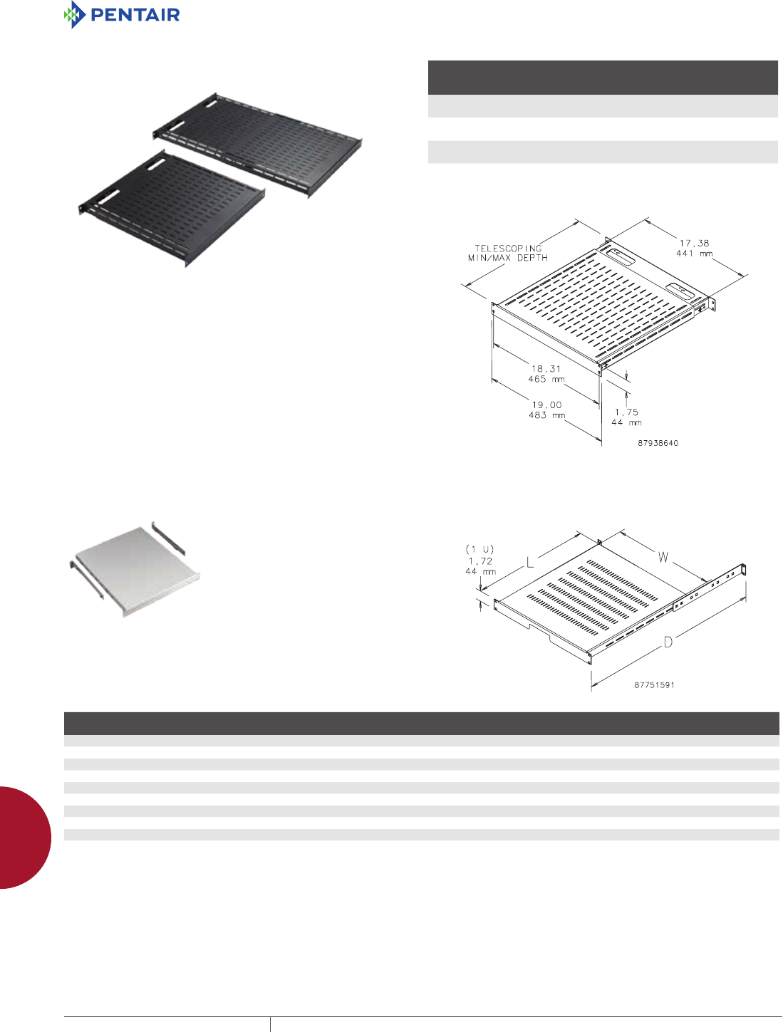
EQUIPMENT PROTECTIONSUBJECT TO CHANGE WITHOUT NOTICEACCESSORIES914
12
SHELVES, KEYBOARD TRAYS AND GLAND PLATES shelves for raCks and Cabinets
TOOLLESS SHELF
An easy-to-install tool-less vented 19-in. shelf. Mounts onto
rack angles that have EIA-spaced square holes (.375 in.). Shelf
slides open and provides a variable-sized, continuous surface
for equipment. Back of shelf has oval cutouts for power and data
cables. Accessory hole patterns at back of shelf fit small and large
D-rings to help manage cable. Made of steel with a 150 lb. (68 kg)
static load rating. Available with RAL 9005 black or RAL 7035 gray
polyester powder coat finish.
BULLETIN: DACCY
Catalog Number Description Finish
Minimum
Depth
mm/in.
Maximum
Depth
mm/in.
D19FVT69B Shelf, vented, 19 in. tool-less Black 495
19.50
851
33.50
D19FVT69G Shelf, vented, 19 in. tool-less Gray 495
19.50
851
33.50
D19FVT912B Shelf, vented, 19 in. tool-less Black 792
31.20
1151
45.30
D19FVT912G Shelf, vented, 19 in. tool-less Gray 792
31.20
1151
45.30
Minimum and maximum depth measured from rack angle to rack angle.
RACKMOUNT ADJUSTABLE SHELF
Mounts to front surface of front
and back rack angles. Shelf is
made of painted 14 gauge steel and
the adjustable support brackets
are clear-plated 12 gauge steel.
Adjustable to fit multiple-depth
enclosures or rack angle placement.
Both solid and vented models
available. Fits 19- or 23-in. rack
spacing. Requires only 1U of rack
space. Shelf has RAL 7035 light-gray
textured or RAL 9005 black textured
polyester powder paint finish.
Load rating: 150 lb. (68 kg)
BULLETIN: DACCY
Catalog Number Type Size Finish L x W (in.) L x W (mm) D max. (in.) D max. (mm)
Fits Enclosure
Depth Up To (in.)
Fits Enclosure
Depth Up To (mm)
P19SH68 Solid 19 in. Gray 19.68 x 17.32 500 x 440 30.71 780 31.50 800
P19SH68B Solid 19 in. Black 19.68 x 17.32 500 x 440 30.71 780 31.50 800
P19VSH68B Vented 19 in. Black 19.68 x 17.32 500 x 440 30.71 780 31.50 800
P19SH810 Solid 19 in. Gray 27.56 x 17.32 700 x 440 38.58 980 39.37 1000
P19SH810B Solid 19 in. Black 27.56 x 17.32 700 x 440 38.58 980 39.37 1000
P19VSH810B Vented 19 in. Black 27.56 x 17.32 700 x 440 38.58 980 39.37 1000
P23SH68B Solid 23 in. Black 19.68 x 21.32 500 x 542 30.71 780 31.50 800
P23VSH68B Vented 23 in. Black 19.68 x 21.32 500 x 542 30.71 780 31.50 800
P23SH810B Solid 23 in. Black 27.56 x 21.32 700 x 542 38.58 980 39.37 1000
P23VSH810B Vented 23 in. Black 27.56 x 21.32 700 x 542 38.58 980 39.37 1000
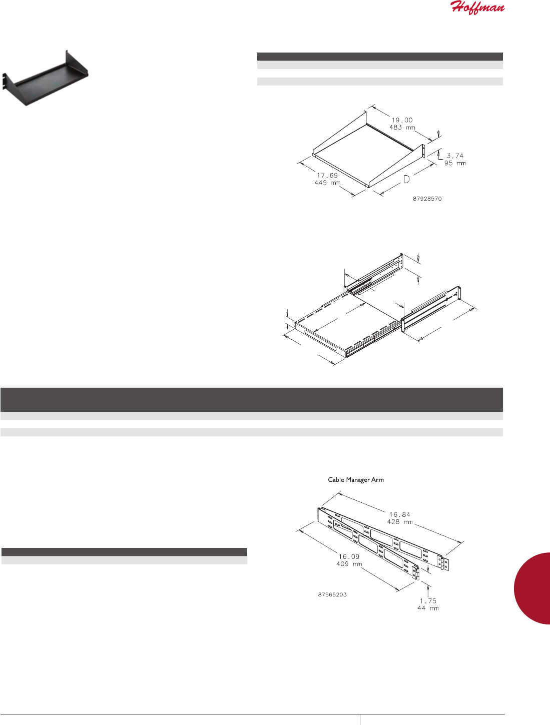
PH 763.422.2211 • FAX 763.422.2600 • PENTAIRPROTECT.COMEQUIPMENT PROTECTION ACCESSORIES 915
12
SHELVES, KEYBOARD TRAYS AND GLAND PLATES shelves for raCks and Cabinets
SINGLESIDED SHELF
Mounts to 19-in. rack angles to
house voice/data networking
equipment. RAL 9005 black finish.
Load rating: 75 lb. (34 kg)
BULLETIN: DACCY
Catalog Number H x W x D (in.) H x W x D (mm) Style Rack Units
ESH198 3.74 x 19.00 x 8.00 95 x 483 x 203 Solid 2
ESH1915 3.74 x 19.00 x 15.00 95 x 483 x 381 Solid 2
ESH1915V 3.74 x 19.00 x 15.00 95 x 483 x 381 Vented 2
ESH1917 3.74 x 19.00 x 17.00 95 x 483 x 432 Solid 2
SLIDING EQUIPMENT SHELF
Steel Sliding Equipment Shelf mounts to front surface of front and
back rack angles. Models fit 19- or 23-in. rack spacing. Adjusts to
fit multiple-depth enclosures and rack angle placements. Shelf
can be used on 2-post rack or cabinet with front rack angles only by
reversing support bracket. Optional cable manager arm available.
14 gauge steel with 12 gauge supports with RAL 9005 black
polyester powder paint finish. Load rating: 150 lb. (68.0 kg) with four
corner mounting; 75 lb. (34.0 kg) with two-post or front-rack-angle
cabinet mounting.
Optional Cable Manager Arm is recommended to help control cable
movement as shelf slides in and out.
BULLETIN: DACCY
2-ISO2
-
'
>@
>@
>@
/
Catalog Number D Max. (in.) D Max. (mm) L (in.) L (mm) J (in.) J (mm)
Shelf
Pullout
(in.)
Shelf
Pullout
(mm)
Fits
Rack
Rack
Units
P19SHP68B 37.40 950 16.72 425 16.20 412 17.00 432 19 in. 2
P19SHP810B 41.30 1050 24.59 625 16.20 412 19.00 483 19 in. 2
P23SHP68B 37.40 950 16.72 425 20.20 513 17.00 432 23 in. 2
P23SHP810B 41.30 1050 24.59 625 20.20 513 19.00 483 23 in. 2
CABLE MANAGER ARM FOR SLIDING EQUIPMENT
SHELF
Cable Manager Arm mounts to back of sliding equipment shelf on
right or left side. Controls cable movement as shelf slides in and
out. 14 gauge steel with RAL 9005 black polyester powder paint
finish.
BULLETIN: DACCY
Catalog Number Description Use With
PHCB Cable Manager Arm Sliding Equipment Shelf
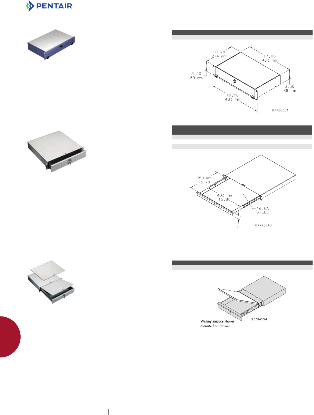
EQUIPMENT PROTECTIONSUBJECT TO CHANGE WITHOUT NOTICEACCESSORIES916
12
SHELVES, KEYBOARD TRAYS AND GLAND PLATES shelves for raCks and Cabinets
KEYBOARD COMPARTMENT FOR 19IN. RACKS
Provides a convenient way to
incorporate a keyboard with
other 19-in. rack-mounted
equipment. Uses 2 RU of space.
Made of light-weight aluminum
with brushed finish. Accommodates
keyboard up to 16.50-in. (419-mm)
wide. Mounting hardware included.
BULLETIN: DACCY
Catalog Number Fits rack width Rack Units
A19KBC2B 19 2
RACKANGLE MOUNTED DRAWER
Steel drawer for 19-in. rack-angle mounting mounts to the front
surface of the rack angles. Integral steel box contains the drawer
and protects surrounding internal equipment. Extends 13 in. (330
mm) on ball bearing slides. Front includes handle and key lock.
Finish is RAL 7035 textured light-gray polyester powder paint.
Mounting hardware is included.
BULLETIN: P20
Catalog Number H (mm) H (in.)
Fits Rack
Width
Rack
Units
P19DR1US 43 1.69 19 in. 1
P19DR2US 88 3.47 19 in. 2
P19DR3US 132 5.20 19 in. 3
WRITING SURFACE FOR RACKANGLEMOUNTED DRAWER
Steel cover mounts on top of the
drawer and serves as a writing
surface and drawer cover. Finish
is RAL 7035 light-gray textured
polyester powder paint. Illustration
and one photo show writing surface
mounted on drawer. Order drawer
separately.
BULLETIN: P20
Catalog Number Description Fits
P19WS Steel writing surface and cover Drawer (order separately)
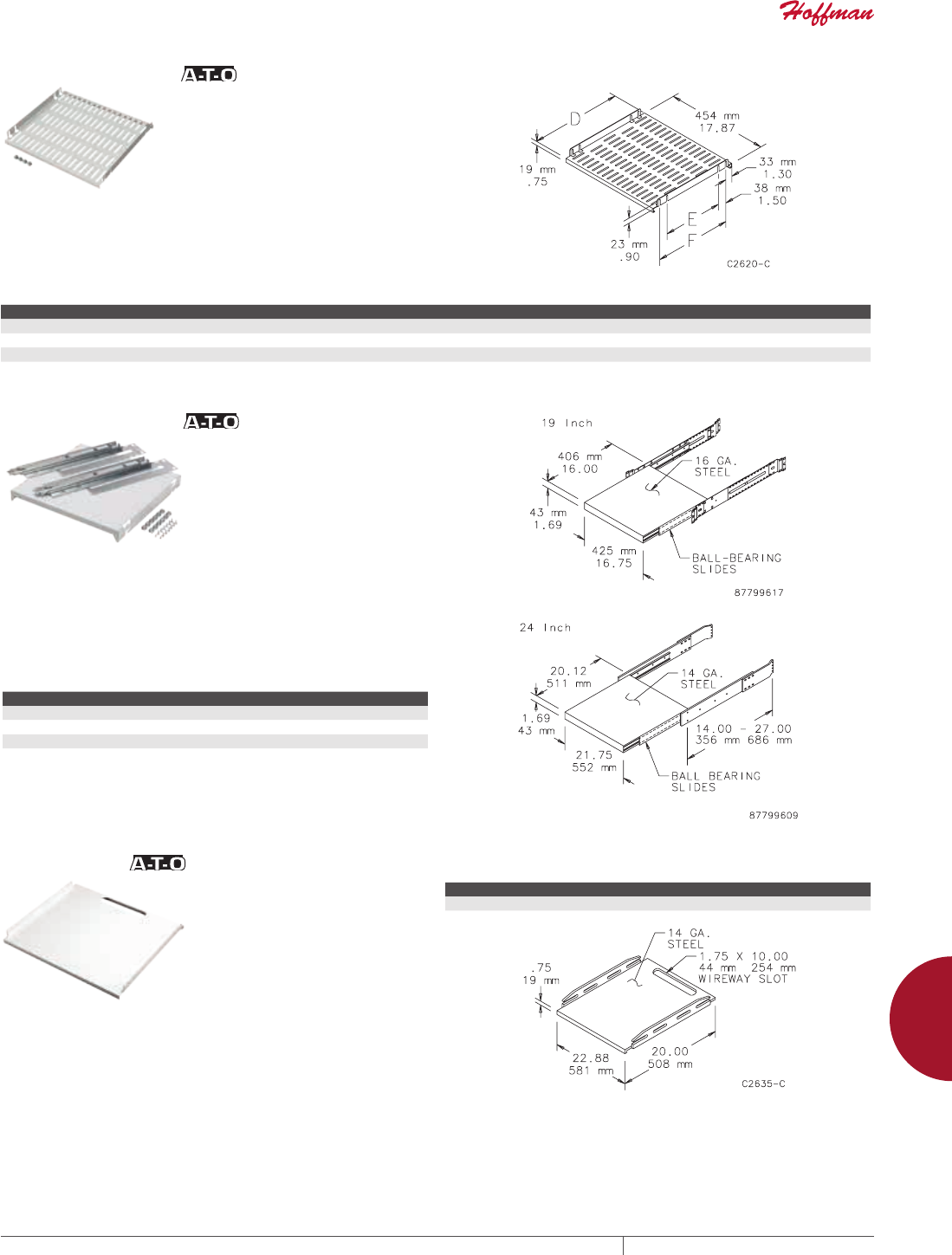
PH 763.422.2211 • FAX 763.422.2600 • PENTAIRPROTECT.COMEQUIPMENT PROTECTION ACCESSORIES 917
12
SHELVES, KEYBOARD TRAYS AND GLAND PLATES shelves for raCks and Cabinets
19IN. FIXED SHELF
14 gauge steel fixed shelf has large ventilation slots in shelf
surface. Mounts between two pair of rack mounting angles that
have accessory mounting legs. Shelves have RAL 7035 light-
gray polyester powder paint finish. Plated mounting hardware is
furnished.
BULLETIN: P20
Catalog Number D (in.) D (mm) E (in.) E (mm) F (in.) F (mm) Fits Rack Width
A19SH5 16.06 408 10.46 266 13.46 342 19 (in.)
A19SH6 20.00 508 14.40 366 17.40 442 19 (in.)
A19SH8 27.87 708 22.27 566 25.27 642 19 (in.)
PULLOUT SHELVES
Pull-Out Shelves extend 17 in. (432 mm) on ball-bearing slides. 16
gauge pull-out shelf mounts to uprights in 19-in. electronic rack
or 19-in. mini-rack using pull-out shelf bracket (EPSBKT) and has
light-gray powder paint finish. Two screws captivate shelf to slides.
14 gauge steel pull-out shelf mounts between two pair of rack-
mounting angles that have accessory mounting legs and has white
finish. Plated mounting hardware is furnished.
BULLETIN: DEC1, P20
Catalog Number Description Fits
A19SHP6 Pull-out shelf 19-in. rack angles
DL29SHP Pull-out shelf 24-in. rack
EPSBKT Pull-out shelf bracket
FIXED SHELF
14 gauge steel fixed shelf has a
large slot in rear of shelf surface for
wire management. Mounts between
two pair of rack mounting angles
that have accessory mounting legs.
Shelves are white. Plated mounting
hardware is furnished.
BULLETIN: P20
Catalog Number Fits Rack Width
DL29SH 24 (in.)
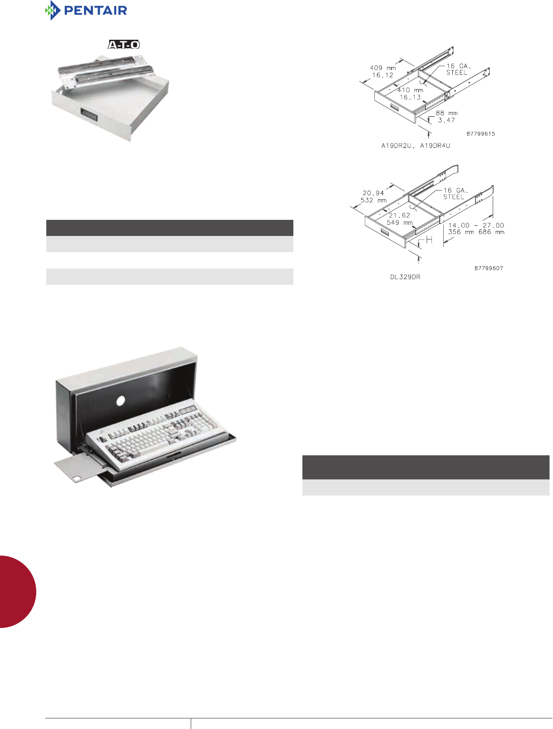
EQUIPMENT PROTECTIONSUBJECT TO CHANGE WITHOUT NOTICEACCESSORIES918
12
SHELVES, KEYBOARD TRAYS AND GLAND PLATES draWers
DRAWERS
DRAWERS
16 gauge steel drawer extends 17.00 in. (432 mm) on ball bearing
slides. Drawer has polyester powder paint finish and recessed black
pull handle. Drawers mount between two pair of rack-mounting
angles that have accessory mounting legs. Includes provision for
attaching a writing surface. Plated steel mounting hardware is
furnished.
BULLETIN: P20, X20
Catalog Number
H
in./mm Color Fits Rack Width
A19DR2U 3.47
88
RAL 7035 Light Gray 19 in.
A19DR4U 6.97
177
RAL 7035 Light Gray 19 in.
DL729DR 6.97
177
White 24 in.
Enclosure must be at least 24-in. (600-mm) deep.
CONCEPT KEYBOARD BOX Keyboard box is designed to fit on an outside surface of an
enclosure to provide a self-contained external Type 4 housing for a
keyboard. The box attaches to the enclosure surface with 4 bolts.
A large hole and rubber plug are provided for keyboard cord and
plug. The hinged cover is supported with flexible cables in the
open position. A left and a right mouse tray slides out from under
the keyboard mounting surface. VELCRO® strips with pressure-
sensitive adhesive are supplied to attach a keyboard. An internal
mouse storage pracket is provided. The box and cover are 16 gauge
steel with ANSI 61 gray polyester powder paint finish. Cover latches
with a single quarterturn slotted latch. Optional CONCEPT latches
also fit.
VELCRO is a trademark of Velcro Industries B.V.
BULLETIN: A80
Catalog Number AxBxC in./mm
Max. Keyboard Size
W x D x H
in./mm
CKBC24 10.00 x 23.30 x 4.79
254 x 592 x 122
20.20 x 8.00 x 2.34
513 x 203 x 59
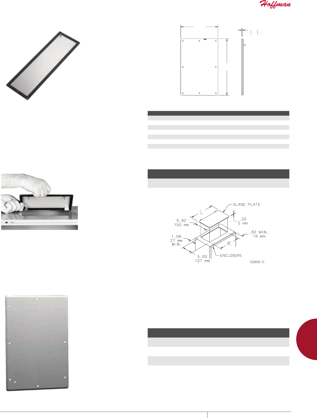
PH 763.422.2211 • FAX 763.422.2600 • PENTAIRPROTECT.COMEQUIPMENT PROTECTION ACCESSORIES 919
12
SHELVES, KEYBOARD TRAYS AND GLAND PLATES Gland Plates
GLAND PLATES
12 GAUGE GLAND PLATE, TYPE 4 AND TYPE 12
Mild steel gland plates are constructed of 12 gauge steel and
finished with ANSI 61 gray polyester powder paint. Gland plates
provide a removable cable egress and entry plate while maintaining
enclosure rating of UL Type 4 and Type 12. Easy installation by
cutting a rectangular opening in the enclosure and fastening with
included hardware kit.
BULLETIN: GP1
:
+
Catalog Number Cutout Size (in.) Cutout Size (mm) W x H (in.) W x H (mm)
GP126 7.50 x 3.75 191 x 95 10.98 x 5.23 279 x 133
GP128 7.50 x 5.75 191 x 146 10.98 x 7.23 279 x 184
GP166 13.50 x 3.75 343 x 95 14.98 x 5.23 380 x 133
GP168 13.50 x 5.75 343 x 146 14.98 x 7.23 380 x 184
GP206 17.50 x 3.75 445 x 95 18.98 x 5.23 482 x 133
GP208 17.50 x 5.75 446 x 146 18.98 x 7.23 482 x 184
GP248 21.50 x 5.75 546 x 146 22.98 x 7.23 584 x 184
GP2412 21.50 x 7.00 246 x 178 22.98 x 8.48 584 x 215
16 GAUGE GLAND PLATE
Constructed of 16 gauge steel. Gland plates will maintain UL/CSA
Type 12 integrity while providing a removable cable egress and
entry plate. Easily installed by cutting a rectangular opening in the
enclosure. Finish is ANSI 61 gray polyester powder paint.
BULLETIN: A80
Catalog Number
K
in./mm
L
in./mm
DLGP610 9.00
229
9.94
252
DLGP618 17.00
432
17.94
457
12 GAUGE GLAND PLATE Constructed of 12 gauge steel and designed for use with 10 gauge
and 12 gauge enclosures. Provides a removable cable egress and
entry plate while maintaining UL/NEMA integrity of the enclosure.
Gasket with pressure-sensitive adhesive is included to be applied
after desired modifications are completed. Finish is ANSI 61 gray
polyester powder paint. Maintains UL/NEMA Type 4 and Type 12 if
properly installed in a Hoffman enclosure.
BULLETIN: A34Y
Catalog Number
Size
in./mm
Opening Size
in./mm
AGP618 6.50 x 18.50
165 x 470
4.00 x 16.00
102 x 406
AGP1218 12.50 x 18.50
318 x 470
10.00 x 16.00
254 x 406
AGP1618 16.50 x 18.50
419 x 470
14.00 x 16.00
356 x 406
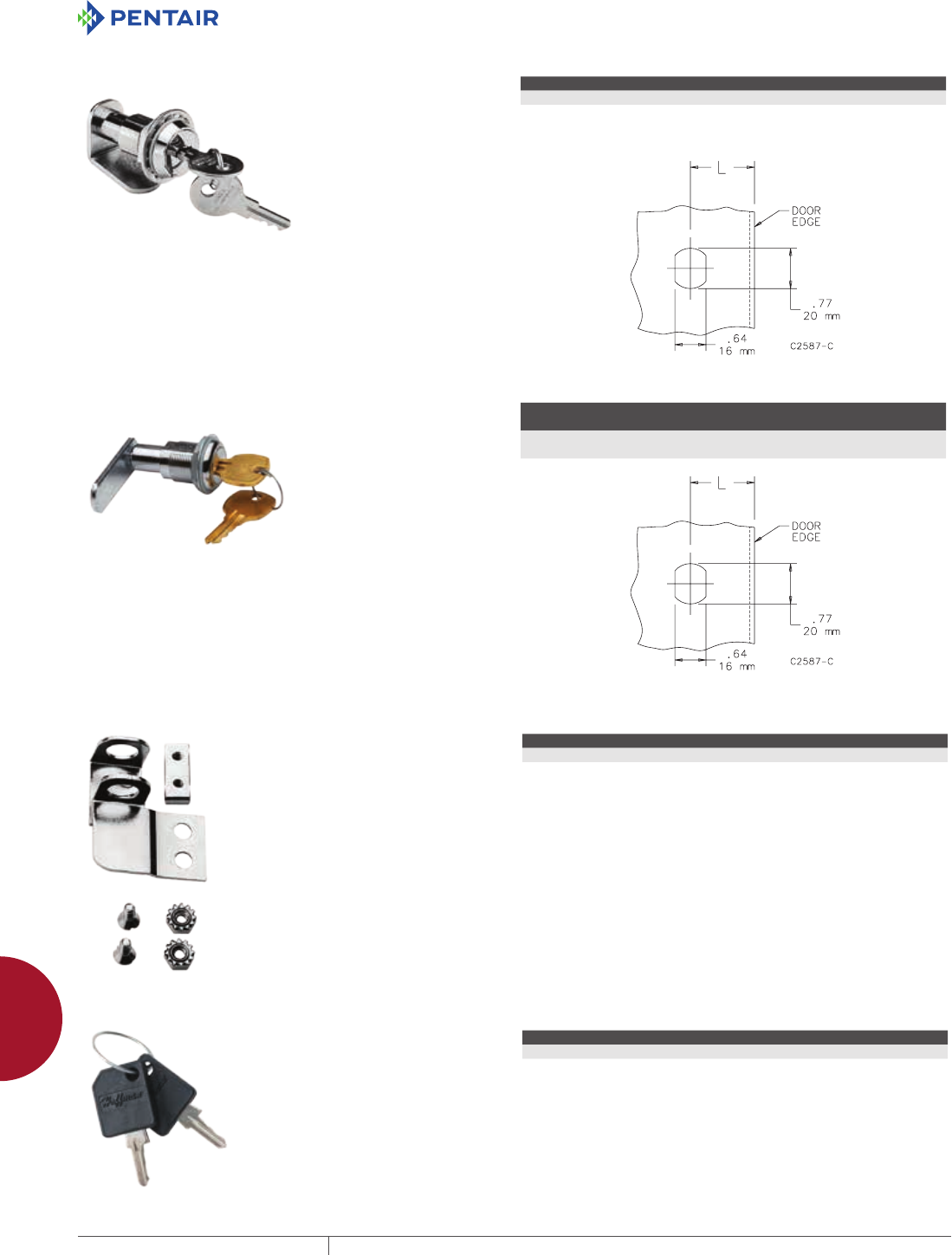
EQUIPMENT PROTECTIONSUBJECT TO CHANGE WITHOUT NOTICEACCESSORIES920
12
LOCKS, LOCKOUTS, LATCHES, HANDLES AND CLAMPS loCks
LOCKS, LOCKOUTS, LATCHES, HANDLES AND CLAMPS
LOCKS
LOCK KIT FOR CLAMP COVER JUNCTION BOXES
Designed for field installation in standard clamp-cover junction
boxes. Includes complete installation instructions. One hole must
be drilled or punched in the cover to receive the cylinder lock.
Punches for Hoffman locks and latches are available from Greenlee
Punches. For more information on Greenlee punches, go to http://
www.greenlee.textron.com/
BULLETIN: A80
Catalog Number L (in.) L (mm)
ACLJIC 1.25 32
LOCK KIT FOR TYPE 3R AND 12 ENCLOSURES
Designed for field installation in standard one-door Type 3R and 12
enclosures. Includes complete installation instructions. One hole
must be drilled or punched in the door to receive the cylinder lock.
BULLETIN: A80
Catalog Number
L, for NEMA 12 Enclosure
in./mm
L, for Medium 3R Hinged-Cover Enclosure
in./mm
ACLSN12 1.69
43
2.25
57
PADLOCK KIT FOR JUNCTION BOXES
Designed for field installation on
standard LP, CH and CHNF junction
boxes. Maintains water-tight and
dust-tight seal. To install simply
drill two holes in the cover and two
holes in the body. Includes complete
instructions. Padlock Kit is plated
steel or Type 316 stainless steel.
BULLETIN: A80
Catalog Number Description
APLKJIC Plated steel
APLKJIC6SS Type 316 stainless steel
REPLACEMENT KEYS
Fits PROLINE Network Cabinet and
Networking Wall-Mount Cabinet.
BULLETIN: DACCY
Catalog Number Key Code Includes Use with
E2233KEY 2233 2 Keys PROLINE , Net Series, PC Cabinet, SOHO
E333KEY 333 2 Keys ACCESSPLUS II, L-BOX , D-BOX
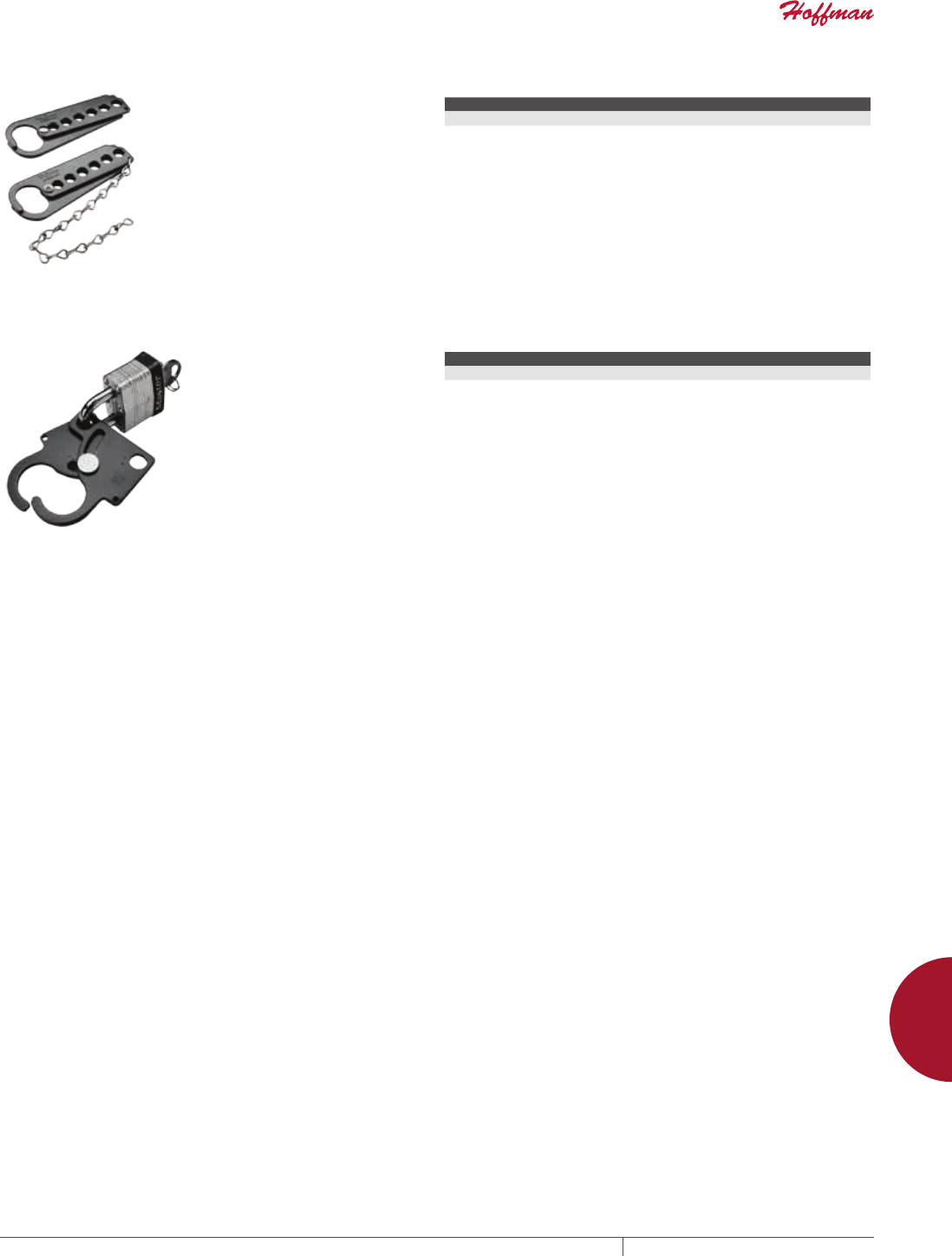
PH 763.422.2211 • FAX 763.422.2600 • PENTAIRPROTECT.COMEQUIPMENT PROTECTION ACCESSORIES 921
12
LOCKS, LOCKOUTS, LATCHES, HANDLES AND CLAMPS loCkouts
LOCKOUTS
SAFETY LOCKOUTS
Provide a means of using multiple
padlocks on a secured power
source. Catalog number ASL6C
includes a 10.00-in. (254-mm) plated
steel chain. Manufactured from 10
gauge steel with six station holes.
Red finish. Overall length is 5.06 in.
(128 mm) and padlock holes are .38-
in. (10-mm) in diameter.
BULLETIN: A80
Catalog Number Description
ASL6 Without chain
ASL6C With chain
DUALACCESS SAFETY LOCKOUTS
Provide a means of using two
padlocks on a secured power
source. Either padlock can be
removed enabling power to be
interrupted and enclosure accessed.
Catalog number ASLDAC includes
a 10.00-in. (254-mm) plated steel
chain. Lockouts are manufactured
from 10 gauge steel and finished
in red. Padlock holes are .38-in.
(10-mm) in diameter. Padlock is not
included.
BULLETIN: A80
Catalog Number Description
ASLDA Without chain
ASLDAC With chain
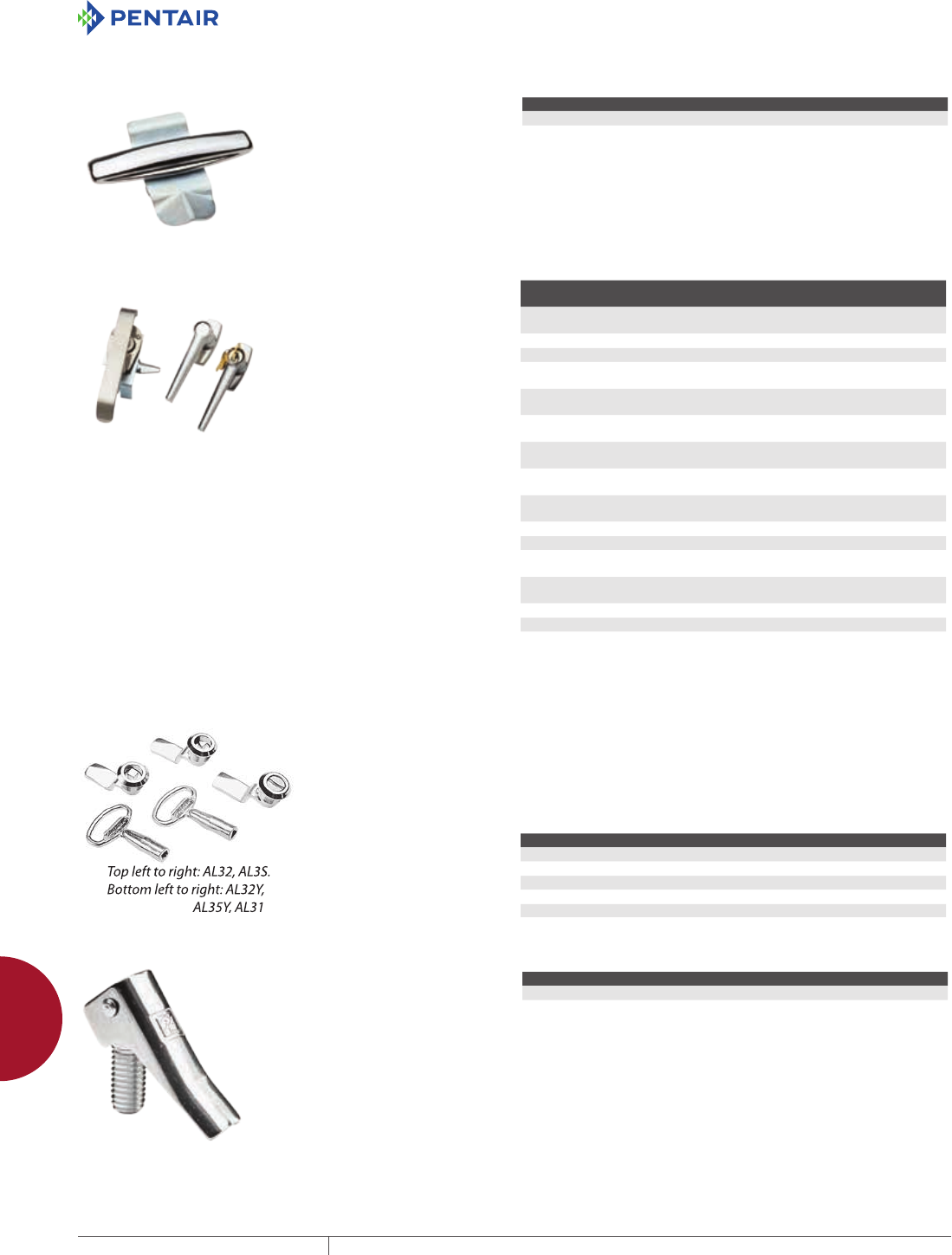
EQUIPMENT PROTECTIONSUBJECT TO CHANGE WITHOUT NOTICEACCESSORIES922
12
LOCKS, LOCKOUTS, LATCHES, HANDLES AND CLAMPS latChes
LATCH ES
THANDLE LATCH AND KEYED CYLINDER LOCK KITS
To install, simply remove the
standard slotted latch and insert
the kit. Complete installation
instructions are furnished. Catalog
number AL7A includes a Type L7 T
handle and all hardware. Catalog
number AL12AR includes a Type L12
cylinder lock, cam and all hardware.
Latch and lock fit Type 1 enclosures
and hinged-cover pull boxes.
BULLETIN: A80
Catalog Number Description
AL7A T handle latch kit
AL12AR Cylinder lock kit
LATCH KIT FOR ONEDOOR TYPE 12 ENCLOSURES
Designed for field installation on most standard one-door Type
12 enclosures. These latch kits will not fit Hoffman disconnect,
CONCEPT or PROLINE enclosures. Each kit includes a handle,
latch, latch rods, adjustable rod guides and all hardware. The latch
rods can be adjusted to maintain the proper gasket compression by
relocating the pins in the rod guides. When the pin is removed, the
latch rod can also be removed. These kits are available with a key
locking handle, a non-locking handle or a padlocking handle. All
openings through the door are gasketed to assure a complete seal.
Ends of latch rods have rollers for easier door closing.
BULLETIN: A80
Catalog
Number
Handle
Type Opens Description
AL36A Padlock Either Clockwise or
Counterclockwise
1-point Latch kit
AL2A Keylock Clockwise 1-point Latch kit
AL2ACCW Keylock Counterclockwise 1-point Latch kit
AL3A Non-
Locking
Clockwise 1-point Latch kit
AL36BR Padlock Either Clockwise or
Counterclockwise
3-point Latch Kit where A is 16, 20, 24
or 30 in.
AL2BR Keylock Clockwise 3-point Latch Kit where A is 16, 20, 24
or 30 in.
AL2BCCW Keylock Counterclockwise 3-point Latch Kit where A is 16, 20, 24
or 30 in.
AL3BR Non-
Locking
Clockwise 3-point Latch Kit where A is 16, 20, 24
or 30 in.
AL36CR Padlock Either Clockwise or
Counterclockwise
3-point Latch kit where A is 36, 42 or 48 in.
AL2CR Keylock Clockwise 3-point Latch kit where A is 36, 42 or 48 in.
AL2CCCW Keylock Counterclockwise 3-point Latch kit where A is 36, 42 or 48 in.
AL3CR Non-
Locking
Clockwise 3-point Latch kit where A is 36, 42 or 48 in.
AL36DR Padlock Either Clockwise or
Counterclockwise
3-point Latch kit where A is 60 or 72 in.
AL2DR Keylock Clockwise 3-point Latch kit where A is 60 or 72 in.
AL2DCCW Keylock Counterclockwise 3-point Latch kit where A is 60 or 72 in.
AL3DR Non-
Locking
Clockwise 3-point Latch kit where A is 60 or 72 in.
See price list for factory installation charges. A is enclosure height.
LATCH KITS FOR TYPE 4 AND 12 ENCLOSURES Fits Type 4 and 12 enclosures which have external screw clamps.
Requires only a quarter-turn (90 degrees) to open or close. An
internal O-ring and external gasket assure a water-tight and dust-
tight seal. Installation requires a hole punched or drilled in the door
for each latch. Complete instructions are furnished. A square or
triangular key is required for tamper-resistant latches. Latch is die-
cast zinc with chrome finish.
BULLETIN: A80
Catalog Number Description
AL31 Slotted insert
AL32 7-mm square insert
AL32Y Key for AL32
AL35 7-mm triangle insert
AL35Y Key for AL 35
TOGGLE LATCH FOR TYPE 4 AND 4X FLOORMOUNT AND FREESTAND ENCLOSURES
Provides quick access to Type
4 and 4X floor-mount and free-
stand enclosures with clamps. The
3/8-16 threaded, stainless steel
toggle latches replace the standard
stainless steel bolts. Operation of
the toggle releases the door clamp
so the door can be opened without
tools. Two Type 316 stainless steel
toggle assemblies included.
BULLETIN: A80
Catalog Number Description
AFT44XSS 2 toggle latches
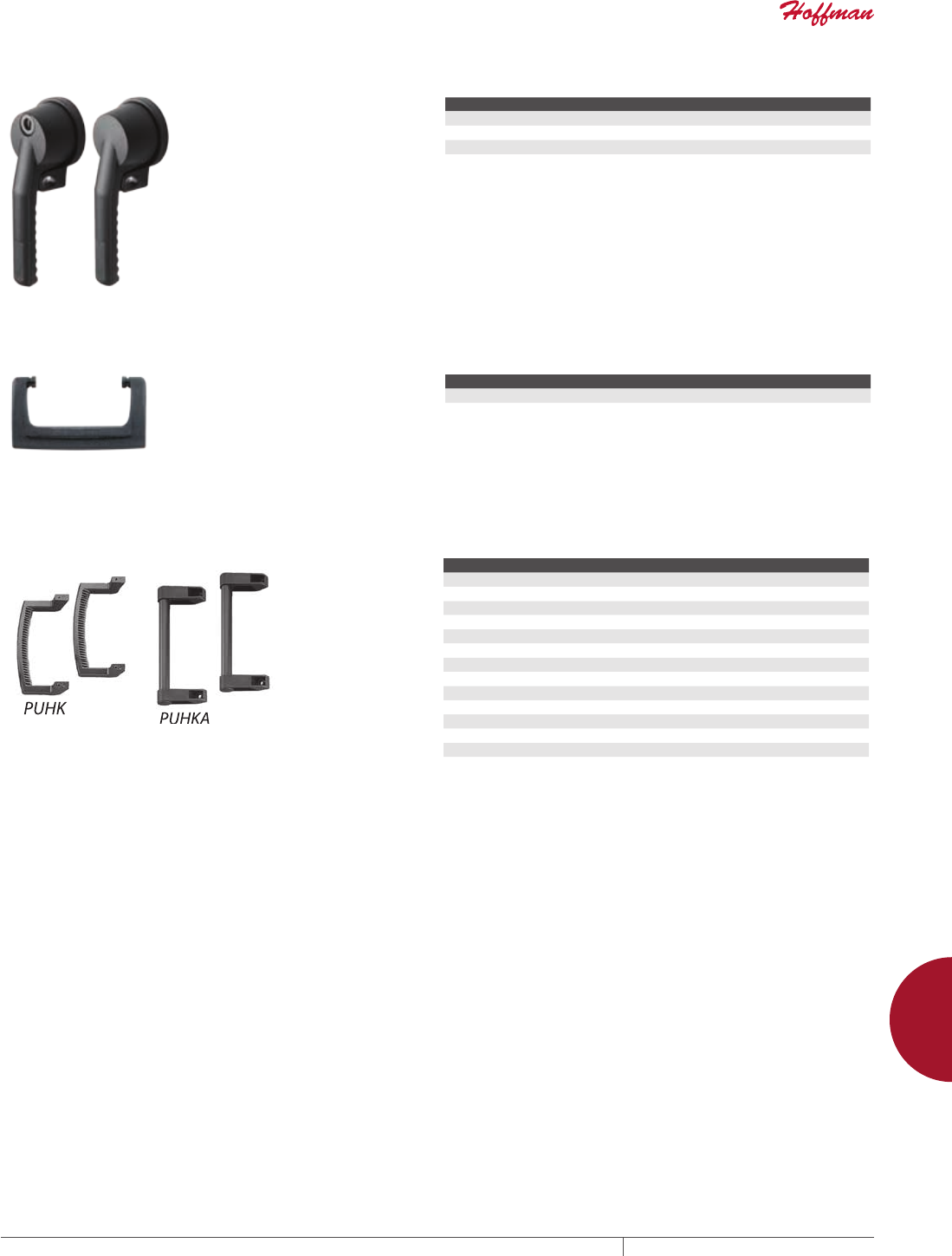
PH 763.422.2211 • FAX 763.422.2600 • PENTAIRPROTECT.COMEQUIPMENT PROTECTION ACCESSORIES 923
12
LOCKS, LOCKOUTS, LATCHES, HANDLES AND CLAMPS handles
HANDLES
POWERGLIDE HANDLES
Easy-to-install medium-size
POWERGLIDE Handles fit into
existing handle holes. They are
available in clockwise and counter-
clockwise non-defeater models and
a clockwise defeater model. The
clockwise defeater model includes
door hardware for Bulletin A25
enclosures.
BULLETIN: A80
Catalog Number Description
AL55CW Medium POWERGLIDE Handle - Clockwise Opening
AL55CCW Medium POWERGLIDE Handle - Counter-Clockwise Opening
AL55CWD Medium POWERGLIDE Handle - Clockwise Opening with Defeater and Door Hardware
HANDLE KIT
Non-metallic handle for small
enclosures. Includes four rubber
bumpers that mount on back of
enclosure to protect exterior
finish. All mounting hardware and
complete installation instructions
are provided.
BULLETIN: A80
Catalog Number Description
DHDLK Handle kit
HANDLES
Attach to sides of enclosure to provide maximum operator control
when using a pendant arm, swivel or swivel tilt.
BULLETIN: C2, CC1, CC2, DEC1, P1
Catalog Number Description Fits
CCCH150 150 mm COMPACT CC1
CCCH220 220 mm COMPACT CC1
CCCH300 300 mm COMPACT CC1
CCCHL L handle COMPACT CC2
CCCHS Straight handle COMPACT CC2
CHDL31 310 mm CONCEPT OI
CHDL40 400 mm CONCEPT OI
CHDL55 550 mm CONCEPT OI
ERCFH3U 132 mm Desktop case
ERCFH4U 177 mm Desktop case
ERCFH6U 266 mm Desktop case
PUHKA 248 mm PROLINE sloped fronts
PUHK 9.75 in. PROLINE sloped fronts
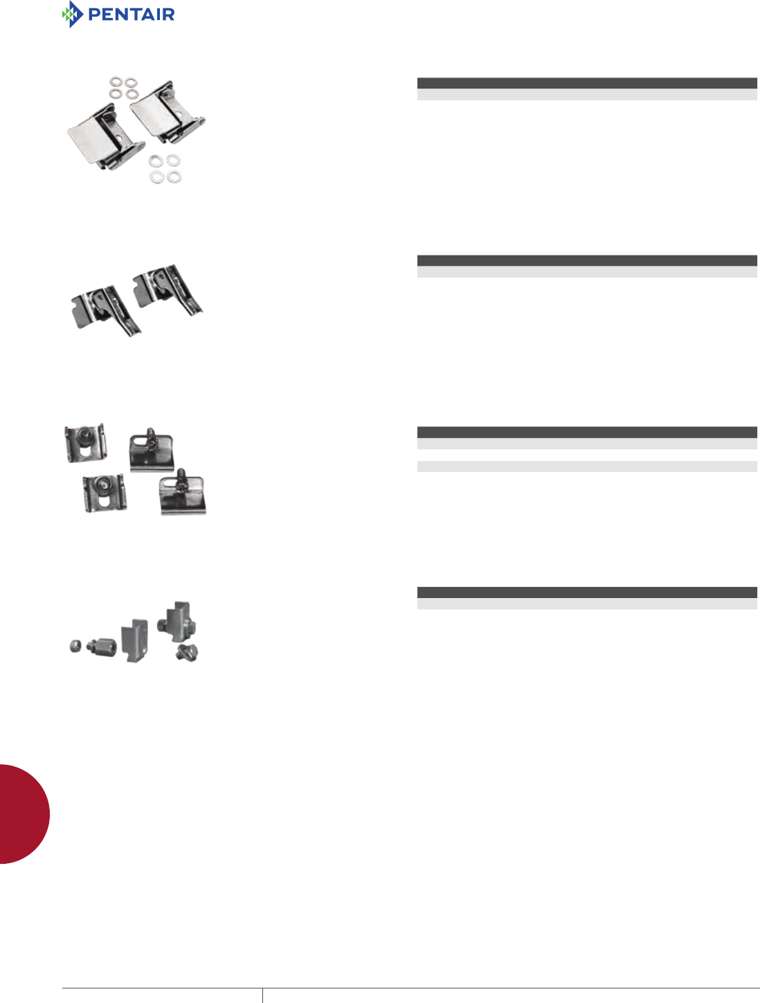
EQUIPMENT PROTECTIONSUBJECT TO CHANGE WITHOUT NOTICEACCESSORIES924
12
LOCKS, LOCKOUTS, LATCHES, HANDLES AND CLAMPS ClamPs
CLAMPS
FASTOPERATING CLAMPCOVER JUNCTION BOX CLAMP
Provides quick access to enclosure
or wireway interiors. Installs on
standard clamp bracket used on
Hoffman junction boxes, Type
12 trough and wireway, Type
4X wireway and similar custom
enclosures. Clamps are available in
plated steel or stainless steel.
BULLETIN: A80
Catalog Number Description
AL23 Plated steel clamp
AL23SS Stainless steel clamp
FASTOPERATING CLAMP ASSEMBLY
Provides quick access to enclosures
which have screw clamps. Install on
clamp brackets used on single-door
Type 4, 4X, 12 and 13 enclosures and
similar custom order enclosures.
The entire clamp assembly is Type
316 stainless steel.
BULLETIN: A80
Catalog Number Qty.
AFC412SS 2
CLAMP KITS
These kits provide replacement
clamps for clamp-cover junction
boxes and wall-mount enclosures.
Each kit contains two clamps and all
mounting hardware.
BULLETIN: A80
Catalog Number Material Use with
AL15 Mild Steel A12 enclosures
AL16 Stainless Steel A4, A4S enclosures
AL17 Mild Steel A51 junction boxes
AL18 Stainless Steel A51S junction boxes
CLAMP BLOCK KIT
Used on floor-mount and free-stand
Type 4X stainless steel enclosures
with clamps. Kit includes two sets of
screws, two Type 316L clamp blocks
and mounting hardware.
BULLETIN: A50Y
Catalog Number Description
ACBK6SS 2 clamp blocks and screw sets
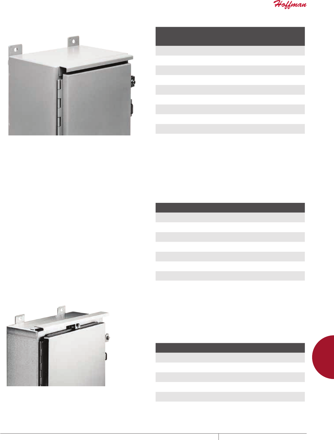
PH 763.422.2211 • FAX 763.422.2600 • PENTAIRPROTECT.COMEQUIPMENT PROTECTION ACCESSORIES 925
12
DRIP SHIELDS driP shields
DRIP SHIELDS
DRIP SHIELDS
DRIP SHIELD KIT FOR TYPE 12 ENCLOSURES
Protects door hardware from dripping water and settling dust.
Attaches quickly and easily to the enclosure with stainless steel
screws and sealing washers (hardware is furnished). Stainless
steel hinge pin and stainless steel door clamping assemblies are
furnished to replace the standard hinge pin and door clamping
assemblies. A tube of sealing compound is also supplied with
each kit. Manufactured from 14 gauge steel with an ANSI 61 gray
polyester powder paint finish over pretreated surfaces.
BULLETIN: A80
Catalog
Number For
Fits
Enclosure
Size B
in./mm
ADK12A Single-Door Wall-Mount Enclosures 12.00
305
ADK16A Single-Door Wall-Mount Enclosures 16.00
406
ADK20A Single-Door Wall-Mount Enclosures 20.00
508
ADK24A Single-Door Wall-Mount/Floor-Mount Enclosures with Continuous Hinge 24.00
610
ADK30A Single-Door Wall-Mount/Floor-Mount Enclosures with Continuous Hinge 30.00
762
ADK36A Single-Door Wall-Mount/Floor-Mount Enclosures with Continuous Hinge 36.00
914
ADK42A Two-Door Floor-Mount, Continuous Hinge Enclosures 42.00
1067
ADK48A Two-Door Floor-Mount, Continuous Hinge Enclosures-Door Floor-Mount
Enclosures
48.00
1219
ADK60A Two-Door Floor-Mount, Continuous Hinge Enclosuresoor Floor-Mount
Enclosures
60.00
1524
ADK72A Two-Door Floor-Mount, Continuous Hinge Enclosuresoor Floor-Mount
Enclosures
72.00
1829
Two-Door Drip Shield kits are not designed for use on 48.00-in. (1219-mm) wide and 60.00-in. (1524-mm)
wide Two-Door Type 12 Wall-Mount Enclosures.
DRIP SHIELD KIT FOR TYPE 12 FREESTANDING AND
FLOORMOUNT ENCLOSURES WITH CONCEALED
HINGES
Protects door hardware from dripping water and settling dust.
Attaches quickly and easily to the enclosure with stainless steel
screws and sealing washers (hardware is furnished). A tube of
sealing compound is also supplied with each kit. Manufactured from
14 gauge steel with an ANSI 61 gray polyester powder paint finish
over pretreated surfaces.
BULLETIN: A80
Catalog Number For
Fits Enclosure Size B
in./mm
ADK24HH Single-Door Free-Stand/Floor-Mount Enclosures 24.00
610
ADK30HH Single-Door Free-Stand/Floor-Mount Enclosures 30.00
762
ADK36HH Single-Door Free-Stand/Floor-Mount Enclosures 36.00
914
ADK42HH Two-Door Free-Stand/Floor-Mount Enclosures 42.00
1067
ADK48HH Two-Door Free-Stand/Floor-Mount Enclosures 48.00
1067
ADK60HH Two-Door Free-Stand/Floor-Mount Enclosures 60.00
1524
ADK72HH Two-Door Free-Stand/Floor-Mount Enclosures 72.00
1829
STAINLESS STEEL DRIP SHIELD KIT FOR TYPE 4 AND 4X
WALLMOUNT ENCLOSURES
Easily installed on Type 4 and 4X wall-mount enclosures (excluding
quick-release latch models). Protects door from dripping water
and settling dust. Attaches quickly and easily to the enclosure with
stainless steel screws and sealing washers (furnished). A tube of
sealing compound is supplied with each kit. Manufactured from
14 gauge Type 316 stainless steel. Kits can be special ordered for
other Hoffman enclosures. Consult factory for more information.
Product maintains UL/CSA Type 4, 4X and 12 rating when properly
installed on a Hoffman enclosure.
BULLETIN: A4SY
Catalog Number
Fits Enclosure Size B
in./mm
ADK12SS6 12.00
305
ADK16SS6 16.00
406
ADK20SS6 20.00
508
ADK24SS6 24.00
610
ADK30SS6 30.00
762
ADK36SS6 36.00
914
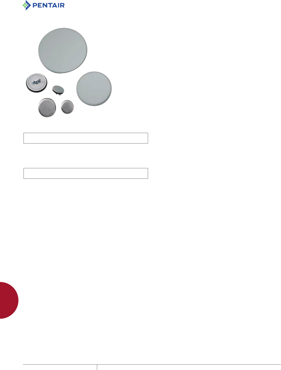
EQUIPMENT PROTECTIONSUBJECT TO CHANGE WITHOUT NOTICEACCESSORIES926
12
HOLE SEALS hole seals
HOLE SEALS
HOLE SEALS
HOLSEALERS HOLE SEALS
INDUSTRY STANDARDS
Steel Hole Seals
UL 508A Component Recognized; Type 3R, 4, 12, 13; File No.
E61997
CSA File No. 42186; Type 3R, 4, 12, 13
NEMA/EEMAC Type 3R, 4, 12, 13
IEC 60529, IP66
Stainless Steel Hole Seals
UL 508A Component Recognized; Type 3R, 4, 4X, 12, 13; File No.
E61997
CSA File No. 42186; Type 3R, 4, 4X, 12, 13
NEMA/EEMAC Type 3R, 4, 4X, 12, 13
IEC 60529, IP66
APPLICATION
Seal extra pushbutton holes, conduit openings and knockout
openings against dust, dirt, oil and water with Hoffman HOL-
SEALERS . Seals will cover any size or shape of hole from .19-in.
diameter to maximum diameter shown in table. Can be used on
enclosure walls up to .31-in. (8-mm) thick.
FEATURES
• Available in multiple colors and sizes
• Oil-resistant gasket provided
SPECIFICATIONS
Steel Models
• 16 gauge galvanized steel backplate
• Plated stud (10-32x5/8) and wing nut
Stainless Steel Models
• 16 gauge stainless steel backplate
• Seal, backplate, stud (10-24x5/8) and wing nut are 300 series
stainless steel
FINISH
Steel seals have polyester powder paint finish over galvanized front
surface.
Stainless steel seals have polished front surface.
BULLETIN: A80HS

PH 763.422.2211 • FAX 763.422.2600 • PENTAIRPROTECT.COMEQUIPMENT PROTECTION ACCESSORIES 927
12
HOLE SEALS hole seals
Standard Product
Catalog Number Material Finish/Color For
Maximum Hole Diameter
in./mm
Hol-Sealer Diameter
in./mm
AS056M Steel ANSI 61 gray Micro 0.56
14
0.80
20
AS056MSS Stainless Steel Stainless Steel Micro 0.56
14
0.80
20
AS056CB Steel Chrysler beige Micro 0.56
14
0.80
20
AS056MFB Steel Ford brown Micro 0.56
14
0.80
20
AS056MLG Steel Light gray Micro 0.56
14
0.80
20
ASPBG Steel ANSI 61 gray 22.5-mm pushbutton holes 0.88
22
1.22
31
ASPBGSS Stainless Steel Stainless Steel 22.5-mm pushbutton holes 0.88
22
1.22
31
AS050 Steel ANSI 61 gray 1/2-in. conduit holes 0.88
22
1.38
35
AS050LG Steel Light gray 1/2-in. conduit holes 0.88
22
1.38
35
AS050SS Stainless Steel Stainless Steel 1/2-in. conduit holes 0.88
22
1.38
35
AS075 Steel ANSI 61 gray 3/4-in. conduit holes 1.06
27
1.56
40
AS075SS Stainless Steel Stainless Steel 3/4-in. conduit holes 1.06
27
1.56
40
AS075LG Steel Light gray 3/4-in. conduit holes 1.06
27
1.56
40
ASPB Steel ANSI 61 gray 30.5-mm pushbutton holes 1.25
32
1.75
44
ASPBSS Stainless Steel Stainless Steel 30.5-mm pushbutton holes 1.25
32
1.75
44
ASPBLG Steel Light gray 30.5-mm pushbutton holes 1.25
32
1.75
44
AS100 Steel ANSI 61 gray 1-in. conduit holes 1.38
35
1.88
48
AS100SS Stainless Steel Stainless Steel 1-in. conduit holes 1.38
35
1.88
48
AS100LG Steel Light gray 1-in. conduit holes 1.38
35
1.88
48
AS125 Steel ANSI 61 gray 1 1/4-in. conduit holes 1.69
43
2.19
56
AS125SS Stainless Steel Stainless Steel 1 1/4-in. conduit holes 1.69
43
2.19
56
AS125LG Steel Light gray 1 1/4-in. conduit holes 1.69
43
2.19
56
AS150 Steel ANSI 61 gray 1 1/2-in. conduit holes 2.00
51
2.50
64
AS150SS Stainless Steel Stainless Steel 1 1/2-in. conduit holes 2.00
51
2.50
64
AS150LG Steel Light gray 1 1/2-in. conduit holes 2.00
51
2.50
64
AS200 Steel ANSI 61 gray 2-in. conduit holes 2.50
64
3.00
76
AS200SS Stainless Steel Stainless Steel 2-in. conduit holes 2.50
64
3.00
76
AS200LG Steel Light gray 2-in. conduit holes 2.50
64
3.00
76
AS250 Steel ANSI 61 gray 2 1/2-in. conduit holes 3.00
76
3.50
89
AS250SS Stainless Steel Stainless Steel 2 1/2-in. conduit 3.00
76
3.50
89
AS300 Steel ANSI 61 gray 3-in. conduit holes 3.62
92
4.12
105
AS300SS Stainless Steel Stainless Steel 3-in. conduit holes 3.62
92
4.12
105
AS350 Steel ANSI 61 gray 3 1/2-in. conduit holes 4.12
105
4.62
117
AS350SS Stainless Steel Stainless Steel 3 1/2-in. conduit holes 4.12
105
4.62
117
AS400 Steel ANSI 61 gray 4-in. conduit holes 4.62
117
5.12
130
AS400SS Stainless Steel Stainless Steel 4-in. conduit holes 4.62
117
5.12
130
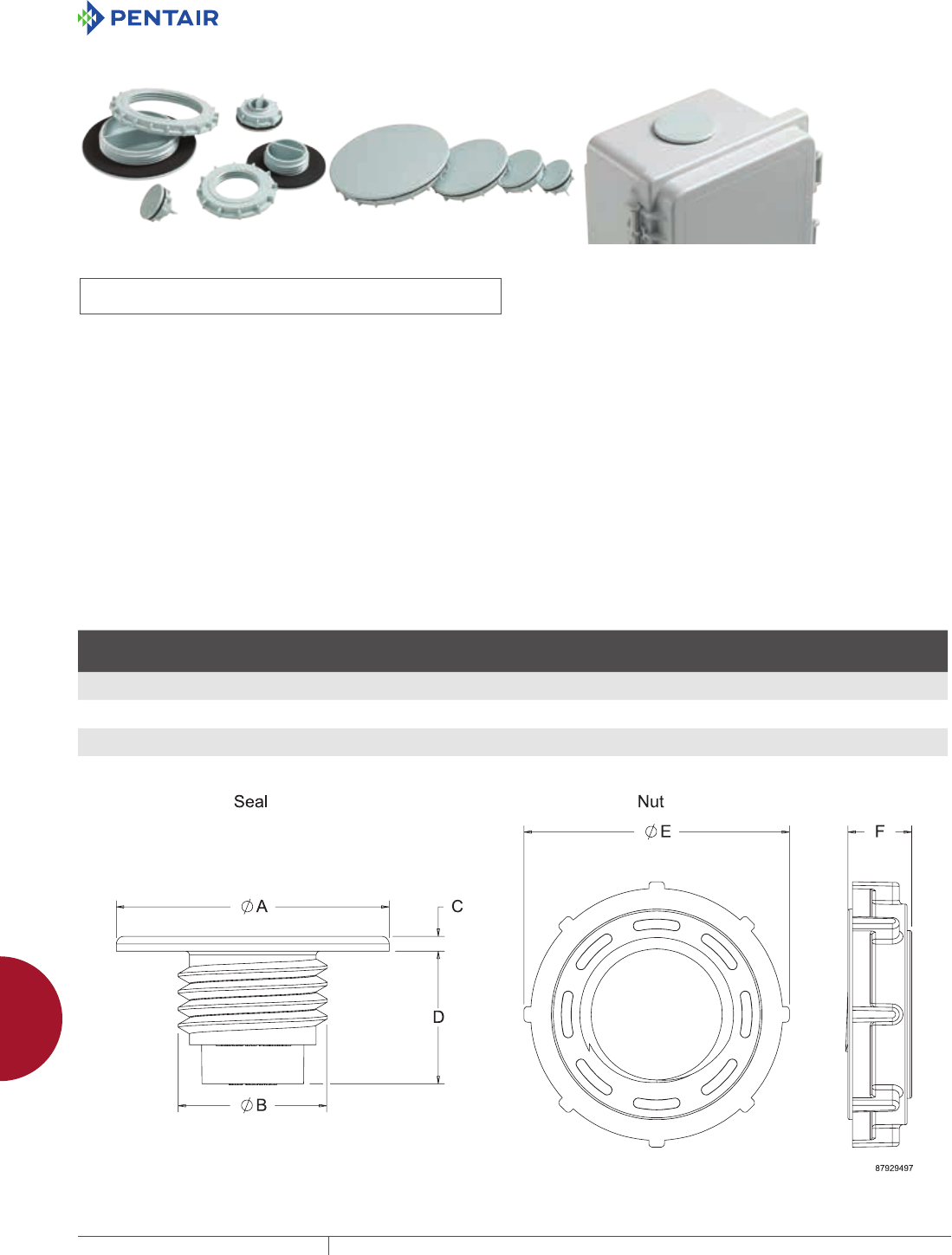
EQUIPMENT PROTECTIONSUBJECT TO CHANGE WITHOUT NOTICEACCESSORIES928
12
HOLE SEALS hole seals
HOLSEALERS NONMETALLIC HOLE SEALS
INDUSTRY STANDARDS
UL 508A Component Recognized; Type 3R, 4, 4X, 12, 13; File No.
E61997
CSA File No. 42186: Type 3R, 4, 4X, 12, 13
NEMA/EEMAC Type 3R, 4, 4X, 12, 13
IEC 60529, IP66
APPLICATION
Designed for use in corrosive environments to seal extra
pushbutton holes, conduit openings and knockout openings against
dust, dirt, oil and water. These hole seals are suitable for sealing
enclosure openings in industries such as petroleum and chemical
processing, wastewater processing, pulp and paper, outdoor
monitoring and any other industry exposed to harsh environments.
Innovative 3-in-1 self-centering design
• Thread self-centers on one hole size
• Nut orientation “A” self-centers on a second hole size (see Nut
Orientation drawing)
• Nut orientation “B” self-centers on a third hole size
FEATURES
• Innovative 3-in-1 self-centering design reduces inventory
requirements; 4 models cover 12 common industry cutouts
ranging from 1/2 in. to 4 in.
• Non-metallic construction provides superior corrosion
resistance for reliability in harsh environments
• UV stabilized; ideal for direct sunlight (avoids fiberbloom
associated with fiberglass)
• Chemically resistant to a broad range of chemicals
• Durable and impact resistant; resists cracking
• Sold in quantities of 2 per catalog number
• Cost-effective alternative to stainless steel
• Polyester material has a UL 94 rating of 5VA
• Easy to install; no tools required
SPECIFICATIONS
• Thread and nut are constructed of non-glass-filled polyester
• Oil-resistant gasket
FINISH
RAL 7035 light-gray textured finish
BULLETIN: A80HS
Standard Product Non-Metallic Hole Seals
Catalog Number AxBxC in./mm Qty.
D
in./mm
E
in./mm
F
in./mm
Max. Hole
Diameter
in./mm
Outside
Diameter
in./mm Torque (in.-lb.)
ASPB05075NM 1.56 x 0.85 x 0.12
40 x 22 x 3
2 1.28
32
1.48
38
.47
12
1.28
33
1.56
40
15
ASPB100125NM 2.19 x 1.19 x 0.12
56 x 30 x 3
2 1.18
30
2.14
54
.51
13
1.91
49
2.19
56
20
AS150200250NM 3.50 x 1.95 x 0.12
89 x 49 x 3
2 .95
24
3.42
87
.51
13
3.14
80
3.50
89
35
AS300350400NM 5.12 x 3.55 x 0.12
130 x 90 x 3
2 .81
21
5.05
128
.51
13
4.77
121
5.12
130
50
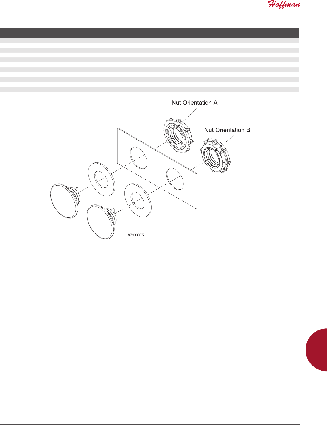
PH 763.422.2211 • FAX 763.422.2600 • PENTAIRPROTECT.COMEQUIPMENT PROTECTION ACCESSORIES 929
12
HOLE SEALS hole seals
HOL-SEALERS Fit These Hole Sizes
Catalog Numbers Fits
Min. Hole
Dia. (inch)
Min. Hole
Dia. (millimeter)
Nut
Orientation
ASPB05075NM .5-in. conduit holes .86 22 A
22.5-mm pushbutton holes .88 22 A
.75-in. conduit holes 1.09 28 A
ASPB100125NM 30.5-mm pushbutton holes 1.20 31 A
1-in. conduit holes 1.36 35 B
1.25-in. conduit holes 1.70 43 A
AS150200250NM 1.5-in. conduit holes 1.95 50 A
2-in. conduit holes 2.38 60 B
2.5-in. conduit holes 2.88 73 A
AS300350400NM 3-in. conduit holes 3.50 89 A
3.5-in. conduit holes 4.00 102 B
4-in. conduit holes 4.50 114 A
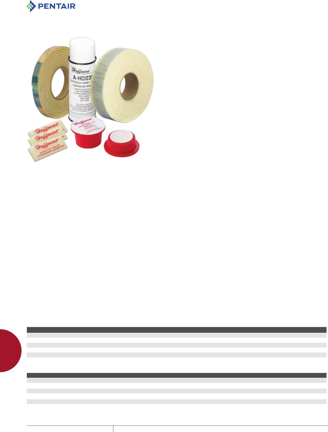
EQUIPMENT PROTECTIONSUBJECT TO CHANGE WITHOUT NOTICEACCESSORIES930
12
CORROSION INHIBITORS Corrosion inhibitors
CORROSION INHIBITORS
CORROSION INHIBITORS
INDUSTRIAL CORROSION INHIBITORS
Hoffman corrosion inhibitors protect
• Interior components of electrical enclosures, boxes, consoles
and wireways
• Interior components of electronic enclosures
• Electrical and electronic equipment and controls
• Parts and components that are packaged in crates during
shipping and storage
• Switch gear and relay cabinets
• Interiors of pipes, conduits and fuse boxes
• Process control computers, instruments and recording devices
• Tool chest interiors and contents
• Equipment stored at construction sites
Chief Advantages
• Protects against salt and high humidity
• Eliminates the need of oiling, plating or dipping metal
• Puts protected equipment to use immediately without degreasing
or coating removal
How They Work
Each inhibitor contains a special chemical combination that
vaporizes and condenses on all surfaces in an enclosed area.
Vapors will redeposit as needed in the event of condensation
of moisture on surfaces. These vapors reach every part of an
enclosure, protecting all interior components. Spraying, wiping
or greasing are not required. This eliminates precoating, special
wraps and drying agents. Protection is effective even in salt-water
atmospheres. The AHCI5E and AHCI10E emitters have additional
red-metal inhibitors for further protection. Enclosures containing
corrosion inhibitors must be reasonably sealed.
Life Expectancy and Usage
The normal useful life-span of Hoffman corrosion inhibitors is in
excess of one year. However, inhibitor life expectancy is shortened
by approximately 25 percent when exposed to temperatures above
104 F (40 C). This product is not recommended for use where
temperature exceeds 199 F. Since Hoffman corrosion inhibitors
are vapor-phase protective, all surfaces to be protected should be
accessible to the vapors. The maximum distance the vapors can
travel is approximately 1.50 ft. (.46 m). Protection of long, narrow
enclosures can be achieved with tape or multiple inhibitors.
Storage and Handling
Each Hoffman corrosion inhibitor is individually packaged in a
resealable bag for maximum effectiveness at the time of usage.
Corrosion inhibitors should be stored at temperatures not
exceeding 120 F (45 C ). Hoffman corrosion inhibitors are not
returnable.
When determining the proper corrosion inhibitor for your
application, assume the enclosure volume to be protected is greater
than calculated if (1) cabinet doors are opened frequently, (2) cabinet
is located in an extremely corrosive area and/or (3) cabinet length
divided by depth is greater than four.
AHCI1DV
Foam device protects one cubic foot (28 liters) of enclosure volume
for approximately one year.
Size: .25 x 1.25 x 3.00 in. (6 x 32 x 76 mm)
AHCI5E
Emitter protects 5 ft.3 (142 liters) of enclosure volume for
approximately two years from the date of manufacture. Emitters
contain additional red metal (non-ferrous) inhibitors.
Size: 2.31 in. (diameter) x 0.81 in. (high) (59 mm x 21 mm)
AHCI10E
Emitter protects 10 ft.3 (283 liters) of enclosure volume for
approximately two years from the date of manufacture. Emitters
contain additional red metal (non-ferrous) inhibitors.
Size: 2.31 in. (diameter) x 1.38 in. (high) (59 mm x 35 mm)
AHCI60R
Tape protects 60 ft.3 of enclosure volume per roll. Use
approximately 2.50 in. (63 mm) of tape per cubic foot (28 liters) of
enclosure volume to be protected. Each roll of tape is packaged
individually in a resealable bag.
Size: .25 in. x .75 in. x 12.00 ft. (6 mm x 19 mm x 3.6 m)
AHCI240R
Tape protects 240 ft.3 of enclosure volume per roll. Use
approximately 1.00 in. (25 mm) of tape per cubic foot (28 liters) of
enclosure volume to be protected. Each roll of tape is packaged
individually in a resealable bag.
Size: .25 in. x 2.00 in. x 20.00 ft. (6 mm x 51 mm x 6.1 m)
AHCI238S
Spray is a non-conductive, nonflammable, vapor-phase film and is
non-toxic. It has essentially neutral pH value. Application provides
instant protection against corrosion. Spray is water soluble and can
be easily flushed away with water if desired. This product should
be kept from freezing and has a shelf life of 2+ years in normal
warehouse conditions.
BULLETIN: A80
Standard Product
Catalog Number Enclosure Volume Protected (ft.3 ) Enclosure Volume Protected (liters) Package Qty.
AHCI1DV 1 28.32 50
AHCI5E 5 141.6 25
AHCI10E 10 283.2 12
AHCI60R 60 per roll 1699 per roll 3
AHCI240R 240 per roll 6797 per roll 1
AHCI238S Corrosion Inhibitor Spray Corrosion Inhibitor Spray 6
Metal Protection Chart
Metal Protected by Chemical Unprotected by Chemical
Aluminum Marked reduction of surface attack; no pitting Severe surface attack; tarnish; pitting
BrassaDecreased tarnish; very minor surface attack Surface discoloration; pitting
Steel, Iron No change Severe corrosion
CopperaSlight staining Heavy corrosive attack
Zinc Plate Slight discoloration Severe corrosion
Tin Plate Slight discoloration Moderate corrosive attack
a AHCI5E and AHCI1OE emitters are recommended for these materials
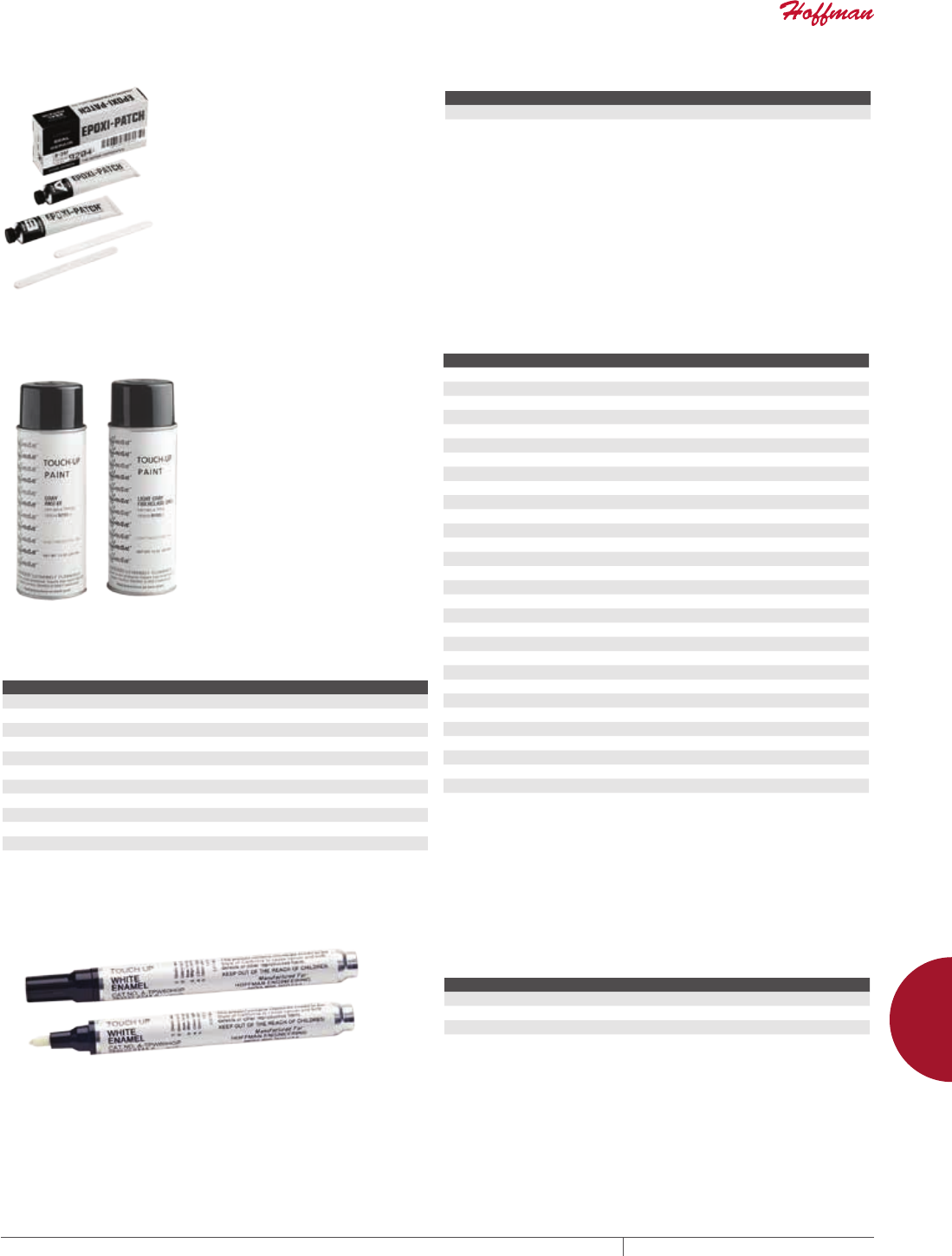
PH 763.422.2211 • FAX 763.422.2600 • PENTAIRPROTECT.COMEQUIPMENT PROTECTION ACCESSORIES 931
12
CORROSION INHIBITORS Corrosion inhibitors
EPOXY PATCH KIT
Applications include sealing
rivets, bolts, metal joints, seams
and welds, cement cracks, pipe
couplings, joints and tees. Each
kit has two tubes of material,
application instructions and a mixing
stick. When the resin and hardener
are mixed, a gray epoxy is formed
which cures at room temperature,
has high adhesion and will not sag.
It is resistant to oils, acids and
chemicals.
BULLETIN: A80
Catalog Number Description
A307 Epoxy Patch Kit
TOUCHUP PAINT
Hoffman touch-up paint is used to repair the finish of enclosures
and panels. Furnished in 12-oz. spray cans.
BULLETIN: A80, DACCY, P20
Catalog Number Color
ATPWE Hoffman #60 White
ATPW RAL 9003 Signal White
ATPTW RAL 9016 Traffic White (S094)
ATPPW RAL 9010 Pure White
ATPBS F63VXW8736 SW Cream
ATPC RAL 9001 Cream
ATPOW RAL 1013 Oyster White
ATPGW RAL 9002 Gray White (IH148)
ATPLI RAL 1015 Light Ivory
ATPDLB Hoffman #78T DesignLine Beige Enamel
ATPG7035 RAL 7035 Light Gray (T012)
Catalog Number Color
ATPPG RAL 7032 Pebble Gray
ATPOF RAL 9002 Gray White (S065)
ATPLGGMW GMW-01 Light Gray
ATPLG RAL 7035 Light Gray (S052)
ATPAG RAL 7038 Agate Gray
ATPLGA70 ANSI 70 Light Gray
ATPPY61 ANSI 61 Hoffman Standard Gray
ATPDG ANSI 49 Dark Gray
ATPBG RAL 7012 Basalt Gray
ATPSG Satin Gray Enamel
ATPMG Hoffman #82 Slate Gray Enamel
ATPHS61 High Solids ANSI 61 Gray
ATPFG Light Gray for fiberglass
ATPG7032 RAL 7032 Gray
ATPSY #5. YB.0/12 OSHA Safety Yellow
ATPR RAL 3001 Signal Red
ATPO RAL 2004 Pure Orange
ATPSB RAL 5015 Sky Blue
ATPSAB #2.5PB3.5/10 OSHA Safety Blue
ATPPB #96Y-23665 Precaution Blue
ATPB RAL 5005 Signal Blue
ATPRG RAL 6011 Reseda Green
ATPOG RAL 6003 Olive Green
ATPMGN PSPL350001 Munsell Green
ATPMB #2.5Y 5/2 Munsell BrownB
ATPB9005 RAL 9005 Black
ATPB7021 RAL 7021 Black
ATPBL Black Lava (S109)
ATPBM RAL 9005 (Jet Black (T009)
ATPJB RAL 9005 Jet Black (S067)
TOUCHUP PAINT PENS Hoffman touch-up paint pens are used to repair the finish of
enclosures and panels. Furnished in .33-oz. pens.
BULLETIN: A80
Catalog Number Paint Color
ATPG7035LP RAL 7035 Light Gray
ATPW60HGP Hoffman #60 White
ATPG20GLP ANSI 61 Gray
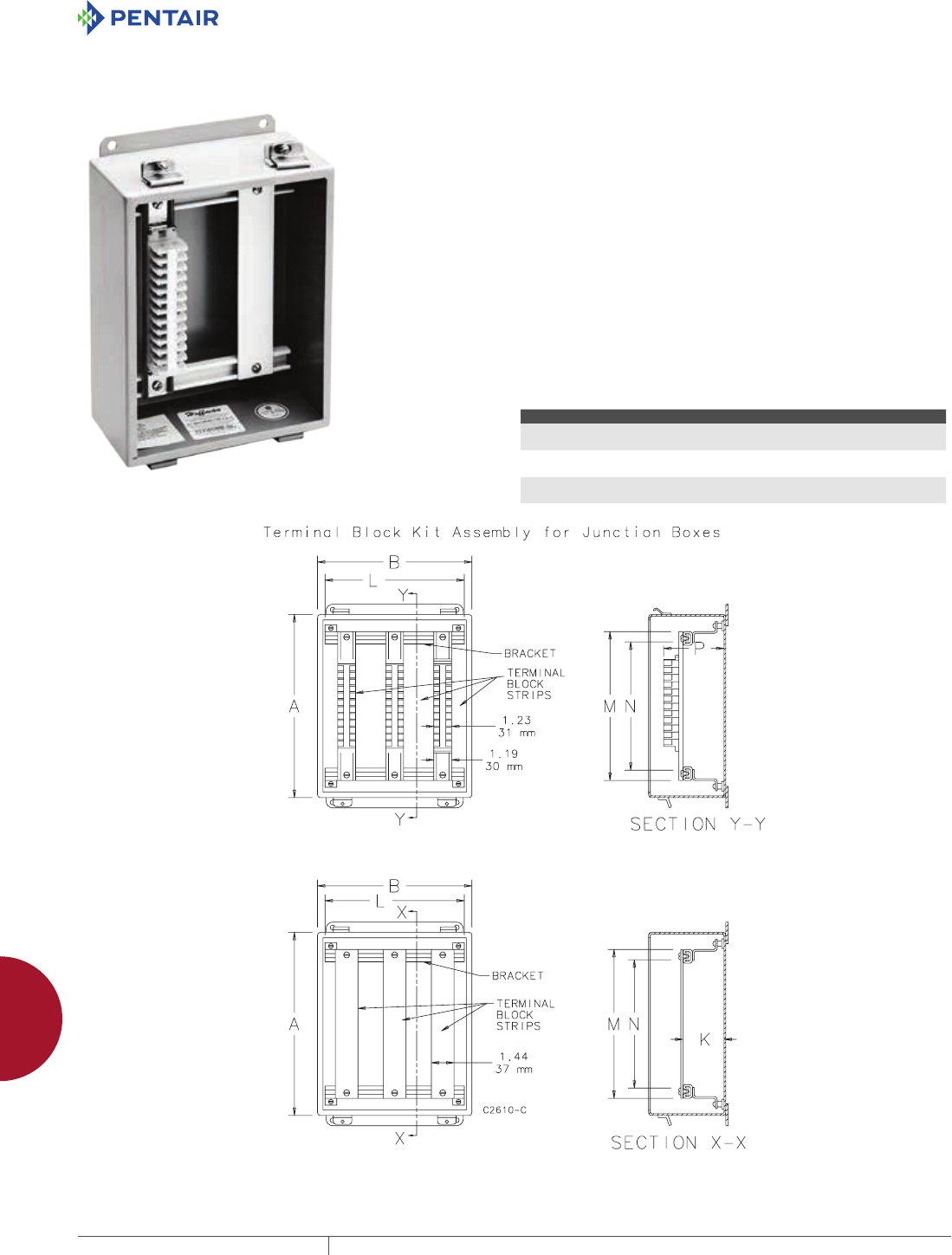
EQUIPMENT PROTECTIONSUBJECT TO CHANGE WITHOUT NOTICEACCESSORIES932
12
ELECTRICAL ACCESSORIES terminal bloCk kits
ELECTRICAL ACCESSORIES
TERMINAL BLO CK KITS
TERMINAL BLOCK KIT ASSEMBLY FOR JUNCTION
BOXES OVERVIEW
Provides a strong, versatile and easily installed means for mounting
terminal blocks in Hoffman junction boxes and other enclosures.
These kits can be installed in:
1. Oil-Tight Junction Boxes
2. Fiberglass Type 4X Enclosures
3. Hinged Cover Lift-Off Type 3R Enclosures (16 gauge only)
These kits will NOT fit in Small Wall-Mount Enclosures or HCR Type
3R Enclosures.
How To Order
Terminal Kit Assemblies can be installed with the terminal straps
or terminal strips parallel to the A dimension or the B dimension of
the box. Each box requires one bracket assembly plus the desired
number of terminal straps or terminal block strips. The bracket
assembly and the terminal straps or terminal block strips must be
ordered separately.
1. To select the correct terminal straps or terminal block
strips, determine whether they will be mounted parallel to
the A dimension or parallel to the B dimension of the box.
Be
sure to specify the quantity required.
2. To select the correct bracket assembly, determine whether
the brackets will be mounted parallel to the A dimension or
to the B dimension of the box.
Component Quantity Comments
Bracket Assembly 1 Mount parallel to A or B
dimension
Terminal Straps As required for installation; specify when
ordering
Use straps or strips
Terminal Block
Strips
As required for installation; specify when
ordering
Use straps or strips
PH 763.422.2211 • FAX 763.422.2600 • PENTAIRPROTECT.COMEQUIPMENT PROTECTION ACCESSORIES 933
12
ELECTRICAL ACCESSORIES terminal bloCk kits
TERMINAL BLOCK BRACKET ASSEMBLIES FOR
JUNCTION BOXES
Each bracket assembly consists of two brackets which mount on the
weldnuts in the box. White finish over pretreated surfaces.
BULLETIN: A80
Catalog Number
Enclosure Dimension
Parallel to Brackets
K
in./mm
L
in./mm
A6JTMA 6 1.44
37
5.00
127
A8JTMA 8 1.44
37
7.00
178
A10JTMA 10 1.44
37
9.00
229
A10JTMAXK 10 2.69
68
9.00
229
A12JTMA 12 2.69
68
11.00
279
A14JTMA 14 2.69
68
13.00
330
TERMINAL BOX STRAPS FOR JUNCTION BOXES
A terminal strap is a 12 gauge flat strap which mounts on top of the
brackets. The straps can be positioned anywhere along the brackets
and are held in place with spring locking nuts. White finish over
pretreated surfaces. Terminal blocks are not included with terminal
straps. Does not work with DIN rail-mounted terminal blocks.
BULLETIN: A80
Catalog Number
Enclosure Dimension
Parallel to Straps
K
in./mm
M
in./mm
Useable
Space, N
in./mm
A8JS 8 1.44
37
5.75
146
4.62
117
A10JS 10 1.44
37
7.75
197
6.62
168
A12JS 12 1.44
37
9.75
248
8.62
219
A14JS 14 2.69
68
11.70
297
10.62
270
A16JS 16 2.69
68
13.70
348
12.62
321
TERMINAL BLOCK STRIPS FOR JUNCTION BOXES
A terminal block strip is a flat channel holding Buchanan 600V
terminal blocks with tubular clamp contacts assembled on the
channel. These terminal blocks will accept wire sizes from #22
through #10. The number of terminal blocks assembled on each
channel is shown in the table. The terminal block strips can be
positioned anywhere along the brackets and are held in place with
spring locking nuts. The channel has a plated finish. Terminal
blocks are included with terminal block strips. Marathon terminal
blocks can be provided on special order. Other brands and sizes of
terminal blocks are available on special order.
BULLETIN: A80
Catalog Number
Enclosure Dimension
Parallel to Strips
Terminal Blocks
per Strip
M
in./mm
Useable
Space, N
in./mm
P
in./mm
A8JBNS 8 8 5.75
146
4.62
117
3.00
76
A10JBNS 10 12 7.75
197
6.62
168
3.00
76
A12JBNS 12 16 9.75
248
8.62
219
3.00
76
A14JBNS 14 20 11.75
298
10.62
270
4.25
108
A16JBNS 16 24 13.75
349
12.62
321
4.25
108
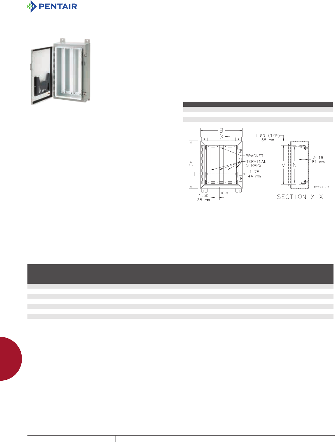
EQUIPMENT PROTECTIONSUBJECT TO CHANGE WITHOUT NOTICEACCESSORIES934
12
ELECTRICAL ACCESSORIES terminal bloCk kits
TERMINAL BLOCK KIT ASSEMBLY FOR TYPE 4, 12 AND
13 ENCLOSURES OVERVIEW
Provide strong, versatile and easily installed terminal block
mounting supports. These assemblies fit many single-door Hoffman
enclosures. They also fit large Type 1 enclosures and the larger
sizes of Hinged Cover Lift-Off Type 3R enclosures as well as most
of the Two-Door Wall-Mounted Type 12 enclosures. Kits have white
finish over pretreated surfaces. Terminal Block Kit Assemblies
can be installed with straps parallel to the A dimension or the B
dimension of the enclosure.
How To Order
Each enclosure requires one bracket assembly plus the desired
number of terminal straps. The bracket assembly and the terminal
straps must be ordered separately.
1. To select the correct terminal straps, determine whether
the terminal straps will be mounted parallel to the A
dimension or the B dimension of the enclosure. Be sure to
specify the quantity required.
2. To select the correct bracket assembly, determine whether
the brackets will be mounted parallel to the A dimension or
the B dimension of the enclosure. Refer to the table.
One bracket is required for each row of collar studs parallel to the
brackets. As a result, if the enclosure dimension is 24.00 in. (610 mm),
30.00 in. (762 mm) or 36.00 in. (914 mm) and if two brackets are needed
to cover all of the collar studs order A___NTMA2; if three brackets are
needed to cover the studs order A___NTMA3.
For example: If you have an A302406LP enclosure and want five
terminal straps running horizontally, order one A30NTMA2
bracket assembly plus five A24T straps. If you have an A483008LP
enclosure and want six terminal straps running vertically, order one
A30NTMA3 bracket assembly plus six A48T straps.
Terminal blocks are not included. Be sure to order one bracket
assembly plus the desired number of terminal straps for each
enclosure.
Component Qty Required Comments
Bracket Assembly 1 Terminal blocks are not included
Terminal Straps Depends on installation Specify quantity when ordering
Terminal Strap Support Kit One kit per strap Optional
BRACKET ASSEMBLY FOR TYPE 4, 12 AND 13 ENCLOSURES
Each bracket assembly consists of two or three brackets which mount on the enclosure collar studs.
BULLETIN: A80
Catalog Number Number of Brackets
Enclosure
Dimension
Parallel
to Brackets (in.)
Enclosure
Dimension
Parallel
to Brackets (mm)
Bracket
Length, L (in.)
Bracket
Length, L (mm)
A12NTMA2 2 12.00 305 8.50 216
A16NTMA2 2 16.00 406 12.50 318
A20NTMA2 2 20.00 508 16.50 419
A24NTMA2 2 24.00 610 20.50 521
A24NTMA3 3 24.00 610 20.50 521
A30NTMA2 2 30.00 762 26.50 673
A30NTMA3 3 30.00 762 26.50 673
A36NTMA3 3 36.00 914 32.50 826
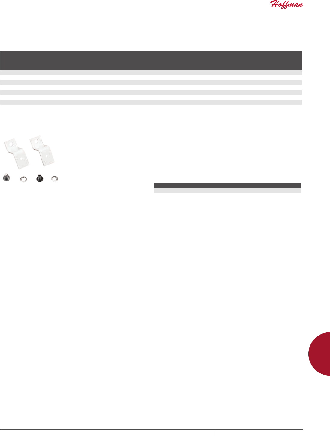
PH 763.422.2211 • FAX 763.422.2600 • PENTAIRPROTECT.COMEQUIPMENT PROTECTION ACCESSORIES 935
12
ELECTRICAL ACCESSORIES terminal bloCk kits
TERMINAL STRAPS FOR TYPE 4, 12 AND 13 ENCLOSURES
The terminal straps can be positioned anywhere along the brackets and are held in place with spring locking nuts. This feature makes
wiring easy and simplifies the addition of terminal straps at a later date.
BULLETIN: A80
Catalog Number
Enclosure
Dimension
Parallel
to Straps M (in.) M (mm)
Useable
Space, N (in.)
Useable
Space, N (mm)
A16T 16 13.00 330 11.75 298
A20T 20 17.00 432 15.75 400
A24T 24 21.00 533 19.75 502
A30T 30 27.00 686 25.75 654
A36T 36 33.00 838 31.75 806
A42T 42 39.00 991 37.75 959
A48T 48 45.00 1143 43.75 1111
A60T 60 57.00 1448 55.75 1416
TERMINAL STRAP SUPPORT KIT Designed to provide a simple and versatile method of mounting
terminal straps. The Z-shaped brackets are 1.50-in. (38-mm)
high with white finish. Brackets can be attached to panels or to
enclosure walls. A terminal strap is then installed on the brackets.
Terminal straps must be ordered separately. Two brackets are
furnished with each kit. Spacing between brackets will depend on
the number and size of terminal blocks installed on the terminal
strap. We recommend a maximum spacing of 15 in. (381 mm) for an
average installation.
BULLETIN: A80
Catalog Number Description
ATZ Two Z-shaped brackets
Terminal strap NOT included.
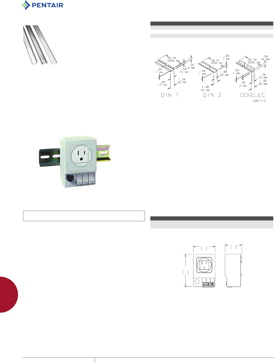
EQUIPMENT PROTECTIONSUBJECT TO CHANGE WITHOUT NOTICEACCESSORIES936
12
ELECTRICAL ACCESSORIES din-mounted aCCessories
DIN-MOUNTED ACCESSORIES
DIN TYPE RAILS
DIN Type Rails receive terminal blocks, relays, switches, filters,
timers and various other electrical and electronic components
manufactured by European, Japanese and U.S. firms. Available in
three styles: (1) asymmetric, DIN 1 profile; (2) symmetric, DIN 3
profile; (3) heavy-duty CENELEC profile. All DIN rails are 78.74-in.
(2000-mm) long and plated.
BULLETIN: A80
Catalog Number Description
ADNR1 DIN 1 mounting rail TS32
ADNR3 DIN 3 mounting rail TS35x7.5
ACENR1 CENELEC mounting rail TS35x15
NEMA 515R DINMOUNTED OUTLETS
INDUSTRY STANDARDS
UL Component Recognized; File No. E222026
cUL Component Recognized; File No. E222026
Ingress protection: IP 20
APPLICATION
The DIN rail-mounted electrical receptacle can be quickly fitted and
connected inside enclosures, allowing the use of auxiliary products
such as hand lamps and power tools. The unit is available with and
without fuses, and in many world outlet standards.
FEATURES
• Tool-less touch-safe wire connections
• Fused and non-fused offerings
• Light-weight composite enclosures
• Easily DIN-mounted
• Small form factor
• Wide operating temperature ranges
SPECIFICATIONS
• Connection: three cage clamps for solid and stranded wire AWG
20-14 (0.5-2.5mm²)
• Housing: plastic, UL94 V-0, light grey
• Fuse: Type 5 x 20 mm dia. (Tubular)
• Integral mounting clip for 35mm DIN rail, EN 60 715
• Mounting position: vertical
• Operating / storage temperature -49 F to +158 F (-45 C to 70 C)
• Dimensions : 3.6 x 2.4 x 1.9 (92mm x 62mm x 48mm)
• Weight: approximately 7.1 oz. (200g)
• Standard NEMA receptacle 5-15R
• Maximum Voltage: 125 VAC
• Protection class I (grounded)
FINISH
Composite, smooth texture, light gray
ACCESSORIES
DIN Rail accessories (CONCEPT , FUSION , INLINE )
BULLETIN: A80
Standard Product
Catalog Number AxBxC in./mm AMP Rating Fused
ADINP120A 3.54 x 2.44 x 1.97
90 x 62 x 50
15 A No
ADINP120F 3.54 x 2.44 x 1.97
90 x 62 x 50
6.3 A Yes
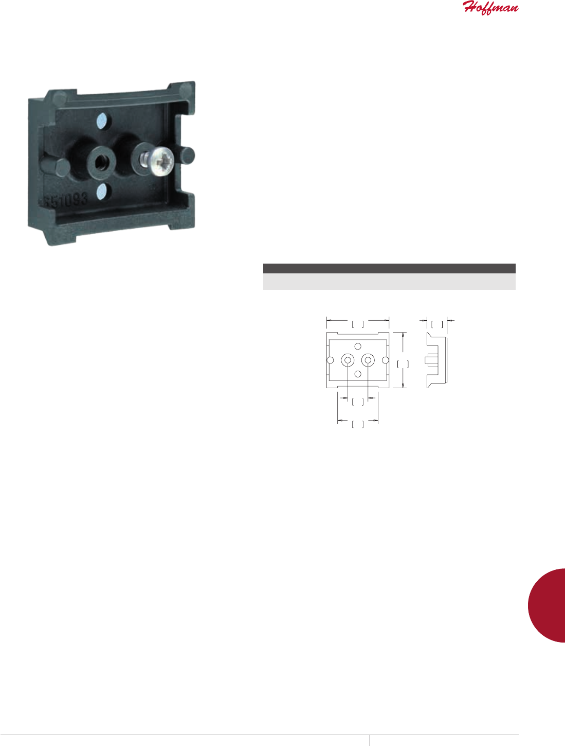
PH 763.422.2211 • FAX 763.422.2600 • PENTAIRPROTECT.COMEQUIPMENT PROTECTION ACCESSORIES 937
12
ELECTRICAL ACCESSORIES din-mounted aCCessories
DIN 3 RAIL, SELFADHESIVE
INDUSTRY STANDARDS
Material conforms to UL 94V-0
APPLICATION
Convenient, symmetrical, 1.7 in. (43mm) DIN 3 rail with pressure-
sensitive, peel-and-stick adhesive. Can be mounted to various
surfaces, in a variety of locations. Fasteners may also be used (five
provided per kit) for increased load rating. DIN rail is made of UL
94V-0 rated material. Five self-adhesive DIN rails per kit.
FEATURES
• DIN 3-style, symmetrical
• Adhesive mount; fastener-capable
• 43mm length
• Constructed from UL 94V-0 rated black plastic
• Sold in qty. five per catalog number
• Optional screw mount; (5) 10-32 / M5 provided
SPECIFICATIONS
• Load 1.1 lbs. (500g) after a 24-hour waiting period
• Mounting self-adhesive (non-aging, high-performance adhesive
strip)
• Material plastic UL 94V-0, black
• Hole pattern 0.5 in. (12.8 mm) distance, Ø 0.14 in. (3.6mm)
• Operating / Storage temperature -49 F to +158 F (-45 C to 70 C)
• Dimensions 1.7 x 1.5 x 0.55 (43mm x 38mm x 14mm)
FINISH
Composite, smooth texture, black
ACCESSORIES
DIN Rail accessories (CONCEPT , FUSION , INLINE , etc.)
BULLETIN: A80
Standard Product
Catalog Number AxBxC in./mm Max. Load Ratinga
ADIN3PA42 0.47 x 1.65 x 1.42
12 x 42 x 36
1.1 lbs (500g)
a 24-hour cure time prior to applying load
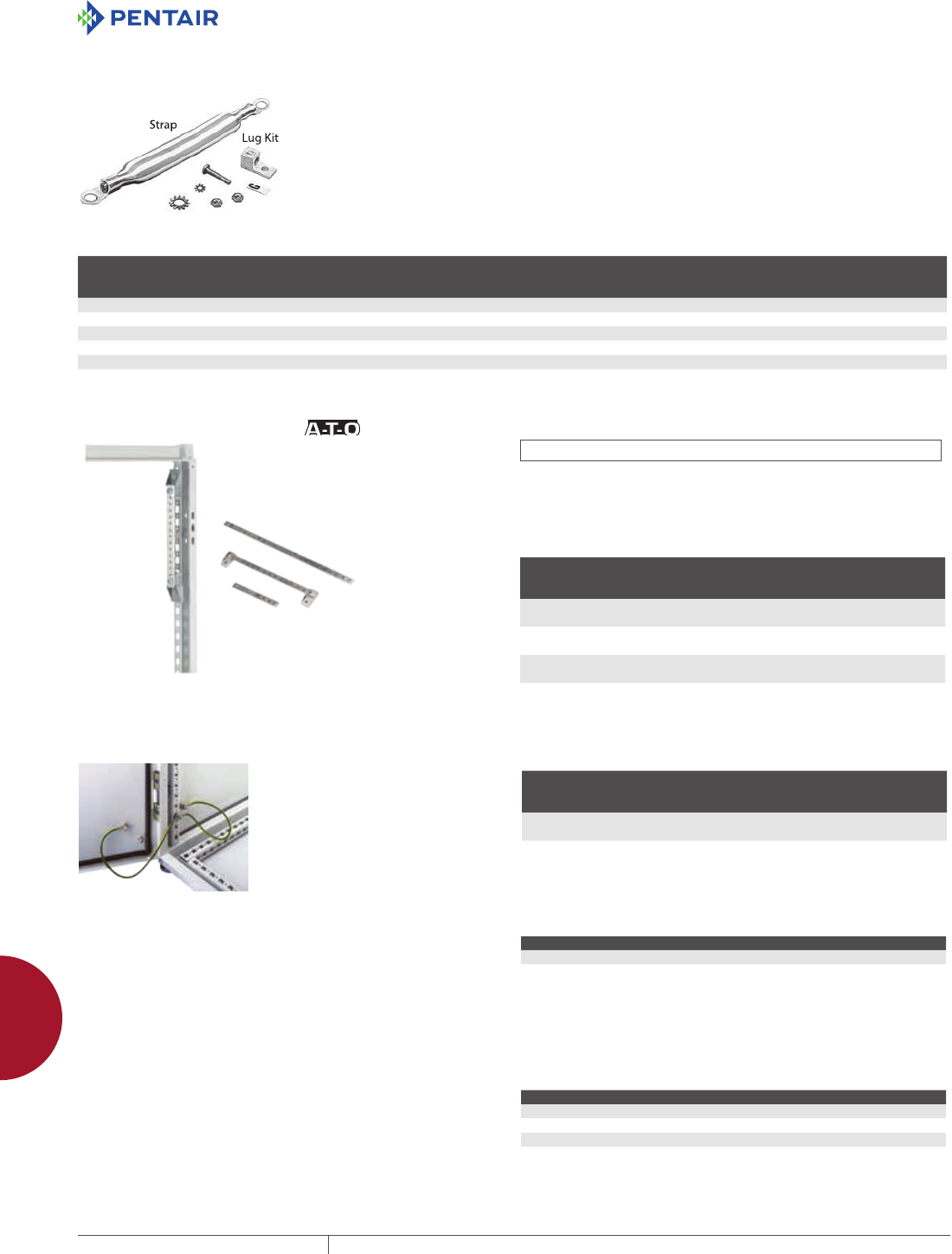
EQUIPMENT PROTECTIONSUBJECT TO CHANGE WITHOUT NOTICEACCESSORIES938
12
ELECTRICAL ACCESSORIES GroundinG
GROUNDING
GROUNDING DEVICE Grounding lug is designed to provide a means of attaching a
grounding conductor to an electrical enclosure. Will accept wire
sizes 2 through 14. Grounding Straps can be used to provide
electrical continuity between metal parts which must be electrically
connected. Each strap consists of a length of braided copper with a
ring terminal at both ends. Braid is insulated with green and yellow
striped plastic.
BULLETIN: A80
Catalog Number Description
Approximate
Wire Size (AWG)
Length
Between Ring
Terminals C-to-C (in.)
Length
Between Ring
Terminals C-to-C (mm)
Ring Terminal
Hole Diameter (in.)
Ring Terminal
Hole Diameter (mm)
AGS808 Grounding Strap #8 8.19 208 0.406 10
AGS816 Grounding Strap #8 16.19 411 0.406 10
AGS408 Grounding Strap #4 8.19 208 0.406 10
AGS416 Grounding Strap #4 16.19 411 0.406 10
AGLK2 Grounding lug kit 2-14 — — — —
GROUNDING BAR SYSTEM INDUSTRY STANDARDS
UL Component Recognized; File No. E61997
Three sizes of grounding bars and insulated mounting brackets
are available. Bars are plated copper with M6 and M5 tapped
holes to provide a common point for grounding equipment. Fits all
enclosures if mounted vertically. See table for horizontal mounting.
BULLETIN: P20
Catalog Number Description
Length
mm/in.
Number of
Holes and
Screws M6
Number of
Holes and
Screws M5
PGS2K Fits 400-mm deep frame
front to back horizontally
200
7.87
3/5 10/10
PGS4K Fits 600-mm deep frame
front to back horizontally
400
15.75
9/11 20/20
PGS6K Fits 800-mm deep frame
front to back horizontally
600
23.62
15/17 30/31
PROLINE GROUNDING KIT
The Grounding Kit allows a PROLINE
enclosure to be grounded to VDE
specifications. Includes six 12 gauge
wires 411-mm (16.19-in.) long with
ring terminations and M6 mounting
hardware.
BULLETIN: P9
Catalog Number
Wire
Size
Length Between
Ring Terminals
mm/in.
Ring Terminal
Hole Diameter
mm/in.
PGK 12 ga. 411
16.19
7
.29
REPLACEMENT PANELMOUNT HARDWARE KIT
Replacement hardware kit for panel mounting and grounding.
Suitable for CONCEPT enclosures. Hardware kit comes with M8
panel mounting nuts, panel grounding hardware and sealing
washers.
BULLETIN: A80
Catalog Number Description
GRDM8PMHDWK Panel Mount Hardware Kit
GROUNDING KIT
These grounding kits come with mounting hardware, ground label
and installation instruction. Cables are not included.
BULLETIN: A80
Catalog Number Description Hardware Size
SMGDK Small grounding kit 10-32
LRGGDK Large grounding kit 1/4-20
LRGGDKSS Large grounding kit for stainless steel M6
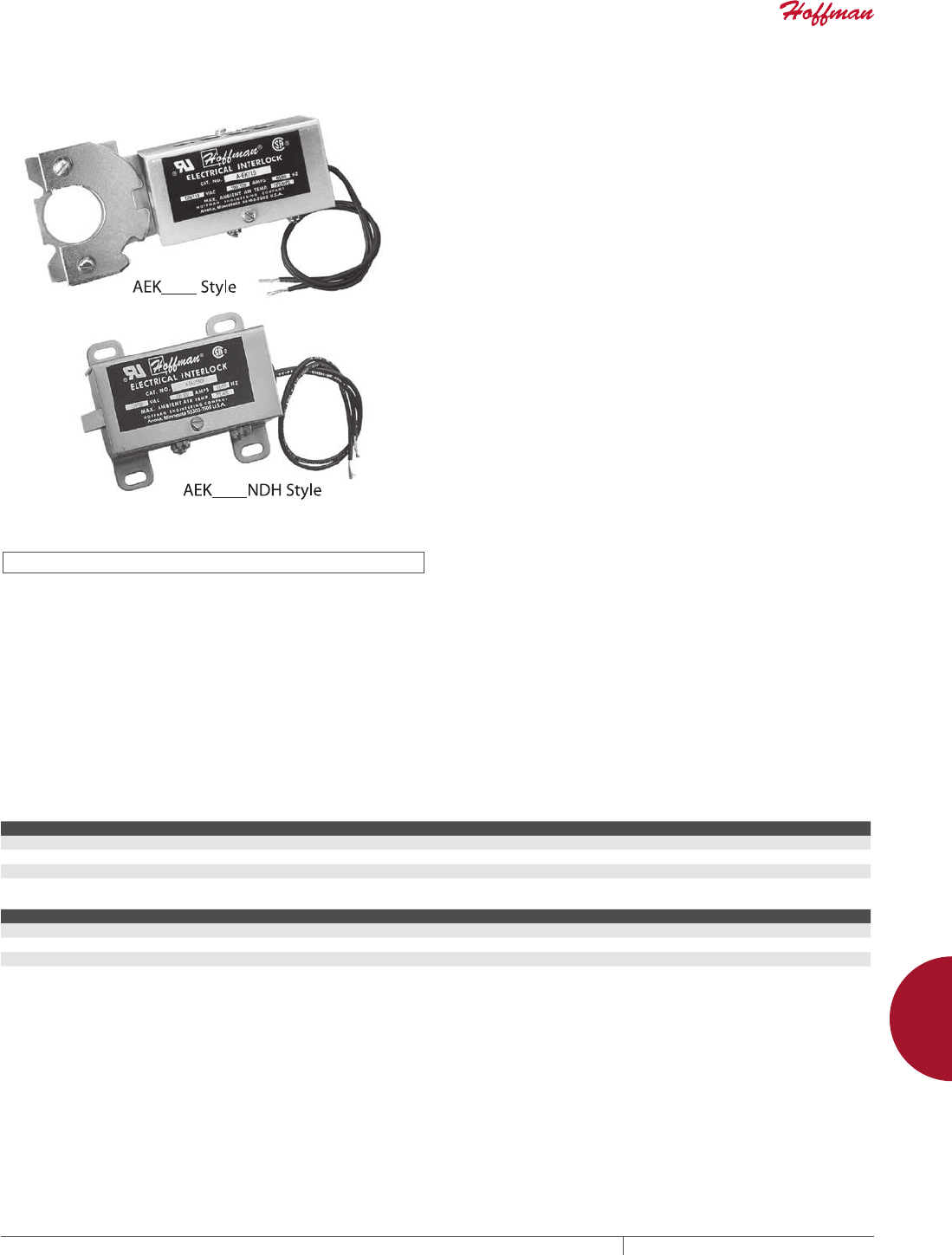
PH 763.422.2211 • FAX 763.422.2600 • PENTAIRPROTECT.COMEQUIPMENT PROTECTION ACCESSORIES 939
12
ELECTRICAL ACCESSORIES eleCtriCal interloCks
ELECTRICAL INTERLOCKS
ELECTRICAL INTERLOCKS
INDUSTRY STANDARDS
UL 508A Component Recognized; File No. E61997
CSA Certified; File No. 42186
APPLICATION
Provide positive internal safety lockout on electrical enclosures
while the equipment is energized. Use catalog numbers AEK115,
AEK230 and AEK460 are used with standard Hoffman door latching
mechanisms. When energized, these interlocks prevent the door
handle from being turned to open the door. Fit either clockwise or
counterclockwise handles in the following enclosures:
1. All two-door Type 4 and 12 enclosures
2. All Type 4X with 3-point latch enclosures
3. Free-standing Type 12 enclosures
4. All one-door Type 12 enclosures with latch kits installed
The interlocks will fit the following enclosures, but modifications
are required. Consult the factory for more information.
1. Two-door Type 12 enclosures for flange-mounted
disconnects
2. Heavy duty free-standing Type 12 enclosures for flange-
mounted disconnects
3. Modular Type 12 enclosures for flange-mounted
disconnects
4. Multi-door Type 12 enclosures
The interlocks will also fit most Hoffman custom enclosures with
door latching mechanisms similar to the mechanisms used on the
preceding enclosures. AC electrical interlocks will not fit CONCEPT
enclosures or Bulletin A25 and A26 enclosures. Interlocks are not
designed to be used in place of the standard door or cover latch.
Catalog numbers AEK115NDH, AEK230NDH and AEK460NDH are
designed to be used on some Hoffman enclosures and boxes which
have exterior latching only. When energized, these interlocks will
prevent the enclosure door from being opened. They fit on the door
or cover of the following enclosures and maintain UL Type 4, 4X and
12 when properly installed per Hoffman instructions:
1. One-door Type 4 and 4X enclosures
2. Two-door Type 4 and 4X enclosures
3. One-door Type 12 enclosures
4. Larger sizes of CH, CHS, CHNF, CHNFSS and CHAL junction
boxes
5. Type 1 and large Type 1 enclosures
The interlocks also fit in most Hoffman custom enclosures and
boxes which have doors or covers hinged similar to doors or covers
on the preceding enclosures.
Installation
AEK115, AEK230 and AEK460 mount on the inside of the enclosure
door using the same screws which hold the door handle in place.
The strike plate attaches to the existing latch assembly.
SPECIFICATIONS
• Rugged steel construction and plated finish
• Solenoids are rated for continuous duty and will stand up under
heavy industrial use
• Packaged complete with a solenoid assembly, strike plate or
bracket and instructions for field installation
• Handles and latch mechanisms are not included.
BULLETIN: A80
Standard Product A-EK___ Style
Catalog Number Volts @ 50/60 Hz Normal/Inrush Amps @ 60 Hz Normal/Inrush Amps @ 50 Hz
AEK115 110/120 .100/.63 .120/.69
AEK230 220/240 .050/.32 .060/.35
AEK460 440/480 .025/.16 .030/.18
Standard Product AEK___NDH Style
Catalog Number Volts @ 50/60Hz Normal/Inrush Amps @ 60 Hz Normal/Inrush Amps @ 50 Hz
AEK115NDH 110/120 .100/.63 .120/.69
AEK230NDH 220/240 .050/.32 .060/.35
AEK460NDH 440/480 .025/.16 .030/.18
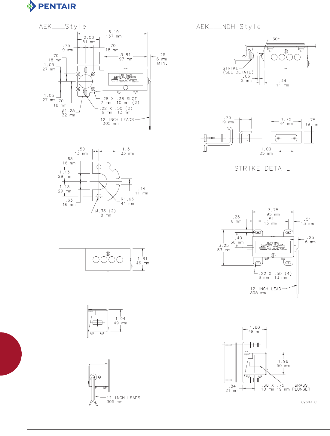
EQUIPMENT PROTECTIONSUBJECT TO CHANGE WITHOUT NOTICEACCESSORIES940
12
ELECTRICAL ACCESSORIES eleCtriCal interloCks
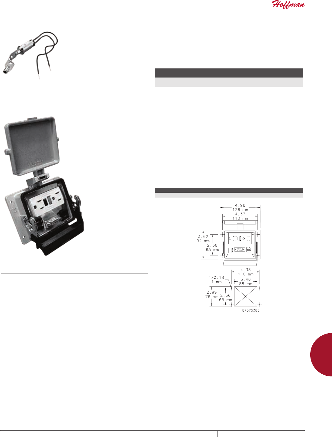
PH 763.422.2211 • FAX 763.422.2600 • PENTAIRPROTECT.COMEQUIPMENT PROTECTION ACCESSORIES 941
12
ELECTRICAL ACCESSORIES eleCtriCal interloCks
ELECTRICAL INTERLOCK DEFEATER Enables authorized personnel to enter an enclosure while the
enclosure contents are energized. Defeater is a key-operated
momentary contact switch with contacts normally closed. Turning
the key disengages the circuit to the electrical interlock. Can be
used with all 110/120 volt Hoffman electrical interlocks. A relay
must be used in conjunction with switch for 220/240 volt and
440/480 volt applications.
BULLETIN: A80
Catalog
Number Description
Amps @ 120V/60 Hz Normal/
Inrush
Amps @ 110V/50 Hz Normal/
Inrush
AEKDF Electrical interlock
defeater
10 Max. 10 Max.
PANEL INTERFACE CONNECTOR
INDUSTRY STANDARDS
UL 508A Component Recognized; File No. E61997
The panel interface connector provides a connection for a PLC
or computer housed inside an enclosure without opening the
enclosure door. It mounts on the outside of the enclosure. The
HBE size 32 housing and hinged cover are die cast aluminum. The
closed assembly is rated UL Type 4. The panel interface connector
enclosure includes:
• A duplex receptacle
• A 9-pin D-sub pass-through connector
• An RJ 45 pass-through connector
• A 3-amp reset
• A covered terminal block with screw connections for the internal
power connection
BULLETIN: A80
Catalog Number Description
AC4DB9RJ45GFI Panel Interface Connector
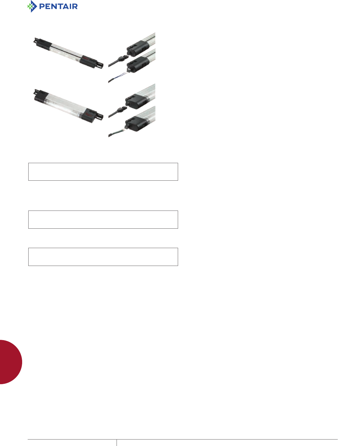
EQUIPMENT PROTECTIONSUBJECT TO CHANGE WITHOUT NOTICEACCESSORIES942
12
ELECTRICAL ACCESSORIES liGhtinG PaCkaGes
LIGHTING PACKAGES
PANELITE ENCLOSURE LIGHTS OVERVIEW
INDUSTRY STANDARDS
PANELITE LED and Fluorescent Enclosure Lights
UL 508A Component Recognized; File No. E61997
cUL Component Recognized per CSA C22.2 No 14; File No.
E61997
CSA File No. 42186
Maintains UL/CSA Type 4, 4X and 12 enclosure rating when properly
installed in a Hoffman enclosure.
230 VAC Fluorescent Enclosure Light
UL 508A Component Recognized; File No. E234324
cUL Component Recognized per CSA C22.2 No 14; File No.
E61997
CE
LED Light
UL 508A Component Recognized; File No. E234324
cUL Component Recognized per CSA C22.2 No 14; File No.
E234324
CE
Ingress protection : IP 20
Maintains enclosure type rating up to 4X when installed per instructions
APPLICATION
Versatile, slim-profile LED and fluorescent lights provide mounting
flexibility and are easy to install in any enclosure. Terminal
blocks allow for easy wiring. Accessories include ganging cables,
power cords and door switches, all provided with plug-and-play
connectors for easy connection to the terminal blocks with an
innovative terminal connection system. LED version provides
superior lighting performance with minimal power consumption.
FEATURES
• Slim profile allows light to be tucked up out of the way for easy
panel installation
• Versatile mounting allows the light to be positioned horizontally
or vertically; two-way mounting provides for ideal orientation
• Includes mounting hardware for the following enclosure
installations: PROLINE Frame, Enclosure Top, Panel Mount and
Unistrut
• On/off switch incorporated in light; optional remote door switch
accessory available to activate light when enclosure door is
opened (230 VAC Fluorescent Enclosure Light has switch or door-
activated sensor)
PANELITE Only:
• Mounting tabs provide easy access point for attachment
hardware; light does not need to be disassembled for installation
• Up to five lights can be daisy-chained together
• Plug-and-play terminal connection system:
- Pre-wired connection sockets on both ends of light allow use
of Hoffman cable accessories
- Optional terminal blocks snap into the connection sockets
allowing customers to use own wiring methods; two terminal
blocks provided with each light kit
- Power supply can be wired manually with Hoffman PANELITE
Power Cable with Leads or with Hoffman optional PANELITE
Power Cord
- Ganging cables are available in 2-, 4- and 6-ft. lengths to easily
join up to five lights together using one power supply
- Remote door switch for easy door activation eliminates need to
mount light in the exact location required to activate the light
LED Light Only:
• Mechanical screw- or magnetic mount (non-slip rubberized)
• Protection Class II (double insulated)
• Operating temperature -22 F to 140 F (-30 C to 60 C)
• On / Off or motion-sensor activation
• LED lights with 400 LM illumination; 120° angle of illumination
• Low, 5-watt power requirement
• Light-weight, all-composite construction
• Input and output connectors included with light (16 AWG)
SPECIFICATIONS
PANELITE:
• Extruded aluminum center support
• Black composite end caps
• Black composite mounting tabs
• Each light fixture includes two mounting tabs, two pre-wired
connection sockets, two optional terminal blocks that snap into
the connection sockets and enclosure attachment hardware (bulb
not included with fluorescent light)
230 VAC Fluorescent Enclosure Light:
• Light gray composite construction – UL 94V-O material
• Hardware kit provides fasteners to mount to PROLINE, NEMA (4,
4X, 12, and 13), CONCEPT , FUSION and other cabinets
• Easy-access terminal block that accommodates up to 16 AWG
wires
• Fluorescent light bulb included (2G7 Base)
LED Light:
• LED (Light Emitting Diode) low-power light kit
• Screw mounting using included hardware kit (maintains
enclosure rating up to UL Type 4X)
• No user-serviceable parts
• Life expectancy of 60,000 hours at 68 F (20 C) under specifications
• Operating temperature: -22 to +140 F (-30 to +60 C) under
specifications
• 5-watt power consumption
• Transparent, composite construction
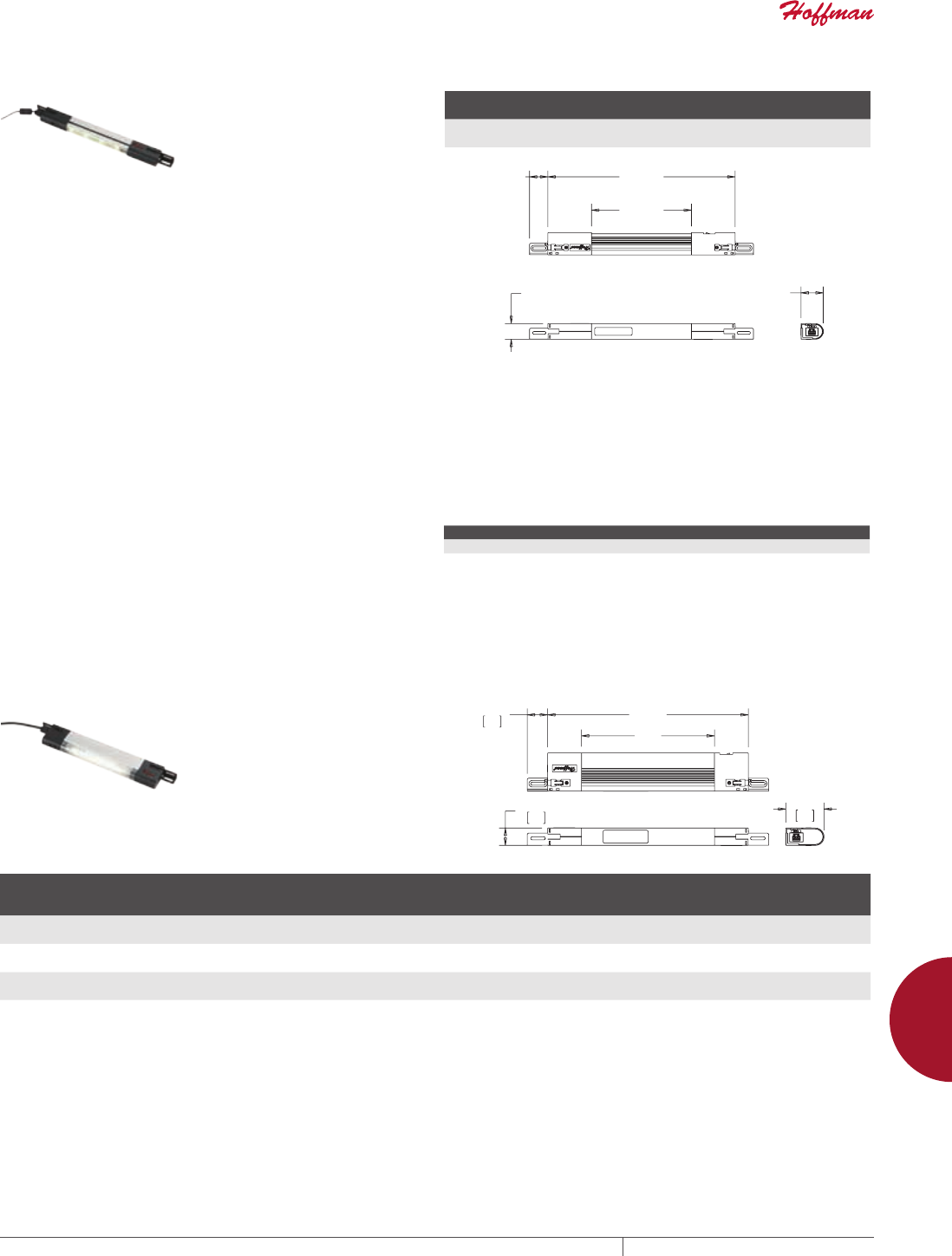
PH 763.422.2211 • FAX 763.422.2600 • PENTAIRPROTECT.COMEQUIPMENT PROTECTION ACCESSORIES 943
12
ELECTRICAL ACCESSORIES liGhtinG PaCkaGes
PANELITE LED ENCLOSURE LIGHT
• 24 VDC operation for superior
lighting performance with
minimal power consumption
• 140-degree cone angle casts a
broad covering of neutral light
between 3500 and 4500K color
temperature
• Center section rotates 120
degrees to re-direct light where
needed
• Long life; 70 percent of initial
luminance at 50,000 hours (at 25
C)
• High power LED emitters produce
470 Lumens for superior lighting
performance
• Can be wired using optional
PANELITE Cable Accessories or
can be hard-wired with terminal
blocks included in hardware kit
• Up to five lights can be daisy-
chained together using hard-
wired connection to power supply
or catalog number LPC72 power
cable with leads
BULLETIN: A80LT
Catalog Number Description VDC Amps
W
in./mm
X
in./mm
LED24V15 LED Light, 15 in. 24 .5 15.00
381
8.00
203
PP
PP
PP
PP
PP
REPLACEMENT HARDWARE KIT FOR PANELITE LED
ENCLOSURE LIGHT
Relacement hardware kit is available for the replacement of lost
or damaged hardware supplied with the PANELITE LED Lights. Kit
includes mounting brackets and all mounting hardware.
BULLETIN: A80LT
Catalog Number Description
LED24VHDWK Replacement hardware kit for LED24V14
PANELITE FLUORESCENT ENCLOSURE LIGHT
• 120 VAC, 50/60 Hz operation
• Can be wired using optional
PANELITE Cable Accessories or
can be hard-wired with terminal
blocks included in hardware kit
• Available in 15-, 18- and 28-in.
lengths with ability to daisy chain
up to five lights together using
one power supply
• Fluorescent bulb not included
BULLETIN: A80LT
;
:
Catalog Number Description VAC Hz Amps
W
in./mm
X
in./mm
Bulb
(purchase
separately)
Replacement
Lens Cover
LF120V15 Fluorescent Light, 15 in. 120 50/60 .13 14.50
368
9.63
245
F6T5 LFL15
LF120V18 Fluorescent Light, 18 in. 120 50/60 .13 17.50
445
12.63
321
F8T5 LFL18
LF120V28 Fluorescent Light, 28 in. 120 50/60 .26 27.75
705
22.88
581
F14T5 LFL28
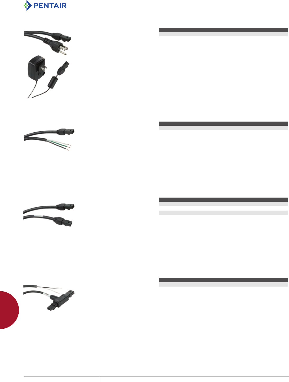
EQUIPMENT PROTECTIONSUBJECT TO CHANGE WITHOUT NOTICEACCESSORIES944
12
ELECTRICAL ACCESSORIES liGhtinG PaCkaGes
PANELITE POWER CORDS
• Connects light to standard North
American wall socket
• LF120VCORD is for 120 VAC
Fluorescent lights (up to five
lights can be daisy chained
together using one power cord)
• LED24VCORD is for 24 VDC LED
lights and includes a transformer
to convert 100-240 VAC power
supply (capable of powering only
one LED light)
• Plugs directly into a connection
socket on switch end of the light
• Includes one cable
Power cord not required. Terminal
blocks are provided with each light for
wired connection to electric supply.
BULLETIN: A80LT
Catalog Number Description Length
LF120VCORD Fluorescent Light Power Cord 72 in.
LED24VCORD LED Light Power Cord 60 in.
PANELITE POWER CABLE WITH LEADS
• 72-in. power cord provides
convenient connection to an
electrical supply
• Eliminates need to run and tag
individual wires into the light
• Compatible with PANELITE LED
and Fluorescent lights
• Plugs directly into connection
socket on switch end of the light
• Includes one 16 AWG cable, black
Power Cable not required. Terminal
blocks are provided with each light for
wired connection to electric supply.
BULLETIN: A80LT
Catalog Number Length
LPC72 72 in.
PANELITE GANGING CABLES
• Ganging Cables provide
convenient method for joining
up to five lights together while
utilizing one power supply
• Available in 24-, 48- and 72-in.
lengths
• Plugs directly into connection
socket on either end of the light
• Compatible with PANELITE LED
and Fluorescent lights
• Includes one 16 AWG cable, black
Ganging Cables not required. Terminal
blocks are provided with each light for
hard-wired connections.
BULLETIN: A80LT
Catalog Number Length
LGCABLE24 24 in.
LGCABLE48 48 in.
LGCABLE72 72 in.
PANELITE DOOR SWITCH CABLE
• Easily connects PANELITE LED
or Fluorescent Light to a Remote
Door Switch
• T-connector allows the Door
Switch Cable to be connected with
a ganging cable or power supply
to the switch end of the light
• Available in 18- and 72-in. lengths
• Includes one 18 AWG cable, black
Door Switch Cables not required.
Terminal blocks are provided with
each light for hard-wired connection to
remote door switch.
BULLETIN: A80LT
Catalog Number Length
LDSWITCH18 18 in.
LDSWITCH72 72 in.
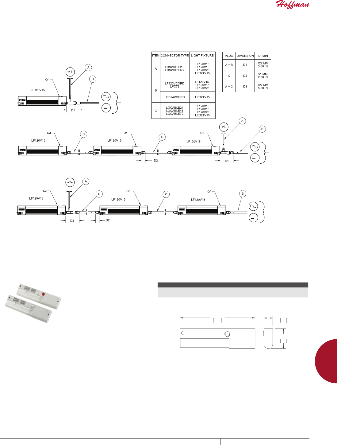
PH 763.422.2211 • FAX 763.422.2600 • PENTAIRPROTECT.COMEQUIPMENT PROTECTION ACCESSORIES 945
12
ELECTRICAL ACCESSORIES liGhtinG PaCkaGes
PANELITE WIRING OPTIONS
See the table on the drawing for cable clearance dimensions.
2SWLRQ(DFKOLJKWLVFRQWUROOHGE\DUHPRWHGRRUVZLWFK
2SWLRQ$OOOLJKWVDUHFRQWUROOHGE\DVLQJOHUHPRWHGRRUVZLWFK
2SWLRQ7KHODVWOLJKWLVFRQWUROOHGE\DUHPRWHGRRUVZLWFK7KHILUVWWZROLJKWVDUHPDQXDOO\RSHUDWHG
(OHFWULF3RZHU
(OHFWULF3RZHU
(OHFWULF3RZHU
89046495
230 VAC FLUORESCENT ENCLOSURE LIGHT
• 230 VAC, 50/60 Hz operation with
electronic ballast
• Compact light-gray plastic
housing, UL 94V-0
• Easy access to wiring terminals,
integral strain relief, 16 AWG max.
• Versatile mounting to many
enclosure types
• Complete assembly, long-life
fluorescent bulb included,
Luminosity 900 LM
• Switch and Door motion sensor
offering
BULLETIN: A80LT
Catalog Number AxBxC in./mm Description
LF230VM 1.57 x 13.58 x 3.58
40 x 345 x 91
Light Kit, 230VAC, Manual switch
LF230VD 1.57 x 13.58 x 3.58
40 x 345 x 91
Light Kit, 230VAC, IR Motion Sensor
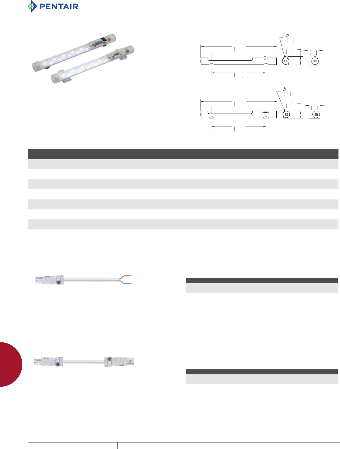
EQUIPMENT PROTECTIONSUBJECT TO CHANGE WITHOUT NOTICEACCESSORIES946
12
ELECTRICAL ACCESSORIES liGhtinG PaCkaGes
LED LIGHT KIT
LED light kits provide interior enclosure lighting. These light kits
are ideal for remote and darkened enclosure applications. The light
can be mechanically fastened with included hardware to maintain
enclosure UL listing (up to Type 4X), or can be magnetically attached
to flat steel surfaces. The lights have auto-sensing circuitry (AC
voltage 90 VAC to 260 VAC and DC voltage 20 VDC to 60 VDC). LED
lights are light-weight and in a small form factor while providing
400 LM of 6000-7000K light. Power consumption for all models is 5
watts.
BULLETIN: A80LT
0DJQHW
0RXQW
0DJQHW
0RXQW
6FUHZ
0RXQW
2Q2II6ZLWFK/LJKW
0RWLRQ6HQVRU/LJKW
6FUHZ
0RXQW
Catalog Number AxBxC in./mm Weight (oz) Weight (gm)
Mounting
Style Power Source Activation Voltage
LEDA1M35 1.34 x 1.26 x 13.82
34 x 32 x 351
4.8 135 Magnetic AC On/off switch 90 VAC-260 VAC
LEDA2M35 1.54 x 1.26 x 13.82
39 x 32 x 351
5.0 140 Magnetic AC IR Motion Sensor 90 VAC-260 VAC
LEDA1S35 1.42 x 2.05 x 13.82
36 x 52 x 351
4.8 135 Screw AC On/off switch 90 VAC-260 VAC
LEDA2S35 1.63 x 2.05 x 13.82
41 x 52 x 351
5.0 140 Screw AC IR Motion Sensor 90 VAC-260 VAC
LEDD1M35 1.34 x 1.26 x 13.82
34 x 32 x 351
4.8 135 Magnetic DC On/off switch 20 VDC-60 VDC
LEDD2M35 1.54 x 1.26 x 13.82
39 x 32 x 351
5.0 140 Magnetic DC IR Motion Sensor 20 VDC-60 VDC
LEDD1S35 1.42 x 2.05 x 13.82
36 x 52 x 351
4.8 135 Screw DC On/off switch 20 VDC-60 VDC
LEDD2S35 1.63 x 2.05 x 13.82
41 x 52 x 351
5.0 140 Screw DC IR Motion Sensor 20 VDC-60 VDC
LED LIGHT INPUT CONNECTOR/CABLE ASSEMBLY
The input connector/cable assembly is used to provide supply power
to the LED light. Pre-assembled connector/cable assembly with
78.7-in. (2000 mm) long cable whip. Cables are constructed of 16
AWG copper wire.
BULLETIN: A80LT
Catalog Number A in./mm Power Source Use with
LEDA20C 78.74
2000
AC AC LED Lights
LEDD20C 78.74
2000
DC DC LED Lights
LED LIGHT EXTENSION CONNECTOR/CABLE ASSEMBLY The extension connector/cable assembly is used to connect
adjacent LED lights (daisy chain). Up to 10 LED lights can be ganged
or connected in series. Pre-assembled connector/cable assembly
with 39.4-in. (1000 mm) long cable between input and output
connectors. Cables are constructed of 16 AWG copper wire.
BULLETIN: A80LT
Catalog Number A in./mm Power Source Use with
LEDA10E 39.37
1000
AC AC LED Lights
LEDD10E 39.37
1000
DC DC LED Lights
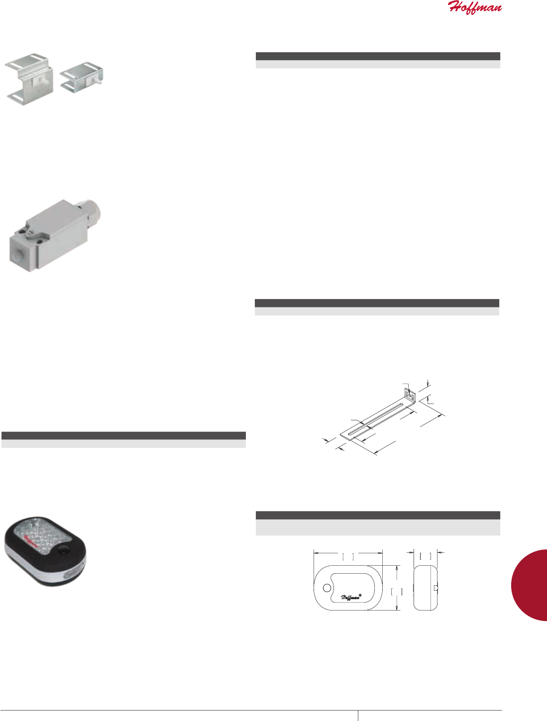
PH 763.422.2211 • FAX 763.422.2600 • PENTAIRPROTECT.COMEQUIPMENT PROTECTION ACCESSORIES 947
12
ELECTRICAL ACCESSORIES liGhtinG PaCkaGes
REMOTE DOOR SWITCHES
• Remote door switch activates the
light when the enclosure door is
opened
• Mounts on enclosure frame and
includes mounting hardware
• Mounting plate is 14 gauge steel
with a plated finish
• Can be hard-wired to the
PANELITE LED or Fluorescent
light or connected via the
PANELITE Door Switch Cable
BULLETIN: A80LT, P20
Catalog Number Description
ALFSWD Door switch assembly (order connection cable separately)
PLFSWD Door switch assembly for PROLINE (order connection cable separately)
TOUCHSAFE UL LIGHT SWITCH
APPLICATION
The Touch-Safe light switch is designed to be used with Hoffman
light kits (AC and DC). It provides a UL listed touch-safe switch that
can be used on many enclosure types and includes hardware for
most applications. The light switch maintains enclosure overall
rating up to UL 508A Type 4X or 12.
FEATURES
• UL listed for a touch-safe wire connection
• Easily mounted to various enclosure types; common bracket and
hardware included for many enclosure types (NEMA, CONCEPT /
FUSION G7, PROLINE , Freestanding Type 12)
• Cable PG compression hub
• Wide operating temperature range: -49°F to +158°F (-45°C to
70°C)
• Rugged die-cast anodized zinc construction
• Connection 3 cage clamps for solid and stranded wire AWG 20-14
(0.5-2.5mm²)
• Protection class I (grounded)
BULLETIN: A80LT
Catalog Number Max. Cable Dia. Max. Voltage
LDSWITCH .375 in. 250 AC / 48 DC
MOUNTING BRACKET KIT FOR LIGHT PACKAGE
Kit simplifies mounting light package in Hoffman PROLINE
disconnect enclosures. Includes brackets, all mounting hardware
and complete instructions.
BULLETIN: A80LT
Catalog Number Description
PDLFBRKT Mounting Bracket Kit
Ø.26
[7]
Ø.25
[6]
.88
[22]
1.08
[27]
7.36
[187] 8.65
[220]
87574479
LED PUCK LIGHT
The LED Puck Light is ideal for
remote and darkened applications.
This versatile light provides
mounting flexibility; it can be
magnetically attached to flat steel
surfaces or can be hung with a
swivel hook. This small form factor,
light-weight LED light provides
superior lighting performance with
minimal power consumption. It can
be used as a three-LED flashlight
or as a 24-LED work light with
operating temperature of 40 F to 120
F (4 C to 48 C). An on/off switch is
incorporated in the light and three
AAA batteries are included.
BULLETIN: A80LT
Catalog Number AxBxC in./mm Product Weight
LEDPUCK 2.25 x 3.75 x 1.38
57 x 95 x 35
0.22 lbs.
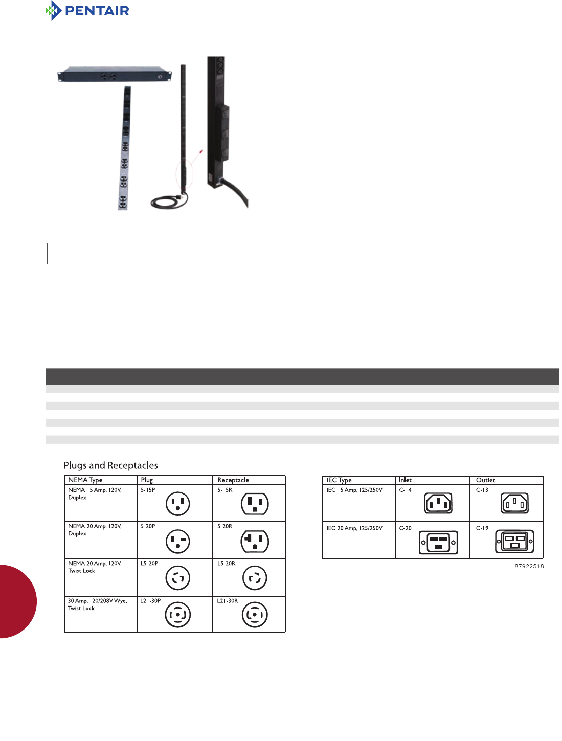
EQUIPMENT PROTECTIONSUBJECT TO CHANGE WITHOUT NOTICEACCESSORIES948
12
ELECTRICAL ACCESSORIES PoWer distribution units
POWER DISTRIBUTION UNITS
RACK AND PANELMOUNT POWER DISTRIBUTION UNITS (PDUS)
INDUSTRY STANDARDS
UL/cUL 60950 listed
UL 1449 (Surge protector models only)
EIA 310-D (19-in. rack-mount models only)
APPLICATION
Rack- and Panel-Mount PDUs not only provide convenient, reliable
power to equipment mounted in cabinets or on open frame racks,
they can also be configured to meet a wide range of design
specifications.
FEATURES
• Power on/off LED indicates whether power is available at the PDU
• External ground stud provided on single-phase models for secure
grounding
• Circuit breakers provide additional equipment protection
• Circuits are isolated on dual circuit model; each has its own
circuit breaker
• Reset button provides easy access to circuit breaker reset
• Surge protector models have an indicator LED to verify surge
circuitry protection
• Rack-mount models mount directly to rack or with adapter
bracket
• Rack-mount models designed for single-phase applications
• Panel-mount models can be mounted flush or with hanging
bracket
• Panel-mount models available for both one- and three-phase
applications
• Three-phase models have three 20 A, double-pole magnetic
breaker/switches with an integral switch guard
SPECIFICATIONS
• Steel housing
• Power cord with molded-on plug:
- 12-in. (305-mm) long single-phase model: 6 ft. (1.8 m)
- Other single-phase models: 15 ft. (4.6 m)
- Three-phase models: 10 ft. (3 m)
Contact Hoffman for custom modifications and non-standard
offerings.
FINISH
Black, low-gloss textured paint.
BULLETIN: DPS
Standard Product Single-Phase Rack-Mount
Catalog Number
Surge
Protection
Amp
Meter
Load
Rating
Voltage
(VAC)
Joule
Rating Receptacle Location
No. of
Receptacles Receptacle Style Power Cord Plug
Rack
Units
DP1N190615 No No 15A 120 — Front 6 NEMA 5-15R NEMA 5-15P 1
DP1N191415 No No 15A 120 — 6 front, 8 back 14 NEMA 5-15R NEMA 5-15P 1
DP1N191415M No Yes 15A 120 — 6 front, 8 back 14 NEMA 5-15R NEMA 5-15P 1
DP1N191015S Yes No 15A 120 2000 2 front, 8 back 10 NEMA 5-15R NEMA 5-15P 1
DP1N191020 No No 20A 120 — 2 front, 8 back 10 NEMA 5-20R NEMA 5-20P 1
DP1N191020S Yes No 20A 120 2000 2 front, 8 back 10 NEMA 5-20R NEMA 5-20P 1
DP1N191020ST Yes No 20A 120 2000 2 front, 8 back 10 NEMA 5-20R NEMA L5-20P Twist Lock 1
Isolated circuits on dual-circuit models with separate circuit breakers.
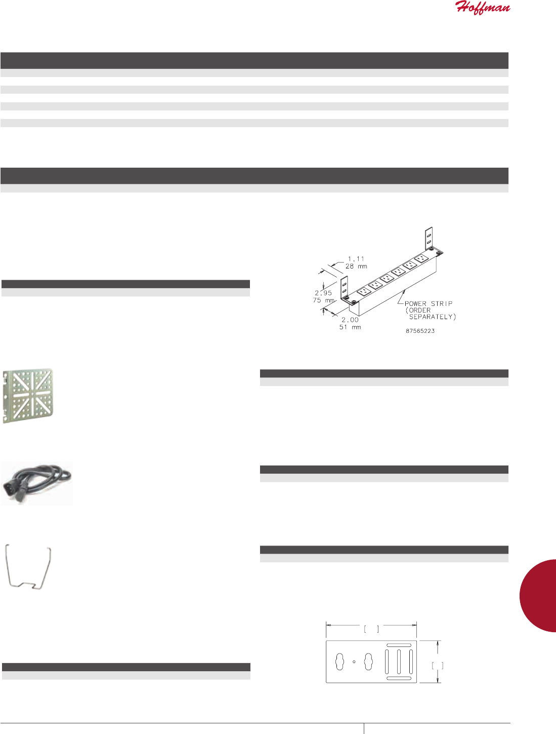
PH 763.422.2211 • FAX 763.422.2600 • PENTAIRPROTECT.COMEQUIPMENT PROTECTION ACCESSORIES 949
12
ELECTRICAL ACCESSORIES PoWer distribution units
Standard Product Single-Phase Vertical-Mount
Catalog Number
Length
(in.)
Length
(mm)
Surge
Protection
Amp
Meter
Load
Rating
Voltage
(VAC)
Joule
Rating
No. of
Receptacles Receptacle Style Power Cord Plug
DP1N120615 12.00 305 No No 15A 120 — 6 NEMA 5-15R NEMA 5-15P
DP1N160620S 16.00 406 Yes No 20A 120 2000 6 NEMA 5-20R NEMA 5-20P
DP1N481815 48.00 1219 No No 15A 120 — 18 NEMA 5-15R NEMA 5-15P
DP1N622415 62.00 1575 No No 15A 120 — 24 NEMA 5-15R NEMA 5-15P
DP1N622420 62.00 1575 No No 20A 120 — 24 NEMA 5-20R NEMA 5-20P
DP1N622420T 62.00 1575 No No 20A 120 — 24 NEMA 5-20R NEMA L5-20P Twist Lock
DP1E2663030MT 66.00 1676 No Yes 30A 250 — 30 24 IEC C-13, 6 IEC C-19 NEMA L6-30P Twist Lock
Isolate circuits on dual circuit models with separate circuit breakers.
DP1E2663030MT is Ethernet metered; SNMP trap provides remote current monitoring via Ethernet.
Standard Product Three-Phase Vertical-Mount
Catalog Number
Length
(in.)
Length
(mm)
Amp
Meter
Load
Rating
Voltage
(VAC) No. of Outlets per Phase Total Outlets per PDU Required Inlet Style Power Cord Plug
DP3E2663635MT 66.00 1676 Yes 35A 250 10 IEC C-13, 2 IEC C-19 30 IEC C-13, 6 IEC C-19 IEC C-14 and C-20 CA style 50A 250 Vac Twist Lock
DP3E2663635MT is Ethernet metered; SNMP trap provides remote current monitoring via Ethernet.
RACKMOUNT PDU BRACKET
Allows rack-mount power strips to be mounted to cabinet sides
without using up rack space. Made of plated steel. Includes two
brackets and mounting hardware. Order power strip separately.
BULLETIN: DPS
Catalog Number Finish Pkg. Qty.
A19PSMB Plated 2 brackets
UNIVERSAL POWER STRIP BRACKET
This bracket fits in the corner of
the frame of all PROLINE cabinets
and facilitates mounting a variety of
power strips.
BULLETIN: DPY
Catalog Number Description
EPDUBK Universal Power Strip Bracket fits all PROLINE cabinets
IEC CORD SETS
Cord sets help minimize cord tangle,
increasing airflow to equipment.
BULLETIN: DPS
Catalog Number Description Pkg. Qty.
DP5E 0.5-m (1.64-ft.) IEC patch cord. 18/3 SJT Black. C-14 to C-13 10
DP10E 1-m (3.28-ft.) IEC patch cord, 18/3 SJT Black. C-14 to C-13 10
IEC C13 RETAINING CLIP
Secures the IEC C-14 inlet into
the C-13 outlet. Helps to prevent
inadvertently unplugging the cord
set.
BULLETIN: DPS
Catalog Number Description Pkg. Qty.
DPCLIP IEC C-13 Retaining Clip 10
PDU BRACKET KIT
The PDU Bracket Kit includes two mounting plates and hardware to
effectively mount power strips within enclosures.
BULLETIN: DCY
Catalog Number Finish Pkg. Qty
DPDU1 Painted black 2
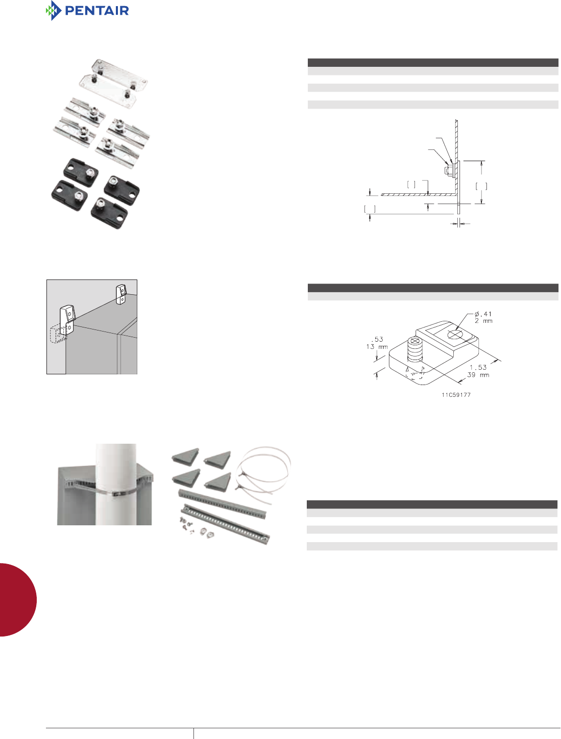
EQUIPMENT PROTECTIONSUBJECT TO CHANGE WITHOUT NOTICEACCESSORIES950
12
MOUNTING ACCESSORIES mountinG kits
MOUNTING ACCESSORIES
MOUNTING KITS
MOUNTING BRACKET KITS
Mounting bracket kits are field-
installable. Composite kits are
rated for 500 lb. (227 kg) maximum
load. Kit includes four brackets
and mounting hardware for all
Type 1 Networking wall-mount and
COMLINE enclosures.
DMFK1 and DMFK2 include two
14 gauge steel external mounting
brackets and fasteners. Mounting
bracket kit CMFK and CMFKSS
each contain four 12 gauge steel or
Type 304 stainless steel external
mounting brackets and fasteners.
Sealing washers are provided
with each kit to maintain Type 4 or
12 rating after installation. Steel
mounting brackets are plated.
BULLETIN: A80
Catalog Number Description Fastener Thread Size
DMFK1 Mounting bracket kit #10-32
DMFK2 Mounting bracket kit #10-32
CMFK Steel mounting kit #3/8-16
CMFKSS Stainless steel mounting bracket kit #3/8-16
CMTGFT Composite mounting bracket kit #3/8-16
*$8*(
+(;187
6($/,1*:$6+(5
&&
ULTRX MOUNTING BRACKET KIT
Kit is field-installable. Corrosion-
resistant fiberglass material.
Type 316 stainless steel mounting
hardware is included. Four
mounting brackets per kit.
BULLETIN: UX1Y
Catalog Number Description Kit Qty.
UUMF Mounting Bracket Kit 4
POLEMOUNT KIT Use to mount CONCEPT, Networking and wall-mount enclosures
to poles of various sizes and shapes. Simply attach the plated steel
channel bar to the mounting holes at the back of the enclosure and
wrap the stainless steel strap around the pole and through the bar.
Kit includes two mounting channels, two straps suitable for 3-in.
(76-mm) to 12-in. (305-mm) diameter pole and mounting hardware.
BULLETIN: CWY
Catalog Number Fits Enclosure (in.) Fits Enclosure (mm)
CPMK12 when B = 12.00 when B = 305
CPMK16 when B = 16.00 when B = 406
CPMK20 when B = 20.00 when B = 508
CPMK24 when B = 24.00 when B = 610
CPMK30 when B = 30.00 when B = 762
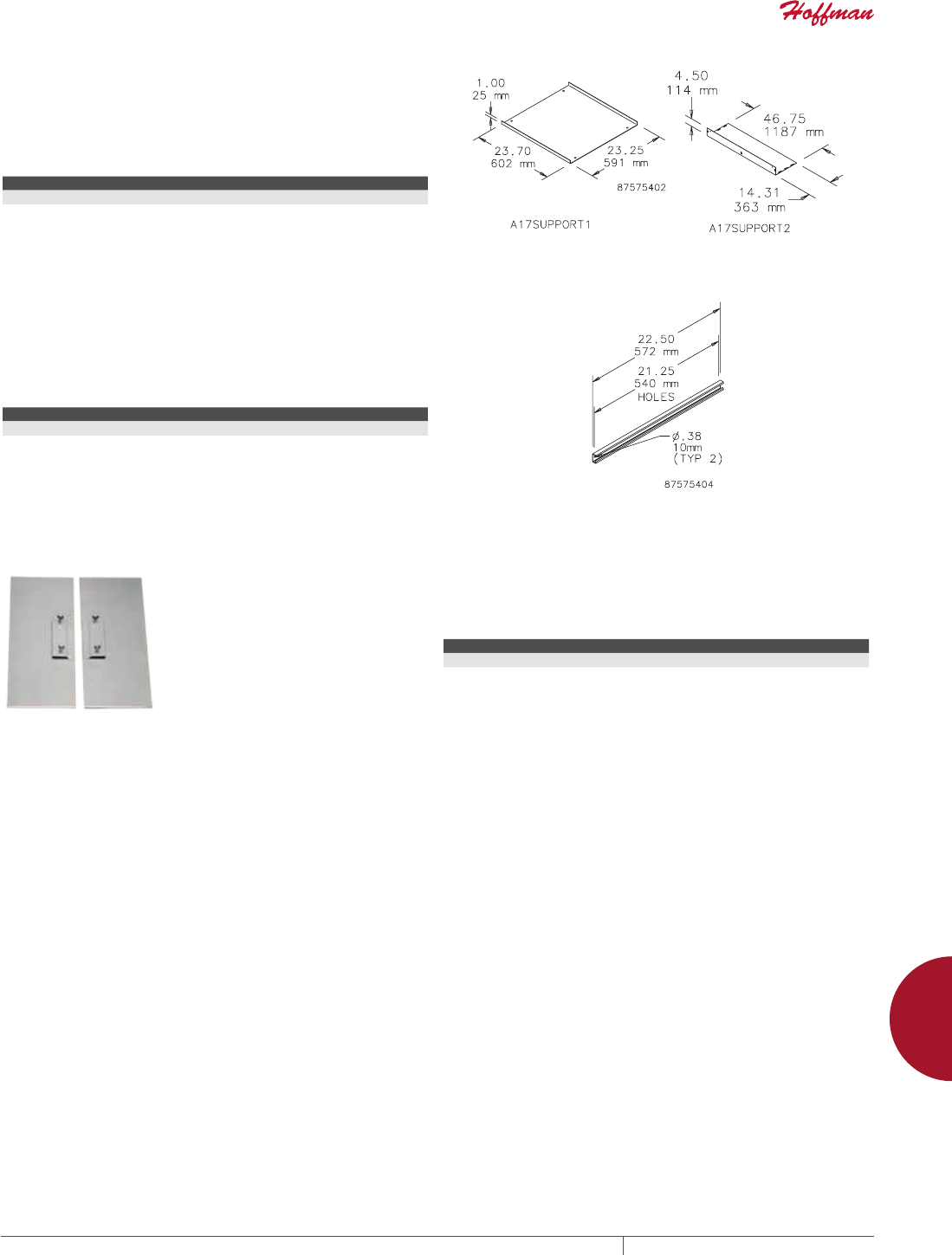
PH 763.422.2211 • FAX 763.422.2600 • PENTAIRPROTECT.COMEQUIPMENT PROTECTION ACCESSORIES 951
12
MOUNTING ACCESSORIES mountinG kits
BOTTOM SUPPORT KIT
Bolt-in bottom support plate with mountng hardware. Coated with
ANSI 61 gray polyester powder paint. Required when installing
Hoffman floor stands or casters on A17 fiberglass free-standing
enclosures.
BULLETIN: A17Y
Catalog Number Use With
A17SUPPORT1 A17 One-Door Fiberglass Enclosures
A17SUPPORT2 A17 Two-Door Fiberglass Enclosures
UNISTRUT MOUNTING KIT
Bolt-in internal unistrut channel (8 pieces) with mounting hardware.
Required to install Hoffman unistrut-mounted free-stand panels
and accessories in two-door A17 fiberglass enclosures. Hoffman
A17SUPPORT2 plate must also be installed to secure unistrut.
BULLETIN: A17Y
Catalog Number Use With
A17UNISTRUT A17 Two-Door Fiberglass Enclosures
ENCLOSURE STABILIZERS Helps prevent injury to workers by stabilizing floor-mount
enclosures which are not bolted down. To install, slip the stabilizer
under the floor stand and tighten two thumb screws. Made from .19-
in. (5-mm) steel plate. Bright orange finish.
BULLETIN: A80
Catalog Number Description
AENST Two stabilizers
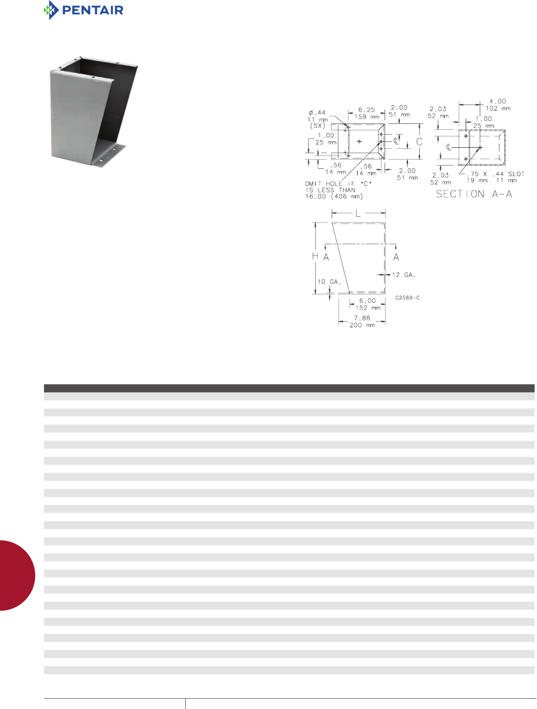
EQUIPMENT PROTECTIONSUBJECT TO CHANGE WITHOUT NOTICEACCESSORIES952
12
MOUNTING ACCESSORIES leGs and Casters
LEGS AND CASTER S
FLOOR STAND KIT
INDUSTRY STANDARDS
Product maintains UL/CSA Type 4, 4X (stainless steel only) and
Type 12 when properly installed on Hoffman Type 4 or Type 12
enclosures.
APPLICATION
Kits are easily installed on most wall-mount Hoffman enclosures.
Can also be used to elevate Hoffman free-stand enclosures.
To install, drill holes in the bottom of the enclosure and bolt the
floor stands to the enclosure.It is not necessary to remove the wall-
mount brackets from the enclosure.
SPECIFICATIONS
12 gauge steel floor stand has an ANSI 61 gray polyester powder
finish over pretreated surfaces. Stainless steel floor stand is
available in Type 316 and Type 304.
COMPONENTS
Each kit includes two stands. Two sets of floor stands are
recommended for enclosures larger than double door free-stand
enclosures.
ORDERING
Special heights, depths, materials and finishes can be provided on
custom order. Consult factory for information.
BULLETIN: A4SY, A80
Catalog Number Material Height, H (in.) Height, H (mm) Width, C (in.) Width, C (mm) L (in.) L (mm)
AFK0608 Steel 6.00 152 8.06 205 7.06 179
AFK0610 Steel 6.00 152 10.06 256 7.06 179
AFK0612 Steel 6.00 152 12.06 306 7.06 179
AFK0618 Steel 6.00 152 18.06 459 7.06 179
AFK1208 Steel 12.00 305 8.06 205 8.12 206
AFK1210 Steel 12.00 305 10.06 256 8.12 206
AFK1212 Steel 12.00 305 12.06 306 8.12 206
AFK1216 Steel 12.00 305 16.06 408 8.12 206
AFK1218 Steel 12.00 305 18.13 461 8.12 206
AFK1220 Steel 12.00 305 20.06 510 8.12 206
AFK1808 Steel 18.00 457 8.06 205 9.17 233
AFK1810 Steel 18.00 457 10.06 256 9.17 233
AFK1812 Steel 18.00 457 12.06 306 9.17 233
AFK1816 Steel 18.00 457 16.06 408 9.17 233
AFK2408 Steel 24.00 610 8.06 205 10.23 260
AFK2410 Steel 24.00 610 10.06 256 10.23 260
AFK2412 Steel 24.00 610 12.06 306 10.23 260
AFK2416 Steel 24.00 610 16.06 408 10.23 260
AFK0608SS Stainless Steel, 304 6.00 152 8.06 205 9.09 231
AFK0610SS Stainless Steel, 304 6.00 152 10.06 256 9.09 231
AFK0612SS Stainless Steel, 304 6.00 152 12.06 306 9.09 231
AFK0618SS Stainless Steel, 304 6.00 152 18.06 459 9.09 231
AFK0624SS Stainless Steel, 304 6.00 152 24.06 611 9.09 231
AFK1208SS Stainless Steel, 304 12.00 305 8.06 205 9.09 231
AFK1210SS Stainless Steel, 304 12.00 305 10.06 256 9.09 231
AFK1212SS Stainless Steel, 304 12.00 305 12.06 306 9.09 231
AFK1216SS Stainless Steel, 304 12.00 305 16.06 408 9.09 231
AFK1218SS Stainless Steel, 304 12.00 305 18.06 459 9.09 231
AFK1224SS Stainless Steel, 304 12.00 305 24.06 611 9.09 231
AFK1808SS Stainless Steel, 304 18.00 457 8.06 205 9.09 231
AFK1810SS Stainless Steel, 304 18.00 457 10.06 256 9.09 231
AFK1812SS Stainless Steel, 304 18.00 457 12.06 306 9.09 231
AFK1816SS Stainless Steel, 304 18.00 457 16.06 408 9.09 231
AFK1818SS Stainless Steel, 304 18.00 457 18.06 459 9.09 231
AFK1824SS Stainless Steel, 304 18.00 457 24.06 611 9.09 231

PH 763.422.2211 • FAX 763.422.2600 • PENTAIRPROTECT.COMEQUIPMENT PROTECTION ACCESSORIES 953
12
MOUNTING ACCESSORIES leGs and Casters
Catalog Number Material Height, H (in.) Height, H (mm) Width, C (in.) Width, C (mm) L (in.) L (mm)
AFK2408SS Stainless Steel, 304 24.00 610 8.06 205 9.09 231
AFK2410SS Stainless Steel, 304 24.00 610 10.06 256 9.09 231
AFK2412SS Stainless Steel, 304 24.00 610 12.06 306 9.09 231
AFK2416SS Stainless Steel, 304 24.00 610 16.06 408 9.09 231
AFK2418SS Stainless Steel, 304 24.00 610 18.06 459 9.09 231
AFK2424SS Stainless Steel, 334 24.00 610 24.06 611 9.09 231
AFK0608SS6 Stainless Steel, 316 6.00 152 8.06 205 9.09 231
AFK0610SS6 Stainless Steel, 316 6.00 152 10.06 256 9.09 231
AFK0612SS6 Stainless Steel, 316 6.00 152 12.06 306 9.09 231
AFK0618SS6 Stainless Steel, 316 6.00 152 18.06 459 9.09 231
AFK0624SS6 Stainless Steel, 316 6.00 152 24.06 611 9.09 231
AFK1208SS6 Stainless Steel, 316 12.00 305 8.06 205 9.09 231
AFK1210SS6 Stainless Steel, 316 12.00 305 10.06 256 9.09 231
AFK1212SS6 Stainless Steel, 316 12.00 305 12.06 306 9.09 231
AFK1216SS6 Stainless Steel, 316 12.00 305 16.06 408 9.09 231
AFK1218SS6 Stainless Steel, 316 12.00 305 18.06 459 9.09 231
AFK1224SS6 Stainless Steel, 316 12.00 305 24.06 611 9.09 231
AFK1808SS6 Stainless Steel, 316 18.00 457 8.06 205 9.09 231
AFK1810SS6 Stainless Steel, 316 18.00 457 10.06 256 9.09 231
AFK1812SS6 Stainless Steel, 316 18.00 457 12.06 306 9.09 231
AFK1816SS6 Stainless Steel, 316 18.00 457 16.06 408 9.09 231
AFK1818SS6 Stainless Steel, 316 18.00 457 18.06 459 9.09 231
AFK1824SS6 Stainless Steel, 316 18.00 457 24.06 611 9.09 231
AFK2408SS6 Stainless Steel, 316 24.00 610 8.06 205 9.09 231
AFK2410SS6 Stainless Steel, 316 24.00 610 10.06 256 9.09 231
AFK2412SS6 Stainless Steel, 316 24.00 610 12.06 306 9.09 231
AFK2416SS6 Stainless Steel, 316 24.00 610 16.06 408 9.09 231
AFK2418SS6 Stainless Steel, 316 24.00 610 18.06 459 9.09 231
AFK2424SS6 Stainless Steel, 316 24.00 610 24.06 611 9.09 231
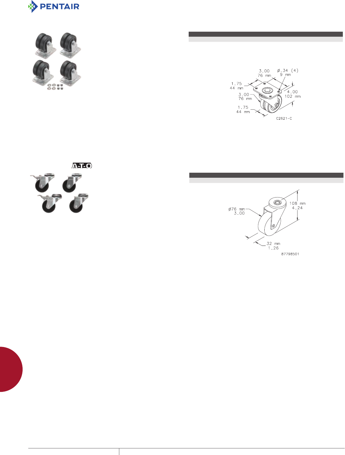
EQUIPMENT PROTECTIONSUBJECT TO CHANGE WITHOUT NOTICEACCESSORIES954
12
MOUNTING ACCESSORIES leGs and Casters
PLATE CASTERS
Plate casters can be used on any enclosure to provide mobility.
Casters have dual hard rubber wheels. Each caster has a 350-
lb. (159-kg) load rating. Caster plates are heavy gauge steel with
a zinc plated finish. Casters have ball bearing swivels. A caster
kit includes 4 swivel casters and necessary mounting hardware.
Catalog number DMCKC caster kit also includes four caster skirts
which partially conceal caster plate and mounting hardware. Caster
skirts are painted medium gray.
BULLETIN: D10
Catalog Number Description
DMCKC Set of four casters, four mounting plates and hardware
CASTER KIT
A set of four casters (two locking,
two non-locking) that mount
directly to the bottom of a PROLINE
frame, 0-mm, or 100-mm Solid
Base or a Console. (Do not use on
plinth bases.) Casters elevate the
enclosure 110 mm (4.33 in.) when
installed. Caster frames are plated
steel with ball-bearing pivots.
Caster wheels are made of a black
polyamide material. Kit includes
M12 mounting hardware.
Order separately.
Casters Maximum Load: 1000 lb.
(453 kg)
Exercise care when using casters
to move the cabinet. Avoid tipping
and damage to the cabinet and
its contents by slowly moving
the cabinet on its casters across
smooth, flat flooring. Avoid:
• large cracks
• floor displacement
• seams
• gravel
• any other obstruction
Never use casters while
transporting a cabinet by truck on
roadways.
Contact Hoffman if further
information is needed.
BULLETIN: P20
Catalog Number Description
PC1M12 Set of 4 Casters
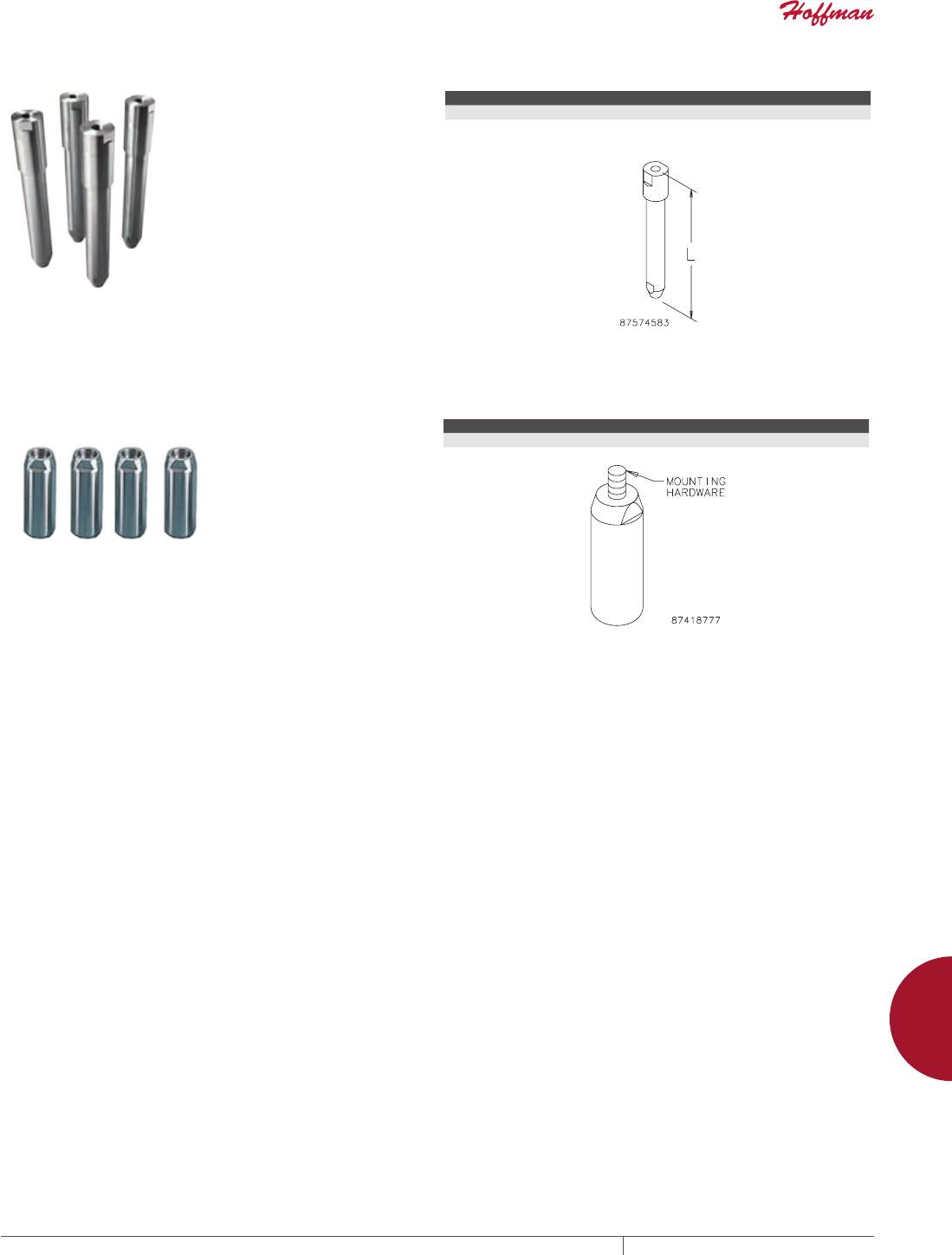
PH 763.422.2211 • FAX 763.422.2600 • PENTAIRPROTECT.COMEQUIPMENT PROTECTION ACCESSORIES 955
12
MOUNTING ACCESSORIES leGs and Casters
SANITARY LEG KITS
Sanitary Leg Kits provide space
between the enclosure and the floor
for better washdown accessibility.
Available with fixed or independently
adjustable legs. Adjustable leg
shown. Four legs per kit. Maintains
NEMA Type 4X rating when properly
installed on a Hoffman Type 4X
enclosure.
BULLETIN: WSY
Catalog Number Description Size L (in.) Size L (mm)
WSASLKSS Adjustable Sanitary Leg Kit 11.50 -12.50 292 -318
WSFSLKSS Fixed Sanitary Leg Kit 12.00 305
STAINLESS STEEL LEGS
Legs mount to the bottom of a solid base to elevate the enclosure 4
in. (100 mm) from the floor. The legs are made of Type 304 stainless
steel and are appropriate for hose-down applications. Mounting
hardware is included.
BULLETIN: P20S
Catalog Number Description
PLEGSS (4) Stainless Steel Legs
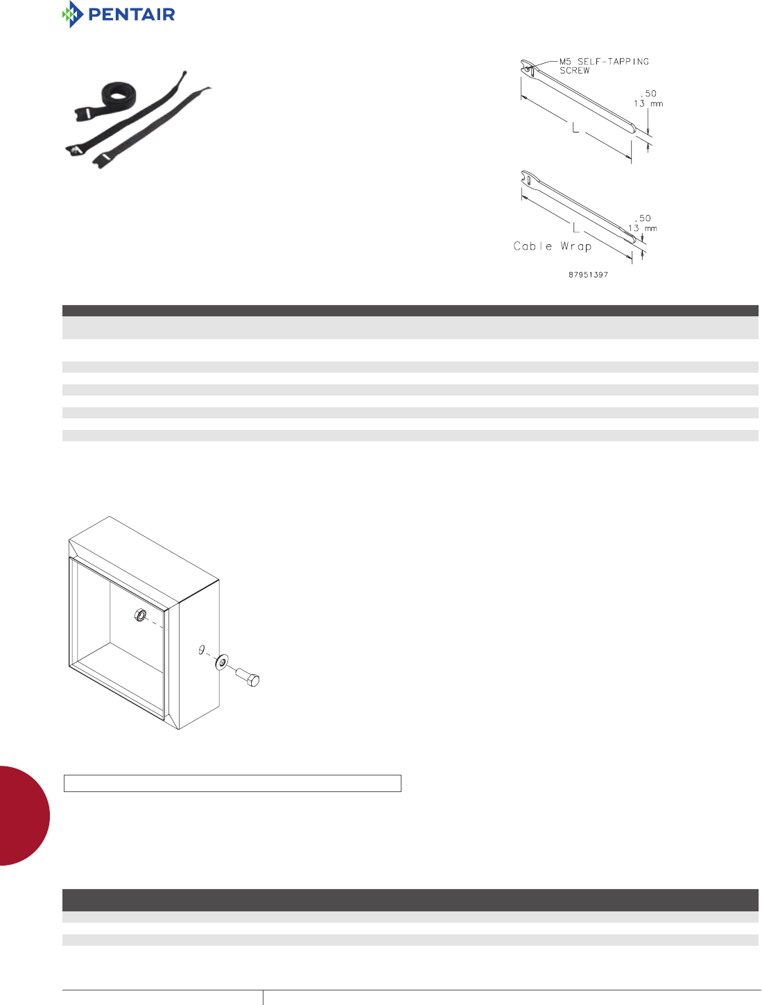
EQUIPMENT PROTECTIONSUBJECT TO CHANGE WITHOUT NOTICEACCESSORIES956
12
MOUNTING ACCESSORIES fasteners
FASTENERS
VELCRO® CABLE WRAP
Securely holds cable to cable manager and unfastens easily for
cable maintenance. VELCRO® is 0.5-in. (12.7-mm) wide. Available
in 8- and 12-in. (203- and 305-mm) lengths in both screw fastener
and wrap styles. M5 self-tapping screw is used on Net Series or
PROLINE frames.
VELCRO is a trademark of Velcro Industries B.V.
BULLETIN: DACCY
Catalog Number Description L (in.) L (mm) Color Pkg. Qty.
ECWTD8B Screw fastener style.
Includes M5 mounting screw.
8.00 203 Black 10
ECWTD12B Screw fastener style.
Includes M5 mounting screw.
12.00 305 Black 10
ECW8B Wrap style 8.00 203 Black 10
ECW8R Wrap style 8.00 203 Red 10
ECW8BL Wrap style 8.00 203 Blue 10
ECW8Y Wrap style 8.00 203 Yellow 10
ECW12B Wrap style 12.00 305 Black 10
ECW12R Wrap style 12.00 305 Red 10
ECW12BL Wrap style 12 305 Blue 10
ECW12Y Wrap style 12 305 Yellow 10
ULRECOGNIZED HARDWARE KITS
89090290
INDUSTRY STANDARDS
UL 508A recognized components
CSA File No. 42186: Type 4, 4X, 12, 13
Cabinet maintains up to UL Type 4X when included hardware is used
per instructions.
APPLICATION
These UL-recognized mountings kits are designed to maintain the
overall UL Type rating of the enclosure when component mounting
holes penetrate the exterior of the enclosure. These hardware kits
are conveniently offered in three common fastener sizes to meet
various applications.
FEATURES
• Each kit provides the capability of sealing 10 hole penetrations
• Kits are offered in 10-32, 1/4-20 and 3/8-16 fastener sizes
• Stainless steel fasteners
• Kit contains screws, sealing washers and locking nuts
• Kit is UL-recognized as a means to maintain UL enclosure cabinet
rating up to Type 4X
SPECIFICATIONS
• Fasteners are made of stainless steel
• Sealing washer has integral rubber sealing and stainless steel
washer
FINISH
Brushed, bright stainless steel
BULLETIN: A80HS
Standard Product
Catalog Number
Fastener Size
(Nominal)
Fastener Length
(Dia. Inches)
Drill/Hole Size
(Inches)
AHK10324X 10-32 5/8 7/32
AHK14204X 1/4-20 1 9/32
AHK38164X 3/8-16 1 13/32
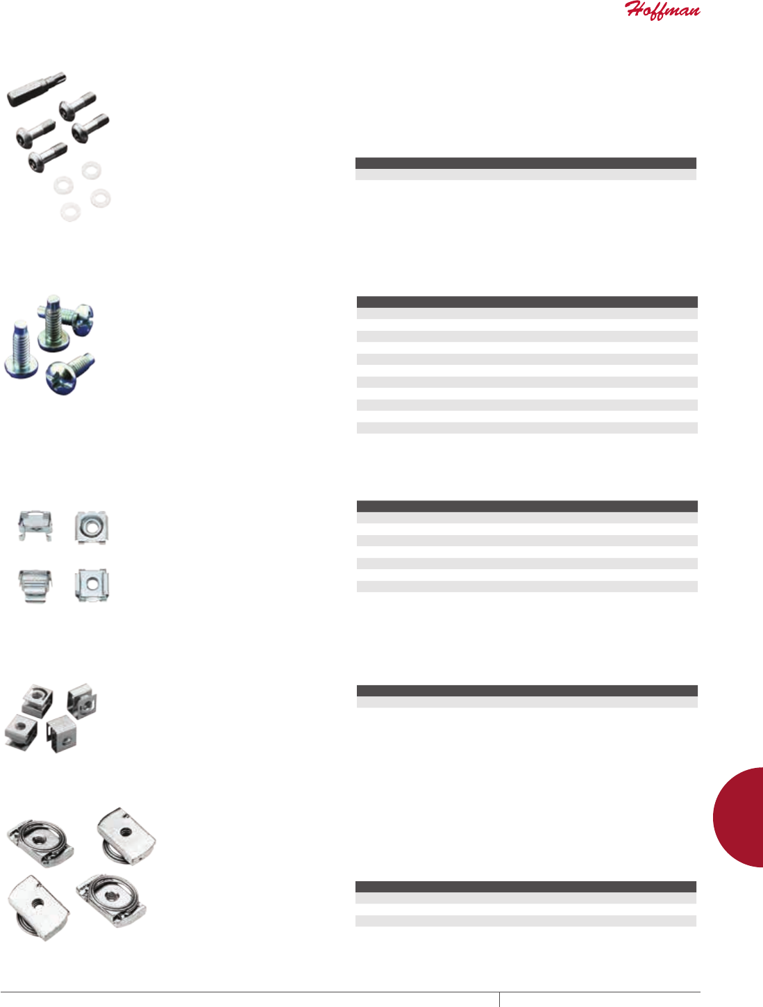
PH 763.422.2211 • FAX 763.422.2600 • PENTAIRPROTECT.COMEQUIPMENT PROTECTION ACCESSORIES 957
12
MOUNTING ACCESSORIES fasteners
TAMPERRESISTANT SCREWS Designed for field installation on screw cover pull boxes and screw
cover Type 3R enclosures (size 16.00 x 12.00 x 6.00 in. or smaller),
consolets, pushbutton enclosures and Type 12 screw cover wiring
trough. Each package consists of four Type 18-8 stainless steel
screws and four nylon captivating washers. Driver bit must be
ordered separately (functions in any handle or socket capable of
holding 1/4-in. hex insert bits).
BULLETIN: A80
Catalog Number Description Pkg. Qty.
ATRSK Tamper-resistant screw (10-32) 4
ATRSDVR Driver bit 1
SCREW PACKAGES
Screw Packages are for mounting
rack panels and equipment to rack
angles.
BULLETIN: A80, DACCY, X20
Catalog Number Color Description Pkg. Qty.
ES1224 Silver 12-24 x 5/8 in. combo head 20
ES1224250 Silver 12-24 x 5/8 in. combo head 250
ES1224B Black 12-24 x 5/8in. combo head 20
ES1224B250 Black 12-24 x 5/8 in. combo head 250
ASM5 Silver M5 x 20 mm Combo Head 20
ASM6 Silver M6 x 16 mm combo head 20
ASM5T Silver M5 x 12 mm thread-forming Phillips hex head screws 20
ASM6250 Silver M6 x 16 mm combo head 250
AS1032 Silver 10-32 x 5/8 in. combo head 20
AS1032250 Silver 10-32 x 5/8 in. combo head 250
AS1032B Black 10-32 x 5/8 in. combo head 20
Use ASM5T on PROLINE frame or Net Series extruded holes.
CAGE NUT PACKAGE
Cage Nut Packages are for use with
square-hole rack angles. Cage nuts
are plated steel.
BULLETIN: DACCY
Catalog Number Color Description Pkg. Qty.
PM5CN Silver M5 cage nut 20
PM6CN Silver M6 cage nut 20
PM6CN250 Silver M6 cage nut 250
P1032CN Silver 10-32 cage nut 20
P1032CN250 Silver 10-32 cage nut 250
P1224CN Silver 12-24 cage nut 20
P1224CN250 Silver 12-24 cage nut 250
CLIP NUT PACKAGE
Twenty plated clip nuts fit all
rack-mounting angles with .281-in.
(7-mm) diameter holes (through-
hole type).
BULLETIN: A80
Catalog Number Description Pkg. Qty. Fits
AN1032 Clip Nut 10-32 20 .281-diameter mounting holes
ANM5 Clip Nut M5 (Metric) 20 .281-diameter mounting holes
CLAMPING NUT PACKAGE Twenty plated clamping nuts with top-grip nut retainers. Clamping
nuts fit into mounting channels that are used on inside walls of
Hoffman enclosures. Clamping nuts are included with all Hoffman
accessories that attach to mounting channels. These clamping nuts
can be used for mounting other equipment (brackets, etc.) to the
enclosure walls.
BULLETIN: A80
Catalog Number Description Thread
APS1032CN Package of 20 10-32
APS1420CN Package of 20 1/4-20
APS51618CN Package of 20 5/16-18
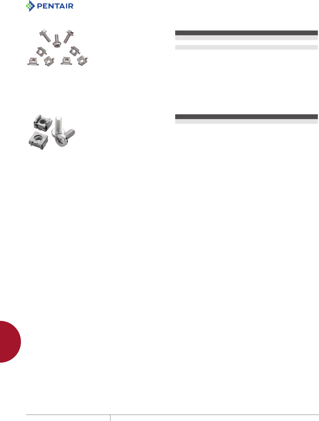
EQUIPMENT PROTECTIONSUBJECT TO CHANGE WITHOUT NOTICEACCESSORIES958
12
MOUNTING ACCESSORIES fasteners
PROLINE FASTENER PACKAGES
Use to fasten components to the
grid system. PGF Packages include
20 front-loading clip nuts (M6) and
20 combination-drive washer-head
bolts (M6).
Grounding Package is used with the
rectangular holes in the PROLINE
frame to provide electrical
continuity between the frame and
the grid system. ASM5T Package is
used with PROLINE frames having
round holes. Package includes 20
M5 self-tapping screws.
BULLETIN: DACCY, P20
Catalog Number Description Use in Pkg. Qty.
ASM5T M5 x 12 mm thread-forming Phillips hex head screws Round holes 20
PGFM6 Standard Package - M6 cage nuts and bolts Rectangular holes 20
PGFGM6 Grounding Package - M6 grounding cage nuts and bolts Tapped holes 20
FASTENER PACKAGE
Kit includes a set of 8 cage nuts and
screws. Used to mount 19-in. rack
equipment to 9-mm square holes in
uprights. Cage nuts are metric (M6).
Screws are pan head Phillips metric
M6x16.
BULLETIN: DACCY, DEC1
Catalog Number Color Description
ELRFM6 No longer available
ECNSM6 Silver M6 x 16 pan head posidrive screws.
M6 cage nuts.
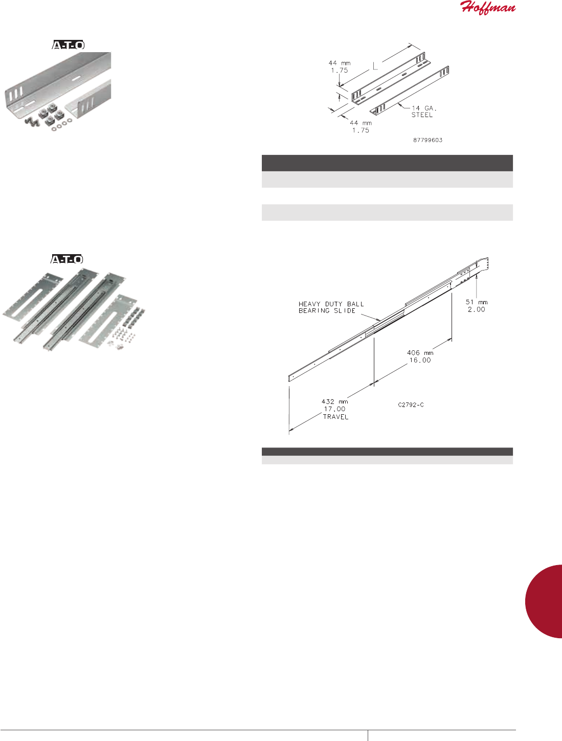
PH 763.422.2211 • FAX 763.422.2600 • PENTAIRPROTECT.COMEQUIPMENT PROTECTION ACCESSORIES 959
12
MOUNTING ACCESSORIES raCk-mount aCCessories
RACK-MOUNT ACCESSORIES
GUIDES
14 gauge steel chassis guides mount between two pairs of rack-
mounting angles that have accessory mounting legs. Guides and
mounting hardware are plated. (XSFG mount on one pair of Type RA
rack-mounting angles that have accessory mounting legs.)
BULLETIN: P20
Catalog Number
Length
in./mm Rack Units
AG1U5 15.00
381.0
1
AG1U6 21.00
533.4
1
AG1U8 26.00
660.4
1
SLIDES
Heavy-duty ball bearing, plated three-section Slides are 16-in.
(406-mm) long and allow 17-in. (423-mm) extension. They are
attached to supports that mount between two pairs of rack-
mounting angles that have accessory mounting legs. Mounting
hardware is furnished. Equipment 16.75-in. (425-mm) wide can be
mounted between Slide assemblies installed on 19-in. rack angles.
A pair of Slides can support up to 160 lb. at the extended position
when load is distributed evenly along the 16-in. (406-mm) Slide
length. Requires Rack Angle Adapter Bracket to fit PROLINE.
Needs to be used with the Rack Angle Adapter Bracket (PBRAA,
PBRAA19 or PBRAA24).
BULLETIN: P20
Catalog Number Quantity
A16SL2U 2
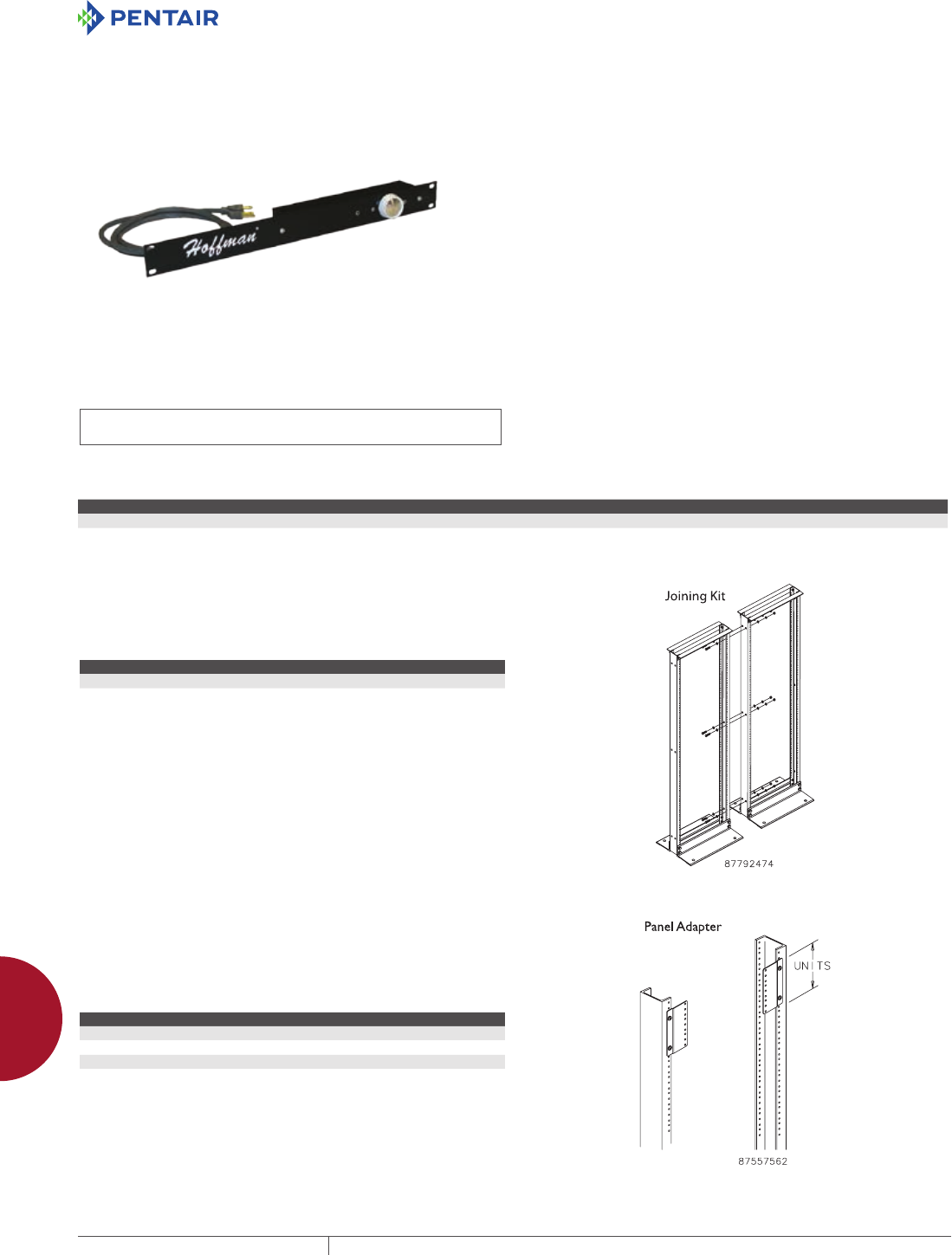
EQUIPMENT PROTECTIONSUBJECT TO CHANGE WITHOUT NOTICEACCESSORIES960
12
MOUNTING ACCESSORIES raCk-mount aCCessories
FAN SPEED CONTROL, RACKMOUNT
INDUSTRY STANDARDS
UL 508A Listed; File No. E249700
cUL Listed per CSA C22.2 No. 14; File No. E249700
APPLICATION
These Hoffman Fan Speed Controls provide a means to optimize
airflow in a cabinet or rack, balancing air volume requirements
with noise level and power use. The AFANTSC Panel Mount Fan
Speed Control adjusts fan speed automatically based on remote
temperature sensor inputs. The A19FANSC 19-in. Rack-Mount Fan
Speed Control allows manual control over fan speed. Both units are
designed to work with Hoffman 3-, 6- and 10-in. Compact Cooling
Fans and with 19-in. fan trays, as well as door- and top-mount fan
trays. These fan speed controls are ideal for offices, classrooms
and other acoustic noise-sensitive areas.
SPECIFICATIONS
• Continuously variable fan speed control knob with minimum
speed adjustment
• Uses 1 RU rack space
• Steel construction
• Two NEMA 5-15R outlets provide power to fan
• Six-foot (1.83-m) power cord plugs into standard 120V 60 Hz
outlet
FINISH
AFANTSC: Light-gray polycarbonate control housing
A19FANSC: RAL 9005 black polyester powder paint
BULLETIN: DTHRM
Catalog Number Description Application Voltage and Frequency Current Draw Temperature Settings (C) Temperature Settings (F)
A19FANSC 19-in. Rack-Mount Fan Speed Control Fan speed adjusted manually 120V, 60 Hz 4A max. Continously variable Continously variable
JOINING KIT
Hardware kit to join two open-frame racks. Made of steel with
plated finish.
BULLETIN: DOFRY
Catalog Number Description
EJ2DR Joining Kit, Side-to-Side
PANEL ADAPTER
Adapts 23-in. open frame rack to accept 19-in. equipment. Offset
provides flush mounting surface. Steel with plated finish. Furnished
in pairs.
BULLETIN: DACCY
Catalog Number Rack Units
ERB1U2319 1
ERB3U2319 3
ERB5U2319 5
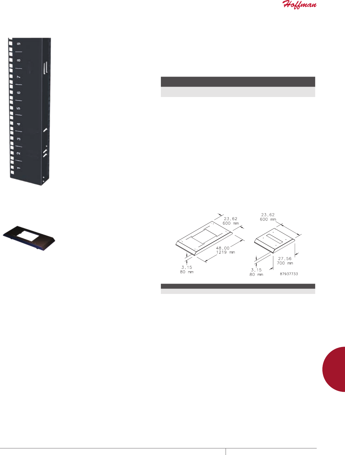
PH 763.422.2211 • FAX 763.422.2600 • PENTAIRPROTECT.COMEQUIPMENT PROTECTION ACCESSORIES 961
12
MOUNTING ACCESSORIES raCk-mount aCCessories
RACK UNIT LABEL Self-adhesive clear Mylar label with white numbers enables
numbering along sides of open frame racks or rack angles.
Numbers spaced one rack unit apart. Can be used for bottom-
up or top-down numbering of rack units to simplify equipment
installation. Each label provided in two pieces (numbers 1-29 and
30-58) for easier installation. Two labels per catalog number. Label
shown mounted on rack angle.
Mylar is a registered trademark of DuPont Tejin Films.
BULLETIN: DOFRY
Catalog Number
Installed Length
in./mm
Width
in./mm
ARULABEL 101.50
2578
.50
13
MOBILE BASE FOR OPEN FRAME RACKS
Models for 19-in. 2- and 4-Post Open Frame Racks. Includes four
non-locking casters. Will also accept standard levelers. Order
catalog number PMBLM12 separately. The rack mounts on the
base to provide greater stability with mobility. Made of steel with
RAL 9005 black polyester powder paint finish. Mounting hardware
included.
BULLETIN: DOFRY
Catalog Number Fits
A19MB600 2-post open-frame racks
A19MB1000 4-post open-frame racks with depth adjustable
between 17.7- and 29.5-in. (450- and 750-mm) in 0.98-in. (25-mm) increments
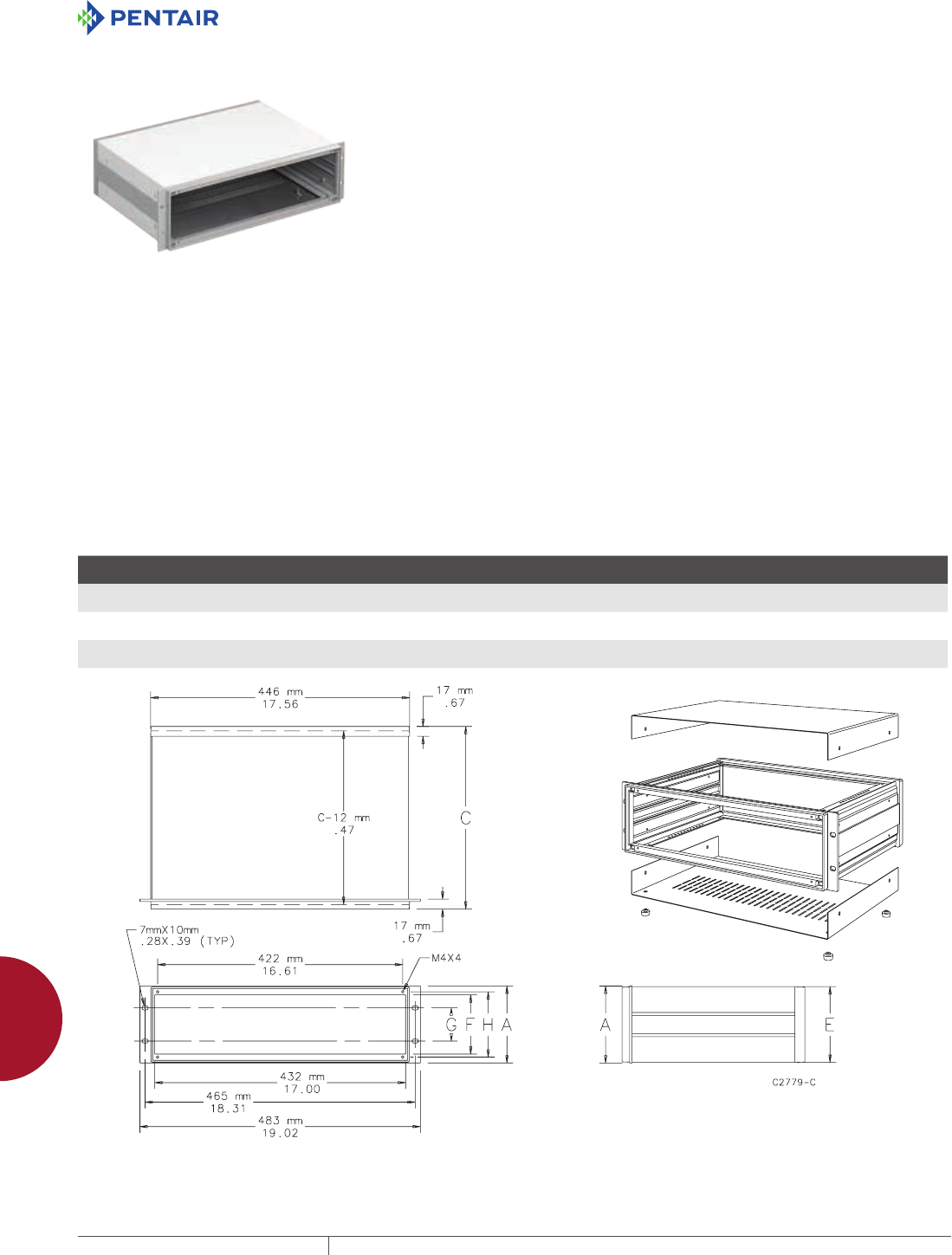
EQUIPMENT PROTECTIONSUBJECT TO CHANGE WITHOUT NOTICEACCESSORIES962
12
MOUNTING ACCESSORIES raCk-mount aCCessories
19IN. RACKMOUNT/DESKTOP CASE, TYPE 1
INDUSTRY STANDARDS
NEMA Type 1
IEC 60529, IP20
Exterior Dimensions
EIA 310-D / IEC 297-1
DIN 41494 Part 1
APPLICATION
Desktop cases house circuit boards and other electronic equipment
in a rigid framework with easy front and rear access. Rack cases
are 19-in. rack mountable with integral mounting provided in the
front bezel.
FEATURES
• Removable top and bottom covers attach directly to case
framework for maintenance convenience
• Bottom cover has multiple rows of holes for ventilation
• Front bezel includes mounting provisions for 19-in. rack mounting
as well as mounting for front panel options for application
flexibility
• Top and bottom of framework have mounting provisions for
optional support rails for application flexibility. Mounting holes
are spaced on 10-mm centers front to back.
• Case framework is assembled for quick installation. Top cover,
bottom cover, anti-skid feet and mounting hardware are included.
• Mounting hardware for optional front and rear panels are
included with case for installation convenience
SPECIFICATIONS
• One-piece aluminum die cast front bezel and rear bezel are
connected front-to-back with aluminum extrusions to form a rigid
structural framework
• Sides on 3U- and 4U-tall cases are the aluminum front-to-back
extrusions. The 6U-tall case has two aluminum extrusions with a
steel middle panel on each side.
• Covers are 1-mm steel and have grounding provisions
FINISH
Framework has an RAL 7030 stone-gray textured finish. Top and
bottom covers have an RAL 7035 light-gray textured finish on the
outside and a plated finish on the inside.
BULLETIN: DEC1
Standard Product
Catalog Number AxBxC mm/in.
E
mm/in.
F
mm/in.
G
mm/in.
H
mm/in. Rack Units
ERC3U4837 133 x 483 x 375
5.20 x 19.00 x 14.80
131
5.14
103
4.04
57
2.25
110
4.33
3
ERC4U4843 177 x 483 x 435
7.00 x 19.00 x 17.10
175
6.89
147
5.77
102
4.00
155
6.08
4
ERC6U4843 266 x 483 x 435
10.50 x 19.00 x 17.10
264
10.39
235
9.27
190
7.50
243
9.58
6
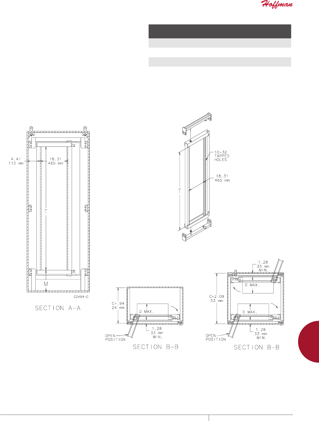
PH 763.422.2211 • FAX 763.422.2600 • PENTAIRPROTECT.COMEQUIPMENT PROTECTION ACCESSORIES 963
12
MOUNTING ACCESSORIES raCk-mount aCCessories
SWINGOUT RACK MOUNTING FRAMES
Full-length 10 gauge swing-out rack mounting frames are available
for mounting 19-in. (483-mm) rack mounting equipment. The
frame pivots within the enclosure to allow access to the back of
the mounted equipment. The frames can be installed in 72.00-in.
(1829-mm) and 90.00-in. (2286-mm) high enclosures that are 30.00-
in. (762-mm) or 36.00-in. (914-mm) wide. They can be installed in
60.00-in. (1524-mm) or 72.00-in. (1829-mm) wide enclosures if a
center panel support is used. Mounting holes are tapped with #10-
32 threads spaced per EIA standard. The design features smooth
operation and secure positioning anywhere along the horizontal
mounting channels. Frame swings from the left side.
All frames are white and furnished with plated mounting hardware.
BULLETIN: A80
Catalog Number
Fits Enclosure
Size A x B
in./mm
T
in./mm
M
in./mm
D max
in./mm
Number
of Units
A7230SOF19 72.06 x 30.06
1830 x 764
57.88
1470
9.09
231
16.25
413
33
A7236SOF19 72.06 x 36.06
1830 x 916
57.88
1470
9.09
231
24.25
616
33
A9036SOF19 90.06 x 36.06
2287 x 916
75.28
1915
9.34
237
24.25
616
43
One unit equals 1.75 inches (44mm).
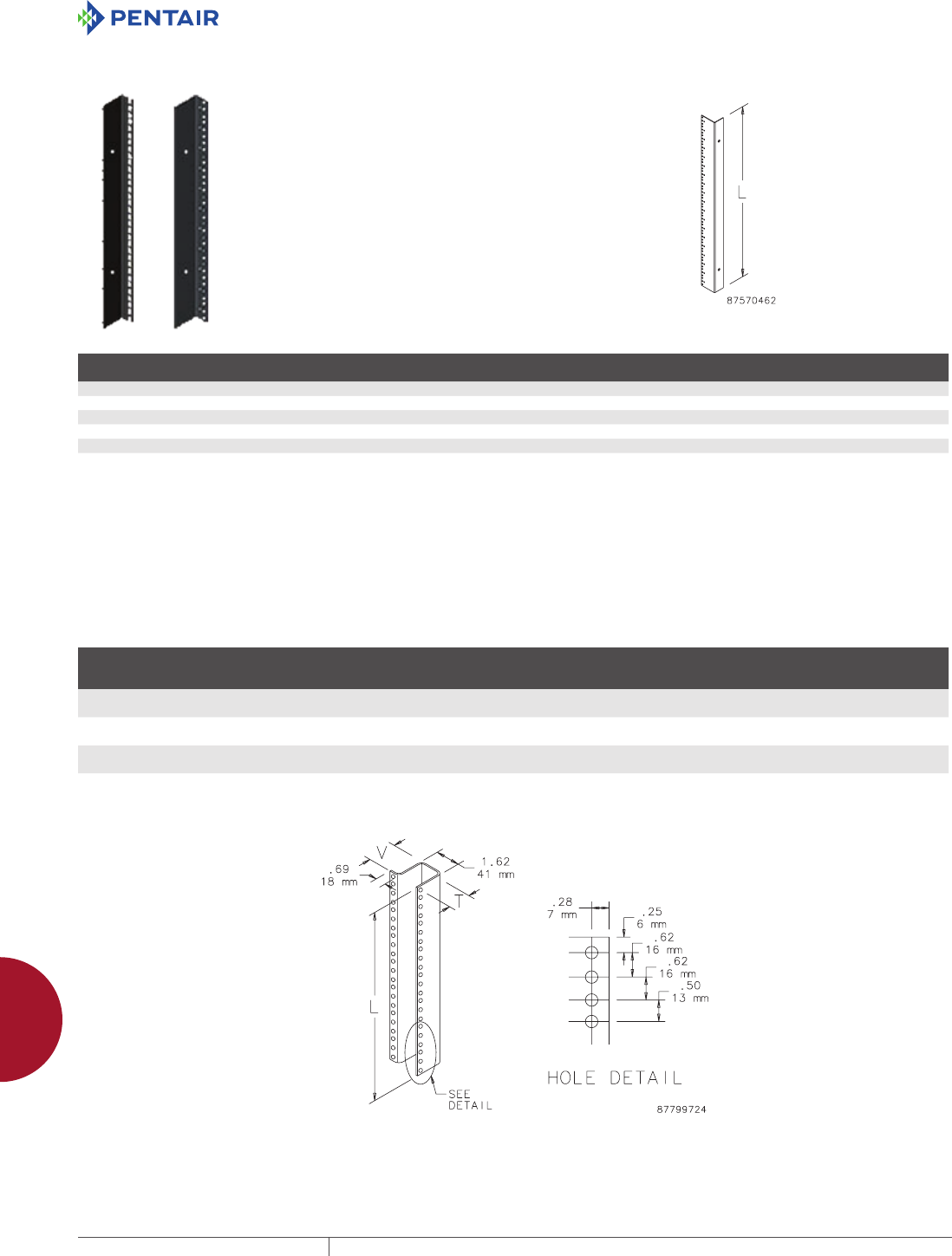
EQUIPMENT PROTECTIONSUBJECT TO CHANGE WITHOUT NOTICEACCESSORIES964
12
MOUNTING ACCESSORIES raCk-mount aCCessories
19IN. AND 23IN. RACK ANGLES
Made of 14 gauge steel with square
holes or 12 gauge steel with 10-32
tapped holes. Provides 19- or 23-in.
rack spacing depending on frame
width. Finished with flat black RAL
9005 polyester powder paint or
plated. Furnished in pairs.
BULLETIN: DNCY, DWDH1
Catalog Number Rack Spacing Hole Type Finish Use With
Fits Frame
Height
Fits Frame
Width
Rack
Units L (mm) L (in.)
ERA197THLN 19 in. Square Black Networking Cabinet - SOHO 700mm 600mm 11 492 19.38
ERA197TPLN 19 in. Tapped Black Networking Cabinet - SOHO 700mm 600mm 11 492 19.38
ERA1921TPL 19 in. Tapped Black Seismic Cabinet 2100mm 700mm 45 2003 78.87
ERA192321TPL 19 & 23 in. Tapped Black Seismic Cabinet 2100mm 800mm 45 2003 78.87
ERA1910TPL 19 in. Tapped Black Network PC Cabinet Bottom Section — 19 848 33.37
RACK MOUNTING ANGLES U STYLE (TYPE RA)
For Free-Stand Enclosures, Type 12 (Bulletin A30), Free-Stand Enclosures, Type 4 (Bulletin A4L) and One-Door Free-Stand Fiberglass
Enclosures, Type 4X (Bulletin A17).
Pairs of full-length rack mounting angles are available for mounting 19-in. (483-mm) and 24-in. (610-mm) rack-mounted equipment.
Type RA rack mounting angles are 14 gauge steel with mounting holes .281 in. (7 mm) in diameter and spaced per EIA standard RS-310-D
universal spacing. Use clip nut package AN1032 to provide tapped holes at desired locations.
Angles and mounting hardware are plated. All mounting hardware is furnished. Includes two full-length angles.
BULLETIN: A80
Catalog Number
Fits Enclosure
A x B
in./mm
K
in./mm
L
in./mm
M
in./mm
T
in./mm
V
in./mm
For Rack
Size
in./mm
Number
of Units
A60RA19TH 60.00 x 24.00
60 x 24
3.78
96
49.00
1245
7.78
198
1.95
50
1.89
48
19.00
483
28
A72RA19TH 72.00 x 24.00
1829 x 610
3.66
93
61.25
1556
7.66
195
1.95
50
1.89
48
19.00
483
35
A72RA24TH 72.00 x 30.00
1829 x 762
3.66
93
61.25
1556
7.66
195
2.45
62
2.39
61
24.00
610
35
A90RA19TH 90.00 x 24.00
2286 x 610
3.91
99
78.75
2000
7.91
201
1.95
50
1.89
48
19.00
483
45
One unit equals 1.75 inches (44 mm).

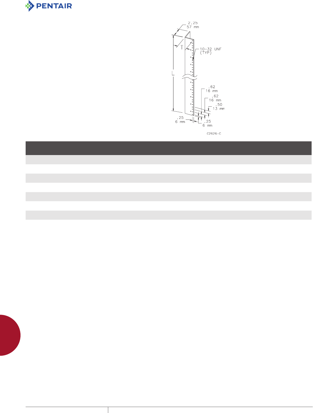
EQUIPMENT PROTECTIONSUBJECT TO CHANGE WITHOUT NOTICEACCESSORIES966
12
MOUNTING ACCESSORIES raCk-mount aCCessories
RACK MOUNTING ANGLES L STYLE (TYPE RP)
For Free-Stand Enclosures, Type 12 (Bulletin A30), Free-Stand
Enclosures, Type 4 (Bulletin A4L) and One-Door Free-Stand
Fiberglass Enclosures, Type 4X (Bulletin A17). Pairs of full-length
or half-length rack mounting angles are available for mounting
19-in. (483-mm) and 24-in. (610-mm) rack-mounted equipment.
Type RP rack mounting angles are 10 gauge steel with mounting
holes tapped #10-32 thread and spaced per EIA standard RS-310-D
universal spacing. Angles and mounting hardware are plated. All
mounting hardware is furnished.
BULLETIN: A80
Catalog Number Description
Fits Enclosure
A x B
in./mm
For Rack
Size
in./mm
K
in./mm
L
in./mm
M
in./mm
T
in./mm
Number
of Units
A60RP24F5 Two full-length angles 60.00 x 24.00
1524 x 610
19.00
483
3.78
96
49.00
1245
7.78
198
1.94
49
28
A60RP24F6 Two half-length angles 60.00 x 24.00
1524 x 610
19.00
483
3.59
91
26.25
667
7.59
193
1.94
49
15
A72RP24F5 Two full-length angles 72.00 x 24.00
1829 x 610
19.00
483
3.66
93
61.25
1556
7.66
195
1.94
49
35
A72RP24F6 Two half-length angles 72.00 x 24.00
1829 x 610
19.00
483
3.97
101
31.50
800
7.97
202
1.94
49
18
A72RP30F5 Two full-length angles 72.00 x 30.00
1829 x 762
24.00
610
3.66
93
61.25
1556
7.66
195
2.44
62
35
A72RP30F6 Two half-length angles 72.00 x 30.00
1829 x 762
24.00
610
3.97
101
31.50
800
7.97
202
2.44
62
18
A90RP24F5 Two full-length angles 90.00 x 24.00
2286 x 610
19.00
483
3.91
99
78.75
2000
7.91
201
1.94
49
45
A90RP24F6 Two half-length angles 90.00 x 24.00
2286 x 610
19.00
483
4.09
104
40.25
1022
8.09
205
1.94
49
23
One unit equals 1.75 inches (44 mm).

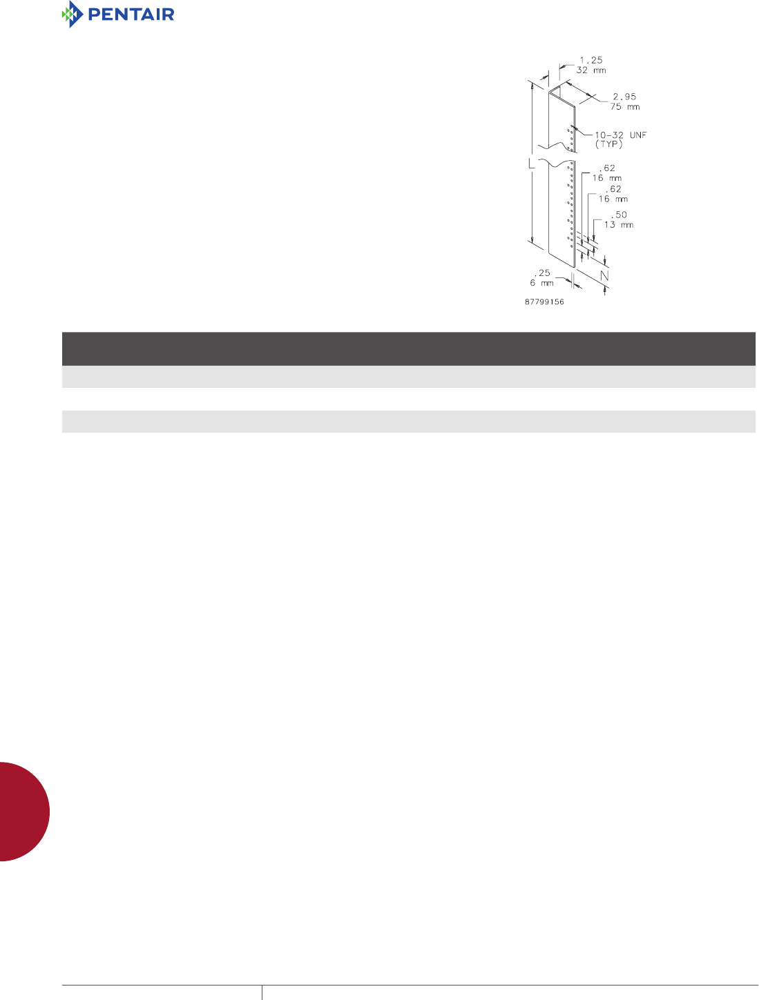
EQUIPMENT PROTECTIONSUBJECT TO CHANGE WITHOUT NOTICEACCESSORIES968
12
MOUNTING ACCESSORIES raCk-mount aCCessories
RACK MOUNTING ANGLE KIT L STYLE
Designed for mounting 19-in. (483-mm) rack-mount equipment in
standard 24-in. (610-mm) wide one-door, wall-mount Type 4 and 12
enclosures. Heavy 10 gauge steel angles are tapped with #10-32
threads spaced to meet EIA RS-310-D. To install, drill small holes in
the sides of the enclosure and bolt angles in place.
All mounting hardware and instructions are furnished. Sealing
washers also are provided to maintain original enclosure standards
rating after installation. Rack angles are zinc-plated. External
screws are stainless steel. Special sizes, materials and finishes are
available on custom order.
BULLETIN: A80
Catalog Number Description
For Enclosure
Size A x B
in./mm
L
in./mm
N
in./mm
Number
of Units
ARAK24 Two Angles 24.00 x 24.00
610 x 610
23.75
603
1.62
41
12
ARAK30 Two Angles 30.00 x 24.00
762 x 610
29.75
756
2.00
51
15
ARAK36 Two Angles 36.00 x 24.00
914 x 610
35.75
908
1.50
38
19
One unit equals 1.75 inches (44 mm).

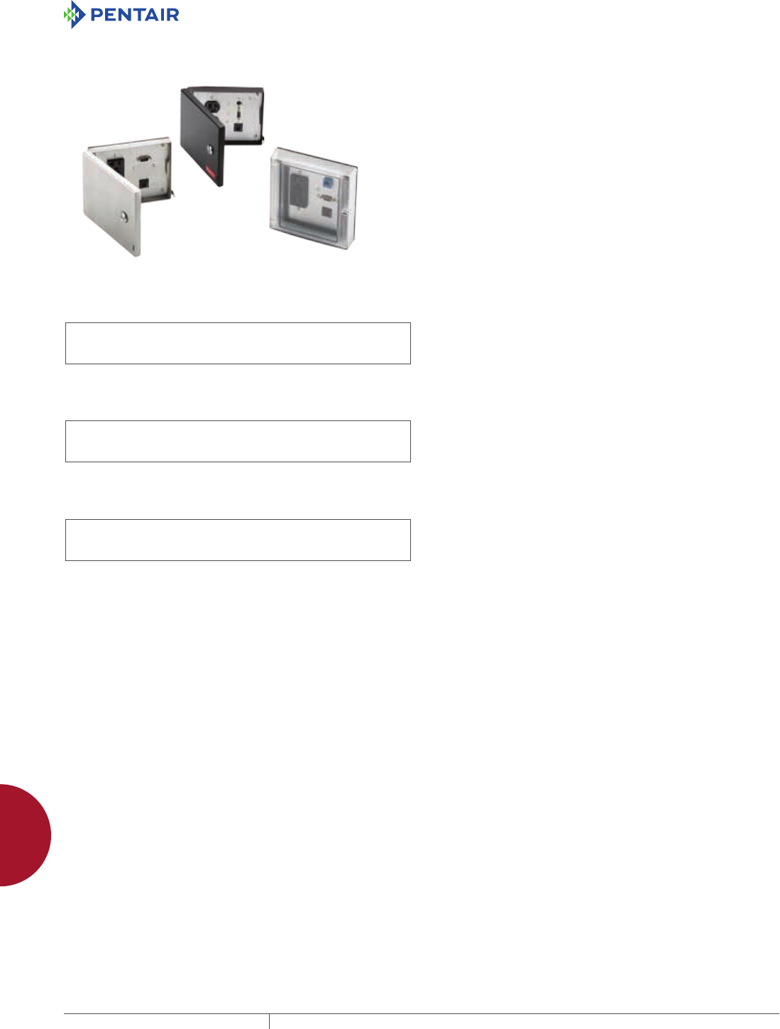
EQUIPMENT PROTECTIONSUBJECT TO CHANGE WITHOUT NOTICEACCESSORIES970
12
INTERSAFE DATA INTERFACE PORTS intersafe data interfaCe Ports, tyPe 4/4X/12
INTERSAFE DATA INTERFAC E PORTS
INTERSAFE DATA INTERFAC E PORTS, TYP E 4/4X/12
INTERSAFE DATA INTERFACE PORTS, TYPE 4/4X/12
INDUSTRY STANDARDS
Mild Steel Painted Ports
UL 508A Component Recognized; Type 4, 12; File No. E61997
cUL Component Recognized per CSA C22.2 No 94; Type 4, 12; File
No. E61997
NEMA/EEMAC Type 4, 12
IEC 60529, IP66
Stainless Steel Ports
UL 508A Component Recognized; Type 4, 4X, 12; File No. E61997
cUL Component Recognized per CSA C22.2 No 94; Type 4, 4X, 12;
File No. E61997
NEMA/EEMAC Type 4, 4X, 12
IEC 60529, IP66
Clear-Cover (polycarbonate) Ports
UL 508A Component Recognized; Type 4X, 12; File No. E61997
cUL Component Recognized per CSA C22.2 No 94; Type 4, 4X, 12;
File No. E61997
IEC 60529, IP66
APPLICATION
INTERSAFE Data Interface Ports are mounted on an enclosure to
allow programming access to devices inside without opening the
enclosure door.
FEATURES
• Ready to use
• Frame and door assembly with aluminum back plate included
with all models; 120 VAC receptacles and programming
connectors are mounted to the plate in 72 standard
configurations
• All standard configurations include a GFCI or standard duplex
receptacle with a 5-A circuit breaker for added safety
• Door gasket (between the door and plate assemblies) and plate
gasket (between the plate assembly and the enclosure) together
provide a tight seal
• Template provided for accurate enclosure cutout dimensions
• Quarter-turn latch with screwdriver slot and padlock hasp on
all steel and stainless steel door models for convenience and
security
• Quarter-turn latch with screwdriver slot on polycarbonate
models
• Disk drive enclosure provides access to one or two customer-
supplied disk drives without opening the cabinet
• Modifications and customization available to accommodate a wide
variety of additional connectors
SPECIFICATIONS
• Door assembly and frame manufactured from 16 gauge steel or
stainless steel
• Clear-cover models have a molded polycarbonate door
• Steel and stainless steel doors are welded and ground
• Back plate is aluminum
FINISH
• RAL 9005 black fine-textured polyester powder coating—mild
steel door assemblies
• Brushed finish—stainless steel door assemblies
• Brushed finish—aluminum back plates
MODIFICATION AND CUSTOMIZATION
Hoffman excels at modifying and customizing products to your
specifications. Contact your local Hoffman sales office or distributor
for complete information.
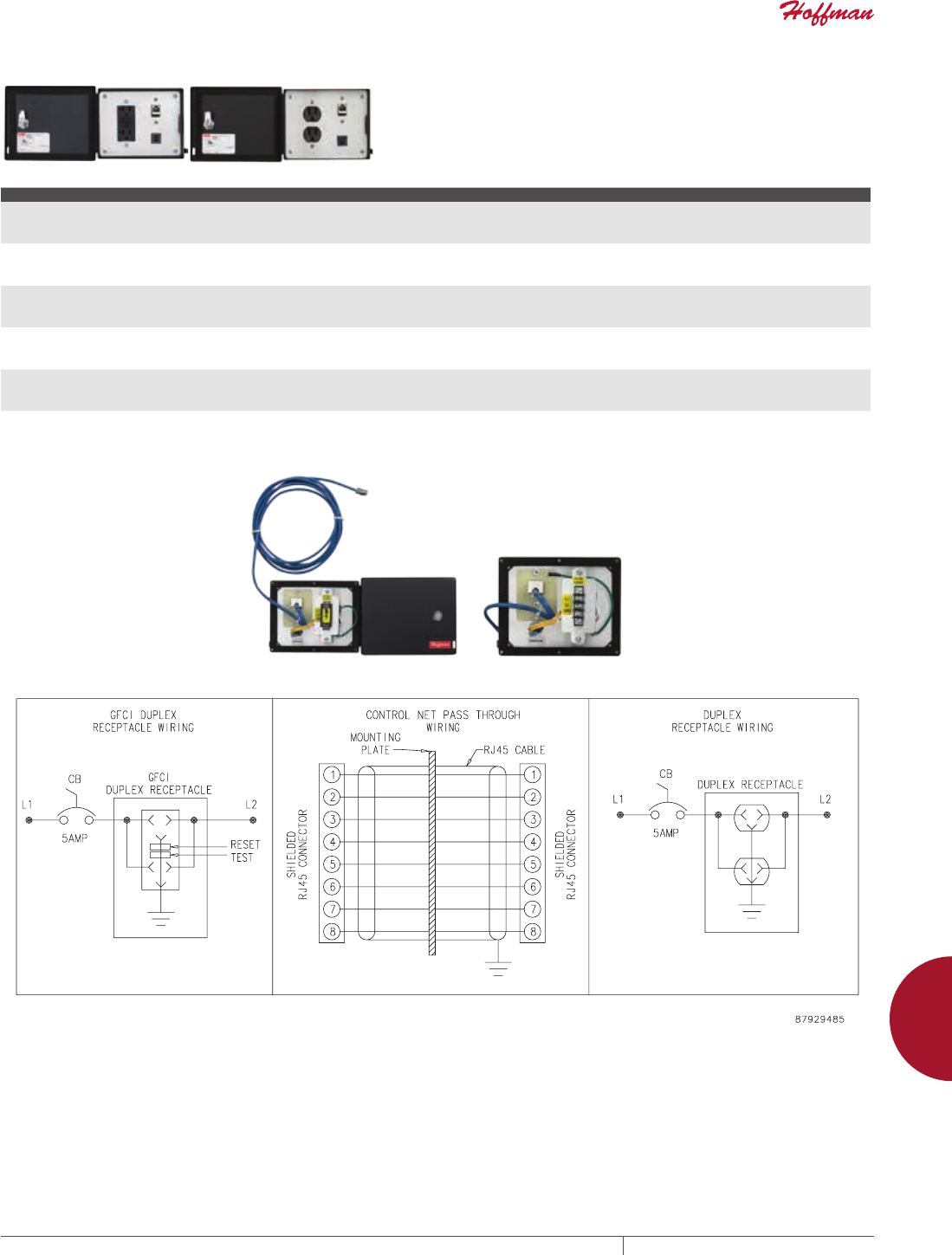
PH 763.422.2211 • FAX 763.422.2600 • PENTAIRPROTECT.COMEQUIPMENT PROTECTION ACCESSORIES 971
12
INTERSAFE DATA INTERFACE PORTS intersafe data interfaCe Ports, tyPe 4/4X/12
INTERSAFE DATA PORTS FOR CONTROLNET PROTOCOL
Left-hand image shows front view, GFCI Receptacle Models. Right-
hand image shows Front front view, Duplex Receptacle Models.
Rear view with and without terminal cover are below the table.
BULLETIN: A70E
Catalog Number Material Configuration Primary Connector/ Termination Secondary Connector/ Termination Supports Devices Sold by the Following Manufacturers
HGF5CN Steel - 120 VAC GFCI receptacle
- Shielded RJ45
- 5-amp circuit breaker
- Shielded RJ45
- 10-ft. shielded cable with male RJ45
— Allen-Bradley
HGF5CNSS Stainless Steel - 120 VAC GFCI receptacle
- Shielded RJ45
- 5-amp circuit breaker
- Shielded RJ45
- 10-ft. shielded cable with male RJ45
— Allen-Bradley
HGF5CNCC Composite - 120 VAC GFCI receptacle
- Shielded RJ45
- 5-amp circuit breaker
- Shielded RJ45
- 10-ft. shielded cable with male RJ45
— Allen-Bradley
HDP5CN Steel - 120 VAC duplex receptacle
- Shielded RJ45
- 5-amp circuit breaker
- Shielded RJ45
- 10-ft. shielded cable with male RJ45
— Allen-Bradley
HDP5CNSS Stainless Steel - 120 VAC duplex receptacle
- Shielded RJ45
- 5-amp circuit breaker
- Shielded RJ45
- 10-ft. shielded cable with male RJ45
— Allen-Bradley
HDP5CNCC Composite - 120 VAC duplex receptacle
- Shielded RJ45
- 5-amp circuit breaker
- Shielded RJ45
- 10-ft. shielded cable with male RJ45
— Allen-Bradley
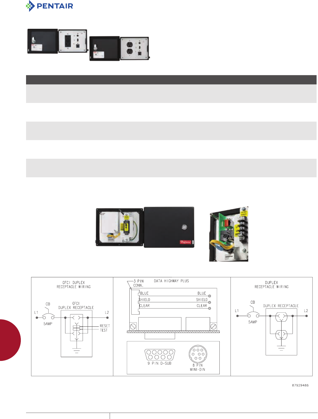
EQUIPMENT PROTECTIONSUBJECT TO CHANGE WITHOUT NOTICEACCESSORIES972
12
INTERSAFE DATA INTERFACE PORTS intersafe data interfaCe Ports, tyPe 4/4X/12
INTERSAFE DATA INTERFACE PORTS FOR DATA HIGHWAY PLUS PROTOCOL
Left-hand image shows front view, GFCI Receptacle Models. Right-
hand image shows front view, Duplex Receptacle Models. Rear view
with and without terminal cover are below the table.
BULLETIN: A70E
Catalog Number Material Configuration Primary Connector/ Termination Secondary Connector/ Termination
Supports Devices Sold by
the Following Manufacturers
HGF58MDH Steel - 120 VAC GFCI receptacle
- 8-pin mini DIN
- DB9F
- 5-amp circuit breaker
Female 8-pin mini DIN DB9F terminal block Allen-Bradley
HGF58MDHSS Stainless Steel - 120 VAC GFCI receptacle
- 8-pin mini DIN
- DB9F
- 5-amp circuit breaker
Female 8-pin mini DIN DB9F terminal block Allen-Bradley
HGF58MDHCC Composite - 120 VAC GFCI receptacle
- 8-pin mini DIN
- DB9F
- 5-amp circuit breaker
Female 8-pin mini DIN DB9F terminal block Allen-Bradley
HDP58MDH Steel - 120 VAC duplex receptacle
- 8-pin mini DIN
- DB9F
- 5-amp circuit breaker
Female 8-pin mini DIN DB9F terminal block Allen-Bradley
HDP58MDHSS Stainless Steel - 120 VAC duplex receptacle
- 8-pin mini DIN
- DB9F
- 5-amp circuit breaker
Female 8-pin mini DIN DB9F terminal block Allen-Bradley
HDP58MDHCC Composite - 120 VAC duplex receptacle
- 8-pin mini DIN
- DB9F
- 5-amp circuit breaker
Female 8-pin mini DIN DB9F terminal block Allen-Bradley
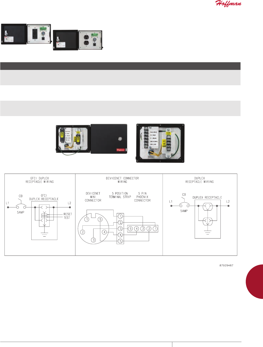
PH 763.422.2211 • FAX 763.422.2600 • PENTAIRPROTECT.COMEQUIPMENT PROTECTION ACCESSORIES 973
12
INTERSAFE DATA INTERFACE PORTS intersafe data interfaCe Ports, tyPe 4/4X/12
INTERSAFE DATA INTERFACE PORTS FOR DEVICENET PROTOCOL
Left-hand image shows front view, GFCI Receptacle Models. Right-
hand image shows front view, Duplex Receptacle Models. Rear view
with and without terminal cover are below the table.
BULLETIN: A70E
Catalog Number Material Configuration Primary Connector/ Termination Secondary Connector/ Termination
Supports Devices Sold by
the Following Manufacturers
HGF5DN5PCC Composite - 120 VAC GFCI receptacle
- 5-pin Phoenix Style
- 5-pin mini receptacle
- 5-amp circuit breaker
5-pin Phoenix Style terminal block 5-pin mini receptacle terminal block Allen-Bradley
GE Fanuc
HDP5DN5PSS Stainless Steel - 120 VAC duplex receptacle
- 5-pin Phoenix Style
- 5-pin mini receptacle
- 5-amp circuit breaker
5-pin Phoenix Style terminal block 5-pin mini receptacle terminal block Allen-Bradley
GE Fanuc
HDP5DN5PCC Composite - 120 VAC duplex receptacle
- 5-pin Phoenix Style
- 5-pin mini receptacle
- 5-amp circuit breaker
5-pin Phoenix Style terminal block 5-pin mini receptacle terminal block Allen-Bradley
GE Fanuc
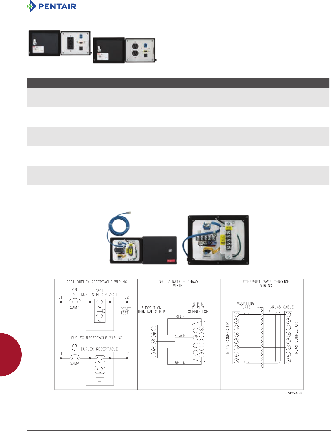
EQUIPMENT PROTECTIONSUBJECT TO CHANGE WITHOUT NOTICEACCESSORIES974
12
INTERSAFE DATA INTERFACE PORTS intersafe data interfaCe Ports, tyPe 4/4X/12
INTERSAFE DATA INTERFACE PORTS FOR DH+, MODBUS PLUS, ETHERNET PROTOCOL
Left-hand image shows front view, GFCI Receptacle Models. Right-
hand image shows front view, Duplex Receptacle Models. Rear view
with and without terminal cover are below the table.
BULLETIN: A70E
Catalog Number Material Configuration Primary Connector/ Termination Secondary Connector/ Termination
Supports Devices Sold by
the Following Manufacturers
HGF5ETHDH Steel - 120 VAC GFCI receptacle
- RJ45
- DB9F
- 5-amp circuit breaker
DB9F terminal block - RJ45
- 10-ft. cable with male RJ45
Allen-Bradley
Group Schneider
Computer peripherals
HGF5ETHDHSS Stainless Steel - 120 VAC GFCI receptacle
- RJ45
- DB9F
- 5-amp circuit breaker
DB9F terminal block - RJ45
- 10-ft. cable with male RJ45
Allen-Bradley
Group Schneider
Computer peripherals
HGF5ETHDHCC Composite - 120 VAC GFCI receptacle
- RJ45
- DB9F
- 5-amp circuit breaker
DB9F terminal block - RJ45
- 10-ft. cable with male RJ45
Allen-Bradley
Group Schneider
Computer peripherals
HDP5ETHDH Steel - 120 VAC duplex receptacle
- RJ45
- DB9F
- 5-amp circuit breaker
DB9F terminal block - RJ45
- 10-ft. cable with male RJ45
Allen-Bradley
Group Schneider
Computer peripherals
HDP5ETHDHSS Stainless Steel - 120 VAC duplex receptacle
- RJ45
- DB9F
- 5-amp circuit breaker
DB9F terminal block - RJ45
- 10-ft. cable with male RJ45
Allen-Bradley
Group Schneider
Computer peripherals
HDP5ETHDHCC Composite - 120 VAC duplex receptacle
- RJ45
- DB9F
- 5-amp circuit breaker
DB9F terminal block - RJ45
- 10-ft. cable with male RJ45
Allen-Bradley
Group Schneider
Computer peripherals
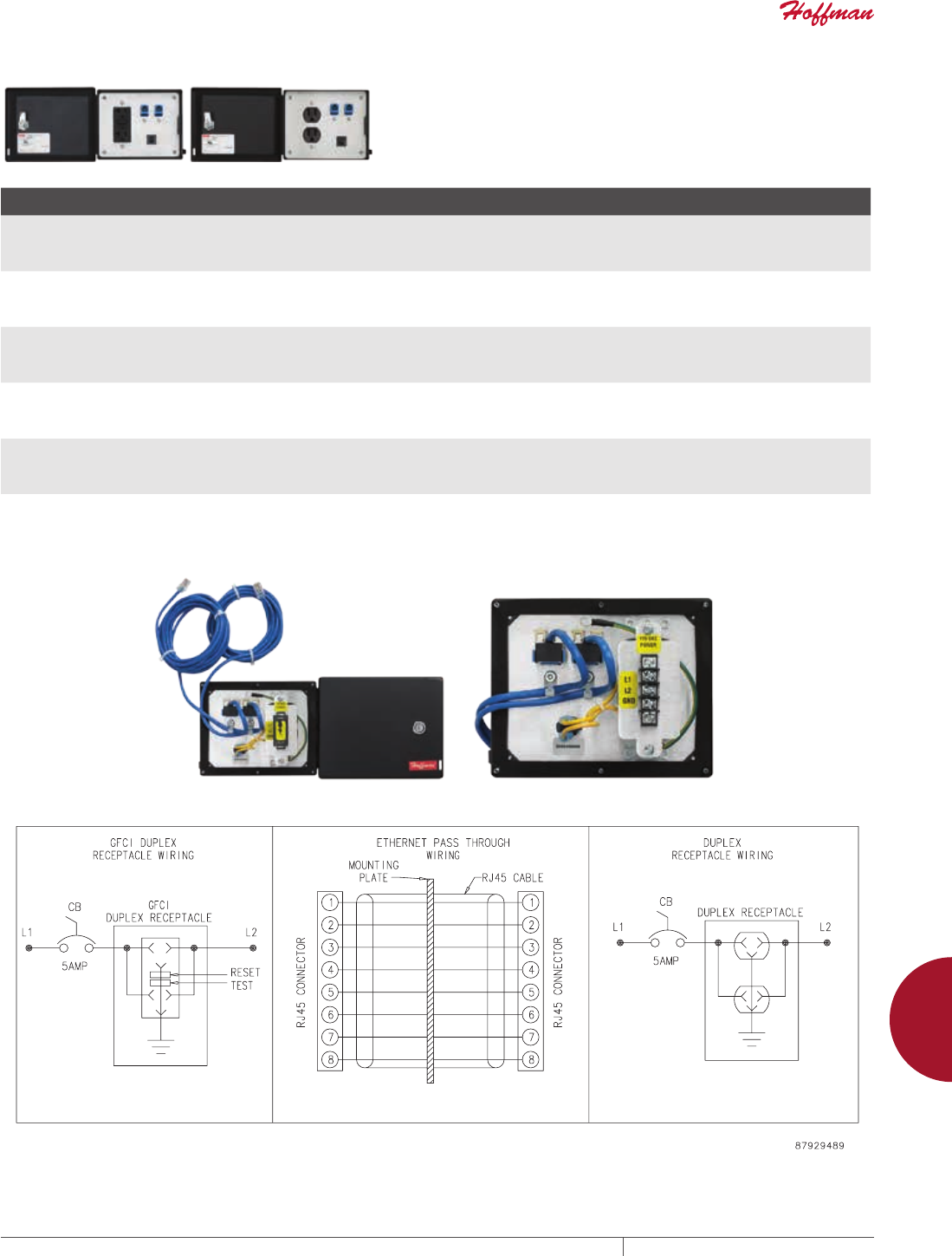
PH 763.422.2211 • FAX 763.422.2600 • PENTAIRPROTECT.COMEQUIPMENT PROTECTION ACCESSORIES 975
12
INTERSAFE DATA INTERFACE PORTS intersafe data interfaCe Ports, tyPe 4/4X/12
INTERSAFE DATA INTERFACE PORTS FOR ETHERNET PROTOCOL
Left-hand image shows front view, GFCI Receptacle Models. Right-
hand image shows front view, Duplex Receptacle Models. Rear view
with and without terminal cover are below the table.
BULLETIN: A70E
Catalog Number Material Configuration Primary Connector/ Termination Secondary Connector/ Termination
Supports Devices Sold by
the Following Manufacturers
HGF5ETHETH Steel - 120 VAC GFCI receptacle
- RJ45
- RJ45
- 5-amp circuit breaker
- RJ45
- 10-ft. cable
- RJ45
- 10-ft. cable
Computer peripherals
HGF5ETHETHSS Stainless Steel - 120 VAC GFCI receptacle
- RJ45
- RJ45
- 5-amp circuit breaker
- RJ45
- 10-ft. cable
- RJ45
- 10-ft. cable
Computer peripherals
HGF5ETHETHCC Composite - 120 VAC GFCI receptacle
- RJ45
- RJ45
- 5-amp circuit breaker
- RJ45
- 10-ft. cable
- RJ45
- 10-ft. cable
Computer peripherals
HDP5ETHETH Steel - 120 VAC duplex receptacle
- RJ45
- RJ45
- 5-amp circuit breaker
- RJ45
- 10-ft. cable
- RJ45
- 10-ft. cable
Computer peripherals
HDP5ETHETHSS Stainless Steel - 120 VAC duplex receptacle
- RJ45
- RJ45
- 5-amp circuit breaker
- RJ45
- 10-ft. cable
- RJ45
- 10-ft. cable
Computer peripherals
HDP5ETHETHCC Composite - 120 VAC duplex receptacle
- RJ45
- RJ45
- 5-amp circuit breaker
- RJ45
- 10-ft. cable
- RJ45
- 10-ft. cable
Computer peripherals
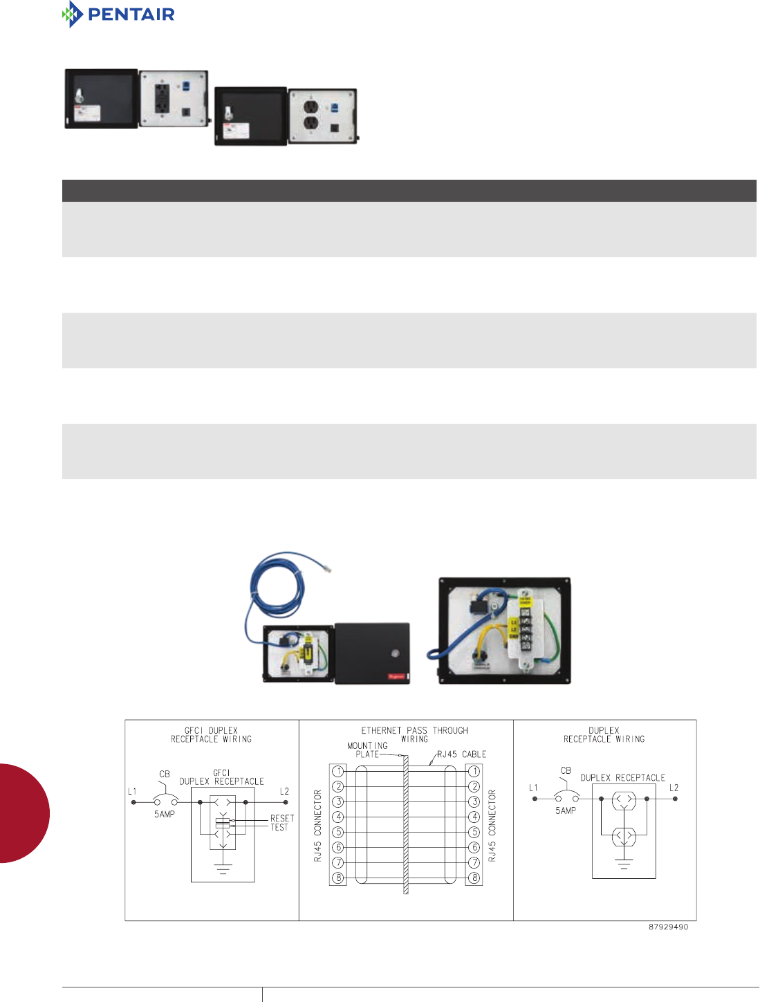
EQUIPMENT PROTECTIONSUBJECT TO CHANGE WITHOUT NOTICEACCESSORIES976
12
INTERSAFE DATA INTERFACE PORTS intersafe data interfaCe Ports, tyPe 4/4X/12
INTERSAFE DATA INTERFACE PORTS FOR ETHERNET/PROFINET PROTOCOL
Left-hand image shows front view, GFCI Receptacle Models. Right-
hand image shows front view, Duplex Receptacle Models. Rear view
with and without terminal cover are below the table.
BULLETIN: A70E
Catalog Number Material Configuration Configuration Secondary Connector/ Termination
Supports Devices Sold by
the Following Manufacturers
HGF5ETH Steel - 120 VAC GFCI receptacle
- RJ45
- 5-amp circuit breaker
- RJ45
- 10-ft. cable
--- Allen-Bradley
GE Fanuc
Groupe Schneider
Siemens
Computer peripherals
HGF5ETHSS Stainless Steel - 120 VAC GFCI receptacle
- RJ45
- 5-amp circuit breaker
- RJ45
- 10-ft. cable
--- Allen-Bradley
GE Fanuc
Groupe Schneider
Siemens
Computer peripherals
HGF5ETHCC Composite - 120 VAC GFCI receptacle
- RJ45
- 5-amp circuit breaker
- RJ45
- 10-ft. cable
--- Allen-Bradley
GE Fanuc
Groupe Schneider
Siemens
Computer peripherals
HDP5ETH Steel - 120 VAC duplex receptacle
- RJ45
- 5-amp circuit breaker
- RJ45
- 10-ft. cable
--- Allen-Bradley
GE Fanuc
Groupe Schneider
Siemens
Computer peripherals
HDP5ETHSS Stainless Steel - 120 VAC duplex receptacle
- RJ45
- 5-amp circuit breaker
- RJ45
- 10-ft. cable
--- Allen-Bradley
GE Fanuc
Groupe Schneider
Siemens
Computer peripherals
HDP5ETHCC Composite - 120 VAC duplex receptacle
- RJ45
- 5-amp circuit breaker
- RJ45
- 10-ft. cable
--- Allen-Bradley
GE Fanuc
Groupe Schneider
Siemens
Computer peripherals
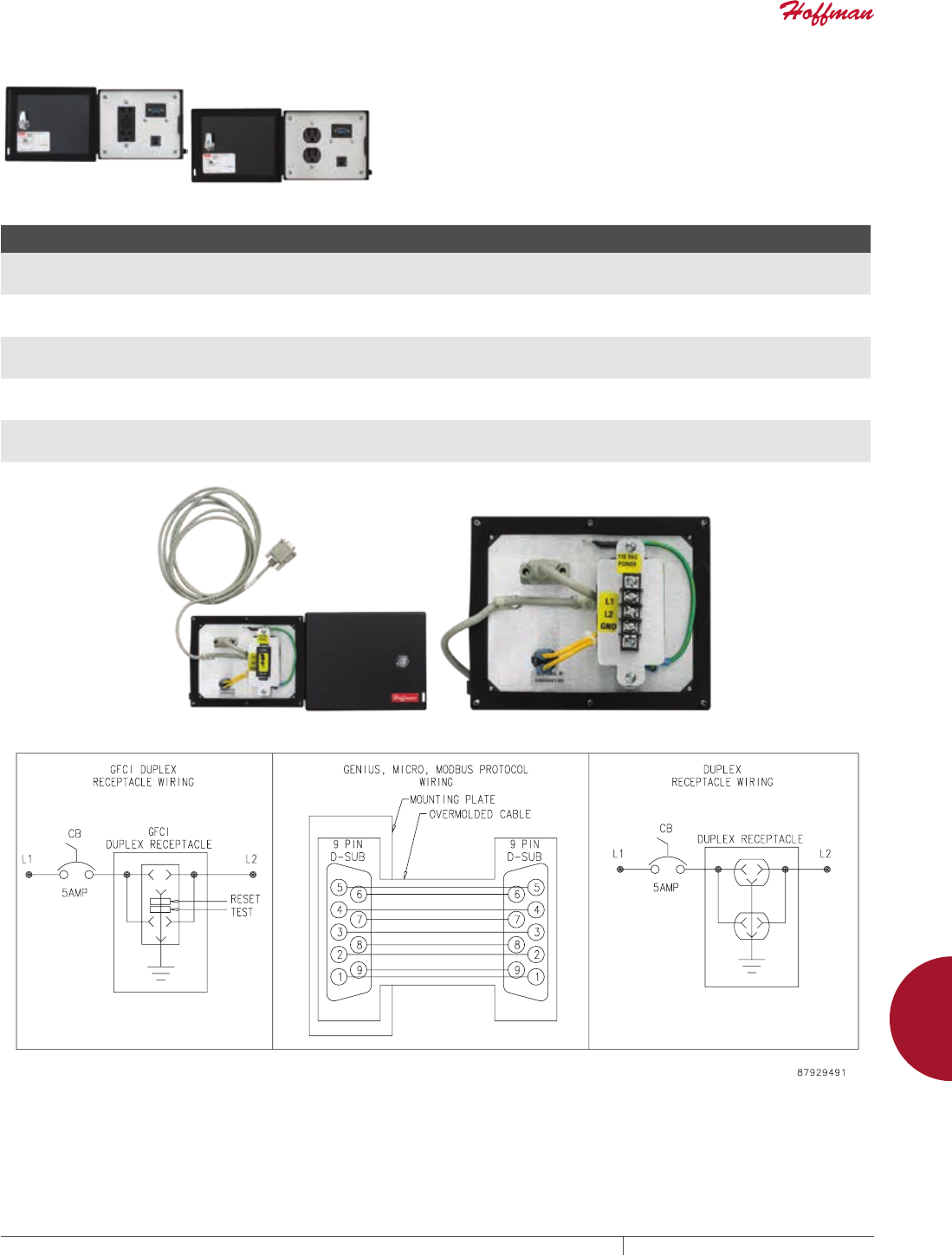
PH 763.422.2211 • FAX 763.422.2600 • PENTAIRPROTECT.COMEQUIPMENT PROTECTION ACCESSORIES 977
12
INTERSAFE DATA INTERFACE PORTS intersafe data interfaCe Ports, tyPe 4/4X/12
INTERSAFE DATA INTERFACE PORTS FOR GENIUS PROTOCOL
Left-hand image shows front view, GFCI Receptacle Models. Right-
hand image shows front view, Duplex Receptacle Models. Rear view
with and without terminal cover are below the table.
BULLETIN: A70E
Catalog Number Material Configuration Primary Connector/ Termination Secondary Connector/ Termination
Supports Devices Sold by
the Following Manufacturers
HGF5GEG Steel - 120 VAC GFCI receptacle
- DB9M
- 5-amp circuit breaker
- DB9M
- 10-ft. cable
--- GE Fanuc
HGF5GEGSS Stainless Steel - 120 VAC GFCI receptacle
- DB9M
- 5-amp circuit breaker
- DB9M
- 10-ft. cable
--- GE Fanuc
HGF5GEGCC Composite - 120 VAC GFCI receptacle
- DB9M
- 5-amp circuit breaker
- DB9M
- 10-ft. cable
--- GE Fanuc
HDP5GEGSS Stainless Steel - 120 VAC duplex receptacle
- DB9M
- 5-amp circuit breaker
- DB9M
- 10-ft. cable
--- GE Fanuc
HDP5GEGCC Composite - 120 VAC duplex receptacle
- DB9M
- 5-amp circuit breaker
- DB9M
- 10-ft. cable
--- GE Fanuc
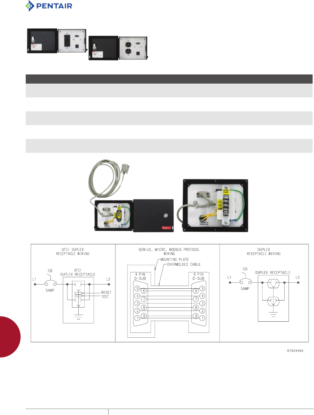
EQUIPMENT PROTECTIONSUBJECT TO CHANGE WITHOUT NOTICEACCESSORIES978
12
INTERSAFE DATA INTERFACE PORTS intersafe data interfaCe Ports, tyPe 4/4X/12
INTERSAFE DATA INTERFACE PORTS FOR MICRO PROTOCOL
Left-hand image shows front view, GFCI Receptacle Models. Right-
hand image shows front view, Duplex Receptacle Models. Rear view
with and without terminal cover are below the table.
BULLETIN: A70E
Catalog Number Material Configuration Primary Connector/ Termination Secondary Connector/ Termination
Supports Devices Sold by
the Following Manufacturers
HGF5TMM Steel - 120 VAC GFCI receptacle
- DB9M
- 5-amp circuit breaker
- DB9M
- 10-ft. cable
--- Groupe Schneider
HGF5TMMSS Stainless Steel - 120 VAC GFCI receptacle
- DB9M
- 5-amp circuit breaker
- DB9M
- 10-ft. cable
--- Groupe Schneider
HGF5TMMCC Composite - 120 VAC GFCI receptacle
- DB9M
- 5-amp circuit breaker
- DB9M
- 10-ft. cable
--- Groupe Schneider
HDP5TMM Steel - 120 VAC duplex receptacle
- DB9M
- 5-amp circuit breaker
- DB9M
- 10-ft. cable
--- Groupe Schneider
HDP5TMMCC Composite - 120 VAC duplex receptacle
- DB9M
- 5-amp circuit breaker
- DB9M
- 10-ft. cable
--- Groupe Schneider
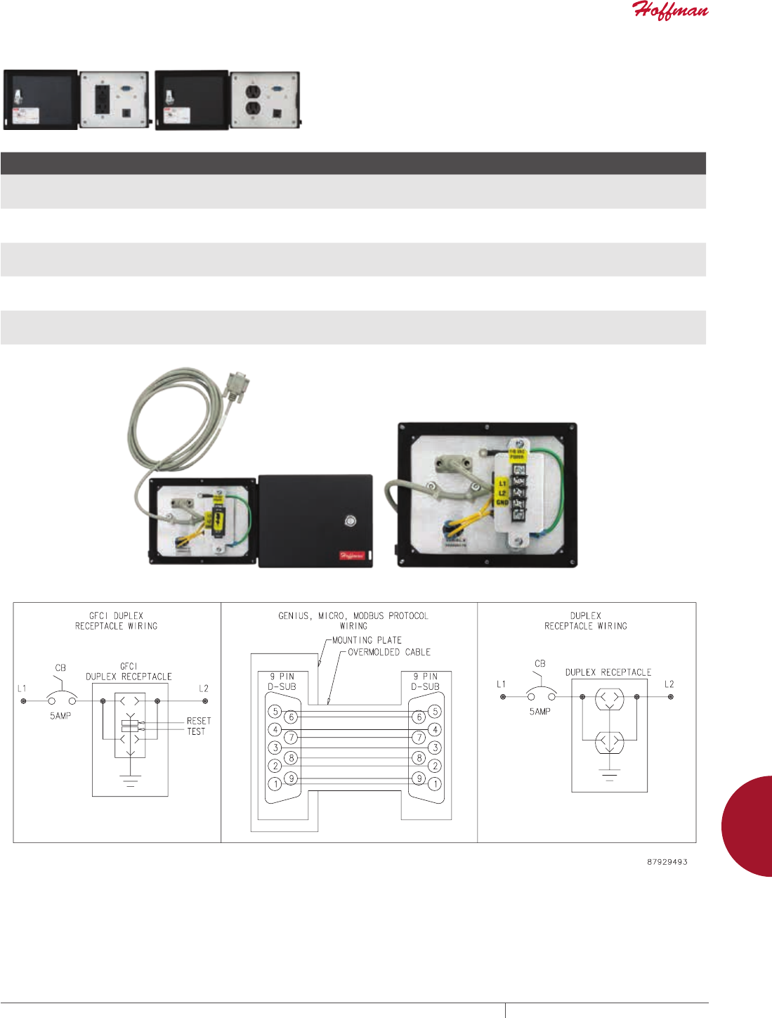
PH 763.422.2211 • FAX 763.422.2600 • PENTAIRPROTECT.COMEQUIPMENT PROTECTION ACCESSORIES 979
12
INTERSAFE DATA INTERFACE PORTS intersafe data interfaCe Ports, tyPe 4/4X/12
INTERSAFE DATA INTERFACE PORTS FOR MODBUS PROTOCOL
Left-hand image shows front view, GFCI Receptacle Models. Right-
hand image shows front view, Duplex Receptacle Models. Rear view
with and without terminal cover are below the table.
BULLETIN: A70E
Catalog Number Material Configuration Primary Connector/ Termination Secondary Connector/ Termination
Supports Devices Sold by
the Following Manufacturers
HGF5TMB Steel - 120 VAC GFCI receptacle
- DB9M
- 5-amp circuit breaker
-DB9M
- 10-ft. cable
--- Groupe Schneider
HGF5TMBCC Composite - 120 VAC GFCI receptacle
- DB9M
- 5-amp circuit breaker
-DB9M
- 10-ft. cable
--- Groupe Schneider
HDP5TMB Steel - 120 VAC duplex receptacle
- DB9M
- 5-amp circuit breaker
-DB9M
- 10-ft. cable
--- Groupe Schneider
HDP5TMBSS Stainless Steel - 120 VAC duplex receptacle
- DB9M
- 5-amp circuit breaker
-DB9M
- 10-ft. cable
--- Groupe Schneider
HDP5TMBCC Composite - 120 VAC duplex receptacle
- DB9M
- 5-amp circuit breaker
-DB9M
- 10-ft. cable
--- Groupe Schneider
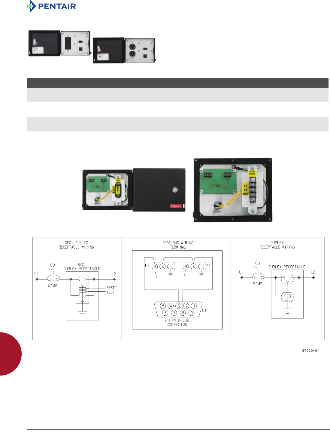
EQUIPMENT PROTECTIONSUBJECT TO CHANGE WITHOUT NOTICEACCESSORIES980
12
INTERSAFE DATA INTERFACE PORTS intersafe data interfaCe Ports, tyPe 4/4X/12
INTERSAFE DATA INTERFACE PORTS FOR PROFIBUS PROTOCOL
Left-hand image shows front view, GFCI Receptacle Models. Right-
hand image shows front view, Duplex Receptacle Models. Rear view
with and without terminal cover are below the table.
BULLETIN: A70E
Catalog Number Material Configuration Primary Connector/ Termination Secondary Connector/ Termination
Supports Devices Sold by
the Following Manufacturers
HGF5PB Steel - 120 VAC GFCI receptacle
- 9-pin Profibus
- 5-amp circuit breaker
9-pin Profibus terminal --- Allen-Bradley
GE Fanuc
Siemens
HGF5PBSS Stainless Steel - 120 VAC GFCI receptacle
- 9-pin Profibus
- 5-amp circuit breaker
9-pin Profibus terminal --- Allen-Bradley
GE Fanuc
Siemens
HDP5PB Steel - 120 VAC duplex receptacle
- 9-pin Profibus
- 5-amp circuit breaker
9-pin Profibus terminal --- Allen-Bradley
GE Fanuc
Siemens
HDP5PBCC Composite - 120 VAC duplex receptacle
- 9-pin Profibus
- 5-amp circuit breaker
9-pin Profibus terminal --- Allen-Bradley
GE Fanuc
Siemens
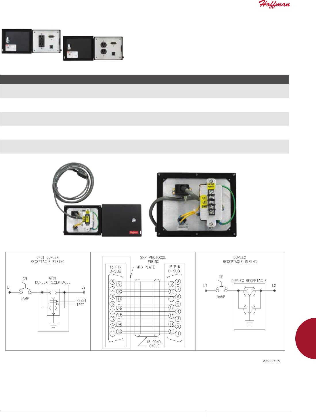
PH 763.422.2211 • FAX 763.422.2600 • PENTAIRPROTECT.COMEQUIPMENT PROTECTION ACCESSORIES 981
12
INTERSAFE DATA INTERFACE PORTS intersafe data interfaCe Ports, tyPe 4/4X/12
INTERSAFE DATA INTERFACE PORTS FOR SNP PROTOCOL
Left-hand image shows front view, GFCI Receptacle Models. Right-
hand image shows front view, Duplex Receptacle Models. Rear view
with and without terminal cover are below the table.
BULLETIN: A70E
Catalog Number Material Configuration Primary Connector/ Termination Secondary Connector/ Termination
Supports Devices Sold by
the Following Manufacturers
HGF5GESNP Steel - 120 VAC GFCI receptacle
- DB15M
- 5-amp circuit breaker
- DB15M
- 10-ft. cable
--- GE Fanuc
HGF5GESNPSS Stainless Steel - 120 VAC GFCI receptacle
- DB15M
- 5-amp circuit breaker
- DB15M
- 10-ft. cable
--- GE Fanuc
HGF5GESNPCC Composite - 120 VAC GFCI receptacle
- DB15M
- 5-amp circuit breaker
- DB15M
- 10-ft. cable
--- GE Fanuc
HDP5GESNPSS Stainless Steel - 120 VAC duplex receptacle
- DB15M
- 5-amp circuit breaker
- DB15M
- 10-ft. cable
--- GE Fanuc
HDP5GESNPCC Composite - 120 VAC duplex receptacle
- DB15M
- 5-amp circuit breaker
- DB15M
- 10-ft. cable
--- GE Fanuc
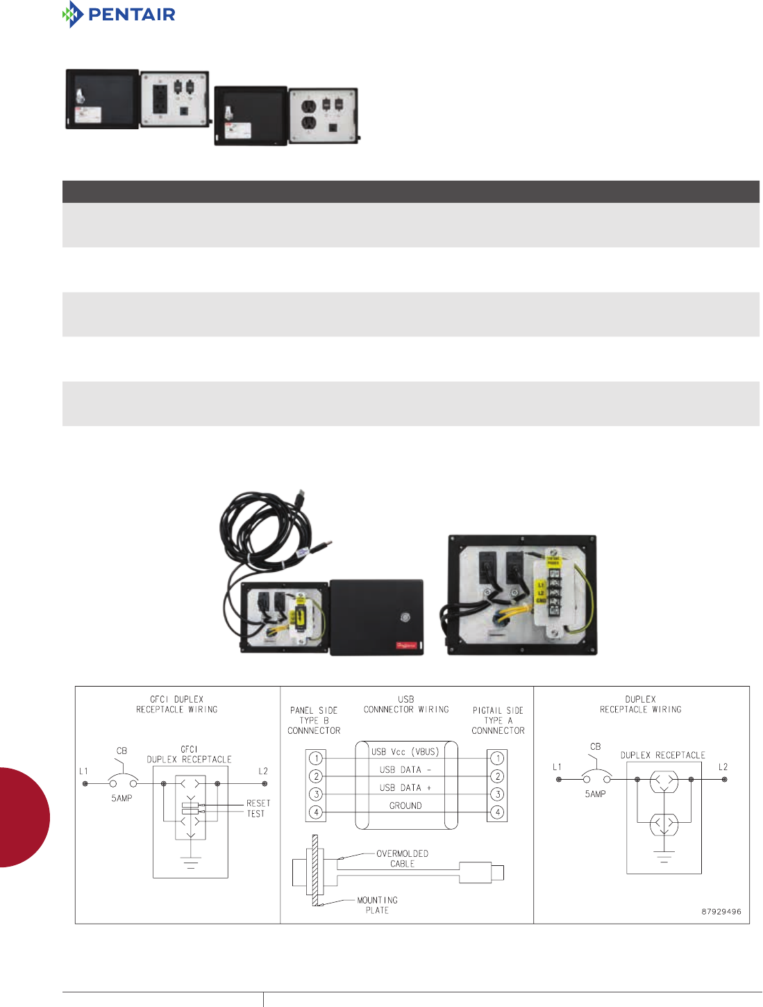
EQUIPMENT PROTECTIONSUBJECT TO CHANGE WITHOUT NOTICEACCESSORIES982
12
INTERSAFE DATA INTERFACE PORTS intersafe data interfaCe Ports, tyPe 4/4X/12
INTERSAFE DATA INTERFACE PORTS FOR USB PROTOCOL, 10FT. CABLE
Left-hand image shows front view, GFCI Receptacle Models. Right-
hand image shows front view, Duplex Receptacle Models. Rear view
with and without terminal cover are below the table.
BULLETIN: A70E
Catalog Number Material Configuration Primary Connector/ Termination Secondary Connector/ Termination
Supports Devices Sold by
the Following Manufacturers
HGF5USBUSB Steel - 120 VAC GFCI receptacle
- USB Type A
- USB Type A
- 5-amp circuit breaker
- USB Type Ab- 10-ft. cable with female USB Type B connector - USB Type A
- 10-ft. cable with female USB Type B connector
Computer peripherals
HGF5USBUSBSS Stainless Steel - 120 VAC GFCI receptacle
- USB Type A
- USB Type A
- 5-amp circuit breaker
- USB Type A
- 10-ft. cable with female USB Type B connector
- USB Type A
- 10-ft. cable with female USB Type B connector
Computer peripherals
HGF5USBUSBCC Composite - 120 VAC GFCI receptacle
- USB Type A
- USB Type A
- 5-amp circuit breaker
- USB Type A
- 10-ft. cable with female USB Type B connector
- USB Type A
- 10-ft. cable with female USB Type B connector
Computer peripherals
HDP5USBUSB Steel - 120 VAC duplex receptacle
- USB Type A
- USB Type A
- 5-amp circuit breaker
- USB Type A
- 10-ft. cable with female USB Type B connector
- USB Type A
- 10-ft. cable with female USB Type B connector
Computer peripherals
HDP5USBUSBSS Stainless Steel - 120 VAC duplex receptacle
- USB Type A
- USB Type A
- 5-amp circuit breaker
- USB Type A
- 10-ft. cable with female USB Type B connector
- USB Type A
- 10-ft. cable with female USB Type B connector
Computer peripherals
HDP5USBUSBCC Composite - 120 VAC duplex receptacle
- USB Type A
- USB Type A
- 5-amp circuit breaker
- USB Type A
- 10-ft. cable with female USB Type B connector
- USB Type A
- 10-ft. cable with female USB Type B connector
Computer peripherals
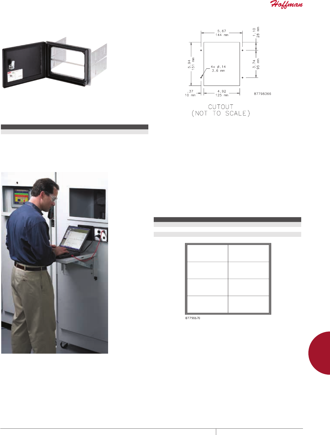
PH 763.422.2211 • FAX 763.422.2600 • PENTAIRPROTECT.COMEQUIPMENT PROTECTION ACCESSORIES 983
12
INTERSAFE DATA INTERFACE PORTS intersafe data interfaCe Ports, tyPe 4/4X/12
INTERSAFE TYPE 4/4X/12 DATA INTERFACE PORT DISK
DRIVE ENCLOSURE
This enclosure, available in both steel and stainless steel, allows
access to one or two customer-supplied disk drives from outside
the cabinet, allowing computer system use and updates without
opening the cabinet.
BULLETIN: A70E
Catalog Number Configuration Description
HCP514B CP2/514b Steel 2 gang dual CD/DVD drive cover
HCP514BSS CP2/514b Stainless steel 2 gang dual CD/DVD drive cover
TO ORDER A MODIFIED CONFIGURATION FOR
INTERSAFE TYPE 4/4X/12 DATA INTERFACE PORTS
• Choose the required connectors to a maximum of 8 plate sectors
(refer to Plate Sector Diagram)
• Order connectors using the code in the Connector ID column of
the INTERSAFE Connectors table
• Hoffman will determine the layout of the connectors. If a specific
layout is required, contact your local Hoffman Sales Office for a
quotation.
• 5-amp circuit breakers will be provided with 120VAC receptacles
unless otherwise specified
• To order, contact your local Hoffman sales representative
Configuration Example Plate Sectors, 8 Maximum
Customer Requires Code Sectors Used
(1) 6-pin mini DIN (female) MD6 1
(1) RJ45 connector (female) R45 1
(1) GFCI duplex receptacle with 3-amp circuit breaker GF3 5
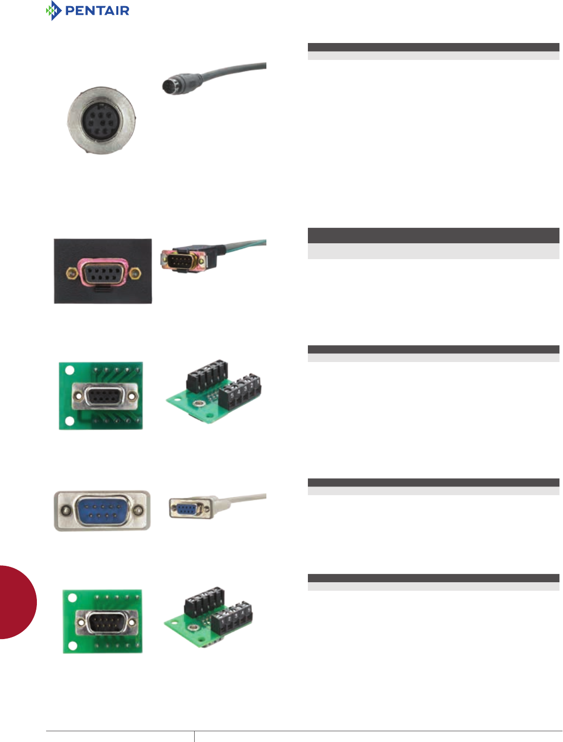
EQUIPMENT PROTECTIONSUBJECT TO CHANGE WITHOUT NOTICEACCESSORIES984
12
INTERSAFE DATA INTERFACE PORTS intersafe data interfaCe Ports, tyPe 4/4X/12
INTERSAFE CONNECTOR 8M
Connector Description Connector Termination Plate Sectors Used
8-pin mini DIN Terminal Block 2
Left-hand image shows front view. Right-hand image shows rear view.
INTERSAFE CONNECTOR 9FG
Connector Description Connector Termination
Plate Sectors
Used
GE Fanuc Genius 9-pin female with
bracket
10 ft. cable to male 9-pin D-Sub with
bracket
1
Left-hand image shows front view. Right-hand image shows rear view.
INTERSAFE CONNECTOR 9FT
Connector Description Connector Termination Plate Sectors Used
D-Sub 9-pin female 9-pin terminal 2
Left-hand image shows front view. Right-hand image shows rear view.
INTERSAFE CONNECTOR 9M
Connector Description Connector Termination Plate Sectors Used
D-Sub 9-pin male with cable 10 ft cable to female 9-pin D-Sub 1
Left-hand image shows front view. Right-hand image shows rear view.
INTERSAFE CONNECTOR 9MT
Connector Description Connector Termination Plate Sectors Used
D-Sub 9-pin male 9-pin terminal 1
Left-hand image shows front view. Right-hand image shows rear view.
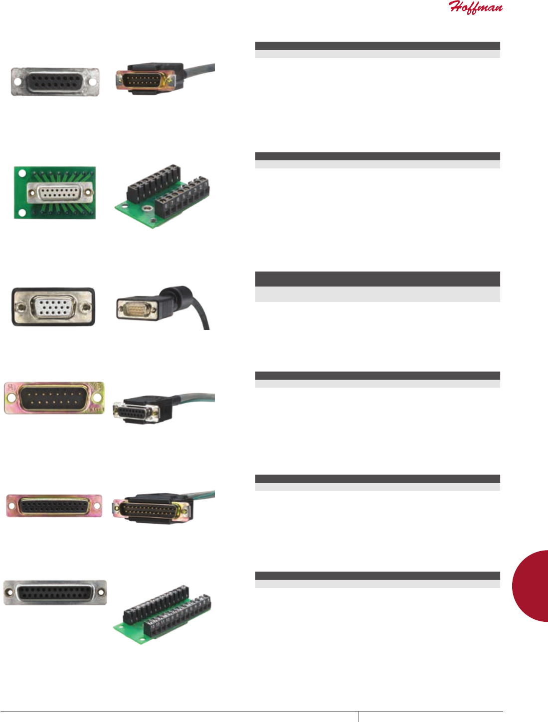
PH 763.422.2211 • FAX 763.422.2600 • PENTAIRPROTECT.COMEQUIPMENT PROTECTION ACCESSORIES 985
12
INTERSAFE DATA INTERFACE PORTS intersafe data interfaCe Ports, tyPe 4/4X/12
INTERSAFE CONNECTOR 15F
Connector Description Connector Termination Plate Sectors Used
D-Sub 15-pin female 10 ft. cable to male 15-pin D-Sub 1
Left-hand image shows front view. Right-hand image shows rear view.
INTERSAFE CONNECTOR 15FT
Connector Description Connector Termination Plate Sectors Used
D-Sub 15-pin female with 15-pin terminal 15-pin terminal 1
Left-hand image shows front view. Right-hand image shows rear view.
INTERSAFE CONNECTOR 15H
Connector Description Connector Termination
Plate Sectors
Used
D-Sub 15-pin high density female
(Monitor)
10 ft cable to male 15-pin high-density
D-Sub
1
Left-hand image shows front view. Right-hand image shows rear view.
INTERSAFE CONNECTOR 15M
Connector Description Connector Termination Plate Sectors Used
D-Sub 15-pin male 10-ft. cable to female 15-pin D-Sub 1
Left-hand image shows front view. Right-hand image shows rear view.
INTERSAFE CONNECTOR 25F
Connector Description Connector Termination Plate Sectors Use
D-Sub 25-pin female with cable 10 ft. cable to male 25-pin D-Sub 1
Left-hand image shows front view. Right-hand image shows rear view.
INTERSAFE CONNECTOR 25FT
Connector Description Connector Termination Plate Sectors Used
D-Sub 25-pin female with 25-pin terminal 25-pin terminal 2
Left-hand image shows front view. Right-hand image shows rear view.
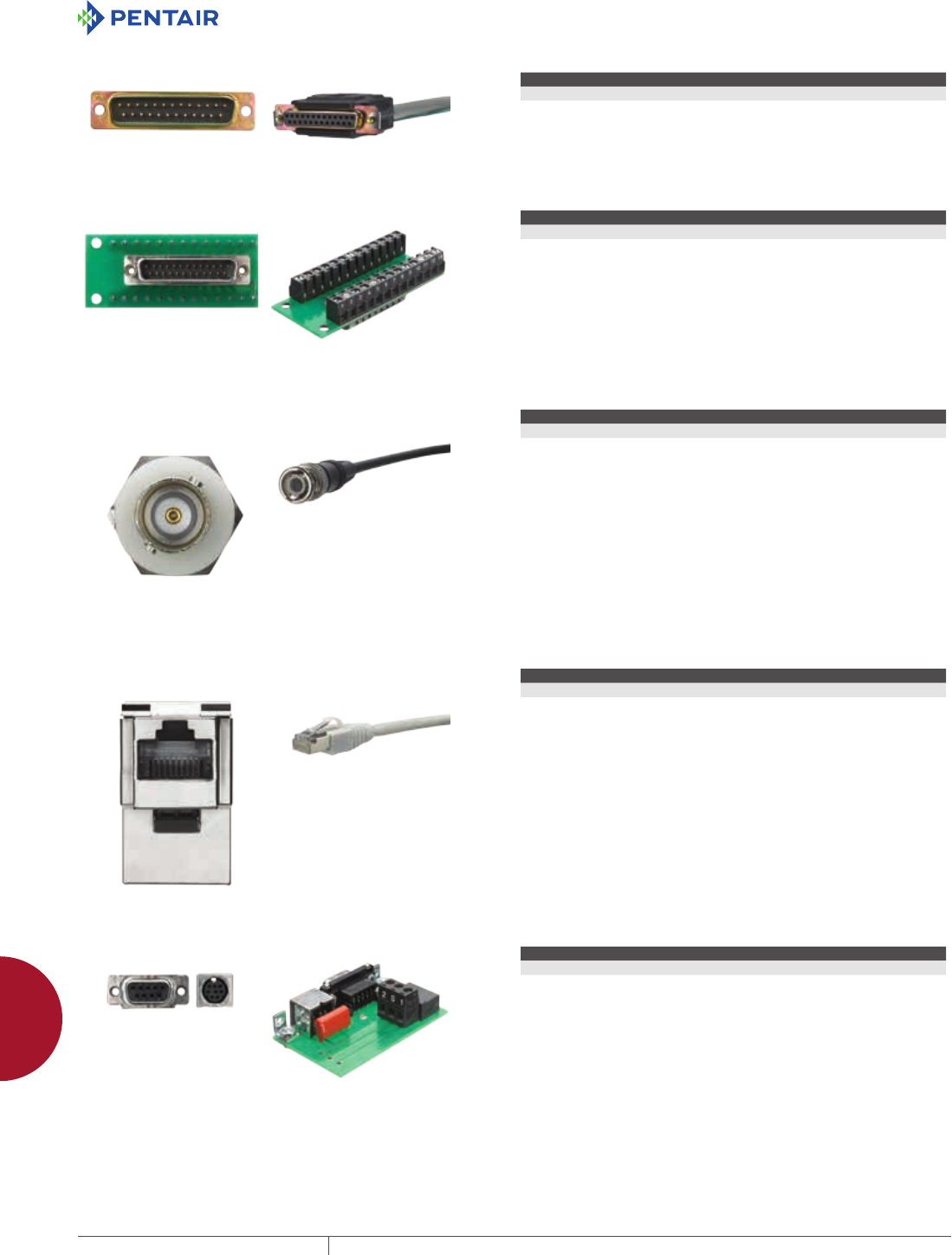
EQUIPMENT PROTECTIONSUBJECT TO CHANGE WITHOUT NOTICEACCESSORIES986
12
INTERSAFE DATA INTERFACE PORTS intersafe data interfaCe Ports, tyPe 4/4X/12
INTERSAFE CONNECTOR 25M
Connector Description Connector Termination Plate Sectors Used
D-Sub 25-pin male with cable 10-ft. cable to female 25-pin D-Sub 1
Left-hand image shows front view. Right-hand image shows rear view.
INTERSAFE CONNECTOR 25MT
Connector Description Connector Termination Plate Sectors Used
D-Sub 25-pin male 25-pin terminal 2
Left-hand image shows front view. Right-hand image shows rear view.
INTERSAFE CONNECTOR BNC
Connector Description Connector Termination Plate Sectors Used
BNC BNC female receptacle with 10-ft. cable to male BNC 1
Left-hand image shows front view. Right-hand image shows rear view.
INTERSAFE CONNECTOR CN
Connector Description Connector Termination Plate Sectors Used
ControlNet shielded RJ45 female connector 10-ft. shielded cable with male RJ45 2
Left-hand image shows front view. Right-hand image shows rear view.
INTERSAFE CONNECTOR DH
Connector Description Connector Termination Plate Sectors Used
Data Highway Plus DB9F Terminal block 2
Left-hand image shows front view. Right-hand image shows rear view.
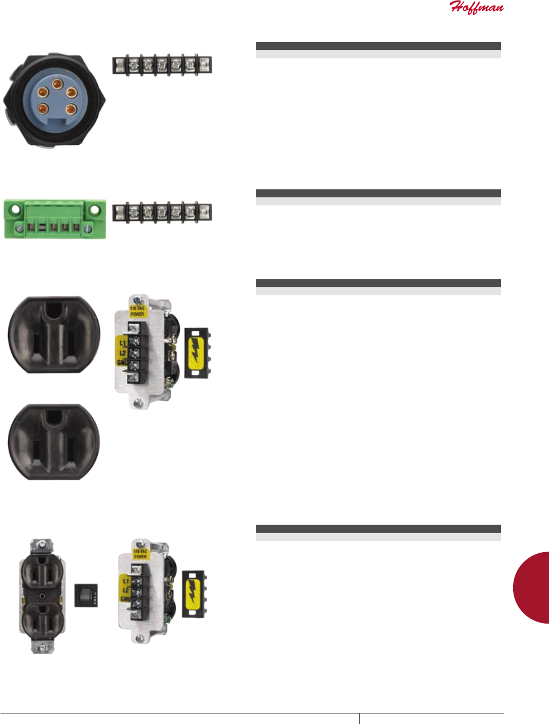
PH 763.422.2211 • FAX 763.422.2600 • PENTAIRPROTECT.COMEQUIPMENT PROTECTION ACCESSORIES 987
12
INTERSAFE DATA INTERFACE PORTS intersafe data interfaCe Ports, tyPe 4/4X/12
INTERSAFE CONNECTOR DNM
Connector Description Connector Termination Plate Sectors Used
DeviceNet Mini Terminal block 2
Left-hand image shows front view. Right-hand image shows rear view.
INTERSAFE CONNECTOR DNP
Connector Description Connector Termination
DeviceNet Phoenix Terminal block
Left-hand image shows front view. Right-hand image shows rear view.
INTERSAFE CONNECTOR DPO
Connector Description Connector Termination Plate Sectors Used
Duplex receptacle with no circuit breaker Terminal block 4
Left-hand image shows front view. Right-hand image shows rear view.
INTERSAFE CONNECTOR DP3
Connector Description Connector Termination Plate Sectors Used
Duplex receptacle with 3-amp circuit breaker Terminal block 5
Left-hand image shows front view. Right-hand image shows rear view.
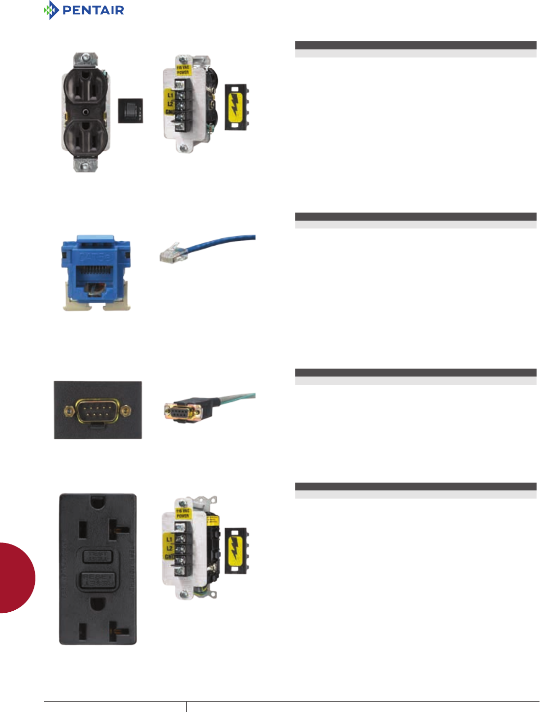
EQUIPMENT PROTECTIONSUBJECT TO CHANGE WITHOUT NOTICEACCESSORIES988
12
INTERSAFE DATA INTERFACE PORTS intersafe data interfaCe Ports, tyPe 4/4X/12
INTERSAFE CONNECTOR DP5
Connector Description Connector Termination Plate Sectors Used
Duplex receptacle with 5-amp circuit breaker Terminal block 5
Left-hand image shows front view. Right-hand image shows rear view.
INTERSAFE CONNECTOR ETH
Connector Description Connector Termination Plate Sectors Used
RJ45 female connector 10-ft. cable with male RJ45 1
Left-hand image shows front view. Right-hand image shows rear view.
INTERSAFE CONNECTOR GEG
Connector Description Connector Termination Plate Sectors Used
DB9 GE Genius 10-ft. cable 1
Left-hand image shows front view. Right-hand image shows rear view.
INTERSAFE CONNECTOR GFO
Connector Description Connector Termination
GFCI receptacle Terminal block
Left-hand image shows front view. Right-hand image shows rear view.
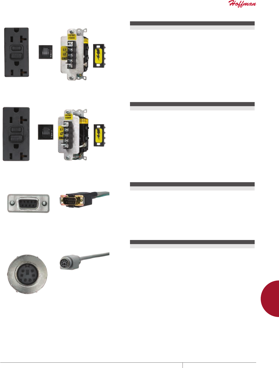
PH 763.422.2211 • FAX 763.422.2600 • PENTAIRPROTECT.COMEQUIPMENT PROTECTION ACCESSORIES 989
12
INTERSAFE DATA INTERFACE PORTS intersafe data interfaCe Ports, tyPe 4/4X/12
INTERSAFE CONNECTOR GF3
Connector Description Connector Termination Plate Sectors Used
GFCI receptacle with 3-amp circuit breaker Terminal block 5
Left-hand image shows front view. Right-hand image shows rear view.
INTERSAFE CONNECTOR GF5
Connector Description Connector Termination Plate Sectors Used
GFCI receptacle with 5-amp circuit breaker Terminal block 5
Left-hand image shows front view. Right-hand image shows rear view.
INTERSAFE CONNECTOR MCL
Connector Description Connector Termination Plate Sectors Used
Micrologix 10-ft. cable 1
Left-hand image shows front view. Right-hand image shows rear view.
INTERSAFE CONNECTOR MD6
Connector Description Connector Termination
6-pin mini DIN (female) 10-ft. cable with female 6-pin mini DIN
Left-hand image shows front view. Right-hand image shows rear view.
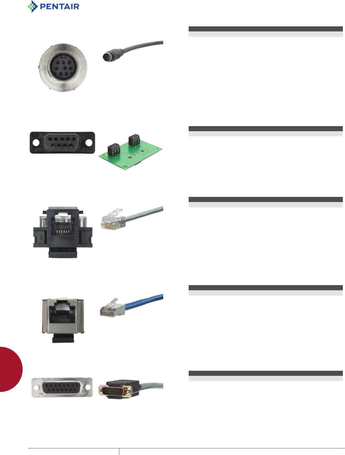
EQUIPMENT PROTECTIONSUBJECT TO CHANGE WITHOUT NOTICEACCESSORIES990
12
INTERSAFE DATA INTERFACE PORTS intersafe data interfaCe Ports, tyPe 4/4X/12
INTERSAFE CONNECTOR MD8
Connector Description Connector Termination Plate Sectors Used
8-pin mini DIN (female) 10-ft. cable with male 8-pin mini DIN 1
Left-hand image shows front view. Right-hand image shows rear view.
INTERSAFE CONNECTOR PB
Connector Description Connector Termination Plate Sectors Used
ProfiBus 9-pin Terminal 2
Left-hand image shows front view. Right-hand image shows rear view.
INTERSAFE CONNECTOR R11
Connector Description Connector Termination Plate Sectors Used
RJ11 female connector with male RJ12 10-ft. cable with male RJ12 1
Left-hand image shows front view. Right-hand image shows rear view.
INTERSAFE CONNECTOR RJS
Connector Description Connector Termination Plate Sectors Used
RJ45 shielded female connector 10-ft. shielded cable with male RJ45 2
Left-hand image shows front view. Right-hand image shows rear view.
INTERSAFE CONNECTOR SNP
Connector Description Connector Termination Plate Sectors Used
DB15F GESNP DB15 male GESNP with 10-ft. cable 1
Left-hand image shows front view. Right-hand image shows rear view.
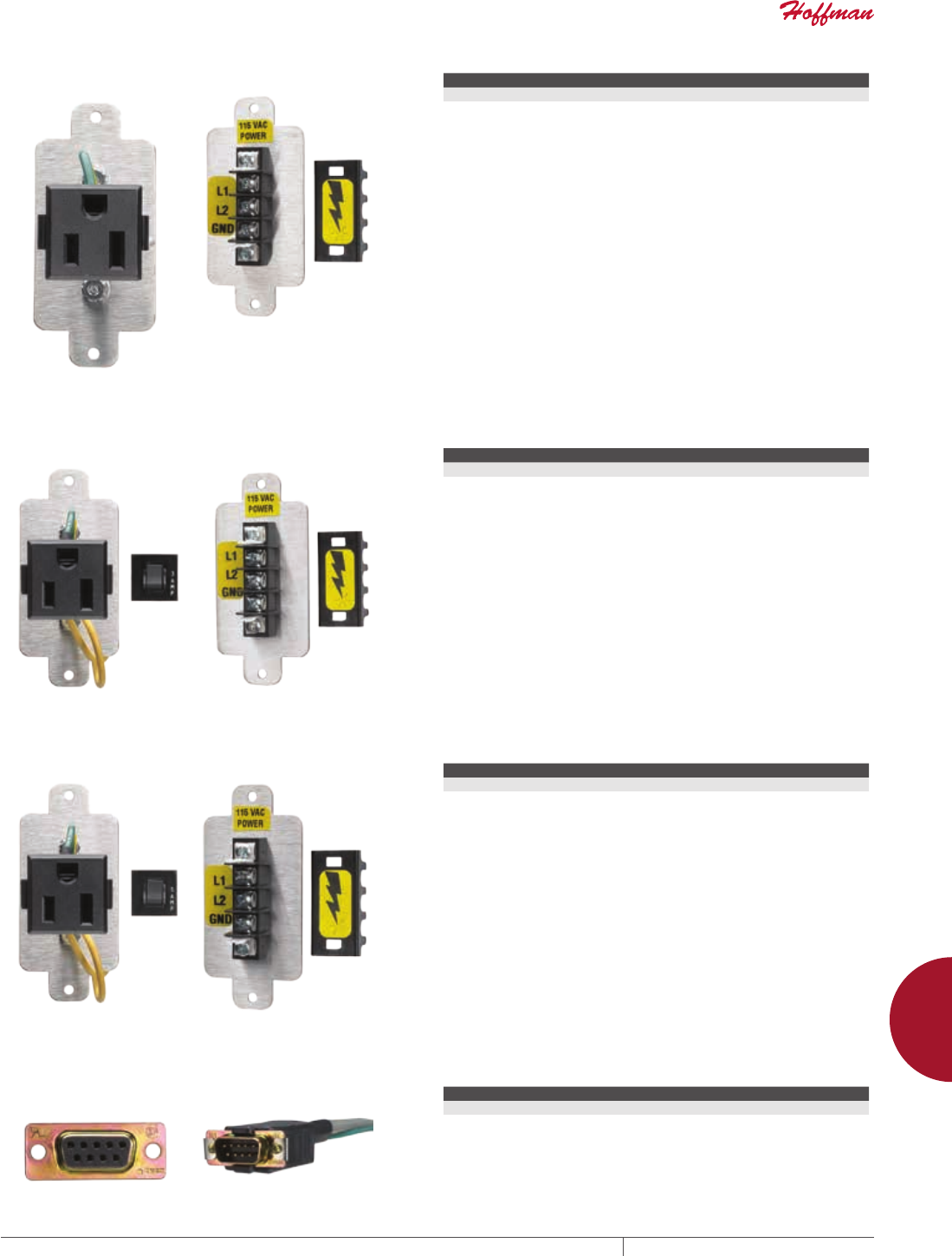
PH 763.422.2211 • FAX 763.422.2600 • PENTAIRPROTECT.COMEQUIPMENT PROTECTION ACCESSORIES 991
12
INTERSAFE DATA INTERFACE PORTS intersafe data interfaCe Ports, tyPe 4/4X/12
INTERSAFE CONNECTOR SPO
Connector Description Connector Termination Plate Sectors Used
Single receptacle with no circuit breaker Terminal block with terminal cover 2
Left-hand image shows front view. Right-hand image shows rear view.
INTERSAFE CONNECTOR SP3
Connector Description Connector Termination Plate Sectors Used
Single receptacle with 3-amp circuit breaker Terminal block with terminal cover 2
Left-hand image shows front view. Right-hand image shows rear view.
INTERSAFE CONNECTOR SP5
Connector Description Connector Termination Plate Sectors Used
Single receptacle with 5-amp circuit breaker Terminal block with terminal cover 2
Left-hand image shows front view. Right-hand image shows rear view.
INTERSAFE CONNECTOR TMB
Connector Description Connector Termination Plate Sectors Used
DB9F Modbus 10-ft. cable 1
Left-hand image shows front view. Right-hand image shows rear view.
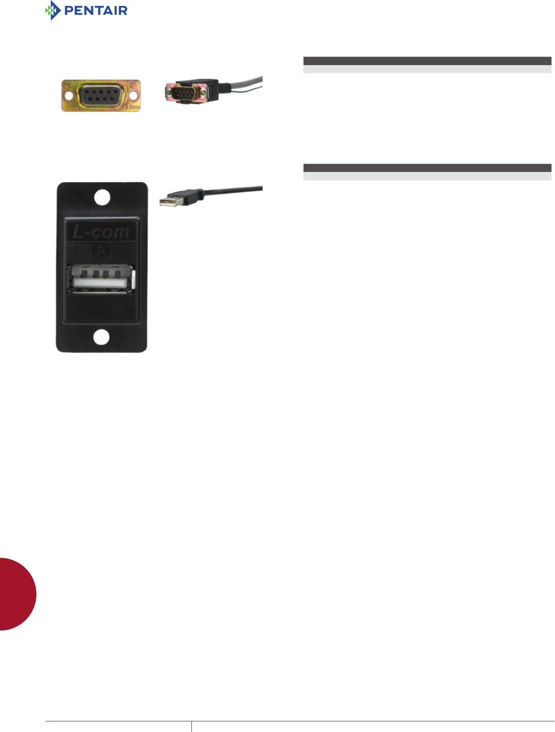
EQUIPMENT PROTECTIONSUBJECT TO CHANGE WITHOUT NOTICEACCESSORIES992
12
INTERSAFE DATA INTERFACE PORTS intersafe data interfaCe Ports, tyPe 4/4X/12
INTERSAFE CONNECTOR TMM
Connector Description Connector Termination Plate Sectors Used
DB9F Micro 10-ft. cable 1
Left-hand image shows front view. Right-hand image shows rear view.
INTERSAFE CONNECTOR USB
Connector Description Connector Termination Plate Sectors Used
USB Type A, female input 10-ft. cable, USB Type B connector 1
Left-hand image shows front view. Right-hand image shows rear view.
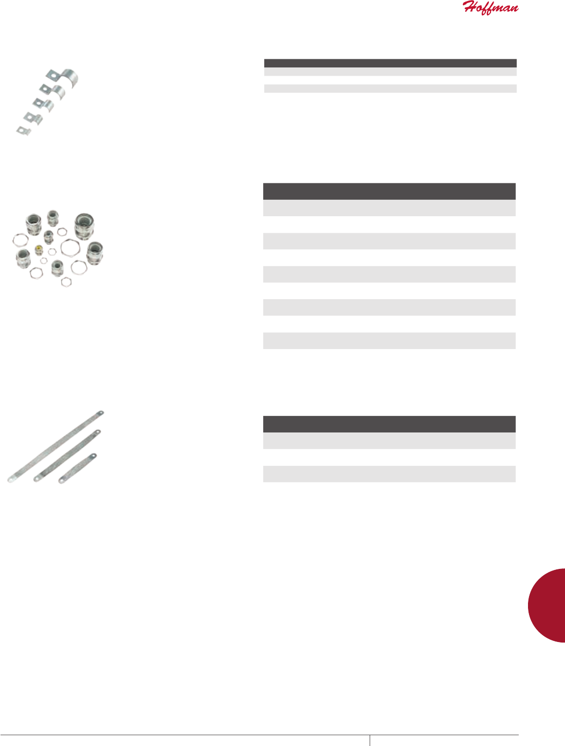
PH 763.422.2211 • FAX 763.422.2600 • PENTAIRPROTECT.COMEQUIPMENT PROTECTION ACCESSORIES 993
12
EMC ACCESSORIES emC aCCessories
EMC ACCESSORIES
EMC ACCESSORIES
BONDING CABLE CLAMPS
These cable clamps are used when
securing cables. They provide the
conductivity required to ground the
shielding on EMC-shielded cable.
BULLETIN: A80
Catalog Number Max. Cable Diameter (in.) Max. Cable Diameter (mm)
ABCC6 0.25 6
ABCC95 0.38 10
ABCC125 0.50 13
ABCC19 0.75 19
EMC CABLE STRAIN RELIEFS
These cable strain reliefs have provisions for grounding the EMC
shielding of cables entering an enclosure while maintaining a NEMA
Type 4 seal.
BULLETIN: A80
Catalog Number Size
Cable Diameter
mm/in.
Hole Diameter
mm/in.
ACSR4EMC PG9 4 - 6
0.16 - 0.24
16
0.63
ACSR6EMC PG11 6 - 10
0.24 - 0.39
19
0.75
ACSR10EMC PG16 10 - 14
0.39 - 0.55
23
0.91
ACSR14EMC PG16 14 - 17
0.55 - 0.67
23
0.91
ACSR17EMC PG21 17 - 20
0.67 - 0.79
29
1.14
ACSR19EMC PG29 19 - 23
0.75 - 0.91
38
1.50
ACSR22EMC PG29 22 - 27
0.87 - 1.06
38
1.50
ACSR25EMC PG36 25 - 30
0.98 - 1.18
48
1.89
ACSR29EMC PG36 29 - 32
1.14 - 1.26
48
1.89
BONDING STRAPS Bonding straps assist in maintaining a constant voltage potential
across a ground plane.
BULLETIN: A80
Catalog Number
Length
mm/in. Package Quantity
ABS6 152
6.00
3
ABS12 305
12.00
3
ABS18 457
18.00
3
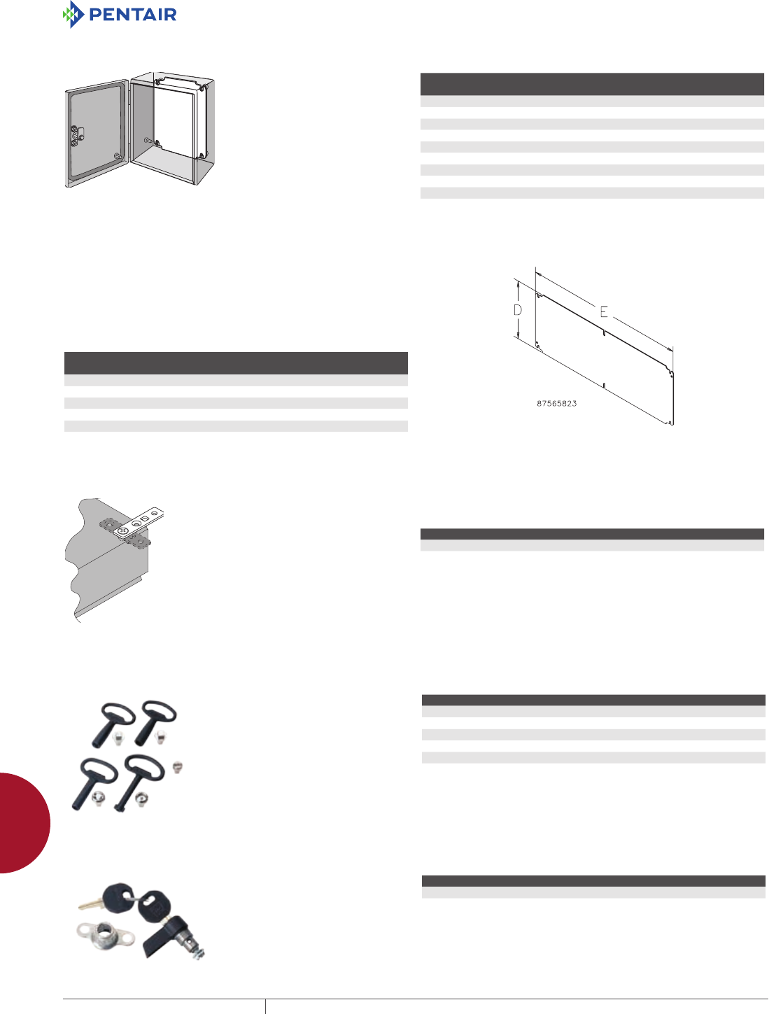
EQUIPMENT PROTECTIONSUBJECT TO CHANGE WITHOUT NOTICEACCESSORIES994
12
INLINE ACCESSORIES inline aCCessories
INLINE ACCESSORIES
INLINE ACCESSORIES
PANEL
Panels are 12 gauge steel with a white polyester powder paint or
conductive finish. Ground hole is labeled. Sized for M6 fastener.
BULLETIN: A53, A54P
Catalog Number Material
Panel Size
D x E (mm)
Panel Size
D x E (in.)
Fits INLINE
Enclosure Size (mm)
LP1515 Painted Steel 131 x 131 5.16 x 5.16 150 x 150
LP1515G Conductive 131 x 131 5.16 x 5.16 150 x 150
LP2015 Painted Steel 181 x 131 7.13 x 5.16 200 x 150
LP2015G Conductive 181 x 131 7.13 x 5.16 200 x 150
LP2520 Painted Steel 231 x 181 9.10 x 7.13 250 x 200
LP2520G Conductive 231 x 181 9.10 x 7.13 250 x 200
LP3025 Painted Steel 281 x 231 11.07 x 9.10 300 x 250
LP3025G Conductive 281 x 231 11.07 x 9.10 300 x 250
LP3530 Painted Steel 331 x 281 13.04 x 11.07 350 x 300
LP3530G Conductive 331 x 281 13.04 x 11.07 350 x 300
INLINE LANDSCAPE PANELS
Panels are 12 gauge steel with a white polyester powder paint or
conductive finish. They include a labeled ground hole sized for an
M6 screw. Panels mount on studs provided in the enclosure or to
optional DIN mounting brackets.
BULLETIN: A54P
Catalog Number
Conductive
Panel
Panel Size
D x E (mm)
Panel Size
D x E (in.)
LP2331 LP2331G 211 x 291 8.31 x 11.46
LP2346 LP2346G 211 x 441 8.31 x 17.36
LP2360 LP2360G 211 x 581 8.31 x 22.87
LP2377 LP2377G 211 x 751 8.31 x 29.57
LP2393 LP2393G 211 x 906 8.31 x 35.67
MOUNTINGBRACKET KIT Kit is field-installable on all solid-back-body enclosures. Hardware
included. Four brackets per kit.
BULLETIN: A54SY, A54Y
Catalog Number Description
LMFK Plated steel mounting-bracket kit
LMFKSS Type 316L stainless steel mounting-bracket kit
LOCK INSERTS
Lock Inserts can replace the
standard slotted quarter-turn latch.
Key included.
BULLETIN: A54SY, A54Y
Catalog Number Description
LLKSM7 Square 7 mm, Chrome Finish
LLKSM7SS Square 7 mm, Type 316L Stainless Steel
LLKSM8 Square 8 mm, Chrome Finish
LLKDB Daimler Benz, Chrome Finish
LLKDBM3 Double bit 3 mm, Chrome Finish
LLKSS Slotted screw, Chrome Finish
WING KNOB LATCH
Wing Knob Latch can replace the
standard slotted, quarter-turn latch
on all hinged-cover and window-
cover enclosures. Latch is black
die-cast zinc. Includes two keys and
installation instructions.
BULLETIN: A54Y
Catalog Number Product Weight
LLKWK 0.2 lb.
Reduces UL Type rating from 4 or 4X to 12.
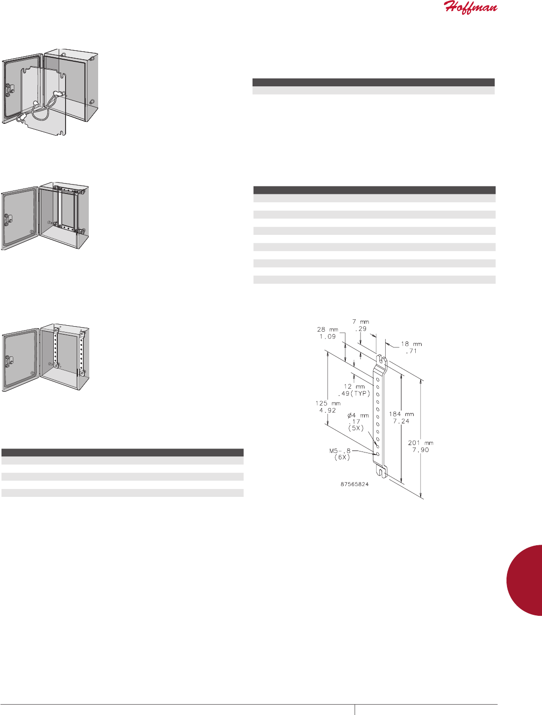
PH 763.422.2211 • FAX 763.422.2600 • PENTAIRPROTECT.COMEQUIPMENT PROTECTION ACCESSORIES 995
12
INLINE ACCESSORIES inline aCCessories
GROUNDING KIT Grounding Kit provides means to attach a grounding conductor to
the enclosure. Kit includes two insulated copper wires with a ring
terminal at each end, all installation hardware and instructions.
BULLETIN: A54Y
Catalog Number Product Weight
LLGK 0.2 lb.
DIN3 TYPE RAILS
Rails furnish mounting surfaces for
DIN3 mount snap-on devices. Rails
attach vertically or horizontally to
mounting brackets. Kit includes 4
rails and installation instructions.
DIN3 Rail Mounting Brackets are
required in order to mount rails.
BULLETIN: A54Y
Catalog Number Fits INLINE Enclosure L (mm) L (in.) Pkg. Qty.
LDR3P15 when A or B = 150 mm 125 4.92 4
LDR3P20 when A or B = 200 mm 175 6.89 4
LDR3P25 when A or B = 250 mm 225 8.86 4
LDR3P30 when A or B = 300 mm 275 10.83 4
LDR3P31 when A or B = 310 mm 285 11.22 4
LDR3P35 when A or B = 350 mm 325 12.80 4
LDR3P40 when A or B = 400 mm 375 14.76 4
LDR3P46 when A or B = 460 mm 435 17.13 4
LDR3P60 when A or B = 600 mm 575 22.64 4
LDR3P77 when A or B = 770 mm 745 29.33 4
LDR3P93 when A or B = 925 mm 900 36.43 4
DIN RAIL OR PANELMOUNTING BRACKETS
Use as a mounting framework to install DIN rails or a panel.
Bracket is offset for additional space in front of or behind mounted
equipment. Plated 12 gauge steel. Mounting hardware included.
Brackets are required for DIN3 type rails.
BULLETIN: A54Y
Catalog Number Fits INLINE Enclosure
LMK15 when A or B = 150 mm
LMK20 when A or B = 200 mm
LMK25 when A or B = 250 mm
LMK30 when A or B = 300 mm
LMK35 when A or B = 350 mm
600-mm and longer enclosures require two sets of brackets for mounting panels.
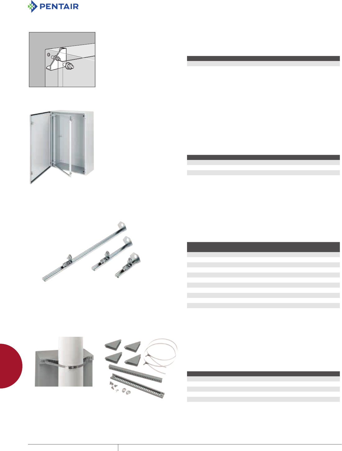
EQUIPMENT PROTECTIONSUBJECT TO CHANGE WITHOUT NOTICEACCESSORIES996
12
CONCEPT ACCESSORIES ConCePt aCCessories
CONCEPT ACCESSORIES
CONCEPT ACCESSORIES
CONCEPT PANEL CONVERSION KIT Panel Conversion Kit adapts enclosure for mounting standard
NEMA-style panels in CONCEPT enclosures. Bracket attaches to
rear collar stud. Kit includes four adapter plates and hardware for
mounting panel.
BULLETIN: CWY
Catalog Number Material Fits CONCEPT Enclosure
CCPM4 Steel When A x B is equal to or less than 30.00 x 30.00 in. (762 x 762 mm)
SWINGOUT RACK FRAME Swing-Out Rack Frames provide 120-degree swing-out access for
19-in. rack equipment. Welded rack frame mounts to front flange.
Distance from frame to door surface is 1.32 in. (33 mm) for solid
doors and 1.07 in. (27 mm) for window doors. Frame is painted
white. Mounting hinge and latching hardware provided.
Order separately clip nut package catalog number XNM5 and
screws XSM5 (metric) or AN1032 and screws AS1032 (English).
Swing-Out Rack Frame cannot be mounted on adjustable mounting kit.
BULLETIN: CWY
Catalog Number Material Fits Enclosure A x B
CSF2424 Painted steel 24.00 x 24.00 in. (610 x 610 mm)
CSF3024 Painted steel 30.00 x 24.00 in. (762 x 610 mm)
CSF3624 Painted steel 36.00 x 24.00 in. (914 x 610 mm)
CONCEPT ADJUSTABLEDEPTH MOUNTING KITS
Adjustable-Depth Mounting Kits provide mounting means for
installing panels, swing-out panels, DIN rails, rack angles,
mounting channels or grid straps at any depth from front to rear of
enclosure. Kits include slide mechanisms and hardware. Use two
kits when enclosure has six collar studs for mounting panel. Kit
catalog numbers ending in 2 contain two slide mechanisms; catalog
numbers ending in 4 contain four slide mechanisms.
Dead Front Panel and Swing-Out Rack Frame cannot be mounted on
adjustable mounting kit.
BULLETIN: CWY
Catalog Number
Fits CONCEPT
Enclosure (in.)
Fits CONCEPT
Enclosure (mm)
CAM64 when C = 6.00 when C = 152
CAM82 when C = 8.00 when C = 203
CAM84 when C = 8.00 when C = 203
CAM102 when C = 10.00 when C = 254
CAM104 when C = 10.00 when C = 254
CAM122 when C = 12.00 when C = 305
CAM124 when C = 12.00 when C = 305
CAM162 when C = 16.00 when C = 406
CAM164 when C = 16.00 when C = 406
CAM202 when C = 20.00 when C = 508
CAM204 when C = 20.00 when C = 508
POLEMOUNT KIT Use to mount CONCEPT, Networking and wall-mount enclosures
to poles of various sizes and shapes. Simply attach the plated steel
channel bar to the mounting holes at the back of the enclosure and
wrap the stainless steel strap around the pole and through the bar.
Kit includes two mounting channels, two straps suitable for 3-in.
(76-mm) to 12-in. (305-mm) diameter pole and mounting hardware.
BULLETIN: CWY
Catalog Number Fits Enclosure (in.) Fits Enclosure (mm)
CPMK12 when B = 12.00 when B = 305
CPMK16 when B = 16.00 when B = 406
CPMK20 when B = 20.00 when B = 508
CPMK24 when B = 24.00 when B = 610
CPMK30 when B = 30.00 when B = 762
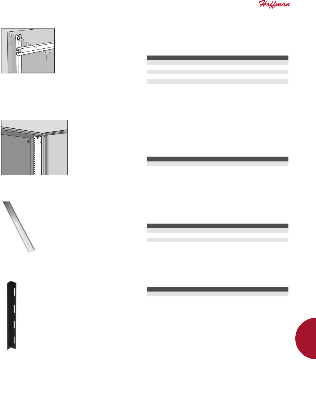
PH 763.422.2211 • FAX 763.422.2600 • PENTAIRPROTECT.COMEQUIPMENT PROTECTION ACCESSORIES 997
12
CONCEPT ACCESSORIES ConCePt aCCessories
MOUNTING CHANNELS Mounting Channels provide mounting framework for installing
DIN rails and grid straps at various positions within the enclosure.
Channels can be mounted vertically or horizontally to collar studs
or to the slide mechanisms of the adjustable-depth mounting kit. Kit
includes two channels.
BULLETIN: CWY
Catalog Number Fits CONCEPT Enclosure
CMC12 when A or B = 12.00 in. (305 mm)
CMC16 when A or B = 16.00 in. (406 mm)
CMC20 when A or B = 20.00 in. (508 mm)
CMC24 when A or B = 24.00 in. (610 mm)
CMC60 when A or B = 60.00 in. (1524 mm)
RACKMOUNT ANGLES Rack-Mount Angles are a mounting means for 19-in. rack
equipment in 24-in. wide enclosures. L-shaped through-hole angles
attach to enclosure flange or the adjustable-depth mounting kit.
Holes are .281 in. (7 mm) in diameter. Clear plated 14 gauge steel
construction. Mounting hardware included.
Order separately clip nut package catalog number XNM5 and screws
XSM5 (metric) or AN1032 and screws AS1032 (English).
BULLETIN: CWY
Catalog Number Fits CONCEPT Enclosure Rack Units
CRA12TH when A = 24.00 in. (610 mm) 12
CRA16TH when A = 30.00 in. (762 mm) 16
DIN3 RAIL KITS DIN3 Rail Kits supply mounting surfaces for DIN mount snap-on
devices in either DIN 1, DIN 3 or CENELEC styles. Rails attach
vertically or horizontally to rear collar stud or to mounting
channels. Kit includes three rails and mounting hardware.
BULLETIN: CWY
Catalog Number Fits CONCEPT Enclosure
CDR3P12 when A or B = 12.00 in. (305 mm)
CDR3P16 when A or B = 16.00 in. (406 mm)
CDR3P20 when A or B = 20.00 in. (508 mm)
CDR3P24 when A or B = 24.00 in. (610 mm)
DOOR BARS Non-metallic door bar includes pressure-sensitive tape adhesive.
BULLETIN: CWY
Catalog Number Description Length Qty.
ADB305MM Door Bar 8 in. (203 mm) 4
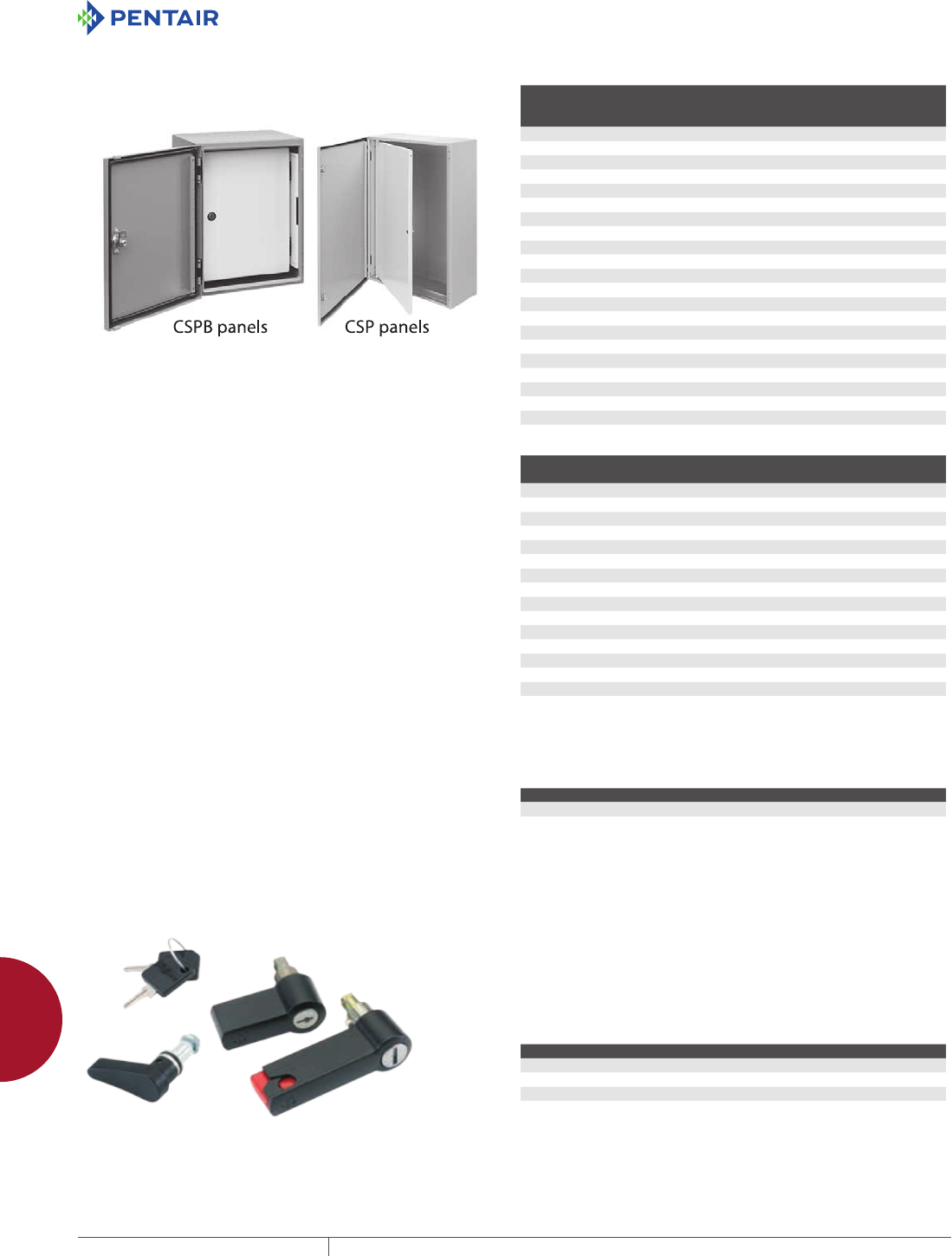
EQUIPMENT PROTECTIONSUBJECT TO CHANGE WITHOUT NOTICEACCESSORIES998
12
CONCEPT ACCESSORIES ConCePt aCCessories
CONCEPT SWINGOUT PANELS
Panels swing clear from the front of the enclosure to provide
access to mounted internal equipment. For CSPB panels, maximum
swing is 94 degrees. For CSP panels, maximum panel swing is 106
degrees. Distance from panel surface to door when in the latched
position is 1.71 in. (43 mm) for solid doors and 1.45 in. (37 mm) for
window doors. Kits include panel, brackets and hardware to mount
to the front flange. Panel is painted white.
Swing-out panels also can be mounted on front-to-back adjustable
rails. CSPB panels require adapter CSPBADB and front-to-back
adjustable rails for front-to-back adjustment.
BULLETIN: CWY
CSPB Panels
Catalog Number
Fits
Enclosure
Size (in.)
Fits
Enclosure
Size (mm)
Panel
Size (in.)
Panel
Size (mm)
CSPB1212 12.00 x 12.00 305 x 305 9.72 x 9.75 247 x 248
CSPB1612 16.00 x 12.00 406 x 305 13.72 x 9.75 349 x 248
CSPB1616 16.00 x 16.00 406 x 406 13.72 x 13.75 349 x 349
CSPB1620 16.00 x 20.00 406 x 508 13.72 x 17.75 349 x 451
CSPB2016 20.00 x 16.00 508 x 406 17.72 x 13.75 450 x 349
CSPB2020 20.00 x 20.00 508 x 508 17.72 x 17.75 450 x 451
CSPB2024 20.00 x 24.00 508 x 610 17.72 x 21.75 450 x 553
CSPB2416 24.00 x 16.00 610 x 406 21.72 x 13.73 552 x 349
CSPB2420 24.00 x 20.00 610 x 508 21.72 x 17.75 552.452
CSPB2424 24.00 x 24.00 610 x 610 21.72 x 21.75 552 x 553
CSPB2430 24.00 x 30.00 610 x 762 21.72 x 27.75 552 x 705
CSPB3020 30.00 x 20.00 762 x 508 27.72 x 17.75 704 x 451
CSPB3024 30.00 x 24.00 762 x 610 27.72 x 21.75 704 x 553
CSPB3030 30.00 x 30.00 762 x 762 27.72 x 27.75 704 x 705
CSPB3624 36.00 x 24.00 914 x 610 33.72 x 21.75 857 x 553
CSPB3630 36.00 x 30.00 914 x 762 33.72 x 27.75 857 x 705
CSPB3636 36.00 x 36.00 914 x 914 33.72 x 33.75 857 x 857
CSPB4236 42.00 x 36.00 1067 x 914 39.72 x 33.75 1009 x 857
CSPB4824 48.00 x 24.00 1219 x 610 45.72 x 21.75 1161 x 553
CSPB4836 48.00 x 36.00 1219 x 914 45.72 x 33.75 1161 x 857
CSPB6036 60.00 x 36.00 1542 x 914 57.72 x 33.75 1466 x 857
CSP Panels
Catalog Number
Fits
Enclosure (in.)
Fits
Enclosure (mm)
Panel
Size (in.)
Panel
Size (mm)
CSP1212 12.00 x 12.00 305 x 305 9.78 x 9.84 248 x 250
CSP1612 16.00 x 12.00 406 x 305 13.78 x 9.84 350 x 250
CSP1616 16.00 x 16.00 406 x 406 13.78 x 13.84 350 x 352
CSP1620 16.00 x 20.00 406 x 508 13.78 x 17.84 350 x 453
CSP2016 20.00 x 16.00 508 x 406 17.78 x 13.84 452 x 352
CSP2020 20.00 x 20.00 508 x 508 17.78 x 17.84 452 x 453
CSP2024 20.00 x 24.00 508 x 610 17.78 x 21.84 452 x 555
CSP2416 24.00 x 16.00 610 x 406 21.78 x 13.84 553 x 352
CSP2420 24.00 x 20.00 610 x 508 21.78 x 17.84 553 x 453
CSP2424 24.00 x 24.00 610 x 610 21.78 x 21.84 553 x 555
CSP3020 30.00 x 20.00 762 x 508 27.78 x 17.84 706 x 453
CSP3024 30.00 x 24.00 762 x 610 27.78 x 21.84 706 x 555
CSP3030 30.00 x 30.00 762 x 762 27.78 x 27.84 706 x 707
CSP3624 36.00 x 24.00 914 x 610 33.78 x 21.84 858 x 555
CSP3630 36.00 x 30.00 914 x 762 33.78 x 27.84 858 x 707
CSP3636 36.00 x 36.00 914 x 914 33.78 x 33.84 858 x 860
CONCEPT ADAPTER BRACKET
Adapter bracket for use with CONCEPT B-style Swing-Out Panels
and Adjustable-Depth Mounting Kits. Bracket enables the B-style
swing-out panels to be mounted in infinite front-to-back positions
within a CONCEPT enclosure.
BULLETIN: CWY
Catalog Number Material
CSPBADB Steel
HANDLES Handles can replace the standard slotted insert on all CONCEPT
wall-mount enclosures. The CONCEPT non-locking handle provides
quick and easy access to the enclosure contents. Handle is black
plastic. A zinc die-cast keylock handle is available for applications
requiring quick access and security. A padlocking handle, also zinc
die-cast, accommodates a padlock with up to a 5/16-in. locking bar.
Each latch system can be converted from clockwise to counter-
clockwise opening. Kit includes all hardware.
BULLETIN: CWY
Catalog Number UL Rating Description
CWHK Maintains UL/CSA Type 12 when properly installed Keylock handle
CWHNL Maintains UL Type 3, 4, 4X, 12 when properly installed Non-locking handle
CWHPTO Maintains UL/CSA Type 3, 4, 12 when properly installed Padlock handle
CWHNL is not suitable for 3-point latch operation.
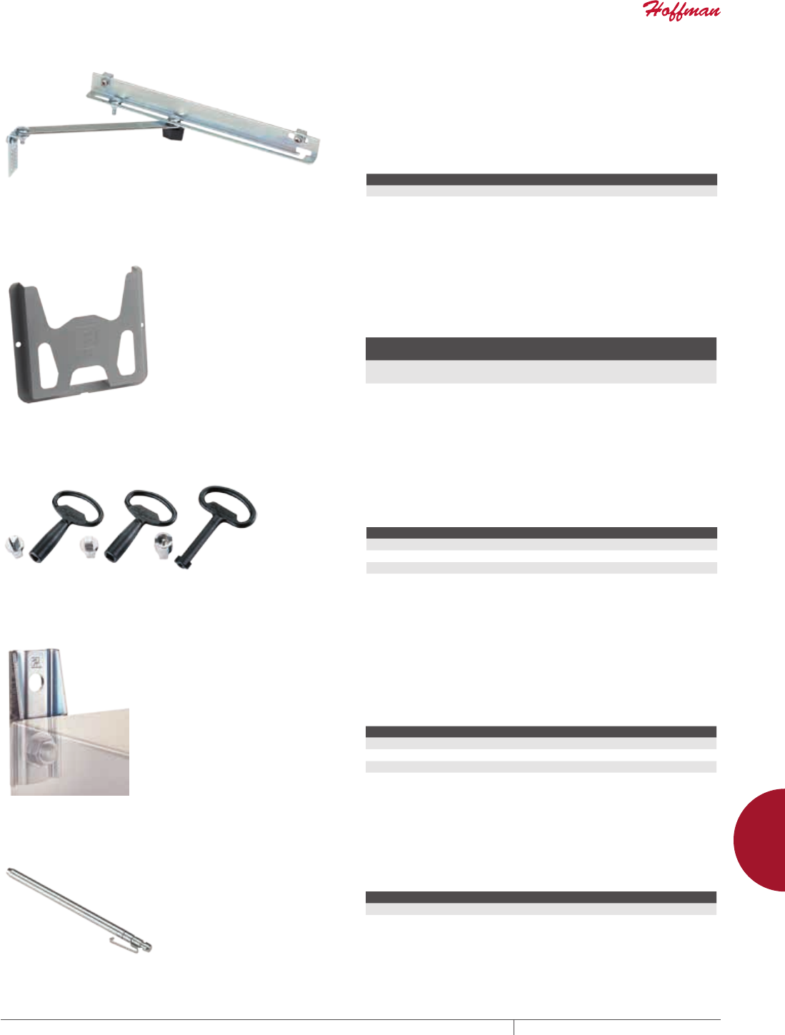
PH 763.422.2211 • FAX 763.422.2600 • PENTAIRPROTECT.COMEQUIPMENT PROTECTION ACCESSORIES 999
12
CONCEPT ACCESSORIES ConCePt aCCessories
DOOR STOP KIT Door Stop Kit secures the door in the open position. Kit can be
installed at the top or bottom of a door which opens horizontally.
Door opening angle can be easily adjusted by means of a wing nut.
Stop arm slides neatly out of the way when the door is closed. All
parts are plated. Mounting hardware included.
• Door stop kits should not be installed on enclosures configured with a
swing-out panel or swing-out rack frame
• Door stop kits cannot be used with CONCEPT window doors
BULLETIN: A80
Catalog Number Finish
ADSTOPK Plated Steel
DATA POCKETS Data Pockets provide convenient storage for wiring diagrams,
operation manuals and other documentation inside an enclosure.
Pocket mounts on studs located on the inside of a solid-door
enclosure. Constructed of high-impact thermoplastic, pockets are
dark gray and have cutout areas for easy access and visibility to
contents. Mounting hardware included.
BULLETIN: UX1Y
Catalog Number
Length x Width
in./mm Fits CONCEPT Enclosure
ADP1 6.00 x 6.00
152 x 152
when A is less than or equal to 24
and B is less than or equal to 24
ADP2 12.00 x 12.00
305 x 305
when A is greater than or equal to 30
and B is greater than or equal to 20
Use ADP2 when A = 24 and B = 30
LOCK INSERTS Lock inserts can be substituted for the standard 3-mm double-bit
latch insert. Inserts have a chrome finish. Matching key is zinc die-
cast.
BULLETIN: A4GY, CWY
Catalog Number Description
CLKTM7 Triangular 7-mm insert with key
CLKSM7 Square 7-mm insert with key
CLKDBM3 Double bit with key
CLKSLOT Slotted Insert no key
MOUNTINGBRACKET KITS Mounting-Bracket Kits are field installable. Composite and
stainless steel brackets are rated to Type 4X. Set of four (4) brackets
can support 500 lb. maximum load. All hardware is included. Four
brackets per kit.
Mounting brackets are required to maintain UL/CSA external mounting
requirement.
BULLETIN: A80
Catalog Number Description
CMFK Steel
CMFKSS Stainless Steel
CMTGFT Composite
HINGE PINS Contact Customer Service to order new mild steel hinge pins for an
existing product.
BULLETIN: VM3
Catalog Number Description Qty.
GHPINMS Hinge Pin 2
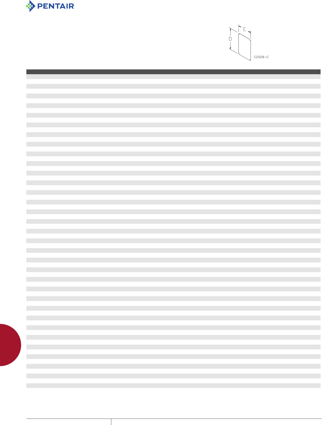
EQUIPMENT PROTECTIONSUBJECT TO CHANGE WITHOUT NOTICEACCESSORIES1000
12
CONCEPT ACCESSORIES ConCePt aCCessories
CONCEPT PANELS
These panels are taller and wider than corresponding NEMA-size
panels. Panels are 14 or 12 gauge steel and painted white or have a
conductive finish.
Panels have a formed flange along any side that is longer than 22.20 in.
(564 mm). CP2420 and CP2424 have a flange on all four sides.
BULLETIN: CWP, CWY, DWDH2
Catalog Number Panel Type Panel Size D x E (in.) Panel Size D x E (mm) Gauge
CP1210 Painted steel 10.20 x 8.20 259 x 208 14
CP1210G Conductive 10.20 x 8.20 259 x 208 14
CP1212 Painted steel 10.20 x 10.20 259 x 259 12
CP1212G Conductive 10.20 x 10.20 259 x 259 12
CP1612 Painted steel 14.20 x 10.20 361 x 259 12
CP1612G Conductive 14.20 x 10.20 361 x 259 12
CP1616 Painted steel 14.20 x 14.20 361 x 361 12
CP1616G Conductive 14.20 x 14.20 361 x 361 12
CP2012 Painted steel 18.20 x 10.20 462 x 259 12
CP2012G Conductive 18.20 x 10.20 462 x 259 12
CP2014 Painted steel 18.20 x 12.20 462 x 310 12
CP2014G Conductive 18.20 x 12.20 462 x 310 12
CP2016 Painted steel 18.20 x 14.20 462 x 361 12
CP2016G Conductive 18.20 x 14.20 462 x 361 12
CP2020 Painted steel 18.20 x 18.20 462 x 462 12
CP2020G Conductive 18.20 x 18.20 462 x 462 12
CP2412 Painted steel 22.20 x 10.20 564 x 259 12
CP2412G Conductive 22.20 x 10.20 564 x 259 12
CP2416 Painted steel 22.20 x 14.20 564 x 361 12
CP2416G Conductive 22.20 x 14.20 564 x 361 12
CP2420 Painted steel 22.20 x 18.20 564 x 462 12
CP2420G Conductive 22.20 x 18.20 564 x 462 12
CP2424 Painted steel 22.20 x 22.20 564 x 564 12
CP2424G Conductive 22.20 x 22.20 564 x 564 12
CP2442 Painted steel 22.20 x 40.20 564 x 1021 12
CP2442G Conductive 22.20 x 40.20 564 x 1021 12
CP3012 Painted steel 28.20 x 10.20 716 x 259 12
CP3012G Conductive 28.20 x 10.20 716 x 259 12
CP3016 Painted steel 28.20 x 14.20 716 x 361 12
CP3016G Conductive 28.20 x 14.20 716 x 361 12
CP3020 Painted steel 28.20 x 18.20 716 x 462 12
CP3020G Conductive 28.20 x 18.20 716 x 462 12
CP3024 Painted steel 28.20 x 22.20 716 x 564 12
CP3024G Conductive 28.20 x 22.20 716 x 564 12
CP3030 Painted steel 28.20 x 28.20 716 x 716 12
CP3030G Conductive 28.20 x 28.20 716 x 716 12
CP3048 Painted steel 28.20 x 46.20 716 x 1173 12
CP3048G Conductive 28.20 x 46.20 716 x 1173 12
CP3060 Painted steel 28.20 x 58.20 716 x 1478 12
CP3060G Conductive 28.20 x 58.20 716 x 1478 12
CP3220 Painted steel 30.20 x 18.20 762 x 462 12
CP3624 Painted steel 34.20 x 22.20 869 x 564 12
CP3624G Conductive 34.20 x 22.20 869 x 564 12
CP3630 Painted steel 34.20 x 28.20 869 x 716 12
CP3630G Conductive 34.20 x 28.20 869 x 716 12
CP3636 Painted steel 34.20 x 34.20 869 x 869 12
CP3636G Conductive 34.20 x 34.20 869 x 869 12
CP4230 Painted steel 40.20 x 28.20 1021 x 716 12
CP4230G Conductive 40.20 x 28.20 1021 x 716 12
CP4236 Painted steel 40.20 x 34.20 1021 x 869 12
CP4236G Conductive 40.20 x 34.20 1021 x 869 12
CP4242 Painted steel 40.20 x 40.20 1021 x 1021 12
CP4242G Conductive 40.20 x 40.20 1021 x 1021 12
CP4260 Painted steel 40.20 x 58.20 1021 x 1478 12
CP4260G Conductive 40.20 x 58.20 1021 x 1478 12
CP4420 Painted steel 42.20 x 18.20 1072 x 462 12
CP4824 Painted steel 46.20 x 22.20 1173 x 564 12
CP4824G Conductive 46.20 x 22.20 1173 x 564 12
CP4836 Painted steel 46.20 x 34.20 1173 x 869 12
CP4836G Conductive 46.20 x 34.20 1173 x 869 12
CP4848 Painted steel 46.20 x 46.20 1173 x 1173 12
CP4848G Conductive 46.20 x 46.20 1173 x 1173 12
CP5620 Painted steel 53.20 x 18.20 1351 x 462 12
CP6036 Painted steel 58.20 x 34.20 1478 x 869 12
CP6036G Conductive 58.20 x 34.20 1478 x 869 12
CP7236 Painted steel 70.20 x 34.20 1783 x 869 12
Catalog number CP4230 is used on CONCEPT disconnect enclosures.

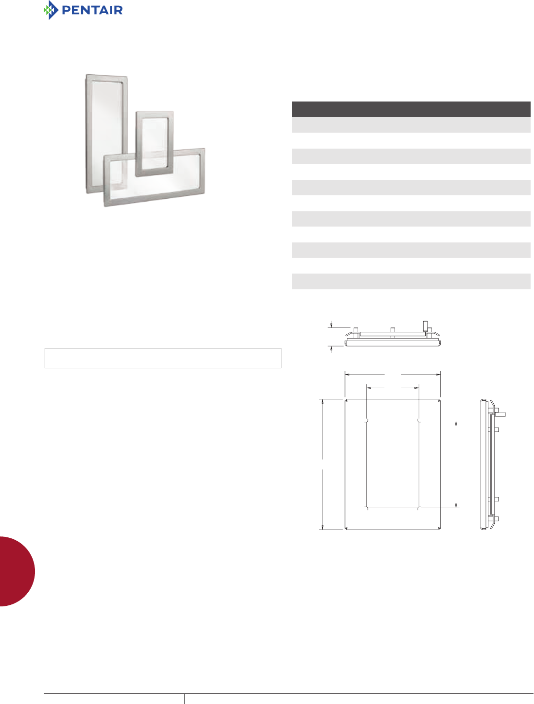
EQUIPMENT PROTECTIONSUBJECT TO CHANGE WITHOUT NOTICEACCESSORIES1002
12
HAZARDOUS LOCATION hazardous loCation aCCessories
HAZARDOUS LOCATION
HAZARDOUS LOCATION ACCESSORIES
HAZARDOUS LOCATION WINDOW KITS
INDUSTRY STANDARDS
IECEx and ATEX Approvals
Suitable for use on increased safety enclosures for ZONE 1 or ZONE
2 assemblies
ATEX Directive 94/9/EC
ATEX
Sira 13ATEX3315U
Ex e IIC Gb
Ex tb IIIC Db IP 66
IECEx
IECEx SIR 13.0123U
Ex e IIC Gb
Ex tb IIIC Db IP 66
UL 508A Component Recognized; Type 4, 4X,12, 3R; File No.
E61997
cUR Component Recognized per CSA C22.2 No. 94; Type 4, 4X, 12,
3R; File No. E61997
NEMA/EEMAC 4, 4X, 12, 13
IEC 60529, IP66
APPLICATION
Hazardous Location Window Kits are designed to be used on
Increased Safety (Ex e) enclosures in ATEX or IECEx Zone 1 or
2 hazardous areas. These window kits are made with a robust
heavy-gauge Type 316 stainless steel frame and a silicone gasket
to ensure a dust-, oil-, and water-tight seal. Designed for use as
viewing windows, these window kits are ideal for visibility of internal
enclosure components. The windows are easily installed by making
a cutout in the enclosure and attaching the window and frame with
included mounting hardware.
FEATURES
• Robust window frames are made from heavy-gauge Type 316
stainless steel with a brushed finish
• Secure sealing with silicon gasket to protect against water and
dust ingress in extreme-temperature applications ranging from
-55 C (-67 F) to 180 C (356 F)
• Maintain visual on components through .25-in. (6-mm) tempered
safety glass
• Easy installation in enclosure cutouts with window frame
hardware
MODIFICATION AND CUSTOMIZATION
Hoffman excels at modifying and customizing products to your
specifications. Contact your local Hoffman sales office or distributor
for complete information.
BULLETIN: HLY
Standard Product
Catalog Number AxBxC in./mm
M
in./mm
N
in./mm
Required Cutout size
in./mm
EXWK53SS6 7.50 x 5.50 x 1.43
191 x 140 x 36
5.00
127
3.00
76
6.69 x 4.69
170 x 119
EXWK95SS6 11.50 x 8.00 x 1.43
292 x 203 x 36
9.00
229
5.50
140
10.69 x 7.19
272 x 183
EXWK711SS6 9.50 x 13.05 x 1.43
241 x 343 x 36
7.00
178
11.00
279
8.69 x 12.69
211 x 392
EXWK138SS6 15.50 x 10.50 x 1.43
394 x 267 x 36
13.00
330
8.00
203
14.69 x 9.69
373 x 246
EXWK715SS6 9.50 x 17.50 x 1.43
241 x 445 x 36
7.00
178
15.00
381
8.69 x 16.69
211 x 424
EXWK1711SS6 19.50 x 13.50 x 1.43
495 x 343 x 36
17.00
432
11.00
279
18.69 x 12.69
475 x 322
EXWK720SS6 9.50 x 22.50 x 1.43
241 x 572 x 36
7.00
178
20.00
508
8.69 x 21.69
221 x 551
EXWK2315SS6 25.50 x 17.50 x 1.43
648 x 445 x 36
23.00
584
15.00
381
24.69 x 16.69
627 x 424
EXWK724SS6 9.50 x 26.50 x 1.43
241 x 673 x 36
7.00
178
24.00
610
8.69 x 25.69
653 x 221
EXWK729SS6 9.50 x 31.50 x 1.43
241 x 800 x 36
7.00
178
29.00
737
8.69 x 30.69
221 x 780
EXWK2919SS6 31.50 x 21.50 x 1.43
800 x 546 x 36
29.00
737
19.00
483
30.69 x 20.69
780 x 526
M x N = Window size
$
%
0
1
&
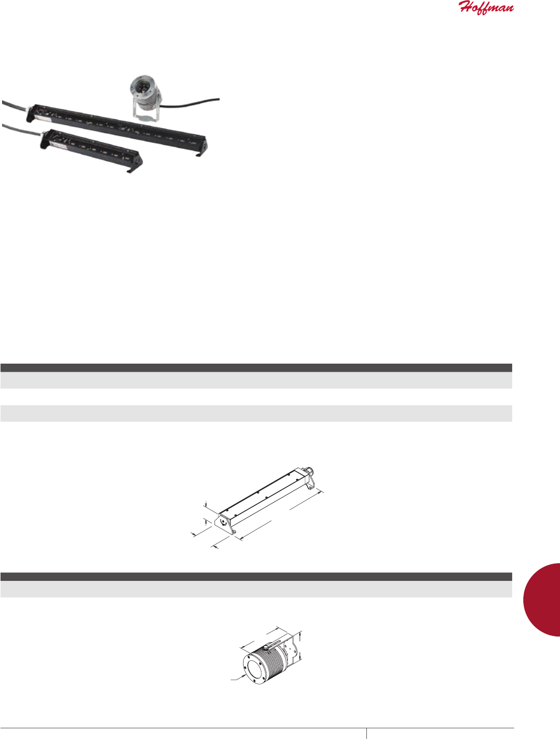
PH 763.422.2211 • FAX 763.422.2600 • PENTAIRPROTECT.COMEQUIPMENT PROTECTION ACCESSORIES 1003
12
HAZARDOUS LOCATION hazardous loCation aCCessories
HAZARDOUS LOCATION LED LIGHTS
INDUSTRY STANDARDS
ETL Listed
Class I Division 2, Groups A, B, C and D, T3
Conforms To CSA.22.2 No. 137, 213, 250 Standards
Conforms To UL 844 & 1598 Standards
Conforms to ISA-12.12-01
Maintains enclosure Type 4, 4X rating when properly installed
APPLICATION
Hazardous Location LED Lights provide enclosure illumination in
hazardous environments. These lights are ideal for remote and
darkened enclosure applications in Class 1, Division 2 hazardous
areas. With a robust design, these lights have a lifespan of 100,000
hours and superior lighting performance with minimal power
consumption. These versatile, slim-profile LED lights provide
mounting flexibility and are are easy to install in an enclosure.
FEATURES
• LED technology provides a life span of up to 100,000 operating
hours
• Operating temperature of -40 F (-40 C) to 185 F (85 C)
• Provide superior cool white lighting with color temperature range
of 6500K
• Easy installation with included mechanical assembly kit while
maintaining enclosure rating up to UL Type 4X
• Includes 6-ft connect cable with flying leads
Standard LED Light
• Maximum lighting for control panels with 558 to 2,256 lumens
light output and ingress protection of IP54
• Minimum power consumption and superior lighting with 24 VDC
power input
• Versatile mounting allows the light to be positioned horizontally
or vertically with 160 degree rotation
• 100 degree angle of illumination
• Available in 12, 24, 36, and 48-inch lengths
Indoor/Outdoor LED Light
• Robust construction design for suitable outdoor applications;
IP66
• Minimum power consumption and superior lighting with 12-24
VDC power input
• Maximum lighting with 459 lumens output
• 360 degree rotation allows flexible and versatile mounting
• 100 degree angle of illumination
BULLETIN: HLY
Standard Product Standard LED Light
Catalog Number AxBxC in./mm Description Weight (lbs.) Weight (kg) VDC Amps Estimated light output LMS
LEDHL24V12 13.56 x 1.69 x 2.69
344 x 43 x 68
LED Light, 12-in. 0.7 0.3 24 0.33 558
LEDHL24V24 25.06 x 1.69 x 2.69
636 x 43 x 68
LED Light, 24-in. 1.4 0.6 24 0.66 1116
LEDHL24V36 36.04 x 1.69 x 2.69
916 x 43 x 68
LED Light, 36-in. 2.1 0.9 24 0.99 1674
LEDHL24V48 47.06 x 1.69 x 2.69
1195 x 43 x 68
LED Light, 48-in. 2.8 1.2 24 1.32 2256
$
%
&
Standard Product Indoor/Outdoor LED Light
Catalog Number AxBxC in./mm Description Weight (lbs.) Weight (kg) VDC Amps
LEDHL24VCAN 3.74 x 3.48 x 5.62
95 x 88 x 143
LED Light, Indoor/Outdoor 2.3 1.0 12-24 0.66 - 0.35
%
$
&
89107324
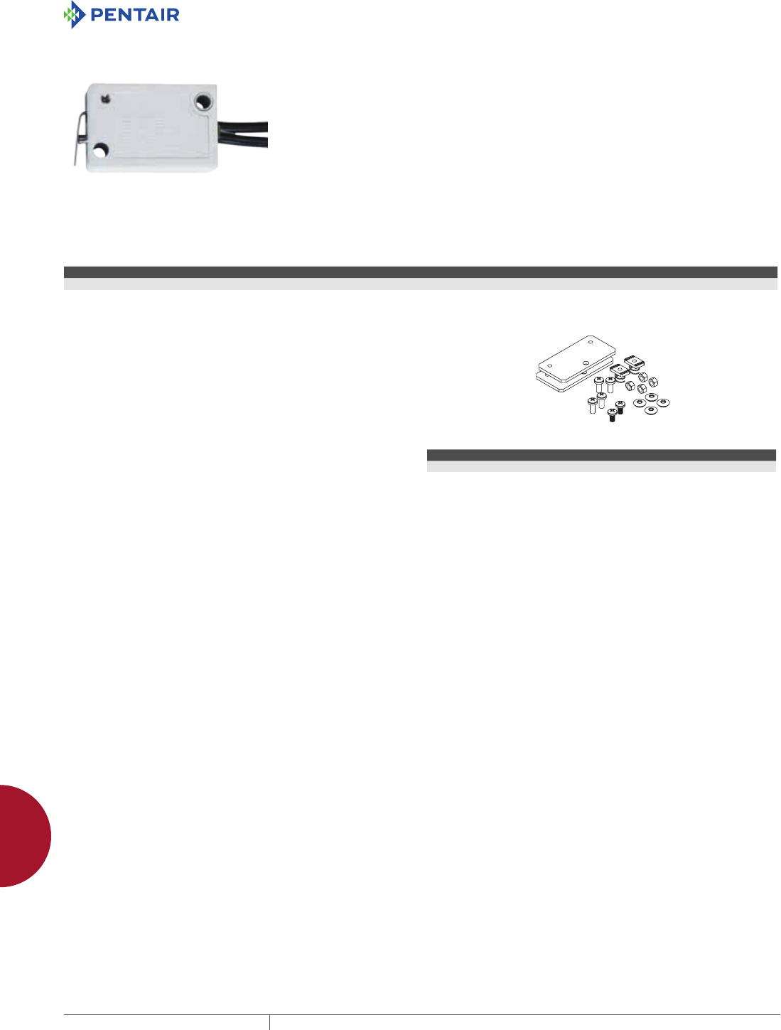
EQUIPMENT PROTECTIONSUBJECT TO CHANGE WITHOUT NOTICEACCESSORIES1004
12
HAZARDOUS LOCATION hazardous loCation aCCessories
HAZARDOUS LOCATION DOOR SWITCH
INDUSTRY STANDARDS
Switch Rating
Explosion-proof for Class 1, Division 2, Groups A, B, C, and D
FM Approved to Standard Class 3600, 3615-1989
APPLICATION
The Hazardous Location Door Switch is designed to be used with
Hoffman Hazardous Location LED Lights in Class 1, Division 2
hazardous areas. The included hardware kit allows the door switch
to easily be mounted and maintain the enclosure rating up to UL
Type 4X. This versatile switch activates the LED light when the
enclosure door is opened and can be mounted on any flange of the
enclosure. The included five-foot connect cable allows ease of
wiring to the enclosure back panel.
BULLETIN: HLY
Catalog Number Description Max. Voltage Operating Temperature Max. load
LEDHLSWITCH Door Switch, C1D2 30 VDC / 5 Amps -40 F (40 C) to 194 F (90 C) 5 Amps at 30 VDC
REPLACEMENT HARDWARE KIT FOR HAZARDOUS
LOCATION LED LIGHTS
Replacement Hardware Kit is available for the replacement of lost
or damaged hardware supplied with Hazardous Location LED lights.
Kit includes bracket adapter plate, all mounting hardware and
complete instructions.
BULLETIN: HLY
Catalog Number Description
AHKC1D2LED Replacement Hardware Kit
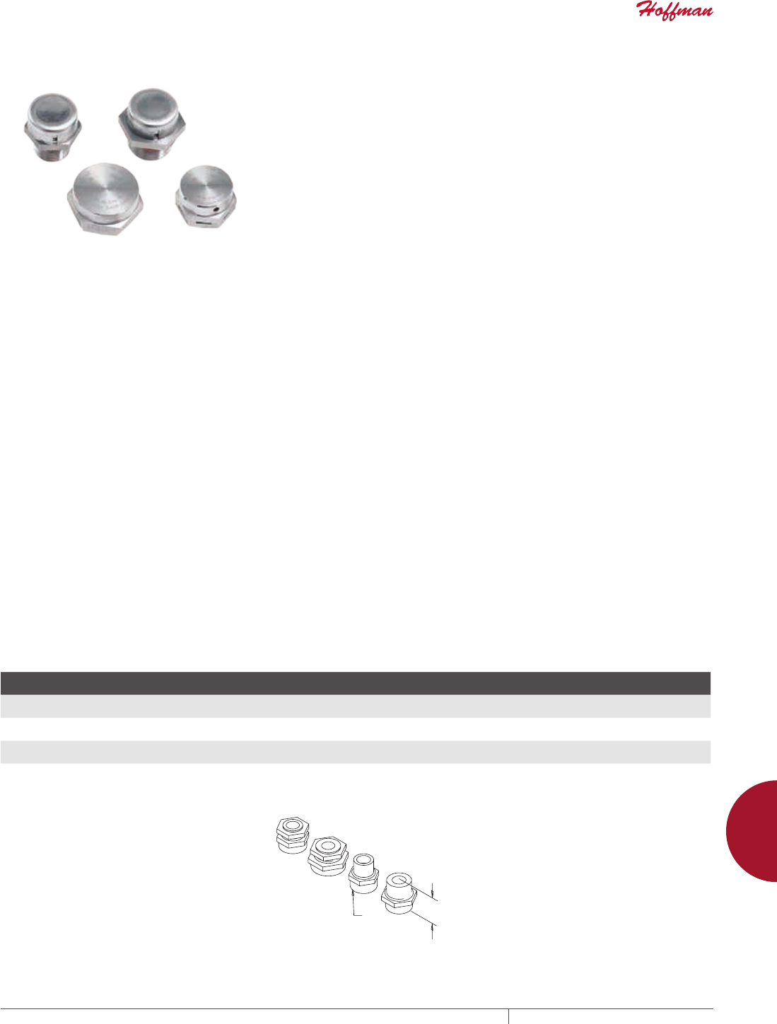
PH 763.422.2211 • FAX 763.422.2600 • PENTAIRPROTECT.COMEQUIPMENT PROTECTION ACCESSORIES 1005
12
HAZARDOUS LOCATION hazardous loCation aCCessories
HAZARDOUS LOCATION BREATHER DRAINS
INDUSTRY STANDARDS
Ex e Breather Drains
Certified for Zone 1 or 2 areas
ATEX
Sira 13ATEX3354U
Ex e IIC Gb
Ex tb IIIC Db IP66
IECEx
IECEx SIR 13.0138U
Ex e IIC Gb
Ex tb IIIC Db IP66
cCSAus Certified Class 1 Zone 1, Ex e II, IP66, Type 4X
NEMA/EEMAC Type 4, 4X
IEC 60529, IP66
Maintain enclosure Type 4, 4X rating when properly installed
Ex d Breather Drains
Certified for Zone 1 or 2 areas
ATEX
ITS13ATEX17900U
Ex d IIC Gb
Ex e IIC Gb
Ex tb IIIC Db IP66
IECEx
IECEx ITS 13.0049U
Ex d IIC Gb
Ex e IIC Gb
Ex tb IIIC Db IP66
NEMA/EEMAC Type 4, 4X
IEC 60529, IP66
Maintain enclosure Type 4, 4X rating when properly installed
APPLICATION
Hazardous Location Breather Drains prevent moisture build-up
within hazardous approved enclosures while maintaining enclosure
UL Type rating. Drains are to be used when an enclosure is subject
to fluctuations in temperature which can lead to the formation of
condensation and a subsequent moisture build-up. These drains
allow air within an enclosure to breathe with the surrounding
atmosphere, preventing condensation and any potential damage to
electrical equipment.
FEATURES
• Reduce corrosion that can limit the life of internal electrical and
electronic components
• Prevent condensation when installations are subject to
fluctuations in temperature in hazardous locations
• Effectively drain any water present within the enclosure
• Minimize moisture build-up within the enclosure by allowing air
in the enclosure to breathe with surrounding atmosphere
• Position at the lowest point of an enclosure to ensure optimal
draining of any moisture
• Maintain enclosure’s UL Type rating when properly installed
• Available for Increased Safety (Ex e) and Flameproof (Ex d)
applications
SPECIFICATIONS
Ex e Breather Drains:
• Type 316 stainless steel with castellated nut and nitrile O-ring
• 10mm thread length
• Install in a clearance hole 0.5 to 1.0mm larger than major
diameter, or in a tapped hole
• Operating temperature of -58 F (-50 C) to 185 F (85 C)
Ex d Breather Drains:
• Type 316 stainless steel with silicone O-ring
• 16mm thread length
• Install in a tapped hole
• Operating temperature of -22 F (-30 C) to 302 F (150 C)
BULLETIN: HLY
Catalog Number AxBxC in./mm Description Thread Type
D
in./mm
L
in./mm Weight (lbs.) Weight (kg)
EXEBDM20SS6 1.57 x 1.57 x 0.98
40 x 40 x 25
Ex e M20 Breather Drain M20 1.13
28.7
.99
25.1
0.16 0.1
EXEBDM25SS6 1.57 x 1.57 x 0.98
40 x 40 x 25
Ex e M25 Breather Drain M25 1.41
35.8
1.30
33.0
0.27 0.1
EXDBDM20SS6 1.57 x 1.57 x 0.98
40 x 40 x 25
Ex d M20 Breather Drain M20 1.06
26.9
.99
25.1
0.18 0.1
EXDBDM25SS6 1.57 x 1.57 x 0.98
40 x 40 x 25
Ex d M25 Breather Drain M25 1.2
31.8
1.30
33.0
0.25 0.1
/
'
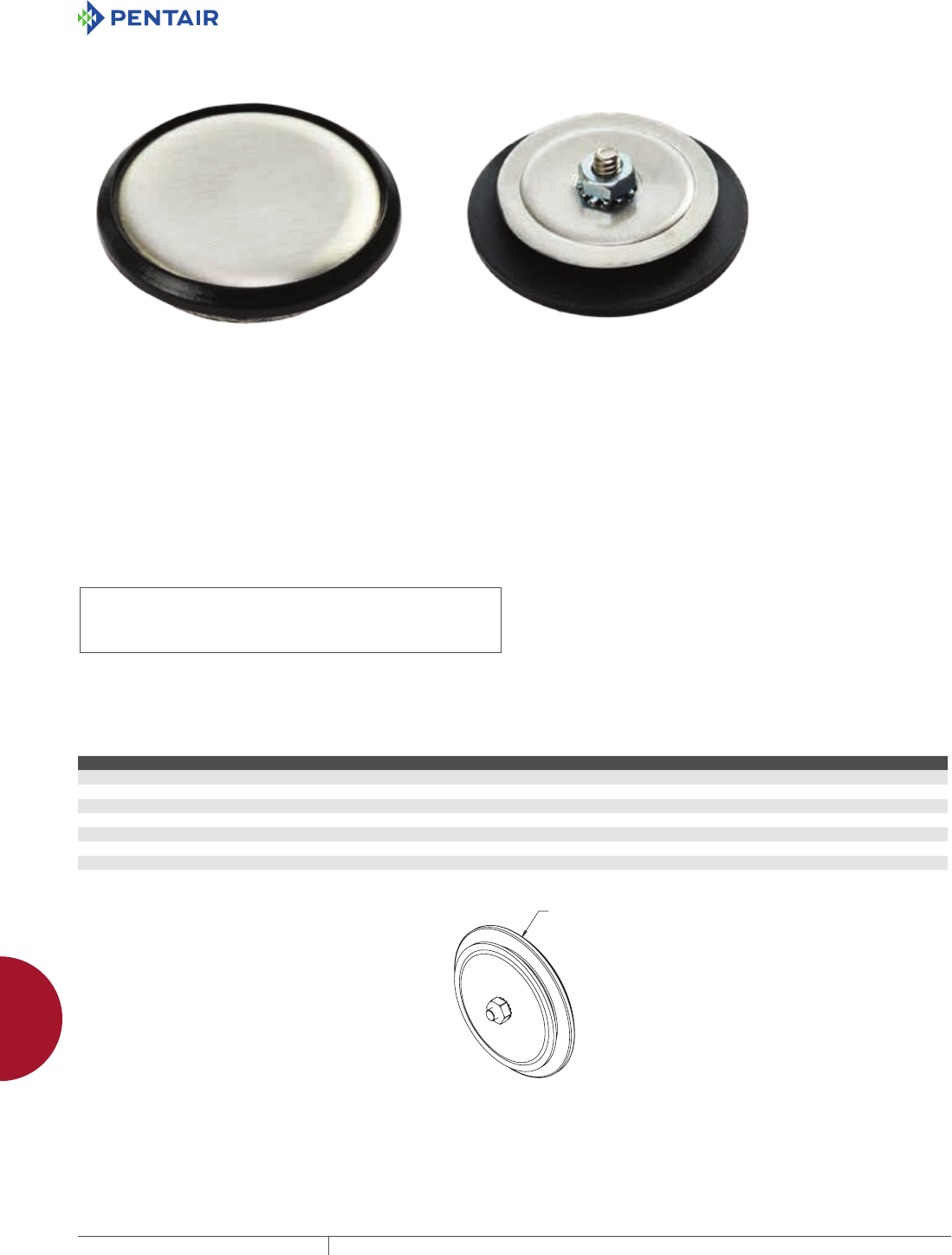
EQUIPMENT PROTECTIONSUBJECT TO CHANGE WITHOUT NOTICEACCESSORIES1006
12
HAZARDOUS LOCATION hazardous loCation aCCessories
HAZARDOUS LOCATION HOLE SEALS
INDUSTRY STANDARDS
IECEx and ATEX Approvals
Suitable for use on increased safety enclosures for ZONE 1 or ZONE
2 assemblies
ATEX Directive 94/9/EC
ATEX
Ex e IIC Gb
Ex tb IIIC Db IP 66
Sira 14ATEX3233U
IECEx
Ex e IIC Gb
Ex tb IIIC Db IP 66
IECEx SIR 14.0073U
UL 508A Component Recognized; Type 4, 4X,12, 3R; File No.
E61997
cUR Component Recognized per CSA C22.2 No. 94; Type 4, 4X, 12,
3R; File No. 42186
NEMA/EEMAC Type 3R, 4, 4X, 12
IEC 60529, IP66
APPLICATION
Hazardous Location Hole Seals are designed to be used on
Increased Safety (Ex e) enclosures in ATEX or IECEx Zone 1 or 2
hazardous areas. Certified to be used on metallic, non-painted
enclosures, these hole seals are made with a robust Type 316
stainless steel formed outer plate and a silicone rubber gasket to
ensure a dust-, oil- and water-tight seal. Designed to seal extra
pushbutton holes, conduit openings and knockout openings, these
self-centering hole seals are easy to install.
FEATURES
• Robust formed outer plates are made from Type 316 stainless
steel with a brushed finish
• Secure sealing with silicon rubber gasket to protect against water
and dust ingress in extreme temperature applications ranging
from -55 C (-67 F) to 180 C (356 F)
• Seal pushbutton holes, conduit openings and knockout openings
against dust, dirt, oil and water
• Easy installation in enclosure cutouts with self-centering hole
seals
• Hole seals are available in metric and english standard hole sizes
BULLETIN: HLY
Standard Product
Catalog Number Fits Hole Dia. (in.) Hole Dia. +.2.5/-.00 (mm) Assembly Dia. D (in.) Assembly Dia. D (mm)
EXAS050SS6 1/2-in. Conduit or M20 .787 - .885 20 1.36 35
EXAS075SS6 3/4-in. Conduit or M25 .984 - 1.082 25 1.71 43
EXAS100SS6 1-in. Conduit or M32 1.259 - 1.358 32 1.89 48
EXAS125SS6 1 1/4-in. Conduit or M40 1.574 - 1.673 40 2.33 59
EXAS150SS6 1 1/2-in. Conduit or M50 1.968 - 2.066 50 2.64 67
EXAS200SS6 2-in. Conduit or M63 2.480 - 2.578 63 3.14 80
EXAS250SS6 2 1/2-in. Conduit or M75 2.952 - 3.051 75 3.64 93
'

