Catalog LV52 · 2016 1000307539
2016-09-04
: Pdf 1000307539-Catalog 1000307539-Catalog B4 unilog
Open the PDF directly: View PDF ![]() .
.
Page Count: 226 [warning: Documents this large are best viewed by clicking the View PDF Link!]
- Catalog LV52 · 2016
- Related catalogs
- Terminal Blocks
- 00 Opening information
- 01 Introduction
- 02 8WH6 iPo Plug-In Terminals
- 03 8WH6 iPo Installation Terminals
- 04 8WH2 Spring-Loaded Terminals
- 05 8WH5 Combination Plug-In Terminals
- 06 8WH3 Insulation Displacement Terminals
- 07 8WH1 Screw Terminals
- Introduction
- General data on 8WH
- 8WH through-type terminals
- 8WH fuse terminals
- 8WH isolating blade terminals
- 8WH isolating terminals
- 8WH two-tier terminals
- 8WH two-tier terminals with isolating function/isolating blade
- 8WH measuring transformer terminals
- 8WH diode terminals
- 8WH two-tier diode terminals
- 8WH high-current terminals
- 8WH shield terminals
- 08 Accessories for 8WH Terminal Blocks
- 09 8WA1 Screw Terminals
- Introduction
- General data on 8WA
- 8WA through-type terminals
- 8WA N-conductor isolating and branch terminals
- 8WA Insta or three-tier terminals
- 8WA two-tier terminals
- 8WA two-tier terminals with electronic components
- 8WA diode and isolating terminals
- 8WA terminals for components
- 8WA fuse terminals
- 8WA through-type terminals with soldered and plug-in connection
- 8WA measuring transformer terminals
- 10 8WA2 Spring-Loaded Terminals
- 11 Accessories for 8WA Terminal Blocks
- 12 Appendix
- Catalog notes
- Ordering notes
- Support on UL topics
- ATEX explosion protection
- Further documentation
- Quality management
- Standards and approvals
- Siemens contacts
- Service & Support
- Comprehensive support from A to Z
- Software Licenses
- Subject index
- Article No. index incl. export markings
- Conditions of sale and delivery
- Catalogs
- Impressum
ALPHA FIX
Terminal Blocks
siemens.com/lowvoltage
Catalog
LV 52
Edition
2016
© Siemens AG 2015© Siemens AG 2015
Siemens LV 52 · 2016
Related catalogs Contents
Low-Voltage Power Distribution and LV 10
Electrical Installation Technology
SENTRON • SIVACON • ALPHA
Protection, Switching, Measuring and Monitoring
Devices, Switchboards and Distribution Systems
print (E86060-K8280-A101-A2-7600)
Standard-Compliant Components LV 11
for Photovoltaic Systems
SENTRON • SIVACON • ALPHA
print (E86060-K8270-A101-A2-7600)
Electrical Components for the LV 12
Railway Industry
SENTRON • ALPHA • DELTA
print (E86060-K1812-A101-A1-7600)
Components for Industrial Control LV 16
Panels according to UL Standards
SIRIUS • SENTRON • ALPHA
print (E86060-K1816-A101-A3-7600)
SIVACON LV 50
System Cubicles, System Lighting and
System Air-Conditioning
PDF (E86060-K1920-A101-A8-7600)
Air circuit breakers • Molded case circuit breakers • Miniature circuit bre-
akers • Residual current protective devices / AFDDs • Fuse systems •
Overvoltage protection devices • Switch disconnectors • Switching
devices • Transformers, power supply units and socket outlets • Busbar
systems • Measuring devices and power monitoring • Monitoring devices
• Software • Switchboards • Busbar trunking systems • System cubicles,
system lighting and system air-conditioning • Distribution boards •
Molded-plastic distribution systems • 8WH2 spring-loaded terminals
Products for the DC side • Products for the AC side • Measuring
and monitoring devices • Distribution systems and system
cubicles • Terminal blocks
Miniature circuit breakers • Residual current protective
devices • Fuse systems • Switch disconnectors • Switching
devices • ALPHA FIX terminal blocks • DELTA profil • Medium-
Voltage components
Circuit breakers • Air circuit breakers/Molded case switches •
Molded case circuit breakers • Miniature circuit breakers • Fuse
systems • Switch disconnectors • Switching devices • Socket
outlets • Busbar systems • Measuring devices and power moni-
toring • Molded-plastic distribution systems • Terminal blocks
System overview • Frame • Enclosure • Expansion •
Preconfigured cubicles • Special cubicles •
SIVACON 8MF/8MR system lighting • SIVACON 8MR system
air-conditioning
Industry Mall / CA 01 Catalog PDF / Response E-mail
Industry Mall
Information and Ordering Platform
in the Internet:
www.siemens.com/industrymall
Products for Automation and Drives CA 01
Interactive Catalog, DVD
E86060-D4001-A510-D6-7600
Catalog PDF
Digital versions of the catalogs are available in
the Information and Download Center.
www.siemens.com/lowvoltage/infomaterial
Response E-mail
Please send your comments and suggestions
for improvement to
catalogs.industry@siemens.com
(include the catalog name in the subject field)
Trademarks
All product designations may be registered trademarks or
product names of Siemens AG or other supplying companies.
Third parties using these trademarks or product names for their
own purposes may infringe upon the rights of the trademark
owners. Further information about low-voltage power distribu-
tion and electrical installation is available on the Internet at:
www.siemens.com/lowvoltage
Technical Support
Expert advice on technical questions with a
wide range of demand-optimized services
for all our products and systems.
www.siemens.com/lowvoltage/contact
© Siemens AG 2015
Introduction 1
8WH
8WH6 iPo Plug-In Terminals 2
8WH6 iPo Installation Terminals 3
8WH2 Spring-Loaded Terminals 4
8WH5 Combination Plug-In Terminals 5
8WH3 Insulation Displacement Terminals 6
8WH1 Screw Terminals 7
Accessories for 8WH Terminal Blocks 8
8WA
8WA1 Screw Terminals 9
8WA2 Spring-Loaded Terminals 10
Accessories for 8WA Terminal Blocks 11
Appendix 12
Terminal Blocks
ALPHA FIX
Catalog LV 52 · 2016
Supersedes:
Catalog LV 52 · 2015
Refer to the Industry Mall for current updates of this
catalog:
www.siemens.com/industrymall
The products contained in this catalog can also be found
in the Interactive Catalog CA 01.
Article No.: E86060-D4001-A510-D6-7600
Please contact your local Siemens branch.
© Siemens AG 2015
The products and systems listed in this
catalog are developed and manufactured
using a certified quality management system
in accordance with EN ISO 9001:2008.
© Siemens AG 2015

2Siemens LV 52 · 2016
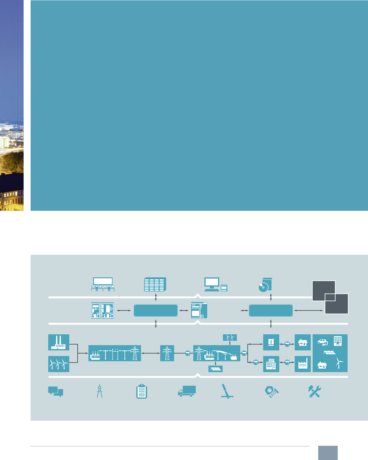
Totally Integrated Power
We bring power to the point –
safely and reliably.
A reliable, highly available and flexible power supply for industries and for buildings and
facilities across all voltage levels is the basis for both industrial processes and infrastructure
solutions. The solution from Siemens is Totally Integrated Power (TIP), which is linked closely
to industrial and building automation systems and into which a company's IT systems can be
integrated. This makes it possible to fully exploit the entire optimization potential of an
integrated solution. TIP meets even the highest of requirements of systems that are critical
in terms of power supply.
TIP is our comprehensive power supply portfolio that contains software and hardware
products, systems and solutions for all voltage levels – from the high-voltage power infeed
to the low-voltage load. Comprehensive support throughout the lifecycle from planning to
maintenance round off our offer.
More information: www.siemens.com/tip
Comprehensive solutions for electricity
distribution in complex power systems
from Siemens
© Siemens AG 2015© Siemens AG 2015
3
Siemens LV 52 · 2016
Consulting,
planning
Grid
control
Grid
applications
Open communication
standards
Open communication
standards
Big Data Planning and
simulation
Power grid
automation
Power automation
for industries and
buildings
Project-
management
Engineering,
network design
Ordering,
delivery
Installation,
commissioning
Operation
and after-
sales service
Services,
modernization
Electrification
Automation
Digitalization
TIA
TBS
Totally Integrated Power offers more:
•Consistency:
For simplified system planning and commissioning and also easy integration in automation solutions
for buildings or production processes
•Everything from a single source:
One reliable partner with a complete portfolio for the entire process and lifecycle –
from the first idea to after-sales service
•Safety:
Comprehensive range of protective components for cable, personal and fire protection,
safety thanks to design and type tests
•Reliability:
A reliable partner that develops long-lasting solutions with the highest quality standards
together with the customer
•Cost-effectiveness:
Bringing power to the point means higher system availability and top energy efficiency
in power distribution
•Flexibility:
Consistency and modularity of Totally Integrated Power for any required expandability and
adaptation to future requirements
•Progressive technology:
Reliable power supply especially in the case of supply-critical applications,
continuous enhancement of technology
Challenges are our strength
© Siemens AG 2015© Siemens AG 2015
4Siemens LV 52 · 2016
The right one for everyone
Our portfolio includes switchboards,
distribution boards, protection, switching,
measuring and monitoring devices,
switches and socket outlets. All over the
world, the universality, modularity and
efficiency of our components and systems
give you innumerable benefits – all the
time they are in use. With products
developed according to the respective
international standards, we offer forward-
looking design with innovative functions
while ensuring the highest quality
standards worldwide.
Sustainability in focus
As one of the worldwide leaders in the
provision of high-quality, standard-
compliant products and systems for
low-voltage power distribution, we
contribute to the sustainable and responsi-
ble handling of electrical energy. With our
integrated portfolio which ranges from
power supply and distribution, through
short-circuit and overload protection
through to power monitoring, we support
the implementation of environmentally
friendly energy concepts based on wind
power, photovoltaics, intelligent buildings
and electromobility.
© Siemens AG 2015© Siemens AG 2015

5
Siemens LV 52 · 2016
Universal, safe and efficient
power distribution
Whether in industrial plants, in infrastructure or in buildings:
every technical plant depends on the reliable supply of electricity. Our products provide a
safe, reliable and efficient electrical infrastructure at the medium and low-voltage levels.
Our components reliably protect against accidents, faults and fires caused by electrical in-
stallations and allow consumers to utilize electrical power in a sustainable, responsible
manner. We are happy to help you with comprehensive support from the initial informa-
tion stage through to operation.
Everything for power distribution
End-to-end solutions are required for
electrical power distribution in buildings.
Our answer is Totally Integrated Power
(TIP). TIP stands for innovative products,
systems and software tools which ensure
the safe and reliable distribution of electric
power. They are supplemented by circuit
breakers and modules with communication
capability which connect the power distri-
bution system to the building automation
or industrial automation solutions. These in
turn can be linked to a comprehensive
energy management system which con-
tributes to optimizing the consumption of
electricity, hence lowering the costs of
operation.
Excellent support
As a competent and reliable partner, we
also offer you comprehensive support –
from the initial information gathering
stage, through planning, configuring and
ordering up to commissioning, operation
and technical support. We know the needs
of your working environment and your
daily business. This enables us to offer you
flexible and high quality support, allowing
you to concentrate on your customers and
their needs.
© Siemens AG 2015© Siemens AG 2015

6Siemens LV 52 · 2016
Planning Efficiency
■
Overview
With Planning Efficiency, Siemens supplies answers to typical
questions that often present themselves in electrical
planning:
• What is the appropriate product for my application?
• Where can I find product data?
• How can I make processes more efficient and save more
time?
The entire electronic support offered by Siemens is merged
under Planning Efficiency. At each phase of the project,
online functions make the everyday work of the planners
easier and more efficient. Planning Efficiency focuses on
optimizing the control cabinet configuration among other
things.
Especially in this early phase, up to 80% of time and costs
can be saved.
In order to supply the planners with all they need and to
simplify the modern electrical planning of every aspect of the
control cabinet configuration, the electrical support of
Planning Efficiency focuses on four benefits:
• Finding the right product faster using intuitive product
selection
• Time savings of up to 80 % with universal product data for
your CAE and CAD systems
• User-friendly compilation of project-specific
documentation
• Comprehensive support –
at any time, whatever your location
© Siemens AG 2015© Siemens AG 2015
7
Siemens LV 52 · 2016
Process phases
At each phase of the process, Siemens provides
comprehensive online functions free of charge. This ensures that all the necessary information and product
data are available around the clock at any location
worldwide.
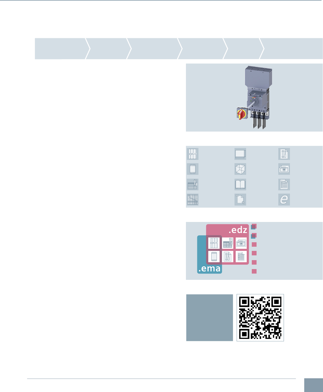
Configurators for products and systems
With just a few mouse clicks, you will find yourself guided by
the configurator to a suitable product or system. Simply enter
the relevant parameters and select your individual solution.
CAx Download Manager
The CAx Download Manager can supply you with all the
necessary CAx file types for the products of your choice for
use in all common CAE and CAD systems. The data
contained in the files is continuously updated. The whole
process involves only four selection steps and is free of
charge. All the files you select will then be compiled into a zip
file and made available for you to download for further use.
This results in a time saving of up to 80 % because there is no
need for manual data collection thanks to the universal
manufacturer data for all commonly used CAE and
CAD systems.
My Documentation Manager
To provide support when creating the plant documentation,
we have developed a manual configurator. My Documenta-
tion Manager enables you to assemble the standard-compli-
ant plant documentation individually with just a few clicks of
the mouse. Simply select the required sections from the exist-
ing manuals of the installed Siemens products.
EPLAN Electric P8 Macro – a big plus for EPLAN users
Using the EPLAN Electric P8 Macro in .edz exchange format
(EPLAN Data Archived Zipped) the overall time required for
data integration can be further reduced. With just a few
clicks, the data types for any number of article numbers can
be imported and combined. In this way, it is possible for the
installed Siemens products to be displayed across different
pages of the circuit diagram quickly and easily.
At a glance
Without Planning Efficiency a lot of time would often be lost
due to manual data transmission. Now you are able to
concentrate on the essentials. All necessary information and
product data is provided by Siemens for easy retrieval.
This makes the control cabinet configuration process more
efficient and simplifies your everyday work.
For more information, see
www.siemens.com/planning-efficiency.
The configurator supplies the appropriate 3D models and dimension
drawings for the control cabinet construction diagram.
The CAx Download-Manager makes 11 universal data types
available, as well as the EPLAN Electric P8 macro.
The EPLAN Electric P8 macro in .edz exchange format offers even
more compared to the .ema exchange format.
Find out more about
Planning Efficiency in our informative videos
Mechanical
design
Concept &
selection
Electrical
design
Plant
documentation
Installation / service /
commissioning /
diagnostics
Ordering
EPLAN Electric
P8 Macros
Data sheets
Certificates
Product images
Characteristic
curves
Operating
instructions
Manuals
Product
master data
3D models
Terminal connection
diagrams
Dimensional
drawings
Internal circuit
diagrams
IC01_00265
Internal circuit diagrams
Connection diagrams
Product master data
Operating Instructions
Product pictures
Data sheets
IC01_00264
Planning Efficiency
© Siemens AG 2015© Siemens AG 2015

8Siemens LV 52 · 2016
P
l
a
n
n
i
n
g
C
o
n
f
i
g
u
r
a
t
i
o
n
O
r
d
e
r
i
n
g
Still have
questions?
Our experts will help
you with competent
specialist support
S
e
r
v
i
c
e
O
p
e
r
a
t
i
o
n
C
o
m
m
i
s
s
i
o
n
i
n
g
I
n
f
o
r
m
a
t
i
o
n
Competent and fast
specialist advice on:
• Product selection
• Commissioning
• Issues during operation
• Possible special versions
• Special requirements
• Product features
• Device communication
Technical
Support
Technical
Support
I201_19185
Technical Support
The Technical Support for low-voltage power distribution and electrical
installation technology assists you with all your technical queries about
our products and systems – both before and after delivery.
Technical Support – fast online access to the latest
information (Service and Support)
www.siemens.com/lowvoltage/product-support
In Product Support you will find FAQs, manuals, certificates,
applications and tools, etc.
Support Request – the quickest route to the experts
www.siemens.com/lowvoltage/technical-support
You can put your question directly to our Technical Support
team using the Support Request Form in Online Support.
Conversion tool – the easy and efficient way of finding
successor products
www.siemens.com/lowvoltage/conversion-tool
The benefits for you
• Response within 4 hours in 93% of cases
• Direct support from an experienced team of engineers
and technicians
Get all the information you need – with just one click
© Siemens AG 2015© Siemens AG 2015

9
Siemens LV 52 · 2016
Get all the information you need –
with just one click
www.siemens.com/lowvoltage/lv-explorer
Windenergy Support Last viewed
3VA Molded Case Circuit Breakers
SENTRON
Protection, Switching, Measuring
and Monitoring Devices
SIVACON
Switchboards and
Busbar Trunking Systems
ALPHA
Distribution Systems
and Terminal Blocks
Photovoltaik
Industry
Infrastructure
Catalog LV 10 • 2015: SENTRON •
SIVACON • ALPHA (English)
I201_19157
Planning/Orders
– Industry Mall
– Configuration
– SIMARIS Planning Tools
– CAx-Download-Manager
Operation/Service
– Siemens Industry
Online Support (SIOS)
– My Documentation
Manager
– Technical Support
– Support Request
Training
– SITRAIN Portal
Information
– Website
– Catalogs & Brochures
– Newsletter
– Picture Database
www.siemens.com/lowvoltage/support
I201_19079
LV Explorer – Discover
Low Voltage in 3D
Get comprehensive and
specific information
about our products using
our 3D animations,
trailers and technical
information.
Always at your service
– every step of the way
We offer comprehensive
support, from planning
and configuration to
operation.
© Siemens AG 2015© Siemens AG 2015

10 Siemens LV 52 · 2016
Notes
© Siemens AG 2015© Siemens AG 2015

Siemens LV 52 · 2016
For further technical
product information:
Siemens Industry Online Support:
www.siemens.com/lowvoltage/product-
support .
→
Application example
Certificate
Characteristic
Download
FAQ
Manual
Product note
Software archive
Technical data
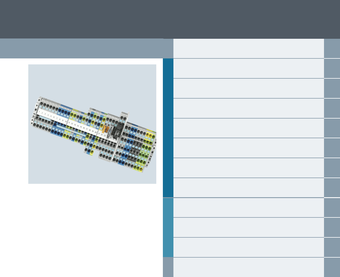
1
1
8WH and 8WA terminal blocks
1/2 General data
1/3
Support rails/protective conductor
busbars
8WH terminal blocks
1/4 8WH order selection
Introduction
© Siemens AG 2015© Siemens AG 2015
1/2 Siemens LV 52 · 2016
General data
Introduction
8WH and 8WA Terminal Blocks
1
■
Overview
Rated short-time withstand current
Our terminals are able to withstand a rated short-time current
corresponding to a current density of 120 A/mm2 specific to the rated cross-section for one second.
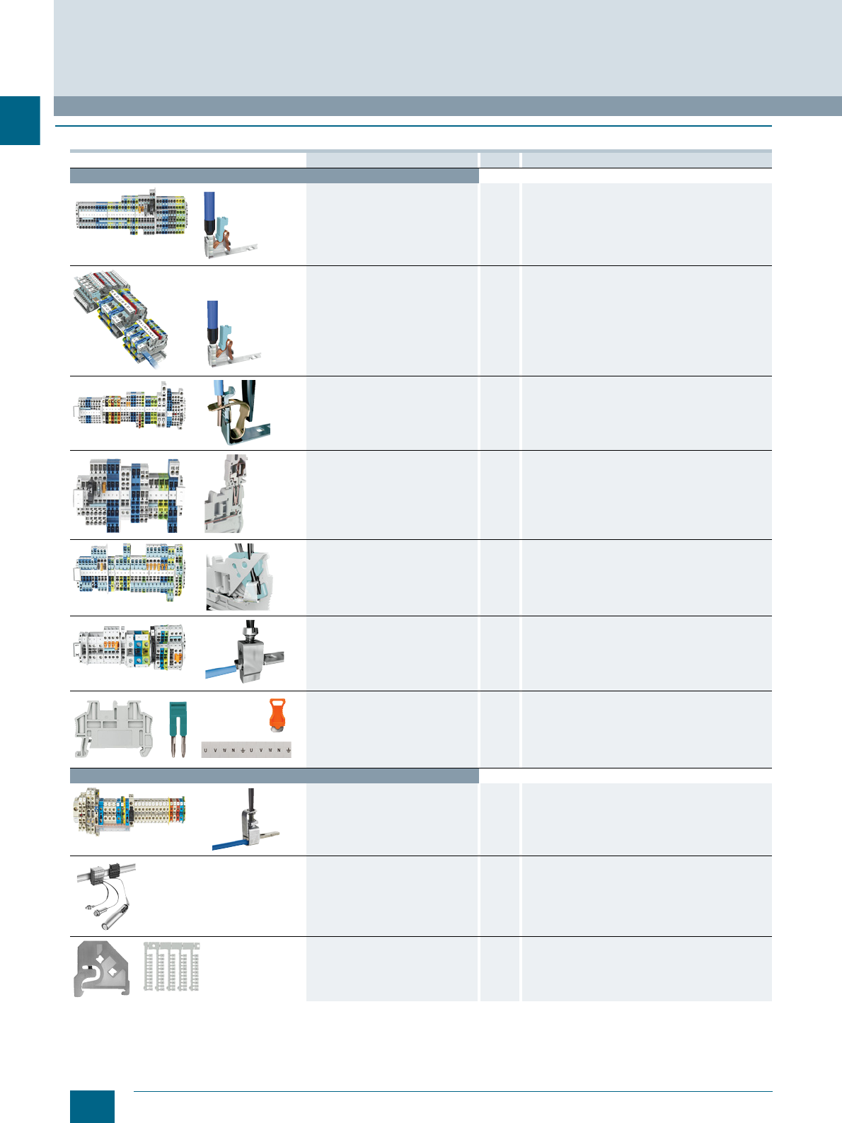
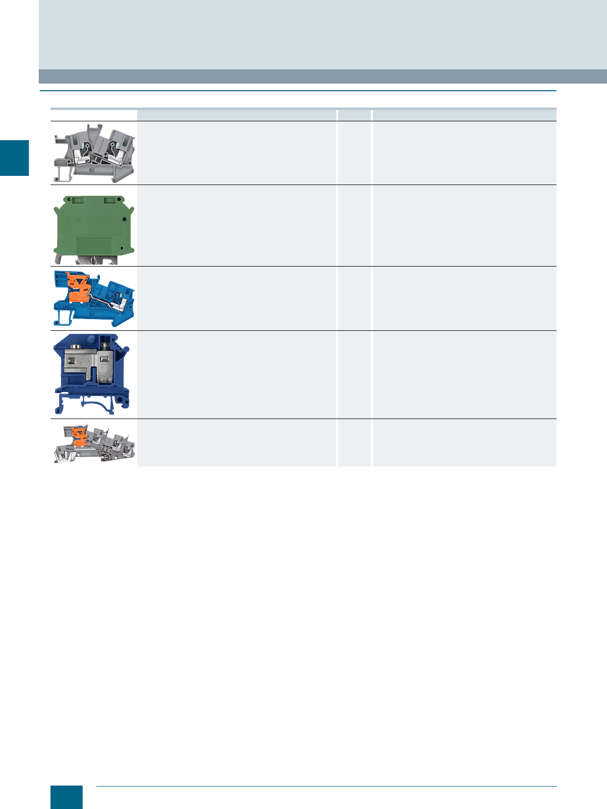
Connection system Section Special features
8WH Terminal Blocks
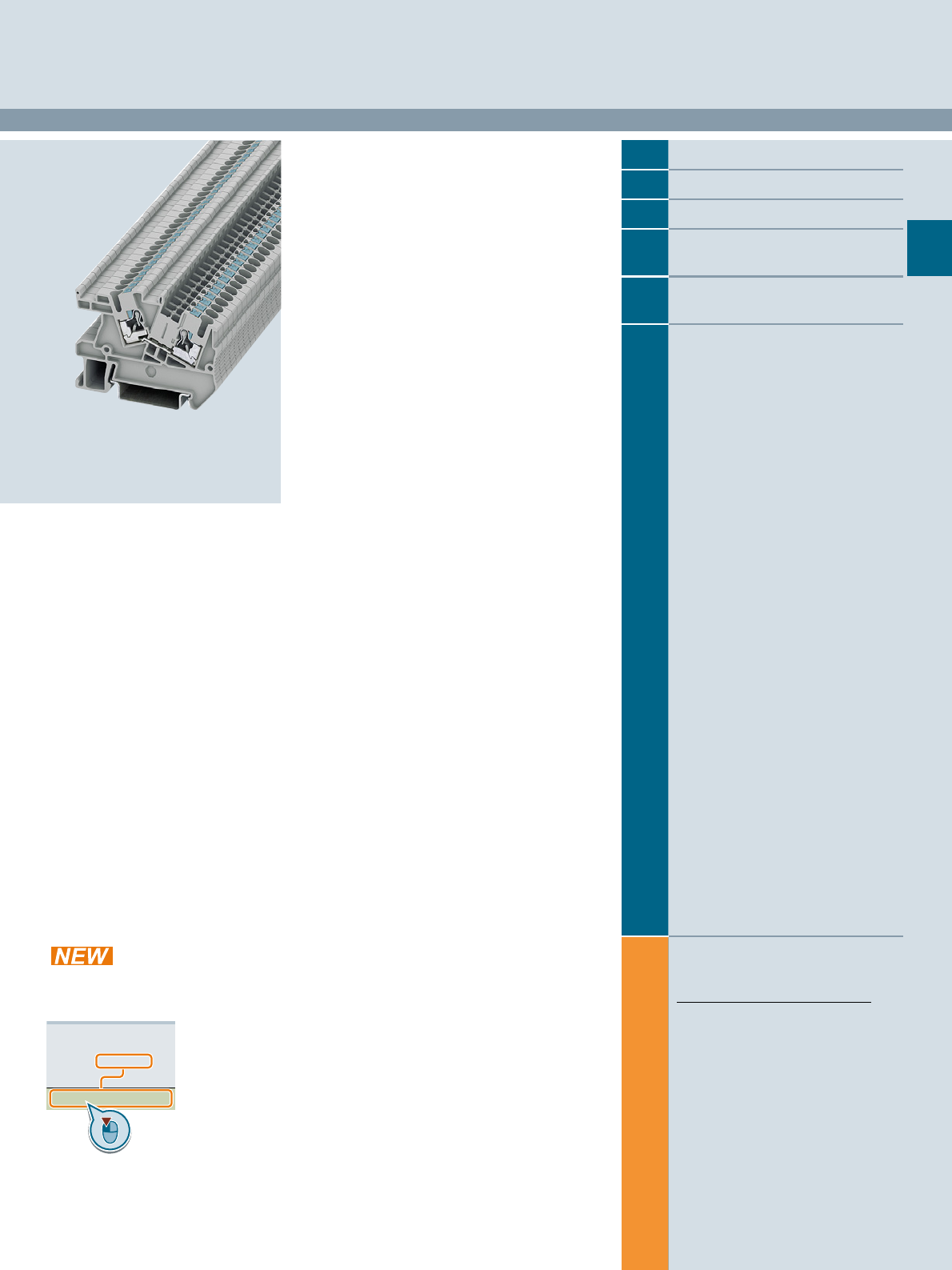
8WH6 iPo plug-in terminals
(iPo: in-Push-out) 2The iPo connection method combines the advantages
of spring-loaded and plug-in terminals – both rigid and
flexible wires are easy to insert without the need for
tools. Fast installation – with a minimum of effort and
maximum contact stability.
8WH6 iPo installation terminals 3The iPo connection method combines the advantages
of spring-loaded and plug-in terminals – both rigid and
flexible wires are easy to insert without the need for
tools. Fast installation – with a minimum of effort and
maximum contact stability.
Fast removal by simply pressing the unlatching button.
8WH2 spring-loaded terminals 4With the spring-loaded connection method, the tension
spring exerts constant pressure on the conductor, which
ensures excellent contact stability – even with applica-
tions subject to high levels of vibration.
Fast removal by simply pressing the unlatching button.
8WH5 combination plug-in terminals 5Combination plug-in terminals are used where high
availability is essential in the event of a fault. The con-
tact system is able to withstand even extreme levels of
vibration and both the terminal and the connector are
fingerproof.
8WH3 insulation displacement
terminals 6Thanks to the use of insulation displacement terminals,
there is no need to strip the conductor. This ensures se-
cure contact between the conductor and the connecting
wire of the terminal.
8WH1 screw terminals 7The screw terminals have an impressively compact de-
sign and offer optimum handling. The elastic deforma-
tion capability of the terminal body prevents any creep-
age of the clamped conductor. Suitable for applications
up to 1000 V DC.
Accessories for 8WH 8The 8WH accessories supplement the 8WH product
range with the additional components required for
installation.
8WA terminal blocks
8WA1 screw terminals 9The tried and tested screw terminals are insulated on
both sides and enclosed at both ends. These terminals
are extremely robust and can withstand high mechani-
cal and thermal loads.
8WA2 spring-loaded terminals
• 8WA2 initiator/actuator terminals
10 Fast and cost-effective connection of signal transmit-
ters.
Accessories for 8WA 11 The 8WA terminal block accessories supplement the
8WA product range with the additional components
required for installation.
© Siemens AG 2015© Siemens AG 2015
1/3
Siemens LV 52 · 2016
Introduction
8WH and 8WA Terminal Blocks
Support rails/protective conductor busbars
1
■
Overview
1) Cross-sections calculated acc. to IEC 60439-1 / EN 60 439-1 / EN 60439-1 / VDE 0660 Part 500.
2) Steel protective conductor busbars are not permissible for PEN function.
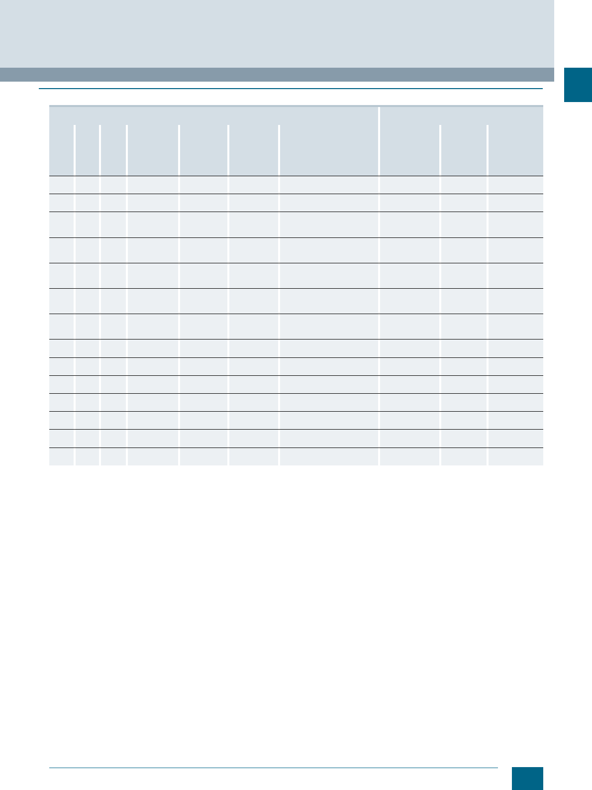
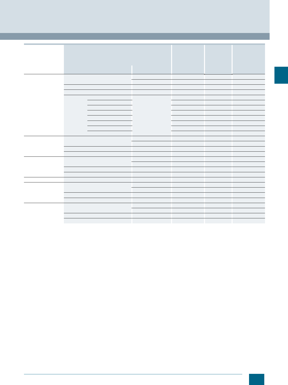
Support rail type Excerpt from IEC 60947-7-2/EN 60947-7-2/
VDE 0611 Part 3
Width Height Thick-
ness Perforation
type Material Surface Rail profile Short-circuit
strength
(Cu conductor)
Short-time
withstand
current, 1 s
Max.
permissible
thermal rated
current with
PEN function
mm mm mm mm² 1) kA A
35 7.5 1.5
Non-perforated
Steel Chromated Standard mounting rail,
acc. to EN 60 715 – 35 × 7.5 16 1.92 1)
35 7.5 1.5
With holes
Steel Chromated Standard mounting rail,
acc. to EN 60 715 – 35 × 7.5 16 1.92 2)
35 7.5 1.5
Non-perforated
Steel Galvanized Standard mounting rail,
dimensions acc. to
EN 60 715 – 35 × 7.5
16 1.92 2)
35 7.5 1.5
With holes
Steel Galvanized Standard mounting rail,
dimensions acc. to
EN 60 715 – 35 × 7.5
16 1.92 2)
35 7.5 1.5
Non-perforated
V2A high-
grade steel Chromated Standard mounting rail,
dimensions acc. to
EN 60 715 – 35 × 7.5
16 1.92 2)
35 7.5 1.5
Non-perforated
Copper Chromated Standard mounting rail,
dimensions acc. to
EN 60 715 – 35 × 7.5
50 6.0 150
35 7.5 1.5
Non-perforated
Aluminum Chromated Standard mounting rail,
dimensions acc. to
EN 60 715 – 35 × 7.5
35 4.2 125
35 15 2.3
Non-perforated
Steel Chromated Standard mounting rail,
acc. to EN 60 715 – 35 × 15 50 6.0 2)
35 15 1.5
Non-perforated
Steel Chromated Standard mounting rail,
similar to EN 60 715 – 35 × 15 35 4.2 2)
35 15 1.5
With holes
Steel Chromated Standard mounting rail,
similar to EN 60 715 – 35 × 15 35 4.2 2)
35 15 1.5
Non-perforated
Steel Galvanized Standard mounting rail,
similar to EN 60 715 – 35 × 15 35 4.2 2)
35 15 1.5
With holes
Steel Galvanized Standard mounting rail,
similar to EN 60 715 – 35 × 15 35 4.2 2)
35 15 1.5
Non-perforated
Copper Chromated Standard mounting rail,
similar to EN 60 715 – 35 × 15 95 11.4 232
35 15 1.5
Non-perforated
Aluminum Chromated Standard mounting rail,
similar to EN 60 715 – 35 × 15 70 8.4 192
© Siemens AG 2015© Siemens AG 2015
1/4 Siemens LV 52 · 2016
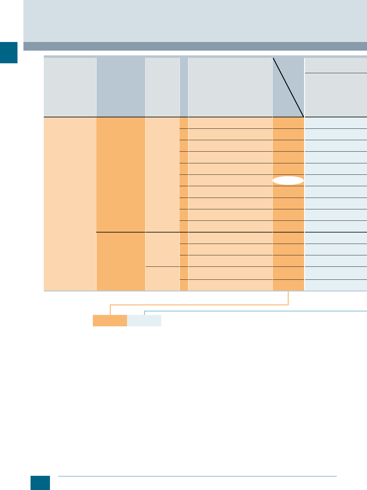
8WH order selection
Introduction
8WH Terminal Blocks
1
Insta terminal: Plug-in design · 5 connection points
2.5 mm2 · Range of functions
Article No., e.g.
Terminal type
Connection type
Design
Number of terminals
Version
MLFB digits 1...9
Installation terminals iPo Standard
L/L
L/N
PE/L/L
PE/L/N
PE/L/NT
PE/L/N isolating blade
PE/L/L isolating blade
PE/L/L through-type term. for isolat. term.
PE/L/L isolation
Spring-loaded
terminals
Two-tier L/PE
N/PE
N/L
Three-tier PE/L/N
PE/L/L
MLFB digits 8...12
8WH6001-
8WH6001-
8WH6001-
8WH6001-
8WH6001-
8WH6001-
8WH6001-
8WH6001-
8WH6001-
8WH2020-
8WH2020-
8WH2020-
8WH2030-
8WH2030-
8WH6001-
4
4
5
5
5
5
5
5
5
4
4
4
6
6
2L
8WH6001- 4FF00
© Siemens AG 2015© Siemens AG 2015
1/5
Siemens LV 52 · 2016
Introduction
8WH Terminal Blocks
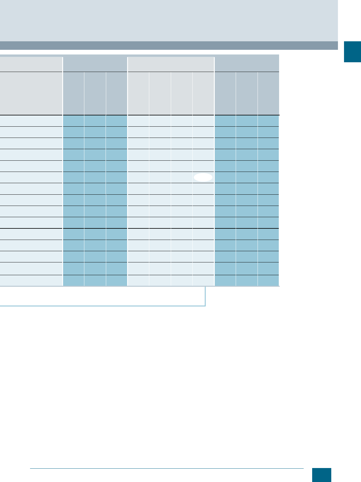
8WH order selection
1
1.5 mm
2
2.5 mm
2
4 mm
2
Through-type
terminal, gray
Through-type
terminal, blue
PE terminal,
green/yellow
Through-type
terminal, gray
Through-type
terminal, blue
PE terminal
Terminals
with range of
functions
Through-type
terminal, gray
Through-type
terminal, blue
PE terminal,
green/yellow
I201_18327a
4QF00
4DF00
4CF00
4HF00
4EF00
4GF00
4NF00
4PF00
4MF00
4AF00
4BF00
4CF00
4EF00
4HF00
4FF00
© Siemens AG 2015© Siemens AG 2015
1/6 Siemens LV 52 · 2016
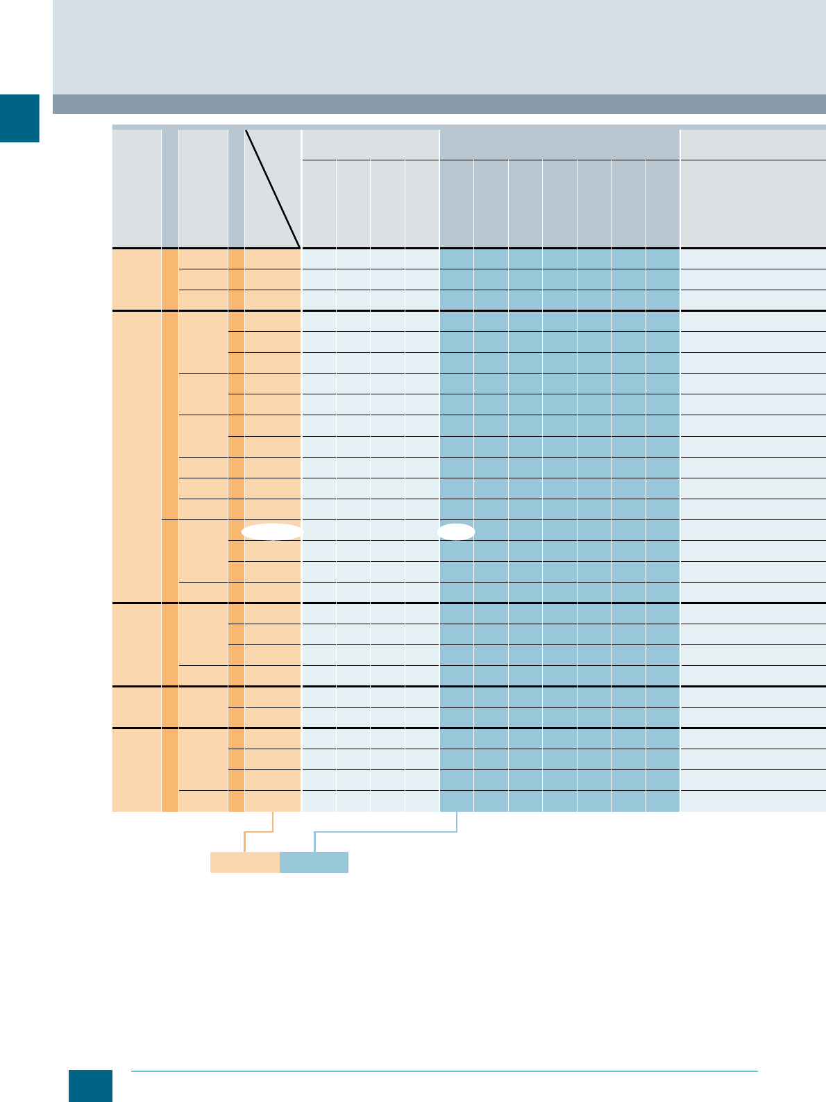
8WH order selection
Introduction
8WH Terminal Blocks
1
Standard terminal: Spring-loaded terminal· compact ·
2 connection points · 2.5 mm2 · Through-type terminal, gray
Article No., e.g.
Connection type
Terminals
Design
Number of terminals
MLFB digits 1...7
1.5 mm
2
2.5 mm
2
Through-type
terminal, gray
Through-type
terminal, colored
Through-type
terminal, blue
PE terminal,
green/yellow
Through-type
terminal, gray
Through-type
terminal, colored
Through-type
terminal, blue
Instrument isolat-
ing terminal, blue
Isolating terminal,
gray
Instrument isolat-
ing terminal, gray
PE terminal
green/yellow
Screw
terminal
Standard
Two-tier
Two-tier
Spring-
loaded
terminal
Standard
Two-tier
Two-tier
1-pole
Three-tier
Three-tier
Four-tier
Molded-case
Two-tier
iPo
Standard
Two-tier
Combi-
nation
plugs
Standard
Insulation
displace-
ment
terminal
technology
(IDC)
Standard
Two-tier
MLFB digits 8...12
8WH2500- 0AF00
2 8WH1000- 0AF00 0AF01 0CF07
4 8WH1020- 0AF00 0AF01 0CF07
4 8WH1025- 0AF00
2 8WH2000- 0AE00 0AE01) 0AE01 0CE07 0AF00 0AF01) 0AF01 6AF00 6CF00 0CF07
3 8WH2003- 0AE00 0AE01 0CE07 0AF00 0AF01 6AF00 6CF00 0CF07
4 8WH2004- 0AE00 0AE01 0CE07 0AF00 0AF01 6CF01 6AF00 6CF00 0CF07
4 8WH2020- 0AE00 0AE01 0CE07 0AF00 0AF01 0CF07
6 8WH2023- 0AF00 0AF01 0CF07
6 8WH2022- 0AF00
4 8WH2025- 0AE00 0AF00 0AF01
6 8WH2030- 0AF00 0AF01
6 8WH2035- 0AF00 0CF07
8 8WH2040- 4LF00
2 0AF01 6AF00 6CF00 0CF07
3 8WH2503- 0AF00 0AF01 0CF07
4 8WH2504- 0AF00 0AF01 0CF07
4 8WH2520- 0AF00 0AF01 0CF07
2 8WH6000- 0AF00 0AF01 0CF07
3 8WH6003- 0AF00 0AF01 0CF07
4 8WH6004- 0AF00 0AF01 0CF07
4 8WH6020- 0AF00 0AF01 0CF07
2 8WH5000- 0AF00 0AF01 0CF07
4 8WH5004- 0AF00 0AF01 0CF07
2 8WH3000- 0AE00 0AE01 0CE07 0AF00 0AF01 0CF07
3 8WH3003- 0AE00 0AE01 0CE07 0AF00 0AF01 0CF07
4 8WH3004- 0AE00 0AE01 0CE07
4 8WH3020- 0AE00 0AE01 0CE07
8WH2500- 0AF00
© Siemens AG 2015© Siemens AG 2015
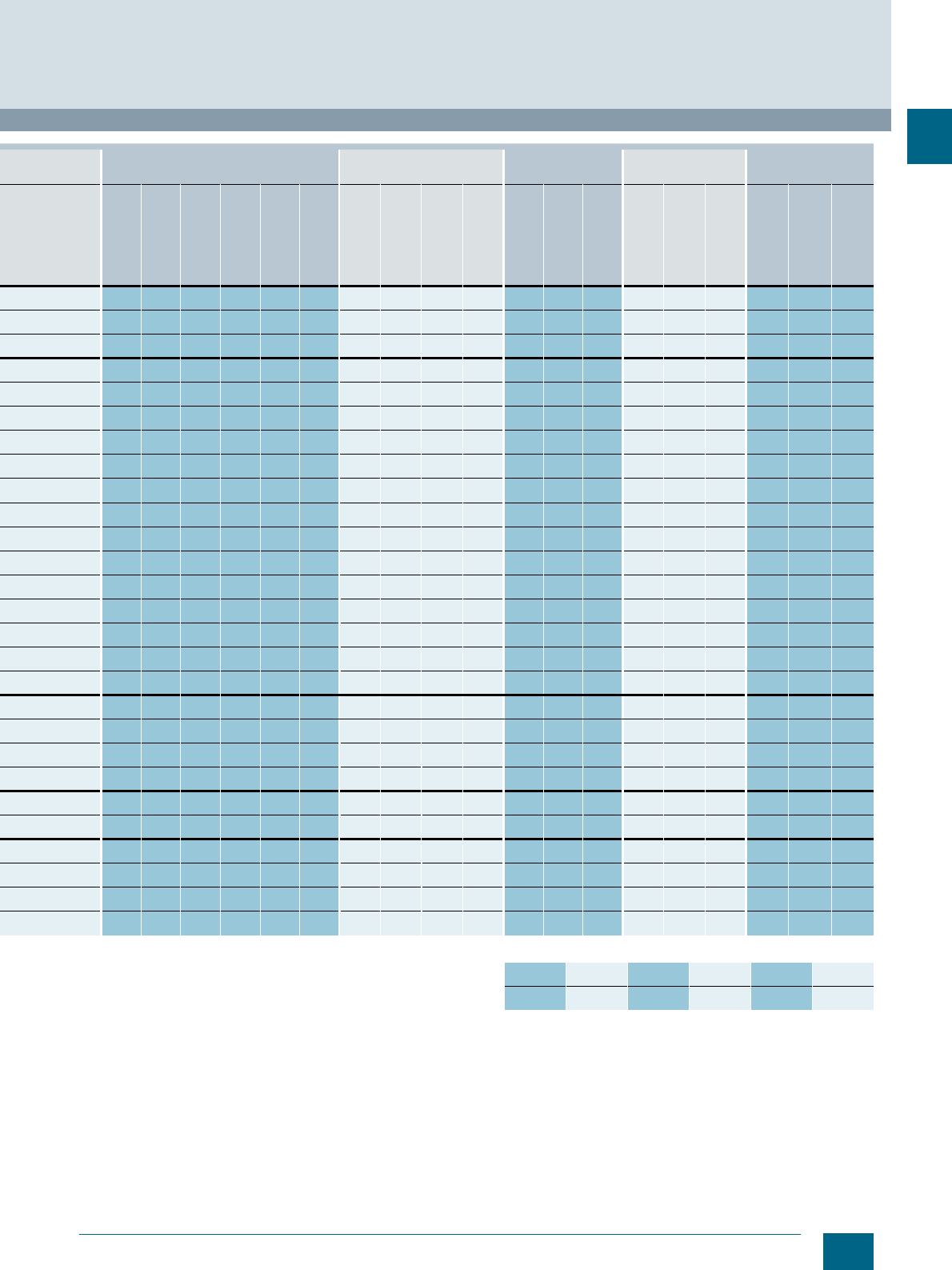
1/7
Siemens LV 52 · 2016
Introduction
8WH Terminal Blocks
8WH order selection
1
4 mm
2
6 mm
2
10 mm
2
16 mm
2
35 mm
2
Through-type
terminal, gray
Through-type
terminal, colored
Through-type
terminal, blue
Isolating terminal,
Gray
Instrument isolat-
ing terminal, gray
PE terminal,
green/yellow
Through-type
terminal, gray
Through-type
terminal, blue
Isolating termi-
nal, blue
PE terminal,
green/yellow
Through-type
terminal, gray
Through-type
terminal, blue
PE terminal,
green/yellow
Through-type
terminal, gray
Through-type
terminal, blue
PE terminal,
green/yellow
Through-type
terminal, gray
Through-type
terminal, blue
PE terminal
green/yellow
Red Green Orange White Yellow Black
I201_18328a
g
g
g
0AG00 0AG01 6AG00 6CG00 0CG07 0AH00 0AH01 6AH00 0CH07 0AJ00 0AJ01 0CJ07 0AK00 0AK01 0CK07 0AM00 0AM01 0CM07
0AG00 0AG01 6AG00 6AC00 0CG07
0AG00
0AG00 0AG01) 0AG01 6AG00 6CG00 0CG07 0AH00 0AH01 0CH07 0AJ00 0AJ01 0CJ07 0AK00 0AK01 0CK07 0AM00 0AM01 0CM07
0AG00 0AG01 0CG07 0AH00 0AH01 0CH07
0AG00 0AG01 0CG07 0AH00 0AH01 0CH07
0AG00 0AG01 0CG07
0AG00
4GL00
0AG00 0AG01 0CG07 0AH00 0AH01 0CH07
0AG00 0AG01 0CG07 0AH00 0AH01 0CH07
0AG00 0AG01 0CG07
0AG00 0AG01 0CG07
0AG00 0AG01 0CG07 0AH00 0AH01 0CH07 0AJ00 0AJ01 0CJ07 0AK00 0AK01 0CK07 0AM00 0AM01 0CM07
0AG00 0AG01 0CG07
0AG00 0AG01 0CG07
0AE02 0AE03 0AE04 0AE05 0AE06 0AE08
1)
© Siemens AG 2015© Siemens AG 2015

1/8 Siemens LV 52 · 2016
Notes
Introduction
1
© Siemens AG 2015© Siemens AG 2015
Siemens LV 52 · 2016
For further technical
product information:
Siemens Industry Online Support:
www.siemens.com/lowvoltage/product-
support .
→
Application example
Certificate
Characteristic
Download
FAQ
Manual
Product note
Software archive
Technical data
2
2
2/2
Introduction
2/3
General data
2/4
8WH6 through-type terminals
2/11
8WH6 fuse terminals
2/12
8WH6 isolating blade terminals
2/14
8WH6 isolating terminals
2/16
8WH6 two-tier terminals
8WH6 iPo Plug-In Terminals
Direct reference to the products in the
Industry Mall from the selection and
ordering data tables:
3VA2025-5HL36-0AA0
Article No.
www.siemens.com/
product? Article No.
Paper catalog:
To get more
product information
enter the Web
address plus
Article No.
PDF catalog:
Get more product information
with just a mouse click.
© Siemens AG 2015© Siemens AG 2015
2/2 Siemens LV 52 · 2016
Introduction
8WH6 iPo Plug-In Terminals
2
■
Overview
Devices Page Function
Through-type terminals 2/4 Connection of incoming and outgoing conductors
Fuse terminals 2/11 Terminals which can be used to protect control circuits,
for example
Isolating blade terminals 2/12 Isolation of the circuit, e.g. for test purposes
Isolating terminals 2/14 Isolation of the circuit, e.g. for test purposes
Two-tier terminals 2/16 Compact form of the terminal blocks in which two
connection wires can be installed
© Siemens AG 2015© Siemens AG 2015
2/3
Siemens LV 52 · 2016
8WH6 iPo Plug-In Terminals
General data
2
■
Overview
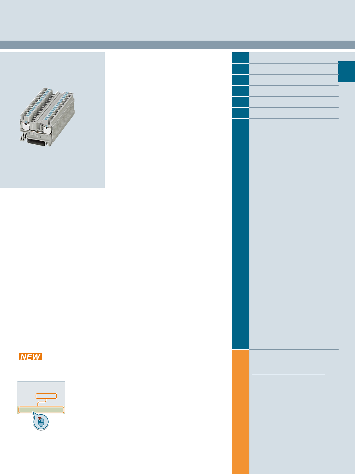
iPo connection method: Characterized by its simple and direct
conductor connection, this series utilizes all the benefits of the
8WH system.
Super-light insertion: With an up to 50 % lower insertion force,
the iPo connection method permits easy and direct insertion of
rigid and flexible conductors with end sleeves with a cross-sec-
tion of more than 0.34 mm2.
Pusher button function: The actuation button is used to open the
spring to either release the conductor or to connect smaller
cross-sections from 0.14 mm2. It can be operated by any tool.
Easy bridging: The double bridge shaft supports the intercon-
nection of any number of terminals using 2-pole jumpers.
The 2-pole to 50-pole jumpers enable up to 50 terminals to be
connected in a single step.
© Siemens AG 2015© Siemens AG 2015
2/4 Siemens LV 52 · 2016
8WH6 through-type terminals
8WH6 iPo Plug-In Terminals
2
■
Overview
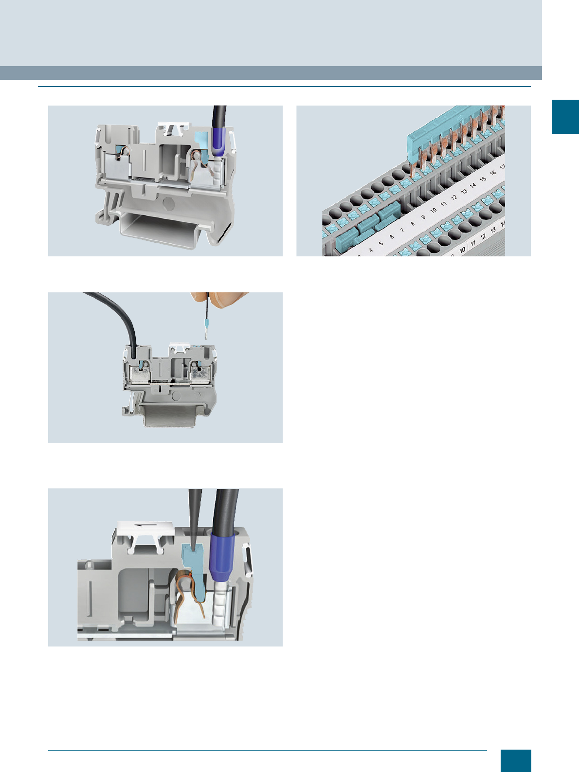
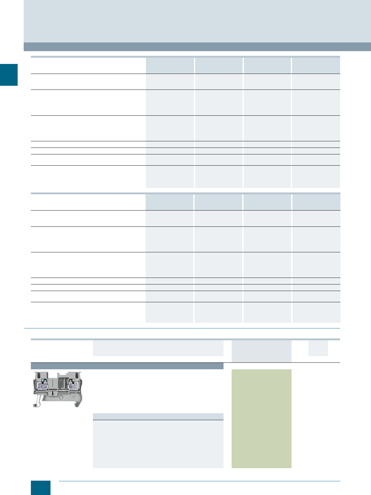
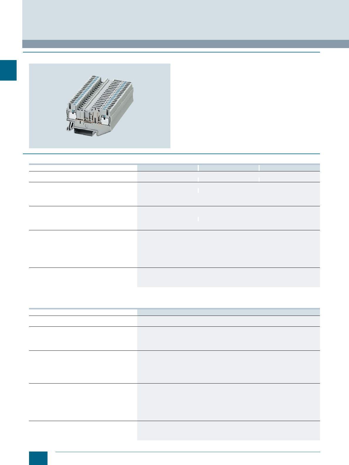
8WH6 through-type terminals are ideal for the direct tool-free
wiring of conductors with end sleeve or rigid conductors. Easy
insertion of flexible conductors with end sleeves upwards of
0.34 mm2. The actuation button can be used to open the clamp-
ing point with any type of screwdriver in order to unwire or wire
small conductors. The compact design and front connection
permit wiring in the narrowest of spaces. The double bridge
shaft enables fast creation of an individual potential distribution
and infeed, e.g. using a screw terminal.
A label can be snapped on to the middle of each terminal at the
front. Further labels can also be mounted flat on the side of the
terminals.
■
Technical specifications
1) The total current through all connected conductors must not exceed the
max. load current.
8WH6000-0AF00
8WH6000-0AF01
2.5 mm2
8WH6003-0AF00
8WH6003-0AF01
2.5 mm2
8WH6004-0AF00
8WH6004-0AF01
2.5 mm2
Dimensions
• Width / length / height (NS 35/7.5) in mm 5.2 / 48.5 / 36.5 5.2 / 60.5 / 36.5 5.2 / 72 / 36.5
Max. technical data
•Imax in A 30 301)
•Umax in V 800
• Max. Ø in mm² 0.14 ... 4
•AWG 26 ... 12
Rating according to IEC 60947-7-1
• Rated voltage in V (IEC / UL/CSA) 800 / 600 800 / --
• Rated current in A / cross-section in mm²
-IEC 24 / 2.5 241) / 2.5
-UL/CSA 20 / -- --
• Nominal cross-section in mm² 2.5
• AWG cross-section range (IEC / UL/CSA) 26 ... 12 / 24 ... 12 26 ... 12 / --
Connection capacities
• 1 conductor
- Rigid in mm² 0.14 ... 4
- Flexible in mm² 0.14 ... 2.5
- Flexible end sleeve with/without plastic sleeve in mm² 0.14 ... 2.5
• Conductor cross-section, direct plug-in
- Rigid in mm² 0.34 ... 4
- Flexible end sleeve with/without plastic sleeve in mm² 0.34 ... 2.5
General data
• Stripped length in mm 10
• Molded plastic PA
• Flammability Class acc. to UL 94 V0
© Siemens AG 2015© Siemens AG 2015
2/5
Siemens LV 52 · 2016
8WH6 iPo Plug-In Terminals
8WH6 through-type terminals
2
1) The total current through all connected conductors must not exceed the
max. load current.
8WH6000-0CF07
2.5 mm28WH6003-0CF07
2.5 mm28WH6004-0CF07
2.5 mm2
Dimensions
• Width / length / height (NS 35/7.5) in mm 5.2 / 48.5 / 36.5 5.2 / 60.5 / 36.5 5.2 / 72 / 36.5
Max. technical data
• Max. Ø in mm² 0.14 ... 4
•AWG 26 ... 12
Rating according to IEC 60947-7-1
• Nominal cross-section in mm² 2.5
• AWG cross-section range (IEC / UL/CSA) 26 ... 12 / 24 ... 12 26 ... 12 / --
Connection capacities
• 1 conductor
- Rigid in mm² 0.14 ... 4
- Flexible in mm² 0.14 ... 2.5
- Flexible end sleeve with/without plastic sleeve in mm² 0.14 ... 2.5
• Conductor cross-section, direct plug-in
- Rigid in mm² 0.34 ... 4
- Flexible end sleeve with/without plastic sleeve in mm² 0.34 ... 2.5
General data
• Stripped length in mm 10
• Molded plastic PA
• Flammability Class acc. to UL 94 V0
8WH6000-0AG00
8WH6000-0AG01
4mm2
8WH6003-0AG00
8WH6003-0AG01
4mm2
8WH6004-0AG00
8WH6004-0AG01
4mm2
Dimensions
• Width / length / height in mm 6.2 / 56 / 36.5 6.2 / 66.5 / 36.5 6.2 / 77 / 36.5
Max. technical data
•Imax in A 38 381) 381)
•Umax in V 800 800 800
• Max. Ø in mm² 0.2 ... 6 0.2 ... 6 0.2 ... 6
•AWG 24 ... 10 24 ... 10 24 ... 10
Rating according to IEC 60947-7-1
• Rated voltage in V (IEC / UL/CSA) 800 / 600 800 / 600 800 / 600
• Rated current in A / cross-section in mm²
-IEC 32/ 4 321) / 4 321)/ 4
-UL/CSA 30 / -- 30 / -- 30 / --
• Nominal cross-section in mm² 444
• AWG cross-section range (IEC / UL/CSA) 24 ... 10 / 24 ... 10 24 ... 10 / 24 ... 10 24 ... 10 / 24 ... 10
Connection capacities
• 1 conductor
- Rigid in mm² 0.2 ... 6 0.2 ... 6 0.2 ... 6
- Flexible in mm² 0.2 ... 4 0.2 ... 4 0.2 ... 4
- Flexible end sleeve with/without plastic sleeve in mm² 0.25 ... 4 0.25 ... 4 0.25 ... 4
• Conductor cross-section, direct plug-in
- Rigid in mm² 0.5 ... 6 0.2 ... 6 0.5 ... 6
- Flexible end sleeve with/without plastic sleeve in mm² 0.5 ... 4 0.5 ... 4 0.5 ... 4
General data
• Stripped length in mm 12 12 12
• Molded plastic PA PA PA
• Flammability Class acc. to UL 94 V0 V0 V0
8WH6000-0CG07
4mm28WH6003-0CG07
4mm28WH6004-0CG07
4mm2
Dimensions
• Width / length / height (NS 35/7.5) in mm 6.2 / 56 / 36.5 6.2 / 66.5 / 36.5 6.2 / 77 / 36.5
Max. technical data
• Max. Ø in mm² 0.2 ... 6 0.2 ... 6 0.2 ... 6
•AWG 24 ... 10 24 ... 10 24 ... 10
Rating according to IEC 60947-7-1
• Nominal cross-section in mm² 444
• AWG cross-section range (IEC / UL/CSA) 24 ... 10 / 24 ... 10 24 ... 10 / 24 ... 10 24 ... 10 / 24 ... 10
Connection capacities
• 1 conductor
- Rigid in mm² 0.2 ... 6 0.2 ... 6 0.2 ... 6
- Flexible in mm² 0.2 ... 4 0.2 ... 6 0.2 ... 6
- Flexible end sleeve with/without plastic sleeve in mm² 0.25 ... 4 0.2 ... 4 0.2 ... 4
• Conductor cross-section, direct plug-in
- Rigid in mm² 0.5 ... 6
- Flexible end sleeve with/without plastic sleeve in mm² 0.5 ... 4
General data
• Stripped length in mm 12 12 12
• Molded plastic PA PA PA
• Flammability Class acc. to UL 94 V0 V0 V0
© Siemens AG 2015© Siemens AG 2015
2/6 Siemens LV 52 · 2016 * You can order this quantity or a multiple thereof.
8WH6 through-type terminals
8WH6 iPo Plug-In Terminals
2
■
Selection and ordering data
8WH6000-0AH00
8WH6000-0AH01
6 mm2
8WH6000-0CH0
6 mm2
8WH6000-0AJ00
8WH6000-0AJ01
10 mm2
8WH6000-0CJ07
10 mm2
Dimensions
• Width/length/cover width in mm 8.2 /57.7 / 2.2 8.2 / 57.7 / 2.2 8.2 / 57.7 / 2.2 8.2 / 57.7 / 2.2
• Height (NS 35/7.5 / NS 35/15) in mm 43.5 / 51 43.5 / 51 43.5 / 51 43.5 / 51
Technical specifications acc. to IEC/DIN VDE
• Max. load current in A / cross-section in mm² 51 / 10 -- 65 / 16 --
• Rated voltage in V 1000 -- 1000 --
• Rated impulse withstand voltage in kV / pollution degree 8 / 3 8 / 3 8 / 3 8 / 3
• Overvoltage category / molded plastic group III / I III / I III / I III / I
Connection capacities
• Flexible with end sleeve, with plastic sleeve in mm² 0.5 ... 6 0.5 ... 6 0.5 ... 10 0.5 ... 10
• Flexible with end sleeve, without plastic sleeve in mm² 0.5 ... 6 0.5 ... 6 0.5 ... 10 0.5 ... 10
• Rigid in mm² 0.5 ... 10 0.5 ... 10 0.5 ... 16 0.5 ... 16
• Flexible in mm² 0.5 ... 6 0.5 ... 6 0.5 ... 10 0.5 ... 10
Stripped length in mm 12 12 18 18
Plug gauge (IEC 60947-1) A5 A5 A6 A6
Molded plastic type PA PA PA PA
• Flammability Class acc. to UL 94 V0 V0 V0 V0
Approval data (UL/cUL and CSA)
• Rated voltage / rated current / conductor sizes
- UL/cUL: in V/A / AWG 600 / 40 / 20 ... 8 -- / -- / 20 ... 8 600 / 60 / 20 ... 6 -- / -- / 20 ... 6
- CSA: in V/A / AWG -- -- --
8WH6000-0AK00
8WH6000-0AK01
16 mm2
8WH6000-0CK07
16 mm2
8WH6000-0AM00
8WH6000-0AM01
35 mm2
8WH6000-0CM07
35 mm2
Dimensions
• Width/length/cover width in mm 12.2 / 75.4 / 2.2 12.2 / 75.4 / 2.2 16 / 91.6 / 2.2 16 / 91.6 / 2.2
• Height (NS 35/7.5 / NS 35/15) in mm 52.6 / 60.1 52.6 / 60.1 -- / 62.3 -- / 62.3
Technical specifications acc. to IEC/DIN VDE
• Max. load current in A / cross-section in mm² 90 / 25 -- 125 / 35 --
• Rated voltage in V 1000 -- 1000 --
• Rated impulse withstand voltage in kV / pollution degree 8 / 3 8 / 3 8 / 3 8 / 3
• Overvoltage category / molded plastic group III III III III
Connection capacities
• Flexible with end sleeve, with plastic sleeve in mm² 0.5 ... 16 0.5 ... 16 6 ... 35 6 ... 35
• Flexible with end sleeve, without plastic sleeve in mm² 0.5 ... 16 0.5 ... 16 6 ... 35 6 ... 35
• Rigid in mm² / AWG 0.5 ... 25 / 20 ... 4 0.5 ... 25 / 20 ... 4 6 ... 35 / 10 ... 2 6 ... 35 / 10 ... 2
• Flexible in mm² / AWG 0.5 ... 16 / 20 ... 6 0.5 ... 16 / 20 ... 6 6 ... 35 / 10 ... 2 6 ... 35 / 10 ... 2
Stripped length in mm 18 18 25 25
Plug gauge (IEC 60947-1) A7 A7 -- --
Molded plastic type PA PA PA PA
• Flammability Class acc. to UL 94 V0 V0 V0 V0
Approval data (UL/cUL and CSA)
• Rated voltage / rated current / conductor sizes
- UL/cUL: in V/A / AWG -- -- -- --
- CSA: in V/A / AWG -- -- -- --
Version DT Article No.
www.siemens.com/
product?Article No.
Price
per PU
PU
(UNIT,
SET, M)
PS*/
P. un it PG
Terminal size 2.5 mm²
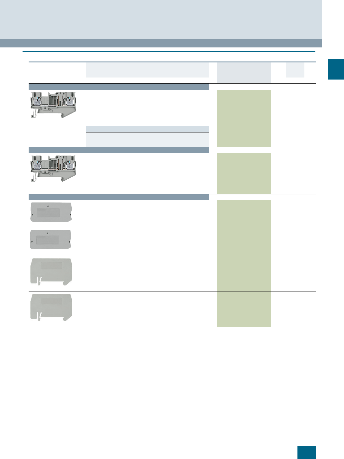
8WH6000-0AF00
Through-type terminals, terminal size 2.5 mm²
•CUUS
• Terminal width 5.2 mm
•Imax = 30 A
•Umax = 800 V
• AWG 26 ... 12
• Connection capacity, one conductor
- Rigid 0.14 ... 4 mm²
- Flexible 0.14 ... 2.5 mm²
Versions
• Two clamping points
-Gray 8WH6000-0AF00 150 units1BT
- Blue 8WH6000-0AF01 150 units1BT
• Three clamping points
-Gray 8WH6003-0AF00 150 units1BT
- Blue 8WH6003-0AF01 150 units1BT
• Four clamping points
-Gray 8WH6004-0AF00 150 units1BT
- Blue 8WH6004-0AF01 150 units1BT
© Siemens AG 2015© Siemens AG 2015
2/7
Siemens LV 52 · 2016
* You can order this quantity or a multiple thereof.
8WH6 iPo Plug-In Terminals
8WH6 through-type terminals
2
8WH6000-0CF07
PE through-type terminals, terminal size 2.5 mm²
•CUUS
• Terminal width 5.2 mm
• AWG 26 ... 12
• Connection capacity, one conductor
- Rigid 0.14 ... 4 mm²
- Flexible 0.14 ... 2.5 mm²
• Green/yellow
Versions
• Two clamping points 8WH6000-0CF07 150 units1BT
• Three clamping points 8WH6003-0CF07 150 units1BT
• Four clamping points 8WH6004-0CF07 150 units1BT
Terminal size 4 mm²
8WH6000-0AG00
8WH6003-0AG00
8WH6003-0AG01
8WH6004-0AG00
8WH6004-0AG01
Through-type terminals, terminal size 4 mm²
•CUUS
• Terminal width 6.2 mm
•Imax = 38 A
•Umax = 800 V
• AWG 24 ... 10
• Connection capacity, one conductor
- Rigid 0.2 ... 6 mm²
- Flexible 0.2 ... 4 mm²
Versions
• Two clamping points
-Gray 8WH6000-0AG00 150 units1BT
- Blue 8WH6000-0AG01 150 units1BT
• Three clamping points
-Gray 8WH6003-0AG00 150 units1BT
- Blue 8WH6003-0AG01 150 units1BT
• Four clamping points
-Gray 8WH6004-0AG00 150 units1BT
- Blue 8WH6004-0AG01 150 units1BT
8WH6000-0CG07
8WH6003-0CG07
8WH6004-0CG07
PE through-type terminals, terminal size 4 mm²
•CUUS
• Terminal width 6.2 mm
• AWG 24 ... 10
• Connection capacity, one conductor
- Rigid 0.2 ... 6 mm²
- Flexible 0.2 ... 4 mm²
• Green/yellow
Versions
• Two clamping points 8WH6000-0CG07 150 units1BT
• Three clamping points 8WH6003-0CG07 150 units1BT
• Four clamping points 8WH6004-0CG07 150 units1BT
Version DT Article No.
www.siemens.com/
product?Article No.
Price
per PU
PU
(UNIT,
SET, M)
PS*/
P. un it PG
© Siemens AG 2015© Siemens AG 2015

2/8 Siemens LV 52 · 2016 * You can order this quantity or a multiple thereof.
8WH6 through-type terminals
8WH6 iPo Plug-In Terminals
2
Terminal size 6 mm²
8WH6000-0AH00
8WH6000-0AH01
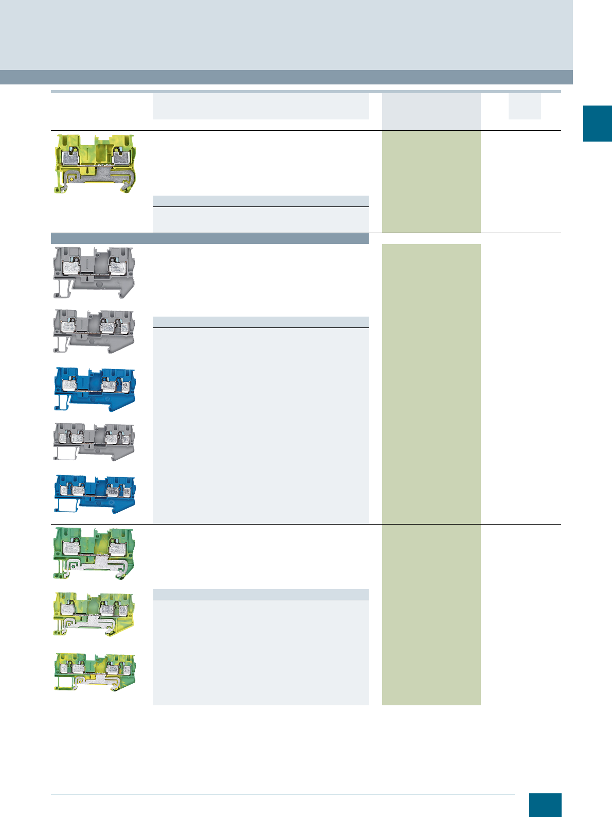
Through-type terminals, terminal size 6 mm²,
two clamping points
• Terminal width 8.2 mm
•CUUS
• IEC 60947-7-1
- Rigid 0.5 ... 10 mm²
- Flexible 0.5 ... 6 mm²
- AWG 20 ... 8
-I = 41 A
-U = 1000 V
Versions
•Gray 8WH6000-0AH00 150 units1BT
•Blue 8WH6000-0AH01 150 units1BT
8WH6000-0CH07
8WH6000-0CH07
PE through-type terminals, terminal size 6 mm²,
two clamping points
• Terminal width 8.2 mm
•CUUS
• IEC 60947-7-2
- Rigid 0.5 ... 10 mm²
- Flexible 0.5 ... 6 mm²
- AWG 20 ... 8
• Green/yellow
8WH6000-0CH07 150 units1BT
Terminal size 10 mm²
8WH6000-0AJ00
8WH6000-0AJ01
Through-type terminals, terminal size 10 mm²
• Terminal width 10.2 mm
•CUUS
• IEC 60947-7-1
- Rigid 0.5 ... 16 mm²
- Flexible 0.5 ... 6 mm²
-AWG 20-6
-I = 57 A
-U = 1000 V
Versions
•Gray 8WH6000-0AJ00 150 units1BT
•Blue 8WH6000-0AJ01 150 units1BT
8WH6000-0CJ07
8WH6000-0CJ07
PE through-type terminals, terminal size 10 mm²
• Terminal width 10.2 mm
•CUUS
• IEC 60947-7-2
- Rigid 0.5 ... 10 mm²
- Flexible 0.5 ... 10 mm²
-AWG 20-6
• Green/yellow
8WH6000-0CJ07 150 units1BT
Version DT Article No.
www.siemens.com/
product?Article No.
Price
per PU
PU
(UNIT,
SET, M)
PS*/
P. un it PG
I201_12670
I201_12672
© Siemens AG 2015© Siemens AG 2015
2/9
Siemens LV 52 · 2016
* You can order this quantity or a multiple thereof.
8WH6 iPo Plug-In Terminals
8WH6 through-type terminals
2
Terminal size 16 mm²
8WH6000-0AK00
8WH6000-0AK01
Through-type terminals, terminal size 16 mm²
• Terminal width 12.2 mm
• IEC 60947-7-1
- Rigid 0.5 ... 25 mm²
- Flexible 0.5 ... 16 mm²
- AWG 20 ... 4
-I = 90 A
-U = 1000 V
Versions
•Gray 8WH6000-0AK00 150 units1BT
•Blue 8WH6000-0AK01 150 units1BT
8WH6000-0CK07
PE through-type terminals, terminal size 16 mm²
• Terminal width 12.2 mm
• IEC 60947-7-2
- Rigid 0.5 ... 25 mm²
- Flexible 0.5 ... 16 mm²
- AWG 20 ... 4
• Green/yellow
8WH6000-0CK07 150 units1BT
Terminal size 35 mm²
8WH6000-0AM00
8WH6000-0AM01
Through-type terminals, terminal size 35 mm²
• Terminal width 16 mm
• Enclosed at both ends
• IEC 60947-7-1
- Rigid 6 ... 35 mm²
- Flexible 6 ... 35 mm²
- AWG 10 ... 2
-I = 125 A
-U = 1000 V
Versions
•Gray 8WH6000-0AM00 150 units1BT
•Blue 8WH6000-0AM01 150 units1BT
8WH6000-0CM07
PE through-type terminals, terminal size 35 mm²
• Terminal width 16 mm
• Enclosed at both ends
• IEC 60947-7-2
- Rigid 6 ... 35 mm²
- Flexible 6 ... 35 mm²
- AWG 10 ... 2
-I = 125 A
-U = 1000 V
8WH6000-0CM07 150 units1BT
Version DT Article No.
www.siemens.com/
product?Article No.
Price
per PU
PU
(UNIT,
SET, M)
PS*/
P. un it PG
© Siemens AG 2015© Siemens AG 2015
2/10 Siemens LV 52 · 2016 * You can order this quantity or a multiple thereof.
8WH6 through-type terminals
8WH6 iPo Plug-In Terminals
2
For general accessories for 8WH terminal blocks, see chapter
"Accessories for 8WH Terminal Blocks"
Accessories
Covers, for terminal size 1.5 ... 2.5 mm², width 2.2 mm
Versions
• For two clamping points 8WH9000-1GA00 100 50 units 1BT
• For three clamping points 8WH9000-2GA00 100 50 units 1BT
• For four clamping points 8WH9000-4GA00 100 50 units 1BT
8WH9000-0GA00
Cover segments, for terminal size 1.5 ... 2.5 mm²
For covering multi-wire terminals when mounting two-wire termi-
nals side-by-side
8WH9000-0GA00 100 10 units 1BT
8WH9070-0AA00
Compartment partitions, for terminal size 1.5 ... 4 mm²
• For visual and electrical separation of terminal groups
• 2 mm thick
•Gray
Versions
• For two clamping points 8WH9070-0AA00 100 50 units 1BT
• For three clamping points 8WH9070-0GA00 100 50 units 1BT
• For four clamping points 8WH9070-0HA00 100 50 units 1BT
Note
For general accessories for 8WH terminal blocks,
see chapter "Accessories for 8WH Terminal Blocks"
8WH9003-1GA00
Covers, for terminal size 4 mm²
Width 2.2 mm
Versions
• For two clamping points 8WH9003-1GA00 100 50 units 1BT
• For three clamping points 8WH9003-2SA00 150 units1BT
• For four clamping points 8WH9003-4SA00 150 units1BT
8WH9070-0AA00
Compartment partitions, for terminal size 1.5 ... 4 mm²
• For visual and electrical separation of terminal groups
• 2 mm thick
•Gray
Versions
• For two clamping points 8WH9070-0AA00 100 50 units 1BT
8WH9004-3SA00
8WH9005-1SA00
Covers, for through-type terminals
• Width 2.2 mm
Versions
• For two clamping points 6 mm² 8WH9004-3SA00 100 50 units 1BT
• For two clamping points 10 mm² 8WH9005-1SA00 100 50 units 1BT
8WH9006-1SA00
Covers, for terminal size 16 mm²
• For closing the open terminal side
• Length 75.4 mm
• Width 2.2 mm
Versions
•Gray 8WH9006-1SA00 100 50 units 1BT
Version DT Article No.
www.siemens.com/
product?Article No.
Price
per PU
PU
(UNIT,
SET, M)
PS*/
P. un it PG
© Siemens AG 2015© Siemens AG 2015
2/11
Siemens LV 52 · 2016
* You can order this quantity or a multiple thereof.
8WH6 iPo Plug-In Terminals
8WH6 fuse terminals
2
■
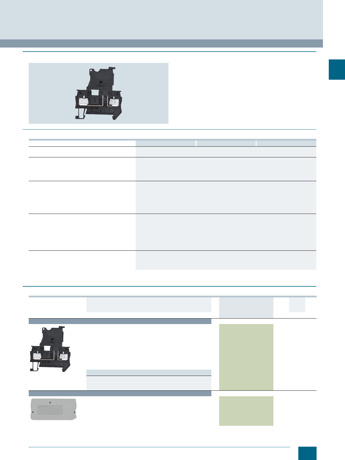
Overview
The fuse terminal is characterized by its compact design and it
has the same contour as through-type terminals and function ter-
minals. Double bridging is possible. Versions with LED display
for signaling a fuse are also available.
Fuse terminals can be inscribed at their clamping points with flat
labels.
■
Technical specifications
1) The total current through all connected conductors must not exceed the
max. load current.
■
Selection and ordering data
For general accessories for 8WH terminal blocks, see chapter
"Accessories for 8WH Terminal Blocks"
8WH6000-1GG08 8WH6000-1KG38 8WH6000-1MG88
Dimensions
• Width / length / height (NS 35/7.5) in mm 6.2 /56 / 62.5
Max. electrical data
•Imax in A 6.31)
•Umax in V 500
• Max. Ø in mm² 0.2 ... 6
•AWG 24 ... 10
Rating according to IEC 60947-7-1
• Rated voltage in V (IEC / UL/CSA) 500 / 300
• Rated current in A / cross-section in mm²
-IEC 6.3/ 1
-UL/CSA 6.3 / --
• Nominal cross-section in mm² 4
• AWG cross-section range (IEC / UL/CSA) 24 ... 10 / 24 ... 10
Connection capacities
• 1 conductor
- Rigid in mm² 0.2 ... 6
- Flexible in mm² 0.2 ... 4
- Flexible end sleeve with/without plastic sleeve in mm² 0.25 ... 4
• Conductor cross-section, direct plug-in
- Rigid in mm² 0.5 ... 6
- Flexible end sleeve with/without plastic sleeve in mm² 0.5 ... 4
General data
• Stripped length in mm 12
• Molded plastic PA
• Flammability Class acc. to UL 94 V0
Version DT Article No.
www.siemens.com/
product?Article No.
Price
per PU
PU
(UNIT,
SET, M)
PS*/
P. unit PG
Terminal size 4 mm²
8WH6000-1GG08
Fuse terminals, terminal size 4 mm², for 5 x 20 mm G fuse links
•CUUS, s
• Terminal width 6.2 mm
•Imax = 6.3 A
•Umax = 500 V
• AWG 24 ... 10
• Connection capacity, one conductor
- Rigid 0.2 ... 4 mm²
- Flexible 0.2 ... 4 mm²
•Black
Versions
• Without LED 8WH6000-1GG08 1 50 units 1BT
• With LED 10 ... 30 V AC/DC 8WH6000-1KG38 1 50 units 1BT
• With LED 110 ... 250 V AC/DC 8WH6000-1MG88 1 50 units 1BT
Accessories
8WA9003-1GA00
Covers, for terminal size 4 mm²
• For two clamping points
• Width 2.2 mm
8WH9003-1GA00 100 50 units 1BT
© Siemens AG 2015© Siemens AG 2015
2/12 Siemens LV 52 · 2016
8WH6 isolating blade terminals
8WH6 iPo Plug-In Terminals
2
■
Overview
Through-type terminals with isolating blade capability are the
most commonly used terminal types in measuring and control
technology. Key features of the 8WH6 isolating blade terminals
are the slim design of only 5.2 mm and their high current-carry-
ing capacity. Convenient testing is made possible by the integral
double function shaft located on one side of the isolating point
and the integrated test contact located on the other. Standard
connecting combs allow easy execution of all potential-distribu-
tion tasks. Three and four-wire terminals up to 2.5 mm² are avail-
able for the multi-conductor connection.
A label can be snapped on to the middle of each terminal at the
front. Further labels can also be mounted flat on the side of the
terminals.
■
Technical specifications
1) The total current through all connected conductors must not exceed the
max. load current.
8WH6000-6AF00 8WH6003-6AF00 8WH6004-6AF00
Dimensions
• Width / length / height (NS 35/7.5) in mm 5.2 / 60.5 / 36.5 5.2 / 74 / 36.5 5.2 / 84 / 36.5
Max. electrical data
•Imax in A 20 201)
•Umax in V 400
• Max. Ø in mm² 0.14 ... 4
•AWG 26 ... 12
Rating according to IEC 60947-7-1
• Rated voltage in V (IEC) 400
• Rated current in A / cross-section in mm² (IEC) 20 / 2.5 201) / 2.5
• Nominal cross-section in mm² 2.5
• AWG cross-section range (IEC) 26 ... 12
Connection capacities
• 1 conductor
- Rigid in mm² 0.14 ... 4
- Flexible in mm² 0.14 ... 2.5
- Flexible end sleeve with/without plastic sleeve in mm² 0.14 ... 2.5
• Conductor cross-section, direct plug-in
- Rigid in mm² 0.34 ... 4
- Flexible end sleeve with/without plastic sleeve in mm² 0.34 ... 2.5
General data
• Stripped length in mm 10
• Molded plastic PA
• Flammability Class acc. to UL 94 V0
8WH6000-6CG00
Dimensions
• Width / length / height (NS 35/7.5) in mm 6.2 / 54 / 36.5
Max. electrical data
•Imax in A 20
•Umax in V 400
• Max. Ø in mm² 0.2 ... 6
•AWG 24 ... 10
Rating according to IEC 60947-7-1
• Rated voltage in V (IEC / UL/CSA) 400 / 300
• Rated current in A / cross-section in mm²
-IEC 20/ 2.5
-UL/CSA 20 / --
• Nominal cross-section in mm² 4
• AWG cross-section range (IEC / UL/CSA) 24 ... 10 / 24 ... 10
Connection capacities
• 1 conductor
- Rigid in mm² 0.2 ... 6
- Flexible in mm² 0.2 ... 4
- Flexible end sleeve with/without plastic sleeve in mm² 0.25 ... 4
• Conductor cross-section, direct plug-in
- Rigid in mm² 0.5 ... 6
- Flexible end sleeve with/without plastic sleeve in mm² 0.5 ... 4
General data
• Stripped length in mm 12
• Molded plastic PA
• Flammability Class acc. to UL 94 V0
© Siemens AG 2015© Siemens AG 2015
2/13
Siemens LV 52 · 2016
* You can order this quantity or a multiple thereof.
8WH6 iPo Plug-In Terminals
8WH6 isolating blade terminals
2
■
Selection and ordering data
For general accessories for 8WH terminal blocks, see chapter
"Accessories for 8WH Terminal Blocks"
Version DT Article No.
www.siemens.com/
product?Article No.
Price
per PU
PU
(UNIT,
SET, M)
PS*/
P. unit PG
Terminal size 2.5 mm²
8WH6000-6AF00
Isolating blade terminals, terminal size 2.5 mm²
• Terminal width 5.2 mm
•Imax = 20 A
•Umax = 400 V
• AWG 26 ... 12
• Connection capacity, one conductor
- Rigid 0.14 ... 4 mm²
- Flexible 0.14 ... 2.5 mm²
Versions
• Two clamping points 8WH6000-6AF00 1 50 units 1BT
• Three clamping points 8WH6003-6AF00 1 50 units 1BT
• Four clamping points 8WH6004-6AF00 1 50 units 1BT
Terminal size 4 mm²
8WH6000-6CG00
Isolating blade terminals, terminal size 4 mm²
• With 2 clamping points
• Terminal width 6.2 mm
•Imax = 20 A
•Umax = 400 V
• AWG 24 ... 10
• Connection capacity, one conductor
- Rigid 0.2 ... 6 mm²
- Flexible 0.2 ... 4 mm²
• Connection capacity, two conductors
- Rigid 0.5 ... 6 mm²
8WH6000-6CG00 1 50 units 1BT
Accessories
8WH9000-3SC00
Covers, for terminal size 2.5 mm²
Width 2.2 mm
• For two clamping points 8WH9000-3SC00 100 50 units 1BT
• For three clamping points 8WH9000-3SD00 100 50 units 1BT
• For four clamping points 8WH9000-5GA00 100 50 units 1BT
8WA9003-1GA00
Covers, for terminal size 4 mm²
• For two clamping points
• Width 2.2 mm
8WH9003-1GA00 100 50 units 1BT
8WH9070-0AA00
Compartment partitions, for terminal size 1.5 ... 4 mm²
• For two clamping points
• For visual and electrical separation of terminal groups
• 2 mm thick
•Gray
8WH9070-0AA00 100 50 units 1BT
© Siemens AG 2015© Siemens AG 2015
2/14 Siemens LV 52 · 2016
8WH6 isolating terminals
8WH6 iPo Plug-In Terminals
2
■
Overview
8WH6 isolating terminals in iPo connection technology are avail-
able for special wiring tasks. With the same contour as the iso-
lating blade terminals, 8WH6 isolating terminals are fitted with a
universal plug-in zone in the middle of the terminal. Numerous
wiring tasks can be performed on a terminal width of 5.2 mm by
integrating the isolated through-type connector, the isolating
plug, the component connector or the fused plug.
A label can be snapped on to the middle of each terminal at the
front. Further labels can also be mounted flat on the side of the
terminals.
■
Technical specifications
1) The total current through all connected conductors must not exceed the
max. load current.
2) Current and voltage are determined by the fitted plug.
8WH6000-6CF00 8WH6003-6CF00 8WH6004-6CF00
Dimensions
• Width / length / height (NS 35/7.5) in mm 5.2 / 60.5 / 36.5 5.2 / 74 / 36.5 5.2 / 84 / 36.5
Max. electrical data
•Imax in A 20 201)
•Umax in V 4002)
• Max. Ø in mm² 0.14 ... 4
•AWG 26 ... 12
Rating according to IEC 60947-7-1
• Rated voltage in V (IEC) 4002)
• Rated current in A / cross-section in mm² (IEC) 20 / 2.5 201) / 2.5
• Nominal cross-section in mm² (IEC) 2.5
• AWG cross-section range (IEC) 26 ... 12
Connection capacities
• 1 conductor
- Rigid in mm² 0.14 ... 4
- Flexible in mm² 0.14 ... 2.5
- Flexible end sleeve with/without plastic sleeve in mm² 0.14 ... 2.5
• Conductor cross-section, direct plug-in
- Rigid in mm² 0.34 ... 4
- Flexible end sleeve with/without plastic sleeve in mm² 0.34 ... 2.5
General data
• Stripped length in mm 10
• Molded plastic PA
• Flammability Class acc. to UL 94 V0
8WH6000-6AG00
Dimensions
• Width / length / height (NS 35/7.5) in mm 6.2 / 56 / 36.5
Max. electrical data
•Imax in A 20
•Umax in V 4002)
• Max. Ø in mm² 0.2 ... 6
•AWG 24 ... 10
Rating according to IEC 60947-7-1
• Rated voltage in V (IEC / UL/CSA) 400 / 300
• Rated current in A / cross-section in mm²
-IEC 20/ 2.5
-UL/CSA 20 / --
• Nominal cross-section in mm² 4
• AWG cross-section range (IEC / UL/CSA) 24 ... 10 / 24 ... 10
Connection capacities
• 1 conductor
- Rigid in mm² 0.2 ... 6
- Flexible in mm² 0.25 ... 4
- Flexible end sleeve with/without plastic sleeve in mm² 0.25 ... 4
• Conductor cross-section, direct plug-in
- Rigid in mm² 0.5 ... 6
- Flexible end sleeve with/without plastic sleeve in mm² 0.5 ... 4
General data
• Stripped length in mm 12
• Molded plastic PA
• Flammability Class acc. to UL 94 V0
© Siemens AG 2015© Siemens AG 2015
2/15
Siemens LV 52 · 2016
* You can order this quantity or a multiple thereof.
8WH6 iPo Plug-In Terminals
8WH6 isolating terminals
2
■
Selection and ordering data
For general accessories for 8WH terminal blocks, see chapter
"Accessories for 8WH Terminal Blocks"
Version DT Article No.
www.siemens.com/
product?Article No.
Price
per PU
PU
(UNIT,
SET, M)
PS*/
P. un it PG
Terminal size 2.5 mm²
8WH6000-6CF00
Isolating terminals, terminal size 2.5 mm²
• Terminal width 5.2 mm
•Imax = 20 A
•Umax = 400 V
• AWG 26 ... 12
• Connection capacity, one conductor
- Rigid 0.14 ... 4 mm²
- Flexible 0.14 ... 2.5 mm²
Versions
• Two clamping points 8WH6000-6CF00 1 50 units 1BT
• Three clamping points 8WH6003-6CF00 1 50 units 1BT
• Four clamping points 8WH6004-6CF00 1 50 units 1BT
Terminal size 4 mm²
8WH6000-6AG00
Isolating terminals, terminal size 4 mm²
• With two clamping points
• Terminal width 6.2 mm
•Imax = 20 A
•Umax = 400 V
• AWG 24 ... 10
• Connection capacity, one conductor
- Rigid 0.2 ... 6 mm²
- Flexible 0.2 ... 4 mm²
8WH6000-6AG00 1 50 units 1BT
Accessories
8WH9000-3SC00
Covers, for terminal size 2.5 mm²
Width 2.2 mm
• For two clamping points 8WH9000-3SC00 100 50 units 1BT
• For three clamping points 8WH9000-3SD00 100 50 units 1BT
• For four clamping points 8WH9000-5GA00 100 50 units 1BT
8WA9003-1GA00
Covers, for terminal size 4 mm²
• For two clamping points
• Width 2.2 mm
8WH9003-1GA00 100 50 units 1BT
8WH9070-0AA00
Compartment partitions, for terminal size 1.5 ... 4 mm²
• For two clamping points
• For visual and electrical separation of terminal groups
• 2 mm thick
•Gray
8WH9070-0AA00 100 50 units 1BT
8WH9070-0AA00
Compartment partitions, for terminal size 1.5 ... 4 mm²
• For three clamping points
• For visual and electrical separation of terminal groups
• 2 mm thick
•Gray
8WH9070-0GA00 100 50 units 1BT
© Siemens AG 2015© Siemens AG 2015
2/16 Siemens LV 52 · 2016
8WH6 two-tier terminals
8WH6 iPo Plug-In Terminals
2
■
Overview
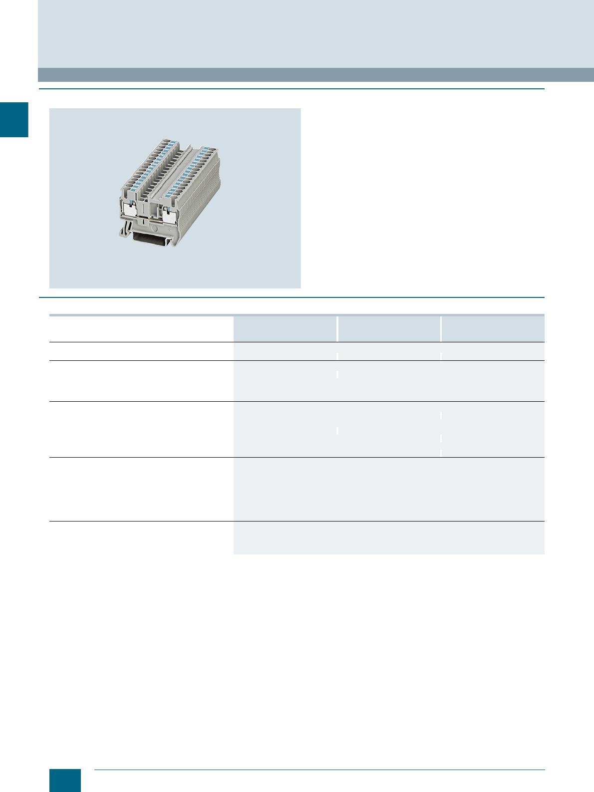
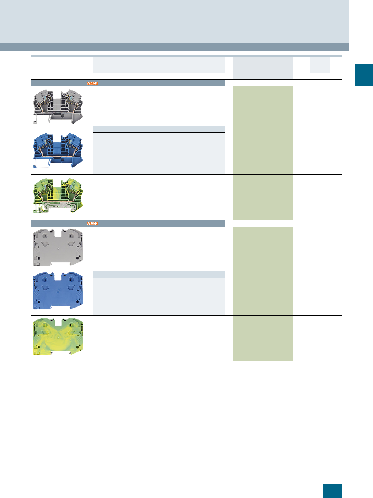
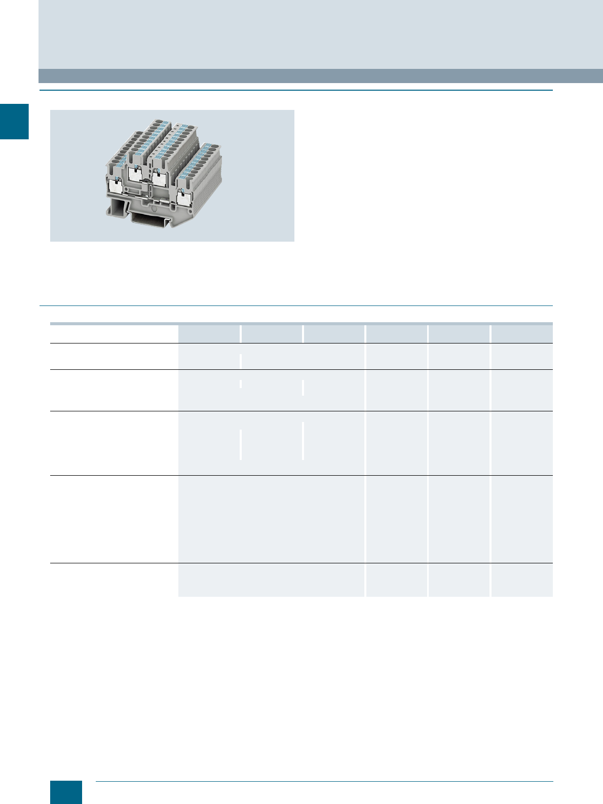
With the two voltage levels routed through two tiers, the 8WH6
two-tier terminals require 50 % less space than equivalent
single-tier terminals. To implement a wide range of wiring tasks,
connecting combs can be fitted to both tiers of the two-tier
terminal series. Facilities for inscription are provided at each
clamping point.
Two-tier terminals with equipotential bonding for the upper and
lower tiers are also available.
With the same contour as 8WH6 two-tier terminals, 8WH6 two-
tier PE terminals round off the product range. Perfect mechani-
cal and electrical contact with the support rail is provided by
simply snapping the terminals onto the rail. 8WH6 two-tier PE ter-
minals comply with all the requirements of IEC 60947-7-2. These
include in particular:
• Low contact resistance
• Stainless clamping points
• Green-yellow enclosure
• Additional inscription options
An inscription label can be mounted flat at each clamping point
by simply snapping it on.
■
Technical specifications
1) The total current through all connected conductors must not exceed the
max. load current.
8WH6020-0AF00
8WH6020-0AF01 8WH6025-0AF00 8WH6020-0CF07 8WH6020-0AG00
8WH6020-0AG01 8WH6025-0AG00 8WH6020-0CG07
Dimensions
• Width / length / height (NS 35/7.5)
in mm 5.2 / 68 / 47.5 5.2 / 78 / 55 6.2 / 83.5 / 47.5
Max. electrical data
•Imax in A 26 261) -- 32 --
•Umax in V 500 -- 500 --
• Max. Ø in mm² 0.14 ... 4 0.2 ... 6
•AWG 26 ... 12 24 ... 10
Rating according to IEC 60947-7-1
• Rated voltage in V (IEC) 500 -- 500 / 600 --
• Rated current in A / cross-section in
mm²
-IEC 20 / 2.5 201) / 2.5 -- / -- -- / --
-UL/CSA 30 / -- -- / --
• Nominal cross-section in mm² (IEC) 2.5 4
• AWG cross-section range (IEC) 26 ... 12 24 ... 10 / 24 ... 10
Connection capacities
• 1 conductor
- Rigid in mm² 0.14 ... 4 0.2 ... 6
- Flexible in mm² 0.14 ... 2.5 0.2 ... 4
- Flexible end sleeve with/without
plastic sleeve in mm² 0.14 ... 2.5 0.25 ... 4
• Conductor cross-section,
direct plug-in
- Rigid in mm² 0.34 ... 4 0.5 ... 6
- Flexible end sleeve with/without
plastic sleeve in mm² 0.34 ... 2.5 0.5 ... 4
General data
• Stripped length in mm 10 12
• Molded plastic PA PA
• Flammability Class acc. to UL 94 V0 V0
© Siemens AG 2015© Siemens AG 2015
2/17
Siemens LV 52 · 2016
* You can order this quantity or a multiple thereof.
8WH6 iPo Plug-In Terminals
8WH6 two-tier terminals
2
■
Selection and ordering data
For general accessories for 8WH terminal blocks, see chapter
"Accessories for 8WH Terminal Blocks"
Version DT Article No.
www.siemens.com/
product?Article No.
Price
per PU
PU
(UNIT,
SET, M)
PS*/
P. un it PG
Terminal size 2.5 mm²
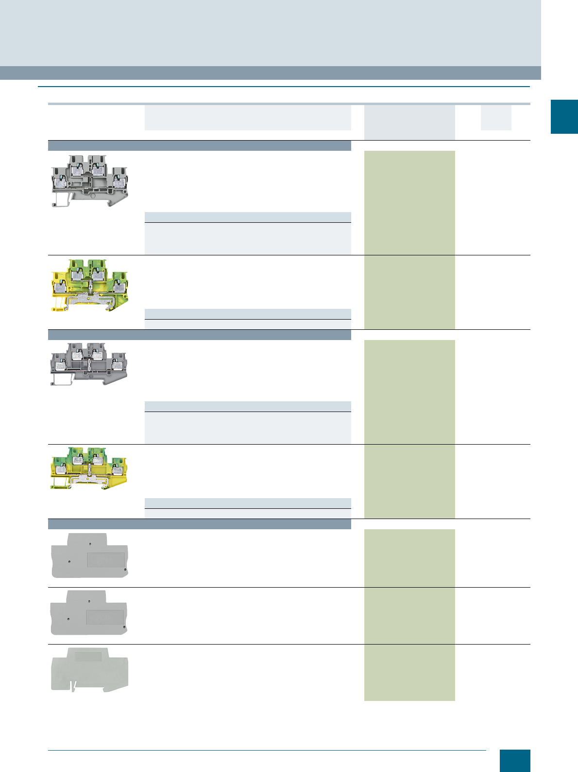
8WH6020-0AF00
Two-tier terminals, terminal size 2.5 mm²
• Terminal width 5.2 mm
•Imax = 26 A
•Umax = 500 V
• AWG 26 ... 12
• Connection capacity, one conductor
- Rigid 0.14 ... 4 mm²
- Flexible 0.14 ... 2.5 mm²
Versions
• Without equipotential bonding
-Gray 8WH6020-0AF00 1 50 units 1BT
- Blue 8WH6020-0AF01 1 50 units 1BT
• With equipotential bonding 8WH6025-0AF00 1 50 units 1BT
8WH6020-0CF07
PE two-tier terminals, terminal size 2.5 mm²
• Terminal width 5.2 mm
• AWG 26 ... 12
• Connection capacity, one conductor
- Rigid 0.14 ... 4 mm²
- Flexible 0.14 ... 2.5 mm²
• Green/yellow
8WH6020-0CF07 1 50 units 1BT
Note
Bridging the terminal is only possible in the top tier (in the center).
Terminal size 4 mm²
8WH6025-0AG00
Two-tier terminals, terminal size 4 mm²
• Terminal width 6.2 mm
•Imax = 32 A
•Umax = 500 V
• AWG 24 ... 10
• Connection capacity, one conductor
- Rigid 0.2 ... 6 mm²
- Flexible 0.2 ... 4 mm²
Versions
• Without equipotential bonding
-Gray 8WH6020-0AG00 1 50 units 1BT
- Blue 8WH6020-0AG01 1 50 units 1BT
• With equipotential bonding 8WH6025-0AG00 1 50 units 1BT
8WH6020-0CF07
PE two-tier terminals, terminal size 4 mm²
• Terminal width 6.2 mm
• AWG 24 ... 10
• Connection capacity, one conductor
- Rigid 0.2 ... 6 mm²
- Flexible 0.2 ... 4 mm²
• Green/yellow
8WH6020-0CG07 1 50 units 1BT
Note
Bridging the terminal is only possible in the top tier (in the center).
Accessories
8WH9000-4SE00
Covers, for terminal size 1.5 ... 2.5 mm²
• Width 2.2 mm
•Gray
8WH9000-4SE00 100 50 units 1BT
8WH9003-1VA00
Covers, for terminal size 1.5 ... 4 mm²
• For two clamping points
• Width 2.2 mm
8WH9003-1VA00 100 50 units 1BT
8WH9070-0BA00
Compartment partitions, for terminal size 1.5 ... 4 mm²
• For visual and electrical separation of terminal groups
• 2 mm thick
•Gray
8WH9070-0BA00 100 50 units 1BT
© Siemens AG 2015© Siemens AG 2015

2/18 Siemens LV 52 · 2016
Notes
8WH6 iPo Plug-In Terminals
2
© Siemens AG 2015© Siemens AG 2015
Siemens LV 52 · 2016
For further technical
product information:
Siemens Industry Online Support:
www.siemens.com/lowvoltage/product-
support .
→
Application example
Certificate
Characteristic
Download
FAQ
Manual
Product note
Software archive
Technical data
3
3
3/2 Introduction
3/4 8WH through-type terminals
3/6
8WH through-type screw terminals
3/8 8WH N-conductor isolating
terminals
3/10 8WH N-conductor isolating screw
terminals
3/12 8WH installation terminals
8WH6 iPo Installation Terminals
Direct reference to the products in the
Industry Mall from the selection and
ordering data tables:
3VA2025-5HL36-0AA0
Article No.
www.siemens.com/
product? Article No.
Paper catalog:
To get more
product information
enter the Web
address plus
Article No.
PDF catalog:
Get more product information
with just a mouse click.
© Siemens AG 2015© Siemens AG 2015
3/2 Siemens LV 52 · 2016
Introduction
8WH6 iPo Installation Terminals
3
■
Overview
Devices Page Function
8WH through-type terminals 3/4 Connection of incoming and outgoing conductors
up to 6 mm²
8WH through-type screw terminals 3/6 Connection of incoming and outgoing conductors
up to 35 mm² with screw terminals
8WH N-conductor isolating terminals 3/8 Terminal blocks up to 6 mm² and connection of an
N-bus-bar 10 × 3 mm
8WH N-conductor isolating screw terminals 3/10 Terminal blocks with screw connection up to 35 mm²
and connection of an N-busbar 10 × 3 mm
8WH installation terminals 3/12 Terminal blocks for connection of an N-busbar
10 × 3 mm. These terminals offer up to three terminal
functions in a single enclosure and are optimized for
distribution board applications in installation technology.
© Siemens AG 2015© Siemens AG 2015
3/3
Siemens LV 52 · 2016
8WH6 iPo Installation Terminals
Introduction
3
1) Only the main terminal types are listed here. You will find further versions on the following pages.
Terminal type →Screw terminals iPo technology Article No.
(digits 8 ... 12)
Design →Standard Insta
No. of clamping points →2
Article No. (digits 1 ... 7) →8WH1001 8WH6001
Conductor cross-
section Terminal type1) Color
2.5 mm2Through-type Gray -- ✔0AF00
Blue -- ✔0AF01
N-conductor isolating Blue -- ✔0BF01
PE Green/yellow -- ✔0CF07
Insta LGray -- ✔4QF00
L/L -- ✔4DF00
L/N -- ✔4CF00
PE/L/L -- ✔4HF00
PE/L/N -- ✔4EF00
PE/L/NT -- ✔4FF00
PE/L/N isolating blade -- ✔4GF00
PE/L/L isolating blade -- ✔4NF00
4 mm2Through-type Gray -- ✔0AG00
Blue -- ✔0AG01
N-conductor isolating Blue -- ✔0BG01
PE Green/yellow -- ✔0CG07
6 mm2Through-type Gray -- ✔0AH00
Blue -- ✔0AH01
N-conductor isolating Blue -- ✔0BH01
PE Green/yellow -- ✔0CH07
10 mm2N-conductor isolating Blue ✔-- 0BJ01
16 mm2Through-type Gray ✔-- 0AK00
Blue ✔-- 0AK01
N-conductor isolating Blue ✔-- 0BK01
PE Green/yellow ✔-- 0CK07
35 mm2Through-type Gray ✔-- 0AM00
Blue ✔-- 0AM01
N-conductor isolating Blue ✔-- 0BM01
PE Green/yellow ✔-- 0CM07
© Siemens AG 2015© Siemens AG 2015
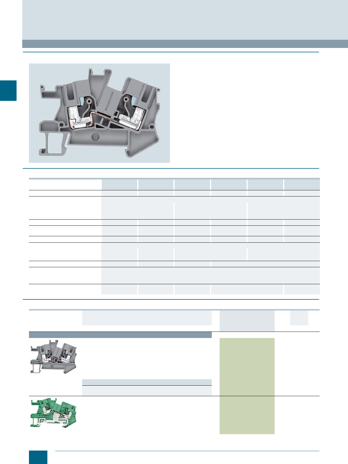
3/4 Siemens LV 52 · 2016 * You can order this quantity or a multiple thereof.
8WH through-type terminals
8WH6 iPo Installation Terminals
3
■
Overview
All types of conductors can be used with 8WH6 iPo technology.
Rigid conductors and crimped flexible conductors are plugged
directly into the terminal.
Flexible, untreated conductors can be connected using a screw-
driver.
These terminals can be used interconnected with the N-busbar
10 × 3 mm.
An inscription label can be snapped on to the middle of each
terminal at the front. Labels can also be mounted flat on the
clamping points of the terminals.
■
Technical specifications
■
Selection and ordering data
8WH6001-0AF00
8WH6001-0AF01 8WH6001-0CF07 8WH6001-0AG00
8WH6001-0AG01 8WH6000-0CG07 8WH6001-0AH00
8WH6001-0AH01 8WH6001-0AH07
Cross-section mm² 2.5 2.5 (PE) 44 (PE) 66 (PE)
Dimensions
• Width / length / width of
cover mm 5.2 / 59.5 / 2.2
43 / 50.5
6.2 / 66 / 2.2
46.3 / 53.8
8.2 / 66 / 2.2
50 / 57.5
• Height (TS 35/7.5 / TS 35/15) mm
Rated current In cross-section A/mm² 24 / 2.5 -- / 2.5 32 / 4 -- / 4 41 / 6 -- / 6
Max. load current Imax /
cross-section A/mm² 24 / 4 -- / 4 32 / 6 -- / 6 50/10 -- / 10
Rated voltage Un V 800 -- 800 -- 800 --
Connection capacities
• Rigid mm² 0.14 ... 4 0.2 ... 6
0.25 ... 4
0.5 ... 10
0.5 ... 6
• Flexible with end sleeve mm² 0.25 ... 2.5
Stripped length mm 10 12 10 12
Molded plastic type PA
Flammability class
acc. to UL 94 V0
Support rails/protective
conductor busbars -- See page 1/3, sec-
tion "Support rails" -- See page 1/3, sec-
tion "Support rails" -- See page 1/3, sec-
tion "Support rails"
Version DT Article No.
www.siemens.com/
product?Article No.
Price
per PU
PU
(UNIT,
SET, M)
PS*/
P. un it PG
Terminal size 2.5 mm²
8WH6001-0AF00
Through-type terminals, terminal size 2.5 mm²,
acc. to IEC 60 947-7-1
• Terminal width 5.2 mm, terminal length 59.5 mm
• Terminal height (NS 35/7.5) 43 mm
• Max. load current Imax = 24 A
• Rated voltage Un = 800 V
• Rigid 0.14 ... 4 mm²
• Flexible with end sleeve 0.14 ... 2.5 mm²
• AWG 26 ... 12
Versions
•Gray 8WH6001-0AF00 1 50 units 1BT
•Blue 8WH6001-0AF01 1 50 units 1BT
8WH6001-0CF07
Through-type PE terminals, terminal size 2.5 mm², IEC 60 947-7-2
• Green/yellow
• Terminal width 5.2 mm, terminal length 59.5 mm
• Terminal height 43 mm
• Cross-section max. 4 mm²
• Rigid 0.2 ... 4 mm²
• Flexible with end sleeve 0.2 ... 2.5 mm²
• AWG 24 ... 12
8WH6001-0CF07 1 50 units 1BT
© Siemens AG 2015© Siemens AG 2015
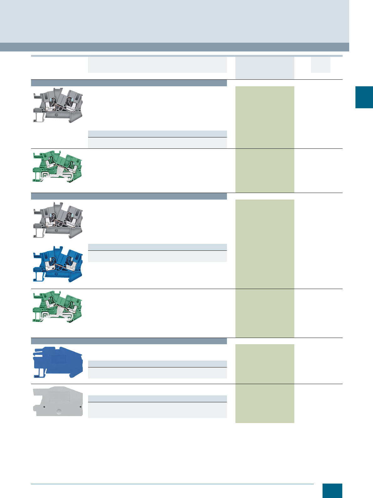
3/5
Siemens LV 52 · 2016
* You can order this quantity or a multiple thereof.
8WH6 iPo Installation Terminals
8WH through-type terminals
3
For general accessories for 8WH terminal blocks, see chapter
"Accessories for 8WH Terminal Blocks"
Terminal size 4 mm²
8WH6001-0AG00
Through-type terminals, terminal size 4 mm², acc. to IEC 60947-7-1
• Terminal width 6.2 mm
• Terminal length 66 mm
• Terminal height 46.3 mm
• Max. load current Imax = 32 A
• Rated voltage Un = 800 V
• Rigid 0.2 ... 6 mm²
• Flexible with end sleeve 0.2 ... 4 mm²
• AWG 24 ... 10
Versions
•Gray 8WH6001-0AG00 1 50 units 1BT
•Blue 8WH6001-0AG01 1 50 units 1BT
8WH6001-0AG07
Through-type PE terminals, terminal size 4 mm²,
acc. to IEC 60947-7-2
• Green/yellow
• Terminal width 6.2 mm
• Terminal length 66 mm
• Terminal height 46.3 mm
• Rigid 0.2 ... 6 mm²
• Flexible with end sleeve 0.2 ... 4 mm²
• AWG 24 ... 10
8WH6001-0CG07 1 50 units 1BT
Terminal size 6 mm²
8WH6001-0AH00
8WH6001-0AH01
Through-type terminals, terminal size 6 mm², acc. to IEC 60947-7-1
• Terminal width 8.2 mm
• Terminal length 66 mm
• Terminal height 50 mm
• Max. load current Imax = 41 A
• Rated voltage Un = 800 V
• Rigid 0.5 ... 10 mm²
• Flexible with end sleeve 0.5 ... 6 mm²
• AWG 20 ... 8
Versions
•Gray 8WH6001-0AH00 1 50 units 1BT
•Blue 8WH6001-0AH01 1 50 units 1BT
8WH6001-0AH07
Through-type PE terminals, terminal size 6 mm²,
acc. to IEC 60947-7-2
• Green/yellow
• Terminal width 8.2 mm
• Terminal length 66 mm
• Terminal height 50 mm
• Rigid 0.5 ... 10 mm²
• Flexible without end sleeve 0.5 ... 10 mm²
• Flexible with end sleeve 0.5 ... 6 mm²
• AWG 20 ... 8
8WH6001-0CH07 1 50 units 1BT
Accessories
8WH9143-0AF01
Support brackets
• Made of blue molded plastic
• For holding the N-busbar
Versions
• For terminal size 2.5 ... 4 mm² 8WH9143-0AF01 1 50 units 1BT
• For terminal size 6 mm² 8WH9143-0AH01 1 50 units 1BT
8WH9000-1WA00
Covers
Gray
Versions
• For terminal size 2.5 mm² 8WH9000-1WA00 100 50 units 1BT
• For terminal size 4 mm² 8WH9003-7WA00 100 50 units 1BT
• For terminal size 6 mm² 8WH9004-1WA00 100 50 units 1BT
Version DT Article No.
www.siemens.com/
product?Article No.
Price
per PU
PU
(UNIT,
SET, M)
PS*/
P. un it PG
© Siemens AG 2015© Siemens AG 2015
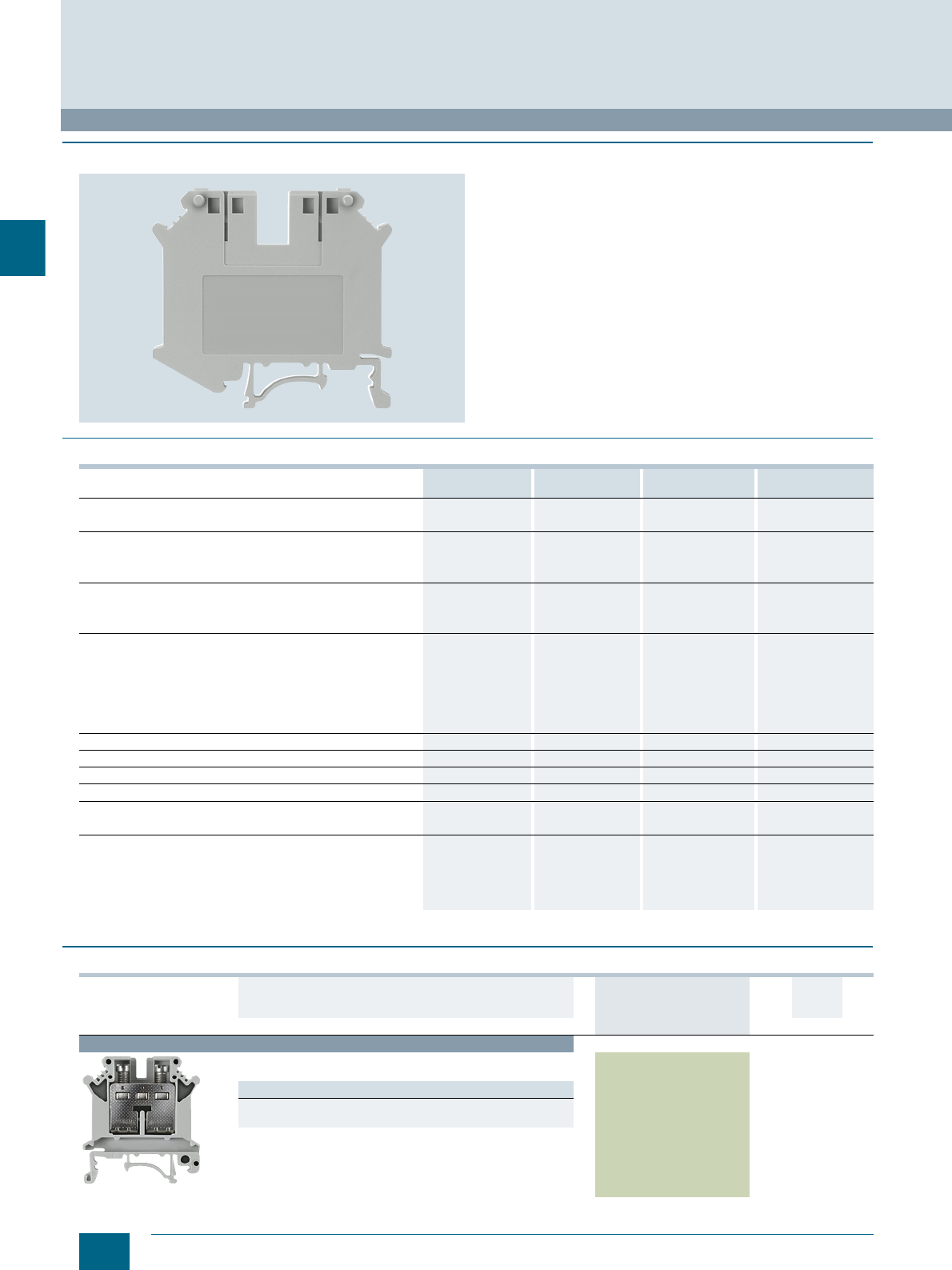
3/6 Siemens LV 52 · 2016 * You can order this quantity or a multiple thereof.
8WH through-type screw terminals
8WH6 iPo Installation Terminals
3
■
Overview
We offer a comprehensive range of installation terminals with iPo
technology for use in building management systems. We also
offer a range of compact, cost-effective terminal blocks with
screw terminals for connecting larger cross-sections.
Terminal blocks mounted on N-busbars are most commonly
used in building management systems. In order to enable the
butt-mounting of different terminals, contact to the N-busbar is
always on the same mounting level. This means that 8WH1-001
screw terminals and 8WH6-001 plug-in terminals can be com-
bined as required and mounted on a single support rail.
Labels can be affixed at each clamping point by simply
snapping them on at the front.
■
Technical specifications
■
Selection and ordering data
8WH1001-0AK00
8WH1001-0AK01 8WH1001-0CK07 8WH1001-0AM00
8WH1001-0AM01 8WH1001-0CM07
Cross-section mm² 16 16 (PE) 35 35 (PE)
Max. cross-section with comb (rigid / flexible) mm² 16 / 16 -- 35 / 35 --
Dimensions
• Width / length / width of cover mm 12.2 / 42.5 / 1.8 12.2 / 42.5 / -- 15.2 / 55 / -- 15.2 / 55 / --
• Height (TS 35/7.5 / TS 35/15) mm 47 / 54.5 / 52 47 / 54.5 / 52 51 / 58.5 / 56 51 / 58.5 / 56
Max. load current Imax / cross-section A/mm² 101 / 25 101 / 25 125 / 35 125 / 35
Rated impulse withstand voltage / pollution degree kV 6 / 3 6 / 3 8 / 3 8 / 3
Overvoltage category / molded plastic group III / I III / I III / I III / I
Connection capacities
• For one conductor
- Rigid mm² 1.5 ... 16 1.5 ... 16 0.75 ... 35 0.75 ... 35
- Flexible with end sleeve mm² 1.5 ... 16 1.5 ... 16 0.75 ... 35 0.75 ... 35
• For two conductors of same cross-section
- Rigid / flexible mm² 1.5 ... 6 / 1.5 ... 6 1.5 ... 6 / 1.5 ... 4 0.75 ... 15 / 0.75 ... 10 0.75 ... 16 / 0.75 ... 10
- Flexible with end sleeve mm² 1.5 ... 4 1.5 ... 6 0.75 ... 10 0.75 ... 10
Stripped length mm 11 11 16 16
Plug gauge (IEC 60947-1) B7 B7 B9 B9
Clamping point: Screw thread / tightening torque Nm M4 / 1.5 ... 1.8 M4 / 1.5 ... 1.8 M6 / 3.2 ... 3.7 M5 / 3.2 ... 3.7
Fixing: Screw thread / tightening torque Nm -- M4 / 1.5 ... 1.8 -- M5 / 2.5 ... 3
Molded plastic type PA PA PA PA
Flammability Class acc. to UL 94 V2 V2 V2 V2
Approval data (UL/cUL and CSA)
•UL/cUL
- Rated voltage / rated current / conductor sizes V/A/AWG 600 / 85 / 22-4 -- / -- / 22-4 600 / 115 / 18-2 -- / -- / 18-2
•CSA
- Rated voltage / rated current / conductor sizes V/A/AWG 600 / 85 / 22-4 -- / -- / 22-4 600 / 130 / 18-2 -- / -- / --
Version DT Article No.
www.siemens.com/
product?Article No.
Price
per PU
PU
(UNIT,
SET, M)
PS*/
P. un it PG
Terminal size 16 mm²
8WH1001-0AK00
Through-type screw terminals, terminal size 16 mm²
Width 12.2 mm
Versions
•Gray 8WH1001-0AK00 1 50 units 1BT
•Blue 8WH1001-0AK01 1 50 units 1BT
© Siemens AG 2015© Siemens AG 2015
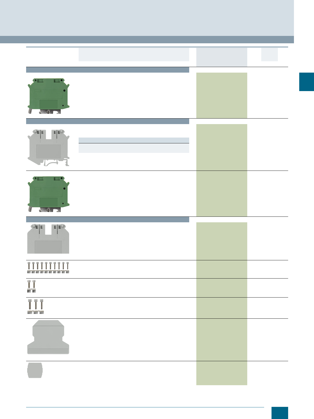
3/7
Siemens LV 52 · 2016
* You can order this quantity or a multiple thereof.
8WH6 iPo Installation Terminals
8WH through-type screw terminals
3
For general accessories for 8WH terminal blocks, see chapter
"Accessories for 8WH Terminal Blocks"
Terminal size 16 mm² (continued)
8WH1001-0CK07
PE through-type screw terminals, terminal size 16 mm²
• Width 12.2 mm
• Enclosed at both ends
• Green/yellow
8WH1001-0CK07 1 50 units 1BT
Terminal size 35 mm²
8WH1001-0AM00
Through-type screw terminals, terminal size 35 mm²
• Width 16 mm
• Enclosed at both ends
Versions
•Gray 8WH1001-0AM00 1 50 units 1BT
•Blue 8WH1001-0AM01 1 50 units 1BT
8WH1001-0CM07
PE through-type screw terminals, terminal size 35 mm²
• Width 16 mm
• Enclosed at both ends
• Green/yellow
8WH1001-0CM07 1 50 units 1BT
Accessories
8WH9005-3PA00
Covers, for screw terminals
• 10/16 mm2
• Width 2 mm
•Gray
8WH9005-3PA00 100 50 units 1BT
8WH9030-6AL00
Bridge, 10-pole
For through-type terminals, 16 mm2, gray and blue
8WH9030-6AL00 1 10 units 1BT
8WH9030-6BC00
Bridge, 2-pole
For through-type terminals, 35 mm2, gray and blue
8WH9030-6BC00 1 10 units 1BT
8WH9030-6BD00
Bridge, 3-pole
For through-type terminals, 35 mm2, gray and blue
8WH9030-6BD00 1 10 units 1BT
8WH9070-6HA00
Compartment partitions
For through-type terminals, 16 mm2, gray and blue
8WH9070-6HA00 100 50 units 1BT
8WH9070-6GA00
Insulation plates
For through-type terminals, 16 and 35 mm2, gray and blue
8WH9070-6GA00 100 50 units 1BT
Version DT Article No.
www.siemens.com/
product?Article No.
Price
per PU
PU
(UNIT,
SET, M)
PS*/
P. un it PG
© Siemens AG 2015© Siemens AG 2015
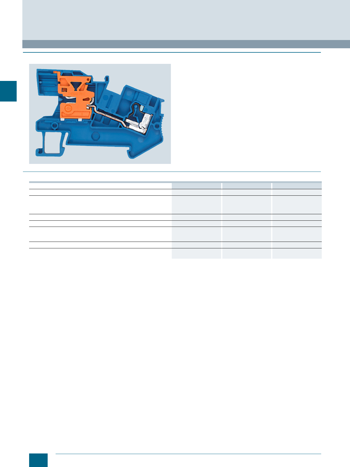
3/8 Siemens LV 52 · 2016
8WH N-conductor isolating terminals
8WH6 iPo Installation Terminals
3
■
Overview
The N-conductor disconnect slides are in the same position on
all 8WH6-001 terminals using iPo plug-in technology.
A 10 × 3 mm busbar is used.
Notice: Only use Cu busbars.
Installation instructions: To ensure that the N-busbars are
securely mounted, the support brackets must be placed at the
beginning and end of each terminal strip (in the case of longer
terminal strips: every 20 cm).
A label can be snapped on to the middle of the terminal at the
front. Labels can also be mounted flat on the clamping points of
the terminals (not with N-busbar connection).
■
Technical specifications
8WH6001-0BF01 8WH6001-0BG01 8WH6001-0BH01
Cross-section mm² 2.5 4 6
Dimensions
• Width / length / width of cover mm 5.2 / 59 / 2.2 6.2 / 66 / 2.2 8.2 / 66 / 2.2
• Height (NS 35/7.5 / NS 35/15) mm 46.3/ 53.8 46.3/ 53.8 50 / 57.5
Rated current In / cross-section A/mm² 24 / 2.5 32 / 4 41 / 6
Rated voltage UnV250 250 400
Connection capacities
• Rigid mm² 0.14 ... 4 0.2 ... 6 0.5 ... 10
• Flexible with end sleeve mm² 0.25 ... 2.5 0.25 ... 4 0.5 ... 6
Stripped length mm 10 10 12
Molded plastic type PA PA PA
• Flammability Class acc. to UL 94 V0 V0 V0
© Siemens AG 2015© Siemens AG 2015
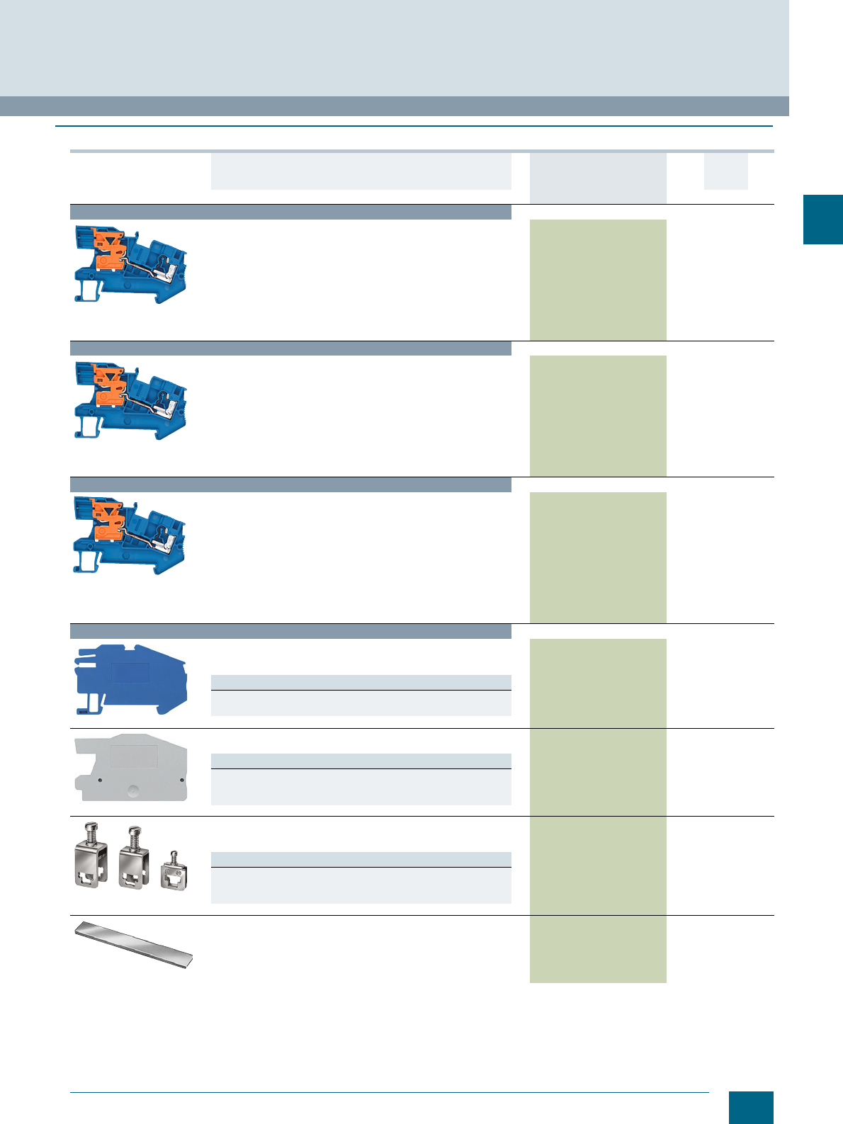
3/9
Siemens LV 52 · 2016
* You can order this quantity or a multiple thereof.
8WH6 iPo Installation Terminals
8WH N-conductor isolating terminals
3
■
Selection and ordering data
For general accessories for 8WH terminal blocks, see chapter
"Accessories for 8WH Terminal Blocks"
Version DT Article No.
www.siemens.com/
product?Article No.
Price
per PU
PU
(UNIT,
SET, M)
PS*/
P. un it PG
Terminal size 2.5 mm²
8WH6001-0BF01
N-conductor isolating terminals, terminal size 2.5 mm²,
acc. to IEC 60947-7-1
• Two clamping points
• Terminal width 5.2 mm
• Terminal length 59 mm
• Terminal height (NS 35/7.5) 46.3 mm
• Rated current / cross-section In = 24 A / 2.5 mm²
• Rated voltage Un = 250 V
• Rigid 0.14 ... 4 mm²
• Flexible with end sleeve 0.14 ... 2.5 mm²
• AWG 26 ... 12
8WH6001-0BF01 150 units1BT
Terminal size 4 mm²
8WH6001-0BG01
N-conductor isolating terminals, terminal size 4 mm²,
acc. to IEC 60947-7-1
• Two clamping points
• Terminal width 6.2 mm
• Terminal length 66 mm
• Terminal height (NS 35/7.5) 46.3 mm
• Rated current / cross-section In = 32 A / 4 mm²
• Rated voltage Un = 250 V
• Rigid 0.2 ... 6 mm²
• Flexible with end sleeve 0.25 ... 4 mm²
• AWG 24 ... 10
8WH6001-0BG01 150 units1BT
Terminal size 6 mm²
8WH6001-0BH01
N-conductor isolating terminals, terminal size 6 mm²,
acc. to IEC 60947-7-1
• Two clamping points
• Terminal width 8.2 mm
• Terminal length 66.3 mm
• Terminal height (NS 35/7.5) 50 mm
• Max. load current Imax = 41 A
• Rated current / cross-section In = 41 A / 6 mm²
• Rated voltage Un = 400 V
• Rigid 0.5 ... 10 mm²
• Flexible with end sleeve 0.5 ... 6 mm²
• AWG 20 ... 8
8WH6001-0BH01 150 units1BT
Accessories
8WH9143-0AF01
Support brackets
• Made of blue molded plastic
• For holding the N-busbar
Versions
• For terminal size 2.5 ... 4 mm² 8WH9143-0AF01 150 units1BT
• For terminal size 6 mm² 8WH9143-0AH01 150 units1BT
8WH9000-1SA00
Covers
Gray
Versions
• For terminal size 2.5 mm² 8WH9000-1SA00 100 50 units 1BT
• For terminal size 4 mm² 8WH9003-1SA00 100 50 units 1BT
• For terminal size 6 mm² 8WH9004-1SA00 100 1 unit 1BT
8WA2867/8WA2868/
8WA2870
Feeder terminals, for N-busbars
• 6 × 6 mm and 10 × 3 mm
•Bare
Versions
• Rated uninterrupted current 32 A, for connection of up to 4 mm28WA2867 150 units1BT
• Rated uninterrupted current 76 A, for connection of up to 25 mm28WA2868 150 units1BT
• Rated uninterrupted current 125 A, for connection of up to 35 mm28WA2870 150 units1BT
8WA2842
N-busbars, 10 x 3 mm
• Tin-plated
• 1000 mm long
8WA2842 1 1 unit 1BT
© Siemens AG 2015© Siemens AG 2015
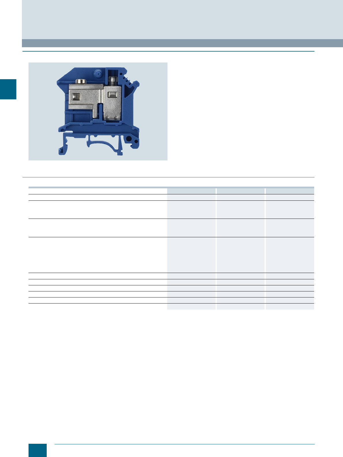
3/10 Siemens LV 52 · 2016
8WH N-conductor isolating screw terminals
8WH6 iPo Installation Terminals
3
■
Overview
We offer a comprehensive range of installation terminals with iPo
plug-in technology for use in building management systems. We
also offer a range of compact, cost-effective terminal blocks with
screw terminals for connecting larger cross-sections.
Terminal blocks mounted on N-busbars are most commonly
used in building management systems. In order to enable the
butt-mounting of different terminals, contact to the N-busbar is
always on the same mounting level. This means that
8WH1-001 screw terminals and 8WH6-001 plug-in terminals can
be combined as required and mounted on a single support rail.
The compact design of our N-conductor isolating terminals
makes for a neat and clearly arranged terminal strip. The N-bus-
bar can be connected over the terminal or over the disconnect
slide of the N-conductor isolating terminal. The N-conductor iso-
lating terminal also makes it easy to perform insulation measure-
ments.
Labels can be affixed on the clamping points (screw) by simply
snapping them on at the front.
Notice: Only use Cu busbars.
■
Technical specifications
8WH1001-0BJ01 8WH1001-0BK01 8WH1001-0BM01
Cross-section mm² 10 16 35
Dimensions
• Width / length / width of cover mm 10.2 / 43.5 / 1.8 12.2 / 43.5 / 1.5 16 / 55 / --
• Height (TS 35/7.5 / TS 35/15) mm 47 / 54.5 / 52 54 / 61.5 / 59 51 / 58.5/ 56
Max. load current Imax / cross-section A/mm² 63 / 16 90 / 25 110 / 35
Rated impulse withstand voltage / pollution degree kV 6 / 3 6 / 3 6 / 3
Overvoltage category / molded plastic group III / I III / I III / I
Connection capacities
• For one conductor
- Rigid mm² 0.5 ... 10 1.5 ... 16 0.75 ... 35
- Flexible with end sleeve mm² 0.5 ... 6 1.5 ... 16 0.75 ... 35
• For two conductors of same cross-section
- Rigid / flexible mm² 0.5 ... 4 / 0.5 ... 4 1.5 ... 6 / 1.5 ... 4 0.75 ... 16 / 0.75 ... 10
- Flexible with end sleeve mm² 0.5 ... 2.5 1.5 ... 8 0.75 ... 10
Stripped length mm 12 11 16
Plug gauge (IEC 60947-1) B5 B6 B9
Clamping point: Screw thread / tightening torque Nm M4 / 1.5 ... 1.8 M4 / 1.5 ... 1.8 M6 / 3.2 ... 3.7
Fixing: Screw thread / tightening torque Nm M3 / 0.6 ... 0.8 M3 / 0.6 ... 0.8 M5 / 2.5 ... 3
Molded plastic type PA PA PA
Flammability Class acc. to UL 94 V2 V2 V2
© Siemens AG 2015© Siemens AG 2015
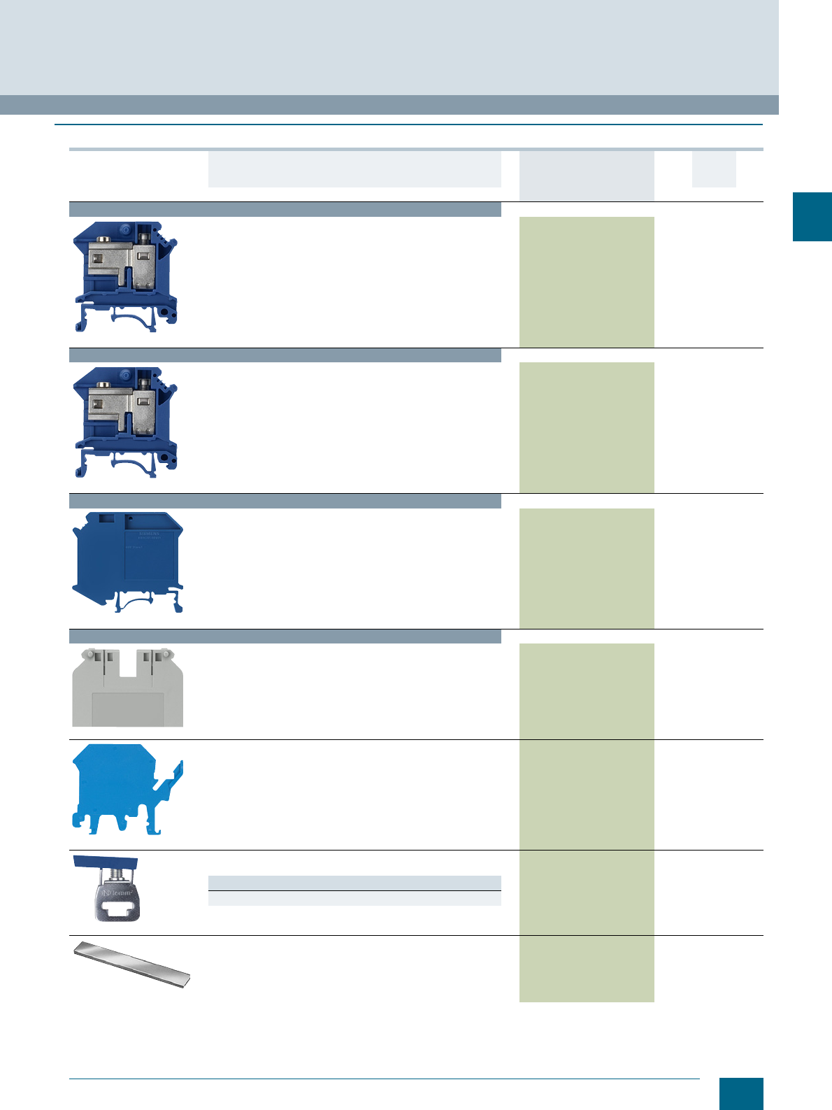
3/11
Siemens LV 52 · 2016
* You can order this quantity or a multiple thereof.
8WH6 iPo Installation Terminals
8WH N-conductor isolating screw terminals
3
■
Selection and ordering data
For general accessories for 8WH terminal blocks, see chapter
"Accessories for 8WH Terminal Blocks"
Version DT Article No.
www.siemens.com/
product?Article No.
Price
per PU
PU
(UNIT,
SET, M)
PS*/
P. un it PG
Terminal size 10 mm²
8WH1001-0BJ01
N-conductor isolating screw terminals, terminal size 10 mm²
• Width 10 mm
•Blue
• For 10 x 3 mm N-busbar
8WH1001-0BJ01 1 50 units 1BT
Terminal size 16 mm²
8WH1001-0BK01
N-conductor isolating screw terminals, terminal size 16 mm²
• Width 12 mm
•Blue
• For 10 x 3 mm N-busbar
8WH1001-0BK01 1 50 units 1BT
Terminal size 35 mm²
8WH1001-0BM01
N-conductor isolating screw terminals, terminal size 35 mm²
• Width 16 mm
• Enclosed at both ends
•Blue
8WH1001-0BM01 1 50 units 1BT
Accessories
8WH9005-3PA00
Covers, for screw terminals
• 10/16 mm2
• Width 2 mm
•Gray
8WH9005-3PA00 100 50 units 1BT
8WH9141-0BA01
Support brackets for N-conductor isolating screw terminals,
terminal size 10 ... 35 mm²
• For holding the N-busbar
• To be placed every 20 cm
• 2 mm wide
8WH9141-0BA01 1 50 units 1BT
8WH9126-0BA01
Terminals
Blue
Versions
• To 16 mm2, width: 10.3 mm 8WH9126-0BA01 1 50 units 1BT
8WA2842
N-busbars, 10 x 3 mm
• Made of copper, tin-plated
• 1000 mm long
8WA2842 11 unit1BT
© Siemens AG 2015© Siemens AG 2015
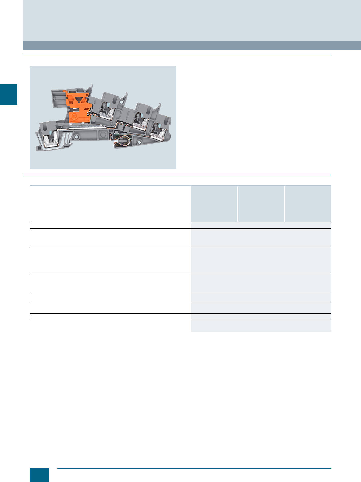
3/12 Siemens LV 52 · 2016
8WH installation terminals
8WH6 iPo Installation Terminals
3
■
Overview
The three-tier plug-in terminals offer optimum operating charac-
teristics for modern building installations. The plug-in connec-
tion allows tool-free wiring of the solid conductors.
These terminals can be used interconnected with the N-busbar
10 × 3 mm.
Notice: Only use Cu busbars.
Thanks to their compact design, the three-tier terminals can be
installed in all types of building distribution boards. A load circuit
can be quickly and easily wired, for example using a 5.2-mm-
wide installation terminal with terminal size 2.5 mm² and PE/L/NT
connections.
The double bridge shafts support a multitude of individual wiring
tasks. This also means it is practical and convenient to make
subsequent modifications to the installation.
Labels can be mounted flat on the clamping points of the
terminals.
■
Technical specifications
1) 3-pole terminal block
Installation terminals, standard version 8WH6001-4QF00
8WH6001-4DF00
8WH6001-4CF00
8WH6001-0HF00
8WH6001-4EF00 8WH6001-4FF00
Installation terminals with isolating function 8WH6001-4GF00
8WH6001-4NF00
8WH6001-4PF00
8WH6001-4MF00
Cross-section mm² 2.5
Dimensions
• Width / length / width of cover mm 5.5 / 101 / 2.2
• Height (TS 35/7.5 / TS 35/15) mm 50.5 / 58
Rated current In cross-section A/mm² 24 / 4
Max. load current Imax / cross-section A/mm² 301) / 4
Rated voltage UnV400 (L-L)
250 (L-N or L-PE)
Connection capacities
• Rigid mm² 0.14 ... 4
• Flexible with end sleeve mm² 0.14 ... 2.5
Stripped length without insulation stop sleeve
(no insulation stop sleeves should be used when using end sleeves)mm 10
Stripped length with insulation stop sleeve
(no insulation stop sleeves should be used when using end sleeves)mm 10
Plug gauge (IEC 60947-1) A3
Molded plastic type PA
Flammability Class acc. to UL 94 V0
© Siemens AG 2015© Siemens AG 2015
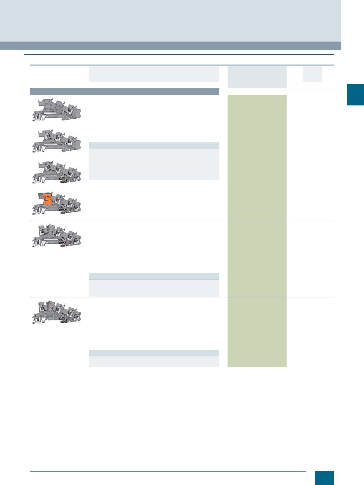
3/13
Siemens LV 52 · 2016
* You can order this quantity or a multiple thereof.
8WH6 iPo Installation Terminals
8WH installation terminals
3
■
Selection and ordering data
Version DT Article No.
www.siemens.com/
product?Article No.
Price
per PU
PU
(UNIT,
SET, M)
PS*/
P. un it PG
Terminal size 2.5 mm²
8WH6001-4QF00
8WH6001-4DF00
8WH6001-4HF00
8WH6001-4FF00
Installation terminals, terminal size 2.5 mm²,
standard version for N-busbar
•Gray
• Terminal width 5.2 mm
• Rigid 0.14 ... 4 mm²
• Flexible with end sleeve 0.14 ... 2.5 mm²
• AWG 26 ... 12
• Rated current / cross-section In = 24 A / 4 mm²
• Rated voltage Un = 400 V (L-L)
Un = 250 V (L-N or L-PE)
Versions
•L 8WH6001-4QF00 1 50 units 1BT
•L/L 8WH6001-4DF00 1 50 units 1BT
•L/N 8WH6001-4CF00 1 50 units 1BT
• PE/L/L 8WH6001-4HF00 1 50 units 1BT
• PE/L/N 8WH6001-4EF00 1 50 units 1BT
• PE/L/NT 8WH6001-4FF00 1 50 units 1BT
8WH6001-4NF00
Installation terminals, terminal size 2.5 mm²,
with isolating blade
•Gray
• Terminal width 5.2 mm
• Rigid 0.25 ... 4 mm²
• Flexible with end sleeve 0.25 ... 2.5 mm²
• AWG 22-12
• Rated current / cross-section In = 24 A / 4 mm²
• Rated voltage
Un = 400 V (L-L)
Un = 250 V (L-N or L-PE)
Versions
• PE/L/L (standard version, suitable for isolating terminal) 8WH6001-4PF00 1 50 units 1BT
• PE/L/N isolating blade 8WH6001-4GF00 1 50 units 1BT
• PE/L/L isolating blade 8WH6001-4NF00 1 50 units 1BT
8WH6001-4PF00
Installation terminals, terminal size 2.5 mm²,
for isolating function
•Gray
• Terminal width 5.2 mm
• Rigid 0.25 ... 4 mm²
• Flexible with end sleeve 0.25 ... 2.5 mm²
• AWG 22-12
• Rated current / cross-section In = 24 A / 4 mm²
• Rated voltage
Un = 400 V (L-L)
Un = 250 V (L-PE)
Versions
• PE/L/L (standard version, suitable for isolating terminal) 8WH6001-4PF00 1 50 units 1BT
• PE/L/L isolation 8WH6001-4MF00 1 50 units 1BT
© Siemens AG 2015© Siemens AG 2015
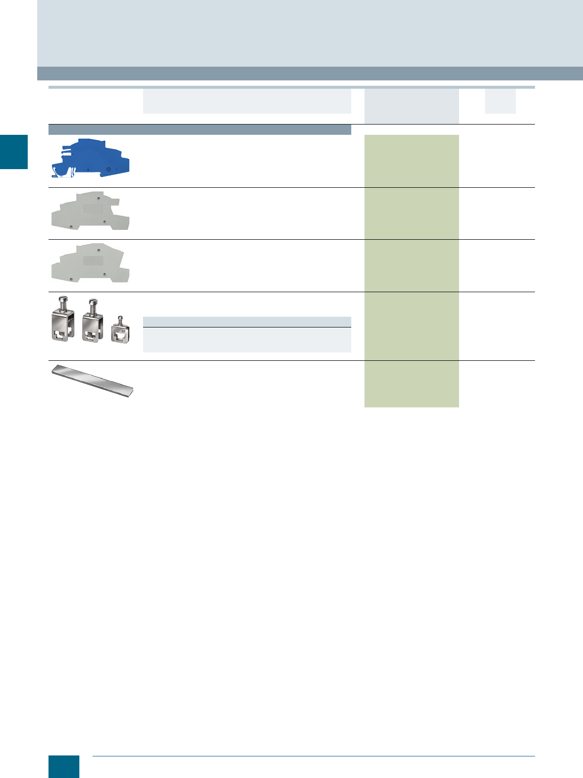
3/14 Siemens LV 52 · 2016 * You can order this quantity or a multiple thereof.
8WH installation terminals
8WH6 iPo Installation Terminals
3
For general accessories for 8WH terminal blocks, see chapter
"Accessories for 8WH Terminal Blocks"
Accessories
8WH9142-0AF01
Support brackets, for terminal size 2.5 mm²
• For holding the N-busbar
• To be placed every 20 cm
• 2 mm wide
8WH9142-0AF01 1 50 units 1BT
8WH9000-3SA00
Covers, for terminal size 2.5 mm²
Gray 8WH9000-3SA00 1 50 units 1BT
8WH9000-6SA00
Covers, for terminal size 2.5 mm² and isolating terminal
in contour
Gray
8WH9000-6SA00 1 50 units 1BT
8WA2867/8WA2868/
8WA2870
Feeder terminals, for N-busbars
• 6 × 6 mm and 10 × 3 mm
•Bare
Versions
• Rated uninterrupted current 32 A, for connection of up to 4 mm28WA2867 1 50 units 1BT
• Rated uninterrupted current 76 A, for connection of up to 25 mm28WA2868 1 50 units 1BT
• Rated uninterrupted current 125 A, for connection of up to 35 mm28WA2870 1 50 units 1BT
8WA2842
N-busbars, 10 x 3 mm
• Made of copper, tin-plated
• 1000 mm long
8WA2842 11 unit1BT
Version DT Article No.
www.siemens.com/
product?Article No.
Price
per PU
PU
(UNIT,
SET, M)
PS*/
P. un it PG
© Siemens AG 2015© Siemens AG 2015

Siemens LV 52 · 2016
For further technical
product information:
Siemens Industry Online Support:
www.siemens.com/lowvoltage/product-
support .
→
Application example
Certificate
Characteristic
Download
FAQ
Manual
Product note
Software archive
Technical data
4
4
4/2 Introduction
4/3 General data on 8WH
4/7 8WH through-type terminals1)
4/18 8WH hybrid through-type
terminals 1)
4/21 8WH fuse terminals
4/23 8WH isolating blade terminals
4/25 8WH isolating terminals
4/27 8WH two-tier terminals1)
4/33 8WH three-tier terminals
4/35 8WH four-tier motor terminals
4/37 8WH diode terminals
4/39 8WH two-tier diode terminals
1) Also available as a PE version
8WH2 Spring-Loaded Terminals
Direct reference to the products in the
Industry Mall from the selection and
ordering data tables:
3VA2025-5HL36-0AA0
Article No.
www.siemens.com/
product? Article No.
Paper catalog:
To get more
product information
enter the Web
address plus
Article No.
PDF catalog:
Get more product information
with just a mouse click.
© Siemens AG 2015© Siemens AG 2015
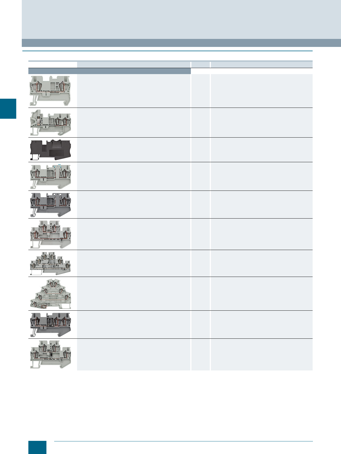
4/2 Siemens LV 52 · 2016
Introduction
8WH2 Spring-Loaded Terminals
4
■
Overview
Devices Page Application
8WH terminals
Through-type terminals 4/7 Connection of incoming and outgoing conductors
up to 35 mm2
Hybrid through-type terminals 4/18 Terminals with a range of connection methods
Fuse terminals 4/21 Terminals which can be used to protect control circuits,
for example
Isolating blade terminals 4/23 Isolation of the circuit, e.g. for test purposes
Isolating terminals 4/25 Isolation of the circuit, e.g. for test purposes
Two-tier terminals 4/27 Compact form of the terminal blocks in which two
connection wires can be installed
Three-tier terminals 4/33 Compact terminal blocks up to 2.5 mm2, in which three
connection wires can be installed
Four-tier motor terminals 4/35 Compact terminal blocks up to 4 mm2, in which three
connection wires plus PE can be installed
Diode terminals 4/37 Terminal blocks with integrated diodes
Two-tier diode terminals 4/39 Terminal blocks with integrated diodes
© Siemens AG 2015© Siemens AG 2015
4/3
Siemens LV 52 · 2016
8WH2 Spring-Loaded Terminals
General data on 8WH
4
■
Overview
1) Only the main terminal types are listed here. You will find further versions on the following pages.
Terminal type →Standard spring-loaded connection Article No.
(digits 8 ... 12)
Design →Standard Two-tier
No. of clamping points →23446
Article No. (digits 1 ... 7) →8WH2000 8WH2003 8WH2004 8WH2020 8WH2023
Conductor
cross-section Terminal type1) Color
1.5 mm2Through-type Gray ✔✔✔✔-- 0AE00
Blue ✔✔✔✔-- 0AE01
PE Green/yellow ✔✔✔✔-- 0CE07
2.5 mm2Through-type Gray ✔✔✔✔✔0AF00
Blue ✔✔✔✔✔0AF01
Isolating Gray ✔✔✔-- -- 6AF00
Isolating blade Gray ✔✔✔-- -- 0CF00
PE Green/yellow ✔✔✔✔✔0CF07
4 mm2Through-type Gray ✔✔✔✔-- 0AG00
Blue ✔✔✔✔-- 0AG01
Isolating Gray ✔-- -- -- -- 6AG00
Isolating blade Gray ✔-- -- -- -- 6CG00
PE Green/yellow ✔✔✔✔-- 0CG07
6 mm2Through-type Gray ✔ ✔ -- -- -- 0AH00
Blue ✔ ✔ -- -- -- 0AH01
PE Green/yellow ✔ ✔ -- -- -- 0CH07
10 mm2Through-type Gray ✔-- -- -- -- 0AJ00
Blue ✔-- -- -- -- 0AJ01
PE Green/yellow ✔-- -- -- -- 0CJ07
16 mm2Through-type Gray ✔-- -- -- -- 0AK00
Blue ✔-- -- -- -- 0AK01
PE Green/yellow ✔-- -- -- -- 0CK07
35 mm2Through-type Gray ✔-- -- -- -- 0AM00
Blue ✔-- -- -- -- 0AM01
PE Green/yellow ✔-- -- -- -- 0CM07
© Siemens AG 2015© Siemens AG 2015
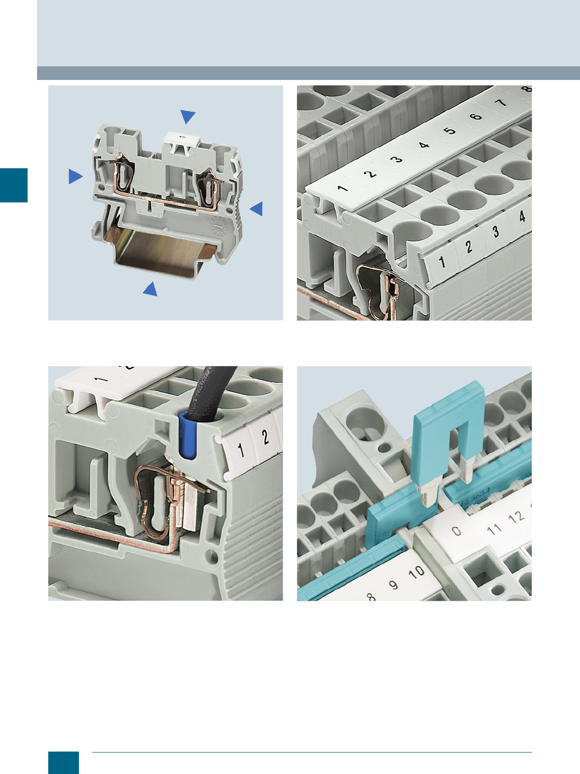
4/4 Siemens LV 52 · 2016
General data on 8WH
8WH2 Spring-Loaded Terminals
4
The space-saving design and conductor routing from above
make spring-loaded terminals ideal for controlgear installations
with minimum available space. The terminals are open at one
end and can be closed using the appropriate covers.
Spring-loaded terminals provide a large connection compart-
ment for fast wiring of flexible and rigid conductors, including
conductors with nominal cross-section and a fitted end sleeve.
The large and unambiguous marking in the center of the terminal
is essential for ensuring reliable installation in minimum time.
Each clamping point can also be separately labeled.
Reducing combs enable easy connection of terminals with vari-
ous nominal cross-sections. For example, they can be used for
the fast creation of infeed blocks, e.g. by connecting a 10 mm²
spring-loaded terminal with a 2.5 or 4 mm² spring-loaded termi-
nal.
© Siemens AG 2015© Siemens AG 2015
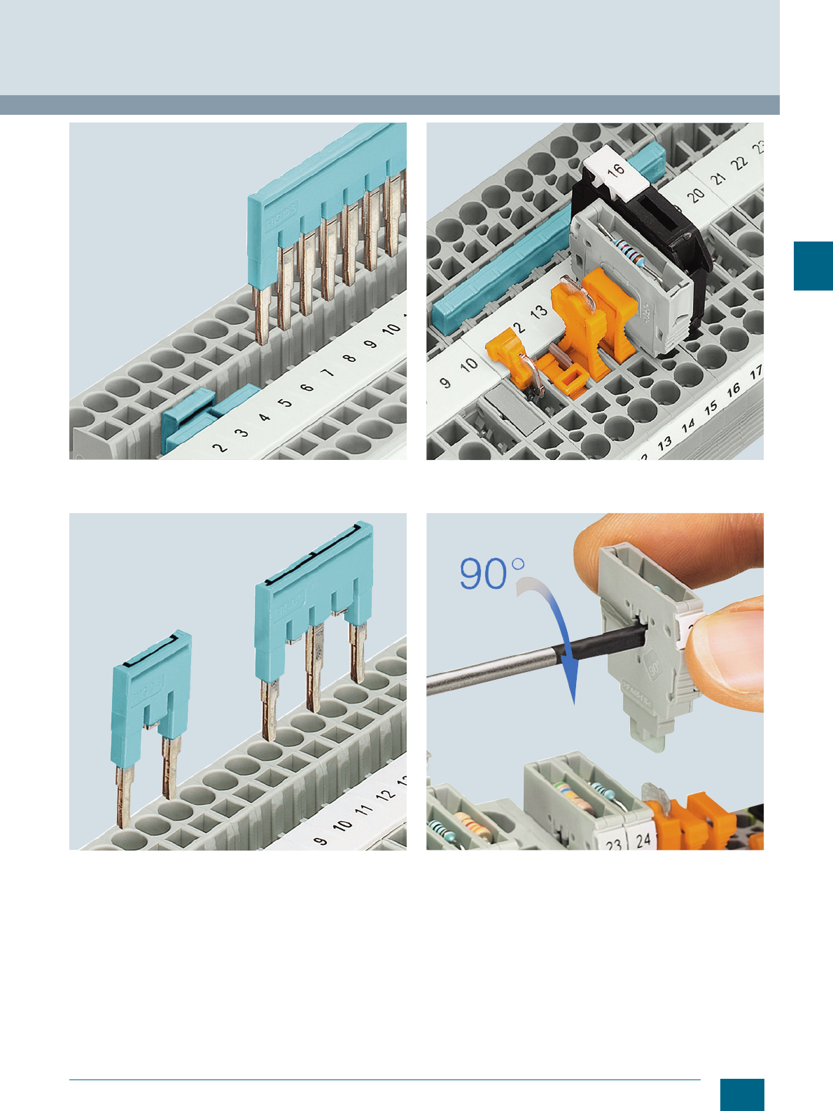
4/5
Siemens LV 52 · 2016
8WH2 Spring-Loaded Terminals
General data on 8WH
4
The 2- to 50-pole connecting combs also considerably reduce
the time needed for assembly and wiring as they enable up to
50 terminals to be connected in a single step.
Contact tabs can be removed from the standard comb in order
to skip individual terminals. This means that two potentials can
run in parallel on a single terminal strip. The contact points can
additionally be marked.
The universal plug-in zones of the isolating terminal can accom-
modate the isolated through-type connectors, isolating plugs,
component connectors and fused connectors.
The component connector enables the convenient equipping
with electronic components. One turn of the screwdriver opens
the contact points and the component is easily inserted.
© Siemens AG 2015© Siemens AG 2015
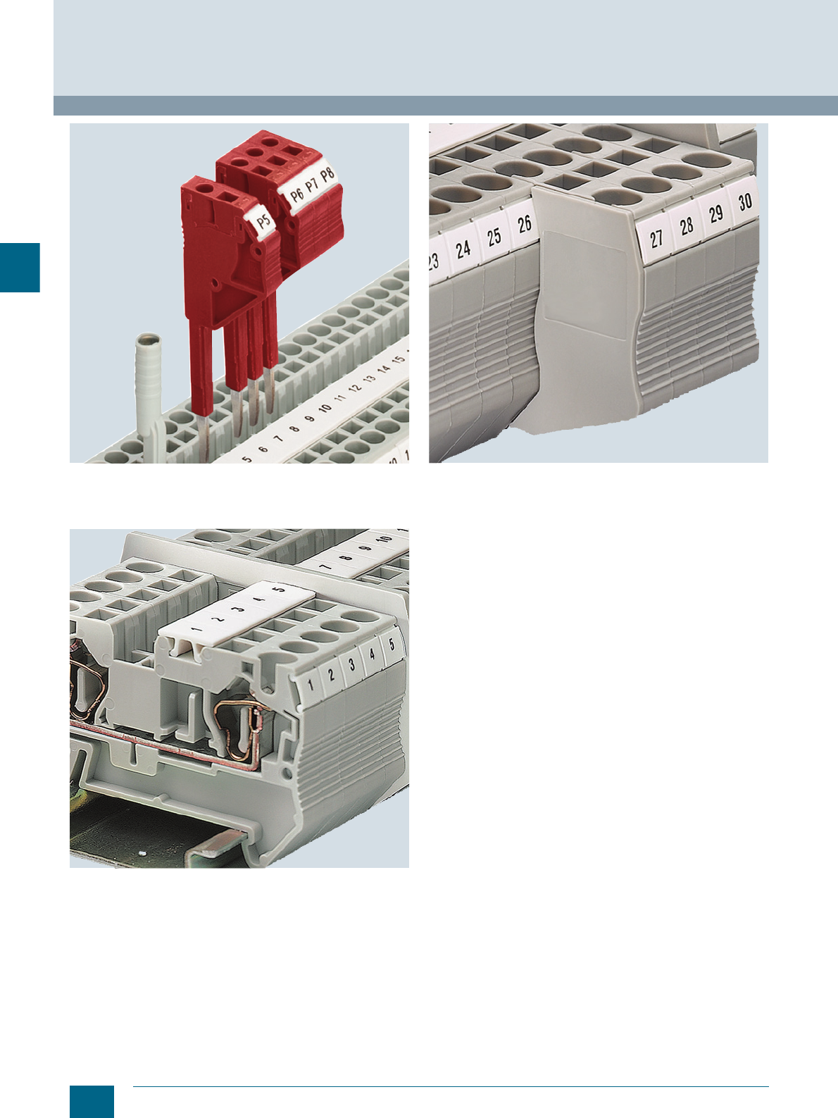
4/6 Siemens LV 52 · 2016
General data on 8WH
8WH2 Spring-Loaded Terminals
4
A comprehensive range of test accessories is also available for
the spring-loaded terminal series. The test adapters for Ø 4 mm
test plugs and modular test plugs enable all measuring and test-
ing jobs to be performed in minimum time.
The compartment partitions project beyond the contours of the
terminals and separate the groups both visually and electrically.
Cover segments are used to cover the projecting terminal seg-
ments of three and four-wire terminals when mounting two-wire
terminals side-by-side. This ensures touch protection.
Note: The accessories for 8WH can only be used for
8WH terminals.
© Siemens AG 2015© Siemens AG 2015
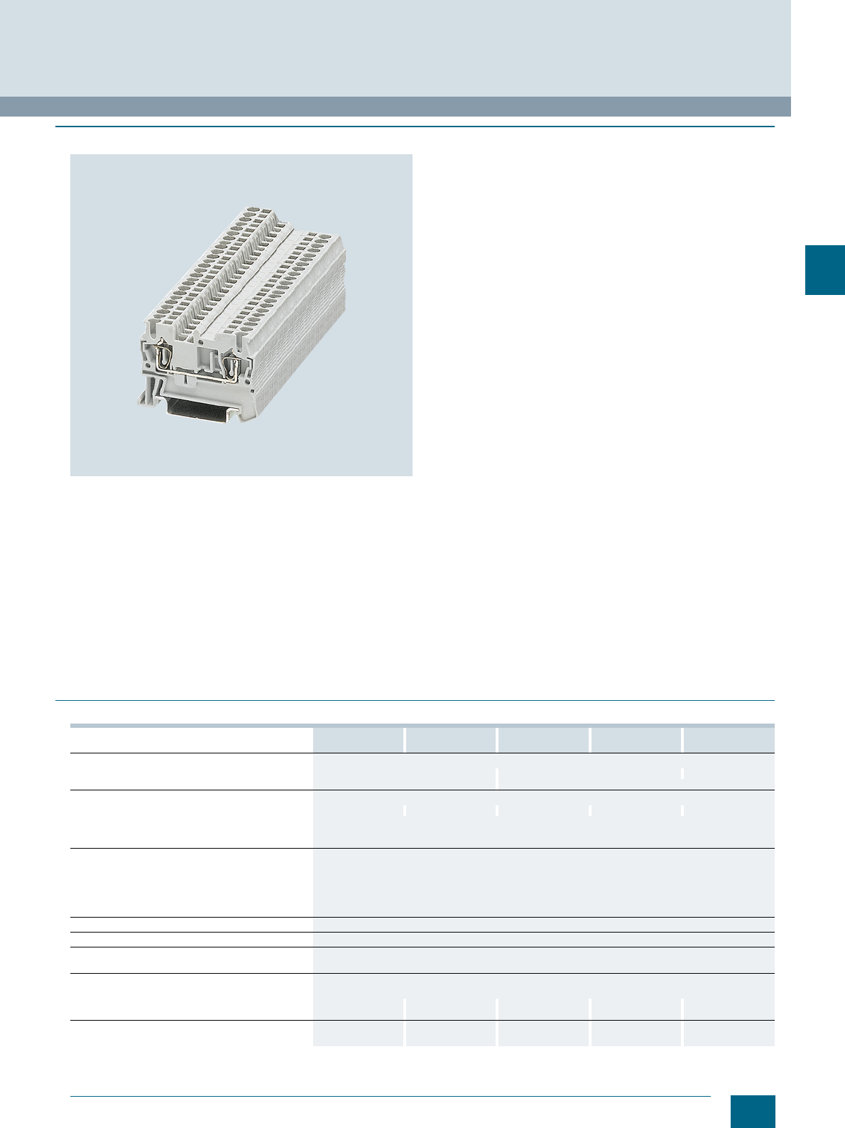
4/7
Siemens LV 52 · 2016
8WH2 Spring-Loaded Terminals
8WH through-type terminals
4
■
Overview
With two clamping points
The through-type terminals have an impressive space-saving
design and offer optimized handling. With its front connection
arrangement this series provides additional space between the
cable ducts for wiring.
The double bridge shaft enables individual chain bridging with
connecting combs. Accessories are available for testing and
labeling.
With three clamping points
Terminals with three clamping points are a space-saving alterna-
tive to the standard through-type terminals for branching the
potential.
It is often necessary for three conductors to be routed to a single
terminal.This three clamping point version enables this without
the need for additional terminals and jumpers.
With four clamping points
The double connection of the through-type terminals with four
clamping points enables four conductors to be connected to a
single potential. These versions with four clamping points are
therefore suitable for use as compact potential distributors.
A label can be snapped on to the middle of each terminal at the
front. Further labels can also be mounted flat on the side of the
terminals.
PE/ground conductor function
The PE through-type terminals are available with the same
contour as the through-type terminals. Simply snap the terminals
onto the support rail to achieve full mechanical and electrical
contact with the support rail.
The PE through-type terminals meet all the requirements of
IEC 60947-7-2:
• Low contact resistance
• Stainless clamping points
• Green-yellow enclosure
• Additional inscription options
■
Technical specifications
8WH2000-0AE0. 8WH2000-0CE07 8WH2003-0AE00
8WH2003-0AE01 8WH2003-0CE07 8WH2004-0AE00
8WH2004-0AE01
Dimensions
• Width/length/cover width in mm 4.2 / 48.5 / 2.2 4.2 / 60.5 / 2.2 4.2 / 72 / 2.2
• Height (NS 35/7.5 / NS 35/15) in mm 36.8 / 44 36.5 / 44
Technical specifications acc. to IEC/DIN VDE
• Max. load current in A / cross-section in mm² 17.5 / 1.5 -- 17.5 / 1.5 -- 17.5 / 1.5
• Rated impulse withstand voltage in kV / pollution
degree 6 / 3
• Overvoltage category / molded plastic group III / I
Connection capacities
• Flexible with end sleeve, with plastic sleeve in mm² 0.25 ... 1.5
• Flexible with end sleeve, without plastic sleeve in
mm² 0.25 ... 1.5
• Flexible with two-wire connection end sleeve, with
plastic sleeve in mm² 0.5
Stripped length in mm 10
Plug gauge (IEC 60947-1) A1
Molded plastic type PA
• Flammability Class acc. to UL 94 V0
Approval data (UL/cUL and CSA)
• Rated voltage / rated current / conductor sizes
- UL/cUL: in V/A / AWG 300 / 15 / 26 ... 14 -- / -- / 26 ... 14 300 / 15 / 26 ... 14 -- / -- / 26 ... 14 300 / 15 / 26 ... 14
- CSA: in V/A / AWG 300 / 15 / 26 ... 14 -- / -- / 26 ... 14 300 / 15 / 26 ... 14 -- 300 / 15 / 26 ... 14
Support rails/protective conductor busbars -- See page 1/3, sec-
tion "Support rails" -- See page 1/3, sec-
tion "Support rails" --
© Siemens AG 2015© Siemens AG 2015
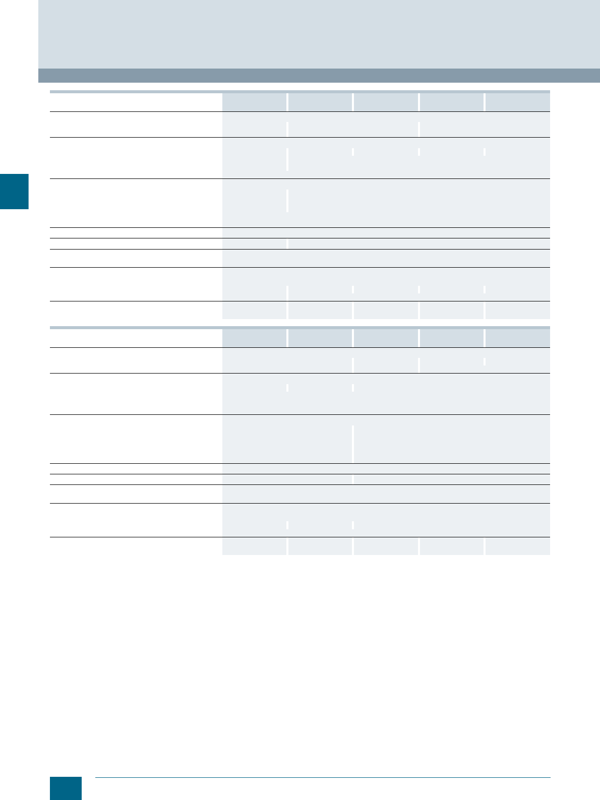
4/8 Siemens LV 52 · 2016
8WH through-type terminals
8WH2 Spring-Loaded Terminals
4
8WH2004-0CE07 8WH2000-0AF0. 8WH2000-0CF07 8WH2003-0AF00
8WH2003-0AF01 8WH2003-0CF07
Dimensions
• Width/length/cover width in mm 4.2 / 72 / 2.2 5.2 / 48.5 / 2.2 5.2 / 60.5 / 2.2
• Height (NS 35/7.5 / NS 35/15) in mm 36.5 / 44 36.8 / 44 36.5 / 44
Technical specifications acc. to IEC/DIN VDE
• Max. load current in A / cross-section in mm² -- 31 / 4 -- 28 / 4 --
• Rated impulse withstand voltage in kV / pollution
degree 6 / 3 8 / 3
• Overvoltage category / molded plastic group III / I
Connection capacities
• Flexible with end sleeve, with plastic sleeve in mm² 0.25 ... 1.5 0.25 ... 2.5
• Flexible with end sleeve, without plastic sleeve in
mm² 0.25 ... 1.5 0.25 ... 2.5
• Flexible with two-wire connection end sleeve, with
plastic sleeve in mm² 0.5
Stripped length in mm 10
Plug gauge (IEC 60947-1) A1 A3
Molded plastic type PA
• Flammability Class acc. to UL 94 V0
Approval data (UL/cUL and CSA)
• Rated voltage / rated current / conductor sizes
- UL/cUL: in V/A / AWG -- / -- / 26 ... 14 300 / 20 / 26 ... 12 -- / -- / 26 ... 12 600 / 20 / 26 ... 12 -- / -- / 26 ... 12
- CSA: in V/A / AWG -- / -- / 26 ... 14 --
Support rails/protective conductor busbars See page 1/3, sec-
tion "Support rails" -- See page 1/3, sec-
tion "Support rails" -- See page 1/3, sec-
tion "Support rails"
8WH2004-0AF00
8WH2004-0AF01 8WH2004-0CF07 8WH2000-0AG0. 8WH2003-0AG00
8WH2003-0AG01 8WH2004-0AG00
8WH2004-0AG01
Dimensions
• Width/length/cover width in mm 5.2 / 72 / 2.2 6.2 / 56 / 2.2 6.2 / 71.5 / 2.2 6.2 / 87 / 2.2
• Height (NS 35/7.5 / NS 35/15) in mm 36.5 / 44 36.8 / 44 36.5 / 44
Technical specifications acc. to IEC/DIN VDE
• Max. load current in A / cross-section in mm² 28 / 4 -- 40 / 6
• Rated impulse withstand voltage in kV / pollution
degree 8 / 3
• Overvoltage category / molded plastic group III / I
Connection capacities
• Flexible with end sleeve, with plastic sleeve in mm² 0.25 ... 2.5 0.25 ... 4
• Flexible with end sleeve, without plastic sleeve in
mm² 0.25 ... 2.5 0.25 ... 4
• Flexible with two-wire connection end sleeve, with
plastic sleeve in mm² 0.5 0.5 ... 1
Stripped length in mm 10
Plug gauge (IEC 60947-1) A3 A4
Molded plastic type PA
• Flammability Class acc. to UL 94 V0
Approval data (UL/cUL and CSA)
• Rated voltage / rated current / conductor sizes
- UL/cUL: in V/A / AWG 600 / 20 / 26 ... 12 -- / -- / 26 ... 12 600 / 30 / 20 ... 10
- CSA: in V/A / AWG --
Support rails/protective conductor busbars -- See page 1/3, sec-
tion "Support rails" -- -- --
© Siemens AG 2015© Siemens AG 2015
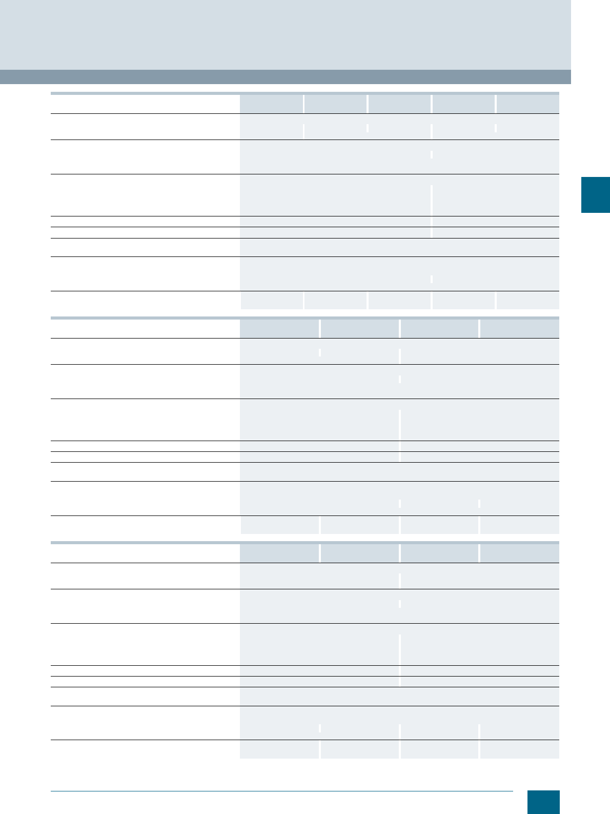
4/9
Siemens LV 52 · 2016
8WH2 Spring-Loaded Terminals
8WH through-type terminals
4
8WH2000-0CG07 8WH2003-0CG07 8WH2004-0CG07 8WH2000-0AH00
8WH2000-0AH01 8WH2003-0AH00
8WH2003-0AH01
Dimensions
• Width/length/cover width in mm 6.2 / 56 / 2.2 6.2 / 71.5 / 2.2 6.2 / 87 / 2.2 8.2 / 69.5 / 2.2 8.2 / 90.5 / 2.2
• Height (NS 35/7.5 / NS 35/15) in mm 36.8 / 44 36.5 / 44 43.5 / 51
Technical specifications acc. to IEC/DIN VDE
• Max. load current in A / cross-section in mm² -- 52 / 10
• Rated impulse withstand voltage in kV / pollution degree 8 / 3
• Overvoltage category / molded plastic group III / I
Connection capacities
• Flexible with end sleeve, with plastic sleeve in mm² 0.25 ... 4 0.25 ... 6
• Flexible with end sleeve, without plastic sleeve in mm² 0.25 ... 4 0.25 ... 6
• Flexible with two-wire connection end sleeve, with plastic
sleeve in mm² 0.5 ... 1 0.5 ... 1.5
Stripped length in mm 10 12
Plug gauge (IEC 60947-1) A4 A5
Molded plastic type PA
• Flammability Class acc. to UL 94 V0
Approval data (UL/cUL and CSA)
• Rated voltage / rated current / conductor sizes
- UL/cUL: in V/A / AWG -- / -- / 20 ... 10 600 / 50 / 20 ... 8
- CSA: in V/A / AWG --
Support rails/protective conductor busbars See page 1/3, sec-
tion "Support rails" See page 1/3, sec-
tion "Support rails" See page 1/3, sec-
tion "Support rails" -- --
8WH2000-0CH07 8WH2003-0CH07 8WH2000-0AJ00
8WH2000-0AJ01 8WH2000-0CJ07
Dimensions
• Width/length/cover width in mm 8.2 / 69.5 / 2.2 8.2 / 90.5 / 2.2 10 / 71.5 / 2.2
• Height (NS 35/7.5 / NS 35/15) in mm 43.5 / 51 50.5 / 58
Technical specifications acc. to IEC/DIN VDE
• Max. load current in A / cross-section in mm² -- 65 / 16
• Rated impulse withstand voltage in kV / pollution degree 8 / 3
• Overvoltage category / molded plastic group III / I
Connection capacities
• Flexible with end sleeve, with plastic sleeve in mm² 0.25 ... 6 0.25 ... 10
• Flexible with end sleeve, without plastic sleeve in mm² 0.25 ... 6 0.25 ... 10
• Flexible with two-wire connection end sleeve, with plastic
sleeve in mm² 0.5 ... 1.5 1.5 ... 2.5
Stripped length in mm 12 18
Plug gauge (IEC 60947-1) A5 A6
Molded plastic type PA
• Flammability Class acc. to UL 94 V0
Approval data (UL/cUL and CSA)
• Rated voltage / rated current / conductor sizes
- UL/cUL: in V/A / AWG -- / -- / 20 ... 8 600 / 65 / 16 ... 6 -- / -- / 16 ... 6
- CSA: in V/A / AWG --
Support rails/protective conductor busbars See page 1/3, section
"Support rails" See page 1/3, section
"Support rails" -- See page 1/3, section
"Support rails"
8WH2000-0AK00
8WH2000-0AK01 8WH2000-0CK07 8WH2000-0AM00
8WH2000-0AM01 8WH2000-0CM07
Dimensions
• Width/length/cover width in mm 12 / 80 / 2.2 16 / 100 / --
• Height (NS 35/7.5 / NS 35/15) in mm 51 / 58.5 59 / 66.5
Technical specifications acc. to IEC/DIN VDE
• Max. load current in A / cross-section in mm² 90 / 25 125 / 35
• Rated impulse withstand voltage in kV / pollution degree 8 / 3
• Overvoltage category / molded plastic group III / I
Connection capacities
• Flexible with end sleeve, with plastic sleeve in mm² 0.25... 16 2.5 ... 35
• Flexible with end sleeve, without plastic sleeve in mm² 0.25 ... 16 2.5 ... 35
• Flexible with two-wire connection end sleeve, with plastic
sleeve in mm² 1.5 ... 4 2.5 ... 10
Stripped length in mm 18 25
Plug gauge (IEC 60947-1) A7 A8
Molded plastic type PA
• Flammability Class acc. to UL 94 V0
Approval data (UL/cUL and CSA)
• Rated voltage / rated current / conductor sizes
- UL/cUL: in V/A / AWG 600 / 85 / 16 ... 4 -- / -- / 16 ... 4 600 / 115 / 14 ... 2 -- / -- / 14 ... 2
- CSA: in V/A / AWG -- 600 / 115 / 14 ... 2 -- / -- / 14 ... 2
Support rails/protective conductor busbars -- See page 1/3, section
"Support rails" -- See page 1/3, section
"Support rails"
© Siemens AG 2015© Siemens AG 2015
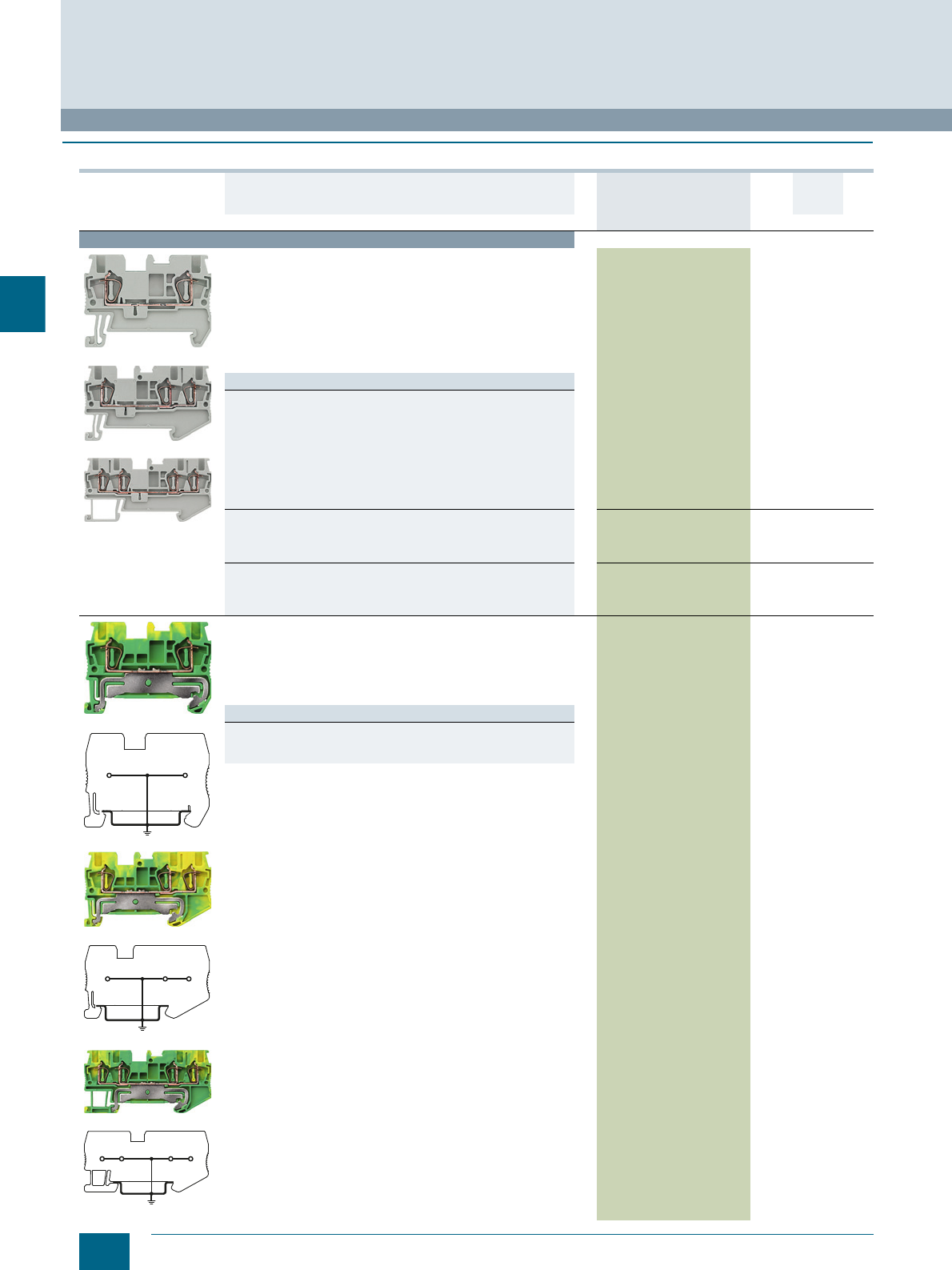
4/10 Siemens LV 52 · 2016 * You can order this quantity or a multiple thereof.
8WH through-type terminals
8WH2 Spring-Loaded Terminals
4
■
Selection and ordering data
Version DT Article No.
www.siemens.com/
product?Article No.
Price
per PU
PU
(UNIT,
SET, M)
PS*/
P. un it PG
Terminal size 1.5 mm²
8WH2000-0AE00
8WH2003-0AE00
8WH2004-0AE00
Through-type terminals, terminal size 1.5 mm²
• Terminal width 4.2 mm, CUUS
• IEC 60947-7-1
- Rigid 0.08 ... 1.5 mm²
- Flexible 0.08 ... 1.5 mm²
- AWG 28-16
-I = 17.5 A
- The total current through all connected conductors must not
exceed the max. load current
-U = 500 V
Versions
• Two clamping points
-Gray 8WH2000-0AE00 150 units1BT
-Blue 8WH2000-0AE01 150 units1BT
- Orange 8WH2000-0AE04 150 units1BT
-Red 8WH2000-0AE02 150 units1BT
- Black 8WH2000-0AE08 150 units1BT
- Green 8WH2000-0AE03 150 units1BT
-White 8WH2000-0AE05 150 units1BT
-Yellow 8WH2000-0AE06 150 units1BT
• Three clamping points
- Gray, s8WH2003-0AE00 150 units1BT
-Blue 8WH2003-0AE01 150 units1BT
- Orange 8WH2003-0AF04 150 units1BT
• Four clamping points
- Gray, s8WH2004-0AE00 150 units1BT
-Blue 8WH2004-0AE01 150 units1BT
- Orange 8WH2004-0AF04 150 units1BT
8WH2000-0CE07
8WH2000-0CE07
8WH2003-0CE07
8WH2003-0CE07
8WH2004-0CE07
8WH2004-0CE07
PE through-type terminals, terminal size 1.5 mm²
• Terminal width 4.2 mm, CUUS
• IEC 60947-7-1
- Rigid 0.08 ... 1.5 mm²
- Flexible 0.08 ... 1.5 mm²
- AWG 28-16
• Green/yellow
Versions
• Two clamping points, s8WH2000-0CE07 150 units1BT
• Three clamping points 8WH2003-0CE07 150 units1BT
• Four clamping points, s8WH2004-0CE07 150 units1BT
I201_12661
I201_12662
I201_12663
© Siemens AG 2015© Siemens AG 2015
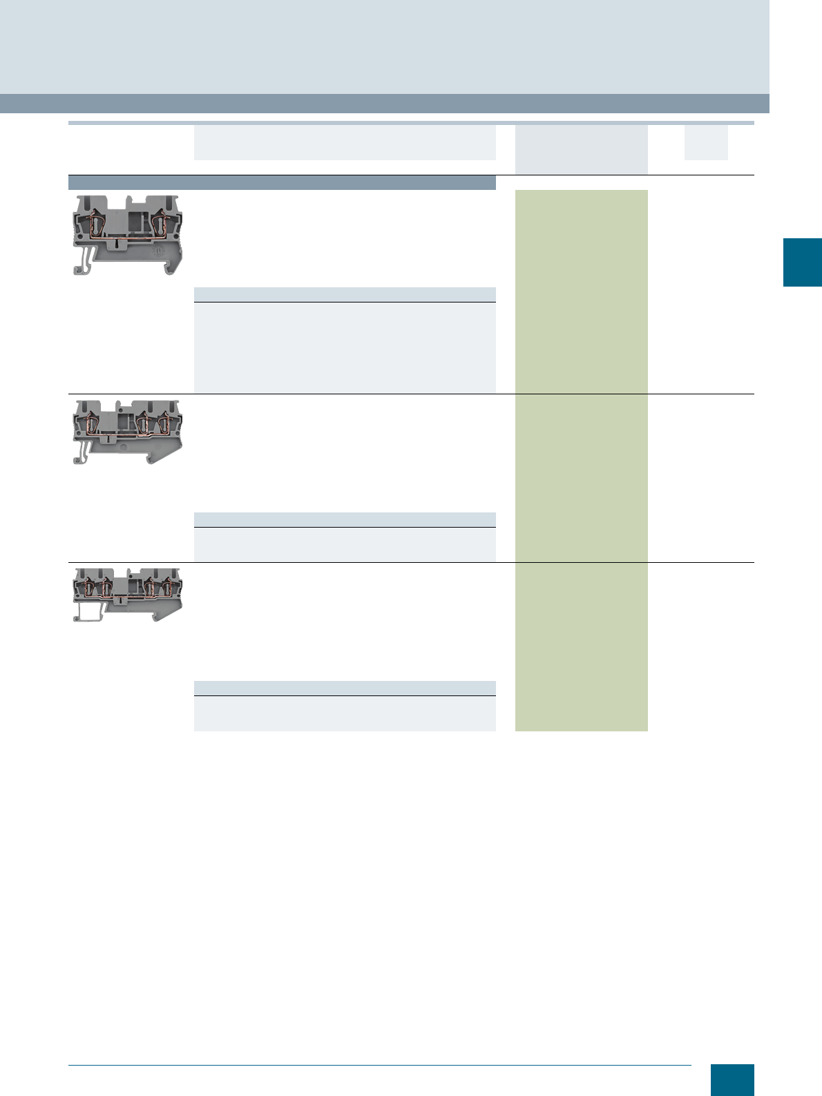
4/11
Siemens LV 52 · 2016
* You can order this quantity or a multiple thereof.
8WH2 Spring-Loaded Terminals
8WH through-type terminals
4
Terminal size 2.5 mm²
8WH2000-0AF00
Through-type terminals, terminal size 2.5 mm², two clamping
points
• Terminal width 5.2 mm, CUUS
• IEC 60947-7-1
- Rigid 0.08 ... 4 mm²
- Flexible 0.08 ... 2.5 mm²
- AWG 28-12
-I = 31 A
-U = 800 V
Versions
•Gray 8WH2000-0AF00 150 units1BT
•Blue 8WH2000-0AF01 150 units1BT
• Orange 8WH2000-0AF04 150 units1BT
•Red 8WH2000-0AF02 150 units1BT
•Black 8WH2000-0AF08 150 units1BT
• Green 8WH2000-0AF03 150 units1BT
•White 8WH2000-0AF05 150 units1BT
• Yellow 8WH2000-0AF06 150 units1BT
8WH2003-0AF00
Through-type terminals, terminal size 2.5 mm², three clamping
points
• Terminal width 5.2 mm, CUUS
• IEC 60947-7-1
- Rigid 0.08 ... 4 mm²
- Flexible 0.08 ... 2.5 mm²
- AWG 28-12
-I = 28 A
- The total current through all connected conductors must not
exceed the max. load current
-U = 800 V
Versions
•Gray 8WH2003-0AF00 150 units1BT
•Blue 8WH2003-0AF01 150 units1BT
•Orange 8WH2003-0AF04 150 units1BT
8WH2004-0AF00
Through-type terminals, terminal size 2.5 mm², four clamping
points
• Terminal width 5.2 mm, CUUS
• IEC 60947-7-1
- Rigid 0.08 ... 4 mm²
- Flexible 0.08 ... 2.5 mm²
- AWG 28-12
-I = 28 A
- The total current through all connected conductors must not
exceed the max. load current
-U = 800 V
Versions
•Gray 8WH2004-0AF00 150 units1BT
•Blue 8WH2004-0AF01 150 units1BT
•Orange 8WH2004-0AF04 150 units1BT
Version DT Article No.
www.siemens.com/
product?Article No.
Price
per PU
PU
(UNIT,
SET, M)
PS*/
P. un it PG
© Siemens AG 2015© Siemens AG 2015
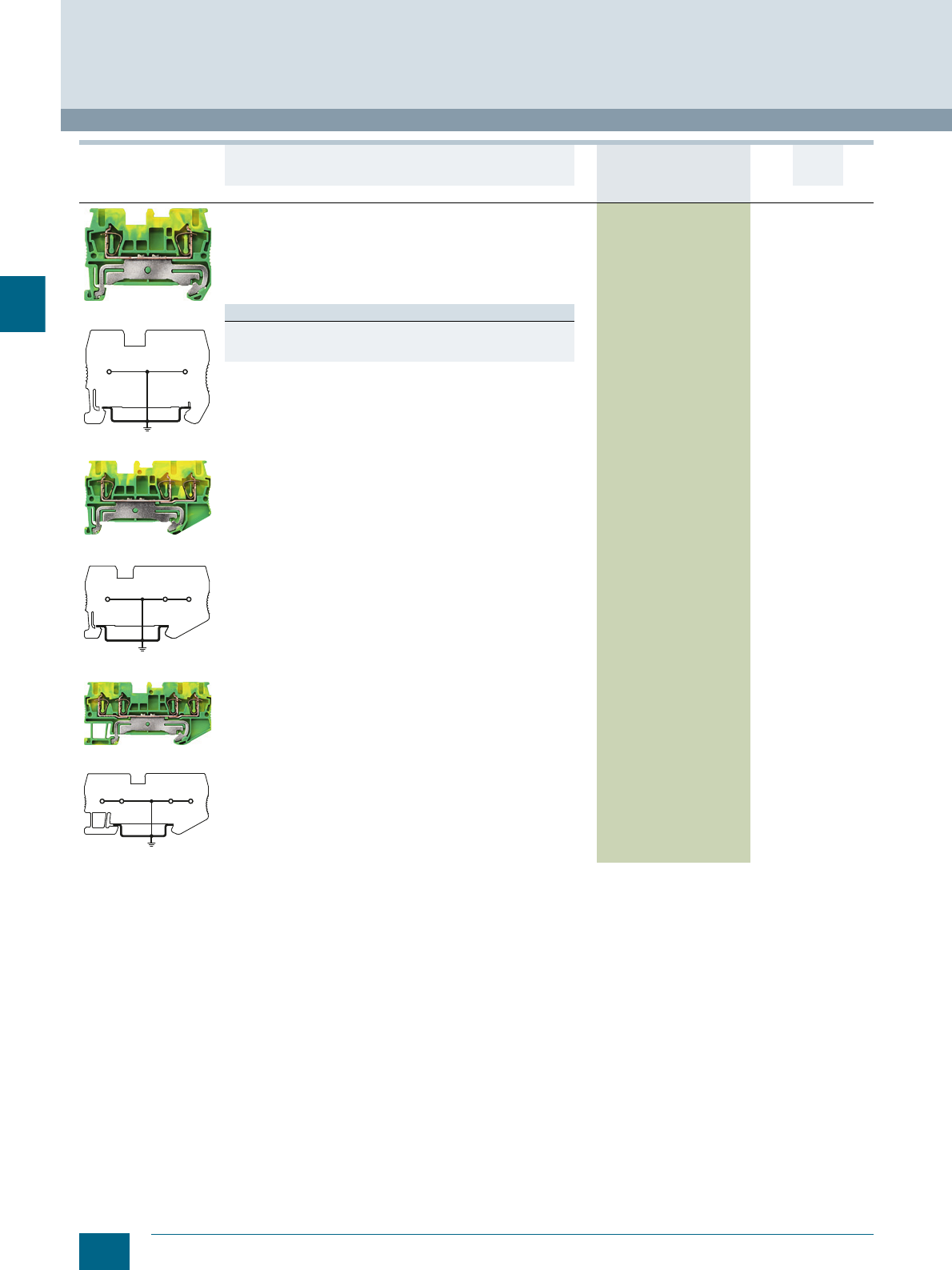
4/12 Siemens LV 52 · 2016 * You can order this quantity or a multiple thereof.
8WH through-type terminals
8WH2 Spring-Loaded Terminals
4
8WH2000-0CF07
8WH2000-0CF07
8WH2003-0CF07
8WH2003-0CF07
8WH2004-0CF07
8WH2004-0CF07
PE through-type terminals, terminal size 2.5 mm²
• Terminal width 5.2 mm
•CUUS
• IEC 60947-7-2
- Rigid 0.08 ... 4 mm²
- Flexible 0.08 ... 2.5 mm²
- AWG 28-12
• Green/yellow
Versions
• Two clamping points 8WH2000-0CF07 150 units1BT
• Three clamping points 8WH2003-0CF07 150 units1BT
• Four clamping points 8WH2004-0CF07 150 units1BT
Version DT Article No.
www.siemens.com/
product?Article No.
Price
per PU
PU
(UNIT,
SET, M)
PS*/
P. un it PG
I201_12664
I201_12665
I201_12666
© Siemens AG 2015© Siemens AG 2015
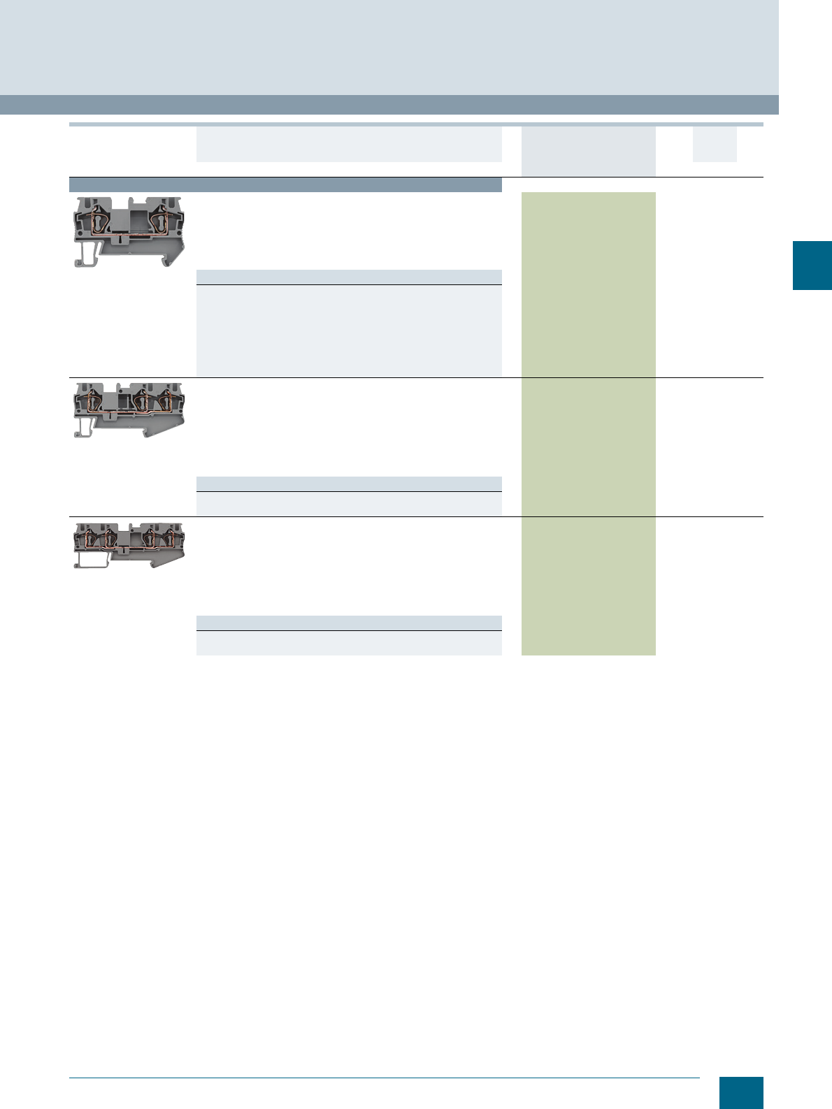
4/13
Siemens LV 52 · 2016
* You can order this quantity or a multiple thereof.
8WH2 Spring-Loaded Terminals
8WH through-type terminals
4
Terminal size 4 mm²
8WH2000-0AG00
Through-type terminals, terminal size 4 mm², two clamping
points
• Terminal width 6.2 mm
•CUUS
• IEC 60947-7-1
- Rigid 0.08 ... 6 mm², flexible 0.08 ... 4 mm², AWG 28-10
-I = 40 A, U = 800 V
Versions
•Gray 8WH2000-0AG00 150 units1BT
•Blue 8WH2000-0AG01 150 units1BT
• Orange 8WH2000-0AG04 150 units1BT
•Red 8WH2000-0AG02 150 units1BT
•Black 8WH2000-0AG08 150 units1BT
• Green 8WH2000-0AG03 150 units1BT
•White 8WH2000-0AG05 150 units1BT
• Yellow 8WH2000-0AG06 150 units1BT
8WH2003-0AG00
Through-type terminals, terminal size 4 mm², three clamping
points
• Terminal width 6.2 mm
•CUUS
• IEC 60947-7-1
- Rigid 0.08 ... 6 mm², flexible 0.08 ... 4 mm², AWG 28-10
-I = 40 A, the total current through all connected conductors must
not exceed the max. load current
-U = 800 V
Versions
•Gray 8WH2003-0AG00 150 units1BT
•Blue 8WH2003-0AG01 150 units1BT
8WH2004-0AG00
Through-type terminals, terminal size 4 mm², four clamping
points
• Terminal width 6.2 mm
•CUUS
• IEC 60947-7-1
- Rigid 0.08 ... 6 mm², flexible 0.08 ... 4 mm², AWG 28-10
-I = 40 A, the total current through all connected conductors must
not exceed the max. load current
-U = 800 V
Versions
•Gray 8WH2004-0AG00 150 units1BT
•Blue 8WH2004-0AG01 150 units1BT
Version DT Article No.
www.siemens.com/
product?Article No.
Price
per PU
PU
(UNIT,
SET, M)
PS*/
P. un it PG
© Siemens AG 2015© Siemens AG 2015
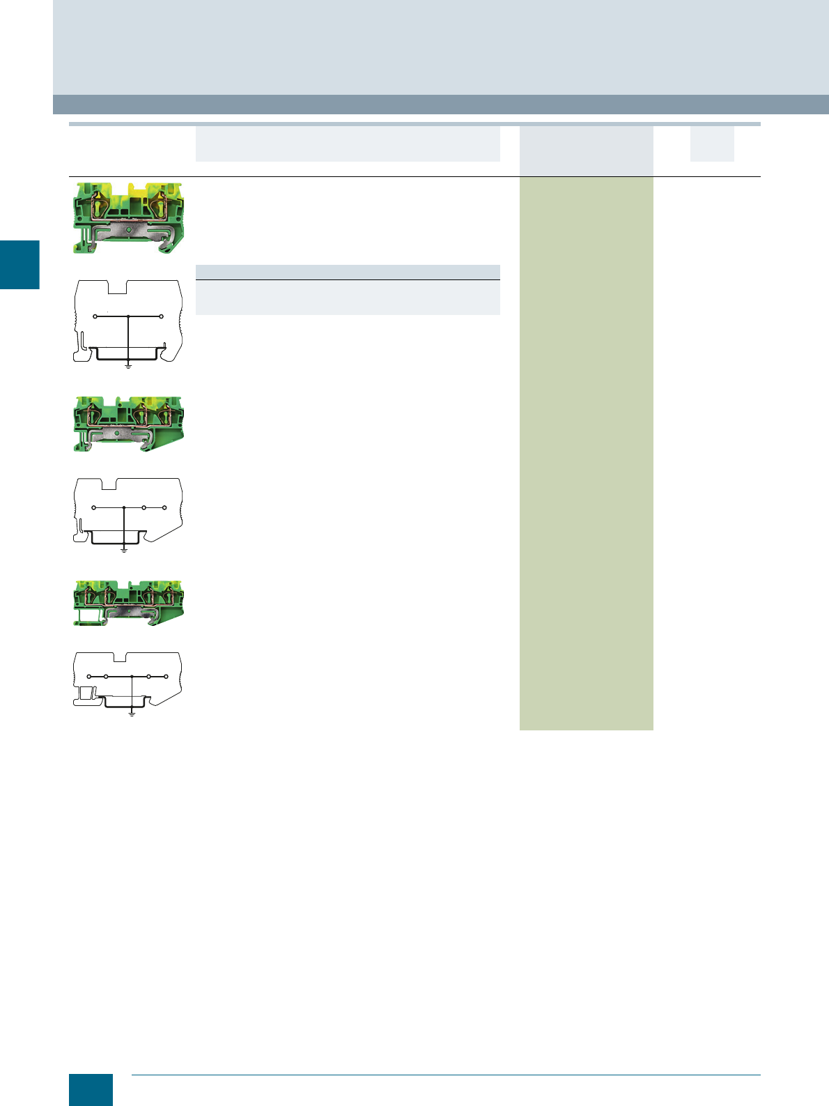
4/14 Siemens LV 52 · 2016 * You can order this quantity or a multiple thereof.
8WH through-type terminals
8WH2 Spring-Loaded Terminals
4
8WH2000-0CG07
8WH2000-0CE07
8WH2003-0CG07
8WH2003-0CG07
8WH2004-0CG07
8WH2004-0CG07
PE through-type terminals, terminal size 4 mm²
• Terminal width 6.2 mm
•CUUS
• IEC 60947-7-2
- Rigid 0.08 ... 6 mm²
- Flexible 0.08 ... 4 mm²
- AWG 28-10
• Green/yellow
Versions
• Two clamping points 8WH2000-0CG07 150 units1BT
• Three clamping points 8WH2003-0CG07 150 units1BT
• Four clamping points 8WH2004-0CG07 150 units1BT
Version DT Article No.
www.siemens.com/
product?Article No.
Price
per PU
PU
(UNIT,
SET, M)
PS*/
P. un it PG
I201_12667
I201_12668
I201_12669
© Siemens AG 2015© Siemens AG 2015
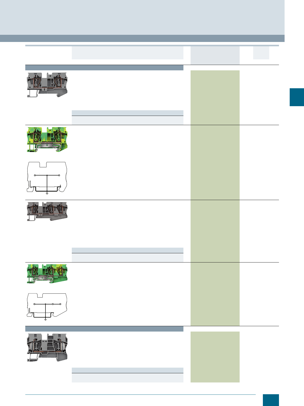
4/15
Siemens LV 52 · 2016
* You can order this quantity or a multiple thereof.
8WH2 Spring-Loaded Terminals
8WH through-type terminals
4
Terminal size 6 mm²
8WH2000-0AH00
Through-type terminals, terminal size 6 mm², two clamping
points
• Terminal width 8.2 mm
•CUUS
• IEC 60947-7-1
- Rigid 0.2 ... 10 mm²
- Flexible 0.2 ... 6 mm²
- AWG 24 ... 8
-I = 52 A
-U = 1000 V
Versions
•Gray 8WH2000-0AH00 150 units1BT
•Blue 8WH2000-0AH01 150 units1BT
8WH2000-0CH07
8WH2000-0CE07
PE through-type terminals, terminal size 6 mm², two clamping
points
• Terminal width 8.2 mm
•CUUS
• IEC 60947-7-2
- Rigid 0.2 ... 10 mm²
- Flexible 0.2 ... 6 mm²
- AWG 24 ... 8
• Green/yellow
8WH2000-0CH07 150 units1BT
8WH2003-0AH00
Through-type terminals, terminal size 6 mm², three clamping
points
• Terminal width 8.2 mm
•CUUS
• IEC 60947-7-1
- Rigid 0.2 ... 10 mm²
- Flexible 0.2 ... 6 mm²
- AWG 24 ... 8
-I = 52 A
- The total current through all connected conductors must not
exceed the max. load current
-U = 1000 V
Versions
•Gray 8WH2003-0AH00 150 units1BT
•Blue 8WH2003-0AH01 150 units1BT
8WH2003-0CH07
8WH2003-0CE07
PE through-type terminals, terminal size 6 mm², three clamping
points
• Terminal width 8.2 mm
•CUUS
• IEC 60947-7-2
- Rigid 0.2 ... 10 mm²
- Flexible 0.2 ... 6 mm²
- AWG 24 ... 8
• Green/yellow
8WH2003-0CH07 150 units1BT
Terminal size 10 mm²
8WH2000-0AJ00
Through-type terminals, terminal size 10 mm²
• Terminal width 10.2 mm
•CUUS
• IEC 60947-7-1
- Rigid 1.5 ... 16 mm²
- Flexible 1.5 ... 10 mm²
- AWG 24-6
-I = 65 A
-U = 1000 V
Versions
•Gray 8WH2000-0AJ00 150 units1BT
•Blue 8WH2000-0AJ01 150 units1BT
Version DT Article No.
www.siemens.com/
product?Article No.
Price
per PU
PU
(UNIT,
SET, M)
PS*/
P. un it PG
I201_12670
I201_12671
© Siemens AG 2015© Siemens AG 2015
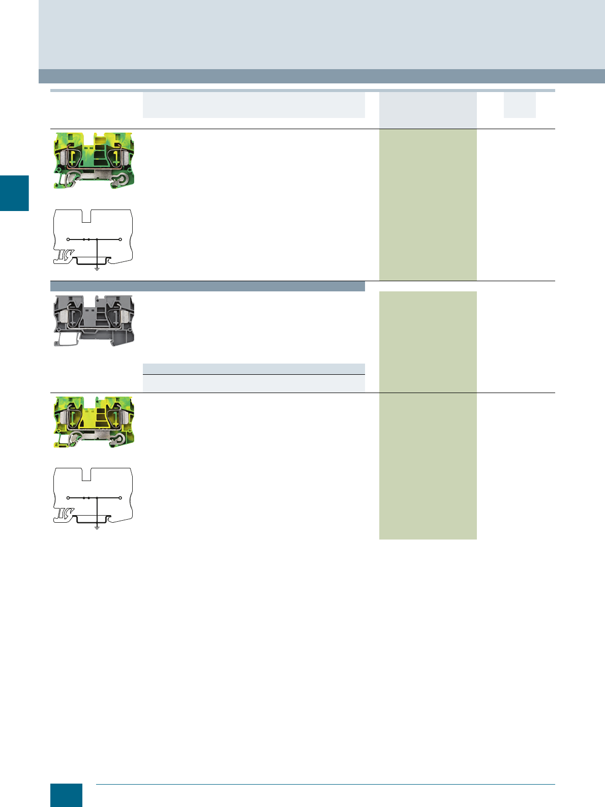
4/16 Siemens LV 52 · 2016 * You can order this quantity or a multiple thereof.
8WH through-type terminals
8WH2 Spring-Loaded Terminals
4
8WH2000-0CJ07
8WH2000-0CJ07
PE through-type terminals, terminal size 10 mm²
• Terminal width 10.2 mm
•CUUS
• IEC 60947-7-2
- Rigid 1.5 ... 16 mm²
- Flexible 1.5 ... 10 mm²
- AWG 24-6
-I = 65 A
• Green/yellow
8WH2000-0CJ07 150 units1BT
Terminal size 16 mm²
8WH2000-0AK00
Through-type terminals, terminal size 16 mm²
• Terminal width 12 mm
•CUUS
• IEC 60947-7-1
- Rigid 1.5 ... 25 mm²
- Flexible 1.5 ... 16 mm²
- AWG 24-4
-I = 90 A
-U = 1000 V
Versions
•Gray 8WH2000-0AK00 150 units1BT
•Blue 8WH2000-0AK01 150 units1BT
8WH2000-0CK07
8WH2000-0CK07
PE through-type terminals, terminal size 16 mm²
• Terminal width 12 mm
•CUUS
• IEC 60947-7-2
- Rigid 1.5 ... 25 mm²
- Flexible 1.5 ... 16 mm²
- AWG 24-4
-I = 90 A
• Green/yellow
8WH2000-0CK07 125 units1BT
Version DT Article No.
www.siemens.com/
product?Article No.
Price
per PU
PU
(UNIT,
SET, M)
PS*/
P. un it PG
I201_12672
I201_12673
© Siemens AG 2015© Siemens AG 2015
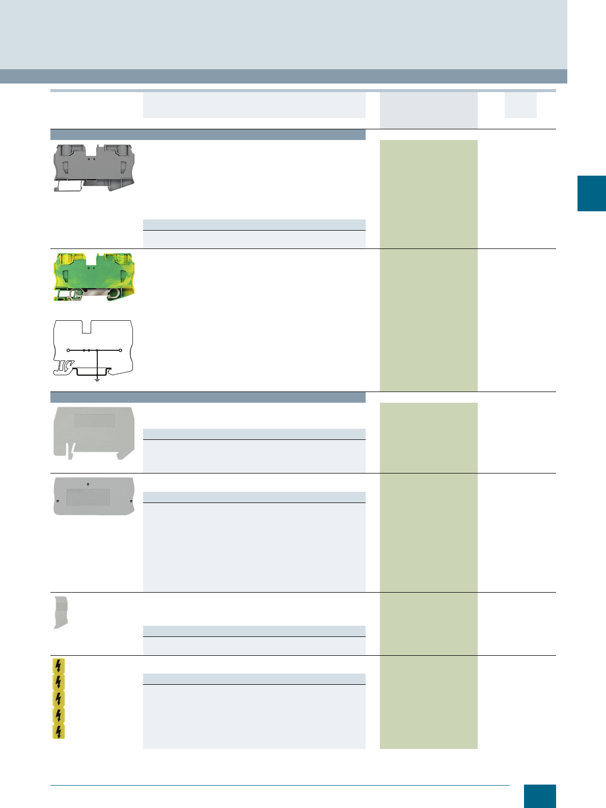
4/17
Siemens LV 52 · 2016
* You can order this quantity or a multiple thereof.
8WH2 Spring-Loaded Terminals
8WH through-type terminals
4
For general accessories for 8WH terminal blocks, see chapter
"Accessories for 8WH Terminal Blocks"
Terminal size 35 mm²
8WH2000-0AM00
Through-type terminals, terminal size 35 mm²
• Terminal width 16 mm
•CUUS
• IEC 60947-7-1
- Rigid 2.5 ... 35 mm²
- Flexible 2.5 ... 35 mm²
- AWG 14 ... 2
-I = 125 A
-U = 1000 V
• Enclosed at both ends
Versions
•Gray, s8WH2000-0AM00 110 units1BT
•Blue 8WH2000-0AM01 110 units1BT
8WH2000-0CM07
8WH2000-0CM07
PE through-type terminals, terminal size 35 mm²
• Terminal width 16 mm
•CUUS, s
• IEC 60947-7-2
- Rigid 2.5 ... 35 mm²
- Flexible 2.5 ... 35 mm²
- AWG 14 ... 2
-I = 125 A
• Enclosed at both ends
• Green/yellow
8WH2000-0CM07 110 units1BT
Accessories
8WH9070-0AA00
Compartment partitions
• For visual and electrical separation of terminal groups
• 2 mm thick
Versions
• For terminal size 1.5 up to 4 mm² and two clamping points 8WH9070-0AA00 100 50 units 1BT
• For terminal size 1.5 up to 4 mm² and three clamping points 8WH9070-0GA00 100 50 units 1BT
• For terminal size 1.5 up to 4 mm² and four clamping points 8WH9070-0HA00 100 50 units 1BT
• For terminal size 6 mm² 8WH9070-0DA00 100 50 units 1BT
8WH9000-1GA00
Covers
Gray
Versions
• For terminal size 1.5 up to 2.5 mm² and two clamping points 8WH9000-1GA00 100 50 units 1BT
• For terminal size 1.5 up to 2.5 mm² and three clamping points 8WH9000-2GA00 100 50 units 1BT
• For terminal size 1.5 up to 2.5 mm² and four clamping points 8WH9000-4GA00 100 50 units 1BT
• For terminal size 4 mm² and two clamping points 8WH9003-1GA00 100 50 units 1BT
• For terminal size 4 mm² and three clamping points 8WH9003-2GA00 100 50 units 1BT
• For terminal size 4 mm² and four clamping points 8WH9003-4GA00 100 50 units 1BT
• For terminal size 6 mm² and two clamping points 8WH9004-1GA00 100 50 units 1BT
• For terminal size 6 mm² and three clamping points 8WH9004-2GA00 100 50 units 1BT
• For terminal size 10 mm² 8WH9005-1GA00 100 50 units 1BT
• For terminal size 16 mm² 8WH9006-1GA00 100 50 units 1BT
8WH9000-0GA00
Cover segments
•Gray
• For covering multi-wire terminals when mounting two-wire terminals
side-by-side
Versions
• For terminal size 1.5 up to 2.5 mm² 8WH9000-0GA00 100 10 units 1BT
• For terminal size 4 mm² 8WH9003-0GA00 100 10 units 1BT
8WH9061-5AA06
Warning covers
Note: For the operating shafts of 8WH2 through-type terminals
Versions
• For terminal size 1.5 mm² 8WH9061-5AA06 100 50 units 1BT
• For terminal size 2.5 mm² 8WH9060-5AA06 100 50 units 1BT
• For terminal size 4 mm² 8WH9063-5AA06 100 50 units 1BT
• For terminal size 6 mm² 8WH9064-5AA06 100 10 units 1BT
• For terminal size 10 mm² 8WH9065-5AA06 100 25 units 1BT
• For terminal size 16 mm² 8WH9066-5AA06 100 25 units 1BT
• For terminal size 35 mm² 8WH9067-5AA06 100 10 units 1BT
Version DT Article No.
www.siemens.com/
product?Article No.
Price
per PU
PU
(UNIT,
SET, M)
PS*/
P. un it PG
I201_12674
© Siemens AG 2015© Siemens AG 2015
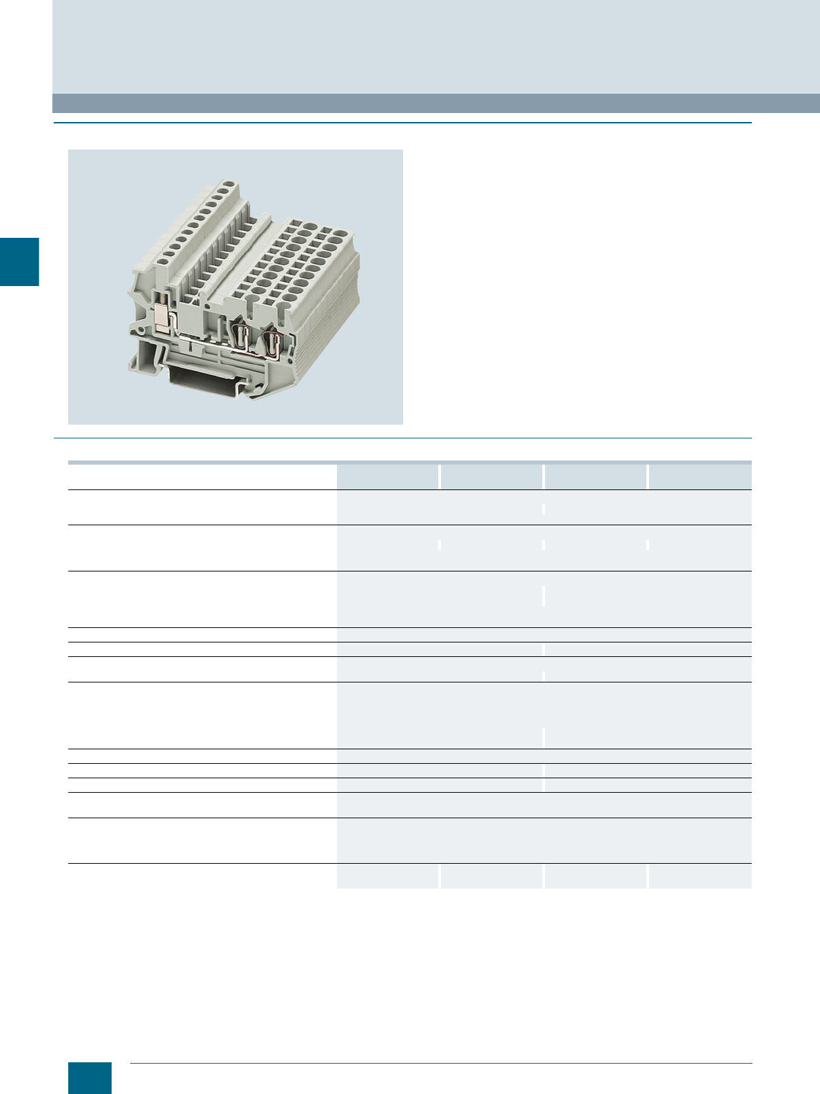
4/18 Siemens LV 52 · 2016
8WH hybrid through-type terminals
8WH2 Spring-Loaded Terminals
4
■
Overview
The terminal connection compartment, on the spring-loaded
side as well as on the screw side, enables connection to a
nominal cross-section of 2.5 mm² or 4 mm², with or without end
sleeves. The advantages of the different connection types are
due to the fact that the spring-loaded terminal of the hybrid
through-type terminal is used inside the control cabinet and the
universal screw terminal is used at the end-user's side.
A PE terminal with the same contour is available for the three-
wire terminal. Contact is made by simply snapping the terminal
onto the support rail.
This meets the following requirements of IEC 60947-7-2:
• Low contact resistance
• Stainless clamping points
• Green-yellow enclosure
• Additional inscription options
A label can be snapped on to the middle of each terminal at the
front. Further labels can also be mounted flat on the side of the
terminals.
■
Technical specifications
8WH2103-2BF00
8WH2103-2BF01 8WH2103-3BF07 8WH2103-2BG00
8WH2103-2BG01 8WH2103-3BG07
Dimensions
• Width/length/cover width in mm 5.2 / 65.3 / 2.2 6.2 / 74.4 / 2.2
• Height (NS 35/7.5 / NS 35/15) in mm 42.8 / 50.3
Technical specifications acc. to IEC/DIN VDE
• Max. load current in A / cross-section in mm² 28 / 4 -- 32 / 6 --
• Rated impulse withstand voltage in kV / pollution degree 8 / 3
• Overvoltage category / molded plastic group III / I
Connection capacities
• Flexible with end sleeve, with plastic sleeve in mm² 0.25 ... 2.5 0.25 ... 4
• Flexible with end sleeve, without plastic sleeve in mm² 0.25 ... 2.5 0.25 ... 4
• Flexible with two-wire connection end sleeve, with plastic
sleeve in mm² 0.5 ... 1
Stripped length in mm 10
Plug gauge (IEC 60947-1) A3 A4
Connection capacity of screw terminal
• Flexible with end sleeves with/without plastic sleeve in mm² 0.25 ... 2.5 / 0.25 ... 2.5 0.25 ... 4 / 0.25 ... 4
Multi-conductor connection (two conductors of same
cross-section)
• Rigid / flexible in mm² 0.14 ... 1.5 / 0.14 ... 1.5
• Flexible with end sleeve, without plastic sleeve in mm² 0.25 ... 1.5
• Flexible with two-wire connection end sleeve, with plastic
sleeve in mm² 0.5 ... 1.5 0.5 ... 2.5
Stripped length in mm 9
Plug gauge (IEC 60947-1) A3 A4
Tightening torque in Nm 0.6 ... 0.8 0.6 ... 0.8
Molded plastic type PA
• Flammability Class acc. to UL 94 V0
Approval data (UL/cUL and CSA)
• Rated voltage / rated current / conductor sizes
- UL/cUL: in V/A / AWG Applied for
- CSA: in V/A / AWG Applied for
Support rails/protective conductor busbars -- See page 1/3, section
"Support rails" -- See page 1/3, section
"Support rails"
© Siemens AG 2015© Siemens AG 2015
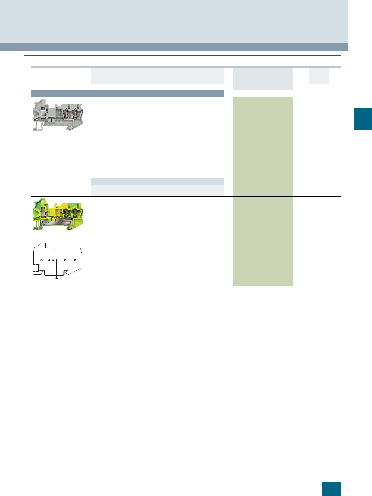
4/19
Siemens LV 52 · 2016
* You can order this quantity or a multiple thereof.
8WH2 Spring-Loaded Terminals
8WH hybrid through-type terminals
4
■
Selection and ordering data
Version DT Article No.
www.siemens.com/
product?Article No.
Price
per PU
PU
(UNIT,
SET, M)
PS*/
P. unit PG
Terminal size 2.5 mm²
8WH2103-2BF00
Hybrid through-type terminals, terminal size 2.5 mm²
• Terminal width 5.2 mm
• IEC 60947-7-1
• Spring
- Rigid 0.08 ... 4 mm²
- Flexible 0.08 ... 2.5 mm²
- AWG 28-12
-I = 28 A
- The total current through all connected conductors must not
exceed the max. load current
-U = 800 V
• Screw
- Rigid 0.14 ... 4 mm²
- Flexible 0.14 ... 2.5 mm²
- AWG 26 ... 14
-I = 28 A
-U = 800 V
Versions
•Gray 8WH2103-2BF00 150 units1BT
•Blue 8WH2103-2BF01 150 units1BT
8WH2103-3BF07
8WH2103-3BF07
PE hybrid through-type terminals, terminal size 2.5 mm²
• Terminal width 5.2 mm
• IEC 60947-7-2
• Spring
- Rigid 0.08 ... 4 mm²
- Flexible 0.08 ... 2.5 mm²
- AWG 28-12
• Screw
- Rigid 0.14 ... 4 mm²
- Flexible 0.14 ... 2.5 mm²
- AWG 26 ... 14
8WH2103-3BF07 150 units1BT
I201_12675
© Siemens AG 2015© Siemens AG 2015
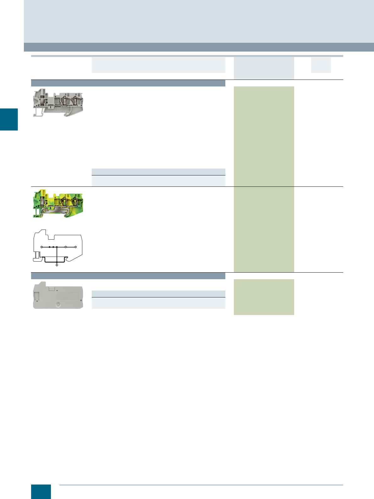
4/20 Siemens LV 52 · 2016 * You can order this quantity or a multiple thereof.
8WH hybrid through-type terminals
8WH2 Spring-Loaded Terminals
4
For general accessories for 8WH terminal blocks, see chapter
"Accessories for 8WH Terminal Blocks"
Terminal size 4 mm²
8WH2103-2BG00
Hybrid through-type terminals, terminal size 4 mm²
• Terminal width 6.2 mm
• IEC 60947-7-1
• Spring
- Rigid 0.08 ... 6 mm²
- Flexible 0.08 ... 4 mm²
- AWG 28-10
-I = 32 A
- The total current through all connected conductors must not
exceed the max. load current
-U = 800 V
• Screw
- Rigid 0.14 ... 6 mm²
- Flexible 0.14 ... 4 mm²
- AWG 26 ... 10
-I = 32 A
-U = 800 V
Versions
•Gray 8WH2103-2BG00 150 units1BT
•Blue 8WH2103-2BG01 150 units1BT
8WH2103-3BG07
8WH2103-3BG07
PE hybrid through-type terminals, terminal size 4 mm²
• Terminal width 6.2 mm
• IEC 60947-7-2
• Spring
- Rigid 0.08 ... 6 mm²
- Flexible 0.08 ... 4 mm²
- AWG 28-10
• Screw
- Rigid 0.14 ... 6 mm²
- Flexible 0.14 ... 4 mm²
- AWG 26 ... 10
8WH2103-3BG07 150 units1BT
Accessories
8WH9000-2HA00
Covers
Gray
Versions
• For terminal size 2.5 mm² and three clamping points 8WH9000-2HA00 100 50 units 1BT
• For terminal size 4 mm² and three clamping points 8WH9003-2HA00 100 50 units 1BT
Version DT Article No.
www.siemens.com/
product?Article No.
Price
per PU
PU
(UNIT,
SET, M)
PS*/
P. unit PG
I201_12676
© Siemens AG 2015© Siemens AG 2015
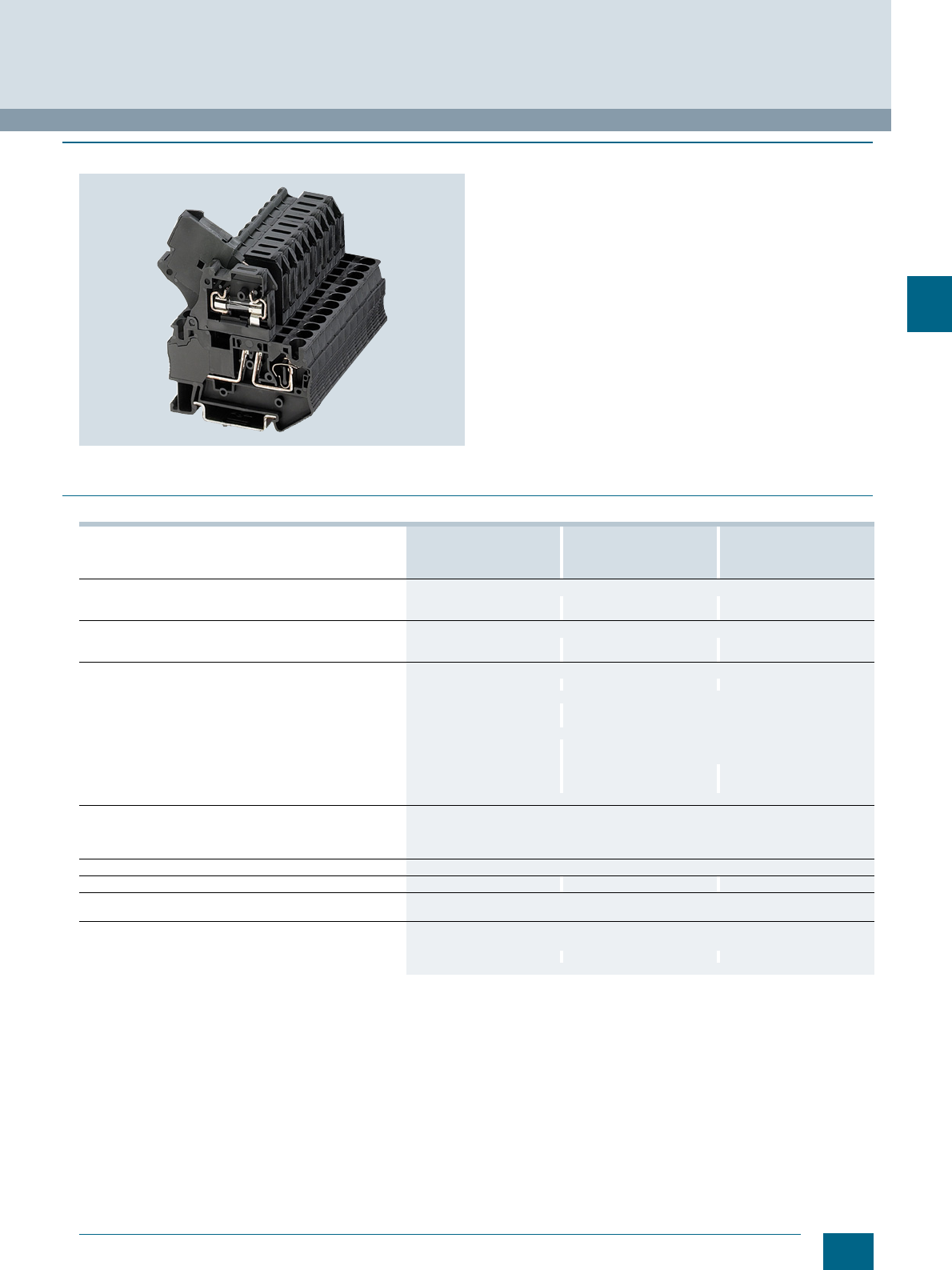
4/21
Siemens LV 52 · 2016
8WH2 Spring-Loaded Terminals
8WH fuse terminals
4
■
Overview
Fuse terminals for blade-type fuses
The fuse terminals for blade-type fuses accommodate blade-
type fuses according to ISO/DIS 8820 / DIN 72581-3. Terminals
with LED display are available for fast fault diagnosis "at a
glance".
Fuse terminals for G fuse links
Fuse terminals perform two important tasks in connected electri-
cal systems. Firstly, they act as a fuse carrier and, secondly, as
a potential distributor.
The full-length bridge shaft enables uninterrupted bridging
between the through-type terminals and the fuse terminals.
Fuse terminals for G fuse links are available for standardized
electrical fuse formats 5 × 20 mm and 6.3 × 32 mm (inch fuse) –
and are optionally available with LED display to signal a blown
fuse.
A label can be snapped on to the middle of the terminal at the
front. Further labels can also be mounted flat on the side of the
terminals.
■
Technical specifications
1) Please note: The G fuse holders must be selected according to the maxi-
mum power loss (heat dissipation) of the G fuse links. Depending on the
application and method of installation, the heat rise conditions in closed
fuse holders must be tested. Higher ambient temperatures represent an
additional load for the fuse links. A shift in rated current should therefore be
taken into account in such applications. When selecting G fuse links, make
sure that they do not exceed the specified maximum power loss.
For specification details, contact the fuse manufacturer.
8WH2000-1AG08
8WH2000-1BG28
8WH2000-1BG38
8WH2000-1GG08
8WH2000-1JG38
8WH2000-1JG68
8WH2000-1MG08
8WH2000-1HG08
8WH2000-1NG38
8WH2000-1NG68
8WH2000-1RG08
Dimensions
• Width/length in mm 8.2 / 86.5 6.2 / 61.5 8.2 / 76.5
• Height (NS 35/7.5 / NS 35/15) in mm 43.5 / 51 62.5 / 70 69 / 76.5
Technical specifications acc. to IEC/DIN VDE
• Fuse type ISO/DIS 8820 / DIN 72581-3 / dimensions / in mm CG / 5 × 20 G / 6.3 × 32
• Maximum current for single arrangement in A 30 3.3 10
Max. power loss at 23 °C acc. to IEC 60647-7-3 in W1)
•U in V -- 250 400
• Overload protection
- Individually in W -- 1.6
- As group in W -- 1.6
• Only short-circuit protection
- Individually in W -- 4
- As group in W -- 2.5
•Imax in A -- 6.3 10
• Rated impulse withstand voltage in kV / pollution degree 6 / 3 4 / 3 6 / 3
• Overvoltage category / molded plastic group III / I
Connection capacities
• Flexible with end sleeve without/with plastic sleeve in mm² 0.25 ... 4 / 0.25 ... 4
• Flexible with two-wire connection end sleeve, with plastic
sleeve in mm² 0.5
Stripped length in mm 10
Plug gauge (IEC 60947-1) A4 A3 A4
Molded plastic type PA
• Flammability Class acc. to UL 94 V0
Approval data (UL/cUL and CSA)
• Rated voltage / rated current / conductor sizes
- UL/cUL: in V/A / AWG 600 / 30 / 24 ... 10 300 / 6.3 / 24 ... 10 300 / 10 / 24 ... 10
- CSA: in V/A / AWG --
© Siemens AG 2015© Siemens AG 2015
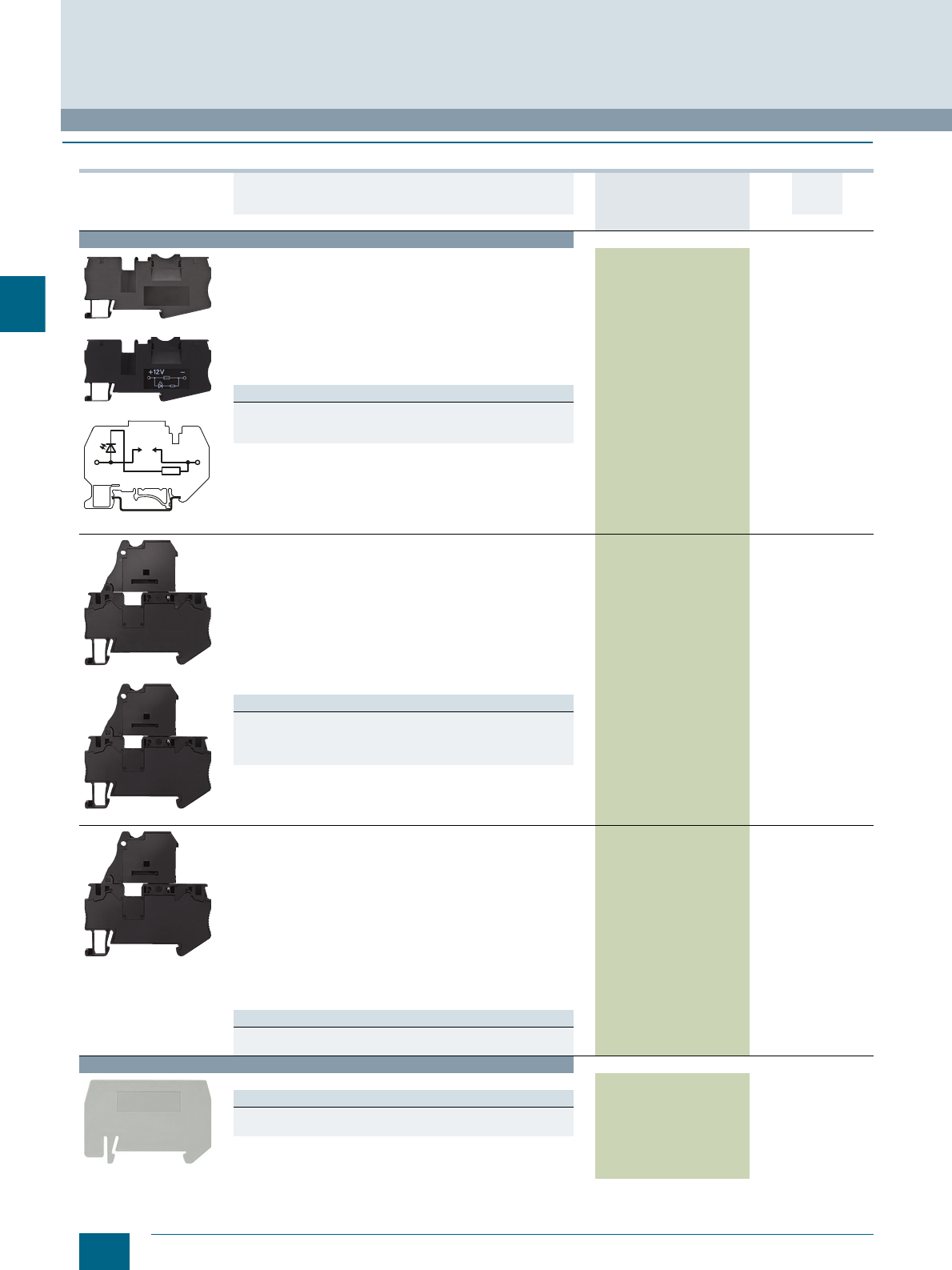
4/22 Siemens LV 52 · 2016 * You can order this quantity or a multiple thereof.
8WH fuse terminals
8WH2 Spring-Loaded Terminals
4
■
Selection and ordering data
For general accessories for 8WH terminal blocks, see chapter
"Accessories for 8WH Terminal Blocks"
Version DT Article No.
www.siemens.com/
product?Article No.
Price
per PU
PU
(UNIT,
SET, M)
PS*/
P. unit PG
Terminal size 4 mm²
8WH2000-1AG08
8WH2000-1BG28
8WH2000-1BG28
Fuse terminals, terminal size 4 mm², for blade-type fuses
acc. to ISO/DIS8820/DIN72581-3
• Terminal width 8.2 mm
•CUUS
• Connection data
- Rigid 0.08 ... 6 mm²
- Flexible 0.08 ... 4 mm²
- AWG 28-10
-I = 30 A
-U = 400 V
• Enclosed at both ends
Versions
• Without LED display 8WH2000-1AG08 150 units1BT
• LED display 12 V 8WH2000-1BG28 150 units1BT
• LED display 24 V 8WH2000-1BG38 150 units1BT
8WH2000-1GG08
8WH2000-1JG38
Fuse terminals, terminal size 4 mm², for 5 x 20 mm G fuse links
• Terminal width 6.2 mm
•CUUS
• IEC 60947-7-3
•With fuse
- Rigid 0.08 ... 6 mm², flexible 0.08 ... 4 mm², AWG 28-10
-Imax = 6.3 A, only short-circuit protection, single 4 W,
group 2.5 W
-U = 250 V, overload protection, single 4 W, group 1.6 W
• As isolating terminal
- Rigid 0.08 ... 6 mm², flexible 0.08 ... 4 mm², AWG 28-10
-I = 6.3 A, U = 250 V
• Enclosed at both ends
Versions
• Without LED display 8WH2000-1GG08 150 units1BT
• LED display 15 ... 30 V 8WH2000-1JG38 150 units1BT
• LED display 30 ... 60 V 8WH2000-1JG68 150 units1BT
• LED display 110 ... 250 V 8WH2000-1MG08 150 units1BT
8WH2000-1HG08
Fuse terminals, terminal size 4 mm², for G fuse links
6.3 x 32 mm (inch fuses)
• Terminal width 8.2 mm
•CUUS
• IEC 60947-7-3
•With fuse
- Rigid 0.08 ... 6 mm², flexible 0.08 ... 4 mm², AWG 28-10
-I = 10 A
-U = 400 V
- Current and voltage are determined by the fitted fuse or the
selected LED display
• As isolating terminal
- Rigid 0.08 ... 6 mm², flexible 0.08 ... 4 mm², AWG 28-10
-I = 10 A, U = 400 V
• Enclosed at both ends
Versions
• Without LED display 8WH2000-1HG08 150 units1BT
• With LED display 100 ... 250 V 8WH2000-1RG08 150 units1BT
Accessories
8WH9070-0AA00
Compartment partitions, for terminal sizes 1.5 and 4 mm²
Versions
• Two clamping points 8WH9070-0AA00 100 50 units 1BT
• Three clamping points (inch fuse) 8WH9070-0KA00 100 50 units 1BT
I201_12681
© Siemens AG 2015© Siemens AG 2015
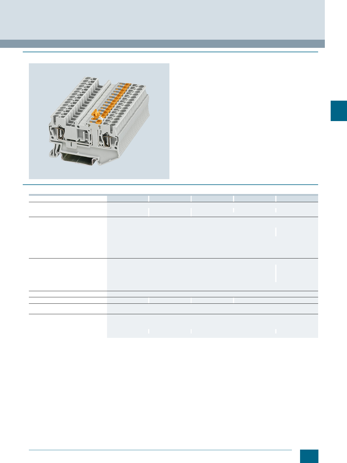
4/23
Siemens LV 52 · 2016
8WH2 Spring-Loaded Terminals
8WH isolating blade terminals
4
■
Overview
Through-type terminals with isolating blade capability are the
most commonly used terminal types in measuring and control
technology.
The isolating blade terminals with nominal cross-section of
2.5 mm² are characterized in particular by their slim design of
5.2 mm and their high current-carrying capacity of 16 A.
In addition the terminals provide a test tap parallel to the isola-
tion point for 2.3 mm ∅ test plugs. Potential distributors can be
conveniently assembled using connecting combs.
Terminals with three and four clamping points are available for
multi-conductor connection. With their compact design these
terminals can also be used in small terminal boxes and their front
connection arrangement enables user-friendly wiring.
The isolating blade is secured to the terminal so that it cannot be
lost.
A label can be snapped on to the middle of the terminal at the
front. Further labels can also be mounted flat on the side of the
terminals.
■
Technical specifications
8WH2000-6CF00 8WH2500-6CF00 8WH2003-6CF00 8WH2004-6CF00 8WH2000-6CG00
Dimensions
• Width/length/cover width in mm 5.2 / 60.5 / 2.2 5.2 / 51 / 2.2 5.2 / 72 / 2.2 5.2 / 84 / 2.2 6.2 / 61.5 / --
• Height (NS 35/7.5 / NS 35/15) in mm 36.5 / 44 43 / 50.5 36.5 / 44
Technical specifications acc. to IEC/DIN
VDE
• Max. load current in A / cross-section
in mm² 16 / 4 16 / 6
• Maximum data / rated data in A / mm² --
• Rated impulse withstand voltage in kV /
pollution degree 6 / 3
• Overvoltage category / molded plastic
group III / I
Connection capacities
• Flexible with end sleeve, with plastic
sleeve in mm² 0,25... 2.5 0.25 ... 4
• Flexible with end sleeve, without plastic
sleeve in mm² 0.25 ... 2.5 0.25 ... 4
• Flexible with two-wire connection end
sleeve, with plastic sleeve in mm² 0.5
Stripped length in mm 10
Plug gauge (IEC 60947-1) A4 A3 A4 A3
Molded plastic type PA
• Flammability Class acc. to UL 94 V0
Approval data (UL/cUL and CSA)
• Rated voltage / rated current /
conductor sizes
- UL/cUL: in V/A / AWG 600 / 16 / 26 ... 12 600 / 16 / 24 ... 12 600 / 16 / 26 ... 12 300 / 6.3 / 24 ... 10
- CSA: in V/A / AWG --
© Siemens AG 2015© Siemens AG 2015
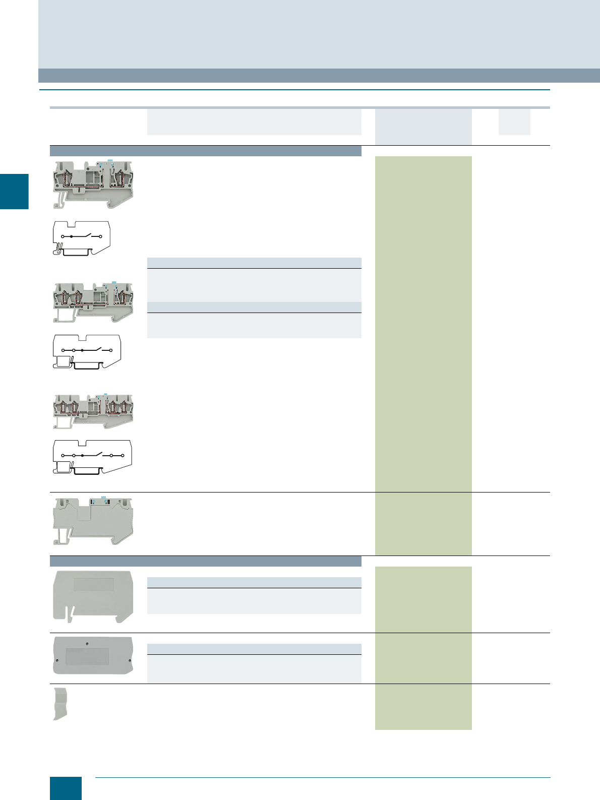
4/24 Siemens LV 52 · 2016 * You can order this quantity or a multiple thereof.
8WH isolating blade terminals
8WH2 Spring-Loaded Terminals
4
■
Selection and ordering data
For general accessories for 8WH terminal blocks, see chapter
"Accessories for 8WH Terminal Blocks"
Version DT Article No.
www.siemens.com/
product?Article No.
Price
per PU
PU
(UNIT,
SET, M)
PS*/
P. un it PG
Terminal size 2.5 mm²
8WH2000-6CF00
8WH2000-6CF00
8WH2003-6CF00
8WH2003-6CF00
8WH2004-6CF00
8WH2004-6CF00
Isolating blade terminals, terminal size 2.5 mm²
• Terminal width 5.2 mm
•CUUS
• IEC 60947-7-1
- Rigid 0.08 ... 4 mm²
- Flexible 0.08 ... 2.5 mm²
- AWG 28-12
-I = 16 A
-U = 400 V
• For 3 and 4 clamping points:
- Rigid 0.14 ... 4 mm²
- Flexible 0.14 ... 2.5 mm²
- AWG 26 ... 14
Versions
•Gray
- Two clamping points 8WH2000-6CF00 150 units1BT
- Three clamping points 8WH2003-6CF00 150 units1BT
- Four clamping points 8WH2004-6CF00 150 units1BT
Note
On terminals with three and four clamping points, the total current
through all connected conductors must not exceed the max. load
current.
8WH2000-6CG00
Isolating blade terminals, size 4 mm², two clamping points
•Gray
• Terminal width 6.2 mm
•CUUS
• IEC 60947-7-1
- Rigid 0.08 ... 6 mm², flexible 0.08 ... 4 mm², AWG 28-10
-I = 16 A, U = 400 V
• Enclosed at both ends
8WH2000-6CG00 150 units1BT
Accessories
8WH9070-0AA00
Compartment partitions, for terminal size 1.5 ... 4 mm²
Versions
• Two clamping points 8WH9070-0AA00 100 50 units 1BT
• Three clamping points 8WH9070-0GA00 100 50 units 1BT
• Four clamping points 8WH9070-0HA00 100 50 units 1BT
88WH9000-2GA00
Covers, for terminal size 1.5 ... 2.5 mm²
Versions
• For two clamping points 8WH9000-2GA00 100 50 units 1BT
• For three clamping points 8WH9000-4GA00 100 50 units 1BT
• For four clamping points 8WH9000-5GA00 100 50 units 1BT
8WH9000-0GA00
Cover segments, for terminal size 2.5 mm² and three or four
clamping points 8WH9000-0GA00 100 10 units 1BT
I201_12684
I201 12685
I201_12686
© Siemens AG 2015© Siemens AG 2015
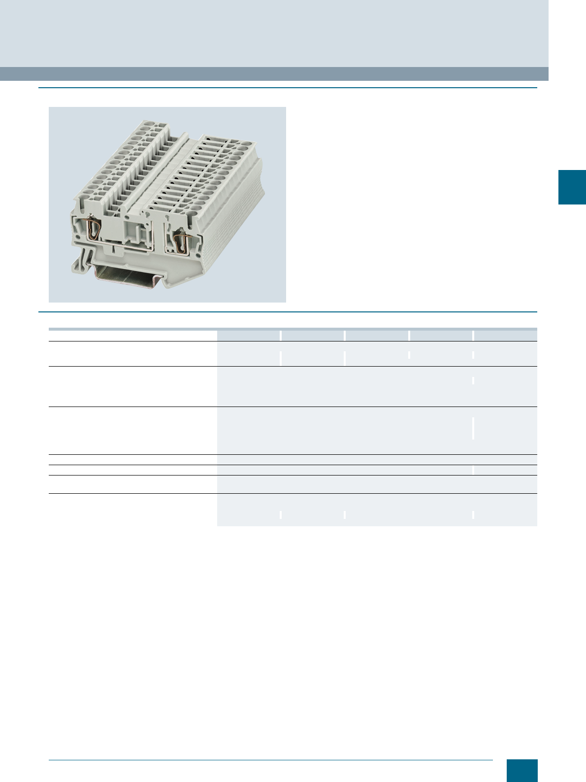
4/25
Siemens LV 52 · 2016
8WH2 Spring-Loaded Terminals
8WH isolating terminals
4
■
Overview
The isolating terminals are available with the same contour as
the isolating blade terminals. The terminals excel with their
narrow width of only 5.2 mm and their high current load rating
of 16 A.
There is a test option for 2.3 mm ∅ test plugs at both ends of the
isolating point.
The 6.2 mm wide isolating terminal with terminal size 4 mm² is a
base terminal for accommodating:
• Isolating plugs,
• Through-type connectors,
• Fused connectors and
• Component connectors.
A label can be snapped on to the middle of the terminal at the
front. Further labels can also be mounted flat on the side of the
terminals.
■
Technical specifications
8WH2000-6AF00 8WH2500-6AF00 8WH2003-6AF00 8WH2004-6AF00 8WH2000-6AG00
Dimensions
• Width/length/cover width in mm 5.2 / 60.5 / 2.2 5.2 / 51 / 2.2 5.2 / 72 / 2.2 5.5 / 84 / 2.2 6.2 / 61.5 / --
• Height (NS 35/7.5 / NS 35/15) in mm 36.5 / 44 43 / 50.5 36.5 / 44
Technical specifications acc. to IEC/DIN VDE
• Max. load current in A / cross-section in mm² 16 / 4 16 / 6
• Rated impulse withstand voltage in kV / pollution
degree 6 / 3
• Overvoltage category / molded plastic group III / I
Connection capacities
• Flexible with end sleeve, with plastic sleeve in mm² 0.25 ... 2.5 0.25 ... 4
• Flexible with end sleeve, without plastic sleeve
in mm² 0.25 ... 2.5 0.25 ... 4
• Flexible with two-wire connection end sleeve,
with plastic sleeve in mm² 0.5
Stripped length in mm 10
Plug gauge (IEC 60947-1) A3 A4
Molded plastic type PA
• Flammability Class acc. to UL 94 V0
Approval data (UL/cUL and CSA)
• Rated voltage / rated current / conductor sizes
- UL/cUL: in V/A / AWG 300 / 16 / 26 ... 12 300 / 16 / 24 ... 12 300 / 16 / 26 ... 12 300 / 6.3 / 24 ... 10
- CSA: in V/A / AWG --
© Siemens AG 2015© Siemens AG 2015
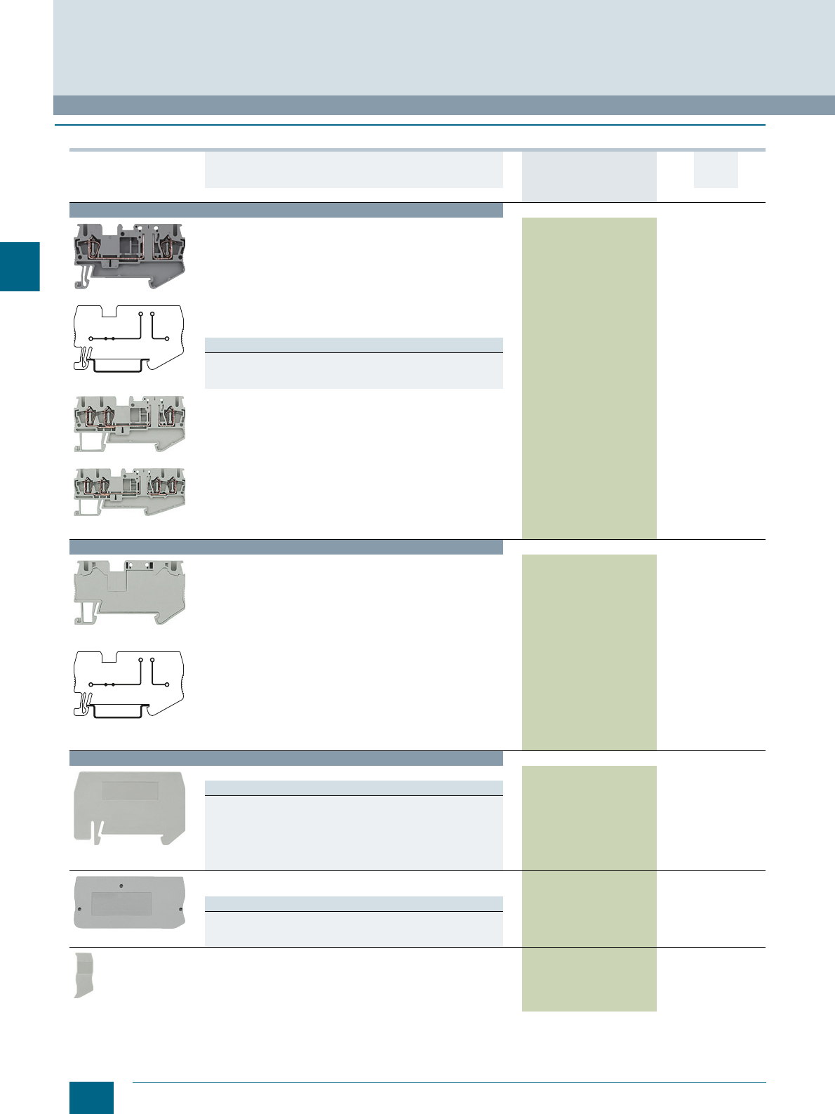
4/26 Siemens LV 52 · 2016 * You can order this quantity or a multiple thereof.
8WH isolating terminals
8WH2 Spring-Loaded Terminals
4
■
Selection and ordering data
For general accessories for 8WH terminal blocks, see chapter
"Accessories for 8WH Terminal Blocks"
Version DT Article No.
www.siemens.com/
product?Article No.
Price
per PU
PU
(UNIT,
SET, M)
PS*/
P. un it PG
Terminal size 2.5 mm²
8WH2000-6AF00
8WH2000-6AF00
8WH2003-6AF00
8WH2004-6AF00
Isolating terminals, terminal size 2.5 mm²
•Gray
• Terminal width 5.2 mm
•CUUS
• IEC 60947-7-1
- Rigid 0.08 ... 4 mm²
- Flexible 0.08 ... 2.5 mm²
- AWG 28-12
- Current and voltage are determined by the fitted plug
-I = 16 A
-U = 400 V
Versions
• Two clamping points 8WH2000-6AF00 150 units1BT
• Three clamping points 8WH2003-6AF00 150 units1BT
• Four clamping points 8WH2004-6AF00 150 units1BT
Terminal size 4 mm²
8WH2000-6AG00
8WH2000-6AG00
Isolating terminals, terminal size 4 mm², two clamping points
•Gray
• Terminal width 6.2 mm
•CUUS
• IEC 60947-7-1
- Rigid 0.08 ... 6 mm²
- Flexible 0.08 ... 4 mm²
- AWG 28-10
- Current and voltage are determined by the fitted plug
-I = 16 A
-U = 400 V
• Enclosed at both ends
8WH2000-6AG00 150 units1BT
Accessories
8WH9070-0GA00
Compartment partitions
Versions
• For terminal size 2.5 mm²
- For three clamping points 8WH9070-0GA00 100 50 units 1BT
- For four clamping points 8WH9070-0HA00 100 50 units 1BT
• For terminal size 4 mm²
- For two clamping points 8WH9070-0AA00 100 50 units 1BT
8WH9000-2GA00
Covers
Gray
Versions
• For terminal size 1.5 up to 2.5 mm² and two clamping points 8WH9000-2GA00 100 50 units 1BT
• For terminal size 2.5 mm² and three clamping points 8WH9000-4GA00 100 50 units 1BT
• For terminal size 2.5 mm² and four clamping points 8WH9000-5GA00 100 50 units 1BT
8WH9000-0GA00
Cover segments, for terminal sizes 1.5 mm² and 2.5 mm²
and three or four clamping points
Gray
8WH9000-0GA00 100 10 units 1BT
I201_12682
I201_12682
© Siemens AG 2015© Siemens AG 2015
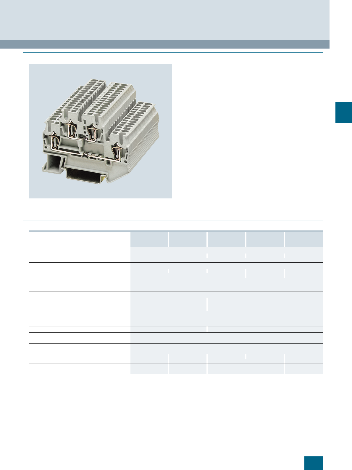
4/27
Siemens LV 52 · 2016
8WH2 Spring-Loaded Terminals
8WH two-tier terminals
4
■
Overview
Standard two-tier terminals
With the two voltage levels routed through two separate tiers,
the two-tier terminals require 50 % less space than equivalent
single-tier terminals. To implement a wide range of wiring tasks,
connecting combs can be fitted to both tiers of the spring-
loaded terminal series. Facilities for inscription are provided at
each clamping point.
PE/ground conductor function
Perfect mechanical and electrical contact with the support rail is
provided by simply snapping the terminals onto the rail.
The PE two-tier terminals meet all the requirements of
IEC 60947-7-2:
• Low contact resistance
• Stainless clamping points
• Green-yellow enclosure
• Additional inscription options
PE/L and PE/N types
The PE/L and PE/N types provide a PE/ground contact to the
support rail in the lower tier. The upper tier is designed as a
through-type tier. Color coding of the PE and neutral tiers
enables clear and unambiguous distribution of the potential.
The clamping points of two-tier terminals can be inscribed with
flat labels.
■
Technical specifications
8WH2020-0AE00
8WH2020-0AE01
8WH2025-0AE00
8WH0020-0CE07 8WH2020-0AF00
8WH2020-0AF01
8WH2025-0AF00
8WH2023-0AF00
8WH2023-0AF01
8WH2022-0AF00
8WH2020-0CF07
Dimensions
• Width/length/cover width in mm 4.2 / 67.5 / 2.2 5.2 / 67.5 / 2.2 5.2 / 91.5 / 2.2 5.2 / 67.5 / 2.2
• Height (NS 35/7.5 / NS 35/15) in mm 47.5 / 55
Technical specifications acc. to IEC/DIN VDE
• Max. load current in A / cross-section in mm² 17.5 / 1.5 -- 26 / 4 -- --
• Maximum data / rated data in A / mm² -- 26 / 4 // 22 / 2.5 --
• Rated impulse withstand voltage in kV / pollution
degree 6 / 3
• Overvoltage category / molded plastic group III / I
Connection capacities
• Flexible with end sleeve, with plastic sleeve in mm² 0.25 ... 1.5 0.25 ... 2.5
• Flexible with end sleeve, without plastic sleeve in
mm² 0.25 ... 1.5 0.25 ... 2.5
• Flexible with two-wire connection end sleeve,
with plastic sleeve in mm² 0.5
Stripped length in mm 10
Plug gauge (IEC 60947-1) A1 A3
Molded plastic type PA
• Flammability Class acc. to UL 94 V0
Approval data (UL/cUL and CSA)
• Rated voltage / rated current / conductor sizes
- UL/cUL: in V/A / AWG 300 / 15 / 26 ... 14 -- / -- / 26 ... 14 600 / 20 / 26 ... 12 300 / 20 / 26 ... 12 -- / -- / 26 ... 12
- CSA: in V/A / AWG 300 / 15 / 26 ... 14 -- / -- / 26 ... 14 -- -- / -- / 26 ... 12
Support rails/protective conductor busbars -- See page 1/3, sec-
tion "Support rails" -- See page 1/3, sec-
tion "Support rails"
© Siemens AG 2015© Siemens AG 2015
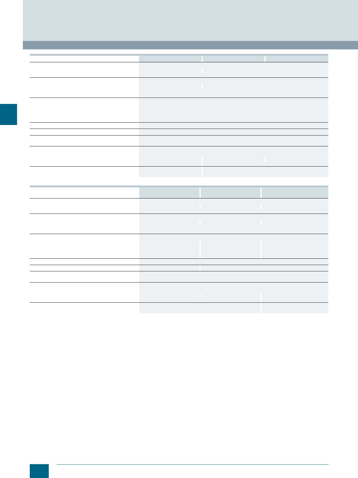
4/28 Siemens LV 52 · 2016
8WH two-tier terminals
8WH2 Spring-Loaded Terminals
4
8WH2023-0CF07 8WH2020-4AF00 8WH2020-4BF00
Dimensions
• Width/length/cover width in mm 5.2 / 91.5 / 2.2 5.2 / 67.5 / 2.2
• Height (NS 35/7.5 / NS 35/15) in mm 47.5 / 55
Technical specifications acc. to IEC/DIN VDE
• Max. load current in A / cross-section in mm² -- 32 / 4
• Rated impulse withstand voltage in kV / pollution degree 6 / 3
• Overvoltage category / molded plastic group III / I
Connection capacities
• Flexible with end sleeve, with plastic sleeve in mm² 0.25 ... 2.5
• Flexible with end sleeve, without plastic sleeve in mm² 0.25 ... 2.5
• Flexible with two-wire connection end sleeve,
with plastic sleeve in mm² 0.5
Stripped length in mm 10
Plug gauge (IEC 60947-1) A3
Molded plastic type PA
• Flammability Class acc. to UL 94 V0
Approval data (UL/cUL and CSA)
• Rated voltage / rated current / conductor sizes
- UL/cUL: in V/A / AWG -- / -- / 26 ... 12 300 / 20 / 26 ... 12 --
- CSA: in V/A / AWG -- / -- / 26 ... 12 --
Support rails/protective conductor busbars See page 1/3, section "Support
rails" --
8WH2020-4CF00 8WH2020-0AG00 8WH2020-
0AG01 8WH2025-0AG00 8WH2020-0CG07
Dimensions
• Width/length/cover width in mm 5.2 / 67.5 / 2.2 6.2 / 83.5 / 2.2 6.2 / 83.5 / 2.2
• Height (NS 35/7.5 / NS 35/15) in mm 47.5 / 55
Technical specifications acc. to IEC/DIN VDE
• Max. load current in A / cross-section in mm² 26 / 4 32 / 6 --
• Rated impulse withstand voltage in kV / pollution degree 6 / 3
• Overvoltage category / molded plastic group III / I
Connection capacities
• Flexible with end sleeve, with plastic sleeve in mm² 0.25 ... 2.5 0.25 ... 4 0.25 ... 4
• Flexible with end sleeve, without plastic sleeve in mm² 0.25 ... 2.5 0.25 ... 4 0.25 ... 4
• Flexible with two-wire connection end sleeve,
with plastic sleeve in mm² 0.5 0.5 ... 1 0.5 ... 1
Stripped length in mm 10
Plug gauge (IEC 60947-1) A3 A4
Molded plastic type PA
• Flammability Class acc. to UL 94 V0
Approval data (UL/cUL and CSA)
• Rated voltage / rated current / conductor sizes
- UL/cUL: in AWG 300 / 20 / 26 ... 12 300 / 30 / 20 ... 10 20 ... 10
-CSA: in AWG -- / -- / 26 ... 12 20 ... 10
Support rails/protective conductor busbars -- See page 1/3, section "Support
rails""
© Siemens AG 2015© Siemens AG 2015
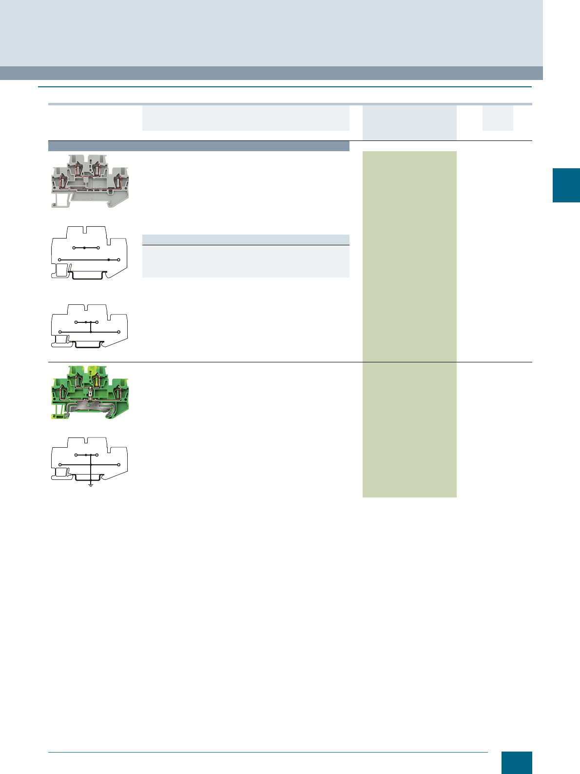
4/29
Siemens LV 52 · 2016
* You can order this quantity or a multiple thereof.
8WH2 Spring-Loaded Terminals
8WH two-tier terminals
4
■
Selection and ordering data
Version DT Article No.
www.siemens.com/
product?Article No.
Price
per PU
PU
(UNIT,
SET, M)
PS*/
P. unit PG
Terminal size 1.5 mm²
8WH2020-0AE00
8WH2020-0AE00
8WH2025-0AE00
Two-tier terminals, terminal size 1.5 mm²
• Terminal width 4.2 mm
•CUUS, s
• IEC 60947-7-1
- Rigid 0.08 ... 1.5 mm²
- Flexible 0.08 ... 1.5 mm²
- AWG 28-16
-I = 17.5 A
- The total current through all connected conductors must not
exceed the max. load current
-U = 500 V
Versions
•Gray
- Without equipotential bonding, 2-pole s8WH2020-0AE00 150 units1BT
- With equipotential bonding, 1-pole 8WH2025-0AE00 150 units1BT
• Blue, 2-pole 8WH2020-0AE01 150 units1BT
8WH2020-0CE07
8WH2020-0CE07
PE two-tier terminals, terminal size 1.5 mm²
• Terminal width 4.2 mm
•CUUS, s
• IEC 60947-7-1
- Rigid 0.08 ... 1.5 mm²
- Flexible 0.08 ... 1.5 mm²
- AWG 28-16
• Green/yellow
8WH2020-0CE07 150 units1BT
I201_12691
I201_14017
I201_12688
© Siemens AG 2015© Siemens AG 2015
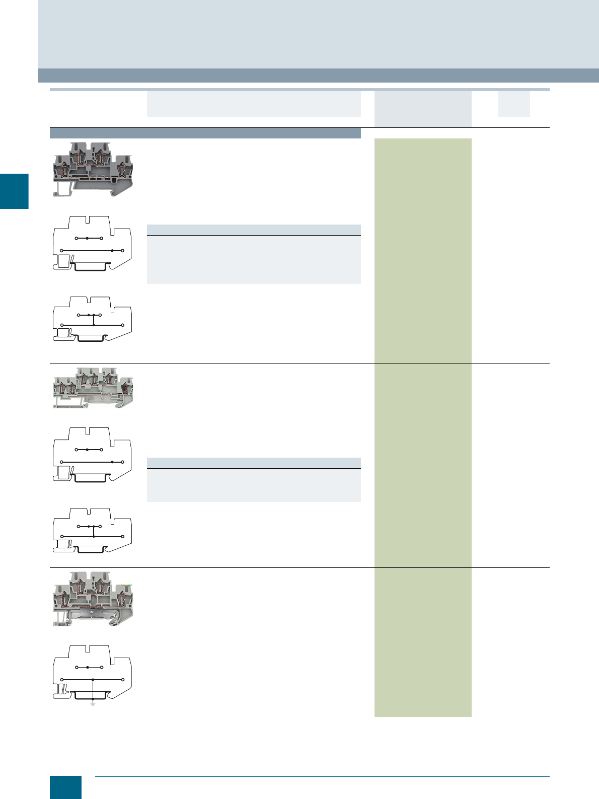
4/30 Siemens LV 52 · 2016 * You can order this quantity or a multiple thereof.
8WH two-tier terminals
8WH2 Spring-Loaded Terminals
4
Terminal size 2.5 mm²
8WH2020-0AF00
8WH2020-0AF00
8WH2025-0AF00
Two-tier terminals, terminal size 2.5 mm²
• Terminal width 5.2 mm
•CUUS
• IEC 60947-7-1
- Rigid 0.08 ... 4 mm²
- Flexible 0.08 ... 2.5 mm²
- AWG 28-12
-I = 26 A
- The total current through all connected conductors must not
exceed the max. load current
-U = 500 V
Versions
•Gray
- Without equipotential bonding, 2-pole 8WH2020-0AF00 150 units1BT
- With equipotential bonding, 1-pole 8WH2025-0AF00 150 units1BT
•Blue
- Without equipotential bonding, 2-pole 8WH2020-0AF01 150 units1BT
- With equipotential bonding, 1-pole 8WH2025-0AF01 150 units1BT
8WH2023-0AF00
8WH2023-0AF00
8WH2022-0AF00
Two-tier terminals, terminal size 2.5 mm², three clamping points
on one level
• Terminal width 5.2 mm
•CUUS
• IEC 60947-7-1
- Rigid 0.08 ... 4 mm²
- Flexible 0.08 ... 2.5 mm²
- AWG 28-12
-I = 26 A
- The total current through all connected conductors must not
exceed the max. load current
-U = 500 V
Versions
•Gray
- Without equipotential bonding, 2-pole 8WH2023-0AF00 150 units1BT
- With equipotential bonding, 1-pole 8WH2022-0AF00 150 units1BT
• Blue, 2-pole 8WH2023-0AF01 150 units1BT
8WH2020-4AF00
8WH2020-4AF00
Two-tier terminals, terminal size 2.5 mm², L at top and PE at
bottom
•Gray
• Terminal width 5.2 mm
•CUUS
• DIN VDE 0611 and IEC 60947-7-2
- Rigid 0.08 ... 4 mm²
- Flexible 0.08 ... 2.5 mm²
- AWG 28-12
-I = 32 A
-U = 500 V
8WH2020-4AF00 150 units1BT
Version DT Article No.
www.siemens.com/
product?Article No.
Price
per PU
PU
(UNIT,
SET, M)
PS*/
P. unit PG
I201_12691
I201_14017
I201_12691
I201_14017
I201_12689
© Siemens AG 2015© Siemens AG 2015
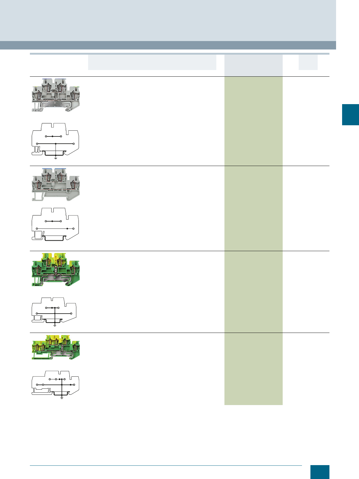
4/31
Siemens LV 52 · 2016
* You can order this quantity or a multiple thereof.
8WH2 Spring-Loaded Terminals
8WH two-tier terminals
4
8WH2020-4BF00
8WH2020-4BF00
Two-tier terminals, terminal size 2.5 mm², N at top and PE at
bottom
•Gray
• Terminal width 5.2 mm
• DIN VDE 0611 and IEC 60947-7-2
- Rigid 0.08 ... 4 mm²
- Flexible 0.08 ... 2.5 mm²
- AWG 28-12
-I = 32 A
-U = 500 V
8WH2020-4BF00 150 units1BT
8WH2020-4CF00
8WH2020-4CF00
Two-tier terminals, terminal size 2.5 mm², N at top and L at
bottom
•Gray
• Terminal width 5.2 mm
•CUUS
• IEC 60947-7-1
- Rigid 0.08 ... 4 mm²
- Flexible 0.08 ... 2.5 mm²
- AWG 28-12
-I = 26 A
-U = 500 V
8WH2020-4CF00 150 units1BT
8WH2020-0CF07
8WH2020-0CF07
PE two-tier terminals, terminal size 2.5 mm², two clamping
points on one level
• Terminal width 5.2 mm
•CUUS
• IEC 60947-7-2
- Rigid 0.08 ... 4 mm²
- Flexible 0.08 ... 2.5 mm²
- AWG 28-12
• Green/yellow
8WH2020-0CF07 150 units1BT
8WH2023-0CF07
8WH2023-0CF07
PE two-tier terminals, terminal size 2.5 mm², three clamping
points on one level
• Terminal width 5.2 mm
•CUUS
• IEC 60947-7-2
- Rigid 0.08 ... 4 mm²
- Flexible 0.08 ... 2.5 mm²
- AWG 28-12
• Green/yellow
8WH2023-0CF07 150 units1BT
Version DT Article No.
www.siemens.com/
product?Article No.
Price
per PU
PU
(UNIT,
SET, M)
PS*/
P. unit PG
I201_12690
I201_12691
I201_12692
I201_12693
© Siemens AG 2015© Siemens AG 2015
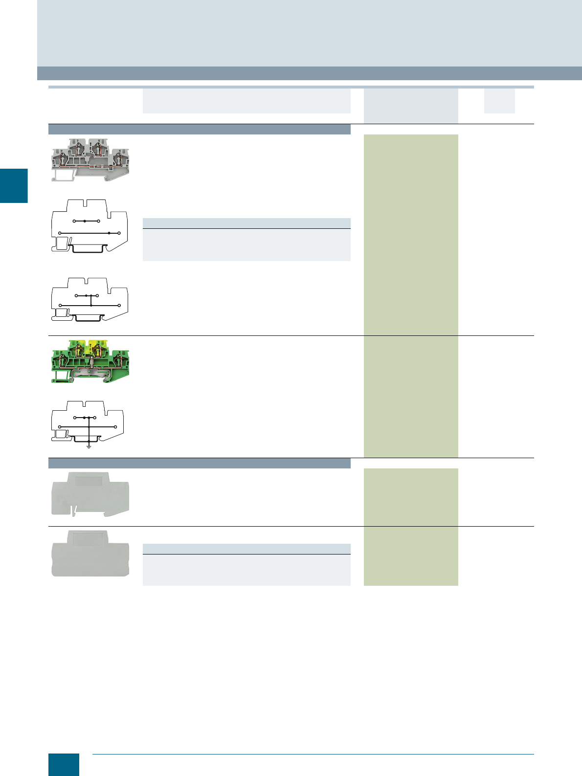
4/32 Siemens LV 52 · 2016 * You can order this quantity or a multiple thereof.
8WH two-tier terminals
8WH2 Spring-Loaded Terminals
4
For general accessories for 8WH terminal blocks, see chapter
"Accessories for 8WH Terminal Blocks"
Terminal size 4 mm²
8WH2020-0AG00
8WH2020-0AG00
8WH2025-0AG00
Two-tier terminals, terminal size 4 mm²
• Terminal width 6.2 mm
•CUUS
• IEC 60947-7-1
- Rigid 0.08 ... 6 mm²
- Flexible 0.08 ... 4 mm²
- AWG 28-10
-I = 32 A
- The total current through all connected conductors must not
exceed the max. load current
-U = 500 V
Versions
•Gray
- Without equipotential bonding, 2-pole 8WH2020-0AG00 150 units1BT
- With equipotential bonding, 1-pole 8WH2025-0AG00 150 units1BT
• Blue, 2-pole 8WH2020-0AG01 150 units1BT
8WH2020-0CG07
8WH2020-0CG07
PE two-tier terminals, terminal size 4 mm²
• Terminal width 6.2 mm
•CUUS
• IEC 60947-7-2
- Rigid 0.08 ... 6 mm²
- Flexible 0.08 ... 4 mm²
- AWG 28-10
• Green/yellow
8WH2020-0CG07 150 units1BT
Accessories
8WH9070-0BA00
Compartment partitions, for terminal size 1.5 ... 4 mm²
• For visual and electrical separation of terminal groups
• 2 mm thick
8WH9070-0BA00 100 50 units 1BT
8WH9000-1VA00
Covers
Gray
Versions
• For terminal size 1.5 up to 2.5 mm² 8WH9000-1VA00 100 50 units 1BT
• For terminal size 2.5 mm² and three clamping points 8WH9000-2VA00 100 50 units 1BT
• For terminal size 4 mm² 8WH9003-1VA00 100 50 units 1BT
Version DT Article No.
www.siemens.com/
product?Article No.
Price
per PU
PU
(UNIT,
SET, M)
PS*/
P. unit PG
I201_12691
I201_14017
I201_12694
© Siemens AG 2015© Siemens AG 2015
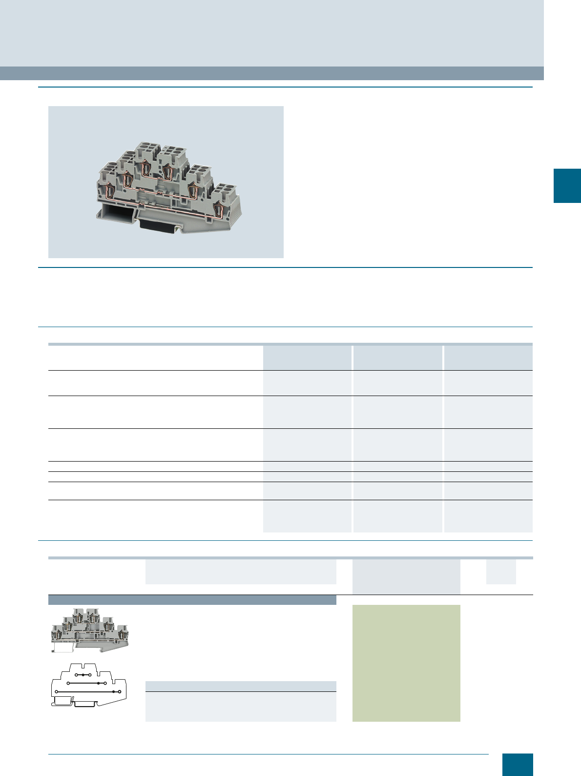
4/33
Siemens LV 52 · 2016
* You can order this quantity or a multiple thereof.
8WH2 Spring-Loaded Terminals
8WH three-tier terminals
4
■
Overview
Our three-tier terminals offer three feed-through levels in a slim
5.2 mm terminal enclosure. They enable high wiring density –
ideal for switchboards where space is at a premium.
With one bridge shaft per tier, these terminal blocks are ideal for
use as compact potential distributors or initiator terminals. All six
clamping points are interconnected on the equipotential
bonding versions.
The three-tier terminal range is rounded off with a PE terminal
with the same contour.
Inscription
Each tier of three-tier terminals can be inscribed with flat labels.
If a label holder is used, the labels can be inserted at the front.
■
Benefits
• Three feed-through levels with minimum footprint
• Comprehensive range of inscription options
• Matching accessories for 8WH terminal range
• One bridge shaft per tier
• Label holder is inserted
■
Technical specifications
■
Selection and ordering data
8WH2030-0AF00
8WH2030-0AF01
8WH2035-0AF00
8WH2035-0CF07 8WH2030-4EF00
8WH2030-4HF00
Dimensions
• Width/length in mm 5.2 / 99.5 5.2 / 99.5 5.2 / 99.5
• Height (TS 35/7.5 / TS 35/15 / TS 32) in mm 58 / 65.5 58 / 65.5 58 / 65.5
Technical specifications acc. to IEC/DIN VDE
• Max. load current in A / cross-section in mm² 28 / 4 -- 28 / 4
• Rated impulse withstand voltage in kV / pollution degree 6 / 3 6 / 3 6 / 3
• Overvoltage category / molded plastic group III / I III / I III / I
Connection capacities
• Flexible with end sleeve without / with plastic sleeve in mm² 0.25 ... 2.5 0.25 ... 2.5 0.25 ... 2.5
• Flexible with end sleeve, without plastic sleeve in mm² 0.25 ... 2.5 0.25 ... 2.5 0.25 ... 2.5
• Flexible with TWIN end sleeve with plastic sleeve in mm² 0.5 0.5 0.5
Stripped length in mm 10 10 10
Plug gauge (IEC 60947-1) A3 A3 A3
Molded plastic type PA PA PA
• Flammability Class acc. to UL 94 V0 V0 V0
Approval data (UL/CUR and CSA)
• Rated voltage / rated current / conductor sizes
- UL/CUR: V/A/AWG 600 / 20 / 26 ... 12 -- / -- / 24 ... 12 300 / 20 / 26 ... 12
- CSA: V/A/AWG -- -- --
Version DT Article No.
www.siemens.com/
product?Article No.
Price per
PU
PU
(UNIT,
SET, M)
PS/
P. unit PG
Terminal size 2.5 mm²
8WH2030-0AF00
8WH2030-0AF00
Three-tier terminals, terminal size 2.5 mm²
• Enclosed at both ends
• Terminal width 5.2 mm
•CUUS
• IEC 60947-7-1
- Rigid 0.08 ... 4 mm²
- Flexible 0.08 ... 2.5 mm²
-AWG 28-12
-I = 28 A
-U = 500 V
Versions
•Gray 8WH2030-0AF00 1 50 units 1BT
•Blue 8WH2030-0AF01 1 50 units 1BT
I201_13974
© Siemens AG 2015© Siemens AG 2015
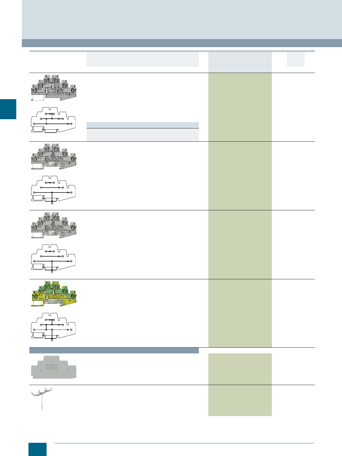
4/34 Siemens LV 52 · 2016 * You can order this quantity or a multiple thereof.
8WH three-tier terminals
8WH2 Spring-Loaded Terminals
4
For general accessories for 8WH terminal blocks, see chapter
"Accessories for 8WH Terminal Blocks"
8WH2035-0AF00
8WH2035-0AF00
Three-tier terminals, with equipotential bonding,
terminal size 2.5 mm²
• Enclosed at both ends
• Terminal width 5.2 mm
•CUUS
• IEC 60947-7-1
- Rigid 0.08 ... 4 mm²
- Flexible 0.08 ... 2.5 mm²
- AWG 28-12
-I = 28 A
-U = 500 V
8WH2035-0AF00 150 units1BT
Note
The total current through all connected conductors must not
exceed the max. load current.
8WH2030-4EF00
8WH2030-4EF00
Three-tier terminals, "PE/L/N", terminal size 2.5 mm²
• Enclosed at both ends
• Terminal width 5.2 mm
•CUUS
• IEC 60947-7-1 + IEC 60947-7-2
- Rigid 0.08 ... 4 mm²
- Flexible 0.08 ... 2.5 mm²
- AWG 28-12
8WH2030-4EF00 150 units1BT
8WH2030-4HF00
8WH2030-4HF00
Three-tier terminals, "PE/L/L", terminal size 2.5 mm²
• Enclosed at both ends
• Terminal width 5.2 mm
•CUUS
• IEC 60947-7-1 + IEC 60947-7-2
- Rigid 0.08 ... 4 mm²
- Flexible 0.08 ... 2.5 mm²
- AWG 28-12
-I = 28 A
-U = 500 V
8WH2030-4HF00 150 units1BT
8WH2035-0CF07
8WH2035-0CF07
PE three-tier terminals, terminal size 2.5 mm²
• Enclosed at both ends
• Terminal width 5.2 mm
•CUUS
• IEC 60947-7-2
- Rigid 0.08 ... 4 mm²
- Flexible 0.08 ... 2.5 mm²
- AWG 28-12
8WH2035-0CF07 150 units1BT
Accessories
8WH9000-1GD00
Covers for three-tier terminals 8WH9000-1GD00 100 50 units 1BT
8WH9060-4BA00
Label holders, for three-tier terminals 8WH9060-4BA00 100
100 units
1BT
Version DT Article No.
www.siemens.com/
product?Article No.
Price per
PU
PU
(UNIT,
SET, M)
PS/
P. unit PG
I201_13975
I201_13976
I201_13976
I201_13978
© Siemens AG 2015© Siemens AG 2015
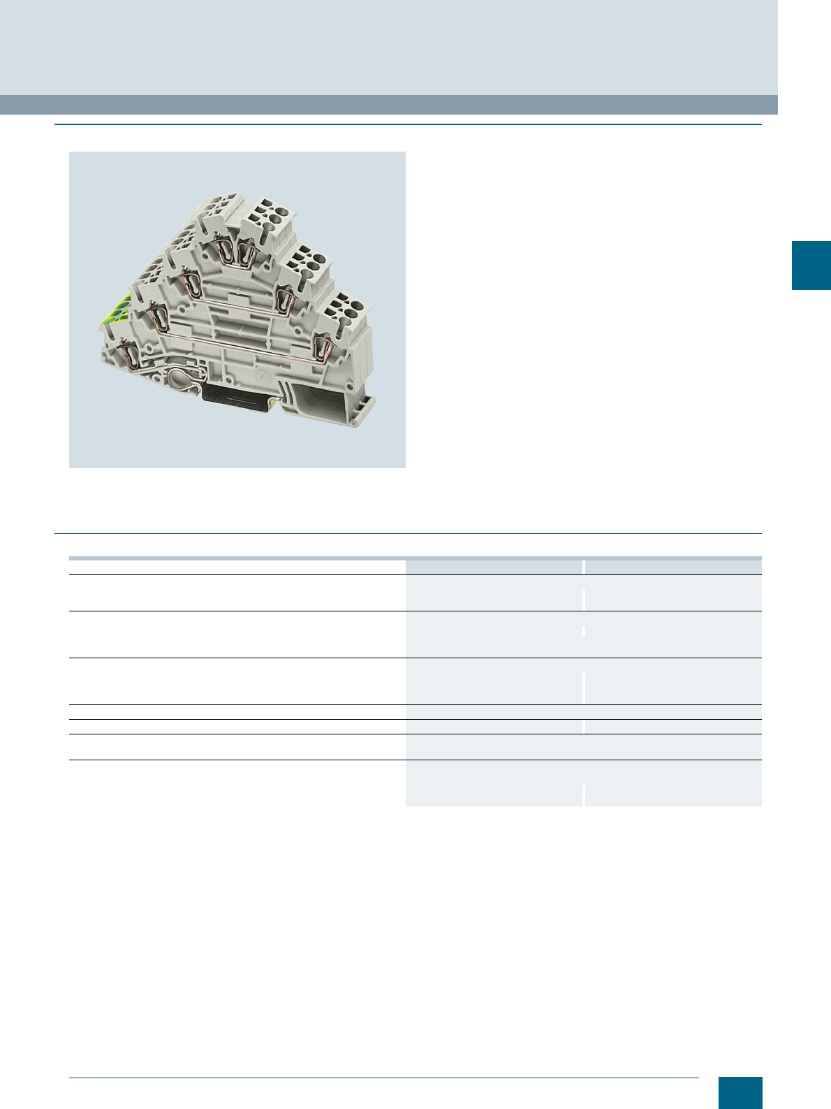
4/35
Siemens LV 52 · 2016
8WH2 Spring-Loaded Terminals
8WH four-tier motor terminals
4
■
Overview
Terminal size 2.5 mm²
The four-tier motor terminals with terminal size 2.5 mm² are ideal
for the compact wiring of AC loads. They have three through-
levels and one PE connection which is contacted by simply
snapping it onto the mounting rail.
No cross-bridging option.
Terminal size 4 mm²
Like the 2.5 mm² version, the four-tier motor terminal with 4 mm²
also allows the wiring of three phases and the PE in a single
terminal. This terminal is enclosed at both ends.
No cross-bridging option.
Integrated PE/ground conductor function
PE contact with the support rail is made by simply snapping the
terminal onto the rail. This makes the four-tier motor terminals
with terminal size 4 mm² ideal for the space-saving wiring of
AC motors.
Inscription
Each clamping point has a facility for inscription and a test
option for 2.3 mm ∅ test plugs.
There is also sufficient space for labeling in the middle of the
terminal on the front.
Labels can be mounted flat at the side of the terminals by simply
snapping on.
■
Technical specifications
8WH2040-4LF00 8WH2040-4LG00
Dimensions
• Width/length/cover width in mm 5.2 / 98.5 / 2.2 6.2 / 101 / --
• Height (NS 35/7.5 / NS 35/15) in mm 73.5 / 81 83.5 / 91
Technical specifications acc. to IEC/DIN VDE
• Max. load current in A / cross-section in mm² 26 / 4 32 / 6
• Rated impulse withstand voltage in kV / pollution degree 8 / 3
• Overvoltage category / molded plastic group III / I
Connection capacities
• Flexible with end sleeve, with plastic sleeve in mm² 0.25 ... 2.5 0.25 ... 4
• Flexible with end sleeve, without plastic sleeve in mm² 0.25 ... 2.5 0.25 ... 4
• Flexible with two-wire connection end sleeve, with plastic sleeve in mm² -- 0.5 ... 1
Stripped length in mm 10
Plug gauge (IEC 60947-1) A3 A4
Molded plastic type PA
• Flammability Class acc. to UL 94 V0
Approval data (UL/cUL and CSA)
• Rated voltage / rated current / conductor sizes
- UL/cUL: in V/A / AWG -- / -- / 26 ... 12 --
- CSA: in V/A / AWG -- 600 / 30 / 28-10
© Siemens AG 2015© Siemens AG 2015
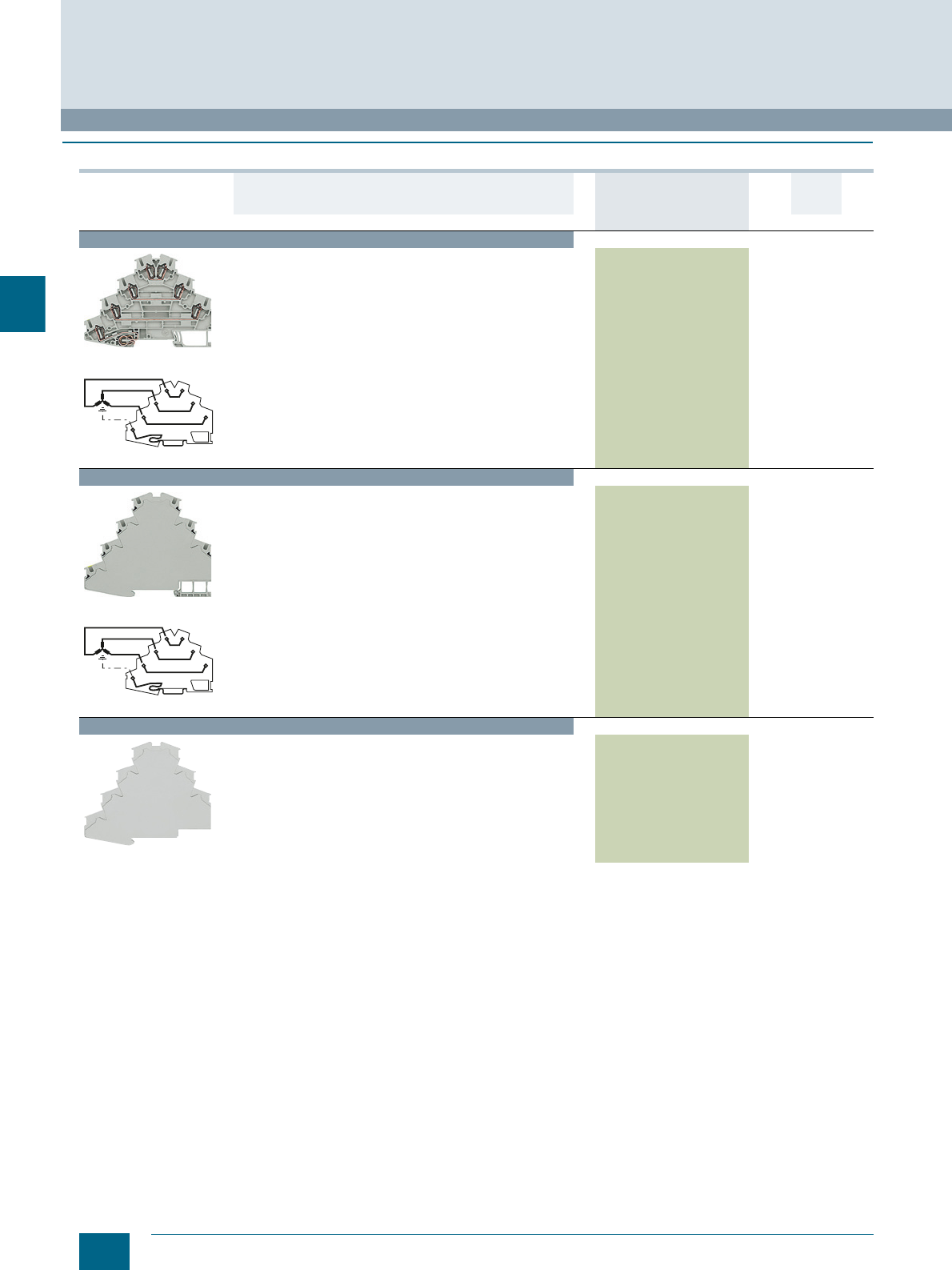
4/36 Siemens LV 52 · 2016 * You can order this quantity or a multiple thereof.
8WH four-tier motor terminals
8WH2 Spring-Loaded Terminals
4
■
Selection and ordering data
For general accessories for 8WH terminal blocks, see chapter
"Accessories for 8WH Terminal Blocks"
Version DT Article No.
www.siemens.com/
product?Article No.
Price
per PU
PU
(UNIT,
SET, M)
PS*/
P. un it PG
Terminal size 2.5 mm²
8WH2040-4LF00
8WH2040-4LF00
Four-tier motor terminals, terminal size 2.5 mm²
• Terminal width 5.2 mm
•CUUS
• IEC 60947-7-1 and IEC 60947-7-2
- Rigid 0.08 ... 4 mm²
- Flexible 0.08 ... 2.5 mm²
- AWG 28-12
-I = 26 A
-U = 800 V
8WH2040-4LF00 150 units 1BT
Terminal size 4 mm²
8WH2040-4LG00
8WH2040-4LG00
Four-tier motor terminals, terminal size 4 mm²
• Terminal width 6.2 mm
•CUUS s
• IEC 60947-7-1 and IEC 60947-7-2
- Rigid 0.08 ... 6 mm²
- Flexible 0.08 ... 4 mm²
- AWG 28-10
-I = 32 A
-U = 800 V
• Enclosed at both ends
8WH2040-4LG00 150 units 1BT
Accessories
8WH2040-4LG00
Covers
For four-tier motor terminals, terminal size 2.5 mm²
8WH9000-1GE00 100 50 units 1BT
I201 13468
I201_13468
© Siemens AG 2015© Siemens AG 2015
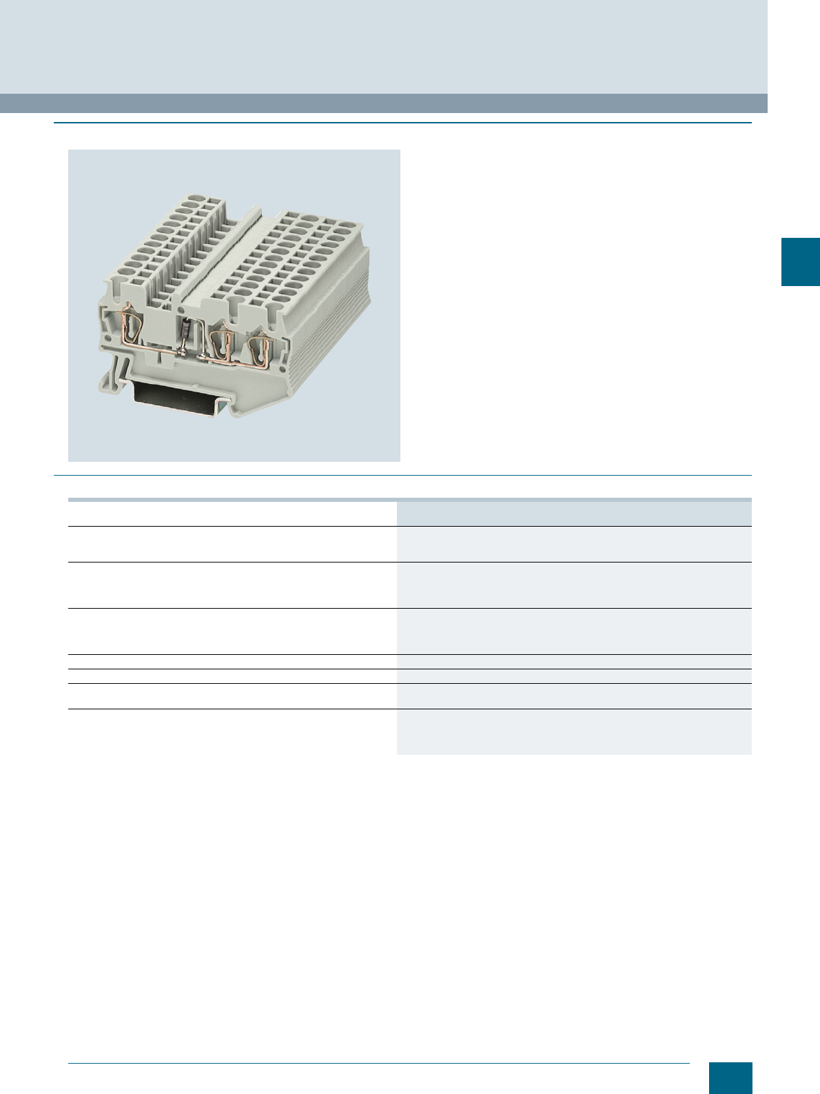
4/37
Siemens LV 52 · 2016
8WH2 Spring-Loaded Terminals
8WH diode terminals
4
■
Overview
Diode terminals with a nominal cross-section of 2.5 mm² and a
mounting width of just 5.2 mm can be used to implement many
different wiring tasks. The diode is soldered in from left to right
or vice versa as required.
A label can be snapped on to the middle of each terminal at the
front. Further labels can also be mounted flat on the side of the
terminals.
■
Technical specifications
8WH2003-5DF00
8WH2003-5CF00
Dimensions
• Width/length/cover width in mm 5.5 / 60.5 / 2.2
• Height HV-M ... (NS 35/7.5 / NS 35/15) in mm 36.5 / 44
Technical specifications acc. to IEC/DIN VDE
• Max. load current in A / cross-section in mm² Determined by the diode / 4
• Rated impulse withstand voltage in kV / pollution degree 4 / 3
• Overvoltage category / molded plastic group III / I
Connection capacities
• Flexible with end sleeve, with plastic sleeve in mm² 0.25 ... 2.5
• Flexible with end sleeve, without plastic sleeve in mm² 0.25 ... 2.5
• Flexible with two-wire connection end sleeve, with plastic sleeve in mm² 0.5
Stripped length in mm 10
Plug gauge (IEC 60947-1) A3
Molded plastic type PA
• Flammability Class acc. to UL 94 V0
Approval data (UL/cUL and CSA)
• Rated voltage / rated current / conductor sizes
- UL/cUL: V/A/AWG 600 / 20 / 26 ... 12
- CSA: V/A/AWG --
© Siemens AG 2015© Siemens AG 2015
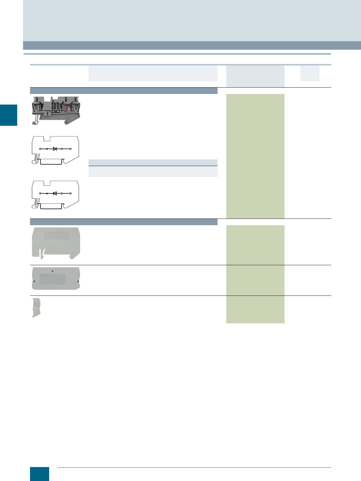
4/38 Siemens LV 52 · 2016 * You can order this quantity or a multiple thereof.
8WH diode terminals
8WH2 Spring-Loaded Terminals
4
■
Selection and ordering data
For general accessories for 8WH terminal blocks, see chapter
"Accessories for 8WH Terminal Blocks"
Version DT Article No.
www.siemens.com/
product?Article No.
Price
per PU
PU
(UNIT,
SET, M)
PS*/
P. unit PG
Terminal size 2.5 mm²
8WH2003-5DF00
8WH2003-5DF00
8WH2003-5CF00
Diode terminals, terminal size 2.5 mm², with three clamping points
• Uninterrupted limiting current: 0.5 A
• Blocking voltage: 1300 V
• Terminal width 5.2 mm
•CUUS
• Connection data
- Rigid 0.08 ... 4 mm²
- Flexible 0.08 ... 2.5 mm²
- AWG 28-12
-I = the maximum current is determined by the diode
-U = 500 V
• With integrated diode
• Integrated: diode 1N 4007
Versions
• Let-through from left to right 8WH2003-5DF00 150 units1BT
• Let-through from right to left 8WH2003-5CF00 150 units1BT
Accessories
8WH9070-0GA00
Compartment partitions, for terminal size 1.5 ... 4 mm² and
three clamping points 8WH9070-0GA00 100 50 units 1BT
8WH9000-4GA00
Covers, for terminal size 1.5 ... 2.5 mm² and three clamping
points 8WH9000-4GA00 100 50 units 1BT
8WH9000-0GA00
Cover segments, for terminal sizes 1.5 and 2.5 mm² and three
clamping points 8WH9000-0GA00 100 10 units 1BT
I201_12712
I201_12713
© Siemens AG 2015© Siemens AG 2015
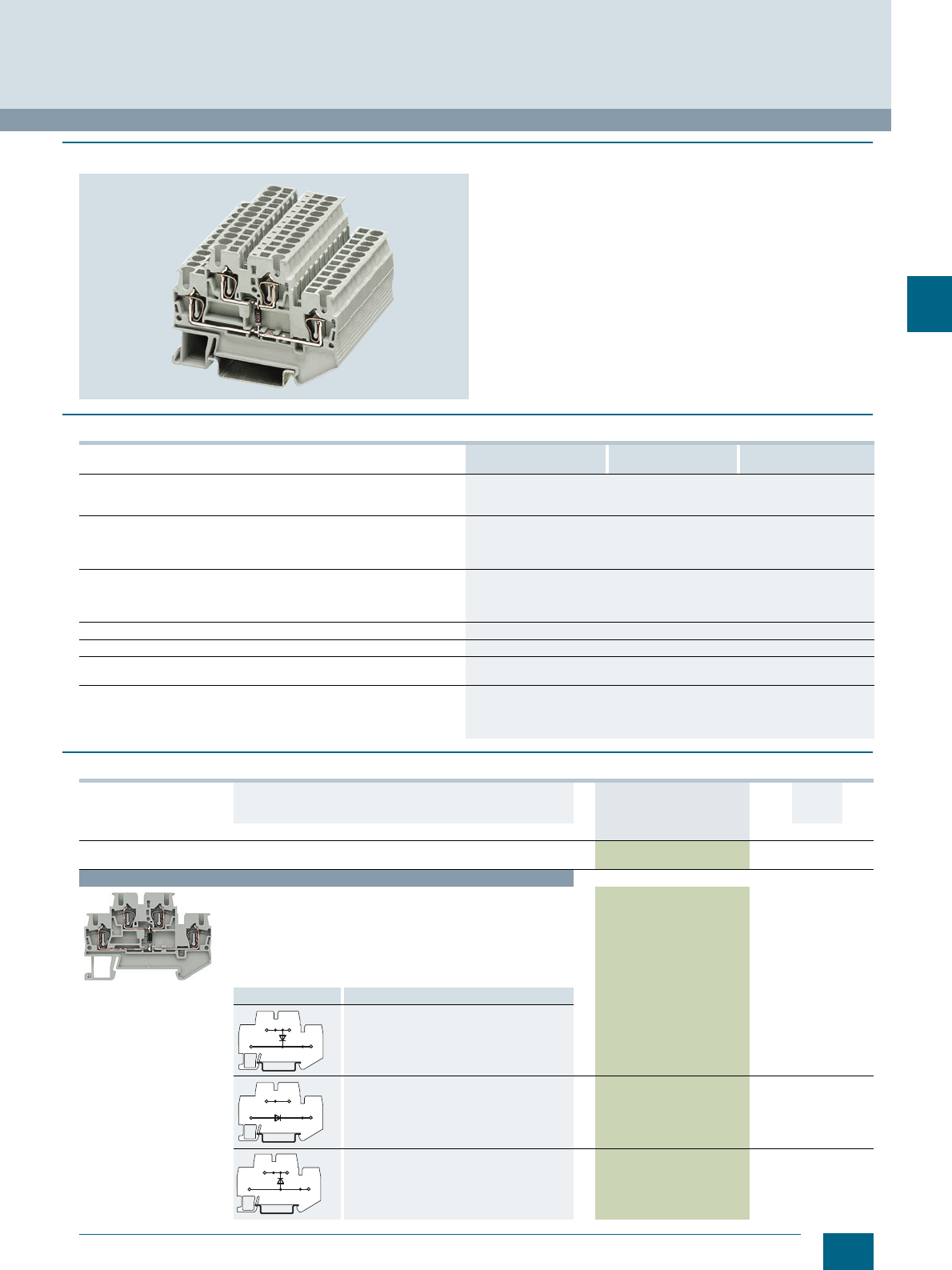
4/39
Siemens LV 52 · 2016
* You can order this quantity or a multiple thereof.
8WH2 Spring-Loaded Terminals
8WH two-tier diode terminals
4
■
Overview
Two-tier diode terminals can be used together with different
versions to implement many different wiring tasks.
The following circuits are possible in the tightest spaces:
• Freewheel diode circuits
• Lamp test circuits
• Signaling and fault signaling circuits
The clamping points of two-tier terminals can be inscribed with
flat labels.
■
Technical specifications
■
Selection and ordering data
8WH2020- 5AF00, 5DF00, 5BF00 5HF00, 5FF00, 5KF00
5EF00, 5GF00 5JF30, 5JF80
Dimensions
• Width/length/cover width in mm 5.2 / 67.5 / 2.2
• Height (NS 35/7.5 / NS 35/15) in mm 47.5 / 55
Technical specifications acc. to IEC/DIN VDE
• Max. load current in A (not via diodes) / cross-section in mm² 26 / 4
• Rated impulse withstand voltage in kV / pollution degree 4 / 3
• Overvoltage category / molded plastic group III / I
Connection capacities
• Flexible with end sleeve, with plastic sleeve in mm² 0.25 ... 2.5
• Flexible with end sleeve, without plastic sleeve in mm² 0.25 ... 2.5
• Flexible with two-wire connection end sleeve, with plastic sleeve in mm² 0.5
Stripped length in mm 10
Plug gauge (IEC 60947-1) A3
Molded plastic type PA
• Flammability Class acc. to UL 94 V0
Approval data (UL/cUL and CSA)
• Rated voltage / rated current / conductor sizes
- UL/cUL: in V/A / AWG 300 / 20 / 26 ... 12
- CSA: in V/A / AWG 300 / 20 / 26 ... 12
Version DT Article No.
www.siemens.com/
product?Article No.
Price
per PU
PU
(UNIT,
SET, M)
PS*/
P. unit PG
General data
CUUS
Terminal size 2.5 mm²
8WH2020-5AF00
Two-tier diode terminals, size 2.5 mm², with one diode
• Terminal width 5.2 mm
• Connection data
- Rigid 0.08 ... 4 mm², flexible 0.08 ... 2.5 mm², AWG 28-12
-I = 26 A, U = 500 V
• Maximum current determined by diode
• Integrated: diode 1N 4007
- Blocking voltage: 1300 V, uninterrupted limiting current: 0.5 A
Circuit diagram Versions
Let-through from top to bottom 8WH2020-5AF00 150 units1BT
Let-through from bottom left to top right 8WH2020-5DF00 150 units1BT
Let-through from bottom to top 8WH2020-5BF00 150 units1BT
I201_12714
I201_12715
I201_12716
© Siemens AG 2015© Siemens AG 2015
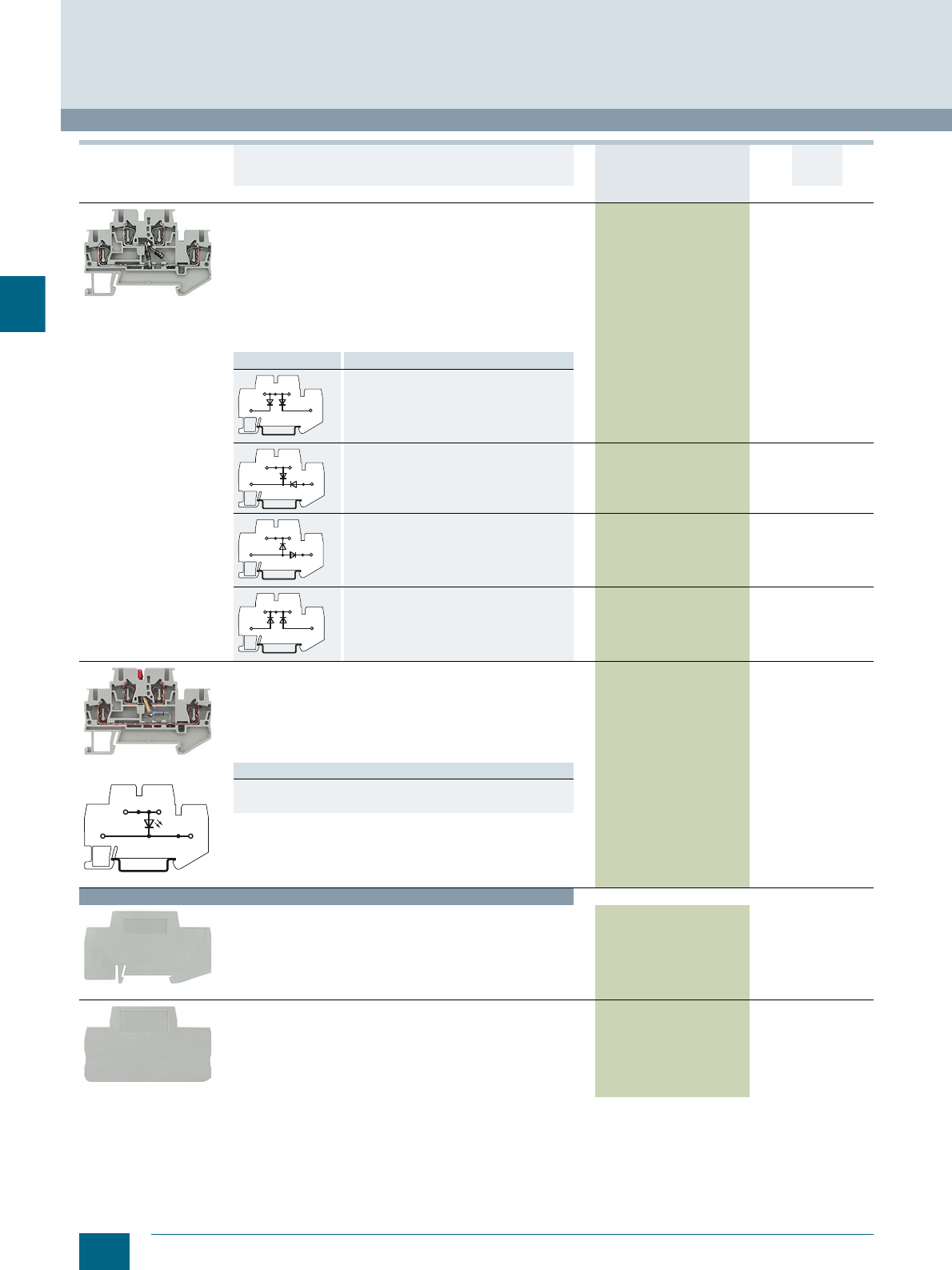
4/40 Siemens LV 52 · 2016 * You can order this quantity or a multiple thereof.
8WH two-tier diode terminals
8WH2 Spring-Loaded Terminals
4
For general accessories for 8WH terminal blocks, see chapter
"Accessories for 8WH Terminal Blocks"
8WH2020-5HF00
Two-tier-diode terminals, terminal size 2.5 mm²,
with two diodes
• Terminal width 5.2 mm
• Connection data
- Rigid 0.08 ... 4 mm²
- Flexible 0.08 ... 2.5 mm²
- AWG 28-12
-I = 26 A, U = 500 V
• Maximum current determined by diode
• Integrated: diode 1N 4007
- Blocking voltage: 1300 V
- Uninterrupted limiting current: 0.5 A
Circuit diagram Versions
Let-through from top to bottom left and from
top to bottom right 8WH2020-5HF00 150 units1BT
Let-through from top to bottom left and from
bottom right to bottom left 8WH2020-5KF00 150 units1BT
Let-through from bottom left to top and from
bottom left to bottom right 8WH2020-5EF00 150 units1BT
Let-through from bottom left to top and from
bottom right to top 8WH2020-5GF00 150 units1BT
8WH2020-5JF30
8WH2020-5JF30
Two-tier diode terminals, terminal size 2.5 mm², with LED
• Terminal width 5.2 mm
• Connection data
- Rigid 0.08 ... 4 mm²
- Flexible 0.08 ... 2.5 mm²
- AWG 28-12
-I = 26 A
-U = 500 V
Versions
• 15 ... 30 V DC / 2.5 ... 7.5 A 8WH2020-5JF30 150 units1BT
• 110 ... 230 V AC/DC / 0.5 ... 1.0 A (glow lamp) 8WH2020-5JF80 150 units1BT
Accessories
8WH9070-0BA00
Compartment partitions, for terminal size 1.5 ... 4 mm² 8WH9070-0BA00 100 50 units 1BT
8WH9000-1VA00
Covers, for terminal sizes 1.5 and 2.5 mm² 8WH9000-1VA00 100 50 units 1BT
Version DT Article No.
www.siemens.com/
product?Article No.
Price
per PU
PU
(UNIT,
SET, M)
PS*/
P. unit PG
I201_12717
I201_12718
I201_13466
I201_13467
© Siemens AG 2015© Siemens AG 2015
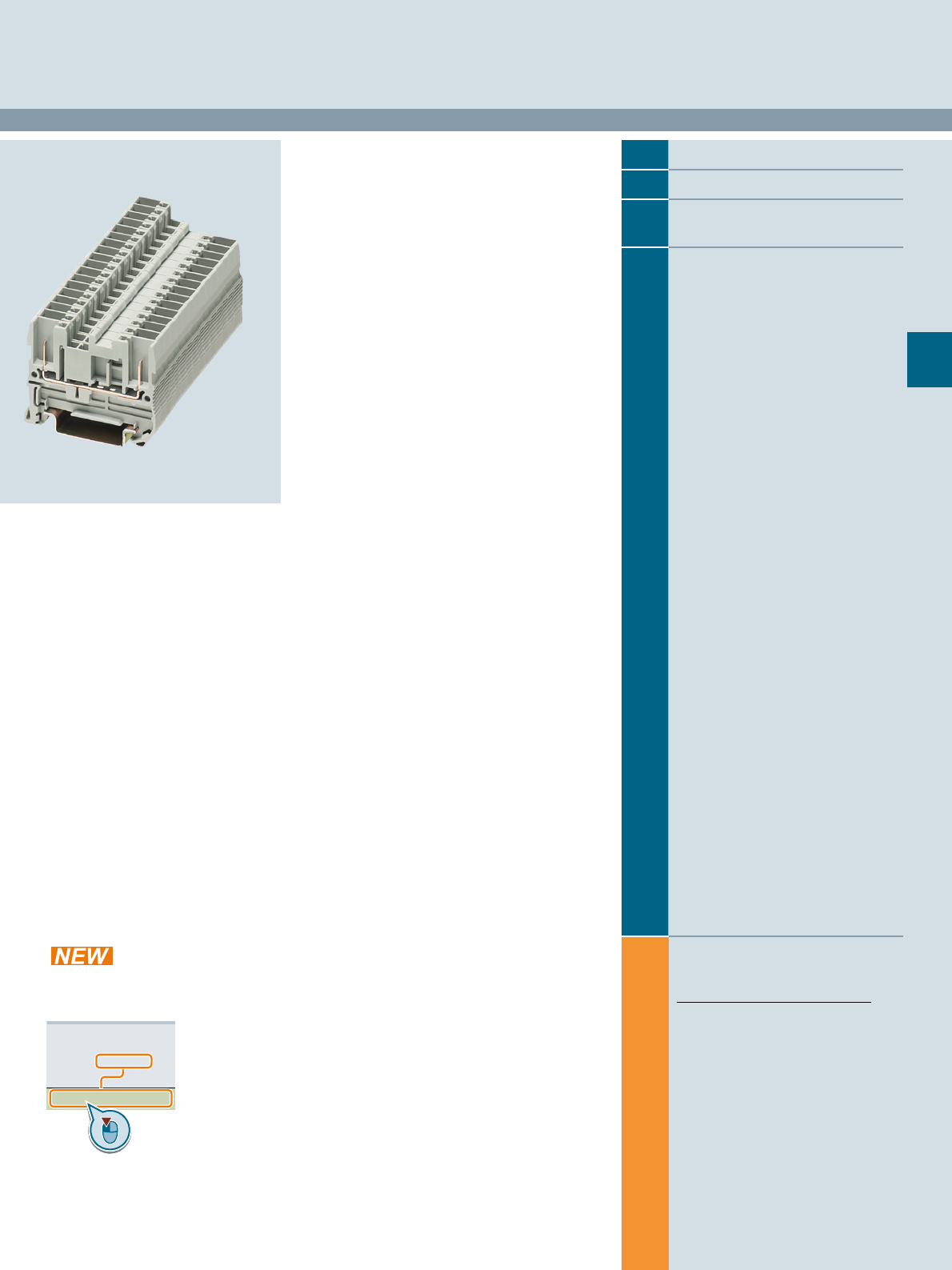
Siemens LV 52 · 2016
For further technical
product information:
Siemens Industry Online Support:
www.siemens.com/lowvoltage/product-
support .
→
Application example
Certificate
Characteristic
Download
FAQ
Manual
Product note
Software archive
Technical data
5
5
5/2 Introduction
5/5 8WH5 through-type terminals1)
5/7 8WH5 hybrid through-type
terminals with iPo connection
5/8 8WH9 plugs1)
1) Also available as a PE version
8WH5 Combination Plug-In Terminals
Direct reference to the products in the
Industry Mall from the selection and
ordering data tables:
3VA2025-5HL36-0AA0
Article No.
www.siemens.com/
product? Article No.
Paper catalog:
To get more
product information
enter the Web
address plus
Article No.
PDF catalog:
Get more product information
with just a mouse click.
© Siemens AG 2015© Siemens AG 2015
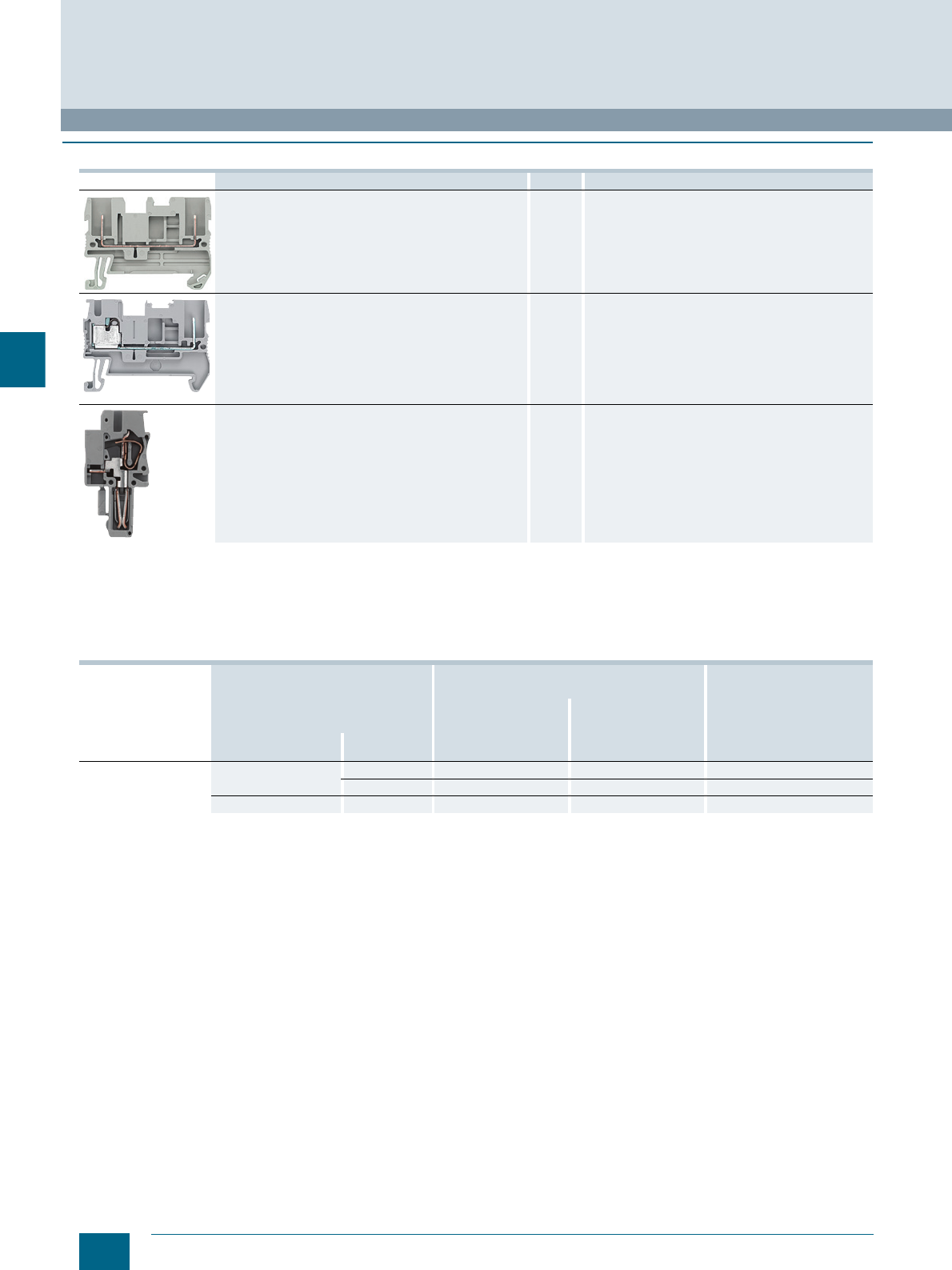
5/2 Siemens LV 52 · 2016
Introduction
8WH5 Combination Plug-In Terminals
5
■
Overview
Features
Devices Page Function
8WH5 through-type terminals 5/5 Terminals for the connection of combination plug-in
terminals
8WH5 hybrid through-type terminals with iPo connection 5/7 Terminals for the connection of combination plug-in
terminals
8WH9 plugs 5/8 For connection of combination plugs for fast wiring
Terminal type →Combination plugs Article No.
(digits 8 ... 12)
Design →Standard
No. of clamping points →2 4
Article No. (digits 1 ... 7) →8WH5000 8WH5004
Conductor cross-
section Terminal type Color
2.5 mm2Through-type Gray ✔ ✔ 0AF00
Blue ✔ ✔ 0AF01
PE Green/yellow ✔ ✔ 0CF07
© Siemens AG 2015© Siemens AG 2015
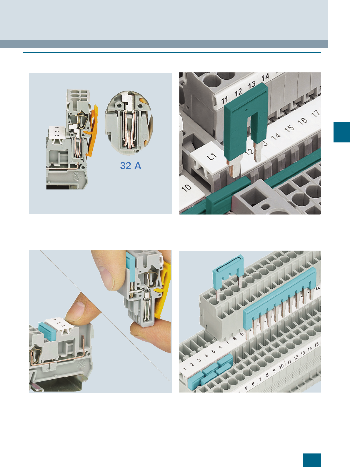
5/3
Siemens LV 52 · 2016
8WH5 Combination Plug-In Terminals
Introduction
5
■
Benefits
High-performance contact
The advanced plug-in system of the combination plug-in termi-
nals enables plug-in wiring up to a rated current of 32 A and a
rated voltage of 800 V. The contact system withstands extreme
vibration thanks to the integral overspring.
Fingerproof design
With its fingerproof base terminals and plugs, the combination
plug-in terminal system provides maximum user protection.
As well as enhancing safety, this provides exceptional flexibility
during configuration: the power can be supplied either through
the terminals or the plugs.
Time and cost-saving potential distribution
When feeding in large cross-sections, the reducing comb
enables time and cost-saving distribution of the potential.
For example, it can link a 10 mm² through-type terminal to a
2.5 mm² through-type terminal and two clamping points.
Standardized connecting comb system
The standardized connecting comb system allows up to
50 terminals to be connected efficiently and quickly with a single
jumper. Teeth can be removed to skip individual terminals.
© Siemens AG 2015© Siemens AG 2015
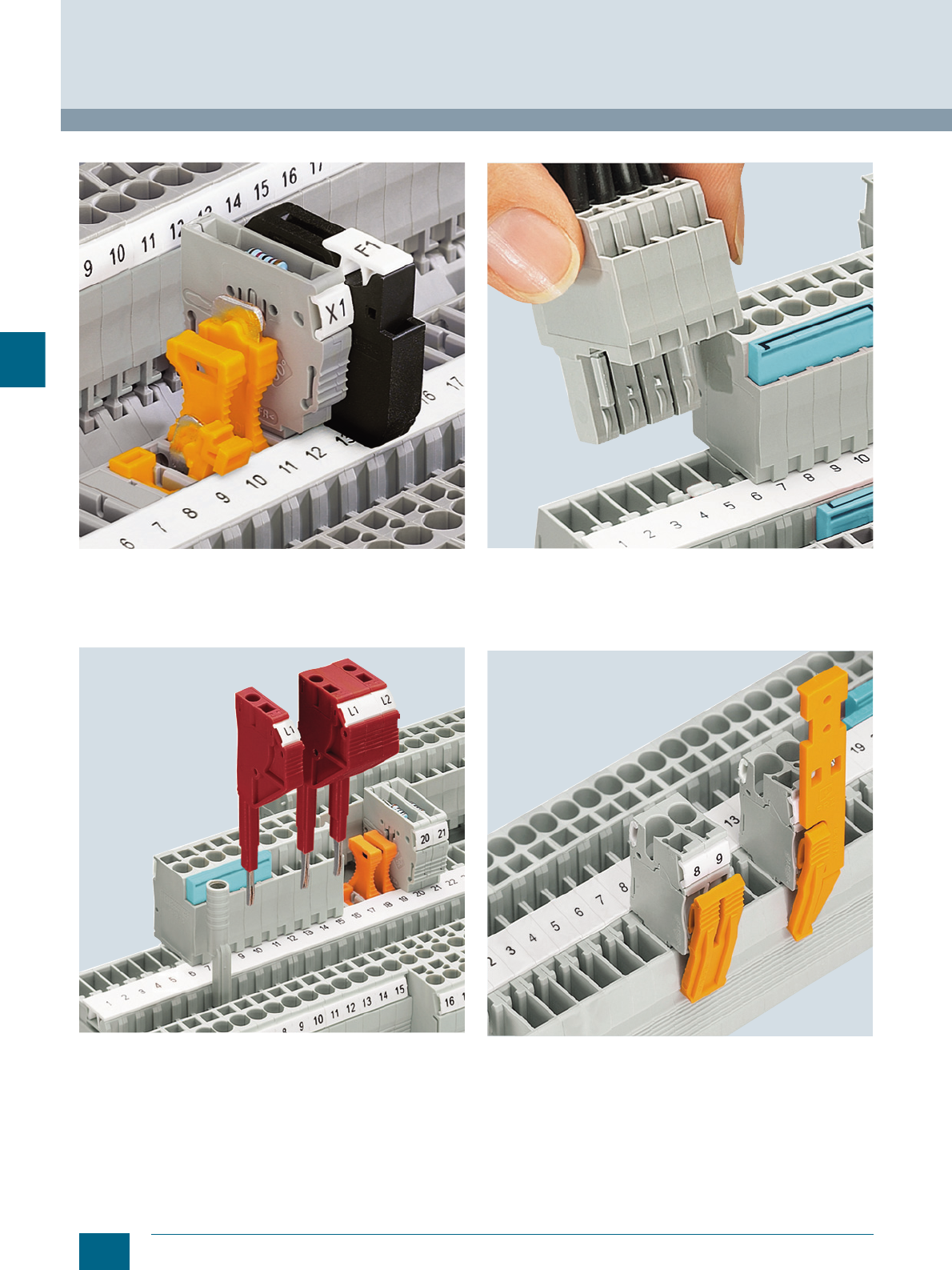
5/4 Siemens LV 52 · 2016
Introduction
8WH5 Combination Plug-In Terminals
5
Universal plug-in zone
The universal plug-in zone of the isolating terminal can accom-
modate isolated through-type connectors, isolating plugs, com-
ponent connectors and fused connectors.
Assembling test adapters
Test adapters are available for Ø 4 mm test and safety test plugs.
Test plugs can be individually assembled, thanks to the modular
design of the test plugs. Measuring leads can be connected
over a 1.5 mm² spring-loaded terminal.
Coding the combination plug-in terminals
The combination plug-in terminals can be coded with the pin on
the plug. The pin is simply removed from the plug, rotated and
fitted in the coding position of the base terminal.
Snap-on strain relief
Snap-on clamps are available to relieve cable strain at the plugs.
Latches are also available to secure the plugs firmly to the base
terminals.
© Siemens AG 2015© Siemens AG 2015
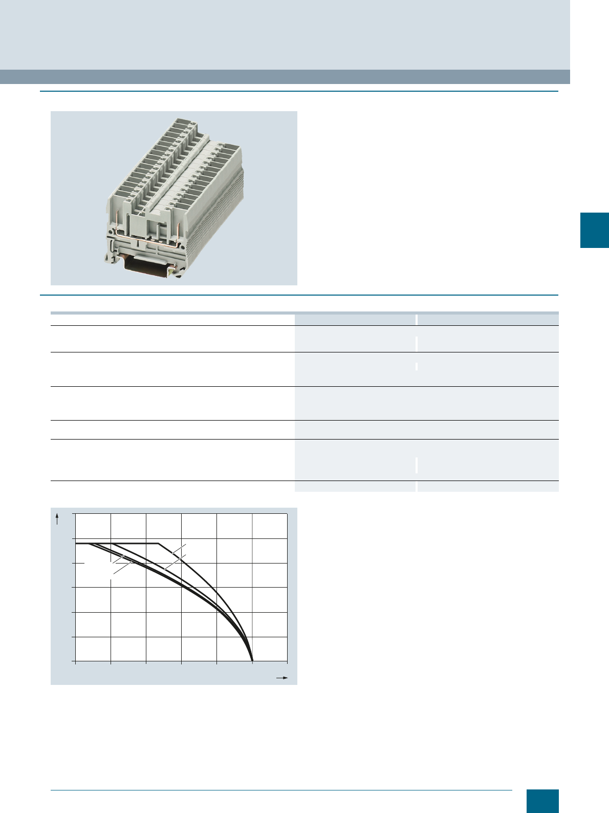
5/5
Siemens LV 52 · 2016
8WH5 Combination Plug-In Terminals
8WH5 through-type terminals
5
■
Overview
Plugs can be connected at both ends of the terminal using the
through-type terminals of the combination plug-in terminals. This
makes the combination plug-in terminal system even more flexi-
ble and allows the terminals to be used as connecting elements
between modules.
The plugs used have a terminal size of 2.5 mm², thus enabling
continued use of familiar accessories, such as latches, strain
relief and shield connectors.
PE terminals with the same contour are available for the base
terminals. These are simply snapped onto the support rail to
establish a connection to ground potential.
A label can be snapped on to the middle of each terminal at the
front. Further labels can also be mounted flat on the side of the
terminals.
■
Technical specifications
Derating curve for 8WH5000-0AF00
8WH5000-0AF00, 8WH5000-0AF01 8WH5000-0CF07
Dimensions
• Width/length/cover width in mm 5.2 / 48.5 / 2.2 5.2 / 48.5 / 2.2
• Height (TS 35/7.5 / TS 35/15) in mm 36.5 / 44 36.5 / 44
Technical specifications acc. to IEC/DIN VDE
• Max. load current in A1) / cross-section in mm² 24 / 4 --
• Rated impulse withstand voltage in kV / pollution degree 6 / 3
• Overvoltage category / molded plastic group III / I
Connection capacities
• Flexible with end sleeve, with plastic sleeve in mm² 0.25 ... 2.5
• Flexible with end sleeve, without plastic sleeve in mm² 0.25 ... 2.5
• Flexible with two-wire connection end sleeve, with plastic sleeve in mm² 0.5
Molded plastic type PA
• Flammability Class acc. to UL 94 V0
Approval data (UL/cUL and CSA)
• Rated voltage / rated current / conductor sizes
- UL/cUL: in V/A / AWG 300 / 20 / -- -- / -- / --
See page 5/8, section 8WH9 plugs
- CSA: in V/A / AWG --
Support rails/protective conductor busbars -- See page 1/3, section "Support rails"
1) Derating of the load current is necessary for higher temperatures and/or multi-pole combination plug versions.
I201_13471
0
5
10
20 40 60 80 100 120
20
25
30
15
2-pole
10-pole
15-pole
5-pole
Ambient temperature in °C
Maximum load current in A
© Siemens AG 2015© Siemens AG 2015
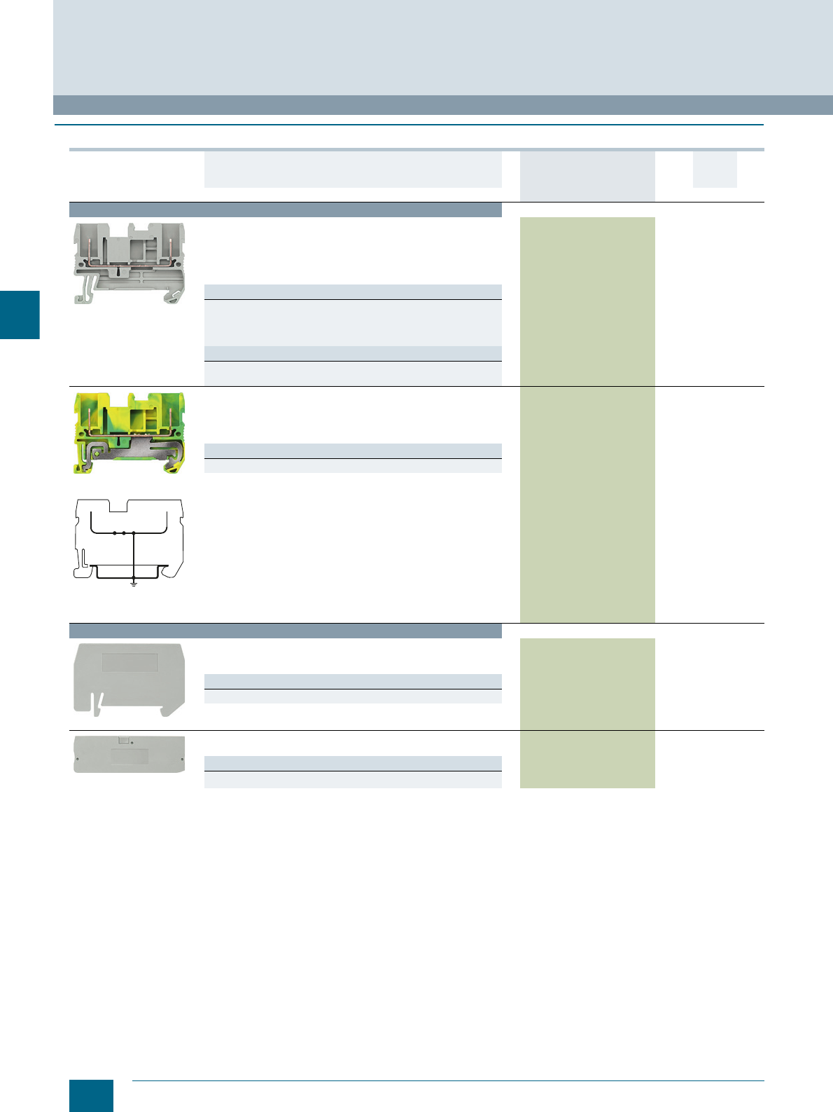
5/6 Siemens LV 52 · 2016 * You can order this quantity or a multiple thereof.
8WH5 through-type terminals
8WH5 Combination Plug-In Terminals
5
■
Selection and ordering data
For general accessories for 8WH terminal blocks, see chapter
"Accessories for 8WH Terminal Blocks"
Version DT Article No.
www.siemens.com/
product?Article No.
Price
per PU
PU
(UNIT,
SET, M)
PS*/
P. un it PG
Terminal size 2.5 mm²
8WH5000-0AF00
Through-type terminals, terminal size 2.5 mm²
• Terminal width 5.2 mm
•CUUS
•IEC 61 984
-I = 24 A
-U = 500 V
Versions
•Gray
- Two clamping points 8WH5000-0AF00 1 50 units 1BT
•Blue
- Two clamping points 8WH5000-0AF01 1 50 units 1BT
Note
On the terminal with four clamping points, the total current through
all connected conductors must not exceed the max. load current.
8WH5000-0CF07
8WH5000-0CF07
PE through-type terminals, terminal size 2.5 mm²
• Green/yellow
• Terminal width 5.2 mm
•CUUS
•IEC 61 984
Versions
• Two clamping points 8WH5000-0CF07 1 50 units 1BT
Accessories
8WH9070-0AA00
Compartment partitions, for terminal size 1.5 ... 4 mm²
• For visual and electrical separation of terminal groups
• 2 mm thick
Versions
• For two clamping points 8WH9070-0AA00 100 50 units 1BT
8WH9000-1GA00
Covers, for terminal size 2.5 mm²
Gray
Versions
• Two clamping points 8WH9000-1GA00 100 50 units 1BT
I201_12625
© Siemens AG 2015© Siemens AG 2015
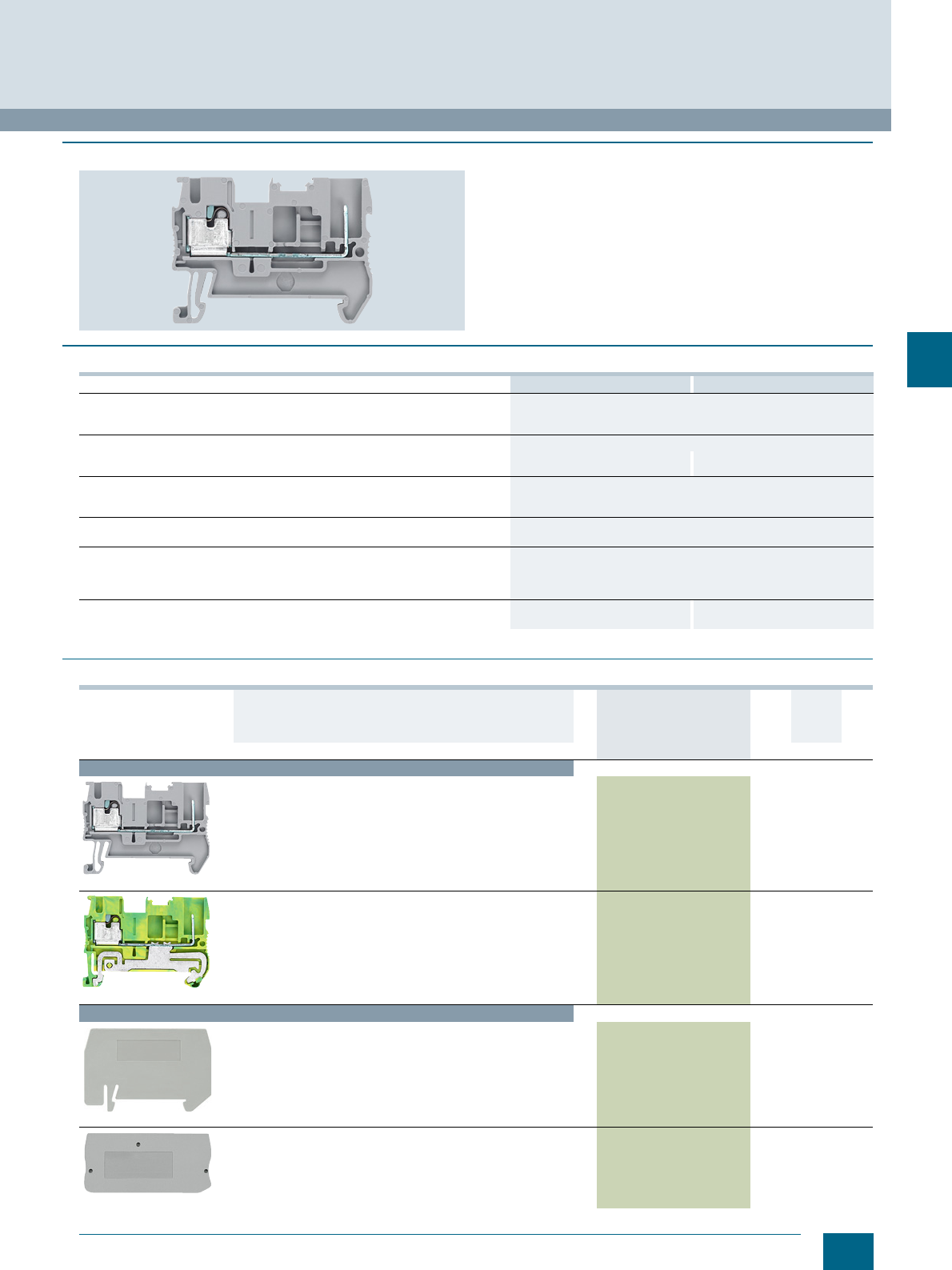
5/7
Siemens LV 52 · 2016
* You can order this quantity or a multiple thereof.
8WH5 Combination Plug-In Terminals
8WH5 hybrid through-type terminals with iPo connection
5
■
Overview
The 8WH5 hybrid through-type terminals with iPo connection
provide a modular solution for fast, flexible wiring of plants and
machines. They combine the advantages of the combination ter-
minal system with those of the iPo terminals.
A label can be snapped on to the middle of each terminal at the
front. Further labels can also be mounted flat on the side of the
terminals.
■
Technical specifications
■
Selection and ordering data
For general accessories for 8WH terminal blocks, see chapter "Accessories for 8WH Terminal Blocks"
8WH5100-2PF00 8WH5100-3PF07
Dimensions
• Width/length/cover width in mm 5.2 / 48.5 / 2.2
• Height (TS 35/7.5 / TS 35/15) in mm 36.5
Technical specifications acc. to IEC/DIN VDE
• Max. load current in A1) / cross-section in mm² 24 --
• Rated impulse withstand voltage in kV / pollution degree 500 --
Connection capacity, 1 conductor
• Rigid 0.14 ... 2.5
• Flexible with end sleeve without / with plastic sleeve in mm² 0.14 ... 2.5
Molded plastic type
• Flammability Class acc. to UL 94 V0
Approval data (UL/cUL and CSA)
• Rated voltage / rated current / conductor sizes
- UL/cUL: in V/A / AWG 500 / 300 /26 ... 12
- CSA: in V/A / AWG -- / --
Support rails/protective conductor busbars -- See page 1/3, section "Support
rails"
1) Derating of the load current is necessary for higher temperatures and/or multi-pole combination plug versions.
Version DT Article No.
www.siemens.com/
product?Article No.
Price
per PU PU
(UNIT,
SET,
M)
PS*/
P. un it PG
Hybrid through-type terminals with iPo connection, terminal size 2.5 mm²
8WH5100-2PF00
Hybrid through-type terminals, terminal size 2.5 mm²
•Gray
• Terminal width 5.2 mm
• Rated current / cross-section In = 24 A / 2.5 mm²
• Rated voltage Un = 500 V
• Rigid 0.14 ... 4 mm²
• Flexible with end sleeve 0.14 ... 2.5 mm²
• Stripped length 10 mm
8WH5100-2PF00 150 units1BT
8WH5100-3PF07
PE hybrid through-type terminals, terminal size 2.5 mm²
• Green/yellow
• Terminal width 5.2 mm
• Rigid 0.14 ... 4 mm²
• Flexible with end sleeve 0.14 ... 2.5 mm²
• Connection type: plug-in spring-loaded connection
• Stripped length 10 mm
8WH5100-3PF07 150 units1BT
Accessories
8WH9070-0HA00
Compartment partitions
For terminal size 1.5 ... 4 mm² and four clamping points
8WH9070-0HA00 100 50 units 1BT
8WH9000-1GA00
Covers
For terminal size 2.5 mm² and two clamping points
8WH9000-1GA00 100 50 units 1BT
© Siemens AG 2015© Siemens AG 2015
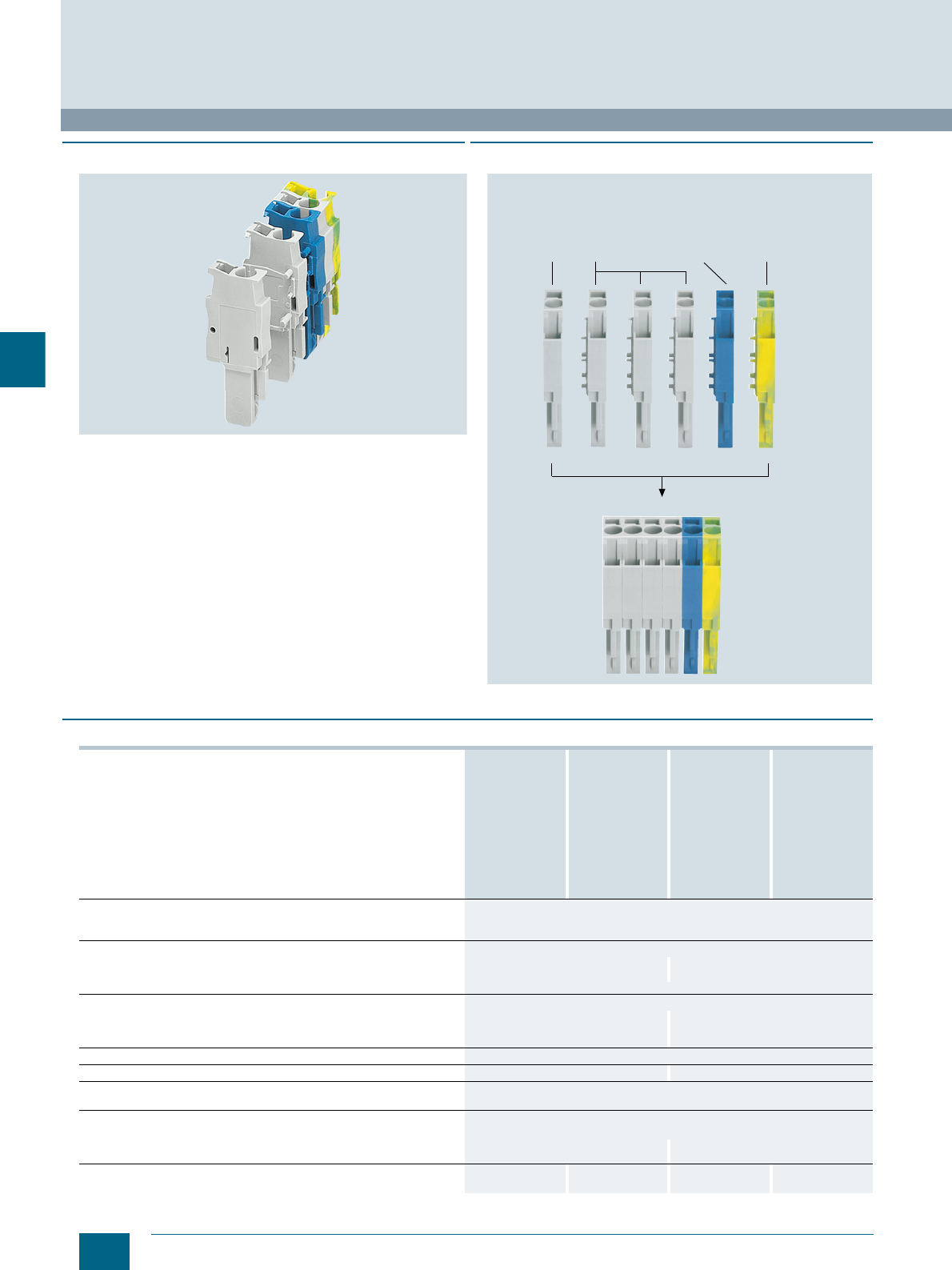
5/8 Siemens LV 52 · 2016
8WH9 plugs
8WH5 Combination Plug-In Terminals
5
■
Overview
Assembled by the user in-situ from single-pole plug elements,
the combination plug-in terminals in kit form provide a cus-
tomized solution for every task.
For the existing plugs with terminal sizes 2.5 mm² and 4 mm²,
and the plug with comb connection and terminal size 2.5 mm²,
single-pole basic versions in the colors gray, blue and green-
yellow are available.
A left element at the begining of the plug and a right element at
the end are needed for each multi-pole plug. The number of
middle elements depends on the plug’s required number of
poles. The individual elements are simply pushed together and
latched with securing pins. Pliers may be needed to push them
together. The right-hand component has an integrated cover,
which covers the plug block. Labels enable flat inscription of the
plugs.
■
Design
Example of a 6-pole plug
■
Technical specifications
I201_12635a
Plugs,
terminal
size 2.5 mm²
gray, left
element, with
slot for comb
Plugs,
terminal
size 2.5 mm²
gray, central
element, with
slot for comb
Plugs,
terminal
size 2.5 mm²
blue, central
element, with
slot for comb
PE plugs,
terminal
size 2.5 mm²
green-yellow,
right element,
with slot for comb
8WH9040-1AB00
8WH9040-1AB01
8WH9040-1BB00
8WH9040-1BB01
8WH9040-1CB00
8WH9040-1CB01
8WH9040-1DB00
8WH9040-1DB01
8WH9040-1EB00
8WH9040-1EB01
8WH9040-1FB00
8WH9040-1FB01
8WH9040-1AB07
8WH9040-1BB07
8WH9040-1CB07
8WH9040-1DB07
8WH9040-1EB07
8WH9040-1FB07
8WH9050-1KB00
8WH9050-1KB01
8WH9050-1LB00
8WH9050-1LB01
8WH9050-1MB00
8WH9050-1MB01
8WH9050-1KB07
8WH9050-1LB07
8WH9050-1MB07
Dimensions
• Width/length/cover width in mm --
• Height (TS 35/7.5 / TS 35/15) in mm --
Technical specifications acc. to IEC/DIN VDE
• Max. load current in A1) / cross-section in A / mm² 24 / 4 32 / 6
• Rated impulse withstand voltage in kV / pollution degree 6 / 3 8 / 3
• Overvoltage category / molded plastic group III / I
Connection capacities
• Flexible with end sleeve, with plastic sleeve in mm² 0.25 ... 2.5 0.25 ... 4
• Flexible with end sleeve, without plastic sleeve in mm² 0.25 ... 2.5 0.25 ... 4
• Flexible with two-wire connection end sleeve, with plastic sleeve in mm² 0.5 0.5 ... 1
Stripped length 10
Plug gauge (IEC 60947-1) A3 A4
Molded plastic type PA
• Flammability Class acc. to UL 94 V0
Approval data (UL/cUL and CSA)
• Rated voltage / rated current / conductor sizes
- UL/cUL: in V/A / AWG 600 / 20 / 26 ... 12 Applied for
- CSA: in V/A / AWG -- Applied for
Support rails/protective conductor busbars -- See page 1/3, sec-
tion "Support rails" -- See page 1/3, sec-
tion "Support rails"
1) Derating of the load current is necessary for higher temperatures and/or multi-pole combination plug versions.
© Siemens AG 2015© Siemens AG 2015
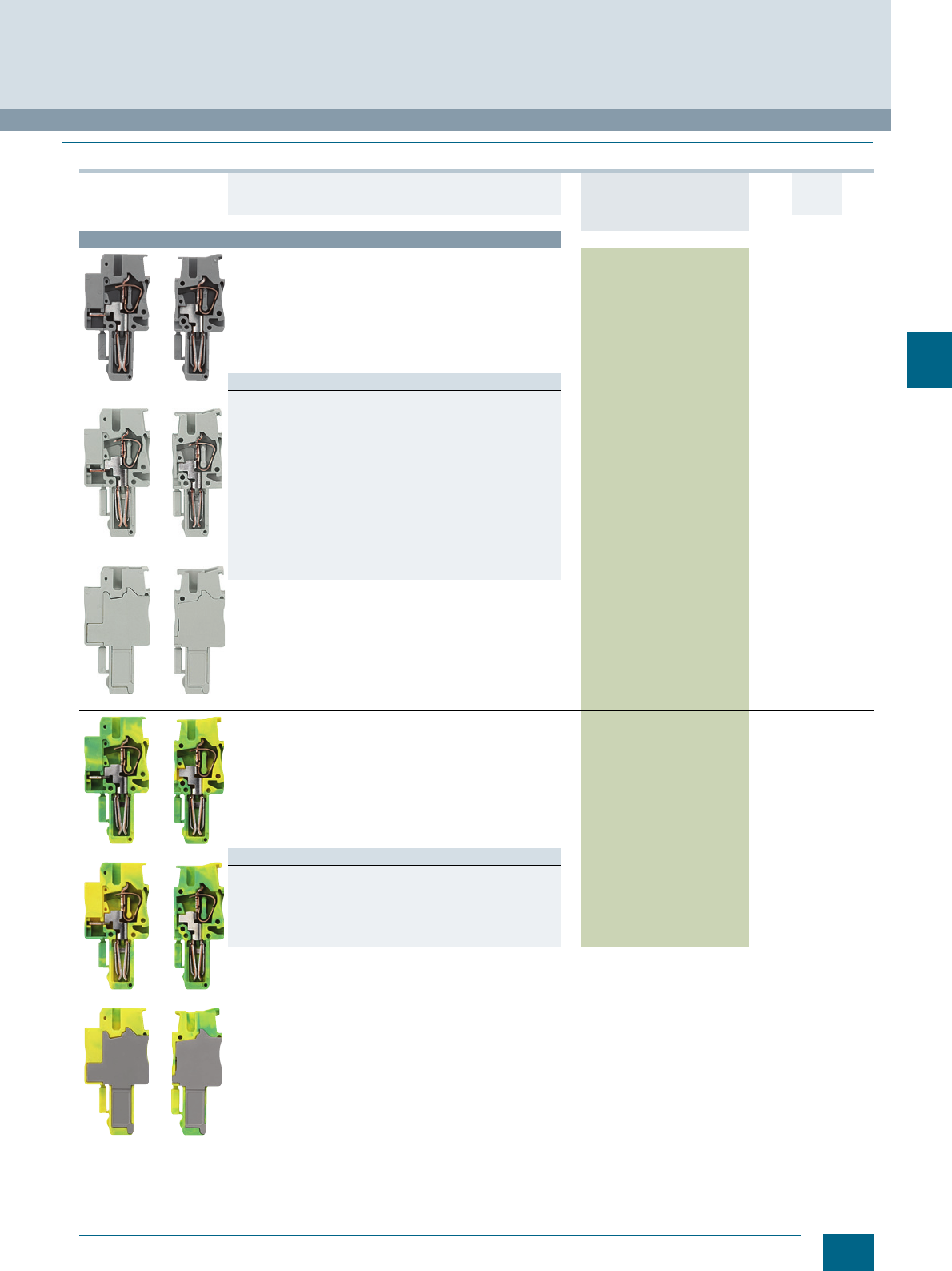
5/9
Siemens LV 52 · 2016
* You can order this quantity or a multiple thereof.
8WH5 Combination Plug-In Terminals
8WH9 plugs
5
■
Selection and ordering data
Version DT Article No.
www.siemens.com/
product?Article No.
Price
per PU
PU
(UNIT,
SET, M)
PS*/
P. un it PG
Terminal size 2.5 mm²
8WH9040-1DB00 / -1AB00
8WH9040-1EB00 / -1BB00
8WH9040-1FB00 / -1CB00
Plugs, terminal size 2.5 mm²
• Terminal width 5.2 mm
•CUUS
• Connection data
- Rigid 0.08 ... 4 mm²
- Flexible 0.08 ... 2.5 mm²
- AWG 28-12
-I = 24 A
-U = 500 V
• Number of poles = 1
Versions
•Gray
- Left element, with slot for comb 8WH9040-1DB00 1 50 units 1BT
- Central element, with slot for comb 8WH9040-1EB00 1 50 units 1BT
- Right element, with slot for comb 8WH9040-1FB00 1 50 units 1BT
- Left element, without slot for comb 8WH9040-1AB00 1 50 units 1BT
- Central element, without slot for comb 8WH9040-1BB00 1 50 units 1BT
- Right element, without slot for comb 8WH9040-1CB00 1 50 units 1BT
•Blue
- Left element, with slot for comb 8WH9040-1DB01 1 50 units 1BT
- Central element, with slot for comb 8WH9040-1EB01 1 50 units 1BT
- Right element, with slot for comb 8WH9040-1FB01 1 50 units 1BT
- Left element, without slot for comb 8WH9040-1AB01 1 50 units 1BT
- Central element, without slot for comb 8WH9040-1BB01 1 50 units 1BT
- Right element, without slot for comb 8WH9040-1CB01 1 50 units 1BT
8WH9040-1DB07 / -1AB07
8WH9040-1EB07 / -1BB07
8WH9040-1FB07 / -1CB07
PE plugs, terminal size 2.5 mm²
•Green/yellow
• Terminal width 5.2 mm
•CUUS
• Connection data
- Rigid 0.08 ... 4 mm²
- Flexible 0.08 ... 2.5 mm²
- AWG 28-12
-I = 24 A
-U = 500 V
• Number of poles = 1
Versions
• Left element, with slot for comb 8WH9040-1DB07 1 50 units 1BT
• Central element, with slot for comb 8WH9040-1EB07 1 50 units 1BT
• Right element, with slot for comb 8WH9040-1FB07 1 50 units 1BT
• Left element, without slot for comb 8WH9040-1AB07 1 50 units 1BT
• Central element, without slot for comb 8WH9040-1BB07 1 50 units 1BT
• Right element, without slot for comb 8WH9040-1CB07 1 50 units 1BT
© Siemens AG 2015© Siemens AG 2015
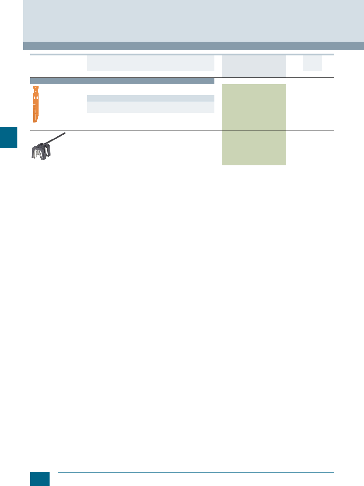
5/10 Siemens LV 52 · 2016 * You can order this quantity or a multiple thereof.
8WH9 plugs
8WH5 Combination Plug-In Terminals
5
For general accessories for 8WH terminal blocks, see chapter
"Accessories for 8WH Terminal Blocks"
Accessories
8WH9050-2BA04
Latches
Number of poles: 2
Versions
• With strain relief 8WH9050-2BA04 100 50 units 1BT
• Without strain relief 8WH9050-2AA04 100 50 units 1BT
8WH9120-DB08
Shielding
• For connection of shielded cables
• For cables with 5 ... 10 mm diameter
• Black
8WH9120-0DB08 1 50 units 1BT
Version DT Article No.
www.siemens.com/
product?Article No.
Price
per PU
PU
(UNIT,
SET, M)
PS*/
P. un it PG
© Siemens AG 2015© Siemens AG 2015
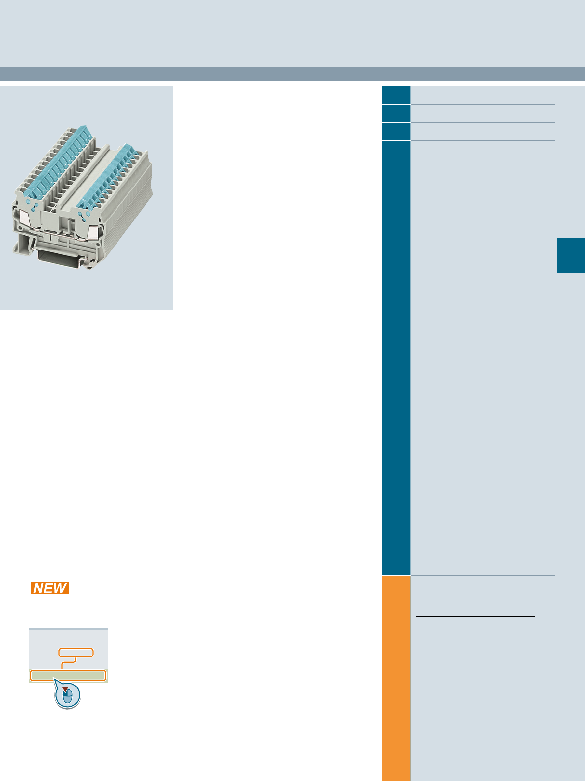
Siemens LV 52 · 2016
For further technical
product information:
Siemens Industry Online Support:
www.siemens.com/lowvoltage/product-
support .
→
Application example
Certificate
Characteristic
Download
FAQ
Manual
Product note
Software archive
Technical data
6
6
6/2 Introduction
6/5 8WH through-type terminals
6/9 8WH two-tier terminals
6/11 8WH isolating terminals
8WH3 Insulation Displacement Terminals
Direct reference to the products in the
Industry Mall from the selection and
ordering data tables:
3VA2025-5HL36-0AA0
Article No.
www.siemens.com/
product? Article No.
Paper catalog:
To get more
product information
enter the Web
address plus
Article No.
PDF catalog:
Get more product information
with just a mouse click.
© Siemens AG 2015© Siemens AG 2015
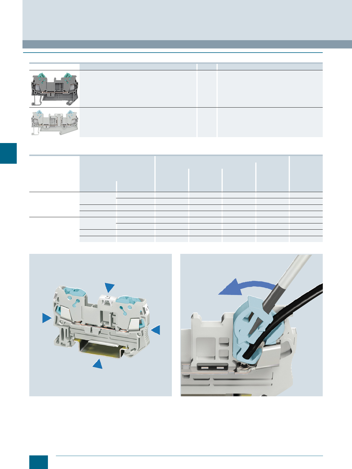
6/2 Siemens LV 52 · 2016
Introduction
8WH3 Insulation Displacement Terminals
6
■
Overview
1) Only the main terminal types are listed here. You will find further versions on the following pages.
Features
A key feature of the insulation displacement series is its IDC
rotary connection. This concept saves considerable space in the
control cabinet without impairing other quality features, such as
• Large surface marking
• Maximum connection compartment
• Flexible connecting combs
Time savings of 60 % and more compared to other connection
systems.
With the quick-connect insulation displacement terminal system,
there is no need to strip the insulation or protect the splice.
The cables only need to be cut to length for contacting within
seconds.
Devices Page Function
8WH through-type terminals 6/5 Connection up to 2.5 mm² of incoming and outgoing
conductors
8WH isolating terminals 6/11 Isolation of the circuit, e.g. for test purposes
Terminal type →Insulation displacement terminal Article No.
(digits 8 ... 12)
Design →Standard Two-tier
No. of clamping points →2344
Article No. (digits 1 ... 7) →8WH3000 8WH3003 8WH3004 8WH3020
Conductor cross-
section Terminal type1) Color
1.5 mm2Through-type Gray ✔✔✔✔0AE00
Blue ✔✔✔✔0AE01
Isolating Gray ✔-- -- -- 6AE00
PE Green/yellow ✔✔✔✔0CE07
2.5 mm2Through-type Gray ✔✔-- -- 0AF00
Blue ✔✔-- -- 0AF01
Isolating Gray ✔-- -- -- 6AF00
PE Green/yellow ✔-- -- -- 0CF07
© Siemens AG 2015© Siemens AG 2015
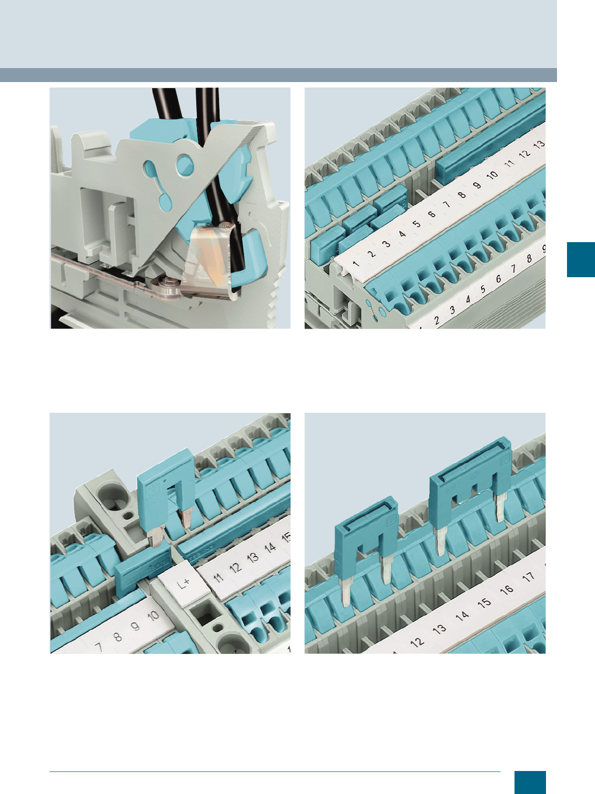
6/3
Siemens LV 52 · 2016
8WH3 Insulation Displacement Terminals
Introduction
6
Conductor connections from 0.25 to 2.5 mm² are produced by
the cutting contact. High-grade special alloys and latching of the
switch states ensure reliable electrical connections at all times.
Large, spring-loaded contact points ensure 24 A current load
rating.
When feeding in large cross-sections, the reducing comb
enables time and cost-saving distribution of the potential.
For example, it can link a 10 mm² spring-loaded through-type
terminal to a 1.5 mm² insulation displacement through-type
terminal and two clamping points – or to a 2.5 mm² insulation
displacement through-type terminal and two clamping points.
The standardized connecting comb system allows several termi-
nals to be linked efficiently and quickly with a single jumper. The
range covers 2- to 50-pole jumpers, which can help consider-
ably to reduce the amount of wiring outlay.
Teeth can be removed from the standard comb in order to skip
individual terminals, so that two potentials can run in parallel.
A marking option is provided on the top of the connecting comb.
© Siemens AG 2015© Siemens AG 2015
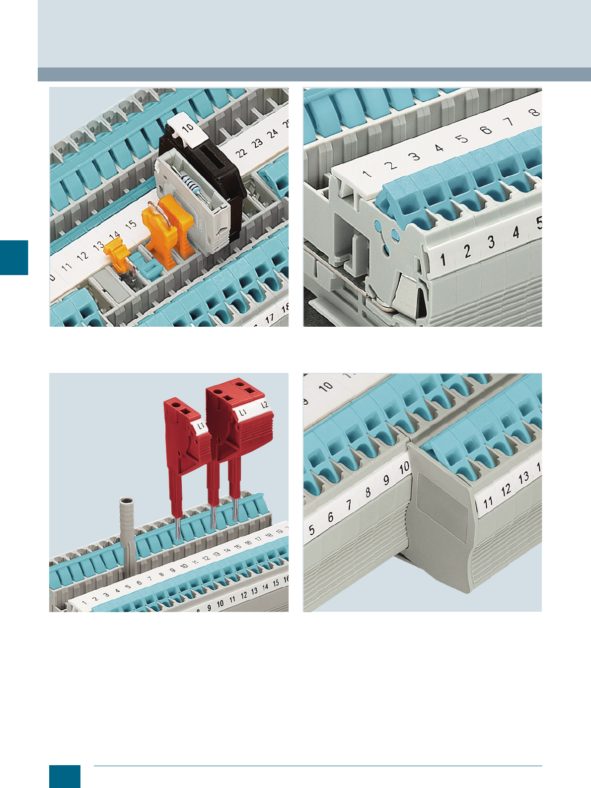
6/4 Siemens LV 52 · 2016
Introduction
8WH3 Insulation Displacement Terminals
6
The universal plug-in zone of the isolating terminal can accom-
modate isolated through-type connectors, isolating plugs, com-
ponent connectors and fused connectors.
Test adapters are available for Ø 4 mm test and safety test plugs.
Test plugs can be individually assembled, thanks to the modular
design of the test plugs. Measuring leads can be connected
over a 1.5 mm² spring-loaded/insulation displacement terminal.
The unambiguous and easy-to-read marking in the center of the
terminal is essential for time-saving installation. In addition to the
large inscription in the center, each clamping point can also be
labeled separately.
The cover segment is used to cover multi-wire terminals when
mounting two-wire terminals side by side. These devices meet
all fingerproof requirements.
© Siemens AG 2015© Siemens AG 2015
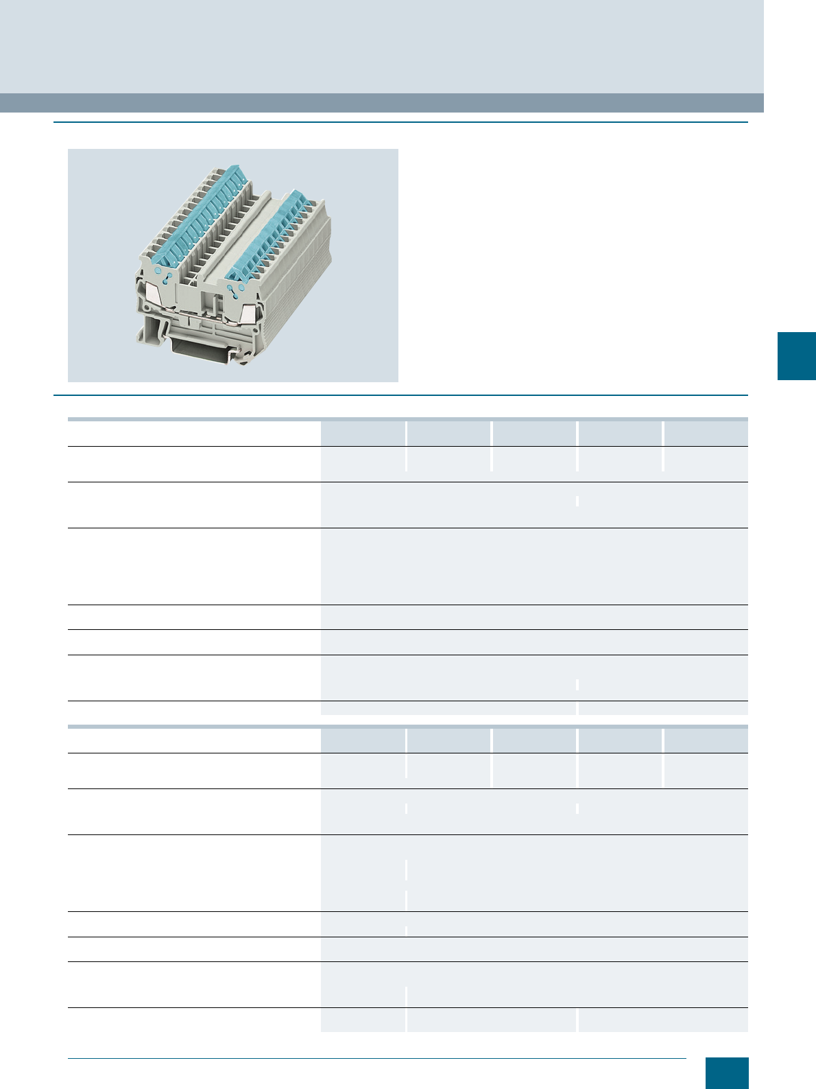
6/5
Siemens LV 52 · 2016
8WH3 Insulation Displacement Terminals
8WH through-type terminals
6
■
Overview
A key feature of the insulation displacement through-type termi-
nal is its compact design. With its clear and space-saving front
connection arrangement, this insulation displacement series
provides additional space between the cable ducts for wiring.
Using the double bridge shaft, it is also possible to use individ-
ual chain bridging, as well as a reducing comb, e.g. from a
2.5 mm² tension spring through-type terminal to a 35 mm²
tension spring through-type terminal. Used in this way, reducing
combs enable the quick and easy assembly of potential in-
coming feeders and distributors.
A label can be snapped on to the middle of the terminal at the
front. Further labels can also be mounted flat on the side of the
terminals.
■
Technical specifications
8WH3000-0AE00
8WH3000-0AE01 8WH3003-0AE00
8WH3003-0AE01 8WH3004-0AE00
8WH3004-0AE01 8WH3000-0CE07 8WH3003-0CE07
Dimensions
• Width/length/cover width in mm 5.2 / 58.8 / 2.2 5.2 / 76.4 / 2.2 5.2 / 94 / 2.2 5.2 / 58.8 / 2.2 5.2 / 76.4 / 2.2
• Height (TS 35/7.5 / TS 35/15) in mm 39.3 / 46.8
Technical specifications acc. to IEC/DIN VDE
• Max. load current in A / cross-section in mm² 17.5 / 1.5 --
• Rated impulse withstand voltage in kV / pollution degree 8 / 3
• Overvoltage category / molded plastic group III / I
Conductor cross-section acc. to DIN VDE 0295
• Core insulation PVC / PE (other insulation types on request)
• Solid/finely stranded H05V-U/R/K / H07V-U/R/K in mm² 0.5 ... 1.0 / 1.5
• Halogen-free H05Z-U/R/K / H07Z-U/R/K in mm² 0.5 ... 1.0 / 1.5
• Finely stranded / very finely stranded
- (Strand ∅ ≥ 0.1 mm) in mm² 0.25 ... 0.34
- (Strand ∅ ≥ 0.19 mm) AWG 24-16
Number of circuits
• At least 100x the same cross-section in mm² 0.25 ... 1.5
Molded plastic type PA
• Flammability Class acc. to UL 94 V0
Approval data (UL/cUL and CSA)
• Rated voltage / rated current / conductor sizes
- UL/cUL: in V/A / AWG 600 / 10 / 24-16 -- / -- / 24-16
- CSA: in V/A / AWG --
Support rails/protective conductor busbars -- See page 1/3, section "Support rails"
8WH3004-0CE07 8WH3000-0AF00
8WH3000-0AF01 8WH3003-0AF00
8WH3003-AF01 8WH3000-0CF07 8WH3003-0CF07
Dimensions
• Width/length/cover width in mm 5.2 / 94 / 2.2 6.2 / 62.6 / 2.2 6.2 / 82.5 / 2.2 6.2 / 62.6 / 2.2 6.2 / 82.5 / 2.2
• Height (TS 35/7.5 / TS 35/15) in mm 39.3 / 46.8 42.8 / 50.3 39.3 / 46.8 42.8 / 50.3
Technical specifications acc. to IEC/DIN VDE
• Max. load current in A / cross-section in mm² -- 24 / 2.5 --
• Rated impulse withstand voltage in kV / pollution degree 8 / 3
• Overvoltage category / molded plastic group III / I
Conductor cross-section acc. to DIN VDE 0295
• Core insulation PVC / PE (other insulation types on request)
• Solid/finely stranded H05V-U/R/K / H07V-U/R/K in mm² 0.5 ... 1.0 / 1.5 0.5 ... 1.5 / 1.5 ... 2.5
• Halogen-free H05Z-U/R/K / H07Z-U/R/K in mm² 0.5 ... 1.0 / 1.5 0.5 ... 1.5 / 1.5 ... 2.5
• Finely stranded / very finely stranded
- (Strand ∅ ≥ 0.1 mm) in mm² 0.25 ... 0.34 --
- (Strand ∅ ≥ 0.19 mm) AWG 24-16 20-14
Number of circuits
• At least 100x the same cross-section in mm² 0.25 ... 1.5 0.5 ... 2.5
Molded plastic type PA
• Flammability Class acc. to UL 94 V0
Approval data (UL/cUL and CSA)
• Rated voltage / rated current / conductor sizes
- UL/cUL: in V/A / AWG -- / -- / 24-16 Applied for
- CSA: in V/A / AWG -- Applied for
Support rails/protective conductor busbars See page 1/3, sec-
tion "Support rails" -- See page 1/3, section "Support rails"
© Siemens AG 2015© Siemens AG 2015
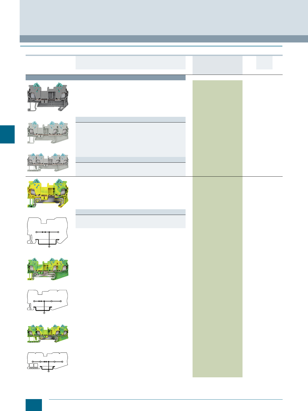
6/6 Siemens LV 52 · 2016 * You can order this quantity or a multiple thereof.
8WH through-type terminals
8WH3 Insulation Displacement Terminals
6
■
Selection and ordering data
Version DT Article No.
www.siemens.com/
product?Article No.
Price
per PU
PU
(UNIT,
SET, M)
PS*/
P. unit PG
Terminal size 1.5 mm²
8WH3000-0AE00
8WH3003-0AE00
8WH3004-0AE00
Through-type terminals, terminal size 1.5 mm²
• Terminal width 5.2 mm
• Connection data
- Rigid 0.25 ... 1.5 mm²
- Flexible 0.25 ... 1.5 mm²
- AWG 24-16
-I = 17.5 A
-U = 800 V
• More information under Technical specifications
Versions
•Gray
- Two clamping points 8WH3000-0AE00 150 units1BT
- Three clamping points 8WH3003-0AE00 150 units1BT
- Four clamping points 8WH3004-0AE00 150 units1BT
•Blue
- Two clamping points 8WH3000-0AE01 150 units1BT
- Three clamping points 8WH3003-0AE01 150 units1BT
- Four clamping points 8WH3004-0AE01 150 units1BT
Note
On terminals with three and four clamping points, the total current
through all connected conductors must not exceed the max. load
current.
8WH3000-0CE07
8WH3000-0CE07
8WH3003-0CE07
8WH3003-0CE07
8WH3004-0CE07
8WH3004-0CE07
PE through-type terminals, terminal size 1.5 mm²
• Green/yellow
• Terminal width 5.2 mm
• Connection data
- Rigid 0.25 ... 1.5 mm²
- Flexible 0.25 ... 1.5 mm²
- AWG 24-16
• More information under Technical specifications
Versions
• Two clamping points 8WH3000-0CE07 150 units1BT
• Three clamping points 8WH3003-0CE07 150 units1BT
• Four clamping points 8WH3004-0CE07 150 units1BT
I201_12722
I201_12723
I201_12724
© Siemens AG 2015© Siemens AG 2015

6/7
Siemens LV 52 · 2016
* You can order this quantity or a multiple thereof.
8WH3 Insulation Displacement Terminals
8WH through-type terminals
6
Terminal size 2.5 mm²
8WH3000-0AF00
8WH3003-0AF00
Through-type terminals, terminal size 2.5 mm²
• Terminal width 6.2 mm
• Connection data
- Rigid 0.5 ... 2.5 mm²
- Flexible 0.5 ... 2.5 mm²
- AWG 20-14
-I = 24 A
-U = 800 V
Versions
•Gray
- Two clamping points 8WH3000-0AF00 150 units1BT
- Three clamping points 8WH3003-0AF00 150 units1BT
•Blue
- Two clamping points 8WH3000-0AF01 150 units1BT
- Three clamping points 8WH3003-0AF01 150 units1BT
Note
On terminals with three clamping points, the total current through all
connected conductors must not exceed the max. load current.
8WH3000-0CF07
8WH3000-0CF07
8WH3003-0CF07
8WH3003-0CF07
PE through-type terminals, terminal size 2.5 mm²
• Green/yellow
• Terminal width 6.2 mm
• Connection data
- Rigid 0.5 ... 2.5 mm²
- Flexible 0.5 ... 2.5 mm²
- AWG 20-14
Versions
• Two clamping points 8WH3000-0CF07 150 units1BT
• Three clamping points 8WH3003-0CF07 150 units1BT
Version DT Article No.
www.siemens.com/
product?Article No.
Price
per PU
PU
(UNIT,
SET, M)
PS*/
P. unit PG
I201_12725
I201_12726
© Siemens AG 2015© Siemens AG 2015
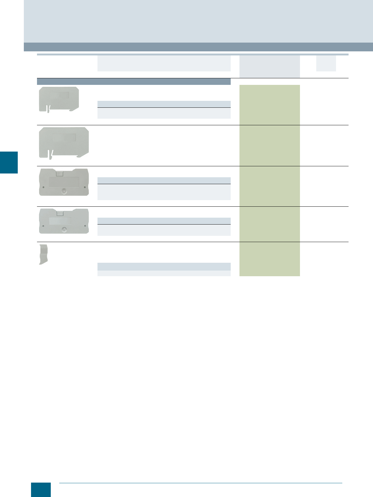
6/8 Siemens LV 52 · 2016 * You can order this quantity or a multiple thereof.
8WH through-type terminals
8WH3 Insulation Displacement Terminals
6
For general accessories for 8WH terminal blocks, see chapter
"Accessories for 8WH Terminal Blocks"
Accessories
8WH9070-0JA00
Compartment partitions, for terminal size 1.5 ... 2.5 mm²
• For visual and electrical separation of terminal groups
• 2 mm thick
Versions
• Two clamping points 8WH9070-0JA00 100 50 units 1BT
• Three clamping points 8WH9070-0KA00 100 50 units 1BT
8WH9070-0LA00
Compartment partitions, for terminal size 1.5 mm² and
four connection points 8WH9070-0LA00 100 50 units 1BT
8WH9001-1AA00
Covers, for terminal size 1.5 mm²
Gray
Versions
• Two clamping points 8WH9001-1AA00 100 50 units 1BT
• Three clamping points 8WH9001-2AA00 100 50 units 1BT
• Four clamping points 8WH9001-4AA00 100 50 units 1BT
8WH9000-1AA00
Covers, for terminal size 2.5 mm²
Gray
Versions
• Two clamping points 8WH9000-1AA00 100 50 units 1BT
• Three clamping points 8WH9000-2AA00 100 50 units 1BT
8WH9001-0AA00
Cover segments, for three or four clamping points
•Gray
• For covering multi-wire terminals when mounting two-wire
terminals side-by-side
Versions
• For terminal size 2.5 mm² 8WH9000-0AA00 100 50 units 1BT
Version DT Article No.
www.siemens.com/
product?Article No.
Price
per PU
PU
(UNIT,
SET, M)
PS*/
P. unit PG
© Siemens AG 2015© Siemens AG 2015
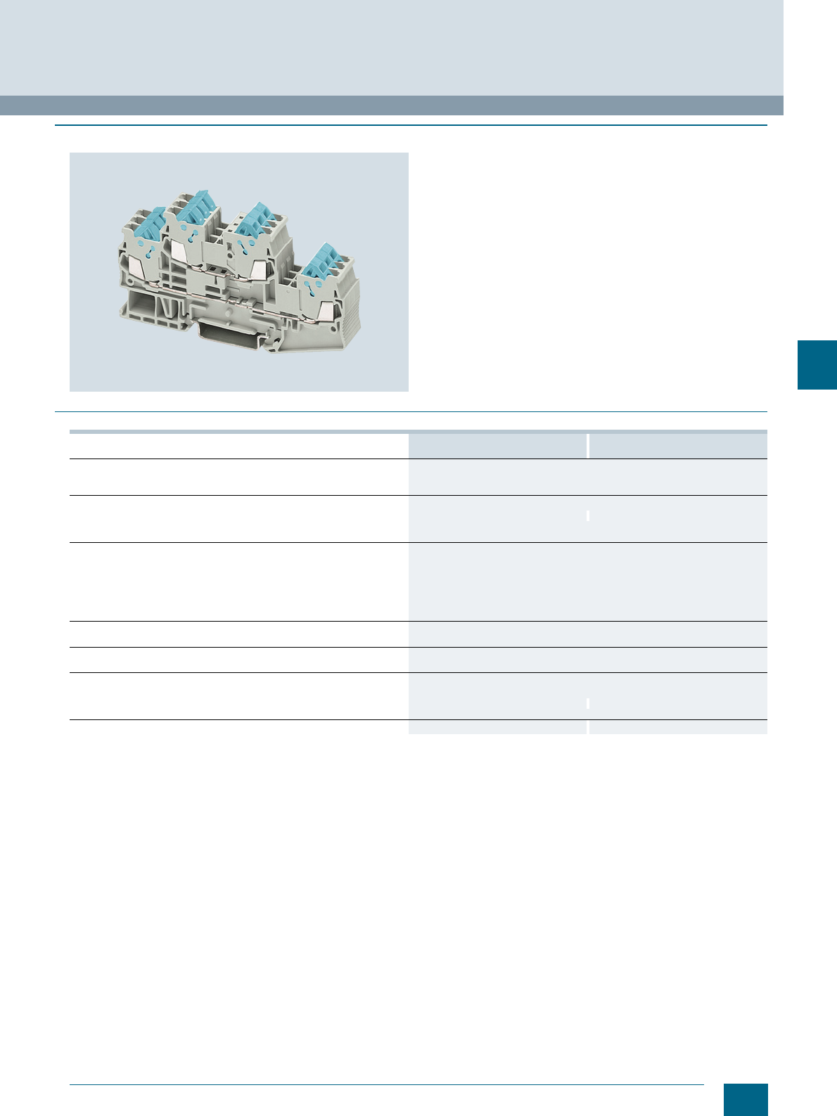
6/9
Siemens LV 52 · 2016
8WH3 Insulation Displacement Terminals
8WH two-tier terminals
6
■
Overview
Key features of the IDC two-tier terminals for terminal size
1.5 mm² are their ultra compact design and the double bridge
shaft for each tier. This enables simultaneous bridging and
testing.
With its clear and space-saving front connection arrangement,
this two-tier terminal series provides additional space between
the cable ducts for wiring.
The PE/ground conductor terminal of this range meets all the
requirements of IEC 60 947-7-2.
These include:
• Low contact resistance
• Stainless clamping points and PE mounting foot
• Green-yellow enclosure and
• Additional inscription options
The clamping points of two-tier terminals can be inscribed with
flat labels.
■
Technical specifications
8WH3020-0AE00
8WH3020-0AE01 8WH3020-0CE07
Dimensions
• Width/length/cover width in mm 5.2 / 99.6 / 2.2
• Height (TS 35/7.5 / TS 35/15) in mm 49.9 / 57.4
Technical specifications acc. to IEC/DIN VDE
• Max. load current in A / cross-section in mm² 17.5 / 1.5 --
• Rated impulse withstand voltage in kV / pollution degree 6 / 3
• Overvoltage category / molded plastic group III / I
Conductor cross-section acc. to DIN VDE 0295
• Core insulation PVC / PE (other insulation types on request)
• Solid/finely stranded H05V-U/R/K / H07V-U/R/K in mm² 0.4 ... 1.0 / 1.5
• Halogen-free H05Z-U/R/K / H07Z-U/R/K in mm² 0.5 ... 1.0 / 1.5
• Finely stranded / very finely stranded
- (Strand ∅ ≥ 0.1 mm) in mm² 0.25 ... 0.34
- (Strand ∅ ≥ 0.19 mm) AWG 24-16
Number of circuits
• At least 100x the same cross-section in mm² 0.25 ... 1.5
Molded plastic type PA
• Flammability Class acc. to UL 94 V0
Approval data (UL/cUL and CSA)
• Rated voltage / rated current / conductor sizes
- UL/cUL: in V/A / AWG 600 / 10 / 24-16 -- / -- / 24-16
- CSA: in V/A / AWG --
Support rails/protective conductor busbars -- See page 1/3, section "Support rails"
© Siemens AG 2015© Siemens AG 2015
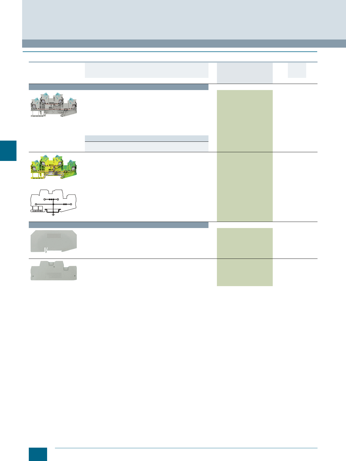
6/10 Siemens LV 52 · 2016 * You can order this quantity or a multiple thereof.
8WH two-tier terminals
8WH3 Insulation Displacement Terminals
6
■
Selection and ordering data
For general accessories for 8WH terminal blocks, see chapter
"Accessories for 8WH Terminal Blocks"
Version DT Article No.
www.siemens.com/
product?Article No.
Price
per PU
PU
(UNIT,
SET, M)
PS*/
P. unit PG
Terminal size 1.5 mm²
8WH3020-0AE00
Two-tier terminals, terminal size 1.5 mm²
• Terminal width 5.2 mm
•CUUS
• Connection data
- Rigid 0.25 ... 1.5 mm²
- Flexible 0.25 ... 1.5
- AWG 24-16
-I = 17.5 A
-U = 500 V
• More information under Technical specifications
Versions
•Gray 8WH3020-0AE00 150 units1BT
•Blue 8WH3020-0AE01 150 units1BT
8WH3020-0CE07
8WH3020-0CE07
PE two-tier terminals, terminal size 1.5 mm²
• Green/yellow
• Terminal width 5.2 mm
•CUUS
• Connection data
- Rigid 0.25 ... 1.5 mm²
- Flexible 0.25 ... 1.5
- AWG 24-16
• More information under Technical specifications
8WH3020-0CE07 150 units1BT
Accessories
8WH9070-0MA00
Compartment partitions, for terminal size 1.5 mm² 8WH9070-0MA00 100 50 units 1BT
8WH9001-1BA00
Covers, for terminal size 1.5 mm² 8WH9001-1BA00 100 50 units 1BT
I2_12738
© Siemens AG 2015© Siemens AG 2015
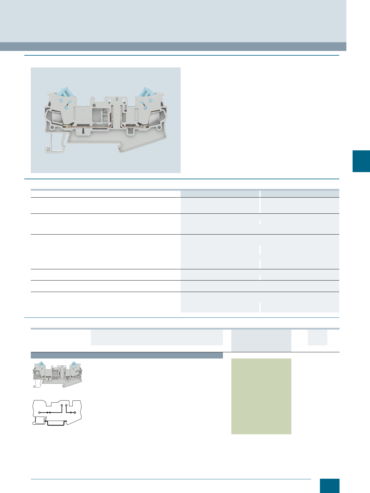
6/11
Siemens LV 52 · 2016
* You can order this quantity or a multiple thereof.
8WH3 Insulation Displacement Terminals
8WH isolating terminals
6
■
Overview
8WH3 isolating terminals using insulation displacement tech-
nology are available for special wiring tasks. Numerous wiring
tasks can be performed on a terminal width of 5.2 mm by inte-
grating the isolated through-type connector, the isolating plug,
the component connector or the fused plug.
A label can be snapped on to the middle of each terminal at the
front. Further labels can also be mounted flat on the side of the
terminals.
■
Technical specifications
■
Selection and ordering data
8WH3000-6AE00 8WH3000-6AF00
Dimensions
• Width/length/cover width in mm 5.2 / 76.4 / 2.2 6.2 / 82.5 / 2.2
• Height (TS 35/7.5 / TS 35/15) in mm 39.3 / 46.8 42.8 / 50.3
Technical specifications acc. to IEC/DIN VDE
• Max. load current in A / cross-section in mm² 16 / 1.5 16 / 2.5
• Rated impulse withstand voltage in kV / pollution degree 6 / 3
• Overvoltage category / molded plastic group III / I
Conductor cross-section acc. to DIN VDE 0295
• Core insulation PVC / PE (other insulation types on request)
• Solid/finely stranded H05V-U/R/K / H07V-U/R/K in mm² 0.5 ... 1.0 / 1.5 0.5 ... 1.0 / 1.5 ... 2.5
• Halogen-free H05Z-U/R/K / H07Z-U/R/K in mm² 0.5 ... 1.0 / 1.5 0.5 ... 1.0 / 1.5 ... 2.5
• Finely stranded / very finely stranded
- (Strand ∅ ≥ 0.1 mm) in mm² 0.25 ... 0.34 --
- (Strand ∅ ≥ 0.19 mm) AWG 24-16 20-14
Number of circuits
• At least 100x the same cross-section in mm² 0.25 ... 1.5 0.5 ... 2.5
Molded plastic type PA
• Flammability Class acc. to UL 94 V0
Approval data (UL/cUL and CSA)
• Rated voltage / rated current / conductor sizes
- UL/cUL: in V/A / AWG 600 / 10 / 24-16 Applied for
- CSA: in V/A / AWG 600 / 10 / 24-16 Applied for
Version DT Article No.
www.siemens.com/
product?Article No.
Price
per PU
PU
(UNIT,
SET, M)
PS*/
P. unit PG
Terminal size 1.5 mm²
8WH3000-6AE00
8WH3000-6AE00
Isolating terminals, terminal size 1.5 mm²
•Gray
• Terminal width 5.2 mm
•CUUS
• Connection data
- Rigid 0.25 ... 1.5 mm²
- Flexible 0.25 ... 1.5 mm²
- AWG 24-16
-I = 16 A
-U = 400 V
- Current and voltage are determined by the fitted plug
• For further information see Technical specifications
8WH3000-6AE00 150 units1BT
I201_12739
© Siemens AG 2015© Siemens AG 2015
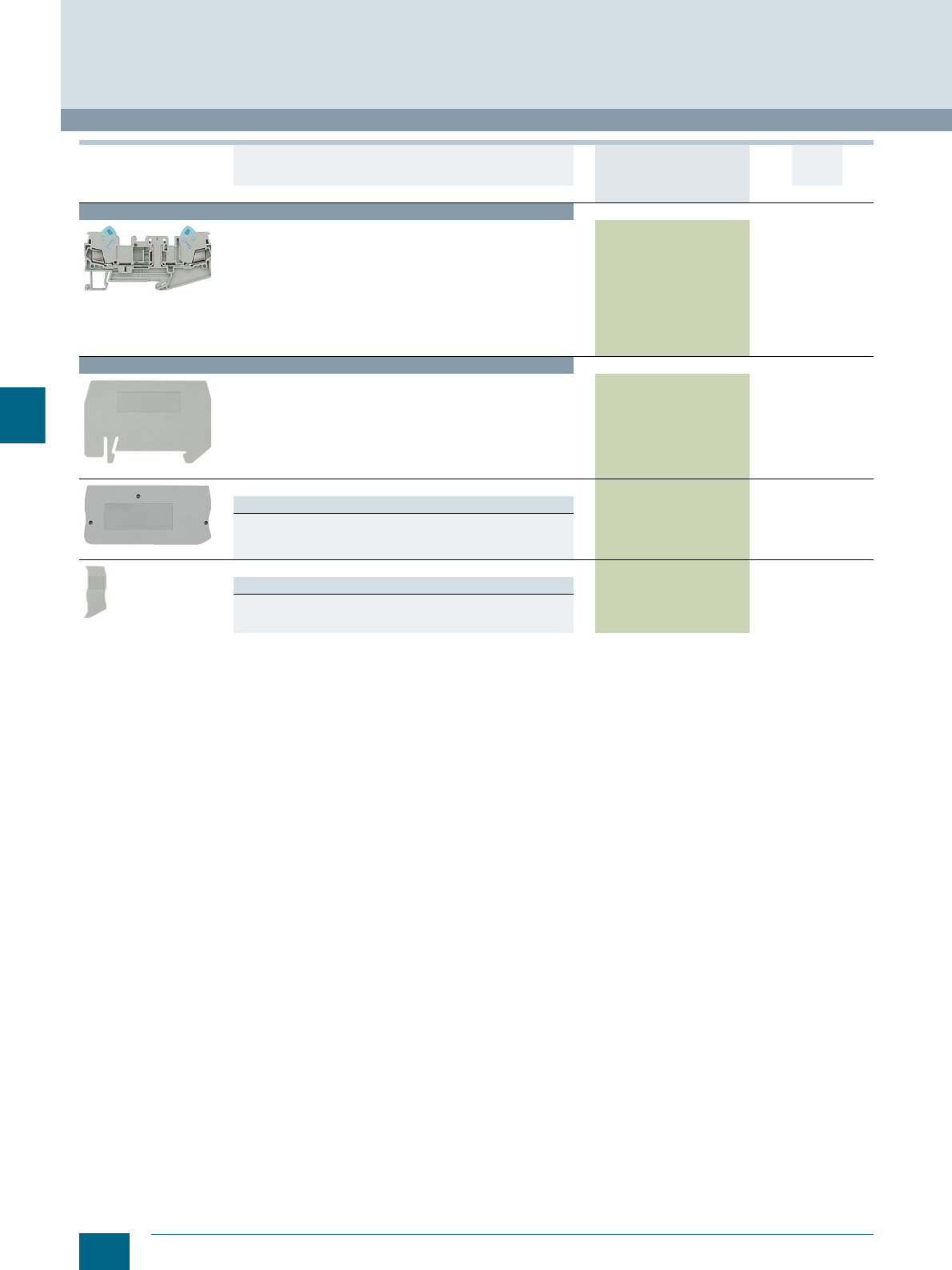
6/12 Siemens LV 52 · 2016 * You can order this quantity or a multiple thereof.
8WH isolating terminals
8WH3 Insulation Displacement Terminals
6
For general accessories for 8WH terminal blocks, see chapter
"Accessories for 8WH Terminal Blocks"
Terminal size 2.5 mm²
8WH3000-6AF00
Isolating terminals, terminal size 2.5 mm²
•Gray
• Terminal width 6.2 mm
• Connection data
- Rigid 0.5 ... 2.5 mm²
- Flexible 0.5 ... 2.5 mm²
- AWG 20-14
-I = 16 A
-U = 400 V
- Current and voltage are determined by the fitted plug
• More information under Technical specifications
8WH3000-6AF00 150 units1BT
Accessories
8WH9070-0KA00
Compartment partitions, for terminal size 1.5 ... 2.5 mm² and
three clamping points 8WH9070-0KA00 100 50 units 1BT
8WH9001-2AA00
Covers
Versions
• For terminal size 1.5 mm² and three clamping points 8WH9001-2AA00 100 50 units 1BT
• For terminal size 2.5 mm² and three clamping points 8WH9000-2AA00 100 50 units 1BT
8WH9001-0AA00
Cover segments
Versions
• For terminal size 1.5 mm² and three or four clamping points 8WH9001-0AA00 100 50 units 1BT
• For terminal size 2.5 mm² and three or four clamping points 8WH9000-0AA00 100 50 units 1BT
Version DT Article No.
www.siemens.com/
product?Article No.
Price
per PU
PU
(UNIT,
SET, M)
PS*/
P. unit PG
© Siemens AG 2015© Siemens AG 2015
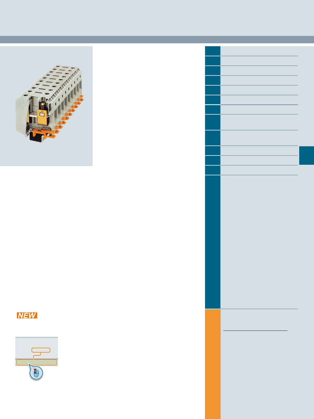
Siemens LV 52 · 2016
For further technical
product information:
Siemens Industry Online Support:
www.siemens.com/lowvoltage/product-
support .
→
Application example
Certificate
Characteristic
Download
FAQ
Manual
Product note
Software archive
Technical data
7
7
7/2 Introduction
7/3 General data on 8WH
7/4 8WH through-type terminals1)
7/8 8WH fuse terminals
7/10 8WH isolating blade terminals
7/11 8WH isolating terminals
7/12 8WH two-tier terminals1)
7/15 8WH two-tier terminals with
isolating function/isolating blade
7/17 8WH measuring transformer
terminals
7/20 8WH diode terminals
7/21 8WH two-tier diode terminals
7/24 8WH high-current terminals1)
7/28 8WH shield terminals
1) Also available as a PE version
8WH1 Screw Terminals
Direct reference to the products in the
Industry Mall from the selection and
ordering data tables:
3VA2025-5HL36-0AA0
Article No.
www.siemens.com/
product? Article No.
Paper catalog:
To get more
product information
enter the Web
address plus
Article No.
PDF catalog:
Get more product information
with just a mouse click.
© Siemens AG 2015© Siemens AG 2015
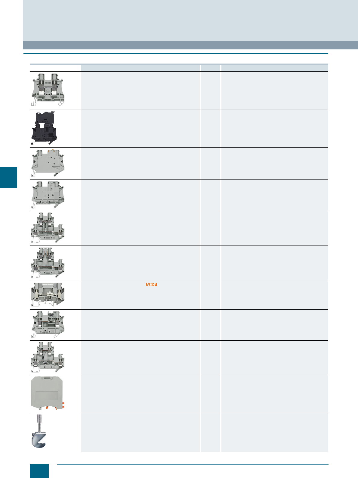
7/2 Siemens LV 52 · 2016
Introduction
8WH1 Screw Terminals
7
■
Overview
Devices Page Function
Through-type terminals 7/4 Connection of incoming and outgoing conductors
up to 35 mm2
Fuse terminals 7/8 Terminals which can be used to protect control circuits,
for example
Isolating blade terminals 7/10 Isolation of the circuit, e.g. for test purposes
Isolating terminals 7/11 Isolation of the circuit, e.g. for test purposes
Two-tier terminals 7/12 Compact form of the terminal block in which two
connection wires can be installed
Two-tier terminals with isolating function 7/15 Compact form of the terminal block in which two
connection wires can be installed
Measuring transformer terminals 7/17 Measuring transformer terminals permit clear and
simple tests
Diode terminals 7/20 Terminal blocks with integrated diodes
Two-tier diode terminals 7/21 Terminal blocks with integrated diodes
8WH high-current terminals 7/24 Connection of incoming and outgoing cables
from 50 to 240 mm2
8WH shield terminals 7/28 Terminals for connection of shielded cables
© Siemens AG 2015© Siemens AG 2015
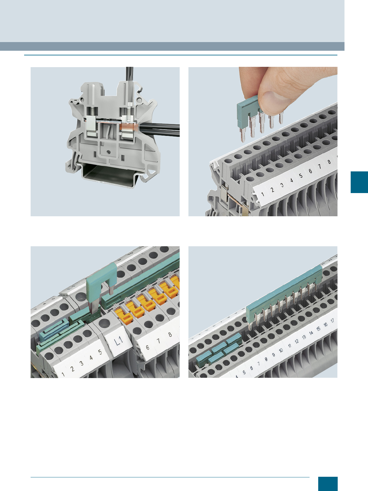
7/3
Siemens LV 52 · 2016
8WH1 Screw Terminals
General data on 8WH
7
■
Overview
The screw terminal is characterized by its global standard, multi-
conductor connection and maintenance-free design. The potential distribution can be quickly implemented with the
standardized connecting combs. Flexible chain bridging, level
bridging, or skipping of several terminals are possible through
two or more bridge shafts in all the terminals.
Reducing combs enable easy connection of terminals with
various nominal cross-sections and terminal designs. Reducing
combs can be used for the quick assembly of infeed blocks.
The double bridge shaft enables an assembly of any number of
terminals with two-pole jumpers. The 2-pole to 50-pole jumpers
enable up to 50 terminals to be connected in a single step.
© Siemens AG 2015© Siemens AG 2015
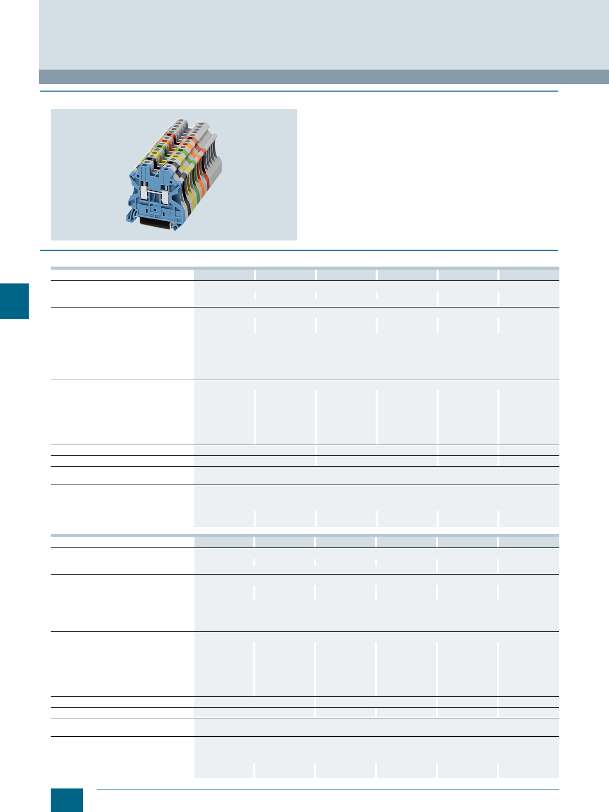
7/4 Siemens LV 52 · 2016
8WH through-type terminals
8WH1 Screw Terminals
7
■
Overview
8WH through-type terminals are characterized by their compact
design and optimum handling. They are available in conductor
cross-section areas from 2.5 to 35 mm2 and can be inscribed
with labels. The double bridge shaft enables individual chain
bridging by means of standard connecting combs. Corre-
sponding accessories are available for testing and labeling.
Secure electrical and mechanical contact with the support rail is
established by simply snapping the terminals onto the rail.
The individual clamping points can be inscribed at the front
using the labels.
■
Technical specifications
8WH1000-0AF0. 8WH1000-0AG0. 8WH1000-0AH0. 8WH1000-0AJ0. 8WH1000-0AK0. 8WH1000-0AM0.
Dimensions
• Width/length/cover width in mm 5.2 / 47.7 / 2.2 6.2 / 47.7 / 2.2 8.2 / 47.7 / 2.2 10.2 / 47.7 / 2.2 12 / 55.3 / 2.2 16 / 60.2 / --
• Height (NS 35/7.5 / NS 35/15) in mm 47.5 / 55 55 / 62.5 65.7 / 73.2
Technical specifications acc. to IEC/DIN VDE
• Max. load current in A /
cross-section in mm² 32 / 4 41 / 6 57 / 10 76 / 16 101 / 25 150 / 50
• Rated impulse withstand voltage in kV /
pollution degree 8 kV / 3
• Rated insulation voltage (working voltage)
Ui in V acc. to IEC 60497-7-1 1000
• Overvoltage category / molded plastic
group III / I
Connection capacities
• Flexible with end sleeve, with
plastic sleeve in mm² 0.25 ... 2.5 0.25 ... 4 0.25 ... 6 0.5 ... 10 1.0 ... 16 1.5 ... 35
• Flexible with end sleeve, without
plastic sleeve in mm² 0.25 ... 2.5 0.25 ... 4 0.25 ... 6 0.5 ... 10 1.0 ... 16 1.5 ... 35
• Flexible with two-wire connection end
sleeve, with plastic sleeve in mm² 0.5 ... 1.5 0.5 ... 2.5 0.5 ... 4 0.5 ... 6 0.75 ... 10 1.5 ... 10
• Rigid in mm² 0.14 ... 4 0.14 ... 6 0.2 ... 10 0.5 ... 16 1.5 ... 25 1.5 ... 50
Stripped length in mm 910 14 18
Tightening torque in Nm 0.6 ... 0.8 1.5 ... 1.8 2.5 ... 3.0 3.2 ... 3.7
Molded plastic type PA
• Flammability Class acc. to UL 94 V0
Approval data (UL/cUL and CSA)
• Rated voltage / rated current / conductor
sizes
- UL/cUL: in V/A / AWG 600 / 20 / 26 ... 12 600 / 30 / 26 ... 10 600 / 50 / 24 ... 8 600 / 65 / 20 ... 6 600 / 85 / 16 ... 4 600 / 150 / 14-1/0
- CSA: in V/A / AWG 600 / 20 / 26 ... 12 600 / 30 / 26 ... 10 600 / 50 / 24 ... 8 600 / 65 / 20 ... 6 600 / 85 / 16 ... 4 600 / 150 / 14-1/0
8WH1000-0CF07 8WH1000-0CG07 8WH1000-0CH07 8WH1000-0CJ07 8WH1000-0CK07 8WH1000-0CM07
Dimensions
• Width/length/cover width in mm 5.2 / 47.7 / 2.2 6.2 / 47.7 / 2.2 8.2 / 47.7 / 2.2 10.2 / 47.7 / 2.2 12 / 55.3 / 2.2 16 / 60.2 / --
• Height (NS 35/7.5 / NS 35/15) in mm 47.5 / 55 55 / 62.5 65.7 / 73.2
Technical specifications acc. to IEC/DIN VDE
• Max. load current in A /
cross-section in mm² -- / 4 -- /6 -- /10 -- /16 101 / 25 125 / 35
• Rated impulse withstand voltage in kV /
pollution degree 8 kV / 3
• Overvoltage category / molded plastic
group III / I
Connection capacities
• Flexible with end sleeve, with
plastic sleeve in mm² 0.25 ... 2.5 0.25 ... 2.4 0.25 ... 6 0.5 ... 10 1.0 ... 16 1.5 ... 35
• Flexible with end sleeve, without
plastic sleeve in mm² 0.25 ... 2.5 0.25 ... 2.4 0.25 ... 6 0.5 ... 10 1.0 ... 16 1.5 ... 35
• Flexible with two-wire connection end
sleeve, with plastic sleeve in mm² 0.5 ... 1.5 0.5 ... 2.5 0.5 ... 4 0.5 ... 6 0.75 ... 10 1.5 ... 10
• Rigid in mm² 0.14 ... 4 0.14 ... 6 0.2 ... 10 0.5 ... 16 1.5 ... 25 1.5 ... 35
Stripped length in mm 910 14 18
Tightening torque in Nm 0.6 ... 0.8 1.6 ... 1.8 1.5 ... 1.8 2.5 ... 3.0 3.2 ... 3.7
Molded plastic type PA
• Flammability Class acc. to UL 94 V0
Approval data (UL/cUL and CSA)
• Rated voltage / rated current / conductor
sizes
- UL/cUL: in V/A / AWG -- / -- / 26 ... 12 -- / -- / 26 ... 10 -- / -- / 24 ... 8 -- / -- / 20 ... 6 -- / -- / 16 ... 4 -- / -- / 14-1/0
- CSA: in V/A / AWG -- / -- / 26 ... 12 -- / -- / 26 ... 10 -- / -- / 24 ... 8 -- / -- / 20 ... 6 -- / -- / 16 ... 4 -- / -- / 14-1/0
© Siemens AG 2015© Siemens AG 2015
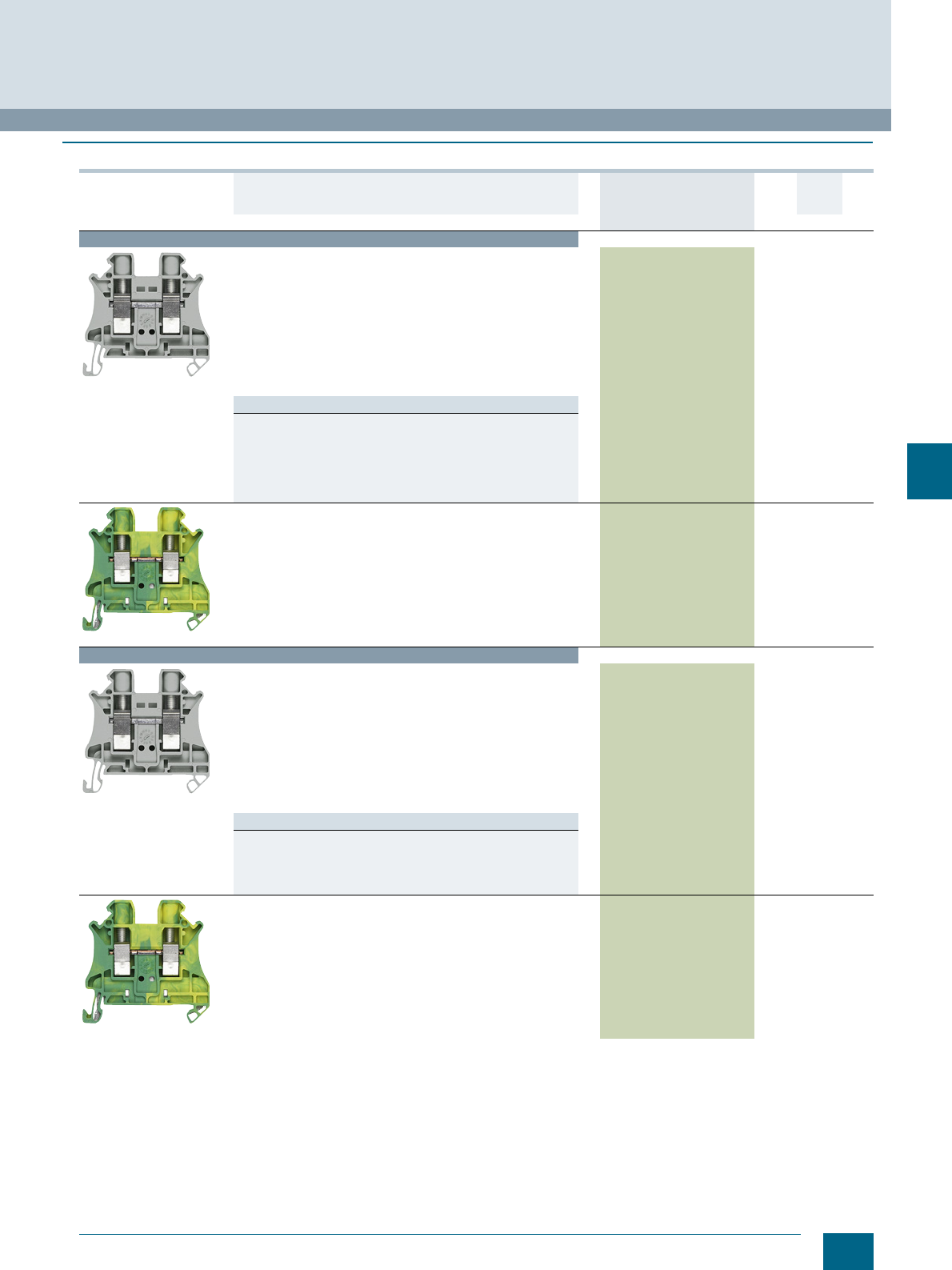
7/5
Siemens LV 52 · 2016
* You can order this quantity or a multiple thereof.
8WH1 Screw Terminals
8WH through-type terminals
7
■
Selection and ordering data
Version DT Article No.
www.siemens.com/
product?Article No.
Price
per PU
PU
(UNIT,
SET, M)
PS*/
P. un it PG
Terminal size 2.5 mm²
8WH1000-0AF00
Through-type terminals, terminal size 2.5 mm²
•CUUS, s
• Terminal width 5.2 mm
•Imax = 32 A
•Umax = 1000 V
• AWG 26 ... 12
• Connection capacity, one conductor
- Rigid 0.14 ... 4 mm²
- Flexible 0.14 ... 4 mm²
• Connection capacity, two conductors
- Rigid 0.14 ... 1.5 mm²
- Flexible 0.14 ... 1.5 mm²
Versions
•Gray 8WH1000-0AF00 1 50 units 1BT
•Blue 8WH1000-0AF01 1 50 units 1BT
•Red 8WH1000-0AF02 1 50 units 1BT
• Black 8WH1000-0AF08 1 50 units 1BT
•Yellow 8WH1000-0AF06 1 50 units 1BT
• Green 8WH1000-0AF03 1 50 units 1BT
• Orange 8WH1000-0AF04 1 50 units 1BT
8WH1000-0CF07
PE through-type terminals, terminal size 2.5 mm²
•CUUS, s
• Terminal width 5.2 mm
• AWG 26 ... 12
• Connection capacity, one conductor
- Rigid 0.14 ... 4 mm²
- Flexible 0.14 ... 4 mm²
• Connection capacity, two conductors
- Rigid 0.14 ... 1.5 mm²
- Flexible 0.14 ... 1.5 mm²
• Green/yellow
8WH1000-0CF07 1 50 units 1BT
Terminal size 4 mm²
8WH1000-0AG00
Through-type terminals, terminal size 4 mm²
•CUUS, s
• Terminal width 6.2 mm
•Imax = 41 A
•Umax = 1000 V
• AWG 26 ... 10
• Connection capacity, one conductor
- Rigid 0.14 ... 6 mm²
- Flexible 0.14 ... 6 mm²
• Connection capacity, two conductors
- Rigid 0.14 ... 1.5 mm²
- Flexible 0.14 ... 1.5 mm²
Versions
•Gray 8WH1000-0AG00 1 50 units 1BT
•Blue 8WH1000-0AG01 1 50 units 1BT
•Red 8WH1000-0AG02 1 50 units 1BT
• Black 8WH1000-0AG08 1 50 units 1BT
• Orange 8WH1000-0AG04 1 50 units 1BT
8WH1000-0CG07
PE through-type terminals, terminal size 4 mm²
•CUUS, s
• Terminal width 6.2 mm
• AWG 26 ... 10
• Connection capacity, one conductor
- Rigid 0.14 ... 6 mm²
- Flexible 0.14 ... 6 mm²
• Connection capacity, two conductors
- Rigid 0.14 ... 1.5 mm²
- Flexible 0.14 ... 1.5 mm²
• Green/yellow
8WH1000-0CG07 1 50 units 1BT
© Siemens AG 2015© Siemens AG 2015
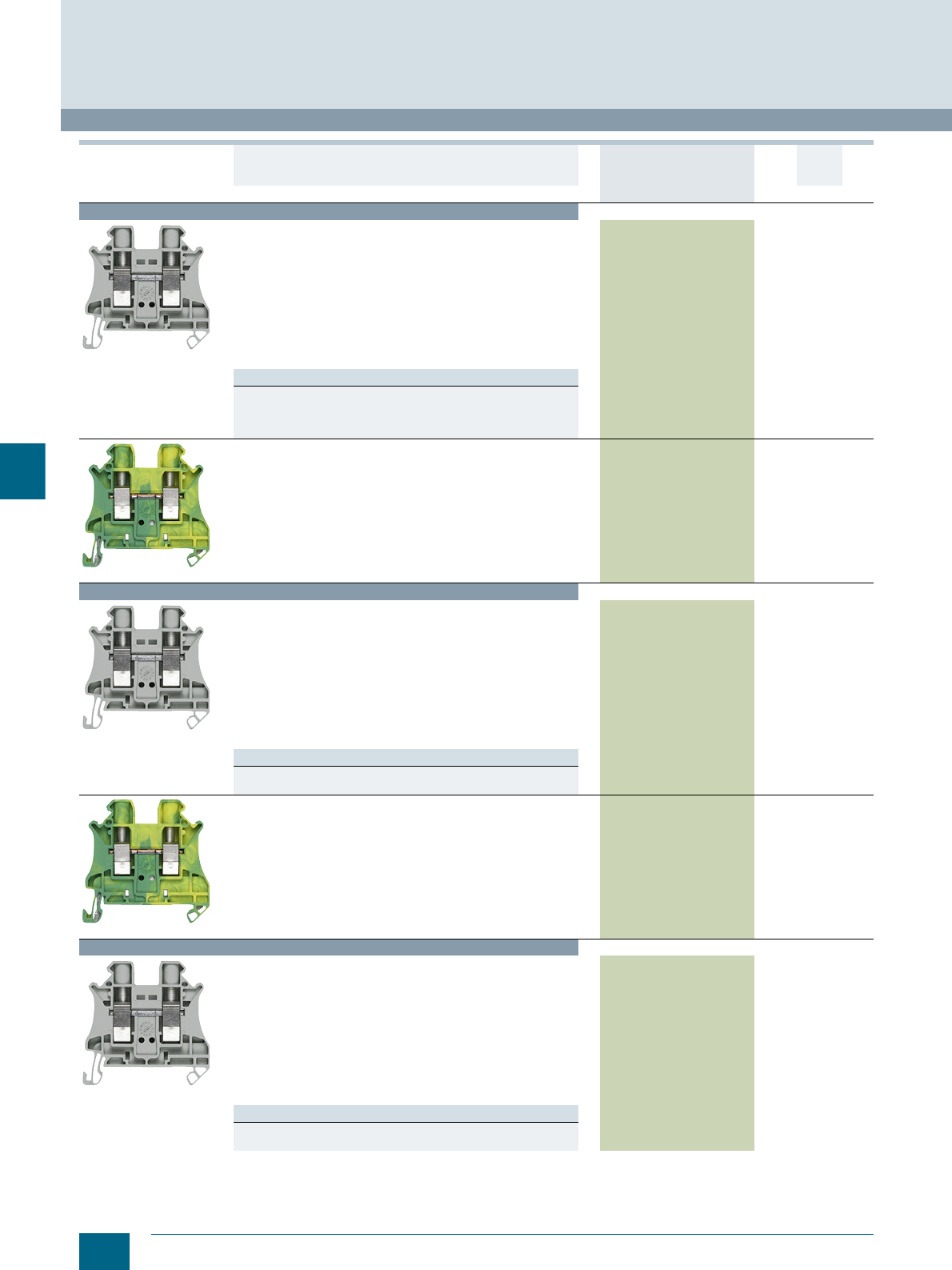
7/6 Siemens LV 52 · 2016 * You can order this quantity or a multiple thereof.
8WH through-type terminals
8WH1 Screw Terminals
7
Terminal size 6 mm²
8WH1000-0AH00
Through-type terminals, terminal size 6 mm²
•CUUS, s
• Terminal width 8.2 mm
•Imax = 57 A
•Umax = 1000 V
• AWG 24 ... 8
• Connection capacity, one conductor
- Rigid 0.2 ... 10 mm²
- Flexible 0.2 ... 10 mm²
• Connection capacity, two conductors
- Rigid 0.2 ... 2.5 mm²
- Flexible 0.2 ... 2.5 mm²
Versions
•Gray 8WH1000-0AH00 1 50 units 1BT
•Blue 8WH1000-0AH01 1 50 units 1BT
•Red 8WH1000-0AH02 1 50 units 1BT
• Black 8WH1000-0AH08 1 50 units 1BT
8WH1000-0CH07
PE through-type terminals, terminal size 6 mm²
•CUUS, s
• Terminal width 8.2 mm
• AWG 24 ... 8
• Connection capacity, one conductor
- Rigid 0.2 ... 10 mm²
- Flexible 0.2 ... 10 mm²
• Connection capacity, two conductors
- Rigid 0.2 ... 2.5 mm²
- Flexible 0.2 ... 2.5 mm²
• Green/yellow
8WH1000-0CH07 1 50 units 1BT
Terminal size 10 mm²
8WH1000-0AJ00
Through-type terminals, terminal size 10 mm²
•CUUS, s
• Terminal width 10.2 mm
•Imax = 76 A
•Umax = 1000 V
• AWG 20-6
• Connection capacity, one conductor
- Rigid 0.5 ... 16 mm²
- Flexible 0.5 ... 16 mm²
• Connection capacity, two conductors
- Rigid 0.5 ... 4 mm²
- Flexible 0.5 ... 4 mm²
Versions
•Gray 8WH1000-0AJ00 1 50 units 1BT
•Blue 8WH1000-0AJ01 1 50 units 1BT
8WH1000-0CJ07
PE through-type terminals, terminal size 10 mm²
•CUUS, s
• Terminal width 10.2 mm
• AWG 20-6
• Connection capacity, one conductor
- Rigid 0.5 ... 16 mm²
- Flexible 0.5 ... 16 mm²
• Connection capacity, two conductors
- Rigid 0.5 ... 4 mm²
- Flexible 0.5 ... 4 mm²
• Green/yellow
8WH1000-0CJ07 1 50 units 1BT
Terminal size 16 mm²
8WH1000-0AK00
Through-type terminals, terminal size 16 mm²
•CUUS, s
• Terminal width 12.2 mm
•Imax = 101 A
•Umax = 1000 V
• AWG 16-4
• Connection capacity, one conductor
- Rigid 1.5 ... 25 mm²
- Flexible 1.5 ... 25 mm²
• Connection capacity, two conductors
- Rigid 1 ... 6 mm²
- Flexible 1 ... 6 mm²
Versions
•Gray 8WH1000-0AK00 1 50 units 1BT
•Blue 8WH1000-0AK01 1 50 units 1BT
Version DT Article No.
www.siemens.com/
product?Article No.
Price
per PU
PU
(UNIT,
SET, M)
PS*/
P. un it PG
© Siemens AG 2015© Siemens AG 2015
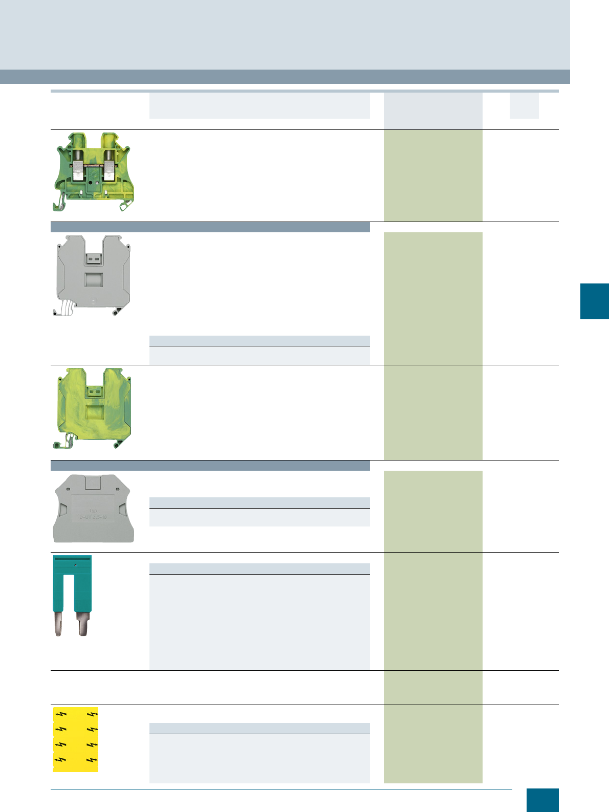
7/7
Siemens LV 52 · 2016
* You can order this quantity or a multiple thereof.
8WH1 Screw Terminals
8WH through-type terminals
7
8WH1000-0CK07
PE through-type terminals, terminal size 16 mm²
•CUUS, s
• Terminal width 12.2 mm
• AWG 16-4
• Connection capacity, one conductor
- Rigid 1.5 ... 25 mm²
- Flexible 1.5 ... 25 mm²
• Connection capacity, two conductors
- Rigid 1 ... 6 mm²
- Flexible 1 ... 6 mm²
• Green/yellow
8WH1000-0CK07 1 50 units 1BT
Terminal size 35 mm²
8WH1000-0AM00
Through-type terminals, terminal size 35 mm²
•CUUS, s
• Terminal width 16 mm
•Imax = 150 A
•Umax = 1000 V
• AWG 16-1/0
• Connection capacity, one conductor
- Rigid 1.5 ... 50 mm²
- Flexible 1.5 ... 50 mm²
• Connection capacity, two conductors
- Rigid 1.5 ... 16 mm²
- Flexible 1.5 ... 10 mm²
• Enclosed at both ends
Versions
•Gray 8WH1000-0AM00 1 50 units 1BT
•Blue 8WH1000-0AM01 1 50 units 1BT
8WH1000-0CM07
PE through-type terminals, terminal size 35 mm²
•CUUS, s
• Terminal width 16 mm
• AWG 16-2
• Connection capacity, one conductor
- Rigid 1.5 ... 35 mm²
- Flexible 1.5 ... 35 mm²
• Connection capacity, two conductors
- Rigid 1.5 ... 16 mm²
- Flexible 1.5 ... 10 mm²
• Enclosed at both ends
• Green/yellow
8WH1000-0CM07 1 50 units 1BT
Accessories
8WH9000-1PA00
Covers, for through-type terminals
• 2.2 mm wide
•Gray
Versions
• For terminal size 2.5 ... 10 mm² 8WH9000-1PA00 100 50 units 1BT
• For terminal size 16 mm² 8WH9076-1PA00 100 50 units 1BT
8WH9002-8AC10
Reducing combs, for connecting terminals, for 8WH1
Versions
• From terminal size 6 mm2 to 2.5 or 4 mm2
- From screw to screw 8WH9002-8AC10 1 10 units 1BT
- From screw to spring 8WH9002-8BC10 1 10 units 1BT
• From terminal size 10 mm2 to 2.5 or 4 mm2
- From screw to screw 8WH9002-8CC10 1 10 units 1BT
- From screw to spring 8WH9002-8DC10 1 10 units 1BT
• From terminal size 16 mm2 to 2.5 or 4 mm2
- From screw to screw 8WH9002-8EC10 1 10 units 1BT
- From screw to spring 8WH9002-8FC10 1 10 units 1BT
• From terminal size 35 mm2 to 2.5 or 4 mm2
- From screw to screw 8WH9002-8GC10 1 10 units 1BT
- From screw to spring 8WH9002-8HC10 1 10 units 1BT
Compartment partitions, for through-type terminals, for terminal
size 2.5 ... 10 mm², for 8WH1
• For visual and electrical separation of terminal groups
• 2 mm thick
8WH9070-6BA00 100 50 units 1BT
8WH9066-5BA06
Warning covers, for 8WH1
• Lightning symbol, yellow
Versions
• For terminal size 2.5 mm², width 5.2 mm 8WH9060-5BA06 100 50 units 1BT
• For terminal size 4 mm², width 6.2 mm 8WH9063-5BA06 100 50 units 1BT
• For terminal size 6 mm², width 8.2 mm 8WH9064-5BA06 100 50 units 1BT
• For terminal size 10 mm², width 10.2 mm 8WH9065-5BA06 100 50 units 1BT
• For terminal size 16 mm², width 12.2 mm 8WH9066-5BA06 100 50 units 1BT
• For terminal size 35 mm², width 16 mm 8WH9067-5BA06 100 50 units 1BT
Version DT Article No.
www.siemens.com/
product?Article No.
Price
per PU
PU
(UNIT,
SET, M)
PS*/
P. un it PG
© Siemens AG 2015© Siemens AG 2015
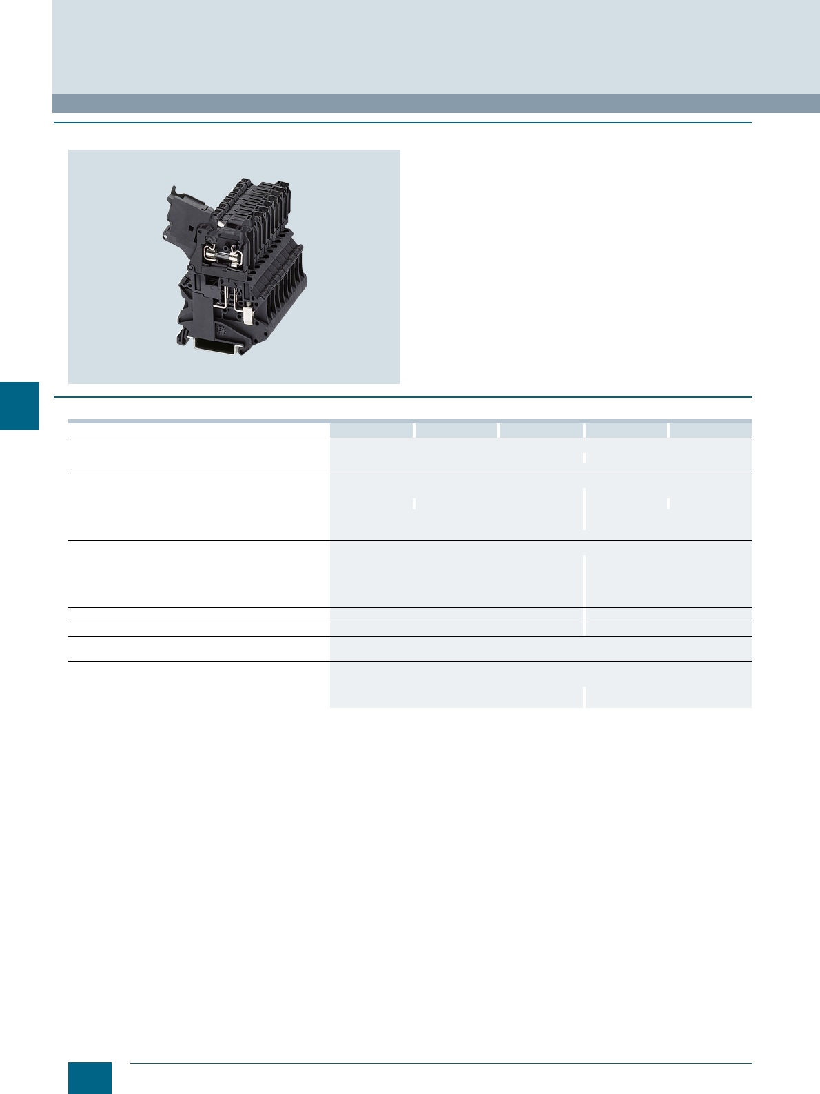
7/8 Siemens LV 52 · 2016
8WH fuse terminals
8WH1 Screw Terminals
7
■
Overview
The 8WH fuse terminals adopt the function of the fuse holders for
5 × 20 mm and 6.3 × 32 mm G fuse links and all potential distri-
bution tasks with the double bridge shaft.
The individual clamping points can be inscribed at the front
using labels.
■
Technical specifications
1) Please observe the maximum power loss.
8WH1000-1GG08 8WH1000-1KG38 8WH1000-1MG88 8WH1000-1HH08 8WH1000-1PH38
Dimensions
• Width/length/cover width in mm 6.2 / 57.8 / -- 8.2 / 57.8 / --
• Height (NS 35/7.5 / NS 35/15) in mm 73 / 80.5
Technical specifications acc. to IEC/DIN VDE
• Max. load current in A1) / cross-section in mm² 6.3 / 6 10 / 10
• Rated impulse withstand voltage in kV / pollution degree 6 kV / 3 4 kV / 3 8 kV / 3 6 kV / 3
• Rated insulation voltage (working voltage) Ui in V
acc. to IEC 60497-7-1 500 630
• Overvoltage category / molded plastic group III / I
Connection capacities
• Flexible with end sleeve, with plastic sleeve in mm² 0.25 ... 4 0.25 ... 6
• Flexible with end sleeve, without plastic sleeve in mm² 0.25 ... 4 0.25 ... 6
• Flexible with two-wire connection end sleeve, with plastic
sleeve in mm² 0.5 ... 2.5 0.5 ... 4
• Rigid in mm² 0.14 ... 6 0.2 ... 10
Stripped length in mm 910
Tightening torque in Nm 0.6 ... 0.8 1.5 ... 1.8
Molded plastic type PA
• Flammability Class acc. to UL 94 V0
Approval data (UL/cUL and CSA)
• Rated voltage / rated current / conductor sizes
- UL/cUL: in V/A / AWG 600 / 6.3 / 26 ... 10 600 / 16 / 24 ... 8
- CSA: in V/A / AWG 600 / 6.3 / 26 ... 10 -- / -- / --
© Siemens AG 2015© Siemens AG 2015
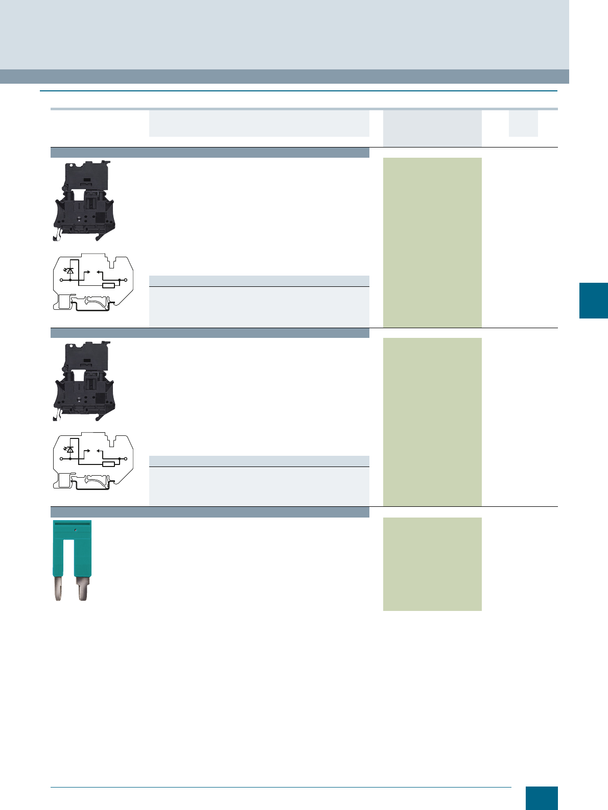
7/9
Siemens LV 52 · 2016
* You can order this quantity or a multiple thereof.
8WH1 Screw Terminals
8WH fuse terminals
7
■
Selection and ordering data
For general accessories for 8WH terminal blocks, see chapter
"Accessories for 8WH Terminal Blocks"
Version DT Article No.
www.siemens.com/
product?Article No.
Price
per PU
PU
(UNIT,
SET, M)
PS*/
P. un it PG
Terminal size 4 mm²
8WH1000-1GG08
8WH1000-1MG88
Fuse terminals, terminal size 4 mm², for 5 x 20 mm G fuse links
•CUUS
s
• Terminal width 6.2 mm
•Imax = 6.3 A
•Umax = 500 V
• AWG 26 ... 10
• Connection capacity, one conductor
- Rigid 0.14 ... 6 mm²
- Flexible 0.14 ... 6 mm²
• Connection capacity, two conductors
- Rigid 0.14 ... 1.5 mm²
- Flexible 0.14 ... 1.5 mm²
• Enclosed at both ends
• Black
Versions
• Without LED 8WH1000-1GG08 1 50 units 1BT
• With LED 10 ... 30 V AC/DC 8WH1000-1KG38 1 50 units 1BT
• With LED 110 ... 250 V AC/DC 8WH1000-1MG88 1 50 units 1BT
Terminal size 6 mm²
8WH1000-1HH08
8WH1000-1PH38
Fuse terminals, terminal size 6 mm², for G fuse links 6.3 × 32 mm
(inch fuses)
•CUUS
• Terminal width 8.2 mm
•Imax = 10 A
•Umax = 630 V
• AWG 24 ... 8
• Connection capacity, one conductor
- Rigid 0.2 ... 10 mm²
- Flexible 0.2 ... 10 mm²
• Connection capacity, two conductors
- Rigid 0.2 ... 2.5 mm²
- Flexible 0.2 ... 2.5 mm²
• Enclosed at both ends
• Black
Versions
• Without LED 8WH1000-1HH08 1 50 units 1BT
• With LED 12 ... 30 V AC/DC 8WH1000-1PH38 1 50 units 1BT
Accessories
8WH9002-8AC10
Reducing combs, for connecting terminals, from terminal size
6 mm² to 2.5 or 4 mm², from screw to screw 8WH9002-8AC10 1 10 units 1BT
I201_12681
I201_12681
© Siemens AG 2015© Siemens AG 2015
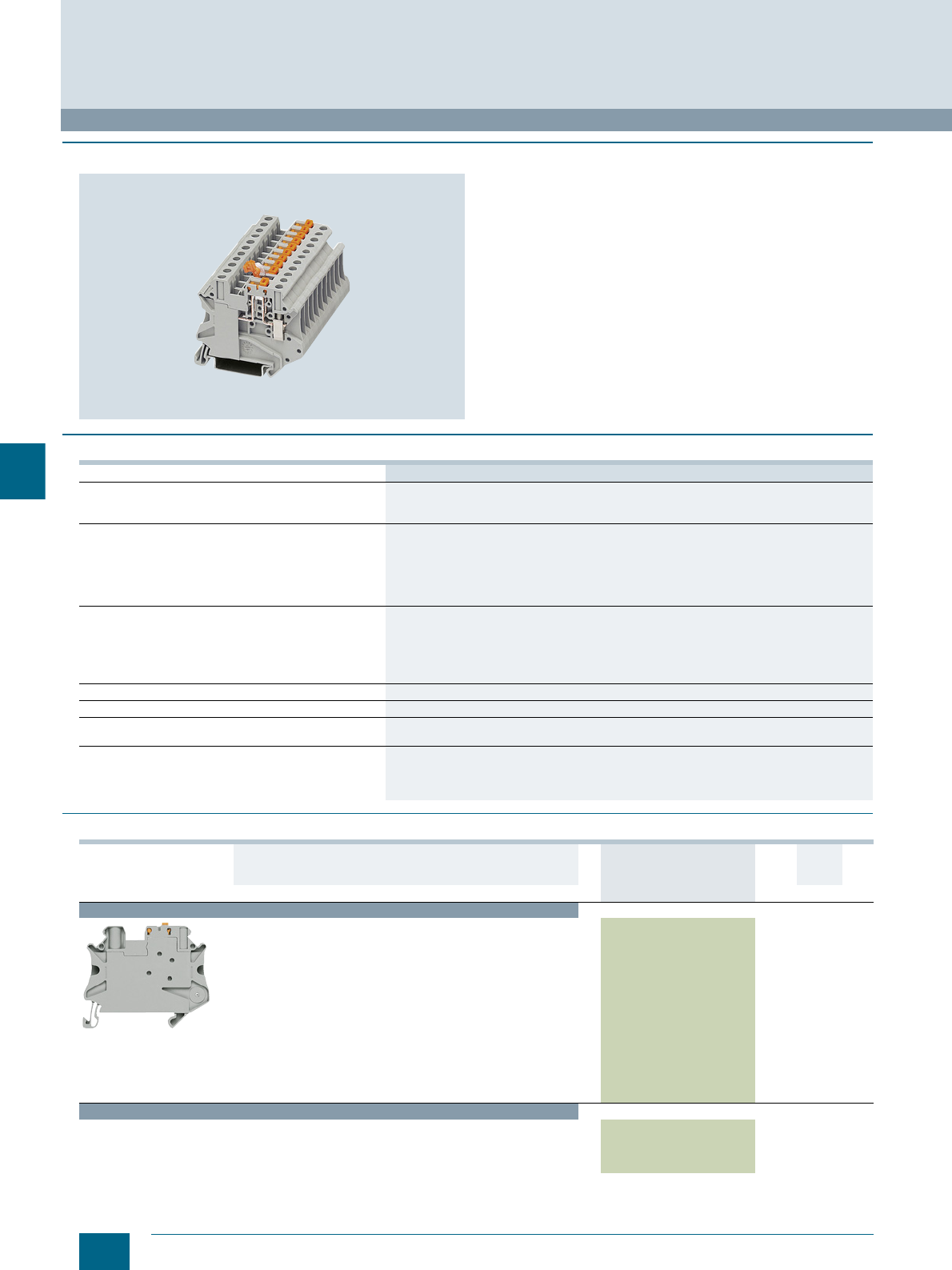
7/10 Siemens LV 52 · 2016 * You can order this quantity or a multiple thereof.
8WH isolating blade terminals
8WH1 Screw Terminals
7
■
Overview
Key features of the 8WH isolating blade terminals are their slim
design and high current carrying capacity of 20 A. They can be
bridged with standard terminal jumpers over the double bridge
shaft.
The individual clamping points can be inscribed at the front
using labels.
■
Technical specifications
■
Selection and ordering data
For general accessories for 8WH terminal blocks, see chapter
"Accessories for 8WH Terminal Blocks"
8WH1000-6CG00
Dimensions
• Width/length/cover width in mm 6.2 / 57.8 / --
• Height (NS 35/7.5 / NS 35/15) in mm 49.1 / 56.6
Technical specifications acc. to IEC/DIN VDE
• Max. load current in A / cross-section in mm² 20 / 6
• Rated impulse withstand voltage in kV / pollution degree 6 kV / 3
• Rated insulation voltage (working voltage) Ui in V
acc. to IEC 60497-7-1 500
• Overvoltage category / molded plastic group III / I
Connection capacities
• Flexible with end sleeve, with plastic sleeve in mm² 0.25 ... 4
• Flexible with end sleeve, without plastic sleeve in mm² 0.25 ... 4
• Flexible with two-wire connection end sleeve, with plastic
sleeve in mm² 0.5 ... 2.5
• Rigid in mm² 0.14 ... 6
Stripped length in mm 9
Tightening torque in Nm 0.6 ... 0.8
Molded plastic type PA
• Flammability Class acc. to UL 94 V0
Approval data (UL/cUL and CSA)
• Rated voltage / rated current / conductor sizes
- UL/cUL: in V/A / AWG 600 / 16 / 26 ... 10
- CSA: in V/A / AWG 600 / 16 / 26 ... 10
Version DT Article No.
www.siemens.com/
product?Article No.
Price
per PU
PU
(UNIT,
SET, M)
PS*/
P. un it PG
Terminal size 4 mm²
8WH1000-6CG00
Isolating blade terminals, terminal size 4 mm²
•CUUS
s
• Terminal width 6.2 mm
•Imax = 20 A
•Umax = 500 V
• AWG 26 ... 12
• Connection capacity, one conductor
- Rigid 0.14 ... 4 mm²
- Flexible 0.14 ... 4 mm²
• Connection capacity, two conductors
- Rigid 0.14 ... 1.5 mm²
- Flexible 0.14 ... 1.5 mm²
• Enclosed at both ends
•Gray
8WH1000-6CG00 1 50 units 1BT
Accessories
Warning covers, for terminal size 4 mm²
• Lightning symbol
• Width 6.2 mm
•Yellow
8WH9063-5BA06 100 50 units 1BT
© Siemens AG 2015© Siemens AG 2015
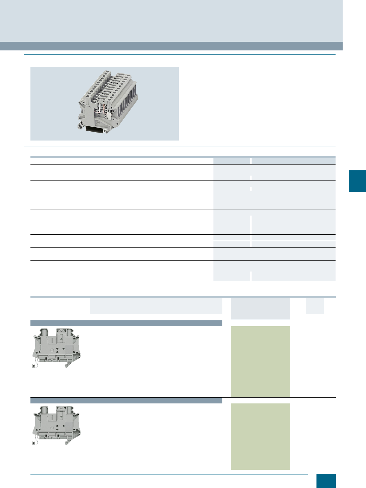
7/11
Siemens LV 52 · 2016
* You can order this quantity or a multiple thereof.
8WH1 Screw Terminals
8WH isolating terminals
7
■
Overview
8WH isolating terminals serve for mounting various function
plugs.
The individual clamping points can be inscribed at the front
using labels.
■
Technical specifications
■
Selection and ordering data
8WH1000-6AG00 8WH1000-6AH00
Dimensions
• Width/length/cover width in mm 6.2 / 57.8 / --
• Height (NS 35/7.5 / NS 35/15) in mm 49.1 / 56.6 73 / 80.5
Technical specifications acc. to IEC/DIN VDE
• Max. load current in A / cross-section in mm² 20 / 6 20 / 10
• Rated impulse withstand voltage in kV / pollution degree 6 kV / 3
• Rated insulation voltage (working voltage) Ui in V acc. to IEC 60497-7-1 500
• Overvoltage category / molded plastic group III / I
Connection capacities
• Flexible with end sleeve, with plastic sleeve in mm² 0.25 ... 4 0.26 ... 6
• Flexible with end sleeve, without plastic sleeve in mm² 0.25 ... 4 0.26 ... 6
• Flexible with two-wire connection end sleeve, with plastic sleeve in mm² 0.5 ... 2.5 0.5 ... 4
• Rigid in mm² 0.14 ... 6 0.2 ... 10
Stripped length in mm 910
Tightening torque in Nm 0.6 ... 0.8 1.5 ... 1.8
Molded plastic type PA
• Flammability Class acc. to UL 94 V0
Approval data (UL/cUL and CSA)
• Rated voltage / rated current / conductor sizes
- UL/cUL: in V/A / AWG 600 / 16 / 26 ... 10 -- / -- / --
- CSA: in V/A / AWG 600 / 16 / 26 ... 10 -- / -- / --
Version DT Article No.
www.siemens.com/
product?Article No.
Price
per PU
PU
(UNIT,
SET, M)
PS*/
P. un it PG
Terminal size 4 mm²
8WH1000-6AG00
Isolating terminals, terminal size 4 mm²
•CUUS
s
• Terminal width 6.2 mm
•Imax = 20 A
•Umax = 400 V
• AWG 26 ... 10
• Connection capacity, one conductor
- Rigid 0.14 ... 6 mm²
- Flexible 0.14 ... 6 mm²
• Connection capacity, two conductors
- Rigid 0.14 ... 1.5 mm²
- Flexible 0.14 ... 1.5 mm²
• Enclosed at both ends
•Gray
8WH1000-6AG00 1 50 units 1BT
Terminal size 6 mm²
8WH1000-6AH00
Isolating terminals, terminal size 6 mm²
•CUUS
• Terminal width 8.2 mm
•Imax = 20 A
•Umax = 500 V
• AWG 24 ... 8
• Connection capacity, one conductor
- Rigid 0.2 ... 10 mm²
- Flexible 0.2 ... 10 mm²
• Connection capacity, two conductors
- Rigid 0.2 ... 2.5 mm²
- Flexible 0.2 ... 2.5 mm²
• Enclosed at both ends
•Gray
8WH1000-6AH00 1 50 units 1BT
© Siemens AG 2015© Siemens AG 2015
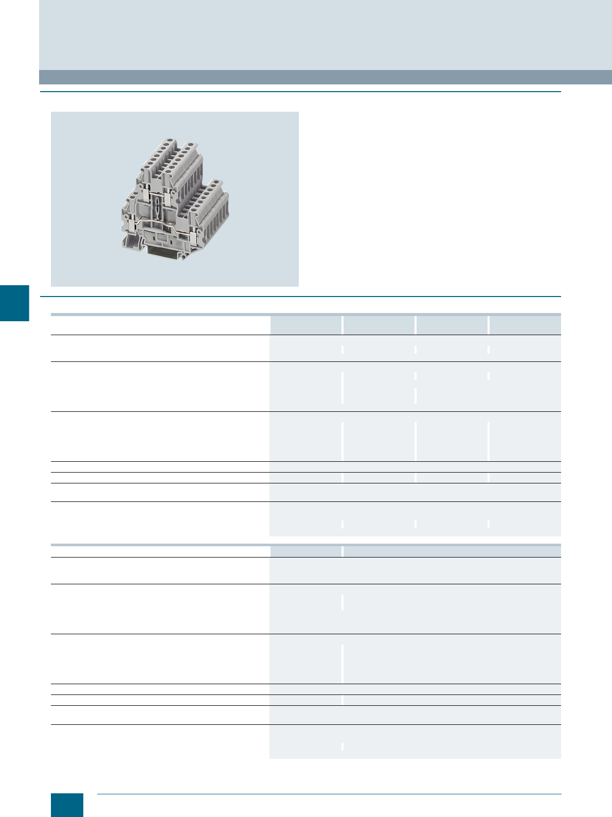
7/12 Siemens LV 52 · 2016
8WH two-tier terminals
8WH1 Screw Terminals
7
■
Overview
The compact 8WH1 two-tier terminal is available in the nominal
cross-sections 2.5 and 4 mm2. The voltage levels routed in a
5.2 mm or 6.2 mm grid through two tiers reduce the space
required in the control cabinet by a further 50 %. Two integral
bridge shafts per tier and two facilities for large inscriptions of all
clamping points are provided.
With 8WH1025 two-tier terminals the upper and lower level are
connected.
The tier offset on the 8WH two-tier terminals allows for excellent
access to the lower level, even when fully wired. Spacer plates
can be used to compensate for the tier offset if other terminals
are mounted side by side.
The clamping points of the 8WH1 two-tier terminals can be
inscribed at the front using the labels.
■
Technical specifications
8WH1020-0AF00
8WH1020-0AF01 8WH1020-0AG00
8WH1020-0AG01 8WH1020-0CF07 8WH1020-0CG07
Dimensions
• Width/length/cover width in mm 5.2 / 69.9 / 2.2 6.2 / 69.9 / 2.2 5.2 / 69.9 / 2.2 6.2 / 69.9 / 2.2
• Height (NS 35/7.5 / NS 35/15) in mm 65 / 72.5
Technical specifications acc. to IEC/DIN VDE
• Max. load current in A / cross-section in mm² 28 / 4 36 / 6 -- / 4 -- / 6
• Rated impulse withstand voltage in kV / pollution degree 6 kV / 3 8 kV / 3
• Rated insulation voltage (working voltage) Ui in V
acc. to IEC 60497-7-1 500 800 --
• Overvoltage category / molded plastic group III / I
Connection capacities
• Flexible with end sleeve, with plastic sleeve in mm² 0.25 ... 2.5 0.25 ... 4 0.25 ... 2.5 0.25 ... 4
• Flexible with end sleeve, without plastic sleeve in mm² 0.25 ... 2.5 0.25 ... 4 0.25 ... 2.5 0.25 ... 4
• Flexible with two-wire connection end sleeve, with
plastic sleeve in mm² 0.5 ... 1.5 0.5 ... 2.5 0.5 ... 1.5 0.5 ... 2.5
• Rigid in mm² 0.14 ... 4 0.14 ... 6 0.14 ... 4 0.14 ... 6
Stripped length in mm 9
Tightening torque in Nm 0.5 ... 0.6 0.6 ... 0.8 0.5 ... 0.6 0.6 ... 0.8
Molded plastic type PA
• Flammability Class acc. to UL 94 V0
Approval data (UL/cUL and CSA)
• Rated voltage / rated current / conductor sizes
- UL/cUL: in V/A / AWG 600 / 20 / 26 ... 12 600 / 30 / 26 ... 12 -- / -- / 26 ... 12 -- / -- / 26 ... 10
- CSA: in V/A / AWG -- / -- / --
8WH1025-0AF00 8WH1025-0AG00
Dimensions
• Width/length/cover width in mm 6.2 / 69.9 / 2.2
• Height (NS 35/7.5 / NS 35/15) in mm 65 / 72.5
Technical specifications acc. to IEC/DIN VDE
• Max. load current in A / cross-section in mm² 28 / 4 36 / 6
• Rated impulse withstand voltage in kV / pollution degree 6 kV / 3 8 kV / 3
• Rated insulation voltage (working voltage) Ui in V
acc. to IEC 60497-7-1 500
• Overvoltage category / molded plastic group III / I
Connection capacities
• Flexible with end sleeve, with plastic sleeve in mm² 0.25 ... 2.5 0.25 ... 4
• Flexible with end sleeve, without plastic sleeve in mm² 0.25 ... 2.5 0.25 ... 4
• Flexible with two-wire connection end sleeve, with
plastic sleeve in mm² 0.5 ... 1.5 0.5 ... 2.5
• Rigid in mm² 0.14 ... 4 0.14 ... 6
Stripped length in mm 9
Tightening torque in Nm 0.5 ... 0.6 0.6 ... 0.8
Molded plastic type PA
• Flammability Class acc. to UL 94 V0
Approval data (UL/cUL and CSA)
• Rated voltage / rated current / conductor sizes
- UL/cUL: in V/A / AWG 600 / 20 / 26 ... 12 600 / 30 / 26 ... 10
- CSA: in V/A / AWG -- / -- / --
© Siemens AG 2015© Siemens AG 2015
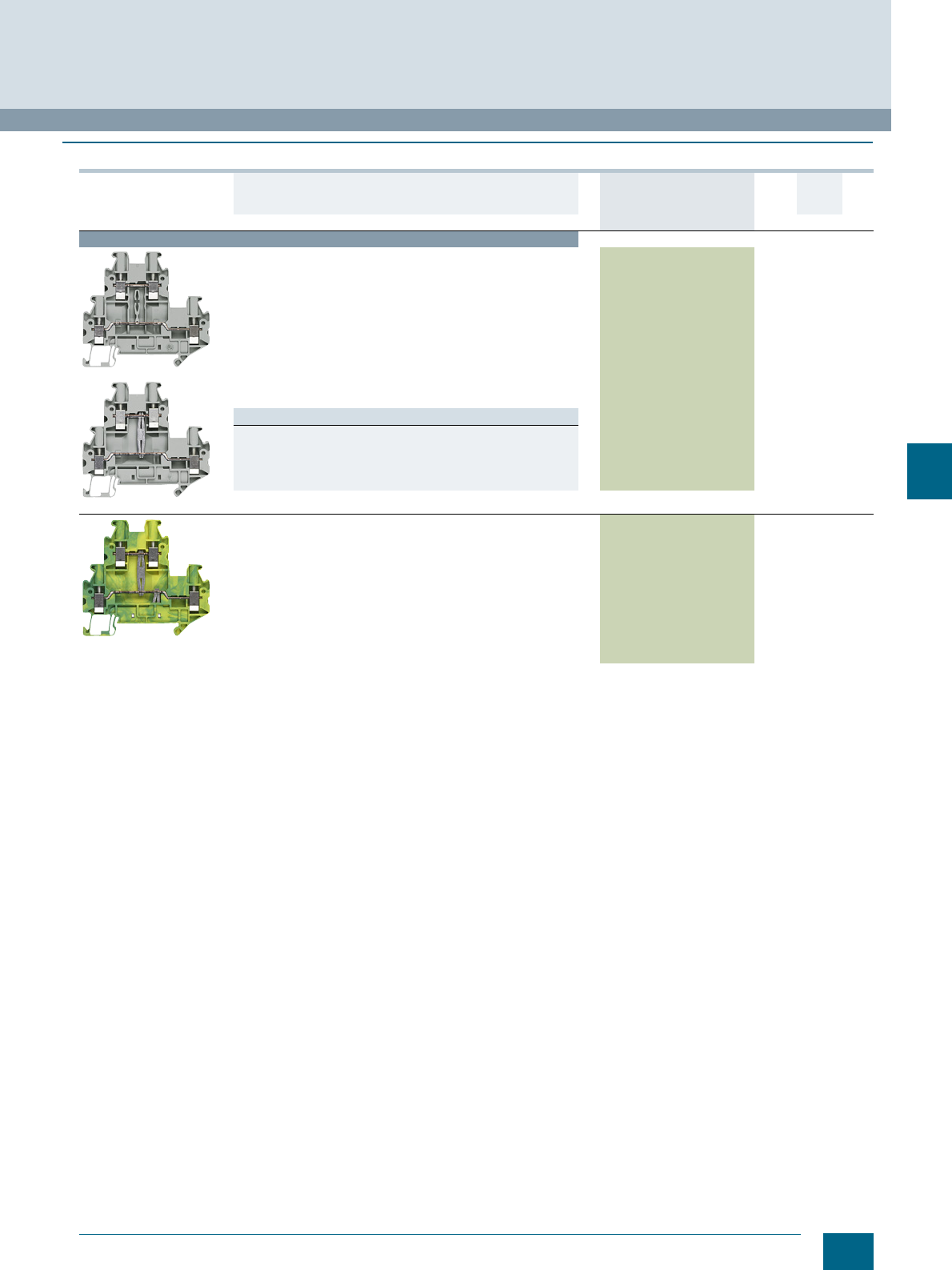
7/13
Siemens LV 52 · 2016
* You can order this quantity or a multiple thereof.
8WH1 Screw Terminals
8WH two-tier terminals
7
■
Selection and ordering data
Version DT Article No.
www.siemens.com/
product?Article No.
Price
per PU
PU
(UNIT,
SET, M)
PS*/
P. un it PG
Terminal size 2.5 mm²
8WH1020-0AF00
8WH1025-0AF00
Two-tier terminals, terminal size 2.5 mm²
•CUUS
s
• Terminal width 5.2 mm
•Imax = 28 A
•Umax = 500 V
• AWG 26 ... 12
• Connection capacity, one conductor
- Rigid 0.14 ... 4 mm²
- Flexible 0.14 ... 4 mm²
• Connection capacity, two conductors
- Rigid 0.14 ... 1.5 mm²
- Flexible 0.14 ... 1.5 mm²
Versions
•Gray
- Without equipotential bonding 8WH1020-0AF00 1 50 units 1BT
- With equipotential bonding 8WH1025-0AF00 1 50 units 1BT
•Blue
- Without equipotential bonding 8WH1020-0AF01 1 50 units 1BT
8WH1020-0CF07
PE two-tier terminals, terminal size 2.5 mm²
•CUUS
s
• Terminal width 5.2 mm
• AWG 26 ... 12
• Connection capacity, one conductor
- Rigid 0.14 ... 4 mm²
- Flexible 0.14 ... 4 mm²
• Connection capacity, two conductors
- Rigid 0.14 ... 1.5 mm²
- Flexible 0.14 ... 1.5 mm²
• Green/yellow
8WH1020-0CF07 1 50 units 1BT
© Siemens AG 2015© Siemens AG 2015
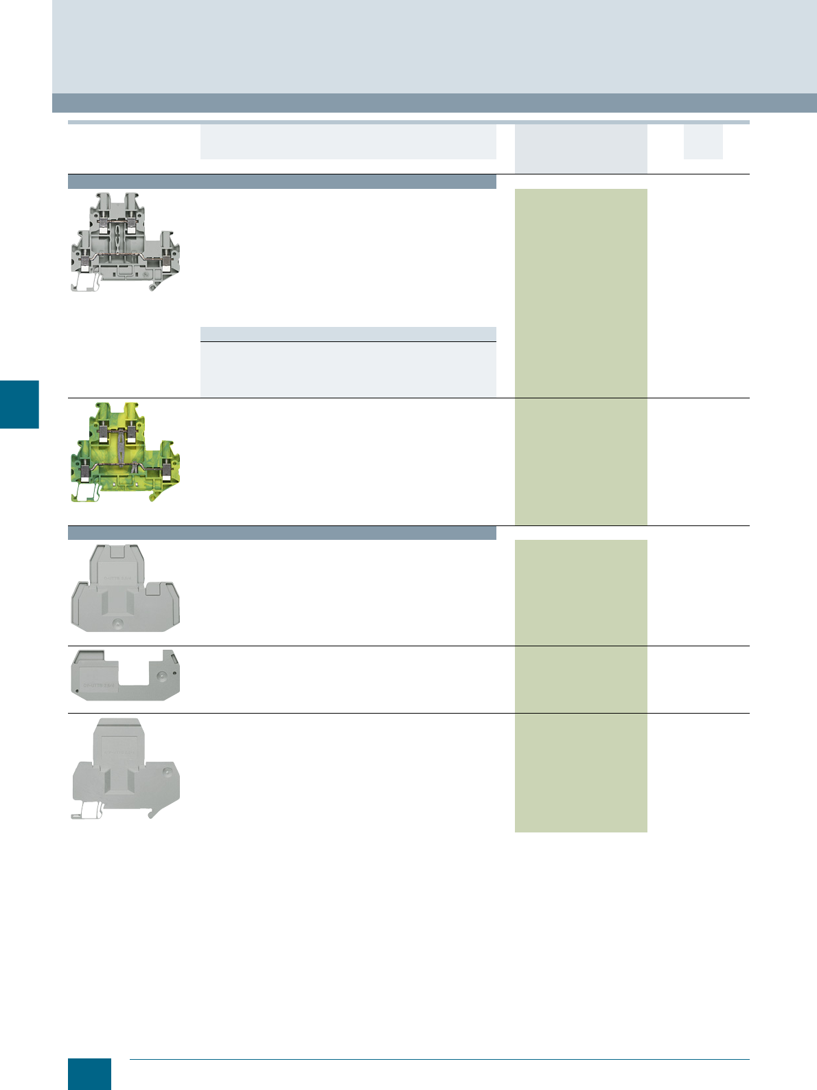
7/14 Siemens LV 52 · 2016 * You can order this quantity or a multiple thereof.
8WH two-tier terminals
8WH1 Screw Terminals
7
For general accessories for 8WH terminal blocks, see chapter
"Accessories for 8WH Terminal Blocks"
Terminal size 4 mm²
8WH1020-0AG00
Two-tier terminals, terminal size 4 mm²
•CUUS
s
• Terminal width 6.2 mm
•Imax = 36 A
•Umax = 800 V
• AWG 26 ... 10
• Connection capacity, one conductor
- Rigid 0.14 ... 6 mm²
- Flexible 0.14 ... 6 mm²
• Connection capacity, two conductors
- Rigid 0.14 ... 1.5 mm²
- Flexible 0.14 ... 1.5 mm²
Versions
•Gray
- Without equipotential bonding 8WH1020-0AG00 1 50 units 1BT
- With equipotential bonding 8WH1025-0AG00 1 50 units 1BT
•Blue
- Without equipotential bonding 8WH1020-0AG01 1 50 units 1BT
8WH1020-0CG07
PE two-tier terminals, terminal size 4 mm²
•CUUS
s
• Terminal width 6.2 mm
• AWG 26 ... 10
• Connection capacity, one conductor
- Rigid 0.14 ... 6 mm²
- Flexible 0.14 ... 6 mm²
• Connection capacity, two conductors
- Rigid 0.14 ... 1.5 mm²
- Flexible 0.14 ... 1.5 mm²
• Green/yellow
8WH1020-0CG07 1 50 units 1BT
Accessories
8WH9000-1QA00
Covers, for two-tier terminals, for terminal size 2.5 ... 4 mm²
• Width 2.2 mm
•Gray
8WH9000-1QA00 100 50 units 1BT
8WH9160-0AA00
Spacer plates, for two-tier terminals, for terminal size
2.5 ... 4 mm²
• Compensates for tier offset if other terminals are mounted
side by side
• 2.5 mm thick
•Gray
8WH9160-0AA00 100 50 units 1BT
8WH9070-6FA00
Compartment partitions, for two-tier terminals, for terminal size
2.5 ... 4 mm²
• For visual and electrical separation of terminal groups
• 2 mm thick
•Gray
8WH9070-6FA00 100 50 units 1BT
Version DT Article No.
www.siemens.com/
product?Article No.
Price
per PU
PU
(UNIT,
SET, M)
PS*/
P. un it PG
© Siemens AG 2015© Siemens AG 2015
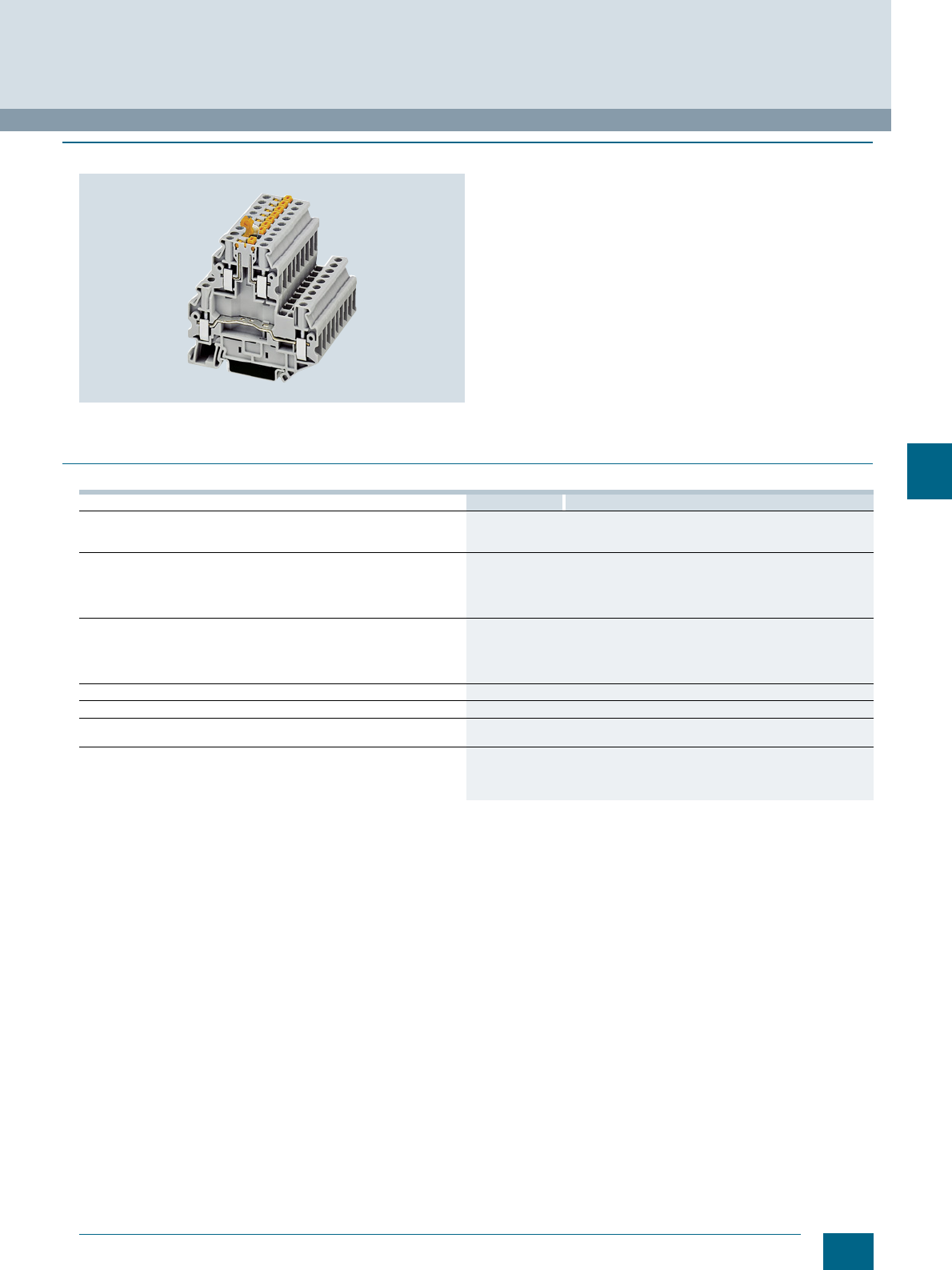
7/15
Siemens LV 52 · 2016
8WH1 Screw Terminals
8WH two-tier terminals with isolating function/isolating blade
7
■
Overview
Two-tier terminals with isolating function/isolating blades are
also available with the same contour as 8WH1 two-tier terminals.
An increasing number of contact points need to be wired in the
same space in the signal wiring. The two voltage levels routed
through two separate tiers require 50 % less space than equiva-
lent single-tier terminals.
To implement a wide range of wiring tasks, particularly in mea-
suring and control technology, an isolating blade or an isolating
plug, a component plug or a fused plug for 5 × 20 mm glass tube
fuses can be used in the standardized separation zone in the
upper tier.
The looping of measuring devices is possible over the terminal
screws with integrated test socket so that voltage and current
measurements can be performed on both tiers without interrup-
tion. The tier offset makes access to the lower tier much easier.
The clamping points of two-tier terminals can be inscribed at the
front using the labels.
■
Technical specifications
1) Bottom level
8WH1020-6AC00 8WH1020-6AG00
Dimensions
• Width/length/cover width in mm 6.2 / 69.9 / 2.2
• Height (NS 35/7.5 / NS 35/15) in mm 65 / 72.5
Technical specifications acc. to IEC/DIN VDE
• Max. load current in A / cross-section in mm² 381) / 6
• Rated impulse withstand voltage in kV / pollution degree 6 kV / 3
• Rated insulation voltage (working voltage) Ui in V acc. to IEC 60497-7-1 500
• Overvoltage category / molded plastic group III / I
Connection capacities
• Flexible with end sleeve, with plastic sleeve in mm² 0.25 ... 4
• Flexible with end sleeve, without plastic sleeve in mm² 0.25 ... 4
• Flexible with two-wire connection end sleeve, with plastic sleeve in mm² 0.5 ... 2.5
• Rigid in mm² 0.14 ... 6
Stripped length in mm 9
Tightening torque in Nm 0.6 ... 0.8
Molded plastic type PA
• Flammability Class acc. to UL 94 V0
Approval data (UL/cUL and CSA)
• Rated voltage / rated current / conductor sizes
- UL/cUL: in V/A / AWG 600 / 5 / 26 ... 10
- CSA: in V/A / AWG -- / -- / --
© Siemens AG 2015© Siemens AG 2015
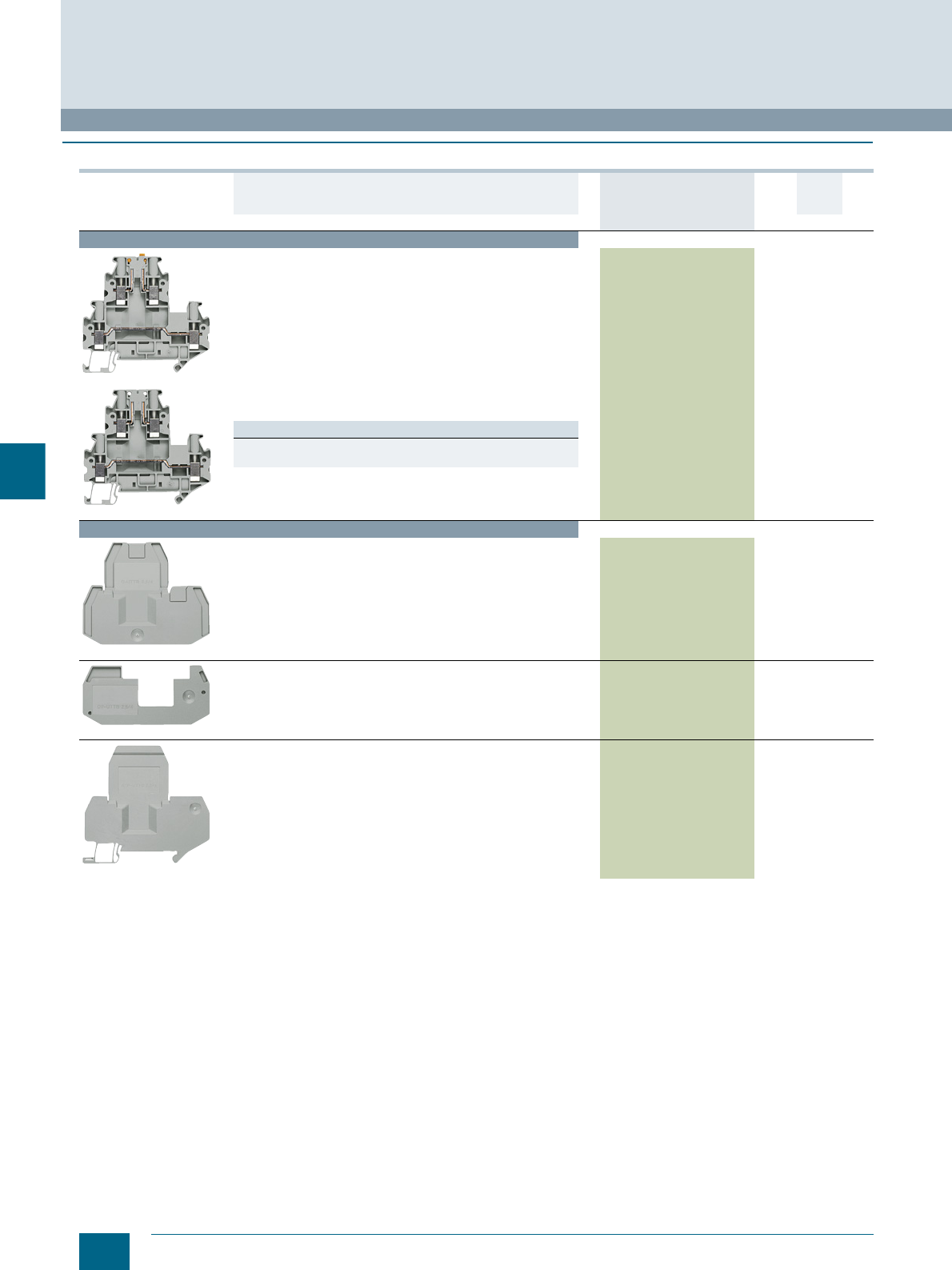
7/16 Siemens LV 52 · 2016 * You can order this quantity or a multiple thereof.
8WH two-tier terminal with isolating function
8WH1 Screw Terminals
7
■
Selection and ordering data
For general accessories for 8WH terminal blocks, see chapter
"Accessories for 8WH Terminal Blocks"
Version DT Article No.
www.siemens.com/
product?Article No.
Price
per PU
PU
(UNIT,
SET, M)
PS*/
P. un it PG
Terminal size 4 mm²
8WH1020-6AC00
8WH1020-6AG00
Two-tier terminal, with isolating function/isolating blade,
terminal size 4 mm²
•CUUS
s
• Terminal width 6.2 mm
•Imax = 38 A
•Umax = 500 V
• AWG 26 ... 10
• Connection capacity, one conductor
- Rigid 0.14 ... 6 mm²
- Flexible 0.14 ... 6 mm²
• Connection capacity, two conductors
- Rigid 0.14 ... 1.5 mm²
- Flexible 0.14 ... 1.5 mm²
Versions
• Isolating links in the upper tier 8WH1020-6AC00 1 50 units 1BT
• Isolating terminal in the upper tier 8WH1020-6AG00 1 50 units 1BT
Accessories
8WH9000-1QA00
Covers, for two-tier terminals, for terminal size 2.5 ... 4 mm²
• Width 2.2 mm
•Gray
8WH9000-1QA00 100 50 units 1BT
8WH9160-0AA00
Spacer plates, for two-tier terminals, for terminal size
2.5 ... 4 mm²
• Compensates for tier offset if other terminals are mounted
side by side
• 2.5 mm thick
•Gray
8WH9160-0AA00 100 50 units 1BT
8WH9070-6FA00
Compartment partitions, for two-tier terminals, for terminal size
2.5 ... 4 mm²
• For visual and electrical separation of terminal groups
• 2 mm thick
•Gray
8WH9070-6FA00 100 50 units 1BT
© Siemens AG 2015© Siemens AG 2015
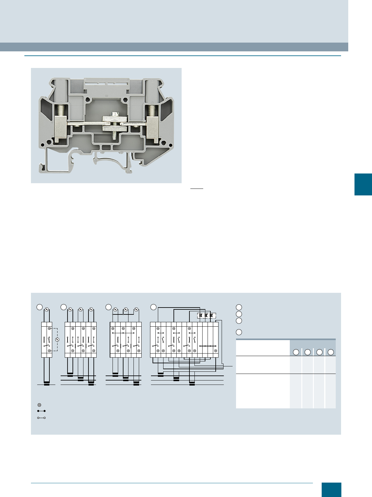
7/17
Siemens LV 52 · 2016
8WH1 Screw Terminals
8WH measuring transformer terminals
7
■
Overview
Measuring transformer terminals can be used for testing and
isolating circuits without interrupting operation. In this way, they
permit easy and transparent maintenance and commissioning.
The isolating and instrument isolating terminals contain an iso-
lating device in the through-type connection. The isolating de-
vice permits electrical separation between the input and output
of a terminal. Test sockets can be screwed into the front side of
the through-type and isolating terminals.
Two adjacent terminals can be connected in parallel with the dis-
connecting link. The disconnecting link can be operated in any
position of the isolating device. Two labels can be snapped on
to the side of each terminal at the front.
Instrument set for one transformer
The instrument set for one transformer makes the basic circuit of
the transformer terminal blocks clear. This basic circuit is also
included in much larger instrument sets, which is extended by
adding on equivalent circuits. Links between the basic circuits
provide many kinds of testing facilities, parallel outgoing lines to
other measuring devices, connection of test equipment, etc.
Instrument set for three transformers
The simplest version of an instrument set for a three-phase
circuit consists of three basic circuits strung together without any
continuing links.
Instrument set for three transformers with neutral point
The instrument set with a neutral point is an extension of the
previous circuit. Four instead of six lines are sufficient for con-
necting it with the measuring devices. The neutral point is pro-
duced on the measuring instruments on the one hand, and using
a shortened 8WH9021-0AL00 connection bar on the other.
Note
The 8WH1000-7BH00 through-type terminals and their associ-
ated disconnecting links enable terminal sets for current trans-
formers to be configured much more easily. Instead of the
12 isolating or instrument isolating terminals used previously,
only 3 instrument isolating terminals and 3 through-type termi-
nals now have to be used.
Instrument set with test facility
This instrument set represents a significant enhancement over
previous types. In normal operation, terminals 2, 5 and 8 are
closed. For testing a measuring instrument (e.g. a plotter), these
terminals are opened and terminals 3, 6 and 9 are closed in
order to feed in a test signal. The transformers first have to be
short-circuited with the disconnecting links between terminals
1-2, 4-5 and 7-8. Wire jumpers connect terminals 1, 4 and 7 with
the neutral point that is formed in terminals 10, 11, 12 and 13 with
a shortened jumper 8WH9021-0AL00.
Connection option for measuring transformer terminals (instrument sets)
1 2 3 4
L
kl
12
L3
kl
12
kl
34
kl
56
L2
L1
L3
kl
1
kl
23
kl
45
L2
L1
6
L3
l
12
l
34
l
56
L2
L1
78910 11
N
12 13
I201_19155
1 2 3 4
7
6
1
3
3
3
3
3
3
1
3
2
2
2
--
6
--
3
2
2
2
--
2
--
1
2
--
--
Test socket
Jumper, 10 pole, 8WH9021-0AL00 (separable)
Disconnecting link (closed)
Instrument set for 1 transformer
Instrument set for 3 transformers
Instrument set for 3 transformers
with neutral point
Instrument set with testing facility
Type Number required for:
Tes t
1
2
3
4
8WH1000-7BH00
8WH1000-7AH00
8WH9021-0AL00 (sep.)
Jumper 2-pole/
colored Test socket
8WH8021-0AC00
8WH9010-0MB03
-0MB11
-0MB06
© Siemens AG 2015© Siemens AG 2015
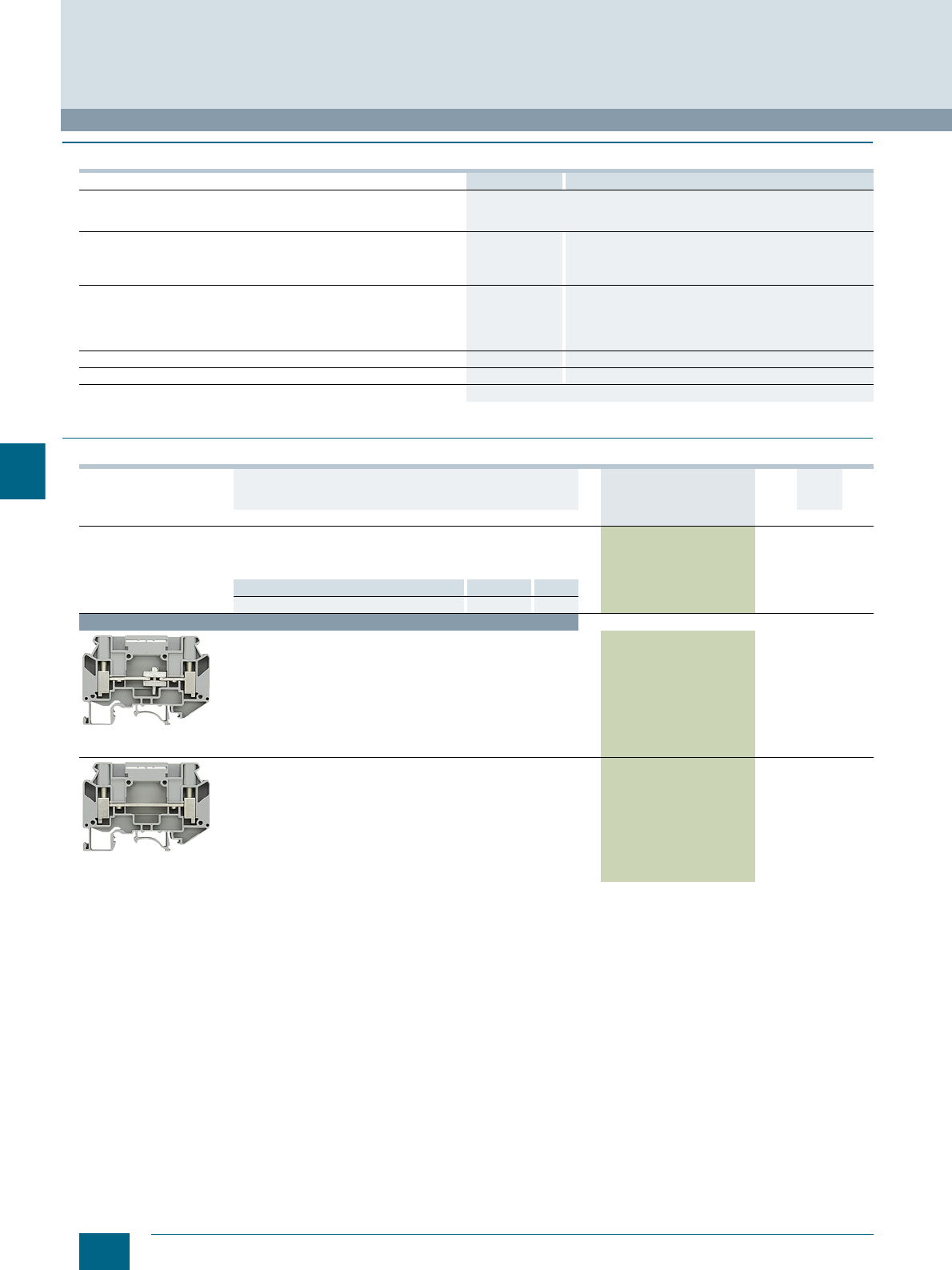
7/18 Siemens LV 52 · 2016 * You can order this quantity or a multiple thereof.
8WH measuring transformer terminals
8WH1 Screw Terminals
7
■
Technical specifications
■
Selection and ordering data
8WH1000-7AH00 8WH1000-7BH00
Dimensions
• Width/length/cover width in mm 8.2 / 66.5 / 2.2
48
• Height (NS 35/7.5 / NS 35/15) in mm
Technical specifications acc. to IEC/DIN VDE
• Max. load current in A / cross-section in mm² 57/10 mm257/10 mm2
• Rated uninterrupted current in A 41 41
• Rated insulation voltage (working voltage) Ui in V acc. to IEC 60497-7-1 500 800
Connection capacities
• Flexible with end sleeve, with plastic sleeve in mm² 0.5 ... 6 0.5 ... 6
• Flexible with end sleeve, without plastic sleeve in mm² 0.5 ... 6 0.5 ... 6
• Flexible with two-wire connection end sleeve, with plastic sleeve in mm² 0.5 ... 6 0.5 ... 6
• Rigid in mm² 0.5 ... 10 0.5 ... 10
Stripped length in mm 10 10
Tightening torque in Nm 1.5 ...1.6 1.5 ...1.6
Flammability Class acc. to UL 94 V0
Version DT Article No.
www.siemens.com/
product?Article No.
Price
per PU
PU
(UNIT,
SET, M)
PS*/
P. un it PG
General details
• With thermoplastic insulating body
• Screw terminals at both ends and 2 recesses for screwing in the
test adapters
Note Section Page
For labeling accessories, see ... Accessories 8/2
Terminal size 6 mm²
8WH1000-7AH00
Measuring transformer isolating terminals,
terminal size 6 mm²
• Rated uninterrupted current 41 A
• Rated insulation voltage 500 V
• Mounting width 8.2 mm
• Disconnect slide tightening torque: 0.6 ... 0.8 Nm
8WH1000-7AH00 1 50 units 1BT
8WH1000-7BH00
Measuring transformer through-type terminal,
terminal size 6 mm²
• Rated uninterrupted current 41 A
• Rated insulation voltage 800 V
• Mounting width 8.2 mm
8WH1000-7BH00 1 50 units 1BT
© Siemens AG 2015© Siemens AG 2015
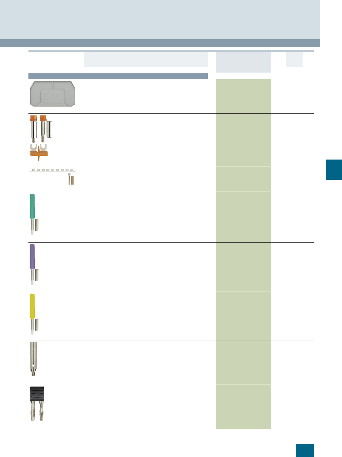
7/19
Siemens LV 52 · 2016
* You can order this quantity or a multiple thereof.
8WH1 Screw Terminals
8WH measuring transformer terminals
7
Accessories
8WH9000-3UA00
Covers, for measuring transformer terminals, size 6 mm²
• Width 2.2 mm
•Gray
8WH9000-3UA00 100 50 units 1BT
8WH9021-0AC00
Disconnecting links, 2-pole
• For bridging two adjacent terminals
• Cannot be used with the bare 8WH9010-0MB12 test socket
• Tightening torque: 0.6....0.8 Nm
8WH9021-0AC00 1 10 units 1BT
8WH90210AL00
Bridges, 10-pole (separable)
• Consisting of connecting wire, spacer sleeves and screws
• For bridging terminals, the connecting wire is adjustable
• Tightening torque: 0.6 ... 0.8 Nm
• Cannot be used with the bare 8WH9010-0MB12 test socket
8WH9021-0AL00 1 10 units 1BT
8WH9010-0MB03
Test sockets, green
• For screwing into the measuring transformer terminals
• Tightening torque: 0.6 ... 0.8 Nm
• The 8WH9021-0AC00 disconnecting link shall be used for
short-circuiting adjacent terminals.
8WH9010-0MB03 1 10 units 1BT
8WH9010-0MB11
Test sockets, violet
• For screwing into the measuring transformer terminals.
• Tightening torque: 0.6 ... 0.8 Nm
• The 8WH9021-0AC00 disconnecting link shall be used for
short-circuiting adjacent terminals.
8WH9010-0MB11 1 10 units 1BT
8WH9010-0MB06
Test sockets, yellow
• For screwing into the measuring transformer terminals.
• Tightening torque: 0.6 ... 0.8 Nm
• The 8WH9021-0AC00 disconnecting link shall be used for
short-circuiting adjacent terminals.
8WH9010-0MB06 1 10 units 1BT
8WH9010-0MB12
Test sockets, bare
• For screwing into the measuring transformer terminals
• For simple transformer measurements
• Tightening torque: 0.6 ... 0.8 Nm
• For tapping with test plug
• The 8WH9010-0BC08 short-circuiting plug shall be used for
short-circuiting adjacent terminals.
8WH9010-0MB12 1 10 units 1BT
8WH9010-0BC08
Short-circuiting plugs, 2-pin
• For short-circuiting adjacent terminals
• For simple transformer measurements
• Tightening torque: 0.6 ... 0.8 Nm
• Required when the bare 8WH9010-0MB12 test adapter is used
in the measuring transformer terminal
• Totally insulated
•Imax = 20 A
8WH9010-0BC08 1 10 units 1BT
Version DT Article No.
www.siemens.com/
product?Article No.
Price
per PU
PU
(UNIT,
SET, M)
PS*/
P. un it PG
© Siemens AG 2015© Siemens AG 2015
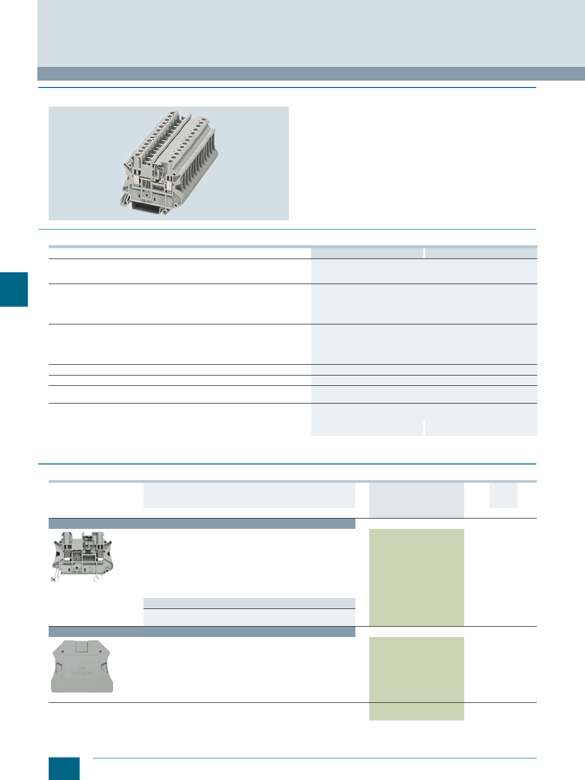
7/20 Siemens LV 52 · 2016 * You can order this quantity or a multiple thereof.
8WH diode terminals
8WH1 Screw Terminals
7
■
Overview
8WH diode terminals can be used to implement many different
wiring tasks. The 1N 4007 diode is soldered in from left to right
or vice versa as required. The double bridge shaft allows for
combination with all standard and function terminals.
The 8WH diode terminals have the same contour as the 8WH
isolating, isolating blade and fuse terminals. This has the advan-
tage of enabling consistent inscriptions on all clamping points.
Secure electrical and mechanical contact with the support rail is
assured by simply snapping the terminals onto the rail.
The clamping points of diode terminals can be inscribed at the
front using the labels.
■
Technical specifications
1) Maximum current determined by diode. A 1N 4007 diode is integrated,
blocking voltage: 1300 V, max. average on-state current: 0.5 A
■
Selection and ordering data
For general accessories for 8WH terminal blocks, see chapter
"Accessories for 8WH Terminal Blocks"
8WH1000-6KG00 8WH1000-6LG00
Dimensions
• Width/length/cover width in mm 6.2 / 57.8 / 2.2
• Height (NS 35/7.5 / NS 35/15) in mm 47.5 / 55
Technical specifications acc. to IEC/DIN VDE
• Max. load current in A1) / cross-section in mm² -- / 6
• Rated impulse withstand voltage in kV / pollution degree 8 kV / 3
• Rated insulation voltage (working voltage) Ui in V acc. to IEC 60497-7-1 800
• Overvoltage category / molded plastic group III / I
Connection capacities
• Flexible with end sleeve, with plastic sleeve in mm² 0.25 ... 4
• Flexible with end sleeve, without plastic sleeve in mm² 0.25 ... 4
• Flexible with two-wire connection end sleeve, with plastic sleeve in mm² 0.5 ... 2.5
• Rigid in mm² 0.14 ... 6
Stripped length in mm 9
Tightening torque in Nm 0.6 ... 0.8
Molded plastic type PA
• Flammability Class acc. to UL 94 V0
Approval data (UL/cUL and CSA)
• Rated voltage / rated current / conductor sizes
- UL/cUL: in V/A / AWG 600 / 1 / 26 ... 10 600 / 1 / 26 ... 10
- CSA: in V/A / AWG 600 / 1 / 26 ... 10 600 / 1 / 26 ... 10
Version DT Article No.
www.siemens.com/
product?Article No.
Price
per PU
PU
(UNIT,
SET, M)
PS*/
P. un it PG
Terminal size 4 mm²
8WH1000-6KG00
Diode terminals, terminal size 4 mm², gray, CUUS, s
• Terminal width 6.2 mm
•Imax = 0.5 A, Umax = 800 V
• AWG 26 ... 10
• Connection capacity, one conductor
- Rigid 0.14 ... 6 mm², flexible 0.14 ... 6 mm²
• Connection capacity, two conductors
- Rigid 0.14 ... 1.5 mm², flexible 0.14 ... 1.5 mm²
• With integrated diode: 1N 4007
Versions
• Let-through from left to right 8WH1000-6LG00 1 50 units 1BT
• Let-through from right to left 8WH1000-6KG00 1 50 units 1BT
Accessories
8WH9000-2PA00
Covers, for diode terminals, for terminal size 2.5 ... 4 mm²
• Width 2.2 mm
•Gray
8WH9000-2PA00 100 50 units 1BT
Warning covers, for terminal size 4 mm²
• Lightning symbol, yellow 8WH9063-5BA06 100 50 units 1BT
© Siemens AG 2015© Siemens AG 2015
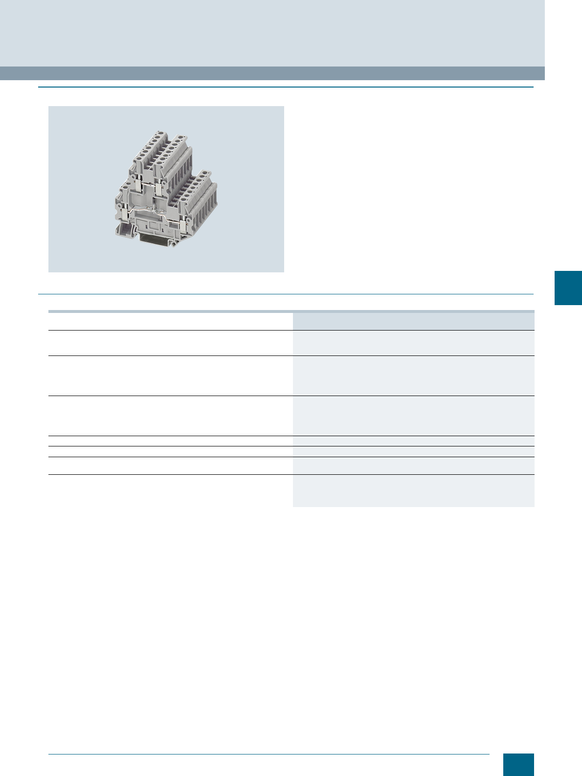
7/21
Siemens LV 52 · 2016
8WH1 Screw Terminals
8WH two-tier diode terminals
7
■
Overview
8WH two-tier diode terminals with a width of only 5.2 mm can be
used to implement many different wiring tasks. This make the
following possible in the narrowest of spaces:
• Freewheel diode circuits
• Lamp test circuits
• Signaling and fault signaling circuits
The clamping points of the 8WH1 two-tier diode terminals can be
inscribed at the front using the labels.
■
Technical specifications
1) Maximum current determined by diode.
Integrated: diode 1N 4007, blocking voltage: 1300 V
Max. average on-state current: 0.5 A
8WH1020-5AF00, 8WH1020-5BF00, 8WH1020-5DF00, 8WH1020-5FF00,
8WH1020-5HF00, 8WH1020-5JF30, 8WH1020-5LF00
Dimensions
• Width/length/cover width in mm 5.2 / 69.9 / 2.2
• Height (NS 35/7.5 / NS 35/15) in mm 65 / 72.5
Technical specifications acc. to IEC/DIN VDE
• Max. load current in A1) / cross-section in mm² 28 / 4
• Rated impulse withstand voltage in kV / pollution degree 6 kV / 3
• Rated insulation voltage (working voltage) Ui in V acc. to IEC 60497-7-1 500
• Overvoltage category / molded plastic group III / I
Connection capacities
• Flexible with end sleeve, with plastic sleeve in mm² 0.25 ... 2.5
• Flexible with end sleeve, without plastic sleeve in mm² 0.25 ... 2.5
• Flexible with two-wire connection end sleeve, with plastic sleeve in mm² 0.5 ... 1.5
• Rigid in mm² 0.14 ... 4
Stripped length in mm 9
Tightening torque in Nm 0.5 ... 0.6
Molded plastic type PA
• Flammability Class acc. to UL 94 V0
Approval data (UL/cUL and CSA)
• Rated voltage / rated current / conductor sizes
- UL/cUL: in V/A / AWG -- / -- / --
- CSA: in V/A / AWG -- / -- / --
© Siemens AG 2015© Siemens AG 2015
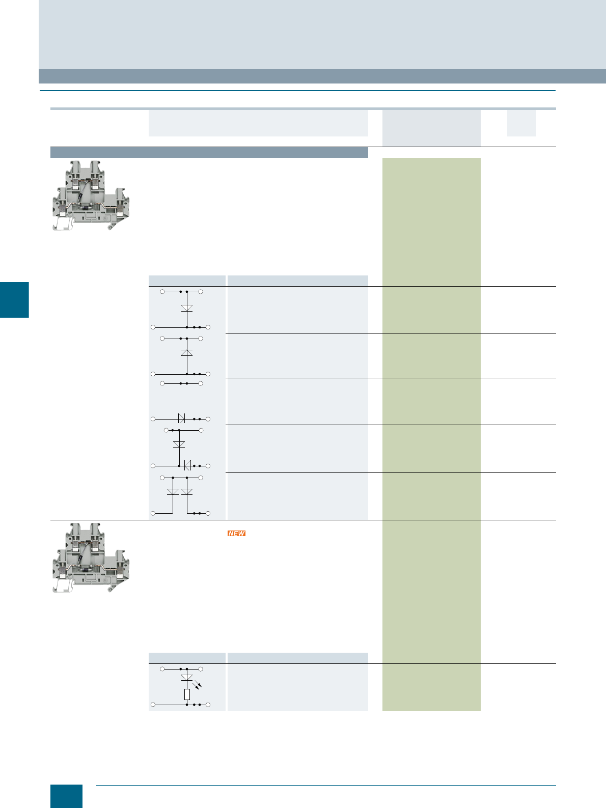
7/22 Siemens LV 52 · 2016 * You can order this quantity or a multiple thereof.
8WH two-tier diode terminals
8WH1 Screw Terminals
7
■
Selection and ordering data
Version DT Article No.
www.siemens.com/
product?Article No.
Price
per PU
PU
(UNIT,
SET, M)
PS*/
P. un it PG
Terminal size 2.5 mm²
8WH1020-5FF00
Two-tier diode terminals, terminal size 2.5mm²
•CUUS
s
• Terminal width 5.2 mm
•Imax = 28 A, through the diode 0.5 A
•Umax = 500 V
• AWG 26 ... 12
• Connection capacity, one conductor
- Rigid 0.14 ... 4 mm²
- Flexible 0.14 ... 4 mm²
• Connection capacity, two conductors
- Rigid 0.14 ... 1.5 mm²
- Flexible 0.14 ... 1.5 mm²
• With integrated diode: 1N 4007
•Gray
Circuit diagram Versions
• With an integrated 1N 4007 diode
• Let-through from top to bottom
8WH1020-5AF00 1 50 units 1BT
• With an integrated 1N 4007 diode
• Let-through from bottom to top
8WH1020-5BF00 1 50 units 1BT
• With an integrated 1N 4007 diode
• Let-through from bottom left to top right
8WH1020-5DF00 1 50 units 1BT
• With two 1N 4007 diodes integrated
• Let-through from top to bottom left and
from bottom right to bottom left
8WH1020-5FF00 1 50 units 1BT
• With two 1N 4007 diodes integrated
• Let-through from top to bottom left and
from top to bottom right
8WH1020-5HF00 1 50 units 1BT
8WH1020-5FF00
Two-tier terminals with LED 24 V DC,
terminal size 2.5 mm²
For checking whether voltage is present
•CUUS
s
• Terminal width 5.2 mm
•Imax = 28 A, through the diode 0.5 A
•Umax = 500 V
• AWG 26 ... 12
• Connection capacity, one conductor
- Rigid 0.14 ... 4 mm²
- Flexible 0.14 ... 4 mm²
• Connection capacity, two conductors
- Rigid 0.14 ... 1.5 mm²
- Flexible 0.14 ... 1.5 mm²
• With integrated diode: 1N 4007
•Gray
Circuit diagram
8WH1020-5JF30 1 50 units 1BT
© Siemens AG 2015© Siemens AG 2015
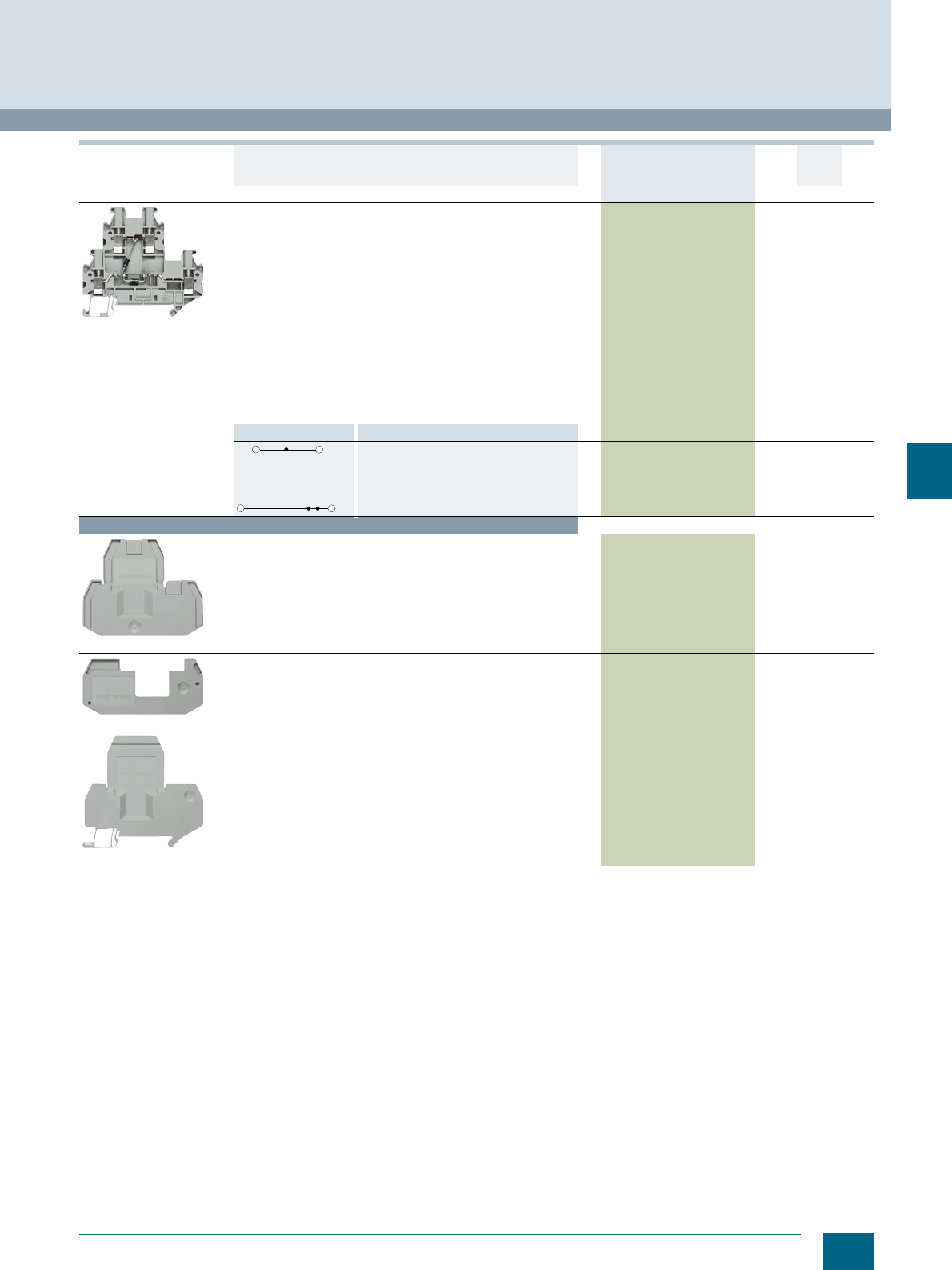
7/23
Siemens LV 52 · 2016
* You can order this quantity or a multiple thereof.
8WH1 Screw Terminals
8WH two-tier diode terminals
7
For general accessories for 8WH terminal blocks, see chapter
"Accessories for 8WH Terminal Blocks"
8WH1020-5FF00
Two-tier terminals for soldering of components,
terminal size 2.5 mm²
Supplied without components; the appropriate components
(resistors, diodes, capacitors, ...) shall be soldered in by user
•CUUS
s
• Terminal width 5.2 mm
•Imax = 28 A, through the diode 0.5 A
•Umax = 500 V
• AWG 26 ... 12
• Connection capacity, one conductor
- Rigid 0.14 ... 4 mm²
- Flexible 0.14 ... 4 mm²
• Connection capacity, two conductors
- Rigid 0.14 ... 1.5 mm²
- Flexible 0.14 ... 1.5 mm²
• With integrated diode: 1N 4007
•Gray
Circuit diagram
8WH1020-5LF00 1 50 units 1BT
Accessories
8WH9000-1QA00
Covers, for two-tier terminals, for terminal size 2.5 ... 4 mm²
• Width 2.2 mm
•Gray
8WH9000-1QA00 100 50 units 1BT
8WH9160-0AA00
Spacer plates, for two-tier terminals, for terminal size
2.5 ... 4 mm²
• Compensates for tier offset if other terminals are mounted
side by side
• 2.5 mm thick
•Gray
8WH9160-0AA00 100 50 units 1BT
8WH9070-6FA00
Compartment partitions, for two-tier terminals, for terminal size
2.5 ... 4 mm²
• For visual and electrical separation of terminal groups
• 2 mm thick
•Gray
8WH9070-6FA00 100 50 units 1BT
Version DT Article No.
www.siemens.com/
product?Article No.
Price
per PU
PU
(UNIT,
SET, M)
PS*/
P. un it PG
© Siemens AG 2015© Siemens AG 2015
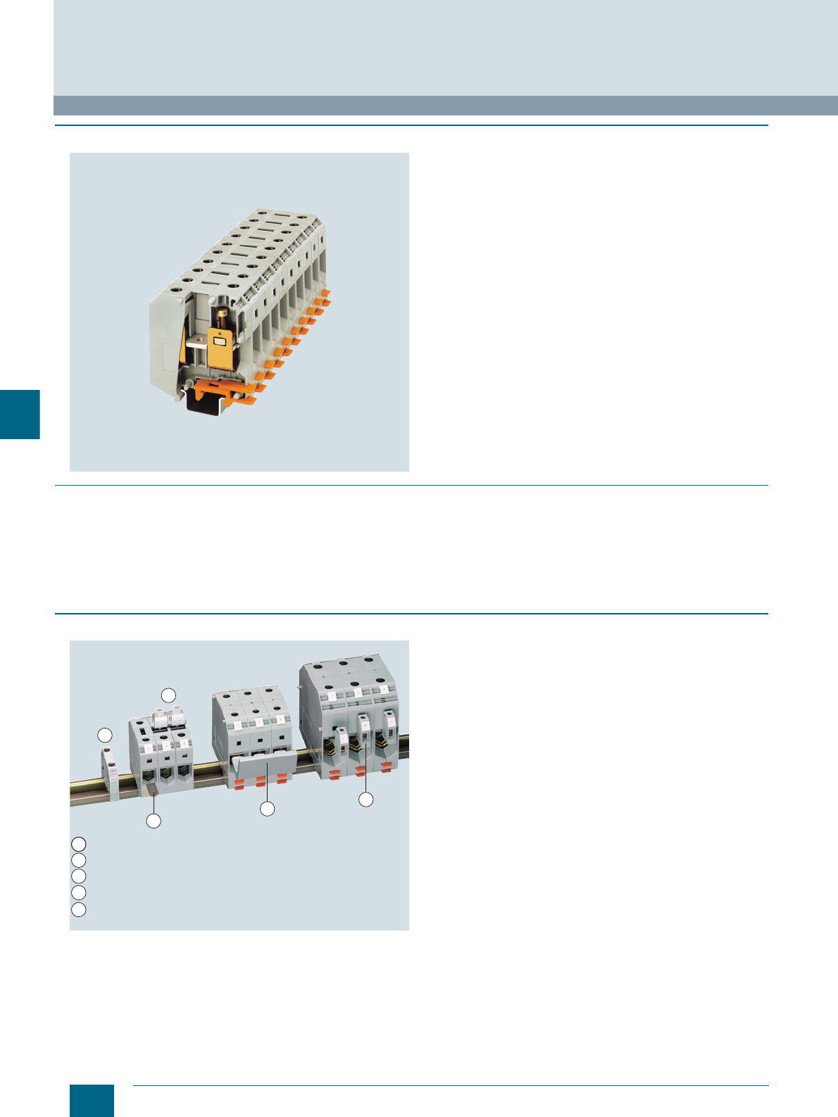
7/24 Siemens LV 52 · 2016
8WH high-current terminals
8WH1 Screw Terminals
7
■
Overview
The high-current terminals cover cross-sectional areas from
16 to 240 mm². A reliable cable connection is ensured through
effective design measures, such as:
• Three-point centering of the conductor in the prismatic sleeve
base
• Low contact resistance of the contact area through grooved
surface
• Screw locking through spring-loaded elements
• Terminals enclosed at both ends
The terminals have an enclosed insulating body made of
polyamide 6.6.
The terminals are available in gray and blue.
8WH labels must be used at the front for inscription purposes.
For terminals with terminal sizes up to 95 mm², green-yellow
PE/ground conductor terminals are available.
Mounting on support rails acc. to IEC 60 715.
■
Benefits
• Larger connection up to 240 mm²
• The right terminal is always available – whatever the connec-
tion functions
• Simple inscription using 8WH standard
• Comprehensive range of accessories available
• Enclosed insulating body made of polyamide 6.6
■
Design
Assembled terminal blocks
Using the 50 mm2 terminals, permanent links can be mounted in
2- and 3-pole versions. Combs are required with 95 ... 240 mm2
terminals.
2
3
4
5
1
1
2
3
4
5
Permanent link
Comb
Tap-off terminal
Insertion profile
End retainer
i201_13957
© Siemens AG 2015© Siemens AG 2015
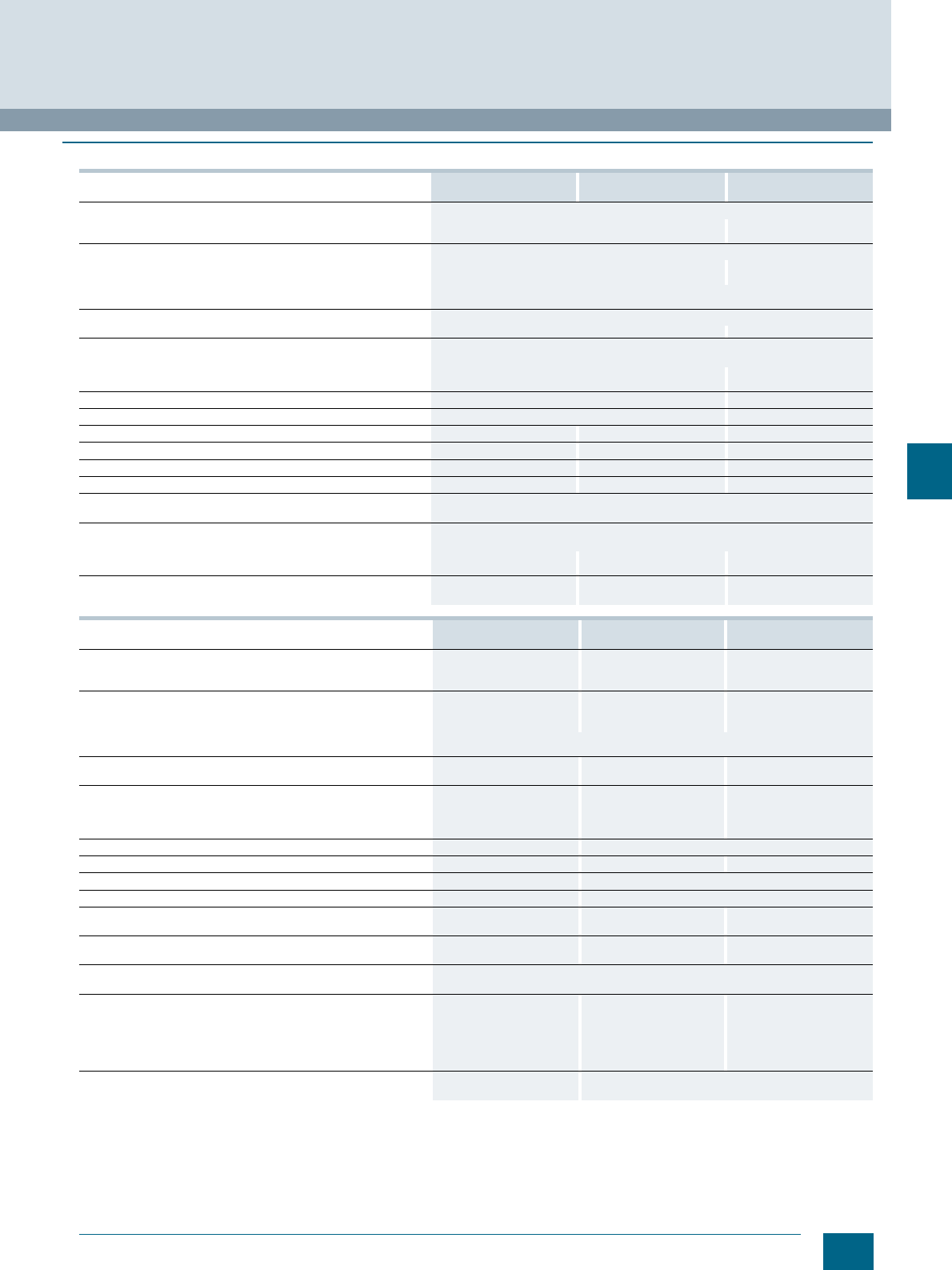
7/25
Siemens LV 52 · 2016
8WH1 Screw Terminals
8WH high-current terminals
7
■
Technical specifications
8WH1000-0AN00
8WH1000-0AN01 8WH1000-0CN07 8WH1000-0AQ00
8WH1000-0AQ01
Dimensions
• Width/length in mm 20 / 70.5 25 / 83
• Height (TS 35/7.5 / TS 35/15 / TS 32) in mm -- / 83.5 / 81.5 -- / 97.5 / 95.5
Technical specifications acc. to IEC/DIN VDE
• Max. load current in A / cross-section in mm² 150 / 50 232 / 95
• Maximum cross-section with comb (rigid / flexible) in mm² -- 95 / 70
• Rated impulse withstand voltage in kV / pollution degree 8 / 3
• Overvoltage category / molded plastic group III / I
Connection capacities
• Flexible with end sleeve without/with plastic sleeve in mm² 25 ... 50 / 25 ... 50 35 ... 95 / 35 ... 95
Multi-conductor connection
(two conductors of same cross-section)
• Rigid / flexible in mm² 10 ... 16 / 10 ... 16 25 ... 35 / 25 ... 35
• Flexible with end sleeve, without plastic sleeve in mm² 10 ... 16 16 ... 35
Stripped length in mm 24 33
Plug gauge (IEC 60947-1) B10 B12
Screw thread M6 -- M8
Tightening torque in Nm 6 ... 8 -- 15 ...20
Clamping point: screw thread / tightening torque in Nm -- M6 / 6 ... 8 --
Fixing: screw thread / tightening torque in Nm -- M6 / 6 ... 8 --
Molded plastic type PA
• Flammability Class acc. to UL 94 V0
Approval data (UL/cUL and CSA)
• Rated voltage / rated current / conductor sizes
- UL/cUL: V/A/AWG 600 / 150 / 6 ... 0 6 ... 1 / 0 600 / 230 / 2 - 000
- CSA: V/A/AWG 600 / 125 / 6 ... 0 -- 600 / 230 / 1 - 000
Support rails / protective conductor busbars -- See page 1/3, section
"Support rails" --
8WH1000-0CQ07 8WH1000-0AS00
8WH1000-0AS01 8WH1000-0AU00
8WH1000-0AU01
Dimensions
• Width/length in mm 25 / 83 31 / 100 36 / 100
• Height (TS 35/7.5 / TS 35/15 / TS 32) in mm -- / 99 / 96.5 -- / 118.5 / 116 -- / 131.5 / 129.5
Technical specifications acc. to IEC/DIN VDE
• Max. load current in A / cross-section in mm² 232 / 95 309 / 150 415 / 240
• Maximum cross-section with comb (rigid / flexible) in mm² -- 150 / 120 240 / 185
• Rated impulse withstand voltage in kV / pollution degree 8 / 3
• Overvoltage category / molded plastic group III / I
Connection capacities
• Flexible with end sleeve without/with plastic sleeve in mm² 50 ... 150 / 50 ... 150 70 ... 185 / 70 ... 185
Multi-conductor connection
(two conductors of same cross-section)
• Rigid / flexible in mm² 25 ... 35 / 25 ... 35 25 ... 50 / 35 ... 50 35 ... 95 / 50...95
• Flexible with end sleeve, without plastic sleeve in mm² 16 ... 35 25 ... 50 35 ... 50
Stripped length in mm 30 40
Plug gauge (IEC 60947-1) B12 B14 B15
Screw thread -- M10
Tightening torque in Nm -- 25 ... 30
Clamping point: screw thread / tightening torque in Nm M8 / 15 ... 20 (hexagon
socket-head screw) -- --
Fixing: screw thread / tightening torque in Nm M8 / 15 ... 20 (hexagon
socket-head screw) -- --
Molded plastic type PA
• Flammability Class acc. to UL 94 V0
Approval data (UL/cUL and CSA)
• Rated voltage / rated current / conductor sizes
- UL/cUL: V/A/AWG 2 ... 4 / 0 600 / 285 /
2 AWG ...300 kcmil 600 / 380 / 00 ... 500 kcmil
- CSA: V/A/AWG 2 ... 4 / 0 600 / 275 /
2 AWG ... 300 kcmil 600 / 400 / 0 ... 500 kcmil
Support rails / protective conductor busbars See page 1/3, section
"Support rails" --
© Siemens AG 2015© Siemens AG 2015
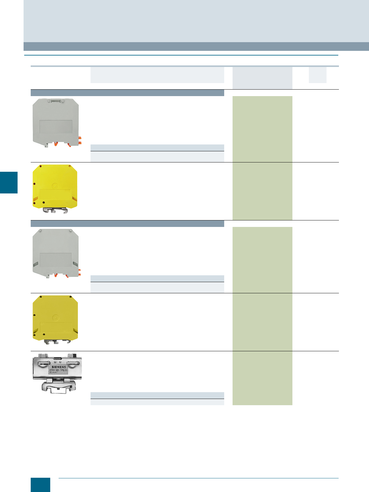
7/26 Siemens LV 52 · 2016 * You can order this quantity or a multiple thereof.
8WH high-current terminals
8WH1 Screw Terminals
7
■
Selection and ordering data
Version DT Article No.
www.siemens.com/
product?Article No.
Price
per PU
PU
(UNIT,
SET, M)
PS*/
P. uni t PG
Terminal size 50 mm²
8WH1000-0AN00
High-current terminals, terminal size 50 mm²
• Enclosed at both ends
• Terminal width 20 mm
•CUUS
• IEC 60947-7-1
- Rigid 16 ... 50 mm²
- Flexible 25 ... 50 mm²
-AWG 6-0
-I = 150 A
-U = 1000 V
Versions
•Gray 8WH1000-0AN00 1 10 units 1BT
•Blue 8WH1000-0AN01 1 10 units 1BT
8WH1000-0CN07
PE high-current terminals, terminal size 50 mm²
• Green/yellow
• Enclosed at both ends
• Terminal width 20 mm
•CUUS
• IEC 60947-7-1
- Rigid 16 ... 50 mm²
- Flexible 25 ... 50 mm²
-AWG 6-0
-I = 150 A
-U = 1000 V
8WH1000-0CN07 1 10 units 1BT
Terminal size 95 mm²
8WH1000-0AQ00
High-current terminals, terminal size 95 mm²
• Enclosed at both ends
• Terminal width 25 mm
•CUUS
• IEC 60947-7-1
- Rigid 25 ... 95 mm²
- Flexible 35 ... 95 mm²
- AWG 4-000
-I = 232 A
-U = 1000 V
Versions
•Gray 8WH1000-0AQ00 1 10 units 1BT
•Blue 8WH1000-0AQ01 1 10 units 1BT
8WH1000-0CQ07
PE high-current terminals, terminal size 95 mm²
• Green/yellow
• Enclosed at both ends
• Terminal width 25 mm
•CUUS
• IEC 60947-7-1
- Rigid 25 ... 95 mm²
- Flexible 35 ... 95 mm²
- AWG 4-000
-I = 232 A
-U = 1000 V
8WH1000-0CQ07 1 10 units 1BT
8WA1010-1PQ00
PE high-current terminals and PEN high-current terminals,
terminal size 95mm², two screw terminals
•Bare
•For I = 232 A
8WA1010-1PQ00 15 units1BT
• Mounting width 16 mm
• Terminal height 63 mm
• Terminal length 75 mm
• For 35 mm x 15 mm standard mounting rail only
Note
8WH accessories do not match this terminal.
© Siemens AG 2015© Siemens AG 2015

7/27
Siemens LV 52 · 2016
* You can order this quantity or a multiple thereof.
8WH1 Screw Terminals
8WH high-current terminals
7
For general accessories for 8WH terminal blocks, see chapter
"Accessories for 8WH Terminal Blocks"
Terminal size 150 mm²
8WH1000-0AS00
High-current terminals, terminal size 150 mm²
• Enclosed at both ends
• Terminal width 31 mm
•CUUS
• IEC 60947-7-1
- Rigid 35 ... 150 mm²
- Flexible 50 ... 150 mm²
- AWG 2-300
-I = 309 A
-U = 1000 V
Versions
•Gray 8WH1000-0AS00 1 10 units 1BT
•Blue 8WH1000-0AS01 1 10 units 1BT
Terminal size 240 mm²
8WH1000-0AU00
High-current terminals, terminal size 240 mm²
• Enclosed at both ends
• Terminal width 36 mm
•CUUS
• IEC 60947-7-1
- Rigid 70 ... 240 mm²
- Flexible 70 ... 240 mm²
- AWG 00-500
-I = 415 A
-U = 1000 V
Versions
•Gray 8WH1000-0AU00 1 10 units 1BT
•Blue 8WH1000-0AU01 1 10 units 1BT
Accessories
8WH9120-0AA00
Tap-off terminals
• When wiring a pick-off with a smaller cross-section, observe the
overload and short-circuit strength specified in VDE 0100 Part 430
•Imax: 57 A
• Cross-section: 10 mm2
Versions
• For terminal size 50 mm² 8WH9120-0AA00 1 10 units 1BT
• For terminal size 95 mm² 8WH9120-0BA00 1 10 units 1BT
• For terminal size 150 ... 240 mm² 8WH9120-0CA00 1 10 units 1BT
8WH9020-3AA00
Combs
• Totally insulated
• Fitted in the clamping sleeve and latched with the terminal
enclosure
Versions
• For terminal size 95 mm², Imax: 232 A
-2-pole 8WH9020-3AA00 1 10 units 1BT
-3-pole 8WH9020-3BA00 1 10 units 1BT
• For terminal size 150 mm², Imax: 232 A
-2-pole 8WH9020-3CA00 1 10 units 1BT
-3-pole 8WH9020-3DA00 1 10 units 1BT
• For terminal size 240 mm², Imax: 320 A
-2-pole 8WH9020-3EA00 1 10 units 1BT
-3-pole 8WH9020-3FA00 1 10 units 1BT
8WH9020-3MA00
Insertion profiles
Evens out the prismatic sleeve base when using flat conductors
Versions
• For terminal size 50 mm² 8WH9020-3MA00 1 10 units 1BT
• For terminal size 95 mm² 8WH9020-3NA00 1 10 units 1BT
• For terminal size 150 and 240 mm² 8WH9020-3PA00 1 10 units 1BT
8WH9020-6HC00
Permanent links, for terminal size 50 mm²
• For cross links
• Screw heads with insulating collar
• Remove partition first
•Imax = 150 A
Versions
•2-pole 8WH9020-6HC00 1 10 units 1BT
•3-pole 8WH9020-6HD00 1 10 units 1BT
Version DT Article No.
www.siemens.com/
product?Article No.
Price
per PU
PU
(UNIT,
SET, M)
PS*/
P. uni t PG
© Siemens AG 2015© Siemens AG 2015
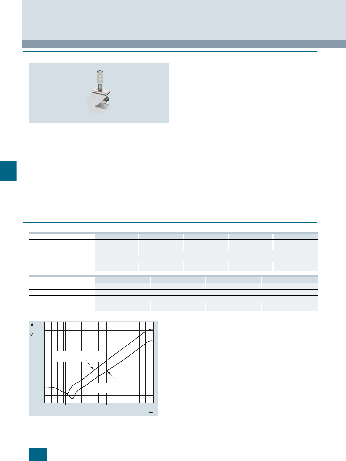
7/28 Siemens LV 52 · 2016
8WH shield terminals
8WH1 Screw Terminals
7
■
Overview
In industrial process engineering, a high interference immunity
is required for electrical measuring and control equipment. It is
a decisive factor in the availability of industrial equipment. When
designing low-interference systems, great importance is placed
on cable shielding and the respective shield ground. The critical
point is where the cable shield is connected to the enclosure
ground. The connection should have a low resistance and a low
inductive reactance, while being quick and easy to establish.
The shield terminals are ideally suited for this purpose and can
be used with all common cable shields.
The effectiveness of cable shields depends to a large extent on
the contact quality of the shield connection. The shield terminals
have a large, low-impedance contact area with the shield, which
reduces the voltage drop across it. Connected at one end only,
shields can help reduce only low-frequency, capacitive interfer-
ence, such as that caused by high-voltage installations. To pro-
tect from the much more common inductive interference signals,
the cable shield must be connected at both ends.
However, differences in the ground potential can cause a com-
pensating current to flow through the cable shield.
To reduce this interference current, it is advisable to connect the
shield at several points along its length. The shorter the spaces
between the clamping points, the smaller the compensating cur-
rents in the cable shield. In systems where safety is especially
important, triaxial shields are used. These consist of two braids
that are insulated from each other, with the outer shield con-
nected at both ends and the inner one at only one end. With this
arrangement, the equipotential bonding currents and the induc-
tive interference are conducted through the outer shield, and the
capacitive interference dissipated through the inner shield.
Depending on the length of the terminal strip, two or more sup-
port brackets are fitted, which provide both an electrical and a
mechanical connection from the busbar to the support rail and
therefore to the enclosure ground. The shield terminal is simply
fitted to the busbar after all wires have been connected.
A spring-loaded pressure plate regulates the force applied to
the cable to ensure an optimum contact with the busbar at all
times.
If the cable shield is to be connected at another point of the con-
trol cabinet instead of directly in front of the terminal strip, we
recommend using support brackets made of molded plastic.
■
Technical specifications
Comparison of shield connection through PE terminal and through shield
terminal
8WH9130-0KA00 8WH9130-0LA00 8WH9130-0MA00 8WH9130-0NA00 8WH9130-0PA00
Dimensions See dimensional
drawing See dimensional
drawing See dimensional
drawing See dimensional
drawing See dimensional
drawing
Contact resistance in mΩ< 1
Connection data
• Diameter 2 ... 5 3 ... 8 3 ... 14 3 ... 20 20 ... 35
• Tightening torque in Nm 0.4 0.6 0.8 0.8 1.5 ... 1.8
8WH9130-0AA00 8WH9130-0BA00 8WH9130-0CA00 8WH9130-0DA00
Dimensions See dimensional drawing See dimensional drawing See dimensional drawing See dimensional drawing
Contact resistance in mΩThe contact resistance is determined by the mounting area
Connection data
• Diameter 3 ... 8 3 ... 14 3 ... 20 20 ... 35
• Tightening torque in Nm 0.6 0.8 0.8 1.5 ... 1.8
10M1M100K
10K
1K 100M
I201_12742
0,5
5
50
500
Impedance [m ]
Shield connection
through PE terminal
Shield terminal
Frequency [Hz]
© Siemens AG 2015© Siemens AG 2015
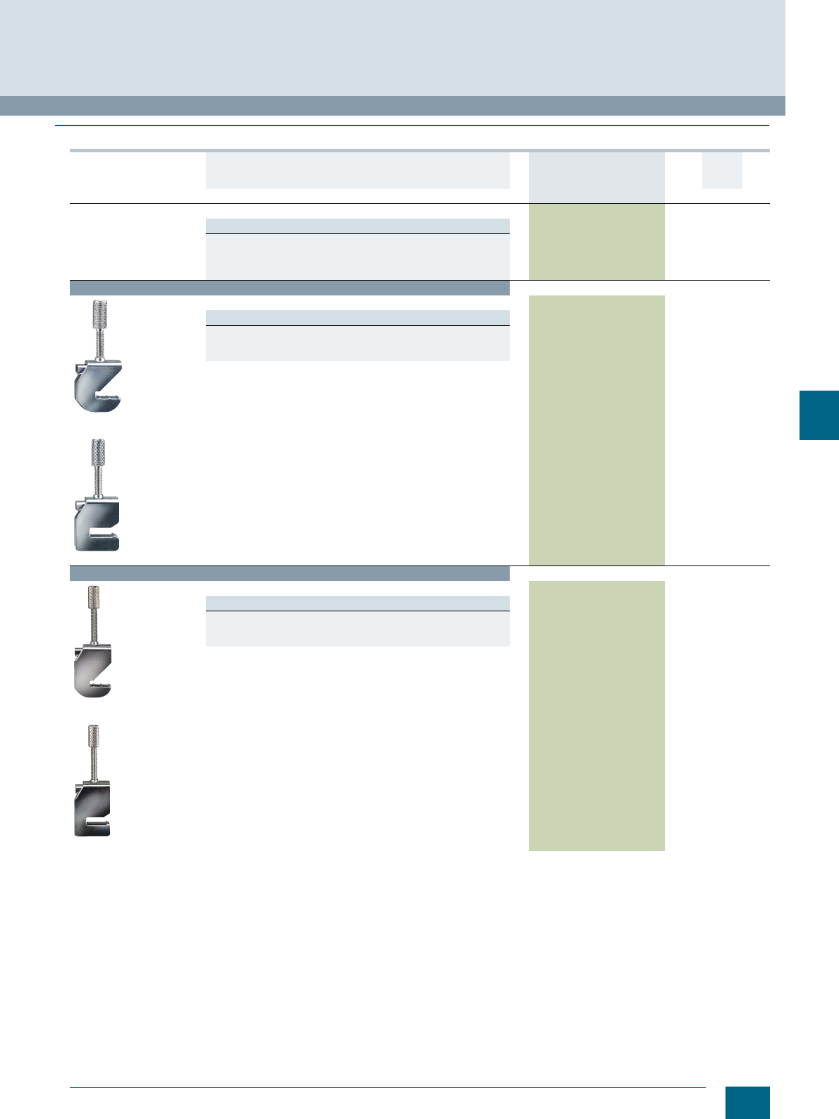
7/29
Siemens LV 52 · 2016
* You can order this quantity or a multiple thereof.
8WH1 Screw Terminals
8WH shield terminals
7
■
Selection and ordering data
Version DT Article No.
www.siemens.com/
product?Article No.
Price
per PU
PU
(UNIT,
SET, M)
PS*/
P. un it PG
General details
Note
• The shield terminals must not be used for strain relief
• Support brackets have galvanic connections from the busbar to the
support rail or to the mounting block
• Busbar 10 x 3 mm
Terminal diameter 3 ... 8 mm
8WH9130-0AA00
8WH9130-0LA00
Shield terminal, terminal diameter 3 ... 8 mm
Versions
• For direct shield attachment on conductive mounting plate
- Sheet thickness 1 ... 2 mm 8WH9130-0AA00 1 10 units 1BT
•For busbars 8WH9130-0LA00 1 10 units 1BT
Terminal diameter 3 ... 14 mm
8WH9130-0BA00
8WH9130-0MA00
Shield terminal, terminal diameter 3 ... 14 mm
Versions
• For direct shield attachment on conductive mounting plate
- Sheet thickness 1 ... 2 mm 8WH9130-0BA00 1 10 units 1BT
•For busbars 8WH9130-0MA00 1 10 units 1BT
© Siemens AG 2015© Siemens AG 2015
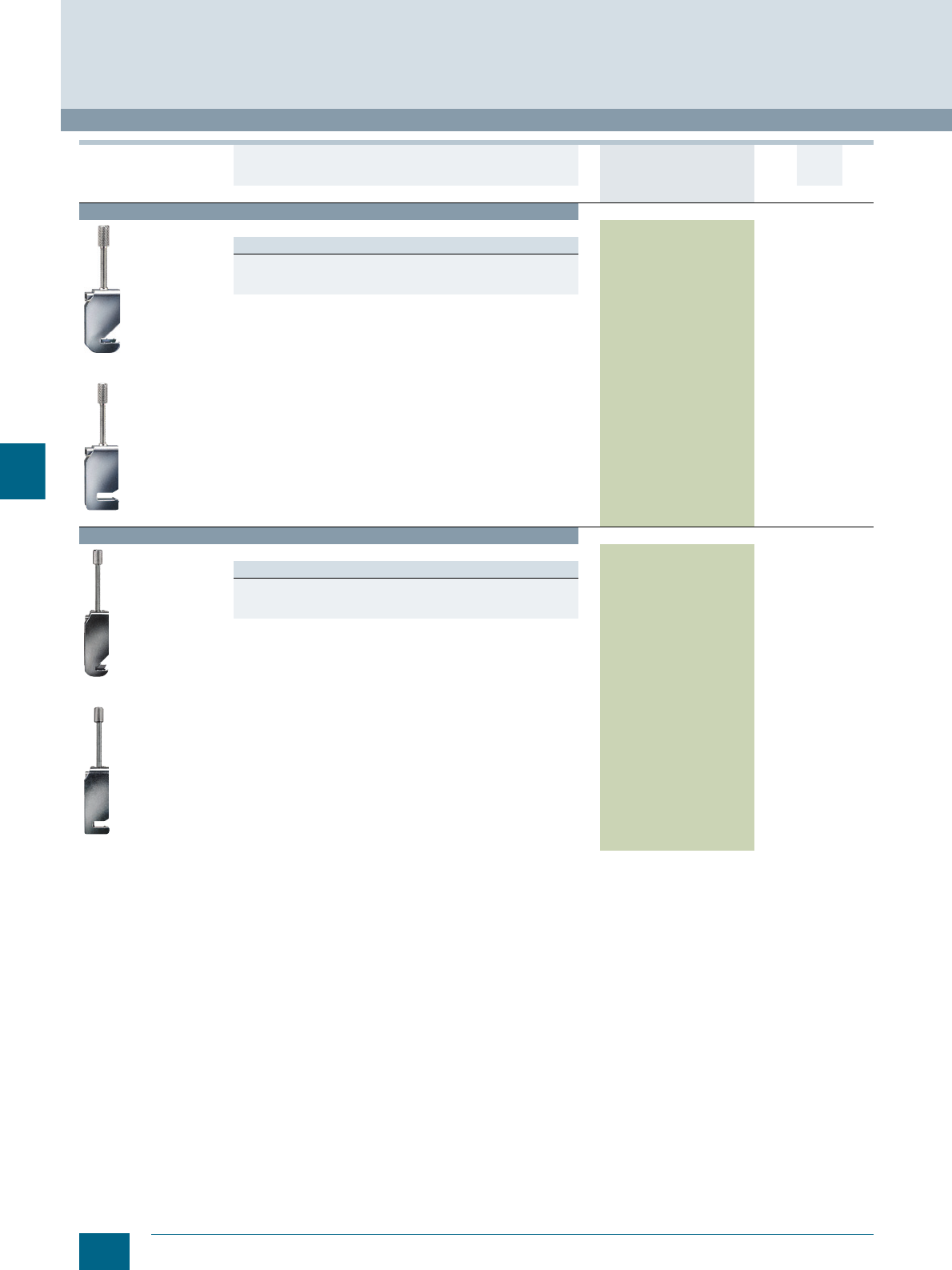
7/30 Siemens LV 52 · 2016 * You can order this quantity or a multiple thereof.
8WH shield terminals
8WH1 Screw Terminals
7
Terminal diameter 3 ... 20 mm
8WH9130-0CA00
8WH9130-0NA00
Shield terminal, terminal diameter 3 ... 20 mm
Versions
• For direct shield attachment on conductive mounting plate
- Sheet thickness 1 ... 2 mm 8WH9130-0CA00 1 10 units 1BT
•For busbars 8WH9130-0NA00 1 10 units 1BT
Terminal diameter 20 ... 35 mm
8WH9130-0DA00
8WH9130-0PA00
Shield terminal, terminal diameter 20 ... 35 mm
Versions
• For direct shield attachment on conductive mounting plate
- Sheet thickness 1 ... 2 mm 8WH9130-0DA00 1 10 units 1BT
•For busbars 8WH9130-0PA00 1 10 units 1BT
Version DT Article No.
www.siemens.com/
product?Article No.
Price
per PU
PU
(UNIT,
SET, M)
PS*/
P. un it PG
© Siemens AG 2015© Siemens AG 2015
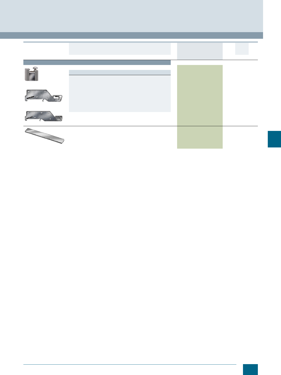
7/31
Siemens LV 52 · 2016
* You can order this quantity or a multiple thereof.
8WH1 Screw Terminals
8WH shield terminals
7
For general accessories for 8WH terminal blocks, see chapter
"Accessories for 8WH Terminal Blocks"
Accessories
8WH9140-0DA00
8WH9140-0BA00
8WH9140-0CA00
Support brackets
Versions
• For terminal diameter 8 ... 35 mm, made of molded plastic and
conductive connection
- With retaining screw
- For 10 x 3 mm busbars
8WH9140-0DA00 1 10 units 1BT
• For terminal diameter 8 ... 20 mm, for mounting rail with clearance
of approx. 30 mm to the busbar
- For 10 x 3 mm busbars
8WH9140-0BA00 1 10 units 1BT
• For terminal diameter 8 ... 20 mm, for mounting rail with clearance
of approx. 65 mm to the busbar
- For 10 x 3 mm busbars
8WH9140-0CA00 1 10 units 1BT
8WA2842
N-busbars, 10 x 3 mm
• Copper, aluminum
• 1000 mm long
8WA2842 11 unit1BT
Version DT Article No.
www.siemens.com/
product?Article No.
Price
per PU
PU
(UNIT,
SET, M)
PS*/
P. un it PG
© Siemens AG 2015© Siemens AG 2015
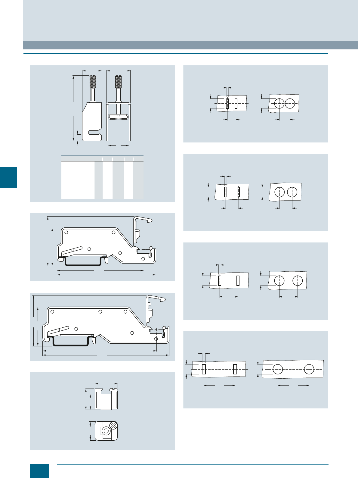
7/32 Siemens LV 52 · 2016
8WH shield terminals
8WH1 Screw Terminals
7
■
Dimensional drawings
Shield terminals
8WH9140-0BA00
8WH9140-0CA00
8WH9140-0DA00
Punching template and drill plan for 8WH9130-0AA00
Punching template and drill plan for 8WH9130-0BA00
Punching template and drill plan for 8WH9130-0CA00
Punching template and drill plan for 8WH9130-0DA00
e
b d
a
max. c
I201_12743b
ba ced
8WH9130-0LA00
8WH9130-0MA00
8WH9130-0NA00
8WH9130-0PA00
8WH9130-0AA00
8WH9130-0BA00
8WH9130-0CA00
8WH9130-0DA00
6,5
6,5
6,5
6,5
6,5
6,5
6,5
6,5
19,5
19,5
19,5
20,0
19,5
19,5
19,5
20,0
12,0
17,0
24,0
40,0
12,0
17,0
24,0
40,0
9,0
14,0
21,0
36,0
9,0
14,0
21,0
36,0
48,7
59,3
75,0
106,5
47,2
57,8
73,5
105,0
I201_12744
28,7
67,4
77,35
37,3
86
95,5
28,7
37,3
I201_12745
19,4 16,1
21,05
23,4
I201_12746
12
1310,5
I201_13761
12
3
12
15,515,5
I201_13762
12
3
12
22,522,5
12
3
I201_13763
12
38,5
I201_13764
12
38,5
4
© Siemens AG 2015© Siemens AG 2015
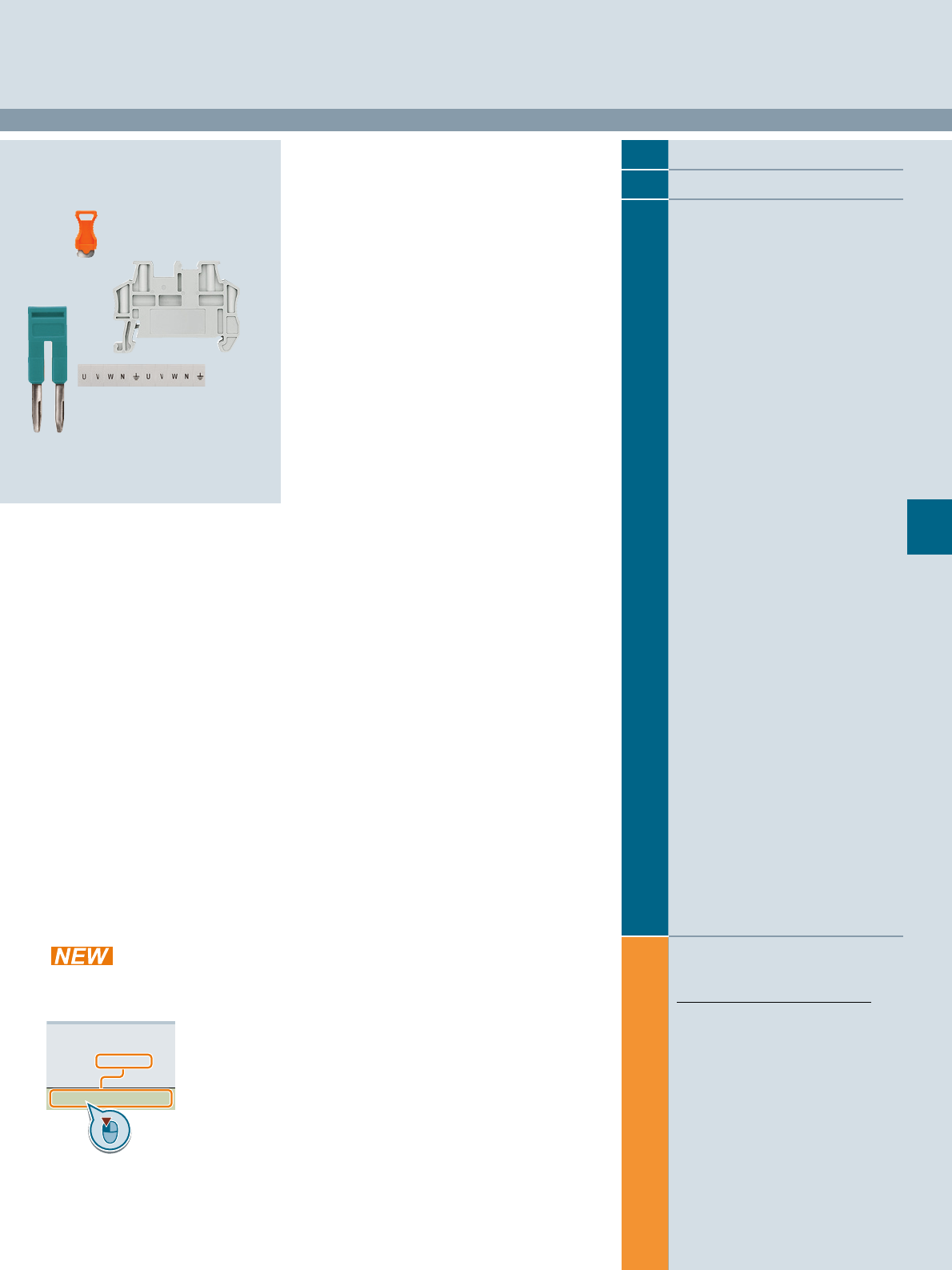
Siemens LV 52 · 2016
For further technical
product information:
Siemens Industry Online Support:
www.siemens.com/lowvoltage/product-
support .
→
Application example
Certificate
Characteristic
Download
FAQ
Manual
Product note
Software archive
Technical data
8
8
8/2 Accessories for the labeling system
8/3 Standard labeling system
8/8 Mounting accessories
Accessories for 8WH Terminal Blocks
Direct reference to the products in the
Industry Mall from the selection and
ordering data tables:
3VA2025-5HL36-0AA0
Article No.
www.siemens.com/
product? Article No.
Paper catalog:
To get more
product information
enter the Web
address plus
Article No.
PDF catalog:
Get more product information
with just a mouse click.
© Siemens AG 2015© Siemens AG 2015
8/2 Siemens LV 52 · 2016 * You can order this quantity or a multiple thereof.
Accessories for the labeling system
Accessories for 8WH Terminal Blocks
8
■
Selection and ordering data
Labeling system for individual inscription
Labeling systems for
• Terminal blocks
• Modular installation devices
• Circuit breakers
• Switch disconnectors
Available from:
Murrplastik Systemtechnik GmbH
Postfach 1143
D-71570 Oppenweiler
Telephone: +49 (0)7191-482-0
e-mail: info@murrplastik.de
Accessories for the labeling system
Note:
The labels can be written by hand or using Murrplastik labeling
systems.
The WIN designation simplifies the assignment in the labeling
software.
Version DT Article No.
www.siemens.com/
product?Article No.
Price
per PU
PU
(UNIT,
SET, M)
PS*/
P. un it PG
8WH8113-1AA05
Blank labels for
8WH8 terminal blocks
Versions
•Front
- For terminal width 4.2 mm (WIN 97) 8WH8112-1AA05 100 1024 units 1BT
- For terminal width 5.2 and 6.2 mm (WIN 88) 8WH8112-2AA05 100 1400 units 1BT
- For terminal width 8.2, 10, 12 and 16 mm (WIN 40) 8WH8112-4AA05 100 1000 units 1BT
•Flat
- For terminal width 4.2 mm (WIN 180), 5.2 mm (WIN 182),
6.2 mm (WIN 184), 8.2 mm (WIN 186) and 10 mm (WIN 188) 8WH8113-1AA05 100 2000 units 1BT
- For 12 and 16 mm terminal width (WIN 46Z) 8WH8113-6AA05 100 1080 units 1BT
Snap-on device labels
For identification of e.g.
• Circuit breakers
• Contactors
• Controllers
Versions
• 20 x 7, white, snap-on hooks at side (WIN 95) 8WH8210-0AA55 100 340 units 1BT
• 20 x 7, turquoise, snap-on hooks at side (WIN 95) 8WH8210-0AA56 100 340 units 1BT
Adhesive device labels
For identification of e.g.
• Modular installation devices
• Switch disconnectors
Versions
• 15 x 6 mm, white (WIN 098) 8WH8210-0AA35 100 3740 units 1BT
• 15 x 6 mm, yellow (WIN 099) 8WH8210-0AA36 100 3740 units 1BT
• 19 x 8 mm, white (WIN 088) 8WH8210-0AA45 100 2700 units 1BT
• 19 x 8 mm, yellow (WIN 082) 8WH8210-0AA46 100 2700 units 1BT
NSH0_00038
© Siemens AG 2015© Siemens AG 2015
8/3
Siemens LV 52 · 2016
* You can order this quantity or a multiple thereof.
Accessories for 8WH Terminal Blocks
Standard labeling system
8
■
Selection and ordering data
Version DT Article No.
www.siemens.com/
product?Article No.
Price
per PU
PU
(UNIT,
SET, M)
PS*/
P. un it PG
8WH8120-1AB05
Labels, front, for terminal width 4.2 mm and
terminal size 1.5 mm2 (excluding 8WH3), horizontal labeling
Versions
• Incremental numbering 8WH8120-1A@@@ 100 100 units 1BT
>>>
- 1 ... 10 (10×) B05
- 11 ... 20 (10×) B15
- 21 ... 30 (10×) B25
- 31 ... 40 (10×) B35
- 41 ... 50 (10×) B45
- 51 ... 60 (10×) B55
- 61 ... 70 (10×) B65
- 71 ... 80 (10×) B75
- 81 ... 90 (10×) B85
- 91 ... 100 (10×) C05
• Custom inscription 8WH8120-1XA05 100 100 units 1BT
8WH8140-1AB05
Labels, front, for terminal width 4.2 mm and
terminal size 1.5 mm2 (excluding 8WH3), vertical labeling
Versions
• Incremental numbering 8WH8140-1A@@@ 100 100 units 1BT
>>>
- 1 ... 10 (10×) B05
- 11 ... 20 (10×) B15
- 21 ... 30 (10×) B25
- 31 ... 40 (10×) B35
• Custom inscription 8WH8140-1XA05 100 100 units 1BT
8WH8110-1AA05
Labels, front, for terminal width 4.2 mm and
terminal size 1.5 mm2 (excluding 8WH3), blank 8WH8110-1AA05 100 100 units 1BT
8WH8121-1AB05
Labels, flat, for terminal width 4.2 mm and
terminal size 1.5 mm2 (excluding 8WH3), horizontal labeling
Versions
• Incremental numbering 8WH8121-1A@@@ 100 100 units 1BT
>>>
- 1 ... 10 (10×) B05
- 11 ... 20 (10×) B15
- 21 ... 30 (10×) B25
- 31 ... 40 (10×) B35
- 41 ... 50 (10×) B45
- 51 ... 60 (10×) B55
- 61 ... 70 (10×) B65
- 71 ... 80 (10×) B75
- 81 ... 90 (10×) B85
- 91 ... 100 (10×) C05
• Custom inscription 8WH8121-1XA05 100 100 units 1BT
8WH8141-1AB05
Labels, flat, for terminal width 4.2 mm and
terminal size 1.5 mm2 (excluding 8WH3), vertical labeling
Versions
• Incremental numbering 8WH8141-1A@@@ 100 100 units 1BT
>>>
- 1 ... 10 (10×) B05
- 11 ... 20 (10×) B15
- 21 ... 30 (10×) B25
- 31 ... 40 (10×) B35
- 41 ... 50 (10×) B45
• Custom inscription 8WH8141-1XA05 100 100 units 1BT
8WH8111-1AA05
Labels, flat, for terminal width 4.2 mm and
terminal size 1.5 mm2 (excluding 8WH3), blank 8WH8111-1AA05 100 100 units 1BT
© Siemens AG 2015© Siemens AG 2015
8/4 Siemens LV 52 · 2016 * You can order this quantity or a multiple thereof.
Standard labeling system
Accessories for 8WH Terminal Blocks
8
8WH8120-2AB05
8WH8120-2AA15
Labels, front, for terminal width 5.2 mm and
terminal size 2.5 mm2 (8WH3: 1.5 mm2), horizontal labeling
Versions
• Incremental numbering 8WH8120-2A@@@ 100 100 units 1BT
>>>
- 1 ... 10 (10×) B05
- 11 ... 20 (10×) B15
- 21 ... 30 (10×) B25
- 31 ... 40 (10×) B35
- 41 ... 50 (10×) B45
- 51 ... 60 (10×) B55
- 61 ... 70 (10×) B65
- 71 ... 80 (10×) B75
- 81 ... 90 (10×) B85
- 91 ... 100 (10×) C05
• L1/L2/L3/N/PE A15
• Custom inscription 8WH8120-2XA05 100 100 units 1BT
8WH8140-2AB05
Labels, front, for terminal width 5.2 mm and
terminal size 2.5 mm2 (8WH3: 1.5 mm2), vertical labeling
Versions
• Incremental numbering 8WH8140-2A@@@ 100 100 units 1BT
>>>
- 1 ... 10 (10×) B05
- 11 ... 20 (10×) B15
- 21 ... 30 (10×) B25
- 31 ... 40 (10×) B35
- 41 ... 50 (10×) B45
- 51 ... 60 (10×) B55
- 61 ... 70 (10×) B65
- 71 ... 80 (10×) B75
- 81 ... 90 (10×) B85
- 91 ... 100 (10×) C05
• Custom inscription 8WH8140-2XA05 100 100 units 1BT
8WH8110-2AA05
Labels, front, for terminal width 5.2 mm and
terminal size 2.5 mm2 (8WH3: 1.5 mm2), blank 8WH8110-2AA05 100 100 units 1BT
8WH8121-2AB15
Labels, flat, for terminal width 5.2 mm and
terminal size 2.5 mm2 (8WH3: 1.5 mm2), horizontal labeling
Versions
• Incremental numbering 8WH8121-2A@@@ 100 100 units 1BT
>>>
- 1 ... 10 (10×) B05
- 11 ... 20 (10×) B15
- 21 ... 30 (10×) B25
- 31 ... 40 (10×) B35
- 41 ... 50 (10×) B45
- 51 ... 60 (10×) B55
- 61 ... 70 (10×) B65
- 71 ... 80 (10×) B75
- 81 ... 90 (10×) B85
- 91 ... 100 (10×) C05
• Custom inscription 8WH8121-2XA05 100 100 units 1BT
8WH8141-2AB15
Labels, flat, for terminal width 5.2 mm and
terminal size 2.5 mm2 (8WH3: 1.5 mm2), vertical labeling
Versions
• Incremental numbering 8WH8141-2A@@@ 100 100 units 1BT
>>>
- 1 ... 10 (10×) B05
- 11 ... 20 (10×) B15
- 21 ... 30 (10×) B25
- 31 ... 40 (10×) B35
- 41 ... 50 (10×) B45
- 51 ... 60 (10×) B55
- 61 ... 70 (10×) B65
- 71 ... 80 (10×) B75
- 81 ... 90 (10×) B85
- 91 ... 100 (10×) C05
• Custom inscription 8WH8141-2XA05 100 100 units 1BT
8WH8111-2AA05
Labels, flat, for terminal width 5.2 mm and
terminal size 2.5 mm2 (8WH3: 1.5 mm2), blank 8WH8111-2AA05 100 100 units 1BT
Version DT Article No.
www.siemens.com/
product?Article No.
Price
per PU
PU
(UNIT,
SET, M)
PS*/
P. un it PG
© Siemens AG 2015© Siemens AG 2015
8/5
Siemens LV 52 · 2016
* You can order this quantity or a multiple thereof.
Accessories for 8WH Terminal Blocks
Standard labeling system
8
8WH8120-3AB05
8WH8120-3AA15
8WH8120-3AA25
Labels, front, for terminal width 6.2 mm and
terminal size 4 mm2 (8WH3: 2.5 mm2), horizontal labeling
Versions
• Incremental numbering 8WH8120-3A@@@ 100 100 units 1BT
>>>
- 1 ... 10 (10×) B05
- 11 ... 20 (10×) B15
- 21 ... 30 (10×) B25
- 31 ... 40 (10×) B35
- 41 ... 50 (10×) B45
- 51 ... 60 (10×) B55
- 61 ... 70 (10×) B65
- 71 ... 80 (10×) B75
- 81 ... 90 (10×) B85
- 91 ... 100 (10×) C05
• L1/L2/L3/N/PE A15
• U/V/W/N/grounding A25
• Custom inscription 8WH8120-3XA05 100 100 units 1BT
8WH8140-3AB05
Labels, front, for terminal width 6.2 mm and
terminal size 4 mm2 (8WH3: 2.5 mm2), vertical labeling
Versions
• Incremental numbering 8WH8140-3A@@@ 100 100 units 1BT
>>>
- 1 ... 10 (10×) B05
- 11 ... 20 (10×) B15
- 21 ... 30 (10×) B25
- 31 ... 40 (10×) B35
- 41 ... 50 (10×) B45
- 51 ... 60 (10×) B55
- 61 ... 70 (10×) B65
- 71 ... 80 (10×) B75
- 81 ... 90 (10×) B85
- 91 ... 100 (10×) C05
• Custom inscription 8WH8140-3XA05 100 100 units 1BT
8WH8110-3AA05
Labels, front, for terminal width 6.2 mm and
terminal size 4 mm2 (8WH3: 2.5 mm2), blank 8WH8110-3AA05 100 100 units 1BT
8WH8121-3AB05
Labels, flat, for terminal width 6.2 mm and
terminal size 4 mm2 (8WH3: 2.5 mm2), horizontal labeling
Versions
• Incremental numbering 8WH8121-3A@@@ 100 100 units 1BT
>>>
- 1 ... 10 (10×) B05
- 11 ... 20 (10×) B15
- 21 ... 30 (10×) B25
- 31 ... 40 (10×) B35
- 41 ... 50 (10×) B45
- 51 ... 60 (10×) B55
- 61 ... 70 (10×) B65
- 71 ... 80 (10×) B75
- 81 ... 90 (10×) B85
- 91 ... 100 (10×) C05
• Custom inscription 8WH8121-3XA05 100 100 units 1BT
8WH8141-3AB05
Labels, flat, for terminal width 6.2 mm and
terminal size 4 mm2 (8WH3: 2.5 mm2), vertical labeling
Versions
• Incremental numbering
- 1 ... 10 (10×) 8WH8141-3AB05 100 100 units 1BT
• Custom inscription 8WH8141-3XA05 100 100 units 1BT
8WH8111-3AA05
Labels, flat, for terminal width 6.2 mm and
terminal size 4 mm2 (8WH3: 2.5 mm2), blank 8WH8111-3AA05 100 100 units 1BT
Version DT Article No.
www.siemens.com/
product?Article No.
Price
per PU
PU
(UNIT,
SET, M)
PS*/
P. un it PG
© Siemens AG 2015© Siemens AG 2015
8/6 Siemens LV 52 · 2016 * You can order this quantity or a multiple thereof.
Standard labeling system
Accessories for 8WH Terminal Blocks
8
8WH8120-4AB05
8WH8120-4AA15
Labels, front, for terminal width 8.2 mm and
terminal size 6 mm2, horizontal labeling
Versions
• Incremental numbering 8WH8120-4A@@@ 100 100 units 1BT
>>>
- 1 ... 10 (10×) B05
- 11 ... 20 (10×) B15
- 21 ... 30 (10×) B25
- 31 ... 40 (10×) B35
- 41 ... 50 (10×) B45
- 51 ... 60 (10×) B55
- 61 ... 70 (10×) B65
- 71 ... 80 (10×) B75
- 81 ... 90 (10×) B85
- 91 ... 100 (10×) C05
• L1/L2/L3/N/PE A15
• Custom inscription 8WH8120-4XA05 100 100 units 1BT
8WH8140-4AB05
Labels, front, for terminal width 8.2 mm and
terminal size 6 mm2, vertical labeling
Versions
• Incremental numbering 8WH8140-4A@@@ 100 100 units 1BT
>>>
- 1 ... 10 (10×) B05
- 11 ... 20 (10×) B15
- 21 ... 30 (10×) B25
• Custom inscription 8WH8140-4XA05 100 100 units 1BT
8WH8110-4AA05
Labels, front, for terminal width 8.2 mm and
terminal size 6 mm2, blank 8WH8110-4AA05 100 100 units 1BT
8WH8121-4AB05
Labels, flat, for terminal width 8.2 mm and
terminal size 6 mm2, horizontal labeling
Versions
• Incremental numbering 8WH8121-4A@@@ 100 100 units 1BT
>>>
- 1 ... 10 (10×) B05
- 11 ... 20 (10×) B15
- 21 ... 30 (10×) B25
• Custom inscription 8WH8121-4XA05 100 100 units 1BT
Labels, flat, for terminal width 8.2 mm and
terminal size 6 mm2, vertical labeling
Versions
• Incremental numbering 8WH8141-4A@@@ 100 100 units 1BT
>>>
- 1 ... 10 (10×) B05
- 11 ... 20 (10×) B15
- 21 ... 30 (10×) B25
• Custom inscription 8WH8141-4XA05 100 100 units 1BT
8WH8111-4AA05
Labels, flat, for terminal width 8.2 mm and
terminal size 6 mm2, blank 8WH8111-4AA05 100 100 units 1BT
Version DT Article No.
www.siemens.com/
product?Article No.
Price
per PU
PU
(UNIT,
SET, M)
PS*/
P. un it PG
© Siemens AG 2015© Siemens AG 2015
8/7
Siemens LV 52 · 2016
* You can order this quantity or a multiple thereof.
Accessories for 8WH Terminal Blocks
Standard labeling system
8
8WH8120-5AB05
8WH8120-5AA15
8WH8120-5AA25
Labels, front, for terminal width 10 and 12 mm and
terminal sizes 10 and 16 mm2, horizontal labeling
Versions
• Incremental numbering 8WH8120-5A@@@ 100 100 units 1BT
>>>
- 1 ... 10 (10×) B05
- 11 ... 20 (10×) B15
- 21 ... 30 (10×) B25
- 31 ... 40 (10×) B35
• L1/L2/L3/N/PE A15
• U/V/W/N/grounding A25
• Custom inscription 8WH8120-5XA05 100 100 units 1BT
8WH8140-5AB05
Labels, front, for terminal width 10 and 12 mm and
terminal sizes 10 and 16 mm2, vertical labeling
Versions
• Incremental numbering 8WH8140-5A@@@ 100 100 units 1BT
>>>
- 1 ... 10 (10×) B05
- 11 ... 20 (10×) B15
- 21 ... 30 (10×) B25
- 31 ... 40 (10×) B35
• Custom inscription 8WH8140-5XA05 100 100 units 1BT
8WH8110-5AA05
Labels, front, for terminal width 10 and 12 mm and
terminal sizes 10 and 16 mm2, blank 8WH8110-5AA05 100 100 units 1BT
8WH8121-5AB05
Labels, flat, for terminal width 10 and 12 mm and
terminal sizes 10 and 16 mm2, horizontal labeling
Versions
• Incremental numbering 8WH8121-5A@@@ 100 100 units 1BT
>>>
- 1 ... 10 (10×) B05
- 11 ... 20 (10×) B15
- 21 ... 30 (10×) B25
• Custom inscription 8WH8121-5XA05 100 100 units 1BT
8WH8141-5AB05
Labels, flat, for terminal width 10 and 12 mm and
terminal sizes 10 and 16 mm2, vertical labeling
Versions
• Incremental numbering
- 1 ... 10 (10×) 8WH8141-5AB05 100 100 units 1BT
• Custom inscription 8WH8141-5XA05 100 100 units 1BT
8WH8111-5AA05
Labels, flat, for terminal width 10 and 12 mm and
terminal sizes 10 and 16 mm2, blank 8WH8111-5AA05 100 100 units 1BT
8WH8120-7AA15
Labels, front, for terminal width 16 mm and
terminal size 35 mm2, horizontal labeling
Versions
• L1/L2/L3/N/PE 8WH8120-7AA15 100 100 units 1BT
• Custom inscription 8WH8120-7XA05 100 100 units 1BT
Labels, front, for terminal width 16 mm and
terminal size 35 mm2, vertical labeling, custom labeling 8WH8140-7XA05 100 100 units 1BT
8WH8110-7AA05
Labels, front, for terminal width 16 mm and
terminal size 35 mm2, blank 8WH8110-7AA05 100 100 units 1BT
Labels, flat, for terminal width 16 mm and
terminal size 35 mm2, blank 8WH8111-7AA05 100 100 units 1BT
Version DT Article No.
www.siemens.com/
product?Article No.
Price
per PU
PU
(UNIT,
SET, M)
PS*/
P. un it PG
© Siemens AG 2015© Siemens AG 2015
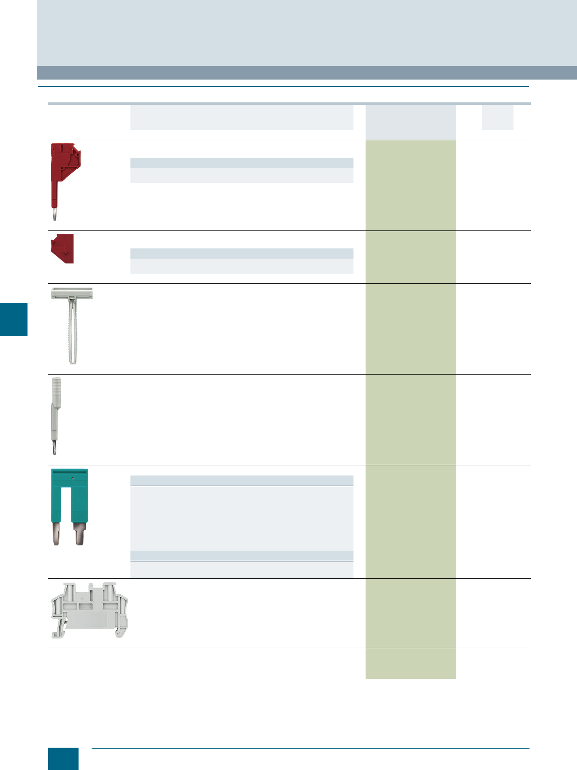
8/8 Siemens LV 52 · 2016 * You can order this quantity or a multiple thereof.
Mounting accessories
Accessories for 8WH Terminal Blocks
8
■
Selection and ordering data
Version DT Article No.
www.siemens.com/
product?Article No.
Price
per PU
PU
(UNIT,
SET, M)
PS*/
P. unit PG
8WH9010-0DB02
Modular test plugs
For individual assembly of test plug connectors
Versions
• For terminal width 5.2 mm and terminal size 2.5 mm2 1) 8WH9010-0EB02 1 10 units 1BT
• For terminal width 6.2 mm and terminal size 6 mm2 1) 8WH9010-0FB02 1 10 units 1BT
8WH9010-2AA02
Spacer plates
For leaving out single terminals for individual test plug assembly
Versions
• For terminal width 5.2 mm and terminal size 2.5 mm2 1) 8WH9010-2BA02 1 10 units 1BT
• For terminal width 6.2 mm and terminal size 6 mm2 1) 8WH9010-2CA02 1 10 units 1BT
8WH9150-1CA00
Terminal strip markers, for end retainers
• Height-adjustable
• For quick-fit end retainers
• Facility for labeling with terminal strip marker or two labels, front,
for terminal width 10.2 mm
• Labeling field size: 20 x 8 mm
8WH9150-1CA00 1 100 units 1BT
8WH9010-0JB00
Test adapters
• For 4 mm ∅ PS test plugs and 4 mm ∅ safety test plugs
• Makes contact in the bridge shaft
8WH9010-0JB00 1 10 units 1BT
8WH9020-0FC10
Reducing combs
Versions
• For bridging of a through-type terminal, terminal size 2.5 or 4 mm²
- For a through-type terminal, terminal size 1.5 mm² 8WH9020-0CC10 1 10 units 1BT
- For a through-type terminal, terminal size 6 mm² 8WH9020-0FC10 1 10 units 1BT
- For a through-type terminal, terminal size 10 mm² 8WH9020-0AC10 1 10 units 1BT
- For a through-type terminal, terminal size 16 mm² 8WH9020-0BC10 1 10 units 1BT
- For a through-type terminal, terminal size 35 mm² 8WH9020-0EC10 1 10 units 1BT
• For bridging of a through-type terminal, terminal size 16 mm²
- For a through-type terminal, terminal size 35 mm² 8WH9020-0DC10 1 10 units 1BT
Note
Not for 8WH1 through-type terminals and 8WH3 insulation displacement
terminals.
8WH9150-0CA00
Quick-fit end retainers
Facility for labeling with labels, front, for terminal width 5.2 mm and
terminal strip marker
8WH9150-0CA00 1 50 units 1BT
1) Excluding 8WH3
© Siemens AG 2015© Siemens AG 2015
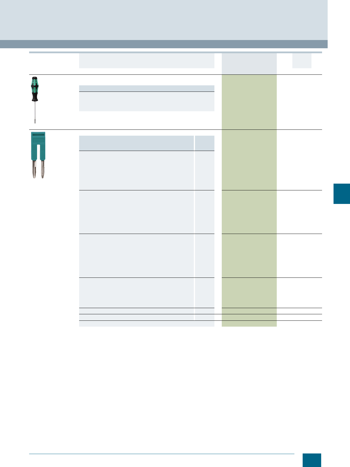
8/9
Siemens LV 52 · 2016
* You can order this quantity or a multiple thereof.
Accessories for 8WH Terminal Blocks
Mounting accessories
8
8WH9200-0AA00
Screwdrivers
For opening spring-loaded terminals
Versions
• 0.4 × 2.5 mm 8WH9200-0AA00 1 10 units 1BT
• 0.6 × 3.5 mm 8WH9200-0AB00 1 10 units 1BT
• 0.8 × 4.0 mm 8WH9200-0AC00 1 10 units 1BT
• 1.0 × 5.5 mm 8WH9200-0AD00 1 10 units 1BT
8WH9020-6AC10
Connecting combs
Versions Max. load
current
Imax
• For terminal width 4.2 mm and terminal size 1.5 mm2
(excluding 8WH3) 17.5 A
-2-pole 8WH9020-6AC10 1 50 units 1BT
-3-pole 8WH9020-6AD10 1 50 units 1BT
-4-pole 8WH9020-6AE10 1 50 units 1BT
-5-pole 8WH9020-6AF10 1 50 units 1BT
- 10-pole 8WH9020-6AL10 1 10 units 1BT
- 20-pole 8WH9020-6AS10 1 10 units 1BT
• For terminal width 5.2 mm and terminal size 2.5 mm2
(for 8WH3: 1.5 mm2)24 A
-2-pole 8WH9020-6BC10 1 50 units 1BT
-3-pole 8WH9020-6BD10 1 50 units 1BT
-4-pole 8WH9020-6BE10 1 50 units 1BT
-5-pole 8WH9020-6BF10 1 50 units 1BT
- 10-pole 8WH9020-6BL10 1 10 units 1BT
- 20-pole 8WH9020-6BS10 1 10 units 1BT
- 50-pole 8WH9020-6BT10 1 10 units 1BT
• For terminal width 6.2 mm and terminal size 4 mm2
(for 8WH3: 2.5 mm2)32 A
-2-pole 8WH9020-6CC10 1 50 units 1BT
-3-pole 8WH9020-6CD10 1 50 units 1BT
-4-pole 8WH9020-6CE10 1 50 units 1BT
-5-pole 8WH9020-6CF10 1 50 units 1BT
- 10-pole 8WH9020-6CL10 1 10 units 1BT
- 20-pole 8WH9020-6CS10 1 10 units 1BT
- 50-pole 8WH9020-6CT10 1 10 units 1BT
• For terminal width 8.2 mm and terminal size 6 mm2 41 A
-2-pole 8WH9020-6DC10 1 10 units 1BT
-3-pole 8WH9020-6DD10 1 10 units 1BT
-4-pole 8WH9020-6DE10 1 10 units 1BT
-5-pole 8WH9020-6DF10 1 10 units 1BT
- 10-pole 8WH9020-6DL10 1 10 units 1BT
• For terminal width 10 mm and terminal size 10 mm2, 2-pole, 57 A 8WH9020-6EC10 1 10 units 1BT
• For terminal width 12 mm and terminal size 16 mm2, 2-pole 76 A 8WH9020-6FC10 1 10 units 1BT
• For terminal width 16 mm and terminal size 35 mm2, 2-pole 101 A 8WH9020-6GC10 1 10 units 1BT
Version DT Article No.
www.siemens.com/
product?Article No.
Price
per PU
PU
(UNIT,
SET, M)
PS*/
P. unit PG
© Siemens AG 2015© Siemens AG 2015
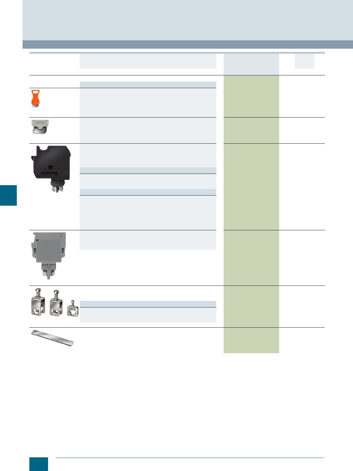
8/10 Siemens LV 52 · 2016 * You can order this quantity or a multiple thereof.
Mounting accessories
Accessories for 8WH Terminal Blocks
8
Plug-in zone connectors, for isolating terminals
Versions
8WH9040-0DB04
• Isolating plugs
-Orange 8WH9040-0DB04 1 50 units 1BT
8WH9020-8AB00
• Through-type connectors
-Gray
-Imax: 16 A
8WH9020-8AB00 1 50 units 1BT
8WH9040-3AB08
• Fused connectors
-Black
-Imax: 6.3 A
- Facility for labeling with labels, flat, for terminal width 6.2 mm
- G fuses 5 x 20 mm
Versions
- With LED display for 12 ... 30 V, 1 ... 2.5 mA 8WH9040-3AB08 1 10 units 1BT
- With LED display for 110 ... 250 V, 0.5 ... 2.5 mA 8WH9040-3CB08 1 10 units 1BT
- Without LED display 8WH9040-3DB08 1 10 units 1BT
Note
• The G fuse holders must be selected according to the maximum power
loss (heat dissipation) of the G fuse links. Depending on the application
and method of installation, the heat rise conditions in closed fuse
holders must be tested.
• Higher ambient temperatures represent an additional load for the fuse
links. A shift in rated current should therefore be taken into account in
such applications.
8WH9040-0BB00
• Component connectors
-Imax: 6 A, depending on the power loss of the components, max. 1 W
for single arrangement
- Facility for labeling with labels, flat, for terminal width 5.2 mm
8WH9040-0BB00 1 10 units 1BT
8WA2867/8WA2868/
8WA2870
Feeder terminals, for N-busbars
• 6 × 6 mm and 10 × 3 mm
•Bare
Versions
• Rated uninterrupted current 32 A, for connection of up to 4 mm28WA2867 1 50 units 1BT
• Rated uninterrupted current 76 A, for connection of up to 25 mm28WA2868 1 50 units 1BT
• Rated uninterrupted current 125 A, for connection of up to 35 mm28WA2870 1 50 units 1BT
8WA2842
N-busbars, 10 x 3 mm
• Made of copper, tin-plated
• 1000 mm long
8WA2842 1 1 unit 1BT
Version DT Article No.
www.siemens.com/
product?Article No.
Price
per PU
PU
(UNIT,
SET, M)
PS*/
P. unit PG
© Siemens AG 2015© Siemens AG 2015
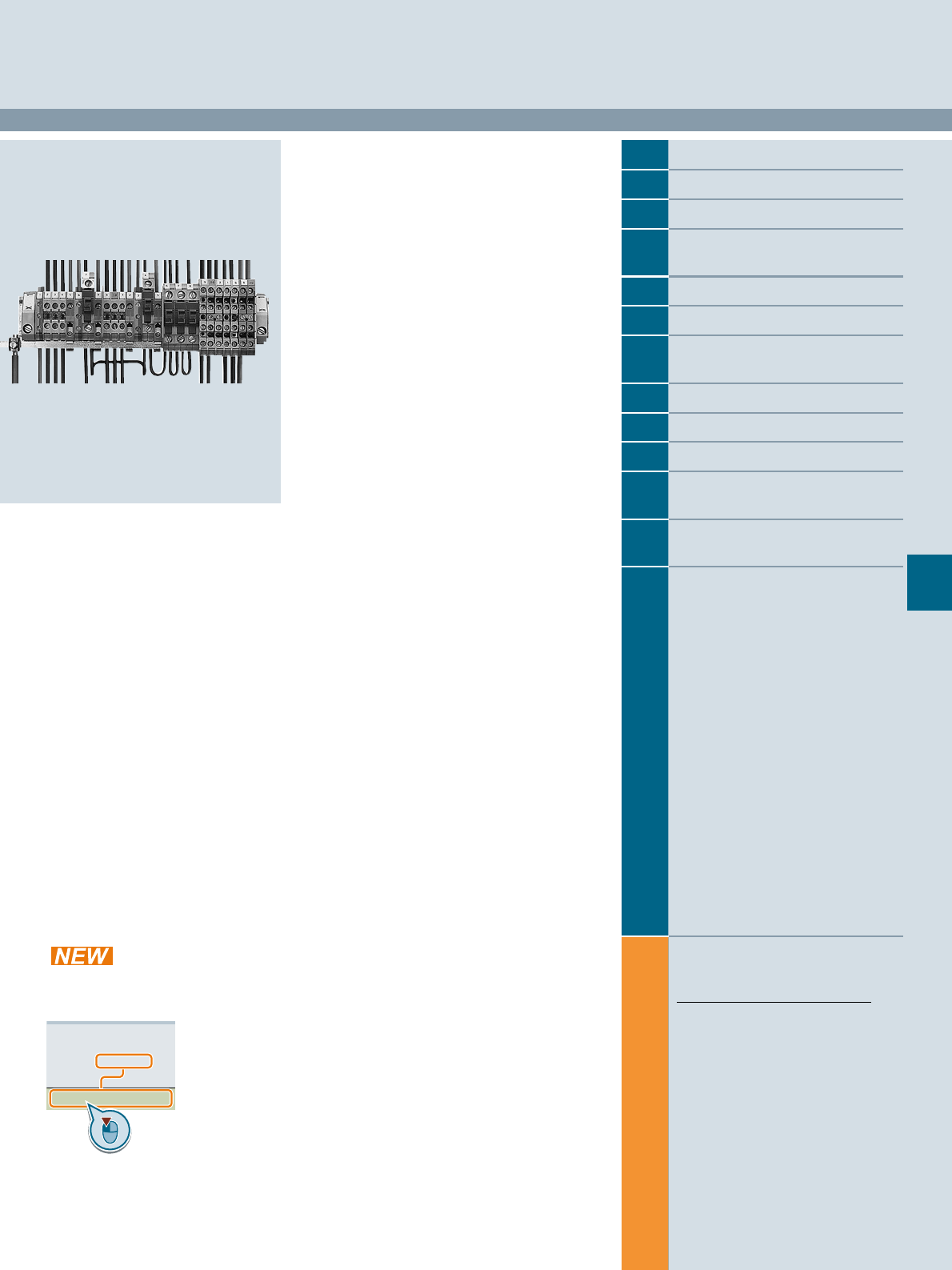
Siemens LV 52 · 2016
For further technical
product information:
Siemens Industry Online Support:
www.siemens.com/lowvoltage/product-
support .
→
Application example
Certificate
Characteristic
Download
FAQ
Manual
Product note
Software archive
Technical data
9
9
9/2 Introduction
9/3 General data on 8WA
9/9 8WA through-type terminals1)
9/15 8WA N-conductor isolating and
branch terminals
9/17 8WA Insta or three-tier terminals
9/19 8WA two-tier terminals
9/21 8WA two-tier terminals with
electronic components
9/23 8WA diode and isolating terminals
9/24 8WA terminals for components
9/25 8WA fuse terminals
9/26 8WA through-type terminals with
soldered and plug-in connection
9/27 8WA measuring transformer
terminals
1) Also available as a PE version
8WA1 Screw Terminals
Direct reference to the products in the
Industry Mall from the selection and
ordering data tables:
3VA2025-5HL36-0AA0
Article No.
www.siemens.com/
product? Article No.
Paper catalog:
To get more
product information
enter the Web
address plus
Article No.
PDF catalog:
Get more product information
with just a mouse click.
© Siemens AG 2015© Siemens AG 2015
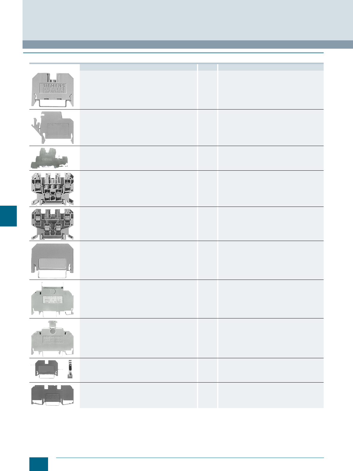
9/2 Siemens LV 52 · 2016
Introduction
8WA1 Screw Terminals
9
■
Overview
Devices Page Function
8WA through-type terminals 9/9 Connection of incoming and outgoing cables
up to 70 mm2
8WA N-conductor isolating and branch terminals 9/15 N-conductor isolating terminals connected to N-busbar
6 × 6 mm
8WA Insta or three-tier terminals 9/17 These terminals have up to three terminal functions in a
single enclosure and may also have an N-isolating termi-
nal connection to an N-busbar 6 × 6 mm. They are opti-
mized for distribution board applications in installation
technology
8WA two-tier terminals 9/19 Compact design of the terminal blocks, in which two
connecting wires can be installed
8WA two-tier terminals with electronic components 9/21 Terminal blocks with integrated diodes
8WA diode and isolating terminals 9/23 Terminal blocks with integrated diodes or isolation for
testing purposes
8WA terminals for components 9/24 Terminals that enable installation of components in the
circuit
8WA fuse terminals 9/25 Terminals which can be used to protect control circuits,
for example
8WA through-type terminals with soldered and
plug-in connection 9/26 Terminals with connection for soldered or plug-in
connection
8WA measuring transformer terminals 9/27 Measuring transformer terminals can be used for testing
and isolating circuits in switchboards, control rooms,
etc. without interrupting operation
© Siemens AG 2015© Siemens AG 2015
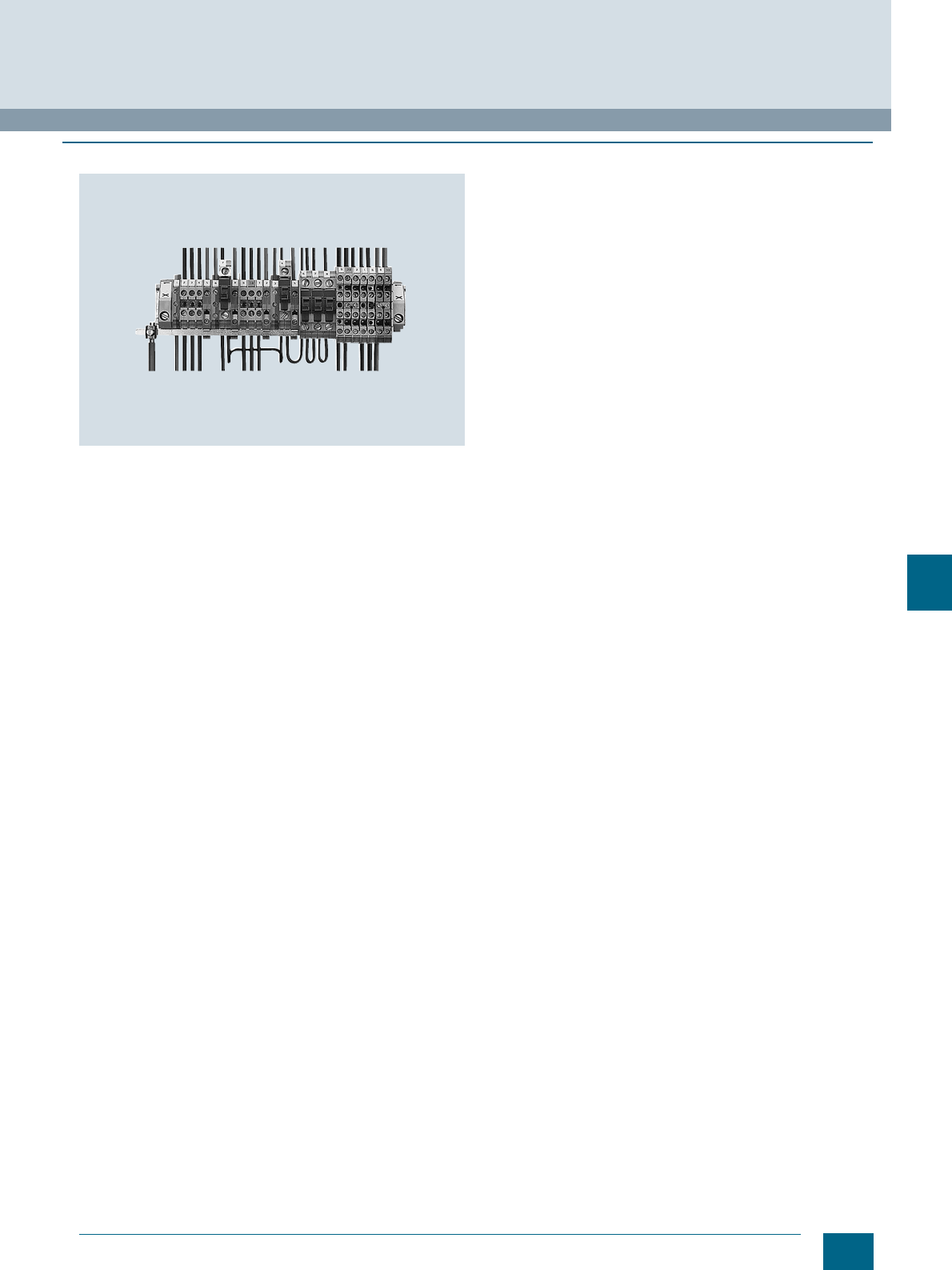
9/3
Siemens LV 52 · 2016
8WA1 Screw Terminals
General data on 8WA
9
■
Overview
Terminal strips with different terminal blocks: 8WA1011-1DG11 terminal
blocks, 8WA1011-1NG31 N-conductor isolating terminals with feeder
terminal for N-busbar 6 × 6 mm, 8WA1011-1PG00 PE terminals,
8WA1011-1SF12 fuse terminals, and various two-tier terminals.
The EN 50022-35-compliant standard mounting rail serves as the PE bar.
Terminal blocks are used for the space-saving connection of
incoming and outgoing cables in switchboards and distribution
boards.
Standards
EN 60664-1,
EN 60999 and
IEC 60947-7-1 or
IEC 60947-7-2
The terminals are finger-safe acc. to IEC 60529 and
DIN EN 50274 (except for bare terminals and solder connec-
tions). Through-type terminals are resistant to earthquakes
according to IEC 60068-2-6.
Rated short-time withstand current
Our screw terminals are able to withstand a rated short-time
current corresponding to a current density of 120 A/mm2
specific to the rated cross-section for one second.
Colored terminal blocks
With colored wiring according to EN 60204-1, the connecting
level can also be included in the colored markings:
• Red for control circuits with AC current
• Blue for control circuits with DC current or neutral conductor
• Orange for interlock circuits with AC or DC current which are
fed from outside and are live when the main switch is turned
off
• Green-yellow through-type terminals for protective conductors
(without connection to the support rail)
Design
The terminal blocks are insulated at both ends, with the excep-
tion of two-tier, flat and bolt-type terminals, which are insulated
on one side only.
The insulating material for terminal sizes up to 70 mm² is made
of thermoplast, polyamide 6.6.
The materials used are environment-friendly: For example, they
are cadmium-free and contain no halogens or silicone.
The plastics used are flame-retardant and self-extinguishing
according to EN 60695-2-2, VDE 0471, Part 2-2 and UL 94 V-2.
Clamping methods
The terminals are designed so that when the terminal screws are
tightened, any tensile stress which occurs causes elastic defor-
mation of the terminal bodies. This compensates for any creep-
age of the clamping conductor. Deformation of the thread part
prevents loosening of the clamping screw, even in the event of
heavy mechanical and thermal strain (e.g. vibration stress of
10 g or thermal cycles).
The following clamping methods are used:
• Terminal body with pressure plate for terminal sizes 16, 35 and
70 mm²
• Strain-relief clamps for terminal sizes 2.5, 4 and 6 mm²
• Screw with connection disk for fuse terminals and component
terminals.
Terminal size
The terminal size corresponds to the nominal cross-section.
According to EN 60947-7-1, a finely stranded copper conductor
of nominal cross-section can be connected to any clamping
point with or without end sleeve.
Mounting
The terminals are snapped onto 35 mm support rails according
to IEC 60715 TH35 and secured against movement using end
retainers.
A lateral mounting tolerance of 0.2 mm must be maintained
between the terminals.
Conductor connection
Except for flat and bolt-type versions, all terminal bodies are
designed so that solid, stranded and finely stranded conductors
with or without end sleeves (according to DIN 46228) can be
securely clamped (please observe cross-section).
Damage to the clamped conductors is prevented by pressure
plates or strain-relief clamps. For the conductor cross-sections
when 1 or 2 conductors are connected, see Technical Specifica-
tions.
© Siemens AG 2015© Siemens AG 2015

9/4 Siemens LV 52 · 2016
General data on 8WA
8WA1 Screw Terminals
9
Connection of aluminum conductors
Siemens screw terminals are suitable for connecting aluminum
conductors provided there is compliance with the normal pro-
cessing guidelines, i.e. the brushing and greasing of the con-
ductors before connection.
After a few days, the connection should be tightened again for
safety reasons.
8WA1 through-type terminal with screw terminal at both ends,
sectional view
PE and PEN terminals
In switchgear and controlgear systems the support rails for the
terminal blocks are frequently used as protective ground bus-
bars. The PE terminals establish the connection to the support
rail.
The fact that there is no separate PE busbar means the PE ter-
minals, the insulated main conductor terminals and N-conductor
isolating terminals can be arranged according to user require-
ments. This makes the individual circuits clearly manageable.
The bare 8WA1010-1PH01 PE terminals are primarily used for
connecting the shields of shielded cables. They are normally
mounted on a standard mounting rail, which is supported by an
8WA1857 insulation carrier and which is equipped with only one
PE terminal for connection to the PE conductor.
Accessories
Parallel connection bars
The connection bars are screwed into the terminals from above
and allow parallel connection of up to 10 terminals up to terminal
size 35 mm². The 10-pole connection bars can be shortened as
required. On 70 mm² terminals the connection bars are two-pole.
Barriers
Barriers are yellow in color and project beyond the contours of
the terminals. They serve the visual separation of groups of ter-
minals, the electrical isolation of adjacent connection bars and
the improvement of the rated insulation voltage for soldered and
plug-in connections.
Insulation plates
8WA1825 and 8WA1822-7TK00 insulation plates can be used
with different terminals for providing electrical insulation
between connection bars.
Disconnecting links
The 8WA1865 disconnecting links provide a detachable con-
nection between two adjacent terminals sizes 2.5 to 6 mm².
Covers with lightning symbol
The purpose of these covers is to identify the power input termi-
nals. At the same time, they provide additional touch protection.
End retainers and end labeling plates
End retainers are available in thermoplastic or galvanized and
chromated steel. The end labeling plate can be fitted in an
8WA1808 end retainer or, in any of three positions, in an
8WA1805 end retainer.
I201_14019
5 1
2
3
4
6
1
2
3
4
5
6
Screwdriver guide
Cut-out for labeling
plate
Cable entry
Terminal body
Thread for parallel
link rail
Elastic retaining feet
© Siemens AG 2015© Siemens AG 2015
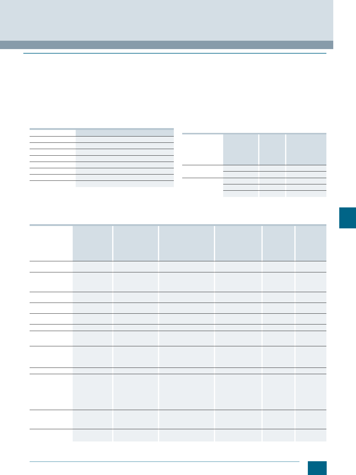
9/5
Siemens LV 52 · 2016
8WA1 Screw Terminals
General data on 8WA
9
■
Technical specifications
Continuous load at increased ambient temperatures
The 8WA1 terminal blocks can withstand an uninterrupted cur-
rent at ambient temperatures of up to +55 °C. At higher ambient
temperatures, a current reduction according to the following for-
mula is required:
The highest permissible clamping point overtemperature of 45 K
specified in IEC 60947-7-1 is not exceeded at an ambient tem-
perature of up to 100 °C.
Standard mounting rails as PEN rails
Only use Cu busbars.
They must have the same current carrying capacity as protec-
tive conductor busbars.
PEN busbars must carry only terminals and no devices.
Standard mounting rails as protective conductor busbars
Protective conductors with a larger cross-section than the pro-
tective conductor busbar, and with the same conductivity, can
be connected to standard mounting rails that are also protective
conductor busbars and carry current only under fault conditions.
1) With 8WA1010-1PQ00 terminal connection of up to 95 mm² finely stranded
or 120 mm² stranded.
Clamping points
1) Tightening torque also applicable for accessories (socket, connection
bars, etc.).
Ith2’ =Ith2 · k
Ith2 = Uninterrupted current according to selection tables, relative to the
nominal cross-section
Ith2’ = Uninterrupted current at increased ambient temperature
k= Derating factor according to table
Ambient temperature Derating factor k
60 °C 0.94
65 °C 0.88
70 °C 0.82
75 °C 0.75
80 °C 0.67
85 °C 0.58
90 °C 0.47
95 °C 0.33
Standard mount-
ing rail acc. to
EN 50022-35
and
IEC 60715 TH35
Material Type Max. permissible
cross-section of
connected protec-
tive conductor
mm²
35 × 7.5 Steel 5ST1141 16
Steel, perforated 5ST1145 16
Similar to 35 × 15 Steel 5ST1142 35
Steel -- 50
Copper 8WA7551 150 1)
Terminal size Type 1) Thread diameter of
terminal screws Screwdriver blades
acc. to DIN 5264
Form B
Tightening torque
= test torque
acc. to DIN VDE 0609
and DIN VDE 0611
Tensile forces
acc. to
IEC 60947-1
at max.
conductor
connection
Stripped
length
Nm Nmm
1.5 8WA1011-. SF. .,
8WA1011-1EE00 M3.5 0.8 × 4 0.8 40 10
2.5 8WA1. .1,
8WA1011-1BF11,
8WA1011-1EF . .
8WA1011- . . F . .
M2.5 and M3
M2.5
0.5 × 3
0.8 × 4
0.5
0.5
50
50
11
11
48WA1011- . . G . .
8WA2867 M3
M3.5 0.8 × 4 0.5
0.8 ... 1 60 11
68WA1. .2,
8WA1011- . . H . . M3.5 0.8 × 4 0.8 80 11
16 8WA1. .4,
8WA1011- . . K . . M4 0.8 × 4 1.2 100 13
25 8WA2868 M5 1.2 × 6.5 2135
35 8WA1. .5,
8WA1011- . . M . .
8WA2870
M6 1.2 × 6.5 2.5
2.5 ... 3
190 17
50 8WH1000-0AN00,
8WH1000-0AN01,
8WH1000-0CN07
8WH1070-0AN00
M6
M6
1.2 × 8
--
6 ... 8
3 ... 7
--
--
24
6 ... 25
70 8WA1 . .6 M8 4 hexagon socket-head 6285 25
95 8WA1010-1PQ00
8WH1000-0AQ00,
8WH1000-0AQ01
8WH1000-0CQ07
8WH1070-0AQ00
8WH1060-0AQ00
M8
M8
M8
M8
M8
6 hexagon socket-head
6 hexagon socket-head
6 hexagon socket-head
--
--
15 ... 20
15 ... 20
15 ... 20
6 ... 15
25 ... 30
--
--
--
--
30
33
30
16... 25
29
150 8WH1000-0AS0.
8WH1070-0AS00
8WH1060-0AS00
M10
M10
M10
8 hexagon socket-head
--
--
25 ... 30
10 ... 18
25 ... 30
--
--
--
40
10 ... 18
34
240 8WH1000-0AU0.
8WH1060-0AU00
M10
M10
10 hexagon socket-head
--
30 ... 35
30 ... 35
--
--
40
34
© Siemens AG 2015© Siemens AG 2015
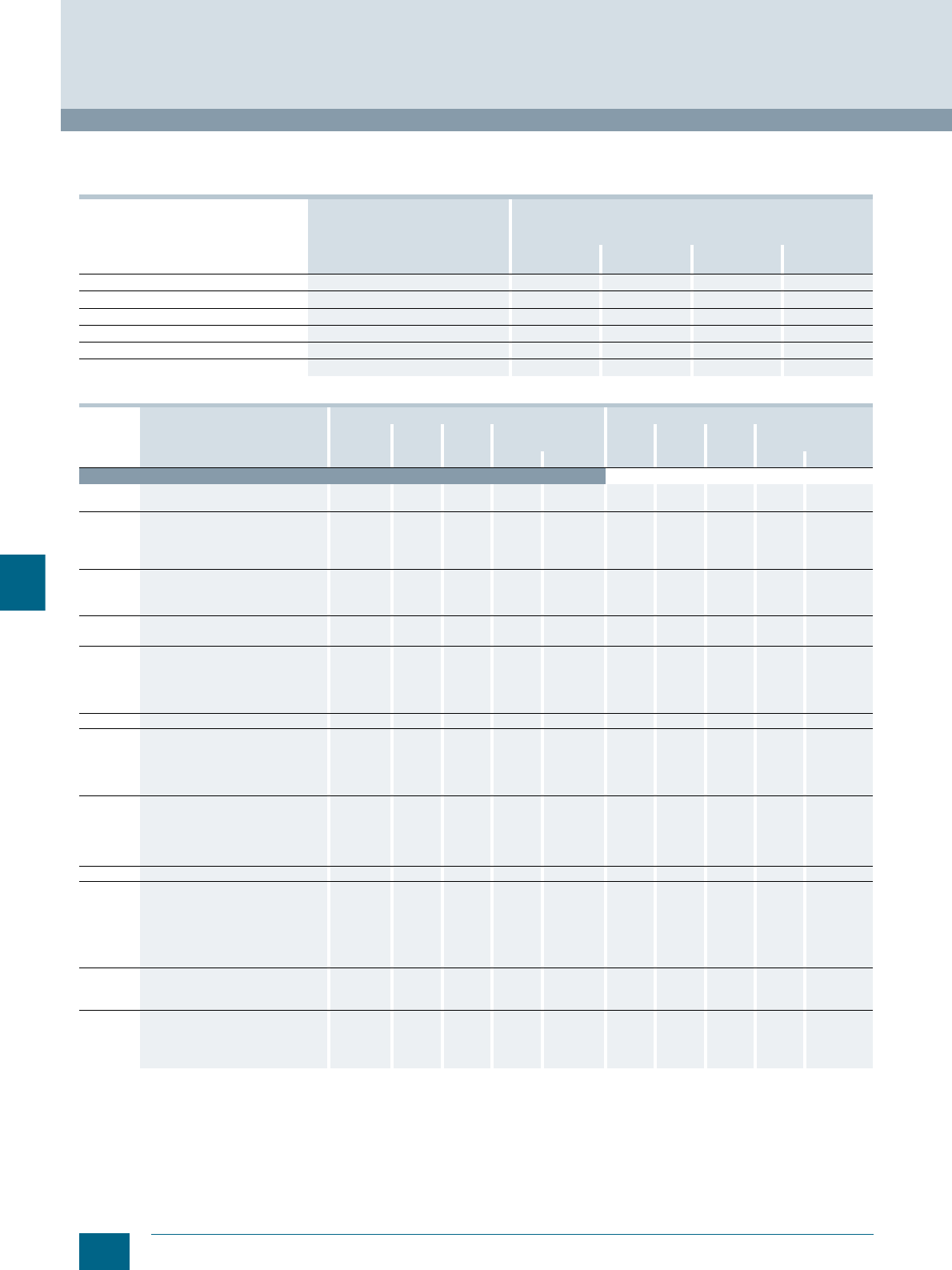
9/6 Siemens LV 52 · 2016
General data on 8WA
8WA1 Screw Terminals
9
Rated impulse withstand voltage of terminal blocks
Values dependent on the mains rated voltage ≤ rated insulation
voltage of terminal block; excerpt from EN 60947-1, table H.1. Terminal blocks are tested acc. to overvoltage category III.
Connection
1) End sleeves acc. to DIN 46228 Sheet 1 without insulation.
Size corresponds to sleeve nominal size.
2) 0.12/0.25 mm² corresponds to ∅ 0.4/0.6 mm.
3) For 0.75 mm² conductors, use end sleeves 1 to 10 and press on with
insert E1 or PZ 1.5.
4) At voltages > 500 V, shorten end sleeves with inserted conductor to
10 mm before pressing on.
5) Tested up to 16 mm².
6) Fit and press on two end sleeves one after the other (up to stop).
7) Voltage reduction to 630 V required.
Rated mains voltage
(≤ rated insulating
voltage of the device)
Maximum rated operating voltage
to ground Preferred values for rated impulse withstand voltage
as 1.2/50 μs pulse
Overvoltage category
RMS value
V AC RMS value
V AC or V DC I
kV II
kV III
kV IV
kV
-- 50 330 500 800 1500
66/115 100 500 800 1500 2500
120/208 127/220 150 800 1500 2500 4000
230/400 277/480 300 1500 2500 4000 6000
400/690 600 2500 4000 6000 8000
1000 1000 4000 6000 8000 12000
Terminal
size Type Smallest conductor cross-section Largest conductor cross-section
Solid Stranded Finely
stranded Finely stranded with
end sleeve 1)Solid Stranded Finely
stranded Finely stranded with
end sleeve 1)
mm² mm² mm² mm² mm² Size mm² mm² mm² mm² Size
Single-conductor connection
1.5 8WA1011-.SF . . ,
8WA1011-1EE00 1-- -- 0.75 0.75 ... 10 2.5 -- -- 1.5 1.5 ... 10
2.5 8WA1211, 8WA1011-. .F. . 0.25 2) 0.5 0.5 0.5 0.5 ... 10 42.5 2.5 2.5 2.5 ... 12 4)
8WA1011-3JF . . 0.25 2) 0.5 0.5 0.5 0.5 ... 10 42.5 2.5 2.5 2.5 ... 7
8WA1501, 8WA1511,
8WA1011-1EF . . 0.25 2) 0.5 0.5 0.5 0.5 ... 10 42.5 2.5 2.5 1.5 ... 10
48WA9200 0.5 1.5 1.5 0.75 0.75 ... 10 64444
8WA286. Feeder terminals 11.5 1.5 0.75 0.75 ... 10 64444 ... 12 4)
8WA1011-. .G.. 0.5 1.5 0.5 0.75 0.75 ... 10 64444 ... 12 4)
68WA1011-1.H.. 0.75 1.5 1.5 0.5 0.5 ... 10 10 6666 ... 12
8WA1010-1PH01 0.5 1.5 1.5 0.5 0.5 ... 10 10 6666 ... 15
16 8WA1204, 8WA1304,
8WA1011-1BK11 1.5 2.5 2.5 11 ... 10 3) 16 25 16 16 16 ... 12
8WA1604 1.5 2.5 41.5 1 ... 10 3) 16 25 16 16 16 ... 12
8WA1011-1PK00 1.5 2.5 41.5 1.5 ... 7 6) 16 25 16 16 16 ... 15
8WA286. Feeder terminals 1.5 2.5 42.5 2.5 ... 12 16 16 10 10 10 ... 12
25 8WH1060-0AL00 -- -- 44-- -- -- 25 25 --
35 8WA1205, 8WA1305,
8WA1011-1BM11 410 666 ... 15 16 5) 50 35 35 35 ... 18 7)
8WA1011-1PM00 410 10 66 ... 15 16 5) 50 35 25 25 ... 15
8JH4114 Feeder terminals 610 16 66 ... 15 16 35 25 25 25 ... 15
8WA2870 610 16 66 ... 15 16 35 25 25 25 ... 15
50 8WH1000-0AN00 -- -- 10 10 -- -- -- 50 50 --
8WH1000-0AN01 -- -- 10 10 -- -- -- 50 50 --
8WH1000-0CN07 -- -- 25 25 -- -- -- 50 50 --
8WH1070-0AN00 -- -- 61) -- -- -- -- -- 351) --
8WH1060-0AN00 -- -- 25 25 -- -- -- 50 50 --
70 8WA1206 10 16 16 16 16 ... 12 6) 95 95 95 -- --
95 8WA1010-1PQ00 -- 50 50 -- -- -- 95 95 -- --
8WH1000-0AQ00 -- -- 35 35 -- -- -- 95 95 --
8WH1000-0AQ01 -- -- 35 35 -- -- -- 95 95 --
8WH1000-0CQ07 -- -- 35 35 -- -- -- 35 95 --
8WH1070-0AQ00 -- -- -- 161) -- -- -- -- 351) --
8WH1060-0AQ00 -- -- 35 35 -- -- -- 95 95 --
150 8WH1000-0AS00,
8WH1000-0AS01 -- -- 50 50 -- -- -- 150 150 --
8WH1060-0AS00 -- -- 50 50 -- -- -- 150 150 --
240 8WA1011-1DU.. -- -- -- -- -- -- 240 240 -- --
8WH1000-0AU00,
8WH1000-0AU01 -- -- 70 70 -- -- -- 185 185 --
8WH1060-0AU00
© Siemens AG 2015© Siemens AG 2015
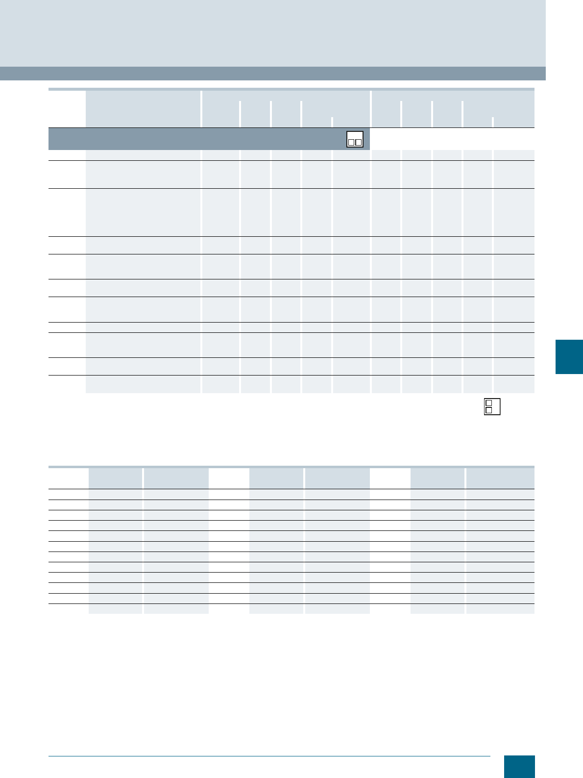
9/7
Siemens LV 52 · 2016
8WA1 Screw Terminals
General data on 8WA
9
1) End sleeves acc. to DIN 46228 Sheet 1 without insulation.
Size corresponds to sleeve nominal size.
2) For 0.75 mm² conductors, use end sleeves 1 to 10 and press on with
insert E1 or PZ 1.5 (crimping tool size 1.5).
3) 0.12/0.25 mm² corresponds to ∅ 0.4/0.6 mm.
4) With PZ 1.5 (crimping tool size 1.5) on top of each other
5) Fit and press on two end sleeves one after the other (up to stop).
Voltage reduction to 630 V required
Conductor cross-sections to AWG "American Wire Gauge"
Terminal
size Type Smallest conductor cross-section Largest conductor cross-section
Solid Stranded Finely
stranded Finely stranded with
end sleeve 1)Solid Stranded Finely
stranded Finely stranded with
end sleeve 1)
mm² mm² mm² mm² mm² Size mm² mm² mm² mm² Size
Two-wire connection, 2 conductors each of same cross-section; with end sleeves
the two rectangular sleeves must be inserted in the same position.
1.5 8WA1011-. SF . ., -1EE00 2 × 1 -- -- 2 × 0.75 1 ... 10 2) 2 × 2.5 -- -- 2 × 1.5 1.5 ... 10
2.5 8WA1211, 8WA1011-. .F. . 2 × 0.12 3) 2 × 0.5 2 × 0.5 2 × 0.54) 0.75 ... 6 2 × 0.75 2 × 0.5 2 × 0.5 2 × 1.5 4) 1.5 ... 10
8WA1501, 8WA1511,
8WA1011-1EF . . 2 × 0.12 3) 2 × 0.5 2 × 0.25 -- -- 2 × 0.75 2 × 0.5 2 × 0.75 -- --
48WA1011-. .G. ., -1DG11 2 × 0.5 2 × 1 2 × 1 2 × 0.5 0.5 × 10 2 × 1.5 2 × 1.5 2 × 1.5 2 × 1.5 1.5 ... 10
8WA1011-2DG11 2 × 0.5 2 × 1 2 × 1 2 × 0.5 0.5 × 10 2 × 1 2 × 1.5 2 × 1.5 2 × 1 1 ... 10
8WA1011-6DG11, top 2 × 0.5 2 × 1 2 × 1 2 × 0.5 0.5 × 10 2 × 1.5 2 × 1.5 2 × 1.5 2 × 1 1 ... 10
8WA1011-6DG11, bottom 2 × 0.5 2 × 1 2 × 1 2 × 0.5 0.5 × 10 2 × 1 2 × 1.5 2 × 1.5 2 × 1 1 ... 10
8WA1011-1PG00 2 × 0.5 2 × 1 2 × 1 2 × 0.5 0.5 × 10 2 × 1 2 × 1.5 2 × 1.5 2 × 1 1 ... 10
8WA1011-1PG11, -1NG01 2 × 0.5 2 × 1 2 × 1 2 × 0.5 0.5 × 10 2 × 1.5 2 × 1.5 2 × 1.5 2 × 1 1 ... 10
68WA1011-1 . H . ., -3DH21 2 × 0.5 2 × 0.75 2 × 0.75 2 × 0.5 0.5 × 10 2 × 1.5 2 × 1.5 2 × 1.5 2 × 1.5 1.5 ... 10
8WA1010-1PH01 2 × 0.5 2 × 0.75 2 × 0.75 2 × 0.5 0.5 × 10 2 × 1.5 2 × 1.5 2 × 1.5 2 × 0.75 1 ... 10
16 8WA1204, 8WA1304, 8WA1604,
8WA1011-1BK11 2 × 1 2 × 2.5 2 × 2.5 2 × 1 1 ... 10 2 × 4 2 × 4 2 × 4 2 × 4 4 ... 12
8WA1734 2 × 2.5 -- -- 2 × 1.5 1.5 ... 7 5) 2 × 4 2 × 4 2 × 4 2 × 4 4 ... 12
35 8WA1205, 8WA1305,
8WA1011-1BM11, 8WA1735 2 × 4 2 × 10 2 × 6 2 × 6 6 ... 15 2 × 10 2 × 10 2 × 10 2 × 10 10 ... 15
50 8WH1000-0AN00,
8WH1000-0AN01,
8WH1000-0CN07
2 × 10 2 × 10 2 × 10 2 × 10 -- 2 × 35 2 × 35 2 × 35 2 × 35 --
70 8WA1206 2 × 10 2 × 10 2 × 10 2 × 10 10 ... 12 5) 2 × 16 2 × 16 2 × 16 2 × 16 16 ... 12 6)
95 8WH1000-0AQ00,
8WH1000-0AQ01,
8WH1000-0CQ07
2 × 25 2 × 25 2 × 25 2 × 25 -- 2 × 35 2 × 35 2 × 35 2 × 35 --
150 8WH1000-0AS00,
8WH1000-0AS01 2 × 25 2 × 25 2 × 25 2 × 25 -- 2 × 50 2 × 50 2 × 50 2 × 50 --
240 8WH1000-0AU00,
8WH1000-0AU01 2 × 35 2 × 35 2 × 35 2 × 35 -- 2 × 95 2 × 95 2 × 95 2 × 95 --
AWG No. Wire diameter Cross-section AWG No. Wire diameter Cross-section AWG No. Wire diameter Cross-section
mm mm² mm mm² mm mm²
30 0.254 0.051 18 1.024 0.82 6 4.115 13.30
29 0.287 0.065 17 1.151 1.04 5 4.620 16.77
28 0.320 0.081 16 1.290 1.31 4 5.189 21.15
27 0.363 0.102 15 1.450 1.65 3 5.827 26.66
26 0.404 0.128 14 1.628 2.08 2 6.543 33.62
25 0.455 0.163 13 1.829 2.63 1 7.348 42.41
24 0.511 0.205 12 2.052 3.31 1/0 8.252 53.52
23 0.574 0.259 11 2.304 4.17 2/0 9.266 67.43
22 0.643 0.33 10 2.588 5.26 3/0 10.404 85.01
21 0.724 0.41 9 2.906 6.63 4/0 11.684 107.21
20 0.813 0.52 8 3.268 8.37 5/0 -- 135.35
19 0.912 0.65 7 3.665 10.55 6/0 -- 170.50
© Siemens AG 2015© Siemens AG 2015
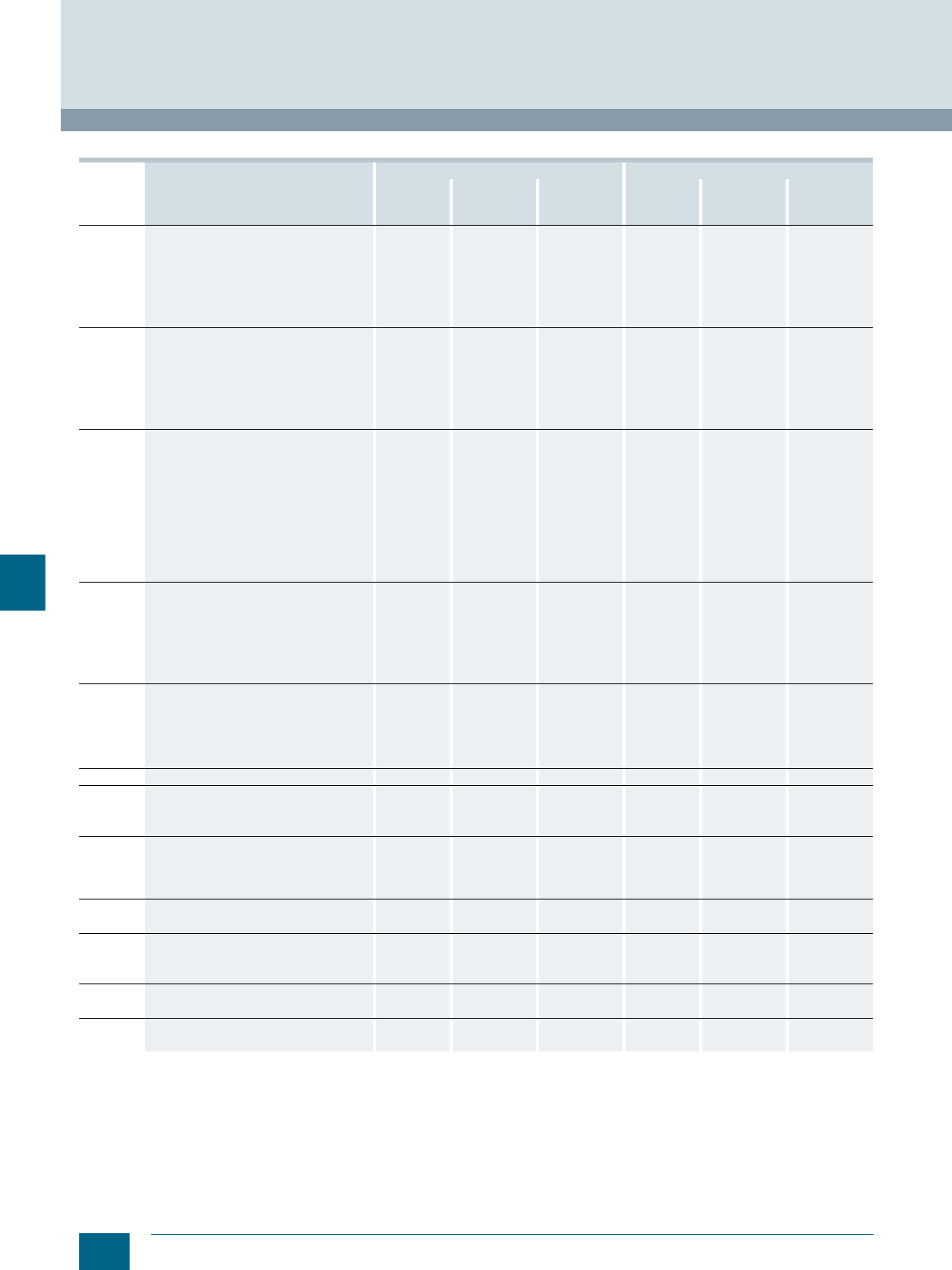
9/8 Siemens LV 52 · 2016
General data on 8WA
8WA1 Screw Terminals
9
s and U rating
1) Plug-in connection
Terminal
size Type CSA rating UR rating
AWG Rated current
In
Rated voltage
Ue
AWG Rated current
In
Rated voltage
Ue
mm² A V A V
1.5 8WA1011-1SF12 18 ... 14 6.3 600 18 ... 14 6.3 600
8WA1011-1SF24, -2SF24, -4SF24 14 1-- 14 ... 12 1AC 240/DC 60
8WA1011-1SF25, -2SF25, -4SF25 14 2-- 14 ... 12 2AC 240/DC 60
8WA1011-1SF26, -2SF26, -4SF26 14 4-- 14 ... 12 4AC 240/DC 60
8WA1011-1SF27, -2SF27, -4SF27 14 6-- 14 ... 12 6AC 240/DC 60
8WA1011-1SF28, -2SF28, -4SF28 14 10 -- 14 ... 12 10 AC 240/DC 60
2.5 8WA1011-1BF21, -1BF22, -1BF23, -1PF11 18 ... 12 25 600 22 ... 12 26 600
8WA1011-1DF11, -3DF21, -0DF21, -0DF22 18 ... 12 25 600 22 ... 12 26 600
8WA1011-1NF01, -1NF02 22 ... 12 26 600 22 ... 12 26 600
8WA1011-3JF.. -- -- -- 22 ... 12 26 300
8WA1011-1PF00, 8WA1011-1PF01 22 ... 12 -- -- 22 ... 12 -- --
8WA1501 22 ... 12 10 300 D 22 ... 12 10 300
48WA1011-1PG00, 8WA1011-1PG01 18 ... 10 -- -- 18 ... 10 -- --
8WA1011-1BG11, -1BG21, -1BG22 18 ... 10 40 600 18 ... 10 35 600
8WA1011-1DG11, -3DG21, -0DG21, -0DG22 18 ... 10 40 600 18 ... 10 35 600
8WA1011-1NG31, -1NG32 18 ... 10 40 600 18 ... 10 35 600
8WA1011-1PG11 18 ... 10 40 600 -- -- --
8WA1011-2BG11, -2DG11 18 ... 10 40 300 18 ... 10 35 600
8WA1011-6BG11, -6DG11 18 ... 10 40 300 18 ... 10 35 600
8WA1011-6EG.. -- -- -- 18 ... 10 34 300
8WA9200 18 ... 10 25 300 18 ... 10 26 600
68WA1011-1PH00 -- -- -- 14 ... 8 -- --
8WA1011-1BH23, -1PH11 16 ... 10 35 600 14 ... 8 44 600
8WA1011-1DH11, -3DH21 16 ... 8 35 600 14 ... 8 44 600
8WA1011-1NH01, -1NH02 14 ... 8 44 600 14 ... 8 44 600
8WA1011-1MH10, -1MH11, -1MH15 16 ... 10 35/40 600/300 C/D 14 ... 8 44 600/300
8WA1232 -- -- -- --1) 24 600
16 8WA1011-1BK11 14 ... 6 70 600 12 ... 4 79 600
8WA1011-1PK00 12 ... 4 -- -- 12 ... 4 -- --
8WA1012-1DK10 -- -- -- -- 79 600
8WA1204, 8WA1304 14 ... 6 70 600 12 ... 4 79 600
8WA1604 -- -- -- 12 ... 4 73 300
25 8WH1060-0AL00 6 ... 4 100 600 6 ... 4 85 600
35 8WA1011-1BM11 12 ... 2 100 600 10 ... 1 120 600
8WA1011-1PM00 10 ... 1 -- -- 10 ... 1 -- --
8WA1205, 8WA1305 12 ... 2 100 600 10 ... 1 120 600
50 8WH1000-0AN00,
8WH1000-0AN01 6 ... 0 125 600 6 ... 0 150 600
8WH1000-0CN07 -- -- -- 6 ... 1
8WH1060-0AN00 6 ... 0 125 600 6 ... 0 150 600
70 8WA1012-1DP14 2/0 ... 1 170 600 6 ... 3/0 -- 600
8WA1206 8 ... 1/0 150 600 8 ... 3/0 220 600
95 8WH1000-0AQ00, 8WH1000-0AQ01 1 ... 000 220 600 2 ... 000 230 600
8WH1000-0CQ07 2 ... 4 2 ... 4
8WH1060-0AQ00 2 ... 000 200 600 2 ... 000 230 600
150 8WH1000-0AS0, 8WH1000-0AS01 2 ... 300 kcmil 275 600 2 ... 300 kcmil 285 600
8WH1060-0AS00 2 ... 300 kcmil 275 600 2 ... 300 kcmil 285 600
240 8WH1000-0AU00, 8WH1000-0AU01 0 ... 500 kcmil 400 600 0 ... 500 kcmil 380 600
8WH1000-0AU00 0 ... 500 kcmil 400 600 0 ... 500 kcmil 380 600
© Siemens AG 2015© Siemens AG 2015
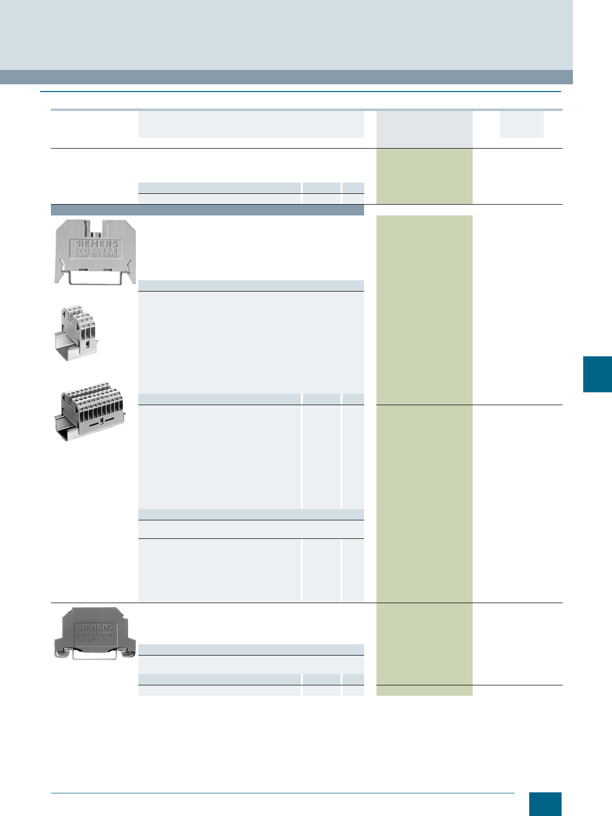
9/9
Siemens LV 52 · 2016
* You can order this quantity or a multiple thereof.
8WA1 Screw Terminals
8WA through-type terminals
9
■
Selection and ordering data
Version DT Article No.
www.siemens.com/
product?Article No.
Price
per PU
PU
(UNIT,
SET, M)
PS*/
P. unit PG
General details
• Thermoplastic insulating body
• Screw terminal at both ends
• Enclosed at both ends
Note Section Page
For labeling accessories, see ... Accessories 8/2
Terminal size 2.5 mm²
8WA1011-1DF11
8WA1011-3DF21
8WA1011-0DF21
Through-type terminals, terminal size 2.5 mm²
• Rated uninterrupted current 24 A
• Rated insulation voltage 800 V
• Mounting width 6 mm
• Terminal height 26 mm
• Terminal length 41 mm
•U AWG 22-12
•s AWG 18-12
Versions
• Single terminals
-Beige 8WA1011-1DF11 1 100 units 1BT
-Blue 8WA1011-1BF23 1 50 units 1BT
-Red 8WA1011-1BF21 1 50 units 1BT
-Orange 8WA1011-1BF22 1 50 units 1BT
- Yellow 8WA1011-1BF26 1 50 units 1BT
-Black 8WA1011-1BF24 1 50 units 1BT
-Green 8WA1011-1BF25 1 50 units 1BT
• Terminal blocks
- Beige, 3-pole, width 18 mm 8WA1011-3DF21 1 10 units 1BT
- Beige, 10-pole, width 61 mm, with designation 1 ... 10 8WA1011-0DF22 1 20 units 1BT
- Beige, 10-pole, width 61 mm, without inscription 8WA1011-0DF21 1 20 units 1BT
Accessories Section Page
Covers
• With lightning symbol, for terminal size
1.5...2.5mm²
Accessories 9/13 8WA1810 1 50 units 1BT
• White, facility for labeling, for terminal size
1.5 ... 2.5 mm²
Accessories 9/13 8WA1860 1 50 units 1BT
• For connection bars:
- Transparent, for terminal size 2.5 ... 6 mm² Accessories 9/13 8WA1822-7AX01 1 10 units 1BT
- White, facility for labeling, for terminal size
2.5 to 6 mm² Accessories 9/13 8WA1822-7AX03 1 10 units 1BT
Jumpers, for terminal size 2.5 mm² Accessories 9/13 8WA1822-7VF01 1 50 units 1BT
Disconnecting links Accessories 9/14 8WA1865 1 50 units 1BT
Note
Between terminals with terminal sizes 2.5 and 6 mm²,
two 8WH1820 barriers are required.
• Insulation plates, for terminal size 2.5 to 6 mm² Accessories 9/14 8WA1825 1 50 units 1BT
• Connection bars, for terminal size 2.5 mm²
- For two terminals Accessories 9/14 8WA1895 1 50 units 1BT
- For three terminals Accessories 9/14 8WA1896 1 50 units 1BT
- For four terminals Accessories 9/14 8WA1897 1 20 units 1BT
- For ten terminals Accessories 9/14 8WA1898 1 10/200 units 1BT
• Barriers, for terminal size 1.5 ... 4 mm² Accessories 9/14 8WA1820 1 50 units 1BT
8WA1011-1PF01
PE through-type terminals, terminal size 2.5 mm²
• Green/yellow
• Mounting width 6 mm
• Terminal height 26 mm
• Terminal length 51 mm
Versions
• One screw terminal 8WA1011-1PF01 1 50 units 1BT
• Two screw terminals 8WA1011-1PF00 1 50 units 1BT
Accessories Section Page
Barriers, for terminal size 1.5 ... 4 mm² Accessories 9/14 8WA1820 1 50 units 1BT
© Siemens AG 2015© Siemens AG 2015
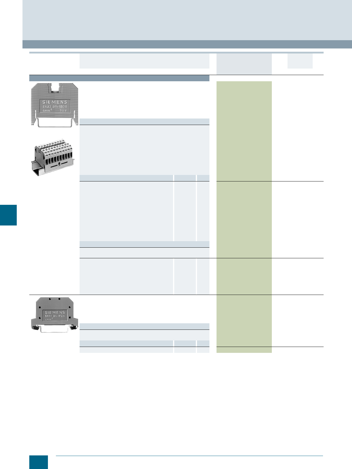
9/10 Siemens LV 52 · 2016 * You can order this quantity or a multiple thereof.
8WA through-type terminals
8WA1 Screw Terminals
9
Terminal size 4 mm²
8WA1011-1DG11
8WA1011-0DG21
Through-type terminals, terminal size 4 mm²
• Rated uninterrupted current 32 A
• Rated insulation voltage 800 V
• Mounting width 6.5 mm
• Terminal height 30 mm
• Terminal length 41 mm
•U AWG 18-10
•s AWG 18-10
Versions
• Single terminals
-Beige 8WA1011-1DG11 1 100 units 1BT
-Blue 8WA1011-1BG11 1 50 units 1BT
-Red 8WA1011-1BG21 1 50 units 1BT
-Orange 8WA1011-1BG22 1 50 units 1BT
-Black 8WA1011-1BG24 1 50 units 1BT
• Terminal blocks
- Beige, 3-pole, width 19.5 mm 8WA1011-3DG21 1 10 units 1BT
-Beige, 10-pole, width 65.5 mm, labeled 1 ... 10 8WA1011-0DG22 1 20 units 1BT
-Beige, 10-pole, width 65.5 mm, without labeling 8WA1011-0DG21 1 20 units 1BT
Accessories Section Page
Covers
• With lightning symbol, for terminal size
4and6mm²
Accessories 9/13 8WA1811 1 50 units 1BT
• White, facility for labeling, for terminal sizes
4 and 6 mm²
Accessories 9/13 8WA1862 1 50 units 1BT
• For connection bars:
- Transparent, for terminal size 2.5 to 6 mm² Accessories 9/13 8WA1822-7AX01 1 10 units 1BT
- White, facility for labeling, for terminal size
2.5 to 6 mm² Accessories 9/13 8WA1822-7AX03 1 10 units 1BT
Jumpers, for terminal size 4 mm² Accessories 9/13 8WA1822-7VG00 1 50 units 1BT
Disconnecting links Accessories 9/14 8WA1865 1 50 units 1BT
Note
Between terminals with terminal sizes 2.5 and 6 mm²,
two 8WH1820 barriers are required.
• Insulation plates, for terminal size 2.5 to 6 mm² Accessories 9/14 8WA1825 1 50 units 1BT
• Connection bars, for terminal size 4 mm²
- For two terminals Accessories 9/14 8WA1850 1 50 units 1BT
- For three terminals Accessories 9/14 8WA1851 1 50 units 1BT
- For four terminals Accessories 9/14 8WA1852 1 20 units 1BT
- For ten terminals Accessories 9/14 8WA1853 1 10 units 1BT
• Barriers, for terminal size 1.5 ... 4 mm² Accessories 9/14 8WA1820 1 50 units 1BT
8WA1011-1PG01
PE through-type terminals, terminal size 4 mm²
• Green/yellow
• Mounting width 7.2 mm
• Terminal height 30 mm
• Terminal length 51 mm
•U s
Versions
• One screw terminal 8WA1011-1PG01 1 50 units 1BT
• Two screw terminals 8WA1011-1PG00 1 50 units 1BT
Accessories Section Page
Barriers, for terminal size 1.5 ... 4 mm² Accessories 9/14 8WA1820 1 50 units 1BT
Version DT Article No.
www.siemens.com/
product?Article No.
Price
per PU
PU
(UNIT,
SET, M)
PS*/
P. unit PG
© Siemens AG 2015© Siemens AG 2015

9/11
Siemens LV 52 · 2016
* You can order this quantity or a multiple thereof.
8WA1 Screw Terminals
8WA through-type terminals
9
Terminal size 6 mm²
8WA1011-1DH11
8WA1011-3DH21
Through-type terminals, terminal size 6 mm²
• Rated uninterrupted current 41 A
• Rated insulation voltage 800 V
• Mounting width 8 mm
• Terminal height 33 mm
• Terminal length 41 mm
•U AWG 14-8
•s AWG 16-8
Versions
• Single terminals
-Beige 8WA1011-1DH11 1 50 units 1BT
-Blue 8WA1011-1BH23 1 50 units 1BT
-Black 8WA1011-1BH24 1 50 units 1BT
• Terminal blocks
- Beige, 3-pole, width 24.5 mm 8WA1011-3DH21 1 20 units 1BT
Accessories Section Page
• Covers
- With lightning symbol, for terminal size
4to6mm² Accessories 9/13 8WA1811 1 50 units 1BT
- White, facility for labeling, for terminal sizes
4 and 6 mm² Accessories 9/13 8WA1862 1 50 units 1BT
- For connection bars, transparent, for terminal
size 2.5 ... 6 mm² Accessories 9/13 8WA1822-7AX01 1 10 units 1BT
• Jumpers, for terminal size 6 mm² Accessories 9/13 8WA1822-7VH00 1 50 units 1BT
• Disconnecting links Accessories 9/14 8WA1865 1 50 units 1BT
Note
Between terminals with terminal sizes 2.5 and 6 mm²,
two 8WH1820 barriers are required.
• Insulation plates, for terminal size 2.5 to 6 mm² Accessories 9/14 8WA1825 1 50 units 1BT
• Connection bars, for terminal size 6 mm²
- For two terminals Accessories 9/14 8WA1885 1 50 units 1BT
- For three terminals Accessories 9/14 8WA1886 1 50 units 1BT
- For four terminals Accessories 9/14 8WA1887 1 20 units 1BT
- For ten terminals Accessories 9/14 8WA1888 1 10 units 1BT
• Barriers, for terminal size 6 and 16 mm² Accessories 9/14 8WA1821 1 50 units 1BT
8WA1010-1PH01
PE through-type terminals, terminal size 6 mm²,
one screw terminal 8WA1010-1PH01 1 50 units 1BT
•Bare
• Mounting width 6 mm
• Terminal height 25 mm
• Terminal length 44 mm
• Also for use as shield terminal
Accessories Section Page
Barriers, for terminal size 6 and 16 mm² Accessories 9/14 8WA1821 1 50 units 1BT
8WA1011-1PH00
PE through-type terminals, terminal size 6 mm²,
two screw terminals 8WA1011-1PH00 1 50 units 1BT
• Green/yellow
• Mounting width 8 mm
• Terminal height 33 mm
• Terminal length 51 mm
•U s
Accessories Section Page
Barriers, for terminal size 6 and 16 mm² Accessories 9/14 8WA1821 1 50 units 1BT
Version DT Article No.
www.siemens.com/
product?Article No.
Price
per PU
PU
(UNIT,
SET, M)
PS*/
P. unit PG
© Siemens AG 2015© Siemens AG 2015

9/12 Siemens LV 52 · 2016 * You can order this quantity or a multiple thereof.
8WA through-type terminals
8WA1 Screw Terminals
9
Terminal size 16 mm²
8WA1204
8WA1304
Through-type terminals, terminal size 16 mm²
• Rated uninterrupted current 76 A
• Rated insulation voltage 800 V
• Mounting width 10 mm
• Terminal height 38 mm
• Terminal length 41 mm
•U AWG 12-4
•s AWG 14-6
Versions
• Single terminals
-Beige 8WA1204 1 20 units 1BT
-Blue 8WA1011-1BK11 1 10 units 1BT
• Terminal blocks
- 3-pole, width 30 mm 8WA1304 1 20 units 1BT
Accessories Section Page
• Covers
- With lightning symbol, for terminal size 16 mm² Accessories 9/13 8WA1812 1 50 units 1BT
- White, facility for labeling, for terminal size
16 mm² Accessories 9/13 8WA1892 1 50 units 1BT
- For connection bars, transparent, for terminal
sizes 16 and 35 mm² Accessories 9/13 8WA1822-7AX02 1 10 units 1BT
• Insulation plates, for terminal size 16 and 35 mm² Accessories 9/14 8WA1822-7TK00 1 50 units 1BT
• Connection bars, for terminal size 16 mm²
- For two terminals Accessories 9/14 8WA1842 1 20 units 1BT
- For three terminals Accessories 9/14 8WA1845 1 20 units 1BT
- For four terminals Accessories 9/14 8WA1848 1 10 units 1BT
- For ten terminals Accessories 9/14 8WA1802 1 10 units 1BT
• Barriers, for terminal size 6 and 16 mm² Accessories 9/14 8WA1821 1 50 units 1BT
8WA1011-1PK00
PE through-type terminals and PEN through-type terminals,
terminal size 16 mm²
• Green/yellow
•For I = 76 A
8WA1011-1PK00 1 25 units 1BT
• Mounting width 12 mm
• Terminal height 38 mm
• Terminal length 53 mm
• Two screw terminals
•U s
Accessories Section Page
Barriers, for terminal size 6 and 16 mm² Accessories 9/14 8WA1821 1 50 units 1BT
Terminal size 35 mm²
8WA1205
8WA1305
Through-type terminals, terminal size 35 mm²
• Rated uninterrupted current 125 A
• Rated insulation voltage 800 V
• Mounting width 16 mm
• Terminal height 50 mm
• Terminal length 53 mm
•U AWG 10-1
•s AWG 12-2
Versions
• Single terminals
-Beige 8WA1205 1 20 units 1BT
-Blue 8WA1011-1BM11 1 10 units 1BT
• Terminal blocks
- 3-pole, width 48 mm 8WA1305 1 20 units 1BT
Accessories Section Page
• Covers
- With lightning symbol, for terminal size 35 mm² Accessories 9/13 8WA1813 1 50 units 1BT
- White, facility for labeling, for terminal size
35 mm² Accessories 9/13 8WA1893 1 50 units 1BT
- For connection bars, transparent, for terminal
sizes 16 and 35 mm² Accessories 9/13 8WA1822-7AX02 1 10 units 1BT
• Insulation plates, for terminal size 16 and 35 mm² Accessories 9/13 8WA1822-7TK00 1 50 units 1BT
• Connection bars, for terminal size 35 mm²
- For two terminals Accessories 9/14 8WA1828 1 20 units 1BT
- For three terminals Accessories 9/14 8WA1803 1 20 units 1BT
- For ten terminals Accessories 9/14 8WA1804 1 10 units 1BT
• Barriers, for terminal size 35 mm² Accessories 9/14 8WA1823 1 25 units 1BT
Version DT Article No.
www.siemens.com/
product?Article No.
Price
per PU
PU
(UNIT,
SET, M)
PS*/
P. unit PG
© Siemens AG 2015© Siemens AG 2015
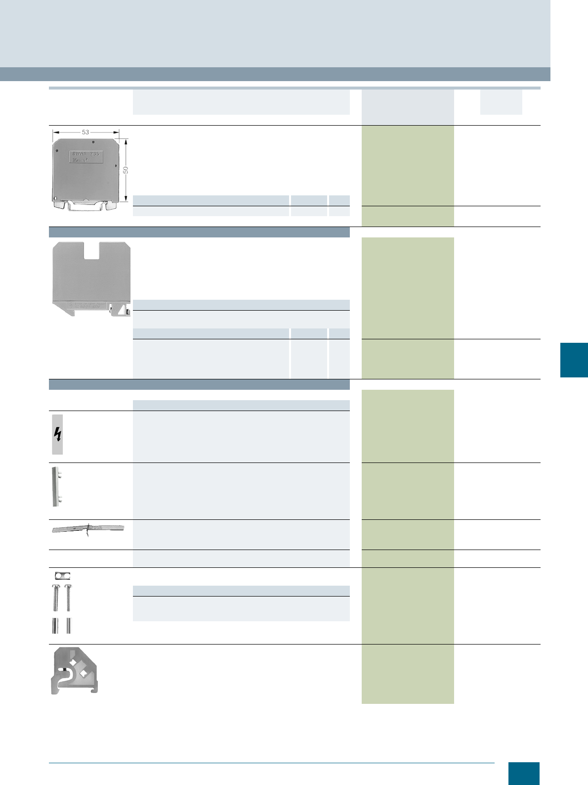
9/13
Siemens LV 52 · 2016
* You can order this quantity or a multiple thereof.
8WA1 Screw Terminals
8WA through-type terminals
9
8WA1011-1PM00
PE through-type terminals and PEN through-type terminals,
terminal size 35 mm²
• Green/yellow
•For I = 125 A
8WA1011-1PM00 1 25 units 1BT
• Mounting width 16 mm
• Terminal height 50 mm
• Terminal length 53 mm
• Two screw terminals
•U s
Accessories Section Page
Barriers, for terminal size 35 mm² Accessories 9/13 8WA1823 1 25 units 1BT
Terminal size 70 mm²
8WA1206
Through-type terminals, terminal size 70 mm²
• Rated uninterrupted current 192 A
• Rated insulation voltage 800 V
• Mounting width 25 mm
• Terminal height 64.5 mm
• Terminal length 73.5 mm
•U AWG 8-3/0
•s AWG 8-1/0
Versions
•Beige 8WA1206 1 10/60 units 1BT
•Blue 8WA1011-1BP11 1 10 units 1BT
Accessories Section Page
• Covers, with lightning symbol, for terminal size
70 mm² Accessories 9/13 8WA1814 1 50 units 1BT
• Connection bars, for terminal size 70 mm²,
for 2 terminals Accessories 9/13 8WA1216 1 20 units 1BT
• Barriers, for terminal size 70 mm² Accessories 9/13 8WA1824 1 25 units 1BT
Accessories
Covers
Versions
8WA1810
• With lightning symbol
- For terminal size 1.5 up to 2.5 mm² 8WA1810 1 50 units 1BT
- For terminal sizes 4 and 6 mm² 8WA1811 1 50 units 1BT
- For terminal size 16 mm² 8WA1812 1 50 units 1BT
- For terminal size 35 mm² 8WA1813 1 50 units 1BT
- For terminal size 70 mm² 8WA1814 1 50 units 1BT
8WA1860
• White, facility for labeling
- For terminal size 1.5 up to 2.5 mm² 8WA1860 1 50 units 1BT
- For terminal sizes 4 and 6 mm² 8WA1862 1 50 units 1BT
- For terminal size 16 mm² 8WA1892 1 50 units 1BT
- For terminal size 35 mm² 8WA1893 1 50 units 1BT
8WA1822-7AX01
• For connection bars, transparent
- For terminal size 2.5 to 6 mm² 8WA1822-7AX01 1 10 units 1BT
- For terminal sizes 16 and 35 mm² 8WA1822-7AX02 1 10 units 1BT
• For connection bars, white, facility for labeling,
for terminal size 2.5 to 6 mm² 8WA1822-7AX03 1 10 units 1BT
8WA1822-7VF01
Jumpers
For connection bars
Versions
• For terminal size 2.5 mm² 8WA1822-7VF01 1 50 units 1BT
• For terminal size 4 mm² 8WA1822-7VG00 1 50 units 1BT
• For terminal size 6 mm² 8WA1822-7VH00 1 50 units 1BT
8WA1808
End retainers, thermoplastic
Width 10 mm 8WA1808 1 50 units 1BT
Version DT Article No.
www.siemens.com/
product?Article No.
Price
per PU
PU
(UNIT,
SET, M)
PS*/
P. unit PG
© Siemens AG 2015© Siemens AG 2015
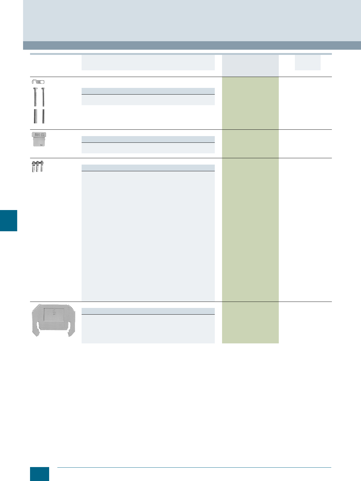
9/14 Siemens LV 52 · 2016 * You can order this quantity or a multiple thereof.
8WA through-type terminals
8WA1 Screw Terminals
9
8WA1865
Disconnecting links
Up to 32 A 8WA1865 1 50 units 1BT
Note
Between terminals with terminal sizes 2.5 and 6 mm²,
two 8WH1820 barriers are required.
8WA1825
Insulation plates
Versions
• For terminal size 2.5 to 6 mm² 8WA1825 1 50 units 1BT
• For terminal sizes 16 and 35 mm² 8WA1822-7TK00 1 50 units 1BT
8WA1895
Connection bars
Versions
• For terminal size 2.5 mm²
- For two terminals 8WA1895 1 50 units 1BT
- For three terminals 8WA1896 1 50 units 1BT
- For four terminals 8WA1897 1 20 units 1BT
- For ten terminals 8WA1898 1
10/200 units
1BT
• For terminal size 4 mm²
- For two terminals 8WA1850 1 50 units 1BT
- For three terminals 8WA1851 1 50 units 1BT
- For four terminals 8WA1852 1 20 units 1BT
- For ten terminals 8WA1853 1 10 units 1BT
• For terminal size 6 mm²
- For two terminals 8WA1885 1 50 units 1BT
- For three terminals 8WA1886 1 50 units 1BT
- For four terminals 8WA1887 1 20 units 1BT
- For ten terminals 8WA1888 1 10 units 1BT
• For terminal size 16 mm²
- For two terminals 8WA1842 1 20 units 1BT
- For three terminals 8WA1845 1 20 units 1BT
- For four terminals 8WA1848 1 10 units 1BT
- For ten terminals 8WA1802 1 10 units 1BT
• For terminal size 35 mm²
- For two terminals 8WA1828 1 20 units 1BT
- For three terminals 8WA1803 1 20 units 1BT
- For ten terminals 8WA1804 1 10 units 1BT
• For terminal size 70 mm²
- For two terminals 8WA1216 1 20 units 1BT
8WA1820
Barriers
Versions
• For terminal size 1.5 ... 4 mm² 8WA1820 1 50 units 1BT
• For terminal sizes 6 and 16 mm² 8WA1821 1 50 units 1BT
• For terminal size 35 mm² 8WA1823 1 25 units 1BT
• For terminal size 70 mm² 8WA1824 1 25 units 1BT
Version DT Article No.
www.siemens.com/
product?Article No.
Price
per PU
PU
(UNIT,
SET, M)
PS*/
P. unit PG
© Siemens AG 2015© Siemens AG 2015
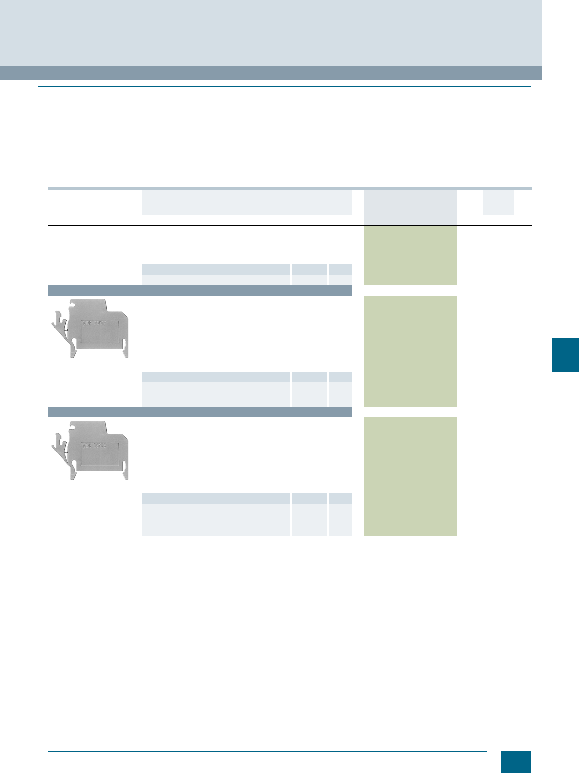
9/15
Siemens LV 52 · 2016
* You can order this quantity or a multiple thereof.
8WA1 Screw Terminals
8WA N-conductor isolating and branch terminals
9
■
Overview
N-conductor isolating terminals permit an insulation test to be
performed without disconnecting the neutral conductor
according to DIN VDE 0108 and DIN VDE 0100 (Standards
for the erection of power installations).
The branch terminals are used for the connection of lines (L),
for example for power supplies, to the 6 x 6 mm busbar.
The rated voltage between two branch terminals (1 slide open)
is 289 V.
When they are used as shield terminals according to DIN
VDE 0160, they provide isolation between the central reference
point (shield connection conductor) and the PE conductor.
■
Selection and ordering data
Version DT Article No.
www.siemens.com/
product?Article No.
Price
per PU
PU
(UNIT,
SET, M)
PS*/
P. unit PG
General details
• 1 screw terminal and connection to the neutral conductor bar
or 6 × 6 mm busbar acc. to DIN 1761
• Insulating body made of blue or beige thermoplastic
• Enclosed at both ends
Note Section Page
For labeling accessories, see ... Accessories 11/2
Terminal size 2.5 mm²
8WA1011-1NF01
N-conductor isolating terminals, terminal size 2.5 mm²
•Blue
• Rated uninterrupted current 24 A
• Rated insulation voltage 500 V
• Mounting width 6 mm
• Terminal height 35 mm
• Terminal length 55 mm
• With built-in test socket in the fixed part of the terminal
•U AWG 22-12
•s AWG 22-12
8WA1011-1NF01 1 50 units 1BT
Accessories Section Page
• Covers, for connection bars Accessories 9/16 8WA1822-7AX00 1 10 units 1BT
• N-busbars, 6 × 6 mm Accessories 9/16 8GF9324-2 1 10 units 1BP
• Label holders Accessories 9/16 3TX4210-0J 100 100 units 41B
Terminal size 4 mm²
8WA1011-1NG31
N-conductor isolating terminals, terminal size 4 mm²
•Blue
• Rated uninterrupted current 32 A
• Rated insulation voltage 500 V
• Mounting width 6.5 mm
• Terminal height 35 mm
• Terminal length 55 mm
• With built-in test socket in the fixed part of the terminal
•U AWG 18-10
•s AWG 18-10
8WA1011-1NG31 1 50 units 1BT
Accessories Section Page
• Covers, for connection bars Accessories 9/16 8WA1822-7AX00 1 10 units 1BT
• Feeder terminals, for N-busbars Accessories 9/16 8WA2867 1 50 units 1BT
• N-busbars, 6 × 6 mm Accessories 9/16 8GF9324-2 1 10 units 1BP
• Label holders Accessories 9/16 3TX4210-0J 100 100 units 41B
© Siemens AG 2015© Siemens AG 2015
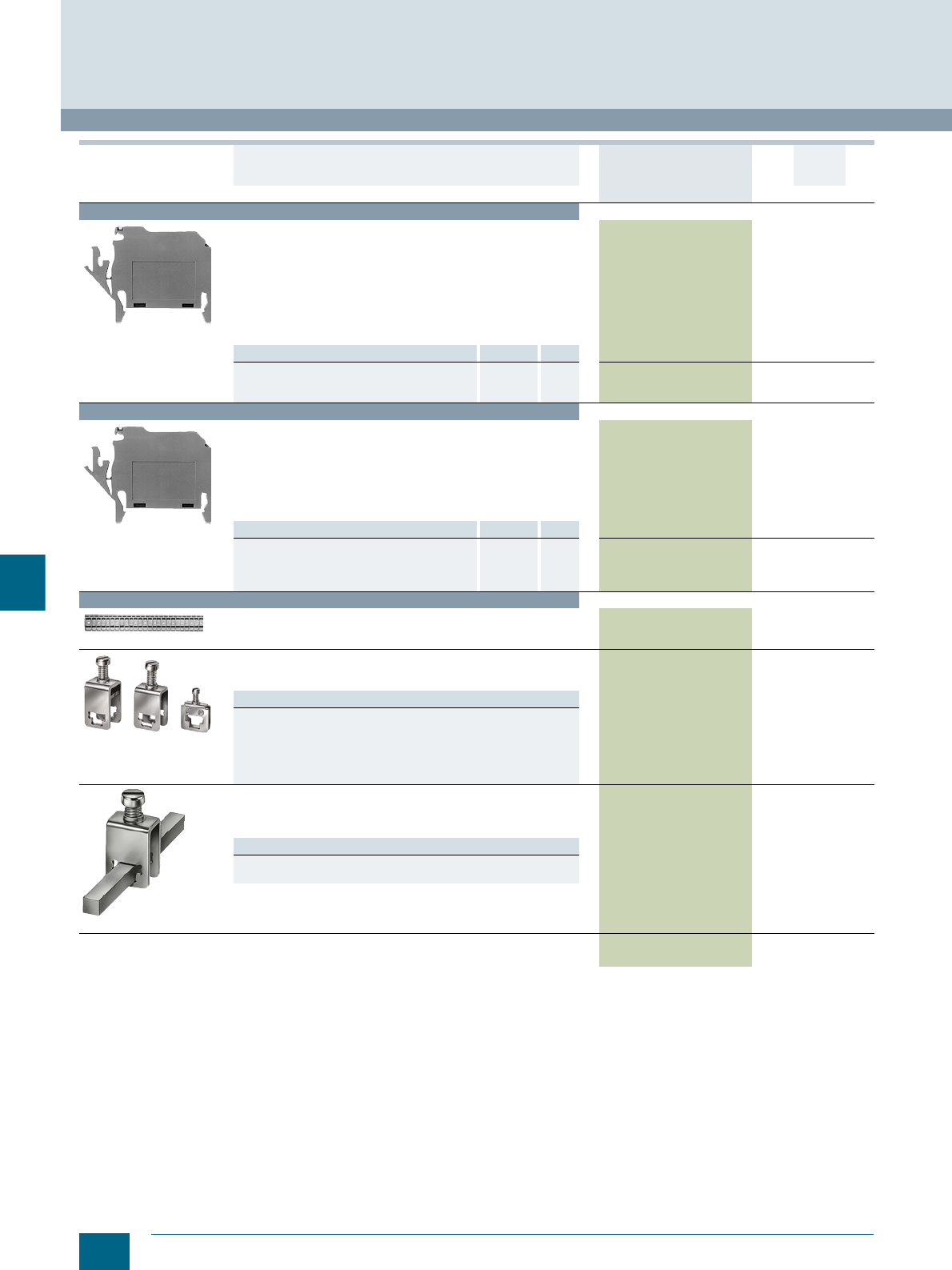
9/16 Siemens LV 52 · 2016 * You can order this quantity or a multiple thereof.
8WA N-conductor isolating and branch terminals
8WA1 Screw Terminals
9
Terminal size 6 mm²
8WA1011-1NH01
N-conductor isolating terminals, terminal size 6 mm²
•Blue
• Rated uninterrupted current 41 A
• Rated insulation voltage 500 V
• Mounting width 8 mm
• Terminal height 35 mm
• Terminal length 55 mm
• With built-in test socket in the fixed part of the terminal
•U AWG 14-8
•s AWG 14-8
8WA1011-1NH01 1 50 units 1BT
Accessories Section Page
• Covers, for connection bars Accessories 9/16 8WA1822-7AX00 1 10 units 1BT
• N-busbars, 6 × 6 mm Accessories 9/16 8GF9324-2 1 10 units 1BP
• Label holders Accessories 9/16 3TX4210-0J 100 100 units 41B
Terminal size 16 mm²
8WA1604
N-conductor isolating terminals, terminal size 16 mm²
•Blue
• Rated uninterrupted current 76 A
• Rated insulation voltage 500 V
• Mounting width 10 mm
• Terminal height 35 mm
• Terminal length 55 mm
•U AWG 12-4
8WA1604 1 50 units 1BT
Accessories Section Page
• Covers, for connection bars Accessories 9/16 8WA1822-7AX00 1 10 units 1BT
• Feeder terminals, for N-busbars Accessories 9/16 8WA2868 1 50 units 1BT
• N-busbars, 6 × 6 mm Accessories 9/16 8GF9324-2 1 10 units 1BP
• Label holders Accessories 9/16 3TX4210-0J 100 100 units 41B
Accessories
8WA1822-7AX00
Covers, for connection bars
• Not for 8WA1604
• Length 155 mm
8WA1822-7AX00 1 10 units 1BT
8WA2870 / 868 / 867
Feeder terminals, for N-busbars
• 6 × 6 mm and 10 × 3 mm
•Bare
Versions
• Rated uninterrupted current 32 A, for connection of
up to 4 mm28WA2867 1 50 units 1BT
• Rated uninterrupted current 76 A, for connection of
up to 25 mm28WA2868 1 50 units 1BT
• Rated uninterrupted current 125 A, for connection of
up to 35 mm28WA2870 1 50 units 1BT
8GF9324-2
N-busbars, 6 × 6 mm
• Rated uninterrupted current 125 A
• 1109 mm long
• For four-field
8GF9324-2 1 10 units 1BP
Note
Prices apply for orders from 25.00. For orders below 25.00,
a processing charge of 2.50 net will be added.
Label holders 3TX4210-0J 100 100 units 41B
Version DT Article No.
www.siemens.com/
product?Article No.
Price
per PU
PU
(UNIT,
SET, M)
PS*/
P. unit PG
© Siemens AG 2015© Siemens AG 2015
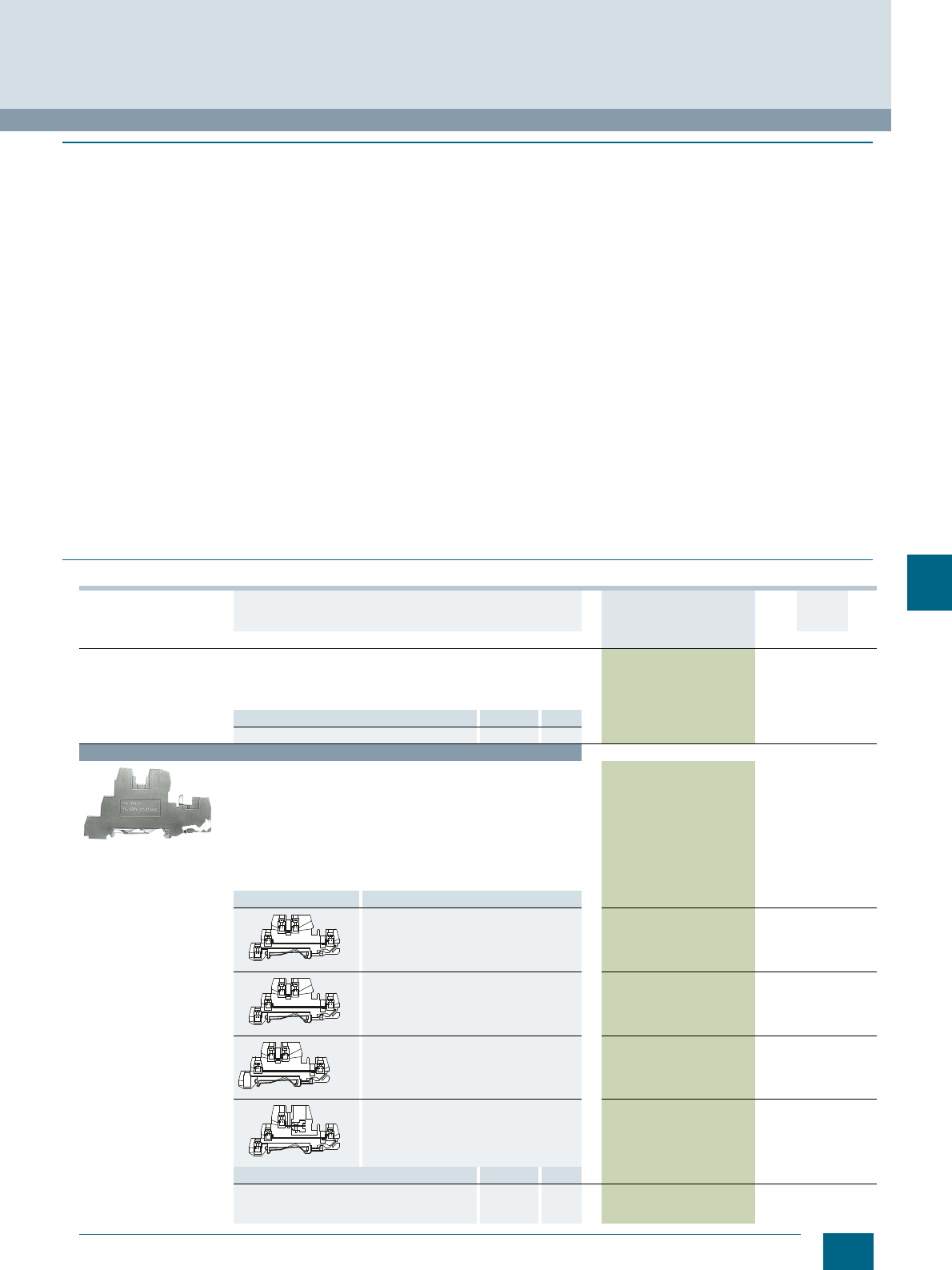
9/17
Siemens LV 52 · 2016
* You can order this quantity or a multiple thereof.
8WA1 Screw Terminals
8WA Insta or three-tier terminals
9
■
Overview
The Insta or three-tier terminals incorporate up to 3 different ter-
minal functions in one insulating body of 6 mm width. The width
of 3 Insta terminals corresponds to the modular width of 18 mm
standardized in distribution board assembly. Tools are required
to remove the terminals from the support rail.
All clamping points for incoming and outgoing cables have a
cutout for an 8WA8 8.. inscription label . The protective conduc-
tor connections are already marked green-yellow and the neutral
conductor connections blue.
The N-busbar has the same position for Insta terminals and
N-conductor isolating terminals. This allows, for example, the
use of a 16 mm² N-conductor isolating terminal as an infeed for
the N-busbar.
8WA1011-3JF16, -3JF17 and -3JF18 allow the N-busbar to be
routed with a mounting depth of 42.5 mm.
PE, L, NT Insta terminal
The 8WA1011-3JF20 terminal is the basic version for AC circuits.
It comprises:
• Protective conductor connection
• Through-type connection for one phase conductor
• Neutral conductor connection that can be isolated from the
6 × 6 mm N-busbar.
PE, L, N Insta terminals
If no neutral conductor isolation is required, the 8WA1011-3JF17
terminal is used:
• Protective conductor connection
• Through-type connection for one phase conductor
• Through-type connection for the neutral conductor
PE, L, L Insta terminal
Design of 8WA1011-3JF16 terminal as previous version. Instead
of the through-type connection for the neutral conductor,
a
through-type connection for a second phase conductor is fitted.
L, L Insta terminal
The 8AW1011-3JF18 terminal contains two through-type con-
nections for two phase conductors. These are generally used for
three-phase outgoing lines.
■
Selection and ordering data
Version DT Article No.
www.siemens.com/
product?Article No.
Price
per PU
PU
(UNIT,
SET, M)
PS*/
P. unit PG
General details
• Thermoplastic insulating body
• Screw terminal at both ends
• Enclosed at both ends
• Neutral terminal, 6 × 6 mm neutral conductor connection
Note Section Page
For labeling accessories, see ... Accessories 11/2
Terminal size 2.5 mm²
8WA1011-3JF16
Insta terminals, terminal size 2.5 mm²
• Rated uninterrupted current 24 A
• Rated insulation voltage
- 400 V between phase conductors
- 250 V between phase and protective conductors and for
neutral isolating distance
• Mounting width 6 mm
• Terminal height 42.5 mm
• Terminal length 87 mm
• Screw terminals at both ends
•U AWG 22-12
Circuit diagram Type
PE, L, L 8WA1011-3JF16 1 50 units 1BT
PE, L, N 8WA1011-3JF17 1 50 units 1BT
L, L 8WA1011-3JF18 1 50 units 1BT
PE, L, NT 8WA1011-3JF20 1 50 units 1BT
Accessories Section Page
Barriers, for Insta terminals, terminal size
2.5 mm2 and measuring transformer terminals,
terminal size 6 mm2
Accessories 9/18 8WA1822-7TH00 1 50 units 1BT
NSH0_00020
PE
L
N/L
NSH0_00020
PE
L
N/L
L
NSH0_00021
L
NSH0_00022
PE
L
NT
© Siemens AG 2015© Siemens AG 2015
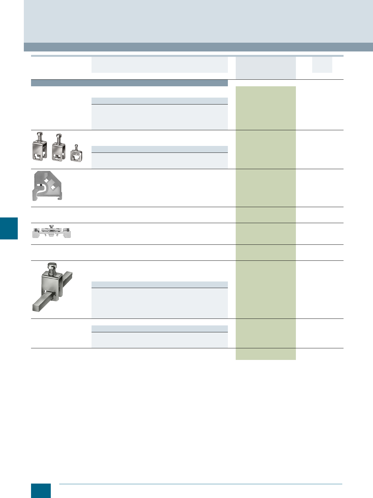
9/18 Siemens LV 52 · 2016 * You can order this quantity or a multiple thereof.
8WA Insta or three-tier terminals
8WA1 Screw Terminals
9
Accessories
Covers
Up to three terminals side-by-side
Versions
• With lightning symbol, for terminal size 4 and 6 mm² 8WA1811 1 50 units 1BT
• White, facility for labeling, for terminal sizes 4 and 6 mm² 8WA1862 1 50 units 1BT
• For connection bars, for terminal size 2.5 up to 6 mm²
- Transparent 8WA1822-7AX01 1 10 units 1BT
-White 8WA1822-7AX03 1 10 units 1BT
8WA2870 / 868 / 867
Feeder terminals, for N-busbars
• 6 × 6 mm and 10 × 3 mm
•Bare
Versions
• Connection up to 4 mm² 8WA2867 1 50 units 1BT
• Connection up to 25 mm² 8WA2868 1 50 units 1BT
• Connection up to 35 mm² 8WA2870 1 50 units 1BT
8WA1808
End retainers, thermoplastic
Width 10 mm 8WA1808 1 50 units 1BT
Terminal strip labels
• Suitable for 8WA1808 end retainer
• Blank (WIN 67)
8WA8212-0AA65 100 380 units 1BT
8WA1857
Insulation carriers, for mounting insulated support rails 8WA1857 1 20 units 1BT
Labels, blank
• Suitable for plotting
• Label size 5 × 7 mm (WIN 68)
8WA8348-2AY 100 136 units 1BT
8GF9324-2
N-busbars, 6 × 6 mm
• Rated uninterrupted current 125 A
• 1109 mm long
• For four-field
8GF9324-2 1 10 units 1BP
Note
Prices apply for orders from 25.00. For orders below 25.00,
a processing charge of 2.50 net will be added.
Connection bars, for Insta terminals
Versions
• For two terminals 8WA1822-7VF02 1 50 units 1BT
• For three terminals 8WA1822-7VF03 1 50 units 1BT
• For ten terminals 8WA1822-7VF10 1 10 units 1BT
Barriers, for Insta terminals, terminal size 2.5 mm² and
measuring transformer terminals, terminal size 6 mm² 8WA1822-7TH00 1 50 units 1BT
Version DT Article No.
www.siemens.com/
product?Article No.
Price
per PU
PU
(UNIT,
SET, M)
PS*/
P. unit PG
© Siemens AG 2015© Siemens AG 2015
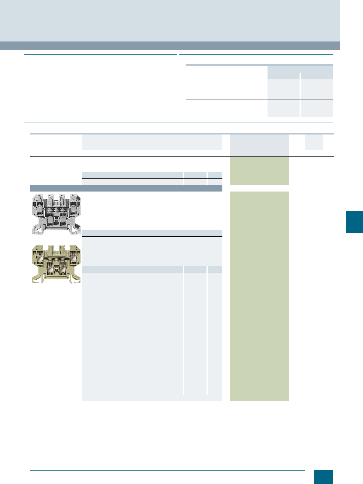
9/19
Siemens LV 52 · 2016
* You can order this quantity or a multiple thereof.
8WA1 Screw Terminals
8WA two-tier terminals
9
■
Overview
Two-tier terminals are a compact form of the terminal blocks.
They are therefore open on one side. They can contain two con-
necting cables with two connections each or they can be laid out
as terminal blocks with four connections on the same potential.
An advantage is the standardized front for mounting, bridging
and labeling.
■
Technical specifications
■
Selection and ordering data
Rated voltage
AC DC
Between connection bars
• With insulation plate 400 V 450 V
• With end plate or barrier 800 V 900 V
• With disconnecting link opened 500 V 600 V
For alternately bent soldering tags 400 V 450 V
For adjacent terminals with soldering tags
and insulated plugs 250 V 300 V
Version DT Article No.
www.siemens.com/
product?Article No.
Price
per PU
PU
(UNIT,
SET, M)
PS*/
P. un it PG
General details
• Thermoplastic insulating body
• Screw terminal at both ends
Note Section Page
For labeling accessories, see ... Accessories 11/2
Terminal size 4 mm²
8WA1011-6DG11
8WA1011-2DG11
Two-tier terminals, terminal size 4 mm²
• Rated uninterrupted current 32 A
• Rated insulation voltage 690 V (with end plate 800 V)
• Mounting width 6.5 mm
• Terminal height 45 mm
• Terminal length 64 mm
•U AWG 18-10
•s AWG 18-10
Versions
•Beige
-1-pole 8WA1011-6DG11 1 50 units 1BT
- 2-pole, with two isolated connections 8WA1011-2DG11 1 50 units 1BT
•Blue
-1-pole 8WA1011-6BG11 1 50 units 1BT
- 2-pole, with two isolated connections 8WA1011-2BG11 1 50 units 1BT
Accessories Section Page
Covers
• With lightning symbol, for terminal size
4 and 6 mm² Accessories 9/20 8WA1811 1 50 units 1BT
• White, facility for labeling, for terminal sizes
4 and mm² Accessories 9/20 8WA1862 1 50 units 1BT
• For connection bars, for terminal size
2.5 to 6 mm², transparent Accessories 9/20 8WA1822-7AX01 1 10 units 1BT
Jumpers
• For upper tier of 2-pole terminals Accessories 9/20 8WA1822-7VG00 1 50 units 1BT
• For lower tier of 1 and 2-pole terminals Accessories 9/20 8WA1822-7VG01 1 50 units 1BT
End plates Accessories 9/20 8WA1817 1 50 units 1BT
Disconnecting links Accessories 9/20 8WA1865 1 50 units 1BT
Insulation plates
• For upper tier of 2-pole terminals Accessories 9/20 8WA1825 1 50 units 1BT
• For lower tier of 1 and 2-pole terminals Accessories 9/20 8WA1825 1 50 units 1BT
Connection bars
• For upper tier of 2-pole terminals:
- For two terminals Accessories 9/20 8WA1850 1 50 units 1BT
- For three terminals Accessories 9/20 8WA1851 1 50 units 1BT
- For four terminals Accessories 9/20 8WA1852 1 20 units 1BT
- For ten terminals Accessories 9/20 8WA1853 1 10 units 1BT
• For lower tier of 1 and 2-pole terminals
- For two terminals Accessories 9/20 8WA1835 1 50 units 1BT
- For ten terminals Accessories 9/20 8WA1838 1 10 units 1BT
Barriers Accessories 9/20 8WA1823 1 25 units 1BT
© Siemens AG 2015© Siemens AG 2015
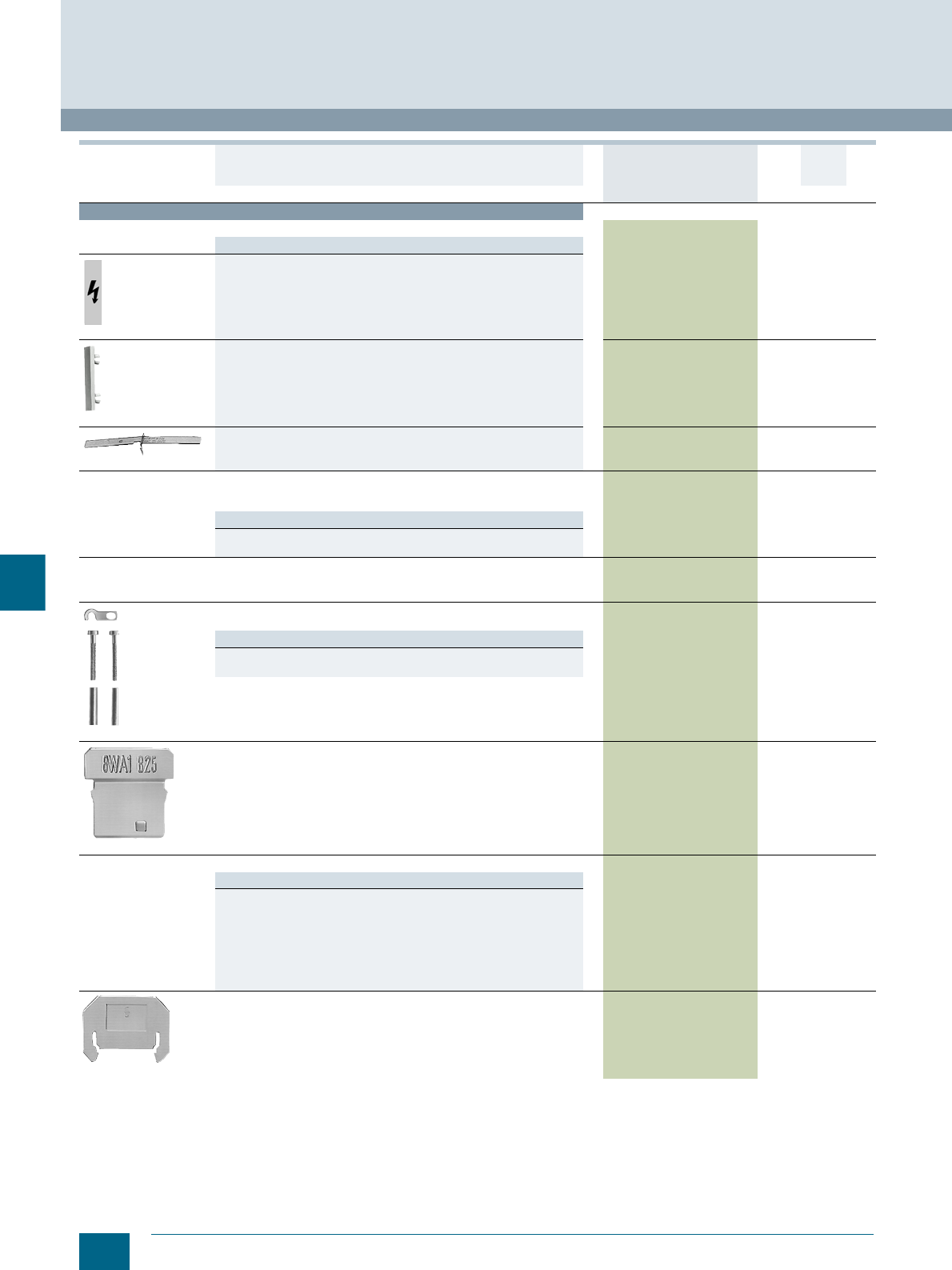
9/20 Siemens LV 52 · 2016 * You can order this quantity or a multiple thereof.
8WA two-tier terminals
8WA1 Screw Terminals
9
Accessories
Covers
Versions
8WA1811
• With lightning symbol, for terminal size 4 and 6 mm² 8WA1811 1 50 units 1BT
8WA1862
• White, facility for labeling, for terminal sizes 4 and 6 mm² 8WA1862 1 50 units 1BT
8WA1822-7AX01
• For connection bars, for terminal size 2.5 to 6 mm², transparent 8WA1822-7AX01 1 10 units 1BT
Jumpers
• For connection bars
• For terminal size 4 mm²
Versions
• For upper tier of 2-pole terminals 8WA1822-7VG00 1 50 units 1BT
• For lower tier of 1 and 2-pole terminals 8WA1822-7VG01 1 50 units 1BT
End plates, for two-tier terminals 8WA1817 1 50 units 1BT
8WA1865
Disconnecting links
For upper tier of 2-pole terminals 8WA1865 1 50 units 1BT
Note
The terminals must be fitted with end plates and must be fitted with the
end plates facing each other.
8WA1825
Insulation plates, for terminal size 2.5 to 6 mm² 8WA1825 1 50 units 1BT
Connection bars
Versions
• For upper tier of 2-pole terminals
- For two terminals 8WA1850 1 50 units 1BT
- For three terminals 8WA1851 1 50 units 1BT
- For four terminals 8WA1852 1 20 units 1BT
- For ten terminals 8WA1853 1 10 units 1BT
• For lower tier of 1 and 2-pole terminals
- For two terminals 8WA1835 1 50 units 1BT
- For ten terminals 8WA1838 1 10 units 1BT
8WA1823
Barriers 8WA1823 1 25 units 1BT
Version DT Article No.
www.siemens.com/
product?Article No.
Price
per PU
PU
(UNIT,
SET, M)
PS*/
P. un it PG
© Siemens AG 2015© Siemens AG 2015
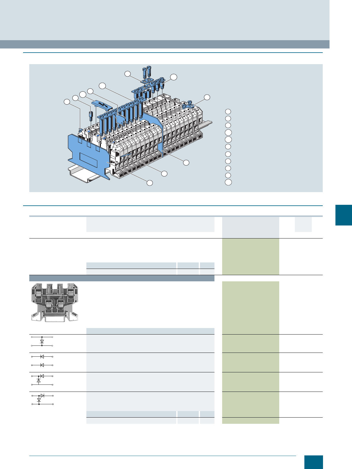
9/21
Siemens LV 52 · 2016
* You can order this quantity or a multiple thereof.
8WA1 Screw Terminals
8WA two-tier terminals with electronic components
9
■
Design
■
Selection and ordering data
10 3
4a
4b
5
6
2
1
8
7
9
End plate
Barrier
Insulation plate
Link rail for lower tier
Link rail for upper tier
Link for link rail
Jumper
Test socket
Soldering tag
Flat connector, slotted
Cover with lightning symbol
1
2
3
4a
4b
5
6
7
8
9
10
I201_14020
Version DT Article No.
www.siemens.com/
product?Article No.
Price
per PU
PU
(UNIT,
SET, M)
PS*/
P. unit PG
General details
• Thermoplastic insulating body
• Screw terminal at both ends
• Open on one side
•Beige
Note Section Page
For labeling accessories, see ... Accessories 11/2
Terminal size 4 mm²
8WA1011-6EG20
Diode terminals, terminal size 4 mm²
• Rated insulation voltage 250 V
• Mounting width 6.5 mm
• Terminal height 45 mm
• Terminal length 64 mm
•U AWG 18-10
• Jumpering not supported
Type
• Rated uninterrupted current 32/1 A 8WA1011-6EG20 1 10 units 1BT
• Rated uninterrupted current 1 A 8WA1011-6EG22 1 10 units 1BT
• Rated uninterrupted current 32/1 A 8WA1011-6EG23 1 10 units 1BT
• Rated uninterrupted current 32/1 A 8WA1011-6EG24 1 10 units 1BT
Accessories Section Page
End plates, for two-tier terminals Accessories 9/22 8WA1817 1 50 units 1BT
34
2
1
34
2
1
34
2
1
34
2
1
© Siemens AG 2015© Siemens AG 2015
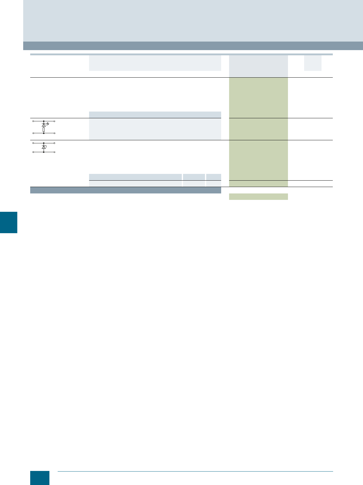
9/22 Siemens LV 52 · 2016 * You can order this quantity or a multiple thereof.
8WA two-tier terminals with electronic components
8WA1 Screw Terminals
9
Terminals with red LED, terminal size 4 mm²
• Rated uninterrupted current 32 A
• Rated insulation voltage 24 V DC
• Mounting width 6.5 mm
• Terminal height 45 mm
• Terminal length 64 mm
•U AWG 18-10
Type
• Without diode for current limitation 8WA1011-6EG25 1 10 units 1BT
Zener diode terminals, terminal size 4 mm² 8WA1011-6EG44 1 10 units 1BT
• Mounting width 6.5 mm
• Terminal height 45 mm
• Terminal length 64 mm
•U AWG 18-10
• Let-through current 0.25 A
• Avalanche voltage UZ = 2.4 V, ± 5 %
Accessories Section Page
End plates, for two-tier terminals Accessories 9/22 8WA1817 1 50 units 1BT
Accessories
End plates, for two-tier terminals 8WA1817 1 50 units 1BT
Version DT Article No.
www.siemens.com/
product?Article No.
Price
per PU
PU
(UNIT,
SET, M)
PS*/
P. unit PG
34
2
1
34
2
1
© Siemens AG 2015© Siemens AG 2015
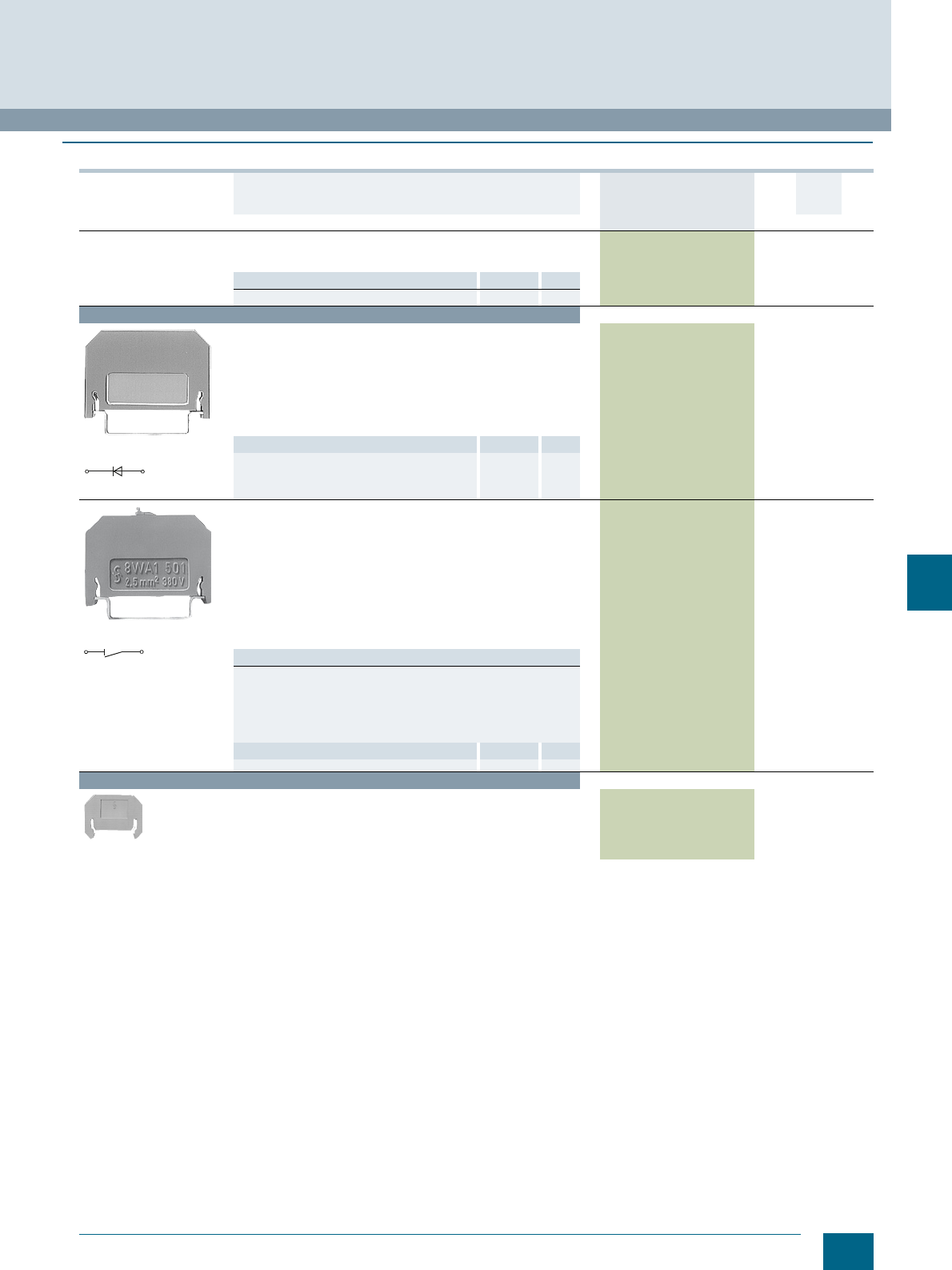
9/23
Siemens LV 52 · 2016
* You can order this quantity or a multiple thereof.
8WA1 Screw Terminals
8WA diode and isolating terminals
9
■
Selection and ordering data
Version DT Article No.
www.siemens.com/
product?Article No.
Price
per PU
PU
(UNIT,
SET, M)
PS*/
P. uni t PG
General details
• Thermoplastic insulating body
• Enclosed at both ends
Note Section Page
For labeling accessories, see ... Accessories 11/2
Terminal size 2.5 mm²
8WA1011-1EF20
8WA1011-1EF20
Diode terminals, terminal size 2.5 mm²
• Rated insulation voltage 250 V URRM
• Mounting width 6 mm
• Terminal height 26 mm
• Terminal length 41 mm
• Screw terminals at both ends with test options for Ø 2.3 mm
test plug
• Rated uninterrupted current 1 A
• Peak blocking voltage 1000 V
8WA1011-1EF20 15 units1BT
Accessories Section Page
• Barriers, for terminal size 1.5 ... 4 mm² Accessories 9/23 8WA1820 1 50 units 1BT
8WA1501
8WA1501
Through-type terminals, terminal size 2.5 mm²,
with sectionalizing feature
• Rated uninterrupted current 10 A
• Rated insulation voltage 380 V AC, 450 V DC
(with alternate outgoing soldering tags)
- Open isolating distance 380 V AC, 450 V DC
- For use of barriers up to 750 V AC, 900 V DC
• Mounting width 6 mm
• Terminal height 29 mm
• Terminal length 41 mm
• With 2 holes for Ø 2.3 mm test plug
• With screw terminals at both ends
8WA1501 1 10 units 1BT
Note
Through-type terminals with sectionalizing feature allow easy isola-
tion of the current path without disconnection of conductors. The
sockets of the terminal screws allow actions, such as the measuring
of the loop resistance or connection of an ammeter to the circuit. The
use of connection combs reduces the conductor cross-section by
one level.
Accessories Section Page
• Barriers, for terminal size 1.5 ... 4 mm² Accessories 9/23 8WA1820 1 50 units 1BT
Accessories
8WA1820
Barriers, for terminal size 1.5 ... 4 mm² 8WA1820 1 50 units 1BT
1
2
© Siemens AG 2015© Siemens AG 2015
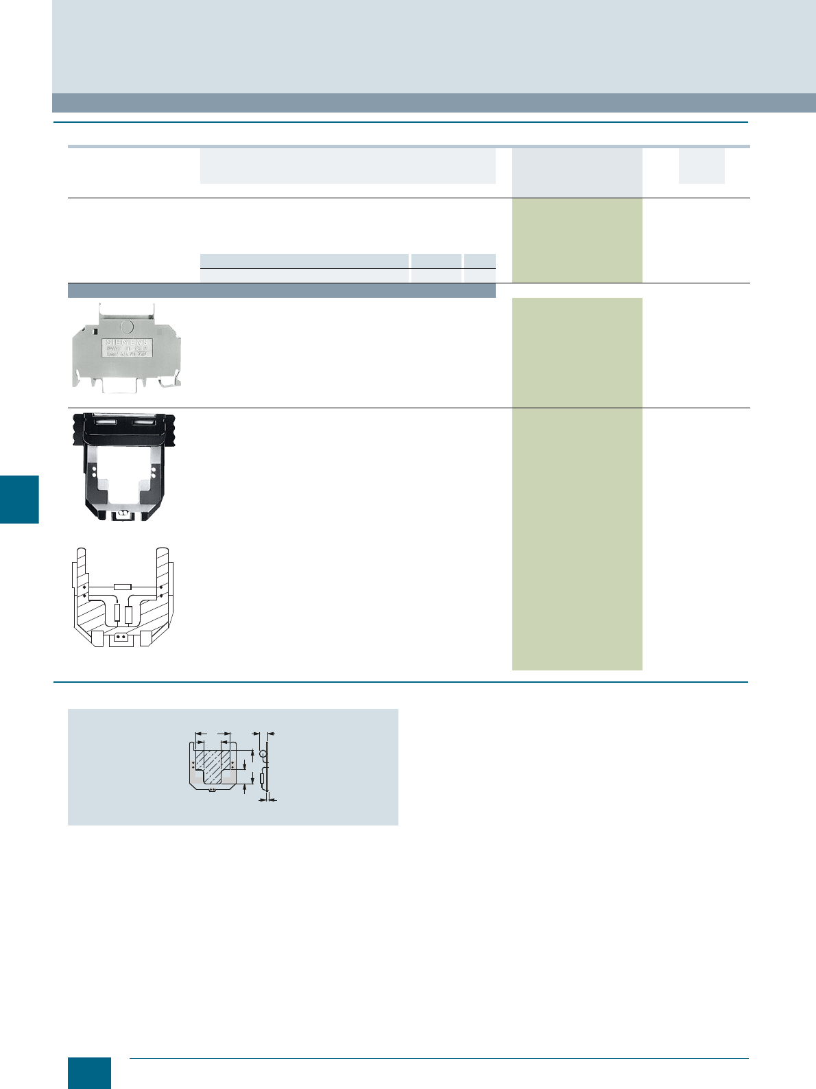
9/24 Siemens LV 52 · 2016 * You can order this quantity or a multiple thereof.
8WA terminals for components
8WA1 Screw Terminals
9
■
Selection and ordering data
■
Dimensional drawings
Space for components
Version DT Article No.
www.siemens.com/
product?Article No.
Price
per PU
PU
(UNIT,
SET, M)
PS*/
P. un it PG
General details
• Terminals for components
• Screw terminal at both ends for 2 conductors each
• Plugs with PCB for components
• Enclosed at both ends
Note Section Page
For labeling accessories, see ... Accessories 11/2
Terminal size 1.5 mm²
8WA1011-1EE00
Terminals for components, terminal size 1.5 mm² (enclosure only)
• Rated uninterrupted current 6.3 A
• Rated insulation voltage 500 V
• Mounting width 10 mm
• Terminal height 40 mm
• Terminal length 57 mm
• For self-fitting with components
• To next terminal, determined internally through customer's
components
8WA1011-1EE00 1 5/50 units 1BT
8WA1822-7EE00
Plugs, fully equipped,
example
Plugs for components, terminal size 1.5 mm²
• Rated uninterrupted current 6.3 A
• Rated insulation voltage 500 V
• Mounting width 10 mm
• Plug height 29 mm
• Plug length 41 mm
• With PCB and inscription label (20 × 9 mm)
8WA1822-7EE00 11 unit1BT
NSH0_00006
NSH0_00005
19
8
10
18 max. 4
max. 2
© Siemens AG 2015© Siemens AG 2015
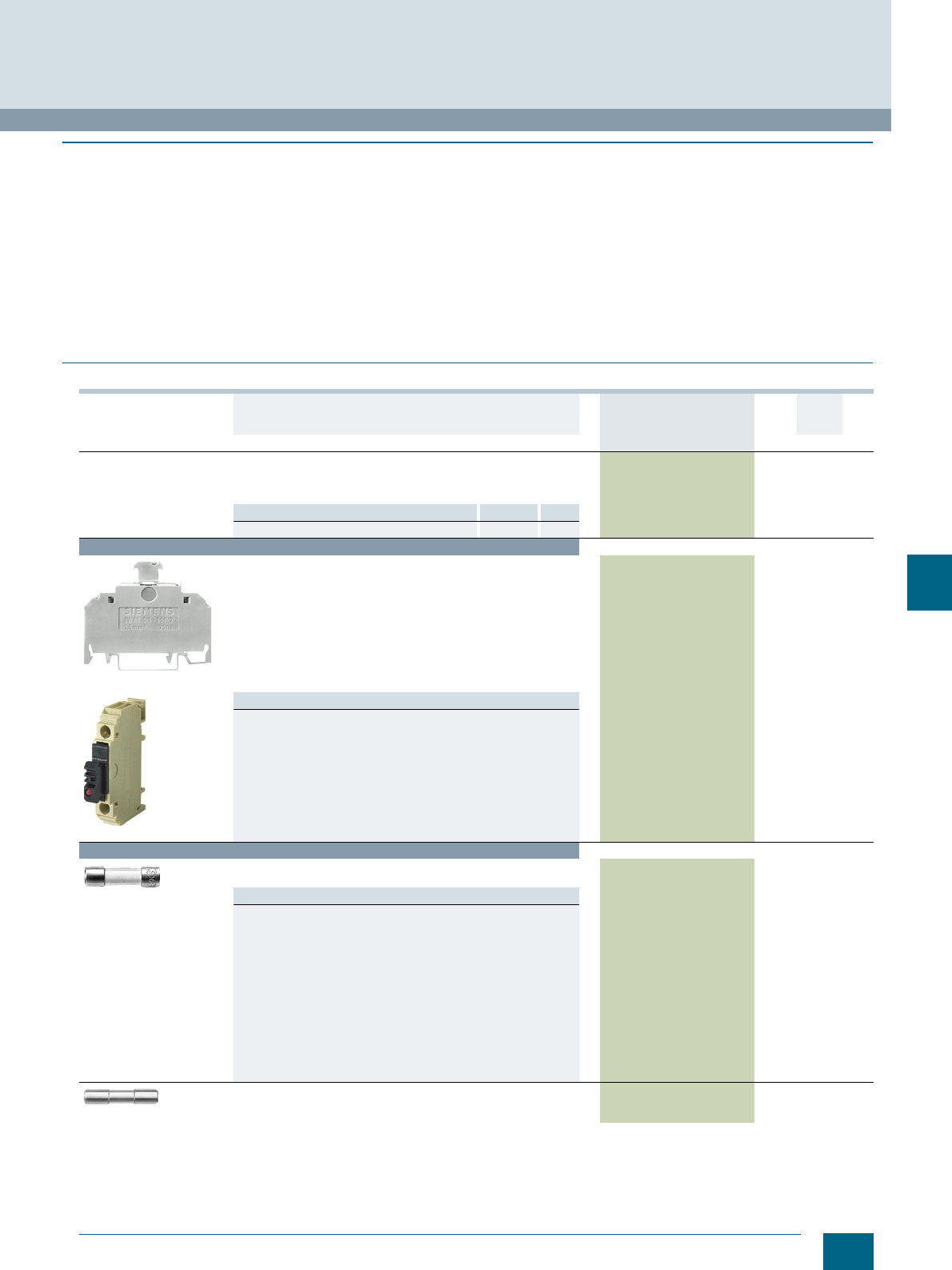
9/25
Siemens LV 52 · 2016
* You can order this quantity or a multiple thereof.
8WA1 Screw Terminals
8WA fuse terminals
9
■
Overview
8WA1011-1SF12 fuse terminals are used to protect control
circuits against short-circuits.
The fuse terminals are intended for 5 × 20 mm and 5 × 25 mm
G fuse links up to 6.3 A and 250 V and for bridging links up to
16 A and 800 V and have a mounting for a replacement fuse link.
The fuse terminals are suitable for fuse links, sizes ¼" × 1",
¼" ×11/4" (6.3 × 32 mm) to 6.3 A and 250 V.
Fuse terminals are positive opening fuse-disconnectors.
The fuse links must be replaced at zero voltage. Finger safety is
ensured in both closed and open positions.
The LED indicates the status of the disconnected fuse (residual
current from 2 mA to 5 mA), but not if the plug is removed
(floating).
The double connection is designed so that two conductors with
different cross-sections can also be securely connected.
The fixing base of the G fuse terminal allows both centered
and recessed mounting, allowing the unhindered routing of a
6 × 6 mm N-busbar. The G fuse terminal can therefore be joined
into a single group with the other terminals of a branch.
■
Selection and ordering data
Version DT Article No.
www.siemens.com/
product?Article No.
Price
per PU
PU
(UNIT,
SET, M)
PS*/
P. unit PG
General details
• With thermoplastic insulating body
• Screw terminal at both ends for 2 conductors each
• Enclosed at both ends
Note Section Page
For labeling accessories, see ... Accessories 11/2
Terminal size 1.5 mm²
8WA1011-1SF12
8WA1011-1SF13
Fuse terminals, terminal size 1.5 mm²
• Rated uninterrupted current 6.3 A when using fuses
• Rated uninterrupted current 16 A when using the bridging link
• Rated uninterrupted voltage 250 V when using fuses
• Rated insulation voltage 800 V when using the bridging link
• Mounting width 10 mm
• Terminal height 42 mm
• Terminal length 57 mm
• Open isolating distance 500 V
•U AWG 18-14
•s AWG 18-14
Versions
• For G-fuse
- Without LED 8WA1011-1SF12 1 10 units 1BT
- With LED 24 V AC/DC 8WA1011-1SF13 1 10 units 1BT
- With LED 230 V AC/DC 8WA1011-1SF15 1 10 units 1BT
• For inch fuse
- Without LED 8WA1011-1SF30 1 10 units 1BT
- With LED 24 V AC/DC 8WA1011-1SF31 1 10 units 1BT
- With LED, 120 V AC/110 V DC 8WA1011-1SF32 1 10 units 1BT
Accessories
8WA1822-7EF16
G fuse links
DIN 41660
Versions
• Quick-response, high breaking capacity
- Rated uninterrupted current 1 A 8WA1822-7EF16 110/200
units 1BT
- Rated uninterrupted current 1.6 A 8WA1822-7EF18 1 10 units 1BT
- Rated uninterrupted current 2.5 A 8WA1822-7EF21 1 10 units 1BT
- Rated uninterrupted current 4 A 8WA1822-7EF23 1 10 units 1BT
- Rated uninterrupted current 6.3 A 8WA1822-7EF25 1 10 units 1BT
• Slow-response, low breaking capacity
- Rated uninterrupted current 1 A 8WA1822-7EF76 1 10 units 1BT
- Rated uninterrupted current 1.6 A 8WA1822-7EF78 1 10 units 1BT
- Rated uninterrupted current 2.5 A 8WA1822-7EF81 1 10 units 1BT
- Rated uninterrupted current 4 A 8WA1822-7EF83 1 10 units 1BT
- Rated uninterrupted current 6.3 A 8WA1822-7EF85 1 10 units 1BT
8WA1891
Bridging links
5 × 25 mm 8WA1891 1 10 units 1BT
© Siemens AG 2015© Siemens AG 2015
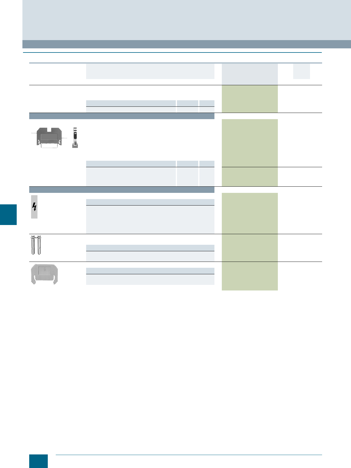
9/26 Siemens LV 52 · 2016 * You can order this quantity or a multiple thereof.
8WA through-type terminals with soldered and plug-in connection
8WA1 Screw Terminals
9
■
Selection and ordering data
Version DT Article No.
www.siemens.com/
product?Article No.
Price
per PU
PU
(UNIT,
SET, M)
PS*/
P. unit PG
General details
• With thermoplastic insulating body
• Enclosed at both ends
Note Section Page
For labeling accessories, see ... Accessories 11/2
Terminal size 1.5 mm²
8WA1221
Through-type terminals, terminal size 1.5 mm²
•Beige
• Rated uninterrupted current 18 A
• Rated insulation voltage 380 V AC, 450 V DC with alternately
arranged terminals; when using barriers up to 800 V
• Mounting width 5.5 mm
• Terminal height 26 mm
• Terminal length 41 mm
• Soldered connection at both ends
8WA1221 1 50 units 1BT
Accessories Section Page
• Covers
- With lightning symbol Accessories 9/26 8WA1810 1 50 units 1BT
- White, facility for labeling Accessories 9/26 8WA1860 1 50 units 1BT
• Barriers, for terminal size 1.5 ... 4 mm² Accessories 9/26 8WA1820 1 50 units 1BT
Accessories
8WA1811
Covers
Versions
• With lightning symbol
- For terminal size 1 ... 2.5 mm² 8WA1810 1 50 units 1BT
- For terminal size 6 mm² 8WA1811 1 50 units 1BT
• White, facility for labeling
- For terminal size 1 ... 2.5 mm² 8WA1860 1 50 units 1BT
- For terminal size 6 mm² 8WA1862 1 50 units 1BT
8WA1822-7VH12
Connection bars, for through-type terminal, terminal size 6 mm²,
with plug-in connection
Versions
• For two terminals 8WA1822-7VH12 1 50 units 1BT
• For ten terminals 8WA1822-7VH20 1 10 units 1BT
8WA1821
Barriers
Versions
• For terminal size 1.5 ... 4 mm² 8WA1820 1 50 units 1BT
• For terminal size 6 ... 16 mm² 8WA1821 1 50 units 1BT
© Siemens AG 2015© Siemens AG 2015
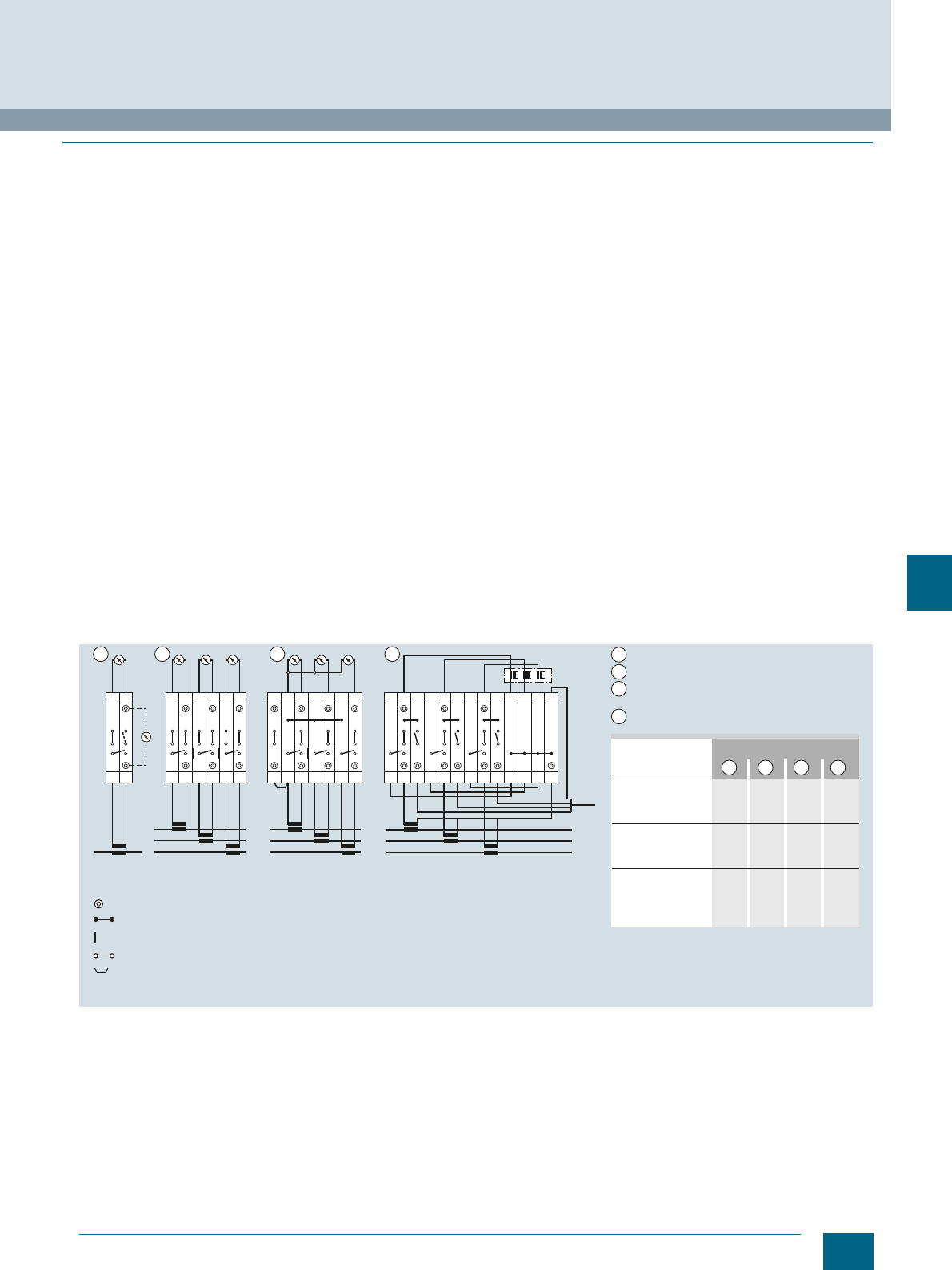
9/27
Siemens LV 52 · 2016
8WA1 Screw Terminals
8WA measuring transformer terminals
9
■
Overview
Measuring transformer terminals can be used for testing and
isolating circuits in switchboards, control rooms, etc. without
interrupting operation.
The isolating and instrument isolating terminals contain an iso-
lating device in the through-type connection. The isolating de-
vice permits electrical separation between the input and output
of a terminal.
Test sockets for plugs with a diameter of 4 mm can be screwed
into the front side of the through-type and isolating terminals.
The rated insulation voltage between colored test sockets is
125 V. The rated insulation voltage between test sockets and
connection bars not connected to the terminal is 16 V (circuit 3,
terminals 3 and 5).
Two adjacent terminals can be connected in parallel with the dis-
connecting link. The disconnecting link can be operated in any
position of the isolating device.
Instrument set for one transformer
The instrument set for one transformer makes the basic circuit of
the transformer terminal blocks clear. This basic circuit is also
included in much larger instrument sets, which is extended by
adding on equivalent circuits. Links between the basic circuits
provide many kinds of testing facilities, parallel outgoing lines to
other measuring devices, connection of test equipment, etc.
Instrument set for three transformers
The simplest version of an instrument set for a three-phase cir-
cuit consists of three basic circuits strung together without any
continuing links or extensions. Instead of isolating terminals 1, 3
and 5, less expensive through-type terminals can also be used.
On the other hand, it is also possible to use instrument isolating
terminals for this purpose so that the terminal versions are all the
same.
Instrument set for three transformers with neutral point
The instrument set with a neutral point is an extension of the pre-
vious circuit. Four instead of six lines are sufficient for connect-
ing it with the measuring devices. The neutral point is produced
on the measuring instruments on the one hand, and using a
shortened 8WA1822-7VH10 connection bar on the other. The
instrument isolating terminal 1 is connected to the neutral point
using a connecting comb.
Note
The introduction of the 8WA1011-1MH10 through-type terminals
and their associated disconnecting links has made it consider-
ably easier to configure terminal sets for current transformers.
Instead of the 12 isolating or instrument isolating terminals used
previously, now only 4 instrument isolating terminals and
3 through-type terminals are required.
Instrument set with test facility
This instrument set represents a significant enhancement over
previous types. In normal operation, terminals 2, 5 and 8 are
closed. For testing a measuring instrument (e.g. a plotter), these
terminals are opened and terminals 3, 6 and 9 are closed in or-
der to feed in a test signal. The transformers first have to be
short-circuited with the disconnecting links between terminals
1-2, 4-5 and 7-8. Wire jumpers connect terminals 1, 4 and 7 with
the neutral point. It is formed in terminals 10, 11, 12 and 13 with
an 8WA1887 connection bar.
Connection option for measuring transformer terminals (instrument sets)
1 2 3 4
L
kl
12
L3
kl
12
kl
34
kl
56
L2
L1
L3
kl
12
kl
34
kl
56
L2
L1
7
N
L3
l
12
l
34
l
56
L2
L1
78910 11
N
12 13
I201_14021a
1
2
3
4
1 2 3 4
8WA1011-1MH10 37
8WA1011-1MH11 331
8WA1011-1MH15 4331
8WA1825 a) 22
8WA1885 3
8WA1887 1
8WA1822-7VH10 1 b)
8WA1822-7VH01 3331
8WA1822-7PH00 4
8WA1822-7VH22 1
Test socket
Link rail
Small partition
Disconnecting link (closed)
Connecting comb, 2-pole b) Shortened
a) In some cases additionally required
between instrument sets
Type Number required for
Instrument set for 1 transformer
Instrument set for 3 transformers
Instrument set for 3 transformers
with neutral point
Instrument set with testing facility
Tes t
© Siemens AG 2015© Siemens AG 2015
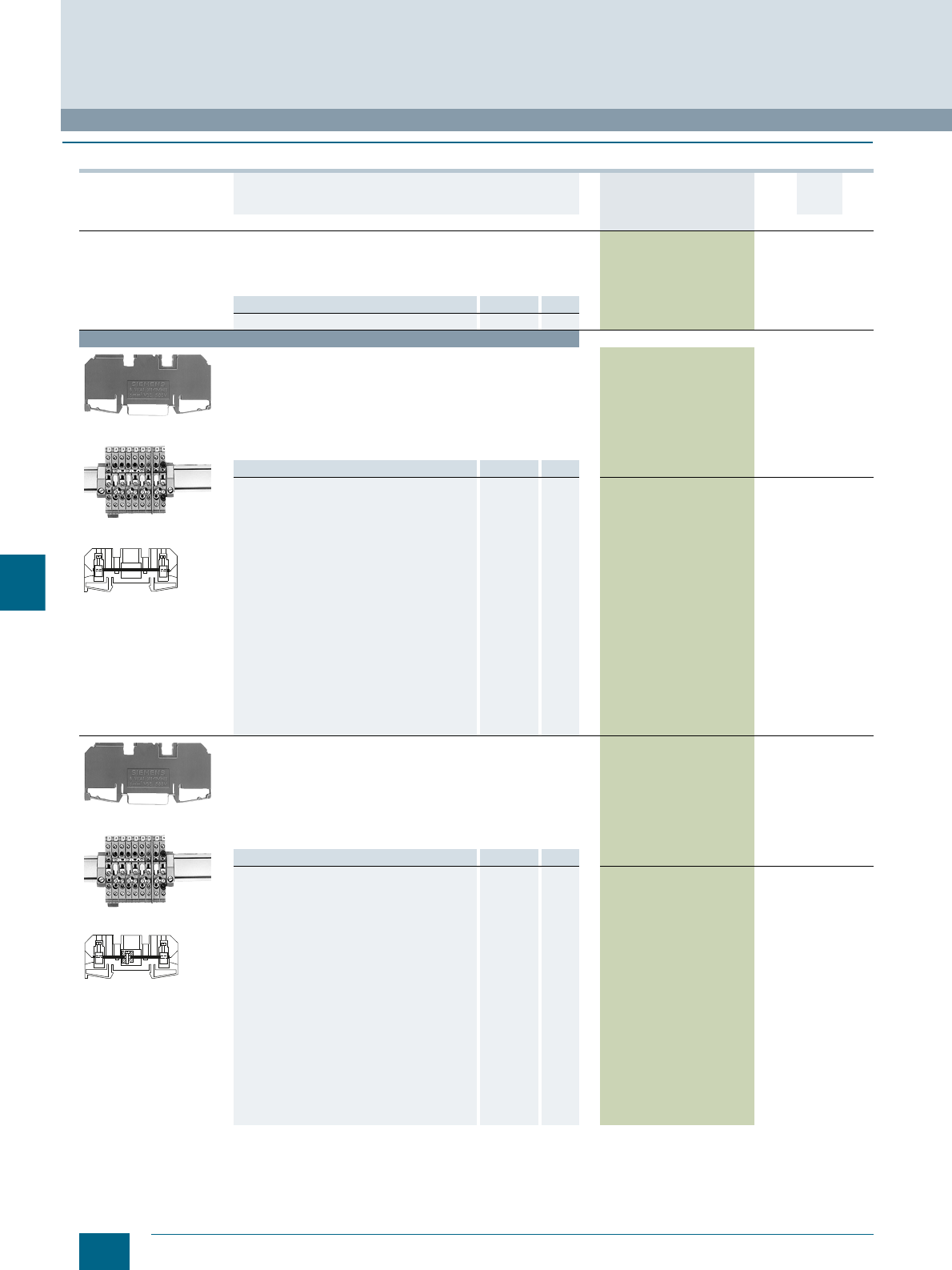
9/28 Siemens LV 52 · 2016 * You can order this quantity or a multiple thereof.
8WA measuring transformer terminals
8WA1 Screw Terminals
9
■
Selection and ordering data
Version DT Article No.
www.siemens.com/
product?Article No.
Price
per PU
PU
(UNIT,
SET, M)
PS*/
P. unit PG
General details
• With thermoplastic insulating body
• Screw terminals at both ends and two holes for test sockets
for Ø 4 mm test plug, insulated at both ends
• Enclosed at both ends
Note Section Page
For labeling accessories, see ... Accessories 11/2
Terminal size 6 mm²
8WA1011-1MH10
Typical circuit diagram
8WA1011-1MH10
Through-type terminals, terminal size 6 mm²
• Rated uninterrupted current 41 A
• Rated insulation voltage 500 V
• Mounting width 8 mm
• Terminal height 33 mm
• Terminal length 83 mm
• Without test sockets
•U AWG 14-8
•s AWG 16-10
8WA1011-1MH10 1 20 units 1BT
Accessories Section Page
Covers, for connection bars
• Transparent Accessories 9/29 8WA1822-7AX01 1 10 units 1BT
Test sockets
• Rated voltage between test socket and
bypassed connection bar: 16 V, recessed Accessories 9/29 8WA1822-7PH00 1 50 units 1BT
Insulation plates, for terminal size 2.5 to 6 mm² Accessories 9/29 8WA1825 1 50 units 1BT
Connection combs
• 10-pole for measuring transformer terminals,
can be shortened as required Accessories 9/29 8WA7163 1 10 units 1BT
•2-pole Accessories 9/29 8WA1822-7VH22 1 10 units 1BT
Connection bars, for terminal size 6 mm²
• Two terminals Accessories 9/29 8WA1885 1 50 units 1BT
• Three terminals Accessories 9/29 8WA1886 1 50 units 1BT
• Four terminals Accessories 9/29 8WA1887 1 20 units 1BT
• Ten terminals Accessories 9/29 8WA1888 1 10 units 1BT
• Unmounted for ten terminals Accessories 9/29 8WA1822-7VH10 1 50 units 1BT
Barriers, for Insta terminals, terminal size
2.5 mm² and measuring transformer terminals,
terminal size 6 mm²
Accessories 9/29 8WA1822-7TH00 1 50 units 1BT
8WA1011-1MH11
Typical circuit diagram
8WA1011-1MH11
Isolating terminals, terminal size 6 mm²
• Rated uninterrupted current 41 A
• Rated insulation voltage 500 V
• Mounting width 8 mm
• Terminal height 33 mm
• Terminal length 83 mm
• Without test sockets
•U AWG 14-8
•s AWG 16-10
8WA1011-1MH11 1 20 units 1BT
Accessories Section Page
Covers, for connection bars
• Transparent Accessories 9/29 8WA1822-7AX01 1 10 units 1BT
• White, facility for labeling Accessories 9/29 8WA1822-7AX03 1 10 units 1BT
Test sockets
• Rated voltage between test socket and
bypassed connection bar: 16 V, recessed Accessories 9/29 8WA1822-7PH00 1 50 units 1BT
Connection combs
• 10-pole for measuring transformer terminals,
can be shortened as required Accessories 9/29 8WA7163 1 10 units 1BT
•2-pole Accessories 9/29 8WA1822-7VH22 1 10 units 1BT
Connection bars, for terminal size 6 mm²
• Two terminals Accessories 9/29 8WA1885 1 50 units 1BT
• Three terminals Accessories 9/29 8WA1886 1 50 units 1BT
• Four terminals Accessories 9/29 8WA1887 1 20 units 1BT
• Ten terminals Accessories 9/29 8WA1888 1 10 units 1BT
• Unmounted for ten terminals Accessories 9/29 8WA1822-7VH10 1 50 units 1BT
Barriers, for Insta terminals, terminal size
2.5 mm² and measuring transformer terminals,
terminal size 6 mm²
Accessories 9/29 8WA1822-7TH00 1 50 units 1BT
NSH0_00026
NSH0_00027
© Siemens AG 2015© Siemens AG 2015
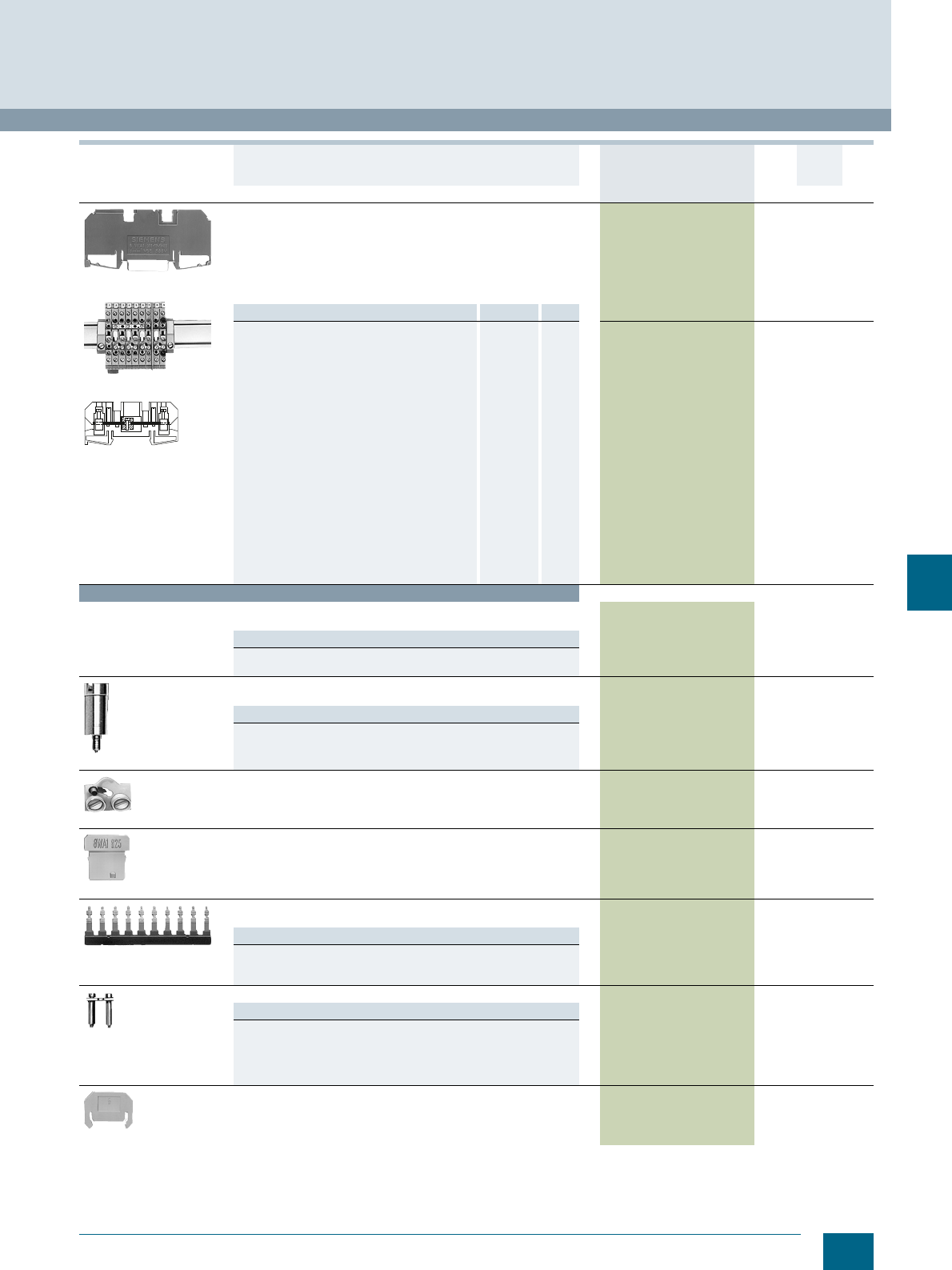
9/29
Siemens LV 52 · 2016
* You can order this quantity or a multiple thereof.
8WA1 Screw Terminals
8WA measuring transformer terminals
9
8WA1011-1MH15
Typical circuit diagram
8WA1011-1MH15
Instrument isolating terminals, terminal size 6 mm²
• Mounting width 8 mm
• Terminal height 33 mm
• Terminal length 83 mm
• Open isolating distance
• With recessed test sockets
•U AWG 14-8
•s AWG 16-10
8WA1011-1MH15 1 20 units 1BT
Accessories Section Page
Covers, for connection bars
• Transparent Accessories 9/29 8WA1822-7AX01 1 10 units 1BT
Test sockets
• Rated voltage between test socket and
bypassed connection bar: 16 V, recessed Accessories 9/29 8WA1822-7PH00 1 50 units 1BT
Insulation plates, for terminal size 2.5 to 6 mm² Accessories 9/29 8WA1825 1 50 units 1BT
Connection combs
• 10-pole for measuring transformer terminals,
can be shortened as required Accessories 9/29 8WA7163 1 10 units 1BT
•2-pole Accessories 9/29 8WA1822-7VH22 1 10 units 1BT
Connection bars, for terminal size 6 mm²
• Two terminals Accessories 9/29 8WA1885 1 50 units 1BT
• Three terminals Accessories 9/29 8WA1886 1 50 units 1BT
• Four terminals Accessories 9/29 8WA1887 1 20 units 1BT
• Ten terminals Accessories 9/29 8WA1888 1 10 units 1BT
• Unmounted for ten terminals Accessories 9/29 8WA1822-7VH10 1 50 units 1BT
Barriers, for Insta terminals, terminal size
2.5 mm² and measuring transformer terminals,
terminal size 6 mm²
Accessories 9/29 8WA1822-7TH00 1 50 units 1BT
Accessories
Covers, for connection bars
For through-type terminals, size 2.5 to 6 mm²
Versions
• Transparent 8WA1822-7AX01 1 10 units 1BT
• White, facility for labeling 8WA1822-7AX03 1 10 units 1BT
8WA1822-7PH00
Test sockets
Ø 4 mm
Versions
• Rated voltage between test socket and bypassed connection bar:
16 V, recessed 8WA1822-7PH00 1 50 units 1BT
8WA1822-7VH01
Disconnecting links
Rated insulation voltage with disconnecting link open according to
DIN VDE 0110: 125 V Gr. C or 250 V Gr. B
8WA1822-7VH01 1 50 units 1BT
8WA1825
Insulation plates, for terminal size 2.5 to 6 mm² 8WA1825 1 50 units 1BT
8WA7163
Connection combs
For inserting in the clamping points
Versions
• 10-pole for measuring transformer terminals, can be shortened as
required 8WA7163 1 10 units 1BT
•2-pole 8WA1822-7VH22 1 10 units 1BT
8WA1885
Connection bars, for terminal size 6 mm²
Versions
• Two terminals 8WA1885 1 50 units 1BT
• Three terminals 8WA1886 1 50 units 1BT
• Four terminals 8WA1887 1 20 units 1BT
• Ten terminals 8WA1888 1 10 units 1BT
• Unmounted for ten terminals 8WA1822-7VH10 1 50 units 1BT
8WA1822-7TH00
Barriers, for Insta terminals, terminal size 2.5 mm² and
measuring transformer terminals, terminal size 6 mm² 8WA1822-7TH00 1 50 units 1BT
Version DT Article No.
www.siemens.com/
product?Article No.
Price
per PU
PU
(UNIT,
SET, M)
PS*/
P. unit PG
NSH0_00028
© Siemens AG 2015© Siemens AG 2015

9/30 Siemens LV 52 · 2016
Notes
8WA1 Screw Terminals
9
© Siemens AG 2015© Siemens AG 2015
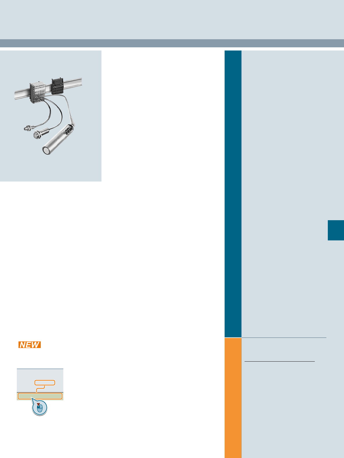
Siemens LV 52 · 2016
For further technical
product information:
Siemens Industry Online Support:
www.siemens.com/lowvoltage/product-
support .
→
Application example
Certificate
Characteristic
Download
FAQ
Manual
Product note
Software archive
Technical data
10
10
10/2 8WA initiator/actuator terminals
8WA2 Spring-Loaded Terminals
Direct reference to the products in the
Industry Mall from the selection and
ordering data tables:
3VA2025-5HL36-0AA0
Article No.
www.siemens.com/
product? Article No.
Paper catalog:
To get more
product information
enter the Web
address plus
Article No.
PDF catalog:
Get more product information
with just a mouse click.
© Siemens AG 2015© Siemens AG 2015

10/2 Siemens LV 52 · 2016
8WA initiator/actuator terminals
8WA2 Spring-Loaded Terminals
10
■
Overview
• Fast and cost-effective connection of signal transmitters to
the PLC
• Only 5 mm wide but still fitted with connection facility for
proximity switches with up to three conductors plus shielding
• Connection is clear, simple and safe due to:
- Front connection
- Color coding of clamping points
- Conductors from only 0.08 ... 1.5 mm² without end sleeves
that are secured using spring-loaded terminals
• LEDs make the switch states or the application of voltage easy
to see. It is no longer necessary to test with measuring instru-
ments.
• Connection modules cut wiring requirements and time
because the potentials of the terminals (L+, L- and S) are
automatically connected; there is therefore no need for linking
accessories.
• The modules contain a feeder terminal and 8 or 17 initiator/
actuator terminals and can be snapped or screwed onto
35 mm standard mounting rails
The feeder terminals are fitted with an additional negative out-
going feeder which can be used to supply isolated digital input/
output modules. The frame (M) can therefore be bridged by
means of the terminals.
Terminals and connection modules (always order as combined unit)
Initiator/actuator terminals with electrically isolated digital input/output
modules
L
NSH0_00007c
88
0
1234567
0
1
2
3
4
5
6
7
0
1
2
3
4
5
6
7
L
L
L
S
E0E1
234567
1 1
3
4
32
1
2
3
4
Digital input/output
modules, electrically
isolated
Feeder terminal
Initiator/actor terminals
Module link rails
M(Minus) M(Minus)
© Siemens AG 2015© Siemens AG 2015

10/3
Siemens LV 52 · 2016
8WA2 Spring-Loaded Terminals
8WA initiator/actuator terminals
10
■
Technical specifications
Continuous load at increased ambient temperatures
8WA2 terminal blocks can be loaded with their full uninterrupted
current at ambient temperatures of up to +55 °C. At higher
ambient temperatures, a current reduction according to the
following formula is required:
The maximum permissible clamping point overtemperature of
45 K according to IEC 60947-7-1 and EN 60947-7-1, Part 1, is
not exceeded at ambient temperatures up to 100 °C.
Clamping points
Single-conductor connection
s and U rating
Ith2’ = Ith2 × k
Ith = Uninterrupted current according to selection tables, relative to the
nominal cross-section
Ith2’ = Uninterrupted current at increased ambient temperature
k= Derating factor according to table
Ambient temperature Derating factor k
60 °C 0.94
65 °C 0.88
70 °C 0.82
75 °C 0.75
80 °C 0.67
85 °C 0.58
90 °C 0.47
95 °C 0.33
Terminal size Type Thread diameter of
terminal screws Screwdriver blades
acc. to DIN 5264
8WA2803 or 8WA2804
Tightening torque
= test torque Tensile forces
acc. to
IEC 60947-1
at max.
conductor
connection
Stripped
length
mm2Nm Nmm
1.5 8WA2011-3KE -- 0.5 × 3.5 -- 40 8 ... 9
Terminal
size Type Smallest conductor cross-section Largest conductor cross-section
Solid Stranded Finely
stranded Finely stranded with
end sleeve Solid Stranded Finely
stranded Finely stranded with
end sleeve
mm2mm² mm² mm² mm² Size mm² mm² mm² mm² Size
1.5 8WA2011-3KE . . 0.08 0.5 0.2 -- -- 1.5 1.5 1.5 -- --
Terminal
size Type CSA rating UR rating
AWG Rated current
In
Rated voltage
Ue
AWG Rated current
In
Rated voltage
Ue
mm2A V A V
1.5 8WA2011-3KE 28 ... 16 10 65 22 ... 16 10 65
© Siemens AG 2015© Siemens AG 2015
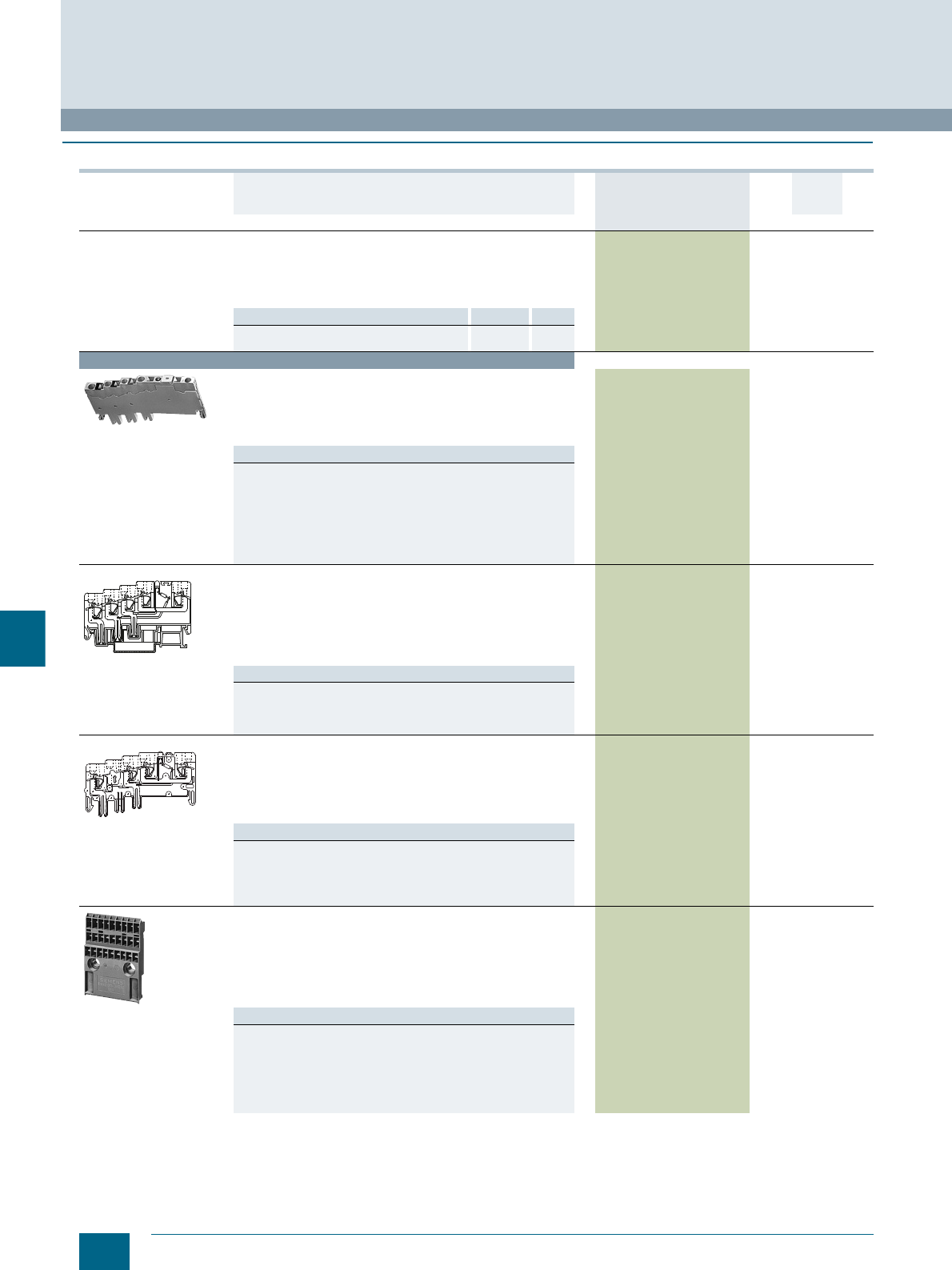
10/4 Siemens LV 52 · 2016 * You can order this quantity or a multiple thereof.
8WA initiator/actuator terminals
8WA2 Spring-Loaded Terminals
10
■
Selection and ordering data
Version DT Article No.
www.siemens.com/
product?Article No.
Price
per PU
PU
(UNIT,
SET, M)
PS*/
P. un it PG
General details
• Thermoplastic insulating body
• Front connection with spring-loaded terminal
• L+ = brown S (shield) = green
L- = blue A (output), connection not colored
• Enclosed at both ends
Note Section Page
For labeling accessories, see ... 8WA acces-
sories 11/2
Terminal size 1.5 mm²
8WA2011-3KE00
Feeder terminals, terminal size 1.5 mm²
• Orange
• Rated uninterrupted current 10 A
• Rated insulation voltage 65 V
• Mounting width 5 mm
• For 250 V, pollution degree 2
Versions
•PNP
- L+, L-, S, without LED 8WA2011-3KE00 1 20 units 1BT
- L+, L-, without LED 8WA2011-3KE01 1 20 units 1BT
- L+, L-, S, with green LED, 15 ... 30 V 8WA2011-3KE02 1 20 units 1BT
•NPN
- L+, L-, S, without LED 8WA2011-3KE00 1 20 units 1BT
- L+, L-, without LED, without ground
connection 8WA2011-3KE01 1 20 units 1BT
8WA2011-3KE13
initiator terminals
with connection module
Initiator terminals, terminal size 1.5 mm²
•Light gray
• Rated uninterrupted current 10 A
• Rated insulation voltage 65 V
• Mounting width 5 mm
• For 250 V, pollution degree 2
• Current consumption with LED 4.8 mA
•PNP
Versions
• L+, L-, A, without LED 8WA2011-3KE10 1 20 units 1BT
• L+, L-, S, A, without LED 8WA2011-3KE11 1 20 units 1BT
• L+, L-, A, with yellow LED, 15 ... 30 V 8WA2011-3KE12 1 20 units 1BT
• L+, L-, S, A, with yellow LED, 15 ... 30 V 8WA2011-3KE13 1 20 units 1BT
8WA2011-3KE33
actuator terminals
with LED
Actuator terminals, terminal size 1.5 mm²
•Light gray
• Rated uninterrupted current 10 A
• Rated insulation voltage 65 V
• Mounting width 5 mm
• For 250 V, pollution degree 2
• Current consumption with LED 4.8 mA
Versions
•PNP
- L-, S, A, without LED 8WA2011-3KE31 1 20 units 1BT
- L-, S, A, with yellow LED, 15 ... 30 V 8WA2011-3KE33 1 20 units 1BT
•NPN
- L+, S, A, without LED 8WA2011-3KE30 1 20 units 1BT
8WA2011-3KE50
Connection modules, terminal size 1.5 mm², for all PNP
and NPN terminals
• Black
• Rated uninterrupted current 10 A
• Rated insulation voltage 65 V
• Mounting width 5 mm
• For 250 V, pollution degree 2
• L+, L-, S integrated
Versions
• For 8 initiator/actuator terminals and one feeder terminal
- Width 47 mm
-Height 65 mm
8WA2011-3KE50 1 10 units 1BT
• For 16 initiator/actuator terminals, one feeder terminal and space
for one terminal for further bridging for subsequent module
- Width 93 mm
-Height 65 mm
8WA2011-3KE51 1 5 units 1BT
AA
L-
L+
S
NSH0_00142
AA
L-
S
NSH0_00010
© Siemens AG 2015© Siemens AG 2015
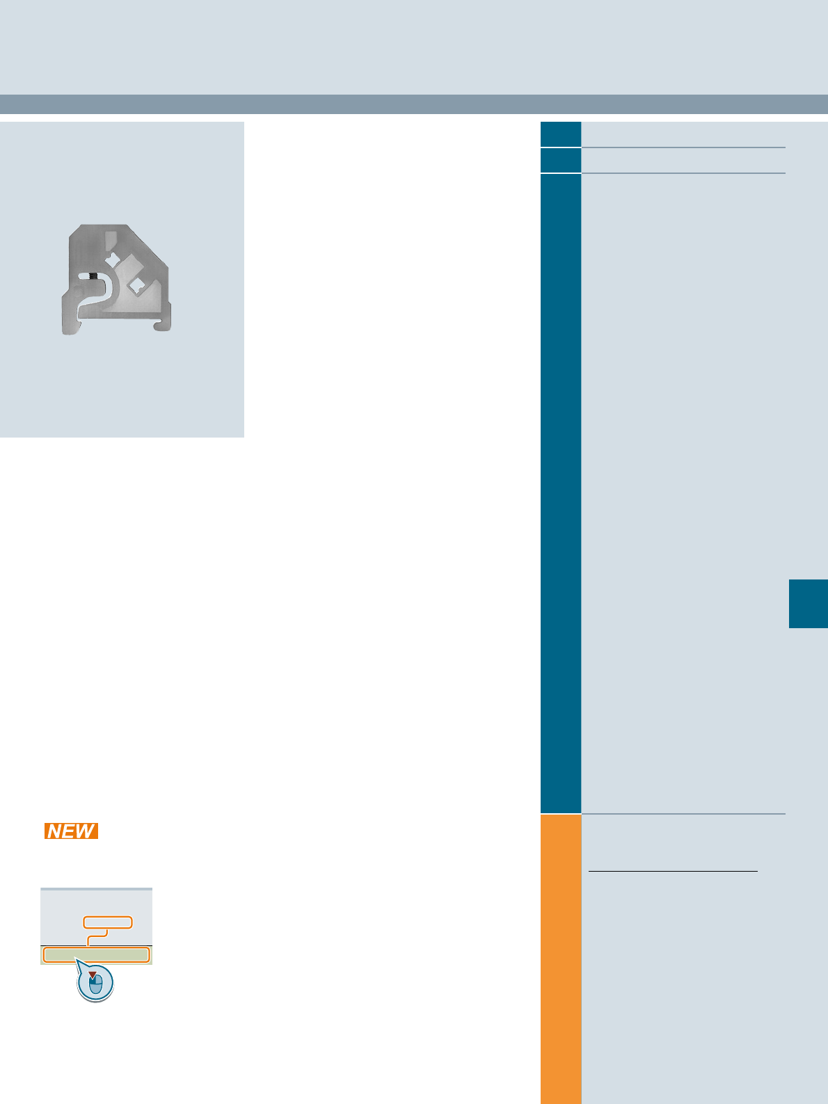
Siemens LV 52 · 2016
For further technical
product information:
Siemens Industry Online Support:
www.siemens.com/lowvoltage/product-
support .
→
Application example
Certificate
Characteristic
Download
FAQ
Manual
Product note
Software archive
Technical data
11
11
11/2 Accessories for the labeling system
11/3 Standard labeling system
11/5 Mounting accessories
Accessories for 8WA Terminal Blocks
Direct reference to the products in the
Industry Mall from the selection and
ordering data tables:
3VA2025-5HL36-0AA0
Article No.
www.siemens.com/
product? Article No.
Paper catalog:
To get more
product information
enter the Web
address plus
Article No.
PDF catalog:
Get more product information
with just a mouse click.
© Siemens AG 2015© Siemens AG 2015
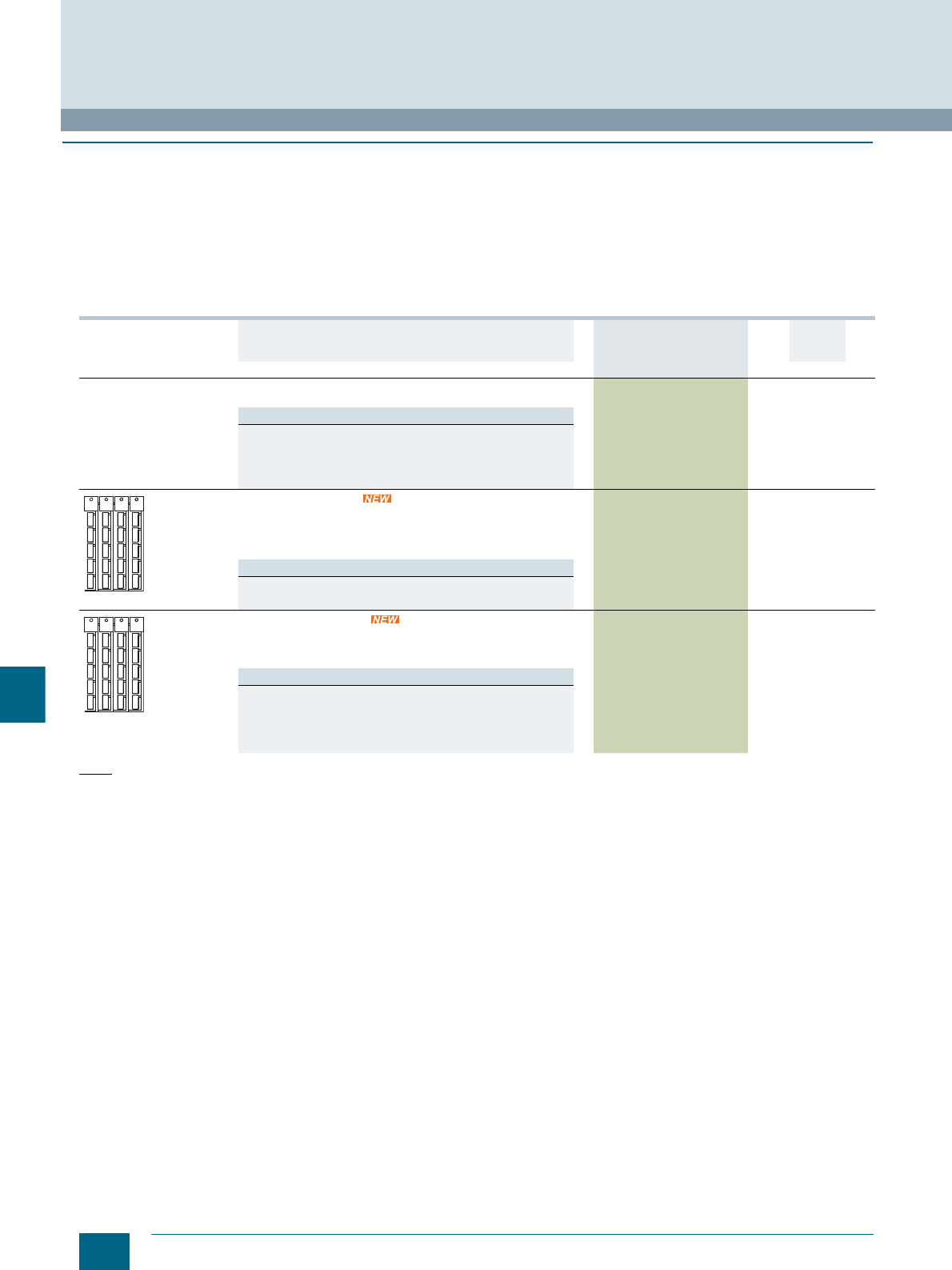
11/2 Siemens LV 52 · 2016 * You can order this quantity or a multiple thereof.
Accessories for the labeling system
Accessories for 8WA Terminal Blocks
11
■
Selection and ordering data
Labeling system for individual inscription
Labeling systems for
• Terminal blocks
• Modular installation devices
• Circuit breakers
• Switch disconnectors
Available from:
Murrplastik Systemtechnik GmbH
Postfach 1143
D-71570 Oppenweiler
Telephone: +49 (0)7191-482-0
e-mail: info@murrplastik.de
Accessories for the labeling system
Note:
The labels can be written by hand or using Murrplastik labeling
systems.
The WIN designation simplifies the assignment in the labeling
software.
Version DT Article No.
www.siemens.com/
product?Article No.
Price
per PU
PU
(UNIT,
SET, M)
PS*/
P. un it PG
Terminal block labels,
for labeling system
Versions
• For 8WA1 and 8WA2, individually removable
- 5 × 7, white (WIN 68) 8WA8850-2AY 100 1020 units 1BT
- 5 × 10, white (WIN 68)
Not for two-tier terminals (bottom tier); flat terminals:
8WA1010-1PQ00, 8WA1808
8WA8851-2AY 100 1020 units 1BT
Snap-on device labels
For identification of e.g.
• Circuit breakers
• Contactors
• Controllers
Versions
• 20 x 7, white, snap-on hooks at side (WIN 95) 8WH8210-0AA55 100 340 units 1BT
• 20 x 7, turquoise, snap-on hooks at side (WIN 95) 8WH8210-0AA56 100 340 units 1BT
Adhesive device labels
For identification of e.g.
• Modular installation devices
• Switch disconnectors
Versions
• 15 x 6 mm, white (WIN 098) 8WH8210-0AA35 100 3740 units 1BT
• 15 x 6 mm, yellow (WIN 099) 8WH8210-0AA36 100 3740 units 1BT
• 19 x 8 mm, white (WIN 088) 8WH8210-0AA45 100 2700 units 1BT
• 19 x 8 mm, yellow (WIN 082) 8WH8210-0AA46 100 2700 units 1BT
NSH0_00038
NSH0_00038
© Siemens AG 2015© Siemens AG 2015
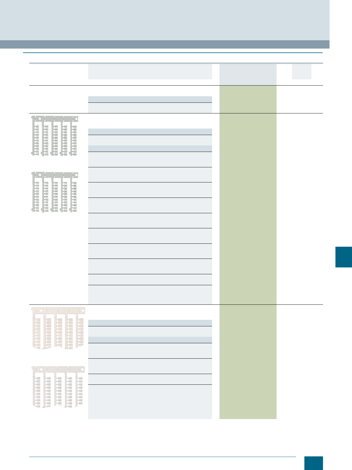
11/3
Siemens LV 52 · 2016
* You can order this quantity or a multiple thereof.
Accessories for 8WA Terminal Blocks
Standard labeling system
11
■
Selection and ordering data
Version DT Article No.
www.siemens.com/
product?Article No.
Price
per PU
PU
(UNIT,
SET, M)
PS*/
P. un it PG
Labels, blank
• Suitable for plotting
Versions
• Label size 5 × 7 mm (WIN 68) 8WA8348-2AY 100 136 units 1BT
• Label size 5 × 10 mm (WIN 68) 8WA8310-2AY 100 136 units 1BT
Horizontal inscription
(8WA8360-0BA)
Vertical inscription
(8WA8361-0BA)
Labels, with inscription
• Label size 5 × 7 mm
• Font height 2 mm
Versions
• Horizontal inscription 8WA8360-@@@ 100 204 units
• Vertical inscription 8WA8361-@@@ 100 204 units
Inscription >>>
• 1…5 (40x) 0BA
• 6…10 (40x) 0BB
• 11…15 (40x) 0BC
• 16…20 (40x) 0BD
• 21…25 (40x) 0BE
• 26…30 (40x) 0BF
• 31…35 (40x) 0BG
• 36…40 (40x) 0BH
• 41…45 (40x) 0BJ
• 46…50 (40x) 0BK
• 51…55 (40x - only available as 8WA8361-0BL) 0BL
• 56…60 (40x) 0BM
• 61…65 (40x) 0BN
• 66…70 (40x - only available as 8WA8361-0BP) 0BP
• 71…75 (40x) 0BQ
• 76…80 (40x) 0BR
• 81…85 (40x) 0BS
• 86…90 (40x - only available as 8WA8361-0BT) 0BT
• 91…95 (40x) 0BU
• 96…100 (40x) 0BV
• 1…20 (10x) 0AB
• 1…40 (5x) 0AC
• 41…100 (3x) 0AD
• 101…200 (2x) 0AF
• 201…300 (2x) 0AG
• 1…100 (2x) 0AE
•A, B…T (10x) 1AA
• U, V, W, X, Y, Z (30x) +, - (10x) 1AB
• L1, L2, L3, N, PE (40x) 1AC
• U1, V1, W1, U2, V2, W2, (30x); blank (20x) 1AD
Horizontal inscription
(8WA8347-2AC)
Vertical inscription
(8WA8348-2AC)
Labels, type 347/348, with inscription
• Label size 5 × 7 mm
• Font height 2 mm
Versions
• Horizontal inscription 8WA8347-@@@ 100 136 units
• Vertical inscription 8WA8348-@@@ 100 136 units
Inscription >>>
• L1 (100x) 2AC
• L2 (100x) 2AD
• L3 (100x) 2AE
• N (100x) 1AR
• MP (100x - only available as 8WA8348-2AB) 2AB
• PE (100x - only available as 8WA8348-2AH) 2AH
•L+ (100x) 2AF
• L- (100x) 2AG
• N (100x) 1AR
• X (100x - only available as 8WA8348-1AG) 1AG
• Y (100x - only available as 8WA8348-1AH) 1AH
© Siemens AG 2015© Siemens AG 2015

11/4 Siemens LV 52 · 2016 * You can order this quantity or a multiple thereof.
Standard labeling system
Accessories for 8WA Terminal Blocks
11
Labels,
custom inscriptions
• Label size 5 × 7 mm
• Font height 2 mm
• Specify required inscription in plain text
Versions
• Horizontal inscription 8WA8347-0XA 100 136 units 1BT
• Vertical inscription 8WA8348-0XA 100 136 units 1BT
8WA1806
End labeling plates
• 21 × 42 mm
• Paper label, inscription possible, with transparent cover
• Suitable for 8WA1805, 8WA1808 and 8WA2808 end retainers
8WA1806 1 50 units 1BT
8WA8826-0AA
Terminal strip labels
Suitable for 8WA1808 end retainer
Versions
• Printed with "X1" 8WA8826-0AA 100 380 units 1BT
• Printed with "X2" 8WA8826-0AB 100 100 units 1BT
• Printed with "X3" 8WA8826-0AC 100 100 units 1BT
• Blank (WIN 67) 8WA8212-0AA65 100 380 units 1BT
Version DT Article No.
www.siemens.com/
product?Article No.
Price
per PU
PU
(UNIT,
SET, M)
PS*/
P. un it PG
NSH0_00041
© Siemens AG 2015© Siemens AG 2015
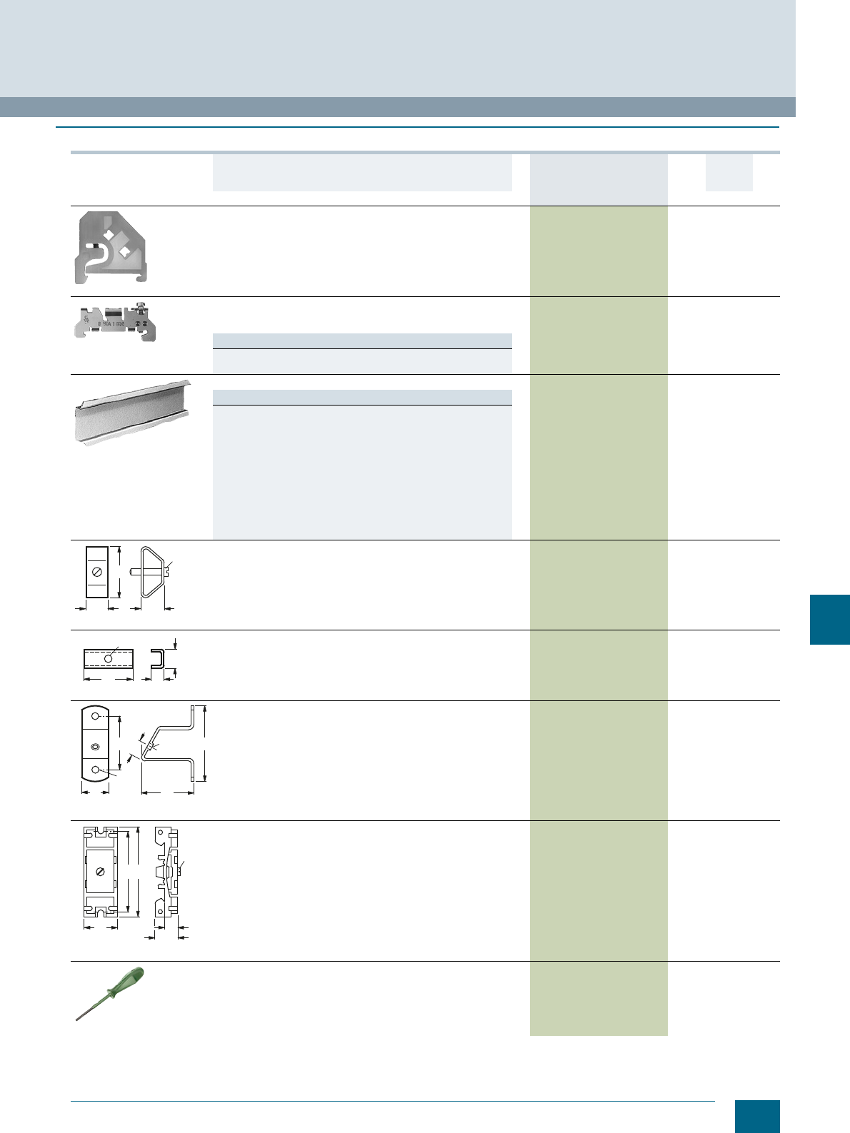
11/5
Siemens LV 52 · 2016
* You can order this quantity or a multiple thereof.
Accessories for 8WA Terminal Blocks
Mounting accessories
11
■
Selection and ordering data
Version DT Article No.
www.siemens.com/
product?Article No.
Price
per PU
PU
(UNIT,
SET, M)
PS*/
P. unit PG
8WA1808
End retainers, with screw fixing
• Mounting width 10 mm
• Suitable for 8WA1806 end labeling plate or 8WA8826-0A.
terminal strip identification label or 3TX4210-0H device label or
four 8WA88. labels.
8WA1808 1 50 units 1BT
8WA1805
End retainers, steel
• Mounting width 10.3 mm
• Suitable for 8WA1806 end labeling plate
8WA1805 1 50 units 1BT
Note
An 8WA1820 barrier must be inserted if using end retainers
against an 8WA189. connection bar (size 2.5).
5ST1141
Standard mounting rails
Versions
• With holes
- EN 50 022-35 × 7.5
- 2 m long, 1 mm thick
- Steel, sendzimir-galvanized
5ST1145 1 20 units 1AD
• Non-perforated 5ST1141 1 20 units 1AD
• Non-perforated, copper
- EN 50022-35 × 15
- 2 m long, 2.3 mm thick
8WA7551 1 1 unit 1BT
• Non-perforated, steel, galvanized, chromated
- Similar to EN 50022-35 × 15
- 2 m long, 1.5 mm thick
5ST1142 1 10 units 1AD
8WA753
Spacer brackets
For raised mounting of terminal strips 8WA753 1 50 units 1BT
8WA752
Spacers
• With 5.5 mm hole
• For raised mounting of terminal strips
8WA752 1 100 units 1BT
8WA746
Mounting brackets
For support rails 8WA746 1 10 units 1BT
8WA1857
Insulation carriers
For insulated mounting of support rails onto plates, frame profiles
and standard mounting rails EN 50022-35
8WA1857 1 20 units 1BT
8WA2880
Screwdrivers, for 8WA2 8WA2880 1 1 unit 1BT
• 3.5 × 0.5 mm, partially insulated
• Green
• Approx. 175 mm long
45
20 22
M5
NSH0_00043
33 9
13
5,5
NSH0_00044
50
70
25 50
14 M 5
NSH0_00042a
6
49
20
54
8
14
M4
NSH0_00045
© Siemens AG 2015© Siemens AG 2015

11/6 Siemens LV 52 · 2016
Notes
Accessories for 8WA Terminal Blocks
11
© Siemens AG 2015© Siemens AG 2015
Siemens LV 52 · 2016
12
12
12/2 Catalog notes
12/3 Ordering notes
12/5 Support on UL topics
12/6 ATEX explosion protection
12/7 Further documentation
12/11 Quality management
12/12 Standards and approvals
12/14 Siemens contacts
12/15 Service & Support
12/16 Comprehensive support
from A to Z
12/17 Software licenses
12/19 Subject index
12/21 Article No. index
incl. export markings
12/28 Conditions of sale and delivery
Appendix
© Siemens AG 2015© Siemens AG 2015
12/2 Siemens LV 52 · 2016
Catalog notes
Appendix
12
■
Overview
Trademarks
All product designations may be registered trademarks or
product names of Siemens AG or supplier companies whose
use by third parties for their own purposes may violate the rights
of the owner.
Amendments
Unless stated otherwise on the individual pages of this catalog,
we reserve the right to make changes, in particular to the
specified values, measurements and weights.
Dimensions
All dimensions are in mm.
Illustrations
The illustrations are not binding.
Technical data
The technical specifications are for general information
purposes only. Always heed the operating instructions and
notices on individual products during assembly, operation and
maintenance.
Further technical information is available at
www.siemens.com/lowvoltage/product-support
• under "Entry type":
- Application example
- Certificate
- Characteristic
- Download
-FAQ
- Manual
- Product note
- Software archive
- Technical data
Configurators can be found under
www.siemens.com/lowvoltage/configurators
Assembly, operation and maintenance
Always heed the operating instructions and notices on individual
products during assembly, operation and maintenance.
Symbols
In the table below, you will find all symbols concerning
connections that can occur in this catalog. In combination with
orange highlighting, these identify special selection criteria.
Connections
Screw connection
Ring cable lug connection
Spring-loaded terminals
© Siemens AG 2015© Siemens AG 2015

12/3
Siemens LV 52 · 2016
Appendix
Ordering notes
12
■
Logistics
General
With regard to delivery service, communications and environ-
mental protection, our logistics service ensures "quality from the
moment of ordering right through to delivery". By designing our
infrastructure according to customer requirements and imple-
menting electronic order processing, we have successfully
optimized our logistics processes.
We are proud of our personal consulting service, on-time
deliveries and 1-day transport within Germany.
To this end, we supply preferred types marked
with } ex works.
We regard the DIN ISO 9001 certification and consistent quality
checks as an integral part of our services.
Electronic order processing is fast, cost-efficient and error-free.
Please contact us if you want to benefit from these advantages.
Packaging, packing units
The packaging in which our equipment is dispatched provides
protection against dust and mechanical damage during
transport, thus ensuring that all our products arrive in perfect
condition.
We select our packaging for maximum environmental compati-
bility and reusability (e.g. crumpled paper for protection during
transport in packages up to 32 kg) and, in particular, with a view
to reducing waste.
With our multi-unit and reusable packaging, we offer you specific
types of packaging that are both kind to the environment and
tailored to your requirements:
Your advantages at a glance:
• Lower ordering costs.
• Cost savings through same-material type packaging:
Low/no disposal costs.
• Reduced time and cost thanks to short unpacking times.
• "Just-in-time" delivery directly to the production line helps
reduce stock: Cost savings through reduction of storage
areas.
• Fast assembly thanks to supply in sets.
• Standard Euro boxes - corresponding to the Euro pallet
modular system - suitable for most conveyor systems.
• Active contribution to environmental protection.
Unless stated otherwise in the "Selection and ordering data" of
this catalog, our products are supplied individually packed.
For small parts/accessories, we offer you cost-effective
packaging units as standard packs containing more than one
item, e.g. 5, 10, 50 or 100 units. It is essential that whole
number multiples of these quantities be ordered to ensure
satisfactory quality of the products and problem-free order
processing.
The products are delivered in a neutral carton. The label
includes warning notices, the CE marking, and device
descriptions in English and German.
In addition to the Article No. (MLFB) and the number of items in
the packaging, the operating instructions order number
(Instr.-Order-No.) is also specified. They can be obtained from
your local Siemens representative (you will find a list at
www.siemens.com/automation/partner).
Most device Article No.'s can be obtained by means of the EAN
barcode to simplify ordering and storage logistics.
The associated master data, too, is available from your local
Siemens representative.
© Siemens AG 2015© Siemens AG 2015
12/4 Siemens LV 52 · 2016
Ordering notes
Appendix
12
■
Overview
Ordering special versions
When ordering products that differ from the standard versions
listed in the catalog, "–Z" must be added to the Article No.
indicated and the required features must be specified using
alphanumeric order codes or plain text.
Ordering very small quantities
When very small orders are placed, the costs associated with
order processing are greater than the order value. We therefore
recommend that you combine several small orders. Where this
is not possible, we regret that we are obliged to make a small
processing charge: for orders with a net goods value of less than
250 we charge an 20 supplement to cover our order
processing and invoicing costs.
Explanations of Selection and Ordering Data
Delivery time class (DT)
Preferred types are device types that can be delivered immediately ex works, i.e. they are dispatched
within 24 hours.
If ordered in normal quantities, the products are usually delivered within the specified delivery times,
calculated from the date we receive your order.
In exceptional cases, delivery times may vary from those specified.
The delivery times are valid ex works from Siemens AG (products ready for dispatch).
Shipping times depend on the destination and the method of shipping. The standard shipping time for
Germany is one day.
The specified delivery times are correct at the time of going to print and are subject to constant
optimization. Up-to-date information can be found at www.siemens.com/industrymall.
Price units (PU)
The price unit defines the number of units, sets or meters to which the specified price and weight apply.
PS/P. unit (packaging size/packaging unit)
The packaging size/packaging unit defines the number, e.g. of units, sets or meters, contained within outer packaging:
• The first digit in the PS/P. unit column (packaging size/packaging unit) indicates the minimum order quantity. You can only order this
specified quantity or a multiple thereof.
• The second digit in the PS/P. unit column (packaging size/packaging unit) specifies the number of units contained within the outer
packaging (e.g. in a carton). You must order this quantity or a multiple thereof if you want the items to be delivered in discrete packaging
quantities.
Examples:
Price group (PG)
Each product is allocated to a price group.
Weight
The defined weight is the net weight in kg and refers to the price unit (PU).
Examples
Note:
The article numbers shown here are examples only. They are not necessarily included in this catalog, nor is it essential that their
specifications regarding selection and ordering data be up to date. When ordering, always use the selection and ordering data.
DT Meaning
}Preferred type
ATwo working days
BOne week
CThree weeks
DSix weeks
XOn request
PS/P. unit Meaning
1 unit You can order one item or a multiple thereof.
5 units Five units are packed in a bag, for example. Because the bags cannot be opened, you can only order a multiple of
the quantity contained in the bag: 5, 10, 15, 20 etc.
5/100 units One carton contains (for example) 20 bags, each containing 5 units, i.e. a total of 100 units. If only cartons are
available for delivery, you need to order a multiple of the carton quantity: 100, 200, 300, etc.
Ordering a quantity of 220 units would result in the following delivery: two cartons, each containing 100 units
(= 200 units) and 4 bags, each containing 5 units (= 20 units).
1 set A set comprises a defined number of different parts.
DT Article No. Price
per PU PU
(UNIT,
SET, M)
PS/
P. un it PG Weight
per PU
approx.
kg
}3NW7013 11/12 units 1BM 0.076
DT: Preferred type
PU: One unit (on which price is based)
PS/P. unit: 1 = minimum order quantity / 12 = quantity per
carton
PG: 1BM
Weight
per PU 76 g, always given in kg
DT Article No. Price
per PU PU
(UNIT,
SET, M)
PS/
P. un it PG
3VA1196-3ED26-0AA0 11 unit 1CB
PU: One unit (on which price is based)
PS/P. unit: 1 = minimum order quantity
PG: 1CB
© Siemens AG 2015© Siemens AG 2015

12/5
Siemens LV 52 · 2016
Appendix
Support on UL topics
12
■
Low-voltage power distribution and electrical installation technology.
The secrets of UL. You have our support.
Application range
We support you where UL is concerned
Product liability laws in the USA are significantly stricter than in
Europe. Anybody wishing to export their products to North
America is strongly advised to have them certified to UL stan-
dards, particularly where electrical equipment is concerned. We
can help you with our comprehensive know-how and broad port-
folio of UL-certified low-voltage controls.
Who or what is UL?
UL (Underwriters Laboratories Inc.®) is one of the world's
leading organizations involved in product safety testing and cer-
tification. This independent, non-profit making US-based organi-
zation was founded in 1894 by American fire insurance groups,
with the intention of investigating the fire hazards presented by
electrical devices.
Today, UL checks and certifies the operational safety of all kinds
of materials, components and end products, particularly with
regard to the possibility of personal injury and the development
of fires. There are branches in numerous European countries.
You can obtain more detailed information about this US organi-
zation, as well as options for contacting the numerous branches
throughout Europe, on the Internet at www.ul.com.
Differences between UL and IEC
The IEC standards for the IEC market merely define the minimum
safety requirements for a device or system. The technical details
relating to how safety requirements are to be implemented in
practice remain a matter for the manufacturer.
By contrast, the guidelines for the US market are much more
specific. Depending on the standard, the entire process may
require monitoring – from product design and manufacture, to
application and installation, right through to operation.
NFPA79 is the electrical standard for industrial machinery
outside the control cabinet. As such it differs from and is the
counterpart to the control cabinet standard UL 508A.
A UL partner since 1969
Enlisting the expertise of a competent partner such as Siemens
is a wise option for anyone who wishes to avoid unnecessary
aggravation and save both time and money.
At our electronics plant in Amberg, Germany, which develops
and manufactures the entire range of low-voltage controls, we
have been collaborating closely with Underwriters Laboratories
Inc. since 1969.
Right from the product development stage, we take not only
IEC guidelines, but also UL standards, into account. This has
resulted in a wide-ranging portfolio of UL-certified low-voltage
switchgear, controlgear and protection circuit technology.
We therefore offer comprehensive know-how on the subject of
UL certification, ranging from production down to control panel
wiring according to UL standards, which we will be pleased to
explain to you within the scope of our application consulting
service.
Our range of low-voltage controls enables you to play safe where
UL is concerned, and allows you to assemble UL-compliant
control cabinets quickly and easily.
Cost-effectiveness in the building and operation of
switchgear and control cabinets for North America
• Stay flexible for the widest range of solutions and expansions
with our comprehensive, coordinated product portfolio, from
the infeed of the machine control system to the smallest
actuator in the machine.
• Reap the benefits of efficient stock keeping thanks to the
universal usability of the products (IEC-UL/CSA).
• Implement a uniform operating and maintenance concept
thanks to our standard system.
• Save space and costs with coordinated product interfaces
and compact designs.
• Experience easy, efficient local operation thanks to
user-friendliness.
UL-certified products
UL-certified products to be found in this catalog include,
for example:
• SENTRON protection, switching, measuring and monitoring
devices
• SIVACON 8MR system air-conditioning
• ALPHA FIX terminal blocks
In catalog LV 16, you will also find a comprehensive selection of
controls and components for applications according to UL.
On the Internet, you will find information on topics including
UL standards, UL classifications and a number of technical
particularities of UL.
Under "Information Material" → "Standards and Approvals" we
have summarized the available products and product groups.
A table lists the UL standards to which the products conform and
refers to the corresponding UL reports.
For more information see
www.siemens.com/applicationconsulting/ul
NSB0_01920b
IEC/UL/NFPA
CSA
UL/NFPA
IEC
© Siemens AG 2015© Siemens AG 2015
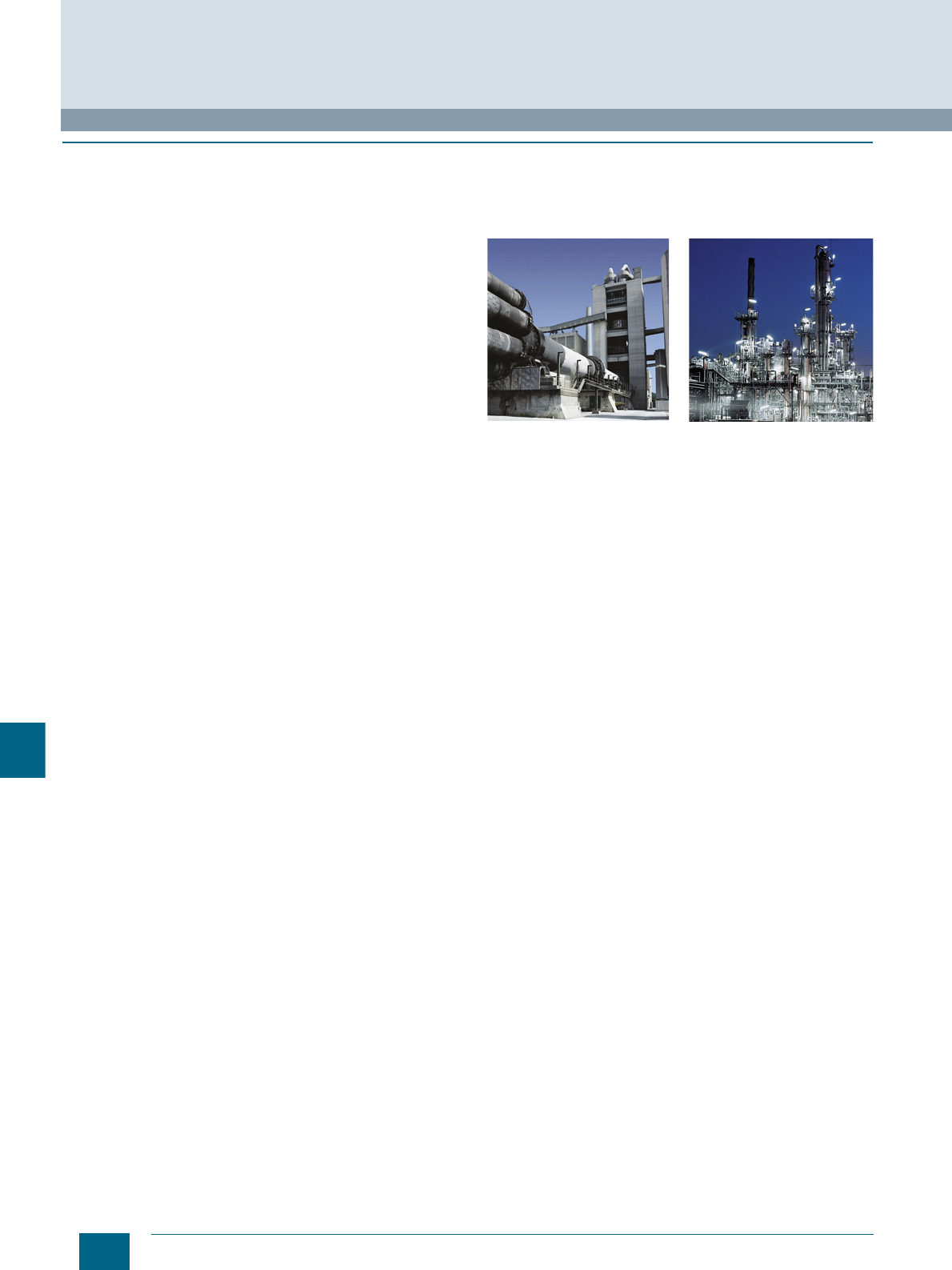
12/6 Siemens LV 52 · 2016
ATEX explosion protection
Appendix
12
■
Overview
In many industries the production, processing, transport and
storage of combustible substances are prone to the escape of
gases, vapors or spray which then find their way into the environ-
ment. Other processes produce combustible dust. Together with
the oxygen in the air, the result can be a potentially explosive
atmosphere which will explode if ignited.
Serious injury to persons and damage to property can result,
particularly in the chemical and petrochemical industries,
mineral oil and natural gas production, mining, mills (e.g. grain,
bulk solids) and many other industrial sectors.
To ensure the maximum possible safety in these areas, legisla-
tors in most countries have drawn up requirements in the form of
laws, regulations and standards. In the course of globalization,
great progress has been made with regard to uniform directives
for explosion protection.
With Directive 94/9/EC, the European Union laid the foundations
for complete harmonization by requiring that all new devices as
from July 1st, 2003 have to be approved in accordance with this
directive.
In this catalog, special attention is drawn to devices which
comply with the ATEX Directive. However, it does not replace the
need for intensive study of the relevant fundamentals and
directives when planning and installing electrical systems.
© Siemens AG 2015© Siemens AG 2015
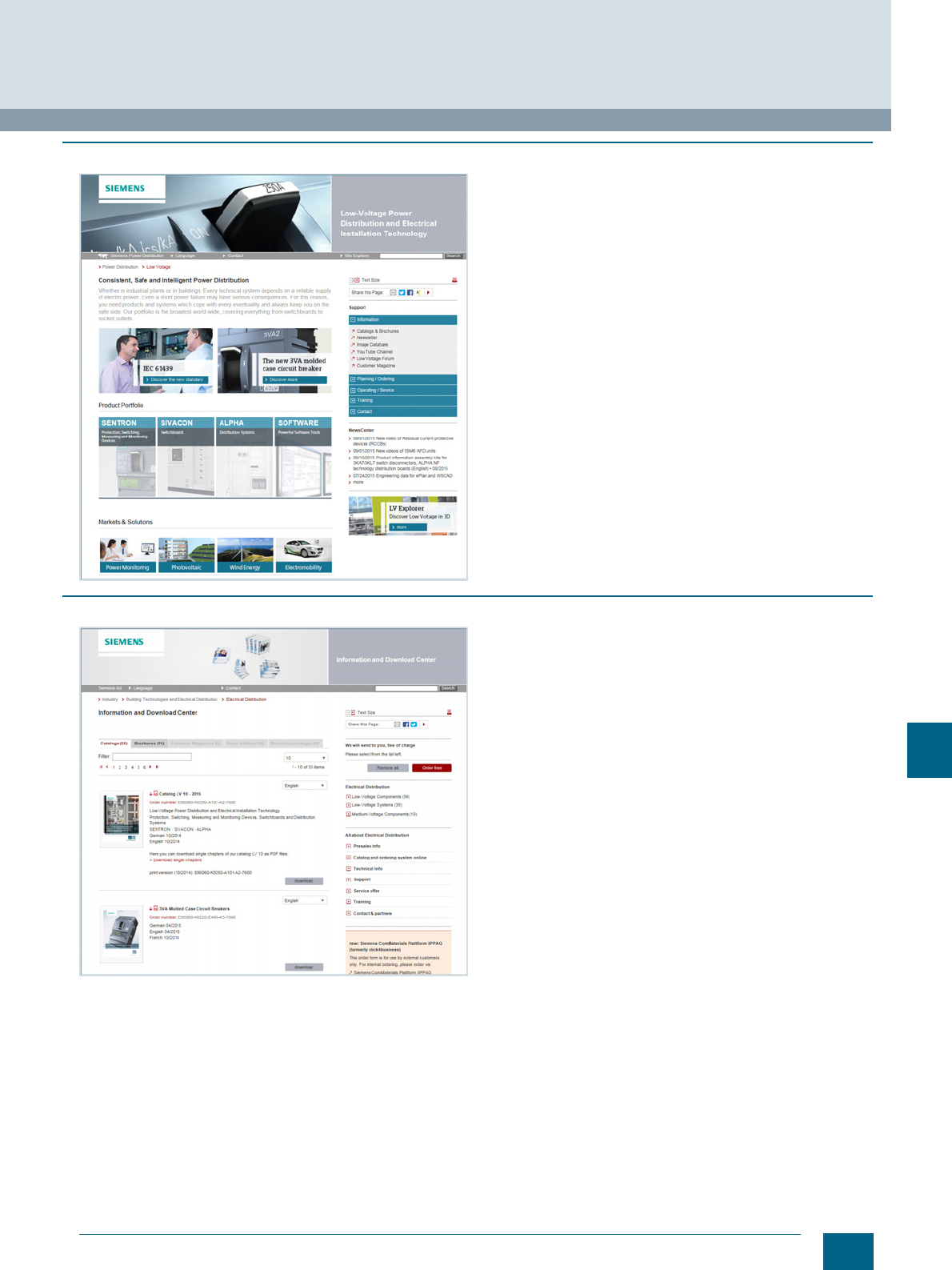
12/7
Siemens LV 52 · 2016
Appendix
Further documentation
12
■
Low-voltage power distribution and electrical installation technology on the WWW
We regard product support to be just as important as the
products and systems themselves.
Visit our website for a comprehensive offering of support for
low-voltage power distribution and electrical installation
products, such as:
• Overview of the entire product portfolio
• Keeping up to date via newsletters, podcasts, blogs and
Twitter
• Access to interesting videos on YouTube
• Contact with partners around the world
• Operating instructions and manuals for direct download
and much more - all conveniently and easily accessible.
www.siemens.com/lowvoltage
■
Information and Download Center
You will find regularly updated information material such as
catalogs, customer magazines, brochures and trial versions of
software for low-voltage power distribution and electrical
installations on the Internet at
www.siemens.com/lowvoltage/infomaterial
Here you can order your copy of the available documentation or
download it in common file formats (PDF, ZIP).
© Siemens AG 2015© Siemens AG 2015
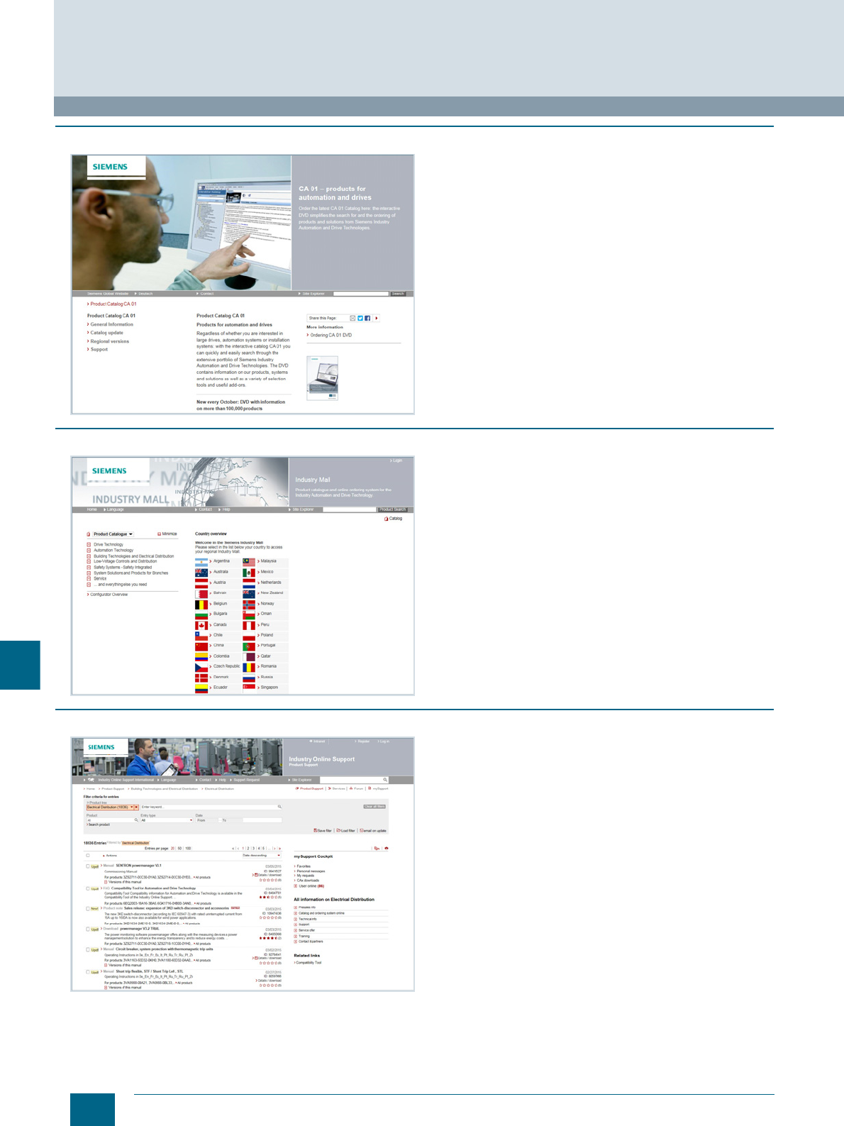
12/8 Siemens LV 52 · 2016
Further documentation
Appendix
12
■
Product selection using the interactive catalog CA 01
Detailed information together with user-friendly interactive
functions:
The interactive catalog CA 01 with more than 80,000 products
provides a comprehensive overview of the product range from
Siemens Industry.
You can find everything you need here for solving automation,
switching, installation and drive technology tasks. All information
is provided over a user interface that is both user-friendly and
intuitive.
After selecting the product of your choice you can order at the
press of a button, by fax or by online link.
Information about the interactive catalog CA 01 can be found on
the Internet at:
www.siemens.com/automation/ca01
or on DVD.
■
Industry Mall
The Industry Mall – for online information, product selection
and ordering:
• Detailed information including product data, illustrations,
certificates and CAx data
• Simple configuring of systems
• Possible to request individualized quotations
• Availability check
• Online ordering facility
• Order tracking/order overview
• Fast access to relevant training offers and services
You can find the Industry Mall on the Internet at
www.siemens.com/industrymall
■
Industry Online Support
Comprehensive support – at any time, whatever your
location
• FAQs, sample applications, information about successor
products and product news
• Prompt assistance with technical queries
• Discussions and best practice sharing with other users in the
forum
• Provision of high-quality product data for your planning
programs
• Faster access to information – with helpful filter and folder
functions in mySupport
• Automatic notification service to keep you up to date with the
latest information about topics of interest to you
To find the link to Siemens Industry Online Support, go to
www.siemens.com/lowvoltage/product-support
© Siemens AG 2015© Siemens AG 2015
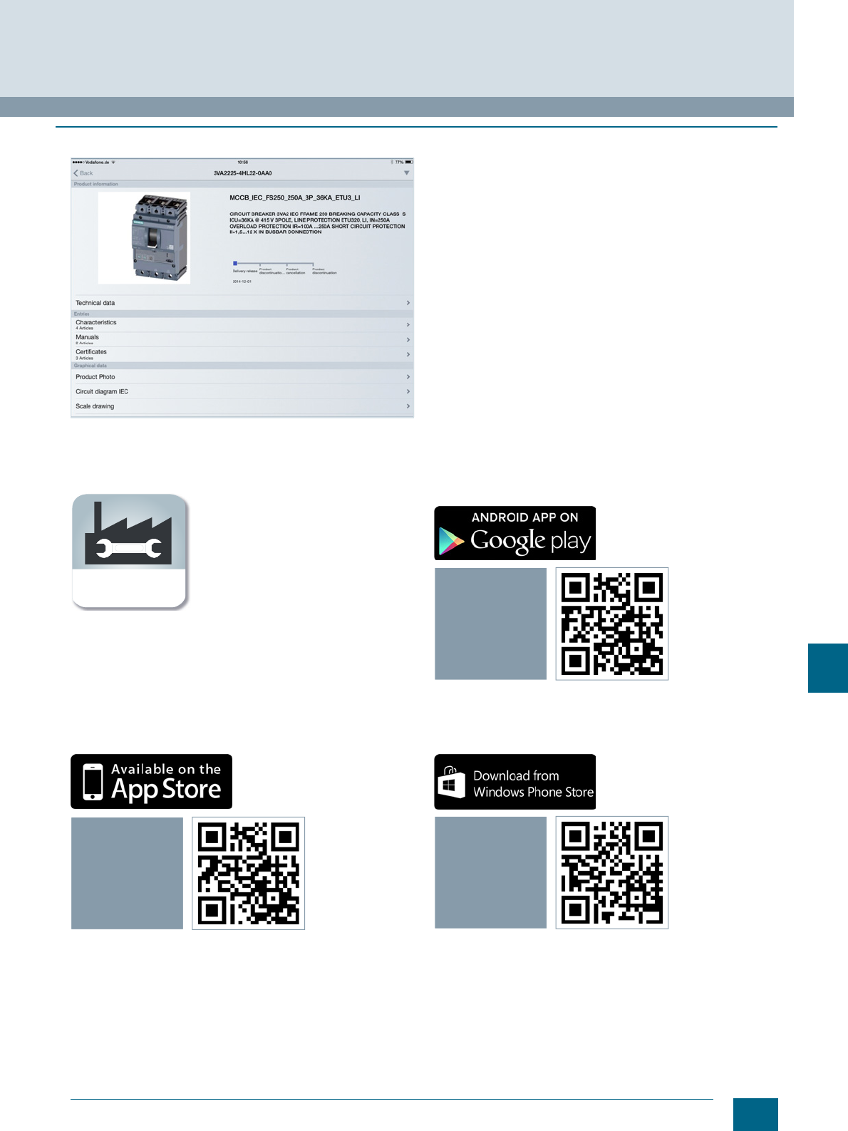
12/9
Siemens LV 52 · 2016
Appendix
Further documentation
12
■
Industry Online Support App
Main functions at a glance
• Scanning of product codes (EAN/QR and data matrix codes)
with direct display of all technical information on the product,
including graphic data (CAx data).
• Delivery of product information or entries by e-mail, so that the
information can immediately be processed at the workplace.
• Submission of queries to Technical Support (Support
Requests). With photo function for transmitting detailed
information.
• Contents and interfaces available in six languages (German,
English, French, Italian, Spanish and Chinese) – including
option of temporary switchover to English.
• Offline cache function for all favorites stored in "mySupport".
These entries can also be retrieved without network reception.
• Import of PDF documents into a library (e.g. iBooks or similar).
• An overview of the main functions can be found at
www.siemens.com/lowvoltage/support-app
Apple iOS:
Android:
Windows:
s
Industry Online
Support App
iOS
Industry Online
Support App
ANDROID
Industry Online
Support App
WINDOWS 8
© Siemens AG 2015© Siemens AG 2015
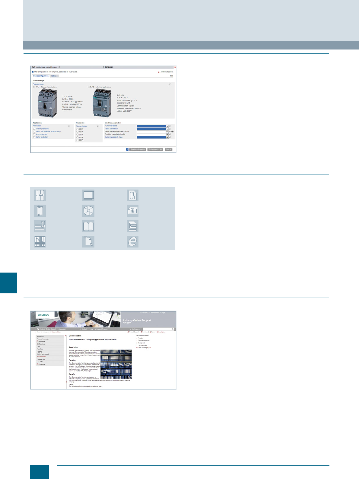
12/10 Siemens LV 52 · 2016
Further documentation
Appendix
12
■
Product configurator
Finding the right product faster
• Complete selection of products and systems based on
technical characteristics or application requirements
• Simple, intuitive operation
• Option to save the configuration and order lists in a file format
of your choice (txt, pdf, xls, csv)
• Direct transfer of the order list into the shopping cart of the
Siemens Industry Mall
• Fast access to product data, diagrams, certificates and CAx
data for the selected product and system configuration
• Available in multiple languages for use by customers
anywhere in the world
The configurators are available online in the Siemens Industry
Mall and offline in Catalog CA 01.
You can find our configurators at the following website:
www.siemens.com/lowvoltage/configurators
■
CAx Download Manager
You can find the CAx Download Manager on the Internet at
Time savings of up to 80 % with universal product data for
your CAE and CAD systems
The CAx Download Manager can supply you with all the neces-
sary CAx file types for the products of your choice for use in all
common CAE and CAD systems. The data contained in the files
is continuously updated. The whole process involves only four
selection steps and is free of charge. All your selected files are
packed into a zip file which you can download for further use.
Siemens makes available up to 12 file types to support your
mechanical (CAD) and electrical (CAE) planning processes for
you to download at any time of the day.
• No manual data collection necessary
• Universal manufacturer data for all common CAE and CAD
systems
• Standardized documentation is simple to generate
• Choice of different languages for system commissioning
anywhere in the world
■
My Documentation Manager
In "mySupport" you can compile individual documentation for
your project by dragging and dropping
* e.g. Low Voltage Directive 2006/95/EC and EC Machinery
Directive 2006/42/EC
You can find My Documentation Manager on the Internet at
www.siemens.com/lowvoltage/mdm
User-friendly compilation of project-specific documentation
In accordance with directives*, the documentation is part of the
plant and requires certification, thus giving the purchaser the
right to full plant documentation.
To support you in this, a manual configurator has been devel-
oped with which you can put together individual and standard-
compliant documentation – fully in accordance with the relevant
project-specific requirements.
You can thus select the chapters relevant to the respective
project from the available manuals of the installed Siemens
components. FAQs, certificates, data sheets and your own
content can also be incorporated.
• Compile and structure manuals, data sheets, FAQs and
certificates simply by dragging and dropping
• Insert personalized content via the Notes function
• Further processing possible thanks to selectable export
formats (pdf, xml, rtf)
• After generating the documentation, automatic translation into
the desired language is possible
• Always up-to-the minute thanks to the Update function
EPLAN Electric
P8 Macros
Data sheets
Certificates
Product images
Characteristic
curves
Operating
instructions
Manuals
Product
master data
3D models
Terminal connection
diagrams
Dimensional
drawings
Internal circuit
diagrams
IC01_00265
© Siemens AG 2015© Siemens AG 2015

12/11
Siemens LV 52 · 2016
Appendix
Quality management
12
■
Overview
The quality management system of our "Low Voltage & Products"
Business Unit in the "Energy Management" Division complies
with the international EN ISO 9001 standard.
The products and systems listed in this catalog are developed
and manufactured using a certified quality management system
in accordance with EN ISO 9001:2008.
© Siemens AG 2015© Siemens AG 2015
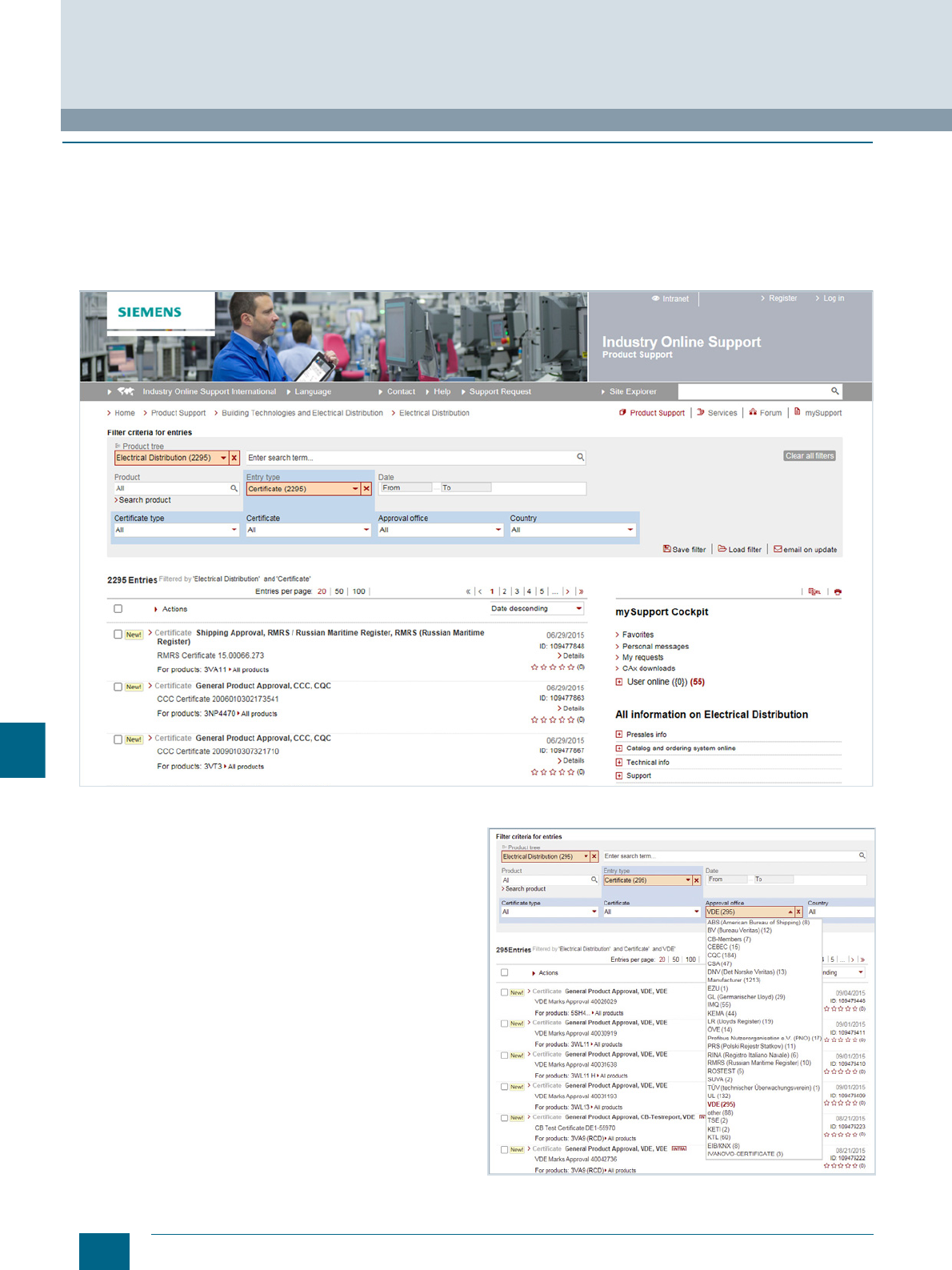
12/12 Siemens LV 52 · 2016
Standards and approvals
Appendix
12
■
Overview
Certificates
An overview, updated on a daily basis, of our products certified
in accordance with CE, UL, CSA, FM, shipping authorizations
etc. for low-voltage power distribution and electrical installation
products can be found on the Internet at
www.siemens.com/lowvoltage/certificates
In the Entry list you can filter the view in order to quickly find
comprehensive information on the following subjects:
• Product or search term
•Date
• Type of certificate (general product approval, test certificates,
shipping approval, ...)
• Certificate (confirmations, UL, VDE,...)
• Approval office (TÜV, VDE, UL, ...)
• Country
© Siemens AG 2015© Siemens AG 2015

12/13
Siemens LV 52 · 2016
Appendix
Standards and approvals
12
■
Approval requirements valid in different countries
Siemens low-voltage switchgear and controlgear are designed,
manufactured and tested according to the relevant German
standards (DIN and VDE), IEC publications and European stan-
dards (EN) as well as CSA and UL standards. You will find the
standards assigned to the single devices in the relevant certifi-
cates at
www.siemens.com/lowvoltage/certificates
In addition to the pertinent VDE, EN and IEC standards, the
requirements of the various regulations valid in other countries
have also been taken into account in the design of the equip-
ment in some cases, in order that the devices can be deployed
globally as far as possible.
In some countries an approval is required for certain low-voltage
switchgear and controlgear components. Depending on the
market requirements, these devices have been submitted for
approval to the authorized testing institutes.
In some cases, CSA for Canada and UL for the USA only
approve special versions. Such special versions are listed
separately from the standard versions in the relevant parts of this
catalog.
For this equipment, there are sometimes limits with regard to the
maximum permissible voltages, currents and rated outputs or
special approvals and, in some cases, special identification may
be required.
For use on board ship, the specifications of the marine classifi-
cation societies must be observed. In some cases, they require
type tests of the components to be approved.
If you have any questions concerning UL/CSA approvals, please
contact Technical Support:
www.siemens.com/lowvoltage/contact
© Siemens AG 2015© Siemens AG 2015
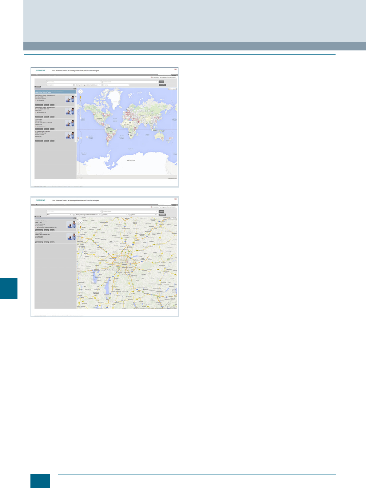
12/14 Siemens LV 52 · 2016
Siemens contacts
Appendix
12
■
Contacts for low-voltage power distribution and electrical installation technology
With low-voltage power distribution and electrical installation
technology we consistently pursue one goal:
long-term improvement of your competitive ability.
We are committed to this goal. Thanks to our dedication, we are
continually setting new standards. In all industries – worldwide.
At your service, locally, around the globe: Partners for
consulting, sales, training, service, support, spare parts ...
on the entire range of low-voltage power distribution and
electrical installation technology.
Your personal contact can be found in our Contact Database at
www.siemens.com/lowvoltage/contact
You start by selecting a
• Competence
• Product or branch
• Country
•City.
© Siemens AG 2015© Siemens AG 2015

12/15
Siemens LV 52 · 2016
Appendix
Service & Support
Unrivaled complete range of services over the entire life cycle
12
■
Online Support Our comprehensive online
information platform covers
every aspect of our
Service & Support and is
available whenever, wherever.
More detailed information is available at
www.siemens.com/lowvoltage/product-support
■
Field Service Siemens Field Service offers
support with all aspects of
maintenance – so that the
availability of your machines
and plants is assured whatever
the case.
More detailed information is available at
www.siemens.com/lowvoltage/contact
■
Technical Support The competent consulting
service for technical issues with
a broad range of customer-
oriented services for all our
products and systems.
More detailed information is available at
www.siemens.com/lowvoltage/contact
■
Spare Parts Plants and systems in all indus-
tries worldwide are expected to
meet ever higher levels of avail-
ability.
We can help you rule out unex-
pected stoppages: with a global
network and optimum logistics
chains.
You will find further information at
www.siemens.com/lowvoltage/contact
■
Training
Extend your lead – with practice-
related
know-how straight from
the manufacturer.
More detailed information is available at
www.siemens.com/lowvoltage/training
■
Specification texts
You can obtain qualified, free support to help you produce
specifications for technically equipping non-residential and
industrial buildings at
www.siemens.com/specifications
© Siemens AG 2015© Siemens AG 2015
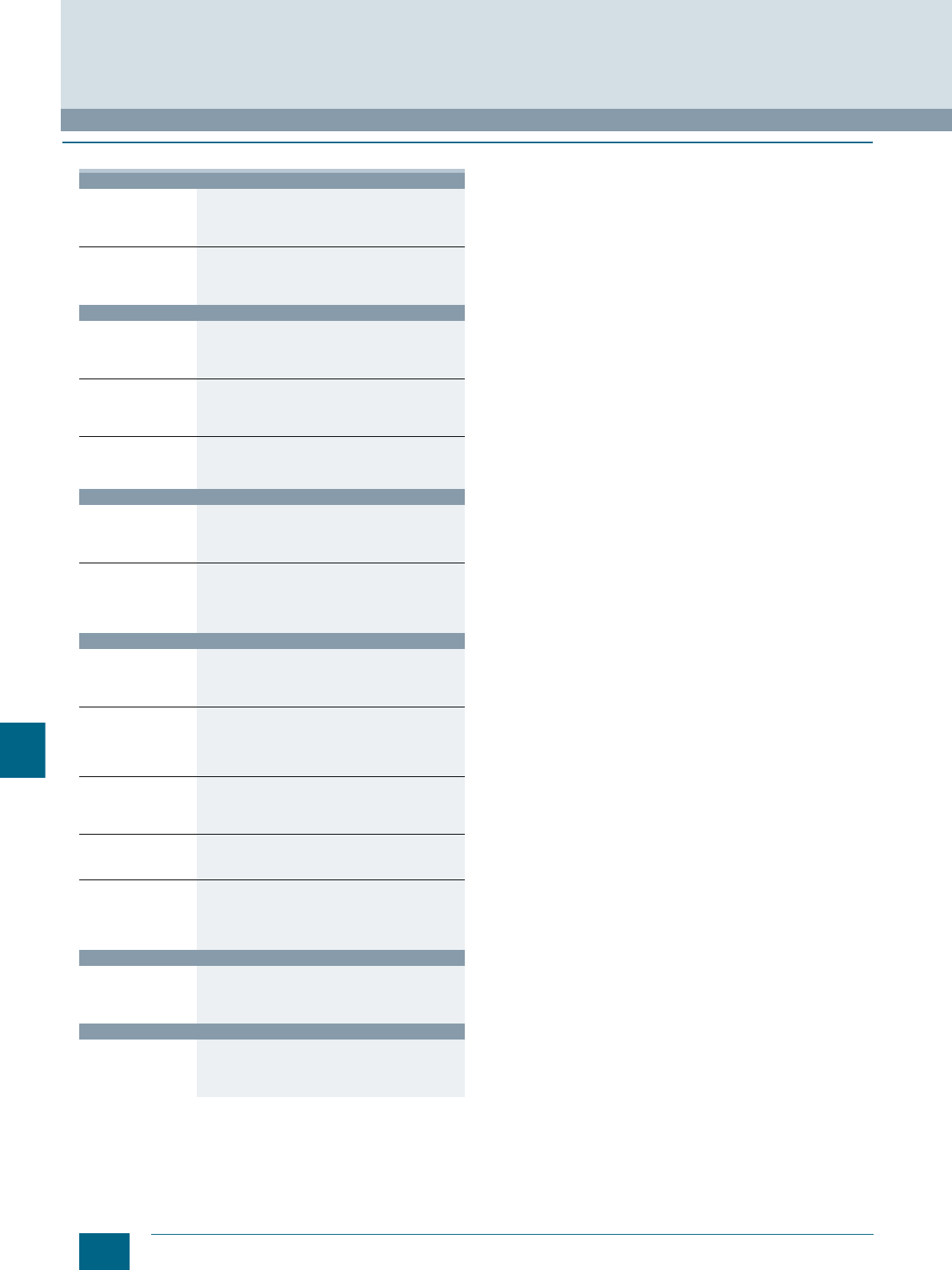
12/16 Siemens LV 52 · 2016
Comprehensive support from A to Z
Appendix
12
■
Overview
Product information
Website Fast and targeted information on low-voltage power
distribution and electrical installation technology:
www.siemens.com/lowvoltage
Newsletter Always up to date about our trend-setting products
and systems:
www.siemens.com/lowvoltage/newsletter
Product information/product & system selection
Information and
Download Center Current catalogs, customer magazines, brochures,
demo software and promotion packages:
www.siemens.com/lowvoltage/infomaterial
Industry Mall Comprehensive information and order platform for
the Siemens Industry Basket:
www.siemens.com/lowvoltage/mall
CA 01 The interactive catalog on DVD for automation and
drive technology and low-voltage power distribution
and electrical installation products
Product and system engineering
SIMARIS
software tools Support in planning and configuring the electrical
power distribution:
www.siemens.com/simaris
SIMARIS
ConFiguration Basic
planning and
configuration tool
Assists in generating offers and configuring products
ranging from ALPHA distribution boards to the
SIKUS 1600 power distribution boards
www.siemens.com/scfb
Product documentation
Siemens Industry
Online Support Comprehensive technical information - from planning
to configuration and operation:
www.siemens.com/lowvoltage/product-support
Product configurator Complete selection of products and systems based
on technical characteristics or application
requirements:
www.siemens.com/lowvoltage/configurators
CAx Download
Manager Collation of CAx data types for standard CAE and
CAD systems:
www.siemens.com/lowvoltage/cax
My Documentation
Manager Compilation of project-specific documentation:
www.siemens.com/lowvoltage/mdm
Image database Collection of product photographs and graphics,
such as dimensional drawings and internal circuit
diagrams:
www.siemens.com/lowvoltage/picturedb
Product training
SITRAIN Portal Comprehensive training program for our products,
systems and engineering tools:
www.siemens.com/lowvoltage/training
Product hotline
Technical Support Support in all technical queries about our products:
www.siemens.com/lowvoltage/contact
www.siemens.com/lowvoltage/technical-support
© Siemens AG 2015© Siemens AG 2015

12/17
Siemens LV 52 · 2016
Appendix
Software Licenses
12
■
Overview
Software types
Software requiring a license is categorized into types.
The following software types have been defined:
• Engineering software
• Runtime software
Engineering software
This includes all software products for creating (engineering)
user software, e.g. for configuring, programming, parameteriz-
ing, testing, commissioning or servicing.
Data generated with engineering software and executable
programs can be duplicated for your own use or for use by third-
parties free-of-charge.
Runtime software
This includes all software products required for plant/machine
operation, e.g. operating system, basic system, system expan-
sions, drivers, etc.
The duplication of the runtime software and executable pro-
grams created with the runtime software for your own use or for
use by third-parties is subject to a charge.
You can find information about license fees according to use in
the ordering data (e.g. in the catalog). Examples of categories of
use include per CPU, per installation, per channel, per instance,
per axis, per control loop, per variable, etc.
Information about extended rights of use for parameteriza-
tion/configuration tools supplied as integral components of the
scope of delivery can be found in the readme file supplied with
the relevant product(s).
License types
Siemens Industry Automation & Drive Technologies offers vari-
ous types of software license:
• Floating license
• Single license
• Rental license
• Rental floating license
• Trial license
• Demo license
• Demo floating license
Floating license
The software may be installed for internal use on any number of
devices by the licensee. Only the concurrent user is licensed.
The concurrent user is the person using the program. Use
begins when the software is started.
A license is required for each concurrent user.
Single license
Unlike the floating license, a single license permits only one
installation of the software per license.
The type of use licensed is specified in the ordering data and
in the Certificate of License (CoL). Types of use include for
example per instance, per axis, per channel, etc.
One single license is required for each type of use defined.
Rental license
A rental license supports the "sporadic use" of engineering
software. Once the license key has been installed, the software
can be used for a specific period of time (the operating hours do
not have to be consecutive).
One license is required for each installation of the software.
Rental floating license
The rental floating license corresponds to the rental license,
except that a license is not required for each installation of the
software. Rather, one license is required per object (for example,
user or device).
Trial license
A trial license supports "short-term use" of the software in a non-
productive context, e.g. for testing and evaluation purposes.
It can be transferred to another license.
Demo license
The demo license support the "sporadic use" of engineering soft-
ware in a non-productive context, for example, use for testing
and evaluation purposes. It can be transferred to another
license. After the installation of the license key, the software can
be operated for a specific period of time, whereby usage can be
interrupted as often as required.
One license is required per installation of the software.
Demo floating license
The demo floating license corresponds to the demo license,
except that a license is not required for each installation of the
software. Rather, one license is required per object (for example,
user or device).
Certificate of license (CoL)
The CoL is the licensee's proof that the use of the software has
been licensed by Siemens. A CoL is required for every type of
use and must be kept in a safe place.
Downgrading
The licensee is permitted to use the software or an earlier ver-
sion/release of the software, provided that the licensee owns
such a version/release and its use is technically feasible.
Delivery versions
Software is constantly being updated.
The following delivery versions
• PowerPack
• Upgrade
can be used to access updates.
Existing bug fixes are supplied with the ServicePack version.
PowerPack
PowerPacks can be used to upgrade to more powerful software.
The licensee receives a new license agreement and CoL
(Certificate of License) with the PowerPack. This CoL, together
with the CoL for the original product, proves that the new soft-
ware is licensed.
A separate PowerPack must be purchased for each original
license of the software to be replaced.
Upgrade
An upgrade permits the use of a new version of the software on
the condition that a license for a previous version of the product
is already held.
The licensee receives a new license agreement and CoL with
the upgrade. This CoL, together with the CoL for the previous
product, proves that the new version is licensed.
A separate upgrade must be purchased for each original license
of the software to be upgraded.
© Siemens AG 2015© Siemens AG 2015

12/18 Siemens LV 52 · 2016
Software Licenses
Appendix
12
■
Overview
ServicePack
ServicePacks are used to debug existing products.
ServicePacks may be duplicated for use as prescribed accord-
ing to the number of existing original licenses.
License key
Siemens Industry Automation & Drive Technologies supplies
software products with and without license keys.
The license key serves as an electronic license stamp and
is also the "switch" for activating the software (floating license,
rental license, etc.).
The complete installation of software products requiring license
keys includes the program to be licensed (the software) and the
license key (which represents the license).
Software Update Service (SUS)
As part of the SUS contract, all software updates for the respec-
tive product are made available to you free of charge for a period
of one year from the invoice date. The contract will automatically
be extended for one year if it is not canceled three months
before it expires.
The possession of the current version of the respective software
is a basic condition for entering into an SUS contract.
You can download explanations concerning license conditions from
www.siemens.com/automation/salesmaterial-as/catalog/en/
terms_of_trade_en.pdf
© Siemens AG 2015© Siemens AG 2015

12/19
Siemens LV 52 · 2016
Appendix
Subject index
12
A
Accessories
• 8WA ......................................................................................................11/2
• 8WH ........................................................................................................8/2
Actuator terminals .....................................................................................10/4
ALPHA FIX PRINT
• Printer labeling system ..................................................................8/2, 11/2
ALPHA FIX terminal blocks .........................................................................1/2
• 8WA accessories ..................................................................................11/2
• 8WA screw terminals ..............................................................................9/2
• 8WA1 screw terminals ............................................................................9/2
• 8WH accessories ...................................................................................8/2
• 8WH combination plug-in terminals .......................................................5/2
• 8WH iPo installation terminals ................................................................3/2
• 8WH iPo plug-in terminals ......................................................................2/2
• 8WH spring-loaded terminals ..........................................................4/2, 4/3
• 8WH1 screw terminals ............................................................................7/2
• 8WH2 spring-loaded terminals ...............................................................4/2
• 8WH3 insulation displacement terminals ...............................................6/2
• 8WH5 combination plug-in terminals .....................................................5/2
• 8WH6 iPo installation terminals ..............................................................3/2
• 8WH6 iPo plug-in terminals ....................................................................2/2
• Spring-loaded terminals .........................................................................1/2
B
Barriers ........................................................9/14, 9/18, 9/20, 9/23, 9/26, 9/29
Branch terminals 8WA ..............................................................................9/15
Bridging links ............................................................................................9/25
C
Combination plug-in terminals 8WH ...........................................................5/2
Combs ......................................................................................................7/27
Compartment partitions ...............................2/10, 2/13, 2/15, 2/17,4/17, 4/22,
........................................................................4/24, 4/26, 4/32, 4/38, 4/40,5/6,
.............................................................................................5/7,6/8, 6/10, 6/12
Connecting combs .....................................................................................8/9
Connection bars ...................................................9/14, 9/18, 9/20, 9/26, 9/29
Connection combs ....................................................................................9/29
Connection modules .................................................................................10/4
Cover segments ....................................2/10, 4/17, 4/24, 4/26, 4/38, 6/8, 6/12
Covers .............................................................2/10, 2/17, 3/5, 3/9, 3/14, 4/17,
.....................................................................4/20, 4/24, 4/26, 4/32, 4/36, 4/38,
...........................................................................4/40, 5/6, 5/7, 6/8, 6/10, 6/12,
........................................................................................9/13, 9/18, 9/20, 9/26
• For connection bars ....................................................................9/16, 9/29
• For screw terminals .......................................................................3/7, 3/11
• For terminal size 2.5 mm² ............................................................2/13, 2/15
• For terminal size 4 mm² .............................................2/11, 2/13, 2/15, 2/17
• For three-tier terminals .........................................................................4/34
D
Device labels .....................................................................................8/2, 11/2
Diode terminals .......................................................................4/37, 9/21, 9/23
Diode terminals 8WH ................................................................................7/20
Disconnecting links .................................................................9/14, 9/20, 9/29
E
End labeling plates ...................................................................................11/4
End plates ........................................................................................9/20, 9/22
End retainers
• Steel ......................................................................................................11/5
• Thermoplast .................................................................................9/13, 9/18
• With screw fixing ..................................................................................11/5
F
Feeder terminals .......................................................................................10/4
• For N-busbars ....................................................3/9, 3/14, 8/10, 9/16, 9/18
Four-tier motor terminals 8WH ..................................................................4/35
Fuse terminals 8WA ..................................................................................9/25
Fuse terminals 8WH ...........................................................................4/21, 7/8
G
G fuse links ...............................................................................................9/25
H
High-current terminals 8WH .....................................................................7/24
Hybrid through-type terminals 8WH .........................................................4/18
Hybrid through-type terminals with iPo connection 8WH5 .........................5/7
I
Initiator terminals ......................................................................................10/4
Initiator/actuator terminals 8WA ................................................................10/2
Insertion profiles .......................................................................................7/27
Insta terminal ............................................................................................9/17
Installation terminals 8WH ........................................................................3/12
Instrument isolating terminals 8WA ..........................................................9/29
Insulation carriers .....................................................................................11/5
• For mounting insulated support rails ...................................................9/18
Insulation displacement terminals 8WH3 ...................................................6/2
Insulation plates .....................................................................9/14, 9/20, 9/29
iPo plug-in terminals 8WH ..........................................................................2/2
Isolating blade terminal ............................................................................ 2/12
Isolating blade terminals 8WH ........................................................4/23, 7/10
Isolating terminal ......................................................................................9/28
Isolating terminal 8WH ........................................................... 4/25, 6/11, 7/11
Isolating terminals 8WH6 ..........................................................................2/14
J
Jumpers ...........................................................................................9/13, 9/20
L
Label holders ............................................................................................9/16
• For three-tier terminals .........................................................................4/34
Labeling system
• Printer ~ .........................................................................................8/2, 11/2
• Standard ~ .................................................................................... 8/3, 11/3
Labels
• Custom inscriptions .............................................................................11/4
• Flat .............................................................................8/3, 8/4, 8/5, 8/6, 8/7
• For manual labeling ....................................................................9/18, 11/3
• Front ........................................................................... 8/3, 8/4, 8/5, 8/6, 8/7
• Type 847/848 ........................................................................................11/3
• Type 860/861 ........................................................................................11/3
Latches .....................................................................................................5/10
M
Measuring transformer terminals 8WA ............................................7/17, 9/27
Modular test plugs ......................................................................................8/8
Mounting accessories 8WA ......................................................................11/5
Mounting accessories 8WH .......................................................................8/8
Mounting brackets ....................................................................................11/5
N
N-busbars ...............................................................3/9, 3/11, 3/14, 7/31, 8/10
• 6 × 6 mm .....................................................................................9/16, 9/18
N-conductor isolating 8WH ...............................................................3/8, 3/10
N-conductor isolating terminals ...............................................................9/15
© Siemens AG 2015© Siemens AG 2015

12/20 Siemens LV 52 · 2016
Subject index
Appendix
12
P
PE high-current terminals 8WH .................................................................7/24
PE hybrid through-type terminals 8WH ....................................................4/18
PE plugs 8WH9 ...........................................................................................5/8
PE through-type terminals .................................................................4/7–4/17
• With screw terminals ..............................................................................3/6
PE through-type terminals 8WA .........................................................9/9–9/13
PE through-type terminals 8WH ...........................................................5/7, 6/5
PE through-type terminals 8WH5 ................................................................5/5
PE two-tier terminals 8WH ........................................................4/27–4/32, 6/9
Permanent links ........................................................................................7/27
Plug-in zone connectors
• For isolating terminals ..........................................................................8/10
Plugs
• For components ...................................................................................9/24
Plugs 8WH9 ................................................................................................5/8
Printer labeling system
• ALPHA FIX PRINT ..........................................................................8/2, 11/2
Q
Quick-fit end retainers ................................................................................8/8
R
Reducing combs ........................................................................................8/8
S
Screw terminals 8WA1 ................................................................................9/2
Screw terminals 8WH1 ................................................................................7/2
Screwdrivers ...............................................................................................8/9
• For 8WA2 ..............................................................................................11/5
Shield terminals 8WH ................................................................................7/28
Spacer brackets .......................................................................................11/5
Spacer plates ..............................................................................................8/8
Spacers .....................................................................................................11/5
Spring-loaded terminals .............................................................................1/2
Spring-loaded terminals 8WH .....................................................................4/2
Standard labeling system ..................................................................8/3, 11/3
Standard mounting rails ............................................................................11/5
Support brackets ...............................................................3/5, 3/9, 3/14, 7/31
T
Tap-off terminals .......................................................................................7/27
Terminal
• For components ...................................................................................9/24
• With red LED ........................................................................................9/22
Terminal strip labels .........................................................................9/18, 11/4
Terminal strip markers
• For end retainers ....................................................................................8/8
Terminals ..................................................................................................3/11
Test adapters ..............................................................................................8/8
Test sockets ..............................................................................................9/29
Three-tier terminal 8WA ............................................................................9/17
Through-type terminals .....................................................................3/4, 9/28
• With sectionalizing feature ...................................................................9/23
Through-type terminals 8WA ......................................................................9/9
• With soldered and plug-in connection .................................................9/26
Through-type terminals 8WH .......................................... 3/4, 4/7, 5/7, 6/5, 7/4
• With screw terminals ..............................................................................3/6
Through-type terminals 8WH5 ....................................................................5/5
Through-type terminals 8WH6 ....................................................................2/4
Two-tier diode terminals 8WH ..........................................................4/39, 7/21
Two-tier terminals 8WA .............................................................................9/19
• With electronic components .................................................................9/21
Two-tier terminals 8WH ...............................................4/27, ??–4/32, 6/9, 7/12
• With isolating blade ..............................................................................7/15
• With isolating function ..........................................................................7/15
Two-tier terminals 8WH6 ...........................................................................2/16
W
Warning covers .........................................................................................4/17
Z
Zener diode terminals ..............................................................................9/22
© Siemens AG 2015© Siemens AG 2015

12/21
Siemens LV 52 · 2016
Appendix
Article No. index incl. export markings
12
■
Overview
Article No. Page Export markings
ECCN AL
3T
3TX4210-0J 9/15, 9/16 N N
5T
5ST1141 11/5 N N
5ST1142 11/5 N N
5ST1145 11/5 N N
8GF
8GF9324-2 9/15, 9/16, 9/18 N N
8WA1
8WA1010-1PH01 9/11 N N
8WA1010-1PQ00 7/26 N N
8WA1011-0DF21 9/9 N N
8WA1011-0DF22 9/9 N N
8WA1011-0DG21 9/10 N N
8WA1011-0DG22 9/10 N N
8WA1011-1BF21 9/9 N N
8WA1011-1BF22 9/9 N N
8WA1011-1BF23 9/9 N N
8WA1011-1BF24 9/9 N N
8WA1011-1BF25 9/9 N N
8WA1011-1BF26 9/9 N N
8WA1011-1BG11 9/10 N N
8WA1011-1BG21 9/10 N N
8WA1011-1BG22 9/10 N N
8WA1011-1BG24 9/10 N N
8WA1011-1BH23 9/11 N N
8WA1011-1BH24 9/11 N N
8WA1011-1BK11 9/12 N N
8WA1011-1BM11 9/12 N N
8WA1011-1BP11 9/13 N N
8WA1011-1DF11 9/9 N N
8WA1011-1DG11 9/10 N N
8WA1011-1DH11 9/11 N N
8WA1011-1EE00 9/24 N N
8WA1011-1EF20 9/23 N N
8WA1011-1MH10 9/28 N N
8WA1011-1MH11 9/28 N N
8WA1011-1MH15 9/29 N N
8WA1011-1NF01 9/15 N N
8WA1011-1NG31 9/15 N N
8WA1011-1NH01 9/16 N N
8WA1011-1PF00 9/9 N N
8WA1011-1PF01 9/9 N N
8WA1011-1PG00 9/10 N N
8WA1011-1PG01 9/10 N N
8WA1011-1PH00 9/11 N N
8WA1011-1PK00 9/12 N N
8WA1011-1PM00 9/13 N N
8WA1011-1SF12 9/25 N N
8WA1011-1SF13 9/25 N N
8WA1011-1SF15 9/25 N N
8WA1011-1SF30 9/25 N N
8WA1011-1SF31 9/25 N N
8WA1011-1SF32 9/25 N N
8WA1011-2BG11 9/19 N N
8WA1011-2DG11 9/19 N N
8WA1011-3DF21 9/9 N N
8WA1011-3DG21 9/10 N N
8WA1011-3DH21 9/11 N N
8WA1011-3JF16 9/17 N N
8WA1011-3JF17 9/17 N N
8WA1011-3JF18 9/17 N N
8WA1011-3JF20 9/17 N N
8WA1011-6BG11 9/19 N N
8WA1011-6DG11 9/19 N N
8WA1011-6EG20 9/21 N N
8WA1011-6EG22 9/21 N N
8WA1011-6EG23 9/21 N N
8WA1011-6EG24 9/21 N N
8WA1011-6EG25 9/22 N N
8WA1011-6EG44 9/22 N N
8WA1204 9/12 N N
8WA1205 9/12 N N
8WA1206 9/13 N N
8WA1216 9/13, 9/14 N N
8WA1221 9/26 N N
8WA1304 9/12 N N
8WA1305 9/12 N N
8WA1501 9/23 N N
8WA1604 9/16 N N
8WA1802 9/12, 9/14 N N
8WA1803 9/12, 9/14 N N
8WA1804 9/12, 9/14 N N
8WA1805 11/5 N N
8WA1806 11/4 N N
8WA1808 9/13, 9/18, 11/5 N N
8WA1810 9/9, 9/13, 9/26 N N
8WA1811 9/10, 9/11, 9/13, 9/18,
9/19, 9/20, 9/26 N N
8WA1812 9/12, 9/13 N N
8WA1813 9/12, 9/13 N N
8WA1814 9/13 N N
8WA1817 9/19, 9/20, 9/21, 9/22 N N
8WA1820 9/9, 9/10, 9/14, 9/23, 9/26 N N
8WA1821 9/11, 9/12, 9/14, 9/26 N N
8WA1822-7AX00 9/15, 9/16 N N
8WA1822-7AX01 9/9, 9/10, 9/11, 9/13, 9/18,
9/19, 9/20, 9/28, 9/29 N N
8WA1822-7AX02 9/12, 9/13 N N
8WA1822-7AX03 9/9, 9/10, 9/13, 9/28, 9/29 N N
8WA1822-7AX03 9/18 N N
8WA1822-7EE00 9/24 N N
8WA1822-7EF16 9/25 N N
8WA1822-7EF18 9/25 N N
8WA1822-7EF21 9/25 N N
8WA1822-7EF23 9/25 N N
8WA1822-7EF25 9/25 N N
8WA1822-7EF76 9/25 N N
8WA1822-7EF78 9/25 N N
8WA1822-7EF81 9/25 N N
8WA1822-7EF83 9/25 N N
Article No. Page Export markings
ECCN AL
© Siemens AG 2015© Siemens AG 2015
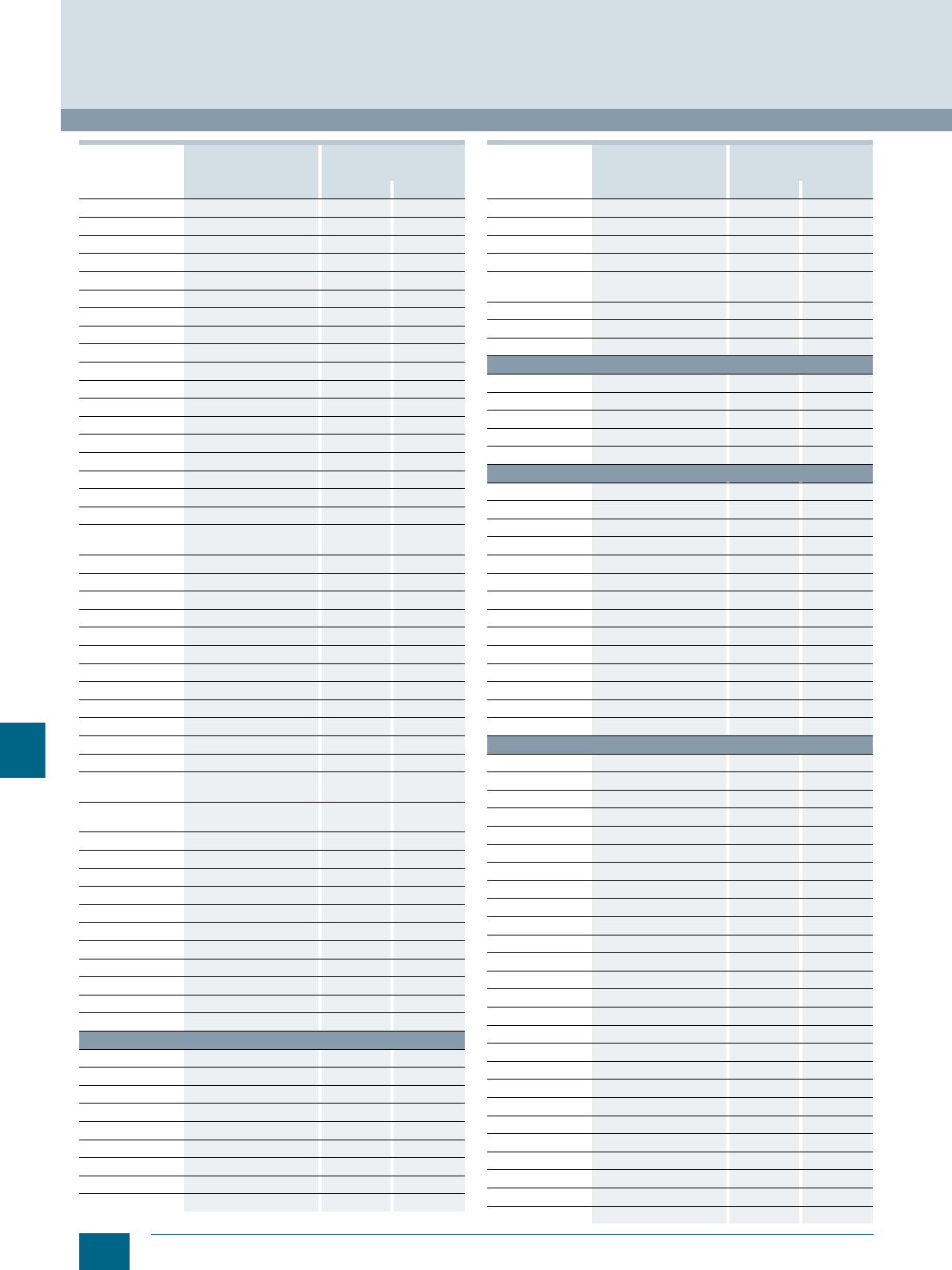
12/22 Siemens LV 52 · 2016
Article No. index incl. export markings
Appendix
12
8WA1822-7EF85 9/25 N N
8WA1822-7PH00 9/28, 9/29 N N
8WA1822-7TH00 9/17, 9/18, 9/28, 9/29 N N
8WA1822-7TK00 9/12, 9/14 N N
8WA1822-7VF01 9/9, 9/13 N N
8WA1822-7VF02 9/18 N N
8WA1822-7VF03 9/18 N N
8WA1822-7VF10 9/18 N N
8WA1822-7VG00 9/10, 9/13, 9/19, 9/20 N N
8WA1822-7VG01 9/19, 9/20 N N
8WA1822-7VH00 9/11, 9/13 N N
8WA1822-7VH01 9/29 N N
8WA1822-7VH10 9/28, 9/29 N N
8WA1822-7VH12 9/26 N N
8WA1822-7VH20 9/26 N N
8WA1822-7VH22 9/28, 9/29 N N
8WA1823 9/12, 9/13, 9/14, 9/19, 9/20 N N
8WA1824 9/13, 9/14 N N
8WA1825 9/9, 9/10, 9/11, 9/14, 9/19,
9/20, 9/28, 9/29 N N
8WA1828 9/12, 9/14 N N
8WA1835 9/19, 9/20 N N
8WA1838 9/19, 9/20 N N
8WA1842 9/12, 9/14 N N
8WA1845 9/12, 9/14 N N
8WA1848 9/12, 9/14 N N
8WA1850 9/10, 9/14, 9/19, 9/20 N N
8WA1851 9/10, 9/14, 9/19, 9/20 N N
8WA1852 9/10, 9/14, 9/19, 9/20 N N
8WA1853 9/10, 9/14, 9/19, 9/20 N N
8WA1857 9/18, 11/5 N N
8WA1860 9/9, 9/13, 9/26 N N
8WA1862 9/10, 9/11, 9/13, 9/18,
9/19, 9/20, 9/26 N N
8WA1865 9/9, 9/10, 9/11, 9/14, 9/19,
9/20 N N
8WA1885 9/11, 9/14, 9/28, 9/29 N N
8WA1886 9/11, 9/14, 9/28, 9/29 N N
8WA1887 9/11, 9/14, 9/28, 9/29 N N
8WA1888 9/11, 9/14, 9/28, 9/29 N N
8WA1891 9/25 N N
8WA1892 9/12, 9/13 N N
8WA1893 9/12, 9/13 N N
8WA1895 9/9, 9/14 N N
8WA1896 9/9, 9/14 N N
8WA1897 9/9, 9/14 N N
8WA1898 9/9, 9/14 N N
8WA2
8WA2011-3KE00 10/4 N N
8WA2011-3KE01 10/4 N N
8WA2011-3KE02 10/4 N N
8WA2011-3KE10 10/4 N N
8WA2011-3KE11 10/4 N N
8WA2011-3KE12 10/4 N N
8WA2011-3KE13 10/4 N N
8WA2011-3KE30 10/4 N N
8WA2011-3KE31 10/4 N N
Article No. Page Export markings
ECCN AL
8WA2011-3KE33 10/4 N N
8WA2011-3KE50 10/4 N N
8WA2011-3KE51 10/4 N N
8WA2842 3/9, 3/11, 3/14, 7/31, 8/10 N N
8WA2867 3/9, 3/14, 8/10, 9/15, 9/16,
9/18 N N
8WA2868 3/9, 3/14, 8/10, 9/16, 9/18 N N
8WA2870 3/9, 3/14, 8/10, 9/16, 9/18 N N
8WA2880 11/5 N N
8WA7
8WA7163 9/28, 9/29 N N
8WA746 11/5 N N
8WA752 11/5 N N
8WA753 11/5 N N
8WA7551 11/5 N N
8WA8
8WA8212-0AA65 9/18, 11/4 EAR99 N
8WA8310-2AY 11/3 N N
8WA8347-@@@ 11/3
8WA8347-0XA 11/4 N N
8WA8348-@@@ 11/3
8WA8348-0XA 11/4 N N
8WA8348-2AY 9/18, 11/3 EAR99 N
8WA8360-@@@ 11/3
8WA8361-@@@ 11/3
8WA8826-0AA 11/4 N N
8WA8826-0AB 11/4 N N
8WA8826-0AC 11/4 N N
8WA8850-2AY 11/2 N N
8WA8851-2AY 11/2 N N
8WH1
8WH1000-0AF00 7/5 N N
8WH1000-0AF01 7/5 N N
8WH1000-0AF02 7/5 N N
8WH1000-0AF03 7/5 N N
8WH1000-0AF04 7/5 N N
8WH1000-0AF06 7/5 N N
8WH1000-0AF08 7/5 N N
8WH1000-0AG00 7/5 N N
8WH1000-0AG01 7/5 N N
8WH1000-0AG02 7/5 N N
8WH1000-0AG04 7/5 N N
8WH1000-0AG08 7/5 N N
8WH1000-0AH00 7/6 N N
8WH1000-0AH01 7/6 N N
8WH1000-0AH02 7/6 N N
8WH1000-0AH08 7/6 N N
8WH1000-0AJ00 7/6 N N
8WH1000-0AJ01 7/6 N N
8WH1000-0AK00 7/6 N N
8WH1000-0AK01 7/6 N N
8WH1000-0AM00 7/7 N N
8WH1000-0AM01 7/7 N N
8WH1000-0AN00 7/26 N N
8WH1000-0AN01 7/26 N N
8WH1000-0AQ00 7/26 N N
8WH1000-0AQ01 7/26 N N
Article No. Page Export markings
ECCN AL
© Siemens AG 2015© Siemens AG 2015

12/23
Siemens LV 52 · 2016
Appendix
Article No. index incl. export markings
12
8WH1000-0AS00 7/27 N N
8WH1000-0AS01 7/27 N N
8WH1000-0AU00 7/27 N N
8WH1000-0AU01 7/27 N N
8WH1000-0CF07 7/5 N N
8WH1000-0CG07 7/5 N N
8WH1000-0CH07 7/6 N N
8WH1000-0CJ07 7/6 N N
8WH1000-0CK07 7/7 N N
8WH1000-0CM07 7/7 N N
8WH1000-0CN07 7/26 N N
8WH1000-0CQ07 7/26 N N
8WH1000-1GG08 7/9 N N
8WH1000-1HH08 7/9 N N
8WH1000-1KG38 7/9 N N
8WH1000-1MG88 7/9 N N
8WH1000-1PH38 7/9 N N
8WH1000-6AG00 7/11 N N
8WH1000-6AH00 7/11 N N
8WH1000-6CG00 7/10 N N
8WH1000-6KG00 7/20 N N
8WH1000-6LG00 7/20 N N
8WH1000-7AH00 7/18 N N
8WH1000-7BH00 7/18 N N
8WH1001-0AK00 3/6 N N
8WH1001-0AK01 3/6 N N
8WH1001-0AM00 3/7 N N
8WH1001-0AM01 3/7 N N
8WH1001-0BJ01 3/11 N N
8WH1001-0BK01 3/11 N N
8WH1001-0BM01 3/11 N N
8WH1001-0CK07 3/7 N N
8WH1001-0CM07 3/7 N N
8WH1020-0AF00 7/13 N N
8WH1020-0AF01 7/13 N N
8WH1020-0AG00 7/14 N N
8WH1020-0AG01 7/14 N N
8WH1020-0CF07 7/13 N N
8WH1020-0CG07 7/14 N N
8WH1020-5AF00 7/22 N N
8WH1020-5BF00 7/22 N N
8WH1020-5DF00 7/22 N N
8WH1020-5FF00 7/22 N N
8WH1020-5HF00 7/22 N N
8WH1020-5JF30 7/22 N N
8WH1020-5LF00 7/23 N N
8WH1020-6AC00 7/16 N N
8WH1020-6AG00 7/16 N N
8WH1025-0AF00 7/13 N N
8WH1025-0AG00 7/14 N N
8WH2
8WH2000-0AE00 4/10 N N
8WH2000-0AE01 4/10 N N
8WH2000-0AE02 4/10 N N
8WH2000-0AE03 4/10 N N
8WH2000-0AE04 4/10 N N
Article No. Page Export markings
ECCN AL
8WH2000-0AE05 4/10 N N
8WH2000-0AE06 4/10 N N
8WH2000-0AE08 4/10 N N
8WH2000-0AF00 4/11 N N
8WH2000-0AF01 4/11 N N
8WH2000-0AF02 4/11 N N
8WH2000-0AF03 4/11 N N
8WH2000-0AF04 4/11 N N
8WH2000-0AF05 4/11 N N
8WH2000-0AF06 4/11 N N
8WH2000-0AF08 4/11 N N
8WH2000-0AG00 4/13 N N
8WH2000-0AG01 4/13 N N
8WH2000-0AG02 4/13 N N
8WH2000-0AG03 4/13 N N
8WH2000-0AG04 4/13 N N
8WH2000-0AG05 4/13 N N
8WH2000-0AG06 4/13 N N
8WH2000-0AG08 4/13 N N
8WH2000-0AH00 4/15 N N
8WH2000-0AH01 4/15 N N
8WH2000-0AJ00 4/15 N N
8WH2000-0AJ01 4/15 N N
8WH2000-0AK00 4/16 N N
8WH2000-0AK01 4/16 N N
8WH2000-0AM00 4/17 N N
8WH2000-0AM01 4/17 N N
8WH2000-0CE07 4/10 N N
8WH2000-0CF07 4/12 N N
8WH2000-0CG07 4/14 N N
8WH2000-0CH07 4/15 N N
8WH2000-0CJ07 4/16 N N
8WH2000-0CK07 4/16 N N
8WH2000-0CM07 4/17 N N
8WH2000-1AG08 4/22 N N
8WH2000-1BG28 4/22 N N
8WH2000-1BG38 4/22 N N
8WH2000-1GG08 4/22 N N
8WH2000-1HG08 4/22 N N
8WH2000-1JG38 4/22 N N
8WH2000-1JG68 4/22 N N
8WH2000-1MG08 4/22 N N
8WH2000-1RG08 4/22 N N
8WH2000-6AF00 4/26 N N
8WH2000-6AG00 4/26 N N
8WH2000-6CF00 4/24 N N
8WH2000-6CG00 4/24 N N
8WH2003-0AE00 4/10 N N
8WH2003-0AE01 4/10 N N
8WH2003-0AF00 4/11 N N
8WH2003-0AF01 4/11 N N
8WH2003-0AF04 4/10, 4/11 N N
8WH2003-0AG00 4/13 N N
8WH2003-0AG01 4/13 N N
8WH2003-0AH00 4/15 N N
8WH2003-0AH01 4/15 N N
Article No. Page Export markings
ECCN AL
© Siemens AG 2015© Siemens AG 2015

12/24 Siemens LV 52 · 2016
Article No. index incl. export markings
Appendix
12
8WH2003-0CE07 4/10 N N
8WH2003-0CF07 4/12 N N
8WH2003-0CG07 4/14 N N
8WH2003-0CH07 4/15 N N
8WH2003-5CF00 4/38 N N
8WH2003-5DF00 4/38 N N
8WH2003-6AF00 4/26 N N
8WH2003-6CF00 4/24 N N
8WH2004-0AE00 4/10 N N
8WH2004-0AE01 4/10 N N
8WH2004-0AF00 4/11 N N
8WH2004-0AF01 4/11 N N
8WH2004-0AF04 4/10, 4/11 N N
8WH2004-0AG00 4/13 N N
8WH2004-0AG01 4/13 N N
8WH2004-0CE07 4/10 N N
8WH2004-0CF07 4/12 N N
8WH2004-0CG07 4/14 N N
8WH2004-6AF00 4/26 N N
8WH2004-6CF00 4/24 N N
8WH2020-0AE00 4/29 N N
8WH2020-0AE01 4/29 N N
8WH2020-0AF00 4/30 N N
8WH2020-0AF01 4/30 N N
8WH2020-0AG00 4/32 N N
8WH2020-0AG01 4/32 N N
8WH2020-0CE07 4/29 N N
8WH2020-0CF07 4/31 N N
8WH2020-0CG07 4/32 N N
8WH2020-4AF00 4/30 N N
8WH2020-4BF00 4/31 N N
8WH2020-4CF00 4/31 N N
8WH2020-5AF00 4/39 N N
8WH2020-5BF00 4/39 N N
8WH2020-5DF00 4/39 N N
8WH2020-5EF00 4/40 N N
8WH2020-5GF00 4/40 N N
8WH2020-5HF00 4/40 N N
8WH2020-5JF30 4/40 N N
8WH2020-5JF80 4/40 N N
8WH2020-5KF00 4/40 N N
8WH2022-0AF00 4/30 N N
8WH2023-0AF00 4/30 N N
8WH2023-0AF01 4/30 N N
8WH2023-0CF07 4/31 N N
8WH2025-0AE00 4/29 N N
8WH2025-0AF00 4/30 N N
8WH2025-0AF01 4/30 N N
8WH2025-0AG00 4/32 N N
8WH2030-0AF00 4/33 N N
8WH2030-0AF01 4/33 N N
8WH2030-4EF00 4/34 N N
8WH2030-4HF00 4/34 N N
8WH2035-0AF00 4/34 N N
8WH2035-0CF07 4/34 N N
8WH2040-4LF00 4/36 N N
Article No. Page Export markings
ECCN AL
8WH2040-4LG00 4/36 N N
8WH2103-2BF00 4/19 N N
8WH2103-2BF01 4/19 N N
8WH2103-2BG00 4/20 N N
8WH2103-2BG01 4/20 N N
8WH2103-3BF07 4/19 N N
8WH2103-3BG07 4/20 N N
8WH3
8WH3000-0AE00 6/6 N N
8WH3000-0AE01 6/6 N N
8WH3000-0AF00 6/7 N N
8WH3000-0AF01 6/7 N N
8WH3000-0CE07 6/6 N N
8WH3000-0CF07 6/7 N N
8WH3000-6AE00 6/11 N N
8WH3000-6AF00 6/12 N N
8WH3003-0AE00 6/6 N N
8WH3003-0AE01 6/6 N N
8WH3003-0AF00 6/7 N N
8WH3003-0AF01 6/7 N N
8WH3003-0CE07 6/6 N N
8WH3003-0CF07 6/7 N N
8WH3004-0AE00 6/6 N N
8WH3004-0AE01 6/6 N N
8WH3004-0CE07 6/6 N N
8WH3020-0AE00 6/10 N N
8WH3020-0AE01 6/10 N N
8WH3020-0CE07 6/10 N N
8WH5
8WH5000-0AF00 5/6 N N
8WH5000-0AF01 5/6 N N
8WH5000-0CF07 5/6 N N
8WH5100-2PF00 5/7 N N
8WH5100-3PF07 5/7 N N
8WH6
8WH6000-0AF00 2/6 N N
8WH6000-0AF01 2/6 N N
8WH6000-0AG00 2/7 N N
8WH6000-0AG01 2/7 N N
8WH6000-0AH00 2/8 N N
8WH6000-0AH01 2/8 N N
8WH6000-0AJ00 2/8 N N
8WH6000-0AJ01 2/8 N N
8WH6000-0AK00 2/9 N N
8WH6000-0AK01 2/9 N N
8WH6000-0AM00 2/9 N N
8WH6000-0AM01 2/9 N N
8WH6000-0CF07 2/7 N N
8WH6000-0CG07 2/7 N N
8WH6000-0CH07 2/8 N N
8WH6000-0CJ07 2/8 N N
8WH6000-0CK07 2/9 N N
8WH6000-0CM07 2/9 N N
8WH6000-1GG08 2/11 N N
8WH6000-1KG38 2/11 N N
8WH6000-1MG88 2/11 N N
Article No. Page Export markings
ECCN AL
© Siemens AG 2015© Siemens AG 2015

12/25
Siemens LV 52 · 2016
Appendix
Article No. index incl. export markings
12
8WH6000-6AF00 2/13 N N
8WH6000-6AG00 2/15 N N
8WH6000-6CF00 2/15 N N
8WH6000-6CG00 2/13 N N
8WH6001-0AF00 3/4 N N
8WH6001-0AF01 3/4 N N
8WH6001-0AG00 3/5 N N
8WH6001-0AG01 3/5 N N
8WH6001-0AH00 3/5 N N
8WH6001-0AH01 3/5 N N
8WH6001-0BF01 3/9 N N
8WH6001-0BG01 3/9 N N
8WH6001-0BH01 3/9 N N
8WH6001-0CF07 3/4 N N
8WH6001-0CG07 3/5 N N
8WH6001-0CH07 3/5 N N
8WH6001-4CF00 3/13 N N
8WH6001-4DF00 3/13 N N
8WH6001-4EF00 3/13 N N
8WH6001-4FF00 3/13 N N
8WH6001-4GF00 3/13 N N
8WH6001-4HF00 3/13 N N
8WH6001-4MF00 3/13 N N
8WH6001-4NF00 3/13 N N
8WH6001-4PF00 3/13 N N
8WH6001-4QF00 3/13 N N
8WH6003-0AF00 2/6 N N
8WH6003-0AF01 2/6 N N
8WH6003-0AG00 2/7 N N
8WH6003-0AG01 2/7 N N
8WH6003-0CF07 2/7 N N
8WH6003-0CG07 2/7 N N
8WH6003-6AF00 2/13 N N
8WH6003-6CF00 2/15 N N
8WH6004-0AF00 2/6 N N
8WH6004-0AF01 2/6 N N
8WH6004-0AG00 2/7 N N
8WH6004-0AG01 2/7 N N
8WH6004-0CF07 2/7 N N
8WH6004-0CG07 2/7 N N
8WH6004-6AF00 2/13 N N
8WH6004-6CF00 2/15 N N
8WH6020-0AF00 2/17 N N
8WH6020-0AF01 2/17 N N
8WH6020-0AG00 2/17 N N
8WH6020-0AG01 2/17 N N
8WH6020-0CF07 2/17 N N
8WH6020-0CG07 2/17 N N
8WH6025-0AF00 2/17 N N
8WH6025-0AG00 2/17 N N
8WH8
8WH8110-1AA05 8/3 N N
8WH8110-2AA05 8/4 N N
8WH8110-3AA05 8/5 N N
8WH8110-4AA05 8/6 N N
8WH8110-5AA05 8/7 N N
Article No. Page Export markings
ECCN AL
8WH8110-7AA05 8/7 N N
8WH8111-1AA05 8/3 N N
8WH8111-2AA05 8/4 N N
8WH8111-3AA05 8/5 N N
8WH8111-4AA05 8/6 N N
8WH8111-5AA05 8/7 N N
8WH8111-7AA05 8/7 N N
8WH8112-1AA05 8/2 N N
8WH8112-2AA05 8/2 N N
8WH8112-4AA05 8/2 N N
8WH8113-1AA05 8/2 N N
8WH8113-6AA05 8/2 N N
8WH8120-1A@@@ 8/3 N N
8WH8120-1XA05 8/3 N N
8WH8120-2A@@@ 8/4 N N
8WH8120-2XA05 8/4 N N
8WH8120-3A@@@ 8/5 N N
8WH8120-3XA05 8/5 N N
8WH8120-4A@@@ 8/6 N N
8WH8120-4XA05 8/6 N N
8WH8120-5A@@@ 8/7 N N
8WH8120-5XA05 8/7 N N
8WH8120-7AA15 8/7 N N
8WH8120-7XA05 8/7 N N
8WH8121-1A@@@ 8/3 N N
8WH8121-1XA05 8/3 N N
8WH8121-2A@@@ 8/4 N N
8WH8121-2XA05 8/4 N N
8WH8121-3A@@@ 8/5 N N
8WH8121-3XA05 8/5 N N
8WH8121-4A@@@ 8/6 N N
8WH8121-4XA05 8/6 N N
8WH8121-5A@@@ 8/7 N N
8WH8121-5XA05 8/7 N N
8WH8140-1A@@@ 8/3 N N
8WH8140-1XA05 8/3 N N
8WH8140-2A@@@ 8/4 N N
8WH8140-2XA05 8/4 N N
8WH8140-3A@@@ 8/5 N N
8WH8140-3XA05 8/5 N N
8WH8140-4A@@@ 8/6 N N
8WH8140-4XA05 8/6 N N
8WH8140-5A@@@ 8/7 N N
8WH8140-5XA05 8/7 N N
8WH8140-7XA05 8/7 N N
8WH8141-1A@@@ 8/3 N N
8WH8141-1XA05 8/3 N N
8WH8141-2A@@@ 8/4 N N
8WH8141-2XA05 8/4 N N
8WH8141-3AB05 8/5 N N
8WH8141-3XA05 8/5 N N
8WH8141-4A@@@ 8/6 N N
8WH8141-4XA05 8/6 N N
8WH8141-5AB05 8/7 N N
8WH8141-5XA05 8/7 N N
8WH8210-0AA35 8/2, 11/2 N N
Article No. Page Export markings
ECCN AL
© Siemens AG 2015© Siemens AG 2015

12/26 Siemens LV 52 · 2016
Article No. index incl. export markings
Appendix
12
8WH8210-0AA36 8/2, 11/2 N N
8WH8210-0AA45 8/2, 11/2 N N
8WH8210-0AA46 8/2, 11/2 N N
8WH8210-0AA55 8/2, 11/2 N N
8WH8210-0AA56 8/2, 11/2 N N
8WH9
8WH9000-0AA00 6/8, 6/12 N N
8WH9000-0GA00 2/10, 4/17, 4/24, 4/26, 4/38 N N
8WH9000-1AA00 6/8 N N
8WH9000-1GA00 2/10, 4/17, 5/6, 5/7 N N
8WH9000-1GD00 4/34 N N
8WH9000-1GE00 4/36 N N
8WH9000-1PA00 7/7 N N
8WH9000-1QA00 7/14, 7/16, 7/23 N N
8WH9000-1SA00 3/9 N N
8WH9000-1VA00 4/32, 4/40 N N
8WH9000-1WA00 3/5 N N
8WH9000-2AA00 6/8, 6/12 N N
8WH9000-2GA00 2/10, 4/17, 4/24, 4/26 N N
8WH9000-2HA00 4/20 N N
8WH9000-2PA00 7/20 N N
8WH9000-2VA00 4/32 N N
8WH9000-3SA00 3/14 N N
8WH9000-3SC00 2/13, 2/15 N N
8WH9000-3SD00 2/13, 2/15 N N
8WH9000-3UA00 7/19 N N
8WH9000-4GA00 2/10, 4/17, 4/24, 4/26, 4/38 N N
8WH9000-4SE00 2/17 N N
8WH9000-5GA00 2/13, 2/15, 4/24, 4/26 N N
8WH9000-6SA00 3/14 N N
8WH9001-0AA00 6/12 N N
8WH9001-1AA00 6/8 N N
8WH9001-1BA00 6/10 N N
8WH9001-2AA00 6/8, 6/12 N N
8WH9001-4AA00 6/8 N N
8WH9002-8AC10 7/7, 7/9 N N
8WH9002-8BC10 7/7 N N
8WH9002-8CC10 7/7 N N
8WH9002-8DC10 7/7 N N
8WH9002-8EC10 7/7 N N
8WH9002-8FC10 7/7 N N
8WH9002-8GC10 7/7 N N
8WH9002-8HC10 7/7 N N
8WH9003-0GA00 4/17 N N
8WH9003-1GA00 2/10, 2/11, 2/13, 2/15, 4/17 N N
8WH9003-1SA00 3/9 N N
8WH9003-1VA00 2/17, 4/32 N N
8WH9003-2GA00 4/17 N N
8WH9003-2HA00 4/20 N N
8WH9003-2SA00 2/10 N N
8WH9003-4GA00 4/17 N N
8WH9003-4SA00 2/10 N N
8WH9003-7WA00 3/5 N N
8WH9004-1GA00 4/17 N N
8WH9004-1SA00 3/9 N N
8WH9004-1WA00 3/5 N N
Article No. Page Export markings
ECCN AL
8WH9004-2GA00 4/17 N N
8WH9004-3SA00 2/10 N N
8WH9005-1GA00 4/17 N N
8WH9005-1SA00 2/10 N N
8WH9005-3PA00 3/7, 3/11 N N
8WH9006-1GA00 4/17 N N
8WH9006-1SA00 2/10 N N
8WH9010-0BC08 7/19 N N
8WH9010-0EB02 8/8 N N
8WH9010-0FB02 8/8 N N
8WH9010-0JB00 8/8 N N
8WH9010-0MB03 7/19 N N
8WH9010-0MB06 7/19 N N
8WH9010-0MB11 7/19 N N
8WH9010-0MB12 7/19 N N
8WH9010-2BA02 8/8 N N
8WH9010-2CA02 8/8 N N
8WH9020-0AC10 8/8 N N
8WH9020-0BC10 8/8 N N
8WH9020-0CC10 8/8 N N
8WH9020-0DC10 8/8 N N
8WH9020-0EC10 8/8 N N
8WH9020-0FC10 8/8 N N
8WH9020-3AA00 7/27 N N
8WH9020-3BA00 7/27 N N
8WH9020-3CA00 7/27 N N
8WH9020-3DA00 7/27 N N
8WH9020-3EA00 7/27 N N
8WH9020-3FA00 7/27 N N
8WH9020-3MA00 7/27 N N
8WH9020-3NA00 7/27 N N
8WH9020-3PA00 7/27 N N
8WH9020-6AC10 8/9 N N
8WH9020-6AD10 8/9 N N
8WH9020-6AE10 8/9 N N
8WH9020-6AF10 8/9 N N
8WH9020-6AL10 8/9 N N
8WH9020-6AS10 8/9 N N
8WH9020-6BC10 8/9 N N
8WH9020-6BD10 8/9 N N
8WH9020-6BE10 8/9 N N
8WH9020-6BF10 8/9 N N
8WH9020-6BL10 8/9 N N
8WH9020-6BS10 8/9 N N
8WH9020-6BT10 8/9 N N
8WH9020-6CC10 8/9 N N
8WH9020-6CD10 8/9 N N
8WH9020-6CE10 8/9 N N
8WH9020-6CF10 8/9 N N
8WH9020-6CL10 8/9 N N
8WH9020-6CS10 8/9 N N
8WH9020-6CT10 8/9 N N
8WH9020-6DC10 8/9 N N
8WH9020-6DD10 8/9 N N
8WH9020-6DE10 8/9 N N
8WH9020-6DF10 8/9 N N
Article No. Page Export markings
ECCN AL
© Siemens AG 2015© Siemens AG 2015

12/27
Siemens LV 52 · 2016
Appendix
Article No. index incl. export markings
12
A product's export markings are updated daily at
www.siemens.com/industrymall.
8WH9020-6DL10 8/9 N N
8WH9020-6EC10 8/9 N N
8WH9020-6FC10 8/9 N N
8WH9020-6GC10 8/9 N N
8WH9020-6HC00 7/27 N N
8WH9020-6HD00 7/27 N N
8WH9020-8AB00 8/10 N N
8WH9021-0AC00 7/19 N N
8WH9021-0AL00 7/19 N N
8WH9030-6AL00 3/7 N N
8WH9030-6BC00 3/7 N N
8WH9030-6BD00 3/7 N N
8WH9040-0BB00 8/10 N N
8WH9040-0DB04 8/10 N N
8WH9040-1AB00 5/9 N N
8WH9040-1AB01 5/9 N N
8WH9040-1AB07 5/9 N N
8WH9040-1BB00 5/9 N N
8WH9040-1BB01 5/9 N N
8WH9040-1BB07 5/9 N N
8WH9040-1CB00 5/9 N N
8WH9040-1CB01 5/9 N N
8WH9040-1CB07 5/9 N N
8WH9040-1DB00 5/9 N N
8WH9040-1DB01 5/9 N N
8WH9040-1DB07 5/9 N N
8WH9040-1EB00 5/9 N N
8WH9040-1EB01 5/9 N N
8WH9040-1EB07 5/9 N N
8WH9040-1FB00 5/9 N N
8WH9040-1FB01 5/9 N N
8WH9040-1FB07 5/9 N N
8WH9040-3AB08 8/10 N N
8WH9040-3CB08 8/10 N N
8WH9040-3DB08 8/10 N N
8WH9050-2AA04 5/10 N N
8WH9050-2BA04 5/10 N N
8WH9060-4BA00 4/34 N N
8WH9060-5AA06 4/17 N N
8WH9060-5BA06 7/7 N N
8WH9061-5AA06 4/17 N N
8WH9063-5AA06 4/17 N N
8WH9063-5BA06 7/7, 7/10, 7/20 N N
8WH9064-5AA06 4/17 N N
8WH9064-5BA06 7/7 N N
8WH9065-5AA06 4/17 N N
8WH9065-5BA06 7/7 N N
8WH9066-5AA06 4/17 N N
8WH9066-5BA06 7/7 N N
8WH9067-5AA06 4/17 N N
8WH9067-5BA06 7/7 N N
8WH9070-0AA00 2/10, 2/13, 2/15, 4/17,
4/22, 4/24, 4/26, 5/6 N N
8WH9070-0BA00 2/17, 4/32, 4/40 N N
8WH9070-0DA00 4/17 N N
8WH9070-0GA00 2/10, 2/15, 4/17, 4/24,
4/26, 4/38 N N
Article No. Page Export markings
ECCN AL
8WH9070-0HA00 2/10, 4/17, 4/24, 4/26, 5/7 N N
8WH9070-0JA00 6/8 N N
8WH9070-0KA00 4/22, 6/8, 6/12 N N
8WH9070-0LA00 6/8 N N
8WH9070-0MA00 6/10 N N
8WH9070-6BA00 7/7 N N
8WH9070-6FA00 7/14, 7/16, 7/23 N N
8WH9070-6GA00 3/7 N N
8WH9070-6HA00 3/7 N N
8WH9076-1PA00 7/7 N N
8WH9120-0AA00 7/27 N N
8WH9120-0BA00 7/27 N N
8WH9120-0CA00 7/27 N N
8WH9120-0DB08 5/10 N N
8WH9126-0BA01 3/11 N N
8WH9130-0AA00 7/29 N N
8WH9130-0BA00 7/29 N N
8WH9130-0CA00 7/30 N N
8WH9130-0DA00 7/30 N N
8WH9130-0LA00 7/29 N N
8WH9130-0MA00 7/29 N N
8WH9130-0NA00 7/30 N N
8WH9130-0PA00 7/30 N N
8WH9140-0BA00 7/31 N N
8WH9140-0CA00 7/31 N N
8WH9140-0DA00 7/31 N N
8WH9141-0BA01 3/11 N N
8WH9142-0AF01 3/14 N N
8WH9143-0AF01 3/5, 3/9 N N
8WH9143-0AH01 3/5, 3/9 N N
8WH9150-0CA00 8/8 N N
8WH9150-1CA00 8/8 N N
8WH9160-0AA00 7/14, 7/16, 7/23 N N
8WH9200-0AA00 8/9 N N
8WH9200-0AB00 8/9 N N
8WH9200-0AC00 8/9 N N
8WH9200-0AD00 8/9 N N
Article No. Page Export markings
ECCN AL
© Siemens AG 2015© Siemens AG 2015

12/28 Siemens LV 52 · 2016
Conditions of sale and delivery
Appendix
12
■
1. General standards
By using this catalog you can acquire hardware and software
products described therein from Siemens AG subject to these
conditions of sale and delivery (hereinafter: CSD). Please note:
the scope, the quality and the conditions for supplies and
services, including software products, by any Siemens group or
Regional Company having a registered office outside of
Germany, shall be subject exclusively to the General Terms and
Conditions of the respective Siemens entity. These CSD apply
exclusively for orders placed with Siemens AG, Germany.
1.1 For customers with a seat or registered office in
Germany
For customers with a seat or registered office in Germany, the
following shall be subordinate to these CSD
• the "General Terms of Payment"1) and
• for software products, the "General License Conditions for
Software Products for Automation and Drives for Customers
with a Seat or Registered Office in Germany"1) and
• the "General Conditions for the Supply of Products and
Services of the Electrical and Electronics Industry"1) for other
deliveries and services.
1.2 For customers with a seat or registered office outside of
Germany
For customers with a seat or registered office outside of
Germany, the following shall be subordinate to these CSD
• the "General Terms of Payment"1) and
• for software products, the "General License Conditions for
Software Products for Automation and Drives for Customers
with a Seat or Registered Office outside of Germany"1) and
• the "General Conditions for Supplies of Siemens Industry for
Customers with a Seat or Registered Office outside of
Germany"1) for other deliveries and services.
■
2. Prices
The prices are in (Euro) ex works, excluding packaging.
The sales tax (value added tax) is not included in the prices. It
shall be debited separately at the respective rate according to
the applicable legal regulations.
Prices are subject to change without prior notice. We will debit
the prices valid at the time of delivery.
To compensate fluctuating prices of raw materials (for example
silver, copper, aluminum, lead, gold, dysprosium and
neodymium), surcharges are calculated on a daily basis for
products containing these raw materials using the metal factor.
A surcharge for the particular raw material is added to the price
of a product if the basic quotations for this raw material are
exceeded.
Each product's metal factor dictates for which raw materials the
metal surcharges are calculated, from which quotation and with
which calculation method (weight or percentage method).
An exact explanation of the metal factor can be found on the
page entitled "Metal surcharges".
The surcharge will be calculated (except in the case of
dysprosium and neodymium) on the basis of the official price on
the day prior to receipt of the order or prior to the release order
for calculation of the surcharge.
In the event of placement of an order, the relevant three-month
average price from the quarter prior to order receipt or the
release order shall be used with a one-month buffer to calculate
the dysprosium and neodymium surcharge ("rare earths") (you
will find details in the aforementioned explanation of the metal
factor).
■
3. Additional terms and conditions
All dimensions are in mm. In Germany, according to the German
law on units in metrology, data in inches only apply to devices for
export.
Illustrations are not binding.
Insofar as there are no remarks on the corresponding pages of
this catalog - especially with regard to data, dimensions and
weights given - these are subject to change without prior notice.
■
4. Export regulations
We shall not be obligated to fulfill this agreement if such
fulfillment is prevented by any impediments arising out of
national or international foreign trade or customs requirements
or any embargoes or other sanctions.
Export of the products listed in this catalog may be subject to
authorization. In delivery information, we label authorization
obligations according to German, European and US export lists.
Goods labeled with an "AL" not equal to "N" are subject to
European or German export authorization when being exported
out of the EU. Goods labeled with "ECCN" not equal to "N" are
subject to a US re-export authorization.
Please note that you can also preview the export designations in
the respective product description via our "Industry Mall" online
catalog system. The deciding factors, however, are the AL or
ECCN export designations indicated on order confirmations,
delivery notes and invoices.
Even if goods are not labeled, or labeled "AL:N" or "ECCN:N",
they may still be subject to export authorization based on the
final destination and end use of the goods.
If you transfer goods (hardware and/or software and/or
technology as well as corresponding documentation, regardless
of the mode of provision) delivered by us or works and services
(including all kinds of technical support) performed by us to a
third party worldwide, you shall comply with all applicable
national and international (re-) export control regulations.
If required to conduct export control checks, you, at our request,
shall promptly provide us with all information pertaining to
particular end customers, destination and intended use of
goods, works and services provided by us, as well as any
relevant export control restrictions.
The products listed in this catalog may be subject to
European/German and/or US export regulations. Therefore, any
export requiring a license is subject to approval by the
competent authorities.
Errors excepted and subject to change without prior notice.
1) You can download the text of the Siemens AG terms and conditions of
trade at
www.siemens.com/automation/salesmaterial-
as/catalog/en/terms_of_trade_en.pdf
© Siemens AG 2015© Siemens AG 2015

Catalogs
Digital Factory, Process Industries and Drives and Energy Management
Further information can be obtained from our branch offices listed at www.siemens.com/automation/partner
Interactive Catalog on DVD Catalog
Products for Automation and Drives
CA 01
Building Control
GAMMA Building Control ET G1
Drive Systems
SINAMICS G130 Drive Converter Chassis Units
SINAMICS G150 Drive Converter Cabinet Units D11
SINAMICS GM150, SINAMICS SM150
Medium-Voltage Converters D12
SINAMICS PERFECT HARMONY GH180
Medium-Voltage Air-Cooled Drives
Germany Edition
D15.1
SINAMICS G180
Converters – Compact Units, Cabinet Systems,
Cabinet Units Air-Cooled and Liquid-Cooled
D18.1
SINAMICS S120 Chassis Format Units and
Cabinet Modules
SINAMICS S150 Converter Cabinet Units
D21.3
SINAMICS DCM DC Converter, Control Module D23.1
SINAMICS DCM Cabinet D23.2
SINAMICS Inverters for Single-Axis Drives and
SIMOTICS Motors D31
SINAMICS G120P and SINAMICS G120P Cabinet
pump, fan, compressor converters D35
LOHER VARIO High Voltage Motors
Flameproof, Type Series 1PS4, 1PS5, 1MV4 and 1MV5
Frame Size 355 to 1000, Power Range 80 to 7100 kW
D 83.2
Three-Phase Induction Motors SIMOTICS HV,
SIMOTICS TN
• Series H-compact
• Series H-compact PLUS
D84.1
High Voltage Three-phase Induction Motors
SIMOTICS HV Series A-compact PLUS D 84.9
Three-Phase Induction Motors SIMOTICS HV,
Series H-compact D86.1
Synchronous Motors with Permanent-Magnet
Technology, HT-direct D86.2
DC Motors DA 12
SIMOREG DC MASTER 6RA70 Digital Chassis
Converters DA 21.1
SIMOREG K 6RA22 Analog Chassis Converters DA 21.2
Digital: SIMOREG DC MASTER 6RM70 Digital
Converter Cabinet Units DA 22
SIMOVERT PM Modular Converter Systems DA 45
SIEMOSYN Motors DA 48
MICROMASTER 420/430/440 Inverters DA 51.2
MICROMASTER 411/COMBIMASTER 411 DA 51.3
Low-Voltage Three-Phase-Motors
SIMOTICS Low-Voltage Motors D81.1
SIMOTICS FD Low-Voltage Motors D81.8
LOHER Low-Voltage Motors D83.1
MOTOX Geared Motors D87.1
SIMOGEAR Geared Motors MD 50.1
SIMOGEAR Gearboxes with adapter MD 50.11
Mechanical Driving Machines
FLENDER Standard Couplings MD 10.1
FLENDER High Performance Couplings MD 10.2
FLENDER Backlash-free Couplings MD 10.3
FLENDER SIG Standard industrial gear units MD 30.1
FLENDER SIP Standard industrial planetary gear units MD 31.1
Process Instrumentation and Analytics
Digital: Field Instruments for Process Automation FI 01
Digital: SIPART Controllers and Software MP 31
Products for Weighing Technology WT 10
Digital: Process Analytical Instruments AP 01
Digital: Process Analytics, Components for Continuous
Emission Monitoring AP 11
Low-Voltage Power Distribution and
Electrical Installation Technology
Catalog
SENTRON · SIVACON · ALPHA
Protection, Switching, Measuring and Monitoring
Devices, Switchboards and Distribution Systems
LV 10
Standards-Compliant Components for
Photovoltaic Plants LV 11
Electrical Components for the Railway Industry LV 12
TÜV-certified Power Monitoring System LV 14
Components for Industrial Control Panels according
to UL Standards LV 16
3WT Air Circuit Breakers up to 4000 A LV 35
3VT Molded Case Circuit Breakers up to 1600 A LV 36
Digital: SIVACON System Cubicles, System Lighting
and System Air-Conditioning LV 50
Digital: ALPHA Distribution Systems LV 51
ALPHA FIX Terminal Blocks LV 52
SIVACON S4 Power Distribution Boards LV 56
SIVACON 8PS Busbar Trunking Systems LV 70
Digital: DELTA Switches and Socket Outlets ET D1
Motion Control
SINUMERIK 840D sl Type 1B
Equipment for Machine Tools NC 62
SINUMERIK 808
Equipment for Machine Tools NC 81.1
SINUMERIK 828
Equipment for Machine Tools NC 82
SIMOTION, SINAMICS S120 & SIMOTICS
Equipment for Production Machines PM 21
Digital: Drive and Control Components for Cranes CR 1
Power Supply
SITOP Power supply KT 10.1
Safety Integrated
Safety Technology for Factory Automation SI 10
SIMATIC HMI / PC-based Automation
Human Machine Interface Systems/
PC-based Automation ST 80/
ST PC
SIMATIC Ident
Industrial Identification Systems ID 10
SIMATIC Industrial Automation Systems
Products for Totally Integrated Automation ST 70
SIMATIC PCS 7 Process Control System
System components
ST PCS 7
SIMATIC PCS 7 Process Control System
Technology components
ST PCS 7 T
Add-ons for the SIMATIC PCS 7
Process Control System
ST PCS 7 AO
SIMATIC NET
Industrial Communication IK PI
SIRIUS Industrial Controls
SIRIUS Industrial Controls IC 10
Digital: These catalogs are only available as a PDF.
Information and Download Center
Digital versions of the catalogs are available on the Internet at:
www.siemens.com/lowvoltage/infomaterial
U3_EM_LP_en_4f.fm Seite 2 Dienstag, 27. Oktober 2015 9:00 09
© Siemens AG 2015© Siemens AG 2015

The information provided in this catalog contains merely general
descriptions or characteristics of performance which in case of actual
use do not always apply as described or which may change as a result
of further development of the products. An obligation to provide the
respective characteristics shall only exist if expressly agreed in the
terms of contract. Availability and technical specifications are subject
to change without notice.
All product designations may be trademarks or product names
of Siemens AG or supplier companies whose use by third parties
for their own purposes could violate the rights of the owners.
Siemens AG
Energy Management
Low Voltage & Products
Postfach 10 09 53
93009 REGENSBURG
GERMANY
Subject to change without prior notice
PDF (E86060-K1852-A101-A4-7600)
KG 1015 222 En
Produced in Germany
© Siemens AG 2015
www.siemens.com/lowvoltage
LV52_2016_umschlag_en.indd 2LV52_2016_umschlag_en.indd 2 22.09.2015 14:36:2222.09.2015 14:36:22
© Siemens AG 2015© Siemens AG 2015
