TB01200001E 1000316763 Catalog
1000416323-Catalog 1 1000416323-Catalog_1 1000416323-Catalog_1 B2 unilog cesco-content
1000423736-Brochure 1000423736-Brochure 1000423736-Brochure B2 unilog cesco-content
1000462356-Catalog 1000462356-Catalog 1000462356-Catalog B2 unilog cesco-content
1000498926-Catalog 1000498926-Catalog 1000498926-Catalog B2 unilog cesco-content
138551-Catalog 138551-Catalog 138551-Catalog B5 unilog cesco-content
2016-07-29
: Pdf 1000316763-Catalog 1000316763-Catalog B2 unilog
Open the PDF directly: View PDF ![]() .
.
Page Count: 276 [warning: Documents this large are best viewed by clicking the View PDF Link!]
November 2008
CA08101001E For more information visit:
www.eaton.com
Contents
Molded Case Circuit Breakers 12-1
12
Molded Case
Circuit Breakers
Description Page
Series C vs. Series G
Typical Applications . . . . . . . . . . . . . . . . . . . . . . . . . . . . . . . . . . . . . . . . . . .
12-2
Series G — Globally Accepted Breaker
General Information. . . . . . . . . . . . . . . . . . . . . . . . . . . . . . . . . . . . . . . . . . .
12-3
Product Line Overview. . . . . . . . . . . . . . . . . . . . . . . . . . . . . . . . . . . . . . . . .
12-3
Electrical Characteristics . . . . . . . . . . . . . . . . . . . . . . . . . . . . . . . . . . . . . . .
12-5
15 – 125 Amperes (EG Frame) . . . . . . . . . . . . . . . . . . . . . . . . . . . . . . . . . . .
12-14
63 – 250 Amperes (JG Frame) . . . . . . . . . . . . . . . . . . . . . . . . . . . . . . . . . . .
12-21
250 – 630 Amperes (LG Frame) . . . . . . . . . . . . . . . . . . . . . . . . . . . . . . . . . .
12-30
400 – 1200 Amperes (NG Frame) . . . . . . . . . . . . . . . . . . . . . . . . . . . . . . . .
12-40
800 – 2500 Amperes (RG Frame). . . . . . . . . . . . . . . . . . . . . . . . . . . . . . . . .
12-50
Motor Circuit Protectors . . . . . . . . . . . . . . . . . . . . . . . . . . . . . . . . . . . . . . .
12-60
Motor Protector Circuit Breaker . . . . . . . . . . . . . . . . . . . . . . . . . . . . . . . . .
12-61
Earth Leakage Modules . . . . . . . . . . . . . . . . . . . . . . . . . . . . . . . . . . . . . . . .
12-62
Special Features and Accessories. . . . . . . . . . . . . . . . . . . . . . . . . . . . . . . .
12-63
Plug-in Blocks and Drawout Cassettes . . . . . . . . . . . . . . . . . . . . . . . . . . . .
12-66
Handle Mechanisms. . . . . . . . . . . . . . . . . . . . . . . . . . . . . . . . . . . . . . . . . . .
12-67
Dimensions . . . . . . . . . . . . . . . . . . . . . . . . . . . . . . . . . . . . . . . . . . . . . . . . . .
12-70
Series C — North American Standards and Special Application Breakers
Product Line Overview. . . . . . . . . . . . . . . . . . . . . . . . . . . . . . . . . . . . . . . . .
12-73
Quick Reference . . . . . . . . . . . . . . . . . . . . . . . . . . . . . . . . . . . . . . . . . . . . . .
12-74
15 – 100 Amperes (GD Frame) . . . . . . . . . . . . . . . . . . . . . . . . . . . . . . . . . .
12-77
10 – 225 Amperes (FD Frame) . . . . . . . . . . . . . . . . . . . . . . . . . . . . . . . . . . .
12-85
70 – 250 Amperes (JD Frame) . . . . . . . . . . . . . . . . . . . . . . . . . . . . . . . . . . .
12-93
70 – 400 Amperes (KD Frame) . . . . . . . . . . . . . . . . . . . . . . . . . . . . . . . . . . .
12-99
125 – 600 Amperes (LD Frame) . . . . . . . . . . . . . . . . . . . . . . . . . . . . . . . . . .
12-115
300 – 800 Amperes (MD Frame) . . . . . . . . . . . . . . . . . . . . . . . . . . . . . . . . .
12-134
400 – 1200 Amperes (ND Frame) . . . . . . . . . . . . . . . . . . . . . . . . . . . . . . . .
12-142
800 – 2500 Amperes (RD Frame) . . . . . . . . . . . . . . . . . . . . . . . . . . . . . . . . .
12-164
Motor Circuit Protectors . . . . . . . . . . . . . . . . . . . . . . . . . . . . . . . . . . . . . . .
12-183
Engine Generator Circuit Breakers . . . . . . . . . . . . . . . . . . . . . . . . . . . . . . .
12-194
Direct Current Circuit Breakers . . . . . . . . . . . . . . . . . . . . . . . . . . . . . . . . . .
12-199
Mining Service Circuit Breakers . . . . . . . . . . . . . . . . . . . . . . . . . . . . . . . . .
12-202
Add-on Ground Fault Protection . . . . . . . . . . . . . . . . . . . . . . . . . . . . . . . . .
12-214
Internal Accessories . . . . . . . . . . . . . . . . . . . . . . . . . . . . . . . . . . . . . . . . . . .
12-217
External Accessories . . . . . . . . . . . . . . . . . . . . . . . . . . . . . . . . . . . . . . . . . .
12-243
Dimensions . . . . . . . . . . . . . . . . . . . . . . . . . . . . . . . . . . . . . . . . . . . . . . . . . .
12-270
Series C Series G
November 2008
12-2
For more information visit:
www.eaton.com
CA08101001E
Molded Case Circuit Breakers
12
Series C vs. Series G
Product Line Overview
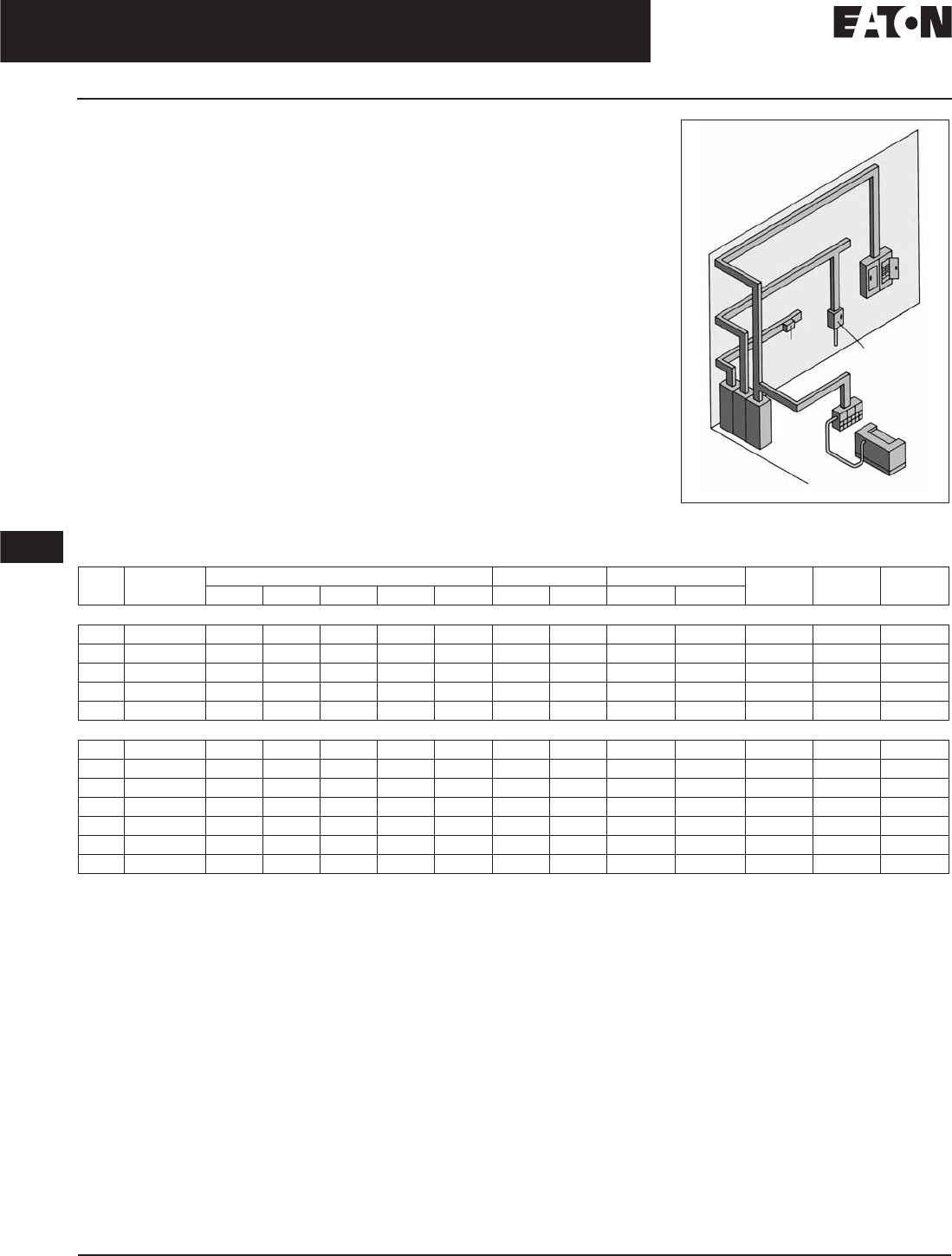
Typical Applications
Machine Tool Control Panels
and Motor Control Centers
Designed for these equipment
requirements, including new
world-class accessories.
Panelboards
As both main and branch circuit
protection devices.
Feeder Pillars
In distribution systems to provide
main and branch circuit protection.
Switchgear
In distribution systems to provide
main and branch circuit protection up
to 2500 amperes (RG-Frame).
Bus Bar Trunking Tap-Offs
In bus bar trunking tap-offs to provide
circuit protection.
Individual Enclosures
Completely assembled in enclosures
to meet specific customer
requirements.
Additional Applications
Special versions of each Cutler-Hammer
frame are available to provide safe
equipment control and protection in
mining and other applications. Contact
your Eaton agent or distributor for
additional information.
Figure 12-1. Typical Cutler-Hammer
Applications
Table 12-1. Cutler-Hammer Molded Case Circuit Breakers in Eaton Assembles
125 amperes is the maximum UL and CSA rating for EG.
600 amperes is the maximum UL and CSA rating for LG.
1200 amperes is the maximum UL and CSA rating for NG.
Cutler-Hammer Molded Case Circuit
Breakers cover the widest range of
applications in the industry:
■
Electrical OEMs.
■
Machinery OEMs.
■
Navy Breakers:
❑
UL Supplement SA and SB
❑
MIL-C-17588
❑
MIL-C-17361
■
Mining Breakers up to 1100 Vac.
■
Earth Leakage.
■
DC Breakers 125 – 750 Vdc.
■
Engine Generator Breakers
15 – 1200 amperes.
■
Current Limiting Breakers.
Panelboard
Bus Bar
Trunking
Tap-Off
Individual
Circuit
Breaker
Enclosure
Machine Tool
Control Panel
Switchboard
Frame Ampere
Range
Panelboards Switchboards Motor Control Centers Enclosed
Control
Bus
Plugs
Enclosed
Breaker
1A 2A 3A 4 5P PRL-C IFS Freedom
IT.
Series G
EG 15 – 160
●●●
JG 20 – 250
LG 100 – 630
●●● ●
NG 400 – 1600
●● ●
RG 800 – 2500
●●
Series C
FD/ED 15 – 225
●●●●●●● ● ● ● ● ●
JD 70 – 250
●●●●●●● ● ● ● ● ●
KD 70 – 400
●●●●●●● ● ● ● ● ●
LD 400 – 600
●●●● ● ● ● ● ●
MDL 300 – 800
●●●● ● ● ●
ND 400 – 1200
●●●● ● ● ● ● ●
RD 800 – 2500
●●● ● ●

November 2008
CA08101001E For more information visit:
www.eaton.com
12-3
Series G Molded Case Circuit Breakers
12
15 – 2500 Amperes for UL, CSA & IEC Applications
Product Line Overview
General Information
Cutler-Hammer Series G Molded Case
Circuit Breakers provide increased
performance in considerably less
space than standard circuit breakers
or comparable fusible devices.
The “G” signifies global applications:
Series G circuit breakers are marked
with UL, CSA
, CE, IEC and KEMA
KEUR listings. Other advantages
include:
■
Field-fit accessories.
■
Common accessories through
630 amperes.
■
Electronic trip units from 20 to
2500 amperes.
■
UL-listed and IEC-rated, 30 mA
ground fault/earth leakage modules.
■
Built-in ground fault protection
down to 20 amperes.
The EG, JG and LG frames are
designed around space-saving foot-
prints. The NG and RG use the proven
Cutler-Hammer Series C
ND and RD
designs but use metric threading on
their line and load conductors.
Cutler-Hammer Series G Circuit
Breakers meet applicable UL 489
and IEC 60947-2 standards.
The Cutler-Hammer Series G family
includes five frame sizes in ratings
from 15 to 2500 amperes. Series G
offers a choice of several interrupting
capacities up to 200 kA at 480 volts ac
(200 kA at 240 volts ac).
Standard calibration is 40°C. For appli-
cations in high ambient temperature
conditions, 50°C factory calibration
is available on thermal magnetic
breakers (not UL).
The Most Logically Designed
Contact Assembly
The flexibility and outstanding
performance characteristics of Cutler-
Hammer Circuit Breakers are made
possible by the best contact designs
in circuit breaker history. Our patented
technology creates a high-speed
“blow-open” action using the
electromechanical forces produced
by high-level fault currents.
Cutler-Hammer Circuit Breakers are
operated by a toggle-type mechanism
that is mechanically trip-free from
the handle so that the contacts cannot
be held closed against short circuit
currents. Tripping due to overload or
short circuits is clearly indicated by the
position on the handle. This remark-
ably fast and dependable contact
action is designed to enhance safety.
Thorough In-Plant Testing
The quality, dependability and reliability
of every Cutler-Hammer Circuit Breaker
is ensured by a thorough program
of in-plant testing. Two calibration
tests are conducted on every pole of
every circuit breaker to verify the trip
mechanism, operating mechanism,
continuity and accuracy.
ISO Certification
Cutler-Hammer Circuit Breakers
are manufactured in ISO
certified
facilities.
Current Limiting Characteristics
Circuit breakers are current limiting
because of their high repulsion contact
arrangement and use of state-of-
the-art arc extinguishing technology.
Eaton offers one of the most
complete lines of current limiting
breakers in the industry. The industrial
breakers are available in current
limiting versions with interrupting
capacities up to 200 kA at 480 V
without fuses in the same physical size
as standard and high interrupting
capacity breakers.
Operating Mechanisms
Cutler-Hammer Circuit Breakers have
a toggle handle operating mechanism,
which also serves as a switching
position indicator. The indicator shows
the positions of: ON, OFF and TRIPPED.
The toggle handle snaps into the
TRIPPED position if the breaker is
tripped by one of its overcurrent, short
circuit, shunt or undervoltage releases.
Before the circuit breaker can be
reclosed following a trip-out, the tog-
gle handle must be brought beyond
the OFF position (RESET). The circuit
breaker can then be reclosed.
As an additional switching position
indicator for EG- to RG-Frame circuit
breakers, there are two windows on
the right and on the left of the toggle
handle, in which the switching state
is indicated by means of the colors
red, green and white corresponding to
the ON, OFF and TRIPPED positions
respectively.
Figure 12-2. Positions of the Toggle
Handle Drive
OFF
RESET
ON
Tripped

November 2008
12-4
For more information visit:
www.eaton.com
CA08101001E
Series G Molded Case Circuit Breakers
12
15 – 2500 Amperes for UL, CSA & IEC Applications
Product Line Overview
Standards and Certifications
Cutler-Hammer
Molded Case Circuit
Breakers from Eaton are designed to
conform with the following interna-
tional standards:
■
Australian Standard AS 2184 and
AS 3947-2 Molded Case Circuit
Breakers.
■
British Standards Institution
Standard EN60947.2.
■
International Electrotechnical
Commission Recommendations
IEC 60947.2 Circuit Breakers.
■
Japanese T-Mark Standard
Molded Case Circuit Breakers.
■
National Electrical Manufacturers
Association Standards Publication
No. AB1-1993 Molded Case
Circuit Breakers.
■
South African Bureau of Standards,
Standard SANS 156, Standard
Specification for Molded Case
Circuit Breakers.
■
Swiss Electro-Technical Association
Standard SEV 947.2, Safety
Regulations for Circuit Breakers.
■
Union Technique de l’Electricite
Standard NF C 63-120, Low Voltage
Switchgear and Control Gear
Circuit Breaker Requirements.
■
Verband Deutscher Elektrotechnike
(Association of German Electrical
Engineers) Standard VDE 0660,
Low Voltage Switchgear and
Control Gear, Circuit Breakers.
Global Third-Party Certification
Certification marks ensure product
compliance with the total standard
via the third party witnessing of tests
by globally recognized independent
certification organizations.
KEMA is a highly recognized, indepen-
dent international organization that
offers certification and inspection
facilities for equipment in many
industries. The KEMA-KEUR mark is
the highest certification an electrical
product can receive from KEMA.
Our IEC 60947-2 Molded Case Circuit
Breakers are KEMA tested and certi-
fied. These breakers are also listed
in accordance with UL
489, as well
as CSA C22.2 No. 5-02.
KEMA, UL and CSA provide ongoing
follow-up testing and inspections to
ensure that Cutler-Hammer Molded
Case Circuit Breakers continue to meet
their exacting standards.
General Information
Eaton’s electrical business, under
the Cutler-Hammer brand, offers the
widest variety of molded case circuit
breakers available today. Designed for
electrical and machinery OEMs serving
a range of industries and applications,
these proven designs incorporate the
latest in innovation with the high
reliability that has been our hallmark
since the advent of the circuit breaker
in the 1920s.
The Series C family ranges from 15 –
2500 amperes, and includes thermal-
magnetic breakers, electronic trip
breakers, molded case switches,
motor circuit protectors, and specially
designed breakers for Engine Genera-
tor, DC and mining applications.
The new Series G line features an
average 35% size reduction, common
field-installable internal accessories,
and advanced trip unit functionality
that eliminates the need for rating
plugs. These breakers meet the
requirements of UL, CSA, IEC, CCC
and CE, allowing the OEM to standard-
ize on a design that meets the needs of
their global customer base.
November 2008
CA08101001E For more information visit:
www.eaton.com
12-5
Series G Molded Case Circuit Breakers
12
15 – 2500 Amperes for UL, CSA & IEC Applications
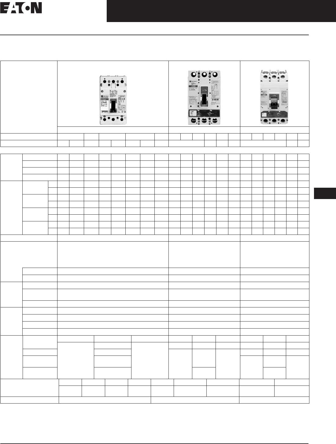
Frame Sizes EG through LG
Electrical Characteristics
Table 12-2. Electrical Characteristics
125 amperes is the maximum UL and CSA rating for the EG.
630 amperes is not a UL or CSA listed rating. 600 amperes is the maximum UL and CSA listed rating for the LG.
EG breaker rated 600/347 Vac.
Two poles in series.
Not suitable for dc application. 4-pole ground fault not available.
125 Vdc only for 1-pole breakers.
Maximum
Rated Current
(Amperes)
EG JG LG
125, 160
250 400, 630
Breaker Type B E S H C E S H C U X E S H C U X
Number of Poles
1 2, 3, 4 2, 3, 4 1 2, 3, 4 1 2, 3, 4 3, 4 2, 3, 4 3, 4 3, 4 3, 4 3, 4 3, 4 3, 4
Breaker Capacity (kA rms) ac 50 – 60 Hz
NEMA,
UL, CSA
240 Vac
25 25 35 85 85 100 100 200 65 85 100 200 200 200 65 85 100 200 200 200
480 Vac
— 18 25 — 35 — 65 100 25 35 65 100 150 200 35 50 65 100 150 200
600 Vac
— — 18 — 22 — 25 35 18 18 25 35 50 50 18 25 35 50 65 65
125/250 Vdc
10
10 10 35
35 42
42 42 10 22 22 42 50 50 22 22 42 42 50 50
IEC
60947-2
220 –
240 Vac
Icu
25 25 35 85 85 100 100 200 65 85 100 200 200 200 65 85 100 200 200 200
Ics
25 25 35 43 43 50 50 200 65 85 100 200 200 200 65 85 100 200 200 200
380 –
415 Vac
Icu
— 18 25 — 40 — 70 100 25 40 70 100 150 200 35 50 70 100 150 200
Ics
— 18 25 — 30 — 35 100 25 40 70 100 150 200 35 50 70 100 150 200
660 –
690 Vac
Icu
——— —————1212 14 16 18 181220 25 30 35 35
Ics
——— ————— 6 6 7 12 14 14 610 13 15 18 18
125/
250 Vdc
Icu
10
10 10 35
35 42
42 42 10 22 22 42 50 50 22 22 42 42 50 50
Ics
10
10 10 35
35 42
42 42 10 22 22 42 50 50 22 22 42 42 50 50
Ampere Range 15 – 160 A 20 – 250 A 100 – 630 A
Trip Units
F = Fixed
A = Adjustable
T = Thermal
M = Magnetic
FT-FM
AT-FM
FT-AM
AT-AM
Electronic (Digitrip RMS 310)
FT-AM
AT-AM
Electronic (Digitrip RMS 310)
Interchangeable
—■■
Built-in
■■■
Thermal
Magnetic
Fixed Thermal
■■■
Adjustable
Thermal
■■■
Magnetic
Fixed Adjustable Adjustable
Elec-
tronic
rms
LS
—■■
LSI
—■■
LSG
—■■
LSIG
—■■
Dimen-
sions
Inches
(mm)
HWDHWDHWD
1-Pole 5.50
(139.7)
1.00 (25.4) 2.99
(76.0)
——— ———
2-Pole 2.00 (50.8) 7.00
(177.8)
4.13
(105.0)
3.57
(87.4)
———
3-Pole 3.00 (76.2) 10.13
(258.0)
5.48
(140.0)
4.09
(104.0)
4-Pole 4.00 (101.6) 5.34
(135.6)
7.22
(183.0)
Weight (approximate)
lbs. (kg)
1-Pole 2-Pole 3-Pole 4-Pole 2-Pole 3-Pole 4-Pole 3-Pole 4-Pole
0.85 (0.39) 1.57 (0.71) 2.28 (1.04) 2.85 (1.29) 11.3 (5.13) 5.06 (2.30) T/M
5.31 (2.41) ETU
6.76 (3.07) T/M
7.12 (3.23) ETU
12.36 (5.61) T/M
13.04 (5.92) ETU
16.27 (7.39) T/M
16.92 (7.68) ETU
Utilization Category A A A
November 2008
12-6
For more information visit: www.eaton.com CA08101001E
Series G Molded Case Circuit Breakers
12
15 – 2500 Amperes for UL, CSA & IEC Applications
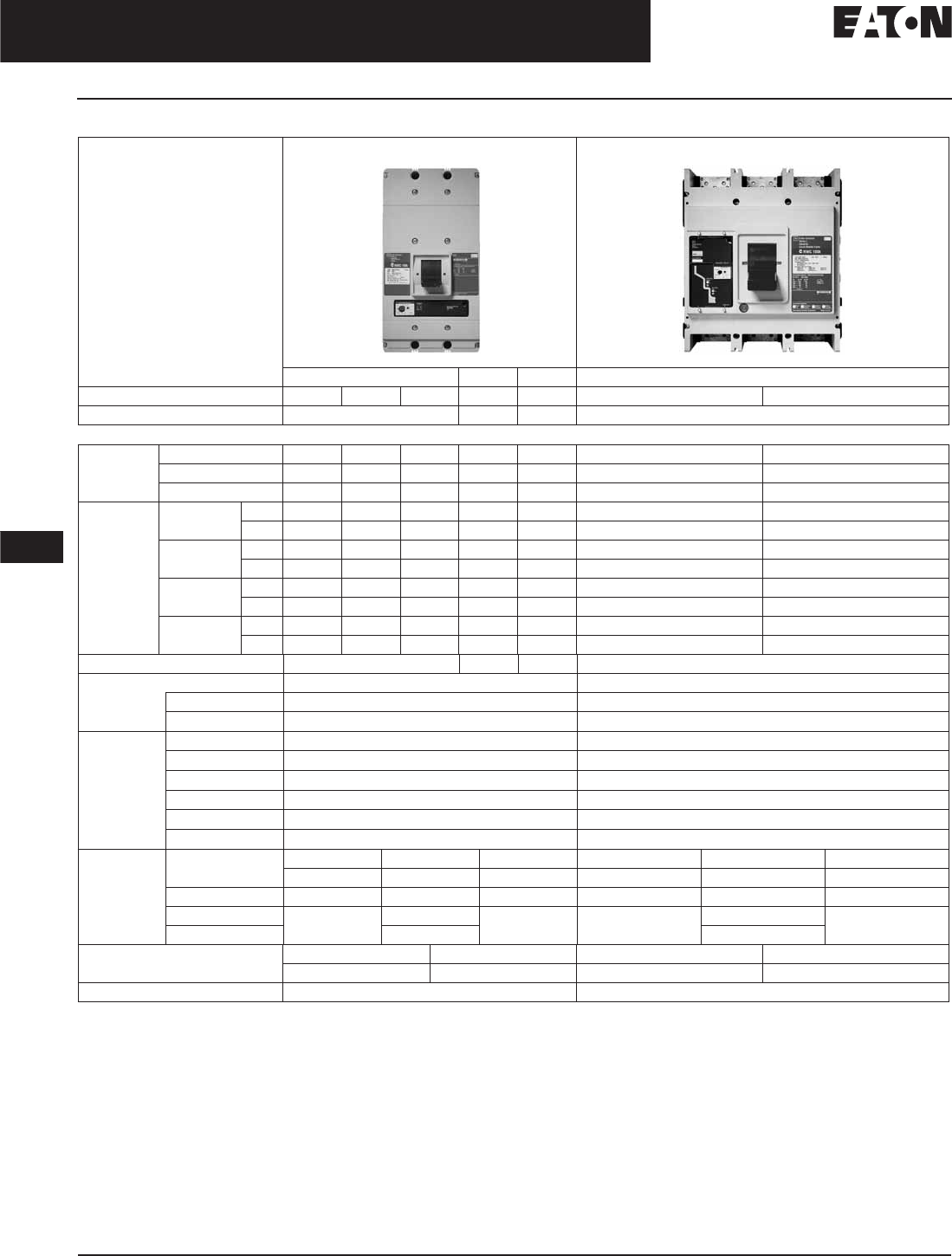
Frame Sizes NG and RG
Table 12-2. Electrical Characteristics (Continued)
The NG and RG MCCBs use metric threading in their line and load terminals. If English (Imperial) threading is needed, use Series C ND and RD MCCBs.
Contact Eaton for more information.
NG 1600 ampere frame is not UL or CSA listed.
Not KEMA-KEUR listed.
IEC 60947-2 H.5 Annex H is not KEMA-KEUR tested.
Not suitable for dc application. 4-pole ground fault not available.
Available only on Digitrip 610 and 910 trip units.
Maximum Rated Current
(Amperes)
NG RG
800, 1200 1600 800 1600, 2000, 2500
Breaker Type S H C SUH C
Number of Poles 2, 3, 4 3 3 3, 4
Breaker Capacity (kA rms) ac 50 – 60 Hz
NEMA,
UL, CSA
240 Vac 85 100 200 — 200 125 200
480 Vac 50 65 100 — 150 65 100
600 Vac 25 35 65 —
65 50 65
IEC 60947-2 220 –
240 Vac
Icu 85 100 200 85 — 135 200
Ics 85 100 100 85 — 100 100
380 –
415 Vac
Icu 50 70 100 50 — 70 100
Ics 50 50 50 50 — 50 50
660 –
690 Vac
Icu 20 25 35 20 — 25 35
Ics 10 13 18 10 — 13 18
250 Vdc Icu —————— —
Ics —————— —
Ampere Range 400 – 1200 A 1600 A 800 A 800 – 2500 A
Trip Units Electronic Electronic (Digitrip RMS 310, 610 and 910)
Interchangeable — —
Built-in ■■
Electronic LI — ■
LS ■■
LSI ■■
LIG — ■
LSG ■■
LSIG ■■
Dimensions
Inches (mm)
HWDH W D
1-Pole — — — — — —
2-Pole — — — — — —
3-Pole 16.00 (406.0) 8.25 (210.0) 5.50 (140.0) 16.00 (406.0) 15.50 (394.0) 9.75 (229.0)
4-Pole 11.13 (280.0) 20.00 (508.0)
Weight (approximate) lbs. (kg) 3-Pole 4-Pole 3-Pole 4-Pole
46.8 (21.3) 62.0 (28.3) 103.0 (47.0) 118.4 (54.0)
Utilization Category A A

November 2008
CA08101001E For more information visit: www.eaton.com
12-7
Series G Molded Case Circuit Breakers
12
15 – 2500 Amperes for UL, CSA & IEC Applications
Frame Sizes EG through RG
Table 12-3. EG through RG Electrical Characteristics
125 amperes is the maximum UL and CSA rating for the EG.
630 amperes is not a UL or CSA listed rating. 600 amperes is the maximum UL and CSA rating for the LG.
1200 amperes is the maximum UL and CSA rating for the NG.
See footnotes for exceptions.
Thermal overload release set to the lower value.
Thermal overload release set to the upper value.
Not suitable for dc switching.
Technical Data EG JG LG NG RG
Maximum Rated Current In
Depending on the Version
160 A 250 A 400, 630 A 800, 1200, 1600 A 1600, 2000, 2500 A
Rated Insulation Voltage U, According to IEC 60947-2
Main Conducting Paths
Auxiliary Circuits
500 Vac
500 Vac
750 Vac
690 Vac
750 Vac
690 Vac
750 Vac
690 Vac
750 Vac
690 Vac
Rated Impulse Withstand Voltage Uimp
Main Conducting Paths
Auxiliary Circuits
6 kV
4 kV
8 kV
4 kV
8 kV
4 kV
8 kV
4 kV
8 kV
4 kV
Rated Operational Voltage Ue
IEC
NEMA
690 Vac
600 Y/347 Vac
690 Vac
600 Vac
690 Vac
600 Vac
690 Vac
600 Vac
690 Vac
600 Vac
UL and CSA Listed Yes Yes Ye s Ye s Yes
Permissible Ambient Temperature -20 to +70°C -20 to +70°C -20 to +70°C -5 to +60°C -5 to +60°C
Permissible Load for Various Ambient Temperatures
Close to the Circuit Breaker, Related to the Rated
Current of the Circuit Breaker
■Circuit Breakers for Plant Protection
– At 40°C
– At 50°C
– At 55°C
– At 60°C
– At 70°C
100%
96%
93%
91%
86%
100%
92%
87%
83%
73%
100%
96%
94%
92%
88%
100%
94%
90%
87%
80%
100%
96%
93%
90%
84%
100%
91%
86%
82%
70%
—
100%
91%
85%
81%
—
—
100%
91%
85%
81%
—
■Circuit Breakers for Motor Protection
– At 40°C
– At 50°C
– At 55°C
– At 60°C
– At 70°C
—
—
—
—
—
100%
100%
100%
100%
90%
100%
100%
100%
100%
90%
—
—
—
—
—
—
—
—
—
—
■Circuit Breakers for Starter Combinations
and Isolating Circuit Breakers
– At 40°C
– At 50°C
– At 55°C
– At 60°C
– At 70°C
100%
100%
96%
91%
86%
100%
100%
96%
82%
88%
100%
100%
95%
90%
84%
100%
91%
85%
81%
—
100%
91%
85%
81%
—
Rated Short Circuit Breaking Capacity (dc)
Not for Circuit Breakers for Motor Protection
(Time Constant = 10 rms)
2 Conducting Paths in Series
For EG to LG up to 250 Vdc
NEMA (Time Constant = 8 rms)
2 Conducting Paths in Series
250 Vdc
42 kA Max.
42 kA Max.
42 kA Max.
42 kA Max.
42 kA Max.
42 kA Max.
Main Switch Characteristics According to IEC 60947-2
in Combination with Lockable Rotary Drives
Yes Ye s Yes Yes Yes
Rated Short Circuit Breaking Capacity According
to IEC 60947-2 (at ac 50/60 Hz)
Rated Short Circuit Breaking Capacity See Table 12-2 on Page 12-5
Endurance (Operating Cycles) 10,000 10,000 8,000 3,000 3,000
Maximum Switching Frequency 300 1/h 240 1/h 240 1/h 60 1/h 20 1/h

November 2008
12-8
For more information visit: www.eaton.com CA08101001E
Series G Molded Case Circuit Breakers
12
15 – 2500 Amperes for UL, CSA & IEC Applications
Frame Sizes EG through RG
Table 12-3. EG through RG Electrical Characteristics (Continued)
Technical Data EG JG LG NG RG
Conductor Cross Sections and Terminal Types
for Main Conductors
■Solid or Stranded
■Finely Stranded with End Sleeve
■Bus Bar
Tightening Torque for Box Terminals
Tightening Torque for Bus Bar Connection Pieces
Box Terminals
2.5 to 95 mm2
2.5 to 50/70 mm2
—
5.6 Nm
5.6 Nm
Box Terminals
50 to 150 mm2
35 to 120 mm2
—
20 Nm
15 Nm
Box Terminals
95 to 240 mm2
70 to 150 mm2
—
42 Nm
30 Nm
Flat Bar
Terminals
—
—
600 A
31 Nm
6 Nm
Flat Bar Terminals
—
—
Optional
31 Nm
50 Nm
Flat Bar Terminals
—
—
Optional
—
20 Nm
Conductor Cross Sections for Auxiliary Circuits
with Terminal Connection or Terminal Strip
■Solid
■Finely Stranded with End Sleeve
■With Brought-out Cable Ends
■Tightening Torque for Fitting Screws
0.75 to 2.5 mm2
0.75 to 2.5 mm20.75 to 2.5 mm2
0.75 to 2.5 mm2
0.82 (AWG 18) mm2
0.8 to 1.4 Nm
0.75 to 2.5 mm2
0.75 to 2.5 mm2
0.82 (AWG 18) mm2
0.8 to 1.4 Nm
Up to 2x4 mm2
Up to 2x2.5 mm2
0.82 (AWG 18) mm2
0.8 to 1.4 Nm
Up to 2x4 mm2
Up to 2x2.5 mm2
0.82 (AWG 18) mm2
0.8 to 1.4 Nm
Power Loss per Circuit Breaker at Maximum
Rated Current ln (The Power Losses of the
Undervoltage Releases (“r” Releases) Must Be
Observed if Necessary) at Three-Phase
Symmetrical Load)
■For Plant Protection
■As Isolating Circuit Breaker
■For Starter Combinations
■For Motor Protection
40 W
40 W
40 W
—
45 W
45 W
45 W
45 W
400 A:
65 W
65 W
65 W
65 W
600 A:
120 W
120 W
120 W
120 W
87/210 W
87/210 W
—
—
220/270/400 W
220/270/400 W
—
—
Permissible Mounting Position
Arc Spacing —
Suitable for Reverse-Feed Applications
Yes
(Except HMCPE)
Yes Ye s Yes Yes
90°
90°
90°
90°

November 2008
CA08101001E For more information visit: www.eaton.com
12-9
Series G Molded Case Circuit Breakers
12
15 – 2500 Amperes for UL, CSA & IEC Applications
Frame Sizes EG through RG
Table 12-3. EG through RG Electrical Characteristics (Continued)
Technical Data EG JG LG NG RG
Auxiliary Switches
Rated Thermal Current lth
Rated Making Capacity
6 A
20 A
6 A
20 A
6 A
20 A
6 A
20 A
6 A
20 A
ac (ac-15)
■Rated Operational Voltage
■Rated Operational Current
230/400/600 V
6/3/0.25 A
230/400/600 V
6/3/0.25 A
230/400/600 V
6/3/0.25 A
600 V
6 A
600 V
6 A
dc (dc-13)
■Rated Operational Voltage
■Rated Operational Current
125/250 V
0.5/0.25 A
125/250 V
0.5/0.15 A
125/250 V
0.5/0.15 A
125/250 V
0.5/0.25 A
125/250 V
0.5/0.25 A
Backup Fuse
Miniature Circuit Breaker
6/4/4 A
6/4 A
4
6/4/4 A
6/4 A
4
6/4/4 A
6/4 A
4
6/4/4 A
6/4 A
4
6/4/4 A
6/4 A
Releases
Undervoltage Releases (“r” Releases)
Response Voltage:
■Drop (Breaker Tripped) Us
■Pickup (Breaker May Be Switched on) Us
35 – 70%
85 – 110%
35 – 70%
85 – 110%
35 – 70%
85 – 110%
35 – 70%
85 – 110%
35 – 70%
85 – 110%
Power Consumption in Continuous Operation at:
■50/60 Hz 12 Vac
■50/60 Hz 24 Vac
■50/60 Hz 48 – 60 Vac
■50/60 Hz 110 – 127 Vac
■50/60 Hz 208 – 240 Vac
■50/60 Hz 380 – 500 Vac
■50/60 Hz 525 – 600 Vac
■12 Vdc
■24 Vdc
■48 – 60 Vdc
■110 – 125 Vdc
■220 – 250 Vdc
Maximum Opening Time
0.95 VA
0.72 VA
1.15 – 1.78 VA
0.96 – 1.25 VA
1.28 – 1.68 VA
2.2 – 3.9 VA
3.4 – 4.3 VA
0.88 W
0.70 W
1.12 – 1.76 W
0.94 – 1.21 W
1.45 – 1.86 W
50 ms
1.9 VA
3.9 VA
2.5 – 3.8 VA
1.8 – 2.4 VA
2.7 – 3.8 VA
3.4 – 5.8 VA
3.4 – 4.3 VA
1.6 W
3.1 W
2.0 – 3.1 W
1.6 – 2.2 W
3.1 – 4 W
50 ms
1.9 VA
3.9 VA
2.5 – 3.8 VA
1.8 – 2.4 VA
2.7 – 3.8 VA
3.4 – 5.8 VA
3.4 – 4.3 VA
1.6 W
3.1 W
2.0 – 3.1 W
1.6 – 2.2 W
3.1 – 4 W
50 ms
1.9 VA
2.4 VA
2.3 – 4.1 VA
3.4 – 4.2 VA
4.8 – 6.5 VA
6.8 – 12.0 VA
—
2.6 W
3.6 W
3.5 – 5.5 W
2.9 – 3.6 W
4.8 – 6.3 W
62 ms
2.9 VA
3.1 VA
3.4 – 6.0 VA
3.3 – 3.8 VA
4.2 – 7.2 VA
3.8 – 10.0 VA
—
3.4 W
4.3 W
4.8 – 7.2 W
3.3 – 3.8 W
6.6 – 7.5 W
62 ms
Shunt Trips
Shunt Trips (“f” Releases)
Response Voltage:
■Pickup (Breaker Tripped) Us70 – 110% 70 – 110% 70 – 110% 70 – 110% 70 – 110%
Power Consumption in (Short Time) at:
■50/60 Hz 24 Vac
■50/60 Hz 48 – 60 Vac
■50/60 Hz 48 – 127 Vac
■50/60 Hz 110 – 240 Vac
■50/60 Hz 380 – 440 Vac
■50/60 Hz 380 – 600 Vac
■50/60 Hz 480 – 600 Vac
■12 – 24 Vdc
■48 – 60 Vdc
■110 – 125 Vdc
■220 – 250 Vdc
10 – 41 VA
139 – 210 VA
—
83 – 360 VA
—
418 – 1080 VA
—
29 – 120 W
475 – 720 W
99 – 121 W
—
87 – 405 VA
710 – 1105 VA
—
66 – 432 VA
127 – 188 VA
—
34 – 60 VA
164 – 631 W
830 – 1580 W
112 – 150 W
40 – 58 W
87 – 405 VA
710 – 1105 VA
—
66 – 432 VA
127 – 188 VA
—
34 – 60 VA
164 – 631 W
830 – 1580 W
112 – 150 W
40 – 58 W
98 – 475 VA
24 – 50 VA
—
67 – 432 VA
76 – 110 VA
—
19 – 42 VA
145 – 610 W
67 – 102 W
121 – 150 W
46 – 55 W
612 VA
403 – 666 VA
—
396 – 1896 VA
1596 – 2156 VA
—
230 – 384 VA
396 W
341 – 528 W
264 – 350 W
374 – 475 W
Maximum Load Duration Interrupts Automatically
Maximum Opening Time 50 ms 50 ms 50 ms 62 ms 62 ms
Molded Case Switch (with High Magnetic Trip)
Unfused kAIC at 480 Vac (415 Vac)
Self-Protected, Will Trip Above:
65 (70)
1250 for EG125;
1600 for EG160
65 (70)
2500
65 (70)
4000/6300
65 (70)
12,500
65 (70)
20,000
November 2008
12-10
For more information visit: www.eaton.com CA08101001E
Series G Molded Case Circuit Breakers
12
15 – 2500 Amperes for UL, CSA & IEC Applications
Frame Sizes EG through LG
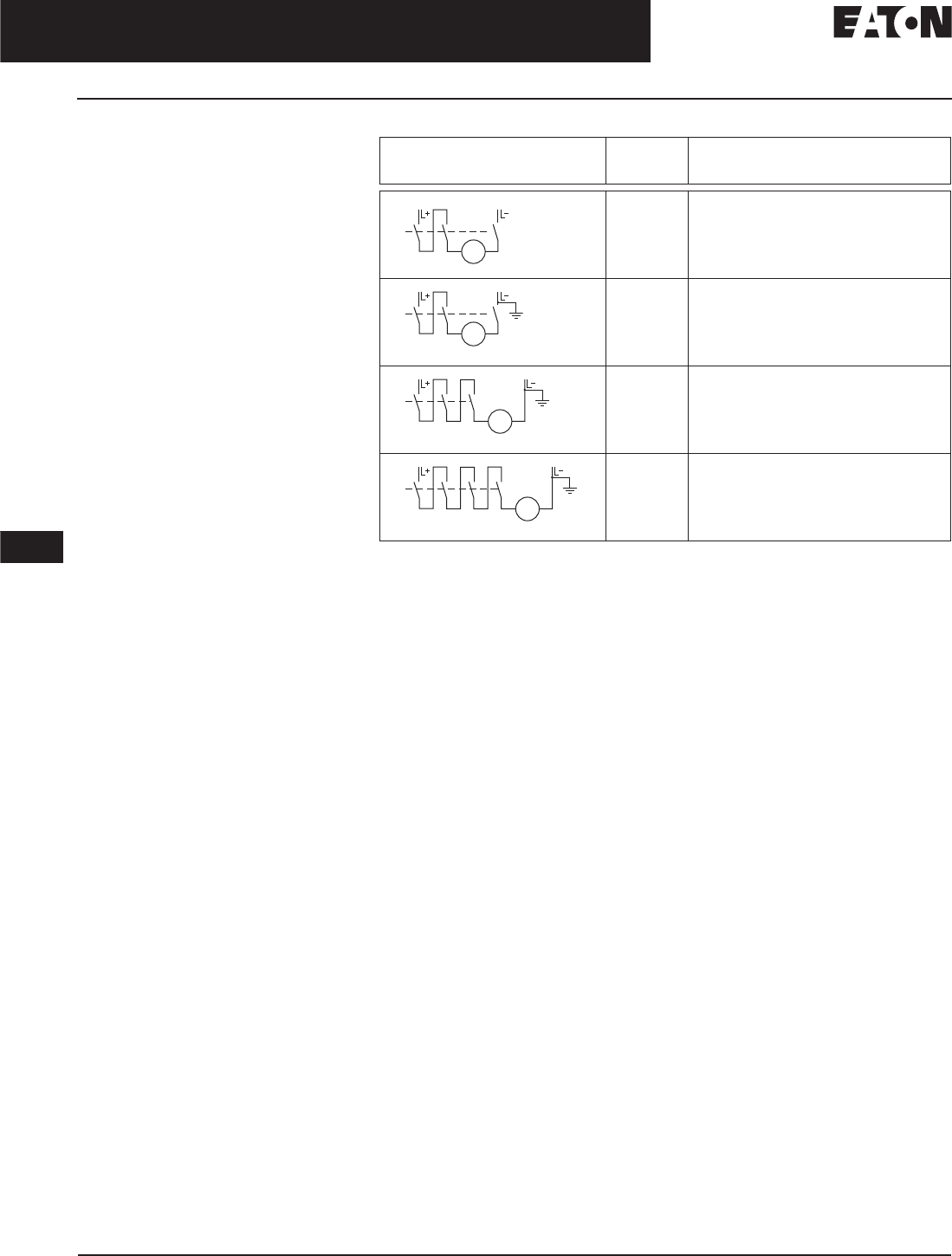
DC Switching Duty
The EG- to LG-Frame circuit breakers
are also suitable for switching dc
currents.
The NG- and RG-Frame circuit break-
ers are not suitable for dc currents
due to the solid-state overcurrent
release system.
For switching dc currents, however,
the maximum permissible dc voltage
per conducting path has to be
considered.
For voltages higher than 250 volts,
the series connection of two or three
conducting paths is required.
As the current has to flow through
all conducting paths so as to maintain
the thermal tripping characteristics,
the following circuit arrangements are
recommended. With dc, the trip values
of the instantaneous short circuit
release (“n” release) are increased
by 30 to 40%.
Table 12-4. For 3- and 4-Pole Circuit Breakers
Proposed
Circuit
Maximum
Permissible
Vdc Ue
Remarks
250 Vdc Double-pole switching.
If there is no risk of an earth fault, or if any
earth fault which occurs is immediately elimi-
nated (earth fault monitoring), the maximum
permissible dc voltage can be 600 volts.
440 Vdc Double-pole switching (earth system).
The earthed pole must always be assigned to
the individual conducting path, so that two
paths are always in series in the event of an
earth fault.
600 Vdc Single-pole switching (earthed system).
Three conducting paths in series. The earthed
pole must be assigned to the nonswitched
conducting path.
750 Vdc Single-pole switching (earthed system).
Four conducting paths in series. The earthed
pole must be assigned to the nonswitched
conducting path.
NSI-5178a
M
NSI-5179a
M
NSI-5180
M
NSI-5181
M
November 2008
CA08101001E For more information visit: www.eaton.com
12-11
Series G Molded Case Circuit Breakers
12
15 – 2500 Amperes for UL, CSA & IEC Applications
Series G Electronic Trip Units
Multi-Function Electronic
Trip Units for All Applications
Digitrip RMS Trip Units
True rms Sensing
Digitrip RMS Trip Units utilize our
patented microprocessor-based intelli-
gence to provide true rms sensing,
permitting increased accuracy and
reliable system protection. True rms
sensing is not susceptible to nuisance
tripping when waveforms containing
high harmonic currents are present.
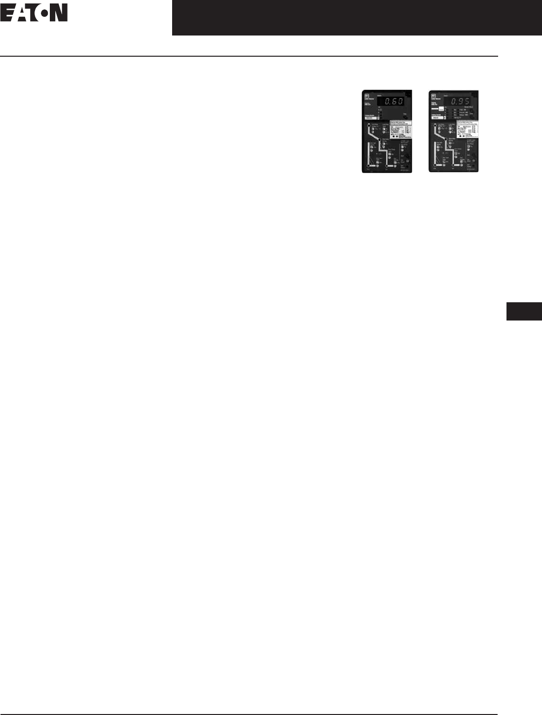
Digitrip RMS 310+
Digitrip RMS 310+ Electronic Trip Units
are available with Cutler-Hammer
Circuit Breakers JG and LG. They are
selectable long time delay (tLD) and
pickup settings (Ir). A rating plug is not
required. The Digitrip 310+ offers true
rms sensing, is front adjustable and
has an optional local display of current
and cause of trip.
Rating Plugs
If rating plugs are needed for N- and
R-Frame, they are marked for 50/60 Hz
applications. Both fixed and adjustable
rating plugs are available, providing
further flexibility when applied to
selectively coordinated systems.
Curve Shaping
When selectively coordinated systems
are called for, Digitrip RMS 310+ will
provide a cost-effective solution for a
variety of applications.
The standard Digitrip RMS 310+
includes an adjustable short time
pickup setting encompassing an I2t
ramp function which provides the
basic LS curve shaping function.
JG- and LG-Frames have an
adjustable long time delay.
JG- and LG-Frames have selectable
long time delay (tLD) and pickup set-
tings (Ir). A rating plug is not required.
The optional Digitrip RMS 310+
provides additional flat response
short time delay adjustments on
an instantaneous setting to provide
LSI curve shaping capability.
Digitrip RMS 310+ Trip Units are
available with ground fault pickup
and flat response ground fault delay
which provides the trip unit with full
function LSG and LSIG curve shaping
flexibility.
Note: Contact factory for availability of
ground fault for LG-Frame trip unit.
Digitrip RMS 310+ Trip Units can effec-
tively coordinate with both sophisti-
cated upstream power breakers as
well as downstream thermal magnetic
breakers…making Digitrip RMS 310+
Trip Units the cost-effective reliable
choice for selectively coordinated
systems.
Thermal Memory
All Digitrip RMS Trip Units incorporate
a long delay. Thermal memory prevents
the system from cumulative overheating
due to repeated overcurrent events that
may occur in quick succession.
Field Testing
A field test kit is available for Digitrip
RMS 310+ trip units.
Digitrip RMS 610 and 910
Digitrip RMS 610 and 910 Trip Units
are available with Cutler-Hammer
R-Frame Circuit Breakers 800 through
2500 amperes. Digitrip 610 and 910
Trip Units provide unparalleled
system protection with the added
convenience of a local display.
Curve Shaping
Digitrip RMS 610 and 910 Trip
Units are available with up to nine
curve shaping choices achieved by
adjusting up to seven switches on the
front of the unit for optimum system
coordination. Maximum curve shaping
flexibility is provided by dependent
long and short delay adjustments that
are long delay pickup (Ir) based,
depicted on the front of the unit by the
blue portion of the time-current curve.
Additional coordination capability
can be provided by utilizing the short
delay and ground fault zone selective
interlocking features available on
these trip units.
RMS 610 RMS 910

November 2008
12-12
For more information visit: www.eaton.com CA08101001E
Series G Molded Case Circuit Breakers
12
15 – 2500 Amperes for UL, CSA & IEC Applications
Series G Electronic Trip Units
System Diagnostics
Digitrip RMS 610 and 910 models of
trip units provide long delay, short
delay, instantaneous, and ground fault
cause of trip LEDs on the front of the
unit. Their display shows a magnitude
of trip information, as well as remote
signal contacts, for improved system
alarming.
System Monitoring
Digitrip 610 and 910 Trip Units
have the capability to monitor
phase currents, as well as neutral or
ground currents. This information is
displayed on a large digital display
mounted on the unit.
Digitrip RMS 910 Trip Units can
also provide the user with power
and energy monitoring capability.
Peak power demand, present power
demand, and total energy, as well as
forward and reverse energy can be
monitored with this unit.
Digitrip RMS 910 Trip Units have the
additional capability of monitoring
line-to-line voltage, as well as system
power factor. Both parameters are dis-
played in the digital display window
and are supported by LEDs to indicate
which parameter is being displayed.
Harmonics Monitoring
Digitrip RMS 910 Trip Units are capa-
ble of displaying values of current
harmonics in the digital display win-
dow. Percentage of harmonic content
can be monitored for each phase,
up to the 27th harmonic. Additionally,
a total harmonic distortion value can
be calculated and displayed.
Communications
Digitrip RMS 910 units have built-in
communications options to allow all
protection, monitoring, and control
information to be transmitted back to a
central location via the Cutler-Hammer
PowerNet system.
Field Testing
Integral field testing capability is
provided on all 610 and 910 Trip Units.
No additional test set is needed to per-
form both trip and no trip field testing.
November 2008
CA08101001E For more information visit: www.eaton.com
12-13
Series G Molded Case Circuit Breakers
12
15 – 2500 Amperes for UL, CSA & IEC Applications
Series G Electronic Trip Units
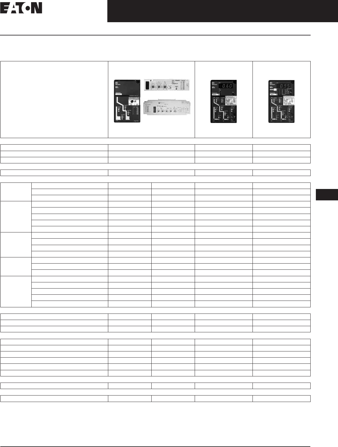
Digitrip RMS Electronic Trip Unit Selection Guide
Table 12-5. Digitrip RMS Electronic Trip Unit Selection Guide
JG- and LG-Frames have selectable settings
instead of a rating plug.
JG-, LG- and NG-Frames have adjustable
long delay times of 2 – 24 seconds.
JG/LG: 2X – 14X (In); NG: 2X – 8X (In);
RG: 2X – 8X (In); 2500 ampere RG-Frame
200 – 600% x (In).
JG-Frame also has a 14X setting.
LS, LSG only.
Not to exceed 1200 amperes.
JG- and LG-Frames are Instantaneous, 120 ms.
NG- and RG-Frames are Instantaneous, 100,
300 and 500 ms.
Note: In = Rating plug rating.
Ir = Long delay setting.
Digitrip RMS 310 RMS 610 RMS 910
Breaker Type
Cutler-Hammer Frame(s) JG-, LG-, NG- and RG-Frames RG-Frame RG-Frame
Ampere Rating 20 – 2500 A 800 – 2500 A 800 – 2500 A
Interrupting Rating at 415 V 35, 70, 100 kA 70, 100 kA 70, 100 kA
Trip Unit Sensing
rms Sensing Yes Yes Yes
Protection and Coordination
Protection Ordering Options LS, LSG LSI, LSIG LI, LS, LSI, LIG, LSG, LSIG LI, LS, LSI, LIG, LSG, LSIG
Fixed Rating Plug (In) Yes Ye s Yes Yes
Overtemperature Trip Yes Yes Yes Yes
Long Delay Adjustable Rating Plug (ln) Yes Yes No No
Long Delay Setting 0.5 – 1.0 (ln) 0.5 – 1.0 (ln) 0.5 – 1.0 x (ln) 0.5 – 1.0 x (ln)
Long Delay Time I2t at 6x 10 Seconds 10 Seconds 2 – 24 Seconds 2 – 24 Seconds
Long Delay Thermal Memory Yes Yes Yes Yes
High Load Alarm No No 0.85 x Ir0.85 x Ir
Short Delay Short Delay Setting Var/Frame Var/Frame 200 – 600% S1 & S2 x (Ir) 200 – 600% S1 & S2 x (Ir)
Short Delay Time I2t 100 ms No 100, 300, 500 ms 100, 300, 500 ms
Short Delay Time Flat No I – 300 ms 100 – 500 ms 100 – 500 ms
Short Delay Time ZSI No No Yes Yes
Instantaneous Instantaneous Setting No 200 – 800% x (ln) 200 – 600% M1 & M2 x (ln) 200 – 600% M1 & M2 x (ln)
Discriminator No No Yes Yes
Instantaneous Override Yes Yes Yes Yes
Ground
Fault
Ground Fault Setting Var/Frame Var/Frame 25 – 100% x (ln) 25 – 100% x (ln)
Ground Fault Delay I2t at .62x No No 100, 300, 500 ms 100, 300, 500 ms
Ground Fault Delay Flat I – 500 ms I – 500 ms 100 – 500 ms 100 – 500 ms
Ground Fault ZSI No No Yes Yes
Ground Fault Thermal Memory No No Yes Yes
System Diagnostics
Cause of Trip LEDs No No Yes Yes
Magnitude of Trip Information No No Yes Yes
Remote Signal Contacts No No Yes Yes
System Monitoring
Digital Display No No Yes Yes
Current No No Yes Yes
Voltage No No No Yes
Power and Energy No No No Yes
Power Quality — Harmonics No No No Yes
Power Factor No No No Yes
System Communications
PowerNet No No No Yes
Field Testing
Testing Method Test Set Test Set Integral Integral
RG
JG
LG/NG
November 2008
12-14
For more information visit: www.eaton.com CA08101001E
Series G Molded Case Circuit Breakers
12
15 – 125 Amperes
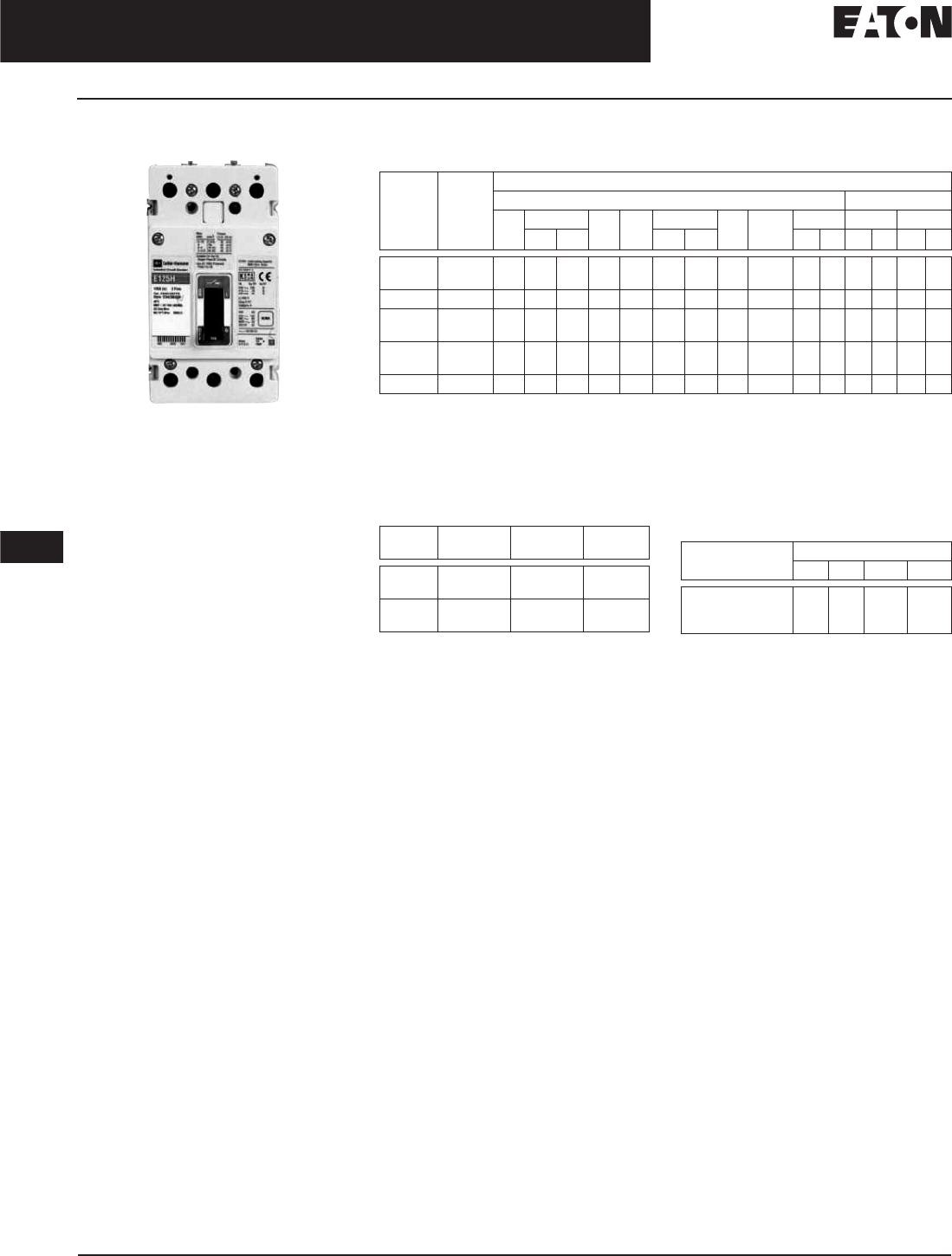
EG-Frame
EG-Frame
Eaton’s Cutler-Hammer EG
Product Description
■EG breaker is HACR rated.
Technical Data and Specifications
Table 12-6. UL 489/IEC 60947-2 Interrupting Capacity Ratings
dc ratings apply to substantially non-inductive circuits.
IEC only.
2-pole circuit breaker, or two poles of 3-pole circuit breaker.
Time constant is 3 milliseconds minimum at 10 kA and 8 milliseconds minimum at 42 kA.
Dimensions/Weights
Table 12-7. Dimensions in Inches (mm) Table 12-8. Approximate Shipping Weight
in Lbs. (kg)
Circuit
Breaker
Type
Number
of Poles
Interrupting Capacity (Symmetrical Amperes) (kA)
Volts ac (50/60 Hz) Volts dc
120 220 – 240 277 347 380 – 415 480 600Y/
347
690 125 250
Icu Ics Icu Ics Icu Ics Icu Ics Icu Ics
EGB125 1
2, 3, 4
35
—
25
25
25
25
18
—
—
—
—
18
—
18
—
18
—
—
—
—
—
—
10
—
10
—
—
10
—
10
EGE125 2, 3, 4 — 35 35 — — 25 25 25 18 — — — — 10 10
EGS125 1
2, 3, 4
100
—
85
85
43
43
35
—
22
—
—
40
—
30
—
35
—
22
—
—
—
—
35
—
35
—
—
35
—
35
EGH125 1
2, 3, 4
200
—
100
100
50
50
65
—
30
—
—
70
—
35
—
65
—
25
—
—
—
—
42
—
42
—
—
42
—
42
EGC125 3, 4 — 200 200 — — 100 100 100 35 — — — — 42 42
Number
of Poles
Width Height Depth
1
2
1.00 (25.4)
2.00 (50.8)
5.50 (139.7)
5.50 (139.7)
2.99 (75.9)
2.99 (75.9)
3
4
3.00 (76.2)
4.00 (101.6)
5.50 (139.7)
5.50 (139.7)
2.99 (75.9)
2.99 (75.9)
Breaker
Type
Number of Poles
123 4
EGB125, EGE125,
EGS125, EGH125,
EGC125
1.5
(.68)
2.0
(.91)
3.0
(1.36)
4.9
(1.82)

November 2008
CA08101001E For more information visit: www.eaton.com
12-15
Series G Molded Case Circuit Breakers
12
15 – 125 Amperes
EG-Frame
Product Selection
Table 12-9. Main Catalog Numbering System
Cannot be UL rated.
Available only as 125 and 160 A sizes.
E G H 3 015 FF G
Frame
E
Poles
1 = One
2 = Two
3 = Three
4 = Four — Neutral 0% Protected
7 = Four — Neutral 100% Protected
Amperes
016
015
020
025
030
032
035
040
045
050
060
063
070
080
090
100
110
125
Standard/Application
G = IEC/CE/UL/CSA
Performance
600Y/
347
480 415 240
B— 181825
E18 25 25 35
S22 35 40 85
H25 65 70 100
C35 100 100 200
KMolded Case Switch
Trip Unit
FF = Fixed Fixed
AF = Adj. Fixed
KS = Molded Case Switch
Terminations/Hardware
Terminals Mounting
Hardware
M= Metric End Caps
E= Imperial End Caps
G= Line/Load Standard
B= Bolt-On
Metric
Imperial
Metric
—

November 2008
12-16
For more information visit: www.eaton.com CA08101001E
Series G Molded Case Circuit Breakers
12
15 – 125 Amperes
EG-Frame
Product Selection
Table 12-10. Complete Breaker (Includes Frame, Trip Unit, Standard Terminals and Mounting Hardware) — IC Rating at 415/480 Volts
16, 32, 63 A are not UL listed ratings.
Adjustable thermal are not UL listed.
Change the fourth digit to 7 for 100% neutral protection. Neutral is on the LH side.
Max.
Cont.
Amps
at 40°C
1-Pole 2-Pole 3-Pole 4-Pole 0% Protected Neutral
Fixed
Thermal
Fixed
Magnetic
Price
U.S. $
Fixed
Thermal
Fixed
Magnetic
Price
U.S. $
Fixed
Thermal
Fixed
Magnetic
Price
U.S. $
Adjustable
Thermal
Fixed
Magnetic
Price
U.S. $
Fixed
Thermal
Fixed
Magnetic
Price
U.S. $
Adjustable
Thermal
Fixed
Magnetic
Price
U.S. $
18/18
15
16
20
25
30
32
35
40
45
EGB1015FFG
EGB1016FFG
EGB1020FFG
EGB1025FFG
EGB1030FFG
EGB1032FFG
EGB1035FFG
EGB1040FFG
EGB1045FFG
EGB2015FFG
EGB2016FFG
EGB2020FFG
EGB2025FFG
EGB2030FFG
EGB2032FFG
EGB2035FFG
EGB2040FFG
EGB2045FFG
EGB3015FFG
EGB3016FFG
EGB3020FFG
EGB3025FFG
EGB3030FFG
EGB3032FFG
EGB3035FFG
EGB3040FFG
EGB3045FFG
—
—
—
EGB3025AFG
—
EGB3032AFG
—
EGB3040AFG
—
EGB4015FFG
EGB4016FFG
EGB4020FFG
EGB4025FFG
EGB4030FFG
EGB4032FFG
EGB4035FFG
EGB4040FFG
EGB4045FFG
—
—
EGB4020AFG
EGB4025AFG
—
EGB4032AFG
—
EGB4040AFG
—
50
60
63
70
80
90
100
125
EGB1050FFG
EGB1060FFG
EGB1063FFG
EGB1070FFG
EGB1080FFG
EGB1090FFG
EGB1100FFG
EGB1125FFG
EGB2050FFG
EGB2060FFG
EGB2063FFG
EGB2070FFG
EGB2080FFG
EGB2090FFG
EGB2100FFG
EGB2125FFG
EGB3050FFG
EGB3060FFG
EGB3063FFG
EGB3070FFG
EGB3080FFG
EGB3090FFG
EGB3100FFG
EGB3125FFG
EGB3050AFG
—
EGB3063AFG
—
EGB3080AFG
—
EGB3100AFG
EGB3125AFG
EGB4050FFG
EGB4060FFG
EGB4063FFG
EGB4070FFG
EGB4080FFG
EGB4090FFG
EGB4100FFG
EGB4125FFG
EGB4050AFG
—
EGB4063AFG
—
EGB4080AFG
—
EGB4100AFG
EGB4125AFG
25/25
15
16
20
25
30
32
35
40
45
—
—
—
—
—
—
—
—
—
EGE2015FFG
EGE2016FFG
EGE2020FFG
EGE2025FFG
EGE2030FFG
EGE2032FFG
EGE2035FFG
EGE2040FFG
EGE2045FFG
EGE3015FFG
EGE3016FFG
EGE3020FFG
EGE3025FFG
EGE3030FFG
EGE3032FFG
EGE3035FFG
EGE3040FFG
EGE3045FFG
—
—
—
EGE3025AFG
—
EGE3032AFG
—
EGE3040AFG
EGE3050AFG
EGE4015FFG
EGE4016FFG
EGE4020FFG
EGE4025FFG
EGE4030FFG
EGE4032FFG
EGE4035FFG
EGE4040FFG
EGE4045FFG
—
—
EGE4020AFG
EGE4025AFG
—
EGE4032AFG
—
EGE4040AFG
—
50
60
63
70
80
90
100
125
—
—
—
—
—
—
—
—
EGE2050FFG
EGE2060FFG
EGE2063FFG
EGE2070FFG
EGE2080FFG
EGE2090FFG
EGE2100FFG
EGE2125FFG
EGE3050FFG
EGE3060FFG
EGE3063FFG
EGE3070FFG
EGE3080FFG
EGE3090FFG
EGE3100FFG
EGE3125FFG
—
—
EGE3063AFG
—
EGE3080AFG
—
EGE3100AFG
EGE3125AFG
EGE4050FFG
EGE4060FFG
EGE4063FFG
EGE4070FFG
EGE4080FFG
EGE4090FFG
EGE4100FFG
EGE4125FFG
EGE4050AFG
—
EGE4063AFG
—
EGE4080AFG
—
EGE4100AFG
EGE4125AFG
40/35
15
16
20
25
30
32
35
40
45
EGS1015FFG
EGS1016FFG
EGS1020FFG
EGS1025FFG
EGS1030FFG
EGS1032FFG
EGS1035FFG
EGS1040FFG
EGS1045FFG
EGS2015FFG
EGS2016FFG
EGS2020FFG
EGS2025FFG
EGS2030FFG
EGS2032FFG
EGS2035FFG
EGS2040FFG
EGS2045FFG
EGS3015FFG
EGS3016FFG
EGS3020FFG
EGS3025FFG
EGS3030FFG
EGS3032FFG
EGS3035FFG
EGS3040FFG
EGS3045FFG
—
—
—
EGS3025AFG
—
EGS3032AFG
—
EGS3040AFG
—
EGS4015FFG
EGS4016FFG
EGS4020FFG
EGS4025FFG
EGS4030FFG
EGS4032FFG
EGS4035FFG
EGS4040FFG
EGS4045FFG
—
—
EGS4020AFG
EGS4025AFG
—
EGS4032AFG
—
EGS4040AFG
—
50
60
63
70
80
90
100
125
EGS1050FFG
EGS1060FFG
EGS1063FFG
EGS1070FFG
EGS1080FFG
EGS1090FFG
EGS1100FFG
EGS1125FFG
EGS2050FFG
EGS2060FFG
EGS2063FFG
EGS2070FFG
EGS2080FFG
EGS2090FFG
EGS2100FFG
EGS2125FFG
EGS3050FFG
EGS3060FFG
EGS3063FFG
EGS3070FFG
EGS3080FFG
EGS3090FFG
EGS3100FFG
EGS3125FFG
EGS3050AFG
—
EGS3063AFG
—
EGS3080AFG
—
EGS3100AFG
EGS3125AFG
EGS7050FFG
EGS7060FFG
EGS7063FFG
EGS7070FFG
EGS7080FFG
EGS7090FFG
EGS7100FFG
EGS7125FFG
EGS4050AFG
—
EGS4063AFG
—
EGS4080AFG
—
EGS4100AFG
EGS4125AFG
Discount Symbol . . . . . . . . . . . . . . . . . . . . . . . . CB-2

November 2008
CA08101001E For more information visit: www.eaton.com
12-17
Series G Molded Case Circuit Breakers
12
15 – 125 Amperes
EG-Frame
Table 12-10. Complete Breaker (Includes Frame, Trip Unit, Standard Terminals and Mounting Hardware) — IC Rating at 415/480 Volts (Continued)
16, 32, 63 A are not UL listed ratings.
Adjustable thermal is not UL listed.
Change the fourth digit to 7 for 100% neutral protection. Neutral is on LH side.
Table 12-11. Molded Case Switches
Note: Molded case switches may open
above 1250 A.
Max.
Cont.
Amps
at 40°C
1-Pole 2-Pole 3-Pole 4-Pole 0% Protected Neutral
Fixed
Thermal
Fixed
Magnetic
Price
U.S. $
Fixed
Thermal
Fixed
Magnetic
Price
U.S. $
Fixed
Thermal
Fixed
Magnetic
Price
U.S. $
Adjustable
Thermal
Fixed
Magnetic
Price
U.S. $
Fixed
Thermal
Fixed
Magnetic
Price
U.S. $
Adjustable
Thermal
Fixed
Magnetic
Price
U.S. $
70/65
15
16
20
25
30
32
35
40
45
EGH1015FFG
EGH1016FFG
EGH1020FFG
EGH1025FFG
EGH1030FFG
EGH1032FFG
EGH1035FFG
EGH1040FFG
EGH1045FFG
EGH2015FFG
EGH2016FFG
EGH2020FFG
EGH2025FFG
EGH2030FFG
EGH2032FFG
EGH2035FFG
EGH2040FFG
EGH2045FFG
EGH3015FFG
EGH3016FFG
EGH3020FFG
EGH3025FFG
EGH3030FFG
EGH3032FFG
EGH3035FFG
EGH3040FFG
EGH3045FFG
—
—
EGH3020AFG
EGH3025AFG
—
EGH3032AFG
—
EGH3040AFG
—
EGH4015FFG
EGH4016FFG
EGH4020FFG
EGH4025FFG
EGH4030FFG
EGH4032FFG
EGH4035FFG
EGH4040FFG
EGH4045FFG
—
—
EGH4020AFG
EGH4025AFG
—
EGH4032AFG
—
EGH4040AFG
EGH4050AFG
50
60
63
70
80
90
100
125
EGH1050FFG
EGH1060FFG
EGH1063FFG
EGH1070FFG
EGH1080FFG
EGH1090FFG
EGH1100FFG
EGH1125FFG
EGH2050FFG
EGH2060FFG
EGH2063FFG
EGH2070FFG
EGH2080FFG
EGH2090FFG
EGH2100FFG
EGH2125FFG
EGH3050FFG
EGH3060FFG
EGH3063FFG
EGH3070FFG
EGH3080FFG
EGH3090FFG
EGH3100FFG
EGH3125FFG
EGH3050AFG
—
EGH3063AFG
—
EGH3080AFG
—
EGH3100AFG
EGH3125AFG
EGH4050FFG
EGH4060FFG
EGH4063FFG
EGH4070FFG
EGH4080FFG
EGH4090FFG
EGH4100FFG
EGH4125FFG
—
—
EGH4063AFG
—
EGH4080AFG
—
EGH4100AFG
EGH4125AFG
100/100
15
16
20
25
30
32
35
40
45
—
—
—
—
—
—
—
—
—
—
—
—
—
—
—
—
—
—
EGC3015FFG
EGC3016FFG
EGC3020FFG
EGC3025FFG
EGC3030FFG
EGC3032FFG
EGC3035FFG
EGC3040FFG
EGC3045FFG
—
—
EGC3020AFG
EGC3025AFG
—
EGC3032AFG
—
EGC3040AFG
—
EGC7015FFG
EGC7016FFG
EGC7020FFG
EGC7025FFG
EGC7030FFG
EGC7032FFG
EGC7035FFG
EGC7040FFG
EGC7045FFG
—
—
EGC7020AFG
EGC7025AFG
—
EGC7032AFG
—
EGC7040AFG
—
50
60
63
70
80
90
100
125
—
—
—
—
—
—
—
—
—
—
—
—
—
—
—
—
EGC3050FFG
EGC3060FFG
EGC3063FFG
EGC3070FFG
EGC3080FFG
EGC3090FFG
EGC3100FFG
EGC3125FFG
EGC3050AFG
—
EGC3063AFG
—
EGC3080AFG
—
EGC3100AFG
EGC3125AFG
EGC7050FFG
EGC7060FFG
EGC7063FFG
EGC7070FFG
EGC7080FFG
EGC7090FFG
EGC7100FFG
EGC7125FFG
EGC7050AFG
—
EGC7063AFG
—
EGC7080AFG
—
EGC7100AFG
EGC7125AFG
Catalog
Number
Price
U.S. $
EGK3125KSG
EGK7125KSG
Discount Symbol . . . . . . . . . . . . . . . . . . . . . . . . . CB-2

November 2008
12-18
For more information visit: www.eaton.com CA08101001E
Series G Molded Case Circuit Breakers
12
15 – 125 Amperes
EG-Frame
Table 12-12. EG Bolt-On Complete Breaker (Includes Frame, Trip Unit and Mounting Hardware)
Max.
Cont.
Amps
1-Pole 2-Pole 3-Pole
Fixed Thermal
Fixed Magnetic
Price
U.S. $
Fixed Thermal
Fixed Magnetic
Price
U.S. $
Fixed Thermal
Fixed Magnetic
Price
U.S. $
18 kAIC at 480 Vac
15
20
25
30
35
40
45
EGB1015FFB
EGB1020FFB
EGB1025FFB
EGB1030FFB
EGB1035FFB
EGB1040FFB
EGB1045FFB
EGB2015FFB
EGB2020FFB
EGB2025FFB
EGB2030FFB
EGB2035FFB
EGB2040FFB
EGB2045FFB
EGB3015FFB
EGB3020FFB
EGB3025FFB
EGB3030FFB
EGB3035FFB
EGB3040FFB
EGB3045FFB
50
60
63
70
80
90
100
125
EGB1050FFB
EGB1060FFB
EGB1070FFB
EGB1080FFB
EGB1090FFB
EGB1100FFB
EGB1110FFB
EGB1125FFB
EGB2050FFB
EGB2060FFB
EGB2070FFB
EGB2080FFB
EGB2090FFB
EGB2100FFB
EGB2110FFB
EGB2125FFB
EGB3050FFB
EGB3060FFB
EGB3070FFB
EGB3080FFB
EGB3090FFB
EGB3100FFB
EGB3110FFB
EGB3125FFB
35 kAIC at 480 Vac
15
20
25
30
35
40
45
EGS1015FFB
EGS1020FFB
EGS1025FFB
EGS1030FFB
EGS1035FFB
EGS1040FFB
EGS1045FFB
EGS2015FFB
EGS2020FFB
EGS2025FFB
EGS2030FFB
EGS2035FFB
EGS2040FFB
EGS2045FFB
EGS3015FFB
EGS3020FFB
EGS3025FFB
EGS3030FFB
EGS3035FFB
EGS3040FFB
EGS3045FFB
50
60
63
70
80
90
100
125
EGS1050FFB
EGS1060FFB
EGS1070FFB
EGS1080FFB
EGS1090FFB
EGS1100FFB
EGS1110FFB
EGS1125FFB
EGS2050FFB
EGS2060FFB
EGS2070FFB
EGS2080FFB
EGS2090FFB
EGS2100FFB
EGS2110FFB
EGS2125FFB
EGS3050FFB
EGS3060FFB
EGS3070FFB
EGS3080FFB
EGS3090FFB
EGS3100FFB
EGS3110FFB
EGS3125FFB
65 kAIC at 480 Vac
15
20
25
30
35
40
45
EGH1015FFB
EGH1020FFB
EGH1025FFB
EGH1030FFB
EGH1035FFB
EGH1040FFB
EGH1045FFB
EGH2015FFB
EGH2020FFB
EGH2025FFB
EGH2030FFB
EGH2035FFB
EGH2040FFB
EGH2045FFB
EGH3015FFB
EGH3020FFB
EGH3025FFB
EGH3030FFB
EGH3035FFB
EGH3040FFB
EGH3045FFB
50
60
63
70
80
90
100
125
EGH1050FFB
EGH1060FFB
EGH1070FFB
EGH1080FFB
EGH1090FFB
EGH1100FFB
EGH1110FFB
EGH1125FFB
EGH2050FFB
EGH2060FFB
EGH2070FFB
EGH2080FFB
EGH2090FFB
EGH2100FFB
EGH2110FFB
EGH2125FFB
EGH3050FFB
EGH3060FFB
EGH3070FFB
EGH3080FFB
EGH3090FFB
EGH3100FFB
EGH3110FFB
EGH3125FFB
Discount Symbol . . . . . . . . . . . . . . . . . . . . . . . . CB-2

November 2008
CA08101001E For more information visit: www.eaton.com
12-19
Series G Molded Case Circuit Breakers
12
15 – 125 Amperes
EG-Frame
Selection Guide and Ordering Information
Line and Load Terminals
EG-Frame circuit breakers and molded case switches have
line and load terminals as standard equipment.
Table 12-13. Line and Load Terminals
Standard line and load terminals.
Insert collar enclosing conductor as shown. Locate nut on top
of conductor and tighten securely with screw and washer.
Caution: Collar must surround conductor.
Insert collar enclosing conductor and center on extrusion.
Tighten securely with screw and washer. Endcap kits are
used on the E-Frame breaker line side to connect bus bar or
similar electrical connections. Includes hardware.
Control Wire Terminal Kit
For use with steel or stainless steel standard line and load
terminals only.
Table 12-14. Control Wire Terminal Kit
Interphase Barriers
The interphase barrier is available for extended insulation
between circuit breaker poles. Specify quantity when ordering.
Table 12-15. Interphase Barriers
Base Mounting Hardware
Metric base mounting hardware is included with a circuit
breaker or molded case switch. (Included with breaker.)
Note: English mounting hardware kit can be supplied separate.
Catalog number is BMHE #6 – 32 x 3 inches.
Table 12-16. DIN Rail Mounting
Multiwire Connectors
Field-installed multiwire connectors for the load side (OFF)
end terminals. They are used to distribute the load from
the circuit breaker to multiple devices without the use of
separate distribution terminal blocks.
Multiwire lug kits include mounting hardware, terminal
shield insulators and tin-plated aluminum connectors to
replace three mechanical load lugs. UL listed as used on the
load side (OFF) end.
Table 12-17. EG-Frame Multiwire Connectors
Ordering Information (Package of 3)
Terminal Shields
The terminal shield is available for line terminal areas in
3- and 4-pole circuit breakers. Special terminal shields
are also available for use when an electrical (solenoid)
operator is mounted on the circuit breaker. The standard
style number by pole for each terminal shield is for a
package of 10 and is priced per each package. Special
terminal shields are packaged individually.
Table 12-18. Terminal Shields
3T125EF 3TA125EF 3TA150EF 3TA160EFK EF2RTWK, 2-Pole – Metric
EF3RTWK, 3-Pole – Metric
EF4RTWK, 4-Pole – Metric
EF2RTDK, 2-Pole – Imperial
EF3RTDK, 3-Pole – Imperial
EF4RTDK, 4-Pole – Imperial
Control Wire
Terminal Kit
GCWTK
Multiwire
Connectors
Max.
Breaker
Amps
Terminal
Body
Material
Wire
Type
Metric
Wire
Range
mm2
AWG
Wire
Range
Catalog
Number
Package of
3 Terminals
Price
U.S. $
Standard Cu/Al Pressure Type Terminals
125 Steel Cu 2.5-95 #14-3/0
3T125EF
125
125/160
Aluminum
Aluminum
Cu/Al
Cu/Al
2.5-50
16-95
#14-1/0
#6-3/0
3TA125EF
3TA150EF
160
160
Aluminum
Aluminum
Cu/Al
Cu/Al
35-120
35-120
#3-250
#3-250
3TA160EFK
4TA160EFK
Package of 12 —
Priced Individually
Catalog
Number
Price
U.S. $
Control Wire Terminal Kit 5652B38G01
Package of 2 —
Priced Individually
Catalog
Number
Price
U.S. $
Interphase Barriers EIPBK
DIN Rail
Adapter
Catalog
Number
Price
U.S. $
3- or 4-Pole EF34DIN
Max.
Amps
Wires per
Terminal
Wire Size
Range AWG Cu
Kit Catalog
Number
Price
U.S. $
125
125
3
6
14 – 2
14 – 6
3TA125E3K
3TA125E6K
Number
of Poles
IP30 Protection Price
U.S. $
Catalog Numbers
3
4
EFTS3K
EFTS4K
Discount Symbol . . . . . . . . . . . . . . . . . . . . . . . . . CB-2

November 2008
12-20
For more information visit: www.eaton.com CA08101001E
Series G Molded Case Circuit Breakers
12
15 – 125 Amperes
EG-Frame
Terminal End Covers (Gas Barrier)
The terminal end cover is available for
3-pole circuit breakers only. Two con-
ductor opening sizes are available.
Specify quantity (one per circuit
breaker) when ordering.
Table 12-19. Terminal End Covers
Allowable Accessory Combinations
Different combinations of accessories can be supplied, depending on the types of accessories and the number
of poles in the circuit breaker.
Table 12-20. Accessories
■Applicable in indicated pole position ❏May be mounted on left or right pole —
not both
● Accessory available/Modification available
Conductor Opening
Diameter – Inches (mm)
Catalog
Number
Price
U.S. $
6.35 (0.25)
10.41 (0.41)
EEC3K
EEC4K
Description Reference
Page
1-Pole 2-Pole 3-Pole 4-Pole
Center Left Right Left Center Right Left Center Right Neutral
Internal Accessories (Only one internal accessory per pole)
Alarm Lockout (Make/Break) 12-65 ■■■
Alarm Lockout (2Make/2Break) 12-65 ■■■
Auxiliary Switch (1A, 1B) 12-65 ■■■
Auxiliary Switch (2A, 2B) 12-65 ■■■
Auxiliary Switch and Alarm Switch Combination 12-65 ■■■
Shunt Trip — Standard 12-65 ■■
Undervoltage Release Mechanism 12-65 ■■
External Accessories
End Cap Kit 12-19 ●● ●
Control Wire Terminal Kit 12-19 ●● ● ●
Multiwire Connectors 12-19 ●● ● ●
Base Mounting Hardware 12-19 ●● ● ●
Terminal Shields 12-19 ●● ● ●
Terminal End Covers 12-20 ●
Interphase Barriers 12-19 ●● ●
Non-Padlockable Handle Block 12-64 ■■ ■ ■
Snap-On Padlockable Handle Lock Hasp 12-64 ■■ ■ ■
Padlockable Handle Lock Hasp 12-64 ■❏ ❏❏ ❏
Walking Beam Interlock — Requires Two Breakers 12-64 ●●
Plug-in Adapters 12-66 ●● ●
Electrical Operator 12-64 ●
Handle Mechanisms 12-67 ●
Modifications (Refer to Eaton)
Moisture Fungus Treatment 12-73 ●● ● ●
Freeze-Tested Circuit Breakers — ●● ● ●
Marine Application — ●● ● ●
November 2008
CA08101001E For more information visit: www.eaton.com
12-21
Series G Molded Case Circuit Breakers
12
63 – 250 Amperes
JG-Frame
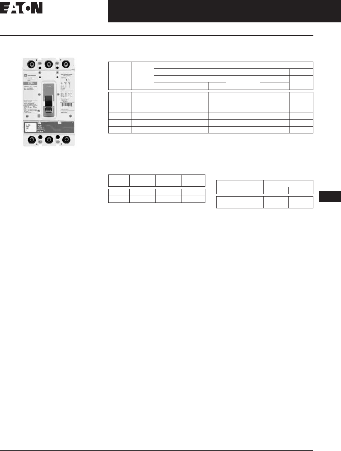
JG-Frame
Eaton’s Cutler-Hammer J250
Product Description
■JG breaker is HACR rated.
Technical Data and Specifications
Table 12-21. UL 489/IEC 60947-2 Interrupting Capacity Ratings
dc ratings apply to substantially non-inductive circuits.
2-pole circuit breaker, or two poles of 3-pole circuit breaker.
Time constant is 3 milliseconds minimum at 10 kA and 8 milliseconds minimum at 22 kA.
Dimensions/Weights
Table 12-22. Dimensions in Inches (mm) Table 12-23. Approximate Shipping
Weight in Lbs. (kg)
Circuit
Breaker
Type
Number
of Poles
Interrupting Capacity (kA Symmetrical Amperes)
Volts ac (50/60 Hz) Volts dc
220 – 240 380 – 415 480 600 690 250
Icu Ics Icu Ics Icu Ics
JGE250 2, 3, 4 65 65 25 25 25 18 12 6 10
JGS250 2, 3, 4 85 85 40 40 35 18 12 6 22
JGH250 2, 3, 4 100 100 70 70 65 25 14 7 22
JGC250 3, 4 200 200 100 100 100 35 16 12 42
JGU250 3, 4 200 200 150 150 150 50 18 14 50
JGX250 3, 4 200 200 200 200 200 50 18 14 50
Number
of Poles
Width Height Depth
2/3 4.13 (104.9) 7.00 (177.8) 3.57 (90.7)
4 5.34 (135.6) 7.00 (177.8) 3.57 (90.7)
Breaker
Type
Number of Poles
2/3 4
JGE, JGS, JGH, JGC,
JGU, JGX
6 (2.7) 8 (3.6)

November 2008
12-22
For more information visit: www.eaton.com CA08101001E
Series G Molded Case Circuit Breakers
12
63 – 250 Amperes
JG-Frame
Product Selection
Table 12-24. Main Catalog Numbering System
100% rating only available on breakers with electronic trip unit.
Table 12-25. Trip Unit Catalog Numbering System
J G S 3 25O FA G C
Frame
J
Standard/Application
G = IEC/CE/UL/CSA
Performance
600 480 415 240
E18 25 25 65
S18 35 40 85
H25 65 70 100
C35 100 100 200
U50 150 150 200
X50 200 200 200
KMolded Case Switch
Poles
2 = Two
3 = Three
4 = Four — Neutral 0% Protected
8 = Four — Neutral 0 – 60% Protected
9 = Four — Neutral 0 – 100 Protected
Amperes
050
070
080
090
100
125
150
160
175
200
225
250
Trip Unit
AA = Adj. Adj.
FA = Fixed Adj.
KS = Molded Case Switch
33 = 310+ Electronic LS
32 = 310+ Electronic LSI
35 = 310+ Electronic LSG
36 = 310+ Electronic LSIG
NN = Frame Only (No Trip)
Terminations/Hardware
Terminals Mounting Hardware
M= Metric End Caps
E= Imperial End Caps
G= Line/Load Standard
Metric
Imperial
Metric
Rating
Blank = 80% Rated
C= 100% Rated
JT 4 100 FA
Trip
JT
Amperes
T/M ETU
080
090
100
110
125
150
160
175
200
225
250
050
100
160
250
Poles
2 = Two
3 = Three
4 = Four — Neutral 0% Protected
8 = Four — Neutral 0/60% Protected
9 = Four — Neutral 0/100% Protected
Trip Unit
AA = Adj. Adj.
FA = Fixed Adj.
KS = Molded Case Switch
33 = 310+ Electronic LS
32 = 310+ Electronic LSI
35 = 310+ Electronic LSG
36 = 310+ Electronic LSIG

November 2008
CA08101001E For more information visit: www.eaton.com
12-23
Series G Molded Case Circuit Breakers
12
63 – 250 Amperes
JG-Frame
Product Selection
Table 12-26. Complete Breaker (Includes Frame, Trip Unit, Standard Terminals and Mounting Hardware) — IC Rating at 415/480 Volts
Change the fourth digit to 8 for adjustable 0 – 60% neutral protection, 9 for 0 – 100% neutral protection. Neutral is on LH side.
IEC-EN 60947-2 only. Adjustment is .8 and 1.0.
Discount Symbol . . . . . . . . . . . . . . . . . . . . . . CB-2
Maximum
Continuous
Amperes
Magnetic
Range
2-Pole 3-Pole 4-Pole 0%
Fixed Thermal
Adjustable Magnetic
Fixed Thermal
Adjustable Magnetic
Adjustable Thermal
Adjustable Magnetic
Fixed Thermal
Adjustable Magnetic
Adjustable Thermal
Adjustable Magnetic
Catalog
Number
Price
U.S. $
Catalog
Number
Price
U.S. $
Catalog
Number
Price
U.S. $
Catalog
Number
Price
U.S. $
Catalog
Number
Price
U.S. $
IEC/CE/UL/CSA 25/25
70
90
100
125
150
160
175
200
225
250
350 – 700
450 – 900
500 – 1000
625 – 1250
750 – 1550
800 – 1600
875 – 1750
1000 – 2000
1125 – 2250
1250 – 2500
JGE2070FAG
JGE2090FAG
JGE2100FAG
JGE2125FAG
JGE2150FAG
—
JGE2175FAG
JGE2200FAG
JGE2225FAG
JGE2250FAG
JGE3070FAG
JGE3090FAG
JGE3100FAG
JGE3125FAG
JGE3150FAG
—
JGE3175FAG
JGE3200FAG
JGE3225FAG
JGE3250FAG
—
—
JGE3100AAG
JGE3125AAG
—
JGE3160AAG
—
JGE3200AAG
—
JGE3250AAG
JGE4070FAG
JGE4090FAG
JGE4100FAG
JGE4125FAG
JGE4150FAG
—
JGE4175FAG
JGE4200FAG
JGE4225FAG
JGE4250FAG
—
—
JGE4100AAG
JGE4125AAG
—
JGE4160AAG
—
JGE4200AAG
—
JGE4250AAG
IEC/CE/UL/CSA 40/35
70
90
100
125
150
160
175
200
225
250
350 – 700
450 – 900
500 – 1000
625 – 1250
750 – 1550
800 – 1600
875 – 1750
1000 – 2000
1125 – 2250
1250 – 2500
JGS2070FAG
JGS2090FAG
JGS2100FAG
JGS2125FAG
JGS2150FAG
—
JGS2175FAG
JGS2200FAG
JGS2225FAG
JGS2250FAG
JGS3070FAG
JGS3090FAG
JGS3100FAG
JGS3125FAG
JGS3150FAG
—
JGS3175FAG
JGS3200FAG
JGS3225FAG
JGS3250FAG
—
—
JGS3100AAG
JGS3125AAG
—
JGS3160AAG
—
JGS3200AAG
—
JGS3250AAG
JGS4070FAG
JGS4090FAG
JGS4100FAG
JGS4125FAG
JGS4150FAG
—
JGS4175FAG
JGS4200FAG
JGS4225FAG
JGS4250FAG
—
—
JGS4100AAG
JGS4125AAG
—
JGS4160AAG
—
JGS4200AAG
—
JGS4250AAG
IEC/CE/UL/CSA 70/65
70
90
100
125
150
160
175
200
225
250
350 – 700
450 – 900
500 – 1000
625 – 1250
750 – 1550
800 – 1600
875 – 1750
1000 – 2000
1125 – 2250
1250 – 2500
JGH2070FAG
JGH2090FAG
JGH2100FAG
JGH2125FAG
JGH2150FAG
—
JGH2175FAG
JGH2200FAG
JGH2225FAG
JGH2250FAG
JGH3070FAG
JGH3090FAG
JGH3100FAG
JGH3125FAG
JGH3150FAG
—
JGH3175FAG
JGH3200FAG
JGH3225FAG
JGH3250FAG
—
—
JGH3100AAG
JGH3125AAG
—
JGH3160AAG
—
JGH3200AAG
—
JGH3250AAG
JGH4070FAG
JGH4090FAG
JGH4100FAG
JGH4125FAG
JGH4150FAG
—
JGH4175FAG
JGH4200FAG
JGH4225FAG
JGH4250FAG
—
—
JGH4100AAG
JGH4125AAG
—
JGH4160AAG
—
JGH4200AAG
—
JGH4250AAG
IEC/CE/UL/CSA 100/100
70
80
90
100
125
150
160
175
200
225
250
350 – 700
400 – 800
450 – 900
500 – 1000
625 – 1250
750 – 1550
800 – 1600
875 – 1750
1000 – 2000
1125 – 2250
1250 – 2500
—
—
—
—
—
—
—
—
—
—
—
JGC3070FAG
—
JGC3090FAG
JGC3100FAG
JGC3125FAG
JGC3150FAG
—
JGC3175FAG
JGC3200FAG
JGC3225FAG
JGC3250FAG
—
JGC3080AAG
—
JGC3100AAG
JGC3125AAG
—
JGC3160AAG
—
JGC3200AAG
—
JGC3250AAG
JGC4070FAG
—
JGC4090FAG
JGC4100FAG
JGC4125FAG
JGC4150FAG
—
JGC4175FAG
JGC4200FAG
JGC4225FAG
JGC4250FAG
—
JGC4080AAG
—
JGC4100AAG
JGC4125AAG
—
JGC4160AAG
—
JGC4200AAG
—
JGC4250AAG
IEC/CE/UL/CSA 150/150
70
80
90
100
125
150
160
175
200
225
250
350 – 700
400 – 800
450 – 900
500 – 1000
625 – 1250
750 – 1550
800 – 1600
875 – 1750
1000 – 2000
1125 – 2250
1250 – 2500
—
—
—
—
—
—
—
—
—
—
—
JGU3070FAG
—
JGU3090FAG
JGU3100FAG
JGU3125FAG
JGU3150FAG
—
JGU3175FAG
JGU3200FAG
JGU3225FAG
JGU3250FAG
—
JGU3080AAG
—
JGU3100AAG
JGU3125AAG
—
JGU3160AAG
—
JGU3200AAG
—
JGU3250AAG
JGU4070FAG
—
JGU4090FAG
JGU4100FAG
JGU4125FAG
JGU4150FAG
—
JGU4175FAG
JGU4200FAG
JGU4225FAG
JGU4250FAG
—
JGU4080AAG
—
JGU4100AAG
JGU4125AAG
—
JGU4160AAG
—
JGU4200AAG
—
JGU4250AAG
IEC/CE/UL/CSA 200/200
70
80
90
100
125
150
160
175
200
225
250
350 – 700
400 – 800
450 – 900
500 – 1000
625 – 1250
750 – 1550
800 – 1600
875 – 1750
1000 – 2000
1125 – 2250
1250 – 2500
—
—
—
—
—
—
—
—
—
—
—
JGX3070FAG
—
JGX3090FAG
JGX3100FAG
JGX3125FAG
JGX3150FAG
—
JGX3175FAG
JGX3200FAG
JGX3225FAG
JGX3250FAG
—
JGX3080AAG
—
JGX3100AAG
JGX3125AAG
—
JGX3160AAG
—
JGX3200AAG
—
JGX3250AAG
JGX4070FAG
—
JGX4090FAG
JGX4100FAG
JGX4125FAG
JGX4150FAG
—
JGX4175FAG
JGX4200FAG
JGX4225FAG
JGX4250FAG
—
JGX4080AAG
—
JGX4100AAG
JGX4125AAG
—
JGX4160AAG
—
JGX4200AAG
—
JGX4250AAG

November 2008
12-24
For more information visit: www.eaton.com CA08101001E
Series G Molded Case Circuit Breakers
12
63 – 250 Amperes
JG-Frame
Product Selection
Table 12-27. Thermal-Magnetic Trip Unit
Adjustable thermal trip units are typically used in IEC markets and are not UL or CSA listed.
Table 12-28. Molded Case Switches
Note: Molded case switches will trip above 2500 amperes.
Table 12-29. Components — Line and Load Terminal
Standard line and load terminals.
Ampere
Rating
Range Catalog
Number
Price
U.S. $
Catalog
Number
Price
U.S. $
Catalog
Number
Price
U.S. $
Range Catalog
Number
Price
U.S. $
Catalog
Number
Price
U.S. $
70
80
90
100
350 – 700
400 – 800
450 – 900
500 – 1000
JT2070FA
—
JT2090FA
JT2100FA
JT3070FA
—
JT3090FA
JT3100FA
—
JT3080AA
—
JT3100AA
—
64 – 100
—
80 – 100
JT4070FA
—
JT4090FA
JT4100FA
—
JT4080AA
—
JT4100AA
125
150
160
175
625 – 1250
750 – 1500
800 – 1600
875 – 1750
JT2125FA
JT2150FA
—
JT2175FA
JT3125FA
JT3150FA
—
JT3175FA
JT3125AA
—
JT3160AA
—
100 – 125
—
128 – 160
—
JT4125FA
JT4150FA
—
JT4175FA
JT4125AA
—
JT4160AA
—
200
225
250
1000 – 2000
1125 – 2250
1250 – 2500
JT2200FA
JT2225FA
JT2250FA
JT3200FA
JT3225FA
JT3250FA
JT3200AA
—
JT3250AA
160 – 200
—
200 – 250
JT4200FA
JT4225FA
JT4250FA
JT4200AA
—
JT4250AA
Catalog
Number
Price
U.S. $
JGK3250KSK
JGK7250KSG
Maximum
Breaker
Amperes
Terminal
Body
Material
Wire
Type
AWG Wire
Range No.
Conductors
Metric Wire
Range mm
2
Catalog
Number
Price
U.S. $
Standard Cu/AI Pressure Terminals
250 Aluminum Cu/Al 4 – 350 kcmil
25 – 185 TA250FJ
250 Stainless
Steel
Cu 4 – 350 kcmil
25 – 185 T250FJ
Discount Symbol . . . . . . . . . . . . . . . . . . . . . . . . CB-2
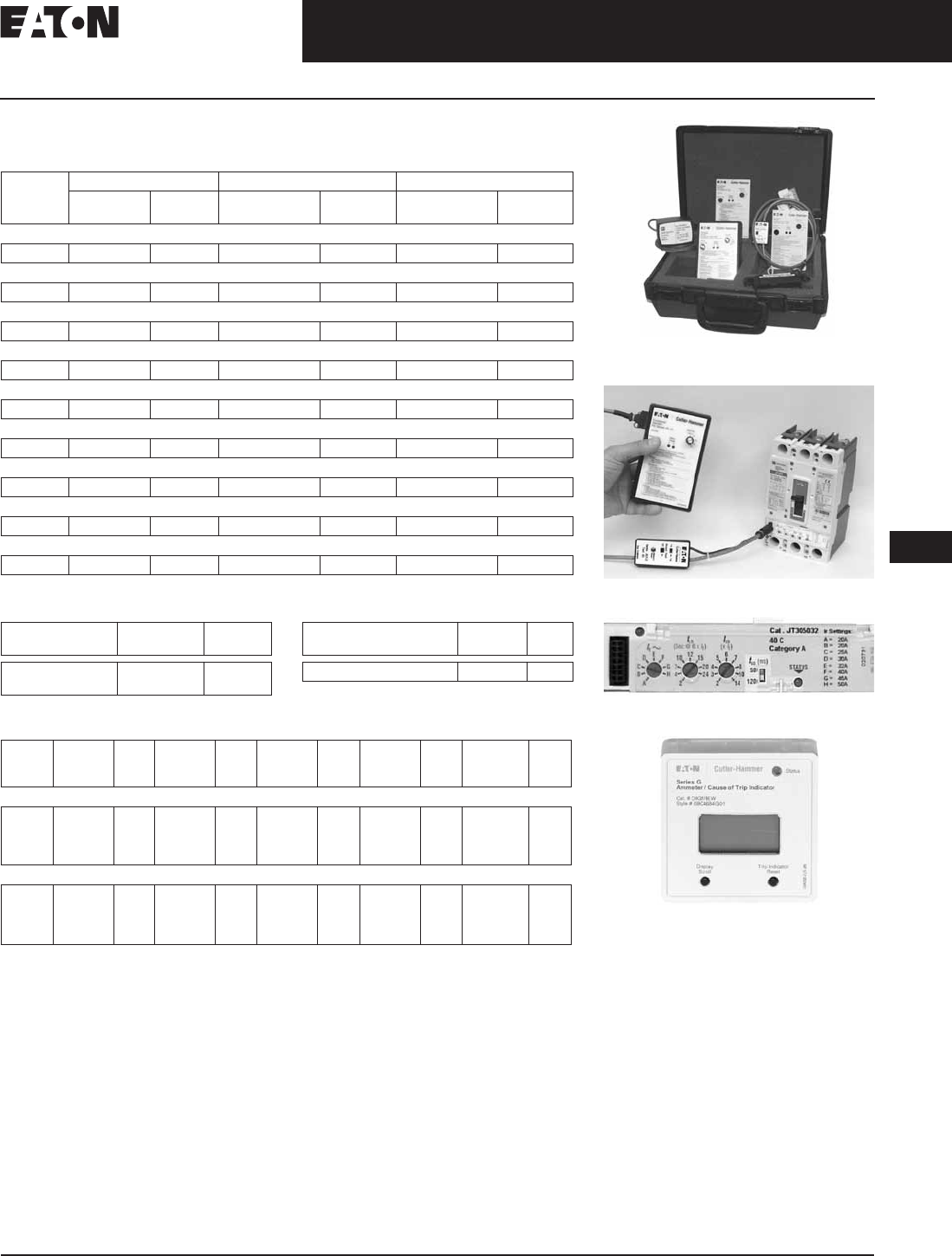
CA08101001E For more information visit: www.eaton.com
12-25
Series G Molded Case Circuit Breakers
November 2008
12
63 – 250 Amperes
JG-Frame
Product Selection
Table 12-30. Components — Frame — IC Rating at 415/480 Volts
Components — 100% rated frame. To be used with electronic trip units only.
Table 12-31. Plug-in Test Kit Table 12-32. Breaker Mount Ammeter
Note: Use on electronic trip only.
Table 12-33. JG Electronic Trip Units
For use on a 3-pole breaker used in a 4-wire system if ground fault protection for the neutral is
required.
Neutral protection 4 = 0%, 6 = 60%, 7 = 100% electronic trip unit neutral protection is not
adjustable.
Note: Long time pickup — no rating plug.
250 Ampere Settings — 250, 225, 200, 175, 160, 150, 125, 100.
160 Ampere Settings — 160, 150, 125, 110, 100, 90, 80, 63.
100 Ampere Settings — 100, 90, 80, 70, 63, 50, 45, 40.
50 Ampere Settings — 50, 45, 40, 32, 30, 25, 20.
Note: Adjustable long time delay — 2 – 24 seconds at 6 x lr.
Adjustable short time delay — Inst., 120, 300 ms
Maximum
Amperes
2-Pole 3-Pole 4-Pole 0%
Catalog
Number
Price
U.S. $
Catalog
Number
Price
U.S. $
Catalog
Number
Price
U.S. $
25/25
250 JGE2250NN JGE3250NN JGE4250NN
40/35
250 JGS2250NN JGS3250NN JGS4250NN
70/65
250 JGH2250NN JGH3250NN JGH4250NN
100/100
250 —JGC3250NN JGC4250NN
150/150
250 —JGU3250NN JGU4250NN
200/200
250 —JGX3250NN JGX4250NN
25/25
250 —JGE3250NNC —
40/35
250 —JGS3250NNC —
70/65
250 —JGH3250NNC —
Voltage
Rating
Catalog
Number
Price
U.S. $
120 Vac
230 Vac
MTST120V
MTST230V
Description Catalog
Number
Price
U.S. $
Breaker Mount Ammeter DIGIVIEW
Ampere
Rating
LS Price
U.S. $
LSI Price
U.S. $
LSG Price
U.S. $
LSIG Price
U.S. $
Neutral CT
for LSG &
LSIG
Price
U.S. $
3-Pole
50
100
160
250
JT305033
JT310033
JT316033
JT325033
JT305032
JT310032
JT316032
JT325032
JT305035
JT310035
JT316035
JT325035
JT305036
JT310036
JT316036
JT325036
JGFCT050
JGFCT100
JGFCT160
JGFCT250
4-Pole
50
100
160
250
JT405033
JT410033
JT416033
JT425033
JT405032
JT410032
JT416032
JT425032
JT405035
JT410035
JT416035
JT425035
JT405036
JT410036
JT416036
JT425036
—
—
—
—
Digitrip 310+ Test Kit
Digitrip 310+ Test Kit Shown with JG MCCB
JG Digitrip 310+ Electronic Trip Unit
Ammeter
Discount Symbol . . . . . . . . . . . . . . . . . . . . . . . . . CB-2

November 2008
12-26
For more information visit: www.eaton.com CA08101001E
Series G Molded Case Circuit Breakers
12
63 – 250 Amperes
JG-Frame
Table 12-34. Complete Breaker with Electronic Trip Units
Required for 4-wire systems if neutral protection is required.
Neutral protection 4 = 0%, 6 = 60%, 7 = 100% electronic trip unit neutral protection is not adjustable.
Ampere
Rating
LS Price
U.S. $
LSI Price
U.S. $
LSG Price
U.S. $
LSIG Price
U.S. $
Neutral CT for
LSG & LSIG
Price
U.S. $
IEC/UL/CSA 25/25 — 3-Pole
50
100
160
250
JGE305033G
JGE310033G
JGE316033G
JGE325033G
JGE305032G
JGE310032G
JGE316032G
JGE325032G
JGE305035G
JGE310035G
JGE316035G
JGE325035G
JGE305036G
JGE310036G
JGE316036G
JGE325036G
JGFCT050
JGFCT100
JGFCT160
JGFCT250
IEC/UL/CSA 25/25 — 4-Pole
50
100
160
250
JGE405033G
JGE410033G
JGE416033G
JGE425033G
JGE405032G
JGE410032G
JGE416032G
JGE425032G
JGE405035G
JGE410035G
JGE416035G
JGE425035G
JGE405036G
JGE410036G
JGE416036G
JGE425036G
—
—
—
—
IEC/UL/CSA 40/35 — 3-Pole
50
100
160
250
JGS305033G
JGS310033G
JGS316033G
JGS325033G
JGS305032G
JGS310032G
JGS316032G
JGS325032G
JGS305035G
JGS310035G
JGS316035G
JGS325035G
JGS305036G
JGS310036G
JGS316036G
JGS325036G
JGFCT050
JGFCT100
JGFCT160
JGFCT250
IEC/UL/CSA 40/35 — 4-Pole
50
100
160
250
JGS405033G
JGS410033G
JGS416033G
JGS425033G
JGS405032G
JGS410032G
JGS416032G
JGS425032G
JGS405035G
JGS410035G
JGS416035G
JGS425035G
JGS405036G
JGS410036G
JGS416036G
JGS425036G
—
—
—
—
IEC/UL/CSA 70/65 — 3-Pole
50
100
160
250
JGH305033G
JGH310033G
JGH316033G
JGH325033G
JGH305032G
JGH310032G
JGH316032G
JGH325032G
JGH305035G
JGH310035G
JGH316035G
JGH325035G
JGH305036G
JGH310036G
JGH316036G
JGH325036G
JGFCT050
JGFCT100
JGFCT160
JGFCT250
IEC/UL/CSA 70/65 — 4-Pole
50
100
160
250
JGH405033G
JGH410033G
JGH416033G
JGH425033G
JGH405032G
JGH410032G
JGH416032G
JGH425032G
JGH405035G
JGH410035G
JGH416035G
JGH425035G
JGH405036G
JGH410036G
JGH416036G
JGH425036G
—
—
—
—
IEC/UL/CSA 100/100 — 3-Pole
50
100
160
250
JGC305033G
JGC310033G
JGC316033G
JGC335033G
JGC305032G
JGC310032G
JGC316032G
JGC325032G
JGC305035G
JGC310035G
JGC316035G
JGC325035G
JGC305036G
JGC310036G
JGC316036G
JGC325036G
JGFCT050
JGFCT100
JGFCT160
JGFCT250
IEC/UL/CSA 100/100 — 4-Pole
50
100
160
250
JGC405033G
JGC410033G
JGC416033G
JGC435033G
JGC405032G
JGC410032G
JGC416032G
JGC425032G
JGC405035G
JGC410035G
JGC416035G
JGC425035G
JGC405036G
JGC410036G
JGC416036G
JGC425036G
—
—
—
—
IEC/UL/CSA 150/150 — 3-Pole
50
100
160
250
JGU305033G
JGU310033G
JGU316033G
JGU335033G
JGU305032G
JGU310032G
JGU316032G
JGU325032G
JGU305035G
JGU310035G
JGU316035G
JGU325035G
JGU305036G
JGU310036G
JGU316036G
JGU325036G
JGFCT050
JGFCT100
JGFCT160
JGFCT250
IEC/UL/CSA 150/150 — 4-Pole
50
100
160
250
JGU405033G
JGU410033G
JGU416033G
JGU435033G
JGU405032G
JGU410032G
JGU416032G
JGU425032G
JGU405035G
JGU410035G
JGU416035G
JGU425035G
JGU405036G
JGU410036G
JGU416036G
JGU425036G
—
—
—
—
IEC/UL/CSA 200/200 — 3-Pole
50
100
160
250
JGX305033G
JGX310033G
JGX316033G
JGX325033G
JGX305032G
JGX310032G
JGX316032G
JGX325032G
JGX305035G
JGX310035G
JGX316035G
JGX325035G
JGX305036G
JGX310036G
JGX316036G
JGX325036G
JGFCT050
JGFCT100
JGFCT160
JGFCT250
IEC/UL/CSA 200/200 — 4-Pole
50
100
160
250
JGX405033G
JGX410033G
JGX416033G
JGX425033G
JGX405032G
JGX410032G
JGX416032G
JGX425032G
JGX405035G
JGX410035G
JGX416035G
JGX425035G
JGX405036G
JGX410036G
JGX416036G
JGX425036G
—
—
—
—
Discount Symbol . . . . . . . . . . . . . . . . . . . . . . . . CB-2

November 2008
CA08101001E For more information visit: www.eaton.com
12-27
Series G Molded Case Circuit Breakers
12
63 – 250 Amperes
JG-Frame
Table 12-35. JG 100% Rated Circuit Breaker
Required for 4-wire systems if neutral protection is required.
Ampere
Rating
LS LSI LSG LSIG Neutral CT for LSG & LSIG
Catalog
Number
Price
U.S. $
Catalog
Number
Price
U.S. $
Catalog
Number
Price
U.S. $
Catalog
Number
Price
U.S. $
Catalog
Number
Price
U.S. $
IEC/UL/CSA 25/25
50
100
160
250
JGE305033GC
JGE310033GC
JGE316033GC
JGE325033GC
JGE305032GC
JGE310032GC
JGE316032GC
JGE325032GC
JGE305035GC
JGE310035GC
JGE316035GC
JGE325035GC
JGE305036GC
JGE310036GC
JGE316036GC
JGE325036GC
JGFCT050
JGFCT100
JGFCT160
JGFCT250
IEC/UL/CSA 40/35
50
100
160
250
JGS305033GC
JGS310033GC
JGS316033GC
JGS325033GC
JGS305032GC
JGS310032GC
JGS316032GC
JGS325032GC
JGS305035GC
JGS310035GC
JGS316035GC
JGS325035GC
JGS305036GC
JGS310036GC
JGS316036GC
JGS325036GC
JGFCT050
JGFCT100
JGFCT160
JGFCT250
IEC/UL/CSA 70/65
50
100
160
250
JGH305033GC
JGH310033GC
JGH316033GC
JGH325033GC
JGH305032GC
JGH310032GC
JGH316032GC
JGH325032GC
JGH305035GC
JGH310035GC
JGH316035GC
JGH325035GC
JGH305036GC
JGH310036GC
JGH316036GC
JGH325036GC
JGFCT050
JGFCT100
JGFCT160
JGFCT250
Discount Symbol . . . . . . . . . . . . . . . . . . . . . . . . . CB-2

November 2008
12-28
For more information visit: www.eaton.com CA08101001E
Series G Molded Case Circuit Breakers
12
63 – 250 Amperes
JG-Frame
Selection Guide and Ordering Information
Line and Load Terminals
JG-Frame circuit breakers include Cu/Al terminals T250FJ as standard. When optional
copper only terminals are required, order by catalog number.
Table 12-36. Line and Load Terminals
Individually packed.
Standard line and load.
Contact factory for availability.
Endcap Kits
Endcap kits are used on J250-Frame
breaker line side to connect bus bar or
similar electrical connections. Includes
hardware.
Table 12-37. Kit Catalog Number
Control Wire Terminal Kit
For use with aluminum or copper
terminals only.
Table 12-38. Control Wire Terminal Kit
T250FJ TA250FJ Endcap
Kit
Control Wire
Terminal Kit
Multiwire
Connectors
Maximum
Breaker Amps
Terminal
Body Material
Wire
Type
Metric Wire
Range mm2AWG Wire Range/
Number of Conductors
Catalog
Number
Price
U.S. $
Standard Pressure Type Terminals
250 Stainless Steel Cu 25 – 185 #4 – 350 (1) T250FJ
250 Aluminum Cu/Al 25 – 185 #4 – 350 (1) TA250FJ
Number
of Poles
Catalog Number Price
U.S. $
Metric Imperial
3
4
FJ3RTWK
FJ4RTWK
FJ3RTDK
FJ4RTDK
Control Wire
Terminal Kit
Catalog
Number
Price
U.S. $
Package of 14 —
Priced Individually
FJCWTK
Multiwire Connectors
Field-installed multiwire connectors
for the load side (OFF) end terminals.
They are used to distribute the load
from the circuit breaker to multiple
devices without the use of separate
distribution terminal blocks.
Multiwire lug kits include terminal
shield, mounting hardware, insulators
and tin-plated aluminum connectors
to replace three mechanical load lugs.
UL listed as used on the load side
(OFF) end.
Table 12-39. JG-Frame Multiwire Connectors
Ordering Information (Package of 3)
Base Mounting Hardware
Base mounting hardware is included
with a circuit breaker or molded case
switch. (Included with breaker.)
Table 12-40. Terminal Shields IP30
Table 12-41. Interphase Barriers
Max.
Amps
Wires
per
Terminal
Wire Size
Range
AWG Cu
Kit
Catalog
Number
Price
U.S. $
250
250
3
6
14 – 2
14 – 6
3TA250FJ3
3TA250FJ6
Location Number
of Poles
Catalog Number Price
U.S. $
Line or
Load
2, 3
4
FJTS3K
FJTS4K
Package of 2 Price
U.S. $
Number of Poles Catalog Number
3
4
FJIPBK
FJIPBK4
Discount Symbol . . . . . . . . . . . . . . . . . . . . . . . . CB-2

November 2008
CA08101001E For more information visit: www.eaton.com
12-29
Series G Molded Case Circuit Breakers
12
63 – 250 Amperes
JG-Frame
Allowable Accessory Combinations
Different combinations of accessories can be supplied, depending on the types of accessories and the number
of poles in the circuit breaker.
Table 12-42. Accessories
■Applicable in indicated pole position
Contact Eaton
❏May be mounted on left or right pole —
not both
●Accessory available/Modification available
Description Reference
Page
2-, 3-Pole 4-Pole
Left Center Right Left Center Right Neu.
Internal Accessories (Only One Internal Accessory Per Pole)
Alarm Lockout (Make/Break) 12-65 ■■
Auxiliary Switch (1A, 1B) 12-65 ■■
Auxiliary Switch (2A, 2B) 12-65 ■■
Auxiliary Switch and Alarm Switch Combination 12-65 ■■
Shunt Trip — Standard 12-65 ■■
Undervoltage Release Mechanism 12-65 ■■
External Accessories
End Cap Kit 12-28 ●●
Control Wire Terminal Kit 12-28 ●●
Multiwire Connectors 12-28 ●●
Base Mounting Hardware 12-28 ●●
Interphase Barriers 12-28 ●●
Padlockable Handle Block 12-64 ■■
Padlockable Handle Lock Hasp 12-64 ❏❏❏❏
Key Interlock Kit 12-64 ❏❏❏❏
Sliding Bar Interlock — Requires Two Breakers 12-64 ●
Electrical Operator 12-64 ●●
Plug-in Adapters 12-66 ●●
Handle Mechanisms 12-67 ●●
Earth Leakage/Ground Fault Protector 12-62 ●●
Drawout Cassette 12-66 ●●
Digitrip 310+ Test Kit 12-25 ●●
Ammeter/Cause of Trip Display 12-25 ●●
Modifications (Refer to Eaton)
Moisture Fungus Treatment 12-73 ●●
Freeze-Tested Circuit Breakers — ●●
Marine/Naval Application, UL Supplement SA and SB ●●
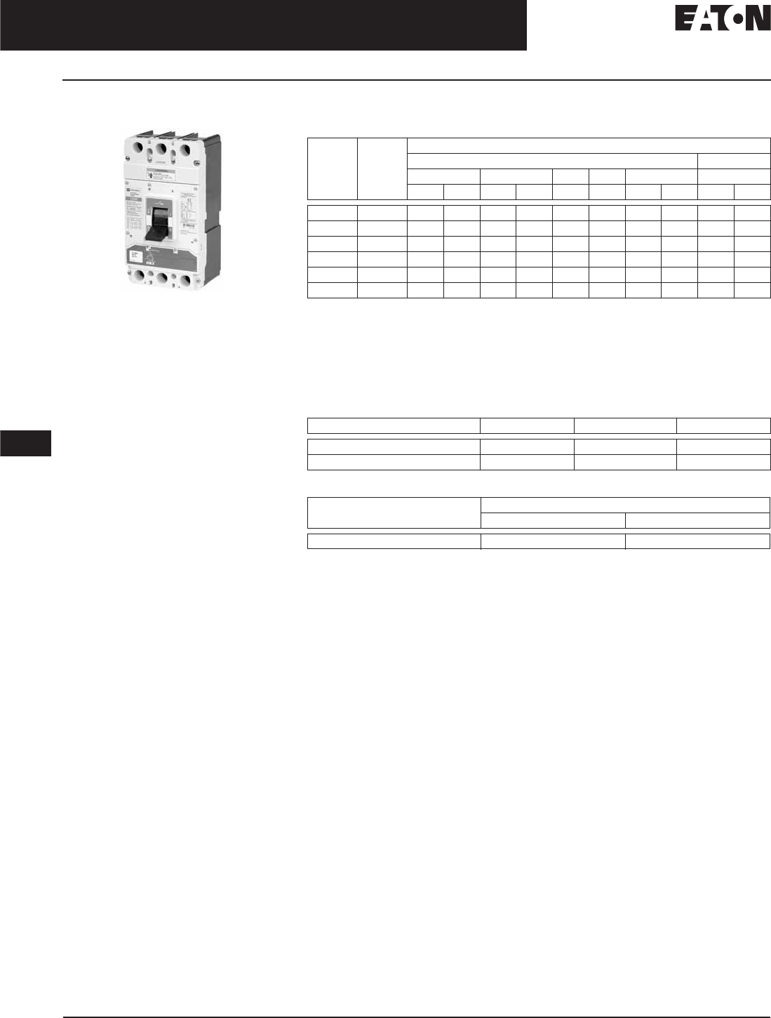
November 2008
12-30
For more information visit: www.eaton.com CA08101001E
Series G Molded Case Circuit Breakers
12
250 – 630 Amperes
LG-Frame
LG-Frame
Typical LG-Frame Circuit Breaker
Product Description
■LG breaker is HACR rated.
Interrupting Capacity Ratings
Table 12-43. UL 489/IEC 60947-2 Interrupting Capacity Ratings
dc rating apply to substantially non-inductive circuits.
2-pole circuit breaker, or two poles of 3-pole circuits.
Time constant is 3 milliseconds minimum at 10 kA and 8 milliseconds minimum at – kA.
3-poles in series. 750 Vdc ratings available (4-poles in series, not UL listed). Contact Eaton.
IEC rating is 300 kA @ 240 Vac.
Dimensions/Weights
Table 12-44. Dimensions in Inches (mm)
Table 12-45. Weight in Lbs (kg)
Circuit
Breaker
Type
Number
of Poles
Interrupting Capacity (kA rms Symmetrical Amperes) (kA)
Volts ac (50/60 Hz) Volts dc
240 – 240 380 – 415 480 600 690 250
Icu Ics Icu Ics Icu Ics Icu Ics
LGE630 3, 4 65 65 35 35 35 18 12 6 22 22
LGS630 3, 4 85 85 50 50 50 25 20 10 22 22
LGH630 3, 4 100 100 70 70 65 35 25 13 42 42
LGC630 3, 4 200 200 100 100 100 50 30 15 42 42
LGU630 3, 4 200 200 150 150 150 65 35 18 50 50
LGX630 3, 4 200 200 200 200 200 65 35 18 50 50
Number of Poles Width Height Depth
2/3 5.48 (139.2) 10.13 (257.3) 4.09 (103.9)
4 7.22 (183.4) 10.13 (257.3) 4.09 (103.9)
Breaker Type Number of Poles
2/3 4
LGE, LGS, LGH, LGC, LGU, LGX 16 (7.3) 20 (9.1)

November 2008
CA08101001E For more information visit: www.eaton.com
12-31
Series G Molded Case Circuit Breakers
12
250 – 630 Amperes
LG-Frame
Product Selection
Table 12-46. Main Catalog Numbering System
100% rating only available on breakers with electronic trip unit.
Table 12-47. Trip Unit Catalog Numbering System
L G S 3 600 FA G C
Frame
L
Standard/Application
G = IEC/CE/UL/CSA
Performance
600 480 415 240
E18 35 35 65
S25 50 50 85
H35 65 70 100
C50 100 100 200
U65 150 150 200
X65 200 200 200
KMolded Case Switch
Poles
3 = Three
4 = Four — Neutral 0% Protected
6 = Four — Neutral 60% Protected
7 = Four — Neutral 100% Protected
8 = Four — Neutral 0 – 60% Protected
9 = Four — Neutral 0 – 100 Protected
Amperes
250
300
350
400
500
600
630
Trip Unit
AA = Adj. Adj.
FA = Fixed Adj.
KS = Molded Case Switch
33 = 310+ Electronic LS
32 = 310+ Electronic LSI
35 = 310+ Electronic LSG
36 = 310+ Electronic LSIG
38 = 310+ Electronic ALSI
39 = 310+ Electronic ALSIG
NN = Frame Only (No Trip)
Terminations
Terminals Mounting Hardware
M= Metric End Caps
E= Imperial End Caps
G= Line/Load Standard
W= Without Terminals
Metric
Imperial
Metric
Rating
Blank = 80% Rated
C= 100% Rated
LT 3 600 FA
Trip
LT
Amperes
250
300
350
400
500
600
630
Poles
3 = Three
4 = Four — Neutral 0% Protected
8 = Four — Neutral 0/60% Protected
9 = Four — Neutral 0/100% Protected
Trip Unit
AA = Adj. Adj. Thermal-Magnetic
FA = Fixed Adj. Thermal-Magnetic
KS = Molded Case Switch
33 = 310+ Electronic LS
32 = 310+ Electronic LSI
35 = 310+ Electronic LSG
36 = 310+ Electronic LSIG
38 = 310+ Electronic ALSI
39 = 310+ Electronic ALSIG

November 2008
12-32
For more information visit: www.eaton.com CA08101001E
Series G Molded Case Circuit Breakers
12
250 – 630 Amperes
Frame Size LG, 630 Amperes (600 Amperes UL, CSA)
LG-Frame, 630 Amperes
Table 12-48. Complete Breaker (Includes Frame, Trip Unit, Standard Terminals and Mounting Hardware)
Replace suffix “G” with “W” for no line and load terminals.
See Table 12-49 below for prices.
For 2-pole applications, use two outer poles.
Neutral protection is indicated by the fourth character: 4 = 0%, 7 = 100%, 8 = adjustable 0 – 60% and 9 = 0 – 100%. Neutral is on LH side.
320/630 amperes is not a UL or CSA listed rating. 600 amperes is the maximum UL and CSA rating for the LG.
Adjustable thermal units are typically used in IEC markets and are not UL or CSA listed.
Table 12-49. Complete Breaker Prices (Includes Frame, Trip Unit, Standard Terminals and Mounting Hardware)
Discount Symbol . . . . . . . . . . . . . . . . . . . . . . . . CB-2
Ampere
Rating
3-Pole 4-Pole (0%) 3-Pole 4-Pole (0%)
Fixed Thermal
Adj. Magnetic
Adj. Thermal
Adj. Magnetic
Fixed Thermal
Adj. Magnetic
Adj. Thermal
Adj. Magnetic
Fixed Thermal
Adj. Magnetic
Adj. Thermal
Adj. Magnetic
Fixed Thermal
Adj. Magnetic
Adj. Thermal
Adj. Magnetic
IC Rating: 35 kAIC at 415 and 480 Vac IC Rating: 50 kAIC at 415 and 480 Vac
250
300
320
350
LGE3250FAG
LGE3300FAG
—
LGE3350FAG
LGE3250AAG
—
LGE3320AAG
—
LGE4250FAG
LGE4300FAG
—
LGE4350FAG
LGE4250AAG
—
LGE4320AAG
—
LGS3250FAG
LGS3300FAG
—
LGS3350FAG
LGS3250AAG
—
LGS3320AAG
—
LGS4250FAG
LGS4350FAG
—
LGS4350FAG
LGS4250AAG
—
LGS4320AAG
—
400
500
600
630
LGE3400FAG
LGE3500FAG
LGE3600FAG
—
LGE3400AAG
LGE3500AAG
—
LGE3630AAG
LGE4400FAG
LGE4500FAG
LGE4600FAG
—
LGE4400AAG
LGE4500AAG
—
LGE4630AAG
LGS3400FAG
LGS3500FAG
LGS3600FAG
—
LGS3400AAG
LGS3500AAG
—
LGS3630AAG
LGS4400FAG
LGS4500FAG
LGS4600FAG
—
LGS4400AAG
LGS4500AAG
—
LGS4630AAG
IC Rating: 70 kAIC at 415 Vac, 65 kAIC at 480 Vac IC Rating: 100 kAIC at 415 and 480 Vac
250
300
320
350
LGH3250FAG
LGH3300FAG
—
LGH3350FAG
LGH3250AAG
—
LGH3320AAG
—
LGH4250FAG
LGH4300FAG
—
LGH4350FAG
LGH4250AAG
—
LGH4320AAG
—
LGC3250FAG
LGC3300FAG
—
LGC3350FAG
LGC3250AAG
—
LGC3320AAG
—
LGC4250FAG
LGC4300FAG
—
LGC4350FAG
LGC4250AAG
—
LGC4320AAG
—
400
500
600
630
LGH3400FAG
LGH3500FAG
LGH3600FAG
—
LGH3400AAG
LGH3500AAG
—
LGH3630AAG
LGH4400FAG
LGH4500FAG
LGH4600FAG
—
LGH4400AAG
LGH4500AAG
—
LGH4630AAG
LGC3400FAG
LGC3500FAG
LGC3600FAG
—
LGC3400AAG
LGC3500AAG
—
LGC3630AAG
LGC4400FAG
LGC4500FAG
LGC4600FAG
—
LGC4400AAG
LGC4500AAG
—
LGC4630AAG
IC Rating: 150 kAIC at 415 and 480 Vac IC Rating: 200 kAIC at 415 and 480 Vac
250
300
320
350
LGU3250FAG
LGU3300FAG
—
LGU3350FAG
LGU3250AAG
—
LGU3320AAG
—
LGU4250FAG
LGU4300FAG
—
LGU4350FAG
LGU4250AAG
—
LGU4320AAG
—
LGX3250FAG
LGX3300FAG
—
LGX3350FAG
LGX3250AAG
—
LGX3320AAG
—
LGX4250FAG
LGX4300FAG
—
LGX4350FAG
LGX4250AAG
—
LGX4320AAG
—
400
500
600
630
LGU3400FAG
LGU3500FAG
LGU3600FAG
—
LGU3400AAG
LGU3500AAG
—
LGU3630AAG
LGU4400FAG
LGU4500FAG
LGU4600FAG
—
LGU4400AAG
LGU4500AAG
—
LGU4630AAG
LGX3400FAG
LGX3500FAG
LGX3600FAG
—
LGX3400AAG
LGX3500AAG
—
LGX3630AAG
LGX4400FAG
LGX4500FAG
LGX4600FAG
—
LGX4400AAG
LGX4500AAG
—
LGX4630AAG
Catalog
Number
Price
U.S. $
Catalog
Number
Price
U.S. $
Catalog
Number
Price
U.S. $
Catalog
Number
Price
U.S. $
LGE3250FAG
LGE3300FAG
LGE3350FAG
LGE3500FAG
LGE3600FAG
LGE3250AAG
LGE3320AAG
LGE3400AAG
LGE3500AAG
LGE3630AAG
LGE4250FAG
LGE4300FAG
LGE4350FAG
LGE4500FAG
LGE4600FAG
LGE4250AAG
LGE4320AAG
LGE4400AAG
LGE4500AAG
LGE4630AAG
LGS3250FAG
LGS3300FAG
LGS3350FAG
LGS3500FAG
LGS3600FAG
LGS3250AAG
LGS3320AAG
LGS3400AAG
LGS3500AAG
LGS3630AAG
LGS4250FAG
LGS4300FAG
LGS4350FAG
LGS4500FAG
LGS4600FAG
LGS4250AAG
LGS4320AAG
LGS4400AAG
LGS4500AAG
LGS4630AAG
LGH3250FAG
LGH3300FAG
LGH3350FAG
LGH3500FAG
LGH3600FAG
LGH3250AAG
LGH3320AAG
LGH3400AAG
LGH3500AAG
LGH3630AAG
LGH4250FAG
LGH4300FAG
LGH4350FAG
LGH4500FAG
LGH4600FAG
LGH4250AAG
LGH4320AAG
LGH4400AAG
LGH4500AAG
LGH4630AAG
LGC3250FAG
LGC3300FAG
LGC3350FAG
LGC3500FAG
LGC3600FAG
LGC3250AAG
LGC3320AAG
LGC3400AAG
LGC3500AAG
LGC3630AAG
LGC4250FAG
LGC4300FAG
LGC4350FAG
LGC4500FAG
LGC4600FAG
LGC4250AAG
LGC4320AAG
LGC4400AAG
LGC4500AAG
LGC4630AAG
LGU3250FAG
LGU3300FAG
LGU3350FAG
LGU3500FAG
LGU3600FAG
LGU3250AAG
LGU3320AAG
LGU3400AAG
LGU3500AAG
LGU3630AAG
LGU4250FAG
LGU4300FAG
LGU4350FAG
LGU4500FAG
LGU4600FAG
LGU4250AAG
LGU4320AAG
LGU4400AAG
LGU4500AAG
LGU4630AAG
LGX3250FAG
LGX3300FAG
LGX3350FAG
LGX3500FAG
LGX3600FAG
LGX3250AAG
LGX3320AAG
LGX3400AAG
LGX3500AAG
LGX3630AAG
LGX4250FAG
LGX4300FAG
LGX4350FAG
LGX4500FAG
LGX4600FAG
LGX4250AAG
LGX4320AAG
LGX4400AAG
LGX4500AAG
LGX4630AAG
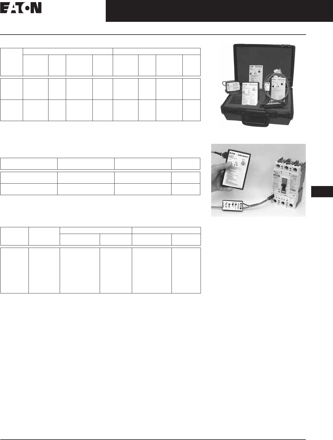
CA08101001E For more information visit: www.eaton.com
12-33
Series G Molded Case Circuit Breakers
November 2008
12
250 – 630 Amperes
Frame Size LG, 630 Amperes (600 Amperes UL, CSA)
Table 12-50. Thermal-Magnetic Trip Unit
For 2-pole applications, use two outer poles.
Neutral protection is indicated by the third character: 4 = 0%, 7 = 100%, 8 = adjustable 0 – 60% and
9 = 0 – 100%
Adjustable thermal, adjustable magnetic trip units are typically used in IEC markets and are not
UL or CSA listed.
Table 12-51. Molded Case Switches
For 2-pole applications, use two outer poles.
630 amperes is not a UL or CSA listed rating. 600 amperes is the maximum UL and CSA
rating for the LG.
Note: Molded case switches will trip above 6300 amperes.
Table 12-52. Breaker Frame Only
630 amperes is not a UL or CSA listed rating. 600 amperes is the maximum UL and CSA
rating for the LG.
For 2-pole applications, use two outer poles.
100% rated frame. For use with electronic trip units only.
Ampere
Rating
3-Pole 4-Pole (0%)
Fixed
Thermal/
Adj.
Magnetic
Price
U.S. $
Adj.
Thermal/
Adj.
Magnetic
Price
U.S. $
Fixed
Thermal/
Adj.
Magnetic
Price
U.S. $
Adj.
Thermal/
Adj.
Magnetic
Price
U.S. $
250
300
320
350
LT3250FA
LT3300FA
—
LT3350FA
LT3250AA
—
LT3320AA
—
LT4250FA
LT4300FA
—
LT4350FA
LT4250AA
—
LT4320AA
—
400
500
600
630
LT3400FA
LT3500FA
LT3600FA
—
LT3400AA
LT3500AA
—
LT3630AA
LT4400FA
LT4500FA
LT4600FA
—
LT4400AA
LT4500AA
—
LT4630AA
Ampere
Rating
Number
of Poles
Catalog
Number
Price
U.S. $
400 3
4
LGK3400KSG
LGK4400KSG
630 3
4
LGK3630KSG
LGK4630KSG
Ampere
Rating
IC Rating
at 415/
480 V
3-Pole 4-Pole (0%)
Catalog
Number
Price
U.S. $
Catalog
Number
Price
U.S. $
630
630
630
630
630
630
630
630
630
35/35
35/35
50/50
50/50
70/65
70/65
100/100
150/150
200/200
LGE3630NN
LGE3630NNWC
LGS3630NN
LGS3630NNWC
LGH3630NN
LGH3630NNWC
LGC3630NN
LGU3630NN
LGX3630NN
LGE4630NN
—
LGS4630NN
—
LGH4630NN
—
LGC4630NN
LGU4630NN
LGX4630NN
Digitrip 310+ Test Kit
Digitrip 310+ Test Kit Shown with JG MCCB
Discount Symbol . . . . . . . . . . . . . . . . . . . . . . . . . CB-2
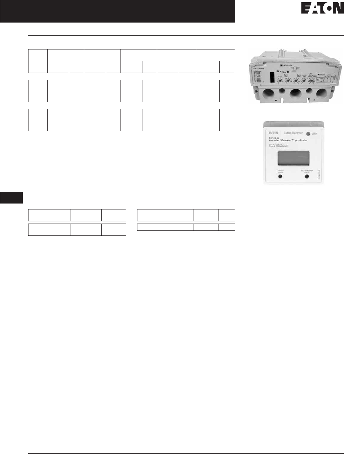
November 2008
12-34
For more information visit: www.eaton.com CA08101001E
Series G Molded Case Circuit Breakers
12
250 – 630 Amperes
Frame Size LG, 630 Amperes (600 Amperes UL, CSA)
Table 12-53. Electronic Trip Units — Digitrip 310+
Required for 4-wire systems if neutral protection is desired.
630 amperes is not a UL or CSA listed rating. 600 amperes is the maximum UL and CSA listed
rating for the LG.
Neutral protection: 4= 0%, 6 = 60%, 7 = 100%. Electronic trip unit neutral protection is not
adjustable.
Note: Long time pickup — no rating plug needed.
630 Ampere Settings — 630, 600, 500, 400, 350, 315, 300, 250 (315, 630 are IEC ratings only).
600 Ampere Settings — 600, 500, 450, 400, 350, 315, 300, 250 (315 is IEC rating only).
400 Ampere Settings — 400, 350, 315, 300, 250, 225, 200, 160 (315 is IEC rating only).
250 Ampere Settings — 250, 225, 200, 175, 160, 150, 125, 100 (160 is IEC rating only).
Note: Adjustable long time delay — 2 – 24 seconds at 6 x Ir.
Adjustable short time delay — Inst., 120, 300 ms.
Table 12-54. Plug-in Test Kit
Note: IL Number is 5721B13.
Table 12-55. Breaker Mount Ammeter
Note: Use on electronic trip only.
Ampere
Rating
LS LSI LSG LSIG Neutral CT for
LSG & LSIG
Catalog
Number
Price
U.S. $
Catalog
Number
Price
U.S. $
Catalog
Number
Price
U.S. $
Catalog
Number
Price
U.S. $
Catalog
Number
Price
U.S. $
3-Pole
250
400
600
630
LT325033
LT340033
LT360033
LT363033
LT325032
LT340032
LT360032
LT363032
LT325035
LT340035
LT360035
LT363035
LT325036
LT340036
LT360036
LT363036
LGFCT250
LGFCT400
LGFCT600
LGFCT600
4-Pole
250
400
600
630
LT425033
LT440033
LT460033
LT463033
LT425032
LT440032
LT460032
LT463032
LT425035
LT440035
LT460035
LT463035
LT425036
LT440036
LT460036
LT463036
—
—
—
—
Voltage
Rating
Catalog
Number
Price
U.S. $
120 Vac
230 Vac
MTST120V
MTST230V
Description Catalog
Number
Price
U.S. $
Breaker Mount Ammeter DIGIVIEW
LG Digitrip 310+ Electronic Trip Unit
Ammeter
Discount Symbol . . . . . . . . . . . . . . . . . . . . . . . . . CB-2

November 2008
CA08101001E For more information visit: www.eaton.com
12-35
Series G Molded Case Circuit Breakers
12
250 – 630 Amperes
Frame Size LG, 630 Amperes (600 Amperes UL, CSA)
Table 12-56. IC Rating at 415/480 V — Complete LG Breakers with Electronic Trip Unit
(Includes Frame, Trip Unit, Standard Terminals and Mounting Hardware)
Replace suffix “G” with “W” for no line and load terminals.
Required for 4-wire systems if neutral protection is desired.
For 2-pole applications, use two outer poles.
630 amperes is not a UL or CSA listed rating. 600 amperes is the maximum UL and CSA listed rating for the LG.
Neutral protection: 4 = 0%, 6 = 60%, 7 = 100%. Electronic trip unit neutral protection is not adjustable.
Ampere
Rating
LS Price
U.S. $
LSI Price
U.S. $
LSG Price
U.S. $
LSIG Price
U.S. $
Neutral CT
for LSG & LSIG
Price
U.S. $
3-Pole — IC Rating: 35 kAIC at 415 and 480 Vac
250
400
600
630
LGE325033G
LGE340033G
LGE360033G
LGE363033G
LGE325032G
LGE340032G
LGE360032G
LGE363032G
LGE325035G
LGE340035G
LGE360035G
LGE363035G
LGE325036G
LGE340036G
LGE360036G
LGE363036G
LGFCT250
LGFCT400
LGFCT600
LGFCT600
4-Pole — IC Rating: 35 kAIC at 415 and 480 Vac
250
400
600
630
LGE425033G
LGE440033G
LGE460033G
LGE463033G
LGE425032G
LGE440032G
LGE460032G
LGE463032G
LGE425035G
LGE440035G
LGE460035G
LGE463035G
LGE425036G
LGE440036G
LGE460036G
LGE463036G
—
—
—
—
3-Pole — IC Rating: 50 kAIC at 415 and 480 Vac
250
400
600
630
LGS325033G
LGS340033G
LGS360033G
LGS363033G
LGS325032G
LGS340032G
LGS360032G
LGS363032G
LGS325035G
LGS340035G
LGS360035G
LGS363035G
LGS325036G
LGS340036G
LGS360036G
LGS363036G
LGFCT250
LGFCT400
LGFCT600
LGFCT600
4-Pole — IC Rating: 50 kAIC at 415 and 480 Vac
250
400
600
630
LGS425033G
LGS440033G
LGS460033G
LGS463033G
LGS425032G
LGS440032G
LGS460032G
LGS463032G
LGS425035G
LGS440035G
LGS460035G
LGS463035G
LGS425036G
LGS440036G
LGS460036G
LGS463036G
—
—
—
—
3-Pole — IC Rating: 70 kAIC at 415 Vac, 65 kAIC at 480 Vac
250
400
600
630
LGH325033G
LGH340033G
LGH360033G
LGH363033G
LGH325032G
LGH340032G
LGH360032G
LGH363032G
LGH325035G
LGH340035G
LGH360035G
LGH363035G
LGH325036G
LGH340036G
LGH360036G
LGH363036G
LGFCT250
LGFCT400
LGFCT600
LGFCT600
4-Pole — IC Rating: 70 kAIC at 415 Vac, 65 kAIC at 480 Vac
250
400
600
630
LGH425033G
LGH440033G
LGH460033G
LGH463033G
LGH425032G
LGH440032G
LGH460032G
LGH463032G
LGH425035G
LGH440035G
LGH460035G
LGH463035G
LGH425036G
LGH440036G
LGH460036G
LGH463036G
—
—
—
—
3-Pole — IC Rating: 100 kAIC at 415 Vac and 480 Vac
250
400
600
630
LGC325033G
LGC340033G
LGC360033G
LGC363033G
LGC325032G
LGC340032G
LGC360032G
LGC363032G
LGC325035G
LGC340035G
LGC360035G
LGC363035G
LGC325036G
LGC340036G
LGC360036G
LGC363036G
LGFCT250
LGFCT400
LGFCT600
LGFCT600
4-Pole — IC Rating: 100 kAIC at 415 Vac and 480 Vac
250
400
600
630
LGC425033G
LGC440033G
LGC460033G
LGC463033G
LGC425032G
LGC440032G
LGC460032G
LGC463032G
LGC425035G
LGC440035G
LGC460035G
LGC463035G
LGC425036G
LGC440036G
LGC460036G
LGC463036G
—
—
—
—
3-Pole — IC Rating: 150 kAIC at 415 Vac and 480 Vac
250
400
600
630
LGU325033G
LGU340033G
LGU360033G
LGU363033G
LGU325032G
LGU340032G
LGU360032G
LGU363032G
LGU325035G
LGU340035G
LGU360035G
LGU363035G
LGU325036G
LGU340036G
LGU360036G
LGU363036G
LGFCT250
LGFCT400
LGFCT600
LGFCT600
4-Pole — IC Rating: 150 kAIC at 415 Vac and 480 Vac
250
400
600
630
LGU425033G
LGU440033G
LGU460033G
LGU463033G
LGU425032G
LGU440032G
LGU460032G
LGU463032G
LGU425035G
LGU440035G
LGU460035G
LGU463035G
LGU425036G
LGU440036G
LGU460036G
LGU463036G
—
—
—
—
3-Pole — IC Rating: 200 kAIC at 415 Vac and 480 Vac
250
400
600
630
LGX325033G
LGX340033G
LGX360033G
LGX363033G
LGX325032G
LGX340032G
LGX360032G
LGX363032G
LGX325035G
LGX340035G
LGX360035G
LGX363035G
LGX325036G
LGX340036G
LGX360036G
LGX363036G
LGFCT250
LGFCT400
LGFCT600
LGFCT600
4-Pole — IC Rating: 200 kAIC at 415 Vac and 480 Vac
250
400
600
630
LGX425033G
LGX440033G
LGX460033G
LGX463033G
LGX425032G
LGX440032G
LGX460032G
LGX463032G
LGX425035G
LGX440035G
LGX460035G
LGX463035G
LGX425036G
LGX440036G
LGX460036G
LGX463036G
—
—
—
—
Discount Symbol . . . . . . . . . . . . . . . . . . . . . . . . . CB-2
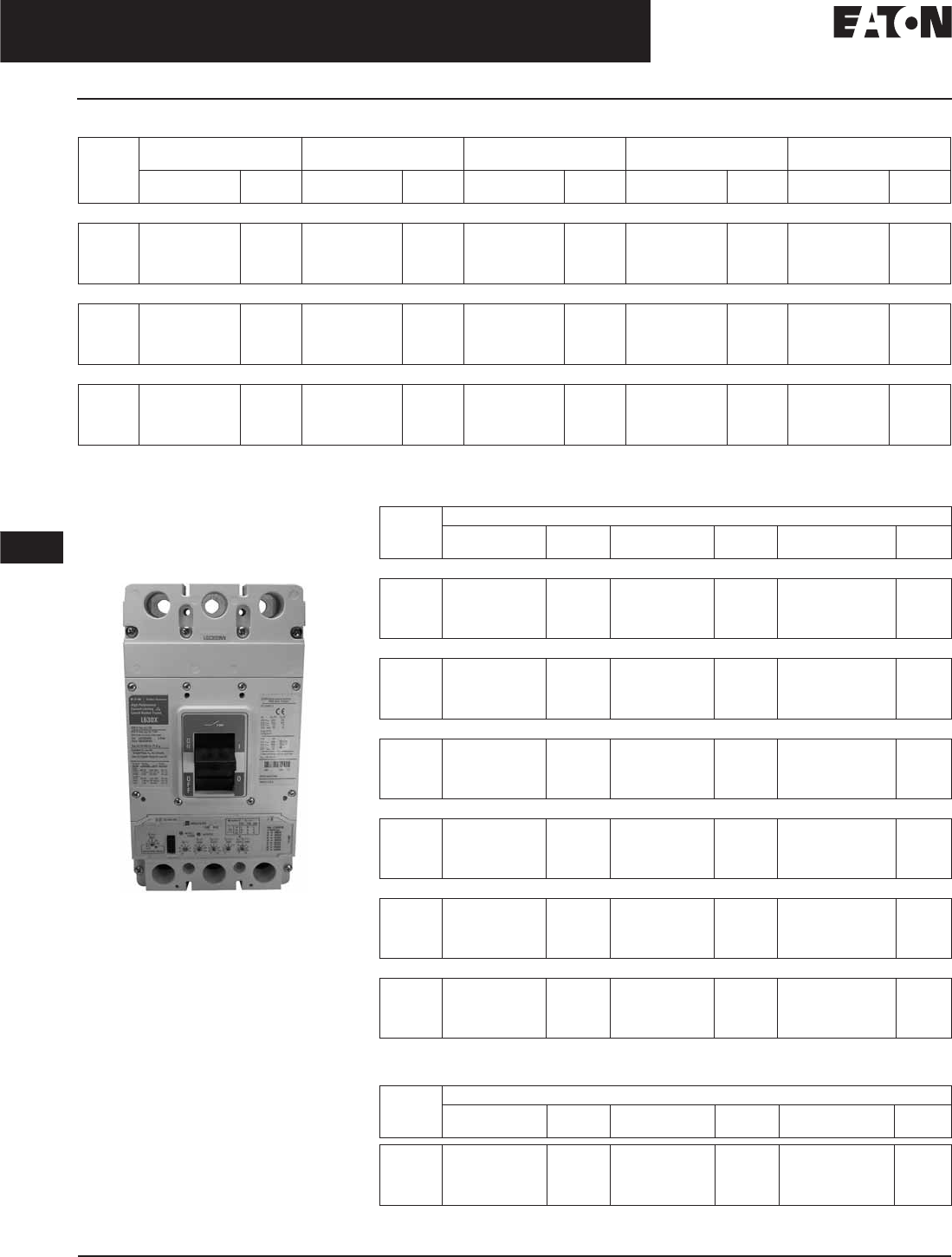
November 2008
12-36
For more information visit: www.eaton.com CA08101001E
Series G Molded Case Circuit Breakers
12
250 – 630 Amperes
Frame Size LG, 630 Amperes (600 Amperes UL, CSA)
Table 12-57. LG 100% Rated Electronic Breaker
LG Electronic Breaker with
Arcflash Reduction Maintenance
System
LG with Arcflash Reduction
Maintenance System
Series G LG circuit breakers are avail-
able with the Arcflash Reduction
Maintenance System integrated into
the electronic trip units helping to
improve safety by providing a simple
and reliable method to reduce fault
clearing time. The Arcflash Reduction
Maintenance System unit utilizes a
separate analog trip circuit that pro-
vides faster interruption times than the
standard (digital) “instantaneous”
protection. Work locations down-
stream of a circuit breaker with an
Arcflash Reduction Maintenance
System unit can have a significantly
lower incident energy level, reducing
arc flash potential to the system.
Ampere
Rating
LS LSI LSG LSIG Neutral CT for
LSG & LSIG
Catalog
Number
Price
U.S. $
Catalog
Number
Price
U.S. $
Catalog
Number
Price
U.S. $
Catalog
Number
Price
U.S. $
Catalog
Number
Price
U.S. $
IEC/UL/CSA 35 kAIC at 415 and 480 Vac
250
400
600
630
LGE325033GC
LGE340033GC
LGE360033GC
LGE363033GC
LGE325032GC
LGE340032GC
LGE360032GC
LGE363032GC
LGE325035GC
LGE340035GC
LGE360035GC
LGE363035GC
LGE325036GC
LGE340036GC
LGE360036GC
LGE363036GC
LGFCT250
LGFCT400
LGFCT600
LGFCT600
IEC/UL/CSA 50 kAIC at 415 and 480 Vac
250
400
600
630
LGS325033GC
LGS340033GC
LGS360033GC
LGS363033GC
LGS325032GC
LGS340032GC
LGS360032GC
LGS363032GC
LGS325035GC
LGS340035GC
LGS360035GC
LGS363035GC
LGS325036GC
LGS340036GC
LGS360036GC
LGS363036GC
LGFCT250
LGFCT400
LGFCT600
LGFCT600
IEC/UL/CSA 70 kAIC at 415 and 480 Vac
250
400
600
630
LGH325033GC
LGH340033GC
LGH360033GC
LGH363033GC
LGH325032GC
LGH340032GC
LGH360032GC
LGH363032GC
LGH325035GC
LGH340035GC
LGH360035GC
LGH363035GC
LGH325036GC
LGH340036GC
LGH360036GC
LGH363036GC
LGFCT250
LGFCT400
LGFCT600
LGFCT600
630 amperes is not a UL or CSA listed rating. 600 amperes is the maximum UL and CSA listed rating for the LG.
Required for 4-wire systems if neutral protection is required.
Table 12-58. LG Electronic Breaker with Arcflash Reduction Maintenance System
Required for 4-wire systems if neutral protection is required.
Table 12-59. LG Electronic Trip Units with Arcflash Reduction Maintenance System
Required for 4-wire systems if neutral protection is required.
Ampere
Rating
Catalog Number
ALSI Price
U.S. $
ALSIG Price
U.S. $
Neutral CT for
LSG & LSIG
Price
U.S. $
IEC/UL/CSA 35 kAIC at 415 and 480 Vac
250
400
600
630
LGE325038G
LGE340038G
LGE360038G
LGE363038G
LGE365039G
LGE340039G
LGE360039G
LGE363039G
LGFCT250
LGFCT400
LGFCT600
LGFCT600
IEC/UL/CSA 50 kAIC at 415 and 480 Vac
250
400
600
630
LGS325038G
LGS340038G
LGS360038G
LGS363038G
LGS365039G
LGS340039G
LGS360039G
LGS363039G
LGFCT250
LGFCT400
LGFCT600
LGFCT600
IEC/UL/CSA 70 kAIC at 415 and 480 Vac
250
400
600
630
LGH325038G
LGH340038G
LGH360038G
LGH363038G
LGH365039G
LGH340039G
LGH360039G
LGH363039G
LGFCT250
LGFCT400
LGFCT600
LGFCT600
IEC/UL/CSA 100 kAIC at 415 and 480 Vac
250
400
600
630
LGC325038G
LGC340038G
LGC360038G
LGC363038G
LGC365039G
LGC340039G
LGC360039G
LGC363039G
LGFCT250
LGFCT400
LGFCT600
LGFCT600
IEC/UL/CSA 150 kAIC at 415 and 480 Vac
250
400
600
630
LGU325038G
LGU340038G
LGU360038G
LGU363038G
LGU365039G
LGU340039G
LGU360039G
LGU363039G
LGFCT250
LGFCT400
LGFCT600
LGFCT600
IEC/UL/CSA 200 kAIC at 415 and 480 Vac
250
400
600
630
LGX325038G
LGX340038G
LGX360038G
LGX363038G
LGX365039G
LGX340039G
LGX360039G
LGX363039G
LGFCT250
LGFCT400
LGFCT600
LGFCT600
Ampere
Rating
Catalog Number
ALSI Price
U.S. $
ALSIG Price
U.S. $
Neutral CT for
LSG & LSIG
Price
U.S. $
250
400
600
630
LT325038
LT340038
LT360038
LT363038
LT325039
LT340039
LT360039
LT363039
LGFCT250
LGFCT400
LGFCT600
LGFCT600
Discount Symbol . . . . . . . . . . . . . . . . . . . . . . . . CB-2
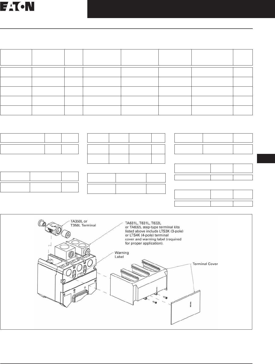
November 2008
CA08101001E For more information visit: www.eaton.com
12-37
Series G Molded Case Circuit Breakers
12
250 – 630 Amperes
Frame Size LG, 630 Amperes (600 Amperes UL, CSA)
Line and Load Terminals
Table 12-60. Line and Load Terminals
Includes LTS3K (3-pole) or LTS4K (4-pole) terminal covers.
Standard terminal included with complete breaker.
Table 12-61. Terminal Covers
Included in TA63IL, T63IL, TA632L kits
listed above.
Table 12-62. End Cap Kits (MIO Metric Nuts)
Table 12-63. Control Wire Terminal Kit
Table 12-64. Terminal Extensions
Table 12-65. Terminal Spreaders
Table 12-66. Handle Extension
Table 12-67. Interphase Barrier
Figure 12-3. Terminals and Terminal Cover for the LG Breaker — Includes LTS3K (3-Pole) or LTS4K (4-Pole) Terminal Covers
Note: Extended terminal covers add 2.13 inches (54.0 mm) to breaker length.
Maximum
Breaker
Amperes
Terminal
Body
Material
Wire
Type
AWG
Wire Range/
Number of
Conductors
Metric
Wire Range
(mm2)
Number of
Terminals
Included
Catalog
Number
Price
U.S. $
400
400
Aluminum
Aluminum
Cu/Al
Cu/Al
500 – 750 (1)
500 – 750 (1)
240 – 380 (1)
240 – 380 (1)
3
4
3TA631LK
4TA631LK
400
400
Copper
Copper
Cu
Cu
500 – 750 (1)
500 – 750 (1)
240 – 380 (1)
240 – 380 (1)
3
4
3T631LK
4T631LK
630
630
Aluminum
Aluminum
Cu/Al
Cu/Al
2 – 500 (2)
2 – 500 (2)
35 – 240 (2)
35 – 240 (2)
3
4
3TA632LK
4TA632LK
630
630
Copper
Copper
Cu
Cu
2 – 500 (2)
2 – 500 (2)
35 – 240 (2)
35 – 240 (2)
3
4
3T632LK
4T632LK
400
400
Aluminum
Copper
Cu/Al
Cu
2 – 500 (1)
2 – 500 (1)
35 – 240 (1)
35 – 240 (1)
1
1
TA350LK
T350LK
Description Catalog
Number
Price
U.S. $
3-Pole Terminal Cover
4-Pole Terminal Cover
LTS3K
LTS4K
Number
of Poles
Catalog
Number
Price
U.S. $
3
4
L3RTWK
L4RTWK
Description Terminal
Body Type
Catalog
Number
Price
U.S. $
3-Pole Kit
4-Pole Kit
Aluminum
Aluminum
3TA632LKW
4TA632LKW
3-Pole Kit
4-Pole Kit
Copper
Copper
3T632LKW
4T632LKW
Number
of Poles
Catalog
Number
Price
U.S. $
3
4
LGTEW3
LGTEW4
Number
of Poles
Catalog
Number
Price
U.S. $
3
4
LGTES3
LGTES4
Description Catalog
Number
Price
U.S. $
Handle Extension HEXLG
Package of 2 Catalog
Number
Price
U.S. $
Interphase Barrier IPB3
Discount Symbol . . . . . . . . . . . . . . . . . . . . . . . . . CB-2

November 2008
12-38
For more information visit: www.eaton.com CA08101001E
Series G Molded Case Circuit Breakers
12
250 – 630 Amperes
LG-Frame
Allowable Accessory Combinations
Different combinations of accessories can be supplied, depending on the types of accessories and the number
of poles in the circuit breaker.
Table 12-68. Accessories
■Applicable in indicated pole position
Contact Eaton.
❏May be mounted on left or right pole —
not both
●Accessory available/Modification available
Description Reference
Page
3-Pole 4-Pole
Left Center Right Left Center Right Neu.
Internal Accessories (Only One Internal Accessory Per Pole)
Alarm Lockout (Make/Break) 12-65 ■■
Auxiliary Switch (1A, 1B) 12-65 ■■
Auxiliary Switch (2A, 2B) 12-65 ■■
Auxiliary Switch and Alarm Switch Combination 12-65 ■■
Shunt Trip — Standard 12-65 ■■
Undervoltage Release Mechanism 12-65 ■■
External Accessories
End Cap Kit 12-37 ●●
Handle Extension 12-37 ●●
Terminal Cover 12-37 ●●
Padlockable Handle Block 12-64 ■■
Padlockable Handle Lock Hasp 12-64 ❏❏❏❏
Key Interlock Kit 12-64 ❏❏❏❏
Sliding Bar Interlock — Requires Two Breakers 12-64 ●
Electrical Operator 12-64 ●●
Plug-in Adapters 12-66 ●●
Rear Connecting Studs 12-64 ●●
Handle Mechanisms 12-67 ●●
Earth Leakage/Ground Fault Protector 12-62 ●●
Drawout Cassette 12-66 ●●
Digitrip 310+ Test Kit 12-33 ●●
Ammeter/Cause of Trip Display 12-33 ●●
Modifications (Refer to Eaton)
Moisture Fungus Treatment 12-73 ●●
Freeze-Tested Circuit Breakers — ●●
Marine/Naval Application, UL Supplement SA and SB ●●
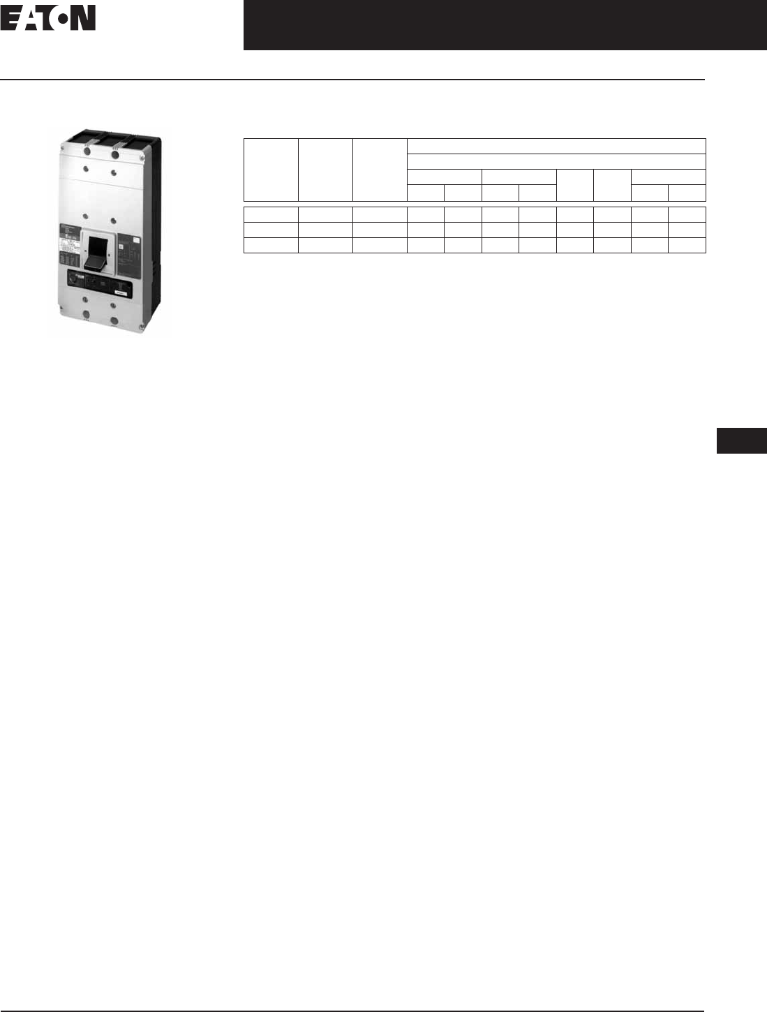
November 2008
CA08101001E For more information visit: www.eaton.com
12-39
Series G Molded Case Circuit Breakers
12
400 – 1200 Amperes
NG-Frame
NG-Frame
Typical NG-Frame Circuit Breaker
Product Description
■All Cutler-Hammer NG-Frame Circuit
Breakers by Eaton Corporation are
suitable for reverse feed use.
■All NG-Frame circuit breakers are
HACR rated.
Technical Data and Specifications
Table 12-69. UL 489/IEC 60947-2 Interrupting Capacity Ratings
1600 amperes is not a UL or CSA listed rating. 1200 amperes is the maximum UL and
CSA rating for NG.
Circuit
Breaker
Type
Number
of Poles
240 (UL) Interrupting Capacity (kA Symmetrical Amperes)
Volts ac (50/60 Hz)
220 – 240 380 – 415 480 600 690
Icu Ics Icu Ics Icu Ics
NGS 2, 3, 4 65 85 85 50 50 50 25 20 10
NGH 2, 3, 4 100 100 100 70 50 65 35 25 13
NGC 2, 3, 4 200 200 100 100 50 100 65 35 18
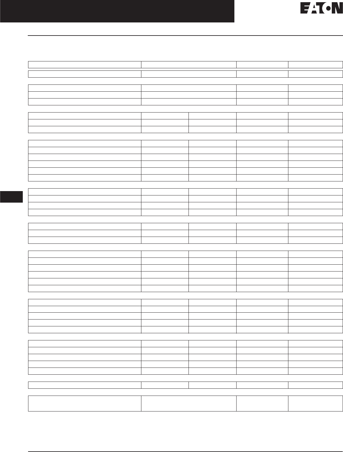
November 2008
12-40
For more information visit: www.eaton.com CA08101001E
Series G Molded Case Circuit Breakers
12
400 – 1200 Amperes
NG-Frame
NG-Frame Digitrip Specifications
Table 12-70. Specifications
Adjust by rating plug.
Zone interlock kit.
With separate ground fault alarm unit (GFAU).
By OPTIMizer/BIM.
Eaton’s Cutler-Hammer PowerNet kit.
Legend: BIM = Breaker Interface Module
(A) = GF Alarm
Is= Sensor Rating
In= Rating Plug
Ir= Long Delay Pickup Setting
Trip Unit Type Digitrip RMS 310 Digitrip OPTIM 550 Digitrip OPTIM 1050
rms Sensing Yes Yes Yes
Breaker Type
Frame NN N
Ampere Range 400 A – 1200 A 400 A – 1200 A 400 A – 1200 A
Interrupting Rating at 480 Volts 50, 65, 100 (kA) 50, 65, 100 (kA) 50, 65, 100 (kA)
Protection
Ordering Options LS, LSG LSI, LSIG LSI, LSIG, LSI(A) LSI(A), LISG
Fixed Rated Plug (In) Yes Yes Yes Yes
Overtemperature Trip Yes Yes Yes Yes
Long Delay Protection (L)
Adjustable Rating Plug (In)YesYesNoNo
Long Delay Pickup 0.5 – 1.0 (In) 0.5 – 1.0 (In) 0.4 – 1.0 x (In) 0.4 – 1.0 x (In)
Long Delay Time I2t 12 Seconds 12 Seconds 2 – 24 Seconds 2 – 24 Seconds
Long Delay Time I4t No No 1 – 5 Seconds 1 – 5 Seconds
Long Delay Thermal Memory Yes Yes Yes Yes
High Load Alarm No No No 0.5 – 1.0 x Ir
Short Delay Protection (S)
Short Delay Pickup 200 – 800% x (In) 200 – 800% x (In) 150 – 800% x (Ir) 150 – 800% x (Ir)
Short Delay Time I2t 100 ms No 100 – 500 ms 100 – 500 ms
Short Delay Time Flat No Inst – 300 ms 100 – 500 ms 100 – 500 ms
Short Delay Time Zone Selective Interlocking No No Yes Yes
Instantaneous Protection (I)
Instantaneous Pickup No 200 – 800% x (In) 200 – 800% x (In) 200 – 800% x (In)
Discriminator No No Yes Yes
Instantaneous Override Yes Yes Yes Yes
Ground Fault Protection (G)
Ground Fault Alarm No No 20 – 100% x (Is) 20 – 100% x (Is)
Ground Fault Pickup 1 – 5 x Ig (160 A) 1 – 5 x Ig (160 A) 20 – 100% x (Is) 20 – 100% x (Is)
Ground Fault Delay I2t No No 100 – 500 ms 100 – 500 ms
Ground Fault Delay Flat Inst – 500 ms Inst – 500 ms 100 – 500 ms 100 – 500 ms
Ground Fault Zone Selective Interlocking No No Yes Yes
Ground Fault Thermal Memory Yes Yes Yes Yes
System Diagnostics
Status LEDs Yes Yes Yes Yes
Cause of Trip LEDs No No Yes Yes
Magnitude of Trip Information No No Yes Yes
Remote Signal Contact — Ground Alarm Yes Yes Ye s Yes
Local Auxiliary and Bell Alarm Contact Optional Optional Optional Included
System Monitoring
Digital Display No No Yes Yes
Current No No Yes Yes
Power and Energy No No No Yes
Power Quality — Harmonics No No No Yes
Power Factor No No No Yes
Communications
Cutler-Hammer PowerNet No No No Yes
Testing
Testing Method Test Set OPTIMizer, BIM,
Cutler-Hammer
PowerNet
OPTIMizer, BIM,
Cutler-Hammer
PowerNet

November 2008
CA08101001E For more information visit: www.eaton.com
12-41
Series G Molded Case Circuit Breakers
12
400 – 1200 Amperes
NG-Frame
Dimensions/Weights
Table 12-71. Dimensions in Inches (mm)
Table 12-72. Approximate Shipping Weight in Lbs. (kg)
Product Selection
This information is presented only as an aid to understanding Catalog Numbers.
It is not to be used to build Catalog Numbers for circuit breakers or trip units.
Table 12-73. Circuit Breaker/Frame Catalog Numbering System
Number of Poles Width Height Depth
2, 3
4
8.25 (209.6)
11.13 (282.6)
16.00 (406.4)
16.00 (406.4)
5.50 (139.7)
5.50 (139.7)
Breaker Type Complete Breaker
Number of Poles
234
NGS, NGH, NGC 37 (16.8) 45 (20.4) 58 (26.3)
N G S 3 800 T33 W P18
Number
of Poles
2 = 2 Poles
3 = 3 Poles
4 = 4 Poles
Trip Unit
33 = LS
32 = LSI
35 = LSG
36 = LSIG
Suffix
W= Without
Terminals
K= Molded
Case
Switch
Rating Plug
P08 = 1200AF = 1200/1000/800/600 Adjustable
P09 = 1250AF = 1250/1000/800/630 Adjustable
P18 = 800AF = 800/600/500/400 Adjustable
P19 = 800AF = 800/630/500/400 Adjustable
P35 = 1600AF = 1600/1250/1000/800 Adjustable
P36 = 1600AF = 1250/1000/800/630 Adjustable
Amperes
800 = 800
12 = 1200
16 = 1600
Performance Rating
600 480 415 240
S
H
C
25
35
65
50
65
100
50
70
100
65
100
200
KMolded Case Switch
Standard/Application
G = IEC/CE/UL/CSA
Frame
N

November 2008
12-42
For more information visit: www.eaton.com CA08101001E
Series G Molded Case Circuit Breakers
12
400 – 1200 Amperes
Frame Size NG, 1200 Amperes 50 kA at 480 Vac or 415 Vac
NG-Frame, 1200 Amperes — Selection Guide and Ordering Information
Table 12-74. Type NGS Standard Interrupting Capacity — Ue Max. 690 Vac, 50 kA lcu at 480 Vac or 415 Vac
See Table 12-75 on Page 12-43 for prices.
For ac use only.
NG MCCBs are suitable for 40°C or 50°C applications. Order suffix V3 to eliminate standard 40°C labeling.
Order terminals separately.
Unprotected left pole neutral. Insert “E” for 100% neutral or “EH” for 60% neutral between “T33” or “T32” and “W” (e.g., NGS412T32EHWP08). Neutral is
on LH side.
Non-UL listed NG 1250 with 1250 ampere trip unit is also available.
Note: NG MCCBs have metric threading on line and load conductors. Use ND MCCBs if imperial threading is required.
Maximum
Continuous
Ampere
Rating
at 40°C
Number
of Poles
Circuit Breaker Frame Including Digitrip RMS 310 Electronic Trip Unit with
Adjustable Rating Plugs — Catalog Number
Interchangeable
Rating Plugs
(Order as Individual
Component)
Included
with Breaker
L – Adjustable Long Delay Pickup (By Adjustable Rating Plug)
S – Adjustable Short Delay Pickup with Fixed Short Delay Time
(I2t Response) or Adjustable Short Delay Time (Flat Response)
I – Adjustable Instantaneous Pickup by Setting Short Delay Time to Instantaneous
G – Adjustable Ground Fault Pickup with Adjustable Ground Fault Delay (Flat Response)
LS LSI LSG LSIG Fixed Rating Plug Adj. Rating Plug
Short Time Range
Short Time Delay
Ground Fault Pickup
Ground Fault Delay
2 – 8 x In
—
—
—
2 – 8 x In
I – 300 ms
—
—
2 – 8 x In
—
200 – 1200 A
I – 500 ms
2 – 8 x In
I – 300 ms
200 – 1200 A
I – 500 ms
Ampere
Rating
Catalog
Number
Adjustable
Ampere
Settings
Catalog Number
800 2-Pole NGS2800T33WP18 NGS2800T32WP18 NGS2800T35WP18 NGS2800T36WP18 400
450
500
550
8NES400T
8NES450T
8NES500T
8NES550T
400/500/600/800
A8NES800T1
600
630
700
800
8NES600T
8NES630T
8NES700T
8NES800T
3-Pole NGS3800T33WP18 NGS3800T32WP18 NGS3800T35WP18 NGS3800T36WP18 400
450
500
550
8NES400T
8NES450T
8NES500T
8NES550T
400/500/600/800
A8NES800T1
600
630
700
800
8NES600T
8NES630T
8NES700T
8NES800T
4-Pole NGS4800T33WP18 NGS4800T32WP18 — — 400
450
500
550
8NES400T
8NES450T
8NES500T
8NES550T
400/500/600/800
A8NES800T1
600
630
700
800
8NES600T
8NES630T
8NES700T
8NES800T
1200 2-Pole NGS212T33WP08 NGS212T32WP08 NGS212T35WP08 NGS212T36WP08 600
630
700
800
12NES600T
12NES630T
12NES700T
12NES800T
600/800/
1000/1200
A12NES1200T1
900
1000
1200
12NES900T
12NES1000T
12NES1200T
3-Pole NGS312T33WP08 NGS312T32WP08 NGS312T35WP08 NGS312T36WP08 600
630
700
800
12NES600T
12NES630T
12NES700T
12NES800T
600/800/
1000/1200
A12NES1200T1
900
1000
1200
12NES900T
12NES1000T
12NES1200T
4-Pole NGS412T33WP08 NGS412T32WP08 —— 600
630
700
800
12NES600T
12NES630T
12NES700T
12NES800T
600/800/
1000/1200
A12NES1200T1
900
1000
1200
12NES900T
12NES1000T
12NES1200T

November 2008
CA08101001E For more information visit: www.eaton.com
12-43
Series G Molded Case Circuit Breakers
12
400 – 1200 Amperes
Frame Size NG, 1200 Amperes 50 kA at 480 Vac or 415 Vac
Table 12-75. Type NGS Standard Interrupting Capacity — Ue Max. 690 Vac, 50 kA lcu at 480 Vac or 415 Vac Prices
Table 12-76. Molded Case Switches
For ac use only. Molded case switch will trip above 14,000 amperes.
For 2-pole applications, use outer poles of 3-pole molded case switch.
Catalog
Number
Price
U.S. $
Catalog
Number
Price
U.S. $
Catalog
Number
Price
U.S. $
Catalog
Number
Price
U.S. $
A12NES1200T1
A8NES800T1
NGS212T32WP09
NGS212T33WP09
NGS212T35WP09
NGS212T36WP09
NGS2800T32WP19
NGS2800T33WP19
NGS2800T35WP19
NGS2800T36WP19
NGS312T32WP08
NGS312T33WP08
NGS312T35WP08
NGS312T36WP08
NGS3800T32WP19
NGS3800T33WP19
NGS3800T35WP19
NGS3800T36WP19
NGS412T32WP08
NGS412T33WP08
NGS4800T32WP19
NGS4800T33WP19
8NES400T
8NES450T
8NES500T
8NES550T
8NES600T
8NES630T
8NES700T
8NES800T
12NES1000T
12NES1200T
12NES600T
12NES630T
12NES700T
12NES800T
12NES900T
—
—
—
Ampere
Rating
Ue Maximum 690 Vac
3-Pole Catalog
Number
Price
U.S. $
4-Pole Catalog
Number
Price
U.S. $
800 MCS Only without Line and Load Terminals NGK3800KSW MCS Only without Line and Load Terminals NGK4800KSW
1200 MCS Only without Line and Load Terminals NGK312KSW MCS Only without Line and Load Terminals NGK412KSW
1250 MCS Only without Line and Load Terminals NGK3125KSW MCS Only without Line and Load Terminals NGK4125KSW
Discount Symbol . . . . . . . . . . . . . . . . . . . . . . . . . CB-2

November 2008
12-44
For more information visit: www.eaton.com CA08101001E
Series G Molded Case Circuit Breakers
12
400 — 1200 Amperes
Frame Size NG, 1200 Amperes 65 kA at 480 Vac, 70 kA at 415 Vac
Table 12-77. Type NGH High Interrupting Capacity — Ue Max. 690 Vac, 65 kA Icu at 480 Vac, 70 kA Icu at 415 Vac
See Table 12-78 on Page 12-45 for prices.
For ac use only.
NG MCCBs are suitable for 40°C or 50°C applications. Order suffix V3 to eliminate standard 40°C labeling.
Order terminals separately.
Unprotected left pole neutral. Insert “E” for 100% neutral or “EH” for 60% neutral between “T33” or “T32” and “W” (e.g., NGH412T32EHWP08).
Neutral is on LH side.
Non-UL listed NG 1250 with 1250 ampere trip unit is also available.
Note: NG MCCBs have metric threading on line and load conductors. Use ND MCCBs if imperial threading is required.
Maximum
Continuous
Ampere
Rating
at 40°C
Number
of Poles
Circuit Breaker Frame Including Digitrip RMS 310 Electronic Trip Unit with
Adjustable Rating Plugs — Catalog Number
Interchangeable
Rating Plugs
(Order as Individual
Component)
Included
with Breaker
L – Adjustable Long Delay Pickup (By Adjustable Rating Plug)
S – Adjustable Short Delay Pickup with Fixed Short Delay Time
(I2t Response) or Adjustable Short Delay Time (Flat Response)
I – Adjustable Instantaneous Pickup by Setting Short Delay Time to Instantaneous
G – Adjustable Ground Fault Pickup with Adjustable Ground Fault Delay (Flat Response)
LS LSI LSG LSIG Fixed
Rating Plug
Adjustable
Rating Plug
Short Time Range
Short Time Delay
Ground Fault Pickup
Ground Fault Delay
2 – 8 x In
—
—
—
2 – 8 x In
I – 300 ms
—
—
2 – 8 x In
—
200 – 1200 A
I – 500 ms
2 – 8 x In
I – 300 ms
200 – 1200 A
I – 500 ms
Ampere
Rating
Catalog
Number
Adjustable
Ampere
Settings
Catalog Number
800 2-Pole NGH2800T33WP18 NGH2800T32WP18 NGH2800T35WP18 NGH2800T36WP18 400
450
500
550
8NES400T
8NES450T
8NES500T
8NES550T
400/500/
600/800
A8NES800T1
600
630
700
800
8NES600T
8NES630T
8NES700T
8NES800T
3-Pole NGH3800T33WP18 NGH3800T32WP18 NGH3800T35WP18 NGH3800T36WP18 400
450
500
550
8NES400T
8NES450T
8NES500T
8NES550T
400/500/
600/800
A8NES800T1
600
630
700
800
8NES600T
8NES630T
8NES700T
8NES800T
4-Pole NGH4800T33WP18 NGH4800T32WP18 — — 400
450
500
550
8NES400T
8NES450T
8NES500T
8NES550T
400/500/
600/800
A8NES800T1
600
630
700
800
8NES600T
8NES630T
8NES700T
8NES800T
1200 2-Pole NGH212T33WP08 NGH212T32WP08 NGH212T35WP08 NGH212T36WP08 600
630
700
800
12NES600T
12NES630T
12NES700T
12NES800T
600/800/
1000/1200
A12NES1200T1
900
1000
1200
12NES900T
12NES1000T
12NES1200T
3-Pole NGH312T33WP08 NGH312T32WP08 NGH312T35WP08 NGH312T36WP08 600
630
700
800
12NES600T
12NES630T
12NES700T
12NES800T
600/800/
1000/1200
A12NES1200T1
900
1000
1200
12NES900T
12NES1000T
12NES1200T
4-Pole NGH412T33WP08 NGH412T32WP08 —— 600
630
700
800
12NES600T
12NES630T
12NES700T
12NES800T
600/800/
1000/1200
A12NES1200T1
900
1000
1200
12NES900T
12NES1000T
12NES1200T

November 2008
CA08101001E For more information visit: www.eaton.com
12-45
Series G Molded Case Circuit Breakers
12
400 – 1200 Amperes
Frame Size NG, 1200 Amperes 65 kA at 480 Vac, 70 kA at 415 Vac
Table 12-78. Type NGS Standard Interrupting Capacity — Ue Max. 690 Vac, 50 kA lcu at 480 Vac or 415 Vac Prices
Catalog
Number
Price
U.S. $
Catalog
Number
Price
U.S. $
Catalog
Number
Price
U.S. $
Catalog
Number
Price
U.S. $
A12NES1200T1
A8NES800T1
NGH212T32WP08
NGH212T33WP08
NGH212T35WP08
NGH212T36WP08
NGH2800T32WP19
NGH2800T33WP19
NGH2800T35WP19
NGH2800T36WP19
NGH312T32WP08
NGH312T33WP08
NGH312T35WP08
NGH312T36WP08
NGH3800T32WP19
NGH3800T33WP19
NGH3800T35WP19
NGH3800T36WP19
NGH412T32WP08
NGH412T33WP08
NGH4800T32WP19
NGH4800T33WP19
8NES400T
8NES450T
8NES500T
8NES550T
8NES600T
8NES630T
8NES700T
8NES800T
12NES1000T
12NES1200T
12NES600T
12NES630T
12NES700T
12NES800T
12NES900T
—
—
—
Discount Symbol . . . . . . . . . . . . . . . . . . . . . . . . . CB-2

November 2008
12-46
For more information visit: www.eaton.com CA08101001E
Series G Molded Case Circuit Breakers
12
400 – 1200 Amperes
Frame Size NG, 1200 Amperes 100 kA at 480 Vac or 415 Vac
Table 12-79. Type NGC Very High Capacity — Ue Max. 690 Vac, 100 kA Icu at 480 Vac or 415 Vac
See Table 12-80 on Page 12-47 for prices.
For ac use only.
NG MCCBs are suitable for 40°C or 50°C applications. Order suffix V3 to eliminate standard 40°C labeling.
Order terminals separately.
Unprotected left pole neutral. Insert “E” for 100% neutral or “EH” for 60% neutral between “T33” or “T32” and “W” (e.g., NGC412T32EHWP08).
Neutral is on LH side.
Non-UL listed NG 1250 with 1250 ampere trip unit is also available.
Note: NG MCCBs have metric threading on line and load conductors. Use ND MCCBs if imperial threading is required.
Maximum
Continuous
Ampere
Rating
at 40°C
Number
of Poles
Circuit Breaker Frame Including Digitrip RMS 310 Electronic Trip Unit with
Adjustable Rating Plugs — Catalog Number
Interchangeable
Rating Plugs
(Order as Individual
Component)
Included
with Breaker
L – Adjustable Long Delay Pickup (By Adjustable Rating Plug)
S – Adjustable Short Delay Pickup with Fixed Short Delay Time
(I2t Response) or Adjustable Short Delay Time (Flat Response)
I – Adjustable Instantaneous Pickup by Setting Short Delay Time to Instantaneous
G – Adjustable Ground Fault Pickup with Adjustable Ground Fault Delay (Flat Response)
LS LSI LSG LSIG Fixed
Rating Plug
Adjustable
Rating Plug
Short Time Range
Short Time Delay
Ground Fault Pickup
Ground Fault Delay
2 – 8 x In
—
—
—
2 – 8 x In
I – 300 ms
—
—
2 – 8 x In
—
200 – 1200 A
I – 500 ms
2 – 8 x In
I – 300 ms
200 – 1200 A
I – 500 ms
Ampere
Rating
Catalog
Number
Adjustable
Ampere
Settings
Catalog Number
800 2-Pole NGC2800T33WP18 NGC2800T32WP18 NGC2800T35WP18 NGC2800T36WP18 400
450
500
550
8NES400T
8NES450T
8NES500T
8NES550T
400/500/600/800
A8NES800T1
600
630
700
800
8NES600T
8NES630T
8NES700T
8NES800T
3-Pole NGC3800T33WP18 NGC3800T32WP18 NGC3800T35WP18 NGC3800T36WP18 400
450
500
550
8NES400T
8NES450T
8NES500T
8NES550T
400/500/600/800
A8NES800T1
600
630
700
800
8NES600T
8NES630T
8NES700T
8NES800T
4-Pole NGC4800T33WP18 NGC4800T32WP18 — — 400
450
500
550
8NES400T
8NES450T
8NES500T
8NES550T
400/500/600/800
A8NES800T1
600
630
700
800
8NES600T
8NES630T
8NES700T
8NES800T
1200 2-Pole NGC212T33WP08 NGC212T32WP08 NGC212T35WP08 NGC212T36WP08 600
630
700
800
12NES600T
12NES630T
12NES700T
12NES800T
600/800/
1000/1200
A12NES1200T1
900
1000
1200
12NES900T
12NES1000T
12NES1200T
3-Pole NGC312T33WP08 NGC312T32WP08 NGC312T35WP08 NGC312T36WP08 600
630
700
800
12NES600T
12NES630T
12NES700T
12NES800T
600/800/
1000/1200
A12NES1200T1
900
1000
1200
12NES900T
12NES1000T
12NES1200T
4-Pole NGC412T33WP08 NGC412T32WP08 —— 600
630
700
800
12NES600T
12NES630T
12NES700T
12NES800T
600/800/
1000/1200
A12NES1200T1
900
1000
1200
12NES900T
12NES1000T
12NES1200T

November 2008
CA08101001E For more information visit: www.eaton.com
12-47
Series G Molded Case Circuit Breakers
12
400 – 1200 Amperes
Frame Size NG, 1200 Amperes 100 kA at 480 Vac or 415 Vac
Table 12-80. Type NGC Very High Capacity — Ue Max. 690 Vac, 100 kA Icu at 480 Vac or 415 Vac Prices
Catalog
Number
Price
U.S. $
Catalog
Number
Price
U.S. $
Catalog
Number
Price
U.S. $
Catalog
Number
Price
U.S. $
A12NES1200T1
A8NES800T1
NGC212T32WP08
NGC212T33WP08
NGC212T35WP08
NGC212T36WP08
NGC2800T32WP19
NGC2800T33WP19
NGC2800T35WP19
NGC2800T36WP19
NGC312T32WP08
NGC312T33WP08
NGC312T35WP08
NGC312T36WP08
NGC3800T32WP19
NGC3800T33WP19
NGC3800T35WP19
NGC3800T36WP19
NGC412T32WP08
NGC412T33WP08
NGC4800T32WP19
NGC4800T33WP19
8NES400T
8NES450T
8NES500T
8NES550T
8NES600T
8NES630T
8NES700T
8NES800T
12NES1000T
12NES1200T
12NES600T
12NES630T
12NES700T
12NES800T
12NES900T
—
—
—
Discount Symbol . . . . . . . . . . . . . . . . . . . . . . . . . CB-2

November 2008
12-48
For more information visit: www.eaton.com CA08101001E
Series G Molded Case Circuit Breakers
12
400 – 1200 Amperes
Frame Size NG, 1600 Amperes 50 kA at 415 Vac
Table 12-81. Type NGS Standard Interrupting Capacity — Ue Max. 690 Vac, 50 kA Icu at 415 Vac
Line and Load Terminals
N-Frame circuit breakers do not include terminals as standard. When copper or
Cu/Al terminals are required, order by catalog number.
Table 12-82. Line and Load Terminals
Single terminals individually packed.
Not suitable with 1600 ampere frame version.
Base Mounting Hardware
Base mounting hardware is included
with a circuit breaker or molded
case switch.
Table 12-83. Base Mounting Hardware
Metric hardware included with breaker.
Terminal Shield
Table 12-84. Terminal Shield
Conductor Extension Kit
Table 12-85. Conductor Extension Kit
Keeper Nut
Not required on NG-Frame. Terminals
are threaded.
Handle Extension
Included with breaker. Additional
handle extensions are available.
Table 12-86. Handle Extension
Maximum
Continuous
Ampere
Rating
at 40°C
Number
of Poles
Circuit Breaker Frame Including Digitrip RMS 310 Electronic Trip Unit and Rating Plugs
L – Adjustable Long Delay Pickup (By Adjustable Rating Plug)
S – Adjustable Short Delay Pickup with Fixed Short Delay Time
(I2t Response) or Adjustable Short Delay Time (Flat Response)
I – Adjustable Instantaneous Pickup by Setting Short Delay Time to Instantaneous
G – Adjustable Ground Fault Pickup with Adjustable Ground Fault Delay (Flat Response)
LS Price
U.S. $
LSI Price
U.S. $
LSG Price
U.S. $
LSIG Price
U.S. $
Adjust-
able
Rating
Plug
Short Time Range
Short Time Delay
Ground Fault Pickup
Ground Fault Delay
2 – 8 x In
—
—
—
2 – 8 x In
I – 300 ms
—
—
2 – 8 x In
—
200 – 1200 A
I – 500 ms
2 – 8 x In
I – 300 ms
200 – 1200 A
I – 500 ms
1600 3-Pole
4-Pole
NGS316T33WP35
NGS416T33WP35
NGS316T32WP35
NGS416T32WP35
NGS316T35WP35
—
NGS316T36WP35
—
800/
1000/
1250/
1600
For ac use only.
NG MCCBs are suitable for 40°C or 50°C applications. Order suffix V3 to eliminate standard 40°C labeling.
No UL or CSA label is available for the 1600 ampere frame size.
Unprotected left pole neutral. Insert “1” for 100% protected neutral or “6” for 60% protected neutral before “WP” suffix (e.g., NGS416T336WP35).
Note: NG 1600 MCCB uses metric threading on line and load conductors. The NG 1600 is not UL or CSA listed.
Maximum
Breaker
Amperes
Terminal
Body
Material
Wire Type Metric Wire
Range mm2AWG Wire
Number of
Conductors
Catalog
Number
Price
U.S. $
Optional Copper and Cu/Al Pressure Type Terminals
1250 Copper Copper 95 – 185 3/0 – 400 (4) T1200NB3M
Number
of Poles
Description Catalog
Number
Price
U.S. $
3- and
4-pole
Imperial
Hardware:
.3125 – 18 x 1.25
Pan-Head Steel
Screws and
Lock Washers
BMH5
3- and
4-pole
Metric
Hardware: M8
Pan-Head Steel
Screws and
Lock Washers
BMH5M
Description Catalog
Number
Price
U.S. $
3-Pole Terminal
Shield
NTS3K
Description Catalog
Number
Price
U.S.
3-Pole Both Ends Metric 5104A24G04
3-Pole Both Ends English 5104A24G02
Description Catalog
Number
Price
U.S. $
Single Handle
Extension
HEX5
Interphase Barriers
The interphase barriers provide
additional electrical clearance between
circuit breaker poles for special termi-
nation applications. Barriers are high
dielectric insulating plates that are
installed in the molded slots between
the terminals. (Field installation only.)
Table 12-87. Interphase Barriers
Description Catalog
Number
Price
U.S. $
Interphase
Barriers
IPB5
Discount Symbol . . . . . . . . . . . . . . . . . . . . . . . . . CB-2

November 2008
CA08101001E For more information visit: www.eaton.com
12-49
Series G Molded Case Circuit Breakers
12
400 — 1200 Amperes
NG-Frame
Allowable Accessory Combinations
Different combinations of accessories can be supplied, depending on the types of accessories and the number
of poles in the circuit breaker.
Table 12-88. Accessories
■Applicable in indicated pole position
Contact Eaton
❏May be mounted on left or right pole —
not both
●Accessory available/Modification available
Description Reference
Page
3-Pole 4-Pole
Left Center Right Left Center Right Neu.
Internal Accessories (Only One Internal Accessory Per Pole)
Alarm Lockout (Make/Break) 12-65 ●■●■
Auxiliary Switch (1A, 1B) 12-65 ●■●■
Auxiliary Switch (2A, 2B) 12-65 ●■●■
Auxiliary Switch and Alarm Switch Combination 12-65 ●■●■
Shunt Trip — Standard 12-65 ■■
Undervoltage Release Mechanism 12-65 ■■
External Accessories
Base Mounting Hardware 12-48 ●●
Interphase Barriers 12-48 ●●
Non-Padlockable Handle Block 12-64 ■■
Padlockable Handle Lock Hasp 12-64 ❏❏❏❏
Key Interlock Kit 12-64 ❏❏❏❏
Sliding Bar Interlock — Requires Two Breakers 12-64 ●
Electrical Operator 12-64 ●●
Plug-in Adapters 12-66 ●●
Rear Connecting Studs 12-64 ●●
Handle Mechanisms 12-67 ●●
Drawout Cassette 12-66 ●●
Handle Extension 12-48 ●●
Digitrip 310 Test Kit 12-268 ●●
Modifications (Refer to Eaton)
Moisture Fungus Treatment 12-73 ●●
Freeze-Tested Circuit Breakers — ●●
Marine/Naval Application, UL Supplement SA and SB ●●
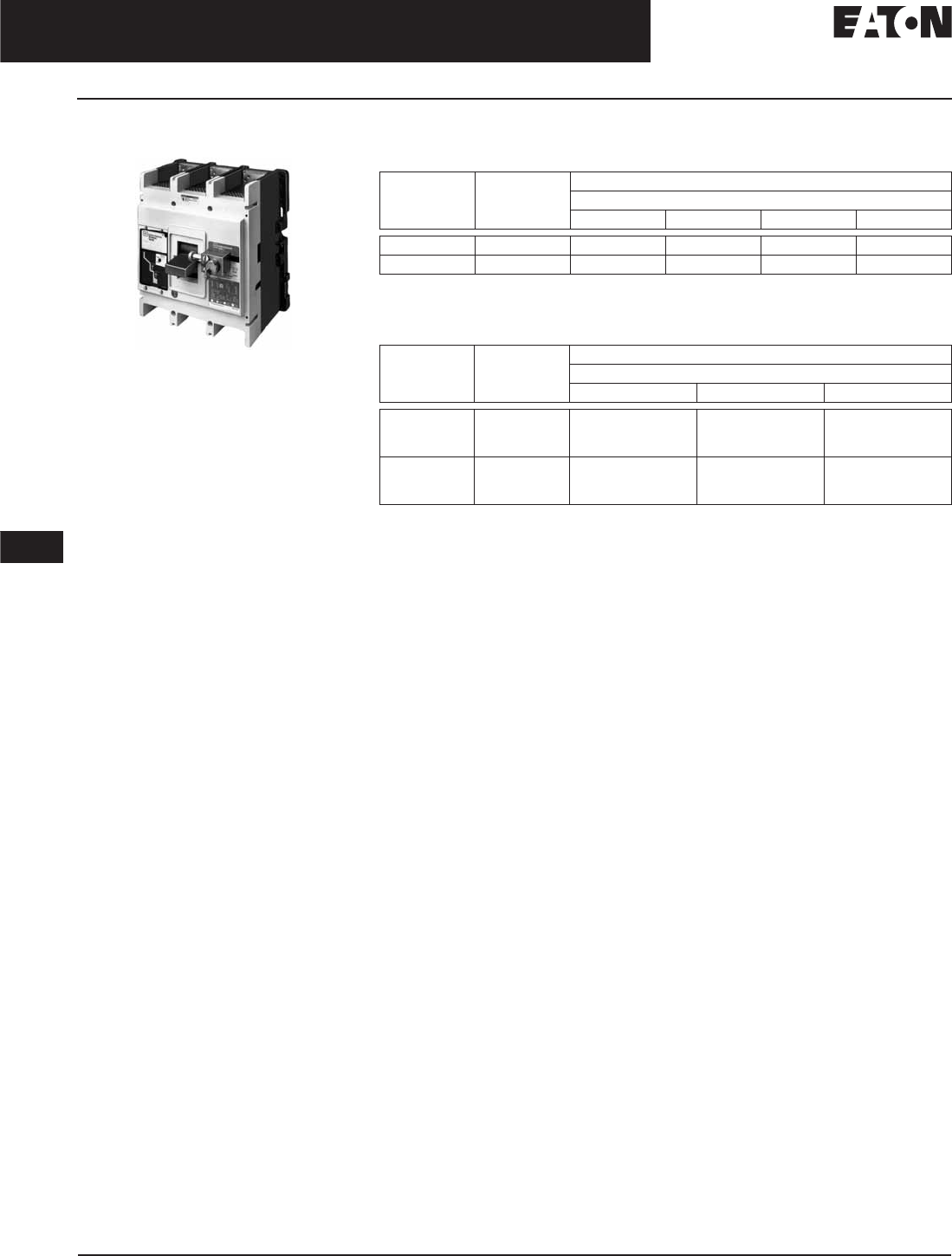
November 2008
12-50
For more information visit: www.eaton.com CA08101001E
Series G Molded Case Circuit Breakers
12
800 — 2500 Amperes
RG-Frame
RG-Frame
RG-Frame Circuit Breaker
Product Description
■Cutler-Hammer RG-Frame Circuit
Breakers by Eaton Corporation are
available as frame (which includes
trip unit), rating plug and terminals.
■All R-Frame circuit breakers are
suitable for reverse feed use.
Technical Data and Specifications
Table 12-89. UL 489/CSA Interrupting Capacity Ratings
Utilization Category A circuit breakers.
Note: See Page 12-164 for Trip Unit Specifications.
Table 12-90. IEC 947-2 Interrupting Capacity Ratings
Utilization Category A circuit breakers.
Circuit
Breaker
Type
Number
of Poles
Interrupting Capacity (kA Symmetrical Amperes)
Volts ac (50/60 Hz)
240 277 480 600
RGH 3, 4 125 — 65 50
RGC 3, 4 200 — 100 65
Circuit
Breaker
Type
Number
of Poles
Interrupting Capacity (kA Symmetrical Amperes)
Volts ac (50/60 Hz)
240 415 690
RGH
Icu
Ics
3, 4
135
100
70
50
25
13
RGC
Icu
Ics
3, 4
200
100
100
50
35
18

November 2008
CA08101001E For more information visit: www.eaton.com
12-51
Series G Molded Case Circuit Breakers
12
800 – 2500 Amperes
Frame Size RG, 2500 Amperes 65 kA at 480 Vac, 70 kA at 415 Vac — Digitrip 310 Trip Unit
Product Selection
Table 12-91. Circuit Breaker/Frame Catalog Numbering System
Dimensions/Weights
Table 12-92. Dimensions in Inches (mm)
Table 12-93. Approximate Shipping Weight, Lbs. (kg)
RGH 3 16 T33 W A01
Number
of Poles
3 = 3 Poles
4 = 4 Poles
Trip Function
Digitrip 310
T33 = LS
T32 = LSI
T35 = LSG
T36 = LSIG
Digitrip 610
T61 = LI
T62 = LSI
T63 = LS
T64 = LIG
T65 = LSG
T66 = LSIG
Digitrip 910
T91 = LI
T92 = LSI
T93 = LS
T94 = LIG
T95 = LSG
T96 = LSIG
Function Codes
A12-A19 = Auxiliary Switch
B01-B02 = Bell Alarm
D01 = Drawout Moving Carrier
E01-E13 = Electrical Operator
H01-H11 = Special Ratings
J01 = Moisture Fungus Proof
L01-L05 = Locks
N01 = Low Energy Shunt Trip
P01-P64 = Rating Plugs
Q01-Q02 = Terminal Block
S21-S88 = Shunt Trip
T21-T37 = UVR (DC)
U33-U58 = UVR (AC)
W01 = Walking Beam Interlock
X01-X08 = Load Termination
Y01-Y08 = Line Termination
Z01-Z08 = Line & Load Termination
Amperes
16 = 1600 A
20 = 2000 A
25 = 2500 A
Type
RGH 65K
RGC 100K
Modification Suffix
R= Ground Fault Remote
RES Trip
E= 100% Protection
(New Design 310)
RES Trip Unit
P= 100% Prot. Neut.
4P RES Trip Unit
V3 = Electronic Trip w/o
Ambient Temperature
Marked on Trip Unit
W= w/o Terms
K= Molded Case Switch
Number
of Poles
Width Height Depth
3
4
15.50 (393.7)
20.00 (508.0)
16.00 (406.4)
16.00 (406.4)
9.75 (247.7)
9.75 (247.7)
Breaker
Type
Complete Breaker
Number of Poles
34
1600 Amperes
RGH, RGC 102 (46.3) 135 (61.2)
2000 Amperes
RGH, RGC 102 (46.3) 135 (61.2)
2500 Amperes
RGH, RGC 135 (61.2) 182 (82.6)

November 2008
12-52
For more information visit: www.eaton.com CA08101001E
Series G Molded Case Circuit Breakers
12
800 – 2500 Amperes
Frame Size RG, 2500 Amperes 65 kA at 480 Vac, 70 kA at 415 Vac — Digitrip 310 Trip Unit
RG-Frame, 2500 Amperes — Selection Guide and Ordering Information
Table 12-94. Type RGH with Digitrip 310 High Interrupting Capacity — Ue Maximum 690 Vac, 70 kA Icu at 415 Vac
See Table 12-95 on Page 12-53 for prices.
For SCR application, use 2000 ampere frame.
Order terminals separately. Mounting hardware not included.
Ground fault equipped trip units available with remote indicating panel. Add “R” to catalog number, e.g., “RGH316T35RW.”
Additional IEC ratings are available on adjustable rating plugs. Contact your Eaton representative.
Unprotected left pole neutral. Add “P” to catalog number for 100% protected left pole neutral, add “E” for 60% protected, e.g.,
“RGH416T33PW”, “RGH416T33EW.”
Note: RG MCCBs have metric threading on line and load conductors. Use RD MCCBs if imperial threading is required.
Maximum
Continuous
Ampere
Rating
at 40°C
Number
of Poles
Circuit Breaker Frame Including Digitrip RMS 310 Electronic Trip Unit with
Adjustable Rating Plugs — Catalog Number
Interchangeable
Rating Plugs
(Order as Individual
Component)
Included
with Breaker
L – Adjustable Long Delay Pickup (By Adjustable Rating Plug)
S – Adjustable Short Delay Pickup with Fixed Short Delay Time
(I2t Response) or Adjustable Short Delay Time (Flat Response)
I – Adjustable Instantaneous Pickup by Setting Short Delay Time to Instantaneous
G – Adjustable Ground Fault Pickup with Adjustable Ground Fault Delay (Flat Response)
LS LSI LSG LSIG Fixed
Rating Plug
Adjustable
Rating Plug
Short Time Range
Short Time Delay
Ground Fault Pickup
Ground Fault Delay
2 – 8 x In
—
—
—
2 – 8 x In
I – 300 ms
—
—
2 – 8 x In
—
200 – 1200 A
I – 500 ms
2 – 8 x In
I – 300 ms
200 – 1200 A
I – 500 ms
Ampere
Rating
Catalog
Number
Adjustable
Ampere
Settings
Catalog Number
1600 3-Pole RGH316T33WP08 RGH316T32WP08 RGH316T35WP08 RGH316T36WP08 800
1000
1200
1250
16RES08T
16RES10T
16RES12T
16RES125T
800/1000/
1200/1600
A16RES16T1
1400
1500
1600
16RES14T
16RES15T
16RES16T
2000 RGH320T33WP16 RGH320T32WP16 RGH320T35WP16 RGH320T36WP16 1000
1200
1250
20RES10T
20RES12T
A20RES125T
1000/1200/
1600/2000
A20RES20T1
1400
1600
2000
A20RES14T
A20RES16T
A20RES20T
2500 RGH325T33WP39 RGH325T32WP39 RGH325T35WP39 RGH325T36WP39 1200
1250
1600
25RES12T
25RES125T
A25RES16T
1200/1600/
2000/2500
A25RES25T1
2000
2500
A25RES20T
A25RES25T
1600 4-Pole RGH416T33WP08 RGH416T32WP08 — — 800
1000
1200
1250
16RES08T
16RES10T
16RES12T
16RES125T
800/1000/
1200/1600
A16RES16T1
1400
1500
1600
16RES14T
16RES15T
16RES16T
2000 RGH420T33WP16 RGH420T32WP16 — — 1000
1200
1250
20RES10T
20RES12T
A20RES125T
1000/1200/
1600/2000
A20RES20T1
1400
1600
2000
A20RES14T
A20RES16T
A20RES20T
2500 RGH425T33WP39 RGH425T32WP39 — — 1200
1250
1600
25RES12T
25RES125T
A25RES16T
1200/1600/
2000/2500
A25RES25T1
2000
2500
A25RES20T
A25RES25T

November 2008
CA08101001E For more information visit: www.eaton.com
12-53
Series G Molded Case Circuit Breakers
12
800 – 2500 Amperes
Frame Size RG, 2500 Amperes 65 kA at 480 Vac, 70 kA at 415 Vac — Digitrip 310 Trip Unit
Table 12-95. Type RGH with Digitrip 310 High Interrupting Capacity — Ue Maximum 690 Vac, 70 kA Icu at 415 Vac Prices
Discount Symbol . . . . . . . . . . . . . . . . . . . . . . . . . CB-2
Catalog
Number
Price
U.S. $
Catalog
Number
Price
U.S. $
Catalog
Number
Price
U.S. $
Catalog
Number
Price
U.S. $
A16RES16T1
20RES125T
20RES14T
20RES16T
20RES20T
A20RES20T1
25RES16T
25RES20T
25RES25T
A25RES25T1
RGH316T32WP09
RGH316T33WP09
RGH316T35WP09
RGH316T36WP09
RGH320T32WP17
RGH320T33WP17
RGH320T35WP17
RGH320T36WP17
RGH325T32WP40
RGH325T33WP40
RGH325T35WP40
RGH325T36WP40
RGH416T32WP09
RGH416T33WP09
RGH420T32WP17
RGH420T33WP17
RGH425T32WP40
RGH425T33WP40
16RES08T
16RES10T
16RES125T
16RES12T
16RES14T
16RES15T
16RES16T
20RES10T
20RES12T
25RES125T
25RES12T
—

November 2008
12-54
For more information visit: www.eaton.com CA08101001E
Series G Molded Case Circuit Breakers
12
800 – 2500 Amperes
Frame Size RG, 2500 Amperes 100 kA at 480 Vac, 415 Vac — Digitrip 310 Trip Unit
Table 12-96. Type RGC with Digitrip 310 Very High Interrupting Capacity — Ue Maximum 690 Vac, 100 kA Icu at 415 Vac Page 12-54
See Table 12-97 on Page 12-55 for prices.
For SCR application, use 2000 ampere frame.
Order terminals separately. Mounting hardware not included.
Ground fault equipped trip units available with remote indicating panel. Add “R” to catalog number, e.g., “RGH316T35RW.”
Additional IEC ratings are available on adjustable rating plugs. Contact your Eaton representative.
Unprotected left pole neutral. Add “P” to catalog number for 100% protected left pole neutral, add “E” for 60% protected, e.g.,
“RGH416T33PW”, “RGH416T33EW.”
Note: RG MCCBs have metric threading on line and load conductors. Use RD MCCBs if imperial threading is required.
Maximum
Continuous
Ampere
Rating
at 40°C
Number
of Poles
Circuit Breaker Frame Including Digitrip RMS 310 Electronic Trip Unit with
Adjustable Rating Plugs — Catalog Number
Interchangeable
Rating Plugs
(Order as Individual
Component)
Included
with Breaker
L – Adjustable Long Delay Pickup (By Adjustable Rating Plug)
S – Adjustable Short Delay Pickup with Fixed Short Delay Time
(I2t Response) or Adjustable Short Delay Time (Flat Response)
I – Adjustable Instantaneous Pickup by Setting Short Delay Time to Instantaneous
G – Adjustable Ground Fault Pickup with Adjustable Ground Fault Delay (Flat Response)
LS LSI LSG LSIG Fixed
Rating Plug
Adjustable
Rating Plug
Short Time Range
Short Time Delay
Ground Fault Pickup
Ground Fault Delay
2 – 8 x In
—
—
—
2 – 8 x In
I – 300 ms
—
—
2 – 8 x In
—
200 – 1200 A
I – 500 ms
2 – 8 x In
I – 300 ms
200 – 1200 A
I – 500 ms
Ampere
Rating
Catalog
Number
Adjustable
Ampere
Settings
Catalog Number
1600 3-Pole RGC316T33WP08 RGC316T32WP08 RGC316T35WP08 RGC316T36WP08 800
1000
1200
1250
16RES08T
16RES10T
16RES12T
16RES125T
800/1000/
1200/1600
A16RES16T1
1400
1500
1600
16RES14T
16RES15T
16RES16T
2000 RGC320T33WP16 RGC320T32WP16 RGC320T35WP16 RGC320T36WP16 1000
1200
1250
20RES10T
20RES12T
A20RES125T
1000/1200/
1600/2000
A20RES20T1
1400
1600
2000
A20RES14T
A20RES16T
A20RES20T
2500 RGC325T33WP40 RGC325T32WP40 RGC325T35WP40 RGC325T36WP40 1200
1250
1600
25RES12T
25RES125T
A25RES16T
1200/1600/
2000/2500
A25RES25T1
2000
2500
A25RES20T
A25RES25T
1600 4-Pole RGC416T33WP08 RGC416T32WP08 — — 800
1000
1200
1250
16RES08T
16RES10T
16RES12T
16RES125T
800/1000/
1200/1600
A16RES16T1
1400
1500
1600
16RES14T
16RES15T
16RES16T
2000 RGC420T33WP16 RGC420T32WP16 — — 1000
1200
1250
20RES10T
20RES12T
A20RES125T
1000/1200/
1600/2000
A20RES20T1
1400
1600
2000
A20RES14T
A20RES16T
A20RES20T
2500 RGC425T33WP40 RGC425T32WP40 — — 1200
1250
1600
25RES12T
25RES125T
A25RES16T
1200/1600/
2000/2500
A25RES25T1
2000
2500
A25RES20T
A25RES25T

November 2008
CA08101001E For more information visit: www.eaton.com
12-55
Series G Molded Case Circuit Breakers
12
800 – 2500 Amperes
Frame Size RG, 2500 Amperes 100 kA at 480 Vac, 415 Vac — Digitrip 310 Trip Unit
Table 12-97. Type RGH with Digitrip 310 High Interrupting Capacity — Ue Maximum 690 Vac, 70 kA Icu at 415 Vac Prices
Table 12-98. Molded Case Switches
Molded case switch will trip above 17,500 amperes.
Catalog
Number
Price
U.S. $
Catalog
Number
Price
U.S. $
Catalog
Number
Price
U.S. $
Catalog
Number
Price
U.S. $
A16RES16T1
A20RES125T
A20RES14T
A20RES16T
A20RES20T
A20RES20T1
A25RES16T
A25RES20T
A25RES25T
A25RES25T1
RGC316T32WP09
RGC316T33WP09
RGC316T35WP09
RGC316T36WP09
RGC320T32WP17
RGC320T33WP17
RGC320T35WP17
RGC320T36WP17
RGC325T32WP40
RGC325T33WP40
RGC325T35WP40
RGC325T36WP40
RGC416T32WP09
RGC416T33WP09
RGC420T32WP17
RGC420T33WP17
RGC425T32WP40
RGC425T33WP40
16RES08T
16RES10T
16RES125T
16RES12T
16RES14T
16RES15T
16RES16T
20RES10T
20RES12T
25RES125T
25RES12T
—
Ampere
Rating
Number
of Poles
Catalog
Number
Price
U.S. $
1600
2000
3-Pole RGK316WK
RGK320WK
1600
2000
4-Pole RGK416WK
RGK420WK
Discount Symbol . . . . . . . . . . . . . . . . . . . . . . . . . CB-2
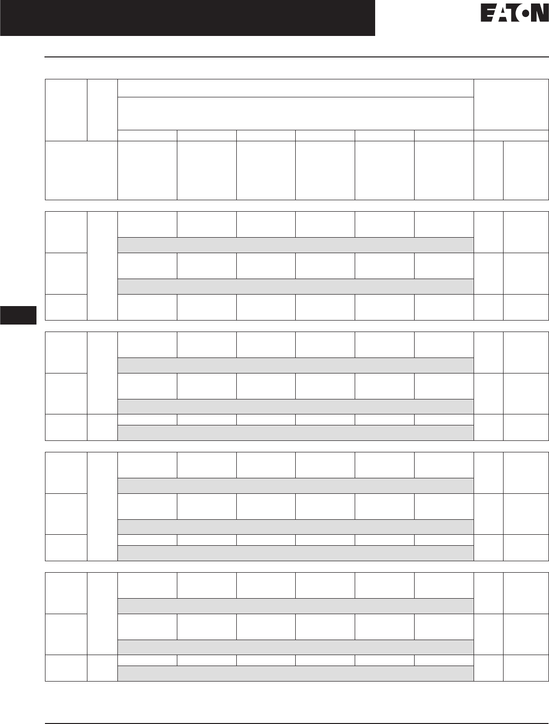
November 2008
12-56
For more information visit: www.eaton.com CA08101001E
Series G Molded Case Circuit Breakers
12
800 — 2500 Amperes
Frame Size RG, 1250 Amperes — Digitrip 610 & 910 Trip Units
Table 12-99. Type RG with Digitrip 610 and 910
Order terminals separately. Mounting hardware not included.
Not to exceed 1200 ampere ground fault pickup.
Note: RG MCCBs have metric threading on line and load conductors. Use RD MCCBs if imperial threading is required.
Maximum
Continuous
Ampere
Rating
at 40°C
Number
of Poles
Circuit Breaker Frame Including Digitrip RMS 610 and 910 Electronic Trip Unit with Rating Plugs
Order as Individual Component — Catalog Number
Digitrip RMS
Interchangeable
Rating Plug
(Order as Individual
Component)
L – Adjustable Long Delay Pickup (Ir) with Adjustable Long Delay Time
S – Adjustable Short Delay Pickup with Adjustable Short Delay Time (I2t or Flat Response)
I – Adjustable Instantaneous Pickup
G – Adjustable Ground Fault Pickup with Adjustable Ground Fault Time Delay (I2t or Flat Response)
LI LS LSI LIG LSG LSIG Fixed Rating Plug
Long Delay Pickup
Long Delay Time
Short Time Range
Short Time Delay
Instantaneous
Ground Fault Pickup
Ground Fault Delay
0.5 – 1.0 x In
2 – 24 Seconds
2 – 6 x Ir
—
2 – 6 x M1 & M2
—
—
0.5 – I.0n
2 – 24 Seconds
2 – 6 x Ir
100 – 500 ms
—
—
—
0.5 – 1.0 x In
2 – 24 Seconds
2 – 6 x Ir
100 – 500 ms
2 – 6 x M1 & M2
—
—
0.5 – 1.0 x In
2 – 24 Seconds
2 – 6 x Ir
—
2 – 6 x M1 & M2
0.25 – 1.0 x In
100 – 500 ms
0.5 – 1.0 x In
2 – 24 Sec.
2 – 6 x Ir
100 – 500 ms
—
0.25 – 1.0 x In
100 – 500 ms
0.5 – 1.0 x In
2 – 24 Seconds
2 – 6 x Ir
100 – 500 ms
2 – 6 x M1 & M2
0.25 – 1.0 x In
100 – 500 ms
Ampere
Rating
Catalog
Number
Type RGH with Digitrip 610 High Interrupting Capacity — Ue Max. 690 Vac, 70 kA Icu at 415 Vac
1600 3-Pole RGH316T61WP44 RGH316T63WP44 RGH316T62WP44 RGH316T64WP44 RGH316T65WP44 RGH316T66WP44 800
1000
1200
1250
1600
RP6R16A080
RP6R16A100
RP6R16A120
RP6R16A125
RP6R16A160
Includes 1600 A Rating Plug
2000 RGH320T61WP49 RGH320T63WP49 RGH320T62WP49 RGH320T64WP49 RGH320T65WP49 RGH320T66WP49 1000
1200
1250
1600
2000
RP6R20A100
RP6R20A120
RP6R20A125
RP6R20A160
RP6R20A200
Includes 2000 A Rating Plug
2500 RGH325T61WP53 RGH325T63WP53 RGH325T62WP53 RGH325T64WP53 RGH325T65WP53 RGH325T66WP53 1600
2000
2500
RP6R25A160
RP6R25A200
RP6R25A250
Type RGC with Digitrip 610 Very High Interrupting Capacity — Ue Max. 690 Vac, 100 kA Icu at 415 Vac
1600 3-Pole RGC316T61WP44 RGC316T63WP44 RGC316T62WP44 RGC316T64WP44 RGC316T65WP44 RGC316T66WP44 800
1000
1200
1250
1600
RP6R16A080
RP6R16A100
RP6R16A120
RP6R16A125
RP6R16A160
Includes 1600 A Rating Plug
2000 RGC320T61WP49 RGC320T63WP49 RGC320T62WP49 RGC320T64WP49 RGC320T65WP49 RGC320T66WP49 1000
1200
1250
1600
2000
RP6R20A100
RP6R20A120
RP6R20A125
RP6R20A160
RP6R20A200
Includes 2000 A Rating Plug
2500 RGC325T61WP53 RGC325T63WP53 RGC325T62WP53 RGC325T64WP53 RGC325T65WP53 RGC325T66WP53 1600
2000
2500
RP6R25A160
RP6R25A200
RP6R25A250
Includes 2500 A Rating Plug
Type RGH with Digitrip 910 High Interrupting Capacity — Ue Max. 690 Vac, 70 kA Icu at 415 Vac
1600 3-Pole RGH316T91WP44 RGH316T93WP44 RGH316T92WP44 RGH316T94WP44 RGH316T95WP44 RGH316T96WP44 800
1000
1200
1250
1600
RP6R16A080
RP6R16A100
RP6R16A120
RP6R16A125
RP6R16A160
Includes 1600 A Rating Plug
2000 RGH320T91WP49 RGH320T93WP49 RGH320T92WP49 RGH320T94WP49 RGH320T95WP49 RGH320T96WP49 1000
1200
1250
1600
2000
RP6R20A100
RP6R20A120
RP6R20A125
RP6R20A160
RP6R20A200
Includes 2000 A Rating Plug
2500 RGH325T91WP53 RGH325T93WP53 RGH325T92WP53 RGH325T94WP53 RGH325T95WP53 RGH325T96WP53 1600
2000
2500
RP6R25A160
RP6R25A200
RP6R25A250
Includes 2500 A Rating Plug
Type RGC with Digitrip 910 Very High Interrupting Capacity — Ue Max. 690 Vac, 100 kA Icu at 415 Vac
1600 3-Pole RGC316T91WP44 RGC316T93WP44 RGC316T92WP44 RGC316T94WP44 RGC316T95WP44 RGC316T96WP44 800
1000
1200
1250
1600
RP6R16A080
RP6R16A100
RP6R16A120
RP6R16A125
RP6R16A160
Includes 1600 A Rating Plug
2000 RGC320T91WP49 RGC320T93WP49 RGC320T92WP49 RGC320T94WP49 RGC320T95WP49 RGC320T96WP49 1000
1200
1250
1600
2000
RP6R20A100
RP6R20A120
RP6R20A125
RP6R20A160
RP6R20A200
Includes 2000 A Rating Plug
2500 RGC325T91WP53 RGC325T93WP53 RGC325T92WP53 RGC325T94WP53 RGC325T95WP53 RGC25T96WP53 1600
2000
2500
RP6R25A160
RP6R25A200
RP6R25A250
Includes 2500 A Rating Plug

November 2008
CA08101001E For more information visit: www.eaton.com
12-57
Series G Molded Case Circuit Breakers
12
800 — 2500 Amperes
Frame Size RG, 1250 Amperes — Digitrip 610 & 910 Trip Units
Table 12-100. Type RG with Digitrip 610 and 910 Prices
Catalog
Number
Price
U.S. $
Catalog
Number
Price
U.S. $
Catalog
Number
Price
U.S. $
Catalog
Number
Price
U.S. $
RGC316T61WP44
RGC316T62WP44
RGC316T63WP44
RGC316T64WP44
RGC316T65WP44
RGC316T66WP44
RGC316T91WP44
RGC316T92WP44
RGC316T93WP44
RGC316T94WP44
RGC316T95WP44
RGC316T96WP44
RGC320T61WP49
RGC320T62WP49
RGC320T63WP49
RGC320T64WP49
RGC320T65WP49
RGC320T66WP49
RGC320T91WP49
RGC320T92WP49
RGC320T93WP49
RGC320T94WP49
RGC320T95WP49
RGC320T96WP49
RGC325T61WP53
RGC325T62WP53
RGC325T63WP53
RGC325T64WP53
RGC325T65WP53
RGC325T66WP53
RGC325T91WP53
RGC325T92WP53
RGC325T93WP53
RGC325T94WP53
RGC325T95WP53
RGH316T61WP44
RGH316T62WP44
RGH316T63WP44
RGH316T64WP44
RGH316T65WP44
RGH316T66WP44
RGH316T91WP44
RGH316T92WP44
RGH316T93WP44
RGH316T94WP44
RGH316T95WP44
RGH316T96WP44
RGH320T61WP49
RGH320T62WP49
RGH320T63WP49
RGH320T64WP49
RGH320T65WP49
RGH320T66WP49
RGH320T91WP49
RGH320T92WP49
RGH320T93WP49
RGH320T94WP49
RGH320T95WP49
RGH320T96WP49
RGH325T61WP53
RGH325T62WP53
RGH325T63WP53
RGH325T64WP53
RGH325T65WP53
RGH325T66WP53
RGH325T91WP53
RGH325T92WP53
RGH325T93WP53
RGH325T94WP53
—
RGH325T95WP53
RGH325T96WP53
RP6R16A080
RP6R16A100
—
RP6R16A120
RP6R16A125
RP6R16A160
RP6R20A100
—
Discount Symbol . . . . . . . . . . . . . . . . . . . . . . . . . CB-2
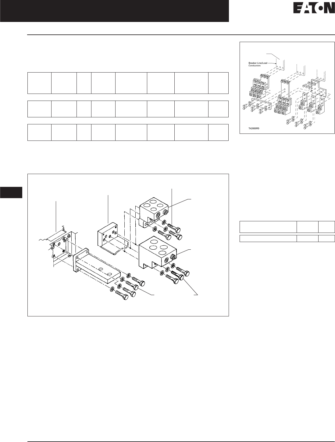
November 2008
12-58
For more information visit: www.eaton.com CA08101001E
Series G Molded Case Circuit Breakers
12
800 — 2500 Amperes
Frame Size RG, 800 – 2500 Amperes
Line and Load Terminals
R-Frame circuit breakers use Cu/Al terminals as standard and copper only
terminals as an option. Specify if factory installation is required.
Table 12-101. Line and Load Terminals
Order one per pole — single terminals individually packed.
Order one TA2000RD kit per 3-poles. Catalog number includes bus connection, terminals and
hardware for either line side or load side of 3-pole breaker.
Note: RG MCCBs have metric threading on line and load conductors. Use RD MCCBs if
imperial threading is required.
Figure 12-4. RD Rear Connector Exploded View
Order one per pole (or two per pole if line and load terminals are required) — single terminals
individually packed.
Note: RG MCCBs have metric threading on line and load conductors. Use RD MCCBs if
imperial threading is required.
Maximum
Breaker
Amperes
Terminal
Body
Material
Wire
Type
Hardware AWG/kcmil
Wire Range/
Number
of Conductors
Metric Wire
Range mm2Catalog
Number
Price
U.S. $
Wire Terminals
1600
1600
2000
Aluminum
Copper
Aluminum
Cu/Al
Cu
Cu/Al
Metric
Metric
Metric
500 – 1000 (4)
1 – 600 (4)
2 – 600 (6)
300 – 500
50 – 300
35 – 300
TA1600RDM
T1600RDM
TA2000RDM
Rear Connectors
2000
2000
2500
Copper
Copper
Copper
—
—
—
Metric
Metric
Metric
—
—
—
—
—
—
B2016RDM
B2016RDLM
B2500RDM
Conductor
(Viewed from Front
of Circuit Breaker)
Conductor
(Viewed from Rear
of Circuit Breaker and
Cut Away for Clarity)
Rear Connector (Cu)
B2016RDM
B2016RDLM (For 100% Application)
(For 1600 A and 2000 A Frames)
B2500RDM for 2500 A
Securing
Hardware
Securing Hardware
Cu Only
Terminal
Catalog
Number
T1600RDM
(For 1600 A
Frame Only)
Al/Cu
Terminal
Catalog
Number
TA1600RDM
(For 1600 A
Frame Only)
OR
Figure 12-5. TA2000RD Wire Terminal
Note: Order one TA2000RDM kit per 3-
poles. Catalog number includes bus con-
nection, terminals and hardware for either
line side or load side of 3-pole breaker.
Base Mounting Hardware
Supplied by customer.
Handle Extension
Included with breaker. Additional
handle extensions are available.
Table 12-102. Handle Extension
Description Catalog
Number
Price
U.S. $
Single Handle Extension HEX6
Discount Symbol . . . . . . . . . . . . . . . . . . . . . . . . CB-2
Breaker Line/Load
Conductors
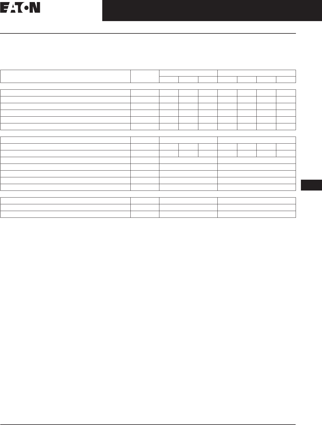
November 2008
CA08101001E For more information visit: www.eaton.com
12-59
Series G Molded Case Circuit Breakers
12
800 — 2500 Amperes
RG-Frame
Allowable Accessory Combinations
Different combinations of accessories can be supplied, depending on the types of accessories and the number
of poles in the circuit breaker.
Table 12-103. Accessories
■Applicable in indicated pole position
Contact Eaton
❏May be mounted on left or right pole —
not both
●Accessory available/Modification available
Description Reference
Page
3-Pole 4-Pole
Left Center Right Left Center Right Neu.
Internal Accessories (Only One Internal Accessory Per Pole)
Alarm Lockout (Make/Break) 12-65 ■■
Auxiliary Switch (1A, 1B) 12-65 ■■
Auxiliary Switch (2A, 2B) 12-65 ■■
Auxiliary Switch and Alarm Switch Combination 12-65 ■■
Shunt Trip — Standard 12-65 ●●
Undervoltage Release Mechanism 12-65 ●●
External Accessories
Base Mounting Hardware 12-58 ●●
Padlockable Handle Lock Hasp 12-64 ❏❏❏❏
Key Interlock Kit 12-64 ❏❏❏❏
Electrical Operator 12-64 ●●
Handle Mechanisms 12-67 ●●
Drawout Cassette 12-66 ●●
Handle Extension 12-58 ●●
Digitrip 310 Test Kit 12-268 ●●
Modifications (Refer to Eaton)
Moisture Fungus Treatment 12-73 ●●
Freeze-Tested Circuit Breakers — ●●
Marine/Naval Application, UL Supplement SA and SB ●●

November 2008
12-60
For more information visit: www.eaton.com CA08101001E
Series G Molded Case Circuit Breakers
12
15 – 2500 Amperes for UL, CSA & IEC Applications
Motor Circuit Protectors
Motor Circuit 480 Vac, Protectors — Selection Guide and Ordering Information
Table 12-104. EG-Frame — 480 Vac, 600Y/347 Vac Maximum
UL listed for use with Cutler-Hammer Motor Starters.
Motor FLA ranges are typical. The corresponding trip setting is at
13 times the minimum FLA value shown. Where a 13 times setting is
required for an intermediate FLA value, alternate cam settings and/or
MCP ratings should be used.
For dc applications, actual trip levels are approximately 40% higher
than values shown.
Settings above 10 x In are for special applications. Where the ampere
rating of the disconnecting means cannot be less than 115% of the
motor full load ampere rating.
Table 12-105. JG-Frame — 600 Vac Maximum, 250 Vdc Maximum
UL listed for use with Cutler-Hammer Motor Starters.
Table 12-106. LG-Frame — 600 Vac Maximum, 250 Vdc Maximum
Equipped with an electromechanical trip device.
UL listed for use with Cutler-Hammer Motor Starters.
Note: 800 and 1200 ampere, 600 Vac maximum motor circuit
protectors are available as Series C HMCP product.
Continuous
Amperes
Cam
Setting
Motor
Full Load
Current
Amperes
MCP
Trip
Setting
MCP
Catalog
Number
Price
U.S. $
3 A
B
C
D
E
F
.69 – .91
1.1 – 1.3
1.6 – 1.7
2.0 – 2.2
2.3 – 2.5
2.6 – 2.8
9
15
21
27
30
33
HMCPE003A0C
7 A
B
C
D
E
F
1.5 – 2.0
2.6 – 3.1
3.7 – 3.9
4.8 – 5.2
5.3 – 5.7
5.8 – 6.1
21
35
49
63
70
77
HMCPE007C0C
15 A
B
C
D
E
F
3.4 – 4.5
5.7 – 6.8
8.0 – 9.1
10.4 – 11.4
11.5 – 12.6
12.7 – 13.0
45
75
105
135
150
165
HMCPE015E0C
30 A
B
C
D
E
F
3.9 – 9.1
11.5 – 13.7
16.1 – 18.3
20.7 – 22.9
23.0 – 25.2
25.3 – 26.1
90
150
210
270
300
330
HMCPE030H1C
50 A
B
C
D
E
F
11.5 – 15.2
19.2 – 22.9
26.9 – 30.6
34.6 – 38.3
38.4 – 42.1
42.2 – 43.5
150
250
350
450
500
550
HMCPE050K2C
70 A
B
C
D
E
F
16.1 – 30.6
26.9 – 32.2
37.6 – 42.9
48.4 – 53.7
53.8 – 59.1
59.2 – 60.9
210
350
490
630
700
770
HMCPE070M2C
100 A
B
C
D
E
F
23.0 – 30.6
38.4 – 46.0
53.8 – 61.4
69.2 – 76.8
76.9 – 84.5
84.6 – 87.0
300
500
700
900
1000
1100
HMCPE100R3C
100 A
B
C
D
E
F
38.4 – 46.0
57.6 – 65.2
76.9 – 84.5
500
750
1000
1250
1375
1500
HMCPE100T3C
Continuous
Amperes
MCP
Trip Range
(Amperes)
MCP
Catalog
Number
Price
U.S. $
250 500 – 1000
625 – 1250
750 – 1500
HMCPJ250D5L
HMCPJ250F5L
HMCPJ250G5L
875 – 1750
1000 – 2000
1125 – 2250
1250 – 2500
HMCPJ250J5L
HMCPJ250K5L
HMCPJ250L5L
HMCPJ250W5L
Continuous
Amperes
MCP
Trip Range
(Amperes)
MCP
Catalog
Number
Price
U.S. $
600 1250 – 2500
1500 – 3000
1750 – 3500
HMCPL600L6G
HMCPL600N6G
HMCPL600R6G
2000 – 4000
2250 – 4500
2500 – 5000
3000 – 6000
HMCPL600X6G
HMCPL600Y6G
HMCPL600P6G
HMCPL600M6G
Discount Symbol . . . . . . . . . . . . . . . . . . . . . . . . CB-2
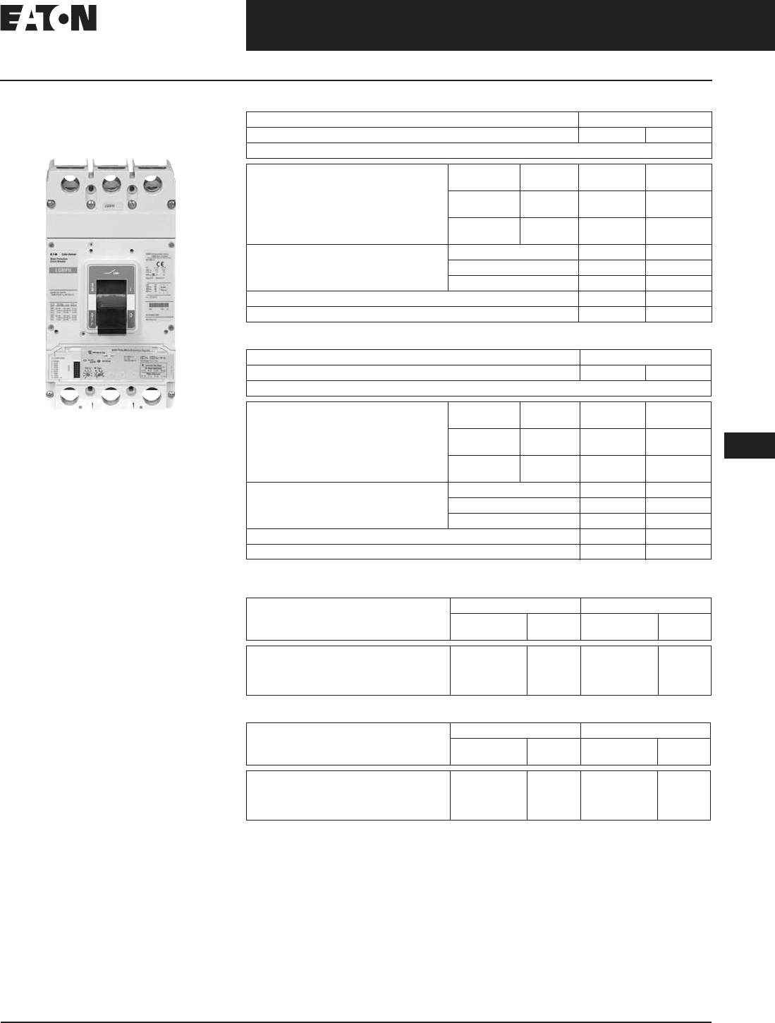
November 2008
CA08101001E For more information visit: www.eaton.com
12-61
Series G Molded Case Circuit Breakers
12
15 – 2500 Amperes for UL, CSA & IEC Applications
Motor Protector Circuit Breaker
Series G Motor Protector
Circuit Breaker (MPCB)
Product Description
■Eliminates need for separate
overload relay.
Features
■IEC 60947-2.
■UL 489 rating.
■CSA C22.2
■Phase unbalance protection.
■Phase loss protection.
■Hot trip/cold trip.
■High load alarm.
■Pre-detection trip relay option.
■Class 10, 15, 20, 30 protection.
Applications
■Can be used with contactor to
eliminate need for overload relay
and still create manual motor
control.
■Meets requirement for motor
branch protection, including:
– Disconnecting means
– Branch circuit short circuit
protection
– Overload protection
Table 12-107. JGMPS and JGMPH Rating and Ampere Range
Table 12-108. LGMPS and LGMPH Rating and Ampere Range
630 amperes is not a UL listed rating. 600 amperes is the maximum UL or CSA for LG breaker.
Table 12-109. JGMP Catalog Numbers
Table 12-110. LGMP Catalog Numbers
630 amperes is not a UL listed rating. 600 amperes is the maximum UL or CSA for LG breaker.
Note: For pre-trip alarm option, order Style Number 5721B31G02.
Maximum Rated Current (Amperes) 250
Breaker Type JGMPS JGMPH
Breaker Capacity (kA rms) ac 50 – 60 Hz
IEC 60947-2 220 – 240 Vac I cu
I cs
85
85
100
100
380 – 415 Vac I cu
I cs
40
40
70
70
660 – 690 Vac I cu
I cs
12
6
14
7
NEMA UL 489 240 Vac 85 100
480 Vac 35 65
600 Vac 25 35
Number of Poles 3 3
Ampere Range 50 – 250 50 –250
Maximum Rated Current (Amperes) 630
Breaker Type LGMPS LGMPH
Breaker Capacity (kA rms) ac 50 – 60 Hz
IEC 60947-2 220 – 240 Vac I cu
I cs
85
85
100
100
380 – 415 Vac I cu
I cs
50
50
70
70
660 – 690 Vac I cu
I cs
20
10
25
13
NEMA UL 489 240 Vac 85 100
480 Vac 50 65
600 Vac 25 35
Number of Poles 3 3
Ampere Range 250 – 630 250 –630
Continuous Amperes 35 kAIC 65 kAIC
Catalog
Number
Price
U.S. $
Catalog
Number
Price
U.S. $
50
100
160
250
JGMPS050G
JGMPS100G
JGMPS160G
JGMPS250G
JGMPH050G
JGMPH100G
JGMPH160G
JGMPH250G
Continuous Amperes 50 kAIC 65 kAIC
Catalog
Number
Price
U.S. $
Catalog
Number
Price
U.S. $
250
400
600
630
LGMPS250G
LGMPS400G
LGMPS600G
LGMPS630G
LGMPH250G
LGMPH400G
LGMPH600G
LGMPH630G
Discount Symbol . . . . . . . . . . . . . . . . . . . . . . . . . CB-2
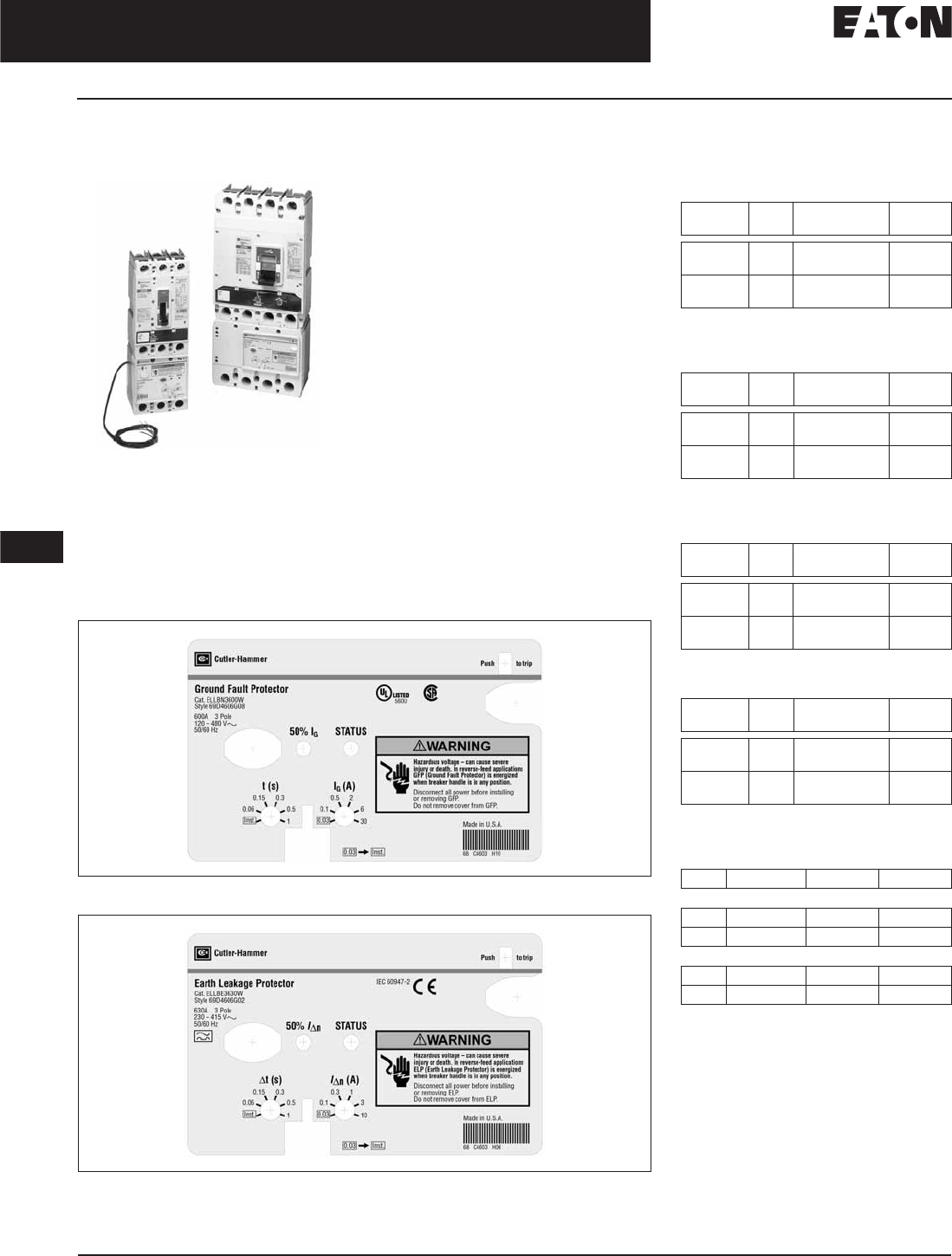
November 2008
12-62
For more information visit: www.eaton.com CA08101001E
Series G Molded Case Circuit Breakers
12
15 – 2500 Amperes for UL, CSA & IEC Applications
30 mA Ground Fault (Earth Leakage) Modules
30 mA Ground Fault
(Earth Leakage) Modules
Clockwise from Left: JG, LG
MCCBs Shown with Ground
Fault (Earth Leakage) Modules
Product Description
Eaton offers a 3- and 4-pole 30 mA
ground fault (earth leakage) protection
module for JG and LG breakers. The
module does not restrict the use of
other breaker accessories. UL-listed
modules are available for JG and LG
MCCBs. The JG and LG modules are
both bottom mounted for circuits up to
160 and 250 amperes (JG), or 400 and
630 amperes for the LG.
The module is completely self-contained
since the current sensor, relay and
power supply are located inside the
product. Current pickup settings are
selectable from 0.03 – 10 amperes for
all IEC-rated modules and JG UL-listed
module, and 0.03 – 30 amperes for
the LG UL-listed modules. Time delays
are also selectable from Instantaneous
– 1.0 seconds for 0.10 ampere settings
and above. A current pickup setting
of 0.03 amperes defaults to an Instan-
taneous time setting regardless of
the time dial’s position. Two alarm
contacts come as standard: a 50% pre-
trip and a 100% after trip, both based
only on earth leakage current levels.
Figure 12-6. UL-Rated LG-Frame Earth Leakage Module Faceplate
Figure 12-7. IEC-Rated LG-Frame Earth Leakage Module Faceplate
Product Selection
Table 12-111. JG-Frame Ground Fault
Modules, UL-Rated (Bottom Mounted,
120 – 480 Vac, 50/60 Hz)
Table 12-112. JG-Frame Earth Leakage
Modules, IEC (Bottom Mounted,
230 – 415 Vac, 50/60 Hz)
Table 12-113. LG-Frame Ground Fault
Modules, UL-Rated (Bottom Mounted,
120 – 480 Vac, 50/60 Hz)
Table 12-114.
LG-Frame Earth Leakage Modules,
IEC (Bottom Mounted, 230 – 415 Vac, 50/60 Hz)
Table 12-115.
Dimensions for Assembled
Breaker and Earth Leakage Module
in Inches (mm)
Amperes Poles Catalog
Number
Price
U.S. $
150
150
3
4
ELJBN3150W
ELJBN4150W
250
250
3
4
ELJBN3250W
ELJBN4250W
Amperes Poles Catalog
Number
Price
U.S. $
160
160
3
4
ELJBE3160W
ELJBE4160W
250
250
3
4
ELJBE3250W
ELJBE4250W
Amperes Poles Catalog
Number
Price
U.S. $
400
400
3
4
ELLBN3400W
ELLBN4400W
600
600
3
4
ELLBN3600W
ELLBN4600W
Amperes Poles Catalog
Number
Price
U.S. $
400
400
3
4
ELLBE3400W
ELLBE4400W
630
630
3
4
ELLBE3630W
ELLBE4630W
Frame Height Width Depth
3-Pole
JG 11.25 (285.8) 4.13 (104.9) 3.57 (90.7)
LG 15.38 (390.7) 5.48 (139.2) 4.06 (103.1)
4-Pole
JG 11.25 (285.8) 5.50 (139.7) 3.57 (90.7)
LG 15.38 (390.7) 7.23 (183.6) 4.06 (103.1)
Discount Symbol . . . . . . . . . . . . . . . . . . . . . . . . CB-2
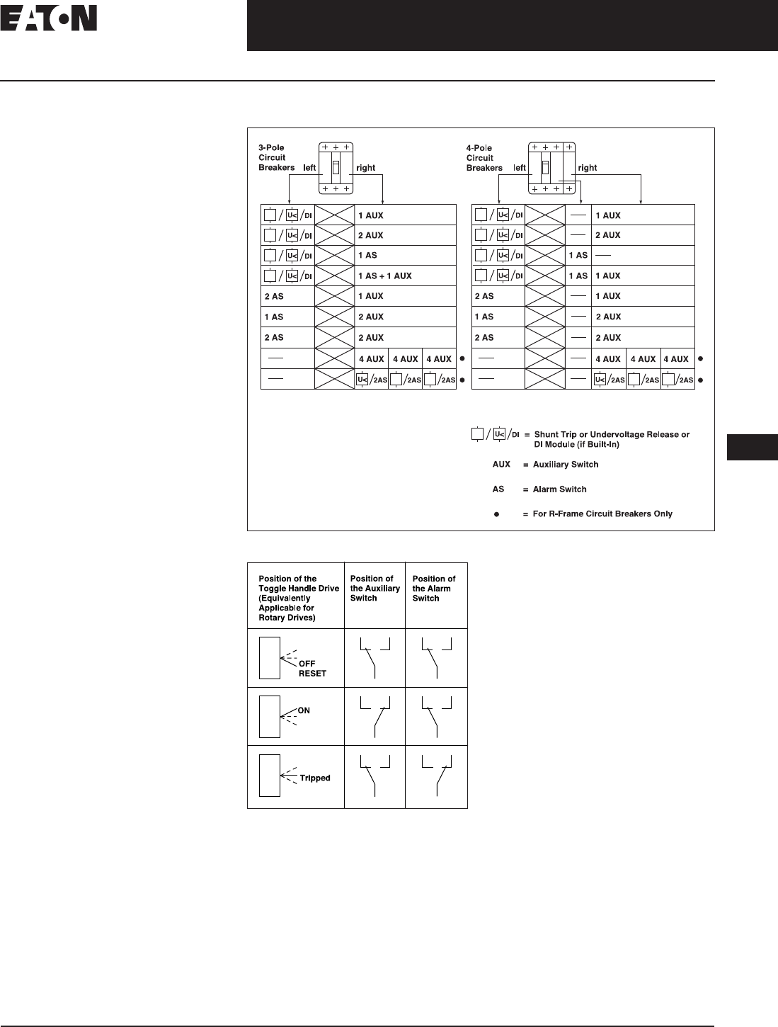
November 2008
CA08101001E For more information visit: www.eaton.com
12-63
Series G Molded Case Circuit Breakers
12
15 – 2500 Amperes for UL, CSA & IEC Applications
Special Features and Accessories
Special Features and
Accessories
Internal Accessories
Alarm Lockout
The alarm switches operate when
the circuit breaker is tripped by a short
circuit or overcurrent, but also when
it is tripped by a shunt trip or under-
voltage release.
Auxiliary Switches
Auxiliary switches are used for
signaling and control purposes.
The various functions of the auxiliary
switches (changeover) are shown in
Figure 12-9.
Shunt Trips
The shunt trip is used for remote
tripping.
The coil of the shunt trip is rated only
for short-time operation.
It is not permissible with the circuit
breaker open to apply a continuous
opening command to the shunt trip
in order to prevent the breaker from
closing. This means that interlocking
circuits with continuous commands
may not be set up with shunt trips.
Undervoltage Releases
The circuit breaker cannot be closed
until the undervoltage release is ener-
gized. If the release is not energized,
the circuit breaker can only perform
an idle switching operation.
Frequent idle switching actions
should be avoided as they shorten the
endurance of the circuit breaker.
Accessory Configurations for EG – RG Circuit Breakers
Figure 12-8. Internal Accessory Configurations
Figure 12-9. Contact Making by the Auxiliary
and Alarm Switches as a Function of the
Switching Position of the Circuit Breaker

November 2008
12-64
For more information visit: www.eaton.com CA08101001E
Series G Molded Case Circuit Breakers
12
15 – 2500 Amperes for UL, CSA & IEC Applications
Special Features and Accessories
Special Calibration
Special non-UL listed calibrations
are available for certain ambient
temperatures other than 40ºC and
for frequencies other than 50/60 Hz
or dc. Reduced interrupting ratings
will apply for 400 Hz applications.
50ºC Calibration
Note: Breakers equipped with electronic trip
units can operate reliably in ambient tem-
peratures of 50ºC. Add suffix “V3” to NG
MCCBs to remove standard 40°C labeling.
Add suffix “V” to catalog number
for complete thermal magnetic
breaker when ordering listed ampere
ratings for breakers to be used in 50ºC
ambients. 50ºC ambient MCCBs are
not UL listed.
Contact Eaton for availability.
Moisture-Fungus Treatment
All Cutler-Hammer Circuit Breaker
cases are molded from glass-polyester
which does not support the growth of
fungus. Any parts which are susceptible
to the growth of fungus will require
special treatment.
Order by description.
Table 12-116. Calibrations and Treatment
Table 12-117. External Accessories and Test Kit
Provision only.
See Page 12-253 for bolt projection
dimensions.
Castell bolt mounting hole must be 10 mm.
Requires two breakers.
Contact Eaton for availability of operators
for EG- and NG-Frames before December
2004.
Description Frame
EG Price
U.S. $
JG Price
U.S. $
LG Price
U.S. $
NG Price
U.S. $
RG Price
U.S. $
Special Calibration ✓✓ ✓✓✓
Moisture-Fungus Treatment ✓✓ ✓✓✓
Description Fit
Type
Frame
EG Price
U.S. $
JG Price
U.S. $
LG Price
U.S. $
NG Price
U.S. $
RG Price
U.S. $
External Accessories
Non-Padlockable
Handle Block
Field EFHB —— LKD4 —
Padlockable
Handle Block
Field EFPHB —— ——
Padlockable Handle
Block Off-Only
Field EFPHBOFF FJPHBOFF LBHPOFF ——
Padlockable Handle
Lock Hasp
Field EFPHL FJPHL LPHL PLK5 HLK6
Padlockable Handle
Lock Hasp Off-Only
Field EFPHLOFF FJPHLOFF LPHLOFF PLK55OFF HLK6OFF
Kirk Key Interlock Kit Field —KYKJG KYKLG KYK4 KYK6
Castell Key Interlock Kit Field —CTKJG CTKLG CTK4 CTK6
Slide Bar Interlock Field EFSBI FJSBI LGSBI SBK5 —
Walking Beam
Interlock
3-Pole EG3WBI JG3WBI LG3WBI WBL5 WBL6
4-Pole EG4WBI JG4WBI LG4WBI WBL5 —
Electrical Operator 120 Vac MOPEG240C EOPFJ240C EOPLG240C EOP5T07 EOP6T08K
240 Vac MOPEG240C EOPFJ240C EOPLG240C EOP5T11 EOP6T11K
24 Vdc MOPEG48D EOPFJ24D EOPLG24D EOP5T21 —
48 Vdc MOPEG48D EOPFJ48D EOPLG48D EOP5T22 EOP6T21K
125 Vdc MOPEG240C EOPFJ240C EOPLG240C EOP5T26 —
Plug-In Adapters 3-Pole PAD3E PAD3J PAD3L PAD53 —
4-Pole PAD4E PAD4J PAD4L ——
Rear Connecting Studs Field EFRCSDL
EFRCSDS
EFRCSWL
EFRCSWS
FJRCSDL
FJRCSDS
FJRCSWL
FJRCSWS
3P–LRCS3WK
4P–LRCS4WK
—
—
——
—
—
—
Test Kit
Electronic Portable
Test Kit
120 V
230 V
N/A
N/A
MTST120V
MTST230V
MTST120V
MTST230V
STK2
—
STK2
—
Discount Symbol . . . . . . . . . . . . . . . . . . . . . . . . CB-2

November 2008
CA08101001E For more information visit: www.eaton.com
12-65
Series G Molded Case Circuit Breakers
12
15 – 2500 Amperes for UL, CSA & IEC Applications
Accessories
Table 12-118. Accessories
All accessories mount in the RH cavity which
will accept one each of shunt trip, UVR,
auxiliary switch and alarm switch.
Part number for JG and LG is ALM1M1BJPK.
Part number for JG and LG is ALM2M2BJPK.
Part number for JG and LG is AUXALRMJPK.
110 – 125 Vdc, 50/60 Hz.
380 – 600 Vdc, 50/60 Hz.
24 Vdc only use UVH5LP03K (NG)
UVH6RP03K (RG) for 24 Vac.
Description Pole
Location
Frame
EG, JG & LG Price U.S. $ NG Price U.S. $ RG Price U.S. $
Field Fit Kit Catalog Numbers
Alarm Lockout Make/Break Left —A1L5LPK —
Right ALM1M1BEPK A1L5RPK A1L6RPK
2 Make/2 Break Left —A2L5LPK —
Right ALM2M2BEPK A2L5RPK A2L6RPK
Auxiliary Switch 1A, 1B Left —A1X5PK —
Right AUX1A1BPK A1X5PK —
2A, 2B Left —A2X5PK —
Right AUX2A2BPK A2X5PK A2X6RPK
3A, 3B Left —A3X5LPK —
Right —A3X5RPK —
4A, 4B Left ———
Right ——A4X6RPK
Auxiliary Switch /
Alarm Lockout
Left —AA115LPK —
Right AUXALRMEPK AA115RPK —
Shunt Trip —
Standard
120 Vac Left SNT120CPK SNT5LP11K —
Right ——SNT6P11K
240 Vac Left SNT120CPK SNT5LP11K —
Right ——SNT6P11K
12 Vdc Left SNT012CPK ——
Right ———
24 Vdc Left SNT060CPK SNT5LP03K —
Right ——SNT6P03K
48 Vdc Left SNT060CPK SNT5LP23K —
Right — —SNT6P23K
380 – 600 Vac Left SNT480CPK ——
Right ———
220 – 250 Vdc or 380 – 440 Vac — SNT5LP14K SNT6P14K
480 – 600 Vac — SNT5LP18K SNT6P18K
Shunt Trip —
Low Energy
Left —LST5LPK —
Right ——LST6RPK
Undervoltage Release
Mechanism
110 – 127 Vac Left UVR120APK UVH5LP08K —
Right ——UVH6RP08K
208 – 240 Vac Left UVR240APK UVH5LP11K —
Right ——UVH6RP11K
24 Vdc, Vac Left UVR024CPK UVH5LP21K —
Right ——UVH6RP21K
48 – 60 Vdc Left UVR048DPK UVH5LP23K —
Right ——UVH6RP23K
12 Vdc, Vac Left UVR012CPK — —
Right ———
48 – 60 Vac Left UVR048APK UVH5LP05K —
Right ——UVH6RP05K
120 Vdc Left UVR125DPK UVH5LP26K —
Right ——UVH6RP26K
220 – 250 Vdc Left UVR250DPK UVH5LP28K —
Right ——UVH6RP28K
380 – 500 Vac Left UVR480APK UVH5LP29K —
Right ——UVH6RP29K
525 – 600 Vac Left UVR600APK — —
Right ———
12 Vdc Left —UVH5LP20K —
Right ——UVH6RP20K
12 Vac Left —UVH5LP02K —
Right ——UVH6RP02K
Make
Break
a
b
ST
a
UV
Discount Symbol . . . . . . . . . . . . . . . . . . . . . . . . . CB-2
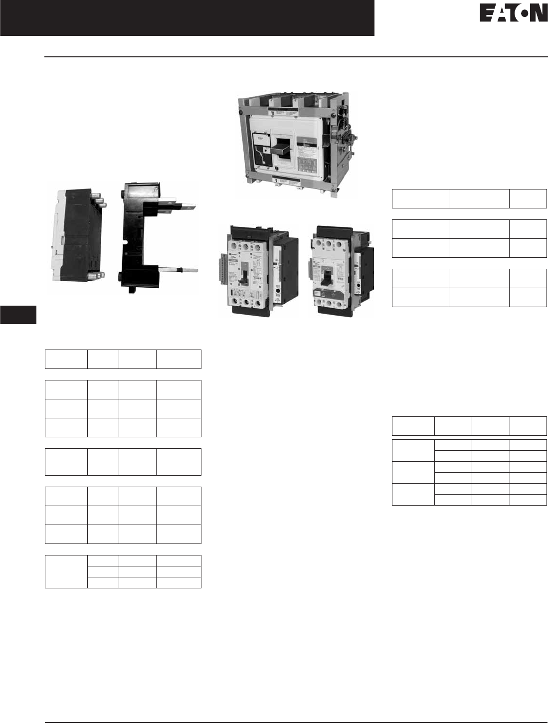
November 2008
12-66
For more information visit: www.eaton.com CA08101001E
Series G Molded Case Circuit Breakers
12
15 – 2500 Amperes for UL, CSA & IEC Applications
Plug-in Blocks and Drawout Cassettes
Plug-in Blocks
Plug-in adapters simplify installation
and front removal of circuit breakers.
Plug-ins are available for rear connec-
tion applications on 3- and 4-pole
circuit breakers. Trip on drawout
interlock kits are included. Stabs for
EG, JG and LG plug-ins rotate 90° for
flexible installation. Use terminal
shields for IP30 protection.
LG Breaker with Plug-in Block
Product Selection
Table 12-119. Plug-in Blocks
Included with plug-in block. Trips the breaker
when breaker is removed from plug-in block.
Drawout Cassette
Drawout Cassette
JG and LG Drawout Cassettes
The Drawout Cassette is available for
use with JG, LG and NG, 3- and 4-pole
breakers. Also available are drawout
cassettes for use with the standard
3-pole 65 and 100 kA/480 Vac, 1600
ampere and 2000 ampere RG circuit
breakers. The cassettes consist of two
separate components: the movable
mechanism, which attaches to the
breaker, and the stationary mechanism,
which houses in the cassette. The sta-
tionary mechanism is shipped sepa-
rately for the RG frame breakers. For
the JG, LG and NG drawout cassettes,
all necessary parts for installation are
included in the one catalog number.
Features of the drawout cassettes for
the JG, LG and NG include:
■Trip on drawout — Breaker will
trip if it is in the ON position when
withdrawn from the cassette.
■Secondary Terminal Block —
The drawout cassettes include a
secondary terminal block for easier
access when wiring low voltage
accessories, including shunts and
undervoltage releases.
Breaker
Frame
Poles Catalog
Number
Price
U.S. $
EG-, JG- and LG-Frame Plug-in Blocks
EG
EG
3
4
PAD3E
PAD4E
JG
JG
3
4
PAD3J
PAD4J
LG
LG
3
4
PAD3L
PAD4L
Trip-on Drawout Interlock Kit
EG
JG
LG
3, 4
3, 4
3, 4
PIILEG
PIILJG
PIILLG
Terminal Shields IP30
EG
EG
3
4
EFTS3K
EFTS4K
JG
JG
3
4
FJTS3K
FJTS4K
LG
LG
3
4
LTS3K
LTS4K
Position Switch
EG 3, 4 PADILE
JG 3, 4 PADILJ
LG 3, 4 PADILL
The drawout mechanism has three
primary positions:
■Connected — The breaker is fully
connected to the primary stabs and
secondary contacts.
■Disconnected — Both the primary
stabs and the secondary contacts
are disconnected.
■Withdraw — The breaker can be
removed from the cassette.
Table 12-120. RG Drawout Cassette
List price included in price of the stationary
mechanism.
Without shutters.
With shutters.
Movable mechanism must be ordered
with RG circuit breaker and is shipped
mounted to circuit breaker frame.
Stationary mechanism is ordered
separately.
Table 12-121. JG, LG and NG Drawout
Cassettes
Description Catalog
Number
Price
U.S. $
65 kA/480 Vac Version
Movable
Mechanism
RD20DOM
Stationary
Mechanism
RD20DOS
RD20DOSS
100 kA/480 Vac Version
Movable
Mechanism
RDC20DOM
Stationary
Mechanism
RDC20DOS
RDC20DOSS
Discount Symbol . . . . . . . . . . . . . . . . . . . . . . . . CB-2
Breaker
Frame
Poles Catalog
Number
Price
U.S. $
JG 3 JG3DOM
4JG4DOM
LG 3 LG3DOM
4LG4DOM
NG 3 NG3DOM
4NG4DOM
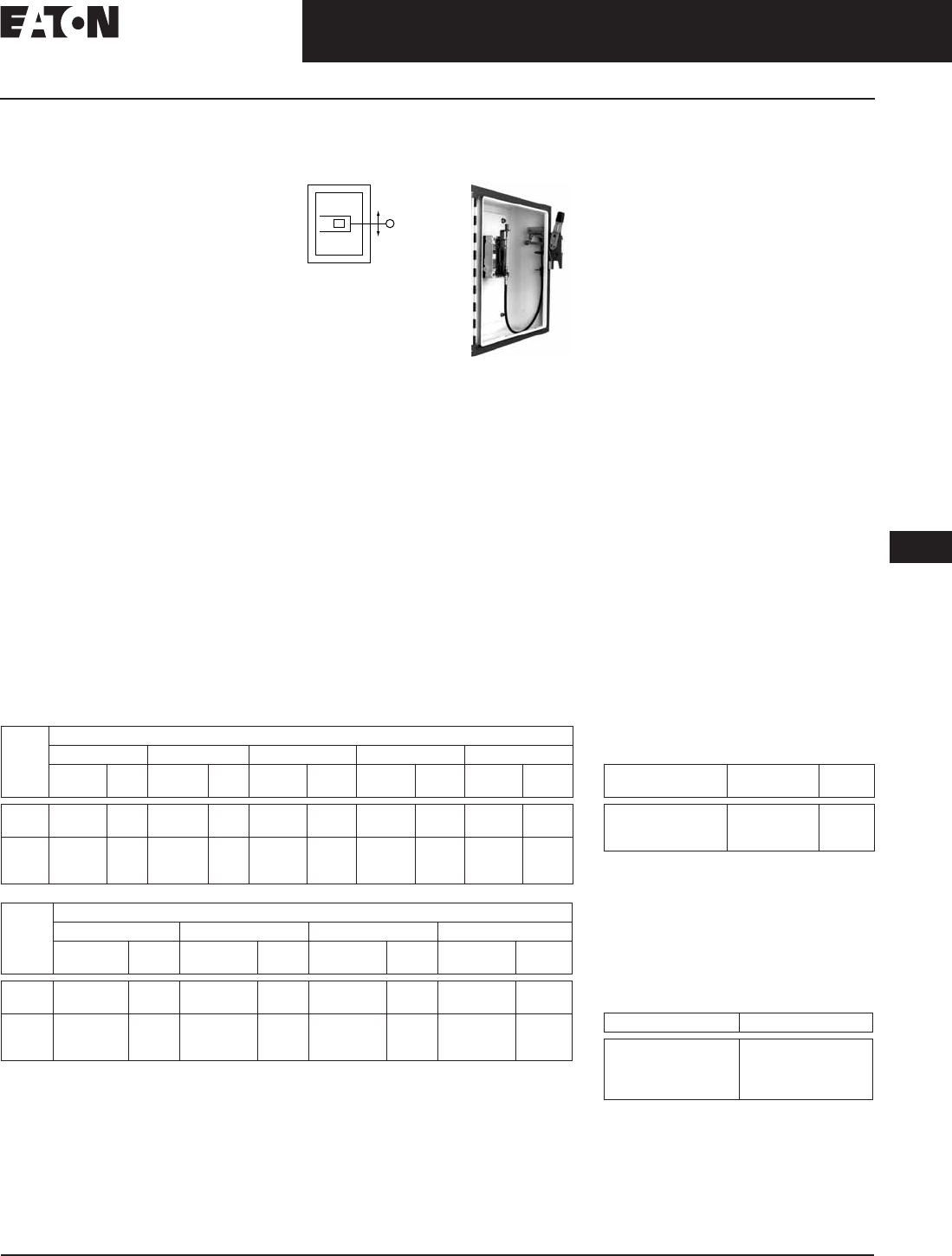
CA08101001E For more information visit: www.eaton.com
12-67
Series G Molded Case Circuit Breakers
November 2008
12
15 – 2500 Amperes for UL, CSA & IEC Applications
Handle Mechanisms
Handle Mechanisms
Overview
Handle mechanisms are used to
operate molded case circuit breakers,
molded case switches and motor
circuit protectors. They are available
in three basic configurations — Flange
Mounted, Through-the-Door and
Direct (Close-Coupled) — providing
safe, dependable operation and ease
of installation.
Flange Mounted
■Flex Shaft
Through-the-Door
■Universal Rotary
Direct (Close Coupled)
■Universal Direct
■Euro IEC
Handle mechanisms are typically used
on enclosed circuit breakers, control
panels and motor control centers
in many different applications. Eaton
Electrical has a handle mechanism
for virtually any need.
Flange Mounted Handle
Mechanisms
The Flex Shaft
Flange Mounted handle mechanisms
mount on the flange of an enclosure
door. The Flex Shaft is an extra
heavy-duty mechanism that includes
a flexible shaft in various lengths,
3 feet (0.9 m) through 10 feet (3 m)
for use with various size enclosures.
The Flex Shaft handle will accept up
to three padlock shackles, each with
a maximum diameter of 3/8 inch
(9.5 mm). Can be used with NEMA 12
fabricated enclosures. An optional
handle is available for Flex Shaft
that is suitable for use with NEMA 4
environments.
Flex Shaft Ordering Information
Table 12-122. Flex Shaft Ordering Information
Note: Add Suffix L to the complete Catalog Number for 6-inch (152.4 mm) handle.
Note: 3-Pole only for EG, 3 and 4 Pole for JG and LG.
Note: EG and LG can be left or right-hand mounted.
Breaker
Frame
Flexible Shaft Length in Feet (m)
2 (0.61) 3 (.9) 4 (1.2) 5 (1.3) 6 (1.8)
Catalog
Number
Price
U.S. $
Catalog
Number
Price
U.S. $
Catalog
Number
Price
U.S. $
Catalog
Number
Price
U.S. $
Catalog
Number
Price
U.S. $
EG
JG
EHMFS02
N/A
EHMFS03
JHMFS03
EHMFS04
JHMFS04
EHMFS05
JHMFS05
EHMFS06
JHMFS06
LG
NG
RG
N/A
N/A
N/A
—
N/A
N/A
LHMFS04
F5S04CI
F6S04
—
F5S05CI
F6S05
—
F5S06CI
F6S06
Breaker
Frame
Flexible Shaft Length in Feet (m)
7 (2.1) 8 (2.4) 9 (2.7) 10 (3.1)
Catalog
Number
Price
U.S. $
Catalog
Number
Price
U.S. $
Catalog
Number
Price
U.S. $
Catalog
Number
Price
U.S. $
EG
JG
EHMFS07
JHMFS07
EHMFS08
JHMFS08
EHMFS09
JHMFS09
EHMFS10
JHMFS10
LG
NG
RG
LHMFS07
N/A
N/A
—
N/A
N/A
—
N/A
N/A
LHMFS10
F5S10CI
N/A
Flex Shaft comes preset from the
factory, requiring only minor field
adjustments on installation, which
takes about 10 minutes — a significant
time savings compared to installation
of other types of flange handle mecha-
nisms. The Flex Shaft mechanism
also takes up less interior enclosure
space than competitive designs and
the handle fits standard flange cutouts.
Flex Shaft handle can be remotely
mounted from breaker, where an
operator can use it by “funneling”
the cable through conduit.
Flex Shaft is UL listed under File
E64893 and meets CSA requirements.
Note: NEMA 4X handle mechanisms are
available. Add Suffix X to the complete
Catalog Number.
Note: When selecting the length of
shaft, ensure minimum bending radius
of 4 inches (101.6 mm) is maintained to
operate properly.
The standard method of shipment
includes the mechanism preset at
the factory; however, minor field
adjustments may be required.
Flex Shaft Accessories
(E- through R-Frame)
Table 12-123. NEMA 12 Safety Door
Hardware for Flex Shaft
Customer: Consult with box manufacturer
for correct door hardware and any adapters
required for assembly.
The 1/4-inch x 1/2-inch (6.35 x 12.7 mm)
standard mill rectangular locking bar is not
supplied with these kits.
Third roller latch for use with 4- or 6-inch
(101.6 or 152.4 mm) handle when 3 point
latching is required.
Table 12-124. NEMA — IP Crossover
Handle Length
in Inches (mm)
Catalog
Number
Price
U.S. $
4.00 (101.6)
6.00 (152.4)
Roller Latch
C361KJ4
C361KJ6
C361KR
NEMA Type IP Type
1
3R
12
4/4X
IP20
IP55
IP54
IP66
Discount Symbol . . . . . . . . . . . . . . . . . . . . . . . . CB-2
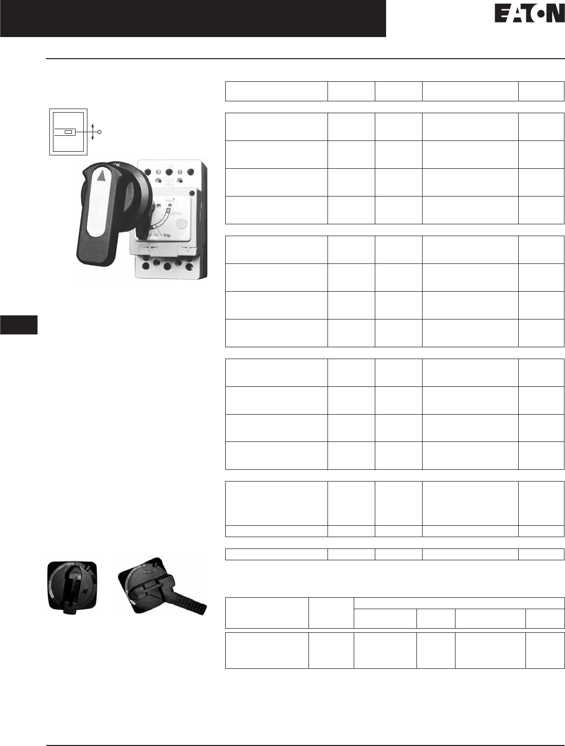
November 2008
12-68
For more information visit: www.eaton.com CA08101001E
Series G Molded Case Circuit Breakers
12
15 – 2500 Amperes for UL, CSA & IEC Applications
Handle Mechanisms
Through-the-Door Handle
Mechanisms
Universal Rotary
The Cutler-Hammer Universal Rotary
is suitable for use with NEMA 12
enclosure types. An optional NEMA
4/4X handle mechanism is also avail-
able. All rotary handle mechanisms
include a handle “Lock Off,” to prevent
turning the breaker ON while in the
OFF position. All Rotary handles indi-
cate ON/OFF/Tripped/Reset positions,
however, Universal Rotary has
the added feature of international
markings for ON (I) and OFF (O). The
Universal Rotary is made of molded
material. Inside handle is lockable.
The Universal Rotary mechanisms
for EG, JG and LG MCCBs can be
operated by hand with the door open
or “locked off” to prevent operation
with the door open.
For the NG-Frame MCCBs, a
Cutler-Hammer Rotary with a metal
handle (Table 12-126) is also available.
4/4X Handle Mechanism
EG-Frame JG & LG-Frames
(JG Shown)
Table 12-125. Universal Rotary Ordering Information
Complete catalog number includes handle, mechanism, shaft and mounting hardware.
Same as HMVD5B, except uses R-Frame T handle.
Table 12-126. Cutler-Hammer Rotary Ordering Information — NG-Frame
Complete catalog number includes handle, mechanism, shaft and mounting hardware.
Shaft Length
in Inches (mm)
Handle
Color
NEMA
Rating
Complete
Catalog Number
Price
U.S. $
EG-Frame
6.00 (152.4)
12.00 (304.8)
24.00 (609.6)
Black
Black
Black
1, 12
1, 12
1, 12
EHMVD06B
EHMVD12B
EHMVD24B
6.00 (152.4)
12.00 (304.8)
24.00 (609.6)
Red
Red
Red
1, 12
1, 12
1, 12
EHMVD06R
EHMVD12R
EHMVD24R
6.00 (152.4)
12.00 (304.8)
24.00 (609.6)
Black
Black
Black
4, 4X, 3R
4, 4X, 3R
4, 4X, 3R
EHMVD06BX
EHMVD12BX
EHMVD24BX
6.00 (152.4)
12.00 (304.8)
24.00 (609.6)
Red
Red
Red
4, 4X, 3R
4, 4X, 3R
4, 4X, 3R
EHMVD06RX
EHMVD12RX
EHMVD24RX
JG-Frame
6.00 (152.4)
12.00 (304.8)
24.00 (609.6)
Black
Black
Black
1, 12
1, 12
1, 12
FJHMVD06B
FJHMVD12B
FJHMVD24B
6.00 (152.4)
12.00 (304.8)
24.00 (609.6)
Red
Red
Red
1, 12
1, 12
1, 12
FJHMVD06R
FJHMVD12R
FJHMVD24R
6.00 (152.4)
12.00 (304.8)
24.00 (609.6)
Black
Black
Black
4, 4X, 3R
4, 4X, 3R
4, 4X, 3R
FJHMVD06BX
FJHMVD12BX
FJHMVD24BX
6.00 (152.4)
12.00 (304.8)
24.00 (609.6)
Red
Red
Red
4, 4X, 3R
4, 4X, 3R
4, 4X, 3R
FJHMVD06RX
FJHMVD12RX
FJHMVD24RX
LG-Frame
6.00 (152.4)
12.00 (304.8)
24.00 (609.6)
Black
Black
Black
1, 12
1, 12
1, 12
KLHMVD06B
KLHMVD12B
KLHMVD24B
6.00 (152.4)
12.00 (304.8)
24.00 (609.6)
Red
Red
Red
1, 12
1, 12
1, 12
KLHMVD06R
KLHMVD12R
KLHMVD24R
6.00 (152.4)
12.00 (304.8)
24.00 (609.6)
Black
Black
Black
4, 4X, 3R
4, 4X, 3R
4, 4X, 3R
KLHMVD06BX
KLHMVD12BX
KLHMVD24BX
6.00 (152.4)
12.00 (304.8)
24.00 (609.6)
Red
Red
Red
4, 4X, 3R
4, 4X, 3R
4, 4X, 3R
KLHMVD06RX
KLHMVD12RX
KLHMVD24RX
NG-Frame
6.00 (152.4)
6.00 (152.4)
6.00 (152.4)
12.00 (304.8)
16.00 (406.4)
Black
Black
Black
Black
Black
1
1
4, 4X, 3R
4, 4X, 3R
4, 4X, 3R
HMVD5B
HMVD5BT
WHM5R06X
WHM5R12X
WHM5R16X
24.00 (609.6) Black 4, 4X, 3R WHM5R24X
RG-Frame
9.00 (235.0) Black 1 HMVD6B
Shaft Length
in Inches (mm)
Handle
Color
Complete Catalog Number
NEMA
1, 3R, 12
Price
U.S. $
NEMA
4/4X
Price
U.S. $
6.00 (152.4)
12.00 (304.8)
16.00 (406.4)
24.00 (609.6)
Black
Black
Black
Black
WHM5R06
WHM5R12
WHM5R16
WHM5R24
WHM5R06X
WHM5R12X
WHM5R16X
WHM5R24X
Discount Symbol . . . . . . . . . . . . . . . . . . . . . . . . CB-2
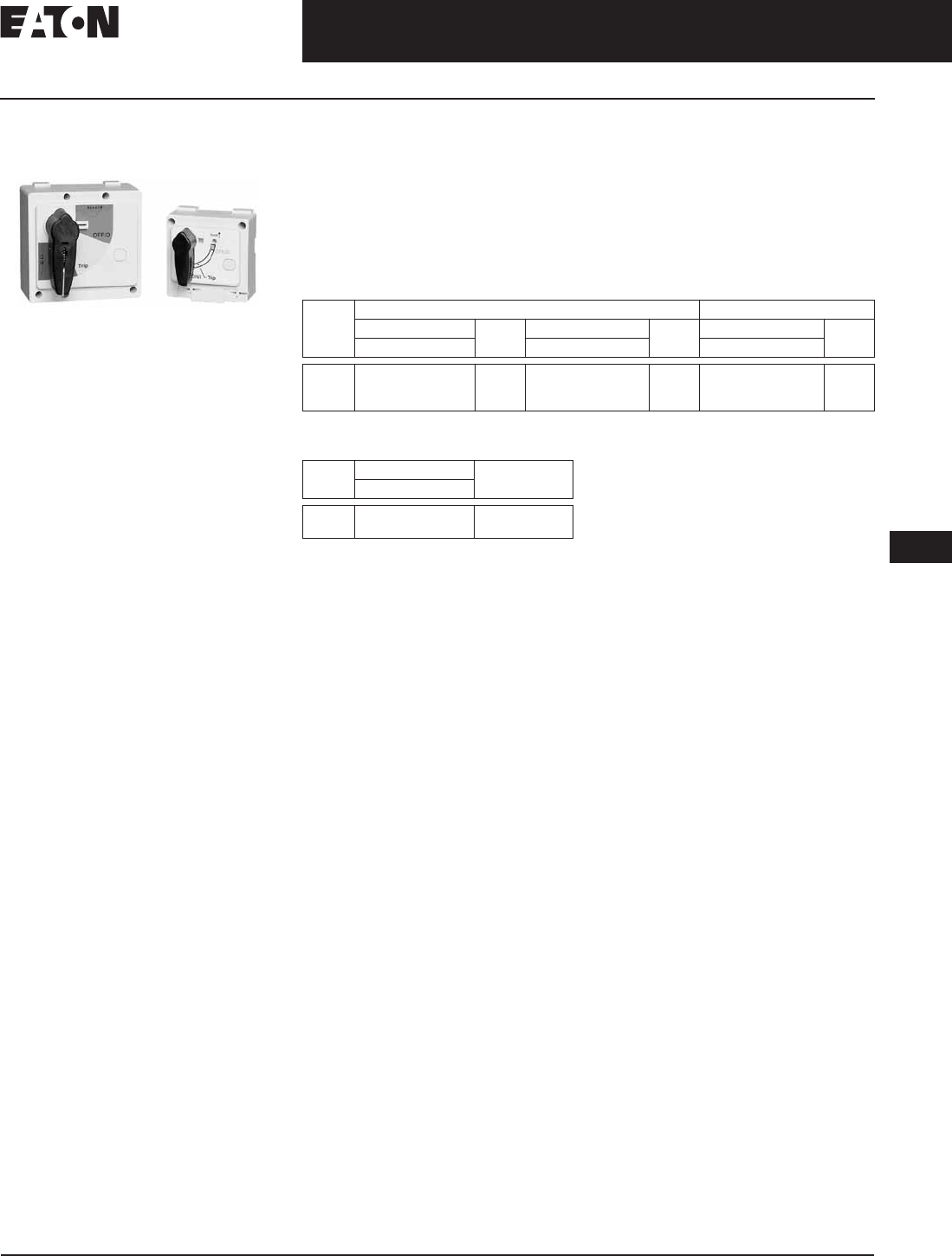
November 2008
CA08101001E For more information visit: www.eaton.com
12-69
Series G Molded Case Circuit Breakers
12
15 – 2500 Amperes for UL, CSA & IEC Applications
Handle Mechanisms
Direct (Close-Coupled)
Handle Mechanisms
Universal Direct (EG – LG)
Direct (Close-Coupled) Handle
Mechanisms mount directly to the
circuit breaker. They are used in shal-
low enclosures where the standard
variable depth Through-the-Door type
mechanism is not practical or cannot
be used. They are typically for applica-
tions where high volume, standardized
enclosures are being fabricated.
NEMA Ratings
Rated NEMA 1 and NEMA 12.
The Universal Direct handle mecha-
nism is designed exclusively for the
new Cutler-Hammer EG, JG and
LG circuit breakers. It is available
as standard with a door interlock to
prevent opening the enclosure while
the circuit breaker is in the ON
position. It is also available without
a door interlock.
The Universal Direct handle mecha-
nism is UL 489 listed, IEC 60947-1/2
and meets CSA requirements.
The Euro IEC Direct handle mechanism
is designed for NG and RG MCCBs.
The Euro IEC Direct handle mechanism
is 60947-112.
Table 12-127. Universal Direct Ordering Information
Table 12-128. Euro IEC Direct Ordering
Information
Frame Black Handle Color Red Handle Color
with Interlock Price
U.S. $
without Interlock Price
U.S. $
without Interlock Price
U.S. $
Catalog Number Catalog Number Catalog Number
EG
JG
LG
EHMCCBI
—
—
EHMCCB
JHMCCB
LHMCCB
EHMCCR
JHMCCR
LHMCCR
Frame Catalog Number Price
U.S. $
Black Handle
NG
RG
HMVD5B
HMVD6B
Discount Symbol . . . . . . . . . . . . . . . . . . . . . . . . . CB-2

November 2008
12-70
For more information visit: www.eaton.com CA08101001E
Series G Molded Case Circuit Breakers
12
15 – 2500 Amperes for UL, CSA & IEC Applications
Frame Sizes EG through JG
Dimensions
Figure 12-10. EG-Frame — Dimensions in Inches (mm)
Figure 12-11. JG-Frame — Dimensions in Inches (mm)
Fr
o
n
t
Vi
e
w
3
-P
o
l
e
Fr
o
n
t
Co
v
e
r
Cutout
S
i
de
Vi
ew
2.77
(
70.4
)
3
.
03
(
77.0
)
5
.
50
(
139.7
)
0.14
(
3.6
)
R
1.
85
(
47.0
)
1.
30
Di
a.
(
33.0
)
0.94
(
23.9
)
0
.
90
(
22.9
)
0.47
(
11.9
)
C
L
C
C
3
.
00
(
76.2
)
H
a
n
d
l
e
C
L
C
C
Br
ea
k
er
Fr
o
n
t
Vi
e
w
3
-P
o
l
e
Fr
o
n
t
Co
v
e
r
Cutout
S
i
de
Vi
ew
4.1
3
(
104.9
)
1.25
(
31.8
)
0.63
(
16.0
)
0.19
(
4.8
)
R
3
.4
4
(
87.4
)
7.
00
(
177.8
)
3
.
95
(
100.3
)
4.
00
(
101.6
)
3.06
(77.7) 2.05
(
52.1
)
1.06
(
27.0
)
0
.
50
(
12.7
)
C
L
CC
H
a
n
d
l
e
0.28 (7.1)
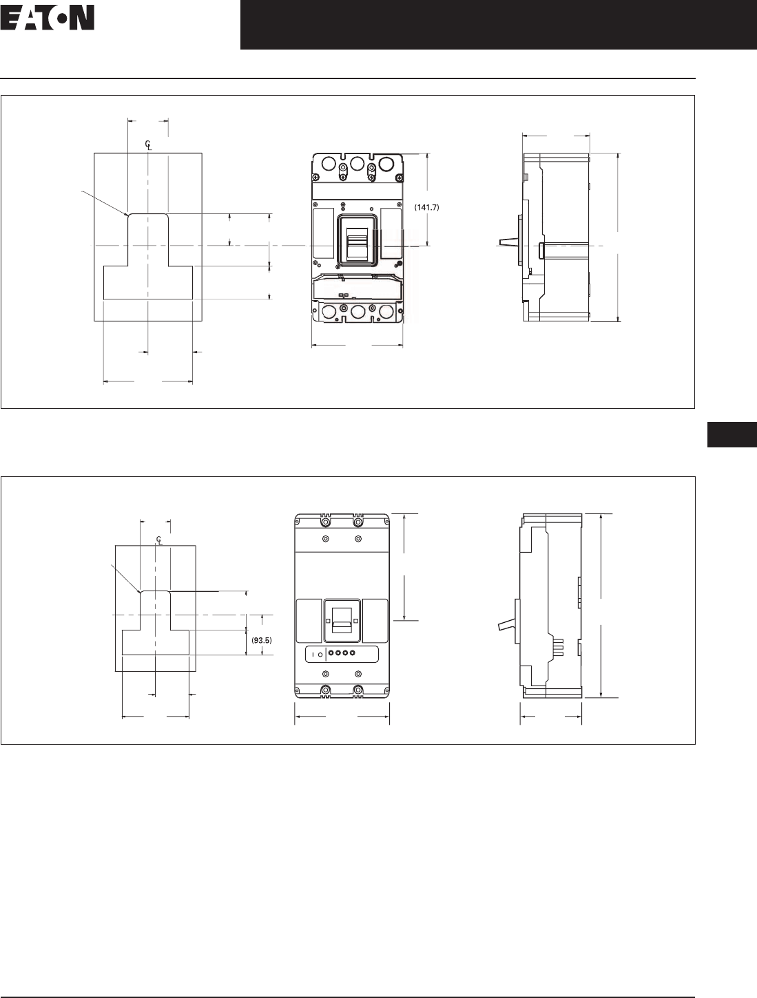
November 2008
CA08101001E For more information visit: www.eaton.com
12-71
Series G Molded Case Circuit Breakers
12
15 – 2500 Amperes for UL, CSA & IEC Applications
Frame Sizes LG through NG
Figure 12-12. LG-Frame — Dimensions in Inches (mm)
Note: TA63IL, T63IL, T632L, TA632L terminals add 1.19 inches (30.2 mm) to line or load side of LG. LTS3K or LTS4K terminal covers add
2.13 inches (54.1 mm) to line or load side of LG.
Figure 12-13. NG-Frame — Dimensions in Inches (mm)
5
.
58
1
0
.1
3
(
257.3
)
4.
06
(
103.1
)
5
.4
8
(
139.2
)
1.
92
(
48.8
)
2.4
3
(
61.7
)
3
.1
6
(
80.3
)
R .2
5
(
6.4
)
2.
00
(
50.8
)
2.
69
(
68.3
)
5
.
38
(
136.7
)
BREAKER
4-P
o
l
e
9
.2
5
(
235.0
)
Fr
o
n
t
Vi
e
w
3
-P
o
l
e
Fr
o
n
t
Co
v
e
r
Cutout
1
6
.
00
(
406.4
)
3
.4
4
(
87.4
)
S
i
de
Vi
e
w
5
.
50
(
139.7
)
8
.2
5
(
209.6
)
1.
91
(48.5)
1.
50
(
38.1
)
6.38
(162.1)
3.19
(81.0)
BREAKER
R .25
(6.4)
3
.
68

November 2008
12-72
For more information visit: www.eaton.com CA08101001E
Series C Molded Case Circuit Breakers
12
15 – 2500 Amperes for UL, CSA & IEC Applications
Frame Size RG
Figure 12-14. RG-Frame — Dimensions in Inches (mm)
14.50
(368.3)
7.25
(184.2)
(129.5)
(196.9)
0.16 R
(4.1)
Front View 3-Pole
Front Cover Cutout
C
L
Breaker
16.00
(406.4)
8.25
(209.6)
15.50
(393.7)
13.13
(333.5)
6.57
(166.9)
(246.4)
15.00
(381.0)
4 Holes
0.44 Dia.
(11.2)
C
L
Handle
13.00
(330.2)
2.25 (57.2)
Tee
Connectors
May Be
Rotated 90
6.75
(171.5)
9.00
(228.6)
Side View
.44 R
(11.2)
5.10
9.70
7.75
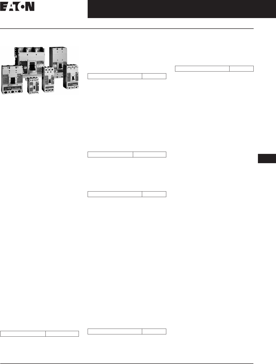
November 2008
CA08101001E For more information visit: www.eaton.com
12-73
Series C Molded Case Circuit Breakers
12
15 – 2500 Amperes for UL, CSA & IEC Applications
Product Line Overview
Product Line Description
Molded Case Circuit Breaker Product Family
Cutler-Hammer Molded Case Circuit
Breakers by Eaton Corporation are
designed to provide circuit protection
for low voltage distribution systems.
They are described by NEMA as, “. . .
a device for closing and interrupting
a circuit between separable contacts
under both normal and abnormal con-
ditions,” and furthermore as, “. . . a
breaker assembled as an integral unit
in a supporting and enclosing housing
of insulating material.” The National
Electrical Code (NEC) describes
them as, “A device designed to open
and close a circuit by non-automatic
means, and to open the circuit auto-
matically on a predetermined overload
of current, without injury to itself when
properly applied within its rating.”
So designed, Cutler-Hammer circuit
breakers protect conductors against
overloads and conductors and con-
nected apparatus, such as motors and
motor starters, against short circuits.
In low voltage distribution systems,
there are many varied applications
of molded case circuit breakers. Eaton
offers the most comprehensive family
of molded case circuit breakers in
the industry.
This section of circuit breakers includes:
■Thermal-Magnetic Trip Breakers.
■Electronic rms Trip Breakers.
■Molded Case Switches.
■Motor Circuit Protectors.
■Current Limiting Breakers.
■Special Application Breakers.
Modified Breakers
Cutler-Hammer breakers can be ordered
with internal accessories installed.
These modified breakers will be subject
to an addition charge.
Special Calibration
Special non-UL-listed calibrations
are available for certain ambient
temperatures other than 40°C and for
frequencies other than 50/60 Hz or dc.
Reduced interrupting ratings will apply
for 400 Hz applications.
50°C Calibration
Add suffix V to Catalog Number for
complete breaker, listed above, when
ordering listed ampere ratings for
breakers to be used in 50°C ambients.
(No price adder.) (No UL label.)
Moisture-Fungus Treatment
All circuit breaker cases are molded
from glass-polyester which does not
support the growth of fungus. Any parts
which are susceptible to the growth of
fungus will require special treatment.
Freeze-Tested Circuit Breakers
The circuit breakers may be ordered
with freeze testing. This option uses
special lubrication and mechanical
operation is verified at -40°C.
Marine Applications
F- to R-Framed circuit breakers can be
supplied to meet the following marine
specifications:
■U.S. Coast Guard CFR 46 ABS —
American Bureau of Shipping
IEEE 45.
These specifications generally require
molded case circuit breakers to be
supplied with special nameplating, and
plug-in adapter kits. When plug-in
adapter kits are used, no terminals need
be supplied.
Circuit breakers can also be supplied
to meet UL 489 Supplement SA
(Marine Use) and UL 489 Supplement
SB (Naval Use).
UL 489 Supplement SA applies to
vessels over 65 feet (19.8 m) in length.
Requirements include 40°C ambient
calibration, special labeling, and no use
of aluminum conductors or terminals.
(No 50ºC available.)
UL 489 Supplement SB requires 50°C
ambient calibration, vibration testing,
special nameplating and no use of
aluminum conductors or terminals.
(“Naval” labeled per UL but no “UL”
mark due to 50°C label.)
Standards and Certifications
Molded case circuit breakers are
designed to conform with the follow-
ing standards:
■Underwriters Laboratories Inc.,
Standard UL 489, Molded Case
Circuit Breakers and Circuit Breaker
Enclosures.
■National Electrical Manufacturers
Association (NEMA) Standards
Publication No. AB1-1993, Molded
Case Circuit Breakers.
■Australian Standard AS 2184,
Molded Case Circuit Breakers.
■British Standards Institution Standard
BS 4752: Part 1, Switchgear and
Control Gear Part 1: Circuit Breakers.
■Canadian Standards Association
(CSA) Standard C22.2 No. 5, Service
Entrance and Branch Circuit Breakers.
■International Electrotechnical
Commission Recommendations
IEC 60947-2, Circuit Breakers.
■Japanese T-Mark Standard Molded
Case Circuit Breakers.
■South African Bureau of Standards,
Standard SABS 156, Standard
Specification for Molded Case
Circuit Breakers.
■Swiss Electro-Technical Association
Standard SEV 157-1, Safety Regula-
tions for Circuit Breakers.
■Union Technique de l’Electricite
Standard NF C 63-120, Low Voltage
Switchgear and Control Gear Circuit
Breaker Requirements.
■Verband Deutscher Elektrotechniker
(Association of German Electrical
Engineers) Standard VDE 0660, Low
Voltage Switchgear and Control
Gear, Circuit Breakers.
Conformance with these standards
satisfies most local and international
codes, assuming user acceptability
and simplified application.
Molded case circuit breakers equal or
exceed Federal Specification Classifi-
cation W-C-375b requirements for the
particular class associated with the
circuit breaker frame being considered.
Open breakers do not have service
entrance ratings. Service entrance
rating is part of the enclosure.
Modified Breakers $75 List Adder
Suffix H01 400 Hz 20% Adder
Suffix J01 Fungus Treated $375 + 20% Adder
Suffix F01 Freeze Tested 20% Adder
Suffix H08 “Marine” 10% Adder
Suffix H09 “Naval” 10% Adder

November 2008
12-74
For more information visit: www.eaton.com CA08101001E
Series C Molded Case Circuit Breakers
12
15 – 2500 Amperes for UL, CSA & IEC Applications
Product Line Overview
Quick Reference
Table 12-129. Industrial Circuit Breakers
N.I.T.U. is non-interchangeable trip unit and I.T.U. is interchangeable trip unit.
2-pole circuit breaker, or two poles of 3-pole circuit breaker at 250 Vdc.
Not defined in W-C-375b.
Current limiting.
Check with Eaton for availability.
Circuit
Breaker
Type
Continuous
Ampere
Rating
at 40°C
No.
Poles
Volts Type
of
Trip
Federal
Specification
W-C-375b
UL Listed Interrupting Ratings (rms Symmetrical
Amperes)
Page
Number
ac dc ac (kV) dc (kV)
120 120/240 240 277 480 600 125 250
G-Frame
GHB
GHB
GHB
GHB
HGHB
GHQ
15 – 100
15 – 100
15 – 100
15 – 100
15 – 30
15 – 20
1
2, 3
1
2, 3
1
1
120
240
277
480Y/277
277
277
125
125/250
125
125/250
125
—
N.I.T.U. 11a
10b, 11b,
12b, 14b,
15b
12c, 13a, 13b
65
—
—
—
65
65
—
—
—
—
—
—
—
65
—
—
—
—
—
—
14
14
25
14
—
—
—
14
—
—
—
—
—
—
—
—
14
—
14
—
14
—
—
14
—
14
—
—
12-80
12-80
12-80
12-80
12-80
12-80
GHBS
GBHS
15 – 30
15 – 20
1, 2
1, 2
480Y/277
600Y/347
—
—
—
N.I.T.U.
—
—
65
—
65
—
—
—
14
—
—
—
—
10
—
—
—
—
11-19
11-19
GD
GD
15 – 50
15 – 100
2
3
480
480
125/250
250
N.I.T.U. 13b
13b
—
—
—
—
65
65
—
—
14
22
—
—
—
—
10
10
12-79
12-79
GHC
GHC
GHC
GHC
HGHC
15 – 100
15 – 100
15 – 100
15 – 100
15 – 30
1
2, 3
1
2, 3
1
120
240
277
480Y/277
277
125
125/250
125
125/250
125
N.I.T.U. 12c, 13a
13b
12c, 13a
13b
65
—
—
—
65
—
—
—
—
—
—
65
—
—
—
—
—
14
14
25
—
—
—
14
—
—
—
—
—
—
14
—
14
—
14
—
14
—
14
—
12-82
12-82
12-82
12-82
12-82
F-Frame
EDB
EDS
100 – 225
100 – 225
2, 3
2, 3
240
240
125
125
N.I.T.U. —
—
—
—
—
—
22
42
—
—
—
—
—
—
10
10
—
—
12-85
12-85
ED
EDH
EDC
15 – 225
100 – 225
100 – 225
2, 3
2, 3
2, 3
240
240
240
125
125
125
N.I.T.U. 12b
14b
1
—
—
—
—
—
—
65
100
200
—
—
—
—
—
—
—
—
—
10
10
10
—
—
—
12-85
12-85
12-85
EHD
EHD
15 – 100
15 – 100
1
2, 3
277
480
125
250
N.I.T.U. 13a
13b
—
—
—
—
—
18
14
—
—
14
—
—
10
—
—
10
12-85
12-85
FDB
FDB
15 – 150
15 – 150
2, 3
4
600
600
250
250
N.I.T.U. 18a
—
—
—
—
18
18
—
—
14
14
14
14
—
—
10
10
12-85
12-85
FD
FD
FD
FDE
15 – 150
15 – 225
15 – 225
15 – 225
1
2, 3
4
3
277
600
600
600
125
250
250
—
N.I.T.U.
N.I.T.
13a
22a
—
—
—
—
—
—
—
—
—
—
65
65
65
35
—
—
—
—
35
35
35
—
18
18
18
10
—
—
—
—
10
10
—
12-85
12-85
12-85
12-85
HFD
HFD
HFD
HFDE
15 – 150
15 – 225
15 – 225
15 – 225
1
2,3
4
3
277
600
600
600
125
250
250
—
N.I.T.U.
N.I.T.
13a
22a
—
—
—
—
—
—
—
—
—
—
100
100
100
65
—
—
—
65
65
65
—
25
25
25
10
—
—
—
—
22
22
—
12-85
12-85
12-85
12-85
FDC
FDC
FDCE
15 – 225
15 – 225
15 – 225
2, 3
4
3
600
600
600
250
250
—
N.I.T.U.
N.I.T.
24a
—
—
—
—
—
—
—
200
200
200
—
—
—
100
100
100
35
35
25
—
—
—
22
22
—
12-85
12-85
12-85

November 2008
CA08101001E For more information visit: www.eaton.com
12-75
Series C Molded Case Circuit Breakers
12
15 – 2500 Amperes for UL, CSA & IEC Applications
Product Line Overview
Table 12-129. Industrial Circuit Breakers (Continued)
N.I.T.U. is non-interchangeable trip unit and I.T.U. is interchangeable trip unit.
2-pole circuit breaker, or two poles of 3-pole circuit breaker at 250 Vdc.
Current limiting.
Circuit
Breaker
Type
Continuous
Ampere
Rating
at 40°C
No.
Poles
Volts Type
of
Trip
Federal
Specification
W-C-375b
UL Listed Interrupting Ratings (rms Symmetrical
Amperes)
Page
Number
ac dc ac (kV) dc (kV)
120 120/240 240 277 480 600 125 250
J-Frame
JDB
JD
HJD
JDC
70 – 250
70 – 250
70 – 250
70 – 250
2, 3
2, 3, 4
2, 3, 4
2, 3, 4
600
600
600
600
250
250
250
250
N.I.T.U.
I.T.U.
I.T.U.
I.T.U.
22a
22a
22a
22a
—
—
—
—
—
—
—
—
65
65
100
200
—
—
—
—
35
35
65
100
18
18
25
35
—
—
—
—
10
10
22
22
12-96
12-95
12-95
12-95
K-Frame
DK
KDB
KD
CKD
HKD
CHKD
KDC
250 – 400
100 – 400
100 – 400
100 – 400
100 – 400
100 – 400
100 – 400
2, 3
2, 3
2, 3, 4
2, 3, 4
2, 3, 4
2, 3, 4
2, 3, 4
240
600
600
600
600
600
600
250
250
250
250
250
250
250
N.I.T.U.
N.I.T.U.
I.T.U.
I.T.U.
I.T.U.
I.T.U.
I.T.U.
14b
23a
23a
23a
23a
23a
23a
—
—
—
—
—
—
—
—
—
—
—
—
—
—
65
65
65
65
100
100
200
—
—
—
—
—
—
—
—
35
35
35
65
65
100
—
25
25
25
35
35
65
—
—
—
—
—
—
—
10
10
10
—
22
—
22
12-107
12-107
12-103, 12-104,
12-109, 12-110
12-108, 12-111,
12-112
12-103, 12-104,
12-109, 12-110
12-108, 12-111,
12-112
12-103, 12-104,
12-109, 12-110
L-Frame
LDB
LD
CLD
HLD
CHLD
LDC
CLDC
300 – 600
300 – 600
300 – 600
300 – 600
300 – 600
300 – 600
300 – 600
2, 3
2, 3, 4
2, 3, 4
2, 3, 4
2, 3, 4
2, 3, 4
2, 3, 4
600
600
600
600
600
600
600
250
250
250
250
250
250
250
N.I.T.U.
I.T.U.
I.T.U.
I.T.U.
I.T.U.
I.T.U.
I.T.U.
23a
23a
23a
23a
23a
23a
23a
—
—
—
—
—
—
—
—
—
—
—
—
—
—
65
65
65
100
100
200
200
—
—
—
—
—
—
—
35
35
35
65
65
100
100
25
25
25
35
35
50
50
—
—
—
—
—
—
—
22
22
—
25
—
30
30
12-123
12-119, 12-120,
12-126
12-122, 12-130
12-119, 12-120,
12-126
12-122, 12-130
12-119, 12-120,
12-127
12-122, 12-131
M-Frame
MDL
CMDL
HMDL
CHMDL
300 – 800
300 – 800
300 – 800
300 – 800
2, 3
2, 3
2, 3
2, 3
600
600
600
600
250
250
250
250
I.T.U.
I.T.U.
I.T.U.
I.T.U.
23a
23a
23a
23a
—
—
—
—
—
—
—
—
65
65
100
100
—
—
—
—
50
50
65
65
25
25
35
35
—
—
—
—
22
—
25
—
12-137, 12-138
12-139
12-137, 12-138
12-139
N-Frame
ND
CND
HND
CHND
NDC
CNDC
NDU
600 – 1200
600 – 1200
600 – 1200
600 – 1200
600 – 1200
600 – 1200
600 – 1200
3, 4
3, 4
3, 4
3, 4
3, 4
3, 4
3
600
600
600
600
600
600
600
—
—
—
—
—
—
—
N.I.T.U.
N.I.T.U.
N.I.T.U.
N.I.T.U.
N.I.T.U.
N.I.T.U.
N.I.T.
23A
23A
23A
23A
23A
23A
—
—
—
—
—
—
—
—
—
—
—
—
—
—
—
65
65
100
100
200
200
300
—
—
—
—
—
—
—
50
50
65
65
100
100
150
25
25
35
35
65
65
75
—
—
—
—
—
—
—
—
—
—
—
—
—
—
12-145, 12-158
12-152, 12-160
12-147, 12-158
12-154, 12-160
12-149, 12-158
12-156, 12-160
—

November 2008
12-76
For more information visit: www.eaton.com CA08101001E
Series C Molded Case Circuit Breakers
12
15 – 2500 Amperes for UL, CSA & IEC Applications
Product Line Overview
Table 12-129. Industrial Circuit Breakers (Continued)
N.I.T.U. is non-interchangeable trip unit and I.T.U. is interchangeable trip unit.
2-pole circuit breaker, or two poles of 3-pole circuit breaker at 250 Vdc.
Circuit
Breaker
Type
Continuous
Ampere
Rating
at 40°C
No.
Poles
Volts Type
of
Trip
Federal
Specification
W-C-375b
UL Listed Interrupting Ratings (rms Symmetrical Amperes) Page
Number
ac dc ac (kV) dc (kV)
120 120/240 240 277 480 600 125 250
R-Frame
RD 1600
CRD 1600
RD 2000
RD 2500
CRD 2000
RDC 1600
CRDC 1600
RDC 2000
RDC 2500
CRDC 2000
800 – 1600
800 – 1600
1000 – 2000
1000 – 2500
1000 – 2000
800 – 1600
800 – 1600
1000 – 2000
1000 – 2500
1000 – 2000
3, 4
3, 4
3, 4
3, 4
3, 4
3, 4
3, 4
3, 4
3, 4
3, 4
600
600
600
600
600
600
600
600
600
600
—
—
—
—
—
—
—
—
—
—
N.I.T.U.
N.I.T.U.
N.I.T.U.
N.I.T.U.
N.I.T.U.
N.I.T.U.
N.I.T.U.
N.I.T.U.
N.I.T.U.
N.I.T.U.
24a
24a
24a
24a
24a
25a
25a
25a
25a
25a
—
—
—
—
—
—
—
—
—
—
—
—
—
—
—
—
—
—
—
—
125
125
125
125
125
200
200
200
200
200
—
—
—
—
—
—
—
—
—
—
65
65
65
65
65
100
100
100
100
100
50
50
50
50
50
65
65
65
65
65
—
—
—
—
—
—
—
—
—
—
—
—
—
—
—
—
—
—
—
—
12-167
12-170
12-167
12-167
12-170
12-169
12-170
12-169
12-169
12-170

November 2008
CA08101001E For more information visit: www.eaton.com
12-77
Series C Molded Case Circuit Breakers
12
15 – 100 Amperes
G-Frame
Product Description
■All two- and three-pole circuit break-
ers are of the common trip type. On
all 3-phase Delta (240 V) Grounded B
phase applications, refer to Eaton.
■Single-pole circuit breakers,
15 and 20 amperes. Switching duty
rated (SWD) for fluorescent lighting
applications.
■All G-Frame circuit breakers are
suitable for reverse feed use.
■HACR rated.
Technical Data and Specifications
Interrupting Capacity Ratings
Table 12-130. UL 489 Interrupting Capacity Ratings
Time constant is 8 milliseconds minimum.
Two poles of 3-pole circuit breaker.
Table 12-130. UL 489 Interrupting Capacity Ratings (Continued)
15 through 70 A breakers only.
Terminal Types
For line and load-side. Terminals are UL listed as suitable for wire type and size
given below.
Table 12-131. Terminal Types
Not UL listed sizes.
Circuit
Breaker
Type
Number
of Poles
Interrupting Capacity (kA Symmetrical Amperes)
Volts ac (50/60 Hz)
120 240 277 480 250
GD 2
3
—
—
65
65
—
—
14
22
10
10
Circuit
Breaker
Type
Number
of Poles
Interrupting Capacity (kA Symmetrical Amperes)
Volts ac (50/60 Hz) Volts dc
120 240 277 480Y/277 125
GHQ — 65 — 14 — —
GHB 1
2, 3
65
—
—
65
14
—
—
14
14
14
HGHB 1 65 — 25 — 14
GHC 1
2, 3
65
—
—
65
14
—
—
14
14
14
HGHC 1 65 — 25 — 14
Circuit
Breaker
Amperes
Terminal Type Material Screw
Head Type
Wire
Type
AWG Wire
Range
Metric Wire
Range (mm2)
Standard
15 – 20
25 – 100
Clamp (Plated Steel)
Pressure (Aluminum Body)
Slotted
Slotted
Cu/Al
Cu/Al
14 – 10
10 – 1/0
2.5 – 4
4 – 50
Optional — GD Only
15 – 100 Pressure (Steel Body) Slotted Cu 14 – 3 —
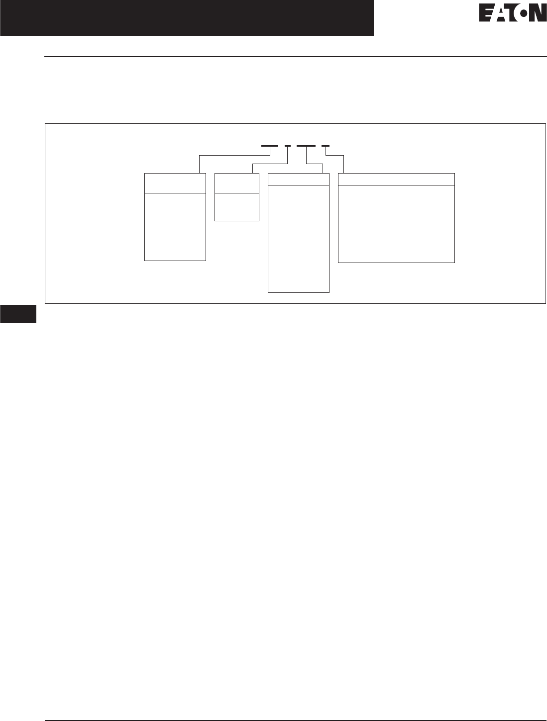
November 2008
12-78
For more information visit: www.eaton.com CA08101001E
Series C Molded Case Circuit Breakers
12
15 – 100 Amperes
G-Frame
Product Selection
This information is presented only as an aid to understanding Catalog Numbers.
It is not to be used to build Catalog Numbers for circuit breakers or trip units.
Table 12-132. Circuit Breaker/Frame Catalog Numbering System
HID suffix only applies to the GHB and GHC 1 pole, 15 – 20 ampere circuit breakers.
GD 3 100 K
Circuit Breaker
Type
GD
GHB
GHC
GHQ
HGHB
HGHC
GHBGFEP
GHCGFEP
Number
of Poles
1 = 1 Pole
2 = 2 Poles
3 = 3 Poles
Trip Amperes
015
020
024
030
035
040
045
050
060
070
080
090
100
Suffix
K= Molded Case Switch
D= Ring Type Terminals
C= Steel Collars
V= 50°C
J01 = Fungus Proofed
R01 = Shock Tested
F01 = Freeze Tester
HID = High Intensity Discharge
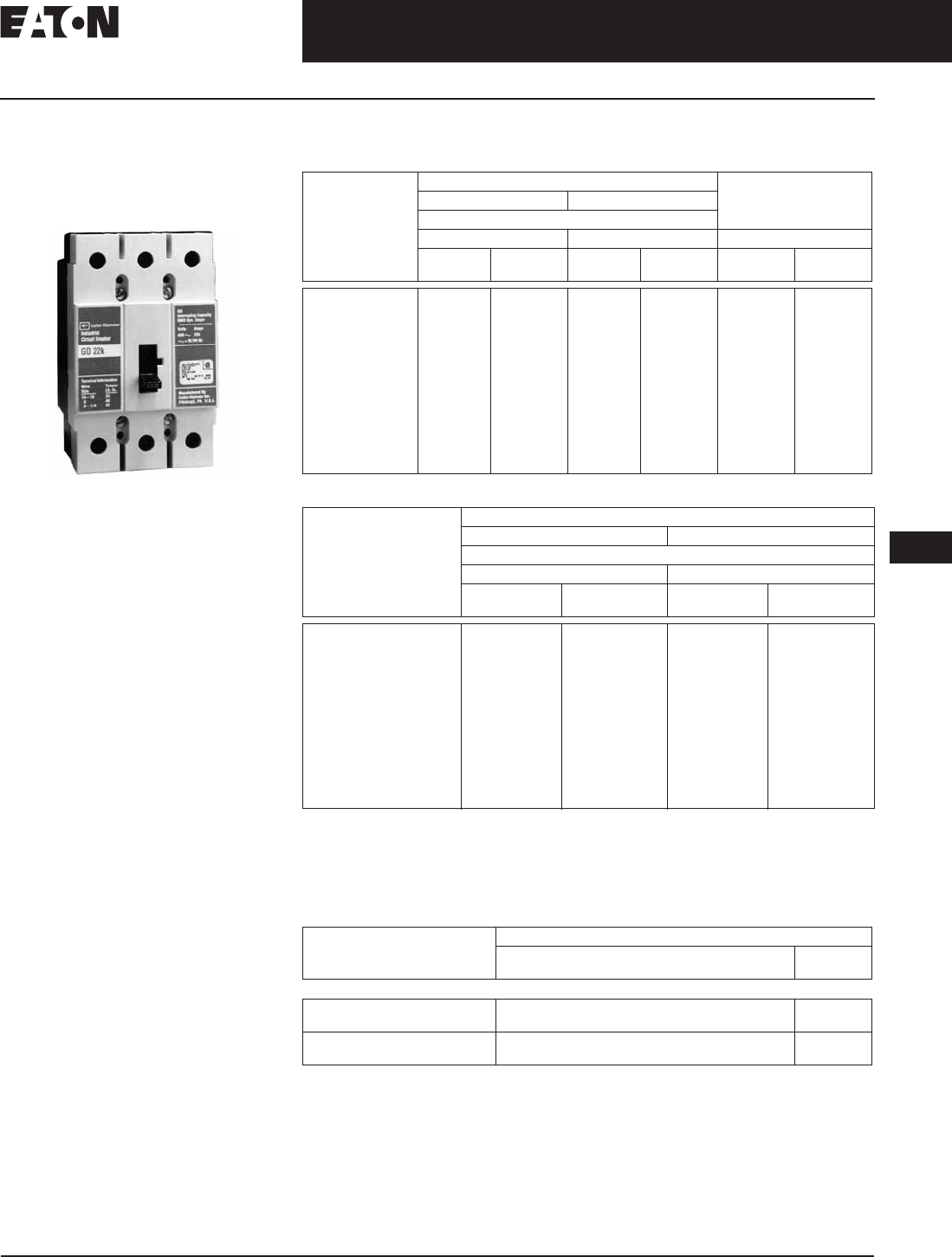
November 2008
CA08101001E For more information visit: www.eaton.com
12-79
Series C Molded Case Circuit Breakers
12
15 – 100 Amperes
G-Frame
Type GD Thermal-Magnetic
Circuit Breakers with
Non-Interchangeable
Trip Units
Typical G-Frame Circuit Breaker
Standards and Certifications
■UL/CSA.
Product Description
■Cable in, cable out.
■Includes mounting hardware and
BMHE.
Product Selection
Table 12-133. Type GD Thermal-Magnetic Circuit Breakers with Non-Interchangeable Trip Units
Table 12-134. Type GDB Thermal-Magnetic Circuit Breakers with Non-Interchangeable Trip Units
Type GD Molded Case Switches
Product Selection
Table 12-135. Type GD Molded Case Switches
Includes line and load steel terminals.
Note: Molded Case Switches may open above 1300 amperes.
Maximum
Continuous
Ampere Rating
at 40°C
480 Vac Maximum, 250 Vdc Includes Binding
Head Screws and Clamps
10 – 32 x .312
14 kAIC at 480 Vac 22 kAIC at 480 Vac
Includes Line and Load Terminals
2-Pole 3-Pole 3-Pole
Catalog
Number
Price
U.S. $
Catalog
Number
Price
U.S. $
Catalog
Number
Price
U.S. $
15
20
25
30
35
40
45
50
60
70
80
90
100
GD2015
GD2020
GD2025
GD2030
GD2035
GD2040
GD2045
GD2050
—
—
—
—
—
GD3015
GD3020
GD3025
GD3030
GD3035
GD3040
GD3045
GD3050
GD3060
GD3070
GD3080
GD3090
GD3100
GD3015D
GD3020D
GD3025D
GD3030D
GD3035D
GD3040D
GD3045D
GD3050D
GD3060D
GD3070D
GD3080D
GD3090D
GD3100D
Maximum
Continuous
Ampere Rating
at 40°C
480 Vac Maximum, 250 Vdc
14 kAIC at 480 Vac 22 kAIC at 480 Vac
Includes Line and Load Terminals
2-Pole 3-Pole
Catalog
Number
Price
U.S. $
Catalog
Number
Price
U.S. $
15
20
25
30
35
40
45
50
60
70
80
90
100
GDB2015
GDB2020
GDB2025
GDB2030
GDB2035
GDB2040
GDB2045
GDB2050
—
—
—
—
—
GDB3015
GDB3020
GDB3025
GDB3030
GDB3035
GDB3040
GDB3045
GDB3050
GDB3060
GDB3070
GDB3080
GDB3090
GDB3100
Maximum Continuous
Ampere Rating at 40°C
480 Vac Maximum, 250 Vdc
Catalog Number
(Includes Line and Load Terminals)
Price
U.S. $
3-Pole
60
100
GD3060K
GD3100K
60
100
GD3060KC
GD3100K
Discount Symbol . . . . . . . . . . . . . . . . . . . . . . . . . CB-2
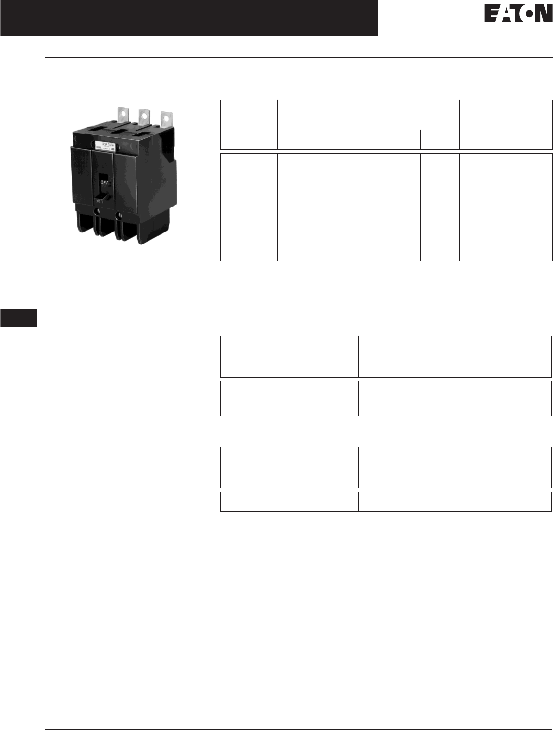
November 2008
12-80
For more information visit: www.eaton.com CA08101001E
Series C Molded Case Circuit Breakers
12
15 – 100 Amperes
G-Frame
Types GHB and HGHB Bolt-On
Panelboard Circuit Breakers
Typical GHB
Standards and Certifications
These breakers meet the requirements
of Federal Specification W-C-375b as
follows:
■Type GHB, 120 and 240 V:
❑1 Pole: Class 11a
❑2, 3 Poles: Classes 10b, 11b, 12b,
14b, 15b
❑UL/CSA
■Type GHB, 277 and 480Y/277 V:
❑1 Pole: Classes 12c, 13a
❑2, 3 Poles: Class 13b
❑Type HGHB 277 V
❑Type GHQ 277 V
Product Selection
Table 12-136. Type GHB Thermal-Magnetic Circuit Breakers with Non-Interchangeable Trip Units
480Y/277 V, circuit breakers (Type GHB) not suitable for 3-phase Delta (480 V).
15 through 70 ampere circuit breakers only.
Use (2) outside poles.
Uses .190 (4.83) -32 screw type clamp terminals.
Add suffix HID for High Intensity Discharge (HID) applications. 15 and 20 ampere, 1-pole are
SWD rated.
Table 12-137. Type HGHB Thermal-Magnetic Circuit Breakers with Non-Interchangeable Trip Units
15 and 20 ampere, 1-pole are SWD rated.
Table 12-138. Type GHQ Thermal-Magnetic Circuit Breakers with Non-Interchangeable Trip Units
Includes 4A33462H01 load clip.
Continuous
Ampere Rating
at 40°C
277/480 Vac Maximum,
125 Vdc Maximum
277/480 Vac Maximum,
125/250 Vdc Maximum
277/480 Vac Maximum,
125/250 Vdc Maximum
1-Pole 2-Pole 3-Pole
Catalog
Number
Price
U.S. $
Catalog
Number
Price
U.S. $
Catalog
Number
Price
U.S. $
15
20
25
30
35
40
45
50
60
70
80
90
100
GHB1015
GHB1020
GHB1025
GHB1030
GHB1035
GHB1040
GHB1045
GHB1050
GHB1060
GHB1070
GHB1080
GHB1090
GHB1100
GHB2015
GHB2020
GHB2025
GHB2030
GHB2035
GHB2040
GHB2045
GHB2050
GHB2060
GHB2070
GHB2080
GHB2090
GHB2100
GHB3015
GHB3020
GHB3025
GHB3030
GHB3035
GHB3040
GHB3045
GHB3050
GHB3060
GHB3070
GHB3080
GHB3090
GHB3100
Continuous
Ampere Rating
at 40°C
277 Vac Maximum, 125 Vdc Maximum
1-Pole
Catalog
Number
Price
U.S. $
15
20
25
30
HGHB1015
HGHB1020
HGHB1025
HGHB1030
Continuous
Ampere Rating
at 40°C
277 Vac Maximum 14 kAIC, No dc Rating (HID & SWD)
1-Pole
Catalog
Number
Price
U.S. $
15
20
GHQ1015
GHQ1020
Discount Symbol . . . . . . . . . . . . . . . . . . . . . . . . CB-2
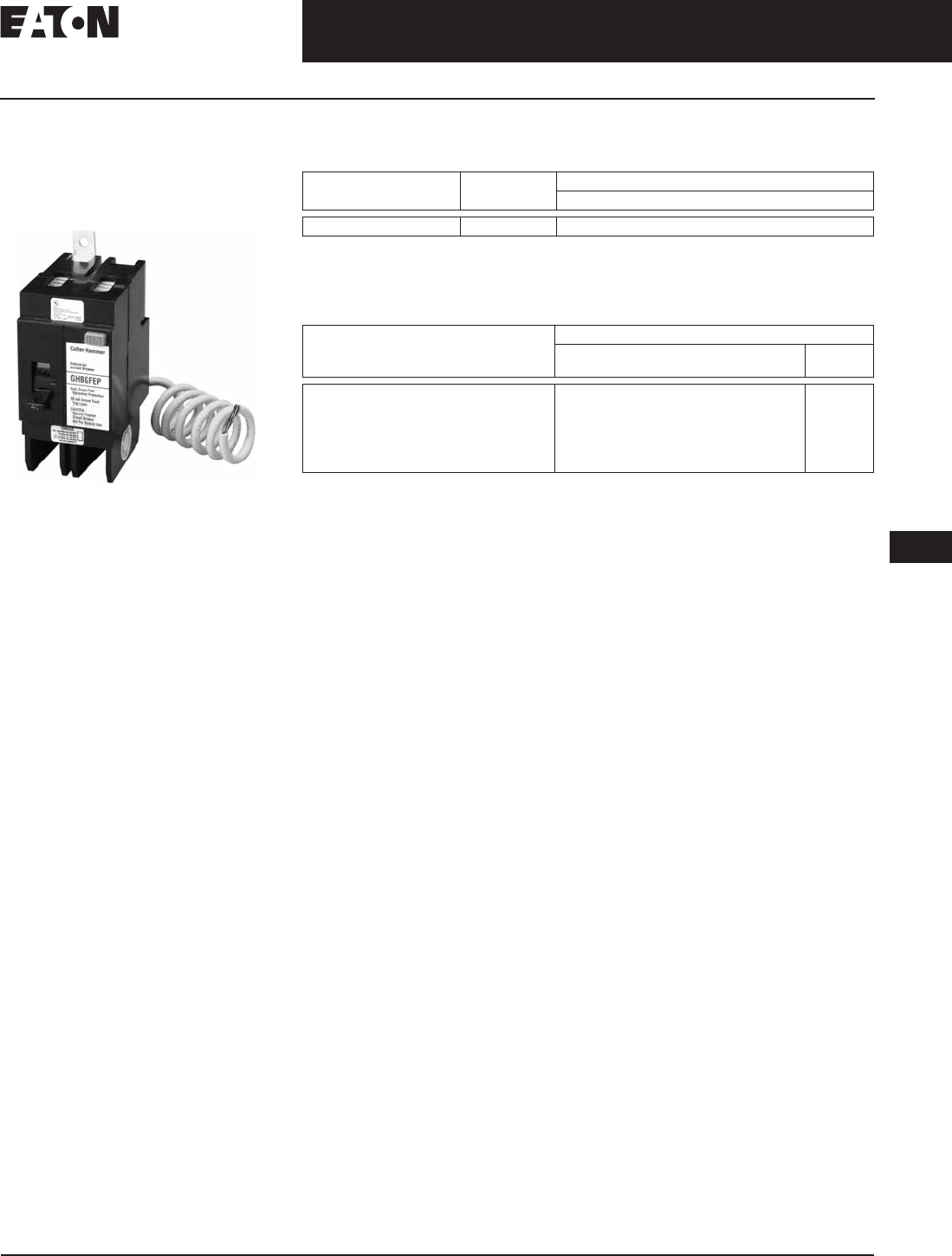
November 2008
CA08101001E For more information visit: www.eaton.com
12-81
Series C Molded Case Circuit Breakers
12
15 – 100 Amperes
G-Frame
Type GHBGFEP Bolt-On
Panelboard 30 mA
Industrial Ground Fault
Circuit Protectors
Single-Phase (Requires 2 Poles)
Product Description
■15 – 60 amperes, 277 V, 50/60 Hz.
■Operational voltage 240 V to 305 V.
Standards and Certifications
These circuit breakers meet the
requirements of UL 489 and UL 1053.
Technical Data
Table 12-139. Interrupting Capacity Ratings
Product Selection
Table 12-140. Type GHBGFEP Bolt-On Panelboard 30 mA Industrial Ground Fault Circuit
Protectors with Non-Interchangeable Trip Units
Circuit Breaker
Type
Number
of Poles
Interrupting Capacity (Symmetrical Amperes)
277 Vac (50/60 Hz)
GHBGFEP 1 14,000
Continuous
Ampere Rating
at 40°C
Single-Phase (Requires 2 Poles) 277 Vac, 30 mA
Catalog
Number
Price
U.S. $
15
20
30
40
50
60
GHBGFEP1015
GHBGFEP1020
GHBGFEP1030
GHBGFEP1040
GHBGFEP1050
GHBGFEP1060
Discount Symbol . . . . . . . . . . . . . . . . . . . . . . . . . CB-2
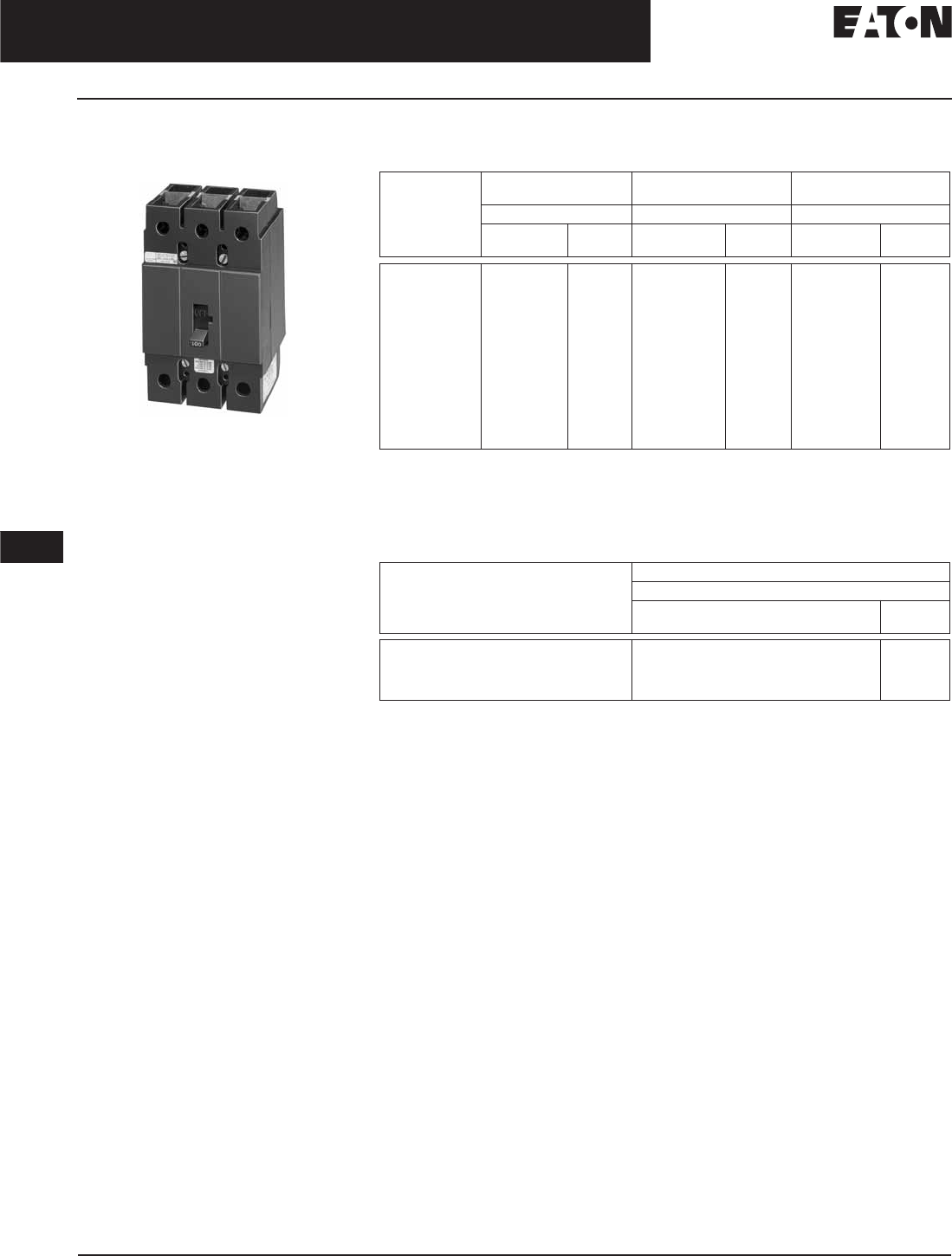
November 2008
12-82
For more information visit: www.eaton.com CA08101001E
Series C Molded Case Circuit Breakers
12
15 – 100 Amperes
G-Frame
Types GHC and HGHC
Circuit Breakers
Typical GHC
Product Description
■15 – 100 amperes.
■120, 240, 277, 480Y/277 V, 50/60 Hz,
125, 125/250 Vdc.
■1, 2 and 3 poles.
■Cable in, cable out.
■Does not include mounting
hardware.
Standards and Certifications
These breakers meet the requirements
of Federal Specification W-C-37b as
follows:
■Type GHC, 277 and 480Y/277 V:
❑1 Pole: Classes 12c, 13a
❑2, 3 Poles: Class 13b
❑UL/CSA
Product Selection
Table 12-141. Type GHC Thermal-Magnetic Circuit Breakers with Non-Interchangeable Trip Units
15 through 70 ampere circuit breakers only.
Use (2) outside poles.
Uses .190-32 screw type clamp terminals.
Add suffix HID for High Intensity Discharge (HID) applications. 15 and 20 ampere, 1-pole are
SWD rated.
Table 12-142. Type HGHC Thermal-Magnetic Circuit Breakers with Non-Interchangeable Trip Units
15 and 20 ampere, 1-pole are SWD rated.
Continuous
Ampere Rating
at 40°C
277 Vac Maximum,
125 Vdc Maximum
480Y/277 Vac Maximum,
125/250 Vdc Maximum
480Y/277 Vac Maximum,
125/250 Vdc Maximum
1-Pole 2-Pole 3-Pole
Catalog
Number
Price
U.S. $
Catalog
Number
Price
U.S. $
Catalog
Number
Price
U.S. $
15
20
25
30
35
40
45
50
60
70
80
90
100
GHC1015
GHC1020
GHC1025
GHC1030
GHC1035
GHC1040
GHC1045
GHC1050
GHC1060
GHC1070
GHC1080
GHC1090
GHC1100
GHC2015
GHC2020
GHC2025
GHC2030
GHC2035
GHC2040
GHC2045
GHC2050
GHC2060
GHC2070
GHC2080
GHC2090
GHC2100
GHC3015
GHC3020
GHC3025
GHC3030
GHC3035
GHC3040
GHC3045
GHC3050
GHC3060
GHC3070
GHC3080
GHC3090
GHC3100
Continuous
Ampere Rating
at 40°C
277 Vac Maximum, 125 Vdc Maximum
1-Pole
Catalog
Number
Price
U.S. $
15
20
25
30
HGHC1015
HGHC1020
HGHC1025
HGHC1030
Discount Symbol . . . . . . . . . . . . . . . . . . . . . . . . CB-2
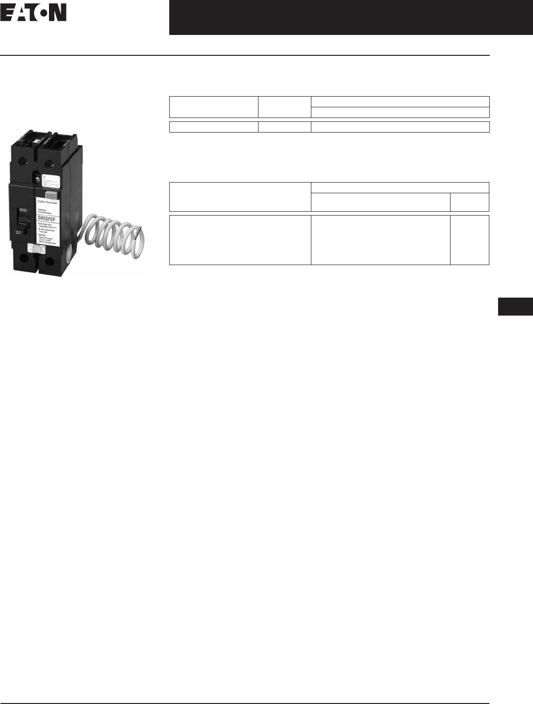
November 2008
CA08101001E For more information visit: www.eaton.com
12-83
Series C Molded Case Circuit Breakers
12
15 – 100 Amperes
G-Frame
Type GHCGFEP Cable-In/
Cable-Out 30 mA
Industrial Ground Fault
Circuit Protectors
Single-Phase
(Requires 2 Pole Spaces)
Product Description
■15 – 60 amperes, 277 V, 50/60 Hz.
■Operational voltage 240 V to 305 V.
Standards and Certifications
These circuit breakers meet the
requirements of UL 489 and UL 1053.
Technical Data and Specifications
Table 12-143. Interrupting Capacity Ratings
Product Selection
Table 12-144. Type GHCGFEP 30 mA Industrial Ground Fault Circuit Protectors with
Non-Interchangeable Trip Units
Circuit Breaker
Type
Number
of Poles
Interrupting Capacity (Symmetrical Amperes)
277 Vac (50/60 Hz)
GHCGFEP 1 14,000
Continuous
Ampere Rating
at 40°C
Single-Phase (Requires 2 Poles) 277 V, 30 mA
Catalog
Number
Price
U.S. $
15
20
30
40
50
60
GHCGFEP1015
GHCGFEP1020
GHCGFEP1030
GHCGFEP1040
GHCGFEP1050
GHCGFEP1060
Discount Symbol . . . . . . . . . . . . . . . . . . . . . . . . . CB-2

November 2008
12-84
For more information visit: www.eaton.com CA08101001E
Series C Molded Case Circuit Breakers
12
15 – 100 Amperes
G-Frame
Special Purpose
GHC Circuit Breakers
Product Description
Eaton’s Cutler-Hammer Type GHC
circuit breakers have binding head
screw-type terminals on line and load
side. These circuit breakers with
screw-type terminals (.190-32) will be
marked “Special purpose breaker not
for general use.” To order this special
breaker, use the Catalog Number from
Tables 12-145 and 12-146.
Product Selection
Table 12-145. Type GHC Thermal-Magnetic Circuit Breakers with Non-Interchangeable Trip Units
Use (2) outside poles.
Table 12-146. Type GHB and GHC Thermal-Magnetic Circuit Breakers with Non-Interchangeable
Trip Units for HID Lighting Applications
Continuous
Ampere Rating
at 40°C
277 Vac Maximum,
125 Vdc Maximum
480Y/277 Vac Maximum,
125/250 Vdc Maximum
480Y/277 Vac Maximum,
125/250 Vdc Maximum
1-Pole 2-Pole 3-Pole
Catalog
Number
Price
U.S. $
Catalog
Number
Price
U.S. $
Catalog
Number
Price
U.S. $
25
30
35
40
45
50
60
70
80
90
100
GHC1025D
GHC1030D
GHC1035D
GHC1040D
GHC1045D
GHC1050D
GHC1060D
GHC1070D
GHC1080D
GHC1090D
GHC1100D
GHC2025D
GHC2030D
GHC2035D
GHC2040D
GHC2045D
GHC2050D
GHC2060D
GHC2070D
GHC2080D
GHC2090D
GHC2100D
GHC3025D
GHC3030D
GHC3035D
GHC3040D
GHC3045D
GHC3050D
GHC3060D
GHC3070D
GHC3080D
GHC3090D
GHC3100D
Type Continuous
Ampere Rating
at 40°C
277 Vac Maximum
1-Pole
Catalog
Number
Price
U.S. $
Cable-in 15
20
GHC1015HID
GHC1020HID
Bolt-on 15
20
GHB1015HID
GHB1020HID
Discount Symbol . . . . . . . . . . . . . . . . . . . . . . . . CB-2
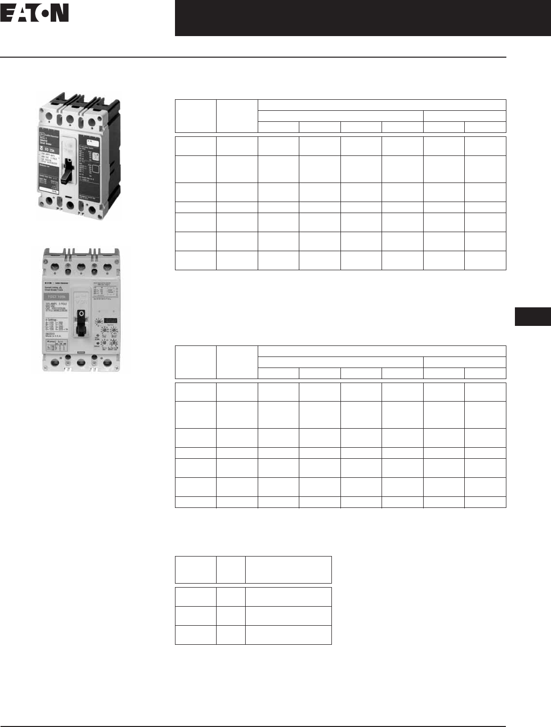
November 2008
CA08101001E For more information visit: www.eaton.com
12-85
Series C Molded Case Circuit Breakers
12
10 – 225 Amperes
F-Frame
F-Frame
Typical F-Frame Breaker
F-Frame Breaker with Electronic Trip Unit
Product Description
■All Eaton’s Cutler-Hammer F-Frame
Circuit Breakers by are HACR rated.
■All circuit breakers 10 through
30 amperes are suitable for HID
(high intensity discharge) use.
■All F-Frame circuit breakers are
suitable for reverse feed use
Technical Data and Specifications
Table 12-147. UL 489 Interrupting Capacity Ratings
dc ratings apply to substantially non-inductive circuits.
2-pole circuit breaker, or two poles of 3-pole circuit breaker.
Time constant is 3 milliseconds minimum at 10 kA and 8 milliseconds minimum at 22 kA.
Electronics available on 3-pole only, no dc rating for FDE, HFDE, FDCE.
Current limiting.
Check with Eaton for availability.
Table 12-148. IEC 157-1 (P1) Interrupting Capacity Ratings (P1)
dc ratings apply to substantially non-inductive circuits.
2-pole circuit breaker, or two poles of 3-pole circuit breaker.
Time constant is 3 milliseconds minimum at 10 kA and 8 milliseconds minimum at 22 kA.
Table 12-149. Digitrip Electronic Trip Units
Circuit
Breaker
Type
Number
of Poles
Interrupting Capacity (kA Symmetrical Amperes)
Volts ac (50/60 Hz) Volts dc
240 277 480 600 125 250
EDB
EDS
2, 3
2, 3
22
42
—
—
—
—
—
—
10
10
—
—
ED
EDH
EDC
2, 3
2, 3
2, 3
65
100
200
—
—
—
—
—
—
—
—
—
10
10
10
—
—
—
EHD 1
2, 3
—
18
4
—
—
14
—
—
10
—
—
10
FDB 2, 3, 4 18 — 14 14 — 10
FD,
FDE
1
2, 3, 4
—
65
35
—
—
35
—
18
10
—
—
10
HFD,
HFDE
1
2, 3, 4
—
100
65
—
—
65
—
25
10
—
—
22
FDC ,
FDCE
2, 3, 4 200 — 100 25 — 22
Circuit
Breaker
Type
Number
of Poles
Interrupting Capacity (kA Symmetrical Amperes)
Volts ac (50/60 Hz) Volts dc
220, 240 380, 415 440 500 125 250
EDB
EDS
2, 3
2, 3
22
42
—
—
—
—
—
—
10
10
—
—
ED
EDH
EDC
2, 3
2, 3
2, 3
65
100
200
—
—
—
—
—
—
—
—
—
10
10
10
—
—
—
EHD 1
2, 3
—
18
14
—
—
14
—
—
10
—
—
10
FDB 2, 3, 4 18 14 14 14 — 10
FD 1
2, 3, 4
35
65
—
35
—
35
—
18
10
—
—
10
HFD 1
2, 3, 4
65
100
—
65
—
65
—
25
10
—
—
22
FDC 2, 3, 4 200 100 100 35 — 22
Circuit
Breaker
Type
Frame Ratings
FDE, HFDE,
FDCE
225 100, 110, 125, 150, 160,
175, 200, 225
FDE, HFDE,
FDCE
160 60, 70, 80, 90, 100, 125,
150, 160
FDE, HFDE,
FDCE
80 15, 20, 30, 40, 50, 60,
70, 80

November 2008
12-86
For more information visit: www.eaton.com CA08101001E
Series C Molded Case Circuit Breakers
12
10 – 225 Amperes
F-Frame
Table 12-150. F-Frame Digitrip Specifications
ZSI (Zone Selective Interlocking) is optional.
Must order with ZSI. Standard 310+ does not
come with ZSI.
Legend: In = Rating Plug
Ir= Long Delay Pickup Setting x In
Trip Unit
Type
Digitrip
RMS 310+
rms Sensing Yes
Breaker Type
Frame
Ampere Range
Interrupting Rating at 480 V
FDE
15 – 225 A
35, 65, 100 (kA)
Protection
Ordering Options LS
LSG
LSI
LSIG
Fixed Rated Plug (In)
Overtemperature Trip
No
Yes
Long Delay Protection (L)
Adjustable Rating Plug (In)
Long Delay Pickup
Long Delay Time I2t
No
40 – 100% Frame
2 – 24 Seconds
Long Delay Time I4t
Long Delay Thermal Memory
High Load Alarm
No
Yes
Yes
Short Delay Protection (S)
Short Delay Pickup 200 – 1000% x (Ir)
Short Delay Time I2t
Short Delay Time Flat
Yes
No
No
Inst – 300 ms
Short Delay Time Z.S.I. Yes
Instantaneous Protection (I)
Instantaneous Pickup
Discriminator
Instantaneous Override
No
No
Yes
Ground Fault Protection (G)
Ground Fault Alarm
Ground Fault Pickup
Ground Fault Delay I2t
No
20 – 100% Frame
No
Ground Fault Delay Flat
Ground Fault Z.S.I.
Ground Fault Thermal Memory
Inst – 300 ms
Yes
Yes
System Diagnostics
Cause of Trip LEDs
Magnitude of Trip Information
Remote Signal Contacts
No
No
No
System Monitoring
Digital Display
Current
Voltage
No
No
No
Power and Energy
Power Quality Harmonics
Power Factor
No
No
No
Communications
PowerNet No
Testing
Testing Method Test Kit
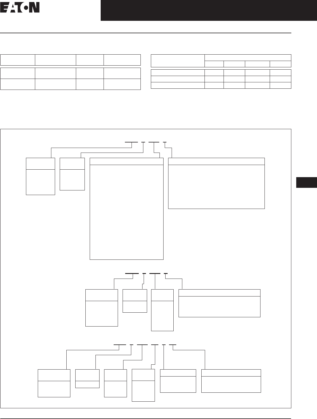
November 2008
CA08101001E For more information visit: www.eaton.com
12-87
Series C Molded Case Circuit Breakers
12
10 – 225 Amperes
F-Frame
Dimensions/Weights
Table 12-151. Dimensions in Inches (mm) Table 12-152. Approximate Shipping Weight, Lbs. (kg)
Product Selection
This information is presented only as an aid to understanding Catalog Numbers. It is not to be used to build Catalog Numbers
for circuit breakers or trip units.
Table 12-153. Circuit Breaker Catalog Numbering System
Number
of Poles
Width Height Depth
1
2
1.38 (35.1)
2.75 (70.0)
6.00 (152.4)
6.00 (152.4)
3.38 (86.0)
3.38 (86.0)
3
4
4.13 (105.0)
5.50 (139.7)
6.00 (152.4)
6.00 (152.4)
3.38 (86.0)
3.38 (86.0)
Breaker
Type
Number of Poles
12 3 4
ED, EDB, EDS, EDH, EDC — 3 (1.4) 4.5 (2.0) —
EHD, FDB, FD, HFD, FDC 2 (.9) 3 (1.4) 4.5 (2.0) 6 (2.7)
FDE, HFDE, FDCE — — 4.5 (2.0) —
Circuit
Breaker Type
EHD
FDB
FD
HFD
FDC
Number
of Poles
1 = 1 Pole
2 = 2 Poles
3 = 3 Poles
4 = 4 Poles
Trip Amperes
010
015
020
025
030
035
040
045
050
060
070
080
090
100
110
125
150
175 (FD, HFD, FDC, 2-, 3-, 4-Pole Only)
200 (FD, HFD, FDC, 2-, 3-, 4-Pole Only)
225 (FD, HFD, FDC, 2-, 3-, 4-Pole Only)
Suffix
E= 100% Protected (4-Pole only) Neutral Pole
EH = 50% Protected (4-Pole only)
K= High Magnetic Molded Case Switch
L= Line and Load Terminals
S= Stainless Steel Terminals
V= 50°C Calibration
W= Without Terminals
Y= Line Terminals Only
Z= Aluminum Terminals (≤ 100 Amperes)
FDC 3 100 L
EDC 3 200 L
Circuit
Breaker Type
EDB
EDS
ED
EDH
EDC
Number
of Poles
2 = 2 Poles
3 = 3 Poles
Trip
Amperes
100
125
150
175
200
225
Suffix
L= Line and Load Terminals
W= Without Terminals
Y= Line Terminals Only
Z= Aluminum Terminals (100 Amperes)
FDE 3 225 32 W
Circuit
Breaker Type
FDE
HFDE
FDCE
Number
of Poles
3 = 3 Poles
Trip
Amperes
80
160
225
Suffix
ZG = Zone
Selective
Interlocking
Trip
Unit
33 = LS
32 = LSI
35 = LSG
36 = LSIG
Suffix
W= Without Terminals
L= Line and Load Terminals
—= Load Side Terminals only

November 2008
12-88
For more information visit: www.eaton.com CA08101001E
Series C Molded Case Circuit Breakers
12
10 – 225 Amperes
F-Frame
Product Selection
Table 12-154. Types ED, EDH and EDC Thermal-Magnetic Circuit Breakers with Non-Interchangeable Trip Units Suitable for Reverse Feed
Table 12-155. Types EDB and EDS Thermal-Magnetic Circuit Breakers with Non-Interchangeable
Trip Units Suitable for Reverse Feed
Table 12-156. Type EHD Thermal-Magnetic Circuit Breakers with Non-Interchangeable Trip Units
Not UL listed. 5 kAIC interrupting rating.
UL listed for SWD applications, see NEC Article 240-83(d).
Maximum
Continuous
Ampere
Rating
at 40°C
240 Vac Maximum, 125 Vdc (Includes Terminals on Load End Only)
65 kAIC at 240 Vac 100 kAIC at 240 Vac 200 kAIC at 240 Vac
Type ED Type EDH Type EDC Current Limiting
2-Pole 3-Pole 2-Pole 3-Pole 2-Pole 3-Pole
Catalog
Number
Price
U.S. $
Catalog
Number
Price
U.S. $
Catalog
Number
Price
U.S. $
Catalog
Number
Price
U.S. $
Catalog
Number
Price
U.S. $
Catalog
Number
Price
U.S. $
15
20
25
30
35
40
50
60
ED2015
ED2020
ED2025
ED2030
ED2035
ED2040
ED2050
ED2060
ED3015
ED3020
ED3025
ED3030
ED3035
ED3040
ED3050
ED3060
—
—
—
—
—
—
—
—
—
—
—
—
—
—
—
—
—
—
—
—
—
—
—
—
—
—
—
—
—
—
—
—
100
125
150
175
200
225
ED2100
ED2125
ED2150
ED2175
ED2200
ED2225
ED3100
ED3125
ED3150
ED3175
ED3200
ED3225
EDH2100
EDH2125
EDH2150
EDH2175
EDH2200
EDH2225
EDH3100
EDH3125
EDH3150
EDH3175
EDH3200
EDH3225
EDC2100
EDC2125
EDC2150
EDC2175
EDC2200
EDC2225
EDC3100
EDC3125
EDC3150
EDC3175
EDC3200
EDC3225
Maximum
Continuous
Ampere
Rating
at 40°C
240 Vac Maximum, 125 Vdc (Includes Terminals on Load End Only)
22 kAIC at 240 Vac 42 kAIC at 240 Vac
Type EDB Type EDS
2-Pole 3-Pole 2-Pole 3-Pole
Catalog
Number
Price
U.S. $
Catalog
Number
Price
U.S. $
Catalog
Number
Price
U.S. $
Catalog
Number
Price
U.S. $
100
110
125
150
175
200
225
EDB2100
EDB2110
EDB2125
EDB2150
EDB2175
EDB2200
EDB2225
EDB3100
EDB3110
EDB3125
EDB3150
EDB3175
EDB3200
EDB3225
EDS2100
EDS2110
EDS2125
EDS2150
EDS2175
EDS2200
EDS2225
EDS3100
EDS3110
EDS3125
EDS3150
EDS3175
EDS3200
EDS3225
Maximum
Continuous
Ampere
Rating
at 40°C
277 Vac Maximum, 125 Vdc 480 Vac Maximum, 250 Vdc
14 kAIC at 277 Vac 14 kAIC at 480 Vac
Type EHD (Includes Terminals on Load End Only)
1-Pole 2-Pole 3-Pole
Catalog
Number
Price
U.S. $
Catalog
Number
Price
U.S. $
Catalog
Number
Price
U.S. $
10
15
20
25
30
35
40
45
50
60
70
80
90
100
EHD1010
EHD1015
EHD1020
EHD1025
EHD1030
EHD1035
EHD1040
EHD1045
EHD1050
EHD1060
EHD1070
EHD1080
EHD1090
EHD1100
EHD2010
EHD2015
EHD2020
EHD2025
EHD2030
EHD2035
EHD2040
EHD2045
EHD2050
EHD2060
EHD2070
EHD2080
EHD2090
EHD2100
EHD3010
EHD3015
EHD3020
EHD3025
EHD3030
EHD3035
EHD3040
EHD3045
EHD3050
EHD3060
EHD3070
EHD3080
EHD3090
EHD3100
Discount Symbol . . . . . . . . . . . . . . . . . . . . . . . . CB-2

November 2008
CA08101001E For more information visit: www.eaton.com
12-89
Series C Molded Case Circuit Breakers
12
10 – 225 Amperes
F-Frame
Table 12-157. Type FD Thermal-Magnetic Circuit Breakers with Non-Interchangeable Trip Units
Not UL listed. 5 kAIC interrupting rating.
UL listed for SWD applications, see NEC Article 240-83(d).
Table 12-158. Types HFD and FDC Thermal-Magnetic Circuit Breakers with Non-Interchangeable Trip Units
UL listed for SWD applications, see NEC Article 240-83(d).
Max.
Cont.
Ampere
Rating
at 40°C
600 Vac Maximum, 250 Vdc 277 Vac Maximum,
125 Vdc
600 Vac Maximum, 250 Vdc
14 kAIC at 600 Vac 35 kAIC at 277 Vac 35 kAIC at 480 Vac
Type FDB (Includes Terminals on Load End Only) Type FD (Includes Terminals on Load End Only)
2-Pole 3-Pole 4-Pole 1-Pole 2-Pole 3-Pole 4-Pole
Catalog
Number
Price
U.S. $
Catalog
Number
Price
U.S. $
Catalog
Number
Price
U.S. $
Catalog
Number
Price
U.S. $
Catalog
Number
Price
U.S. $
Catalog
Number
Price
U.S. $
Catalog
Number
Price
U.S. $
10
15
20
25
30
FDB2010
FDB2015
FDB2020
FDB2025
FDB2030
FDB3010
FDB3015
FDB3020
FDB3025
FDB3030
FDB4010
FDB4015
FDB4020
FDB4025
FDB4030
FD1010
FD1015
FD1020
FD1025
FD1030
—
FD2015
FD2020
FD2025
FD2030
—
FD3015
FD3020
FD3025
FD3030
—
FD4015
FD4020
FD4025
FD4030
35
40
45
50
60
FDB2035
FDB2040
FDB2045
FDB2050
FDB2060
FDB3035
FDB3040
FDB3045
FDB3050
FDB3060
FDB4035
FDB4040
FDB4045
FDB4050
FDB4060
FD1035
FD1040
FD1045
FD1050
FD1060
FD2035
FD2040
FD2045
FD2050
FD2060
FD3035
FD3040
FD3045
FD3050
FD3060
FD4035
FD4040
FD4045
FD4050
FD4060
70
80
90
100
110
FDB2070
FDB2080
FDB2090
FDB2100
FDB2110
FDB3070
FDB3080
FDB3090
FDB3100
FDB3110
FDB4070
FDB4080
FDB4090
FDB4100
FDB4110
FD1070
FD1080
FD1090
FD1100
FD1110
FD2070
FD2080
FD2090
FD2100
FD2110
FD3070
FD3080
FD3090
FD3100
FD3110
FD4070
FD4080
FD4090
FD4100
FD4110
125
150
175
200
225
FDB2125
FDB2150
—
—
—
FDB3125
FDB3150
—
—
—
FDB4125
FDB4150
—
—
—
FD1125
FD1150
—
—
—
FD2125
FD2150
FD2175
FD2200
FD2225
FD3125
FD3150
FD3175
FD3200
FD3225
FD4125
FD4150
FD4175
FD4200
FD4225
Max.
Cont.
Ampere
Rating
at 40°C
277 Vac Maximum,
125 Vdc
600 Vac Maximum, 250 Vdc 600 Vac Maximum, 250 Vdc
65 kAIC at 277 Vac 65 kAIC at 480 Vac 100 kAIC at 480 Vac
Type HFD
(Includes Terminals on Load End Only)
Type FDC Current Limiting
(Includes Terminals on Load End Only)
1-Pole 2-Pole 3-Pole 4-Pole 2-Pole 3-Pole 4-Pole
Catalog
Number
Price
U.S. $
Catalog
Number
Price
U.S. $
Catalog
Number
Price
U.S. $
Catalog
Number
Price
U.S. $
Catalog
Number
Price
U.S. $
Catalog
Number
Price
U.S. $
Catalog
Number
Price
U.S. $
15
20
25
30
35
HFD1015
HFD1020
HFD1025
HFD1030
HFD1035
HFD2015
HFD2020
HFD2025
HFD2030
HFD2035
HFD3015
HFD3020
HFD3025
HFD3030
HFD3035
HFD4015
HFD4020
HFD4025
HFD4030
HFD4035
FDC2015
FDC2020
FDC2025
FDC2030
FDC2035
FDC3015
FDC3020
FDC3025
FDC3030
FDC3035
FDC4015
FDC4020
FDC4025
FDC4030
FDC4035
40
45
50
60
70
HFD1040
HFD1045
HFD1050
HFD1060
HFD1070
HFD2040
HFD2045
HFD2050
HFD2060
HFD2070
HFD3040
HFD3045
HFD3050
HFD3060
HFD3070
HFD4040
HFD4045
HFD4050
HFD4060
HFD4070
FDC2040
FDC2045
FDC2050
FDC2060
FDC2070
FDC3040
FDC3045
FDC3050
FDC3060
FDC3070
FDC4040
FDC4045
FDC4050
FDC4060
FDC4070
80
90
100
110
125
HFD1080
HFD1090
HFD1100
HFD1110
HFD1125
HFD2080
HFD2090
HFD2100
HFD2110
HFD2125
HFD3080
HFD3090
HFD3100
HFD3110
HFD3125
HFD4080
HFD4090
HFD4100
HFD4110
HFD4125
FDC2080
FDC2090
FDC2100
FDC2110
FDC2125
FDC3080
FDC3090
FDC3100
FDC3110
FDC3125
FDC4080
FDC4090
FDC4100
FDC4110
FDC4125
150
175
200
225
HFD1150
—
—
—
HFD2150
HFD2175
HFD2200
HFD2225
HFD3150
HFD3175
HFD3200
HFD3225
HFD4150
HFD4175
HFD4200
HFD4225
FDC2150
FDC2175
FDC2200
FDC2225
FDC3150
FDC3175
FDC3200
FDC3225
FDC4150
FDC4175
FDC4200
FDC4225
Discount Symbol . . . . . . . . . . . . . . . . . . . . . . . . . CB-2
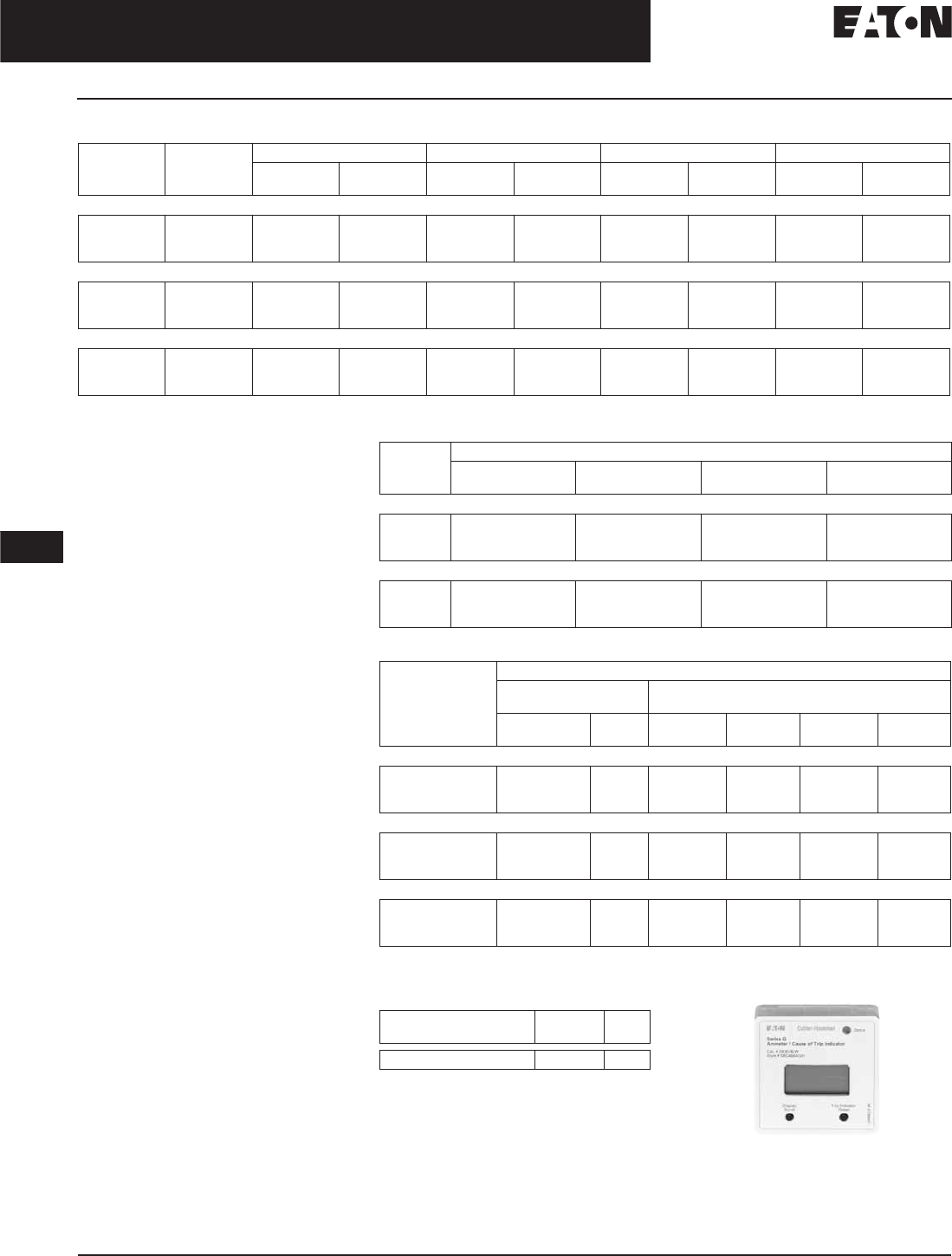
November 2008
12-90
For more information visit: www.eaton.com CA08101001E
Series C Molded Case Circuit Breakers
12
10 – 225 Amperes
F-Frame
Check with Eaton for availability.
Molded Case Switches
Eaton’s Cutler-Hammer molded
case switches are used as compact
switches in applications requiring high
current switching capabilities. Molded
case switches are constructed of
circuit breaker components and are
of the high instantaneous automatic
type. Molded case switches are listed
in accordance with Underwriters
Laboratories Inc., Standard UL 1087.
Line and Load Terminals
Line and load terminals provide wire
connecting capabilities for specific
ranges of continuous current ratings
and wire types. Except as noted,
terminals comply with Underwriters
Laboratories Inc., Standards UL 486A
and UL 486B. Unless otherwise speci-
fied, F-Frame circuit breakers are factory
equipped with load terminals only.
Ordering Information
F-Frame circuit breakers and molded
case switches have load terminals
only as standard equipment. When
standard line-end terminals (same as
standard load-end terminals) are
required, add Suffix L to the circuit
breaker Catalog Number. When non-
standard or optional line and/or load
terminals are required, order by style
number. Specify if factory installation
is required.
Table 12-159. Types FDE, HFDE and FDCE Electronic Circuit Breakers with Non-Interchangeable Trip Units
Maximum
Ampere
Rating
Neutral
CT for LSG
and LSIG
LS LSI LSG LSIG
Catalog
Number
Price
U.S. $
Catalog
Number
Price
U.S. $
Catalog
Number
Price
U.S. $
Catalog
Number
Price
U.S. $
IC Rating 35 kAIC at 480 Vac
80
160
225
CTF080
CTF160
CTF225
FDE308033
FDE316033
FDE322533
FDE308032
FDE316032
FDE322532
FDE308035
FDE316035
FDE322535
FDE308036
FDE316036
FDE322536
IC Rating 65 kAIC at 480 Vac
80
160
225
CTF080
CTF160
CTF225
HFDE308033
HFDE316033
HFDE322533
HFDE308032
HFDE316032
HFDE322532
HFDE308035
HFDE316035
HFDE322535
HFDE308036
HFDE316036
HFDE322536
IC Rating 100 kAIC at 480 Vac
80
160
225
CTF080
CTF160
CTF225
FDCE308033
FDCE316033
FDCE322533
FDCE308032
FDCE316032
FDCE322532
FDCE308035
FDCE316035
FDCE322535
FDCE308036
FDCE316036
FDCE322536
Table 12-160. FDE Electronic Breaker with Zone Selective Interlocking
Table 12-161. Molded Case Switches
Note: Molded Case Switches will open above 1800 amperes.
Table 12-162. Breaker Mount Ammeter
Note: Use on FDE, HFDE and FDCE
electronic trip only.
Ammeter
Ampere
Rating
Catalog Number
LSI w/ZSI Price
U.S. $
LSIG w/ZSI Price
U.S. $
35 kAIC at 480 Vac
80
160
225
FDE308032ZG
FDE316032ZG
FDE322532ZG
FDE308036ZG
FDE316036ZG
FDE322536ZG
65 kAIC at 480 Vac
80
160
225
HFDE308032ZG
HFDE316032ZG
HFDE322532ZG
HFDE308036ZG
HFDE316036ZG
HFDE322536ZG
Maximum
Continuous
Ampere Rating
at 40°C
Complete Circuit Breaker with Load Side Terminals Only
480 Vac Maximum,
250 Vdc
600 Vac Maximum,
250 Vdc
Catalog
Number
Price
U.S. $
Catalog
Number
Price
U.S. $
Catalog
Number
Price
U.S. $
2-Pole
100
150
225
EHD2100K
—
—
FD2100K
FD2150K
FD2225K
HFD2100K
HFD2150K
HFD2225K
3-Pole
100
150
225
EHD3100K
—
—
FD3100K
FD3150K
FD3225K
HFD3100K
HFD3150K
HFD3225K
4-Pole
100
150
225
—
—
—
FD4100K
FD4150K
FD4225K
HFD4100K
HFD4150K
HFD4225K
Description Catalog
Number
Price
U.S. $
Breaker Mount Ammeter DIGIVIEW
Discount Symbol . . . . . . . . . . . . . . . . . . . . . . . . CB-2
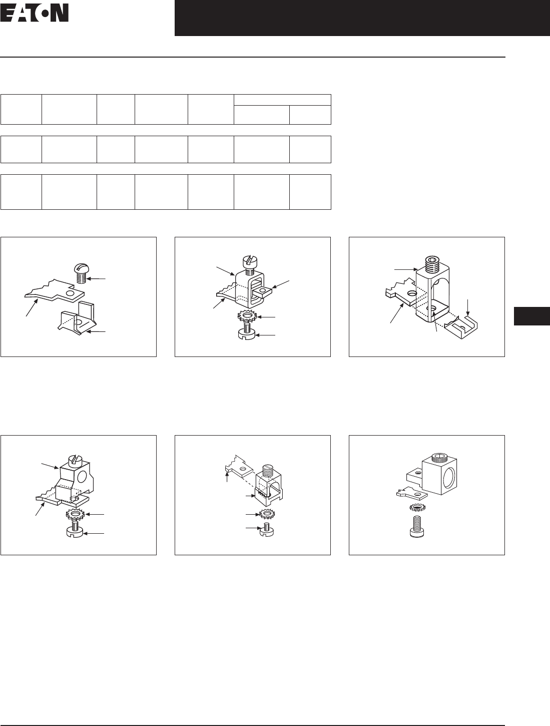
November 2008
CA08101001E For more information visit: www.eaton.com
12-91
Series C Molded Case Circuit Breakers
12
10 – 225 Amperes
F-Frame
Line and Load Terminals (Continued)
Table 12-163. Line and Load Terminals
Not for use with ED, EDH, EDC breakers.
Includes terminal shield kit. Adds approximately 3 inches (76.2) to breaker height. Available for use on 3-pole breaker only.
Figure 12-15. 3T20FB
Assemble wire clamp to bottom of
conductor as shown.
Figure 12-16. 3T100FB, 3T150FB
Insert collar enclosing conductor as
shown. Locate nut on top of conductor
and tighten securely with screw and
washer. Caution: Collar must surround
conductor.
Figure 12-17. 3TA225FD
Insert collar enclosing conductor and
center on extrusion on collar. Install
clip with legs on top of conductor and
snap end around bottom of collar.
Figure 12-18. 3TA50FB
Assemble collar on top of conductor
as shown. Tighten securely with screw
and washer.
Figure 12-19. 3TA100FD
Collar slides onto conductor and is held
in position by a screw and lockwasher.
Figure 12-20. 3TA225FDK (Up to 150 mm2)
Assemble collar on top of conductor
as shown. Tighten securely with screw
and washer. Terminal shield must be
used with this collar.
Note: For 185 mm2, use 3TA225FDK1.
Maximum
Breaker
Amperes
Terminal Body
Material
Wire Type AWG Wire
Range
Metric Wire
Range mm2Package of 3 Terminals
Catalog
Number
Price
U.S. $
Standard Pressure Type Terminals
20 (EHD)
100
225
Steel
Steel
Aluminum
Cu/AI
Cu/AI
Cu/AI
14 – 10
14 – 1/0
4 – 4/0
2.5 – 4
2.5 – 50
25 – 95
3T20FB
3T100FB
3TA225FD
Optional Pressure Terminals
50
100
200
225
Aluminum
Aluminum
Stainless Steel
Aluminum
Cu/AI
Cu/AI
Cu
Cu/AI
14 – 4
14 – 1/0
4 – 4/0
6 – 300 kcmil
2.5 – 25
2.5 – 50
25 – 95
16 – 150
3TA50FB
3TA100FD
3T150FB
3TA225FDK
Screw
Wire Clamp
Conductor
Screw
Washer
Collar
Conductor
Nut
Conductor
Extrusion
Clip
Collar
Collar
Screw
Washer
Conductor
Conductor
Collar
Washer
Screw
Discount Symbol . . . . . . . . . . . . . . . . . . . . . . . . . CB-2

November 2008
12-92
For more information visit: www.eaton.com CA08101001E
Series C Molded Case Circuit Breakers
12
10 – 225 Amperes
F-Frame
Allowable Accessory Combinations
Different combinations of accessories can be supplied, depending on the types of accessories and the number of poles in the
circuit breaker.
Table 12-164. Accessories
■Applicable in indicated pole position ❏May be mounted on left or right pole —
not both
●Accessory available/Modification available
Description Reference
Page
1-Pole 2-Pole 3-Pole 4-Pole
Center Left Right Left Center Right Left Center Right Neutral
Internal Accessories (Only one internal accessory per pole)
Alarm Lockout Switch (Make Only) 12-217 ■
Alarm Lockout (Make/Break) 12-217 ■❏ ❏■
Alarm Lockout (2Make/2Break) 12-217 ■❏ ❏■
Auxiliary Switch (1A, 1B) 12-220 ■■ ■■ ■
Auxiliary Switch (2A, 2B) 12-220 ■■ ■■ ■
Auxiliary Switch and Alarm Switch Combination 12-223 ■❏ ❏■
Shunt Trip — Standard 12-226 ■■ ■■ ■
Shunt Trip — Low Energy 12-231 ■■ ■■
Undervoltage Release Mechanism 12-232 ■■ ■■
External Accessories
End Cap Kit 12-243 ●● ●
Keeper Nut 12-243 ●● ● ●
Control Wire Terminal Kit 12-244 ●● ● ●
Multiwire Connectors 12-245 ●● ● ●
Base Mounting Hardware 12-246 ●● ● ●
Terminal Shields 12-248 ●● ● ●
Terminal End Covers 12-249 ●
Interphase Barriers 12-249 ●● ●
Non-Padlockable Handle Block 12-251 ■■ ■ ■
Snap-on Padlockable Handle Lock Hasp 12-251 ■■ ■ ■
Padlockable Handle Lock Hasp 12-252 ■❏ ❏❏ ❏
Cylinder Lock 12-252 ■
Key Interlock Kit 12-253 ■❏ ❏❏ ❏
Sliding Bar Interlock — Requires Two Breakers 12-254 ●
Walking Beam Interlock — Requires Two Breakers 12-254 ●●
Electrical (Solenoid and Motor) Operators 12-255 ●●
Plug-in Adapters 12-257 ●● ●
Rear Connecting Studs 12-258 ●● ● ●
Panelboard Connecting Straps 12-261 ●● ● ●
Handle Mechanisms 12-262 ●
LFD Current Limiter 12-268 ●
IQ Energy Sentinel 12-268 ●●
Modifications (Refer to Eaton)
Special Calibration — ●● ● ●
Moisture Fungus Treatment 12-73 ●● ● ●
Freeze-Tested Circuit Breakers — ●● ● ●
Marine Application — ●● ● ●

November 2008
CA08101001E For more information visit: www.eaton.com
12-93
Series C Molded Case Circuit Breakers
12
70 – 250 Amperes
J-Frame
J-Frame
Typical J-Frame Circuit Breaker
Product Description
■All Eaton’s Cutler-Hammer J-Frame
Circuit Breakers are HACR rated.
■J-Frame circuit breakers are available
as individual components (Frame,
Trip Unit, Terminals), or factory
assembled complete breakers.
■J-Frame circuit breakers with
non-interchangeable trip units are
suitable for reverse feed use
Technical Data and Specifications
Table 12-165. UL 489 Interrupting Capacity Ratings
2-pole circuit breaker or two outside poles of 3-pole circuit breaker.
Time constant is 3 milliseconds minimum at 10 kA and 8 milliseconds minimum at 22 kA.
Current limiting.
Table 12-166. IEC 157-1 (P1) Interrupting Capacity Ratings
2-pole circuit breaker or two outside poles of 3-pole circuit breaker.
Time constant is 3 milliseconds minimum at 10 kA and 8 milliseconds minimum at 22 kA.
Circuit
Breaker
Type
Number
of Poles
Interrupting Capacity (kA Symmetrical Amperes)
Volts ac (50/60 Hz) Volts dc
240 480 600 125 250
JDB
JD
HJD
JDC
2, 3
2, 3, 4
2, 3, 4
2, 3, 4
65
65
100
200
35
35
65
100
18
18
25
35
—
—
—
—
10
10
22
22
Circuit
Breaker
Type
Number
of Poles
Interrupting Capacity (kA Symmetrical Amperes)
Volts ac (50/60 Hz) Volts dc
240 380 415 600 125 250
JD
HJD
JDC
2, 3, 4
2, 3, 4
2, 3, 4
65
100
200
35
65
100
35
65
100
—
—
—
—
—
—
10
22
22

November 2008
12-94
For more information visit: www.eaton.com CA08101001E
Series C Molded Case Circuit Breakers
12
70 – 250 Amperes
J-Frame
Dimensions/Weights
Table 12-167. Dimensions in Inches (mm)
Table 12-168. Approximate Shipping Weight in Lbs. (kg)
Product Selection
This information is presented only as an aid to understanding Catalog Numbers. It is not to be used to build Catalog Numbers
for circuit breakers or trip units.
Table 12-169. Circuit Breaker/Frame Catalog Numbering System
Table 12-170. Trip Unit Catalog Numbering System
Number of Poles Width Height Depth
2, 3
4
4.13 (105.0)
5.50 (139.7)
10.00 (254.0)
10.00 (254.0)
4.06 (104.1)
4.06 (104.1)
Breaker
Type
Complete Breaker Frame Only Trip Unit
Number of Poles
234234234
JDB
JD
11.25 (5.1)
11.25 (5.1)
12.50 (5.7)
12.50 (5.7)
—
13.25 (6.0)
—
9.00 (4.1)
—
10.00 (4.5)
—
10.50 (4.8)
—
2.00 (.9)
—
2.00 (.9)
—
2.25 (1.0)
HJD
JDC
11.25 (5.1)
12.25 (5.6)
12.50 (5.7)
13.50 (6.1)
13.25 (6.0)
14.25 (6.5)
9.00 (4.1)
10.00 (4.5)
10.00 (4.5)
11.00 (5.0)
10.50 (4.8)
11.50 (5.2)
2.00 (.9)
2.00 (.9)
2.00 (.9)
2.00 (.9)
2.25 (1.0)
2.25 (1.0)
JD 3 250 F
Circuit Breaker/
Frame Type
JDB
JD
HJD
JDC
Number
of Poles
2 = 2 Poles
3 = 3 Poles
4 = 4 Poles
Circuit Breaker/
Frame Ampere Rating
070
090
100
125
150
175
200
225
250
Suffix
C= Non-Aluminum Terminals
F= Frame Only
K= High Magnetic Molded Case Switch
V= 50°C Calibration
W= Without Terminals
X= Load Side Terminals Only
Y= Line Side Terminals Only
JT 3 250 T
Trip Unit Type
JT = Thermal-Magnetic
Number
of Poles
2 = 2 Poles
3 = 3 Poles
4 = 4 Poles
Trip Unit Rating/
Plug Ampere Rating
070
090
100
125
150
175
200
225
250
Suffix
T= Trip Unit
Thermal-Magnetic
Fixed Thermal
Adj. Magnetic
V= 50°C Calibration
(Thermal-Magnetic
Trip Units Only)

November 2008
CA08101001E For more information visit: www.eaton.com
12-95
Series C Molded Case Circuit Breakers
12
70 – 250 Amperes
J-Frame
Product Selection
Table 12-171. Types JD, HJD and JDC Thermal-Magnetic Circuit Breakers with Interchangeable Trip Units
Magnetic trip adjustable 5 – 10 times continuous ampere rating.
Individually packed.
Fully rated neutral pole with no protection.
Neutral is in right pole.
Table 12-172. Types JD, HJD and JDC Thermal-Magnetic Circuit Breakers — Frame Only
Max.
Cont.
Amp
Rating
at 40°C
Standard Interrupting
Capacity
600 Vac Rated
35 kAIC at 480 Vac
High Interrupting Capacity
600 Vac Rated
65 kAIC at 480 Vac
Ultra High Interrupting
Capacity Current Limiting
600 Vac Rated
100 kAIC at 480 Vac
Thermal-Magnetic
Trip Unit Only
For Use with Standard or
High or Ultra High
Interrupting Frames
Standard
Terminals
Only
See Page 12-97
for Optional
Terminals
Factory Assembled
Circuit Consisting
of Frame, Trip Unit and
Terminals
Factory Assembled
Circuit Consisting
of Frame, Trip Unit and
Terminals
Factory Assembled
Circuit Consisting
of Frame, Trip Unit and
Terminals
Catalog
Number
Price
U.S. $
Catalog
Number
Price
U.S. $
Catalog
Number
Price
U.S. $
Catalog
Number
Price
U.S. $
Catalog
Number
Price
U.S. $
2-Pole
70
90
100
125
150
175
200
225
250
JD2070
JD2090
JD2100
JD2125
JD2150
JD2175
JD2200
JD2225
JD2250
HJD2070
HJD2090
HJD2100
HJD2125
HJD2150
HJD2175
HJD2200
HJD2225
HJD2250
JDC2070
JDC2090
JDC2100
JDC2125
JDC2150
JDC2175
JDC2200
JDC2225
JDC2250
JT2070T
JT2090T
JT2100T
JT2125T
JT2150T
JT2175T
JT2200T
JT2225T
JT2250T
TA250KB
3-Pole
70
90
100
125
150
175
200
225
250
JD3070
JD3090
JD3100
JD3125
JD3150
JD3175
JD3200
JD3225
JD3250
HJD3070
HJD3090
HJD3100
HJD3125
HJD3150
HJD3175
HJD3200
HJD3225
HJD3250
JDC3070
JDC3090
JDC3100
JDC3125
JDC3150
JDC3175
JDC3200
JDC3225
JDC3250
JT3070T
JT3090T
JT3100T
JT3125T
JT3150T
JT3175T
JT3200T
JT3225T
JT3250T
TA250KB
4-Pole
125
150
175
200
225
250
JD4125
JD4150
JD4175
JD4200
JD4225
JD4250
HJD4125
HJD4150
HJD4175
HJD4200
HJD4225
HJD4250
JDC4125
JDC4150
JDC4175
JDC4200
JDC4225
JDC4250
JT3125T
JT3150T
JT3175T
JT3200T
JT3225T
JT3250T
TA250KB
Standard Interrupting Capacity
600 Vac Rated
35 kAIC at 480 Vac
High Interrupting Capacity
600 Vac Rated
65 kAIC at 480 Vac
Ultra High Interrupting
Capacity Current Limiting
600 Vac Rated
100 kAIC at 480 Vac
Catalog
Number
Price
U.S. $
Catalog
Number
Price
U.S. $
Catalog
Number
Price
U.S. $
2-Pole
JD2250F HJD2250F JDC2250F
3-Pole
JD3250F HJD3250F JDC3250F
4-Pole
JD4250F HJD4250F JDC4250F
Discount Symbol . . . . . . . . . . . . . . . . . . . . . . . . . CB-2

November 2008
12-96
For more information visit: www.eaton.com CA08101001E
Series C Molded Case Circuit Breakers
12
70 – 250 Amperes
J-Frame
Table 12-173. Type JDB Thermal-Magnetic Circuit Breakers with Non-Interchangeable
Thermal-Magnetic Trip Units Suitable for Reverse Feed Application
Molded Case Switches
Eaton’s Cutler-Hammer molded
case switches are used as compact
switches in applications requiring high
current switching capabilities. Molded
case switches are constructed of
circuit breaker components and are
of the high instantaneous automatic
type. Molded case switches are listed
in accordance with Underwriters
Laboratories Standard UL 1087.
Table 12-174. Molded Case Switches
Individually packed.
Note: Molded case switches may open above 2500 amperes.
Maximum
Continuous
Ampere Rating
at 40°C
600 Vac Rated, 250 Vdc
Complete Circuit Breaker
Without Line and
Load Terminals
With Standard Line and
Load Terminals Only
Catalog
Number
Price
U.S. $
Catalog
Number
Price
U.S. $
2-Pole
70
90
100
125
150
175
200
225
250
JDB2070W
JDB2090W
JDB2100W
JDB2125W
JDB2150W
JDB2175W
JDB2200W
JDB2225W
JDB2250W
JDB2070
JDB2090
JDB2100
JDB2125
JDB2150
JDB2175
JDB2200
JDB2225
JDB2250
3-Pole
70
90
100
125
150
175
200
225
250
JDB3070W
JDB3090W
JDB3100W
JDB3125W
JDB3150W
JDB3175W
JDB3200W
JDB3225W
JDB3250W
JDB3070
JDB3090
JDB3100
JDB3125
JDB3150
JDB3175
JDB3200
JDB3225
JDB3250
Maximum
Continuous
Ampere Rating
at 40°C
600 Vac Maximum, 250 Vdc Standard
Terminals Only
See Page 12-97 for
Optional Terminals
Complete Circuit Breaker Only without
Line and Load Terminals
— Suitable for
Reverse Feed Use
Catalog
Number
Price
U.S. $
Catalog
Number
Price
U.S. $
Catalog
Number
Price
U.S. $
2-Pole
250 JD2250KW
HJD2250KW
JDB2250KW
HJDB2250KW
TA250KB
—
3-Pole
250 JD3250KW
HJD3250KW
JDB3250KW
HJDB3250KW
TA250KB
—
4-Pole
250 JD4250KW
HJD4250KW
JDB4250KW
HJDB4250KW
TA250KB
—
Discount Symbol . . . . . . . . . . . . . . . . . . . . . . . . CB-2

November 2008
CA08101001E For more information visit: www.eaton.com
12-97
Series C Molded Case Circuit Breakers
12
70 – 250 Amperes
J-Frame
Line and Load Terminals
Eaton’s Cutler-Hammer line and load
terminals provide wire connecting
capabilities for specific ranges of con-
tinuous current ratings and wire types.
All terminals comply with Underwriters
Laboratories Standards UL 486A and
UL 486B and CSA Standard C22.2 No.
65, or Electrical Bulletin 1165. Unless
otherwise specified, J-Frame circuit
breaker line and load terminals are
shipped separately for field installation.
The bottom of the standard TA250KB
terminal contains a recess which is
positioned over the J-Frame circuit
breaker terminal conductor.
Ordering Information
J-Frame circuit breakers use Cu/AI
terminals as standard. When optional
copper-only terminals are required,
order by Catalog Number. Specify if
factory installation is required.
Table 12-175. Line and Load Terminals
Note: No dual lugs. See multiwire lugs Page 12-245.
Figure 12-21. T250KB Terminal Figure 12-22. TA250KB Terminal (Standard)
Maximum
Breaker
Amperes
Terminal
Body
Material
Wire
Type
AWG Wire Range/
No. Conductors
Metric Wire
Range mm2Catalog
Number
Price
U.S. $
Standard Cu/AI Pressure Terminals
250 Aluminum Cu/AI 4 – 350 kcmil 25 – 185 TA250KB
Optional Cu Pressure Terminals
250 Stainless Steel Cu 4 – 350 kcmil 25 – 185 T250KB
Nut
Slotted
Screw
Collar
Discount Symbol . . . . . . . . . . . . . . . . . . . . . . . . . CB-2
Collar
Slotted
Screw

November 2008
12-98
For more information visit: www.eaton.com CA08101001E
Series C Molded Case Circuit Breakers
12
70 – 250 Amperes
J-Frame
Allowable Accessory Combinations
Different combinations of accessories can be supplied, depending on the types of accessories and the number of poles in the
circuit breaker.
Table 12-176. Accessories
■Applicable in indicated pole position ❏May be mounted on left or right pole —
not both
●Accessory available/Modification available
Description Reference
Page
2-, 3-Pole 4-Pole
Left Center Right Left Center Right Neu.
Internal Accessories (Only One Internal Accessory Per Pole)
Alarm Lockout (Make/Break) 12-217 ❏❏❏❏
Auxiliary Switch (1A, 1B) 12-220 ■■■■
Auxiliary Switch (2A, 2B) 12-220 ■■■■
Auxiliary Switch and Alarm Switch Combination 12-223 ❏❏❏❏
Shunt Trip — Standard 12-226 ■■■■
Shunt Trip — Low Energy 12-231 ■■■■
Undervoltage Release Mechanism 12-232 ■■■■
External Accessories
End Cap Kit 12-243 ●●
Plug Nut 12-244 ●●
Control Wire Terminal Kit 12-244 ●●
Multiwire Connectors 12-245 ●●
Base Mounting Hardware 12-246 ●●
Terminal Shields 12-248 ●●
Interphase Barriers 12-249 ●●
Non-Padlockable Handle Block 12-251 ■■
Padlockable Handle Block 12-251 ■■
Padlockable Handle Lock Hasp 12-252 ❏❏❏❏
Cylinder Lock 12-252 ❏❏
Key Interlock Kit 12-253 ❏❏❏❏
Sliding Bar Interlock — Requires Two Breakers 12-254 ●
Electrical (Solenoid) Operator 12-255 ●●
Plug-in Adapters 12-257 ●●
Rear Connecting Studs 12-258 ●●
Panelboard Connecting Straps 12-261 ●●
Handle Mechanisms 12-262 ●●
Handle Extension 12-267 ●●
IQ Energy Sentinel 12-268 ●
Modifications (Refer to Eaton)
Special Calibration — ●●
Moisture Fungus Treatment 12-73 ●●
Freeze-Tested Circuit Breakers — ●●
Marine/Naval Application — ●●
November 2008
CA08101001E For more information visit: www.eaton.com
12-99
Series C Molded Case Circuit Breakers
12
70 – 400 Amperes
K-Frame
K-Frame
Typical K-Frame Circuit Breaker
Product Description
■All Cutler-Hammer K-Frame Circuit
Breakers by Eaton Corporation are
HACR rated.
■K-Frame circuit breakers are available
as individual components (Frame,
Trip Unit, Terminals), or factory
assembled complete breakers.
■K-Frame circuit breakers with
non-interchangeable trip units are
suitable for reverse feed use.
Technical Data and Specifications
Table 12-177. NEMA/UL 489/CSA Interrupting Capacity Ratings
2-pole circuit breaker or two outside poles of 3-pole circuit breaker.
Time constant is 3 milliseconds minimum at 10 kA and 8 milliseconds minimum at 22 kA.
Current limiting.
Table 12-178. IEC 157-1 (P1) Interrupting Capacity Ratings
2-pole circuit breaker or two outside poles of 3-pole circuit breaker.
Time constant is 3 milliseconds minimum at 10 kA and 8 milliseconds minimum at 22 kA.
Circuit
Breaker
Type
Number
of Poles
Interrupting Capacity (kA Symmetrical Amperes)
Volts ac (50/60 Hz) Volts dc
240 277 480 600 250
DK
KDB
KD
HKD, HKDB
2, 3
2, 3, 4
2, 3, 4
2, 3, 4
65
65
65
100
—
—
—
—
—
35
35
65
—
25
25
35
10
10
10
22
KDC
CKD
CHKD
2, 3, 4
3
3
200
65
100
—
—
—
100
35
65
65
25
35
22
—
—
Circuit
Breaker
Type
Number
of Poles
Interrupting Capacity (kA Symmetrical Amperes)
Volts ac (50/60 Hz) Volts dc
240 380 415 440 500 600 250
DK
KDB
KD
HKD, HKDB
KDC
2, 3
2, 3, 4
2, 3, 4
2, 3, 4
2, 3, 4
65
65
65
100
200
—
40
40
65
100
—
40
40
65
100
—
—
—
—
—
—
—
—
—
—
—
—
—
—
—
10
10
10
22
22

November 2008
12-100
For more information visit: www.eaton.com CA08101001E
Series C Molded Case Circuit Breakers
12
70 – 400 Amperes
K-Frame
K-Frame Digitrip Specifications
Table 12-179. Specifications
Adjust by rating plug.
Zone interlock kit.
With separate ground fault alarm unit (GFAU).
By OPTIMizer/BIM.
Eaton’s Cutler-Hammer PowerNet kit.
400 ampere frame 1 – 5 x Ig (80 A).
250 ampere frame 1 – 5 x Ig (50 A).
125 ampere frame 1 – 5 x Ig (25 A).
Legend: BIM = Breaker Interface Module
(A) = GF Alarm
Is = Sensor Rating
In = Rating Plug
Ir = Long Delay Pickup Setting
Trip Unit Type Digitrip RMS 310 Digitrip OPTIM 550 Digitrip OPTIM 1050
rms Sensing Ye s Yes Ye s
Breaker Type
Frame KKK
Ampere Range 125 – 400A 125 – 400A 125 – 400A
Interrupting Rating at 480 Volts 35, 65, 100 (kA) 35, 65, 100 (kA) 35, 65, 100 (kA)
Protection
Ordering Options LS, LSG LSI, LSIG LSI, LSI(A), LSIG LSI(A), LSIG
Fixed Rated Plug (In) Yes Yes Yes Yes
Overtemperature Trip Yes Yes Yes Yes
Long Delay Protection (L)
Adjustable Rating Plug (In)YesYesNoNo
Long Delay Pickup 0.5 – 1.0 (In) 0.5 – 1.0 (In) 0.4 – 1.0 x (In) 0.4 – 1.0 x (In)
Long Delay Time I2t 12 Seconds 12 Seconds 2 – 24 Seconds 2 – 24 Seconds
Long Delay Time I4t No No 1 – 5 Seconds 1 – 5 Seconds
Long Delay Thermal Memory Yes Yes Yes Yes
High Load Alarm No No 0.5 – 1.0 x Ir0.5 – 1.0 x Ir
Short Delay Protection (S)
Short Delay Pickup 200 – 800% x (In) 200 – 800% x (In) 150 – 800% x (Ir) 150 – 800% x (Ir)
Short Delay Time I2t 100 ms No 100 – 500 ms 100 – 500 ms
Short Delay Time Flat No Inst – 300 ms 100 – 500 ms 100 – 500 ms
Short Delay Time Zone Selective Interlocking No No Yes Yes
Instantaneous Protection (I)
Instantaneous Pickup No 200 – 800% x (In) 200 – 800% x (In) 200 – 800% x (In)
Discriminator No No Yes Yes
Instantaneous Override Yes Yes Yes Yes
Ground Fault Protection (G)
Ground Fault Alarm No No 20 – 100% x (Is) 20 – 100% x (Is)
Ground Fault Pickup Varies by Frame Varies by Frame 20 – 100% x (Is) 20 – 100% x (Is)
Ground Fault Delay I2t No No 100 – 500 ms 100 – 500 ms
Ground Fault Delay Flat Inst – 500 ms Inst – 500 ms 100 – 500 ms 100 – 500 ms
Ground Fault Zone Selective Interlocking No No Yes Yes
Ground Fault Thermal Memory Yes Yes Yes Yes
System Diagnostics
Status LEDs Yes Yes Yes Yes
Cause of Trip LEDs No No Yes Yes
Magnitude of Trip Information No No Yes Yes
Remote Signal Contact — Ground Alarm Yes Yes Ye s Yes
Local Auxiliary and Bell Alarm Contact Optional Optional Optional Included
System Monitoring
Digital Display No No Yes Yes
Current No No Yes Yes
Power and Energy No No No Yes
Power Quality — Harmonics No No No Yes
Power Factor No No No Yes
Communications
Cutler-Hammer PowerNet No No Yes Yes
Testing
Testing Method Test Set OPTIMizer, BIM, Cutler-Hammer PowerNet

November 2008
CA08101001E For more information visit: www.eaton.com
12-101
Series C Molded Case Circuit Breakers
12
70 – 400 Amperes
K-Frame
Dimensions/Weights
Table 12-180. Dimensions in Inches (mm)
Table 12-181. Approximate Shipping Weight, Lbs. (kg)
Weights shown are for thermal-magnetic trip units. 3-pole electronic trip units weigh
2.5 lbs. (1.1 kg).
Number
of Poles
Width Height Depth
2, 3
4
5.50 (149.7)
7.22 (183.4)
10.13 (257.3)
10.13 (257.3)
4.10 (104.1)
4.10 (104.1)
Breaker
Type
Complete Breaker Frame Only Trip Unit
Number of Poles
232323
DK
KDB
KD
10.0 (4.5)
10.0 (4.5)
10.0 (4.5)
11.5 (5.2)
11.5 (5.2)
11.5 (5.2)
—
—
7.5 (3.4)
—
—
8.5 (3.9)
—
—
1.5 (.7)
—
—
1.5 (.7)
HKD, HKDB
KDC
10.0 (4.5)
10.0 (4.5)
11.5 (5.2)
11.5 (5.2)
7.5 (3.4)
7.5 (3.4)
8.5 (3.9)
8.5 (3.9)
1.5 (.7)
1.5 (.7)
1.5 (.7)
1.5 (.7)

November 2008
12-102
For more information visit: www.eaton.com CA08101001E
Series C Molded Case Circuit Breakers
12
70 – 400 Amperes
K-Frame
Product Selection
This information is presented only as an aid to understanding Catalog Numbers. It is not to be used to build Catalog Numbers
for circuit breakers or trip units.
Table 12-182. Circuit Breaker/Frame Catalog Numbering System
Table 12-183. Trip Unit Catalog Numbering System
Ampere rating available with electronic trip unit only.
Table 12-184. OPTIM Circuit Breaker/Frame Catalog Numbering System
KD 3 400 F
Circuit Breaker/
Frame Type
DK
KD
KDB
HKD
HKDB
KDC
CKD
CHKD
Number
of Poles
2 = 2 Poles
3 = 3 Poles
4 = 4 Poles
Circuit Breaker/
Frame Ampere Rating
100
125
150
175
200
225
250
300
350
400
Suffix
C= Copper Terminals
E= 50% Protected Neutral Pole
(4-Pole Electronic Trip Circuit
Breaker Only)
F= Frame Only
K= High Magnetic Molded
Case Switch
V= 50°C Calibration (Thermal-
Magnetic Trip Units Only)
W= Without Terminals
X= Load Side Terminals Only
Y= Line Side Terminals Only
No Suffix Number Indicates
Standard Load and Lineside
Terminals
Trip Unit Type
KT = Thermal-Magnetic
KES = Electronic
Number
of Poles
2 = 2-Poles
3 = 3 Poles
4 = 4 Poles
Trip Unit Rating/
Plug Ampere Rating
070
090
100
125
150
175
200
225
250
300
350
400
Suffix
LS = Electronic Trip Unit Adjustable Short
Time Delay with I2t Short Delay Ramp
LSI = Electronic Trip Unit Independently
Adjustable Short Time Pickup and Delay
LSG = Electronic Trip Unit Adjustable Short
Time Pickup with I2t Short Delay and
Ground Fault Protection
LSIG = Electronic Trip Unit Independently
Adjustable Short Time Pickup and Delay and
Ground Fault Protection
V= 50°C Calibration
(Thermal-Magnetic Trip Units Only)
E= 50% Protected Neutral Pole
(4-Pole Electronic Trip Unit Only) Terminals Only
T= Trip Unit Only
KT 3 400 T
KD 3 125 T5 7 W
Circuit Breaker/
Frame Type
KD
HKD
KDC
CKD
CHKD
Number
of Poles
3 = 3 Poles
Circuit Breaker/Frame
Ampere Rating
125
250
400
Trip Model
T5 = Model 550
T10 = Model 1050
Trip Type
2 = LSI
6 = LSIG
7 = LSIA
Suffix
W = Without Terminals

November 2008
CA08101001E For more information visit: www.eaton.com
12-103
Series C Molded Case Circuit Breakers
12
70 – 400 Amperes
K-Frame
Product Selection
Table 12-185. Types KD, HKD and KDC Thermal-Magnetic Circuit Breakers with Interchangeable Trip Units
Magnetic trip adjustable 5 – 10 times continuous ampere rating.
Individually packed.
2TA400K, 3TA400K and 4TA400K terminal kits contain one terminal for each pole and one terminal cover.
Table 12-186. Types KD, HKD and KDC Thermal-Magnetic Circuit Breakers — Frame Only
Maximum
Continuous
Ampere
Rating
at 40°C
Standard Interrupting
Capacity
600 Vac Rated
35 kAIC at 480 Vac
High Interrupting Capacity
600 Vac Rated
65 kAIC at 480 Vac
Ultra High Interrupting
Capacity Current Limiting
600 Vac Rated
100 kAIC at 480 Vac
Thermal-Magnetic
Trip Unit Only
For Use with Standard
or High or Ultra High
Interrupting Frames
Standard Terminals Only
See Page 12-113 for
Optional Terminals
Factory Assembled
Circuit Consisting
of Frame, Trip Unit
and Terminals
Factory Assembled
Circuit Consisting
of Frame, Trip Unit
and Terminals
Factory Assembled
Circuit Consisting
of Frame, Trip Unit
and Terminals
Catalog
Number
Price
U.S. $
Catalog
Number
Price
U.S. $
Catalog
Number
Price
U.S. $
Catalog
Number
Price
U.S. $
Catalog
Number
Price
U.S. $
2-Pole
100
125
150
175
200
225
250
300
350
400
KD2100
KD2125
KD2150
KD2175
KD2200
KD2225
KD2250
KD2300
KD2350
KD2400
HKD2100
HKD2125
HKD2150
HKD2175
HKD2200
HKD2225
HKD2250
HKD2300
HKD2350
HKD2400
KDC2100
KDC2125
KDC2150
KDC2175
KDC2200
KDC2225
KDC2250
KDC2300
KDC2350
KDC2400
KT2100T
KT2125T
KT2150T
KT2175T
KT2200T
KT2225T
KT2250T
KT2300T
KT2350T
KT2400T
TA300K
TA300K
TA300K
TA300K
TA300K
TA300K
TA350K
TA350K
TA350K
2TA400K
3-Pole
100
125
150
175
200
225
250
300
350
400
KD3100
KD3125
KD3150
KD3175
KD3200
KD3225
KD3250
KD3300
KD3350
KD3400
HKD3100
HKD3125
HKD3150
HKD3175
HKD3200
HKD3225
HKD3250
HKD3300
HKD3350
HKD3400
KDC3100
KDC3125
KDC3150
KDC3175
KDC3200
KDC3225
KDC3250
KDC3300
KDC3350
KDC3400
KT3100T
KT3125T
KT3150T
KT3175T
KT3200T
KT3225T
KT3250T
KT3300T
KT3350T
KT3400T
TA300K
TA300K
TA300K
TA300K
TA300K
TA300K
TA350K
TA350K
TA350K
3TA400K
4-Pole
100
125
150
175
200
225
250
300
350
400
KD4100
KD4125
KD4150
KD4175
KD4200
KD4225
KD4250
KD4300
KD4350
KD4400
HKD4100
HKD4125
HKD4150
HKD4175
HKD4200
HKD4225
HKD4250
HKD4300
HKD4350
HKD4400
KDC4100
KDC4125
KDC4150
KDC4175
KDC4200
KDC4225
KDC4250
KDC4300
KDC4350
KDC4400
KT3100T
KT3125T
KT3150T
KT3175T
KT3200T
KT3225T
KT3250T
KT3300T
KT3350T
KT3400T
TA300K
TA300K
TA300K
TA300K
TA300K
TA300K
TA350K
TA350K
TA350K
4TA400K
Standard Interrupting Capacity
600 Vac Rated
35 kAIC at 480 Vac
High Interrupting Capacity
600 Vac Rated
65 kAIC at 480 Vac
Ultra High Interrupting
Capacity Current Limiting
600 Vac Rated
100 kAIC at 480 Vac
Catalog
Number
Price
U.S. $
Catalog
Number
Price
U.S. $
Catalog
Number
Price
U.S. $
2-Pole
KD2400F HKD2400F KDC2400F
3-Pole
KD3400F HKD3400F KDC3400F
4-Pole
KD4400F HKD4400F KDC4400F
Discount Symbol . . . . . . . . . . . . . . . . . . . . . . . . . CB-2

November 2008
12-104
For more information visit: www.eaton.com CA08101001E
Series C Molded Case Circuit Breakers
12
70 – 400 Amperes
K-Frame
Types KD, HKD and KDC Electronic Circuit Breakers with Interchangeable Trip Units
Order as individual components: Breaker Frame, Trip Unit, Rating Plug, Terminals.
Table 12-187. Types KD, HKD and KDC Electronic Circuit Breakers with Interchangeable Trip Units
See Table 12-188 on Page 12-105 for prices.
Ampere rating is established by rating plug.
For ac use only.
3-pole KES Trip Units are for use in 3-pole frames only.
Individually packed.
3TA400K and 4TA400K terminal kits contain one terminal for each pole and one terminal cover.
Trip unit includes protected neutral pole. Use corresponding 3-pole trip unit if protected neutral pole is not required.
Fully rated neutral pole protection is standard. For 50% rated protection on neutral pole, add Suffix E to 4-pole trip unit Catalog Number.
Max.
Cont.
Ampere
Rating
at 40°C
Circuit Breaker Frame Only Digitrip RMS 310 Trip Unit Only Digitrip 310 Rating Plug Only Standard
Terminals
Only
See Page
12-113 for
Optional
Terminals
Standard
Inter-
rupting
Capacity
600 Vac
Rated
35 kAIC at
480 Vac
High
Inter-
rupting
Capacity
600 Vac
Rated
65 kAIC at
480 Vac
Ultra High
Inter-
rupting
Capacity
Current
Limiting
600 Vac
Rated
100 kAIC at
480 Vac
Standard Options Ampere
Rating
Fixed
Rating
Plug
Adjustable
Rating Plug
Adjustable
Short Time
Pickup with
I2t Short
Delay Ramp
Indepen-
dently
Adjustable
Short Time
Pickup and
Delay
Adjustable
Short Time
Pickup with
I2t Short
Delay and
Ground Fault
Protection
Indepen-
dently
Adjustable
Short Time
Pickup and
Delay and
Ground Fault
Protection
Ampere
Rating
Catalog Number Catalog Number
3-Pole
125 KD3400F HKD3400F KDC3400F KES3125LS KES3125LSI KES3125LSG KES3125LSIG 70
90
100
110
125
1KES070T
1KES090T
1KES100T
1KES110T
1KES125T
70/90/100/125
A1KES125T1
TA300K
TA300K
TA300K
TA300K
TA300K
250 KD3400F HKD3400F KDC3400F KES3250LS KES3250LSI KES3250LSG KES3250LSIG 70
100
125
150
160
175
200
225
250
2KES070T
2KES100T
2KES125T
2KES150T
2KES160T
2KES175T
2KES200T
2KES225T
2KES250T
125/150/200/250
A2KES250T1
TA300K
TA300K
TA300K
TA300K
TA300K
TA300K
TA350K
400 KD3400F HKD3400F KDC3400F KES3400LS KES3400LSI KES3400LSG KES3400LSIG 200
225
250
300
350
400
4KES200T
4KES225T
4KES250T
4KES300T
4KES350T
4KES400T
200/250/300/400
A4KES400T1
TA300K
TA300K
TA300K
TA300K
TA350K
3TA400K
200/240/260/280
A4KES200T5
320/340/360/380
A4KES300T5
4-Pole
125 KD4400F HKD4400F KDC4400F KES4125LS KES4125LSI — — 70
90
100
110
125
1KES070T
1KES090T
1KES100T
1KES110T
1KES125T
70/90/100/125
A1KES125T1
TA300K
TA300K
TA300K
TA300K
TA300K
250 KD4400F HKD4400F KDC4400F KES4250LS KES4250LSI — — 70
100
125
150
160
175
200
225
250
2KES070T
2KES100T
2KES125T
2KES150T
2KES160T
2KES175T
2KES200T
2KES225T
2KES250T
125/150/200/250
A2KES250T1
TA300K
TA300K
TA300K
TA300K
TA300K
TA300K
TA300K
TA300K
TA350K
400 KD4400F HKD4400F KDC4400F KES4400LS KES4400LSI — — 200
225
250
300
350
400
4KES200T
4KES225T
4KES250T
4KES300T
4KES350T
4KES400T
200/250/300/400
A4KES400T1
TA300K
TA300K
TA350K
TA350K
TA350K
4TA400K
200/240/260/280
A4KES200T5
320/340/360/380
A4KES300T5

November 2008
CA08101001E For more information visit: www.eaton.com
12-105
Series C Molded Case Circuit Breakers
12
70 – 400 Amperes
K-Frame
Product Selection
Table 12-188. Types KD, HKD and KDC Electronic Circuit Breakers with Interchangeable Trip Unit Prices
Table 12-189. Types KDB and HKDB with Non-Interchangeable Trip Unit Suitable for Reverse Feed
See Table 12-190 on Page 12-106 for prices.
Catalog
Number
Price
U.S. $
Catalog
Number
Price
U.S. $
Catalog
Number
Price
U.S. $
Catalog
Number
Price
U.S. $
A1KES125T1
A2KES250T1
A4KES400T1
HKD3400F
HKD4400F
KES3250LSI
KES3250LSIG
KES3400LS
KES3400LSG
KES3400LSI
1KES090T
1KES100T
1KES110T
1KES125T
2KES070T
4KES225T
4KES250T
4KES300T
4KES350T
4KES400T
KDC3400F
KDC4400F
KD3400F
KD4400F
KES3400LSIG
KES4125LS
KES4125LSI
KES4250LS
2KES100T
2KES125T
2KES150T
2KES160T
4TA400K
A4KES200T5
A4KES300T5
—
KES3125LS
KES3125LSG
KES3125LSI
KES3125LSIG
KES3250LS
KES3250LSG
KES4250LSI
KES4400LS
KES4400LSI
TA300K
TA350K
1KES070T
2KES175T
2KES200T
2KES225T
2KES250T
3TA400K
4KES200T
—
—
—
—
—
—
Maximum
Continuous
Ampere Rating
at 40ºC
Number
of Poles
Circuit Breaker Frame Including Digitrip RMS 310 Electronic Tip Unit Less
Terminals and Rating Plug
Digitrip RMS 310 Rating Plug
(Order as Separate Items)
L – Adjustable Long Delay Pickup (By Adjustable Rating Plug)
S – Adjustable Short Delay Pickup with Fixed Short Delay Time
(I2t Response) or Adjustable Short Time (Flat Response)
I – Adjustable Instantaneous Pickup by Setting Short Time Delay Time to Instantaneous
G – Adjustable Ground Fault Pickup with Adjustable Ground Fault Delay (Flat Response)
Fixed Adjustable
LS LSI LSG LSIG
Catalog Number Catalog Number
Short Time Range
Short Time Delay
Ground Fault Pickup
Ground Fault Delay
2 – 8 x In
—
—
—
2 – 8 x In
0 – 300 ms
—
—
2 – 8 x In
—
Varies by Frame
0 – 500 ms
2 – 8 x In
0 – 300 ms
Varies by Frame
0 – 500 ms
Type KDB with Digitrip 310 Non-Interchangeable Trip Unit Suitable for Reverse Feed
125 3 KDB3125FT33W KDB3125FT32W KDB3125FT35W KDB3125FT36W 1KES070T
1KES090T
1KES100T
1KES125T
70/90/100/125
A1KES125T1
250 3 KDB3250FT33W KDB3250FT32W KDB3250FT35W KDB3250FT36W 2KES070T
2KES090T
2KES100T
2KES125T
2KES150T
2KES160T
2KES175T
2KES200T
2KES225T
2KES250T
125/150/200/250
A2KES250T1
400 3 KDB3400FT33W KDB3400FT32W KDB3400FT35W KDB3400FT36W 4KES200T
4KES225T
4KES250T
4KES300T
4KES350T
4KES400T
200/250/300/400
A4KES400T1
200/240/260/280
A4KES200T5
320/340/360/380
A4KES300T5
Discount Symbol . . . . . . . . . . . . . . . . . . . . . . . . . CB-2

November 2008
12-106
For more information visit: www.eaton.com CA08101001E
Series C Molded Case Circuit Breakers
12
70 – 400 Amperes
K-Frame
Table 12-189. Types KDB and HKDB with Non-Interchangeable Trip Unit Suitable for Reverse Feed (Continued)
See Table 12-190 below for prices.
Table 12-190. Types KDB and HKDB with Non-Interchangeable Trip Unit Suitable for Reverse Feed Prices
Maximum
Continuous
Ampere Rating
at 40ºC
Number
of Poles
Circuit Breaker Frame Including Digitrip RMS 310 Electronic Tip Unit Less
Terminals and Rating Plug
Digitrip RMS 310 Rating plug
(Order as Separate Items)
L – Adjustable Long Delay Pickup (By Adjustable Rating Plug)
S – Adjustable Short Delay Pickup with Fixed Short Delay Time
(I2t Response) or Adjustable Short Time (Flat Response)
I – Adjustable Instantaneous Pickup by Setting Short Time Delay Time to Instantaneous
G – Adjustable Ground Fault Pickup with Adjustable Ground Fault Delay (Flat Response)
Fixed Adjustable
LS LSI LSG LSIG
Catalog Number Catalog Number
Short Time Range
Short Time Delay
Ground Fault Pickup
Ground Fault Delay
2 – 8 x In
—
—
—
2 – 8 x In
0 – 300 ms
—
—
2 – 8 x In
—
Varies by Frame
0 – 500 ms
2 – 8 x In
0 – 300 ms
Varies by Frame
0 – 500 ms
Type HKDB with Digitrip 310 Non-Interchangeable Trip Unit Suitable for Reverse Feed
125 3 HKDB3125FT33W HKDB3125FT32W HKDB3125FT35W HKDB3125FT36W 1KES070T
1KES090T
1KES100T
1KES125T
70/90/100/125
A1KES125T1
250 3 HKDB3250FT33W HKDB3250FT32W HKDB3250FT35W HKDB3250FT36W 2KES070T
2KES090T
2KES100T
2KES125T
2KES150T
2KES160T
2KES175T
2KES200T
2KES225T
2KES250T
125/150/200/250
A2KES250T1
400 3 HKDB3400FT33W HKDB3400FT32W HKDB3400FT35W HKDB3400FT36W 4KES200T
4KES225T
4KES250T
4KES300T
4KES350T
4KES400T
125/150/200/250
A4KES250T1
200/240/260/280
A4KES200T5
320/340/360/380
A4KES300T5
Catalog
Number
Price
U.S. $
Catalog
Number
Price
U.S. $
Catalog
Number
Price
U.S. $
Catalog
Number
Price
U.S. $
A1KES125T1
A1KES125T1
A2KES250T1
A4KES200T5
A4KES300T5
A4KES400T1
HKDB3125FT32W
HKDB3125FT33W
HKDB3125FT35W
HKDB3125FT36W
HKDB3250FT32W
HKDB3250FT33W
HKDB3250FT35W
HKDB3250FT36W
HKDB3400FT32W
HKDB3400FT33W
HKDB3400FT35W
HKDB3400FT36W
KDB3125FT32W
KDB3125FT33W
KDB3125FT35W
KDB3125FT36W
KDB3250FT32W
KDB3250FT33W
KDB3250FT35W
KDB3250FT36W
KDB3400FT32W
KDB3400FT33W
KDB3400FT35W
KDB3400FT36W
1KES070T
1KES090T
1KES100T
1KES125T
2KES070T
2KES090T
2KES100T
2KES125T
2KES150T
2KES160T
2KES175T
2KES200T
2KES225T
2KES250T
4KES200T
4KES225T
4KES250T
4KES300T
4KES350T
4KES400T
—
—
Discount Symbol . . . . . . . . . . . . . . . . . . . . . . . . CB-2
November 2008
CA08101001E For more information visit: www.eaton.com
12-107
Series C Molded Case Circuit Breakers
12
70 – 400 Amperes
K-Frame
Types DK and KDB Thermal-Magnetic Circuit Breakers with Non-Interchangeable Trip Units
Suitable for reverse feed application.
Table 12-191. Types DK and KDB Thermal-Magnetic Circuit Breakers with Non-Interchangeable Trip Units
Molded Case Switches
Eaton’s Cutler-Hammer molded
case switches are used as compact
switches in applications requiring high
current switching capabilities. Molded
case switches are constructed of
circuit breaker components and are
of the high instantaneous automatic
type. Molded case switches are listed
in accordance with Underwriters
Laboratories Standard UL 1087.
Table 12-192. Molded Case Switches
Note: Molded case switches may open above 4000 amperes.
Maximum
Continuous
Ampere
Rating
at 40°C
240 Vac Rated, 250 Vdc 600 Vac Rated, 250 Vdc
Complete Circuit Breaker Complete Circuit Breaker
Without Line and
Load Terminals
With Line
Terminals Only
With Standard Line and
Load Terminals Only
Without Line and
Load Terminals
With Standard Line
and Load Terminals
Catalog
Number
Price
U.S. $
Catalog
Number
Price
U.S. $
Catalog
Number
Price
U.S. $
Catalog
Number
Price
U.S. $
Catalog
Number
Price
U.S. $
2-Pole
100
125
150
175
200
225
—
—
—
—
—
—
—
—
—
—
—
—
—
—
—
—
—
—
KDB2100W
KDB2125W
KDB2150W
KDB2175W
KDB2200W
KDB2225W
KDB2100
KDB2125
KDB2150
KDB2175
KDB2200
KDB2225
250
300
350
400
DK2250W
DK2300W
DK2350W
DK2400W
DK2250Y
DK2300Y
DK2350Y
DK2400Y
DK2250
DK2300
DK2350
DK2400
KDB2250W
KDB2300W
KDB2350W
KDB2400W
KDB2250
KDB2300
KDB2350
KDB2400
3-Pole
100
125
150
175
200
225
—
—
—
—
—
—
—
—
—
—
—
—
—
—
—
—
—
—
KDB3100W
KDB3125W
KDB3150W
KDB3175W
KDB3200W
KDB3225W
KDB3100
KDB3125
KDB3150
KDB3175
KDB3200
KDB3225
250
300
350
400
DK3250W
DK3300W
DK3350W
DK3400W
DK3250Y
DK3300Y
DK3350Y
DK3400Y
DK3250
DK3300
DK3350
DK3400
KDB3250W
KDB3300W
KDB3350W
KDB3400W
KDB3250
KDB3300
KDB3350
KDB3400
Maximum
Continuous
Ampere
Rating
at 40°C
240 Vac Maximum,
250 Vdc
600 Vac Maximum,
250 Vdc
600 Vac Maximum,
250 Vdc
Complete Circuit Breaker
with Standard Line and
Load Terminals
Complete Circuit Breaker
with Standard Line and
Load Terminals
Complete Circuit Breaker
with Standard Line and
Load Terminals. Suitable for
Reverse Feed Use
Catalog
Number
Price
U.S. $
Catalog
Number
Price
U.S. $
Catalog
Number
Price
U.S. $
2-Pole
400 DK2400K
—
KD2400K
HKD2400K
KDB2400K
HKDB2400K
3-Pole
400 DK3400K
—
KD3400K
HKD3400K
KDB3400K
HKDB3400K
4-Pole
400 —
—
KD4400K
HKD4400K
KDB4400K
HKDB4400K
Discount Symbol . . . . . . . . . . . . . . . . . . . . . . . . . CB-2

November 2008
12-108
For more information visit: www.eaton.com CA08101001E
Series C Molded Case Circuit Breakers
12
70 – 400 Amperes
K-Frame
100% Rated Types CKD and CHKD Electronic Circuit Breakers
The NEC allows the breaker to be rated at 100% of its frame size in an assembly, provided that 90°C wire is applied at the 75°C
ampacity. All 100% rated circuit breakers have electronic trip units.
Table 12-193. 100% Rated Types CKD and CHKD Electronic Circuit Breakers
See Table 12-194 below for prices.
Individually packed.
3TA400K terminal kit contains one terminal for each pole and one terminal cover.
Table 12-194. 100% Rated Types CKD and CHKD Electronic Circuit Breakers Prices
Maximum
Continuous
Ampere
Rating
at 40°C
Circuit Breaker Frame Only Digitrip RMS 310 Trip Unit Only Digitrip 310 Rating Plug Only Standard
Terminals
Only
See
Page 12-113
for Optional
Terminals
Standard
Interrupting
Capacity
35 kAIC at
480 Vac
High
Interrupting
Capacity
65 kAIC at
480 Vac
Standard Options Ampere
Rating
Fixed
Rating
Plug
Adjustable
Rating Plug
Adjustable
Short Time
Pickup with
I2t Short
Delay Ramp
Independently
Adjustable
Short Time
Pickup and
Delay
Adjustable
Short Time
Pickup with
I2t Short
Delay and
Ground Fault
Protection
Independently
Adjustable
Short Time
Pickup and
Delay and
Ground Fault
Protection
Ampere
Rating
Catalog Number Catalog Number
3-Pole
125 CKD3400F CHKD3400F KES3125LS KES3125LSI KES3125LSG KES3125LSIG 70
90
100
110
125
1KES070T
1KES090T
1KES100T
1KES110T
1KES125T
70/90/100/125
A1KES125T1
TA300K
TA300K
TA300K
TA300K
TA300K
250 CKD3400F CHKD3400F KES3250LS KES3250LSI KES3250LSG KES3250LSIG 70
100
125
150
160
175
200
225
250
2KES070T
2KES100T
2KES125T
2KES150T
2KES160T
2KES175T
2KES200T
2KES225T
2KES250T
125/150/200/225
A2KES250T1 TA300K
TA300K
TA300K
TA300K
TA300K
TA300K
TA300K
TA350K
400 CKD3400F CHKD3400F KES3400LS KES3400LSI KES3400LSG KES3400LSIG 200
225
250
300
350
400
4KES200T
4KES225T
4KES250T
4KES300T
4KES350T
4KES400T
200/250/300/400
A4KES400T1
TA300K
TA300K
TA350K
TA350K
TA350K
3TA400K
220/240/260/280
A4KES200T5
320/340/360/380
A4KES300T5
Catalog
Number
Price
U.S. $
Catalog
Number
Price
U.S. $
Catalog
Number
Price
U.S. $
Catalog
Number
Price
U.S. $
A1KES125T1
A2KES250T1
A4KES400T1
A4KES200T5
A4KES300T5
KES3250LSG
KES3250LSI
KES3250LSIG
KES3400LS
KES3400LSG
1KES070T
1KES090T
1KES100T
1KES110T
1KES125T
2KES200T
2KES225T
2KES250T
3TA400K
—
CHKD3400F
CKD3400F
KES3125LS
KES3125LSG
KES3125LSI
KES3125LSIG
KES3250LS
KES3400LSI
KES3400LSIG
TA300K
TA350K
—
—
—
2KES070T
2KES100T
2KES125T
2KES150T
2KES160T
2KES175T
—
4KES200T
4KES225T
4KES250T
4KES300T
4KES350T
4KES400T
—
Discount Symbol . . . . . . . . . . . . . . . . . . . . . . . . CB-2

November 2008
CA08101001E For more information visit: www.eaton.com
12-109
Series C Molded Case Circuit Breakers
12
70 – 400 Amperes
K-Frame
Digitrip OPTIM 550 Electronic Circuit Breakers with Interchangeable Rating Plug
Order as individual components: Breaker Frame (which includes Trip Unit), Rating Plug, Terminals.
Table 12-195. Digitrip OPTIM 550 Electronic Circuit Breakers with Interchangeable Rating Plug
Long delay I4t response selection limits short delay time to flat response.
Zone Interlocking, PowerNet, or both features can be added at the factory by adding Suffixes ZG, PN or ZGP respectively to above Catalog Number
(refer to Page 12-242 and take list price Adder x 1.25).
Maximum
Continuous
Ampere
Rating
at 40°C
Circuit Breaker Frame Only Digitrip OPTIM Rating Plug Only
L – Adjustable Long Delay Pickup (Ir) with Adjustable Long Delay Time (I2t or I4t Response) ➀
S – Adjustable Short Delay Pickup with Adjustable Short Delay Time (I2t or Flat Response)
I – Adjustable Instantaneous Pickup
G – Adjustable Ground Fault Pickup with Adjustable Ground Fault Time (I2t or Flat Response)
A – Adjustable Ground Fault Alarm with Adjustable Ground Fault Time (I2t or Flat Response)
Ampere
Rating
Fixed
Rating Plug
OPTIM 550
LSI LSIG LSIA
Catalog
Number
Price
U.S. $
Catalog
Number
Price
U.S. $
Catalog
Number
Price
U.S. $
Catalog
Number
Price
U.S. $
3-Pole Standard Interrupting Capacity 600 Vac Rated 35 kAIC at 480 Vac
125 KD3125T52W KD3125T56W KD3125T57W 70
90
100
110
125
ORPK125A70
ORPK125A90
ORPK125A100
ORPK125A110
ORPK125A125
250 KD3250T52W KD3250T56W KD3250T57W 125
150
175
200
225
250
ORPK025A125
ORPK025A150
ORPK025A175
ORPK025A200
ORPK025A225
ORPK025A250
400 KD3400T52W KD3400T56W KD3400T57W 200
225
250
300
350
400
ORPK40A200
ORPK40A225
ORPK40A250
ORPK40A300
ORPK40A350
ORPK40A400
3-Pole High Interrupting Capacity 600 Vac Rated 65 kAIC at 480 Vac
125 HKD3125T52W HKD3125T56W HKD3125T57W 70
90
100
110
125
ORPK125A70
ORPK125A90
ORPK125A100
ORPK125A110
ORPK125A125
250 HKD3250T52W HKD3250T56W HKD3250T57W 125
150
175
200
225
250
ORPK025A125
ORPK025A150
ORPK025A175
ORPK025A200
ORPK025A225
ORPK025A250
400 HKD3400T52W HKD3400T56W HKD3400T57W 200
225
250
300
350
400
ORPK40A200
ORPK40A225
ORPK40A250
ORPK40A300
ORPK40A350
ORPK40A400
3-Pole Ultra High Interrupting Capacity Current Limiting 600 Vac Rated 100 kAIC at 480 Vac
125 KDC3125T52W KDC3125T56W KDC3125T57W 70
90
100
110
125
ORPK125A70
ORPK125A90
ORPK125A100
ORPK125A110
ORPK125A125
250 KDC3250T52W KDC3250T56W KDC3250T57W 125
150
175
200
225
250
ORPK025A125
ORPK025A150
ORPK025A175
ORPK025A200
ORPK025A225
ORPK025A250
400 KDC3400T52W KDC3400T56W KDC3400T57W 200
225
250
300
350
400
ORPK40A200
ORPK40A225
ORPK40A250
ORPK40A300
ORPK40A350
ORPK40A400
Discount Symbol . . . . . . . . . . . . . . . . . . . . . . . . . CB-2
November 2008
12-110
For more information visit: www.eaton.com CA08101001E
Series C Molded Case Circuit Breakers
12
70 – 400 Amperes
K-Frame
Digitrip OPTIM 1050 Electronic Circuit Breakers with Interchangeable Rating Plug
Order as individual components: Breaker Frame (which includes Trip Unit), Rating Plug, Terminals.
Table 12-196. Digitrip OPTIM 1050 Electronic Circuit Breakers with Interchangeable Rating Plug
Long delay I4t response selection limits short delay time to flat response.
Factory sealed.
Maximum
Continuous
Ampere
Rating
at 40°C
Circuit Breaker Frame Only Digitrip OPTIM Rating Plug Only
L – Adjustable Long Delay Pickup (Ir) with Adjustable Long Delay Time (I2t or I4t Response)
S – Adjustable Short Delay Pickup with Adjustable Short Delay Time (I2t or Flat Response)
I – Adjustable Instantaneous Pickup
G – Adjustable Ground Fault Pickup with Adjustable Ground Fault Time (I2t or Flat Response)
A – Adjustable Ground Fault Alarm with Adjustable Ground Fault Time (I2t or Flat Response)
Ampere
Rating
Fixed
Rating Plug
OPTIM 1050
LSIG LSIA
Catalog
Number
Price
U.S. $
Catalog
Number
Price
U.S. $
Catalog
Number
Price
U.S. $
3-Pole Standard Interrupting Capacity 600 Vac Rated 35 kAIC at 480 Vac
125 KD3125T106W KD3125T107W 70
90
100
110
125
ORPK125A70
ORPK125A90
ORPK125A100
ORPK125A110
ORPK125A125
250 KD3250T106W KD3250T107W 125
150
175
200
225
250
ORPK025A125
ORPK025A150
ORPK025A175
ORPK025A200
ORPK025A225
ORPK025A250
400 KD3400T106W KD3400T107W 200
225
250
300
350
400
ORPK40A200
ORPK40A225
ORPK40A250
ORPK40A300
ORPK40A350
ORPK40A400
3-Pole High Interrupting Capacity 600 Vac Rated 65 kAIC at 480 Vac
125 HKD3125T106W HKD3125T107W 70
90
100
110
125
ORPK125A70
ORPK125A90
ORPK125A100
ORPK125A110
ORPK125A125
250 HKD3250T106W HKD3250T107W 125
150
175
200
225
250
ORPK025A125
ORPK025A150
ORPK025A175
ORPK025A200
ORPK025A225
ORPK025A250
400 HKD3400T106W HKD3400T107W 200
225
250
300
350
400
ORPK40A200
ORPK40A225
ORPK40A250
ORPK40A300
ORPK40A350
ORPK40A400
3-Pole Ultra High Interrupting Capacity Current Limiting 600 Vac Rated 100 kAIC at 480 Vac
125 KDC3125T106W KDC3125T107W 70
90
100
110
125
ORPK125A70
ORPK125A90
ORPK125A100
ORPK125A110
ORPK125A125
250 KDC3250T106W KDC3250T107W 125
150
175
200
225
250
ORPK025A125
ORPK025A150
ORPK025A175
ORPK025A200
ORPK025A225
ORPK025A250
400 KDC3400T106W KDC3400T107W 200
225
250
300
350
400
ORPK40A200
ORPK40A225
ORPK40A250
ORPK40A300
ORPK40A350
ORPK40A400
Discount Symbol . . . . . . . . . . . . . . . . . . . . . . . . CB-2

November 2008
CA08101001E For more information visit: www.eaton.com
12-111
Series C Molded Case Circuit Breakers
12
70 – 400 Amperes
K-Frame
100% Rated Digitrip OPTIM 550 Electronic Circuit Breakers with Interchangeable Rating Plug
Order as individual components: Breaker Frame (which includes Trip Unit), Rating Plug, Terminals.
Table 12-197. 100% Rated Digitrip OPTIM 550 Electronic Circuit Breakers with Interchangeable Rating Plug
Long delay I4t response selection limits short delay time to flat response.
Zone Interlocking, PowerNet, or both features can be added at the factory by adding Suffixes ZG, PN or ZGP respectively to above Catalog Number
(refer to Page 12-242 and take list price Adder x 1.25).
Maximum
Continuous
Ampere
Rating
at 40°C
Circuit Breaker Frame Only Digitrip OPTIM Rating Plug Only
L – Adjustable Long Delay Pickup (Ir) with Adjustable Long Delay Time (I2t or I4t Response)
S – Adjustable Short Delay Pickup with Adjustable Short Delay Time (I2t or Flat Response)
I – Adjustable Instantaneous Pickup
G – Adjustable Ground Fault Pickup with Adjustable Ground Fault Time (I2t or Flat Response)
A – Adjustable Ground Fault Alarm with Adjustable Ground Fault Time (I2t or Flat Response)
Ampere
Rating
Fixed
Rating Plug
OPTIM 550
LSI LSIG LSIA
Catalog
Number
Price
U.S. $
Catalog
Number
Price
U.S. $
Catalog
Number
Price
U.S. $
Catalog
Number
Price
U.S. $
3-Pole Standard Interrupting Capacity 600 Vac Rated 35 kAIC at 480 Vac
125 CKD3125T52W CKD3125T56W CKD3125T57W 70
90
100
110
125
ORPK125A70
ORPK125A90
ORPK125A100
ORPK125A110
ORPK125A125
250 CKD3250T52W CKD3250T56W CKD3250T57W 125
150
175
200
225
250
ORPK025A125
ORPK025A150
ORPK025A175
ORPK025A200
ORPK025A225
ORPK025A250
400 CKD3400T52W CKD3400T56W CKD3400T57W 200
225
250
300
350
400
ORPK40A200
ORPK40A225
ORPK40A250
ORPK40A300
ORPK40A350
ORPK40A400
3-Pole High Interrupting Capacity 600 Vac Rated 65 kAIC at 480 Vac
125 CHKD3125T52W CHKD3125T56W CHKD3125T57W 70
90
100
110
125
ORPK125A70
ORPK125A90
ORPK125A100
ORPK125A110
ORPK125A125
250 CHKD3250T52W CHKD3250T56W CHKD3250T57W 125
150
175
200
225
250
ORPK025A125
ORPK025A150
ORPK025A175
ORPK025A200
ORPK025A225
ORPK025A250
400 CHKD3400T52W CHKD3400T56W CHKD3400T57W 200
225
250
300
350
400
ORPK40A200
ORPK40A225
ORPK40A250
ORPK40A300
ORPK40A350
ORPK40A400
Discount Symbol . . . . . . . . . . . . . . . . . . . . . . . . . CB-2

November 2008
12-112
For more information visit: www.eaton.com CA08101001E
Series C Molded Case Circuit Breakers
12
70 – 400 Amperes
K-Frame
100% Rated Digitrip OPTIM 1050 Electronic Circuit Breakers with Interchangeable Rating Plug
Order as individual components: Breaker Frame (which includes Trip Unit), Rating Plug, Terminals.
Table 12-198. 100% Rated Digitrip OPTIM 1050 Electronic Circuit Breakers with Interchangeable Rating Plug
Long delay I4t response selection limits short delay time to flat response.
Factory sealed.
Maximum
Continuous
Ampere
Rating
at 40°C
Circuit Breaker Frame Only Digitrip OPTIM Rating Plug Only
L – Adjustable Long Delay Pickup (Ir) with Adjustable Long Delay Time (I2t or I4t Response)
S – Adjustable Short Delay Pickup with Adjustable Short Delay Time (I2t or Flat Response)
I – Adjustable Instantaneous Pickup
G – Adjustable Ground Fault Pickup with Adjustable Ground Fault Time (I2t or Flat Response)
A – Adjustable Ground Fault Alarm with Adjustable Ground Fault Time (I2t or Flat Response)
Ampere
Rating
Fixed
Rating Plug
OPTIM 1050
LSIG LSIA
Catalog
Number
Price
U.S. $
Catalog
Number
Price
U.S. $
Catalog
Number
Price
U.S. $
3-Pole Standard Interrupting Capacity 600 Vac Rated 35 kAIC at 480 Vac
125 CKD3125T106W CKD3125T107W 70
90
100
110
125
ORPK125A70
ORPK125A90
ORPK125A100
ORPK125A110
ORPK125A125
250 CKD3250T106W CKD3250T107W 125
150
175
200
225
250
ORPK025A125
ORPK025A150
ORPK025A175
ORPK025A200
ORPK025A225
ORPK025A250
400 CKD3400T106W CKD3400T107W 200
225
250
300
350
400
ORPK40A200
ORPK40A225
ORPK40A250
ORPK40A300
ORPK40A350
ORPK40A400
3-Pole High Interrupting Capacity 600 Vac Rated 65 kAIC at 480 Vac
125 CHKD3125T106W CHKD3125T107W 70
90
100
110
125
ORPK125A70
ORPK125A90
ORPK125A100
ORPK125A110
ORPK125A125
250 CHKD3250T106W CHKD3250T107W 125
150
175
200
225
250
ORPK025A125
ORPK025A150
ORPK025A175
ORPK025A200
ORPK025A225
ORPK025A250
400 CHKD3400T106W CHKD3400T107W 200
225
250
300
350
400
ORPK40A200
ORPK40A225
ORPK40A250
ORPK40A300
ORPK40A350
ORPK40A400
Discount Symbol . . . . . . . . . . . . . . . . . . . . . . . . CB-2
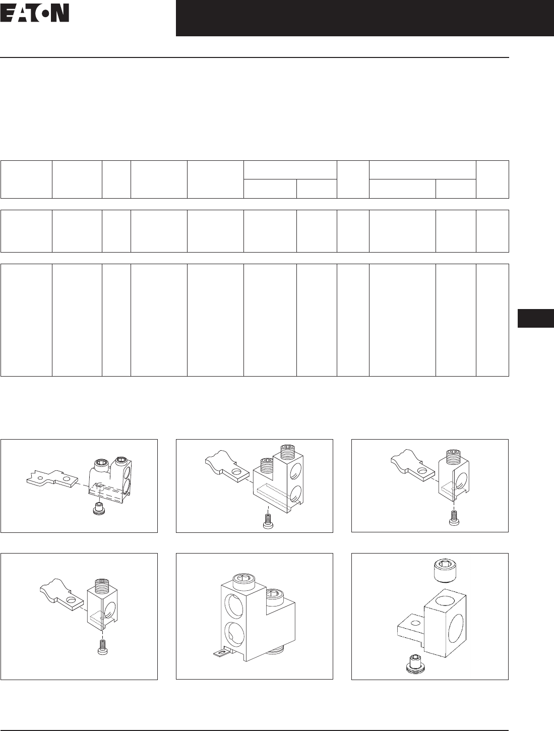
November 2008
CA08101001E For more information visit: www.eaton.com
12-113
Series C Molded Case Circuit Breakers
12
70 – 400 Amperes
K-Frame
Line and Load Terminals
Eaton’s Cutler-Hammer line and load
terminals provide wire connecting
capabilities for specific ranges of
continuous current ratings and wire
types. All terminals comply with
Underwriters Laboratories Standards
UL 486A and UL 486B and CSA Stan-
dard C22.2 No. 65, or Electrical Bulletin
1165. Unless otherwise specified, K-
Frame circuit breaker line and load ter-
minals are shipped separately for field
installation.
Ordering Information
K-Frame circuit breakers use Cu/AI
terminals as standard. When optional
copper or Cu/AI terminals are required,
order by Catalog Number. Specify if
factory installation is required.
Table 12-199. Line and Load Terminals
Individually packed.
Terminal kits contain one terminal for each pole and one terminal cover.
2-pole kit.
3-pole kit.
4-pole kit.
Terminal kits contain one terminal for each pole and three interphase barriers.
Figure 12-23. TA401K Figure 12-24. TA400K, T400K Figure 12-25. TA350K, T350K
Figure 12-26. TA300K, T300K Figure 12-27. T400KCW, TA400KCW,
TA401KCW
Figure 12-28. TA402K, T402K
Maximum
Breaker
Amperes
Terminal
Body
Material
Wire
Type
AWG Wire
Range/No.
Conductors
Metric Wire
Range mm2Terminal Figure Terminals with
Control Wire Termination
Figure
Catalog
Number
Price
U.S. $
Catalog
Number
Price
U.S. $
Standard Cu/AI Pressure Terminals
225
350
400
Aluminum
Aluminum
Aluminum
Cu/AI
Cu/AI
Cu/AI
3 – 350/(1)
250 – 500/(1)
3/0 – 250/(2)
35 – 185
120 – 240
95 – 120
TA300K
TA350K
2TA400K
3TA400K
4TA400K
12-26
12-25
12-24
12-24
12-24
—
—
2TA400KCW
3TA400KCW
4TA400KCW
—
—
12-27
12-27
12-27
Optional Copper and Cu/AI Pressure Type Terminals
225
350
400
400
400
400
Copper
Copper
Copper
Aluminum
Aluminum
Copper
Cu
Cu
Cu
Cu/AI
Cu/AI
Cu
3 – 350/(1)
250 – 500/(1)
3/0 – 250/(2)
2/0 – 250/(2)
or
2/0 – 500/(1)
500 – 750/(1)
500 – 750/(1)
35 – 185
120 – 240
95 – 120
70 – 120
70 – 240
70 – 240
300 – 400
—
T300K
T350K
2T400K
3T400K
4T400K
2TA401K
3TA401K
4TA401K
2TA402K
3TA402K
4TA402K
2T402K
3T402K
4T402K
12-26
12-25
12-24
12-24
12-24
12-23
12-23
12-23
12-28
12-28
12-28
12-28
12-28
12-28
—
—
2T400KCW
3T400KCW
4T400KCW
2TA401KCW
3TA401KCW
4TA401KCW
—
—
—
—
—
—
—
—
12-27
12-27
12-27
12-27
12-27
12-27
—
—
—
—
—
—
Tab is 1/4 x .032
Discount Symbol . . . . . . . . . . . . . . . . . . . . . . . . . CB-2

November 2008
12-114
For more information visit: www.eaton.com CA08101001E
Series C Molded Case Circuit Breakers
12
70 – 400 Amperes
K-Frame
Allowable Accessory Combinations
Different combinations of accessories can be supplied, depending on the types of accessories and the number of poles in the
circuit breaker.
Table 12-200. Accessories
■ Applicable in indicated pole position. ❏ May be mounted on left or right pole —
not both.
● Accessory available/Modification available.
2-pole breaker supplied in 3-pole frame. Current carrying parts omitted from center pole.
Shunt trip and UVR cannot be mounted in right poles on LES or OPTIM trip units.
Description Reference
Page
2-Pole 3-Pole 4-Pole
Left Right Left Center Right Left Center Right Neu.
Internal Accessories (Only One Internal Accessory Per Pole)
Alarm Lockout (Make/Break) 12-217 ■❏ ❏■
Alarm Lockout (2Make/2Break) 12-217 ❏❏■
Auxiliary Switch (1A, 1B) 12-220 ■■ ■■ ■
Auxiliary Switch (2A, 2B) 12-220 ■■■■
Auxiliary Switch (3A, 3B) 12-220 ■■■■
Auxiliary Switch and Alarm Switch Combination 12-223 ❏❏❏❏
Shunt Trip — Standard 12-226 ■■ ■■ ■
Shunt Trip — Low Energy 12-231 ■■■
Undervoltage Release Mechanism 12-232 ■■ ■■
PowerNet or Zone Interlock Kit (OPTIM 550) 12-242 ■
External Accessories
End Cap Kit 12-243 ●● ●
Keeper Nut 12-243 ●● ●
Control Wire Terminal Kit 12-244 ●● ●
Terminal Adapter 12-244 ●● ●
Multiwire Connectors 12-245 ●● ●
Base Mounting Hardware 12-246 ●● ●
Terminal Shields 12-248 ●● ●
Interphase Barriers 12-249 ●● ●
Non-Padlockable Handle Block 12-251 ■■■
Padlockable Handle Block 12-251 ■
Padlockable Handle Lock Hasp 12-252 ■❏ ❏❏ ❏
Cylinder Lock 12-252 ❏❏❏ ❏
Key Interlock Kit 12-253 ■❏❏ ❏❏ ❏
Sliding Bar Interlock — Requires Two Breakers 12-254 ●
Walking Beam Interlock — Requires Two Breakers 12-254 ●●
Electrical (Solenoid) Operator 12-255 ●●
Plug-in Adapters 12-257 ●● ●
Rear Connecting Studs 12-258 ●● ●
Panelboard Connecting Straps 12-261 ●● ●
Handle Mechanisms 12-262 ●● ●
Handle Extension 12-267 ●● ●
IQ Energy Sentinel 12-268 ●●
Solid-State (Electronic) Portable Test Kit 12-268 ●● ●
OPTIM System Components 3-Poles
Breaker Interface Module (BIM) 12-269
Digitrip OPTIMizer 12-269
Auxiliary Power Module 12-269
Modifications (Refer to Eaton)
Special Calibration — ●● ●
Moisture Fungus Treatment 12-73 ●● ●
Freeze-Tested Circuit Breakers — ●● ●
Marine Application — ●● ●
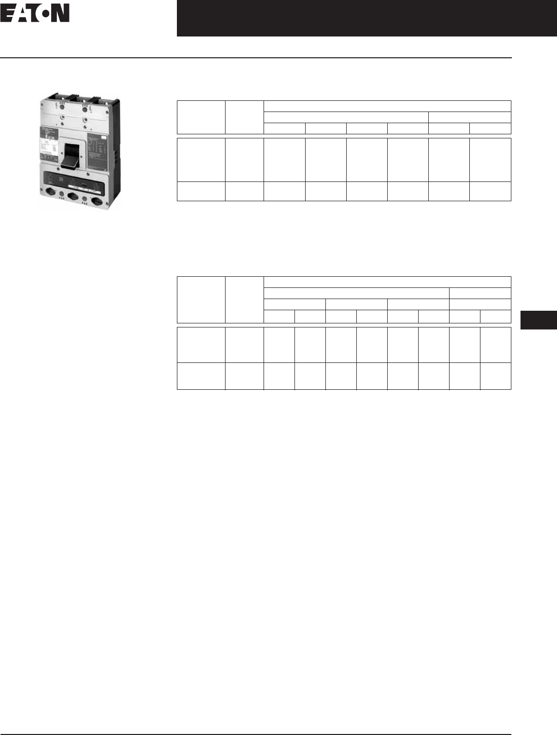
November 2008
CA08101001E For more information visit: www.eaton.com
12-115
Series C Molded Case Circuit Breakers
12
125 – 600 Amperes
L-Frame
L-Frame
Typical L-Frame Circuit Breaker
Product Description
■All Cutler-Hammer L-Frame Circuit
Breakers by Eaton Corporation are
HACR rated.
■L-Frame circuit breakers are available
as individual components (Frame,
Trip Unit, Terminals), or factory
assembled complete breakers.
■L-Frame circuit breakers with
non-interchangeable trip units
are suitable for reverse feed use.
■CE marked.
Technical Data and Specifications
Table 12-201. UL 489 Interrupting Capacity Ratings
Utilization category A circuit breakers.
L/R = 8 milliseconds minimum.
2-pole circuit breaker or two poles of 3-pole circuit breaker. Incorporating Thermal-Magnetic trip
unit only.
100% rated breakers.
Current limiting.
Table 12-202. IEC 947-2 Interrupting Capacity Ratings
Utilization category A circuit breakers.
L/R = 8 milliseconds minimum.
2-pole circuit breaker or two poles of 3-pole circuit breaker. Incorporating Thermal-Magnetic trip
unit only.
100% rated breakers.
Circuit
Breaker
Type
Number
of Poles
Interrupting Capacity (kA rms Symmetrical Amperes)
Volts ac (50/60 Hz) Volts dc
240 277 480 600 125 250
LDB
LD
CLD
HLD, HLDB
CHLD
2, 3
2, 3, 4
2, 3, 4
2, 3, 4
2, 3, 4
65
65
65
100
100
—
—
—
—
—
35
35
35
65
65
25
25
25
35
35
—
—
—
—
—
22
22
—
25
—
LDC, LDCB
CLDC
2, 3, 4
2, 3, 4
200
200
—
—
100
100
50
50
—
—
30
—
Circuit
Breaker
Type
Number
of Poles
Interrupting Capacity (kA Symmetrical Amperes)
Volts ac (50/60 Hz) Volts dc
240 415 690 250
Icu Ics Icu Ics Icu Ics Icu Ics
LDB
LD
CLD
HLD, HLDB
2, 3
2, 3, 4
2, 3, 4
2, 3, 4
85
85
85
100
85
85
85
100
45
45
45
70
45
45
45
70
20
20
20
25
10
10
10
13
20
20
—
20
10
10
—
10
CHLD
LDC, LDCB
CLDC
2, 3, 4
2, 3, 4
2, 3, 4
100
200
200
100
100
100
70
100
100
70
75
75
25
35
35
13
18
18
—
20
—
—
10
—
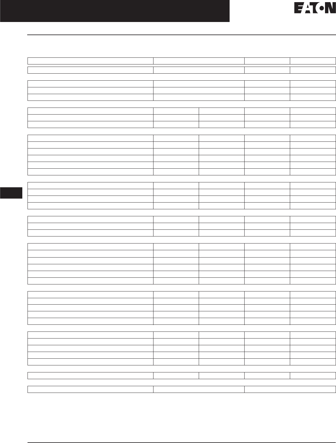
November 2008
12-116
For more information visit: www.eaton.com CA08101001E
Series C Molded Case Circuit Breakers
12
125 – 600 Amperes
L-Frame
L-Frame Digitrip Specifications
Table 12-203. Specifications
Adjust by rating plug.
By OPTIMizer/BIM.
Eaton’s Cutler-Hammer PowerNet kit.
Zone interlock kit.
With separate ground fault alarm unit (GFAU).
Legend: BIM = Breaker Interface Module
(A) = GF Alarm
Is = Sensor Rating
In = Rating Plug
Ir = Long Delay Pickup Setting
Trip Unit Type Digitrip RMS 310 Digitrip OPTIM 550 Digitrip OPTIM 1050
rms Sensing Ye s Yes Ye s
Breaker Type
Frame LLL
Ampere Range 300 – 600 A 200 – 600 A 200 – 600 A
Interrupting Rating at 480 Volts 35, 65, 100 (kA) 35, 65, 100 (kA) 35, 65, 100 (kA)
Protection
Ordering Options LS, LSG LSI, LSIG LSI, LSI(A), LSIG LSI(A), LSIG
Fixed Rated Plug (In) Yes Yes Yes Yes
Overtemperature Trip Yes Yes Yes Yes
Long Delay Protection (L)
Adjustable Rating Plug (In)YesYesNoNo
Long Delay Pickup 0.5 – 1.0 (In) 0.5 – 1.0 (In) 0.4 – 1.0 x (In) 0.4 – 1.0 x (In)
Long Delay Time I2t 12 Seconds 12 Seconds 2 – 24 Seconds 2 – 24 Seconds
Long Delay Time I4t No No 1 – 5 Seconds 1 – 5 Seconds
Long Delay Thermal Memory Yes Yes Yes Yes
High Load Alarm No No 0.5 – 1.0 x Ir0.5 – 1.0 x Ir
Short Delay Protection (S)
Short Delay Pickup 200 – 800% x (In) 200 – 800% x (In) 150 – 800% x (Ir) 150 – 800% x (Ir)
Short Delay Time I2t 100 ms No 100 – 500 ms 100 – 500 ms
Short Delay Time Flat No Inst – 300 ms 100 – 500 ms 100 – 500 ms
Short Delay Time Zone Selective Interlocking No No Yes Yes
Instantaneous Protection (I)
Instantaneous Pickup No 200 – 800% x (In) 200 – 800% x (In) 200 – 800% x (In)
Discriminator No No Yes Yes
Instantaneous Override Yes Yes Yes Yes
Ground Fault Protection (G)
Ground Fault Alarm No No 20 – 100% x (Is) 20 – 100% x (Is)
Ground Fault Pickup 1 – 5 x Ig (120 A) 1 – 5 x Ig (120 A) 20 – 100% x (Is) 20 – 100% x (Is)
Ground Fault Delay I2t No No 100 – 500 ms 100 – 500 ms
Ground Fault Delay Flat Inst – 500 ms Inst – 500 ms 100 – 500 ms 100 – 500 ms
Ground Fault Zone Selective Interlocking No No Yes Yes
Ground Fault Thermal Memory Yes Yes Yes Yes
System Diagnostics
Status LEDs Yes Yes Yes Yes
Cause of Trip LEDs No No Yes Yes
Magnitude of Trip Information No No Yes Yes
Remote Signal Contact — Ground Alarm Yes Yes Ye s Yes
Local Auxiliary and Bell Alarm Contact Optional Optional Optional Included
System Monitoring
Digital Display No No Yes Yes
Current No No Yes Yes
Power and Energy No No No Yes
Power Quality — Harmonics No No No Yes
Power Factor No No No Yes
Communications
Cutler-Hammer PowerNet No No Yes Yes
Testing
Testing Method Test Set OPTIMizer, BIM, Cutler-Hammer PowerNet

November 2008
CA08101001E For more information visit: www.eaton.com
12-117
Series G Molded Case Circuit Breakers
12
125 – 600 Amperes
L-Frame
Dimensions/Weights
Table 12-204. Dimensions in Inches (mm)
Table 12-205. Approximate Shipping Weight, Lbs. (kg)
Number of Poles Width Height Depth
2, 3
4
8.25 (209.6)
11.00 (279.4)
10.75 (273.1)
10.75 (273.1)
4.06 (103.1)
4.06 (103.1)
Breaker
Type
Complete Breaker Frame Only Trip Unit
Number of Poles
234 234234
LD, HLD, LDC
LDB
18 (8.2)
18 (8.2)
20 (9.1)
20 (9.1)
25 (11.3)
25 (11.3)
14 (6.4)
—
15 (6.8)
—
20 (9.1)
—
3 (1.4)
—
4 (1.8)
—
5 (2.3)
—

November 2008
12-118
For more information visit: www.eaton.com CA08101001E
Series C Molded Case Circuit Breakers
12
125 – 600 Amperes
L-Frame
Product Selection
This information is presented only as an aid to understanding catalog numbers. It is not to be used to build catalog numbers
for circuit breakers or trip units.
Table 12-206. Circuit Breaker/Frame Catalog Numbering System
Table 12-207. Thermal-Magnetic Trip Unit Catalog Numbering System
Table 12-208. OPTIM Circuit Breaker/Frame Catalog Numbering System
Table 12-209. Digitrip RMS 310 Trip Unit Catalog Numbering System
LD 3 600 F
Circuit Breaker/
Frame Type
LDB
LD
HLD
LDC
CLD
CHLD
CLDC
Number
of Poles
2 = 2 Poles
3 = 3 Poles
4 = 4 Poles
Circuit Breaker/
Frame Ampere
Rating
300
350
400
450
500
600
Suffix
C= Copper Terminals
F= Frame Only
K= High Magnetic Molded Case Switch
V= 50°C (Thermal-Magnetic Trip Units Only)
W= Without Terminals
X= Load Side Terminals Only
Y= Line Side Terminals Only
LT 3 400 T
Trip Unit Type
LT = Thermal
Magnetic
Number
of Poles
2 = 2 Poles
3 = 3 Poles
4 = 4 Poles
Trip Unit Rating/
Plug Ampere Rating
300
350
400
450
500
600
Suffix
T= Trip Unit Thermal-Magnetic
Fixed Thermal Adjustable Magnetic
V= 50°C Calibration
(Thermal-Magnetic Trip Units Only)
LD 3 125 T5 7 W
Circuit Breaker/
Frame Type
LD
HLD
LDC
CLD
CHLD
CLDC
Trip Type
2 = LSI (550 Only)
6 = LSIG
7 = LSIA
Suffix
W = Without Terminals
Circuit Breaker/
Frame Ampere Rating
125 = (Available on Model 1050 Only)
250 = (Available on Model 1050 Only)
400
600
Number
of Poles
3 = 3 Poles
Trip Model
T5 = Model 550
T10 = Model 1050
LES 3 600 LS P
Trip Unit Type
LES = Electronic
Number
of Poles
3 = 3 Poles
4 = 4 Poles
Suffix
P= 100% Protected
Neutral on 4-Pole
Trip Unit
Suffix
LS
LSI
LSG
LSIG
Trip Unit
Ampere
Rating
600

CA08101001E For more information visit: www.eaton.com
12-119
Series C Molded Case Circuit Breakers
November 2008
12
125 – 600 Amperes
L-Frame
Product Selection
Table 12-210. Types LD, HLD and LDC Thermal-Magnetic Circuit Breakers with Interchangeable
Trip Units
Magnetic trip range 5 – 10 times continuous ampere rating.
Individually packed.
Terminal kits contain one terminal for each pole and one terminal cover.
Neutral is in right pole.
Table 12-211. Types LD, HLD and LDC Thermal-Magnetic Circuit Breakers — Frame Only
Maximum
Continuous
Ampere
Rating
at 40°C
Standard Interrupting
Capacity
600 Vac Rated
35 kAIC at 480 Vac
High Interrupting
Capacity
600 Vac Rated
65 kAIC at 480 Vac
Ultra High Interrupting
Capacity Current Limiting
600 Vac Rated
100 kAIC at 480 Vac
Thermal-Magnetic
Trip Unit Only
For Use with Standard
or High or Ultra High
Interrupting Frames
Standard Terminals Only
See Page 12-132 for
Optional
Terminals
Factory Assembled
Circuit Consisting of
Frame, Trip Unit and
Terminals
Factory Assembled
Circuit Consisting of
Frame, Trip Unit and
Terminals
Factory Assembled Circuit
Consisting of Frame, Trip
Unit and Terminals
Catalog
Number
Price
U.S. $
Catalog
Number
Price
U.S. $
Catalog
Number
Price
U.S. $
Catalog
Number
Price
U.S. $
Catalog
Number
Price
U.S. $
2-Pole
300
350
400
450
500
600
LD2300
LD2350
LD2400
LD2450
LD2500
LD2600
HLD2300
HLD2350
HLD2400
HLD2450
HLD2500
HLD2600
LDC2300
LDC2350
LDC2400
LDC2450
LDC2500
LDC2600
LT2300T
LT2350T
LT2400T
LT2450T
LT2500T
LT2600T
TA602LD
TA602LD
TA602LD
TA602LD
TA602LD
2TA603LDK
3-Pole
300
350
400
450
500
600
LD3300
LD3350
LD3400
LD3450
LD3500
LD3600
HLD3300
HLD3350
HLD3400
HLD3450
HLD3500
HLD3600
LDC3300
LDC3350
LDC3400
LDC3450
LDC3500
LDC3600
LT3300T
LT3350T
LT3400T
LT3450T
LT3500T
LT3600T
TA602LD
TA602LD
TA602LD
TA602LD
TA602LD
3TA603LDK
4-Pole
300
350
400
450
500
600
LD4300
LD4350
LD4400
LD4450
LD4500
LD4600
HLD4300
HLD4350
HLD4400
HLD4450
HLD4500
HLD4600
LDC4300
LDC4350
LDC4400
LDC4450
LDC4500
LDC4600
LT4300T
LT4350T
LT4400T
LT4450T
LT4500T
LT4600T
TA602LD
TA602LD
TA602LD
TA602LD
TA602LD
4TA603LDK
Standard Interrupting
Capacity 600 Vac Rated
35 kAIC at 480 Vac
High Interrupting Capacity
600 Vac Rated
65 kAIC at 480 Vac
Ultra High Interrupting
Capacity Current Limiting
600 Vac Rated
100 kAIC at 480 Vac
Catalog
Number
Price
U.S. $
Catalog
Number
Price
U.S. $
Catalog
Number
Price
U.S. $
2-Pole
LD2600F HLD2600F LDC2600F
3-Pole
LD3600F HLD3600F LDC3600F
4-Pole
LD4600F HLD4600F LDC4600F
Discount Symbol . . . . . . . . . . . . . . . . . . . . . . . . . CB-2

November 2008
12-120
For more information visit: www.eaton.com CA08101001E
Series C Molded Case Circuit Breakers
12
125 – 600 Amperes
L-Frame
Types LD, HLD and LDC Electronic Circuit Breakers with Interchangeable Trip Units
Order as individual components: Breaker Frame, Trip Unit, Rating Plug, Terminals.
Table 12-212. Types LD, HLD and LDC Electronic Circuit Breakers with Interchangeable Trip Units
See Table 12-213 below for prices.
Individually packed.
For ac use only.
Neutral is in right pole.
Terminal kits contain one terminal for each pole and one terminal cover.
Table 12-213. Types LD, HLD and LDC Electronic Circuit Breakers with Interchangeable Trip Units Prices
Maxi-
mum
Contin-
uous
Ampere
Rating
at 40°C
Circuit Breaker Frame Only Digitrip RMS 310 Trip Unit Only Digitrip RMS 310 Rating Plug Only Standard
Terminals
Only
See
Page 12-132
for Optional
Terminals
Standard
Inter-
rupting
Capacity
600 Vac
Rated
35 kAIC at
480 Vac
High
Inter-
rupting
Capacity
600 Vac
Rated
65 kAIC at
480 Vac
Ultra High
Inter-
rupting
Capacity
Current
Limiting
600 Vac Rated
100 kAIC at
480 Vac
L – Adjustable Long Delay Pickup (By Adjustable
Rating Plug)
S – Adjustable Short Delay Pickup with Fixed Short
Delay Time (I2t Response) or Adjustable Short
Delay Time (Flat Response)
I – Adjustable Instantaneous Pickup by Setting
Short Delay Time to Instantaneous
G – Adjustable Ground Fault Pickup with Adjustable
Ground Fault Delay (Flat Response)
Ampere
Rating
Fixed
Rating
Plug
Adjustable
Rating Plug
Ampere
Rating
Catalog Number Catalog Number Catalog Number
3-Pole
600 LD3600F HLD3600F LDC3600F LES3600LS LES3600LSI LES3600LSG LES3600LSIG 300
350
400
450
500
600
6LES300T
6LES350T
6LES400T
6LES450T
6LES500T
6LES600T
300/400/
500/600
A6LES600T1
TA602LD
TA602LD
TA602LD
TA602LD
3TA603LDK
420/440/
460/480
A6LES400T5
520/540/
560/580
A6LES500T5
4-Pole
600 LD4600F HLD4600F LDC4600F LES4600LS LES4600LSI — — 300
350
400
450
500
600
6LES300T
6LES350T
6LES400T
6LES450T
6LES500T
6LES600T
300/400/
500/600
A6LES600T1
TA602LD
TA602LD
TA602LD
TA602LD
4TA603LDK
420/440/
460/480
A6LES400T5
520/540/
560/580
A6LES500T5
Catalog
Number
Price
U.S. $
Catalog
Number
Price
U.S. $
Catalog
Number
Price
U.S. $
Catalog
Number
Price
U.S. $
Catalog
Number
Price
U.S. $
A6LES600T1
HLD3600F
HLD4600F
LDC3600F
LDC4600F
—
LD3600F
LD4600F
LES3600LS
LES3600LSG
LES3600LSI
—
LES3600LSIG
LES4600LS
LES4600LSI
TA602LD
3TA603LDK
—
4TA603LDK
6LES300T
6LES350T
6LES400T
6LES450T
6LES500T
6LES600T
—
—
A6LES400T5
A6LES500T5
—
Discount Symbol . . . . . . . . . . . . . . . . . . . . . . . . CB-2

November 2008
CA08101001E For more information visit: www.eaton.com
12-121
Series C Molded Case Circuit Breakers
12
125 – 600 Amperes
L-Frame
Table 12-214. Types LDB, HLDB and LDCB Electronic Circuit Breakers with Non-Interchangeable Electronic Trip Units Suitable for Reverse Feed
Page 12-121
See Table 12-215 on Page 12-121 for prices.
For ac use only.
Table 12-215. Type NGC Very High Capacity — Ue Max. 690 Vac, 100 kA Icu at 480 Vac or 415 Vac Prices
Maximum
Continuous
Ampere Rating
at 40ºC
Number
of Poles
Circuit Breaker Frame Including DigiTrip RMS 310 Electronic Tip Unit Less
Terminals and Rating Plug
Digitrip RMS 310 Rating Plug
(Order as Separate Items)
L – Adjustable Long Delay Pickup (By Adjustable Rating Plug)
S – Adjustable Short Delay Pickup with Fixed Short Delay Time
(I2t Response) or Adjustable Short Time (Flat Response)
I – Adjustable Instantaneous Pickup by Setting Short Time Delay Time to
Instantaneous
G – Adjustable Ground Fault Pickup with Adjustable Ground Fault Delay
(Flat Response)
Fixed Adjustable
Catalog Number
LS LSI LSG LSIG Catalog Number
Short Time Range
Short Time Delay
Ground Fault Pickup
Ground Fault Delay
2 – 8 x In
—
—
—
2 – 8 x In
0 – 300 ms
—
—
2 – 8 x In
—
Varies by Frame
0 – 500 ms
2 – 8 x In
0 – 300 ms
Varies by Frame
0 – 500 ms
Type LDB, HLDB and LDCB with Digitrip 310 Non-Interchangeable Trip Unit
600 3 LDB3600FT33W LDB3600FT32W LDB3600FT35W LDB3600FT35W 6LES300T
6LES350T
6LES400T
6LES450T
6LES500T
6LES600T
300/400/500/600
A6LES600T1
420/440/460/480
A6LES400T5
520/540/560/580
A6LES500T5
600 3 HLDB3600FT33W HLDB3600FT32W HLDB3600FT35W HLDB3600FT36W 6LES300T
6LES350T
6LES400T
6LES450T
6LES500T
6LES600T
300/400/500/600
A6LES600T1
420/440/460/480
A6LES400T5
520/540/560/580
A6LES500T5
600 3 LDCB3600FT33W LDCB3600FT32W LDCB3600FT35W LDCB3600FT36W 6LES300T
6LES350T
6LES400T
6LES450T
6LES500T
6LES600T
300/400/500/600
A6LES600T1
420/440/460/480
A6LES400T5
520/540/560/580
A6LES500T5
Catalog
Number
Price
U.S. $
Catalog
Number
Price
U.S. $
Catalog
Number
Price
U.S. $
Catalog
Number
Price
U.S. $
A6LES400T5
A6LES500T5
A6LES600T1
HLDB3600FT32W
HLDB3600FT33W
HLDB3600FT35W
HLDB3600FT36W
LDB3600FT32W
LDB3600FT33W
LDB3600FT35W
LDB3600FT36W
LDCB3600FT32W
LDCB3600FT33W
LDCB3600FT35W
LDCB3600FT36W
6LES300T
6LES350T
—
6LES400T
6LES450T
—
6LES500T
6LES600T
—
Discount Symbol . . . . . . . . . . . . . . . . . . . . . . . . . CB-2

November 2008
12-122
For more information visit: www.eaton.com CA08101001E
Series C Molded Case Circuit Breakers
12
125 – 600 Amperes
L-Frame
100% Rated Types CLD, CHLD, and CLDC Electronic Circuit Breakers with Interchangeable Trip Units
The NEC allows the breaker to be rated at 100% of its frame size in an assembly, provided that 90°C wire is applied at the 75°C
ampacity. All 100% rated circuit breakers have electronic trip units. Order as individual components: Breaker Frame, Trip Unit,
Rating Plug and Terminals.
Table 12-216. 100% Rated Types CLD, CHLD, and CLDC Electronic Circuit Breakers with Interchangeable Trip Units
See Table 12-217 below for prices.
Ampere rating is established by rating plug.
Individually packed.
3TA603LDK terminal kit contains one terminal for each pole and one terminal cover.
Table 12-217. 100% Rated Types CLD, CHLD and CLDC Electronic Circuit Breakers with
Interchangeable Trip Units Prices
Maximum
Continuous
Ampere
Rating
at 40°C
Circuit Breaker Frame Only Digitrip RMS 310 Trip Unit Only Digitrip RMS 310 Rating Plug Only Standard
Terminals
Only
See
Page 12-132
for Optional
Terminals
Standard
Inter-
rupting
Capacity
600 Vac
Rated
35 kAIC at
480 Vac
High
Inter-
rupting
Capacity
600 Vac
Rated
65 kAIC at
480 Vac
Ultra High
Inter-
rupting
Capacity
Current
Limiting
600 Vac
Rated
100 kAIC at
480 Vac
Standard Options Ampere
Rating
Fixed
Rating
Plug
Adjustable
Rating Plug
Adjustable
Short Time
Pickup with
I
2
t Short
Delay Ramp
Indepen-
dently
Adjustable
Short Time
Pickup and
Delay
Ground
Fault
Protection
Adjustable
Short Time
Pickup with
I
2
t Short
Delay and
Ground
Fault
Protection
Indepen-
dently
Adjustable
Short Time
Pickup and
Delay and
Ground
Fault
Protection
Ampere
Rating
Catalog Number Catalog Number
3-Pole
600 CLD3600F CHLD3600F CLDC3600F LES3600LS LES3600LSI LES3600LSG LES3600LSIG 300
350
400
450
500
600
6LES300T
6LES350T
6LES400T
6LES450T
6LES500T
6LES600T
300/400/
500/600
A6LES600T1
TA602LD
TA602LD
TA602LD
TA602LD
3TA603LDK
420/440/460/480
A6LES400T5
520/540/560/580
A6LES500T5
Catalog
Number
Price
U.S. $
Catalog
Number
Price
U.S. $
Catalog
Number
Price
U.S. $
A6LES600T1
CHLD3600F
CLDC3600F
CLD3600F
LES3600LS
—
LES3600LSG
LES3600LSI
LES3600LSIG
TA602LD
3TA603LDK
—
6LES300T
6LES350T
6LES400T
6LES450T
6LES500T
6LES600T
Discount Symbol . . . . . . . . . . . . . . . . . . . . . . . . CB-2

November 2008
CA08101001E For more information visit: www.eaton.com
12-123
Series C Molded Case Circuit Breakers
12
125 – 600 Amperes
L-Frame
Table 12-218. Type LDB Thermal-Magnetic Circuit Breakers with
Non-interchangeable Trip Units
Factory sealed — suitable for reverse feed application.
Molded Case Switches
Eaton’s Cutler-Hammer molded case switches are used as
compact switches in applications requiring high current
switching capabilities. Molded case switches are con-
structed of circuit breaker components and are of the high
instantaneous automatic type. Molded case switches
are listed in accordance with Underwriters Laboratories
Standard UL 489.
Table 12-219. Molded Case Switches
Factory sealed — suitable for reverse feed application.
Note: Molded case switch will trip above 6000 amperes.
Maximum
Continuous
Ampere
Rating
600 Vac Rated, 250 Vdc
Complete Circuit Breaker
Without Line and
Load Terminals
With Standard Line and
Load Terminals Only
Catalog
Number
Price
U.S. $
Catalog
Number
Price
U.S. $
2-Pole
300
350
400
LDB2300W
LDB2350W
LDB2400W
LDB2300
LDB2350
LDB2400
450
500
600
LDB2450W
LDB2500W
LDB2600W
LDB2450
LDB2500
LDB2600
3-Pole
300
350
400
LDB3300W
LDB3350W
LDB3400W
LDB3300
LDB3350
LDB3400
450
500
600
LDB3450W
LDB3500W
LDB3600W
LDB3450
LDB3500
LDB3600
Maximum
Continuous
Ampere
Rating
at 40°C
600 Vac Maximum, 250 Vdc Standard Terminals Only
See Page 12-132 for
Optional Terminals
Circuit Breaker Only
without Line and Load
Terminals
Catalog
Number
Price
U.S. $
Catalog
Number
Price
U.S. $
2-Pole
600
600
600
LD2600WK
LDB2600WK
HLD2600WK
2TA603LDK
2TA603LDK
2TA603LDK
3-Pole
600
600
600
LD3600WK
LDB3600WK
HLD3600WK
3TA603LDK
3TA603LDK
3TA603LDK
4-Pole
600
600
600
LD4600WK
LDB4600WK
HLD4600WK
4TA603LDK
4TA603LDK
4TA603LDK
Discount Symbol . . . . . . . . . . . . . . . . . . . . . . . . . CB-2

November 2008
12-124
For more information visit: www.eaton.com CA08101001E
Series C Molded Case Circuit Breakers
12
125 – 600 Amperes
L-Frame
Digitrip OPTIM Electronic Circuit Breaker with Interchangeable Rating Plug
Order as individual components: Breaker Frame (which includes Trip Unit), Rating Plug, Terminals.
Table 12-220. Digitrip OPTIM 550 Electronic Circuit Breaker with Interchangeable Rating Plug
Long delay I4t response selection limits short delay time to flat response.
Zone Interlocking, PowerNet, or both features can be added at the factory by adding Suffixes ZG, PN or ZGP respectively to above Catalog Number
(refer to Page 12-242 and take list price Adder x 1.25).
Maximum
Continuous
Ampere
Rating
at 40°C
Circuit Breaker Frame Only Digitrip OPTIM Rating Plug Only
L – Adjustable Long Delay Pickup (Ir) with Adjustable Long Delay Time (I2t or I4t Response)
S – Adjustable Short Delay Pickup with Adjustable Short Delay Time (I2t or Flat Response)
I – Adjustable Instantaneous Pickup
G – Adjustable Ground Fault Pickup with Adjustable Ground Fault Time (I2t or Flat Response)
A – Adjustable Ground Fault Alarm with Adjustable Ground Fault Time (I2t or Flat Response)
Ampere
Rating
Fixed
Rating Plug
OPTIM 550
LSI LSIG LSIA
Catalog
Number
Price
U.S. $
Catalog
Number
Price
U.S. $
Catalog
Number
Price
U.S. $
Catalog
Number
Price
U.S. $
3-Pole Standard Interrupting Capacity 600 Vac Rated 35 kAIC at 480 Vac
125 LD3125T52W LD3125T56W LD3125T57W —
—
—
—
—
ORPL125A070
ORPL125A090
ORPL125A100
ORPL125A110
ORPL125A125
250 LD3250T52W LD3250T56W LD3250T57W —
—
—
—
—
—
ORPL025A125
ORPL025A150
ORPL025A175
ORPL025A200
ORPL025A225
ORPL025A250
400 LD3400T52W LD3400T56W LD3400T57W 200
225
250
300
350
400
ORPL40A200
ORPL40A225
ORPL40A250
ORPL40A300
ORPL40A350
ORPL40A400
600 LD3600T52W LD3600T56W LD3600T57W 300
350
400
500
600
ORPL60A300
ORPL60A350
ORPL60A400
ORPL60A500
ORPL60A600
3-Pole High Interrupting Capacity 600 Vac Rated 65 kAIC at 480 Vac
125 HLD3125T52W HLD3125T56W HLD3125T57W 70
90
100
110
125
ORPL125A070
ORPL125A090
ORPL125A100
ORPL125A110
ORPL125A125
250 HLD3250T52W HLD3250T56W HLD3250T57W 125
150
175
200
225
250
ORPL025A125
ORPL025A150
ORPL025A175
ORPL025A200
ORPL025A225
ORPL025A250
400 HLD3400T52W HLD3400T56W HLD3400T57W 200
225
250
300
350
400
ORPL40A200
ORPL40A225
ORPL40A250
ORPL40A300
ORPL40A350
ORPL40A400
600 HLD3600T52W HLD3600T56W HLD3600T57W 300
350
400
500
600
ORPL60A300
ORPL60A350
ORPL60A400
ORPL60A500
ORPL60A600
Discount Symbol . . . . . . . . . . . . . . . . . . . . . . . . CB-2

November 2008
CA08101001E For more information visit: www.eaton.com
12-125
Series C Molded Case Circuit Breakers
12
125 – 600 Amperes
L-Frame
Table 12-220. Digitrip OPTIM 550 Electronic Circuit Breaker with Interchangeable Rating Plug (Continued)
Zone Interlocking, PowerNet, or both features can be added at the factory by adding Suffixes ZG, PN or ZGP respectively to above Catalog Number
(refer to Page 12-242 and take list price Adder x 1.25).
Maximum
Continuous
Ampere
Rating
at 40°C
Circuit Breaker Frame Only Digitrip OPTIM Rating Plug Only
L – Adjustable Long Delay Pickup (Ir) with Adjustable Long Delay Time (I2t or I4t Response)
S – Adjustable Short Delay Pickup with Adjustable Short Delay Time (I2t or Flat Response)
I – Adjustable Instantaneous Pickup
G – Adjustable Ground Fault Pickup with Adjustable Ground Fault Time (I2t or Flat Response)
A – Adjustable Ground Fault Alarm with Adjustable Ground Fault Time (I2t or Flat Response)
Ampere
Rating
Fixed
Rating Plug
OPTIM 550
LSI LSIG LSIA
Catalog
Number
Price
U.S. $
Catalog
Number
Price
U.S. $
Catalog
Number
Price
U.S. $
Catalog
Number
Price
U.S. $
3-Pole Ultra High Interrupting Capacity Current Limiting 600 Vac Rated 100 kAIC at 480 Vac
125 LDC3125T52W LDC3125T56W LDC3125T57W —
—
—
—
—
ORPL125A070
ORPL125A090
ORPL125A100
ORPL125A110
ORPL125A125
250 LDC3250T52W LDC3250T56W LDC3250T57W —
—
—
—
—
—
ORPL025A125
ORPL025A150
ORPL025A175
ORPL025A200
ORPL025A225
ORPL025A250
400 LDC3400T52W LDC3400T56W LDC3400T57W 200
225
250
300
350
400
ORPL40A200
ORPL40A225
ORPL40A250
ORPL40A300
ORPL40A350
ORPL40A400
600 LDC3600T52W LDC3600T56W LDC3600T57W 300
350
400
500
600
ORPL60A300
ORPL60A350
ORPL60A400
ORPL60A500
ORPL60A600
Discount Symbol . . . . . . . . . . . . . . . . . . . . . . . . . CB-2

November 2008
12-126
For more information visit: www.eaton.com CA08101001E
Series C Molded Case Circuit Breakers
12
125 – 600 Amperes
L-Frame
Digitrip OPTIM Electronic Circuit Breaker with Interchangeable Rating Plug
Order as individual components: Breaker Frame (which includes Trip Unit), Rating Plug, Terminals.
Table 12-221. Digitrip OPTIM 1050 Electronic Circuit Breaker with Interchangeable Rating Plug
Long delay I4t response selection limits short delay time to flat response.
One Form C auxiliary switch and one Form C bell alarm switch supplied with breaker as standard.
Factory sealed.
Maximum
Continuous
Ampere
Rating
at 40°C
Circuit Breaker Frame Only Digitrip OPTIM Rating Plug Only
L – Adjustable Long Delay Pickup (Ir) with Adjustable Long Delay Time (I2t or I4t Response)
S – Adjustable Short Delay Pickup with Adjustable Short Delay Time (I2t or Flat Response)
I – Adjustable Instantaneous Pickup
G – Adjustable Ground Fault Pickup with Adjustable Ground Fault Time (I2t or Flat Response)
A – Adjustable Ground Fault Alarm with Adjustable Ground Fault Time (I2t or Flat Response)
Ampere
Rating
Fixed
Rating Plug
OPTIM 1050
LSIG LSIA
Catalog
Number
Price
U.S. $
Catalog
Number
Price
U.S. $
Catalog
Number
Price
U.S. $
3-Pole Standard Interrupting Capacity 600 Vac Rated 35 kAIC at 480 Vac
125 LD3125T106W LD3125T107W 70
90
100
110
125
ORPL125A070
ORPL125A090
ORPL125A100
ORPL125A110
ORPL125A125
250 LD3250T106W LD3250T107W 125
150
175
200
225
250
ORPL025A125
ORPL025A150
ORPL025A175
ORPL025A200
ORPL025A225
ORPL025A250
400 LD3400T106W LD3400T107W 200
225
250
300
350
400
ORPL40A200
ORPL40A225
ORPL40A250
ORPL40A300
ORPL40A350
ORPL40A400
600 LD3600T106W LD3600T107W 300
350
400
500
600
ORPL60A300
ORPL60A350
ORPL60A400
ORPL60A500
ORPL60A600
3-Pole High Interrupting Capacity 600 Vac Rated 65 kAIC at 480 Vac
125 HLD3125T106W HLD3125T107W 70
90
100
110
125
ORPL125A070
ORPL125A090
ORPL125A100
ORPL125A110
ORPL125A125
250 HLD3250T106W HLD3250T107W 125
150
175
200
225
250
ORPL025A125
ORPL025A150
ORPL025A175
ORPL025A200
ORPL025A225
ORPL025A250
400 HLD3400T106W HLD3400T107W 200
225
250
300
350
400
ORPL40A200
ORPL40A225
ORPL40A250
ORPL40A300
ORPL40A350
ORPL40A400
600 HLD3600T106W HLD3600T107W 300
350
400
500
600
ORPL60A300
ORPL60A350
ORPL60A400
ORPL60A500
ORPL60A600
Discount Symbol . . . . . . . . . . . . . . . . . . . . . . . . . CB-2

November 2008
CA08101001E For more information visit: www.eaton.com
12-127
Series C Molded Case Circuit Breakers
12
125 – 600 Amperes
L-Frame
Table 12-221. Digitrip OPTIM 1050 Electronic Circuit Breaker with Interchangeable Rating Plug (Continued)
Long delay I4t response selection limits short delay time to flat response.
One Form C auxiliary switch and one Form C bell alarm switch supplied with breaker as standard.
Factory sealed.
Maximum
Continuous
Ampere
Rating
at 40°C
Circuit Breaker Frame Only Digitrip OPTIM Rating Plug Only
L – Adjustable Long Delay Pickup (Ir) with Adjustable Long Delay Time (I2t or I4t Response)
S – Adjustable Short Delay Pickup with Adjustable Short Delay Time (I2t or Flat Response)
I – Adjustable Instantaneous Pickup
G – Adjustable Ground Fault Pickup with Adjustable Ground Fault Time (I2t or Flat Response)
A – Adjustable Ground Fault Alarm with Adjustable Ground Fault Time (I2t or Flat Response)
Ampere
Rating
Fixed
Rating Plug
OPTIM 1050
LSIG LSIA
Catalog
Number
Price
U.S. $
Catalog
Number
Price
U.S. $
Catalog
Number
Price
U.S. $
3-Pole Ultra High Interrupting Capacity Current Limiting 600 Vac Rated 100 kAIC at 480 Vac
125 LDC3125T106W LDC3125T107W 70
90
100
110
125
ORPL125A070
ORPL125A090
ORPL125A100
ORPL125A110
ORPL125A125
250 LDC3250T106W LDC3250T107W 125
150
175
200
225
250
ORPL025A125
ORPL025A150
ORPL025A175
ORPL025A200
ORPL025A225
ORPL025A250
400 LDC3400T106W LDC3400T107W 200
225
250
300
350
400
ORPL40A200
ORPL40A225
ORPL40A250
ORPL40A300
ORPL40A350
ORPL40A400
600 LDC3600T106W LDC3600T107W 300
350
400
500
600
ORPL60A300
ORPL60A350
ORPL60A400
ORPL60A500
ORPL60A600
Discount Symbol . . . . . . . . . . . . . . . . . . . . . . . . . CB-2

November 2008
12-128
For more information visit: www.eaton.com CA08101001E
Series C Molded Case Circuit Breakers
12
125 – 600 Amperes
L-Frame
100% Rated Digitrip OPTIM Circuit Breakers with Interchangeable Rating Plug
Order as individual components: Breaker Frame (which includes Trip Unit), Rating Plug, Terminals.
Table 12-222. 100% Rated Digitrip OPTIM 550 Circuit Breakers with Interchangeable Rating Plug
Long delay I4t response selection limits short delay time to flat response.
Zone Interlocking, PowerNet, or both features can be added at the factory by adding Suffixes ZG, PN or ZGP respectively to above Catalog Number
(refer to Page 12-242 and take list price Adder x 1.25).
Maximum
Continuous
Ampere
Rating
at 40°C
Circuit Breaker Frame Only Digitrip OPTIM Rating Plug Only
L – Adjustable Long Delay Pickup (Ir) with Adjustable Long Delay Time (I2t or I4t Response)
S – Adjustable Short Delay Pickup with Adjustable Short Delay Time (I2t or Flat Response)
I – Adjustable Instantaneous Pickup
G – Adjustable Ground Fault Pickup with Adjustable Ground Fault Time (I2t or Flat Response)
A – Adjustable Ground Fault Alarm with Adjustable Ground Fault Time (I2t or Flat Response)
Ampere
Rating
Fixed
Rating Plug
OPTIM 550
LSI LSIG LSIA
Catalog
Number
Price
U.S. $
Catalog
Number
Price
U.S. $
Catalog
Number
Price
U.S. $
Catalog
Number
Price
U.S. $
3-Pole Standard Interrupting Capacity 600 Vac Rated 35 kAIC at 480 Vac
125 CLD3125T52W CLD3125T56W CLD3125T57W 70
90
100
110
125
ORPL125A070
ORPL125A090
ORPL125A100
ORPL125A110
ORPL125A125
250 CLD3250T52W CLD3250T56W CLD3125T57W 125
150
175
200
225
250
ORPL025A125
ORPL025A150
ORPL025A175
ORPL025A200
ORPL025A225
ORPL025A250
400 CLD3400T52W CLD3400T56W CLD3400T57W 200
225
250
300
350
400
ORPL40A200
ORPL40A225
ORPL40A250
ORPL40A300
ORPL40A350
ORPL40A400
600 CLD3600T52W CLD3600T56W CLD3600T57W 300
350
400
500
600
ORPL60A300
ORPL60A350
ORPL60A400
ORPL60A500
ORPL60A600
3-Pole High Interrupting Capacity 600 Vac Rated 65 kAIC at 480 Vac
125 CHLD3125T52W CHLD3125T56W CHLD3125T57W 70
90
100
110
125
ORPL125A070
ORPL125A090
ORPL125A100
ORPL125A110
ORPL125A125
250 CHLD3250T52W CHLD3250T56W CHLD3125T57W 125
150
175
200
225
250
ORPL025A125
ORPL025A150
ORPL025A175
ORPL025A200
ORPL025A225
ORPL025A250
400 CHLD3400T52W CHLD3400T56W CHLD3400T57W 200
225
250
300
350
400
ORPL40A200
ORPL40A225
ORPL40A250
ORPL40A300
ORPL40A350
ORPL40A400
600 CHLD3600T52W CHLD3600T56W CHLD3600T57W 300
350
400
500
600
ORPL60A300
ORPL60A350
ORPL60A400
ORPL60A500
ORPL60A600
Discount Symbol . . . . . . . . . . . . . . . . . . . . . . . . . CB-2

November 2008
CA08101001E For more information visit: www.eaton.com
12-129
Series C Molded Case Circuit Breakers
12
125 – 600 Amperes
L-Frame
Table 12-222. 100% Rated Digitrip OPTIM 550 Circuit Breakers with Interchangeable Rating Plug (Continued)
Long delay I4t response selection limits short delay time to flat response.
Zone Interlocking, PowerNet, or both features can be added at the factory by adding Suffixes ZG, PN or ZGP respectively to above Catalog Number
(refer to Page 12-242 and take list price Adder x 1.25).
Maximum
Continuous
Ampere
Rating
at 40°C
Circuit Breaker Frame Only Digitrip OPTIM Rating Plug Only
L – Adjustable Long Delay Pickup (Ir) with Adjustable Long Delay Time (I2t or I4t Response)
S – Adjustable Short Delay Pickup with Adjustable Short Delay Time (I2t or Flat Response)
I – Adjustable Instantaneous Pickup
G – Adjustable Ground Fault Pickup with Adjustable Ground Fault Time (I2t or Flat Response)
A – Adjustable Ground Fault Alarm with Adjustable Ground Fault Time (I2t or Flat Response)
Ampere
Rating
Fixed
Rating Plug
OPTIM 550
LSI LSIG LSIA
Catalog
Number
Price
U.S. $
Catalog
Number
Price
U.S. $
Catalog
Number
Price
U.S. $
Catalog
Number
Price
U.S. $
3-Pole Ultra High Interrupting Capacity Current Limiting 600 Vac Rated 100 kAIC at 480 Vac
125 CLDC3125T52W CLDC3125T56W CLDC3125T57W 70
90
100
110
125
ORPL125A070
ORPL125A090
ORPL125A100
ORPL125A110
ORPL125A125
250 CLDC3250T52W CLDC3250T56W CLDC3125T57W 125
150
175
200
225
250
ORPL025A125
ORPL025A150
ORPL025A175
ORPL025A200
ORPL025A225
ORPL025A250
400 CLDC3400T52W CLDC3400T56W CLDC3400T57W 200
225
250
300
350
400
ORPL40A200
ORPL40A225
ORPL40A250
ORPL40A300
ORPL40A350
ORPL40A400
600 CLDC3600T52W CLDC3600T56W CLDC3600T57W 300
350
400
500
600
ORPL60A300
ORPL60A350
ORPL60A400
ORPL60A500
ORPL60A600
Discount Symbol . . . . . . . . . . . . . . . . . . . . . . . . . CB-2

November 2008
12-130
For more information visit: www.eaton.com CA08101001E
Series C Molded Case Circuit Breakers
12
125 – 600 Amperes
L-Frame
Table 12-223. 100% Rated Digitrip OPTIM 1050 Circuit Breakers with Interchangeable Rating Plug
Long delay I4t response selection limits short delay time to flat response.
One Form C auxiliary switch and one Form C bell alarm switch supplied with breaker as standard.
Factory sealed.
Maximum
Continuous
Ampere
Rating
at 40°C
Circuit Breaker Frame Only Digitrip OPTIM Rating Plug Only
L – Adjustable Long Delay Pickup (Ir) with Adjustable Long Delay Time (I2t or I4t Response)
S – Adjustable Short Delay Pickup with Adjustable Short Delay Time (I2t or Flat Response)
I – Adjustable Instantaneous Pickup
G – Adjustable Ground Fault Pickup with Adjustable Ground Fault Time (I2t or Flat Response)
A – Adjustable Ground Fault Alarm with Adjustable Ground Fault Time (I2t or Flat Response)
Ampere
Rating
Fixed
Rating Plug
OPTIM 1050
LSIG LSIA
Catalog
Number
Price
U.S. $
Catalog
Number
Price
U.S. $
Catalog
Number
Price
U.S. $
3-Pole Standard Interrupting Capacity 600 Vac Rated 35 kAIC at 480 Vac
125 CLD3125T106W CLD3125T107W 70
90
100
110
125
ORPL125A070
ORPL125A090
ORPL125A100
ORPL125A110
ORPL125A125
250 CLD3250T106W CLD3250T107W 125
150
175
200
225
250
ORPL025A125
ORPL025A150
ORPL025A175
ORPL025A200
ORPL025A225
ORPL025A250
400 CLD3400T106W CLD3400T107W 200
225
250
300
350
400
ORPL40A200
ORPL40A225
ORPL40A250
ORPL40A300
ORPL40A350
ORPL40A400
600 CLD3600T106W CLD3600T107W 300
350
400
500
600
ORPL60A300
ORPL60A350
ORPL60A400
ORPL60A500
ORPL60A600
3-Pole High Interrupting Capacity 600 Vac Rated 65 kAIC at 480 Vac
125 CHLD3125T106W CHLD3125T107W 70
90
100
110
125
ORPL125A070
ORPL125A090
ORPL125A100
ORPL125A110
ORPL125A125
250 CHLD3250T106W CHLD3250T107W 125
150
175
200
225
250
ORPL025A125
ORPL025A150
ORPL025A175
ORPL025A200
ORPL025A225
ORPL025A250
400 CHLD3400T106W CHLD3400T107W 200
225
250
300
350
400
ORPL40A200
ORPL40A225
ORPL40A250
ORPL40A300
ORPL40A350
ORPL40A400
600 CHLD3600T106W CHLD3600T107W 300
350
400
500
600
ORPL60A300
ORPL60A350
ORPL60A400
ORPL60A500
ORPL60A600
Discount Symbol . . . . . . . . . . . . . . . . . . . . . . . . CB-2

November 2008
CA08101001E For more information visit: www.eaton.com
12-131
Series C Molded Case Circuit Breakers
12
125 – 600 Amperes
L-Frame
Table 12-223. 100% Rated Digitrip OPTIM 1050 Electronic Circuit Breaker with Interchangeable Rating Plug (Continued)
Long delay I4t response selection limits short delay time to flat response.
One Form C auxiliary switch and one Form C bell alarm switch supplied with breaker as standard.
Factory sealed.
Maximum
Continuous
Ampere
Rating
at 40°C
Circuit Breaker Frame Only Digitrip OPTIM Rating Plug Only
L – Adjustable Long Delay Pickup (Ir) with Adjustable Long Delay Time (I2t or I4t Response)
S – Adjustable Short Delay Pickup with Adjustable Short Delay Time (I2t or Flat Response)
I – Adjustable Instantaneous Pickup
G – Adjustable Ground Fault Pickup with Adjustable Ground Fault Time (I2t or Flat Response)
A – Adjustable Ground Fault Alarm with Adjustable Ground Fault Time (I2t or Flat Response)
Ampere
Rating
Fixed
Rating Plug
OPTIM 1050
LSIG LSIA
Catalog
Number
Price
U.S. $
Catalog
Number
Price
U.S. $
Catalog
Number
Price
U.S. $
3-Pole Ultra High Interrupting Capacity Current Limiting 600 Vac Rated 100 kAIC at 480 Vac
125 CLDC3125T106W CLDC3125T107W 70
90
100
110
125
ORPL125A070
ORPL125A090
ORPL125A100
ORPL125A110
ORPL125A125
250 CLDC3250T106W CLDC3250T107W 125
150
175
200
225
250
ORPL025A125
ORPL025A150
ORPL025A175
ORPL025A200
ORPL025A225
ORPL025A250
400 CLDC3400T106W CLDC3400T107W 200
225
250
300
350
400
ORPL40A200
ORPL40A225
ORPL40A250
ORPL40A300
ORPL40A350
ORPL40A400
600 CLDC3600T106W CLDC3600T107W 300
350
400
500
600
ORPL60A300
ORPL60A350
ORPL60A400
ORPL60A500
ORPL60A600
Discount Symbol . . . . . . . . . . . . . . . . . . . . . . . . . CB-2
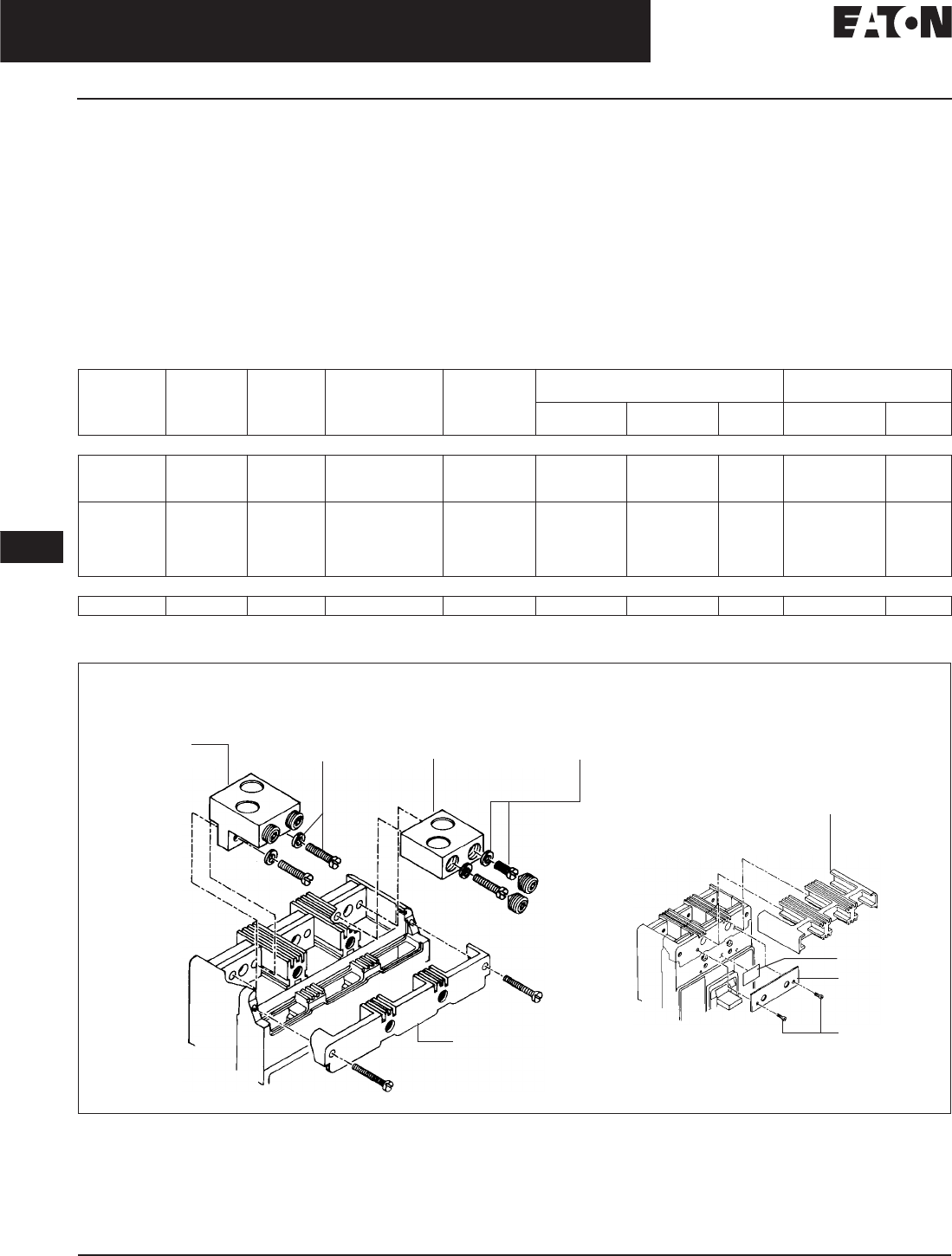
November 2008
12-132
For more information visit: www.eaton.com CA08101001E
Series C Molded Case Circuit Breakers
12
125 – 600 Amperes
L-Frame
Line and Load Terminals
Eaton’s Cutler-Hammer line and load
terminals provide wire connecting
capabilities for specific ranges of con-
tinuous current ratings and wire types.
All terminals comply with Underwrit-
ers Laboratories Standards UL 486A
and UL 486B and CSA Standard C22.2
No. 65M. Unless otherwise specified,
L-Frame circuit breaker line and load
terminals are shipped separately for
field installation.
The wire connecting terminal is
secured with two pan-head, slotted
screws and lockwashers which can be
checked for the correct torque loading
or retightened from the front of the
circuit breaker before installation of
the conductors. (Applies to all styles.)
The circuit breaker line/load terminal
conductors are positioned in the con-
ducting holes in the wire connecting
terminal and are secured with recessed
socket screws which are tightened to
the correct torque loading from the
front of the circuit breaker.
Ordering Information
L-Frame circuit breakers use Cu/AI
terminals as standard. When optional
copper terminals are required, order by
Catalog Number. Specify if factory
installation is required.
Table 12-224. Line and Load Terminals
Terminal kits contain one terminal for each pole and one terminal cover.
Individually packed.
Figure 12-29. Terminals
Maximum
Breaker
Amperes
Terminal
Body
Material
Wire
Type
AWG Wire
Range/Number
of Conductors
Metric Wire
Range mm2Terminal Terminals with
Control Wire Termination
Poles Catalog
Number
Price
U.S. $
Catalog
Number
Price
U.S. $
Standard Cu/AI Pressure Terminals
400 Aluminum Cu/AI 4/0 – 600 (1) 120 – 300 2-Pole Kit
3-Pole Kit
4-Pole Kit
2TA401LDK
3TA401LDK
4TA401LDK
—
—
—
450
500
600
Aluminum
Aluminum
Aluminum
Cu/AI
Cu/AI
Cu/AI
4 – 4/0 (2)
3/0 – 350 (2)
400 – 500 (2)
25 – 95
95 – 150
185 – 240
2-Pole Kit
3-Pole Kit
4-Pole Kit
TA450LD
TA602LD
2TA603LDK
3TA603LDK
4TA603LDK
—
TA602LDCW
2TA603LDKCW
3TA603LDKCW
4TA603LDKCW
Optional Copper and Cu/AI Pressure Type Terminals
600 Copper Cu 250 – 350 (2) 120 – 250 T602LD T602LDCW
TA450LD or TA602LD
or T602LD Terminal
Pan-Head Screws and
Lockwashers (Installed
before Cable Clamping
Screws)
Terminal Cover
Screws
Retainer
TA401LD or TA603LD
Terminal (Step-Type
Terminal Requires
Terminal Cover and
Warning Label.
See Inset.)
Pan-Head
Screws and
Lockwashers
Warning Label
Circuit Breaker
Line Terminal Cover
Discount Symbol . . . . . . . . . . . . . . . . . . . . . . . . CB-2

November 2008
CA08101001E For more information visit: www.eaton.com
12-133
Series C Molded Case Circuit Breakers
12
125 – 600 Amperes
L-Frame
Allowable Accessory Combinations
Different combinations of accessories can be supplied, depending on the types of accessories and the number of poles in the
circuit breaker.
Table 12-225. Accessories
■Applicable in indicated pole position ❏May be mounted on left or right pole —
not both
●Accessory available/Modification available
2-pole breaker supplied in 3-pole frame. Current carrying parts omitted from center pole.
Refer to Eaton for appropriate neutral pole accessory combinations.
OPTIM model 1050 is factory sealed and does not have the right pole space available for accessories.
Shunt trip and UVR cannot be mounted in right poles on LES or OPTIM trip units.
Description Reference
Page
2-Pole , 3-Pole 4-Pole
Left Center Right Left Center Right Neu.
Internal Accessories (Only One Internal Accessory Per Pole)
Alarm Lockout (Make/Break) 12-217 ■■■■
Alarm Lockout (2Make/2Break) 12-217 ■■■■
Auxiliary Switch (1A, 1B) 12-220 ■■■■
Auxiliary Switch (2A, 2B) 12-220 ■■■■
Auxiliary Switch (3A, 3B) 12-220 ■■■■
Auxiliary Switch (1A, 1B) and Alarm Switch Combination 12-223 ■■■■
Auxiliary Switch (2A, 2B) and Alarm Switch Combination 12-223 ■■■■
Shunt Trip — Standard 12-226 ■■■■
Shunt Trip — Low Energy 12-231 ■■■■
Undervoltage Release Mechanism 12-232 ■■■■
Cutler-Hammer PowerNet Communications Kit (OPTIM 550) 12-242 ■
External Accessories
End Cap Kit 12-243 ●●
Control Wire Terminal Kit 12-244 ●●
Base Mounting Hardware 12-246 ●●
Terminal Shields 12-248 ●●
Interphase Barriers 12-249 ●●
Non-Padlockable Handle Block 12-251 ■■
Padlockable Handle Lock Hasp 12-252 ❏❏❏❏
Key Interlock Kit 12-253 ❏❏❏❏
Sliding Bar Interlock — Requires Two Breakers 12-254 ●
Walking Beam Interlock — Requires Two Breakers 12-254 ●●
Electrical (Motor) Operator 12-255 ●●
Plug-in Adapters 12-257 ●●
Rear Connecting Studs 12-258 ●●
Panelboard Connecting Straps 12-261 ●●
Handle Mechanisms 12-262 ●●
Handle Extension 12-267 ●●
Solid-State (Electronic) Portable Test Kit 12-268 ●●
OPTIM System Components 3-Poles
Ground Fault Alarm Unit 12-268
Potential Transformer Module 12-268
Breaker Interface Module (BIM) 12-269
Digitrip OPTIMizer 12-269
Auxiliary Power Module 12-269
Modifications (Refer to Eaton)
Special Calibration — ●●
Moisture Fungus Treatment 12-73 ●●
Freeze-Tested Circuit Breakers — ●●
Marine Application — ●●
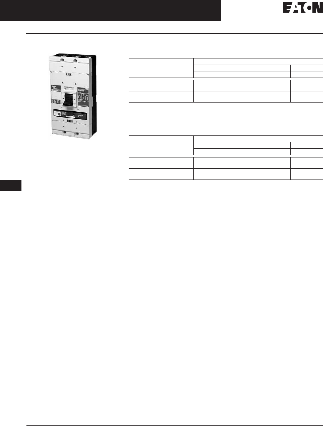
November 2008
12-134
For more information visit: www.eaton.com CA08101001E
Series C Molded Case Circuit Breakers
12
300 – 800 Amperes
M-Frame
M-Frame
Typical M-Frame Circuit Breaker
Product Description
■All Cutler-Hammer M-Frame Circuit
Breakers by Eaton Corporation are
HACR rated.
■MDL-Frame circuit breakers are
available as individual components
(Frame, Trip Unit, Terminals), or
factory assembled complete
breakers.
■MDLB, HMDLB-Frame circuit breakers
with non-interchangeable trip units
are suitable for reverse feed use.
■CE marked.
Technical Data and Specifications
Table 12-226. UL 489/CSA Interrupting Capacity Ratings
Utilization category A circuit breakers.
2-pole or two poles of 3-pole circuit breaker. Thermal-magnetic trip units only, MDL, HMDL
breakers with electronic trip unit are not dc rated.
Time constant is 3 milliseconds minimum at 10 kA and 8 milliseconds at 22 kA.
Table 12-227. IEC 947-2 Interrupting Capacity Ratings
Utilization category A circuit breakers.
2-pole or two poles of 3-pole circuit breaker. Thermal-magnetic trip units only, MDL, HMDL
breakers with electronic trip unit are not dc rated.
Time constant is 3 milliseconds minimum at 10 kA and 8 milliseconds at 20 kA.
Circuit
Breaker
Type
Number
of Poles
Interrupting Capacity (kA Symmetrical Amperes)
Volts ac (50/60 Hz) Volts dc
240 480 600 250
MDL, MDLB
CMDL
2, 3
2, 3
65
65
50
50
25
25
22
—
HMDL, HMDLB
CHMDL
2, 3
2, 3
100
100
65
65
35
35
25
—
Circuit
Breaker
Type
Number
of Poles
Interrupting Capacity rms (kA Symmetrical Amperes) ICU ≠ ICS
Volts ac (50/60 Hz) Volts dc
240 415 690 250
MDL, MDLB
CMDL
2, 3
2, 3
65/65
65/65
50/50
50/50
20/10
20/10
20/10
—
HMDL, HMDLB
CHMDL
2, 3
2, 3
100/100
100/100
70/50
70/50
25/13
25/13
20/10
—

November 2008
CA08101001E For more information visit: www.eaton.com
12-135
Series C Molded Case Circuit Breakers
12
300 – 800 Amperes
M-Frame
MDL-Frame Digitrip Specifications
Table 12-228. Specifications
Adjust by rating plug.
With separate ground fault alarm unit (GFAU). Legend: In = Rating Plug
Trip Unit Type Digitrip RMS 310
rms Sensing Yes
Breaker Type
Frame MDL, MDLB, CMDL, HMDL, HMDLB, CHMDL
Ampere Range 400 – 800 A
Interrupting Rating at 480 Volts 50, 65 (kA)
Protection
Ordering Options LS, LSG LSI, LSIG
Fixed Rated Plug (In)YesYes
Overtemperature Trip Yes Yes
Long Delay Protection (L)
Adjustable Rating Plug (In)YesYes
Long Delay Pickup 0.5 – 1.0 (In) 0.5 – 1.0 (In)
Long Delay Time I2t 12 Seconds 12 Seconds
Long Delay Time I4tNoNo
Long Delay Thermal Memory Yes Yes
High Load Alarm No No
Short Delay Protection (S)
Short Delay Pickup 200 – 800% x (In) 200 – 800% x (In)
Short Delay Time I2t 100 ms No
Short Delay Time Flat No Inst – 300 ms
Short Delay Time Zone Selective Interlocking No No
Instantaneous Protection (I)
Instantaneous Pickup No 200 – 800% x (In)
Discriminator No No
Instantaneous Override Yes Yes
Ground Fault Protection (G)
Ground Fault Alarm No No
Ground Fault Pickup 1 – 5 x Ig (160 A) 1 – 5 x Ig (160 A)
Ground Fault Delay I2tNoNo
Ground Fault Delay Flat Inst – 500 ms Inst – 500 ms
Ground Fault Zone Selective Interlocking No No
Ground Fault Thermal Memory Yes Yes
System Diagnostics
Status LEDs Yes Ye s
Cause of Trip LEDs No No
Magnitude of Trip Information No No
Remote Signal Contacts — Ground Alarm Yes Yes
System Monitoring
Digital Display No No
Current No No
Power and Energy No No
Power Quality — Harmonics No No
Power Factor No No
Communications
Eaton’s Cutler-Hammer PowerNet No No
Testing
Testing Method Test Set

November 2008
12-136
For more information visit: www.eaton.com CA08101001E
Series C Molded Case Circuit Breakers
12
300 – 800 Amperes
M-Frame
Dimensions/Weights
Table 12-229. Dimensions in Inches (mm) Table 12-230. Approximate Shipping Weight in Lbs. (kg)
Thermal-magnetic only.
Product Selection
This information is presented only as an aid to understanding Catalog Numbers. It is not to be used to build Catalog Numbers
for circuit breakers or trip units.
Table 12-231. Circuit Breaker/Frame Catalog Numbering System
Thermal-magnetic only.
Table 12-232. Thermal-Magnetic Trip Unit Catalog Numbering System
Thermal-magnetic only.
Number of Poles Width Height Depth
2, 3 8.25 (209.6) 16.00 (406.4) 4.06 (103.1)
Breaker
Type
Complete Breaker Frame Only Trip Unit
Number of Poles
2 3 2323
MDL, HMDL
(T/M T.U.)
26.5
(12.0)
29.0
(13.2)
24.5
(11.1)
26.0
(11.8)
2.5
(1.1)
3.0
(1.4)
MDL, HMDL
(Elec. T.U.)
— 30.0
(13.6)
— 26.0
(11.8)
—4.0
(1.8)
MDL 3 800 F
Circuit Breaker/
Frame Type
MDL, MDLB
HMDL, HMDLB
Number
of Poles
2 = 2 Poles
3 = 3 Poles
Circuit Breaker/
Frame Ampere Rating
300
350
400
450
500
600
700
800
Suffix
F= Frame Only
K= High Magnetic
Molded Case Switch
V= 50°C (Thermal-Magnetic
Trip Units Only)
W= Without Terminals
X= Load Side Terminals Only
Y= Line Side Terminals Only
MT 3 800 T
Trip Unit Type
MT
MES
Number
of Poles
2 = 2 Poles
3 = 3 Poles
Trip Unit Rating/
Plug Ampere Rating
300
350
400
450
500
600
700
800
Suffix
T= Thermal-Magnetic
V= 50°C (Thermal-Magnetic
Trip Units Only)
LS = Digitrip RMS 310
LSI = Digitrip RMS 310
LSG = Digitrip RMS 310
LSIG = Digitrip RMS 310
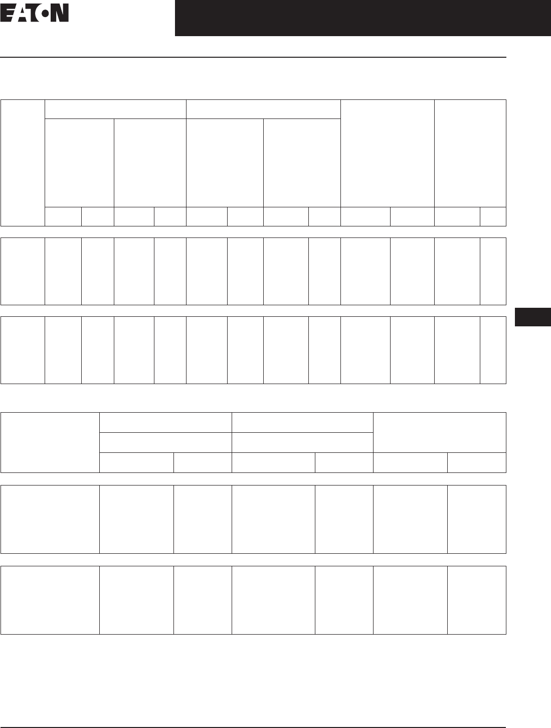
November 2008
CA08101001E For more information visit: www.eaton.com
12-137
Series C Molded Case Circuit Breakers
12
300 – 800 Amperes
M-Frame
Product Selection
Table 12-233. Types MDL and HMDL Thermal-Magnetic Circuit Breakers with Interchangeable Trip Units
Two terminals are required per pole.
Table 12-234. Types MDLB and HMDLB Thermal-Magnetic Circuit Breakers with Non-Interchangeable Trip Units
Factory sealed for reverse feed application.
Two terminals are required per pole.
Maximum
Continuous
Ampere
Rating
at 40°C
Standard Interrupting Capacity
600 Vac Rated 50 kAIC at 480 Vac
High Interrupting Capacity
600 Vac Rated 65 kAIC at 480 Vac
Thermal-Magnetic
Trip Unit Only
For Use with
Standard or High
or Ultra High Interrupting
Frames
Magnetic Trip Range
is 5 – 10 up through
600 A; 4 – 8 on 700 and 800
A x Continuous
Ampere Rating
Standard Terminals
Only
See Page 12-140 for
Optional Terminals
Factory Assembled
Circuit Consisting
of Frame, Trip Unit
and Terminals
Frame
Only
Factory Assembled
Circuit Consisting
of Frame, Trip Unit
and Terminals
Frame
Only
Catalog
Number
Price
U.S. $
Catalog
Number
Price
U.S. $
Catalog
Number
Price
U.S. $
Catalog
Number
Price
U.S. $
Catalog
Number
Price
U.S.$
Catalog
Number
Price
U.S.$
2-Pole
300
350
400
450
500
600
700
800
MDL2300
MDL2350
MDL2400
MDL2450
MDL2500
MDL2600
MDL2700
MDL2800
MDL2800F HMDL2300
HMDL2350
HMDL2400
HMDL2450
HMDL2500
HMDL2600
HMDL2700
HMDL2800
HMDL2800F MT2300T
MT2350T
MT2400T
MT2450T
MT2500T
MT2600T
MT2700T
MT2800T
TA700MA1
TA700MA1
TA700MA1
TA700MA1
TA700MA1
TA700MA1
TA700MA1
TA800MA2
3-Pole
300
350
400
450
500
600
700
800
MDL3300
MDL3350
MDL3400
MDL3450
MDL3500
MDL3600
MDL3700
MDL3800
MDL3800F HMDL3300
HMDL3350
HMDL3400
HMDL3450
HMDL3500
HMDL3600
HMDL3700
HMDL3800
HMDL3800F MT3300T
MT3350T
MT3400T
MT3450T
MT3500T
MT3600T
MT3700T
MT3800T
TA700MA1
TA700MA1
TA700MA1
TA700MA1
TA700MA1
TA700MA1
TA700MA1
TA800MA2
Maximum
Continuous
Ampere
Rating
at 40°C
Standard Interrupting Capacity
600 Vac Rated 50 kAIC at 480 Vac
High Interrupting Capacity
600 Vac Rated 65 kAIC at 480 Vac
Standard Terminals Only
See Page 12-140 for Optional
Terminals
Factory Assembled Circuit Consisting
of Frame, Trip Unit and Terminals
Factory Assembled Circuit Consisting
of Frame, Trip Unit and Terminals
Catalog
Number
Price
U.S. $
Catalog
Number
Price
U.S. $
Catalog
Number
Price
U.S. $
2-Pole
300
350
400
450
500
600
700
800
MDLB2300
MDLB2350
MDLB2400
MDLB2450
MDLB2500
MDLB2600
MDLB2700
MDLB2800
HMDLB2300
HMDLB2350
HMDLB2400
HMDLB2450
HMDLB2500
HMDLB2600
HMDLB2700
HMDLB2800
TA700MA1
TA700MA1
TA700MA1
TA700MA1
TA700MA1
TA700MA1
TA700MA1
TA800MA2
3-Pole
300
350
400
450
500
600
700
800
MDLB3300
MDLB3350
MDLB3400
MDLB3450
MDLB3500
MDLB3600
MDLB3700
MDLB3800
HMDLB3300
HMDLB3350
HMDLB3400
HMDLB3450
HMDLB3500
HMDLB3600
HMDLB3700
HMDLB3800
TA700MA1
TA700MA1
TA700MA1
TA700MA1
TA700MA1
TA700MA1
TA700MA1
TA800MA2
Discount Symbol . . . . . . . . . . . . . . . . . . . . . . . . . CB-2

November 2008
12-138
For more information visit: www.eaton.com CA08101001E
Series C Molded Case Circuit Breakers
12
300 – 800 Amperes
M-Frame
Types MDL and HMDL Electronic Circuit Breakers with Interchangeable Trip Units
Order as Individual Components: Breaker Frame, Trip Unit, Rating Plug, Terminals.
Table 12-235. Types MDL and HMDL Electronic Circuit Breakers with Interchangeable Trip Units
Ampere rating is established by rating plug.
For ac use only.
Maximum
Continuous
Ampere
Rating
at 40°C
Circuit Breaker Frame Only Digitrip RMS 310 Trip
Unit Only
Digitrip RMS 310 Rating Plug Only Terminals
Standard
Interrupting
Capacity 600 Vac
Rated 50 kAIC at
480 Vac
High Interrupting
Capacity 600 Vac
Rated 65 kAIC at
480 Vac
L – Adjustable Long
Delay Pickup (by
Adjustable Rating
Plug)
S – Adjustable Short
Delay Pickup with
Fixed Short Delay
Time (I2t Response)
or Adjustable
Short Delay Time
(Flat Response)
I – Adjustable
Instantaneous
Pickup by Setting
Short Delay Time
to Instantaneous
G – Adjustable Ground
Fault Pickup with
Adjustable Ground
Fault Delay (Flat
Response)
Ampere
Rating
Fixed
Rating Plug
Adjustable
Rating Plugs
Ampere
Rating
Catalog
Number
Price
U.S. $
Catalog
Number
Price
U.S. $
Catalog
Number
Price
U.S. $
Catalog
Number
Price
U.S. $
Catalog
Number
Price
U.S. $
3-Pole
800 MDL3800F HMDL3800F MES3800LS
MES3800LSI
MES3800LSG
MES3800LSIG
—
400
500
600
700
800
8MES400T
8MES500T
8MES600T
8MES700T
8MES800T
400/500/600/800
A8MES800T
See
Page 12-140
for Standard
and Optional
Terminals
620/640/660/680
A8MES600T5
720/740/760/780
A8MES700T5
Discount Symbol . . . . . . . . . . . . . . . . . . . . . . . . CB-2

November 2008
CA08101001E For more information visit: www.eaton.com
12-139
Series C Molded Case Circuit Breakers
12
300 – 800 Amperes
M-Frame
Table 12-236. Types MDLB and HMDLB Electronic Circuit Breakers with Non-Interchangeable Trip Units
Factory sealed, suitable for reverse feed application. CMDLB and CHMDLB are also available.
Ampere rating is established by rating plug.
100% Rated Types CMDL and CHMDL Electronic Circuit Breakers with Non-Interchangeable Trip Units
The NEC allows the breaker to be rated at 100% of its frame size in an assembly, provided that 90°C wire is applied at the 75°C
ampacity. All 100% rated circuit breakers have electronic trip units. Order as individual components: breaker frame, trip unit,
rating plug and terminals.
Table 12-237. 100% Rated Types CMDL and CHMDL Electronic Circuit Breakers with Interchangeable Trip Units
See Table 12-238 below for prices.
Ampere rating is established by rating plug.
For ac use only.
Table 12-238. 100% Rated Types CMDL and CHMDL Electronic Circuit Breakers with
Non-Interchangeable Trip Units Prices
Maximum
Continuous
Ampere
Rating
at 40°C
Factory Assembled Circuit Breaker Consisting of Frame and Trip Unit
LS LSI LSG LSIG
Catalog
Number
Price
U.S. $
Catalog
Number
Price
U.S. $
Catalog
Number
Price
U.S. $
Catalog
Number
Price
U.S. $
3-Pole Standard Interrupting Capacity 600 Vac Rated 50 kAIC at 480 Vac
800 MDLB3800T33W MDLB3800T32W MDLB3800T35W MDLB3800T36W
3-Pole High Interrupting Capacity 600 Vac Rated 65 kAIC at 480 Vac
800 HMDLB3800T33W HMDLB3800T32W HMDLB3800T35W HMDLB3800T36W
Maximum
Continuous
Ampere
Rating
at 40°C
Circuit Breaker Frame Only Digitrip RMS 310 Trip Unit Only Digitrip RMS 310 Trip Unit Only Terminals
Standard
Interrupting
Capacity
50 kAIC at
480 Vac
High
Interrupting
Capacity
65 kAIC at
480 Vac
Standard Options Ampere
Rating
Fixed
Rating
Plug
Adjustable
Rating Plug
Adjustable
Short Time
Pickup with
I2t Short
Delay Ramp
Indepen-
dently
Adjustable
Short Time
Pickup and
Delay
Ground
Fault
Protection
Adjustable
Short Time
Pickup with
I2t Short
Delay and
Ground Fault
Protection
Indepen-
dently
Adjustable
Short Time
Pickup and
Ground Fault
Protection
Ampere
Rating
Catalog Number Catalog Number
3-Pole
800 CMDL3800F CHMDL3800F MES3800LS MES3800LSI MES3800LSG MES3800LSIG 400
500
600
700
800
8MES400T
8MES500T
8MES600T
8MES700T
8MES800T
400/500/
600/800
A8MES800T
See
Page 12-140
for Standard
and Optional
Terminals
620/640/
660/680
A8MES600T5
720/740/
760/780
A8MES700T5
Catalog
Number
Price
U.S. $
Catalog
Number
Price
U.S. $
Catalog
Number
Price
U.S. $
A8MES800T
A8MES600T5
A8MES700T5
CHMDL3800F
CMDL3800F
MES3800LS
MES3800LSG
MES3800LSI
MES3800LSIG
8MES400T
8MES500T
8MES600T
8MES700T
8MES800T
—
Discount Symbol . . . . . . . . . . . . . . . . . . . . . . . . . CB-2
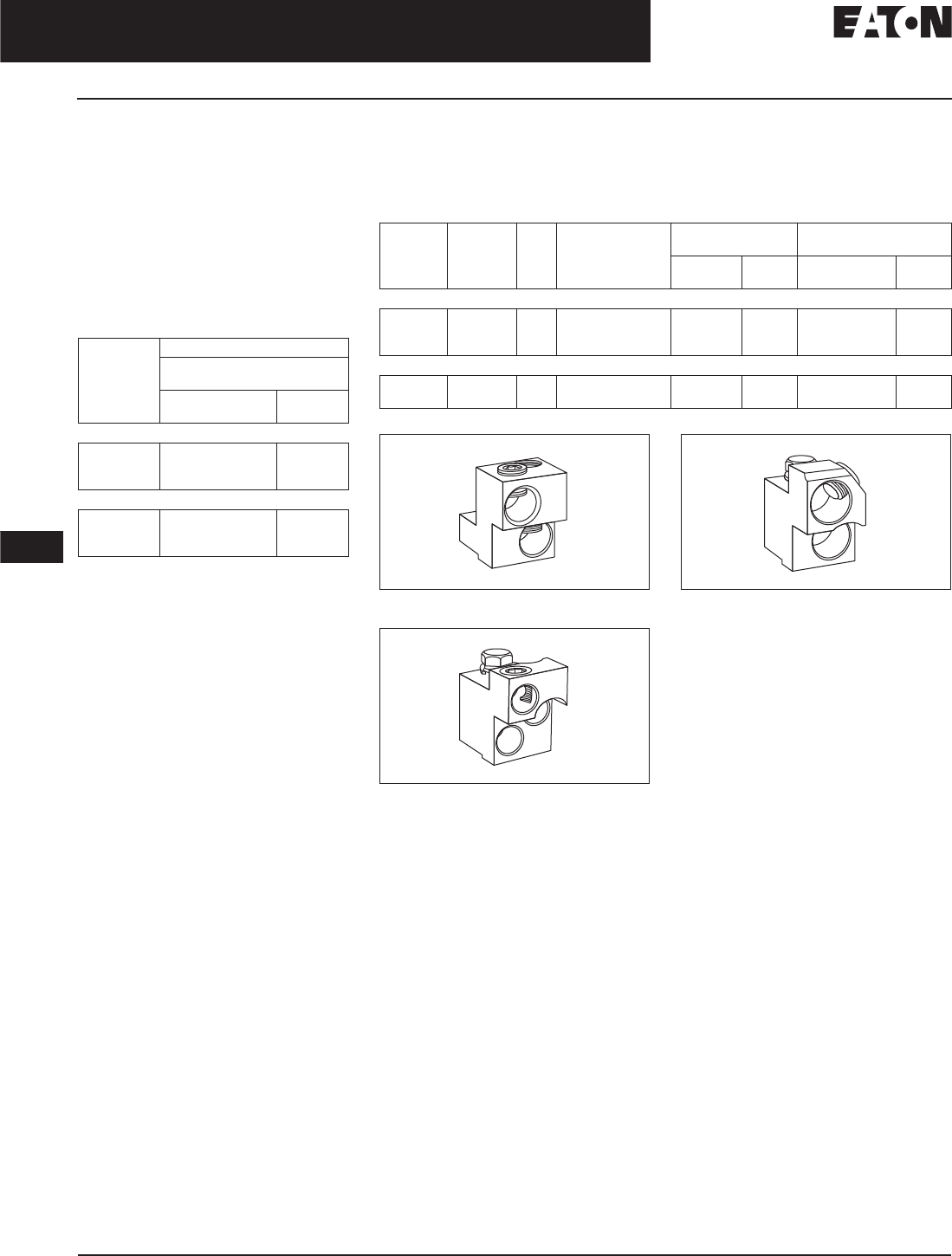
November 2008
12-140
For more information visit: www.eaton.com CA08101001E
Series C Molded Case Circuit Breakers
12
300 – 800 Amperes
M-Frame
Molded Case Switches
Eaton’s Cutler-Hammer molded
case switches are used as compact
switches in applications requiring high
current switching capabilities. Molded
case switches are constructed of cir-
cuit breaker components and are of
the high instantaneous automatic
type. Molded case switches are listed
in accordance with Underwriters
Laboratories Standard UL 489.
Table 12-239. Molded Case Switches
MDLB and HMDLB are suitable for reverse-
feed applications.
Note: Molded case switch may trip above
6000 amperes.
Maximum
Continuous
Ampere
Rating
at 40°C
600 Vac Maximum, 250 Vdc
Circuit Breaker Only without
Line and Load Terminals
Catalog
Number
Price
U.S. $
2-Pole
800 MDL2800WK
MDLB2800WK
HMDL2800WK
3-Pole
800 MDL3800WK
MDLB3800WK
HMDL3800WK
Line and Load Terminals
M-Frame circuit breakers use Cu/AI terminals as standard. When optional copper
or Cu/AI terminals are required, order by Catalog Number. Specify if factory
installation is required.
Table 12-240. Line and Load Terminals
Figure 12-30. TA700MA1
Figure 12-31. TA800MA2
Figure 12-32. TA801MA
Maximum
Breaker
Amperes
Terminal
Body
Material
Wire
Type
AWG Wire
Range/No.
Conductors
Terminal Terminals with Control
Wire Termination
Catalog
Number
Price
U.S. $
Catalog
Number
Price
U.S. $
Standard Cu/AI Pressure Terminals
600
800 std.
800
Aluminum
Aluminum
Aluminum
Cu/AI
Cu/AI
Cu/AI
(2) 1 – 500 kcmil
(3) 3/0 – 400 kcmil
(2) 500 – 750 kcmil
TA700MA1
TA800MA2
TA801MA
TA700MA1CWT
TA800MA2CWT
TA801MACWT
Optional Copper and Cu/AI Pressure Type Terminals
600
800
Copper
Copper
Cu
Cu
(2) 2/0 – 500 kcmil
(3) 3/0 – 300 kcmil
T600MA1
T800MA1
—
—
Discount Symbol . . . . . . . . . . . . . . . . . . . . . . . . CB-2

November 2008
CA08101001E For more information visit: www.eaton.com
12-141
Series C Molded Case Circuit Breakers
12
300 – 800 Amperes
M-Frame
Allowable Accessory Combinations
Different combinations of accessories can be supplied, depending on the types of accessories and the number of poles in the
circuit breaker.
Table 12-241. Accessories
■Applicable in indicated pole position ❏May be mounted on left or right pole —
not both
●Accessory available/Modification available
2-pole breaker supplied in 3-pole frame. Current carrying parts omitted from center pole.
Shunt trip and UVR cannot be mounted in right poles on MES trip units.
Description Reference
Page
2-Pole 3-Pole
Left Right Left Center Right
Internal Accessories (Only One Internal Accessory Per Pole)
Alarm Lockout (Make/Break) 12-217 ■■ ■
Alarm Lockout (2Make/2Break) 12-217 ■■ ■
Auxiliary Switch (1A, 1B) 12-220 ■■ ■
Auxiliary Switch (2A, 2B) 12-220 ■■ ■
Auxiliary Switch (3A, 3B) 12-220 ■■ ■
Auxiliary Switch (1A, 1B) and Alarm Switch Combination 12-223 ■■ ■
Auxiliary Switch (2A, 2B) and Alarm Switch Combination 12-223 ■■ ■
Shunt Trip — Standard 12-226 ■■ ■
Shunt Trip — Low Energy 12-231 ■■ ■
Undervoltage Release Mechanism 12-232 ■■ ■
External Accessories
Base Mounting Hardware 12-246 ●
Terminal Shields 12-248 ●
Interphase Barriers 12-249 ●
Non-Padlockable Handle Block 12-251 ■
Padlockable Handle Lock Hasp 12-252 ❏❏ ❏
Key Interlock Kit 12-253 ❏❏ ❏
Sliding Bar Interlock — Requires Two Breakers 12-254 ●●
Walking Beam Interlock — Requires Two Breakers 12-254 ●●
Electrical (Motor) Operator 12-255 ●●
Plug-in Adapters 12-257 ●●
Rear Connecting Studs 12-258 ●●
Panelboard Connecting Straps 12-261 ●●
Handle Mechanisms 12-262 ●●
Handle Extension 12-267 ●
Solid-State (Electronic) Portable Test Kit 12-268 ●●
Modifications (Refer to Eaton)
Special Calibration — ●●
Moisture Fungus Treatment 12-73 ●●
Freeze-Tested Circuit Breakers — ●●
Marine Application — ●●
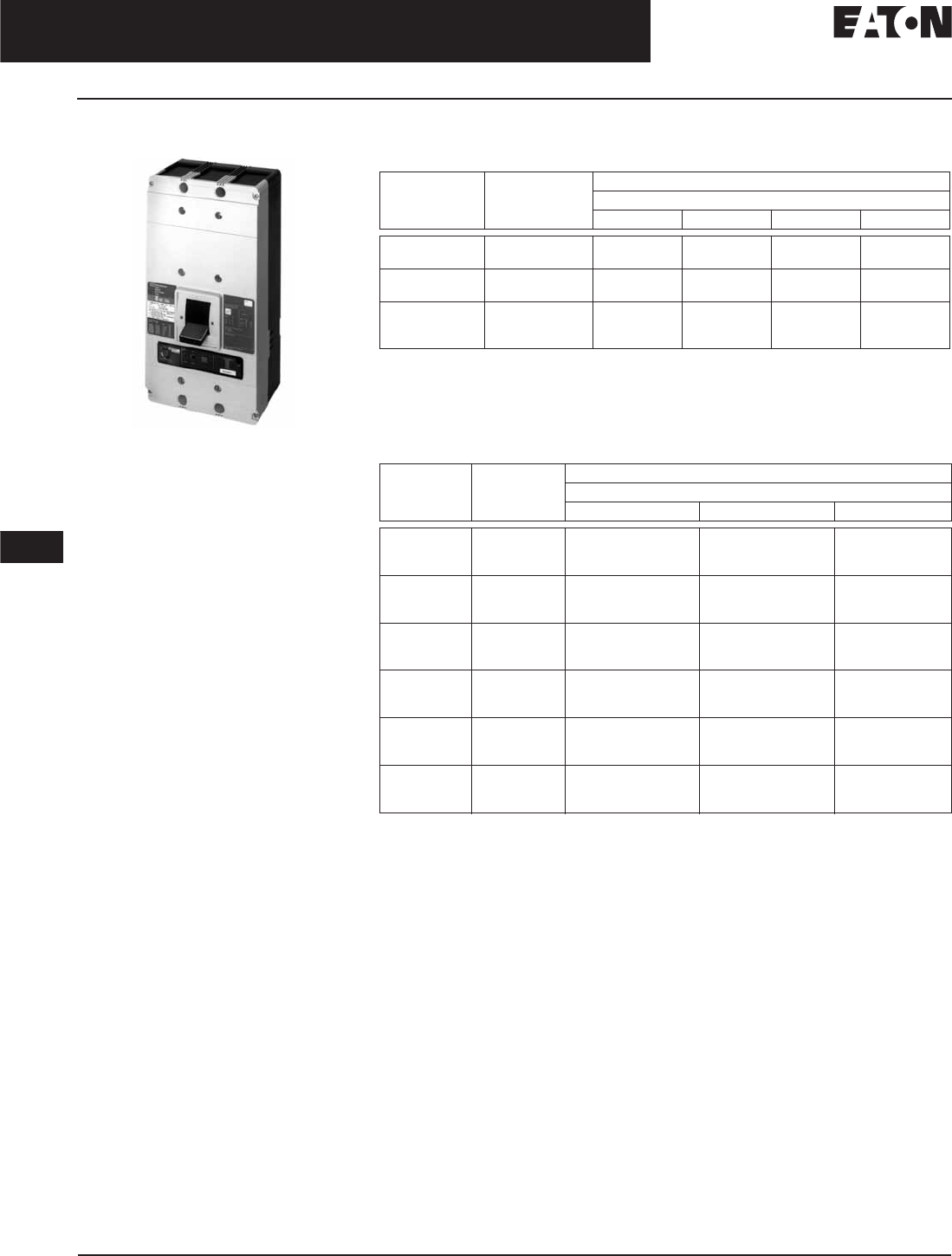
November 2008
12-142
For more information visit: www.eaton.com CA08101001E
Series C Molded Case Circuit Breakers
12
400 – 1200 Amperes
N-Frame
N-Frame
Typical N-Frame Circuit Breaker
Product Description
■All Cutler-Hammer N-Frame Circuit
Breakers by Eaton Corporation are
suitable for reverse feed use.
■All N-Frame circuit breakers are
HACR rated.
Technical Data and Specifications
Table 12-242. UL 489 Interrupting Capacity Ratings
Utilization Category A circuit breakers.
100% rated breakers.
800 amperes maximum rating.
Successfully tested at 300 kAIC, although UL recognizes maximum of 200 kAIC at 240 Vac.
Successfully tested at 75 kAIC, although UL recognizes maximum of 65 kAIC at 600 Vac.
Table 12-243. IEC 947-2 Interrupting Capacity Ratings
Utilization Category A circuit breakers.
100% rated breakers.
Circuit
Breaker
Type
Number
of Poles
Interrupting Capacity (kA Symmetrical Amperes)
Volts ac (50/60 Hz)
240 277 480 600
ND
CND
2, 3, 4
2, 3, 4
65
65
—
—
50
50
25
25
HND
CHND
2, 3, 4
2, 3, 4
100
100
—
—
65
65
35
35
NDC
CNDC
NDU
2, 3, 4
2, 3, 4
3
200
200
300
—
—
—
100
100
150
65
65
75
Circuit
Breaker
Type
Number
of Poles
Interrupting Capacity (kA Symmetrical Amperes)
Volts ac (50/60 Hz)
240 415 690
ND
Icu
Ics
2, 3, 4
85
85
50
50
20
10
CND
Icu
Ics
2, 3, 4
85
85
50
50
20
10
HND
Icu
Ics
2, 3, 4
100
100
70
50
25
13
CHND
Icu
Ics
2, 3, 4
100
100
70
50
25
13
NDC
Icu
Ics
2, 3, 4
200
100
100
50
35
18
CNDC
Icu
Ics
2, 3, 4
200
100
100
50
35
18

November 2008
CA08101001E For more information visit: www.eaton.com
12-143
Series C Molded Case Circuit Breakers
12
400 – 1200 Amperes
N-Frame
N-Frame Digitrip Specifications
Table 12-244. Specifications
Adjust by rating plug.
By OPTIMizer/BIM.
Zone interlock kit.
With separate ground fault alarm unit (GFAU).
Eaton’s Cutler-Hammer PowerNet kit.
Legend: BIM = Breaker Interface Module
(A) = GF Alarm
Is= Sensor Rating
In= Rating Plug
Ir= Long Delay Pickup Setting
Trip Unit Type Digitrip RMS 310 Digitrip OPTIM 550 Digitrip OPTIM 1050
rms Sensing Yes Yes Yes
Breaker Type
Frame NN N
Ampere Range 400 A – 1200 A 400 A – 1200 A 400 A – 1200 A
Interrupting Rating at 480 Volts 50, 65, 100 (kA) 50, 65, 100 (kA) 50, 65, 100 (kA)
Protection
Ordering Options LS, LSG LSI, LSIG LSI, LSIG, LSI(A) LSI(A), LISG
Fixed Rated Plug (In) Yes Yes Yes Yes
Overtemperature Trip Yes Yes Yes Yes
Long Delay Protection (L)
Adjustable Rating Plug (In)YesYesNoNo
Long Delay Pickup 0.5 – 1.0 (In) 0.5 – 1.0 (In) 0.4 – 1.0 x (In) 0.4 – 1.0 x (In)
Long Delay Time I2t 12 Seconds 12 Seconds 2 – 24 Seconds 2 – 24 Seconds
Long Delay Time I4t No No 1 – 5 Seconds 1 – 5 Seconds
Long Delay Thermal Memory Yes Yes Yes Yes
High Load Alarm No No No 0.5 – 1.0 x Ir
Short Delay Protection (S)
Short Delay Pickup 200 – 800% x (In) 200 – 800% x (In) 150 – 800% x (Ir) 150 – 800% x (Ir)
Short Delay Time I2t 100 ms No 100 – 500 ms 100 – 500 ms
Short Delay Time Flat No Inst – 300 ms 100 – 500 ms 100 – 500 ms
Short Delay Time Zone Selective Interlocking No No Yes Yes
Instantaneous Protection (I)
Instantaneous Pickup No 200 – 800% x (In) 200 – 800% x (In) 200 – 800% x (In)
Discriminator No No Yes Yes
Instantaneous Override Yes Yes Yes Yes
Ground Fault Protection (G)
Ground Fault Alarm No No 20 – 100% x (Is) 20 – 100% x (Is)
Ground Fault Pickup Varies by Frame Varies by Frame 20 – 100% x (Is) 20 – 100% x (Is)
Ground Fault Delay I2t No No 100 – 500 ms 100 – 500 ms
Ground Fault Delay Flat Inst – 500 ms Inst – 500 ms 100 – 500 ms 100 – 500 ms
Ground Fault Zone Selective Interlocking No No Yes Yes
Ground Fault Thermal Memory Yes Yes Yes Yes
System Diagnostics
Status LEDs Yes Yes Yes Yes
Cause of Trip LEDs No No Yes Yes
Magnitude of Trip Information No No Yes Yes
Remote Signal Contact — Ground Alarm Yes Yes Ye s Yes
Local Auxiliary and Bell Alarm Contact Optional Optional Optional Included
System Monitoring
Digital Display No No Yes Yes
Current No No Yes Yes
Power and Energy No No No Yes
Power Quality — Harmonics No No No Yes
Power Factor No No No Yes
Communications
Cutler-Hammer PowerNet No No No Yes
Testing
Testing Method Test Set OPTIMizer, BIM,
Cutler-Hammer
PowerNet
OPTIMizer, BIM,
Cutler-Hammer
PowerNet

November 2008
12-144
For more information visit: www.eaton.com CA08101001E
Series C Molded Case Circuit Breakers
12
400 – 1200 Amperes
N-Frame
Dimensions/Weights
Table 12-245. Dimensions in Inches (mm) Table 12-246. Approximate Shipping Weight in Lbs. (kg)
Product Selection
This information is presented only as an aid to understanding Catalog Numbers. It is not to be used to build Catalog Numbers
for circuit breakers or trip units.
Table 12-247. Circuit Breaker/Frame Catalog Numbering System
Number of Poles Width Height Depth
2, 3
4
8.25 (209.6)
11.13 (282.6)
16.00 (406.4)
16.00 (406.4)
5.50 (139.7)
5.50 (139.7)
Breaker Type Complete Breaker
Number of Poles
234
ND, HND, NDC, NDU 37 (16.8) 45 (20.4) 58 (26.3)
ND 3 12 T3 2 W
Circuit Breaker/
Frame Type
ND
HND
NDC
NDU
CND
CHND
CNDC
Number
of Poles
2 = 2 Poles
3 = 3 Poles
4 = 4 Poles
Circuit Breaker/Frame
Ampere Rating
800 = 800 Amperes
12 = 1200 Amperes
Trip Model
T3 = Model 310
T5 = Model 550
T7 = Model 750
T10 = Model 1050
Trip Type
2 = LSI
3 = LS
5 = LSG
6 = LSIG
7 = LSIA
Suffix
E= 100% R.P. protected (4-Pole)
EH = 50% R.P. protected (4-Pole)
K= High Magnetic Molded
Case Switch
W= Without Terminals
X= Load Only Terminals
Y= Line Only Terminals

November 2008
CA08101001E For more information visit: www.eaton.com
12-145
Series C Molded Case Circuit Breakers
12
400 – 1200 Amperes
N-Frame
Product Selection
Type ND Electronic Circuit Breakers with Non-Interchangeable Trip Units
Order as individual components: Breaker Frame, Rating Plug, Terminals.
Table 12-248. Type ND Electronic Circuit Breakers with Non-Interchangeable Trip Units
See Table 12-249 on Page 12-146 for prices.
Two terminals are required per pole.
Neutral is in right pole.
Maximum
Continuous
Ampere
Rating
at 40°C
Digitrip RMS 310 Circuit Breaker Frame Only Digitrip RMS 310 Rating Plug Only Standard
Terminals
Only
See
Page 12-162
for Optional
Terminals
Standard Interrupting Capacity 600 Vac Rated 50 kAIC at 480 Vac Ampere
Rating
Fixed
Rating
Plugs
Adjustable Rating Plug
Standard Options Adjustable
Ampere Ratings
Adjustable Short
Time Pickup
with I2t Short
Delay Ramp
Independently
Adjustable
Short Time
Pickup and
Delay
Adjustable Short
Time Pickup
with I2t Short
Delay and
Ground Fault
Protection
Independently
Adjustable Short
Time Pickup and
Delay and
Ground Fault
Protection
Catalog Number Catalog Number
2-Pole
800 ND2800T33W ND2800T32W ND2800T35W ND2800T36W 400
450
500
600
700
800
8NES400T
8NES450T
8NES500T
8NES600T
8NES700T
8NES800T
Adjustable Settings are:
400, 500, 600, 800
A8NES800T1
TA700NB1
TA700NB1
TA700NB1
TA700NB1
TA700NB1
TA1000NB1
3-Pole
800 ND3800T33W or
ND4800T33EW
(100% Neutral)
ND3800T32W ND3800T35W ND3800T36W 400
450
500
600
700
800
8NES400T
8NES450T
8NES500T
8NES600T
8NES700T
8NES800T
Adjustable Settings are:
400, 500, 600, 800
A8NES800T1
TA700NB1
TA700NB1
TA700NB1
TA700NB1
TA700NB1
TA1000NB1
4-Pole
800 ND4800T33W ND4800T32W — — 400
450
500
600
700
800
8NES400T
8NES450T
8NES500T
8NES600T
8NES700T
8NES800T
Adjustable Settings are:
400, 500, 600, 800
A8NES800T1
TA700NB1
TA700NB1
TA700NB1
TA700NB1
TA700NB1
TA1000NB1
2-Pole
1200 ND212T33W ND212T32W ND212T35W ND212T36W 600
700
800
900
1000
1200
12NES600T
12NES700T
12NES800T
12NES900T
12NES1000T
12NES1200T
Adjustable Settings are:
600, 800, 1000, 1200
A12NES1200T1
TA700NB1
TA700NB1
TA1000NB1
TA1000NB1
TA1000NB1
TA1200NB1
3-Pole
1200 ND312T33W ND312T32W ND312T35W ND312T36W 600
700
800
900
1000
1200
12NES600T
12NES700T
12NES800T
12NES900T
12NES1000T
12NES1200T
Adjustable Settings are:
600, 800, 1000, 1200
A12NES1200T1
TA700NB1
TA700NB1
TA1000NB1
TA1000NB1
TA1000NB1
TA1200NB1
4-Pole
1200 ND412T33W ND412T32W — — 600
700
800
900
1000
1200
12NES600T
12NES700T
12NES800T
12NES900T
12NES1000T
12NES1200T
Adjustable Settings are:
600, 800, 1000, 1200
A12NES1200T1
TA700NB1
TA700NB1
TA1000NB1
TA1000NB1
TA1000NB1
TA1200NB1

November 2008
12-146
For more information visit: www.eaton.com CA08101001E
Series C Molded Case Circuit Breakers
12
400 – 1200 Amperes
N-Frame
Table 12-249. Type ND Electronic Circuit Breakers with Non-Interchangeable Trip Unit Prices
Catalog
Number
Price
U.S. $
Catalog
Number
Price
U.S. $
Catalog
Number
Price
U.S. $
Catalog
Number
Price
U.S. $
A12NES1200T1
A8NES800T1
ND212T32W
ND212T33W
ND212T35W
ND312T32W
ND312T33W
ND312T35W
ND312T36W
ND3800T32W
ND4800T32W
ND4800T33W
ND4800T33EW
TA1000NB1
TA1200NB1
12NES800T
12NES900T
8NES400T
8NES450T
8NES500T
ND212T36W
ND2800T32W
ND2800T33W
ND2800T35W
ND2800T36W
ND3800T33W
ND3800T35W
ND3800T36W
ND412T32W
ND412T33W
TA700NB1
12NES1000T
12NES1200T
12NES600T
12NES700T
8NES600T
8NES700T
8NES800T
—
—
Discount Symbol . . . . . . . . . . . . . . . . . . . . . . . . CB-2

November 2008
CA08101001E For more information visit: www.eaton.com
12-147
Series C Molded Case Circuit Breakers
12
400 – 1200 Amperes
N-Frame
Type HND Electronic Circuit Breakers with Non-Interchangeable Trip Units
Order as individual components: Breaker Frame, Rating Plug, Terminals.
Table 12-250. Type HND Electronic Circuit Breakers with Non-Interchangeable Trip Units
See Table 12-251 on Page 12-148 for prices.
Two terminals are required per pole.
Neutral is in right pole.
Maximum
Continuous
Ampere
Rating
at 40°C
Digitrip RMS 310 Circuit Breaker Frame Only Digitrip RMS 310 Rating Plug Only Standard
Terminals
Only
See
Page 12-162
for Optional
Terminals
High Interrupting Capacity 600 Vac Rated 65 kAIC at 480 Vac Ampere
Rating
Fixed
Rating
Plugs
Adjustable Rating Plug
Standard Options Adjustable
Ampere Ratings
Adjustable
Short Time
Pickup with I2t
Short Delay
Ramp
Independently
Adjustable
Short Time
Pickup and
Delay
Adjustable
Short Time
Pickup with I2t
Short Delay
and
Ground Fault
Protection
Independently
Adjustable
Short Time
Pickup and
Delay and
Ground Fault
Protection
Catalog Number Catalog Number
2-Pole
800 HND2800T33W HND2800T32W HND2800T35W HND2800T36W 400
450
500
600
700
800
8NES400T
8NES450T
8NES500T
8NES600T
8NES700T
8NES800T
Adjustable Settings are:
400, 500, 600, 800
A8NES800T1
TA700NB1
TA700NB1
TA700NB1
TA700NB1
TA700NB1
TA1000NB1
3-Pole
800 HND3800T33W HND3800T32W HND3800T35W HND3800T36W 400
450
500
600
700
800
8NES400T
8NES450T
8NES500T
8NES600T
8NES700T
8NES800T
Adjustable Settings are:
400, 500, 600, 800
A8NES800T1
TA700NB1
TA700NB1
TA700NB1
TA700NB1
TA700NB1
TA1000NB1
4-Pole
800 HND4800T33W HND4800T32W — — 400
450
500
600
700
800
8NES400T
8NES450T
8NES500T
8NES600T
8NES700T
8NES800T
Adjustable Settings are:
400, 500, 600, 800
A8NES800T1
TA700NB1
TA700NB1
TA700NB1
TA700NB1
TA700NB1
TA1000NB1
2-Pole
1200 HND212T33W HND212T32W HND212T35W HND212T36W 600
700
800
900
1000
1200
12NES600T
12NES700T
12NES800T
12NES900T
12NES1000T
12NES1200T
Adjustable Settings are:
600, 800, 1000, 1200
A12NES1200T1
TA700NB1
TA700NB1
TA1000NB1
TA1000NB1
TA1000NB1
TA1200NB1
3-Pole
1200 HND312T33W HND312T32W HND312T35W HND312T36W 600
700
800
900
1000
1200
12NES600T
12NES700T
12NES800T
12NES900T
12NES1000T
12NES1200T
Adjustable Settings are:
600, 800, 1000, 1200
A12NES1200T1
TA700NB1
TA700NB1
TA1000NB1
TA1000NB1
TA1000NB1
TA1200NB1
4-Pole
1200 HND412T33W HND412T32W — — 600
700
800
900
1000
1200
12NES600T
12NES700T
12NES800T
12NES900T
12NES1000T
12NES1200T
Adjustable Settings are:
600, 800, 1000, 1200
A12NES1200T1
TA700NB1
TA700NB1
TA1000NB1
TA1000NB1
TA1000NB1
TA1200NB1

November 2008
12-148
For more information visit: www.eaton.com CA08101001E
Series C Molded Case Circuit Breakers
12
400 – 1200 Amperes
N-Frame
Table 12-251. Type HND Electronic Circuit Breakers with Non-Interchangeable Trip Unit Prices
Catalog
Number
Price
U.S. $
Catalog
Number
Price
U.S. $
Catalog
Number
Price
U.S. $
Catalog
Number
Price
U.S. $
A12NES1200T1
A8NES800T1
HND212T32W
HND212T33W
HND212T35W
HND312T32W
HND312T33W
HND312T35W
HND312T36W
HND3800T32W
HND4800T32W
HND4800T33W
TA1000NB1
TA1200NB1
TA700NB1
12NES900T
8NES400T
8NES450T
8NES500T
8NES600T
HND212T36W
HND2800T32W
HND2800T33W
HND2800T35W
HND2800T36W
HND3800T33W
HND3800T35W
HND3800T36W
HND412T32W
HND412T33W
12NES1000T
12NES1200T
12NES600T
12NES700T
12NES800T
8NES700T
8NES800T
—
—
—
Discount Symbol . . . . . . . . . . . . . . . . . . . . . . . . CB-2

November 2008
CA08101001E For more information visit: www.eaton.com
12-149
Series C Molded Case Circuit Breakers
12
400 – 1200 Amperes
N-Frame
Type NDC Electronic Circuit Breakers with Non-Interchangeable Trip Units
Order as individual components: Breaker Frame, Rating Plug, Terminals.
Table 12-252. Type NDC Electronic Circuit Breakers with Non-Interchangeable Trip Units
See Table 12-253 on Page 12-150 for prices.
Two terminals are required per pole.
Neutral is in right pole.
Maximum
Continuous
Ampere
Rating
at 40°C
Digitrip RMS 310 Circuit Breaker Frame Only Digitrip RMS 310 Rating Plug Only Standard
Terminals
Only
See
Page 12-162
for Optional
Terminals
Ultra High Interrupting Capacity 600 Vac Rated 100 kAIC at 480 Vac Ampere
Rating
Fixed
Rating
Plugs
Adjustable
Rating Plug
Standard Options Adjustable
Ampere Ratings
Adjustable
Short Time
Pickup with I2t
Short Delay
Ramp
Independently
Adjustable
Short Time
Pickup and
Delay
Adjustable
Short Time
Pickup with I2t
Short Delay and
Ground Fault
Protection
Independently
Adjustable
Short Time
Pickup and Delay
and Ground
Fault Protection
Catalog Number Catalog Number
2-Pole
800 NDC2800T33W NDC2800T32W NDC2800T35W NDC2800T36W 400
450
500
600
700
800
8NES400T
8NES450T
8NES500T
8NES600T
8NES700T
8NES800T
Adjustable
Settings are:
400, 500, 600, 800
A8NES800T1
TA700NB1
TA700NB1
TA700NB1
TA700NB1
TA700NB1
TA1000NB1
3-Pole
800 NDC3800T33W NDC3800T32W NDC3800T35W NDC3800T36W 400
450
500
600
700
800
8NES400T
8NES450T
8NES500T
8NES600T
8NES700T
8NES800T
Adjustable
Settings are:
400, 500, 600, 800
A8NES800T1
TA700NB1
TA700NB1
TA700NB1
TA700NB1
TA700NB1
TA1000NB1
4-Pole
800 NDC4800T33W NDC4800T32W — — 400
450
500
600
700
800
8NES400T
8NES450T
8NES500T
8NES600T
8NES700T
8NES800T
Adjustable
Settings are:
400, 500, 600, 800
A8NES800T1
TA700NB1
TA700NB1
TA700NB1
TA700NB1
TA700NB1
TA1000NB1
2-Pole
1200 NDC212T33W NDC212T32W NDC212T35W NDC212T36W 600
700
800
900
1000
1200
12NES600T
12NES700T
12NES800T
12NES900T
12NES1000T
12NES1200T
Adjustable
Settings are:
600, 800, 1000, 1200
A12NES1200T1
TA700NB1
TA700NB1
TA1000NB1
TA1000NB1
TA1000NB1
TA1200NB1
3-Pole
1200 NDC312T33W NDC312T32W NDC312T35W NDC312T36W 600
700
800
900
1000
1200
12NES600T
12NES700T
12NES800T
12NES900T
12NES1000T
12NES1200T
Adjustable
Settings are:
600, 800, 1000, 1200
A12NES1200T1
TA700NB1
TA700NB1
TA1000NB1
TA1000NB1
TA1000NB1
TA1200NB1
4-Pole
1200 NDC412T33W NDC412T32W — — 600
700
800
900
1000
1200
12NES600T
12NES700T
12NES800T
12NES900T
12NES1000T
12NES1200T
Adjustable
Settings are:
600, 800, 1000, 1200
A12NES1200T1
TA700NB1
TA700NB1
TA1000NB1
TA1000NB1
TA1000NB1
TA1200NB1

November 2008
12-150
For more information visit: www.eaton.com CA08101001E
Series C Molded Case Circuit Breakers
12
400 – 1200 Amperes
N-Frame
Table 12-253. Type NDC Electronic Circuit Breakers with Non-Interchangeable Trip Unit Prices
Catalog
Number
Price
U.S. $
Catalog
Number
Price
U.S. $
Catalog
Number
Price
U.S. $
Catalog
Number
Price
U.S. $
A12NES1200T1
A8NES800T1
NDC212T32W
NDC212T33W
NDC212T35W
NDC312T32W
NDC312T33W
NDC312T35W
NDC312T36W
NDC3800T32W
NDC4800T32W
NDC4800T33W
TA1000NB1
TA1200NB1
TA700NB1
12NES900T
8NES400T
8NES450T
8NES500T
8NES600T
NDC212T36W
NDC2800T32W
NDC2800T33W
NDC2800T35W
NDC2800T36W
NDC3800T33W
NDC3800T35W
NDC3800T36W
NDC412T32W
NDC412T33W
12NES1000T
12NES1200T
12NES600T
12NES700T
12NES800T
8NES700T
8NES800T
—
—
—
Discount Symbol . . . . . . . . . . . . . . . . . . . . . . . . CB-2

November 2008
CA08101001E For more information visit: www.eaton.com
12-151
Series C Molded Case Circuit Breakers
12
400 – 1200 Amperes
N-Frame
Type ND, 1200 Amperes 150 kA at 480 Vac
Table 12-254. Type NDU Ultra High Capacity — Ue Max. 600 Vac, 150 kA Icu at 480 Vac
For ac use only.
ND MCCBs are suitable for 40°C or 50°C applications. Order suffix V3 to eliminate standard 40°C labeling.
Order terminals separately.
Unprotected left pole neutral. Insert “E” for 100% neutral or “EH” for 60% neutral between “W” and “P” (e.g., NDS412T32EHP08).
Neutral is on LH side.
Check with Eaton for availability.
Note: Non-UL listed ND 1250 with 1250 ampere trip unit is also available.
Maximum
Continuous
Ampere
Rating
at 40°C
Number
of Poles
Circuit Breaker Frame Including Digitrip RMS 310 Electronic Trip Unit with
Adjustable Rating Plugs — Catalog Number
Interchangeable
Rating Plugs
(Order as Individual
Component)
Included
with Breaker
L – Adjustable Long Delay Pickup (By Adjustable Rating Plug)
S – Adjustable Short Delay Pickup with Fixed Short Delay Time
(I
2
t Response) or Adjustable Short Delay Time (Flat Response)
I – Adjustable Instantaneous Pickup by Setting Short Delay Time to Instantaneous
G – Adjustable Ground Fault Pickup with Adjustable Ground Fault Delay (Flat Response)
LS LSI LSG LSIG Fixed
Rating Plug
Adjustable
Rating Plug
Short Time Range
Short Time Delay
Ground Fault Pickup
Ground Fault Delay
2 – 8 x In
—
—
—
2 – 8 x In
I – 300 ms
—
—
2 – 8 x In
—
200 – 1200 A
I – 500 ms
2 – 8 x In
I – 300 ms
200 – 1200 A
I – 500 ms
Ampere
Rating
Catalog
Number
Adjustable
Ampere
Setting
Catalog
Number
Catalog
Number
Price
U.S. $
Catalog
Number
Price
U.S. $
Catalog
Number
Price
U.S. $
Catalog
Number
Price
U.S. $
800 3-Pole
NDU3800T33W NDU3800T32W NDU3800T35W NDU3800T36W
400
450
500
550
8NES400T
8NES450T
8NES500T
8NES550T
400/500/
600/800
A8NES800T1
600
630
700
800
8NES600T
8NES630T
8NES700T
8NES800T
4-Pole
NDU4800T33W NDU4800T32W — — 400
450
500
550
8NES400T
8NES450T
8NES500T
8NES550T
400/500/
600/800
A8NES800T1
600
630
700
800
8NES600T
8NES630T
8NES700T
8NES800T
Discount Symbol . . . . . . . . . . . . . . . . . . . . . . . . . CB-2

November 2008
12-152
For more information visit: www.eaton.com CA08101001E
Series C Molded Case Circuit Breakers
12
400 – 1200 Amperes
N-Frame
100% Rated Type CND Electronic Circuit Breakers with Non-Interchangeable Trip Units
The NEC allows the breaker to be rated at 100% of its frame size in an assembly, provided that 90°C wire is applied at the 75°C
ampacity. Order as individual components: Breaker Frame, Rating Plug, Terminals.
Table 12-255. 100% Rated Type CND Electronic Circuit Breakers with Non-Interchangeable Trip Units
See Table 12-256 on Page 12-153 for prices.
Two terminals are required per pole.
Neutral is in right pole.
Includes conductor extension kit which increase breaker length 3.75 on each end. Terminal ordered separate.
Maximum
Continuous
Ampere
Rating
at 40°C
Digitrip RMS 310 Circuit Breaker Frame Only Digitrip RMS 310 Rating Plug Only Standard
Terminals
Only
See
Page 12-162
for Optional
Terminals
Standard Interrupting Capacity 600 Vac Rated 50 kAIC at 480 Vac Ampere
Rating
Fixed
Rating
Plugs
Adjustable Rating Plug
Standard Options Adjustable
Ampere Ratings
Adjustable
Short Time
Pickup with I2t
Short Delay
Ramp
Independently
Adjustable
Short Time
Pickup and
Delay
Adjustable
Short Time
Pickup with I2t
Short Delay and
Ground Fault
Protection
Independently
Adjustable
Short Time
Pickup and
Delay and
Ground Fault
Protection
Catalog Number Catalog Number
2-Pole
800 CND2800T33W CND2800T32W CND2800T35W CND2800T36W 400
450
500
600
700
800
8NES400T
8NES450T
8NES500T
8NES600T
8NES700T
8NES800T
Adjustable Settings are:
400, 500, 600, 800
A8NES800T1
TA700NB1
TA700NB1
TA700NB1
TA700NB1
TA700NB1
TA1000NB1
3-Pole
800 CND3800T33W CND3800T32W CND3800T35W CND3800T36W 400
450
500
600
700
800
8NES400T
8NES450T
8NES500T
8NES600T
8NES700T
8NES800T
Adjustable Settings are:
400, 500, 600, 800
A8NES800T1
TA700NB1
TA700NB1
TA700NB1
TA700NB1
TA700NB1
TA1000NB1
4-Pole
800 CND4800T33W CND4800T32W — — 400
450
500
600
700
800
8NES400T
8NES450T
8NES500T
8NES600T
8NES700T
8NES800T
Adjustable Settings are:
400, 500, 600, 800
A8NES800T1
TA700NB1
TA700NB1
TA700NB1
TA700NB1
TA700NB1
TA1000NB1
2-Pole
1200 CND212T33W CND212T32W CND212T35W CND212T36W 600
700
800
900
1000
1200
12NES600T
12NES700T
12NES800T
12NES900T
12NES1000T
12NES1200T
Adjustable Settings are:
600, 800, 1000, 1200
A12NES1200T1
TA700NB1
TA700NB1
TA1000NB1
TA1000NB1
TA1000NB1
TA1200NB1
3-Pole
1200 CND312T33W CND312T32W CND312T35W CND312T36W 600
700
800
900
1000
1200
12NES600T
12NES700T
12NES800T
12NES900T
12NES1000T
12NES1200T
Adjustable Settings are:
600, 800, 1000, 1200
A12NES1200T1
TA700NB1
TA700NB1
TA1000NB1
TA1000NB1
TA1000NB1
TA1200NB1
4-Pole
1200 CND412T33W CND412T32W — — 600
700
800
900
1000
1200
12NES600T
12NES700T
12NES800T
12NES900T
12NES1000T
12NES1200T
Adjustable Settings are:
600, 800, 1000, 1200
A12NES1200T1
TA700NB1
TA700NB1
TA1000NB1
TA1000NB1
TA1000NB1
TA1200NB1

November 2008
CA08101001E For more information visit: www.eaton.com
12-153
Series C Molded Case Circuit Breakers
12
400 – 1200 Amperes
N-Frame
Table 12-256. 100% Rated Type CND Electronic Circuit Breakers with Non-Interchangeable Trip Unit Prices
Catalog
Number
Price
U.S. $
Catalog
Number
Price
U.S. $
Catalog
Number
Price
U.S. $
Catalog
Number
Price
U.S. $
A12NES1200T1
A8NES800T1
CND212T32W
CND212T33W
CND212T35W
CND312T32W
CND312T33W
CND312T35W
CND312T36W
CND3800T32W
CND4800T32W
CND4800T33W
TA1000NB1
TA1200NB1
TA700NB1
12NES900T
8NES400T
8NES450T
8NES500T
8NES600T
CND212T36W
CND2800T32W
CND2800T33W
CND2800T35W
CND2800T36W
CND3800T33W
CND3800T35W
CND3800T36W
CND412T32W
CND412T33W
12NES1000T
12NES1200T
12NES600T
12NES700T
12NES800T
8NES700T
8NES800T
—
—
—
Discount Symbol . . . . . . . . . . . . . . . . . . . . . . . . . CB-2

November 2008
12-154
For more information visit: www.eaton.com CA08101001E
Series C Molded Case Circuit Breakers
12
400 – 1200 Amperes
N-Frame
100% Rated Type CHND Electronic Circuit Breakers with Non-Interchangeable Trip Units
The NEC allows the breaker to be rated at 100% of its frame size in an assembly, provided that 90°C wire is applied at the 75°C
ampacity. Order as individual components: Breaker Frame, Rating Plug, Terminals.
Table 12-257. 100% Rated Type CHND Electronic Circuit Breakers with Non-Interchangeable Trip Units
See Table 12-258 on Page 12-155 for prices.
Two terminals are required per pole.
Neutral is in right pole.
Includes conductor extension kit which increase breaker length 3.75 on each end. Terminal ordered separate.
Maximum
Continuous
Ampere
Rating
at 40°C
Digitrip RMS 310 Circuit Breaker Frame Only Digitrip RMS 310 Rating Plug Only Standard
Terminals
Only
See
Page 12-162
for Optional
Terminals
High Interrupting Capacity 600 Vac Rated 65 kAIC at 480 Vac Ampere
Rating
Fixed
Rating
Plugs
Adjustable
Rating Plug
Standard Options Adjustable
Ampere Ratings
Adjustable Short
Time Pickup with
I2t Short Delay
Ramp
Independently
Adjustable Short
Time Pickup and
Delay
Adjustable Short
Time Pickup with
I2t Short Delay
and Ground Fault
Protection
Independently
Adjustable Short
Time Pickup and
Delay and Ground
Fault Protection
Catalog Number Catalog Number
2-Pole
800 CHND2800T33W CHND2800T32W CHND2800T35W CHND2800T36W 400
450
500
600
700
800
8NES400T
8NES450T
8NES500T
8NES600T
8NES700T
8NES800T
Adjustable
Settings are:
400, 500, 600, 800
A8NES800T1
TA700NB1
TA700NB1
TA700NB1
TA700NB1
TA700NB1
TA1000NB1
3-Pole
800 CHND3800T33W CHND3800T32W CHND3800T35W CHND3800T36W 400
450
500
600
700
800
8NES400T
8NES450T
8NES500T
8NES600T
8NES700T
8NES800T
Adjustable
Settings are:
400, 500, 600, 800
A8NES800T1
TA700NB1
TA700NB1
TA700NB1
TA700NB1
TA700NB1
TA1000NB1
4-Pole
800 CHND4800T33W CHND4800T32W — — 400
450
500
600
700
800
8NES400T
8NES450T
8NES500T
8NES600T
8NES700T
8NES800T
Adjustable
Settings are:
400, 500, 600, 800
A8NES800T1
TA700NB1
TA700NB1
TA700NB1
TA700NB1
TA700NB1
TA1000NB1
2-Pole
1200 CHND212T33W CHND212T32W CHND212T35W CHND212T36W 600
700
800
900
1000
1200
12NES600T
12NES700T
12NES800T
12NES900T
12NES1000T
12NES1200T
Adjustable
Settings are:
600, 800, 1000,
1200
A12NES1200T1
TA700NB1
TA700NB1
TA1000NB1
TA1000NB1
TA1000NB1
TA1200NB1
3-Pole
1200 CHND312T33W CHND312T32W CHND312T35W CHND312T36W 600
700
800
900
1000
1200
12NES600T
12NES700T
12NES800T
12NES900T
12NES1000T
12NES1200T
Adjustable
Settings are:
600, 800, 1000,
1200
A12NES1200T1
TA700NB1
TA700NB1
TA1000NB1
TA1000NB1
TA1000NB1
TA1200NB1
4-Pole
1200 CHND412T33W CHND412T32W — — 600
700
800
900
1000
1200
12NES600T
12NES700T
12NES800T
12NES900T
12NES1000T
12NES1200T
Adjustable
Settings are:
600, 800, 1000,
1200
A12NES1200T1
TA700NB1
TA700NB1
TA1000NB1
TA1000NB1
TA1000NB1
TA1200NB1

November 2008
CA08101001E For more information visit: www.eaton.com
12-155
Series C Molded Case Circuit Breakers
12
400 – 1200 Amperes
N-Frame
Table 12-258. 100% Rated Type CHND Electronic Circuit Breakers with Non-Interchangeable Trip Unit Prices
Catalog
Number
Price
U.S. $
Catalog
Number
Price
U.S. $
Catalog
Number
Price
U.S. $
Catalog
Number
Price
U.S. $
A12NES1200T1
A8NES800T1
CHND212T32W
CHND212T33W
CHND212T35W
CHND312T32W
CHND312T33W
CHND312T35W
CHND312T36W
CHND3800T32W
CHND4800T32W
CHND4800T33W
TA1000NB1
TA1200NB1
TA700NB1
12NES900T
8NES400T
8NES450T
8NES500T
8NES600T
CHND212T36W
CHND2800T32W
CHND2800T33W
CHND2800T35W
CHND2800T36W
CHND3800T33W
CHND3800T35W
CHND3800T36W
CHND412T32W
CHND412T33W
12NES1000T
12NES1200T
12NES600T
12NES700T
12NES800T
8NES700T
8NES800T
—
—
—
Discount Symbol . . . . . . . . . . . . . . . . . . . . . . . . . CB-2

November 2008
12-156
For more information visit: www.eaton.com CA08101001E
Series C Molded Case Circuit Breakers
12
400 – 1200 Amperes
N-Frame
100% Rated Type CNDC Electronic Circuit Breakers with Non-Interchangeable Trip Units
The NEC allows the breaker to be rated at 100% of its frame size in an assembly, provided that 90°C wire is applied at the 75°C
ampacity. Order as individual components: Breaker Frame, Rating Plug, Terminals.
Table 12-259. 100% Rated Type CNDC Electronic Circuit Breakers with Non-Interchangeable Trip Units
See Table 12-260 on Page 12-157 for prices.
Two terminals are required per pole.
Neutral is in right pole.
Includes conductor extension kit which increases breaker length 3.75 on each end. Terminal ordered separate.
Maximum
Continuous
Ampere
Rating
at 40°C
Digitrip RMS 310 Circuit Breaker Frame Only Digitrip RMS 310 Rating Plug Only Standard
Terminals
Only
See
Page 12-162
for Optional
Terminals
Ultra High Interrupting Capacity 600 Vac Rated 100 kAIC at 480 Vac Ampere
Rating
Fixed
Rating
Plugs
Adjustable
Rating Plug
Standard Options Adjustable
Ampere Ratings
Adjustable Short
Time Pickup with
I2t Short Delay
Ramp
Independently
Adjustable Short
Time Pickup and
Delay
Adjustable Short
Time Pickup with
I2t Short Delay
and Ground Fault
Protection
Independently
Adjustable Short
Time Pickup and
Delay and Ground
Fault Protection
Catalog Number Catalog Number
2-Pole
800 CNDC2800T33W CNDC2800T32W CNDC2800T35W CNDC2800T36W 400
450
500
600
700
800
8NES400T
8NES450T
8NES500T
8NES600T
8NES700T
8NES800T
Adjustable
Settings are:
400, 500, 600,
800
A8NES800T1
TA700NB1
TA700NB1
TA700NB1
TA700NB1
TA700NB1
TA1000NB1
3-Pole
800 CNDC3800T33W CNDC3800T32W CNDC3800T35W CNDC3800T36W 400
450
500
600
700
800
8NES400T
8NES450T
8NES500T
8NES600T
8NES700T
8NES800T
Adjustable
Settings are:
400, 500, 600,
800
A8NES800T1
TA700NB1
TA700NB1
TA700NB1
TA700NB1
TA700NB1
TA1000NB1
4-Pole
800 CNDC4800T33W CNDC4800T32W — — 400
450
500
600
700
800
8NES400T
8NES450T
8NES500T
8NES600T
8NES700T
8NES800T
Adjustable
Settings are:
400, 500, 600,
800
A8NES800T1
TA700NB1
TA700NB1
TA700NB1
TA700NB1
TA700NB1
TA1000NB1
2-Pole
1200 CNDC212T33W CNDC212T32W CNDC212T35W CNDC212T36W 600
700
800
900
1000
1200
12NES600T
12NES700T
12NES800T
12NES900T
12NES1000T
12NES1200T
Adjustable
Settings are:
600, 800, 1000,
1200
A12NES1200T1
TA700NB1
TA700NB1
TA1000NB1
TA1000NB1
TA1000NB1
TA1200NB1
3-Pole
1200 CNDC312T33W CNDC312T32W CNDC312T35W CNDC312T36W 600
700
800
900
1000
1200
12NES600T
12NES700T
12NES800T
12NES900T
12NES1000T
12NES1200T
Adjustable
Settings are:
600, 800, 1000,
1200
A12NES1200T1
TA700NB1
TA700NB1
TA1000NB1
TA1000NB1
TA1000NB1
TA1200NB1
4-Pole
1200 CNDC412T33W CNDC412T32W — — 600
700
800
900
1000
1200
12NES600T
12NES700T
12NES800T
12NES900T
12NES1000T
12NES1200T
Adjustable
Settings are:
600, 800, 1000,
1200
A12NES1200T1
TA700NB1
TA700NB1
TA1000NB1
TA1000NB1
TA1000NB1
TA1200NB1

November 2008
CA08101001E For more information visit: www.eaton.com
12-157
Series C Molded Case Circuit Breakers
12
400 – 1200 Amperes
N-Frame
Table 12-260. 100% Rated Type CNDC Electronic Circuit Breakers with Non-Interchangeable Trip Unit Prices
Catalog
Number
Price
U.S. $
Catalog
Number
Price
U.S. $
Catalog
Number
Price
U.S. $
Catalog
Number
Price
U.S. $
A12NES1200T1
A8NES800T1
CNDC212T32W
CNDC212T33W
CNDC212T35W
CNDC312T32W
CNDC312T33W
CNDC312T35W
CNDC312T36W
CNDC3800T32W
CNDC4800T32W
CNDC4800T33W
TA1000NB1
TA1200NB1
TA700NB1
12NES900T
8NES400T
8NES450T
8NES500T
8NES600T
CNDC212T36W
CNDC2800T32W
CNDC2800T33W
CNDC2800T35W
CNDC2800T36W
CNDC3800T33W
CNDC3800T35W
CNDC3800T36W
CNDC412T32W
CNDC412T33W
12NES1000T
12NES1200T
12NES600T
12NES700T
12NES800T
8NES700T
8NES800T
—
—
—
Discount Symbol . . . . . . . . . . . . . . . . . . . . . . . . CB-2

November 2008
12-158
For more information visit: www.eaton.com CA08101001E
Series C Molded Case Circuit Breakers
12
400 – 1200 Amperes
N-Frame
Digitrip OPTIM Electronic Circuit Breakers with Interchangeable Rating Plugs
Order as individual components: Breaker Frame (which includes Trip Unit), Rating Plug, Terminals.
Table 12-261. Digitrip OPTIM 550 Electronic Circuit Breakers with Interchangeable Rating Plugs
Long delay I4t response selection limits short delay time to flat response.
Zone Interlocking, PowerNet, or both features can be added at the factory by adding Suffixes ZG, PN or ZGP respectively to above Catalog Number
(refer to Page 12-242 and take list price Adder x 1.25).
Maximum
Continuous
Ampere
Rating
at 40°C
Circuit Breaker Frame Only Digitrip OPTIM Rating Plug Only
L – Adjustable Long Delay Pickup (Ir) with Adjustable Long Delay Time (I2t or I4t Response)
S – Adjustable Short Delay Pickup with Adjustable Short Delay Time (I2t or Flat Response)
I – Adjustable Instantaneous Pickup
G – Adjustable Ground Fault Pickup with Adjustable Ground Fault Time Delay (I2t or Flat Response)
A – Adjustable Ground Fault Alarm with Adjustable Ground Fault Time Delay (I2t or Flat Response)
Ampere
Rating
Fixed
Rating Plug
OPTIM 550
LSI LSIG LSIA
Catalog
Number
Price
U.S. $
Catalog
Number
Price
U.S. $
Catalog
Number
Price
U.S. $
Catalog
Number
Price
U.S. $
3-Pole Standard Interrupting Capacity 600 Vac Rated 50 kAIC at 480 Vac
800 ND3800T52W ND3800T56W ND3800T57W 400
450
500
550
600
700
800
ORPN80A400
ORPN80A450
ORPN80A500
ORPN80A550
ORPN80A600
ORPN80A700
ORPN80A800
1200 ND312T52W ND312T56W ND312T57W 600
700
800
1000
1200
ORPN12A600
ORPN12A700
ORPN12A800
ORPN12A100
ORPN12A120
3-Pole High Interrupting Capacity 600 Vac Rated 65 kAIC at 480 Vac
800 HND3800T52W HND3800T56W HND3800T57W 400
450
500
550
600
700
800
ORPN80A400
ORPN80A450
ORPN80A500
ORPN80A550
ORPN80A600
ORPN80A700
ORPN80A800
1200 HND312T52W HND312T56W HND312T57W 600
700
800
1000
1200
ORPN12A600
ORPN12A700
ORPN12A800
ORPN12A100
ORPN12A120
3-Pole Ultra High Interrupting Capacity 600 Vac Rated 100 kAIC at 480 Vac
800 NDC3800T52W NDC3800T56W NDC3800T57W 400
450
500
550
600
700
800
ORPN80A400
ORPN80A450
ORPN80A500
ORPN80A550
ORPN80A600
ORPN80A700
ORPN80A800
1200 NDC312T52W NDC312T56W NDC312T57W 600
700
800
1000
1200
ORPN12A600
ORPN12A700
ORPN12A800
ORPN12A100
ORPN12A120
Discount Symbol . . . . . . . . . . . . . . . . . . . . . . . . CB-2

November 2008
CA08101001E For more information visit: www.eaton.com
12-159
Series C Molded Case Circuit Breakers
12
400 – 1200 Amperes
N-Frame
Table 12-262. Digitrip OPTIM 1050 Electronic Circuit Breakers with Interchangeable Rating Plugs
Long delay I4t response selection limits short delay time to flat response.
One Form C auxiliary switch and one Form C bell (trip) alarm switch supplied with breaker as standard.
Factory sealed.
Maximum
Continuous
Ampere
Rating
at 40°C
Circuit Breaker Frame Only Digitrip OPTIM Rating Plug Only
L – Adjustable Long Delay Pickup (Ir) with Adjustable Long Delay Time (I2t or I4t Response)
S – Adjustable Short Delay Pickup with Adjustable Short Delay Time (I2t or Flat Response)
I – Adjustable Instantaneous Pickup
G – Adjustable Ground Fault Pickup with Adjustable Ground Fault Time Delay (I2t or Flat Response)
A – Adjustable Ground Fault Alarm with Adjustable Ground Fault Time Delay (I2t or Flat Response)
Ampere
Rating
Fixed
Rating Plug
OPTIM 1050
LSIG LSIA
Catalog
Number
Price
U.S. $
Catalog
Number
Price
U.S. $
Catalog
Number
Price
U.S. $
3-Pole Standard Interrupting Capacity 600 Vac Rated 50 kAIC at 480 Vac
800 ND3800T106W ND3800T107W 400
450
500
550
600
700
800
ORPN80A400
ORPN80A450
ORPN80A500
ORPN80A550
ORPN80A600
ORPN80A700
ORPN80A800
1200 ND312T106W ND312T107W 600
700
800
1000
1200
ORPN12A600
ORPN12A700
ORPN12A800
ORPN12A100
ORPN12A120
3-Pole High Interrupting Capacity 600 Vac Rated 65 kAIC at 480 Vac
800 HND3800T106W HND3800T107W 400
450
500
550
600
700
800
ORPN80A400
ORPN80A450
ORPN80A500
ORPN80A550
ORPN80A600
ORPN80A700
ORPN80A800
1200 HND312T106W HND312T107W 600
700
800
1000
1200
ORPN12A600
ORPN12A700
ORPN12A800
ORPN12A100
ORPN12A120
3-Pole Ultra High Interrupting Capacity 600 Vac Rated 100 kAIC at 480 Vac
800 NDC3800T106W NDC3800T107W 400
450
500
550
600
700
800
ORPN80A400
ORPN80A450
ORPN80A500
ORPN80A550
ORPN80A600
ORPN80A700
ORPN80A800
1200 NDC312T106W NDC312T107W 600
700
800
1000
1200
ORPN12A600
ORPN12A700
ORPN12A800
ORPN12A100
ORPN12A120
Discount Symbol . . . . . . . . . . . . . . . . . . . . . . . . . CB-2

November 2008
12-160
For more information visit: www.eaton.com CA08101001E
Series C Molded Case Circuit Breakers
12
400 – 1200 Amperes
N-Frame
100% Rated Digitrip OPTIM Circuit Breakers with Interchangeable Rating Plugs
Order as individual components: Breaker Frame (which includes Trip Unit), Rating Plug, Terminals.
Table 12-263. 100% Rated Digitrip OPTIM 550 Circuit Breakers with Interchangeable Rating Plugs
Long delay I4t response selection limits short delay time to flat response.
Zone Interlocking, PowerNet, or both features can be added at the factory by adding Suffixes ZG, PN or ZGP respectively to above Catalog Number
(refer to Page 12-242 and take list price Adder x 1.25).
Includes conductor extension kit which increases breaker length 3.75 on each end. Terminal ordered separate.
Maximum
Continuous
Ampere
Rating
at 40°C
Circuit Breaker Frame Only Digitrip OPTIM Rating Plug Only
L – Adjustable Long Delay Pickup (Ir) with Adjustable Long Delay Time (I2t or I4t Response)
S – Adjustable Short Delay Pickup with Adjustable Short Delay Time (I2t or Flat Response)
I – Adjustable Instantaneous Pickup
G – Adjustable Ground Fault Pickup with Adjustable Ground Fault Time Delay (I2t or Flat Response)
A – Adjustable Ground Fault Alarm with Adjustable Ground Fault Time Delay (I2t or Flat Response)
Ampere
Rating
Fixed
Rating Plug
OPTIM 550
LSI LSIG LSIA
Catalog
Number
Price
U.S. $
Catalog
Number
Price
U.S. $
Catalog
Number
Price
U.S. $
Catalog
Number
Price
U.S. $
3-Pole Standard Interrupting Capacity 600 Vac Rated 50 kAIC at 480 Vac
800 CND3800T52W CND3800T56W CND3800T57W 400
450
500
550
600
700
800
ORPN80A400
ORPN80A450
ORPN80A500
ORPN80A550
ORPN80A600
ORPN80A700
ORPN80A800
1200 CND312T52W CND312T56W CND312T57W 600
700
800
1000
1200
ORPN12A600
ORPN12A700
ORPN12A800
ORPN12A100
ORPN12A120
3-Pole High Interrupting Capacity 600 Vac Rated 65 kAIC at 480 Vac
800 CHND3800T52W CHND3800T56W CHND3800T57W 400
450
500
550
600
700
800
ORPN80A400
ORPN80A450
ORPN80A500
ORPN80A550
ORPN80A600
ORPN80A700
ORPN80A800
1200 CHND312T52W CHND312T56W CHND312T57W 600
700
800
1000
1200
ORPN12A600
ORPN12A700
ORPN12A800
ORPN12A100
ORPN12A120
3-Pole Ultra High Interrupting Capacity 600 Vac Rated 100 kAIC at 480 Vac
800 CNDC3800T52W CNDC3800T56W CNDC3800T57W 400
450
500
550
600
700
800
ORPN80A400
ORPN80A450
ORPN80A500
ORPN80A550
ORPN80A600
ORPN80A700
ORPN80A800
1200 CNDC312T52W CNDC312T56W CNDC312T57W 600
700
800
1000
1200
ORPN12A600
ORPN12A700
ORPN12A800
ORPN12A100
ORPN12A120
Discount Symbol . . . . . . . . . . . . . . . . . . . . . . . . CB-2

November 2008
CA08101001E For more information visit: www.eaton.com
12-161
Series C Molded Case Circuit Breakers
12
400 – 1200 Amperes
N-Frame
Table 12-264. 100% Rated Digitrip OPTIM 1050 Circuit Breakers with Interchangeable Rating Plugs
Long delay I4t response selection limits short delay time to flat response.
One Form C auxiliary switch one Form C bell (trip) alarm switch supplied with breaker as standard.
Factory sealed.
Includes conductor extension kit which increases breaker length 3.75 on each end. Terminal ordered separate.
Maximum
Continuous
Ampere
Rating
at 40°C
Circuit Breaker Frame Only Digitrip OPTIM Rating Plug Only
L – Adjustable Long Delay Pickup (Ir) with Adjustable Long Delay Time (I2t or I4t Response)
S – Adjustable Short Delay Pickup with Adjustable Short Delay Time (I2t or Flat Response)
I – Adjustable Instantaneous Pickup
G – Adjustable Ground Fault Pickup with Adjustable Ground Fault Time Delay (I2t or Flat Response)
A – Adjustable Ground Fault Alarm with Adjustable Ground Fault Time Delay (I2t or Flat Response)
Ampere
Rating
Fixed
Rating Plug
OPTIM 1050
LSIG LSIA
Catalog
Number
Price
U.S. $
Catalog
Number
Price
U.S. $
Catalog
Number
Price
U.S. $
3-Pole Standard Interrupting Capacity 600 Vac Rated 50 kAIC at 480 Vac
800 CND3800T106W CND3800T107W 400
450
500
550
600
700
800
ORPN80A400
ORPN80A450
ORPN80A500
ORPN80A550
ORPN80A600
ORPN80A700
ORPN80A800
1200 CND312T106W CND312T107W 600
700
800
1000
1200
ORPN12A600
ORPN12A700
ORPN12A800
ORPN12A100
ORPN12A120
3-Pole High Interrupting Capacity 600 Vac Rated 65 kAIC at 480 Vac
800 CHND3800T106W CHND3800T107W 400
450
500
550
600
700
800
ORPN80A400
ORPN80A450
ORPN80A500
ORPN80A550
ORPN80A600
ORPN80A700
ORPN80A800
1200 CHND312T106W CHND312T107W 600
700
800
1000
1200
ORPN12A600
ORPN12A700
ORPN12A800
ORPN12A100
ORPN12A120
3-Pole Ultra High Interrupting Capacity 600 Vac Rated 100 kAIC at 480 Vac
800 CNDC3800T106W CNDC3800T107W 400
450
500
550
600
700
800
ORPN80A400
ORPN80A450
ORPN80A500
ORPN80A550
ORPN80A600
ORPN80A700
ORPN80A800
1200 CNDC312T106W CNDC312T107W 600
700
800
1000
1200
ORPN12A600
ORPN12A700
ORPN12A800
ORPN12A100
ORPN12A120
Discount Symbol . . . . . . . . . . . . . . . . . . . . . . . . . CB-2
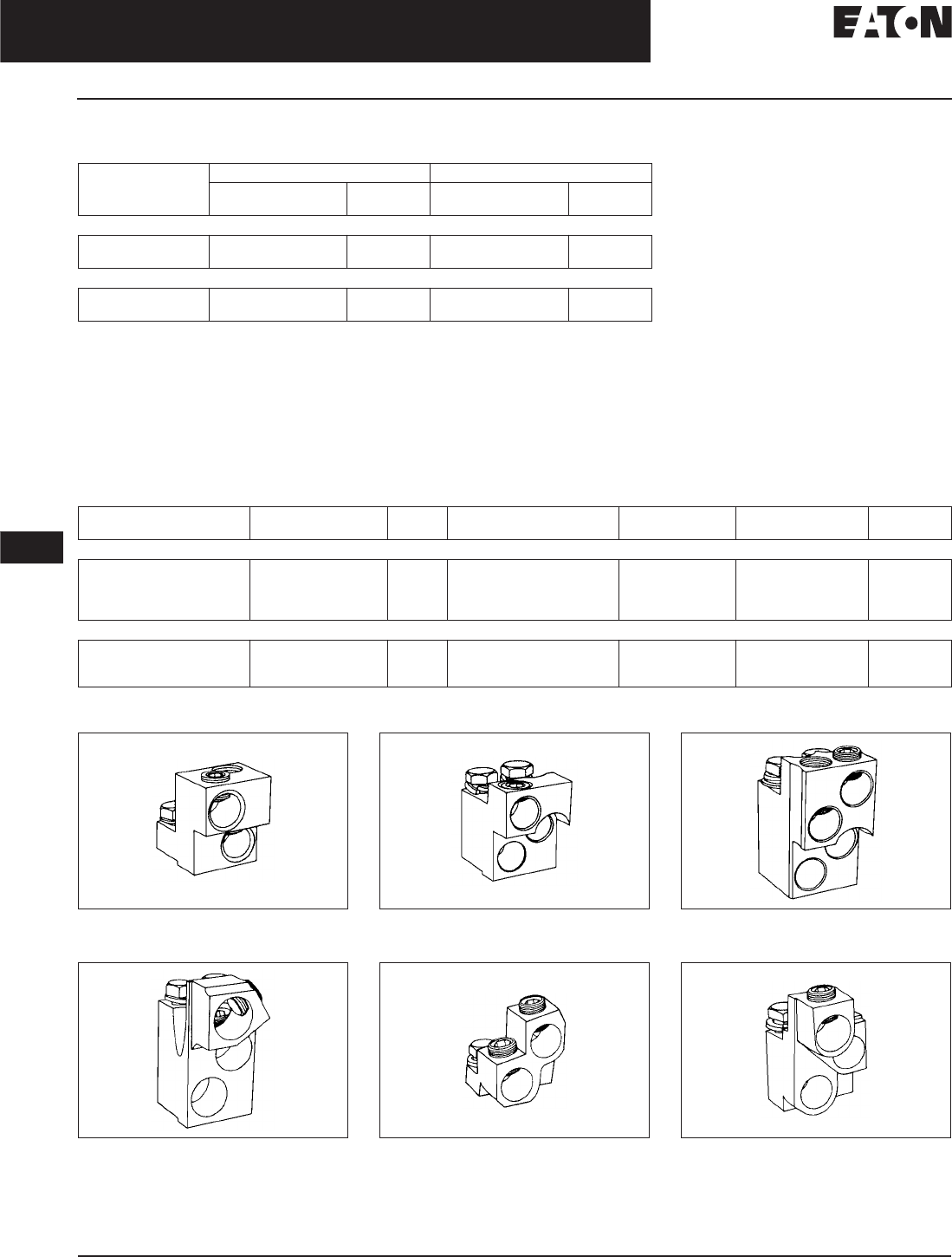
November 2008
12-162
For more information visit: www.eaton.com CA08101001E
Series C Molded Case Circuit Breakers
12
400 – 1200 Amperes
N-Frame
Type ND Molded Case Switches
Table 12-265. Type ND Molded Case Switches
Neutral is in right pole.
Note: Molded case switch will trip above 14,000 amperes.
Note: For UL listed, series tested molded case switch application data, refer to Eaton.
Line and Load Terminals
Ordering Information
N-Frame circuit breakers use Cu/AI terminals as standard. When optional copper or Cu/AI terminals are required, order by
Catalog Number. Specify if factory installation is required.
Table 12-266. Line and Load Terminals
Terminal rating is AL9CU.
Terminal rating is AL7CU.
Figure 12-33. TA700NB1 Figure 12-34. TA1000NB1 Figure 12-35. TA1200NB1
Figure 12-36. TA1201NB1 Figure 12-37. T700NB1 Figure 12-38. T1000NB1
Continuous
Ampere Rating
at 40°C
3-Pole 4-Pole
Catalog
Number
Price
U.S. $
Catalog
Number
Price
U.S. $
Type ND – High Instantaneous (K)
800 ND3800WK
HND3800WK
ND4800WK
HND4800WK
Type ND – High Instantaneous (K)
1200 ND312WK
HND312WK
ND412WK
HND412WK
Maximum Breaker
Amperes
Terminal Body
Material
Wire
Type
AWG Wire Range/
No. Conductors
Metric Wire
Range mm2Catalog
Number
Price
U.S. $
Standard Cu/AI Pressure Terminals
700
1000
1200
1200
Aluminum
Aluminum
Aluminum
Aluminum
Cu/AI
Cu/AI
Cu/AI
Cu/AI
(2) 1 – 500 kcmil
(3) 3/0 – 400 kcmil
(4) 4/0 – 500 kcmil
(3) 500 – 750 kcmil
50 – 240
95 – 185
120 – 240
300 – 400
TA700NB1
TA1000NB1
TA1200NB1
TA1201NB1
Optional Copper and Cu/AI Pressure Type Terminals
700
1000
1200
Copper
Copper
Copper
Cu
Cu
Cu
(2) 2/0 – 500 kcmil
(3) 3/0 – 500 kcmil
(4) 3/0 – 400 kcmil
70 – 240
95 – 240
95 – 185
T700NB1
T1000NB1
T1200NB3
Discount Symbol . . . . . . . . . . . . . . . . . . . . . . . . . CB-2

November 2008
CA08101001E For more information visit: www.eaton.com
12-163
Series C Molded Case Circuit Breakers
12
400 – 1200 Amperes
N-Frame
Allowable Accessory Combinations
Different combinations of accessories can be supplied, depending on the types of accessories and the number of poles in the
circuit breaker.
Table 12-267. Accessories
■Applicable in indicated pole position ❏May be mounted on left or right pole —
not both
●Accessory available/Modification available
OPTIM 550 and 1050 are factory sealed and do not have the right pole available for accessories.
Description Reference
Page
3-Pole 4-Pole
Left Center Right Left Center Right Neu.
Internal Accessories (Only One Internal Accessory Per Pole)
Alarm Lockout (Make/Break) 12-217 ■■■■
Alarm Lockout (2Make/2Break) 12-217 ■■■■
Auxiliary Switch (1A, 1B) 12-220 ■■■■
Auxiliary Switch (2A, 2B) 12-220 ■■■■
Auxiliary Switch (3A, 3B) 12-220 ■■■■
Auxiliary Switch (1A, 1B) and Alarm Switch Combination 12-223 ■■■■
Auxiliary Switch (2A, 2B) and Alarm Switch Combination 12-223 ■■■■
Shunt Trip — Standard 12-226 ■■
Shunt Trip — Low Energy 12-231 ■■
Undervoltage Release Mechanism 12-232 ■■
Cutler-Hammer PowerNet Communications Kit (OPTIM 550) 12-242 ■
External Accessories
Base Mounting Hardware 12-246 ●●
Interphase Barriers 12-249 ●●
Non-Padlockable Handle Block 12-251 ■■
Padlockable Handle Lock Hasp 12-252 ❏❏❏❏
Key Interlock Kit 12-253 ❏❏❏❏
Sliding Bar Interlock — Requires Two Breakers 12-254 ●
Walking Beam Interlock — Requires Two Breakers 12-254 ●●
Electrical (Motor) Operator 12-255 ●●
Plug-in Adapters 12-257 ●●
Rear Connecting Studs 12-258 ●●
Panelboard Connecting Straps 12-261 ●●
Handle Mechanisms 12-262 ●●
Handle Extension 12-267 ●●
Solid-State (Electronic) Portable Test Kit 12-268 ●●
OPTIM System Components 3-Poles
Ground Fault Alarm Unit 12-268
Potential Transformer Module 12-268
Breaker Interface Module (BIM) 12-269
Digitrip OPTIMizer 12-269
Auxiliary Power Module 12-269
Modifications (Refer to Eaton)
Special Calibration — ●●
Moisture Fungus Treatment 12-73 ●●
Freeze-Tested Circuit Breakers — ●●
Marine Application — ●●

November 2008
12-164
For more information visit: www.eaton.com CA08101001E
Series C Molded Case Circuit Breakers
12
800 – 2500 Amperes
R-Frame
R-Frame
Typical R-Frame Circuit Breaker
Product Description
■Cutler-Hammer R-Frame Circuit
Breakers by Eaton Corporation are
available as frame (which includes
trip unit), rating plug and terminals.
■All R-Frame circuit breakers are
suitable for reverse feed use.
Technical Data and Specifications
Table 12-268. UL 489/CSA Interrupting Capacity Ratings
Utilization Category A circuit breakers.
100% rated breakers.
Note: See Page 12-165 for Trip Unit Specifications.
Table 12-269. IEC 947-2 Interrupting Capacity Ratings
Utilization Category A circuit breakers.
Circuit
Breaker
Type
Number
of Poles
Interrupting Capacity (kA Symmetrical Amperes)
Volts ac (50/60 Hz)
240 277 480 600
RD
CRD
3, 4
3, 4
125
125
—
—
65
65
50
50
RDC
CRDC
3, 4
3, 4
200
200
—
—
100
100
65
65
Circuit
Breaker
Type
Number
of Poles
Interrupting Capacity (kA Symmetrical Amperes)
Volts ac (50/60 Hz)
240 415 690
RD
Icu
Ics
3, 4
135
100
70
50
25
13
RDC
Icu
Ics
3, 4
200
100
100
50
35
18
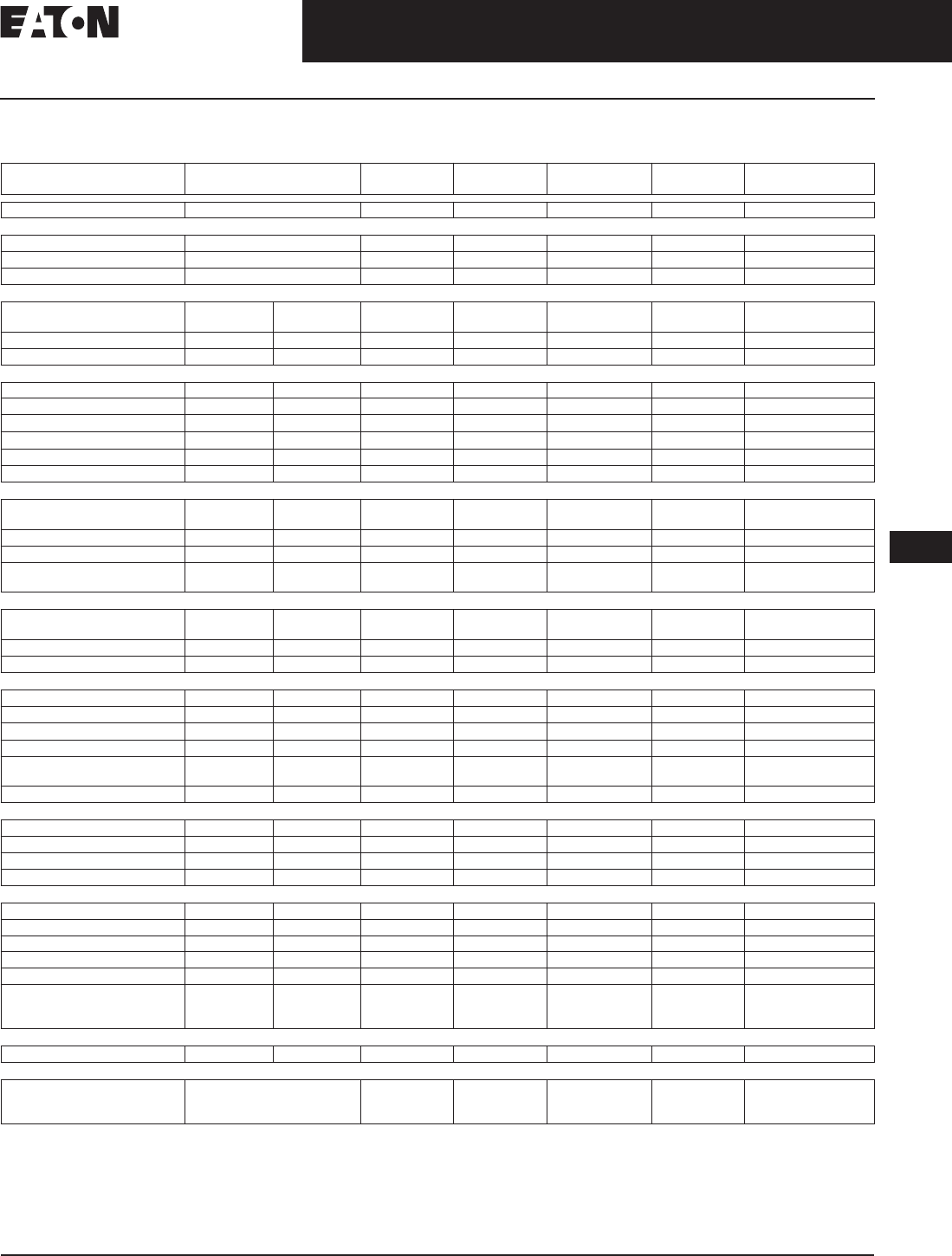
November 2008
CA08101001E For more information visit: www.eaton.com
12-165
Series C Molded Case Circuit Breakers
12
800 – 2500 Amperes
R-Frame
R-Frame Digitrip Specifications
Table 12-270. Specifications
Adjust by rating plug.
Except 2500 ampere frame is 200 – 600%.
Varies by frame.
LS/LSG only.
Not to exceed 1200 amperes.
By OPTIMizer/BIM.
Optional. Add suffix “R” to Catalog Number.
Legend: BIM= Breaker Interface Module
(A)= GF Alarm
Is= Sensor Rating
In= Rating Plug
Ir= Long Delay Pickup Setting x In
Trip Unit Type Digitrip
RMS 310
Digitrip
RMS 510
Digitrip
RMS 610
Digitrip
RMS 810
Digitrip
RMS 910
Digitrip
OPTIM 1050
rms Sensing Yes Yes Yes Yes Yes Yes
Breaker Type
Frame R RRR RR
Ampere Range 800 A – 2500 A 800 A – 2500 A 800 A – 2500 A 800 A – 2500 A 800 A – 2500 A 800 A – 2500 A
Interrupting Rating at 480 Volts 65, 100 (kA) 65, 100 (kA) 65, 100 (kA) 65, 100 (kA) 65, 100 (kA) 65, 100 (kA)
Protection
Ordering Options LS, LSG LSI, LSIG LI, LS, LSI, LIG,
LSG, LSIG
LI, LS, LSI, LIG,
LSG, LSIG
LI, LS, LSI, LIG,
LSG, LSIG
LI, LS, LSI, LIG,
LSG, LSIG
LSI(A), LISG
Fixed Rated Plug (In) Yes Yes Yes Yes Yes Yes Yes
Overtemperature Trip Yes Yes Yes Yes Yes Yes Yes
Long Delay Protection (L)
Adjustable Rating Plug (In)YesYesNoNoNo NoNo
Long Delay Pickup 0.5 – 1.0 (In) 0.5 – 1.0 (In) 0.5 – 1.0 x (In) 0.5 – 1.0 x (In) 0.5 – 1.0 x (In) 0.5 – 1.0 x (In) 0.4 – 1.0 x (In)
Long Delay Time I2t12 Seconds 12 Seconds 2 – 24 Seconds 2 – 24 Seconds 2 – 24 Seconds 2 – 24 Seconds 2 – 24 Seconds
Long Delay Time I4tNo No No No No No 1 – 5 Seconds
Long Delay Thermal Memory Yes Yes Yes Yes Yes Yes Yes
High Load Alarm No No No 0.85 x Ir0.85 x Ir0.85 x Ir0.5-1.0 x Ir
Short Delay Protection (S)
Short Delay Pickup 200 – 800%
x (In)
200 – 800%
x (In)
200 – 600%
S1&S2 x (Ir)
200 – 600%
S1&S2 x (Ir)
200 – 600%
S1&S2 x (Ir)
200 – 600%
S1&S2 x (Ir)
150-800% x (Ir)
Short Delay Time I2t 100 ms No 100 – 500 ms 100 – 500 ms 100 – 500 ms 100 – 500 ms 100 – 500 ms
Short Delay Time Flat No Inst – 300 ms 100 – 500 ms 100 – 500 ms 100 – 500 ms 100 – 500 ms 100 – 500 ms
Short Delay Time Zone
Selective Interlocking
No No Yes Yes Yes Yes Yes
Instantaneous Protection (I)
Instantaneous Pickup No 200 – 800%
x (In)
200 – 600%
M1&M2 x (In)
200 – 600%
M1&M2 x (In)
200 – 600%
M1&M2 x (In)
200 – 600%
M1&M2 x (In)
200 – 800% x (In)
Discriminator No No Yes Yes Ye s Yes Ye s
Instantaneous Override Yes Yes Yes Yes Yes Yes Yes
Ground Fault Protection (G)
Ground Fault Alarm No No No No No No 25 – 100% x (In)
Ground Fault Pickup 200 – 1200 A 200 – 1200 A 25 – 100% x (Is) 25-100% x (Is) 25 – 100% x (Is) 25 – 100% x (Is) 25 – 100% x (In)
Ground Fault Delay I2tNo No 100 – 500 ms 100 – 500 ms 100 – 500 ms 100 – 500 ms 100 – 500 ms
Ground Fault Delay Flat Inst – 500 ms Inst – 500 ms 100 – 500 ms 100 – 500 ms 100 – 500 ms 100 – 500 ms 100 – 500 ms
Ground Fault Zone
Selective Interlocking
No No Yes Yes Yes Yes Yes
Ground Fault Thermal Memory Yes Yes Yes Yes Yes Yes Yes
System Diagnostics
Status LEDs Yes Yes Yes Yes Yes Yes Yes
Cause of Trip LEDs No No Yes Yes Yes Yes Yes
Magnitude of Trip Information No No No Yes Yes Yes Yes
Remote Signal Contacts Yes Yes No Yes Yes Yes Yes
System Monitoring
Digital Display No No No Yes Yes Yes Yes
Current No No No Yes Yes Yes Yes
Voltage No No No No No Yes No
Power and Energy No No No No Yes Yes Yes
Power Quality — Harmonics No No No No No Yes Yes
Power Factor No No No No Yes (Over
Cutler-Hammer
PowerNet Only)
Yes Ye s
Communications
Cutler-Hammer PowerNet No No No No Yes Yes Yes
Testing
Testing Method Test Set Integral Integral Integral Integral OPTIMizer, BIM,
Cutler-Hammer
PowerNet

November 2008
12-166
For more information visit: www.eaton.com CA08101001E
Series C Molded Case Circuit Breakers
12
800 – 2500 Amperes
R-Frame
Dimensions/Weights
Table 12-271. Dimensions in Inches (mm)
Table 12-272. Approximate Shipping Weight, Lbs. (kg)
Product Selection
This information is presented only as an aid to understanding catalog numbers.
It is not to be used to build catalog numbers for circuit breakers or trip units.
Table 12-273. Circuit Breaker/Frame Catalog Numbering System
For complete list of available trip types refer to Pages 12-167 – 12-180.
Number
of Poles
Width Height Depth
3
4
15.50 (393.7)
20.00 (508.0)
16.00 (406.4)
16.00 (406.4)
9.75 (247.7)
9.75 (247.7)
Breaker
Type
Complete Breaker
Number of Poles
34
1600 Amperes
RD, CRD, RDC, CRDC 102 (46.3) 135 (61.2)
2000 Amperes
RD, RDC 102 (46.3) 135 (61.2)
CRD, CRDC 130 (59.0) 175 (79.4)
2500 Amperes
RD, RDC 135 (61.2) 182 (82.6)
RD 3 16 T32 W
Circuit Breaker/
Frame Type
RD
RDC
CRD
CRDC
Number
of Poles
3 = 3 Poles
4 = 4 Poles
Circuit Breaker/
Frame Ampere Rating
16 = 1600 Amperes
20 = 2000 Amperes
25 = 2500 Amperes
Trip Type
T32 = Digitrip RMS 310 LSI
T53 = Digitrip RMS 510 LS
T65 = Digitrip RMS 610 LSG
T86 = Digitrip RMS 810 LSIG
T96 = Digitrip RMS 910 LSIG
T106 = Digitrip OPTIM 1050 LSIG
T107 = Digitrip OPTIM 1050 LSIA
Suffix
W= Without Terminals
P= 100% Protected Neutral Pole
R= Ground Fault Remote
(310 Only)
K= Molded Case Switch

November 2008
CA08101001E For more information visit: www.eaton.com
12-167
Series C Molded Case Circuit Breakers
12
800 – 2500 Amperes
R-Frame
Product Selection
Digitrip RMS 310 Electronic Circuit Breakers with Interchangeable Rating Plugs
Order as individual components: Breaker Frame (which includes Trip Unit) and Rating Plug.
Table 12-274. Digitrip RMS 310 Electronic Circuit Breakers with Interchangeable Rating Plugs
See Table 12-275 on Page 12-168 for prices.
Add R to Catalog Number for ground fault remote indication compatibility, i.e., RD316T35RW.
For SCR application use 2000 ampere frame.
Unprotected right pole neutral. Add P to Catalog Number for 100% protected right pole neutral, i.e., RD416T33PW.
Maximum
Continuous
Ampere
Rating
at 40°C
Circuit Breaker Frame Only Digitrip RMS 310 Rating Plug Only
L – Adjustable Long Delay Pickup (By Adjustable Rating Plug)
S – Adjustable Short Delay Pickup with Fixed Short Delay Time
(I2t Response) or Adjustable Short Delay Time (Flat Response)
I – Adjustable Instantaneous Pickup by Setting Short Delay Time to
Instantaneous
G – Adjustable Ground Fault Pickup with Adjustable Ground Fault Time
(Flat Response)
Ampere
Rating
Fixed
Rating
Plug
Adjustable Rating Plug
Adjustable
Ampere Ratings
LS LSI LSG LSIG
Catalog Number Catalog Number
3-Pole Standard Interrupting Capacity 600 Vac Rated 65 kAIC at 480 Vac
1600 RD316T33W RD316T32W RD316T35W RD316T36W 800
1000
1200
1250
1400
1500
1600
16RES08T
16RES10T
16RES12T
16RES125T
16RES14T
16RES15T
16RES16T
Adjustable Settings are:
800, 1000, 1200, 1600
A16RES16T1
2000 RD320T33W RD320T32W RD320T35W RD320T36W 1000
1200
1250
1400
1600
2000
20RES10T
20RES12T
20RES125T
20RES14T
20RES16T
20RES20T
Adjustable Settings are:
1000, 1200, 1600, 2000
A20RES20T1
2500 RD325T33W RD325T32W RD325T35W RD325T36W 1200
1250
1600
2000
2500
25RES12T
25RES125T
25RES16T
25RES20T
25RES25T
Adjustable Settings are:
1200, 1600, 2000, 2500
A25RES25T1
4-Pole Standard Interrupting Capacity 600 Vac Rated 65 kAIC at 480 Vac
1600 RD416T33W RD416T32W —— 800
1000
1200
1250
1400
1500
1600
16RES08T
16RES10T
16RES12T
16RES125T
16RES14T
16RES15T
16RES16T
Adjustable Settings are:
800, 1000, 1200, 1600
A16RES16T1
2000 RD420T33W RD420T32W — — 1000
1200
1250
1400
1600
2000
20RES10T
20RES12T
20RES125T
20RES14T
20RES16T
20RES20T
Adjustable Settings are:
1000, 1200, 1600, 2000
A20RES20T1
2500 RD425T33W RD425T32W — — 1200
1250
1600
2000
2500
25RES12T
25RES125T
25RES16T
25RES20T
25RES25T
Adjustable Settings are:
1200, 1600, 2000, 2500
A25RES25T1

November 2008
12-168
For more information visit: www.eaton.com CA08101001E
Series C Molded Case Circuit Breakers
12
800 – 2500 Amperes
R-Frame
Table 12-275. Digitrip RMS 310 Electronic Circuit Breakers with Interchangeable Rating Plugs Prices
Catalog
Number
Price
U.S. $
Catalog
Number
Price
U.S. $
Catalog
Number
Price
U.S. $
Catalog
Number
Price
U.S. $
A16RES16T1
A20RES20T1
A25RES25T1
RD316T32W
RD316T33W
RD320T36W
RD325T32W
RD325T33W
RD325T35W
RD325T36W
RD425T33W
16RES08T
16RES10T
16RES12T
16RES125T
20RES125T
20RES14T
20RES16T
20RES19T
20RES20T
RD316T35W
RD316T36W
RD320T32W
RD320T33W
RD320T35W
RD416T32W
RD416T33W
RD420T32W
RD420T33W
RD425T32W
16RES14T
16RES15T
16RES16T
20RES10T
20RES12T
25RES12T
25RES125T
25RES16T
25RES20T
25RES25T
Discount Symbol . . . . . . . . . . . . . . . . . . . . . . . . . CB-2

November 2008
CA08101001E For more information visit: www.eaton.com
12-169
Series C Molded Case Circuit Breakers
12
800 – 2500 Amperes
R-Frame
Digitrip RMS 310 Electronic Circuit Breakers with Interchangeable Rating Plugs
Order as individual components: Breaker Frame (which includes Trip Unit) and Rating Plug.
Table 12-276. Digitrip RMS 310 Electronic Circuit Breakers with Interchangeable Rating Plugs
See Table 12-277 below for prices.
Add R to Catalog Number for ground fault remote indication compatibility, i.e., RDC316T35RW.
For SCR application use 2000 ampere frame.
Unprotected right pole neutral. Add P to Catalog Number for 100% protected right pole neutral, i.e., RDC416T33PW.
Table 12-277. Digitrip RMS 310 Electronic Circuit Breakers with Interchangeable Rating Plugs Prices
Maximum
Continuous
Ampere
Rating
at 40°C
Circuit Breaker Frame Only Digitrip RMS 310 Rating Plug Only
L – Adjustable Long Delay Pickup (By Adjustable Rating Plug)
S – Adjustable Short Delay Pickup with Fixed Short Delay Time
(I2t Response) or Adjustable Short Delay Time (Flat Response)
I – Adjustable Instantaneous Pickup by Setting Short Delay Time to Instantaneous
G – Adjustable Ground Fault Pickup with Adjustable Ground Fault Time (Flat Response)
Ampere
Rating
Fixed
Rating
Plug
Adjustable Rating Plug
Adjustable
Ampere Ratings
LS LSI LSG LSIG
Catalog Number Catalog Number
3-Pole High Interrupting Capacity 600 Vac Rated 100 kAIC at 480 Vac
1600 RDC316T33W RDC316T32W RDC316T35W RDC316T36W 800
1000
1200
1250
1400
1500
1600
16RES08T
16RES10T
16RES12T
16RES125T
16RES14T
16RES15T
16RES16T
Adjustable Settings are:
800, 1000, 1200, 1600
A16RES16T1
2000 RDC320T33W RDC320T32W RDC320T35W RDC320T36W 1000
1200
1250
1400
1600
2000
20RES10T
20RES12T
20RES125T
20RES14T
20RES16T
20RES20T
Adjustable Settings are:
1000, 1200, 1600, 2000
A20RES20T1
2500 RDC325T33W RDC325T32W RDC325T35W RDC325T36W 1200
1250
1600
2000
2500
25RES12T
25RES125T
25RES16T
25RES20T
25RES25T
Adjustable Settings are:
1200, 1600, 2000, 2500
A25RES25T1
4-Pole High Interrupting Capacity 600 Vac Rated 100 kAIC at 480 Vac
1600 RDC416T33W RDC416T32W — — 800
1000
1200
1250
1400
1500
1600
16RES08T
16RES10T
16RES12T
16RES125T
16RES14T
16RES15T
16RES16T
Adjustable Settings are:
800, 1000, 1200, 1600
A16RES16T1
2000 RDC420T33W RDC420T32W — — 1000
1200
1250
1400
1600
2000
20RES10T
20RES12T
20RES125T
20RES14T
20RES16T
20RES20T
Adjustable Settings are:
1000, 1200, 1600, 2000
A20RES20T1
2500 RDC425T33W RDC425T32W — — 1200
1250
1600
2000
2500
25RES12T
25RES125T
25RES16T
25RES20T
25RES25T
Adjustable Settings are:
1200, 1600, 2000, 2500
A25RES25T1
Catalog
Number
Price
U.S. $
Catalog
Number
Price
U.S. $
Catalog
Number
Price
U.S. $
Catalog
Number
Price
U.S. $
A16RES16T1
A20RES20T1
A25RES25T1
RDC316T32W
RDC316T33W
RDC320T36W
RDC325T32W
RDC325T33W
RDC325T35W
RDC325T36W
RDC425T33W
16RES08T
16RES10T
16RES12T
16RES125T
20RES125T
20RES14T
20RES16T
20RES20T
25RES12T
RDC316T35W
RDC316T36W
RDC320T32W
RDC320T33W
RDC320T35W
RDC416T32W
RDC416T33W
RDC420T32W
RDC420T33W
RDC425T32W
16RES14T
16RES15T
16RES16T
20RES10T
20RES12T
25RES125T
25RES16T
25RES20T
25RES25T
—
Discount Symbol . . . . . . . . . . . . . . . . . . . . . . . . . CB-2

November 2008
12-170
For more information visit: www.eaton.com CA08101001E
Series C Molded Case Circuit Breakers
12
800 – 2500 Amperes
R-Frame
100% Rated Digitrip RMS 310 Electronic Circuit Breakers
The NEC allows the breaker to be rated at 100% of its frame size in an assembly, provided that 90°C wire is applied at 75°C
ampacity. Order as individual components: Breaker Frame (which includes Trip Unit) and Rating Plug.
Table 12-278. 100% Rated Digitrip RMS 310 Electronic Circuit Breakers
See Table 12-279 below for prices.
Add R to Catalog Number for ground fault remote indication compatibility, i.e., CRD316T35RW.
For SCR application use 2000 ampere frame.
Includes B2016RDL rear connectors.
Table 12-279. 100% Rated Digitrip RMS 310 Electronic Circuit Breakers Prices
Maximum
Continuous
Ampere
Rating
at 40°C
Circuit Breaker Frame Only Digitrip RMS 310 Rating Plug Only
L – Adjustable Long Delay Pickup (By Adjustable Rating Plug)
S – Adjustable Short Delay Pickup with Fixed Short Delay Time
(I2t Response) or Adjustable Short Delay Time (Flat Response)
I – Adjustable Instantaneous Pickup by Setting Short Delay Time to Instantaneous
G – Adjustable Ground Fault Pickup with Adjustable Ground Fault Time (Flat Response)
Ampere
Rating
Fixed
Rating
Plug
Adjustable
Rating Plug
Adjustable
Ampere Ratings
LS LSI LSG LSIG
Catalog Number Catalog Number
3-Pole Standard Interrupting Capacity 600 Vac Rated 65 kAIC at 480 Vac
1600 CRD316T33W CRD316T32W CRD316T35W CRD316T36W 800
1000
1200
1250
1400
1500
1600
16RES08T
16RES10T
16RES12T
16RES125T
16RES14T
16RES15T
16RES16T
Adjustable Settings are:
800, 1000, 1200, 1600
A16RES16T1
2000 CRD320T33W CRD320T32W CRD320T35W CRD320T36W 1000
1200
1250
1400
1600
2000
20RES10T
20RES12T
20RES125T
20RES14T
20RES16T
20RES20T
Adjustable Settings are:
1000, 1200, 1600, 2000
A20RES20T1
3-Pole High Interrupting Capacity 600 Vac Rated 100 kAIC at 480 Vac
1600 CRDC316T33W CRDC316T32W CRDC316T35W CRDC316T36W 800
1000
1200
1250
1400
1500
1600
16RES08T
16RES10T
16RES12T
16RES125T
16RES14T
16RES15T
16RES16T
Adjustable Settings are:
800, 1000, 1200, 1600
A16RES16T1
2000 CRDC320T33W CRDC320T32W CRDC320T35W CRDC320T36W 1000
1200
1250
1400
1600
2000
20RES10T
20RES12T
20RES125T
20RES14T
20RES16T
20RES20T
Adjustable Settings are:
1000, 1200, 1600, 2000
A20RES20T1
Catalog
Number
Price
U.S. $
Catalog
Number
Price
U.S. $
Catalog
Number
Price
U.S. $
Catalog
Number
Price
U.S. $
A16RES16T1
A20RES20T1
CRDC316T32W
CRDC316T33W
CRDC316T35W
CRD316T32W
CRD316T33W
CRD316T35W
CRD316T36W
CRD320T32W
16RES12T
16RES125T
16RES14T
16RES15T
16RES16T
20RES20T
—
—
—
—
CRDC316T36W
CRDC320T32W
CRDC320T33W
CRDC320T35W
CRDC320T36W
CRD320T33W
CRD320T35W
CRD320T36W
16RES08T
16RES10T
20RES10T
20RES12T
20RES125T
20RES14T
20RES16T
—
—
—
—
—
Discount Symbol . . . . . . . . . . . . . . . . . . . . . . . . . CB-2

November 2008
CA08101001E For more information visit: www.eaton.com
12-171
Series C Molded Case Circuit Breakers
12
800 – 2500 Amperes
R-Frame
Digitrip RMS 510 Electronic Circuit Breakers with Interchangeable Rating Plugs
Order as individual components: Breaker Frame (which includes Trip Unit) and Rating Plug.
Table 12-280. Digitrip RMS 510 Electronic Circuit Breakers with Interchangeable Rating Plugs
See Table 12-281 below for prices.
Table 12-281. Digitrip RMS 510 Electronic Circuit Breakers with Interchangeable Rating Plugs Prices
Maximum
Continuous
Ampere
Rating
at 40°C
Circuit Breaker Frame Only Digitrip Rating Plug Only
L – Adjustable Long Delay Pickup (Ir) with Adjustable Long Delay Time
S – Adjustable Short Delay Pickup with Adjustable Short Delay Time (I2t or Flat Response)
I – Adjustable Instantaneous Pickup
G – Adjustable Ground Fault Pickup with Adjustable Ground Fault Time Delay (I2t or Flat Response)
Rated
Current
(In)
Fixed
Rating Plug
LI LS LSI LIG LSG LSIG
Catalog Number Catalog Number
3-Pole Standard Interrupting Capacity 600 Vac Rated 65 kAIC at 480 Vac
1600 RD316T51W RD316T53W RD316T52W RD316T54W RD316T55W RD316T56W 800
1000
1200
1600
RP6R16A080
RP6R16A100
RP6R16A120
RP6R16A160
2000 RD320T51W RD320T53W RD320T52W RD320T54W RD320T55W RD320T56W 1000
1200
1600
2000
RP6R20A100
RP6R20A120
RP6R20A160
RP6R20A200
2500 RD325T51W RD325T53W RD325T52W RD325T54W RD325T55W RD325T56W 1600
2000
2500
RP6R25A160
RP6R25A200
RP6R25A250
3-Pole High Interrupting Capacity 600 Vac Rated 100 kAIC at 480 Vac
1600 RDC316T51W RDC316T53W RDC316T52W RDC316T54W RDC316T55W RDC316T56W 800
1000
1200
1600
RP6R16A080
RP6R16A100
RP6R16A120
RP6R16A160
2000 RDC320T51W RDC320T53W RDC320T52W RDC320T54W RDC320T55W RDC320T56W 1000
1200
1600
2000
RP6R20A100
RP6R20A120
RP6R20A160
RP6R20A200
2500 RDC325T51W RDC325T53W RDC325T52W RDC325T54W RDC325T55W RDC325T56W 1600
2000
2500
RP6R25A160
RP6R25A200
RP6R25A250
Catalog
Number
Price
U.S. $
Catalog
Number
Price
U.S. $
Catalog
Number
Price
U.S. $
Catalog
Number
Price
U.S. $
Catalog
Number
Price
U.S. $
RDC316T51W
RDC316T52W
RDC316T53W
RDC316T54W
RDC316T55W
RDC320T55W
RDC320T56W
RDC325T51W
RDC325T52W
RDC325T53W
RD316T53W
RD316T54W
RD316T55W
RD316T56W
RD320T51W
RD325T51W
RD325T52W
RD325T53W
RD325T54W
RD325T55W
RP6R20A100
RP6R20A120
RP6R20A160
RP6R20A200
RP6R25A160
RDC316T56W
RDC320T51W
RDC320T52W
RDC320T53W
RDC320T54W
RDC325T54W
RDC325T55W
RDC325T56W
RD316T51W
RD316T52W
RD320T52W
RD320T53W
RD320T54W
RD320T55W
RD320T56W
RD325T56W
RP6R16A080
RP6R16A100
RP6R16A120
RP6R16A160
RP6R25A200
RP6R25A250
—
—
—
Discount Symbol . . . . . . . . . . . . . . . . . . . . . . . . . CB-2

November 2008
12-172
For more information visit: www.eaton.com CA08101001E
Series C Molded Case Circuit Breakers
12
800 – 2500 Amperes
R-Frame
100% Rated Digitrip RMS 510 Circuit Breakers
The NEC allows the breaker to be rated at 100% of its frame size in an assembly, provided that 90°C wire is applied at 75°C
ampacity. Order as individual components: Breaker Frame (which includes Trip Unit) and Rating Plug.
Table 12-282. 100% Rated Digitrip RMS 510 Circuit Breakers
See Table 12-283 below for prices.
Includes B2016RDL rear connectors.
Table 12-283. 100% Rated Digitrip RMS 510 Circuit Breakers Prices
Maximum
Continuous
Ampere
Rating
at 40°C
Circuit Breaker Frame Only Digitrip Rating Plug Only
L – Adjustable Long Delay Pickup (Ir) with Adjustable Long Delay Time
S – Adjustable Short Delay Pickup with Adjustable Short Delay Time (I2t or Flat Response)
I – Adjustable Instantaneous Pickup
G – Adjustable Ground Fault Pickup with Adjustable Ground Fault Time Delay (I2t or Flat Response)
Rated
Current
(In)
Fixed
Rating Plug
LI LS LSI LIG LSG LSIG
Catalog Number Catalog Number
3-Pole Standard Interrupting Capacity 600 Vac Rated 65 kAIC at 480 Vac
1600 CRD316T51W CRD316T53W CRD316T52W CRD316T54W CRD316T55W CRD316T56W 800
1000
1200
1600
RP6R16A080
RP6R16A100
RP6R16A120
RP6R16A160
2000 CRD320T51W CRD320T53W CRD320T52W CRD320T54W CRD320T55W CRD320T56W 1000
1200
1600
2000
RP6R20A100
RP6R20A120
RP6R20A160
RP6R20A200
3-Pole High Interrupting Capacity 600 Vac Rated 100 kAIC at 480 Vac
1600 — CRDC316T53W CRDC316T52W CRDC316T54W CRDC316T55W CRDC316T56W 800
1000
1200
1600
RP6R16A080
RP6R16A100
RP6R16A120
RP6R16A160
2000 CRDC320T51W CRDC320T53W CRDC320T52W CRDC320T54W CRDC320T55W CRDC320T56W 1000
1200
1600
2000
RP6R20A100
RP6R20A120
RP6R20A160
RP6R20A200
Catalog
Number
Price
U.S. $
Catalog
Number
Price
U.S. $
Catalog
Number
Price
U.S. $
Catalog
Number
Price
U.S. $
CRDC316T52W
CRDC316T53W
CRDC316T54W
CRDC316T55W
CRDC316T56W
CRDC320T56W
CRD316T51W
CRD316T52W
CRD316T53W
CRD316T54W
CRD320T54W
CRD320T55W
CRD320T56W
RP6R16A080
RP6R16A100
RP6R20A200
—
—
—
—
CRDC320T51W
CRDC320T52W
CRDC320T53W
CRDC320T54W
CRDC320T55W
CRD316T55W
CRD316T56W
CRD320T51W
CRD320T52W
CRD320T53W
RP6R16A120
RP6R16A160
RP6R20A100
RP6R20A120
RP6R20A160
—
—
—
—
—
Discount Symbol . . . . . . . . . . . . . . . . . . . . . . . . . CB-2

November 2008
CA08101001E For more information visit: www.eaton.com
12-173
Series C Molded Case Circuit Breakers
12
800 – 2500 Amperes
R-Frame
Digitrip RMS 610 Electronic Circuit Breakers with Interchangeable Rating Plugs
Order as individual components: Breaker Frame (which includes Trip Unit) and Rating Plug.
Table 12-284. Digitrip RMS 610 Electronic Circuit Breakers with Interchangeable Rating Plugs
See Table 12-285 below for prices.
Table 12-285. Digitrip RMS 610 Electronic Circuit Breakers with Interchangeable Rating Plug Prices
Maximum
Continuous
Ampere
Rating
at 40°C
Circuit Breaker Frame Only Digitrip Rating Plug Only
L – Adjustable Long Delay Pickup (Ir) with Adjustable Long Delay Time
S – Adjustable Short Delay Pickup with Adjustable Short Delay Time (I2t or Flat Response)
I – Adjustable Instantaneous Pickup
G – Adjustable Ground Fault Pickup with Adjustable Ground Fault Time Delay (I2t or Flat Response)
Rated
Current
(In)
Fixed
Rating Plug
LI LS LSI LIG LSG LSIG
Catalog Number Catalog Number
3-Pole Standard Interrupting Capacity 600 Vac Rated 65 kAIC at 480 Vac
1600 RD316T61W RD316T63W RD316T62W RD316T64W RD316T65W RD316T66W 800
1000
1200
1600
RP6R16A080
RP6R16A100
RP6R16A120
RP6R16A160
2000 RD320T61W RD320T63W RD320T62W RD320T64W RD320T65W RD320T66W 1000
1200
1600
2000
RP6R20A100
RP6R20A120
RP6R20A160
RP6R20A200
2500 RD325T61W RD325T63W RD325T62W RD325T64W RD325T65W RD325T66W 1600
2000
2500
RP6R25A160
RP6R25A200
RP6R25A250
3-Pole High Interrupting Capacity 600 Vac Rated 100 kAIC at 480 Vac
1600 RDC316T61W RDC316T63W RDC316T62W RDC316T64W RDC316T65W RDC316T66W 800
1000
1200
1600
RP6R16A080
RP6R16A100
RP6R16A120
RP6R16A160
2000 RDC320T61W RDC320T63W RDC320T62W RDC320T64W RDC320T65W RDC320T66W 1000
1200
1600
2000
RP6R20A100
RP6R20A120
RP6R20A160
RP6R20A200
2500 RDC325T61W RDC325T63W RDC325T62W RDC325T64W RDC325T65W RDC325T66W 1600
2000
2500
RP6R25A160
RP6R25A200
RP6R25A250
Catalog
Number
Price
U.S. $
Catalog
Number
Price
U.S. $
Catalog
Number
Price
U.S. $
Catalog
Number
Price
U.S. $
Catalog
Number
Price
U.S. $
RDC316T61W
RDC316T62W
RDC316T63W
RDC316T64W
RDC316T65W
RDC320T65W
RDC320T66W
RDC325T61W
RDC325T62W
RDC325T63W
RD316T63W
RD316T64W
RD316T65W
RD316T66W
RD320T61W
RD325T61W
RD325T62W
RD325T63W
RD325T64W
RD325T65W
RP6R20A100
RP6R20A120
RP6R20A160
RP6R20A200
RP6R25A160
RDC316T66W
RDC320T61W
RDC320T62W
RDC320T63W
RDC320T64W
RDC325T64W
RDC325T65W
RDC325T66W
RD316T61W
RD316T62W
RD320T62W
RD320T63W
RD320T64W
RD320T65W
RD320T66W
RD325T66W
RP6R16A080
RP6R16A100
RP6R16A120
RP6R16A160
RP6R25A200
RP6R25A250
—
—
—
Discount Symbol . . . . . . . . . . . . . . . . . . . . . . . . . CB-2

November 2008
12-174
For more information visit: www.eaton.com CA08101001E
Series C Molded Case Circuit Breakers
12
800 – 2500 Amperes
R-Frame
100% Rated Digitrip RMS 610 Circuit Breakers
The NEC allows the breaker to be rated at 100% of its frame size in an assembly, provided that 90°C wire is applied at 75°C
ampacity. Order as individual components: Breaker Frame (which includes Trip Unit) and Rating Plug.
Table 12-286. 100% Rated Digitrip RMS 610 Circuit Breakers
See Table 12-287 below for prices.
Includes B2016RDL rear connectors.
Table 12-287. 100% Rated Digitrip RMS 610 Circuit Breaker Prices
Maximum
Continuous
Ampere
Rating
at 40°C
Circuit Breaker Frame Only Digitrip Rating Plug Only
L – Adjustable Long Delay Pickup (Ir) with Adjustable Long Delay Time
S – Adjustable Short Delay Pickup with Adjustable Short Delay Time (I2t or Flat Response)
I – Adjustable Instantaneous Pickup
G – Adjustable Ground Fault Pickup with Adjustable Ground Fault Time Delay (I2t or Flat Response)
Rated
Current
(In)
Fixed
Rating Plug
LI LS LSI LIG LSG LSIG
Catalog Number Catalog Number
3-Pole Standard Interrupting Capacity 600 Vac Rated 65 kAIC at 480 Vac
1600 CRD316T61W CRD316T63W CRD316T62W CRD316T64W CRD316T65W CRD316T66W 800
1000
1200
1600
RP6R16A080
RP6R16A100
RP6R16A120
RP6R16A160
2000 CRD320T61W CRD320T63W CRD320T62W CRD320T64W CRD320T65W CRD320T66W 1000
1200
1600
2000
RP6R20A100
RP6R20A120
RP6R20A160
RP6R20A200
3-Pole High Interrupting Capacity 600 Vac Rated 100 kAIC at 480 Vac
1600 CRDC316T61W CRDC316T63W CRDC316T62W CRDC316T64W CRDC316T65W CRDC316T66W 800
1000
1200
1600
RP6R16A080
RP6R16A100
RP6R16A120
RP6R16A160
2000 CRDC320T61W CRDC320T63W CRDC320T62W CRDC320T64W CRDC320T65W CRDC320T66W 1000
1200
1600
2000
RP6R20A100
RP6R20A120
RP6R20A160
RP6R20A200
Catalog
Number
Price
U.S. $
Catalog
Number
Price
U.S. $
Catalog
Number
Price
U.S. $
Catalog
Number
Price
U.S. $
CRDC316T61W
CRDC316T62W
CRDC316T63W
CRDC316T64W
CRDC316T65W
CRDC320T65W
CRDC320T66W
CRD316T61W
CRD316T62W
CRD316T63W
CRD320T63W
CRD320T64W
CRD320T65W
CRD320T66W
RP6R16A080
RP6R20A160
RP6R20A200
—
—
—
CRDC316T66W
CRDC320T61W
CRDC320T62W
CRDC320T63W
CRDC320T64W
CRD316T64W
CRD316T65W
CRD316T66W
CRD320T61W
CRD320T62W
RP6R16A100
RP6R16A120
RP6R16A160
RP6R20A100
RP6R20A120
—
—
—
—
—
Discount Symbol . . . . . . . . . . . . . . . . . . . . . . . . . CB-2

November 2008
CA08101001E For more information visit: www.eaton.com
12-175
Series C Molded Case Circuit Breakers
12
800 – 2500 Amperes
R-Frame
Digitrip RMS 810 Electronic Circuit Breakers with Interchangeable Rating Plugs
Order as individual components: Breaker Frame (which includes Trip Unit) and Rating Plug.
Table 12-288. Digitrip RMS 810 Electronic Circuit Breakers with Interchangeable Rating Plugs
See Table 12-289 below for prices.
Table 12-289. Digitrip RMS 810 Electronic Circuit Breakers with Interchangeable Rating Plug Prices
Maximum
Continuous
Ampere
Rating
at 40°C
Circuit Breaker Frame Only Digitrip Rating Plug Only
L – Adjustable Long Delay Pickup (Ir) with Adjustable Long Delay Time
S – Adjustable Short Delay Pickup with Adjustable Short Delay Time (I2t or Flat Response)
I – Adjustable Instantaneous Pickup
G – Adjustable Ground Fault Pickup with Adjustable Ground Fault Time Delay (I2t or Flat Response)
Rated
Current
(In)
Fixed
Rating Plug
LI LS LSI LIG LSG LSIG
Catalog Number Catalog Number
3-Pole Standard Interrupting Capacity 600 Vac Rated 65 kAIC at 480 Vac
1600 RD316T81W RD316T83W RD316T82W RD316T84W RD316T85W RD316T86W 800
1000
1200
1600
RP6R16A080
RP6R16A100
RP6R16A120
RP6R16A160
2000 RD320T81W RD320T83W RD320T82W RD320T84W RD320T85W RD320T86W 1000
1200
1600
2000
RP6R20A100
RP6R20A120
RP6R20A160
RP6R20A200
2500 RD325T81W RD325T83W RD325T82W RD325T84W RD325T85W RD325T86W 1600
2000
2500
RP6R25A160
RP6R25A200
RP6R25A250
3-Pole High Interrupting Capacity 600 Vac Rated 100 kAIC at 480 Vac
1600 RDC316T81W RDC316T83W RDC316T82W RDC316T84W RDC316T85W RDC316T86W 800
1000
1200
1600
RP6R16A080
RP6R16A100
RP6R16A120
RP6R16A160
2000 RDC320T81W RDC320T83W RDC320T82W RDC320T84W RDC320T85W RDC320T86W 1000
1200
1600
2000
RP6R20A100
RP6R20A120
RP6R20A160
RP6R20A200
2500 RDC325T81W RDC325T83W RDC325T82W RDC325T84W RDC325T85W RDC325T86W 1600
2000
2500
RP6R25A160
RP6R25A200
RP6R25A250
Catalog
Number
Price
U.S. $
Catalog
Number
Price
U.S. $
Catalog
Number
Price
U.S. $
Catalog
Number
Price
U.S. $
Catalog
Number
Price
U.S. $
RDC316T81W
RDC316T82W
RDC316T83W
RDC316T84W
RDC316T85W
RDC320T85W
RDC320T86W
RDC325T81W
RDC325T82W
RDC325T83W
RD316T83W
RD316T84W
RD316T85W
RD316T86W
RD320T81W
RD325T81W
RD325T82W
RD325T83W
RD325T84W
RD325T85W
RP6R20A100
RP6R20A120
RP6R20A160
RP6R20A200
RP6R25A160
RDC316T86W
RDC320T81W
RDC320T82W
RDC320T83W
RDC320T84W
RDC325T84W
RDC325T85W
RDC325T86W
RD316T81W
RD316T82W
RD320T82W
RD320T83W
RD320T84W
RD320T85W
RD320T86W
RD325T86W
RP6R16A080
RP6R16A100
RP6R16A120
RP6R16A160
RP6R25A200
RP6R25A250
—
—
—
Discount Symbol . . . . . . . . . . . . . . . . . . . . . . . . . CB-2

November 2008
12-176
For more information visit: www.eaton.com CA08101001E
Series C Molded Case Circuit Breakers
12
800 – 2500 Amperes
R-Frame
100% Rated Digitrip RMS 810 Circuit Breakers
The NEC allows the breaker to be rated at 100% of its frame size in an assembly, provided that 90°C wire is applied at 75°C
ampacity. Order as individual components: Breaker Frame (which includes Trip Unit) and Rating Plug.
Table 12-290. 100% Rated Digitrip RMS 810 Circuit Breakers
See Table 12-291 below for prices.
Includes B2016RDL rear connectors.
Table 12-291. 100% Rated Digitrip RMS 810 Circuit Breaker Prices
Maximum
Continuous
Ampere
Rating
at 40°C
Circuit Breaker Frame Only Digitrip Rating Plug Only
L – Adjustable Long Delay Pickup (Ir) with Adjustable Long Delay Time
S – Adjustable Short Delay Pickup with Adjustable Short Delay Time (I2t or Flat Response)
I – Adjustable Instantaneous Pickup
G – Adjustable Ground Fault Pickup with Adjustable Ground Fault Time Delay (I2t or Flat Response)
Rated
Current
(In)
Fixed
Rating Plug
LI LS LSI LIG LSG LSIG
Catalog Number Catalog Number
3-Pole Standard Interrupting Capacity 600 Vac Rated 65 kAIC at 480 Vac
1600 CRD316T81W CRD316T83W CRD316T82W CRD316T84W CRD316T85W CRD316T86W 800
1000
1200
1600
RP6R16A080
RP6R16A100
RP6R16A120
RP6R16A160
2000 CRD320T81W CRD320T83W CRD320T82W CRD320T84W CRD320T85W CRD320T86W 1000
1200
1600
2000
RP6R20A100
RP6R20A120
RP6R20A160
RP6R20A200
3-Pole High Interrupting Capacity 600 Vac Rated 100 kAIC at 480 Vac
1600 CRDC316T81W CRDC316T83W CRDC316T82W CRDC316T84W CRDC316T85W CRDC316T86W 800
1000
1200
1600
RP6R16A080
RP6R16A100
RP6R16A120
RP6R16A160
2000 CRDC320T81W CRDC320T83W CRDC320T82W CRDC320T84W CRDC320T85W CRDC320T86W 1000
1200
1600
2000
RP6R20A100
RP6R20A120
RP6R20A160
RP6R20A200
Catalog
Number
Price
U.S. $
Catalog
Number
Price
U.S. $
Catalog
Number
Price
U.S. $
Catalog
Number
Price
U.S. $
CRDC316T81W
CRDC316T82W
CRDC316T83W
CRDC316T84W
CRDC316T85W
CRDC320T85W
CRDC320T86W
CRD316T81W
CRD316T82W
CRD316T83W
CRD320T83W
CRD320T84W
CRD320T85W
CRD320T86W
RP6R16A080
RP6R20A160
RP6R20A200
—
—
—
CRDC316T86W
CRDC320T81W
CRDC320T82W
CRDC320T83W
CRDC320T84W
CRD316T84W
CRD316T85W
CRD316T86W
CRD320T81W
CRD320T82W
RP6R16A100
RP6R16A120
RP6R16A160
RP6R20A100
RP6R20A120
—
—
—
—
—
Discount Symbol . . . . . . . . . . . . . . . . . . . . . . . . . CB-2

November 2008
CA08101001E For more information visit: www.eaton.com
12-177
Series C Molded Case Circuit Breakers
12
800 – 2500 Amperes
R-Frame
Digitrip RMS 910 Electronic Circuit Breakers with Interchangeable Rating Plugs
Order as individual components: Breaker Frame (which includes Trip Unit) and Rating Plug.
Table 12-292. Digitrip RMS 910 Electronic Circuit Breakers with Interchangeable Rating Plugs
See Table 12-293 below for prices.
Table 12-293. Digitrip RMS 910 Electronic Circuit Breakers with Interchangeable Rating Plug Prices
Maximum
Continuous
Ampere
Rating
at 40°C
Circuit Breaker Frame Only Digitrip Rating Plug Only
L – Adjustable Long Delay Pickup (Ir) with Adjustable Long Delay Time
S – Adjustable Short Delay Pickup with Adjustable Short Delay Time (I2t or Flat Response)
I – Adjustable Instantaneous Pickup
G – Adjustable Ground Fault Pickup with Adjustable Ground Fault Time Delay (I2t or Flat Response)
Rated
Current
(In)
Fixed
Rating Plug
LI LS LSI LIG LSG LSIG
Catalog Number Catalog Number
3-Pole Standard Interrupting Capacity 600 Vac Rated 65 kAIC at 480 Vac
1600 RD316T91W RD316T93W RD316T92W RD316T94W RD316T95W RD316T96W 800
1000
1200
1600
RP6R16A080
RP6R16A100
RP6R16A120
RP6R16A160
2000 RD320T91W RD320T93W RD320T92W RD320T94W RD320T95W RD320T96W 1000
1200
1600
2000
RP6R20A100
RP6R20A120
RP6R20A160
RP6R20A200
2500 RD325T91W RD325T93W RD325T92W RD325T94W RD325T95W RD325T96W 1600
2000
2500
RP6R25A160
RP6R25A200
RP6R25A250
3-Pole High Interrupting Capacity 600 Vac Rated 100 kAIC at 480 Vac
1600 RDC316T91W RDC316T93W RDC316T92W RDC316T94W RDC316T95W RDC316T96W 800
1000
1200
1600
RP6R16A080
RP6R16A100
RP6R16A120
RP6R16A160
2000 RDC320T91W RDC320T93W RDC320T92W RDC320T94W RDC320T95W RDC320T96W 1000
1200
1600
2000
RP6R20A100
RP6R20A120
RP6R20A160
RP6R20A200
2500 RDC325T91W RDC325T93W RDC325T92W RDC325T94W RDC325T95W RDC325T96W 1600
2000
2500
RP6R25A160
RP6R25A200
RP6R25A250
Catalog
Number
Price
U.S. $
Catalog
Number
Price
U.S. $
Catalog
Number
Price
U.S. $
Catalog
Number
Price
U.S. $
Catalog
Number
Price
U.S. $
RDC316T91W
RDC316T92W
RDC316T93W
RDC316T94W
RDC316T95W
RDC320T95W
RDC320T96W
RDC325T91W
RDC325T92W
RDC325T93W
RD316T93W
RD316T94W
RD316T95W
RD316T96W
RD320T91W
RD325T91W
RD325T92W
RD325T93W
RD325T94W
RD325T95W
RP6R20A100
RP6R20A120
RP6R20A160
RP6R20A200
RP6R25A160
RDC316T96W
RDC320T91W
RDC320T92W
RDC320T93W
RDC320T94W
RDC325T94W
RDC325T95W
RDC325T96W
RD316T91W
RD316T92W
RD320T92W
RD320T93W
RD320T94W
RD320T95W
RD320T96W
RD325T96W
RP6R16A080
RP6R16A100
RP6R16A120
RP6R16A160
RP6R25A200
RP6R25A250
—
—
—
Discount Symbol . . . . . . . . . . . . . . . . . . . . . . . . . CB-

November 2008
12-178
For more information visit: www.eaton.com CA08101001E
Series C Molded Case Circuit Breakers
12
800 – 2500 Amperes
R-Frame
100% Rated Digitrip RMS 910 Circuit Breakers
The NEC allows the breaker to be rated at 100% of its frame size in an assembly, provided that 90°C wire is applied at 75°C
ampacity. Order as individual components: Breaker Frame (which includes Trip Unit) and Rating Plug.
Table 12-294. 100% Rated Digitrip RMS 910 Circuit Breakers
See Table 12-295 below for prices.
Includes B2016RDL rear connectors.
Table 12-295. 100% Rated Digitrip RMS 910 Circuit Breaker Prices
Maximum
Continuous
Ampere
Rating
at 40°C
Circuit Breaker Frame Only Digitrip Rating Plug Only
L – Adjustable Long Delay Pickup (Ir) with Adjustable Long Delay Time
S – Adjustable Short Delay Pickup with Adjustable Short Delay Time (I2t or Flat Response)
I – Adjustable Instantaneous Pickup
G – Adjustable Ground Fault Pickup with Adjustable Ground Fault Time Delay (I2t or Flat Response)
Rated
Current
(In)
Fixed
Rating Plug
LI LS LSI LIG LSG LSIG
Catalog Number Catalog Number
3-Pole Standard Interrupting Capacity 600 Vac Rated 65 kAIC at 480 Vac
1600 CRD316T91W CRD316T93W CRD316T92W CRD316T94W CRD316T95W CRD316T96W 800
1000
1200
1600
RP6R16A080
RP6R16A100
RP6R16A120
RP6R16A160
2000 CRD320T91W CRD320T93W CRD320T92W CRD320T94W CRD320T95W CRD320T96W 1000
1200
1600
2000
RP6R20A100
RP6R20A120
RP6R20A160
RP6R20A200
3-Pole High Interrupting Capacity 600 Vac Rated 100 kAIC at 480 Vac
1600 CRDC316T91W CRDC316T93W CRDC316T92W CRDC316T94W CRDC316T95W CRDC316T96W 800
1000
1200
1600
RP6R16A080
RP6R16A100
RP6R16A120
RP6R16A160
2000 CRDC320T91W CRDC320T93W CRDC320T92W CRDC320T94W CRDC320T95W CRDC320T96W 1000
1200
1600
2000
RP6R20A100
RP6R20A120
RP6R20A160
RP6R20A200
Catalog
Number
Price
U.S. $
Catalog
Number
Price
U.S. $
Catalog
Number
Price
U.S. $
Catalog
Number
Price
U.S. $
CRDC316T91W
CRDC316T92W
CRDC316T93W
CRDC316T94W
CRDC316T95W
CRDC320T95W
CRDC320T96W
CRD316T91W
CRD316T92W
CRD316T93W
CRD320T93W
CRD320T94W
CRD320T95W
CRD320T96W
RP6R16A080
RP6R20A160
RP6R20A200
—
—
—
CRDC316T96W
CRDC320T91W
CRDC320T92W
CRDC320T93W
CRDC320T94W
CRD316T94W
CRD316T95W
CRD316T96W
CRD320T91W
CRD320T92W
RP6R16A100
RP6R16A120
RP6R16A160
RP6R20A100
RP6R20A120
—
—
—
—
—
Discount Symbol . . . . . . . . . . . . . . . . . . . . . . . . . CB-2

November 2008
CA08101001E For more information visit: www.eaton.com
12-179
Series C Molded Case Circuit Breakers
12
800 – 2500 Amperes
R-Frame
Digitrip OPTIM Electronic Circuit Breakers with Interchangeable Rating Plugs
Order as individual components: Breaker Frame (which includes Trip Unit) and Rating Plug.
Table 12-296. Digitrip OPTIM Electronic Circuit Breakers with Interchangeable Rating Plugs
Maximum
Continuous
Ampere
Rating
at 40°C
Circuit Breaker Frame Only Digitrip OPTIM Rating Plug Only
L – Adjustable Long Delay Pickup (Ir) with Adjustable Long Delay Time
S – Adjustable Short Delay Pickup with Adjustable Short Delay Time (I2t or Flat Response)
I – Adjustable Instantaneous Pickup
G – Adjustable Ground Fault Pickup with Adjustable Ground Fault Time Delay (I2t or Flat Response)
A – Adjustable Ground Fault Alarm with Adjustable Ground Fault Time Delay (I2t or Flat Response)
Ampere
Rating
Fixed
Rating Plug
LSIA 1050 LSIG 1050
Catalog
Number
Price
U.S. $
Catalog
Number
Price
U.S. $
Catalog
Number
Price
U.S. $
3-Pole Standard Interrupting Capacity 600 Vac Rated 65 kAIC at 480 Vac
1600 RD316T107W RD316T106W 800
1000
1200
1600
ORPR16A080
ORPR16A100
ORPR16A120
ORPR16A160
2000 RD320T107W RD320T106W 1000
1200
1600
2000
ORPR20A100
ORPR20A120
ORPR20A160
ORPR20A200
2500 RD325T107W RD325T106W 1600
2000
2500
ORPR25A160
ORPR25A200
ORPR25A250
3-Pole High Interrupting Capacity 600 Vac Rated 100 kAIC at 480 Vac
1600 RDC316T107W RDC316T106W 800
1000
1200
1600
ORPR16A080
ORPR16A100
ORPR16A120
ORPR16A160
2000 RDC320T107W RDC320T106W 1000
1200
1600
2000
ORPR20A100
ORPR20A120
ORPR20A160
ORPR20A200
2500 RDC325T107W RDC325T106W 1600
2000
2500
ORPR25A160
ORPR25A200
ORPR25A250
Discount Symbol . . . . . . . . . . . . . . . . . . . . . . . . . CB-2
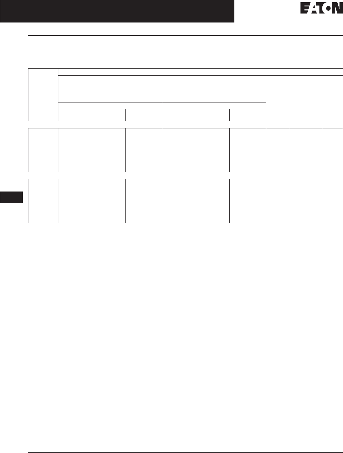
November 2008
12-180
For more information visit: www.eaton.com CA08101001E
Series C Molded Case Circuit Breakers
12
800 – 2500 Amperes
R-Frame
100% Rated 600 Volts ac Digitrip OPTIM Circuit Breakers with Interchangeable Rating Plugs
Order as individual components: Breaker Frame (which includes Trip Unit) and Rating Plug.
Table 12-297. 100% Rated 600 Volts ac Digitrip OPTIM Circuit Breakers with Interchangeable Rating Plugs
Includes B2016RDL rear connectors.
Maximum
Continuous
Ampere
Rating
at 40°C
Circuit Breaker Frame Only Digitrip OPTIM Rating Plug Only
L – Adjustable Long Delay Pickup (Ir) with Adjustable Long Delay Time
S – Adjustable Short Delay Pickup with Adjustable Short Delay Time (I2t or Flat Response)
I – Adjustable Instantaneous Pickup
G – Adjustable Ground Fault Pickup with Adjustable Ground Fault Time Delay (I2t or Flat Response)
A – Adjustable Ground Fault Alarm with Adjustable Ground Fault Time Delay (I2t or Flat Response)
Ampere
Rating
Fixed
Rating Plug
LSIA 1050 LSIG 1050
Catalog
Number
Price
U.S. $
Catalog
Number
Price
U.S. $
Catalog
Number
Price
U.S. $
3-Pole Standard Interrupting Capacity 600 Vac Rated 65 kAIC at 480 Vac
1600 CRD316T107W CRD316T106W 800
1000
1200
1600
ORPR16A080
ORPR16A100
ORPR16A120
ORPR16A160
2000 CRD320T107W CRD320T106W 1000
1200
1600
2000
ORPR20A100
ORPR20A120
ORPR20A160
ORPR20A200
3-Pole High Interrupting Capacity 600 Vac Rated 100 kAIC at 480 Vac
1600 CRDC316T107W CRDC316T106W 800
1000
1200
1600
ORPR16A080
ORPR16A100
ORPR16A120
ORPR16A160
2000 CRDC320T107W CRDC320T106W 1000
1200
1600
2000
ORPR20A100
ORPR20A120
ORPR20A160
ORPR20A200
Discount Symbol . . . . . . . . . . . . . . . . . . . . . . . . . CB-2
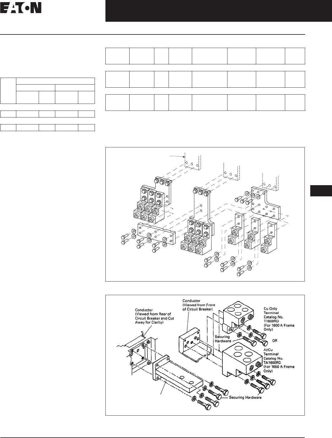
November 2008
CA08101001E For more information visit: www.eaton.com
12-181
Series C Molded Case Circuit Breakers
12
800 – 2500 Amperes
R-Frame
Molded Case Switches
Refer to Eaton for UL listed,
series tested Molded Case Switch
application data.
Table 12-298. Molded Case Switches
Note: Molded case switch may trip above
17,500 amperes.
Line and Load Terminals
Line and Load Terminals provide wire
connecting capabilities for specific
ranges of continuous current ratings
and wire types. All terminals comply
with Underwriters Laboratories Stan-
dards UL 486A and UL 486B and CSA
C22.2 No. 65M. Unless otherwise spec-
ified, R-Frame circuit breaker line load
terminals are shipped separately for
field installation.
Ordering Information
R-Frame circuit breakers have Cu/AI
terminals as standard and Cu only
terminals as an option. Specify if factory
installation is required.
Cont.
Amp
Rating
at
40°C
Complete without Terminals
3-Pole 4-Pole
Catalog
Number
Price
U.S. $
Catalog
Number
Price
U.S. $
Type RD — High Instantaneous (K)
1600 RD316WK RD416WK
Type RD — High Instantaneous (K)
2000 RD320WK RD420WK
Table 12-299. Line and Load Terminals
Catalog Number includes bus connection, terminals and hardware for either line side or load side
of 3-pole breaker.
For use with 100% rated 1600 A and 2000 A frame. Do not order separately unless for replacement
purposes. Included in breaker carton when 100% rated device is ordered.
For use with 2500 A frame. Do not order separately unless for replacement purposes. Included in
breaker carton when 2500 A breaker is ordered.
Figure 12-39. Mounting Hardware
Figure 12-40. Mounting Hardware
Maximum
Breaker
Amperes
Terminal
Body
Material
Wire
Type
Hardware AWG/kcmil
Wire Range/
No. Conductors
Metric Wire
Range mm2Catalog
Number
Price
U.S. $
Wire Terminals
1600
1600
2000
Aluminum
Copper
Aluminum
Cu/AI
Cu
Cu/AI
English
English
English
500 – 1000 (4)
1 – 600 (4)
2 – 600 (6)
300 – 500
50 – 300
35 – 300
TA1600RD
T1600RD
TA2000RD
Rear Connectors
2000
2000
2500
Copper
Copper
Copper
—
—
—
English
English
English
—
—
—
—
—
—
B2016RD
B2016RDL
B2500RD
Discount Symbol. . . . . . . . . . . . . . . . . . . . . . . . . . CB-2
Breaker Line/Load
Conductors
TA2000RD
Rear Connector (Cu)
B2016RD
B2016RDL (For 100% Appl.
(For 1600 A & 2000 A Frames)
B2500RD (For 2500 A Frame)

November 2008
12-182
For more information visit: www.eaton.com CA08101001E
Series C Molded Case Circuit Breakers
12
800 – 2500 Amperes
R-Frame
Allowable Accessory Combinations
Different combinations of accessories can be supplied, depending on the types of accessories and the number of poles in the
circuit breaker.
Table 12-300. Accessories
All accessories mount in the RH cavity
which will accept one each shunt trip, UVR,
auxiliary switch and alarm switch.
Mounts outside breaker.
Included with breaker.
■Applicable in indicated pole position ●Accessory available/Modification available
Description Reference
Page
3-Pole 4-Pole
Left Center Right Left Center Right Neu.
Internal Accessories
Alarm Lockout (Make/Break) 12-219 ■■
Alarm Lockout (2Make/2Break) 12-219 ■■
Auxiliary Switch (2A, 2B) 12-222 ■■
Auxiliary Switch (4A, 4B) 12-222 ■■
Shunt Trip — Standard 12-226 ■■
Shunt Trip — Low Energy 12-231 ■■
Undervoltage Release Mechanism 12-232 ■■
Accessory Terminal Block 12-241 ■■
External Accessories
Base Mounting Hardware 12-246
Padlockable Handle Lock Hasp 12-252 ●●
Key Interlock Kit 12-253 ■■
Walking Beam Interlock 12-254
Electrical (Motor) Operator 12-255 ■■
Drawout Cassette 12-66 ●
Handle Mechanisms 12-262 ■■
Handle Extension 12-267 ■■
Solid-State (Electronic) Portable Test Kit (310 Only) 12-268 ●●
OPTIM System Components
Breaker Interface Module (BIM) 12-269 ●
Digitrip OPTIMizer 12-269 ●
Auxiliary Power Module 12-269 ●
Modifications (Refer to Eaton)
Special Calibration — ●●
Moisture Fungus Treatment 12-73 ●●
Freeze-Tested Circuit Breakers — ●●
Marine Application — ●●
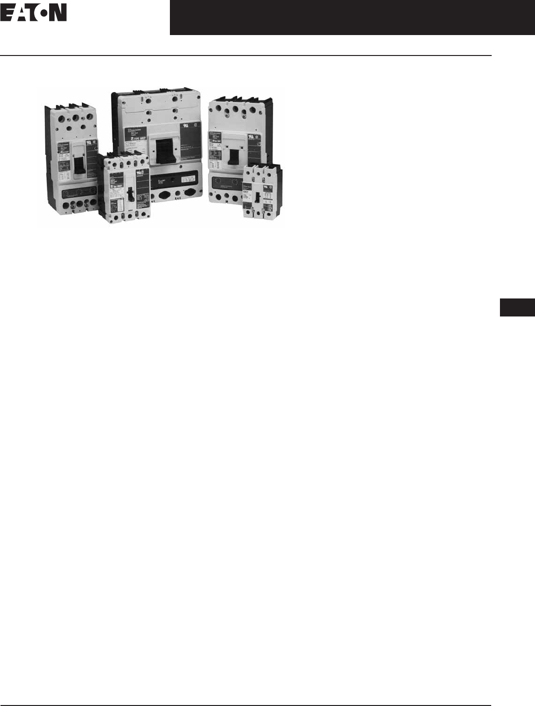
CA08101001E For more information visit: www.eaton.com
12-183
Series C Molded Case Circuit Breakers
November 2008
12
Motor Circuit Protectors
Product Description
Motor Circuit Protectors
Motor Circuit Protectors
Product Description
Designated as Eaton’s Cutler-Hammer
Types GMCP and HMCP, the instanta-
neous-only Motor Circuit Protector
(MCP) is available in ratings from 3 A
to 1200 A for motor starter sizes 0
through 8. The MCP is designed to
comply with the applicable requirements
of Underwriters Laboratories Standard
UL 489, Canadian Standards Associa-
tion Standard C22.2 No. 5.1, and
International Electrotechnical
Commission Recommendations
IEC 157-1.
An innovative design of internal
components allows higher MCP-starter
combination interrupting ratings.
The MCP is marked to permit proper
electrical application within the
assigned equipment ratings.
The MCP is a recognized component
(UL File E7819) and complies with the
applicable requirements of Underwriters
Laboratories Standard UL 489. It is also
designed to comply with the applica-
ble requirements of Canadian Stan-
dards Association Standard C22.2
No. 5.1, International Electrotechnical
Commission Recommendations
IEC 157-1, and nameplates bear the
CE marking.
Note: Interrupting ratings are dependent on
starter it is used with.

November 2008
12-184
For more information visit: www.eaton.com CA08101001E
Series C Molded Case Circuit Breakers
12
Motor Circuit Protectors
Product Selection
Product Selection
This information is presented only as an aid to understanding catalog numbers.
It is not to be used to build catalog numbers for circuit breakers or trip units.
Table 12-301. Motor Circuit Protector Catalog Numbering System
On J- and K-Frame HMCPs only.
Table 12-302. Motor Circuit Protector Catalog Numbering System
HMCP 003 A0 C
Motor Circuit
Protective Type
HMCP = 3 Poles
HM2P = 2 Poles
HMCPS = 3 Poles
Magnetic Trip Range/
NEMA Starter Size
A0 = 9 – 30/0
C0 = 21 – 70/0
E0 = 45 – 150/0
D0 = 40 – 60/0
H1 = 90 – 300/1
G2 = 80 – 120/2
K2 = 150 – 500/2
J2 = 115 – 170/2
M2 = 210 – 700/2
L3 = 160 – 240/3
R3 = 300 – 1000/3
T4 = 450 – 1500/4
U4 = 750 – 2500/4
A5 = 350 – 700/5
C5 = 450 – 900/5
D5 = 500 – 1000/5
F5 = 625 – 1250/5
G5 = 750 – 1500/5
J5 = 875 – 1750/5
K5 = 1000 – 2000/5
L5 = 1125 – 2250/5
W5 = 1250 – 2500/5
N5 = 1500 – 3000/5
R5 = 1750 – 3500/5
X5 = 2000 – 4000/5
Y5 = 2250 – 4500/5
L6 = 1800 – 6000/6 (Electronic)
X6 = 500 – 2500/6 (Electronic)
Y6 = 1000 – 4000/6 (Electronic)
X7 = 1600 – 6400/7 (Electronic)
Y8 = 2400 – 9600/8 (Electronic)
Suffix
C= Non-aluminum
Terminals
W= Without Terminals
X= Load Terminals Only
Y= Line Terminals Only
S= Stainless Steel Terminals
(150 A Frame Only)
No Suffix: Standard Terminals
on Line and Load
Continuous
Ampere Rating
003
007
015
025
030
050
070
100
150
250
400
600
800
1200
GMCP 003 A0 C
Motor Circuit
Protective Device
GMCP = 3 Poles
Continuous
Ampere
Rating
GMCP 003
007
015
030
050
060
063
Magnetic Trip
Range/NEMA
Starter Size
A0 = 15 – 30/0
C0 = 35 – 70/0
E0 = 75 – 150/0
H1 = 150 – 300/1
K2 = 250 – 500/2
J2 = 300 – 600/2
M2 = 320 – 630/2
Suffix
C = Non-aluminum Terminals

November 2008
CA08101001E For more information visit: www.eaton.com
12-185
Series C Molded Case Circuit Breakers
12
Motor Circuit Protectors
Product Selection
Product Selection
G-Frame
Table 12-303. 480 Vac Maximum, 600Y/347 Vac
Motor FLA ranges are typical. The corresponding trip setting is at
13 x the minimum FLA value shown. Where a 13 x setting is required
for an intermediate FLA value, alternate Cam settings and/or MCP
ratings should be used.
Note: All GMCP 3 – 63 A come with line and load steel body
terminals for Cu only wire. Refer to Table 12-131 on Page 12-77
under Optional Terminal Types.
Note: UL recognized and CSA approved.
NEMA
Starter
Size
Cont.
Amps
Cam
Setting
Motor
Full Load
Current
Amperes
(FLA)
MCP
Trip
Setting
MCP
Catalog
Number
Price
U.S. $
0 3A
B
C
D
E
F
1.1 – 1.2
1.3 – 1.5
1.6 – 1.7
1.8 – 1.9
2.0 – 2.2
2.3 – 2.5
15
18
21
24
27
30
GMCP003A0C
0 7A
B
C
D
E
F
2.6 – 3.1
3.2 – 3.6
3.7 – 3.9
4.3 – 4.7
4.8 – 5.2
5.3 – 5.7
35
42
49
56
63
70
GMCP007C0C
015A
B
C
D
E
F
5.7 – 6.8
6.9 – 7.9
8.0 – 9.1
9.2 – 10.3
10.4 – 11.4
11.5 – 12.6
75
90
105
120
135
150
GMCP015E0C
130A
B
C
D
E
F
11.5 – 13.7
13.8 – 16.0
16.1 – 18.3
18.4 – 20.6
20.7 – 22.9
23.0 – 25.2
150
180
210
240
270
300
GMCP030H1C
250A
B
C
D
E
F
19.3 – 22.9
23.0 – 26.8
26.9 – 30.6
30.7 – 34.5
34.6 – 38.3
38.4 – 42.1
250
300
350
400
450
500
GMCP050K2C
360A
B
C
D
E
F
23.1 – 27.5
27.7 – 32.2
32.3 – 36.7
36.9 – 41.4
41.5 – 46.0
46.2 – 50.5
300
360
420
480
540
600
GMCP060J2C
363A
B
C
D
E
F
24.2 – 32.1
29.1 – 34.8
33.9 – 39.4
38.8 – 46.4
43.6 – 48.9
48.5 – 53.7
320
380
440
500
570
630
GMCP063M2C
Discount Symbol . . . . . . . . . . . . . . . . . . . . . . . . . CB-2
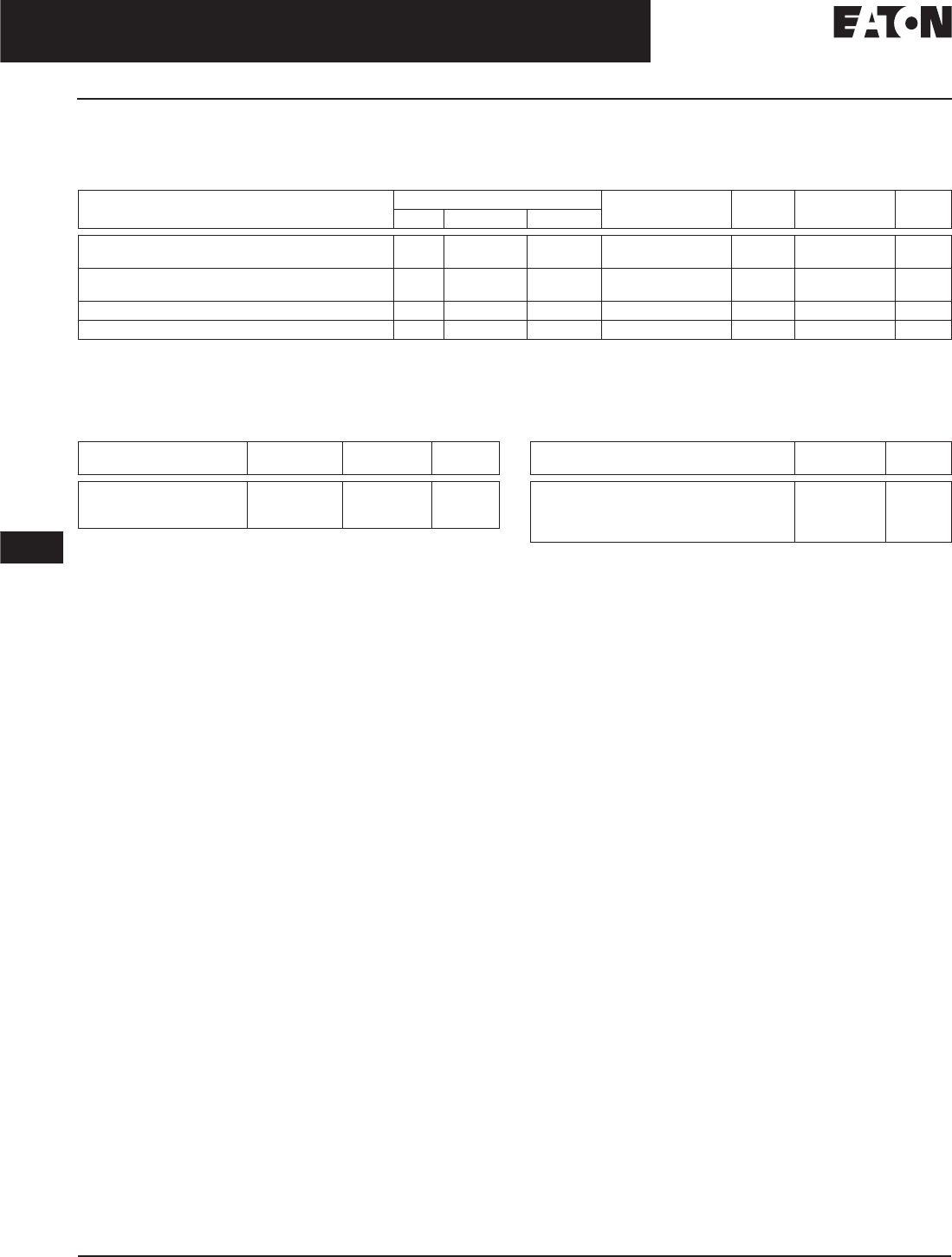
November 2008
12-186
For more information visit: www.eaton.com CA08101001E
Series C Molded Case Circuit Breakers
12
Motor Circuit Protectors
Accessories
Modifications for GMCP
Internal accessories must be factory installed.
Table 12-304. Internal Accessories
Only one accessory may be installed in GMCP.
LH only.
RH only.
Note: No UVR available on GMCP.
Table 12-305. External Mounted Accessories
For use with standard 35 mm DIN rail such as, 35 x 7.5 or 15 mm per
DIN EN50022.
Modifications for HMCP
See Internal Accessories starting on Page 12-217.
Table 12-306. Vari-Depth Handle Mechanism
For use with GMCP only.
Type
Accessory
Electrical Ratings Contact
Arrangement
Factory
Suffix
Style
Number
Adder
U.S. $
Volts Frequency Amperes
Shunt Trip
Shunt Trip
120
240
50/60 Hz
50/60 Hz
1.1
2.1
—
—
S5
S6
1373D62G18
1373D62G19
Auxiliary Switch
Auxiliary Switch
240
240
50/60 Hz
50/60 Hz
6.0
6.0
1A/1B
2A/2B
A3
A6
1288C74G03
1288C73G03
Alarm Switch 240 50/60 Hz 6.0 Make/Break B3 1288C75G03
Auxiliary Switch/Alarm Switch Combination 240 50/60 Hz 6.0 1A/1B Make/Break B13 1288C76G09
Description Number Units
in Package
Style
Number
Price
U.S. $
Lock Dog (Non-padlockable)
Mounting Hardware
DIN Rail Adapter
1
1
10
1294C01H01
624B375G23
1225C79G02
Description Catalog
Number
Price
U.S. $
For Type 1 use
For Type 3R, 4X, 12 use
Close Coupled Black with Gray Handle
Close Coupled Red with Yellow Handle
HRGMV11L
HRGMV14L
HRGMC10
HRGMC30
Discount Symbol . . . . . . . . . . . . . . . . . . . . . . . . . CB-2

November 2008
CA08101001E For more information visit: www.eaton.com
12-187
Series C Molded Case Circuit Breakers
12
Motor Circuit Protectors
F-Frame
F-Frame
Table 12-307. 600 Vac Maximum, 250 Vdc Maximum Table 12-307. 600 Vac Maximum, 250 Vdc Maximum (Continued)
Motor FLA ranges are typical. The corresponding trip setting is at
13 x the minimum FLA value shown. Where a 13 x setting is required
for an intermediate FLA value, alternate Cam settings and/or MCP
ratings should be used.
For dc applications, actual trip levels are approximately 40% higher
than values shown.
Settings above 130 amperes are for special applications. NEC Article
430-110(a) requires the ampere rating of the disconnecting means to
be not less than 115% of the motor full load ampere rating.
Note: HMCP 3 – 100 A come with line and load steel body terminals,
3T100FB. HMCP 150 A come with line and load steel body terminals,
3T150FB.
NEMA
Starter
Size
Cont.
Amps
Cam
Setting
Motor
Full Load
Current
Amperes
(FLA)
MCP
Trip
Setting
MCP
Catalog
Number
Price
U.S. $
0 3A
B
C
D
E
F
G
H
.69 – .91
.92 – 1.0
1.1 – 1.2
1.3 – 1.5
1.6 – 1.7
1.8 – 1.9
2.0 – 2.2
2.3 – 2.5
9
12
15
18
21
24
27
30
HMCP003A0C
0 7A
B
C
D
E
F
G
H
1.5 – 2.0
2.1 – 2.5
2.6 – 3.1
3.2 – 3.6
3.7 – 3.9
4.3 – 4.7
4.8 – 5.2
5.3 – 5.7
21
28
35
42
49
56
63
70
HMCP007C0C
015A
B
C
D
E
F
G
H
3.4 – 4.5
4.6 – 5.6
5.7 – 6.8
6.9 – 7.9
8.0 – 9.1
9.2 – 10.3
10.4 – 11.4
11.5 – 12.6
45
60
75
90
105
120
135
150
HMCP015E0C
130A
B
C
D
E
F
G
H
6.9 – 9.1
9.2 – 11.4
11.5 – 13.7
13.8 – 16.0
16.1 – 18.3
18.4 – 20.6
20.7 – 22.9
23.0 – 25.2
90
120
150
180
210
240
270
300
HMCP030H1C
250A
B
C
D
E
F
G
H
11.5 – 15.2
15.3 – 19.1
19.2 – 22.9
23.0 – 26.8
26.9 – 30.6
30.7 – 34.5
34.6 – 38.3
38.4 – 42.1
150
200
250
300
350
400
450
500
HMCP050K2C
NEMA
Starter
Size
Cont.
Amps
Cam
Setting
Motor
Full Load
Current
Amperes
(FLA)
MCP
Trip
Setting
MCP
Catalog
Number
Price
U.S. $
2 70A
B
C
D
E
F
G
H
16.1 – 21.4
21.5 – 26.8
26.9 – 32.2
32.3 – 37.5
37.6 – 42.9
43.0 – 48.3
48.4 – 53.7
53.8 – 59.1
210
280
350
420
490
560
630
700
HMCP070M2C
3 100 A
B
C
D
E
F
G
H
23.0 – 30.6
30.7 – 38.3
38.4 – 46.0
46.1 – 53.7
53.8 – 61.4
61.5 – 69.1
69.2 – 76.8
76.9 – 84.5
300
400
500
600
700
800
900
1000
HMCP100R3C
4 150 A
B
C
D
E
F
G
H
34.6 – 46.0
46.1 – 57.5
57.6 – 69.1
69.2 – 80.6
80.7 – 92.2
92.3 – 103.7
103.8 – 115.2
115.3 – 126.7
450
600
750
900
1050
1200
1350
1500
HMCP150T4C
4 150 A
B
C
D
E
F
G
H
57.0 – 75.0
76.0 – 95.0
96.0 – 114.0
115.0 – 130.7
750
1000
1250
1500
1750
2000
2250
2500
HMCP150U4C
Discount Symbol . . . . . . . . . . . . . . . . . . . . . . . . . CB-2
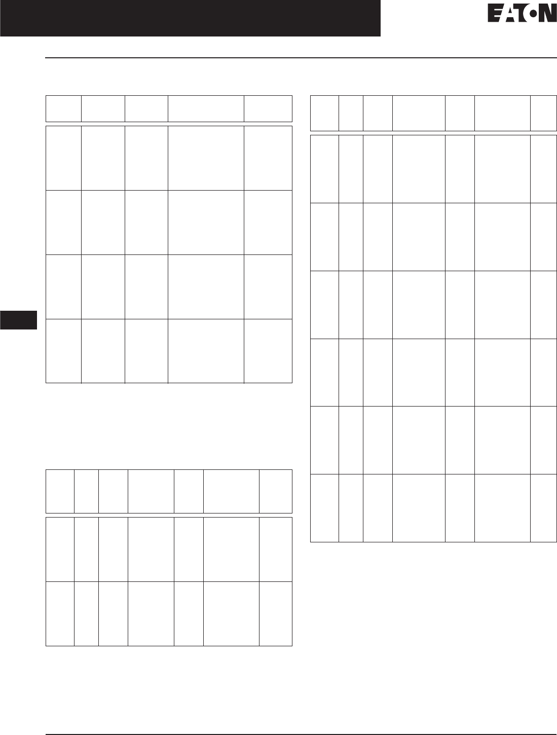
November 2008
12-188
For more information visit: www.eaton.com CA08101001E
Series C Molded Case Circuit Breakers
12
Motor Circuit Protectors
Low Magnetic Protection — F-Frame
Special Low Magnetic Protection Application MCP
Table 12-308. 600 Vac Maximum, 250 Vdc Maximum
For dc applications, actual trip levels are approximately 40% higher
than values shown.
Note: HMCP 25 – 100 A come with line and load steel body terminals,
3T100FB.
MCPs for Application with Motor Starters Equipped
with Electronic Overload Relays
Table 12-309. 600 Vac Maximum, 250 Vdc Maximum
Table 12-309. 600 Vac Maximum, 250 Vdc Maximum (Continued)
Motor FLA ranges are typical. The corresponding trip setting is at
13 x the minimum FLA value shown. Where a 13 x setting is required
for an intermediate FLA value, alternate cam settings and/or MCP
ratings should be used.
For dc applications, actual trip levels are approximately 40% higher
than values shown.
Settings above 130 amperes are for special applications. NEC Article
430-110(a) requires the ampere rating of the disconnecting means to
be not less than 115% of the motor full load ampere rating.
Note: HMCPS 3 – 100 A come with line and load steel body
terminals, 3T100FB. HMCPS 150 A come with line and load steel
body terminals, 3T150FB.
Cont.
Amps
Cam
Setting
MCP
Trip
Setting
MCP
Catalog
Number
Price
U.S. $
25 A
B
C
D
E
F
G
H
40
43
46
49
52
55
58
60
HMCP025D0C
50 A
B
C
D
E
F
G
H
80
87
93
98
103
109
115
120
HMCP050G2C
70 A
B
C
D
E
F
G
H
115
122
130
139
145
153
160
170
HMCP070J2C
100 A
B
C
D
E
F
G
H
160
174
185
196
207
218
229
240
HMCP100L3C
NEMA
Starter
Size
Cont.
Amps
Cam
Setting
Motor
Full Load
Current
Amperes
(FLA)
MCP
Trip
Setting
MCP
Catalog
Number
Price
U.S. $
03A
B
C
D
E
F
G
H
.69 – .91
.92 – 1.0
1.1 – 1.2
1.3 – 1.5
1.6 – 1.7
1.8 – 1.9
2.0 – 2.2
2.3 – 2.5
9
12
15
18
21
24
27
30
HMCPS003A0C
07A
B
C
D
E
F
G
H
1.5 – 2.0
2.1 – 2.5
2.6 – 3.1
3.2 – 3.6
3.7 – 3.9
4.3 – 4.7
4.8 – 5.2
5.3 – 5.7
21
28
35
42
49
56
63
70
HMCPS007C0C
NEMA
Starter
Size
Cont.
Amps
Cam
Setting
Motor Full
Load Current
Amperes
(FLA)
MCP
Trip
Setting
MCP
Catalog
Number
Price
U.S. $
015A
B
C
D
E
F
G
H
3.4 – 4.5
4.6 – 5.6
5.7 – 6.8
6.9 – 7.9
8.0 – 9.1
9.2 – 10.3
10.4 – 11.4
11.5 – 12.6
45
60
75
90
105
120
135
150
HMCPS015E0C
130A
B
C
D
E
F
G
H
6.9 – 9.1
9.2 – 11.4
11.5 – 13.7
13.8 – 16.0
16.1 – 18.3
18.4 – 20.6
20.7 – 22.9
23.0 – 25.2
90
120
150
180
210
240
270
300
HMCPS030H1C
250A
B
C
D
E
F
G
H
11.5 – 15.2
15.3 – 19.1
19.2 – 22.9
23.0 – 26.8
26.9 – 30.6
30.7 – 34.5
34.6 – 38.3
38.4 – 42.1
150
200
250
300
350
400
450
500
HMCPS050K2C
3 100 A
B
C
D
E
F
G
H
23.0 – 30.6
30.7 – 38.3
38.4 – 46.0
46.1 – 53.7
53.8 – 61.4
61.5 – 69.1
69.2 – 76.8
76.9 – 84.5
300
400
500
600
700
800
900
1000
HMCPS100R3C
4 150 A
B
C
D
E
F
G
H
34.6 – 46.0
46.1 – 57.5
57.6 – 69.1
69.2 – 80.6
80.7 – 92.2
92.3 – 103.7
103.8 – 115.2
115.3 – 126.7
450
600
750
900
1050
1200
1350
1500
HMCPS150T4C
4 150 A
B
C
D
E
F
G
H
57.0 – 75.0
76.0 – 95.0
96.0 – 114.0
115.0 – 130.7
750
1000
1250
1500
1750
2000
2250
2500
HMCPS150U4C
Discount Symbol. . . . . . . . . . . . . . . . . . . . . . . . . CB-2
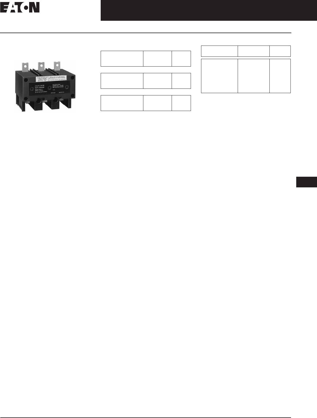
November 2008
CA08101001E For more information visit: www.eaton.com
12-189
Series C Molded Case Circuit Breakers
12
Motor Circuit Protectors
Product Description
Type ELC Current Limiter
Attachment (Size 0 – 4)
Type ELC Current Limiter Attachment
Product Description
Eaton’s Cutler-Hammer Type ELC cur-
rent limiter attachment for the MCP is
designed to provide increased inter-
rupting capacity. The combination
may be used for the application up to
200,000 A symmetrical at 600 Vac, mak-
ing the MCP suitable for use in net-
work distribution systems or other
applications where unusually high
fault currents are available. The
current limiter connects to the load
end of the MCP and is provided with
terminals suitable for copper or alumi-
num conductors. (See Table 12-310.)
Limiters are coordinated with the
MCP so that normal fault currents are
interrupted automatically by the MCP
without any damage to the limiter.
Only the rare very high fault is opened
by the limiter. Faults that are interrupted
by the limiter
also magnetically trip the
MCP, open
ing all three poles, prevent-
ing single-phase operation.
Each of the three poles of the type ELC
limiter is equipped with an indicator
that extends when a fault is interrupted
by the limiter.
Table 12-310. Type ELC Current Limiter
Terminal Wire Sizes
Terminal wire connectors are UL listed for
standard stranded wire sizes as defined in
UL 486A or UL 486B.
Optional on special order for copper
cable only.
Table 12-311. ELC Current Limiter Attachment
Type ELC Current
Limiter Maximum
Amperes
Wire Range
AWG
Metric
(mm2)
Standard Aluminum Terminals
50
100
150
14 – 2
1 – 4/0
1 – 4/0
2.5 – 35
50 – 95
50 – 95
Non-standard Terminals (Steel)
50
100
150
14 – 2
—
—
2.5 – 35
—
—
MCP Rating
(Amperes)
Catalog
Number
Price
U.S. $
3
7
15
30
50
100
150
ELC3003R
ELC3007R
ELC3015R
ELC3030R
ELC3050R
ELC3100R
ELC3150R
Discount Symbol . . . . . . . . . . . . . . . . . . . . . . . . . CB-2

November 2008
12-190
For more information visit: www.eaton.com CA08101001E
Series C Molded Case Circuit Breakers
12
Motor Circuit Protectors
J-Frame
J-Frame
Table 12-312. 600 Vac Maximum, 250 Vdc Maximum Table 12-312. 600 Vac Maximum, 250 Vdc Maximum (Continued)
Motor FLA ranges are typical. The corresponding trip setting is at
13 times the minimum FLA value shown. Where a 13 times setting is
required for an intermediate FLA value, alternate cam settings and/or
MCP ratings should be used.
For dc applications, actual trip levels are approximately 40% higher
than values shown.
Three-pole catalog numbers shown. Two-pole catalog numbers begin
with HM2P in place of HMCP.
Note: All HMCP and HM2P 250 A come with line and load steel
body terminals, T250KB. (With suffix “C”, without “C” comes with
TA250KB.)
NEMA
Starter
Size
Cont.
Amps
Cam
Setting
Motor
Full Load
Current
Amperes
(FLA)
MCP
Trip
Setting
MCP
Catalog
Number
Price
U.S. $
4
4
4
5
5
5
5
5
5
250 A
B
C
D
E
F
G
H
I
27.0 – 30.7
30.8 – 33.8
33.9 – 36.9
37.0 – 40.3
40.4 – 43.8
43.9 – 46.9
47.0 – 50.7
50.8 – 53.8
53.9 – 57.2
350
400
440
480
525
570
610
660
700
HMCP250A5C
5
5
5
5
5
5
5
5
5
250 A
B
C
D
E
F
G
H
I
34.7 – 38.8
38.9 – 43.4
43.5 – 47.6
47.7 – 52.2
52.3 – 56.5
56.6 – 60.7
60.8 – 64.9
65.0 – 69.2
69.3 – 73.5
450
505
565
620
680
735
790
845
900
HMCP250C5C
5
5
5
5
5
5
5
5
5
250 A
B
C
D
E
F
G
H
I
38.5 – 43.4
43.5 – 48.0
48.1 – 53.0
53.1 – 57.6
57.7 – 62.3
62.4 – 67.3
67.4 – 71.9
72.0 – 76.9
77.0 – 81.6
500
565
625
690
750
810
875
935
1000
HMCP250D5C
5
5
5
5
5
5
5
5
5
250 A
B
C
D
E
F
G
H
I
48.1 – 53.8
53.9 – 59.9
60.0 – 66.1
66.2 – 72.3
72.4 – 78.4
78.5 – 83.8
83.9 – 89.9
90.0 – 96.1
96.2 – 102.0
625
700
780
860
940
1020
1090
1170
1250
HMCP250F5C
5
5
5
5
5
5
5
5
5
250 A
B
C
D
E
F
G
H
I
57.7 – 64.6
64.7 – 71.9
72.0 – 79.2
79.3 – 86.5
86.6 – 93.8
93.9 – 101.1
101.2 – 108.4
108.5 – 115.3
115.4 – 122.4
750
840
935
1030
1125
1220
1315
1410
1500
HMCP250G5C
NEMA
Starter
Size
Cont.
Amps
Cam
Setting
Motor
Full Load
Current
Amperes
(FLA)
MCP
Trip
Setting
MCP
Catalog
Number
Price
U.S. $
5
5
5
5
5
5
5
5
5
250 A
B
C
D
E
F
G
H
I
67.4 – 75.3
75.4 – 83.8
83.9 – 92.3
92.4 – 100.7
100.8 – 109.2
109.3 – 117.6
117.7 – 126.1
126.2 – 134.6
134.7 – 142.8
875
980
1090
1200
1310
1420
1530
1640
1750
HMCP250J5C
5
5
5
5
5
5
5
5
5
250 A
B
C
D
E
F
G
H
I
77.0 – 86.6
86.6 – 96.1
96.2 – 105.7
105.8 – 115.3
115.4 – 124.9
125.0 – 134.6
134.7 – 144.2
144.3 – 153.8
153.9 – 163.3
1000
1125
1250
1375
1500
1625
1750
1875
2000
HMCP250K5C
5
5
5
5
5
5
5
5
5
250 A
B
C
D
E
F
G
H
I
86.6 – 97.3
97.4 – 108.4
108.5 – 118.8
118.9 – 129.9
130.0 – 140.7
140.8 – 151.5
151.6 – 162.3
162.4 – 173.0
173.1 – 183.6
1125
1265
1410
1545
1690
1830
1970
2110
2250
HMCP250L5C
5
5
5
5
5
5
5
5
5
250 A
B
C
D
E
F
G
H
I
96.2 – 108.0
108.1 – 119.9
120.0 – 132.3
132.4 – 144.2
144.3 – 156.1
156.2 – 168.0
168.1 – 179.9
180.0 – 192.3
192.4 – 204.0
1250
1405
1560
1720
1875
2030
2185
2340
2500
HMCP250W5C
Discount Symbol . . . . . . . . . . . . . . . . . . . . . . . . . CB-2

November 2008
CA08101001E For more information visit: www.eaton.com
12-191
Series C Molded Case Circuit Breakers
12
Motor Circuit Protectors
K-Frame
K-Frame
Table 12-313. 600 Vac Maximum, 250 Vdc Maximum Table 12-313. 600 Vac Maximum, 250 Vdc Maximum (Continued)
Motor FLA ranges are typical. The corresponding trip setting is at
13 x the minimum FLA value shown. Where a 13 x setting is required
for an intermediate FLA value, alternate cam settings and/or MCP
ratings should be used.
For dc applications, actual trip levels are approximately 40% higher
than values shown.
Three-pole Catalog Numbers shown. Two-pole Catalog Numbers begin
with HM2P in place of HMCP.
Note: All HMCP and HM2P 400A come with aluminum body
terminals, 3TA400K. Catalog numbers with suffix “C” as shown
above come with copper body terminals 3T400K.
NEMA
Starter
Size
Cont.
Amps
Cam
Setting
Motor
Full Load
Current
Amperes
(FLA)
MCP
Trip
Setting
MCP
Catalog
Number
Price
U.S. $
4
4
4
5
5
5
5
5
5
400 A
B
C
D
E
F
G
H
I
27.0 – 30.7
30.8 – 33.8
33.9 – 36.9
37.0 – 40.3
40.4 – 43.8
43.9 – 46.9
47.0 – 50.7
50.8 – 53.8
53.9 – 57.2
350
400
440
480
525
570
610
660
700
HMCP400A5C
5
5
5
5
5
5
5
5
5
400 A
B
C
D
E
F
G
H
I
38.5 – 43.4
43.5 – 48.0
48.1 – 53.0
53.1 – 57.6
57.7 – 62.3
62.4 – 67.3
67.4 – 71.9
72.0 – 76.9
77.0 – 81.6
500
565
626
690
750
810
875
935
1000
HMCP400D5C
5
5
5
5
5
5
5
5
5
400 A
B
C
D
E
F
G
H
I
48.1 – 53.8
53.9 – 59.9
60.0 – 66.1
66.2 – 72.3
72.4 – 78.4
78.5 – 83.8
83.9 – 89.9
90.0 – 96.1
96.2 – 102.0
625
700
780
860
940
1020
1090
1170
1250
HMCP400F5C
5
5
5
5
5
5
5
5
5
400 A
B
C
D
E
F
G
H
I
57.7 – 64.6
64.7 – 71.9
72.0 – 79.2
79.3 – 86.5
86.6 – 93.8
93.9 – 101.1
101.2 – 108.4
108.5 – 115.3
115.4 – 122.4
750
840
935
1030
1125
1220
1315
1410
1500
HMCP400G5C
5
5
5
5
5
5
5
5
5
400 A
B
C
D
E
F
G
H
I
67.4 – 75.3
75.4 – 83.8
83.9 – 92.3
92.4 – 100.7
100.8 – 109.2
109.3 – 117.6
117.7 – 126.1
126.2 – 134.6
134.7 – 142.8
875
980
1090
1200
1310
1420
1530
1640
1750
HMCP400J5C
5
5
5
5
5
5
5
5
5
400 A
B
C
D
E
F
G
H
I
77.0 – 86.5
86.6 – 96.1
96.2 – 105.7
105.8 – 115.3
115.4 – 124.9
125.0 – 134.6
134.7 – 144.2
144.3 – 153.8
153.9 – 163.3
1000
1125
1250
1375
1500
1625
1750
1875
2000
HMCP400K5C
5
5
5
5
5
5
5
5
5
400 A
B
C
D
E
F
G
H
I
86.6 – 97.3
97.4 – 108.4
108.5 – 118.8
118.9 – 129.9
130.0 – 140.7
140.8 – 151.5
151.6 – 162.3
162.4 – 173.0
173.1 – 183.6
1125
1265
1410
1545
1690
1830
1970
2110
2250
HMCP400L5C
NEMA
Starter
Size
Cont.
Amps
Cam
Setting
Motor
Full Load
Current
Amperes
(FLA)
MCP
Trip
Setting
MCP
Catalog
Number
Price
U.S. $
5
5
5
5
5
5
5
5
5
400 A
B
C
D
E
F
G
H
I
96.2 – 108.0
108.1 – 119.9
120.0 – 132.3
132.4 – 144.2
144.3 – 156.1
156.2 – 168.0
168.1 – 179.9
180.0 – 192.3
192.4 – 204.0
1250
1405
1560
1720
1875
2030
2185
2340
2500
HMCP400W5C
5
5
5
5
5
5
5
5
5
400 A
B
C
D
E
F
G
H
I
115.4 – 129.9
130.0 – 144.2
144.3 – 158.4
158.5 – 173.0
173.1 – 187.6
187.7 – 201.9
202.0 – 216.1
216.2 – 230.7
230.8 – 244.9
1500
1690
1875
2060
2250
2440
2625
2810
3000
HMCP400N5C
5
5
5
5
5
5
5
5
5
400 A
B
C
D
E
F
G
H
I
134.7 – 151.5
151.6 – 168.4
168.5 – 185.3
185.4 – 201.9
202.0 – 218.8
218.9 – 235.7
235.8 – 252.6
252.7 – 269.2
269.3 – 285.7
1750
1970
2190
2410
2625
2845
3065
3285
3500
HMCP400R5C
5
5
5
5
5
5
5
5
5
400 A
B
C
D
E
F
G
H
I
153.9 – 173.0
173.1 – 192.3
192.4 – 211.5
211.6 – 230.7
230.8 – 249.9
250.0 – 269.2
269.3 – 288.4
288.5 – 307.6
307.7 – 326.9
2000
2250
2500
2750
3000
3250
3500
3750
4000
HMCP400X5C
5
5
5
5
5
5
5
5
5
400 A
B
C
D
E
F
G
H
I
173.1 – 194.5
194.6 – 216.1
216.2 – 237.6
237.7 – 259.5
259.6 – 281.1
281.2 – 302.6
302.7 – 324.1
324.2 – 346.1
346.2 – 368.1
2250
2530
2810
3090
3375
3655
3935
4215
4500
HMCP400Y5C
Discount Symbol . . . . . . . . . . . . . . . . . . . . . . . . . CB-2

November 2008
12-192
For more information visit: www.eaton.com CA08101001E
Series C Molded Case Circuit Breakers
12
Motor Circuit Protectors
L-Frame
L-Frame
Table 12-314. 600 Vac Maximum
Equipped with electronic trip device.
Motor FLA ranges are typical. The corresponding trip setting is at 13X
the minimum FLA value shown. Where a 13X setting is required for an
intermediate FLA value, alternate cam settings and/or MCP ratings
should be used.
Note: All HMCP 600 A come without terminals. For Terminals,
see Table 12-240 on Page 12-140.
NEMA
Starter
Size
Cont.
Amps
Cam
Setting
Motor Full
Load Current
Amperes (FLA)
MCP
Trip
Setting
MCP
Catalog
Number
Price
U.S. $
6
6
6
6
6
6
6
6
600 A
B
C
D
E
F
G
H
138.5 – 184.5
184.6 – 230.7
230.8 – 276.8
276.9 – 323.0
323.1 – 369.1
369.2 – 415.3
415.4 – 461.4
461.5 – 507.7
1800
2400
3000
3600
4200
4800
5400
6000
HMCP600L6W
6
6
6
6
6
6
6
6
600 A
B
C
D
E
F
G
H
38.5 – 46.1
46.2 – 61.4
61.5 – 76.8
76.9 – 96.1
96.2 – 115.3
115.4 – 153.7
153.8 – 192.2
192.3 – 230.7
500
600
800
1000
1250
1500
2000
2500
HMCP600X6W
6
6
6
6
6
6
6
6
600 A
B
C
D
E
F
G
H
76.9 – 96.1
96.2 – 115.3
115.4 – 153.7
153.8 – 192.2
192.3 – 230.7
230.8 – 269.1
269.2 – 307.6
307.7 – 346.1
1000
1250
1500
2000
2500
3000
3500
4000
HMCP600Y6W
Discount Symbol . . . . . . . . . . . . . . . . . . . . . . . . CB-2

CA08101001E For more information visit: www.eaton.com
12-193
Series C Molded Case Circuit Breakers
November 2008
12
Motor Circuit Protectors
N-Frame
N-Frame
Table 12-315. 600 Vac Maximum
Equipped with electronic trip device.
Motor FLA ranges are typical. The corresponding trip setting is at 13X the minimum FLA value
shown. Where a 13X setting is required for an intermediate FLA value, alternate cam settings and/
or MCP ratings should be used.
Note: All HMCP 800 A and 1200 A come without terminals. For Terminals, see Table 12-307
on Page 12-187.
NEMA
Starter
Size
Cont.
Amps
Cam
Setting
Motor Full
Load Current
Amperes (FLA)
MCP
Trip
Setting
MCP
Catalog
Number
Price
U.S. $
7
7
7
7
7
7
7
800 A
B
C
D
E
F
G
123.1 – 184.5
184.6 – 246.1
246.2 – 307.6
307.7 – 369.1
369.2 – 430.7
430.8 – 492.2
492.3 – 553.7
1600
2400
3200
4000
4800
5600
6400
HMCP800X7W
8
8
8
8
8
8
8
1200 A
B
C
D
E
F
G
184.6 – 276.8
276.9 – 369.1
369.2 – 461.4
461.5 – 553.7
553.8 – 646.1
646.2 – 738.4
738.5 – 830.7
2400
3600
4800
6000
7200
8400
9600
HMCP12Y8W
Discount Symbol . . . . . . . . . . . . . . . . . . . . . . . CB-2

November 2008
12-194
For more information visit: www.eaton.com CA08101001E
Series C Molded Case Circuit Breakers
12
Engine Generator Circuit Breakers
Product Description
Engine Generator
Circuit Breakers
Product Description
Eaton’s Cutler-Hammer engine genera-
tor molded case circuit breakers are
designed specifically for application
on diesel engine powered standby
generators where high interrupting
circuit breakers are not required. The
JG through NG breakers are equipped
with a special trip unit, that includes
standard thermal (overload) protection
and special low magnetic pickup range
(FG includes a fixed thermal-magnetic
pickup). The standard thermal trip unit
provides overload protection for con-
ductors per the National Electrical
Code. The low magnetic pickup range
is approximately two to five times the
continuous rating and provides closer
low-level short-circuit protection when
applied on generators that have very
low short-circuit capacity. This combi-
nation allows the user to customize
the breaker to the generator output.
Engine generator circuit breakers are
suitable for reverse feed application.
Standards and Certifications
Engine generator molded case circuit
breakers are designed to conform with
the following standards:
■Underwriters Laboratories
Standard UL 489, Molded Case
Circuit Breakers and Circuit Breaker
Enclosures File E7819.
■Canadian Standards Association
Standard C22.2 No. 5, Service
Entrance and Branch Circuit Breakers.
■International Electrotechnical
Commission Recommendations
IEC 947-2, Circuit Breakers.
Conformance with these standards
satisfies most local and international
codes, assuming user acceptability
and simplified application.
Technical Data
and Specifications
Table 12-316. UL 489 Interrupting Capacity
Ratings
Table 12-317. IEC 947-2 Interrupting Capacity
Ratings
Volts ac
(50/60 Hz)
Interrupting Capacity
(Symmetrical Amperes)
240
480
600
18,000
14,000
10,000
Volts ac
(50/60 Hz)
Interrupting Capacity
(Symmetrical Amperes)
220, 240
380, 415
660, 690
18,000/ 9,000
14,000/ 7,000
10,000/5,000

November 2008
CA08101001E For more information visit: www.eaton.com
12-195
Series C Molded Case Circuit Breakers
12
Engine Generator Circuit Breakers
Product Selection
Product Selection
This information is presented only as an aid to understanding catalog numbers. It is not to be used to build catalog numbers for
circuit breakers.
■FG breakers include both line and load side terminals.
■JG, KG, LG and NG breakers with W Catalog Number
Suffix do not include any terminals.
■JG, KG, LG and NG breakers without W Catalog Number
Suffix include both line and load terminals.
■Contact Eaton for additional ratings and internal/external
accessories.
■Reverse feed.
Table 12-318. Catalog Numbering System
FG 3 100 W
Frame
FG
JG
KG
LG
NG
Number
of Poles
3 = 3 Poles
Trip Amperes
015
020
025
030
035
040
045
050
060
070
080
090
100
125
150
175
200
225
175
200
225
250
300
350
400
450
500
600
700
800
900
1000
1200
Suffix
W = Without Terminals

November 2008
12-196
For more information visit: www.eaton.com CA08101001E
Series C Molded Case Circuit Breakers
12
Engine Generator Circuit Breakers
Product Selection
Product Selection
The following table lists FG through NG engine generator breakers with the maximum generator kVA and kW rating.
Engine generator breakers are applied at 115% of the generator full load current rating (FLA). The maximum kW rating is
based on 3-phase generators at 80% power factor.
Table 12-319. Product Selection
Breaker continuous current is based on 115% of the generator full load ampere rating.
Based on 3-phase generators at 80% power factor.
FG, JG, KG include Thermal-Magnetic Trip Units, LG and NG include Electronic Trip Units.
Breaker includes line and load terminals.
Without terminals.
Note: The following catalog numbers have center tap studs for dual voltage applications: JG3070CT, JG3100CT, JG3125CT, KG3175CT,
LG3300CTW.
Magnetic
Pickup
Range
Maximum Generator Rating 60 Hz Engine Generator Breaker
240 Vac 480 Vac 600 Vac
kVA kW kVA kW kVA kW Catalog
Number
Price
U.S. $
Thermal Magnetic
Fixed
Fixed
Fixed
Fixed
5
7
9
11
4
6
7
9
11
14
18
22
9
12
14
17
14
18
23
27
11
14
18
22
FG3015
FG3020
FG3025
FG3030
Fixed
Fixed
Fixed
Fixed
13
14
16
18
10
12
13
14
25
29
32
36
20
23
26
29
32
36
41
45
25
29
32
36
FG3035
FG3040
FG3045
FG3050
Fixed
Fixed
Fixed
Fixed
22
25
29
32
17
20
23
26
43
51
58
65
35
40
46
52
54
63
72
81
43
51
58
65
FG3060
FG3070
FG3080
FG3090
Fixed
Fixed
Fixed
Fixed
Fixed
Fixed
Fixed
36
40
45
54
63
72
81
29
32
36
43
51
58
65
72
79
90
108
126
144
162
58
64
72
87
101
116
130
90
99
113
135
158
181
203
72
79
90
108
126
144
162
FG3100
FG3110
FG3125
FG3150
FG3175
FG3200
FG3225
350 – 700
350 – 700
63
72
51
58
126
144
101
116
158
181
126
144
JG3175W
JG3175
JG3200W
JG3200
350 – 700
350 – 700
81
90
65
72
162
181
130
144
203
226
162
181
JG3225W
JG3225
JG3250W
JG3250
500 – 1000
500 – 1000
108
126
87
101
217
253
173
202
271
316
217
253
KG3300W
KG3300
KG3350W
KG3350
1000 – 2000 144 116 289 231 361 289 KG3400
Electronic
500 – 2500
500 – 2500
500 – 2500
162
181
217
130
144
173
325
361
433
260
289
347
406
451
542
325
361
433
LG3450
LG3500
LG3600
500 – 2500
500 – 2500
253
289
202
231
505
578
404
462
632
722
505
578
NG3700
NG3800
1250 – 5000
1250 – 5000
325
361
260
289
650
722
520
578
812
903
650
722
NG3900
NG31000
1250 – 5000 433 347 867 693 1083 867 NG31200
Discount Symbol . . . . . . . . . . . . . . . . . . . . . . . . CB-2
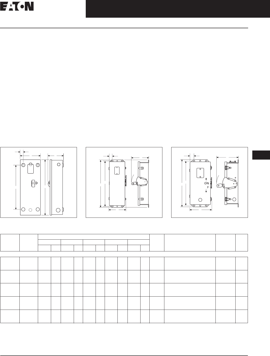
November 2008
CA08101001E For more information visit: www.eaton.com
12-197
Series C Molded Case Circuit Breakers
12
Engine Generator Circuit Breakers
Enclosures
Enclosures
Type 1 General Purpose
■Surface or flush mounting.
■15 – 1200 ampere range.
■600 Vac, 500 Vdc.
Type 1 enclosed breakers are designed
for use in commercial buildings, apart-
ment buildings and other areas where
a general purpose enclosure is appli-
cable. The breaker is front operable
and is capable of being padlocked in
either the ON or OFF position. Ratings
through 1200 amperes are listed
with Underwriters Laboratories as
approved for service entrance applica-
tion. Both surface and flush mounted
enclosures are available.
Type 3R Rainproof Surface
Mounting
■Interchangeable hubs
(through 400 amperes).
■15 – 1200 ampere range.
■600 Vac, 500 Vdc.
This general purpose outdoor service
center employs a circuit breaker inside
a weatherproof sheet steel breaker
enclosure to serve as a main discon-
nect and protective device for feeder
circuits. Ratings through 1200 amperes
are listed by Underwriters Laboratories
as suitable for service entrance
application.
Type 12 Dustproof Surface
Mounting
■No knockouts or other openings.
■15 – 1200 ampere range.
■600 Vac, 500 Vdc.
The Type 12 enclosure is designed
in line with specifications for special
industry applications where unusually
severe conditions involving oil, coolant,
dust and other foreign materials exist
in the operating atmosphere. The handle
padlocks in the OFF position and the
cover is interlocked with the handle
mechanism to prevent opening the
cover with the circuit breaker in the
ON position. Ratings through 1200
amperes are listed by Underwriters
Laboratories as suitable for service
entrance application.
Figure 12-41. Type 1 Surface Mounted Figure 12-42. Type 3R Rainproof Figure 12-43. Type 12, 12K Dustproof
Table 12-320. Enclosure Selection Data
E
D
A
C
B
C
ON
O
F
F
E
A
D
B
OF
E
C
A
D
B
Breaker
Frame
Amperes
Enclosure
Type
Class
Dimensions Approx.
Weight
Lbs.
(kg)
Conduit Sizes,
Inches
Catalog
Number
Price
U.S. $
A BCD E
Inches mm Inches mm Inches mm Inches mm Inches mm
FG
15 – 225
Type 1
Type 3R
Type 12
23.25
25.66
25.66
591
652
652
8.41
8.84
8.84
214
225
226
6.28
9.31
9.31
160
237
238
18.75
24.28
24.28
476
617
618
1.20
1.70
1.70
31
43
43
15 (7)
19 (9)
18 (8)
.25, .50, .75, 1, 1.25, 1.50, 2, 2.50
.25, .50, .75, 1, 1.25, 1.50, 2, 2.50
SFDN225
RFDN225
JFDN225
JG
175 – 250
Type 1
Type 3R
Type 12
34.70
37.50
37.53
881
891
953
10.92
11.56
11.56
227
294
294
7.20
10.22
10.22
183
260
260
30.00
35.77
35.77
762
909
909
1.88
1.94
1.94
48
49
49
31 (14)
40 (18)
37 (17)
.25, .50, 2, 2.50, 3
.25, .50, 2, 2.50, 3
SJDN250
RJDN250
JJDN250
KG
300 – 400
Type 1
Type 3R
Type 12
38.81
41.69
41.69
986
997
997
11.06
11.75
11.75
281
298
298
10.94
14.06
14.06
278
357
357
34.00
39.90
39.90
869
1014
1015
2.28
1.97
1.97
58
50
50
53 (24)
60 (27)
53 (24)
.25, .50, .75, 1.50, 2, 2.50, 3, 3.50
.25, .50, .75, 2.50, 3, 3.50
SKDN400
RKDN400
JKDN400
LG
450 – 600
Type 1
Type 3R
Type 12
45.88
48.31
48.31
1165
1227
1227
14.31
14.91
14.91
364
379
379
12.38
15.50
15.50
314
394
394
46.56
46.56
46.56
1183
1183
1183
1.91
1.92
1.92
48
49
49
81 (37)
84 (38)
81 (37)
.25, .50, .75, 3, 3.50, 4
.25, .50, .75, 3, 3.50, 4
SLDN600
RLDN600
JLDN600
NG
700 – 1200
Type 1
Type 3R
Type 12
61.22
63.59
63.59
1555
1615
1615
21.44
22.00
22.00
545
559
559
15.41
17.63
17.63
391
448
448
61.84
61.84
61.84
1571
1571
1571
1.97
1.97
1.97
50
50
50
178 (81)
175 (79)
170 (77)
—SNDN1200
RNDN1200
JNDN1200
Discount Symbol . . . . . . . . . . . . . . . . . . . . . . . . . CB-2
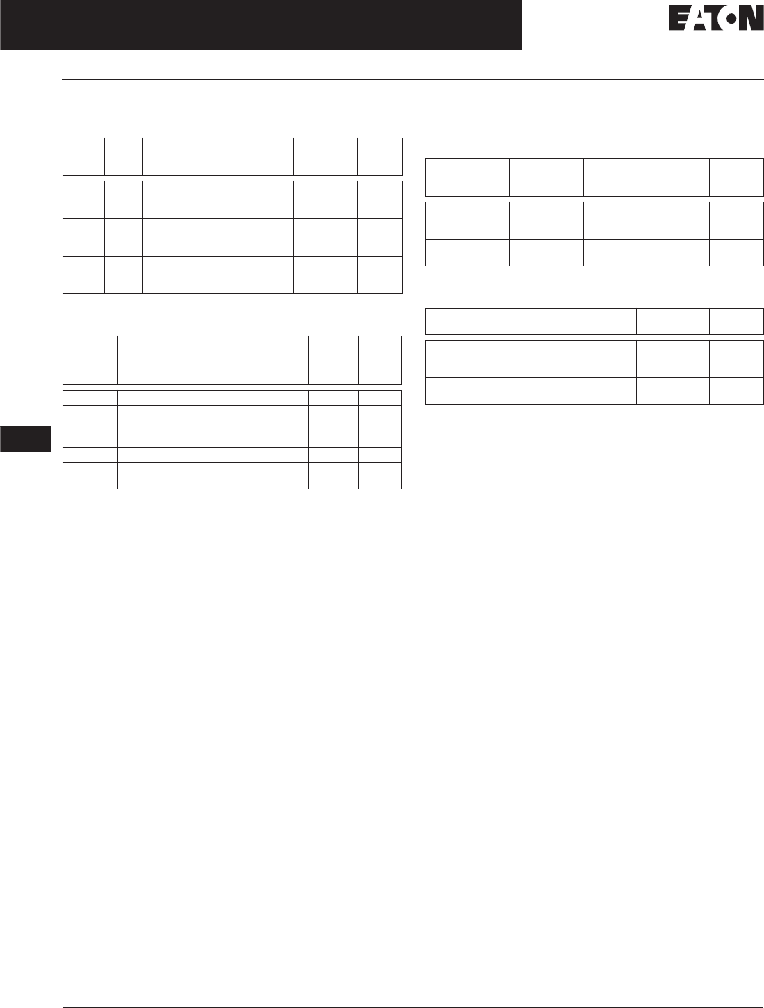
November 2008
12-198
For more information visit: www.eaton.com CA08101001E
Series C Molded Case Circuit Breakers
12
Engine Generator Circuit Breakers
Accessories
Options and Accessories
Table 12-321. Standard Terminals
Package of 3 terminals.
Table 12-322. Neutral Kits, Insulated and Groundable
Internal Accessories
Table 12-323. Auxiliary Switch
Other accessories are available. Same as standard frame breakers.
Table 12-324. Shunt Trip
Other accessories are available. Same as standard frame breakers.
Breaker
Frame
Max.
Amp
Rating
AWG Wire
Range
Metric Wire
Range mm2Catalog
Number
Price
U.S. $
FG
FG
JG
100
150
250
14 – 1/0
4 – 4/0
4 – 350 kcmil
2.5 – 50
25 – 95
25 – 185
3T100FB
3TA225FD
TA250KB
KG
KG
LG
350
400
600
250 – 500 kcmil
3/0 – 250 kcmil (2)
250 – 500 kcmil (2)
120 – 240
95 – 120
120 – 240
TA350K
3TA400K
3TA603LDK
NG
NG
NG
700
1000
1200
1 – 500 kcmil (2)
3/0 – 400 kcmil (3)
4/0 – 500 kcmil (4)
50 – 300
95 – 185
120 – 300
TA700NB1
TA1000NB1
TA1200NB1
Max.
Enclosure
Rating
(Amperes)
Main Lug Number
Size Cu/Al
Ground Lug
Size Cu/Al
Catalog
Number
Price
U.S. $
100 (1) 14 – 1/0 (1) 14 – 1/0 INK100
250 (1) 6 – 350 kcmil (1) 4 – 300 kcmil INK250
400 (1) 4 – 750 kcmil or
(2) 1/0 – 250 kcmil
(1) 4 – 300 kcmil INK400
600 (2) 250 – 500 kcmil (1) 4 – 300 kcmil INK600
1200 (3) 1/0 to 750 kcmil or
(4) 1/0 to 750 kcmil
(1) 6 – 250 kcmil INK1200
Breaker
Frame
1A-1B
Catalog
Number
Price
U.S. $
2A-2B
Catalog
Number
Price
U.S. $
FG
JG
KG
A1X1PK
A1X2PK
A1X3PK
A2X1RPK
A2X2PK
A2X3PK
LG
NG
A1X4PK
A1X5PK
A2X4PK
A2X5PK
Breaker
Frame
Rating Catalog
Number
Price
U.S. $
FG
JG
KG
12 – 24 Vdc
12 – 24 Vdc
12 – 24 Vdc
SNT1LP03K
SNT2P04K
SNT3P04K
LG
NG
12 – 24 Vdc
12 – 24 Vdc
SNT4LP03K
SNT5LP03K
Discount Symbol . . . . . . . . . . . . . . . . . . . . . . . . . CB-2

November 2008
CA08101001E For more information visit: www.eaton.com
12-199
Series C Molded Case Circuit Breakers
12
Direct Current Circuit Breakers
Product Description
Direct Current
Circuit Breakers
Product Description
Eaton’s Cutler-Hammer dc molded
case circuit breakers are UL listed
for use in general dc circuits and
battery supply circuits of UPS systems
providing continuous, reliable ac
power to computer controlled applica-
tions such as financial transactions
and telecommunications.
For standard interrupting capacity
250 dc molded case circuit breakers.
Refer to Table 12-129 on Page 12-74.
The Series C dc breakers listed below
use the same internal and external
accessories as the standard Series C
breaker. NBDC and PBDC use the same
internal and external accessories as
standard NB and PB breakers.
Molded case circuit breakers for trans-
portation application requiring 750 Vdc
are available for certain amperages
interrupting capacity at 750 Vdc.
Breakers require 4 poles in series
for 750 Vdc application. However,
750 volt is not a UL rating. For 750 Vdc
application refer to Eaton for ordering
information. Dimensions are the same
as the standard thermal-magnetic
equivalent.
Technical Data and Specifications
Interrupting Capacity Ratings
Table 12-325. UL 489 Interrupting Capacity Ratings
dc ratings apply to substantially non-inductive circuits. 8 millisecond time constant.
1 pole in series.
2 poles in series.
3 poles in series.
4 poles in series. 750 Vdc is not a UL listed voltage rating.
Wiring Diagrams
Figure 12-44. Series Connection Diagrams for dc Application
Note: Use rated cable per NEC. Connect to terminals as per breaker nameplate.
Circuit
Breaker
Type
Interrupting Capacity (Symmetrical kA)
Volts dc
125 250 600 750
HFDDC
HJDDC
HKDDC
HLDDC
HMDLDC
NBDC
PBDC
42
42
42
42
42
42
42
42
42
42
42
42
50
65
35
35
35
35
35
50
65
42
—
—
—
—
—
—
Load
Load
Load
600 Vdc
3 Poles in Series
750 Vdc
4 Poles in Series

November 2008
12-200
For more information visit: www.eaton.com CA08101001E
Series C Molded Case Circuit Breakers
12
Direct Current Circuit Breakers
Product Selection
Product Selection
Table 12-326. Type HFDDC DC Circuit Breakers
Table 12-327. DC Circuit Breakers
Complete circuit breaker includes frame, trip unit and terminals.
Maximum
Continuous
Ampere Rating
at 40°C
Complete Circuit Breaker with Line and Load Terminals
1-Pole 2-Pole 3-Pole 4-Pole
Catalog
Number
Price
U.S. $
Catalog
Number
Price
U.S. $
Catalog
Number
Price
U.S. $
Catalog
Number
Price
U.S. $
3-Pole High Interrupting Capacity 35 kAIC at 600 Vdc
15
20
25
30
35
HFDDC1015L
HFDDC1020L
HFDDC1025L
HFDDC1030L
HFDDC1035L
HFDDC2015L
HFDDC2020L
HFDDC2025L
HFDDC2030L
HFDDC2035L
HFDDC3015L
HFDDC3020L
HFDDC3025L
HFDDC3030L
HFDDC3035L
HFDDC4015L
HFDDC4020L
HFDDC4025L
HFDDC4030L
HFDDC4035L
40
45
50
60
HFDDC1040L
HFDDC1045L
HFDDC1050L
HFDDC1060L
HFDDC2040L
HFDDC2045L
HFDDC2050L
HFDDC2060L
HFDDC3040L
HFDDC3045L
HFDDC3050L
HFDDC3060L
HFDDC4040L
HFDDC4045L
HFDDC4050L
HFDDC4060L
70
80
90
100
HFDDC1070L
HFDDC1080L
HFDDC1090L
HFDDC1100L
HFDDC2070L
HFDDC2080L
HFDDC2090L
HFDDC2100L
HFDDC3070L
HFDDC3080L
HFDDC3090L
HFDDC3100L
HFDDC4070L
HFDDC4080L
HFDDC4090L
HFDDC4100L
110
125
150
HFDDC1110L
HFDDC1125L
HFDDC1150L
HFDDC2110L
HFDDC2125L
HFDDC2150L
HFDDC3110L
HFDDC3125L
HFDDC3150L
HFDDC4110L
HFDDC4125L
HFDDC4150L
Maximum
Continuous
Ampere Rating
at 40°C
Circuit Breaker
Frame Only
Thermal-Magnetic
Trip Unit
Standard
Terminals
Catalog
Number
Price
U.S. $
Catalog
Number
Price
U.S. $
Catalog
Number
Price
U.S. $
3-Pole High Interrupting Capacity 35 kAIC at 600 Vdc
70
90
100
125
150
175
200
225
250
HJDDC3250F JT3070T
JT3090T
JT3100T
JT3125T
JT3150T
JT3175T
JT3200T
JT3225T
JT3250T
TA250KB
TA250KB
TA250KB
TA250KB
TA250KB
TA250KB
TA250KB
TA250KB
TA250KB
100
125
150
175
200
225
250
300
350
400
HKDDC3400F KT3100T
KT3125T
KT3150T
KT3175T
KT3200T
KT3225T
KT3250T
KT3300T
KT3350T
KT3400T
TA300K
TA300K
TA300K
TA300K
TA300K
TA300K
TA350K
TA350K
TA350K
3TA400K
300
350
400
450
500
600
HLDDC3600F LT3300T
LT3350T
LT3400T
LT3450T
LT3500T
LT3600T
TA602LD
TA602LD
TA602LD
TA602LD
TA602LD
3TA603LDK
Discount Symbol . . . . . . . . . . . . . . . . . . . . . . . . . CB-2

CA08101001E For more information visit: www.eaton.com
12-201
Series C Molded Case Circuit Breakers
November 2008
12
Direct Current Circuit Breakers
Product Selection
Table 12-328. Type HMDLDC DC Circuit Breakers
Complete circuit breaker includes frame, trip unit and terminals.
Table 12-329. Type NBDC DC Circuit Breakers
Complete circuit breaker includes frame, trip unit and terminals.
Table 12-330. Type PBDC DC Circuit Breakers
Complete circuit breaker includes frame, trip unit and terminals.
Maximum
Continuous
Ampere Rating
at 40°C
Circuit Breaker Frame Only Thermal-Magnetic Trip Unit
Catalog
Number
Price
U.S. $
Catalog
Number
Price
U.S. $
3-Pole High Interrupting Capacity 35 kAIC at 600 Vdc
300
350
400
450
500
600
700
800
HMDLDC3800F MT3300T
MT3350T
MT3400T
MT3450T
MT3500T
MT3600T
MT3700T
MT3800T
Maximum
Continuous
Ampere Rating
at 40°C
Complete Circuit Breaker
Factory Assembled
without Terminals
Includes
Magnetic Only
Trip Unit
Calibrated
at 135%
Standard Terminals
Catalog
Number
Price
U.S. $
Catalog
Number
Price
U.S. $
3-Pole High Interrupting Capacity 50 kAIC at 600 Vdc
700
800
900
1000
1200
NBDC3700MW
NBDC3800MW
NBDC3900MW
NBDC31000MW
NBDC31200MW
Included
Included
Included
Included
Included
TA1000NB1
TA1000NB1
TA1000NB1
TA1000NB1
TA1200NB1
Maximum
Continuous
Ampere Rating
at 40°C
Complete Circuit Breaker
Factory Assembled
without Terminals
Includes
Magnetic Only
Trip Unit
Calibrated
at 135%
Standard Rear Connectors
Catalog
Number
Price
U.S. $
Catalog
Number
Price
U.S. $
3-Pole High Interrupting Capacity 65 kAIC at 600 Vdc
1600
2000
2500
PBDC31600W
PBDC32000W
PBDC32500W
Included
Included
Included
BA2000PB
BA2000PB
BA2500PB
Discount Symbol . . . . . . . . . . . . . . . . . . . . . . . . . CB-2

November 2008
12-202
For more information visit: www.eaton.com CA08101001E
Series C Molded Case Circuit Breakers
12
Mining Service Circuit Breakers
E2
E2 Mining Service Breakers
Product Description
State-of-the-art E2 Mining Service Break-
ers incorporate the rigid specifications
and testing procedures developed by
a focus group led by engineers from
several large coal companies and
Eaton’s design engineers. Additionally,
the performance of these breakers was
proven and verified during hundreds
of hours of field testing in harsh mine
environments.
E2 Mining Breakers are available
in 600 Vac and l000Y/577 Vac.
Interchangeable trip units can be used
on either 600 or 1000 Vac frames.
The E2 mining breaker family is
designed especially for trailing cable
application per MSHA 30 CFR 75. Field
interchangeable electronic rms sensing
trip units are available from 150 to 2000
amperes with instantaneous pickup set-
tings conforming to the code of Federal
Regulations 30 CFR 75.601-2. Electrome-
chanical trip units are also available with
a wide range of magnetic pickup ranges.
E2 electronic trip units are the first to
provide the mining industry with true
rms sensing, made possible by the
patented SuRE chip microprocessor
in each electronic trip unit.
E2 breakers are designed to be physi-
cally and electrically interchangeable
with Classic Mining Service Breakers
and supersede Series C Mining Service
Breakers. Table 12-331 outlines direct
replacements.
Table 12-331. 600 Vac Mining Breaker
Replacement Chart
E2N/E2NM is physically different than the
MAM/MCM/HMAM/HMCM/HLCLM see
DS29-170MS.
E2R/E2RM is a new frame physically
different than the HPBM see DS29-170MS.
Table 12-332. 1000 Vac Mining Breaker
Replacement Chart
E2R/E2RM is a new frame physically
different than the HPBM see DS29-170MS.
Table 12-333. Interrupting Capacity Rating
Series rated for application with
Eaton’s Cutler-Hammer E2NM and
E2RM Breakers.
Two poles in series. Breakers with electronic
trip units are not dc rated.
Classic Series C E2
FBM
HFBM
FDBM
FDM
HFDM (Mag. Only)
E2F
— JDM E2J
KAM
KAMH
KDM E2K
LAM
LAMH
LCM
LCMH
LDM E2L
MAM
MAMH
MCM
MCMH
NBM
NBMH
NCM
NCMH
—E
2N
—— E
2R
Classic Series C E2M
HFM — E2FM
— JDCM E2JM
HKAM KDCM E2KM
HLAM
HLCM
LDCM E2LM
HMAM
HMCM
—E
2MM
HNBM
HNBMH
HNCM
HLCLM
—E
2NM
HPBM — E2RM
Circuit
Breaker
Type
Interrupting Capacity
(Symmetrical kA)
Vac (50/60 Hz) Vdc
240 480 600 1000Y/
577
250
E2F
E2J
E2K
65
65
65
25
35
35
18
18
25
—
—
—
10
10
10
E2L
E2M
E2N
E2R
65
65
65
125
35
35
50
65
25
25
25
50
—
—
—
—
22
22
—
—
E2FM
E2JM
E2KM
65
65
65
25
35
35
18
18
25
10
10
14
10
22
10
E2LM
E2MM
E2NM
E2RM
—
—
—
—
35
35
50
65
25
25
25
50
18
18
25
25
22
22
—
—

November 2008
CA08101001E For more information visit: www.eaton.com
12-203
Series C Molded Case Circuit Breakers
12
Mining Service Circuit Breakers
E2F/E2FM
Eaton’s Cutler-Hammer mining service circuit breakers provide
short circuit protection as specified in the code of Federal Reg-
ulations 30 CFR 75.601-2. E2 225/400 ampere K frame and 400/
600 ampere L frame electronic trip units feature specifically
designed instantaneous pickup settings to conform exactly
with the code of Federal Regulations 30 CFR 75.601-2. Electro-
mechanical trip units are also available with a wide range of
magnetic pickup ranges.
Table 12-334 lists the conductor size maximum allowable
circuit breaker instantaneous setting and the E2 breaker
that meets that setting.
Table 12-334. Trailing Cable Setting Per 30 CFR 75
E2F/E2FM
Table 12-335. Interrupting Capacity Ratings
Table 12-336. Thermal-Magnetic Circuit Breakers Sealed Breakers
with Non-Interchangeable Trip Unit — Include Line/Load Terminals
For 2-pole application use outer poles.
Table 12-337. Magnetic Only Circuit Breakers Sealed Breakers with
Non-Interchangeable Trip Unit — Include Line/Load Terminals
Conductor
Size
Maximum
Breaker
Instantaneous
Setting
Maximum
Ampere
75°C
Insulated
Conductor
E2/E2M
Instantaneous
Only
Setting
14
12
10
50
75
150
15
20
30
E2K 150 A
E2K 150 A
E2K 150 A
A
B
C
8
6
4
200
300
500
50
65
85
E2K 225 A
E2K 225 A
E2K 225 A/E2L 400 A
A
B
C/A
3
2
1
600
800
1000
100
115
130
E2K 225 A/E2L 400 A
E2K 225 A/E2L 400 A
E2K 225 A/E2L 400 A
D/B
E/C
F/D
1/0
2/0
3/0
1250
1500
2000
150
175
200
E2K 225 A/E2L 400 A
E2K 225 A/E2L 400 A
E2L 400 A
G/E
H/F
G
4/0
250
300
2500
2500
2500
230
255
285
E2L 400 A
E2L 400 A
E2L 400 A
H
H
H
350
400
500
2500
2500
2500
310
335
380
E2L 400 A
E2L 400 A
E2L 400 A
H
H
H
Circuit
Breaker
Type
Interrupting Capacity (Symmetrical Amperes)
Vac (50/60 Hz) Vdc
240 480 600 1000Y/577 250
E2F
E2FM
65,000
—
25,000
25,000
18,000
18,000
—
10,000
10,000
10,000
Maximum
Continuous
Ampere Rating
at 40°C
600 Vac Maximum,
250 Vdc
25 kA at 480 Vac
3-Pole
1000Y/577 Vac Maximum,
250 Vdc
10 kA at 1000 Vac
3-Pole
Catalog
Number
Price
U.S. $
Catalog
Number
Price
U.S. $
15
20
25
E2F3015
E2F3020
E2F3025
—
—
—
30
35
40
E2F3030
E2F3035
E2F3040
—
—
—
45
50
60
E2F3045
E2F3050
E2F3060
—
E2FM3050
E2FM3060
70
80
90
E2F3070
E2F3080
E2F3090
E2FM3070
E2FM3080
E2FM3090
100
125
150
E2F3100
E2F3125
E2F3150
E2FM3100
E2FM3125
E2FM3150
Maximum
Continuous
Ampere
Rating
at 40°C
Magnetic
Trip Range
600 Vac
Maximum,
250 Vdc
25 kA at 480 Vac
3-Pole
1000Y/577 Vac
Maximum,
250 Vdc
10 kA at 1000 Vac
3-Pole
Catalog
Number
Price
U.S. $
Catalog
Number
Price
U.S. $
3
7
15
9 – 30
21 – 70
45 – 150
E2F003AM
E2F007CM
E2F015EM
—
—
—
30
30
50
90 – 300
50 – 150
150 – 500
E2F030HM
E2F030EM
E2F050KM
—
—
E2FM050KM
50
70
100
66 – 190
210 – 700
150 – 500
E2F050YM
E2F070MM
E2F100KM
E2FM050YM
E2FM070MM
E2FM100KM
100
150
150
300 – 1000
450 – 1500
750 – 2500
E2F100RM
E2F150TM
E2F150UM
E2FM100RM
E2FM150TM
E2FM150UM
Further Information
Dimensions . . . . . . . . . . . . . . . . . . . . DS 29-170MS
Discount Symbol . . . . . . . . . . . . . . . . . . . . . . . . . CB-2
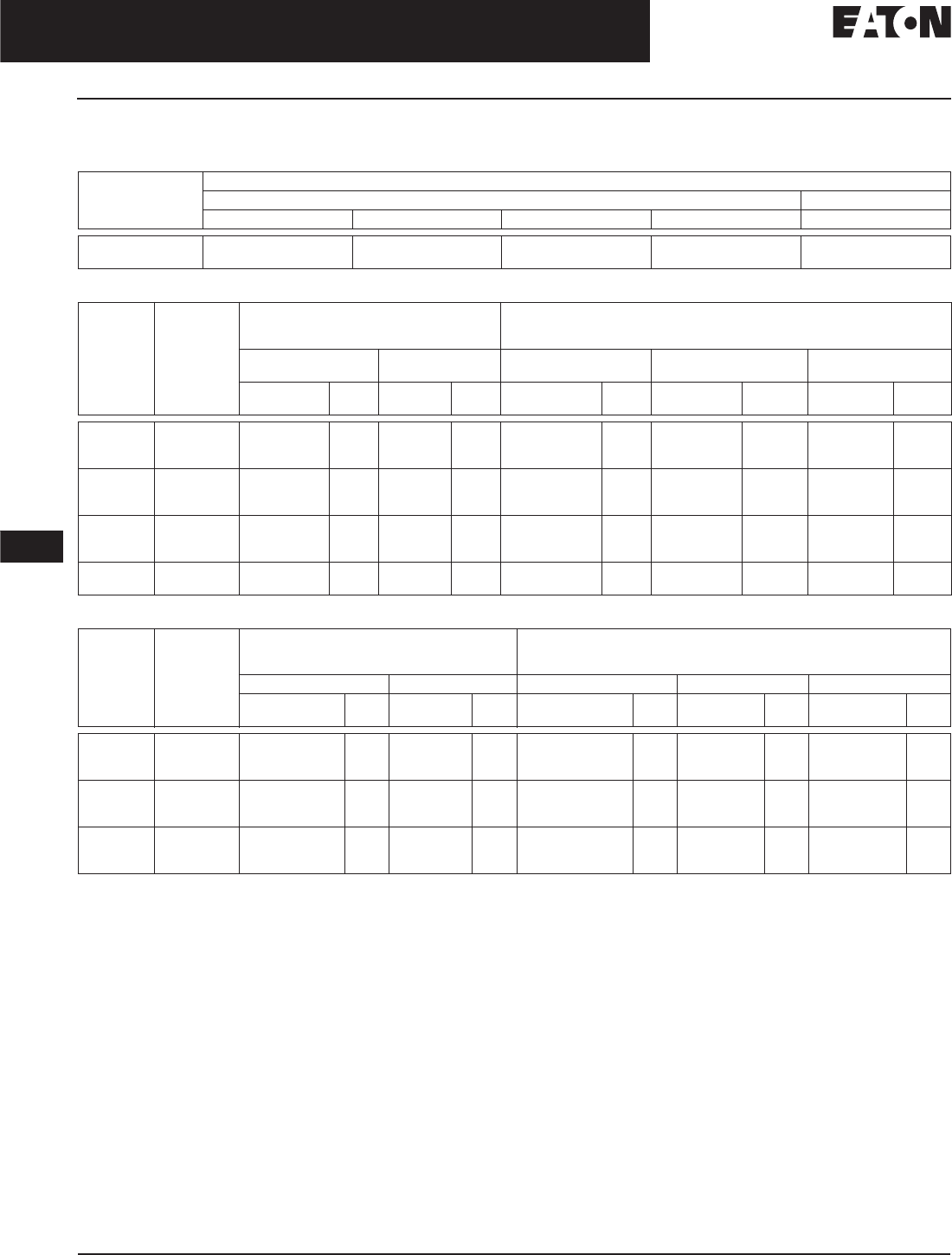
November 2008
12-204
For more information visit: www.eaton.com CA08101001E
Series C Molded Case Circuit Breakers
12
Mining Service Circuit Breakers
E2J/E2JM
E2J/E2JM
Table 12-338. Interrupting Capacity Ratings
Table 12-339. Circuit Breakers with Interchangeable Thermal-Magnetic Trip Unit
Table 12-340. Circuit Breakers with Interchangeable Magnetic Only Trip Unit
Circuit
Breaker
Type
Interrupting Capacity (Symmetrical Amperes)
Vac (50/60 Hz) Vdc
240 480 600 1000Y/577 250
E2J
E2JM
65,000
—
35,000
35,000
18,000
18,000
—
10,000
10,000
10,000
Maximum
Continuous
Ampere
Rating
at 40°C
Magnetic
Trip Range
600 Vac Maximum, 250 Vdc
35 kA at 480 Vac
3-Pole
1000Y/577 Vac Maximum, 250 Vdc
10 kA at 1000 Vac
3-Pole
Complete Breaker Frame
Only
Complete Breaker Frame Only Trip Unit Only
Catalog
Number
Price
U.S. $
Catalog
Number
Price
U.S. $
Catalog
Number
Price
U.S. $
Catalog
Number
Price
U.S. $
Catalog
Number
Price
U.S. $
70
90
100
300 – 650
450 – 900
500 – 1000
E2J3070W
E2J3090W
E2J3100W
E2J3250F
—
—
E2JM3070W
E2JM3090W
E2JM3100W
E2JM3250F
—
—
E2J3070T
E2J3090T
E2J3100T
125
150
175
625 – 1250
750 – 1500
875 – 1750
E2J3125W
E2J3150W
E2J3175W
—
—
—
E2JM3125W
E2JM3150W
E2JM3175W
—
—
—
E2J3125T
E2J3150T
E2J3175T
200
225
225
1000 – 2000
300 – 650
500 – 1000
E2J3200W
E2J3225AW
E2J3225DW
—
—
—
E2JM3200W
E2JM3225AW
E2JM3225DW
—
—
—
E2J3200T
E2J3225TA
E2J3225TD
225
250
1125 – 2250
1250 – 2500
E2J3225W
E2J3250W
—
—
E2JM3225W
E2JM3250W
—
—
E2J3225T
E2J3250T
Maximum
Continuous
Ampere
Rating
at 40°C
Magnetic
Trip Range
600 Vac Maximum, 250 Vdc
25 kA at 480 Vac
3-Pole
1000Y/577 Vac Maximum, 250 Vdc
10 kA at 1000 Vac
3-Pole
Complete Breaker Frame Only Complete Breaker Frame Only Trip Unit Only
Catalog
Number
Price
U.S. $
Catalog
Number
Price
U.S. $
Catalog
Number
Price
U.S. $
Catalog
Number
Price
U.S. $
Catalog
Number
Price
U.S. $
250
250
250
300 – 650
450 – 900
500 – 1000
E2J3250MAW
E2J3250MCW
E2J3250MDW
E2J3250F
—
—
E2JM3250MAW
E2JM250MCW
E2JM3250MDW
E2JM3250F
—
—
E2J3250TMA
E2J3250TMC
E2J3250TMD
250
250
250
625 – 1250
750 – 1500
875 – 1750
E2J3250MFW
E2J3250MGW
E2J3250MJW
—
—
—
E2JM3250MFW
E2JM3250MGW
E2JM3250MJW
—
—
—
E2J3250TMF
E2J3250TMG
E2J3250TMJ
250
250
250
1000 – 2000
1125 – 2250
1250 – 2500
E2J3250MKW
E2J3250MLW
E2J3250MW
—
—
—
E2JM3250MKW
E2JM3250MLW
E2JM3250MW
—
—
—
E2J3250TMK
E2J3250TML
E2J3250TM
Further Information
Dimensions . . . . . . . . . . . . . . . . . . . . DS 29-170MS
Discount Symbol . . . . . . . . . . . . . . . . . . . . . . . . . CB-2

November 2008
CA08101001E For more information visit: www.eaton.com
12-205
Series C Molded Case Circuit Breakers
12
Mining Service Circuit Breakers
E2K/E2KM
E2K/E2KM
Table 12-341. Interrupting Capacity Ratings
dc rating applies to breakers with thermal-magnetic trip unit, breakers with electronic trip unit are not dc rated.
Table 12-342. Circuit Breakers with Interchangeable Thermal-Magnetic Trip Unit
Table 12-343. Circuit Breakers with Interchangeable Magnetic Only Trip Unit
Circuit
Breaker
Type
Interrupting Capacity (Symmetrical Amperes)
Vac (50/60 Hz) Vdc
240 480 600 1000Y/577 250
E2K
E2KM
65,000
—
35,000
35,000
25,000
25,000
—
14,000
10,000
10,000
Maximum
Continuous
Ampere
Rating
at 40°C
Magnetic
Trip Range
600 Vac Maximum, 250 Vdc
35 kA at 480 Vac
3-Pole
1000Y/577 Vac Maximum, 250 Vdc
14 kA at 1000 Vac
3-Pole
Complete Breaker Frame Only Complete Breaker Frame Only Trip Unit Only
Catalog
Number
Price
U.S. $
Catalog
Number
Price
U.S. $
Catalog
Number
Price
U.S. $
Catalog
Number
Price
U.S. $
Catalog
Number
Price
U.S. $
100
125
150
500 – 1000
625 – 1250
750 – 1500
E2K3100W
E2K3125W
E2K3150W
E2K3400F
—
—
E2KM3100W
E2KM3125W
E2KM3150W
E2KM3400F
—
—
E2K3100T
E2K3125T
E2K3150T
175
200
225
875 – 1750
1000 – 2000
300 – 650
E2K3175W
E2K3200W
E2K3225AW
—
—
—
E2KM3175W
E2KM3200W
E2KM3225AW
—
—
—
E2K3175T
E2K3200T
E2K3225TA
225
225
250
500 – 1000
1125 – 2250
1250 – 2500
E2K3225DW
E2K3225W
E2K3250W
—
—
—
E2KM3225DW
E2KM3225W
E2KM3250W
—
—
—
E2K3225TD
E2K3225T
E2K3250T
300
350
400
1500 – 3000
1750 – 3500
2000 – 4000
E2K3300W
E2K3500W
E2K3400W
—
—
—
E2KM3300W
E2KM3350W
E2KM3400W
—
—
—
E2K3300T
E2K3500T
E2K3400T
Maximum
Continuous
Ampere
Rating
at 40°C
Magnetic
Trip Range
600 Vac Maximum, 250 Vdc
35 kA at 480 Vac
3-Pole
1000Y/577 Vac Maximum, 250 Vdc
14 kA at 1000 Vac
3-Pole
Complete Breaker Frame Only Complete Breaker Frame Only Trip Unit Only
Catalog
Number
Price
U.S. $
Catalog
Number
Price
U.S. $
Catalog
Number
Price
U.S. $
Catalog
Number
Price
U.S. $
Catalog
Number
Price
U.S. $
400
400
400
300 – 650
500 – 1000
625 – 1250
E2K3400MAW
E2K3400MDW
E2K3400MFW
E2K3400F
—
—
E2KM3250MAW
E2KM3400MDW
E2KM3400MFW
E2KM3400F
—
—
E2K3400TMA
E2K3400TMD
E2K3400TMF
400
400
400
750 – 1500
875 – 1750
1000 – 2000
E2K3400MGW
E2K3400MJW
E2K3400MKW
—
—
—
E2KM3400MGW
E2KM3400MJW
E2KM3400MKW
—
—
—
E2K3400TMG
E2K3400TMJ
E2K3400TMK
400
400
400
1125 – 2250
1250 – 2500
1500 – 3000
E2K3400MLW
E2K3400MWW
E2K3400MNW
—
—
—
E2KM3400MLW
E2KM3400MWW
E2KM3400MNW
—
—
—
E2K3400TML
E2K3400TMW
E2K3400TMN
400
400
1750 – 3500
2000 – 4000
E2K3400MRW
E2K3400MW
—
—
E2KM3400MRW
E2KM3400MW
—
—
E2K3400TMR
E2K3400TM
Discount Symbol . . . . . . . . . . . . . . . . . . . . . . . . . CB-2

November 2008
12-206
For more information visit: www.eaton.com CA08101001E
Series C Molded Case Circuit Breakers
12
Mining Service Circuit Breakers
E2K/E2KM
Table 12-344. Circuit Breakers with Interchangeable Electronic Trip Unit, Long/Instantaneous (Includes Rating Plug)
Table 12-345. Circuit Breakers with Interchangeable Electronic Trip Unit, Instantaneous Only (Includes Rating Plug)
Maximum
Continuous
Ampere
Rating
at 40°C
Magnetic
Trip Range
600 Vac Maximum
35 kA at 480 Vac
3-Pole
1000Y/577 Vac Maximum
14 kA at 1000 Vac
3-Pole
Complete Breaker Frame Only Complete Breaker Frame Only Trip Unit Only
Catalog
Number
Price
U.S. $
Catalog
Number
Price
U.S. $
Catalog
Number
Price
U.S. $
Catalog
Number
Price
U.S. $
Catalog
Number
Price
U.S. $
100
125
150
200
225
225
400
400
50 – 800
50 – 800
50 – 800
200 – 1500
200 – 1500
500 – 2500
200 – 1500
500 – 2500
E2KE3100W
E2KE3125W
E2KE3150W
E2KE3200W
E2KE3225W
E2KE32252W
E2KE3400W
E2KE34002W
E2K3400F
—
—
—
—
—
—
—
E2KEM3100W
E2KEM3125W
E2KEM3150W
E2KEM3200W
E2KEM3225W
E2KEM32252W
E2KEM3400W
E2KEM34002W
E2KM3400F
—
—
—
—
—
—
—
KEM3100T
KEM3125T
KEM3150T
KEM3200T
KEM3225T
KEM3225T2
KEM3400T
KEM3400T2
Maximum
Continuous
Ampere
Rating
at 40°C
Magnetic
Trip Range
600 Vac Maximum
35 kA at 480 Vac
3-Pole
1000Y/577 Vac Maximum
14 kA at 1000 Vac
3-Pole
Complete Breaker Frame Only Complete Breaker Frame Only Trip Unit Only
Catalog
Number
Price
U.S. $
Catalog
Number
Price
U.S. $
Catalog
Number
Price
U.S. $
Catalog
Number
Price
U.S. $
Catalog
Number
Price
U.S. $
150
225
225
400
400
50 – 800
200 – 1500
500 – 2500
200 – 1500
500 – 2500
E2KE3150MW
E2KE3225MW
E2KE3225M2W
E2KE3400MW
E2KE3400M2W
E2K3400F
—
—
—
—
E2KEM3150MW
E2KEM3225MW
E2KEM3225M2W
E2KEM3400MW
E2KEM3400M2W
E2KM3400F
—
—
—
—
KEM3150TM
KEM3225TM
KEM3225TM2
KEM3400TM
KEM3400TM2
Further Information
Dimensions . . . . . . . . . . . . . . . . . . . . DS 29-170MS
Discount Symbol . . . . . . . . . . . . . . . . . . . . . . . . . CB-2

November 2008
CA08101001E For more information visit: www.eaton.com
12-207
Series C Molded Case Circuit Breakers
12
Mining Service Circuit Breakers
E2L/E2LM
E2L/E2LM
Table 12-346. Interrupting Capacity Ratings
dc rating applies to breakers with thermal-magnetic trip unit, breakers with electronic trip unit are not dc rated.
Table 12-347. Circuit Breakers with Interchangeable Thermal-Magnetic Trip Unit
600 Ampere Thermal 1125 – 2250 T.A.
Table 12-348. Circuit Breakers with Interchangeable Magnetic Only Trip Unit
Table 12-349. Circuit Breakers with Interchangeable Electronic Trip Unit, Long/Instantaneous (Includes Rating Plug)
Table 12-350. Circuit Breakers with Interchangeable Electronic Trip Unit, Instantaneous Only (Includes Rating Plug)
Further Information
Dimensions. . . . . . . . . . . . . . . . . . . . . . DS 29-170MS
Discount Symbol . . . . . . . . . . . . . . . . . . . . . . . . . CB-2
Circuit Breaker
Type
Interrupting Capacity (Symmetrical Amperes)
Volts ac (50/60 Hz) Volts dc
240 480 600 1000Y/577 250
E2L
E2LM
65,000
—
35,000
35,000
25,000
25,000
—
14,000
22,000
22,000
Maximum
Continuous
Ampere
Rating
at 40°C
Magnetic
Trip Range
600 Vac Maximum, 250 Vdc
35 kA at 480 Vac, 3-Pole
1000Y/577 Vac Maximum, 250 Vdc
18 kA at 1000 Vac, 3-Pole
Complete Breaker Frame Only Complete Breaker Frame Only Trip Unit Only
Catalog
Number
Price
U.S. $
Catalog
Number
Price
U.S. $
Catalog
Number
Price
U.S. $
Catalog
Number
Price
U.S. $
Catalog
Number
Price
U.S. $
300
350
400
450
500
600
600
1500 – 3000
1750 – 3500
2000 – 4000
2250 – 4500
2500 – 5000
3000 – 6000
1125 – 2250
E2L3300W
E2L3550W
E2L3400W
E2L3450W
E2L3500W
E2L3600W
—
E2L3600F
—
—
—
—
—
—
E2LM3300W
E2LM3500W
E2LM3400W
E2LM3450W
E2LM3500W
E2LM3600W
—
E2LM3600F
—
—
—
—
—
—
E2L3300T
E2L3500T
E2L3400T
E2L3450T
E2L3500T
E2L3600T
E2L3600TL
Maximum
Continuous
Ampere
Rating
at 40°C
Magnetic
Trip Range
600 Vac Maximum, 250 Vdc
35 kA at 480 Vac, 3-Pole
1000Y/577 Vac Maximum, 250 Vdc
18 kA at 1000 Vac, 3-Pole
Complete Breaker Frame Only Complete Breaker Frame Only Trip Unit Only
Catalog
Number
Price
U.S. $
Catalog
Number
Price
U.S. $
Catalog
Number
Price
U.S. $
Catalog
Number
Price
U.S. $
Catalog
Number
Price
U.S. $
600
600
600
600
600
600
600
1125 – 2250
1500 – 3000
1750 – 3500
2000 – 4000
2250 – 4500
2500 – 5000
3000 – 6000
E2L3600MLW
E2L3600MNW
E2L3600MRW
E2L3600MXW
E2L3600MYW
E2L3600MPW
E2L3600MW
E2L3600F
—
—
—
—
—
—
E2LM3600MLW
E2LM3600MNW
E2LM3600MRW
E2LM3600MXW
E2LM3600MYW
E2LM3600MPW
E2LM3600MW
E2LM3600F
—
—
—
—
—
—
E2L3600TML
E2L3600TMN
E2L3600TMR
E2L3600TMX
E2L3600TMY
E2L3600TMP
E2L3600TM
Maximum
Continuous
Ampere
Rating
at 40°C
Magnetic
Trip Range
600 Vac Maximum
35 kA at 480 Vac, 3-Pole
1000Y/577 Vac Maximum
18 kA at 1000 Vac, 3-Pole
Complete Breaker Frame Only Complete Breaker Frame Only Trip Unit Only
Catalog
Number
Price
U.S. $
Catalog
Number
Price
U.S. $
Catalog
Number
Price
U.S. $
Catalog
Number
Price
U.S. $
Catalog
Number
Price
U.S. $
300
350
400
400
600
600
500 – 2500
500 – 2500
500 – 2500
1000 – 4000
500 – 2500
2500 – 5000
E2LE3300W
E2LE3350W
E2LE3400W
E2LE34002W
E2LE3600W
E2LE36002W
E2L3600F
—
—
—
—
—
E2LEM3300W
E2LEM3350W
E2LEM3400W
E2LEM34002W
E2LEM3600W
E2LEM36002W
E2LM3600F
—
—
—
—
—
LEM3300T
LEM3350T
LEM3400T
LEM3400T2
LEM3600T
LEM3600T2
Maximum
Continuous
Ampere
Rating
at 40°C
Magnetic
Trip Range
600 Vac Maximum
35 kA at 480 Vac, 3-Pole
1000Y/577 Vac Maximum
18 kA at 1000 Vac, 3-Pole
Complete Breaker Frame Only Complete Breaker Frame Only Trip Unit Only
Catalog
Number
Price
U.S. $
Catalog
Number
Price
U.S. $
Catalog
Number
Price
U.S. $
Catalog
Number
Price
U.S. $
Catalog
Number
Price
U.S. $
400
400
600
600
500 – 2500
1000 – 4000
500 – 2500
1000 – 4000
E2LE3400MW
E2LE3400M2W
E2LE3600MW
E2LE3600M2W
E2L3600F
—
—
—
E2LEM3400MW
E2LEM3400M2W
E2LEM3600MW
E2LEM3600M2W
E2LM3600F
—
—
—
LEM3400TM
LEM3400TM2
LEM3600TM
1483D53G50

November 2008
12-208
For more information visit: www.eaton.com CA08101001E
Series C Molded Case Circuit Breakers
12
Mining Service Circuit Breakers
E2M/E2MM
E2M/E2MM
Table 12-351. Interrupting Capacity Ratings
Table 12-352. Circuit Breaker with Interchangeable Thermal-Magnetic Trip Unit
Table 12-353. Circuit Breaker with Interchangeable Magnetic Only Trip Unit
Table 12-354. Circuit Breaker with Interchangeable Electronic Trip Unit, Long/Instantaneous
Table 12-355. Circuit Breaker with Interchangeable Electronic Trip Unit, Instantaneous Only
Circuit Breaker
Type
Interrupting Capacity (Symmetrical Amperes)
Volts ac (50/60 Hz) Volts dc
240 480 600 1000Y/577 250
E2M
E2MM
65,000
—
35,000
35,000
25,000
25,000
—
18,000
22,000
22,000
Maximum
Continuous
Ampere
Rating
Magnetic
Trip Range
600 Vac Maximum 1000 Vac Maximum
Complete Breaker Frame Only Complete Breaker Frame Only Trip Unit Only
Catalog
Number
Price
U.S. $
Catalog
Number
Price
U.S. $
Catalog
Number
Price
U.S. $
Catalog
Number
Price
U.S. $
Catalog
Number
Price
U.S. $
600
800
1500 – 3000
2000 – 4000
E2M3600W
E2M3800W
E2M3800F
E2M3800F
E2MM3600W
E2MM3800W
E2MM3800F
E2MM3800F
E2M3600TN
E2M3800TX
Maximum
Continuous
Ampere
Rating
Magnetic
Trip Range
600 Vac Maximum 1000 Vac Maximum
Complete Breaker Frame Only Complete Breaker Frame Only Trip Unit Only
Catalog
Number
Price
U.S. $
Catalog
Number
Price
U.S. $
Catalog
Number
Price
U.S. $
Catalog
Number
Price
U.S. $
Catalog
Number
Price
U.S. $
800
800
800
800
1500 – 3000
2000 – 4000
2500 – 5000
3000 – 6000
E2M3800MNW
E2M3800MXW
E2M3800MPW
E2M3800MWW
E2M3800F
E2M3800F
E2M3800F
E2M3800F
E2MM3800MNW
E2MM3800MXW
E2MM3800MPW
E2MM3800MWW
E2MM3800F
E2MM3800F
E2MM3800F
E2MM3800F
E2M3800TMN
E2M3800TMX
E2M3800TMP
E2M3800TMW
Maximum
Continuous
Ampere
Rating
Magnetic
Trip Range
600 Vac Maximum 1000 Vac Maximum
Complete Breaker Frame Only Complete Breaker Frame Only Trip Unit Only
Catalog
Number
Price
U.S. $
Catalog
Number
Price
U.S. $
Catalog
Number
Price
U.S. $
Catalog
Number
Price
U.S. $
Catalog
Number
Price
U.S. $
800
800
500 – 2500
1000 – 4000
E2ME3800W
E2ME38002W
E2M3800F
E2M3800F
E2MEM3800W
E2MEM38002W
E2MM3800F
E2MM3800F
MEM3800T
MEM3800T2
Maximum
Continuous
Ampere
Rating
Magnetic
Trip Range
600 Vac Maximum 1000 Vac Maximum
Complete Breaker Frame Only Complete Breaker Frame Only Trip Unit Only
Catalog
Number
Price
U.S. $
Catalog
Number
Price
U.S. $
Catalog
Number
Price
U.S. $
Catalog
Number
Price
U.S. $
Catalog
Number
Price
U.S. $
800
800
500 – 2500
1000 – 4000
E2ME3800MW
E2ME3800M2W
E2M3800F
E2M3800F
E2MEM3800MW
E2MEM3800M2W
E2MM3800F
E2MM3800F
MEM3800TM
MEM3800TM2
Further Information
Dimensions . . . . . . . . . . . . . . . . . . . . . DS 29-170MS
Discount Symbol . . . . . . . . . . . . . . . . CB-2

CA08101001E For more information visit: www.eaton.com
12-209
Series C Molded Case Circuit Breakers
November 2008
12
Mining Service Circuit Breakers
E2N2MM
E2N2MM
Table 12-356. Interrupting Capacity Rating
Note: The E2NM is series rated with E2KM and E2LM for application where 25 kAIC is
required at 1000Y/577 Vac.
Table 12-357. Circuit Breakers with Electronic Trip Unit, Long/Instantaneous
(Includes Rating Plug)
Table 12-358. Circuit Breakers with Electronic Trip Unit, Instantaneous Only
(Includes Rating Plug)
Circuit
Breaker
Type
Interrupting Capacity (Symmetrical Amperes)
Volts ac (50/60 Hz)
240 480 600 1000Y/577
E2N
E2NM
65,000
—
50,000
50,000
25,000
25,000
—
25,000
Maximum
Continuous
Ampere
Rating
at 40°C
Magnetic
Trip Range
600 Vac Maximum
50 kA at 480 Vac
3-Pole
Frame
1000Y/577 Vac Maximum
25 kA at 1000 Vac
3-Pole
Frame
Catalog
Number
Price
U.S. $
Catalog
Number
Price
U.S. $
400
500
600
700
800
900
1000
1200
500 – 2500
500 – 2500
500 – 2500
500 – 2500
500 – 2500
1250 – 5000
1250 – 5000
1250 – 5000
E2N3400W
E2N3500W
E2N3600W
E2N3700W
E2N3800W
E2N3900W
E2N310W
E2N312W
E2NM3400W
E2NM3500W
E2NM3600W
E2NM3700W
E2NM3800W
E2NM3900W
E2NM310W
E2NM312W
Maximum
Continuous
Ampere
Rating
at 40°C
Magnetic
Trip Range
600 Vac Maximum
50 kA at 480 Vac
3-Pole
Frame
1000Y/577 Vac Maximum
25 kA at 1000 Vac
3-Pole
Frame
Catalog
Number
Price
U.S. $
Catalog
Number
Price
U.S. $
800
1200
500 – 2500
1250 – 5000
E2N3800MW
E2N312MW
E2NM3800MW
E2NM312MW
Further Information
Dimensions . . . . . . . . . . . . . . . . . . . . DS 29-170MS
Discount Symbol . . . . . . . . . . . . . . . . . . . . . . . . . CB-2

November 2008
12-210
For more information visit: www.eaton.com CA08101001E
Series C Molded Case Circuit Breakers
12
Mining Service Circuit Breakers
E2R/E2RM
E2R/E2RM
Table 12-359. Interrupting Capacity Ratings
Table 12-360. Circuit Breakers with Electronic Trip Unit, Long/Instantaneous
(Does Not Include Rating Plugs)
Rating Plugs: 1600 amperes 16RES16T; 2000 amperes 20RES20T.
Circuit
Breaker
Type
Interrupting Capacity (Symmetrical Amperes)
Volts ac (50/60 Hz)
240 480 600 1000Y/577
E2R
E2RM
125,000
—
65,000
65,000
50,000
50,000
—
25,000
Maximum
Continuous
Ampere
Rating
at 40°C
Magnetic
Trip Range
600 Vac Maximum
50 kA at 480 Vac
3-Pole
Frame
1000Y/577 Vac Maximum
25 kA at 1000 Vac
3-Pole
Frame
Catalog
Number
Price
U.S. $
Catalog
Number
Price
U.S. $
LS
1600
2000
2 – 8 x In
2 – 8 x In
E2R316T33W
E2R320T33W
E2RM316T33W
E2RM320T33W
LSI
1600
2000
2 – 8 x In
2 – 8 x In
E2R316T32W
E2R320T32W
E2RM316T32W
E2RM320T32W
Further Information
Dimensions . . . . . . . . . . . . . . . . . . . . DS 29-170MS
Discount Symbol . . . . . . . . . . . . . . . . . . . . . . . . . CB-2

CA08101001E For more information visit: www.eaton.com
12-211
Series C Molded Case Circuit Breakers
November 2008
12
Mining Service Circuit Breakers
E2 Accessories
Accessories
Table 12-361. Line and Load Terminals
Table 12-362. End Cap Terminals —
for Use with Ring Type Terminals
Breaker
Type
Maximum
Breaker
Amperes
Wire
Type
AWG Wire
Range
(No. Conductors)
Catalog
Number
Price
U.S. $
E2F/E2FM 100
150
250
Cu/AI
Cu
#14-1/0 (1)
#4-4/0 (1)
3T100FB Package of 3
3T150FB Package of 3
E2J/E2JM 250 Cu #4-350 (1) T250KB
E2K/E2KM 225
350
400
Cu
Cu
Cu
#3-350 (1)
250-500 (1)
2/0-250 (2)
T300K
T350K
3T400K (3-Pole Kit)
E2L/E2LM 400
600
Cu/AI
Cu
4/0-600 (1)
250-350 (2)
3TA401LDK (3-Pole Kit)
T602LD
E2M/E2MM 600
600
800 std.
800
800
Cu
Cu/AI
Cu/AI
Cu/AI
Cu
(2) 2/0 – 500 kcmil
(2) 1 – 500 kcmil
(3) 3/0 – 400 kcmil
(2) 500 – 750 kcmil
(3) 3/0 – 300 kcmil
T600MA1
TA700MA1
TA800MA2
TA801MA
T800MA1
E2N/E2NM 700
1000
1200
1600
2000
Cu
Cu
Cu
Cu/AI
Cu/AI
2/0-500 (2)
3/0-500 (3)
3/0-400 (4)
500-1000 (4)
2-600 (6)
T700NB1
T1000NB1
T1200NB3
TA1600RD
TA2000RD
Breaker
Type
Maximum
Breaker
Amperes
Catalog
Number
Price
U.S. $
E2F/E2FM
E2J/E2JM
E2K/E2KM
E2L/E2LM
150
250
400
600
KPEK1
KPEK2
KPEK3
KPEK4
External Accessories
Table 12-363. Padlockable Handle Lock Hasp
Breaker
Type
Catalog
Number
Price
U.S. $
E2F/E2FM
E2J/E2JM
E2K/E2KM
E2L/E2LM
E2M/E2MM
E2N/E2NM
E2R/E2RM
PLK1
PLK3
PLK3
HLK4
HLK4
PLK5
HLK6
Discount Symbol . . . . . . . . . . . . . . . . . . . . . . . . . CB-2

November 2008
12-212
For more information visit: www.eaton.com CA08101001E
Series C Molded Case Circuit Breakers
12
Mining Service Circuit Breakers
E2 Accessories
Internal Accessories
Table 12-364. Undervoltage Release
Contact Eaton for internal accessory voltage ratings not listed.
LH (RH also available).
Pigtail leads.
Terminal blocks.
RH only.
Table 12-365. Shunt Trip
Contact Eaton for internal accessory voltage ratings not listed.
LH (RH also available).
LH or RH.
RH only.
Breaker
Type
UVR
Type
Voltage
Rating
Mounting
Location
Catalog
Number
Price
U.S. $
E2F/E2FM Handle Reset 208 – 240 Vac
110 – 127 Vdc
110 – 127 Vac
208 – 240 Vac
110 – 127 Vdc
Left Pole
Left Pole
Left Pole
Left Pole
Left Pole
UVH1LP11K (Thermal/Magnetic Only)
UVH1LP26K (Thermal/Magnetic Only)
MUVH1LP08K (Magnetic Only)
MUVH1LP11K (Magnetic Only)
MUVH1LP26K (Magnetic Only)
E2J/E2JM Handle Reset 110 – 127 Vac
208 – 240 Vac
110 – 125 Vdc
Left Pole
Left Pole
Left Pole
UVH2LP08K
UVH2LP11K
UVH2LP26K
E2K/E2KM 120 Volt Handle Reset with LED
120 Volt Handle Reset with LED
Handle Reset
Handle Reset
Handle Reset
120 Vac
120 Vac
110 – 127 Vac
208 – 240 Vac
110 – 125 Vdc
Left Pole
Left Pole
Left Pole
Left Pole
Left Pole
UVM3LP08K
UVM3LP08KT
UVH3LP08K
UVH3LP11K
UVH3LP26K
E2L/E2LM/
E2M/E2MM
120 Volt Handle Reset with LED
120 Volt Handle Reset with LED
Handle Reset
Handle Reset
Handle Reset
120 Vac
120 Vac
110 – 127 Vac
208 – 240 Vac
110 – 125 Vdc
Left Pole
Left Pole
Left Pole
Left Pole
Left Pole
UVM4LP08K
UVM4LP08KT
UVH4LP08K
UVH4LP11K
UVH4LP26K
E2N/E2NM 120 Volt Handle Reset with LED
120 Volt Handle Reset with LED
Handle Reset
Handle Reset
Handle Reset
120 Vac
120 Vac
110 – 127 Vac
208 – 240 Vac
110 – 125 Vdc
Left Pole
Left Pole
Left Pole
Left Pole
Left Pole
UVM5LP08K
UVM5LT08K
UVH5LP08K
UVH5LP11K
UVH5LP26K
E2R/E2RM 120 Volt Handle Reset with LED
Handle Reset
Handle Reset
Handle Reset
120 Vac
110 – 127 Vac
208 – 240 Vac
110 – 125 Vdc
Right Pole
Right Pole
Right Pole
Right Pole
UVM6RP08K
UVH6RP08K
UVH6RP11K
UVH6RP26K
Breaker
Type
Voltage
Rating
Mounting
Location
Catalog
Number
Price
U.S. $
E2F/E2FM 48 – 127 Vac or 48 – 60 Vdc
208 – 230 Vac or 110 – 127 Vdc
Left Pole
Left Pole
SNT1LP08K
SNT1LP12K
E2J/E2JM 110 – 240 Vac or 110 – 125 Vdc Left Pole SNT2P11K
E2K/E2KM 110 – 240 Vac or 110 – 125 Vdc Left Pole SNT3P11K
E2L/E2LM/
E2M/E2MM
48 – 60 Vac
48 – 60 Vdc
110 – 240 Vac
110 – 125 Vdc
Left Pole
Left Pole
Left Pole
Left Pole
SNT4LP05K
SNT4LP23K
SNT4LP11K
SNT4LP26K
E2N/E2NM 110 – 240 Vac
110 – 125 Vdc
Left Pole
Left Pole
SNT5LP11K
SNT5LP26K
E2R/E2RM 110 – 240 Vac
110 – 125 Vdc
Right Pole
Right Pole
SNT6P11K
SNT6P26K
Discount Symbol . . . . . . . . . . . . . . . . . . . . . . . . . CB-2

November 2008
CA08101001E For more information visit: www.eaton.com
12-213
Series C Molded Case Circuit Breakers
12
Mining Service Circuit Breakers
E2 Accessories
Table 12-366. Auxiliary Switch Electrical
Rating Data
Table 12-367. Auxiliary Switch
Table 12-368. Alarm (Signal/Lockout Switch)
Electrical Rating Data
Table 12-369. Alarm (Signal/Lockout Switch)
Maximum
Voltage
Frequency Maximum Current
Amperes
600
125
250
50/60 Hz
dc
dc
6.0
0.5 (non-inductive load)
0.25 (non-inductive load)
Breaker
Type
Number of Sets of
Contacts (1A and 1B)
Mounting
Location
Catalog
Number
Price
U.S. $
E2F/E2FM 1
2
2
Left or Right
Left
Right
A1X1PK
A2X1LPK
A2X1RPK
E2J/E2JM 1
2
Left or Right
Left or Right
A1X2PK
A2X2PK
E2K/E2KM 1
2
Left or Right
Left or Right
A1X3PK
A2X3PK
E2L/E2LM/
E2M/E2MM
1
2
3
Left or Right
Left or Right
Left or Right
A1X4PK
A2X4PK
A3X4PK
E2N/E2NM 1
2
3
3
Left or Right
Left or Right
Left
Right
A1X5PK
A2X5PK
A3X5LPK
A3X5RPK
E2R/E2RM 2
4
Right
Right
A2X6RPK
A4X6RPK
Maximum
Voltage
Frequency Maximum Current
Amperes
600
125
250
50/60 Hz
dc
dc
6.0
0.5 (non-inductive load)
0.25 (non-inductive load)
Breaker
Type
Number of Sets of Contacts
(Make and Break)
Mounting
Location
Catalog
Number
Price
U.S. $
E2F/E2FM 1
2
Left/Right
Left/Right
A1L1LPK/A1L1RPK
A2L1LPK/A2L1RPK
E2J/E2JM 1 Left/Right A1L2LPK/A1L2RPK
E2K/E2KM 1
2
Left/Right
Left/Right
A1L3LPK/A1L3RPK
A2L3LPK/A2L3RPK
E2L/E2LM/
E2M/E2MM
1
2
Left/Right
Left/Right
A1L4LPK/A1L4RPK
A2L4LPK/A2L4RPK
E2N/E2NM 1
2
Left/Right
Left/Right
A1L5LPK/A1L5RPK
A2L5LPK/A2L5RPK
E2R/E2RM 1
2
Right
Right
A1L6RPK
A2L6RPK
Discount Symbol . . . . . . . . . . . . . . . . . . . . . . . . . CB-2
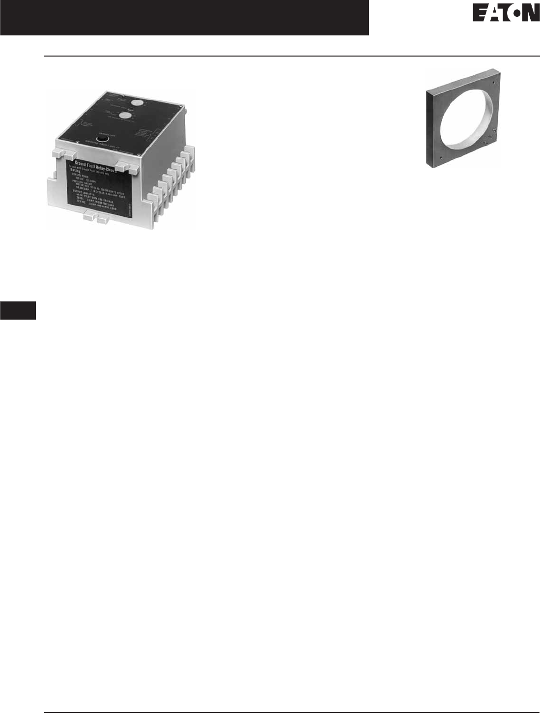
November 2008
12-214
For more information visit: www.eaton.com CA08101001E
Series C Molded Case Circuit Breakers
12
Add-On Ground Fault Protection
Product Description
Type GFR
GFR Relay
Product Description
Eaton’s Cutler-Hammer GFR ground
fault relays, current sensors, test
panels and accessory devices are UL
listed by Underwriters Laboratories
in accordance with their standard for
Ground Fault Sensing and Relaying
Equipment, UL 1053, under File
E48381.
Note: Suitable for either surface or semi-
flush mounting.
A Type GFR ground fault protection
system, when properly installed on a
grounded electrical system, will sense
phase-to-ground fault currents. When
the level of fault current is in excess
of the pre-selected current pickup and
time delay settings, the GFR relay will
initiate a trip action of a disconnect
device, which will open the faulted
circuit and clear the fault.
The GFR devices are UL Class I devices
designed to protect electrical equip-
ment against extensive damage from
arcing ground faults.
A basic Type GFR ground fault protec-
tion system consists of a ground fault
relay, a ground fault current sensor
and a disconnect device equipped with
a shunt trip device. This disconnect
device can be a molded case circuit
breaker, a power circuit breaker, a
bolted pressure switch or other fusible
disconnect device, suitable for applica-
tion with UL Class I Ground Fault
Sensing and Relaying equipment.
Note: Relays are also listed with CSA under
their file number 43357.
Typical Current Sensor
Sensor
■600 volt, 50/60 Hz maximum system
voltage.
Electrical Ratings
GFR Relay
■Ground fault detection ranges:
❑1 to 12, 5 to 60 or 100 to 1200
amperes
■Output contacts:
❑240 volt, 50/60 Hz: 3.0 amperes
❑120 volt, 50/60 Hz: 6.0 amperes
❑28 Vdc: 3.0 amperes
❑125 Vdc: .5 amperes
■Control power requirements:
❑
120 volt, 50/60 Hz or
125 Vdc
(optional)

CA08101001E For more information visit: www.eaton.com
12-215
Series C Molded Case Circuit Breakers
November 2008
12
Add-On Ground Fault Protection
Accessories
Options and Accessories
Options
Additional optional equipment can be
added to the protection system to meet
the requirements of the specifying
engineer, including:
■Ground fault test panel.
■Ground fault warning indicator relay.
■Ground fault indicating ammeter.
GFR relays are available with zone
selective interlocking circuitry to inter-
lock several relays within the same
system. This allows the relay which
detects a ground fault to instantly clear
the fault by tripping the disconnect
device. The relay simultaneously sends
a signal to relay units “upstream” from
the fault to time delay or to block their
operation completely. Current sensors
in various designs provide a range
of “window” sizes to accommodate
standard bus and cable arrangements.
Shunt trip attachments may be ordered
for field mounting in Eaton’s Cutler-
Hammer molded case circuit breakers,
or may be ordered factory installed in
the breaker.
Accessories
Test Panel (120 Vac)
Used to test the ground fault system,
to give an indication the relay has
tripped the breaker, and to reset the
relay after tripping. These functions
may be separately mounted pilot
devices.
Note: When a mechanically reset relay is
used with a test panel, both the relay and
test panel must be reset following either a
simulated ground fault test or actual ground
fault. Not UL listed.
Table 12-370. Optional Test Panel
Ground Fault Warning Indicator
This is an accessory item for use with
GFR relays with interlocking circuitry.
At approximately 30 – 50% of the relay
pickup setting, the indicator switches
separate 120 Vac control power to a
lamp or relay, (not included) to give an
indication of a ground fault. The indi-
cator is rated 110/120 Vac 50/60 Hz
for a maximum indicator load of
.5 amperes.
Table 12-371. Ground Fault Warning
Indicator
Control Test Catalog
Number
Price
U.S. $
120 Volt
50/60 Hz
120 Volt
50/60 Hz
GFRTP
Description Catalog
Number
Price
U.S. $
Manual Reset 1234C67G01
Self-Resetting 1234C67G02
Indicating Ammeter
The optional indicating ammeter
connects to the sensor terminals
through a momentary contact push-
button, and will indicate (in amperes)
any ground fault current flowing
through the sensor. Kit includes the
ammeter and pushbutton.
Note: Not UL listed.
Table 12-372. Ammeter Kit
Shunt Trip Attachments
Use 120 Vac shunt trips.
Faceplate
Recommended when these relays are
semi-flush mounted, to close the door
cutout opening.
Table 12-373. Face Plate
GFR System
Used with
Kit Catalog
Number
Price
U.S. $
1 – 12 Ampere
5 – 60 Ampere
100 – 1200 Ampere
752B820G01
752B820G02
752B820G03
Description Catalog
Number
Price
U.S. $
Faceplate 752B410G01
Discount Symbol . . . . . . . . . . . . . . . . . . . . . . . . . CB-2

November 2008
12-216
For more information visit: www.eaton.com CA08101001E
Series C Molded Case Circuit Breakers
12
Add-On Ground Fault Protection
Product Selection
Product Selection
Each installation requires:
■One relay unit (select trip ampere as required).
■One current sensor (select configuration required).
■One circuit breaker or disconnect device with shunt trip, or
a shunt trip attachment for mounting in existing breaker.
■Test panel (optional).
Table 12-374. GFR Relay
Suitable for either surface or semi-flush mounting.
Table 12-375. Current Sensor
One end removable for installation.
GFR Relay
Types
Ground Fault Pickup Amperes
1 – 12 5 – 60 100 – 1200
Catalog
Number
Price
U.S. $
Catalog
Number
Price
U.S. $
Catalog
Number
Price
U.S. $
For 120 Volt 50/60 Hz Control
Electrical Reset with Zone Interlocking
Electrical Reset without Zone Interlocking
Mechanical Reset with Zone Interlocking
Mechanical Reset without Zone Interlocking
GFR12EI
GFR12E
GFR12MI
GFR12M
GFR60EI
GFR60E
GFR60MI
GFR60M
GFR1200EI
GFR1200E
GFR1200MI
GFR1200M
For 120 Vdc Control
Electrical Reset with Zone Interlocking
Electrical Reset without Zone Interlocking
Mechanical Reset with Zone Interlocking
Mechanical Reset without Zone Interlocking
—
—
—
—
—
—
—
—
GFR1200EID
GFR1200ED
GFR1200MID
GFR1200MD
Window Size
in Inches (mm)
Catalog
Number
Price
U.S. $
Used with Relays Rated 1 – 12 Amperes
5.50 (139.7) I.D. 1283C45G01
Used with Relays Rated 5 – 60 Amperes
2.50 (63.5) I.D.
5.50 (139.7) I.D.
7.81 x 11.00 (198.4 x 279.4) Rect.
3.31 x 24.94 (84.1 x 760.5) Rect.
179C768G01
1256C13G01
1257C88G04
1257C92G03
Used with Relays Rated 100 – 1200 Amperes
2.50 (63.5) I.D.
5.50 (139.7) I.D.
8.25 (209.6). I.D.
7.81 x 11.00 (198.4 x 279.4) Rect.
9.94 x 16.94 (252.5 x 430.3) Rect.
9.94 x 23.94 (252.5 x 608.1) Rect.
15.94 x 19.94 (404.9 x 506.4) Rect.
3.31 x 24.94 (84.1 x 633.5) Rect.
6.75 x 29.64 (171.5 x 752.9) Rect.
179C768G02
1256C13G02
179C767G02
1257C88G03
1257C90G02
1257C91G02
1257C89G02
1257C92G04
1255C39G03
Discount Symbol . . . . . . . . . . . . . . . . . . . . . . . . CB-2
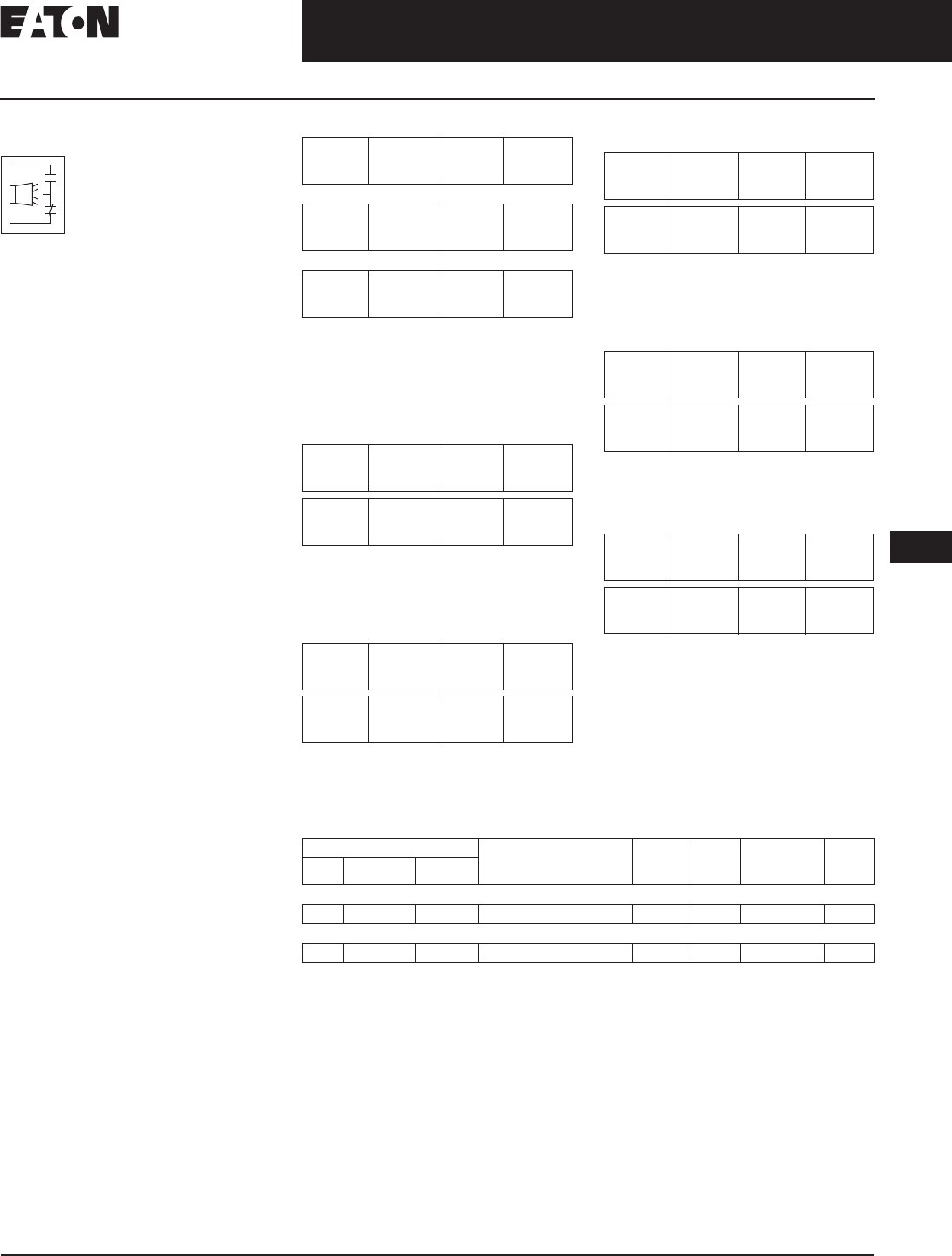
November 2008
CA08101001E For more information visit: www.eaton.com
12-217
Series C Molded Case Circuit Breakers
12
Internal Accessories
Alarm Switch
Alarm Switch
For remote indication of
automatic trip operation.
Does not function with
manual switching; how-
ever, it will operate when
either a shunt trip or under-
voltage release is operated. A “make”
contact closes and a “break” contact
opens when the alarm/lockout switch
operates. The switch automatically
resets when the circuit breaker is reset.
Make
Break
Table 12-376.
F-Frame Electrical Rating Data
Endurance: 6,000 electrical operations plus
4,000 mechanical operations.
Endurance: 6,000 electrical operations plus
2,000 mechanical operations.
Non-inductive load.
Inductive (L/R = 0.026).
Table 12-377.
J-Frame Electrical Rating Data
Endurance: 6,000 electrical operations plus
2,000 mechanical operations.
Pigtail wire size: 18 AWG (0.82 mm2).
Non-inductive load.
Table 12-378.
K-Frame Electrical Rating Data
Pigtail wire size: 18 AWG (0.82 mm2).
Endurance: 5,000 electrical operations plus
1,000 mechanical operations.
Non-inductive load.
Table 12-379. L- and M-Frames
Electrical Rating Data
Pigtail wire size: 18 AWG (0.82 mm2).
Endurance: 5,000 electrical operations plus
1,000 mechanical operations.
Non-inductive load.
Table 12-380. N-Frame Electrical Rating Data
Endurance: 3,000 electrical operations plus
1,000 mechanical operations.
Non-inductive load.
Table 12-381.
R-Frame Electrical Rating Data
Endurance: 500 electrical operations plus
2,500 mechanical operations.
Pigtail wire size: 18 AWG (0.82 mm2).
Leads are red, black and blue.
Non-inductive load.
Table 12-382. G-Frame Alarm Switch (RH Only)
F-Frame circuit breakers are factory sealed. Underwriters Laboratories, requires that internal
accessories be installed at the factory. Internal accessories are UL listed for factory installation
under E7819. Where local codes and standards permit and UL listing is not required, internal
accessories can be field installed. Accessory installation should be done before the circuit
breaker is mounted and connected.
Includes 24-inch (609.6 mm) external pigtail leads,18 AWG (16-.010).
A maximum of two internal accessories may be mounted in a 3-pole circuit breaker.
Suitable for mounting in right pole only of 2- or 3-pole breaker.
Maximum
Voltage
Frequency Maximum
Current
Amperes
Dielectric
Withstand
Voltage
Multi-Pole Circuit Breakers
600
125
250
50/60 Hz
dc
dc
6
0.50
0.25
2500
Single-Pole Circuit Breakers
125/250
28
28
50/60 Hz
dc
dc
6
3
5
2000
Maximum
Voltage
Frequency Maximum
Current
Amperes
Dielectric
Withstand
Voltage
600
125
250
50/60 Hz
dc
dc
6
0.50
0.25
2500
Maximum
Voltage
Frequency Maximum
Current
Amperes
Dielectric
Withstand
Voltage
600
125
250
50/60 Hz
dc
dc
6
0.50
0.25
2500
Maximum
Voltage
Frequency Maximum
Current
Amperes
Dielectric
Withstand
Voltage
600
125
250
50/60 Hz
dc
dc
6
0.50
0.25
2500
Maximum
Voltage
Frequency Maximum
Current
Amperes
Dielectric
Withstand
Voltage
600
125
250
50/60 Hz
dc
dc
6
0.50
0.25
2500
Maximum
Voltage
Frequency Maximum
Current
Amperes
Dielectric
Withstand
Voltage
600
125
250
50/60 Hz
dc
dc
6
0.50
0.25
2500
Electrical Ratings Contact
Arrangement
Factory
Suffix
Adder
U.S. $
Catalog
Number
Price
U.S. $
Volts Frequency Amperes
Alarm Switch
240 50/60 Hz 6 1 Make/1 Break B3 1288C75G03
Alarm Switch Auxiliary Switches Combination
240 50/60 Hz 6 1 Make/1 Break and 1A/1B B13 1288C76G09
Discount Symbol . . . . . . . . . . . . . . . . . . . . . . . . . CB-2

November 2008
12-218
For more information visit: www.eaton.com CA08101001E
Series C Molded Case Circuit Breakers
12
Internal Accessories
Alarm Switch
Table 12-383. F-Frame Alarm Switch
F-Frame circuit breakers are factory sealed. Underwriters Laboratories, requires that internal accessories be installed at the factory. Internal accessories
are UL listed for factory installation under E7819. Where local codes and standards permit and UL listing is not required, internal accessories can be
field installed. Accessory installation should be done before the circuit breaker is mounted and connected.
Not listed with Underwriters Laboratories, for field installation.
Standard pigtail lead exit location.
Standard mounting location.
Factory installation only. Leads exit load end of circuit breaker.
Table 12-384. F-Frame HMCP Alarm Switch
F-Frame circuit breakers are factory sealed. Underwriters Laboratories, requires that internal accessories be installed at the factory. Internal accessories
are UL listed for factory installation under E7819. Where local codes and standards permit and UL listing is not required, internal accessories can be
field installed. Accessory installation should be done before the circuit breaker is mounted and connected.
Not listed with Underwriters Laboratories, for field installation.
Standard pigtail lead exit location.
Standard mounting location.
Table 12-385. J-Frame and HMCP (J) Alarm Switch
Listed with Underwriters Laboratories, for field installation on interchangeable trip unit breakers under E64983.
Standard mounting location.
Standard mounting location — leads exit rear of breaker.
Standard pigtail lead exit location.
Number of
Contacts
(Make and
Break)
Mounting
Location
(Pole)
Factory Mounted Field Mounted
Connection Type and Location Field Installation Kits
18-Inch (457.2 mm) Pigtail Leads Terminal Block Pigtail Leads Terminal Block
Same Side Rear Opposite Side Same Side
Suffix
Number
Adder
U.S. $
Suffix
Number
Adder
U.S. $
Suffix
Number
Adder
U.S. $
Suffix
Number
Adder
U.S. $
Catalog
Number
Price
U.S. $
Catalog
Number
Price
U.S. $
1 Left
Right
B01
B05
B02
B06
B03
B07
B04
B08
A1L1LPK
A1L1RPK
A1L1LTK
A1L1RTK
2 Left
Right
B09
B12
B10
B13
—
—
B11
B14
A2L1LPK
A2L1RPK
A2L1LTK
A2L1RTK
1 (Make
Only)
Single-
Pole
B15 ———— —
Number of
Contacts
(Make and
Break)
Mounting
Location
(Pole)
Factory Mounted Field Mounted
Connection Type and Location Field Installation Kits
18-Inch (457.2 mm) Pigtail Leads Terminal Block Pigtail Leads Terminal Block
Same Side Rear Opposite Side Same Side
Suffix
Number
Adder
U.S. $
Suffix
Number
Adder
U.S. $
Suffix
Number
Adder
U.S. $
Suffix
Number
Adder
U.S. $
Catalog
Number
Price
U.S. $
Catalog
Number
Price
U.S. $
1 Left
Right
B01
B05
B02
B06
B03
B07
B04
B08
MA1L1LPK
MA1L1RPK
MA1L1LTK
MA1L1RTK
2 Left
Right
B09
B12
B10
B13
—
—
B11
B14
MA2L1LPK
MA2L1RPK
MA2L1LTK
MA2L1RTK
Number of
Contacts
(Make and
Break)
Mounting
Location
(Pole)
Factory Mounted Field Mounted
Connection Type and Location Field Installation Kits
18-Inch (457.2 mm) Pigtail Leads Terminal Block Pigtail Leads Terminal Block
Same Side Rear Opposite Side Same Side
Suffix
Number
Adder
U.S. $
Suffix
Number
Adder
U.S. $
Suffix
Number
Adder
U.S. $
Suffix
Number
Adder
U.S. $
Catalog
Number
Price
U.S. $
Catalog
Number
Price
U.S. $
1 Left
Right
B01
B05
B02
B06
B03
B07
B04
B08
A1L2LPK
A1L2RPK
A1L2LTK
A1L2RTK
Discount Symbol . . . . . . . . . . . . . . . . . . . . . . . . CB-2

November 2008
CA08101001E For more information visit: www.eaton.com
12-219
Series C Molded Case Circuit Breakers
12
Internal Accessories
Alarm Switch
Table 12-386. K-Frame and HMCP (K) Alarm Switch
Listed with Underwriters Laboratories, for field installation on interchangeable trip unit breakers under E64983.
Standard mounting location.
Standard mounting location — leads exit rear of breaker.
Breakers with K-Frame OPTIM 550 can only accept accessories in left pole.
Table 12-387. L-, HMCP (L) and (M) Frames and Alarm Switch
Listed with Underwriters Laboratories, for field installation on interchangeable trip unit breakers under E64983.
Standard mounting location.
Standard mounting location — leads exit rear of breaker.
Table 12-388. N-Frame and HMCP (N) Alarm Switch
Listed with Underwriters Laboratories for field installation under E64983.
Standard mounting location.
Standard mounting location — leads exit rear of breaker.
Table 12-389. R-Frame Alarm Switch (RH only)
Listed with Underwriters Laboratories for field installation under E64983.
A maximum of three ASL plug-in modules may be installed in a circuit breaker.
Number of
Sets of
Contacts
(1M and 1B)
Mounting
Location
(Pole)
Factory Mounted Field Mounted
Connection Type and Location Field Installation Kits
18-Inch (457.2 mm) Pigtail Leads Terminal Block Pigtail
Leads
Terminal
Block
Same Side Rear Opposite Side Same Side
Suffix
Number
Adder
U.S. $
Suffix
Number
Adder
U.S. $
Suffix
Number
Adder
U.S. $
Suffix
Number
Adder
U.S. $
Catalog
Number
Price
U.S. $
Catalog
Number
Price
U.S. $
1 Left
Right
B01
B05
B02
B06
B03
B07
B04
B08
A1L3LPK
A1L3RPK
A1L3LTK
A1L3RTK
2 Left
Right
B09
B12
B10
B13
—
—
B11
B14
A2L3LPK
A2L3RPK
A2L3LTK
A2L3RTK
Number of
Sets of
Contacts
(1M and 1B)
Mounting
Location
(Pole)
Factory Mounted Field Mounted
Connection Type and Location Field Installation Kits
18-Inch (457.2 mm) Pigtail Leads Terminal Block Pigtail
Leads
Terminal
Block
Same Side Rear Opposite Side Same Side
Suffix
Number
Adder
U.S. $
Suffix
Number
Adder
U.S. $
Suffix
Number
Adder
U.S. $
Suffix
Number
Adder
U.S. $
Catalog
Number
Price
U.S. $
Catalog
Number
Price
U.S. $
1 Left
Right
B01
B05
B02
B06
B03
B07
B04
B08
A1L4LPK
A1L4RPK
A1L4LTK
A1L4RTK
2 Left
Right
B09
B12
B10
B13
—
—
B11
B14
A2L4LPK
A2L4RPK
A2L4LTK
A2L4RTK
Number of
Sets of
Contacts
(Make and
Break)
Mounting
Location
(Pole)
Factory Mounted Field Mounted
Connection Type and Location Field Installation Kits
18-Inch (457.2 mm) Pigtail Leads Terminal Block Pigtail
Leads
Terminal
Block
Same Side Rear Opposite Side Same Side
Suffix
Number
Adder
U.S. $
Suffix
Number
Adder
U.S. $
Suffix
Number
Adder
U.S. $
Suffix
Number
Adder
U.S. $
Catalog
Number
Price
U.S. $
Catalog
Number
Price
U.S. $
1 Left
Right
B01
B05
B02
B06
B03
B07
B04
B08
A1L5LPK
A1L5RPK
A1L5LTK
A1L5RTK
2 Left
Right
B09
B12
B10
B13
—
—
B11
B14
A2L5LPK
A2L5RPK
A2L5LTK
A2L5RTK
Number of
Contacts
(Make and Break)
Factory Mounted Field Mounted
Connection Type and Location Field Installation Kits
18-Inch (457.2 mm) Pigtail Leads Pigtail Leads
Suffix
Number
Adder
U.S. $
Catalog
Number
Price
U.S. $
1B05 A1L6RPK
2B12 A2L6RPK
Discount Symbol . . . . . . . . . . . . . . . . . . . . . . . . . CB-2

November 2008
12-220
For more information visit: www.eaton.com CA08101001E
Series C Molded Case Circuit Breakers
12
Internal Accessories
Auxiliary Switch
Auxiliary Switch
The Auxiliary Switch provides circuit breaker con-
tact status information by monitoring the position
of the molded cross bar which contains the mov-
ing contact arms. The auxiliary switch is used for
remote indication and interlock system verifica-
tion, and consists of one or two SPDT switches
housed in a plug-in module. Each SPDT switch has one “a”
and one “b” contact. When the circuit breaker contacts are
open, the “a” contact is open and the “b” contact is closed.
Table 12-390. F-Frame Electrical Rating Data
Endurance: 6,000 electrical operations plus 4,000 mechanical operations.
Pigtail wire size: 18 AWG (0.82 mm2).
For use in electronic circuit of 100 micro amperes and 15 Vdc minimum.
Non-inductive load.
Table 12-391. J-Frame Electrical Rating Data
Endurance: 6,000 electrical operations plus 4,000 mechanical operations.
Pigtail wire size: 18 AWG (0.82 mm2).
Non-inductive load.
Table 12-392. K-Frame Electrical Rating Data
Endurance: 5,000 electrical operations plus 1,000 mechanical operations.
Pigtail wire size: 18 AWG (0.82 mm2).
Non-inductive load.
Table 12-393. L- and M-Frames Electrical Rating Data
Pigtail wire size: 18 AWG (0.82 mm2).
Non-inductive load.
Table 12-394. N-Frame Electrical Rating Data
Endurance: 3,000 electrical operations plus 1,000 mechanical operations.
Pigtail wire size: 18 AWG (0.82 mm2).
Non-inductive load.
Table 12-395. R-Frame Electrical Rating Data
Endurance: 500 electrical operations plus 2,500 mechanical operations.
Pigtail wire size: 18 AWG (0.82 mm2). Leads are red, black and blue.
Non-inductive load.
Table 12-396. G-Frame Auxiliary Switch (RH only)
Includes 24-inch external pigtail leads, 18 AWG (16-.010).
A maximum of two internal accessories may be mounted in a 3-pole circuit breaker. Suitable for mounting in right pole only of 2- or 3-pole breaker.
Maximum
Voltage
Frequency Maximum
Current
Amperes
Dielectric
Withstand
Voltage
125
600
125
250
50/60 Hz
50/60 Hz
dc
dc
1
6
0.50
0.25
2500
Maximum
Voltage
Frequency Maximum
Current
Amperes
Dielectric
Withstand
Voltage
600
125
250
50/60 Hz
dc
dc
6
0.50
0.25
2500
a
b
Maximum
Voltage
Frequency Maximum
Current
Amperes
Dielectric
Withstand
Voltage
600
125
250
50/60 Hz
dc
dc
6
0.50
0.25
2500
Maximum
Voltage
Frequency Maximum
Current
Amperes
Dielectric
Withstand
Voltage
600
125
250
50/60 Hz
dc
dc
6
0.50
0.25
2500
Maximum
Voltage
Frequency Maximum
Current
Amperes
Dielectric
Withstand
Voltage
600
125
250
50/60 Hz
dc
dc
6
0.50
0.25
2500
Maximum
Voltage
Frequency Maximum
Current Amperes
600
125
250
50/60 Hz
dc
dc
6
0.50
0.25
Electrical Ratings Contact
Arrangement
Factory
Suffix
Adder
U.S. $
Catalog
Number
Price
U.S. $
Volts Frequency Amperes
240
240
50/60 Hz
50/60 Hz
6
6
1a/1b
2a/2b
A3
A6
.1288C74G03
1288C73G03
Discount Symbol . . . . . . . . . . . . . . . . . . . . . . . . . CB-2

November 2008
CA08101001E For more information visit: www.eaton.com
12-221
Series C Molded Case Circuit Breakers
12
Internal Accessories
Auxiliary Switch
Table 12-397. F-Frame and HMCP (F) Auxiliary Switch
Standard pigtail lead exit location.
Not listed with Underwriters Laboratories, for field installation.
Pigtail wire size: 18 AWG (0.82 mm2).
Not for use on F-Frame with electronic trip unit.
125 volts (Max.), 50/60 Hz switch for use in electronic circuit of 100 micro amperes and 15 Vdc minimum.
Not for use on 4-pole circuit breakers.
Table 12-398. F-Frame with Electronic Trip Unit Auxiliary Switch
Only for use on 3-pole F-Frame breakers with electronic trip unit.
Not listed with Underwriters Laboratories, for field installation.
Table 12-399. J-Frame and HMCP (J) Auxiliary Switch
Listed with Underwriters Laboratories for field installation or interchangeable trip unit breakers under E64983.
Standard mounting location — leads exit rear of breaker.
Not for use on 4-pole circuit breakers.
Table 12-400. K-Frame and HMCP (K) Auxiliary Switch
Listed with Underwriters Laboratories for field installation under E64983.
Standard mounting location — leads exit rear of breaker.
Breakers with K-Frame OPTIM 550 can only accept accessories in left pole.
Not for use on 4-pole circuit breaker.
Discount Symbol . . . . . . . . . . . . . . . . . . . . . . . . . CB-2
Number of
Contacts
A and B
Mounting
Location
(Pole)
Factory Mounted Field Mounted
Connection Type and Location Field Installation Kits
18-Inch (457.2 mm) Pigtail Leads Terminal Block Pigtail Leads Terminal Block
Same Side Rear Opposite Side Same Side
Suffix
Number
Adder
U.S. $
Suffix
Number
Adder
U.S. $
Suffix
Number
Adder
U.S. $
Suffix
Number
Adder
U.S. $
Catalog
Number
Price
U.S. $
Catalog
Number
Price
U.S. $
1 Left
Right or
Neutral
A01
A15
A05
A18
A02
A16
A06
A19
A03
A17
A07
A20
A04
—
A08
—
A1X1PK
E1X1PK
A1X1PK
—
A1X1LTK
—
A1X1RTK
—
2 Left
Right or
Neutral
A09
A21
A12
A23
A10
A22
A13
A24
—
—
—
—
A11
—
A14
—
A2X1LPK
E2X1LPK
A2X1RPK
E2X1RPK
A2X1LTK
—
A2X1RTK
—
Number of
Contacts
A and B
Mounting
Location
(Pole)
Factory Mounted Field Mounted
Connection Type and Location Field Installation Kits
18-Inch (457.2 mm) Pigtail Leads Terminal Block Pigtail Leads Terminal Block
Same Side Rear Opposite Side Same Side
Suffix
Number
Adder
U.S. $
Suffix
Number
Adder
U.S. $
Suffix
Number
Adder
U.S. $
Suffix
Number
Adder
U.S. $
Catalog
Number
Price
U.S. $
Catalog
Number
Price
U.S. $
1 Right A30 A31 A32 — A1X1RPKFDE —
Number of
Sets of
Contacts
A and B
Mounting
Location
(Pole)
Factory Mounted Field Mounted
Connection Type and Location Field Installation Kits
18-Inch (457.2 mm) Pigtail Leads Terminal Block Pigtail Leads Terminal Block
Same Side Rear Opposite Side Same Side
Suffix
Number
Adder
U.S. $
Suffix
Number
Adder
U.S. $
Suffix
Number
Adder
U.S. $
Suffix
Number
Adder
U.S. $
Catalog
Number
Price
U.S. $
Catalog
Number
Price
U.S. $
1 Left
Right
A01
A05
A02
A06
A03
A07
A04
A08
A1X2PK
A1X2PK
A1X2LTK
A1X2RTK
2 Left
Right
A09
A12
A10
A13
—
—
A11
A14
A2X2PK
A2X2PK
A2X2LTK
A2X2RTK
Number of
Sets of
Contacts
A and B
Mounting
Location
(Pole)
Factory Mounted Field Mounted
Connection Type and Location Field Installation Kits
18-Inch (457.2 mm) Pigtail Leads Terminal Block Pigtail Leads Terminal Block
Same Side Rear Opposite Side Same Side
Suffix
Number
Adder
U.S. $
Suffix
Number
Adder
U.S. $
Suffix
Number
Adder
U.S. $
Suffix
Number
Adder
U.S. $
Catalog
Number
Price
U.S. $
Catalog
Number
Price
U.S. $
1 Left
Right
A01
A05
A02
A06
A03
A07
A04
A08
A1X3PK
A1X3PK
A1X3LTK
A1X3RTK
2 Left
Right
A09
A12
A10
A13
—
—
A11
A14
A2X3PK
A2X3PK
A2X3LTK
A2X3RTK
3 Left
Right
A18
A17
—
—
—
—
A15
A16
A3X3LPK
A3X3RPK
A3X3LTK
A3X3RTK

November 2008
12-222
For more information visit: www.eaton.com CA08101001E
Series C Molded Case Circuit Breakers
12
Internal Accessories
Auxiliary Switch
Table 12-401. L-, HMCP (L) and (M) Frames and Auxiliary Switch
Listed with Underwriters Laboratories for field installation under E64983.
Standard mounting location — leads exit rear of breaker.
Not for use on 4-pole circuit breaker.
Table 12-402. N-Frame and HMCP (N) Auxiliary Switch
Listed with Underwriters Laboratories for field installation under E64983.
Standard mounting location — leads exit rear of breaker.
Not for use on 4-pole circuit breaker.
Table 12-403. R-Frame Auxiliary Switch (RH Only)
Listed with Underwriters Laboratories for field installation under E64983.
A maximum of two auxiliary switches (any combination of 2a/2b or 4a/4b plug-in modules
may be installed in a circuit breaker.
Number of
Sets of
Contacts
A and B
Mounting
Location
(Pole)
Factory Mounted Field Mounted
Connection Type and Location Field Installation Kits
18-Inch (457.2 mm) Pigtail Leads Terminal Block Pigtail Leads Terminal Block
Same Side Rear Opposite Side Same Side
Suffix
Number
Adder
U.S. $
Suffix
Number
Adder
U.S. $
Suffix
Number
Adder
U.S. $
Suffix
Number
Adder
U.S. $
Catalog
Number
Price
U.S. $
Catalog
Number
Price
U.S. $
1 Left
Right
A01
A05
A02
A06
A03
A07
A04
A08
A1X4PK
A1X4PK
A1X4LTK
A1X4RTK
2 Left
Right
A09
A12
A10
A13
—
—
A11
A14
A2X4PK
A2X4PK
A2X4LTK
A2X4RTK
3 Left
Right
A18
A17
—
—
—
—
A15
A16
A3X4PK
A3X4PK
A3X4LTK
A3X4RTK
Number of
Sets of
Contacts
A and B
Mounting
Location
(Pole)
Factory Mounted Field Mounted
Connection Type and Location Field Installation Kits
18-Inch (457.2 mm) Pigtail Leads Terminal Block Pigtail Leads Terminal Block
Same Side Rear Opposite Side Same Side
Suffix
Number
Adder
U.S. $
Suffix
Number
Adder
U.S. $
Suffix
Number
Adder
U.S. $
Suffix
Number
Adder
U.S. $
Catalog
Number
Price
U.S. $
Catalog
Number
Price
U.S. $
1 Left
Right
A01
A05
A02
A06
A03
A07
A04
A08
A1X5PK
A1X5PK
A1X5LTK
A1X5RTK
2 Left
Right
A09
A12
A10
A13
—
—
A11
A14
A2X5PK
A2X5PK
A2X5LTK
A2X5RTK
3 Left
Right
A18
A17
—
—
—
—
A15
A16
A3X5LPK
A3X5RPK
A3X5LTK
A3X5RTK
Number of Contacts
A and B
Factory Mounted Field Mounted
Connection Type and Location Field Installation Kits
18-Inch (457.2 mm) Pigtail Leads Pigtail Leads
Suffix
Number
Adder
U.S. $
Catalog
Number
Price
U.S.
2A12 A2X6RPK
4A19 A4X6RPK
Discount Symbol . . . . . . . . . . . . . . . . . . . . . . . . . CB-2

November 2008
CA08101001E For more information visit: www.eaton.com
12-223
Series C Molded Case Circuit Breakers
12
Internal Accessories
Auxiliary Switch and Alarm Switch Combination
Auxiliary Switch and Alarm Switch Combination
Each Catalog Number listed in Tables 12-402 –
12-412 includes one Auxiliary Switch and one
Alarm Switch. In an auxiliary switch ASL switch
combination, the auxiliary switch is always
mounted on the side of the plug-in module next
to the center pole of the circuit breaker.
Table 12-404. F-Frame Electrical Rating Data
Endurance: 6,000 electrical operations plus 4,000 mechanical operations.
Pigtail wire size: 18 AWG (0.82 mm2).
Non-inductive load.
Table 12-405. J-Frame Electrical Rating Data
Endurance: 6,000 electrical operations plus 2,000 mechanical operations.
Pigtail wire size: 18 AWG (0.82 mm2).
Non-inductive load.
Table 12-406. K-Frame Electrical Rating Data
Endurance: 5,000 electrical operations plus 1,000 mechanical operations.
Pigtail wire size: 18 AWG (0.82 mm2).
Non-inductive load.
Table 12-407. L- and M-Frames Electrical Rating Data
Endurance: 5,000 electrical operations plus 1,000 mechanical operations.
Pigtail wire size: 18 AWG (0.82 mm2).
Non-inductive load.
Table 12-408. N-Frame Electrical Rating Data
Endurance: 3,000 electrical operations plus 1,000 mechanical operations.
Pigtail wire size: 18 AWG (0.82 mm2).
Non-inductive load.
Maximum
Voltage
Frequency Maximum
Current
Amperes
Dielectric
Withstand
Voltage
600
125
250
50/60 Hz
dc
dc
6
0.50
0.25
2500
2200
2200
Maximum
Voltage
Frequency Maximum
Current
Amperes
Dielectric
Withstand
Voltage
600
125
250
50/60 Hz
dc
dc
6
0.50
0.25
2500
Maximum
Voltage
Frequency Maximum
Current
Amperes
Dielectric
Withstand
Voltage
600
125
250
50/60 Hz
dc
dc
6
0.50
0.25
2500
a
b
Maximum
Voltage
Frequency Maximum
Current
Amperes
Dielectric
Withstand
Voltage
600
125
250
50/60 Hz
dc
dc
6
0.50
0.25
2500
Maximum
Voltage
Frequency Maximum
Current
Amperes
Dielectric
Withstand
Voltage
600
125
250
50/60 Hz
dc
dc
6
0.50
0.25
2500

November 2008
12-224
For more information visit: www.eaton.com CA08101001E
Series G Molded Case Circuit Breakers
12
Internal Accessories
Auxiliary Switch and Alarm Switch Combination
Table 12-409. F-Frame Auxiliary Switch and Alarm Switch Combination
Not listed with Underwriters Laboratories for field installation.
Standard mounting location.
Not for use on 4-pole circuit breakers
Table 12-410. F-Frame HMCP Auxiliary Switch and Alarm Switch Combination
Not listed with Underwriters Laboratories for field installation.
Standard mounting location.
Not for use on 4-pole circuit breakers
Table 12-411. J-Frame and HMCP (J) Auxiliary Switch and Alarm Switch Combination
Listed with Underwriters Laboratories for field installation of interchangeable trip unit breakers under E64983.
Standard mounting location — leads exit rear of breaker.
Not for use on 4-pole circuit breakers.
Table 12-412. K-Frame and HMCP (K) Auxiliary Switch and Alarm Switch Combination
Listed with Underwriters Laboratories for field installation of interchangeable trip unit breakers under E64983.
Standard mounting location — leads exit rear of breaker.
Breakers with K-Frame OPTIM 550 can only accept accessories in left pole.
Will not install on OPTIM Trip (RH).
Mounting
Location
(Pole)
Factory Mounted Field Mounted
Connection Type and Location Field Installation Kits
18-Inch (457 mm) Pigtail Leads Terminal Block Pigtail Leads Terminal Block
Same Side Rear Same Side
Suffix
Number
Adder
U.S. $
Suffix
Number
Adder
U.S. $
Suffix
Number
Adder
U.S. $
Catalog
Number
Price
U.S. $
Catalog
Number
Price
U.S. $
Left
Right
C01
C04
C02
C05
C03
C06
AAL1LPK
AAL1RPK
AAL1LTK
AAL1RTK
Mounting
Location
(Pole)
Factory Mounted Field Mounted
Connection Type and Location Field Installation Kits
18-Inch (457 mm) Pigtail Leads Terminal Block Pigtail Leads Terminal Block
Same Side Rear Same Side
Suffix
Number
Adder
U.S. $
Suffix
Number
Adder
U.S. $
Suffix
Number
Adder
U.S. $
Catalog
Number
Price
U.S. $
Catalog
Number
Price
U.S. $
Left
Right
C01
C04
C02
C05
C03
C06
MAAL1LPK
MAAL1RPK
MAAL1LTK
MAAL1RPK
Number of
Sets of
Contacts
(1A and 1B)
(1M – 1B)
Mounting
Location
(Pole)
Factory Mounted Field Mounted
Connection Type and Location Field Installation Kits
18-Inch (457 mm) Pigtail Leads Terminal Block Pigtail Leads Terminal Block
Same Side Rear Opposite Side Same Side
Suffix
Number
Adder
U.S. $
Suffix
Number
Adder
U.S. $
Suffix
Number
Adder
U.S. $
Suffix
Number
Adder
U.S. $
Catalog
Number
Price
U.S. $
Catalog
Number
Price
U.S. $
1 Left
Right
C01
C04
C02
C05
—
—
C03
C06
AAL2LPK
AAL2RPK
AAL2LTK
AAL2RTK
Number of
Sets of
Contacts
(1A and 1B)
(1M – 1B)
Mounting
Location
(Pole)
Factory Mounted Field Mounted
Connection Type and Location Field Installation Kits
18-Inch (457 mm) Pigtail Leads Terminal Block Pigtail Leads Terminal Block
Same Side Rear Opposite Side Same Side
Suffix
Number
Adder
U.S. $
Suffix
Number
Adder
U.S. $
Suffix
Number
Adder
U.S. $
Suffix
Number
Adder
U.S. $
Catalog
Number
Price
U.S. $
Catalog
Number
Price
U.S. $
1 Left
Right
C01
C04
C02
C05
—
—
C03
C06
AAL3LPK
AAL3RPK
AAL3LTK
AAL3RTK
Discount Symbol . . . . . . . . . . . . . . . . . . . . . . . . . CB-2

November 2008
CA08101001E For more information visit: www.eaton.com
12-225
Series G Molded Case Circuit Breakers
12
Internal Accessories
Auxiliary Switch and Alarm Switch Combination
Table 12-413. L-, HMCP (L) and (M) Frames and Auxiliary Switch and Alarm Switch Combination
Listed with Underwriters Laboratories for field installation under E64983.
Standard mounting location — leads exit rear of breaker.
Not for use on 4-pole circuit breaker.
Table 12-414. N-Frame and HMCP (N) Auxiliary Switch and Alarm Switch Combination
Listed with Underwriters Laboratories for field installation under E64983.
Standard mounting location — leads exit rear of breaker.
Not for use on 4-pole circuit breaker.
Number of
Sets of
Contacts
Mounting
Location
(Pole)
Factory Mounted Field Mounted
Connection Type and Location Field Installation Kits
18-Inch (457.2 mm) Pigtail Leads Terminal Block Pigtail Leads Terminal Block
Same Side Rear Opposite Side Same Side
Suffix
Number
Adder
U.S. $
Suffix
Number
Adder
U.S. $
Suffix
Number
Adder
U.S. $
Suffix
Number
Adder
U.S. $
Catalog
Number
Price
U.S. $
Catalog
Number
Price
U.S. $
1A, 1B and
1 Make/1 Break
Left
Right
C01
C04
C02
C05
—
—
C03
C06
AA114LPK
AA114RPK
AA114LTK
AA114RTK
2A, 2B and
1 Make/1 Break
Left
Right
C07
C10
C08
C11
—
—
C12
C13
AA214LPK
AA214RPK
AA214LTK
AA214RTK
3A, 3B and
1 Make/1 Break
Left
Right
C14
C15
—
—
—
—
—
—
AA314LPK
AA314RPK
—
—
Number of
Sets of
Contacts
Mounting
Location
(Pole)
Factory Mounted Field Mounted
Connection Type and Location Field Installation Kits
18-Inch (457.2 mm) Pigtail Leads Terminal Block Pigtail Leads Terminal Block
Same Side Rear Opposite Side Same Side
Suffix
Number
Adder
U.S. $
Suffix
Number
Adder
U.S. $
Suffix
Number
Adder
U.S. $
Suffix
Number
Adder
U.S. $
Catalog
Number
Price
U.S. $
Catalog
Number
Price
U.S. $
1A, 1B and
1 Make/1 Break
Left
Right
C01
C04
C02
C05
—
—
C03
C06
AA115LPK
AA115RPK
AA115LTK
AA115RTK
2A, 2B and
1 Make/1 Break
Left
Right
C07
C10
C08
C11
—
—
C12
C13
AA215LPK
AA215RPK
AA215LTK
AA215RTK
Discount Symbol . . . . . . . . . . . . . . . . . . . . . . . . . CB-2

November 2008
12-226
For more information visit: www.eaton.com CA08101001E
Series C Molded Case Circuit Breakers
12
Internal Accessories
Shunt Trip
Shunt Trip
The Shunt Trip provides remote controlled
tripping of the circuit breaker. The shunt trip
consists of an intermittent rated solenoid with a
tripping plunger and a cutoff switch assembled
to a plug-in module. When required for ground
fault protection applications, certain ac rated
shunt trips, as noted in the Electrical Rating Table, are
suitable for operation at 55 percent of rated voltage.
Select shunt trip catalog number for the voltage within the
indicated voltage range. Shunt trip coils are designed to
be applied at specific ac or dc voltages within the voltage
range shown. Electrical ratings are also shown on applicable
circuit breaker accessory nameplates.
Table 12-415. F-Frame Electrical Rating Data
Average unlatching time: 6 milliseconds.
Average circuit breaker contact total opening time: 18 milliseconds.
Endurance: 6,000 electrical operations plus 4,000 mechanical operations.
Table 12-416. J-Frame Electrical Rating Data
Average unlatching time: 6 milliseconds.
Average circuit breaker contact total opening time: 18 milliseconds.
Endurance: 6,000 electrical operations plus 2,000 mechanical operations.
Supply voltages suitable for use with Class 1 GFP devices. Marking
label included with accessory kits.
Table 12-417. K-Frame Electrical Rating Data
Approximate unlatching time: 6 milliseconds.
Approximate total circuit breaker contact opening time: 8 milliseconds.
Endurance: 5,000 electrical operations plus 1,000 mechanical
operations.
Supply voltages suitable for use with Class 1 GFP devices. Marking
label included with accessory kits.
Table 12-418. L- and M-Frame Electrical Rating Data
Approximate unlatching time: 6 milliseconds.
Approximate total circuit breaker contact opening time: 18 milliseconds.
Endurance: 5,000 electrical operations plus 1,000 mechanical operations.
Supply voltages suitable for use with Class 1 GFP devices. Marking
label included with accessory kits.
ST
a
50/60 Hz dc
Supply
Voltage
Minimum
Operating
Voltage
VA Supply
Voltage
Minimum
Operating
Voltage
VA
12
24
6.75 75
300
12
24
9 100
400
48
60
36 92
140
48
60
36 100
160
110
120
127
208
220
240
156 480
570
640
180
200
240
110
120
125
77 55
66
71
380
415
440
300 610
130
330
127
220
250
—
—
72
110
140
480
525
550
600
300 380
450
530
590
—
—
—
—
—
—
—
—
—
—
—
—
50/60 Hz dc
Supply
Voltage
Minimum
Operating
Voltage
VA Supply
Voltage
Minimum
Operating
Voltage
VA
12
24
9 31
173
12
24
8.4 50
247
48
60
36 686
1014
48
60
33.6 1094
1698
110
120
127
208
220
240
60.5 66
84
102
354
396
432
110
120
125
—
—
—
77
—
—
112
138
150
—
—
—
380
400
415
440
285 180
200
240
610
110
120
125
127
154 40
58
—
—
480
525
550
600
360 34
42
50
60
—
—
—
—
—
—
—
—
—
—
—
—
50/60 Hz dc
Supply
Voltage
Minimum
Operating
Voltage
VA Supply
Voltage
Minimum
Operating
Voltage
VA
12
24
9 45
200
12
24
8.4 35
170
48
60
830
1280
48
60
710
1105
110
120
127
208
220
240
60 100
120
140
420
470
550
110
120
125
—
—
—
77
—
—
—
110
130
140
—
—
—
380
400
415
440
285 95
108
120
136
220
250
—
—
154 41
54
—
—
480
525
550
600
360 40
50
50
70
—
—
—
—
—
—
—
—
—
—
—
—
50/60 Hz dc
Supply
Voltage
Minimum
Operating
Voltage
VA Supply
Voltage
Minimum
Operating
Voltage
VA
12
24
9 45
200
12
24
9 35
170
48
60
34 830
1280
48
60
34 710
1105
110
120
127
208
220
240
60 100
120
140
420
470
550
110
120
125
—
—
—
77
—
—
110
130
140
—
—
—
380
400
415
440
266 95
108
120
136
220
250
—
—
154
—
—
—
41
54
—
—
480
525
550
600
336 40
50
50
70
—
—
—
—
—
—
—
—
—
—
—
—

CA08101001E For more information visit: www.eaton.com
12-227
Series C Molded Case Circuit Breakers
November 2008
12
Internal Accessories
Shunt Trip
Table 12-419. N-Frame Electrical Rating Data
Approximate unlatching time: 6 milliseconds.
Approximate total circuit breaker contact opening time: 18 milliseconds.
Endurance: 3,000 electrical operations plus 1,000 mechanical operations.
Supply voltages suitable for use with Class 1 GFP devices. Marking label included with
accessory kits.
Table 12-420. R-Frame Electrical Rating Data
Approximate unlatching time of 6 milliseconds.
Average circuit breaker contact total opening time approximately 62 milliseconds,
at rated voltage.
Endurance: 500 electrical operations and 2,500 mechanical operations.
Shunt trip can be operated up to a maximum of six times per minute.
Maximum operating voltage — 110% of maximum voltage range rating.
Pigtail wire size: 18 AWG (0.82 mm2). Leads are yellow and white.
50/60 Hz dc
Supply
Voltage
Minimum
Operating
Voltage
VA Supply
Voltage
Minimum
Operating
Voltage
VA
24 16.8 200 24 16.8 170
48
60
33.6 830
1280
48
60
33.6 710
1150
110
120
127
208
220
240
60 100
120
140
420
470
550
110
120
125
—
—
—
77
—
—
—
110
130
140
—
—
—
380
400
415
440
266 95
108
120
136
220
250
—
—
154
—
—
—
41
54
—
—
480
525
550
600
336 40
50
50
70
—
—
—
—
—
—
—
—
—
—
—
—
Suffix
Number
Application Ratings Electrical Operating Ratings
Voltage
(V)
Frequency
(Hz)
Supply
Voltage
(V)
Minimum
Operating
Voltage (V)
Ip (A) Irms
at
0.250s
(A)
Irms
at
0.033s
(A)
VA One
Minute
Dielectric
Withstand
Voltage (V)
03/03K 24 50/60 24 16.8 36.1 — 25.5 612 1050
24 dc 24 16.8 36.1 16.5 — 396 1050
05/05K 48 – 60 50/60 48
60
34.0 13.1
17.2
— 9.2
12.2
450
740
1120
11/11K 110 – 240 50/60 110
120
127
208
220
240
60.5 4.2
4.5
4.6
7.9
8.5
8.7
— 3.0
3.2
3.3
5.6
6.0
6.1
330
390
430
1170
1370
1470
1480
14/14K 380 – 440 50/60 380
415
440
266.0 4.5
5.0
5.3
— 3.2
3.6
3.7
1220
1500
1640
1880
220 – 250 dc 220
250
154.0 — 2.4
2.7
— 530
680
1500
18/18K 480 – 600 50/60 480
525
550
600
336.0 0.6
0.7
0.7
0.8
— 0.4
0.5
0.5
0.6
200
270
280
360
2200
23/23K 48 – 60 dc 48
60
34.0 — 9.8
11.6
— 470
700
1120
26/26K 110 – 125 dc 110
120
125
77.0 — 3.3
3.6
3.8
— 370
440
480
1250

November 2008
12-228
For more information visit: www.eaton.com CA08101001E
Series C Molded Case Circuit Breakers
12
Internal Accessories
Shunt Trip
Table 12-421. G-Frame Shunt Trip (LH 3-Pole only)
Note: G-Frame circuit breakers are factory sealed. Underwriters Laboratories requires that internal accessories be installed at the factory.
Note: Internal accessories are UL listed for factory installation under E7819.
Note: Where local codes and standards permit and UL listing is not required, internal accessories can be field installed. Accessory installation
should be done before the circuit breaker is mounted and connected.
Table 12-422. F-Frame and HMCP (F) Shunt Trip
Not listed with Underwriters Laboratories, for field installation.
Pigtail wire size: 18 AWG (0.82 mm2).
Standard pigtail lead exit location.
120 Vac marked suitable for ground fault protection devices.
Standard mounting location.
Not for use on 4-pole circuit breakers
Electrical Ratings Suffix
Number
Adder
U.S. $
Catalog
Number
Price
U.S. $
Volts Frequency Amperes
120
240
12
24
24
50/60 Hz
50/60 Hz
dc
dc
60 Hz
1.1
2.1
2.8
5.7
—
S1
S2
S3
S4
S7
1373D62G01
1373D62G02
1373D62G15
1373D62G16
1373D62G20
Voltage Rating
(ac Frequency = 50/60 Hz)
Factory Mounted Field Mounted
Connection Type and Location Field Installation Kits
18-Inch (457.2 mm) Pigtail Leads Terminal Block Pigtail Leads Terminal Block
Same Side Rear Opposite Side Same Side
Suffix
Number
Adder
U.S. $
Suffix
Number
Adder
U.S. $
Suffix
Number
Adder
U.S. $
Suffix
Number
Adder
U.S. $
Catalog
Number
Price
U.S. $
Catalog
Number
Price
U.S. $
Left-Pole Mounting ac/dc Ratings
12 – 24 Vac or dc
48 – 127 Vac or 48 – 60 Vdc
208 – 380 Vac or 110 – 127 Vdc
415 – 600 Vac or 220 – 250 Vdc
S01
S05
S09
S13
S02
S06
S10
S14
S03
S07
S11
S15
S04
S08
S12
S16
SNT1LP03K
SNT1LP08K
SNT1LP12K
SNT1LP18K
SNT1LT03K
SNT1LT08K
SNT1LT12K
SNT1LT18K
Right- or Neutral-Pole Mounting ac/dc Ratings
12 – 24 Vac or dc
48 – 127 Vac or 48 – 60 Vdc
208 – 380 Vac or 110 – 127 Vdc
415 – 600 Vac or 220 – 250 Vdc
S17
S21
S25
S29
S18
S22
S26
S30
S19
S23
S27
S31
S20
S24
S28
S32
SNT1RP03K
SNT1RP08K
SNT1RP12K
SNT1RP18K
SNT1RT03K
SNT1RT08K
SNT1RT12K
SNT1RT18K
Discount Symbol . . . . . . . . . . . . . . . . . . . . . . . . CB-2

November 2008
CA08101001E For more information visit: www.eaton.com
12-229
Series C Molded Case Circuit Breakers
12
Internal Accessories
Shunt Trip
Table 12-423. J-Frame and HMCP (J) Shunt Trip
Listed with Underwriters Laboratories for field installation under E64983.
Standard mounting location — leads exit rear of breaker.
Suitable for use with Class 1 ground fault sensing element.
Not for use on 4-pole circuit breakers.
Table 12-424. K-Frame and HMCP (K) Shunt Trip
Listed with Underwriters Laboratories, for field installation under E64983.
Standard mounting location — leads exit rear of breaker.
Suitable for use with Class 1 ground fault sensing element.
For use with KT (thermal-magnetic) trip units only.
Breakers with K-Frame OPTIM 550 can only accept accessories in left pole.
Not for use on 4-pole circuit breaker.
Voltage Rating
(ac Frequency = 50/60 Hz)
Factory Mounted Field Mounted
Connection Type and Location Field Installation Kits
18-Inch (457.2 mm) Pigtail Leads Terminal Block Pigtail Leads Terminal Block
Same Side Rear Opposite Side Same Side
Suffix
Number
Adder
U.S. $
Suffix
Number
Adder
U.S. $
Suffix
Number
Adder
U.S. $
Suffix
Number
Adder
U.S. $
Catalog
Number
Price
U.S. $
Catalog
Number
Price
U.S. $
Left-Pole Mounting ac/dc Ratings
12 – 24 Vac or dc
48 – 60 Vac or dc
110 – 240 Vac or 110 – 125 Vdc
380 – 440 Vac or 220 – 250 Vdc
480 – 600 Vac
S41
S49
S09
S13
S17
S42
S50
S10
S14
S18
S43
S51
S11
S15
S19
S44
S52
S12
S16
S20
SNT2P04K
SNT2P06K
SNT2P11K
SNT2P14K
SNT2P18K
SNT2T04K
SNT2T06K
SNT2T11K
SNT2T14K
SNT2T18K
Right- or Neutral-Pole Mounting ac/dc Ratings
12 – 24 Vac or dc
48 – 60 Vac or dc
110 – 240 Vac or 110 – 125 Vdc
380 – 440 Vac or 220 – 250 Vdc
480 – 600 Vac
S45
S53
S29
S33
S37
S46
S54
S30
S34
S38
S47
S55
S31
S35
S39
S48
S56
S32
S36
S40
SNT2P04K
SNT2P06K
SNT2P11K
SNT2P14K
SNT2P18K
SNT2T04K
SNT2T06K
SNT2T11K
SNT2T14K
SNT2T18K
Voltage Rating
(ac Frequency = 50/60 Hz)
Factory Mounted Field Mounted
Connection Type and Location Field Installation Kits
18-Inch (457.2 mm) Pigtail Leads Terminal Block Pigtail Leads Terminal Block
Same Side Rear Opposite Side Same Side
Suffix
Number
Adder
U.S. $
Suffix
Number
Adder
U.S. $
Suffix
Number
Adder
U.S. $
Suffix
Number
Adder
U.S. $
Catalog
Number
Price
U.S. $
Catalog
Number
Price
U.S. $
Left-Pole Mounting ac/dc Ratings
12 – 24 Vac or dc
48 – 60 Vac or dc
110 – 240 Vac or 110 – 125 Vdc
380 – 440 Vac or 220 – 250 Vdc
480 – 600 Vac
S41
S49
S09
S13
S17
S42
S50
S10
S14
S18
S43
S51
S11
S15
S19
S44
S52
S12
S16
S20
SNT3P04K
SNT3P06K
SNT3P11K
SNT3P14K
SNT3P18K
SNT3T04K
SNT3T06K
SNT3T11K
SNT3T14K
SNT3T18K
Right- or Neutral-Pole Mounting ac/dc Ratings
12 – 24 Vac or dc
48 – 60 Vac or dc
110 – 240 Vac or 110 – 125 Vdc
380 – 440 Vac or 220 – 250 Vdc
480 – 600 Vac
S45
S53
S29
S33
S37
S46
S54
S30
S34
S38
S47
S55
S31
S35
S39
S48
S56
S32
S36
S40
SNT3P04K
SNT3P06K
SNT3P11K
SNT3P14K
SNT3P18K
SNT3T04K
SNT3T06K
SNT3T11K
SNT3T14K
SNT3T18K
Discount Symbol . . . . . . . . . . . . . . . . . . . . . . . . . CB-2

November 2008
12-230
For more information visit: www.eaton.com CA08101001E
Series C Molded Case Circuit Breakers
12
Internal Accessories
Shunt Trip
Table 12-425. L-, HMCP (L) and (M) Frames and Shunt Trip
Listed with Underwriters Laboratories, for field installation under E64983.
Standard mounting location — leads exit rear of breaker.
For use with LT (thermal-magnetic) 3-pole trip units only.
Table 12-426. N-Frame and HMCP (N) Shunt Trip
Listed with Underwriters Laboratories for field installation under E64983.
Standard mounting location — leads exit rear of breaker.
Supply voltages suitable for use with Class 1 GFP devices. Marking label included with accessory kits.
Table 12-427. R-Frame Shunt Trip (RH Only)
Listed with Underwriters Laboratories for field installation under E64983.
A maximum of two shunt trip plug-in modules may be installed in a circuit breaker.
Voltage Rating
(ac Frequency = 50/60 Hz)
Factory Mounted Field Mounted
Connection Type and Location Field Installation Kits
18-Inch (457.2 mm) Pigtail Leads Terminal Block Pigtail Leads Terminal Block
Same Side Rear Opposite Side Same Side
Suffix
Number
Adder
U.S. $
Suffix
Number
Adder
U.S. $
Suffix
Number
Adder
U.S. $
Suffix
Number
Adder
U.S. $
Catalog
Number
Price
U.S. $
Catalog
Number
Price
U.S. $
Left-Pole Mounting ac/dc Ratings
12 – 24 Vac or dc
48 – 60 Vdc
48 – 60 Vdc
110 – 240 Vac
110 – 125 Vdc
380 – 440 Vac or 220 – 250 Vdc
480 – 600 Vac
S01
S05
S85
S09
S41
S13
S17
S02
S06
S86
S10
S42
S14
S18
S03
S07
S87
S11
S43
S15
S19
S04
S08
—
S12
S44
S16
S20
SNT4LP03K
SNT4LP05K
SNT4LP23K
SNT4LP11K
SNT4LP26K
SNT4LP14K
SNT4LP18K
SNT4LT03K
SNT4LT05K
SNT4LT23K
SNT4LT11K
SNT4LT26K
SNT4LT14K
SNT4LT18K
Right-Pole Mounting ac/dc Ratings
12 – 24 Vac or dc
48 – 60 Vdc
48 – 60 Vdc
110 – 240 Vac
110 – 125 Vdc
380 – 440 Vac or 220 – 250 Vdc
480 – 600 Vac
S21
S25
S88
S29
S45
S33
S37
S22
S26
S89
S30
S46
S34
S38
S23
S27
S90
S31
S47
S35
S39
S24
S28
—
S32
S48
S36
S40
SNT4RP03K
SNT4RP05K
SNT4RP23K
SNT4RP11K
SNT4RP26K
SNT4RP14K
SNT4RP18K
SNT4RT03K
SNT4RT05K
SNT4RT23K
SNT4RT11K
SNT4RT26K
SNT4RT14K
SNT4RT18K
Voltage Rating
(ac Frequency = 50/60 Hz)
Factory Mounted Field Mounted
Connection Type and Location Field Installation Kits
18-Inch (457.2 mm) Pigtail Leads Terminal Block Pigtail Leads Terminal Block
Same Side Rear Opposite Side Same Side
Suffix
Number
Adder
U.S. $
Suffix
Number
Adder
U.S. $
Suffix
Number
Adder
U.S. $
Suffix
Number
Adder
U.S. $
Catalog
Number
Price
U.S. $
Catalog
Number
Price
U.S. $
Left-Pole Mounting ac/dc Ratings
9 – 24 Vac or dc
48 – 60 Vac
110 – 240 Vac
110 – 125 Vdc
380 – 440 Vac or 220 – 250 Vdc
480 – 600 Vac
48 – 60 Vdc
S01
S05
S09
S41
S13
S17
S21
S02
S06
S10
S42
S14
S18
S22
S03
S07
S11
S43
S15
S19
S23
S04
S08
S12
S44
S16
S20
S24
SNT5LP03K
SNT5LP05K
SNT5LP11K
SNT5LP26K
SNT5LP14K
SNT5LP18K
SNT5LP23K
SNT5LT03K
SNT5LT05K
SNT5LT11K
SNT5LT26K
SNT5LT14K
SNT5LT18K
SNT5LT23K
Voltage Rating
(ac Frequency = 50/60 Hz)
Factory Mounted Field Mounted
Connection Type and Location Field Installation Kits
18-Inch (457.2 mm) Pigtail Leads Pigtail Leads
Suffix
Number
Adder
U.S. $
Catalog
Number
Price
U.S. $
24 Vac or dc
48 – 60 Vac
110 – 240 Vac
380 – 440 Vac or 220 – 250 Vdc
480 – 600 Vac
48 – 60 Vdc
110 – 125 Vdc
S21
S25
S29
S33
S37
S88
S45
SNT6P03K
SNT6P05K
SNT6P11K
SNT6P14K
SNT6P18K
SNT6P23K
SNT6P26K
Discount Symbol. . . . . . . . . . . . . . . . . . . . . . . . . . CB-2
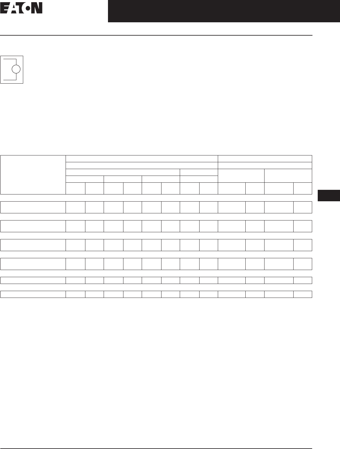
November 2008
CA08101001E For more information visit: www.eaton.com
12-231
Series C Molded Case Circuit Breakers
12
Internal Accessories
Low Energy Shunt Trip
Low Energy Shunt Trip
Low Energy Shunt Trip
devices are designed to
operate from low energy
output signals from dedi-
cated current sensors typi-
cally applied in ground
fault protection schemes. However,
with a proper control voltage source,
they may be applied in place of
conventional trip devices for special
applications. Flux paths surrounding
permanent magnets used in the shunt
trip assembly hold a charged spring
poised in readiness to operate the
circuit breaker trip mechanism.
When a 100 microfarad capacitor
charged to 28 Vdc is discharged
through the shunt trip coil, the result-
ant flux opposes the permanent mag-
net flux field, which releases the
stored energy in the spring to trip the
circuit breaker. As the circuit breaker
resets, the shunt trip reset arm is actu-
ated by the circuit breaker handle,
resetting the shunt trip. The plug-in
module is mounted in retaining slots
in the top of the trip unit. Coil is inter-
mittent-rated only. Cutoff provisions
required in control circuit.
Ordering Information
Select shunt trip catalog number
for the voltage within the indicated
voltage range. Shunt trip coils are
designed to be applied at specific
ac or dc voltages within the voltage
range shown. Electrical ratings are
also shown on applicable circuit
breaker accessory nameplates.
Table 12-428. F-, J-, K-, L-, M-, N- and R-Frames and HMCPs Low Energy Shunt Trip
Cutoff provisions required in control circuit.
Listed with Underwriters Laboratories for field installation under E64983.
Standard mounting location — leads exit rear of breaker.
For F-Frame HMCP, add an “M” to beginning of catalog number.
For use with thermal-magnetic trip units only.
Breakers with K-Frame OPTIM 550 can only accept accessories in left pole.
UV
Mounting
Positions
(Pole)
Factory Mounted Field Mounted
Connection Type and Location Field Installation Kits
18-Inch (457.2 mm) Pigtail Leads Terminal Block Pigtail Leads Terminal Block
Same Side Rear Opposite Side Same Side
Suffix
Number
Adder
U.S. $
Suffix
Number
Adder
U.S. $
Suffix
Number
Adder
U.S. $
Suffix
Number
Adder
U.S. $
Catalog
Number
Price
U.S. $
Catalog
Number
Price
U.S. $
F-Frame
Left
Right
NO1
NO5
NO2
NO6
NO3
NO7
NO4
NO8
LST1LPK
LST1RPK
LST1LTK
LST1RTK
J-Frame
Left
Right
NO1
NO5
NO2
NO6
NO3
NO7
—
—
LST2LPK
LST2RPK
—
—
K-Frame
Left
Right
NO1
NO5
NO2
NO6
NO3
NO7
—
—
LST3LPK
LST3RPK
—
—
L- and M-Frames
Left
Right
NO1
NO5
NO2
NO6
NO3
NO7
—
—
LST4LPK
LST4RPK
—
—
N-Frame
Left NO1 NO2 NO3 — LST5LPK —
R-Frame
Right NO1 — — — LST6RPK —
Discount Symbol . . . . . . . . . . . . . . . . . . . . . . . . . CB-2
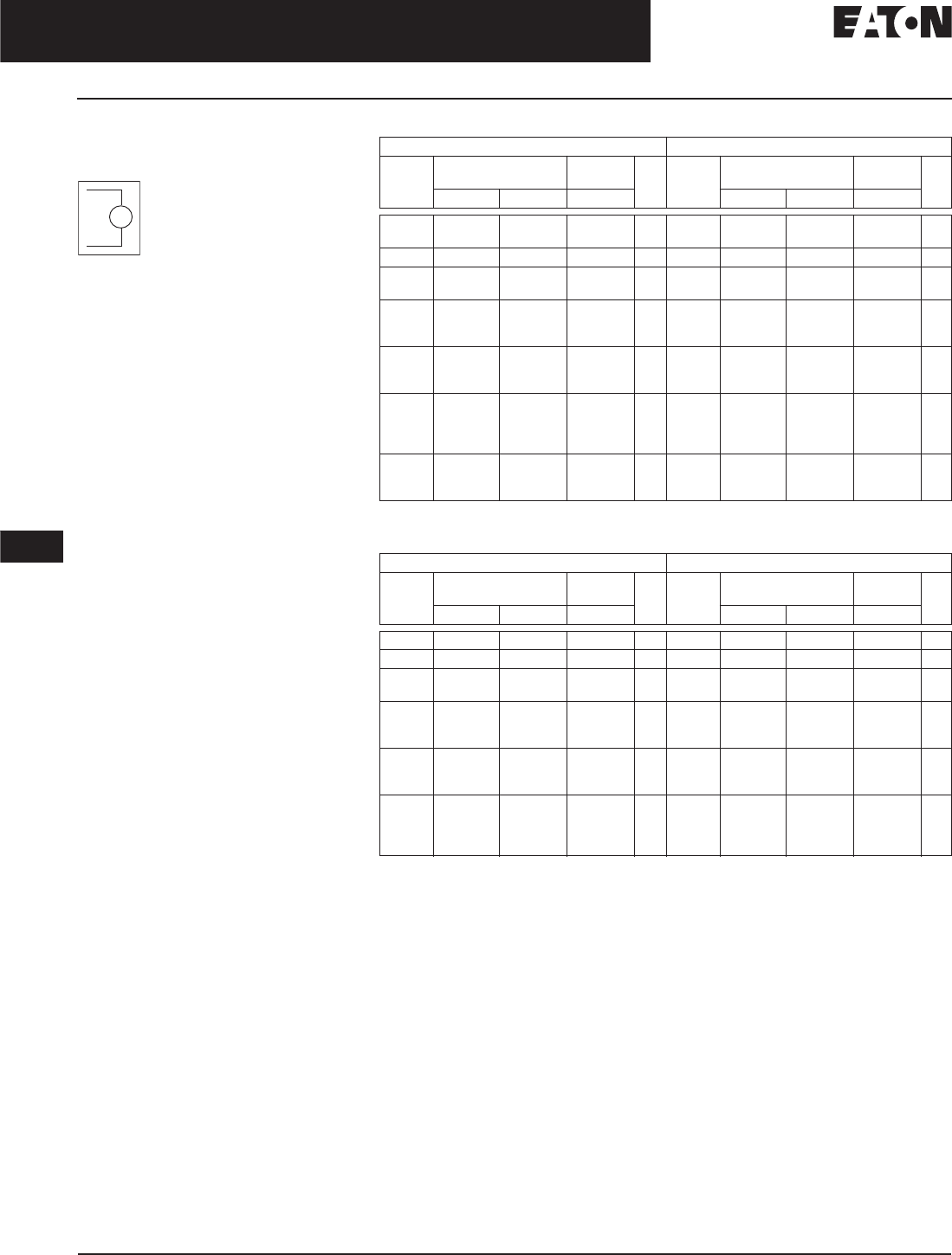
November 2008
12-232
For more information visit: www.eaton.com CA08101001E
Series C Molded Case Circuit Breakers
12
Internal Accessories
Undervoltage Release Mechanism
Undervoltage Release
Mechanism
The Undervoltage Release
Mechanism monitors a
voltage (typically a line
voltage) and trips the
circuit breaker when the
voltage falls to between
70 and 35 percent of the solenoid
coil rating.
The undervoltage release mechanism
consists of a continuous rated sole-
noid with a plunger and tripping lever
mounted in a plug-in module. The tab
on the tripping lever resets the under-
voltage release mechanism when
normal voltage has been restored and
the circuit breaker handle is moved to
the reset (or OFF) position. With less
than pickup voltage applied to the
undervoltage release mechanism, the
circuit breaker contacts will not touch
when a closing operation is attempted.
Note: Undervoltage release mechanism
accessories are not designed for, and
should not be used as, circuit interlocks.
Ordering Information
Select handle reset undervoltage
release mechanism catalog number
for the voltage within the indicated
voltage range. Undervoltage release
mechanism coils are designed to be
applied at specific ac or dc voltages
within the voltage range shown on
applicable circuit breaker accessory
nameplates.
UV
Table 12-429. F-Frame Electrical Rating Data
Endurance: 6,000 electrical operations plus 4,000 mechanical operations.
Table 12-430. J-Frame Electrical Rating Data
Endurance: 6,000 electrical operations plus 2,000 mechanical operations.
For electrical rating data for manual, automatic and electrical reset undervoltage release
mechanisms, refer to Eaton.
50/60 Hz dc
Supply
Voltage
Dropout
Voltage
Pickup
Voltage
VA Supply
Voltage
Dropout
Voltage
Pickup
Voltage
VA
Minimum Maximum Maximum Minimum Maximum Maximum
12 4.2 6.3 7.6 1.3
2.5
12 4.2 8.4 10.2 2.8
24 8.4 16.8 20.4 1.4 24 8.4 16.8 20.4 1.6
48
60
21.0 33.6 40.8 1.2
1.9
48
60
21.0 33.6 40.8 1.3
2.0
110
120
127
44.5 77.0 93.5 1.3
1.5
1.7
110
120
125
44.5 77.0 93.5 1.5
1.7
1.9
208
220
240
84.0 145.6 176.8 2.2
2.4
2.9
220
250
—
87.5
—
154.0
—
187.0
—
2.6
3.4
—
380
415
440
480
168.0 266.0 323.0 2.9
3.5
3.9
4.6
—
—
—
—
—
—
—
—
—
—
—
—
—
—
—
—
—
—
—
—
525
550
600
210.0 367.0 446.0 4.3
4.8
5.8
—
—
—
—
—
—
—
—
—
—
—
—
—
—
—
50/60 Hz dc
Supply
Voltage
Dropout
Voltage
Pickup
Voltage
VA Supply
Voltage
Dropout
Voltage
Pickup
Voltage
VA
Minimum Maximum Maximum Minimum Maximum Maximum
12 4.2 8.4 10.2 1.9 12 4.2 8.4 10.2 1.6
24 8.4 16.8 20.4 3.9 24 8.4 16.8 20.4 3.1
48
60
21.0 33.6 40.8 2.5
3.8
48
60
21.0 33.6 40.8 2.0
3.1
110
120
127
44.5 77.0 93.5 1.8
2.1
2.4
110
120
125
44.5 77.0 93.5 1.6
1.9
2.2
208
220
240
84.0 145.6 176.8 2.7
3.1
3.8
220
250
—
87.5
—
154.0
—
187.0
—
3.1
4.0
—
380
415
440
480
168.0 266.0 323.0 3.4
4.0
4.6
5.4
—
—
—
—
—
—
—
—
—
—
—
—
—
—
—
—
—
—
—
—

November 2008
CA08101001E For more information visit: www.eaton.com
12-233
Series G Molded Case Circuit Breakers
12
Internal Accessories
Undervoltage Release Mechanism
Table 12-431. K-Frame Electrical Rating Data
Endurance: 5,000 electrical operations plus 1,000 mechanical operations.
Table 12-432. L- and M-Frames Electrical Rating Data
Endurance: 5,000 electrical operations plus 1,000 mechanical operations.
Table 12-433. N-Frame Electrical Rating Data
Endurance: 3,000 electrical operations plus 1,000 mechanical operations.
50/60 Hz dc
Supply
Voltage
Dropout
Voltage
Pickup
Voltage
VA Supply
Voltage
Dropout
Voltage
Pickup
Voltage
VA
Minimum Maximum Maximum Minimum Maximum Maximum
12 4.2 8.4 10.2 1.9 12 4.2 8.4 10.2 1.6
24 8.4 16.8 20.4 3.9 24 8.4 16.8 20.4 3.1
48
60
21.0 33.6 40.8 2.5
3.8
48
60
21.0 33.6 40.8 2.0
3.1
110
120
127
44.5 77.0 93.5 1.8
2.1
2.4
110
120
125
44.5 77.0 93.5 1.6
1.9
2.2
208
220
240
84.0 145.6 176.8 2.7
3.1
3.8
220
250
—
87.5
—
154.0
—
187.0
—
3.1
4.0
—
380
415
440
480
168.0 266.0 323.0 3.4
4.0
4.6
5.4
—
—
—
—
—
—
—
—
—
—
—
—
—
—
—
—
—
—
—
—
50/60 Hz dc
Supply
Voltage
Dropout Voltage Pickup
Voltage
VA Supply
Voltage
Dropout Voltage Pickup
Voltage
VA
Minimum Maximum Maximum Minimum Maximum Maximum
12 4.2 8.4 10.2 1.9 12 4.2 8.4 10.2 1.6
24 8.4 16.8 20.4 3.9 24 8.4 16.8 20.4 3.1
48
60
21.0 33.6 40.8 2.5
3.8
48
60
21.0 33.6 40.8 2.0
3.1
110
120
127
44.5 77.0 93.5 1.8
2.1
2.4
110
120
125
44.5 77.0 93.5 1.6
1.9
2.2
208
220
240
84.0 145.6 176.8 2.7
3.1
3.8
220
250
87.5
—
154.0
—
187.0
—
3.1
—
4.0
380
415
480
500
175.0 266.0 323.0 3.4
4.0
4.6
5.4
—
—
—
—
—
—
—
—
—
—
—
—
—
—
—
—
—
—
—
—

November 2008
12-234
For more information visit: www.eaton.com CA08101001E
Series C Molded Case Circuit Breakers
12
Internal Accessories
Undervoltage Release Mechanism
Table 12-434. R-Frame ac Undervoltage Release Mechanism (Handle Reset) Ratings
Endurance: 500 electrical operations plus 2500 mechanical operations.
Pigtail wire size: 18 AWG (0.82 mm2). Leads are orange and brown.
UVR will override a momentary voltage dip up to the response time shown.
Unlatching occurs 1 millisecond before circuit breaker contacts begin to separate.
For 1 minute.
Table 12-435. R-Frame dc Undervoltage Release Mechanism (Handle Reset) Ratings
Endurance: 500 electrical operations plus 2500 mechanical operations.
Pigtail wire size: 18 AWG (0.82 mm2). Leads are orange and brown.
UVR will override a momentary voltage dip up to the response time shown.
Unlatching occurs 1 millisecond before circuit breaker contacts begin to separate.
For 1 minute.
Table 12-436. G-Frame Undervoltage Release Mechanism (LH 3-Pole Only)
Includes 24-inch (609.6 mm) external pigtail leads, 18 AWG (16-.010).
A maximum of two internal accessories may be mounted in a 3-pole
circuit breaker.
Suitable for mounting in left pole only of 3-pole breaker.
Note: G-frame circuit breakers are factory sealed. Underwriters
Laboratories, requires that internal accessories be installed at
the factory.
Note: Internal accessories are UL listed for factory installation
under E7819.
Note: Where local codes and standards permit and UL listing is not
required, internal accessories can be field installed. Accessory
installation should be done before the circuit breaker is mounted
and connected.
Catalog
Suffix
Application
Ratings
Electrical Operating Ratings Approximate Operating Time (ms)
Voltage
(V)
Supply
Voltage
(V)
Dropout Voltage (V) Pickup
Voltage
(V) Max.
VA Minimum
UVR
Response
Initiation
Circuit Breaker
Contact Separation
Maximum Circuit
Breaker
Contact Opening
Dielectric
Withstand
Voltage (V)
Minimum Maximum
02/02K 12 12 4.2 8.4 10.2 2.3 5 46 77 1024
03/03K 24 24 8.4 16.8 20.4 3.1 5 46 77 1048
05/05K 48 – 60 48
60
21.0 33.5 40.8 3.4
6.0
5 46 77 1120
08/08K 110 – 127 110
120
127
44.5 77.0 93.5 3.3
3.6
3.8
5 46 77 1254
11/11K 208 – 240 208
220
240
84.0 145.6 176.8 4.2
6.6
7.2
5 46 77 1480
29/29K 380 – 500 380
415
440
480
500
168.0 266.0 323.0 3.8
8.3
8.8
9.6
10.0
5 46 77 2000
Catalog
Suffix
Application
Ratings
Electrical Operating Ratings Approximate Operating Time (ms)
Voltage
(V)
Supply
Voltage
(V)
Dropout Voltage (V) Pickup
Voltage
(V) Max.
VA Minimum
UVR
Response
Initiation
Circuit Breaker
Contact Separation
Maximum Circuit
Breaker
Contact Opening
Dielectric
Withstand
Voltage (V)
Minimum Maximum
20/20K 12 12 4.2 8.4 10.2 3.4 5 46 77 1024
21/21K 24 24 8.4 16.8 20.4 4.3 5 46 77 1048
23/23K 48 – 60 48
60
21.0 33.5 40.8 4.8
7.2
5 46 77 1120
26/26K 110 – 127 110
120
125
43.8 77.0 93.5 3.3
3.6
3.8
5 46 77 1250
28/28K 220 – 250 220
250
87.5 154.0 187.0 6.6
7.5
5 46 77 1500
Electrical Ratings Style
Numbers
Price
U.S. $
Factory
Suffix
Adder
U.S. $
Volts
(ac Only)
Frequency Amperes
120
24
48
60
110
208
220
240
380
415
440
480
50/60 Hz
50/60 Hz
50/60 Hz
50/60 Hz
50 Hz
60 Hz
50 Hz
50/60 Hz
50 Hz
50 Hz
50 Hz
60 Hz
0.05
0.22
0.11
0.10
0.049
0.026
0.025
0.024
0.015
0.013
0.012
0.01
1373D62G03
1373D62G04
1373D62G05
1373D62G06
1373D62G07
1373D62G08
1373D62G09
1373D62G10
1373D62G11
1373D62G12
1373D62G13
1373D62G14
T1
T2
T3
T4
T5
T6
T7
T8
T9
T10
T11
T12
Discount Symbol . . . . . . . . . . . . . . . . . . . . . . . . CB-2

November 2008
CA08101001E For more information visit: www.eaton.com
12-235
Series C Molded Case Circuit Breakers
12
Internal Accessories
Undervoltage Release Mechanism
Table 12-437. F-Frame Factory Mounted (For F-Frame Breaker and F-Frame HMCP) Undervoltage Release Mechanism
Standard pigtail lead exit location.
Standard mounting location.
Not for use on right pole of 4-pole circuit breaker.
Note: F-frame circuit breakers are factory sealed. Underwriters Laboratories, requires that internal accessories be installed at the factory.
Note: Internal accessories are UL listed for factory installation under E7819.
Note: Where local codes and standards permit and UL listing is not required, internal accessories can be field installed. Accessory installation
should be done before the circuit breaker is mounted and connected.
Voltage Rating
(ac Freq. = 50/60 Hz)
Connection Type and Location
18-Inch Pigtail Leads Terminal Block
Same Side Rear Opposite Side Same Side
Suffix
Number
Adder
U.S. $
Suffix
Number
Adder
U.S. $
Suffix
Number
Adder
U.S. $
Suffix
Number
Adder
U.S. $
Left-Pole Mounting ac Ratings
12 Vac
24 Vac
48 Vac
60 Vac
110 – 127 Vac
208 – 240 Vac
380 – 480 Vac
525 – 600 Vac
U01
U05
U37
U97
U13
U17
U21
U25
U02
U06
U38
U98
U14
U18
U22
U26
U03
U07
U39
U99
U15
U19
U23
U27
U04
U08
U40
U100
U16
U20
U24
U28
Right-Pole Mounting ac Ratings
12 Vac
24 Vac
48 Vac
60 Vac
110 – 127 Vac
208 – 240 Vac
380 – 480 Vac
525 – 600 Vac
U49
U53
U85
U101
U61
U65
U69
U73
U50
U54
U86
U102
U62
U66
U70
U74
U51
U55
U87
U103
U63
U67
U71
U75
U52
U56
U88
U104
U64
U68
U72
U76
Left-Pole Mounting dc Ratings
12 Vdc
24 Vdc
48 Vdc
60 Vdc
110 – 127 Vdc
220 – 250 Vdc
U29
U33
U37
U97
U41
U45
U30
U34
U38
U98
U42
U46
U31
U35
U39
U99
U43
U47
U32
U36
U40
U100
U44
U48
Right-Pole Mounting dc Ratings
12 Vdc
24 Vdc
48 Vdc
60 Vdc
110 – 127 Vdc
220 – 250 Vdc
U77
U81
U85
U101
U89
U93
U78
U82
U86
U102
U90
U94
U79
U83
U87
U103
U91
U95
U80
U84
U88
U104
U92
U96
Discount Symbol . . . . . . . . . . . . . . . . . . . . . . . . . CB-2

November 2008
12-236
For more information visit: www.eaton.com CA08101001E
Series C Molded Case Circuit Breakers
12
Internal Accessories
Undervoltage Release Mechanism
Table 12-438. F-Frame Field Mounted Undervoltage Release Mechanism
Not listed with Underwriters Laboratories, for field installation.
Standard mounting location.
Not for use on right pole of 4-pole circuit breaker.
Voltage Rating
(ac Freq. = 50/60 Hz)
F-Frame Breaker F-Frame Breaker HMCP
Field Installation Kits
Pigtail Leads Terminal Block Pigtail Leads Terminal Block
Catalog
Number
Price
U.S. $
Catalog
Number
Price
U.S. $
Catalog
Number
Price
U.S. $
Catalog
Number
Price
U.S. $
Left-Pole Mounting ac Ratings
12 Vac
24 Vac
48 Vac
60 Vac
110 – 127 Vac
208 – 240 Vac
380 – 480 Vac
525 – 600 Vac
UVH1LP02K
UVH1LP03K
UVH1LP22K
UVH1LP24K
UVH1LP08K
UVH1LP11K
UVH1LP15K
UVH1LP18K
UVH1LT02K
UVH1LT03K
UVH1LT22K
UVH1LT24K
UVH1LT08K
UVH1LT11K
UVH1LT15K
UVH1LT18K
MUVH1LP02K
MUVH1LP03K
MUVH1LP22K
MUVH1LP24K
MUVH1LP08K
MUVH1LP11K
MUVH1LP15K
MUVH1LP18K
MUVH1LT02K
MUVH1LT03K
MUVH1LT22K
MUVH1LT24K
MUVH1LT08K
MUVH1LT11K
MUVH1LT15K
MUVH1LT18K
Right-Pole Mounting ac Ratings
12 Vac
24 Vac
48 Vac
60 Vac
110 – 127 Vac
208 – 240 Vac
380 – 480 Vac
525 – 600 Vac
UVH1RP02K
UVH1RP03K
UVH1RP22K
UVH1RP24K
UVH1RP08K
UVH1RP11K
UVH1RP15K
UVH1RP18K
UVH1RT02K
UVH1RT03K
UVH1RT22K
UVH1RT24K
UVH1RT08K
UVH1RT11K
UVH1RT15K
UVH1RT18K
MUVH1RP02K
MUVH1RP03K
MUVH1RP22K
MUVH1RP24K
MUVH1RP08K
MUVH1RP11K
MUVH1RP15K
MUVH1RP18K
MUVH1RT02K
MUVH1RT03K
MUVH1RT22K
MUVH1RT24K
MUVH1RT08K
MUVH1RT11K
MUVH1RT15K
MUVH1RT18K
Left-Pole Mounting dc Ratings
12 Vdc
24 Vdc
48 Vdc
60 Vdc
110 – 127 Vdc
220 – 250 Vdc
UVH1LP20K
UVH1LP21K
UVH1LP22K
UVH1LP24K
UVH1LP26K
UVH1LP28K
UVH1LT20K
UVH1LT21K
UVH1LT22K
UVH1LT24K
UVH1LT26K
UVH1LT28K
MUVH1LP20K
MUVH1LP21K
MUVH1LP22K
MUVH1LP24K
MUVH1LP26K
MUVH1LP28K
MUVH1LT20K
MUVH1LT21K
MUVH1LT22K
MUVH1LT24K
MUVH1LT26K
MUVH1LT28K
Right-Pole Mounting dc Ratings
12 Vdc
24 Vdc
48 Vdc
60 Vdc
110 – 127 Vdc
220 – 250 Vdc
UVH1RP20K
UVH1RP21K
UVH1RP22K
UVH1RP22K
UVH1RP26K
UVH1RP28K
UVH1RT20K
UVH1RT21K
UVH1RT22K
UVH1RT22K
UVH1RT26K
UVH1RT28K
MUVH1RP20K
MUVH1RP21K
MUVH1RP22K
MUVH1RP22K
MUVH1RP26K
MUVH1RP28K
MUVH1RT20K
MUVH1RT21K
MUVH1RT22K
MUVH1RT22K
MUVH1RT26K
MUVH1RT28K
Discount Symbol . . . . . . . . . . . . . . . . . . . . . . . . CB-2

November 2008
CA08101001E For more information visit: www.eaton.com
12-237
Series C Molded Case Circuit Breakers
12
Internal Accessories
Undervoltage Release Mechanism
Table 12-439. J-Frame and HMCP (J) Undervoltage Release Mechanism
For electrical rating data for manual, automatic and electrical reset undervoltage release mechanisms, refer to Eaton.
Listed with Underwriters Laboratories for field installation under E64983.
Not for use on right pole of 4-pole circuit breakers.
Standard mounting location — leads exit rear of breaker.
Voltage Rating
(ac Freq. =
50/60 Hz)
Factory Mounted Field Mounted
Connection Type and Location Field Installation Kits
18-Inch (457.2 mm) Pigtail Leads Terminal Block Pigtail Leads Terminal Block
Same Side Rear Opposite Side Same Side
Suffix
Number
Adder
U.S. $
Suffix
Number
Adder
U.S. $
Suffix
Number
Adder
U.S. $
Suffix
Number
Adder
U.S. $
Catalog
Number
Price
U.S. $
Catalog
Number
Price
U.S. $
Left-Pole Mounting ac Ratings
12 Vac
24 Vac
48 – 60 Vac
110 – 127 Vac
208 – 240 Vac
380 – 480 Vac
U05
U09
U13
U17
U21
U25
U06
U10
U14
U18
U22
U26
U07
U11
U15
U19
U23
U27
U08
U12
U16
U20
U24
U28
UVH2LP02K
UVH2LP03K
UVH2LP05K
UVH2LP08K
UVH2LP11K
UVH2LP15K
UVH2LT02K
UVH2LT03K
UVH2LT05K
UVH2LT08K
UVH2LT11K
UVH2LT15K
Right-Pole Mounting ac Ratings
12 Vac
24 Vac
48 – 60 Vac
110 – 127 Vac
208 – 240 Vac
380 – 480 Vac
U37
U41
U45
U49
U53
U57
U38
U42
U46
U50
U54
U58
U39
U43
U47
U51
U55
U59
U40
U44
U48
U52
U56
U60
UVH2RP02K
UVH2RP03K
UVH2RP05K
UVH2RP08K
UVH2RP11K
UVH2RP15K
UVH2RT02K
UVH2RT03K
UVH2RT05K
UVH2RT08K
UVH2RT11K
UVH2RT15K
Left-Pole Mounting dc Ratings
12 Vdc
24 Vdc
48 – 60 Vdc
110 – 127 Vdc
220 – 250 Vdc
T01
T05
T09
T13
T17
T02
T06
T10
T14
T18
T03
T07
T11
T15
T19
T04
T08
T12
T16
T20
UVH2LP20K
UVH2LP21K
UVH2LP23K
UVH2LP26K
UVH2LP28K
UVH2LT20K
UVH2LT21K
UVH2LT23K
UVH2LT26K
UVH2LT28K
Right-Pole Mounting dc Ratings
12 Vdc
24 Vdc
48 – 60 Vdc
110 – 127 Vdc
220 – 250 Vdc
T21
T25
T29
T33
T37
T22
T26
T30
T34
T38
T23
T27
T31
T35
T39
T24
T28
T32
T36
T40
UVH2RP20K
UVH2RP21K
UVH2RP23K
UVH2RP26K
UVH2RP28K
UVH2RT20K
UVH2RT21K
UVH2RT23K
UVH2RT26K
UVH2RT28K
Discount Symbol . . . . . . . . . . . . . . . . . . . . . . . . . CB-2

November 2008
12-238
For more information visit: www.eaton.com CA08101001E
Series C Molded Case Circuit Breakers
12
Internal Accessories
Undervoltage Release Mechanism
Table 12-440. K-Frame and HMCP (K) Undervoltage Release Mechanism
Listed with Underwriters Laboratories, for field installation under E64983.
Standard mounting location — leads exit rear of breaker.
For use with KT (thermal-magnetic) trip units only.
Not for use on right pole of 4-pole circuit breaker.
Breakers with K-Frame OPTIM 550 can only accept accessories in left pole.
Voltage Rating
(ac Freq. =
50/60 Hz)
Factory Mounted Field Mounted
Connection Type and Location Field Installation Kits
18-Inch (457.2 mm) Pigtail Leads Terminal Block Pigtail Leads Terminal Block
Same Side Rear Opposite Side Same Side
Suffix
Number
Adder
U.S. $
Suffix
Number
Adder
U.S. $
Suffix
Number
Adder
U.S. $
Suffix
Number
Adder
U.S. $
Catalog
Number
Price
U.S. $
Catalog
Number
Price
U.S. $
Left-Pole Mounting ac Ratings
12 Vac
24 Vac
48 – 60 Vac
110 – 127 Vac
208 – 240 Vac
380 – 480 Vac
U05
U09
U13
U17
U21
U25
U06
U10
U14
U18
U22
U26
U07
U11
U15
U19
U23
U27
U08
U12
U16
U20
U24
U28
UVH3LP02K
UVH3LP03K
UVH3LP05K
UVH3LP08K
UVH3LP11K
UVH3LP15K
UVH3LT02K
UVH3LT03K
UVH3LT05K
UVH3LT08K
UVH3LT11K
UVH3LT15K
Right-Pole Mounting ac Ratings
12 Vac
24 Vac
48 – 60 Vac
110 – 127 Vac
208 – 240 Vac
380 – 480 Vac
U37
U41
U45
U49
U53
U57
U38
U42
U46
U50
U54
U58
U39
U43
U47
U51
U55
U59
U40
U44
U48
U52
U56
U60
UVH3RP02K
UVH3RP03K
UVH3RP05K
UVH3RP08K
UVH3RP11K
UVH3RP15K
UVH3RT02K
UVH3RT03K
UVH3RT05K
UVH3RT08K
UVH3RT11K
UVH3RT15K
Left-Pole Mounting dc Ratings
12 Vdc
24 Vdc
48 – 60 Vdc
110 – 127 Vdc
220 – 250 Vdc
T01
T05
T09
T13
T17
T02
T06
T10
T14
T18
T03
T07
T11
T15
T19
T04
T08
T12
T16
T20
UVH3LP20K
UVH3LP21K
UVH3LP23K
UVH3LP26K
UVH3LP28K
UVH3LT20K
UVH3LT21K
UVH3LT23K
UVH3LT26K
UVH3LT28K
Right-Pole Mounting dc Ratings
12 Vdc
24 Vdc
48 – 60 Vdc
110 – 127 Vdc
220 – 250 Vdc
T21
T25
T29
T33
T37
T22
T26
T30
T34
T38
T23
T27
T31
T35
T39
T24
T28
T32
T36
T40
UVH3RP20K
UVH3RP21K
UVH3RP23K
UVH3RP26K
UVH3RP28K
UVH3RT20K
UVH3RT21K
UVH3RT23K
UVH3RT26K
UVH3RT28K
Discount Symbol . . . . . . . . . . . . . . . . . . . . . . . . . CB-2

November 2008
CA08101001E For more information visit: www.eaton.com
12-239
Series C Molded Case Circuit Breakers
12
Internal Accessories
Undervoltage Release Mechanism
Table 12-441. L-, HMCP (L) and (M)-Frames and Undervoltage Release Mechanism
Listed with Underwriters Laboratories for field installation under E64983.
Standard mounting location — leads exit rear of breaker.
For use with LT (thermal-magnetic) trip units only.
Not for use on right pole of 4-pole circuit breaker.
Table 12-442. N-Frame and HMCP (N) Undervoltage Release Mechanism
Listed with Underwriters Laboratories for field installation under E64983.
Standard mounting location — leads exit rear of breaker.
Voltage Rating
(ac Freq. =
50/60 Hz)
Factory Mounted Field Mounted
Connection Type and Location Field Installation Kits
18-Inch (457.2 mm) Pigtail Leads Terminal Block Pigtail Leads Terminal Block
Same Side Rear Opposite Side Same Side
Suffix
Number
Adder
U.S. $
Suffix
Number
Adder
U.S. $
Suffix
Number
Adder
U.S. $
Suffix
Number
Adder
U.S. $
Catalog
Number
Price
U.S. $
Catalog
Number
Price
U.S. $
Left-Pole Mounting ac Ratings
12 Vac
24 Vac
48 – 60 Vac
110 – 127 Vac
208 – 240 Vac
380 – 480 Vac
U05
U09
U13
U17
U21
U25
U06
U10
U14
U18
U22
U26
U07
U11
U15
U19
U23
U27
U08
U12
U16
U20
U24
U28
UVH4LP02K
UVH4LP03K
UVH4LP05K
UVH4LP08K
UVH4LP11K
UVH4LP15K
UVH4LT02K
UVH4LT03K
UVH4LT05K
UVH4LT08K
UVH4LT11K
UVH4LT15K
Right-Pole Mounting ac Ratings
12 Vac
24 Vac
48 – 60 Vac
110 – 127 Vac
208 – 240 Vac
380 – 480 Vac
U37
U41
U45
U49
U53
U57
U38
U42
U46
U50
U54
U58
U39
U43
U47
U51
U55
U59
U40
U44
U48
U52
U56
U60
UVH4RP02K
UVH4RP03K
UVH4RP05K
UVH4RP08K
UVH4RP11K
UVH4RP15K
UVH4RT02K
UVH4RT03K
UVH4RT05K
UVH4RT08K
UVH4RT11K
UVH4RT15K
Left-Pole Mounting dc Ratings
12 Vdc
24 Vdc
48 – 60 Vdc
110 – 127 Vdc
220 – 250 Vdc
T01
T05
T09
T13
T17
T02
T06
T10
T14
T18
T03
T07
T11
T15
T19
T04
T08
T12
T16
T20
UVH4LP20K
UVH4LP21K
UVH4LP23K
UVH4LP26K
UVH4LP28K
UVH4LT20K
UVH4LT21K
UVH4LT23K
UVH4LT26K
UVH4LT28K
Right-Pole Mounting dc Ratings
12 Vdc
24 Vdc
48 – 60 Vdc
110 – 127 Vdc
220 – 250 Vdc
T21
T25
T29
T33
T37
T22
T26
T30
T34
T38
T23
T27
T31
T35
T39
T24
T28
T32
T36
T40
UVH4RP20K
UVH4RP21K
UVH4RP23K
UVH4RP26K
UVH4RP28K
UVH4RT20K
UVH4RT21K
UVH4RT23K
UVH4RT26K
UVH4RT28K
Voltage Rating
(ac Freq. =
50/60 Hz)
Factory Mounted Field Mounted
Connection Type and Location Field Installation Kits
18-Inch (457.2 mm) Pigtail Leads Terminal Block Pigtail Leads Terminal Block
Same Side Rear Opposite Side Same Side
Suffix
Number
Adder
U.S. $
Suffix
Number
Adder
U.S. $
Suffix
Number
Adder
U.S. $
Suffix
Number
Adder
U.S. $
Catalog
Number
Price
U.S. $
Catalog
Number
Price
U.S. $
Left-Pole Mounting ac Ratings
12 Vac
24 Vac
48 – 60 Vac
110 – 127 Vac
208 – 240 Vac
380 – 480 Vac
U05
U09
U13
U17
U21
U25
U06
U10
U14
U18
U22
U26
U07
U11
U15
U19
U23
U27
U08
U12
U16
U20
U24
U28
UVH5LP02K
UVH5LP03K
UVH5LP05K
UVH5LP08K
UVH5LP11K
UVH5LP29K
UVH5LT02K
UVH5LT03K
UVH5LT05K
UVH5LT08K
UVH5LT11K
UVH5LT29K
Left-Pole Mounting dc Ratings
12 Vdc
24 Vdc
48 – 60 Vdc
110 – 127 Vdc
220 – 250 Vdc
T01
T05
T09
T13
T17
T02
T06
T10
T14
T18
T03
T07
T11
T15
T19
T04
T08
T12
T16
T20
UVH5LP20K
UVH5LP21K
UVH5LP23K
UVH5LP26K
UVH5LP28K
UVH5LT20K
UVH5LT21K
UVH5LT23K
UVH5LT26K
UVH5LT28K
Discount Symbol . . . . . . . . . . . . . . . . . . . . . . . . . CB-2

November 2008
12-240
For more information visit: www.eaton.com CA08101001E
Series C Molded Case Circuit Breakers
12
Internal Accessories
Undervoltage Release Mechanism
Table 12-443. R-Frame Undervoltage Release Mechanism (RH only)
Endurance: 500 electrical operations plus 2500 mechanical operations.
Pigtail wire size: 18 AWG (0.82 mm2). Leads are orange and brown.
Voltage Rating
(ac Frequency = 50/60 Hz)
Factory Mounted Field Mounted
Connection Type and Location Field Installation Kits
18-Inch (457.2 mm) Pigtail Leads Pigtail Leads
Suffix
Number
Adder
U.S. $
Catalog
Number
Price
U.S. $
12 Vac
24 Vac
48 – 60 Vac
110 – 127 Vac
208 – 240 Vac
380 – 500 Vac
12 Vdc
24 Vdc
48 – 60 Vdc
110 – 125 Vdc
220 – 250 Vdc
U37
U41
U45
U49
U53
U57
T21
T25
T29
T33
T37
UVH6RP02K
UVH6RP03K
UVH6RP05K
UVH6RP08K
UVH6RP11K
UVH6RP29K
UVH6RP20K
UVH6RP21K
UVH6RP23K
UVH6RP26K
UVH6RP28K
Discount Symbol . . . . . . . . . . . . . . . . . . . . . . . . . CB-2
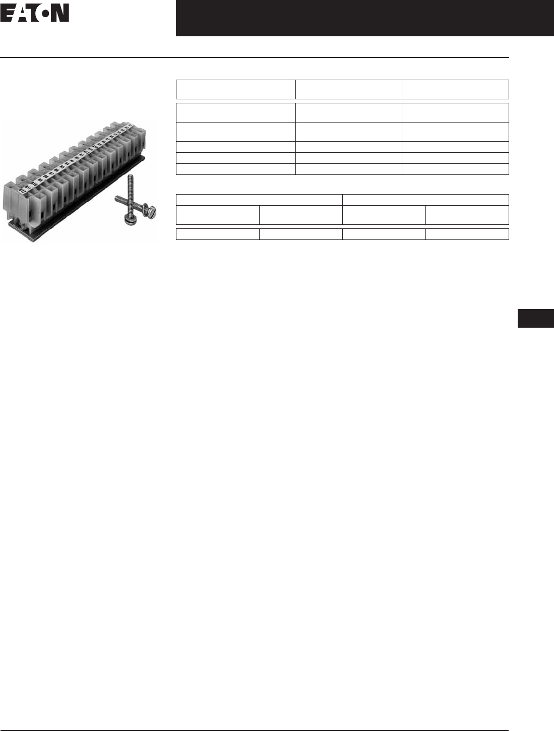
November 2008
CA08101001E For more information visit: www.eaton.com
12-241
Series C Molded Case Circuit Breakers
12
Internal Accessories
Accessory Terminal Block
Accessory Terminal Block
(R-Frame)
(For Fixed Mounted Configuration)
Accessory Terminal Block
Internal accessory wiring leads are
normally supplied with pigtail leads
(18 AWG) that exit from the right side
of the circuit breaker. Where specified,
fixed mounted Accessory Terminal
Blocks are available. A maximum of
one 24-point terminal block can be
installed on the right side of the circuit
breaker for the internal accessories.
For convenience in determining the
appropriate number of terminal block
points required, refer to Table 12-444.
Table 12-444. Number of Control Wires for Each Internally Mounted Accessory
Table 12-445. R-Frame Accessory Terminal Block
One 24-point accessory terminal block provided with circuit breaker when ordered factory
installed or shipped from warehouse as separate item when ordered for field installation.
See Digitrip RMS master connection diagram (IL 29C714).
Type of
Accessory
Number of Contacts per
Single Accessory
Required Number
of Wires
Auxiliary Switch 2a/2b
4a/4b
6
12
Alarm (Signal)/
Lockout Switch
1m/1b
2m/2b
6
12
Shunt Trip N/A 2
Low Energy Shunt N/A 2
Undervoltage Release Mechanism N/A 2
Factory Installed Field Mounted
Suffix
Number
Adder
U.S. $
Catalog
Number
Price
U.S. $
Q01 TBRDK
Discount Symbol . . . . . . . . . . . . . . . . . . . . . . . . . CB-2
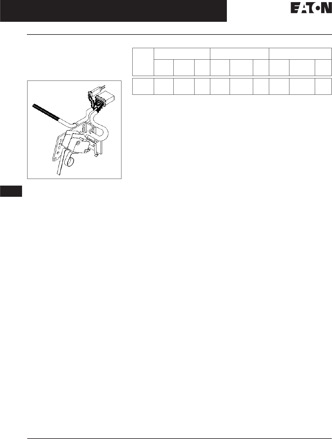
November 2008
12-242
For more information visit: www.eaton.com CA08101001E
Series C Molded Case Circuit Breakers
12
Internal Accessories
PowerNet and Zone Interlock Kits
Eaton’s Cutler-Hammer
PowerNet and Zone Interlock
Kits (OPTIM 550 only)
K-, L- and N-Frames
Figure 12-45. PowerNet Communication Kit
Eaton’s Cutler-Hammer PowerNet
Communications Kit can be ordered to
add PowerNet communications to an
existing OPTIM 550 breaker in the
field. An 18-inch (457.2 mm) wiring
pigtail is routed to the rear of the
breaker: two wires for PowerNet and
two wires for 24 Vdc (45 mA load). It is
recommended that the power supply
be an “isolated high quality” unit.
Table 12-446. PowerNet and Zone Interlock Kits
Installation of these kits restrict any other attachments from being installed in the RH pole.
Includes a ground fault alarm signal which can drive the Ground Fault Alarm unit
(Catalog Number GFAU).
Circuit
Breaker
PowerNet Zone Interlocking/
Ground
PowerNet & Zone
Interlocking/Ground
Factory
Install
Suffix
Catalog
Number
Price
U.S. $
Factory
Install
Suffix
Catalog
Number
Price
U.S. $
Factory
Install
Suffix
Catalog
Number
Price
U.S. $
K-Frame
L-Frame
N-Frame
PN
PN
PN
ICK550K
ICK550L
ICK550N
ZG
ZG
ZG
ZGK550K
ZGK550L
ZGK550N
ZGP
ZGP
ZGP
ZGPK550K
ZGPK550L
ZGPK550N
Discount Symbol . . . . . . . . . . . . . . . . . . . . . . . . . CB-2
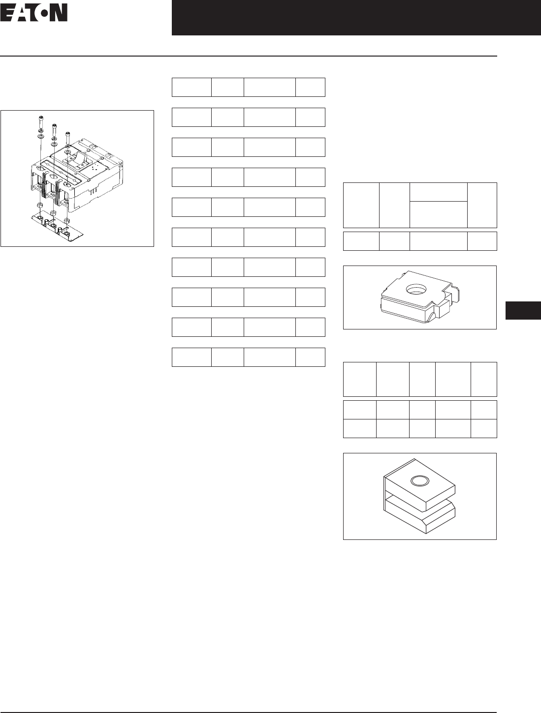
November 2008
CA08101001E For more information visit: www.eaton.com
12-243
Series C Molded Case Circuit Breakers
12
External Accessories
Termination Hardware
Termination Hardware
End Cap Kit
Figure 12-46. End Cap Kit
The End Cap Kit slides onto the line or
load conductor of the circuit breaker
and acts as a threaded adapter for the
conductor to accept a ring terminal or
other bolt-on connector. The end cap
kit is available with English and metric
thread sizes. (Field installation only.)
Listed per UL File E7819.
Table 12-447. End Cap Kit Keeper Nut
The Keeper Nut slides onto the line or
load conductor of the circuit breaker
and acts as a threaded adapter for the
conductor to accept a ring terminal or
other bolt-on connector. The keeper
nut is available with English and met-
ric thread sizes. Screws and washers
are supplied by customer. (Field instal-
lation only.) Listed per UL File E7819.
Table 12-448. F-Frame Keeper Nut
Figure 12-47. F-Frame Keeper Nut
Table 12-449. K-Frame Keeper
Figure 12-48. K-Frame Keeper Nut
L-, M-, N-Frames
Not required. Terminals are threaded.
Thread
Type
Thread
Size
Catalog
Number
Price
U.S. $
2-Pole F-Frame (225 A)
Imperial
Metric
10-32
M-5
KPEK12
KPEKM12
3-Pole F-Frame (225 A)
Imperial
Metric
10-32
M-5
KPEK1
KPEKM1
4-Pole F-Frame (225 A)
Imperial
Metric
10-32
M-5
KPEK14
KPEKM14
3-Pole J-Frame
Imperial
Metric
.312-18
M-8
KPEK2
KPEKM2
4-Pole J-Frame
Imperial
Metric
.312-18
M-8
KPEK24
KPEKM24
3-Pole K-Frame
Imperial
Metric
.312-18
M-8
KPEK3
KPEKM3
4-Pole K-Frame
Imperial
Metric
.312-18
M-8
KPEK34
KPEKM34
3-Pole L-Frame
Imperial
Metric
.312-18
M-8
KPEK4
KPEKM4
4-Pole L-Frame
Imperial
Metric
.312-18
M-8
KPEK44
KPEKM44
Thread
Type
Thread
Size
Catalog
Number
Price
U.S. $
Package of 12
(Priced
Individually)
Imperial
Metric
10-32
M-5
KPR1A
KPR1AM
Thread
Type
Thread
Size
Line/
Load
End
Catalog
Number
Package
of 3
Price
U.S. $
Imperial .375-16 Line
Load
KPR3A
KPR3B
Metric M-8 Line
Load
KPR3AM
KPR3BM
Discount Symbol . . . . . . . . . . . . . . . . . . . . . . . . CB-2
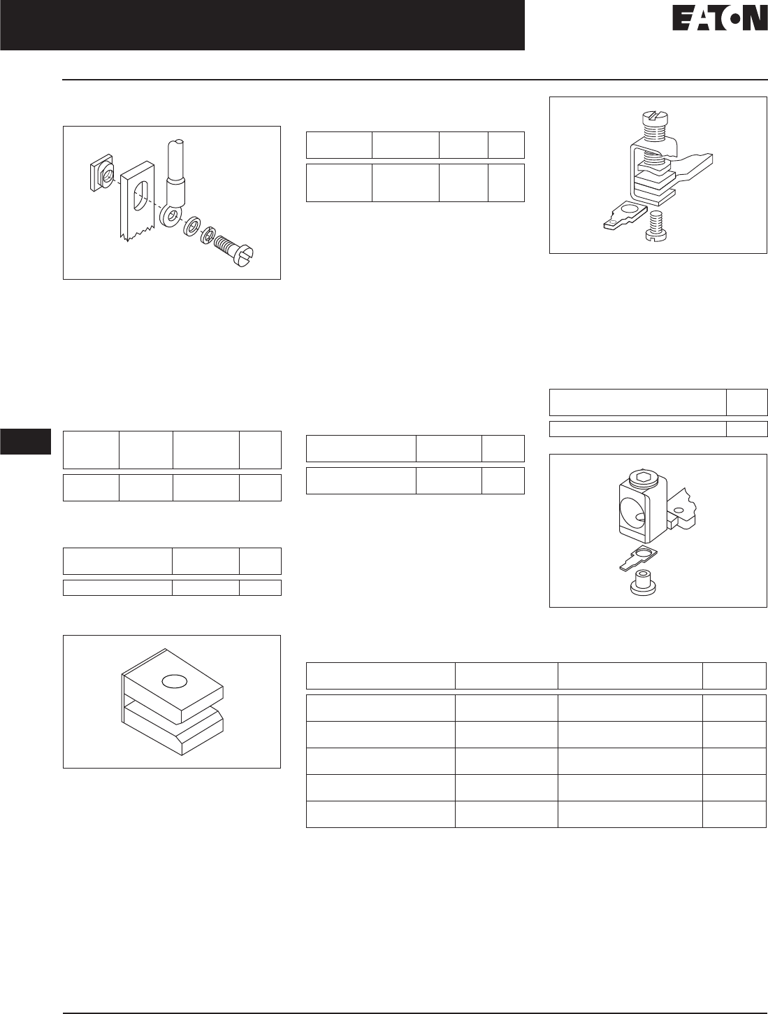
November 2008
12-244
For more information visit: www.eaton.com CA08101001E
Series C Molded Case Circuit Breakers
12
External Accessories
Termination Hardware
Plug Nut
Figure 12-49. J-Frame Plug Nut
The Plug Nut is used in applications
where screw-connected ring-type
terminals are preferred to connect
cables to circuit breaker conductors.
The plug nut is press-fit into the
opening in the circuit breaker terminal
conductor. Screws and washers are
supplied by customer.
Table 12-450. J-Frame Plug Nut
Terminal Adapter
Table 12-451. K-Frame Terminal Adapter
K-Frame terminal adapter for use in replacing
LB/DA breakers.
Figure 12-50. K-Frame Terminal Adapter
Thread
Type
Thread
Size
Catalog
Number
Package of 6
Price
U.S. $
Imperial
Metric
.250-20
M-6
PLN2
PLN2M
Line/Load End Catalog
Number
Price
U.S. $
Line & Load TAD3
Control Wire Terminal Kit
Table 12-452. G-Frame Control Wire Terminal
The Control Wire Terminal Kit provides
a means to tap off control power from
a main disconnect, using the provided
male end of a quick disconnect.
For use with steel or stainless steel
terminals only.
Note: Terminal Kits contain one terminal
for each pole and one terminal cover.
F-Frame Ordering Information
Package of 12 control wire terminal
tangs. Terminals must be ordered
separately. Priced individually.
Table 12-453. F-Frame Control Wire
Terminal Kit
Figure 12-51. F-Frame Kit
Not for use with T250KB terminals.
J- and K-Frame Ordering Information
Package of 12 control wire terminal
tangs. Terminals must be ordered
separately. Priced individually.
Table 12-454. J- and K-Frame Control Wire
Terminal Kit Ordering Information
Figure 12-52. J- and K-Frame Kit
Table 12-455. L-Frame Control Wire Terminal Kit
Individually packed.
Terminal kits contain one terminal for each pole and one terminal cover.
Description Catalog
Number
Catalog
Number
Price
U.S. $
Control Wire
Terminal
(Kit of 12)
5652B38G01 GCWTK
Maximum
Amperes
Catalog
Number
Price
U.S. $
150
225
FCWTK
FCWTK225
Catalog
Number
Price
U.S. $
KCWTK
AWG Wire
Range/Number Conductors
Metric Wire
Range mm2
Catalog
Number
Price
U.S. $
Al/Cu
(2) 250 – 350 kcmil
120 – 150 TA602LDCW
Cu
(2) 3/0 – 350 kcmil
120 – 150 T602LDCW
Al/Cu
(2) 400 – 500 kcmil
185 – 240 2TA603LDKCW 2-Pole Kit
Al/Cu
(2) 400 – 500 kcmil
185 – 240 3TA603LDKCW 3-Pole Kit
Al/Cu
(2) 400 – 500 kcmil
185 – 240 4TA603LDKCW 4-Pole Kit
Discount Symbol . . . . . . . . . . . . . . . . . . . . . . . . CB-2

November 2008
CA08101001E For more information visit: www.eaton.com
12-245
Series C Molded Case Circuit Breakers
12
External Accessories
Multiwire Connectors
Multiwire Connectors
Eaton’s Cutler-Hammer field-installed
multiwire connectors for the load
side (OFF) end terminals, are used
to distribute the load from the circuit
breaker to multiple devices without the
use of separate distribution terminal
blocks.
Multiwire lug kits include mounting
hardware, insulators and tin-plated
aluminum connectors to replace three
mechanical load lugs. UL listed as
used on the load side (OFF) end.
Figure 12-53. Multiwire Connectors
Table 12-456. Multiwire Connectors Ordering Information (Package of 3)
GD breakers require special tapping for multiwire lugs, as described in the IL. Special terminals
are required as well.
Maximum
Amperes
Wires per
Terminal
Wire Size
Range AWG Cu
Kit Catalog
Number
Price
U.S. $
G-Frame
100
100
3
6
14 – 2
14 – 6
3TA100G3K
3TA100G6K
F-Frame
225
225
3
6
14 – 2
14 – 6
3TA150F3K
3TA150F6K
J-Frame
250
250
3
6
14 – 2
14 – 6
3TA250J3K
3TA250J6K
K-Frame
400
400
3
6
14 – 2/0
14 – 3
3TA400K3K
3TA400K6K
Discount Symbol . . . . . . . . . . . . . . . . . . . . . . . . CB-2
November 2008
12-246
For more information visit: www.eaton.com CA08101001E
Series C Molded Case Circuit Breakers
12
External Accessories
Base Mounting Hardware
Base Mounting Hardware
Ordering Information
Hardware for surface mounting of
circuit breakers is supplied only on
request. Hardware consists of mount-
ing screws and lockwashers. Order
hardware for circuit breaker pole
configurations as required.
Table 12-457. Mounting Hardware
Screw Length
in Inches (mm)
Catalog
Number
Price
U.S. $
G-Frame
.138-32 x 2.63
(3.5 x 66.7 mm) Std.
624B375G23
.138-32 x 3.00
(3.5 x 76.2 mm)
8703C80G05
Table 12-458. Imperial Thread Mounting Hardware
One set of hardware for two circuit breakers.
Table 12-459. Metric Thread Mounting Hardware
Number
of Poles
Description Type of
Mounting
Catalog
Number
Price
U.S. $
F-Frame
1 .164-32 x 3.188-inch Pan-Head Steel
Screws, Lockwashers, and Clamps
Individual
Group
624B375G01
624B375G02
2 .164-32 x 1.5-inch Pan-Head
Steel Screws and Lockwashers
Individual 4218B80G01
3, 4 .164-32 x 1.5-inch Pan-Head
Steel Screws and Lockwashers
Individual BMH1
J-Frame
2, 3, 4 .250-20 x 2.75 inch Pan-Head
Steel Screws and Lockwashers
Individual BMH2
K-Frame
2, 3, 4 .250-20 x 1.5 inch Pan-Head
Steel Screws and Lockwashers
Individual BMH3
L-Frame
2, 3, 4 .250-20 x 1.5 inch Filister-Head
Steel Screws and Lockwashers
and Flat Washers
Individual BMH4
M-Frame
2, 3 .3125-18 x 1.25 inch Filister-Head
Steel Screws and Lockwashers
and Flat Washers
Individual BMH5
N-Frame
2, 3, 4 .3125-18 x 1.25 inch Pan-Head
Steel Screws and Lockwashers
Individual BMH5
R-Frame
Supplied by customer
Number
of Poles
Description Type of
Mounting
Catalog
Number
Price
U.S. $
F-Frame
1 M4 – 0.7 x 80 mm Pan-Head Steel
Screws, Lockwashers, and Clamps
Individual
Group
(one set of hardware for
two circuit breakers)
4218B80G09
4218B80G10
2 M4 – 0.7 x 38 mm Pan-Head
Steel Screws and Lockwashers
Individual 4218B80G11
3, 4 M4 – 0.7 x 38 mm Pan-Head
Steel Screws and Lockwashers
Individual BMH1M
J-Frame
2, 3, 4 M6 – 0.7 x 70 mm Pan-Head
Steel Screws and Lockwashers
Individual BMH2M
K-Frame
2, 3, 4 M6 – 0.7 x 38 mm Pan-Head
Steel Screws and Lockwashers
Individual BMH3M
L-Frame
2, 3 — Individual BMH4M
M-Frame
2, 3 — Individual BMH5M
N-Frame
2, 3 — Individual BMH5M
R-Frame
Supplied by customer
Discount Symbol . . . . . . . . . . . . . . . . . . . . . . . . CB-2
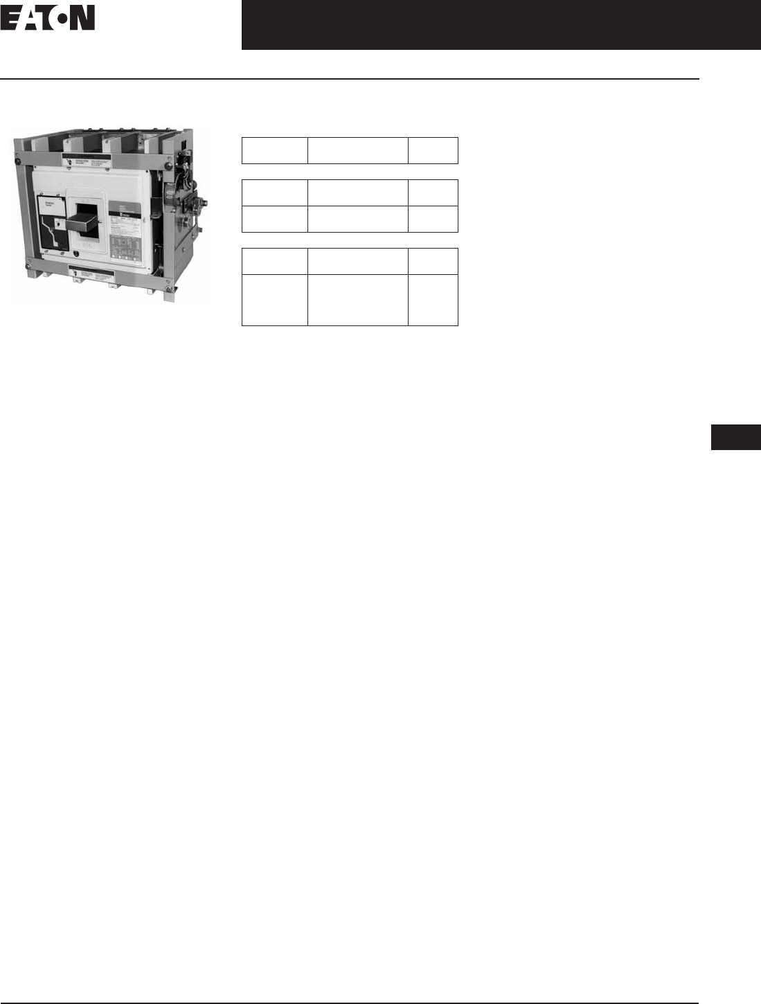
CA08101001E For more information visit: www.eaton.com
12-247
Series C Molded Case Circuit Breakers
November 2008
12
External Accessories
Drawout Cassette
Drawout Cassette
R-Frame with Moveable Mechanism
Product Description
The Drawout Cassette is currently for
use with the standard 3-pole 65 kA/
480 Vac, 1600 and 2000 ampere RD
circuit breakers only. It consists of two
separate components: the movable
mechanism which is factory mounted
to the circuit breaker frame and
the stationary mechanism which
is housed in the cassette and
shipped separately.
The drawout mechanism has four
positions.
■Connected: The breaker is fully
connected to the primary stabs and
secondary contacts.
■Test: The breaker is not connected
to the primary stab but is connected
to the secondary contacts.
■Disconnected: Both the primary
stabs and the secondary contacts
are disconnected.
■Withdraw: The breaker can be
removed from the cassette.
Product Selection
Table 12-460. RD Drawout Cassette
List price included in price of the stationary
mechanism.
Without shutters.
With shutters.
Description Catalog
Number
Price
U.S. $
65 kA/480 Vac Version
Movable
Mechanism
RD20DOM
Stationary
Mechanism
RD20DOS
RD20DOSS
100 kA/480 Vac Version
Movable
Mechanism
RDC20DOM
Stationary
Mechanism
RDC20DOS
(without shutters)
RDC20DOSS
(with shutters)
Movable mechanism must be ordered
with RD or RDC circuit breaker and
is shipped mounted to circuit breaker
frame. Stationary mechanism is
ordered separately.
All internal accessories must be factory
installed for use with drawout.
Discount Symbol . . . . . . . . . . . . . . . . . . . . . . . . CB-2
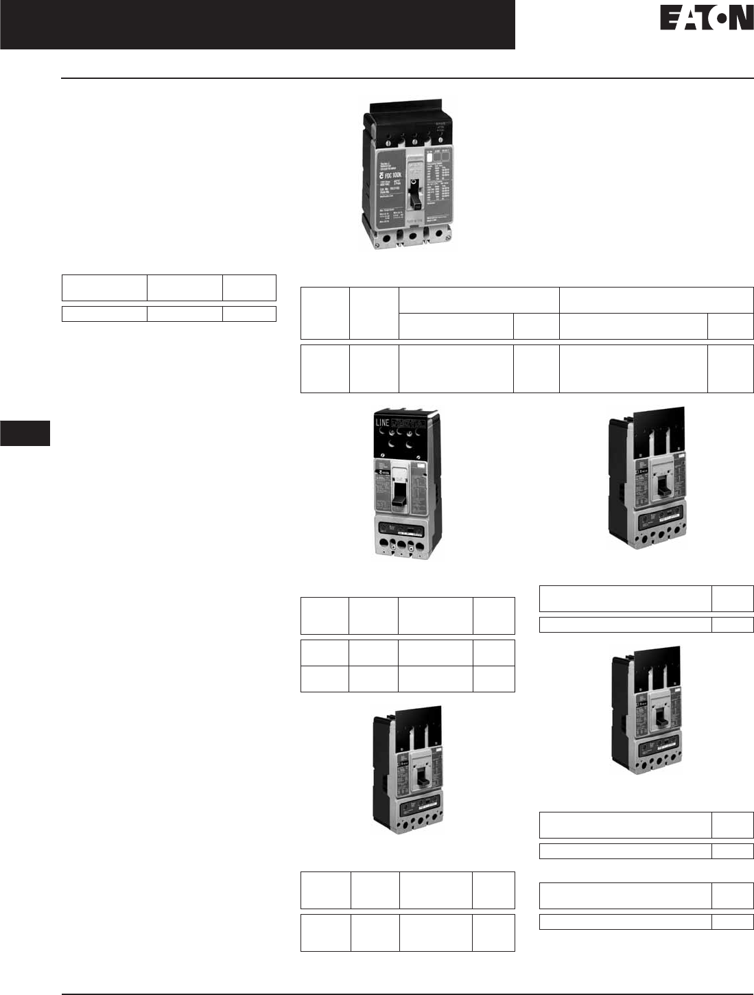
November 2008
12-248
For more information visit: www.eaton.com CA08101001E
Series C Molded Case Circuit Breakers
12
External Accessories
Terminal Shields and End Covers
Terminal Shields
Terminal Shields provide protection
against accidental contact with live
line side terminations. Terminal
shields are fabricated from high
dielectric insulating material and
fasten over the front terminal access
openings. Small openings in the
shields provide limited access to the
terminals for tightening connectors.
(Field installation only.)
Table 12-461. G-Frame Terminal Shield
Number Units
in Package
Catalog
Number
Price
U.S. $
10 GTSK3
F-Frame
Table 12-462. F-Frame Terminal Shield
J-Frame
Table 12-463. J-Frame Terminal Shield
K-Frame
Table 12-464. K-Frame Terminal Shield
L-Frame
Table 12-465. L-Frame Terminal Shield
M-Frame
Table 12-466. M-Frame Terminal Shield
Table 12-467. N-Frame Terminal Shield
Number
of Poles
Location Standard (Package of 10)
(Priced Individually)
Special — For use when electrical
operator is mounted on circuit breaker
Catalog
Number
Price
U.S. $
Catalog
Number
Price
U.S. $
1
2
3
4
Line 625B229G06
625B229G07
625B229G08
625B229G09
—
—
4210B95G01
4210B95G02
Number
of Poles
Location Catalog
Number
(Package of 10)
Price
U.S. $
2,3
4
Line End 1266C07G01
6631C01G01
2,3
4
Load End 6641C16G01
6641C16G02
Number
of Poles
Location Catalog
Number
(Package of 10)
Price
U.S. $
2, 3
4
3
Line
Line
Load
TS33LN
TS34LN
TS33LD
Catalog Number
(Package of 1)
Price
U.S. $
314C420G05
Catalog Number
(Package of 1)
Price
U.S. $
208B966G01
Discount Symbol . . . . . . . . . . . . . . . . . . . . . . . . CB-2
Catalog Number
(Package of 1)
Price
U.S. $
NTS3K
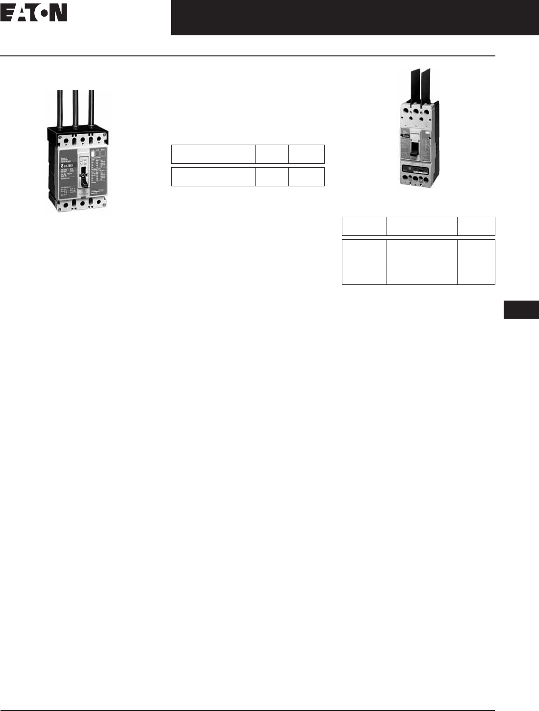
November 2008
CA08101001E For more information visit: www.eaton.com
12-249
Series C Molded Case Circuit Breakers
12
External Accessories
Terminal Shields and End Covers
Terminal End Covers
F-Frame
Product Description
The Terminal End Covers are designed
for use in motor control center applica-
tions where, because of confined
spaces, line side conductors are nor-
mally custom fitted. The molded end
covers are made of high dielectric
glass-polyester and slide over the line
ends of the circuit breaker. Close fitting
conductor openings are molded into
the end covers. The end cover and
circuit breaker case fit together to form
terminal compartments that isolate
discharged ionizing gases during
circuit breaker tripping. Terminal end
covers are available with two conductor
opening diameters, 0.25-inch (6.4 mm)
and 0.41-inch (10.4 mm), and are
listed per UL File E7819. (Field
installation only.)
Ordering Information
The terminal end cover is available
for 3-pole circuit breakers only. Two
conductor opening sizes are available.
Specify quantity (one per circuit
breaker) when ordering.
Table 12-468. F-Frame Terminal End Covers
Interphase Barriers
The interphase barriers provide
additional electrical clearance between
circuit breaker poles for special
termination applications. The barriers
are high dielectric insulating plates
that are installed in the molded
slots between the terminals. (Field
installation only.) Two per package.
Interphase Barrier
Table 12-469. Interphase Barriers
Conductor Opening
Diameter in Inches (mm)
Catalog
Number
Price
U.S. $
0.25 (6.35 mm)
0.41 (10.41 mm)
TEC1
TEC2
Frame Catalog
Number
Price
U.S. $
F
J, K
L
IPB1
IPB3
IPB4
M
N
IPB4
IPB5
Discount Symbol . . . . . . . . . . . . . . . . . . . . . . . . CB-2
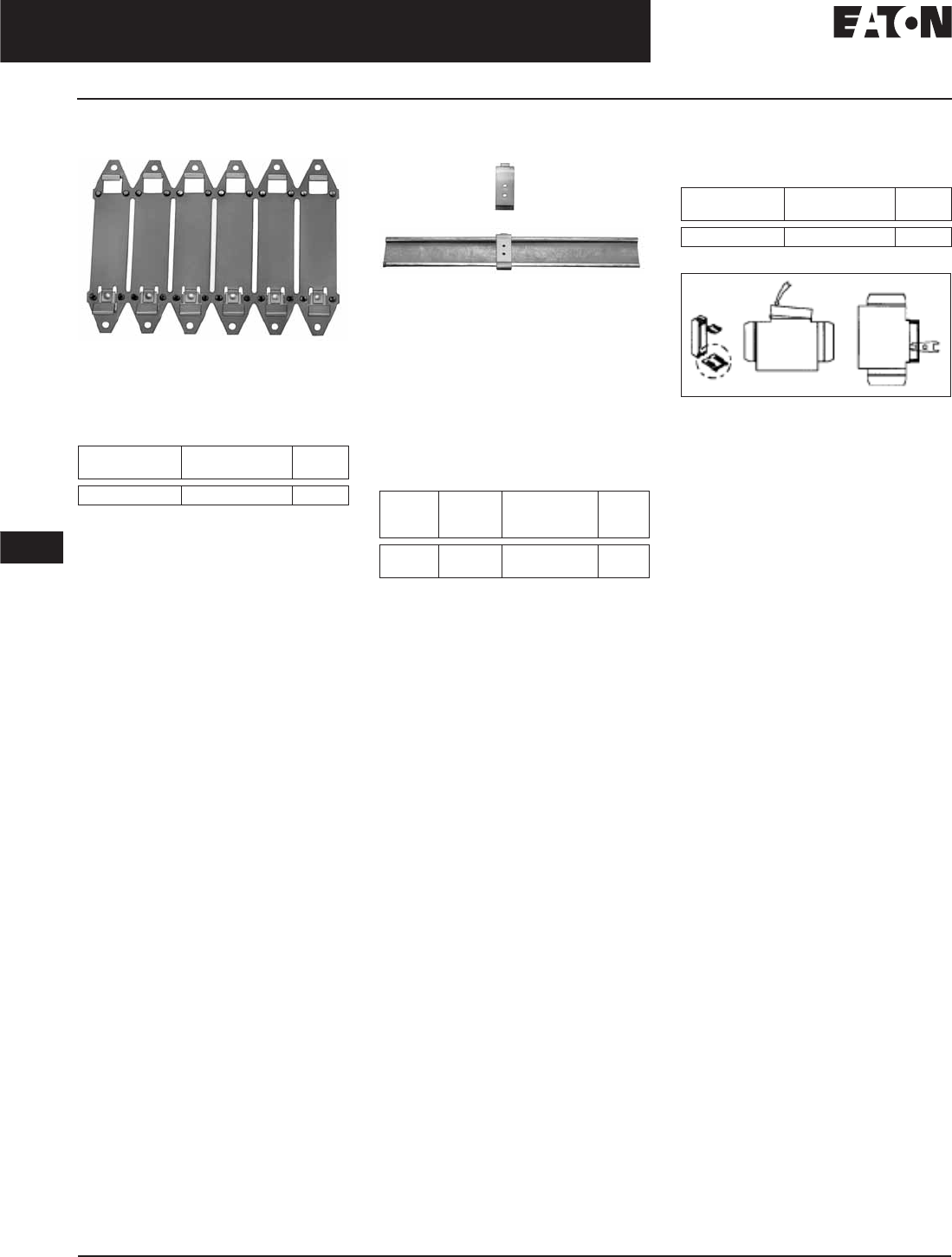
November 2008
12-250
For more information visit: www.eaton.com CA08101001E
Series C Molded Case Circuit Breakers
12
External Accessories
Base Mounting Adapters
Base Mounting Plate
Base Mounting Plate
Suitable for mounting (6) single-pole
circuit breakers.
Table 12-470. Base Mounting Plate
G-Frame GD/GHC
DIN Rail Adapter
DIN Rail Adapter
For use with standard 35 mm DIN Rail
such as, 35 x 7.5 or 35 x 15 mm per
DIN EN50022.
Adapter mounting screws included
are for use with 2- and 3-pole circuit
breakers. Adapters for 1-pole circuit
breakers (pictured above) clip into the
base molding.
Table 12-471. DIN Rail Adapter
G-Frame GD/GHC
For use on 3-pole breakers only.
Key Operated Attachment
Table 12-472. Key Operated Attachment
G-Frame GD/GHC
Figure 12-54. Key Operated Attachment
Number Units
in Package
Catalog
Number
Price
U.S. $
1207B513G01 Poles Number
Units in
Package
Catalog
Number
Price
U.S. $
1, 2-Pole
3-Pole
10
10
1225C79G01
1225C79G02
Number Units
in Package
Catalog
Number
Price
U.S. $
10 GKOA
Discount Symbol . . . . . . . . . . . . . . . . . . . . . . . . CB-2
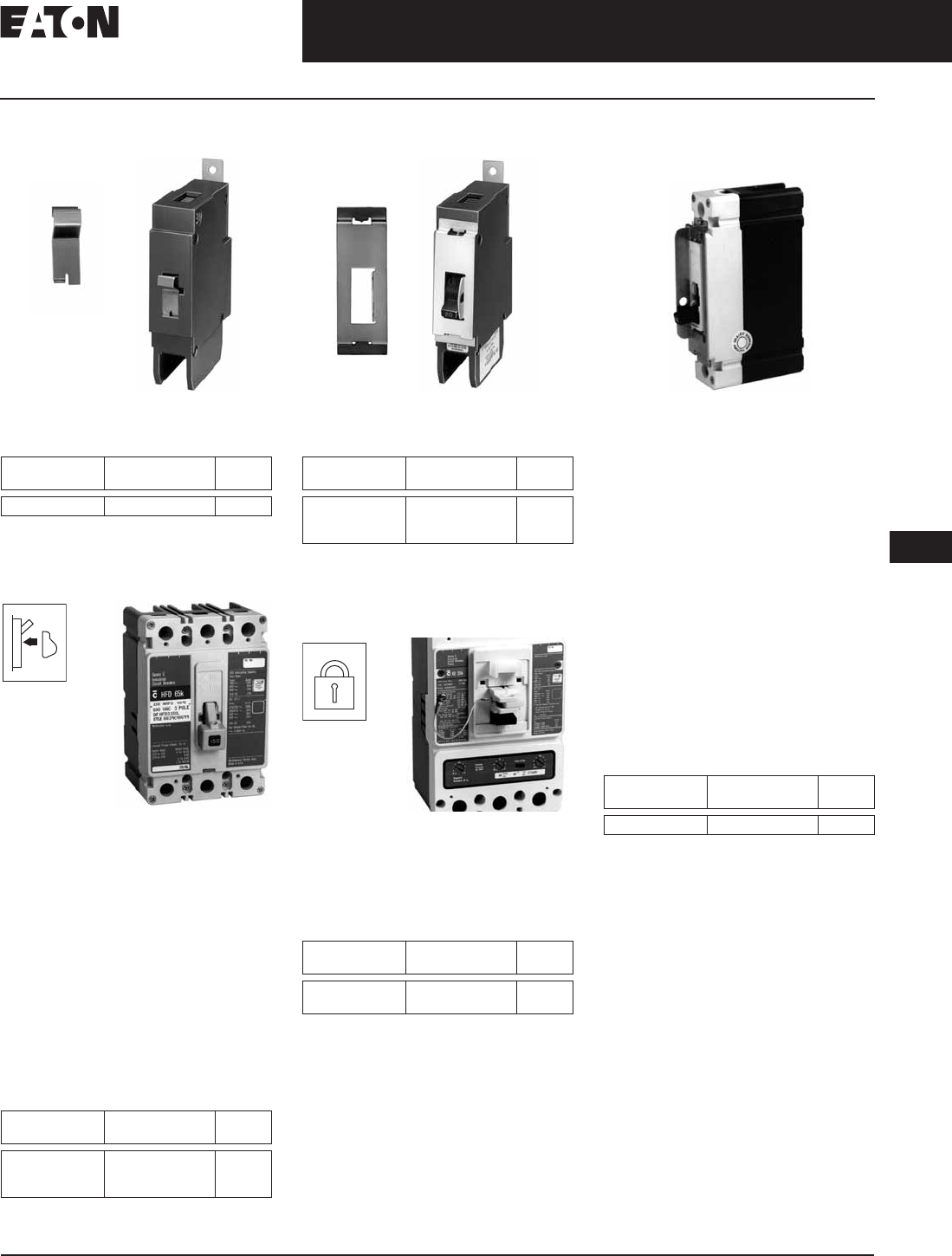
November 2008
CA08101001E For more information visit: www.eaton.com
12-251
Series C Molded Case Circuit Breakers
12
External Accessories
Handle Locking and Blocking Devices
Lock Dog (Non-Padlockable)
Lock Dog (Non-Padlockable)
Table 12-473. Lock Dog (Non-Padlockable)
G-Frame GD/GHC/GHB/GMCP
Non-Padlockable
Handle Block
Non-Padlockable Handle Block
Product Description
The Non-Padlockable Handle Block
secures the circuit breaker handle
in either the ON or OFF position.
(Trip-free operation allows the circuit
breaker to trip when the handle block
holds the circuit breaker handle in the
ON position.) The device is positioned
over the circuit breaker handle and
secured by a setscrew to deter acci-
dental operation of the circuit breaker
handle. Listed per UL File E7819.
(Field installation only.)
Table 12-474. Non-Padlockable Handle Block
Padlockable Handle
Padlockable Handle
Table 12-475. Padlockable G-Frame
GD/GHC/GHB
Accepts .285 Lock Shank.
Padlockable in the OFF position only.
Padlockable Handle Lock
Padlockable Handle Lock
The device is positioned in the cover
opening to prevent handle movement.
Will accommodate one 5/16-inch
(8 mm) padlock.
Table 12-476. Padlockable Handle Lock
Snap-on Padlockable
Handle Lock Hasp
Snap-on Padlockable Handle Lock Hasp
Product Description
The Snap-on Padlockable Handle Lock
allows the handle to be locked in the
OFF or ON position. (Trip-free opera-
tion allows the circuit breaker to trip
when the handle lock holds the circuit
breaker handle in the ON position.)
This device was designed for use on
the 1-pole circuit breaker, but may be
used on 1-, 2-, 3- and 4-pole styles. The
handle lock snaps onto the escutcheon
area of the handle with an optional
retaining screw for added secureness.
The handle lock will accommodate
one padlock with a 1/4-inch (6.4 mm)
shackle. Listed per UL File E7819.
(Field installation only.)
Table 12-477. Snap-on Padlockable
Handle Lock Hasp
Number Units
in Package
Catalog
Number
Price
U.S. $
11294C01H01
Frame Catalog
Number
Price
U.S. $
F
J, K
L, M, N
LKD1
LKD3
LKD4
Number Units
in Package
Catalog
Number
Price
U.S. $
10
10
100
1223C77G03
1223C77G05
1223C77G06
Frame Catalog
Number
Price
U.S. $
G
J, K
GPHBOFF
PHB3
Frame Catalog
Number
Price
U.S. $
FPHL1
Discount Symbol . . . . . . . . . . . . . . . . . . . . . . . CB-2
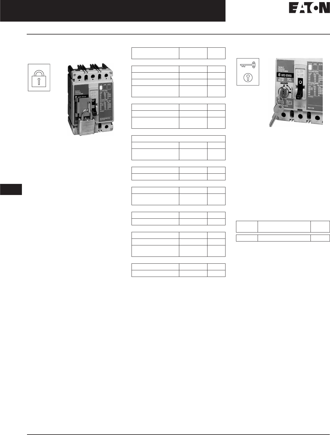
November 2008
12-252
For more information visit: www.eaton.com CA08101001E
Series G Molded Case Circuit Breakers
12
External Accessories
Handle Locking and Blocking Devices
Padlockable
Handle Lock Hasp
Padlockable Handle Lock Hasp
Product Description
The Padlockable Handle Lock Hasp
allows the handle to be locked in the
ON or OFF position. (Trip-free opera-
tion allows the circuit breaker to trip
when the handle lock holds the circuit
breaker handle in the ON position.)
The hasp mounts on the circuit breaker
cover within the trimline. The cover
is predrilled on both sides of the oper-
ating handle so that the hasp can be
mounted on either side of the handle.
The hasp will accommodate up to
three padlocks with 1/4-inch (6.4 mm)
shackles, one per circuit breaker.
Listed per UL File E7819. (Field
installation only.)
Table 12-478. Padlockable Handle Lock Hasp
For padlockable handle lock hasp to padlock
handle in OFF position only order either
catalog number.
Cylinder Lock
Cylinder Lock
Product Description
The Cylinder Lock internally blocks
the trip bar in the tripped position to
prevent the circuit breaker from being
switched to ON. The cylinder lock is
factory installed in the left pole only
of the circuit breaker cover. Other
internally mounted accessories
cannot be installed in the same pole
as the cylinder lock. (Factory installa-
tion only.)
Table 12-479. Cylinder Lock
Description Catalog
Number
Price
U.S. $
F-Frame
1-Pole Breakers PHL1
2-, 3-, 4-Pole Breakers PLK1
For Left Side Mounting PLK1LOFF
For Right Side
Mounting
PLK1ROFF
J, K-Frames
2-, 3-, 4-Pole Breakers PLK3
For Left Side Mounting PLK3LOFF
For Right Side
Mounting
PLK3ROFF
L-Frame (Side Mounted)
Side Mounted
Lock ON or OFF HLK4
Lock OFF Only
(Left-Hand Mount)
HLK4LOFF
L-Frame (Top Mounted)
Lock ON or OFF HLK4S
Lock OFF Only HLK4SOFF
M-Frame
Lock ON or OFF HLK4
Lock OFF Only
(Left-Hand Mount)
HLK4LOFF
M-Frame (Vertical Mounting)
Lock ON/OFF HLK4S
Lock OFF Only HLK4SOFF
N-Frame
Side Mounted PLK5
Top Mounted (ON/OFF) PLK5S
Top Mounted
(OFF Only)
PLK5SOFF
R-Frame
Lock ON/OFF HLK6
Lock OFF Only HLK6OFF
Frame Catalog
Number
Price
U.S. $
F, J, K Order by Description
Discount Symbol . . . . . . . . . . . . . . . . . . . . . . . . CB-2
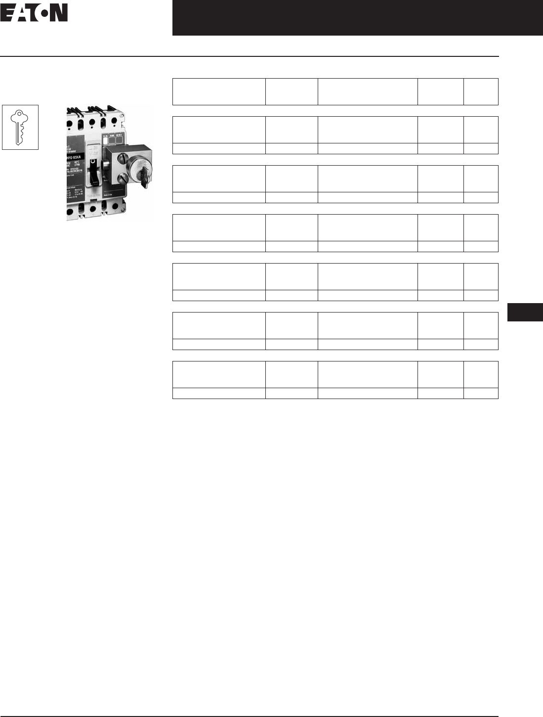
November 2008
CA08101001E For more information visit: www.eaton.com
12-253
Series C Molded Case Circuit Breakers
12
External Accessories
Mechanical Interlocking Devices
Key Interlock Kit
(Lock Not Included)
Key Interlock Kit
Product Description
The Key Interlock is used to externally
lock the circuit breaker handle in the
OFF position. When the key interlock
is locked, an extended deadbolt blocks
movement of the circuit breaker han-
dle. Uniquely coded keys are remov-
able only with the deadbolt extended.
Each coded key controls a group of
circuit breakers for a given specific
customer installation.
The key interlock assembly is Under-
writers Laboratories listed for field
installation under UL File E7819 and
consists of a mounting kit and a pur-
chaser supplied deadbolt lock. The
mounting kit comprises a mounting
plate, which is secured to the circuit
breaker cover in either the left- or
right-pole position, key interlock
mounting screws, and a wire seal.
Specific mounting kits are required
for individual key interlock types.
Ordering Information
Key interlock mounting kits are for
field installation only. Select mounting
kit catalog numbers to match type of
lock used. Key interlocks are supplied
by customer.
Table 12-480. Key Interlock Kit
When ordering Castell Interlock, it is necessary for customer to specify that the mounting bolt
holes must be 10 mm in diameter.
Lock
Manufacturer
Lock
Type
Bolt Projection in
Withdrawn Position
in Inches (mm)
Kit
Catalog
Number
Price
U.S. $
F-Frame
Superior
Kirk
Square D
B-4003-1
F
SF
.38 (9.5)
.38 (9.5)
None
KYK1
Castell K or QK .38 (9.5) CTK1
J, K-Frames
Superior
Kirk
Square D
B-4003-1
F
SF
.38 (9.5)
.38 (9.5)
None
KYK3
Castell K or QK .38 (9.5) CTK3
L-, M-, N-Frames
Superior
Kirk
Square D
B-4003-1
F
SF
.38 (9.5)
.38 (9.5)
None
KYK4
Castell K or QK .38 (9.5) CTK4
R-Frame
Superior
Kirk
Square D
B-4003-1
F
SF
1.0 (25.4)
1.0 (25.4)
1.0 (25.4)
KYK6
Castell K or QK 1.0 (25.4) CTK6
JG-Frame
Superior
Kirk
Square D
B-4003-1
F
SF
.38 (9.5)
.38 (9.5)
None
KYKJG
Castell K or QK .38 (9.5) CTKJG
LG-Frame
Superior
Kirk
Square D
B-4003-1
F
SF
.38 (9.5)
.38 (9.5)
None
KYKLG
Castell K or QK .38 (9.5) CTKLG
Discount Symbol . . . . . . . . . . . . . . . . . . . . . . . . CB-2
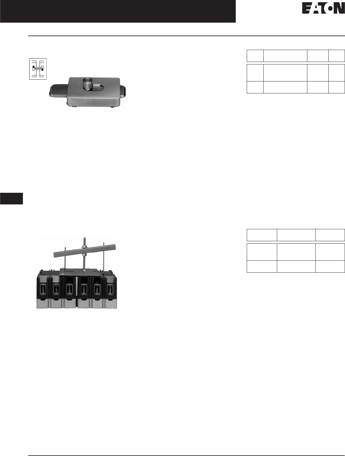
November 2008
12-254
For more information visit: www.eaton.com CA08101001E
Series C Molded Case Circuit Breakers
12
External Accessories
Mechanical Interlocking Devices
Sliding Bar Interlock
Sliding Bar Interlock
Product Description
The Sliding Bar Interlock provides
mechanical interlocking between
two adjacent 3-pole circuit breakers.
It is installed on the enclosure cover
between the circuit breakers. When the
sliding bar interlock handle is moved
from one side to the other, a bar
extends to alternately block movement
of the circuit breaker handles and
prevents both circuit breakers from
being switched to ON at the same
time. Sliding bar interlocks are not
UL listed. (Field installation only.)
Walking Beam Interlock
Walking Beam Interlock
Product Description
The Walking Beam Interlock provides
mechanical interlocking between two
adjacent circuit breakers of the same
pole configuration. The walking beam
interlock mounts on a bracket behind
and between the circuit breakers.
A plunger on each end of the beam
is inserted through an access hole in
the back plate and base of each circuit
breaker. The walking beam interlock
prevents both circuit breakers from
being switched ON at the same time.
If a walking beam interlock is installed,
the wiring troughs in the back of the
circuit breaker case are blocked by the
plungers and cannot be used for cross
wiring. Factory modified circuit break-
ers are required for this application.
UL File E3816.
Ordering Information
The sliding bar interlock is available
for mounting between two adjacent
3-pole circuit breakers with circuit
breakers centerline spacing as indi-
cated in table and enclosure front
panel thickness of 1/8 or 3/16 inch (3.2
or 4.8 mm). (For field installation only.)
Ordering Information
The walking beam interlock is avail-
able for mounting between two adja-
cent circuit breakers spaced 1/4-inch
(6.4 mm) apart and having the same
pole configuration. The two circuit
breakers must be factory modified
to accept the walking beam interlock
assembly (suitable for use with either
2-, 3- or 4-pole circuit breakers).
With properly modified circuit breakers,
the walking beam interlock is suitable
for field installation. Order circuit
breakers specifying modification
for walking beam (20% price adder)
and select walking beam interlock
from table below. Circuit breakers
and walking beam interlock are
boxed and shipped separately.
Table 12-481. Sliding Bar Interlock
Table 12-482. Walking Beam Interlock
3-pole only.
➤
➤
Frame Centerline Spacing
in Inches (mm)
Catalog
Number
Price
U.S. $
F
J
K
4.19 (106.4)
4.38 (111.3)
5.75 (146.0)
SBK1
SBK2
SBK3
L, M
N
8.50 (215.9)
8.50 (215.9)
SBK4
SBK5
Discount Symbol . . . . . . . . . . . . . . . . . . . . . . . . CB-2
Frame Catalog
Number
Price
U.S. $
F
K
L, M
WBL1
WBL3
WBL4A
N
R
WBL5
WBL6
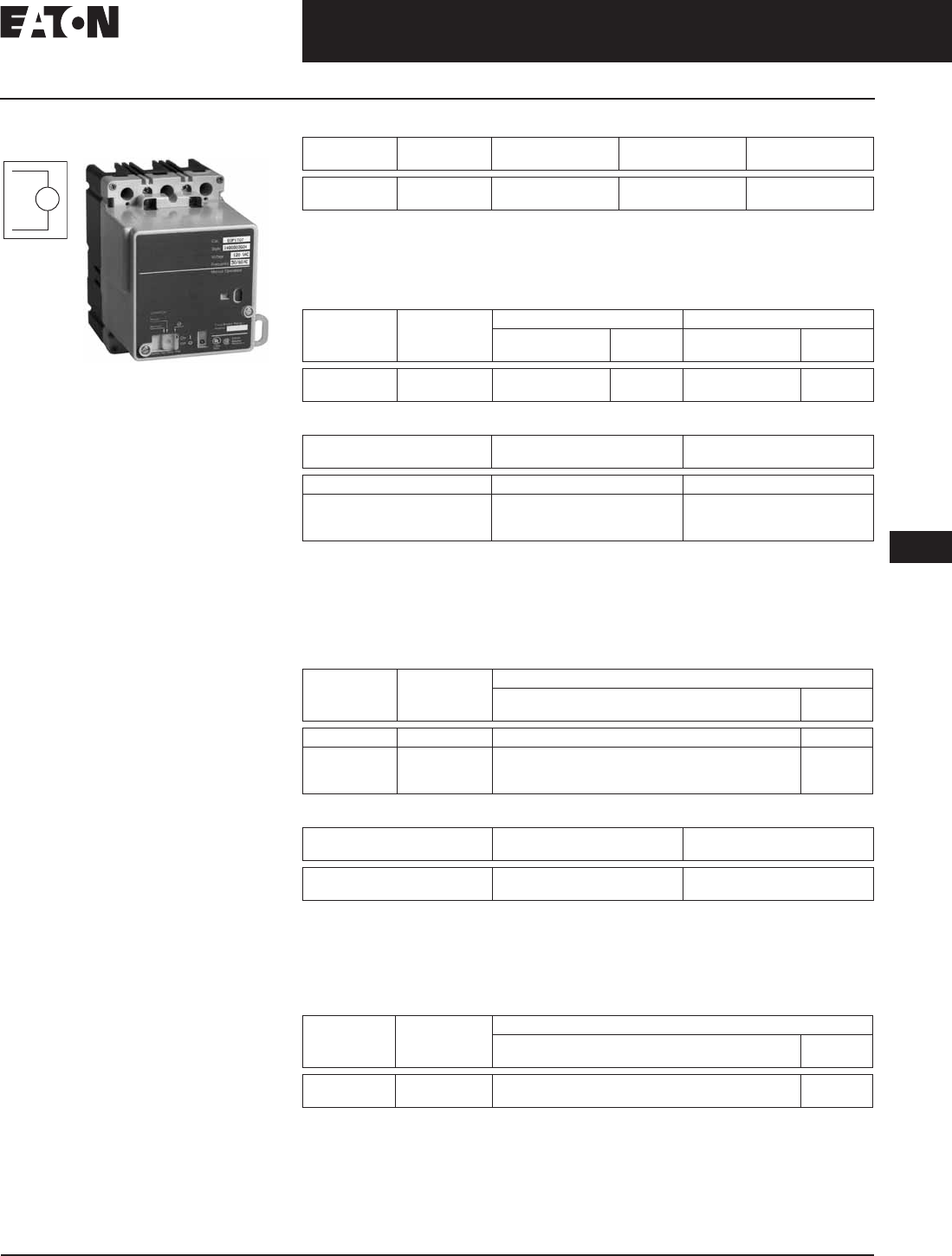
November 2008
CA08101001E For more information visit: www.eaton.com
12-255
Series C Molded Case Circuit Breakers
12
External Accessories
Electrical Operator
Electrical Operator
Electrical Operator
Product Description
The Electrical (Solenoid) Operator
is a single solenoid mechanism that
enables local and remote circuit
breaker ON, OFF, and reset switching.
The electrical operator is mounted on
the circuit breaker cover within the
trimline of the circuit breaker. The elec-
trical operator uses a unique bi-stable
latch that allows the device to operate
using one solenoid. The accessory
provides high-speed switching with a
maximum operating time of 5 cycles
(80 mS), making it suitable for generator
synchronizing applications.
Means are provided for remote electri-
cal operation and for local manual
operation. A special slide includes
provisions for padlocking the circuit
breaker handle in the OFF position.
The slide will accept three padlock
shackles with a maximum diameter of
1/4-inch (6.4 mm) each. An interlock
electrically disconnects the solenoid
when the electrical operator cover is
removed. The Rating Data Tables
provide electrical rating data for the
electrical (solenoid) operator.
The Electrical (Motor) Operator allows
the circuit’s breaker to be opened,
closed or reset remotely. It also has a
lock-off capability and provisions for
manual operation.
The Electrical (Motor) Operator con-
tains a reversible motor connected to a
ball screw. The ball screw drives the
circuit breaker handle. Limit switches
and relays are used to control the
motor.
EO
Table 12-483. F-Frame Electrical (Solenoid) Operator Rating Data
UL listed under UL File E64983.
The electrical operator design is endurance tested for 8,000 electrical operations.
Tolerance: +10%, –15% of nominal voltage.
Use current-limiting type fuse where required.
Table 12-484. F-Frame Electrical (Solenoid) Operator
Table 12-485. F-Frame Electrical (Motor) Operator Rating Data
UL listed under UL File E64124.
Frequency: 50/60 Hz.
The electrical operator design has been endurance tested for 8,000 electrical operations.
Maximum operating time: 3 seconds max. Operator is an intermittent duty device. The safe duty
cycle (OFF to ON to OFF) should not exceed one per minute.
Tolerance: +10%, -15% of nominal voltage.
Table 12-486. F-Frame Electrical (Motor) Operator
Table 12-487. J-Frame Electrical (Solenoid) Operator Rating Data
UL listed under UL File E64983.
The electrical operator design has been endurance tested for 6,000 electrical operations.
Frequency: 50/60 Hz.
Maximum operating time: 5 cycles (80 mS).
Tolerance: +10%, -15% of nominal voltage.
Table 12-488. J-Frame Electrical (Solenoid) Operator
Voltage Frequency Inrush Current
Amperes
Maximum
Operating Time
Fuse
Amperes
120
240
50/60 Hz ac 10
5
5 cycles
(80 ms)
3
2
Voltage Frequency Terminal Block 18-Inch (457.2 mm) Pigtail Lead
Catalog
Number
Price
U.S. $
Catalog
Number
Price
U.S. $
120
240
ac EOP1T07
EOP1T11
EOP1P07
EOP1P11
Voltage Frequency Inrush Current
Amperes
120 ac 2
24
48
125
dc 5
3
2
Voltage Frequency 18-Inch (457.2 mm) Pigtail Lead
Catalog
Number
Price
U.S. $
120 50/60 Hz ac MOP1P07
24
48
125
dc MOP1P03DC
MOP1P05DC
MOP1P07DC
Voltage Inrush Current
Amperes
Fuse
Amperes
120
240
30
16
6
4
Operating
Voltage
Frequency Terminal Block
Catalog
Number
Price
U.S. $
120
240
50/60 Hz ac EOP2T07
EOP2T11
Discount Symbol . . . . . . . . . . . . . . . . . . . . . . . . CB-2

November 2008
12-256
For more information visit: www.eaton.com CA08101001E
Series C Molded Case Circuit Breakers
12
External Accessories
Electrical Operator
Table 12-489. K-Frame Electrical (Solenoid) Operator Rating Data
UL listed under UL File E64983.
The electrical operator design has been endurance tested for 6,000
electrical operations.
Frequency: 50/60 Hz.
Maximum operating time: 5 cycles (80 mS).
Tolerance: +10%, -15% of nominal voltage.
Table 12-490. K-Frame Electrical (Solenoid) Operator
Table 12-491. K-Frame Electrical (Solenoid) Operator Base Mounting Kit
Table 12-492. L- and M-Frame Electrical (Motor) Operator
Rating Data
UL listed under UL File E64983.
The electrical operator design has been endurance tested for 6,000
electrical operations.
Frequency: 50/60 Hz.
Maximum operating time: 12 cycles.
Tolerance: +10%, –15% of nominal voltage.
Table 12-493. L- and M-Frame Electrical (Motor) Operator 310 and OPTIM)
Table 12-494. N-Frame Electrical (Motor) Operator Rating Data
UL listed under UL File E64983.
Frequency: 50/60 Hz.
The electrical operator design has been endurance tested for 2,500
electrical operations.
Maximum operating time: 12 cycles max. Operator is an intermittent
duty device. The safe duty cycle (OFF to ON to OFF) should not exceed
one per minute.
Tolerance: +10%, –15% of nominal voltage.
Table 12-495. N-Frame Electrical (Motor) Operator
Note: For OPTIM trip, OPEOPCK kit required.
Table 12-496. R-Frame Electrical (Motor) Operator Rating Data
Operator is an intermittent duty service. The safe duty cycle (OFF to ON
to OFF) should not exceed one per minute.
Electric Operating time at rated voltage; (a) To turn breaker ON –
1/2 second max. (b) To turn breaker OFF – 1/2 second max.
Motor operating temperature; Class “A” temperature limits apply.
A minimum 1 kVA power source is recommended for motor operation.
Applied voltage should be no less than 85% or no more than 110%
of rated voltage.
Table 12-497. R-Frame Electrical (Motor) Operator
Operating
Voltage
Inrush Current
Amperes
Fuse
Amperes
120
240
30
16
6
4
Operating
Voltage
Frequency Terminal Block
Catalog
Number
Price
U.S. $
120
240
50/60 Hz ac EOP3MT07
EOP3MT11
Frame Catalog
Number
Price
U.S. $
KBBMK3
Operating
Voltage
Inrush Current
Amperes
120 ac
208
240
31
13
12
125 dc
24
21
50
Operating
Voltage
Frequency Terminal Block
Catalog
Number
Price
U.S. $
120
208
240
480
50/60 Hz EOP4MT07
EOP4MT11
EOP4MT11A
EOP4MT15
125
24
dc EOP4MT26
EOP4MT21
Operating
Voltage
Frequency Inrush Current
Amperes
Fuse
Amperes
120
208
240
480
50/60 Hz 31
21
19
—
6
—
4
—
24
48
125
dc 50
80
21
—
—
—
Operating
Voltage
Frequency Pigtail Leads
Catalog
Number
Price
U.S. $
120
208
240
480
50/60 Hz EOP5T07
EOP5T09
EOP5T11
EOP5T15
24
48
125
dc EOP5T21
EOP5T22
EOP5T26
Operating
Voltage
Frequency Motor Inrush Current
Amperes
120
240
50/60 Hz
50/60 Hz
40
27
48
24
dc 53
58
Operating
Voltage
Frequency Factory-Installed Terminal Block
Catalog
Number
Price
U.S. $
120
240
50/60 Hz
50/60 Hz
EOP6T08K
EOP6T11K
48 dc EOP6T21K
Discount Symbol . . . . . . . . . . . . . . . . . . . . . . . . CB-2
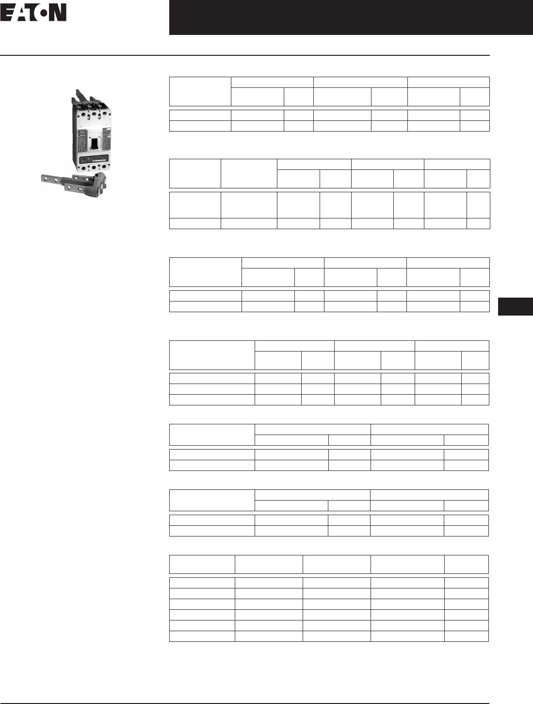
November 2008
CA08101001E For more information visit: www.eaton.com
12-257
Series C Molded Case Circuit Breakers
12
External Accessories
Plug-in Adapters
Plug-in Adapters
Plug-in Adapter
Product Description
Plug-in Adapters simplify installation
and front removal of circuit breakers.
Individual line and load plug-in adapt-
ers are available for rear connection
applications on 2-, 3- and 4-pole circuit
breakers. Common mounting plates
for line- and load-end adapters are
available.
One Plug-in Adapter Kit is required for
line-end and one for load-end.
Plug-in Adapters are UL approved
unless otherwise noted.
Table 12-498. F-Frame Ordering Information (Flat Bar Type)
100 ampere maximum.
Table 12-499. J-Frame Ordering Information (Flat Bar Type)
Use 3-pole mounting plate for 2-pole circuit breaker.
Table 12-500. K-Frame Ordering Information (Flat Bar Type) — 600 Vac Maximum
Use 3-pole mounting plate for 2-pole circuit breaker.
Table 12-501. L-Frame Ordering Information (Threaded Stud Type)
Table 12-502. M-Frame Ordering Information (Flat Bar Type) — 600 Vac Maximum
Table 12-503. N-Frame Ordering Information (Flat Bar Type)
Table 12-504. Plug-in Adapters
Continuous
Current Rating
(Amperes)
2-Pole 3-Pole 4-Pole
Catalog
Number
Price
U.S. $
Catalog
Number
Price
U.S. $
Catalog
Number
Price
U.S. $
100 – 225 1480D13G01 1480D13G02 1480D13G07
Mounting Plate 176C511H01 507C047H01 —
Continuous
Current Rating
(Amperes)
Terminal
End
2-Pole 3-Pole 4-Pole
Catalog
Number
Price
U.S. $
Catalog
Number
Price
U.S. $
Catalog
Number
Price
U.S. $
250
Line
Load
1 Line and 1 Load
1260C86G05
1260C86G07
506C144G27
1260C86G06
1260C86G08
506C144G28
1231C67G01
1231C67G02
—
Mounting Plate
—
PMP23
—
Continuous Current
Rating (Amperes)
2-Pole 3-Pole 4-Pole
Catalog
Number
Price
U.S. $
Catalog
Number
Price
U.S. $
Catalog
Number
Price
U.S. $
400 PAD32 PAD33 —
Mounting Plate PMP33 —
Continuous Current
Rating (Amperes)
2-Pole 3-Pole 4-Pole
Catalog
Number
Price
U.S. $
Catalog
Number
Price
U.S. $
Catalog
Number
Price
U.S. $
600 (Threaded Stud Type) 506C059G03 506C059G04 PAD44
600 (Flat Bar Type) 1288C19G01 1288C19G02 6636C55H01
Mounting Plate 504C824H01 504C824H01 —
Continuous Current
Rating (Amperes)
2-Pole 3-Pole
Catalog Number Price U.S. $ Catalog Number Price U.S. $
800 2614D53G05 2614D53G06
Mounting Plate 1290C73H01 1290C73H01
Continuous Current
Rating (Amperes)
2-Pole 3-Pole
Catalog Number Price U.S. $ Catalog Number Price U.S. $
1200 2614D53G03 2614D53G04
Mounting Plate 1290C73H01 1290C73H01
Discount Symbol. . . . . . . . . . . . . . . . . . . . . . . . . CB-2
Frame Poles Standard
Certification
Catalog
Number
Price
U.S. $
FD 3 IEC PAD3F
FD 4 IEC PAD4F
JD 3 IEC PAD3JD
KD 3 IEC PAD3K
LD 3 IEC PAD3LD
LD 4 IEC PAD4LD
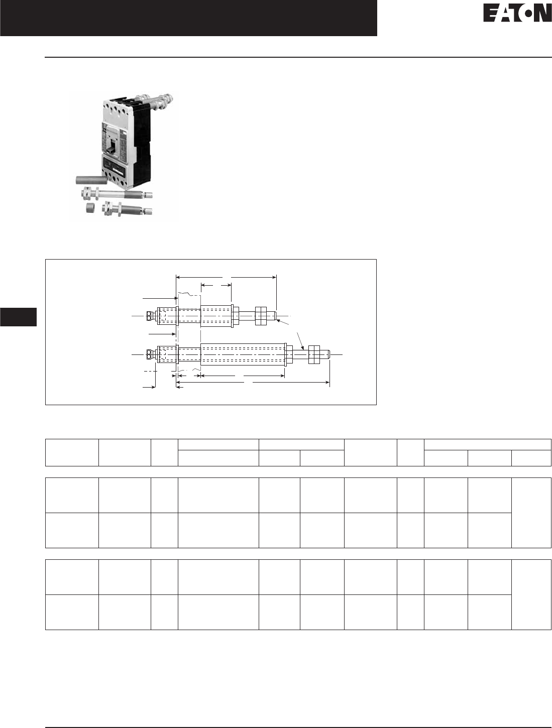
November 2008
12-258
For more information visit: www.eaton.com CA08101001E
Series C Molded Case Circuit Breakers
12
External Accessories
Rear Connecting Studs
Rear Connecting Studs Product Description
Rear Connecting Studs are available in
several sizes to accommodate specific
fixed-mounted circuit breaker
applications.
Each rear connecting stud assembly
consists of one stud and one tube. To
maintain proper clearances between
poles, select alternate long and short
stud assemblies for circuit breakers
with more than one pole. One assem-
bly is required for line-end and one
for load-end of each pole. Tubes
must be ordered separately.
Connecting studs are available
only with English thread sizes.
Note: Not UL listed.
Figure 12-55. F-Frame
Table 12-505. F-Frame Ordering Information — Dimensions in Inches (mm)
Not UL listed.
Stud
Ampere
Rating
Stud
Catalog
Number
Price
U.S. $
Panel Thickness Tube Length Tube
Catalog
Number
Price
U.S. $
Dimensions
ABC DEF
For 15 to 100 Ampere Circuit Breakers
100 A Short
100 A Short
100 A Short
100 A Short
451D874G01
451D874G01
451D874G01
451D874G01
1.00 (25.4)
.69 – .94 (17.5 to 23.8)
.38 – .63 (9.5 to 15.9)
.25 – .31 (6.4 to 7.9)
1.06 (26.9)
1.38 (34.9)
1.69 (42.9)
2.00 (50.8)
—
—
—
—
32B9446H20
32B9446H21
32B9446H22
32B9446H23
—
—
—
—
3.63 (92.1) .31
(7.9) – 18
100 A Long
100 A Long
100 A Long
100 A Long
451D874G02
451D874G02
451D874G02
451D874G02
1.00 (25.4)
.69 – .94 (17.5 to 23.8)
.38 – .63 (9.5 to 15.9)
.25 – .31 (6.4 to 7.9)
—
—
—
—
3.44 (87.3)
3.75 (95.2)
4.06 (103.1)
4.38 (111.3)
32B9446H24
32B9446H25
32B9446H26
32B9446H27
6.13 (155.6) —
—
—
—
For 110 to 225 Amperes Circuit Breakers
225 A Short
225 A Short
225 A Short
225 A Short
374D883G01
374D883G01
374D883G01
374D883G01
1.00 (25.4)
.69 – .94 (17.5 to 23.8)
.38 – .63 (9.5 to 15.9)
.25 – .31 (6.4 to 7.9)
1.06 (26.9)
1.38 (34.9)
1.69 (42.9)
2.00 (50.8)
—
—
—
—
374D883H06
374D883H07
374D883H08
374D883H09
—
—
—
—
4.25 (108.0) .44
(11.1) – 14
225 A Long
225 A Long
225 A Long
225 A Long
374D883G02
374D883G02
374D883G02
374D883G02
1.00 (25.4)
.69 – .94 (17.5 to 23.8)
.38 – .63 (9.5 to 15.9)
.25 – .31 (6.4 to 7.9)
—
—
—
—
3.44 (87.3)
3.75 (95.2)
4.06 (103.1)
4.38 (111.3)
374D883H10
374D883H11
374D883H12
374D883H13
7.50 (190.5) —
—
—
—
E
B
AC
D
Mounting Panel
Breaker Mounting
Surface
“F” Thread
.75
(19.1)
.06
(1.5)
Discount Symbol . . . . . . . . . . . . . . . . . . . . . . . . . CB-2

November 2008
CA08101001E For more information visit: www.eaton.com
12-259
Series G Molded Case Circuit Breakers
12
External Accessories
Rear Connecting Studs
Table 12-506. J-Frame Ordering Information — Dimensions in Inches (mm)
Not UL listed.
Figure 12-56. J-Frame
Table 12-507. K-Frame Ordering Information — Dimensions in Inches (mm)
Not UL listed.
Figure 12-57. K-Frame
Stud
Ampere
Rating
Stud
Catalog
Number
Price
U.S. $
Panel Thickness Tube Length Tube
Catalog
Number
Price
U.S. $
ABC
250 A Short
250 A Short
250 A Short
250 A Long
250 A Long
250 A Long
5010D23G01
5010D23G01
5010D23G01
5010D23G02
5010D23G02
5010D23G02
.75 – 1.00 (19.1 – 25.4)
.50 – .75 (12.7 – 19.1)
.25 – .50 (6.4 – 12.7)
.75 – 1.00 (19.1 – 25.4)
.50 – .75 (12.7 – 19.1)
.25 – .50 (6.4 – 12.7)
.84 (21.4)
1.09 (27.7)
1.03 (26.2)
—
—
—
—
—
—
3.88 (98.6)
4.13 (104.9)
4.38 (111.3)
456D983H05
456D983H06
456D983H07
5010D23H05
5010D23H06
5010D23H07
Stud
Ampere
Rating
Stud
Catalog
Number
Price
U.S. $
Panel Thickness Tube Length Standard Tube
Catalog
Number
Price
U.S. $
Dimensions
ABC DEF
400 A Short
400 A Short
400 A Short
400 A Long
400 A Long
400 A Long
6642C14G02
6642C14G04
6642C14G06
6642C14G03
6642C14G05
6642C14G07
.75 – 1 (19.1 – 25.4)
.50 – .75 (12.7 – 18.4)
.25 – .5 (6.35 – 12.7)
.75 – 1 (19.1 – 25.4)
.50 – .75 (12.7 – 18.4)
.25 – .5 (6.35 – 12.7)
.84 (21.3)
1.09 (27.69)
1.03 (26.16)
—
—
—
—
—
—
3.78 (96.0)
4.03 (102.4)
4.28 (108.7)
313C909H17
313C909H18
313C909H19
313C909H20
313C909H21
313C909H22
—
—
—
—
6.58 (167.1)
—
3.66 (93.0)
—
—
—
—
—
.75 – 16 (19.1 – 406.4)
—
—
—
—
—
Mountin
g
Pane
l
D
o
N
ot
Use
M
o
r
e
Th
a
n 1
0
F
t
. L
bs.
Torque to Ti
g
hten Nut
s
C
A
.31
(
7.9
)
–
1
8
Thr
ead
Breaker
r
B
6
.
66
(
169.2
)
.
06
(
1.5
)
.
59
(
15.0
)
159
1
.
59
(
40.4
)
.
03
(
.7
)
.50
(
12.7
)
–
13 Thread
h
r
e
363
3
.
63
(92
.
2)
(92 2)
Mountin
g
Pane
l
Breaker Mountin
g
Su
rf
ace
“
F
”
Thr
ead
C
A
A
A
D
B
E
.
06
(
1.5
)
167
1
.
67
(42.4)
42 4
Discount Symbol . . . . . . . . . . . . . . . . . . . . . . . . CB-2
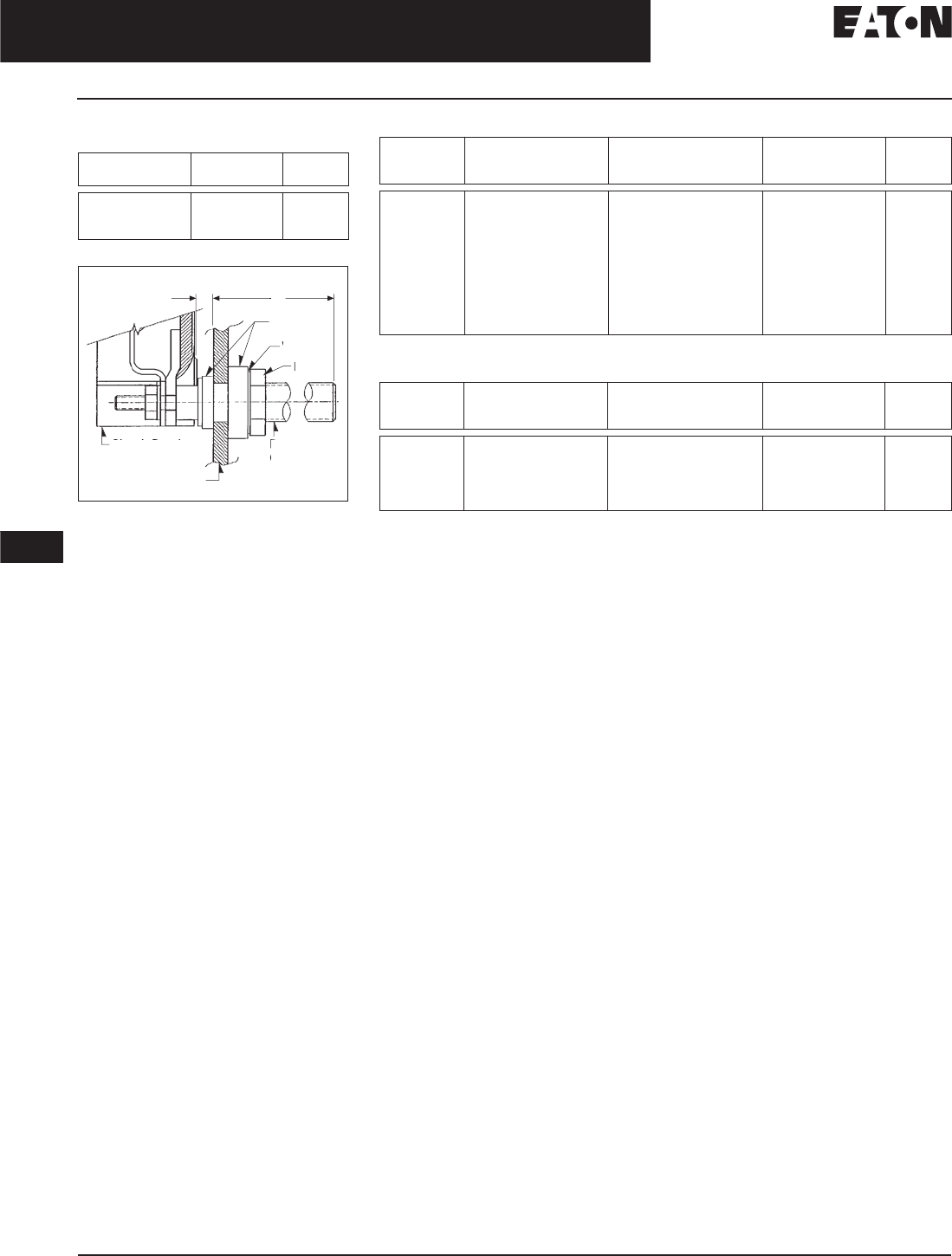
November 2008
12-260
For more information visit: www.eaton.com CA08101001E
Series C Molded Case Circuit Breakers
12
External Accessories
Rear Connecting Studs
Table 12-508. L-Frame Ordering Information
— Dimensions in Inches (mm)
Figure 12-58. L-Frame
Stud Length (A) Stud Catalog
Number
Price
U.S. $
5.47 (138.9)
7.97 (202.4)
10.47 (265.9)
314C960G07
314C960G08
314C960G09
A
A
A
I
n
sulato
r
s
Nut
Rear
C
onnectin
g
S
Stud
Was
h
er
Insulatin
g
Pane
l
Ci
r
cuit
B
r
eaker
.44
(
11.2
)
Table 12-509. M-Frame Ordering Information — Dimensions in Inches (mm)
Not UL listed.
Table 12-510. N-Frame Ordering Information — Dimensions in Inches (mm)
Not UL listed.
Stud
Ampere
Rating
Diameter
and
Thread
Extension
Back of
Breaker
Stud
Catalog
Number
Price
U.S. $
225
400
400
400
600
600
600
800
800
800
.50 (12.7) – 13
.75 (19.1) – 16
.75 (19.1) – 16
.75 (19.1) – 16
1.00 (25.4) – 12
1.00 (25.4) – 12
1.00 (25.4) – 12
1.13 (28.7) – 12
1.13 (28.7) – 12
1.13 (28.7) – 12
3.66 (93.0)
5.91 (150.1)
8.41 (213.6)
10.91 (277.0)
5.91 (150.1)
8.41 (213.6)
10.91 (277.0)
5.91 (150.1)
8.41 (213.6)
10.91 (277.0)
314C960G01
314C960G04
314C960G05
314C960G06
314C960G07
314C960G08
314C960G09
314C960G10
314C960G11
314C960G12
Stud
Ampere
Rating
Diameter
and
Thread
Extension
Back of
Breaker
Stud
Catalog
Number
Price
U.S. $
800
800
800
1200
1200
1.13 (28.7) – 12
1.13 (28.7) – 12
1.13 (28.7) – 12
1.25 (31.8) – 12
1.25 (31.8) – 12
5.5 (139.7)
8.0 (203.2)
10.5 (266.7)
5.5 (139.7)
10.5 (266.7)
623B222G01
623B222G02
623B222G03
373B375G04
373B375G03
Discount Symbol . . . . . . . . . . . . . . . . . . . . . . . . . CB-2
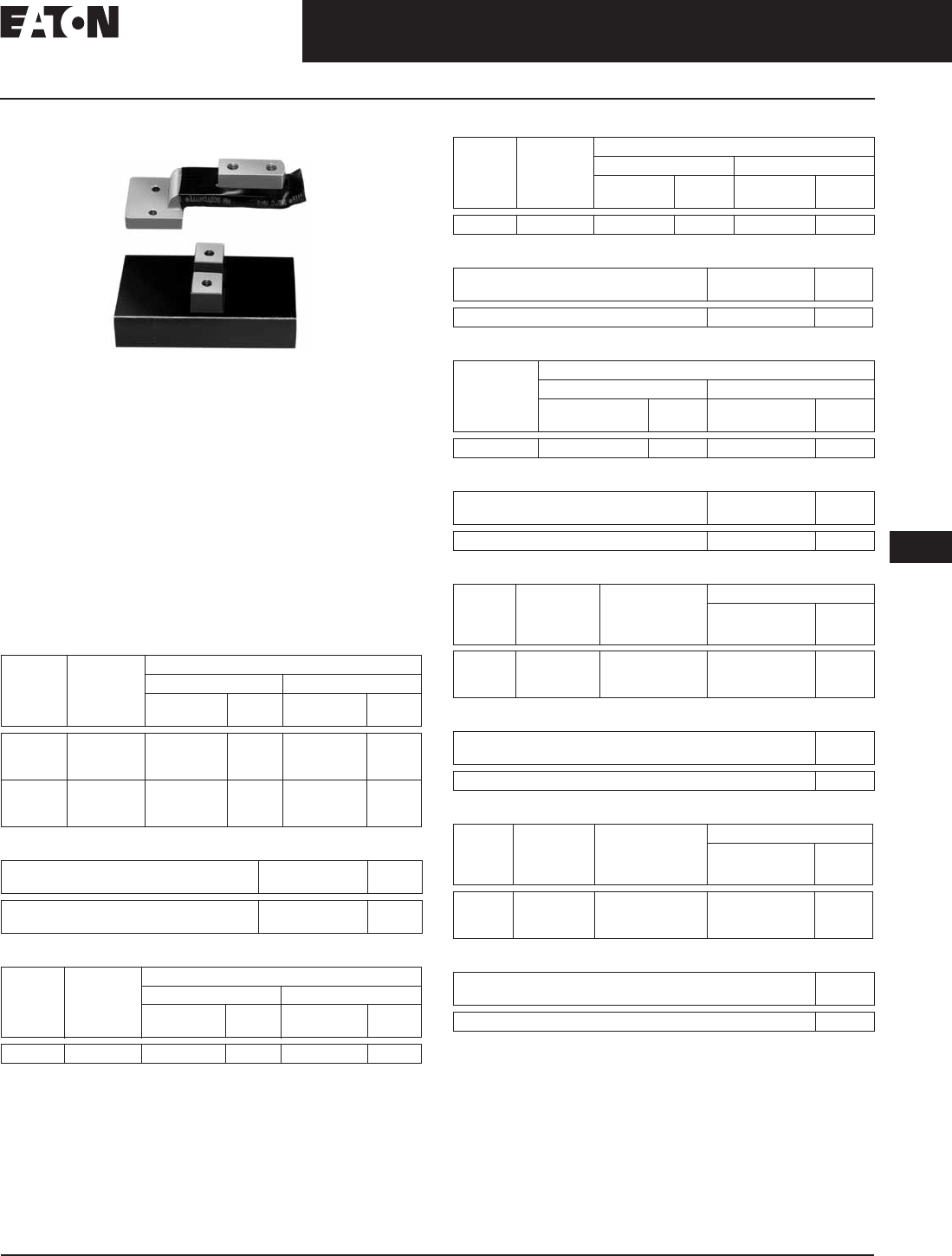
November 2008
CA08101001E For more information visit: www.eaton.com
12-261
Series C Molded Case Circuit Breakers
12
External Accessories
Panelboard Connecting Straps
Panelboard Connecting Straps
Panelboard Connecting Straps
Product Description
Panelboard Connecting Straps are used to connect the
circuit breaker terminals to the panelboard bus. The panel-
board connecting straps are available with various ratings
for outside and center poles. (Field installation only.)
Panelboard connecting straps are available to meet the
needs of most standard panelboard applications. Style
numbers for mounting brackets for CDP panelboard
installations are also included.
Note: Not UL listed.
Refer to panelboard manufacturer for compatibility.
Table 12-511. F-Frame Panelboard Connecting Straps
Table 12-512. F-Frame Mounting Bracket
Table 12-513. J-Frame Panelboard Connecting Straps
Table 12-514. K-Frame Panelboard Connecting Straps
Table 12-515. K-Frame Mounting Bracket
Table 12-516. L-Frame Panelboard Connecting Straps
Table 12-517. L-Frame Mounting Bracket
Table 12-518. M-Frame Panelboard Connecting Straps
Table 12-519. M-Frame Mounting Bracket
Table 12-520. N-Frame Panelboard Connecting Straps
Table 12-521. N-Frame Mounting Bracket (Four [4] Required)
Bus
Spacing
in Inches
(mm)
Continuous
Current
Rating
(Amperes)
Pole Connector Type
Center Outside
Catalog
Number
Price
U.S. $
Catalog
Number
Price
U.S. $
2.75 (69.9)
2.75 (69.9)
2.75 (69.9)
50
100
150
673B142G02
673B142G02
673B142G04
673B142G09
673B142G10
673B142G03
3.50 (88.9)
3.50 (88.9)
3.50 (88.9)
50
100
150
1253C72G01
1253C73G03
1253C73G01
1253C72G03
1253C73G06
1253C73G05
Number
of Poles
Catalog
Number
Price
U.S. $
2
3
624B600H02
624B600H01
Bus
Spacing
in Inches
(mm)
Continuous
Current
Rating
(Amperes)
Pole Connector Type
Center Outside
Catalog
Number
Price
U.S. $
Catalog
Number
Price
U.S. $
3.50 (88.9) 250 2600D26G01 2600D26G02
Bus
Spacing
in Inches
(mm)
Continuous
Current
Rating
(Amperes)
Pole Connector Type
Center Outside
Catalog
Number
Price
U.S. $
Catalog
Number
Price
U.S. $
3.50 (88.9) 400 4212B78G02 4212B77G01
Number
of Poles
Catalog
Number
Price
U.S. $
2, 3 208B264H01
Continuous
Current
Rating
(Amperes)
Pole Connector Type
Center Outside
Catalog
Number
Price
U.S. $
Catalog
Number
Price
U.S. $
600 624B609G01 506C052G01
Number
of Poles
Catalog
Number
Price
U.S. $
2, 3 208B297H01
Bus
Spacing
in Inches
(mm)
Continuous
Current
Rating
(Amperes)
Connector
Type
Pole Connector Type
Catalog
Number
Price
U.S. $
3.50
(88.9)
800 Short
Medium
Long
314C996G01
314C996G02
314C996G03
Catalog
Number
Price
U.S. $
315C270H01
Bus
Spacing
in Inches
(mm)
Continuous
Current
Rating
(Amperes)
Connector
Type
Pole Connector Type
Catalog
Number
Price
U.S. $
3.50
(88.9)
1200 Short
Medium
Long
505C606G04
505C606G05
505C606G06
Catalog
Number
Price
U.S. $
315C270H01
Discount Symbol . . . . . . . . . . . . . . . . . . . . . . . . . CB-2
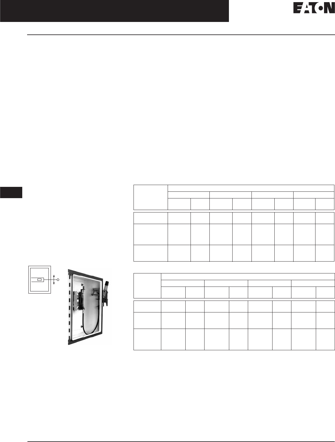
November 2008
12-262
For more information visit: www.eaton.com CA08101001E
Series C Molded Case Circuit Breakers
12
External Accessories
Handle Mechanisms
Handle Mechanisms
Overview
Handle Mechanisms are used to
operate molded case circuit breakers,
molded case switches and motor
circuit protectors. They are available in
three basic configurations — Flange
Mounted, Through-the-Door and
Direct (Close-Coupled) — providing
safe, dependable operation and ease
of installation.
■Flange Mounted:
❑Flex Shaft
❑C371
■Through-the-Door:
❑Series C Rotary
❑Universal Rotary
■Direct (Close-Coupled):
❑Universal Direct
❑Euro IEC
❑G Direct
Handle mechanisms are typically used
on enclosed circuit breakers, control
panels and motor control centers in
many different applications. Eaton
has a handle mechanism for virtually
any need.
Flange Mounted Handle
Mechanisms
Flex Shaft™
Product Description
Flange Mounted Handle Mechanisms
mount on the flange of an enclosure
door. The Flex Shaft™ is an extra
heavy-duty mechanism that includes a
flexible shaft in various lengths, 3 feet
(.9 m) through 10 feet (3 m) for use
with various size enclosures.
The Flex Shaft Handle will accept up
to three padlock shackles, each with
a maximum diameter of 3/8-inch
(9.5 mm). Can be used with NEMA 1,
3R and 12 fabricated enclosures. An
optional handle is available for Flex
Shaft that is suitable for use with
NEMA 4 and 4X environments. Flex
Shaft comes preset from the factory,
requiring only minor field adjustments
on installation, which takes about 10
minutes — a significant time savings
compared to installation of other types
of flange handle mechanisms. The
Flex Shaft mechanism also takes up
less interior enclosure space than
competitive designs and the handle
fits standard flange cutouts. Flex Shaft
Handle can be remotely mounted from
breaker, where an operator can use it by
“funneling” the cable through conduit.
Flex Shaft is UL listed under File
E64983 and meets CSA requirements.
The Type C371 Circuit Breaker Oper-
ating Mechanisms are designed for
installation in control enclosures
where main or branch circuit protec-
tive devices are required. All circuit
breaker mechanisms are suitable
for right-hand mounting.
Auxiliary contacts are not available for
mounting on operating mechanisms.
Where required, have them installed
in circuit breaker.
Type C371 is UL listed under File E62635.
Table 12-522. Flex Shaft Ordering Information
Table 12-522. Flex Shaft Ordering Information (Continued)
Note: Type 4/4X handle mechanisms are available. Add Suffix X to complete catalog
number. Add Suffix I to complete catalog number for IEC handle. Original narrow handle
design (No C Suffix) is available. Remove C from catalog number.
Note: When selecting the length of shaft, ensure minimum bending radius of 4 inches
(101.6 mm) (5 inches, 12.7 mm for L, N, R Frames) is maintained to operate properly. The
standard method of shipment includes the mechanism preset at the factory; however, minor
field adjustments may be required.
Note: Dual breakers operator available on F-Frame only. Only the F, J & K can mount LH & RH
all other RH only.
Breaker
Frame
Flexible Shaft Length in Feet (m)
3 (.9) 4 (1.2) 5 (1.5) 6 (1.8)
Catalog
Number
Price
U.S. $
Catalog
Number
Price
U.S. $
Catalog
Number
Price
U.S. $
Catalog
Number
Price
U.S. $
G
F
F0S03C
F1S03C
F0S04C
F1S04C
F0S05C
F1S05C
F0S06C
F1S06C
F (Dual)
J
K
L and MDL
F1S03CD
F2S03C
F3S03C
N/A
F1S04CD
F2S04C
F3S04C
F4S04C
F1S05CD
F2S05C
F3S05C
F4S05C
F1S06CD
F2S06C
F3S06C
F4S06C
N
R
MD, MDS (Old)
N/A
N/A
N/A
F5S04C
F6S04
F7S04
F5S05C
F6S05
F7S05
F5S06C
F6S06
F7S06
Breaker
Frame
Flexible Shaft Length in Feet (m)
7 (2.1) 8 (2.4) 9 (2.7) 10 (3.0)
Catalog
Number
Price
U.S. $
Catalog
Number
Price
U.S. $
Catalog
Number
Price
U.S. $
Catalog
Number
Price
U.S. $
G
F
N/A
F1S07C
N/A
F1S08C
N/A
F1S09C
N/A
F1S10C
F (Dual)
J
K
F1S07CD
F2S07C
F3S07C
F1S08CD
F2S08C
F3S08C
F1S09CD
F2S09C
F3S09C
F1S10CD
F2S10C
F3S10C
L and MDL
N
R
MD
N/A
N/A
N/A
N/A
N/A
N/A
N/A
N/A
N/A
N/A
N/A
N/A
F4S10C
F5S10C
N/A
F7S10C
Discount Symbol . . . . . . . . . . . . . . . . . . . . . . . . CB-2

CA08101001E For more information visit: www.eaton.com
12-263
Series C Molded Case Circuit Breakers
November 2008
12
External Accessories
Handle Mechanisms
Table 12-523. Type C371 Ordering Information — Dimensions in Inches (mm)
For increased maximum allowable depth, see connecting rods right.
Dimensions shown are from panel flange surface.
Does not include handle.
Table 12-524. Handle Only — Dimensions in Inches (mm)
Circuit Breaker
or Motor Circuit
Protector
Frame
Size
Variable
Depth
Mounting
Range
Min/Max
Operating
Mechanism
Only
Operating Mechanism w/ 4-inch Handle
For NEMA 1–12
Enclosure
For NEMA 4/4X
Enclosure
Catalog
Number
Price
U.S. $
Catalog
Number
Price
U.S. $
Catalog
Number
Price
U.S. $
HMCP & Series C
EHD, FDB, FD,
FDC, HFD, ED
150 6.5 – 16
(165.1 – 406.4)
C371E C371E1 C371E2
HMCP & Series C
HJD, JD, JDB, JDC
250 6.5 – 16.63
(165.1 – 422.4)
C371F C371F5 C371F6
HMCP & Series C
DK, HKD, KD, KDB
400 6.5 – 16.63
(165.1 – 422.4)
C371F C371F5 C371F6
Series C
HLD, LD, LDC
600 8.5 – 22
(215.9 – 558.8)
C371G C371G5 C371G6
Series C MD, MDS
(No MDL)
800 8.75 – 22
(222.3 – 558.8)
C371K C371K5 C371K6
Series C
HND, ND, NDC
1200 9.75 – 22
(247.7 – 558.8)
C371K C371K5 C371K6
Circuit Breaker Frame Size
(Amperes)
NEMA
Enclosure Type
Operating
Handle Length
Catalog
Number
Price
U.S. $
150 1-3R-3-12
4/4X
4 (101.6) C371H1
C371H2
1-3R-3-12
4/4X
6 (152.4) C371H3
C371H4
250 – 1200 1-3R-3-12
4/4X
4 (101.6) C371H5
C371H6
1-3R-3-12
4/4X
6 (152.4) C371H7
C371H8
Table 12-525. Channel Support Kit
(Rod Not Supplied)
For use to prevent bending of the
operating handle mounting surface.
This is especially useful when the
operating handle is mounted on a
channel in a multi-door enclosure.
Included in 600 – 1200 A.
Table 12-526. Connecting Rods
Increase maximum allowable depth by
5 inches (127 mm).
Flex Shaft Accessories
(F- through R-Frame)
Table 12-527. NEMA 12 Safety Door
Hardware for Flex Shaft and C371
Customer: Consult with box manufacturer
for correct door hardware and any adapters
required for assembly.
The 1/4-inch x 1/2-inch (6.35 x 12.7 mm)
standard mill rectangular locking bar is not
supplied with these kits.
Third roller latch for use with 4- or 6-inch
(101.6 or 152.4 mm) handle when 3 point
latching is required.
Catalog
Number
Price
U.S. $
C371CS6
Application Catalog
Number
Price
U.S. $
Disconnect Switches
(30, 60, 100, 200 A Sizes)
C371CS1
Circuit Breakers
(150, 250, 400 A Sizes)
C371CS1
Circuit Breakers
(600, 800, 1200 A Sizes)
C371CS2
Handle Length
in Inches (mm)
Catalog
Number
Price
U.S. $
4 (101.6)
6 (152.4)
C361KJ4
C361KJ6
Roller Latch C361KR
Discount Symbol . . . . . . . . . . . . . . . . . . . . . . . . . CB-2
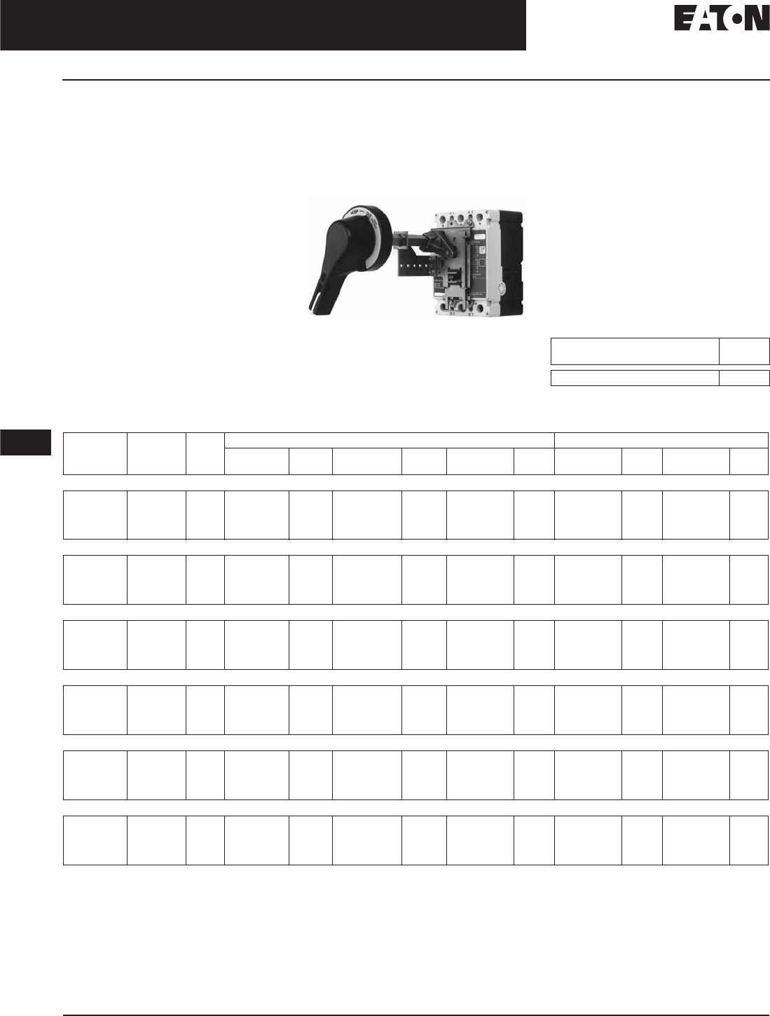
November 2008
12-264
For more information visit: www.eaton.com CA08101001E
Series C Molded Case Circuit Breakers
12
External Accessories
Handle Mechanisms
Through-the-Door
Handle Mechanisms
Eaton’s Cutler-Hammer through-the-
door handle mechanisms mount on the
front of an enclosure or cabinet door
and externally operate the circuit
breaker via a variable depth shaft or a
linear operator (Type MC). Each rotary
type handle mechanism includes a
handle, base operating mechanism and
shaft that can be cut to various lengths.
Series C Rotary and Universal Rotary
handle mechanisms are for use with
Molded Case Circuit Breakers (G, F, J,
K, L, MDL), Molded Case Switches and
Motor Circuit Protectors.
Series C Rotary and Universal Rotary,
are UL listed and meet CSA require-
ments. Universal Rotary also meets
IEC947-1/2 for international
compliance. Rotary UL File Number
is E64983.
Series C Rotary
Type 4/4X handles are similar to stan-
dard handles except they include an
internal neoprene gasket. Type 4/4X
handle style number is 6648C22G03.
Due to gasketing effect between the
handle and the housing, the handle
may not indicate a tripped position.
Series C Rotary Accessories
As an option, an auxiliary switch is
offered so that the control panel
builder may electrically indicate the
status of the breaker. This accessory
would be mounted on the mechanism
and comes with 24-inch (609.6 mm)
pigtail leads.
Table 12-528. Series C Auxiliary Switch
Table 12-529. Series C Rotary Ordering Information
Complete catalog number includes the standard handle, mechanism, shaft and support brace/bracket.
Handle is designed suitable for NEMA Types 1, 3R and 12 enclosures. Use style number 6648C22G03 for Type 4/4X handle or add X Suffix to complete
catalog number. Handle is cast aluminum.
Breaker mechanism includes a shaft support bracket and its parts. Shaft is .50-inch (12.7 mm).
Longer shafts,16-inch (406.4 mm) and 24-inch (609.6 mm), include an adjustable support extension.
IEC Handle Mechanism supplied with Metric thread mounting hardware.
Complete catalog number includes a handle, mechanism and shaft.
Catalog
Number
Price
U.S. $
5108A61G01
Shaft
Length
Inches (mm)
Complete
Catalog
Number
Price
U.S. $
Separate Catalog Number Catalog Number
Standard
Handle
Price
U.S. $
Breaker
Mechanism
Price
U.S. $
Shaft Price
U.S. $
IEC IP65 Price
U.S. $
IEC IP66 Price
U.S. $
F-Frame
6 (152.4)
12 (304.8)
16 (406.4)
24 (609.6)
HM1R06
HM1R12
HM1R16
HM1R24
6648C22G25
6648C22G25
6648C22G25
6648C22G25
6648C23G11
6648C23G11
6648C23G11
6648C23G11
4217B37G08
4217B37G05
4217B37G06
4217B37G07
WHM1R06
WHM1R12
WHM1R16
WHM1R24
WHM1R06X
WHM1R12X
WHM1R16X
WHM1R24X
J-Frame
6 (152.4)
12 (304.8)
16 (406.4)
24 (609.6)
HM2R06
HM2R12
HM2R16
HM2R24
6648C22G01
6648C22G01
6648C22G01
6648C22G01
6648C23G21
6648C23G21
6648C23G21
6648C23G21
4217B37G08
4217B37G05
4217B37G06
4217B37G07
WHM2R06
WHM2R12
WHM2R16
WHM2R24
WHM2R06X
WHM2R12X
WHM2R16X
WHM2R24X
K-Frame
6 (152.4)
12 (304.8)
16 (406.4)
24 (609.6)
HM3R06
HM3R12
HM3R16
HM3R24
6648C22G01
6648C22G01
6648C22G01
6648C22G01
6648C23G25
6648C23G25
6648C23G25
6648C23G25
4217B37G08
4217B37G05
4217B37G06
4217B37G07
WHM3R06
WHM3R12
WHM3R16
WHM3R24
WHM3R06X
WHM3R12X
WHM3R16X
WHM3R24X
L- and MDL-Frame
6 (152.4)
12 (304.8)
16 (406.4)
24 (609.6)
HM4R06
HM4R12
HM4R16
HM4R24
6648C22G11
6648C22G11
6648C22G11
6648C22G11
6648C23G19
6648C23G19
6648C23G19
6648C23G19
4217B37G08
4217B37G05
4217B37G06
4217B37G07
WHM4R06
WHM4R12
WHM4R16
WHM4R24
WHM4R06X
WHM4R12X
WHM4R16X
WHM4R24X
MD/MDS
6 (152.4)
12 (304.8)
16 (406.4)
24 (609.6)
HM7R06
HM7R12
HM7R16
HM7R24
6648C22G21
6648C22G21
6648C22G21
6648C22G21
6648C23G17
6648C23G17
6648C23G17
6648C23G17
4217B37G08
4217B37G05
4217B37G06
4217B37G07
—
—
—
—
—
—
—
—
N-Frame
6 (152.4)
12 (304.8)
16 (406.4)
24 (609.6)
HM5R06
HM5R12
HM5R16
HM5R24
6648C22G21
6648C22G21
6648C22G21
6648C22G21
6648C23G08
6648C23G08
6648C23G08
6648C23G08
4217B37G08
4217B37G05
4217B37G06
4217B37G07
WHM5R06
WHM5R12
WHM5R16
WHM5R24
WHM5R06X
WHM5R12X
WHM5R16X
WHM5R24X
Discount Symbol. . . . . . . . . . . . . . . . . . . . . . . . . CB-2
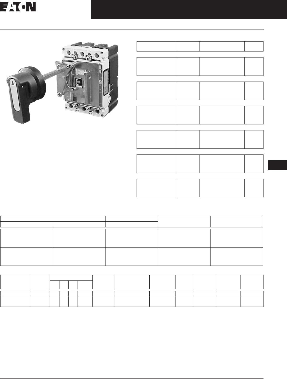
November 2008
CA08101001E For more information visit: www.eaton.com
12-265
Series C Molded Case Circuit Breakers
12
External Accessories
Handle Mechanisms
Universal Rotary F-Frame
Table 12-530. Series C Universal Rotary Ordering Information
Only available as complete handle mechanism. Parts not sold
separately.
Table 12-531. Series C G-Frame Vari-Depth Handle Mechanism (Not Shown)
Table 12-532. Features Comparison of Series C Rotary and Universal Rotary Handle Mechanism
Type 4/4X application requires special handle. See “Ordering Information.”
All rotary handle mechanisms include a handle “Lock Off” to prevent turning the breaker ON while in the OFF position.
Series C Rotary handle was ergonomically designed with extra clearance for a “gloved hand” to operate. Handle has a 45-degree rotation.
Universal Rotary has a 90-degree rotation (“pipe valve” operation) where ON is vertical and OFF is horizontal. Shafts include a support brace to
ensure proper alignment.
Shaft Length
in Inches (mm)
Handle
Color
Complete
Catalog Number
Price
U.S. $
F-Frame
6 (152.4)
12 (304.8)
6 (152.4)
12 (304.8)
Black
Black
Red
Red
FHMVD06B
FHMVD12B
FHMVD06R
FHMVD12R
G-Frame
6 (152.4)
12 (304.8)
6 (152.4)
12 (304.8)
Black
Black
Red
Red
GHMVD06B
GHMVD12B
GHMVD06R
GHMVD12R
J-Frame
6 (152.4)
12 (304.8)
6 (152.4)
12 (304.8)
Black
Black
Red
Red
JHMVD06B
JHMVD12B
JHMVD06R
JHMVD12R
K-Frame
6 (152.4)
12 (304.8)
6 (152.4)
12 (304.8)
Black
Black
Red
Red
KHMVD06B
KHMVD12B
KHMVD06R
KHMVD12R
L-Frame
6 (152.4)
12 (304.8)
6 (152.4)
12 (304.8)
Black
Black
Red
Red
LHMVD06B
LHMVD12B
LHMVD06R
LHMVD12R
MDL-Frame
6 (152.4)
12 (304.8)
6 (152.4)
12 (304.8)
Black
Black
Red
Red
MHMVD06B
MHMVD12B
MHMVD06R
MHMVD12R
For Use With: Handle Color Complete
Catalog Number
Price
U.S. $
Enclosure Breaker Black
NEMA 1
NEMA 1
NEMA 3R/12/4X
NEMA 3R/12/4X
GC/GHC/GD
GC/GHC/GD
GC/GHC/GD
GC/GHC/GD
Yellow
Black
Yellow
Black
HRGCV11L
HRGCV31L
HRGCV14L
HRGCV34L
NEMA 1
NEMA 1
NEMA 3R/12/4X
NEMA 3R/12/4X
GMCP
GMCP
GMCP
GMCP
Yellow
Black
Yellow
Black
HRGMV11L
HRGMV31L
HRGMV14L
HRGMV34L
Rotary Number
of Poles
NEMA Enclosure Type Handle
Lock-Off
Handle Indication:
ON/OFF TRIPPED/
RESET
International
Markings ON
(I) OFF (O)
Handle
Material
Available
Handle
Colors
Handle
Rotation
Shaft
Lengths
(Inches)
1 3R 12 4/4X
Series C Rotary X X X X X X X Metal Black 45 deg. 6, 12, 16, 24
Universal
Rotary
X — X — X X X Molded
Plastic
Yellow/Red 90 deg. 6, 12
Discount Symbol . . . . . . . . . . . . . . . . . . . . . . . . . CB-2
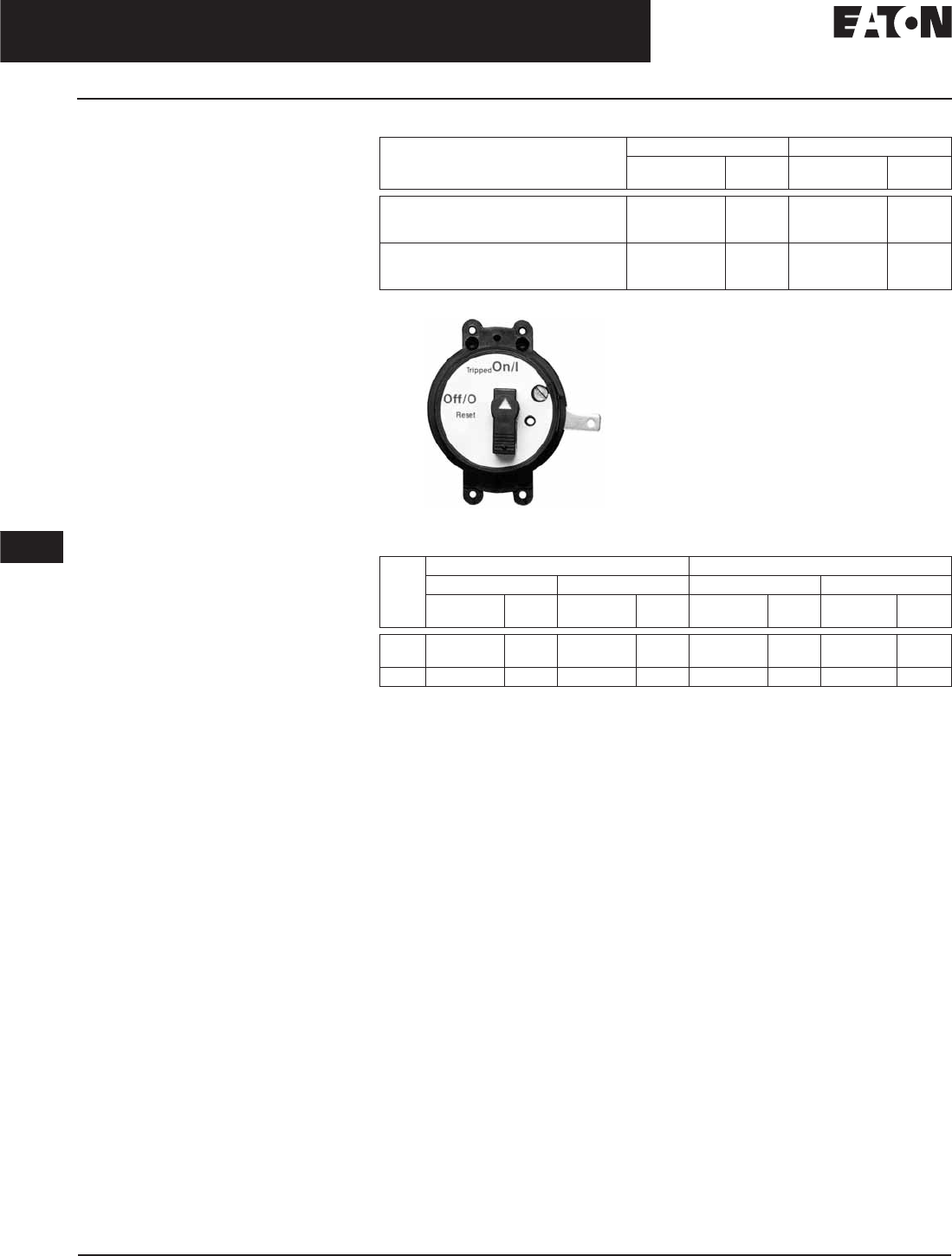
November 2008
12-266
For more information visit: www.eaton.com CA08101001E
Series C Molded Case Circuit Breakers
12
External Accessories
Handle Mechanisms
Direct (Close-Coupled)
Handle Mechanisms
Product Description
Direct (Close-Coupled) Handle Mech-
anisms mount directly to the circuit
breaker. They are used in shallow
enclosures where the standard vari-
able depth Through-the-Door type
mechanism is not practical or cannot
be used. They are typically for applica-
tions where high volume, standardized
enclosures are being fabricated.
The Euro IEC Direct handle mechanism
can be used on F- through R-Frames.
The G Direct is available with a black
or the yellow handle, and with or
without a shroud. It is suitable for
use with NEMA 1 enclosures. It is for
use only with the G-Frame (GD, GC,
GHC, GMCP).
An escutcheon ring and interlock clip
are provided as standard. The stan-
dard design includes a lock-off feature.
The Universal Direct handle mecha-
nism is UL 489 listed, IEC947-1/2 and
meets CSA requirements. The Euro
IEC Direct handle mechanism is IEC-
240-1. G Direct is UL listed and meets
CSA requirements.
Table 12-533. Euro IEC Direct Ordering Information
G Direct
Table 12-534. G Direct Ordering Information
Suitable for use on 2- or 3-Pole G-Frame.
Frame Black Handle Red Handle
Catalog
Number
Price
U.S. $
Catalog
Number
Price
U.S. $
F
J
K
HMCC1B
HMCC2B
HMCC3B
HMCC1R
HMCC2R
HMCC3R
L and M
N
R
HMCC4B
HMVD5B
HMVD6B
HMCC4R
—
—
Frame Black Handle Yellow Handle
with Shroud without Shroud with Shroud without Shroud
Catalog
Number
Price
U.S. $
Catalog
Number
Price
U.S. $
Catalog
Number
Price
U.S. $
Catalog
Number
Price
U.S. $
GD/
GHC
HRGCC1S HRGCC10 HRGCC3S HRGCC30
GMCP HRGMC1S HRGMC10 HRGMC3S HRGMC30
Discount Symbol . . . . . . . . . . . . . . . . . . . . . . . . . CB-2
November 2008
CA08101001E For more information visit: www.eaton.com
12-267
Series C Molded Case Circuit Breakers
12
External Accessories
Handle Mechanisms
Handle Extension
Handle Extension
Handle Extension is not included
with J, K, L, M and N-Frame breakers.
It must be purchased separately.
Table 12-535. Handle Extension
Handle Extension is included with
breaker with R-Frame breakers.
Table 12-536. Handle Extension
Frame Style
Number
Price
U.S. $
J, K
L, M
HEX3
HEX4
Frame Style
Number
Price
U.S. $
N
R
HEX5
HEX6
Discount Symbol . . . . . . . . . . . . . . . . . . . . . . . . CB-2
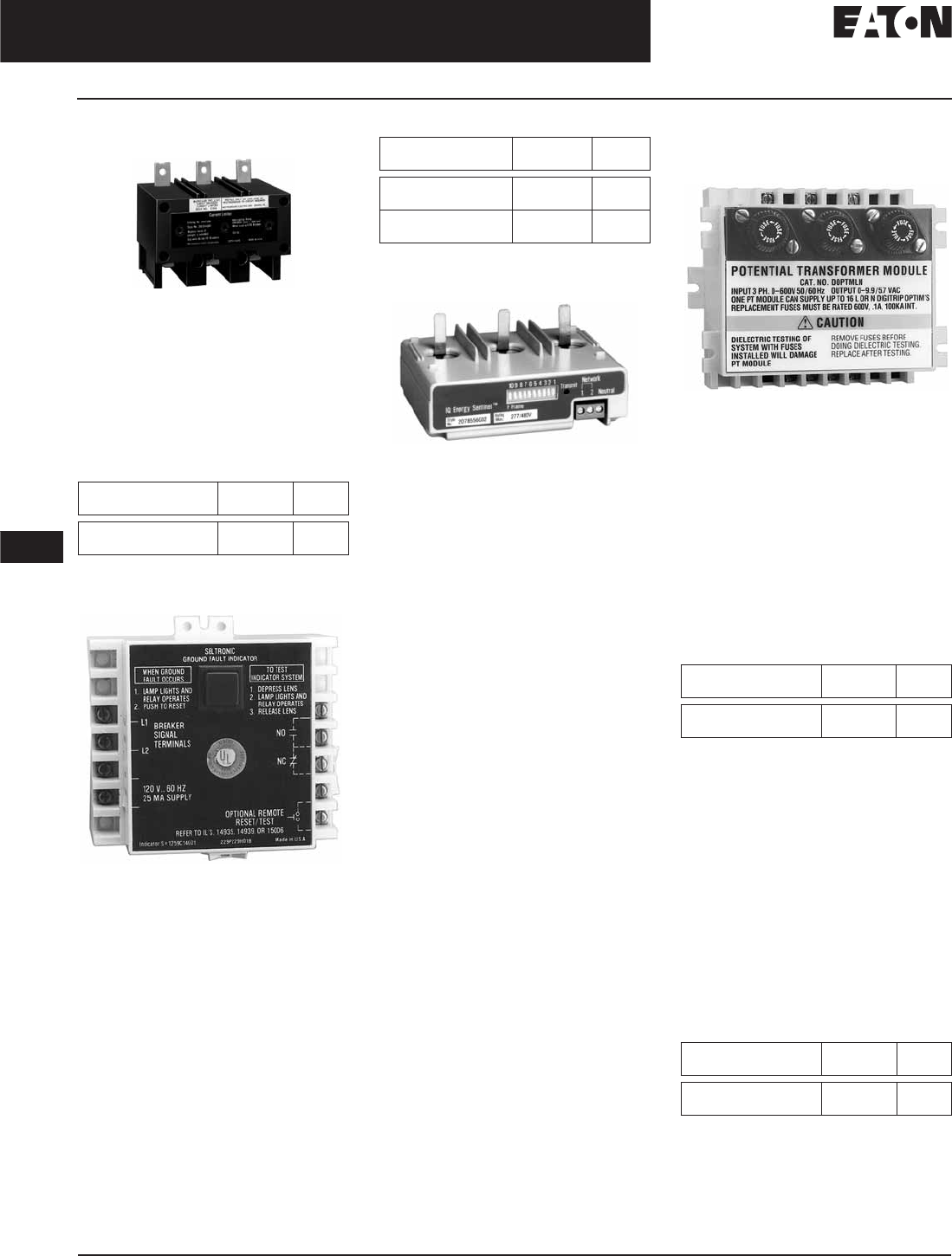
November 2008
12-268
For more information visit: www.eaton.com CA08101001E
Series C Molded Case Circuit Breakers
12
External Accessories
Current Limiters, Alarms and Test Kits
Type LFD Current Limiter
The LFD Current Limiter is an acces-
sory that bolts to the load end of a
standard FDB or FD thermal-magnetic
circuit breaker, providing 200,000 A
interrupting capacity at up to 600 Vac.
LFD current limiters for thermal-
magnetic circuit breakers are listed
with Underwriters Laboratories under
File E47239.
Table 12-537. Type LFD Current Limiter
Ground Fault Alarm Unit
The Ground Fault Alarm Unit is a
remotely mounted device with a com-
bination indicating light/test button
that will light when the breaker trips or
alarms on ground fault. The Ground
Fault Alarm Unit requires a separate
120 Vac power source to power the
light and the internal relay which has
1NO and 1NC contacts for remote indi-
cation. The Ground Fault Alarm Unit
can be panel mounted for ordering
with an optional face mounting
bracket. For use on Digitrip 310 only,
K- through N-Frame.
Circuit Breaker
Rating Amperes
Catalog
Number
Price
U.S. $
15 – 70
80 – 160
LFD3070R
LFD3150R
Table 12-538. GF Alarm Unit
IQ Energy Sentinel
The IQ Energy Sentinel is a highly
accurate, microprocessor-based,
breaker-mounted device designed to
monitor power and energy readings.
It represents an alternative to watt
meters, watt-hour meters, and watt
demand meters. Key advantages
include savings in space, lower instal-
lation costs, and remote monitoring
capability.
The IQ Energy Sentinel mounts on
the load side of a Series C F-Frame
(150 ampere) circuit breaker. It can be
applied on 3-phase, 4-wire systems,
or single-phase, 3-wire systems with
voltage connected through phases
A and C.
For more information, see Descriptive
Bulletin 8178.
Potential Transformer
Module
The Potential Transformer Module is
required for the Digitrip OPTIM 1050
to provide a voltage input to allow the
trip unit to monitor power and energy
as well as power factor. The Potential
Transformer Module is a 6 VA trans-
former with a primary voltage input
of up to 600 volt line to line. Three 0.1
ampere fuses are provided on the
primary of the transformer and can
be used for isolation purposes during
dielectric testing. The device is nor-
mally panel mounted and can feed
up to 16 OPTIM trip units.
Table 12-539. Potential Transformer Module
Solid-State (Electronic)
Portable Test Kit
The Solid-State (Electronic) Portable
Test Kit provides verification of perfor-
mance of all ratings of Digitrip 310
electronic trip units installed in circuit
breakers while in service under vary-
ing load and/or phase imbalance. The
test kit operates on 120-volt, 50/60 Hz
power; it includes complete instruc-
tions and test times for testing long
time, short time/instantaneous opera-
tion and optional ground fault opera-
tion of the circuit breaker.
Table 12-540. Portable Test Kit
Description Catalog
Number
Price
U.S. $
Ground Fault
Alarm Unit
GFAU
Face Mounting
Bracket
1264C67G01
Description Catalog
Number
Price
U.S. $
Potential Transformer
Module
DOPTMLN
Description Catalog
Number
Price
U.S. $
Solid-State (Electronic)
Portable Test Kit
STK2
Discount Symbol . . . . . . . . . . . . . . . . . . . . . . . . CB-2
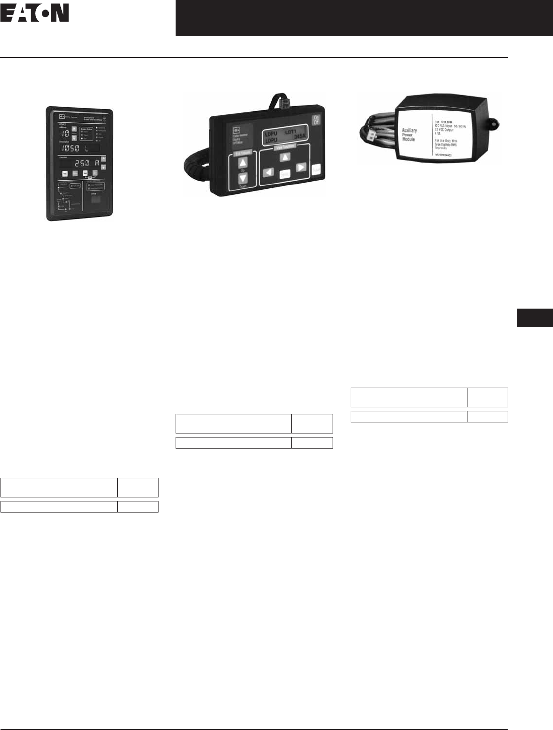
November 2008
CA08101001E For more information visit: www.eaton.com
12-269
Series C Molded Case Circuit Breakers
12
External Accessories
OPTIM System Components
Breaker Interface
Module (BIM)
The Breaker Interface Module (BIM) is a
panel mounted user interface device
that is mounted on the front of an elec-
trical assembly or at a remote location.
The BIM is used to access, configure,
test and display information for OPTIM
trip units and other devices. The BIM
consists of four display windows, eight
function buttons, 18 LEDs, and a graph-
ical time/current curve to provide
breaker status, operational information,
protection status and energy monitor-
ing. A 24 Vdc power supply is required
to provide power to the BIM. This is
supplied by the switchboard builder to
Eaton’s specifications. The BIM is a
member of Eaton’s Cutler-Hammer
PowerNet family of communicating
devices that connects OPTIM trip units,
Digitrip RMS 810/910 trip units and
energy sentinels as a subnetwork sys-
tem. The BIM can also be connected
to a main network via a PONI module
to PowerNet software.
Table 12-541. Breaker Interface Module (BIM)
Catalog
Number
Price
U.S. $
BIMII
Digitrip OPTIMizer
The Digitrip OPTIMizer is a hand-held
programmer that is used to access,
configure, test and display information
from OPTIM trip units. The OPTIMizer
plugs into the front of an OPTIM trip
unit via an eight-pin telephone jack
and is powered by a nine-volt battery
or the auxiliary power module. One
highlighted feature is the “Copy” and
“Download” commands. Setting up
multiple OPTIM trips can be finished in
minutes and with no errors. An Auxil-
iary Power Module connection provides
a trip test when control power is not
present at the breaker. The OPTIMizer
is supplied as a standard package to
include the programmer, the eight-pin
connection cord, battery and carrying
case. The Auxiliary Power Module
is optional.
Table 12-542. Digitrip OPTIMizer
Note: 24 Vdc Power Supply
A 24 Vdc power supply is required for all
Digitrip OPTIM trip units that are required to
communicate either on the main Eaton’s
Cutler-Hammer PowerNet network or as a
subnetwork to a BIM. The breaker’s load is
45 mA of current. Typically one power sup-
ply is required per switchboard and can pro-
vide control power to a BIM and the OPTIM
trip units. The 24 Vdc power supply should
be an “isolated high quality” power supply
with a “CE” label, and is normally provided
by the switchboard manufacturer to Eaton’s
recommendations.
Auxiliary Power Module
The Auxiliary Power Module is a
power supply requiring 120 Vac input
at 50 or 60 Hz that provides a 32 Vdc
output. The Auxiliary Power Module
provides control power for testing an
OPTIM trip unit when other means of
control power is not available or for
continuous OPTIMizer operation versus
temporary with a battery. The Auxiliary
Power Module connects into the top
of the Digitrip OPTIMizer via a keyed
receptacle. The main application for
the Auxiliary Power Module would
be for the testing of a stand-alone
non-communicating OPTIM breaker
that ordinarily would not have
control power.
Note: The OPTIMizer can work off of 32 Vdc
control power, although 24 Vdc is the stan-
dard on OPTIM breakers.
Table 12-543. Auxiliary Power Module
Catalog
Number
Price
U.S. $
OPTIMizer — Standard Package
Catalog
Number
Price
U.S. $
PRTBAPMDV
Discount Symbol . . . . . . . . . . . . . . . . . . . . . . . . CB-2
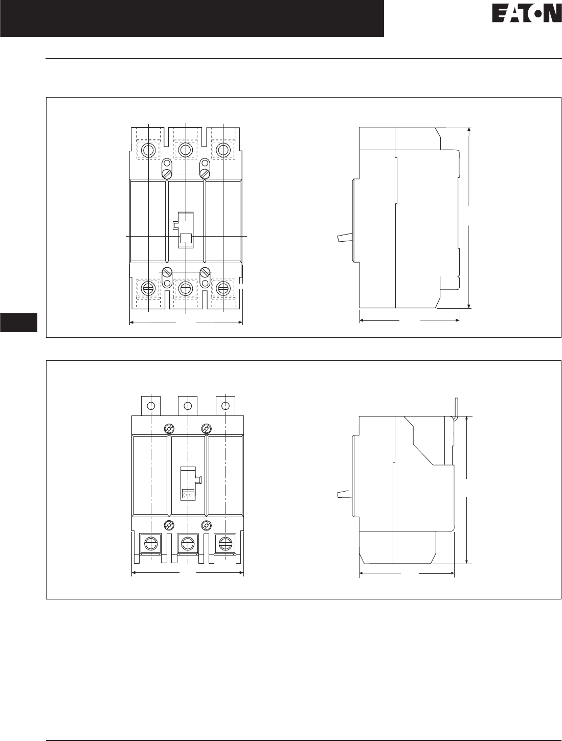
November 2008
12-270
For more information visit: www.eaton.com CA08101001E
Series C Molded Case Circuit Breakers
12
15 – 2500 Amperes for UL, CSA & IEC Applications
Frame Size GD and GDB
Dimensions
Figure 12-59. GD-Frame, 3-Pole — Dimensions in Inches (mm)
Figure 12-60. GDB-Frame, 3-Pole — Dimensions in Inches (mm)
Off
3.00
(76.2)
4.88
(123.8)
2.63
(66.7)
Front View Side View
3.00
(76.2)
Max.
2.63
(66.7)
4.00
(101.6)
Front View
Side View
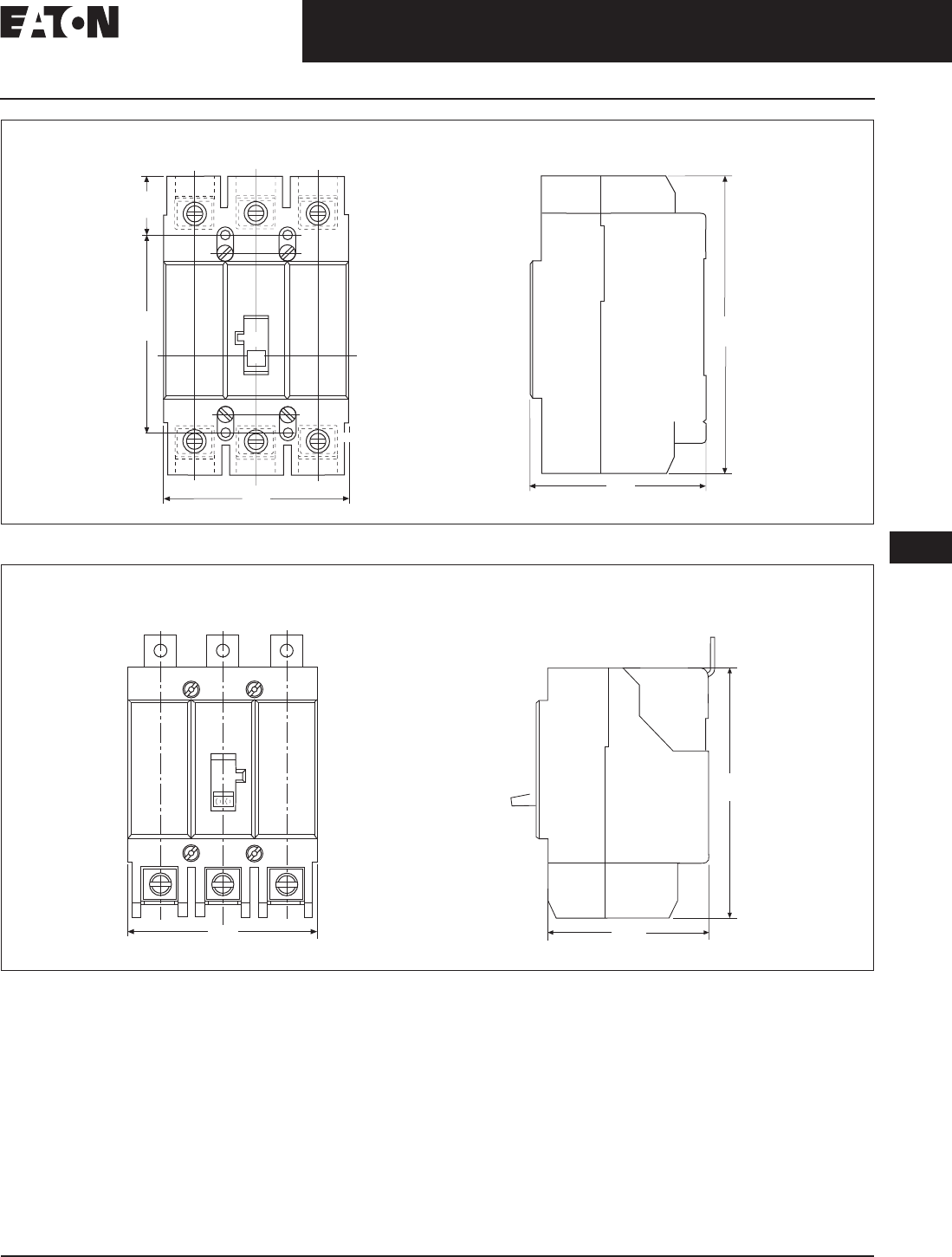
November 2008
CA08101001E For more information visit: www.eaton.com
12-271
Series C Molded Case Circuit Breakers
12
15 – 2500 Amperes for UL, CSA & IEC Applications
Frame Size GC and GHB
Figure 12-61. GC-Frame, 3-Pole — Dimensions in Inches (mm)
Figure 12-62. GHB-Frame, 3-Pole — Dimensions in Inches (mm)
0.97
(24.6)
3.22
(81.7) OFF
3.00
(76.2)
4.88
(123.8)
2.81
(71.4)
Front View Side View
3.00
(76.2)
2.63
(66.7)
4.00
(101.6)
Front View
Side View
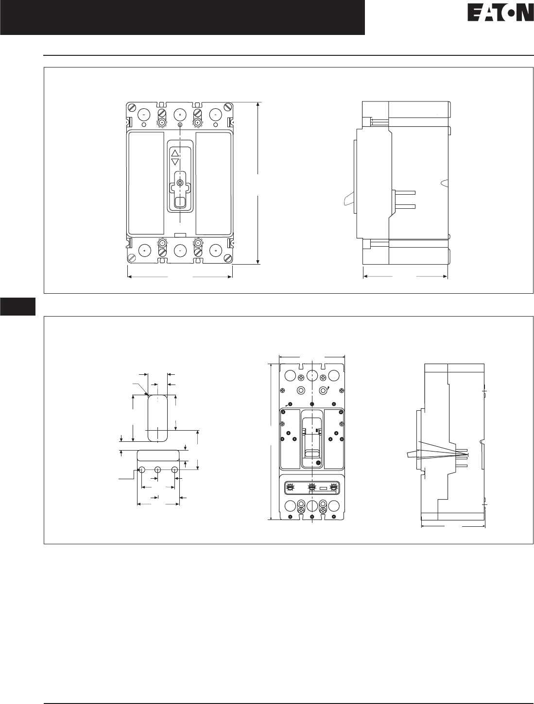
November 2008
12-272
For more information visit: www.eaton.com CA08101001E
Series C Molded Case Circuit Breakers
12
15 – 2500 Amperes for UL, CSA & IEC Applications
Frame Size FD and JD
Figure 12-63. FD-Frame, 3-Pole — Dimensions in Inches (mm)
Figure 12-64. JD-Frame, 3-Pole — Dimensions in Inches (mm)
3.38
(85.7)
6.00
(152.4)
4.13
(104.9)
On
Off
Front View Side View
4.13
(104.8)
10.00
(254.0)
ON
OFF
4.06
(103.2)
0.34 R
(8.7 R)
1.56
(39.7) 0.78
(19.8)
3.94
(100.0)
2.92
(74.2)
0.88
(22.2)
3.33
(84.5)
0.72
(18.2)
1.38
(34.9)
1.75
(44.5)
2.75
(69.9)
3.50
(88.9)
C
LHandle
BreakerC
L
Front View
Side View
0.19 R
(4.8) R
0.50 (12.7)
Diameter
3 Megger Holes
if Required
Front View Cutout
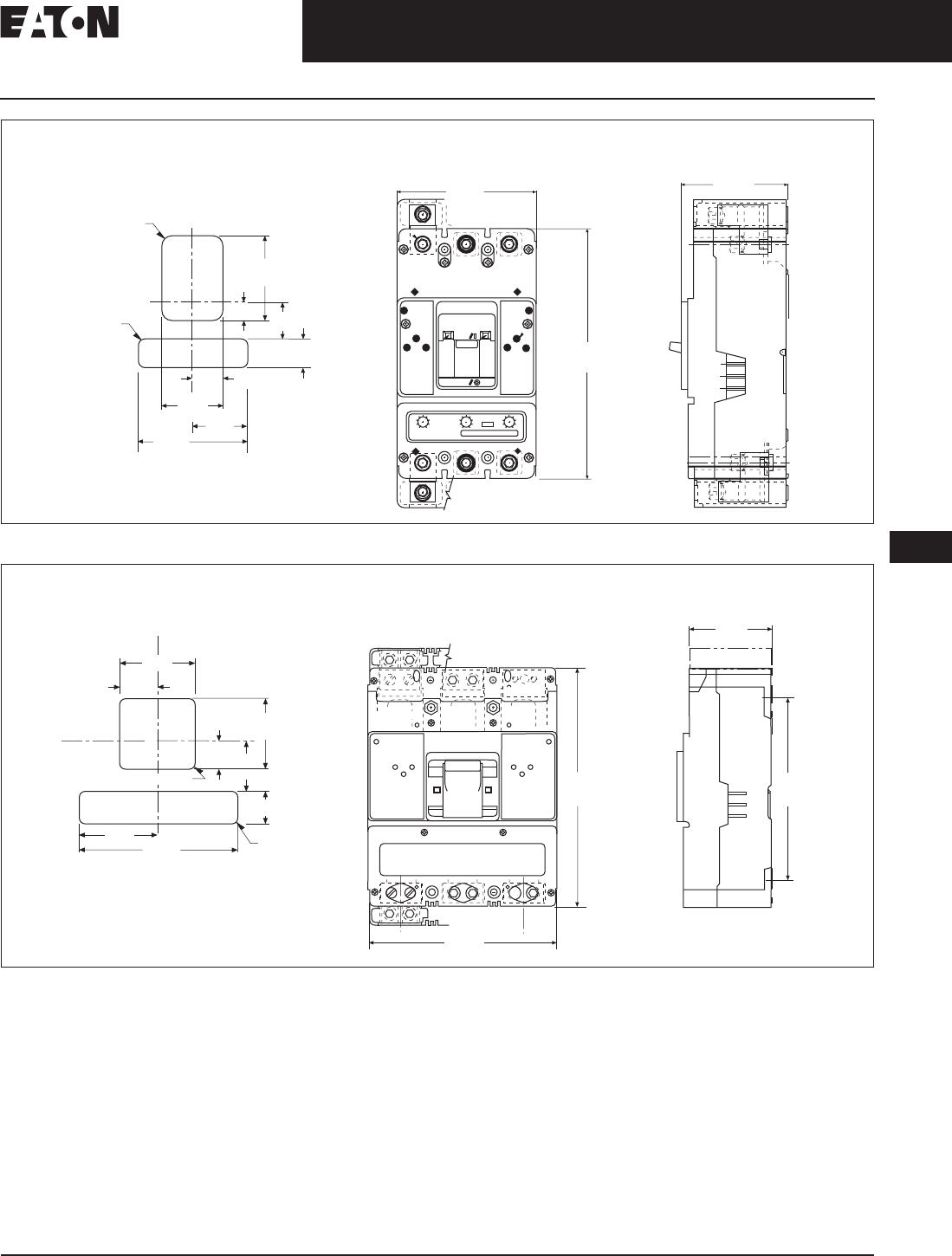
November 2008
CA08101001E For more information visit: www.eaton.com
12-273
Series C Molded Case Circuit Breakers
12
15 – 2500 Amperes for UL, CSA & IEC Applications
Frame Size KD and LD
Figure 12-65. KD-Frame, 2- and 3-Pole — Dimensions in Inches (mm)
Figure 12-66. LD-Frame, 2- and 3-Pole — Dimensions in Inches (mm)
5.49
(139.4)
ON
OFF
10.13
(257.2)
4.31
(109.6)
0.34 R
(8.7 R)
0.19 R
(4.8 R)
3.75
(95.3)
0.83
(21.0) 1.64
(41.7)
1.25
(31.8)
1.31
(33.3)
2.63
(66.7)2.39
(60.7)
4.78
(121.5)
C
LHandle
Front View Side View
Front Cover Cutout
10.75
(273.1)
8.25
(209.6)
3.81
(96.8)
8.21
(208.6)
Handle
7.28
(184.9)
0.19 R
(4.8) R
3.64
(92.5)
1.50
(38.1)
2.29
(58.2)
1.33
(33.7)
1.72
(43.7)
3.44
(87.3)
3.28
(83.3)
0.25 (6.4) R
Breaker
C
L
C
L
Front View
Side View
Front Cover Cutout
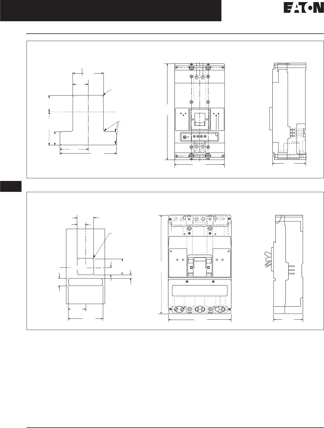
November 2008
12-274
For more information visit: www.eaton.com CA08101001E
Series C Molded Case Circuit Breakers
12
15 – 2500 Amperes for UL, CSA & IEC Applications
Frame Size MDL and ND
Figure 12-67. ND-Frame, 2- and 3-Pole — Dimensions in Inches (mm)
Figure 12-68. MDL-Frame, 2- and 3-Pole — Dimensions in Inches (mm)
16.00
(406.4) ON/I
OFF/O
8.25
(209.6)
5.50
(139.7)
3.44
(87.3)
1.72
(43.6)
1.91
(48.4)
3.68
(93.2)
1.50
(38.1)
3.19
(80.9) 6.38
(161.9)
0.19 R
(4.8 R)
0.25 R
(6.4 R)
C
LHandle
C
LHandle
Front View Side View
Front Cover Cutout
16.00
(406.4)
8.25
(209.6)
4.06
(103.2)
3.44
(87.3)
1.72
(43.7)
C
LBreaker R 0.25
(6.4)
R 0.19
(4.8)
1.50
(38.1)
3.64
(92.5)
7.28
(184.9)
0.97
(24.6)
3.28
(83.3)
1.33
(33.7)
Handle
C
L
Front View Side View
Drilling Plan
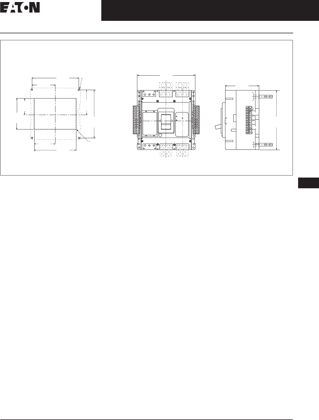
November 2008
CA08101001E For more information visit: www.eaton.com
12-275
Series C Molded Case Circuit Breakers
12
15 – 2500 Amperes for UL, CSA & IEC Applications
Frame Size RD
Figure 12-69. RD-Frame, 3-Pole, 1600 and 2000 Amperes — Dimensions in Inches (mm)
CSA is a registered trademark of the Canadian
Standards Association. National Electrical Code and
NEC are registered trademarks of the National Fire
Protection Association, Quincy, Mass. NEMA is the
registered trademark and service mark of the National
Electrical Manufacturers Association. UL is a registered
trademark of Underwriters Laboratories Inc. Kirk is
a registered trademark of the Kirk Key Interlock Com-
pany LLC. Square D is a federally registered trademark
of SNA Holdings Inc. Federal Pioneer is a federally
registered name of Electro-Mechanical Corporation.
Cutler-Hammer is a federally registered trademark
of Eaton Corporation.
Push
To
Trip
9.69
(246.1)
5.09
(129.4)
7.25
(184.2)
14.50
(368.3)
C
LBreaker
Handle
C
L
11.13 (0.4) Dia.
(4 Holes) Use 4,
0.38 (Mil) Dia. Bolts
for Mounting Breaker
7.75
(196.9)
15.00
(381.0)
0.16
(4.0)
R Typ.
6.65
(166.7) 12.91
(327.8)
Front View
Side View
15.50
(393.7)
9.00
(228.6)
16.00
(406.4)

November 2008
12-276
For more information visit: www.eaton.com CA08101001E
Series C Molded Case Circuit Breakers
12
This page intentionally left blank.
