Edison Fuse Full Line Catalog, # 1005 1000318087 Catalog
2016-06-25
: Pdf 1000318087-Catalog 1000318087-Catalog B1 unilog
Open the PDF directly: View PDF ![]() .
.
Page Count: 196 [warning: Documents this large are best viewed by clicking the View PDF Link!]
Edison product catalog
Circuit Protection
Products

Catalog Number Page
12ABCNA(Amp) . . . . . . . . . . 124
12CAV . . . . . . . . . . . . . . . . . . 124
12TDLEJ(Amp) . . . . . . . . . . . 127
12THLEJ(Amp) . . . . . . . . . . . 127
12TKLEJ(Amp) . . . . . . . . . . . 127
12TXLEJ(Amp) . . . . . . . . . . . 127
15.5CAV, CAVH. . . . . . . . . . . 124
17.5ABGNA(Amp). . . . . . . . . 124
17.5CAV . . . . . . . . . . . . . . . . 124
17.5TDLSJ(Amp) . . . . . . . . . 127
17.5TFLSJ(Amp). . . . . . . . . . 127
17.5TDMEJ(Amp) . . . . . . . . . 127
17.5THMEJ(Amp) . . . . . . . . . 127
17.5TKMEJ(Amp) . . . . . . . . . 127
2A1910-1. . . . . . . . . . . . . . . . 172
24ABGNA(Amp) . . . . . . . . . . 124
24CAV . . . . . . . . . . . . . . . . . . 124
24TDMEJ(Amp) . . . . . . . . . . 127
24THMEJ(Amp) . . . . . . . . . . 127
24TFMEJ(Amp). . . . . . . . . . . 127
24TXMEJ(Amp). . . . . . . . . . . 127
2703 . . . . . . . . . . . . . . . . . . . 130
3.6ABCNA(Amp) . . . . . . . . . . 123
3.6ABWNA(Amp) . . . . . . . . . 123
36ABGNA(Amp) . . . . . . . . . . 124
3.6ADLSJ(Amp) . . . . . . . . . . 127
3.6ADOSJ(Amp) . . . . . . . . . . 127
3.6CAV . . . . . . . . . . . . . . . . . 123
3.6WDLSJ(Amp) . . . . . . . . . . 127
3.6WDOSJ(Amp) . . . . . . . . . 127
3.6WFLSJ(Amp) . . . . . . . . . . 127
3.6WFOSJ(Amp). . . . . . . . . . 127
3.6WKLSJ(Amp) . . . . . . . . . . 127
36ABGNA(Amp) . . . . . . . . . . 124
36CAV . . . . . . . . . . . . . . . . . . 124
36TDQSJ(Amp). . . . . . . . . . . 127
36TFQSJ(Amp) . . . . . . . . . . . 127
36TXQEJ(Amp). . . . . . . . . . . 127
3835 Series . . . . . . . . . . . . . . 169
38CAV, CAVH . . . . . . . . . . . . 124
4164 . . . . . . . . . . . . . . . . . . . . 55
5.5ABWNA(Amp) . . . . . . . . . 123
5.5AMWNA(Amp) . . . . . . . . . 123
5.5CAV, CAVH. . . . . . . . . . . . 123
7.2ABCNA(Amp) . . . . . . . . . . 123
7.2ABWNA(Amp) . . . . . . . . . 123
7.2AMWNA(Amp) . . . . . . . . . 123
7.2CAV . . . . . . . . . . . . . . . . . 123
7.2WKMSJ(Amp) . . . . . . . . . 127
8000 Series Fuseblocks 169
A3354705 . . . . . . . . . . . . . . . 124
A3354745 . . . . . . . . . . . . . . . 130
ABC. . . . . . . . . . . . . . . . . . . . . 43
ACK. . . . . . . . . . . . . . . . . . . . . 54
ACL . . . . . . . . . . . . . . . . . . . . . 54
AGC . . . . . . . . . . . . . . . . . . . . 43
ALS . . . . . . . . . . . . . . . . . . . . . 54
ANL . . . . . . . . . . . . . . . . . . . . . 55
ANN. . . . . . . . . . . . . . . . . . . . . 56
Catalog Number . . . . . . . . Page
ATC . . . . . . . . . . . . . . . . . . . . . 46
ATM. . . . . . . . . . . . . . . . . . . . . 46
BCM Fuse Blocks . . . . . . . . . 152
BH Modular Blocks. . . . . . . . . . 154
BMM Fuse Blocks. . . . . . . . . . . 152
Box Cover Units . . . . . . . . . . 155
CCLB. . . . . . . . . . . . . . . . . . . . 52
CCLW . . . . . . . . . . . . . . . . . . . 52
CDNC . . . . . . . . . . . . . . . . . . 102
CDSC . . . . . . . . . . . . . . . . . . 102
CL1 . . . . . . . . . . . . . . . . . . . . . 98
Clip Clamps. . . . . . . . . . . . . . 172
CM(XX)CF. . . . . . . . . . . . . . . 105
CT . . . . . . . . . . . . . . . . . . . . . . 94
CVR-J . . . . . . . . . . . . . . . . . . 138
CVRI-J. . . . . . . . . . . . . . . . . . 138
CVR-RH . . . . . . . . . . . . . . . . 137
CVRI-RH . . . . . . . . . . . . . . . . 137
C(XX)BS . . . . . . . . . . . . . . . . 108
C(XX)F . . . . . . . . . . . . . . . . . 108
C(XX)FBS . . . . . . . . . . . . . . . 108
D16, D27, D33, D125 . . . . . . . . 99
DRA-1, DRA-2. . . . . . . . . . . . 134
E13S . . . . . . . . . . . . . . . . . . . . 60
E15SF . . . . . . . . . . . . . . . . . . . 61
E25SFX. . . . . . . . . . . . . . . . . . 64
E50S . . . . . . . . . . . . . . . . . . . . 68
E50SF . . . . . . . . . . . . . . . . . . . 68
E60C . . . . . . . . . . . . . . . . . . . . .71
E60SF . . . . . . . . . . . . . . . . . . . 73
E70SF . . . . . . . . . . . . . . . . . . . 75
EB3P . . . . . . . . . . . . . . . . . . . 134
EBS . . . . . . . . . . . . . . . . . . . . . 31
ECNR . . . . . . . . . . . . . . . . . . . . 1
ECSR . . . . . . . . . . . . . . . . . . . . 1
EDCC . . . . . . . . . . . . . . . . . . . 27
EECAP . . . . . . . . . . . . . . . . . 134
EFSCVR . . . . . . . . . . . . . . . . 134
EHCC . . . . . . . . . . . . . . . . . . 132
EHM . . . . . . . . . . . . . . . . . . . 132
EPDB Series . . . . . . . . . . . . . 157
EPWR . . . . . . . . . . . . . . . . . . 134
ERFL . . . . . . . . . . . . . . . . . . . . 45
ERFS. . . . . . . . . . . . . . . . . . . . 45
ET . . . . . . . . . . . . . . . . . . . . . . 94
FE . . . . . . . . . . . . . . . . . . . . . . 94
FEE . . . . . . . . . . . . . . . . . . . . . 94
FM . . . . . . . . . . . . . . . . . . . . . . 94
FMM . . . . . . . . . . . . . . . . . . . . 94
FP Series (Fusepullers) . . . . 172
FWA . . . . . . . . . . . . . . 61, 63, 65
FWC . . . . . . . . . . . . . . . . . . . . 77
FWH . . . . . . . . . . . . . . 71, 73, 75
FWJ. . . . . . . . . . . . . . . . . . 86, 88
FWP . . . . . . . . . . . . . . 79, 81, 83
G Fuseblocks . . . . . . . . . . . . 151
GBB. . . . . . . . . . . . . . . . . . . . . 43
GDA (S501). . . . . . . . . . . . . . . 41
GDB (S500). . . . . . . . . . . . . . . 41
Catalog Number . . . . . . . . Page
GDC (S506) . . . . . . . . . . . . . . 41
GMA . . . . . . . . . . . . . . . . . . . . 42
GMC . . . . . . . . . . . . . . . . . . . . 42
GMD . . . . . . . . . . . . . . . . . . . . 42
H Fuseblocks . . . . . . . . . . . . 144
HCLR . . . . . . . . . . . . . . . . . . . 29
HCTR . . . . . . . . . . . . . . . . . . . 29
HEB. . . . . . . . . . . . . . . . . . . . 165
HET . . . . . . . . . . . . . . . . . . . . 165
HEX. . . . . . . . . . . . . . . . . . . . 165
HEY. . . . . . . . . . . . . . . . . . . . 165
HKP Series . . . . . . . . . . . . . . 168
HM25. . . . . . . . . . . . . . . . . . . 137
HM60. . . . . . . . . . . . . . . . . . . 137
HPF . . . . . . . . . . . . . . . . . . . . 168
HVAC Disconnects . . . . . . . . 170
In-Line Fuseholders . . . . . . . 167
J Fuseblocks . . . . . . . . . . . . . 148
JC__ . . . . . . . . . . . . . . . . . . . 111
JDL . . . . . . . . . . . . . . . . . . . . . 18
JFL . . . . . . . . . . . . . . . . . . . . . 20
JHL . . . . . . . . . . . . . . . . . . . . . 59
JM60 . . . . . . . . . . . . . . . 138, 142
KON . . . . . . . . . . . . . . . . 35, 102
KOS . . . . . . . . . . . . . . . . . . 35, 102
LCL . . . . . . . . . . . . . . . . . . . . . .14
LCT . . . . . . . . . . . . . . . . . . . . . 91
LCU . . . . . . . . . . . . . . . . . . . . . 14
LENRK . . . . . . . . . . . . . . . . . . . 6
LESRK . . . . . . . . . . . . . . . . . . . 6
LET . . . . . . . . . . . . . . . . . . . . . 91
LMMT . . . . . . . . . . . . . . . . . . . 91
LMT . . . . . . . . . . . . . . . . . . . . . 91
MAI . . . . . . . . . . . . . . . . . . . . . 98
MAX . . . . . . . . . . . . . . . . . . . . 46
MCL. . . . . . . . . . . . . . . . . . . . . 31
MDA . . . . . . . . . . . . . . . . . . . . 44
MDL. . . . . . . . . . . . . . . . . . . . . 44
MEN . . . . . . . . . . . . . . . . . . . . 33
MEQ . . . . . . . . . . . . . . . . . . . . 33
MID . . . . . . . . . . . . . . . . . . . . . 33
MKE . . . . . . . . . . . . . . . . . . . . 45
MMT . . . . . . . . . . . . . . . . . . . . 94
MOL . . . . . . . . . . . . . . . . . . . . 31
MT . . . . . . . . . . . . . . . . . . . . . . 94
MV055 Series . . . . . . . . . . . . 115
MV155 Series . . . . . . . . . . . . 119
NCLR. . . . . . . . . . . . . . . . . . . . 11
NH . . . . . . . . . . . . . . . . . . . . . 100
NO.213 . . . . . . . . . . . . . . . . . 171
NO.213-R . . . . . . . . . . . . . . . 171
NO.216 . . . . . . . . . . . . . . . . . 171
NO.216-R . . . . . . . . . . . . . . . 171
NO.226 . . . . . . . . . . . . . . . . . 171
NO.226-R . . . . . . . . . . . . . . . 171
NO.242-R . . . . . . . . . . . . . . . 171
NO.2621 . . . . . . . . . . . . . . . . 171
NO.2621-R . . . . . . . . . . . . . . 171
NO.263 . . . . . . . . . . . . . . . . . 171
Catalog Number . . . . . . . . Page
NO.263-R . . . . . . . . . . . . . . . 171
NO.2641 . . . . . . . . . . . . . . . . 171
NO.2641-R . . . . . . . . . . . . . . 171
NO.2642 . . . . . . . . . . . . . . . . 171
NO.2661 . . . . . . . . . . . . . . . . 171
NO.2661-R . . . . . . . . . . . . . . 171
NO.2662 . . . . . . . . . . . . . . . . 171
NO.2662-R . . . . . . . . . . . . . . 171
NO.2664 . . . . . . . . . . . . . . . . 171
NO.2664-R . . . . . . . . . . . . . . 171
NO.616 . . . . . . . . . . . . . . . . . 171
NO.626 . . . . . . . . . . . . . . . . . 171
NO.626-R . . . . . . . . . . . . . . . 171
NO.642-R . . . . . . . . . . . . . . . 171
NO.663 . . . . . . . . . . . . . . . . . 171
NO.663-R . . . . . . . . . . . . . . . 171
NZ01, NZ02. . . . . . . . . . . . . . . 99
P. . . . . . . . . . . . . . . . . . . . . . . 40
PB1 & PB3 Series . . . . . . . . . 160
PB4, PB5 & PB7 Series . . . . 162
PONC . . . . . . . . . . . . . . . . . . 102
R Fuseblocks . . . . . . . . . . . . . .144
RM25 . . . . . . . . . . . . . . . . . . . . 137
RM60. . . . . . . . . . . . . . . . . . . 137
S . . . . . . . . . . . . . . . . . . . . . . . .37
SA . . . . . . . . . . . . . . . . . . . . . . 38
SAFELOC HRC. . . . . . . . . . . 108
SAMI Series . . . . . . . . . . . . . 164
SCLR. . . . . . . . . . . . . . . . . . . . 11
SEC. . . . . . . . . . . . . . . . . . . . . 25
SFC-Fuse-CAB . . . . . . . . . . . 172
SFE . . . . . . . . . . . . . . . . . . . . . 46
SL . . . . . . . . . . . . . . . . . . . . . . 37
SPH50SP . . . . . . . . . . . . . . . 173
SPP40SP . . . . . . . . . . . . . . . 177
T. . . . . . . . . . . . . . . . . . . . . . . 39
TC . . . . . . . . . . . . . . . . . . . . . . 40
T Fuseblocks. . . . . . . . . . . . . 149
TI__ . . . . . . . . . . . . . . . . . . . . . 98
TJN . . . . . . . . . . . . . . . . . . . . . 22
TJS . . . . . . . . . . . . . . . . . . . . . 22
TL . . . . . . . . . . . . . . . . . . . . . . 39
UCL 25XX to 75XX . . . . . . . . . 47
UCLA. . . . . . . . . . . . . . . . . . . . 47
W. . . . . . . . . . . . . . . . . . . . . . . 38
Edison circuit protection solutions comply with major industrial standards and agency requirements such as: BS, IEC, DIN, UL, NEMA, SAE, CSA, CE, C-UL, etc. and
are manufactured at facilities that are ISO 9000 certified. This catalog is intended to present product data and provide technical information that will help the end user
with designapplication. We reserve the right, without notice, to change design or construction of any products and to discontinue or limit distribution of any
products. We also reserve the right to change or update, without notice, any technical information contained in this catalog. Once a product has been selected, it should
be tested by the user in all possible applications. Further, We take no responsibility for errors or omissions contained in this catalog, or for misapplication of any Edison
product. Extensive product information is available in the Edison product data sheets available online at www.edisonfuse.com.
©2014
Index

i
UL Fuses: Current Limiting
Class RK5 Dual-Element, Time-Delay - ECNR/ECSR . . . . . . . . . . . . . . . . . . .1
Class RK1 Dual-Element, Time-Delay - LENRK/LESRK . . . . . . . . . . . . . . . . .6
Class RK Fast-Acting - NCLR/SCLR . . . . . . . . . . . . . . . . . . . . . . . . . . . . . .11
Class L Time-Delay - LCL . . . . . . . . . . . . . . . . . . . . . . . . . . . . . . . . . . . . .14
Fast-Acting - LCU . . . . . . . . . . . . . . . . . . . . . . . . . . . . . . . . . . . . .14
Class J Dual-Element, Time-Delay - JDL . . . . . . . . . . . . . . . . . . . . . . . . .18
Fast-Acting - JFL . . . . . . . . . . . . . . . . . . . . . . . . . . . . . . . . . . . . . .20
Class T Extremely Fast-Acting - TJN/TJS . . . . . . . . . . . . . . . . . . . . . . . . .22
Class G SEC . . . . . . . . . . . . . . . . . . . . . . . . . . . . . . . . . . . . . . . . . . . . . . . .25
Class CC Time-Delay - EDCC . . . . . . . . . . . . . . . . . . . . . . . . . . . . . . . . . . .27
Time-Delay - HCTR . . . . . . . . . . . . . . . . . . . . . . . . . . . . . . . . . . .29
Fast-Acting - HCLR . . . . . . . . . . . . . . . . . . . . . . . . . . . . . . . . . . . .29
UL Fuses: General Purpose
Midget Fuses (13⁄32" x 1 1⁄2") Fast-Acting - MCL . . . . . . . . . . . . . . . . . . . . . . . . . . . . . . . . . . . . .31
Fast-Acting - MOL . . . . . . . . . . . . . . . . . . . . . . . . . . . . . . . . . . . . .31
13⁄32" x 1 3⁄8", Fast-Acting - EBS . . . . . . . . . . . . . . . . . . . . . . . . . . . .31
Time-Delay - MEN . . . . . . . . . . . . . . . . . . . . . . . . . . . . . . . . . . . .33
Time-Delay - MEQ . . . . . . . . . . . . . . . . . . . . . . . . . . . . . . . . . . . .33
Pin Indicating, Time-Delay - MID . . . . . . . . . . . . . . . . . . . . . . . . .33
Class H and KS "One-Time" Fast-Acting - KON/KOS . . . . . . . . . . . . . . . . . . . . . . . . . . . . . . . .35
Plug Fuses Rejection Base, Dual-Element, Time-Delay - S . . . . . . . . . . . . . .37
Rejection Base, Time-Delay - SL . . . . . . . . . . . . . . . . . . . . . . . . .37
Edison Base, Fast-Acting - W . . . . . . . . . . . . . . . . . . . . . . . . . . . .38
S and SL Rejection Base Fuse Adapter SA . . . . . . . . . . . . . . . . . . . . . . . . . . . . . . . . . . . . . . . . . . . . . . . . .38
Plug Fuses Edison Base, Dual-Element, Time-Delay - T . . . . . . . . . . . . . . . .39
Edison Base, Time-Delay - TL . . . . . . . . . . . . . . . . . . . . . . . . . . .39
Edison Base, Dual-Element, Time-Delay - TC, P . . . . . . . . . . . . .40
5 x 20mm Fuses Ceramic, Fast-Acting - GDA (S501) . . . . . . . . . . . . . . . . . . . . . . .41
Glass, Fast-Acting - GDB (S500) . . . . . . . . . . . . . . . . . . . . . . . . .41
Glass, Time-Delay - GDC (S506) . . . . . . . . . . . . . . . . . . . . . . . . .41
Glass, Fast-Acting - GMA . . . . . . . . . . . . . . . . . . . . . . . . . . . . . . .42
Glass, Medium Time-Delay - GMC . . . . . . . . . . . . . . . . . . . . . . . .42
Glass, Time-Delay - GMD . . . . . . . . . . . . . . . . . . . . . . . . . . . . . . .42
1⁄4" x 1 1⁄4" Fuses Glass, Fast-Acting - ABC . . . . . . . . . . . . . . . . . . . . . . . . . . . . . . .43
Glass, Fast-Acting - AGC . . . . . . . . . . . . . . . . . . . . . . . . . . . . . . .43
Ceramic, Very Fast-Acting - GBB . . . . . . . . . . . . . . . . . . . . . . . . .43
Ceramic, Time-Delay - MDA . . . . . . . . . . . . . . . . . . . . . . . . . . . . .44
Glass, Time-Delay - MDL . . . . . . . . . . . . . . . . . . . . . . . . . . . . . . .44
Electronic & Electrical Fuse Displays
& Assortments ERFL/ERFS, MKE . . . . . . . . . . . . . . . . . . . . . . . . . . . . . . . . . . . .45
Automotive Fuses Glass, Fast-Acting - SFE . . . . . . . . . . . . . . . . . . . . . . . . . . . . . . .46
Blade, Fast-Acting – ATM, ATC, MAX . . . . . . . . . . . . . . . . . . . . .46
Special Purpose Fuses
Cable Limiters UCL/UCLA . . . . . . . . . . . . . . . . . . . . . . . . . . . . . . . . . . . . . . . . . .47
Capacitor Fuse, Non-Time-Delay CCLB/CCLW . . . . . . . . . . . . . . . . . . . . . . . . . . . . . . . . . . . . . . . . .52
Lift Truck Fuses ACK/ACL/ALS . . . . . . . . . . . . . . . . . . . . . . . . . . . . . . . . . . . . . . . .54
Limiters ANL Non-Time-Delay . . . . . . . . . . . . . . . . . . . . . . . . . . . . . . . . . .55
ANN Very Fast-Acting . . . . . . . . . . . . . . . . . . . . . . . . . . . . . . . . . .56
High Speed Fuses . . . . . . . . . . . . . . . . . . . . . . . . . . . . . . . . . . . . . . . . . . . . . . . . . . .57
JHL . . . . . . . . . . . . . . . . . . . . . . . . . . . . . . . . . . . . . . . . . . . . . . . .59
FWA, 5 - 30A (10 x 38mm) and 35 - 60A (21 x 51mm) . . . . . . . .61
FWA, 70 - 1000A . . . . . . . . . . . . . . . . . . . . . . . . . . . . . . . . . . . . .63
FWA, 1000 - 4000A . . . . . . . . . . . . . . . . . . . . . . . . . . . . . . . . . . .65
FWX, 1-50A (14 x 51mm) . . . . . . . . . . . . . . . . . . . . . . . . . . . . . . .67
FWX, 35 - 2500A . . . . . . . . . . . . . . . . . . . . . . . . . . . . . . . . . . . . .69
FWH, 0.25 - 30A (6 x 32mm) . . . . . . . . . . . . . . . . . . . . . . . . . . . .71
FWH, 1 - 30A (14 x 51mm) . . . . . . . . . . . . . . . . . . . . . . . . . . . . . .73
FWH, 35 - 1600A . . . . . . . . . . . . . . . . . . . . . . . . . . . . . . . . . . . . .75
FWC, 6 - 32A (10 x 38mm) . . . . . . . . . . . . . . . . . . . . . . . . . . . . . .77
FWP, 1 - 50A (14 x 51mm) . . . . . . . . . . . . . . . . . . . . . . . . . . . . . .79
FWP, 20 - 100A (22 x 58mm) . . . . . . . . . . . . . . . . . . . . . . . . . . . .81
FWP, 5 - 1200A . . . . . . . . . . . . . . . . . . . . . . . . . . . . . . . . . . . . . .83
Page
Table of Contents

Special Purpose Fuses (Con’t)
FWJ, 20 - 30A (14 x 67mm) . . . . . . . . . . . . . . . . . . . . . . . . . . . . .86
FWJ, 35 - 2000A . . . . . . . . . . . . . . . . . . . . . . . . . . . . . . . . . . . . . .88
British Style . . . . . . . . . . . . . . . . . . . . . . . . . . . . . . . . . . . . . . . . . .90
LCT, LET, LMT, LMMT, 6 - 900A . . . . . . . . . . . . . . . . . . . . . . . . .91
CT, ET, FE, EET, FEE, FM, FMM, MT, MMT, 6 - 710A . . . . . . . .94
Trip Indicators . . . . . . . . . . . . . . . . . . . . . . . . . . . . . . . . . . . . . . . . . . . . . . . . . . .98
Microswitch Adapter - MAI . . . . . . . . . . . . . . . . . . . . . . . . . . . . . . . . . . . . . . . . . . . . . . . . . . .98
Type “D” Bottle Fuses . . . . . . . . . . . . . . . . . . . . . . . . . . . . . . . . . . . . . . . . . . . . . . . . . . .99
Neozed Fuses . . . . . . . . . . . . . . . . . . . . . . . . . . . . . . . . . . . . . . . . . . . . . . . . . . .99
NH Fuses . . . . . . . . . . . . . . . . . . . . . . . . . . . . . . . . . . . . . . . . . . . . . . . . . .100
Canadian Fuses & Accessories
Standard Code Fuses 250V & 600V KOS/KON/PONC . . . . . . . . . . . . . . . . . . . . . . . . . . . . . . . . . . . .102
CDSC/CDNC . . . . . . . . . . . . . . . . . . . . . . . . . . . . . . . . . . . . . . .102
Fuse Holders CAMaster HRC Fuse Holder . . . . . . . . . . . . . . . . . . . . . . . . . . . .105
SAFEloc HRCI-CB Fuse Holder . . . . . . . . . . . . . . . . . . . . . . . . .108
Medium Voltage Fuses
R-Rated Fuses JCG, JCH, JCK, JCL, JCR, 25 - 450A (2.4 - 7.2kV) . . . . . . . . . .111
E-Rated Fuses MV055, 5 - 450A (5.5kV) . . . . . . . . . . . . . . . . . . . . . . . . . . . . . .115
MV155, 5 - 200A (15.5kV) . . . . . . . . . . . . . . . . . . . . . . . . . . . . .119
Potential Transformer Fuses AB, AM and CAV Series (3.6 to 38kV) . . . . . . . . . . . . . . . . . . . .123
High Voltage DIN Distribution Fuses 3.6 to 36kV . . . . . . . . . . . . . . . . . . . . . . . . . . . . . . . . . . . . . . . . .126
Fuse Blocks, Holders & Misc.
Class CC Global Modular Fuse Holders CH Series, 8x32, 10x38, 14x51, 22x58 . . . . . . . . . . . . . . . . . . .132
Class R H(K) and J Modular Knifeblade Blocks Class R H(K) 250 and 600V, Class J 600V . . . . . . . . . . . . . . . .136
Class J Power Distribution Fuse Blocks JM60_, 70 - 400A, 600V . . . . . . . . . . . . . . . . . . . . . . . . . . . . . . .142
Class H (K) and R Fuse Blocks H250, H600, R250 and R600 Series . . . . . . . . . . . . . . . . . . . . .144
Class J Fuse Blocks J600 Series . . . . . . . . . . . . . . . . . . . . . . . . . . . . . . . . . . . . . . . . .148
Class T Fuse Blocks T300 and T600 Series . . . . . . . . . . . . . . . . . . . . . . . . . . . . . . . .149
Class G Fuse Blocks BG and G Series . . . . . . . . . . . . . . . . . . . . . . . . . . . . . . . . . . . . .151
Class CC Fuse Blocks BCM and BMM Series . . . . . . . . . . . . . . . . . . . . . . . . . . . . . . . .152
Modular Fuse blocks BH Series . . . . . . . . . . . . . . . . . . . . . . . . . . . . . . . . . . . . . . . . . .154
Edison Base Plug Fuse Holders Box Cover Units . . . . . . . . . . . . . . . . . . . . . . . . . . . . . . . . . . . . .155
Power Blocks Enclosed Power Distribution Blocks . . . . . . . . . . . . . . . . . . . . . .157
High SCCR Terminal Blocks . . . . . . . . . . . . . . . . . . . . . . . . . . . .160
Power Distrbution Blocks . . . . . . . . . . . . . . . . . . . . . . . . . . . . . .162
SAMI Fuse Covers For Class J, RK, K5, H and Midget Fuses . . . . . . . . . . . . . . . . .164
In-line Fuse Holders Class CC and Midget Fuses - HEB/HET/HEY/HEX . . . . . . . . . .165
Panel Mount Fuse Holders 1⁄4" x 1 1⁄4" Fuses - HKP, HKP-HH/HKP-W . . . . . . . . . . . . . . . . . .168
13⁄32" x 1 1⁄2" Fuses - HPF . . . . . . . . . . . . . . . . . . . . . . . . . . . . . . . .168
Fuse Blocks 13⁄32" x 1 1⁄2" Fuses - 3835 Series . . . . . . . . . . . . . . . . . . . . . . . . . .169
1⁄4" x 1 1⁄4" Fuses - S-8000 Series . . . . . . . . . . . . . . . . . . . . . . . . .169
HVAC Disconnects B22 Series . . . . . . . . . . . . . . . . . . . . . . . . . . . . . . . . . . . . . . . . .170
Fuse Reducers Class H, J, K, & R . . . . . . . . . . . . . . . . . . . . . . . . . . . . . . . . . . . .171
Spare Fuse Cabinet SFC-FUSE-CAB . . . . . . . . . . . . . . . . . . . . . . . . . . . . . . . . . . . . .172
Fuse Clip Clamp . . . . . . . . . . . . . . . . . . . . . . . . . . . . . . . . . . . . . . . . . . . . . . . . . .172
Fuse Pullers FP Series . . . . . . . . . . . . . . . . . . . . . . . . . . . . . . . . . . . . . . . . . .172
Surge Protective Devices
SurgePOD™ HEAVY DUTY NEMA 4X Rated HEAVY DUTY Type 1 UL Listed SPD . . . . . . .173
SurgePOD™ PRO NEMA 4X Rated PRO Type 1 UL Listed SPD . . . . . . . . . . . . . .177
Elements of a Practical Fuse Specification 180
Fuse Terminology 181
Cross Reference Guides 183
Quick Cross Reference Guide 190
Page
ii
Table of Contents
1
For additional information, visit www.edisonfuse.com
UL/CSA Fuses
Current Limiting
UL/CSA Fuses
General Purpose
Special
Purpose Fuses
Canadian
Fuses & Holders
Medium
Voltage Fuses
Fuse Blocks,
Holders & Misc.
Application
Section
Surge Protective
Devices
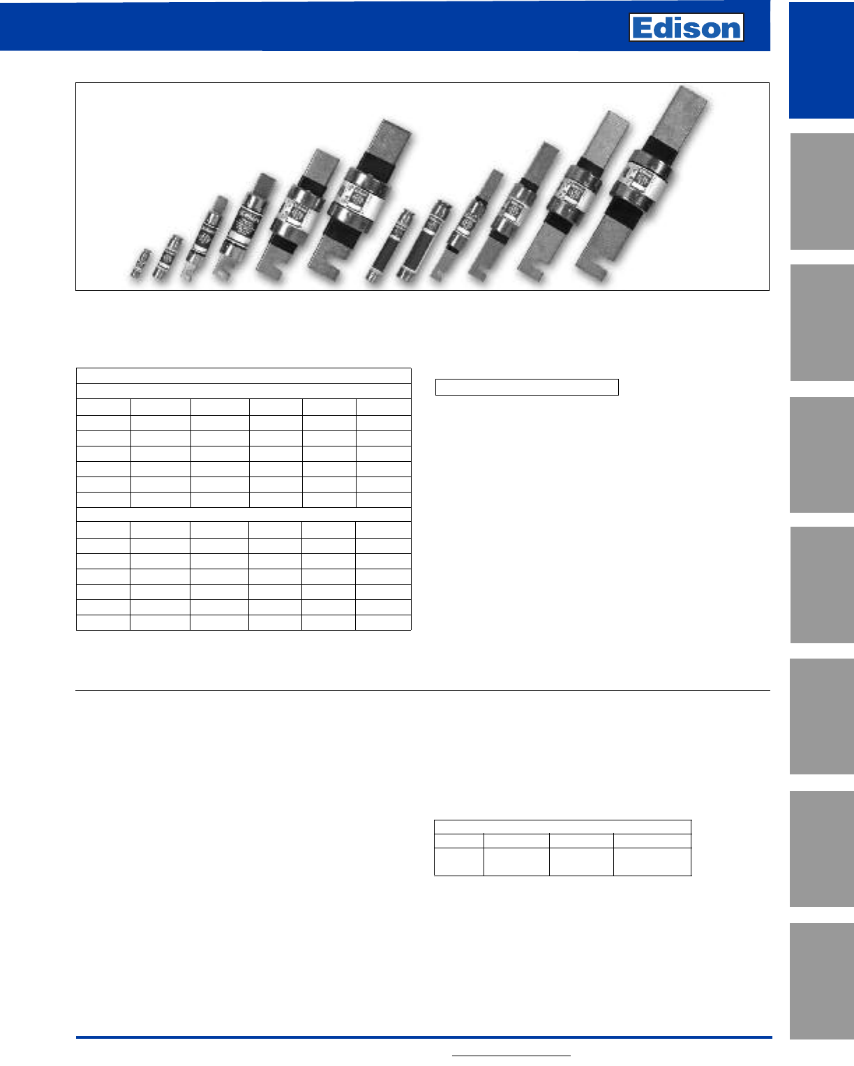
Amp Ratings
ECNR
1825 70 150 400
2930 75 175 450
3 10 35 80 200 500
4 12 40 90 225 600
5 15 45 100 250 —
6 17.5 50 110 300 —
7 20 60 125 350 —
ECSR
1825 70 150 400
2930 75 175 450
3 10 35 80 200 500
4 12 40 90 225 600
5 15 45 100 250 —
6 17.5 50 110 300 —
7 20 60 125 350 —
ECNR/ECSR Specifications
Dual-Element Time-Delay
Voltage Rating: ECNR - 250Vac
ECNR - (1-60A, 110-200A) 125Vdc;
(225-600A) 250Vdc
ECSR - 600Vac
ECSR - (1-30A, 70-600A) 300Vdc
(35-60A) 250Vdc
Amp Rating: 1 - 600A
Interrupting Rating: 200kA RMS Symmetrical Amps
Current Limiting: RK5 Fuse
Agency Information:
UL Listed for US and Canada, Class RK5, Guide JDDZ, File
E162363
Interrupting Rating: ECNR/ECSR 20kA DC
Recommended Fuse Blocks:
Refer to pages 146 in this catalog.
Recommended Upgrade:
Class RK1 (LENRK/LESRK) for greater degree of
short-circuit protection.
Catalog Number ECNR (1 - 600A) 250Vac or Less
Catalog Number ECSR (1 - 600A) 600Vac or Less
Benefits:
• True dual-element construction allows sizing of 125%
FLA for motor backup protection.
• Superior overload and cycling capabilities.
• Current limiting provides component short-circuit
protection.
Applications:
• Recommended for AC power distribution system mains,
feeders, and branch circuits.
• Protection of motors and motor branch circuits.
• Protection of transformers and other inductive loads.
• All general-purpose applications including lighting,
heating and other non-inductive loads.
ECNR/ECSR Class RK5
Dual-Element Time-Delay Fuses
CROSS REFERENCE
VOLTS EDISON MERSEN LITTELFUSE
250 ECNR TR FLNR
600 ECSR TRS FLSR
characteristics of these fuses typically allows them to be
sized closer to the running ampacity of inductive loads to
reduce cost and provide improved overcurrent
protection. These fuses will override normal equipment
current surges to reduce unnecessary fuse openings. They
are the most popular fuses used in the industry and the
most economical for most applications, especially motors
and transformers. They have moderate current limitation.
2
ECNR/ECSR Class RK5
Dual-Element Time-Delay Fuses
For additional information, visit www.edisonfuse.com
Application
Section
Fuse Blocks,
Holders & Misc.
Surge Protective
Devices
Medium
Voltage Fuses
Canadian
Fuses & Holders
Special
Purpose Fuses
UL/CSA Fuses
General Purpose
UL/CSA Fuses
Current Limiting
ECNR/ECSR Dual Element Fuses
These fuses are recommended for AC power distribution
system mains, feeders and branch circuits having inductive
loads (motors, transformers) or non-inductive loads
(lighting, heating) where the available short-circuit current
does not exceed 200,000 RMS symmetrical amps. These
“dual-element, time-delay” fuses have minimum industry
standard time-delay of 10 seconds at 5 times the fuse rating
(8 sec. minimum for 250V, 30A and less). The time-delay
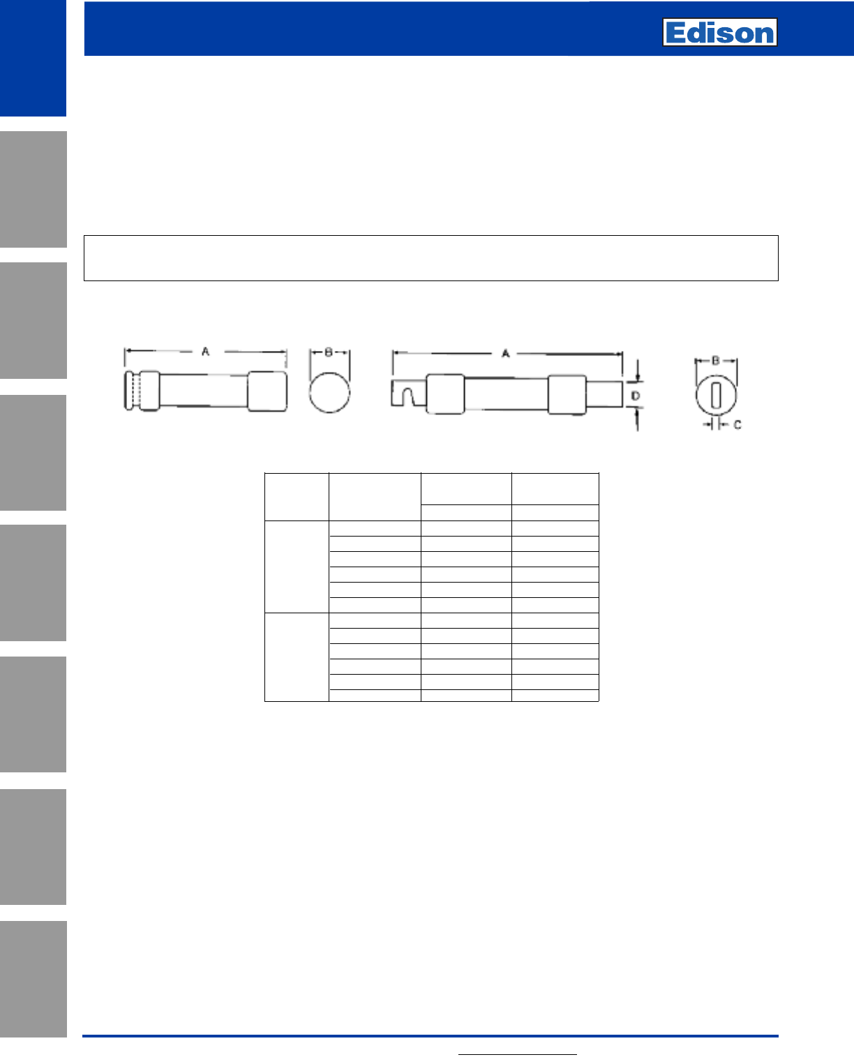
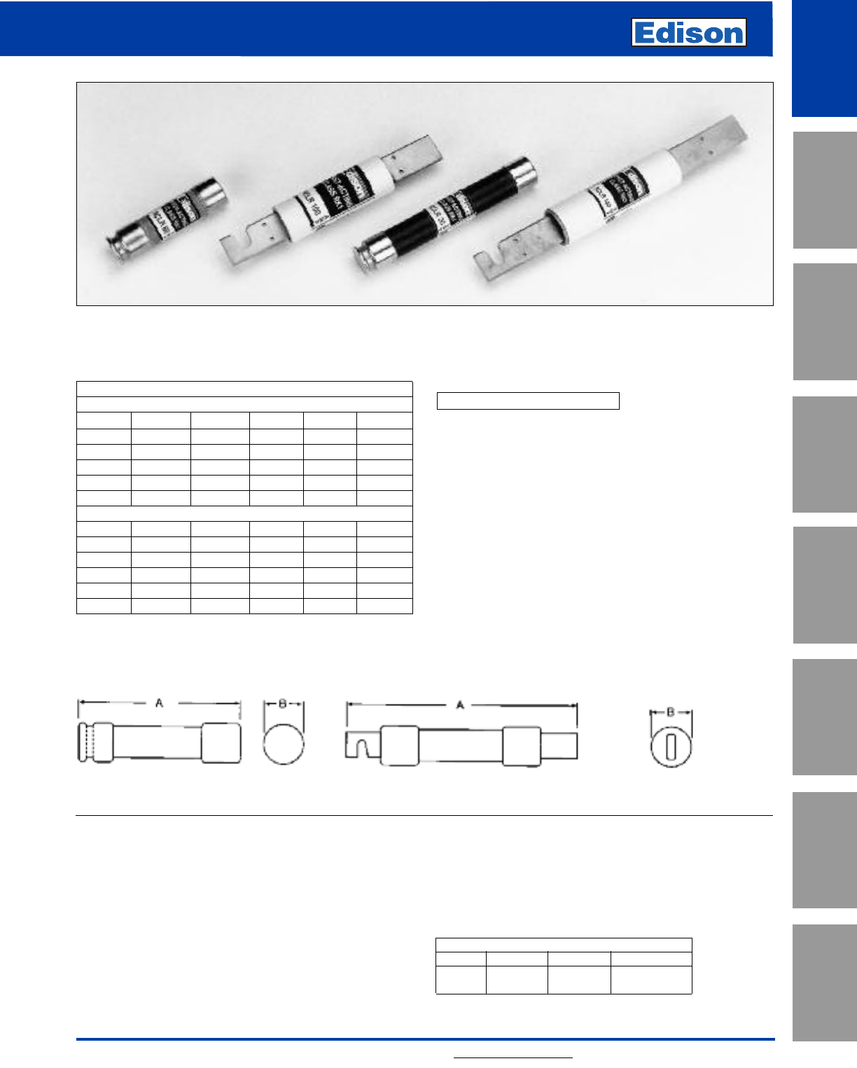
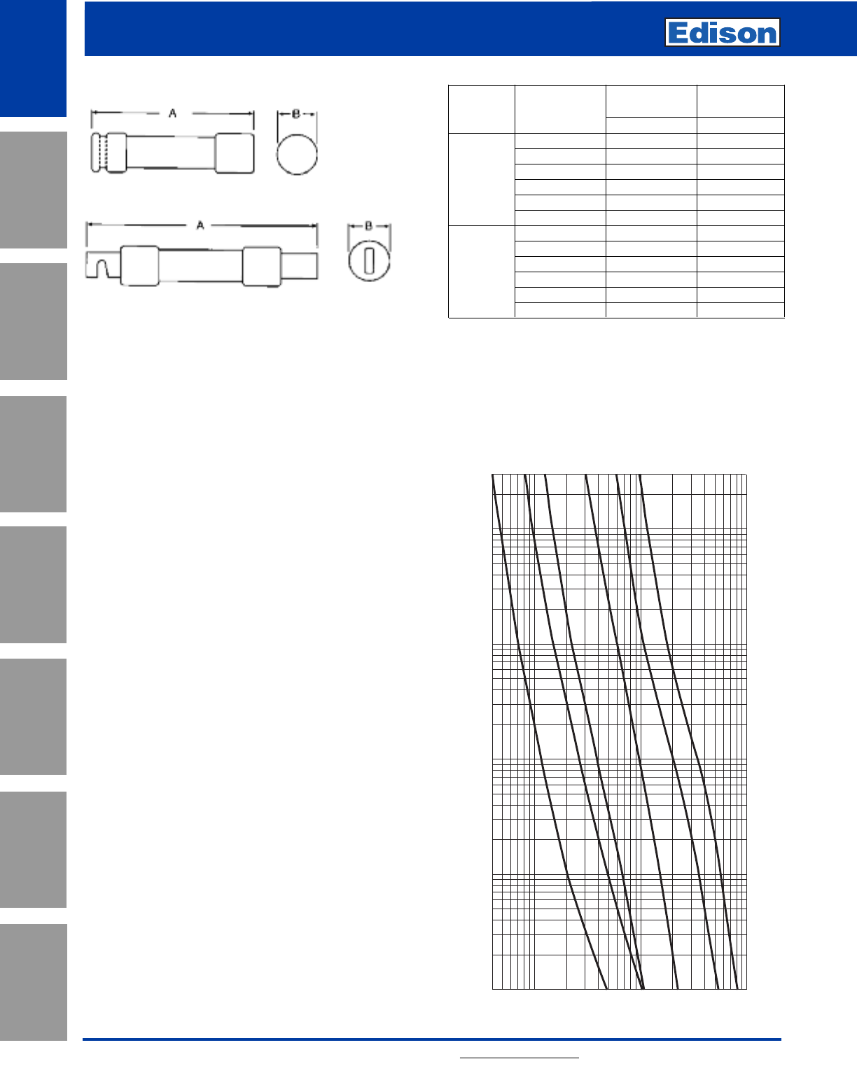
Overall Max
Catalog Length - in Diameter - in
Number Amps AB
0-30 2 0.56
35-60 3 0.81
70-100 5.88 1.06
ECNR 110-200 7.13 1.56
225-400 8.63 2.38
450-600 10.38 2.88
0-30 5 0.81
35-60 5.5 1.06
ECSR 65-100 7.88 1.11
110-200 9.63 1.61
225-400 11.63 2.34
450-600 13.38 2.88
Class R fuses will fit Class H, K and R fuse clips. Class R fuse clips will only accept Class R fuses. Fuses rated 600Vac
or less may be applied at any lower voltage.
Dimensions
Ferrule Design–0 through 60 Amps Knife Blade–70 through 600 Amps
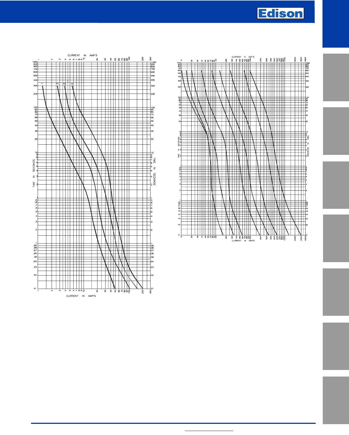
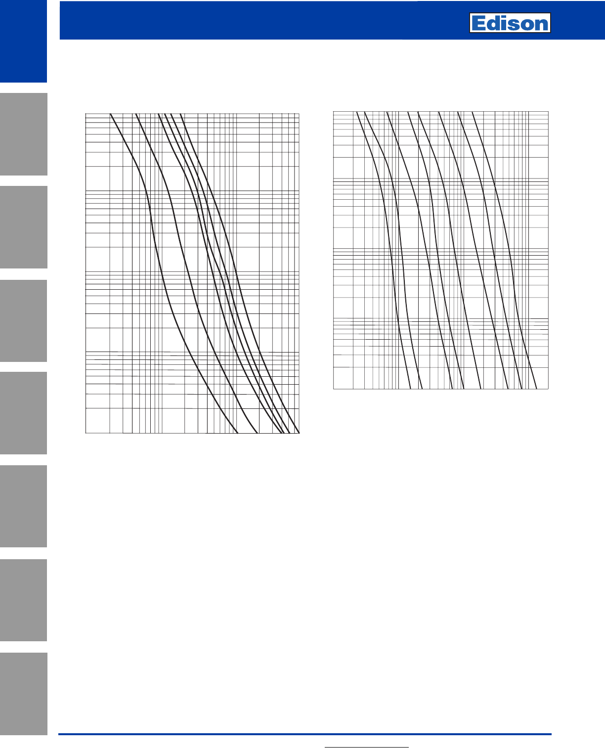
8
10
15
30
60
100
200
400
600
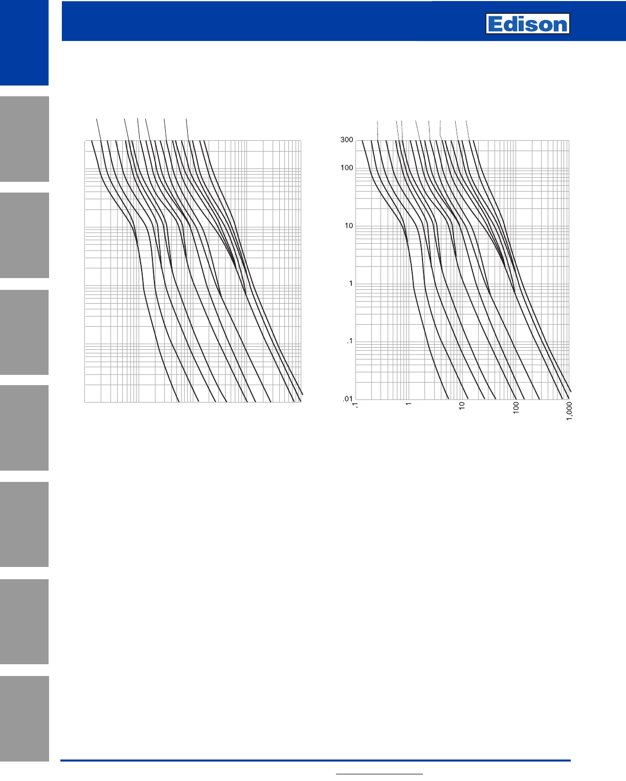
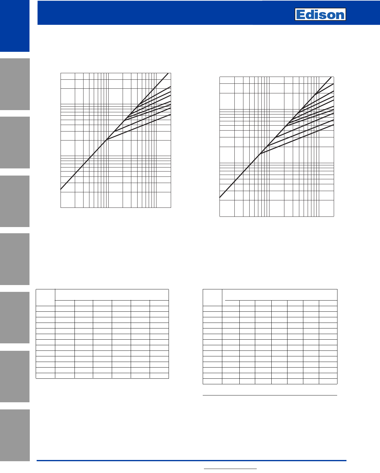
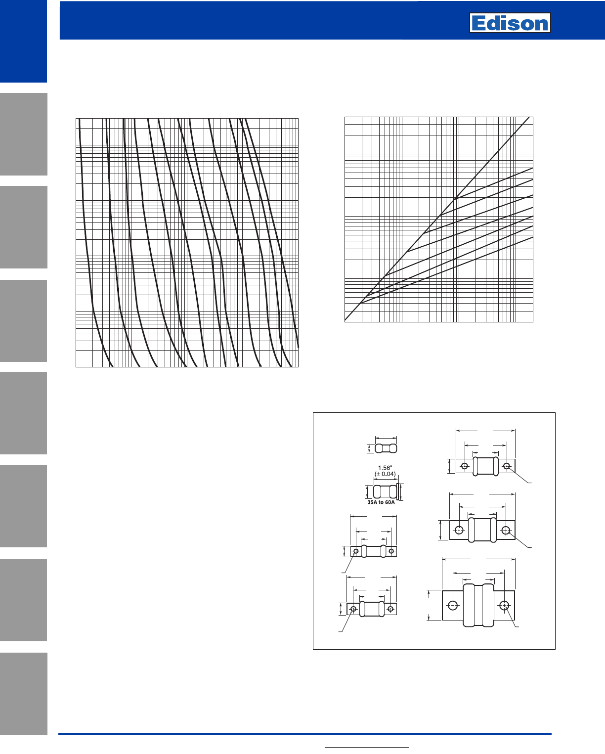
Average Melt Time-Current Curves
Cat No. ECNR (Amp)
3
ECNR/ECSR Class RK5
Dual-Element Time-Delay Fuses
For additional information, visit www.edisonfuse.com
UL/CSA Fuses
Current Limiting
UL/CSA Fuses
General Purpose
Special
Purpose Fuses
Canadian
Fuses & Holders
Medium
Voltage Fuses
Fuse Blocks,
Holders & Misc.
Surge Protective
Devices
Application
Section
4
ECNR/ECSR Class RK5
Dual-Element Time-Delay Fuses
For additional information, visit www.edisonfuse.com
Application
Section
Fuse Blocks,
Holders & Misc.
Surge Protective
Devices
Medium
Voltage Fuses
Canadian
Fuses & Holders
Special
Purpose Fuses
UL/CSA Fuses
General Purpose
UL/CSA Fuses
Current Limiting
AMP
RATING
RMS SYMMETRICAL CURRENTS IN AMPS
1,000
100
10
10,000
600A
10
100
TIME IN SECONDS
1
.1
.01
20,000
400A
200A
100A
60A
30A
15A
10A
AMP
RATING
RMS SYMMETRICAL CURRENTS IN AMPS
10
.1
100
10
100
TIME IN SECONDS
1
.1
.01
700
1A
2A
4A
5A
8A
Average Melt Time-Current Curves
Cat No. ECSR (Amp)
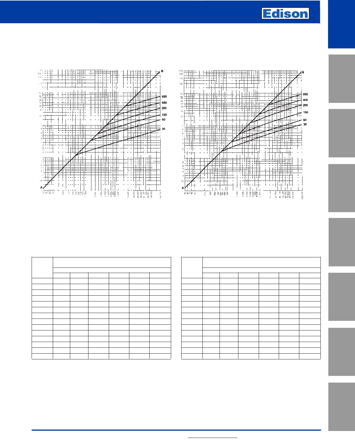
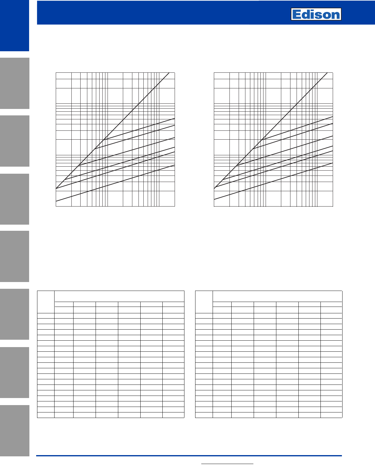
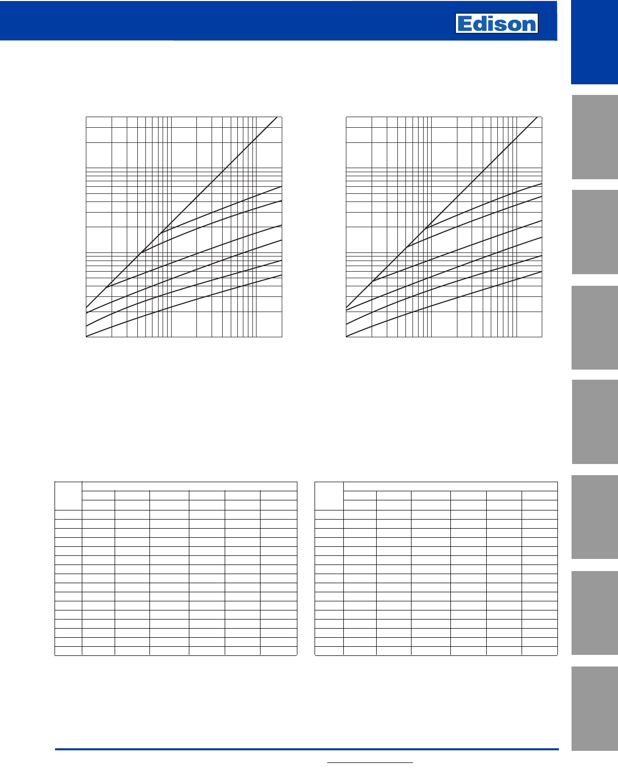
Peak Let-Through Current Curves
PEAK LET-THROUGH CURRENT IN AMPS X10 3
PEAK LET-THROUGH CURRENT IN AMPS X10 3
AMP
RATING
AMP
RATING
RMS SYMMETRICAL CURRENTS IN AMPS
A—B=ASYMMETRICAL AVAILABLE PEAK (2.3 x SYMM RMS AMPS)
RMS SYMMETRICAL CURRENTS IN AMPS
A—B=ASYMMETRICAL AVAILABLE PEAK (2.3 x SYMM RMS AMPS)
ECNR ECSR
Current Limitation Tables
ECNR*
Available
Fault Apparent Effective Let-Through Amps
Current Fuse Amp Ratings
RMS Amps 30A 60A 100A 200A 400A 600A
5,000 1,050 2,070 2,820 4,300 5,000 5,000
10,000 1,310 2,570 3,630 5,400 8,700 10,000
15,000 1,490 2,920 4,140 6,200 9,900 15,000
20,000 1,630 3,200 4,500 6,800 10,700 16,100
25,000 1,720 3,420 4,800 7,200 11,400 17,200
30,000 1,840 3,630 5,100 7,700 12,100 18,300
35,000 1,920 3,810 5,400 8,100 12,600 19,200
40,000 2,000 3,980 5,600 8,500 13,100 19,900
50,000 2,140 4,200 6,000 9,100 14,000 21,400
60,000 2,260 4,500 6,400 9,600 14,900 22,600
80,000 2,450 4,900 7,000 10,600 16,000 24,600
100,000 2,620 5,200 7,500 11,400 17,100 26,200
150,000 2,920 5,800 8,300 13,000 19,200 29,200
200,000 3,140 6,200 8,900 14,300 20,800 31,700
ECSR*
Available
Fault Apparent Effective Let-Thruough Amps
Current Fuse Fuse Amp Ratings
RMS Amps 30A 60A 100A 200A 400A 600A
5,000 1,290 2,070 2,980 5,000 5,000 5,000
10,000 1,640 2,590 3,810 6,500 8,800 10,000
15,000 1,890 2,940 4,400 7,500 10,200 15,000
20,000 2,110 3,250 4,800 8,300 11,400 18,200
25,000 2,260 3,470 5,200 8,900 12,400 19,600
30,000 2,420 3,660 5,500 9,600 13,200 21,100
35,000 2,570 3,850 5,800 10,100 14,100 22,400
40,000 2,670 4,030 6,000 10,500 14,700 23,400
50,000 2,890 4,300 6,500 11,400 16,000 25,300
60,000 3,060 4,500 6,900 12,100 17,200 27,000
80,000 3,360 4,900 7,600 13,400 19,100 29,500
100,000 3,630 5,200 8,200 14,400 20,700 31,700
150,000 4,100 5,800 9,300 16,500 23,900 36,300
200,000 4,400 6,100 10,400 18,300 26,700 39,500
*"Apparent Let-Through Amps" values are read from "Peak Let-Through Current Curves" and the peak current value divided by 2.3
Asymmetry Factor.
5
ECNR/ECSR Class RK5
Dual-Element Time-Delay Fuses
For additional information, visit www.edisonfuse.com
UL/CSA Fuses
Current Limiting
UL/CSA Fuses
General Purpose
Special
Purpose Fuses
Canadian
Fuses & Holders
Medium
Voltage Fuses
Fuse Blocks,
Holders & Misc.
Application
Section
Surge Protective
Devices
6
LENRK/LESRK Class RK1
Dual-Element Time-Delay Fuses
For additional information, visit www.edisonfuse.com
Application
Section
Fuse Blocks,
Holders & Misc.
Surge Protective
Devices
Medium
Voltage Fuses
Canadian
Fuses & Holders
Special
Purpose Fuses
UL/CSA Fuses
General Purpose
UL/CSA Fuses
Current Limiting
Amp Ratings
LENRK
0.2 2 6.25 40 175
0.3 2.25 8 45 200
0.4 2.5 9 50 225
0.5 3 10 60 250
0.6 3.2 12 70 300
0.8 3.5 15 80 350
1417.5 90 400
1.125 4.5 20 100 450
1.4 5 25 110 500
1.6 5.6 30 125 600
1.8 6 35 150
LESRK
0.5 2.5 7 40 175
0.6 2.8 8 45 200
13 950 225
1.125 3.2 10 60 250
1.25 3.5 12 70 300
1.4 4 15 80 350
1.5 4.5 17.5 90 400
1.6 5 20 100 450
1.8 5.6 25 110 500
2630 125 600
2.25 6.25 35 150
LENRK/LESRK Specifications
Dual-Element Time-Delay
Voltage Rating: LENRK - 250Vac, LESRK - 600Vac
Amp Rating: 0.2 - 600A
Interrupting Rating: 200kA RMS Symmetrical Amps
Current Limiting: RK1 Fuse
Agency Information:
UL Listed, Class RK1, Guide JDDZ, File E162363
CSA Certified, HRCI-R per C22.2, No. 248.12
Self-Certified DC Ratings:
Voltage Rating: LENRK (0-60A) 125Vdc; (70-600A) 250Vdc
LESRK (0.25-600A) 300Vdc
Interrupting Rating: LENRK/LESRK 20kA DC
Recommended Fuse Blocks:
Refer to pages 145 and 146 in this catalog.
Recommended Upgrade:
None.
Catalog Number LENRK (0.2 - 600A) 250Vac or Less
Catalog Number LESRK (0.25 - 600A) 600Vac or Less
Benefits:
• True dual-element spring - trigger construction allows
sizing of 125% FLA for motor backup protection.
• Superior overload and cycling capabilities.
• Extremely current limiting provides superior short-circuit
component protection.
Applications:
• Recommended for AC power distribution system mains,
feeders, and branch circuits.
• Protection of motors and motor branch circuits.
• Type 2 “No Damage” protection for IEC components.
• All general-purpose applications including lighting,
heating and other non-inductive loads.
CROSS REFERENCE
VOLTS EDISON MERSEN LITTELFUSE
250 LENRK A2DR LLNRK
600 LESRK A6DR* LLSRK
*Not dual element 110 - 600 Amp
7
LENRK/LESRK Class RK1
Dual-Element Time-Delay Fuses
For additional information, visit www.edisonfuse.com
UL/CSA Fuses
Current Limiting
UL/CSA Fuses
General Purpose
Special
Purpose Fuses
Canadian
Fuses & Holders
Medium
Voltage Fuses
Fuse Blocks,
Holders & Misc.
Application
Section
Surge Protective
Devices
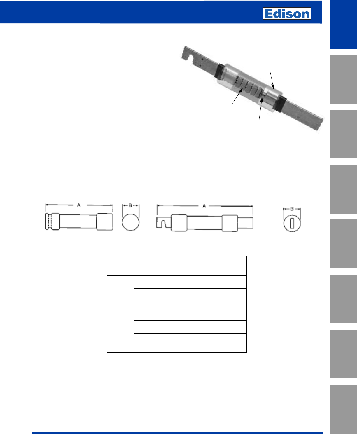
Overall Max
Catalog Length - in Diameter - in
Number Amps AB
0-30 2 0.56
35-60 3 0.81
LENRK 70-100 5.88 1.10
110-200 7.13 1.61
225-400 8.63 2.38
450-600 10.38 2.88
0-30 5 0.81
35-60 5.5 1.06
LESRK 70-100 7.88 1.11
110-200 9.63 1.61
225-400 11.63 2.36
450-600 13.38 2.88
Class R fuses will fit Class H, K and R fuse clips. Class R fuse clips will only accept Class R fuses. Fuses rated 600Vac
or less may be applied at any lower voltage.
Dimensions
Ferrule Design–0 through 60 Amps Knife Blade–70 through 600 Amps
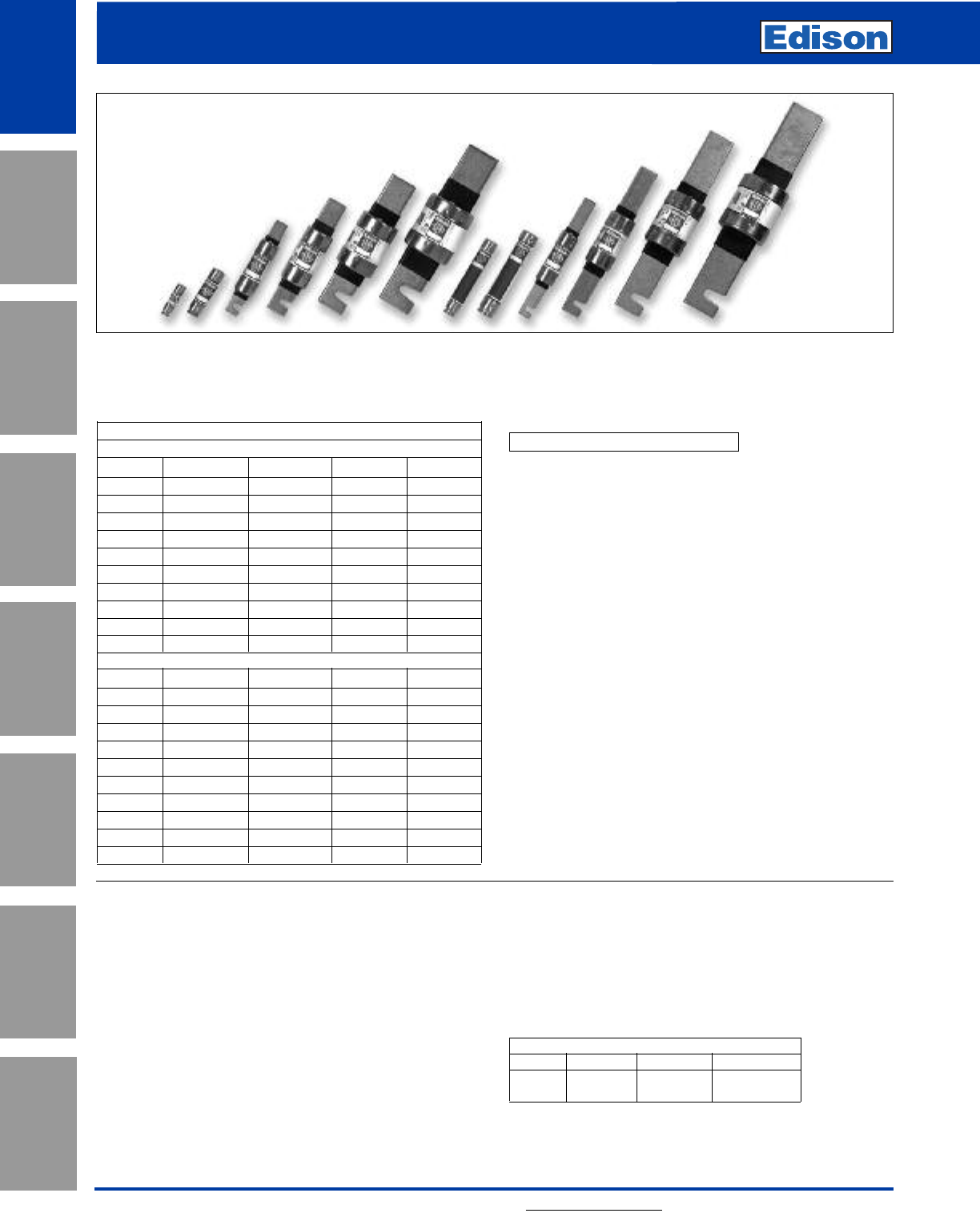
LENRK/LESRK Dual-Element Fuses
The application recommended for these fuses is exactly the
same as for the Edison ECNR/ECSR fuses except for the
advantages of greater current limitation. The Edison
LENRK/LESRK fuses have up to 40% more current
limitation and up to 350% more Amps-Squared-Second (I2t)
limitation under fault conditions than Edison ECNR/ECSR
fuses to reduce potential for damage. In addition,
LENRK/LESRK fuses allow better selectivity for electrical
power system designers and better short-circuit protection
for breakers having inadequate interrupting ratings.
ECNR/ECSR and LENRK/LESRK fuse lines are physically
interchangeable (and electrically interchangeable per UL
equipment listing conditions) and are recommended as a
practical, economical way to upgrade systems for many
situations.
True Dual-Element Construction
Insulated end-caps to prevent
accidental contact with live parts.
Overload element
Short-circuit element
8
LENRK/LESRK Class RK1
Dual-Element Time-Delay Fuses
For additional information, visit www.edisonfuse.com
Application
Section
Fuse Blocks,
Holders & Misc.
Surge Protective
Devices
Medium
Voltage Fuses
Canadian
Fuses & Holders
Special
Purpose Fuses
UL/CSA Fuses
General Purpose
UL/CSA Fuses
Current Limiting
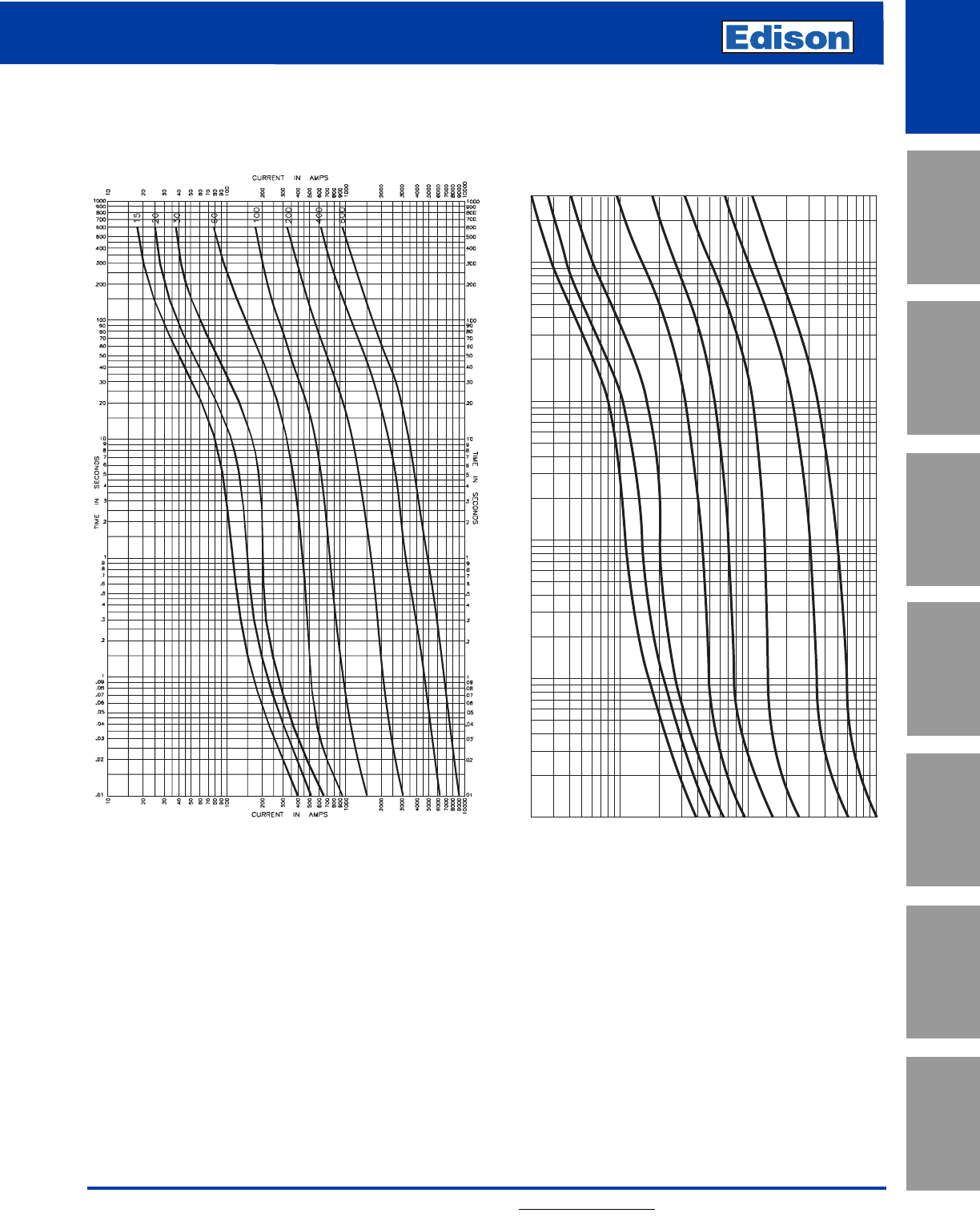
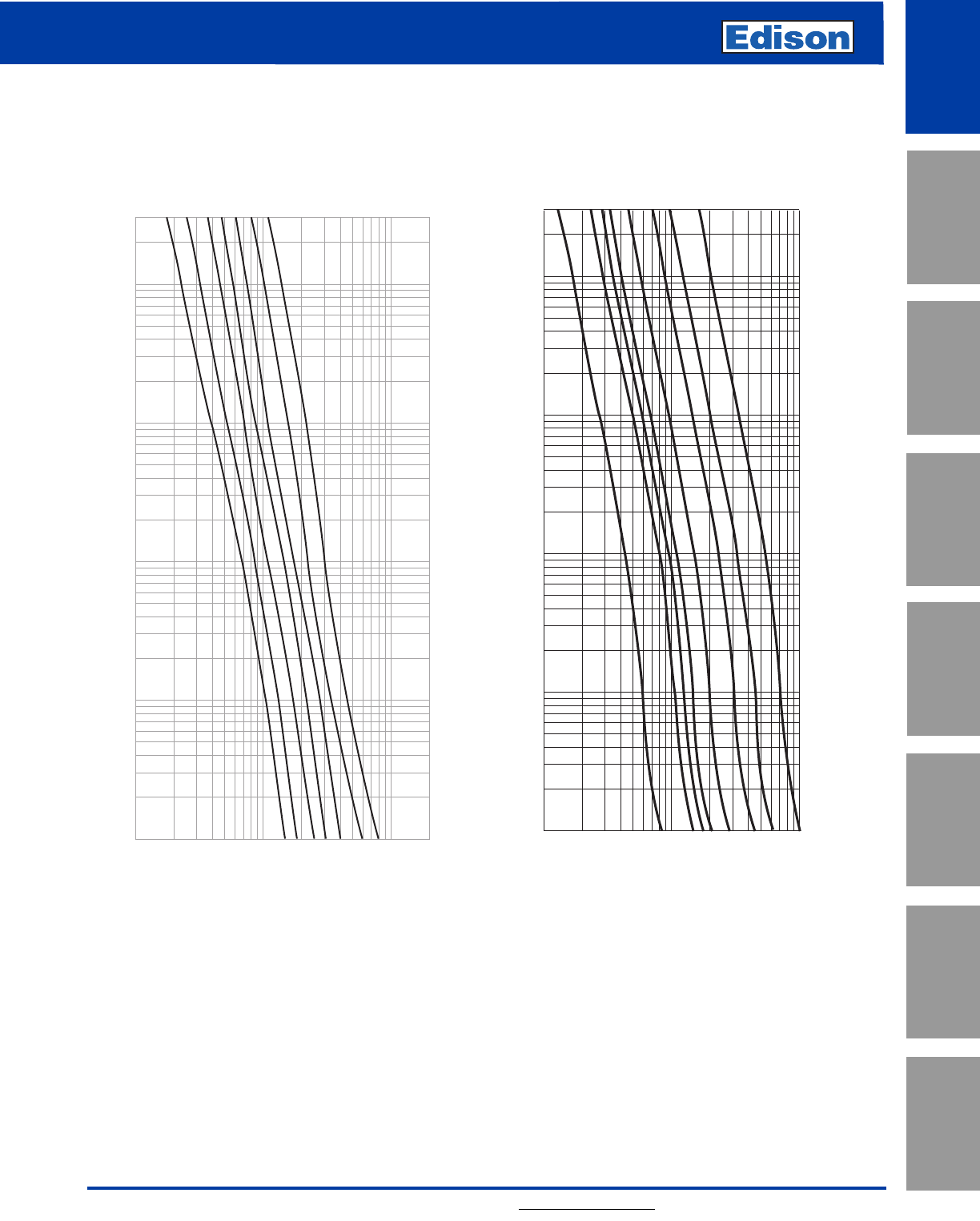
Average Melt Time-Current Curves
1
2
4
5
8
10
12
AMP RATING
300
100
10
1
.1
.01
.1
1
10
100
1,000
TIME IN SECONDS
RMS SYMMETRICAL CURRENT IN AMPS
1/10 15/100
2/10
3/10
4/10 1/2
6/10 8/10
11/4
16/10
21/2
32/10
61/4
1/10
15/100
2/10
4/10
6/10
16/10
8/10
1
2
4
5
8
12
10
11/4
21/232/10
61/4
1/2
3/10
TIME IN SECONDS
CURRENT IN AMPS
AMP RATING
LENRK (Amp) LESRK (Amp)
9
LENRK/LESRK Class RK1
Dual-Element Time-Delay Fuses
For additional information, visit www.edisonfuse.com
UL/CSA Fuses
Current Limiting
UL/CSA Fuses
General Purpose
Special
Purpose Fuses
Canadian
Fuses & Holders
Medium
Voltage Fuses
Fuse Blocks,
Holders & Misc.
Application
Section
Surge Protective
Devices
Average Melt Time-Current Curves
LENRK LESRK
RMS SYMMETRICAL CURRENT IN AMPS
TIME IN SECONDS
300
200
100
80
60
40
30
20
10
8
6
4
3
2
1
.8
.6
.4
.3
.2
.1
.08
.06
.04
.03
.02
.01
20
30
40
60
80
100
200
300
400
600
800
1,000
2,000
3,000
4,000
6,000
8,000
10,000
20A
60A
100A
200A
30A
400A
AMP
RATING
600A
15A
10
LENRK/LESRK Class RK1
Dual-Element Time-Delay Fuses
For additional information, visit www.edisonfuse.com
Application
Section
Fuse Blocks,
Holders & Misc.
Surge Protective
Devices
Medium
Voltage Fuses
Canadian
Fuses & Holders
Special
Purpose Fuses
UL/CSA Fuses
General Purpose
UL/CSA Fuses
Current Limiting
*Curves test data obtained at 15% short-circuit power factor when possible.
INSTANTANEOUS PEAK LET-THROUGH CURRENT IN AMPS
400,000
300,000
200,000
100,000
80,000
60,000
40,000
30,000
20,000
10,000
8,000
6,000
4,000
3,000
2,000
1,000
5,000
50,000
1,000
2,000
3,000
4,000
5,000
6,000
8,000
10,000
20,000
30,000
40,000
50,000
60,000
80,000
100,000
200,000
RMS SYMMETRICAL CURRENTS IN AMPS
A–B=ASYMMETRICAL AVAILABLE PEAK (2.3 X SYMM RMS AMPS)
600
400
200
100
60
30
AMP
RATING
A
B
INSTANTANEOUS PEAK LET-THROUGH CURRENT IN AMPS
Peak Let-Through Current Curves*
LENRK LESRK
Current Limtation Tables**
**"Apparent Let-Through Amps" values are read from "Peak Let-Through Current Curves" and the peak current value divided by 2.3
Asymmetry Factor.
LENRK RMS & Peak Let-Through Currents (kA)
Available
Fault Apparent Effective Let-Through Amps (kA)
current 30 60 100 200 400 600
RMS Amps IRMS IpIRMS IpIRMS IpIRMS IpIRMS IpIRMS Ip
1,000 111212121212
2,000 121324252525
3,000 121324363737
5,000 12242537512 5 12
10,000 13242649715 9 21
15,000 132536410 7 17 10 23
20,000 132637511 8 19 11 25
25,000 133637512 9 20 12 27
30,000 233638512 9 21 13 29
35,000 243748613 10 22 13 30
40,000 243749613 10 23 13 31
50,000 243749614 10 24 14 33
60,000 2438410 7 15 11 26 15 35
70,000 2438410 7 16 12 27 16 36
80,000 2548511 7 16 12 28 17 38
90,000 2549511 7 17 13 29 17 39
100,000 2549511 8 18 13 30 17 40
150,000 26410 5 13 8 19 16 36 20 46
200,000 36511 6 14 9 21 18 42 22 50
LESRK RMS & Peak Let-Through Currents (kA)
Available
Fault Apparent Effective Let-Through Amps (kA)
current 30 60 100 200 400 600
RMS Amps IRMS IpIRMS IpIRMS IpIRMS IpIRMS IpIRMS Ip
1,000 111212121212
2,000 121324242424
3,000 121324363737
5,000 12242537512 5 12
10,000 13253649716 9 21
15,000 132537511 8 18 10 24
20,000 133637512 8 19 11 26
25,000 243638512 9 21 12 28
30,000 243648613 10 22 13 30
35,000 243749614 10 23 13 31
40,000 243749614 10 24 14 32
50,000 2538410 7 15 11 26 15 35
60,000 2538410 7 16 12 28 16 37
70,000 2548511 7 17 13 29 17 39
80,000 2549511 8 18 13 30 17 40
90,000 2549512 8 18 13 31 18 42
100,000 2649512 8 19 14 32 19 44
150,000 36511 6 14 9 21 16 36 22 50
200,000 3 7512 7 15 10 23 17 40 23 54
Amp Ratings
NCLR
1 10 35 80 175 400
3 12 40 90 200 450
4 15 45 100 225 500
5 20 50 110 250 600
6 25 60 125 300 —
8 30 70 150 350 —
SCLR
1830 70 175 450
2 10 35 80 225 500
3 12 40 90 250 600
4 15 45 100 300 —
5 20 50 110 350 —
6 25 60 125 400 —
NCLR/SCLR Specifications
Fast-Acting
Voltage Rating: NCLR - 250Vac, SCLR - 600Vac
Amp Rating: 1 - 600A
Interrupting Rating: 200kA RMS Symmetrical Amps
Current Limiting: RK1 Fuse
Agency Information:
UL Listed, Class RK1, Guide JDDZ, File E162363
CSA Certified per C22.2, No. 248.12
Self-Certified DC Ratings:
Voltage Rating: NCLR (1-600) 250Vdc
SCLR (1-600) 300Vdc
Interrupting Rating: NCLR/SCLR 10kA DC
Recommended Fuse Blocks:
Refer to pages 145 and 146 in this catalog.
Recommended Upgrade:
LENRK/LESRK.
Catalog Number NCLR (1- 600A) 250Vac or Less
Catalog Number SCLR (1- 600A) 600Vac or Less
Benefits:
• No intentional time-delay opens quickly on overload
current.
Applications:
• Recommended for protection on non-inductive loads such
as lighting and resistance heating circuits.
• Use to protect lower interrupting rating circuit breakers in
series rated applications.
11
NCLR Class RK1 Fast-Acting Fuses
SCLR Class RK1 Fast-Acting Fuses
For additional information, visit www.edisonfuse.com
UL/CSA Fuses
Current Limiting
UL/CSA Fuses
General Purpose
Special
Purpose Fuses
Canadian
Fuses & Holders
Medium
Voltage Fuses
Fuse Blocks,
Holders & Misc.
Application
Section
Surge Protective
Devices
CROSS REFERENCE
VOLTS EDISON MERSEN LITTELFUSE
250 NCLR A2KR KLNR
600 SCLR A6KR* KLSR*
* Larger body size on blade type.
Dimensions
Ferrule Design–0 through 60 Amps Knife Blade–70 through 600 Amps
Application:
Edison NCLR/SCLR Class RK1 fast-acting fuses are
recommended for general power distribution system use for
main, feeder and branch circuits having a high percentage
of non-inductive loads such as heating and lighting.
NCLR/SCLR fuses are suitable for circuit breaker
protection.* When NCLR/SCLR fast-acting fuses are used
for inductive loads, the fuses usually require oversizing to
override normal transient current surges of motors and
transformers. Oversizing fuses usually increases fuse and
equipment cost and reduces overcurrent protection. (For
inductive loads, LENRK/LESRK fuses are recommended).
NCLR/SCLR Class RK1 fast-acting fuses are physically
interchangeable with other Class R fuses. They will replace
Class K or Class H fuses in standard fuse clips.
*When used as recommended by a specific circuit breaker manufacturer for a
specific application.
Average Time-Current Curves
Cat. No. NCLR (Amp) and SCLR (Amp)
12
NCLR Class RK1 Fast-Acting Fuses
SCLR Class RK1 Fast-Acting Fuses
For additional information, visit www.edisonfuse.com
Application
Section
Fuse Blocks,
Holders & Misc.
Surge Protective
Devices
Medium
Voltage Fuses
Canadian
Fuses & Holders
Special
Purpose Fuses
UL/CSA Fuses
General Purpose
UL/CSA Fuses
Current Limiting
RMS SYMMETRICAL CURRENT IN AMPS
TIME IN SECONDS
300
200
100
80
60
40
30
20
10
8
6
4
3
2
1
.8
.6
.4
.3
.2
.1
.08
.06
.04
.03
.02
.01
40
60
80
100
200
300
400
600
800
1,000
2,000
3,000
4,000
6,000
8,000
10,000
30A
60A
100A
200A
400A
600A
AMP
RATING
Dimensions
Ferrule Design–0 through 60 Amps
Knife Blade–70 through 600 Amps
Overall Max
Catalog Length - in Diameter - in
Number Amps AB
0-30 2 0.56
35-60 3 0.81
NCLR 70-100 5.88 1.10
110-200 7.13 1.61
225-400 8.63 2.38
450-600 10.38 2.88
0-30 5 0.81
35-60 5.5 1.06
SCLR 70-100 7.88 1.11
110-200 9.63 1.61
225-400 11.63 2.36
450-600 13.38 2.88
13
NCLR Class RK1 Fast-Acting Fuses
SCLR Class RK1 Fast-Acting Fuses
For additional information, visit www.edisonfuse.com
UL/CSA Fuses
Current Limiting
UL/CSA Fuses
General Purpose
Special
Purpose Fuses
Canadian
Fuses & Holders
Medium
Voltage Fuses
Fuse Blocks,
Holders & Misc.
Application
Section
Surge Protective
Devices
INSTANTANEOUS PEAK LET-THROUGH CURRENT IN AMPS
400,000
300,000
200,000
100,000
80,000
60,000
40,000
30,000
20,000
10,000
8,000
6,000
4,000
3,000
2,000
1,000
5,000
50,000
1,000
2,000
3,000
4,000
5,000
6,000
8,000
10,000
20,000
30,000
40,000
50,000
60,000
80,000
100,000
200,000
RMS SYMMETRICAL CURRENTS IN AMPS
A–B=ASYMMETRICAL AVAILABLE PEAK (2.3 X SYMM RMS AMPS)
600
100
60
AMP
RATING
30
400
200
B
A
200,000
100,000
80,000
60,000
50,000
40,000
30,000
20,000
10,000
8,000
6,000
5,000
4,000
3,000
2,000
1,000
1,000
400,000
300,000
200,000
100,000
80,000
60,000
40,000
30,000
20,000
10,000
8,000
6,000
4,000
3,000
2,000
5,000
50,000
RMS SYMMETRICAL CURRENTS IN AMPS
A–B=ASYMMETRICAL AVAILABLE PEAK (2.3 X SYMM RMS AMPS)
600
100
60
AMP
RATING
30
400
200
B
A
INSTANTANEOUS PEAK LET-THROUGH CURRENT IN AMPS
Peak Let-Through Current Curves*
NCLR SCLR
Current Limitation Tables**
NCLR SCLR
NCLR – RMS & Peak Let-Through Currents (kA)
Prosp. Fuse Size
Short 30 60 100 200 400 600
C.C. IRMS IpIRMS IpIRMS IpIRMS IpIRMS IpIRMS Ip
5,000 12132436510 5 12
10,000 12132538614 8 19
15,000 13242649717 10 22
20,000 132436410 8 19 11 25
25,000 132537410 9 20 12 27
30,000 132537511 10 22 13 29
35,000 132538512 10 23 13 31
40,000 132538512 10 24 14 32
50,000 242549613 11 26 15 36
60,000 242649614 12 28 17 38
70,000 243649615 13 29 17 40
80,000 2436410 7 15 13 30 18 42
90,000 2436510 7 16 13 31 19 44
100,000 2437511 7 17 14 32 20 46
150,000 2537513 8 19 16 37 23 53
200,000 2538614 9 21 18 41 26 59
SCLR – RMS & Peak Let-Through Currents (kA)
Prosp. Fuse Size
Short 30 60 100 200 400 600
C.C. IRMS IpIRMS IpIRMS IpIRMS IpIRMS IpIRMS Ip
5,000 12132436512 5 12
10,000 12242548715 9 20
15,000 132436410 8 18 11 24
20,000 132537511 9 20 12 28
25,000 132537512 10 22 13 31
30,000 132538513 10 24 14 33
35,000 242548613 11 25 15 35
40,000 242649614 11 26 16 37
50,000 243649614 12 28 17 40
60,000 2436410 7 15 13 30 19 43
70,000 2437510 7 16 14 32 20 45
80,000 2437511 7 17 14 33 21 48
90,000 2537512 8 18 15 35 22 50
100,000 2537512 8 19 16 36 23 52
150,000 2548614 9 21 18 41 26 60
200,000 3649715 10 23 20 46 29 66
*Curves test data obtained at 15% short-circuit power factor when possible.
**"Apparent Let-Through Amps" values are read from "Peak Let-Through Current Curves" and the peak current value divided by 2.3
Asymmetry Factor.
14
Class L Time-Delay Fuses
Class L Fast-Acting Fuses
For additional information, visit www.edisonfuse.com
Application
Section
Fuse Blocks,
Holders & Misc.
Surge Protective
Devices
Medium
Voltage Fuses
Canadian
Fuses & Holders
Special
Purpose Fuses
UL/CSA Fuses
General Purpose
UL/CSA Fuses
Current Limiting
Amp Ratings
LCL
300* 650 801 1350 1800 3500
400* 700 900 1400 2000 4000
500* 750 1000 1500 2500 —
601 800 1200 1600 3000 —
LCU
601 800 1350 1800 3000 6000
650 1000 1500 2000 3500 —
700 1200 1600 2500 4000 —
* Not UL Listed (See note below).
LCL: Time-delay of 5 seconds minimum at 500% rated current
allows closer sizing.
NOTE: LCL 300 - 500 amp fuses are physically the same as 800
amp size; Use in 800 amp switch where load current is not
fully utilized and a smaller fuse amp size is desired. Also
useful in new installations to allow for future upgrades in
service.
LCL/LCU Specifications
LCL: Time-Delay
LCU: Fast-Acting
Voltage Rating: LCL - 600Vac, LCU - 600Vac
Amp Rating: LCL: 300 - 4000A
LCU: 601 - 6000A
Interrupting Rating: 200kA RMS Symmetrical Amps
Current Limiting: Class L Fuse
Agency Information:
UL Listed, Class L, Guide JDDZ, File E162363
CSA Certified HRC-L per C22.2, No. 248.10
Recommended Sizing:
LCL: 150% or more of motor full load current.
Recommended Upgrade:
None Available.
Catalog Number LCL (300 - 4000A) Time-Delay 600Vac or Less
Catalog Number LCU (601 - 6000A) Fast-Acting 600Vac or Less
Benefits:
• “O-ring” construction insures maximum current limiting
ability.
• Silver plated micro-peened terminals.
• High strength melamine fuse tubes.
Applications:
•LCL: Recommended for AC power distribution system
mains and large feeders.
•LCU: Recommended for non-inductive heating and
lighting loads. Also suitable for protection of low
interrupting rating circuit breakers.
CROSS REFERENCE
EDISON MERSEN LITTELFUSE
LCL A4BY KLP-C, KLLU
LCU None None
15
Class L Time-Delay Fuses
Class L Fast-Acting Fuses
For additional information, visit www.edisonfuse.com
UL/CSA Fuses
Current Limiting
UL/CSA Fuses
General Purpose
Special
Purpose Fuses
Canadian
Fuses & Holders
Medium
Voltage Fuses
Fuse Blocks,
Holders & Misc.
Application
Section
Surge Protective
Devices
300
100
10
1
.1
.01
1,000
10,000
100,000
200,000
CURRENT IN AMPS
TIME IN SECONDS
800A
1200A
1600A
2000A
2500A
3000A
4000A
AMP
RA TING
RMS SYMMETRICAL CURRENT IN AMPS
TIME IN SECONDS
300
200
100
80
60
40
30
20
10
8
6
4
3
2
1
.8
.6
.4
.3
.2
.1
.08
.06
.04
.03
.02
.01
2,000
1,000
3,000
4,000
6,000
8,000
10,000
20,000
30,000
40,000
60,000
100,000
800A
1200A
1600A
2000A
1350A
3000A
4000A
6000A
AMP
RATING
Average Time-Current Curves
Cat. No.LCL (Amp) Cat. No. LCU (Amp)
16
Class L Time-Delay Fuses
Class L Fast-Acting Fuses
For additional information, visit www.edisonfuse.com
Application
Section
Fuse Blocks,
Holders & Misc.
Surge Protective
Devices
Medium
Voltage Fuses
Canadian
Fuses & Holders
Special
Purpose Fuses
UL/CSA Fuses
General Purpose
UL/CSA Fuses
Current Limiting
400,000
300,000
200,000
100,000
80,000
60,000
40,000
20,000
30,000
10,000
8,000
6,000
4,000
3,000
2,000
1,000
1,000
2,000
3,000
4,000
6,000
8,000
10,000
20,000
30,000
40,000
60,000
80,000
100,000
200,000
RMS SYMMETRICAL CURRENTS IN AMPS
A–B=ASYMMETRICAL AVAILABLE PEAK (2.3 X SYMM RMS AMPS)
A
B
6,000
4,000
3,000
2,500
2,000
1,600
1,200
800
601
AMP
RATING
INSTANTENOUS PEAK LET-THROUGH CURRENT AMPS
A
B
4,000
3,000
2,500
2,000
1,600
1,200
800
AMP
RATING
400,000
100,000
10,000
1,000
1,000
10,000
100,000
200,000
RMS SYMMETRICAL CURRENTS IN AMPS
A-B= ASYMMETRICAL AVAILABLE PEAK (2.3 X SYMM RMS AMPS)
INSTANTENOUS PEAK LET-THROUGH CURRENT AMPS
Peak Let-Through Current Curves*
LCL LCU
Current Limitation Tables**
LCL LCU
Current-Limiting Effects
*Prosp. Let-Through Current (Apparent RMS Symmetrical)
S.C.C. Versus Fuse Ratings
800A 1200A 1600A 2000A 3000A 4000A
5,000 5,000 5,000 5,000 5,000 5,000 5,000
10,000 10,000 10,000 10,000 10,000 10,000 10,000
15,000 13,000 15,000 15,000 15,000 15,000 15,000
20,000 14,000 18,000 20,000 20,000 20,000 20,000
25,000 16,000 21,000 25,000 25,000 25,000 25,000
30,000 16,500 22,500 26,000 30,000 30,000 30,000
40,000 18,000 25,500 29,000 34,000 40,000 40,000
50,000 19,000 27,000 32,000 37,000 42,000 45,000
60,000 21,000 29,000 35,000 41,000 45,000 50,000
80,000 24,000 32,000 39,000 45,000 51,000 57,000
100,000 26,000 36,000 41,000 51,000 55,000 64,000
150,000 30,000 40,000 48,000 58,000 66,000 78,000
200,000 34,000 45,000 52,000 65,000 76,000 92,000
* RMS Symmetrical Amps Short-Circuit Current.
NOTE: Data derived from Current Limiting Curves.
Current-Limiting Effects
*Prosp. Let-Through Current (Apparent RMS Symmetrical)
S.C.C. Versus Fuse Ratings
800A 1200A 1600A 2000A 3000A 4000A 6000A
5,000 5,000 5,000 5,000 5,000 5,000 5,000 5,000
10,000 9,700 10,000 10,000 10,000 10,000 10,000 10,000
15,000 11,500 13,000 15,000 15,000 15,000 15,000 15,000
20,000 12,500 15,400 18,000 20,000 20,000 20,000 20,000
25,000 14,000 16,000 21,000 25,000 25,000 25,000 25,000
30,000 14,500 17,500 22,000 27,000 30,000 30,000 30,000
35,000 15,000 18,000 24,000 28,000 35,000 35,000 35,000
40,000 15,500 19,000 25,000 29,000 40,000 40,000 40,000
50,000 16,000 21,000 26,000 32,000 44,000 48,000 50,000
60,000 19,000 24,000 28,000 34,000 48,000 51,000 60,000
80,000 20,000 26,000 31,000 36,000 52,000 60,000 80,000
100,000 23,000 29,000 39,000 40,000 57,000 68,000 95,000
150,000 27,000 34,000 40,000 47,000 70,000 79,000 115,000
200,000 29,000 39,000 43,000 50,000 78,000 93,000 141,000
*RMS Symmetrical Amps Short-Circuit Current.
NOTE: Data derived from Current Limiting Curves.
**"Apparent Let-Through Amps" values are read from "Peak Let-Through Current Curves" and the peak current value divided by 2.3
Asymmetry Factor.
*Curves test data obtained at 15% short-circuit power factor when possible.
17
Class L Time-Delay Fuses
Class L Fast-Acting Fuses
For additional information, visit www.edisonfuse.com
UL/CSA Fuses
Current Limiting
UL/CSA Fuses
General Purpose
Special
Purpose Fuses
Canadian
Fuses & Holders
Medium
Voltage Fuses
Fuse Blocks,
Holders & Misc.
Application
Section
Surge Protective
Devices
General Application:
Edison Class L fuses, Catalog Numbers LCL time-delay or
LCU fast acting are recommended for high capacity main,
feeder or branch circuits in power distribution systems and
for special applications such as system upgrading, install
ahead of network protectors, etc. The choice of LCL or LCU
depends on the extent of mixed inductive and non-inductive
loads diversity. Apply LCL fuses for protection of large
individual motor circuits. Size LCL fuses at 150% or more of
the motor nameplate current rating by checking starting
characteristics against minimum melt Time-Current Curve.
Class L Fuses Specification:
Install Class L Fuses in switches rated 601-6000
amps and in AMP RATINGS and “time-delay” or
“fast-acting” types as shown on the plans. Installed and
spare “time-delay” fuses shall be Catalog Number LCL and
“fast-acting” fuses shall have silver links and be Catalog
Number LCU. Fuses shall be Edison fuses or equivalent
submitted to the design engineer for approval 10 days prior
to the project bid date.
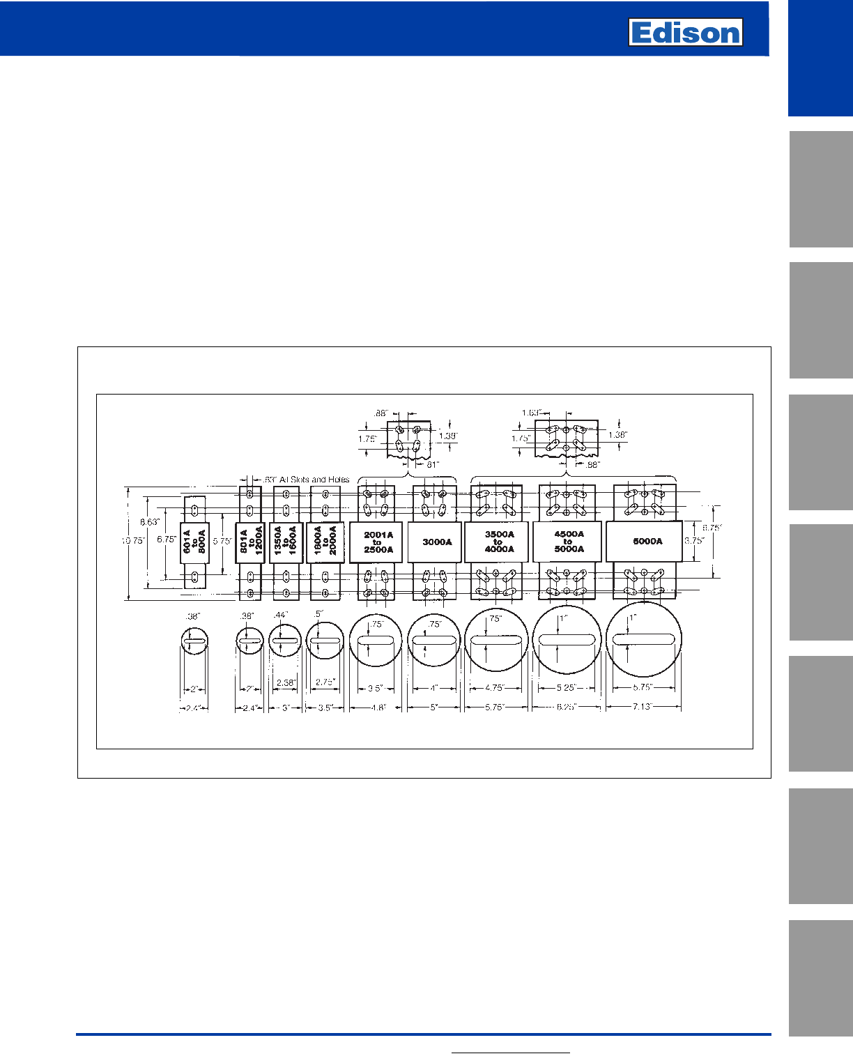
Mounting of “Bolt-On” Fuses shall be made by installing
stainless steel bolts of correct number, diameter and
length*, stainless steel spring washers on each side of the
bolt and stainless steel nuts. The nuts shall be tightened to
the torque recommended by ASTM Standards for the bolt
size used.
*Bolts shall have the largest diameter to fit fuse bolt holes and length to allow
full nut thread engagement. Bolts shall be installed in each fuse mounting
hole.
Class L Fuse Dimensions - inches
18
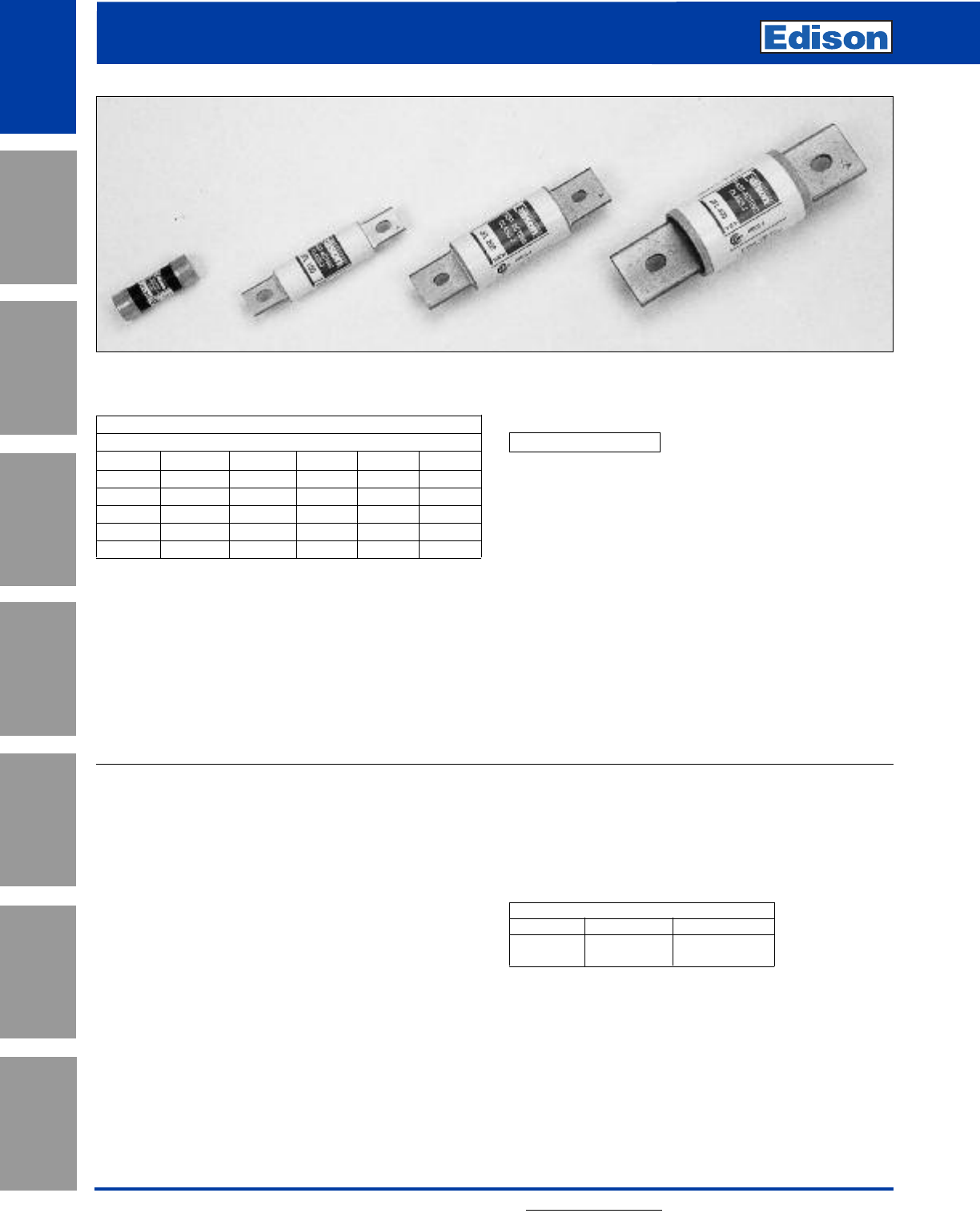
JDL Class J
Time-Delay Fuses
For additional information, visit www.edisonfuse.com
Application
Section
Fuse Blocks,
Holders & Misc.
Surge Protective
Devices
Medium
Voltage Fuses
Canadian
Fuses & Holders
Special
Purpose Fuses
UL/CSA Fuses
General Purpose
UL/CSA Fuses
Current Limiting
Amp Ratings
JDL
1412 40 100 250
1.25 5 15 45 110 300
1.6 5.6 17.5 50 125 350
2620 60 150 400
2.5 7 25 70 175 450
3830 80 200 500
3.5 10 35 90 225 600
JDL Specifications
Dual-Element, Time-Delay
Voltage Rating: JDL - 600Vac
300Vdc
Amp Rating: 1 - 600A
Interrupting Rating: 200kA RMS Symmetrical Amps
100kA DC
Current Limiting: Class J Fuse
Agency Information:
UL Listed, Class J, Guide JDDZ, File E162363
CSA Certified per C22.2, No. 248.8
Recommend Fuse Blocks:
Refer to page 129 in this catalog.
Recommend Upgrade:
None.
Catalog Number JDL (1 - 600A) 600Vac or Less
Benefits:
• Space saving dimensions vs. Class R.
• Dual-Element construction provides superior time-delay
to pass harmless motor or transformer surges.
• High performance with fatigue - free cycling capabilities.
• Extremely current limiting.
Applications:
• Recommended for Type 2 “No Damage” protection of IEC
style motor starters and contactors.
• Use to protect lower interrupting rating circuit breakers.
• All general purpose circuits with inductive (high inrush)
loads, including motor and motor branch circuits, and
transformer circuits. Also suitable for lighting loads.
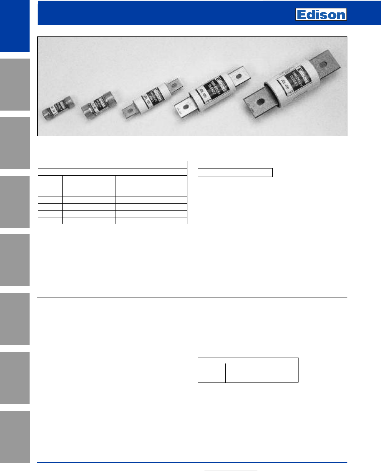
Edison JDL Class J fuses are among the most current
limiting time-delay fuses available. Their small physical size
and high performance characteristics makes Class J fuses
ideal for any space-limited application.
CROSS REFERENCE
EDISON MERSEN LITTELFUSE
JDL AJT JTD
19
JDL Class J
Time-Delay Fuses
For additional information, visit www.edisonfuse.com
UL/CSA Fuses
Current Limiting
UL/CSA Fuses
General Purpose
Special
Purpose Fuses
Canadian
Fuses & Holders
Medium
Voltage Fuses
Fuse Blocks,
Holders & Misc.
Application
Section
Surge Protective
Devices
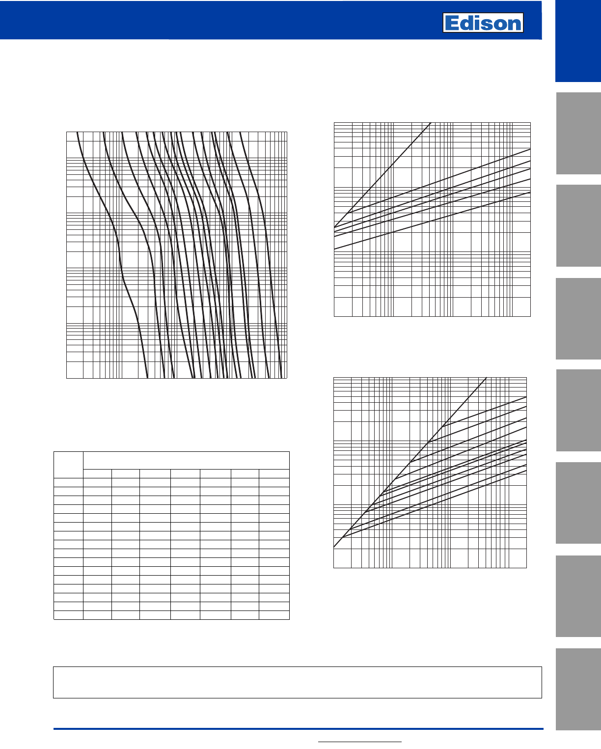
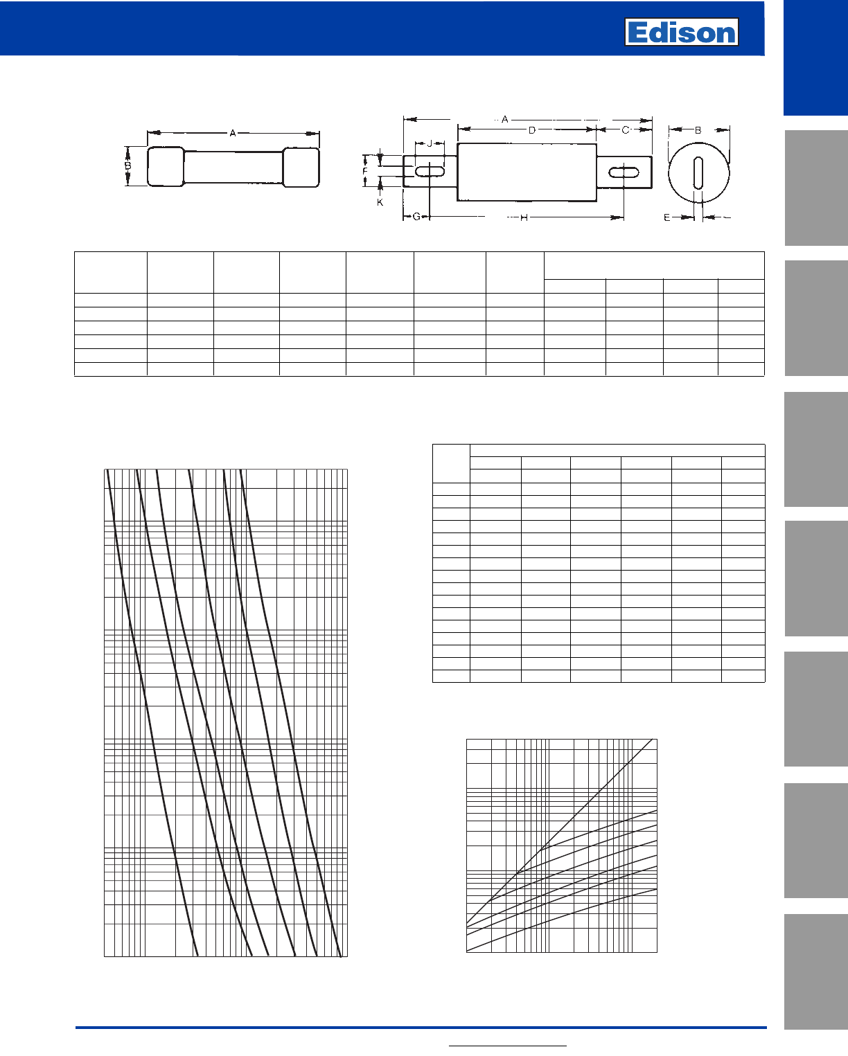
Average Time-Current Curve
Cat. No. JDL (Amp)
Peak Let-Through Current Curves
Cat. No. JDL (Amp)
Current-Limiting Effects
*Prosp. Let-Through Current (Apparent RMS Symmetrical)
S.C.C. JDL Fuse Ratings
15A 30A 60A 100A 200A 400A 600A
1,000 270 470 750 ————±
3,000 370 670 1,130 1,640 2,360 ——
5,000 450 800 1,420 1,910 2,760 4,400 —
10,000 550 1,000 1,730 2,450 3,520 5,540 8,000
15,000 625 1,220 1,890 2,850 4,000 6,420 9,000
20,000 700 1,330 2,120 3,090 4,400 7,000 10,000
25,000 750 1,440 2,250 3,400 5,000 7,500 11,100
30,000 800 1,530 2,370 3,650 5,140 8,000 11,800
35,000 820 1,600 2,580 3,780 5,430 8,330 12,500
40,000 900 1,640 2,670 4,000 5,640 9,000 13,270
50,000 925 1,760 2,790 4,470 6,000 9,380 13,820
60,000 1,000 1,850 3,000 4,670 6,420 10,000 15,000
80,000 1,160 2,000 3,220 5,000 7,400 11,270 16,000
100,000 1,220 2,150 3,520 5,360 7,950 12,180 17,270
150,000 1,400 2,460 4,000 6,170 9,000 14,360 19,270
200,000 1,560 2,640 4,450 7,000 10,000 15,820 20,600
*RMS Symmetrical Amps Short-Circuit Current.
NOTE: Data derived from Current Limiting Curves.
300
200
100
80
60
40
30
20
10
8
6
4
3
2
1
.8
.6
.4
.3
.2
.1
.08
.06
.04
.03
.02
.01
TIME IN SECONDS
10,000
8,000
6,000
1,000
4,000
3,000
2,000
800
600
400
300
200
100
80
60
40
30
20
10
8
6
4
3
2
1
RMS SYMMETRICAL CURRENT IN AMPS
Amp
Rating
1A
3A
5A
10A
15A
20A
30A
40A
50A
60A
100A
125A
200A
225A
400A
600A
RMS SYMMETRICAL CURRENTS IN AMPS
A–B=ASYMMETRICAL AVAILABLE PEAK (2.3 X SYMM RMS AMPS)
100
200
300
400
600
800
1,000
2,000
3,000
4,000
6,000
8,000
10,000
20,000
30,000
40,000
60,000
80,000
100,000
200,000
30,000
20,000
10,000
8,000
6,000
4,000
3,000
2,000
1,000
800
600
400
300
200
100
100,000
80,000
60,000
40,000
600
400
200
100
60
50
40
30
20
15
AMP
RATING
B
A
INSTANTANEOUS PEAK LET-THROUGH CURRENT IN AMPS
INSTANTANEOUS PEAK LET-THROUGH CURRENT IN AMPS
100,000
80,000
60,000
40,000
30,000
20,000
10,000
8,000
6,000
4,000
3,000
2,000
1,000
800
600
400
300
200
100
RMS SYMMETRICAL CURRENTS IN AMPS
A–B=ASYMMETRICAL AVAILALBE PEAK (2.3 X SYMM RMS AMPS)
100
200
300
400
600
800
1,000
2,000
3,000
4,000
6,000
8,000
10,000
20,000
30,000
40,000
60,000
80,000
100,000
200,000
10
7
3
6
1
AMP
RATING
B
A
Dimensions
Refer to JFL Section on page 21.
20
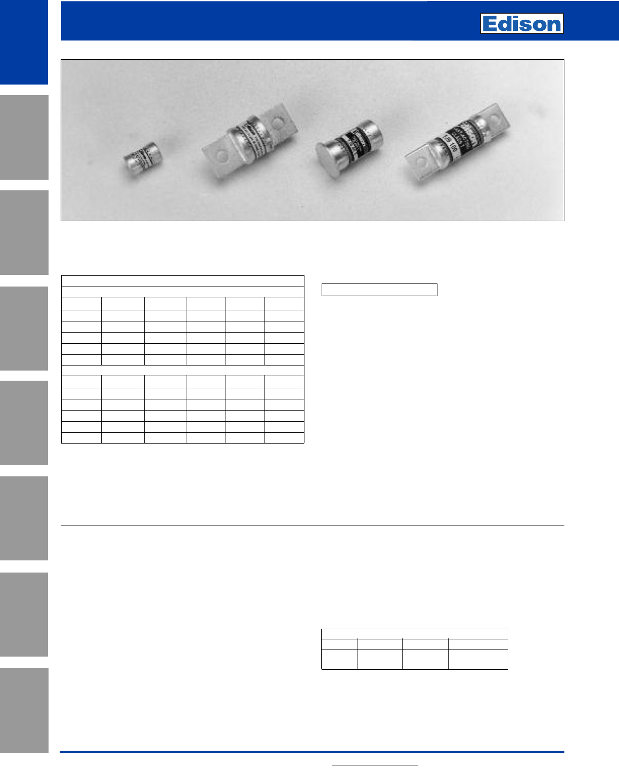
JFL Class J
Fast-Acting Fuses
For additional information, visit www.edisonfuse.com
Application
Section
Fuse Blocks,
Holders & Misc.
Surge Protective
Devices
Medium
Voltage Fuses
Canadian
Fuses & Holders
Special
Purpose Fuses
UL/CSA Fuses
General Purpose
UL/CSA Fuses
Current Limiting
Amp Ratings
JFL
1830 70 150 350
2 10 35 80 175 400
3 12 40 90 200 450
4 15 45 100 225 500
5 20 50 110 250 600
6 25 60 125 300 —
JFL Specifications
Fast-Acting
Voltage Rating: JFL - 600Vac
Amp Rating: 1 - 600A
Interrupting Rating: 200kA RMS Symmetrical Amps
Current Limiting: Class J Fuse
Agency Information:
UL Listed, Class J, Guide JDDZ, File E162363
CSA Certified per C22.2, No. 248.8
Recommended Fuse Blocks:
Refer to page 148 in this catalog.
Recommended Upgrade:
JDL.
Catalog Number JFL (1 - 600A) 600Vac or Less
Benefits:
• Space saving dimensions vs. Class R.
• Fast-acting design permits quick response for both
overloads and shorts.
• Extremely current-limiting.
Applications:
• Recommended for protection of non-inductive loads, such
as lighting and resistance heating circuits.
• For motor applications, refer to Edison JDL.
Edison JFL Class J fuses are among the most current
limiting fuses available. Their small physical size and high
performance characteristics makes Class J fuses ideal for
any space - limited application.
Edison JFL fuses are best suited for the protection of
non-inductive loads such as resistive heating, and lighting
circuits.
CROSS REFERENCE
EDISON MERSEN LITTELFUSE
JFL A4J JLS
21
JFL Class J Fast-Acting Fuses
JDL Class J Time-Delay Fuses
For additional information, visit www.edisonfuse.com
UL/CSA Fuses
Current Limiting
UL/CSA Fuses
General Purpose
Special
Purpose Fuses
Canadian
Fuses & Holders
Medium
Voltage Fuses
Fuse Blocks,
Holders & Misc.
Application
Section
Surge Protective
Devices
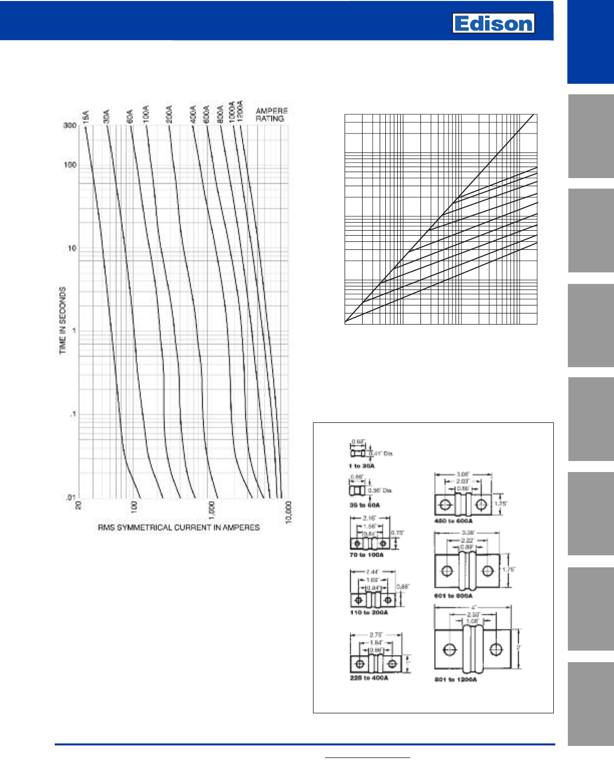
Average Time-Current Curve
Cat. No. JFL (Amp)
Peak Let-Through Current Curves**
Current Limitation Table*
JFL
RMS SYMMETRICAL CURRENT IN AMPS
TIME IN SECONDS
300
200
100
80
60
40
30
20
10
8
6
4
3
2
1
.8
.6
.4
.3
.2
.1
.08
.06
.04
.03
.02
.01
40
60
80
100
200
300
400
600
800
1,000
2,000
3,000
4,000
6,000
8,000
10,000
60A
100A
200A
30A
400A
AMP
RATING
600A
INSTANTANEOUS PEAK LET-THROUGH CURRENT IN AMPS
1,000
2,000
3,000
4,000
5,000
6,000
8,000
10,000
20,000
30,000
40,000
50,000
60,000
80,000
100,000
200,000
400,000
300,000
200,000
100,000
80,000
60,000
40,000
30,000
20,000
10,000
8,000
6,000
4,000
3,000
2,000
1,000
5,000
50,000
RMS SYMMETRICAL CURRENTS IN AMPS
A–B=ASYMMETRICAL AVAILABLE PEAK (2.3 X SYMM RMS AMPS)
600
400
200
AMP
RATING
100
60
30
B
A
Amp Overall Max. Blade Barrel Blade Blade
Rating Length Dia. Length Length Thickness Width Mounting Hole Spacing
Range ABCDEFGHJK
1-30 2-1/4 13/16 ––––––––
35-60 2-3/8 1-1/16 ––––––––
70-100 4-5/8 1-1/18 1 2-5/8 1/8 3/4 1/2 3-5/8 3/8 9/32
110-200 5-3/4 1-5/8 1-3/8 3 3/16 1-1/8 11/16 4-3/8 3/8 9/32
225-400 7-1/8 2-1/8 1-7/8 3-3/8 1/4 1-5/8 15/16 5-1/4 17/32 13/32
450-600 8 2-5/8 2-1/8 3-3/4 3/8 21611/16 17/32
Prosp. Fuse Size
Short 30 60 100 200 400 600
S.C.C. IRMS IpIRMS IpIRMS IpIRMS IpIRMS IpIRMS Ip
5,000 12132437410 5 12
10,000 13243649613 9 19
15,000 132436410 7 15 10 22
20,000 132537512 8 18 11 25
25,000 243638613 9 19 12 28
30,000 243638613 9 20 13 30
35,000 243749614 9 21 13 30
40,000 243749715 10 22 14 32
50,000 2538410 7 16 10 23 15 35
60,000 2538511 7 17 11 25 16 37
70,000 2538512 8 18 11 25 17 39
80,000 2538512 8 18 12 28 17 39
90,000 2549613 9 19 13 29 18 41
100,000 2549613 9 19 13 30 18 42
150,000 25511 6 14 9 21 14 33 22 50
200,000 36512 7 15 10 22 16 37 24 55
Cat No. JFL and JDL Dimensions - inches
* "Apparent Let-Through Amps" values are read from "Peak Let-Through Current Curves" and the peak current value divided by 2.3 Asymmetry Factor.
** Curves test data obtained at 15% short-circuit power factor when possible.
JFL (600Vac)
22
TJN (300Vac) Class T Fast-Acting Fuses
TJS (600Vac) Class T Fast-Acting Fuses
For additional information, visit www.edisonfuse.com
Application
Section
Fuse Blocks,
Holders & Misc.
Surge Protective
Devices
Medium
Voltage Fuses
Canadian
Fuses & Holders
Special
Purpose Fuses
UL/CSA Fuses
General Purpose
UL/CSA Fuses
Current Limiting
Amp Ratings
TJN
1 30 70 150 350 800
3 35 80 175 400 1000
6 40 90 200 450 1200
10 45 100 225 500 —
15 50 110 250 600 —
20 60 125 300 700 —
TJS
1 25 60 125 300 800
3 30 70 150 350 —
6 35 80 175 400 —
10 40 90 200 450 —
15 45 100 225 500 —
20 50 110 250 600 —
Edison Class T fuses are extremely fast-acting fuses in a
compact, space saving size. These fuses are ideal as the
main fuse protection for panelboards, load centers and
meter stacks.
TJN/TJS Specifications
Extremely Fast-Acting
Voltage Rating: TJN - 300Vac, TJS - 600Vac
Amp Rating: TJN: 1 - 1200A TJS: 1 - 800A
Interrupting Rating: 200kA RMS Symmetrical Amps
TJN (15-600) 20kA Amps DC
Current Limiting: Class T Fuse
Agency Information:
UL Listed, Class T, Guide JDDZ,, File E162363
CSA Certified per C22.2, No. 248.15, LR700489
Self-Certified DC Ratings:
Voltage Rating: TJN (15-600) 160Vdc
TJN (601-1200) 170Vdc
Interrupting Rating:
TJN (15-600) 20kA DC
TJN (601-1200) 100kA DC
Recommended Fuse Blocks:
Refer to page 149 in this catalog.
Recommended Upgrade:
None Available.
Catalog Number TJN (1 - 1200A) 300Vac or Less
Catalog Number TJS (1 - 800A) 600Vac or Less
Benefits:
• No intentional time-delay; opens quickly on overload.
• Extremely current-limiting silver link construction; provides
superior short-circuit component protection.
Applications:
• Recommended for protection of non-inductive loads, such
as lighting and resistance heating circuits.
• Use to protect lower interrupting rating circuit breakers
when series rated with Class T fuses.
• For motor protection, size at 300% FLA which provides
short-circuit protection only.
CROSS REFERENCE
VOLTS EDISON MERSEN LITTELFUSE
300 TJN A3T JLLN
600 TJS A6T JLLS
23
TJN (300Vac) Class T Fast-Acting Fuses
TJS (600Vac) Class T Fast-Acting Fuses
For additional information, visit www.edisonfuse.com
UL/CSA Fuses
Current Limiting
UL/CSA Fuses
General Purpose
Special
Purpose Fuses
Canadian
Fuses & Holders
Medium
Voltage Fuses
Fuse Blocks,
Holders & Misc.
Application
Section
Surge Protective
Devices
INSTANTANEOUS PEAK LET-THROUGH CURRENT IN AMPS
RMS SYMMETRICAL CURRENTS IN AMPS
A-B = ASYMMETRICAL AVAILABLE PEAK (2.3 x SYMM RMS AMPS)
100,000
80,000
60,000
40,000
30,000
20,000
10,000
8,000
6,000
4,000
3,000
2,000
1,000
800
600
400
300
200
100
200
300
400
600
800
1,000
2,000
3,000
4,000
6,000
8,000
10,000
20,000
30,000
40,000
60,000
80,000
100,000
200,000
200,000
400,000
300,000
600
400
200
100
60
30
15
AMP
RATING
800
1200
B
A
Average Time-Current Curve
Cat. No. TJN (Amp)
Peak Let-Through Current Curve
Cat. No. TJN (Amp)
TJN Dimensions - in
24
TJN (300Vac) Class T Fast-Acting Fuses
TJS (600Vac) Class T Fast-Acting Fuses
For additional information, visit www.edisonfuse.com
Application
Section
Fuse Blocks,
Holders & Misc.
Surge Protective
Devices
Medium
Voltage Fuses
Canadian
Fuses & Holders
Special
Purpose Fuses
UL/CSA Fuses
General Purpose
UL/CSA Fuses
Current Limiting
Average Time-Current Curve
Cat. No. TJS (Amp)
Peak Let-Through Current Curve
Cat. No. TJS (Amp)
800
RMS SYMMETRICAL CURRENTS IN AMPS
A–B=ASYMMETRICAL AVAILABLE PEAK (2.3 X SYMM RMS AMPS)
100,000
80,000
60,000
40,000
30,000
20,000
10,000
8,000
6,000
4,000
3,000
2,000
1,000
600
400
300
200
100
200
300
400
600
800
1,000
2,000
3,000
4,000
6,000
8,000
10,000
20,000
30,000
40,000
60,000
80,000
100,000
200,000
200,000
400,000
300,000
600
400
200
100
60
30
AMP
RATING
800
B
A
INSTANTANEOUS PEAK LET-THROUGH CURRENT IN AMPS
10,000
8,000
6,000
1,000
4,000
3,000
2,000
800
600
400
300
200
100
80
60
40
30
20
10
8
6
4
3
2
1
300
200
100
80
60
40
30
20
10
8
6
4
3
2
1
.8
.6
.4
.3
.2
.1
.08
.06
.04
.03
.02
.01
CURRENT IN AMPS
TIME IN SECONDS
1A
3A
5A
10A
30A
15A
60A
200A
400A
500A
100A
800A
AMP
RATING
TJS Dimensions - inches
3.98"
(± 0.04)
2.95"
1.78"
1.25"
(± 0.04)
450A to 600A
3.63"
(± 0.04)
2.72"
1.73"
1"
(± 0.04)
225A to 400A
601A to 800A
4.33"
(± 0.04)
3.17"
1.88"
1.75"
(± 0.04)
0.88"
(± 0.04)
3.25"
(± 0.04)
2.5"
1.66"
110A to 200A
Dia. 0.56"
(± 0.04) 1A to 30A
1.5"
(± 0.04)
Dia. 0.81"
(± 0.04)
0.75"
(± 0.04)
2.95"
(± 0.04)
2.36"
1.64"
70A to 100A
0.344"
(Typ. 2)
0.563"
(Typ. 2)
0.484"
(Typ. 2)
0.406"
(Typ. 2)
0.281"
(Typ. 2)
1.00"
(± 0.01)
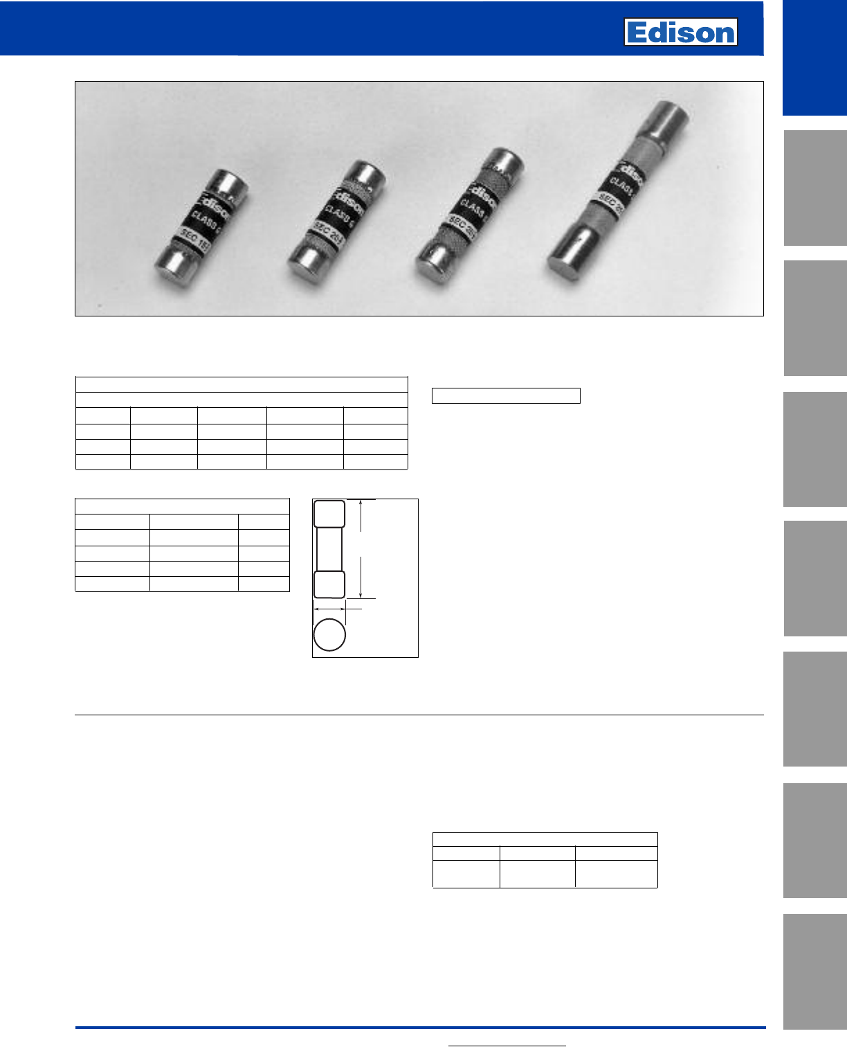
Amp Ratings
SEC
0.5 3825 45
1410 30 50
1.5 5 15 35 60
2620 40 —
Amps Ferrule Diameter Length
1 - 15 0.41 1.31
20 0.41 1.41
25 - 30 0.41 1.63
35 - 60 0.41 2.25
SEC Specifications
Fast-Acting; Time-Delay*
Voltage Rating: SEC 0.5 to 20 600Vac
SEC 25 to 60 480Vac
SEC (30 and 60A only) 300Vdc
Amp Rating: 0.5 to 6A (fast-acting),
7 to 60A (time-delay)
Interrupting Rating: 100kA RMS Symmetrical Amps
Current Limiting: Class G Fuse
Agency Information:
UL Listed, Std. 248-5, Class G, Guide JDDZ, File E162363
CSA Certified, C22.2 No. 248.5, Class 1422-01, File
700489
Self-Certified DC Ratings:
Voltage Rating: SEC (0.5-20A) 170Vdc;
Interrupting Rating: 10kA Amps DC
*Fast-acting/time-delay varies by amp rating
Recommended Fuse Blocks:
Refer to page 151 in this catalog.
Recommended Upgrade:
None Available.
Catalog Number SEC (0.5 - 60A) 600Vac or Less
Benefits:
• Branch circuit rated for 480Vac.
• Compact size features varying length rejection feature
which helps prevent overfusing.
• Time-delay of 12 sec. min. at 200% rating for amp sizes
6 through 60.
Applications:
• General purpose for use in 120/208 and 277/480 circuits.
Ideal for fluorescent fixture protection.
• Light inductive loads including motors, solenoids, etc.
(For additional delay, refer to Edison EDCC or JDL).
25
SEC Time-Lag
Class G Fuses
For additional information, visit www.edisonfuse.com
UL/CSA Fuses
Current Limiting
UL/CSA Fuses
General Purpose
Special
Purpose Fuses
Canadian
Fuses & Holders
Medium
Voltage Fuses
Fuse Blocks,
Holders & Misc.
Application
Section
Surge Protective
Devices
CROSS REFERENCE
EDISON MERSEN LITTELFUSE
SEC AG SLC
A
(Length)
0.41"
(10.41mm)
Dimensions - inches
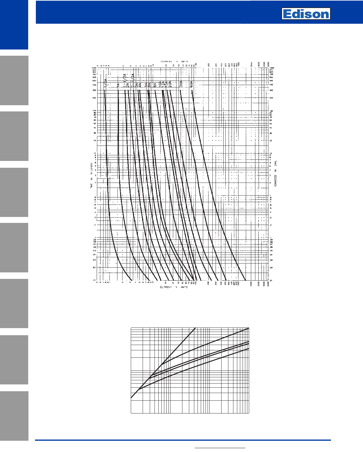
Peak Let-Through Current Curve
Cat. No. SEC (Amp)
Average Time-Current Curve
Cat. No. SEC (Amp)
10,000
8,000
6,000
4,000
3,000
2,000
1,000
800
600
400
200
300
100
100
200
300
400
2,000
2,000
600
800
1,000
4,000
6,000
8,000
10,000
20,000
30,000
40,000
60,000
80,000
100,000
INSTANTANEOUS PEAK LET- THROUGH CURRENT IN AMPS
B60
30
20
15
AMP
RATING
A
RMS SYMMETRICAL CURRENTS IN AMPS
A–B=ASYMMETRICAL AVAILABLE PEAK (2.3 X SYMM RMS AMPS)
26
SEC Time-Lag
Class G Fuses
For additional information, visit www.edisonfuse.com
Application
Section
Fuse Blocks,
Holders & Misc.
Surge Protective
Devices
Medium
Voltage Fuses
Canadian
Fuses & Holders
Special
Purpose Fuses
UL/CSA Fuses
General Purpose
UL/CSA Fuses
Current Limiting
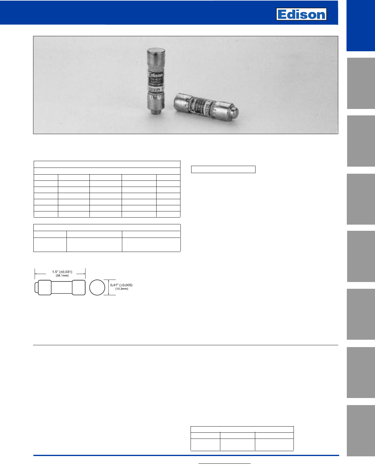
27
EDCC Time-Delay
CLASS CC Fuses
For additional information, visit www.edisonfuse.com
UL/CSA Fuses
Current Limiting
UL/CSA Fuses
General Purpose
Special
Purpose Fuses
Canadian
Fuses & Holders
Medium
Voltage Fuses
Fuse Blocks,
Holders & Misc.
Application
Section
Surge Protective
Devices
Amp Ratings
EDCC
0.5 1.5 3612
0.6 1.6 3.2 6.25 15
0.8 1.8 3.5 7 20
1247.5 25
1.125 2.25 4.5 8 30
1.25 2.5 59—
1.4 2.8 5.6 10 —
Dimensions - inches
Amps Dimension Length
0.5 - 30 13/32 1-1/2
Edison EDCC Class CC fuses are extremely current-limiting fuses in
a compact size.
EDCC fuses are designed specifically for the protection of small
horsepower motor circuits.
Recommended sizing for most applications is 200% FLA. Refer to
time-current curves for specific applications.
EDCC Specifications
Time-Delay
Voltage Rating: EDCC - 600Vac
0.5-2.5A, 20-30A 300Vdc
2.8-15A, 150Vdc
Amp Rating: 0.5 - 30A
Interrupting Rating: 200kA RMS Symmetrical Amps
20kA DC
Current Limiting: Class CC Fuse
Agency Information:
UL Listed, Class CC, Guide JDDZ, File E162363
CSA Certified per C22.2, No. 248.4
Recommended Fuse Blocks:
Refer to page 151 in this catalog.
Recommended Inline Fuse Holders:
Refer to page 165 in this catalog.
Recommended Panel Mount Holders:
Refer to page 168 in this catalog.
Recommended Upgrade:
None Available.
Catalog Number EDCC (0.5 - 30A) 600Vac or Less
Benefits:
• Branch circuit rated for 600Vac.
• Time-delay for motor branch circuit protection.
• Excellent current-limiting performance.
• Upgrade for standard “midget” fuses.
Applications:
• Use for protection of small horsepower motor circuits or
other circuits requiring small dimension, time-delay fuses.
• Can provide Type 2 “No Damage” protection for IEC or
NEMA starters/contactors.
• For control transformer applications, refer to HCTR.
CROSS REFERENCE
EDISON MERSEN LITTELFUSE
EDCC ATDR CCMR
Dimensions - in (mm)
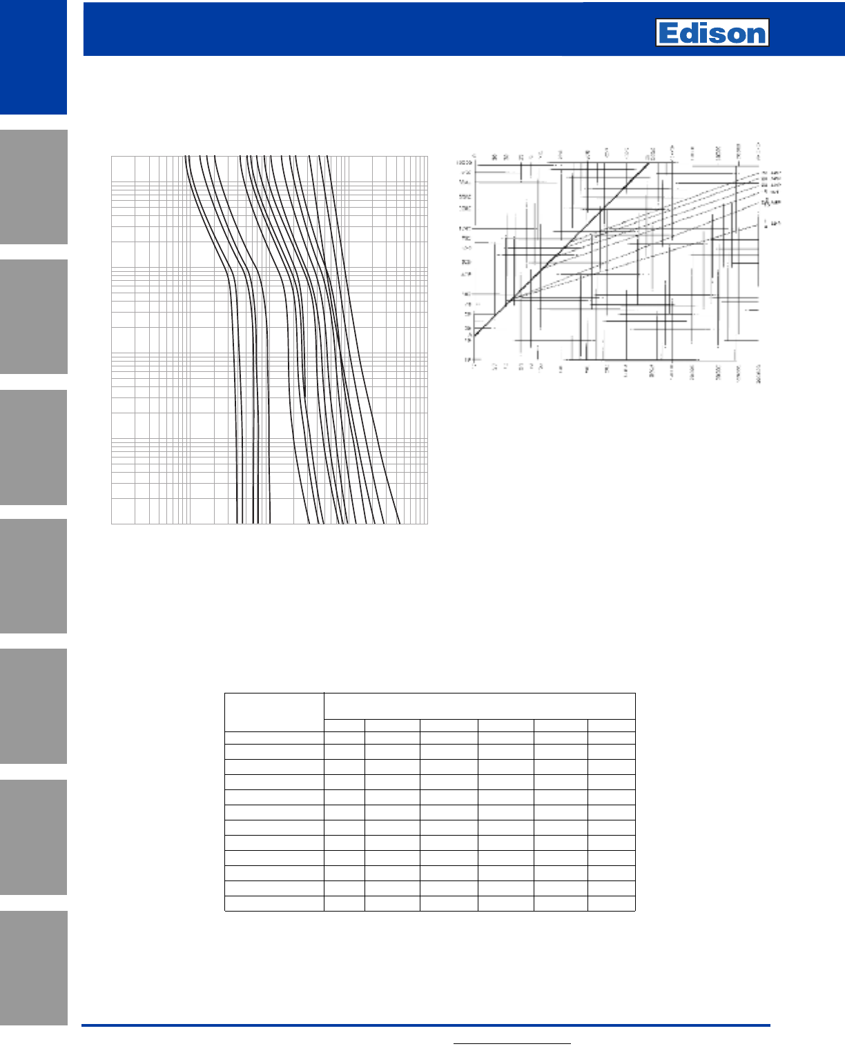
28
EDCC Time-Delay
Class CC Fuses
For additional information, visit www.edisonfuse.com
100
10
1
.1
.01
.1
1
10
100
1000
CURRENT IN AMPS
TIME IN SECONDS
.5
.6
.8
1
1.25
3
3.5
4
4.5
6
8
10
12
15
20
25
30
AMP
RATING
Current-Limiting Effects EDCC Fuse Rating
Let-Through Current (Apparent RMS Symmetrical)
*Prospective Short- Versus Fuse Ratings
Circuit Current 1.25A 2.8A 15A 20A 25A 30A
1000 100 135 240 305 380 435
3000 140 210 350 440 575 580
5000 165 255 420 570 690 710
10,000 210 340 540 700 870 1,000
20,000 260 435 680 870 1,090 1,305
30,000 290 525 800 1,030 1,300 1,520
40,000 315 610 870 1,150 1,390 1,700
50,000 340 650 915 1,215 1,520 1,820
60,000 350 735 1,050 1,300 1,650 1,980
80,000 390 785 1,130 1,500 1,780 2,180
100,000 420 830 1,210 1,600 2,000 2,400
200,000 525 1,100 1,600 2,000 2,520 3,050
*RMS Symmetrical amps short-circuit current.
NOTE: To calculate Ip(Ipeak) multiply IRMS value x 2.3.
Time- Current Characteristics Curve
Average Melt EDCC Fuses Peak Let-Through Current Curve
Cat. No. EDCC Amp
Application
Section
Fuse Blocks,
Holders & Misc.
Surge Protective
Devices
Medium
Voltage Fuses
Canadian
Fuses & Holders
Special
Purpose Fuses
UL/CSA Fuses
General Purpose
UL/CSA Fuses
Current Limiting
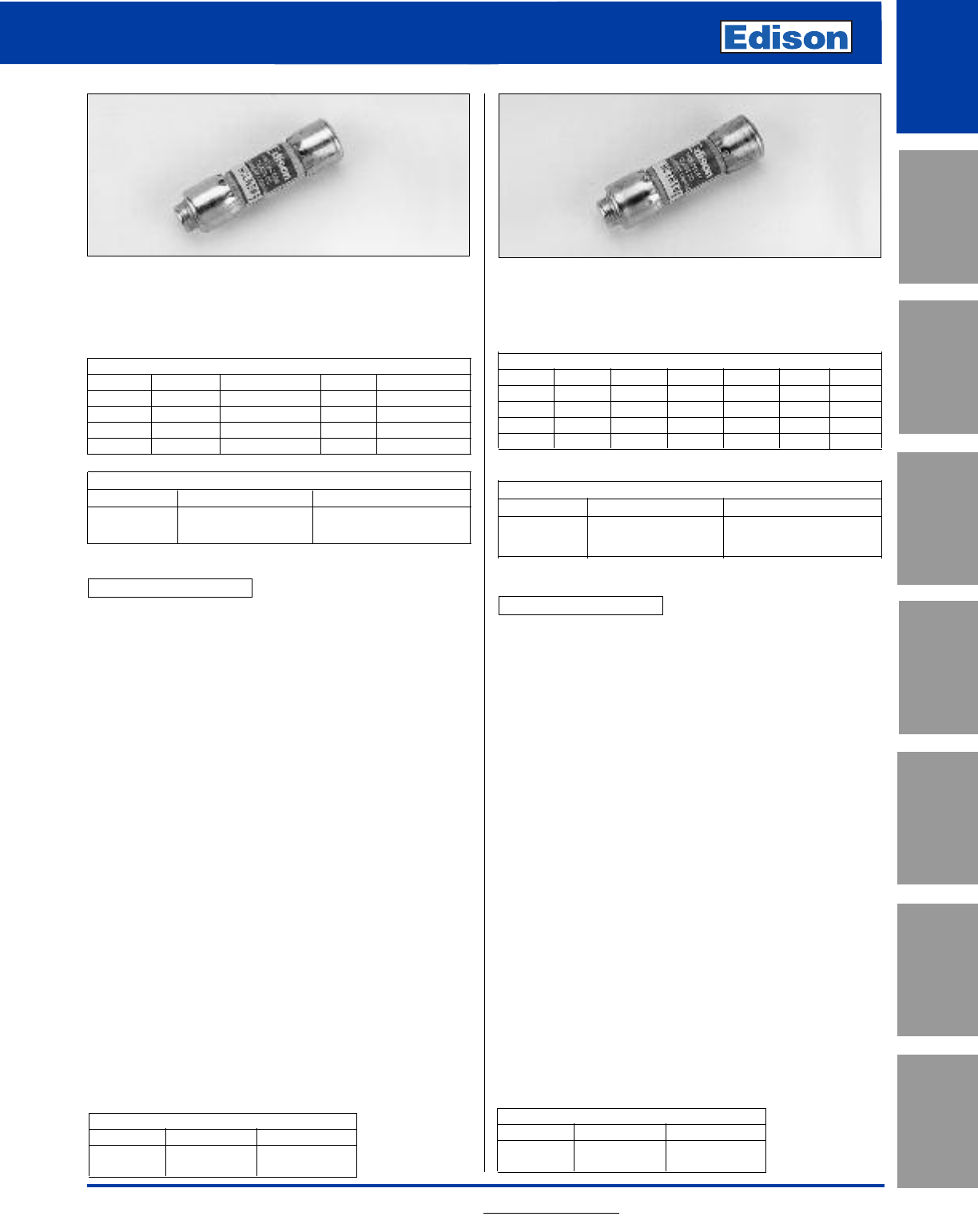
Circuit Protection
HCLR Fast-Acting Class CC Fuses
HCTR Time-Delay Class CC Fuses
For additional information, visit www.edisonfuse.com 29
Amp Ratings
0.1 0.5 2.5 6 12
0.125 0.75 3715
0.2 1 3.5 8 20
0.25 1.5 4925
0.3 2510 30
Dimensions - inches
Amps Diameter Length
0.1 - 30 13/32 1-1/2
HCLR Specifications
Fast-Acting
Voltage Rating: HCLR - 600Vac
300Vdc (15-20A)
Amp Rating: 0.1 - 30A
Interrupting Rating: 200kA RMS Symmetrical Amps
20kA DC
Current Limiting: Class CC Fuse
Agency Information:
UL Listed, Class CC, Guide JDDZ, File E162363
CSA Certified per C22.2, No. 248.4
Benefits:
• Branch circuit rated for 600Vac.
• Compact dimensions.
• Fast-acting design responds quickly to both overload and
short-circuit current.
Applications:
• Lighting and resistive heating loads.
Recommended Fuse Blocks:
Refer to page 152 in this catalog.
Recommended Inline Fuse Holders:
Refer to page 165 in this catalog.
Recommended Panel Mount Holders:
Refer to page 168 in this catalog.
Catalog Number HCLR (0.1 - 30A)
600Vac or Less
Fast-Acting
Amp Ratings
0.25 0.75 1.3 2 3.2 6.25 12
0.3 0.8 1.4 2.25 3.5 7.5 15
0.4 1 1.5 2.5 48 20
0.5 1.125 1.6 2.8 59 25
0.6 1.25 1.8 3610 30
Dimensions - inches
Amps Diameter Length
0.25 - 30 13/32 1-1/2
HCTR Specifications
Time-Delay
Voltage Rating: HCTR - 600Vac
Amp Rating: 0.25 - 30A
Interrupting Rating: 200kA RMS Symmetrical Amps
Current Limiting: Class CC Fuse
Agency Information:
UL Listed, Class CC, Guide JDDZ, File E162363
CSA Certified per C22.2, No. 248.4
Benefits:
• Branch circuit rated for 600Vac.
• Compact dimensions.
• Time-delay design allows closer sizing for inductive loads
such as control transformers and solenoids.
Applications:
• Primary protection for control transformers.
Recommended Fuse Blocks:
Refer to page 152 in this catalog.
Recommended Inline Fuse Holders:
Refer to page 165 in this catalog.
Recommended Panel Mount Holders:
Refer to page 168 in this catalog.
Catalog Number HCTR (0.25 - 30A)
600Vac or Less
Time-Delay
CROSS REFERENCE
EDISON MERSEN LITTELFUSE
HCLR ATMR KLKR
CROSS REFERENCE
EDISON MERSEN LITTELFUSE
HCTR ATQR KLDR
UL/CSA Fuses
Current Limiting
UL/CSA Fuses
General Purpose
Special
Purpose Fuses
Canadian
Fuses & Holders
Medium
Voltage Fuses
Fuse Blocks,
Holders & Misc.
Application
Section
Surge Protective
Devices
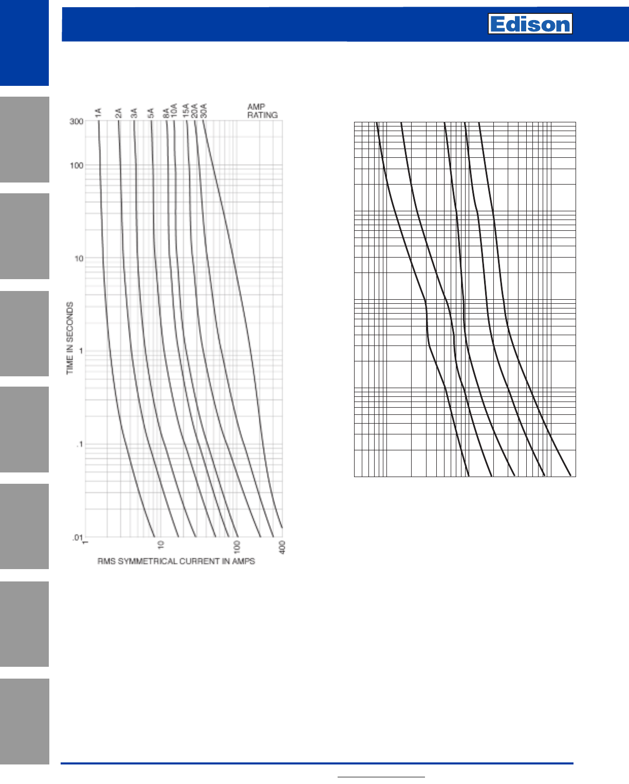
30
HCLR Fast-Acting Class CC Fuses
HCTR Time-Delay Class CC Fuses
For additional information, visit www.edisonfuse.com
Application
Section
Fuse Blocks,
Holders & Misc.
Surge Protective
Devices
Medium
Voltage Fuses
Canadian
Fuses & Holders
Special
Purpose Fuses
UL/CSA Fuses
General Purpose
UL/CSA Fuses
Current Limiting
Average Time-Current Curve
Cat. No. HCLR (Amp) Fast-Acting Cat. No. HCTR (Amp) Time-Delay
1/2
1
3
5
7-1/2
AMP
RATING
.4
.6
.8
1
2
3
4
6
8
10
20
30
40
60
80
100
200
RMS SYMMETRICAL CURRENT IN AMPS
100
80
60
30
40
20
10
8
6
4
3
1
.8
.6
.4
.3
.2
.1
.08
.06
.04
2
.01
.03
.02
TIME IN SECONDS
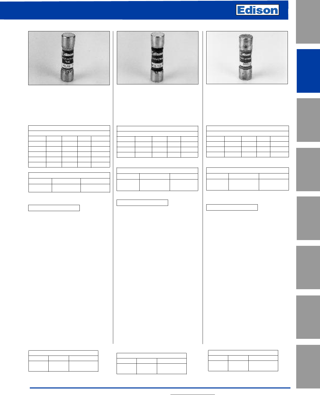
31
For additional information, visit www.edisonfuse.com
UL/CSA Fuses
Current Limiting
UL/CSA Fuses
General Purpose
Special
Purpose Fuses
Canadian
Fuses & Holders
Medium
Voltage Fuses
Fuse Blocks,
Holders & Misc.
Application
Section
Surge Protective
Devices
Catalog No. MCL (0.1 - 30A)
600Vac or Less
Fast-Acting
Amp Ratings
MCL
0.1 0.75 3.5 9 30
0.125 1410 —
0.2 1.5 5 12 —
0.25 2615 —
0.3 2.5 7 20 —
0.5 3825 —
Dimensions - inches
Amps Diameter Length
0.1 - 30 13/32 1-1/2
MCL Specifications
Fast-Acting
Voltage Rating: 600Vac
Amp Rating: 0.1 - 30A
Interrupting Rating: 100kA RMS Amps
Agency Information:
(0.1 - 30) UL Listed, Guide File JDYX,
File E162443
(0.1 - 30) CSA Cert., LR700489
Benefits:
• Compact dimensions.
• High interrupting rating.
• Fast-acting design responds quickly
to both overloads and short-circuit
current.
Applications:
• Street lighting holders, HID lighting,
control circuits, electronic equipment
protection.
Catalog No. MOL (0.5 - 30A)
250Vac or Less
Fast-Acting
Amp Ratings
MOL
0.5 2.5 6 10 25
13 6.25 12 30
1.5 4815 —
25 920 —
Dimensions - inches
Amps Diameter Length
0.5 - 30 13/32 1-1/2
MOL Specifications
Fast-Acting
Voltage Rating: 0.5-15A, 250Vac
20-30A, 125Vac
Amp Rating: 0.5 - 30A
Interrupting Rating:
10kA @ 125Vac 2/10-30A
35A @ 250Vac 0.5-1A
100A@ 250Vac 1.5-6A
200A@ 250Vac 6.5-10A
750A @ 250Vac 12-15A
200A@ 250Vac 20-30A
Agency Information:
(0.5 - 30) UL Listed, Guide File JDYX,
File E162443
(0.5 - 30) CSA Cert., LR700489
Benefits:
• Compact dimensions.
• Economical laminated paper tube
design.
Applications:
• Supplemental protection for non-
inductive control and lighting
circuits.
Catalog No. EBS (0.2 - 10A)
0.2 - 5A 600Vac or Less
6 - 10A 250Vac or Less
Fast-Acting
Amp Ratings
EBS
0.2 0.8 1.8 5 10
0.4 126—
0.5 1.5 37—
0.75 1.6 48—
Dimensions - inches
Amps Diameter Length
0.2 - 10 13/32 1-3/8
EBS Specifications
Fast-Acting
Voltage Rating: 0.2-5A, 600Vac
6-10A, 250Vac
Amp Rating: 0.2 - 10A
Interrupting Rating: 10kA RMS Amps
Agency Information:
UL Listed, Guide File JDYX,
File E162443
CSA Cert., LR700489
Benefits:
• Compact dimensions.
• Shorter than standard midget
dimensions.
• Economical design.
Applications:
• Supplemental protection for
non-inductive control and lighting
circuits.
Midget Fuses
Fast-Acting
CROSS REFERENCE
EDISON MERSEN LITTELFUSE
MCL ATM —
CROSS REFERENCE
EDISON MERSEN LITTELFUSE
MOL OTM BLF
CROSS REFERENCE
EDISON MERSEN LITTELFUSE
EBS None BLS
Recommended Fuse Blocks: Pages 152 & 169. Recommended Inline Fuse Holders: Page 165.
Recommended Panel
Mount Holders:
Page 168.
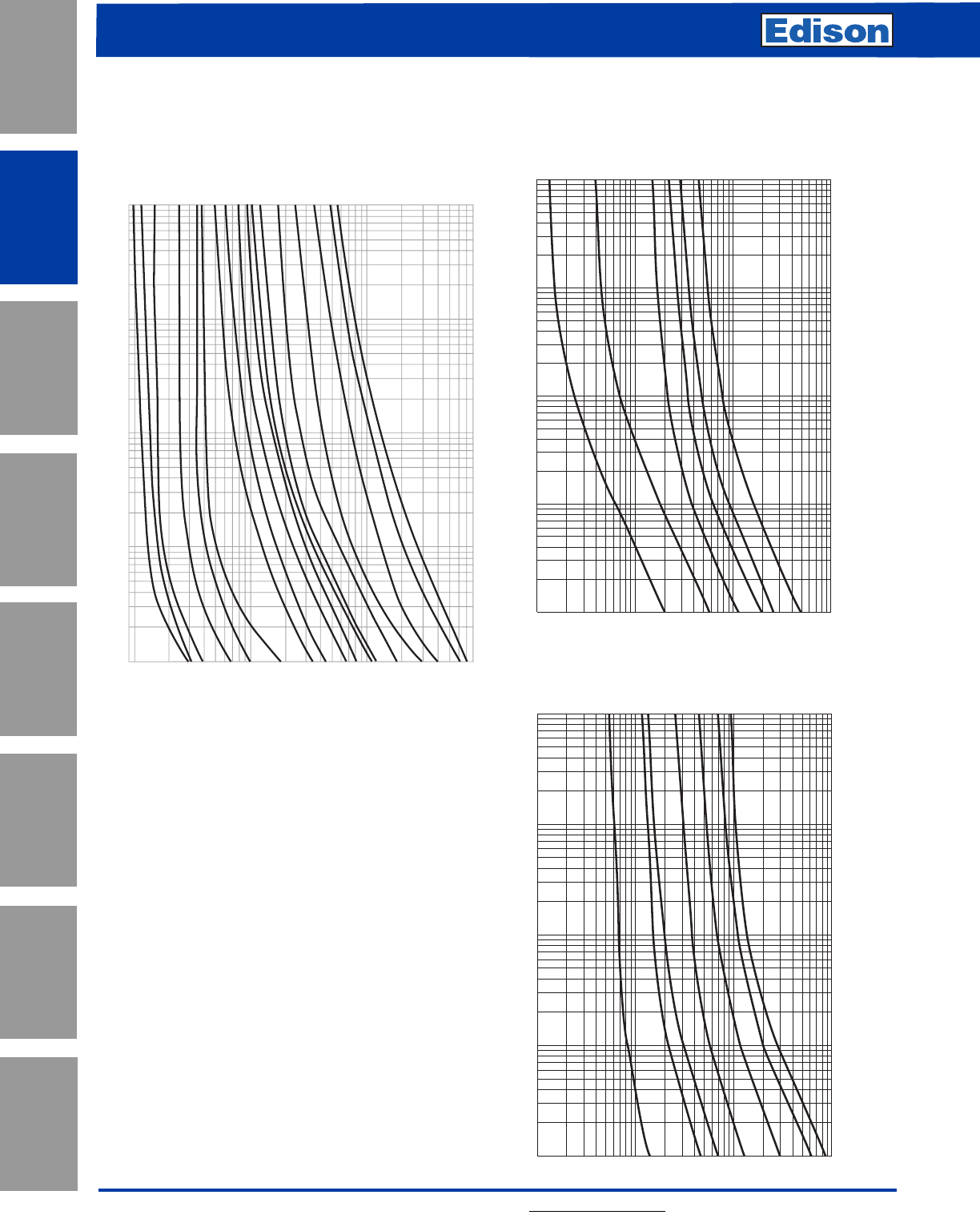
6
4
3
2
1
.8
.6
.4
.3
.2
.1
.08
.06
.04
.03
.02
.01
.05
.5
5
1
2
3
4
5
6
8
10
20
30
40
50
60
80
100
200
300
400
500
600
800
1,000
10
8
20
30
40
50
60
80
100
RMS SYMMETRICAL CURRENT IN AMPS
TIME IN SECONDS
AMP
RATING
4/10A
3/4A
1A
2A
3A
6A
7A
6
4
3
2
1
.8
.6
.4
.3
.2
.1
.08
.06
.04
.03
.02
.01
.05
.5
5
1
2
3
4
5
6
8
10
20
30
40
50
60
80
100
200
300
400
500
600
800
1,000
10
8
20
30
40
50
60
80
100
RMS SYMMETRICAL CURRENT IN AMPS
TIME IN SECONDS
AMP
RATING
3A
10A
1A
15A
20A
30A
Current in Amps
Time in Seconds
10
100
800
1
100
10
1
Amp Rating
0.1
0.01
1
3/4
6/10
3
4
6
5
0.9
1-1/2
8
2-1/2
7
10
30
15
25
20
2
Average Time-Current Curve
Cat. No. MCL (Amp) Cat. No. MOL (Amp)
32 For additional information, visit www.edisonfuse.com
Application
Section
Fuse Blocks,
Holders & Misc.
Surge Protective
Devices
Medium
Voltage Fuses
Canadian
Fuses & Holders
Special
Purpose Fuses
UL/CSA Fuses
General Purpose
UL/CSA Fuses
Current Limiting
Cat. No. EBS (Amp)
Midget Fuses
Fast-Acting
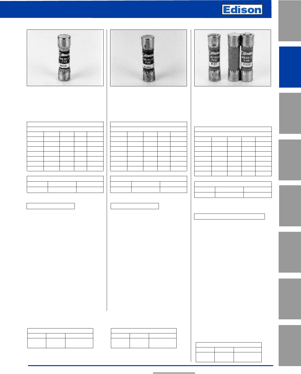
For additional information, visit www.edisonfuse.com
UL/CSA Fuses
Current Limiting
UL/CSA Fuses
General Purpose
Special
Purpose Fuses
Canadian
Fuses & Holders
Medium
Voltage Fuses
Fuse Blocks,
Holders & Misc.
Application
Section
Surge Protective
Devices
33
Catalog No. MEQ (0.1 - 30A)
500Vac or Less
Time-Delay
Amp Ratings
MEQ
0.1 0.6 2.25 5.6 15
0.125 0.8 2.5 6 20
0.15 136.25 25
0.2 1.125 3.2 7 30
0.25 1.25 3.5 8—
0.3 1.5 49—
0.4 1.6 4.5 10 —
0.5 2512 —
Dimensions - inches
Amps Diameter Length
0.1 - 30 13/32 1-1/2
MEQ Specifications
Time-Delay
Voltage Rating: 500Vac
Amp Rating: 0.1 - 30A
Interrupting Rating: 10kA RMS Amps
Agency Information:
(0.1 - 30) UL Listed, Guide File JDYX,
File E162443
(0.1 - 30) CSA Cert, LR700489
Benefits:
• Compact dimensions.
• Fiber tube construction.
• Time-delay allows harmless
inductive surges to pass without
needless fuse opening.
Applications:
• Supplemental protection of
transformers, solenoids, and other
high inrush circuits.
• For motor applications, refer to EDCC.
Catalog No. MEN (0.1 - 30A)
250Vac or Less
Time-Delay
Amp Ratings
MEN
0.1 0.8 2 4.5 10
0.15 1 2.25 5 12
0.2 1.125 2.5 5.6 15
0.25 1.25 2.8 6 20
0.3 1.4 3 6.25 25
0.4 1.5 3.2 7 30
0.5 1.6 3.5 8—
0.6 1.8 49—
Dimensions - inches
Amps Diameter Length
0.1 - 30 13/32 1-1/2
MEN Specifications
Time-Delay
Voltage Rating: 250Vac
Amp Rating: 0.5 - 30A
Interrupting Rating: 10kA RMS Amps
@ 125Vac
Agency Information:
(12-30A) UL Listed, Guide File JDYX,
File E162443
CSA Cert., LR700489
Benefits:
• Compact dimensions.
• Fiber tube construction.
• Dual-element construction allows
harmless inductive surges to pass
without opening.
Applications:
• Supplemental protection of small
motors, transformers, solenoids, and
other high inrush power electronic
circuits.
Catalog No. MID (0.1 - 30A)
0.1 - 6A 250Vac or Less
6 1/4 - 15A 125Vac or Less
20 - 30A 32Vac or Less
Pin Indicating - Time-Delay
Amp Ratings
MID
0.1 1 2.25 5.6 15
0.15 1.125 2.5 6 20
0.2 1.25 2.8 6.25 25
0.3 1.4 3730
0.4 1.5 3.2 8—
0.5 1.6 3.5 9—
0.6 1.8 4 10 —
0.8 2512 —
Dimensions - inches
Amps Diameter Length
0.1 - 30 13/32 1-1/2
NOTE: 12-30 A is dual-tube construction.
MID Specifications
Pin Indicating — Time-Delay
Voltage Rating: 0.1 - 0.8A,
250Vac
1 - 15A,125Vac
20 - 30A, 32Vac
Amp Rating: 0.1 - 30A
Interrupting Rating:
10kA @ 125Vac (1/10-15A)
1000A @ 32Vac (20-30A)
35A @ 250Vac (1/10-8/10A)
Agency Information:
(1-15A) UL Listed, Guide File JDYX,
File E162443
CSA Cert., LR700489
Benefits:
• Compact dimensions.
• Silver-plated pin indicates when fuse
is opened. Provides positive
electrical signal activation.
Applications:
• Supplemental protection for high
inrush power electronic circuits.
Midget Fuses
Time-Delay
Recommended Fuse Blocks: Pages 152 and 169. Recommended Inline Fuse
Holders: Page 165.
Recommended Panel Mount Holders:
Page 168.
CROSS REFERENCE
EDISON MERSEN LITTELFUSE
MID GFN FLA
CROSS REFERENCE
EDISON MERSEN LITTELFUSE
MEQ ATQ FLQ
CROSS REFERENCE
EDISON MERSEN LITTELFUSE
MEN TRM FLM
Recommended Fuse Blocks:
Refer to page 169 in this catalog.
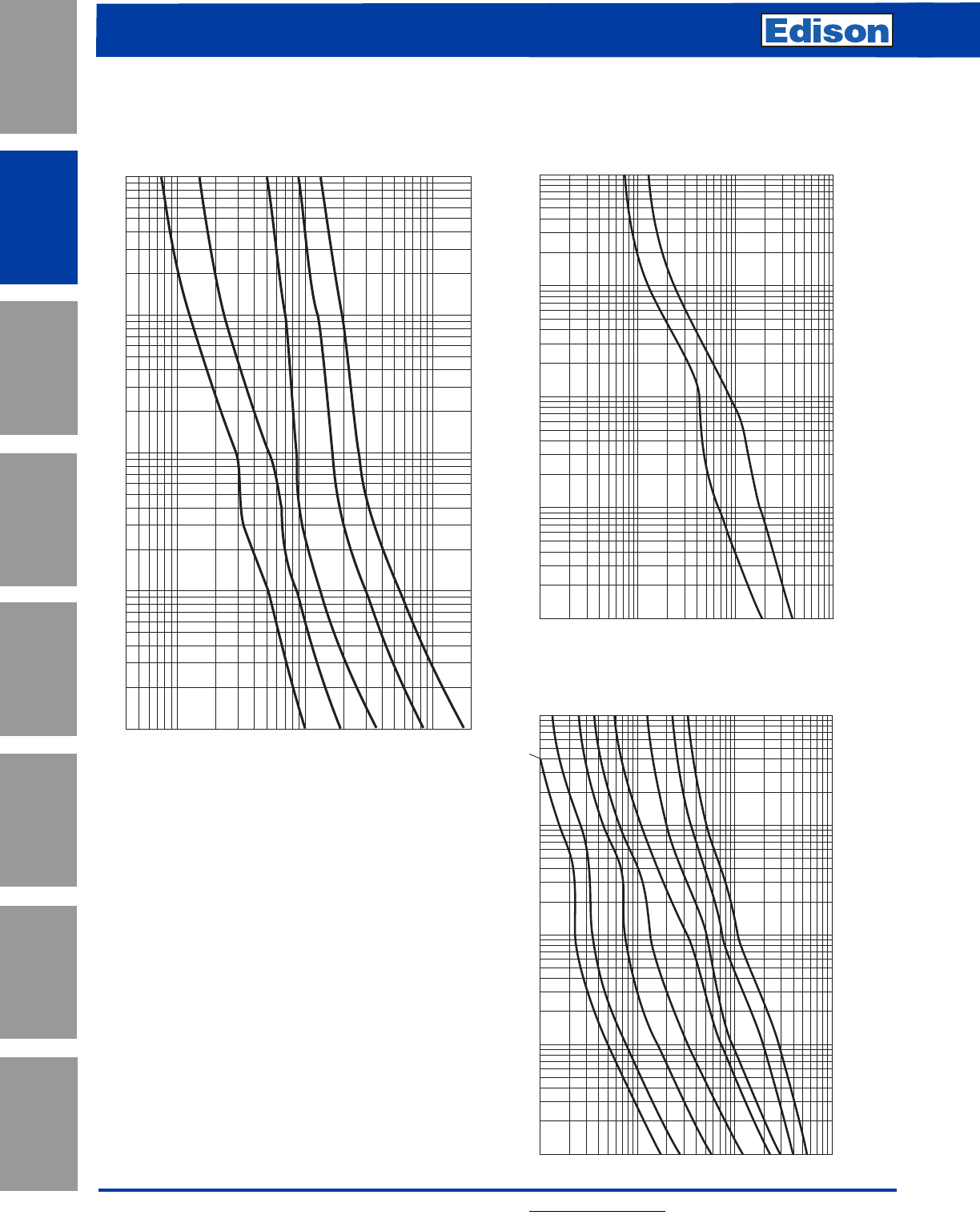
6
4
3
2
1
.8
.6
.4
.3
.2
.1
.08
.06
.04
.03
.02
.01
.05
.5
5
1
2
3
4
5
6
8
10
20
30
40
50
60
80
100
200
300
400
500
600
800
1,000
10
8
20
30
40
50
60
80
100
RMS SYMMETRICAL CURRENT IN AMPS
TIME IN SECONDS
AMP
RATING
1/2A
1A
6
4
3
2
1
.8
.6
.4
.3
.2
.1
.08
.06
.04
.03
.02
.01
.05
.5
5
1
2
3
4
5
6
8
10
20
30
40
50
60
80
100
200
300
400
500
600
800
1,000
10
8
20
30
40
50
60
80
100
RMS SYMMETRICAL CURRENT IN AMPS
TIME IN SECONDS
AMP
RATING
3A
2A
1A
15A
20A
1/2A
5A
10A
Cat. No. MID (Amp)
34 For additional information, visit www.edisonfuse.com
Application
Section
Fuse Blocks,
Holders & Misc.
Surge Protective
Devices
Medium
Voltage Fuses
Canadian
Fuses & Holders
Special
Purpose Fuses
UL/CSA Fuses
General Purpose
UL/CSA Fuses
Current Limiting
Midget Fuses
Time-Delay
1/2
1
3
5
7-1/2
AMP
RATING
.4
.6
.8
1
2
3
4
6
8
10
20
30
40
60
80
100
200
RMS SYMMETRICAL CURRENT IN AMPS
100
80
60
30
40
20
10
8
6
4
3
1
.8
.6
.4
.3
.2
.1
.08
.06
.04
2
.01
.03
.02
TIME IN SECONDS
Average Time-Current Curve
Cat. No. MEN (Amp) Cat. No. MEQ (Amp)
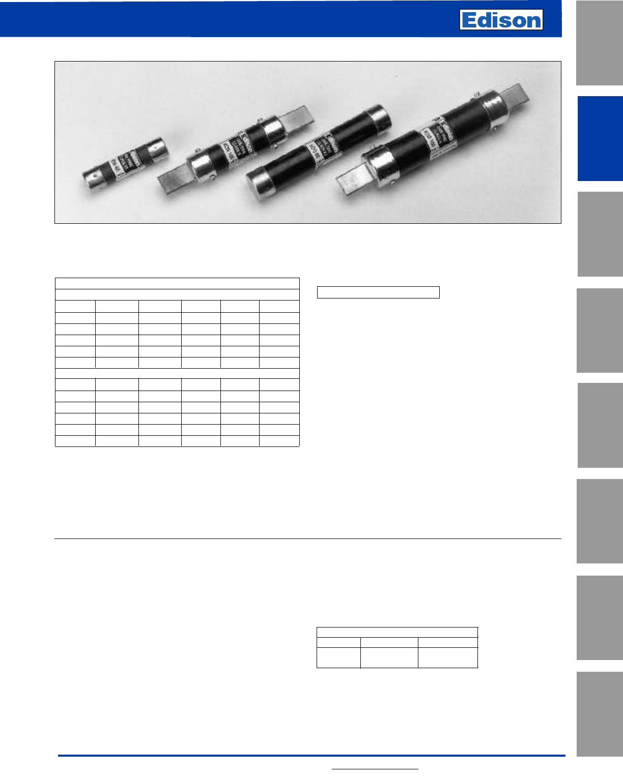
35
For additional information, visit www.edisonfuse.com
UL/CSA Fuses
Current Limiting
UL/CSA Fuses
General Purpose
Special
Purpose Fuses
Canadian
Fuses & Holders
Medium
Voltage Fuses
Fuse Blocks,
Holders & Misc.
Application
Section
Surge Protective
Devices
Amp Ratings
KON 250Vac
1725 60 125 300
2830 70 150 350
3 10 35 80 175 400
4 12 40 90 200 450
5 15 45 100 225 500
6 20 50 110 250 600
KOS 600Vac
1725 60 125 300
2830 70 150 350
3 10 35 80 175 400
4 12 40 90 200 450
5 15 45 100 225 500
6 20 50 110 250 600
Self-Certified DC Ratings:
Voltage Rating: KON (1-600A) 250Vdc
KOS (1-30A) 600Vdc
KOS (35-60A) 300Vdc
KOS (70-600A) 600Vdc
Interrupting Rating: 10kA DC @ Rated Voltage
KON/KOS Specifications
“One-Time”, Fast-Acting
Voltage Rating: KON - 250Vac, KOS - 600Vac
Amp Rating: 1 - 600A
Interrupting Rating:
KON 1-60A Class K5 50kA RMS Symmetrical Amps
KON 70-600A Class H 10kA RMS Symmetrical Amps
KOS 1-12A Class H 10kA RMS Symmetrical Amps
KOS 15-60A Class K5 50kA RMS Symmetrical Amps
KOS 70-600A Class H 10kA RMS Symmetrical Amps
Agency Information:
UL Listed, Class K5, UL248-9, Guide File JDDZ,
File E162363
UL Listed, Class H, UL248-6, Guide File JDDZ, File E162363
CSA Certified* HRC-K5 per C22.22, No. 248.9, LR700489
CSA Certified HRC-H per C22.22, No. 248.6, LR700489
*NOTE: KON15 - 60A are not CSA Certified. Refer to PONC
for use in CANADA.
Recommended Fuse Blocks:
Refer to pages 144 and 146 in this catalog.
Recommended Upgrade:
ECNR/ECSR or LENRK/LESRK.
Catalog Number KON (1 - 600A) 250Vac or Less
Catalog Number KOS (1 - 600A) 600Vac or Less
Benefits:
• Economical, for general purpose use.
Applications:
• Lighting or heating circuits not subject to high levels of
inrush current.
• Circuits having relatively low levels of available
short-circuit current.
• For motor applications, refer to Edison ECNR/ECSR.
KON Class K5 and H One-Time Fuses
KOS Class K5 and H One-Time Fuses
CROSS REFERENCE
EDISON MERSEN LITTELFUSE
KON OT NLN
KOS OTS NLS
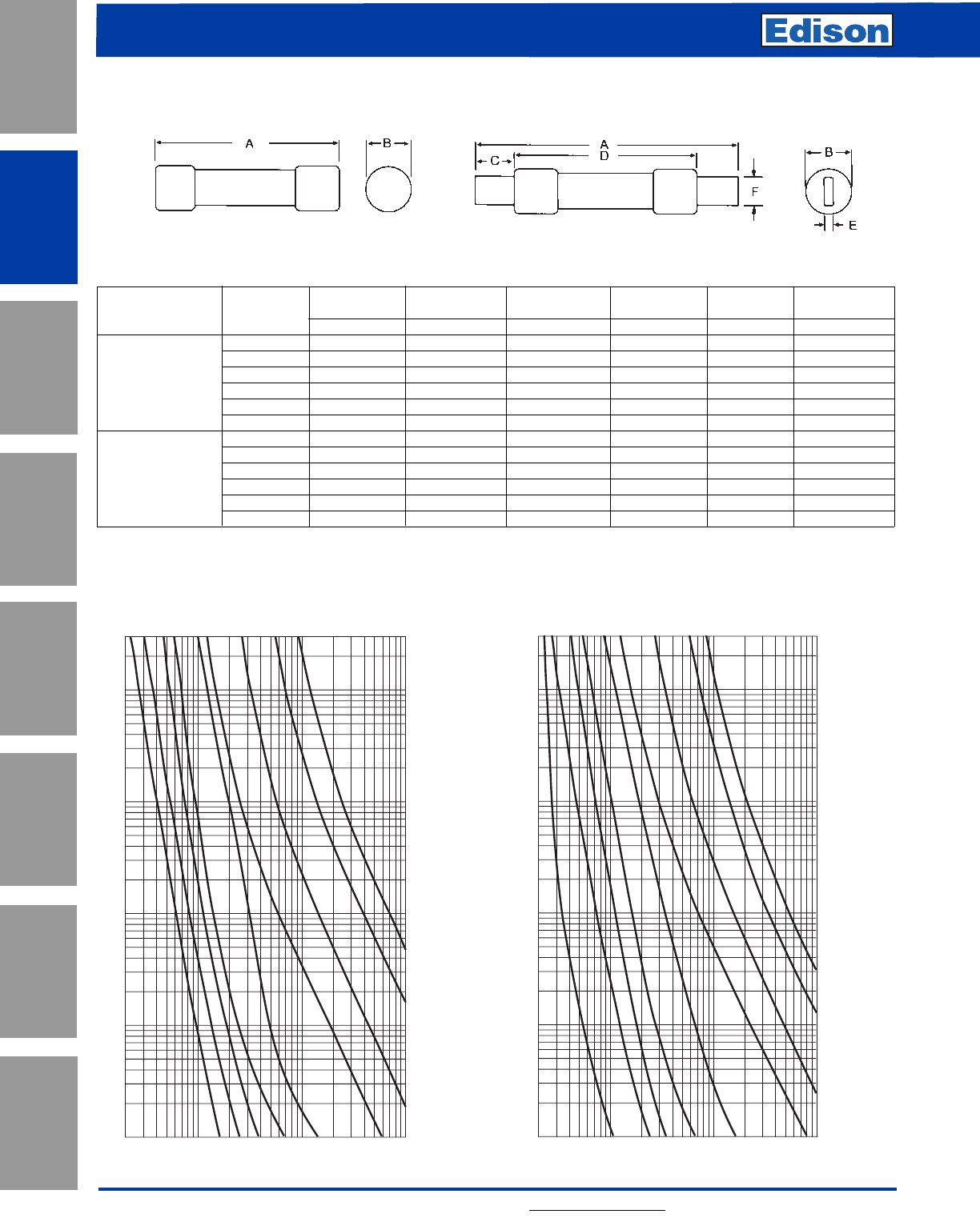
36 For additional information, visit www.edisonfuse.com
Application
Section
Fuse Blocks,
Holders & Misc.
Surge Protective
Devices
Medium
Voltage Fuses
Canadian
Fuses & Holders
Special
Purpose Fuses
UL/CSA Fuses
General Purpose
UL/CSA Fuses
Current Limiting
Dimensions - inches
Max. Min. Min. Blade Blade
Volts and Overall Diameter Blade Length Barrel Length Thickness Width
Catalog Number Amps ABCDEF
1-30 2 9/16 ––––
35-60 3 13/16 ––––
KON 70-100 5-7/8 1-1/16 1–1/8 3/4
250Vac 110-200 7-1/8 1-5/8 1-3/8 4-1/8 3/16 1-1/8
225-400 8-5/8 1-15/16 1-7/8 4-5/8 1/4 1-5/8
450-600 10-3/8 2-5/16 2-1/4 5-3/16 1/4 2
1-30 5 13/16 ––––
35-60 5-1/2 1-1/16 ––––
KOS 70-100 7-7/8 1-1/16 1–1/8 3/4
600Vac 110-200 9-5/8 1-5/8 1-3/8 6-1/8 3/16 1-1/8
225-400 11-5/8 2-3/4 1-7/8 7-1/8 1/4 1-5/8
450-600 13-3/8 3-1/4 2-1/4 8-3/16 1/4 2
Ferrule Design—1 through 60 Amps Knife Blade—70 through 600 Amps
RMS Symmetrical Current in Amps
Time in Seconds
20
30
40
60
80
100
200
300
400
600
800
1,000
2,000
3,000
4,000
6,000
8,000
10,000
300
200
100
80
60
40
30
20
10
8
6
4
3
2
1
.8
.6
.4
.3
.2
.1
.08
.06
.04
.03
.02
.01
60A
100A
200A
30A
400A
Amp
Rating
600A
15A
35A
20A
RMS Symmetrical Current in Amps
Time in Seconds
20
30
40
60
80
100
200
300
400
600
800
1,000
2,000
3,000
4,000
6,000
8,000
10,000
300
200
100
80
60
40
30
20
10
8
6
4
3
2
1
.8
.6
.4
.3
.2
.1
.08
.06
.04
.03
.02
.01
60A
100A
200A
30A
400A
Amp
Rating
600A
15A
35A
20A
Average Time-Current Curve
Cat. No. KON (Amp) 250Vac Cat. No. KOS (Amp) 600Vac
KON Class K5 and H One-Time Fuses
KOS Class K5 and H One-Time Fuses
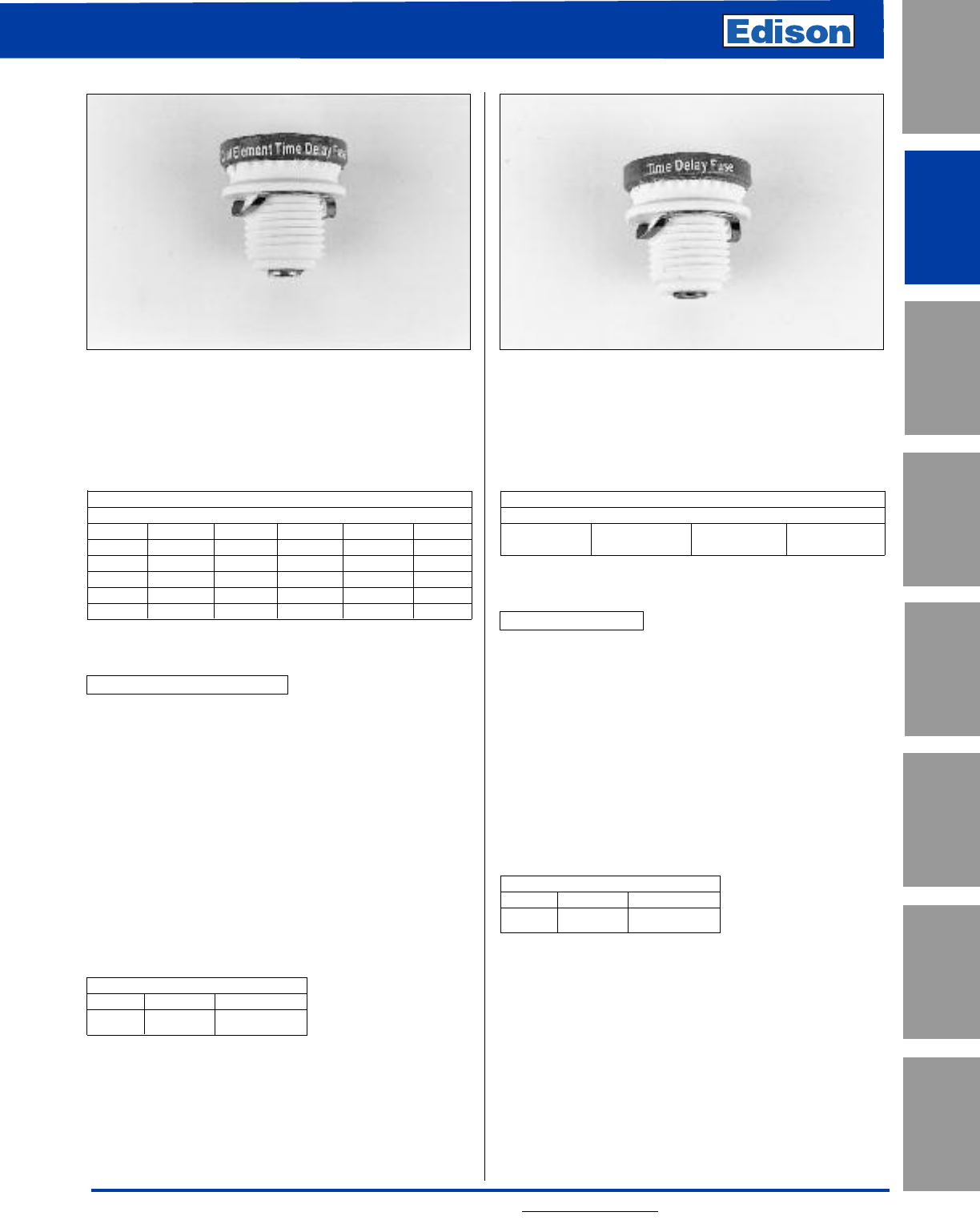
Amp Ratings
S (Amp)
1/4 123-1/2 6-1/4 14
3/10 1-1/8 2-1/4 4715
4/10 1-1/4 2-1/2 4-1/2 8 20
1/2 1-4/10 2-8/10 5925
6/10 1-6/10 3 5-6/10 10 30
8/10 1-8/10 3-2/10 6 12 —
S Specifications
Dual-Element, Time-Delay
Voltage Rating: 125Vac
Amp Rating: 1/4 - 30A
Interrupting Rating: 10kA RMS Symmetrical Amps
Agency Information:
UL Listed, (0 - 6-1/4A) Guide JFHR, File E56412
(1 - 30A) Guide JEFV, File 12112
CSA Certified per C22.2, No. 248.4
Benefits:
• Size rejection feature helps to prevent overfusing.
• Heavy duty dual-element construction.
• Superior overload and short-circuit protection.
Catalog Number S (1/4 - 30A)
125Vac or Less
Rejection Base
Dual-Element, Time-Delay
Amp Ratings
SL (Amp)
15 20 25 30
SL Specifications
Time-Delay
Voltage Rating: 125Vac
Amp Rating: 15 - 30A
Interrupting Rating: 10kA RMS Symmetrical Amps
Agency Information:
UL Listed, Guide JEFV, File 12112
Benefits:
• Size rejection feature helps to prevent overfusing.
• Time-delay construction withstands light motor loads.
• For upgrade refer to “S” fuse.
Catalog Number SL (15 - 30A)
125Vac or Less
Rejection Base
Time-Delay
CROSS REFERENCE
EDISON MERSEN LITTELFUSE
S None SOO
37
For additional information, visit www.edisonfuse.com
“S” and “SL”
Rejection Base Plug Fuses
CROSS REFERENCE
EDISON MERSEN LITTELFUSE
SL GSL SLO
UL/CSA Fuses
Current Limiting
UL/CSA Fuses
General Purpose
Special
Purpose Fuses
Canadian
Fuses & Holders
Medium
Voltage Fuses
Fuse Blocks,
Holders & Misc.
Application
Section
Surge Protective
Devices
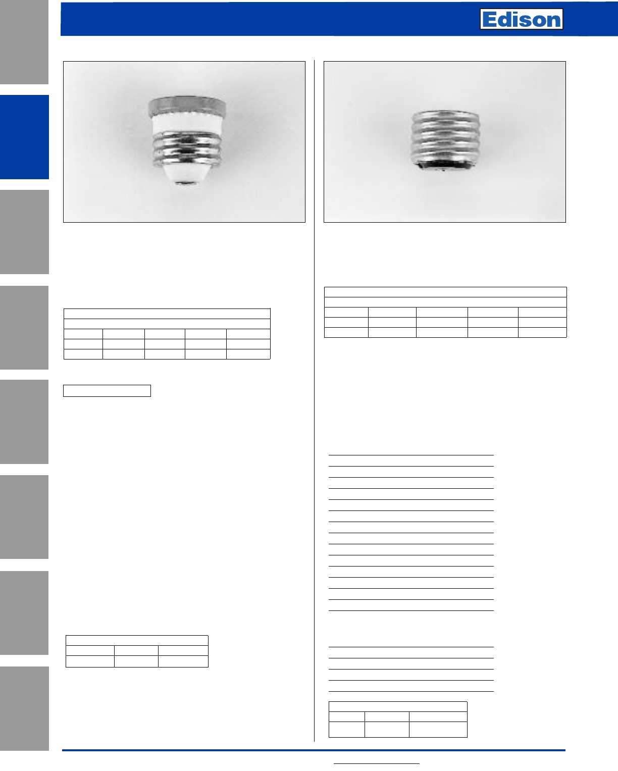
38 For additional information, visit www.edisonfuse.com
Application
Section
Fuse Blocks,
Holders & Misc.
Surge Protective
Devices
Medium
Voltage Fuses
Canadian
Fuses & Holders
Special
Purpose Fuses
UL/CSA Fuses
General Purpose
UL/CSA Fuses
Current Limiting
Amp Ratings
W (Amp)
1/2 246-1/2 10
1 2-1/2 57 12
1-8/10 368 Dummy
W Specifications
Fast-Acting
Voltage Rating: 125Vac
Amp Rating: 1/2 - 12A
Interrupting Rating: 10kA RMS Symmetrical Amps
Agency Information:
UL Listed, Guide JEFV, File E 12112
Benefits:
• General purpose for non-inductive lighting and heating
loads.
• Economical.
• Edison base threads into non-rejection fuse receptacles.
Obsoleted W-15 through W-30 plug fuses are replaced with
T and TL plug fuses.
Recommended Box Cover Units:
Refer to page 156 in this catalog.
Catalog Number W (1/2 - 12A)
125Vac or Less
Edison Base
Fast-Acting Adapter Sizes
SA (Amp)
124820
1-1/4 2-1/2 5 10 30
1-6/10 3-2/10 6-1/4 15 —
Rejection base fuses (Type S and SL) require adapters to
be used in standard Edison base sockets. Once installed,
rejection base adapters accept only rejection base fuses
which prevents the wrong fuse size from being used.
Agency Information:
UL Listed, File E12853; CSA Certified File #6225-01, File
#47235.
Fustat™Adapters for Small Motor Protection*
Adapter Accepts Fuses
SA-1 S-1 or smaller
SA-1-1⁄4S-1-1⁄4or smaller
SA-1-6⁄10 S-1-6⁄10 or smaller
SA-2 S-2 or S-1-8⁄10
SA-2-1⁄2S-2-1⁄2to S-1-8⁄10
SA-3-2⁄10S-3-2⁄10to S-1-8⁄10
SA-4 S-4 to S-3-1⁄2
SA-5 S-5 to S-3-1⁄2
SA-6-1⁄4S-6-1⁄4to S-3-1⁄2
SA-8 S-8 to S-7
SA-10 S-10 to S-7
SA-15 S-15 to S-7
SA-20 S-20
SA-30 S-30 to S-20
* Both motor running and short-circuit protection.
Fustat™Adapters for Branch Circuit Protection
Adapter Accepts Fuses
SA-15 S-15 to S-7
SA-20 S-20
SA-30 S-25
SA 30 S-30 to S-20
Catalog Number SA (1 - 30A)
Rejection Base Fuse Adapter
Edison Base Plug Fuses
and Fuse Adapters
CROSS REFERENCE
EDISON MERSEN LITTELFUSE
W GW WOO
CROSS REFERENCE
EDISON MERSEN LITTELFUSE
SA SAG SAO
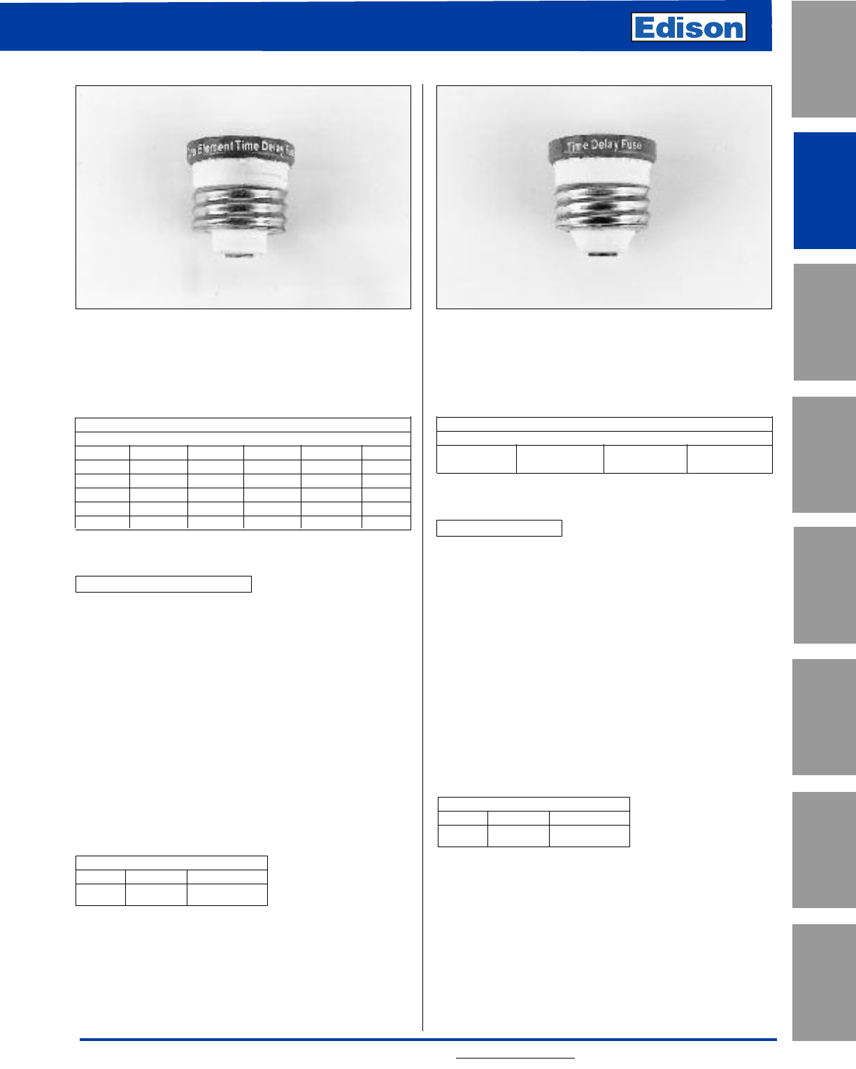
39
For additional information, visit www.edisonfuse.com
UL/CSA Fuses
Current Limiting
UL/CSA Fuses
General Purpose
Special
Purpose Fuses
Canadian
Fuses & Holders
Medium
Voltage Fuses
Fuse Blocks,
Holders & Misc.
Application
Section
Surge Protective
Devices
Amp Ratings
T (Amp)
3/10 1-1/8 2-1/4 4715
4/10 1-1/4 2-1/2 4-1/2 8 20
1/2 1-4/10 2-8/10 5925
6/10 1-6/10 3 5-6/10 10 30
8/10 1-8/10 3-2/10 6 12 —
123-1/2 6-1/4 14 —
T Specifications
Dual-Element, Time-Delay
Voltage Rating: 125Vac
Amp Rating: 3/10 - 30A
Interrupting Rating: 10kA RMS Symmetrical Amps
Agency Information:
UL Listed, Guide JEFV, File E 12112
Benefits:
• Heavy duty dual-element construction for motor circuits.
• Edison base threads into non-rejection fuse receptacles.
• Superior overload and short-circuit protection.
Recommended Box Cover Units:
Refer to page 155 in this catalog.
Catalog Number T (3/10 - 30A)
125Vac or Less
Edison Base
Dual-Element, Time-Delay
Amp Ratings
TL (Amp)
15 20 25 30
TL Specifications
Time-Delay
Voltage Rating: 125Vac
Amp Rating: 15 - 30A
Interrupting Rating: 10kA RMS Symmetrical Amps
Agency Information:
UL Listed, Guide JEFV, File 12112
Benefits:
• Time-delay construction withstands light motor loads.
• Edison base threads into non-rejection fuse receptacles.
• For upgrade refer to “T” fuse.
Recommended Box Cover Units:
Refer to page 155 in this catalog.
Catalog Number TL (15 - 30A)
125Vac or Less
Edison Base
Time-Delay
“T” and “TL”
Edison Base Plug Fuses
CROSS REFERENCE
EDISON MERSEN LITTELFUSE
T GT TOO
CROSS REFERENCE
EDISON MERSEN LITTELFUSE
TL GTL TLO
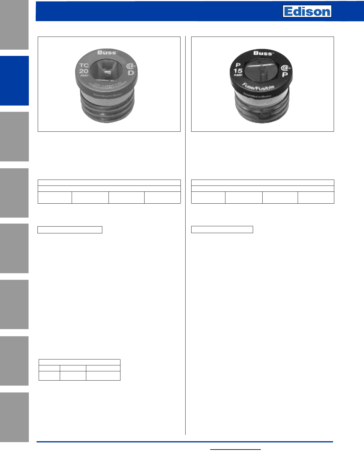
For additional information, visit www.edisonfuse.com
Application
Section
Fuse Blocks,
Holders & Misc.
Surge Protective
Devices
Medium
Voltage Fuses
Canadian
Fuses & Holders
Special
Purpose Fuses
UL/CSA Fuses
General Purpose
UL/CSA Fuses
Current Limiting
40
“TC” and “P”
Edison Base Plug Fuses
Catalog Number TC (15 - 30A)
125 Volts AC or Less
Edison Base
Dual-Element, Time-Delay
Amp Ratings
P (Amp)
P-15PK4 P-20PK4 P-25PK4 P-30PK4
P Specifications
Dual-Element, One-Time
Voltage Rating: 125Vac
Amp Rating: 15 - 30A
Benefits:
• For non-inductive loads.
• Edison base threads into non-rejection fuse receptacles.
Recommended Box Cover Units:
Refer to page 155 in this catalog.
Catalog Number P (15 - 30A)
125 Volts AC or Less
Edison Base
Dual-Element, One-Time
Amp Ratings
TC (Amp)
TC-15PK4 TC-20PK4 TC-25PK4 TC-30PK4
TC Specifications
Dual-Element, Time-Delay
Voltage Rating: 125Vac
Amp Rating: 15 - 30A
Agency Information:
CSA Certified (Class 1423-01, File # 53787)
Benefits:
• “D” rating for Canadian applications.
• Heavy Duty TC fuses are industrial strength products,
featuring a exclusive Dual-Element construction.
• This spring loaded design provides superior short-circuit
and overload protection.
• The TC fuses have more time-delay than the medium
duty fuses in order to better protect industrial motors and
optical residential circuits.
Recommended Box Cover Units:
Refer to page 155 in this catalog.
CROSS REFERENCE
EDISON MERSEN LITTELFUSE
T GT TOO
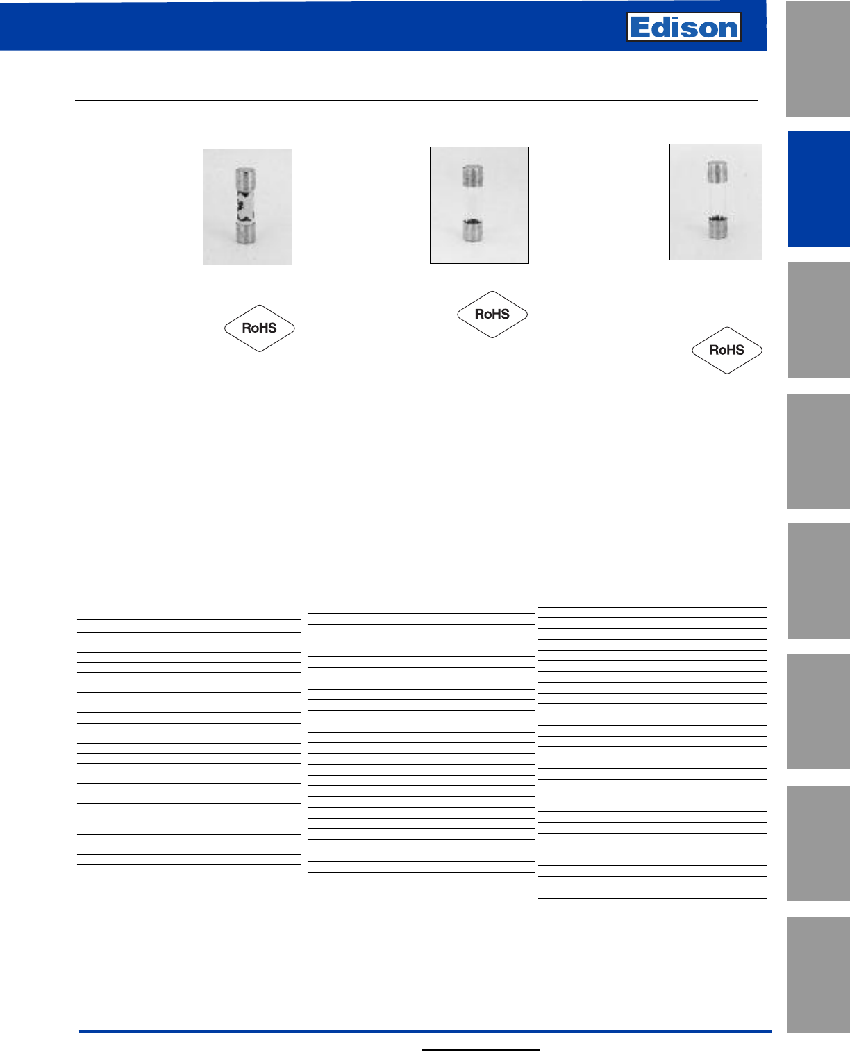
For additional information, visit www.edisonfuse.com
UL/CSA Fuses
Current Limiting
UL/CSA Fuses
General Purpose
Special
Purpose Fuses
Canadian
Fuses & Holders
Medium
Voltage Fuses
Fuse Blocks,
Holders & Misc.
Application
Section
Surge Protective
Devices
41
Small Dimension (Electronic) Fuses
5 x 20mm — IEC Standards
S501-V (GDA-V)*
(axial leads)
S501 (GDA)*
Specifications
Description: Fast-
acting, high-breaking
capacity fuse.
Construction:
Ceramic tube,
nickel-plated brass
endcaps (silver-
plated endcaps 50mA-400mA).
Ratings:
Volts — 250Vac (or less)
— 32Vdc (Self Certified)
Amps — 50mA-10A**
IR — 1500A @ 250Vac
Agency Information:
CE, cURus,
SEMKO, VDE, IMQ, CCC, CSA, BSI.
See data sheet for complete agency informa-
tion. Not all approvals apply to all ratings.
Features and Benefits
• Fast-acting for maximum protection.
• High break capacity for use in higher
fault energy electronic circuitry.
• Conforming to IEC standards.
Typical Applications
• Electronic Circuits
Catalog Numbers (Amps)
Catalog Typical Voltage
Numbers I2t Drop (mV)
S501-50-R 0.0017 9000
S501-63-R 0.0005 3300
S501-80-R 0.0011 2600
S501-100-R 0.0018 2300
S501-125-R 0.0037 1900
S501-160-R 0.008 1600
S501-200-R 0.020 1350
S501-250-R 0.027 1300
S501-315-R 0.010 1400
S501-400-R 0.018 1200
S501-500-R 0.038 1050
S501-630-R 0.064 1200
S501-800-R 0.097 490
S501-1-R 0.146 330
S501-1.25-R 0.313 297
S501-1.6-R 0.748 239
S501-2-R 2.0 205
S501-2.5-R 3.9 190
S501-3.15-R 8.1 160
S501-4-R 14 160
S501-5-R 25 155
S501-6.3-R 48 150
S501-8-R N/A N/A
S501-10-R N/A N/A
Options
Axial leads, put “V” in P/N.
*When ordering GDA version, do not
add “-R” suffix to part number.
S500-V (GDB-V)* (axial leads)
S500 (GDB)*
Specifications
Description: Fast-
acting, low-breaking
capacity fuse.
Construction:
Glass tube, nickel-
plated brass endcaps
(silver-plated endcaps, 32-125mA).
Ratings:
Volts — 250Vac (or less)
— 32Vdc (Self Certified)
Amps — 32mA-10A
IR — See catalog table
Agency Information: CE,
cURus,
SEMKO, VDE, BSI, IMQ, CCC.
See data sheet for complete agency
information. Not all approvals apply to all
ratings.
Features and Benefits
• Fast-acting for maximum protection,
conforms to IEC 60127-2 (160mA-10A).
Typical Applications
• Electronic Circuits
Catalog Numbers (Amps)
Catalog IR Max Voltage
Numbers (Amps) I2t Drop (mV)
S500-32-R 35 0.000047 3200
S500-40-R 35 0.00011 2500
S500-50-R 35 0.00020 2400
S500-63-R 35 0.00057 2000
S500-80-R 35 0.0012 1200
S500-100-R 35 0.003 1100
S500-125-R 35 0.005 1000
S500-160-R 35 0.008 2000
S500-200-R 35 0.016 1700
S500-250-R 35 0.028 1400
S500-315-R 35 0.058 1300
S500-400-R 35 0.018 1100
S500-500-R 35 0.018 220
S500-630-R 35 0.035 220
S500-800-R 35 0.067 190
S500-1-R 35 0.60 200
S500-1.25-R 35 0.84 200
S500-1.6-R 35 1.6 190
S500-2-R 35 4.2 150
S500-2.5-R 35 6.1 150
S500-3.15-R 35 13 130
S500-4-R 40 22 130
S500-5-R 50 42 120
S500-6.3-R 63 69 120
S500-8-R 80 - 120
S500-10-R 100 —- 120
Options
Axial leads, put “V” in P/N,
*When ordering GDB version, do not add
“-R” suffix to part number.
S506-V (GDC-V)* (axial leads)
S506 (GDC)*
Specifications
Description: Time-
delay, low-breaking
capacity fuse.
Construction: Glass
tube, nickel-plated
brass endcaps.
Ratings:
Volts — 250Vac (or less)
— 32Vdc (Self Certified)
Amps — 32mA-15A**
IR — 35A @ 250Vac
Agency Information: UR, CSA,
cURus, SEMKO, VDE, BSI, IMQ,
PSE/JET, CCC.
See data sheet for complete agency
information. Not all approvals apply to all
ratings.
Features and Benefits
• Time-delay compatibility for inductive circuits
• Conforming to IEC standards
Typical Applications
• Electronic Circuits
Catalog Numbers (Amps)
Catalog Typical Max Voltage
Numbers I2t Drop (mV)
S506-32-R 0.0051 1050
S506-40-R 0.0072 920
S506-50-R 0.0095 800
S506-63-R 0.021 760
S506-80-R 0.038 580
S506-100-R 0.045 490
S506-125-R 0.063 390
S506-160-R 0.093 320
S506-200-R 0.114 340
S506-250-R 0.265 270
S506-315-R 0.621 250
S506-400-R 0.872 210
S506-500-R 0.827 140
S506-630-R 1.33 150
S506-800-R 2.78 75
S506-1-R 6.45 87.5
S506-1.25-R 10.05 86
S506-1.6-R 21.7 82
S506-2-R 31.6 77
S506-2.5-R 59.4 72.5
S506-3.15-R 96.4 68.5
S506-4-R 71.8 67
S506-5-R 142.5 60.5
S506-6.3-R 237.6 54
S506-8-R 255.8 55
S506-10-R 450 54
S506-12.5-R 1019.5 45
S506-15-R 1091.7 65.5
Options
Axial leads, put “V” in P/N.
*When ordering GDC version, do not add
“-R” suffix to part number.
**GDC series is not available above 6.3A.
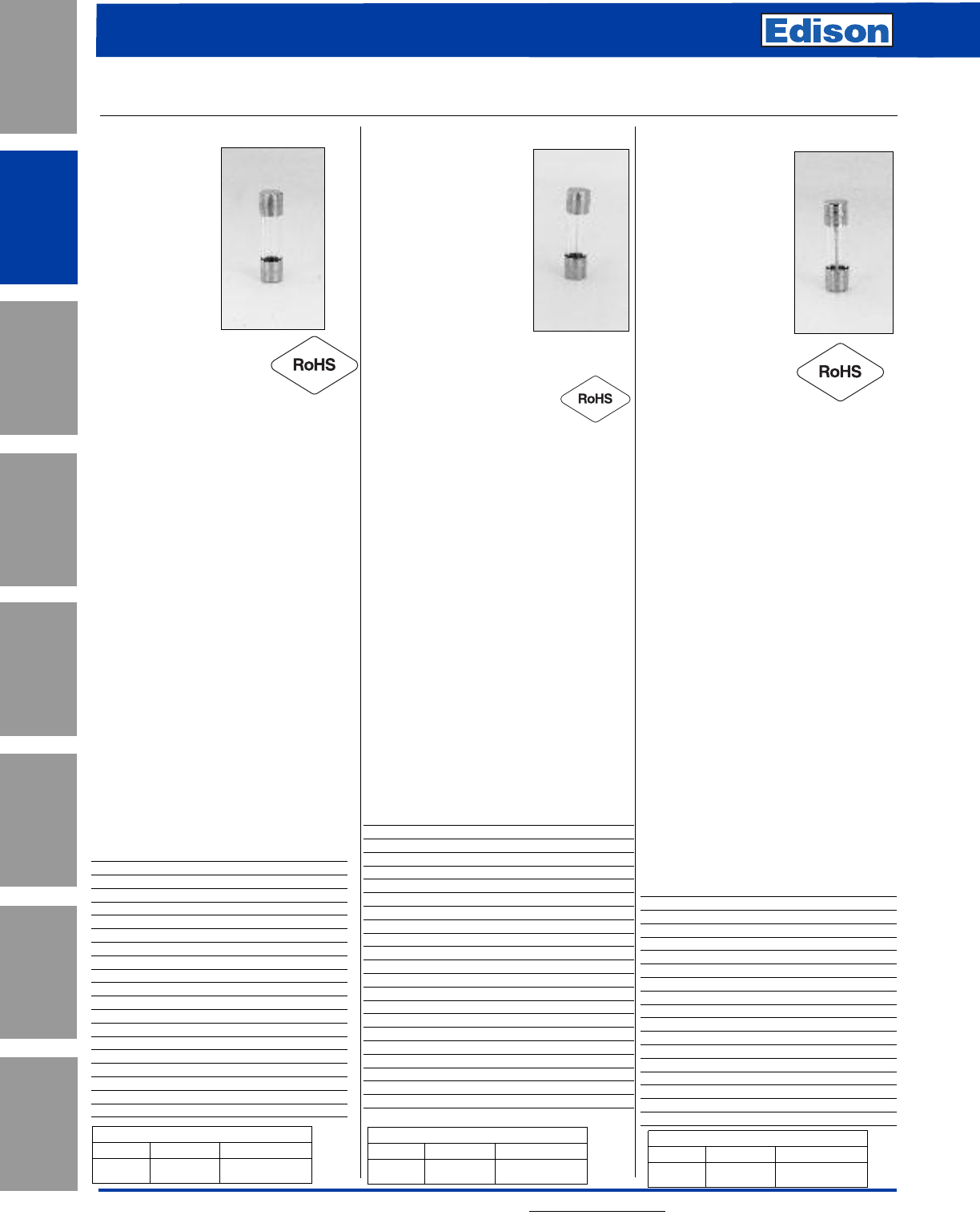
42 For additional information, visit www.edisonfuse.com
Application
Section
Fuse Blocks,
Holders & Misc.
Surge Protective
Devices
Medium
Voltage Fuses
Canadian
Fuses & Holders
Special
Purpose Fuses
UL/CSA Fuses
General Purpose
UL/CSA Fuses
Current Limiting
Small Dimension (Electronic) Fuses
5 x 20mm — N. American Standards
GMA-V (axial leads)
GMA
Specifications
Description:
Fast-acting fuse.
Dimensions:
5 x 20mm
(0.197” x 0.788”).
Construction:
Glass tube,
nickel-plated brass endcaps.
Ratings:
Volts — 250Vac (63mA-2.5A)
— 125Vac (3.15-15A)
— 32Vdc (Self Certified)
Amps — 63mA-15A
IR — 35A (63mA- 1A @ 250Vac,
p.f. = 0.7-0.8)
— 10kA (63mA-6A @ 125Vac,
p.f. = 0.7-0.8)
— 100A (1.25-2.5A @ 250Vac,
p.f. = 0.7-0.8)
— 200A (7-8A @ 125Vac, p.f. = 1.0)
— 150A (10-15A @ 125Vac,
p.f. = 1.0)
Agency Information:
CE, Std.
248-14 UL Listed Guide JDYX, File
E19180, 0-6A, UL Recognized, Guide
JDYX2, File E19180, 7-15A, CSA
Certified, Class 1422-01,File 53787, 0-6.
Features and Benefits
• Fast-acting for maximum protection.
Typical Applications
• Electronic Circuits
Catalog Numbers (Amps)
With Axial Leads
GMA-V-63-R GMA-V-800-R GMA-V-4-R
GMA-V-100-R GMA-V-1-R GMA-V-5-R
GMA-V-125-R GMA-V-1.25-R GMA-V-6-R
GMA-V-200-R GMA-V-1.5-R GMA-V-7-R
GMA-V-250-R GMA-V-1.6-R GMA-V-8-R
GMA-V-300-R GMA-V-2-R GMA-V-10-R
GMA-V-500-R GMA-V-2.5-R GMA-V-15-R
GMA-V-600-R GMA-V-3.15-R
GMA-V-750-R GMA-V-3.5-R
Without Axial Leads
GMA-63-R GMA-800-R GMA-4-R
GMA-100-R GMA-1-R GMA-5-R
GMA-125-R GMA-1.25-R GMA-6-R
GMA-200-R GMA-1.5-R GMA-7-R
GMA-250-R GMA-1.6-R GMA-8-R
GMA-300-R GMA-2-R GMA-10-R
GMA-500-R GMA-2.5-R GMA-15-R
GMA-600-R GMA-3.15-R
GMA-750-R GMA-3.5-R
CROSS REFERENCE
EDISON MERSEN LITTELFUSE
GMA GGM 235
CROSS REFERENCE
EDISON MERSEN LITTELFUSE
GMC GSC None
CROSS REFERENCE
EDISON MERSEN LITTELFUSE
GMD None 239
GMC-V (axial leads)
GMC
Specifications
Description: Medium
time-delay fuse.
Dimensions: 5 x 20mm
(0.197” x 0.788”).
Construction: Glass
tube, nickel-plated brass
endcaps.
Ratings:
Volts — 250Vac (63mA-3.15A)
— 125Vac (3.5-10A)
— 32Vdc (Self Certified)
Amps — 63mA-10A
IR — 35A (63mA- 1A @ 250Vac,
p.f. = 0.7-0.8)
— 10kA (63mA-6A @ 125Vac, p.f.
= 0.7-0.8)
— 100A (1.25-3.15A @ 250Vac,
p.f. = 0.7-0.8)
— 200A (6.3-10A @ 125Vac, p.f.
= 1.0)
Agency Information: CE, Std. 248-14,
UL Listed Guide JDYX, File E19180,
0-6.3A, UL Recognized, Guide JDYX2,
File E19180, 7-8A, CSA Certified, Class
1422-01, File 53787, 0-6.3A.
Features and Benefits
• Conforming to UL standards.
Typical Applications
• Electronic Circuits
Catalog Numbers (Amps)
With Axial Leads
GMC-V-63-R GMC-V-500-R GMC-V-2.5
GMC-V-80-R GMC-V-600-R GMC-V-3.15
GMC-V-100-R GMC-V-630-R GMC-V-3.5
GMC-V-125-R GMC-V-750-R GMC-V-4
GMC-V-150-R GMC-V-800-R GMC-V-5
GMC-V-200-R GMC-V-1-R GMC-V-6
GMC-V-250-R GMC-V-1.25-R GMC-V-6.3
GMC-V-300-R GMC-V-1.5-R GMC-V-7
GMC-V-315-R GMC-V-1.6-R GMC-V-8
GMC-V-400-R GMC-V-2-R GMC-V-10
Without Axial Leads
GMC-63mA GMC-500-R GMC-2.5-R
GMC-80mA GMC-600-R GMC-3.15-R
GMC-100mA GMC-630-R GMC-3.5-R
GMC-125mA GMC-750-R GMC-4-R
GMC-150mA GMC-800-R GMC-5-R
GMC-200mA GMC-1-R GMC-6-R
GMC-250mA GMC-1.25-R GMC-6.3-R
GMC-300mA GMC-1.5-R GMC-7-R
GMC-315mA GMC-1.6-R GMC-8-R
GMC-400mA GMC-2-R GMC-10-R
GMD-V (axial leads)
GMD
Specifications
Description: Time-
delay fuse.
Dimensions:
5 x 20mm
(0.197” x 0.788”).
Construction: Glass
tube, nickel-plated
brass endcaps.
Ratings:
Volts — 250Vac
— 32Vdc (Self Certified)
Amps — 125mA-4A
IR — 10kA (125mA-3A @ 125Vac,
p.f. = 0.7-0.8)
— 10kA (4A @ 125Vac,
p.f. = 1.0)
— 35A (125mA-1A @ 250Vac,
p.f. = 0.7-0.8)
— 100A (1.2A-3.A @ 250Vac,
p.f. = 0.7-0.8)
— 200A (4A @ 250Vac,
p.f. = 1.0)
Agency Information: CE, UL Listed
Guide JDYX, File E19180, 125mA-3A,
UL Recognized, Guide JDYX2, File
E19180, 4A, CSA Certified, Class
1422-01, File 53787, 0-4A, PSE/JET.
File 1641-31003-1001, 1.2A-4A.
Features and Benefits
• Time-delay compatibility for inductive circuits.
• Conforming to UL standards.
Typical Applications
• Electronic Circuits
Catalog Numbers (Amps)
With Axial Leads
GMD-V-125-R GMD-V-500-R GMD-V-1.5-R
GMD-V-150-R GMD-V-600-R GMD-V-1.6-R
GMD-V-200-R GMD-V-630-R GMD-V-2-R
GMD-V-250-R GMD-V-750-R GMD-V-2.5-R
GMD-V-300-R GMD-V-800-R GMD-V-3-R
GMD-V-315-R GMD-V-1-R GMD-V-4-R
GMD-V-375-R GMD-V-1.2-R
GMD-V-400-R GMD-V-1.25-R
Without Axial Leads
GMD-125-R GMD-500-R GMD-1.5-R
GMD-150-R GMD-600-R GMD-1.6-R
GMD-200-R GMD-630-R GMD-2-R
GMD-250-R GMD-750-R GMD-2.5-R
GMD-300-R GMD-800-R GMD-3-R
GMD-315-R GMD-1-R GMD-4-R
GMD-375-R GMD-1.2-R
GMD-400-R GMD-1.25-R
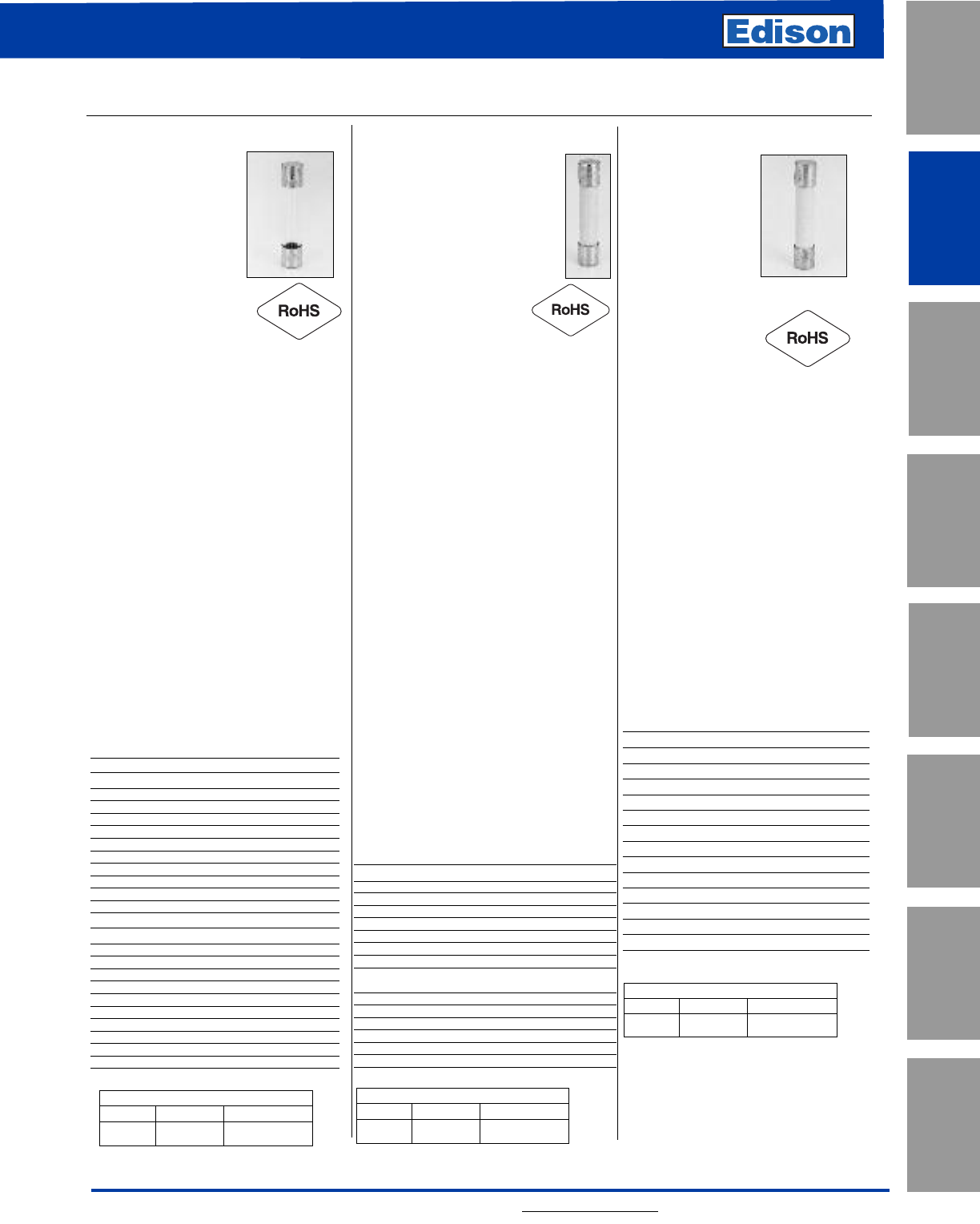
43
For additional information, visit www.edisonfuse.com
UL/CSA Fuses
Current Limiting
UL/CSA Fuses
General Purpose
Special
Purpose Fuses
Canadian
Fuses & Holders
Medium
Voltage Fuses
Fuse Blocks,
Holders & Misc.
Application
Section
Surge Protective
Devices
Small Dimension (Electronic) Fuses
1⁄4˝ x 1 1⁄4˝ Fast-Acting Fuses
CROSS REFERENCE
EDISON MERSEN LITTELFUSE
AGC GGC 312
CROSS REFERENCE
EDISON MERSEN LITTELFUSE
ABC GAB 314
CROSS REFERENCE
EDISON MERSEN LITTELFUSE
GBB None 322
AGC (AGC-V axial leads)
Specifications
Description:
Fast-acting fuse.
Dimensions: 1⁄4˝ x 1 1⁄4˝
(6.4 x 31.7mm).
Construction: Glass
tube with nickel-plated
brass endcaps.
Ratings:
Volts — 250Vac (1⁄20-10A)
— 32Vac (12-30A)
— 32Vdc (Self Certified)
Amps — 1⁄20-30A
IR — 35A (1⁄20-1A @ 250Vac)
— 100A (11⁄4-3A @ 250Vac)
— 200A (4-10A @ 250Vac)
— 10kA (1⁄20-10A @ 125Vac)
— 1000A (12-30A @ 32Vac)
Agency Information: CE, UL Listed,
Guide JDYX, File E19180, 0-10A UL
Recognized, Guide JDYX2, File
E19180, 12-30A CSA Certification,
Class 1422-01, File 053787, 1⁄20-30A.
Features and Benefits
• Original electronic glass tube fuse.
• Fast-acting for maximum protection.
• Wide amp/volt ratings allow versatility
of protecting electronic circuits.
Typical Applications
• Electronic Circuits
Catalog Numbers (Amps)
With Axial Leads
AGC-V-1⁄20-R AGC-V-1-1⁄4-R AGC-V-8-R
AGC-V-1⁄10-R AGC-V-1-1⁄2-R AGC-V-9-R
AGC-V-1⁄8-R AGC-V-2-R AGC-V-10 -R
AGC-V-3⁄16-R AGC-V-2-1⁄4-R AGC-V-12-R
AGC-V-2⁄10-R AGC-V-2-1⁄2-R AGC-V-14-R
AGC-V-1⁄4-R AGC-V-3-R AGC-V-15-R
AGC-V-3⁄10-R AGC-V-4-R AGC-V-20-R
AGC-V-3⁄8-R AGC-V-5-R AGC-V-25-R
AGC-V-1⁄2-R AGC-V-6-R AGC-V-30-R
AGC-V-3⁄4-R AGC-V-7-R
AGC-V-1-R AGC-V-7- 1⁄2-R
Without Axial Leads
AGC-1⁄20-R AGC-1-1⁄4-R AGC-8-R
AGC-1⁄10-R AGC-1-1⁄2-R AGC-9-R
AGC-1⁄8-R AGC-2-R AGC-10-R
AGC-3⁄16-R AGC-2-1⁄4-R AGC-12-R
AGC-2⁄10-R AGC-2-1⁄2-R AGC-14-R
AGC-1⁄4-R AGC-3-R AGC-15-R
AGC-3⁄10-R AGC-4-R AGC-20-R
AGC-3⁄8-R AGC-5-R AGC-25-R
AGC-1⁄2-R AGC-6-R AGC-30-R
AGC-3⁄4-R AGC-7-R
AGC-1-R AGC-7- 1⁄2-R
ABC (ABC-V axial leads)
Specifications
Description: Fast-acting fuse.
Dimensions:
1⁄4˝ x 1 1⁄4˝ (6.4 x 31.7mm).
Construction: Ceramic tube
with nickel-plated brass endcaps.
Ratings:
Volts — 250Vac/125Vdc
(1⁄4-15A, 20-30A)*
— 250Vac (18A)
— 32Vdc (Self Certified)
Amps — 1⁄4-30A
IR** — 35A (1⁄4-1A @ 250Vac)
— 100A (11⁄2-3A @ 250Vac)
— 200A (4-10A @ 250Vac)
— 750A (12-15A @ 250Vac)
— 400A (18-20A @ 250Vac)
— 10kA (1⁄4-15A @ 125Vac)
— 1kA (18-30A @ 125Vac)
— 10kA (1⁄4-15, 20A @ 125Vdc)
— 400A (25-30A @ 125Vdc)
— 200A (25-30A @ 250Vac)
*CSA approvals for 25A and 30A are at 125Vac – IR 1000A and Vdc – IR 400A
(IR 1000A at 75Vdc)
**Interrupting ratings measured at 70% – 80% power factor on AC. The
interrupting ratings for 18A and 20A were measured at 85%-95% power factor
on AC. The interrupting ratings for 25A and 30A were measured at 89% power
factor on AC.
Agency Information: CE, Std. 248-14
UL Listed, Guide JDYX File E19180,
1⁄4-15A; UL Recognized, Guide JDYX2,
File E19180, 18-30A; CSA Certification,
Class 1422-01 & 1422-30, File 53787,
1⁄4-30A.
Features and Benefits
• Ceramic body allows for higher
amp/volt rating combinations.
Typical Applications
• Electronic Circuits
Catalog Numbers (Amps)
With Axial Leads
ABC -V-1⁄4-R ABC-V-3-R ABC-V-12-R
ABC -V-1⁄2-R ABC-V-4-R ABC-V-15-R
ABC -V-3⁄4-R ABC-V-5-R ABC-V-18-R
ABC-V-1-R ABC-V-6-R ABC-V-20-R
ABC-V-1-1⁄2-R ABC-V-7-R ABC-V-25-R
ABC-V-2-R ABC-V-8-R ABC-V-30-R
ABC-V-2-1⁄2-R ABC-V-10-R
Without Axial Leads
ABC -1⁄4-R ABC-3-R ABC-12-R
ABC -1⁄2-R ABC-4-R ABC-15-R
ABC -3⁄4-R ABC-5-R ABC-18-R
ABC-1-R ABC-6-R ABC-20-R
ABC-1-1⁄2-R ABC-7-R ABC-25-R
ABC-2-R ABC-8-R ABC-30-R
ABC-2-1⁄2-R ABC-10-R
GBB (GBB-V axial leads)
Specifications
Description: Very
fast-acting fuse.
Dimensions:
1⁄4˝ x 1 1⁄4˝
(6.4 x 31.7mm).
Construction:
Ceramic cartridge with nickel-plated
brass endcaps.
Ratings:
Volts — 250Vac/125Vdc
Amps — 1-30A
IR — 200A @ 250Vac
— 200A (20-30A @ 125Vac/dc)
— 10,000A (1A -15A @
125Vac/dc)
Agency Information:
CE, Std. 248-14, UL Recognized,
1-30,125Vdc/250Vac, File E56412,
Guide JFHR2, CSA Accepted, 1-30,
125Vdc/250Vac, File 53787, Class
1422-30.
Features and Benefits
• Very fast-acting performance allows
protection of highly sensitive
electronic circuitry.
Typical Applications
• Electronic Circuits
Catalog Numbers (Amps)
With Axial Leads
GBB-V-1-R GBB-V-6-R GBB-V-15-R
GBB-V-1-1⁄4-R GBB-V-7-R GBB-V-20-R
GBB-V-2-R GBB-V-8-R GBB-V-25-R
GBB-V-3-R GBB-V-9-R GBB-V-30-R
GBB-V-4-R GBB-V-10-R
GBB-V-5-R GBB-V-12-R
Without Axial Leads
GBB-1-R GBB-6-R GBB-15-R
GBB-1-1⁄4-R GBB-7-R GBB-20-R
GBB-2-R GBB-8-R GBB-25-R
GBB-3-R GBB-9-R GBB-30-R
GBB-4-R GBB-10-R
GBB-5-R GBB-12-R
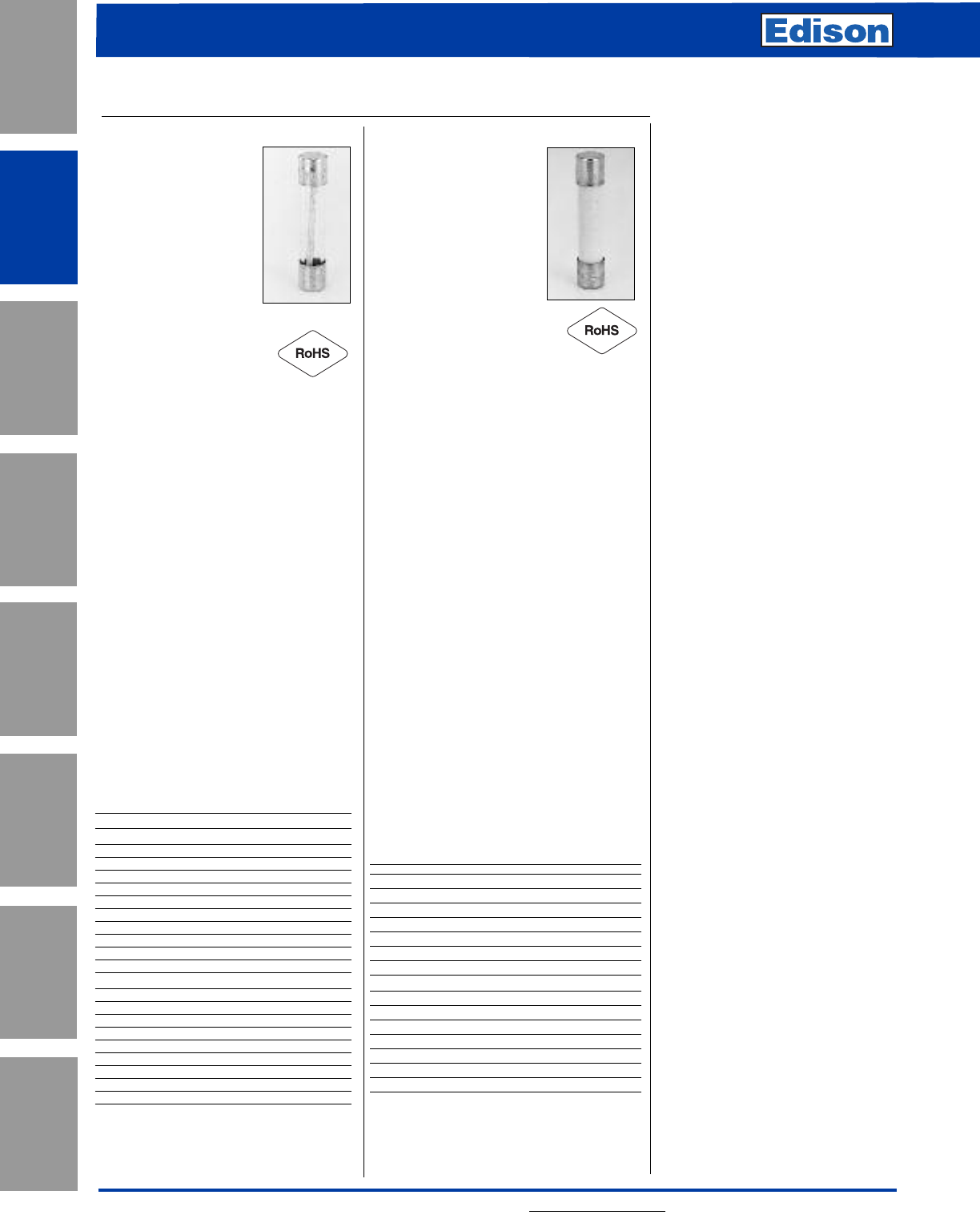
44 For additional information, visit www.edisonfuse.com
Application
Section
Fuse Blocks,
Holders & Misc.
Surge Protective
Devices
Medium
Voltage Fuses
Canadian
Fuses & Holders
Special
Purpose Fuses
UL/CSA Fuses
General Purpose
UL/CSA Fuses
Current Limiting
Small Dimension (Electronic) Fuses
Recommended Fuse Blocks:
Refer to page 169 in this catalog.
Recommended Panel Mount Holder:
Refer to page 168 in this catalog.
1/4˝ x 1-1/4˝ Time-Delay Fuses
MDL-V (axial leads)
MDL
Specifications
Description:
Time-delay fuse.
Dimensions: 1⁄4˝ x 1 1⁄4˝
(6.4 x 31.7mm).
Construction: Glass
tube with nickel-plated brass endcaps.
Ratings:
Volts — 250Vac (1⁄16-8A)
— 32Vac (9-30A)
— 32Vdc (Self Certified)
Amps — 1⁄16-30A
IR* — 35A (1⁄16-1A @ 250Vac)
— 100A (11⁄4-3A @ 250Vac)
— 200A (4-8A @ 250Vac)
— 10000A (1⁄16-8A @ 125Vac)
— 1000A (9-30A @ 32Vac)
*Interrupting ratings were measured at 70% – 80% power
factor on AC, and at a time constant described in UL 198L.
Agency Information: CE, UL Listed,
Guide JDYX, File E19180, 1⁄16-8A; CSA
Certification Class 1422-01, 1⁄16-8A; UL
Recognized, Guide JDYX2, File
E19180, 9-30A; CSA Component
Acceptance, Class 142230, 9-30A.
Features and Benefits
• Time-delay allows close sizing on
inductive circuits.
Typical Applications
• Electronic Circuits
Catalog Numbers (Amps)
With Axial Leads
MDL-V-1⁄16-R MDL-V-1-R MDL-V-7-R
MDL-V-1⁄10-R MDL-V-1-1⁄4-R MDL-V-8-R
MDL-V-1⁄8-R MDL-V-1-1⁄2-R MDL-V-9-R
MDL-V-2⁄10-R MDL-V-2-R MDL-V-10-R
MDL-V-3⁄16-R MDL-V-2-1⁄4-R MDL-V-12-R
MDL-V-1⁄4-R MDL-V-2-1⁄2-R MDL-V-15-R
MDL-V-3⁄10-R MDL-V-3-R MDL-V-20-R
MDL-V-3⁄8-R MDL-V-4-R MDL-V-25*
MDL-V-1⁄2-R MDL-V-5-R MDL-V-30*
MDL-V-3⁄4-R MDL-V-6-R
Without Axial Leads
MDL-1⁄16-R MDL-1-R MDL-7-R
MDL-1⁄10-R MDL-1-1⁄4-R MDL-8-R
MDL-1⁄8-R MDL-1-1⁄2-R MDL-9-R
MDL-2⁄10-R MDL-2-R MDL-10-R
MDL-3⁄16-R MDL-2-1⁄4-R MDL-12-R
MDL-1⁄4-R MDL-2-1⁄2-R MDL-15-R
MDL-3⁄10-R MDL-3-R MDL-20-R
MDL-3⁄8-R MDL-4-R MDL-25*
MDL-1⁄2-R MDL-5-R MDL-30*
MDL-3⁄4-R MDL-6-R
*MDL-25 & MDL-30 are not available in RoHS compliant
construction.
MDA-V (axial leads)
MDA
Specifications
Description: Time-delay
fuse.
Dimensions: 1⁄4˝ x 1 1⁄4˝
(6.35 x 31.75mm).
Construction: Ceramic
tube with nickel-plated
brass endcaps.
Ratings:
Volts — 250Vac (or less)
— 125Vdc (20A- 30A)
— 32Vdc (Self Certified)
Amps — 1⁄4-30A
IR** — 35A (1⁄4-1A @ 250Vac)
— 100A (11⁄2-2A @ 250Vac)
— 200A (21⁄2-10A @ 250Vac)
— 750A (12-15A @ 250Vac)
— 1500A (20-30A @ 250Vac)
— 10kA (1⁄4-30A @ 125Vac)
— 10kA (20-30A @ 125Vdc)
**Interrupting ratings were measured at 70% – 80% power
factor on AC, and at a time constant described in UL 248.
Agency Information: CE, Std. 248-14,
UL Listed, Guide JDYX, File E19180,
0-20A CSA Certification, Class 1422-01,
File 53787, 0-20A. UL Recognized,
Guide JDYX2, File E19180, 25-30A,
CSA Component Acceptance, Class
1422-30, 25-30A
Features and Benefits
• Ceramic body allows for higher amp/volt
rating combinations.
• Inventory consolidation by replacing
MDL fuses allows for reduced SKU
investment and minimizing potential for
misapplying fuse.
Typical Applications
• Electronic Circuits
Catalog Numbers (Amps)
With Axial Leads
MDA-V-1⁄4-R MDA-V-3-R MDA-V-12-R
MDA-V-1⁄2-R MDA-V-4-R MDA-V-15-R
MDA-V-3⁄4-R MDA-V-5-R MDA-V-20-R
MDA-V-1-R MDA-V-6-R MDA-V-25-R
MDA-V-1-1⁄2-R MDA-V-7-R MDA-V-30-R
MDA-V-2-R MDA-V-8-R
MDA-V-2-1⁄2-R MDA-V-10-R
Without Axial Leads
MDA-1⁄4-R MDA-3-R MDA-12-R
MDA-1⁄2-R MDA-4-R MDA-15-R
MDA-3⁄4-R MDA-5-R MDA-20-R
MDA-1-R MDA-6-R MDA-25A-R
MDA-1-1⁄2-R MDA-7-R MDA-30A-R
MDA-2-R MDA-8-R
MDA-2-1⁄2-R MDA-10-R
Recommended Fuse Blocks:
Refer to page 169 in this catalog.
Recommended Panel Mount Holder:
Refer to page 168 in this catalog.
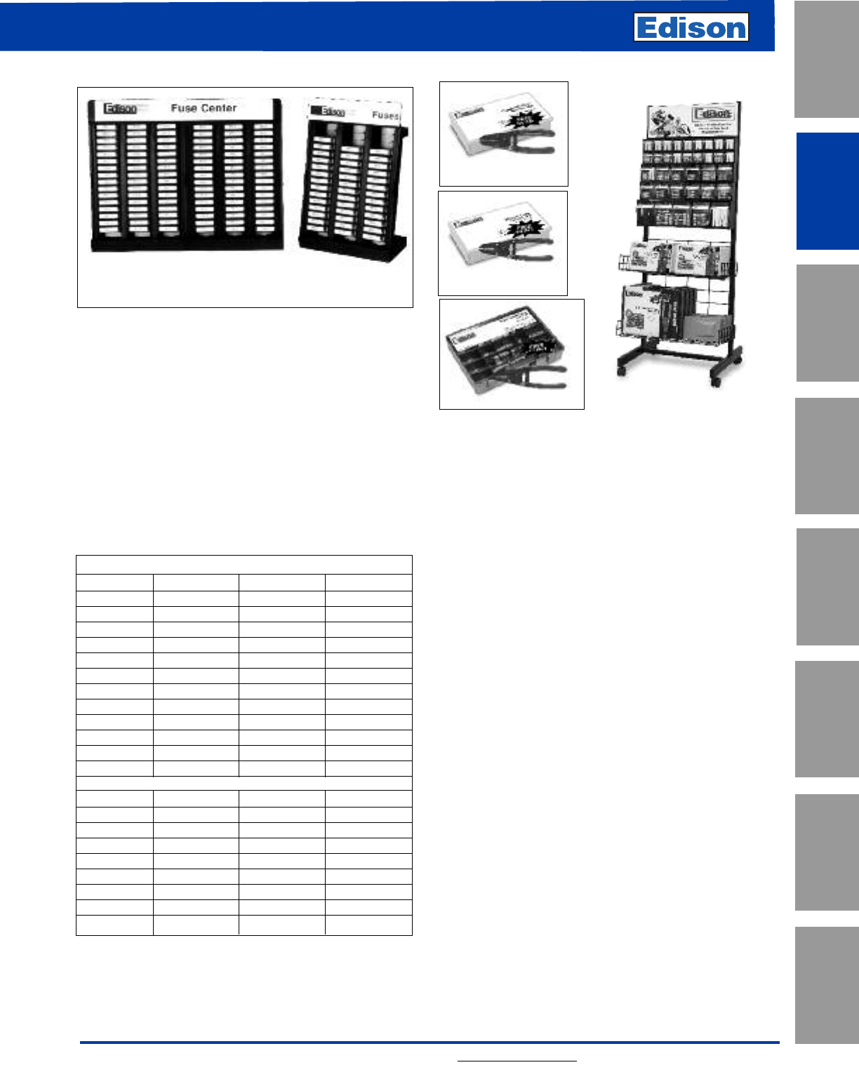
45
For additional information, visit www.edisonfuse.com
UL/CSA Fuses
Current Limiting
UL/CSA Fuses
General Purpose
Special
Purpose Fuses
Canadian
Fuses & Holders
Medium
Voltage Fuses
Fuse Blocks,
Holders & Misc.
Application
Section
Surge Protective
Devices
Small Dimension (Electronic)
Fuse Displays
ERFL (Large Assortment)
2 AGC-1 2 AGX-20 1 MDL-35 1 GMA-3A
2 AGC-2 1 AGX-30 1 ABC-1 1 GMA-5A
2 AGC-3 2 MDL-1 1 ABC-2 1 GDC-1A
1 AGC-4 2 MDL-2 2 ABC-3 1 GDC-2A
2 AGC-5 2 MDL-3 2 ABC-5 1 GDC-3.15A
1 AGC-7 1 MDL-4 1 ABC-7 1 GDC-5A
4 AGC-10 2 MDL-5 2 ABC-10 1 GDB-1A
2 AGC-15 1 MDL-7 2 ABC-15 1 GDB-2A
6 AGC-20 2 MDL-10 2 ABC-20 1 GDB-3.15A
2 AGC-25 2 MDL-15 2 ABC-25 1 GDB-5A
7 AGC-30 6 MDL-20 2 ABC-30 —
1 AGC-35 2 MDL-25 1 GMA-1A —
2 AGX-15 7 MDL-30 1 GMA-2A —
ERFS (Small Assortment)
2 AGC-1 1 AGC-30 1 MDL-25 1 ABC-25
1 AGC-2 2 MDL-1 1 MDL-30 1 ABC-30
1 AGC-3 1 MDL-2 1 ABC-1 1 GMA-1A
2 AGC-5 1 MDL-3 2 ABC-2 1 GMA-2A
1 AGC-7 2 MDL-5 2 ABC-3 1 GMA-3A
3 AGC-10 1 MDL-7 1 ABC-5 1 GMA-5A
1 AGC-15 2 MDL-10 2 ABC-10 —
1 AGC-20 1 MDL-15 2 ABC-15 —
1 AGC-25 1 MDL-20 2 ABC-20 —
Catalog Number ERFL Display (480 Fuses)
Catalog Number ERFS Display (200 Fuses)
Features:
• Edison display and fuse assortments are compact. They
don’t waste space. Display and storage area is minimal.
• Slots in the display racks are all labeled for easy
inventory and reorder status.
• Display racks are solidly constructed.
• Each assortment has the right fuse mix per actual usage.
No dead inventory.
Fuse Assortment consist of the following fuses
(packed in 5-in tins) and a FREE Display Stand.
ERFL Display
(480 Fuses) ERFS Display
(200 Fuses)
MKE Merchandising Kits
Purchase the MKE unit as an empty display, or fully
stocked (MKE- C).
Features
• Shelves adjust to handle just about any product.
• Heavy-duty casters.
• Product part number bin labels available online.
• A fuse cross-reference guide .
• Flexible header card.
Dimensions
24” wide x 65” tall x 211/2” deep. Weight: 48 lbs. when
empty.
CCFSK-45
RK5FSK-39
MFSK-45
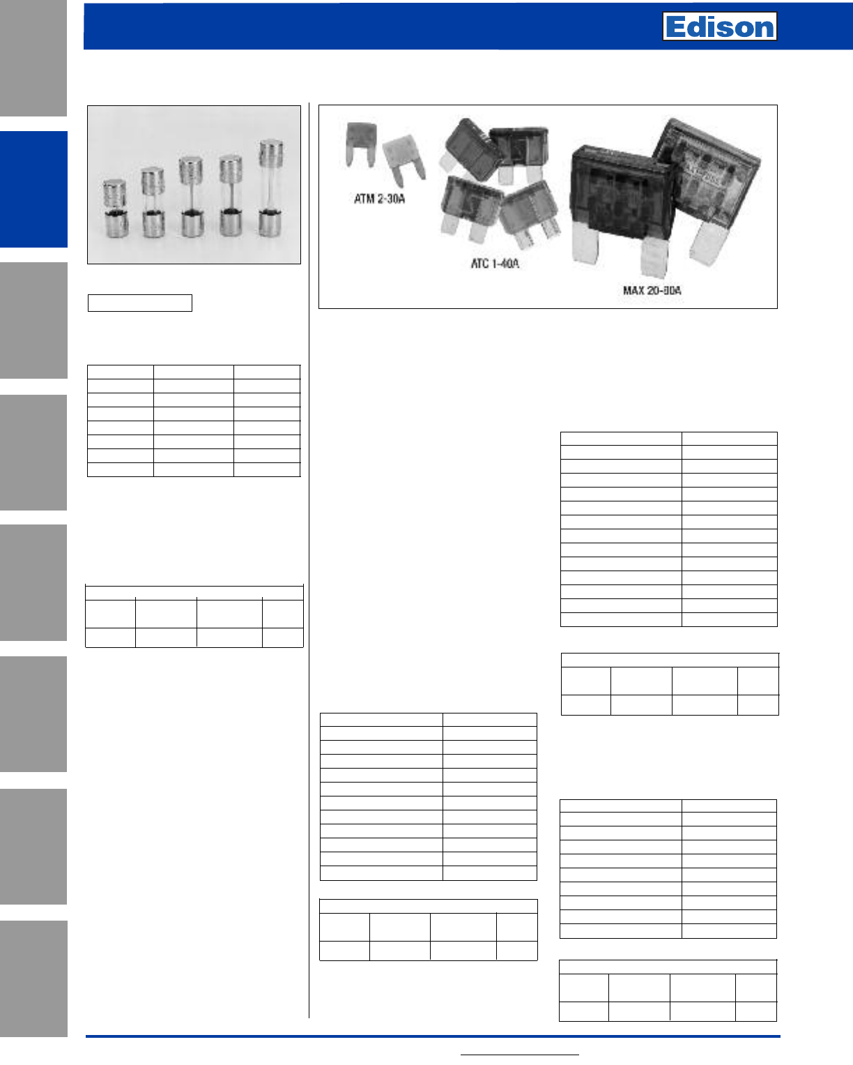
46 For additional information, visit www.edisonfuse.com
Application
Section
Fuse Blocks,
Holders & Misc.
Surge Protective
Devices
Medium
Voltage Fuses
Canadian
Fuses & Holders
Special
Purpose Fuses
UL/CSA Fuses
General Purpose
UL/CSA Fuses
Current Limiting
Automotive Fuses
Glass Tube Fuses Blade Fuses
Specifications
Description: Fast-acting blade fuse.
Construction: Plastic housing with
zinc fuse element. Zinc ATM blades
are silver-plated.
Ratings:
Volts — 32Vdc
Amps — 2-30A (ATM)
1-40A (ATC)
20-80A (MAX)
IR — 1kA
Features and Benefits
• Color coded for easy identification of
fuse ratings
Typical Applications
• Automotive
Catalog Numbers (Amps)
Cat. No. ATM (2-30A)
Catalog Numbers (Amps)
Cat. No. ATC (1-40A)
Agency Information: UL Recognized,
(3-40A) (Guide JFHR2, File E56412),
SAE Standard J1284.
Catalog Numbers (Amps)
Cat. No. MAX (20-80A)
Catalog Numbers (Amps)
Catalog Numbers Color Code
ATM-1 Black
ATM-2 Gray
ATM-3 Violet
ATM-4 Pink
ATM-5 Tan
ATM-7 1/2 Brown
ATM-10 Red
ATM-15 Blue
ATM-20 Yellow
ATM-25 Clear
ATM-30 Green
Catalog Numbers Color Code
ATC-1 Black
ATC-2 Gray
ATC-3 Violet
ATC-4 Pink
ATC-5 Tan
ATC-7 1/2 Brown
ATC-10 Red
ATC-15 Blue
ATC-20 Yellow
ATC-25 Clear
ATC-30 Green
ATC-35 Blue-Green
ATC-40 Orange
Catalog Numbers Color Code
MAX-20 Yellow
MAX-25 Grey
MAX-30 Green
MAX-35 Brown
MAX-40 Orange
MAX-50 Red
MAX-60 Blue
MAX-70 Tan
MAX-80 Clear
SFE
Fast-Acting
Physical Size: 1/4” diameter x length
as below
Catalog No. Ampere Rating Length (In.)
SFE-4 4 5/8
SFE-6 6 3/4
SFE-7-1/2 7-1/2 7/8
SFE-9 9 7/8
SFE-14 14 1-1/16
SFE-20 20 1-1/4
SFE-30 30 1-7/16
Construction: Glass Tube
Voltage Rating: 32V
Agency Information:
UL Listed
(Guide #FHXT, File #AU169)
CROSS REFERENCE
NEW OLD
EDISON EDISON MERSEN LF
SFE ——307
CROSS REFERENCE
NEW OLD
EDISON EDISON FERRAZ LF
ATM – AF2 MIN
CROSS REFERENCE
NEW OLD
EDISON EDISON FERRAZ LF
MAX – AF3 MAX
CROSS REFERENCE
NEW OLD
EDISON EDISON FERRAZ LF
ATC BTC AF ATO
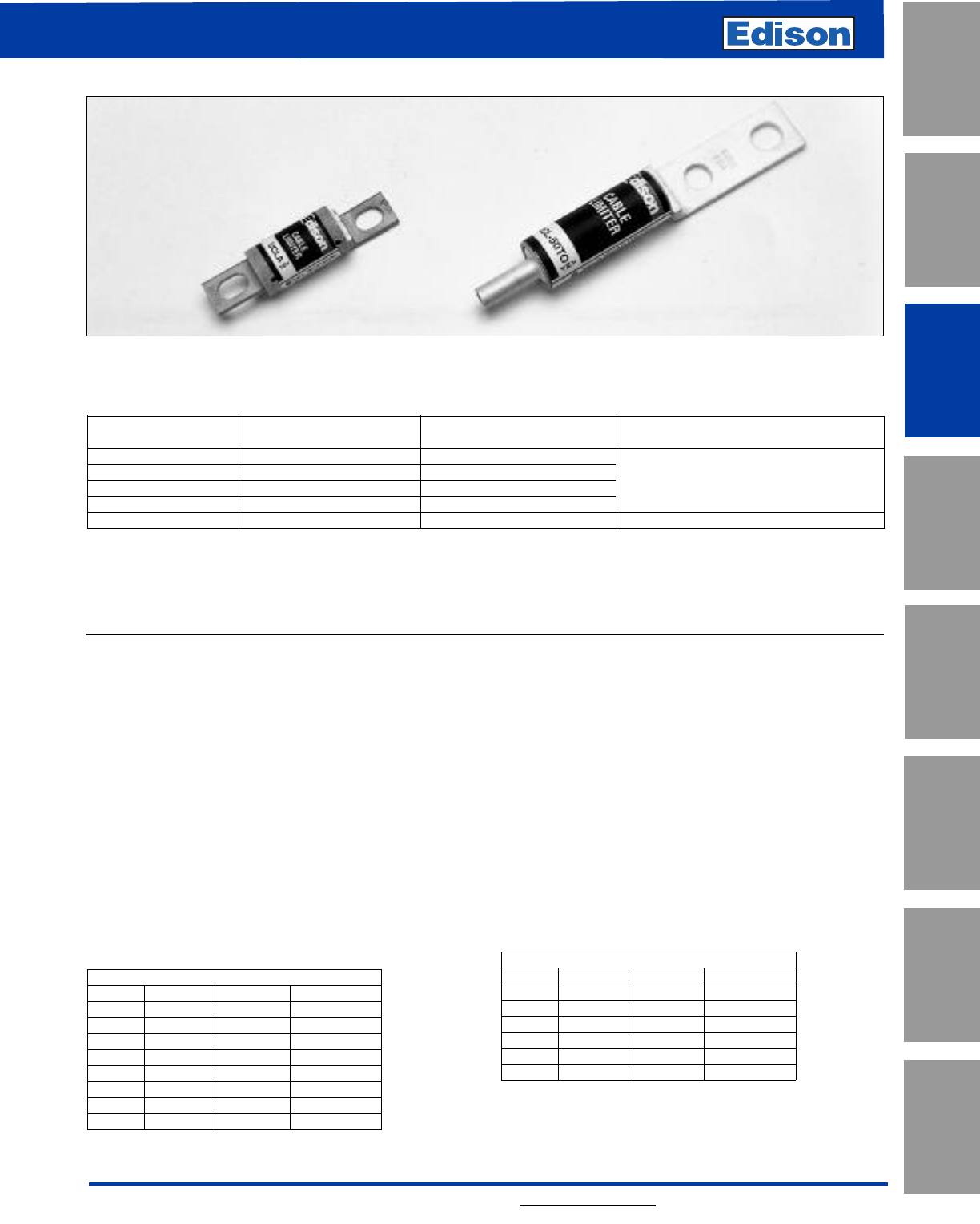
47
For additional information, visit www.edisonfuse.com
UL/CSA Fuses
Current Limiting
UL/CSA Fuses
General Purpose
Special
Purpose Fuses
Canadian
Fuses & Holders
Medium
Voltage Fuses
Fuse Blocks,
Holders & Misc.
Application
Section
Surge Protective
Devices
Cable Limiter Specifications
Voltage Rating: UCL25XX – 75XX, 600Vac
UCLA, 250Vac
Cable Ratings: 250MCM to 750MCM Cu - 600Vac
2/0 or 3/0 Cu - 250Vac
4/0 Al - 250Vac (Cu/Al terminal
required)
Interrupting Rating: 600V - 200kA RMS
250V - 100kA RMS
Current Limiting
Catalog AC Volts Copper
Number* Rating Cable Size Cable Terminals Available
UCL25XX(1) 600 250MCM T = Copper crimp tube
UCL35XX(1) 600 350MCM O = Bolt-on blade offset from center
UCL50XX(1) 600 500MCM B = Bolt-on blade, centered
UCL75XX(1) 600 750MCM
UCLA 250 2/0 or 3/0(2) Bolt-on blade, one end offset from center
*Contact Edison Customer Satisfaction for availability, limiters not shown, latest data or information.
(1) Choose terminals from "Cable Terminals Available" column to complete catalog number, EXAMPLE: "UCL-25TO" is rated for a "25" 250MCM copper cable
and has a "T" tube for crimping and an "O" bolt-on blade, offset from center. Any combination of the three terminals may be selected.
(2) A 4/0 aluminum cable may be used with a copper blade-to-aluminum cable connector.
Catalog Number UCL (25XX – 75XX) 600Vac or Less
Catalog Number UCLA 250Vac or Less
Benefits:
• Cable limiters help to a maintain electrical service by
minimizing cable damage due to short circuit currents.
• Isolates faulted cable(s) in multiple cables per phase
installations.
• Several cable termination types available.
Applications:
• Residential: 250Vac limiters can be used to protect
individual service cables tapped from a single
transformer.
• Non-Residential: 600Vac cable limiters should be
specified to protect parallel service cables in 120/208Vac,
277/480Vac etc. systems.
Copper Cable Limiters (600Vac)
Copper/Aluminum Cable Limiters (250Vac)
CROSS REFERENCE
VOLTS EDISON GOULD LITTELFUSE
250 UCLA — —
250 UCLC ——
600 UCL25TO CP250C3 LFCL250C3
600 UCL25BO CP250C5 LFCL250C5
600 UCL25TT CP250C1 LFCL250C1
600 UCL35TO CP350C3 LFCL350C3
600 UCL35BO CP350C5 LFCL350C5
600 UCL35TT CP350C1 LFCL350C1
CROSS REFERENCE
VOLTS EDISON GOULD LITTELFUSE
600 UCL50TO CP500C3 LFCL500C3
600 UCL50BO CP500C5 LFCL500C5
600 UCL50TT CP500C1 LFCL500C1
600 UCL75TO CP750C3 LFCL750C3
600 UCL75BO CP750C5 LFCL750C5
600 UCL75TT CP750C1 LFCL750C1
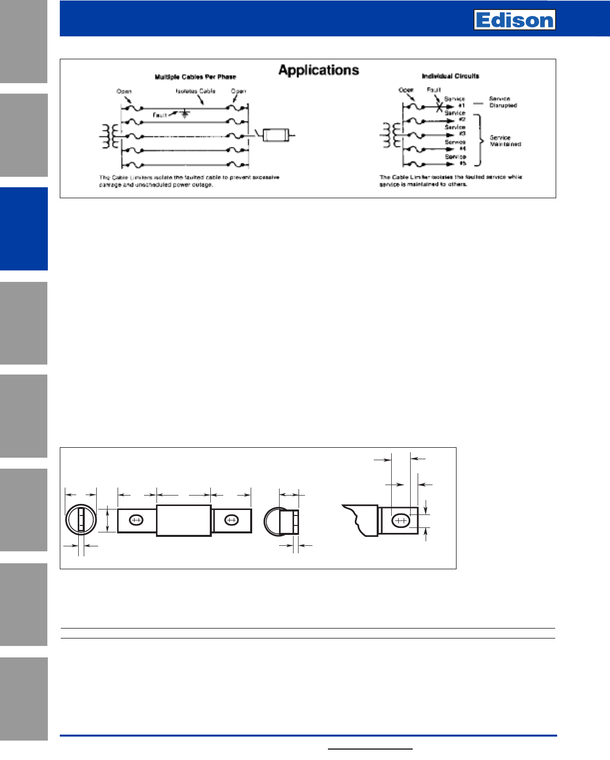
48
Copper Cable Limiters (600Vac)
Copper/Aluminum Cable Limiters (250Vac)
For additional information, visit www.edisonfuse.com
C A1F
BA2
E
D
EI
G
H
Bolt
terminal
detail
detail
Application of Cable Limiters:
By industry definition, cable limiters do not provide overload
protection. Class J and Class L fuses for three or more
cables-per-phase applications should be considered if
overload protection is a concern. This may also be a
desirable consideration for aluminum cable using suitable
connectors.
Cable limiters applied in utility networks and building power
system main parallel service cables are primarily intended
to isolate faults in multiple-cables-per-phase installations.
This prevents total power outages until maintenance of
faulted cable(s) can be scheduled. During the process of
opening under fault conditions to isolate faulted cable(s),
limiters current limiting action reduces potential for excess
heat damage to unfaulted cables.
Dimensions - inches
Cable Limiters 250V or Less AC
For applications having three or more parallel cables-
per-phase, cable limiters are installed at each end of each
cable. For nonparallel or multiple radial cables, limiters may
successfully be applied at the source end of each cable for
fault isolation.
When analyzing cable limiter potential applications, it is not
unusual to forget that normal and abnormal current through
cable limiters is divided just as it is between cables.
Selectivity with upstream overcurrent protection devices is
seldom of concern. When designing for cable limiter fault
isolation to prevent a burn down or unscheduled blackout by
one faulted cable, it is desirable to determine the continuous
rating load (3 hours or more) that the remaining cables must
handle without overheating.
Cat. No. UCLA
Application
Section
Fuse Blocks,
Holders & Misc.
Surge Protective
Devices
Medium
Voltage Fuses
Canadian
Fuses & Holders
Special
Purpose Fuses
UL/CSA Fuses
General Purpose
UL/CSA Fuses
Current Limiting
Catalog Copper Aluminum
Symbol Cable Size Cable Size A1A2BCDEFGH I
UCLA 2/0AWG 4/0AWG 1.06 (27.0) 1.19 (30.2) 1.44 (36.5) 1.00 (25.4) 0.75 (19.0) 0.12 (3.2) 0.56 (14.3) 0.19 (4.8) 0.59 (15.1) 0.41 (10.3)
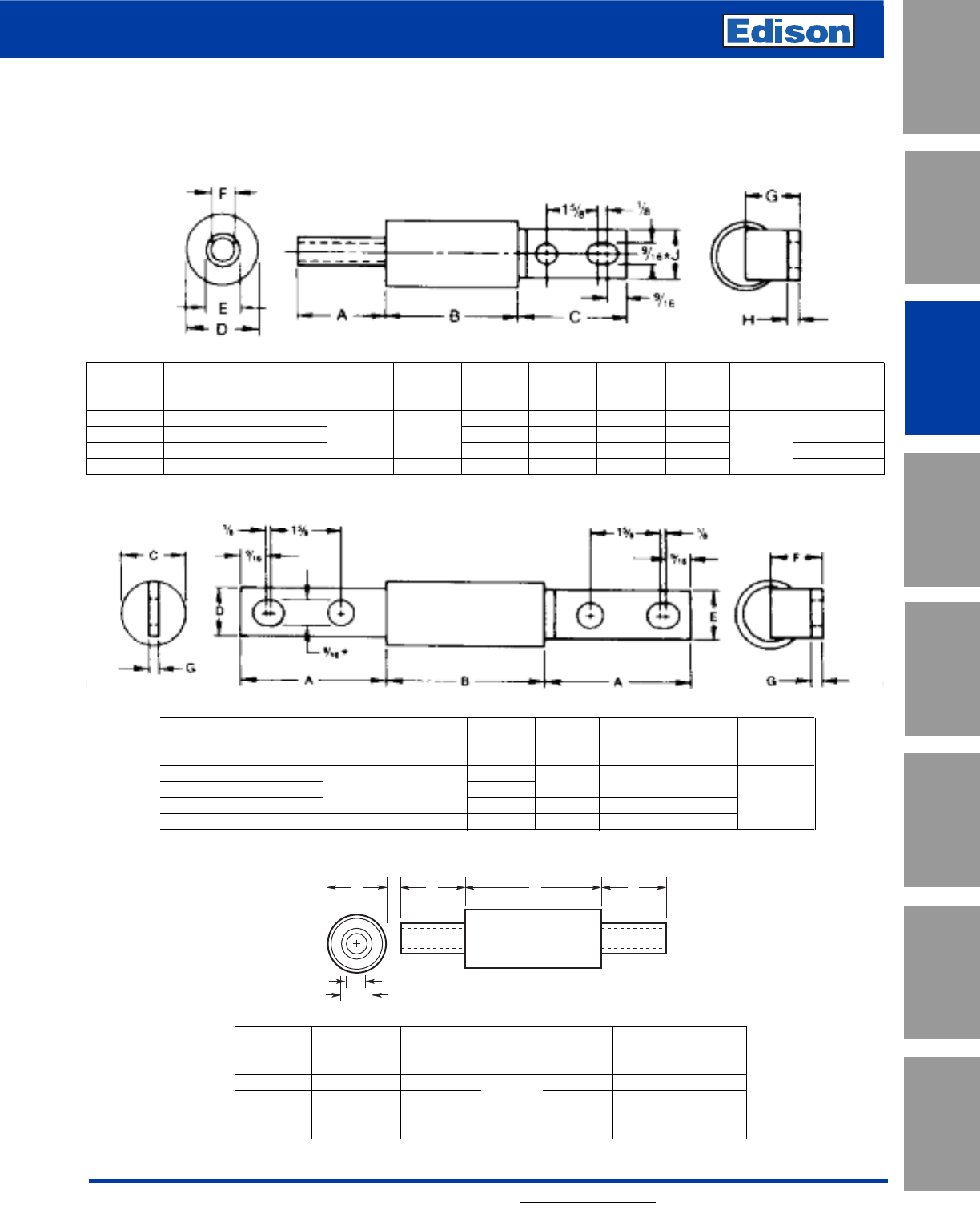
49
For additional information, visit www.edisonfuse.com
Cable Limiters 600V or Less AC
Dimensions are shown in inches.*
Tube-Offset Blade (TO)**
Copper
Catalog Cable
Number Size* ABCDEFGHJ
UCL25TO 250 MCM 1-7/8 1-7/16 3/4 19/32 31/32 1-1/8
UCL35TO 350 MCM 2 3-5/8 3-3/8 1-5/8 7/8 45/64 1-1/16 1/4
UCL50TO 500 MCM 2-7/8 1-7/8 1-1/16 53/64 1-3/16 1-5/8
UCL75TO 750 MCM 3-1/2 3-3/4 3-1/2 2-1/2 1-5/16 1-1/16 1-1/2 2
Center Blade-Offset Blade (BO)**
Copper and
Catalog Aluminum
Number Cable Size* ABCDEFG
UCL25BO 250 MCM 1-7/16 1-1/8 1-1/8 31/32
UCL35BO 350 MCM 3-3/8 3-5/8 1-5/8 1-1/16 1/4
UCL50BO 500 MCM 1-7/8 1-1/2 1-5/8 1-3/16
UCL75BO 750 MCM 3-1/2 3-3/4 2-1/2 221-1/2
Tube-Tube (TT)
Copper
Catalog Cable
Number Size* ABCDE
UCL25TT 250 MCM 1-7/8 1-7/16 3/4 19/32
UCL35TT 350 MCM 2 3-5/8 1-5/8 7/8 45/64
UCL50TT 500 MCM 2-7/8 1-7/8 1-1/16 53/64
UCL75TT 750 MCM 3-1/2 2-7/8 2-1/2 1-5/16 1-1/16
A B A
D
E
C
*Limiter terminals are silver plated copper.
**Dimensions of "TT", "OO", "TB", etc., terminals are determined by matching appropriate dimensions shown.
Copper Cable Limiters (600Vac)
Copper/Aluminum Cable Limiters (250Vac)
UL/CSA Fuses
Current Limiting
UL/CSA Fuses
General Purpose
Special
Purpose Fuses
Canadian
Fuses & Holders
Medium
Voltage Fuses
Fuse Blocks,
Holders & Misc.
Application
Section
Surge Protective
Devices
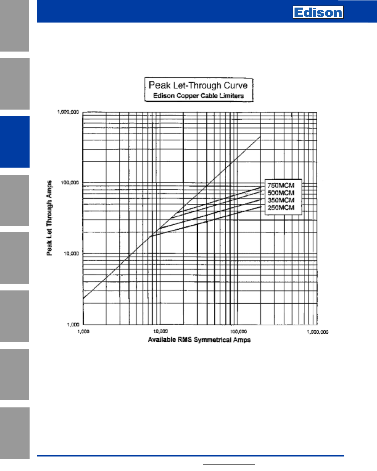
50
Copper Cable Limiters (600Vac)
Copper/Aluminum Cable Limiters (250Vac)
For additional information, visit www.edisonfuse.com
Average Time-Current Curve
Cat. No. UCL-(XXXX)-600Vac
Application
Section
Fuse Blocks,
Holders & Misc.
Surge Protective
Devices
Medium
Voltage Fuses
Canadian
Fuses & Holders
Special
Purpose Fuses
UL/CSA Fuses
General Purpose
UL/CSA Fuses
Current Limiting
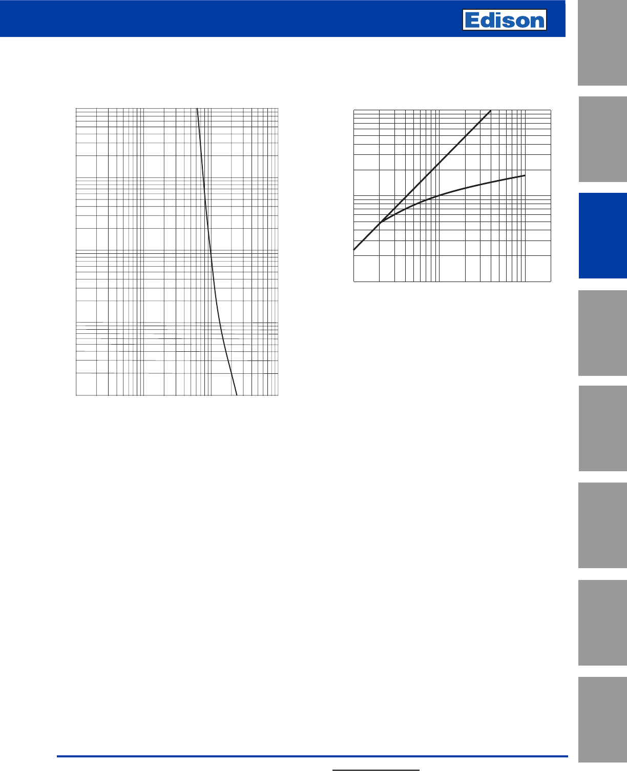
51
For additional information, visit www.edisonfuse.com
AMP
RATING
RMS SYMMETRICAL CURRENT IN AMPS
1,000
100
10
10,000
UCLA
10
100
TIME IN SECONDS
1
.1
.01
100,000
80,000
60,000
40,000
30,000
20,000
10,000
8,000
6,000
4,000
3,000
2,000
1,000
1,000
2,000
3.000
4,000
6,000
8,000
10,000
20,000
30,000
40,000
60,000
80,000
100,000
200,000
INSTANTANEOUS PEAK LET-THRU CURRENTIN AMPS
RMS SYMMETRICAL CURRENTS IN AMPS
A–B=ASYMMETRICAL AVAILABLE PEAK (2.3 x SYMM RMS AMPS)
B
A
Average Time-Current Curve Peak Let-Through Current Curve
Cat. No. UCLA and 250V
Copper Cable Limiters (600Vac)
Copper/Aluminum Cable Limiters (250Vac)
UL/CSA Fuses
Current Limiting
UL/CSA Fuses
General Purpose
Special
Purpose Fuses
Canadian
Fuses & Holders
Medium
Voltage Fuses
Fuse Blocks,
Holders & Misc.
Application
Section
Surge Protective
Devices
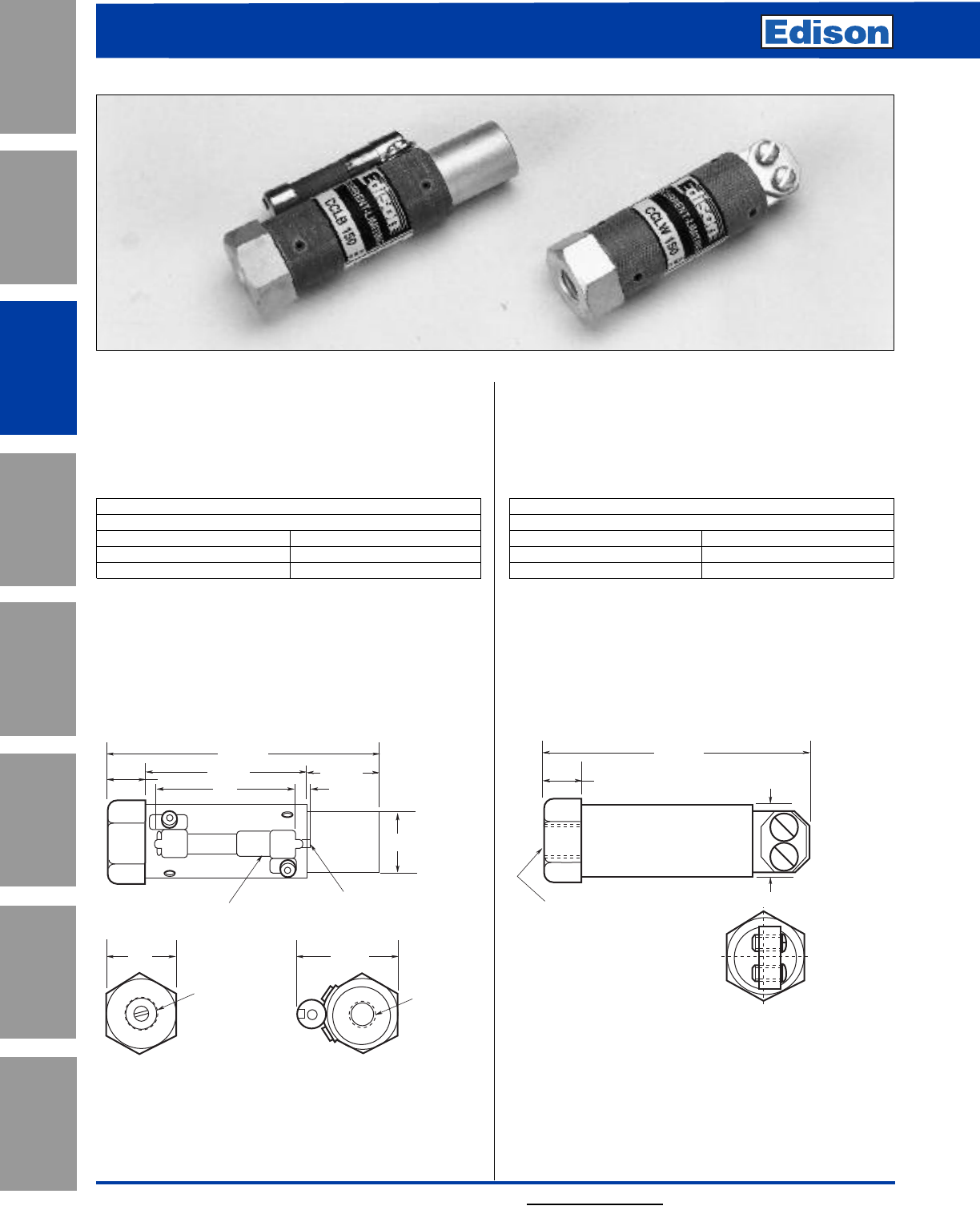
52
600Vac Capacitor Fuses
For additional information, visit www.edisonfuse.com
Cat. No. CCLB(Amps)
600Vac or Less
AC Interrupting Rating: 200kA
With open fuse indicator
UL Recognized (80 to 150A) E56412, JFHR2
Non-Time Delay
Amp Ratings
CCLB
80 150
100 200
125 250
Characteristics:
• Stud mount with tapped terminals
• Isolates faulted capacitor
• Size amp rating 250% to 300% of capacitor rated amps
• Maximum quality assurance
Dimensions - inches
Cat. No. CCLW(Amps)
600Vac or Less
AC Interrupting Rating: 200kA
Without open fuse indicator
UL Recognized 80-150A, (E56412, JFHR2)
Non-Time Delay
Amp Ratings
CCLW
50 150
80 —
100 —
Characteristics:
• Stud mount and pressure plate terminals
• Isolates faulted capacitor
• Size amp rating 250% to 300% of capacitor rated amps
• Maximum quality assurance
Dimensions - inches
2"
2-9/32"
3-13/16"
3/16"
1-1/32"
13/16"
BLOWN POSITION
INDICATOR
1" 1-1/2"
1/2"-13
THREADS
11/16" DEEP
3/8"-16
THREADS
3/4" DEEP
1/2"
3-17/32"
1.0"
HEX TERMINAL TAPPED
1/2"-13 x 11/16" DEEP
1/2"
Application
Section
Fuse Blocks,
Holders & Misc.
Surge Protective
Devices
Medium
Voltage Fuses
Canadian
Fuses & Holders
Special
Purpose Fuses
UL/CSA Fuses
General Purpose
UL/CSA Fuses
Current Limiting
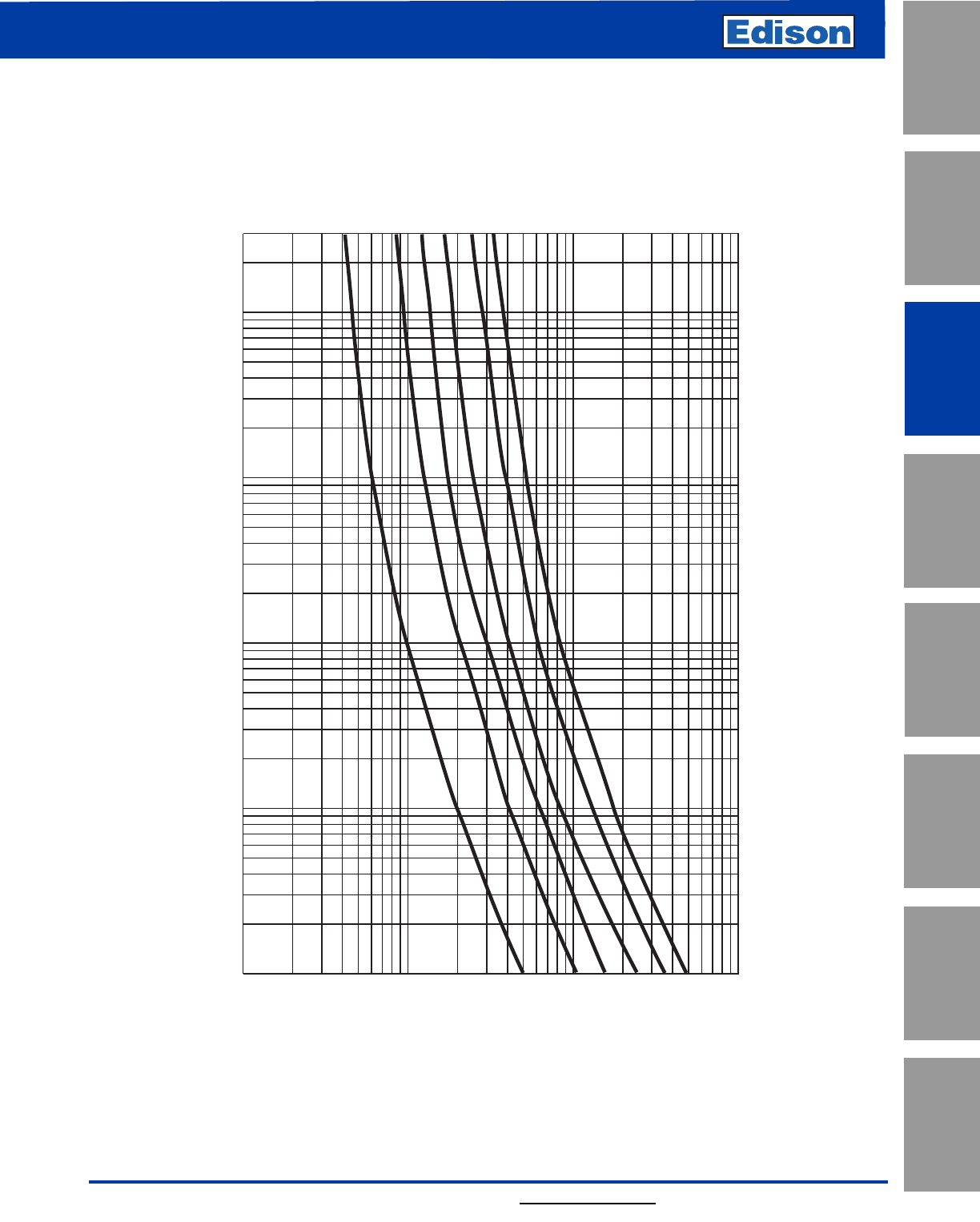
53
For additional information, visit www.edisonfuse.com
Average Time-Current Curve
Cat. No. CCLB or CCLW (Amp)
10,000
8,000
6,000
4,000
3,000
2,000
1,000
800
600
400
300
200
100
80
60
40
30
20
10
300
200
100
80
60
40
30
20
10
8
6
4
3
2
1
.8
.6
.4
.3
.2
.1
.08
.06
.04
.03
.02
.01
TIME IN SECONDS
RMS SYMMETRICAL CURRENT IN AMPS
25
75
AMP
RATING
100
150
200
50
600Vac Capacitor Fuses
UL/CSA Fuses
Current Limiting
UL/CSA Fuses
General Purpose
Special
Purpose Fuses
Canadian
Fuses & Holders
Medium
Voltage Fuses
Fuse Blocks,
Holders & Misc.
Application
Section
Surge Protective
Devices
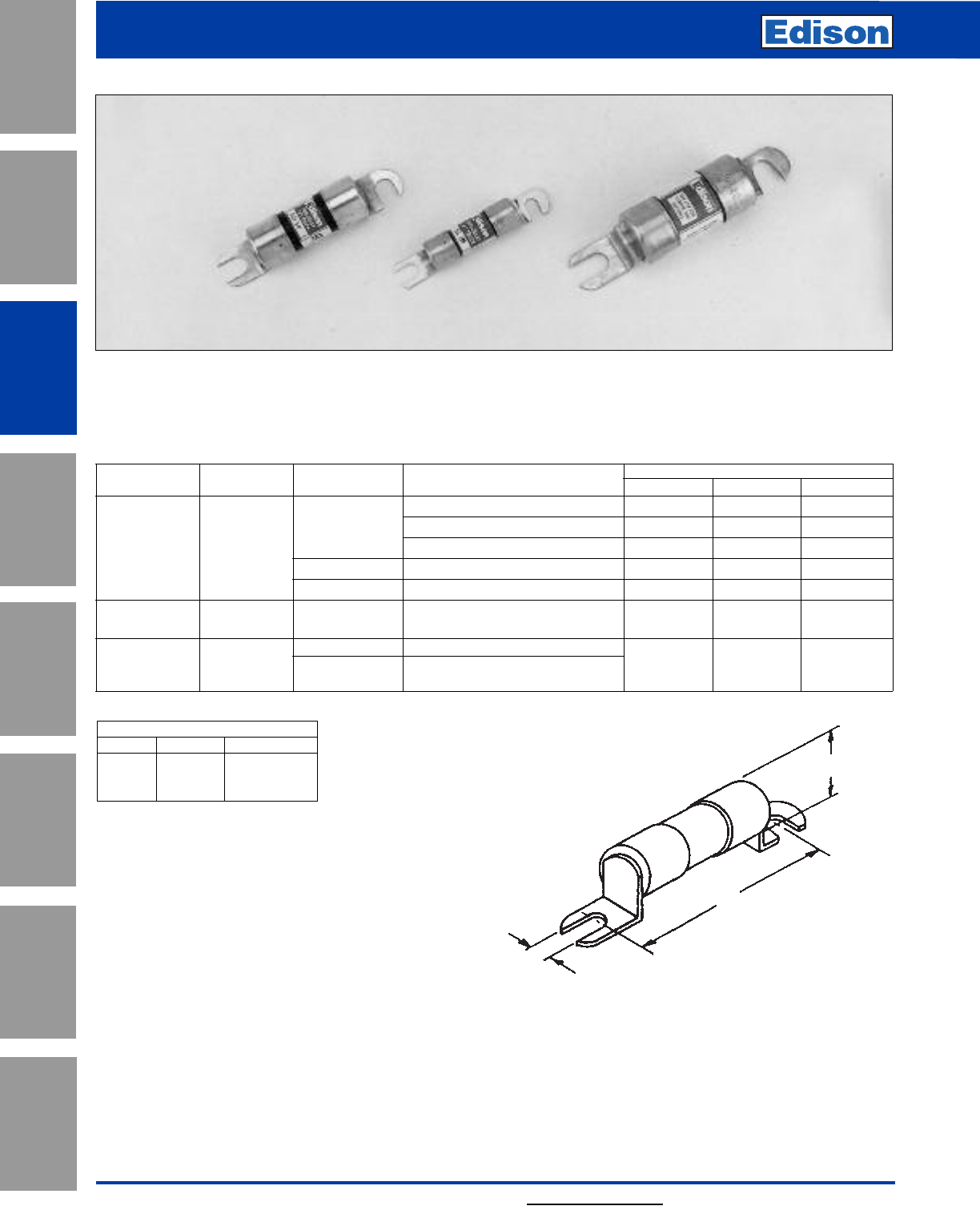
54
Lift truck & Battery Charger Fuses
For additional information, visit www.edisonfuse.com
Catalog Number ACK (15 - 400A), ACL (30 - 100A) and ALS (100 - 500A)
Applications:
Popular for protection of DC circuits in fork lift trucks and battery chargers.
Catalog Dimensions (Inches)
Number Type Volts Amps AB C
15, 20, 25, 30 2.500 0.250 0.563
130Vdc 35, 40, 50, 60 3.000 0.344 0.813
ACK Time-Delay 70, 75, 80, 100 3.500 0.313 1.063
72Vdc 120, 140, 150, 175, 200 3.635 0.313 1.063
48Vdc 225, 250, 300, 400 3.875 0.313 1.063
ACL Time-Delay 72Vdc 30, 35, 40, 50, 60 2.500 0.250 0.563
80, 100
Non-Time 130Vdc 100, 120, 140, 150, 175
ALS Delay 48Vdc 200, 225, 250, 300 3.750 0.375 1.063
350, 400, 450, 500
C (Dia.)
B
A
Application
Section
Fuse Blocks,
Holders & Misc.
Surge Protective
Devices
Medium
Voltage Fuses
Canadian
Fuses & Holders
Special
Purpose Fuses
UL/CSA Fuses
General Purpose
UL/CSA Fuses
Current Limiting
Dimensions - inches
CROSS REFERENCE
EDISON GOULD LITTELFUSE
ACK — CCK
ACL — CCL
ALS ——
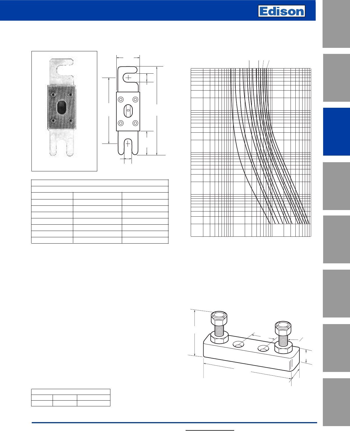
55
For additional information, visit www.edisonfuse.com
Amp Ratings
ANL 800Vdc
35 150 350
40 175 400
50 200 500
60 225 600
80 250 675
100 275 750
125 300 —
130 325 —
Catalog Number ANL (35 - 750A)
800Vdc or Less
ANL Specifications:
Non-Time-Delay
Voltage Rating: 80Vdc, 125Vac Self Certified
Interrupting Rating: 2700A@80Vdc
6kA RMS Symmetrical Amps
Agency Information: UL Recognized, CSA Certified,
35-750A@80Vdc, IR = 2700A, Guide JFHR2, File E56412,
Class 1422-30, File 53787, SAE J1171
Recommended Fuse Block: 4164
Characteristics:
• Isolates faults in equipment systems such as lift trucks
and other battery operated systems.
• Link element visible through mica window.
Average Time-Current Curve
0.34"
(8.7mm)
0.88"
(22.2mm)
0.88"
(22.2mm)
0.34"
(8.7mm)
3.19"
(81.0mm)
2.44"
(61.9mm)
Low-Voltage Limiter Non Time-Delay
UL/CSA Fuses
Current Limiting
UL/CSA Fuses
General Purpose
Special
Purpose Fuses
Canadian
Fuses & Holders
Medium
Voltage Fuses
Fuse Blocks,
Holders & Misc.
Application
Section
Surge Protective
Devices
15/16"
0.483"
1"
3-13/32"
1.563"
5
16 -24
Fuse Block 4164
Holes drilled 0.217” diameter with 0.438” counterbore with
5/16-24 stud with nylon inserted locknuts.
Dimensions - inches
CROSS REFERENCE
EDISON GOULD LITTELFUSE
ANL CNL CNL
10,000
10
100
1000
CURRENT IN AMPS
100
10
1
.1
.01
TIME IN SECONDS
AMP
RATING
50
35
80
100
130 150
200
225 275
325 350
400 500
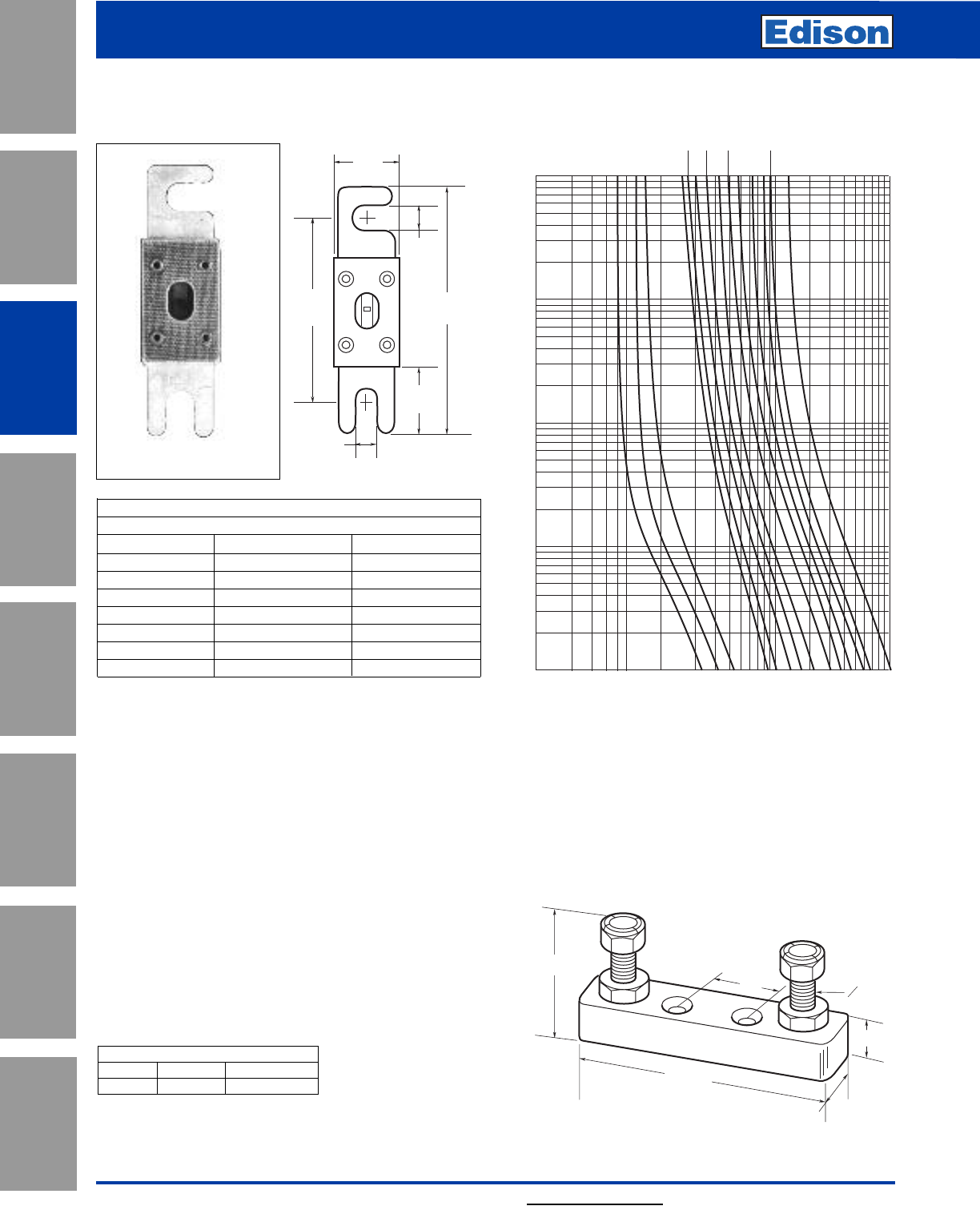
56
Limiter
Very Fast-Acting
For additional information, visit www.edisonfuse.com
Amp Ratings
ANN 125Vac
10 125 325
35 150 350
40 175 400
50 200 500
60 225 600
80 250 700
90 275 800
100 300 —
Catalog Number ANN (10 - 800A)
125Vac or Less
ANN Specifications:
Very Fast-Acting
Voltage Rating: 125Vac, 80Vdc
Interrupting Rating: 2500@125Vac
2700@80Vdc
Agency Information: 35-400A@125Vac, IR=2500A and
500A@80Vdc, IR=2700A: UL Recognized Guide JFHR2,
File E56412; CSA Certified Class 1422-30, File 53787,
CE for 35-400A
Recommended Fuse Block: 4164
Characteristics:
• Very fast-acting (high speed of response to short-circuit
currents.
• Link element visible through mica window.
• UL Recognized 35-400A (Guide #JFHR2, File #E56412)
Average Time-Current Curve
10,000
10
100
1000
CURRENT IN AMPS
100
10
1
.1
.01
TIME IN SECONDS
AMP
RATING
35
50
60
80 100
125 150
200
300
400
500
250
600
800
0.34"
(8.7mm)
0.88"
(22.2mm)
0.88"
(22.2mm)
0.34"
(8.7mm)
3.19"
(81.0mm)
2.44"
(61.9mm)
15/16"
0.483"
1"
3-13/32"
1.563"
5
16 -24
Application
Section
Fuse Blocks,
Holders & Misc.
Surge Protective
Devices
Medium
Voltage Fuses
Canadian
Fuses & Holders
Special
Purpose Fuses
UL/CSA Fuses
General Purpose
UL/CSA Fuses
Current Limiting
Fuse Block 4164
Holes drilled 0.217” diameter with 0.438” counterbore with
5/16-24 stud with nylon inserted locknuts.
Dimensions - inches
CROSS REFERENCE
EDISON GOULD LITTELFUSE
ANN CNN CNN
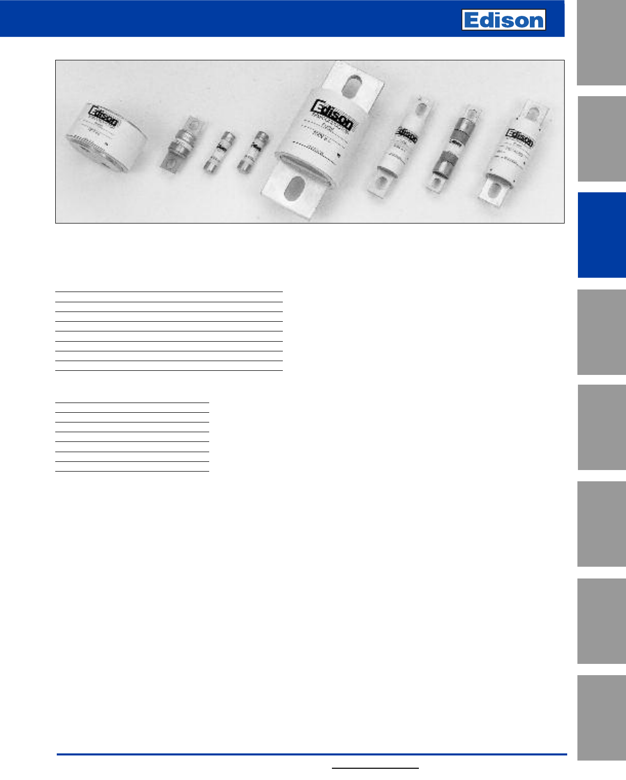
57
For additional information, visit www.edisonfuse.com
High Speed Fuses
UL/CSA Fuses
Current Limiting
UL/CSA Fuses
General Purpose
Special
Purpose Fuses
Canadian
Fuses & Holders
Medium
Voltage Fuses
Fuse Blocks,
Holders & Misc.
Application
Section
Surge Protective
Devices
Introduction
North American Contents
Catalog Amp
Number Volts Range Page
JHL 600 1-600 59
FWA 130 1000-4000 65-66
FWA 150 5-1000 61-64
FWX 250 1-2500 67-70
FWH 500 0.25-1600 71-76
FWC 600 6-32 77-78
FWP 700 1-1200 79-85
FWJ 1000 20-2000 86-89
North American Fuse Ranges
Amps Volts AC DC
1000-4000 130 XX
5-1000 150 XX
1-2500 250 XX
0.25-1600 500 XX
6-32 600 X X
1-1200 700 XX
20-2000 1000 XX
General Information
Edison offers a complete range of North American blade
and flush-end style fuses and accessories. Their design
and construction were optimized to provide:
• Low energy let-through (I2t)
• Low watts loss
• Superior cycling capability
• Low arc voltage
• Excellent DC performance
North American style fuses provide an excellent solution
for medium power applications. While there are currently
no published standards for these fuses, the industry has
standardized on mounting centers that accept Edison
fuses.
Voltage Rating
All Edison North American style fuses are tested at their
rated voltage. Edison should be consulted for applications
exceeding those values.
Accessories
External and internal open fuse indication is available for
selected portions of the North American line. Fuse blocks
are available for most applications.
58
High Speed Fuses
For additional information, visit www.edisonfuse.com
Application
Section
Fuse Blocks,
Holders & Misc.
Surge Protective
Devices
Medium
Voltage Fuses
Canadian
Fuses & Holders
Special
Purpose Fuses
UL/CSA Fuses
General Purpose
UL/CSA Fuses
Current Limiting
Breaking Capacity
In general, high speed fuses perform well at very high fault
currents and many products have been successfully tested
up to 200kA rms symmetrical. The fuses are essentially for
short-circuit protection and therefore in general, only
required to clear faults for melting times less than 30
seconds.
Peak Let-Through Current Curves
Short-circuit coordination of power semiconductors is
assessed with the use of I2t values. Traditional
supplementary peak let-through current curves are also
shown in the catalog.
Arc-Voltage Characteristics
Applications using modern power semiconductors are not
normally sensitive to the peak arc voltages produced by
Edison high speed fuses.
Typical values of arc voltages in relation to the rated fuse
voltage, Un, are:
System Voltage Arc Voltage of Fuse
Un2.0 Un
0.5 Un1.25 Un
0.2 Un0.7 Un
Power Dissipation
The values of watts loss given are related to full rated
current with the correct sizes of conductors and natural
cooling.
Time Current Characteristics
Individual time current characteristics are subject to a ±10%
tolerance on current and are based on symmetrical
sinusoidal 60Hz currents. High speed fuses are designed
to clear fault currents associated with pre-arcing times of
30 seconds or less. Dashed lines on time-current
characteristic curves represent overload conditions which,
should always be avoided.
Permitted Overloads
In many applications, surges occur during the normal duty
of equipment and under such permitted overloads, the fuse
must not open.
For permitted overloads lasting longer than a few minutes,
the fuse current rating should be selected based on the
overload current. The current rating of the fuse should
exceed the overload current.
For infrequent normal overloads, fuse selection can be
made on the basis of an overload curve of not more than
75% of the published time current characteristic.
For highly repetitive overloads, such as in a steel mill
thyristor drive, fuse selection should be made on the basis
of an overload curve of not more than 60% of the published
time current characteristic.
I2t Characteristics
The melting I2t of fuses is independent of voltage and
reduces to a minimum value for times less than about 1ms.
For longer times, reference should be made to the time
current characteristics.
The total I2t values for operating times less than one half-
cycle are shown in the data sheets and relate to a fault
current of at least 20x rated current, In, with a power factor
of 15%.
The total I2t values reduce considerably at voltages below
the rated voltage since the arc interruption is easier.
Example: a 500V Edison high speed fuse used on a 250V
system would produce an arc voltage of approximately
625V.
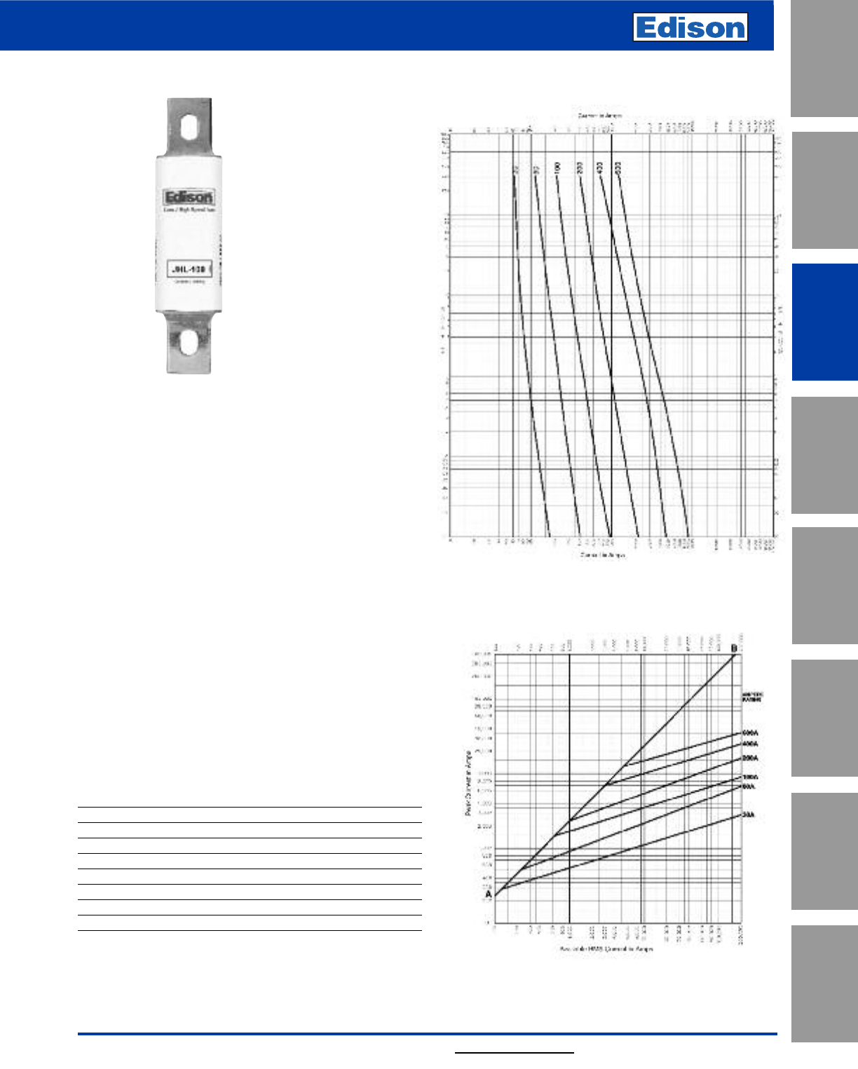
59
For additional information, visit www.edisonfuse.com
130V High Speed Fuses
UL/CSA Fuses
Current Limiting
UL/CSA Fuses
General Purpose
Special
Purpose Fuses
Canadian
Fuses & Holders
Medium
Voltage Fuses
Fuse Blocks,
Holders & Misc.
Application
Section
Surge Protective
Devices
Catalog Symbol: JHL
High Speed Fuse
Current-Limiting
Ampere Rating: 1 to 600A
Voltage Rating: 600Vac (or less), 450Vdc (or less)
Interrupting Rating: 200kA RMS Sym., 100kA DC
Agency Information:
UL Listed, Std. 248-8, Class J, Guide JDDZ, File E162363
CSA Certified, C22.2 No. 248.8, Class 1422-02, File 53787
Catalog Numbers (Amps)
JHL1 JHL15 JHL70 JHL225
JHL2 JHL20 JHL80 JHL250
JHL3 JHL25 JHL90 JHL300
JHL4 JHL30 JHL100 JHL350
JHL5 JHL35 JHL110 JHL400
JHL6 JHL40 JHL125 JHL450
JHL8 JHL45 JHL150 JHL500
JHL10 JHL50 JHL175 JHL600
JHL12 JHL60 JHL200
Combine the performance of high speed
semiconductor fuses and the convenience of Class J
branch circuit fuses in on package.
The Edison Drive Fuse will provide maximum protection for
AC and DC drives and controllers and meet NEC®branch
circuit protection requirements.
General Information:
• Easily coordinated with existing and new variable speed
drives and electric controllers.
• Standard Class J dimensions allowing the use of readily
available fuse blocks, holders, and switches.
• Allows the lowest let-thru energy of any branch circuit
overcurrent protective device.
Time-Current Characteristic Curves—Average Melt
Current Limitation Curves
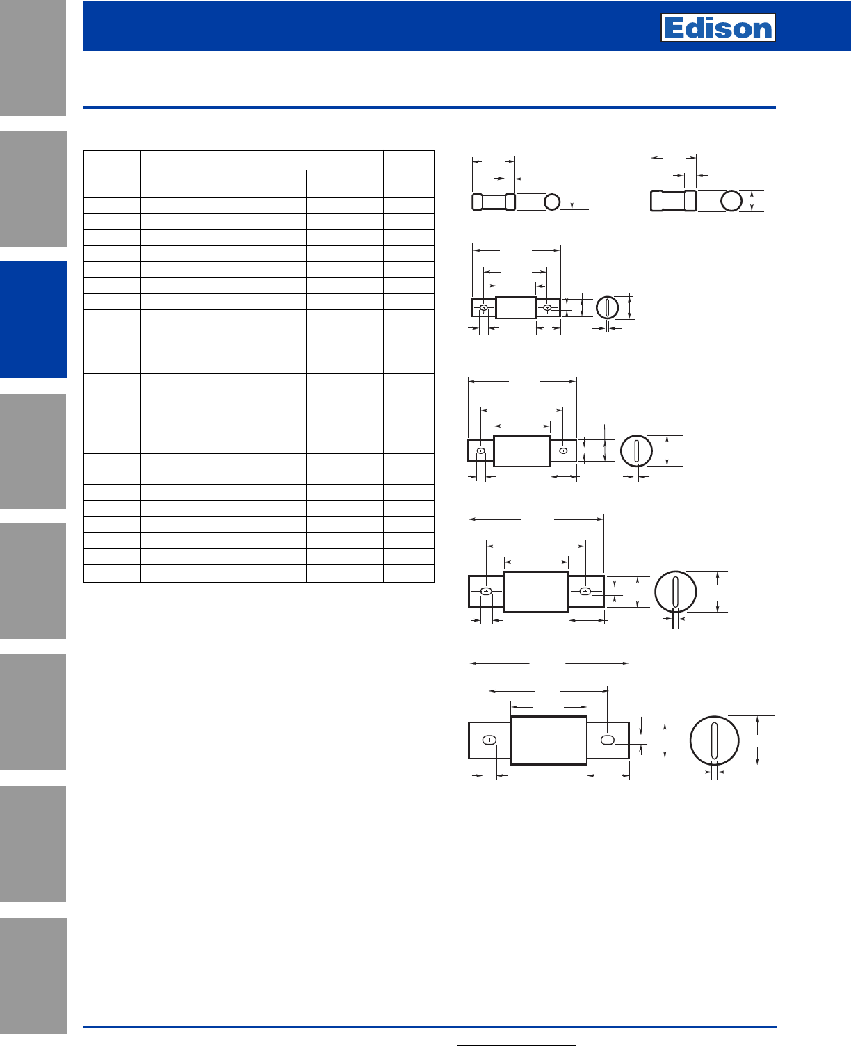
60 For additional information, visit www.edisonfuse.com
Application
Section
Fuse Blocks,
Holders & Misc.
Surge Protective
Devices
Medium
Voltage Fuses
Canadian
Fuses & Holders
Special
Purpose Fuses
UL/CSA Fuses
General Purpose
UL/CSA Fuses
Current Limiting
130V High Speed Fuses
Catalog Number JHL 1 –600A
6.0"
8.0"
(± 0.03)
3.75"
0.74" 2.13" 0.38"
0.53"
2"
450A to
600A 2.5"
7.13"
(± 0.03)
5.25"
3.38"
0.58"
1.63"
1.88"
0.41"
2.11"
0.25"
225A to
400A
5.75"
(± 0.03)
4.38"
3.0"
0.43" 1.38"
4.63"
(± 0.03)
3.63"
2.63"
70A to 100A
0.28"
0.75" 1.13"
0.13"
1"
0.43"
1.13"
0.28"
0.19"
1.63"
110A to
200A
2.25˝
0.50˝ 0.81˝
2.38˝
0.63˝ 1.06˝
1A to 30A 35A to 60A
Dimensions - inElectrical Characteristics
Catalog Rated Current I2t (A2Sec) @ 600Vac/100kA Watts
Number RMS Amps Pre-arc Clearing Loss
JHL-15 15 4 110 4.1
JHL-20 20 8 365 4.0
JHL-25 25 12 610 4.9
JHL-30 30 20 1000 5.5
JHL-35 35 55 1100 6.8
JHL-40 40 90 1900 8.6
JHL-50 50 140 2800 8.7
JHL-60 60 290 6000 8.5
JHL-70 70 450 3100 12
JHL-80 80 650 4600 13
JHL-90 90 1010 7200 13
JHL-100 100 1460 10500 13
JHL-110 110 1710 9500 17
JHL-125 125 3580 20000 15
JHL-150 150 5080 28000 19
JHL-175 175 6310 35000 23
JHL-200 200 9850 54500 24
JHL-225 225 11420 51000 29
JHL-250 250 17000 74500 30
JHL-300 300 23500 103000 36
JHL-350 350 38800 170000 39
JHL-400 400 62200 272000 40
JHL-450 450 44600 270000 56
JHL-500 500 79500 480000 52
JHL-600 600 138000 830000 57
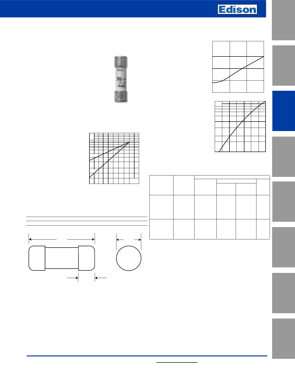
61
For additional information, visit www.edisonfuse.com
UL/CSA Fuses
Current Limiting
UL/CSA Fuses
General Purpose
Special
Purpose Fuses
Canadian
Fuses & Holders
Medium
Voltage Fuses
Fuse Blocks,
Holders & Misc.
Application
Section
Surge Protective
Devices
150V High Speed Fuses
Catalog Number FWA 5 – 60A
Arc Voltage
This curve gives the peak
arc voltage, UL, which may
appear across the fuse
during its operation as a
function of theapplied
working voltage, Eg, (rms)
at a power factor of 15%.
Power Losses
Watts loss at rated current
is given in the electrical
characteristics. The curve
allows the calculation of
the power losses at load
currents lower than the
rated current. The
correction factor, Kp, is
given as a function of the
RMS load current, Ib, in %
of the rated current.
Catalog Numbers
Electrical Characteristics
I2t (A2Sec)
Rated
Catalog Current Clearing Watts
Numbers Size RMS-Amps Pre-arc at 150V Loss
FWA-5A10F 5 1.6 81
FWA-10A10F 10 3.6 16 2.7
FWA-15A10F 10 x 38mm 15 14 55 3.3
FWA-20A10F (13⁄32” x 11⁄2”) 20 33 130 3.8
FWA-25A10F 25 58 220 4.9
FWA-30A10F 30 100 400 4.9
FWA-35A21F 35 75 800 4.5
FWA-40A21F 21 x 51mm 40 100 1000 5.1
FWA-45A21F (13⁄16” x 2”) 45 130 1300 6
FWA-50A21F 50 170 1600 7.3
FWA-60A21F 60 250 2400 8.0
• Watts loss provided at rated current.
Features and Benefits
• Excellent cycling capability and DC performance
• Low arc voltage and low energy let-through (I2t)
• Low watts loss in a compact size
• Used with finger-safe holders/blocks
Typical Applications
• DC Common bus
• DC Drives
• Power converters/rectifiers
• Reduced voltage starters
Dimensions - in (mm)
Amp Dimensions
Range AB C
5-30 1.5 (38.1) 0.375 (9.5) 0.406 (10.3)
35-60 2.0 (50.8) 0.625 (15.9) 0.811 (20.6)
UL
Eg
200
100
100 15050
300
Kp
1.0
0.8
0.4
0.5
0.6
0.3
0.2
0.1
30 40 50 60 70 80 90 100%
Ib
A
B
C
FWA 5-30A (10 x 38mm)
35-60A (21 X 51mm)
Specifications
Description: Ferrule style high
speed fuses.
Dimensions: See dimensions
illustration.
Ratings:
Volts: — 150Vac/dc
Amps: — 5-60A
IR: — 100kA Sym.
Agency Information: CE, UL Recognition JFHR2.E91958
Electrical
Characteristics
Total Clearing I2t
The total clearing I2t at
rated voltage and at power
factor of 15% are given in
the electrical
characteristics. For other
voltages, the clearing I2t is
found by multiplying by
correction factor, K, given
as a function of applied
working voltage, Eg, (rms).
1501027022
1.5
1.0
0.5
0.3
0.2
0.15 Eg
K
1)
2)
1) 5-30A Range
2) 35-60A Range
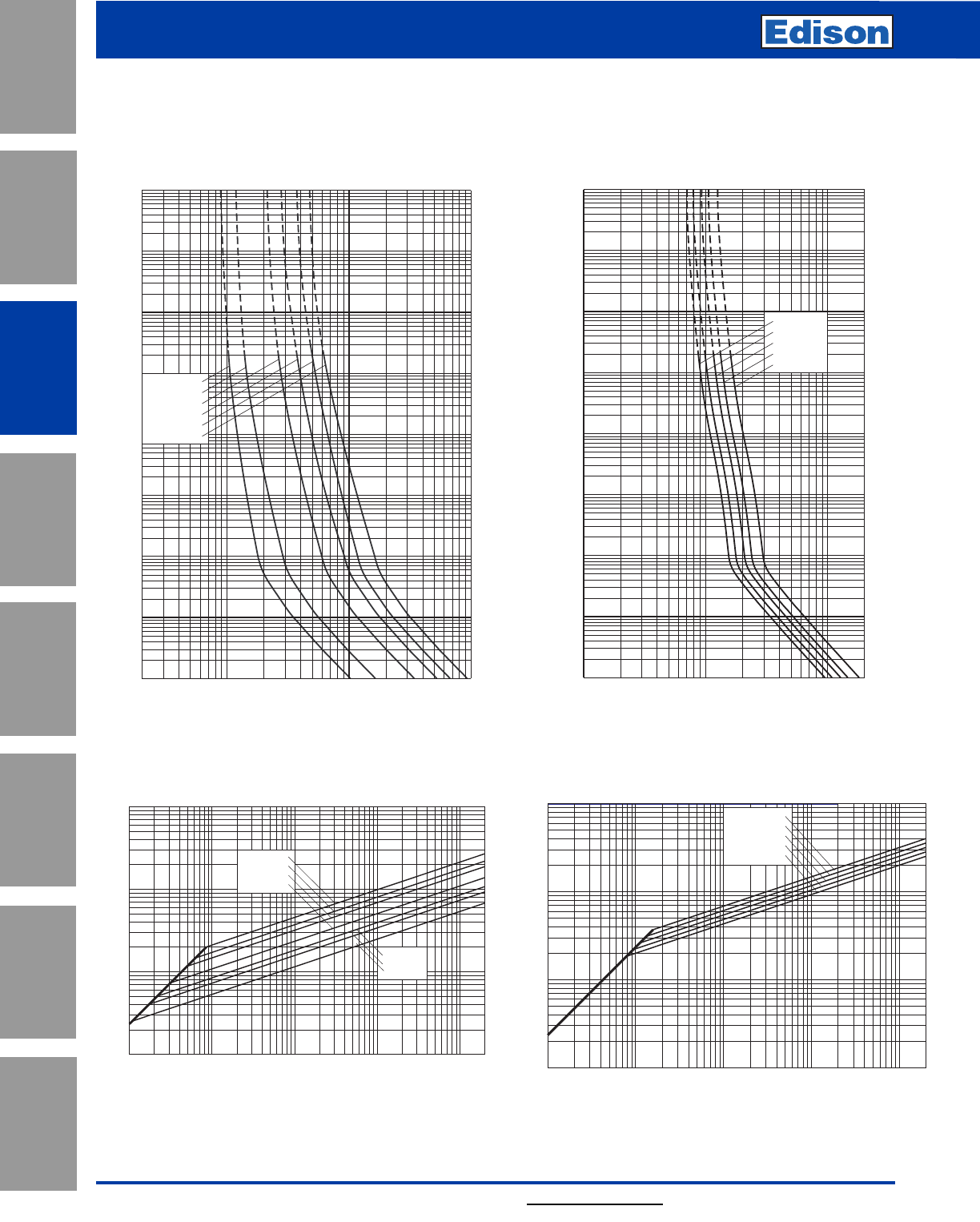
62 For additional information, visit www.edisonfuse.com
150V High Speed Fuses
Application
Section
Fuse Blocks,
Holders & Misc.
Surge Protective
Devices
Medium
Voltage Fuses
Canadian
Fuses & Holders
Special
Purpose Fuses
UL/CSA Fuses
General Purpose
UL/CSA Fuses
Current Limiting
Catalog Number FWA 5 – 60A
10–4
2 4 6 8 101 2 2 4 6 8 2
102 2 4 6 8 103
2
4
6
2
6
4
100
2
6
4
101
2
6
4
2
6
4
2
6
4
6
4
2
6
2
4
10–1
10–2
10–3
102
103
104
FWA-10A10F
FWA-30A10F
FWA-25A10F
FWA-20A10F
FWA-15A10F
FWA-5A10F
Virtual Pre-Arcing Time In Seconds
Prospective Current In Amps RMS
10122468 2
1022468
103
2
4
6
2
6
4
100
2
6
4
101
2
6
4
2
6
4
2
6
4
6
4
2
6
2
4
10–1
10–2
10–3
10–4
102
103
104
FWA-45A21F
FWA-50A21F
FWA-60A21F
FWA-35A21F
FWA-40A21F
Virtual Pre-Arcing Time In Seconds
Prospective Current In Amps RMS
Prospective Short-Circuit Current Symmetrical RMS
Peak Let-Through Current
2
4
2
6
6
4
2
6
4
246 246 246 246
101
102
103
104
101102103104105
FWA-20A10F
FWA-25A10F
FWA-30A10F
FWA-15A10F
FWA-12A10F
FWA-5A10F
FWA-10A10F
2
Prospective Short-Circuit Current Symmetrical RMS
Peak Let-Through Current
2
4
2
6
6
4
2
6
4
246 246 246 246
101
102
103
104
101102103104105
FWA-35A21F
FWA-40A21F
FWA-45A21F
FWA-50A21F
FWA-60A21F
2
Peak Let-Through CurvePeak Let-Through Curve
FWA 35-60A: 150V (21 x 51mm)
Time-Current Curve
FWA 5-30A: 150V (10 x 38mm)
Time-Current Curve
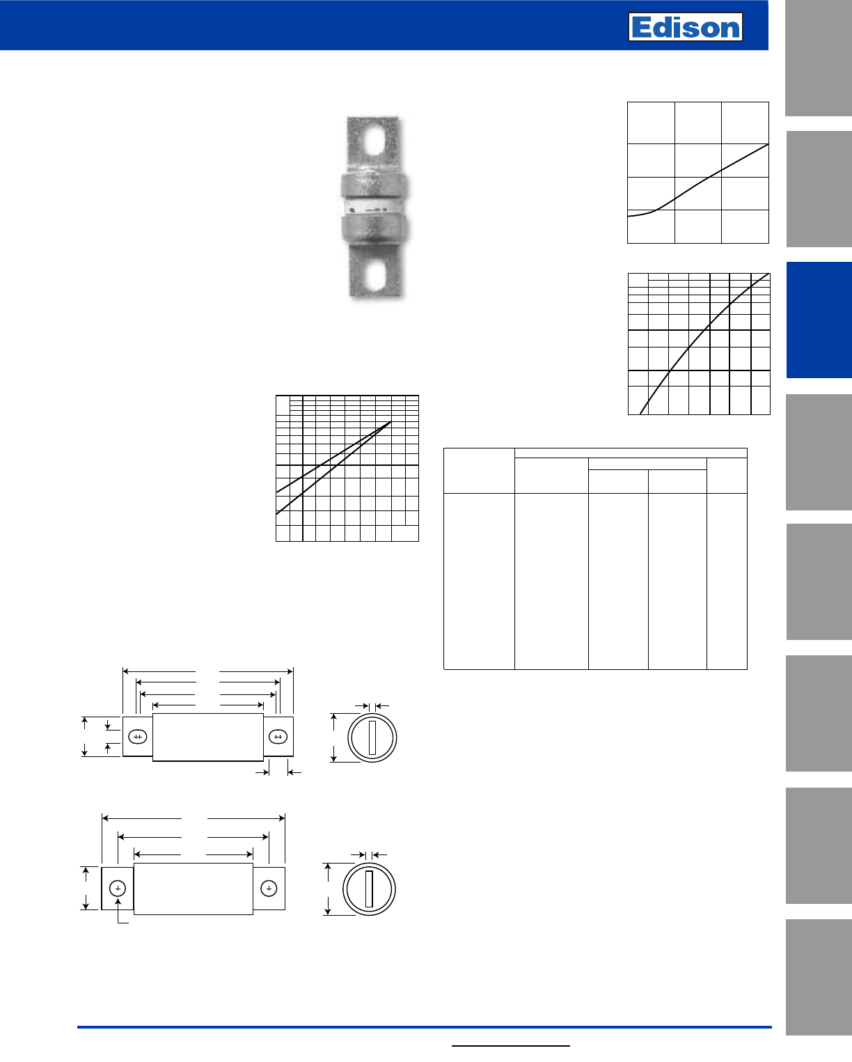
63
For additional information, visit www.edisonfuse.com
150V High Speed Fuses
UL/CSA Fuses
Current Limiting
UL/CSA Fuses
General Purpose
Special
Purpose Fuses
Canadian
Fuses & Holders
Medium
Voltage Fuses
Fuse Blocks,
Holders & Misc.
Application
Section
Surge Protective
Devices
Catalog Number FWA 70 – 1000A
2.656
1.936
2.188
1.156
0.312
0.438
0.750 1.000
0.125
Dimensions - in
Fig. 1: 70-400A
1.500
0.250
3.500
2.438
1.250
1.000
0.406
Fig. 2: 500-1000A
1mm = 0.0394” / 1” = 25.4mm
FWA
Specifications
Description: North American style
stud-mount fuses.
Dimensions: See Dimensions
illustrations.
Ratings:
Volts:— 150Vac/dc*
Amps:— 70-1000A
IR:— 100kA Sym. (70-400A)
— 200kA Sym. (450-1000A)
— 20kA @150Vdc (70-800A)
— 100kA @ 80Vdc (70-1000A)
*1000A rated @ 80Vdc.
Agency Information: CE, UL Recognized JFHR2.E91958
Electrical Characteristics
Total Clearing I2t
The total clearing I2t at rated
voltage and at power factor
of 15% are given in the
electrical characteristics. For
other voltages, the clearing
I2t is found by multiplying by
correction factor, K, given as
a function of applied working
voltage, Eg, (rms).
Arc Voltage
This curve gives the peak
arc voltage, UL, which may
appear across the fuse
during its operation as a
function of the applied
working voltage, Eg, (rms)
at a power factor of 15%.
Power Losses
Watts loss at rated current
is given in the electrical
characteristics. The curve
allows the calculation of the
power losses at load cur-
rents lower than the rated
current. The
correction factor, Kp, is
given as a function of the
RMS load current, Ib, in %
of the rated current.
Catalog Numbers Electrical Characteristics
Rated I2t (A2Sec)
Catalog Current Clearing Watts
Number RMS-Amps Pre-arc at 150V Loss
FWA-70B 70 470 4000 6.9
FWA-80B 80 670 6000 7.7
FWA-100B 100 1200 12000 9.0
FWA-125B 125 1870 18000 11.2
FWA-150B 150 2700 26000 13.5
FWA-200B 200 4780 45000 17.6
FWA-250B 250 7470 70000 22.5
FWA-300B 300 10760 100000 27.0
FWA-350B 350 15700 140000 30.6
FWA-400B 400 20300 180000 35.2
FWA-500A 500 39000 120000 35.0
FWA-600A 600 46000 140000 47.0
FWA-700A 700 75000 220000 49.0
FWA-800A 800 92000 280000 58.0
FWA-1000A 1000 170000 510000 60.0
• Watts loss provided at rated current.
Features and Benefits
• Excellent DC performance
• Low arc voltage and low energy let-through (I2t)
• Low watts loss
• Superior cycling capability
Typical Applications
• DC Common bus
• DC Drives
• Power converters/rectifiers
• Reduced voltage starters
1501027022
1.5
1.0
0.5
0.3
0.2
0.15 Eg
K
1)
2)
Kp
1.0
0.8
0.4
0.5
0.6
0.3
0.2
0.1
30 40 50 60 70 80 90 100%
Ib
UL
Eg
200
100
100 15050
300
1) 500-1000A Range
2) 70-400A Range
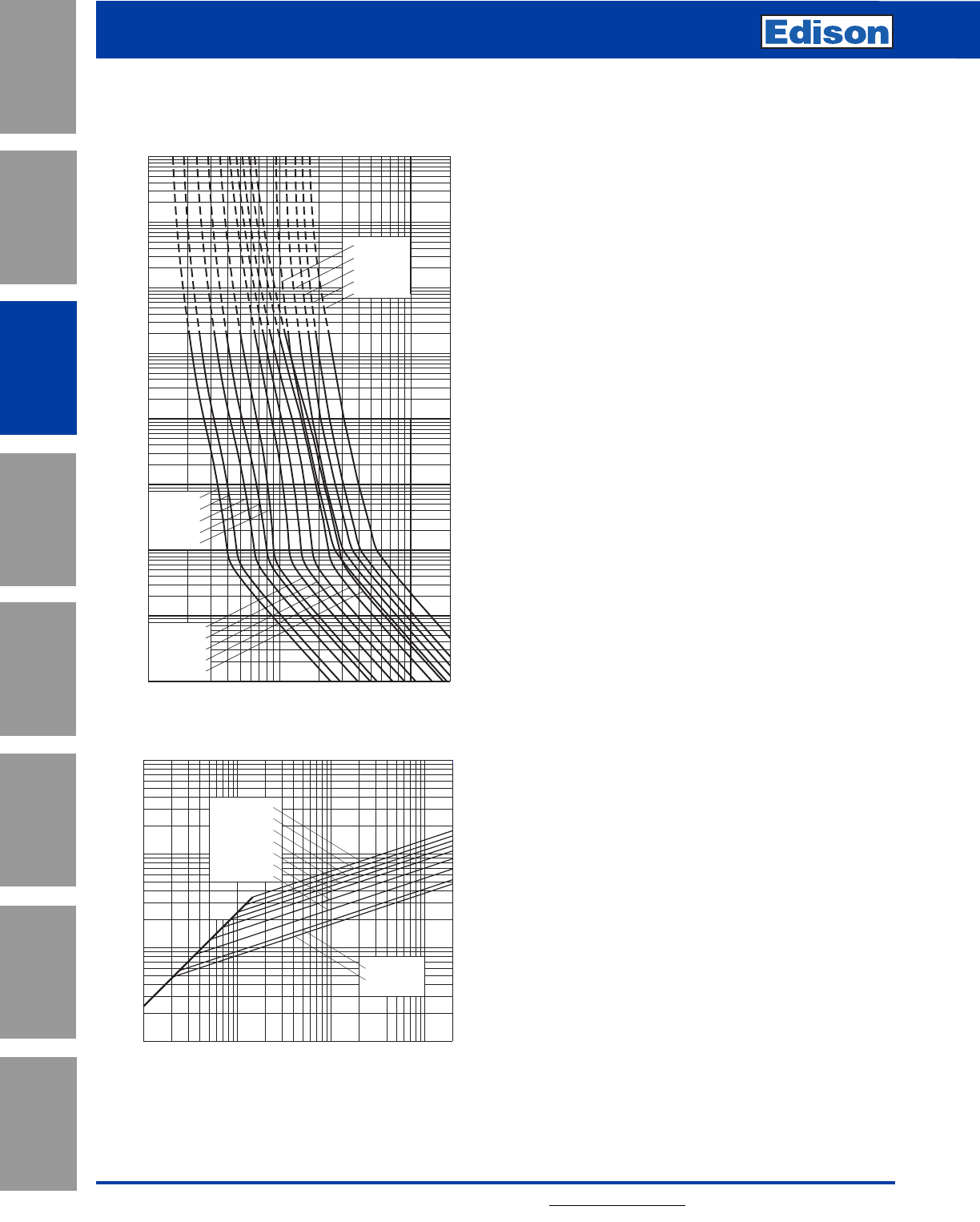
150V High Speed Fuses
For additional information, visit www.edisonfuse.com
Application
Section
Fuse Blocks,
Holders & Misc.
Surge Protective
Devices
Medium
Voltage Fuses
Canadian
Fuses & Holders
Special
Purpose Fuses
UL/CSA Fuses
General Purpose
UL/CSA Fuses
Current Limiting
64
Prospective Current In Amps RMS
Virtual Pre-Arcing Time In Seconds
1022468
1032468
104
2
4
6
2
6
4
100
2
6
4
101
2
6
4
2
6
4
2
6
4
6
4
2
6
2
4
10–1
10–2
10–3
10–4
102
103
104
FWA-1000A
FWA-800A
FWA-700A
FWA-600A
FWA-500A
FWA-200A
FWA-400A
FWA-350A
FWA-300A
FWA-250A
FWA-150A
FWA-70A
FWA-80A
FWA-100A
FWA-125A
Catalog Number FWA 70 – 1000A
Time-Current Curve
Prospective Short-Circuit Current Symmetrical RMS
Peak Let-Through Current
2
6
4
2
6
4
2
6
4
246 246 246
102
103
104
106
102103104105
2
FWA-400A
FWA-350A
FWA-300A
FWA-250A
FWA-200A
FWA-150A
FWA-100A
FWA-80A
FWA-70A
Peak Let-Through Curve
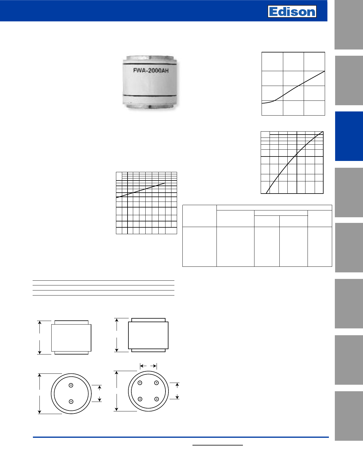
65
For additional information, visit www.edisonfuse.com
130V High Speed Fuses
UL/CSA Fuses
Current Limiting
UL/CSA Fuses
General Purpose
Special
Purpose Fuses
Canadian
Fuses & Holders
Medium
Voltage Fuses
Fuse Blocks,
Holders & Misc.
Application
Section
Surge Protective
Devices
Catalog Number FWA 1000 – 4000A
Dimensions - in
Catalog Number Fig. BCDThread Depth
FWA-1000AH-2000AH 1 2.0 1.0 — Tapped 3⁄8”-24 x 1⁄2”
FWA-2500AH-3000AH 1 3.0 1.5 — Tapped 1⁄2”-20 x 1⁄2”
FWA-4000AH 2 3.5 1.5 1.5 Tapped 1⁄2”-20 x 1⁄2”
1mm = 0.0394˝ / 1˝ = 25.4mm
Fig. 1: 1000-3000A Fig. 2: 4000A
1.875
BC
1.875
C
B
D
Arc Voltage
This curve gives the peak
arc voltage, UL, which
may appear across the
fuse during its operation
as a function of the
applied working voltage,
Eg, (rms) at a power
factor of 15%.
Power Losses
Watts loss at rated current
is given in the electrical
characteristics. The curve
allows the calculation of
the power losses at load
currents lower than the
rated current. The
correction factor, Kp, is
given as a function of the
RMS load current, Ib, in %
of the rated current.
Catalog Numbers Electrical Characteristics
I2t (A2Sec)
Catalog Rated Current Clearing Watts
Numbers RMS-Amps Pre-arc at 130V Loss
FWA-1000AH 1000 170000 460000 60
FWA-1200AH 1200 270000 730000 70
FWA-1500AH 1500 520000 1400000 78
FWA-2000AH 2000 860000 2400000 108
FWA-2500AH 2500 1500000 4100000 130
FWA-3000AH 3000 2100000 5700000 150
FWA-4000AH 4000 3400000 9200000 257
• Watts loss provided at rated current.
Features and Benefits
• Excellent DC performance
• Low arc voltage and low energy let-through (I2t)
• Low watts loss
• Superior cycling capability
Typical Applications
• DC Common bus
• DC Drives
• Power converters/rectifiers
• Reduced voltage starters
FWA
Specifications
Description: North American
style flush-end high speed fuses.
Dimensions: See Dimensions
illustrations.
Ratings:
Volts: — 130Vac
Amps: — 1000-4000A
IR: — 200kA RMS Sym.
— 50kA @130Vdc
Agency Information: CE, UL Recognized JFHR2.E91958
on 1000-2000A fuses
Electrical Characteristics
Total Clearing I2t
The total clearing I2t at
rated voltage and at power
factor of 15% are given in
the electrical
characteristics. For other
voltages, the clearing I2t is
found by multiplying by
correction factor, K, given
as a function of applied
working voltage, Eg, (rms).
1301046526
1.5
1.0
0.5
0.3
0.2
0.15 Eg
K
UL
Eg
200
100
100 15050
300
Kp
1.0
0.8
0.4
0.5
0.6
0.3
0.2
0.1
30 40 50 60 70 80 90 100%
Ib
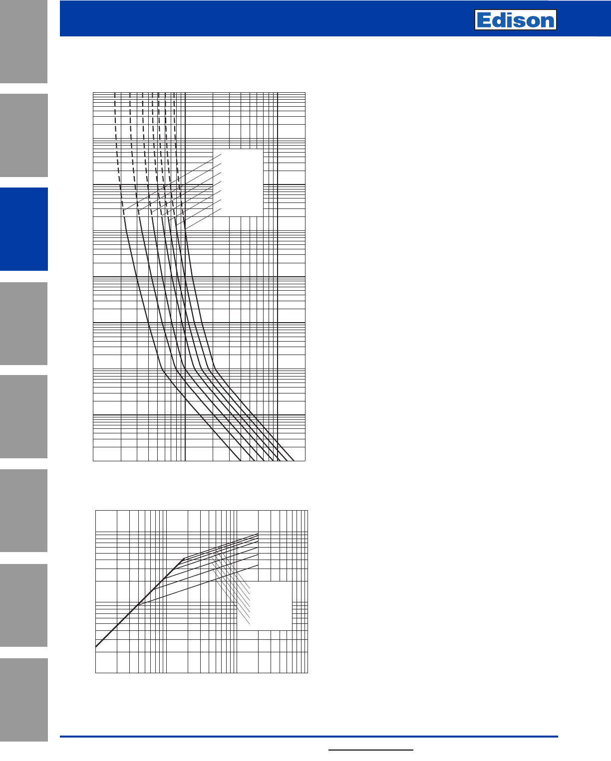
66
130V High Speed Fuses
For additional information, visit www.edisonfuse.com
Application
Section
Fuse Blocks,
Holders & Misc.
Surge Protective
Devices
Medium
Voltage Fuses
Canadian
Fuses & Holders
Special
Purpose Fuses
UL/CSA Fuses
General Purpose
UL/CSA Fuses
Current Limiting
Catalog Number FWA 1000 – 4000A
Time-Current Curve
10322468 2
1042468
105
Prospective Current In Amps RMS
2
4
6
2
6
4
100
2
6
4
101
2
6
4
2
6
4
2
6
4
Virtual Pre-Arcing Time In Seconds
6
4
2
6
2
4
10–1
10–2
10–3
10–4
102
103
104
FWA-4000AH
FWA-3000AH
FWA-2500AH
FWA-2000AH
FWA-1500AH
FWA-1200AH
FWA-1000AH
FWA-4000AH
FWA-3000AH
FWA-2500AH
FWA-2000AH
FWA-1500AH
FWA-1200AH
FWA-1000AH
Prospective Short-Circuit Current Symmetrical RMS
Peak Let-Through Current
2
6
4
2
6
4
2
246 246 246
104105
103
104
105
103
Peak Let-Through Curve
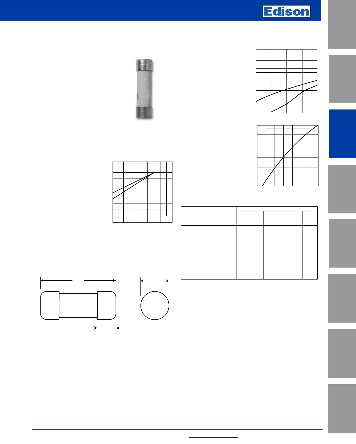
67
For additional information, visit www.edisonfuse.com
250V High Speed Fuses
UL/CSA Fuses
Current Limiting
UL/CSA Fuses
General Purpose
Special
Purpose Fuses
Canadian
Fuses & Holders
Medium
Voltage Fuses
Fuse Blocks,
Holders & Misc.
Application
Section
Surge Protective
Devices
Catalog Number FWX 1 – 50A
FWX (14 x 51mm)
Specifications
Description: Ferrule style high
speed fuses.
Dimensions: See dimensions
illustration.
Ratings:
Volts: — 250Vac/dc
Amps: — 1-50A
IR: — 200kA RMS Sym.
— 50kA @ 250Vdc
Agency Information: CE, UL Recognition JFHR2.E91958
1-50A & CSA Component Acceptance file Class 1422-30,
1422-90 (53787) 5-30A
Electrical
Characteristics
Total Clearing I2t
The total clearing I2t at
rated voltage and at power
factor of 15% are given in
the electrical
characteristics. For other
voltages, the clearing I2t is
found by multiplying by
correction factor, K, given
as a function of applied
working voltage, Eg, (rms).
Dimensions - mm (in)
50.8
(2.000")
15.5
(0.610")
14.3
(0.563")
Arc Voltage
This curve gives the
peak arc voltage, UL,
which may appear
across the fuse during
its operation as a
function of the applied
working voltage, Eg,
(rms) at a power factor
of 15%.
Power Losses
Watts loss at rated current
is given in the electrical
characteristics. The curve
allows the calculation of
the power losses at load
currents lower than the
rated current. The
correction factor, Kp, is
given as a function of the
RMS load current, Ib, in %
of the rated current.
Catalog Numbers
Electrical Characteristics
Rated I2t (A2Sec)
Catalog Current Clearing Watts
Number Size RMS-Amps Pre-arc at 250V Loss
FWX-1A14F 1———
FWX-2A14F 2———
FWX-3A14F 3———
FWX-4A14F 4———
FWX-5A14F 14 x 51mm 5 1.6 13 1.3
FWX-10A14F (9⁄16” x 2”) 10 3.6 24 3.4
FWX-15A14F 15 14 83 3.8
FWX-20A14F 20 33 200 4.6
FWX-25A14F 25 58 300 5.3
FWX-30A14F 30 100 500 5.9
FWX-50A14F 50 200 1800 5.7
• Watts loss provided at rated current.
• (250Vdc/Interrupting rating 50kA) UL Recognition & CSA Component Acceptance on
5 through 30A only. Consult Edison for additional ratings.
Features and Benefits
• Excellent cycling capability and DC performance
• Low arc voltage and low energy let-through (I2t)
• Low watts loss in a compact size
• Used with finger-safe holders/blocks
Typical Applications
• DC Common bus
• DC Drives
• Power converters/rectifiers
• Reduced voltage starters
1.5
1.0
0.5
0.3
0.2
0.15
75 125 300200 250
Eg
K
1)
2)
UL
1.4
1.2
103
800
600
500
400
300
200
50100150200250
Eg
1)
2)
Kp
1.0
0.8
0.4
0.5
0.6
0.3
0.2
0.1
30 40 50 60 70 80 90 100%
Ib
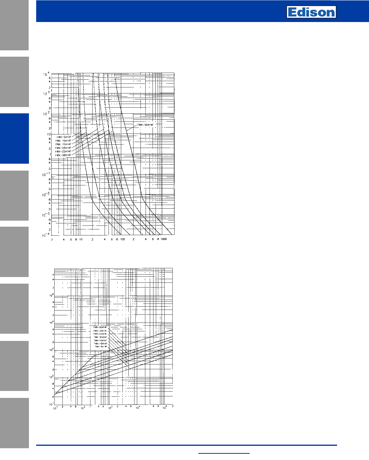
68
250V High Speed Fuses
For additional information, visit www.edisonfuse.com
Application
Section
Fuse Blocks,
Holders & Misc.
Surge Protective
Devices
Medium
Voltage Fuses
Canadian
Fuses & Holders
Special
Purpose Fuses
UL/CSA Fuses
General Purpose
UL/CSA Fuses
Current Limiting
Catalog Number FWX 1 – 50A
Prospective Current In Amps RMS
Prospective Current In Amps RMS
Peak Let-Through Curve
FWX 1-30A: 250V (14 x 51mm)
Time-Current Curve
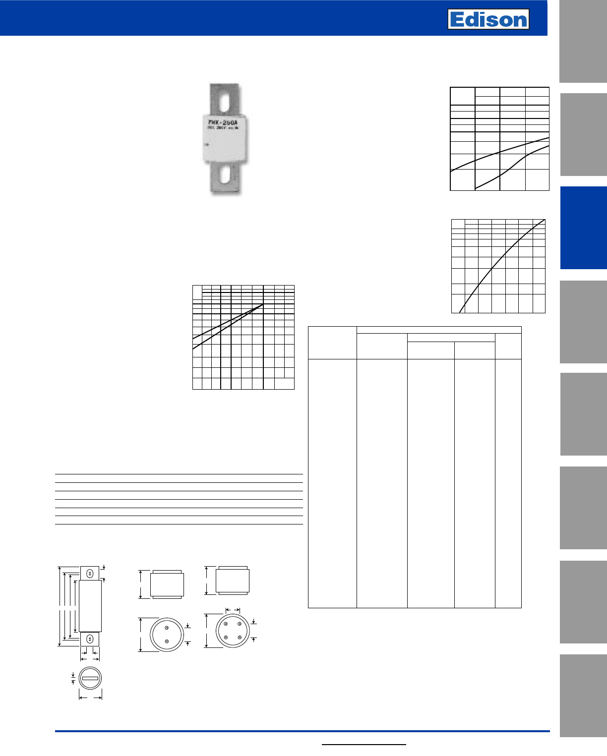
69
For additional information, visit www.edisonfuse.com
250V High Speed Fuses
UL/CSA Fuses
Current Limiting
UL/CSA Fuses
General Purpose
Special
Purpose Fuses
Canadian
Fuses & Holders
Medium
Voltage Fuses
Fuse Blocks,
Holders & Misc.
Application
Section
Surge Protective
Devices
Catalog Number FWX 35 – 2500A
FWX
Specifications
Description: North American
style stud-mount and flush-end
fuses.
Dimensions: See Dimensions
illustrations.
Ratings:
Volts:— 250Vac/dc
Amps:— 35-2500A
IR:— 200kA RMS Sym.
50kA@250Vdc (35-800A)
Agency Information: CE, UL Recognized JFHR2.E56412
& CSA Component Acceptance file Class 1422-30, (53787)
on 35-800A fuses (50kA IR @250Vdc).
Electrical
Characteristics
Total Clearing I2t
The total clearing I2t at rated
voltage and at power factor
of 15% are given in the
electrical characteristics.
For other voltages, the
clearing I2t is found by
multiplying by correction
factor, K, given as a
function of applied working
voltage, Eg, (rms).
Arc Voltage
This curve gives the peak
arc voltage, UL, which may
appear across the fuse
during its operation as a
function of the applied
working voltage, Eg, (rms)
at a power factor of 15%.
Power Losses
Watts loss at rated current is
given in the electrical char
acteristics. The curve allows
the calculation of the power
losses at load currents lower
than the rated current. The
correction factor, Kp, is
given as a function of the
RMS load current, Ib, in %
of the rated current.
Catalog Numbers Electrical Characteristics
Rated I2t (A2Sec)
Catalog Current Clearing Watts
Number RMS-Amps Pre-arc at 250V Loss
FWX-35A 35 50 230 4.2
FWX-40A 40 60 310 5.2
FWX-45A 45 80 390 5.7
FWX-50A 50 100 520 6.0
FWX-60A 60 140 740 8.1
FWX-70A 70 330 1400 7.2
FWX-80A 80 430 1850 8.1
FWX-90A 90 570 2450 9.0
FWX-100A 100 740 3150 10.0
FWX-125A 125 1130 4850 12.5
FWX-150A 150 1620 6950 15.7
FWX-175A 175 2170 9300 18.5
FWX-200A 200 2790 12000 22
FWX-225A 225 3210 14700 24
FWX-250A 250 3960 18100 27
FWX-275A 275 4720 21600 31
FWX-300A 300 6000 27300 32
FWX-350A 350 10600 48600 39
FWX-400A 400 14500 66100 44
FWX-450A 450 22100 101000 49
FWX-500A 500 28000 128000 54
FWX-600A 600 41100 188000 62
FWX-700A 700 48800 190000 72
FWX-800A 800 59000 230000 84
FWX-1000AH 1000 44000 360000 100
FWX-1200AH 1200 92000 750000 103
FWX-1500AH 1500 120000 880000 140
FWX-1600AH 1600 160000 1200000 140
FWX-2000AH 2000 320000 2300000 151
FWX-2500AH 2500 670000 4700000 163
• Watts loss provided at rated current.
Features and Benefits
• Excellent DC performance
• Low arc voltage and low
energy let-through (I2t)
• Superior cycling capability
Kp
1.0
0.8
0.4
0.5
0.6
0.3
0.2
0.1
30 40 50 60 70 80 90 100%
Ib
1.5
1.0
0.5
0.3
0.2
0.15
75 125 300200 250
Eg
K
1)
2)
UL
1.4
1.2
103
800
600
500
400
300
200
50100150200250
Eg
1)
2)
1) 35-800A Range
2) 1000-2500A Range
1) 35-800A Range
2) 1000-2500A Range
AEDC
F
J
G
B
H
A
BC
A
BC
D
Fig. 1:
35-800A
Fig. 2:
1000-1200A
Fig. 3:
1500-2500A
Dimensions - in Tapped
Amp Thread
Range Fig. ABC DE FGH JDepth
35-60 1 3.19 0.81 1.59 2.59 2.25 0.34 0.63 0.13 0.52 —
70-200 1 3.13 1.22 1.59 2.44 2.19 0.34 1.00 0.19 0.47 —
225-600 1 3.84 1.50 1.59 2.94 2.25 0.41 1.00 0.25 0.75 —
700-800 1 3.84 2.00 1.59 3.03 2.28 0.41 1.50 0.25 0.78 —
1000-1200 2 2.59 3.00 1.50 —— ————
3⁄8”-24 x 1⁄2”
1500-2500 3 2.59 3.50 1.50 1.50 —————
3⁄8”--24 x 1⁄2”
1mm = 0.0394” / 1” = 25.4mm
Typical Applications
• DC Common bus
• DC Drives
• Power converters/rectifiers
• Reduced voltage starters
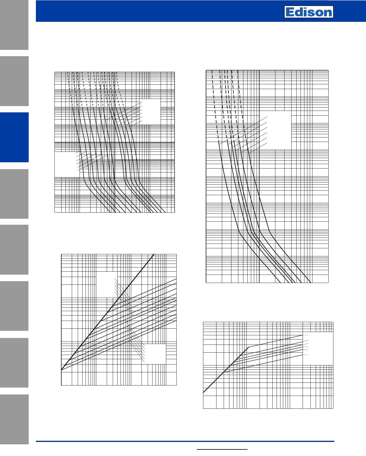
70
250V High Speed Fuses
For additional information, visit www.edisonfuse.com
Application
Section
Fuse Blocks,
Holders & Misc.
Surge Protective
Devices
Medium
Voltage Fuses
Canadian
Fuses & Holders
Special
Purpose Fuses
UL/CSA Fuses
General Purpose
UL/CSA Fuses
Current Limiting
Catalog Number FWX 35 – 2500A
104
103
102
102103104
101
100
10–1
10–2
10–3
10–4
2
Prospective Current In Amps RMS
Virtual Pre-arcing Time In Seconds
FWX-800A
FWX-600A
FWX-500A
FXW-400A
FWX-350A
FWX-200A
FWX-150A
FWX-70A
FWX-60A
FWX-40A
FWX-35A
FWX-100A
10322468 2
1042468
105
2
4
6
2
6
4
100
2
6
4
2
6
4
2
6
4
2
6
4
6
4
2
6
2
4
10–1
10–2
10–3
10–4
102
101
103
104
FWX-2500AH
FWX-2000AH
FWX-1600AH
FWX-1500AH
FWX-1200AH
FWX-1000AH
Prospective Current In Amps RMS
Virtual Pre-Arcing Time In Seconds
FWX 1000-2500A(H): 250V
Time-Current Curve
FWX 35-800A: 250V
Time-Current Curve
FWX-150A
FWX-100A
FWX-70A
FWX-60A
FWX-45A
FWX-35A
FWX-200A
FWX-300A
FWX-400A
FWX-600A
FWX-800A
102103104105
102
103
104
105
Prospective Short-Circuit Current Symmetrical RMS
Peak Let-Through Current
A
B
Prospective Short-Circuit Current Symmetrical RMS
Peak Let-Through Current
2
6
4
2
6
4
246 246 246
103
104
105
FWX-2000AH
FWX-1600AH
FWX-1500AH
FWX-1200AH
FWX-1000AH
103104105
FWX-2500AH
Peak Let-Through Curve
Peak Let-Through Curve
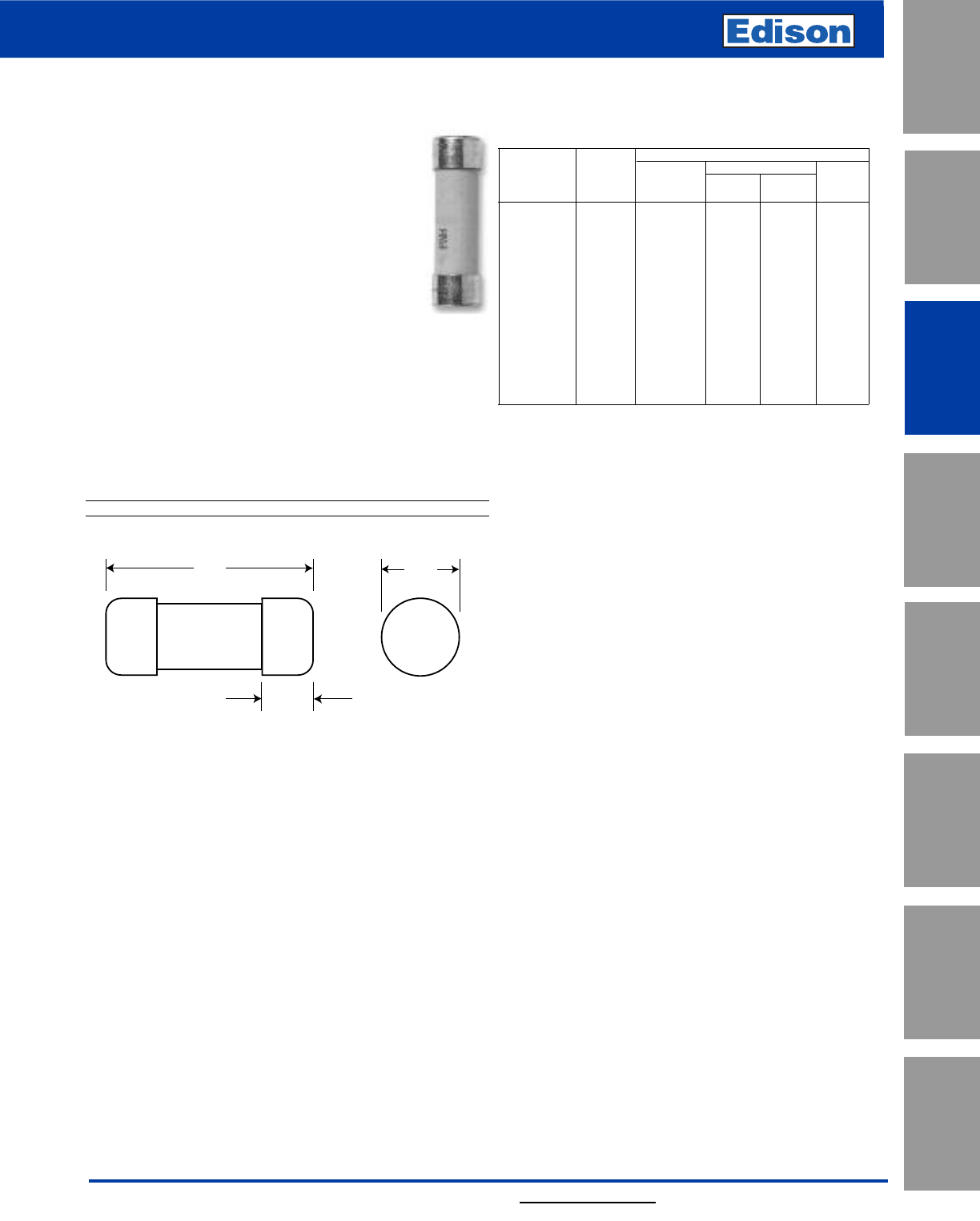
71
For additional information, visit www.edisonfuse.com
500V High Speed Fuses
UL/CSA Fuses
Current Limiting
UL/CSA Fuses
General Purpose
Special
Purpose Fuses
Canadian
Fuses & Holders
Medium
Voltage Fuses
Fuse Blocks,
Holders & Misc.
Application
Section
Surge Protective
Devices
Catalog Number FWH 0.25 – 30A
FWH (6 x 32mm)
Specifications
Description: Ferrule style high speed fuses.
Dimensions: See dimensions illustrations.
Ratings:
Volts: — 0.25-1A 500Vac
2-5A 500Vac/600Vdc
6.3-7A 500Vac
10-20A 600Vac
25-30A 500Vac
Amps: — 0.25-30A
IR: — 50kA at ≥ 20% pf (0.25-20A)
— 20kA at ≥ 20% pf (25-30A)
Agency Information: CE, UL Recognition JFHR2.E91958
0.25-30A, CSA Component Acceptance file Class 1422-30,
1422-90 (53787) 0.25-7A
Opening Times
Amp Ratings 150% 200% 300%
0.25-7 > 30 min < 30 min ≤ 10 sec
10-30 < 30 min < 30 min ≤ 10 sec
31.8
(1.25")
3.2
(0.125")
6.4
(0.25")
Dimensions - mm (inches)
Catalog Numbers
Electrical Characteristics
Rated I2t (A2Sec)
Catalog Current Clearing Watts
Numbers Size RMS-Amps Pre-arc at 500V Loss
FWH-.250A6F 0.25* 0.01 0.05 2.7
FWH-.500A6F 0.5* 0.05 0.25 1.2
FWH-001A6F 1* 0.4 2 1.7
FWH-002A6F 2* 1.3 3.5 3.2
FWH-3.15A6F 3.15* 3.1 7.7 2.9
FWH-005A6F 5* 15 40 2.1
FWH-6.30A6F 6 x 32mm 6.3* 36 90 2.3
FWH-007A6F (1⁄4” x 11⁄4”) 7* 50 125 2.5
FWH-010A6F 10** 9.9 139 2.86
FWH-12.5A6F 12.5** 20 60 3.53
FWH-015A6F 15** 44 146 3.08
FWH-016A6F 16** 48 177 4.48
FWH-020A6F 20** 75 259 4.26
FWH-025A6F 25** 126 345 —
FWH-030A6F 30** 145 430 —
*300% minimum opening current at rated voltage.
**200% minimum opening current at rated voltage.
• Consult Edison for DC ratings.
Features and Benefits
• Excellent cycling capability and DC performance
• Low arc voltage and low energy let-through (I2t)
• Low watts loss in a compact size
• Used with finger-safe holders/blocks
Typical Applications
• DC Common bus
• DC Drives
• Power converters/rectifiers
• Reduced voltage starters
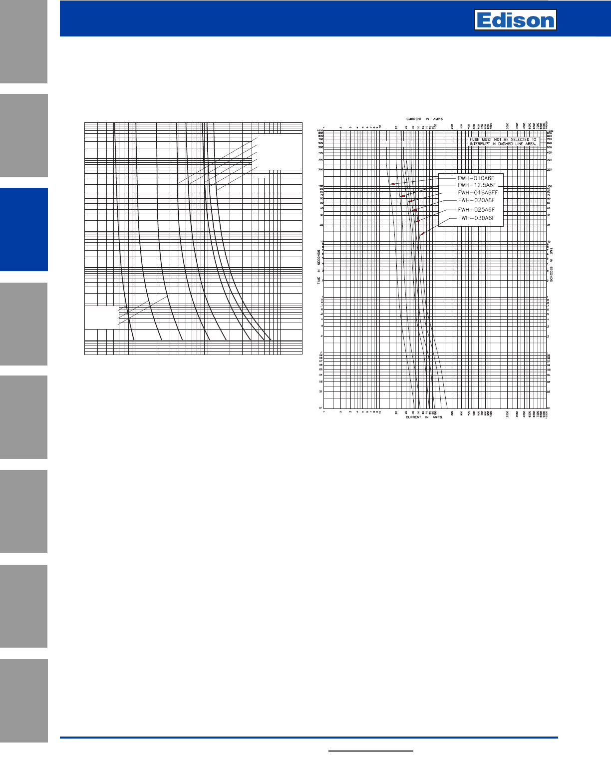
72
500V High Speed Fuses
For additional information, visit www.edisonfuse.com
Application
Section
Fuse Blocks,
Holders & Misc.
Surge Protective
Devices
Medium
Voltage Fuses
Canadian
Fuses & Holders
Special
Purpose Fuses
UL/CSA Fuses
General Purpose
UL/CSA Fuses
Current Limiting
Catalog Number FWH 0.25 – 30A
.2 .4 .6 .8 10022468 2
1012468 2
102
Prospective Current In Amps RMS
2
4
6
2
6
4
2
6
4
2
6
4
2
6
4
2
6
4
10–1
10–2
4x10⁻³
100
101
102
103
104
Virtual Pre-Arcing Time In Seconds
FWH-002A6F
FWH-3.15A6F
FWH-005A6F
FWH-6.30A6F
FWH-001A6F
FWH-.500A6F
FWH-.250A6F
FWH-007A6F
FWH 0.25-7A: 500V (6 x 32mm)
Time-Current Curve
FWH 10-30A: 500V (6 x 32mm)
Time-Current Curve
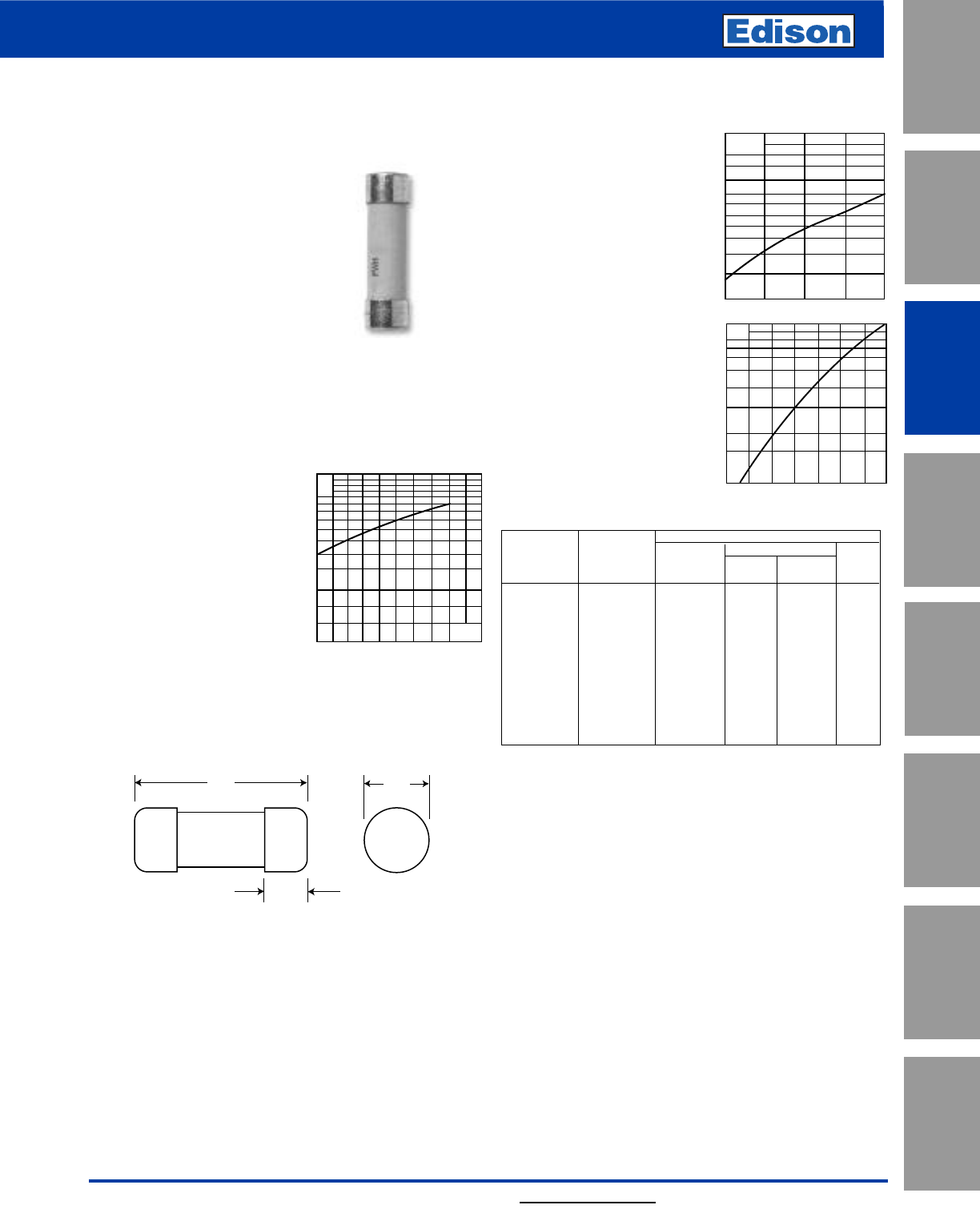
73
For additional information, visit www.edisonfuse.com
500V High Speed Fuses
UL/CSA Fuses
Current Limiting
UL/CSA Fuses
General Purpose
Special
Purpose Fuses
Canadian
Fuses & Holders
Medium
Voltage Fuses
Fuse Blocks,
Holders & Misc.
Application
Section
Surge Protective
Devices
Catalog Number FWH 1 – 30A
Dimensions - mm (inches)
50.8
(2.000")
15.5
(0.610")
14.3
(0.563")
FWH (14 x 51mm)
Specifications
Description: Ferrule style high
speed fuses.
Dimensions: See Dimensions
illustration.
Ratings:
Volts: — 500Vac
Amps: — 1-30A
IR: — 200kA RMS Sym.
— 50kA @500Vdc
Agency Information: CE, UL Recognition 1- 30A & CSA
Component Acceptance file Class 1422-30, (53787) on:
5 - 30A.
Electrical Characteristics
Total Clearing I2t
The total clearing I2t at rated
voltage and at power factor
of 15% are given in the
electrical characteristics. For
other voltages, the clearing I2t
is found by multiplying by
correction factor, K, given as
a function of applied working
voltage, Eg, (rms).
500400250100
1.5
1.0
0.5
0.3
0.2
0.15 Eg
K
Arc Voltage
This curve gives the peak
arc voltage, UL, which may
appear across the fuse
during its operation as a
function of the applied
working voltage, Eg, (rms)
at a power factor of 15%.
Power Losses
Watts loss at rated current is
given in the electrical char-
acteristics. The curve allows
the calculation of the power
losses at load
currents lower than the
rated current. The correction
factor, Kp, is given as a
function of the RMS load
current, Ib, in % of the rated
current.
Catalog Numbers
Electrical Characteristics
Rated I2t (A2Sec)
Catalog Current Clearing Watts
Numbers Size RMS-Amps Pre-arc at 500V Loss
FWH-1A14F 1———
FWH-2A14F 2———
FWH-3A14F 3——2.3
FWH-4A14F 4———
FWH-5A14F 5 1.6 6.4 1.5
FWH-6A14F 14 x 51mm 6 1.6 6.4 1.5
FWH-10A14F (9⁄16” x 2”) 10 3.6 13 4
FWH-12A14F 12 ———
FWH-15A14F 15 10 40 5.5
FWH-20A14F 20 26 96 6
FWH-25A14F 25 49 191 7
FWH-30A14F 30 58 232 9
• Watts loss provided at rated current.
Features and Benefits
• Excellent cycling capability and DC performance
• Low arc voltage and low energy let-through (I2t)
• Low watts loss in a compact size
• Used with finger-safe holders/blocks
Typical Applications
• DC common bus
• DC drives
• Power converters/rectifiers
• Reduced voltage starters
UL
2.0
1.6
1.2
103
800
600
500
400
300
100 400300200 500
Eg
Kp
1.0
0.8
0.4
0.5
0.6
0.3
0.2
0.1
30 40 50 60 70 80 90 100%
Ib
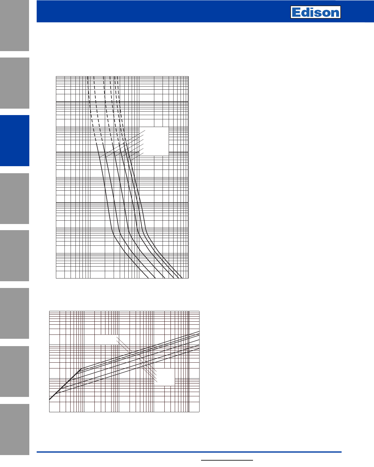
74
600V High Speed Fuses
For additional information, visit www.edisonfuse.com
Application
Section
Fuse Blocks,
Holders & Misc.
Surge Protective
Devices
Medium
Voltage Fuses
Canadian
Fuses & Holders
Special
Purpose Fuses
UL/CSA Fuses
General Purpose
UL/CSA Fuses
Current Limiting
Catalog Number FWH 1 – 30A
Peak Let-Through Curve
2468
10
1
22468 2
10
2
2468
10
3
2
4
6
2
6
4
2
6
4
2
6
4
2
6
4
2
6
4
6
4
2
6
2
4
FWH-5A14F
FWH-10A14F
FWH-15A14F
FWH-20A14F
FWH-25A14F
FWH-30A14F
Virtual Pre-Arcing Time In Seconds
Prospective Current In Amps RMS
10
3
10
0
10
1
10
4
10
2
10–4
10–3
10–2
10–1
FWH 1-30A: 500V (14 x 51mm)
Time-Current Curve
Prospective Short-Circuit Current Symmetrical RMS
Peak Let-Through Current
2
4
2
6
6
4
2
6
4
246 246 246 246
101
102
103
104
101102103104105
FWH-5A14F
FWH-10A14F
FWH-15A14F
FWH-20A14F
FWH-25A14F
FWH-30A14F
2
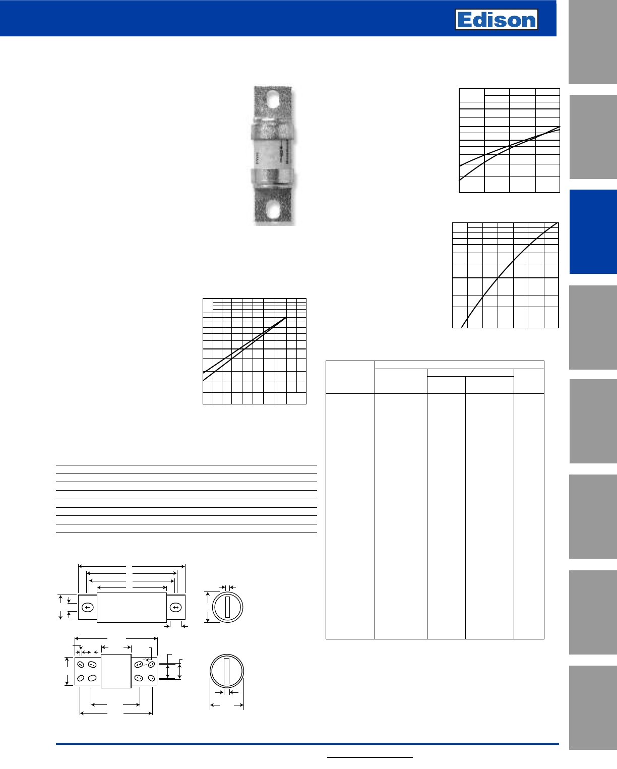
75
For additional information, visit www.edisonfuse.com
500V High Speed Fuses
UL/CSA Fuses
Current Limiting
UL/CSA Fuses
General Purpose
Special
Purpose Fuses
Canadian
Fuses & Holders
Medium
Voltage Fuses
Fuse Blocks,
Holders & Misc.
Application
Section
Surge Protective
Devices
Catalog Number FWH 35 – 1600A
FWH
Specifications
Description: North American style
stud-mount fuses.
Dimensions: See Dimensions
illustration.
Ratings:
Volts: — 500Vac/dc (35-800A only)
Amps: — 35-1600A
IR: — 200kA Sym.
— 50kA @ 500Vdc (35-800A)
Agency Information: CE, UL Recognition JFHR2.E91958
FWH-_B (35-200A, 1000-1200A), JFHR2.E56412
FWH-_A (225-600A), CSA Component Acceptance Class
1422-30, File 53787 (35-1600A).
Electrical Characteristics
Total Clearing I2t
The total clearing I2t at rated
voltage and at power factor of
15% are given in the electrical
characteristics. For other
voltages, the clearing I2t is
found by multiplying by
correction factor, K, given as a
function of applied working
voltage, Eg, (rms).
Arc Voltage
This curve gives the peak
arc voltage, UL, which
may appear across the
fuse during its operation
as a function of theapplied
working voltage, Eg, (rms)
at a power
factor of 15%.
Power Losses
Watts loss at rated
current is given in the
electrical characteristics.
The curve allows the
calculation of the power
losses at load currents
lower than the rated
current. The correction
factor, Kp, is given as a
function of the RMS load
current, Ib, in % of the
rated current.
Catalog Numbers Electrical Characteristics
Rated I2t (A2Sec)
Catalog Current Clearing Watts
Numbers RMS-Amps Pre-arc at 500V Loss
FWH-35B 35 34 150 8
FWH-40B 40 76 320 7.5
FWH-45B 45 105 450 7.5
FWH-50B 50 135 670 7.5
FWH-60B 60 210 900 9.9
FWH-70B 70 210 900 10.6
FWH-80B 80 305 1400 12.7
FWH-90B 90 360 1600 15
FWH-100B 100 475 2000 17
FWH-125B 125 800 3500 25
FWH-150B 150 1100 4600 30
FWH-175B 175 1450 6200 35
FWH-200B 200 1900 8500 40
FWH-225A 225 4600 23300 39
FWH-250A 250 6300 32200 41
FWH-275A 275 7900 40300 46
FWH-300A 300 9800 49800 51
FWH-325A 325 13700 63800 53
FWH-350A 350 14500 72900 58
FWH-400A 400 19200 96700 65
FWH-450A 450 24700 127000 74
FWH-500A 500 29200 149000 84
FWH-600A 600 41300 206000 108
FWH-700A 700 55000 298000 120
FWH-800A 800 76200 409000 129
FWH-1000A 1000 92000 450000 145
FWH-1200A 1200 122000 600000 180
FWH-1400A 1400 200000 1000000 210
FWH-1600A 1600 290000 1400000 230
• Watts loss provided at rated current.
Features and Benefits
• Excellent DC performance
• Low arc voltage and low
energy let-through (I2t)
• Superior cycling capability
500400250100
1.5
1.0
0.5
0.3
0.2
0.15 Eg
K
1)
2)
UL
2.0
1.6
1.2
103
800
600
500
400
300
100 400300200 500
Eg
2)
1)
1) 35-200 & 1000-1600A Range
2) 225-800A Range
A
E
D
C
F
J
GB
H
10.219
3.219 0.625
4.25
0.75
3.5
6.219
0.125 0.5
1.625
1.750
8.969
Fig. 1: 35-1200A
Fig. 2: 1400-1600A
Dimensions - in
Amp
Range Fig. AB C D E F G H J
35-60 1 3.188 0.813 1.593 2.541 2.193 0.344 0.719 0.125 0.518
70-100 1 3.625 0.947 1.736 2.853 2.807 0.352 0.750 0.125 0.375
125-200 1 3.625 1.156 1.836 2.892 2.768 0.344 1.000 0.188 0.406
225-400 1 4.340 1.500 2.090 3.440 2.750 0.410 1.000 0.250 0.750
450-600 1 4.340 2.000 2.090 3.530 2.780 0.410 1.500 0.250 0.780
700-800 1 6.340 2.500 2.090 4.970 3.440 0.530 2.000 0.380 1.300
1000-1200 1 6.969 3.000 3.219 5.465 4.475 0.625 2.375 0.438 1.120
1400-1600 2 See Drawing
1mm = 0.0394” / 1” = 25.4mm
Kp
1.0
0.8
0.4
0.5
0.6
0.3
0.2
0.1
30 40 50 60 70 80 90 100%
Ib
1) 35-800A Range
2) 1000-1600A Range
Typical Applications
• DC Common bus
• DC Drives
• Power converters/rectifiers
• Reduced voltage starters
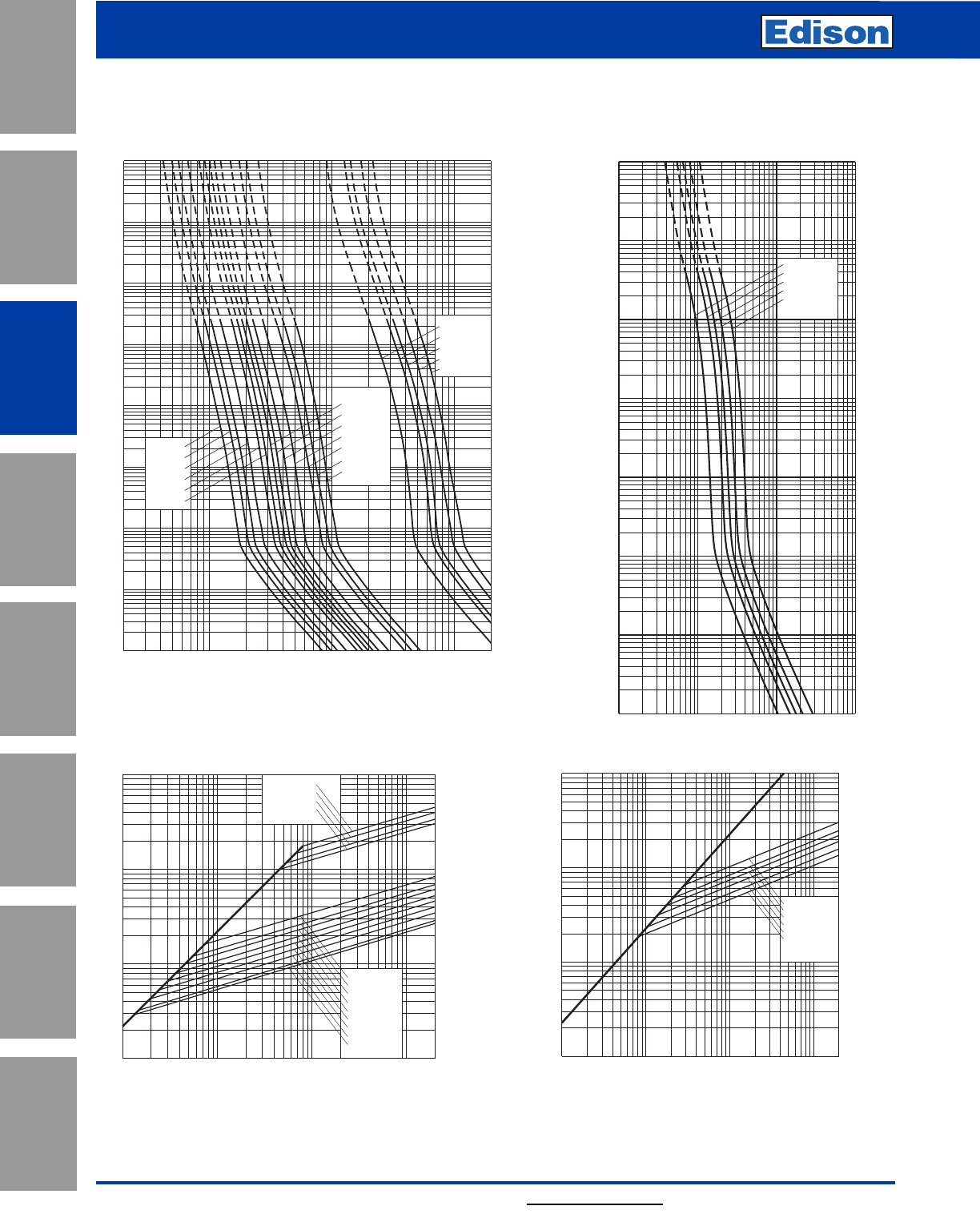
76
500V High Speed Fuses
For additional information, visit www.edisonfuse.com
Application
Section
Fuse Blocks,
Holders & Misc.
Surge Protective
Devices
Medium
Voltage Fuses
Canadian
Fuses & Holders
Special
Purpose Fuses
UL/CSA Fuses
General Purpose
UL/CSA Fuses
Current Limiting
2468
10222468 2
1032468
104
2
4
6
2
6
4
2
6
4
2
6
4
2
6
4
2
6
4
6
4
2
6
2
4
100
101
10–1
10–2
10–3
10–4
102
103
104
FWH-90B
FWH-80B
FWH-125B
FWH-100B
FWH-175B
FWH-200B
FWH-150B
FWH-60B
FWH-70B
FWH-50B
FWH-45B
FWH-40B
FWH-35B
FWH-1200A
FWH-1400A
FWH-900A
FWH-1000A
FWH-1600A
Prospective Current In Amps RMS
10–3
10–2
10–1
100
101
102
103
10–4
FWH-300A
FWH-400A
FWH-500A
FWH-600A
FWH-800A
Prospective Current In Amps RMS
Virtual Pre-Arcing Time In Seconds
102103104105
FWH 250-800A
Time-Current Curve
FWH 35-200A(B) & 900-1600A(A)
Time-Current Curve
FWH-200B
FWH-150B
FWH-125B
FWH-100B
FWH-80B
FWH-60B
FWH-50B
FWH-35B
FWH-40B
FWH-1000A
FWH-1200A
FWH-1400A
FWH-1600A
Prospective Short-Circuit Current Symmetrical RMS
Peak Let-Through Current
2
4
2
6
6
4
2
6
4
246 246 246 2
102
103
104
105
102103104105
FWH-800A
FWH-600A
FWH-500A
FWH-400A
FWH-300A
FWH-250A
102
105
104
103
103104105
102
Prospective Short-Circuit Current Symmetrical RMS
Peak Let-Through Current
A
B
Peak Let-Through Curve
Peak Let-Through Curve
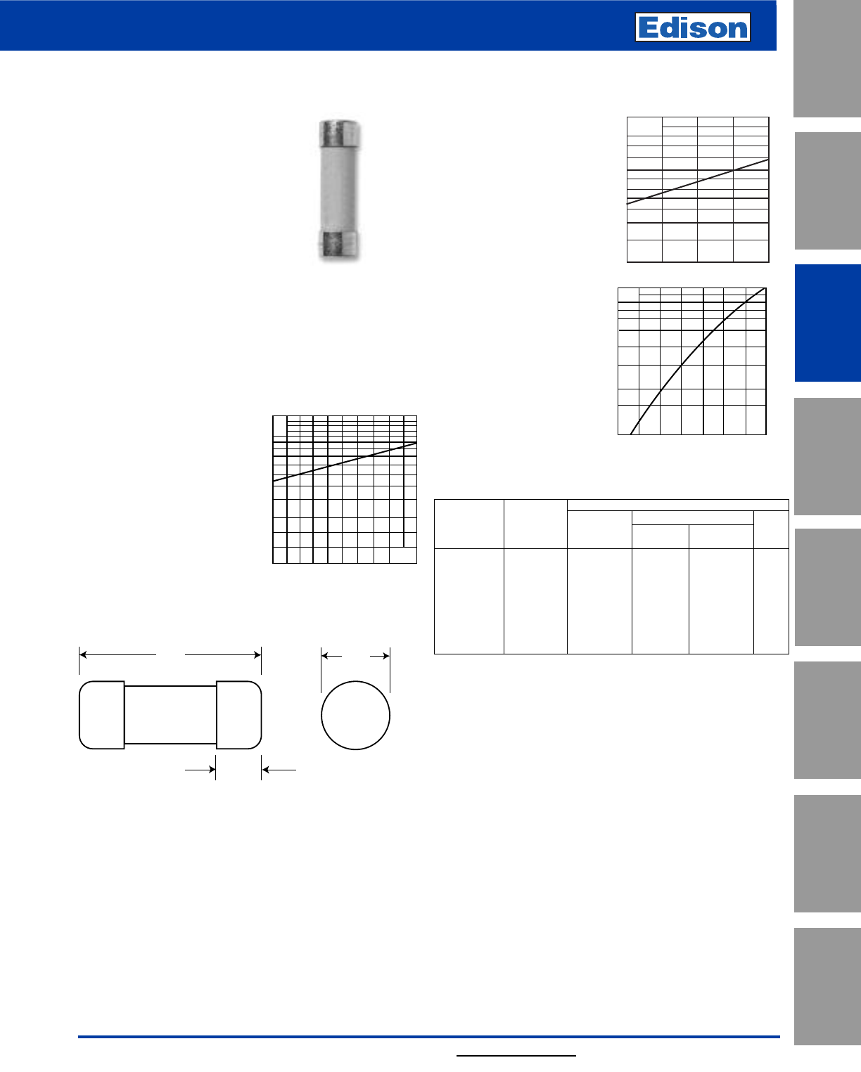
77
For additional information, visit www.edisonfuse.com
600V High Speed Fuses
UL/CSA Fuses
Current Limiting
UL/CSA Fuses
General Purpose
Special
Purpose Fuses
Canadian
Fuses & Holders
Medium
Voltage Fuses
Fuse Blocks,
Holders & Misc.
Application
Section
Surge Protective
Devices
Catalog Number FWC 6 – 32A
Dimensions - mm (in)
38.1
(1.500")
9.5
(0.375")
10.3
(0.406")
FWC (10 x 38mm)
Specifications
Description: Ferrule style high
speed fuses.
Dimensions: See dimensions
illustration.
Ratings:
Volts: — 600Vac/700Vdc (6-25A)
600Vac (30-32A)
Amps: — 6-32A
IR: — 200kA RMS Sym.
— 50kA @ 700Vdc (6-25A)
Agency Information: CE, UL Recognition JFHR8.E91958
6-32A. & CSA Component Acceptance file Class 1422-30,
(53787) on (6-32A)
Electrical Characteristics
Total Clearing I2t
The total clearing I2t at rated
voltage and at power factor
of 15% are given in the
electrical characteristics. For
other voltages, the clearing
I2t is found by multiplying by
correction factor, K, given as
a function of applied working
voltage, Eg, (rms).
Arc Voltage
This curve gives the peak
arc voltage, UL, which
may appear across the
fuse during its operation
as a function of theapplied
working voltage, Eg, (rms)
at a power
factor of 15%.
Power Losses
Watts loss at rated
current is given in the
electrical characteristics.
The curve allows the
calculation of the power
losses at load currents
lower than the rated
current. The correction
factor, Kp, is given as a
function of the RMS load
current, Ib, in % of the
rated current.
Catalog Numbers
Electrical Characteristics
Rated I2t (A2Sec)
Catalog Current Clearing Watts
Numbers Size RMS-Amps Pre-arc at 600V Loss
FWC-6A10F 6430 1.5
FWC-8A10F 8650 2.0
FWC-10A10F 10 9 70 2.5
FWC-12A10F 12 15 120 3.0
FWC-16A10F 16 25 150 3.5
FWC-20A10F 10 x 38mm 20 34 260 4.8
FWC-25A10F (13⁄32˝ x 11⁄2˝) 25 60 390 6.0
FWC-30A10F 30 95 600 7.5
FWC-32A10F 32 95 600 7.5
• Watts loss provided at rated current.
Features and Benefits
• Excellent cycling capability and DC performance
• Low arc voltage and low energy let-through (I2t)
• Low watts loss in a compact size
• Used with finger-safe holders/blocks
Typical Applications
• DC Common bus
• DC Drives
• Power converters/rectifiers
• Reduced voltage starters
500 600400250100
1.5
1.0
0.5
0.3
0.2
0.15 Eg
K
UL
2.0
1.6
1.2
103
800
600
500
400
300
400300200 500 600
Eg
Kp
1.0
0.8
0.4
0.5
0.6
0.3
0.2
0.1
30 40 50 60 7080 90 100%
Ib
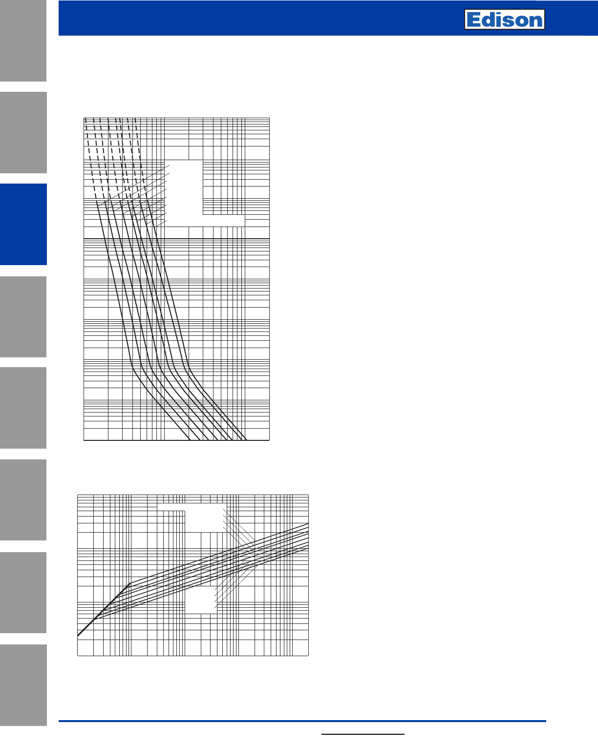
78
600V High Speed Fuses
For additional information, visit www.edisonfuse.com
Application
Section
Fuse Blocks,
Holders & Misc.
Surge Protective
Devices
Medium
Voltage Fuses
Canadian
Fuses & Holders
Special
Purpose Fuses
UL/CSA Fuses
General Purpose
UL/CSA Fuses
Current Limiting
Catalog Number FWC 6 – 32A
103
104
102
10–1
10–2
10–3
10–4
10122468 2
1022468
103
2
4
6
2
6
4
100
2
6
4
101
2
6
4
2
6
4
2
6
4
6
4
2
6
2
4
Prospective Current In Amps RMS
Virtual Pre-Arcing Time In Seconds
FWC-10A10F
FWC-30A10F & FWC-32A10F
FWC-20A10F
FWC-25A10F
FWC-12A10F
FWC-16A10F
FWC-8A10F
FWC-6A10F
Prospective Short-Circuit Current Symmetrical RMS
Peak Let-Through Current
2
4
2
6
6
4
2
6
4
246 246 246 24 6
101
102
103
104
101102103104105
FWC-6A10F
FWC-8A10F
FWC-10A10F
FWC-12A10F
FWC-16A10F
FWC-20A10F
FWC-25A10F
FWC-30A10F & FWC-32A10F
Peak Let-Through Curve
FWC 6-32A: 600V (10 x 38mm)
Time-Current Curve
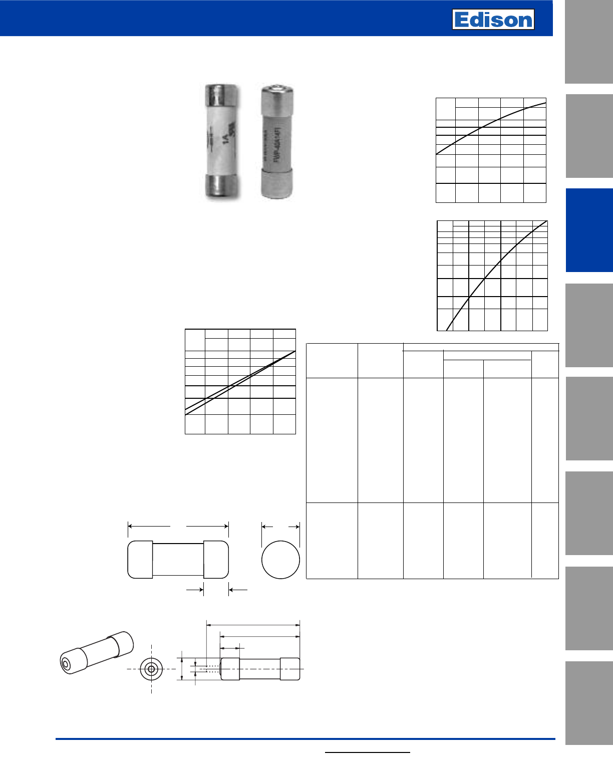
79
For additional information, visit www.edisonfuse.com
UL/CSA Fuses
Current Limiting
UL/CSA Fuses
General Purpose
Special
Purpose Fuses
Canadian
Fuses & Holders
Medium
Voltage Fuses
Fuse Blocks,
Holders & Misc.
Application
Section
Surge Protective
Devices
690V/700V High Speed Fuses
Catalog Number FWP 1 – 50A
Dimensions - mm (in)
51 (2.00")
59 (2.323")
13 (0.511")
14.3
(0.563")
5 (0.197")
FWP (14 x 51mm)
Specifications
Description: Ferrule style high
speed fuses with and without
indicating striker.
Dimensions: See dimensions
illustrations.
Ratings:
Volts: — 690Vac (IEC)
— 700Vac (UL)
— 800Vdc (5-50A)
Amps: — 1-50A
IR: — 200kA RMS Sym.
— 50kA @800Vdc
Agency Information: CE, UL Recognition JFHR2.E91958,
CSA Component Acceptance file Class 1422-30, 1422-90
(53787) for versions without indicator only. Designed and
tested to IEC 60269: Part 4.
Electrical
Characteristics
Total Clearing I2t
The total clearing I2t at
rated voltage and at power
factor of 15% are given in
the electrical
characteristics. For other
voltages, the clearing I2t is
found by multiplying by cor-
rection factor, K, given as a
function of applied working voltage,
Eg, (rms).
Arc Voltage
This curve gives the peak
arc voltage, UL, which may
appear across the fuse
during its operation as a
function of theapplied
working voltage, Eg, (rms)
at a power factor of 15%.
Power Losses
Watts loss at rated current
is given in the electrical
characteristics. The curve
allows the calculation of
the power losses at load
currents lower than the
rated current. The
correction factor, Kp, is
given as a function of the
RMS load current, Ib, in %
of the rated current.
Catalog Numbers
Rated I2t (A2Sec)
Catalog Current Minimum Clearing At Watts
Numbers Size RMS-Amps Melting Rated Voltage Loss
Without Striker
FWP-1A14F 1— — —
FWP-2A14F 2— ——
FWP-2.5A14F 2.5 ———
FWP-3A14F 3— ——
FWP-4A14F 4— ——
FWP-5A14F 14 x 51mm 5 1.6 11.0 1.5
FWP-10A14F (9⁄16" x 2") 10 3.6 38.5 4
FWP-15A14F 15 8.6 70 5.5
FWP-20A14F 20 26.0 230 6
FWP-25A14F 25 46.5 375 7
FWP-30A14F 30 58 485 9
FWP-32A14F 32 68 600 7.6
FWP-40A14F 40 84 750 8
FWP-50A14F 50 200 1800 9
With Striker*
FWP-10A14FI 10 3.6 38.5 4
FWP-15A14FI 15 8.6 70 5.5
FWP-20A14FI 14 x 51mm 20 26.0 230 6
FWP-25A14FI (9⁄16” x 2”) 25 46.5 375 7
FWP-30A14FI 30 58 485 9
FWP-32A14FI 32 68 600 7.6
FWP-40A14FI 40 84 750 8
FWP-50A14FI 50 200 1800 9
*Striker range is 600Vdc only
• Watts loss provided at rated current.
Features and Benefits
• Excellent cycling capability and DC performance
• Low arc voltage and low energy let-through (I2t)
• Low watts loss in a compact size
• Used with finger-safe holders/blocks
UL
1.4
1.2
103
6
8
7
9
5
4
3
200 300 400 500 600 700
Eg
Kp
1.0
0.8
0.4
0.5
0.6
0.3
0.2
0.1
30 40 50 60 70 80 90 100%
Ib
K
1.4
1.2
1.0
0.6
0.8
0.7
0.9
0.5
0.4
0.3
200 300 400 500 600 700
Eg
1)
2)
1) 5-30A Range
2) 32-50A Range
50.8
(2.000")
15.5
(0.610")
14.3
(0.563")
With Striker
Without Striker
FWP with
striker option.
Electrical Characteristics
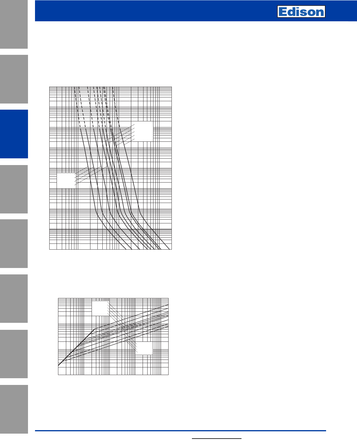
80 For additional information, visit www.edisonfuse.com
690V/700V High Speed Fuses
Application
Section
Fuse Blocks,
Holders & Misc.
Surge Protective
Devices
Medium
Voltage Fuses
Canadian
Fuses & Holders
Special
Purpose Fuses
UL/CSA Fuses
General Purpose
UL/CSA Fuses
Current Limiting
Catalog Number FWP 1 – 50A
103
102
10–1
10–2
10–3
10–4
FWP-10A14F
FWP-15A14F
FWP-20A14F
FWP-5A14F
FWP-50A14F
FWP-30A14F
FWP-32A14F
FWP-40A14F
FWP-25A14F
2468
10122468 2
1022468
103
2
4
6
2
6
4
100
2
6
4
101
2
6
4
2
6
4
2
6
4
6
4
2
6
2
4
Prospective Current In Amps RMS
Virtual Pre-Arcing Time In Seconds
104
Prospective Short-Circuit Current Symmetrical RMS
Peak Let-Through Current
2
4
2
6
6
4
2
6
4
246 246 246 246
101
102
103
104
101102103104105
FWP-5A14F
FWP-10A14F
FWP-15A14F
FWP-20A14F
FWP-25A14F
FWP-30A14F
FWP-32A14F
FWP-40A14F
FWP-50A14F
2
Peak Let-Through Curve
Without Striker
FWP 5-50A: 660V/700V (14 x 51mm)
Time-Current Curve
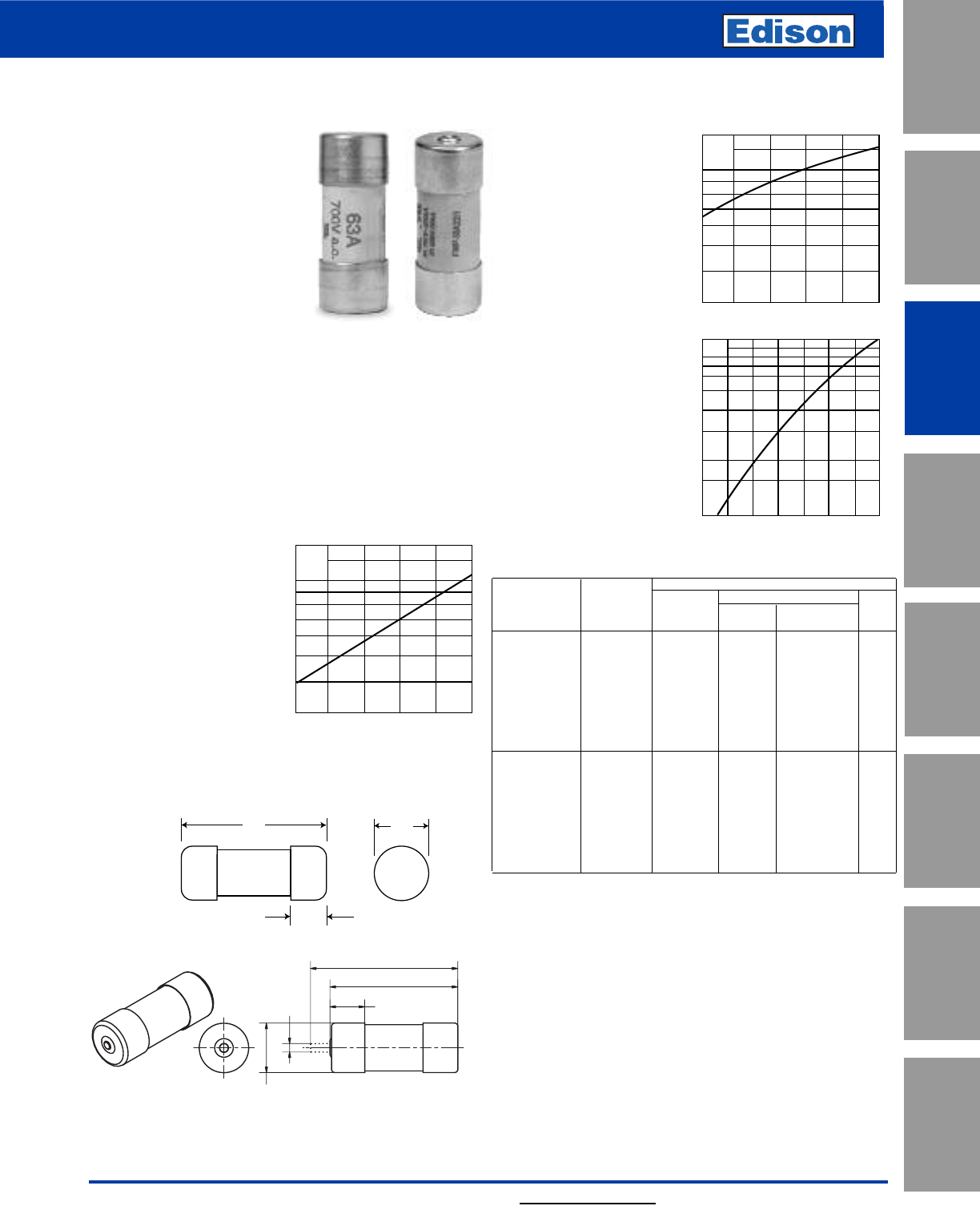
81
For additional information, visit www.edisonfuse.com
UL/CSA Fuses
Current Limiting
UL/CSA Fuses
General Purpose
Special
Purpose Fuses
Canadian
Fuses & Holders
Medium
Voltage Fuses
Fuse Blocks,
Holders & Misc.
Application
Section
Surge Protective
Devices
690V/700V High Speed Fuses
Catalog Number FWP 20 – 100A, Striker Optional
Dimensions - mm (in)
66 (2.598")
58 (2.283")
16 (0.630"
22.2 (0.874")
5
(0.197")
FWP (22 x 58mm)
Specifications
Description: Ferrule style high
speed fuses with and without
indicating striker.
Dimensions: See dimensions
illustration.
Ratings:
Volts: — 690Vac (IEC)
— 700Vac (UL)
— 500Vdc (20-100A)
Amps: — 20-100A
IR: — 200kA RMS Sym.
— 50kA @ 500Vdc
Agency Information: CE, UL Recognition JFHR2.E91958,
CSA Component Acceptance file Class 1422-30, 1422-90
(53787)
Electrical
Characteristics
Total Clearing I2t
The total clearing I2t at
rated voltage and at power
factor of 15% are given in
the electrical
characteristics. For other
voltages, the clearing I2t is
found by multiplying by
correction factor, K, given
as a function of applied
working voltage, Eg, (rms).
Arc Voltage
This curve gives the peak
arc voltage, UL, which may
appear across the fuse
during its operation as a
function of theapplied
working voltage, Eg, (rms)
at a power factor of 15%.
Power Losses
Watts loss at rated current
is given in the electrical
characteristics. The curve
allows the calculation of
the power losses at load
currents lower than the
rated current. The
correction factor, Kp, is
given as a function of the
RMS load current, Ib, in %
of the rated current.
Catalog Numbers
Electrical Characteristics
Rated I2t (A2Sec)
Catalog Current Minimum Clearing At Watts
Numbers Size RMS-Amps Melting Rated Voltage Loss
Without Striker
FWP-20A22F 20 19.0 260 5
FWP-25A22F 25 34.0 410 6
FWP-32A22F 22 x 58mm 32 53.5 605 8
FWP-40A22F (7⁄8" x 29⁄32") 40 68 750 9
FWP-50A22F 50 135 1600 9.5
FWP-63A22F 63 280 3080 11
FWP-80A22F 80 600 6600 13.5
FWP-100A22F 100* 1100 12500 16
With Striker
FWP-20A22FI 20 19.0 260 5
FWP-25A22FI 25 34.0 410 6
FWP-32A22FI 22 x 58mm 32 53.5 605 8
FWP-40A22FI (7⁄8" x 29⁄32") 40 68 750 9
FWP-50A22FI 50 135 1600 9.5
FWP-63A22FI 63 280 3080 11
FWP-80A22FI 80 600 6600 13.5
FWP-100A22FI 100* 1100 12500 16
*IEC/UL Voltage rating 690/700
Features and Benefits
• Excellent cycling capability and DC performance
• Low arc voltage and low energy let-through (I2t)
• Low watts loss in a compact size
• Used with finger-safe holders/blocks
Typical Applications
• DC Common bus
• DC Drives
• Power converters/rectifiers
• Reduced voltage starters
K
1.4
1.2
1.0
0.6
0.8
0.7
0.9
0.5
0.4
0.3
200 300 400 500 600 700
Eg
UL
1.4
1.2
103
6
8
7
9
5
4
3
200 300 400 500 600 700
Eg
Kp
1.0
0.8
0.4
0.5
0.6
0.3
0.2
0.1
30 40 50 60 70 80 90 100%
Ib
58.0
(2.283")
15.0
(0.591")
22.2
(0.875")
With Striker
Without Striker
FWP with
striker
option.
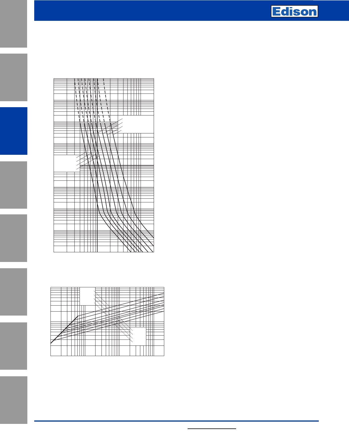
82 For additional information, visit www.edisonfuse.com
690V/700V High Speed Fuses
Application
Section
Fuse Blocks,
Holders & Misc.
Surge Protective
Devices
Medium
Voltage Fuses
Canadian
Fuses & Holders
Special
Purpose Fuses
UL/CSA Fuses
General Purpose
UL/CSA Fuses
Current Limiting
Catalog Number FWP 20 – 100A, Striker Optional
10122468 2
1022468
103
2
4
6
2
6
4
2
6
4
2
6
4
2
6
4
2
6
4
6
4
2
6
2
4
101
100
10–1
10–2
10–3
10–4
102
103
104
Prospective Current In Amps RMS
Virtual Pre-Arcing Time In Seconds
FWP-20A22F
FWP-25A22F
FWP-32A22F
FWP-40A22F
FWP-50A22F
FWP-63A22F
FWP-80A22F
FWP-100A22F
104
Prospective Short-Circuit Current Symmetrical RMS
Peak Let-Through Current
2
6
4
2
6
4
246 246 24 6
102
103
102103104105
FWP-20A22F
FWP-25A22F
FWP-32A22F
FWP-40A22F
FWP-50A22F
FWP-63A22F
FWP-80A22F
FWP-100A22F
2
Peak Let-Through Curve
Without Striker
FWP 20-100A: 660V/700V (22 x 58mm)
Time-Current Curve
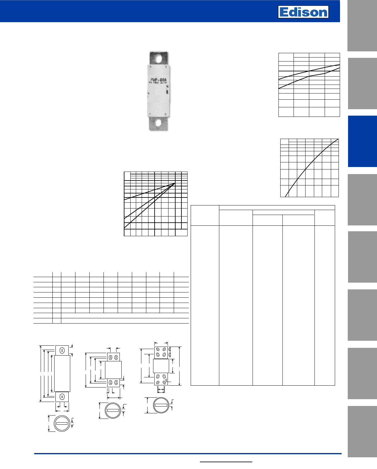
83
For additional information, visit www.edisonfuse.com
UL/CSA Fuses
Current Limiting
UL/CSA Fuses
General Purpose
Special
Purpose Fuses
Canadian
Fuses & Holders
Medium
Voltage Fuses
Fuse Blocks,
Holders & Misc.
Application
Section
Surge Protective
Devices
700V High Speed Fuses
Catalog Number FWP 5 – 1200A
FWP
Specifications
Description: North American
style stud-mount fuses.
Dimensions: See Dimensions
illustrations.
Ratings:
Volts: — 700Vac/dc
Amps: — 5-1200A
IR: — 200kA RMS Sym.
— 50kA @700Vdc
Agency Information: CE, UL Recognition JFHR2.E91958
FWP-_B (5-100A, 700-1200A), JFHR2.E56412 FWP-_A
(125-600A) & CSA Component Acceptance file Class
1422-30, (53787) on 5-800A
Electrical Characteristics
Total Clearing I2t
The total clearing I2t at rated
voltage and at power factor of
15% are given in the electrical
characteristics. For other
voltages, the clearing I2t is
found by multiplying by
correction factor, K, given as
a function of applied working
voltage, Eg, (rms).
Arc Voltage
This curve gives the peak arc
voltage, UL, which may
appear across the fuse
during its operation as a func-
tion of the applied
working voltage, Eg, (rms) at
a power factor of 15%.
Power Losses
Watts loss at rated current is
given in the electrical
characteristics. The curve
allows the calculation of the
power losses at load
currents lower than the rated
current. The correction factor,
Kp, is given as a function of
the RMS load current, Ib, in %
of the rated current.
Catalog Numbers Electrical Characteristics
Rated I2t (A2Sec)
Catalog Current Clearing Watts
Numbers RMS-Amps Pre-arc at 700V Loss
FWP-5B 5 1.6 10 1.5
FWP-10B 10 3.6 20 4
FWP-15B 15 10 75 5.5
FWP-20B 20 26 180 6
FWP-25B 25 44 340 7
FWP-30B 30 58 450 9
FWP-35B 35 34 160 12
FWP-40B 40 76 320 12
FWP-50B 50 135 600 12
FWP-60B 60 210 950 15.5
FWP-70B 70 305 2000 18
FWP-80B 80 360 2400 21
FWP-90B 90 415 2700 25
FWP-100B 100 540 3500 27
FWP-125A 125 1800 7300 28
FWP-150A 150 2900 11700 32
FWP-175A 175 4200 16700 35
FWP-200A 200 5500 22000 43
FWP-225A 225 7700 31300 45
FWP-250A 250 10500 42500 48
FWP-300A 300 17600 71200 58
FWP-350A 350 23700 95600 65
FWP-400A 400 31000 125000 78
FWP-450A 450 36400 137000 94
FWP-500A 500 45200 170000 107
FWP-600A 600 66700 250000 122
FWP-700A 700 54000 300000 125
FWP-800A 800 78000 450000 140
FWP-900A 900 91500 530000 150
FWP-1000A 1000 120000 600000 170
FWP-1200A 1200 195000 1100000 190
• Watts loss provided at rated current.
Features and Benefits
• Excellent DC performance
• Low arc voltage and low
energy let-through (I2t)
• Superior cycling capability
700604460316
1.5
1.0
0.5
0.3
0.2
0.15 Eg
K
1)
3)
2)
UL
2
1.6
1.4
1.2
103
8
6
5
4
3
400300 500 600 700
Eg
1)
2)
Kp
1.0
0.8
0.4
0.5
0.6
0.3
0.2
0.1
30 40 50 60 7080 90 100%
Ib
1) 125-600A Range
2) 35-100 & 700-1200A Range
1) 35-100A Range
2) 125-600A Range
3) 700-1200A Range
AED C
F
J
G
B
H
Fig. 1: 5-800A
Dimensions - in
Amp
Range Fig. ABCD E FGHI
5-30 1 2.870 0.563 1.855 2.477 2.477 0.250 0.405 0.063 0.250
35-60 1 4.375 0.813 2.750 3.708 3.312 0.344 0.725 0.125 0.542
70-100 1 4.406 0.947 2.594 3.625 3.563 0.344 0.750 0.125 0.375
125-200 1 5.090 1.500 2.840 4.190 3.500 0.410 1.000 0.250 0.750
225-400 1 5.090 2.000 2.840 4.280 3.530 0.410 1.500 0.250 0.780
450-600 1 7.090 2.500 2.840 5.720 4.190 0.530 2.000 0.380 1.300
700-800 1 6.630 2.000 2.844 5.562 5.062 0.625 1.500 0.250 0.875
900-1000 2 See Drawing
1200 3 See Drawing
1mm = 0.0394” / 1” = 25.4mm
7.594
0.5
3.500
3.844
1.031
0.625
2.750
5.966
5.154
1.375
Fig. 2: 900-1000A Fig. 3: 1200A
10.844
3.844
0.625
4.250
0.750
3.500
6.840
0.125
0.500
1.625
1.750
9.590
Typical Applications
• DC Common bus
• DC Drives
• Power converters/rectifiers
• Reduced voltage starters
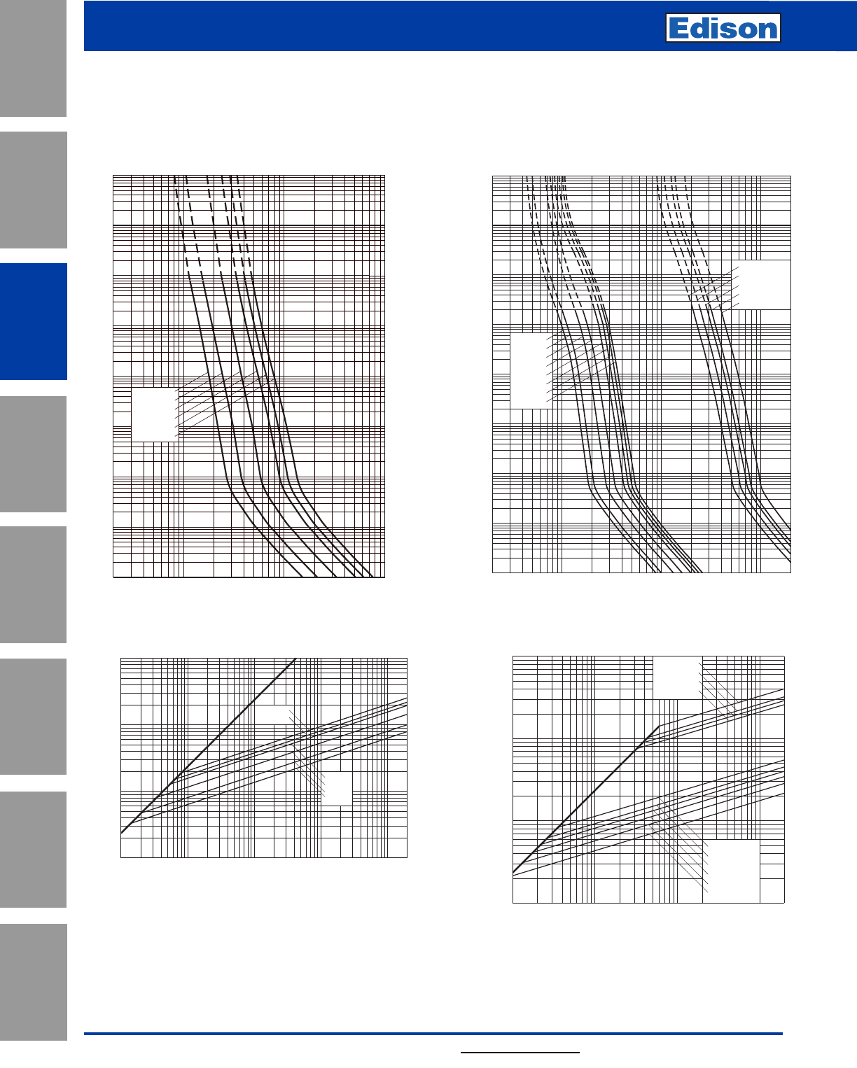
84 For additional information, visit www.edisonfuse.com
Application
Section
Fuse Blocks,
Holders & Misc.
Surge Protective
Devices
Medium
Voltage Fuses
Canadian
Fuses & Holders
Special
Purpose Fuses
UL/CSA Fuses
General Purpose
UL/CSA Fuses
Current Limiting
700V High Speed Fuses
Catalog Number FWP 5 – 1200A
2468
10222468 2
1032468
104
2
4
6
2
6
4
2
6
4
101
100
2
6
4
2
6
4
2
6
4
6
4
2
6
2
4
10–1
10–2
10–3
10–4
102
103
104
FWP-35B
FWP-80B
FWP-90B
FWP-100B
FWP-60B
FWP-70B
FWP-40B
FWP-50B
FWP-900A
FWP-1200A
FWP-1000A
FWP-800A
FWP-700A
Prospective Current In Amps RMS
Virtual Pre-Arcing Time In Seconds
FWP 35-100A(B) & 700-1200A(A): 700V
Time-Current Curve
Prospective Short-Circuit Current
Peak Let-Through Current
2
6
4
2
6
4
2
6
4
246 246 246
102
103
104
106
102103104105
2
FWP-700A
FWP-800A
FWP-1000A
FWP-100B
FWP-35B
FWP-70B
FWP-40B
FWP-50B
FWP-60B
FWP-1200A
Peak Let-Through Curve
2468
1012
2468 2
1022468
103
2
4
6
2
6
4
2
6
4
2
6
4
2
6
4
2
6
4
6
4
2
6
2
4
10–1
10–2
10–3
10–4
102
101
100
103
104
Prospective Current In Amps RMS
Virtual Pre-Arcing Time In Seconds
FWP-10B
FWP-15B
FWP-20B
FWP-5B
FWP-30B
FWP-25B
FWP 5-30A(B): 700V
Time-Current Curve
Prospective Short-Circuit Current
Peak Let-Through Current
2
4
2
6
6
4
2
6
4
246 246 246 246
101
102
103
104
101102103104105
FWP- 5B
FWP-10B
FWP-15B
FWP-20B
FWP-25B
FWP-30B
2
Peak Let-Through Curve
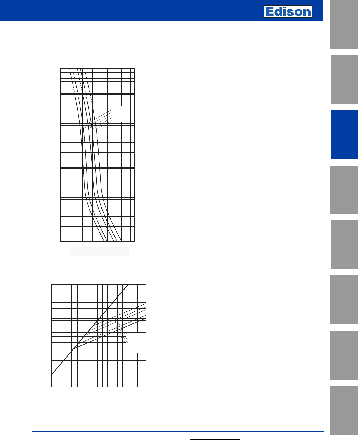
85
For additional information, visit www.edisonfuse.com
UL/CSA Fuses
Current Limiting
Special
Purpose Fuses
Canadian
Fuses & Holders
Medium
Voltage Fuses
Fuse Blocks,
Holders & Misc.
Application
Section
Surge Protective
Devices
UL/CSA Fuses
General Purpose
700V High Speed Fuses
10–4
10–3
10–2
10–1
100
101
102
103
FWP-150A
FWP-200A
FWP-300A
FWP-400A
FWP-600A
Prospective Current In Amperes RMS
Virtual Pre-Arcing Time In Seconds
102103104105
Prospective Current In Amps RMS
FWP 150-600A: 700V
Time-Current Curve
FWP-600A
FWP-400A
FWP-300A
FWP-200A
FWP-150A
102103104105
102
103
104
105
Prospective Short-Circuit Current Symmetrical RMS
Peak Let-Through Current
A
B
Peak Let-Through Curve
Catalog Number FWP 5 – 1200A
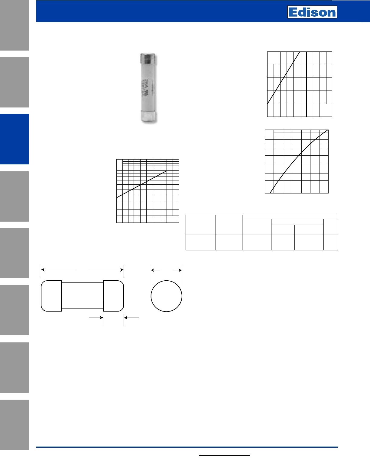
86 For additional information, visit www.edisonfuse.com
Application
Section
Fuse Blocks,
Holders & Misc.
Surge Protective
Devices
Medium
Voltage Fuses
Canadian
Fuses & Holders
Special
Purpose Fuses
UL/CSA Fuses
General Purpose
UL/CSA Fuses
Current Limiting
1000V High Speed Fuses
Catalog Number FWJ 20 – 30A
Dimensions - mm (in)
66.7
(2.626")
15.9
(0.625")
14.5
(0.571")
FWJ (14 x 67mm)
Specifications
Description: Ferrule style high
speed fuses.
Dimensions: See dimensions
illustration.
Ratings:
Volts: — 1000Vac/800Vdc
Amps: — 20-30A
IR: — 25kA RMS Sym.
— 20kA @ 800Vdc
Agency Information: CE, UL Recognized JFHR2 E91958
Electrical
Characteristics
Total Clearing I2t
The total clearing I2t at
rated voltage and at power
factor of 15% are given in
the electrical
characteristics. For other
voltages, the clearing I2t is
found by multiplying by
correction factor, K, given
as a function of applied
working voltage, Eg, (rms).
Arc Voltage
This curve gives the peak
arc voltage, UL, which may
appear across the fuse
during its operation as a
function of theapplied
working voltage, Eg, (rms)
at a power factor of 15%.
Power Losses
Watts loss at rated current
is given in the electrical
characteristics. The curve
allows the calculation of
the power losses at load
currents lower than the
rated current. The
correction factor, Kp, is
given as a function of the
RMS load current, Ib, in %
of the rated current.
Catalog Numbers
Electrical Characteristics
Rated I2t (A2Sec)
Catalog Current Clearing Watts
Numbers Size RMS-Amps Pre-arc at 1000V Loss
FWJ-20A14F 14 x 67mm 20 25 220 9
FWJ-25A14F (9⁄16” x 25⁄8”) 25 33 350 11
FWJ-30A14F 30 52 450 14
• Watts loss provided at rated current.
Features and Benefits
• Excellent cycling capability and DC performance
• Low arc voltage and low energy let-through (I2t)
• Low watts loss in a compact size
• Used with finger-safe holders/blocks
Typical Applications
• DC Common bus
• DC Drives
• Power converters/rectifiers
• Reduced voltage starters
1000800500200
1.5
1.0
0.5
0.3
0.2
0.15 Eg
K
2000
1600
1200
800
400
200 600 1000 1400 1800
UL
Eg
Kp
1.0
0.8
0.4
0.5
0.6
0.3
0.2
0.1
30 40 50 60 70 80 90 100%
Ib
Fuseclips:
• Catalog Number: 5591 (see data sheet 2132)
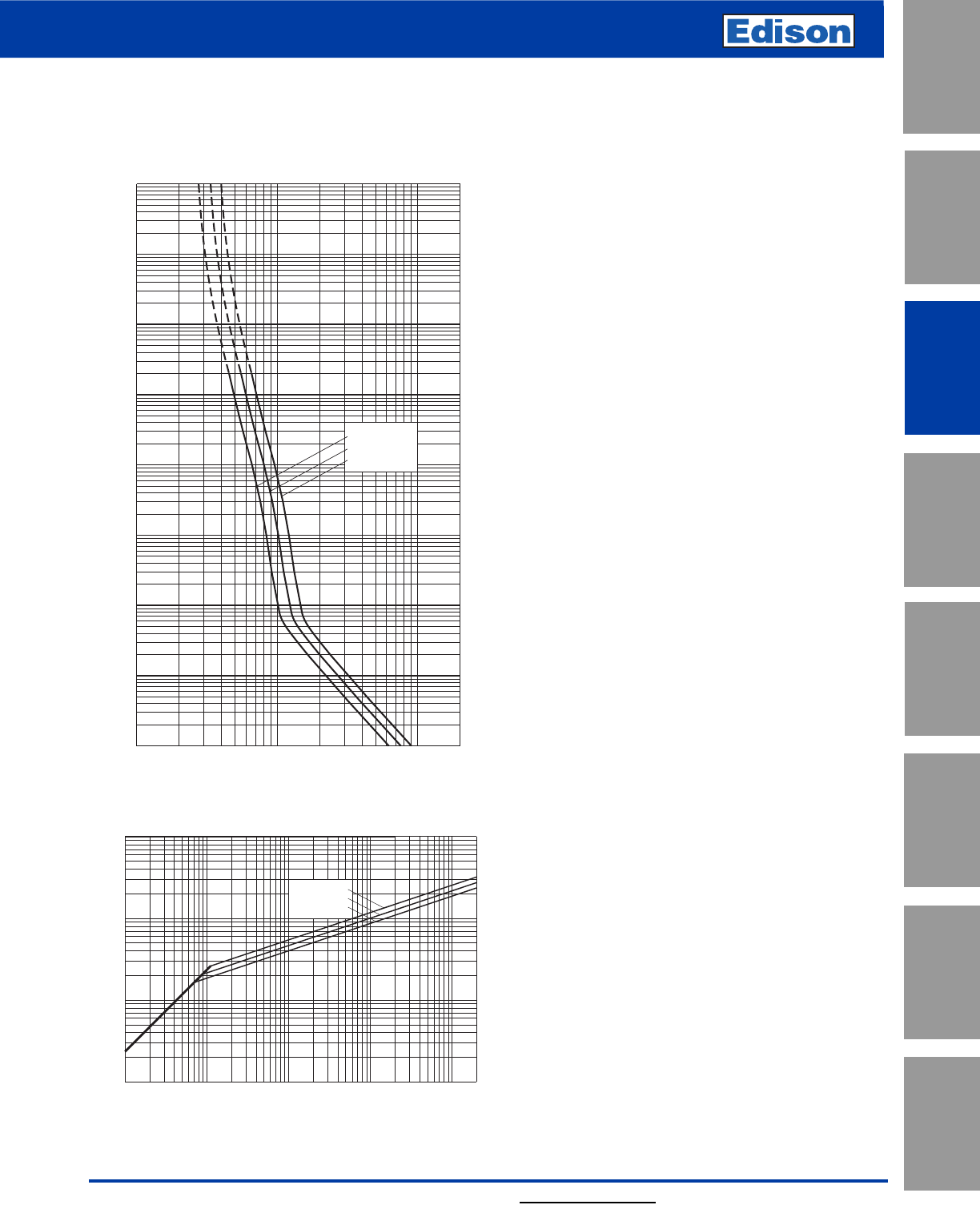
87
For additional information, visit www.edisonfuse.com
UL/CSA Fuses
Current Limiting
UL/CSA Fuses
General Purpose
Special
Purpose Fuses
Canadian
Fuses & Holders
Medium
Voltage Fuses
Fuse Blocks,
Holders & Misc.
Application
Section
Surge Protective
Devices
1000V High Speed Fuses
Catalog Number FWJ 20 – 30A
FWJ-20A14F
FWJ-25A14F
FWJ-30A14F
10122468 2
1022468
103
2
4
6
2
6
4
2
6
4
2
6
4
2
6
4
2
6
4
6
4
2
6
2
4
10–4
100
101
10–1
10–2
10–3
102
103
104
Prospective Current In Amps RMS
Virtual Pre-Arcing Time In Seconds
FWJ 20-30A: 1000V (14 x 67mm)
Time-Current Curve
Prospective Short-Circuit Current Symmetrical RMS
Peak Let-Through Current
2
4
2
6
6
4
2
6
4
246 246 246 246
101
102
103
104
101102103104105
FWJ-20A14F
FWJ-25A14F
FWJ-30A14F
2
Peak Let-Through Curve
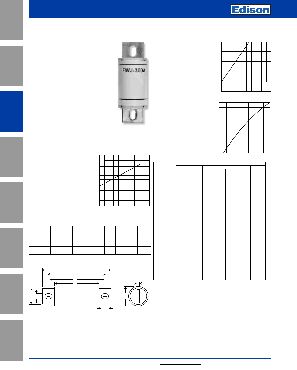
88 For additional information, visit www.edisonfuse.com
Application
Section
Fuse Blocks,
Holders & Misc.
Surge Protective
Devices
Medium
Voltage Fuses
Canadian
Fuses & Holders
Special
Purpose Fuses
UL/CSA Fuses
General Purpose
UL/CSA Fuses
Current Limiting
FWJ
Specifications
Description: North American style
stud-mount fuses.
Dimensions: See Dimensions illus-
tration.
Ratings:
Volts: — 1000Vac/800Vdc
Amps: — 35-2000A
IR: — 25kA (35-200A)
— 100kA (250-2000A)
— 50kA @ 800Vdc
(35-200A, 450-600A)
Agency Information: CE, UL
Recognition JFHR8.E91958 on
35-600A only.
Electrical Characteristics
Total Clearing I2t
The total clearing I2t at rated
voltage and at power factor of
15% are given in the electrical
characteristics. For other
voltages, the clearing I2t is
found by multiplying by
correction factor, K, given as a
function of applied working
voltage, Eg, (rms).
Arc Voltage
This curve gives the peak
arc voltage, UL, which may
appear across the fuse
during its operation as a
function of the applied
working voltage, Eg, (rms)
at a power factor of 15%.
Power Losses
Watts loss at rated current
is given in the electrical
characteristics. The curve
allows the calculation of
the power losses at load
currents lower than the
rated current. The
correction factor, Kp, is
given as a function of the
RMS load current, Ib, in %
of the rated current.
Catalog Numbers
Electrical Characteristics
Rated I2t (A2 Sec)
Catalog Current Clearing Watts
Numbers RMS-Amps Pre-arc at 1000V Loss
FWJ-35A 35 210 2000 7
FWJ-40A 40 300 2500 8
FWJ-50A 50 470 3500 10
FWJ-60A 60 670 5000 11
FWJ-70A 70 1100 6900 12
FWJ-80A 80 1550 9700 13
FWJ-90A 90 1900 12000 14
FWJ-100A 100 2800 17500 15
FWJ-125A 125 4800 35000 16
FWJ-150A 150 6300 45000 25
FWJ-175A 175 7500 65000 30
FWJ-200A 200 11700 80000 32
FWJ-250A 250 16000 112000 50
FWJ-300A 300 23500 164000 56
FWJ-350A 350 33000 231000 62
FWJ-400A 400 47000 330000 67
FWJ-500A 500 39500 329000 95
FWJ-600A 600 61000 520000 105
FWJ-800A 800 87000 500000 182
FWJ-1000A 1000 190000 1100000 206
FWJ-1200A 1200 370000 2100000 240
FWJ-1400A 1400 470000 2700000 248
FWJ-1600A 1600 700000 4000000 267
FWJ-1800A 1800 925000 5300000 239
FWJ-2000A 2000 1330000 7600000 244
• Watts loss provided at rated current.
Features and Benefits
• Excellent DC performance
• Low arc voltage and low energy let-through (I2t)
• Low watts loss
• Superior cycling capability
Typical Applications
• DC Common bus
• DC Drives
• Power converters/rectifiers
• Reduced voltage starters
2000
1600
1200
800
400
200 600 1000 1400 1800
UL
Eg
Kp
1.0
0.8
0.4
0.5
0.6
0.3
0.2
0.1
30 40 50 60 7080 90 100%
Ib
1000800500200
1.5
1.0
0.5
0.3
0.2
0.15 Eg
K
A
E
D
C
F
J
GB
H
Fig. 1: 35-2000A
Dimensions - in
Amp
Range Fig. ABCDEFGHI
35-60 1 5.000 0.940 3.110 4.235 4.180 0.352 0.750 0.125 0.380
70-100 1 4.932 1.125 3.085 4.266 4.156 0.352 1.000 0.188 0.407
125-200 1 5.685 1.526 3.261 4.803 4.055 0.445 1.000 0.250 0.819
250-400 1 5.768 2.000 3.500 4.811 4.150 0.433 1.500 0.250 0.764
500-600 1 7.201 2.500 3.465 5.984 4.706 0.562 2.000 0.375 1.201
800-2000 1 6.811 3.500 3.312 5.472 4.962 0.625 2.750 0.500 0.880
1mm = 0.0394” / 1” = 25.4mm
Catalog Number FWJ 35 – 2000A
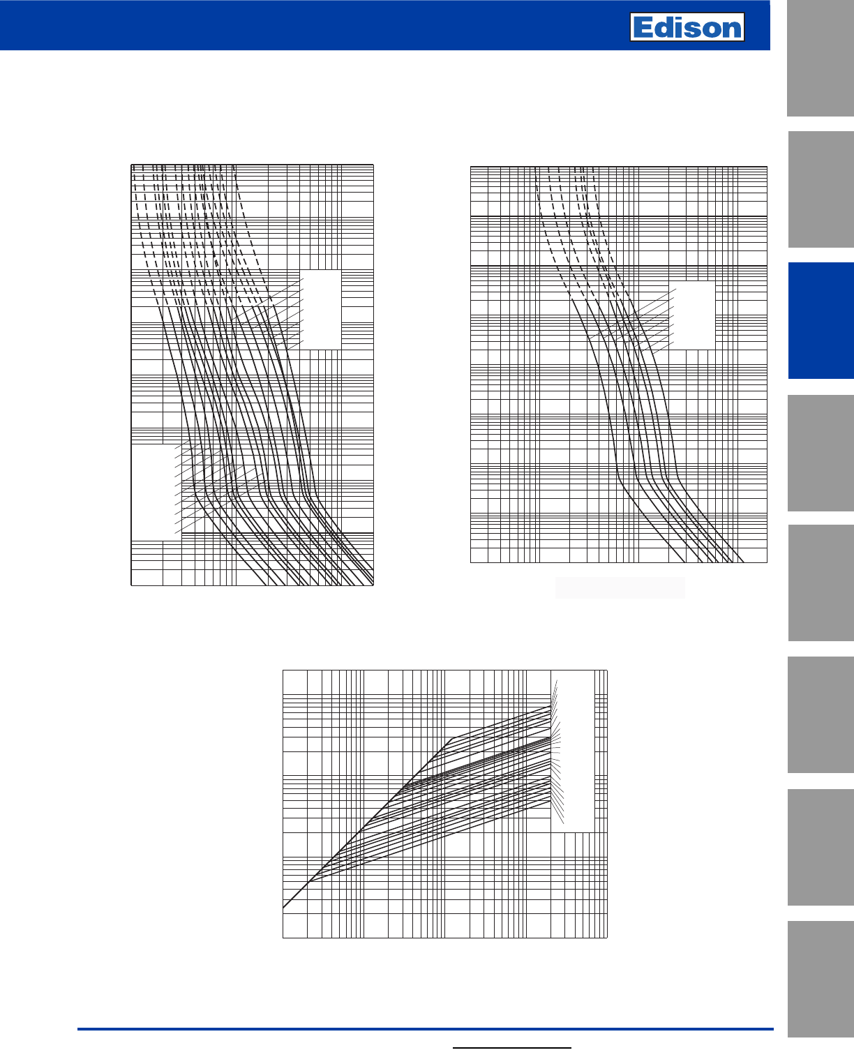
89
For additional information, visit www.edisonfuse.com
UL/CSA Fuses
Current Limiting
UL/CSA Fuses
General Purpose
Special
Purpose Fuses
Canadian
Fuses & Holders
Medium
Voltage Fuses
Fuse Blocks,
Holders & Misc.
Application
Section
Surge Protective
Devices
1000V High Speed Fuses
Catalog Number FWJ 35 – 2000A
2468
10322468 2
1042468
105
2
4
6
2
6
4
100
2
6
4
101
2
6
4
2
6
4
2
6
4
6
4
2
6
2
4
10–1
10–2
10–3
10–4
102
103
104
FWJ-1800A
FWJ-2000A
FWJ-800A
FWJ-1000A
FWJ-1200A
FWJ-1400A
FWJ-1600A
Prospective Current In Amperes RMS
Virtual Pre-Arcing Time In Seconds
Prospective Current in Amps
FWJ 800-2000A: 1000V
Time-Current Curve
Prospective Current In Amps RMS
Virtual Pre-Arcing Time In Seconds
10222468 2
1032468
104
2
4
6
2
6
4
100
2
6
4
2
6
4
2
6
4
2
6
4
6
4
2
6
2
4
10–1
10–2
10–3
10–4
102
103
104
FWJ-125A
FWJ-150A
FWJ-60A
FWJ-100A
FWJ-90A
FWJ-80A
FWJ-70A
FWJ-50A
FWJ-40A
FWJ-600A
FWJ-200A
FWJ-250A
FWJ-300A
FWJ-350A
FWJ-400A
FWJ-500A
FWJ-175A
101
FWJ 35-600A: 1000V
Time-Current Curve
Prospective Short-Circuit Current Symmetrical RMS
Peak Let-Through Current
2
4
2
6
6
4
2
6
4
2
246 246 246 246
102
103
104
105
102103104105
FWJ-40A
FWJ-50A
FWJ-60A
FWJ-70A
FWJ-80A
FWJ-90A
FWJ-100A
FWJ-125A
FWJ-150A
FWJ-175A
FWJ-200A
FWJ-500A
FWJ-350A
FWJ-300A
FWJ-250A
FWJ-600A
FWJ-800A
FWJ-2000A
FWJ-1800A
FWJ-1600A
FWJ-1400A
FWJ-1250A
FWJ-1000A
FWJ-400A
Peak Let-Through Curve
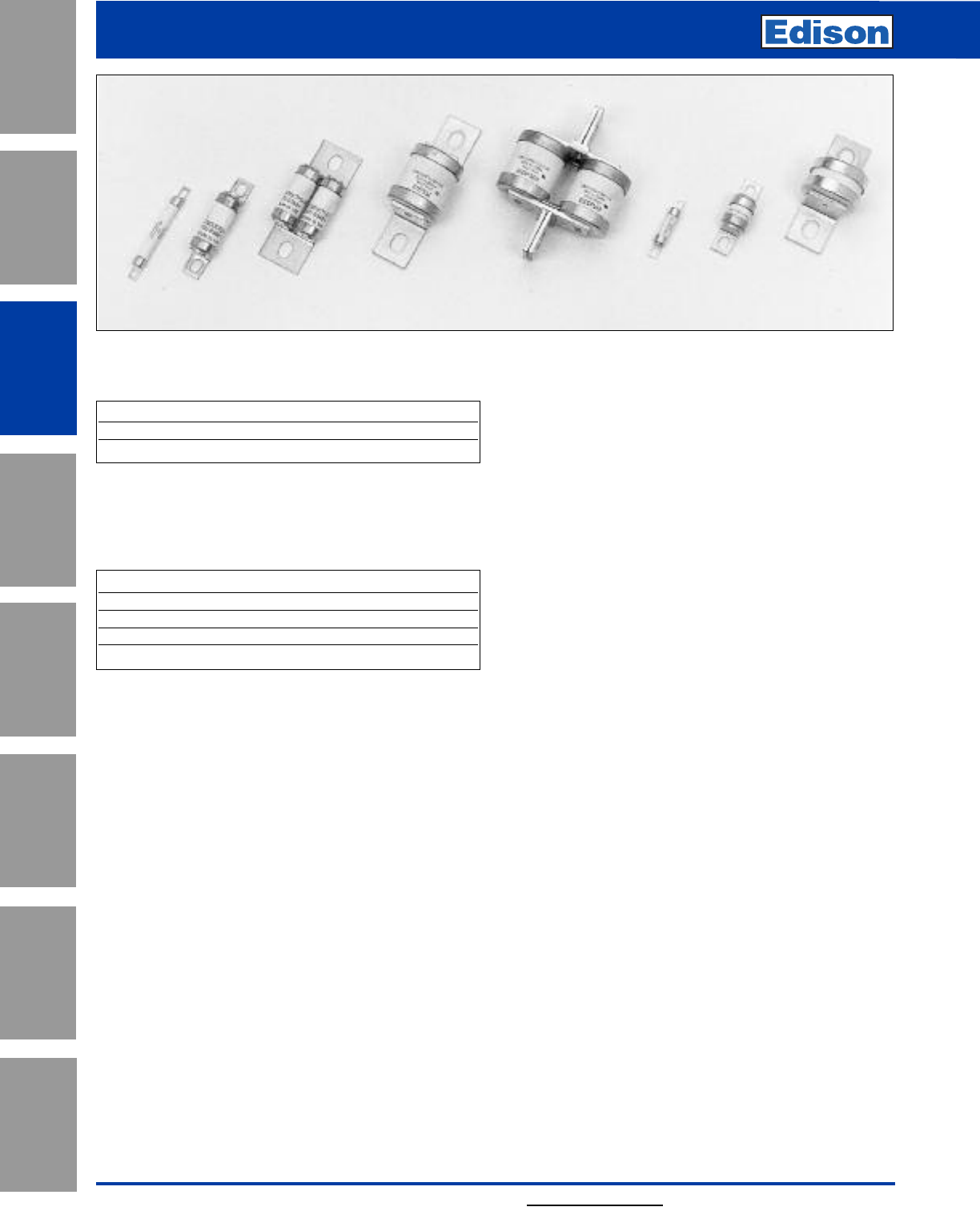
90 For additional information, visit www.edisonfuse.com
Application
Section
Fuse Blocks,
Holders & Misc.
Surge Protective
Devices
Medium
Voltage Fuses
Canadian
Fuses & Holders
Special
Purpose Fuses
UL/CSA Fuses
General Purpose
UL/CSA Fuses
Current Limiting
British Style
High Speed Fuses
Introduction
British BS 88 Contents
Accessories
• Indicator System (see end of this section)
• Fuse Blocks (see BH Series fuse blocks in this catalog)
British BS 88 Fuse Ranges
General Information
Designed and tested to:
• BS 88: Part 4
• IEC 269: Part 4
• UL Recognized
We offer the industry’s widest range of British style
semiconductor fuses and accessories.
Edison British style products use innovative arc quenching
techniques and high grade materials to provide:
• Minimal energy let-through (I2t)
• Excellent DC performance
• Good surge withstand profile
British style fuses are typically found in equipment
manufactured in the United Kingdom or British
Commonwealth countries. However, North American
manufacturers have begun to specify British style fuses —
particularly in UPS applications at 240V or less — to take
advantage of their size, performance and cost benefits.
Fuse Volts Amp Range
240 6-900
690 6-710
Amps Volts AC DC
6-900 240 X—
6-900 150 —X
6-700 690 X—
6-700 500 —X
Voltage Rating
All Edison British style fuses are tested to IEC 269: Part 4.
This standard requires a test voltage which is 5% higher
than the rated voltage. In North America, fuses are required
to clear only their rated voltage.
Accessories
Trip-indicator fuses are available for use in parallel with the
main fuse. Indicator fuses can be attached to the
associated fuse, or mounted separately in panel-mounted
fuseclips. In addition, a push-on adapter and microswitch
attachment are available, to provide remote indication.
The BH Series fuse blocks are also available for most
applications.
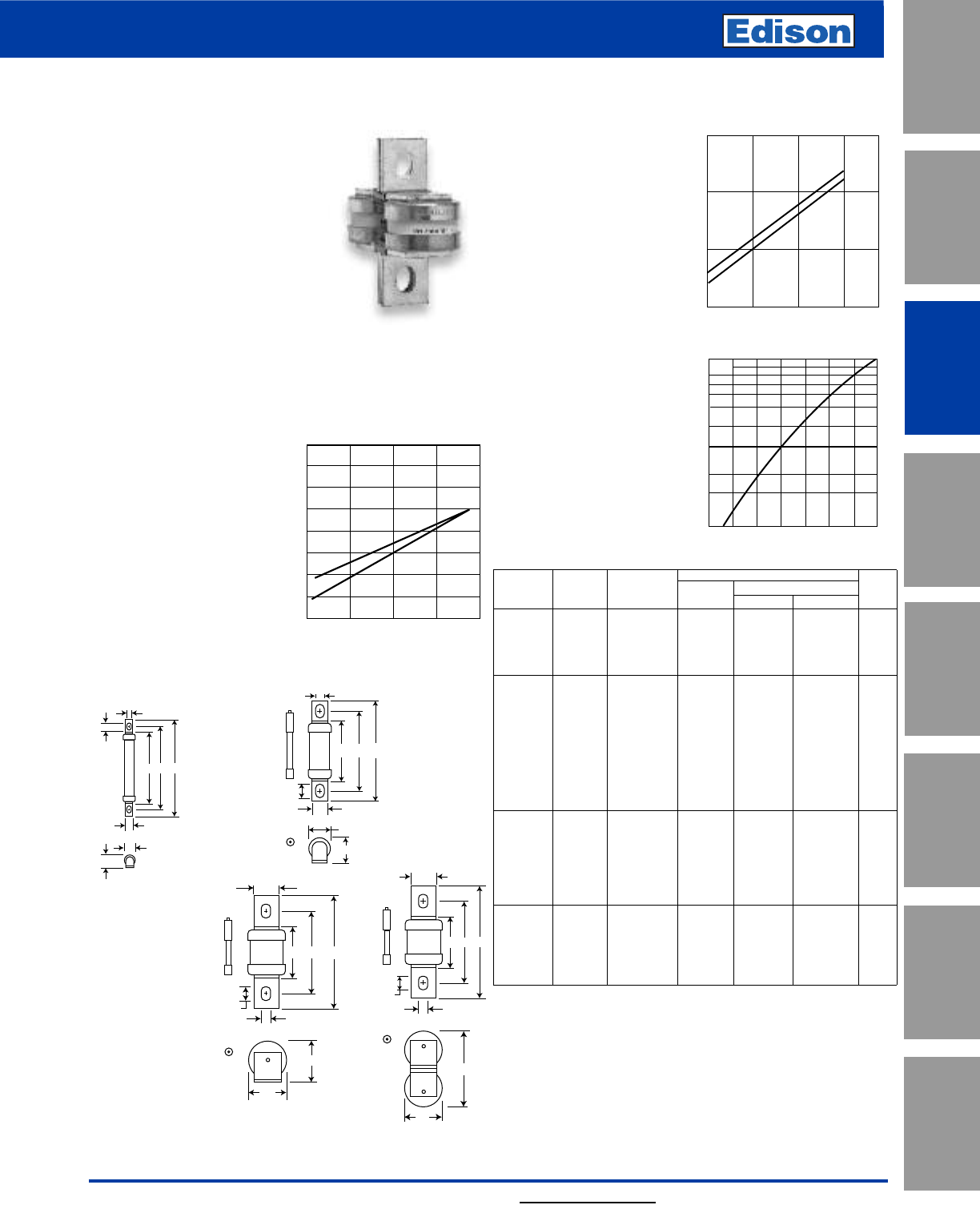
91
For additional information, visit www.edisonfuse.com
UL/CSA Fuses
Current Limiting
UL/CSA Fuses
General Purpose
Special
Purpose Fuses
Canadian
Fuses & Holders
Medium
Voltage Fuses
Fuse Blocks,
Holders & Misc.
Application
Section
Surge Protective
Devices
Catalog Number LCT, LET, LMT, LMMT 6 – 900A
British Style
240V High Speed Fuses
Arc Voltage
This curve gives the peak
arc voltage, UL, which may
appear across the fuse
during its operation as a
function of theapplied
working voltage, Eg, (rms)
at a power factor of 15%.
Power Losses
Watts loss at rated current
is given in the electrical
characteristics. The curve
allows the calculation of
the power losses at load
currents lower than the
rated current. The correc-
tion factor, Kp, is given as
a function of the RMS load
current, Ib, in % of the
rated current.
Catalog Numbers
Electrical Characteristics
Rated I2t (A2Sec)
Catalog Current Clearing Clearing Watts
Numbers Type RMS-Amps Pre-arc at 120V at 240V Loss
6LCT 62691.0
10LCT 10 3.8 12 22 2.5
12LCT LCT 12 7 22 32 2.5
16LCT 16 20 50 100 2.5
20LCT 20 25 80 160 4.0
25LET 25 18 120 250 4.0
32LET 32 32 200 450 5.0
35LET 35 50 320 600 5.0
50LET 50 100 500 1400 7.0
63LET LET 63 180 1100 2200 9.0
80LET 80 300 1900 3800 10.0
100LET 100 600 3800 7500 10.0
125LET 125 600 3800 7500 16.0
160LET 160 1100 7000 16000 20.0
180LETa 180 1600 12000 29000 21.0
160LMT 160 1100 7000 16000 17.0
200LMT 200 1500 10000 20000 28.0
250LMT 250 3200 20000 40000 28.0
315LMT LMT 315 6000 35000 75000 35.0
355LMT 355 8000 50000 100000 35.0
400LMT 400 14000 70000 160000 40.0
450LMT 450 18000 100000 220000 42.0
400LMMT 400 6000 35000 80000 60.0
500LMMT 500 14000 80000 170000 64.0
630LMMT LMMT 630 24000 150000 300000 75.0
710LMMT 710 32000 200000 460000 77.0
800LMMT 800 52000 300000 600000 82.0
900LMMT 900 75000 400000 800000 97.0
• Watts loss provided at rated current.
• Note: 7LET, 10LET, 12LET and 16LET are available for replacement purposes on existing
equipment.
Features and Benefits
• Excellent cycling capability
• Excellent DC performance
• Low arc voltage and low
energy let-through (I2t)
5641.8
26.2
17.7
19.1
12.7
7.1
9.7
Fig. 2: LET
473828
6.4
8.4
8.7
4
5.5
Dimensions - mm
Fig. 1: LCT
1mm = 0.0394” / 1” = 25.4mm
LCT, LET, LMT, LMMT
Specifications
Description: BS 88 style
stud-mount fuses.
Dimensions: See dimensions
illustrations.
Ratings:
Volts: — 240Vac/150Vdc
Amps: — 6-900A
IR: — 200kA RMS Sym.
Agency Information: CE, Designed and tested to: BS 88
Part 4, IEC 269 Part 4, UL Recognized. All fuses above have
been tested at 318Vac. Consult Edison for specific UL
Recognition status.
Electrical Characteristics
Total Clearing I2t
The total clearing I2t at rated
voltage and at power factor
of 15% are given in the
electrical characteristics. For
other voltages, the clearing I2t
is found by multiplying by
correction factor, K, given as
a function of applied working
voltage, Eg, (rms).
845931
83
38
25.4
13.5
10.3
0.2
0.4
0.6
0.8
1.0
1.2
1.4
1.6
10050150200250
1)
2) Eg
K
845931
41
38.1
25.4
10.3
13.5
Fig. 3: LMT
Fig. 4: LMMT
Indicator (Optional)
1) LCT
2) LET, LMT, LMMT
Kp
1.0
0.8
0.4
0.5
0.6
0.3
0.2
0.1
30 40 50 60 70 80 90 100%
Ib
750
500
250
100 200 300
1)
2)
Eg
UL
1) LCT
2) LET, LMT, LMMT
Typical Applications
• DC Common bus
• AC and DC drives
• Power converters/rectifiers
• Reduced voltage starters
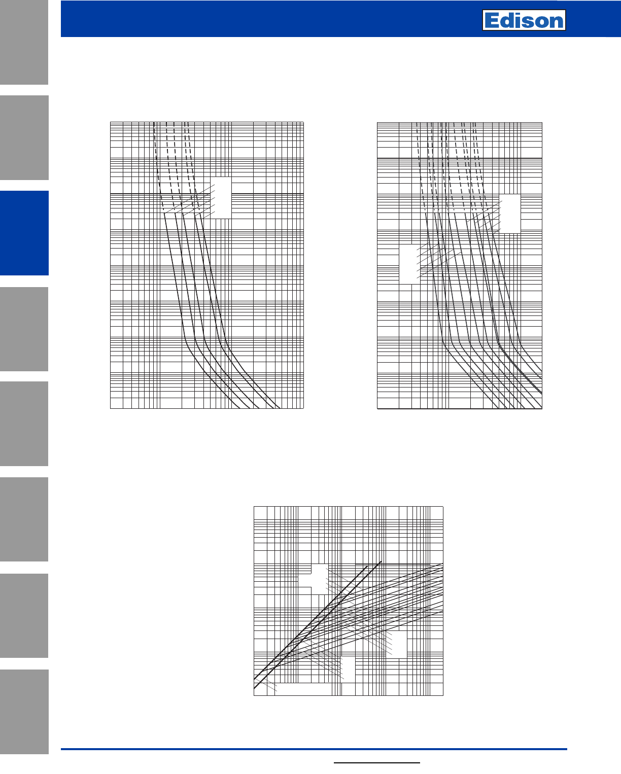
92 For additional information, visit www.edisonfuse.com
Application
Section
Fuse Blocks,
Holders & Misc.
Surge Protective
Devices
Medium
Voltage Fuses
Canadian
Fuses & Holders
Special
Purpose Fuses
UL/CSA Fuses
General Purpose
UL/CSA Fuses
Current Limiting
Catalog Number LCT, LET, LMT, LMMT 6 – 900A
British Style
240V High Speed Fuses
Peak Let-Through Curve
LET 25-180A: 240V
Time-Current Curve
LCT 6-20A: 240V
Time-Current Curve
104
103
102
10–1
10–2
10–3
10–4
Prospective Current In Amps RMS
Virtual Pre-Arcing Time In Seconds
2468
10122468 2
1022468
103
2
4
6
2
6
4
100
2
6
4
101
2
6
4
2
6
4
2
6
4
6
4
2
6
2
4
20LCT
16LCT
12LCT
10LCT
6LCT
104
103
102
10122468 2
1022468
103
2
4
6
2
6
4
100
2
6
4
101
2
6
4
2
6
4
2
6
4
6
4
2
6
2
4
Prospective Current In Amps RMS
Virtual Pre-Arcing Time In Seconds
63LET
50LET
35LET
32LET
25LET
180LETa
160LET
125LET
100LET
80LET
10–4
10–3
10–2
10–1
Prospective Short-Circuit Current Symmetrical RMS
101102
264246
103246
104246
105
Peak Let-Through Current
101
6
2
4
2
102
4
6
2
103
6
4
104
6
4
2
2
105
SYMMETRICAL FAULT
FULLY ASYMMETRICAL FAULT
20LCT
16LCT
12LCT
10LCT
6LCT
25LET
32LET
35LET
50LET
63LET
80LET
125 & 100LET
160LET
180LET
Data Sheet: 35785296 Data Sheet: 35785293
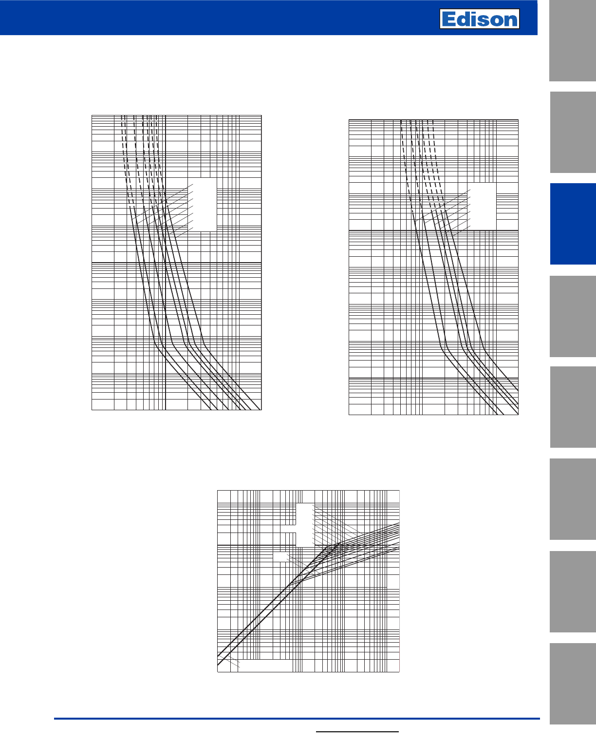
93
For additional information, visit www.edisonfuse.com
UL/CSA Fuses
Current Limiting
UL/CSA Fuses
General Purpose
Special
Purpose Fuses
Canadian
Fuses & Holders
Medium
Voltage Fuses
Fuse Blocks,
Holders & Misc.
Application
Section
Surge Protective
Devices
Catalog Number LCT, LET, LMT, LMMT 6 – 900A
British Style
240V High Speed Fuses
10–4
10–3
10–1
102
10222468 2
1032468
104
2
4
6
2
6
4
100
2
6
4
101
2
6
4
2
6
4
2
6
4
6
4
2
6
2
4
104
315LMT
450LMT
400LMT
355LMT
250LMT
200LMT
160LMT
Prospective Current In Amps RMS
Virtual Pre-Arcing Time In Seconds
103
10–2
10–1
10–3
10–2
102
103
104
10222468 2
1032468
104
2
4
6
2
6
4
100
2
6
4
101
2
6
4
2
6
4
2
6
4
6
4
2
6
2
4
Prospective Current In Amps RMS
Virtual Pre-Arcing Time In Seconds
10–4
710LMMT
900LMMT
800LMMT
630LMMT
500LMMT
400LMMT
Prospective Short-Circuit Current Symmetrical RMS
101102
264246
103246
104246
105
Peak Let-Through Current
101
6
2
4
2
102
4
6
2
103
6
4
104
6
4
2
2
105
SYMMETRICAL FAULT
FULLY ASYMMETRICAL FAULT
160LMT
200LMT
250LMT
315LMT
355LMT
400 & 500LMMT
450LMT
630LMMT
710LMMT
800LMMT
900LMMT
Peak Let-Through Curve
LMMT 400-900A: 240V
Time-Current Curve
LMT 160-450A: 240V
Time-Current Curve
Data Sheet: 35785294 Data Sheet: 35785295
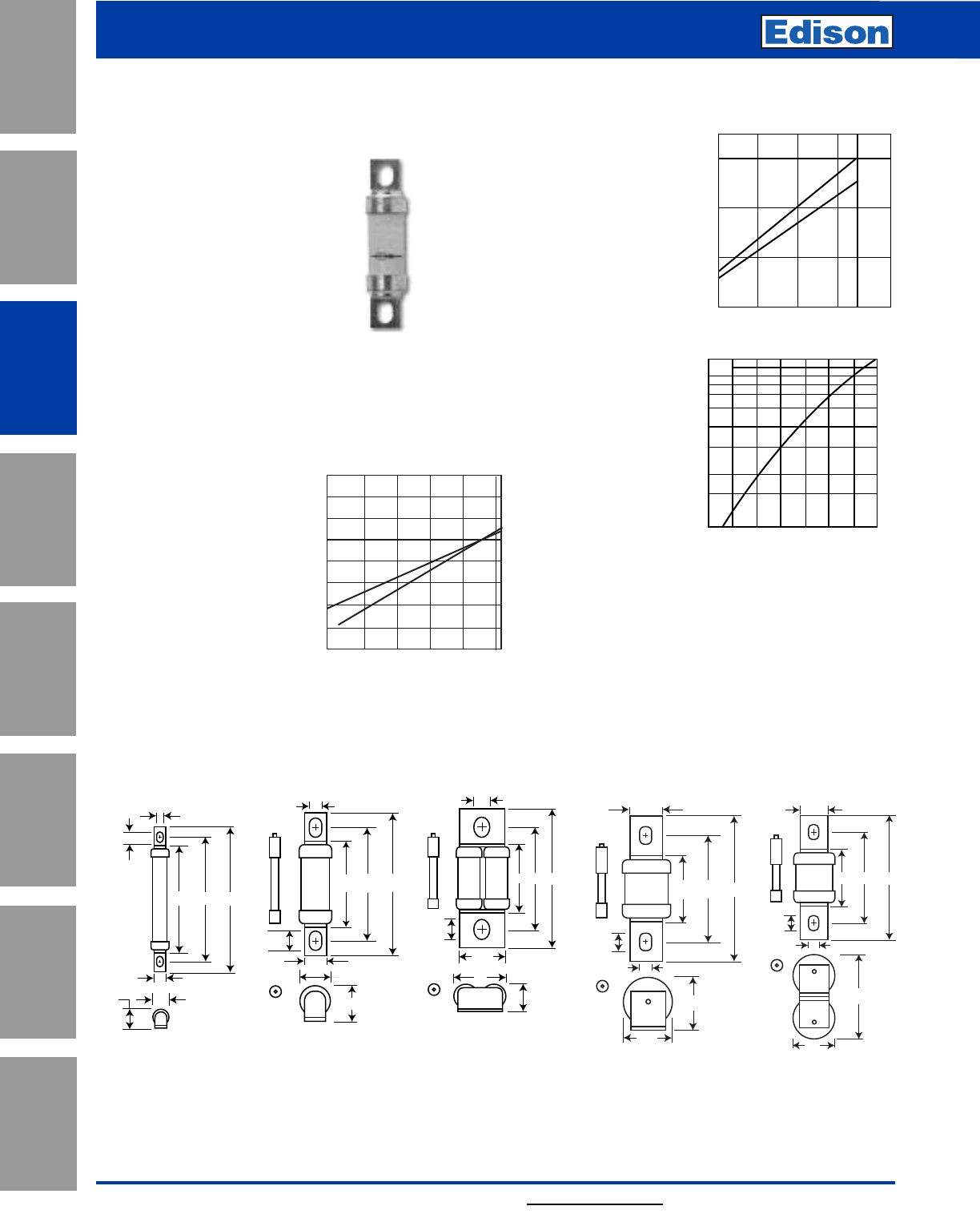
94 For additional information, visit www.edisonfuse.com
Application
Section
Fuse Blocks,
Holders & Misc.
Surge Protective
Devices
Medium
Voltage Fuses
Canadian
Fuses & Holders
Special
Purpose Fuses
UL/CSA Fuses
General Purpose
UL/CSA Fuses
Current Limiting
Catalog Number CT, ET, FE, EET, FEE, FM, FMM, MT, MMT 6 – 710A
British Style
690V High Speed Fuses
CT, ET, FE, EET, FEE, FM, FMM, MT, MMT
Specifications
Description: BS 88 style
stud-mount fuses.
Dimensions: See dimensions
illustrations.
Ratings:
Volts: — 690Vac/500Vdc
Amps: — 6-710A
IR: — 200kA RMS Sym.
Agency Information: CE, Designed and tested to: BS 88
Part 4, IEC 269 Part 4, UL Recognized. MT and MMT —
350Vdc (IEC) rating. Consult Edison for UL Recognition
status.
Electrical
Characteristics
Total Clearing I2t
The total clearing I2t at rated
voltage and at power factor
of 15% are given in the
electrical characteristics. For
other voltages, the clearing I2t
is found by multiplying by
correction factor, K, given as
a function of applied working
voltage, Eg, (rms).
Dimensions - mm
Fig. 1: CT
7763.5
48
17.1
19.1
12.7
7.1
9.7
947046
37
19
31.8
8.7
11.9
113
A50
41
38.1
25.4
10.3
13.5
113A50
83
38
25.4
10.3
14
Fig. 2: ET, FE
74.664.354.8
6.4
8.7
8.7
4
5.5
Fig. 3: EET, FEE Fig. 4: FM, MT Fig. 5: FMM, MMT
1mm = 0.0394” / 1” = 25.4mm Figs. 4 & 5 “A” Dimensions
Type “A”
FM 80-85mm
FMM 80-85mm
MT 85mm
MMT 85mm
Arc Voltage
This curve gives the
peak arc voltage, UL,
which may appear
across the fuse during its
operation as a function of
the applied working volt-
age, Eg, (rms) at a
power factor of 15%.
Power Losses
Watts loss at rated
current is given in the
electrical characteristics.
The curve allows the cal-
culation of the power
losses at load currents
lower than the rated
current. The correction
factor, Kp, is given as a
function of the RMS load
current, Ib, in % of the
rated current.
Features and Benefits
• Excellent cycling capability
• Excellent DC performance
• Low arc voltage and low energy let-through (I2t)
• Low watts loss
Typical Applications
• DC Common bus
• DC Drives
• Power converters/rectifiers
• Reduced voltage starters
1500
1000
500
200 400 600 660
Eg
UL
1)
2)
1) CT
2) ET, FE, EET, FEE, FM, FMM
200 300 400 500 600 690
0.2
0.4
0.6
0.8
1.0
1.2
1.4
1.6
1) 2)
Eg
K
1) CT, ET, EET, FE, FEE, MT, MMT
2) FM, FMM
Kp
1.0
0.8
0.4
0.5
0.6
0.3
0.2
0.1
30 40 50 60 70 80 90 100%
Ib
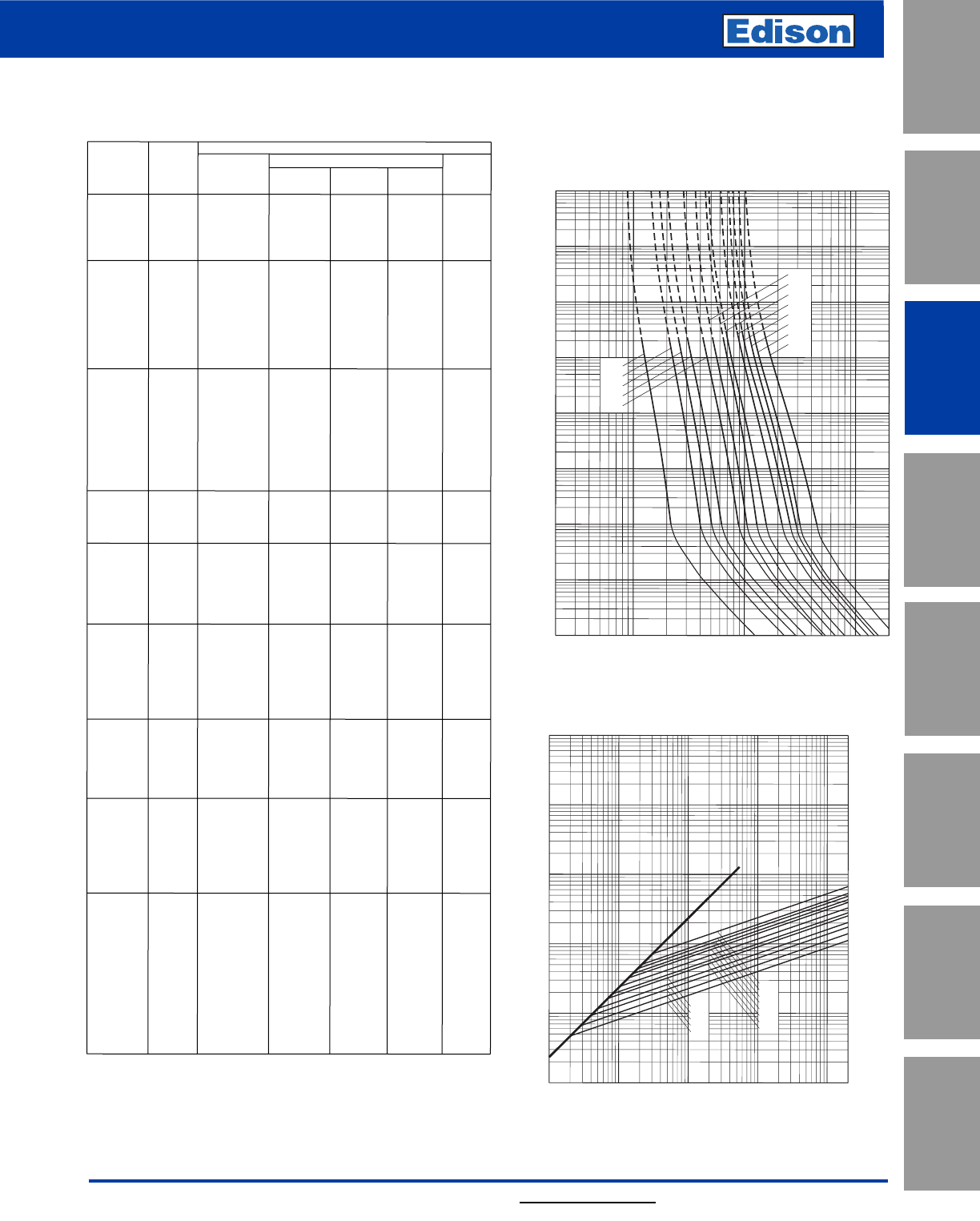
95
For additional information, visit www.edisonfuse.com
UL/CSA Fuses
Current Limiting
UL/CSA Fuses
General Purpose
Special
Purpose Fuses
Canadian
Fuses & Holders
Medium
Voltage Fuses
Fuse Blocks,
Holders & Misc.
Application
Section
Surge Protective
Devices
Catalog Number CT, ET, FE, EET, FEE, FM, FMM, MT, MMT 6 – 710A
British Style
690V High Speed Fuses
103
10–1
24681012
2468 2
1022468103
2
4
6
2
6
4
100
2
6
4
101
2
6
4
2
6
4
2
6
4
6
4
2
6
2
4
10CT
12CT
16CT
20CT
6CT
32ET
25ET
Prospective Current In Amps RMS
Virtual Pre-Arcing Time In Seconds
56ET
80ET
63ET
45ET
40ET
35ET
10–4
10–3
10–2
102
104
Prospective Short-Circuit Current Symmetrical RMS
Peak Let-Through Current
2
4
2
6
6
4
2
4
6
4
2
6
4
2
6
246 2 4 6 2 4 6 2 4 6
101
102
103
104
105
1011021031041052
20CT
16CT
12CT
10CT
6CT
80ET
63ET
56ET
45ET
40ET
35ET
32ET
25ET
Peak Let-Through Curve
CT 6-20, ET 25-80A: 690V
Time-Current Curve
Electrical Characteristics
RatedI2t (A2Sec)
Catalog Current Clearing Clearing Watts
NumbersType RMS-Amps Pre-arcat 415Vat 660VLoss
6CT 6 1.88.5 122
10CT 10 7 30483
12CT CT 121040653
16CT 1616661107
20CT 20321502207
25ET25251502507
32ET323219035011
35ET355231050011
40ETET401036009009
45ET45103680110011
56ET56135950150014
63ET631711200200016
80ET803602500400018
35FE 35331302009
40FE 40521803009
45FE 457627045011
50FE 50103380600 11
63FE FE 63135480750 12
71FE 71210600950 17
80FE 802509001500 20
90FE 9036013002100 20
100FE 10047018002800 23
90EET 9049030004500 19
110EET EET 11060040006500 27
140EET 14010507000 1200035
160EET 1601500100001700039
100FEE 10040016002400 24
120FEE 12054019003100 32
140FEE FEE 14085025003800 36
160FEE 160100037005700 46
180FEE 180140053008400 46
200FEE 20019007100 1140052
180FM 18014007500 1350040
200FM 2002600105001850040
225FM 2253700145002650044
250FM FM 2505200205003750048
280FM 2807000305005500048
315FM 31510000400007700055
350FM 350150006000010500055
400FMM4001000040000 7250085
450FMM4501500060000105000 90
500FMMFMM5002000082000150000100
550FMM55030000120000215000100
630FMM63045000180000310000100
700FMM70060000245000420000120
160MT160240015000 2500026
180MT180380025000 3800026
200MT 200 6000 40000 5800027
250MT MT 250 11500 80000 11000032
280MT 280 16500 100000 15000035
315MT 315 19000 125000 18000042
355MT 355 22000160000 20000051
180MMT 180 1650 12000 1800042
200MMT 200 2200 16000 2300042
225MMT 2253700 26000 4000042
280MMT 2806600 47000 7000047
315MMT 3158600 62000 9100051
355MMT MMT 355 13500 97000 14000054
400MMT 400 21000 150000 22000060
450MMT 450 30000220000 32000057
500MMT 500 42000 30000045000064
560MMT 560 60000 430000 64000064
630MMT 630 68500 500000 720000 86
710MMT 710 78000 600000 850000 105
• Watts loss provided at rated current.
• Note: FC, 8ET, 12ET, 15ET, 20ET, 65EET and 75EET are available for replacement
purposes on existing equipment.
Catalog Numbers
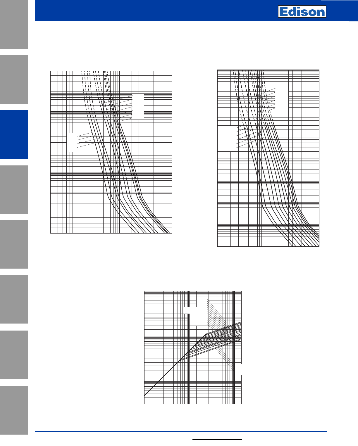
96 For additional information, visit www.edisonfuse.com
Application
Section
Fuse Blocks,
Holders & Misc.
Surge Protective
Devices
Medium
Voltage Fuses
Canadian
Fuses & Holders
Special
Purpose Fuses
UL/CSA Fuses
General Purpose
UL/CSA Fuses
Current Limiting
Catalog Number EET, MT, MMT 6 – 710A
British Style
690V High Speed Fuses
103
104
102
10–1
10–2
2468
1022
2468 2
1032468
104
2
4
6
2
6
4
100
2
6
4
101
2
6
4
2
6
4
2
6
4
6
4
2
6
2
4
Prospective Current In Amps RMS
Virtual Pre-Arcing Time In Seconds
160EET
140EET
110EET
90EET
200MT
355MT
315MT
280MT
250MT
180MT
160MT
10–4
10–3
Prospective Short-Circuit Current Symmetrical RMS
Peak Let-Through Current
2
4
2
6
6
4
2
4
6
4
2
6
4
2
6
246 246 246 246
101
102
103
104
105
1011021031041052
710MMT
630MMT
560MMT
500MMT
450MMT
315MT 355MT 400MMT
280MT 355MMT
250MT 315MMT
280MMT
200MT
180MT 225MMT
160MT 200MMT
180MMT
160EET
140EET
110EET
90EET
Peak Let-Through Curve
EET 90-160A, MT 160-355A: 690V
Time-Current Curve
104
103
102
10–1
10–3
Prospective Current In Amps RMS
Virtual Pre-Arcing Time In Seconds
10222468 2
1032468
104
2
4
6
2
6
4
100
2
6
4
101
2
6
4
2
6
4
2
6
4
6
4
2
6
2
4
280MMT
355MMT
315MMT
225MMT
200MMT
180MMT
630MMT
710MMT
560MMT
500MMT
450MMT
400MMT
10–4
10–2
MMT 180-710A: 690V
Time-Current Curve
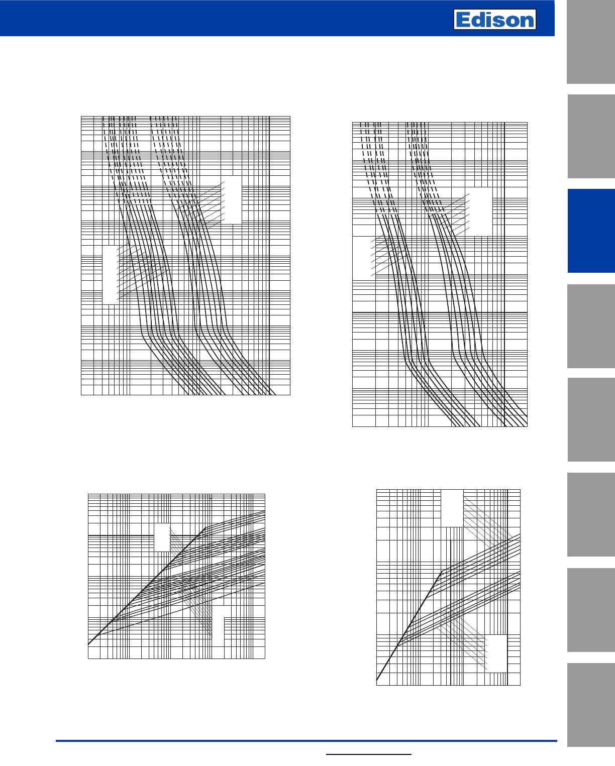
97
For additional information, visit www.edisonfuse.com
UL/CSA Fuses
Current Limiting
UL/CSA Fuses
General Purpose
Special
Purpose Fuses
Canadian
Fuses & Holders
Medium
Voltage Fuses
Fuse Blocks,
Holders & Misc.
Application
Section
Surge Protective
Devices
Catalog Number FE, FM, FEE, FMM 6 – 710A
British Style
690V High Speed Fuses
104
103
102
10–1
10–2
10–3
10–4
10222468 2
1032468
104
2
4
6
2
6
4
100
2
6
4
101
2
6
4
2
6
4
2
6
4
6
4
2
6
2
4
120FEE
140FEE
160FEE
180FEE
200FEE
100FEE
550FMM
700FMM
630FMM
500FMM
450FMM
400FMM
Prospective Current In Amps RMS
Virtual Pre-Arcing Time In Seconds
FEE 100-200A & FMM 400-700A: 690V
Time-Current Curve
Prospective Short-Circuit Current Symmetrical RMS
Peak Let-Through Current
102246
2
4
6
103
8
2
8
4
6
104
2
4
6
8
103246
104246
1052
180FEE
100FEE
120FEE
140FEE
160FEE
200FEE
400FMM
450FMM
500FMM
550FMM
630FMM
700FMM
Peak Let-Through Curve
103
102
10–1
10–2
10–4
2468
10222468 2
1032468
104
2
4
6
2
6
4
100
2
6
4
101
2
6
4
2
6
4
2
6
4
6
4
2
6
2
4
100FE
35FE
40FE
45FE
50FE
63FE
71FE
80FE
90FE
350FM
315FM
280FM
250FM
220FM
200FM
180FM
Prospective Current In Amps RMS
Virtual Pre-Arcing Time In Seconds
10–3
104
FE 35-100A & FM 180-350A: 690V
Time-Current Curve
Prospective Short-Circuit Current Symmetrical RMS
Peak Let-Through Current
2
4
2
6
6
4
2
6
4
2
6
4
246 246 246 246
101
102
103
104
105
1011021031041052
350FM
315FM
280FM
250FM
225FM
200FM
180FM
100FE
90FE
80FE
71FE
63FE
50FE
45FE
40FE
35FE
Peak Let-Through Curve
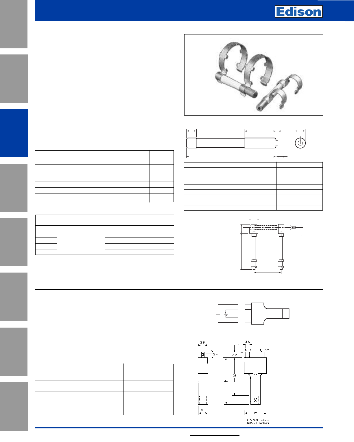
98
British Style High Speed Fuses
Indicators & Accessories
For additional information, visit www.edisonfuse.com
Application
Section
Fuse Blocks,
Holders & Misc.
Surge Protective
Devices
Medium
Voltage Fuses
Canadian
Fuses & Holders
Special
Purpose Fuses
UL/CSA Fuses
General Purpose
UL/CSA Fuses
Current Limiting
Indicator System
Trip-Indicators
Trip-indicators are available for use in parallel with the main
fuse. They can either be attached to the associated fuse or
mounted separately in panel mounted fuse clips, reference
CL1. A push-on adapter and microswitch attachment is
available for use with the trip indicator to give the facility of
remote indication, reference MAI.
Fuse ratings of 20A and below cannot usually
accommodate a trip-indicator.
When a trip-indicator is to be attached to the main fuse an
accessory pack comprising a pair of mounting clips and an
appropriate trip indicator would be required. The clips are
snapped onto the fuse end caps and the indicator is
pressed into clips as shown.
Electrical Specifications
Type TI500 TI700
Maximum RMS Voltage 500 700
Maximum Peak Voltage 700 1000
Maximum DC Voltage 130 350
Cold Resistance (ohms) 0.3 0.45
Maximum permissible steady-state current 1.5A 1.5A
Interrupting Capacity (RMS Symm.) 100,000 100,000
Pre-Arcing I2t 23 23
Microswitch Adapter – MAI
We offer a microswitch, complete with adapter for
securing the indicator. The microswitch is provided with
double pole, single throw contacts, having both a normally
open and a normally closed position. A special material has
been employed in the construction of the adapter to provide
reliable operation in the range of temperatures associated
with standard operating conditions and during fuse
operation.
Microswitch and Adapter Type MAI
Current Rating:
AC 50/60Hz resistive load @ 250V RMS 4A
AC 50/60Hz resistive load @ 127V RMS 6A
DC, resistive load @ 110Vdc 0.7A DC
DC, resistive load @ 30Vdc 2A DC
Maximum Working Voltage:
Contact-to-contact (RMS) 1000V
Contact-to-contact (RMS) 1500V
Maximum DC Volts: 110Vdc
Ref. Dim. “A” (mm) RMS Volts
TI250 37.6 250
TI500 47.5 500
TI600 55.7 600
TI700 61.8 700
TI1100 98.4 1100
TI1500 120.6 1500
TI2000 147.5 2000
TI2500 198.3 2500
RMS For use
Kit. Ref. Details Volts with Fuse Ref.
EC-250 Fuse Mount 250 LET
MC250 Indicator Kits 250 LMT & LMMT
EC-600 (Includes one 660 FE, FEE & ET
MC600 indicator 660 FM & FMM
MC700 and two clips) 700 MT & MMT
E
C
A
B
D
F
6 210.8
6.8
6.35
NO
NC
NC
NO
Terminal Arrangement
Trip-Indicator Dimensions - mm
Dimensions in mm
Fuse Indicator Kits
6.0 8.7
50.8
B
14
CL1 Panel Mount Clips
CL1 Panel mount fuse clips are available for mounting a
trip-indicator when mounting directly on the fuse is
impractical. Order part number CL1.
CL1 Panel Mount Clip
Dimensions - mm
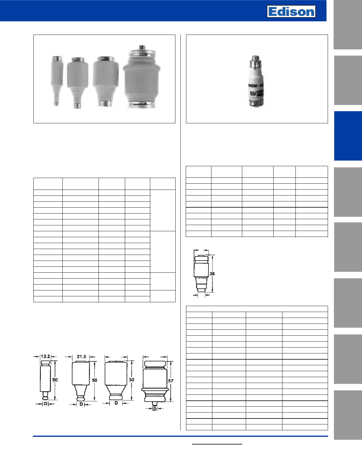
CROSS REFERENCE
EDISON LINDNER SIEMENS JEAN MULLER
2D16 594-0027 5SA2-11 gTN Dz/2
4D16 594-0047 5SA2-21 gTN Dz/4
6D16 594-0067 5SA2-31 gTN Dz/6
10D16 594-0107 5SA2-51 gTN Dz/10
16D16 594-0167 5SA2-61 gTN Dz/16
20D16 594-0207 5SA2-71 gTN Dz/20
25D16 594-0257 5SA2-81 gTN Dz/25
2D27 597-0027 5SB2-11 gLD 2/2
4D27 597-0047 5SB2-21 gLD 2/4
6D27 597-0067 5SB2-31 gLD 2/6
10D27 597-0107 5SB2-51 gLD 2/10
16D27 597-0167 5SB2-61 gLD 2/16
20D27 597-0207 5SB2-71 gLD 2/20
25D27 597-0257 5SB2-81 gLD 2/25
35D33 598-0357 5SB4-11 gLD 3/35
50D33 598-0357 5SB4-11 gLD 3/35
63D33 598-0357 5SB4-11 gLD 3/35
80D125 595-0807 5SC2-11 gLD 4/80
100D125 595-1007 5SC2-21 gLD 4/100
99
For additional information, visit www.edisonfuse.com
Type D “Bottle” Fuse
Amp Ratings: 2 to 100A
Voltage Ratings: 500Vac
Interrupting Rating: 100kA
Agency Approvals:
“D” type fuses complying with DIN 49360 (time lag) 2 and
DIN 49515, operating class gG/gL
Catalog Dimension Ampere Color Figure
Number “D” Rating Code Number
2D16 62Pink
4D16 64Brown
6D16 66Green
10D16 8 10 Red 1
16D16 10 16 Gray
20D16 12 20 Blue
25D16 14 25 Yellow
2D27 62Pink
4D27 64Brown
6D27 66Green
10D27 8 10 Red 2
16D27 10 16 Gray
20D27 12 20 Blue
25D27 14 25 Yellow
35D33 16 35 Black
50D33 18 50 White 3
63D33 20 63 Copper
80D125 5 80 Silver 4
100D125 7 100 Red
Additional fuse links: Quick acting fuse links in body size D16, D27, D33 and
D125 rated 2-100A. Reference number with suffix “Q”, i.e. 10D27Q. Voltage
rating 500V ultra fast-acting fuse links in body size D27, D33, and D125
rated 6-100A. Reference number with suffix “R”, i.e., 10D27R.
Notes: Gauge rings and keys can also be supplied.
27.0 33.0
Neozed Fuse
Also suitable for use on 250Vdc systems.
Amp Ratings: 2 to 63A
Voltage Ratings: 400Vac
Interrupting Rating: 100kA
Catalog Dimension Contact Amp Color
Number “D” Diameter D1Rating Code
2NZ01 11 7.3 2 Pink
4NZ01 11 7.3 4 Brown
6NZ01 11 7.3 6 Green
10NZ01 11 8.5 10 Red
16NZ01 11 9.7 16 Gray
20NZ02 15 10.9 20 Blue
25NZ02 15 12.1 25 Yellow
35NZ02 15 13.3 35 Black
50NZ02 15 14.5 50 White
63NZ02 15 15.9 63 Copper
Figure 1 Figure 2 Figure 3 Figure 4
D
D1
British & Canadian Standard
Industrial Fuses
UL/CSA Fuses
Current Limiting
UL/CSA Fuses
General Purpose
Special
Purpose Fuses
Canadian
Fuses & Holders
Medium
Voltage Fuses
Fuse Blocks,
Holders & Misc.
Application
Section
Surge Protective
Devices
Dimensions - mm
Dimensions - mm
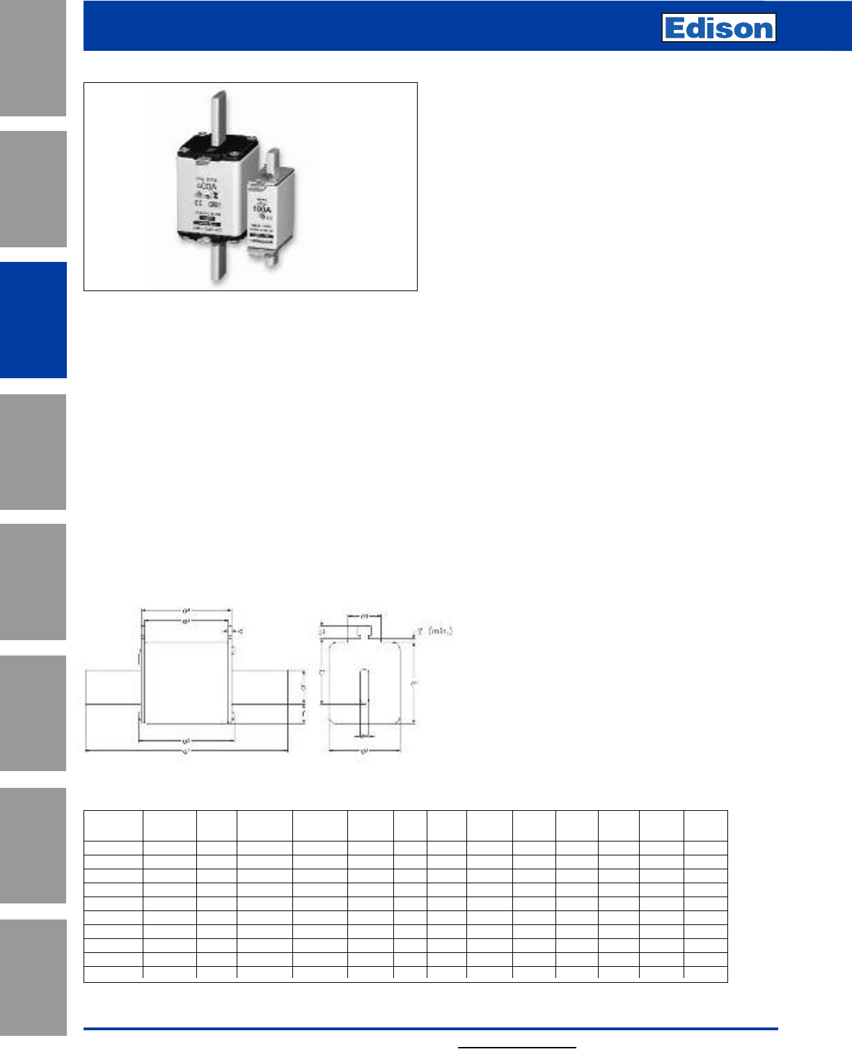
100
European Style
Line Protection Fuses
For additional information, visit www.edisonfuse.com
Application
Section
Fuse Blocks,
Holders & Misc.
Surge Protective
Devices
Medium
Voltage Fuses
Canadian
Fuses & Holders
Special
Purpose Fuses
UL/CSA Fuses
General Purpose
UL/CSA Fuses
Current Limiting
Catalog Number NH
HRC Fuse Links
Class of Operation: gG/gL
Amp Ratings: 2 to 1250A
Voltage Ratings: 500Vac
Rated Breaking Capacity: 120kA
Rated Frequency: 50 Hz
Operating Frequency: 45 - 62 Hz
Sizes: 000 to 4
Standards/Approvals: IEC 60269, VDE0636, DIN 43620
part 1 to 4, VDE mark and CE
Description: A square bodied range of industrial fuse
links for a wide variety of applications.
Packaging: 3's, except size 4 packed in 1
Ordering Code: Rating/Type Size Category, e.g.,
63NHG000B
Selectivity: 1 : 1.6 up to 500Vac
Design - Insulator: Ceramic
- Metal Parts: Corrosion-proof (top plate also
galvanic plated)
Contact Blades: Full contact and insulated blades
available, silver-plated brass.
Protection Type: IP00 according to DIN40050
Dimensions: DIN 43620
Tests: VDE 0636/22
Constancy of Characteristics: Resistant of aging.
On/Off Indicator: Patented spring dual indication
Mechanical Stress: Vibrations 7 up to 50Hz with 1 g,
shocks with 5 g.
Environmental: 100% recyclable, RoHS compliant,
cadmium and lead free across entire
range, corrosion free screws.
Dimensions - mm
a2bc
1c2De
1e2e3e4f
Size a a1(max) a3a4(rated) (±8) (rated) (rated) (max) (max) (max) (rated) (max)
000 78.5±1.5 54 45±1.5 49±1.5 15 35 10 2±0.5 41 21 16 68
00 78.5±1.5 54 45±1.5 49±1.5 15 35 11 2±0.5 48 30 25 6 15
0 125±2.5 68 62+3/-1.5 68+1.5/-3 15 35 11 2.5±0.5 48 30 25 6 15
01 135±2.5 75 62±2.5 68±2.5 15 40 11 2.5±0.5 48 30 25 6 15
1 135±2.5 75 62±2.5 68±2.5 20 40 11 2.5±0.5 53 52 25 6 15
02 150±2.5 75 62±2.5 68±2.5 20 48 11 2.5±0.5 53 52 25 6 15
2 150±2.5 75 62±2.5 68±2.5 25 48 11 2.5±0.5 61 60 25 6 15
03 150±2.5 75 62±2.5 68±2.5 25 60 11 2.5±0.5 61 60 25 6 15
3 150±2.5 75 62±2.5 68±2.5 32 60 11 3±0.5 75 70 25 6 18
4 200 84 80 90 50 85 10 3 102 87 -830
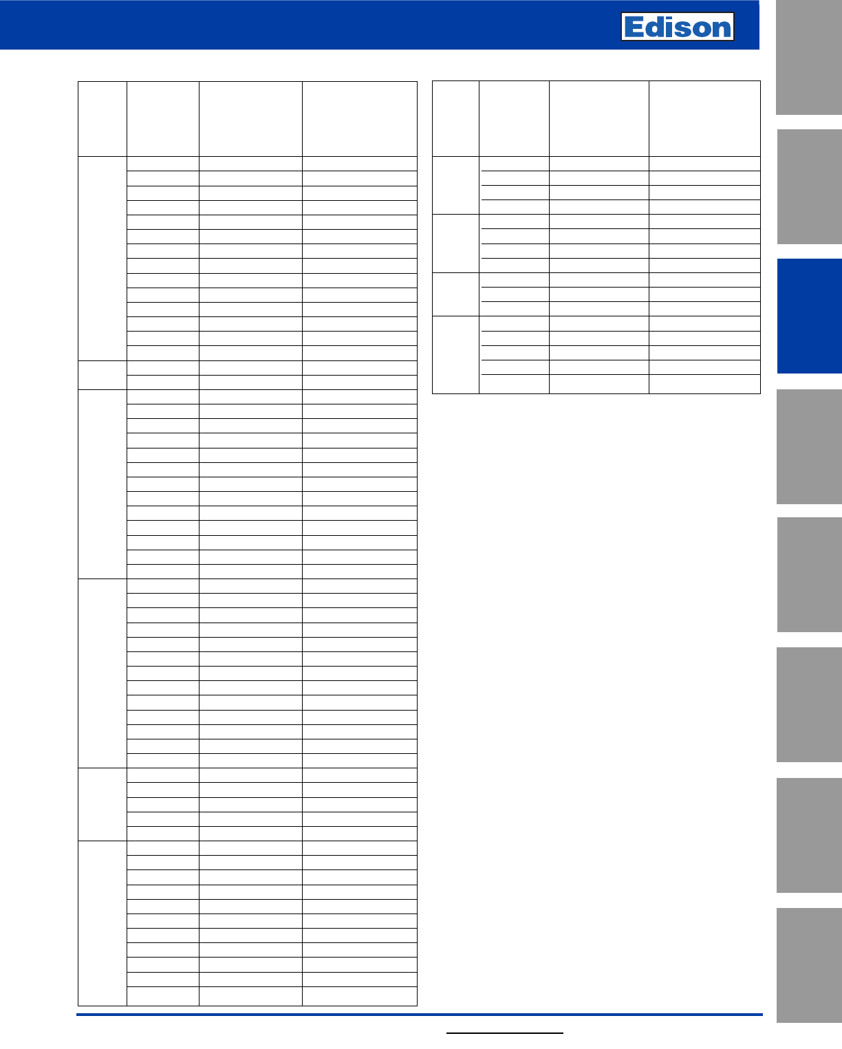
101
European Style
Line Protection Fuses
For additional information, visit www.edisonfuse.com
UL/CSA Fuses
Current Limiting
UL/CSA Fuses
General Purpose
Special
Purpose Fuses
Canadian
Fuses & Holders
Medium
Voltage Fuses
Fuse Blocks,
Holders & Misc.
Application
Section
Surge Protective
Devices
500 gG-gL
Dual Indicator
500 gG-gL with voltage free
Amp Dual Indicator metal gripping lugs
Size Rating Part Number Part Number
2 2NHG000B 2NHG000BI
4 4NHG000B 4NHG000BI
6 6NHG000B 6NHG000BI
10 10NHG000B 10NHG000BI
16 16NHG000B 16NHG000BI
20 20NHG000B 20NHG000BI
25 25NHG000B 25NHG000BI
000 32 32NHG000B 32NHG000BI
35 35NHG000B 35NHG000BI
40 40NHG000B 40NHG000BI
50 50NHG000B 50NHG000BI
63 63NHG000B 63NHG000BI
80 80NHG000B 80NHG000BI
100 100NHG000B 100NHG000BI
00 125 125NHG00B 125NHG00BI
160 160NHG00B 160NHG00BI
10 10NHG0B —
16 16NHG0B —
20 20NHG0B —
25 25NHG0B —
32 32NHG0B —
35 35NHG0B —
0 40 40NHG0B —
50 50NHG0B —
63 63NHG0B —
80 80NHG0B —
100 100NHG0B —
125 125NHG0B —
160 160NHG0B —
10 10NHG01B 10NHG01BI
16 16NHG01B 16NHG01BI
20 20NHG01B 20NHG01BI
25 25NHG01B 25NHG01BI
32 32NHG01B 32NHG01BI
35 35NHG01B 35NHG01BI
01 40 40NHG01B 40NHG01BI
50 50NHG01B 50NHG01BI
63 63NHG01B 63NHG01BI
80 80NHG01B 80NHG01BI
100 100NHG01B 100NHG01BI
125 125NHG01B 125NHG01BI
160 160NHG01B 160NHG01BI
200 200NHG1B 200NHG1BI
224 224NHG1B 224NHG1BI
1 250 250NHG1B 250NHG1BI
315 315NHG1B* —
355 355NHG1B* —
35 35NHG02B 35NHG02BI
40 40NHG02B 40NHG02BI
50 50NHG02B 50NHG02BI
63 63NHG02B 63NHG02BI
80 80NHG02B 80NHG02BI
02 100 100NHG02B 100NHG02BI
125 125NHG02B 125NHG02BI
160 160NHG02B 160NHG02BI
200 200NHG02B 200NHG02BI
224 224NHG02B 224NHG02BI
250 250NHG02B 250NHG02BI
500 gG-gL
Dual Indicator
500 gG-gL with voltage free
Amp Dual Indicator metal gripping lugs
Size Rating Part Number Part Number
315 315NHG2B 315NHG2BI
2 355 355NHG2B 355NHG2BI
400 400NHG2B 400NHG2BI
425 425NHG2B —
250 250NHG03B 250NHG03BI
03 315 315NHG03B 315NHG03BI
355 355NHG03B 355NHG03BI
400 400NHG03B 400NHG03BI
425 425NHG3B —
3 500 500NHG3B 500NHG3BI
630 630NHG3B —
500 500NHG4G —
4 Slotted 630 630NHG4G —
End Tags 800 800NHG4G —
1000 1000NHG4G —
1250 1250NHG4G —
* Denotes 440V
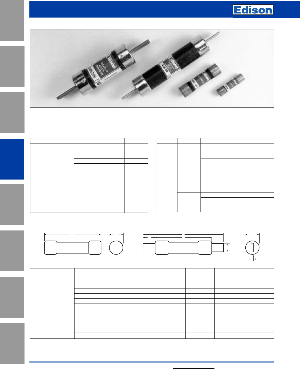
For additional information, visit www.edisonfuse.com
Application
Section
Fuse Blocks,
Holders & Misc.
Surge Protective
Devices
Medium
Voltage Fuses
Canadian
Fuses & Holders
Special
Purpose Fuses
UL/CSA Fuses
General Purpose
UL/CSA Fuses
Current Limiting
102
Time-Delay
Volts Ref. Amp Ratings Ctn. Qty.
Below 10A use ECSR
10, 12, 15, 20, 25, 30, 10
35, 40, 45, 50, 60
600Vac CDSC* 70, 80, 90, 100 5
110, 125, 150, 175, 200,
225, 250, 300, 350, 400, 1
450, 500, 600
Below 10A use ECNR
10, 12, 15, 20, 25, 30, 10
35, 40, 45, 50, 60
250Vac CDNC* 70, 80, 90, 100 5
110, 125, 150, 175, 200,
225, 250, 300, 350, 400, 1
450, 500, 600
One-Time
Volts Ref. Amp Ratings Ctn. Qty.
1, 2, 3, 4, 5, 6, 7, 8,
10, 12, 15, 20, 25, 30 10
35, 40, 45, 50, 60
600Vac KOS** 70, 80, 90, 100 5
110, 125, 150, 175, 200,
225, 250, 300, 350, 400, 1
450, 500, 600
KON** 1, 2, 3, 4, 5, 6, 7, 8, 10, 12
PONC*** 15, 20, 25, 30, (CSA ‘P’) 10
35, 40, 45, 50, 60
250Vac 70, 80, 90, 100 5
KON 110, 125, 150, 175, 200,
225, 250, 300, 350, 400, 1
450, 500, 600
Catalog
Volts Number Amps Max. A Min. B Min. C DEF
1-30 2.0 (50.8) 0.56 (14.3) –– – –
CDNC* 35-60 3.0 (76.2) 0.81 (20.6) –– – –
250Vac PONC*** 70-100 5.88 (149.4) – 1.0 (25.4) – 0.13 (3.2) 0.75 (19.1)
KON** 110-200 7.3 (185.4) – 1.38 (34.9) 4.13 (104.8) 0.19 (4.8) 1.13 (28.6)
225-400 8.63 (219.2) – 1.88 (47.6) 4.63 (117.5) 0.25 (6.4) 1.63 (41.3)
450-600 10.38 (263.7) – 2.25 (57.2) 5.19 (131.8) 0.25 (6.4) 2 (50.8)
1-30 5.0 (127.0) 0.81 (20.6) –– – –
35-60 5.5 (139.7) 1.06 (27.0) –– – –
600Vac CDSC* 70-100 7.88 (200.2) – 1.0 (25.4) – 0.13 (3.2) 0.75 (19.1)
KOS* 110-200 9.63 (244.6) – 1.38 (34.9) 6.13 (115.6) 0.19 (4.8) 1.13 (28.6)
225-400 11.63 (295.4) – 1.88 (47.6) 7.13 (118.1) 0.25 (6.4) 1.63 (41.3)
450-600 13.38 (339.9) – 2.25 (57.2) 8.19 (208.0) 0.25 (6.4) 2 (50.8)
Standard Dimension Fuses with 10kA Minimum Interrupting Rating;
CSA Certified to C22.2 No. 59.1
Dimensions - in (mm)
E
B
F
A
DC
Knife Blade–70 through 600 Amps
AB
Ferrule Design–1 through 60 Amps
*CDSC & CDNC are CSA certified Type “D”.
** KON 1-12A and KOS 1-60A are not CSA Certified.
*** PONC are CSA certified Type “P”.
Canadian Standard Fuses
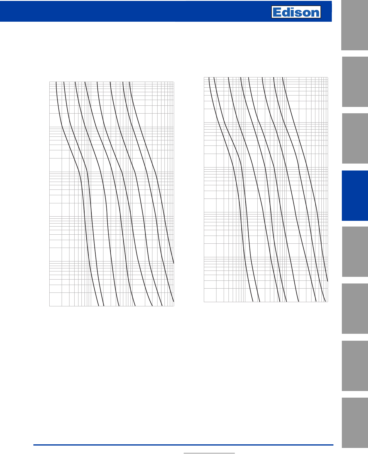
Fast-Acting
Canadian Standard Fuses
For additional information, visit www.edisonfuse.com 103
UL/CSA Fuses
Current Limiting
UL/CSA Fuses
General Purpose
Special
Purpose Fuses
Canadian
Fuses & Holders
Medium
Voltage Fuses
Fuse Blocks,
Holders & Misc.
Application
Section
Surge Protective
Devices
Fast-Acting
Canadian Standard Fuses
Average Time-Current Curves
Cat. No. CDNC 250Vac Cat. No. CDSC 600Vac
10,000
1,000
100
10
1,000
100
10
1
.1
CURRENT IN AMPS
TIME IN SECONDS
.01
30
60
100
200
400
600
AMP RATING
10
15
10,000
1,000
100
10
1,000
100
10
1
.1
CURRENT IN AMPS
TIME IN SECONDS
.01
30
60
100
200
400
600
AMP RATING
10
15
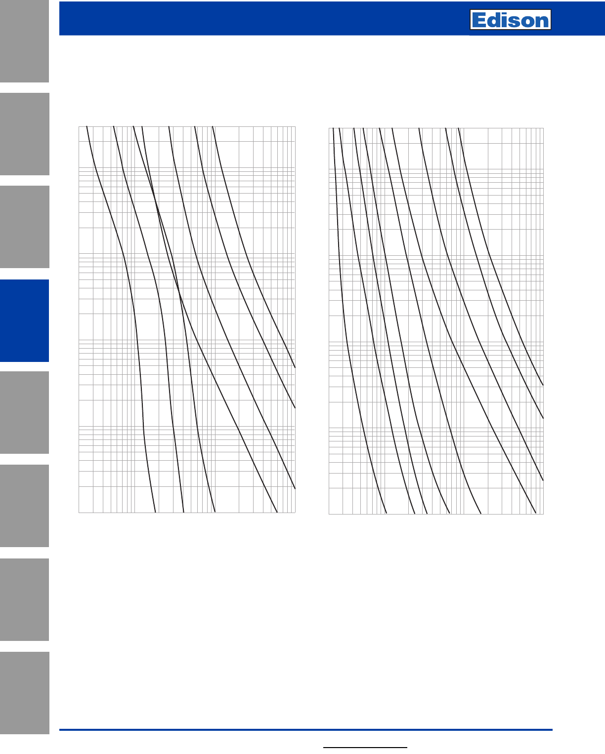
104
Application
Section
Fuse Blocks,
Holders & Misc.
Surge Protective
Devices
Medium
Voltage Fuses
Canadian
Fuses & Holders
Special
Purpose Fuses
UL/CSA Fuses
General Purpose
UL/CSA Fuses
Current Limiting
For additional information, visit www.edisonfuse.com
Time-Delay
Canadian Standard Fuses
Average Time-Current Curves
Cat. No. KON/PONC 250Vac Cat. No. KOS 600Vac
RMS SYMMETRICAL CURRENT IN AMPS
TIME IN SECONDS
100
1,000
10,000
100
10
1
.1
.01
20
60A
100A
200A
30A
400A
AMP RATING
600A
15A
RMS SYMMETRICAL CURRENT IN AMPS
TIME IN SECONDS
100
1,000
10,000
100
10
1
.1
.01
20
60A
100A
200A
30A
400A
AMP RATING
600A
15A
35A
20A
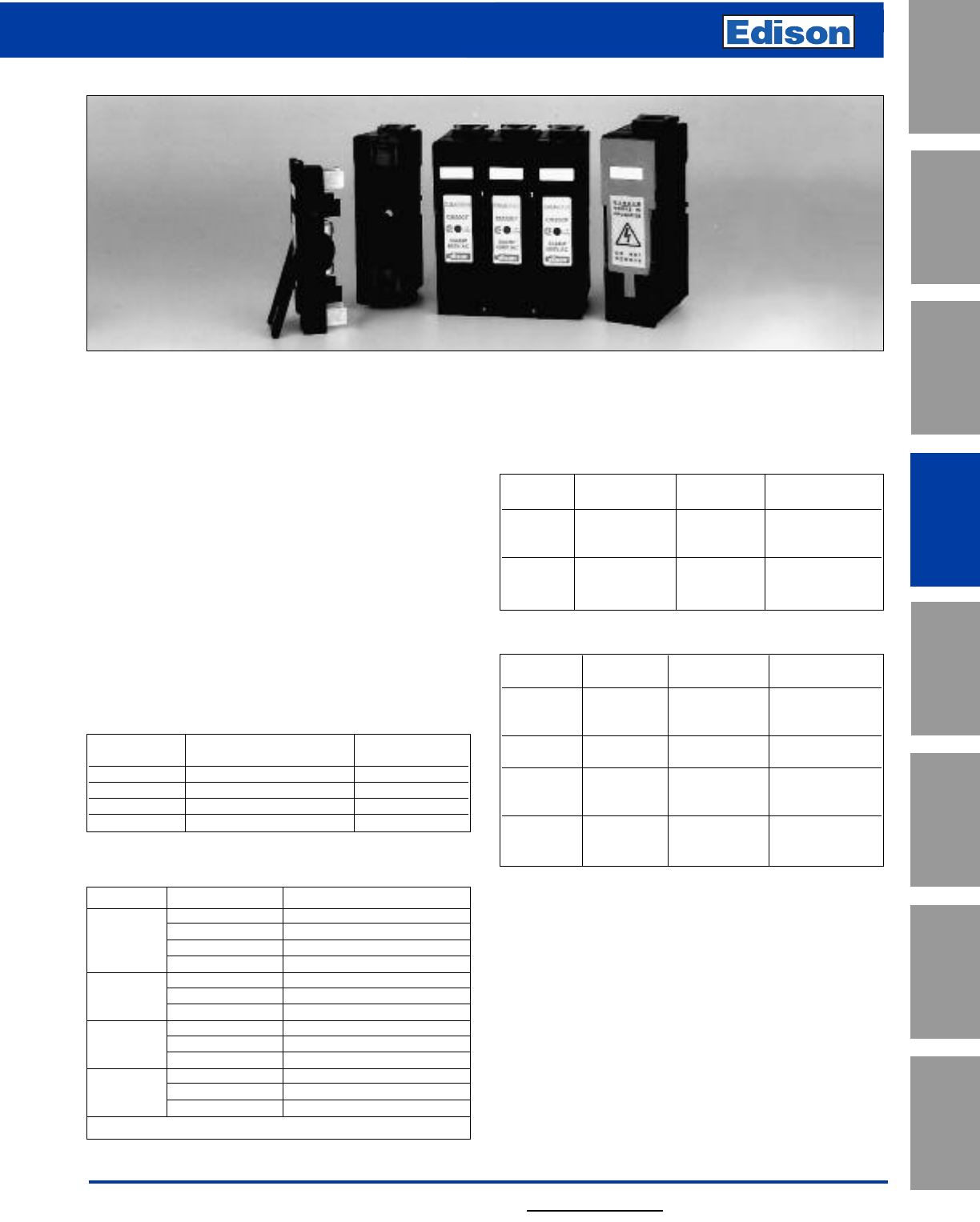
105
UL/CSA Fuses
Current Limiting
UL/CSA Fuses
General Purpose
Special
Purpose Fuses
Canadian
Fuses & Holders
Medium
Voltage Fuses
Fuse Blocks,
Holders & Misc.
Application
Section
Surge Protective
Devices
For additional information, visit www.edisonfuse.com
Figure 1
CAMaster HRC Fuse Holders
Fuse
Rating Details Reference Accommodated
30 Amp 20BS For CM20CF
30 Amp Back Stud 32BS For CM30CF
60/100 Amp 60/100BS For CM60/100CF
All 660V Neon NI –
Indicator
30 Amp Security 20LSC For CM20CF
30 Amp Carrier 32LSC For CM30CF
60/100 Amp with Clip. 63/100LSC For CM60/100CF
30 Amp 20CML For CM20CF
30 Amp Solid Link 32CML For CM30CF
60/100 Amp 63/100CML For CM60/100CF
Fuse
Rating Details Reference Accommodated
For
30 Amp HRCI-CA CM20CF --CIF21
Applications
30 Amp For CM30CF ---H07C
60 Amp HRCII CM60CF ---KO7C
100 Amp Applications CM100CF ---K07CR
Unique Cam Action
The fuse carriers are fitted with a cam for ease of removal
from the fuse bases allowing significantly improved contact
pressure between fuse carrier and fuse base contacts, with
a corresponding enhanced electrical performance level.
This design overcomes a major problem of all existing dead
front style fuse holders manufactured worldwide, which
have to compromise between difficulties of fuse carrier
removal from base and contact pressure achieved.
Lockable Safety Carriers
A range of lockable safety carriers for the CAMaster fuse
holder (Cat ref: LSC), are available. This distinct feature
ensures isolation can be achieved allowing maintenance to
be carried out safely.
Fixing Torque and Cable Size
CAMaster Ratings
Range: 30 (miniature), 30, 60, and 100A, 600Vac
A range of fully shrouded HRC fuse holders having an advanced design. They incorporate a high level of innovation, with
enhanced performance characteristics and comply with the requirements of: CSA C22.2 No. 39 as well as IEC 60269 and
BS88 Standards.
Amps Mounting Edison Catalog Numbers
Front CM20CF
30 Front/2-pole 2xCM20CF
Back CM20CF + 2 off 20BS
Front/Back CM20CF _ 1 off 20BS
Front CM30CF
30 Back CM30CF + 2 off 30BS
Front/Back CM30CF + 1 off 30BS
Front CM60CF
60 Back CM60CF + 2 of 60/100BS
Front/Back CM60CF + 1 of 60/100BS
Front CM100CF
100* Back CM100CF + 2 of 60/100BS
Front/Back CM100CF + 1 or 60/100BS
*Uses compact Edison fuses.
Catalog Numbers
Fuse Fixing Max Cable
Ref Tightening Torques Size
CM20CF 1.5N•m #2
CM30CF 1.5N•m #2
CM60CF 2.0N•m 2/0
CM100CF 2.0N•m 2/0
Accessories for CAMaster Units
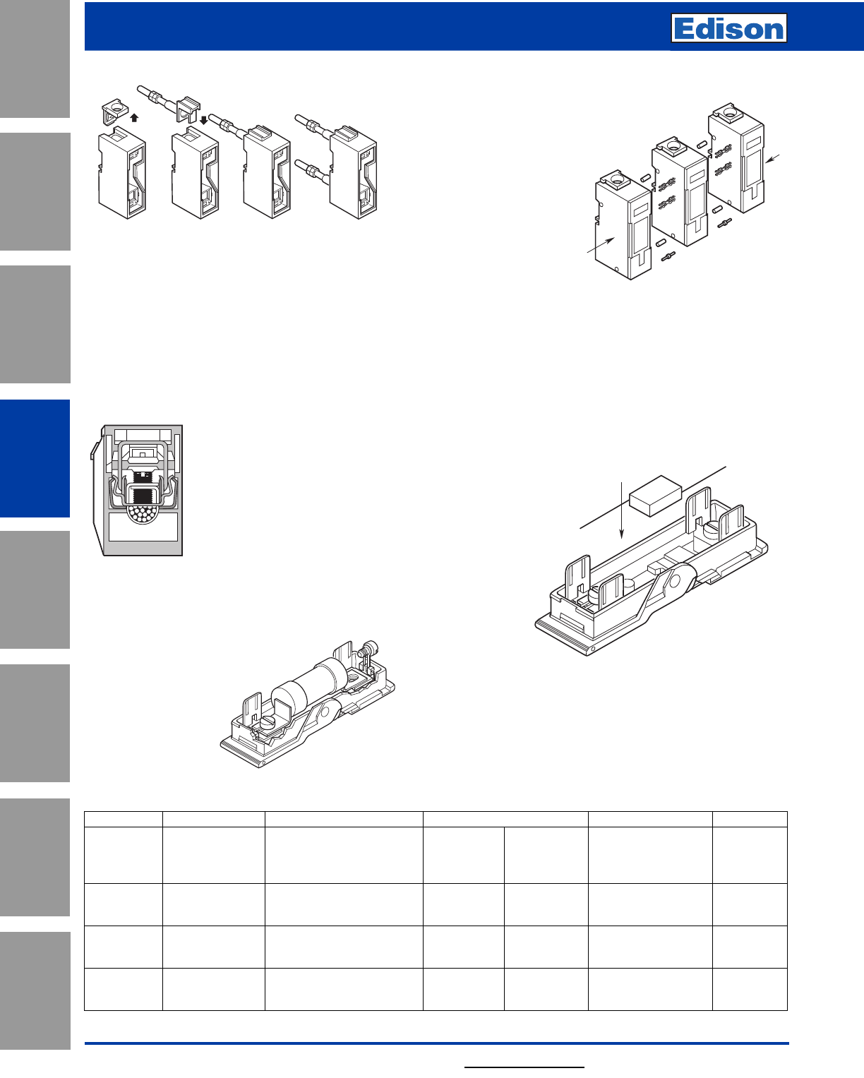
106
Application
Section
Fuse Blocks,
Holders & Misc.
Surge Protective
Devices
Medium
Voltage Fuses
Canadian
Fuses & Holders
Special
Purpose Fuses
UL/CSA Fuses
General Purpose
UL/CSA Fuses
Current Limiting
For additional information, visit www.edisonfuse.com
CAMaster HRC Fuse Holders
Unique Conversion Capability
The standard fuse holders can be readily converted from front
connection to front/back stud and double-back stud connection
types at the point of use. This is achieved with a unique back stud
accessory and the use of a screwdriver. See conversion sequence
in Fig. 2. Steps 1, 2 and 3 show removal of ferrule end and
insertion of back stud accessory to give the front/back stud
connection type. This sequence repeated at the opposite end gives
the double-back stud connection type shown in step 4.
Unique Cable Termination
The fuse holder’s unique cable terminations are designed for user
convenience and to ensure long-term
reliability. They incorporate stainless steel
saddles and hardened termination screws,
maintaining permanent cable clamping to
profiled contact plates. The main electrical
contact path between the cable and fuse link
tag is shown highlighted. This permits the
use of high tightening torques without
damage to cables or threads and provides
resistance to high cable pull out forces. (See
Fig. 3.) The fuse holders are supplied with
the hardened termination screws backed out
ready for cable insertion, saving installation
time.
Hinged Captive Screws
The fuse fixing screws to fuse carrier are held in captive hinges
providing ease of fixing and preventing loss
during installation. (See Fig. 4.)
Figure 3. Unique
Cable Termination
Figure 4. Hinged
Captive Screws
Two/Three Pole Ganging
The unique design of the carriers allows
ganging to be readily achieved by the use of
standard accessories. This provides
improved safety related to
isolation and protection of 2-Pole
and 3-Pole electrical circuits
by ensuring that the
correctly related
poles are removed
at the same time.
(See Fig. 5.)
Dual
Mounting
Capability
The design as standard provides both bolted panel and DIN-Rail
mounting features. The DIN-Rail mounting facility for each of the
various dimensioned ratings is so designed as to give equal height
and depth above the DIN-Rail.
Hinged Internal Shields
Non-removable full shrouding of live parts within the fuse base is
provided by the use of hinged shields. The positive captive nature
of these ensures that they cannot be omitted during installation and
are so designed that insertion of the fuse carrier can only be made
with them correctly positioned.
Neon Indicator
Neon clip-in indicator accessories are
available providing clear location
and status of fuses which have
opened. (See Fig. 6.)
Circuit Identification
The fuse carrier has a marking label for ease of circuit
identification.
Strip Length Marking
The length of cable insulation that should be stripped off is shown
on the side of the fuse base.
Figure 6.
Neon Indicators.
1234
Figure 2. Unique Conversion Capability
Cross Reference
Amps Mounting Edison Old Brush GEC Fusetek
Front CM20CF CIF15F CIF15A CRS15H MF20F
30 Front/2-pole 2xCM20CF + GLP ––C2RS15H –
Back CM20CF + 2 off 20BS CIF15BS CIF15B – –
Front/Back CM20CF _ 1 off 20BS CIF15FBS CIF15C ––
Front CM30CF C30AF CCH30A C30H or CRS30H MF30F
30 Back CM30CF + 2 off 30BS C20ABS CCH30B C30P MF30B
Front/Back CM30CF + 1 off 30BS C30AFBS CCH30C C30PH MF30FB
Front CM60CF C60BF CCK60A C60H or CRS60H MF60F
60 Back CM60CF + 2 of 60/100BS C60BBS CCK60B C60P MF60B
Front/Back CM60CF + 1 of 60/100BS C60FBS CCK60C C60PH MF60FB
Front CM100CF C100CF CCL100A C100H or CRS100H MF100F
100* Back CM100CF + 2 of 60/100BS C100CBS CCL100B C100P MF100B
Front/Back CM100CF + 1 or 60/100BS C100CFBS CCL100C C100PH MF100FB
*Edison uses compact fuse.
Figure 5.
Two/Three-Pole
Ganging.
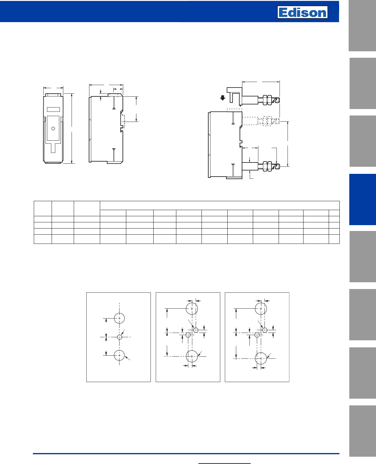
107
UL/CSA Fuses
Current Limiting
UL/CSA Fuses
General Purpose
Special
Purpose Fuses
Canadian
Fuses & Holders
Medium
Voltage Fuses
Fuse Blocks,
Holders & Misc.
Application
Section
Surge Protective
Devices
For additional information, visit www.edisonfuse.com
CAMaster HRC Fuse Holder
Dimensions
Standard Front Connected Unit Front/Back Stud and Double Back Stud
Connected Units
A
B
D
44
C
L OF DIN RAIL
C
E
STRIPSTRIP
STRIP
STRIP
F
H
G
øK
øJ
Rating Catalog Dimensions - in (mm)
Amps Number Category AB CD E F GHJ K
30 CM20CF HRCI-CA 1.0 (25.4) 3.69 (93.7) 2.36 (60) 0.13 (3.2) 0.64 (17.5) 2.60 (66) 2.29 (58) 1.13 (28.6) 0.47 (11.9) M6
30 CM30CF HRCII-C 1.25 (31.8) 4.63 (117.5) 2.36 (60) 0.13 (3.2) 0.69 (17.5) 2.60 (66) 2.92 (74) 1.13 (28.6) 0.47 (11.9) M6
60 CM60CF HRCII-C 1.40 (35.6) 4.93 (125) 2.36 (60) 0.19 (4.75) 0.65 (16.4) 3.41 (86.5) 3.14 (79.8) 1.13 (28.6) 0.47 (11.9) M8
100 CM100CF HRCII-MISC 1.40 (35.6) 4.93 (125) 2.36 (60) 0.19 (4.75) 0.65 (16.4) 3.41 (86.5) 3.14 (79.8) 1.13 (28.6) 0.47 (11.9) M8
Panel Drilling Plans, Viewed from Front of Panel
C
L
C
L
1.14"
29.0mm
1.14"
29.0mm
0.22"
ø5.5mm
0.59"
ø15.0mm
CM20CF
C
L
C
L
0.22"
ø5.5mm
0.75"
ø19mm
CM30CF
1.46"
37.0mm
0.13"
3.2mm
0.13"
3.2mm
0.25"
6.35mm
0.25"
6.35mm
C
L
C
L
0.22"
ø5.5mm
0.75"
ø19mm
CM60 + 100CF
1.46"
37.0mm
0.13"
3.2mm
0.13"
3.2mm
0.25"
6.35mm
0.25"
6.35mm
1.46"
37.0mm
1.62"
41.0mm
Dimensions - in (mm)
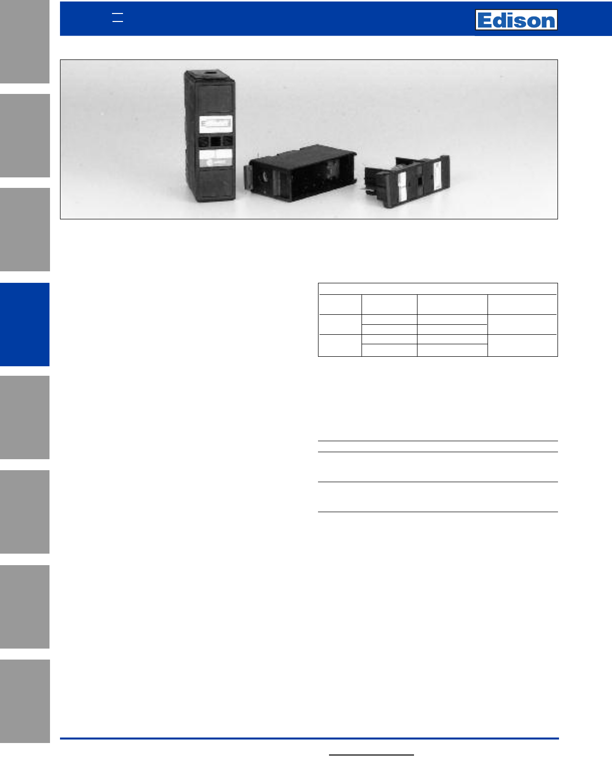
108 For additional information, visit www.edisonfuse.com
Application
Section
Fuse Blocks,
Holders & Misc.
Surge Protective
Devices
Medium
Voltage Fuses
Canadian
Fuses & Holders
Special
Purpose Fuses
UL/CSA Fuses
General Purpose
UL/CSA Fuses
Current Limiting
SAFELOC HRC Fuse Holders
For use with HRCI-CB Fuses
Edison Fuse
Rating Connection Catalog Numbers Accommodated
30 Amp Front C30F CIF06
Front-Back C30FBS
Front C60F
60 Amp Back C60BS EK
Description
SAFEloc fuse holders provide a simple range designed to
accommodate the compact range of offset blade fuse to
CSA C22.2 No. 106, HRCI-CB. The combination offers
significant savings in volume and cost as well as a reduction
in fitting time and power loss.
Features
The fuse holders incorporate a unique slide/snap action
carrier which eliminates the need for fuse carrier contacts.
This provides positive, stress free fitting of fuse and locks
the fuse in position ensuring safe insertion and withdrawal
from the base. The resulting direct contact between fuse
blades and the plated base contacts provides lower watts
loss and increased reliability. The base contacts are fully
shrouded to protect personnel from direct contact electric
shock. The shrouds utilize simple slide/snap action allowing
access to the contact terminal screws. They are semi-
captive within the base, reducing the risk of loss during
cabling. The fuse base, which consists of glass filled, high
impact resistant thermoplastic polyester, incorporates a
direct 35mm DIN-Rail mounting facility as well as single
screw fixing.
Tightening Torque
To avoid a heat build up it is most important the cable
terminal screws are screwed in tight and are holding the
cable firmly. A tightening torque of 2.5 to 2.8 Newton meters
(N•m) or 22 to 25lb-in is recommended.
Catalog Numbers
For use with HRCI-CB Fuses. Suitable for Bolted Panel Mounting or DIN-Rail Mounting.
SAFEloc fuse holders provide an easy method of protecting
a wide range of electrical equipment such as lighting,
heating, motor and control equipment circuits, and offer
significant savings on volume, cost, fitting time and power
loss.
Cross Reference
Amps Mounting Edison GEC FUSETEK
Front C30F CSC30H MD30F
30 Back C30BS CSC30P MD30B
Front/Back C30FBS – MD30FB
Front C60F CSC60H –
60 Back C60BS ––
Front/Back C60FBS ––
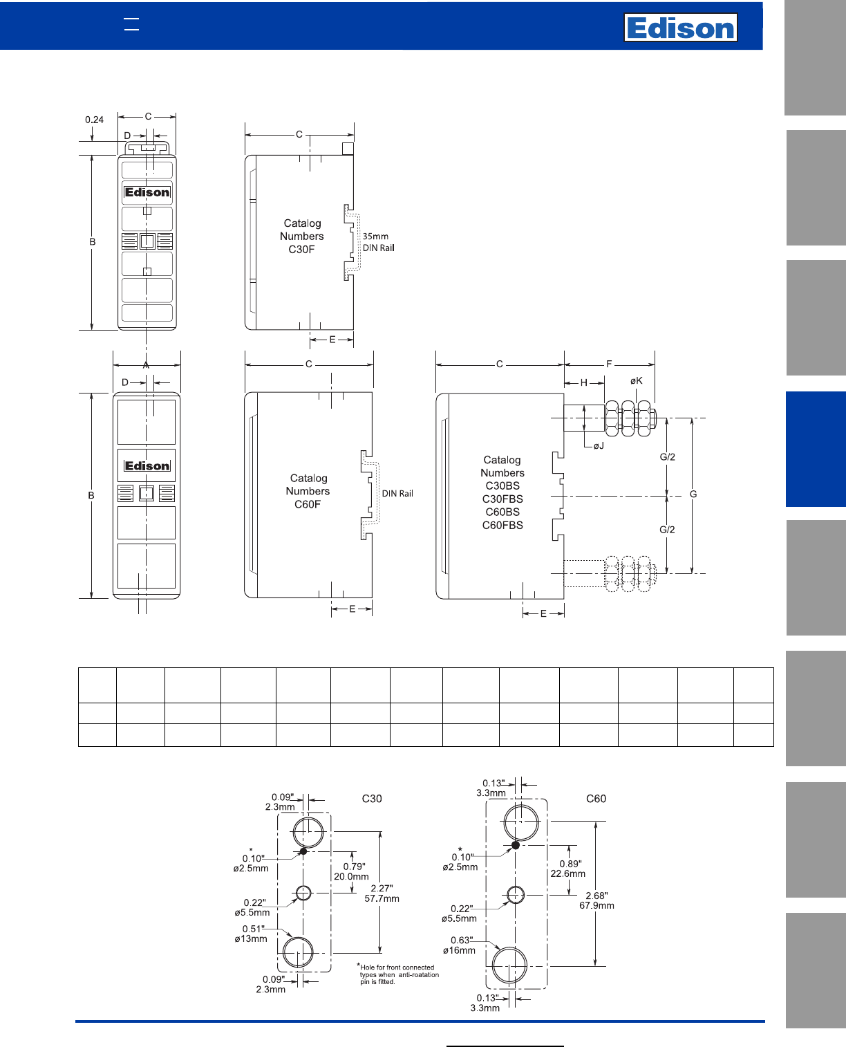
109
UL/CSA Fuses
Current Limiting
UL/CSA Fuses
General Purpose
Special
Purpose Fuses
Canadian
Fuses & Holders
Medium
Voltage Fuses
Fuse Blocks,
Holders & Misc.
Application
Section
Surge Protective
Devices
For additional information, visit www.edisonfuse.com
Dimensions - in (mm)
Series Max.
Amps Number Cable mm2ABC DE F G H J K
30 C30 16 1.0 (25.4) 3.0 (76.2) 1.83 (46.5) 0.09 (2.3) 0.63 (16.0) 1.54 (39.2) 2.27 (57.7) 0.67 (17.0) 0.38 (9.7) M6
60 C60 35 1.15 (29.1) 3.55 (90.0) 2.18 (55.0) 0.13 (3.3) 0.70 (17.7) 1.54 (39.2) 2.68 (67.9) 0.69 (17.5) 0.43 (11.0) M8
Dimensions - in (mm)
SAFELOC HRC Fuse Holders
110 For additional information, visit www.edisonfuse.com
Application
Section
Fuse Blocks,
Holders & Misc.
Surge Protective
Devices
Medium
Voltage Fuses
Canadian
Fuses & Holders
Special
Purpose Fuses
UL/CSA Fuses
General Purpose
UL/CSA Fuses
Current Limiting
Medium voltage fuses for motor circuits offer the following
user benefits:
• Performance complies with latest ANSI Standards
• Dramatic reduction in energy let-through
•Lower power dissipation
• Low arc voltage during operation
• Includes heavy duty striker to IEC 282-1
Advantages of Edison Motor Fuses
During the full voltage starting of motors the fuse elements
reach a considerably higher temperature than normally
occurs under continuous operation. The resulting expansion
and contraction of the fuse element can cause premature
operation. The Edison motor circuit fuse incorporates
provisions in the design of the element to minimize this
effect and hence avoid the necessity of having to use a
much larger size of fuse.
Edison fuses operate very quickly on heavy fault currents.
This results from the steepness of the time-current
characteristic, which also facilitates coordination with the
other components of the circuit.
Lower power dissipation helps to ensure low temperature
rise of, for example, multi-tier starters.
Switching (arc) voltages are appreciably less than permitted
values and fall with lower values of system voltage. Thus,
the 5.5kV fuses are equally suitable for use in 4.8kV,
4.16kV and 2.4kV circuits.
The superior low-overcurrent breaking performance is of
advantage whether or not the striker is used to open the
contactor.
“R” Rating
The R-Rated motor circuit fuses should be selected to
coordinate with the motor and controller to provide
short-circuit protection.
The actual “R” rating signifies a 20 second opening time at
100 times the “R” rating of the fuse.
For example:
2R fuse opens in 20 seconds at 200A.
12R fuse opens in 20 seconds at 1200A.
Motor Starting Application
Application Procedure
For any motor the fuse current rating is determined by
magnitude and duration of starting current, except in a few
situations where the starting conditions are very light. The
fuse current rating should be selected as follows.
Direct On-Line Starting
In the absence of specific information the starting current
can usually be taken to be six times the motor full load
current. The starting time will depend on the type of drive
but will be approximately as follows:
Pump Motors - 6 seconds
Mill Motors - 10 to 15 seconds
Fan Motors - 60 seconds
These are average values and the appropriate figures for
starting current and starting time for the actual installation
should be obtained wherever possible. Multiply the starting
current by 1.6 and using this value of current and the
starting time (it is recommended that a minimum time of 8
seconds be adopted) plot this point on the minimum melting
time-current characteristics of the fuses. The correct current
rating of fuse is then chosen as being the one immediately
to the right of the point so plotted. The chosen fuse must
also have a current rating of at least 1.3 times the full-load
current of the associated motor.
The rating thus chosen will be adequate for normal
applications where the associated motor is not started more
than twice in any given period of one hour. For applications
involving more frequent starting duties, a greater derating
factor must be applied as shown in the following table.
Derating Factor
The figures in the above table apply only when the Minimum Melting
Time-Current Characteristic Curve is used.
For applications involving more frequent starting duty than 16 times per
hour or where unusual duty cycles are involved consult Edison Customer
Satisfaction for advice.
Assisted Starting
A similar method of fuse selection may be used as for
direct-on-line starting (see above) but it must be noted that
the normal running current of the motor is likely to be closer
in value to the nominal current rating of the fuse than for
direct-on-line applications.
The rating of fuse chosen will need to be appreciably
greater than the motor running current to allow for restricted
cooling inside control gear cubicles, particularly where
multi-tier starters are involved. In case of doubt refer to
Edison Customer Satisfaction for further guidance.
Maximum of starts per hour Derating factor
2 1.6
4 1.7
8 2.0
16 2.2
R-Rated Medium Voltage Fuses
for Motor Circuits
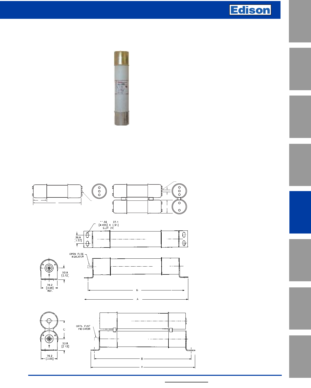
111
For additional information, visit www.edisonfuse.com
UL/CSA Fuses
Current Limiting
UL/CSA Fuses
General Purpose
Special
Purpose Fuses
Canadian
Fuses & Holders
Medium
Voltage Fuses
Fuse Blocks,
Holders & Misc.
Application
Section
Surge Protective
Devices
R-Rated Medium Voltage Fuses
For Motor Circuits
JCG, JCH, JCK,
JCK-A, JCK-B, JCL,
JCL-A, JCL-B, JCR-A,
& JCR-B
Specifications
Description: Indoor/enclosure
R-Rated medium voltage,
current-limiting fuses for motor
circuit protection.
Dimensions: See Dimensions
illustrations.
Ratings:
Volts: — 2.4-7.2kV (See Catalog Numbers table for details)
Amps: — 25-450A (See Catalog Numbers table for details)
IR: — 50kA Sym
— 80kA ASYM
— See Catalog Numbers table for details
R-Rated Fuses for Motor Circuit Protection
0.38"
(9.5mm)
B
INDICATOR
Showing Fuse is Open
INDICATOR
Showing Fuse
is Open
A
C
Dimensions - mm (in)
Figure 1
Figure 2
Figure 3
Agency Information: UL Recognized: 2540Vac — JCK,
JCK-A, 5080Vac — JCL, JCL-A, UL Recognized (Guide
#MSSS2, File #E96676).
Features and Benefits
• Physically dimensioned for retrofitting in existing hardware
•Open fuse indicator for ease in troubleshooting
• Available with optional Cutler Hammer®hookeye for ease of
insertion and removal
• Classified as back-up fuses for current-limited protection of
medium voltage motor controllers
Typical Applications
• Medium Voltage Motor Controllers
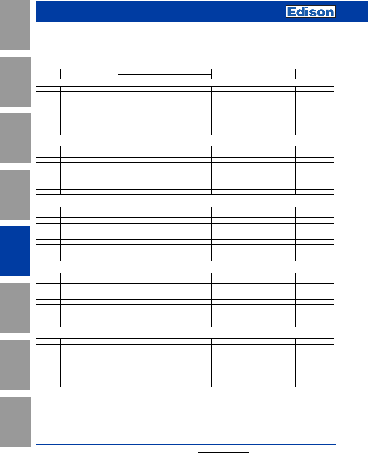
112 For additional information, visit www.edisonfuse.com
Application
Section
Fuse Blocks,
Holders & Misc.
Surge Protective
Devices
Medium
Voltage Fuses
Canadian
Fuses & Holders
Special
Purpose Fuses
UL/CSA Fuses
General Purpose
UL/CSA Fuses
Current Limiting
R-Rated Medium Voltage Fuses
for Motor Circuits
R-Rated Fuses for Motor Circuit Protection
Catalog Numbers: R-Rated; Indoor/Enclosure
Catalog Amp Maximum Dimensions - in (mm)* Max Int. Cap. Amps Min Int. Cap.
Numbers Ratings Design Voltage AB C
Construction
Amps (Asym.) (Sym.) Amps (Sym.)
2400V (See Figure 1)
JCK-2R 70 2540 11.24 (285.5) 3.0 (76.2) 3.0 (76.2) Single 80,000 50,000 165
JCK-3R 100 2540 11.24 (285.5) 3.0 (76.2) 3.0 (76.2) Single 80,000 50,000 220
JCK-4R 130 2540 11.24 (285.5) 3.0 (76.2) 3.0 (76.2) Single 80,000 50,000 320
JCK-5R 150 2540 11.24 (285.5) 3.0 (76.2) 3.0 (76.2) Single 80,000 50,000 410
JCK-6R 170 2540 11.24 (285.5) 3.0 (76.2) 3.0 (76.2) Single 80,000 50,000 480
JCK-9R 200 2540 11.24 (285.5) 3.0 (76.2) 3.0 (76.2) Single 80,000 50,000 720
JCK-12R 230 2540 11.24 (285.5) 3.0 (76.2) 3.0 (76.2) Single 80,000 50,000 970
JCK-18R 390 2540 11.24 (285.5) 3.0 (76.2) 3.0 (76.2) Double 80,000 50,000 1,430
JCK-24R 450 2540 11.24 (285.5) 3.0 (76.2) 3.0 (76.2) Double 80,000 50,000 1,880
2400V — With Westinghouse Ampguard Hookeye (See Figure 1)
JCK-A-2R 70 2540 11.24 (285.5) 3.0 (76.2) 3.0 (76.2) Single 80,000 50,000 165
JCK-A-3R 100 2540 11.24 (285.5) 3.0 (76.2) 3.0 (76.2) Single 80,000 50,000 220
JCK-A-4R 130 2540 11.24 (285.5) 3.0 (76.2) 3.0 (76.2) Single 80,000 50,000 320
JCK-A-5R 150 2540 11.24 (285.5) 3.0 (76.2) 3.0 (76.2) Single 80,000 50,000 410
JCK-A-6R 170 2540 11.24 (285.5) 3.0 (76.2) 3.0 (76.2) Single 80,000 50,000 480
JCK-A-9R 200 2540 11.24 (285.5) 3.0 (76.2) 3.0 (76.2) Single 80,000 50,000 720
JCK-A-12R 230 2540 11.24 (285.5) 3.0 (76.2) 3.0 (76.2) Single 80,000 50,000 970
JCK-A-18R 390 2540 11.24 (285.5) 3.0 (76.2) 3.0 (76.2) Double 80,000 50,000 1,430
JCK-A-24R 450 2540 11.24 (285.5) 3.0 (76.2) 3.0 (76.2) Double 80,000 50,000 1,880
2400V — Bolt-On (See Figures 2 & 3)
JCK-B-30 25 2540 14.18 (360.2) 12.81 (325.4) - Single 80,000 50,000 90
JCK-B-2R 70 2540 14.18 (360.2) 12.81 (325.4) - Single 80,000 50,000 170
JCK-B-3R 100 2540 14.18 (360.2) 12.81 (325.4) - Single 80,000 50,000 245
JCK-B-4R 130 2540 14.18 (360.2) 12.81 (325.4) - Single 80,000 50,000 340
JCK-B-5R 150 2540 14.18 (360.2) 12.81 (325.4) - Single 80,000 50,000 430
JCK-B-6R 170 2540 14.18 (360.2) 12.81 (325.4) - Single 80,000 50,000 500
JCK-B-9R 200 2540 14.18 (360.2) 12.81 (325.4) - Single 80,000 50,000 1,000
JCK-B-12R 230 2540 14.18 (360.2) 12.81 (325.4) - Single 80,000 50,000 1,250
JCK-B-18R 390 2540 14.18 (360.2) 12.81 (325.4) 3.56 (90.4) Double 80,000 50,000 1,700
JCK-B-24R 450 2540 14.18 (360.2) 12.81 (325.4) 3.56 (90.4) Double 80,000 50,000 1,210
2400V — Hermetically Sealed, For Use with Ampguard Motor Starters (See Figure 1)
JCH-30 25 2540 10.81 (275.6) 3.0 (76.2) 3.0 (76.2) Single 80,000 50,000 90
JCH-2R 70 2540 10.81 (275.6) 3.0 (76.2) 3.0 (76.2) Single 80,000 50,000 170
JCH-3R 100 2540 10.81 (275.6) 3.0 (76.2) 3.0 (76.2) Single 80,000 50,000 245
JCH-4R 130 2540 10.81 (275.6) 3.0 (76.2) 3.0 (76.2) Single 80,000 50,000 340
JCH-5R 150 2540 10.81 (275.6) 3.0 (76.2) 3.0 (76.2) Single 80,000 50,000 430
JCH-6R 170 2540 10.81 (275.6) 3.0 (76.2) 3.0 (76.2) Single 80,000 50,000 500
JCH-9R 200 2540 10.81 (275.6) 3.0 (76.2) 3.0 (76.2) Single 80,000 50,000 1,000
JCH-12R 230 2540 10.81 (275.6) 3.0 (76.2) 3.0 (76.2) Single 80,000 50,000 1,250
JCH-18R 390 2540 10.81 (275.6) 3.0 (76.2) 3.0 (76.2) Double 80,000 50,000 1,700
JCH-24R 450 2540 10.81 (275.6) 3.0 (76.2) 3.0 (76.2) Double 80,000 50,000 2,100
4800V (See Figure 1)
JCL-2R 70 5080 15.76 (400.3) 3.0 (76.2) 3.0 (76.2) Single 80,000 50,000 165
JCL-3R 100 5080 15.76 (400.3) 3.0 (76.2) 3.0 (76.2) Single 80,000 50,000 220
JCL-4R 130 5080 15.76 (400.3) 3.0 (76.2) 3.0 (76.2) Single 80,000 50,000 320
JCL-5R 150 5080 15.76 (400.3) 3.0 (76.2) 3.0 (76.2) Single 80,000 50,000 410
JCL-6R 170 5080 15.76 (400.3) 3.0 (76.2) 3.0 (76.2) Single 80,000 50,000 480
JCL-9R 200 5080 15.76 (400.3) 3.0 (76.2) 3.0 (76.2) Single 80,000 50,000 720
JCL-12R 230 5080 15.76 (400.3) 3.0 (76.2) 3.0 (76.2) Single 80,000 50,000 970
JCL-18R 390 5080 15.76 (400.3) 3.0 (76.2) 3.0 (76.2) Double 80,000 50,000 1,430
JCL-24R 450 5080 15.76 (400.3) 3.0 (76.2) 3.0 (76.2) Double 80,000 50,000 1,880
• See previous page Figure 2 for single construction and Figure 3 for double construction information.
Recommended fuseclips: see page 118 - 1A0065, A3354730, 9078A67G04.
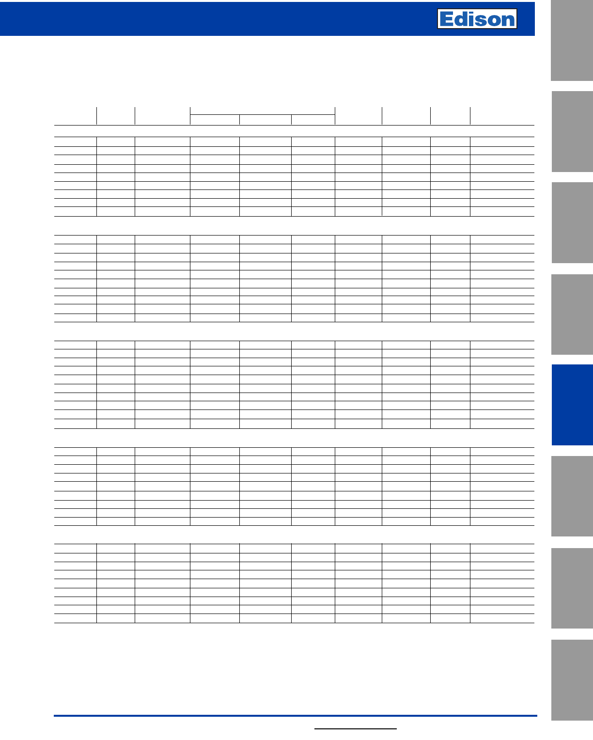
113
For additional information, visit www.edisonfuse.com
UL/CSA Fuses
Current Limiting
UL/CSA Fuses
General Purpose
Special
Purpose Fuses
Canadian
Fuses & Holders
Medium
Voltage Fuses
Fuse Blocks,
Holders & Misc.
Application
Section
Surge Protective
Devices
R-Rated Medium Voltage Fuses
For Motor Circuits
R-Rated Fuses for Motor Circuit Protection
Catalog Numbers: R-Rated; Indoor/Enclosure
Catalog Amp Maximum Dimensions - in (mm) Max Int. Cap. Amps Min Int. Cap.
Numbers Ratings Design Voltage AB CConstruction Amps (Asym. (Sym.) Amps (Sym.)
4800V — With Westinghouse Ampguard Hookeye (See Figure 1)
JCL-A-2R 70 5080 15.76 (400.3) 3.0 (76.2) 3.0 (76.2) Single 80,000 50,000 165
JCL-A-3R 100 5080 15.76 (400.3) 3.0 (76.2) 3.0 (76.2) Single 80,000 50,000 220
JCL-A-4R 130 5080 15.76 (400.3) 3.0 (76.2) 3.0 (76.2) Single 80,000 50,000 320
JCL-A-5R 150 5080 15.76 (400.3) 3.0 (76.2) 3.0 (76.2) Single 80,000 50,000 410
JCL-A-6R 170 5080 15.76 (400.3) 3.0 (76.2) 3.0 (76.2) Single 80,000 50,000 480
JCL-A-9R 200 5080 15.76 (400.3) 3.0 (76.2) 3.0 (76.2) Single 80,000 50,000 720
JCL-A-12R 230 5080 15.76 (400.3) 3.0 (76.2) 3.0 (76.2) Single 80,000 50,000 970
JCL-A-18R 390 5080 15.76 (400.3) 3.0 (76.2) 3.0 (76.2) Double 80,000 50,000 1,430
JCL-A-24R 450 5080 15.76 (400.3) 3.0 (76.2) 3.0 (76.2) Double 80,000 50,000 1,880
4800V — Bolt-On (See Figures 2 & 3)
JCL-B-30 30 5080 19.25 (488.9) 17.88 (454.1) - Single 80,000 50,000 95
JCL-B-2R 70 5080 19.25 (488.9) 17.88 (454.1) - Single 80,000 50,000 180
JCL-B-3R 100 5080 19.25 (488.9) 17.88 (454.1) - Single 80,000 50,000 270
JCL-B-4R 130 5080 19.25 (488.9) 17.88 (454.1) - Single 80,000 50,000 350
JCL-B-5R 150 5080 19.25 (488.9) 17.88 (454.1) - Single 80,000 50,000 450
JCL-B-6R 170 5080 19.25 (488.9) 17.88 (454.1) - Single 80,000 50,000 540
JCL-B-9R 200 5080 19.25 (488.9) 17.88 (454.1) - Single 80,000 50,000 700
JCL-B-12R 230 5080 19.25 (488.9) 17.88 (454.1) - Single 80,000 50,000 1,000
JCL-B-18R 390 5080 19.25 (488.9) 17.88 (454.1) 3.31 (84.1) Double 80,000 50,000 1,450
JCL-B-24R 450 5080 19.25 (488.9) 17.88 (454.1) 3.31 (84.1) Double 80,000 50,000 2,000
4800V — Hermetically Sealed, For Use with Ampguard Motor Starters (See Figure 1)
JCG-30 30 5080 15.91 (404.1) 3.0 (76.2) 3.0 (76.2) Single 80,000 50,000 95
JCG-2R 70 5080 15.91 (404.1) 3.0 (76.2) 3.0 (76.2) Single 80,000 50,000 180
JCG-3R 100 5080 15.91 (404.1) 3.0 (76.2) 3.0 (76.2) Single 80,000 50,000 270
JCG-4R 130 5080 15.91 (404.1) 3.0 (76.2) 3.0 (76.2) Single 80,000 50,000 350
JCG-5R 150 5080 15.91 (404.1) 3.0 (76.2) 3.0 (76.2) Single 80,000 50,000 450
JCG-6R 170 5080 15.91 (404.1) 3.0 (76.2) 3.0 (76.2) Single 80,000 50,000 540
JCG-9R 200 5080 15.91 (404.1) 3.0 (76.2) 3.0 (76.2) Single 80,000 50,000 700
JCG-12R 230 5080 15.91 (404.1) 3.0 (76.2) 3.0 (76.2) Single 80,000 50,000 1,000
JCG-A-18R 390 5080 15.91 (404.1) 3.0 (76.2) 3.0 (76.2) Double 80,000 50,000 1,450
JCG-A-24R 450 5080 15.91 (404.1) 3.0 (76.2) 3.0 (76.2) Double 80,000 50,000 2,000
7200V — With Ampguard Hookeye (See Figure 1)
JCR-A-2R 70 8300 15.85 (402.6) 3.0 (76.2) 3.0 (76.2) Single 80,000 50,000 160
JCR-A-3R 100 8300 15.85 (402.6) 3.0 (76.2) 3.0 (76.2) Single 80,000 50,000 250
JCR-A-4R 130 8300 15.85 (402.6) 3.0 (76.2) 3.0 (76.2) Single 80,000 50,000 325
JCR-A-5R 150 8300 15.85 (402.6) 3.0 (76.2) 3.0 (76.2) Single 80,000 50,000 390
JCR-A-6R 170 8300 15.85 (402.6) 3.0 (76.2) 3.0 (76.2) Single 80,000 50,000 500
JCR-A-9R 200 7200 15.85 (402.6) 3.0 (76.2) 3.0 (76.2) Single 80,000 50,000 750
JCR-A-12R 230 7200 15.85 (402.6) 3.0 (76.2) 3.0 (76.2) Single 80,000 50,000 1,000
JCR-A-18R 390 7200 15.85 (402.6) 3.0 (76.2) 3.0 (76.2) Double 80,000 50,000 1,450
JCR-A-24R 450 7200 15.85 (402.6) 3.0 (76.2) 3.0 (76.2) Double 80,000 50,000 2,500
7200V — Bolt-On (See Figures 2 & 3)
JCR-B-2R 70 8300 19.25 (488.9) 17.88 (454.1) - Single 80,000 50,000 160
JCR-B-3R 100 8300 19.25 (488.9) 17.88 (454.1) - Single 80,000 50,000 250
JCR-B-4R 130 8300 19.25 (488.9) 17.88 (454.1) - Single 80,000 50,000 325
JCR-B-5R 150 8300 19.25 (488.9) 17.88 (454.1) - Single 80,000 50,000 390
JCR-B-6R 170 8300 19.25 (488.9) 17.88 (454.1) - Single 80,000 50,000 500
JCR-B-9R 200 7200 19.25 (488.9) 17.88 (454.1) - Single 80,000 50,000 750
JCR-B-12R 230 7200 19.25 (488.9) 17.88 (454.1) - Single 80,000 50,000 1,000
JCR-B-18R 390 7200 19.25 (488.9) 17.88 (454.1) 3.31 (84.1) Double 80,000 50,000 1,450
JCR-B-24R 450 7200 19.25 (488.9) 17.88 (454.1) 3.31 (84.1) Double 80,000 50,000 2,500
Recommended fuseclips: see page 118 - 1A0065, A3354730, 9078A67G04.
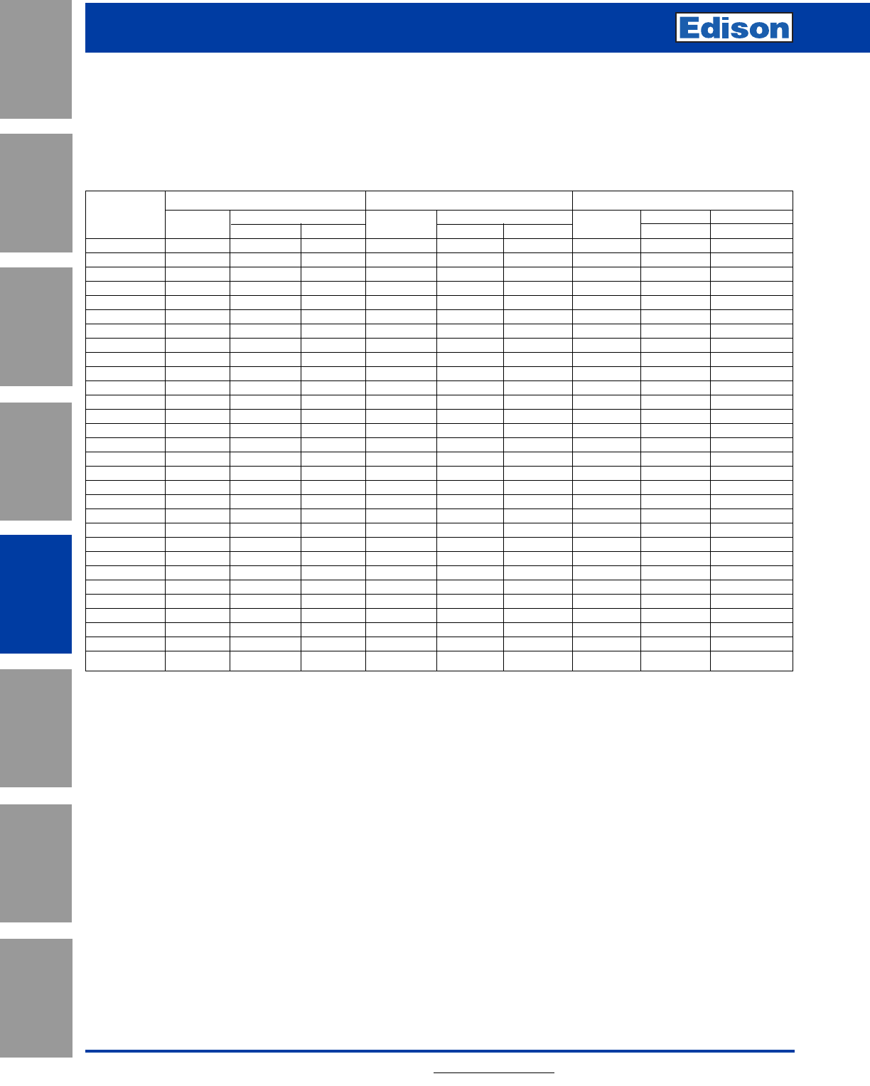
114 For additional information, visit www.edisonfuse.com
Application
Section
Fuse Blocks,
Holders & Misc.
Surge Protective
Devices
Medium
Voltage Fuses
Canadian
Fuses & Holders
Special
Purpose Fuses
UL/CSA Fuses
General Purpose
UL/CSA Fuses
Current Limiting
R-Rated Medium Voltage Fuses
For Motor Circuits
2.4kV 4.16kV 4.8kV
FLA FUSE FLA FUSE FLA FUSE
Hp Amps “R” Amps Amps “R” Amps Amps “R” Amps
75 17 2R 70 ––––––
100 22 2R 70 ––––––
125 28 3R 70 16 2R 70 –––
150 33 3R 100 19 2R 70 17 2R 70
200 44 4R 130 26 3R 100 22 2R 70
250 55 6R 170 32 3R 100 28 3R 100
300 67 6R 170 38 4R 130 33 3R 100
350 78 9R 170 45 4R 130 39 4R 130
400 89 9R 200 45 4R 130 44 4R 130
500 111 12R 230 64 6R 170 55 6R 170
600 133 18R 390 77 9R 200 67 6R 170
700 155 18R 390 90 9R 200 78 9R 200
800 177 18R 390 102 9R 230 89 9R 200
900 200 18R 390 115 12R 230 100 9R 200
1000 222 24 450 128 18R 390 111 12R 230
1100 244 24R 450 141 18R 390 122 12R 230
1200 266 24R 450 154 18R 390 133 18R 390
1400 311 30R 450 179 18R 390 155 18R 390
1600 355 36R 500 205 18R 390 177 18R 390
1800 399 40R 600 230 24R 450 200 18R 390
1900 422 40R 600 243 24R 450 211 18R 390
2000 444 40R 600 256 24R 450 222 24R 450
2200 488 48R 650 282 30R 450 244 24R 450
2400 –––307 30R 450 266 24R 450
2600 –––333 36R 500 288 30R 450
2800 –––358 36R 500 311 30R 450
3000 –––384 36R 500 333 36R 500
3500 –––448 40R 600 388 36R 500
4000 ––––––444 40R 600
4500 ––––––500 48R 650
Application for HV Motor Circuit Fuses
The following table is a general guide only based on a
number of assumptions regarding the motor duty
application which are listed below. The application tables
are based on the following
assumptions:
Motor Efficiency ---------- 90% Run Up Time ------ 10 Secs.
Motor Power Factor ----- 0.9 Starting Method -- Full Voltage
Starting Current ---------- 6 x FLA Min. Fuse Size---- 1.3 x FLA
Starts/Hour ---------------- Max of 2/Hour
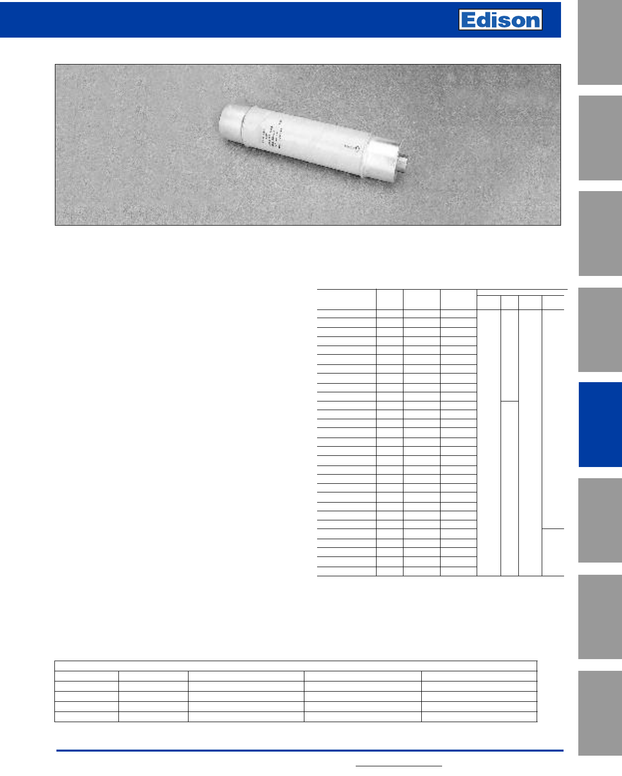
115
For additional information, visit www.edisonfuse.com
UL/CSA Fuses
Current Limiting
UL/CSA Fuses
General Purpose
Special
Purpose Fuses
Canadian
Fuses & Holders
Medium
Voltage Fuses
Fuse Blocks,
Holders & Misc.
Application
Section
Surge Protective
Devices
5.5kV E-Rated Medium Voltage Fuses
E-Rated Power Fuses Having Full Range Clearing Capability for Medium Voltage
Transformer Circuit Protection
CROSS REFERENCE
NEW EDISON OLD EDISON MERSEN (old/new) WESTINGHOUSE GE (old/new)
MV055F1CAX — A550X – 1B/A055F1CORO ——
MV055F1DAX 5.5FFNHA or K A550X – 1F/A055F1DORO 151D978G01 thru G08 9F60FJDxxx/9F62DCBxxx
MV055F1DAX 5.5BFNHA — 5HLExxxE – 1 —
MV055F2DAX 5.5BFNHK A550X – 1/A055F2DORO 151D978G11 thru G13 9F60GHC (250-400)
MV055
Specifications
Description: E-rated medium, voltage current-limiting fuses
for transformer and feeder protection.
Dimensions: See Catalog Numbers table.
Construction: Silver ribbon element surrounded by silica
filler housed in a fiberglass tube and plated endcaps. An
epoxy paint protects the fuse tube from the surrounding
environment.
Ratings:
Volts: — 5.5kV
Amps: — 5-450A
IR: — 50kA Sym. Max
Agency Information: Meets E requirements per ANSI
C37.46, Meets full range requirements per ANSI C37.40.
Features and Benefits
• MV055 Standard clip center distance of 12 inches with 2
and 3 inch barrel diameters for retrofitting in existing
hardware
• Open fuse indicator for ease in troubleshooting
• Full range rating with 50KA Interrupting Rating
• Double pulsed at 90% of minimum I2t to establish
manufacturing reliability
MV055 Typical Applications
• 5.0kV Transformer Primary Protection
• 5.0kV Feeder Circuit Protection
• 5.0kV Voltage Switches
• 5.0kV Metal-enclosed Switchgear
5.5kV Catalog Numbers
Min Max Dimensions (in)*
Catalog Amp Melt Clear Clip
Numbers Rating I2tI
2t Length Dia. Center Barrels
MV055F1CAX5E 5 180 2,400
MV055F1CAX7E 7 850 8,000
MV055F1CAX10E 10 850 8,000
MV055F1CAX15E 15 2,070 11,000
MV055F1CAX20E 20 2,370 23,000
MV055F1CAX25E 25 4,650 31,000
MV055F1CAX30E 30 9,490 45,000
MV055F1CAX40E 40 9,490 45,000
MV055F1CAX50E 50 13,600 90,000
MV055F1CAX65E 65 30,700 181,000
MV055F1DAX10E 10 850 8,000 15.75 3 12 1
MV055F1DAX15E 15 2,070 12,000
MV055F1DAX20E 20 2,370 23,000
MV055F1DAX25E 25 4,650 31,000
MV055F1DAX30E 30 9,490 45,000
MV055F1DAX40E 40 9,490 45,000
MV055F1DAX50E 50 13,600 90,000
MV055F1DAX65E 65 30,700 181,000
MV055F1DAX80E 80 54,600 270,000
MV055F1DAX100E 100 116,200 580,000
MV055F1DAX125E 125 167,400 600,000 15.75 3 12 1
MV055F1DAX150E 150 218,700 786,000
MV055F1DAX175E 175 227,900 1,100,000
MV055F1DAX200E 200 297,600 1,520,000
MV055F2DAX250E 250 669,600 2,400,000 15.75 3 12 2
MV055F2DAX300E 300 874,800 3,149,000
MV055F2DAX350E 350 911,600 4,376,000
MV055F2DAX400E 400 1,190,400 6,071,000
MV055F2DAX450E 450 1,555,000 9,796,000
1” = 25.4mm
15.75˝ 12
2˝
1
2
3˝

116 For additional information, visit www.edisonfuse.com
Application
Section
Fuse Blocks,
Holders & Misc.
Surge Protective
Devices
Medium
Voltage Fuses
Canadian
Fuses & Holders
Special
Purpose Fuses
UL/CSA Fuses
General Purpose
UL/CSA Fuses
Current Limiting
5.5kV E-Rated Medium Voltage Fuses
E-Rated Medium Voltage Fuses for Transformer and Feeder Protection
TIME IN SECONDS
100
10
1
.1
.01
30A
25A
20A
15A
10A
7A
5A
AMP RATING
1000
7000
100
10
CURRENT IN AMPS
40A
50A
65A
TIME IN SECONDS
AMP RATING
1000
7000
100
10
CURRENT IN AMPS
65A
50A
40A
30A
25A
20A
15A
10A
7A
5A
100
10
1
.1
.01
Time-Current Characteristics–Min. Melt Time-Current Characteristics–Total Clear
Dimensions - in
MV055F1CAX10E to 65E
2.03" 0.63"
0.38"
1.25" 1.25"
15.75"
14.74"
Position of Open Fuse
Indicator After Operating
2.00"
12.00"
Clip Center
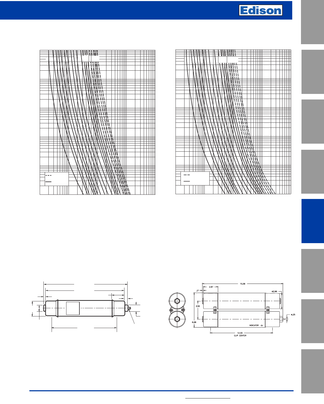
117
For additional information, visit www.edisonfuse.com
UL/CSA Fuses
Current Limiting
UL/CSA Fuses
General Purpose
Special
Purpose Fuses
Canadian
Fuses & Holders
Medium
Voltage Fuses
Fuse Blocks,
Holders & Misc.
Application
Section
Surge Protective
Devices
5.5kV E-Rated Medium Voltage Fuses
E-Rated Medium Voltage Fuses for Transformer and Feeder Protection
Time-Current Characteristics–Min. Melt Time-Current Characteristics–Total Clear
Dimensions - in
MV055F1DAX10E to 200E MV055F2DAX250E to 450E
TIME IN SECONDS
CURRENT IN AMPERES
.1
10
100
1000
.01
1
100000
10000
1000
100
10
10A
15A
20A
25A
30A
40A
50A
65A
80A
100A
125A
150A
175A
200A
250A
300A
350A
400A
450A
DOUBLE BARREL
FUSE ASSY.
SINGLE BARREL
FUSE ASSY.
TIME IN SECONDS
CURRENT IN AMPE RES
.1
10
100
1000
.01
1
100000
10000
1000
10
100
SINGLE BARREL
FUSE AS SY.
DOUBLE BARREL
FUSE AS SY.
10A
15A
20A
25A
30A
40A
50A
65A
80A
100A
125A
150A
175A
200A
250A
300A
350A
400A
450A
2.40" 0.63"
0.38"
1.25"
3.00"
12.00"
Clip Center
1.25"
15.75"
14.74"
Position of Open Fuse
Indicator After Operating
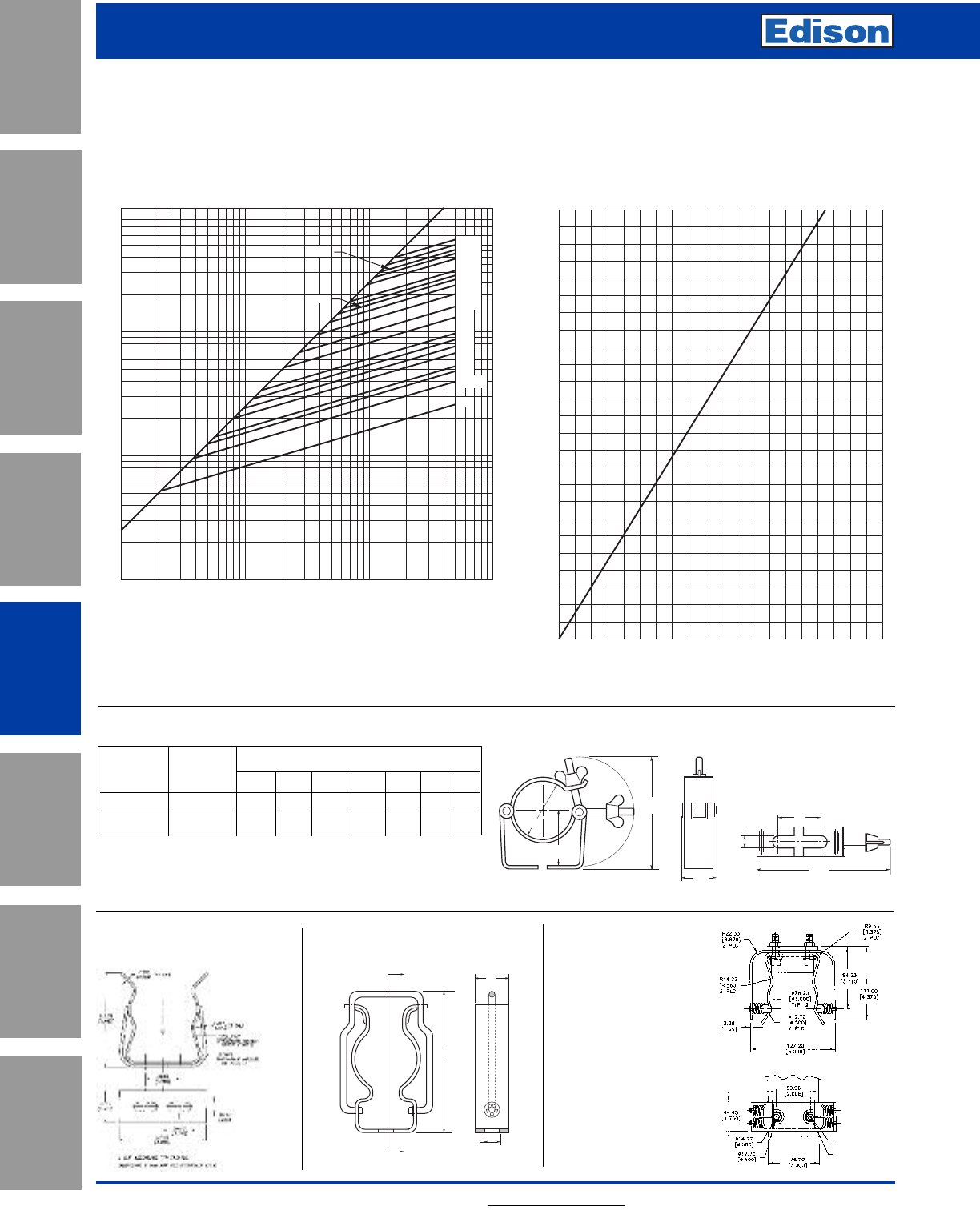
118 For additional information, visit www.edisonfuse.com
Application
Section
Fuse Blocks,
Holders & Misc.
Surge Protective
Devices
Medium
Voltage Fuses
Canadian
Fuses & Holders
Special
Purpose Fuses
UL/CSA Fuses
General Purpose
UL/CSA Fuses
Current Limiting
5.5kV E-Rated Medium Voltage Fuses
E-Rated Medium Voltage Fuses for Transformer and Feeder Protection
Maximum Peak Let-Through Current Curves Max. Peak Arc Voltage for E-Rated
Full Range Power Fuse
1
AVAILABLE CURRENT IN KILOAMPERES (RMS Symmetrical)
MAXIMUM LET-THRU (Peak Kiloamperes)
100
10
.1
.1 110
100
15A
20A
25A
40A
50A
65A
80A
100A
07&10A
05A
125A
175A
450A
400A
300A
150A
350A
30A
200A
250A
A
B
MAXIMUM PEAK ARC VOLTAGE (kV)
50
40
CIRCUIT VOLTAGE (kV)
30
20
10
0
0
5
10
15
20
C
A
B
D
G
E
F
Recommended Fuse Clips for Medium Voltage Fuses
Fuseclips are for single barrel applications only.
Part Fuse Clip Dimensions - in
No. Diameter ABCDEFG
A3354710 2 inches 3.75 1.98 2.01 1.19 4.54 1.51 0.40
A3354730 3 inches 4.14 2.45 3.01 1.19 5.64 1.51 0.40
1A0065
3˝ Diameter Clip 270303
DIN Fuseclip
A
A
0.43"
10.8mm
0.99"
25.0mm
4.06"
103mm
9078A67G04
3˝ Diameter Clip
2 Cup assemblies per package.
Dimensions shown are for reference only.
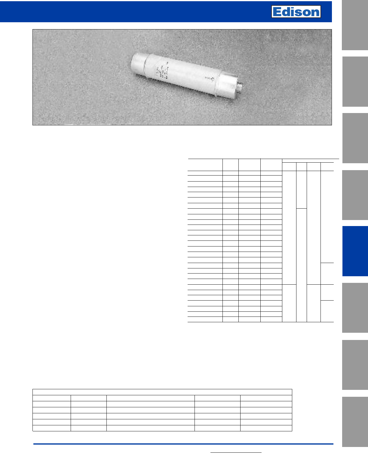
119
For additional information, visit www.edisonfuse.com
UL/CSA Fuses
Current Limiting
UL/CSA Fuses
General Purpose
Special
Purpose Fuses
Canadian
Fuses & Holders
Medium
Voltage Fuses
Fuse Blocks,
Holders & Misc.
Application
Section
Surge Protective
Devices
15.5kV E-Rated Medium Voltage Fuses
E-Rated Power Fuses Having Full Range Clearing Capability for Medium Voltage
Transformer Circuit Protection
CROSS REFERENCE
NEW EDISON OLD EDISON MERSEN (old/new) WESTINGHOUSE GE (old/new)
MV155F1CBX — A1550X – 1B/A155F1CORO ——
MV155F1DBX 15.5FFVHA A1550X – 1F/A155F1DORO (10-50E) 15HLE–xxxE 9F60FMH/9F62DDD
MV155F2DBX 15.5FFVHK ———
MV155F1DCX — A1550X – 1D/A155F1DORO (65-100E) ——
MV155F2DCX — A1550X – 1D/A155F2DORO (125-200E) ——
MV155
Specifications
Description: E-rated medium, voltage current-limiting fuses
for transformer and feeder protection.
Dimensions: See Catalog Numbers table.
Construction: Silver ribbon element surrounded by silica
filler housed in a fiberglass tube and plated endcaps. An
epoxy paint protects the fuse tube from the surrounding
environment.
Ratings:
Volts: — 15.5kV
Amps: — 5-200A
IR: — 50kA Sym. Max
Agency Information: Meets E requirements per ANSI
C37.46, Meets full range requirements per ANSI C37.40.
Features and Benefits
• MV155 Standard clip center distance of 15 and 18 inches
with 2 and 3 inch barrel diameters for retrofitting in existing
hardware
• Open fuse indicator for ease in troubleshooting
• Full range rating with 50kA Interrupting Rating
• Double pulsed at 90% of minimum I2t to establish
manufacturing reliability
MV155 Typical Applications
• 15.0kV Transformer Primary Protection
• 15.0kV Feeder Circuit Protection
• 15.0kV Voltage Switches
• 15.0kV Metal-enclosed Switchgear
15.5kV Catalog Numbers
Min Max Dimensions*
Catalog Amp Melt Clear Clip
Numbers Rating I2tI
2t Length Dia. Center Barrels
MV155F1CBX5E 5 180 2,900 18.75 15 1
MV155F1CBX7E 7 850 8,000
MV155F1CBX10E 10 850 8,000
MV155F1CBX15E 15 2,070 12,000 1˝
MV155F1CBX20E 20 2,370 23,000
MV155F1CBX25E 25 4,650 31,000
MV155F1CBX30E 30 9,490 45,000
MV155F1DBX10E 10 850 8,000 18.75 3 15 1
MV155F1DBX15E 15 2,070 12,000
MV155F1DBX20E 20 2,370 23,000
MV155F1DBX25E 25 4,650 31,000
MV155F1DBX30E 30 9,490 45,000
MV155F1DBX40E 40 9,490 45,000
MV155F1DBX50E 50 13,600 90,000
MV155F1DBX65E 65 30,700 181,000
MV155F1DBX80E 80 54,600 270,000
MV155F1DBX100E 100 116,200 600,000
MV155F2DBX125E 125 123,000 677,000 18.75 3˝ 15 2
MV155F2DBX150E 150 218,700 1,287,000
MV155F2DBX175E 175 314,700 1,689,000
MV155F2DBX200E 200 465,100 2,405,000
MV155F1DCX65E 65 30,700 181,000 21.75 3 18 1
MV155F1DCX80E 80 54,600 270,000
MV155F1DCX100E 100 116,200 600,000
MV155F2DCX125E 125 123,000 677,000 21.75 3 18 2
MV155F2DCX150E 150 218,700 1,287,000
MV155F2DCX175E 175 314,700 1,689,000
MV155F2DCX200E 200 465,100 2,405,000
*1” = 25.4mm.
18.75˝
2˝
15
1
2
2
1
18
21.75˝
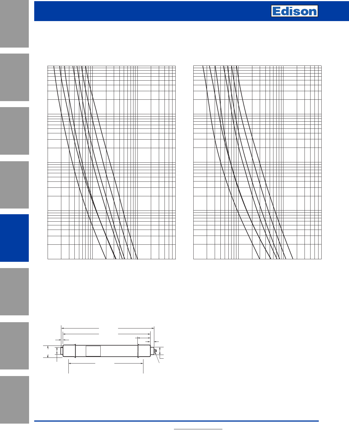
120 For additional information, visit www.edisonfuse.com
Application
Section
Fuse Blocks,
Holders & Misc.
Surge Protective
Devices
Medium
Voltage Fuses
Canadian
Fuses & Holders
Special
Purpose Fuses
UL/CSA Fuses
General Purpose
UL/CSA Fuses
Current Limiting
E-Rated Medium Voltage Fuses for Transformer and Feeder Protection
TIME IN SECONDS
100
10
1
.1
.01
30A
25A
20A
15A
10A
7A
5A
AMP RATING
1000
7000
100
10
CURRENT IN AMPS
TIME IN SECONDS
AMP RATING
1000
7000
100
10
CURRENT IN AMPS
30A
25A
20A
15A
10A
7A
5A
100
10
1
.1
.01
Time-Current Characteristics – Min. Melt Time-Current Characteristics –Total Clear
Dimensions - in
MV155F1CBX5E to 30E
17.74" 2.03" 0.63"
0.38"
1.25"
1.25"
18.75"
Position of Open Fuse
Indicator After
Operation
2.00"
15.00"
Clip Center
15.5kV E-Rated Medium Voltage Fuses
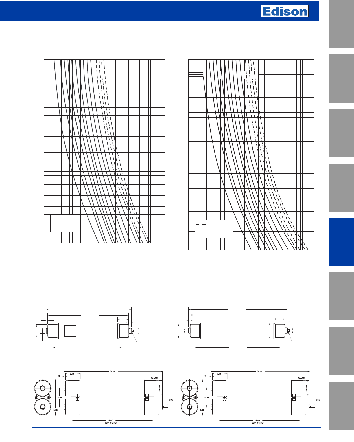
121
For additional information, visit www.edisonfuse.com
UL/CSA Fuses
Current Limiting
UL/CSA Fuses
General Purpose
Special
Purpose Fuses
Canadian
Fuses & Holders
Medium
Voltage Fuses
Fuse Blocks,
Holders & Misc.
Application
Section
Surge Protective
Devices
15.5kV E-Rated Medium Voltage Fuses
E-Rated Medium Voltage Fuses for Transformer and Feeder Protection
Time-Current Characteristics – Min. Melt Time-Current Characteristics –Total Clear
Dimensions - in
MV155F1DBX10E to 100E
TIME IN SECONDS
CURRENT IN AMPERES
.1
10
100
1000
.01
1
10000
1000
10
100
20000
10A
15A
20A
25A
30A
40A
50A
65A
80A
100A
125A
150A
175A
200A
SINGLE BARREL
FUSE ASSY.
DOUBLE BARREL
FUSE ASSY.
.1
10
100
1000
.01
1
100
10
1000
10000
20000
TIME IN SECONDS
CURRENT IN AMPERES
10A
15A
20A
25A
30A
40A
50A
65A
80A
100A
125A
150A
175A
200A
DOUBLE BARREL
FUSE ASSY.
SINGLE BARREL
FUSE ASSY.
17.74"
2.40" 0.63"
0.38"
1.25"
3.00"
15.00"
Clip Center
1.25"
18.75"
Position of Open Fuse
Indicator After
Operating
21.75"
20.74"
2.40" 0.63"
1.25"
3.38"
0.38"
1.25"
3.00"
18.00"
Clip Center
Position of Open Fuse
Indicator After
Operating
MV155F1DCX65E to 100E
MV155F2DBX125E to 200E MV155F2DCX125E to 200E

122 For additional information, visit www.edisonfuse.com
Application
Section
Fuse Blocks,
Holders & Misc.
Surge Protective
Devices
Medium
Voltage Fuses
Canadian
Fuses & Holders
Special
Purpose Fuses
UL/CSA Fuses
General Purpose
UL/CSA Fuses
Current Limiting
E-Rated Medium Voltage Fuses for Transformer and Feeder Protection
Max. Peak Let-through Current Curves Maximum Peak Arc Voltage for E-Rated
Full Range Power Fuse
1
AVAILABLE CURRENT IN KILOAMPERES (RMS Symmetrical)
MAXIMUM LET-THROUGH (Peak Kiloamperes)
100
10
.1
.1 110
100
15A
20A
25A
30&40A
50A
65A
80A
100A
07&10A
05A
125A
150A
175A
200A
A
B
MAXIMUM PEAK ARC VOLTAGE (kV)
50
40
CIRCUIT VOLTAGE (kV)
30
20
10
0
0
5
10
15
20
15.5kV E-Rated Medium Voltage Fuses
C
A
B
D
G
E
F
Recommended Fuse Clips for Medium Voltage Fuses
Fuseclips are for single barrel applications only.
Part Fuse Clip Dimensions - in
No. Diameter ABCDEFG
A3354710 2 inches 3.75 1.98 2.01 1.19 4.54 1.51 0.40
A3354730 3 inches 4.14 2.45 3.01 1.19 5.64 1.51 0.40
1A0065
3˝ Diameter Clip 270303
DIN Fuseclip
A
A
0.43"
10.8mm
0.99"
25.0mm
4.06"
103mm
9078A67G04
3˝ Diameter Clip
2 Cup assemblies per package.
Dimensions shown are for reference only.
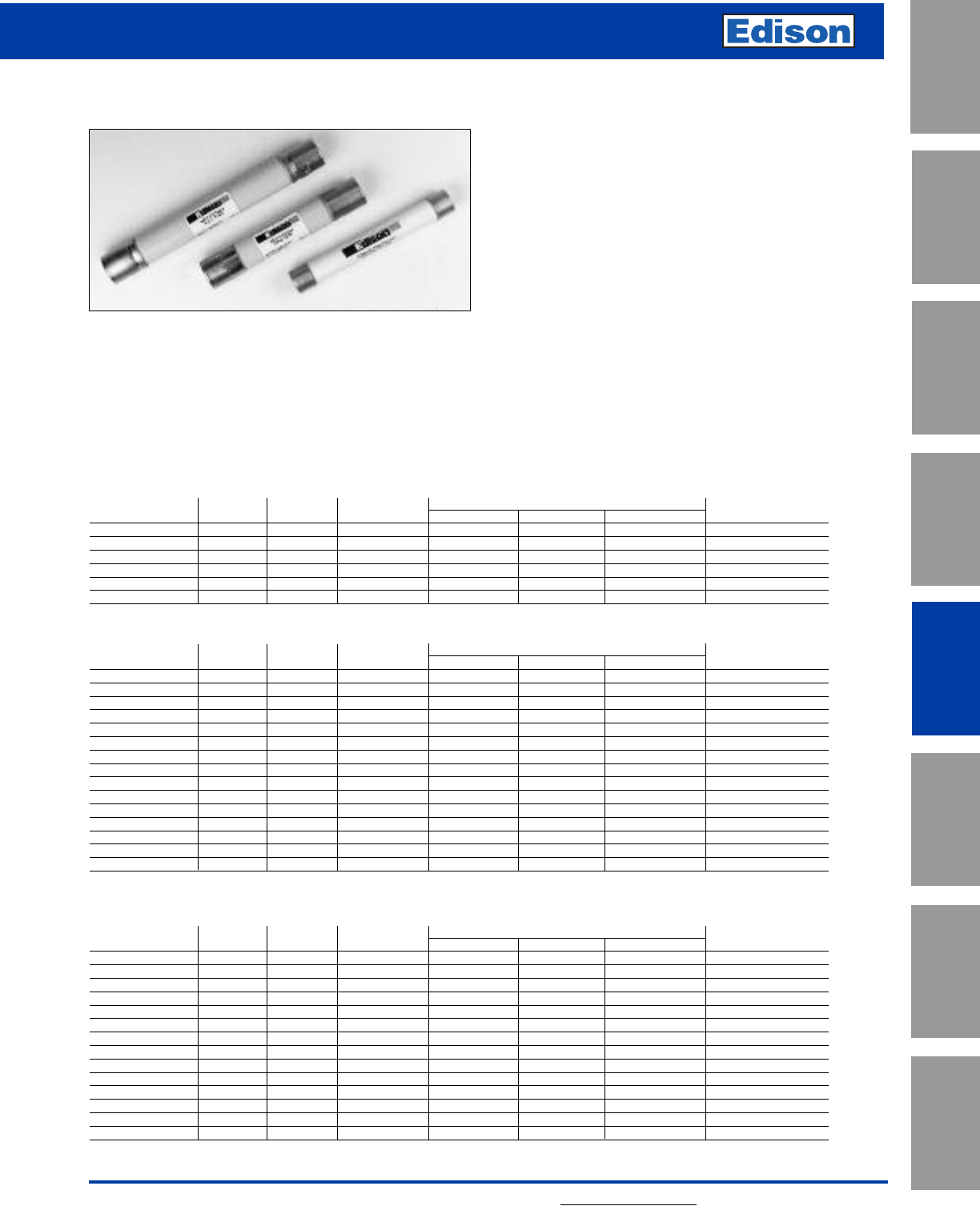
123
For additional information, visit www.edisonfuse.com
UL/CSA Fuses
Current Limiting
UL/CSA Fuses
General Purpose
Special
Purpose Fuses
Canadian
Fuses & Holders
Medium
Voltage Fuses
Fuse Blocks,
Holders & Misc.
Application
Section
Surge Protective
Devices
3.6kV – 38kV Potential Transformer Fuses
AB, AM and CAV
Specifications
Description: Indicating and non-indicating E-Rated medium
voltage, current-limiting fuses for potential and small power
transformers.
Dimensions: See Catalog Numbers table.
Dimension Illustration on the following page
Ratings:
Volts: — 5.5-38kV
Amps: — 0.5-15A
IR: — 40kA-80kA Sym.
— See Catalog Numbers table for details
Features and Benefits
• Sized for retrofitting in existing hardware
• Space saving size
Typical Applications
• Primary protection of medium voltage potential
transformers
• Primary protection of small medium voltage service
transformers
• Primary protection of small medium voltage control
transformers
3.6kV; E-Rated PT Fuse; Non-indicating
Catalog Amp Rated Dimensions Spare Parts
Number Rating Voltage IR RMS Sym. Length Diameter Clip Centers (Clips)
3.6CAV2 2 3.6kV 50kA 8.66 (220) 1.63 (41.3) 7.46 (189.48) 1A0835
3.6ABWNA3.15 3.15 3.6kV 50kA 5.6 (142.2) 1 (25.4) 4.42 (112.2) A3354705
3.6ABWNA6.3 3.15 3.6kV 50kA 5.6 (142.2) 1 (25.4) 4.42 (112.2) A3354705
3.6ABCNA3.15 3.15 3.6kV 50kA 7.69 (195.3) 1 (25.4) 6.51 (165.3) A3354705
3.6ABCNA6.3 6.3 3.6kV 50kA 7.69 (195.3) 1 (25.4) 6.51 (165.3) A3354705
3.6ABCNA10 10 3.6kV 50kA 7.69 (195.3) 1 (25.4) 6.51 (165.3) A3354705
7.2kV; E-Rated PT Fuse; Non-indicating
Catalog Amp Rated Dimensions Spare Parts
Number Rating Voltage IR RMS Sym. Length Diameter Clip Centers (Clips)
7.2CAV2 2 7.2kV 63kA 8.66 (220) 1.63 (41.3) 7.46 (189.48) 1A0835
7.2CAV4 4 7.2kV 63kA 8.66 (220) 1.63 (41.3) 7.46 (189.48) 1A0835
7.2CAV6 6 7.2kV 63kA 8.66 (220) 1.63 (41.3) 7.46 (189.48) 1A0835
7.2CAV10 10 7.2kV 63kA 8.66 (220) 1.63 (41.3) 7.46 (189.48) 1A0835
7.2ABWNA3.15 3.15 7.2kV 45kA 5.6 (142.2) 1 (25.4) 4.42 (112.2) A3354705
7.2ABWNA6.3 6.3 7.2kV 45kA 5.6 (142.2) 1 (25.4) 4.42 (112.2) A3354705
7.2ABCNA3.15 3.15 7.2kV 45kA 7.69 (195.3) 1 (25.4) 6.51 (165.3) A3354705
7.2ABCNA6.3 6.3 7.2kV 45kA 7.69 (195.3) 1 (25.4) 6.51 (165.3) A3354705
7.2AMWNA0.5E 0.5 7.2kV 50kA 5.6 (142.2) 0.81 (20.6) 4.79 (121.6) 1A1837
7.2AMWNA1.0E 1 7.2kV 50kA 5.6 (142.2) 0.81 (20.6) 4.79 (121.6) 1A1837
7.2AMWNA2.0E 2 7.2kV 50kA 5.6 (142.2) 0.81 (20.6) 4.79 (121.6) 1A1837
7.2AMWNA3.0E 3 7.2kV 50kA 5.6 (142.2) 0.81 (20.6) 4.79 (121.6) 1A1837
7.2AMWNA4.0E 4 7.2kV 50kA 5.6 (142.2) 0.81 (20.6) 4.79 (121.6) 1A1837
7.2AMWNA5.0E 5 7.2kV 50kA 5.6 (142.2) 0.81 (20.6) 4.79 (121.6) 1A1837
5.5kV; E-Rated PT Fuse; Indicating & Non-indicating
Catalog Amp Rated Dimensions Spare Parts
Number Rating Voltage IR RMS Sym. Length Diameter Clip Centers (Clips)
5.5CAVH0.5E 0.5 5.5kV 63kA 7.375 (187.3) 1.63 (41.3) 6.18 (156.84) 1A0835
5.5CAVH1E 1 5.5kV 63kA 7.375 (187.3) 1.63 (41.3) 6.18 (156.84) 1A0835
5.5CAVH2E 2 5.5kV 63kA 7.375 (187.3) 1.63 (41.3) 6.18 (156.84) 1A0835
5.5CAV15E 15 5.5kV 63kA 7.375 (187.3) 1.63 (41.3) 6.18 (156.84) 1A0835
5.5ABWNA0.5E 0.5 5.5kV 50kA 5.6 (142.2) 1 (25.4) 4.42 (112.2) A3354705
5.5ABWNA1E 1 5.5kV 50kA 5.6 (142.2) 1 (25.4) 4.42 (112.2) A3354705
5.5ABWNA2E 2 5.5kV 50kA 5.6 (142.2) 1 (25.4) 4.42 (112.2) A3354705
5.5ABWNA3E 3 5.5kV 50kA 5.6 (142.2) 1 (25.4) 4.42 (112.2) A3354705
5.5ABWNA5E 5 5.5kV 50kA 5.6 (142.2) 1 (25.4) 4.42 (112.2) A3354705
5.5AMWNA0.5E 0.5 5.5kV 50kA 5.6 (142.2) 0.81 (20.6) 4.79 (121.6) 1A1837
5.5AMWNA1.0E 1 5.5kV 50kA 5.6 (142.2) 0.81 (20.6) 4.79 (121.6) 1A1837
5.5AMWNA2.0E 2 5.5kV 50kA 5.6 (142.2) 0.81 (20.6) 4.79 (121.6) 1A1837
5.5AMWNA3.0E 3 5.5kV 50kA 5.6 (142.2) 0.81 (20.6) 4.79 (121.6) 1A1837
5.5AMWNA4.0E 4 5.5kV 50kA 5.6 (142.2) 0.81 (20.6) 4.79 (121.6) 1A1837
5.5AMWNA5.0E 5 5.5kV 50kA 5.6 (142.2) 0.81 (20.6) 4.79 (121.6) 1A1837
Type CAVH are fitted with a striker pin for indication
Catalog Numbers: E-Rated PT Fuses, Indicating & Non-Indicating
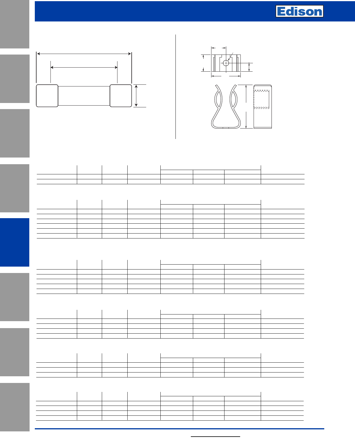
124 For additional information, visit www.edisonfuse.com
Application
Section
Fuse Blocks,
Holders & Misc.
Surge Protective
Devices
Medium
Voltage Fuses
Canadian
Fuses & Holders
Special
Purpose Fuses
UL/CSA Fuses
General Purpose
UL/CSA Fuses
Current Limiting
3.6kV – 38kV Potential Transformer Fuses
12kV; E-Rated PT Fuse; Non-indicating
Catalog Amp Rated Dimensions Spare Parts
Number Rating Voltage IR RMS Sym. Length Diameter Clip Centers (Clips)
12CAV2 2 12kV 40kA 8.66 (220) 1.63 (41.3) 7.46 (189.48) 1A0835
12ABCNA3.15 3.15 12kV 45kA 7.69 (195.3) 1 (25.4) 6.51 (165.3) A3354705
17.5kV; E-Rated PT Fuse; Non-indicating
Catalog Amp Rated Dimensions Spare Parts
Number Rating Voltage IR RMS Sym. Length Diameter Clip Centers (Clips)
17.5CAV2 2 17.5kV 40kA 8.66 (220) 1.63 (41.3) 7.46 (189.48) 1A0835
17.5CAV4 4 17.5kV 40kA 8.66 (220) 1.63 (41.3) 7.46 (189.48) 1A0835
17.5CAV6 6 17.5kV 40kA 8.66 (220) 1.63 (41.3) 7.46 (189.48) 1A0835
17.5CAV10 10 17.5kV 40kA 8.66 (220) 1.63 (41.3) 7.46 (189.48) 1A0835
17.5ABGNA3.15 3.15 17.5kV 35kA 14.13 (358.9) 1 (25.4) 12.95 (328.9) A3354705
24kV; E-Rated PT Fuse; Non-indicating
Catalog Amp Rated Dimensions Spare Parts
Number Rating Voltage IR RMS Sym. Length Diameter Clip Centers (Clips)
24CAV2 2 24kV 40kA 13.39 (340.1) 1.63 (41.3) 12.19 (309.62) 1A0835
24CAV3 3 24kV 40kA 13.39 (340.1) 1.63 (41.3) 12.19 (309.62) 1A0835
24CAV4 4 24kV 40kA 13.39 (340.1) 1.63 (41.3) 12.19 (309.62) 1A0835
24ABGNA3.15 3.15 24kV 25kA 14.13 (358.9) 1 (25.4) 12.95 (328.9) A3354705
36kV; E-Rated PT Fuse; Non-indicating
Catalog Amp Rated Dimensions Spare Parts
Number Rating Voltage IR RMS Sym. Length Diameter Clip Centers (Clips)
36CAV2 2 36kV 40kA 17.32 (439.9) 1.63 (41.3) 16.12 (409.44) 1A0835
36CAV4 4 36kV 40kA 17.32 (439.9) 1.63 (41.3) 16.12 (409.44) 1A0835
36ABGNA3.15 3.15 36kV 31.5kA 14.13 (358.9) 1 (25.4) 12.95 (328.9) A3354705
38kV; E-Rated PT Fuse; Indicating & Non-indicating
Catalog Amp Rated Dimensions Spare Parts
Number Rating Voltage IR RMS Sym. Length Diameter Clip Centers (Clips)
38CAVH0.5E 0.5 38kV 40kA 17.32 (439.9) 1.63 (41.3) 16.12 (409.44) 1A0835
38CAVH1E 1 38kV 40kA 17.32 (439.9) 1.63 (41.3) 16.12 (409.44) 1A0835
38CAVH2E 2 38kV 40kA 17.32 (439.9) 1.63 (41.3) 16.12 (409.44) 1A0835
38CAV4E 4 38kV 40kA 17.32 (439.9) 1.63 (41.3) 16.12 (409.44) 1A0835
15.5kV; E-Rated PT Fuse; Indicating & Non-indicating
Catalog Amp Rated Dimensions Spare Parts
Number Rating Voltage IR RMS Sym. Length Diameter Clip Centers (Clips)
15.5CAV(H)0.5E 0.5 15.5kV 80kA 12.87 (326.9 1.63 (41.3) 1.2 (30.5) 1A0835
15.5CAV(H)1E 1 15.5kV 80kA 12.87 (326.9 1.63 (41.3) 1.2 (30.5) 1A0835
15.5CAV(H)2E 2 15.5kV 80kA 12.87 (326.9 1.63 (41.3) 1.2 (30.5) 1A0835
15.5CAV3E 3 15.5kV 80kA 12.87 (326.9 1.63 (41.3) 1.2 (30.5) 1A0835
15.5CAV5E 5 15.5kV 80kA 12.87 (326.9 1.63 (41.3) 1.2 (30.5) 1A0835
15.5CAV7E 7 15.5kV 80kA 12.87 (326.9 1.63 (41.3) 1.2 (30.5) 1A0835
Type CAVH are fitted with a striker pin for indication
Catalog Numbers: E-Rated PT Fuses, Indicating & Non-Indicating
Length
Clip Centers
Diameter
Dimension Illustration
0.5"
12.7mm
0.21"
5.3mmø
0.34"
8.6mm
0.68"
17.3mm
1"
25.4mm
1.37"
34.8mm
Part No. A3354705
For 1” diameter potential transformer fuses.
Fuseclips
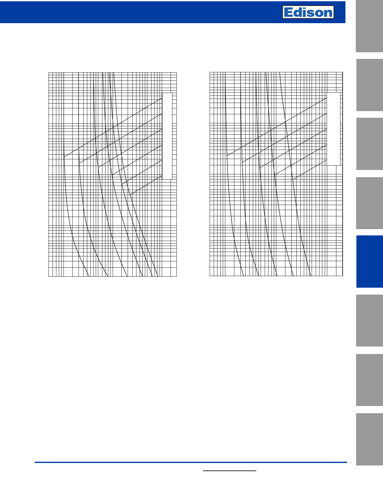
125
For additional information, visit www.edisonfuse.com
UL/CSA Fuses
Current Limiting
UL/CSA Fuses
General Purpose
Special
Purpose Fuses
Canadian
Fuses & Holders
Medium
Voltage Fuses
Fuse Blocks,
Holders & Misc.
Application
Section
Surge Protective
Devices
1
0.5E
1E
2E
3E
4E
5E
100
80
60
50
40
30
20
10
8
5
4
3
2
1
.8
.6
.5
.4
.3
.2
.1
.08
.06
.05
.04
.03
.02
.01
2
3
4
5
6
8
10
200
0.5
20
30
40
50
60
80
100
TIME IN SECONDS
RMS SYMMETRICAL CURRENT IN AMPS
Time-Current Curves
100
80
60
50
40
30
20
10
8
5
4
3
2
1
.8
.6
.5
.4
.3
.2
.1
.08
.06
.05
.04
.03
.02
.01
2
3
4
5
6
8
10
200
0.5
20
30
40
50
60
80
100
TIME IN SECONDS
RMS SYMMETRICAL CURRENT IN AMPS
0.5E
1E
2E
3E
5E
5.5kV ABWNA 5.5kV AMWNA
3.6kV – 38kV Potential Transformer Fuses
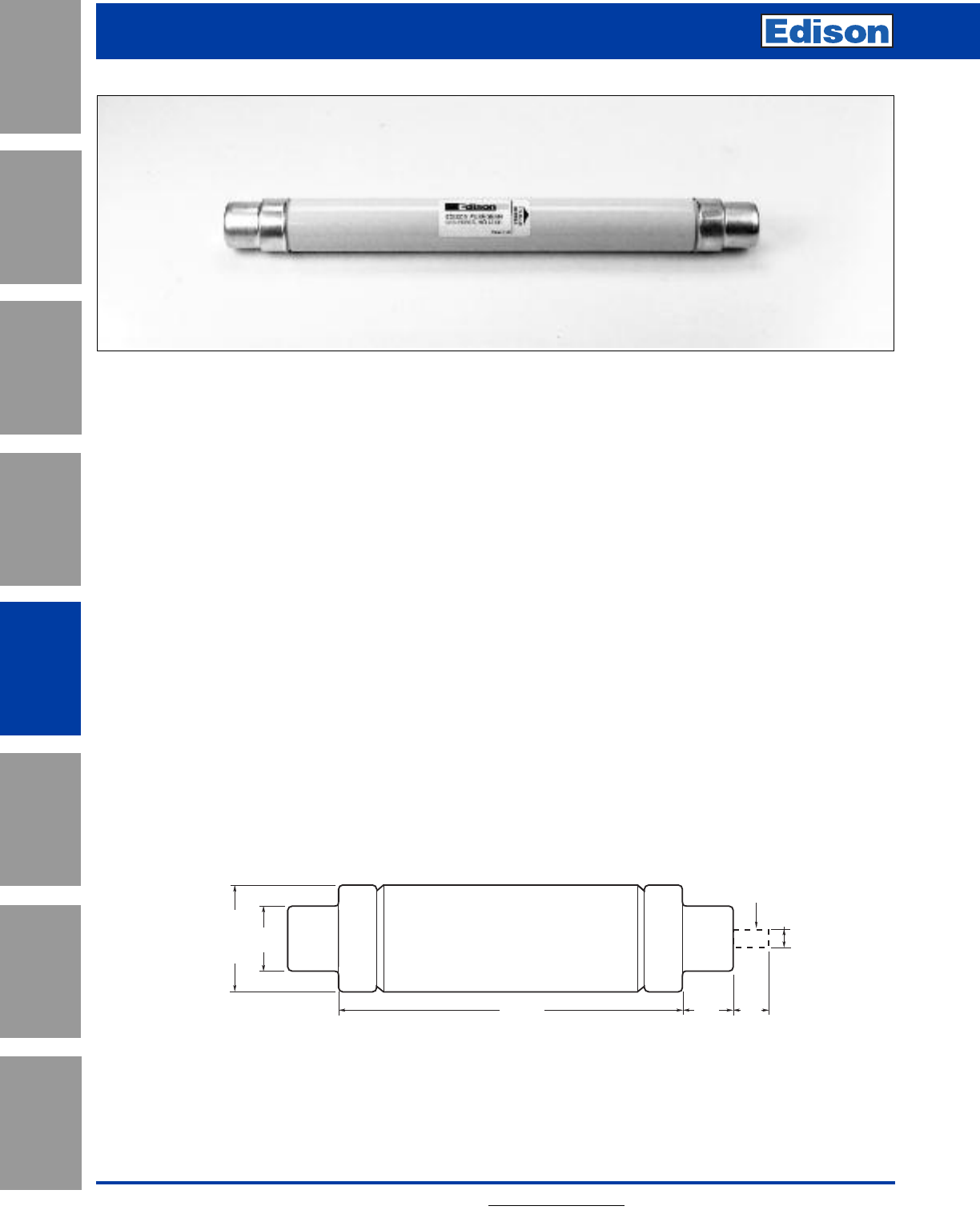
126 For additional information, visit www.edisonfuse.com
Application
Section
Fuse Blocks,
Holders & Misc.
Surge Protective
Devices
Medium
Voltage Fuses
Canadian
Fuses & Holders
Special
Purpose Fuses
UL/CSA Fuses
General Purpose
UL/CSA Fuses
Current Limiting
3.6kV – 36kV High Voltage DIN Distribution Fuses
For Diameter and Length Dimensions See Table Above
1.77"
45.0mm
Diameter
0.59"
15.0mm
Striker In
Operated Position
Length 1.34"
34.0mm
1.02"
26.0mm
Dimensions - Inches (mm)
DIN Dimension Fuses To Specification
DIN 43.625
This product group covers current limiting fuses with
dimensions to DIN 43.625 and performance in compliance
with IEC 282-1.
Advantages of Edison High Voltage Current - Limiting
Fuses
The low power dissipation of Edison fuses ensures low
temperature rise of switchgear in which they are
incorporated.
The elements use the ‘M’ (metallurgical) effect, similar to
that used in low voltage fuses. This ensures that, with
melting on long time overloads, excessive temperatures are
not reached and damage to switchgear components, such
as epoxy encapsulating enclosures, is thus prevented.
Fuses that do not employ this feature are not only hotter
running by comparison but also usually need to employ a
higher current rating of fuse for the same service; thus an
Edison 40A fuse is equivalent in terms of thermal
performance to many other types of 63A rating.
Edison fuses exhibit considerable limitation of current and
I2t under short-circuit conditions. The stress on circuit
components is thereby minimized and the reduction of
energy release at the fault reduces fire risks.
Switching (arc) voltages are appreciably less than
permitted values and fall with lower values of recovery
voltage. The use of, for example, 12kV fuse on 6/7.2kV
systems is therefore permissible.
Striker Characteristics
The spring operated striker pin has a travel and energy
output in compliance with the requirements of DIN 43625
and IEC 282-1.
Recommended Fuse Clips:
Refer to page 130 in this catalog.
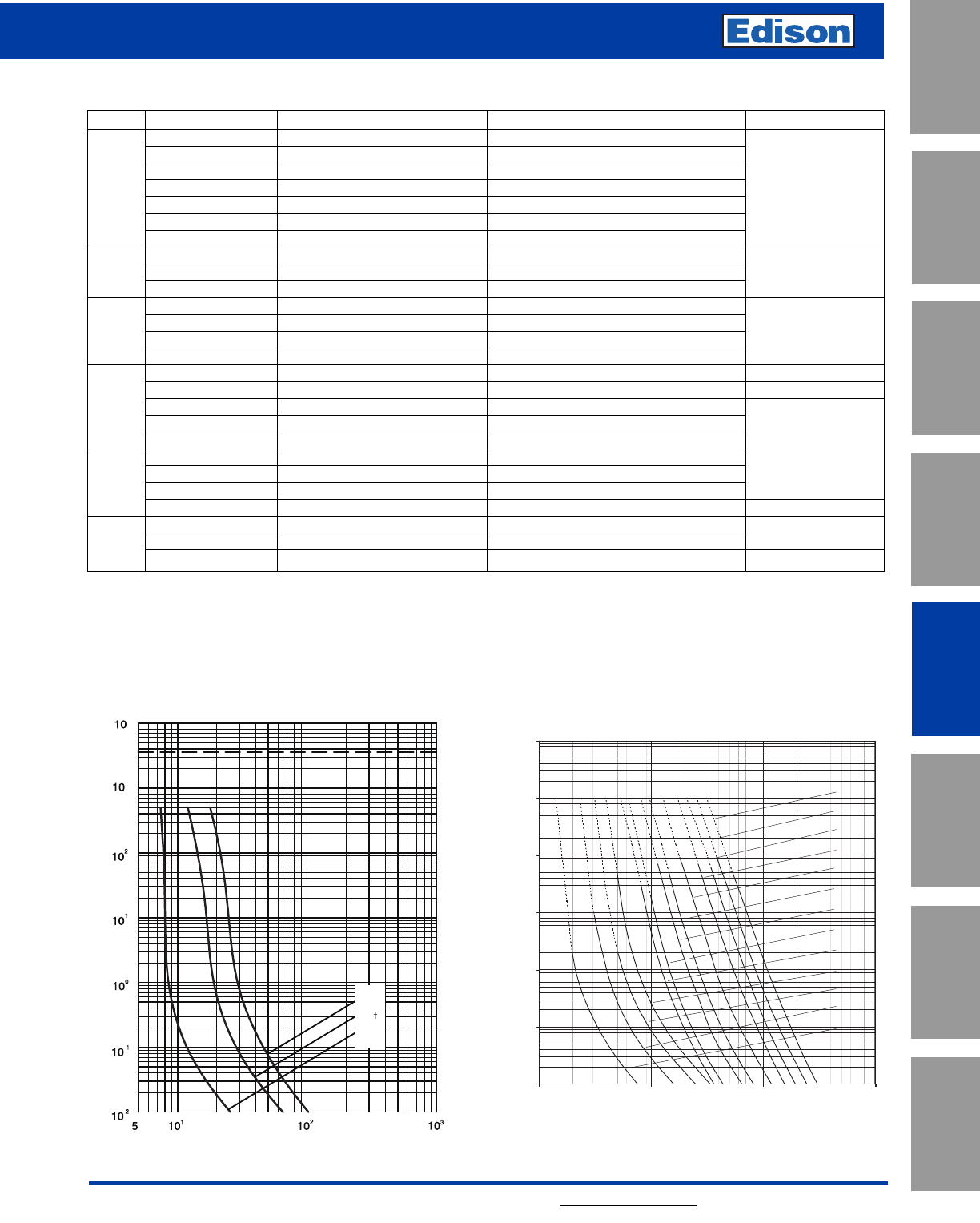
127
For additional information, visit www.edisonfuse.com
UL/CSA Fuses
Current Limiting
UL/CSA Fuses
General Purpose
Special
Purpose Fuses
Canadian
Fuses & Holders
Medium
Voltage Fuses
Fuse Blocks,
Holders & Misc.
Application
Section
Surge Protective
Devices
3.6kV – 36kV High Voltage DIN Distribution Fuses
kV Catalog Numbers Amp Ratings Dimensions - in (mm) Diameter x Length IR RMS Sym
3.6ADOSJ(amp) 6.3, 10, 16, 20, 25, 31.5, 40 2.00 x 7.56 (51 x 192)
3.6WDOSJ(amp) 50, 63, 80, 100, 125 2.00 x 7.56 (51 x 192)
3.6WFOSJ(amp) 160, 200 3.00 x 7.56 (76 x 192
3.6 3.6ADLSJ(amp) 25, 40 2.00 x 11.50 (51 x 292) 50kA
3.6WDLSJ(amp) 50, 63, 80, 100, 125 2.00 x 11.50 (51 x 292)
3.6WFLSJ(amp) 160, 200 3.00 x 11.50 (76 X 292)
3.6WKLSJ(amp) 250, 315, 400 3.00 x 11.50 (76 X 292)
7.2TDLSJ(amp) 6.3, 10, 16, 20, 25, 31.5, 40, 50, 63 2.00 x 11.50 (51 x 292)
7.2 7.2TFLSJ(amp) 80, 100, 125, 160 3.00 x 11.50 (76 x 292) 40kA
7.2WKMSJ(amp) 200, 225, 250, 315, 355 3.00 x 17.41 (76 x 442)
12TDLEJ(amp) 6.3, 10, 16, 20, 25, 31.5, 40, 50, 63 2.00 x 11.50 (51 x 292)
12 12THLEJ(amp) 80, 100 2.52 x 11.50 (64 x 292) 63kA
12TKLEJ(amp) 125 3.00 x 11.50 (76 x 292)
12TXLEJ(amp)* 160, 200 3.50 x 11.50 (88 x 292)
17.5TDLSJ(amp)* 6.3, 10, 16, 20, 25, 31.5, 40 2.00 x 11.50 (51 x 292) 50kA
17.5TFLSJ(amp)* 50 3.00 x 11.50 (76 x 292) 35.5kA
17.5 17.5TDMEJ(amp) 6.3, 10, 16, 20, 25, 31.5, 40, 50, 63 2.00 x 17.41 (51 x 442)
17.5THMEJ(amp) 80, 100 2.52 x 17.41 (64 x 442) 50kA
17.5TKMEJ(amp) 125 3.00 x 17.41 (76 x 442)
24TDMEJ(amp) 6.3, 10, 16, 20, 25, 31.5, 40, 50 2.00 x 17.41 (51 x 442)
24 24THMEJ(amp) 63 2.52 x 17.41 (64 x 442) 50kA
24TFMEJ(amp) 80, 100*13.00 x 17.41 (76 x 442)
24TXMEJ(amp)* 1252, 160 3.46 x 17.41 (88 x 442) 31.5kA
36TDQSJ(amp) 3.153, 6.3, 10, 16, 20, 25 2.00 x 21.16 (51 x 537) 35.5kA
36 36TFQSJ(amp) 31.5, 40, 50 3.00 x 21.16 (51 x 537)
36TXQEJ(amp)* 63 3.46 x 21.16 (88 x 537) 20kA
Ratings and Dimensions
For 7.2kV Fuses: • 7.2TDLSJ
• 7.2TFLSJ
• 7.2WKMSJ
For 3.6kV Fuses: • 3.6ADOS 3.6WDLS
• 3.6WDOS 3.6WFLS
• 3.6ADLS 3.6WKLS
0.01
0.1
1
10
100
1000
10000
10 100 10001
0000
R.M.S. SYMMETRICAL PROSPECTIVE CURENTINAMPS
VIRTUAL PRE-ARCING TIME IN SECONDS
TIME-C
URRENTCHARACTERISTIC
FOR 7.2kVFUSE-LINKS
FUSE TYPES: TDL / TFL
CURVESRELATE TOM
EAN PRE_ARCING TIMES WITH ATOLERANCEOF ±10% ONCURRENT
160A
125A
100A
80A
63A
50A
40A
31.5A
25A
20A
16A
10A
6.3A
* Curve valid for all 3.15A ratings shown in the selection table.
† Curve valid for all 6.3A ratings shown in the selection table.
HOUR
10A
6.3A
3.15A*
3
4
PRE - ARCING TIME IN SECONDS
CURVES RELATE TO MEAN PRE-ARCING TIME
WITH TOLERANCE ±10% ON CURRENT
RMS SYMMETICAL PROSPECTIVE CURRENT IN AMPS
Time-Current Characteristics–Average
*Not compliant with VDE 0670, part 402.
1-IR RMS Sym is 63kA 2-IR RMS Sym is 40kA 3-IR RMS Sym is 20kA
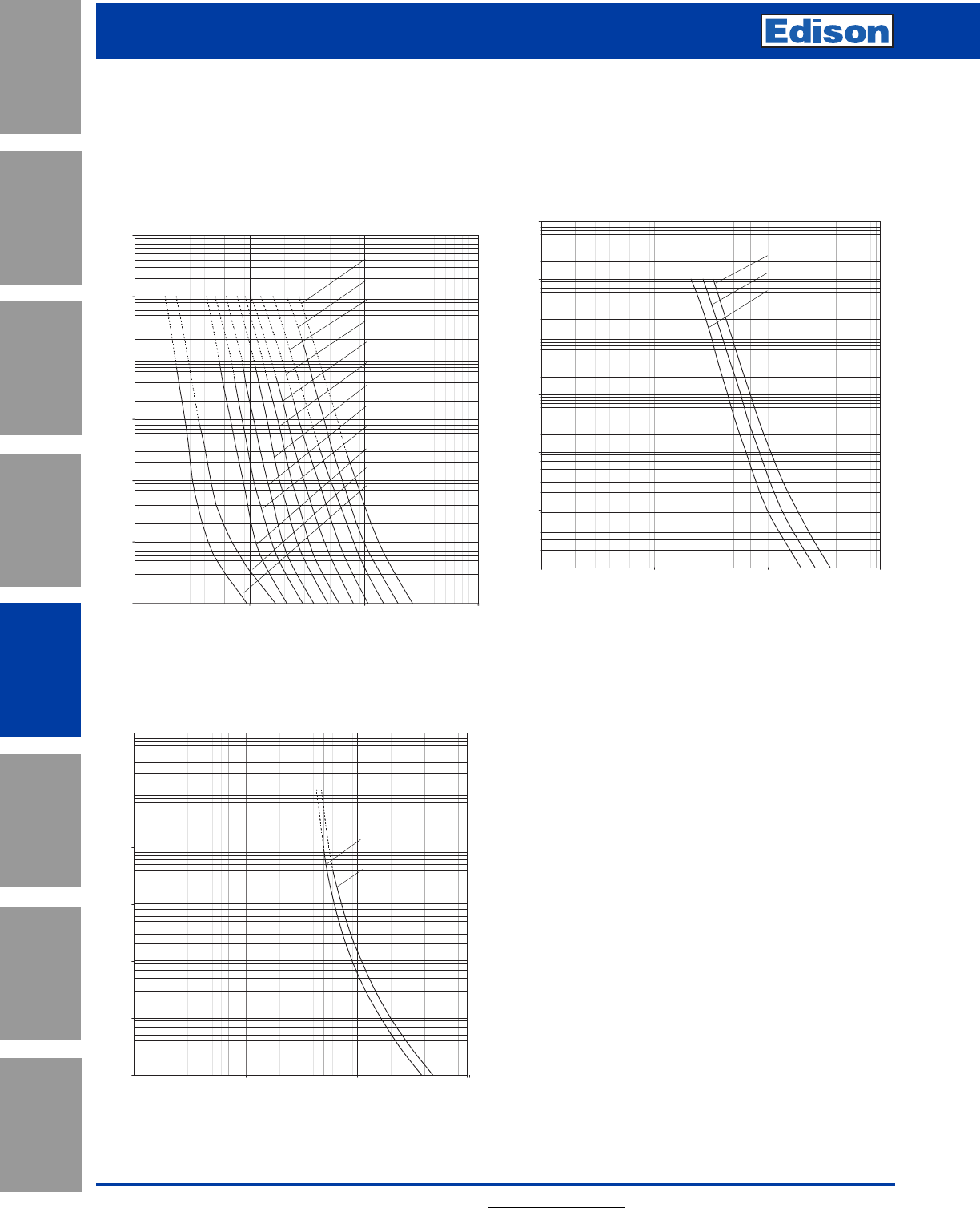
128 For additional information, visit www.edisonfuse.com
Application
Section
Fuse Blocks,
Holders & Misc.
Surge Protective
Devices
Medium
Voltage Fuses
Canadian
Fuses & Holders
Special
Purpose Fuses
UL/CSA Fuses
General Purpose
UL/CSA Fuses
Current Limiting
3.6kV – 36kV High Voltage DIN Distribution Fuses
0.01
0.1
1
10
100
1000
10000
10100 1000 10000
R.M.S. SYMMETRICAL PROSPECTIVE CURENT IN AMPS
VIRTUAL PRE-ARCING TIME IN SECONDS
TIME- CURRENT CHARACTERISTIC
FOR12kVFUSE-LINKS
FUSE TYPES:TDL/THL/TKL
CURVES RELATE TO MEAN PRE_ARCINGTI
MES WITH ATOLERANCEOF ±10%ONCURRENT
20A
16A
10A
6.3A
25A
31.5A
40A
50A
63A
80A
100A
125A
0.01
0.1
1
10
100
1000
10000
1010
010001
0000
R.M.S.SYMMETRICAL PROSPECTIVE CURENTINAMPS
VIRTUAL PRE-ARCING TIME IN SECONDS
TIME- CURRENT CHARACTERISTIC
FOR 12kV FUSE-LINKS
FUSETYPES:THM /T
KM/TFM
CURVESRELATETOMEANP
RE_ARCING TIMES WITH A TOLERANCEOF ±10% ON CURRENT
100A (THM)
125A(TKM)
160A (TFM)
0.01
0.1
1
10
100
1000
10000
10 100 1000 10000
R.M.S. SYMMETRICALPROSPECTIVECURENT INAMPS
TIME- CURRENT CHARACTERISTIC
FOR 12kV FUSE-LINKS
FUSETYPES: TXL
CURVES RELATE TOMEAN PRE_ARCING TIMES WITHATO
LERANCEOF±
10%ONCURRENT
160A
200A
Time-Current Characteristics–Average
For 12kV Fuses: • 12TDLEJ • 12TXLEJ
• 12THLEJ
• 12TKLEJ
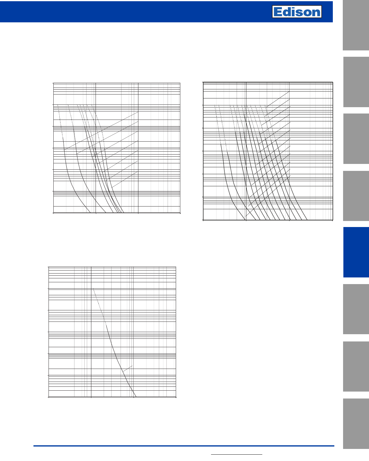
129
For additional information, visit www.edisonfuse.com
UL/CSA Fuses
Current Limiting
UL/CSA Fuses
General Purpose
Special
Purpose Fuses
Canadian
Fuses & Holders
Medium
Voltage Fuses
Fuse Blocks,
Holders & Misc.
Application
Section
Surge Protective
Devices
3.6kV – 36kV High Voltage DIN Distribution Fuses
0.01
0.1
1
10
100
1000
10000
10100100010000
R.M.S. SYMMETRICALPROSPECTIVE CURENT INAMPS
VIRTUAL PRE-ARCING TIME IN SECONDS
TIME- CURRENT CHARACTERISTIC
FOR 17.5kVFUSE-LINKS
FUSE TYPES:TDL
CURVESREL
ATE TO MEANP
RE_ARCINGTIMES WITH ATOLER
ANCE OF±10% ON CURRENT
6.3A
10A
16A
40A
20A
25A
31.5A
0.01
0.1
1
10
100
1000
10000
000
0
10001001
0
1
R.M.S. SYMMETRICAL PROSPECTIVE CURENT IN AMPS
VIRTUAL PRE-ARCING TIME IN SECONDS
TIME- CURRENT CHARACTERISTIC
FOR 17.5kV FUSE-LINKS
FUSE TYPES: TDM/THM/TKM
CURVES RELATE TO MEAN PRE_ARCING TIMES WITH A TOLERANCE OF ±10% ON CURRENT
20A
16A
10A
6.3A
25A
31.5A
40A
50A
63A
80A
100A
125A
0.01
0.1
1
10
100
1000
10000
10100 10001
0000
R.M.S.SYMMETRICALPROSPECTIVE CURENT INAMPS
VIRTUAL PRE-ARCING TIME IN SECONDS
TIME-CURRENTCHARACTERISTIC
FOR 17.5kVFUSE-LINKS
FUSE TYPES:TFL
CURVES RELATE TO MEAN PRE_ARCING TIMESWITH A TOLERANCEOF ±10%ONCURRENT
50A
Time-Current Characteristics–Average
For 17.5kV Fuses: • 17.5TDLSJ • 17.5THMEJ
• 17.5TFLSJ • 17.5TKMEJ
• 17.5TDMEJ
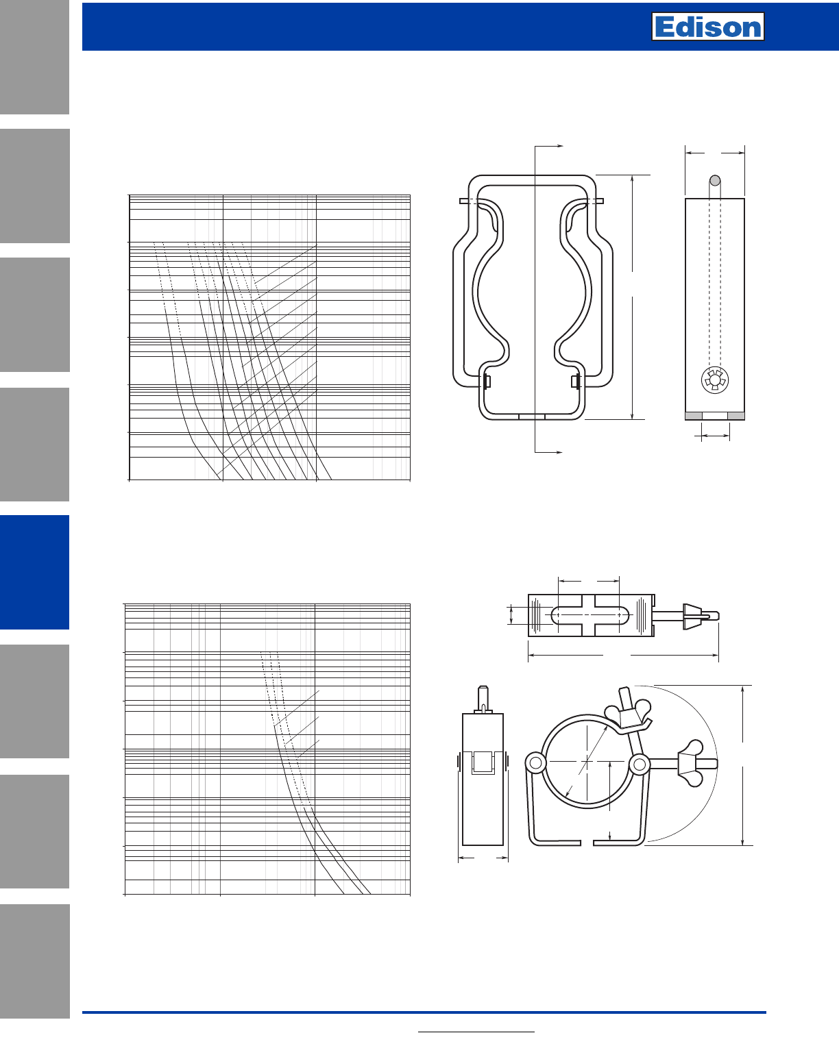
130 For additional information, visit www.edisonfuse.com
Application
Section
Fuse Blocks,
Holders & Misc.
Surge Protective
Devices
Medium
Voltage Fuses
Canadian
Fuses & Holders
Special
Purpose Fuses
UL/CSA Fuses
General Purpose
UL/CSA Fuses
Current Limiting
3.6kV – 36kV High Voltage DIN Distribution Fuses
A
A
0.43"
10.8mm
0.99"
25.0mm
4.06"
103mm
Average Time-Current Curves
For 24-27.6kV Fuses: • 24TDMEJ • 24TXMEJ
• 24THMEJ
• 24TFMEJ
0.01
0.1
1
10
100
1000
10000
10 100 1000 10000
R.M.S. SYMMETRICAL PROSPECTIVE CURENTIN AMPS
VIRTUAL PRE-ARCING TIME IN SECONDS
TIME-CURRENTCHARACTERISTIC
FOR24kVFUSE-LINKS
FUSETYPES: TDM/THM/TFM
CURVES RELATE TO MEANPRE_ARCINGTIMESWITHATOLER
ANCEOF±
10%ONCURRENT
20A
16A
10A
6.3A
25A
31.5A
40A
50A
63A
80A
0.01
0.1
1
10
100
1000
10000
10 100 100010000
R.M.S. SYMMETRICAL PROSPECTIVEC
URENT IN AMPS
VIRTUAL PRE-ARCING TIME IN SECONDS
TIME- CURRENTC
HARACTERISTIC
FOR24kVFUSE-LINKS
FUSETYPES:TF
M/TXM
CURVESRELATE TO MEANPRE_ARCINGTIMESWITH ATOLERANCEO
F±
10% ONCURRENT
100A
125A
160A
Part No. 270303
For Standard Duty (up to 200A)
1.77"
45.0mm
3.50"
88.9mm
1.19"
30.2mm
2.5"
63.5mm
0.38"
9.5mm
4.50"
114 .3m m
1.5"
38.1mm
Part No. A3354745
Heavy Duty
DIN Fuseclips
Suitable for use with all DIN HV fuses having 45mm
end fittings.
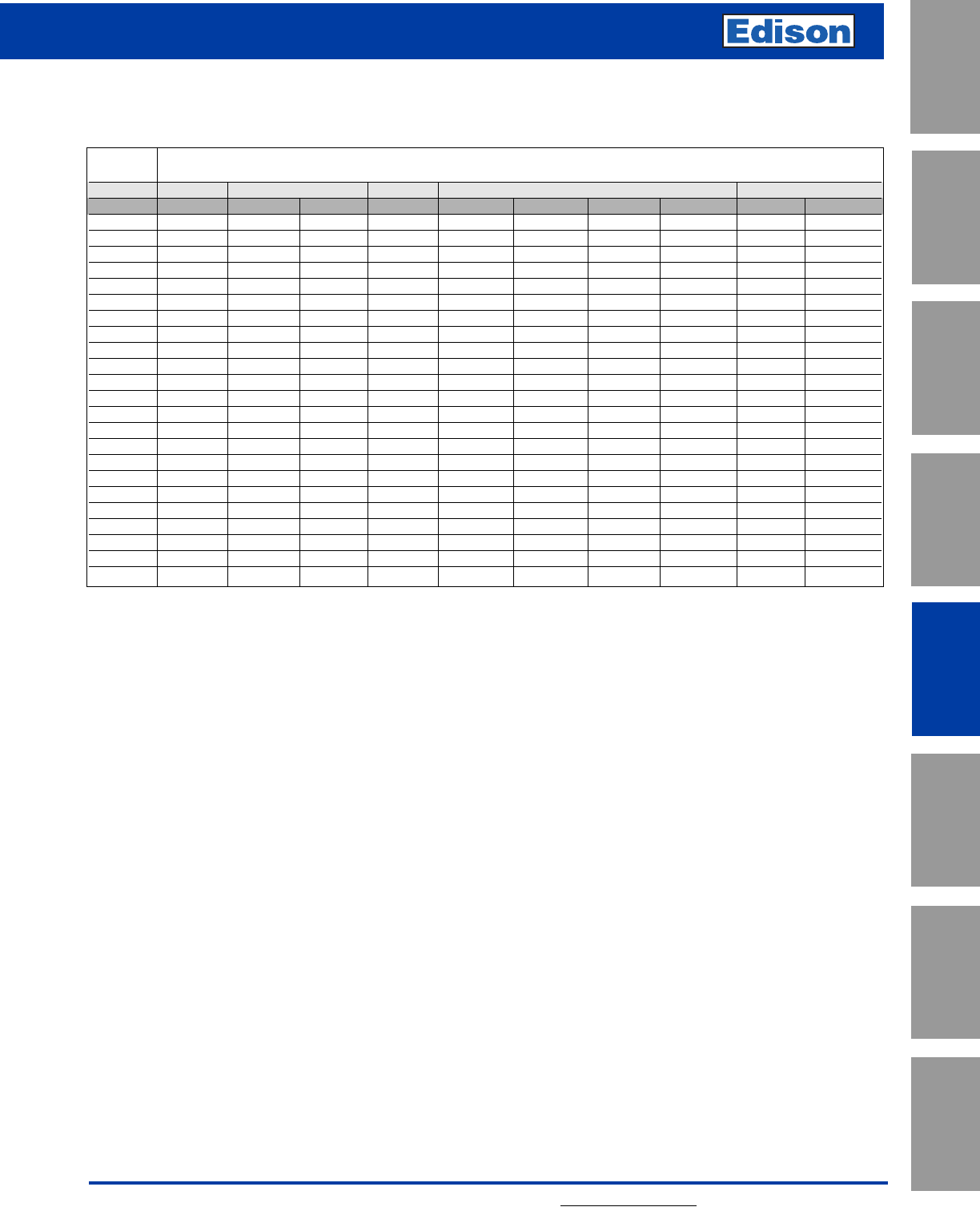
131
For additional information, visit www.edisonfuse.com
UL/CSA Fuses
Current Limiting
UL/CSA Fuses
General Purpose
Special
Purpose Fuses
Canadian
Fuses & Holders
Medium
Voltage Fuses
Fuse Blocks,
Holders & Misc.
Application
Section
Surge Protective
Devices
High Voltage DIN Distribution Fuses
Transformer
3-ph kVA Fuse Reference and Rating in Amps
Fuse kV 3.6kV 7.2kV 12kV 17.5kV 24kV
System kV 2.4kV 4.16kV 6.9kV 10kV 12.47kV 13.2kV 13.8kV 15.5kV 20kV 24kV
25 ADLSJ 16 TDLSJ 10 TDLSJ 6.3 TDLEJ 6.3 TDMEJ 6.3 TDMEJ 6.3 TDMEJ 6.3 TDMEJ 6.3 TDMEJ 6.3 TDMEJ 6.3
30 ADLSJ 16 TDLSJ 10 TDLSJ 6.3 TDLEJ 6.3 TDMEJ 6.3 TDMEJ 6.3 TDMEJ 6.3 TDMEJ 6.3 TDMEJ 6.3 TDMEJ 6.3
40 ADLSJ 20 TDLSJ 16 TDLSJ 10 TDLEJ 6.3 TDMEJ 6.3 TDMEJ 6.3 TDMEJ 6.3 TDMEJ 6.3 TDMEJ 6.3 TDMEJ 6.3
45 ADLSJ 20 TDLSJ 16 TDLSJ 10 TDLEJ 6.3 TDMEJ 6.3 TDMEJ 6.3 TDMEJ 6.3 TDMEJ 6.3 TDMEJ 6.3 TDMEJ 6.3
63 ADLSJ 31.5 TDLSJ 20 TDLSJ 16 TDLEJ 10 TDMEJ 10 TDMEJ 10 TDMEJ 6.3 TDMEJ 6.3 TDMEJ 6.3 TDMEJ 6.3
75 ADLSJ 40 TDLSJ 25 TDLSJ 16 TDLEJ 10 TDMEJ 10 TDMEJ 10 TDMEJ 10 TDMEJ 10 TDMEJ 6.3 TDMEJ 6.3
100 ADLSJ 40 TDLSJ 25 TDLSJ 20 TDLEJ 10 TDMEJ 10 TDMEJ 10 TDMEJ 10 TDMEJ 10 TDMEJ 10 TDMEJ 6.3
112 ADLSJ 40 TDLSJ 31.5 TDLSJ 20 TDLEJ 16 TDMEJ 10 TDMEJ 10 TDMEJ 10 TDMEJ 10 TDMEJ 10 TDMEJ 6.3
125 WDLSJ 50 TDLSJ 31.5 TDLSJ 25 TDLEJ 16 TDMEJ 10 TDMEJ 10 TDMEJ 10 TDMEJ 10 TDMEJ 10 TDMEJ 10
150 WDLSJ 50 TDLSJ 40 TDLSJ 25 TDLEJ 16 TDMEJ 16 TDMEJ 16 TDMEJ 16 TDMEJ 10 TDMEJ 10 TDMEJ 10
200 WDLSJ 63 TDLSJ 50 TDLSJ 31.5 TDLEJ 20 TDMEJ 16 TDMEJ 16 TDMEJ 16 TDMEJ 16 TDMEJ 10 TDMEJ 10
225 WDLSJ 80 TDLSJ 50 TDLSJ 40 TDLEJ 20 TDMEJ 16 TDMEJ 16 TDMEJ 16 TDMEJ 16 TDMEJ 10 TDMEJ 10
300 WDLSJ 100 TDLSJ 63 TDLSJ 40 TDLEJ 25 TDMEJ 20 TDMEJ 20 TDMEJ 20 TDMEJ 20 TDMEJ 16 TDMEJ 10
400 WDLSJ 125 TDLSJ 80 TDLSJ 50 TDLEJ 31.5 TDMEJ 31.5 TDMEJ 25 TDMEJ 25 TDMEJ 20 TDMEJ 20 TDMEJ 20
450 WFLSJ 160 TFLSJ 80 TDLSJ 63 TDLEJ 40 TDMEJ 31.5 TDMEJ 31.5 TDMEJ 31.5 TDMEJ 25 TDMEJ 20 TDMEJ 20
500 WFLSJ 160 TFLSJ 100 TDLSJ 63 TDLEJ 40 TDMEJ 31.5 TDMEJ 31.5 TDMEJ 31.5 TDMEJ 31.5 TDMEJ 25 TDMEJ 20
600 WFLSJ 200 TFLSJ 125 TFLSJ 80 TDLEJ 50 TDMEJ 40 TDMEJ 40 TDMEJ 40 TDMEJ 31.5 TDMEJ 25 TDMEJ 20
750 WKLSJ 250 TFLSJ 160 TFLSJ 80 TDLEJ 63 TDMEJ 50 TDMEJ 50 TDMEJ 40 TDMEJ 40 TDMEJ 31.5 TDMEJ 25
1000 WKLSJ 315 WKMSJ 200 TFLSJ 125 THLEJ 80 TDMEJ 63 TDMEJ 63 TDMEJ 63 TDMEJ 50 TDMEJ 40 TDMEJ 31.5
1250 WKLSJ 400 WKMSJ 250 TSFLSJ 160 THLEJ 100 TDMEJ 80 TDMEJ 80 TDMEJ 80 TDMEJ 63 TDMEJ 50 TDMEJ 40
1500 – WKMSJ 315 TFLSJ 160 TKLEJ 125 TDMEJ 100 TDMEJ 100 TDMEJ 80 TDMEJ 80 THMEJ 63 TDMEJ 50
2000 ––WKMSJ 250 – TKMEJ 125 TKMEJ 125 TKMEJ 125 TDMEJ 100 ––
2500 ––WKMSJ 315 ––––TKMEJ 125 ––
General Guide to the Selection of Fuses.
For use in the Primary Circuit of Three-Phase Transformers
Selection of these fuses has been based on a compromise between the following:
1. The fuse should withstand transformer magnetizing inrush currents, taken as 12 times full load current for 0.1 second.
2. The fuse should coordinate with the highest rating of the secondary fuse likely to be used.
3. The fuse should operate reasonably quickly in the event of a transformer inter-turn fault or a fault in the secondary terminal zone of the transformer.
NOTES:
A. In general, the recommendations apply equally to the use of fuse in open air or in an encapsulated enclosure, since “1” and “2” above dictate the use of a
fuse current rating sufficiently above the transformer current rating to nullify any adverse thermal affect of encapsulation. However, if the transformer is
subjected to long time overcurrents, a higher rate of fuse may be required.
B. The above recommendations are not generally applicable to transformers feeding motor circuits with starting currents in excess of the rated current of the
fuse. In this event, please consult your local Edison representative.
C. Recommendations for other voltages are available on request.
D. While the above recommendations give a good general guide, recommendations for specific cases will be sent on receipt of full details of the application.
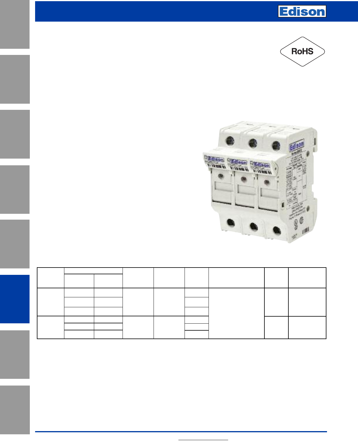
132 For additional information, visit www.edisonfuse.com
Application
Section
Fuse Blocks,
Holders & Misc.
Surge Protective
Devices
Medium
Voltage Fuses
Canadian
Fuses & Holders
Special
Purpose Fuses
UL/CSA Fuses
General Purpose
UL/CSA Fuses
Current Limiting
Fuse Blocks, Holders and
Accessories
Specifications
Agency Information: UL File E300536
Guide IZLT Listed, IZLT2 Recognized
CSA: File 47235; EHM - Class 6225-30,
EHCC - Class 6225-01
CCC GB13539
Ratings:
600V/30A (UL)
690V/32A (IEC)
Wire Range:
#18 to #4 (0.8 to 21.1mm2)
Torque Ratings:
30 Lb-In (3.4 N•m) maximum
Flammability Ratings:
UL 94V0, self-extinguishing
Storage & Operating Temperature Range:
-20ºC to +90ºC (indicating)
-20ºC to +120ºC (non-indicating)
Features and Benefits
• High SCCR rated, UL Listed Class CC holder with
indicator option for 600Vac/dc
• UL Recognized midget and 10 x 38 holders
• Terminals rated for use with 75ºC or 90ºC wire, fine stranded
wire, spade terminals and comb-bus bars. Use any
higher temperature rated wire with appropriate derating
• Complete range of UL Listed and high SCCR rated
1- and 3-phase finger-safe comb-bus bars and power feed lugs
Catalog Number
Series & With Without Voltage & Agency Number Terminal SCCR Edison
Size Indicator Indicator Current Markings of Poles Rating Rating Fuses
EHM EHM1DIU EHM1DU UL 1 Solid, Stranded,
10x38 EHM2DIU EHM2DU 600V/30A; UR, IEC
2Fine Stranded, 200kA MCL, MOL,
and
EHM3DIU EHM3DU
IEC 60269-2,
3
Spade Lug, rms sym MEQ, MEN
Midget 690V/32A CSA Comb-Bus Bar,
EHCC EHCC1DIU EHCC1DU UL 1 Single and Dual Wire;
Class CC EHCC2DIU EHCC2DU 600V/30A UL, CSA 2 75ºC and 90ºC 200kA EDCC, HCLR,
EHCC3DIU EHCC3DU 3 Cu wire rms sym HCTR
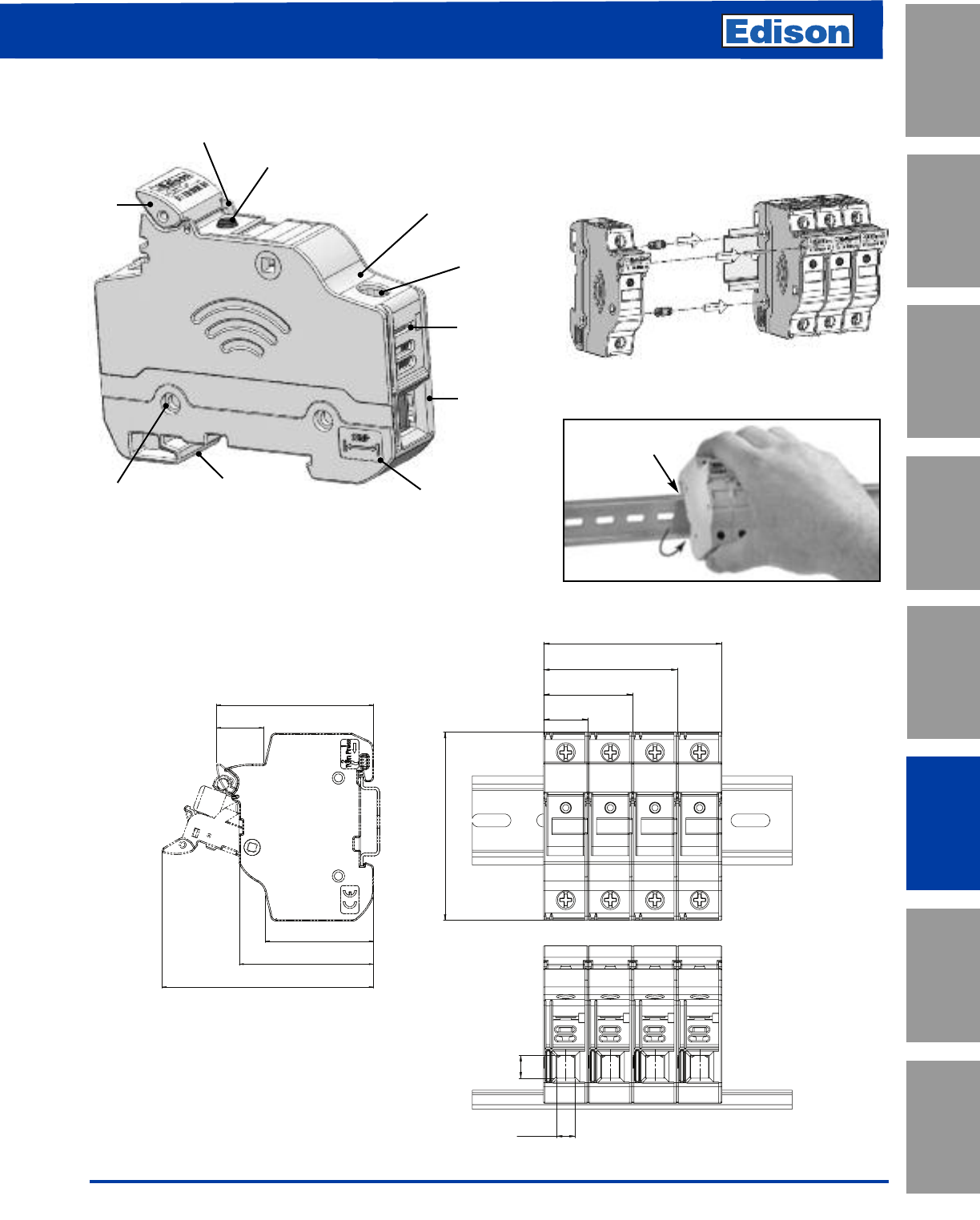
133
For additional information, visit www.edisonfuse.com
Fuse Blocks, Holders and
Accessories
UL/CSA Fuses
Current Limiting
UL/CSA Fuses
General Purpose
Special
Purpose Fuses
Canadian
Fuses & Holders
Medium
Voltage Fuses
Fuse Blocks,
Holders & Misc.
Application
Section
Surge Protective
Devices
Multi-Pole Ganging
Use multi-pole connection kit part number
EV-L to gang multiple poles together. One
EV-L kit is sufficient to gang up to 4 poles.
Dimensional Data - mm (in)
17.5
[ 0.689 ]
35
[ 1.378 ]
52.5
[ 2.067 ]
70
[ 2.756 ]
73.88
[ 2.909 ]
42.58
[ 1.676 ]
52.83
[ 2.080 ]
61.83
[ 2.434 ]
18.59
[ 0.732 ]
83.19
[ 3.275 ]
9
[ 0.354 ]
7.0
[ 0.276 ]
Removing Instructions
1. Press down on top
of DIN-Rail
2. Rotate out
on the bottom
4mm
Lockout
Feature
in Fuse
Carrier
Toolless
Ganging of
Multiple
Poles
Toolless DIN Rail
Mounting Wire Strip
Length
Indicator
6mm Wire
Clamp Lug and
open bus bar
connection
(#4 to #18)
Captive, Fully
Backed Out
Phil-Slot Screw
Spade lug
connection
Self-Extinguishing,
UL 94V0 Rated
Polyester
Material
Optional
Open Fuse
Indicator
Hole for Wire
Security Tag
Features
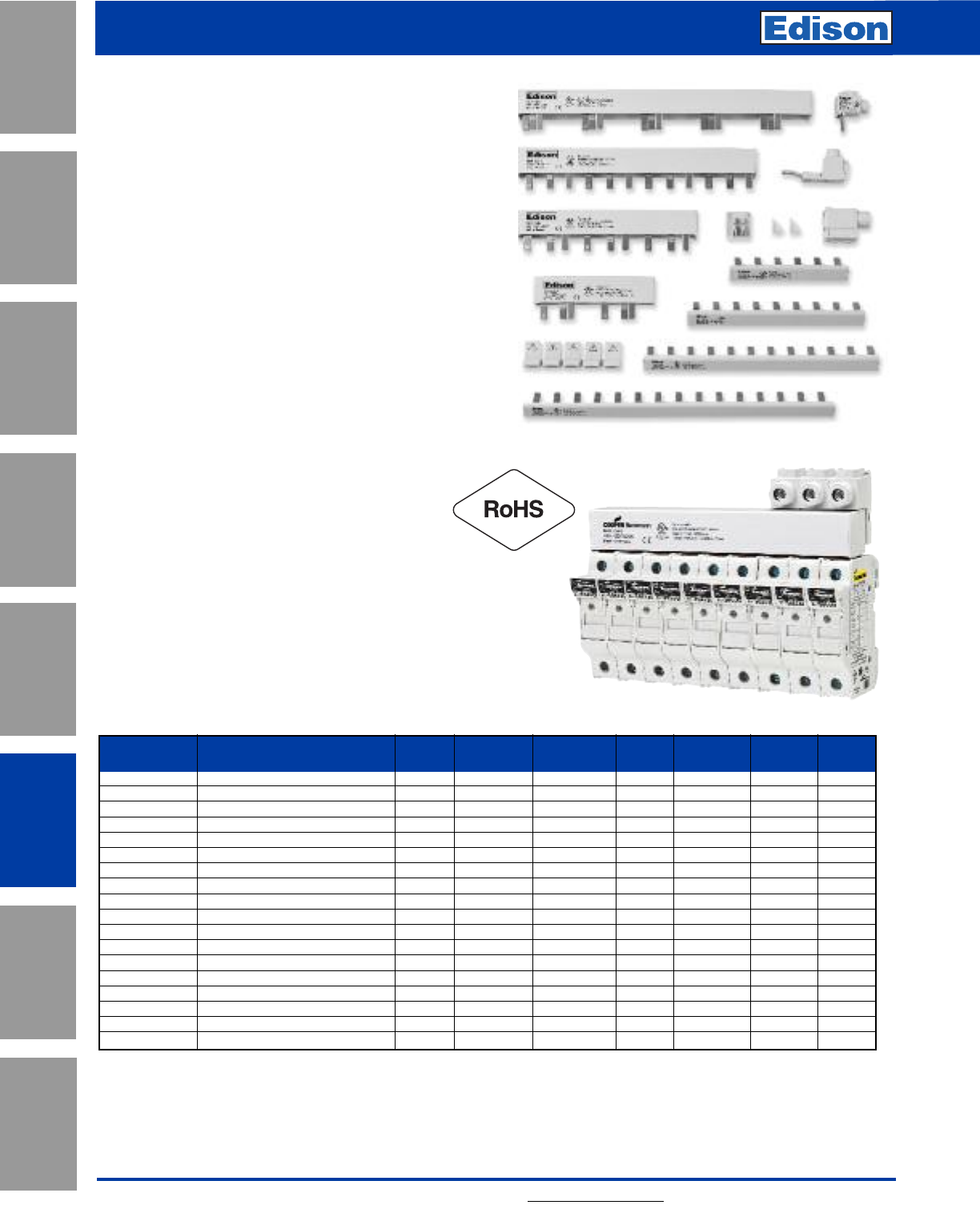
134 For additional information, visit www.edisonfuse.com
Application
Section
Fuse Blocks,
Holders & Misc.
Surge Protective
Devices
Medium
Voltage Fuses
Canadian
Fuses & Holders
Special
Purpose Fuses
UL/CSA Fuses
General Purpose
UL/CSA Fuses
Current Limiting
Fuse Blocks, Holders and
Accessories
Features and Benefits
• Easily distribute power in single-phase or
three-phase configurations
• Flexible cut-to-length solutions without
compromising on the product’s finger-safe
features
• 100kA SCCR (Short Circuit Current Rating) when
protected by a 200A Class J fuse
• Single-phase bus bars rated to 1000Vdc and
100A in end-fed configuration (200A for
center-fed configuration)
• Three-phase bus bars rated to 600Vac/dc and
100A in end-fed configuration
• Power feed terminals for single-phase and
three-phase service
Specifications
Agency Information: UL508, File E195399
Pitch: 17.8mm
SCCR: 10kA (default)
100kA (with upstream Class J 200A fuses)
Max Current: 100A (power feed from end)
Max Voltage: 600Vac/dc (three phase)
1000Vdc/600Vac (single phase)
Part Voltage Amperage # of Wire Size Wire Torque
Number Description Phase Rating (V) Rating (A) Poles (AWG) Type (LB-in)
EB1P100M3 Single-phase, 3-pole busbar Single 1000 100 3 N/A N/A N/A
EB1P100M6 Single-phase, 6-pole busbar Single 1000 100 6 N/A N/A N/A
EB1P100M9 Single-phase, 9-pole busbar Single 1000 100 9 N/A N/A N/A
EB1P100M12 Single-phase, 12-pole busbar Single 1000 100 12 N/A N/A N/A
EB1P100M15 Single-phase, 15-pole busbar Single 1000 100 15 N/A N/A N/A
EB1P100M57 Single-phase, 57-pole busbar Single 1000 100 57 N/A N/A N/A
EB3P100M3 Three-phase, 3-pole busbar Three 600 100 3 N/A N/A N/A
EB3P100M6 Three-phase, 6-pole busbar Three 600 100 6 N/A N/A N/A
EB3P100M9 Three-phase, 3-pole busbar Three 600 100 9 N/A N/A N/A
EB3P100M12 Three-phase, 12-pole busbar Three 600 100 12 N/A N/A N/A
EB3P100M15 Three-phase, 15-pole busbar Three 600 100 15 N/A N/A N/A
EB3P100M57 Three-phase, 57-pole busbar Three 600 100 57 N/A N/A N/A
EECAP1P Single-phase, busbar end cap N/A N/A N/A N/A N/A N/A N/A
EECAPMP Three-phase, busbar end cap N/A N/A N/A N/A N/A N/A N/A
EFSCVR Open pin safety covers, 5-poles N/A N/A N/A 5 N/A N/A N/A
EPWR35MM Three-phase, feeder terminal N/A 1000 115 N/A 1/0 - 10 CU 60ºC 50
EPWR50MM Direct feed, feeder terminal N/A 1000 115 N/A 1 - 14 CU 75ºC 35
EPWR1PLP Single-phase, feeder terminal N/A 1000 115 N/A 1/0 - 10 CU 60ºC 80
Selection Guide
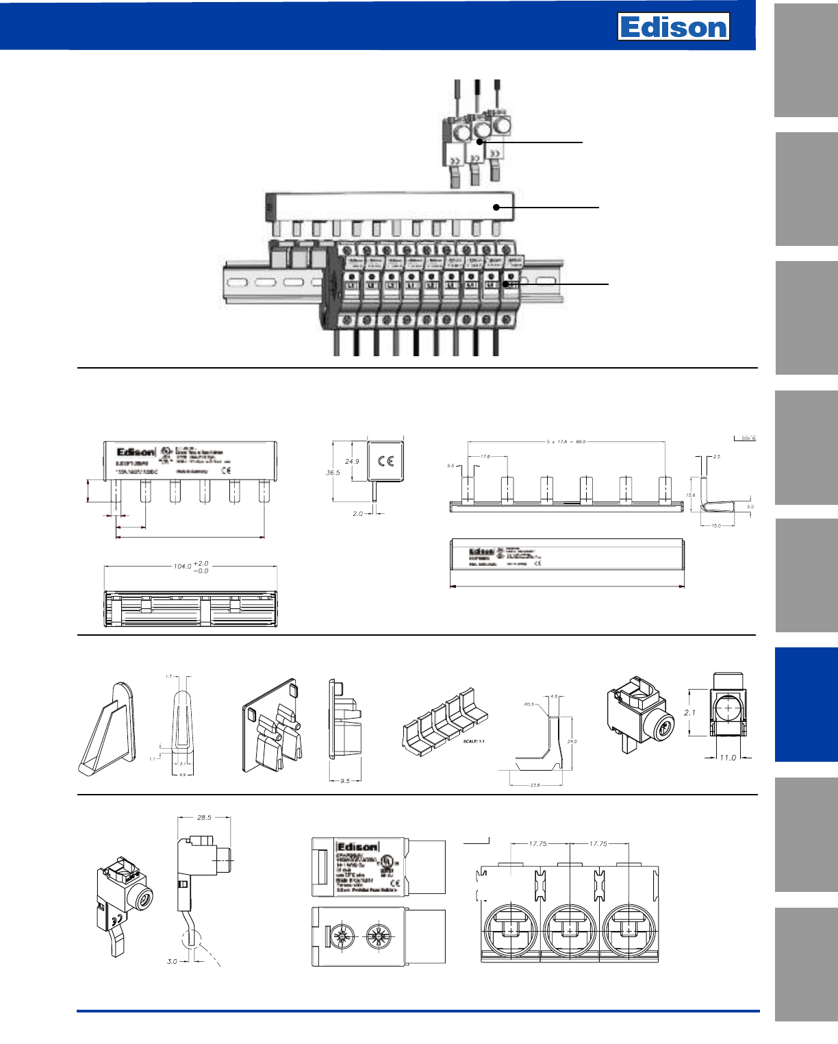
135
For additional information, visit www.edisonfuse.com
UL/CSA Fuses
Current Limiting
UL/CSA Fuses
General Purpose
Special
Purpose Fuses
Canadian
Fuses & Holders
Medium
Voltage Fuses
Fuse Blocks,
Holders & Misc.
Application
Section
Surge Protective
Devices
Fuse Blocks, Holders and
Accessories
Typical Dimensional Data
Three-phase Single-phase
EECAP1P EECAPMP EFSCVR EPWR1PLP
EPWR35MM EPWR50MM
Typical Installation Example
Power Feed Terminals
Comb-Bus Bar
Modular Fuse Holders
6
17 , 8
895x17,8 =
1
3,5
113
2
+
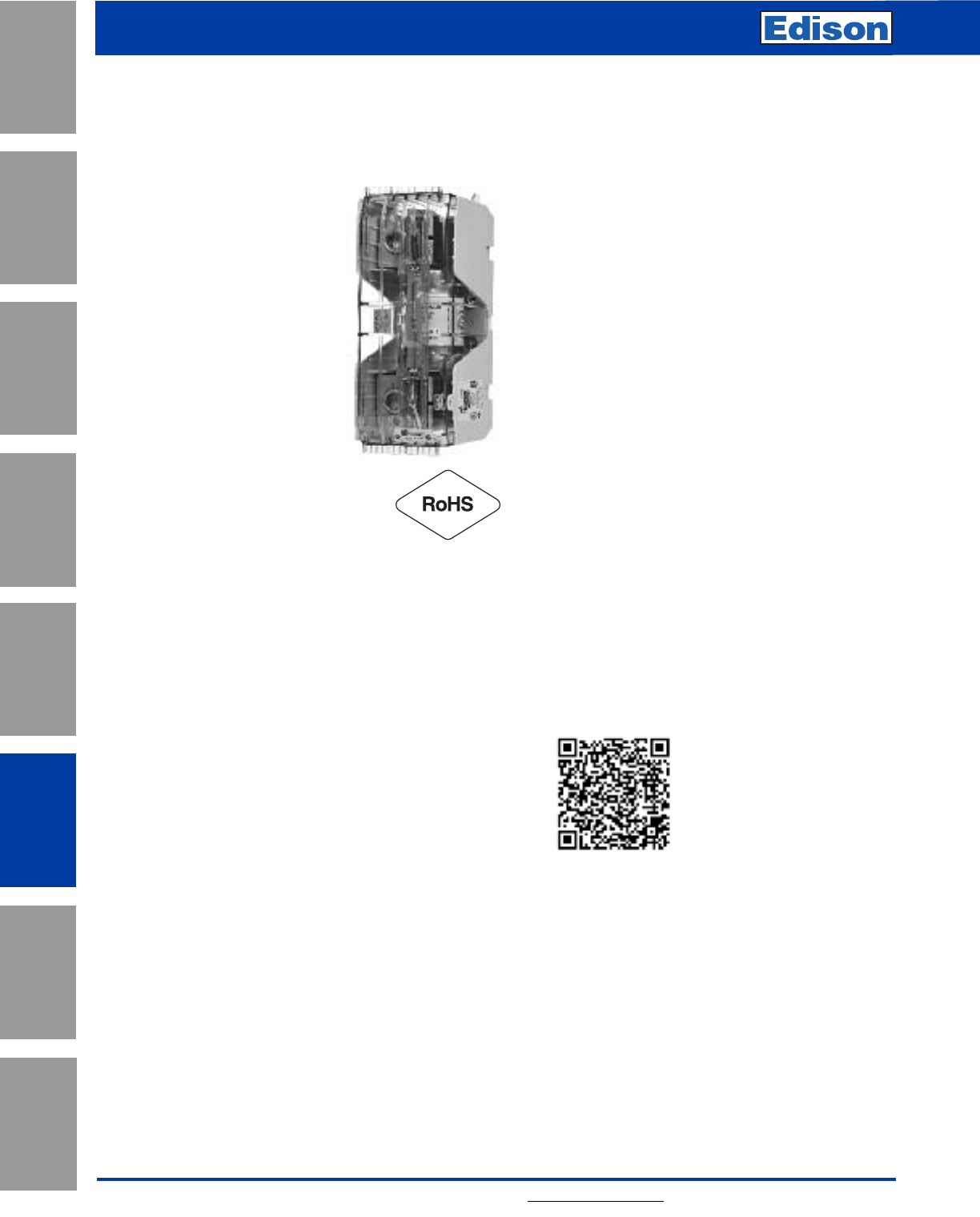
136 For additional information, visit www.edisonfuse.com
Application
Section
Fuse Blocks,
Holders & Misc.
Surge Protective
Devices
Medium
Voltage Fuses
Canadian
Fuses & Holders
Special
Purpose Fuses
UL/CSA Fuses
General Purpose
UL/CSA Fuses
Current Limiting
Fuse Blocks, Holders and
Accessories
Modular Knifeblade Fuse Blocks
Class R, H(K), & J Applications up to 600
Amps
Specifications
Ratings:
Volts: — 250V, 600V
Amps: — 70-600A
SCCR: — 200kA (Class R & J)
10kA (Class H & K)
Agency Information:
Blocks: UL - Listed cULus
E14853 – IZLT & IZLT7
CSA - Certified 47235 –
6225-01
Covers: UL - Listed UL
E58836 – JDVS2
CSA - Certified 47235 –
6225-01
Flammability Ratings:
Blocks: UL 94V0, self-extinguishing
Covers: UL 94HB, self-extinguishing
Operating & Storage Temperature Range:
Blocks -40ºC to 120ºC
Covers non-indicating covers -40ºC to 120ºC
indicating covers -20ºC to 90ºC
Materials:
Base – Thermoplastic
Box Lug – Tin-plated aluminum
Wire:*
Cu/Al – 75ºC/90ºC (100 - 200A)
Cu/Al – 75ºC only (400 - 600A)**
*Higher temperature rated wire can be used with appropriate derating.
**400A Class J double box lug rated for 75ºC/90ºC Cu/Al.
Features and Benefits
• Integral dovetails allow snapping together multiple
poles at point-of-use for greater application flexibility
• Factory assembled two- and three-pole configurations
available
• Up to four mounting holes per pole increase installation
flexibility
• Standard phase barriers between poles for additional
safety
• Design meets UL creep and clearance requirements
for Industrial Control Circuits (UL 508 and UL 845)
• 200 to 600A blocks meet the higher UL creep and
clearance requirements for Industrial Power
Distribution Standards (UL 98, UL 69, UL 489, UL 891
and UL 869A)
• Optional IP20 finger-safe covers available on entire
knifeblade fuse block product line:
– High-clarity see-through covers allow for inspecting
wire terminations or thermography measurements
without removing cover
– Probe holes included for easy, safer testing and
troubleshooting
– Built-in lockout/tagout feature improves safety
• Standard fuse clip reinforcing springs enhance
electrical contact
Typical Applications
• Critical power, factory automation, renewable energy,
HVAC, building/elevator controls, building entrance,
process industries
Scan this tag to get the
latest product information for the
Modular Knifeblade Fuse Blocks.
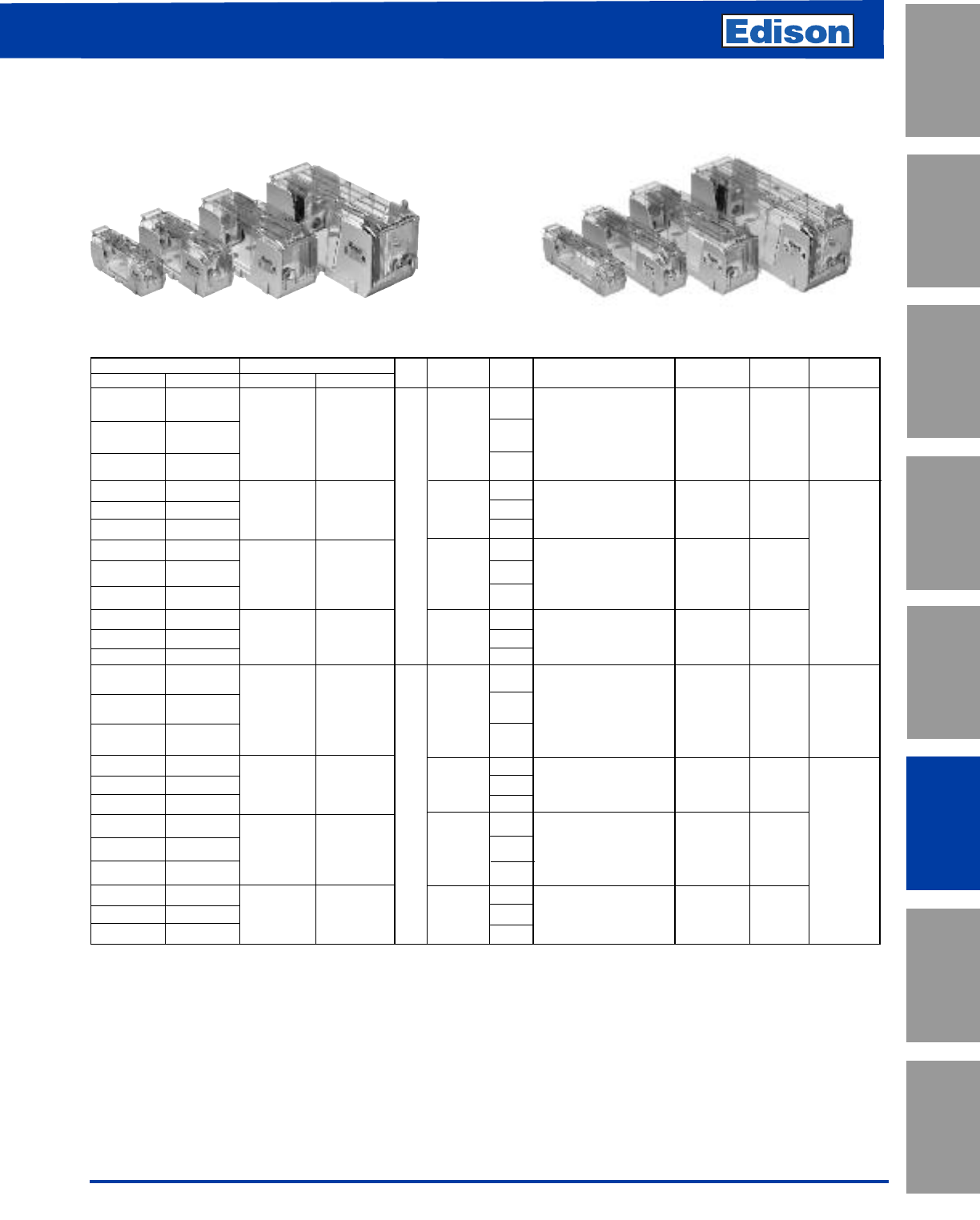
137
For additional information, visit www.edisonfuse.com
UL/CSA Fuses
Current Limiting
UL/CSA Fuses
General Purpose
Special
Purpose Fuses
Canadian
Fuses & Holders
Medium
Voltage Fuses
Fuse Blocks,
Holders & Misc.
Application
Section
Surge Protective
Devices
Fuse Blocks, Holders and
Accessories
Catalog Number Covers* Fuse Range Number Wire Range Wire Range Torque Edison
Class H(K) Class R w/o Indication w/ Indication Volts (amps) of Poles (solid and stranded)*** (fine stranded Cu) N•m (Lb-In) Fuses
HM25100-1CR RM25100-1CR 1 – 1-3 AWG 6.2 (55)
70- 1/0-3 AWG; (2) Cu 4-6 AWG 4-6 AWG 5.6 (50) Class H(K):
HM25100-2CR RM25100-2CR CVR-RH-25100 CVRI-RH-25100 100 2 4-6 AWG; (2) Cu 8 AWG 8 AWG 5.1 (45) KON
HM25100-3CR RM25100-3CR 3
8 AWG; (2) Cu 10-14 AWG – 4.5 (40) CDNC/PONC
Cu 10-14 AWG; Al 10-12 AWG – 4.0 (35)
HM25200-1CR RM25200-1CR 110- 1250 MCM-1 AWG 3/0-1 AWG 42 (375)
HM25200-2CR RM25200-2CR CVR-RH-25200 CVRI-RH-25200 200 22-6 AWG; (2) Cu 2-6 AWG 2-6 AWG 31 (275)
HM25200-3CR RM25200-3CR 250 3 Class R:
HM25400-1CR RM25400-1CR 1 600kcmil 57 (500) ECNR
HM25400-2CR RM25400-2CR CVR-RH-25400 CVRI-RH-25400 225- 2500kcmil-4 AWG N/A 51 (450) LENRK
HM25400-3CR RM25400-3CR
400
3
(2) Cu 3/0 - 4 AWG 57 (500) NCLR
(2) Al 3/0 - 4 AWG 34 (300)
HM25600-1CR RM25600-1CR 450- 1
HM25600-2CR RM25600-2CR CVR-RH-25600 CVRI-RH-25600 600 2 (2) 500kcmil-4 AWG N/A 51 (450)
HM25600-3CR RM25600-3CR 3
HM60100-1CR RM60100-1CR 1–1-3 AWG 6.2 (55)
HM60100-2CR RM60100-2CR CVR-RH-60100 CVRI-RH-60100 70- 2
1/0-3 AWG; (2) Cu 4-6 AWG 4-6 AWG 5.6 (50) Class H(K):
100 4-6 AWG; (2) Cu 8 AWG 8 AWG 5.1 (45) KOS
HM60100-3CR RM60100-3CR 3 8 AWG; (2) Cu 10-14 AWG – 4.5 (40) CDSC
Cu 10-14 AWG; Al 10-12 AWG – 4.0 (35)
HM60200-1CR RM60200-1CR 110- 1250 MCM-1 AWG 3/0-1 AWG 42 (375)
HM60200-2CR RM60200-2CR CVR-RH-60200 CVRI-RH-60200 200 22-6 AWG; (2) Cu 2-6 AWG 2-6 AWG 31 (275)
HM60200-3CR RM60200-3CR 600 3 Class R:
HM60400-1CR RM60400-1CR 1 600kcmil 57 (500) ECSR
HM60400-2CR RM60400-2CR CVR-RH-60400 CVRI-RH-60400 225- 2500kcmil-4 AWG N/A 51 (450) LESRK
HM60400-3CR RM60400-3CR
400
3
(2) Cu 3/0 - 4 AWG 57 (500) SCLR
(2) Al 3/0 - 4 AWG 34 (300) PVS-R
HM60600-1CR RM60600-1CR 450- 1
HM60600-2CR RM60600-2CR CVR-RH-60600 CVRI-RH-60600 600 2 (2) 500kcmil-4 AWG N/A 51 (450)
HM60600-3CR RM60600-3CR 3
*Covers sold serarately. Blown fuse indication requires 90 volts minimum and closed circuit to operate.
**With
easy
ID™ blown fuse indication.
***Ratings for copper and aluminum wire except where otherwise noted.
250V Class H(K) and R 600V Class H(K) and R
Modular Knifeblade Fuse Blocks Part Number Table
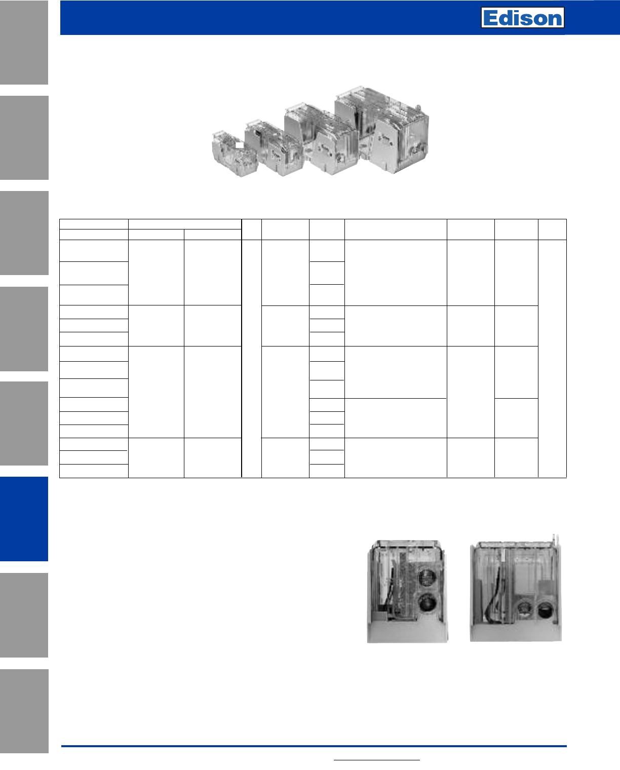
138 For additional information, visit www.edisonfuse.com
Application
Section
Fuse Blocks,
Holders & Misc.
Surge Protective
Devices
Medium
Voltage Fuses
Canadian
Fuses & Holders
Special
Purpose Fuses
UL/CSA Fuses
General Purpose
UL/CSA Fuses
Current Limiting
Fuse Blocks, Holders and
Accessories
Modular Knifeblade Fuse Blocks Part Number Table (continued)
Catalog Number Covers* Fuse Range Number Wire Range Wire Range Torque Edison
Class J w/o Indication w/ Indication Volts (amps) of Poles (solid and stranded)***
(fine stranded)
N•m (Lb-In) Fuses
JM60100-1CR 1 –1-3 AWG 6.2 (55)
2
1/0-3 AWG; (2) Cu 4-6 AWG 4-6 AWG 5.6 (50)
JM60100-2CR CVR-J-60100-M CVRI-J-60100-M 70- 4-6 AWG; (2) Cu 8 AWG 8 AWG 5.1 (45)
JM60100-3CR
100 8 AWG; (2) Cu 10-14 AWG – 4.5 (40)
3Cu 10-14 AWG; Al 10-12 AWG – 4.0 (35)
JM60200-1CR 110- 1250 MCM-1 AWG 3/0-1 AWG 42 (375)
JM60200-2CR CVR-J-60200-M CVRI-J-60200-M 200 22-6 AWG; (2) Cu 2-6 AWG 2-6 AWG 31 (275)
JM60200-3CR 3 JHL
JM60400-1CR 600 1600kcmil 57 (500) JDL
JM60400-2CR 2 500kcmil-4 AWG 51 (450) JFJ
JM60400-3CR 3
(2) Cu 3/0 - 4 AWG 57 (500)
CVR-J-60400-M CVRI-J-60400-M 225-400 (2) Al 3/0 - 4 AWG N/A 34 (300)
JM60400-1MW22†1(2) 350kcmil-1 AWG 42 (375)
JM60400-2MW22†2(2) 2 AWG - 6 AWG 51 (275)
JM60400-3MW22†3
JM60600-1CR 450- 1
JM60600-2CR CVR-J-60600 CVRI-J-60600 600 2 (2) 500kcmil-4 AWG N/A 51 (450)
JM60600-3CR 3
Class J
*Covers sold serarately. Blown fuse indication requires 90 volts minimum and closed circuit to operate.
**With
easy
ID™ blown fuse indication.
***Ratings for copper and aluminum wire except where otherwise noted.
†400A Class J double box lug rated for 75oC/90oC Cu/Al.
††For Class J 400A double box lug configuration, optional cover provides IP20 finger-safe protection for
dual 350kcmil-300kcmil wires or one single 350kcmil-6 AWG wire.
Double Box Lug Configurations
• Allows for ease of installation with smaller, more flexible wire
• Capable of achieving maximum current rating with parallel
copper or aluminum wires
• Standard on all 600A blocks
• Optional on 400A Class J blocks
• Compatible with IP20 finger-safe covers††
Optional 400A
Class J Version
(JM60400-_MW22)
All 600A Versions
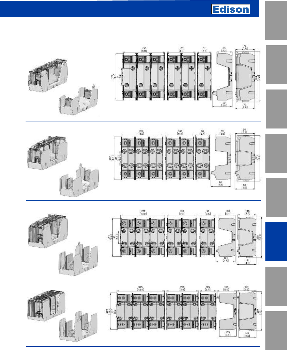
139
For additional information, visit www.edisonfuse.com
UL/CSA Fuses
Current Limiting
UL/CSA Fuses
General Purpose
Special
Purpose Fuses
Canadian
Fuses & Holders
Medium
Voltage Fuses
Fuse Blocks,
Holders & Misc.
Application
Section
Surge Protective
Devices
250V Class R & H(K) Dimensional Specifications
Dimensions - mm (in)
70- 100A
110- 200A
225- 400A
450- 600A
Fuse Blocks, Holders and
Accessories
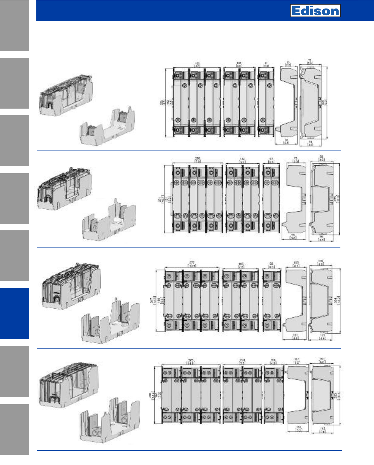
140 For additional information, visit www.edisonfuse.com
Application
Section
Fuse Blocks,
Holders & Misc.
Surge Protective
Devices
Medium
Voltage Fuses
Canadian
Fuses & Holders
Special
Purpose Fuses
UL/CSA Fuses
General Purpose
UL/CSA Fuses
Current Limiting
Fuse Blocks, Holders and
Accessories
600V Class R & H(K) Dimensional Specifications
Dimensions - mm (in)
70- 100A
110- 200A
225- 400A
450- 600A
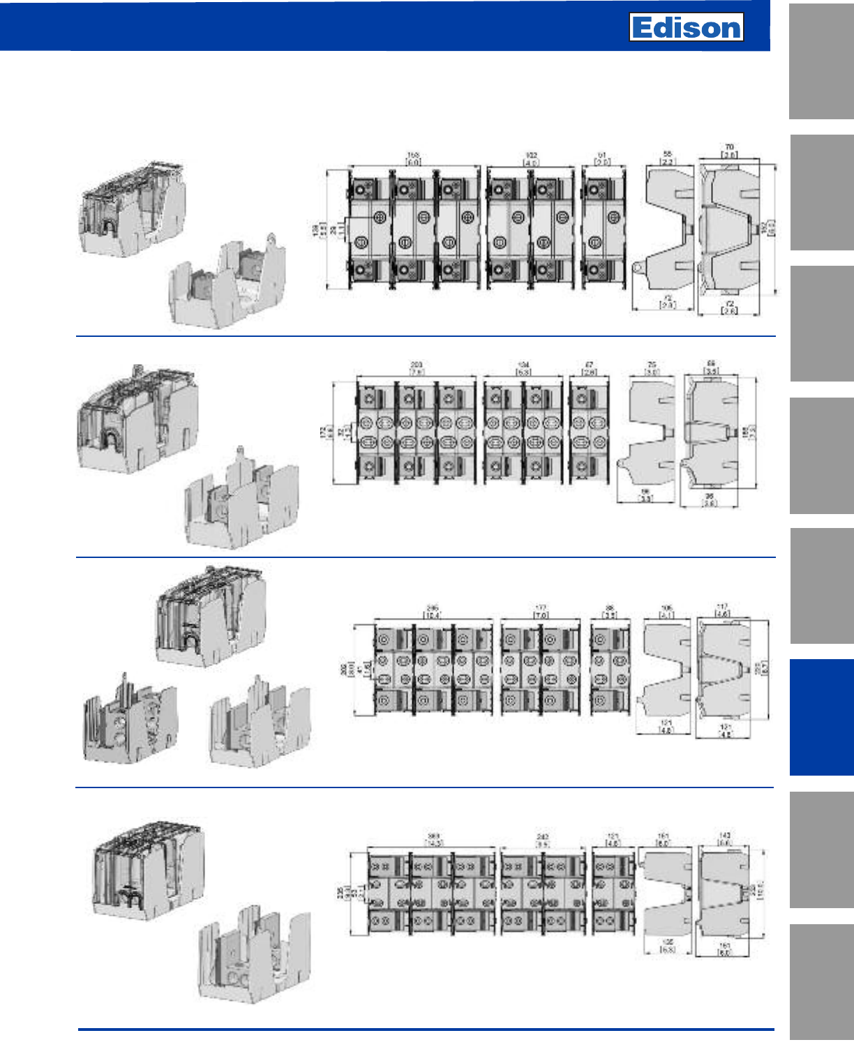
141
For additional information, visit www.edisonfuse.com
UL/CSA Fuses
Current Limiting
UL/CSA Fuses
General Purpose
Special
Purpose Fuses
Canadian
Fuses & Holders
Medium
Voltage Fuses
Fuse Blocks,
Holders & Misc.
Application
Section
Surge Protective
Devices
Fuse Blocks, Holders and
Accessories
Class J Dimensional Specifications
Dimensions - mm (in)
70- 100A
110- 200A
450- 600A
Optional Lug Standard Lug
225- 400A
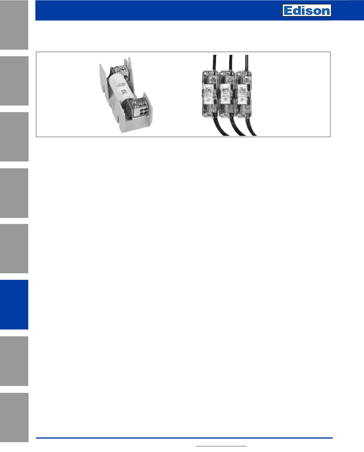
142 For additional information, visit www.edisonfuse.com
Application
Section
Fuse Blocks,
Holders & Misc.
Surge Protective
Devices
Medium
Voltage Fuses
Canadian
Fuses & Holders
Special
Purpose Fuses
UL/CSA Fuses
General Purpose
UL/CSA Fuses
Current Limiting
Fuse Blocks, Holders and
Accessories
Power Distribution Fuse Block
Catalog symbol: JM60___-_MW_
Fuse Class:
• Class J
Ratings:
Volts - 600V
Amps - 70-400A
Withstand - 200kA Sym RMS
Agency information:
• Blocks: - UL Recognized E14853 – IZLT2
- CSA Certified 47235 — 6225-01
• Covers: - UL Listed UL E58836 – JDVS2
Poles:
• 1-, 2-, 3-pole
Flammability ratings:
• Blocks: - UL 94V0, self-extinguishing
• Covers: - UL 94HB, self-extinguishing
Operating and storage temperature range:
• Blocks: -40°C to +120°C
• Covers: - Non-indicating -40°C to +120°C
- Indicating -20°C to +90°C
Materials:
• Base: - Thermoplastic
• Terminals: - Tin-plated aluminum
Features and bene ts:
• Combination power distribution block and
fuse block reduces wire connections and total
panel components, using 50% less panel
space and reducing installation time and
labor by 33%.
• A 200kA withstand rating helps achieve a
higher assembly short-circuit current rating
(SCCR) for compliance with NEC® sections
110.10, 409.110(4), 409.22, 440.4(B), 670.3(A)(4)
and 670.5.
• Optional see-through cover enhances safety
with IP20 finger-safe protection, lockout/
tagout capability and open circuit indication.
B
Product description:
New Class J fuse block features power
distribution capability.
This patented design simplifies your panel
layout and uses up to 50% less panel
space. Additionally, it lowers inventory
costs while reducing installation time and
labor by 33%.
Furthermore, this design uses fewer wire
connections, reducing watts loss and
overall operating temperature when
compared with traditional fuse block/power
distribution block solutions.
Bussmann power distribution fuse blocks are available
preassembled into 1-, 2- and 3-pole versions. Individual
blocks can be dovetailed together to achieve the desired
number of poles. Use of covers requires ordering separately
one cover for each pole.
Wire:
• 75°C CU/AL*
* Conductors with higher temperature rating may be used, but at
their 75°C ampacity.
Accessories:
• Optional IP20 finger-safe covers in indicating and non-
indicating versions. Order one for each pole.
Recommended fuses (order separately):
• Time-delay Class J Low-Peak™ (see Data Sheet # 1007)
- Indicating LPJ-_(amp)SPI
- Non-indicating LPJ-_(amp)SP
• Fast-acting Class J Limitron™ (see Data Sheet # 1027)
- Non-indicating JKS-(amp)
• High Speed Class J DFJ Drive Fuses (see Data Sheet #
1048)
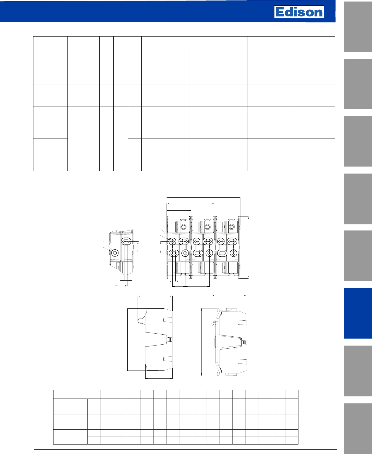
143
For additional information, visit www.edisonfuse.com
UL/CSA Fuses
Current Limiting
UL/CSA Fuses
General Purpose
Special
Purpose Fuses
Canadian
Fuses & Holders
Medium
Voltage Fuses
Fuse Blocks,
Holders & Misc.
Application
Section
Surge Protective
Devices
Fuse Blocks, Holders and
Accessories
Block Size A B C D E F G H I J K L M ØN ØO
100A
in 2.0 4.0 6.0 5.5 5.5 2.8 2.2 6.0 2.8 0.9 2.0 0.4 1.1 0.4 0.5
mm 51 102 153 139 139 72 55 152 72 22 51 10 29 9 13
200A in 2.6 5.3 8.0 6.8 6.8 3.8 3.0 7.3 3.8 1.4 2.6 0.3 1.3 0.4 0.7
mm 67 134 203 172 172 97 75 186 97 35 67 8 32 9 19
400A in 3.5 7.0 10.6 8.0 8.0 4.8 4.1 8.7 4.8 2.0 3.5 0.3 1.6 0.4 0.7
mm 88 177 268 202 202 121 105 220 121 50 88 8 41 9 19
Lineside Loadside
Part
Number
Optional
Covers
Volts
(V)
Fuse
Range Poles
Conductors Torque
AWG; N•m (Lb-In)
Conductors Torque
AWG; N•m (Lb-In)
JM60100-1MW14
JM60100-2MW14
JM60100-3MW14
CVR-J-60100-M
CVRI-J-60100-M* 600 70-
100A
1
2
3
(1) 1/0-14 CU/AL
1/0-1; 5.6 (50)
4-6; 5.0 (45)
8; 4.5 (40)
10-14; 4.0 (35)
(4) 4-14 CU, 4-8 AL
(8)**10-14 CU
4-6; 4.0 (35)
8; 2.8 (25)
10-14; 2.3 (20)†
(2) 10-14; 3.4 (30)†
JM60200-1MW16
JM60200-2MW16
JM60200-3MW16
CVR-J-60200-M
CVRI-J-60200-M* 600 110-
200A
1
2
3
(1) 250kcmil-6 CU/AL 250kcmil-1; 42 (375)
(2) 2-6; 31 (275)
(6) 4-14 CU, 4-8 AL
(12)**10-14 CU
4-6; 4.0 (35)
8; 2.8 (25)
10-14; 2.3 (20)†
(2) 10-14; 3.4 (30)†
JM60400-1MW16
JM60400-2MW16
JM60400-3MW16
CVR-J-60400-M
CVRI-J-60400-M* 600 225-
400A
1
2
3(1) 600kcmil-4 CU/AL
600kcmil-4; 57 (500)
500kcmil; 51 (450)
(2) 3/0-4; 57 (500) CU
34 (300) AL
(6) 2-14 CU, 2-8 AL
(12)**8-14 CU, 8 AL
2-3; 5.6 (50)
4-6; 5.0 (45)
8; 4.5 (40)
(2) 8; 4.5 (40)†††
10-14; 4.0 (35)†
(2) 10-14; 4.5 (40)†
JM60400-1MW26††
JM60400-2MW26††
JM60400-3MW26††
1
2
3
(2) 350kcmil-6 CU/AL (2) 350kcmil-1; 42 (375)
(2) 2-6; 31 (275)
(6) 2-14 CU, 2-8 AL
(12)**8-14 CU, 8 AL
2-3; 5.6 (50)
4-6; 5.0 (45)
8; 4.5 (40)
(2) 8; 4.5 (40)†††
10-14; 4.0 (35)†
(2) 10-14; 4.5 (40)†
* With open fuse indication. 90V minimum and closed circuit required for illumination.
** Dual wire rated lugs with same wire size.
† Copper conductor only.
†† Lineside dual box lug.
††† Dual wire not for CSA installations
A
B
C
D
E
K
J
L
F
G
I
H
ØN
ØO
M
100A Block
Mounting Holes
ØN
ØO
J
L
M
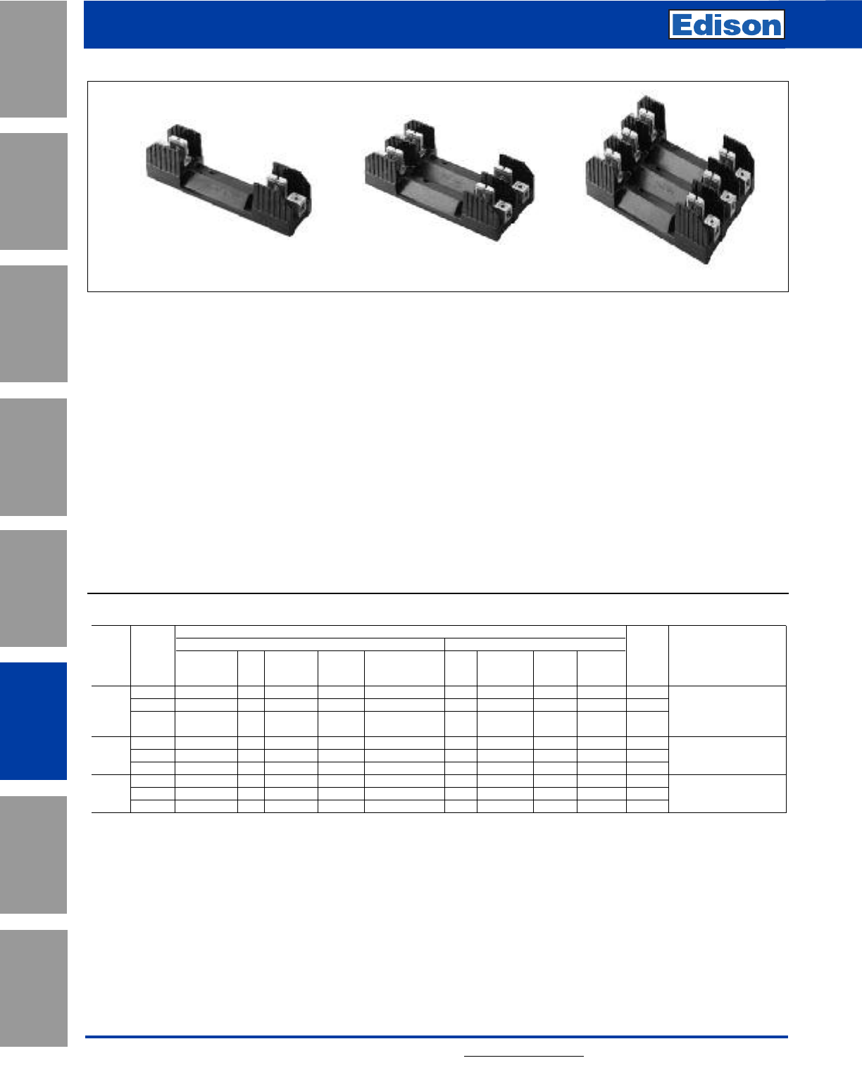
144 For additional information, visit www.edisonfuse.com
Application
Section
Fuse Blocks,
Holders & Misc.
Surge Protective
Devices
Medium
Voltage Fuses
Canadian
Fuses & Holders
Special
Purpose Fuses
UL/CSA Fuses
General Purpose
UL/CSA Fuses
Current Limiting
Fuse Blocks, Holders and
Accessories
Catalog Number H250 & H600 Series
Catalog Number R250 & R600 Series
Class H(K) and R Fuse Blocks:
H250 & H600 Series: For use with Class H and K5 Fuses
(Edison KON and ERN, H250;
Edison KOS and ERS, H600)
R250 & R600 Series: For use with Class R Fuses
(Edison LENRK and ECNR, R250;
Edison LESRK and ECSR, R600)
Construction: Thermoplastic, UL Flammability 94V0
Amp Ratings: 1/10-100A
Voltage Ratings: H250, 250Vac; H600, 600Vac/dc; R250,
250Vac; R600, 600Vac
Agency Approvals:
UL Listed, Guide IZLT, File E14853
CSA, Class 6225-01, File 47235
Class H Fuseblocks (250V) Catalog Data (For Use With KON, ERN, PONC, and CDNC Fuses)
Terminal Type (Suffix No.)
Screw Box Lug w/
1⁄10 1 H25030-1 S SR P PR C CR —Q 1C, CR #2-14 CU, #2-12 AL
to 2 H25030-2 S SR P PR C CR —— 2P, PR #10-18 CU ONLY
30 3 H25030-3 S SR P PR C CR —— 3 Q N/A
S, SR #10-18 CU ONLY
31 1 H25060-1 —— — — C CR CO —4
C, CR #2-14 CU, #2-8 AL
to 2 H25060-2 — — — — C CR CO —5
CO #2-14 CU ONLY
60 3 H25060-3 — — — — C CR CO —6
61 1 H25100-1 — SR — — — CR ——7
to 2 H25100-2 — SR — — — CR ——8
CR #1/0-8 CU/AL
100 3 H25100-3 — SR — — — CR ——9
SR #8W/ Ring Terminal
Amps
Catalog
Number
Pressure
Plate
Pressure Plate
& Clip with
Reinforced Spring
Copper
Only
Wire
Range
0.25 =
Quick
Connect
Clip with
Reinforced
Spring
Clip with
Reinforced
Spring
——
Figure
Number
Poles
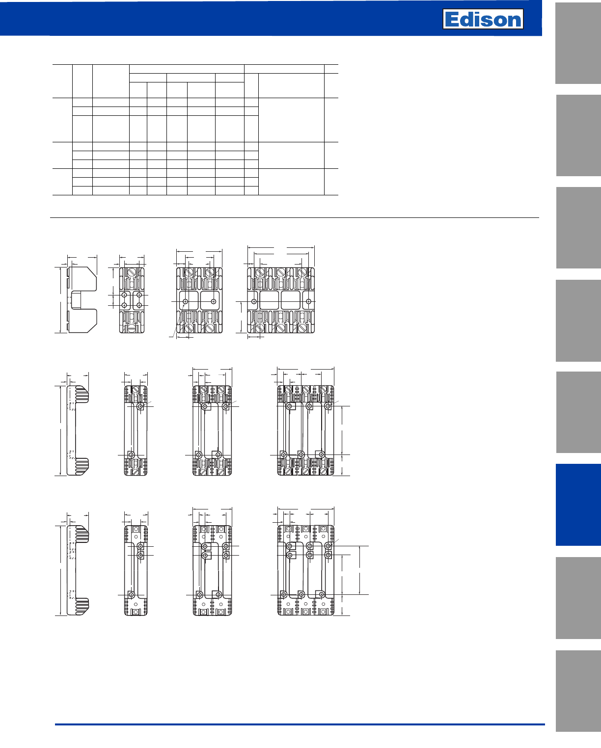
145
For additional information, visit www.edisonfuse.com
UL/CSA Fuses
Current Limiting
UL/CSA Fuses
General Purpose
Special
Purpose Fuses
Canadian
Fuses & Holders
Medium
Voltage Fuses
Fuse Blocks,
Holders & Misc.
Application
Section
Surge Protective
Devices
Fuse Blocks, Holders and
Accessories
Class R Fuseblocks (250V) Catalog Data (For Use With ECNR, LENRK, and NCLR Fuses)
Terminal Type (Suffix No.)
Screw w/ Box Lug w/ 0.25”
Catalog Pres. Clip Quick- Fig. Wire
Number — Plate — Cu Only Connect No. Range
1⁄10 1 R25030-1 SR PR CR COR QR* 1 COR #6-14 CU ONLY
to 2 R25030-2 SR PR CR COR —2CR #2-14 CU, #2-12 AL
30 3 R25030-3 SR PR CR COR —3PR #10-18 CU ONLY
QR N/A
SR #10-18 CU ONLY
31 1 R25060-1 ——CR ——4
to 2 R25060-2 ——CR ——5CR #2-14 CU, #2-8 AL
60 3 R25060-3 ——CR ——6
61 1 R25100-1 ——CR ——7
to 2 R25100-2 ——CR ——8CR 1/0-8 CU/AL
100 3 R25100-3 ——CR ——9
*UL Recognized, No CSA Certification.
Poles
Amps
1.41"
0.22"
1.09"
3.03"
0.5"
0.17" 0.75" 0.25"
1.25"
0.95"
0.22" DIAMETER
0.41"
2.05"
2 SPACES AT
0.95" - 1.91"
2.5"
3"
0.55"
1.27"
1.52"
0.55"
Dimensions – in
250V 1⁄10to 30A
FIGURE 1. FIGURE 2. FIGURE 3.
4.25
0.27
1.73 1.5
0.5
2.81
0.5 1.31
0.5
1.31
4.125
G
1.5
0.5
1.310.5
1.25
0.22 x 0.41
0.22 x 0.41
0.22 x 0.41
250V, 31A to 60A
FIGURE 4. FIGURE 5. FIGURE 6.
250V, 61A to 100A
FIGURE 7. FIGURE 8. FIGURE 9.
7.36"
0.25"
2.06" 1.81"
0.62"
3.38"
0.59"
0.62"
4.94"
2.38"
2.125"
0.62"
0.28" DIA. x
0.5" C'BORE
0.59"
1.56" 1.56"1.56"
3.125"
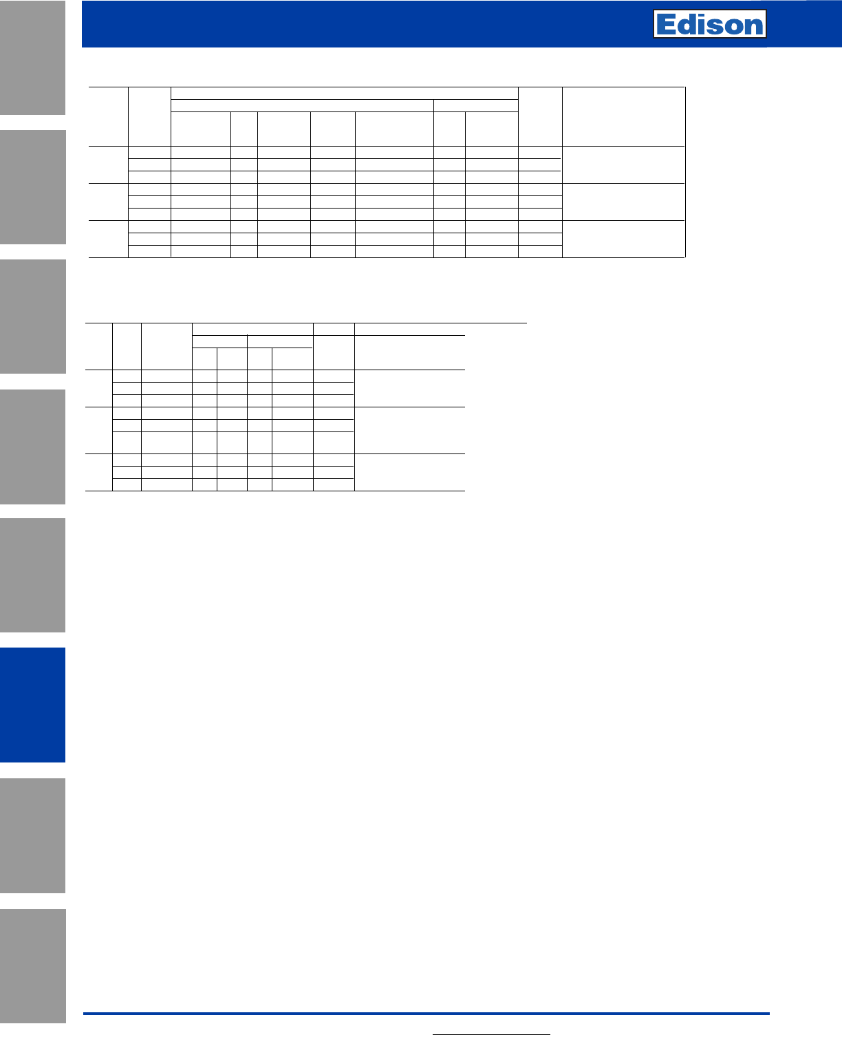
146 For additional information, visit www.edisonfuse.com
Application
Section
Fuse Blocks,
Holders & Misc.
Surge Protective
Devices
Medium
Voltage Fuses
Canadian
Fuses & Holders
Special
Purpose Fuses
UL/CSA Fuses
General Purpose
UL/CSA Fuses
Current Limiting
Fuse Blocks, Holders and
Accessories
Class H Fuseblocks (600V) Catalog Data (For Use With KOS, ERS, and CDSC Fuses)
Terminal Type (Suffix No.)
Screw Box Lug w/
1⁄10 1 H60030-1 S SR P PR C CR 1
C, CR #2-14 CU, #2-12 AL
to 2 H60030-2 S SR P PR C CR 2 P, PR, S, SR #10-18 CU ONLY
30 3 H60030-3 S SR P PR C CR 3
31 1 H60060-1 —— — — C CR 4
to 2 H60060-2 — — — — C CR 5 C, CR #2-14 CU, #2-8 AL
60 3 H60060-3 — — — — C CR 6
61 1 H60100-1 — — — — — CR 7
to 2 H60100-2 — — — — — CR 8 CR #1/0-8 CU/AL
100 3 H60100-3 — — — — — CR 9
Pressure
Plate
Pressure Plate
& Clip with
Reinforced Spring
Wire
Range
Clip with
Reinforced
Spring
—
Figure
Number
Amps
Catalog
Number
Clip with
Reinforced
Spring
—
Poles
Class R Fuseblocks (600V) Catalog Data (For Use With LESRK, ECSR, and SCLR Fuses)
Terminal Type (Suffix No.)
Screw w/ Box Lug w/
Catalog Pres. Clip Fig. Wire
Number — Plate — Cu Only No. Range
1⁄10 1 R60030-1 SR PR CR —1COR #6-14 CU ONLY
to 2 R60030-2 SR PR CR COR 2 CR #2-14 CU, #2-12 AL
30 3 R60030-3 SR PR CR COR 3 PR, SR #10-18 CU ONLY
31 1 R60060-1 ——CR —4
to 2 R60060-2 ——CR —5CR #2-14 CU, #2-8 AL
60 3 R60060-3 ——CR —6
61 1 R60100-1 ——CR —7
to 2 R60100-2 ——CR —8 CR, 1/0-8 CU/AL
100 3 R60100-3 ——CR — 9
Poles
Amps
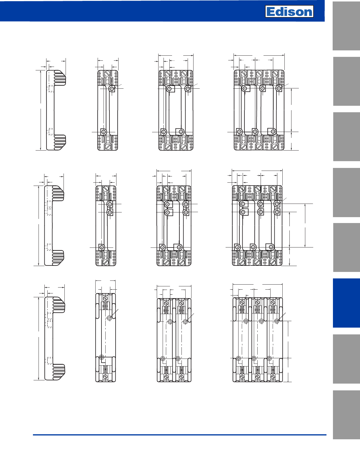
Fuse Blocks, Holders and
Accessories
147
For additional information, visit www.edisonfuse.com
UL/CSA Fuses
Current Limiting
UL/CSA Fuses
General Purpose
Special
Purpose Fuses
Canadian
Fuses & Holders
Medium
Voltage Fuses
Fuse Blocks,
Holders & Misc.
Application
Section
Surge Protective
Devices
Fuse Blocks, Holders and
Accessories
6.25
0.26
1.73 1.54
0.62
2.90
0.25 1.56
0.62
1.56
4.25
3.13
1.56
0.62
1.56
0.25
0.28 x 0.5
0.28 x 0.5
0.28 x 0.5
7.36"
0.25"
2.06" 1.81"
0.62"
3.38"
0.59"
0.62"
4.94"
2.38"
2.125"
0.62"
0.28" DIA. x
0.5" C'BORE
0.59"
1.56" 1.56"
1.56"
3.125"
Dimensions – in
600V, 1⁄10 to 30A
600V, 31 to 60A
FIGURE 1. FIGURE 2. FIGURE 3.
0.88
0.88
0.67 1.81
4.03
2.22
0.28 x 0.5
0.28 x 0.5
0.88
0.67 1.81 1.81
0.28 x 0.5
5.84
9.5
0.34
2.38
4.25
2.63
600V, 61 to 100A
FIGURE 7. FIGURE 8. FIGURE 9.
FIGURE 4. FIGURE 5. FIGURE 6.
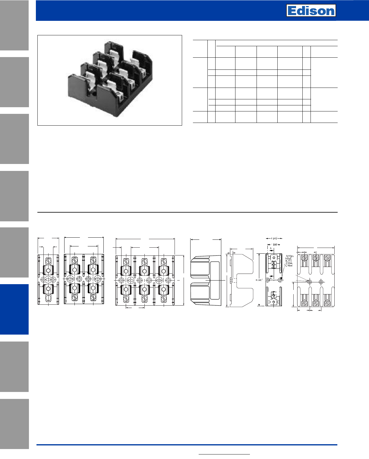
148 For additional information, visit www.edisonfuse.com
Fuse Blocks, Holders and
Accessories
Application
Section
Fuse Blocks,
Holders & Misc.
Surge Protective
Devices
Medium
Voltage Fuses
Canadian
Fuses & Holders
Special
Purpose Fuses
UL/CSA Fuses
General Purpose
UL/CSA Fuses
Current Limiting
Catalog Number J600 Series
Class J Fuse Blocks:
J600 Series: For use with Class J Fuses
(Edison JDL, JFL and CJ)
Construction: Thermoplastic, UL Flammability 94V0
Amp Ratings: 1/2-100A
Voltage Ratings: 600Vac/dc
Agency Approvals:
UL Listed, Guide IZLT, File E14853
CSA, Class 6225-01, File 47235
1/2 to 60A 61 to 100A
Dimensions - inches
Standard J Fuse Blocks (600V) Catalog Data
Catalog Numbers
Pressure Box Box Lug w/ Fig. Max. Wire
Amps Screw Plate Lug Retaining Clip No. Size
1 J60030-1S* J60030-1P J60030-1C J60030-1CR 1 C, CR#2-14 CU,
#2-8 AL
1/2–30 2 J60030-2S* J60030-2P J60030-2C J60030-2CR 2 P, PR, S, SR
3 J60030-3S* J60030-3P J60030-3C J60030-3CR 3 #10-14 CU Only
1—— J60060-1C J60060-1CR 1 C, CR, #2-14
CU/AL
31–60 2— — J60060-2C J60060-2CR 2
3— — J60060-3C J60060-3CR 3 CU only
61–100 3— — — J60100-3CR 4 CR 1/0-8 CU/AL
Poles
0.30"
2.28"
6.28"
0.94"
0.22"
Dia.
0.5"
C'Bore
1.583"
5"
3.14"
1.75" 1.5"
2.250"
3.202"
0.750"
4.702"
2.250"
C
L
L
1.500"
4.005"
C
2.415"
1.702"
0.750"
Figure 1. Figure 2. Figure 3. Figure 5.
Figure 4.
* No UL, No CSA Certification.
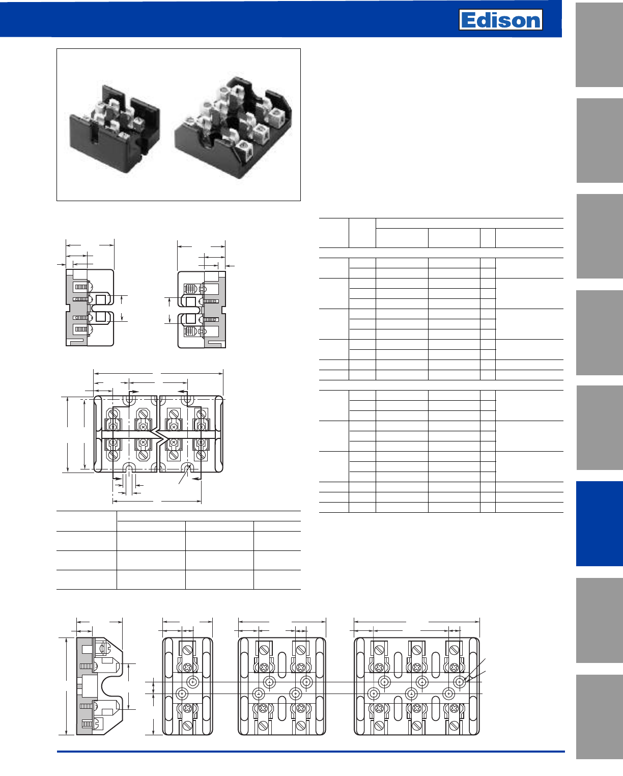
149
For additional information, visit www.edisonfuse.com
Fuse Blocks, Holders and
Accessories
UL/CSA Fuses
Current Limiting
UL/CSA Fuses
General Purpose
Special
Purpose Fuses
Canadian
Fuses & Holders
Medium
Voltage Fuses
Fuse Blocks,
Holders & Misc.
Application
Section
Surge Protective
Devices
Terminal Dimensions (inches)
Type ABC
T30030-2 2.41 — 1.03
T30060-2
T30030-3 3.44 1.03 2.06
T30060-3
T30030-4 4.47 2.06 3.09
T30060-4
Class T Fuse Blocks:
T300 Series: For use with Class T Fuses
(Edison TJN)
T600 Series: For use with Class T Fuses
(Edison TJS)
Construction: Glass Polyester, Phenolic on 600A,
UL Flammability: 94V0
Ratings: T300: 300Vac/dc, 1⁄2- 600A
T600: 600Vac/dc, 1⁄2- 600A
Agency Approvals:
UL Listed, Guide IZLT, File E14853
CSA, Class 6225-01, File 47235
Figure 2. 600V 1/2A to 30A
3.19"
1.44"
1.563"
0.33"
1.42"
0.5"
1.44"
0.55" 0.33" 0.55"
2.59"
1.16" 0.33" 0.55"
3.75"
2.31" 0.33"
0.22" DIAMETER
0.5" C'BORE
Dimensions - inches Class T Fuse Blocks (300V & 600V) Catalog Data
Catalog Numbers
Box Fig. Max. Wire
Amps Poles Screw Lug No. Size
TJN, 300V
2T30030-2SR T30030-2CR 1 SR #10Cu;
1⁄2–30 3 T30030-3SR T30030-3CR 1 CR #6Cu-Al
2 T30060-2SR* T30060-2CR 1 SR #10Cu
31–60 3 T30060-3SR* T30060-3CR 1 CR #2Cu Al
4 T30060-4SR* T30060-4CR 1
1— T30100-1C 4
61–100 2— T30100-2C 4 1/0 Cu-Al
3— T30100-3C 4
1— T30200-1C 5
101-200 3— T30200-3C 5 250MCM Cu-Al
201-400 1— T30400-1C 6 600MCM Cu-Al
401-600 1— T30600-1C 7 (2) 600MCM Cu-Al
TJS, 600V
1 T60030-1SR T60030-1CR 2
1⁄2–30 2 T60030-2SR T60030-2CR 2 SR #10Cu;
3 T60030-3SR T60030-3CR 2 CR #2Cu-Al
1 T60060-1SR* T60060-1CR 3
31–60 2 T60060-2SR T60060-2CR 3 CR#2Cu Al
3 T60060-3SR* T60060-3CR 3 SR #10Cu
1— T60100-1C 4
61–100 2— T60100-2C 4 2/0 Cu-Al
3— T60100-3C 4
101-200 1— T60200-1C 5 250MCM Cu-Al
201-400 1— T60400-1C 6 600MCM Cu-Al
401-600 1— T60600-1C 7 (2) 600MCM Cu-Al
* U.L. Recognized
T30030-S
SECTION X-X
0.91"
1.63"
0.72"
0.16"
T30060-C
SECTION Z-Z
0.91"
1.63"
0.72"
0.16"
Z
XFull
Radius
ZX
0.44"
0.20"
C
B
1.20"
A
0.69"
2.5"
2.75"
Figure 1. 300V 1/2A to 60A
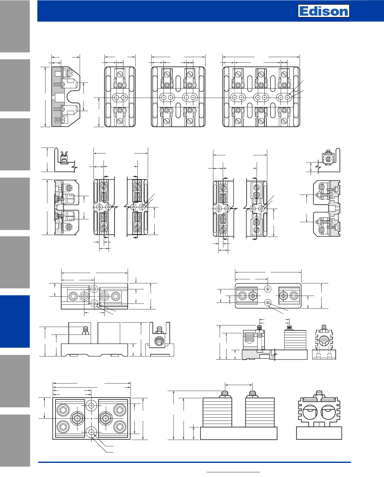
150
Fuse Blocks, Holders and
Accessories
For additional information, visit www.edisonfuse.com
Application
Section
Fuse Blocks,
Holders & Misc.
Surge Protective
Devices
Medium
Voltage Fuses
Canadian
Fuses & Holders
Special
Purpose Fuses
UL/CSA Fuses
General Purpose
UL/CSA Fuses
Current Limiting
Figure 4. 300V, 61 to 100A 600V, 61 to 100A
3"
6"
0.28" DIAMETER
0.63" C'BORE 0.5" DEEP
1.125"
2.56"
1.94"
0.81"
3.06"
1.69"
0.05"
1.25" 2.25"
Figure 5. 300V, 600V 101 to 200A
3.44"
0.75"
3"
2.03" - 300V
3"2"
1.5"
5.75" - 300V
0.33" Diameter
0.75" C'Bore 0.5" Deep
2.88" - 300V
3.38" - 600V
6.75" - 600V 2.95" - 600V
Figure 7. 300V, 600V 401 to 600A
6"
0.63" C'BORE 0.5" DEEP
0.28" DIAMETER
1.125"
2.25"
0.63"
3"
1.84" - 300V
1.25"
0.81"
2.38"
3.06"
2.72" - 600V
Figure 6. 300V, 600V 201 to 400A
Figure 3. 600V 31 to 60A
2.94"
1.75"
1.63"
1.47"
0.5"
1.81"
0.59" 0.63" 0.59"
3.34"
1.53" 0.63" 0.59"
4.86"
3.06" 0.63"
0.22" DIAMETER
0.5" C'BORE
Dimensions - inches
Z
Z
0.52" C'BORE
0.55" DEEP
0.22" DIA.
X
X
2.39"
2.25"
REF.
4.78"
2.06"
1.69" (1 POLE)
3.09" (2 POLE)
4.5" (3 POLE)
1.41" (2 POLE)
2.81" (3 POLE)
0.84"
0.38"
0.75"
Z
Z
0.52" C'BORE
0.55" DEEP
0.22" DIA.
X
X
2.39"
1.69" (1 POLE)
3.09" (2 POLE)
4.5" (3 POLE)
1.41" (2 POLE)
2.81" (3 POLE)
0.84"
0.38" SECTION Z-Z
0.78"
2.34"
REF.
0.75"
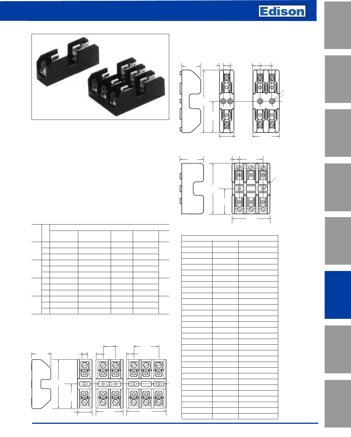
151
For additional information, visit www.edisonfuse.com
Fuse Blocks, Holders and
Accessories
UL/CSA Fuses
Current Limiting
UL/CSA Fuses
General Purpose
Special
Purpose Fuses
Canadian
Fuses & Holders
Medium
Voltage Fuses
Fuse Blocks,
Holders & Misc.
Application
Section
Surge Protective
Devices
Catalog Number BG Series and G Series
Class G Fuse Blocks:
BG Series and G Series: For use with Class G Fuses
(Edison SEC)
Construction: (0-30A) Thermoplastic
(35-60A) Phenolic
Amp Ratings: 1-60A
UL Listed, Guide IZLT,
File E14853
Voltage Ratings: 600V (0-20A)
480V (25-60A)
Agency Approvals: CSA, Class 6225-01, File 47235
Catalog Data
Terminal Type
Screw with Pressure Plate Box Box Lug w/ Fig.
Amps Quick-Connect w/Quick Connect Lug Clip No.
11BG3011SQ BG3011PQ BG3011B —1
to 2 BG3012SQ BG3012PQ BG3012B —2
15 3 BG3013SQ BG3013PQ BG3013B —3
1 BG3021SQ BG3021PQ BG3021B —1
20 2 BG3022SQ BG3022PQ BG3022B —2
3 BG3023SQ BG3023PQ BG3023B —3
25 1 BG3031S BG3031P BG3031B —1
to 2 BG3032S BG3032P BG3032B —2
30 3 BG3033S BG3033P BG3033B —3
35 1— — — G30060-1CR 4
to 2— — — G30060-2CR 4
60 3— — — G30060-3CR 5
Torque vales for above terminals: 18-8AWG: 20 lb•in
6AWG: 35 lb•in
Poles
0.42"
1.53"
0.42"
0.77"
3"
1.22"
1.5"
0.36"
0.86" 1.63" 2.38"
1 to 30A
35 to 60A
Figure 1. Figure 2. Figure 3.
Figure 4.
Figure 5.
1.38" 0.5"
0.22" 0.47"
0.29" DIAMETER
0.38" C'BORE
0.84"
1.78"0.94"
4.25"
1.41" 1.69"
0.53"
2.125"
1.78"
3.56"
2.75"
0.22" DIAMETER
HOLE
Dimensions - inches
Dimensions - inches
CROSS REFERENCE
EDISON MERSEN LITTELFUSE
BG3011SQ NONE LG30015-1SQ
BG3012SQ NONE LG30015-2SQ
BG3013SQ NONE LG30015-3SQ
BG3021SQ NONE LG30020-1SQ
BG3022SQ NONE LG30020-2SQ
BG3023SQ NONE LG30020-3SQ
BG3031S NONE LG30030-1SQ
BG3032S NONE LG30030-2SQ
BG3033S NONE LG30030-3SQ
BG3011PQ NONE NONE
BG3012PQ NONE NONE
BG3013PQ NONE NONE
BG3021PQ NONE NONE
BG3022PQ NONE NONE
BG3023PQ NONE NONE
BG3031P NONE LG30030-1PQ
BG3032SP NONE LG30030-2PQ
BG3033P NONE LG30030-3PQ
BG3011B NONE NONE
BG3012B NONE NONE
BG3013B NONE NONE
BG3021B NONE NONE
BG3022B NONE NONE
BG3023B NONE NONE
BG3031B NONE NONE
BG3032B NONE NONE
BG3033B NONE NONE
G30060-1CR NONE LG30060-1CR
G30060-2CR NONE LG30060-2CR
G30060-3CR NONE LG30060-3CR
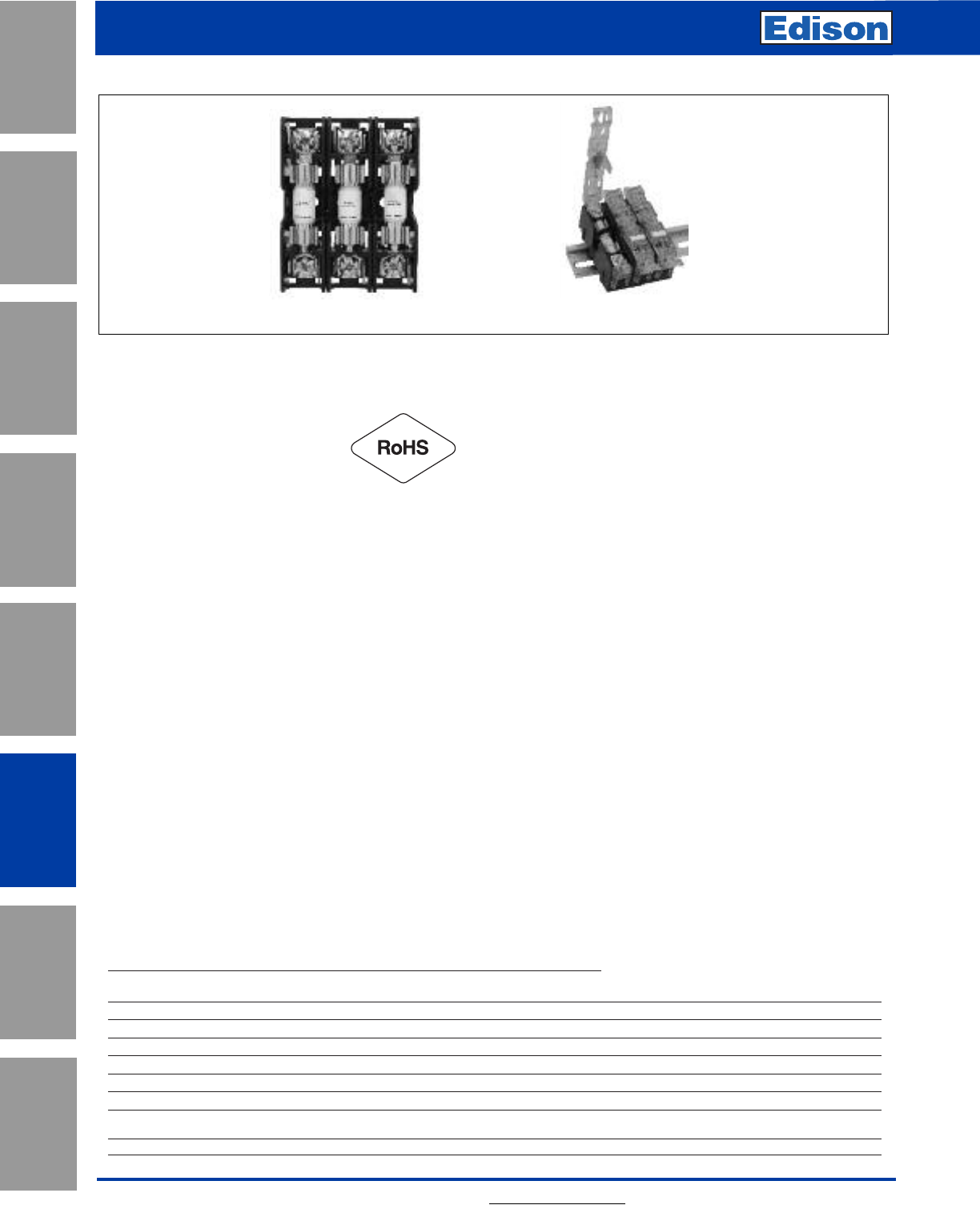
BMM Series
152 For additional information, visit www.edisonfuse.com
Fuse Blocks, Holders and
Accessories
Application
Section
Fuse Blocks,
Holders & Misc.
Surge Protective
Devices
Medium
Voltage Fuses
Canadian
Fuses & Holders
Special
Purpose Fuses
UL/CSA Fuses
General Purpose
UL/CSA Fuses
Current Limiting
Catalog Number BCM and BMM Modular Class CC and Supplemental Ferrule
Fuse Blocks
Ratings:
Volts: 600V
Amps: up to 30A
Withstand: 200kA RMS Sym
Agency Information:
Class CC BCM Series
UL Listed E14853 - IZLT
CSA Certified 47235-6225-01
CE
RoHS Compliant
Conflict mineral free
Reach declaration available upon request
13/32˝ x 1-1/2˝ (Midget) BMM Series
UL Recognized E14853 - IZLT
CSA Certified 47235-6225-01
CE
RoHS Compliant
Conflict mineral free
Reach declaration available upon request
Covers:
Covers are included in the overall UL Listing/Recognition
IP20 finger-safe
RoHS Compliant
Reach declaration available upon request
Poles:
1-, 2-, 3-pole units factory assembled
Single-pole units snap together to create desired number
of poles
Flammability Ratings:
Blocks — UL 94V0, self-extinguishing
Covers — UL 94HB, self-extinguishing
Operating and Storage Temoerature Range:
Blocks -40ºC to +120ºC
Non indicating covers -40ºC to +120ºC
Indicating covers -20ºC to +120ºC
* Indication requires minimum 90Vac/dc and closed circuit
to illuminate.
Materials:
Base — Thermoplastic
Terminals — Tin-plated bimetallic copper
Covers — Thermoplastic
Screws and pressure plates — Zinc-plated steel
Cover Part Numbers:
For blocks with quick connect terminals — CVR(I)-CCM-QC
All other terminal options — CVR(I)-CCM
Marker Labels:
Use part number TM27CB
Recommended DIN-Rail End Stops:
Part No. BRKT-ND
Part No. BRKT-NDSCREW2
2
Technical Data 10241
Effective August 2014
BCM and BMM modular
Class CC and supplemental ferrule fuse blocks
EATON www.eaton.com
Ratings:
• Volts 600V
• Amps up to 30A
• Withstand 200kA RMS Sym
Agency information:
Class CC BCM Series
• UL Listed E14853 - IZLT
• CSA Certified 47235-6225-01
• CE
• RoHS Compliant
• Conflict mineral free
• Reach declaration available upon request
13/32” x 1-1/2” (Midget) BMM Series
• UL Recognized E14853 - IZLT2
• CSA Certified 47235-6225-01
• CE
• RoHS Compliant
• Conflict mineral free
• Reach declariation available upon request
Covers:
• Covers are included in the overall UL Listing/Recognition
• IP20 finger-safe
• RoHS Compliant
• Reach declariation available upon request
Poles:
• 1-, 2-, 3-pole units factory assembled
• Single-pole units snap together to create desired number of
poles
Operating and Storage Temperature Range:
• Blocks -40°C to +120°C
• Non indicating covers -40°C to +120°C
• Indicating covers -20°C to +90°C*
* Indication requires minimum 90Vac/dc and closed circuit to
illuminate.
Materials:
• Base — Thermoplastic
• Terminals — Tin-plated bimetallic copper
• Covers — Thermoplastic
• Screws and pressure plates — Zinc-plated steel
Cover Part Numbers:
• For blocks with quick connect terminals — CVR(I)-CCM-QC
• All other terminal options — CVR(I)-CCM
Marker Labels:
• Use part number TM27CB
Recommended DIN-Rail End Stops:
• Part No. BRKT-ND
• Part No. BRKT-NDSCREW2
Table 1. Catalog numbers
Terminal type
Poles Fuse class
#10-32
Phil-slot screw
Screw with
quick connect* Pressure plate
Pressure plate with
quick connect* Box lug
BCM603-1S BCM603-1SQ BCM603-1P BCM603-1PQ BCM603-1C 1 CC
BCM603-2S BCM603-2SQ BCM603-2P BCM603-2PQ BCM603-2C 2 CC
BCM603-3S BCM603-3SQ BCM603-3P BCM603-3PQ BCM603-3C 3 CC
— BMM603-1SQ — BMM603-1PQ BMM603-1C 1 10x38 (13/32”x1-1/2”)
— BMM603-2SQ — BMM603-2PQ BMM603-2C 2 10x38 (13/32”x1-1/2”)
— BMM603-3SQ — BMM603-3PQ BMM603-3C 3 10x38 (13/32”x1-1/2”)
—BCCMM603-3SQ—BCCMM603-3PQ — 3
3-Pole control circuit transformer block
2-pole CC with 1-pole 10x38 (13/32”x1-½”)
*Quick Connect terminals rated for 20A maximum
Flammability Ratings:
• Blocks — UL 94V0, self-extinguishing
• Covers — UL 94HB, self-extinguishing
Table 1. Catalog Numbers
BCC Series
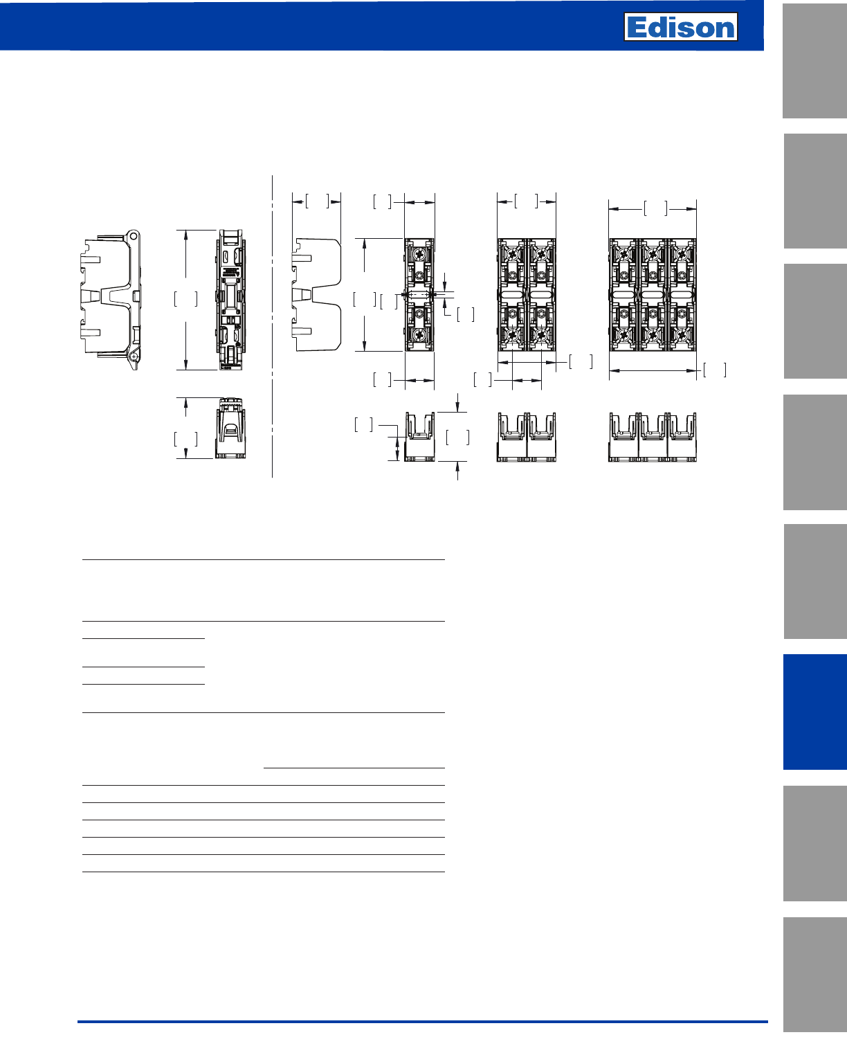
153
For additional information, visit www.edisonfuse.com
Fuse Blocks, Holders and
Accessories
UL/CSA Fuses
Current Limiting
UL/CSA Fuses
General Purpose
Special
Purpose Fuses
Canadian
Fuses & Holders
Medium
Voltage Fuses
Fuse Blocks,
Holders & Misc.
Application
Section
Surge Protective
Devices
Catalog Number BCM and BMM Modular Class CC and Supplemental Ferrule
Fuse Blocks — (Continued)
3
Technical Data 10241
Effective August 2014
BCM and BMM modular
Class CC and supplemental ferrule fuse blocks
EATON www.eaton.com
The only controlled copy of this Data Sheet is the electronic read-only version located on the Bussmann Network Drive. All other copies of this document
are by definition uncontrolled. This bulletin is intended to clearly present comprehensive product data and provide technical information that will help the
end user with design applications. Bussmann reserves the right, without notice, to change design or construction of any products and to discontinue
or limit distribution of any products. Bussmann also reserves the right to change or update, without notice, any technical information contained in this
bulletin. Once a product has been selected, it should be tested by the user in all possible applications.
Eaton’s Bussmann Business
114 Old State Road
Ellisville, MO 63021
United States
www.bussmann.com
© 2014 Eaton
All Rights Reserved
Publication No. 10241 - BU-SB14605
August 2014
Eaton is a registered trademark.
All other trademarks are property
of their respective owners.
Table 2. Terminal specifications
Terminal type
Wire
range
Wire temp
rating
Torque
AWG lb-in (N•m)
Box lug (“CR” option) CU 2-14
AL 2-8 75/90°C
CU 2-3 50 (5.6)
CU 4-6 45 (5.1)
CU 8-14 35 (4.0)
AL 2-6 50 (5.6)
AL 8 40 (4.5)
Screw (S)
CU 10-18 75/90°C 10-18 20 (2.3)
Screw/quick connect*
(SQ)
Pressure plate (P)
Pressure plate/
quick connect* (PQ)
* Quick connect terminals rated to 20A max.
Table 3. Recommended covers*
Terminal type
Cover part numbers
Indicating Non indicating
Box lug (CR) CVRI-CCM CVR-CCM
Screw (S) CVRI-CCM CVR-CCM
Screw/quick connect (SQ) CVRI-CCM-QC CVR-CCM-QC
Pressure plate (P) CVRI-CCM CVR-CCM
Pressure plate/quick connect (PQ) CVRI-CCM-QC CVR-CCM-QC
* For use with 4AWG max conductors.
Dimensions - mm (in)
77
3.0
21
.8
20
.8
20
.8
40
1.6
39
1.6 59
2.3
60
2.4
95
3.7
41
1.6
33
1.3
16
.6 33
1.3
4
.2
10
.4
With cover.
See Table 3 for available covers.
Dimensions - mm (in)
154 For additional information, visit www.edisonfuse.com
Fuse Blocks, Holders and
Accessories
Application
Section
Fuse Blocks,
Holders & Misc.
Surge Protective
Devices
Medium
Voltage Fuses
Canadian
Fuses & Holders
Special
Purpose Fuses
UL/CSA Fuses
General Purpose
UL/CSA Fuses
Current Limiting
Catalog Number BH Series
Block Series:
BH Series: For use with Edison high speed semiconductor
and “bolt-in” fuses
Base: Light weight, high temperature thermoplastic
Mounting Studs: Plated steel
Nut: Plated steel
Washer: Spring steel
Agency Approvals:
UL Recognized, Guide IZLT2/IZLT8, File E14853 up to 700V
CSA, Class 6225-01, File 47235 up to 700V
Contact Edison Customer Satisfaction for ordering information
and dimensional data.
Catalog Code Description:
Block Series
BH - X X X X
NOTES: 1. The #4 connector must be used with either the 7/16 - 14 or the 3/8” - 16 stud.
2. The only compatible connector for the 7/16” - 14 stud is #4.
3. Always check applicable end use standards for required spacing between blocks, fuses or other hardware.
4. For applications above 700V, consult appropriate electrical standard for proper creepage distances, clearance distances and insulator voltage withstand ratings.
Agency Approval
0 No agency approval
1 UL Recognition and CSA Certification
2 UL Recognition only
3 cURus
Fuseblock Base
0 Small base for 0-200 amp fuses, 0-700V
1 Medium base, for 0-400 amp fuses, 0-2500V
2 Medium base, for 0-600 amp fuses, 0-5000V
3 Large base, for 0-700 amp, 0-1250V
Wire Connector
0 No connector
1 1 Hole for #14 - 2/0 copper wire
(for use with base 0)
2 2 Hole for #14 - 1/0 copper wire
(for use with base 0)
3 2 Hole for #6 - 250 MCM copper wire
(for use with base 1, 2, & 3)
4 2 Hole for #14 - 500 MCM copper cable
(for use with base 3)
See Note 1 below
Stud Size
1 1⁄4- 20 (for use with bases 0, 1, & 2)
2 5⁄16 - 18 (For use with bases 0, 1, & 2)
3 3⁄8- 16 (for use with bases 0, 1, 2 & 3)
4 7⁄16 - 14 (for use with base 3)
See Note 2 below.
5 3⁄8- 16 (for use with base 3)
Catalog Numbers
BH-0001 BH-0122 BH-2001 BH-3004
BH-0002 BH-1001 BH-2002 BH-3033
BH-0003 BH-1002 BH-2003 BH-3144
BH-0111 BH-1003 BH-2031 BH-3145
BH-0112 BH-1131 BH-2032 —
BH-0113 BH-1132 BH-2033 —
BH-0121 BH-1133 BH-3003 —
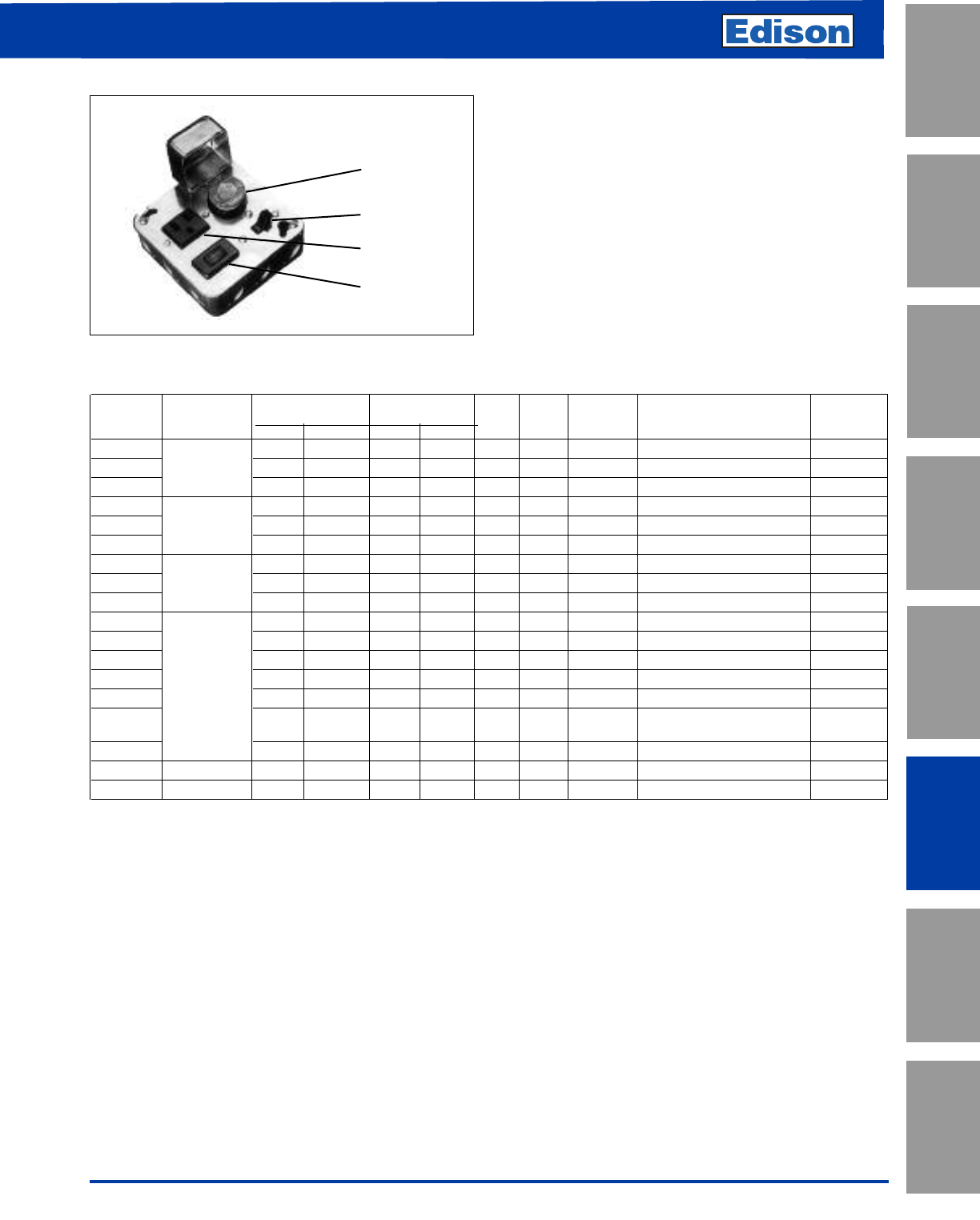
155
For additional information, visit www.edisonfuse.com
Box Cover Units
for Plug Fuses
UL/CSA Fuses
Current Limiting
UL/CSA Fuses
General Purpose
Special
Purpose Fuses
Canadian
Fuses & Holders
Medium
Voltage Fuses
Fuse Blocks,
Holders & Misc.
Application
Section
Surge Protective
Devices
Box Cover Units
For Plug Fuses
Plug fuse box cover units provide a simple, inexpensive way
to protect small motors with Edison-type “T”, “TL”, “TC”, “P”
and “W” plug fuses. Box cover units are easily installed in
standard electrical boxes. By using fuses sized at the amp
rating of a motor or slightly larger, optimum overload and
short-circuit protection is provided. Box cover units are UL
Listed.
Fuse Holder
On/Off Switch
Receptacle
Switch Light
SSY-RL
Selection Data — Plug Fuse Box Cover Units
Receptacle Motor Agency†
Box Cover Fuseholder Outlet to Load Switch Switch Size Listing/
Cat. No. Type Box Single Double 125Vac 250Vac Control+ Light++ (Max.) General Data Certification
SOU X3⁄4Hp 125V, 15A UL, CSA
SRU 2 1⁄4" Handy XX 1⁄2Hp 125V, 15A UL
SSU XX
1⁄2Hp 125Vac (do not use on DC), 15A UL, CSA
SOW X3⁄4Hp 125V, 15A UL, CSA
SRW 2 3⁄4" Switch XX 1⁄2Hp 125V, 15A UL
SSW XX
1⁄2Hp 125Vac (do not use on DC), 15A UL, CSA
SOX X3⁄4Hp 125V, 15A UL, CSA
SRX 4" Octagon XX 1⁄2Hp 125V, 15A UL
SSX XX
1⁄2Hp 125Vac (do not use on DC), 15A UL, CSA
SOY X3⁄4Hp 125V, 15A UL, CSA
SRY XX 1⁄2Hp 125V, 15A UL
SSY XX
1⁄2Hp 125Vac (do not use on DC), 15A UL, CSA
SSY-RL 4" Square XXXX
1⁄2Hp 125Vac (do not use on DC), 15A —
STY* X X* 1⁄2Hp* 125Vac (do not use on DC)*, 15A UL
SCY** X X(2)** 1⁄2Hp(2)** 125Vac (do not use on DC); UL
can protect two motors**, 15A
SOY-B X3⁄4Hp 125V, protects two motors, 15A UL
SKA 4 11⁄16" Square X X(15A) 2 Hp 250V, 15A single-phase UL
SSN Single Gang XX
1⁄2Hp 125V, 15A Weatherproof UL
+ Switch turns power to fused load OFF or ON.
++ Switch light indicates power to load (dark when switch OFF or fuse open).
* Double-pole switch opens both sides of circuit. STY can be used for two separate 125V motors not larger than 1⁄2Hp with the common switch, or a single motor not
larger than 2 Hp at 250V (Maximum of 150V to ground).
** The SCY unit can be used for protection of a single motor not larger than 2Hp at 250V (Maximum of 150V to ground).
† UL Guide JAMZ, File E6491; CSA Class 6225-01, File 47235.
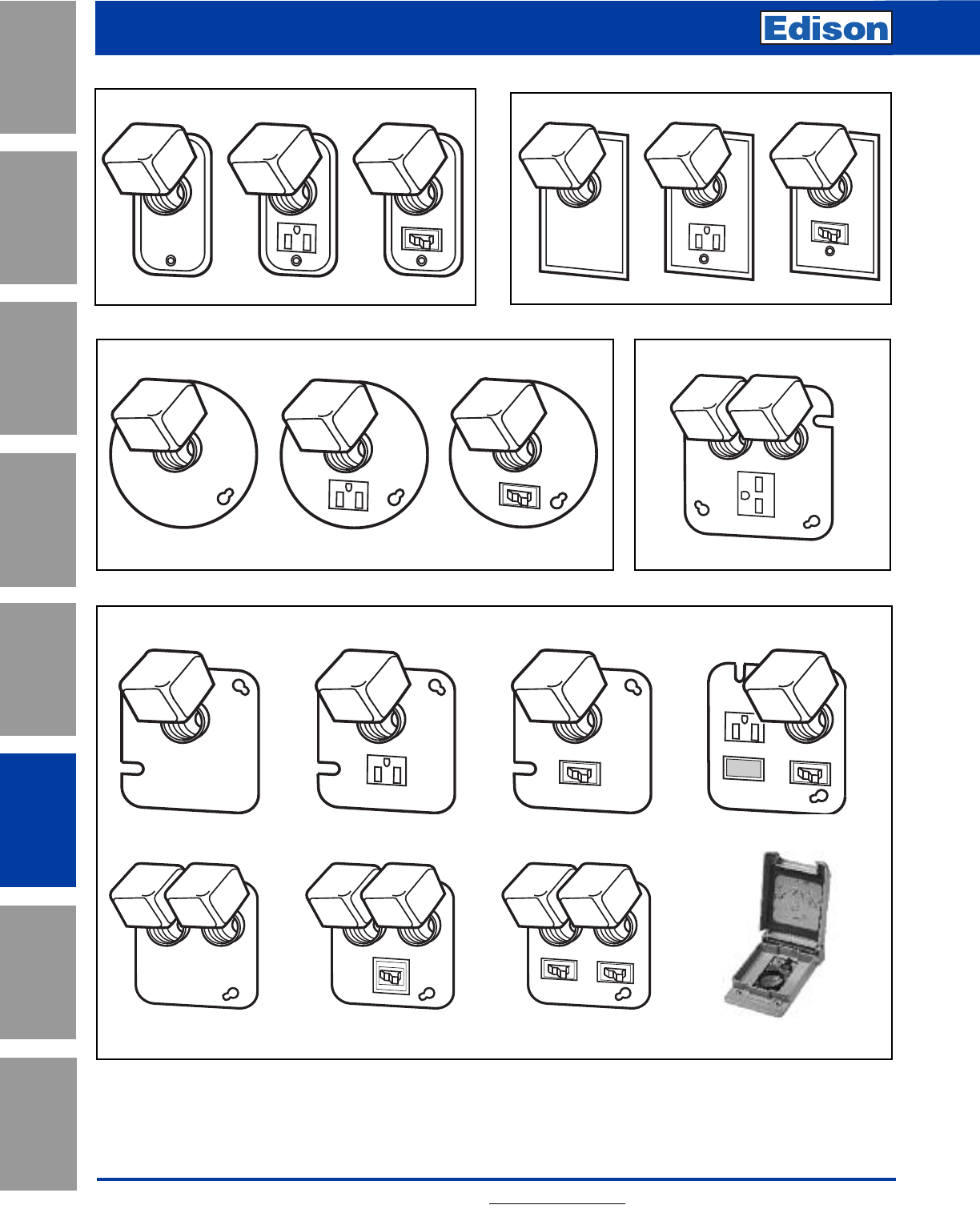
156 For additional information, visit www.edisonfuse.com
Box Cover Units
for Plug Fuses
Application
Section
Fuse Blocks,
Holders & Misc.
Surge Protective
Devices
Medium
Voltage Fuses
Canadian
Fuses & Holders
Special
Purpose Fuses
UL/CSA Fuses
General Purpose
UL/CSA Fuses
Current Limiting
2 1⁄4˝ Handy Boxes 2 3⁄4˝ Switch Boxes
4˝ Octagon Boxes 4-11⁄16˝ Square Boxes
SOU SRU SSU SOW SRW SSW
SOX SRX SSX SKA
4˝ Square Boxes
SOY SRY SSY SSY-RL
SOY-B STY SCY SSN
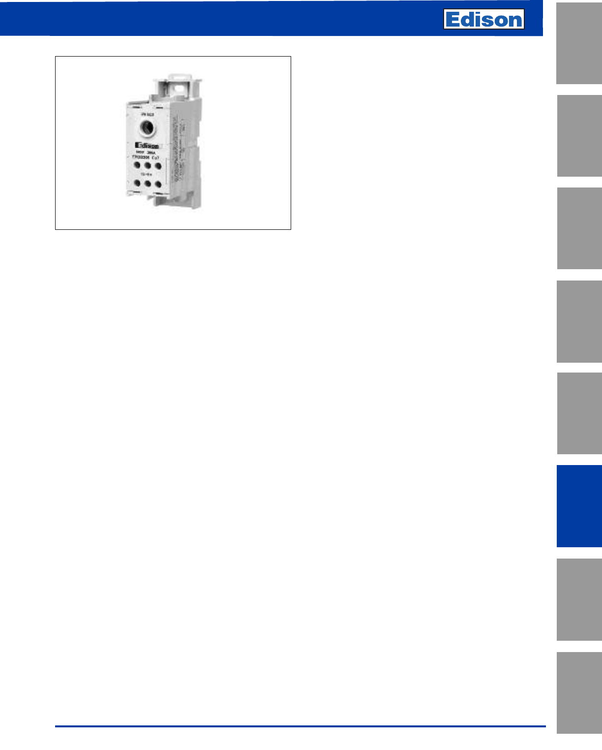
157
For additional information, visit www.edisonfuse.com
UL/CSA Fuses
Current Limiting
UL/CSA Fuses
General Purpose
Special
Purpose Fuses
Canadian
Fuses & Holders
Medium
Voltage Fuses
Fuse Blocks,
Holders & Misc.
Application
Section
Surge Protective
Devices
Enclosed Power Distribution Blocks
EPDB Series
Feature/Benefits
•Enclosed, safer installation; IP20 finger-safe under specific
conditions
• High short-circuit current ratings up to 200kA: PDBs do not
have to be the weak link in achieving high SCCR for an
industrial control panel
• Small footprint saves panel space
• Listed to UL 1953 which has minimum spacing
requirements at 600V of at least 1” through air and 2” over
surface required for feeders in UL 508A Industrial Control
Panels
• For 2D CAD drawings visit www.cooperbussmann.com
Agency/Standards
• UL Listed 1953, Guide QPQS, File E256146
• CSA Certified, Class 6228-01, File 47235
• IEC 60947-7-1
• IEC 60529, IP20 (finger-safe) under specific wiring
conditions
Electrical
• 600Vac/dc (UL 1953), 690Vac/dc (IEC)
• IP20 finger-safe under specific conditions
• Short-circuit current ratings up to 200kA, see table
• Ampacities up to 760 amps
• Cu/Al wire range 14 AWG to 500 kcmil or 2.5 to 240 mm2
Mechanical
• DIN-Rail or panel mount; EPDB306 & EPDB702 panel
mount only
• Captive termination screws; screws do not get misplaced
• Wire ready: captive termination screws shipped backed out
to save time on conductor installations
• Sliding DIN-Rail latch for easy mounting
• Single pole, gang mountable for multiple pole applications
with interlocking dovetail accessory (optional)
• Flammability, UL 94V0
• Tin-plated Al connectors suitable for Cu/Al conductors
• Elongated hole for panel mounting; easier mounting with
greater flexibility in matching up with drilled panel holes
• Part 2A1279: Interlocking dovetail pin accessory
One pin interlocks two units, two pins to interlock three units
• DIN-Rail end anchors required to prevent damage to block
when torquing
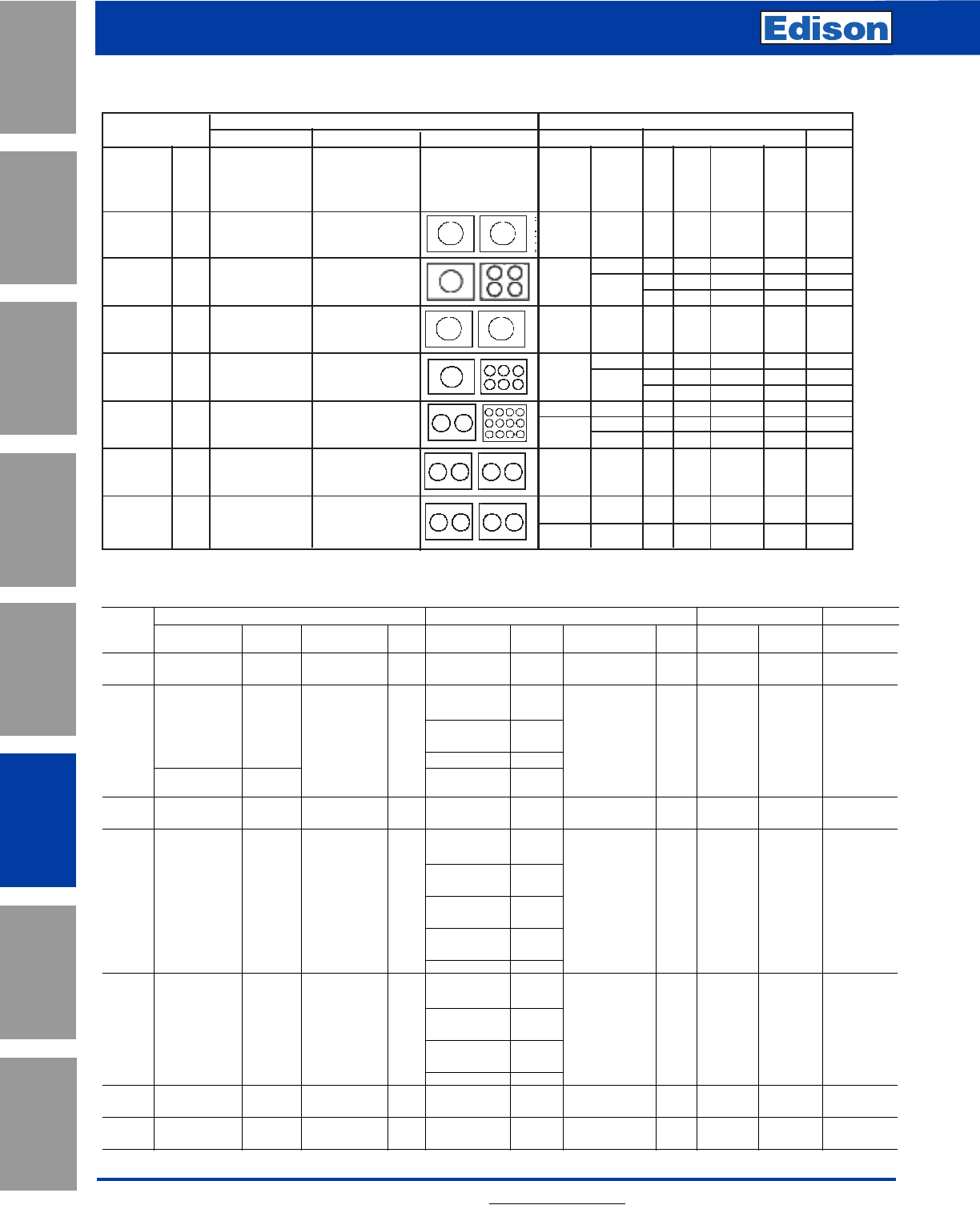
Lineside Loadside
Wire Connector Hole Diameter
Part Wire Range* Torque Trim Length Hex Key Wire Range* Torque Trim Length Hex Key Lineside Loadside Min. Enclosure
Number Lb•in (N•m) (mm) Lb•in (N•m) (mm) (mm) (mm) Size - inch
EPDB101 2/0 to 8 AWG 110 (12.4) 0.85 (21.6) 3/16˝ 2/0 to 8 AWG, Cu 110.(12.4) 0.97 (24.6) 3/16˝ 0.45 (11.5) 0.45 (11.5) 16 x 16 x 6.75
70 to 10mm270 to10mm
4 to 6 AWG, Cu
25 to 16mm235 (4.0)
2/0 to 8 AWG 120 (13.6) 8 AWG, Cu 0.55 (14) top row
EPDB104 70 to 10mm2
0.75 (19.0) 3/16˝ 10mm225 (2.8)
0.85 (21.6) bottom view 1/8˝ 0.45 (11.5) 0.246 (6.25) 16 x 16 x 6.75
4 to 8 AWG, Al 35 (4.0)
10 to 14 AWG, Cu 120 (13.6) 10 to 14 AWG, Cu
6 to 2.5mm220 (2.3)
EPDB301 350 kcmil to 6 AWG 275 (31.1) 1.35 (34.3) 5/16˝ 350 kcmil to 6 AWG 275 (31.1) 1.25 (31.8) 5/16˝ 0.72 (18.3) 0.72 (18.3) 36 x 30 x 12.625
185 to 16mm2150 to 16mm220 (2.3)
2 to 3 AWG, Cu
35mm250 (5.7)
4 to 6 AWG, Cu
500 kcmil to 6 AWG 25 to 16mm245 (5.1) 0.59 (15) top row
EPDB306 240 to 16mm2500 (56.5) 1.25 (31.8) 3/8˝ 8 AWG, Cu 1.2 (30.5) bottom row 1/8˝ 0.87 (22.1) 0.314 (8.0) 24 x 20 x 6.75
10mm240 (4.5)
10 to 14 AWG, Cu
6 to 2.5mm235 (4.0)
2 to 12 AWG, Al 50 (5.7)
4 to 6 AWG, Cu
25 to 16mm2 35 (4.0)
300 kcmil to 4 AWG 1.15 (29.2) top row 8 AWG, Cu 0.55 (14) top row
EPDB512 150 to 25mm2 (275 (31.1) 1.4 (35.6) bottom row 1/4˝ 10mm2 25 (2.8) 1 (25.4) middle row 1/8˝ 0.687 (17.5) 0.265 (6.7) 24 x 20 x 6.75
10 to 14 AWG, Cu
6 to 2.5mm2 20 (2.3)
4 to 12 AWG, Al 35 (4.0)
EPDB602 350 kcmil to 4 AWG 275 (31.1) 1.25 (31.8) 5/16˝ 350 kcmil to 4 AWG 275 (31.1) 125 (31.8) 5/16˝ 0.718 (18.2) 0.718 (18.2) 36 x 30 x 12.625
185 to 25mm2185 to 25mm2
EPDB702 500 kcmil to 6 AWG 500 (56.5) 1.25 (31.8) 3/8˝ 350 kcmil to 4 AWG 500 (56.5) 1.25 (31.8) 3/8˝ 0.875 (22.2) 0.875 (22.2) 36 x 30 x 12.625
240 to 16mm2 240 to 16mm2
158 For additional information, visit www.edisonfuse.com
Enclosed Power Distribution Blocks
EPDB Series
Application
Section
Fuse Blocks,
Holders & Misc.
Surge Protective
Devices
Medium
Voltage Fuses
Canadian
Fuses & Holders
Special
Purpose Fuses
UL/CSA Fuses
General Purpose
UL/CSA Fuses
Current Limiting
Electrical Data Series PDBFS
157
For additional information, visit www.edisonfuse.com
Enclosed Power Distribution Blocks
EPDB Series
UL/CSA Fuses
Current Limiting
UL/CSA Fuses
General Purpose
Special
Purpose Fuses
Canadian
Fuses & Holders
Medium
Voltage Fuses
Fuse Blocks,
Holders & Misc.
Application
Section
Surge Protective
Devices
Electrical Data
Terminal Copper Conductor Capability Short-Circuit Current Rating Data
Line Load Configuration Conductors Max Fuse Class & Amp**
Catalog
Number Openings per Pole Line Load JT RK1 RK5
(All Single Amps Wire Range Wire Range AWG or AWG or LPJ JJS LPS-RK FRS-R SCCR
Pole) Line Load kcmil kcmil JJN LPN-RK FRN-R
EPDB101 175A
2/0 to 8 AWG Cu/Al 2/0 to 8 AWG Cu/Al
2/0 to 8 2/0 to 8 200 200 100 60 200kA
4 to 14 AWG Cu 4 to 12 200 200 100 60 200kA
EPDB104 175A
2/0 to 14 AWG Cu
2/0 to 8 4 to 14 175 175 100 30 100kA
2/0 to 8 Al 4 to 8 AWG Al 200 200 100 60 50kA
350kcmil to 350kcmil to
EPDB301 310A 6 AWG Cu/Al 6 AWG Cu/Al 350 to 6 350 to 6 400 400 200 100 200kA
500kcmil to 2 to 14 AWG Cu 2 to 6 400 400 200 100 200kA
EPDB306 380A 6 AWG Cu/Al 500 to 6 2 to 14 200 200 100 60 50kA
2 to 12 Al 175 175 100 30 100kA
300kcmil to 4 to 14 AWG Cu 300 4 to 8 600 600 400 200 200kA
EPDB512 570A 4 AWG Cu/Al 300 to 4 4400 400 200 100 100kA
4 to 12 Al 4 to 14 200 200 100 60 50kA
EPDB602 620A 350kcmil to 350kcmil to 350 to 4 350 to 4 600 600 400 200 200kA
4 AWG Cu/Al 4 AWG Cu/Al
500kcmil to 500kcmil to 500 500 600 800* 600 200 200kA
EPDB702 760A 6 AWG Cu/Al 6 AWG Cu/Al 500 to 6 500 to 6 600 600 400 200 100kA
Ampacities 75C per NEC®Table 310.16 and UL 508A Table 28.1
*Class L 800A (LCL 800) or less fuses suitable for this particular SCCR case.
** Class G 60A (SEC-60) or less or Class CC 30A (EDCC-30, HCTR-30, HCLR-30) or less are suitable for all SCCRs in this table.
Series PDBFS
Electrical
*Cu/Al unless otherwise noted.
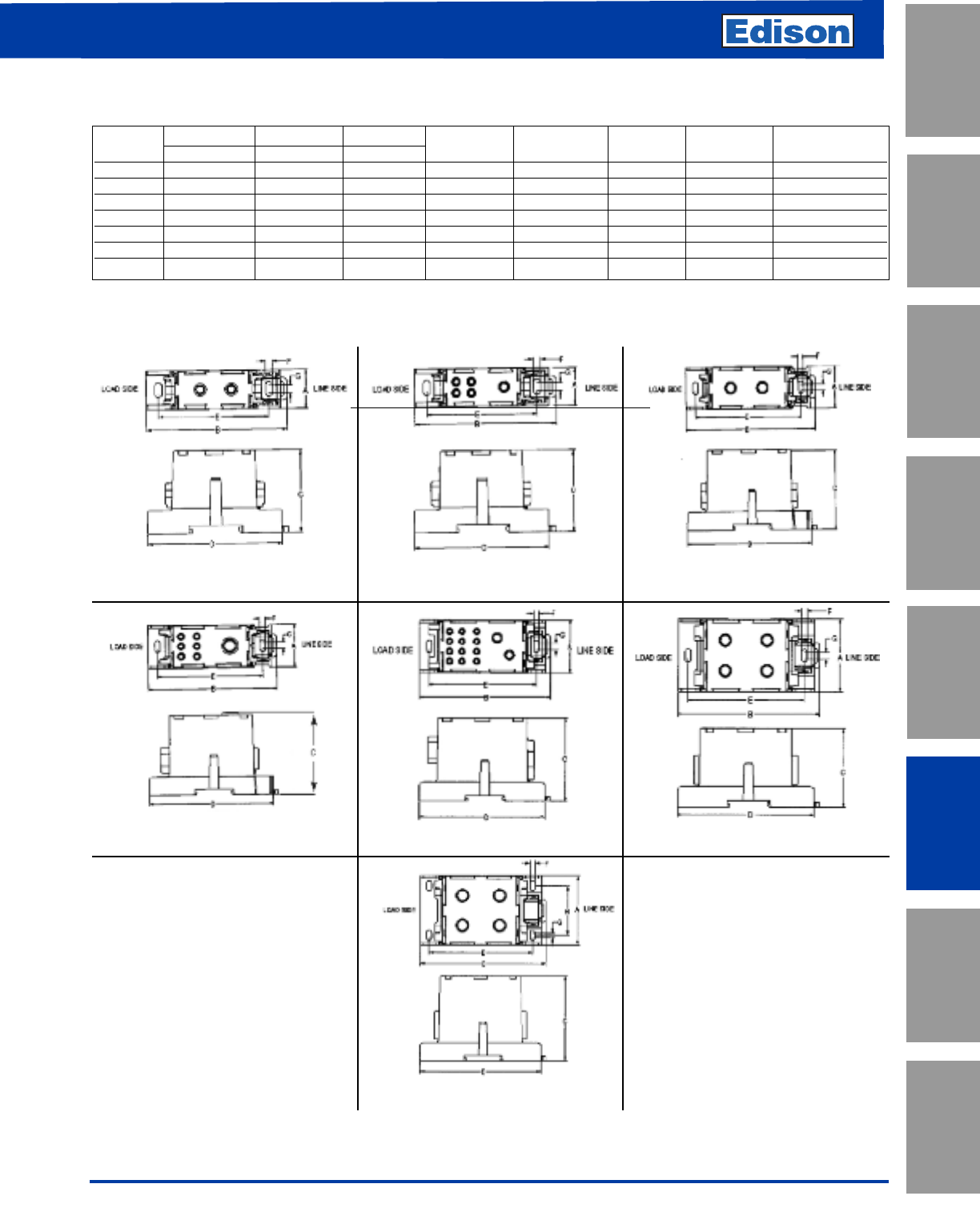
159
For additional information, visit www.edisonfuse.com
Enclosed Power Distribution Blocks
EPDB Series
UL/CSA Fuses
Current Limiting
UL/CSA Fuses
General Purpose
Special
Purpose Fuses
Canadian
Fuses & Holders
Medium
Voltage Fuses
Fuse Blocks,
Holders & Misc.
Application
Section
Surge Protective
Devices
EPDB101 EPDB104 EPDB301
EPDB306 EPDB512 EPDB602
EPDB702
Part Width Length Height
Number ABCDEFGH
EPDB101 1.03 (26.16) 3.372 (94.8) 2.15 (54.5) 3.55 (90.17) 2.91 (73.79) 0.2 (5) 0.2 (5) N/A
EPDB104 1.03 (26.16) 3.372 (94.8) 2.15 (54.5) 3.55 (90.17) 2.91 (73.79) 0.2 (5) 0.2 (5) N/A
EPDB301 1.55 (39.37) 4.67 (118.5) 2.874 (73) 4.48 (113.67) 3.81 (96.77) 0.2 (5) 0.24 (6) N/A
EPDB306 1.55 (39.37) 4.67 (118.5) 2.95 (74.93) 4.48 (113.67) 3.81 (96.77) 0.2 (5) 0.24 (6) N/A
EPDB512 1.88 (47.62) 4.67 (118.5) 2.93 (74.5) 4.48 (113.67) 3.81 (96.77) 0.2 (5) 0.24 (6) N/A
EPDB602 2.38 (60.45) 4.67 (118.5) 2.60 (66) 4.48 (113.67) 3.81 (96.77) 0.2 (5) 0.24 (6) N/A
EPDB702 2.56 (65.02) 4.67 (118.5) 3.15 (80) 4.48 (113.67) 3.81 (96.77) 0.2 (5) 0.24 (6) 1.81 (46)
Dimensions – in (mm)
UR
CSA
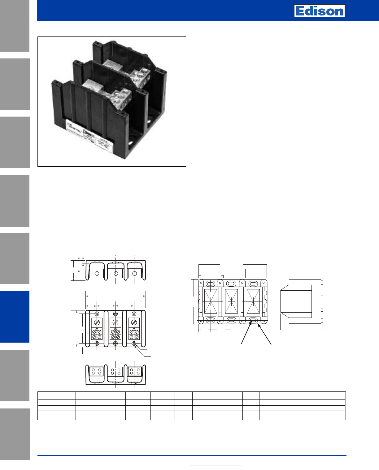
160 For additional information, visit www.edisonfuse.com
High SCCR Terminal Blocks
PB1 & PB3 Series
Application
Section
Fuse Blocks,
Holders & Misc.
Surge Protective
Devices
Medium
Voltage Fuses
Canadian
Fuses & Holders
Special
Purpose Fuses
UL/CSA Fuses
General Purpose
UL/CSA Fuses
Current Limiting
Features and Benefits
• High short-circuit current ratings up to 200kA
• UL 1059 Recognition
• 1-, 2- and 3-poles
Dimensions (inches)
F
A
B
GL C'Bore
K Dia.
LOADSIDE
LINESIDE
D
HJ
SIDE
TOP
C
A 3-Pole
B
D
A 2-Pole
A 1-Pole
E
E
C
D
KL
F
Electrical:
• Short-circuit current ratings up to 200kA,
see table next page
• Ampacities up to 310A
• 600Vac/dc (UL 1953)
• 75ºC rated connectors
•Cu Wire range 14AWG to 350kcmil
Mechanical:
• Flammability, UL 94V0
• Panel mount
• Tin-plated aluminum (Al) connectors suitable for copper
(Cu) conductors
Agency and Standards
• UL 1059 Recognized, Guide XCFR2, File E221592
• General Industry Class per UL 1059, usage Category C
• CSA Certified, Class 6228-01, File 700489
Part Width/Poles Length Height
Number A/1 A/2 A/3 BCDEFGHJ K L
PB1011-10S3 1.06 1.88 2.60 2.88 1.75 0.81 2.25 0.53 0.31 0.84 0.31 0.20 0.42
PB1061-3093 1.96 3.58 5.20 4.00 3.32 1.62 3.37 0.97 ---Slot 0.20x0.41 Slot 0.42x0.62
PB1061-3093 Series (1-, 2-, and 3-pole)PB1011-10S3 Series (1-, 2-, and 3-pole)
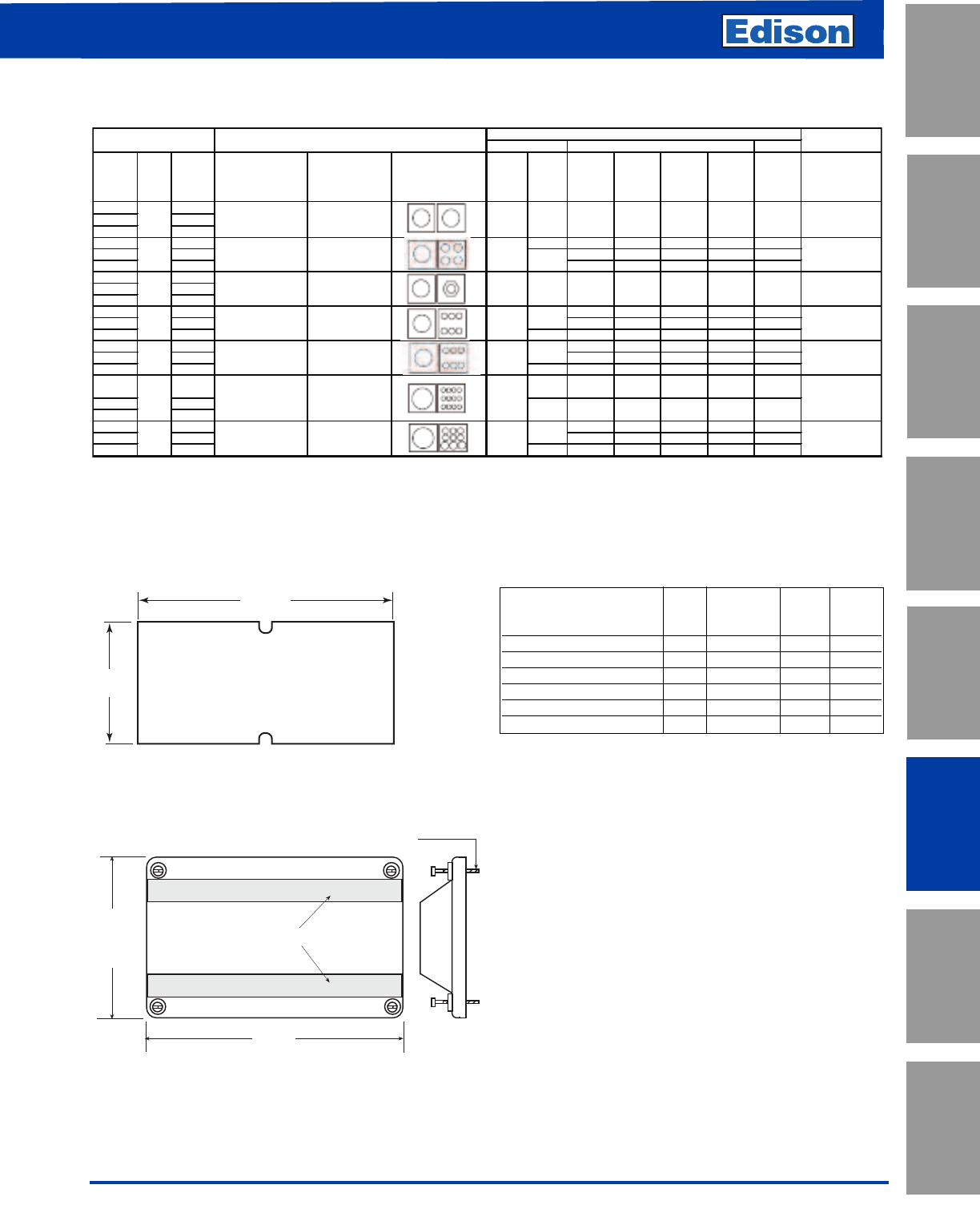
161
For additional information, visit www.edisonfuse.com
High SCCR Terminal Blocks
PB1 & PB3 Series
UL/CSA Fuses
Current Limiting
UL/CSA Fuses
General Purpose
Special
Purpose Fuses
Canadian
Fuses & Holders
Medium
Voltage Fuses
Fuse Blocks,
Holders & Misc.
Application
Section
Surge Protective
Devices
Electrical Data
Lineside Loadside
Part
Number
Amps
Number
of Poles
Wire Range W ire Range
Line Load
side
JTRK1RK5
SCCR
Line Load
AW G or
kcmil
AW G or
kcmil
JDL
TJS
TJN
LESRK
LENRK
ECS R
ECNR
kA
PB1011 1
PB1012 2
PB1013 3
PB1041 1 4 to 12 200 200 200 60 200
PB1042 2 175 175 100 60 100
PB1043 3 200 200 100 60 50
PB10S1 1
PB10S2 2
PB10S3 3
PB1061 1 400 400 200 100 200
PB1062 2 400 400 400 100 100
PB1063 3 4 to 14 175 175 100 60 100
PB3061 1 400 400 200 100 200
PB3062 2 400 400 400 100 100
PB3063 3 4 to 12 175 175 100 60 100
PB3121 1 4 to 8 400 400 200 100 200
PB3122 2
PB3123 3
PB3091 1 400 400 200 100 200
PB3092 2 400 400 400 100 100
PB3093 3 4 to 12 175 175 100 60 100
Ampacities 75C per NEC® Table 310.16 and UL508A Table 28.1
Minimum
Enclosure Size
4 to 14
175
175
100
4 to 8
100
4 to 14
Stud
24 X 20 X 6.75
350 kcm il to 4 AW G
350 kcm il to 4 AW G
350 kcm il to 4 AW G
(6) 2 to 12 AW G
(3) 1/0 to 12
350 to 4
350 to 4
350 to 4
1/0 to 6
4 TO 14 AW G
4 TO 12 AW G
2/0 to 8
4 TO 14 AW G
2/0 TO 8 AW G
2/0 TO 8 AW G
2/0 to 8
2/0 to 8
4 TO 14 AW G
1/4-20 X 3/4 STUD
60
200
200
175A
310A
310A
175A
4 to 12
100
60
2/0 TO 8 AW G
200
310A
*Class G 60A (SEC-60) or less or Class CC 30A (EDCC30, HCTR30, HCLR30) or less are suitable for all the SCCRs in this table
Openings per Pole
Terminal Copper Conductor Capability
Configuration
Short-Circuit Current Rating Data
Conductors
M ax Fuse Class & Am p*
175A
175A
16 X 16 X 6.75
2/0 TO 8 AW G
2/0 TO 8 AW G
200
60
200
2/0 to 8
2/0 to 8
200
200
side
Inches
16 X 16 X 6.75
16 X 16 X 6.75
24 X 20 X 6.75
24 X 20 X 6.75
24 X 20 X 6.75
Optional Covers & Dimensions (inches)
#4 Thread-cutting screws assembled
Textured surface for marking
A
B
B
A
#4 Thread-cutting screws assembled
Textured surface for marking
A
B
B
A
Cover
Part
Block Poles Number A (In) B (In)
PB1011, 1041, 10S1 1 PBC21 0.94 2.75
PB1012, 1042, 10S2 2 PBC22 1.75 2.75
PB1013, 1043, 10S3 3 PBC23 2.56 2.75
PB1061, 3061, 3091, 3121 1 PBC31 4.14 2.10
PB1062, 3062, 3092, 3122 2 PBC32 4.14 3.72
PB1063, 3063, 3093, 3123 3 PBC33 4.14 5.34
PBC2_
PBC3_
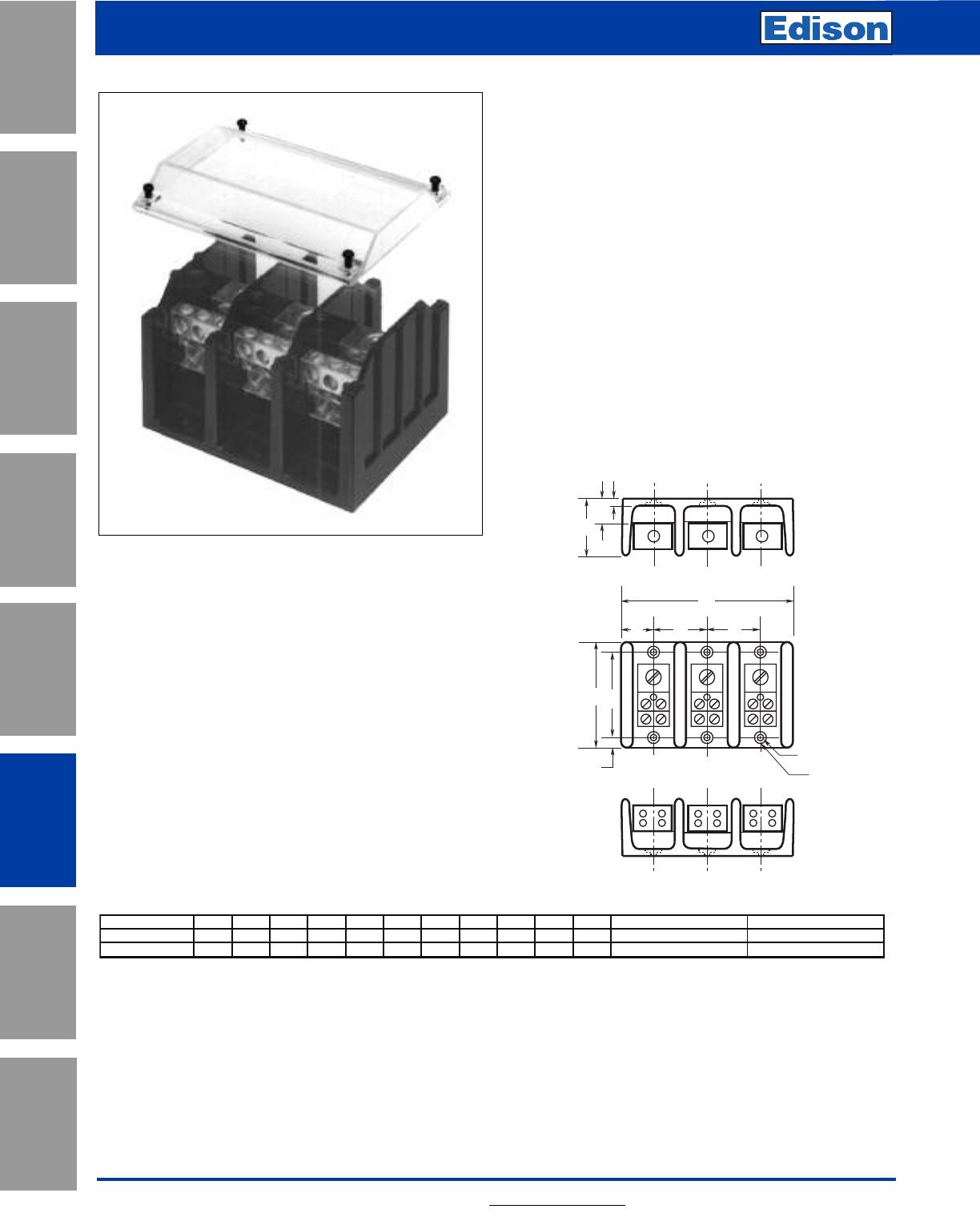
162 For additional information, visit www.edisonfuse.com
Power Distribution Blocks
PB4, PB5 & PB7 Series
Application
Section
Fuse Blocks,
Holders & Misc.
Surge Protective
Devices
Medium
Voltage Fuses
Canadian
Fuses & Holders
Special
Purpose Fuses
UL/CSA Fuses
General Purpose
UL/CSA Fuses
Current Limiting
Feature and Benefits
• Available in 1-, 2-, or 3-pole versions
• Thermoset material to withstand high heat applications
• Optional cover is clear with write-on surface for field
termination identification (Order PBC Series)
• For industrial controls, HVAC and other control
automation panel applications
• Mounting slots allow greater flexibility to fit pre-drilled
panel holes
Dimensions (inches)
FE
E
C
AB
G
L
K
LOADSIDE
LINESIDE
D
HJ
Voltage Ratings:
• 600Vac/dc maximum
• 75°C Rated connectors
Mechanical:
• Panel mount
• Tin-plated aluminum connectors
• Flammability: UL 94V0
Agency Information:
• UL Recognized, Guide XCFR2, File E221592, General
Industrial Class per UL 1059
• CSA Certified: CSA File 700489, Class 6228-01
Series A B C1 C2 C3 D E F G H J K (Slot) L (Slot)
PB401X, PB512X 4.00 3.38 1.98 3.6 5.21 3.32 1.62 0.99 0.31 0.87 0.35 0.20" wide x 0.41" long 0.42" wide x 0.62" long
PB712X 5.5 4.75 3.1 5.79 8.48 2.93 2.69 1.55 0.38 1.19 0.44 0.20" wide x 0.33" long 0.41" wide x 0.53" long
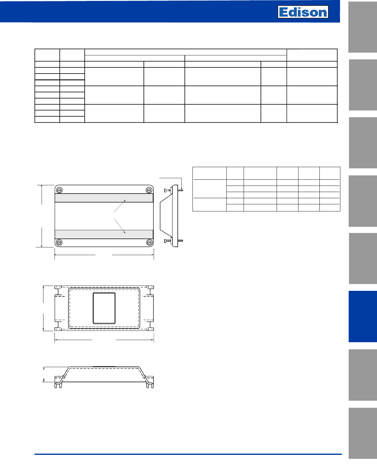
163
For additional information, visit www.edisonfuse.com
Power Distribution Blocks
PB4, PB5 & PB7 Series
UL/CSA Fuses
Current Limiting
UL/CSA Fuses
General Purpose
Special
Purpose Fuses
Canadian
Fuses & Holders
Medium
Voltage Fuses
Fuse Blocks,
Holders & Misc.
Application
Section
Surge Protective
Devices
#4 Thread-cutting screws assembled
Textured surface for marking
A
B
B
A
Electrical Data
Optional Covers & Dimensions (inches)
W ire Range per pole Torque (Lb-In) W ire Range per pole Torque
PB4011 1
PB4012 2
PB4013 3
PB5121 1
PB5122 2
PB5123 3
PB7121 1
PB7122 2
PB7123 3
(12) #4 - #14 Cu-Al
500
(2) 500kcm il - #6 Cu-Al
(2) 300kcm il - #4 Cu-Al
275
(12) #4 - #14 Cu, #4 - #12 Al
AL-380A
AL-570A
AL-760A
35
20
(1) 500kcm il - #6 Cu-Al
500
(1) 3/8 - 16 x 1 Stud
---------
Part
Number
Number
Poles
Connector
Lineside
Loadside
Connection
M aterial & Ampacity
Cover
Series Poles Part Number ABC
1 PBC31 4.14 2.10 –
PB4 & PB5 2 PBC32 4.14 3.72 –
3 PBC33 4.14 5.34 –
PB7 1 PBC71 2.52 5.50 0.84
3 3 (PBC71)
PB4 & PB5
PB3
B
For PB4 & PB5 Blocks
For PB7 Blocks
A
C
PB7
B
For PB4 & PB5 Blocks
For PB7 Blocks
A
C
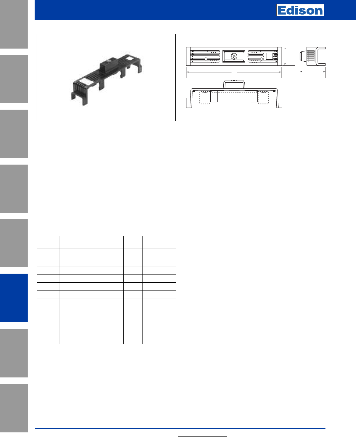
164 For additional information, visit www.edisonfuse.com
Fuse Covers,
Indicating and Non-Indicating
Application
Section
Fuse Blocks,
Holders & Misc.
Surge Protective
Devices
Medium
Voltage Fuses
Canadian
Fuses & Holders
Special
Purpose Fuses
UL/CSA Fuses
General Purpose
UL/CSA Fuses
Current Limiting
SAMI Features:
• Innovative design, covers exposed terminals and contacts
of Edison fuse blocks.
• Fits most competitive fuse blocks.
• Light on indicating SAMI shows when the fuse is
open–helps troubleshoot the system and reduces
downtime.
• All versions are reusable—no need to pay for indication
every time a fuse opens.
• Indication contacts have teeth to break oxidation layer on
the existing fuse endcap to provide a clear signal path.
• Less than 0.6mA leakage current at 600 volt.
• Visual marking of lineside and loadside.
• SAMI cover ends can easily be trimmed if necessary, to
fit cover over existing wiring or to fit most safety switches.
• Dead front construction provides added protection against
accidental contact by maintenance personnel.
• Labels are provided with the SAMI fuse cover for writing
in circuit or fuse information.
• One cover is required for each pole.
WARNING: To avoid electrical shock, turn power
off before installing, removing or servicing.
For SAMI trimming guide specifications refer to
the following data sheet numbers:
7008 - SAMI 1-9 Trimming Guides.
*Catalog Numbers
For Indicating Cover, add suffix I.
For Non-indicating cover, add suffix N.
Example:SAMI-7I = Indicating
SAMI-7N = Non-indicating
Indicating feature requires a minimum of 90Vac or
115Vdc to illuminate lamp.
**UL Recoginized
***Non-indicating only
† SAMI-8A adapter available for small RK, K5, H body
design. SAMI-8N comes standard with adapter
(SAMI-8A)
LINE
Buss
SAMI -2
LOAD
TEST PROBE TEST PROBE
C
B
A
FUSE
Catalog Number SAMI™ Series
Indicating Fuse Covers:
SAMI™ Series: For Class J, RK1, RK5, H, K5, CC, G, T
and midget type fuses.
Operating Voltage:
Non-Indicating - 0-600Vac/dc
Indicating - 90 to 600Vac
- 115 to 600Vdc
Amp Rating: 0 - 100A
Agency Approvals: UL Listed
CSA (Class 6225-01,
File No. LR47235)
Material: Black Thermoplastic with a flammability
rating of UL 94V2
Catalog Data (600V) Dimensional Data (inches)
Catalog
Number* Description ABC
600V, J (0-30A) and 600V, T
SAMI-1 (35-60A)*** 250V, RK, K5, H 5.02 1.03 1.94
(35-60A)
SAMI-2 600V, RK, K5, H (0-30A) 7.03 1.30 2.07
SAMI-3 600V, J (65-100A) 7.03 1.30 2.33
SAMI-4 250V, RK, K5, H (65-100A) 8.20 1.30 2.18
SAMI-5 600V, RK, K5, H (35-60A) 8.20 1.30 2.18
SAMI-6 600V, J (35-60A) 4.98 1.17 2.14
SAMI-7** 600V, Midget, Class CC, 3.82 0.75 1.72
G (0-30A)
SAMI-8† 600V, RK, K5, H (65-100A) 10.38 1.50 2.33
SAMI-9 250V, RK, K5, H (0-30A) 3.82 0.75 1.72
and 600V, T (0-30A)
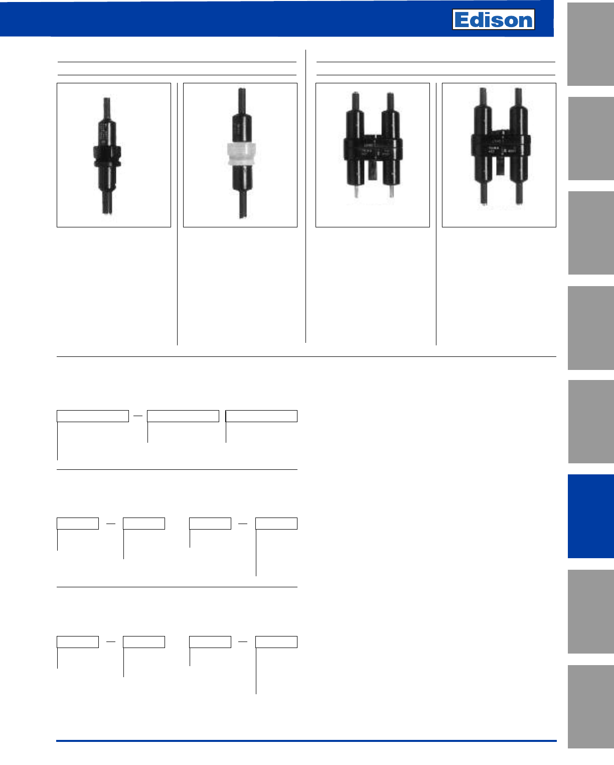
165
For additional information, visit www.edisonfuse.com
In-Line Fuse Holders for
13⁄32˝ x 1 1⁄2˝ and Class CC Fuses
UL/CSA Fuses
Current Limiting
UL/CSA Fuses
General Purpose
Special
Purpose Fuses
Canadian
Fuses & Holders
Medium
Voltage Fuses
Fuse Blocks,
Holders & Misc.
Application
Section
Surge Protective
Devices
HEB-
Water-resistant, in-line fuse
holder for any 13⁄32" x 1 1⁄2"
fuse. Fuse holder rated 30A,
600V (CSA Listed 15A
max.). Typical fuse types:
Edison MOL MEN, MEQ
and MCL. (1⁄10 -30A)
HET-
A HEB- fuse holder with a
permanently installed solid
neutral. Easily identified by
white plastic coupling nut.
Single-Pole
13⁄32" x 1 1⁄2" Fuses
HEY-
Double-pole fuse holder has
water-resistant, polarized
design, and accepts Class
CC branch circuit fuses
(Edison fuse types EDCC,
HCTR or HCLR, 600V or
less) Particularly applicable
in street lighting circuits with
optional breakaway
receptacle.
HEX-
Water-resistant, in-line
2-Pole fuse holder for any
13⁄32" x 1 1⁄2" fuse. Fuse holder
rated 30A, 600V (CSA
Listed 15A max.). Typical
fuse types: Edison MOL
MEN, MEQ and MCL.
(1⁄10-30A)
Double-Pole
Class CC 13⁄32" x 1 1⁄2" Midget Fuses
Packaging & Ordering Information:
HEB Load Side Line
HET Terminal Terminal
HEY A thru W A thru W
HEX
XXX
Single- and Double-Pole without Breakaway
Option
Packaging & Ordering Information:
HEB or Load Line Break-W-Way
HET Terminal Terminal Terminal
A thru K RLC -
A thru J
or RYC
XXX W
Single-Pole with Breakaway Option
Packaging & Ordering Information:
HEX or Load Line Break-W-Way
HEY Terminal Terminal Terminal
A thru K DRLC -
A thru J
or DRYC
XXX W
Double-Pole with Breakaway Option
Available Part Numbers
Non-Breakaway Units:
HEB-AA(1) (2) (3), HEB-AB(2), HEB-AC(2),
HEB-AD(2), HEB-AE(2), HEB-AJ, HEB-AK, HEB-AL, HEB-AR,
HEB-AY, HEB-BA(2), HEB-BB(2), HEB-BC(2), HEB-BD(2),
HEB-CC(2), HEB-DD(2), HEB-JJ, HEB-JK, HEB-JL, HEB-JY,
HEB-LL, HEB-NN, HEB-PP(2), HEB-QQ(2), HEB-RR(2),
HEB-SS, HEB-TT(2), HEB-ZA.
Agency Information:
(1)UL Recognized, Guide IZLT2, File E14853
(2)CSA Certified, Class 6225-01, File 47235
(3)CE
Breakaway Units:
(Includes fuse holder, breakaway part and insulating boots):
HEB-AW-RLA, HEB-AW-RLC-A(1) (2) (3), HEB-AW-RLC-B,
HEB-AW-RLC-C, HEB-AW-RLC-J, HEB-AW-RYA,
HEB-AW-RYC, HEB-BW-RLC-A, HEB-BW-RLC-B,
HEB-BW-RYC, HEB-JW-RLC-J, HEB-JW-RYC,
HEB-KW-RLC-J, HEB-KW-RYC, HEB-LW-RLA,
HEB-LW-RLC-J, HEB-LW-RYA
Fuse Holder Only: HEB-AW(2), HEB-BW(2), HEB-DW(2),
HEB-JW, HEB-LW
Breakaway Part: RLC-A, RLC-B, RLC-C, RLC-J,
RYC, RLA, RYA
Agency Information:
(1)UL Recognized, Guide IZLT2, File E14853
(2)CSA Certified, Class 6225-01, File 47235
(3)CE
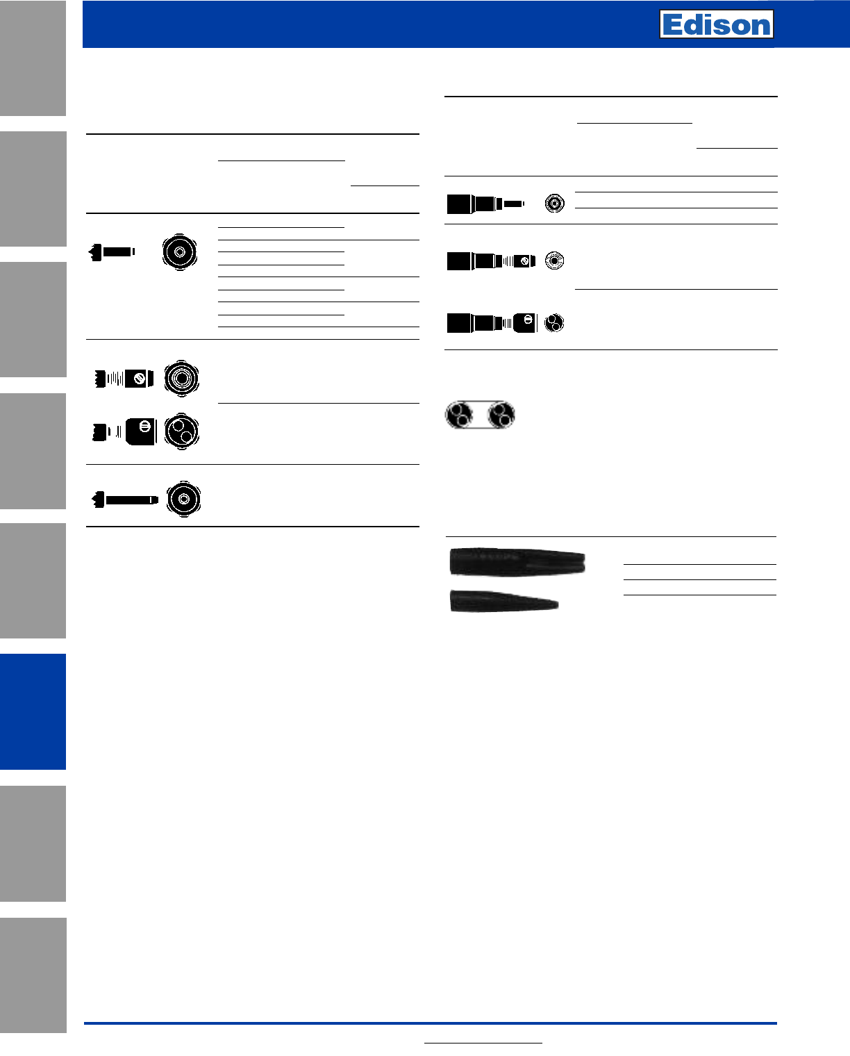
166 For additional information, visit www.edisonfuse.com
Application
Section
Fuse Blocks,
Holders & Misc.
Surge Protective
Devices
Medium
Voltage Fuses
Canadian
Fuses & Holders
Special
Purpose Fuses
UL/CSA Fuses
General Purpose
UL/CSA Fuses
Current Limiting
In-Line
Fuse Holders
Catalog and Specification Data
Note: The construction elements listed below illustrate the full
construction of the available part numbers. NOT all
construction elements are available in all combinations.
Conductor Terminals
Conductor Data
Terminal
Symbols
Load Line
Type Terminal Size Side Side
Copper Crimp #12 to #8 1•• AA
#12 2••
#10 2••
#6 1•• BB
#4 1••
#8 2•• CC
#4 1—•
#62•• DD
#21—•
#42•• EE
Copper Set-Screw
#12 to #2 1•• JJ
#12 to #2 2•• KK
Solid Breakaway (Required with WW
Breakaway
Receptacle)
Available Part Numbers
HEX Series:
HEX-AA(1) (2), HEX-AB, HEX-AC, HEX-AD,
HEX-AW-DRLC-A, HEX-AW-DRYC, HEX-AW-RLC-A,
HEX-AW-RYC, HEX-AE, HEX-AY, HEX-BB, HEX-CC, HEX-JJ,
HEX-JK, HEX-JW-DRYC, and HEX-KK.
Agency Information:
(1)UL Recognized, Guide IZLT2, File E14853
(2)CSA Certified, Class 6225-01, File 47235
HEY Series:
HEY-AA, HEY-AB, HEY-AC, HEY-AD, HEY-AE, HEY-AL,
HEY-AW-DRLC-A, HEY-AW-DRLC-B, HEY-AW-DRYC,
HEY-BB, and HEY-JJ.
HET Series:
HET-AA, HET-AB, HET-AW, HET-AW-RLC-A, HET-AW-RLC-
B, HET-AW-RLC-C, HET-AW-RLC-J, HET-AW-RYC,
HET-BB, HET-BW-RLC-B, HET-BW-RYC, HET-JJ,
HET-JK, HET-JW-RLC-J, HET-JW-RYC, and HET-KK.
Catalog Data — Insulating Boots
Catalog
Numbers Type
2A0660 Single Conductor
2A0661 Two Conductor
Insulating boots are optional and not included with
non-Breakaway holders and must be ordered separately.
They are included as a standard item with the breakaway
series.
When boots are utilized, extra heat retention requires
that fuses are sized at a minimum of 200% of the RMS
load current.
No. Per
Terminal
Solid
Stranded
Optional
Conductor Data
Breakaway
Terminal
Single- *Double-
Type Terminal Size Pole Pole
Copper Crimp #12 to #8 1• •-RLC-A -DRLC-A
#61• •-RLC-B -DRLC-B
#4 1• •-RLC-C -DRLC-C
Copper Set-Screw
#12 to #2 1• •-RLC-J -DRLC-J
#12 to #2 2• •` -RYC -DRYC
* Terminal illustrations show the end view of single-pole receptacles and one-pole only of
the double-pole receptacles. Thus, for example, in the case of a double-pole, set-screw
type receptacle with terminals that accept two conductors, a total of four conductors could
be connected to the receptacle per the following drawing.
No. Per
Terminal
Solid
Stranded
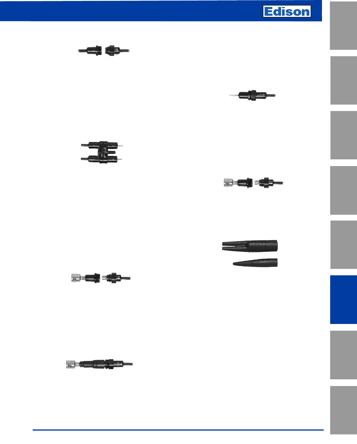
167
For additional information, visit www.edisonfuse.com
UL/CSA Fuses
Current Limiting
UL/CSA Fuses
General Purpose
Special
Purpose Fuses
Canadian
Fuses & Holders
Medium
Voltage Fuses
Fuse Blocks,
Holders & Misc.
Application
Section
Surge Protective
Devices
In-Line
Fuse Holders
Watertight Fuse Protection
HEB in-line fuse holders are water resistant and easy to
install. Protect fuses in locations exposed to water,
weather, corrosive fumes, salt-spray, etc. Holders are two-
sectioned, molded plastic. The captive nut couples the
loadside section to the lineside section; compression of the
o-ring when the nut is tightened forms a vapor and water
resistant unit.
Double-Pole Fuse Holders For Simultaneous
Non- Load-Break Disconnect of Two Conductors
HEX and HEY units permit the fusing of two conductors.
Loadside conductors can be disconnected from the lineside
conductors by disengaging a captive stainless steel screw.
Positive non-load-break disconnect (for non-energized
circuits) provides maintenance safety. Helps prevent shock.
Makes loads electrically dead.
Fuse holders are polarized. They can be used for line-to-
line or line-to-neutral loads. Polarization prevents
inadvertent reversal of loadside conductors (provides
compliance with NEC®Section 240-22).
Both loadside terminals are always identical; both lineside
terminals are always identical.
Serve As A Non-Load-Break Disconnect
The body of the fuse recesses within the loadside section
so that it does not make electrical contact with the lineside
section until the coupling nut engages the threads on the
lineside section. The holder section thus provides a positive
means of breaking or opening a non-energized electrical
circuit for maintenance and repair.
Breakaway Receptacles For Impact Seperation
Are available as an option with fuse holders. Ideally suited
for breakaway lighting standards as required by state and
federal highway commissions). Receptacle consists of a
female terminal jacketed in an integral rubber insulating
sleeve, and an external wire/cable terminal. The female
terminal tightly mates with a lineside, solid, copper rod
terminal (symbol “W”) of the fuse holder. The insulating
sleeve also insulates the body of the lineside section of the
fuse holder. Should the holder be subjected to an undue
pull, it will separate from the lineside, Breakaway
receptacle and become electrically dead. Separating the
holder and receptacle on a non-engergized circuit facilitates
repair/maintenance.
Solid “W” Terminals Mate With Breakaway
Receptacles
A solid copper “rod” terminal must be used on the line-side
of a fuse holder when holder is equipped with a breakaway
receptacle. This solid rod terminal mates with the internal
female terminal(s) of the breakaway receptacle. The letter
“W” in the catalog number of the fuse holder
designates this type terminal.
Crimp And Set-Screw Terminals
Crimp and setscrew type terminals are available for copper
conductors.
Insulating Boots Save Installation Time
Boots come in two configurations - for single conductor and
the “Y” type for two conductors. Fit all Edison in-line fuse
holders. Designed to snugly fit over conductor insulation.
Fits to wire by cutting off tapered tip. Diameter of conductor
insulation cannot exceed 0.450". Inside of boots are treated
with silicone to facilitate drawing of wire.
Boots come as a standard item with breakaway
receptacles. They are optional and must be ordered
separately for fuse holders without breakaway
receptacles. When boots are utilized, extra heat
retention requires that fuses are sized at a minimum of
200% of the RMS load current.
“Tap-Off” Connections
Fuse holders with terminal accepting two conductors can
be used as a tap-off connector. Saves cost and manhours.
2A0661
2A0660
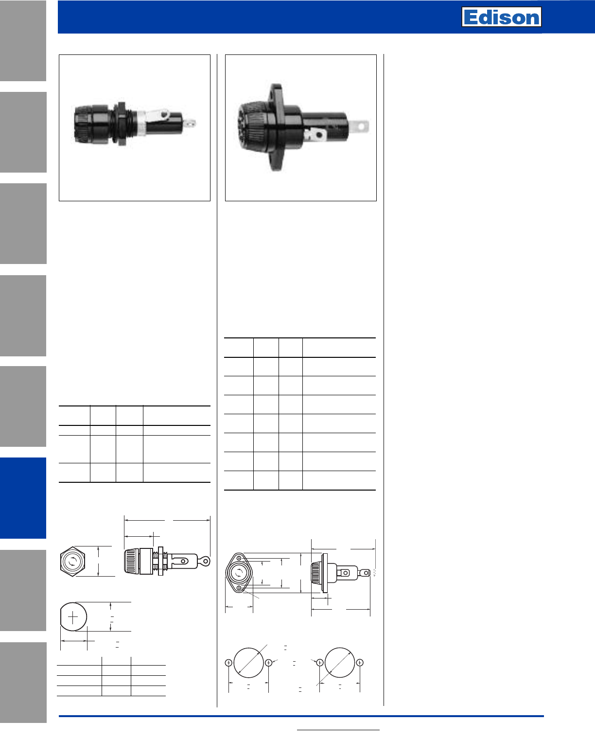
168 For additional information, visit www.edisonfuse.com
Application
Section
Fuse Blocks,
Holders & Misc.
Surge Protective
Devices
Medium
Voltage Fuses
Canadian
Fuses & Holders
Special
Purpose Fuses
UL/CSA Fuses
General Purpose
UL/CSA Fuses
Current Limiting
Panel-Mount and
In-Line Fuse Holders
Catalog Number HKP,
HKP-HH, and HKP-W
Standard Fuse Holders:
For use with 1⁄4" x 1 1⁄4" fuses
(Edison type ABC, AGC, MDL, MDA
etc.)
Terminals: Bayonet-type knob.
Vibration resistant.
For panels up to 5⁄16"
(7.9mm) thick.
Agency Approvals:
UL Recognized, Guide IZLT2,
File E14853
CSA Certified, Class 6225-01,
File 47235
Electrical Ratings for HPF Series
Catalog
Number Amps Volts Fuse Description
HKP 30 250 —
HKP-HH 15 250 HKP with 1/4"
Quick-connect
terminal
HKP-W 30 250 HKP with drip-proof
knob.
Catalog Number HPF
Standard Fuse Holders With
Screw-Type Knob:
For use with 13⁄32" x 1 5⁄16" to 1 1⁄2" fuses.
Agency Approvals:
UL Recognized, Guide IZLT2,
File E14853, cURus
UL 94V0 Flammability Rating
Electrical Ratings
Catalog
Number Amps Volts Fuse Description
HPF 30 600 1 1/2" (38.1mm)
MOL, MEN, MCL
HPF-L 5 600 EBS, 13/32" x 1 3/8"
fuses
HPF-EE 15 600 SEC 0-15,
13/32" x 1 3/8" fuses
HPF-JJ 20 600 SEC 20,
13/32” x 1 13/32" fuses
HPF-FF* 30 480 SEC 25 & 30,
13/32" x 1 5/8" fuses
HPF-RR 30 600 HCLR, HCTR & EDCC
Class CC fuses
HPF-WT 30 600 Splash-proof knob
for 1 1/2" fuses
*No CSA Certification.
0.78"
B
A
Max
0.505" + 0.005"
(12.8mm + 0.13mm)
0.473"
+ 0.005"
(12.0mm + 0.13mm)
Punched Mounting Hole
F
U
S
E
F
U
S
E
F
U
S
E
1.031" + 0.003"
(26.2mm + 0.08mm)
0.187" + 0.002"
(4.75mm + 0.05mm)
Mounting Hole
Flange Rear of Panel
Mounting Hole
Flange Front of Panel
0.890" + 0.003"
(22.6mm + 0.08mm)
1.312" + 0.003"
(33.3mm + 0.08mm)
1.312" + 0.003"
(33.3mm + 0.08mm)
0.180" DIA.
(4.6mm)
1.125"
(28.6mm)
1.00"
(25.4mm)
Without Fuse
2.69"
(68.3mm)
0.88"
(22.2mm)
1.78"
(45.2mm)
1.31"
(33.3mm)
2.81"
(71.4mm)
With Fuse
Dimensions - in (mm)
Dimensions - in (mm)
AB
HKP 2.33 0.75
HKP-HH 2.44 0.69
HKP-W 2.33 0.75
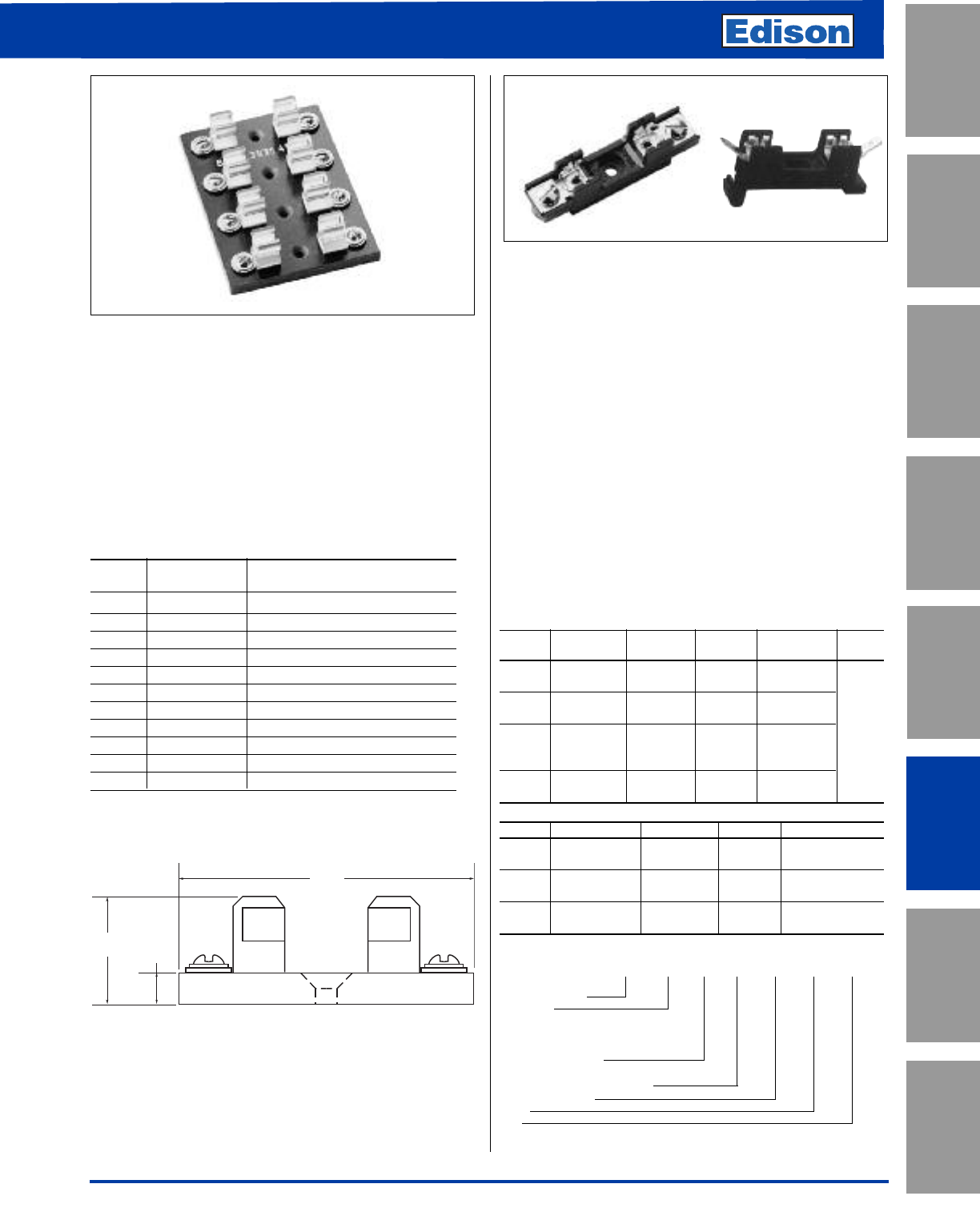
169
For additional information, visit www.edisonfuse.com
UL/CSA Fuses
Current Limiting
UL/CSA Fuses
General Purpose
Special
Purpose Fuses
Canadian
Fuses & Holders
Medium
Voltage Fuses
Fuse Blocks,
Holders & Misc.
Application
Section
Surge Protective
Devices
Fuse Blocks for Midget
and Electronic Fuses
Catalog Number 3835 Series
Multiple Pole Fuse Blocks:
For 13⁄32" x 1 1⁄2" (10.3 x 28.1mm) fuses.
Amp Rating: 30A
Voltage Rating: 250Vac/dc
Material: Silver-plated, beryllium copper clips.
No side barriers. Screw terminals.
Phenolic base.
Catalog Data
Catalog No. of
Number Poles Base Length - Inches (mm)
3835-1 1 27/32 (21.4)
3835-2 2 1-13/16 (46.0)
3835-3 3 2-25/32 (70.6)
3835-4 4 3-3/4 (95.2)
3835-5 5 4-23/32 (119.9)
3835-6 6 5-11/16 (144.5)
3835-7 7 6-21/32 (169.0)
3835-8 8 7-5/8 (193.7)
3835-9 9 8-19/32 (218.8)
3835-10 10 9-9/16 (242.9)
3835-12 12 11-1/2 (292.1)
*Base width — 2-3/4" (69.9mm)
Catalog Number S-8000 Series
Bolt-in and Snap-in Mounting Fuse Blocks:
For 1⁄4" x 1 1⁄4" fuses.
Construction: Blocks are molded flame retarded
thermopastic. Clips are spring-bronze.
Voltage Rating: 300Vac/dc
Agency Approvals:
UL Recognized under Components Program; File E14853,
Guide IZLT2
CSA Certified Class 6225-01, File 47235
Anti-Rotation Pin: Single-pole blocks may be ordered
without the antirotational pin simply
by adding an “X” to the number of
poles (Example: BK/S-8001-1X).
Carton Quantity: 10; shelf package: 100.
Bulk Carton: Single-pole and 2-pole fuse blocks
— 1,000; Multiple-pole fuse blocks
— 3-8 pole: 200; 9-12 pole: 50.
When ordering bulk quantities, prefix “BK/” to catalog
number: (Example: BK/S-8001-1SNP).
Bolt-in Mounting
*Basic Poles
Series Terminal Amps Angle Cat. No. (Suffix)
S-8000 Solder UL 25A 0° S-8001-
CSA 21A 40° S-8002-
S-8100 3/16" Quick UL 20A 0° S-8101-
Connect CSA 16A 40° S-8102- 1 - 12
1/4" Quick UL 20A 0° S-8201-
S-8200 Connect CSA 16A 40° S-8202-
Side S-8203-
S-8301 Screw UL 30A — S-8301-
CSA 10A
Snap-in Mounting (Poles available in single-pole only)
Series Terminal Amps Angle Cat. No.
S-8000 Solder UL 25A 0° S-8001-1-SNP
CSA 21A 40° S-8002-1-SNP
S-8100 3/16" Quick UL 20A 0° S-8101-1-SNP
Connect CSA 16A 40° S-8102-1-SNP
1/4" Quick UL 20A 0° S-8201-1-SNP
S-8200 Connect CSA 16A Side S-8203-1-SNP
0.25"
(6.4mm)
1.0"
(25.4mm)
2.75"
(69.9mm)
NOTE: Mounting screw hole diameter is 0.148" (3.7mm).
Countersink, 0.313" (7.9mm). Max. Mounting scrw No. 6.
Dimensions - inches (mm)
Catalog Part Number System
BK/ S-8 0 00 -00 -SNP -R
Prefix for Bulk Packing
S-8000 Series
Type Terminal
“0”-Solder; “1”-3/16"
Quick Connect; “2”-1/4"
Quick Connect; “3”-Screw
Terminal Angle
“01”-straight (0‚); “02”-40°; “03”-side*
Number of Poles (01-12)
Snap-In
RoHS
* Available only in a single pole
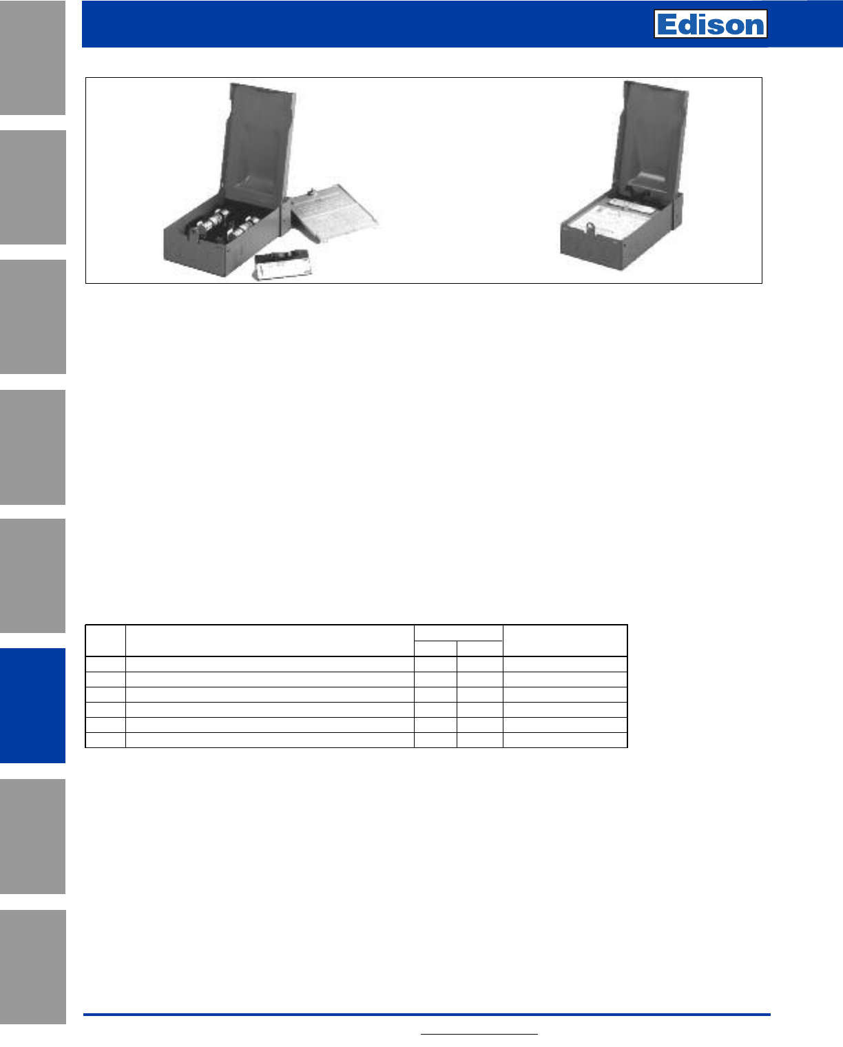
170 For additional information, visit www.edisonfuse.com
Application
Section
Fuse Blocks,
Holders & Misc.
Surge Protective
Devices
Medium
Voltage Fuses
Canadian
Fuses & Holders
Special
Purpose Fuses
UL/CSA Fuses
General Purpose
UL/CSA Fuses
Current Limiting
HVAC Disconnect
Fused and Non-Fused
Metallic
Fused Disconnect
Metallic
Non-Fused Disconnect
Metallic
Ratings: Single-Phase 2-Wire, 240Vac, 30 & 60A
UL Guide WGEW
Wire Range: #14-3 AWG, Al/Cu
Catalog Number B22 Series
Rainproof Air Conditioner Pullout Units:
Fused, Non-Fused, GFCI and Cable Whip.
Agency Approvals: UL Listed to UL 1429
CSA Certification
Features:
• NEMA 3R enclosure.
• Compact design but offers ample working space.
• Internal shield can be removed without tools.
• Specifications are printed on internal shield.
• Knockouts on back, bottom and both sides.
• Finger-safe construction.
• Padlockable.
Catalog Data
Main Maximum HP1Approx. Dim.
Rating Catalog Number/Description 120Vac 240Vac H x W x D (in.)
30A B221-30F* Fused Disconnect (Class H or R) 1.5 3 8 3⁄4x 5 3⁄8x 32 7⁄8
30A B221-30FGF Fused Disconnect with GFCI (Class H or R) 1.5 3 13 x 7 1⁄2x 4 3⁄4
60A B222-60F* Fused Disconnect (Class H or R) 3 10 8 3⁄4x 5 3⁄8x 32 7⁄8
60A B222-60FGF Fused Disconnect with GFCI (Class H or R) 3 10 13 x 7 1⁄2x 4 3⁄4
60A B222-60NF Non-fused Disconnect 3 10 13 x 7 1⁄2x 4 3⁄4
60A B222-60NFGF Non-fused Disconnect with GFCI 3 10 11 3⁄4x 6 1⁄2x 4 1⁄2
*Suitable for use as service equipment with optional field installed lug kit number B-DPOG.
1Rated with Edison ECNR and LENRK dual-element time-delay fuses.
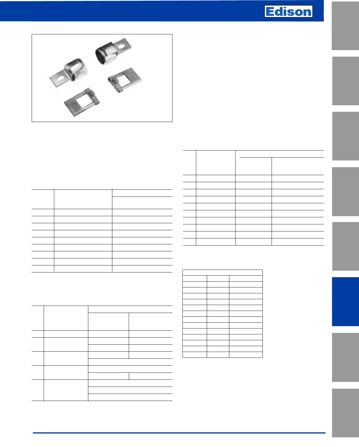
171
For additional information, visit www.edisonfuse.com
UL/CSA Fuses
Current Limiting
UL/CSA Fuses
General Purpose
Special
Purpose Fuses
Canadian
Fuses & Holders
Medium
Voltage Fuses
Fuse Blocks,
Holders & Misc.
Application
Section
Surge Protective
Devices
Fuse Reducers
Class H, J, K, and R
Fuses Reducers for Class H, J, K, &
R Fuses
Agency Approvals: UL Listed,
Guide #IZZR, File #E12853
CSA Certified,
Class 6225-01, File 47235
Features:
• Fuse reducers install on fuses and permit smaller size
fuses to be used in larger amp size switches and blocks.
• Reducers will fit into any panel or switch including the
dead-front type.
• Strong contact is maintained both mechanically and
electrically.
• UL Listed.
• There are no reducers to go from 250V to 600V.
• There are no reducers for switching from one fuse class to
another.
• There are no reducers for Class T or Class L fuses.
Fuse Reducers for Class H & K Dimension Fuses
KON, ERN, PONC, CDNC; KOS, ERS, CDSC
Catalog No. (Pairs)
250V 600V
Fuse Desired Reducer Reducer
Size Size No. No.
30A 60A NO.263 NO.663
30A 100A NO.213 NO.216
60A 100A NO.216 NO.616
60A 200A NO.226 NO.626
100A 200A NO.2621 NO.2621
100A 400A *NO.2641 *NO.2641
200A 400A NO.2642 NO.2642
100A 600A *NO.2661 *NO.2661
200A 600A *NO.2662 *NO.2662
400A 600A *NO.2664 *NO.2664
* Product does not have CSA certification.
Fuse Reducers for Class J Dimension Fuses- JDL, JFL, & CJ
Catalog No. (Pairs)
Fuse Desired Reducer
Size Size No.
30A 60A **J-63
30A 100A **J-13
60A 100A **J-16
60A 200A **J-26
100A †200A **J-21
100A †400A **J-41
200A †400A **J-42
200A 600A **J-62
400A †600A **J-64
† Not for Bolt-on Applications.
** Product does not have UL or CSA certification.
Fuse Reducers for Class R Dimension Fuses
ECNR, LENRK, NCLR; ECSR, LESRK, & SCLR
Catalog No. (Pairs)
250V 600V
Fuse Desired Reducer Reducer
Size Size No. No.
30A 60A NO.263-R NO.663-R
30A 100A NO.213-R NO.216-R
60A NO.216-R NO.616-R
60A 200A NO.226-R NO.626-R
100A *NO.2621-R
100A 400A *NO.2641-R
200A *NO.242-R *NO.642-R
100A *NO.2661-R
200A 600A *NO.2662-R
400A **NO.2664-R
* Product does not have CSA certification.
**Single reducer only (pair not required)
Note: Carton quantity - 10 pair.
CROSS REFERENCE
EDISON MERSEN LITTELFUSE
NO.263 None LRU263M
NO.213 H1032 LRU213M
NO.216 H1062 LRU216
NO.226 None None
NO.663 None LRU663M
NO.616 H1066 LRU616
NO.626 None None
NO.2621 None LRU2621
NO.2641 None None
NO.2642 None LRU2642
NO.2661 None None
NO.2662 None None
NO.2664 None None
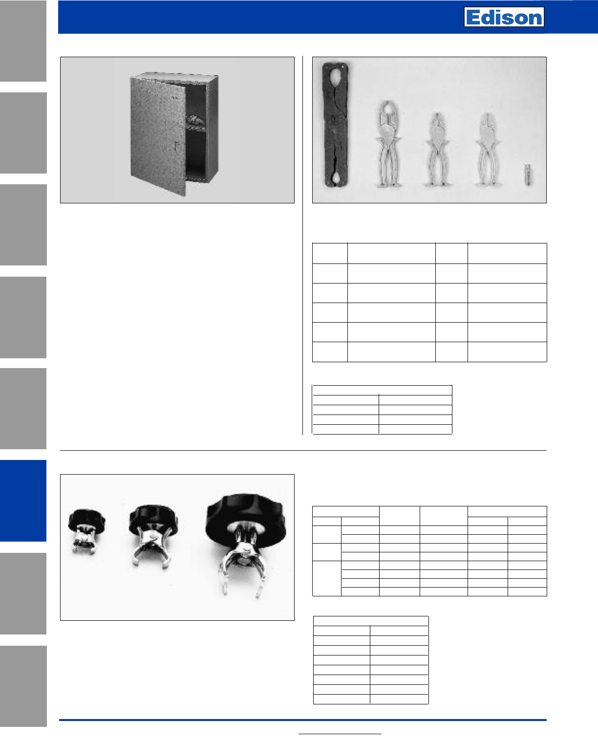
172 For additional information, visit www.edisonfuse.com
Application
Section
Fuse Blocks,
Holders & Misc.
Surge Protective
Devices
Medium
Voltage Fuses
Canadian
Fuses & Holders
Special
Purpose Fuses
UL/CSA Fuses
General Purpose
UL/CSA Fuses
Current Limiting
Fuse Accessories
Catalog Number SFC-FUSE-CAB
Spare Fuse Cabinet
Size: 24"wide x 30"high x 12"deep
FEATURES:
• Sturdy storage cabinet construction holds spare fuses.
• Cabinet door equipped with locking handle.
• Durable baked ASA 61 grey enamel.
• Mounting holes with key slot 16-inches on center.
Extra shelf for spare fuse cabinet
Fuse pullers
FP-4 FP-3 FP-2 FP-6 FP-A3
Catalog Data
Catalog For Fuse Carton
Number Diameter Qty. Fuse Type
FP-2 13/32" to 13/16" 10 0 – 60A, 250V
0 – 30A, 600V
FP-3 1" to 1-3/4" 10 70 – 200A, 250V
35 – 200A, 600V
FP-4 1-3/4" to 2-1/2" 1 225 – 600A, 250V
225 – 400A, 600V
FP-6 13/32" to 13/16" 1 Class T Fuses
0 – 60A, 300/600V
FP-A3 1/4" diameter and 10 Electronic glass
automotive blade fuses and blade type
Fuse Clip-Clamps
Catalog Data
Clamp Size Weight
Volts Amps Cat. No. Ctn. Qty. Lbs. Kg.
250 0-30A NO.1 12 0.66 .30
35-60A NO.2 12 0.96 .44
600 0-30A NO.2 12 0.96 .44
35-60A NO.4 12 1.44 .65
70-100A NO.5 12 1.20 .54
250 110-200A NO.6 6 1.26 .57
or 225-400A NO.7 6 1.86 .84
600 450-600A NO.8 6 2.52 1.14
Catalog Number SFC-SHELF
CROSS REFERENCE
NEW EDISON OLD EDISON
FP-2 38072
FP-3 38073
FP-4 38074
CROSS REFERENCE
NEW EDISON LITTELFUSE
NO.1 LCC1
NO.2 LCC2
NO.4 LCC4
NO.5 LCC5
NO.6 LCC6
NO.7 LCC7
NO.8 LCC8
Spare Key: Catalog Number: 2A1910-1
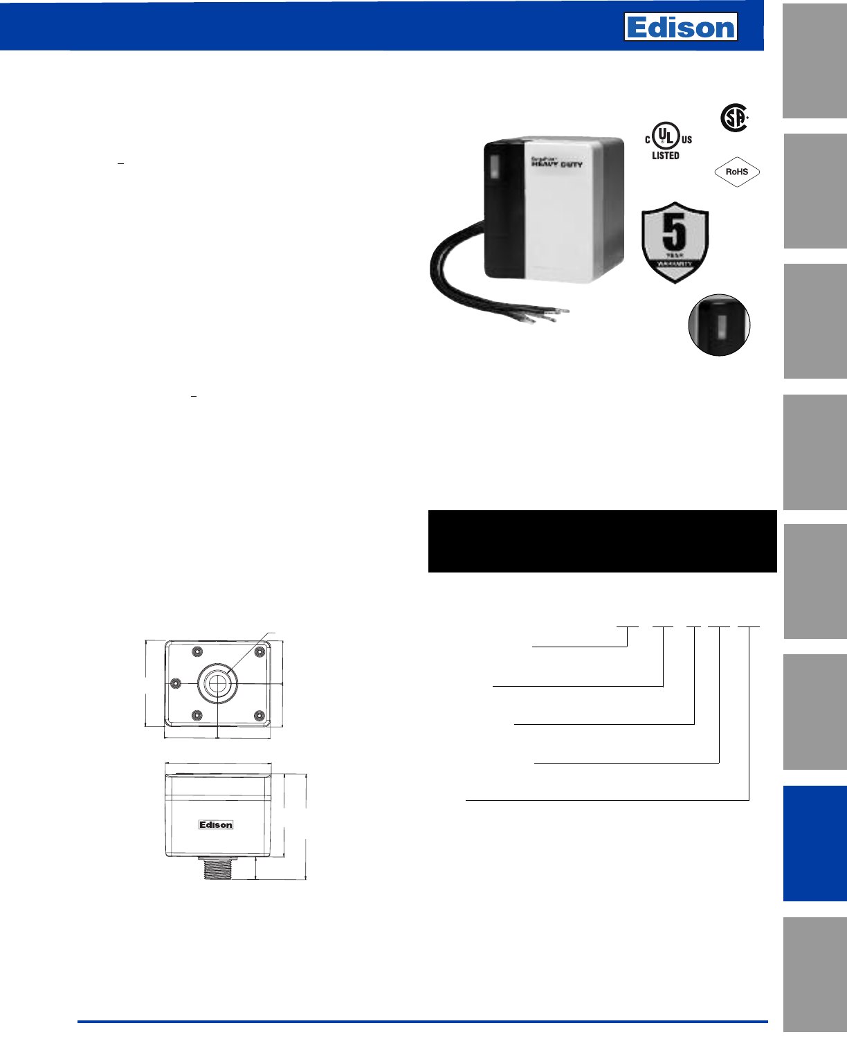
173
For additional information, visit www.edisonfuse.com
UL/CSA Fuses
Current Limiting
UL/CSA Fuses
General Purpose
Special
Purpose Fuses
Canadian
Fuses & Holders
Medium
Voltage Fuses
Fuse Blocks,
Holders & Misc.
Application
Section
Surge Protective
Devices
Surge Protective Devices
2-1/16” 2-1/16”
1-11/16”
1-11/16”
4-1/8”
3-3/16”
4-1/16”
3-3/8”
7/8”
1-1/16” Dia.
NEMA 4X Rated Heavy Duty
Type 1 UL Listed SPD
Description
The SurgePOD™ HEAVY DUTY is a Type 1 UL Listed
1449 3rd Edition surge protective device suitable for
installation on both the loadside or lineside of the service
entrance overcurrent protective device.
Available in voltage and system specific versions to
match electrical system and equipment requirements.
The SurgePOD HEAVY DUTY delivers optimum surge
protection using advanced patent pending SurgePOD™
module featuring thermal disconnect technology that
eliminates the need for additional overcurrent protection.
Parallel connection to the electrical system permits the
SurgePOD HEAVY DUTY SPD to be installed on any
ampacity panel.
• Type 1 UL 1449 3rd Edition Listed SPDs are easily
selected and installed on the loadside or lineside of
the service entrance overcurrent protective device
• Patented SurgePOD module technology eliminates
the need for additional fusing
• Voltage specific models precisely match and protect
electrical systems and equipment up to 600Vac
• Compact UV resistant NEMA 4X for indoor or outdoor
applications
•easyID™ LED status indicator provides surge
protection status at a glance
Dimensions - in
SPH50SP1120SN
SPH50SP1240SN
SPH50SP1347SN
SPH50SP2120SNG
SPH50SP2240SNG
SPH50SP2347SNG
SPH50SP2240PN
SPH50SP2480PN
SPH50SP3240PNG
SPH50SP3480PNG
SPH50SP3240DLG
SPH50SP3480DLG
SPH50SP4240HLG
SPH50SP4480HLG
SPH50SP3208WYG
SPH50SP3480WYG
SPH50SP3600WYG
SPH50SP4208WYNG
SPH50SP4480WYNG
SPH50SP4600WYNG
easyID™ LED
Status Indicator
Type 1 SPD Part Number System
SPH 50S PX XXX XXX
SPH = Product Series
Surge Protection Heavy Duty
Surge Rating
50S = 50kA max discharge current
No of Wires/Poles
P1 = 1 P2 = 2 P3 = 3 P4 = 4
Rated System Voltage
120, 208, 240, 347, 480, 600Vac
System
SN = Single-Phase 2 Wire, 2 Connection Points
SNG = Single-Phase 2 Wire + G, 3 Connection Points
PN = Split-Phase 3 Wire , 3 Connection Points
PNG = Split-Phase 3 Wire + G, 4 Connection Points
DLG = Three-Phase Delta 3 Wire + G, 4 Connection Points
HLG = Three-Phase Highleg Delta 4 Wire + G, 5 Connection Points
WYG = Three-Phase Wye 3 Wire, 4 Connection Points
WYNG = Three-Phase Wye 3 Wire + G, 5 Connection Points
SPD Type 2
SurgePOD™ HEAVY DUTY
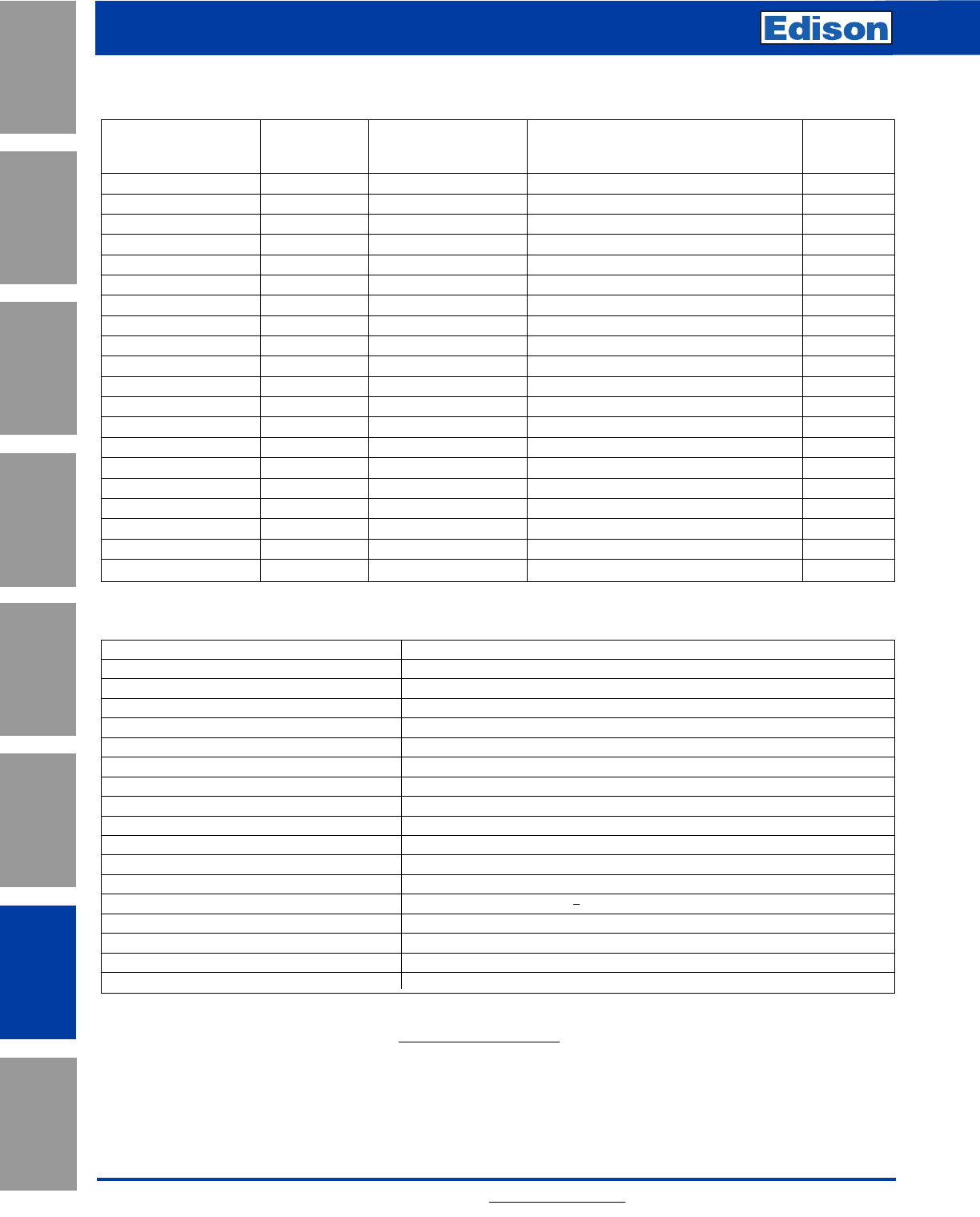
174 For additional information, visit www.edisonfuse.com
Application
Section
Fuse Blocks,
Holders & Misc.
Surge Protective
Devices
Medium
Voltage Fuses
Canadian
Fuses & Holders
Special
Purpose Fuses
UL/CSA Fuses
General Purpose
UL/CSA Fuses
Current Limiting
Surge Protective Devices
SurgePOD™ HEAVY DUTY Technical Information
Nominal Max. Continuous
System Operating AC Connection
Catalog Number Voltage Voltage (MCOV) (VC) System Type Points
SPH50SP1120SN 120V 150V Single-Phase 2 Wire 2
SPH50SP1240SN 240V 320V Single-Phase 2 Wire 2
SPH50SP1347SN 347V 420V Single-Phase 2 Wire 2
SPH50SP2120SNG 120V 150V Single-Phase 2 Wire + G 3
SPH50SP2240SNG 240V 320V Single-Phase 2 Wire + G 3
SPH50SP2347SNG 347V 420V Single-Phase 2 Wire + G 3
SPH50SP2240PN 120/240V 150V Split-Phase 3 Wire 3
SPH50SP2480PN 240/480V 320V Split-Phase 3 Wire 3
SPH50SP3240PNG 120/240V 150V Split-Phase 3 Wire + G 4
SPH50SP3480PNG 240/480V 320V Split-Phase 3 Wire + G 4
SPH50SP3240DLG 240V 320V Three-Phase Delta 3 Wire + G 4
SPH50SP3480DLG 480V 550V Three-Phase Delta 3 Wire + G 4
SPH50SP4240HLG 120/240V 150/320V Three-Phase Highleg Delta 4 Wire + G 5
SPH50SP4480HLG 240/480V 320/550V Three-Phase Highleg Delta 4 Wire + G 5
SPH50SP3208WYG 208V 150V Three-Phase Wye 3 Wire + G 4
SPH50SP3480WYG 480V 320V Three-Phase Wye 3 Wire + G 4
SPH50SP3600WYG†600V 420V Three-Phase Wye 3 Wire + G 4
SPH50SP4208WYNG 208Y/120V 150V Three-Phase Wye 4 Wire + G 5
SPH50SP4480WYNG 480Y/277V 320V Three-Phase Wye 4 Wire + G 5
SPH50SP4600WYNG†600Y/347V 420V Three-Phase Wye 4 Wire + G 5
Specifications (for all SurgePOD HD units) Values
Short Circuit Current Rating (SCCR) 200kA
Nominal Discharge Current (8x20µs) In20kA
Max. Discharge Current (8x20µs) Imax 50kA
Response Time tA<25ns
Frequency 50/60Hz
Operating State/Fault Indication Bi-Color LED - Green (good) / Red (replace)
Conductor Length / Guage 18 inches, 10 AWG Stranded Tinned Copper
Mounting Chase Nipple / Bracket*
Enclosure / Flammability Ratings NEMA 4X - UL 94-5VA
Degree of Protection (Installed State) IP20 (finger-safe)
SPD Install Location Indoor/Outdoor
Circuit Location Lineside or Loadside of service entrance overcurrent protective device
Standard UL 1449 3rd Edition Type 1 Listed SPD
Agency Information cULus, CSA**, RoHS Compliant
Product Warranty 5 Years***
Operating Temperature -40˚C to +85˚C
Maximum Operating Altitude 16,000FT
* Customer-supplied bracket.
** 600V Wye versions not CSA Certified.
*** See SPD Limited Warranty Statement (3A1502) for details at www.cooperbussmann.com/Surge.
SurgePOD™ HEAVY DUTY Technical Information
† 600V Wye versions are not CSA Certified.
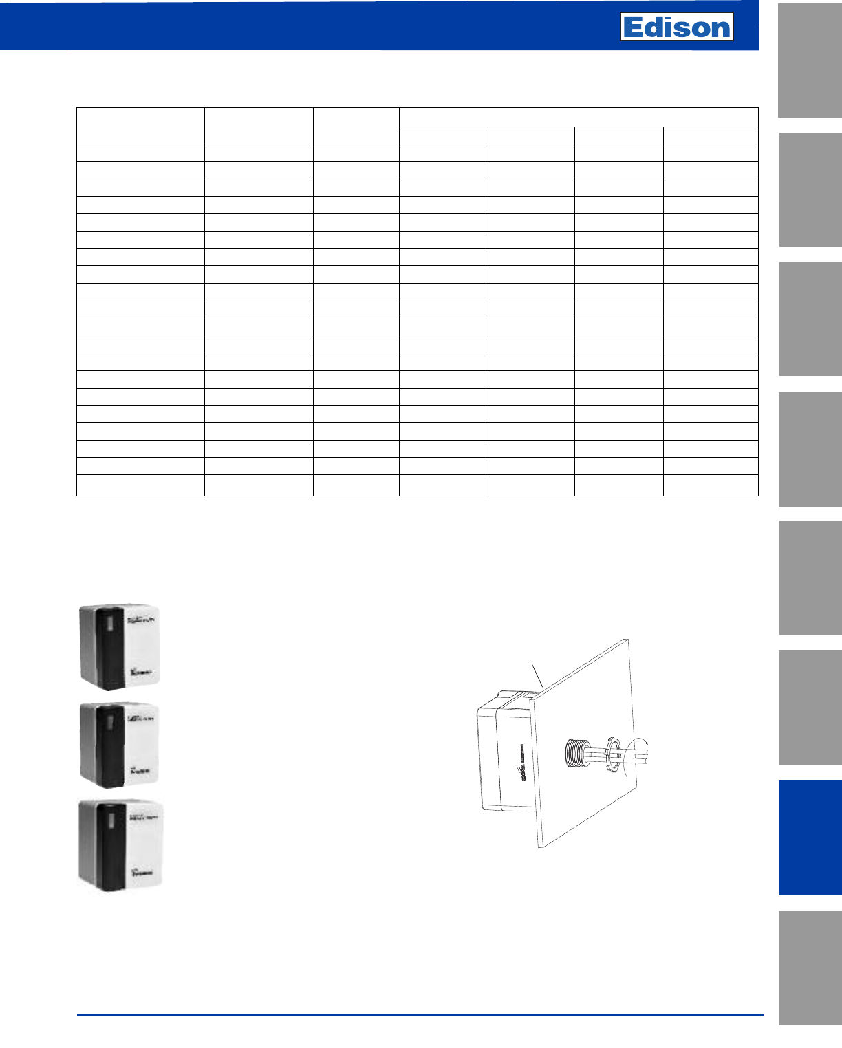
175
For additional information, visit www.edisonfuse.com
UL/CSA Fuses
Current Limiting
UL/CSA Fuses
General Purpose
Special
Purpose Fuses
Canadian
Fuses & Holders
Medium
Voltage Fuses
Fuse Blocks,
Holders & Misc.
Application
Section
Surge Protective
Devices
Surge Protective Devices
Rated System MCOV Voltage Protection Ratings (VPRs)
Catalog Number Voltage (Vo) (VC) L-N L-L L-G N-G
SPH50SP1120SN 120V 150V 700 —— —
SPH50SP1240SN 240V 320V 1200 —— —
SPH50SP1347SN 347V 420V 1500 —— —
SPH50SP2120SNG 120V 150V 700 — 1200 700
SPH50SP2240SNG 240V 320V 1200 — 2500 1200
SPH50SP2347SNG 347V 420V 1500 — 2500 1500
SPH50SP2240PN 120V/240V 150V 700 1200 ——
SPH50SP2480PN 240V/480V 320V 1200 2500 ——
SPH50SP3240PNG 120V/240V 150V 700 1200 1200 700
SPH50SP3480PNG 240V/480V 320V 1200 2500 2500 1200
SPH50SP3240DLG 240V 320V — 2500 1200 —
SPH50SP3480DLG 480V 550V — 3000 1800 —
SPH50SP4240HLG 120/240V 150V/320V 700/1200 1200/2500 1200/2500 700/1200
SPH50SP4480HLG 240/480V 320V/550V 1200/1800 2500/3000 2500/3000 1200/1800
SPH50SP3208WYG 208V 150V — 1200 700 —
SPH50SP3480WYG 480V 320V — 2500 1200 —
SPH50SP3600WYG†600V 420V — 2500 1500 —
SPH50SP4208WYNG 208Y/120V 150V 700 1200 1200 700
SPH50SP4480WYNG 480Y/277V 320V 1200 2500 2500 1200
SPH50SP4600WYNG†600Y/347V 420V 1500 2500 2500 1500
Voltage Protection Ratings (VPRs)
easyID™ LED Status Indicator
The easyID™ LED status indicator will illuminate when the unit is
properly installed and the system or equipment being protected is
energized. The following LED color/status indicates:
GREEN LED = Good
The circuit is energized and protected.
RED LED = Replace
The circuit is energized and unprotected.
The unit needs replacing.
LED is Out / Unlit:
•The circuit is most likely deenergized
• The unit’s leads are disconnected
• The unit is damaged
Authorized personnel should follow all prescribed lockout/tagout and safety procedures in troubleshooting
the cause for the above conditions. Opening SurgePOD HEAVY DUTY enclosure will void UL listing and warranty.
Tighten locknut to
20.3 Lb-In (2.3N•m)
For NEMA 4X installation,
install appropriate customer
supplied gasket between
SurgePOD™ HEAVY DUTY
SPD and enclosure wall.
Mounting
SurgePOD HEAVY DUTY is a panel mount device. It may also
be mounted using a customer supplied bracket or directly onto
a female threaded conduit fitting.
† 600V Wye versions are not CSA Certified.
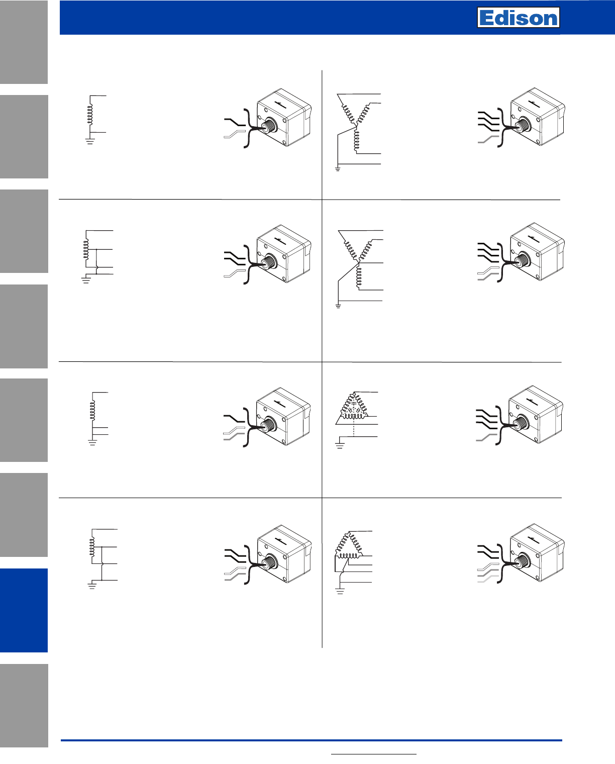
176 For additional information, visit www.edisonfuse.com
Application
Section
Fuse Blocks,
Holders & Misc.
Surge Protective
Devices
Medium
Voltage Fuses
Canadian
Fuses & Holders
Special
Purpose Fuses
UL/CSA Fuses
General Purpose
UL/CSA Fuses
Current Limiting
Surge Protective Devices
Wiring Connections
Black
Black
White
L1 (Black)
L2 (Black)
N (White)
120V (L-N) / 240V (L1-L2),
240V (L-N) / 480V (L1-L2)
Single Phase (Split) Center Tap
SPH50SP2240PN,
SPH50SP2480PN
Black
Black
Green
White
Orange
L3 (Black)
L2 (Orange)
Highleg
L1 (Black)
N (White)
GND (Green)
120V (L1 / L3-N) / 240V (L-L),
240V (L1 / L3-N) / 480V (L-L)
4 Wire Highleg Delta + Ground
SPH50SP4240HLG,
SPH50SP4480HLG
L (Black)
N (White)
Black
White
120, 240, 347V (L-N)
2 Wire
120, 240, 347V (L-N)
2 Wire + Ground
SPH50SP1120SN,
SPH50SP1240SN,
SPH50SP1347SN
L (Black)
N (White)
GND (Green)
Black
Green
White
SPH50SP2120SNG,
SPH50SP2240SNG,
SPH50SP2347SNG
Black
Black
Black
Green
White
GND (Green)
L2 (Black)
N (White)
L3 (Black)
L1 (Black)
SPH50SP4208WYNG,
SPH50SP4480WYNG,
SPH50SP4600WYNG
120V (L-N) / 208V (L-L),
127V (L-N) / 220V (L-L),
277V (L-N) / 480V (L-L),
347V (L-N) / 600V (L-L)
4 Wire Wye + Ground
L1 (Black)
L2 (Black)
L3 (Black)
GND (Green)
SPH50SP3240DLG,
SPH50SP3480DLG
Black
Black
Black
Green
240, 480V (L-L)
3 Wire Delta + Ground
Black
Black
Black
Green
L1 (Black)
L3 (Black)
L2 (Black)
GND (Green)
SPH50SP3208WYG,
SPH50SP3480WYG,
SPH50SP3600WYG
208, 480, 600V (L-L)
3 Wire Wye + Ground
Black
Black
Green
White
L1 (Black)
L2 (Black)
N (White)
GND (Green)
120V (L-N) / 240V (L1-L2),
240V (L-N) / 480V (L1-L2)
Single Phase (Split) Center Tap + Ground
SPH50SP3240PNG,
SPH50SP3480PNG
Must be installed within 10 feet (3m) of a bonded
neutral-ground connection per IEEE C62.41-1991
For installations at or less than 10 feet (3m)
from the transformer.
For installation when located greater than 10 feet (3m) of a
bonded neutral-ground connection.
For installation when located greater than 10 feet (3m)
of a bonded neutral-ground connection.
Single-Phase
Two-Pole with Neutral
Two-Pole with Neutral + Ground
Wye + Ground
Wye with Neutral + Ground
Delta + Ground
Highleg Delta
Single-Phase + Ground
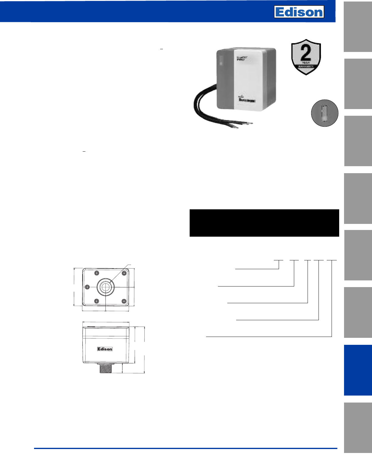
177
For additional information, visit www.edisonfuse.com
UL/CSA Fuses
Current Limiting
UL/CSA Fuses
General Purpose
Special
Purpose Fuses
Canadian
Fuses & Holders
Medium
Voltage Fuses
Fuse Blocks,
Holders & Misc.
Application
Section
Surge Protective
Devices
Surge Protective Devices
2-1/16” 2-1/16”
1-11/16”
1-11/16”
4-1/8”
3-3/16”
4-1/16”
3-3/8”
7/8”
1-1/16” Dia.
NEMA 4X Rated Pro
Type 1 UL Listed SPD
Description
The SurgePOD™ PRO is a Type 1 UL Listed 1449 3rd Edition
surge protective device suitable for installation on both the
loadside or lineside of the service entrance overcurrent
protective device.
Available in popular voltage and system specific versions to
match common residential and light commercial electrical
system and equipment requirements. The SurgePOD PRO
delivers superior surge protection using MOV thermal
disconnect technology that eliminates the need for additional
overcurrent protection.
Parallel connection to the electrical system permits the
SurgePOD PRO SPD to be installed on any ampacity panel.
• Type 1 UL 1449 3rd Edition Listed SPDs are easily selected
and installed on the loadside or lineside of the service
entrance overcurrent protective device
• Voltage specific models precisely match and protect
electrical systems and equipment better than
“one-size-fits-all” SPDs
• Thermal disconnect technology eliminates the need for
additional fusing
• Compact UV resistant NEMA 4X enclosure for indoor or
outdoor applications
•easyID™ LED status indicator provides surge protection
status at a glance
Dimensions - in
SPP40SP1120SN
SPP40SP2240PN
SPP40SP3240DLG
SPP40SP3480DLG
SPP40SP3208WYG
SPP40SP3480WYG
easyID™ LED
Status Indicator
Type 1 SPD Part Number System
SPP 40S PX XXX XXX
SPP = Product Series
Surge Protection PRO
Surge Rating
40S = 40kA max discharge current
No of Wires/Poles
P1 = 1 P2 = 2 P3 = 3 P4 = 4
Rated System Voltage
120, 208, 240, 480Vac
System
SN = Single-Phase 2 Wire, 2 Connection Points
PN = Split-Phase, 3 Wire, 3 Connection Points
DLG = Three-Phase Delta 3 Wire + G, 4 Connection Points
WYG = Three-Phase Wye 3 Wire, 4 Connection Points
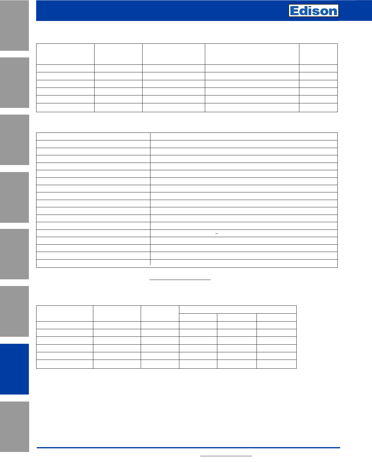
178 For additional information, visit www.edisonfuse.com
Application
Section
Fuse Blocks,
Holders & Misc.
Surge Protective
Devices
Medium
Voltage Fuses
Canadian
Fuses & Holders
Special
Purpose Fuses
UL/CSA Fuses
General Purpose
UL/CSA Fuses
Current Limiting
Surge Protective Devices
Nominal System MCOV Voltage Protection Ratings (VPRs)
Catalog Number Voltage (VC) L-N L-L L-G
SPP40SP1120SN 120V 150V 700 ——
SPP40SP2240PN 120V/240V 150V 700 1200 —
SPP40SP3240DLG 240V 320V — 2500 1200
SPP40SP3480DLG 480V 550V — 3000 1800
SPP40SP3208WYG 208V 150V — 1200 700
SPP40SP3480WYG 480V 320V — 2500 1200
Voltage Protection Ratings (VPRs)
Specifications (for all SurgePOD PRO units) Values
Short Circuit Current Rating (SCCR) 200kA
Nominal Discharge Current (8x20µs) In10kA
Max. Discharge Current (8x20µs) Imax 40kA
Response Time (ns) tA<25ns
Frequency 50/60Hz
Operating State/Fault Indication Bi-Color LED - Green (good) / Red (replace)
Conductor Length / Guage 18 inches, 10 AWG Stranded Tinned Copper
Mounting Chase Nipple / Bracket*
Enclosure / Flammability Ratings NEMA 4X - UL 94-5VA
Degree of Protection (Installed State) IP20 (finger-safe)
SPD Install Location Indoor/Outdoor
Circuit Location Lineside or Loadside of service entrance overcurrent protective device
Standard UL 1449 3rd Edition Type 1 Listed SPD
Agency Information cULus, RoHS Compliant
Product Warranty 2 Years**
Operating Temperature -40˚C to +65˚C
Maximum Operating Altitude 12000FT
* Customer-supplied bracket.
** See SPD Limited Warranty Statement (3A1502) for details at www.cooperbussmann.com/Surge.
SurgePOD™ PRO Technical Information
Nominal Max. Continuous
System Operating AC Connection
Catalog Number Voltage Voltage (MCOV) (VC)System Type Points
SPP40SP1120SN 120V 150V Single-Phase 2 Wire 2
SPP40SP2240PN 120/240V 150V Split Phase 3 Wire 3
SPP40SP3240DLG 240V 320V Three-Phase Delta 3 Wire + G 4
SPP40SP3480DLG 480V 550V Three-Phase Delta 3 Wire + G 4
SPP40SP3208WYG 208V 150V Three-Phase Wye 3 Wire + G 4
SPP40SP3480WYG 480V 320V Three-Phase Wye 3 Wire + G 4
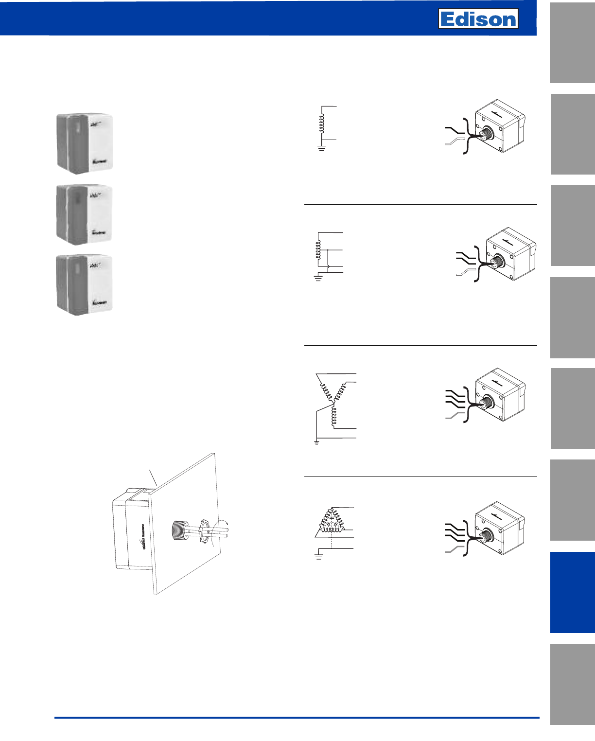
179
For additional information, visit www.edisonfuse.com
UL/CSA Fuses
Current Limiting
UL/CSA Fuses
General Purpose
Special
Purpose Fuses
Canadian
Fuses & Holders
Medium
Voltage Fuses
Fuse Blocks,
Holders & Misc.
Application
Section
Surge Protective
Devices
Surge Protective Devices
Wiring Connections
L (Black)
N (White)
Black
White
120V (L-N)
2 Wire
SPP40SP1120SN
L1 (Black)
L2 (Black)
L3 (Black)
GND (Green)
SPP40SP3240DLG,
SPP40SP3480DLG
Black
Black
Black
Green
240, 480V (L-L)
3 Wire Delta + Ground
Black
Black
Black
Green
L1 (Black)
L3 (Black)
L2 (Black)
GND (Green)
SPP40SP3208WYG,
SPP40SP3480WYG
208, 480V (L-L)
3 Wire Wye + Ground
Must be installed within 10 feet (3m) of a bonded
neutral-ground connection per IEEE C62.41-1991
Single-Phase
Wye + Ground
Delta + Ground
easyID™ LED Status Indicator
The easyID™ LED status indicator will illuminate when the unit is
properly installed and the system or equipment being protected is
energized. The following LED color/status indicates:
GREEN LED = Good
The circuit is energized and protected.
RED LED = Replace
The circuit is energized and unprotected.
The unit needs replacing.
LED is Out / Unlit:
•The circuit is most likely deenergized
• The unit’s leads are disconnected
• The unit is damaged
Authorized personnel should follow all
prescribed lockout/tagout and safety
procedures in troubleshooting the cause for
the above conditions. Opening SurgePOD
PRO enclosure will void UL listing and
warranty.
Tighten locknut to
20.3 Lb-In (2.3N•m)
For NEMA 4X installation,
install appropriate customer
supplied gasket between
SurgePOD™ PRO
SPD and enclosure wall.
Mounting
SurgePOD PRO is a panel mount device. It may also be
mounted using a customer supplied bracket or directly onto a
female threaded conduit fitting.
Black
Black
White
L1 (Black)
L2 (Black)
N (White)
120V (L-N) / 240V (L1-L2),
Single Phase (Split) Center Tap
SPP40SP2240PN,
For installations at or less than 10 feet (3m)
from the transformer.
Two-Pole with Neutral

180 For additional information, visit www.edisonfuse.com
Application
Section
Fuse Blocks,
Holders & Misc.
Surge Protective
Devices
Medium
Voltage Fuses
Canadian
Fuses & Holders
Special
Purpose Fuses
UL/CSA Fuses
General Purpose
UL/CSA Fuses
Current Limiting
Elements of a Practical Fuse Specification
General:
The contractor shall install UL “Listed” fuses of the correct
UL Class, type and ampere ratings in switches or place in
spare fuses cabinet(s) as indicated on the plans and/or as
specified below. All installed and spare fuses shall be in
their original new, clean, dry and unused condition when
installed and when placed in a spare fuses cabinet(s). The
contractor shall thoroughly clean, mechanically check and
electrically test, as required, all equipment and components
before installing fuses and energizing.
UL Class L bolt-on fuses rated 601 to
6000A:
To mount UL Class L fuse types and amps ratings as
shown on the plans, use stainless steel bolts of correct
number, diameter and length, stainless steel spring washers
on each side of the bolt and stainless steel nuts. The nuts
shall be tightened to the torque recommended by ASTM
Standards for the bolt size used. The bolts shall have the
largest diameter that will fit the bolt holes and length to
allow full nut thread engagement. Bolts shall be installed in
each fuse mounting hole or slot. Class L fuses shall have
silver links. The quality benchmark for Class L fuses shall
be Edison Fusegear Catalog Symbol LCL time-delay type or
Catalog Symbol LCU fast-acting type as shown on the
plans. Edison Class L fuses are quality engineered and
constructed, using Statistical Process Control, for foolproof
filler retention without “O” rings, and do not expel gases.
UL Class R fuses rated up to 600A:
UL Class RK1 dual element, time-delay fuse type and
ratings shall be installed in Class R switches as shown on
the plans. Class RK1 dual element fuses shall not use
springs in the overload elements in ratings 70A and larger;
they shall have non-ferrous end caps for energy efficiency.
The quality benchmark for Class RK1 dual element fuses
shall be Edison Catalog Symbol LENRK(AMP)(250V) or
LESRK(AMP) (600V).
UL Class J fuses rated up to 600A and
300V Class T fuses rated 35 to 800A:
Protection of circuit breakers requires the use of Class J or
Class T fuses as shown on the plans. These fuse Classes
are not interchangeable with fuses having less current
limiting ability. The quality benchmark for these fuses shall
be Edison Catalog Symbol JFL (Class J fast acting type) or
Catalog Symbol TJN (300V Class T fast acting type).
Fuse classes, types and ratings:
All fuses have been specified as to UL Class, type, volts
and amp rating on the plans when the project was
engineered. No fuse types or ratings will be changed in the
field without approval from the project design engineer.
Generally, the fuse types commonly specified are Class L
time-delay type, Class RK1 dual element type and Class J
fast-acting type. Class L fast-acting, Class RK1 fast-acting
and 300V Class T fast-acting fuses may be specified for
special conditions.
Interchangeability of specified fuses:
The fuse brand specified is the quality benchmark and is
preferred. All installed and spare fuses shall be both
electrically and physically interchangeable with the same
specific Classes, types and ratings of any other brand of
fuses that are UL “Listed” per the appropriate UL Standard
for safety without creating a safety hazard for the public
and/or building occupants. Otherwise, a fuse-protected
power distribution system design can not meet the require-
ments of good engineering practice, as applied during the
design of this project, and can not meet the requirements of
the National Electrical Code®during the life of the
installation. The contractor shall place an instruction label
inside the door of each switch (do not cover other
instructions) identifying the UL Class, Type, Volts and Amp
rating oforiginally installed fuses.
Spare fuses:
A metal spare fuse cabinet(s) shall be provided as required,
surface mounted, with lockable handle. 10% of each type
and rating of installed fuses shall be duplicated as spare
fuses, or a minimum of 3 fuses of each type and rating, and
placed in a Edison Catalog Symbol ESFC spare fuse
cabinet(s) and locked.
Engineering plans and specifications:
A copy of the pertinent sheets of the plans and the pages of
specifications pertaining specifically to installed fuses
information shall be placed inside one of the Edison Catalog
Symbol spare fuse cabinets for maintenance reference
purposes.
Low Voltage (600V or Less) Fuse Specification:

181
For additional information, visit www.edisonfuse.com
UL/CSA Fuses
Current Limiting
UL/CSA Fuses
General Purpose
Special
Purpose Fuses
Canadian
Fuses & Holders
Medium
Voltage Fuses
Fuse Blocks,
Holders & Misc.
Application
Section
Surge Protective
Devices
Fuse Terminology
Ambient Temperature*
The temperature of the air surrounding the fuse.
Arcing Time
The amount of time that passes from the instant the fuse
element or link has melted until the overcurrent is interrupted or
cleared.
Asymmetrical Current
Refer to ALTERNATING CURRENT. A-C current is
asymmetrical when the loops about a zero axis are unequal
(offset). This condition is usually associated with the first five or
less cycles of fault current flow in a circuit that has inductive
reactance. All power distribution systems have a variable
amount of inductive reactance.
Body*
The part of the fuse which encloses the fuse elements and
supports the contacts. Also referred to as cartridge, tube or
case.
Bolted Fault
This refers to a zero impedance fault considered at locations in
a power system where the maximum value of available fault
current is calculated.
Bridge
The specially designed narrow portion of a fuse link that heats
fastest under overcurrent conditions to open first.
Cartridge Fuse*
A fuse consisting of a current responsive element inside a fuse
body with contacts on both ends.
Cartridge Size*
The range of voltage and ampere ratings assigned to a
cartridge of specific dimensions and shape.
Clearing I2t (Ampere Squared Seconds)*
The measure of heat energy developed as a result of current
flow between the time that current begins to flow and until the
fuse clears the circuit. “I2” stands for the square of the effective
let-through current and “t” stands for the time of current flow in
seconds. The term I2t also applies during the melting or arcing
portions of the clearing time and is referred to as melting or
arcing I2t respectively. Clearing I2t is the sum of melting I2t and
arcing I2t.
Clearing Time
This is the total opening time of a fuse from the occurrence of
an overcurrent until the fuse stops current flow. This is the sum
of link melting and arcing time.
Contacts*
The external metallic parts of the fuse used to complete the
circuit. Also referred to as ferrules, caps, blades or terminals.
Current Limitation
A fuse provides current limitation when the link melts under
short-circuit conditions to interrupt the current flow before the
peak of the first one-half cycle of prospective current and the
current flow is stopped within one-half cycle.
Current-Limiting Fuse*
A fuse that meets the following three conditions: 1) interrupts all
available overcurrents within its interrupting rating; 2) within its
current-limiting range, limits the clearing time at rated voltage to
an interval equal to, or less than, the first major or symmetrical
current loop duration; and 3) limits peak let-through current to a
value less than the available peak current.
Current-Limiting Range*
A range of available currents from the threshold current to the
interrupting current rating of a fuse.
Current Rating*
The A-C or D-C ampere rating which the fuse is capable of
carrying continuously under specified conditions.
Delay
This refers to intentional “delay” designed into the overload
range operation of a fuse and is meaningless except as defined
by a fuse manufacturer. Other words used to indicate delay but
not UL defined may be “Time-Lag”, “Delay Type”, etc..
Dual Element Fuse
The words “Dual Element” and “Time-Delay” appear on the
labels of Class R fuses to indicate that the fuse has UL defined
delay in the overload operation range of a minimum of 10
seconds at 500% of the fuse amperes rating. A “Dual Element”
fuse has separate overload and short-circuit elements and is
considered a “true time-delay fuse” design as opposed to other
types of construction to obtain delay.
Effective Current (Ie)
“Effective” and “RMS” both refer to the heating effect value of
an A-C current equivalent to a steady flow of a D-C current.
“Effective let-through amperes” (Ie) refers to the heating effect
value of the current allowed to flow during the clearing of a
short-circuit current.
Eutectic Alloy
This is an alloy of lead, tin and other metals that, by
metallurgical definition, changes from a solid directly to a liquid
when its melting point is reached. This alloy is used in Edison
Class R fuses for dependable overload element operation.
Fast-Acting Fuse
This is a fuse with no intentional time-delay designed into the
overload range. Sometimes referred to as a “single element
fuse” or “non-delay fuse”.
Fault Current
Short-circuit current that flows partially or entirely outside the
intended normal load current path of a circuit or component.
Values may be from hundreds to many thousands of amperes.
Ferrule
The cylindrical brass, bronze or copper mounting terminals of
fuses with amps ratings up to 60 amperes. The cylindrical
terminals at each end of a fuse fit into fuse clips.
Filler*
A material used to fill a section or sections of a fuse which aids
in arc extinction.
Fuse*
A protective device which opens by the melting of a current
sensitive element during specified overcurrent conditions.
Heat Sink
A mass of metal, usually copper or a eutectic alloy, used in the
overload element of Class R fuses to provide accurate time
delay by absorbing heat from an overload current flow through
a fuse.
High Rupturing Capacity (HRC)
HRC is used by Canadian and British Standards as an
equivalent to the U.S. interrupting rating of a fuse. HRC must
be at least 100,000 amperes.
*From ANSI/ NEMA FU1-86

182 For additional information, visit www.edisonfuse.com
Fuse Terminology
Application
Section
Fuse Blocks,
Holders & Misc.
Surge Protective
Devices
Medium
Voltage Fuses
Canadian
Fuses & Holders
Special
Purpose Fuses
UL/CSA Fuses
General Purpose
UL/CSA Fuses
Current Limiting
I2t (Amperes Squared Seconds)
This is a value obtained by multiplying an effective current
squared by the time of flow of the current in seconds. It is not a
heat energy value, but represents heat energy for comparison
purposes. Some common uses are to determine fuse selectivity
and to select current limiting fuses that will limit this value to be
compatible with the withstandability of semi-conductors that
have an I2t rating.
Interrupting Rating*
A rating based upon the highest rms alternating current or
direct current which the fuse is required to interrupt under
specific conditions.
Knife Blade
A flat copper mounting blade (terminal) at each end of fuses
rated 70 through 6000 amperes. Knife blades may be mounted
in fuse clips or bolted in place via blade holes, depending on
the fuse type.
Limiter
Limiters have internal construction like fuses but provide only
short-circuit protection and no overload protection. They are
intended for special applications such as Cable Limiters and
Welder Limiters.
Link
The fusible portion of the fuse which melts, or reacts by other
means, to clear the circuit during an overcurrent condition. Also
referred to as an element.
Magnetic Stress
When thousands of amps of short-circuit current flows through
equipment and conductors, strong magnetic fields are
developed that may cause serious damage unless adequate
physical bracing is applied. Force is proportional to the value of
peak current squared. This force is usually reduced by current
limiting fuses as compared to other overcurrent protective
devices.
Maximum Energy*
A condition under which, in a specified time, the maximum
amount of heat possible is generated in the fuse before
clearing.
Melting Time*
The time from the initiation of an overcurrent to the instant
arcing begins inside a fuse.
Nonrenewable Fuse*
A fuse which cannot be restored for service after operation.
Normal Frequency Recovery Voltage*
The normal frequency rms voltage impressed upon the fuse
after the circuit has been interrupted and after high frequency
transients have subsided.
One-Line Diagram
An electrical diagram that shows one line to represent two or
more conductors for simplification.
One-Time Fuse
A term used to identify a non-renewable Class H fuse as
opposed to a Class H fuse with replaceable Iinks. See
“non-renewable fuse”.
Overcurrent*
Any current in excess of the fuse current rating.
Overload
A value of overcurrent usually considered to be up to about 10
times the ampere rating of an overcurrent protection device or
circuit ampere rating.
Peak Arc Voltage*
The maximum peak voltage across the fuse during the arcing
time.
Peak Let-Through Current (Ip)*
The maximum instantaneous current through a fuse during
interruption in its current-limiting range.
Rating*
A designated limit of operating characteristics based on definite
conditions.
Rejection Feature*
The physical characteristic of a fuse and fuseholder (slot,
groove pin or overall dimension) which prevents substitution by
other classes of fuses.
Renewable Fuse*
A fuse which can be readily restored for service after operation
by the replacement of the renewal elements.
Renewal Element (Renewal Link)*
That part of a renewable fuse that is replaced after each
interruption to restore the fuse to operating condition.
Short-Circuit Current
Refer to Fault Current.
Single-Element Fuse
Refer to Fast-Acting Fuse.
Supplemental Fuse (UL)
A UL fuse class per Standard 198G that defines certain small
fuses not intended for branch circuit protection.
Thermal Stress
Heat builds up in equipment and conductors during the time of
overcurrent flow that may cause thermal stress and potential
thermal (heat) damage if overcurrent protection devices do not
operate fast enough.
Threshold Current*
The minimum rms symmetrical available current of the current-
limiting range, where melting of the fuse element occurs at
approximately 90 degrees on the symmetrical current wave,
and total clearing time is less than one-half cycle.
Threshold Ratio*
The threshold current divided by the fuse current rating.
Time-Delay Fuse*
A fuse capable of carrying a specific overcurrent for a minimum
time.
Total Clearing Time*
Refer to Clearing Time.
Voltage Rating*
The maximum rms ac voltage or the maximum dc voltage at
which the fuse is designed to operate.
*From ANSI/NEMA FU1-86
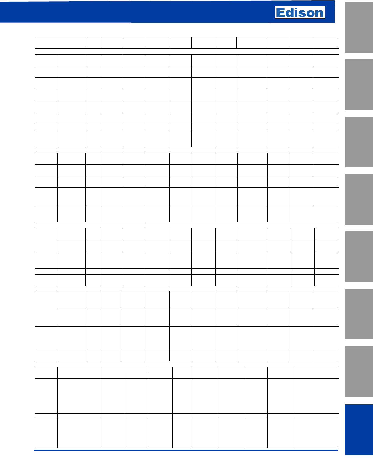
183
Cross Reference
For additional information, visit www.edisonfuse.com
UL/CSA Fuses
Current Limiting
UL/CSA Fuses
General Purpose
Special
Purpose Fuses
Canadian
Fuses & Holders
Medium
Voltage Fuses
Fuse Blocks,
Holders & Misc.
Application
Section
Surge Protective
Devices
CROSS REFERENCE GUIDE
BRUSH/ GEC/
VOLT EDISON DORMAN CEFCO MERSEN LITTELFSE. FUSETEK SIEMENS NORAM AEROFLEX
UL CLASS CURRENT LIMITING FUSES (CSA CLASS)
RK1 Fast Acting 250 NCLR NCLR C-HG A2KR, HNR KLNR RHN ——HB
(HRCI-R) 600 SCLR SCLR C-HR A6KR, HSR KLSR RHS ——HA
RK1 Time Delay 250 LENRK LENRK LON-RK A2D-R LLNRK ——2R-D —
(HRCI-R) 600 LESRK LESRK LOS-RK A6D-R LLSRK ——6R-D —
RK5 Time Delay 250 ECNR ECNR CRNR TRNR, TR FLN-R RDN ———
(HRCI-R) 600 ECSR ECSR NRSR TRSR,TRS FLS-R IDSR RDS ———
LFast Acting 600 LCU LCU CL, CLU A4BQ — LFA — 6L-F L8, L12
(HRCI-L) Time Delay 600 LCL LCL CLL A4BY,A4BT KLPC, KLLU ——6L-D L16, L20
JFast Acting 600 JFL JCL, CJ C-J A4J, CJ JLS JFC 3NW2-71- 6J-F JA
(HRCI-J) Time Delay 600 JDL ——AJT JTD ——J-D —
TFast Acting 300 TJN TJN — A3T JLLN ————
(HRCI-T) 600 TJS TJS — A6T JLLS ————
GTime Delay 480 SEC ——AG5 SLC ————
CC Time Delay 600 EDCC ——ATDR CCMR ——6M-S —
(HRCI-CC) Time Delay 600 HCTR ——ATQR KLDR ——6CC-S —
Fast Acting 600 HCLR HCLR CTK-R ATMR KLKR FLKR — 6CC-F —
UL CLASS GENERAL PURPOSE FUSES
HFast Acting 250 KON KON 50KOTN OTN NLN OFN ———
and K5 600 KOS KOS 50KOTS OTS NLS OFS ———
HTime Lag 250 ERN ERN — RFN RLN ————
Renewable 600 ERS ERS — RFS RLS ————
HFuse Links 250 ELNE ELN — RLN LKN ————
Renewable (1-60A) 600 ELS ELS — RLS LKS ————
600 MCL MCL CTK ATM KLK FLK — 6M-S —
Midget Fast Acting 600 EBS EBS — SBS BLS ——6N-F —
250 MOL MOL — OTM BLF FLF ———
500 MEQ MEQ — ATQ FLQ ————
Midget Time Delay 250 MEN MEN — TRM FLM FRM ———
125/250 MID MID — GFN FLA ————
CANADIAN FUSES
Code/ One Time 250 KON/PONC KON/PON 50KOTN NRN OTN NLN OFN ———
Standard 600 KOS KOS 50KOTS NRS OTS NLS OFS ———
10K AIR Time Delay 250 CDNC CDN — CRN FLN ODN ———
600 CDSC CDS — CRS FLS ODS ———
TYPE K Offset CIH07 CIH07 C-K ESK —— — — —
Class C Blade 600 CIK07 CIK07 C-K ESK —— — — —
CIL14 CIL14 C-K ESK —— — — —
HRCI-CA Fast Acting 600 CIF21 CIF21 C-N MS ——3NWOMFS2 6CA-F —
HRCI-CB Fast Acting 600 CIF06 CIF06/NK CNS GNS — NIC 3NWOMFS1 6CB-F —
EK EK CES ——— — — —
HRC-II FUSES
Offset H07C H07C, AAO CIA FES,GIA — 2CO 3NW2-11 6C-F 932
Blade 600 K07C K07C, BAO CIS FES, GIS — 2CO 3NW2-12 6C-F 933
HRC-II-C L14C L14C, CEO CCP FES, GCP — 2CO 3NW2-13 6C-F 944
Center M09C M09C, DD CF FESC, GF — 2CC 3NW2-23 6C-F 965
Blade 600 P11C P11C, EF CM FESC, GM — 2CC 3NW2-31 6C-F 976
R11C R11C, FF CLM FESC, GLM — 2CC 3NW2-34 6C-R 977
Offset K07CR K07CR, OSD ———— — — —
HRC-II Center 600 L09C L09C, CD CC FESC, GC — 2CM 3NW2-22 — 964
MISC Offset M14C M14C, DEO CFP FES, GFP — 2CM 3NW2-14 — 945
Center P09C P09C, ED CMF FESF, GMF — 2CM 3NW2-25 — 966
Miniature Offset 600 CIF21 F21, NITD NIT GIT — N2B ———
Blade CIF06 F06,NSD,NSC NS NSG — N2C ———
SMALL DIMENSION FUSES
EDISON GEC/
Size Description new old BRUSH CEFCO MERSEN LITTELFSE. FUSETEK NORAM
Time Delay, Glass GDC BDC BDC CMB GDG 218 SD6 SE-S
Fast Acting, Glass GMA BMA BMA CMA GGM 235 MQ4 SE-F
5 x 20mm Fast Acting, Glass GDB BDB BDB — GSB 217 ——
Fast Acting, Glass GDA ——— — 216 ——
Time Delay, Glass GMC ———GSC ———
Time Delay, Glass GMD ———GSC 239 ——
1/4 x 1" Fast Acting, Glass AGX BGX BGX 8AG GGX 361/2 SL4 —
Fast Acting, Glass AGC BGC BGC 3AG GGC 312 SS2/SS6 SU-F
Fast Acting, Cer. ABC BBC BBC 3AB GAB 314 CES14 —
1/4 x 1-1/4" V Fast Acting, Cer. GBB ——— — 322 ——
Time Delay, Glass MDL BDL BDL 3AG-SB GDL 313 SD4 SU-S
Time Delay, Cer. MDA BDA —— GSA 326 ——
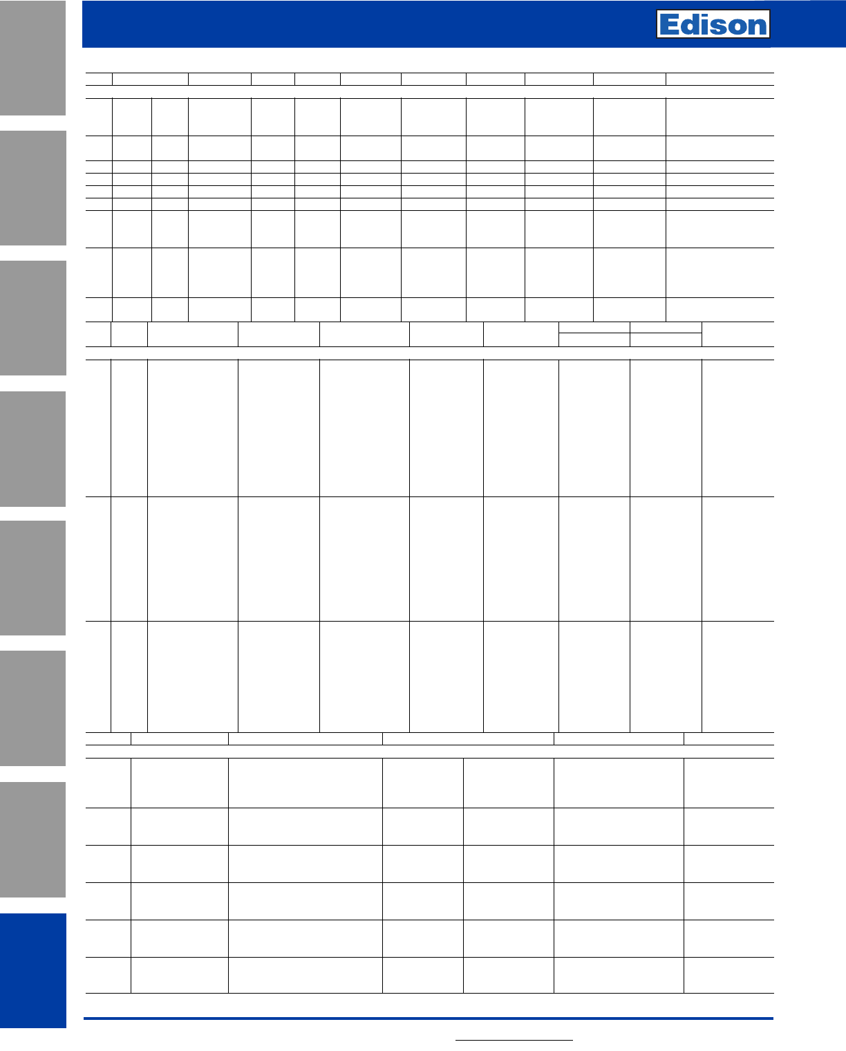
184
Cross Reference
For additional information, visit www.edisonfuse.com
Application
Section
Fuse Blocks,
Holders & Misc.
Surge Protective
Devices
Medium
Voltage Fuses
Canadian
Fuses & Holders
Special
Purpose Fuses
UL/CSA Fuses
General Purpose
UL/CSA Fuses
Current Limiting
CROSS REFERENCE GUIDE
KV DIMENSIONS EDISON GEC MERSEN B & S CGE GE WESTINGHOUSE WESTINGHOUSE
POTENTIAL TRANSFORMER FUSES (FERRULE MOUNTING)
3.6 5.6" 1" 3.6ABWNA ——OMBNN —— — —
5.5 5.6" 1" 5.5ABWNA — A500T OMBNN —— — —
5.5 5.6" 13/16" 5.5AMWNA — A480T ——— —
7.2 5.6"1" 7.2ABWNA VTF6.6 — OMBNN —— — —
7.2 7.69"1" 7.2ABCNA VTF11 — OMDNN —— — —
12.0 7.69"1" 12ABCNA VTF11 — OMDNN —— — —
15.5 10.00"1" 15.5ABFNA VTF15 — OMFNN —— — —
17.5 14.13"1" 17.5ABGNA ——OMGNN —— — —
24.0 14.13"1
"24ABGNA ——OMGNN —— — —
5.5CAVH0.5E ——FC464-0.5E 328L497-G7 —— —
5.5 7.375" 1.63" 5.5CAVH1E ——FC464-1E 328L497-G8 —— —
5.5CAVH2E ——FC464-2E 328L497-G9 —— —
15.5CAVH0.5E ——FC467-0.5E 328L497-G19 9F60BHH905 758C433A21 677C452G03
15.5 12.87" 1.63" 15.5CAVH1E ——FC467-1E 328L497-G20 9F60BHH001 758C433A26 677C452G08
15.5CAVH2E ——FC467-2E 328L497-G21 —— —
15.5CAVH3E ——FC467-3E 328L497-G22 ——
38.0 17.32" 1.63" 38CAVH0.5E ——SCA22-.0.5E —— 758C433A22 677452G04
38CAVH1E ——SCA22-.1E —— 758C433A24 677452G09
EDISON EDISON/BRUSH MERSEN CGE CGE
KV BODIES new old new MERSEN WESTINGHOUSE new old
MEDIUM VOLTAGE DISTRIBUTION FUSES (N.A. DIMENSIONS)
1MV055F1DAX30E 5.5FFNHA 30E A055F1DORO-30E A550X30E-1 151D978 G01 9F60FJD 030 6193406 G11
1MV055F1DAX40E 5.5FFNHA 40E A055F1DORO-40E A550X40E-1 ——6193406 G12
1 MV055F1DAX50E 5.5FFNHA 50E A055F1DORO-50E A550X50E-1 151D978 G02 9F60FJD 050 6193406 G13
1 MV055F1DAX65E 5.5FFNHA 65E A055F1DORO-65E A550X65E-1 151D978 G03 9F60FJD 065 6193406 G14
1 MV055F1DAX80E 5.5FFNHA 80E A055F1DORO-80E A550X80E-1 151D978 G04 9F60FJD 080 6193406 G15
5.5 1 MV055F1DAX100E 5.5FFNHA 100 A055F1DORO-100E A550X100E-1 151D978 G05 9F60FJD 100 6193406 G16
1MV055F1DAX150E 5.5FFNHA 150 A055F1DORO-150E A550X150E-1 151D978 G07 9F60HJD 150 6193406 G18
1 MV055F1DAX200E 5.5FFNHA 200 A055F1DORO-200E — 151D978 G08 9F60HJD 200 6193406 G19
2 MV055F2DAX250E 5.5FFNHK 250 A055F2DORO-250E A550X250E-1 151D978 G11 9F60GJC 250 178L611 G12
2 MV055F2DAX300E 5.5FFNHK 300 A055F2DORO-300E A550X300E-1 151D978 G12 9F60GJC 300 178L611 G14
2 MV055F2DAX400E 5.5FFNHK 400 A055F2DORO-400E A550X400E-1 151D978 G13 9F60GJC 400 178L611 G18
1 JDZ-20E 8.25FFNHA 20E — A825X20E-1 — 9060FJE 020 6193481 G9
1 JDZ-25E 8.25FFNHA 25E — A825X25E-1 — 9060FJE 025 6193481 G10
1 JDZ-30E 8.25FFNHA 30E — A825X30E-1 677C573 G01 9060FJE 030 6193481 G11
1 JDZ-40E 8.25FFNHA 40E — A825X40E-1 677C573 G02 9060FJE 040 6193481 G12
1 JDZ-50E 8.25FFNHA 50E — A825X50E-1 677C573 G03 9060FJE 050 6193481 G13
8.25 1 JDZ-65E 8.25FFNHA 65E — A825X65E-1 677C573 G04 9060FJE 065 6193481 G14
1 JDZ-80E 8.25FFNHA 80E — A825X80E-1 677C573 G05 9060FJE 080 6193481 G15
2 JDZ-100E 8.25FFNHK 100E —————
2 JDZ-150E 8.25FFNHK 150E — A825X150E-1 — 9060HJE 150 6193481 G18
2 JDZ-200E 8.25FFNHK 200E — A825X200E-1 — 9060HJE 200 6193481 G19
1 MV155F1DBX15E 15.5FFVHA 15E A155F1DORO-15E A1550X15E-1 — 9060FMH 015 6193496 G8
1 MV155F1DBX20E 15.5FFVHA 20E A155F1DORO-20E A1550X20E-1 — 9060FMH 020 6193496 G9
1 MV155F1DBX25E 15.5FFVHA 25E A155F1DORO-25E A1550X25E-1 — 9060FMH 025 6193496 G10
1 MV155F1DBX30E 15.5FFVHA 30E A155F1DORO-30E A1550X30E-1 — 9060FMH 030 6193496 G11
15.5 1 MV155F1DBX40E 15.5FFVHA 40E A155F1DORO-40E A1550X40E-1 — 9060FMH 040 6193496 G12
1 MV155F1DBX50E 15.5FFVHA 50E A155F1DORO-50E A1550X50E-1 — 9060FMH 050 6193496 G13
1 MV155F1DBX65E 15.5FFVHA 65E A155F1DORO-65E —— ——
2 MV155F2DBX100E 15.5FFVHK 100E A155F1DORO-100E A1550X100E-1 — 9060FMH 100 6193496 G16
2 MV155F2DBX150E 15.5FFVHK 150E A155F1DORO-150E —— ——
AMPS MOUNTING EDISON OLD BRUSH GEC FUSETEK
FUSEHOLDERS (600V)
Front CM20CF CIF15F CIF15A CRS15H MF20F
30 Front/2 Pole 2xCM20CF —— C2RS15H —
Back CM20CF + 2 of 30BS CF15BS CIF15B ——
Front/Back CM20CF +1 of 30BS CIF15FBS CIF15C ——
Front CM630CF C30AF CCH30A C30H or CFR30H MF30F
30 Back CM30CF + 2 of 20BS C30ABS CCH30B C30P MF30B
Front/Back CM30CF + 1 of 20BS C30AFBS CCH30C C30PH MF30FB
Front CM60CF C60BF CCK60A C60H or CRS60H MF60F
60 Back CM60CF + 2 of 60/100BS C60BBS CCK60B C60P MF60B
Front/Back CM60CF + 1 of 60/100BS C60BFBS CCK60C C60PH MF60FB
Front CM100CF C100CF CCL100A C100H or CRS100H MF100F
100* Back CM100CF + 2 of 60/100BS C100BS CCL100B C100P MF100B
Front/Back CM100CF + 1 of 60/100BS C100FBS CCL100C C100PH MF100FB
Front C30F C30F — CSC30H MD30F
30 Back C30BS C30BS — CSC30P MD30B
Front/Back C30FBS C30FBS —— MD30FB
Front C60F C60F — CSC60H —
60 Back C60BS C60BS —— —
Front/Back C60FBS C60FBS —— —
NOTE: This Cross Reference is a general guide based on dimensions and fuse type. Fuse characteristics can vary between manufacturers and should be evaluated for critical applications. *Edison uses compact
fuse.
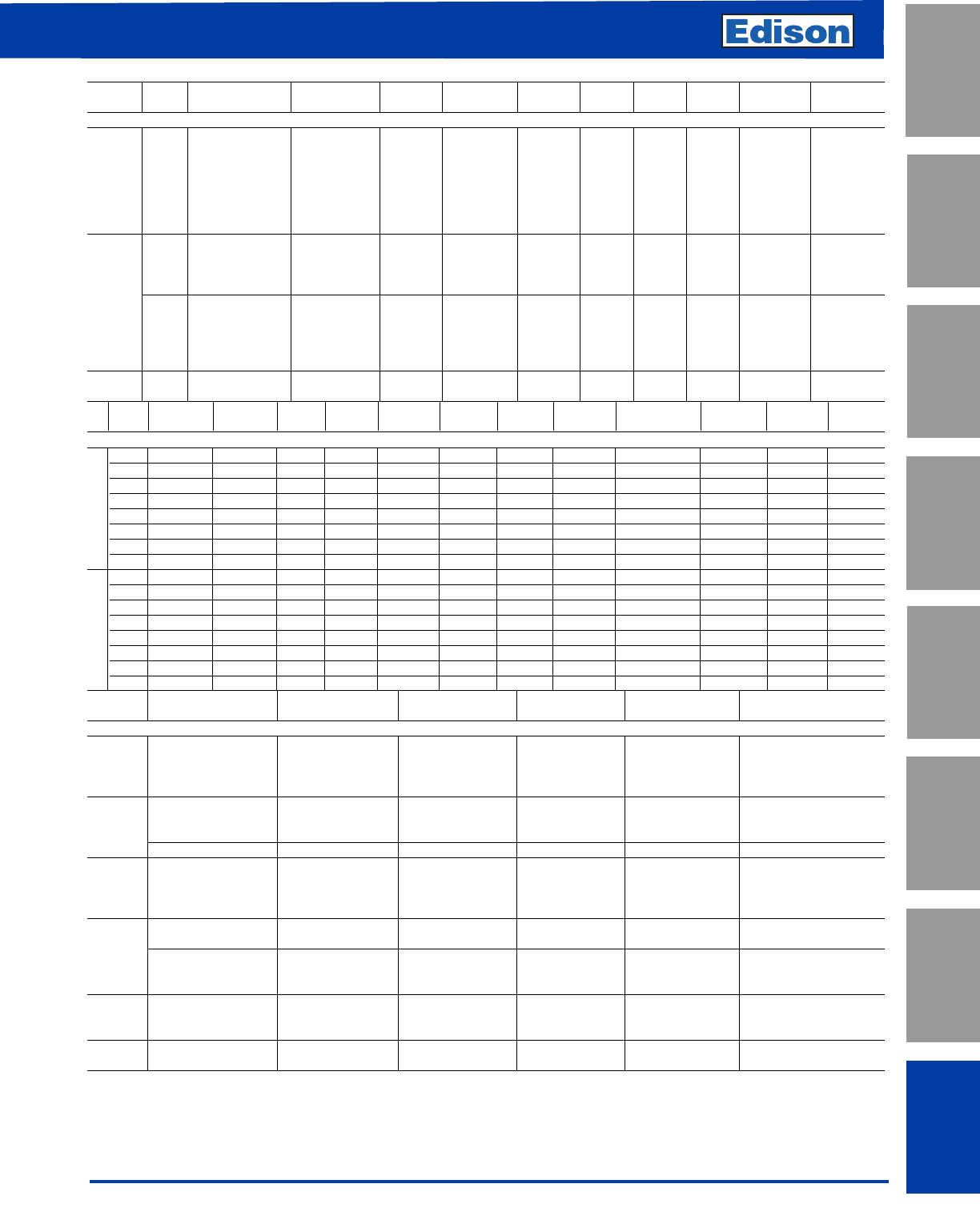
185
For additional information, visit www.edisonfuse.com
Cross Reference
UL/CSA Fuses
Current Limiting
UL/CSA Fuses
General Purpose
Special
Purpose Fuses
Canadian
Fuses & Holders
Medium
Voltage Fuses
Fuse Blocks,
Holders & Misc.
Application
Section
Surge Protective
Devices
CROSS REFERENCE GUIDE
NEW OLD OLD RELIANCE/
FUSE VOLT EDISON EDISON BRUSH BRUSH GEC/CEFCO GOULD IR FERRAZ FUSETEK LITTELFUSE
SEMICONDUCTOR FUSES
130/150 FWA E13S, E15SF, E15S XL-SF13X RFA CSF-15X A13X SF13X A013FA RF13X L15S, KLW, KLA
250 FWX E25S, E25SF XL25X RFN CSF25X A25X SF25X AO25FA RF25X L25S, KLB
USA 500 FWH E50S, E50SF XL50F RFV CSF50P A50P SF50P AO50FA RF50X L50S, KLH
Dimensions 600 KBC E60S, E60SF XL60X RFS CSF60X A60X SF60X AO60FA RF60X L60S
600 KAC E60C XL60C RFC — A60X-4K SF60C — ——
700 FWP E70S, E70SF XL70F RFL CSF70P A70P SF70P AO70FA RF70P L70S
1000 FWJ E100S, E100SF XL100P RFK CSF100P A100P SF100P AO70FB RF100P —
LCT — LCT — GSA — A350 — URE —
240 LET — LET — GSA & GSD — L350 — URGS —
LMT — LMT — GSA & GSD — T350 — URGGT —
European LMMT — LMMT — GSA & GSD — TT350 — URGHT —
Dimensions FC — CT, FC — GSB — B1000 — 6.6URE —
FE — ET, FE — GSB — E100 — 6.6URS —
660 FEE, EET — EET, FEE — GSGB — EE1000 — 6.6URT —
FM — MT, FM — GSB, GSGB — M1000 — 6.6URGLT —
FMM — MMT, FMM — GSB, GSGB — MM1000 — 6.6URGMT —
Trip 500 TI500 — TI500 — GS700 — I700 —— —
Indicators 700 TI700 — TI700 — CSL1000 — I1000 —— —
WESTING- WESTING-
KV BODIES EDISON BRUSH GOULD GE CGE HOUSE HOUSE GEC/CEFCO NELSON CHAMBERS FUSETEK
MEDIUM VOLTAGE “R” RATED MOTOR CIRCUIT FUSES
1 5.5VFNHA2R 5.5VFNHA2R A480-2R 9F60LJD802 328L493G14 151D241G02 208D512G02 5.5KDAX2R 70-2M-1C-5.5 48-FM-2X-4 MRP1.2R
1 5.5VFNHA3R 5.5VFNHA3R A480-3R 9F60LJD803 328L493G16 151D241G03 208D512G03 5.5KDAX3R 100-3M-1C-5.5 48-FM-3X-4 MRP1.3R
15.5VFNHA4R 5.5VFNHA4R A480-4R 9F60LJD804 328L493G17 151D241G04 208D512G04 5.5KDAX4R 130-4M-1C-5.5 48-FM-4X-4 MRP1.4R
4.8/ 1 5.5VFNHA6R 5.5VFNHA6R A480-6R 9F60LJD806 328L493G19 151D241G06 208D512G06 5.5KDAX6R 170-6M-1C-5.5 48-FM-6X-4 MRP1.6R
5.5 1 5.5VFNHA9R 5.5VFNHA9R A480-9R 9F60LJD809 328L493G21 151D961G01 208D522G01 5.5KDAX9R 200-9M-1C-5.5 48-FM-9X-4 MRP1.9R
15.5VFNHA12R 5.5VFNHA12R A480-12R 9F60LJD812 328L493G23 151D961G02 208D522G02 5.5KDAX12R 230-12M-1C-5.5 48-FM-12X-4 MRP1.12R
2 5.5VFNHK18R 5.5VFNHK18R A480-18R 9F60MJD818 328L493G25 151D961G03 208D522G02 5.5KDBX18R 390-18M-2C-5.5 48-FM-18X-5 MRP1.18R
2 5.5VFNHK24R 5.5VFNHK24R A480-24R 9F60MJD824 328L493G27 151D961G04 208D522G03 5.5KDBX24R 450-24M-2C-5.5 48-FM-24X-5 MRP1.24R
12.75VFRHA2R 2.75VFRHA2R A240-2R 9F60LCB802 328L492G14 591C812G02 208D480G02 — 70-2M-1C-2.75 24-FM-2X-4 FC6005.2R
1 2.75VFRHA3R 2.75VFRHA3R A240-3R 9F60LCB803 328L492G16 591C812G03 208D480G03 — 100-3M-1C-2.75 24-FM-3X-4 FC6005.3R
1 2.75VFRHA4R 2.75VFRHA4R A240-4R 9F60LCB804 328L492G17 591C812G04 208D480G04 — 130-4M-1C-2.75 24-FM-4X-4 FC6005.4R
2.4/ 1 2.75VFRHA6R 2.75VFRHA6R A240-6R 9F60LCB806 328L492G19 591C812G06 208D480G06 — 170-6M-1C-2.75 24-FM-6X-4 FC6005.6R
2.75 1 2.75VFRHA9R 2.75VFRHA9R A240-9R 9F60LCB809 328L492G21 591C812G07 208D480G07 — 200-9M-1C-2.75 24-FM-9X-4 FC6005.9R
1 2.75VFRHA12R 2.75VFRHA12R A240-12R 9F60LCB812 328L492G23 591C812G08 208D480G08 — 230-12M-1C-2.75 24-FM-12X-4 FC6005.12R
2 2.75VFRHK18R 2.75VFRHK18R A240-18R 9F60MCB818 328L492G25 591C812G01 208D480G09 — 390-18M-2C-2.75 24-FM-18X-5 FC6005.18R
2 2.75VFRHK24R 2.75VFRHK24R A240-24R 9F60MCB824 328L492G27 591C812G02 208D480G10 — 450-24M-2C-2.75 24-FM-24X-5 —
BODY
KV LENGTH AMPS EDISON GEC B & S DELLE
H.V. DIN DISTRIBUTION FUSES
6-40 3.6ADLSJ — SOLDD —
3.6 292mm 50-125 3.6WDLSJ — SOLDD —
160-200 3.6WFLSJ — SRLDD —
250-400 3.6WKLSJ — SRLDD —
6-63 7.2TDLSJ DSSAX SRLDD FD3
7.2 292mm 80-100 7.2TFLSJ DSSAX SRLDD FD3
125-160 7.2TFLSJ DSSBX SRLDD —
442mm 200-355 7.2WKMSJ DSLBX SRMDD —
6-50 12TDLEJ DESAGX — FD4
12 292mm 50-80 12THLEJ DESAX — FD4
100 12THLEJ DESBX ——
125 12THLEJ —— —
292mm 6-40 17.5TDLSJ — SOLDD —
50 17.5TFLSJ — SFLDD —
17.5 6-40 17.5TDMEJ DFLAX SOMDD FD5
442mm 40-63 17.5TDMEJ DFLAX SRMDD FD5
80 17.5THMEJ DFLBX SRMDD —
6-31 24TDMEJ DTLAX — FD6
25 442mm 40-50 24TDMEJ DTLAX — FD6
63-71 24THMEJ DTLBX — FD6
36 537mm 3-25 36TDQSJ DHMBX — FD7
31-50 36TFQSJ BHMBX — FD7
186
Notes
For additional information, visit www.edisonfuse.com
Application
Section
Fuse Blocks,
Holders & Misc.
Surge Protective
Devices
Medium
Voltage Fuses
Canadian
Fuses & Holders
Special
Purpose Fuses
UL/CSA Fuses
General Purpose
UL/CSA Fuses
Current Limiting

187
For additional information, visit www.edisonfuse.com
UL/CSA Fuses
Current Limiting
UL/CSA Fuses
General Purpose
Special
Purpose Fuses
Canadian
Fuses & Holders
Medium
Voltage Fuses
Fuse Blocks,
Holders & Misc.
Application
Section
Surge Protective
Devices
Notes

188
Notes
For additional information, visit www.edisonfuse.com
Application
Section
Fuse Blocks,
Holders & Misc.
Surge Protective
Devices
Medium
Voltage Fuses
Canadian
Fuses & Holders
Special
Purpose Fuses
UL/CSA Fuses
General Purpose
UL/CSA Fuses
Current Limiting

189
For additional information, visit www.edisonfuse.com
UL/CSA Fuses
Current Limiting
UL/CSA Fuses
General Purpose
Special
Purpose Fuses
Canadian
Fuses & Holders
Medium
Voltage Fuses
Fuse Blocks,
Holders & Misc.
Application
Section
Surge Protective
Devices
Notes
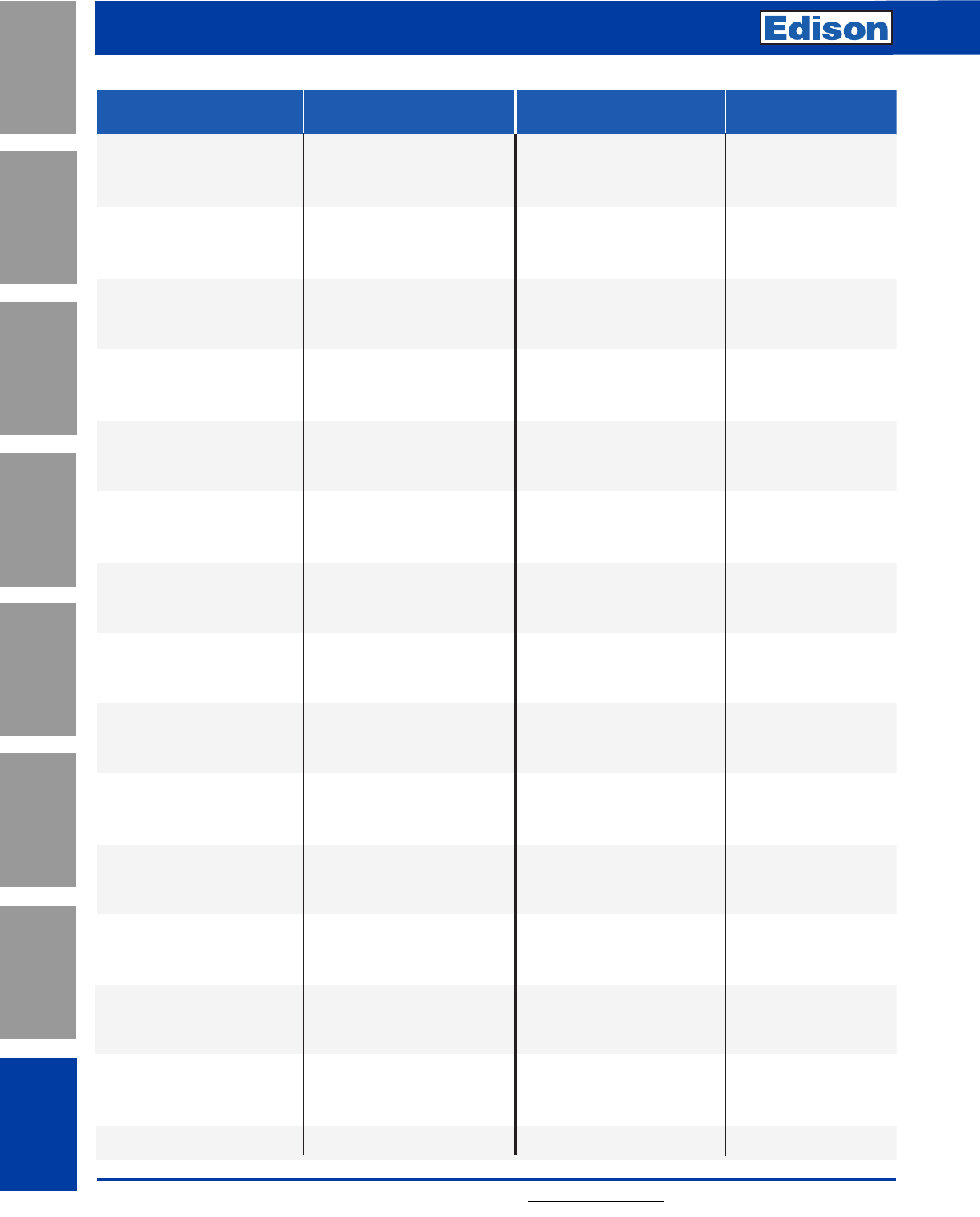
190 For additional information, visit www.edisonfuse.com
Application
Section
Fuse Blocks,
Holders & Misc.
Surge Protective
Devices
Medium
Voltage Fuses
Canadian
Fuses & Holders
Special
Purpose Fuses
UL/CSA Fuses
General Purpose
UL/CSA Fuses
Current Limiting
Quick Cross Reference
Competitor
Fuse Family Edison
Competitor
Fuse Family Edison
KON(AMP)
KOS(AMP)
GDA(AMP)
GDB(AMP)
GDC(AMP)
GMA(AMP)
GMD(AMP)
SF25H(AMP)
SFE(AMP)
AGC(12-30)
AGC(.1-10)
MDL(AMP)
ABC(AMP)
MDA(AMP)
HKP
AGX(AMP)
AGC(AMP)
TL(15-30)
TL(15-30)
SL(15-30)
S(1/4-30)
T(3/10-30)
ABC(AMP)
MDA(AMP)
AGC(AMP)
MDL(AMP)
KON(1-60)
KOS(15-60)
AGX(AMP)
LENRK(AMP)
LENRK(AMP)
NCLR(AMP)
TJN(AMP)
LCL(AMP)
JFL(AMP)
LESRK(AMP)
LESRK(AMP)
SCLR(AMP)
SCLR(AMP)
TJS(AMP)
SEC(AMP)
JDL(AMP)
ALS(AMP)
EDCC(AMP)
MCL(AMP)
ATM(AMP)
HCLR(AMP)
ATC(AMP)
MEQ(AMP)
HCTR(AMP)
MOL(AMP)
MOL(AMP)
ABC(AMP)
EBS(AMP)
AGC(AMP)
AGX(AMP)
MOL(AMP)
MOL(AMP)
BLS(AMP)
CBS(AMP)
CCK(AMP)
CCL(AMP)
CCMR(1/2-30A)
CJ(AMP)
CJS(AMP)
CLU(AMP)
CMF(AMP)
CNL(AMP)
CNM(AMP)
CNN(AMP)
CNQ(AMP)
CRN-R(AMP)
CRS-R(AMP)
CSU
CSY
CTK(AMP)
CTK-R(AMP)
CTN-R(AMP)
CTS-R(AMP)
ECK(AMP)
ECL(AMP)
EGX(AMP)
ENL(AMP)
ENN(AMP)
EON(AMP)
EOS(AMP)
ESA
ESOU
ESRU
ESSU
FLA(AMP)
FLM(AMP)
FLNR(AMP)
FLQ(AMP)
FLSR(AMP)
FNA(AMP)
FNM(AMP)
FNQ(AMP)
FNQ-R(AMP)
FNW(AMP)
FRN(AMP)
FRN-R(AMP)
FRS(AMP)
FRS-R(AMP)
GAB(AMP)
GDL(AMP)
GFN(AMP)
GGC(AMP)
GGM(AMP)
GGX(AMP)
GSB(AMP)
GSC(AMP)
GSFC
GSL(15-30)
GT(AMP)
GTL(15-30)
EBS(AMP)
EBS(AMP)
ACK(AMP)
ACL(AMP)
EDCC(AMP)
JFL(AMP)
JFL(AMP)
LCU(AMP)
MOL(AMP)
ANL(AMP)
MEN(AMP)
ANN(AMP)
MEQ(AMP)
ECNR(AMP)
ECSR(AMP)
SSU
SSY
MCL(AMP)
HCLR(AMP)
NCLR(AMP)
SCLR(AMP)
ACK(AMP)
ACL(AMP)
AGX(AMP)
ANL(AMP)
ANN(AMP)
KON(AMP)
KOS(AMP)
SA(AMP)
SOU
SRU
SSU
MID(AMP)
MEN(AMP)
ECNR(AMP)
MEQ(AMP)
ECSR(AMP)
MID(AMP)
MEN(AMP)
MEQ(AMP)
HCTR(AMP)
MEN(AMP)
ECNR(AMP)
ECNR(AMP)
ECSR(AMP)
ECSR(AMP)
ABC(AMP)
MDL(AMP)
MID(AMP)
AGC(AMP)
GMA(AMP)
AGX(AMP)
GDB(AMP)
GMC(AMP)
SFC-FUSE-CAB
SL(15-30)
T(AMP)
TL(15-30)
10KOTN(AMP)
10KOTS(AMP)
216(AMP)
217(AMP)
218(AMP)
235(AMP)
239(AMP)
25SH(AMP)
307(AMP)
311(12-30)
312(1/10-10)
313(AMP)
314(AMP)
326(AMP)
342012
361(AMP)
362(AMP)
3740(15-30)
3765(15-30)
3770(15-30)
3780(.25-30)
3785(.3-30)
3AB(AMP)
3AB-SB(AMP)
3AG(AMP)
3AG-SB(AMP)
50KOTN(1-60)
50KOTS(15-60)
8AG(AMP)
A2D(AMP)
A2D(AMP)R
A2K(AMP)R
A3T(AMP)
A4BY(AMP)
A4J(AMP)
A6D(AMP)
A6D(AMP)R
A6K(AMP)
A6K(AMP)R
A6T(AMP)
AG5(AMP)
AJT(AMP)
AOK(AMP)
ATDR(AMP)
ATM(AMP) Gould
ATM(AMP) BUSS
ATMR(AMP)
ATO(AMP)
ATQ(AMP)
ATQR(AMP)
BAF(AMP)
BAN(AMP)
BBC(AMP)
BBS(AMP)
BGC(AMP)
BGX(AMP)
BLF(AMP)
BLN(AMP)
Quick Cross Reference Guide
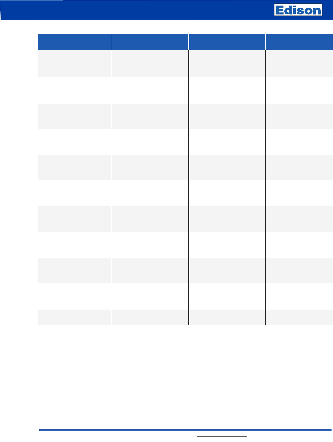
Quick Cross Reference (Continued)
For additional information, visit www.edisonfuse.com
Competitor
Fuse Family Edison
Competitor
Fuse Family Edison
GW(15-30)
JCE(1/2-4)E
JCK(2-6)R
JCK(9-12)R
JCK(18-24)R
JCL(2-6)R
JCL(9-12)R
JCL(18-24)R
JCL(AMP)
JCT(0.5-1)E
JCW(1/2-4)E
JHC(AMP)
JJN(AMP)
JJS(AMP)
JKS(AMP)
JLLN(AMP)
JLLS(AMP)
JLS(AMP)
JTD(AMP)
KLDR(AMP)
KLK(AMP)
KLKR(AMP)
KLLU(AMP)
KLMR(AMP)
KLNR(AMP)
KLPC(AMP)
KLSR(AMP)
KLU(AMP)
KRP-C(AMP)SP
KTK(AMP)
KTK-R(AMP)
KTN(AMP)
KTN-R(AMP)
KTS(AMP)
KTS-R(AMP)
KTU(AMP)
LGR(AMP)
LHR000
LLNRK(AMP)
LLSRK(AMP)
LON-R(AMP)
LON-RK(AMP)
LOS-R(AMP)
LOS-RK(AMP)
LP-CC(AMP)
LPJ(AMP)
LPN(AMP)
LPN-RK(AMP)
LPS(AMP)
LPS-RK(AMP)
MDX(AMP)
MSL(AMP)
MTH(AMP)
NLN(AMP)
NLS(AMP)
NON(AMP)
NOS(AMP)
OT(AMP)
OTM(AMP)
OTS(AMP)
REN(AMP)
RES(AMP)
RF(AMP)
RFS(AMP)(GOULD)
RLN(AMP)(LF)
RLS(AMP)(GOULD)
SAO(AMP)
SAO(AMP)
SC(AMP)
SLC(AMP)
SLO(15-30)
SLR
SOO(AMP)
TLO(15-30)
TOO(15-30)
TR(AMP)
TR(AMP)R
TRM(AMP)
TRS(AMP)
TRS(AMP)R
UHA
UHC
WOO(1/2-12)
WOO(15-30)
ECSR(AMP)
LESRK(AMP)
EDCC(AMP)
JDL(AMP)
LENRK(AMP)
LENRK(AMP)
LESRK(AMP)
LESRK(AMP)
MDL(AMP)
MDA(AMP)
AGC(AMP)
KON(AMP)
KOS(AMP)
KON(AMP)
KOS(AMP)
KON(AMP)
MOL(AMP)
KOS(AMP)
ERN(AMP)
ERS(AMP)
ERN(AMP)
ERS(AMP)
ERN(AMP)
ELS(AMP)
SA(AMP)
SA(AMP)
SEC(AMP)
SEC(AMP)
SL(15-30)
GLR(AMP)
S(AMP)
TL(15-30)
T(15-30)
ECNR(AMP)
ECNR(AMP)
MEN(AMP)
ECSR(AMP)
ECSR(AMP)
UCLA
UCLC
W (1/2-12)
TL(15-30)
TL(15-30)
5.5AMWNA(0.5-4.0)E
2.75VFRHA(2-6)R
2.75VKRHA(9-12)R
2.75VKRHK(18-24)R
5.5VFHNA(2-6)R
5.5VKNHA(9-12)R
5.5VKNHK(18-24)R
JFL(AMP)
15.5CAVH(0.5-1)E)
5.5CAVH(0.5-4.0)E
JDL(AMP)
TJN(AMP)
TJS(AMP)
JFL(AMP)
TJN(AMP)
TJS(AMP)
JFL(AMP)
JDL(AMP)
HCTR(AMP)
MCL(AMP)
HCLR(AMP)
LCL(AMP)
EDCC(AMP)
NCLR(AMP)
LCL(AMP)
SCLR(AMP)
LCL(AMP)
LCL(AMP)
MCL(AMP)
HCLR(AMP)
NCLR(AMP)
NCLR(AMP)
SCLR(AMP)
SCLR(AMP)
LCU(AMP)
GLR(AMP)
HLR
LENRK(AMP)
LESRK(AMP)
ECNR(AMP)
LENRK(AMP)

Customer Assistance
Customer Satisfaction Team - US and Canada
Available to answer questions regarding Edison products
Monday-Friday, 8:00 a.m. – 4:30 p.m. Central Time. Contact:
• Toll-free phone: 855-4EDISON (855-433-4766)
• Toll-free fax: 800-862-5178
• E-mail: edisonorders@eaton.com
Online Resources
Visit www.edisonfuse.com for additional product information.
C3 – the Enhanced, Online Cooper Customer Center
Provides real time product availability, net pricing, order
status & shipment tracking for Edison distributors. Available at:
• www.cooperc3.com
• 877-995-5955 for log-in assistance
Eaton is a registered trademark.
All other trademarks are property
of their respective owners.
Eaton
1000 Eaton Boulevard
Cleveland, OH 44122
United States
Eaton.com
© 2014 Eaton
All Rights Reserved
Printed in USA
Publication No.1005
November 2014
Edison Circuit Protection
www.edisonfuse.com
Your authorized distributor is:
