Installation Directions
2016-10-06
: Pdf 1000319220-Installationsheet 1000319220-InstallationSheet B5 unilog
Open the PDF directly: View PDF ![]() .
.
Page Count: 2
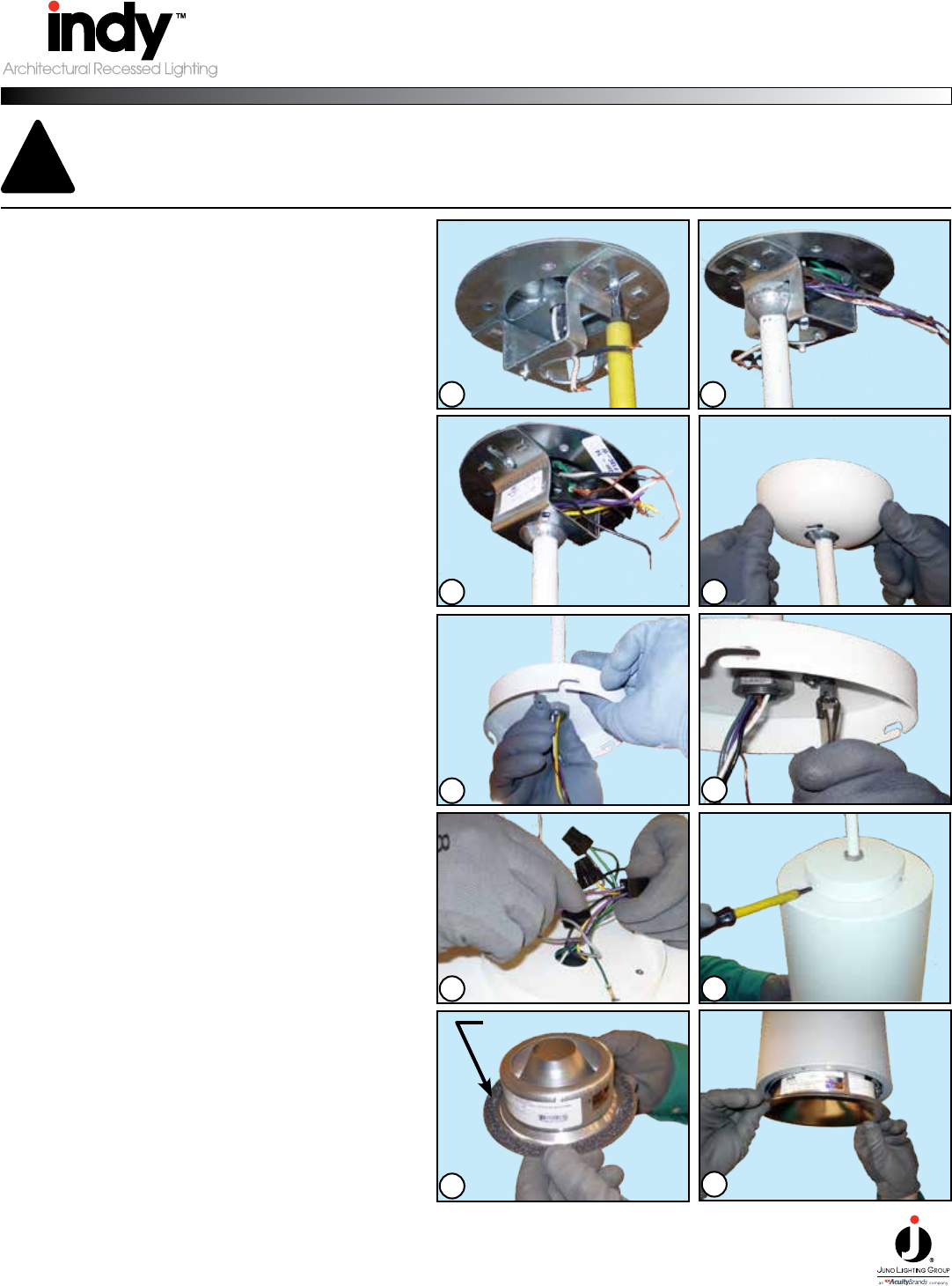
Step : Tab on canopy bracket should slide into slot
on ball joint to insure proper installation. Wire junc-
tion box leads and pendant leads together, to ensure
proper wiring, see wiring diagrams on next page.
Step : Install canopy cover by aligning the tabs on
bracket with slots in the cover and turning to lock in
place.
Step : Remove reveal from top of cylinder.
Attach reveal to stem with one (1) nut on top of reveal
and two (2) nuts on the inside.
Step : Hang stem to canopy bracket by inserting
ball joint into slot of bracket.
Step : Mount the canopy bracket to junction box
using screws (2). Pull wires thru center hole of
bracket.
For Pendant Mounting:
Step : Attach safety cable to eyelet backet within
reveal.
5
2
34
6
8
7
1
10
9
Step : Trim gasket provided seperately and must
be installed on to trim ange.
Step : Insert trim into housing until trim ange
seats rmly against housing.
Installation is complete.
Step : Attach cylinder housing to reveal by align-
ing screws to slots in reveal, pushing housing up and
twisting slightly. Tighten screws to secure in place.
Step : With safety cable attached to reveal, make
wiring connects.
To ensure proper wiring, see wiring diagrams on
next page.
PENDANT MOUNT INSTRUCTIONS
FOR CYLINDERS - GEN3
IMPORTANT SAFETY INSTRUCTIONS
This xture must be installed in accordance with local, federal codes and the NEC.
1. Read all instructions completely before beginning. Keep these instructions in
safe place for future reference.
2. To reduce risk of re and over-heating, make sure all connections are tight.
3. Turn off the electrical power before proceeding.
CAUTION: Risk of Fire or Electric Shock
LED Surface, Pendant & Cable Mounted Cylinder installation requires
knowledge of luminaires electrical systems. If not qualied, do not
attempt installation. Contact a qualied person.
!
GASKET
©2016 Acuity Brands Lighting, Inc. Rev 05/16 065-1212 pg. 1 of 2
Technical Services Phone (888) 387-2212
1300 South Wolf Road • Des Plaines, IL 60018 • Phone 800-323-5068 • Fax 888-708-6578 • www.junolightinggroup.com
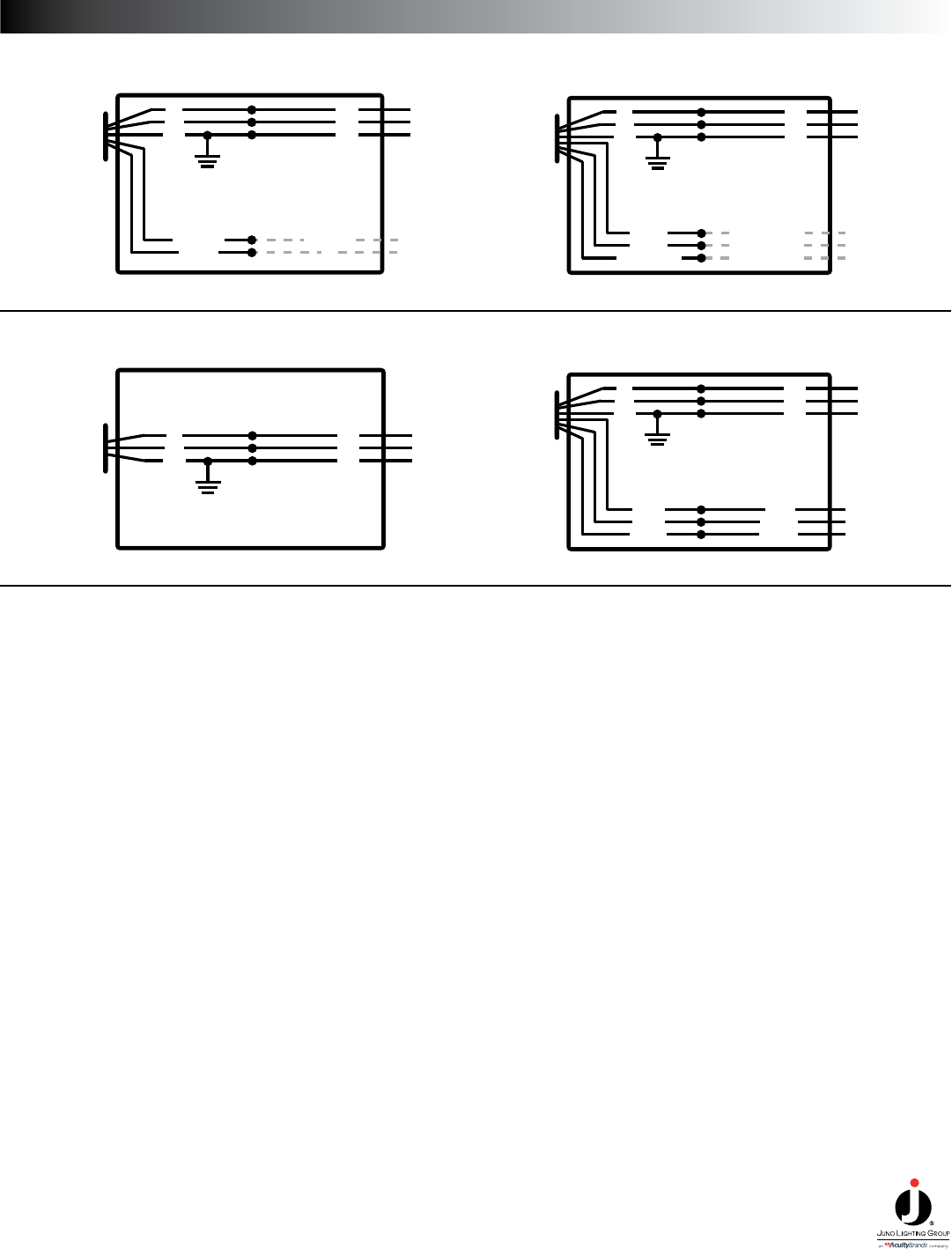
WIRING DIAGRAMS
TO LED
DRIVER
SUPPLY
BK
WH
GRN
LINE
COM
GRN
0-10V INPUT
RTN
PURPLE (+)
GRAY (–)
120/277V WIRING DIAGRAM
0-10V DIMMING
USE WHEN
DIMMING
JUNCTION BOX
TO LED
DRIVER
SUPPLY
BK
WH
GRN
LINE
COM
GRN
120V WIRING DIAGRAM
LUTRON FORWARD PHASE DIMMING
JUNCTION BOX
TO LED
DRIVER
SUPPLY
BK
WH
GRN
LINE
COM
GRN
DIMMING HOT
ECOSYSTEM (E1)
ORANGE
PURPLE
PURPLE/WHITE
120/277V WIRING DIAGRAM
LUTRON ECOSYSTEM DIMMING
3-WIRE/ECO
DIMMING
JUNCTION BOX
ECOSYSTEM (E2)
TO LED
DRIVER
BP/SUPPLY
BK
WH
GRN
LINE
COM
GRN
BLUE
YELLOW
YEL/BLK
BLUE
YELLOW
YEL/BLU
120/277V WIRING DIAGRAM
BODINE BATTERY PACK
BATTERY
PACK
JUNCTION BOX
©2016 Acuity Brands Lighting, Inc. Rev 05/16 065-1212 pg. 2 of 2
Technical Services Phone (888) 387-2212
1300 South Wolf Road • Des Plaines, IL 60018 • Phone 800-323-5068 • Fax 888-708-6578 • www.junolightinggroup.com
