Thomas & Betts OCAL PVC Coated Products 1000319966 Catalog
2016-09-04
: Pdf 1000319966-Catalog 1000319966-Catalog B4 unilog
Open the PDF directly: View PDF ![]() .
.
Page Count: 84

w w w . t n b . c a
PVC-Coated Products
H1
OCALTM
Overview .......................................................................................H2–H7
Conduit and Accessories..............................................................H8–H15
Ordinary Location Fittings ..........................................................H16–H35
Hazardous Location Fittings.......................................................H36–H42
Strut and Accessories ................................................................H43–H46
Installation Products ..................................................................H47–H55
Products for Corrosive Environments .........................................H56–H60
Chemical Resistance .................................................................H61–H62
Specification Guide....................................................................H63–H64
CEC ...........................................................................................H65–H73
Installation Guidelines................................................................H74–H81
Industry Standards — NEMA .............................................................H82
Table of Contents
w w w . t n b . c a
PVC-Coated Products
H2
OCALTM
Overview
Better by Design
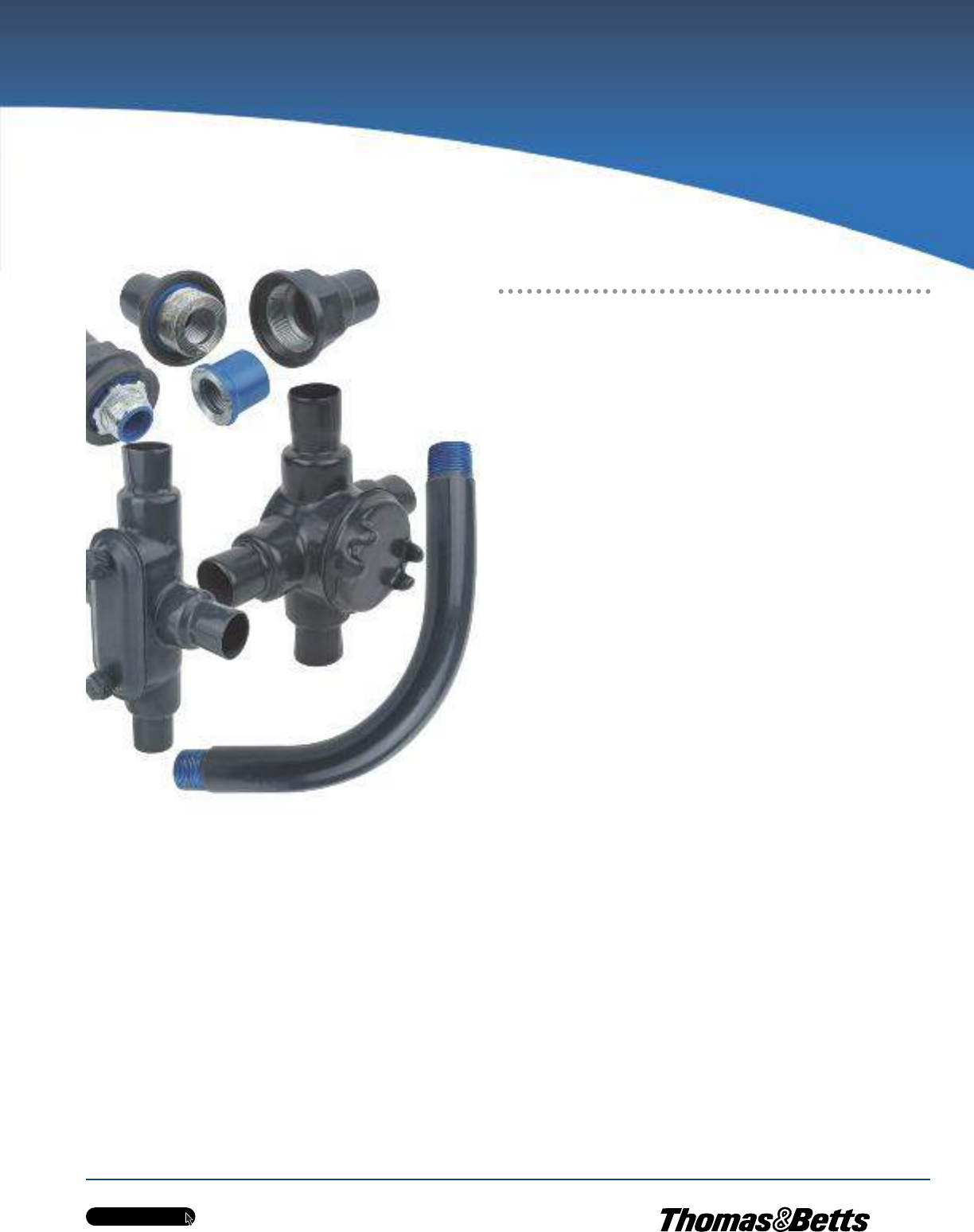
Ocal-BlueTM PVC-coated conduit and fittings represent a complete corrosion
protection package for your entire conduit system. This extensive product line
includes the largest number of items in stock along with corrosion resistant
supports and patching compounds. With OcalTM PVC-coated conduit and fittings,
you get corrosion protection that will extend the life of your electrical raceway
system for years and years.
Only OcalTM Offers These Advantages
•Only OcalTM PVC-coated conduit is CSA Certified and UL Listed
with both the zinc coating and the PVC coating investigated and
listed per UL6 and CSA 22.2 no. 45.1 Standard for rigid metal
conduit.
•Only OcalTM PVC-coated conduit has hot-dipped galvanized
threads. Hot-dip galvanizing is the process through which the
steel shell is dipped in molten zinc, causing the zinc to penetrate
the steel.
•Only OcalTM PVC-coated conduit offers a full undisturbed zinc
coating under the PVC coating, fulfilling the requirement of NEMA
RN-1 regarding undisturbed zinc coating over the conduit.
•Only OcalTM PVC-coated conduit meets the requirements of NEMA
RN-1 without exception.
•Only OcalTM PVC-coated conduit is UL Listed for UV resistance.
•Only OcalTM supplies ‘‘Double-Coat’’ coated fittings, enhancing
corrosion protection by applying urethane to the interior and
exterior of the fittings before PVC coating.
•Only OcalTM offers custom colours.
•Only OcalTM offers local installation training and certification
Standards Met
•ANSI C80.1
•Federal Specification WW-C-581
•NEMA RN-1
•CSA C22.2 No. 45.1
•UL6
w w w . t n b . c a
PVC-Coated Products
H3
OCALTM
Overview
What is Corrosion?
CORROSION PROTECTION OPTIONS
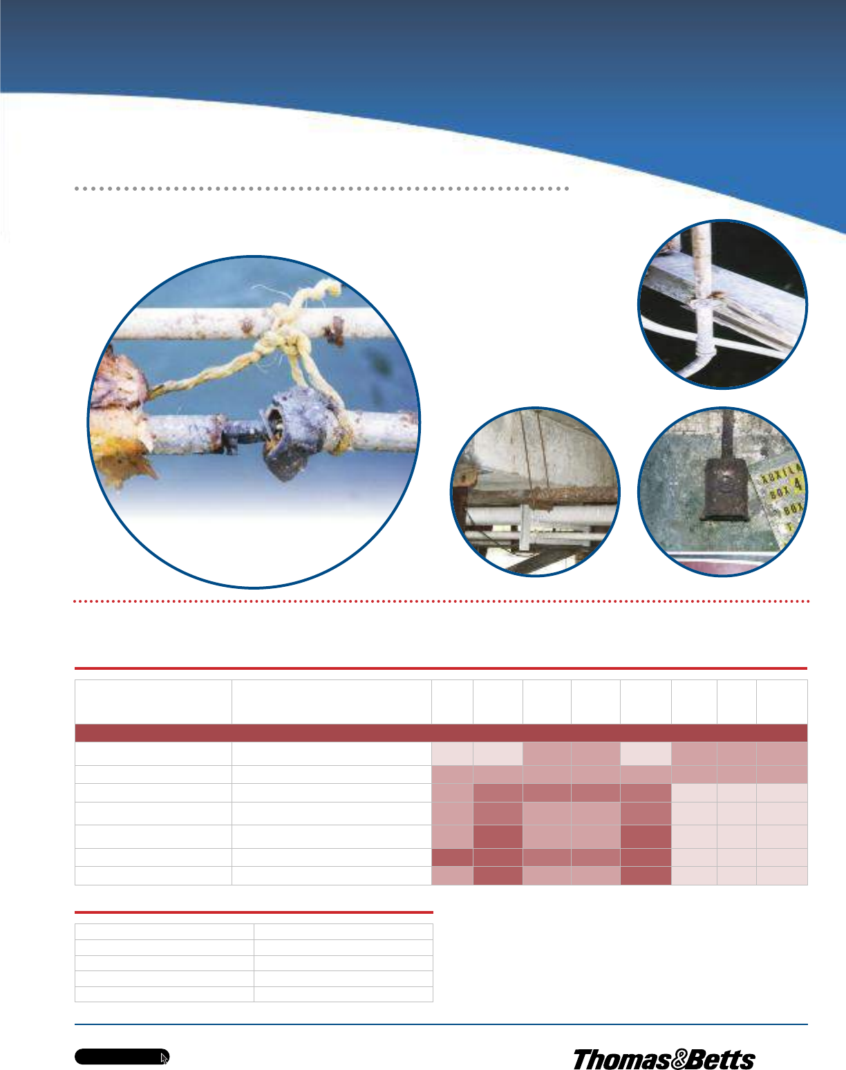
Examples of corrosion
Corrosive elements cause millions of
dollars in damage through lost time,
materials and labor.
The chart above provides a general guide for the end-user to choose the most
suitable material for his corrosion protection needs.
As you can see, PVC coated conduit and fittings are suitable for almost all
applications. When it comes to PVC coated conduit systems, there is no higher
quality than OcalTM.
CHEMICAL COMPATIBILITY LEGEND
Chemical Categories Chemical EXAMPLES PVC Urethane
304
Stainless
Steel
316
Stainless
Steel
Poly-
carbonate Cast Iron Brass Aluminum
COMPATIBILITY RATING
Solvents
(excluding alcohols and aliphatic) Acetone, toluene, ketones, etc. NR NR L L NR L L L
Fuels Jet fuel (alcohol based and aliphatic solvent based) L L L L L L L L
Plating Solutions Chrome, nickel, copper brass, gold, zinc, etc. L F F F F NR NR NR
Salts and Alkaline
Materials Caustic soda, caustic potash, alkaline cleaners, etc. L F L L F NR NR NR
Mild Acids Low-concentration hydrochloric, sulfuric, fruit acids,
glycolic, citric, etc. L S L L S NR NR NR
Strong or High-Purity Acids Nitric, hydrofluoric, etc. S S F F S NR NR NR
Oxidizing Agents Bleach, chlorine, hydrogen peroxide, etc. L S L L S NR NR NR
Suitability Description Compatibility Rating
Rated for all Fumes, Splash & Liquid L
Rated only for Fumes & Splash S
Rated for Fumes only F
Not Recommended NR
Corrosion protection of electrical conduit systems
w w w . t n b . c a
PVC-Coated Products
H4
OCALTM
Overview
OcalTM Manufacturing Process
1
1
2
3
4
5
2
3
4
Introduction
OcalTM is the only PVC-coated conduit system in the industry to fully comply
with all standards for proper use and protection in corrosive environments
mandated by CSA 22.2 No. 45.1, UL6, NEMA RN-1 and ANSI C80.1. It is
manufactured in the United States by Thomas & Betts in our Jonesboro, AR
manufacturing facility.
The Process of Manufacturing
PVC-Coated Conduit
•The process begins with 20-foot (6 meters) sticks of raw
steel shell.
•The steel shell is cut, threaded and prepared for the hot-dip
galvanizing process.
•The threaded shell is immersed in a molten zinc bath. This
hot-dip galvanizing process enables the zinc to penetrate the
steel, providing the best possible protection. After the conduit
is extracted from the zinc bath, super-heated steam is blown
through the interior and over the outside of the conduit to
remove any slag. The ends of the conduit are heated enough to
blow excess zinc out of the thread cavities. Thomas & Betts is
the only manufacturer of steel conduit that hot-dip galvanizes
the threads as well as the conduit itself. Other methods such as
‘‘hot galvanizing’’ provide only a sprayed-on zinc coating.
•Prior to the exterior PVC coating, 2 mils (nominal) of blue
urethane is applied to the inside diameter as well as the
threads of each conduit. After priming, the conduit is heated
and then rolled through liquid plastisol, achieving complete
coverage of 40 mils in thickness.
•Standard colours include grey, white and blue.
Custom colours are also available.
Superior Service
Our reputation for dependability and customer service have made OcalTM the
most trusted name in corrosion protection for the electrical industry.
w w w . t n b . c a
PVC-Coated Products
H5
OCALTM
Overview
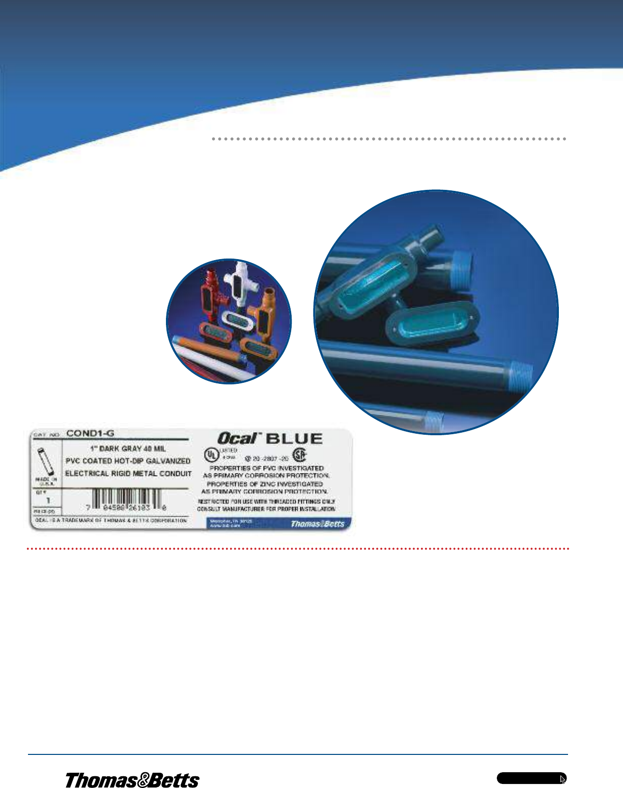
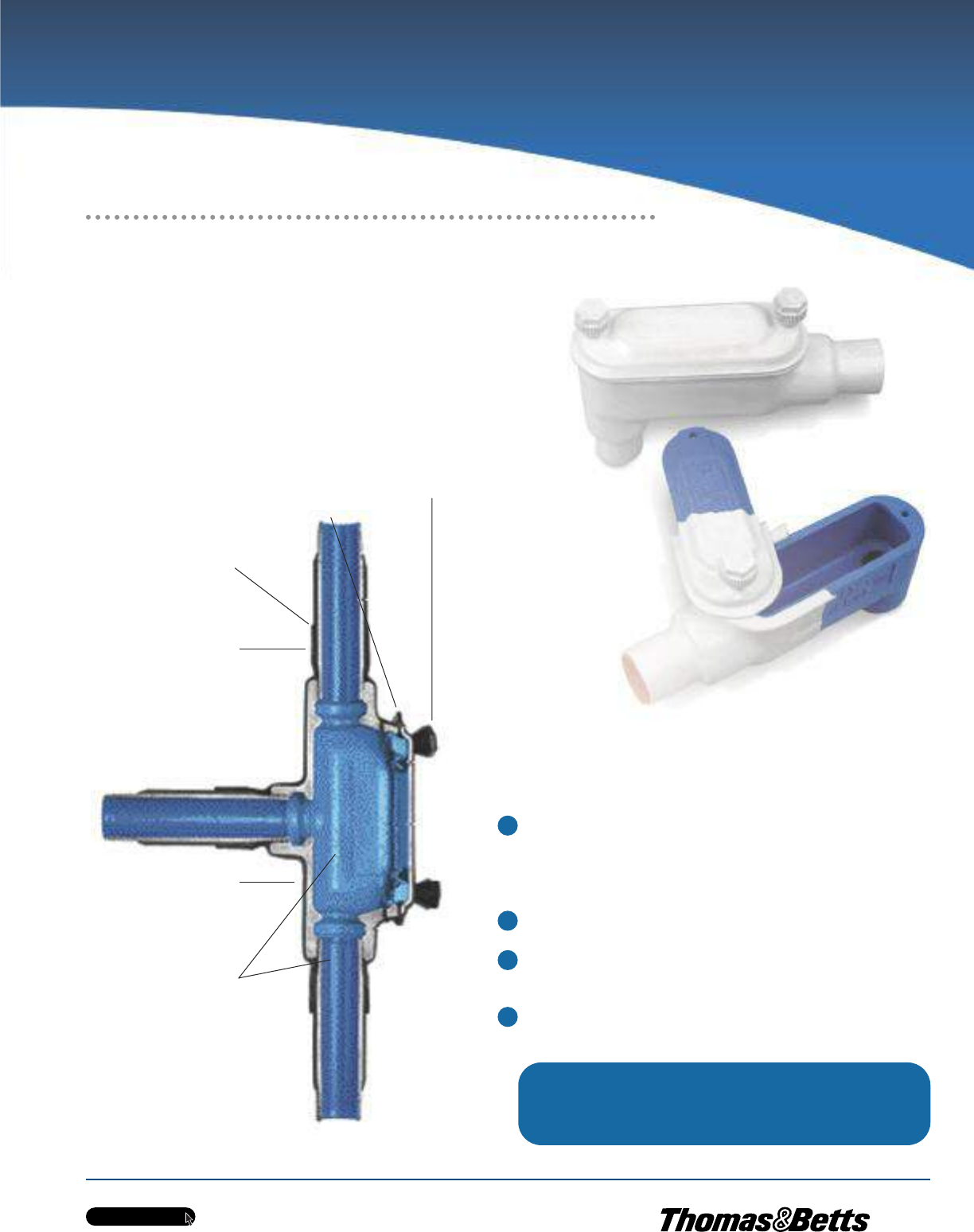
Complete Corrosion Protection
OcalTM has developed a process for coating the interior and exterior of all fittings
with a nominal 0.002 in. (2 mils) of blue urethane, which is baked on. This
proprietary application of urethane enhances the corrosion protection of your
system, even if you accidentally nick or cut the PVC coating during installation.
Flexible, overlapping sleeves on all OcalTM fittings guarantee protection with a
vapor- and moisture-tight seal at every connection.
•Fittings are cleaned and then sprayed inside and outside with a
nominal 2 mils (0.002 in.) of blue urethane. This gives the fittings
corrosion protection on the exterior as well as the interior — all
fittings are ‘‘double-coated.’’
•40 mils (0.040 in.) of PVC is applied to the exterior of the fitting.
•Covers are coated with a molded flange, and conduit bodies are
molded with a flat surface to ensure a superior seal.
•Standard colours include grey, white and blue. Custom colours
also available.
The Process of Manufacturing
PVC-Coated Fittings
1
2
3
4
Thomas & Betts works hard to provide the only standards-
compliant PVC-coated conduit on the market today.
It is this dedication to superior quality that makes OcalTM
‘‘Better by Design.’’
Encapsulated Stainless Steel
Screws standard on both
Form 7 and Form 8 Fittings
PVC Gasket-like Flange
Pressure-Sealing
Sleeve on All Hubs
2 mils (0.002 in.)
Urethane
Exterior
Coating
under PVC
40 mils (0.040 in.)
PVC Bonded
to Exterior
2 mils (0.002 in.)
Urethane
Interior
Coating

w w w . t n b . c a
PVC-Coated Products
H6
OCALTM
Overview
Evaluating Corrosion
Protection of PVC-Coated Conduit
When evaluating any electrical raceway conduit or fittings, applicable standards
should be referenced. The three standards that address the design
and performance of PVC-coated rigid steel conduit are ANSI C80.1, CSA 22.2
No. 45.1, UL6 and NEMA RN-1. ANSI C80.1, CSA 22.2 No. 45.1, UL and NEMA
have determined the appropriate ASTM standards and test methods that apply.
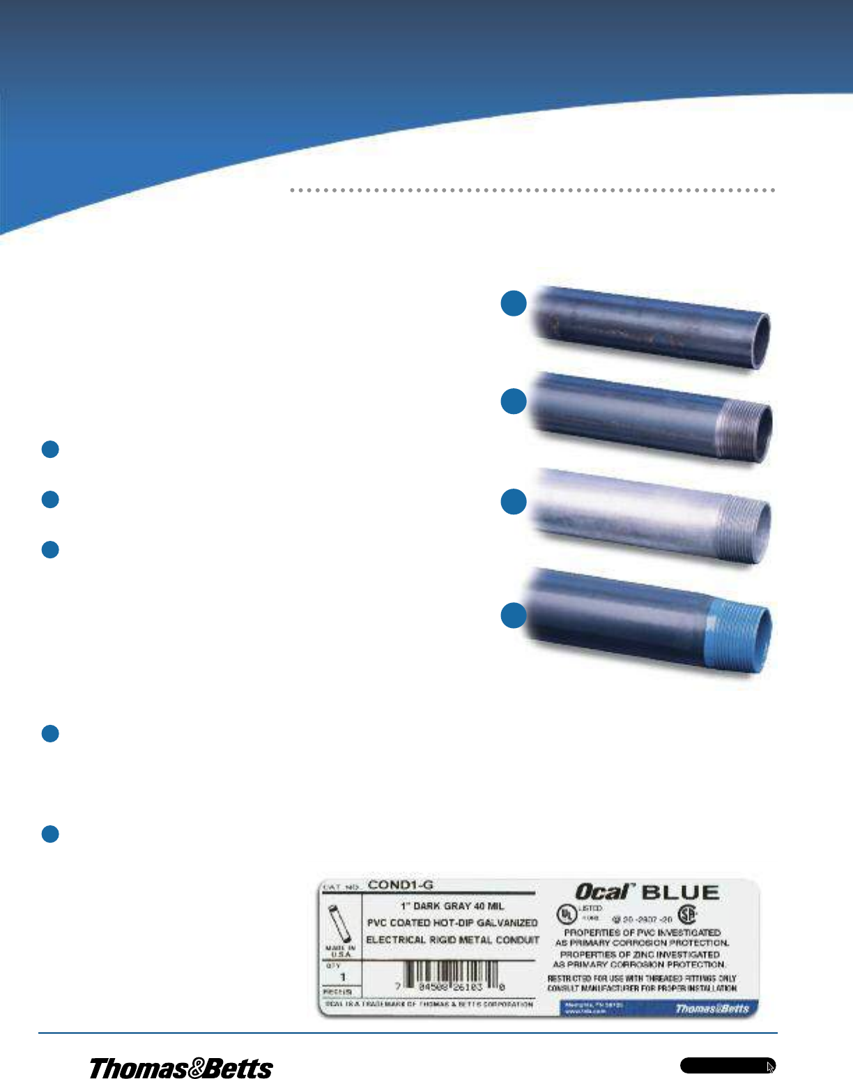
Hot-Dip Galvanized Threads
Since electrical conduit systems breathe, the threads will be exposed to the
corrosive environment for the duration of the installation. NEMA RN-1-2005 is
the electrical industry’s standard for PVC externally coated galvanized rigid
steel conduit. Section 2.1 of this standard states, ‘‘Where unusually corrosive
environments are encountered, it is recommended that threads be given
additional protection suitable for the intended application.’’ Hot-dip galvanizing
is the process through which the steel shell is dipped in molten zinc, causing
the zinc to penetrate the steel. Only OcalTM hot-dip galvanizes the threads of
the conduit, in addition to the conduit itself. This gives the threads the protection
necessary in corrosive environments.
A compelling demonstration of the protection hot-dip galvanizing provides is
shown at right, using a common corrosive agent, salt, on hot-dip galvanized
threads versus threads that are spray galvanized. CSA 22.2 No. 45.1, UL6, the
standard for rigid metal conduit, references ASTM B117 for evaluating
protective coatings. At right are the results of a salt-fog test using the standard
test method ASTM B117.
Galvanized conduit underneath the PVC coating — Preece Test
With so much riding on the integrity of their electrical conduit systems, facilities need the
superior protection offered by the Thomas & Betts OcalTM PVC-coated conduit systems. The
simple fact is that OcalTM is the only PVC-coated conduit system to comply fully with the
design and performance standards for PVC-coated conduit set forth by CSA 22.2 No 45.1
UL6, NEMA RN-1 and ANSI C80.1.
ANSI C80.1, CSA 22.2 No. 45.1, UL6 and NEMA RN-1 have determined the appropriate
ASTM standards and test methods that apply, and the Preece test is one test that must be
passed to be in full compliance.
Why is the Preece test relevant to PVC-coated conduit?
In cases where the PVC protection is accidentally breached, resulting from cuts, scrapes,
etc., it is critical to have a second line of defense — a zinc, or galvanized, coating. The zinc
coating will significantly slow corrosion and allow more time for repairs. Conduit systems
without adequate zinc protection underneath the PVC coating are most likely to suffer cata-
strophic corrosion damage. This is why NEMA RN-1 section 3.1.1 requires the proper and correct
treatment of galvanized conduit before it is PVC coated. It states, ‘‘The surface shall be cleaned in
such a manner that the galvanized surface of the conduit is not harmed or eroded.’’
The purpose of the Preece test is to evaluate the zinc coating on galvanized rigid conduit to ensure adequate
protection from corrosion per UL6.2.2. The test will also determine if the surface of the conduit has been damaged
as a result of preparation for PVC coating.
In evaluating the test results, the conduit receives a passing grade when the sample does not show a bright, adherent de-
posit of copper after four 60-second immersions in the copper sulfate solution. The conduit showing the bright, firmly adhering
copper has failed to provide adequate zinc protection against corrosion.
The Preece test follows procedures set forth by UL6.2.2 and ASTM A239 and is the test recognized by CSA 22.2 No. 45.1, UL6,
NEMA RN-1 and ANSI C80.1 to adequately assess zinc protection for rigid steel conduit. Only the OcalTM line of PVC-coated conduit
systems, manufactured by Thomas & Betts, complies with UL6, CSA 22.2 No. 45.1 NEMA RN-1 and ANSI C80.1 without exception.
Examples of Spray-Galvanized (Hot-Galvanized) Threads after 42-day salt-fog test
Examples of Hot-Dip Galvanized Threads after 42-day salt-fog test
Disturbed zinc coating not
adequate for corrosion
protection
Zinc coating surpasses
requirement for corrosion
resistance
w w w . t n b . c a
PVC-Coated Products
H7
OCALTM
Overview
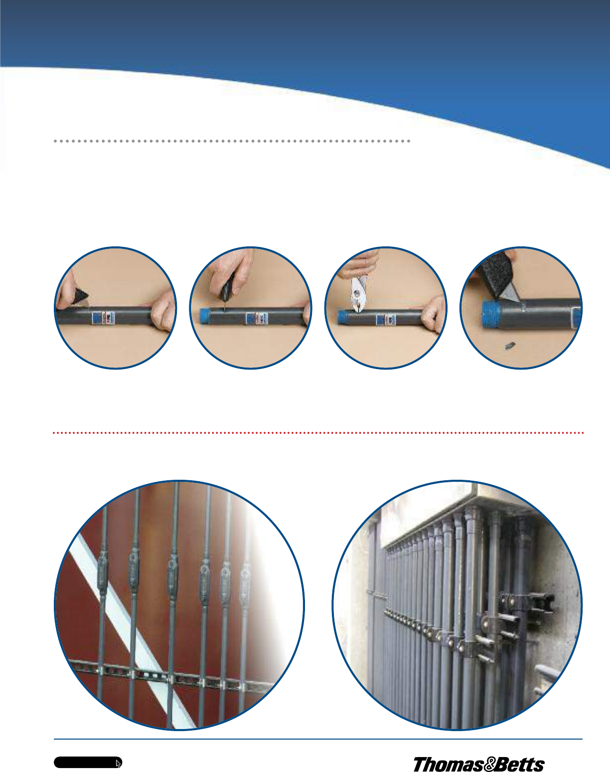
Evaluating Adhesion of PVC Coating
Step 1 consists of two cuts through the plastic to
the substrate along the length of the conduit,
approximately 1/2 in. apart and 3 in. to 4 in. in
length. A third, perpendicular cut crosses the
lengthwise parallel cuts.
Step 2 calls for the edge of the PVC that was cut
on the perpendicular to be carefully lifted to form
a plastic tab.
Step 4 is the evaluation of the test, which in this
case, results in a passing grade for OcalTM. This
result is more testimony to the fact that OcalTM
is ‘‘Better by Design.’’
In Step 3, the tab is pulled perpendicular to the
conduit with a pair of pliers. The plastic tab will
tear off rather than having any peeling effect or
the coating separating from the substrate.
The evaluation process for adhesion of PVC coating on conduit is governed by NEMA RN-1 section 3.8, Adhesion, which states, ‘‘The adhesion of the PVC coating
to the conduit shall be greater than the strength of the coating itself.’’ This adhesion test is straightforward and simple. There are no specialized conditions
necessary to perform this test. OcalTM routinely performs quality-control testing — including the adhesion test — on conduit as it rolls off the line. Conduit that
passes this test demonstrates that the adhesion will provide years of trouble-free service.
The following demonstration shows OcalTM PVC-coated conduit being subjected to the adhesion test.
Results
With OcalTM PVC-coated conduit and fittings, you get corrosion protection that will extend the life of your electrical raceway systems for years and years.
w w w . t n b . c a
PVC-Coated Products
H8
OCALTM
Conduit and Accessories
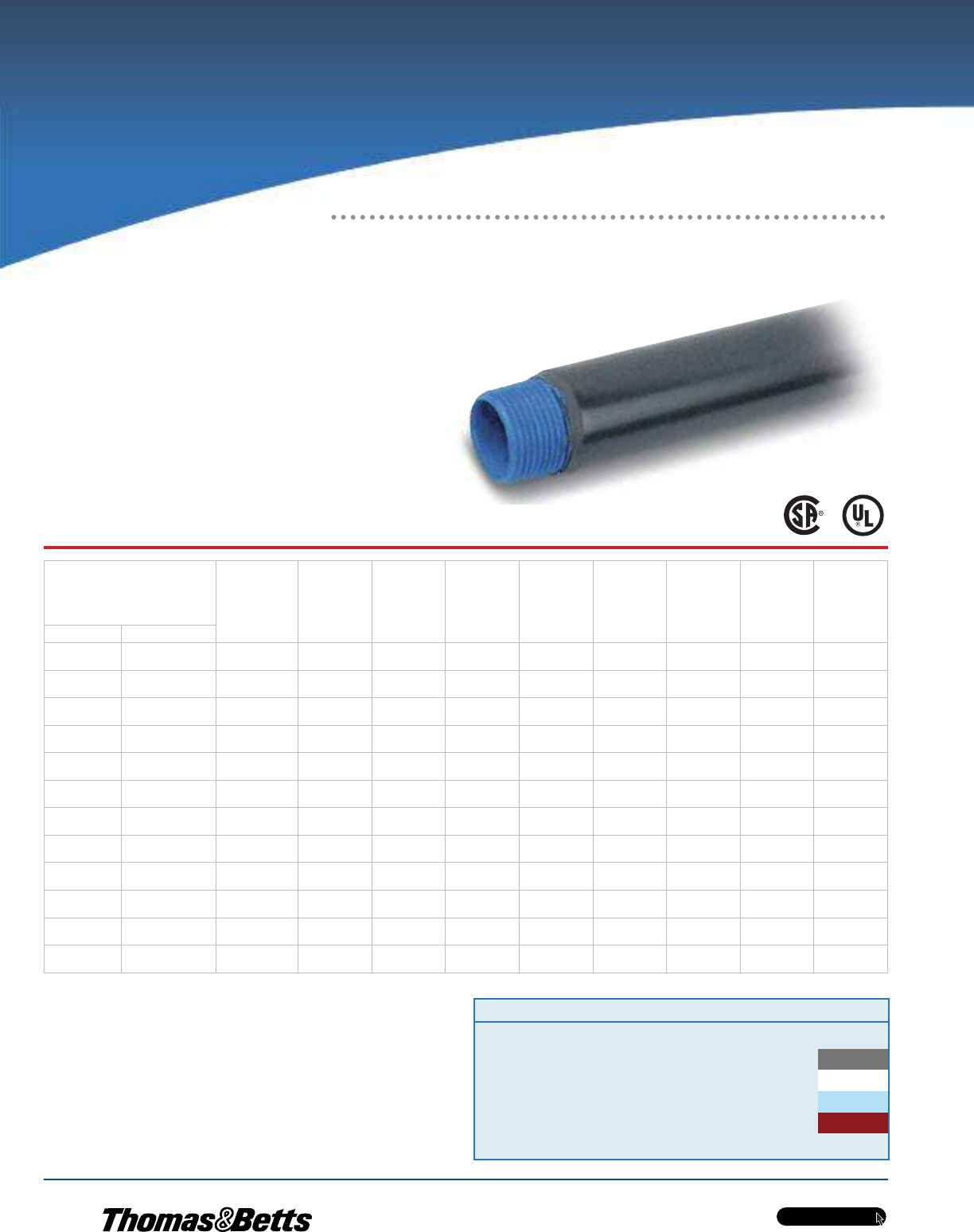
The Ultimate in Corrosion Protection!
OCAL-BLUETM Conduit
•Hot-dip galvanized steel or aluminum conduit
•Nominal 0.002 in. (2 mils) blue urethane coating on interior
•Hot-dipped galvanized threads (steel)
•Minimum 0.040 in. (40 mils) PVC coating on exterior
•Colour-coded thread protectors
•Couplings shipped with conduit are packaged separately
Cat. No.
Pipe
Size
in.
(mm)
Outside
Diameter
Steel Only
in.
(mm)
Outside
Diameter
With PVC
in.
(mm)
Nominal
Wall
Thickness
Steel Only
in.
(mm)
Nominal
Wall
Thickness
With PVC
in.
(mm)
Nominal
Inside
Diameter
in.
(mm)
Cross
Section
Area in
Square
in.
(mm)
Length
Without
Couplings
ft.
(m)
Minimum
Weight
Per Foot
Steel Only
lb.
(KG)
Steel Aluminum
COND1/2-_ COND1/2SA-_ 1/2
(16)
0.84
(21.30)
0.92
(23.30)
0.10
(2.64)
0.14
(3.56)
0.63
(16.10)
0.30
(7.72)
9’ 11-1/4’’
(3.03)
0.79
(35.83)
COND3/4-_ COND3/4SA-_ 3/4
(21)
1.05
(26.70)
1.13
(28.70)
0.11
(2.71)
2.71
(3.73)
0.84
(21.20)
0.53
(13.53)
9’ 11-1/4’’
(3.03)
1.05
(47.63)
COND1-_ COND1SA-_ 1
(27)
1.32
(33.40)
1.40
(35.40)
0.13
(3.20)
0.17
(4.21)
1.06
(27.00)
0.86
(21.94)
9’ 11’’
(3.02)
1.53
(69.40)
COND1-1/4-_ COND1-1/4SA-_ 1-1/4
(35)
1.66
(42.20)
1.74
(44.10)
0.13
(3.37)
0.17
(4.39)
1.39
(35.40)
1.50
(37.97)
9’ 11’’
(3.02)
2.01
(91.17)
COND1-1/2-_ COND1-1/2SA-_ 1-1/2
(41)
1.90
(48.30)
1.98
(50.20)
0.14
(3.50)
0.18
(4.52)
1.62
(41.20)
2.04
(51.71)
9’ 11’’
(3.02)
2.40
(112.95)
COND2-_ COND2SA-_ 2
(53)
2.38
(60.30)
2.46
(62.30)
0.15
(3.70)
0.19
(4.72)
2.08
(52.90)
3.36
(85.21)
9’ 11’’
(3.02)
3.32
(150.60)
COND2-1/2-_ COND2-1/2SA-_ 2-1/2
(63)
2.88
(73.00)
2.96
(75.00)
0.19
(4.90)
0.23
(5.91)
2.49
(63.20)
4.80
(121.61)
9’ 10-1/2’’
(3.01)
5.27
(239.05)
COND3-_ COND3SA-_ 3
(78)
3.50
(88.90)
3.58
(90.90)
0.21
(5.20)
0.25
(6.22)
3.09
(78.50)
7.39
(187.80)
9’ 10-1/2’’
(3.01)
6.83
(309.63)
COND3-1/2-_ COND3-1/2SA-_ 3-1/2
(91)
4.00
(101.60)
4.08
(103.60)
0.22
(5.46)
0.26
(6.47)
3.57
(90.70)
9.87
(250.60)
9’ 10-1/4’’
(3.00)
8.31
(376.94)
COND4-_ COND4SA-_ 4
(103)
4.50
(114.30)
4.58
(116.30)
0.23
(5.71)
0.27
(6.73)
4.05
(102.90)
12.73
(323.34)
9’ 10-1/4’’
(3.00)
9.73
(441.04)
*COND5-_ COND5SA-_ 5
(129)
5.56
(141.30)
5.64
(143.30)
0.25
(6.22)
0.29
(7.23)
5.07
(128.90)
20.01
(508.15)
9’ 10’’
(3.00)
13.14
(595.85)
*COND6-_ COND6SA-_ 6
(155)
6.63
(168.30)
6.71
(170.30)
0.27
(6.75)
0.31
(7.87)
6.09
(154.80)
28.89
(733.83)
9’ 10’’
(3.00)
17.46
(791.67)
Metric size designator (ANSI C80.1-1994).
*Not CSA certified.
Cat. No. Size Material Colour
COND 3/4 _- _ = space for colour identifier
Blank = Steel G = Grey
SA = Aluminum W = White
Catalogue No. Example:
COND3/4-G is 3/4 in. steel
conduit coated in grey PVC.
B = Blue
R = Red
Custom colours also available - Std. min. quantities are
required. Please contact your Regional Sales Office.
w w w . t n b . c a
PVC-Coated Products
H9
OCALTM
Conduit and Accessories
Corrosion-Protected Connections
for Conduit Sections
Cat. No. Size Material Colour
CPL 3/4 _- _ = space for colour identifier
Blank = Steel G = Grey
SA = Aluminum W = White
Catalogue No. Example:
CPL1SA-B is 1 in. aluminum
coupling coated in blue PVC.
B = Blue
R = Red
Custom colours also available - Std. min. quantities are
required. Please contact your Regional Sales Office.
Cat. No.
Coupling
Size
in.
(mm)
Minimum
Length of
Metal
in.
(mm)
Total
Minimum Length
Including Sleeve
in.
(mm)
Weight
Steel Only
lb./kg
Steel Aluminum
CPL1/2-_ CPL1/2SA-_ 1/2
(16)
1.50
(38.10)
3.75
(95.25)
0.13
(0.6)
CPL3/4-_ CPL3/4SA-_ 3/4
(21)
1.53
(38.91)
3.75
(95.25)
0.19
(0.85)
CPL1-_ CPL1SA-_ 1
(27)
1.91
(48.41)
4.94
(139.70)
0.33
(0.15)
CPL1-1/4-_ CPL1-1/4SA- 1-1/4
(35)
1.91
(48.41)
5.50
(139.70)
0.43
(.19)
CPL1-1/2-_ CPL1-1/2SA-_ 1-1/2
(41)
1.91
(48.41)
5.75
(146.05)
0.56
(.25)
CPL2-_ CPL2SA-_ 2
(53)
1.94
(49.19)
5.94
(150.79)
0.77
(.35)
CPL2-1/2-_ CPL2-1/2SA-_ 2-1/2
(63)
2.88
(73.10)
6.88
(174.70)
1.85
(.83)
CPL3-_ CPL3SA-_ 3
(78)
3.03
(76.98)
7.03
(178.58)
2.70
(1.22)
CPL3-1/2-_ CPL3-1/2SA-_ 3-1/2
(91)
3.09
(78.58)
7.09
(180.18)
3.78
(1.70)
CPL4-_ CPL4SA-_ 4
(103)
3.19
(80.97)
7.19
(182.57)
3.08
(1.39)
*CPL5-_ CPL5SA-_ 5
(129)
3.37
(85.69)
7.37
(187.29)
5.00
(2.25)
*CPL6-_ CPL6SA-_ 6
(155)
3.44
(87.29)
7.44
(188.89)
8.00
(3.60)
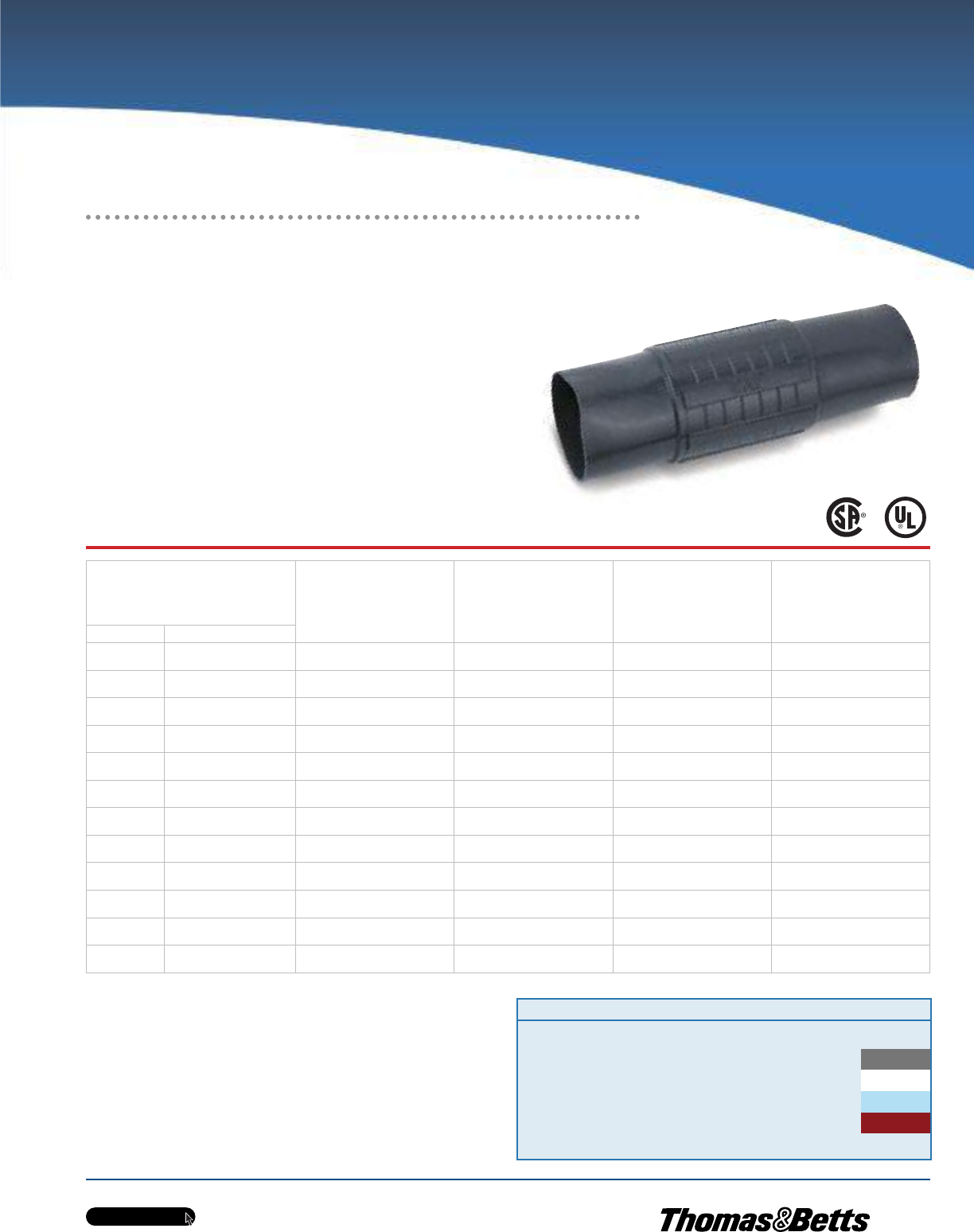
OCAL-BLUETM Couplings
•Nominal 0.002 in. (2 mils) blue urethane coating on
interior and threads
•Minimum 0.040 in. (40 mils) PVC coating bonded to exterior
•Couplings have straight threads (NPS), not tapered
•Molded ribs on outer coating for easy installation
(up to and including 4 in. trade size)
•Couplings have pressure-sealing sleeves to protect your
connection
Metric size designator (ANSI C80.1-1994).
*Not CSA certified.
w w w . t n b . c a
PVC-Coated Products
H10
OCALTM
Conduit and Accessories
Join Threaded Conduit Where You Can’t
Use a Standard Coupling
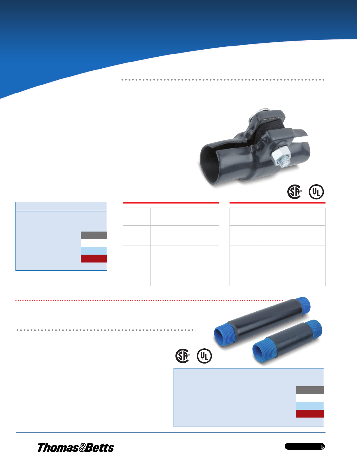
OCAL-BLUETM Double-Coat Split
Couplings
Split couplings serve as speed unions for cost-effective joining of two separate
lengths of threaded conduit. Like other OcalTM fittings, they're double coated in
urethane and PVC to safeguard your entire conduit system against corrosion.
•Malleable iron construction
•Nominal 0.002 in. (2 mils) blue urethane on both
interior and exterior
•Minimum 0.040 in. (40 mils) PVC bonded to exterior
•Stainless steel hardware included
OCAL-BLUETM Nipples
•Made from OcalTM PVC-coated steel or aluminum
conduit
•Blue urethane coating over threads
•Nominal 0.002 in. (2 mils) blue urethane on interior
•Minimum 0.040 in. (40 mils) PVC coating on exterior
•Colour-coded thread protectors for easy identification
of conduit size
•Available in 11 standard lengths — close and 2 in. to
12 in. with custom lengths available on request
•Close nipples are coated only in urethane
Speed Up Your Field Installations
with Pre-Threaded Conduit Nipples!
Cat. No. Colour
TCC1-
_ = space for colour identifier
G = Grey
W = White
B = Blue
R = Red
Custom colours also available - Std. min. quantities are required.
Please contact your Regional Sales Office.
NOTE — The use of standard couplings is recommended
whenever possible over the use of split couplings, because
standard couplings provide better overall corrosion protec-
tion.
_Cat. No.
Pipe Size
in.
(mm)
TCC7-_ 2-1/2
(63)
TCC8-_ 3
(78)
TCC9-_ 3-1/2
(91)
TCC10-_ 4
(103)
*TCC12-_ 5
(129)
*TCC14-_ 6
(155)
Cat. No.
Pipe Size
in.
(mm)
TCC1-_ 1/2
(16)
TCC2-_ 3/4
(21)
TCC3-_ 1
(27)
TCC4-_ 1-1/4
(35)
TCC5-_ 1-1/2
(41)
TCC6-_ 2
(53)
Metric size designator (ANSI C80.1-1994).
*Not CSA certified.
Cat. No. Size X Length Material Colour
NPL 3/4 X 6 _- _ = space for colour identifier
Blank = Steel G = Grey
SA = Aluminum W = White
Catalogue No. Example:
NPL3/4X6-G is 3/4 in. x 6 in. long
steel nipple coated in grey PVC.
B = Blue
R = Red
Custom colours also available - Std. min. quantities are
required. Please contact your Regional Sales Office.
w w w . t n b . c a
PVC-Coated Products
H11
OCALTM
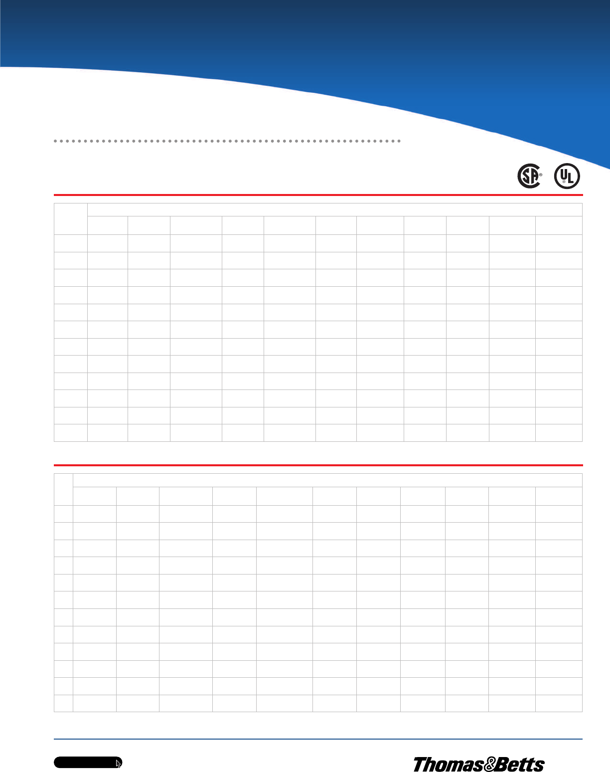
OCAL-BLUETM NIPPLES (cont’d)
PVC-Coated Conduit Nipples — Steel
PVC-Coated Conduit Nipples — Aluminum
Pipe Size
in.
(mm)
Nipple Length
Close 2
(50.8)
2-1/2
(63.5)
3
(76.2)
3-1/2
(88.9)
4
(101.6)
5
(127.0)
6
(152.4)
8
(203.2)
10
(254.0)
12
(304.8)
1/2
(6) CLNPl1/2-_ NPL1/2X2-_ NPL1/2X21/2-_ NPL1/2X3-_ NPL1/2X31/2-_ NPL1/2X4-_ NPL1/2X5-_ NPL1/2X6-_ NPL1/2X8-_ NPL1/2X10-_ NPL1/2X12-_
3/4
(21) CLNPL3/4-_ NPL3/4X2-_ NPL3/4X21/2-_ NPL3/4X3-_ NPL3/4X31/2-_ NPL3/4X4-_ NPL3/4X5-_ NPL3/4X6-_ NPL3/4X8-_ NPL3/4X10-_ NPL3/4X12-_
1
(27) CLNPL1-_ NPL1X2-_ NPL1X21/2-_ NPL1X3-_ NPL1X31/2-_ NPL1X4-_ NPL1X5-_ NPL1X6-_ NPL1X8-_ NPL1X10-_ NPL1X12-_
1-1/4
(35) CLNPL11/4-_ NPL11/4X2-_ NPL11/4X21/2-_ NPL11/4X3-_ NPL11/4X31/2-_ NPL11/4X4-_ NPL11/4X5-_ NPL11/4X6-_ NPL11/4X8-_ NPL11/4X10-_ NPL11/4X12-_
1-1/2
(41) CLNPL11/2-_ NPL11/2X2-_ NPL11/2X21/2-_ NPL11/2X3-_ NPL11/2X31/2-_ NPL11/2X4-_ NPL11/2X5-_ NPL11/2X6-_ NPL11/2X8-_ NPL11/2X10-_ NPL11/2X12-_
2
(53) CLNPL2-_ — NPL2X21/2-_ NPL2X3-_ NPL2X31/2-_ NPL2X4-_ NPL2X5-_ NPL2X6-_ NPL2X8-_ NPL2X10-_ NPL2X12-_
2-1/2
(63) CLNPL21/2-_ —— —NPL21/2X31/2-_ NPL21/2X4-_ NPL21/2X5-_ NPL21/2X6-_ NPL21/2X8-_ NPL21/2X10-_ NPL21/2X12-_
3
(78) CLNPL3-_ —— —NPL3X31/2-_ NPL3X4-_ NPL3X5-_ NPL3X6-_ NPL3X8-_ NPL3X10-_ NPL3X12-_
3-1/2
(91) CLNPL31/2-_ —— —— NPL31/2X4-_ NPL31/2X5-_ NPL31/2X6-_ NPL31/2X8-_ NPL31/2X10-_ NPL31/2X12-_
4
(103) CLNPL4-_ —— —— NPL4X4-_ NPL4X5-_ NPL4X6-_ NPL4X8-_ NPL4X10-_ NPL4X12-_
*5
(129) CLNPL5-_ —— —— —NPL5X5-_ NPL5X6-_ NPL5X8-_ NPL5X10-_ NPL5X12-_
*6
(155) CLNPL6-_ —— —— —NPL6X5-_ NPL6X6-_ NPL6X8-_ NPL6X10-_ NPL6X12-_
Pipe
Size
in.
(mm)
Nipple Length
Close 2
(50.8)
2-1/2
(63.5)
3
(76.2)
3-1/2
(88.9)
4
(101.6)
5
(127.0)
6
(152.4)
8
(203.2)
10
(254.0)
12
(304.8)
1/2
(6) CLNPL1/2SA-_ NPL1/2X2SA-_ NPL1/2X21/2SA-_ NPL1/2X3SA-_ NPL1/2X31/2SA-_ NPL1/2X4SA-_ NPL1/2X5SA-_ NPL1/2X6SA-_ NPL1/2X8SA-_ NPL1/2X10SA-_ NPL1/2X12SA-_
3/4
(21) CLNPL3/4SA-_ NPL3/4X2SA-_ NPL3/4X21/2SA-_ NPL3/4X3SA-_ NPL3/4X31/2SA-_ NPL3/4X4SA-_ NPL3/4X5SA-_ NPL3/4X6SA-_ NPL3/4X8SA-_ NPL3/4X10SA-_ NPL3/4X12SA-_
1
(27) CLNPL1SA-_ NPL1X2SA-_ NPL1X21/2SA-_ NPL1X3SA-_ NPL1X31/2SA-_ NPL1X4SA-_ NPL1X5SA-_ NPL1X6SA-_ NPL1X8SA-_ NPL1X10SA-_ NPL1X12SA-_
1-1/4
(35) CLNPL11/4SA-_ NPL11/4X2SA-_ NPL11/4X21/2SA-_ NPL11/4X3SA-_ NPL11/4X31/2SA-_ NPL11/4X4SA-_ NPL11/4X5SA-_ NPL11/4X6SA-_ NPL11/4X8SA-_ NPL11/4X10SA-_ NPL11/4X12SA-_
1-1/2
(41) CLNPL11/2SA-_ NPL11/2X2SA-_ NPL11/2X21/2SA-_ NPL11/2X3SA-_ NPL11/2X31/2SA-_ NPL11/2X4SA-_ NPL11/2X5SA-_ NPL11/2X6SA-_ NPL11/2X8SA-_ NPL11/2X10SA-_ NPL11/2X12SA-_
2
(53) CLNPL2SA-_ — NPL2X21/2SA-_ NPL2X3SA-_ NPL2X31/2SA-_ NPL2X4SA-_ NPL2X5SA-_ NPL2X6SA-_ NPL2X8SA-_ NPL2X10SA-_ NPL2X12SA-_
2-1/2
(63) CLNPL21/2SA-_ —— — NPL21/2X31/2SA-_ NPL21/2X4SA-_ NPL21/2X5SA-_ NPL21/2X6SA-_ NPL21/2X8SA-_ NPL21/2X10SA-_ NPL21/2X12SA-_
3
(78) CLNPL3SA-_ —— — NPL3X31/2SA-_ NPL21/2X4SA-_ NPL3X5SA-_ NPL3X6SA-_ NPL3X8SA-_ NPL3X10SA-_ NPL3X12SA-_
3-1/2
(91) CLNPL31/2SA-_ —— — — NPL31/2X4SA-_ NPL31/2X5SA-_ NPL31/2X6SA-_ NPL31/2X8SA-_ NPL31/2X10SA-_ NPL31/2X12SA-_
4
(103) CLNPL4SA-_ —— — — NPL4X4SA-_ NPL4X5SA-_ NPL4X6SA-_ NPL4X8SA-_ NPL4X10SA-_ NPL4X12SA-_
*5
(129) CLNPL5SA-_ —— — — — NPL5X5SA-_ NPL5X6SA-_ NPL5X8SA-_ NPL5X10SA-_ NPL5X12SA-_
*6
(155) CLNPL6SA-_ —— — — — NPL6X5SA-_ NPL6X6SA-_ NPL6X8SA-_ NPL6X10SA-_ NPL6X12SA-_
Metric size designator (ANSI C80.1-1994).
*Not CSA certified.
Conduit and Accessories
w w w . t n b . c a
PVC-Coated Products
H12
OCALTM
Conduit and Accessories
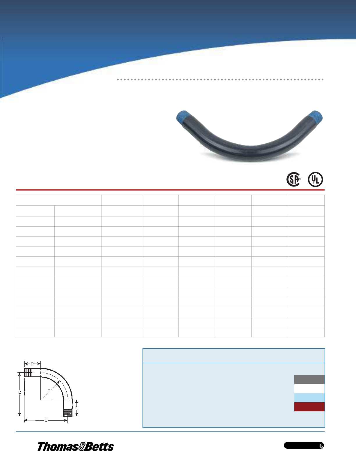
Factory Bent to Save Time and Materials!
OCAL-BLUETM Standard-Radius
Elbows
•Fabricated from OcalTM PVC-coated conduit
•Standard radius in 30°, 45°, 60° and 90° available for
immediate shipment
•Colour-coded thread protectors for easy identification of
conduit size
•Special radius and degrees not listed are also available
upon request
Cat. No. Pipe Size Radius ‘‘R’’ Offset ‘‘C’’ Straight End ‘‘D’’ Unbent
Length
Weight Each
Steel Only
Steel Aluminum in.
(mm)
in.
(mm)
in.
(mm)
in.
(mm)
in.
(mm)
lb.
(kg)
ELL1/2-_-_ ELL1/2-_-SA-_ 1/2
(16)
4.00
(101.60)
6.00
(152.40)
2.00
(50.80)
10.28
(261.19)
0.67
(16.95)
ELL3/4-_-_ ELL3/4-_-SA-_ 3/4
(21)
4.50
(114.30)
6.50
(165.10)
2.00
(50.80)
11.07
(281.14)
0.95
(24.07)
ELL1-_-_ ELL1-_-SA-_ 1
(27)
5.75
(146.05)
8.00
(203.20)
2.25
(57.15)
13.53
(343.71)
1.77
(44.97)
ELL1-1/4-_-_ ELL1-1/4-_-SA-_ 1-1/4
(35)
7.25
(184.15)
9.50
(241.30)
2.25
(57.15)
15.89
(403.56)
2.55
(64.80)
ELL1-1/2-_-_ ELL1-1/2-_-SA-_ 1-1/2
(41)
8.25
(209.55)
11.00
(279.40)
2.75
(69.85)
18.46
(468.86)
3.98
(101.13)
ELL2-_-_ ELL2-_-SA-_ 2
(53)
9.50
(241.30)
13.00
(330.20)
3.50
(88.90)
21.92
(556.83)
6.33
(160.86)
ELL2-1/2-_-_ ELL2-1/2-_-SA-_ 2-1/2
(63)
10.50
(266.70)
14.00
(355.60)
3.50
(88.90)
23.49
(596.73)
9.65
(245.09)
ELL3-_-_ ELL3-_-SA-_ 3
(78)
13.00
(330.20)
16.50
(419.10)
3.50
(88.90)
27.42
(696.48)
15.42
(391.77)
ELL3-1/2-_-_ ELL3-1/2-_-SA-_ 3-1/2
(91)
15.00
(381.00)
20.75
(527.05)
5.75
(146.05)
35.06
(890.57)
23.30
(591.84)
ELL4-_-_ ELL4-_-SA-_ 4
(103)
16.00
(406.40)
21.75
(552.45)
5.75
(146.05)
36.63
(930.47)
29.68
(753.80)
*ELL5-_-_ ELL5-_-SA-_ 5
(129)
24.00
(609.60)
31.00
(787.40)
7.00
(177.80)
51.70
(1313.16)
60.82
(1544.89)
*ELL6-_-_ ELL6-_-SA-_ 6
(155)
30.00
(762.00)
39.00
(990.60)
9.00
(228.60)
65.12
(1654.15)
85.69
(2176.51)
Metric size designator (ANSI C80.1-1994).
*Not CSA certified.
Cat. No. Pipe
Size Angle Material Colour
ELL 3/4- _ - _ - _
30 = 30º Blank = Steel G = Grey
45 = 45º SA = Aluminum W = White
60 = 60º B = Blue
Blank = 90º R = Red
Catalogue No. Example:
ELL3/4SA-W is a 3/4 in. trade size 90º aluminum elbow coated in
white PVC.
Custom colours also available - Std. min. quantities are
required. Please contact your Regional Sales Office.
w w w . t n b . c a
PVC-Coated Products
H13
OCALTM
Conduit and Accessories
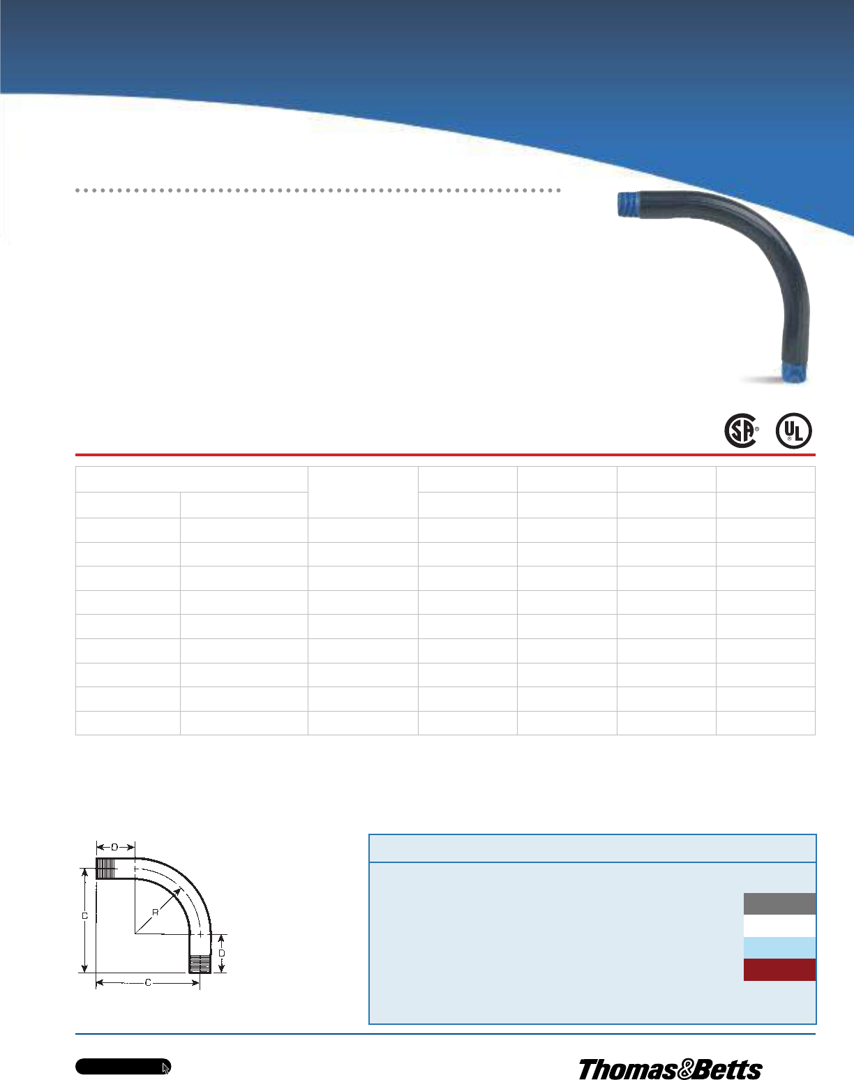
Choose the Size and Angle to
Meet your Exact Requirements
Cat. No. Pipe
Size Radius Angle Material Colour
LRELL_X12- _ - _ - _
1 = 1’’ 30 = 30º Blank = Steel G = Grey
2 = 2’’ 45 = 45º SA = Aluminum W = White
etc. 60 = 60º B = Blue
Blank = 90º R = Red
Catalogue No. Example:
LRELL3X18-45-G is a 3’’ trade size steel elbow with a radius of 18’’ and an
angle of 45º, coated in grey PVC.
Custom colours also available - Std. min. quantities
are required. Please contact your Regional Sales Of-
fice.
OCAL-BLUETM Large-Radius Elbows
•Fabricated from OcalTM PVC-coated conduit
•Standard radius in 90° available for immediate shipment
•Special radius and degrees not listed are also available
upon request
•Colour-coded thread protectors for easy identification of
conduit size
Cat. No. Pipe Size
in.
(mm)
Radius ‘‘R’’ Offset ‘‘C’’ Straight End ‘‘D’’ Unbent
Length
Steel Aluminum in.
(mm)
ft.
(mm)
in.
(mm)
ft.
(mm)
LRELL_X12-_-_ LRELL_X12-_-SA-_ 1 - 2-1/2
(27- 63)
12.00
(304.80)
1.9
(533.40)
9.00
(228.60)
3.00
(914.40)
LRELL_X15-_-_ LRELL_X15-_-SA-_ 1 - 3
(27- 78)
15.00
(381.00)
2.00
(609.60)
9.00
(228.60)
3.6
(1066.80)
LRELL_X18-_-_ LRELL_X18-_-SA-_ 1 - 4
(27 - 103)
18.00
(457.20)
2.4
(711.20)
10.00
(254.00)
4.00
(1219.20)
LRELL_X24-_-_ LRELL_X24-_-SA-_ 1 - 4
(27 - 103)
24.00
(609.60)
2.11
(889.00)
11.00
(279.40)
4.11
(1498.60)
LRELL_X30-_-_ LRELL_X30-_-SA-_ 1 - 6
(27 - 155)
30.00
(762.00)
3.5
(1041.40)
11.00
(279.40)
5.9
(1752.60)
LRELL_X36-_-_ LRELL_X36-_-SA-_ 1 - 6
(27 - 155)
36.00
(914.40)
3.11
(1193.80)
11.00
(279.40)
6.6
(1981.20)
LRELL_X42-_-_ LRELL_X42-_-SA-_ 1 - 6
(27 - 155)
42.00
(1066.80)
4.6
(1371.60)
12.00
(304.80)
7.6
(2286.00)
LRELL_X48-_-_ LRELL_X48-_-SA-_ 1 - 6
(27 - 155)
48.00
(1219.20)
5.00
(1524.00)
12.00
(304.80)
8.6
(2590.80)
LRELL_X60-_-_ LRELL_X60-_-SA-_ 2-1/2 - 6
(63 - 155)
60.00
(1524.00)
6.00
(1828.80)
12.00
(304.80)
9.10
(2997.20)
Metric size designator (ANSI C80.1-1994).
#5 and 6 inch not CSA certified.
w w w . t n b . c a
PVC-Coated Products
H14
OCALTM
Conduit and Accessories
PVC Coating Evenly Molded Around Saddle
Prevents Exposure of Metal — an OcalTM Exclusive!
Cat. No. Size Colour
RA1-
_ = space for colour identifier
G = Grey
W = White
B = Blue
Custom colours also available - Std. min. quantities are
required. Please contact your Regional Sales Office.
_
Cat. No. Size Colour
UB1-
_ = space for colour identifier
G = Grey
W = White
B = Blue
Custom colours also available - Std. min. quantities are
required. Please contact your Regional Sales Office.
_
Cat. No. Pipe Size
Right Angle Parallel Edge in. (mm)
RA1/2-_ PAR1/2-_ EC1/2-_ 1/2 (16)
RA3/4-_ PAR3/4-_ EC3/4-_ 3/4 (21)
RA1-_ PAR1-_ EC1-_ 1 (27)
RA1-1/4-_ PAR1-1/4-_ EC1-1/4-_ 1-1/4 (35)
RA1-1/2-_ PAR1-1/2-_ EC1-1/2-_ 1-1/2 (41)
RA2-_ PAR2-_ EC2-_ 2 (53)
RA2-1/2-_ PAR2-1/2-_ — 2-1/2 (63)
RA3-_ PAR3-_ — 3 (78)
RA3-1/2-_ PAR3-1/2-_ — 3-1/2 (91)
RA4-_ PAR4-_ — 4 (103)
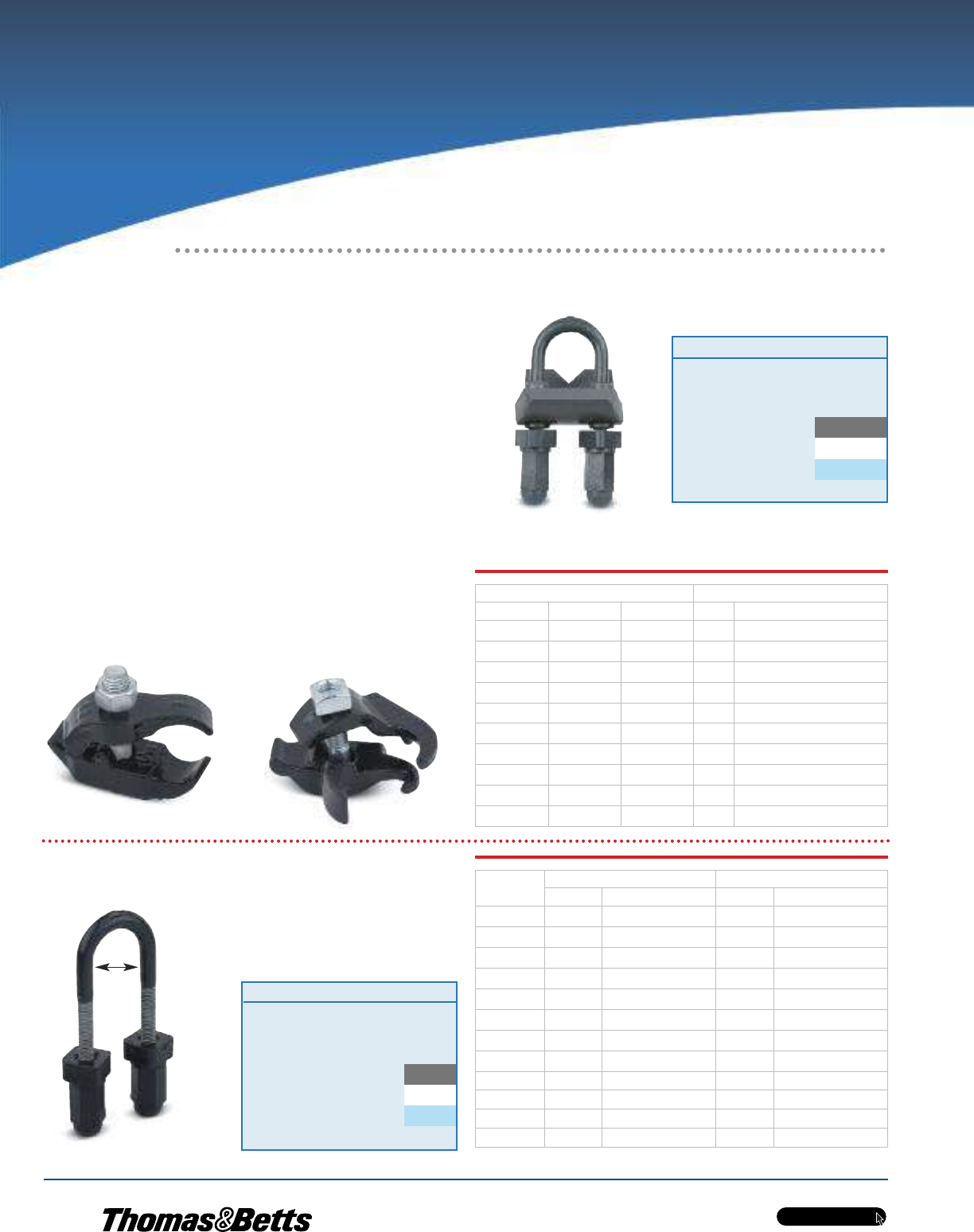
Cat. No. Pipe Size ‘‘A’’ Dimension
in. (mm) in. (mm)
UB1/2-_ 1/2 (16) 1.38 (34.93)
UB3/4-_ 3/4 (21) 1.56 (39.69)
UB1-_ 1 (27) 1.84 (46.83)
UB1-1/4-_ 1-1/4 (35) 2.19 (55.56)
UB1-1/2-_ 1-1/2 (41) 2.50 (63.50)
UB2- 2 (53) 2.97 (75.41)
UB2-1/2-_ 2-1/2 (63) 3.47 (88.11)
UB3- 3 (78) 4.09 (103.98)
UB3-1/2-_ 3-1/2 (91) 4.59 (116.68)
UB4-_ 4 (103) 5.09 (129.38)
UB5-_ 5 (129) 6.63 (168.28)
UB6-_ 6 (155) 8.00 (203.20)
U-Bolts
A
Right Angle (RA)
U-Bolt (UB)
Metric size designator (ANSI C80.1-1994).
Parallel (PAR)
PVC-Coated Beam Clamps
OcalTM PVC-Coated Beam Clamps
and U-Bolts
•Beam clamps support and attach conduit runs to structural
beams
•Molded right-angle beam clamps and U-bolts provide extra
protection
•Nuts are encapsulated, (RA) providing complete protection.
•Hex-shaped nuts fit standard wrenches
•Stainless steel hardware included
•Parallel (PAR) and edge (EC) clamps feature nominal
0.015 in. (15 mils) PVC coating for corrosion protection
•Right-Angle clamps (RA) and U-Bolts (UB) feature nominal
0.040 in. (40 mils) PVC coating for corrosion protection
•The coating is evenly molded around the saddle which only
OcalTM provides to prevent exposure to metal
Edge (EC)
_
_
w w w . t n b . c a
PVC-Coated Products
H15
OCALTM
Conduit and Accessories
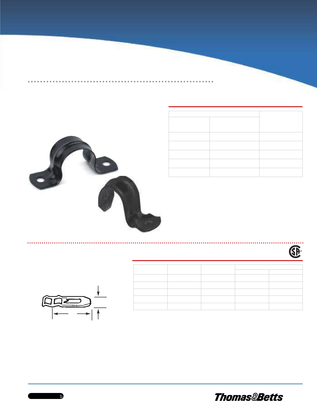
Support Conduit on Walls and Structures
Cat. No. Pipe Size
in.
(mm)
One-Hole
Malleable
Iron
Two-Hole
Stamped
Steel
1HS1/2C-_ 2HS1/2C-_ 1/2
(16)
1HS3/4C-_ 2HS3/4C-_ 3/4
(21)
1HS1C-_ 2HS1C-_ 1
(27)
1HS1-1/4C-_ 2HS1-1/4C-_ 1-1/4
(35)
1HS1-1/2C-_ 2HS1-1/2C-_ 1-1/2
(41)
PVC-Coated Pipe Straps
Cat. No. Conduit
Size (in.)
Screw
Size
Dimensions (in.)
A B
1350CR 1/2 – 3/4 – 1 #7 3 7/8
1351CR 1/4 – 1/2 – 2 #12 5 3/8
1352CR 2-1/2 – 3 #12 6-9/16 1-3/4
1353CR 3-1/2 – 4 #14 7-9/16 2
1354CR 4-1/2 – 5 – 6 #16 10-9/16 2-9/16
Metric size designator (ANSI C80.1-1994).
UL not applicable.
Conforms to CEC Rule 12-012 (5)
One-Hole PVC-Coated Pipe Strap
Two-Hole PVC-Coated Pipe
Strap
Pipe Straps
•Available in malleable iron/stamped steel with nominal 0.015 in
(15 mils) PVC coating in your choice of blue, white or grey
•Choose one- or two-hole versions
•Sized to allow for the extra thickness of the PVC coating
Pipe Spacers — PVC Coated
Corrosion resistant PVC coated malleable iron.
Pre-mountable, stackable to eliminate offsetting.
Spacers can be stacked for offsets on wall or into
outlet box. Prevents conduit rusting from wall con-
densation. Eliminates offsetting of conduit.
A
B
w w w . t n b . c a
PVC-Coated Products
H16
OCALTM
Ordinary Location Fittings
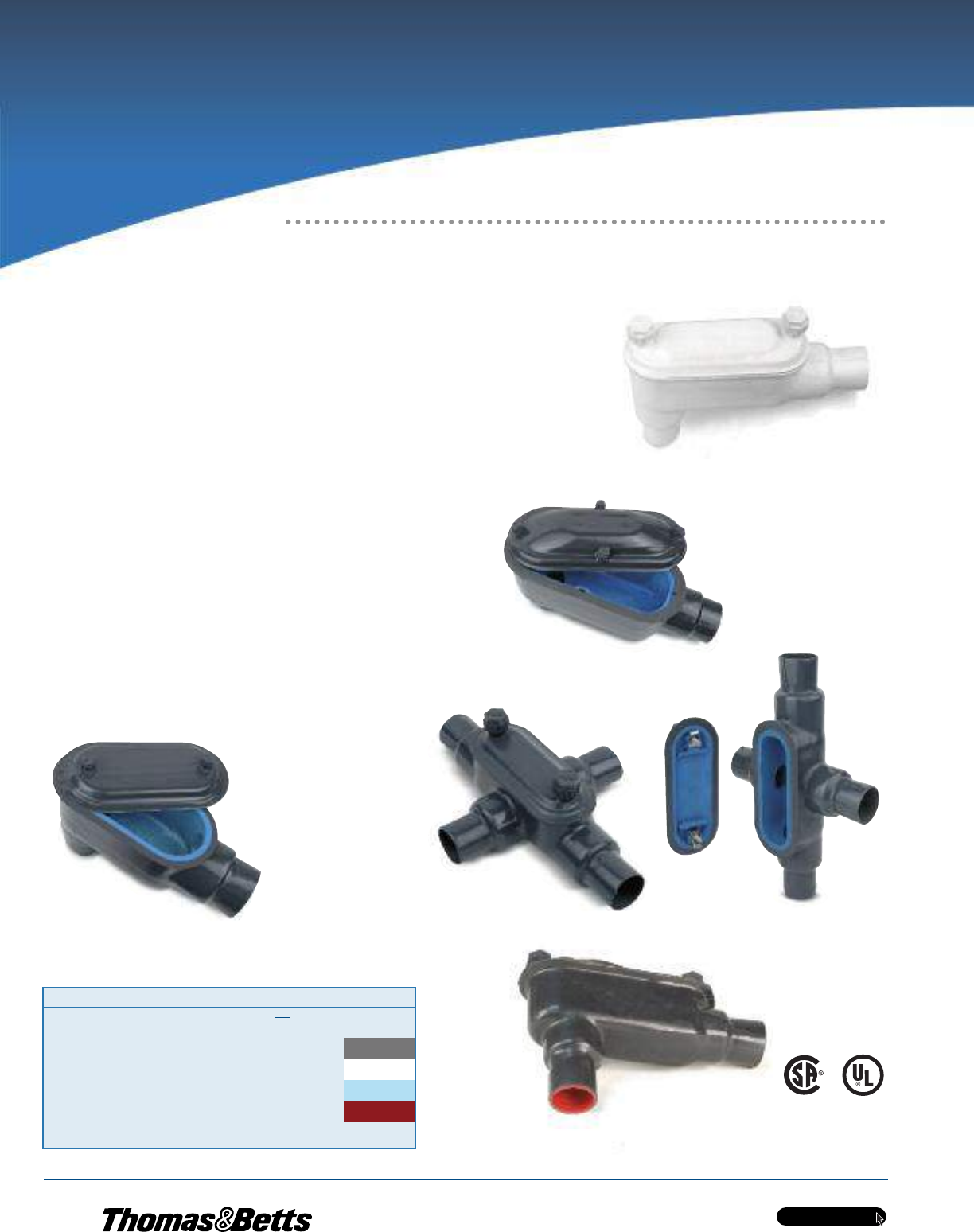
Easy Access for Pulling, Splicing, Mounting
and Maintenance!
OCAL-BLUETM Double-Coat
Conduit Bodies
With OCAL-BLUETM Double-Coat Conduit Bodies, you can connect sections of
conduit — with or without 90° bends — and provide easy access for wire
pulling, making splices in branch conductors and maintenance and future
system changes. Conduit bodies can also serve as mounting outlets for wiring
devices and lighting fixtures.
•Flat surface molded on conduit body seals with molded flange
on cover
•Available in Form 7 and Form 8 ferrous as well as Mark 9 and
Form 7 aluminum
•All OCAL-BLUETM conduit bodies offer double corrosion protection
— both bodies and covers coated inside and out with a nominal
0.002 in. (2 mils) blue urethane, then exterior coated with a
nominal 0.040 in. (40 mils) PVC
•All threaded hubs fitted with pressure-sealing sleeves
•Conduit bodies ship complete with covers and encapsulated
stainless steel screws
•Covers also sold separately for replacement or retrofit purposes
Cat. No. Material Colour
LB27 _- _ = space for colour identifier
Blank = Steel G = Grey
SA = Aluminum W = White
Catalogue No. Example:
LB27-W is 3/4 in. LB ferrous
conduit body and cover
coated in white PVC.
B = Blue
R = Red
Custom colours also available - Std. min. quantities are
required. Please contact your Regional Sales Office. 3⁄4 in. LB Mark 9 conduit
body and cover
Up to and including 2 in.
3/4 in. B Form 8 conduit body and cover
2-1/2 in. LB Form 8 conduit body and cover
2-1/2 in. LB Form 7 conduit body and cover 3⁄4 in. X Form 7 conduit body and cover
w w w . t n b . c a
PVC-Coated Products
H17
OCALTM
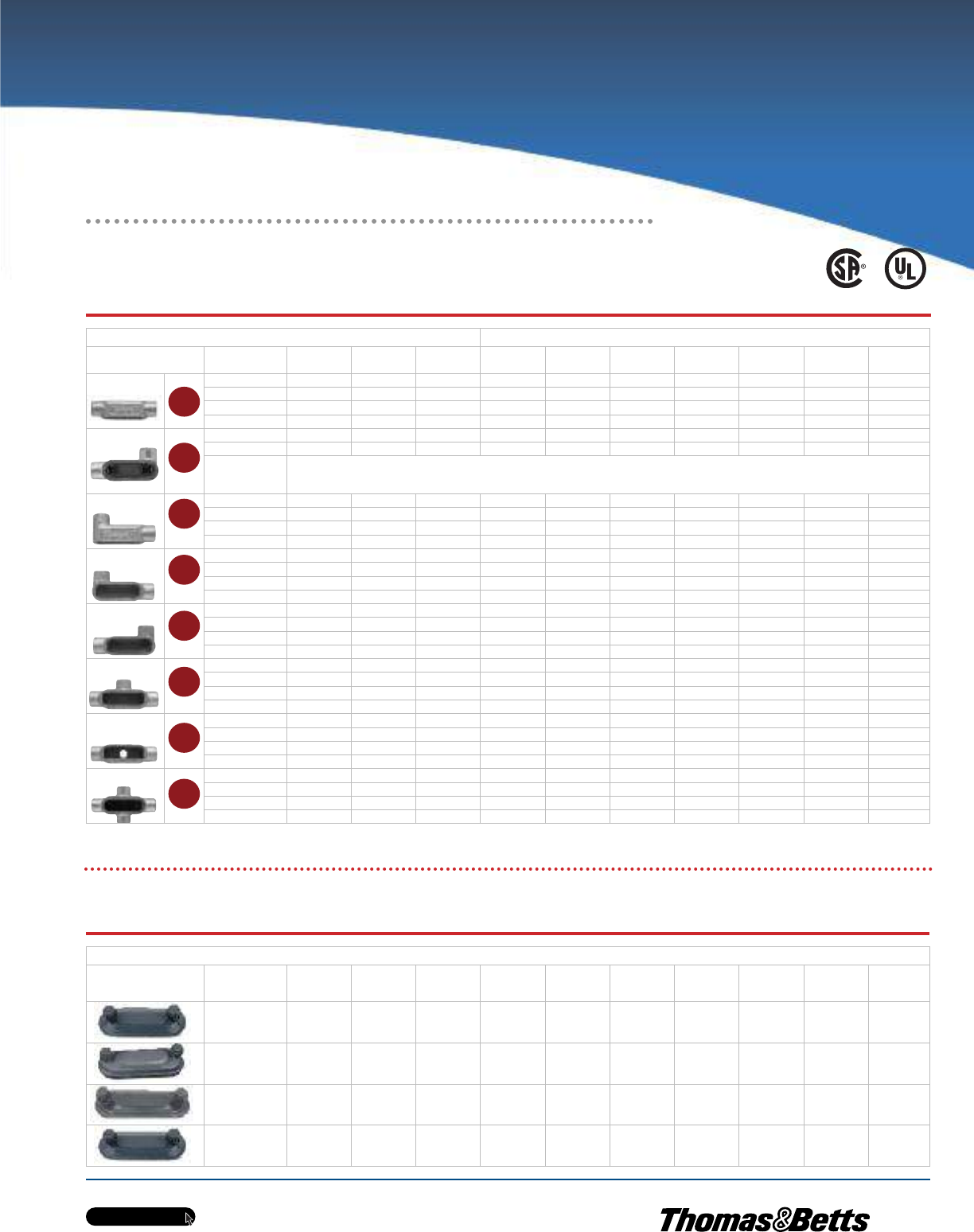
OCAL-BLUETM Conduit Bodies Quick Reference
OCAL-BLUETM Conduit Body Covers
NOTE: Fittings shown uncoated Size in. (mm) 1/2 in. to 2 in.*
Shape Style 1/2
(16)
3/4
(21)
1
(27)
1-1/4
(35)
1-1/2
(41)
2
(53)
2-1/2
(63)
3
(78)
3-1/2
(91)
4
(103)
Form 7 C17-_ C27-_ C37-_ C47-_ C57-_ C67-_ C77-_ C87-_ ——
Form 8 C18-_ C28-_ C38-_ C448-_ C58-_ C68-_ C78-_ C88-_ ——
Mark 9 C19-_ C29-_ C39-_ C49-_ C59-_ C69-_ C789-_ C889-_ C989-_ C1089-_
Form 7 Aluminum C17SA-_ C27SA-_ C37SA-_ C47SA-_ C57SA-_ C67SA-_ C77SA-_ C87SA-_ ——
Form 7 L17-_ L27-_ L37-_ L47-_ L57-_ L67-_ ————
Form 7 Aluminum L17SA-_ L27SA-_ L37SA-_ L47SA-_ L57SA-_ L67SA-_ ————
Double faced — may be use as LL or LR — has 2 openings
Not CSA certified
Form 7 LB17-_ LB27-_ LB37-_ LB47-_ LB57-_ LB67-_ LB777-_ LB87-_ LB97-_ LB107-_
Form 8 LB18-_ LB28-_ LB38-_ LB448-_ LB58-_ LB68-_ LB78-_ LB888-_ LB98-_ LB108-_
Mark 9 LB19-_ LB29-_ LB39-_ LB49-_ LB59-_ LB69-_ LB789-_ LB889-_ LB989-_ LB1089-_
Form 7 Aluminum LB17SA-_ LB27SA-_ LB37SA-_ LB47SA-_ LB57SA-_ LB67SA-_ LB777SA-_ LB87SA-_ LB97SA-_ LB107SA-_
Form 7 LL17-_ LL27-_ LL37-_ LL47-_ LL57-_ LL67-_ LL777-_ LL87-_ LL97-_ LL107-_
Form 8 LL18-_ LL28-_ LL38-_ LL448-_ LL58-_ LL68-_ LL78-_ LL888-_ ——
Mark 9 LL19-_ LL29-_ LL39-_ LL49-_ LL59-_ LL69-_ LL789-_ LL889-_ LL989-_ LL1089-_
Form 7 Aluminum LL17SA-_ LL27SA-_ LL37SA-_ LL47SA-_ LL57SA-_ LL67SA-_ LL777SA-_ LL87SA-_ LL97SA-_ LL107SA-_
Form 7 LR17-_ LR27-_ LR37-_ LR47-_ LR57-_ LR67-_ LR777-_ LR87-_ LR97-_ LR107-_
Form 8 LR18-_ LR28-_ LR38-_ LR448-_ LR58-_ LR68-_ LR78-_ LR888-_ ——
Mark 9 LR19-_ LR29-_ LR39-_ LR49-_ LR59-_ LR69-_ LR789-_ LR889-_ LR989-_ LR1089-_
Form 7 Aluminum LR17SA-_ LR27SA-_ LR37SA-_ LR47SA-_ LR57SA-_ LR67SA-_ LR777SA-_ LR87SA-_ LR97SA-_ LR107SA-_
Form 7 T17-_ T27-_ T37-_ T47-_ T57-_ T67-_ T77-_ T87-_ T97-_ T107-_
Form 8 T18-_ T28-_ T38-_ T448-_ T58-_ T68-_ T78-_ T88-_ ——
Mark 9 T19-_ T29-_ T39-_ T49-_ T59-_ T69-_ T789-_ T889-_ T989-_ T1089-_
Form 7 Aluminum T17SA-_ T27SA-_ T37SA-_ T47SA-_ T57SA-_ T67SA-_ T77SA-_ T87SA-_ T97SA-_ T107SA-_
Form 7 TB17-_ TB27-_ TB37-_ TB47-_ TB57-_ TB67-_ ————
Form 8 TB18-_ TB28-_ TB38-_ TB448-_ TB58-_ TB68-_ ————
Mark 9 TB19-_ TB29-_ TB39-_ TB49-_ ——————
Form 7 Aluminum TB17SA-_ TB27SA-_ TB37SA-_ TB47SA-_ TB57SA-_ TB67SA-_ ————
Form 7 X17-_ X27-_ X37-_ X47-_ X57-_ X67-_ ————
Form 8 X18-_ X28-_ X38-_ X448-_ X58-_ X68-_ ————
Mark 9 X19-_ X29-_ X39-_ ———————
Form 7 Aluminum X17SA-_ X27SA-_ X37SA-_ X47SA-_ X57SA-_ X67SA-_ ————
C
LB
LL
LR
T
TB
X
L
*PVC coated ‘‘OCAL-BLUETM’’ conduit bodies with covers for threaded rigid conduit series C, LB, LL, LR, T, TB and X with supports 28-4X, 38-4X, 448-4X, J8-4X and 6R-4X. Type 4X ratings in 1/2 in. (16) to
2 in. (53) trade size.
Size in. (mm)
STYLE 1/2
(16)
3/4
(21)
1
(27)
1-1/4
(35)
1-1/2
(41)
2
(53)
2-1/2
(63)
3
(78)
3-1/2
(91)
4
(103)
Form 7 170F-_ 270F-_ 370F-_ 470F-_ 570F-_ 670F-_ 870F-_ 870F-_ 970F-_ 970F-_
Form 8 180F-_ 280F-_ 380F-_ 480F-_ 580F-_ 680F-_ 880F-_ 880F-_ 980F-_ 980F-_
Mark 9 190-_ 290-_ 390-_ 490-_ 590-_ 690-_ 889-_ 889-_ 989-_ 989-_
Form 7 Aluminum 170SA-_ 270SA-_ 370SA-_ 470SA-_ 570SA-_ 670SA-_ 870SA-_ 870SA-_ 970SA-_ 970SA-_
Up to and including 2 in.
Ordinary Location Fittings
w w w . t n b . c a
PVC-Coated Products
H18
OCALTM
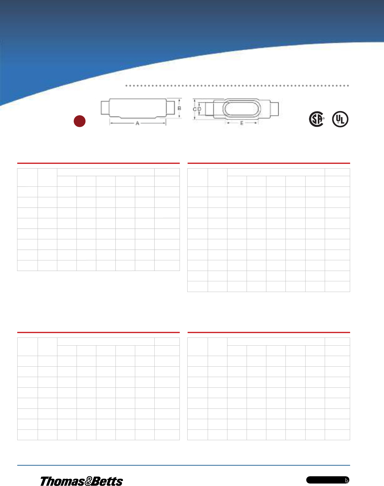
C Form 7 Ferrous Conduit Bodies
with Covers
C
Cat. No.
Hub
Size
in. (mm)
Dimensions in. (mm)*Vol. Cap.
ABCDE(cu.in./
cu.cm)
C17-_1/2
(16)
5.45
(138.43)
1.40
(35.56)
1.45
(36.83)
0.95
(24.13)
3.20
(81.28)
4.00
(65.55)
C27-_3/4
(21)
6.05
(153.67)
1.60
(40.64)
1.65
(41.91)
1.15
(29.21)
3.80
(96.52)
6.60
(108.15)
C37-_1
(27)
6.75
(171.45)
1.90
(48.26)
1.80
(45.72)
1.35
(34.29)
4.55
(115.57)
10.60
(173.70)
C47-_1-1/4
(35)
7.30
(185.42)
2.30
(58.42)
2.20
(55.88)
1.80
(45.72)
5.00
(127.00)
18.80
(308.08)
C57-_1-1/2
(41)
8.60
(218.44)
2.60
(66.04)
2.45
(62.23)
2.05
(52.07)
5.45
(138.43)
26.40
(432.62)
C67-_2
(53)
9.50
(241.30)
3.20
(81.28)
3.05
(77.47)
2.45
(62.23)
6.40
(162.56)
51.00
(835.74)
C77-_2-1/2
(63)
12.10
(307.34)
3.65
(92.71)
4.25
(107.95)
3.60
(91.44)
8.40
(213.36)
102.00
(1671.48)
C87-_3
(78)
12.10
(307.34)
4.40
(111.76)
4.25
(107.95)
3.60
(91.44)
8.40
(213.36)
132.00
(2163.09)
C Mark 9 Aluminium Conduit Bodies
with Covers
Cat. No.
Hub
Size
in. (mm)
Dimensions in. (mm)* Vol. Cap.
ABCDE
(cu.in./
cu.cm)
C19-_ 1/2
(16)
5.00
(127.00)
1.38
(35.05)
1.38
(35.05)
1.19
(30.23)
3.31
(84.07)
—
—
C29-_ 3/4
(21)
5.69
(144.53)
1.63
(41.40)
1.56
(39.62)
1.38
(35.05)
3.94
(100.08)
—
—
C39-_ 1
(27)
6.59
(167.39)
1.88
(47.75)
1.75
(44.45)
1.50
(38.10)
4.56
(115.82)
—
—
C49-_ 1-1/4
(35)
7.50
(190.50)
2.50
(63.50)
2.19
(55.63)
1.94
(49.28)
5.31
(134.87)
—
—
C59-_ 1-1/2
(41)
8.25
(209.55)
2.75
(69.85)
2.50
(63.50)
2.25
(57.15)
6.00
(152.40)
—
—
C69-_ 2
(53)
10.50
(266.70)
3.44
(87.38)
3.19
(81.03)
2.88
(73.15)
8.06
(204.72)
—
—
C789-_ 2-1/2
(63)
15.63
(397.00)
4.44
(112.78)
5.00
(127.00)
4.25
(107.95)
10.88
(276.35)
—
—
C889-_ 3
(78)
15.63
(397.00)
4.81
(122.17)
5.00
(127.00)
4.25
(107.95)
10.88
(276.35)
—
—
C989-_ 3-1/2
(91)
18.75
(476.25)
5.69
(144.53)
6.25
(158.75)
5.44
(138.18)
13.44
(341.38)
—
—
C1089-_ 4
(103)
18.75
(476.25)
5.94
(150.88)
6.25
(158.75)
5.44
(138.18)
13.44
(341.38)
—
—
C Form 8 Ferrous Conduit Bodies
with Covers
Cat. No.
Hub
Size
in. (mm)
Dimensions in. (mm)* Vol. Cap.
ABCDE
(cu.in./
cu.cm)
C18-_ 1/2
(16)
5.53
(140.49)
1.44
(36.51)
1.38
(34.93)
1.00
(25.40)
3.31
(84.14)
4.90
(80.30)
C28-_ 3/4
(21)
6.28
(159.54)
1.53
(38.89)
1.19
(30.16)
1.19
(30.16)
3.94
(100.01)
8.00
(131.10)
C38-_ 1
(27)
7.31
(185.74)
1.94
(49.21)
1.75
(44.45)
1.38
(34.93)
4.56
(115.89)
13.00
(213.03)
C448-_ 1-1/4
(35)
8.50
(215.90)
2.38
(60.33)
2.19
(55.56)
1.75
(44.45)
5.31
(134.94)
23.50
(385.10)
C58-_ 1-1/2
(41)
10.38
(263.53)
2.78
(70.64)
2.75
(69.85)
2.13
(53.98)
6.50
(165.10)
45.00
(737.42)
C68-_ 2
(53)
12.25
(311.15)
3.56
(90.49)
3.75
(95.25)
3.00
(76.20)
8.56
(217.49)
88.00
(1442.06)
C78-_ 2-1/2
(63)
15.63
(396.88)
4.44
(112.71)
5.00
(127.00)
4.25
(107.95)
10.88
(276.23)
110.00
(1802.58)
C88-_ 3
(78)
15.63
(396.88)
4.81
(122.24)
5.00
(127.00)
4.25
(107.95)
10.88
(276.23)
110.00
(1802.58)
C Form 7 Aluminum Conduit Bodies
with Covers
Cat. No.
Hub
Size
in. (mm)
Dimensions in. (mm)* Vol. Cap.
ABCDE
(cu.in./
cu.cm)
C17SA-_ 1/2
(16)
5.45
(138.43)
1.40
(35.56)
1.45
(36.83)
0.95
(24.13)
3.20
(81.28)
4.00
(65.55)
C27SA-_ 3/4
(21)
6.05
(153.67)
1.60
(40.64)
1.65
(41.91)
1.15
(29.21)
3.80
(96.52)
6.60
(108.15)
C37SA-_ 1
(27)
6.75
(171.45)
1.90
(48.26)
1.80
(45.72)
1.35
(34.29)
4.55
(115.57)
10.60
(173.70)
C47SA-_ 1-1/4
(35)
7.30
(185.42)
2.30
(58.42)
2.20
(55.88)
1.80
(45.72)
5.00
(127.00)
18.80
(308.08)
C57SA-_ 1-1/2
(41)
8.60
(218.44)
2.60
(66.04)
2.45
(62.23)
2.05
(52.07)
5.45
(138.43)
26.40
(432.62)
C67SA-_ 2
(53)
9.50
(241.30)
3.20
(81.28)
3.05
(77.47)
2.45
(62.23)
6.40
(162.56)
51.00
(835.74)
C77SA-_ 2-1/2
(63)
12.10
(307.34)
3.65
(92.71)
4.25
(107.95)
3.60
(91.44)
8.40
(213.36)
102.00
(1671.48)
C87SA-_ 3
(78)
12.10
(307.34)
4.40
(111.76)
4.25
(107.95)
3.60
(91.44)
8.40
(213.36)
132.00
(2163.09)
Metric size designator (ANSI C80.1-1994).
*Dimensions shown are for uncoated conduit bodies.
Up to and including 2 in.
Ordinary Location Fittings

w w w . t n b . c a
PVC-Coated Products
H19
OCALTM
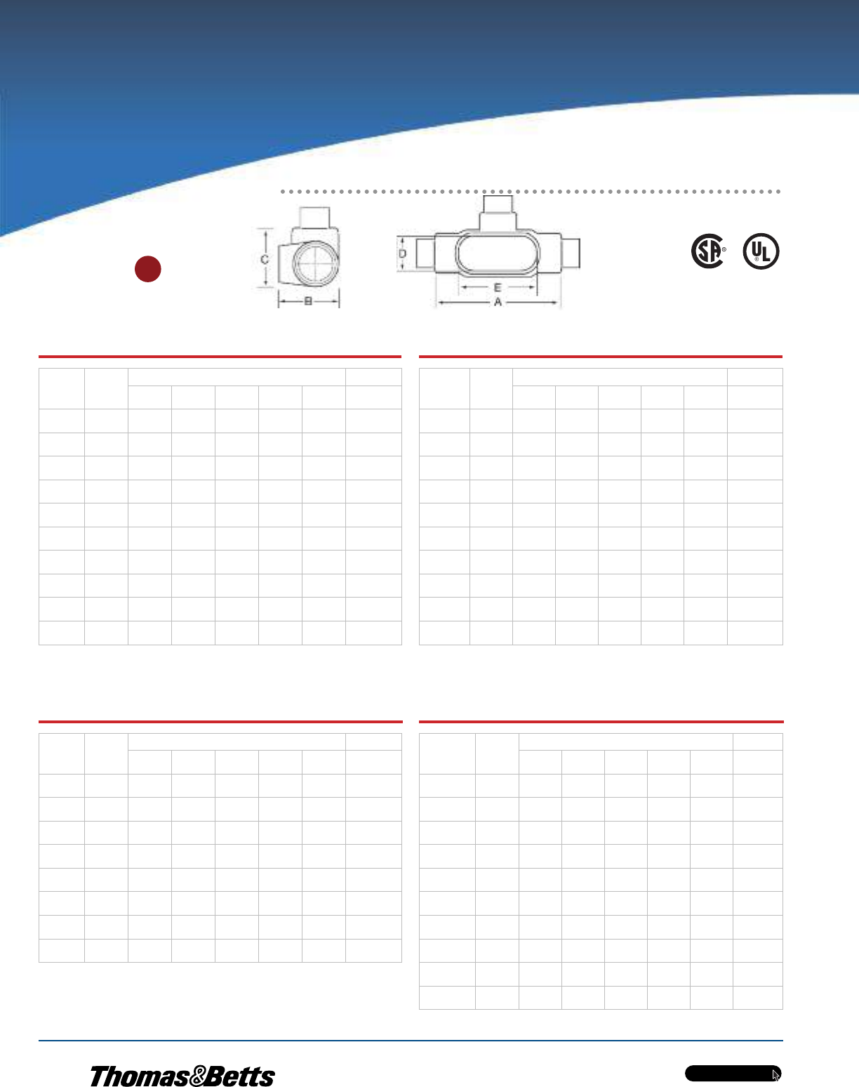
LB Form 7 Ferrous Conduit Bodies
with Covers
Cat. No.
Hub
Size
in. (mm)
Dimensions in. (mm)* Vol. Cap.
ABCDE
(cu.in./
cu.cm)
LB17-_ 1/2
(16)
4.60
(116.84)
2.20
(55.88)
1.35
(34.29)
0.95
(24.13)
3.20
(81.28)
4.00
(65.55)
LB27-_ 3/4
(21)
5.25
(133.35)
2.40
(60.96)
1.65
(41.91)
1.15
(29.21)
3.80
(96.52)
6.60
(108.15)
LB37-_ 1
(27)
6.00
(152.40)
2.65
(67.31)
1.80
(45.72)
1.35
(34.29)
4.55
(115.57)
10.60
(173.70)
LB47-_ 1-1/4
(35)
6.45
(163.83)
3.20
(81.28)
2.20
(55.88)
1.80
(45.72)
5.00
(127.00)
18.80
(308.08)
LB57-_ 1-1/2
(41)
7.25
(184.15)
3.90
(99.06)
2.45
(62.23)
2.05
(52.07)
5.45
(138.43)
26.40
(432.62)
LB67-_ 2
(53)
8.30
(210.82)
4.45
(113.03)
3.10
(78.74)
2.45
(62.23)
6.40
(162.56)
51.00
(835.74)
LB777-_ 2-1/2
(63)
10.55
(267.97)
5.20
(132.08)
4.25
(107.95)
3.60
(91.44)
8.40
(213.36)
102.00
(1671.48)
LB87-_ 3
(78)
10.55
(267.97)
5.95
(151.13)
4.25
(107.95)
3.60
(91.44)
8.40
(213.36)
132.00
(2163.09)
LB97-_ 3-1/2
(91)
12.85
(326.39)
6.70
(170.18)
5.25
(133.35)
4.55
(115.57)
10.25
(260.35)
210.00
(3441.28)
LB107-_ 4
(103)
12.85
(326.39)
7.20
(182.88)
5.25
(133.35)
4.55
(115.57)
10.25
(260.35)
243.00
(3982.06)
LB Form 8 Ferrous Conduit Bodies
with Covers
Cat. No.
Hub
Size
in. (mm)
Dimensions in. (mm)* Vol. Cap.
ABCDE
(cu.in./
cu.cm)
LB18-_ 1/2
(16)
4.94
(125.41)
2.22
(56.36)
1.38
(34.93)
1.00
(25.40)
3.31
(84.14)
4.90
(80.30)
LB28- 3/4
(21)
5.56
(141.29)
2.44
(61.93)
1.56
(39.69)
1.19
(30.16)
3.31
(84.14)
8.00
(131.10)
LB38-_ 1
(27)
6.50
(165.10)
2.81
(71.45)
1.75
(44.45)
1.38
(34.93)
4.56
(115.89)
13.00
(213.03)
LB448-_ 1-1/4
(35)
7.53
(191.29)
3.34
(84.93)
2.19
(55.56)
1.75
(44.45)
5.31
(134.94)
23.50
(385.10)
LB58-_ 1-1/2
(41)
9.13
(231.78)
4.03
(102.39)
2.75
(69.85)
2.13
(53.98)
6.50
(165.10)
45.00
(737.42)
LB68-_ 2
(53)
11.00
(279.40)
4.41
(111.92)
3.75
(95.25)
3.00
(76.20)
8.56
(217.49)
88.00
(1442.06)
LB78-_ 2-1/2
(63)
13.94
(354.01)
6.13
(155.58)
5.00
(127.00)
4.25
(107.95)
10.88
(276.23)
110.00
(1802.58)
LB888-_ 3
(78)
13.94
(354.01)
6.50
(165.10)
5.00
(127.00)
4.25
(107.95)
10.88
(276.23)
110.00
(1802.58)
LB98-_ 3-1/2
(91)
16.88
(428.63)
7.56
(192.09)
6.25
(158.75)
5.44
(138.11)
13.44
(341.31)
250.00
(4096.77)
LB108-_ 4
(103)
16.88
(428.63)
7.81
(198.44)
6.25
(158.75)
5.44
(138.11)
13.44
(341.31)
250.00
(4096.77)
LB Form 7 Aluminum Conduit Bodies
with Covers
Cat. No.
Hub
Size
in. (mm)
Dimensions in. (mm)* Vol. Cap.
ABCDE
(cu.in./
cu.cm)
LB17SA-_ 1/2
(16)
4.60
(116.84)
2.20
(55.88)
1.35
(34.29)
0.95
(24.13)
3.20
(81.28)
4.00
(65.55)
LB27SA-_ 3/4
(21)
5.25
(133.35)
2.40
(60.96)
1.65
(41.91)
1.15
(29.21)
3.80
(96.52)
6.60
(108.15)
LB37SA-_ 1
(27)
6.00
(152.40)
2.65
(67.31)
1.80
(45.72)
1.35
(34.29)
4.55
(115.57)
10.60
(173.70)
LB47SA-_ 1-1/4
(35)
6.45
(163.83)
3.20
(81.28)
2.20
(55.88)
1.80
(45.72)
5.00
(127.00)
18.80
(308.08)
LB57SA-_ 1-1/2
(41)
7.25
(184.15)
3.90
(99.06)
2.45
(62.23)
2.05
(52.07)
5.45
(138.43)
26.40
(432.62)
LB67SA-_ 2
(53)
8.30
(210.82)
4.45
(113.03)
3.10
(78.74)
2.45
(62.23)
6.40
(162.56)
51.00
(835.74)
LB777SA-_ 2-1/2
(63)
10.55
(267.97)
5.20
(132.08)
4.25
(107.95)
3.60
(91.44)
8.40
(213.36)
102.00
(1671.48)
LB87SA-_ 3
(78)
10.55
(267.97)
5.95
(151.13)
4.25
(107.95)
3.60
(91.44)
8.40
(213.36)
132.00
(2163.09)
LB97SA-_ 3-1/2
(91)
12.85
(326.39)
6.70
(170.18)
5.25
(133.35)
4.55
(115.57)
10.25
(260.35)
210.00
(3441.28)
LB107SA-_ 4
(103)
12.85
(326.39)
7.20
(182.88)
5.25
(133.35)
4.55
(115.57)
10.25
(260.35)
243.00
(3982.06)
LB Mark 9 Aluminum Conduit Bodies
with Covers
Cat. No.
Hub
Size
in. (mm)
Dimensions in. (mm)* Vol. Cap.
ABCDE
(cu.in./
cu.cm)
LB19-_ 1/2
(16)
4.59
(116.68)
2.13
(53.98)
1.38
(34.93)
1.19
(30.16)
3.31
(84.14) —
LB29-_ 3/4
(21)
5.25
(133.35)
2.41
(61.12)
1.56
(39.69)
1.38
(34.93)
3.94
(100.01) —
LB39-_ 1
(27)
6.09
(154.78)
2.84
(72.23)
1.75
(44.45)
1.50
(38.10)
4.56
(115.89) —
LB49-_ 1-1/4
(35)
7.03
(178.59)
3.47
(88.11)
2.19
(55.56)
1.94
(49.21)
5.31
(134.94) —
LB59-_ 1-1/2
(41)
7.75
(196.85)
3.75
(95.25)
2.50
(63.50)
2.25
(57.15)
6.00
(152.40) —
LB69-_ 2
(53)
10.03
(254.79)
4.47
(113.51)
3.19
(80.96)
2.88
(73.03)
8.06
(204.79) —
LB789-_ 2-1/2
(63)
13.94
(354.01)
6.13
(155.58)
5.00
(127.00)
4.25
(107.95)
10.88
(276.23) —
LB889-_ 3
(78)
13.94
(354.01)
6.50
(165.10)
5.00
(127.00)
4.25
(107.95)
10.88
(276.23) —
LB989-_ 3-1/2
(91)
16.88
(428.63)
7.56
(192.09)
6.25
(158.75)
5.44
(138.11)
13.44
(341.31) —
LB1089-_ 4
(103)
16.88
(428.63)
7.81
(198.44)
6.25
(158.75)
5.44
(138.11)
13.44
(341.31) —
Metric size designator (ANSI C80.1-1994).
*Dimensions shown are for uncoated conduit bodies.
LB
Up to and including 2 in.
Ordinary Location Fittings

w w w . t n b . c a
PVC-Coated Products
H20
OCALTM
Metric size designator (ANSI C80.1-1994).
*Dimensions shown are for uncoated conduit bodies.
LL Form 8 Ferrous Conduit Bodies
with Covers
LL
Cat. No.
Hub
Size
in. (mm)
Dimensions in. (mm)* Vol. Cap.
ABCDE
(cu.in./
cu.cm)
LL18-_ 1/2
(16)
4.94
(125.41)
1.44
(36.51)
2.16
(54.77)
1.00
(25.40)
3.31
(84.14)
4.90
(80.30)
LL28-_ 3/4
(21)
5.56
(141.29)
1.69
(42.86)
2.31
(58.74)
1.19
(30.16)
3.94
(100.01)
8.00
(131.10)
LL38-_ 1
(27)
6.47
(164.31)
1.94
(49.21)
2.63
(66.68)
1.38
(34.93)
4.56
(115.89)
13.00
(213.03)
LL448-_ 1-1/4
(35)
7.53
(191.29)
2.38
(60.33)
3.16
(80.17)
1.75
(44.45)
5.31
(134.94)
23.50
(385.10)
LL58-_ 1-1/2
(41)
9.13
(231.78)
2.78
(70.64)
4.00
(101.60)
2.13
(53.98)
6.50
(165.10)
45.00
(737.42)
LL68-_ 2
(53)
11.00
(279.40)
3.56
(90.49)
5.00
(127.00)
3.00
(76.20)
8.56
(217.49)
88.00
(1442.06)
LL78-_ 2-1/2
(63)
13.94
(354.01)
4.44
(112.71)
6.69
(169.86)
4.25
(107.95)
10.88
(276.23)
110.00
(1802.58)
LL888-_ 3
(78)
13.94
(354.01)
4.81
(122.24)
6.69
(169.86)
4.25
(107.95)
10.88
(276.23)
110.00
(1802.58)
Cat. No.
Hub
Size
in. (mm)
Dimensions in. (mm)* Vol. Cap.
ABCDE
(cu.in./
cu.cm)
LL19-_ 1/2
(16)
4.59
(116.68)
1.38
(34.93)
2.13
(53.98)
1.19
(30.16)
3.31
(84.14)
—
—
LL29-_ 3/4
(21)
5.25
(133.35)
1.63
(41.28)
2.38
(60.33)
1.38
(34.93)
3.94
(100.01)
—
—
LL39-_ 1
(27)
6.09
(154.78)
1.88
(47.63)
2.63
(66.68)
1.50
(38.10)
4.56
(115.89)
—
—
LL49-_ 1-1/4
(35)
7.03
(178.59)
2.50
(63.50)
3.09
(78.58)
1.94
(49.21)
5.31
(134.94)
—
—
LL59-_ 1-1/2
(41)
7.75
(196.85)
2.75
(69.85)
3.44
(87.31)
2.25
(57.15)
6.00
(152.40)
—
—
LL69-_ 2
(53)
10.03
(254.79)
3.44
(87.31)
4.13
(104.78)
2.88
(73.03)
8.06
(204.79)
—
—
LL789-_ 2-1/2
(63)
13.94
(354.01)
4.44
(112.71)
6.69
(169.86)
4.25
(107.95)
10.88
(276.23)
—
—
LL889-_ 3
(78)
13.94
(354.01)
4.81
(122.24)
6.69
(169.93)
4.25
(107.95)
10.88
(276.35)
—
—
LL989-_ 3-1/2
(91)
16.88
(428.63)
5.69
(144.46)
8.13
(206.38)
5.44
(138.11)
13.44
(341.31)
—
—
LL1089-_ 4
(103)
16.88
(428.63)
5.94
(150.81)
8.13
(206.38)
5.44
(138.11)
13.44
(341.31)
—
—
Cat. No.
Hub
Size
in. (mm)
Dimensions in. (mm)* Vol. Cap.
ABCDE
(cu.in./
cu.cm)
LL17-_ 1/2
(16)
4.60
(116.84)
1.40
(35.56)
1.45
(36.83)
0.95
(24.13)
3.20
(81.28)
4.00
(65.55)
LL27- 3/4
(21)
5.25
(133.35)
1.60
(40.64)
1.65
(41.91)
1.15
(29.21)
3.80
(96.52)
6.60
(108.15)
LL37-_ 1
(27)
6.00
(152.40)
1.90
(48.26)
2.60
(66.04)
1.35
(34.29)
4.55
(115.57)
10.60
(173.70)
LL47-_ 1-1/4
(35)
6.45
(163.83)
2.30
(58.42)
3.05
(77.47)
1.80
(45.72)
5.00
(127.00)
18.60
(304.80)
LL57-_ 1-1/2
(41)
7.90
(200.66)
2.60
(66.04)
3.80
(96.52)
2.05
(52.07)
5.45
(138.43)
26.40
(432.62)
LL67-_ 2
(53)
8.30
(210.82)
3.20
(81.28)
4.25
(107.95)
2.45
(62.23)
6.40
(162.56)
51.00
(835.74)
LL777-_ 2-1/2
(63)
10.55
(267.97)
3.65
(92.71)
5.80
(147.32)
3.60
(91.44)
8.40
(213.36)
102.00
(1671.48)
LL87-_ 3
(78)
10.55
(267.97)
4.40
(111.76)
5.80
(147.32)
3.60
(91.44)
8.40
(213.36)
132.00
(2163.09)
LL97-_ 3-1/2
(91)
12.85
(326.39)
4.90
(124.46)
7.03
(178.56)
4.55
(115.57)
10.25
(260.35)
210.00
(3441.28)
LL107-_ 4
(103)
12.85
(326.39)
5.40
(137.16)
7.03
(178.56)
4.55
(115.57)
10.25
(260.35)
243.00
(3982.06)
LL Form 7 Aluminum Conduit Bodies
with Covers
Cat. No.
Hub
Size
in. (mm)
Dimensions in. (mm)* Vol. Cap.
ABCDE
(cu.in./
cu.cm)
LL17SA-_ 1/2
(16)
4.60
(116.84)
1.40
(35.56)
1.45
(36.83)
0.95
(24.13)
3.20
(81.28)
4.00
(65.55)
LL27SA-_ 3/4
(21)
5.25
(133.35)
1.60
(40.64)
1.65
(41.91)
1.15
(29.21)
3.80
(96.52)
6.60
(108.15)
LL37SA-_ 1
(27)
6.00
(152.40)
1.90
(48.26)
2.60
(66.04)
1.35
(34.29)
4.55
(115.57)
10.60
(173.70)
LL47SA-_ 1-1/4
(35)
6.45
(163.83)
2.30
(58.42)
3.05
(77.47)
1.80
(45.72)
5.00
(127.00)
18.60
(304.80)
LL57SA-_ 1-1/2
(41)
7.90
(200.66)
2.60
(66.04)
3.80
(96.52)
2.05
(52.07)
5.45
(138.43)
26.40
(432.62)
LL67SA-_ 2
(53)
8.30
(210.82)
3.20
(81.28)
4.25
(107.95)
2.45
(62.23)
6.40
(162.56)
51.00
(835.74)
LL777SA-_ 2-1/2
(63)
10.55
(267.97)
3.65
(92.71)
5.80
(147.32)
3.60
(91.44)
8.40
(213.36)
102.00
(1671.48)
LL87SA-_ 3
(78)
10.55
(267.97)
4.40
(111.76)
5.80
(147.32)
3.60
(91.44)
8.40
(213.36)
132.00
(2163.09)
LL97SA-_ 3-1/2
(91)
12.85
(326.39)
4.90
(124.46)
7.03
(178.56)
4.55
(115.57)
10.25
(260.35)
210.00
(3441.28)
LL107SA-_ 4
(103)
12.85
(326.39)
5.40
(137.16)
7.03
(178.56)
4.55
(115.57)
10.25
(260.35)
243.00
(3982.06)
Up to and including 2 in.
Ordinary Location Fittings
LL Form 7 Ferrous Conduit Bodies
with Covers
LL Mark 9 Aluminum Conduit Bodies
with Covers

w w w . t n b . c a
PVC-Coated Products
H21
OCALTM
LR
Metric size designator (ANSI C80.1-1994).
*Dimensions shown are for uncoated conduit bodies.
LR Form 8 Ferrous Conduit Bodies
with Covers
Cat. No.
Hub
Size
in. (mm)
Dimensions in. (mm)* Vol. Cap.
A B C D E (cu.in./
cu.cm)
LR18-_ 1/2
(16)
4.94
(125.41)
1.44
(36.51)
2.16
(54.77)
1.00
(25.40)
3.31
(84.14)
4.90
(80.30)
LR28-_ 3/4
(21)
5.56
(141.29)
1.69
(42.86)
2.31
(58.74)
1.19
(30.16)
3.94
(100.01)
8.00
(131.10)
LR38-_ 1
(27)
6.47
(164.31)
1.94
(49.21)
2.63
(66.68)
1.38
(34.93)
4.56
(115.89)
13.00
(213.03)
LR448-_ 1-1/4
(35)
7.53
(191.29)
2.38
(60.33)
3.16
(80.17)
1.75
(44.45)
5.31
(134.94)
23.50
(385.10)
LR58-_ 1-1/2
(41)
9.13
(231.78)
2.78
(70.64)
4.00
(101.60)
2.13
(53.98)
6.50
(165.10)
45.00
(737.42)
LR68-_ 2
(53)
11.00
(279.40)
3.56
(90.49)
5.00
(127.00)
3.00
(76.20)
8.56
(217.49)
88.00
(1442.06)
LR78-_ 2-1/2
(63)
13.94
(354.01)
4.44
(112.71)
6.69
(169.86)
4.25
(107.95)
10.88
(276.23)
110.00
(1802.58)
LR888-_ 3
(78)
13.94
(354.01)
4.81
(122.24)
6.69
(169.86)
4.25
(107.95)
10.88
(276.23)
110.00
(1802.58)
Cat. No.
Hub
Size
in. (mm)
Dimensions in. (mm)* Vol. Cap.
ABCDE
(cu.in./
cu.cm)
LR19-_ 1/2
(16)
4.59
(116.68)
1.38
(34.93)
2.13
(53.98)
1.19
(30.16)
3.31
(84.14)
—
—
LR29-_ 3/4
(21)
5.25
(133.35)
1.63
(41.28)
2.38
(60.33)
1.38
(34.93)
3.94
(100.01)
—
—
LR39-_ 1
(27)
6.09
(154.78)
1.88
(47.63)
2.63
(66.68)
1.50
(38.10)
4.56
(115.89)
—
—
LR49-_ 1-1/4
(35)
7.03
(178.59)
2.50
(63.50)
3.09
(78.58)
1.94
(49.21)
5.31
(134.94)
—
—
LR59-_ 1-1/2
(41)
7.75
(196.85)
2.75
(69.85)
3.44
(87.31)
2.25
(57.15)
6.00
(152.40)
—
—
LR69-_ 2
(53)
10.03
(254.79)
3.44
(87.31)
4.13
(104.78)
2.88
(73.03)
8.06
(204.79)
—
—
LR789-_ 2-1/2
(63)
13.94
(354.01)
4.44
(112.71)
6.69
(169.86)
4.25
(107.95)
10.88
(276.23)
—
—
LR889-_ 3
(78)
13.94
(354.08)
4.81
(122.24)
6.69
(169.93)
4.25
(107.95)
10.88
(276.35)
—
—
LR989- 3-1/2
(91)
16.88
(428.63)
5.69
(144.46)
8.13
(206.38)
5.44
(138.11)
13.44
(341.31)
—
—
LR1089-_ 4
(103)
16.88
(428.63)
5.94
(150.81)
8.13
(206.38)
5.44
(138.11)
13.44
(341.31)
—
—
Cat. No.
Hub
Size
in. (mm)
Dimensions in. (mm)* Vol. Cap.
ABCDE
(cu.in./
cu.cm)
LR17-_ 1/2
(16)
4.60
(116.84)
1.40
(35.56)
1.45
(36.83)
0.95
(24.13)
3.20
(81.28)
4.00
(65.55)
LR27-_ 3/4
(21)
5.25
(133.35)
1.60
(40.64)
1.65
(41.91)
1.15
(29.21)
3.80
(96.52)
6.60
(108.15)
LR37-_ 1
(27)
6.00
(152.40)
1.90
(48.26)
2.60
(66.04)
1.35
(34.29)
4.55
(115.57)
10.60
(173.70)
LR47-_ 1-1/4
(35)
6.45
(163.83)
2.30
(58.42)
3.05
(77.47)
1.80
(45.72)
5.00
(127.00)
18.80
(308.08)
LR57-_ 1-1/2
(41)
7.90
(200.66)
2.60
(66.04)
3.80
(96.52)
2.05
(52.07)
5.45
(138.43)
26.40
(432.62)
LR67-_ 2
(53)
8.30
(210.82)
3.20
(81.28)
4.25
(107.95)
2.45
(62.23)
6.40
(162.56)
51.00
(835.74)
LR777-_ 2-1/2
(63)
10.55
(267.97)
3.65
(92.71)
5.80
(147.32)
3.60
(91.44)
8.40
(213.36)
102.00
(1671.48)
LR87-_ 3
(78)
10.55
(267.97)
4.40
(111.76)
5.80
(147.32)
3.60
(91.44)
8.40
(213.36)
132.00
(2163.09)
LR97-_ 3-1/2
(91)
12.85
(326.39)
4.90
(124.46)
7.03
(178.56)
4.55
(115.57)
10.25
(260.35)
210.00
(3441.28)
LR107-_ 4
(103)
12.85
(326.39)
5.40
(137.16)
7.03
(178.56)
4.55
(115.57)
10.25
(260.35)
243.00
(3982.06)
LR Form 7 Aluminum Conduit Bodies
with Covers
Cat. No.
Hub
Size
in. (mm)
Dimensions in. (mm)* Vol. Cap.
A B C D E (cu.in./
cu.cm)
LR17SA-_ 1/2
(16)
4.60
(116.84)
1.40
(35.56)
1.45
(36.83)
0.95
(24.13)
3.20
(81.28)
4.00
(65.55)
LR27SA-_ 3/4
(21)
5.25
(133.35)
1.60
(40.64)
1.65
(41.91)
1.15
(29.21)
3.80
(96.52)
6.60
(108.15)
LR37SA-_ 1
(27)
6.00
(152.40)
1.90
(48.26)
2.60
(66.04)
1.35
(34.29)
4.55
(115.57)
10.60
(173.70)
LR47SA-_ 1-1/4
(35)
6.45
(163.83)
2.30
(58.42)
3.05
(77.47)
1.80
(45.72)
5.00
(127.00)
18.80
(308.08)
LR57SA-_ 1-1/2
(41)
7.90
(200.66)
2.60
(66.04)
3.80
(96.52)
2.05
(52.07)
5.45
(138.43)
26.40
(432.62)
LR67SA-_ 2
(53)
8.30
(210.82)
3.20
(81.28)
4.25
(107.95)
2.45
(62.23)
6.40
(162.56)
51.00
(835.74)
LR777SA-_ 2-1/2
(63)
10.55
(267.97)
3.65
(92.71)
5.80
(147.32)
3.60
(91.44)
8.40
(213.36)
102.00
(1671.48)
LR87SA-_ 3
(78)
10.55
(267.97)
4.40
(111.76)
5.80
(147.32)
3.60
(91.44)
8.40
(213.36)
132.00
(2163.09)
LR97SA-_ 3-1/2
(91)
12.85
(326.39)
4.90
(124.46)
7.03
(178.56)
4.55
(115.57)
10.25
(260.35)
210.00
(3441.28)
LR107SA-_ 4
(103)
12.85
(326.39)
5.40
(137.16)
7.03
(178.56)
4.55
(115.57)
10.25
(260.35)
243.00
(3982.06)
Up to and including 2 in.
Ordinary Location Fittings
LR Form 7 Ferrous Conduit Bodies
with Covers
LR Mark 9 Aluminum Conduit Bodies
with Covers
w w w . t n b . c a
PVC-Coated Products
H22
OCALTM
T
Metric size designator (ANSI C80.1-1994).
*Dimensions shown are for uncoated conduit bodies.
T Form 8 Ferrous Conduit Bodies
with Covers
Cat. No.
Hub
Size
in. (mm)
Dimensions in. (mm)* Vol. Cap.
ABCDE
(cu.in./
cu.cm)
T18-_ 1/2
(16)
5.69
(144.46)
1.75
(44.45)
2.16
(54.77)
1.00
(25.40)
3.31
(84.14)
6.00
(98.32)
T28-_ 3/4
(21)
6.28
(159.54)
2.00
(50.80)
2.31
(58.74)
1.19
(30.16)
3.94
(100.01)
9.00
(147.48)
T38-_ 1
(27)
7.31
(185.74)
2.25
(57.15)
2.63
(66.68)
1.38
(34.93)
4.56
(115.89)
15.00
(245.81)
T448-_ 1-1/4
(35)
8.50
(215.90)
2.63
(66.68)
3.16
(80.17)
1.75
(44.45)
5.31
(134.94)
24.00
(393.29)
T58-_ 1-1/2
(41)
10.38
(263.53)
2.78
(70.64)
4.00
(101.60)
2.13
(53.98)
6.50
(165.10)
46.50
(762.00)
T68-_ 2
(53)
12.25
(311.15)
3.56
(90.49)
5.00
(127.00)
3.00
(76.20)
8.56
(217.49)
88.00
(1442.06)
T78-_ 2-1/2
(63)
15.63
(396.88)
4.44
(112.71)
6.69
(169.86)
4.25
(107.95)
10.88
(276.23)
110.00
(1802.58)
T88-_ 3
(78)
15.63
(396.88)
4.81
(122.24)
6.69
(169.86)
4.25
(107.95)
10.88
(276.23)
110.00
(1802.58)
Cat. No.
Hub
Size
in. (mm)
Dimensions in. (mm)* Vol. Cap.
ABCDE
(cu.in./
cu.cm)
T19-_ 1/2
(16)
5.00
(127.00)
1.38
(34.93)
2.13
(53.98)
1.19
(30.16)
3.31
(84.14)
—
—
T29-_ 3/4
(21)
5.69
(144.46)
1.63
(41.28)
2.38
(60.33)
1.38
(34.93)
3.94
(100.01)
—
—
T39-_ 1
(27)
6.59
(167.48)
1.88
(47.63)
2.63
(66.68)
1.50
(38.10)
4.56
(115.89)
—
—
T49-_ 1-1/4
(35)
7.50
(190.50)
2.50
(63.50)
3.09
(78.58)
1.94
(49.21)
5.31
(134.94)
—
—
T59-_ 1-1/2
(41)
8.25
(209.55)
2.75
(69.85)
3.44
(87.31)
2.25
(57.15)
6.00
(152.40)
—
—
T69-_ 2
(53)
10.50
(266.70)
3.44
(87.31)
4.13
(104.78)
2.88
(73.03)
8.06
(204.79)
—
—
T789-_ 2-1/2
(63)
15.63
(396.88)
4.44
(112.71)
6.69
(169.86)
4.25
(107.95)
10.88
(276.23)
—
—
T889-_ 3
(78)
15.63
(396.88)
4.81
(122.24)
6.69
(169.86)
4.25
(107.95)
10.88
(276.23)
—
—
T989-_ 3-1/2
(91)
18.75
(476.25)
5.69
(144.46)
8.13
(206.38)
5.44
(138.11)
13.44
(341.31)
—
—
T1089-_ 4
(103)
18.75
(476.25)
5.94
(150.81)
8.13
(206.38)
5.44
(138.11)
13.44
(341.31)
—
—
Cat. No.
Hub
Size
in. (mm)
Dimensions in. (mm)* Vol. Cap.
ABCDE
(cu.in./
cu.cm)
T17-_ 1/2
(16)
5.60
(142.24)
1.80
(45.72)
2.35
(59.69)
0.95
(24.13)
3.20
(81.28)
6.00
(98.32)
T27-_ 3/4
(21)
6.20
(157.48)
2.00
(50.80)
2.60
(66.04)
1.15
(29.21)
3.80
(96.52)
9.10
(149.12)
T37-_ 1
(27)
7.35
(186.69)
2.30
(58.42)
3.10
(78.74)
1.35
(34.29)
4.55
(115.57)
16.90
(276.94)
T47-_ 1-1/4
(35)
7.30
(185.42)
2.30
(58.42)
3.05
(77.47)
1.80
(45.72)
5.00
(127.00)
19.30
(316.27)
T57-_ 1-1/2
(41)
8.60
(218.44)
2.60
(66.04)
3.80
(96.52)
2.05
(52.07)
5.45
(138.43)
27.50
(450.64)
T67-_ 2
(53)
9.50
(241.30)
3.20
(81.28)
4.25
(107.95)
2.45
(62.23)
6.40
(162.56)
50.00
(819.35)
T77-_ 2-1/2
(63)
12.10
(307.34)
3.65
(92.71)
5.80
(147.32)
3.60
(91.44)
8.40
(213.36)
102.00
(1671.48)
T87-_ 3
(78)
12.10
(307.34)
4.40
(111.76)
5.80
(147.32)
3.60
(91.44)
8.40
(213.36)
132.00
(2163.09)
T97-_ 3-1/2
(91)
14.65
(372.11)
4.90
(124.46)
7.05
(179.07)
4.55
(115.57)
10.25
(260.35)
210.00
(3441.28)
T107-_ 4
(103)
14.65
(372.11)
5.40
(137.16)
7.05
(179.07)
4.55
(115.57)
10.25
(260.35)
243.00
(3982.06)
T Form 7 Aluminum Conduit Bodies
with Covers
Cat. No.
Hub
Size
in. (mm)
Dimensions in. (mm)* Vol. Cap.
ABCDE
(cu.in./
cu.cm)
T17SA-_ 1/2
(16)
5.60
(142.24)
1.80
(45.72)
2.35
(59.69)
0.95
(24.13)
3.20
(81.28)
6.00
(98.32)
T27SA-_ 3/4
(21)
6.20
(157.48)
2.00
(50.80)
2.60
(66.04)
1.15
(29.21)
3.80
(96.52)
9.10
(149.12)
T37SA-_ 1
(27)
7.35
(186.69)
2.30
(58.42)
3.10
(78.74)
1.35
(34.29)
4.55
(115.57)
16.90
(276.94)
T47SA-_ 1-1/4
(35)
7.30
(185.42)
2.30
(58.42)
3.05
(77.47)
1.80
(45.72)
5.00
(127.00)
19.30
(316.27)
T57SA-_ 1-1/2
(41)
8.60
(218.44)
2.60
(66.04)
3.80
(96.52)
2.05
(52.07)
5.45
(138.43)
27.50
(450.64)
T67SA-_ 2
(53)
9.50
(241.30)
3.20
(81.28)
4.25
(107.95)
2.45
(62.23)
6.40
(162.56)
50.00
(819.35)
T77SA-_ 2-1/2
(63)
12.10
(307.34)
3.65
(92.71)
5.80
(147.32)
3.60
(91.44)
8.40
(213.36)
102.00
(1671.48)
T87SA-_ 3
(78)
12.10
(307.34)
4.40
(111.76)
5.80
(147.32)
3.60
(91.44)
8.40
(213.36)
132.00
(2163.09)
T97SA-_ 3-1/2
(91)
14.65
(372.11)
4.90
(124.46)
7.05
(179.07)
4.55
(115.57)
10.25
(260.35)
210.00
(3441.28)
T107SA-_ 4
(103)
14.65
(372.11)
5.40
(137.16)
7.05
(179.07)
4.55
(115.57)
10.25
(260.35)
243.00
(3982.06)
Up to and including 2 in.
Ordinary Location Fittings
T Form 7 Ferrous Conduit Bodies
with Covers
T Mark 9 Aluminum Conduit Bodies
with Covers
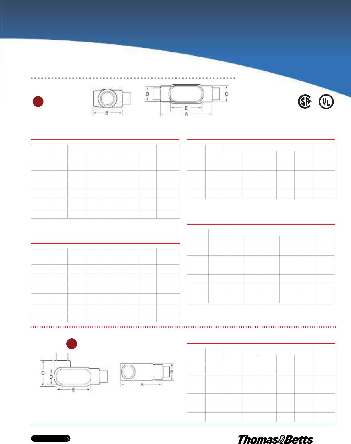
w w w . t n b . c a
PVC-Coated Products
H23
OCALTM
Metric size designator (ANSI C80.1-1994).
*Dimensions shown are for uncoated conduit bodies.
Cat. No.
Hub
Size
in. (mm)
Dimensions in. (mm)* Vol. Cap.
ABCDE
(cu.in./
cu.cm)
TB17-_ 1/2
(16)
5.60
(142.24)
2.06
(52.32)
1.63
(41.40)
0.95
(24.13)
3.20
(81.28)
6.00
(98.32)
TB27-_ 3/4
(21)
6.20
(157.48)
2.31
(58.67)
1.81
(45.97)
1.15
(29.21)
3.80
(96.52)
9.10
(149.12)
TB37-_ 1
(27)
7.35
(186.69)
2.50
(63.50)
2.31
(58.67)
1.35
(34.29)
4.55
(115.57)
16.90
(276.94)
TB47-_ 1-1/4
(35)
7.30
(185.42)
3.19
(81.03)
2.25
(57.15)
1.80
(45.72)
5.00
(127.00)
19.30
(316.27)
TB57-_ 1-1/2
(41)
8.60
(218.44)
3.91
(99.31)
2.42
(61.47)
2.05
(52.07)
5.45
(138.43)
27.50
(450.64)
TB67-_ 2
(53)
9.50
(241.30)
4.50
(114.30)
3.06
(77.72)
2.45
(62.23)
6.40
(162.56)
52.80
(865.24)
TB Form 8 Ferrous Conduit Bodies
with Covers
Cat. No.
Hub
Size
in. (mm)
Dimensions in. (mm)* Vol. Cap.
ABCDE
(cu.in./
cu.cm)
TB18-_ 1/2
(16)
5.69
(144.46)
2.63
(66.68)
1.38
(34.93)
1.00
(25.40)
3.31
(84.14)
6.00
(98.32)
TB28-_ 3/4
(21)
6.28
(159.54)
2.88
(73.03)
1.19
(30.16)
1.19
(30.16)
3.94
(100.01)
9.00
(147.48)
TB38-_ 1
(27)
7.31
(185.74)
3.25
(82.55)
1.75
(44.45)
1.38
(34.93)
4.56
(115.89)
15.00
(245.81)
TB448-_ 1-1/4
(35)
8.50
(215.90)
3.31
(84.14)
2.19
(55.56)
1.75
(44.45)
5.31
(134.94)
24.00
(393.29)
TB58-_ 1-1/2
(41)
10.38
(263.53)
3.69
(93.66)
2.75
(69.85)
2.13
(53.98)
6.50
(165.10)
46.50
(762.00)
TB68-_ 2
(53)
12.25
(311.15)
4.25
(107.95)
3.75
(95.25)
3.00
(76.20)
8.56
(217.49)
88.00
(1442.06)
TB Form 7 Aluminum Conduit Bodies
with Covers
Cat. No.
Hub
Size
in. (mm)
Dimensions in. (mm)* Vol. Cap.
ABCDE
(cu.in./
cu.cm)
TB17SA-_ 1/2
(16)
5.60
(142.24)
2.06
(52.32)
1.63
(41.40)
0.95
(24.13)
3.20
(81.28)
6.00
(98.32)
TB27SA-_ 3/4
(21)
6.20
(157.48)
2.31
(58.67)
1.81
(45.97)
1.15
(29.21)
3.80
(96.52)
9.10
(149.12)
TB37SA-_ 1
(27)
7.35
(186.69)
2.50
(63.50)
2.31
(58.67)
1.35
(34.29)
4.55
(115.57)
16.90
(276.94)
TB47SA-_ 1-1/4
(35)
7.30
(185.42)
3.19
(81.03)
2.25
(57.15)
1.80
(45.72)
5.00
(127.00)
19.30
(316.27)
TB57SA-_ 1-1/2
(41)
8.60
(218.44)
3.91
(99.31)
2.42
(61.47)
2.05
(52.07)
5.45
(138.43)
27.50
(450.64)
TB67SA-_ 2
(53)
9.50
(241.30)
4.50
(114.30)
3.06
(77.72)
2.45
(62.23)
6.40
(162.56)
52.80
(865.24)
Cat. No.
Hub
Size
in. (mm)
Dimensions in. (mm)* Vol. Cap.
ABCDE
(cu.in./
cu.cm)
TB19-_ 1/2
(16)
5.00
(127.00)
2.13
(53.98)
1.38
(34.93)
1.19
(30.16)
3.31
(84.14)
—
—
TB29-_ 3/4
(21)
5.69
(144.46)
2.41
(61.12)
1.56
(39.69)
1.38
(34.93)
3.94
(100.01)
—
—
TB39-_ 1
(27)
6.59
(167.48)
2.84
(72.23)
1.75
(44.45)
1.50
(38.10)
4.56
(115.89)
—
—
TB49-_ 1-1/4
(35)
7.50
(190.50)
3.47
(88.11)
2.19
(55.56)
1.94
(49.21)
5.31
(134.94)
—
—
**L Form 7 Ferrous Conduit Bodies with Covers
Cat. No.
Hub
Size
in. (mm)
Dimensions in. (mm)* Vol. Cap.
ABCDE
(cu.in./
cu.cm)
L17-_ 1/2
(16)
4.60
(116.84)
1.40
(35.56)
1.45
(36.83)
0.95
(24.13)
3.20
(81.28)
—
—
L27-_ 3/4
(21)
5.25
(133.35)
1.60
(40.64)
1.65
(41.91)
1.15
(29.21)
3.80
(96.52)
—
—
L37-_ 1
(27)
6.00
(152.40)
1.90
(48.26)
2.60
(66.04)
1.35
(34.29)
4.55
(115.57)
—
—
L47-_ 1-1/4
(35)
6.45
(163.83)
2.30
(58.42)
3.05
(77.47)
1.80
(45.72)
5.00
(127.00)
—
—
L57-_ 1-1/2
(41)
7.90
(200.66)
2.60
(66.04)
3.80
(96.52)
2.05
(52.07)
5.45
(138.43)
—
—
L67-_ 2
(53)
8.30
(210.82)
3.20
(81.28)
4.25
(107.95)
2.45
(62.23)
6.40
(162.56)
—
—
TB
L
Up to and including 2 in.
Metric size designator (ANSI C80.1-1994).
*Dimensions shown are for uncoated
conduit bodies.
** Not CSA Certified.
Ordinary Location Fittings
TB Form 7 Ferrous Conduit Bodies
with Covers
TB Mark 9 Aluminum Conduit Bodies
with Covers
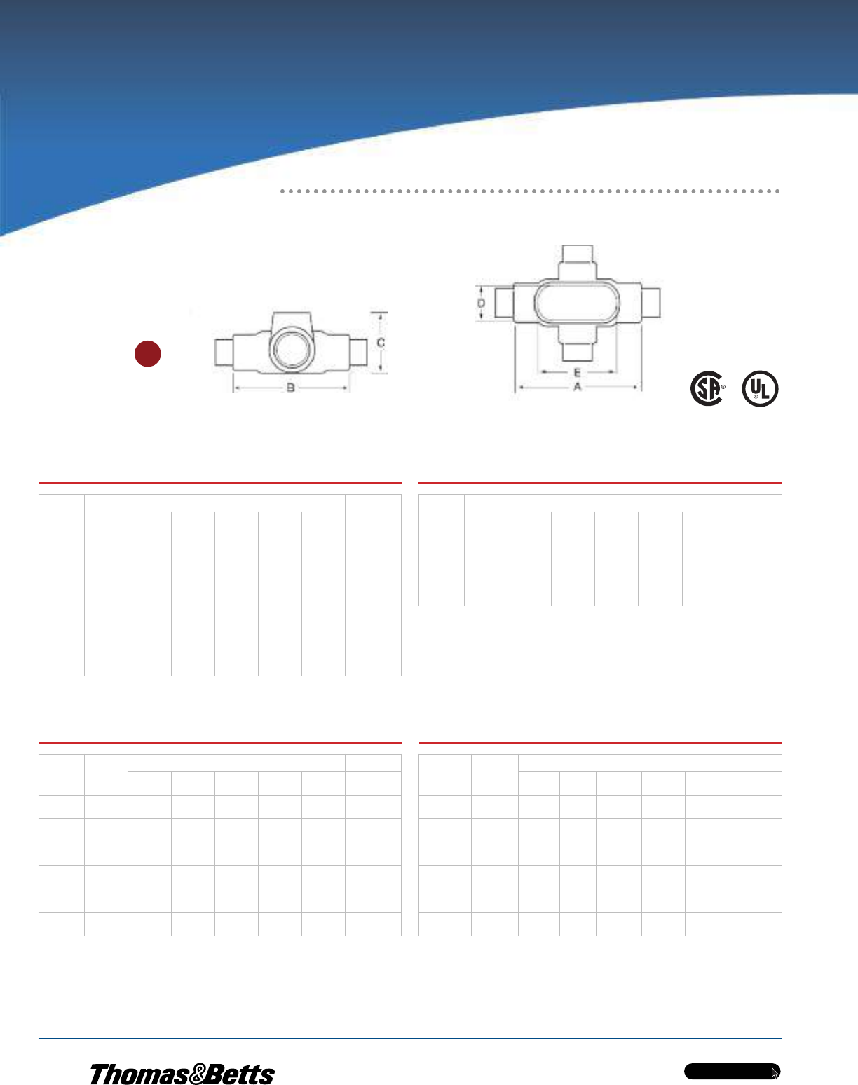
w w w . t n b . c a
PVC-Coated Products
H24
OCALTM
Metric size designator (ANSI C80.1-1994).
*Dimensions shown are for uncoated conduit bodies.
X Form 7 Ferrous Conduit Bodies
with Covers
Cat. No.
Hub
Size
in. (mm)
Dimensions in. (mm)* Vol. Cap.
ABCDE
(cu.in./
cu.cm)
X17-_ 1/2
(16)
5.60
(142.24)
1.80
(45.72)
3.05
(77.47)
0.95
(24.13)
3.20
(81.28)
6.00
(98.32)
X27-_ 3/4
(21)
6.20
(157.48)
2.00
(50.80)
3.30
(83.82)
1.15
(29.21)
3.80
(96.52)
9.10
(149.12)
X37-_ 1
(27)
7.35
(186.69)
2.30
(58.42)
3.80
(96.52)
1.35
(34.29)
4.55
(115.57)
16.90
(276.94)
X47-_ 1-1/4
(35)
7.30
(185.42)
2.30
(58.42)
3.85
(97.79)
1.80
(45.72)
5.00
(127.00)
19.30
(316.27)
X57-_ 1-1/2
(41)
8.60
(218.44)
2.60
(66.04)
5.05
(128.27)
2.05
(52.07)
5.45
(138.43)
27.50
(450.64)
X67-_ 2
(53)
9.50
(241.30)
3.20
(81.28)
5.45
(138.43)
2.45
(62.23)
6.40
(162.56)
52.80
(865.24)
X Form 8 Ferrous Conduit Bodies
with Covers
Cat. No.
Hub
Size
in. (mm)
Dimensions in. (mm)* Vol. Cap.
ABCDE
(cu.in./
cu.cm)
X18-_ 1/2
(16)
5.69
(144.46)
1.75
(44.45)
2.91
(73.82)
1.00
(25.40)
3.31
(84.14)
6.00
(98.32)
X28-_ 3/4
(21)
6.28
(159.54)
2.00
(50.80)
3.06
(77.79)
1.38
(34.93)
3.94
(100.01)
9.00
(147.48)
X38-_ 1
(27)
7.31
(185.74)
2.25
(57.15)
3.50
(88.90)
1.38
(34.93)
4.56
(115.89)
15.00
(245.81)
X448-_ 1-1/4
(35)
8.50
(215.90)
2.63
(66.68)
4.13
(104.78)
1.75
(44.45)
5.31
(134.94)
24.00
(393.29)
X58-_ 1-1/2
(41)
10.38
(263.53)
2.47
(62.71)
5.25
(133.35)
2.13
(53.98)
6.50
(165.10)
46.50
(762.00)
X68-_ 2
(53)
12.25
(311.15)
3.56
(90.49)
6.25
(158.75)
3.00
(76.20)
8.56
(217.49)
88.00
(1442.06)
X Form 7 Aluminum Conduit Bodies
with Covers
Cat. No.
Hub
Size
in. (mm)*
Dimensions in. (mm)* Vol. Cap.
AB C D E
(cu.in./
cu.cm)
X17SA-_ 1/2
(16)
5.60
(142.24)
1.80
(45.72)
3.05
(77.47)
0.95
(24.13)
3.20
(81.28)
6.00
(98.32)
X27SA-_ 3/4
(21)
6.20
(157.48)
2.00
(50.80)
3.30
(83.82)
1.15
(29.21)
3.80
(96.52)
9.10
(149.12)
X37SA-_ 1
(27)
7.35
(186.69)
2.30
(58.42)
3.80
(96.52)
1.35
(34.29)
4.55
(115.57)
16.90
(276.94)
X47SA-_ 1-1/4
(35)
7.30
(185.42)
2.30
(58.42)
3.85
(97.79)
1.80
(45.72)
5.00
(127.00)
19.30
(316.27)
X57SA-_ 1-1/2
(41)
8.60
(218.44)
2.60
(66.04)
5.05
(128.27)
2.05
(52.07)
5.45
(138.43)
27.50
(450.64)
X67SA-_ 2
(53)
9.50
(241.30)
3.20
(81.28)
5.45
(138.43)
2.45
(62.23)
6.40
(162.56)
52.80
(865.24)
X Mark 9 Aluminum Conduit Bodies
with Covers
Cat. No.
Hub
Size
in. (mm)
Dimensions in. (mm)* Vol. Cap.
ABCDE
(cu.in./
cu.cm)
X19-_ 1/2
(16)
5.69
(144.46)
2.91
(73.82)
1.75
(44.45)
1.00
(25.40)
3.31
(84.14)
—
—
X29-_ 3/4
(21)
6.28
(159.54)
3.06
(77.79)
2.00
(50.80)
1.19
(30.16)
3.94
(100.01)
—
—
X39-_ 1
(27)
7.31
(185.74)
3.50
(88.90)
2.25
(57.15)
1.38
(34.93)
4.56
(115.89)
—
—
X
Up to and including 2 in.
Ordinary Location Fittings
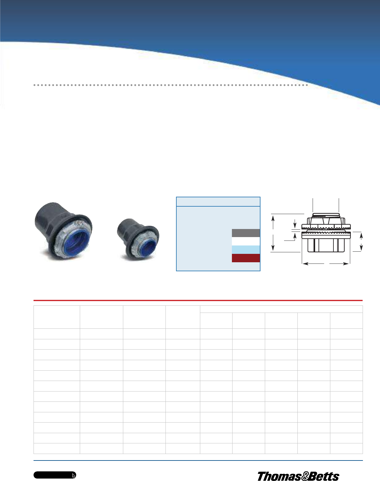
w w w . t n b . c a
PVC-Coated Products
H25
OCALTM
Ordinary Location Fittings
Unique Sealing Ring and Groove Design
for Optimum Performance!
PVC-Coated
Zinc
Hub
Cat. No.
PVC-Coated
Aluminum
Hub
Cat. No.
PVC-Coated
Zinc Grounded
Hub
Cat. No.
Pipe Size
in.
(mm)
Dimensions (Uncoated Hub)
A
(Overall
Dia.)
BC
D
(Max. Panel
Thickness)
E
(Throat
Dia.)
HUB1/2-_ HUB1/2SA-_ STG1-_ 1/2
(16)
1.44
(36.58)
1.56
(39.62)
0.88
(22.35)
0.19
(4.83)
0.59
(14.99)
HUB3/4-_ HUB3/4SA-_ STG2-_ 3/4
(21)
1.44
(36.58)
1.59
(40.39)
0.91
(23.11)
0.19
(4.83)
0.78
(19.81)
HUB1-_ HUB1SA-_ STG3-_ 1
(27)
2.00
(50.80)
1.81
(45.97)
1.06
(26.92)
0.25
(6.35)
1.00
(25.40)
HUB1-1/4-_ HUB1-1/4SA-_ STG4-_ 1-1/4
(35)
2.38
(60.45)
1.88
(47.75)
1.06
(26.92)
0.25
(6.35)
1.31
(6.35)
HUB1-1/2-_ HUB1-1/2SA-_ STG5-_ 1-1/2
(41)
2.75
(69.85)
1.88
(47.75)
1.06
(26.92)
0.25
(6.35)
1.53
(38.86)
HUB2-_ HUB2SA-_ STG6-_ 2
(53)
3.25
(82.55)
1.94
(49.28)
1.16
(29.46)
0.25
(6.35)
1.97
(50.04)
HUB2-1/2-_ HUB2-1/2SA-_ STG7-_ 2-1/2
(63)
3.75
(95.25)
2.56
(65.02)
1.56
(39.62)
0.25
(6.35)
2.41
(61.21)
HUB3-_ HUB3SA-_ STG8-_ 3
(78)
4.38
(111.25)
2.44
(61.98)
1.59
(40.39)
0.25
(6.35)
2.97
(75.44)
HUB3-1/2-_ HUB3-1/2SA-_ STG9-_ 3-1/2
(91)
5.00
(127.00)
2.72
(69.09)
1.63
(41.40)
0.25
(6.35)
3.41
(86.61)
HUB4-_ HUB4SA-_ STG10-_ 4
(103)
5.50
(139.70)
2.72
(69.09)
1.63
(41.40)
0.25
(6.35)
3.88
(98.55)
HUB5-_ HUB5SA-_ STG11-_ 5
(129)
6.88
(174.75)
3.03
(76.96)
1.94
(49.28)
0.25
(6.35)
4.94
(125.48)
HUB6-_ HUB6SA-_ STG12-_ 6
(155)
7.69
(195.33)
3.16
(80.26)
2.00
(50.80)
0.31
(7.87)
6.00
(152.40)
OCAL-BLUETM Double-Coat and
Stainless Steel Hubs
•Captive sealing ring won’t buckle or slip during installation and
provides a complete 360° seal — even when conduit isn’t
perpendicular to the enclosure
•Hexagonal/splined body and locknut enables fast and easy
installation
•Insulated throat molded from 105°C-rated thermoplastic, UL94V0
flammability rated
•Sharper and deeper teeth provide a more penetrating bite for
improved bonding to the enclosure
•Zinc or copper-free aluminum with a nominal 0.040 in. (40 mils)
PVC coating bonded to exterior
•Pressure-sealing sleeves protect your connections
Throat Dia. E
D
B
A
C
HUB1-1/4-G
PVC-Coated Zinc Hub
Knockout Hubs
STG6-G
PVC-Coated Zinc Grounded Hub
Cat. No. Colour
HUB-1
_ = space for colour identifier
G = Grey
W = White
B = Blue
R = Red
Custom colours also available - Std. min. quantities are re-
quired. Please contact your Regional Sales Office.
_
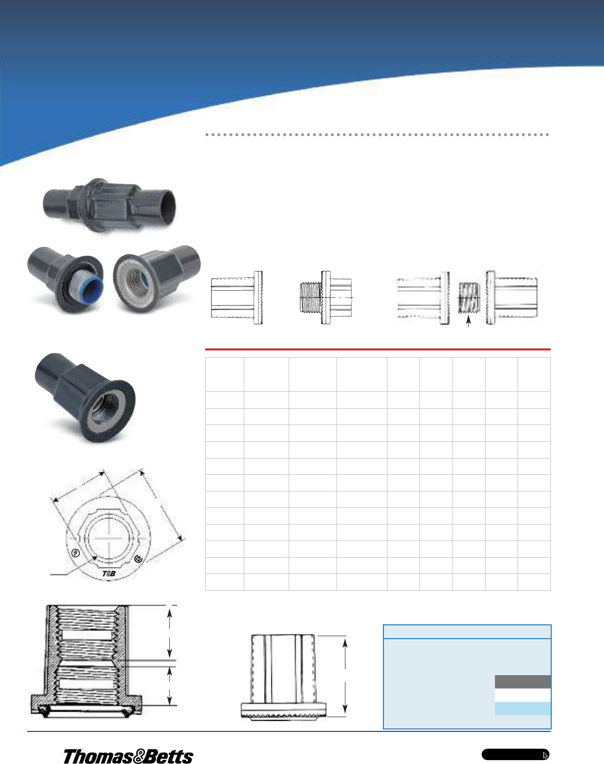
w w w . t n b . c a
PVC-Coated Products
H26
OCALTM
Ordinary Location Fittings
In Bulkhead and
Through-Bulkhead Styles!
OcalTM PVC-Coated Bulkhead Fittings
•Zinc body and locknut with thermoplastic insulating throat and nitrile sealing ring
•Nominal 0.040 in. (40 mils) PVC coating bonded to exterior
•Pressure-sealing sleeves protect your connections
Metric size designator (ANSI C80.1-1994).
Dimensions shown are for uncoated fittings.
Across Flats
Diameter
Thread
NPT THREAD
NPSL THREAD
Bulkhead Fitting
Nipple Nut Not Included
Through-Bulkhead Fitting
A
B
Height
STTB2-G
Bulkhead Fitting
STTTB2-G
Through-Bulk-
head Fitting
Bulkhead
Fitting
Cat. No.
Through-
Bulkhead
Fitting
Cat. No.
Pipe Size
in.
(mm)
Thread
Height
in.
(mm)
Dia.
in.
(mm)
Across
Flats
in.
(mm)
‘‘A’’
in.
(mm)
‘‘B’’
in.
(mm)
STTB1-_ STTTB1-_ 1/2
(16)
1/2—14
—
1.41
(35.72)
1.44
(36.51)
1.00
(25.40)
0.75
(19.05)
0.50
(12.70)
STTB2-_ STTTB2-_ 3/4
(21)
3/4—14
—
1.47
(37.31)
1.69
(42.86)
1.25
(31.75)
0.78
(19.84)
0.53
(13.49)
STTB3-_ STTTB3-_ 1
(27)
1 — 11-1/2
—
1.69
(42.86)
2.00
(50.80)
1.53
(38.89)
0.91
(23.02)
0.59
(15.08)
STTB4-_ STTTB4-_ 1-1/4
(35)
1-1/4 — 11-1/2
—
1.78
(45.24)
2.38
(60.33)
1.84
(46.83)
0.91
(23.02)
0.66
(16.67)
STTB5-_ STTTB5-_ 1-1/2
(41)
1-1/2 — 11-1/2
—
1.81
(46.04)
2.75
(69.85)
1.13
(28.58)
0.91
(23.02)
0.66
(16.67)
STTB6-_ STTTB6-_ 2
(53)
2 — 11-1/2
—
1.84
(46.83)
3.25
(82.55)
2.63
(66.68)
0.94
(23.81)
0.66
(16.67)
STTB7-_ — 2-1/2
(63)
2-1/2 — 8
—
2.28
(57.94)
3.75
(95.25)
3.13
(79.38)
1.22
(30.96)
0.88
(22.23)
STTB8-_ — 3
(78)
3 — 8
—
2.56
(65.09)
4.38
(111.13)
3.78
(96.04)
1.19
(30.16)
0.91
(23.02)
STTB9-_ — 3-1/2
(91)
3-1/2 — 8
—
2.56
(65.09)
5.00
(127.00)
4.28
(108.74)
1.38
(34.93)
0.88
(22.23)
STTB10-_ — 4
(103)
4 — 8
—
2.56
(65.09)
5.50
(139.70)
4.84
(123.03)
1.38
(34.93)
0.88
(22.23)
STTB11-_ — 5
(129)
5 — 8
—
2.72
(69.06)
6.63
(168.28)
5.91
(150.02)
1.47
(37.31)
0.88
(22.23)
STTB12-_ — 6
(155)
6 — 8
—
3.00
(76.20)
7.69
(195.26)
7.03
(178.58)
1.50
(38.10)
0.97
(24.61)
Cat. No. Colour
STTB1-
_ = space for colour identifier
G = Grey
W = White
B = Blue
Custom colours also available - Std. min. quantities are required. Please
contact your Regional Sales Office.
_
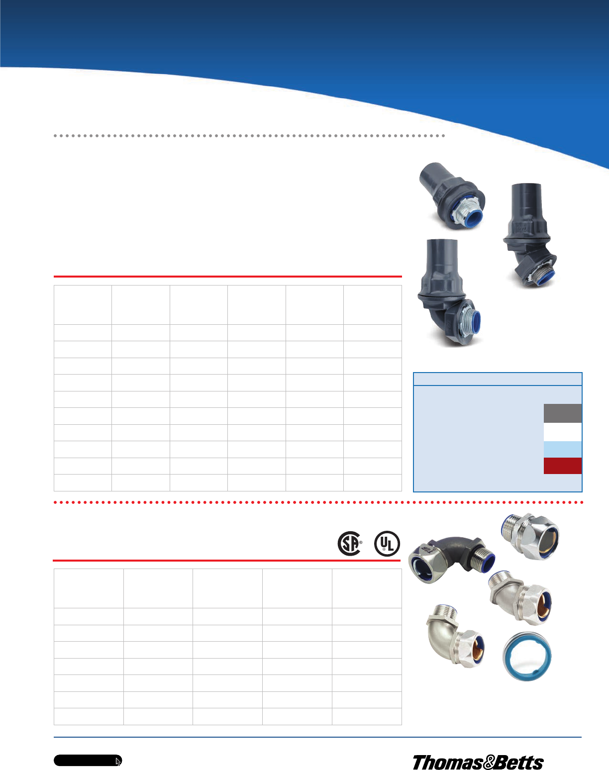
w w w . t n b . c a
PVC-Coated Products
H27
OCALTM
Ordinary Location Fittings
The Ultimate Liquidtight Solution for
Corrosive Environments!
OcalTM PVC-Coated Liquidtight Conduit Connectors
•Nominal 0.040 in. (40 mils) PVC coating bonded to exterior
•Pressure-sealing sleeves are designated to protect the connection
•OcalTM uses only genuine T&B®liquidtight fittings to ensure quality installations
PVC-Coated
Steel
Straight
Cat. No.
PVC-Coated
Aluminum
Straight
Cat. No.
PVC-Coated
Steel
45º
Cat. No.
PVC-Coated
Steel
90º
Cat. No.
PVC-Coated
Aluminum
90º
Cat. No.
Pipe Size
in.
(mm)
ST3/8-_ ST3/8SA-_ ST3/845-_ ST3/890-_ ST3/890SA-_ 3/8
(12)
ST1/2-_ ST1/2SA-_ ST1/245-_ ST1/290-_ ST1/290SA-_ 1/2
(16)
ST3/4-_ ST3/4SA-_ ST3/445-_ ST3/490-_ ST3/490SA-_ 3/4
(21)
ST1-_ ST1SA-_ ST145-_ ST190-_ ST190SA-_ 1
(27)
ST1-1/4-_ ST1-1/4SA-_ ST1-1/445-_ ST1-1/490-_ ST1-1/490SA-_ 1-1/4
(35)
ST1-1/2-_ ST1-1/2SA-_ ST1-1/245-_ ST1-1/290-_ ST1-1/290SA-_ 1-1/2
(41)
ST2-_ ST2SA-_ ST245-_ ST290-_ ST290SA-_ 2
(53)
ST2-1/2-_ ST2-1/2SA-_ ST2-1/245-_ ST2-1/290-_ ST2-1/290SA-_ 2-1/2
(63)
ST3-_ ST3SA-_ ST345-_ ST390-_ ST390SA-_ 3
(78)
ST4-_ ST4SA-_ ST445-_ ST490-_ ST490SA-_ 4
(103)
Cat. No Material Colour
ST3/4- _-_
Blank =
Steel/Iron G = Grey
SA =
Aluminum W = White
B = Blue
R = Red
Custom colours also available - Std. min. quantities are required.
Please contact your Regional Sales Office.
OcalTM PVC-Coated
Liquidtight Fittings —
Straight (top left),
45° Angled (above)
and 90° Angled (left).
ST3/490-G
ST3/4-G
ST3/445-G
T&B 304 Stainless Steel Liquidtight Conduit Connectors
Stainless
Steel
Straight
Cat. No.
Stainless
Steel
45º
Cat. No.
Stainless
Steel
90º
Cat. No.
Sealing
Ring
Gasket
Cat. No.
Pipe Size
in. (mm)
Designator*
5331SST 5341SST 5351SST 5261 3/8
(12)
5332SST 5342SST 5352SST 5262 1/2
(16)
5333SST 5343SST 5353SST 5263 3/4
(21)
5334SST 5344SST 5354SST 5264 1
(27)
5335SST 5345SST 5355SST 5265 1-1/4
(35)
5336SST 5346SST 5356SST 5266 1-1/2
(41)
5337SST 5347SST 5357SST 5267 2
(53)
Metric size designator (ANSI C80.1-1994).
T&B 304 Stainless Steel Liquidtight Fittings –
Staight (top left), 45oAngled (bottom left) and
90oAngled (top right). 5262 Series Sealing Ring
Gasket (bottom right) sold separately.
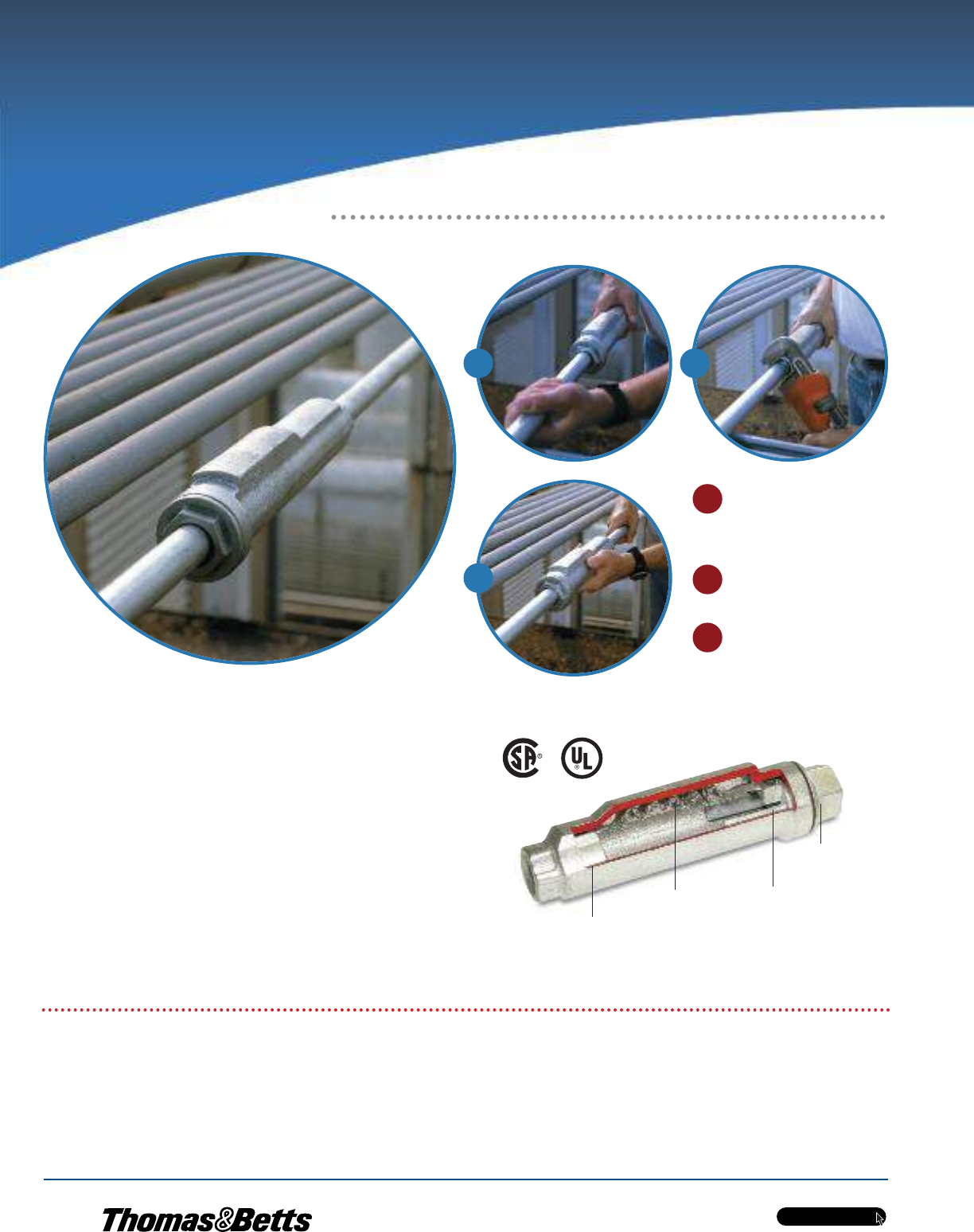
w w w . t n b . c a
PVC-Coated Products
H28
OCALTM
OcalTM PVC-Coated XJG Rigid Conduit
Expansion Couplings
When you install a rigid expansion coupling in a long conduit run, you normally
need three hands, two strong backs and lots of patience. Now you can relax.
With the no-hassle XJG Rigid Conduit Expansion Coupling, installation’s just a
few turns and you’re done.
The XJG Rigid Conduit Expansion Coupling features innovations that provide
convenience to the installer, saving time and money on the job. No disassembly
is needed during installation, requiring fewer tools and less opportunity for lost
pieces. It also features a true internal bonding jumper, eliminating the need for
external jumpers, so there are fewer parts to buy and install.
If you need a fitting that can give and take without a lot of hassle, reach for the
XJG Rigid Conduit Expansion Coupling. It’s the latest breakthrough in the in-
dustry’s leading line of conduit fittings.
8’’ Movement
Coupling shown uncoated
•No disassembly necessary to install
•Fast, simple and requires fewer steps
•True internal bonding jumper —
no external grounding strap required
•Tamper-proof internal jumper protected
from the environment
•Exceed code requirements for long
conduit runs to permit linear movement
•Double coated with a nominal 0.002 in.
(2 mils) blue urethane, on both the
interior and exterior, before PVC coating
is applied
•A minimum of 0.040 in. (40 mils) PVC
Coating is borded to the exterior
•Pressure sealing sleeve to seal the
connection
Internal Sliding
Bushing (keyed)
Coupling shown uncoated
Internal Bonding
Jumper
Bonding
Bushing
Gland
Nut
1Slide the fitting onto the conduit until it
stops at the internal sliding bushing.
Tighten and you’re ready. No parts to
reassemble!
With a wrench, tighten the gland nut to
create a raintight seal around the
conduit.
Thread the next length of conduit into
the other end of the fitting and tighten.
You’re done!
Innovative Design Makes Installations Easier.
Ordinary Location Fittings
No Disassembly Required
1
2
2
3
3
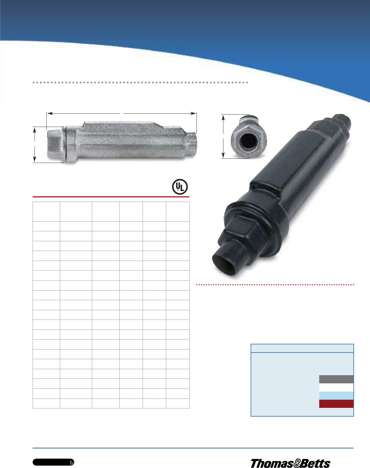
w w w . t n b . c a
PVC-Coated Products
H29
OCALTM
OcalTM PVC-Coated XJG Rigid Conduit Expansion
Couplings (cont’d)
Metric size designator (ANSI C80.1-1994).
Dimensions shown are for uncoated coupling.
Cat. No.
Pipe Size
in.
(mm)
Movement
in.
(mm)
A
Diameter
in.
(mm)
B
Length
in.
(mm)
C
Height
in.
(mm)
XJG24-_ 3⁄4
(21)
4.00
(101.60)
2.43
(61.72)
10.00
(254.00)
2.75
(69.85)
XJG28-_ 3/4
(21)
8.00
(203.20)
2.43
(61.72)
14.00
(355.60)
2.75
(69.85)
XJG34-_ 1
(27)
4.00
(101.60)
2.67
(67.82)
10.00
(254.00)
2.99
(75.95)
XJG38-_ 1
(27)
8.00
(203.20)
2.67
(67.82)
14.00
(355.60)
2.99
(75.95)
XJG44-_ 1-1/4
(35)
4.00
(101.60)
3.36
(85.34)
10.56
(268.22)
3.68
(93.47)
XJG48-_ 1-1/4
(35)
8.00
(203.20)
3.36
(85.34)
14.56
(369.82)
3.68
(93.47)
XJG54-_ 1-1/2
(41)
4.00
(101.60)
3.36
(85.34)
10.56
(268.22)
3.68
(93.47)
XJG58-_ 1-1/2
(41)
8.00
(203.20)
3.36
(85.34)
14.56
(369.82)
3.68
(93.47)
XJG64-_ 2
(53)
4.00
(101.60)
3.86
(98.04)
11.25
(285.75)
4.18
(106.17)
XJG68-_ 2
(53)
8.00
(203.20)
3.86
(98.04)
15.25
(387.35)
4.18
(106.17)
XJG74-_ 2-1/2
(63)
4.00
(101.60)
4.96
(125.98)
12.12
(307.85)
5.25
(133.35)
XJG78-_ 2-1/2
(63)
8.00
(203.20)
4.96
(125.98)
16.12
(409.45)
5.25
(133.35)
XJG84-_ 3
(78)
4.00
(101.60)
4.96
(125.98)
12.12
(307.85)
5.25
(133.35)
XJG88-_ 3
(78)
8.00
(203.20)
4.96
(125.98)
16.12
(409.45)
5.25
(133.35)
XJG94-_ 3-1/2
(91)
4.00
(101.60)
6.37
(161.80)
12.87
(326.90)
6.75
(171.45)
XJG98-_ 3-1/2
(91)
8.00
(203.20)
6.37
(161.80)
16.87
(428.50)
6.75
(171.45)
XJG104-_ 4
(103)
4.00
(101.60)
6.37
(161.80)
12.87
(326.90)
6.75
(171.45)
XJG108-_ 4
(103)
8.00
(203.20)
6.37
(161.80)
16.87
(428.50)
6.75
(171.45)
XJG1208-_ 5
(129)
8.00
(203.20)
7.99
(161.80)
18.87
(479.30)
8.56
(217.42)
B
A
XJG24-G
4 in. Movement
Coupling shown uncoated
C
Cat. No. Colour
XJG24-
_ = space for colour identifier
G = Grey
W = White
B = Blue
R = Red
Custom colours also available - Std. min. quantities are required. Please
contact your Regional Sales Office.
_
Ordinary Location Fittings
Standard Materials / Finish
Body / Finish Ductiles iron with nominal
0.040 in. (40 mils) PVC
exterior coating
Internal Bonding Jumper Tinned copper braid
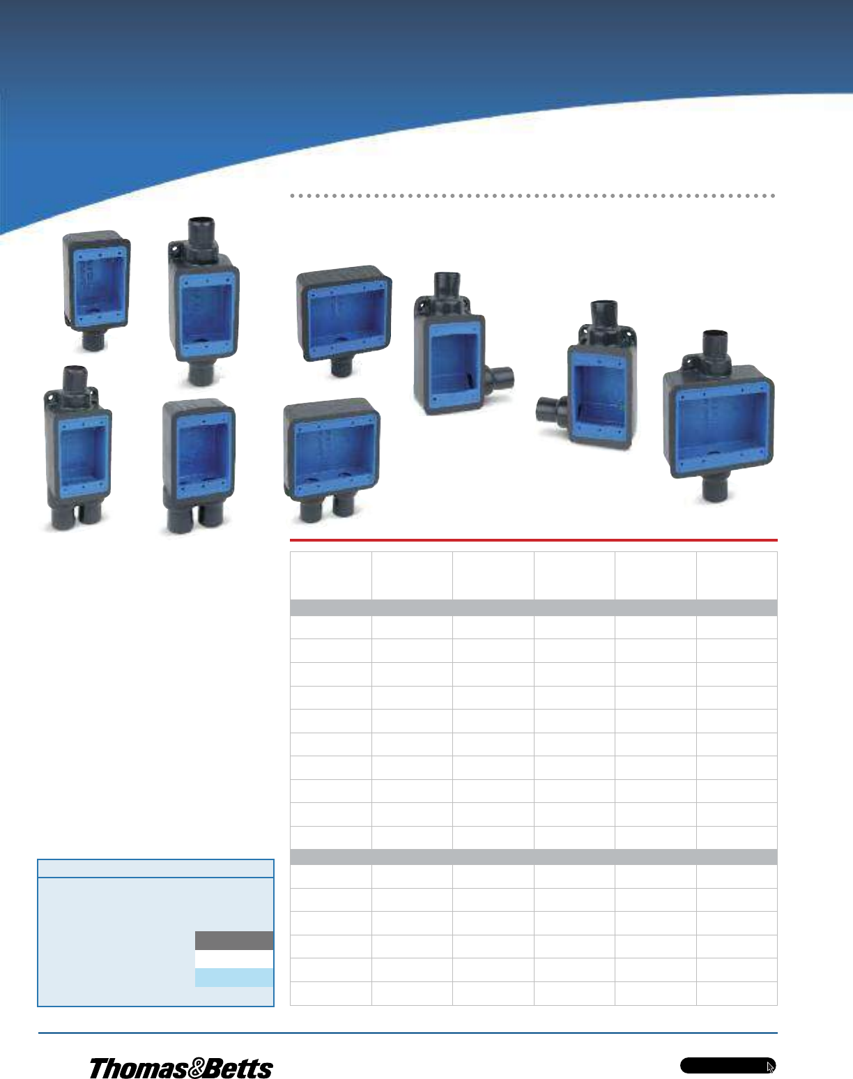
w w w . t n b . c a
PVC-Coated Products
H30
OCALTM
Metric size designator (ANSI C80.1-1994).
FS2-G
FSC2-G
FSL2-G
FSR2-G
FS22-G
FSS222-G
FSC222-G
FSCC2-G
FSS2-G
Install these boxes in conduit systems to
accommodate wiring devices, act as pull boxes
for conductors, provide openings to make splices
and taps and provide access to conductors for
maintenance and future system changes.
•Cast class 30 grey iron alloy boxes
•Coated with a nominal 0.002 in. (2 mils)
blue urethane on both the interior and
exterior before PVC coating is applied
•Nominal 0.040 in. (40 mils) PVC coating
bonded to exterior
•PVC coating available in your choice
of blue, white or grey
•Pressure sealing sleeves protect
connections with conduit
OCAL-BLUETM Double-Coat FS and FD Series Device Boxes
Dead End
Cat. No.
Feed-Thru
Cat. No.
Hub Right
Cat. No.
Hub Left
Cat. No. Style
Pipe Size
in.
(mm)
Single Gang
FS1-_ FSC1-_ FSR1-_ FSL1-_ Shallow 1/2
(16)
FS2-_ FSC2-_ FSR2-_ FSL2-_ Shallow 3/4
(21)
FS3-_ FSC3-_ —— Shallow 1
(27)
FD1-_ FDC1-_ FDR1-_ FDL1-_ Deep 1/2
(16)
FD2-_ FDC2-_ FDR2-_ FDL2-_ Deep 3/4
(21)
FD3- FDC3-_ —— Deep 1
(27)
— FSCC2-_ —— Shallow 3/4
(21)
— FDCC2-_ —— Deep 3/4
(21)
FSS2-_ ——— Shallow 3/4
(21)
FDD2-_ ——— Deep 3/4
(21)
Double Gang
FS22-_ ——— Shallow 3⁄4
(21)
FD22-_ ——— Deep 3/4
(21)
FSS222-_ ——— Shallow 3⁄4
(21)
FDS222-_ ——— Deep 3⁄4
(21)
— FSC222-_ —— Shallow 3⁄4
(21)
— FDC222-_ —— Deep 3⁄4
(21)
Ordinary Location Fittings
Variety of Styles Offers Versatility!
Cat. No. Colour
FS1-
_ = space for colour identifier
G = Grey
W = White
B = Blue
Custom colours also available - Std. min. quantities are required. Please
contact your Regional Sales Office.
_
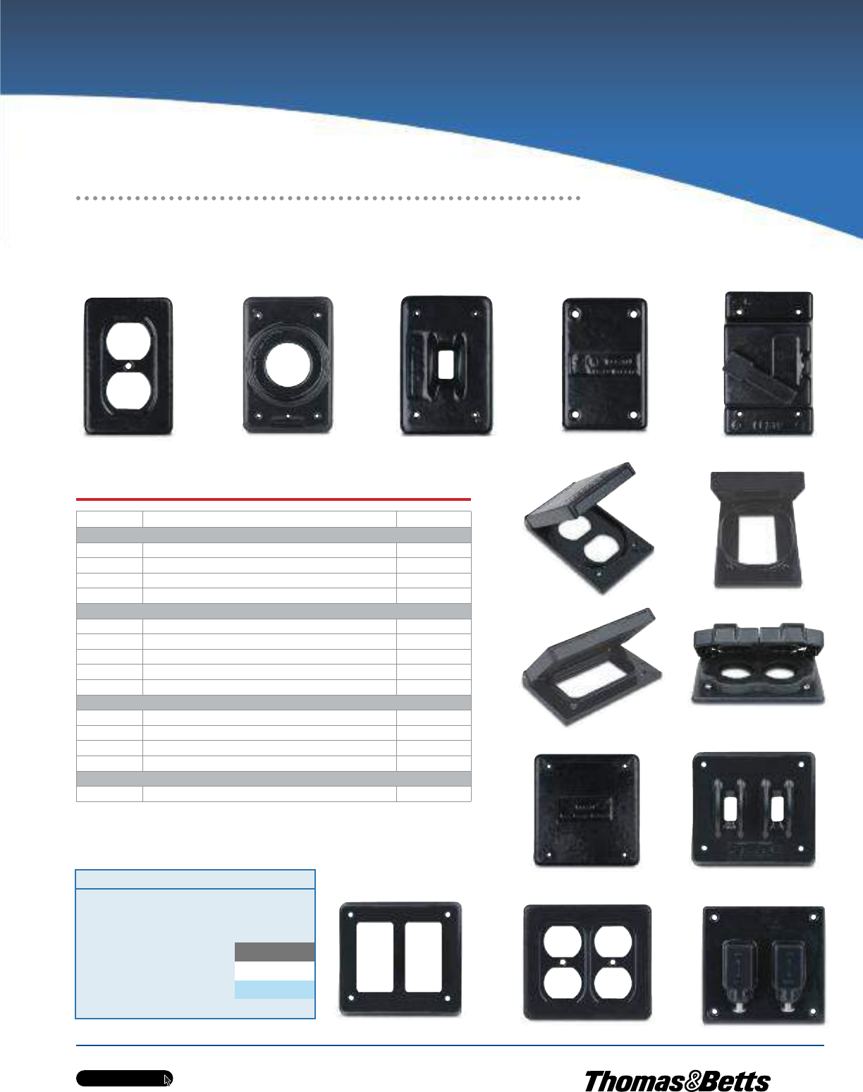
w w w . t n b . c a
PVC-Coated Products
H31
OCALTM
DS23-G DS21G-G DS32G-G DS100G-G
CWPDR-FS-G
CFSHG-G
CFSTF-G
S232-G
S1002G-G
DS1282-G
CFSRG-G
S322G-G
S232GFI-G
CFSDR-G
Cat. No. Description Material
Single Gang
DS23-_ Duplex Receptacle Cover Steel
DS21G-_ Round Flush Receptacle Cover Iron
DS32G-_ Toggle Switch Cover Iron
DS100G-_ Blank Cover Aluminum
Single Gang — NEMA 3R Raintight when used with appropriate OcalTM boxes
CWPDR-FS-_ Duplex Receptacle Cover — Box Mount — Horizontal Aluminum
CFSDR-_ Duplex Receptacle Cover — Box Mount — Vertical Aluminum
CFSHG-_ GFCI Receptacle Cover — Box Mount — Horizontal Aluminum
CFSRG-_ GFCI Receptacle Cover — Box Mount — Vertical Aluminum
CFSTF-_ Front Lever Switch Cover — Box Mount — NEMA 4 Aluminum
Double Gang
S1002G-_ Blank Cover Iron
S322G-_ 2 Toggle Switch Cover Iron
S232-_ 2 Duplex Receptacle Cover Stamped Steel
S232GFI-_ 2 GFCI Receptacle Cover Steel
Double Gang — NEMA 3R Raintight when used with appropriate OcalTM boxes
2CFST-_ 2 Plunger-Style Switch Cover Aluminum
PVC-coated covers in other styles and materials are available upon request.
Contact your Regional Sales Office for more information.
Cat. No. Colour
DS23-
_ = space for colour identifier
G = Grey
W = White
B = Blue
Custom colours also available - Std. min. quantities are required. Please
contact your Regional Sales Office.
_
OCAL-BLUETM Double-Coat FS and FD Series Covers
Ordinary Location Fittings
Designed for Use with OcalTM FS and FD
Series Boxes
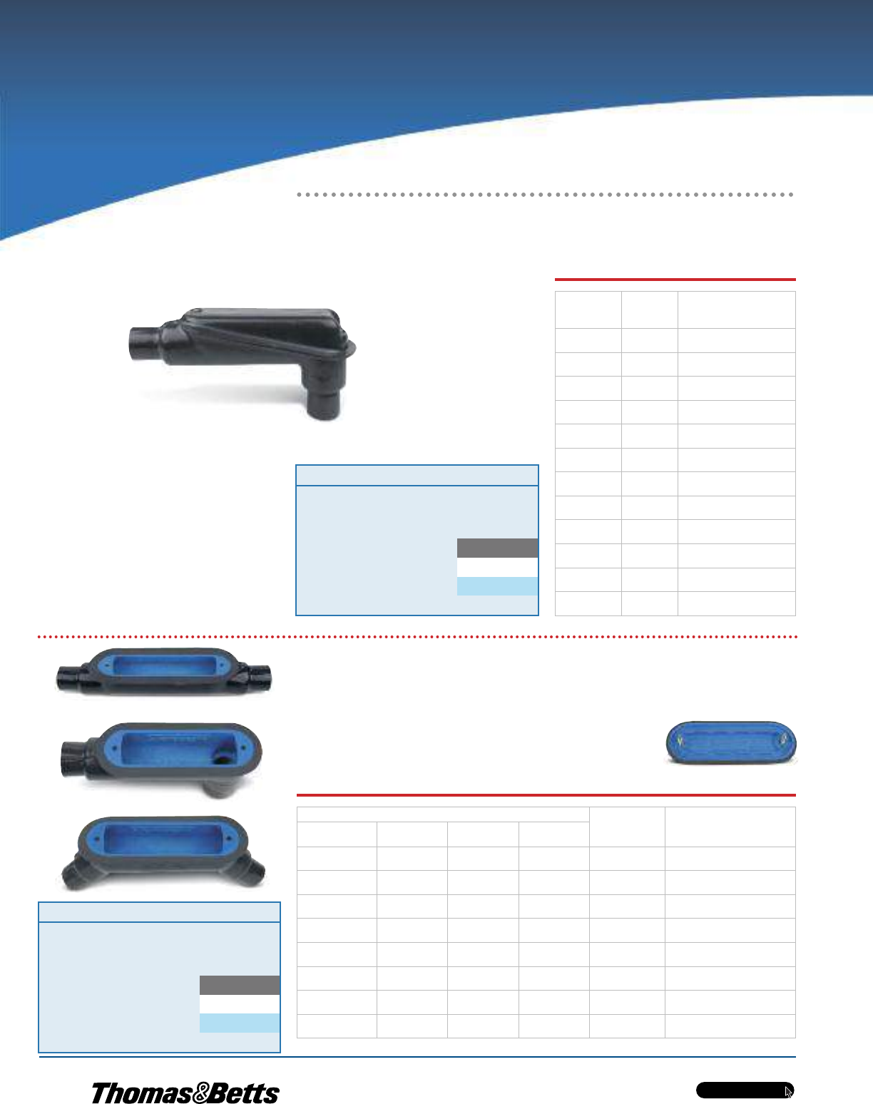
w w w . t n b . c a
PVC-Coated Products
H32
OCALTM
OCAL-BLUETM Double-Coat Mogul Fittings
Install mogul fittings in conduit systems to act as pull outlets for conductors that are stiff due to large size
or type of installation, to provide the longer openings needed when pulling large conductors, to prevent
sharp bends and kinks in large conductors or to provide more splicing space.
•Nominal 0.002 in. (2 mils) blue urethane on both interior and exterior
•Nominal 0.040 in. (40 mils) PVC coating bonded to exterior
•Pressure-sealing sleeves protect connections
Ordinary
LBD Series
Cat. No.
Hazardous
LBH Series
Cat. No.
Pipe Size
in.
(mm)
LBD1100-_ LBH10-_ 1/2
(16)
LBD2200-_ LBH20-_ 3/4
(21)
LBD3300-_ LBH30-_ 1
(27)
LBD4400-_ LBH40-_ 1-1/4
(35)
LBD5500-_ LBH50-_ 1-1/2
(41)
LBD6600-_ LBH60-_ 2
(53)
LBD7700-_ LBH70-_ 2-1/2
(63)
LBD8800-_ LBH80-_ 3
(78)
LBD9900-_ LBH90-_ 3-1/2
(91)
LBD10900-_ LBH100-_ 4
(103)
LBD012-_ — 5
(129)
LBD014-_ — 6
(155)
Mogul Fitting with Cover and Gasket Replacement
Cover BG
Cat. No.
Pipe Size
in.
(mm)
BC
Cat. No.
BLB
Cat. No.
BUB
Cat. No.
BT
Cat. No.
BC3-_ BLB3-_ BUB3-_ BT3-_ BG48-_ 1
(27)
BC4-_ BLB4-_ BUB4-_ BT4-_ BG48-_ 1-1/4
(35)
BC5-_ BLB5-_ BUB5-_ BT5-_ BG68-_ 1-1/2
(41)
BC6-_ BLB6-_ BUB6-_ BT6-_ BG68-_ 2
(53)
BC7-_ BLB7-_ BUB7-_ BT7-_ BG88-_ 2-1/2
(63)
BC8-_ BLB8-_ BUB8-_ BT8-_ BG88-_ 3
(78)
BC9-_ BLB9-_ BUB9-_ BT9-_ BG98-_ 3-1/2
(91)
BC10-_ BLB10-_ BUB10-_ BT10-_ BG98-_ 4
(103)
Metric size designator (ANSI C80.1-1994).
•Choose LBD Series for ordinary locations
and LBH Series for hazardous locations
•Coated with a nominal 0.002 in. (2 mils)
blue urethane on both interior and exterior
•Nominal 0.040 in. (40 mils) PVC coating
bonded to exterior
•Pressure-sealing sleeves seal connections
LBD and LBH bodies are installed at 90° bends in rigid conduit to act as pull outlets for conductors that
are stiff due to large size or type of insulation and to make 90° bends in conduit system while allowing
straight wire pulls in either direction.
LBD2200-G
BLB4-G Mogul
BC3-G Mogul
BUB3-G Mogul
BG48-G Replacement Cover
Ordinary Location Fittings
Make 90º Bends While
Allowing Straight Pulls!
Cat. No. Colour
LBD1100-
_ = space for colour identifier
G = Grey
W = White
B = Blue
Custom colours also available - Std. min. quantities are required. Please
contact your Regional Sales Office.
_
Cat. No. Colour
BC3-
_ = space for colour identifier
G = Grey
W = White
B = Blue
Custom colours also available - Std. min. quantities are required. Please
contact your Regional Sales Office.
_
OCAL-BLUETM Double-Coat Pulling Elbows
Metric size designator (ANSI C80.1-1994).
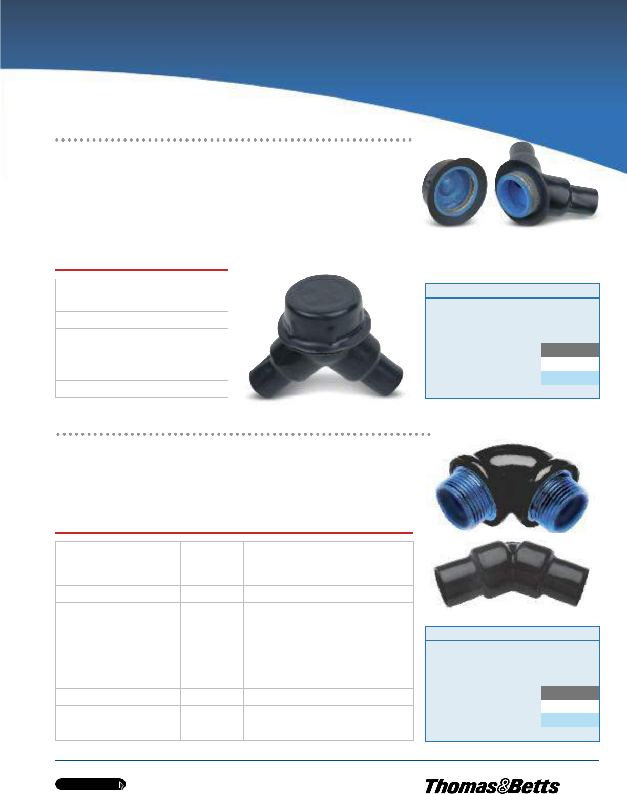
w w w . t n b . c a
PVC-Coated Products
H33
OCALTM
End or Change Directions in Conduit Runs
OCAL-BLUETM Double-Coat Malleable Elbows
EL Series elbows are installed at the end of conduit runs, in a box or a fitting hub to change direction
in threaded rigid conduit run by 45° or 90°, or when terminating at a box or fitting.
•Nominal 0.002 in. (2 mils) blue urethane on both interior and exterior
•Nominal 0.040 in. (40 mils) PVC coating bonded to exterior
•Pressure-sealing sleeves protect connections
90º
Male
Cat. No.
90º
Female
Cat. No.
90º
Male-Female
Cat. No.
45º
Female
Cat. No
Pipe Size
in.
(mm)
EL195-_ EL19-_ EL196-_ EL1-_ 1/2
(16)
EL295-_ EL29-_ EL296-_ EL2-_ 3/4
(21)
EL395-_ EL39-_ EL396-_ EL3-_ 1
(27)
— EL49-_ EL496-_ EL4-_ 1-1/4
(35)
— EL59-_ — EL5-_ 1-1/2
(41)
— EL69-_ — EL6-_ 2
(53)
— EL79-_ — EL7-_ 2-1/2
(63)
———EL8-_ 3
(78)
———EL9-_ 3-1/2
(91)
———EL10-_ 4
(103)
Metric size designator (ANSI C80.1-1994).
LBY25-G
Cat. No. Colour
LBY15-
SA = Aluminum
_ = space for colour identifier
G = Grey
W = White
B = Blue
Custom colours also available - Std. min. quantities are required. Please
contact your Regional Sales Office.
_
Cat. No. Colour
EL195-
SA = Aluminum
_ = space for colour identifier
G = Grey
W = White
B = Blue
Custom colours also available - Std. min. quantities are required. Please
contact your Regional Sales Office.
_
Ordinary Location Fittings
Make 90º Bends in Limited Space!
LBY25-G
Ordinary
LBD Series
Cat. No.
Pipe Size
in.
(mm)
LBY15-_ 1/2
(16)
LBY25-_ 3/4
(21)
LBY35-_ 1
(27)
LBY45-_ 1-1/4
(35)
LBY55-_ 1-1/2
(41)
Metric size designator (ANSI C80.1-1994).
OCAL-BLUETM Double-Coat Service Entrance Elbows
LBY Series elbows are installed in conduit systems within hazardous areas to make 90° bends where space
is limited, to act as pull outlets and to provide access to conductors for maintenance and future
system changes.
•Nominal 0.002 in. (2 mils) blue urethane on both interior and exterior
•Nominal 0.040 in. (40 mils) PVC coating bonded to exterior
•Pressure-sealing sleeves protect connections
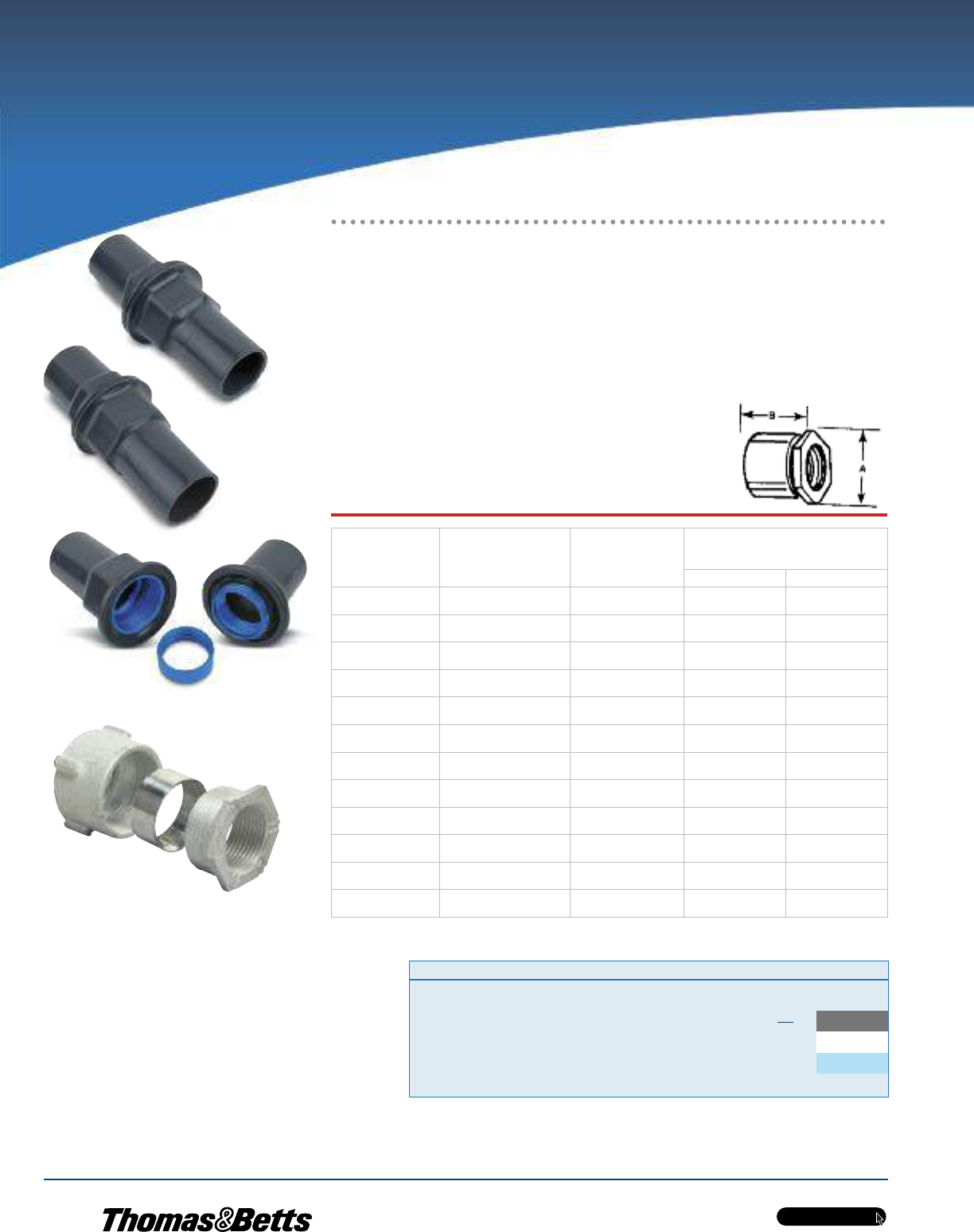
PVC-Coated Products
OCALTM
w w w . t n b . c a
H34
OCAL-BLUETM Double-Coat Threaded Erickson®
3-Piece Couplings
•Malleable iron and steel or copper-free aluminum
•Nominal 0.002 in. (2 mils) blue urethane coating on both interior and exterior
•Nominal 0.040 in. (40 mils) PVC coating bonded to exterior
•Free fitting threads ensure easy assembly
•Provide rigid in-line coupling with high-quality grounding —
won’t loosen under vibration
•Suitable for concrete-tight applications
Standard Materials / Finish
Cat. No. ERICSON
Bushing & Case. . . . . . . Malleable iron
Ring . . . . . . . . . . . . . . . Steel and malleable iron
Finish . . . . . . . . . . . . . . Nominal 0.002 in. (2 mils) blue urethane interior
and exterior coating with nominal
0.040 in. (40 mils) PVC exterior coating
Cat. No. ERICSON_SA
Bushing & Case. . . . . . . Copper-free aluminum
Ring . . . . . . . . . . . . . . . Copper-free aluminum
Finish . . . . . . . . . . . . . . Nominal 0.002 in. (2 mils) blue urethane interior
. . . . . . . . . . . . . . . . . . . and exterior coating with nominal
0.040 in. (40 mils) PVC exterior coating
Cat. No. Size Material Colour
ERICSON 1/2 _- _ = space for colour identifier
Blank = Steel G = Grey
SA = Aluminum W = White
Catalogue No. Example:
ERICSON2SA-B is 2 in. aluminum
Erickson®coupling coated in blue PVC.
B = Blue
Custom colours also available - Std. min. quantities are
required. Please contact your Regional Sales Office.
ERICSON3/4-G
ERICSON1-G
ERICSON3/4-G unassembled
Erickson®coupling before coating
Ordinary Location Fittings
Join Two Conduit Runs When
Neither Can Rotate!
Steel/
Malleable
Iron
Cat. No.
Copper
Free
Aluminum
Cat. No.
Pipe Size
in.
(mm)
Dimensions
in.
(mm)
AB
ERICSON1/2-_ ERICSON1/2SA-_ 1/2
(16)
1.47
(37.34)
1.25
(31.75)
ERICSON3/4-_ ERICSON3/4SA-_ 3/4
(21)
1.56
(39.62)
1.41
(35.81)
ERICSON1-_ ERICSON1SA-_ 1
(27)
1.91
(48.51)
1.63
(41.40)
ERICSON1-1/4-_ ERICSON1-1/4SA-_ 1-1/4
(35)
2.38
(60.45)
1.81
(45.97)
ERICSON1-1/2-_ ERICSON1-1/2SA-_ 1-1/2
(41)
2.63
(66.80)
1.97
(50.04)
ERICSON2-_ ERICSON2SA-_ 2
(53)
3.22
(81.79)
2.22
(56.39)
ERICSON2-1/2-_ ERICSON2-1/2SA-_ 2-1/2
(63)
3.97
(100.84)
2.69
(68.33)
ERICSON3-_ ERICSON3SA-_ 3
(78)
4.44
(112.78)
2.91
(73.91)
ERICSON3-1/2-_ ERICSON3-1/2SA-_ 3-1/2
(91)
5.00
(127.00)
3.00
(76.20)
ERICSON4-_ ERICSON4SA-_ 4
(103)
5.50
(139.70)
3.19
(81.03)
ERICSON5-_ ERICSON5SA-_ 5
(129)
6.78
(172.21)
3.75
(95.25)
ERICSON6-_ ERICSON6SA-_ 6
(155)
8.00
(203.20)
4.03
(102.36)
Metric size designator (ANSI C80.1-1994).
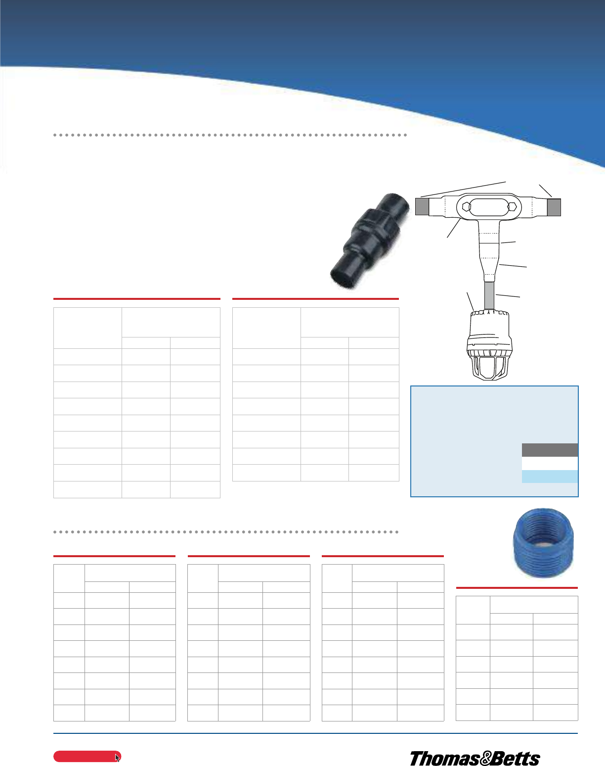
PVC-Coated Products
OCALTM
w w w . t n b . c a
H35
OCAL-BLUETM Urethane-Coated Reducing Bushings
Reduce a Conduit Hub to a Smaller Size
REC
Application
Cat. No.
Pipe Size in.
(mm)
A - Male B - Female
RE21-G 3/4
(21)
1/2
(16)
RE31-G 1
(27)
1/2
(16)
RE32-G 1
(27)
3/4
(21)
RE41-G 1-1/4
(35)
1/2
(16)
RE42-G 1-1/4
(35)
3/4
(21)
RE43-G 1-1/4
(35)
1
(27)
RE51-G 1-1/2
(41)
1/2
(16)
RE52-G 1-1/2
(41)
3/4
(21)
Cat. No.
Pipe Size in.
(mm)
A - Male B - Female
RE53-G 1-1/2
(41)
1
(27)
RE54-G 1-1/2
(41)
1-1/4
(35)
RE61-G 2
(53)
1/2
(16)
RE62-G 2
(53)
3/4
(21)
RE63-G 2
(53)
1
(27)
RE64-G 2
(53)
1-1/4
(35)
RE65-G 2
(53)
1-1/2
(41)
RE73-G 2-1/2
(63)
1
(27)
Cat. No.
Pipe Size in.
(mm)
A - Male B - Female
RE74-G 2-1/2
(63)
1-1/4
(35)
RE75-G 2-1/2
(63)
1-1/2
(41)
RE76-G 2-1/2
(63)
2
(53)
RE83-G 3
(78)
1
(27)
RE84-G 3
(78)
1-1/4
(35)
RE85-G 3
(78)
1-1/2
(41)
RE86-G 3
(78)
2
(53)
RE87-G 3
(78)
2-1/2
(63)
Cat. No.
Pipe Size in.
(mm)
A - Male B - Female
RE96-G 3-1/2
(91)
2
(53)
RE97-G 3-1/2
(91)
2-1/2
(63)
RE98-G 3-1/2
(91)
3
(78)
RE106-G 4
(103)
2
(53)
RE107-G 4
(103)
2-1/2
(63)
RE108-G 4
(103)
3
(78)
Metric size designator (ANSI C80.1-1994).Also available in Aluminum (SA).
1-1/4 in. Conduit
1-1/4 in. T Short 1-1/4 in. Nipple
1-1/4 in.- 3/4 in. Series
REC Reducing
3/4 in. Conduit
Lighting Fixture
Cat. No. Colour
REC21-
SA = Aluminum
_ = space for colour identifier
G = Grey
W = White
B = Blue
Custom colours also available - Std. min. quantities are required. Please
contact your Regional Sales Office.
_
RE32-G
REC21-G
OCAL-BLUETM Double-Coat Reducing Couplings
•Integral bushings in both ends prevent damage to wires
•Funnel-shaped interior guides wires from large to small conduit,
making them easier to pull
•Nominal 0.002 in. (2 mils) blue urethane coating on both interior
and exterior
•Nominal 0.040 in. (40 mils) PVC coating bonded to exterior
•Pressure-sealing sleeves protect connections
Ordinary Location Fittings
Easily Join Two Different
Sizes of Conduit!
Cat. No.
Pipe Size
in.
(mm)
AB
REC21-_ 3/4
(21)
1/2
(16)
REC31-_ 1
(27)
1/2
(16)
REC32-_ 1
(27)
3/4
(21)
REC42-_ 1-1/4
(35)
3/4
(21)
REC43-_ 1-1/4
(35)
1
(27)
REC52-_ 1-1/2
(41)
3/4
(21)
REC53-_ 1-1/2
(41)
1
(27)
REC54-_ 1-1/2
(41)
1-1/4
(35)
REC602-_ 2
(53)
3/4
(21)
Cat. No.
Pipe Size
in.
(mm)
AB
REC603-_ 3/4
(21)
1/2
(16)
REC604-_ 1
(27)
1/2
(16)
REC605-_ 1
(27)
3/4
(21)
REC75-_ 1-1/4
(35)
3/4
(21)
REC86-_ 1-1/4
(35)
1
(27)
REC97-_ 1-1/2
(41)
3/4
(21)
REC108-_ 1-1/2
(41)
1
(27)
REC01210-_ 1-1/2
(41)
1-1/4
(35)
Metric size designator (ANSI C80.1-1994).
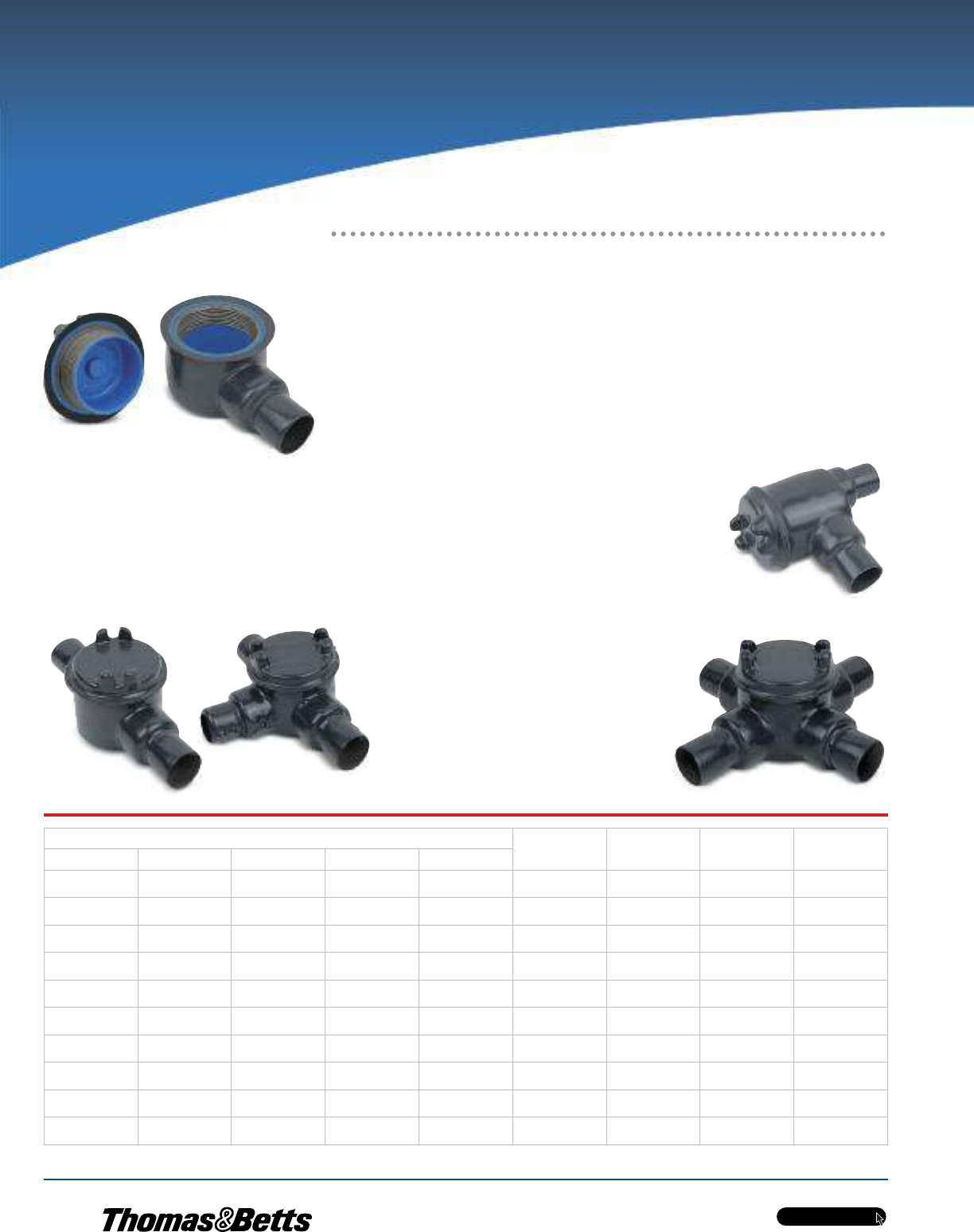
PVC-Coated Products
OCALTM
w w w . t n b . c a
H36
Metric size designator (ANSI C80.1-1994).
† Ratings prior to PVC coating.
GUAC
GUA
GUAB
Listings / Certifications†
•UL514A Wet Locations
(when used with gasketed covers)
•UL886
GUAT
Cat. No. Aluminum
Cover
Only
Iron
Cover
Only
Pipe Size
in.
(mm)
Cover Opening
in.
(mm)
GUA GUAC GUAT GUAX GUAB
GUA14-_ GUAC14-_ GUAT14-_ GUAX14-_ GUAB14-_ GUA04-_ GUA04WOD-_ 1/2
(16)
2.00
(50.80)
GUA24-_ GUAC24-_ GUAT24-_ GUAX24-_ GUAB24-_ GUA04-_ GUA04WOD-_ 3/4
(21)
2.00
(50.80)
GUA16-_ GUAC16-_ GUAT16-_ GUAX16-_ GUAB16-_ GUA06-_ GUA06WOD-_ 1/2
(16)
3.00
(76.20)
GUA26-_ GUAC26-_ GUAT26-_ GUAX26-_ GUAB26-_ GUA06-_ GUA06WOD-_ 3/4
(21)
3.00
(76.20)
GUA36-_ GUAC36-_ GUAT36-_ GUAX36-_ GUAB36-_ GUA06-_ GUA06WOD-_ 1
(27)
3.00
(76.20)
——GUAT37-_ GUAX37-_ — GUA07-_ GUA07WOD-_ 1
(27)
3.63
(92.20)
GUA47-_ GUAC47-_ GUAT47-_ GUAX47-_ GUAB47-_ GUA07-_ GUA07WOD-_ 1-1/4
(35)
3.63
(92.20)
— GUAC49-_ GUAT49-_ GUAX49-_ — GUA09-_ GUA09WOD-_ 1-1/4
(35)
5.00
(127.00)
GUA59-_ GUAC59-_ GUAT59-_ GUAX59-_ GUAB59-_ GUA09-_ GUA09WOD-_ 1-1/2
(41)
5.00
(127.00)
— GUAC69-_ GUAT69-_ GUAX69-_ GUAB69-_ GUA09-_ GUA09WOD-_ 2
(53)
5.00
(127.00)
GUAX
Hazardous Location Fittings
Provide Access to Wiring, Directional
Changes in Conduit and More!
OCAL-BLUETM Double-Coat GUA Series Conduit
Boxes
GUA series conduit boxes are installed in hazardous areas to protect conductors, act as pull and splice
boxes, provide access to conductors for maintenance and future system changes, act as mounting outlets
for fixtures (with proper covers) or change conduit direction.
•Grade 60-45-10 ductile iron bodies and cast aluminum covers
(iron covers also available)
•Nominal 0.002 in. (2 mils) blue urethane coating on both interior
and exterior and nominal 0.040 in. (40 mils) PVC coating bonded
to exterior
•All hubs have minimum 5 full threads, integral bushing and
pressure-sealing sleeves
•All units furnished with internal grounding screw and ship
complete with aluminum cover with O-ring gasket
(covers also sold separately for replacement purposes)
•Explosion-proof, dust-ignition proof, raintight
and suitable for use in the following environments:†
– Class I, Divisions 1 & 2, Groups C and D
– Class II, Division 1, Groups E, F and G
– Class III, Divisions 1 & 2
– NEMA 3, 4, 7 CD and 9 EFG
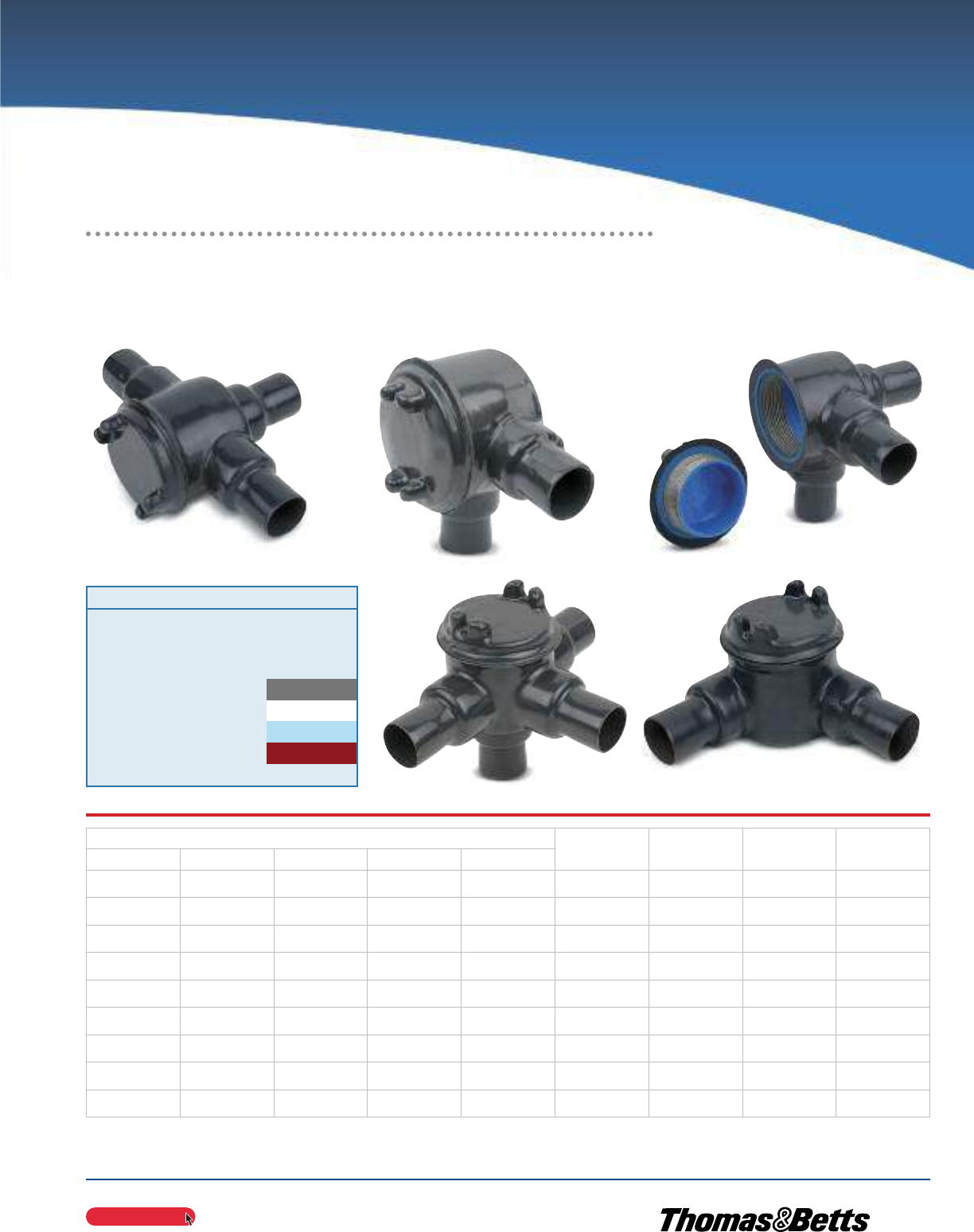
PVC-Coated Products
OCALTM
w w w . t n b . c a
H37
Metric size designator (ANSI C80.1-1994).
Cat. No. Aluminum
Cover
Only
Iron
Cover
Only
Pipe Size
in.
(mm)
Cover Opening
in.
(mm)
GUAD GUAL GUAM GUAN GUAW
GUAD14-_ GUAL14-_ GUAM14-_ GUAN14-_ GUAW14-_ GUA04-_ GUA04WOD-_ 1/2
(16)
2.00
(50.80)
GUAD24-_ GUAL24-_ GUAM24-_ GUAN24-_ GUAW24-_ GUA04-_ GUA04WOD-_ 3/4
(21)
2.00
(50.80)
GUAD16-_ GUAL16-_ GUAM16-_ GUAN16-_ GUAW16-_ GUA06-_ GUA06WOD-_ 1/2
(16)
3.00
(76.20)
GUAD26-_ GUAL26-_ GUAM26-_ GUAN26-_ GUAW26-_ GUA06-_ GUA06WOD-_ 3/4
(21)
3.00
(76.20)
GUAD36-_ GUAL36-_ GUAM36-_ GUAN36-_ — GUA06-_ GUA06WOD-_ 1
(27)
3.00
(76.20)
— GUAL47-_ GUAM47-_ GUAN47-_ — GUA07-_ GUA07WOD-_ 1-1/4
(35)
3.63
(92.20)
GUAD49-_ GUAL49-_ ———GUA09-_ GUA09WOD-_ 1-1/4
(35)
5.00
(127.00)
— GUAL59-_ — GUAN59-_ — GUA09-_ GUA09WOD-_ 1-1/2
(41)
5.00
(127.00)
— GUAL69-_ GUAM69-_ GUAN69-_ — GUA09-_ GUA09WOD-_ 2
(53)
5.00
(127.00)
GUAD GUAM
GUAN
GUAL
GUAW
Cat. No. Colour
GUA14-
SA = Aluminum
_ = space for colour identifier
G = Grey
W = White
B = Blue
R = Red
Custom colours also available - Std. min. quantities are required. Please
contact your Regional Sales Office.
_
Hazardous Location Fittings
OCAL-BLUETM Double-Coat GUA Series Conduit Boxes (cont’d)
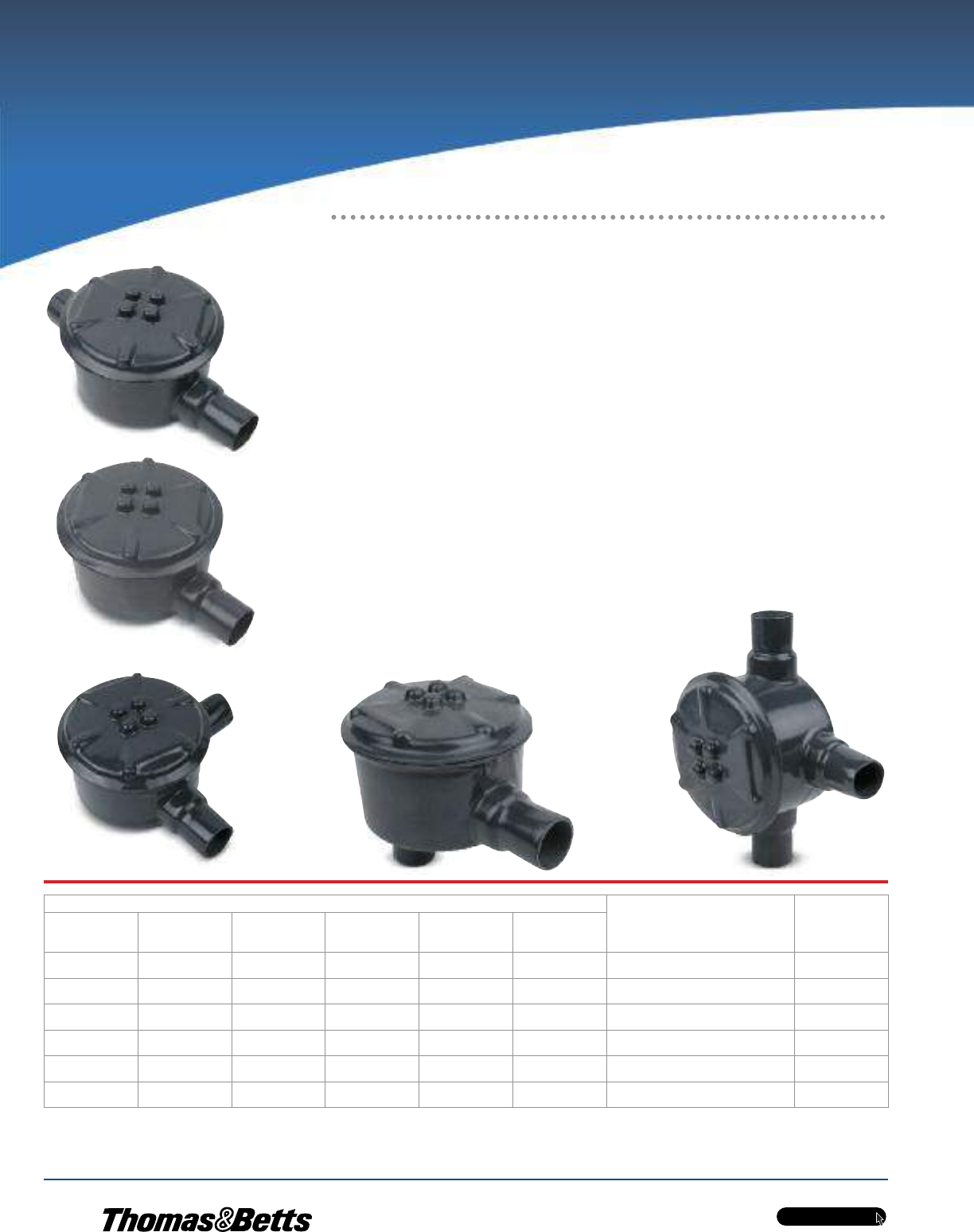
PVC-Coated Products
OCALTM
w w w . t n b . c a
H38
GAC
GAE
GAL GALB
GAT
Hazardous Location Fittings
Junction Boxes for Branch Conduits
in Hazardous Locations
Cat. No. Pipe Size
in.
(mm)
Cover Opening
in.
(mm)
Through-Feed
W/Surf. Cover
GAC
Dead End
W/Surf. Cover
GAE
L-Style
W/Surf. Cover
GAL
LB-Style
W/Surf. Cover
GALB
T-Style
W/Surf. Cover
GAT
Surface
Cover Only
GAS
GAC-1-_ † GAE-1-_ † GAL-1-_ † GALB-1-_† GAT-1-_ † GAS-123-_ • 1/2
(16)
3.69
(93.73)
GAC-2-_ † GAE-2-_ † GAL-2-_ † GALB-2-_ † GAT-2-_ † GAS-123-_ • 3/4
(21)
3.69
(93.73)
GAC-3-_ †• GAE-3-_ †• GAL-3-_ †• GALB-3-_ † GAT-3-_ † GAS-123-_ • 1
(27)
3.69
(93.73)
GAC-4-_ †• — GAL-4-_ †• GALB-4-_ † GAT-4-_ † GAS-4-_ • 1-1/4
(35)
3.91
(99.31)
GAC-5-_ †• — GAL-5-_ †• GALB-5-_ †• GAT-5-_ † GAS-56-_ • 1-1/2
(41)
5.19
(131.83)
GAC-6-_ †• — GAL-6-_ †• GALB-6-_ †• GAT-6-_ † GAS-56-_ • 2
(53)
5.19
(131.83)
† Suffix -OR: O-ring available for NEMA 4 rating. Consult your Regional Sales Office for lead time and price.
• Made-to-order item. Consult factory for lead time and minimum quantities.
†† Ratings prior to PVC coating.
Metric size designator (ANSI C80.1-1994).
OCAL-BLUETM Double-Coat External Hubs with
Covers and Installed Green Ground Screw
•Accessible wiring chamber provides a convenient location to maintain or change a
system, pull conductors and make splices
•Unique mounting pads and rugged protective housing ideal for installation of OEM
devices or instruments
•Die-cast copper-free aluminum alloy A360 construction with precision cast and
machined surfaces
•Precision NPT threaded hubs for trouble-free field installation
•Nominal 0.002 in. (2 mils) blue urethane coating on both interior and exterior and
nominal 0.040 in. (40 mils) PVC coating bonded to exterior
•Explosion-proof, dust-ignition proof, raintight and suitable for use in the following
environments:††
– Class I, Divisions 1 & 2, Groups C and D
– Class II, Division 1, Groups E, F and G
– Class III, Divisions 1 & 2
– NEMA 3, 4, 7 CD and 9 EFG (NEMA 4 rated
when ordered with O-ring installed)
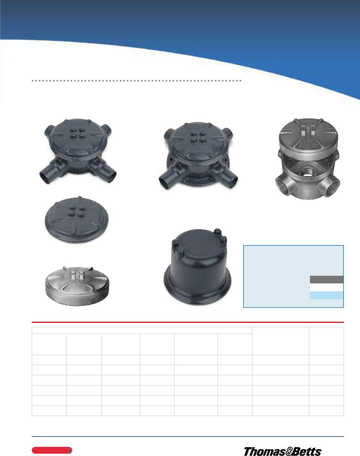
PVC-Coated Products
OCALTM
OCAL-BLUETM Double-Coat External Hubs with Covers
and Installed Green Ground Screw (cont’d)
w w w . t n b . c a
H39
Cat. No.
Pipe Size
in.
(mm)
Cover Opening
in.
(mm)
X-Style
W/Surf. Cover
GAX
X-Style
W/Flange
& Surf. Cover
GAFX
U-Style
Surface
W/Canopy Cover
GAJU
Surface
Cover Only
GAS
Dome Cover Only
(Class I, Gr. D)
GAD
Canopy
Cover Only
GAJ
GAX-1-_ † GAFX-1-_ † GAJU-1-_ • GALB-1-_ † GAD-123-_ • GAJ-123-_• 1/2
(16)
3.69
(93.73)
GAX-2-_ † GAFX-2-_ † GAJU-2-_ • GALB-2-_ † GAD-123-_ • GAJ-123-_• 3/4
(21)
3.69
(93.73)
GAX-3-_ †• GAFX-3-_ † GAJU-3-_ GALB-3-_ † GAD-123-_ • GAJ-123-_• 1
(27)
3.69
(93.73)
GAX-4-_ †• — — GALB-4-_ † — GAJ-4-_• 1-1/4
(35)
3.91
(99.31)
GAX-5-_ †• — GAJU-5-_ • GALB-5-_ †• — GAJ-56-_• 1-1/2
(41)
5.19
(131.83)
GAX-6-_ †• — GAJU-6-_ GALB-6-_ †• — GAJ-56-_• 2
(53)
5.19
(131.83)
GAFX
GAS
GAD
GAJU
(shown uncoated)
GAJ
(shown uncoated)
GAX
• Made-to-order item. Consult your Regional Sales Office for lead time and minimum quantities.
† Suffix -OR: O-ring available for NEMA 4 rating. Consult your Regional Sales Office for lead time and price.
Metric size designator (ANSI C80.1-1994).
Cat. No. Colour
GAC1-
_ = space for colour identifier
G = Grey
W = White
B = Blue
Custom colours also available - Std. min. quantities are required. Please
contact your Regional Sales Office.
_
Hazardous Location Fittings
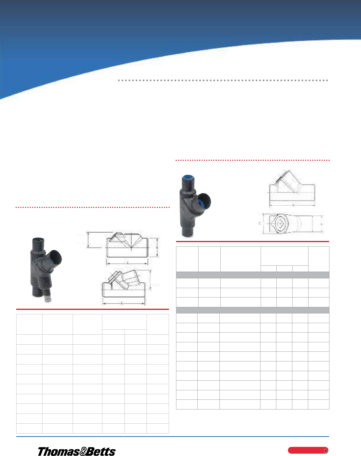
PVC-Coated Products
OCALTM
w w w . t n b . c a
H40
OCAL-BLUETM Double-Coat Sealing
Fittings
•Sealing fittings restrict the passage of gases, vapors, or
flames from one portion of the electrical installation to another
at atmospheric pressure and normal ambient temperatures. They
prevent precompression or ‘‘pressure pilling’’ in conduit systems.
•Grey iron alloy body construction coated with nominal 0.002 in.
(2 mils) blue urethane on both interior and exterior
•Nominal 0.040 in. (40 mils) PVC coating bonded to exterior —
available in grey, white, blue or custom colours
•Explosion-proof, dust-ignition proof and suitable for use in the
following environments:†
– Class I, Divisions 1 & 2, Groups C and D
– Class II, Division 1, Groups E, F and G
– Class III, Divisions 1 & 2
EYS
EYD
EYD 1/2 in. — 1 in.
EYD 1-1/4 in. — 4 in.
EYS1 — EYS5
EYD Series Drain Sealing Fittings
EYS Series Sealing Fittings
Female
Cat. No.
Male &
Female
Cat. No.
Pipe Size
in.
(mm)
Dimensions
in.
(mm)
Turning
Radius
in.
(mm)
AB
EYD1-_ EYD16-_ 1/2
(16)
3.81
(96.77)
1.50
(38.10)
1.75
(44.45)
EYD2-_ EYD26-_ 3/4
(21)
4.08
(103.63)
1.75
(44.45)
1.98
(50.29)
EYD3-_ EYD36-_ 1
(27)
4.85
(123.19)
2.19
(55.63)
2.19
(55.63)
EYD4-_ EYD46-_ 1-1/4
(35)
5.00
(127.00)
2.25
(57.15)
1.80
(45.72)
EYD5-_ EYD56-_ 1-1/2
(41)
5.44
(138.18)
2.44
(61.98)
2.00
(61.98)
EYD6-_ EYD66-_ 2
(53)
6.25
(158.75)
3.00
(76.20)
2.32
(58.93)
EYD7-_ EYD76-_ 2-1/2
(63)
7.50
(190.50)
3.50
(88.90)
2.69
(68.33)
EYD8-_ EYD86-_ 3
(78)
8.50
(215.90)
4.25
(107.95)
3.15
(80.01)
EYD9-_ EYD96-_ 3-1/2
(91)
9.19
(233.43)
4.75
(120.65)
3.38
(85.85)
EYD10-_ EYD106-_ 4
(103)
9.75
(247.65)
5.25
(133.35)
3.64
(92.46)
Female
Cat. No.
Male &
Female
Cat. No.
Pipe Size
in.
(mm)
Dimensions
in.
(mm)
Turning
Radius
in.
(mm)
ABC
Vertical Only
EYS1-_ EYS16-_ 1/2
(16)
3.31
(84.07)
1.25
(31.75)
1.50
(38.10)
1.66
(42.16)
EYS2-_ EYS26-_ 3/4
(21)
3.65
(92.71)
1.50
(38.10)
1.75
(44.45)
1.96
(49.78)
EYS3-_ EYS36-_ 1
(27)
4.25
(107.95)
1.75
(44.45)
2.19
(55.63)
2.40
(60.96)
Vertical or Horizontal
EYS11-_ EYS116-_ 1/2
(16)
3.63
(92.20)
1.25
(31.75)
—
—
1.09
(27.69)
EYS21-_ EYS216-_ 3/4
(21)
3.66
(92.96)
1.50
(38.10)
—
—
1.25
(31.75)
EYS31-_ EYS316-_ 1
(27)
4.25
(107.95)
1.75
(44.45)
—
—
1.59
(40.39)
EYS4-_ EYS46-_ 1-1/4
(35)
5.00
(127.00)
2.25
(57.15)
—
—
1.81
(45.97)
EYS5-_ EYS56-_ 1-1/2
(41)
5.44
(138.18)
2.44
(61.98)
—
—
2.00
(50.80)
EYS6-_ EYS66-_ 2
(53)
6.25
(158.75)
3.00
(76.20)
—
—
2.31
(58.67)
EYS7-_ EYS76-_ 2-1/2
(63)
7.50
(190.50)
3.50
(88.90)
—
—
2.56
(65.02)
EYS8-_ EYS86-_ 3
(78)
8.50
(215.90)
4.25
(107.95)
—
—
3.09
(78.49)
EYS9-_ EYS96-_ 3-1/2
(91)
9.19
(233.43)
4.75
(120.65)
—
—
3.38
(85.85)
EYS10-_ EYS106-_ 4
(103)
9.75
(247.65)
5.25
(133.35)
—
—
3.53
(89.66)
Turning
Radius
Turning
Radius
IMPORTANT: MUST BE USED WITH CHICOTM SEALING COMPOUND AND FIBER SEE PAGE H41.
† Ratings prior to PVC coating.
EYSX and EYDX are expanded-fill styles. When ordering, add X to part number.
For example: EYSX31-G, EYDX31-B.
Metric size designator (ANSI C80.1-1994).
Hazardous Location Fittings
Restrict the Passage of gGases, Vapors
and Flames at Atmospheric Pressure and
Normal Ambient Temperatures
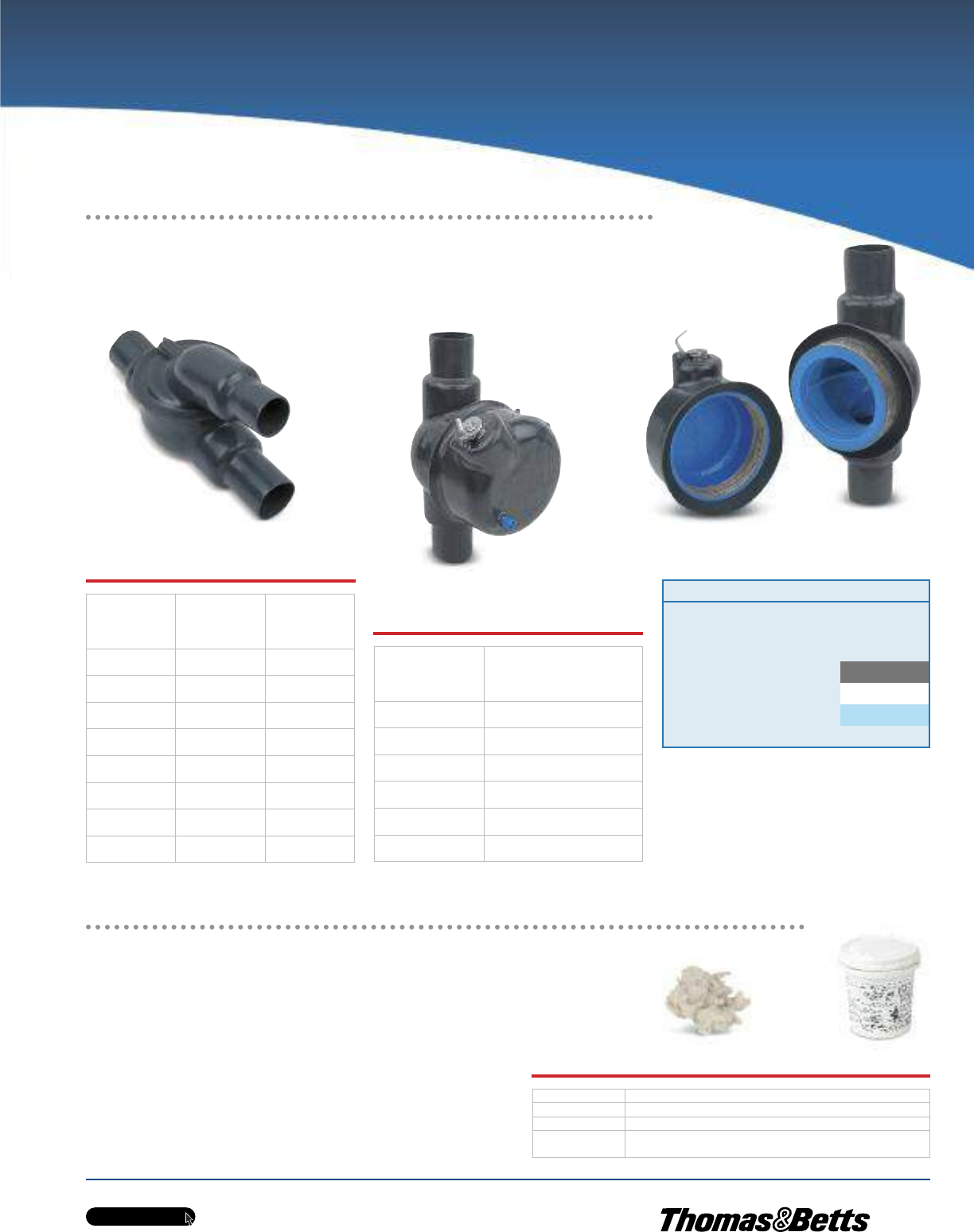
PVC-Coated Products
OCALTM
w w w . t n b . c a
H41
EZS
EZD
with Inspection Cover off
EZD
Ensures Proper Functioning of EYS Sealing Fittings
ChicoTM Sealing Compound and Fiber
•Sealing compound mixes with water, pours easily
and hardens in 60 — 70 minutes
•Fiber filler mineral wool holds sealing compound in
place while it hardens
OCAL-BLUETM Double-Coat EYS Sealing Fittings require fiber filler and sealing
compound to function properly. Use ChicoTM X Fiber Filler to form a dam around
the sealing fitting’s integral bushing, as well as at the end of the conduit and around
conductors entering the hub. ChicoTM A Sealing Compound expands slightly while
hardening and bonds to the inner walls of the sealing fitting.
Female
Cat. No.
Male &
Female
Cat. No.
in.
(mm)
EZS1-_ EZS16-_ 1/2
(16)
EZS2-_ EZS26-_ 3/4
(21)
EZS3-_ EZS36-_ 1
(27)
EZS4-_ EZS46-_ 1-1/4
(35)
EZS5-_ EZS56-_ 1-1/2
(41)
EZS6-_ EZS66-_ 2
(53)
EZS7-_ EZS76-_ 2-1/2
(63)
EZS8-_ EZS86-_ 3
(78)
Metric size designator (ANSI C80.1-1994).
Cat. No. in.
(mm)
EZD111-_ 1/2
(16)
EZD211-_ 3/4
(21)
EZD311-_ 1
(27)
EZD411-_ 1-1/4
(35)
EZD511-_ 1-1/2
(41)
EZD611-_ 2
(53)
Metric size designator (ANSI C80.1-1994).
EZS Series Sealing
Fittings
EZD Series Sealing
Fittings
Cat. No. Description
SEAL-A3 ChicoTM A Sealing Compound, 1 lb. net wt./23 cu.in. vol.
FIBER-X6 ChicoTM X Fiber Filler, 8 oz.
SEALKIT-A4 ChicoTM A Sealing Compound, 1 lb. net wt./23 cu.in. vol.,
with 1 oz. ChicoTM X Fiber Filler
ChicoTM is a trademark of Cooper Technologies Company.
SEAL-A3
FIBER-X6
Cat. No. Colour
EYS1-
_ = space for colour identifier
G = Grey
W = White
B = Blue
Custom colours also available - Std. min. quantities are required. Please
contact your Regional Sales Office.
_
Hazardous Location Fittings
OCAL-BLUETM Double-Coat Sealing Fittings (cont’d)
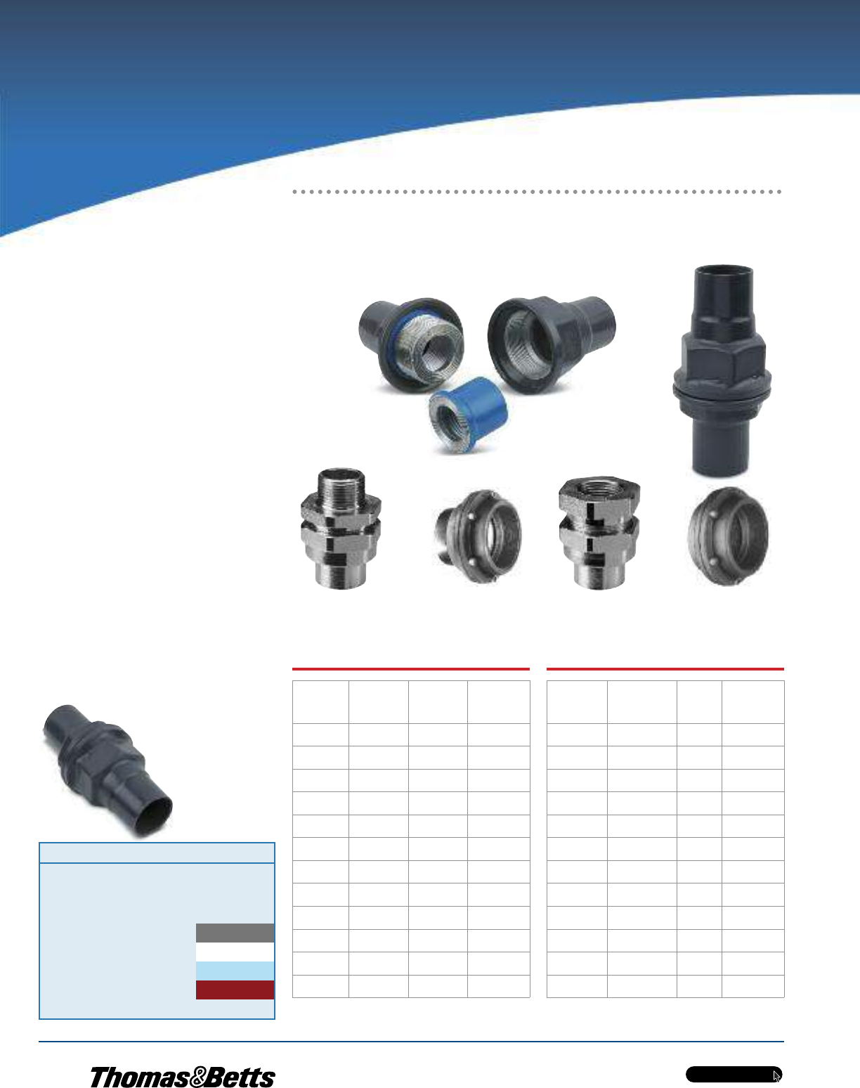
w w w . t n b . c a
PVC-Coated Products
H42
OCALTM
UNF Female 1/2 - 4 in.
(shown uncoated)
UNF Female 5 - 6 in.
(shown uncoated)
UNF205-G
Cat. No.
Pipe Size
in.
(mm)
Overall
Length
in. (mm)
Overall
Diameter
in. (mm)
UNY105-_ 1/2
(16)
2.39
(60.71)
1.50
(38.10)
UNY205-_ 3/4
(21)
2.44
(61.98)
1.81
(38.10)
UNY305-_ 1
(27)
2.75
(69.85)
2.00
(50.80)
UNY405-_ 1-1/4
(35)
3.06
(77.72)
2.75
(69.85)
UNY505-_ 1-1/2
(41)
3.63
(92.20)
3.06
(77.72)
UNY605-_ 2
(53)
3.50
(88.90)
3.81
(96.77)
UNY705-_ 2-1/2
(63)
4.81
(122.17)
4.31
(109.47)
UNY805-_ 3
(78)
5.34
(135.64)
5.06
(128.52)
UNY905-_ 3-1/2
(91)
5.50
(139.70)
5.69
(144.53)
UNY1005-_ 4
(103)
5.63
(143.00)
6.19
(157.23)
UNY905-_ 5
(129)
5.25
(133.35)
8.19
(208.03)
UNY014-_ 6
(155)
5.38
(136.65)
9.31
(236.47)
Metric size designator (ANSI C80.1-1994).
UNY Male Unions
Cat. No.
Pipe Size
in.
(mm)
Overall
Length
in. (mm)
Overall
Diameter
in. (mm)
UNF105-_ 1/2
(16)
1.88
(47.75)
1.50
(38.10)
UNF205-_ 3/4
(21)
2.13
(54.10)
1.81
(45.97)
UNF305-_ 1
(27)
2.16
(54.86)
2.00
(50.80)
UNF405-_ 1-1/4
(35)
2.25
(57.15)
2.75
(69.85)
UNF505-_ 1-1/2
(41)
2.75
(69.85)
3.06
(77.72)
UNF605-_ 2
(53)
2.50
(63.50)
3.81
(96.77)
UNF705-_ 2-1/2
(63)
3.50
(88.90)
4.31
(109.47)
UNF805-_ 3
(78)
4.00
(101.60)
5.06
(128.52)
UNF905-_ 3-1/2
(91)
4.16
(105.66)
5.69
(144.53)
UNF1005-_ 4
(103)
4.25
(107.95)
6.19
(157.23)
UNF012-_ 5
(129)
3.81
(96.77)
8.19
(208.03)
UNF014-_ 6
(155)
3.81
(96.77)
9.31
(236.47)
† Ratings prior to PVC coating.
UNF Female Unions
UNY Male 1/2 - 4 in.
(shown uncoated)
UNY Male 5 - 6 in.
(shown uncoated)
Hazardous Location Fittings
Explosion-Proof, Dust-Ignition Proof
Three-Piece Couplings
Cat. No. Colour
UNF105-
SA = Aluminum
_ = space for colour identifier
G = Grey
W = White
B = Blue
R = Red
Custom colours also available - Std. min. quantities are required. Please
contact your Regional Sales Office.
_
OCAL-BLUETM Double-
Coat Conduit Unions
•Install in threaded thick-wall conduit
systems in hazardous areas
•Use UNY male unions to connect conduit
to a conduit fitting, junction box or
device enclosure
•Use UNF female unions to connect
conduit to conduit or to provide
means for future modifications to
the conduit system
•Nominal 0.002 in. (2 mils) blue urethane
on interior and exterior
•Nominal 0.040 in. (40 mils) PVC coating
bonded to exterior
•Pressure-sealing sleeves protect
your connection
•Explosion-proof, dust-ignition
proof and suitable for use
in the following environments:†
– Class I, Divisions 1 & 2,
Groups A, B, C and D
– Class II, Division 1,
Groups E, F and G
– Class III, Divisions 1 & 2
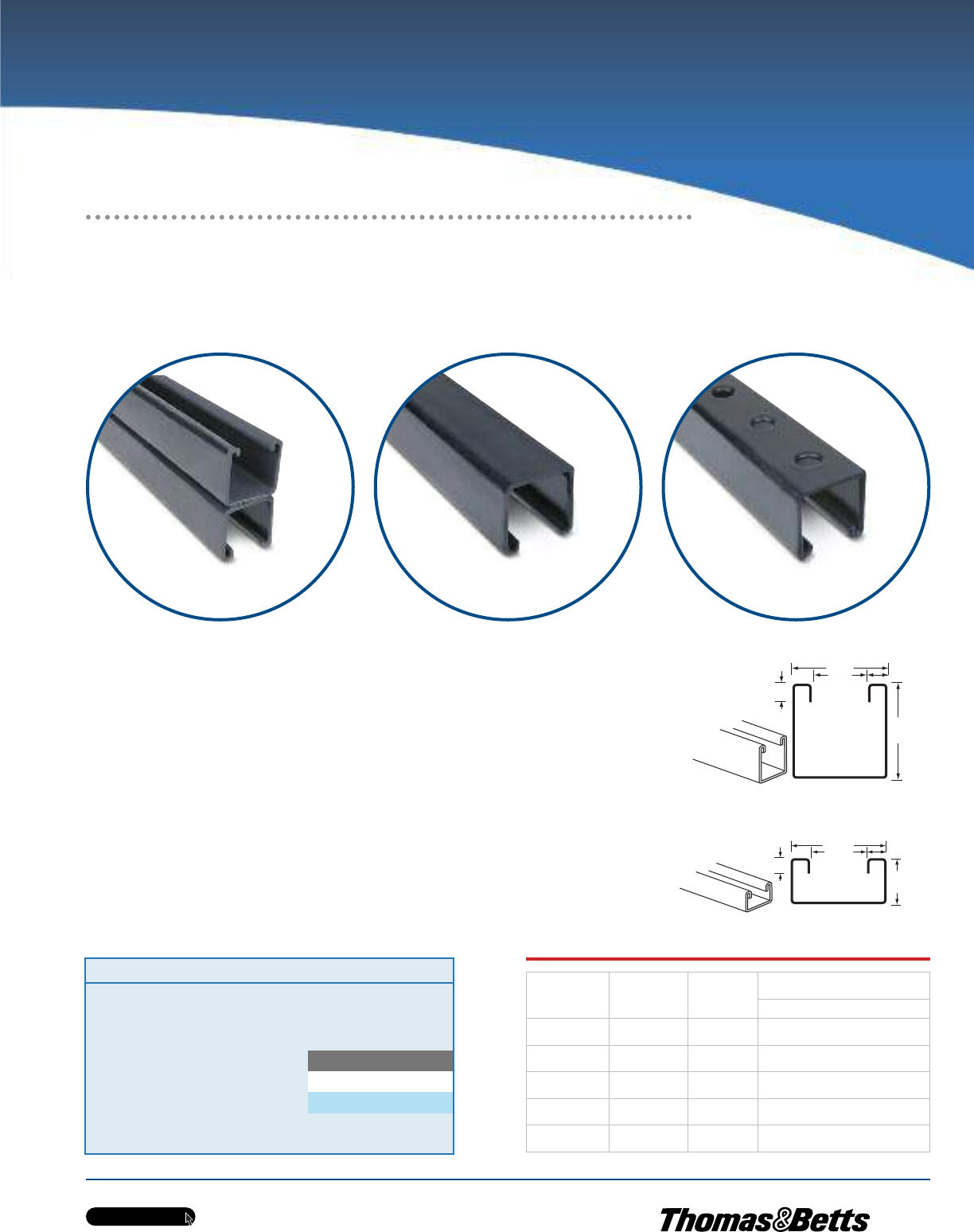
w w w . t n b . c a
PVC-Coated Products
H43
OCALTM
•Channels cold formed from hot-rolled pickled and oiled strip steel
•Nominal 0.015 in. (15 mils) PVC coating
•PVC coating available in your choice of blue, white or grey standard colours
•Custom colours also available on request
•Sold in 10 ft. (3.048 m) lengths with standard length tolerance of ± 1/8 in. (3.18 mm)
•Choose between standard 15/8 in. (41.28 mm) and shallow 13/16 in. (20.64 mm) depths
•Available in both solid and punched styles
•Available in 316 stainless steel (contact your Regional Sales Office)
•Strut accessories also available PVC Coated (contact your Regional Sales Office)
C14
9/32
1-5/8
1-5/8
1-5/8
3/8
7/8
7/8
13/16
9/32
A12
Cat. No. Colour
A12-
SA = Aluminum
_ = space for colour identifier
G = Grey
W = White
B = Blue
Catalogue No. Example:
C14P-W is shallow punched strut
channel coated in white PVC.
Custom colours also available - Std.
min. quantities are required. Please
contact your Regional Sales Office.
_
A12A A12 A12P
Cat. No. Style
Steel
Gauge
(mm)
in.
(mm)
W x H
A12-_ Standard 12
(2.65)
1.63 x 1.63
(41.28 x 41.28)
A12A-_ Back to Back 12
(2.65)
1.63 x 3.25
(41.28 x 82.55)
A12P-_ Standard Punched 12
(2.65)
1.63 x 1.63
(41.28 x 41.28)
C14-_ Shallow 14
(1.89)
1.63 x 0.81
(41.28 x 20.64)
C14P-_ Shallow Punched 14
(1.89)
1.63 x 0.81
(41.28 x 20.64)
Strut and Accessories
Rugged Steel Channels Protected
by Corrosion-Resistant PVC!
OcalTM PVC-Coated Steel Strut
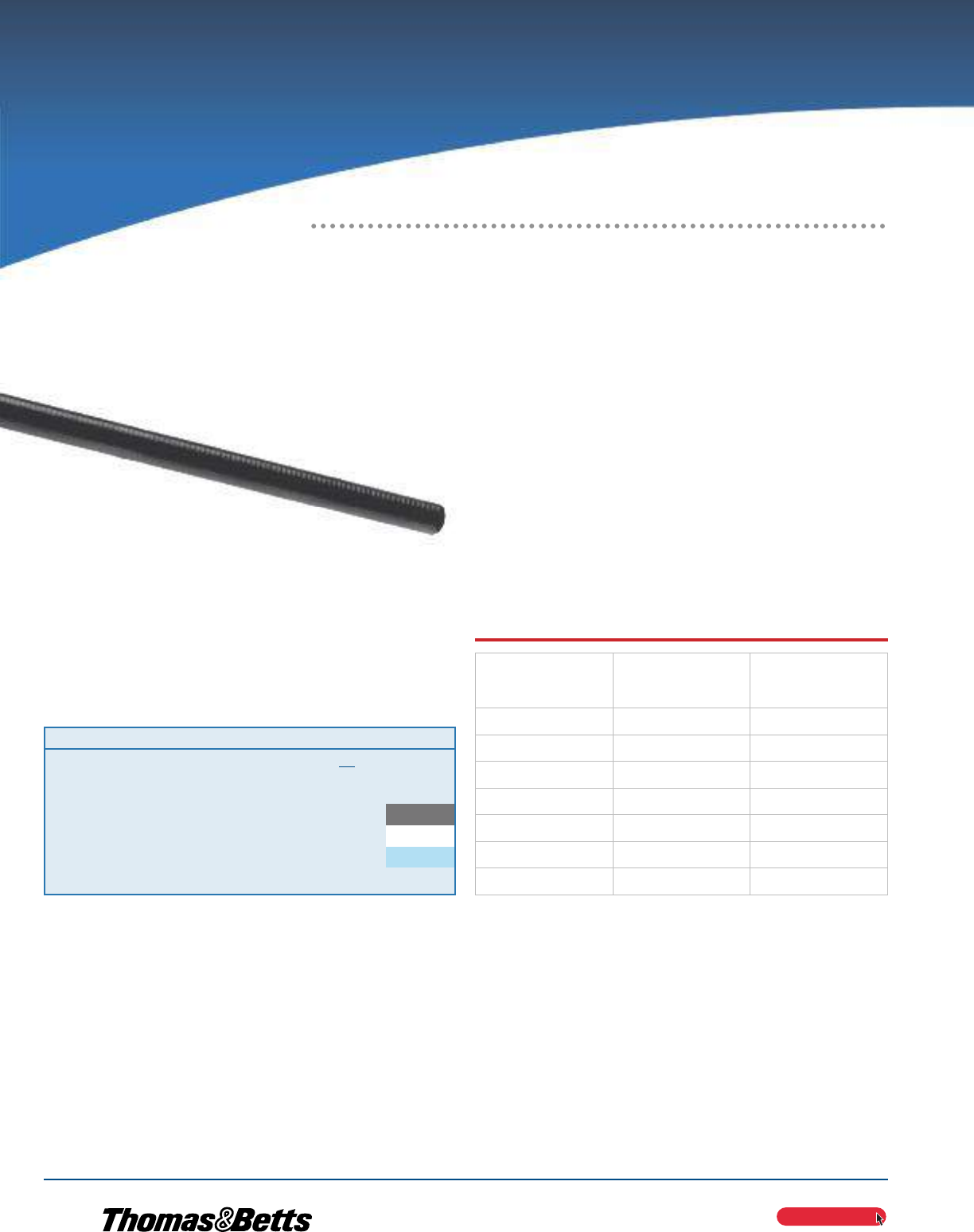
PVC-Coated Products
OCALTM
w w w . t n b . c a
H44
OcalTM PVC-Coated Steel Strut
All-Thread Rods
•All-thread steel rods coated with nominal 0.015 in. (15 mils) PVC
in blue, white or grey; custom colours available on request
•Available in 1/4 in., 3/8 in. or 1/2 in. standard diameters and in
3-, 6- or 10-ft. standard lengths
•Also available uncoated in Type 316 stainless steel
Cat. No. Diameter X Length Colour
THR3/8X3-
Catalogue No. Example:
NPL3/4X6-G is 3/4’’ x 6’’ long
steel nipple coated in grey PVC.
_ = space for colour identifier
G = Grey
W = White
B = Blue
Custom colours also available - Std. min. quantities are
required. Please contact your Regional Sales Office.
PVC-Coated All-Thread Rod
Cat. No.
Trade Size
in.
(mm)
Length
ft.
(m)
THR1/4X10-_ 1/4
(6.35)
10.00
(3.05)
THR3/8X3-_ 3/8
(9.53)
3.00
(0.91)
THR3/8X6-_ 3/8
(9.53)
6.00
(1.83)
THR3/8X10-_ 3/8
(9.53)
10.00
(3.05)
THR1/2X3-_ 1/2
(12.70)
3.00
(0.91)
THR1/2X6-_ 1/2
(12.70)
6.00
(1.83)
THR1/2X10-_ 1/2
(12.70)
10.00
(3.05)
OcalTM PVC-Coated
Steel All-Thread Rods
Strut and Accessories
Continuously Threaded Rods for Use With
Conduit Hangers and Strut to Suspend
Overhead Conduit Runs
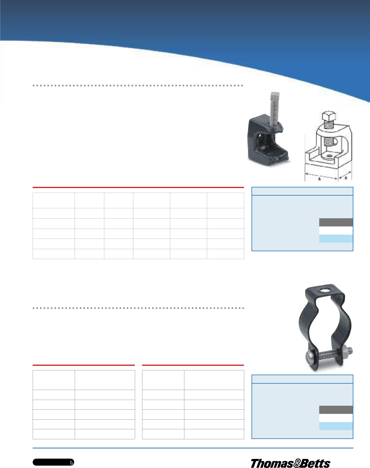
PVC-Coated Products
OCALTM
w w w . t n b . c a
H45
500-G
Hanger Rod Beam Clamp
OcalTM PVC-Coated Hanger Rod Beam Clamps
•Malleable iron construction
•Nominal 0.015 in. (15 mils) PVC coating in blue, white, grey or custom colours
•500, 502 and 503 also available uncoated in Type 316 stainless steel;
add -SS316 to catalogue number to order (for example: 502-SS316)
OcalTM PVC-Coated Mini Conduit Hangers
•Nominal 0.015 in. (15 mils) PVC coating in blue, white, grey or custom colours
•Rated for loads of up to 500 lb. (226.80 kg) with a safety factor of three
Includes Stainless Steel
Bolt and Nut for Fast, Easy Installation
Cat. No.
Base ‘‘A’’
in.
(mm)
Base ‘‘B’’
in.
(mm)
Jaw Opening
in.
(mm)
Tapped Hole
in.
(mm)
Load Rating‡
lb.
(kg)
500-_ 1
(25.40)
1-1/4
(31.75)
15/16
(23.81)
1/4 - 20
(6.35 - 20)
450
(204.12)
501-_ 1-1/2
(38.10)
1-5/8
(41.28)
7/8
(22.23)
15/16 - 18
(7.94 - 18)
800
(362.87)
502-_ 2
(50.80)
2
(50.80)
1
(25.40)
3/8 - 16
(9.53 - 16)
1300
(589.67)
503-_ 2-5/8
(66.68)
2-1/2
(63.50)
1
(25.40)
1/2 - 13
(12.70 - 13)
1300
(589.67)
508-_ 2-1/2
(63.50)
2-3/8
(60.33)
2-1/8
(53.98)
1/2 - 13
(12.70 - 13)
1700
(771.11)
‡ Load ratings based on bottom hole of beam clamp with safety factor of three.
Metric size designator (ANSI C80.1-1994).
Cat. No.
Pipe Size
in.
(mm)
MINE1/2-_ 1/2
(16)
MINE3/4-_ 3/4
(21)
MINE1-_ 1
(27)
MINE1-1/4-_ 1-1/4
(35)
MINE1-1/2-_ 1-1/2
(41)
Cat. No.
Pipe Size
in.
(mm)
MINE2-_ 2
(53)
MINE2-1/2-_ 2-1/2
(63)
MINE3-_ 3
(78)
MINE3-1/2-_ 3-1/2
(91)
MINE4-__ 4
(103)
Metric size designator (ANSI C80.1-1994).
MINE3/4-G
Mini Conduit
Hanger
Cat. No. Colour
500-
_ = space for colour identifier
G = Grey
W = White
B = Blue
Custom colours also available - Std. min. quantities are required. Please
contact your Regional Sales Office.
_
Cat. No. Colour
MINE1-
_ = space for colour identifier
G = Grey
W = White
B = Blue
Custom colours also available - Std. min. quantities are required. Please
contact your Regional Sales Office.
_
Strut and Accessories
Corrosion-Protected
Clamps for Hanging Threaded Rod
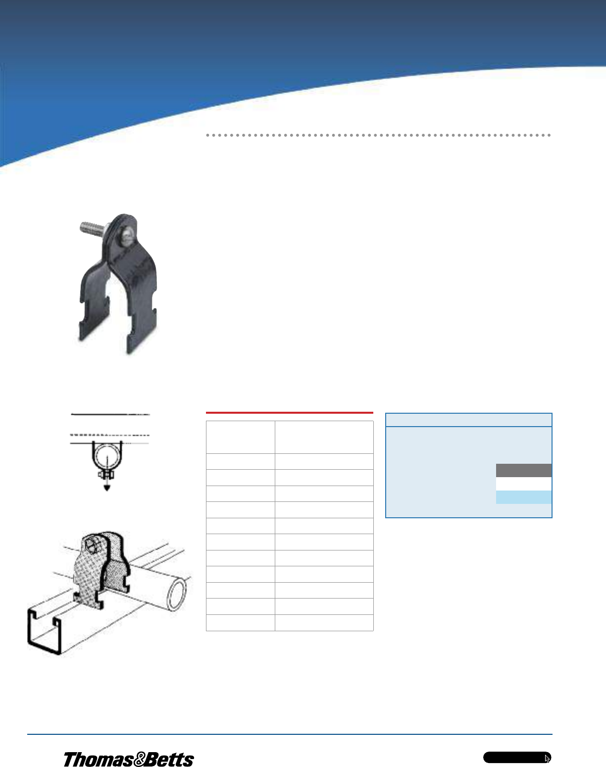
w w w . t n b . c a
PVC-Coated Products
H46
OCALTM
Cat. No.
Pipe Size
in.
(mm)
SS1/2-_ 1/2
(16)
SS3/4-_ 3/4
(21)
SS1-_ 1
(27)
SS1-1/4-_ 1-1/4
(35)
SS1-1/2-_ 1-1/2
(41)
SS2-_ 2
(53)
SS2-1/2-_ 2-1/2
(63)
SS3-_ 3
(78)
SS3-1/2-_ 3-1/2
(91)
SS4-_ 4
(103)
SS5-_ 5
(129)
Metric size designator (ANSI C80.1-1994).
OcalTM PVC-Coated
Strut Pipe Straps
PVC-Coated Pipe Strap
Strut and Accessories
Designed for Easy Attachment of
Conduit to Strut!
Cat. No. Colour
SS1-
_ = space for colour identifier
G = Grey
W = White
B = Blue
Custom colours also available - Std. min. quantities are required. Please
contact your Regional Sales Office.
_
Pipe Straps for Strut
Just twist-insert these pipe straps anywhere you need them along the slot side of a channel.
For additional flexibility, you can position the straps as closely as your pipe couplings permit.
•Combination slot and hex head bolt for flexibility of attachment
•Captivated square nut on shoulder enables easy one-handed tightening
•Use with either 1-5/8 in. or 1-1/2 in. strut for greater versatility
•Shipped pre-assembled for easier counting, sorting and handling
•Available with nominal 0.015 in. (15 mils) PVC coating in your choice of blue, white
or grey standard colours (custom colours also available on request)
•Uncoated pipe straps are available by ordering Series 700 and adding Type 316
stainless steel
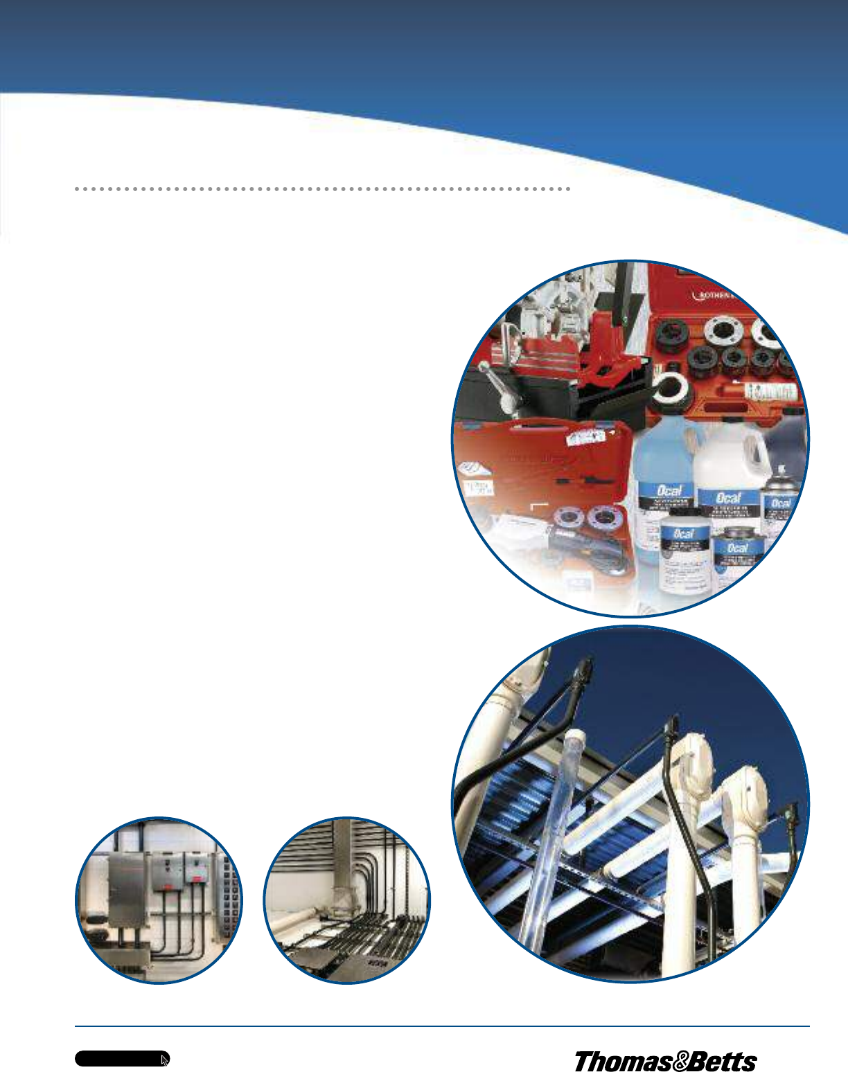
w w w . t n b . c a
PVC-Coated Products
H47
OCALTM
Thomas & Betts OcalTM PVC-Coated Conduit is designed to prevent corrosion
from striking weak points in conduit systems. But any PVC-coated conduit
system is only as good as the installation job. The wrong tools can result in
incorrectly installed pipes and fittings or damage to PVC coating, creating those
weak points where corrosion starts.
After careful research and evaluation, Thomas & Betts now offers you the very
best installation tools available for PVC-coated conduit. These tools are ready
for use on PVC-coated conduit right out of the box. What that means to you,
the installer, is lower costs — in equipment, in installation time and in time
you’d normally have to spend adapting standard tools for use on PVC-coated
conduit.
Hassle-Free Installation
•Count on Thomas & Betts to provide a hassle-free way for
installers to get the right tools for the job in their hands
— just another benefit of using OcalTM products
•For more information on OcalTM Installation Guidelines,
see pages H74 – H81.
Installation Products
The Right Tools for the Job!
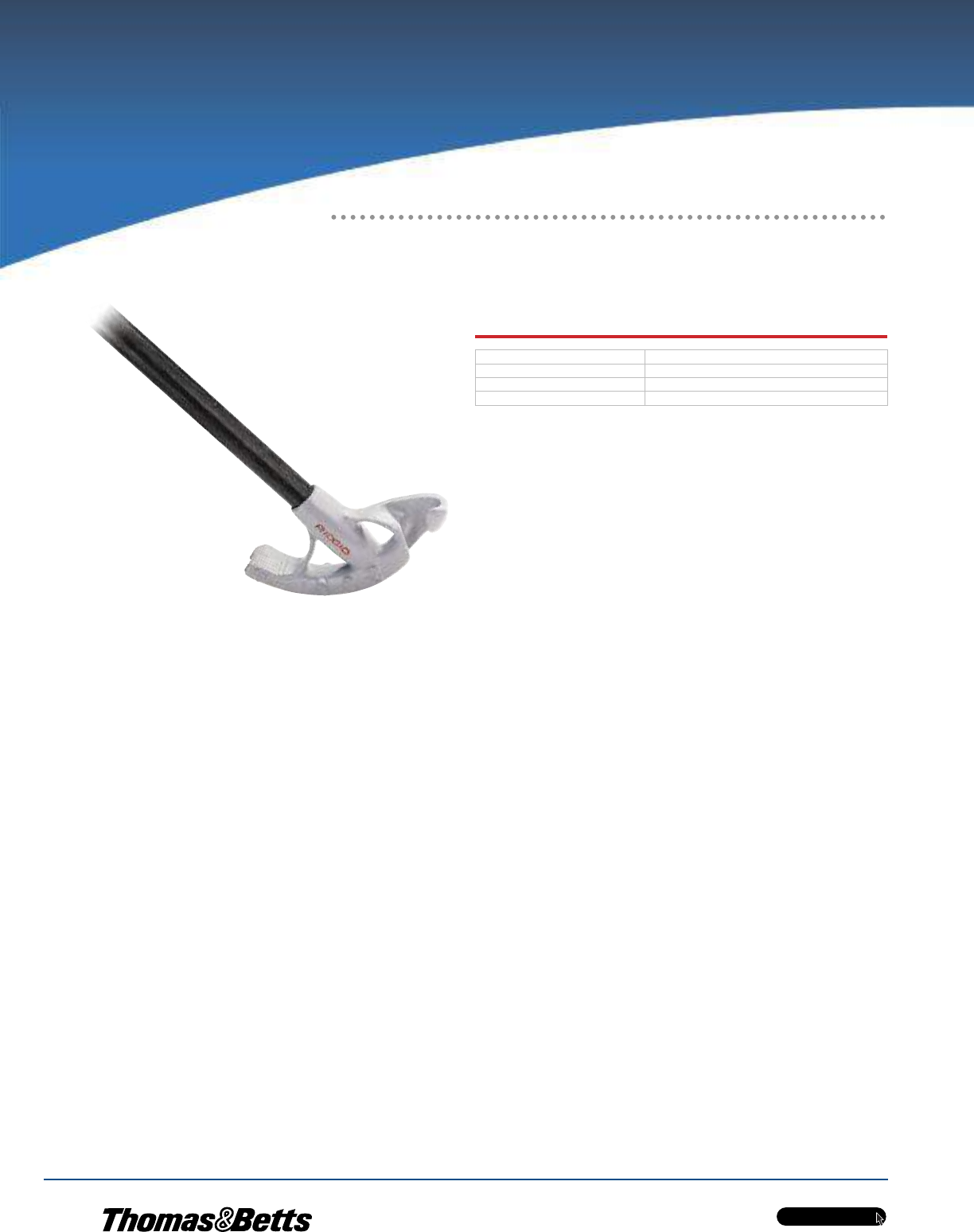
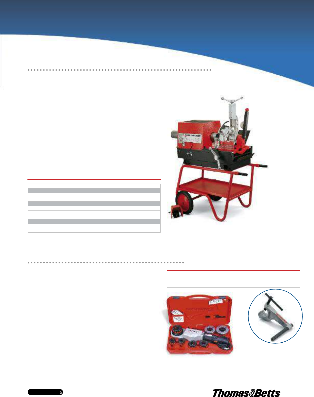
w w w . t n b . c a
PVC-Coated Products
H49
OCALTM
Installation Products
High-Speed Threading — Up to 25 RPM!
RHINOTM High-Performance
Threading Machine
•Standard threading machine with built-in pipe cutter, reamer,
foot-operated safety switch, 1/2 in. to 2 in. and 2-1/2 in. to 4 in.
automatic die heads and precision alloy dies
•Heavy-duty, 115V AC/DC, 50/60 Hz motor develops up to 3hp
•Quiet operation — 85dB maximum noise level
•Easy to maintain and service
•Precision pipe cutter with dual guide for accuracy and control
•COLLINSTM SUPER GRIP R/L chucking system features 4 heavy-
duty jaws, specially designed for PVC-coated conduit, at front
and rear to automatically grip and center pipe
Portable and compact for mobile
use and hard-to-reach spaces!
RHINOTM Threading Machine with optional wheeled stand
SUPERTRONICTM 2000 Power
Threader
•Quick and easy production of precision-threaded joints to
approved standards
•Dust-tight casing with sealed lubrication ensures long service life
and low maintenance
•Optimized gearing for high-performance output with minimal
energy consumption
•15 — 25 rpm threading speed with 60 rpm rapid reverse for
time savings
•Complete set includes SUPERTRONICTM 2000, forged pipe clamp,
thread-cutting spray,quick-change die heads with tempered-
steel precision dies for 1/2 in., 3/4 in., 1 in., 1-1/4 in., 1-1/2 in.
and 2 in. PVC-coated conduit and carrying case
RhinoTM, CollinsTM and SUPERTRONICTM are trademarks of Rothenberger AG.
Cat. No. Description
RHINOTM High-Performance Threading Machine
P00551C RHINOTM 1/2 in. — 4 in. Threading Machine with Jaws for PVC-Coated Conduit
ROTH00548 Optional Wheeled Stand with Tool Tray for RHINOTM Threading Machine
Replacement Threading Die Sets for RHINOTM Threading Machine
89101 1/2 in. — 3⁄4 in. Threading Die Set
89102 1 in. — 2 in. Threading Die Set
59912 2-1/2 in. — 4 in. Threading Die Set
Replacement Jaws Sets for RHINOTM Threading Machine
P20305C Jaw Set for PVC-Coated Conduit
ROTH02385 Jaw Set for Galvanized Rigid Conduit
Cat. No. Description
P71259C SUPERTRONICTM 2000 Power Threader Set
for 1/2 in., 3/4 in., 1 in., 1-1/4 in., 1-1/2 in. and 2 in. PVC-Coated Conduit
Forged pipe clamp, shown at right, is included
with the P71259C SUPERTRONICTM 2000 Power
Threader Set.
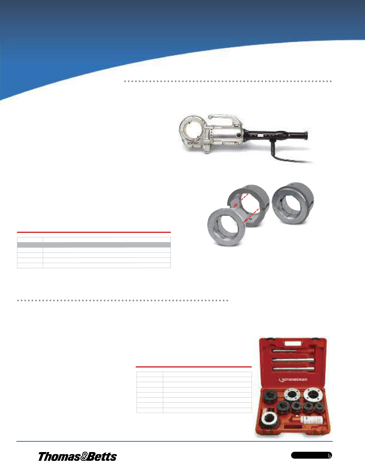
w w w . t n b . c a
PVC-Coated Products
H50
OCALTM
Installation Products
Threads 1/2 in. to 2 in.
Conduit in Seconds!
MINI-COLLINSTM Electric Power Drive
•Lightweight, compact design goes anywhere —
only 28 in. long and requires only 1-3/4 in. clearance
in trenches, overhead and other tight spaces
•Easy to maintain — built-in fill plug eliminates
disassembly of gearbox for oiling
•115V, 15A reversible motor provides the power
to make any turning job easier
•Tightens nuts, drives cable pullers, turns hoists
and jacks, opens and closes valves and drives
up to 6 in. geared threaders
•Compatible with RIDGID®12R die heads
•Cat. No. 13158 Adapter enables SUPER CUT die heads (below)
to be used with ROTHENBERGER®MINI-COLLINSTM and RIDGID®
Model 700 portable threading machines
MINI-COLLINSTM Electric Power Drive
The two-piece 13158 adapter enables the use of SUPER CUT die heads with the MINI-COLLINSTM.
For dies up to 1-1/4 in. in size, use both pieces together, as shown at right. For larger dies, separate
the two pieces, as shown at left, and use only the outer ring.
Mini-CollinsTM and Rothenberger®are trademarks of Rothenberger AG.
Ridgid®is a trademark of Emerson Electric Co.
Machined to thread PVC-coated conduit
SUPER CUT Die Heads
•Optimized cutting geometry offers easy starting and excellent shaving discharge
•Purchase dies individually or choose the complete set, including ratchet handle, quick-change die
heads, tempered-steel precision dies for 1/2 in., 3/4 in., 1 in., 1-1/4 in., 1-1/2 in. and 2 in. PVC-coated
conduit and plastic carrying case
•Fit SUPERTRONICTM 2000 power threader
•Use with MINI-COLLINSTM (above)
or RIDGID®Model 700 with
Catalogue No. 13158 adapter (above)
•Dies also sold separately
Cat. No.Description
MINI-COLLINSTMElectric Power Drive & Accessories
ROTH00074MINI-COLLINSTMElectric Power Drive
13158MINI-COLLINSTMAdapter for SUPER CUT Die Heads
ROTH00117MINI-COLLINSTM1 in. Square Shaft Drive for Geared Threaders
ROTH00119Steel Carrying Case for MINI-COLLINSTM
Cat. No. Description
P70905C Complete Die Set for 1/2 in. — 2 in.
P70912C 1/2 in. Die
P70913C 3/4 in. Die
P70914C 1 in. Die
P70915C 1-1/4 in. Die
P70849C 1-1/2 in. Die
P70850C 2 in. Die
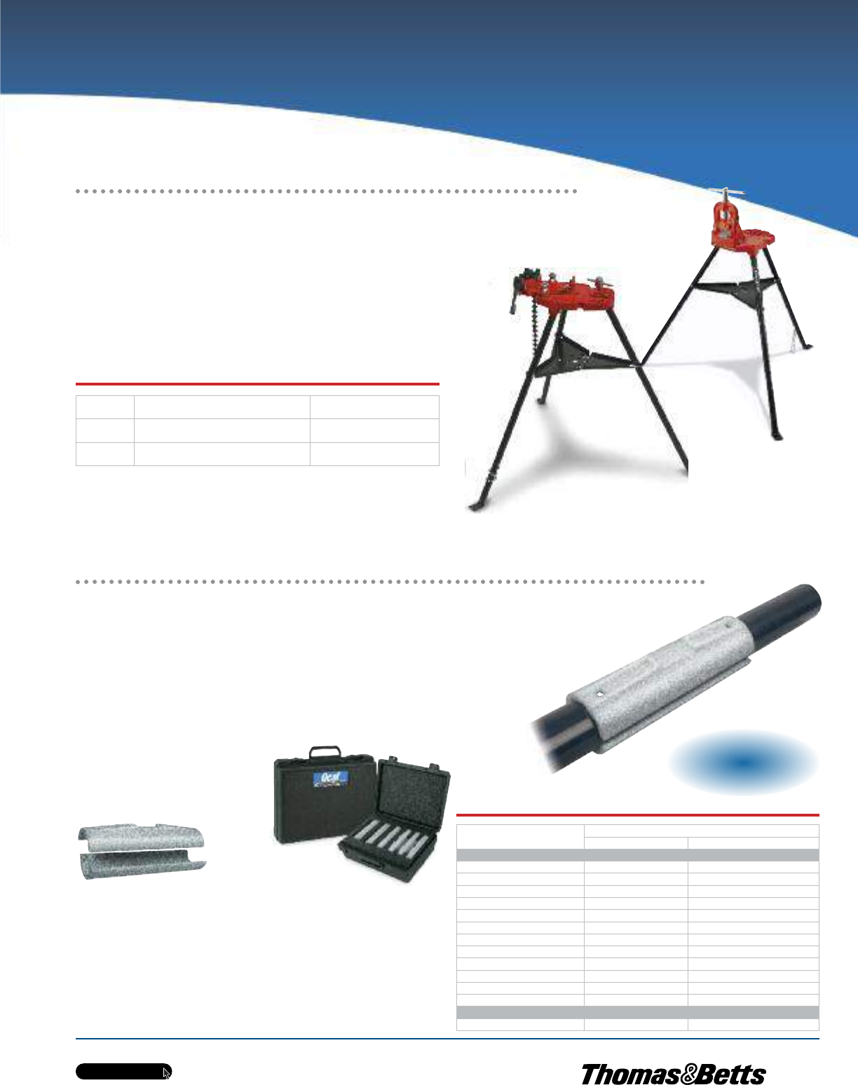
w w w . t n b . c a
PVC-Coated Products
H51
OCALTM
Installation Products
Equipped With Chain or Bench Yoke Vise
ROTH00076
P00076C
OcalTM Half-Shell Clamps
If you already have a chain vise, now you can avoid the expense of purchasing
a yoke vise with special jaws — or the trouble of making clamps out of PVC or
steel pipe — to cut and thread PVC-coated conduit. These Half-Shell Clamps
come in the full range of 1/2 in. to 6 in. trade sizes. Buy the individual sizes
you need, or choose one of our convenient sets, which contain all the sizes
from 1/2 in. to 2 in. or 2-1/2 in. to 4 in. in a handy carrying/storage case.
A unique internal design ensures secure
clamping while protecting the integrity
of the conduit’s PVC coating. Cast from
ductile iron for extreme strength and
durability, OcalTM Half-Shell Clamps offer
you years of consistent, reliable service.
•Two-piece construction, cast from ductile iron for exceptional
strength, durability and performance
•Cross-hatched interior surface grips conduit securely
while safeguarding PVC jacket from damage
•Available individually in 1/2 in. through 6 in. trade sizes
•Also available in two convenient sets — 1/2 in. to 2 in. and
2-1/2 in. to 4 in.
•Each clamp clearly marked with trade size for easy identification
•Openings at each end enable hanging for handy storage
Cat. No. Conduit Size
in. (mm)
Individual Half-Shell Clamps
HLF-SHL-CLP1/2 1/2 (16)
HLF-SHL-CLP3/4 3/4 (21)
HLF-SHL-CLP1 1 (27)
HLF-SHL-CLP1-1/4 1-1/4 (35)
HLF-SHL-CLP1-1/2 1-1/2 (41)
HLF-SHL-CLP2 2 (53)
HLF-SHL-CLP2-1/2 2-1/2 (63)
HLF-SHL-CLP3 3 (78)
HLF-SHL-CLP3-1/2 3-1/2 (91)
HLF-SHL-CLP4 4 (103)
HLF-SHL-CLP5 5 (129)
HLF-SHL-CLP6 6 (155)
Half-Shell Clamp Set (in carrying/storage case)
HLF-SHL-CLPSET1 1/2 — 2 (16 — 53)
Superior Design and Construction for Faster,
Safer Chain-Vise Clamping of PVC-Coated Conduit
Tri-Stand Vises
•Sturdy, stable frame collapses for easy mobility and storage
•Ceiling brace for overhead support enables you to secure frame
even during difficult work
•Features recesses for bending tubes 3/8 in., 1/2 in. and
3/4 in. O.D
Cat. No. Description Pipe Capacity in.
(mm)
ROTH00076 Tri-Stand with 6 in. Chain Vise
(use with OcalTM Jaws for PVC-coated conduit)
1/2 — 6
(16 — 155)
P00076C Tri-Stand with Bench Yoke Vise (includes jaws
designed for use with PVC-coated conduit)
1/2 — 3
(16 — 78)
Metric size designator (ANSI C80.1-1994).
NEW!
NEW!
NEW!
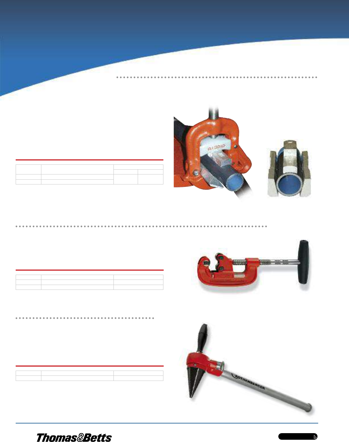
w w w . t n b . c a
PVC-Coated Products
H52
OCALTM
Installation Products
Designed to Hold PVC-Coated Conduit
Safely and Securely in a Yoke-Style Vise
Ratchet Pipe Reamer
•Smooth running ratchet
•Tempered-steel cutting bit
•For steel tubes 1/4 in. to 2 in. O.D
Specially designed for cutting PVC-coated conduit
Rapid and clean deburring!
OcalTM Jaws for PVC-Coated Conduit
•Replace the standard jaw inserts in a yoke vise
•Provide greater clamping force and prevents pipe
from spinning during threading
•Machined aluminum construction
•Three-piece set
Cat. No. Description Weight
lb. kg
JAWS23 Used with RIDGID No. 23 or No. 40A Yoke Vises 2.80 1.27
JAWS76 Used with Rothenberger Yoke Vise
Cat. No. Description Pipe O.D. (in.)
P70045C Steel Pipe Cutter — Up to 2 in. 1/8 — 2
P70060C Steel Pipe Cutter — Up to 4 in. 1/8 — 4
Steel Pipe Cutters
•Easy pressure control transmits optimum force onto tube
•Hardened, high-alloy steel cutter wheel provides long service life
and burr-free external cutting
Cat. No. Description Pipe O.D. (in.)
70289 Ratchet Pipe Reamer 1/4 —2
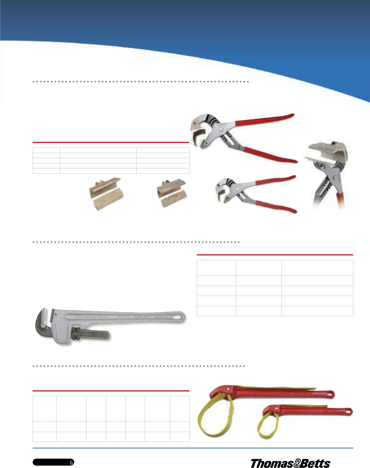
w w w . t n b . c a
PVC-Coated Products
H53
OCALTM
Installation Products
Removable Aluminum
Jaws for PVC-Coated Conduit
OcalTM J-Wrenches
Use with our pliers, or purchase just the jaws and adapt your own!
Specially Coated Strap Won’t Absorb Oil
RIDGID®Strap Wrenches
Aluminum Pipe Wrenches
•Extremely light aluminum alloy offers high strength but weighs
40% less than standard cast
•Self-clamping, spring-supported hook for easy, one-handed,
ratchet-like use
•Scale on hook for quick preset of tube diameter
Jaws Grip PVC-Coated Pipe Securely
Without Damaging the Plastic Coating!
31355
31370
Cat. No. Description Pipe Capacity (in.)
J442 12 in. J-Wrench with Jaws 1/2 to 1-1/4
J460 16 in. J-Wrench with Jaws 1-1/2 to 2-1/2
J42 12 in. Jaw Set only 1/2 to 1-1/4
J60 16 in. Jaw Set only 1-1/2 to 2-1/2
Cat. No.
Length
in.
(mm)
Steel Tube O.D. Max.
in.
(mm)
P70159C 10
(254)
1-1/2
(16)
P70160C 14
(356)
2
(53)
P70161C 18
(457)
2-1/2
(63)
P70162C 24
(610)
3
(78)
Cat. No.
Handle
Length
in.
(mm)
Strap
Length
in.
(mm)
Strap
Width
in.
(mm)
Pipe
Capacity
in.
(mm)
Pipe
Capacity
(O.D.)
in.
(mm)
Weight
lb.
(kg)
31355 11.75
(298.45)
17.00
(431.80)
1.75
(44.45)
2.00
(50.80)
3.50
(88.90)
1.75
(.79)
31370 18.00
(457.20)
29.25
(742.95)
1.75
(44.45)
5.00
(127.00)
5.50
(139.70)
2.75
(1.25)
J42
J60
J442
J460
J460
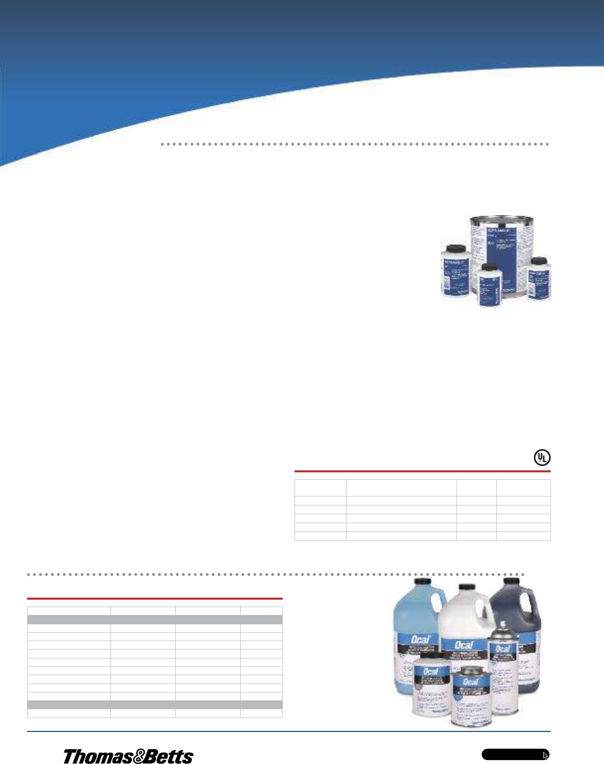
w w w . t n b . c a
PVC-Coated Products
H54
OCALTM
Installation Products
Accessories for Aluminum/Copper
Code Conductors and Connectors
Use Kopr-Shield®Compound for
battery lugs and cables to:
•Prevent “green scourge” corrosion
•Reduce resistance
•Ease terminal installation and removal
Use Kopr-Shield®Compound for raceways to:
•Lubricate for ease of assembly and disassembly
•Improve grounding continuity (exceeds code requirements)
Use Kopr-Shield®Compound for fuse clips to:
•Eliminate hot spots for even head distribution
•Prevent oxidation by preventing carbon path formation
•Lubricate for easy installation and removal of fuses
Use Kopr-Shield®Compound for wiping contacts, drum switches and slip
rings to:
•Prevent galling, burning, pitting and discolouration
•Suppress arching and dissipation of coronas
•Lubricate for ease of operation
KOPR-SHIELD®Joint Compound
•Unique, homogenized blend of pure, polished colloidal copper,
rust and corrosion inhibitors
•Simultaneously protects, lubricates and enhances conductivity of
mating surfaces
•Extremely adhesive compound flows smoothly into uneven
contours and voids, ensuring easy application and complete,
positive protection and lubrication
•Won’t settle-out, thin, thicken, harden or dry out under the most
severe environmental conditions
•Excellent temperature characteristics — can be brushed on at
-45.5ºC (-50ºF) to 121ºC (250ºF) (other compounds either turn
solid or run like water at these extremes) and remains intact at
short terms even at 980ºC (1,800ºF)
Good connections are one of the most important aspects of electrical work.
Mechanics know how much downtime is caused when fluids or oils leak into
the raceway system or when they have to look for a weak link in a ground
system caused by a high-resistance connection. Mechanics also know how
much time is spent keeping contacts, switches, lugs and other connectors clean
or replacing parts because of “green scourge” buildup. Thomas & Betts has
the solution to improve connections made in thousands of electrical and
raceway installations made each day by electricians everywhere Kopr-Shield®.
Compound may be used to advantage in all electrical installations. When the
environment is hostile to electrical and mechanical connections, Kopr-Shield®
Compound is a must!
Kopr-Shield®is a trademark of Jet-Lube Inc.
Copper colloidal surface treatment protects, lubricates and enhances conductivity of all electrical connections
Cat. No. Description Std. Pkg. Weight
lb./container
201-31879 1-1/2 oz. Container with Brush 96 11.46
201-31879-1 4 oz. Container with Brush 24 38.54
CP8-TB 8 oz. Container with Brush 12 64.58
CP16 16 oz. Container with Brush 12 120.83
CP128 1 Gallon Can 4 952.00
Cat. No. Container Size Colour
Exterior PVC Patch
SPRAY-G Spray Can 12-1/2 oz. (0.37 liter) Dark Grey
SPRAY-W Spray Can 12-1/2 oz. (0.37 liter) White
SPRAY-B Spray Can 12-1/2 oz. (0.37 liter) Light Blue
PATCHP-G Brush Cap Can 1 pint (0.47 liter) Dark Grey
PATCHP-W Brush Cap Can 1 pint (0.47 liter) White
PATCHP-B Brush Cap Can 1 pint (0.47 liter) Light Blue
PATCHG-G Bottle 1 gallon (3.79 liter) Dark Grey
PATCHG-W Bottle 1 gallon (3.79 liter) White
PATCHG-B Bottle 1 gallon (3.79 liter) Light Blue
Interior Urethane Patch
URETHANEPATCH Brush Cap Can 1 pint (0.47 liter) Blue
OcalTM Touch-Up Compounds
Fast-Drying, Air-Cure Patch for OcalTM Conduit and Fittings
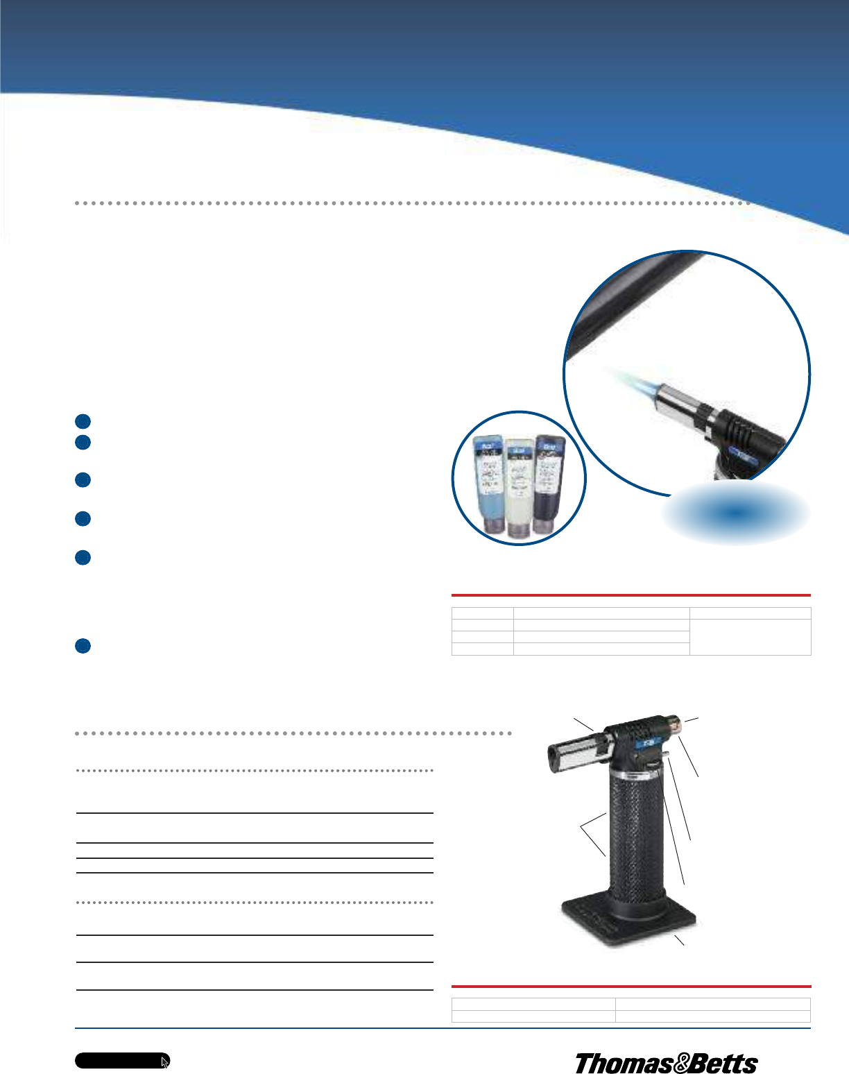
w w w . t n b . c a
PVC-Coated Products
H55
OCALTM
Installation Products
A Better Patching Solution for Hot weather Applications!
OcalTM Heat-Cure Patch
Even in the best of installations, the PVC jacket on PVC-coated conduit or fittings
can be cut, nicked or abraded. To maintain corrosion protection, OcalTM has
added a new, thicker PVC patch to its offering of touch-up compounds.
Ideal for use in hot weather, OcalTM Heat-Cure Patch offers a thicker consistency
at high ambient temperatures than standard air-cure patches, ensuring better
coverage and a more effective patch.
OcalTM Heat-Cure Patch makes patching fast and easy.
Make sure the area to be patched is clean and dry
Squeeze the amount of patch material needed onto
the area to be repaired
If necessary, spread and level the patch material with
a putty knife
Apply heat with a heat gun or torch, such as the T&B®
Portable Heat-Shrink Torch
Being careful not to overheat (260ºC/500ºF max.), apply heat
for 2 minutes total, or at least 1 minute after surface of patch
has turned glossy. (The patch material is a glossy liquid that
turns flat with initial heat application and then turns glossy
again as heating continues.)
Allow the patched area to air cool, or use a water quench
Separate Controls Enable Precise Adjustment of Flame
and Temperature!
Portable Heat-Shrink Torch
T&B®Portable Heat-Shrink Torch
•(1,371ºC) (2,500ºF) output capacity satisfies virtually
any heating, brazing or soldering requirement
•Dual fuel- and air-flow controls enable separate adjustment
of temperature and flame precision
•Brass and steel construction provides durability
•Operates on standard butane lighter fluid (not included)
Specifications
Dimensions (without base) L x W x H: 3.90 in. x 1.40 in. x 5.40 in.
99.06 mm x 35.56 mm x 137.16 mm
Weight (when filled): 9.88 oz.
280.09g
Fuel Tank Capacity: 2.03 fl. oz.
60.03 ml
Operating Time (per full fuel tank): Up to 220 minutes
Heat-Cure Patch
Cat. No. Colour Size
PATCHT-G Dark Grey
6 oz. (0.18 liter)PATCHT-W White
PATCHT-B Light Blue
Cat. No. Description
WT-PTORCH Portable Heat-Shrink Torch
1
2
3
4
5
6
NEW!
NEW!
NEW!
Removable Base
Safety Lock
(push and turn to
lock or unlock)
Ergonomic
Rubber Grip
Kill-Switch Button
Fuel-Flow Control
Air-Flow Control
Automatic-Ignition
Start Button
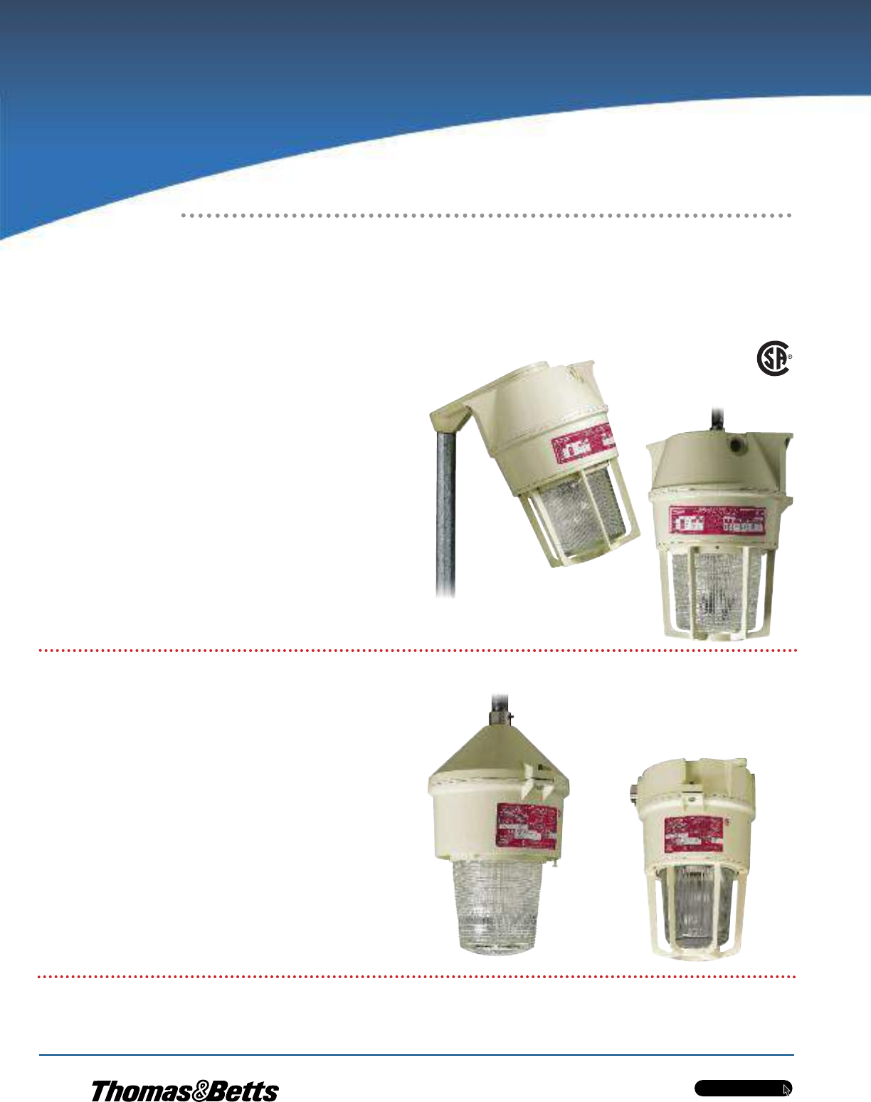
w w w . t n b . c a
PVC-Coated Products
H56
OCALTM
Products for corrosive environments
Polymeric Fixtures for Class I, Zone 2, Groups IIC,
IIB, IIA, Division 2, Groups A, B, C and D Wet and
Marine Locations
Hazlite™M1 — HID or Fluorescent,
Medium or Bi-Pin Base, 9-100W
•Polymeric (fiberglass-reinforced polyester) guard with a variety
of globe options
•Metal halide, high-pressure sodium or fluorescent lamp
•9 to 100 watts, 120 to 277 volts
•Cone pendant, one-hub ceiling or two-hub ceiling mounting
Standards / Certifications
•CSA Class I, Zone 2, Groups IIC, IIB, IIA,
Division 2, Groups A, B, C and D Hazardous Locations
•UL1598 Wet Locations
•UL1598 Marine Applications
•NEMA 4X
Hazlux®1 — HID, Mogul Base,
50-175W
•Enclosed and gasketed
•Polymeric (fiberglass-reinforced polyester) guard with a
variety of globe options
•High-pressure sodium, metal halide
•50 to 175 watts, 120 to 480 volts
•Pendant, ceiling, wall, angle stanchion
or straight stanchion mounting
Standards / Certifications
•CSA Class I, Zone 2, Groups IIC, IIB, IIA,
Division 2, Groups A, B, C and D
•UL1598 Wet Locations
•UL1598 Marine Applications
•NEMA 4X
Ordering Hazlux®Lighting Fixtures
To order or learn more about the many styles and varieties of Hazlux®fixtures for corrosive environments, please see our Hazlux®catalogue or visit www.tnb.ca
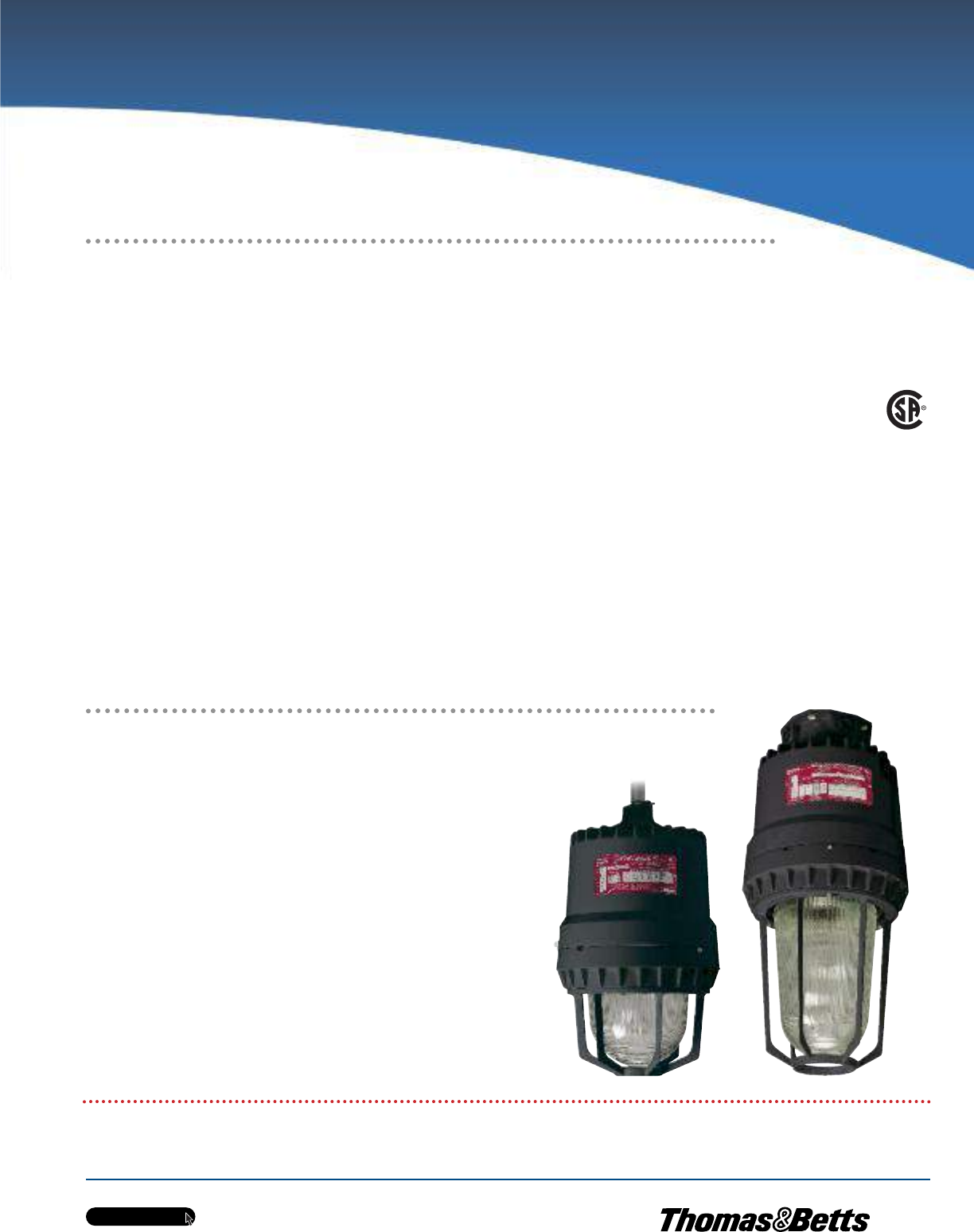
w w w . t n b . c a
PVC-Coated Products
H57
OCALTM
Hazlux®3 — HID, Mogul Base, 50-400W
•Enclosed and gasketed
•Cast copper-free aluminum housing — available
with HazCote™ Kynar coating for extremely
corrosive environments
•Variety of globe material options
•High-pressure sodium, metal halide
•50 to 400 watts, 120 to 480 volts
•Cone top pendant, wall, ceiling, flexible pendant,
ring, straight stanchion, angle stanchion or rigid
pendant mounting
Standards / Certifications
•CSA Class I, Zone 2, Groups IIC, IIB, IIA,
Division 2, Groups A, B, C and D
•EXN RII T3 (Restricted Drawing)
•CSA Class II, Divisions 1 & 2, Groups E, F and G
•CSA Class III
•UL1598 Wet Locations
•UL1598 Marine Applications
•NEMA 4X, IP66
Explosion-Proof Fixtures for Class I,
Division 1, Class II, Wet and Marine Locations
Ordering Hazlux®Lighting Fixtures
To order or learn more about the many styles and varieties of Hazlux®fixtures for corrosive environments, please see our Hazlux®catalogue or visit www.tnb.ca.
Hazlux®5 — HID Explosion-Proof, Mogul Base, 50-400W
•Cast copper-free aluminum housing — available with HazCote™ Kynar coating
for extremely corrosive environments
•High-pressure sodium, metal halide
•50 to 400 watts, 120 to 480 volts
•Pendant, wall, ceiling, bulkhead or stanchion mounting
Standards / Certifications
•CSA Class I, Zone 2, Groups IIC, IIB, IIA,
Division 2, Groups A, B, C and D
•CSA Class II, Divisions 1 & 2, Groups E, F and G
•UL1598 Wet Locations
•UL1598 Marine Applications
•NEMA 4X, IP66
Products for corrosive environments
Enclosed and Gasketed Fixtures for Class I, Zone 2,
Groups IIC, IIB, IIA, Division 1, Class II, Wet and
Marine Locations
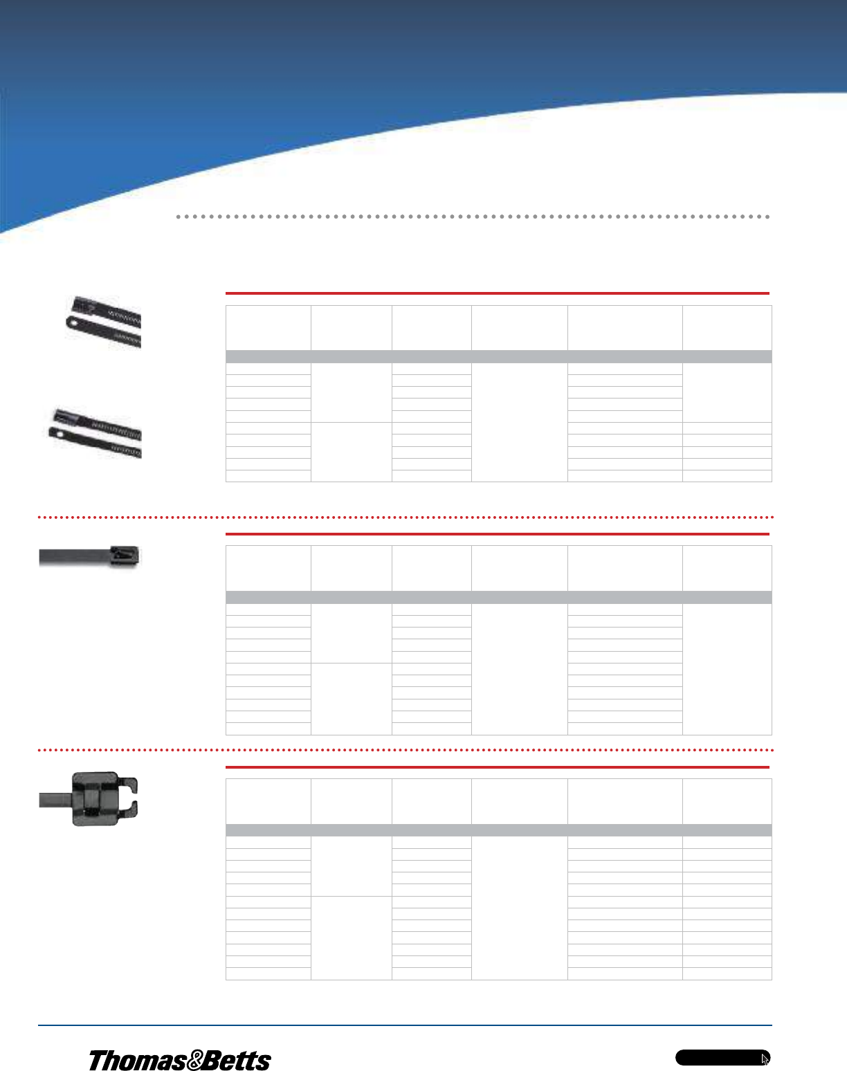
w w w . t n b . c a
PVC-Coated Products
H58
OCALTM
Type TYS
Multi-Lok Stainless Steel
Ties — Coated
Type TYS
Multi-Lok Stainless Steel
Ties — Uncoated
Type LS
Heavy-Duty Stainless Steel
Ball-Lock Cable Ties — Coated
Type SSR
Reusable Stainless Steel
Cable Ties
Cat. No.
Nylon 11 Coated
Width
in./(mm)
Length
in./(mm)
Thickness
in./(mm)
Max. Dia.
Single Wrap
in./(mm)
Max. Dia. Double
Wrap
in./(mm)
Type TYS Multi-Lok Stainless Steel Cable Ties
TYS6-280C
0.28 / (7.00)
6 / (152)
0.01 / (.25)
1.9 / (48)
(Single wrap only)
TYS9-280C 9 / (229) 2.8 / (71)
TYS12-280C 12 / (305) 3.8 / (96)
TYS18-280C 18 / (457) 5.7 / (144)
TYS24-280C 24 / (610) 7.6 / (193)
TYS6-470C
0.47 / (12.00)
6 / (152) 1.9 / (48)
TYS9-470C 9 / (229) 2.8 / (71)
TYS12-470C 12 / (305) 3.8 / (96)
TYS18-470C 18 / (457) 5.7 / (144)
TYS24-470C 24 / (610) 7.6 / (193)
Cat. No.
Fully Polyester
Coated
Width
in./(mm)
Length
in./(mm)
Thickness
in./(mm)
Max. Dia.
Single Wrap
in./(mm)
Max. Dia. Double
Wrap
in./(mm)
Type LS Heavy-Duty Stainless Steel Ball-Lock Cable Ties
LS-4.6-200-C
0.18 / (4.6)
7.9 / (201)
—
2 / (51)
(Single wrap only)
LS-4.6-360-C 14.2 / (360) 4 / (102)
LS-4.6-520-C 20.5 / (520) 6 / (152)
LS-4.6-680-C 26.7 / (679) 8 / (203)
—33.0 / (838) 10 / (254)
LS-7.9-200-C
0.31 / (7.9)
7.9 / (201) 2 / (51)
LS-7.9-360-C 14.2 / (360) 4 / (102)
LS-7.9-520-C 20.5 / (520) 6 / (152)
LS-7.9-680-C 26.7 / (679) 8 / (203)
—33.0 / (838) 10 / (254)
—41.3 / (1050) 12.5 / (318)
Cat. No. Width
in./(mm)
Length
in./(mm)
Thickness
in./(mm)
Max. Dia.
Single Wrap
in./(mm)
Max. Dia. Double
Wrap
in./(mm)
Type SSR Reusable Stainless Steel Cable Ties
SSR6-250C
0.25 / (6.35)
6 / (152)
0.015 / (0.38)
1.5 / (38) N/A
SSR9-250C 9 / (229) 2.5 / (63) 1.1 / (28)
SSR12-250C 12 / (305) 3.4 / (86) 1.5 / (38)
SSR18-250C 18 / (457) 5.4 / (137) 2.5 / (64)
SSR24-250C 24 / (610) 7.3 / (185) 3.5 / (89)
SSR6-375C
0.38 / (9.53)
6 / (152) 1.5 / (38) N/A
SSR9-375C 9 / (229) 2.5 / (63) 1.1 / (28)
SSR12-375C 12 / (305) 3.4 / (86) 1.5 / (38)
SSR18-375C 18 / (457) 5.4 / (137) 2.5 / (64)
SSR24-375C 24 / (610) 7.3 / (185) 3.5 / (89)
SSR30-375C 30 / (762) 9.1 / (231) 4.4 / (112)
SSR36-375C 36 / (914) 11.0 / (280) 5.3 / (135)
SS Series also available in Type 316 stainless.
Ty-Rap®Stainless Steel Cable Ties
Products for Corrosive Environments
w w w . t n b . c a
PVC-Coated Products
H59
OCALTM
Ty-Rap®Stainless Steel Cable Ties (cont’d)
Stainless Steel
Type
Coating
or Finish
Min. Loop
Tensile Strength
Single Wrap
lb./n.
Min. Loop
Tensile Strength
Double Wrap
lb./n.
Application
Tools Used
General
Application
Type TYS Multi-Lok Stainless Steel Cable Ties
316
Uncoated or
Nylon 11
Coated Black
250/1112
(Single wrap only)
WTAE200
• Self-locking
• Cable bundling
WTAE200
WTAE200
WTAE200
WTAE201
WTC075
• Hazardous
and corrosive
environments
WTC075
WTC075
WTC075
WTC075
Stainless Steel
Type
Coating
or Finish
Min. Loop
Tensile Strength
Single Wrap
lb./n.
Min. Loop
Tensile Strength
Double Wrap
lb./n.
Application
Tools Used
General
Application
Type LS Heavy-Duty Stainless Steel Ball-Lock Cable Ties
316
Uncoated
or Fully
Polyester
Coated Black
100/445 (Single wrap only)
DAS250
• Offshore drilling
• Petrochemical processing
• Shipbuilding
250/1112 • Food & Beverage processing
• Pharmaceutical processing
Stainless Steel
Type
Coating
or Finish
Min. Loop
Tensile Strength
Single Wrap
lb./n.
Min. Loop
Tensile Strength
Double Wrap
lb./n.
Application
Tools Used
General
Application
Type SSR Reusable Stainless Steel Cable Ties
200/300
Nylon 11 Coated
(Uncoated or other
colours available on
special order)
75/334 300/1334
WTAE200
• Reusable
• Cable bundling
• Oil rigs
100/445 500/2224
• Telecommunications towers
• Hazardous and corrosive
environments
• Cable trays
WTC075
Ty-Rap® Stainless Steel Cable Ties have passed a variety of mechanical, environmental and electrical tests. Other data can be made available upon request.
Products for Corrosive Environments
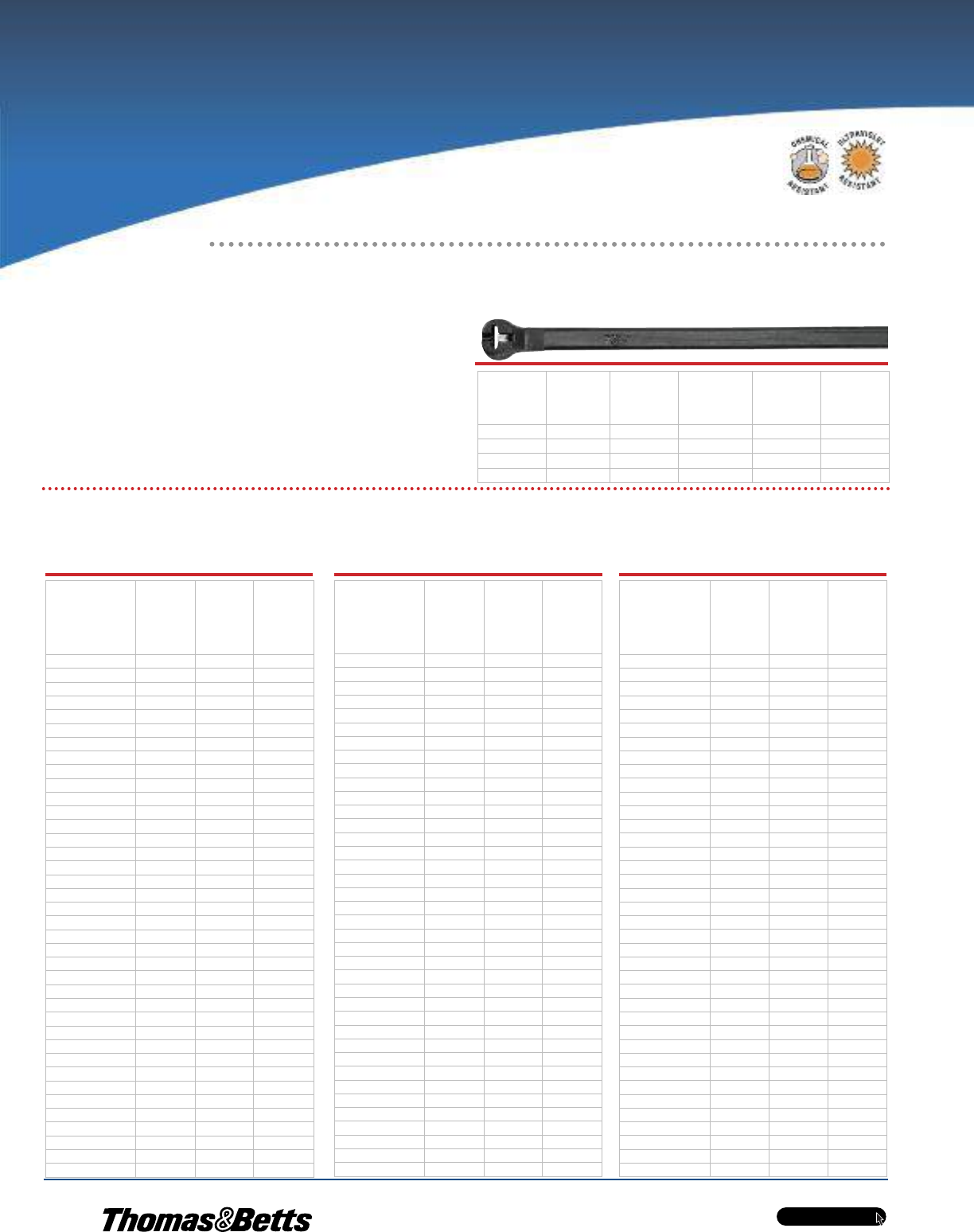
PVC-Coated Products
OCALTM
w w w . t n b . c a
H60
Ty-Rap®Weather-Resistant
Polypropylene Cable Ties
•Especially resistant to chemical exposure
•For use in temperatures ranging from - 40°C to 85°C
(-40°F to 185°F)
•Black polypropylene body and head construction with
stainless steel locking device
Ty-Rap®Cable Ties Chemical Resistance
The table below shows the resistance of Ty-Rap®cable tie materials to various chemicals. The table is designed to help you determine the cable tie material best suited for a particular
chemical environment.
Bulk Pkg.
Cat. No.
Width
in./(mm)
Body
Length
in./(mm)
Max. Wire
Bundle Dia.
in./(mm)
Tensile
Str.
lb./n.
Bulk
Pkg.
Qty.
TYP23MX 0,09 / (2,29) 3,62 / (91,95) 0,63 / (16,00) 18 / (80,07) 1000
TYP25MX 0,18 / (4,57) 7,31 / (185,67) 1,75 / (44,45) 30 / (133,40) 1000
TYP28MX 0,18 / (4,57) 14,20 / (360,68) 4,00 / (101,60) 30 / (133,40) 1000
TYP27MX 0,27 / (6,86) 13,20 / (335,28) 3,50 / (88,90) 60 / (266,90) 500
RESISTANCE OF AVAILABLE MATERIALS TO VARIOUS CHEMICALS AT TEMPERATURE OF 21°C (70°F)
Reagents Concentra-
tion
Weather-
Resistant
Poly-Propy-
lene as
used in TYP
X Series
Stainless
Steel
as used in
TYS Series
Arsenic Acid 40% EE
Acetaldehyde 50% ——
Acetone 100% EE
Aluminum Hydroxide AQ EE
Ammonia All EE
Ammonium Carbonate 5% EE
Ammonium Hydroxide 10% EE
Ammonium Nitrate —E E
Ammonium Sulfate 10% SS
Barium Carbonate All EE
Barium Chloride 5% EE
Barium Sulfate 10% EE
Barium Sulfide 10% EE
Benzene 100% SE
Benzoic Acid 100% EE
Butyric Acid 50% EE
Calcium Carbonate AQ EE
Calcium Hydroxide 20% EE
Calcium Hydrochlorite 2% FF
Calcium Sulfate 2% EE
Carbon Tetrachloride 100% FE
Chlorine (WET) —F F
Chlorine (DRY) — NR F
Chloroacetic Acid 30% —F
Chloroform 100% FE
Chromic Acid 50% FF
Citric Acid 50% EE
Copper Cyanide 10% EE
Copper Nitrate 50% EE
Cider —E E
Dichloroethane 100% —E
Diethyl Ether 100% EE
Ethyl Alcohol 100% EE
Ethyl Chloride 100% FE
Ethylene Glycol 100% EE
Ferric Hydroxide All EE
Ferric Nitrate 10% EE
Ferrous Sulfate 10% EE
Reagents Concentra-
tion
Weather-
Resistant
Poly-Propy-
lene as
used in TYP
X Series
Stainless
Steel
as used in
TYS Series
Potassium Ferrocyanide 25% EE
Potassium Hydroxide 5% EE
Potassium Iodide All EE
Potassium Nitrate 50% EE
Potassium Permanganate 5% EE
Potassium Sulfate 5% EE
Potassium Sulfide AQ EE
Propyl Alcohol 100% EE
Silver Nitrate 10% EE
Sodium Acetate 60% EE
Sodium Bicarbonate All EE
Sodium Bisulfate 10% EE
Sodium Borate All EE
Sodium Carbonate 5% EE
Sodium Chlorate 25% EE
Sodium Chloride 2% EE
Sodium Fluoride 5% FF
Sodium Hydroxide 10% EE
Sodium Hyposulfite AQ —E
Sodium Nitrate 5% EE
Sodium Nitrite AQ EE
Sodium Perchlorate 10% —E
Sodium Phosphate 5% EE
Sodium Sulfate 5% EE
Sodium Thiosulfate 5% SS
Stearic Acid 100% EE
Sulfur 100% EE
Sulfur Dioxide All EE
Sulfuric Acid Conc. SE
Sulfuric Acid 5% FF
Tannic Acid 10% EE
Tartaric Acid 50% EE
Tetrahydrofuran 100% FE
Toluene 100% FF
Xylene 100% FE
Zinc Chloride 70% EE
Zinc Nitrate AQ EE
Zinc Sulfate AQ EE
Reagents Concentra-
tion
Weather-
Resistant
Poly-Propy-
lene as
used in TYP
X Series
Stainless
Steel
as used in
TYS Series
Fuel Oil 100% —E
Furfural 100% FE
Gallic Acid AQ —E
Gasoline 100% SE
Glycerine 100% EE
Hydrocyanic Acid All EE
Hydrogen Peroxide 30% EE
Hydrogen Sulfide Dry EE
Iodoform 100% —E
Isopropyl Alcohol 100% EE
Jet Fuel 100% SE
Lactic Acid 10% EE
Lanolin 10% EE
Lead Acetate 5% EE
Linseed Oil 10% EE
Magnesium Carbonate All EE
Magnesium Chloride 10% FF
Magnesium Nitrate All EE
Malic Acid AQ EE
Mercury 100% EE
Methyl Alcohol 100% EE
Methyl Chloride 100% SE
Methyl Ethyl Ketone 100% EE
Naptha 100% EE
Nitric Acid 30% EE
Nitric Acid 30 – 70% FE
Nitrous Acid 5% FE
Oleic Acid 100% EE
Oxalic Acid 10% EE
Paraffin 100% EE
Petroleum Ether 100% FE
Phenol 90% EE
Phosphoric Acid 10% EE
Picric Acid 1% EE
Potassium Bromide AQ SS
Potassium Carbonate 1% —E—
Potassium Chlorate AQ EE
Potassium Dichromate 40% EE
Ratings: E = Excellent S = Satisfactory F = Fair NR = Not Recommended (AQ = Aqueous)
Products for Corrosive Environments
Bundle Cables Up to 4 in. in Diameter
in Harsh Environments
PVC-Coated Products
OCALTM
w w w . t n b . c a
H61
Solutions Conc. Temp. ºC
(ºF)
Recommended Exposure
Splashing Liquid Fumes
Acetic Acid 10% 49 (120) no no no
Acid Copper Plating Solution 71 (160) yes yes yes
Alkaline Cleaners 71 (160) yes yes yes
Aluminum Chloride Sat'd 71 (160) yes yes yes
Aluminum Sulfate Sat'd 71 (160) yes yes yes
Alums Sat'd 71 (160) yes yes yes
Ammonium Chloride Sat'd 71 (160) yes yes yes
Ammonium Hydroxide 28% 49 (120) yes yes yes
Ammonium Hydroxide 10% 49 (120) yes yes yes
Ammonium Sulfate Sat'd 71 (160) yes yes yes
Ammonium Thiocyanate Sat'd 71 (160) yes yes yes
Amyl Alcohol Any 90 (32) yes yes yes
Arsenic Acids Any 66 (150) yes yes yes
Barium Sulfide Sat'd 49 (120) yes yes yes
Black Liquor Sat'd 90 (32) yes yes yes
Benzoic Acid Sat'd 71 (160) yes yes yes
Brass Plating Solution Any 71 (160) yes yes yes
Bromine Water Sat'd 49 (120) yes yes yes
Butyl Alcohol Any 90 (32) yes yes yes
Cadmium Plating Solution Any 66 (150) yes yes yes
Calcium Bisulfite Any 66 (150) yes yes yes
Calcium Chloride Sat'd 71 (160) yes yes yes
Calcium Hypochlorite Sat'd 49 (120) yes yes yes
Carbonic Acid Sat'd 71 (160) yes yes yes
Casein Sat'd 90 (32) yes yes yes
Castor Oil Any 90 (32) yes yes yes
Caustic Soda 35% 49 (120) yes yes yes
Caustic Soda 10% 66 (150) yes yes yes
Caustic Potash 35% 49 (120) yes yes yes
Caustic Potash 10% 66 (150) yes yes yes
Chlorine Water Sat'd 90 (32) yes yes yes
Chromium Plating Solution Any 66 (150) yes yes yes
Citric Acid Sat'd 71 (160) yes yes yes
Copper Cyanide Plating Sol Any 71 (160) yes yes yes
(High Speed) Any 82 (180) yes yes yes
(with Alkali Cyanides) Sat'd 71 (160) yes yes yes
Copper Sulfate Sat'd 71 (160) yes yes yes
Coconut Oil Sat'd 90 (32) yes yes yes
Cottonseed Oil Sat'd 90 (32) yes yes yes
Disodium Phosphate Sat'd 71 (160) yes yes yes
Ethyl Alcohol Any 90 (32) yes yes yes
Ethylene Glycol Any 90 (32) yes no yes
Ferric Chloride 45% 49 (120) yes yes yes
Ferrous Sulfate Sat'd 66 (150) yes yes yes
Fluoboric Acid Any 66 (150) yes yes yes
Formaldehyde 37% 49 (120) yes yes yes
Formic Acid 85% 66 (150) no no no
Gallic Acid Sat'd 66 (150) no no yes
Glucose Any 66 (150) yes yes yes
Glue Any 66 (150) yes yes yes
Glycerine Any 90 (32) yes yes yes
Gold Plating Solution Any 66 (150) yes yes yes
Hydrochloric Acid 10% 49 (120) yes no yes
Hydrochloric Acid 21.5% 49 (120) yes no yes
Hydrochloric Acid 37.5% 49 (120) yes no yes
Hydrochloric Acid 37.5% 90 (32) yes no yes
Hydrofluoric Acid 4% 60 (140) yes no yes
Hydrofluoric Acid 10% 49 (120) yes no yes
Hydrofluoric Acid 48% 49 (120) yes no yes
Hydrogen Peroxide 30% 49 (120) yes yes yes
Hydrogen Sulfide Sat'd 49 (120) yes yes yes
Hydroquinone Any 90 (32) yes yes yes
Indium Plating Solution Any 66 (150) yes yes yes
Lactic Acid 50% 49 (120) yes yes yes
Lactic Acid Any 90 (32) yes yes yes
Solutions Conc. Temp. ºC
(ºF)
Recommended Exposure
Splashing Liquid Fumes
Lead Plating Solution Any 66 (150) yes yes yes
Malic Acid Any 32 (90) yes yes yes
Methyl Alcohol Any 32 (90) yes yes yes
Mineral Oils Any 32 (90) yes yes yes
Nickel Acetate Sat'd 71 (160) yes yes yes
Nickel Plating Solution 71 (160) yes yes yes
Nickel Salts Sat'd 71 (160) yes yes yes
Nitric Acid 35% 49 (120) yes no yes
Nitric Acid 40% 32 (90) yes no yes
Nitric Acid 60% 49 (120) yes no yes
Nitric Acid/ 15% 60 (140) yes yes yes
Hydrofluoric Acid 4%
Nitric Acid/ 16%
54 (130) yes yes yesSodium Dichromate 13%
Water 71%
Oleic Acid Any 32 (90) yes yes yes
Oxalic Acid Sat'd 49 (120) yes yes yes
Any 32 (90) yes yes yes
Phenol Sat'd 49 (120) no no no
Phosphoric Acid 75% 66 (150) yes yes yes
Phosphoric Acid 85% 49 (120) yes yes yes
Phosphoric Acid 85% 71 (160) yes yes yes
Potassium Acid Sulfate Sat'd 66 (150) yes yes yes
Potassium Antimonate Sat'd 66 (150) yes yes yes
Potassium Bisulfite Sat'd 32 (90) yes yes yes
Potassium Chloride Sat'd 71 (160) yes yes yes
Potassium Cuprocyanide Sat'd 66 (150) yes yes yes
Potassium Cyanide Sat'd 71 (160) yes yes yes
Potassium Diachromate Sat'd 71 (160) yes yes yes
Potassium Hypochlorite Sat'd 32 (90) yes no yes
Potassium Sulfide Sat'd 66 (150) yes yes yes
Potassium Thiosulfate Sat'd 66 (150) yes yes yes
Propyl Alcohol Sat'd 66 (150) yes yes yes
Rhodium Plating Solution Sat'd 66 (150) yes yes yes
Silver Plating Solution Sat'd 66 (150) yes yes yes
Soaps Any 32 (90) yes yes yes
Sodium Acid Sulfate Sat'd 71 (160) yes yes yes
Sodium Antimonate Sat'd 66 (150) yes yes yes
Sodium Bicarbonate Sat'd 71 (160) yes yes yes
Sodium Bisulfite Sat'd 32 (90) yes yes yes
Sodium Chloride Sat'd 71 (160) yes yes yes
Sodium Cyanide Sat'd 71 (160) yes yes yes
Sodium Dichromate Sat'd 71 (160) yes yes yes
Sodium Hydroxide 10% 66 (150) yes no yes
Sodium Hydroxide 35% 49 (120) yes no yes
Sodium Hydroxide 73% 71 (160) no no no
Sodium Hypochlorite Sat'd 32 (90) yes no yes
Sodium Hypochlorite 15% 49 (120) yes no yes
Sodium Sulfide Sat'd 66 (150) yes yes yes
Sodium Thiosulfate Sat'd 66 (150) yes yes yes
Sulfuric Acid 15% 49 (120) yes yes yes
Sulfuric Acid 15% 71 (160) yes yes yes
Sulfuric Acid 50% 49 (120) yes yes yes
Sulfuric Acid 70% 32 (90) yes no yes
Sulfuric Acid 98% 38 (100) no no yes
Sulfurous Acid 2% 49 (120) yes no yes
Sulfurous Acid 6% 49 (120) yes no yes
Tannic Acid Sat'd 32 (90) yes yes yes
Tartaric Acid Sat'd 32 (90) yes yes yes
Tin Chloride Aqueous Sat'd 66 (150) yes yes yes
Tin Plating Solution Sat'd 66 (150) yes yes yes
Triethaneolamine Sat'd 66 (150) yes yes yes
Trisodium Phosphate Sat’d 66 (150) yes yes yes
Water Sat'd 66 (150) yes yes yes
White Liquor 32 (90) yes yes yes
Zinc Plating Solution 71 (160) yes yes yes
Zinc Sulfate Sat'd 71 (160) yes yes yes
Chemical Resistance
PVC Exterior Coating
w w w . t n b . c a
PVC-Coated Products
H62
OCALTM
Solutions Conc. Temp. ºC
(ºF)
Recommended Exposure
Splashing Liquid Fumes
Acetic Acid 10% 24 (75) yes no yes
Acid Copper Plating Solution Any 24 (75) yes no yes
Alkaline Cleaners Any 24 (75) yes no yes
Aluminum Chloride Sat'd 24 (75) yes no yes
Aluminum Sulfate Sat'd 24 (75) yes no yes
Alums Sat'd 24 (75) yes no yes
Ammonium Chloride Sat'd 24 (75) yes no yes
Ammonium Hydroxide 28% 24 (75) yes no yes
Ammonium Hydroxide 10% 24 (75) yes no yes
Ammonium Sulfate Sat'd 24 (75) yes no yes
Ammonium Thiocyanate Sat'd 24 (75) yes no yes
Amyl Alcohol Any 24 (75) yes yes yes
Arsenic Acids Any 24 (75) yes no yes
Barium Sulfide Sat'd 24 (75) yes no yes
Black Liquor Sat'd 24 (75) yes no yes
Benzoic Acid Sat'd 24 (75) yes no yes
Brass Plating Solution Any 24 (75) yes no yes
Bromine Water Sat'd 24 (75) yes no yes
Butyl Alcohol Any 24 (75) yes no yes
Cadmium Plating Solution Any 24 (75) yes no yes
Calcium Bisulfite Any 24 (75) yes no yes
Calcium Chloride Sat'd 24 (75) yes no yes
Calcium Hypochlorite Sat'd 24 (75) yes no yes
Carbonic Acid Sat'd 24 (75) yes no yes
Casein Sat'd 24 (75) yes no yes
Castor Oil Any 24 (75) yes yes yes
Caustic Soda 35% 24 (75) yes no yes
Caustic Soda 10% 24 (75) yes no yes
Caustic Potash 35% 24 (75) yes no yes
Caustic Potash 10% 24 (75) yes no yes
Chlorine Water Sat'd 24 (75) yes no yes
Chromium Plating Solution Any 24 (75) yes no yes
Citric Acid Sat'd 24 (75) yes no yes
Copper Chloride (Cupric) Sat'd 24 (75) yes no yes
Copper Cyanide Plating Sol Any 24 (75) yes no yes
(High Speed) Any 24 (75) yes no yes
(with Alkali Cyanides) Sat'd 24 (75) yes no yes
Copper Sulfate Sat'd 24 (75) yes no yes
Coconut Oil Sat'd 24 (75) yes yes yes
Cottonseed Oil Sat'd 24 (75) yes yes yes
Disodium Phosphate Sat'd 24 (75) yes no yes
Ethyl Alcohol Any 24 (75) yes no yes
Ethylene Glycol Any 24 (75) yes yes yes
Ferric Chloride 45% 24 (75) yes no yes
Ferrous Sulfate Sat'd 24 (75) yes no yes
Fluoboric Acid Any 24 (75) yes no yes
Formaldehyde 37% 24 (75) yes no yes
Formic Acid 85% 24 (75) yes no yes
Gallic Acid Sat'd 24 (75) yes no yes
Glucose Any 24 (75) yes yes yes
Glue Any 24 (75) yes no yes
Glycerine Any 24 (75) yes yes yes
Gold Plating Solution Any 24 (75) yes no yes
Hydrochloric Acid 10% 24 (75) yes no yes
Hydrochloric Acid 21.5% 24 (75) yes no yes
Hydrochloric Acid 37.5% 24 (75) yes no yes
Hydrofluoric Acid 4% 24 (75) yes no yes
Hydrofluoric Acid 10% 24 (75) yes no yes
Hydrofluoric Acid 48% 24 (75) yes no yes
Hydrogen Peroxide 30% 24 (75) yes no yes
Hydrogen Sulfide Sat'd 24 (75) yes no yes
Hydroquinone Any 24 (75) yes no yes
Indium Plating Solution Any 24 (75) yes no yes
Lactic Acid 50% 24 (75) yes no yes
Lactic Acid Any 24 (75) yes no yes
Solutions Conc. Temp. ºC
(ºF)
Recommended Exposure
Splashing Liquid Fumes
Lead Plating Solution Any 24 (75) yes no yes
Malic Acid Any 24 (75) yes no yes
Methyl Alcohol Any 24 (75) yes no yes
Mineral Oils Any 24 (75) yes yes yes
Nickel Acetate Sat'd 24 (75) yes no yes
Nickel Plating Solution 24 (75) yes no yes
Nickel Salts Sat'd 24 (75) yes no yes
Nitric Acid 35% 24 (75) yes no yes
Nitric Acid 40% 24 (75) yes no yes
Nitric Acid 60% 24 (75) yes no yes
Nitric Acid/ 15% 24 (75) yes no yes
Hydrofluoric Acid 4%
Nitric Acid/ 16%
24 (75) yes no yesSodium Dichromate 13%
Water 71%
Oleic Acid Any 24 (75) yes no yes
Oxalic Acid Sat'd 24 (75) yes no yes
Any 24 (75) yes no yes
Phenol Sat'd 24 (75) yes no yes
Phosphoric Acid 75% 24 (75) yes no yes
Phosphoric Acid 85% 24 (75) yes no yes
Potassium Acid Sulfate Sat'd 24 (75) yes no yes
Potassium Antimonate Sat'd 24 (75) yes no yes
Potassium Bisulfite Sat'd 24 (75) yes no yes
Potassium Chloride Sat'd 24 (75) yes no yes
Potassium Cuprocyanide Sat'd 24 (75) yes no yes
Potassium Cyanide Sat'd 24 (75) yes no yes
Potassium Diachromate Sat'd 24 (75) yes no yes
Potassium Hypochlorite Sat'd 24 (75) yes no yes
Potassium Sulfide Sat'd 24 (75) yes no yes
Potassium Thiosulfate Sat'd 24 (75) yes no yes
Propyl Alcohol Sat'd 24 (75) yes no yes
Rhodium Plating Solution Sat'd 24 (75) yes no yes
Silver Plating Solution Sat'd 24 (75) yes no yes
Soaps Any 24 (75) yes no yes
Sodium Acid Sulfate Sat'd 24 (75) yes no yes
Sodium Antimonate Sat'd 24 (75) yes no yes
Sodium Bicarbonate Sat'd 24 (75) yes no yes
Sodium Bisulfite Sat'd 24 (75) yes no yes
Sodium Chloride Sat'd 24 (75) yes no yes
Sodium Cyanide Sat'd 24 (75) yes no yes
Sodium Dichromate Sat'd 24 (75) yes no yes
Sodium Hydroxide 10% 24 (75) yes no yes
Sodium Hydroxide 35% 24 (75) yes no yes
Sodium Hydroxide 73% 24 (75) yes no yes
Sodium Hypochlorite Sat'd 24 (75) yes no yes
Sodium Hypochlorite 15% 24 (75) yes no yes
Sodium Sulfide Sat'd 24 (75) yes no yes
Sodium Thiosulfate Sat'd 24 (75) yes no yes
Sulfuric Acid 15% 24 (75) yes no yes
Sulfuric Acid 50% 24 (75) yes no yes
Sulfuric Acid 70% 24 (75) yes no yes
Sulfuric Acid 98% 24 (75) yes no yes
Sulfurous Acid 2% 24 (75) yes no yes
Sulfurous Acid 6% 24 (75) yes no yes
Tannic Acid Sat'd 24 (75) yes no yes
Tartaric Acid Sat'd 24 (75) yes no yes
Tin Chloride Aqueous Sat'd 24 (75) yes no yes
Tin Plating Solution Sat'd 24 (75) yes no yes
Triethaneolamine Sat'd 24 (75) yes no yes
Trisodium Phosphate Sat’d 24 (75) yes no yes
Water Sat'd 24 (75) yes no yes
White Liquor 24 (75) yes no yes
Zinc Plating Solution 24 (75) yes no yes
Zinc Sulfate Sat'd 24 (75) yes no yes
Chemical Resistance
Urethane Interior Coating

w w w . t n b . c a
PVC-Coated Products
H63
OCALTM
Specification Guide
Section 26 05 33 — Underground Ducts and Raceways
for Electrical Systems: Conduit Systems for Use in
Corrosive Environments
Part 1 — General
1.1 Summary
A. Section Includes: Furnishing, installation and assembly of
PVC-coated electrical rigid metal conduit (ERMC) systems
and stainless steel fittings.
B. Related Sections
1. Section 26 05 29 —
Hangers and Supports for Electrical Systems.
1.2 References
A. National Electrical Manufacturers Association (NEMA)
1. NEMA RN 1: Polyvinyl-Chloride (PVC) Externally Coated
Galvanized Rigid Steel Conduit and Intermediate Metal Conduit.
B. National Fire Protection Association (NFPA)
1. NFPA 70: National Electrical Code (NEC).
C. American Society for Testing and Materials (ASTM):
1. ASTM A 239: Standard Practice for Locating the Thinnest
Spot in a Zinc (Galvanized) Coating on Iron or Steel Articles.
D. Underwriters Laboratories, Inc. (UL)
1. UL 6: Safety Standard for Rigid Metal Conduit.
2. UL 514B: Safety Standard for Fittings for Conduit
and Outlet Boxes.
E. American National Standards Institute (ANSI)
1. ANSI C80.1: American National Standard for Rigid Steel
Conduit — Zinc Coated.
F. Steel Tube Institute of North America
1. Guidelines for Installing Steel Conduit/Tubing.
1.3 Submittals
A. General: Submit in accordance with Section 01 33 00.
B. Product Data
1. Manufacturer’s descriptive literature and product
specifications for each product.
2. Manufacturer’s installation literature and training guide.
3. Manufacturer’s product drawings, when applicable.
1.4 Quality Assurance
A. Manufacturer Qualifications: Products shall be free of defects
in material and workmanship.
B. Installer Qualifications: Installer shall be trained and certified
based on the acceptable manufacturer’s listed requirements.
Part 2 — Products
2.1 General
A. Furnish PVC-coated ERMC of size as indicated. If not indicated,
the smallest trade size shall be 3⁄4 in. The PVC-coated ERMC
system shall include necessary PVC-coated fittings, boxes
and covers to form a complete encapsulated system.
2.2 Manufacturer
A. Acceptable Manufacturer: Thomas & Betts Limited;
700, avenue Thomas, Saint-Jean-sur-Richelieu, J2X 2M9
Tel: 450-347-5318. Web: www.tnb.ca
B. Substitutions: Not permitted
C. Requests for substitutions will be considered in accordance
with provisions of Section 01 25 00.
2.3 Materials/Components
A. PVC-Coated Rigid Steel Conduit
The PVC-coated rigid steel conduit shall be hot-dip galvanized
inside and out with hot-dip galvanized threads. The interior
galvanizing shall be listed per UL 6. The exterior galvanizing
shall be listed per UL 6 as primary corrosion protection. Thread
protectors shall be used on the exposed threads of the
PVC-coated conduit. PVC-coated ERMC steel conduit shall
comply with UL 6, ANSI C80.1 and NEMA RN 1 standards
without exception.
The PVC coating, in compliance with NEMA RN 1, shall be
nominal 40 mils (0.04 in.) in thickness continuous over the entire
length of the conduit except at the threads and be free of
blisters, bubbles or pinholes. PVC shall be UL listed as a
primary corrosion protection.
A blue urethane coating shall be uniformly and consistently
applied to the interior of conduit. This internal coating shall
be a nominal 2 mils (0.002 in.) thickness. All male threads on
elbows and nipples shall be protected by this same application
of urethane coating.
Coated couplings shall be used with coated conduit. The
thickness of the coating on couplings shall be at least equal to
the thickness of the coating on the conduit. Each coated
coupling shall have a flexible PVC sleeve which extends from
each end of the coupling and which will overlap the PVC
coating on the conduit when the coupling has been installed on
the conduit. The length of the sleeve extension(s) shall be at
least equivalent to the nominal conduit size for sizes up through
2 in. For sizes 2 — 6 in., the length of the sleeve extension(s)
shall be at least 2 in.
The PVC sleeve shall be a nominal thickness of 40 (0.04 in.) mils
in thickness. The inside diameter of the overlapping sleeve shall
be less than the outside diameter of the PVC-coated conduit.
B. PVC-Coated Rigid Aluminum Conduit
The PVC-coated ERMC aluminum conduit prior to coating shall
be UL listed. The exterior of the conduit shall have a PVC
coating of a minimum thickness of nominal 40 mils.(0.04 in.)
A blue urethane coating shall be uniformly and consistently
applied to the interior of conduit. This internal coating shall be a
nominal 2 mils (0.002 in.) thickness. All male threads on elbows
and nipples shall be protected by this same application of
urethane coating.

w w w . t n b . c a
PVC-Coated Products
H64
OCALTM
Coated couplings shall be used with coated conduit. The thickness
of the coating on couplings shall be at least equal to the thickness
of the coating on the conduit. Each coated coupling shall have
a flexible PVC sleeve which extends from each end of the coupling
and which will overlap the PVC coating on the conduit when
the coupling has been installed on the conduit. The length
of the sleeve extension(s) shall be at least equivalent to the
nominal conduit size for sizes up through 2 in. For sizes 2 — 6 in.,
the length of the sleeve extension(s) shall be at least 2 in.
The PVC sleeve shall be a nominal thickness of 40 mils (0.04 in.)
in thickness. The inside diameter of the overlapping sleeve shall be
less than the outside diameter of the PVC-coated conduit.
C. PVC-Coated Ordinary Location Fittings
PVC-coated ferrous and aluminum fittings for general service
and corrosive locations must be UL listed. The PVC coating shall be
minimum 40 mils (0.04 in.) in thickness and be free of blisters,
bubbles or pinholes. Female threads on fittings shall be protected
by application of urethane coating.
All female ends of PVC-coated conduit fittings shall have a flexible
PVC sleeve which extends from the female ends of the fitting and
which will overlap the PVC coating on the conduit when the fitting
has been installed on the conduit. The length of the sleeve
extension(s) shall be at least equivalent to the nominal conduit size
for sizes up through 2 in. For sizes 2 — 6 in., the length of the
sleeve extension(s) shall be at least 2 in. The PVC sleeve shall be a
nominal thickness of 40 mils (0.04 in.) in thickness. The inside
diameter of the overlapping sleeve shall be less than the outside
diameter of thePVC-coated conduit.
1. The PVC coating on all form 8 covers shall form a gasket-like
flangeof at least 5/16 in. wide and minimum 40 mils (0.04 in.)
covering the top of the fitting around the opening and the bottom
of the cover/matting with the flange of the fitting. A blue urethane
coating shall be uniformly and consistently applied to the interior,
exterior and threads of all conduit bodies, including but not limited
to form 8 and form 7 conduit bodies. This coating shall be a
nominal 2 mils (0.002 in.)thickness. Stainless steel encapsulated
screws shall be supplied with all form 7 and form 8 fittings.
2. Rigid hubs shall have a nominal 40 mils (0.04 in.) PVC coating
thickness with a nominal 2 mils (0.002 in.) of blue urethane on
interior andthreads. The male threads and locknut shall remain
uncoated.
3. Liquid-tight fittings shall have an exterior PVC coating of a
minimum thickness of nominal 40 mils (0.04 in.).
D. PVC-Coated Hazardous Location Fittings
Hazardous location fittings prior to PVC coating must be UL listed.
All female ends of PVC-coated conduit fittings shall have a flexible
PVC sleeve which extends from the female ends of the fitting
and which will overlap the PVC coating on the conduit when the
fitting has been installed on the conduit. The length of the sleeve
extension(s) shall be at least equivalent to the nominal conduit size
for sizes up through 2 in. For sizes 2 — 6 in., the length of the
sleeve extension(s) shall be at least 2 in. The PVC sleeve shall be a
nominal thickness of 40 mils (0.04 in.) in thickness. The inside
diameter of the overlapping sleeve shall be less than the outside
diameter of the PVC-coated conduit.
E. PVC-Coated Strut, Hangers and Clamps
Right-angle beam clamps and U-bolts shall be specially formed
and sized to fit snugly the outside diameter of the PVC-coated
conduit. Support products such as ferrous strut, beam clamps,
pipe straps, clamp back spacers, conduit clamp hangers and
all-thread rods shall have a minimum 15 mils (0.015 in.) PVC
coating by the manufacturer of the ERMC conduit and system
components.
F. Stainless Steel Fittings
Stainless steel liquid-tight fittings shall be made of 304-grade
stainless steel or better.
G. Stainless Steel Strut, Hangers, Etc.
Stainless steel strut, beam clamps, pipe straps, clamp back
spacers, conduit clamp hangers and all-thread rods shall be
made of304-grade stainless steel or better.
Part 3 — Execution
3.1 Examination
A. The PVC-coated ERMC and system components have been
selected for use in an atmosphere considered to be corrosive
for this project. The corrosive atmosphere is considered
to be more damaging than merely the presence of moisture.
Accordingly, conduit and the corresponding fittings for it must
have PVC protection as described under Part 2 — Products.
Conduit and fittings that are merely galvanized for this purpose
are insufficient.
3.2 Preparation
A. Preparation shall be done in accordance with manufacturer’s
printed instructions.
3.3 Installation
A. Install in accordance with manufacturer’s printed instructions
and manufacturer’s installation training.
3.4 Quality Control
A. General: Comply with requirements of Section 01 45 13.
3.5 Manufacturer’s Field Services
A. Free on-site installation training course by company
representative. This representative must conduct the on-site
training course in order to qualify for the installation certificate.
The time required for this training is estimated to be two (2) hours.
B. After the on-site training installation, the representative shall
then register the installer in his database and provide
certification for installation.
END OF SECTION
Notes
1. OcalTM PVC-coated conduit and fittings are not recommended for
use in areas where they will be exposed to sustained temperatures
above 200 degrees Fahrenheit or exposed to fire. Prolonged
exposure to heat greater than 200 degrees Fahrenheit or exposure
to fire may cause the plastic coatings to release harmful
emissions, posing a potential health hazard to persons subjected
to such emissions.
2. If subjected to sustained flame or sustained heat above 400
degrees Fahrenheit, PVC will burn. PVC is self-extinguishing at
room temperature.
Specification Guide (cont’d)

w w w . t n b . c a
PVC-Coated Products
H65
OCALTM
Table 1 — Allowable ampacity for single copper conductors in free air
Based on Ambient Temperature of 30°C* (86°F)
* See Table 5A for the correction factors to be applied to the values in Columns 2 to 7 for ambient temperatures over 30°C.
¬ The ampacity of single-conductor aluminum-sheathed cable is based on the type of insulation used on the copper conductor.
¥ These are maximum allowable conductor temperatures for single conductors run in free air and may be used in determining the ampacity of other conductor types in Table 19, which are so
run, as follows: From Table 19 determine the maximum allowable conductor temperature for that particular type; then from Table 1 determine the ampacity under the column of corresponding
temperature rating.
§ These ratings are based on the use of 90ºC insulation on the emerging conductors and for sealing. Where a deviation has been allowed in accordance with Rule 2-030, mineral-insulated cable
may be used at higher temperatures without decrease in allowable ampacity, provided that insulation and sealing material approved for such higher temperature is used.
Notes:
(1) The ratings of Table 1 may be applied to a conductor mounted on a plane surface of masonry, plaster, wood or any material having a conductivity not less than 0.4 W/(mºC).
(2) See Table 5B for correction factors where from 2 to 4 conductors are present and in contact.
(3) These ampacities are applicable only under special circumstances where the use of insulated conductors having this temperature rating is acceptable.
With the permission of Canadian Standards Association, material is reproduced from CSA Standard, C22.1-06: Canadian Electrical Code, Part I (20th Edition), Safety Standard for Electrical Installations,
which is copyrighted by Canadian Standards Association, 178 Rexdale Blvd, Toronto, Ontario, M9W 1R3. While use of this material has been authorized, CSA shall not be responsible for the manner in
which the information is presented, nor for any interpretations thereof. For more information on CSA or to purchase standards, please visit our website at www.shopcsa.ca or call 1-800-463-6727.
Allowable ampacity ¬
60°C — (140°F) ¥ 75°C — (167°F) ¥ 90°C — (194°F) ¥ 110°C — (230°F) ¥ 125°C — (257°F) ¥ 200°C — (392°F) ¥
Size AWG or kcmil W Types
RW75, TW75
Types R90, RW90,
T90 NYLON
Single-conductor
mineral-insulated
cables §
See
Note (3)
See
Note (3)
Bare
Wire
14 20 20 20 40 — —
12 25 25 25 50 — —
10 40 40 40 65 — —
8 55 65 70 85 30 35
6 80 95 100 120 40 45
4 105 125 135 160 50 60
3 120 145 155 180 65 75
2 140 170 180 210 75 85
1 165 195 210 245 100 115
0 195 230 245 285 120 135
00 225 265 285 330 135 150
000 260 310 330 385 155 175
0000 300 360 385 445 180 205
250 340 405 425 495 205 230
300 375 445 480 555 230 255
350 420 505 530 610 250 280
400 455 545 575 665 270 305
500 515 620 660 765 310 350
600 575 690 740 855 340 385
700 630 755 815 940 375 420
750 655 785 845 980 385 435
800 680 815 880 1020 395 450
900 730 870 940 — 425 480
1000 780 935 1000 1165 445 500
1250 890 1065 1130 — 485 545
1500 980 1175 1260 1450 520 585
1750 1070 1280 1370 — 545 615
2000 1155 1385 1470 1715 560 630
CEC

w w w . t n b . c a
PVC-Coated Products
H66
OCALTM
Table 2 — Allowable ampacity for not more than 3 copper conductors in raceway or cable
Based on Ambient Temperature of 30°C* (86°F)
Allowable ampacity ¬¥¥
60°C — (140°F) ¥ 75°C — (167°F) ¥ 90°C — (194°F) ¥ 110°C — (230°F) ¥ 125°C — (257°F) ¥ 200°C — (392°F) ¥
Size AWG or kcmil Type
W
Types
RW75, TW75
Types R90, RW90,
T90 NYLON
Mineral-insulated
cables **
See
Note
See
Note
See
Note
14 15 15 15 30 30 30
12 20 20 20 35 40 40
10 30 30 30 45 50 55
8 40 40 45 60 65 70
6 55 ¬¬ 65 65 80 85 95
4 70 85 85 105 115 120
3 80 100 105 120 130 145
2 100 115 120 135 145 165
1 110 130 140 160 170 190
0 125 150 155 190 200 225
00 145 175 185 ¬¬ 215 230 250
000 165 200 210 245 265 285
0000 195 230 235 275 310 340
250 215 255 265 315 335 —
300 240 285 295 345 380 —
350 260 310 325 390 420 —
400 280 335 345 420 450 —
500 320 380 395 470 500 —
600 355 420 455 525 545 —
700 385 460 490 560 600 —
750 400 475 500 580 620 —
800 410 490 515 600 640 —
900 435 520 555 — — —
1000 455 545 585 680 730 —
1250 495 590 645 — — —
1500 520 625 700 785 — —
1750 545 650 735 — — —
2000 560 665 775 840 — —
* See Table 5A for the correction factors to be applied to the values in Columns 2 to 7 for ambient temperatures over 30°C.
¬ The ampacity of aluminum-sheathed cable is based on the type of insulation used on the copper conductor.
¥ These are maximum allowable conductor temperatures for single conductors run in free air and may be used in determining the ampacity of other conductor types in Table 19, which are so
run, as follows: From Table 19 determine the maximum allowable conductor temperature for that particular type; then from Table 2 determine the ampacity under the column of corresponding
temperature rating.
** These ratings are based on the use of 90ºC insulation on the emerging conductors and for sealing. Where a deviation has been allowed in accordance with Rule 2-030, mineral-insulated cable may
be used at higher temperatures without decrease in allowable ampacity, provided that insulation and sealing material approved for such higher temperature is used.
¬¬ For 3-wire 120/240 V and 120/208 V service conductors for single dwellings, or for feeder conductors supplying single dwelling units of row housing of appartment and similar buildings, and sized
in accordance with Rules 8-200(1), 8-200(2), and 8-202(1), the allowable ampacity for sizes No. 6 and No. 2/0 AWG shall be 60 A and 200 A respectively. In this case, the 5% adjustment of Rule
8-106(1) cannot be applied.
¥¥ See Table 5C for the correction factors to be applied to the values in Columns 2 to 7 where there are more than 3 conductors in a run of raceway or cable.
Notes: These ampacities are applicable only under special circumstances where the use of insulated conductors having this temperature rating is acceptable.
With the permission of Canadian Standards Association, material is reproduced from CSA Standard, C22.1-06: Canadian Electrical Code, Part I (20th Edition), Safety Standard for Electrical Installations,
which is copyrighted by Canadian Standards Association, 178 Rexdale Blvd, Toronto, Ontario, M9W 1R3. While use of this material has been authorized, CSA shall not be responsible for the manner in
which the information is presented, nor for any interpretations thereof. For more information on CSA or to purchase standards, please visit our website at www.shopcsa.ca or call 1-800-463-6727.
CEC

w w w . t n b . c a
PVC-Coated Products
H67
OCALTM
* See Table 5A for the correction factors to be applied to the values in Columns 2 to 7 for ambient temperatures over 30°C.
¬ The ampacity of single-conductor aluminum-sheathed cable is based on the type of insulation used on the copper conductor.
¥ These are maximum allowable conductor temperatures for single conductors run in free air and may be used in determining the ampacity of other conductor types in Table 19, which are so
run, as follows: From Table 19 determine the maximum allowable conductor temperature for that particular type; then from Table 3 determine the ampacity under the column of corresponding
temperature rating.
Notes:
(1) The ratings of Table 3 may be applied to a conductor mounted on a plane surface of masonry, plaster, wood or any material having a conductivity not less than 0.4 W/(mºC).
(2) See Table 5B for correction factors where from 2 to 4 conductors are present and in contact.
(3) These ampacities are applicable only under special circumstances where the use of insulated conductors having this temperature rating is acceptable.
Table 3 — Allowable ampacity for single aluminum conductors in free air
Based on Ambient Temperature of 30°C* (86°F)
Allowable ampacity ¬
60°C — (140°F) ¥ 75°C — (167°F) ¥ 90°C — (194°F) ¥ 110°C — (230°F) ¥ 125°C — (257°F) ¥ 200°C — (392°F) ¥
Size AWG or kcmil Type
W
Types
RW75, TW75
Types R90, RW90,
T90 NYLON
See
Note (3)
See
Note (3)
Bare
Wire
12 20 20 20 40 40 45
10 30 30 30 50 55 60
8 45 45 45 65 70 80
6 60 75 80 95 100 105
4 80 100 105 125 135 140
3 95 115 120 140 150 165
2 110 135 140 165 175 185
1 130 155 165 190 205 220
0 150 180 190 220 240 255
00 175 210 220 255 275 290
000 200 240 255 300 320 335
0000 230 280 300 345 370 400
250 265 315 330 385 415 —
300 290 350 375 435 460 —
350 330 395 415 475 510 —
400 355 425 450 520 555 —
500 405 485 515 595 635 —
600 455 545 585 675 720 —
700 500 595 645 745 795 —
750 515 620 670 775 825 —
800 535 645 695 805 855 —
900 580 700 750 — — —
1000 625 750 800 930 990 —
1250 710 855 905 — — —
1500 795 950 1020 1175 — —
1750 875 1050 1125 — — —
2000 960 1150 1220 1425 — —
With the permission of Canadian Standards Association, material is reproduced from CSA Standard, C22.1-06: Canadian Electrical Code, Part I (20th Edition), Safety Standard for Electrical Installations,
which is copyrighted by Canadian Standards Association, 178 Rexdale Blvd, Toronto, Ontario, M9W 1R3. While use of this material has been authorized, CSA shall not be responsible for the manner in
which the information is presented, nor for any interpretations thereof. For more information on CSA or to purchase standards, please visit our website at www.shopcsa.ca or call 1-800-463-6727.
CEC

w w w . t n b . c a
PVC-Coated Products
H68
OCALTM
Allowable ampacity ¬¥¥
60°C — (140°F) ¥ 75°C — (167°F) ¥ 90°C — (194°F) ¥ 110°C — (230°F) ¥ 125°C — (257°F) ¥ 200°C — (392°F) ¥
Size AWG or kcmil Type
W
Types
RW75, TW75
Types R90, RW90,
T90 NYLON
See
Note
See
Note
See
Note
12 15 15 15 30 30 30
10 20 20 20 35 40 40
10 30 30 30 45 50 55
8 40 40 45 60 65 70
6 55 ¬¬ 65 65 80 85 95
4 70 85 85 105 115 120
3 80 100 105 120 130 145
1 100 115 120 135 145 165
0 110 130 140 160 170 190
00 125 150 155 190 200 225
000 145 175 185 ¬¬ 215 230 250
0000 165 200 210 245 265 285
250 195 230 235 275 310 340
300 215 255 265 315 335 —
350 240 285 295 345 380 —
400 260 310 325 390 420 —
500 280 335 345 420 450 —
600 320 380 395 470 500 —
700 355 420 455 525 545 —
750 385 460 490 560 600 —
800 400 475 500 580 620 —
900 410 490 515 600 640 —
1000 435 520 555 — — —
1250 455 545 585 680 730 —
1500 495 590 645 — — —
1750 520 625 700 785 — —
2000 545 650 735 — — —
Table 4 — Allowable ampacity for not more than 3 aluminum conductors in raceway or cable
Based on Ambient Temperature of 30°C* (86°F)
* See Table 5A for the correction factors to be applied to the values in Columns 2 to 7 for ambient temperatures over 30°C.
¬ The ampacity of aluminum-sheathed cable is based on the type of insulation used on the aluminum conductor.
¥ These are maximum allowable conductor temperatures for single conductors run in free air and may be used in determining the ampacity of other conductor types in Table 19, which are so
run, as follows: From Table 19 determine the maximum allowable conductor temperature for that particular type; then from Table 2 determine the ampacity under the column of corresponding
temperature rating.
¥¥ See Table 5C for the correction factors to be applied to the values in Columns 2 to 7 where there are more than 3 conductors in a run of raceway or cable.
¬¬ For 3-wire 120/240 V and 120/208 V service conductors for single dwellings, or for feeder conductors supplying single dwelling units of row housing of apartment and similar buildings, and sized
in accordance with Rules 8-200(1), 8-200(2), and 8-202(1), the allowable ampacity for sizes No. 6 and No. 2/0 AWG shall be 60 A and 200 A respectively. In this case, the 5% adjustment of Rule
8-106(1) cannot be applied.
Notes: These ampacities are applicable only under special circumstances where the use of insulated conductors having this temperature rating is acceptable.
With the permission of Canadian Standards Association, material is reproduced from CSA Standard, C22.1-06: Canadian Electrical Code, Part I (20th Edition), Safety Standard for Electrical Installations,
which is copyrighted by Canadian Standards Association, 178 Rexdale Blvd, Toronto, Ontario, M9W 1R3. While use of this material has been authorized, CSA shall not be responsible for the manner in
which the information is presented, nor for any interpretations thereof. For more information on CSA or to purchase standards, please visit our website at www.shopcsa.ca or call 1-800-463-6727.
CEC

w w w . t n b . c a
PVC-Coated Products
H69
OCALTM
Table 5A — Correction factors applying to Tables 1, 2, 3 and 4
Ampacity Factors for Ambient Temperature Above 30°C (86°F)
Correction factor
60°C — (140°F) ¥ 75°C — (167°F) ¥ 90°C — (194°F) ¥ 110°C — (230°F) ¥ 125°C — (257°F) ¥ 200°C — (392°F) ¥
Ambient
Temperature, ºC
Type
W
Types
RW75, TW75
Types R90, RW90,
T90 NYLON
See
Note (2)
See
Note (2)
See
Note (2)
40 0.82 0.88 0.90 0.94 0.95 1.00
45 0.71 0.82 0.85 0.90 0.92 1.00
50 0.58 0.75 0.80 0.87 0.89 1.00
55 0.41 0.65 0.74 0.83 0.86 1.00
60 — 0.58 0.67 0.79 0.83 0.91
70 — 0.35 0.52 0.71 0.76 0.87
75 — — 0.43 0.66 0.72 0.86
80 — — 0.30 0.61 0.69 0.84
90 — — — 0.50 0.61 0.80
100 — — — — 0.51 0.77
120 — — — — — 0.69
140 — — — — — 0.59
Notes:
(1) These correction factors apply, column for column, to Tables 1, 2, 3 and 4. The correction factors in Column 2 also apply to Table 57.
(2) The ampacity of a given conductor type at these higher ambient temperatures is obtained by multiplying the appropriate value from Table 1, 2, 3 and 4
by the correction factor for that higher temperature.
(3) These ampacities are applicable only under special circumstances where the use of insulated conductors having this temperature rating is acceptable.
With the permission of Canadian Standards Association, material is reproduced from CSA Standard, C22.1-06: Canadian Electrical Code, Part I (20th Edition), Safety Standard for Electrical Installations,
which is copyrighted by Canadian Standards Association, 178 Rexdale Blvd, Toronto, Ontario, M9W 1R3. While use of this material has been authorized, CSA shall not be responsible for the manner in
which the information is presented, nor for any interpretations thereof. For more information on CSA or to purchase standards, please visit our website at www.shopcsa.ca or call 1-800-463-6727.
CEC

w w w . t n b . c a
PVC-Coated Products
H70
OCALTM
Conductors
Conductor Metric Designator (Trade Size)
Type Size
(AWG/kcmil)
16
(1/2)
21
(3/4)
27
(1)
35
(1-1/4)
41
(1-1/2)
53
(2)
63
(2-1/2)
78
(3)
91
(3-1/2)
103
(4)
116
(4-1/2)
129
(5)
155
(6)
600 V
Without
jacket
14 8 15 25 43 59 97 139 200 200 200 200 200 200
12 6 11 19 33 45 74 106 164 200 200 200 200 200
10 5 8 14 24 33 55 78 121 162 200 200 200 200
8 2 4 7 13 18 30 43 67 90 116 146 183 200
R90XLPE
RW75XLPE
RW90XLPE
6 1 3 5 10 13 22 32 50 67 86 108 136 196
4 1 2 4 7 10 16 23 36 48 62 78 98 142
3 1 1 3 6 8 14 19 30 41 53 66 83 120
2 1 1 3 5 7 11 16 25 34 44 55 70 101
1 1 1 1 3 5 8 12 19 25 33 41 52 75
1/0 0 1 1 3 4 7 10 16 21 27 34 44 63
2/0 0 1 1 2 3 6 8 13 17 23 29 36 53
3/0 0 1 1 1 3 5 7 11 14 19 24 30 44
4/0 0 0 1 1 1 4 6 9 12 15 20 25 36
250 0 0 1 1 1 3 4 7 10 13 16 21 30
300 0 0 1 1 1 2 4 6 8 11 14 18 25
350 0 0 0 1 1 2 3 5 7 9 12 16 23
400 0 0 0 1 1 1 3 5 7 8 11 14 20
450 0 0 0 1 1 1 3 4 6 8 10 13 18
500 0 0 0 1 1 1 2 4 5 7 9 11 17
600 00001113457913
700 00001113456812
750 00001112346811
800 00001112345710
900 0000011134569
10000000011123469
12500000011113357
15000000001111346
17500000001111235
20000000001111134
1000 V
Without
jacket
14 5 10 16 28 39 64 92 142 190 200 200 200 200
12 4 8 13 23 31 52 74 114 153 197 200 200 200
10 3 6 10 18 24 40 57 88 118 53 191 200 200
8 2 4 7 13 18 30 43 67 90 116 146 183 200
R90XLPE
RW75XLPE
RW90XLPE
6 1 2 4 8 11 18 26 40 54 70 88 110 159
4 1 1 3 6 7 13 19 30 40 52 65 82 118
3 1 1 3 5 7 11 16 26 34 44 56 70 102
2 1 1 2 4 6 10 14 22 29 38 47 60 86
1 0 1 1 3 4 7 10 15 20 26 33 42 60
1/0 0 1 1 2 3 6 8 13 17 22 28 35 51
2/0 0 1 1 1 3 5 7 11 15 19 24 30 43
3/0 0 0 1 1 2 4 6 9 12 16 20 25 37
4/0 0 0 1 1 1 3 5 8 10 13 17 21 31
250 0 0 1 1 1 3 4 6 8 11 14 17 25
300 0 0 0 1 1 2 3 5 7 9 12 15 22
350 0 0 0 1 1 1 3 5 6 8 11 13 20
400 0 0 0 1 1 1 2 4 6 7 9 12 17
450 0 0 0 1 1 1 2 4 5 7 8 11 16
500 0 0 0 1 1 1 1 3 5 6 8 10 15
600 00001113457812
700 00001112346711
750 00001112345710
Table 6 — Maximum Number of Conductors of One Size in Trade Sizes of Conduit or Tubing
With the permission of Canadian Standards Association, material is reproduced from CSA Standard, C22.1-06: Canadian Electrical Code, Part I (20th Edition), Safety Standard for Electrical Installations,
which is copyrighted by Canadian Standards Association, 178 Rexdale Blvd, Toronto, Ontario, M9W 1R3. While use of this material has been authorized, CSA shall not be responsible for the manner in
which the information is presented, nor for any interpretations thereof. For more information on CSA or to purchase standards, please visit our website at www.shopcsa.ca or call 1-800-463-6727.
CEC

w w w . t n b . c a
PVC-Coated Products
H71
OCALTM
Conductors
Conductor Metric Designator (Trade Size)
Type Size
(AWG/kcmil)
16
(1/2)
21
(3/4)
27
(1)
35
(1-1/4)
41
(1-1/2)
53
(2)
63
(2-1/2)
78
(3)
91
(3-1/2)
103
(4)
116
(4-1/2)
129
(5)
155
(6)
1000V
Without
jacket
800 0 0 0 0 0 1 1 2 3 4 5 7 10
900 0000011134569
10000000011123458
12500000011112346
R90XLPE
RW75XLPE
RW90XLPE
(continued)
15000000001111335
17500000001111234
20000000000111134
600V
with
jacket
14 5 10 16 28 39 64 92 152 190 200 200 200 200
12 4 8 13 23 31 52 74 114 153 197 200 200 200
10 3 6 10 18 24 40 57 88 118 153 191 200 200
R90XLPE
RW75XLPE
RW90XLPE
R90EP
RW75EP
RW90EP
8 1 3 6 10 14 24 34 53 71 91 115 144 200
6 1 1 3 6 9 15 21 33 45 58 72 91 132
4 1 1 3 5 7 11 16 25 34 44 55 69 101
3 1 1 2 4 6 10 14 22 30 38 48 60 87
2 1 1 1 3 5 8 12 19 25 33 41 52 75
1 0 1 1 2 4 6 8 13 17 22 28 36 52
1/0 0 1 1 1 3 5 7 11 15 19 24 31 44
2/0 0 0 1 1 2 4 6 9 13 16 21 26 38
3/0 0 0 1 1 1 3 5 8 11 14 18 22 32
4/0 0 0 1 1 1 3 4 7 9 12 15 19 27
250 0 0 0 1 1 1 3 5 7 9 11 14 21
300 0 0 0 1 1 1 3 4 6 8 10 12 18
350 0 0 0 1 1 1 2 4 5 7 9 11 16
400 0 0 0 1 1 1 1 3 5 6 8 10 15
450 0 0 0 0 1 1 1 3 4 6 7 9 13
500 0 0 0 0 1 1 1 3 4 5 7 8 12
600 0 0 0 0 1 1 1 2 3 4 5 7 10
700 0000011134569
750 0000011133468
800 0000011123458
900 0000011123457
10000000011113347
12500000001111235
15000000001111134
17500000000111124
20000000000111113
RWU90XLPE 14 4 7 11 20 28 46 66 102 136 175 200 200 200
12 3 6 9 17 23 38 54 84 113 145 182 200 200
TWU 10 2 4 8 13 18 30 44 68 91 117 147 184 200
8 1 2 4 8 11 18 26 40 53 69 87 109 157
TWU75
6 1 1 3 6 8 14 20 31 42 55 68 86 124
4 1 1 2 5 6 11 15 24 32 42 52 66 95
3 1 1 1 4 5 9 13 21 28 36 46 57 83
2 1 1 1 3 5 8 11 18 24 31 39 49 72
1 0 1 1 2 3 6 9 13 18 23 29 37 54
1/0 0 1 1 1 3 5 7 11 16 20 25 32 46
2/0 0 1 1 1 2 4 6 10 13 17 21 27 39
3/0 0 0 1 1 1 3 5 8 11 14 18 23 33
Table 6 — Maximum Number of Conductors of One Size in Trade Sizes of Conduit or Tubing
(cont’d)
With the permission of Canadian Standards Association, material is reproduced from CSA Standard, C22.1-06: Canadian Electrical Code, Part I (20th Edition), Safety Standard for Electrical Installations,
which is copyrighted by Canadian Standards Association, 178 Rexdale Blvd, Toronto, Ontario, M9W 1R3. While use of this material has been authorized, CSA shall not be responsible for the manner in
which the information is presented, nor for any interpretations thereof. For more information on CSA or to purchase standards, please visit our website at www.shopcsa.ca or call 1-800-463-6727.
CEC
w w w . t n b . c a
PVC-Coated Products
H72
OCALTM
Conductors
Conductor Metric Designator (Trade Size)
Type Size
(AWG/kcmil)
16
(1/2)
21
(3/4)
27
(1)
35
(1-1/4)
41
(1-1/2)
53
(2)
63
(2-1/2)
78
(3)
91
(3-1/2)
103
(4)
116
(4-1/2)
129
(5)
155
(6)
RWU90XLPE 4/0 0 0 1 1 1 3 4 7 9 12 15 19 28
250 0 0 0 1 1 2 3 6 8 10 12 16 23
TWU 300 0 0 0 1 1 1 3 5 7 9 11 14 20
350 0 0 0 1 1 1 3 4 6 8 10 12 18
TWU75
(continued)
400 0 0 0 1 1 1 2 4 5 7 9 11 16
450 0 0 0 1 1 1 1 3 5 6 8 10 15
500 0 0 0 0 1 1 1 3 4 6 7 9 13
600 0 0 0 0 1 1 1 2 3 5 6 7 11
700 0 0 0 0 0 1 1 1 3 4 5 6 10
750 0000011134569
800 0000011134569
900 0000011123458
10000000011113457
12500000001112346
15000000001111235
17500000001111134
20000000000011124
TW 14 8 15 25 43 59 97 139 200 200 200 200 200 200
12 6 11 19 33 45 74 106 164 200 200 200 200 200
TW75
10 5 8 14 24 33 55 78 121 162 200 200 200 200
8 2 4 7 13 18 30 43 67 90 116 146 183 200
6 1 2 4 8 11 18 26 40 54 70 88 110 159
4 1 1 3 6 8 13 19 30 40 52 65 82 118
3 1 1 3 5 7 11 16 26 34 44 56 70 102
2 1 1 2 4 6 10 14 22 29 38 47 60 86
1 0 1 1 3 4 7 10 15 20 26 33 42 60
1/0 0 1 1 2 3 6 8 13 17 22 28 35 51
2/0 0 1 1 1 3 5 7 11 15 19 24 30 43
3/0 0 0 1 1 2 4 6 9 12 16 20 25 37
4/0 0 0 1 1 1 3 5 8 10 13 17 21 31
250 0 0 1 1 1 2 4 6 8 11 13 17 25
300 0 0 0 1 1 1 3 5 7 9 12 15 21
350 0 0 0 1 1 1 3 5 6 8 10 13 19
400 0 0 0 1 1 1 2 4 6 7 9 12 17
450 0 0 0 1 1 1 2 4 5 7 8 11 15
500 0 0 0 1 1 1 1 3 5 6 8 10 14
600 0 0 0 0 1 1 1 3 4 5 6 8 11
700 0 0 0 0 1 1 1 2 3 4 5 7 10
750 0000011134569
800 0000011134569
900 0000011123458
10000000011123457
12500000001112345
15000000001111235
17500000001111234
20000000000111124
Table 6 — Maximum Number of Conductors of One Size in Trade Sizes of Conduit or Tubing
(cont’d)
With the permission of Canadian Standards Association, material is reproduced from CSA Standard, C22.1-06: Canadian Electrical Code, Part I (20th Edition), Safety Standard for Electrical Installations,
which is copyrighted by Canadian Standards Association, 178 Rexdale Blvd, Toronto, Ontario, M9W 1R3. While use of this material has been authorized, CSA shall not be responsible for the manner in
which the information is presented, nor for any interpretations thereof. For more information on CSA or to purchase standards, please visit our website at www.shopcsa.ca or call 1-800-463-6727.
CEC

w w w . t n b . c a
PVC-Coated Products
H73
OCALTM
Conductors
Conductor Metric Designator (Trade Size)
Type Size
(AWG/kcmil)
16
(1/2)
21
(3/4)
27
(1)
35
(1-1/4)
41
(1-1/2)
53
(2)
63
(2-1/2)
78
(3)
91
(3-1/2)
103
(4)
116
(4-1/2)
129
(5)
155
(6)
TWN75 14 12 22 36 62 85 140 200 200 200 200 200 200 200
12 9 16 26 45 62 102 145 200 200 200 200 200 200
T90 Nylon
10 5 10 16 28 38 63 90 139 187 200 200 200 200
8 3 5 9 16 22 36 52 80 100 138 173 200 200
6 1 4 6 11 16 26 37 58 80 100 125 157 200
4 1 2 4 7 9 16 23 35 47 61 77 96 140
3 1 1 3 6 8 13 19 30 40 52 65 82 118
2 1 1 2 5 7 11 16 25 34 43 55 69 99
1 1 1 2 3 4 8 12 18 25 32 40 51 73
1/0 0 1 1 3 4 7 10 15 21 27 34 42 62
2/0 0 1 1 2 3 6 8 13 17 22 28 35 51
3/0 0 1 1 1 3 5 7 11 14 19 23 29 43
4/0 0 0 1 1 1 4 5 9 12 15 19 24 35
250 0 0 1 1 1 3 4 7 10 12 16 20 29
300 0 0 1 1 1 2 4 6 8 11 13 17 25
350 0 0 0 1 1 2 3 5 7 9 12 15 22
400 0 0 0 1 1 1 3 5 6 8 10 13 19
450 0 0 0 1 1 1 2 4 6 7 9 12 17
500 0 0 0 1 1 1 2 4 5 7 9 11 16
Table 6 — Maximum Number of Conductors of One Size in Trade Sizes of Conduit or Tubing
(cont’d)
Notes:
(1) The calculated values in this Table are based on conventional concentric Class B stranded conductors.
(2) The calculated values in this Table are based on metallic conduit. Other types of raceway of the same nominal size may have different dimensions.
(3) Some raceways are required to contain a separate bonding or grounding conductor. No allowance is made for extra conductors in this Table.
With the permission of Canadian Standards Association, material is reproduced from CSA Standard, C22.1-06: Canadian Electrical Code, Part I (20th Edition), Safety Standard for Electrical Installations,
which is copyrighted by Canadian Standards Association, 178 Rexdale Blvd, Toronto, Ontario, M9W 1R3. While use of this material has been authorized, CSA shall not be responsible for the manner in
which the information is presented, nor for any interpretations thereof. For more information on CSA or to purchase standards, please visit our website at www.shopcsa.ca or call 1-800-463-6727.
CEC
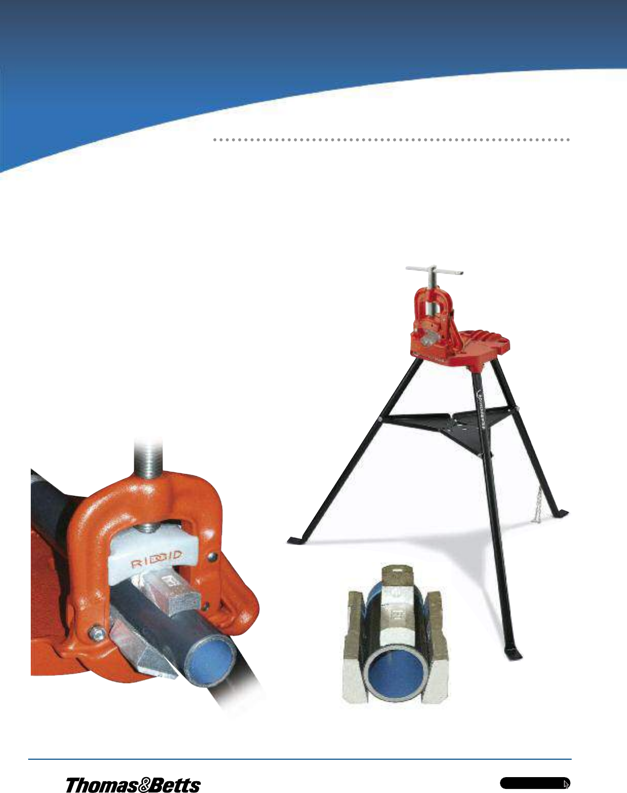
w w w . t n b . c a
PVC-Coated Products
H74
OCALTM
Installation Guidelines
OcalTM Recommended
Installation Procedures
PVC-coated conduit is installed in much the same manner as conventional rigid galvanized steel conduit; however, certain precautions must be taken to protect
the exterior coating and ensure satisfactory results. By following these guidelines and using the proper tooling, a damage-free installation can be achieved.
When an engineer has specified OcalTM PVC-coated conduit, the intent is for the total run to be PVC coated. There are no exceptions to this rule. This means from
the beginning of the run to its completion and all in between, no exposed metal shall be allowed.
Clamping in a Yoke-Style Vise
The first step is the correct clamping of the PVC-coated conduit.
When you use a yoke-style vise, you should replace both the upper and lower
jaw inserts with the specially designed OcalTM jaw vise adapters. These adapters
provide greater clamping force and prevent the pipe from spinning during the
threading process. (See Catalogue No. JAWS76 or JAWS23 on page H52).
Your other option is to purchase a yoke-style vise already equipped with jaws
designed specifically for PVC-coated conduit, such as the yoke-style tri-stand
vise manufactured by Rothenberger (Catalogue No. P00076C) on page H51.
OcalTM Jaw Vise Adapters
JAWS23 or JAWS76
(see page H52)
Yoke-Style Tri-Stand Vise
with jaws designed
for PVC-coated conduit
P00076C
(see page H51)
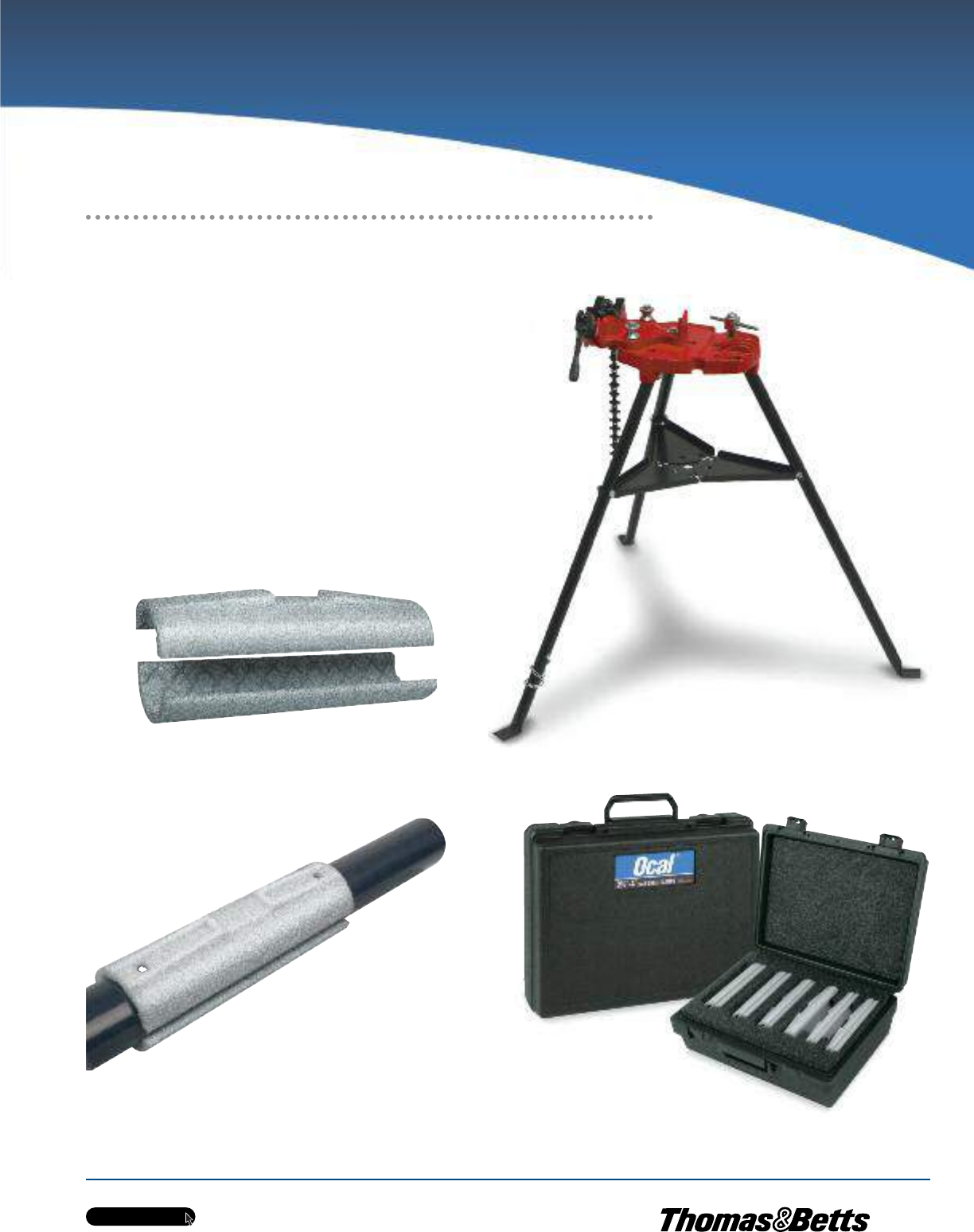
w w w . t n b . c a
PVC-Coated Products
H75
OCALTM
Chain-Style Vise
ROTH00076
(see page H51)
Half-Shell Clamps
for conduit sizes 1⁄2 in. to 6 in.
HLF-SHL-CLP-_
(see page H51)
Clamping in a Chain-Style Vise
If a chain-style vise is used, the chain — as well as the jaw inserts — will
tear the PVC coating when the threading force is applied.
To prevent this from happening, installers sometimes make “shells” from PVC
pipe or standard rigid steel conduit that fit over the PVC-coated conduit.
To save time and obtain more consistency, longer life and better protection,
you can use the OcalTM half-shell clamps featured on page H51.
Available in trade sizes 1/2 in. to 6 in., OcalTM half-shell clamps are made
from ductile iron for superior strength and durability. They feature a
cross-hatched interior surface designed to safeguard the PVC coating while
holding the conduit securely in a chain-style vise.
Half-Shell Clamp Sets
HLF-SHL-CLP-SET1
(see page H51)
Installation Guidelines
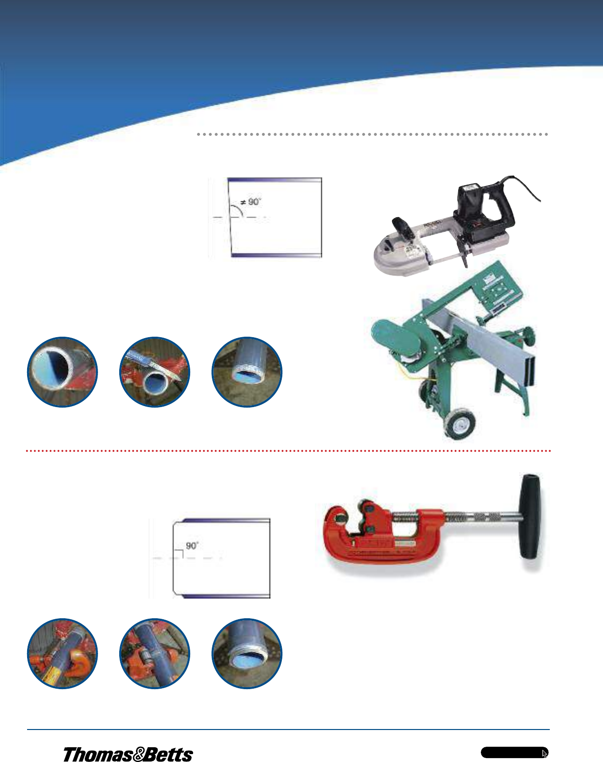
w w w . t n b . c a
PVC-Coated Products
H76
OCALTM
Cutting with a Band Saw
Cutter
A band saw cutter will cut the PVC coating flush with the
end of the conduit. PVC material cut flush to the end of
the conduit will not allow the die teeth to bite into the
steel to start the threading process.
Therefore, before threading, you must remove approximately 1/4 in. of the PVC
coating from the end of the conduit. Using a knife, whittle in a pencil-sharpening
style, cutting the coating from the conduit. A wire brush may also be used to
remove PVC coating.
A band saw cutter usually will not cut the conduit at a “perfect” 90° angle (the
accuracy of this cut depends heavily on the skill of the operator).
Cutting with a Roller-Style Cutter
Although most personnel in the field prefer a band saw cutter, a roller-style
cutter is the recommended tool for cutting OcalTM PVC-coated conduit.
A roller-style cutter cuts the edge of
the conduit at a bevel and removes
1/4 in. of the coating at the same
time. In addition, a roller-style cutter
provides an exact 90° cut in relation
to the conduit. No additional removal
of PVC coating is necessary. Steel Pipe Cutters
P70045C
P70060C
(see page H52)
Installation Guidelines
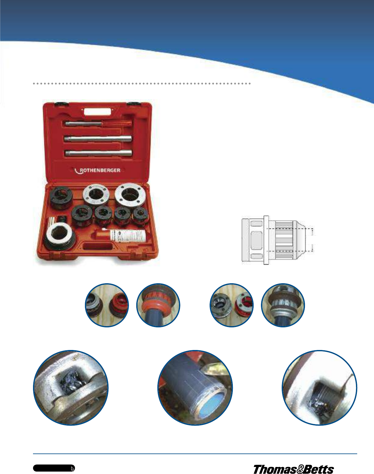
w w w . t n b . c a
PVC-Coated Products
H77
OCALTM
Throat & Collar Shown Cover Plate Shown
The die teeth are cutting tapered threads and will
become clogged with PVC and metal shavings.
To prevent clogging, use a knife and score the conduit lengthwise from the point where the threads will end to where they
begin. This will allow the PVC and metal shavings to fall into the throat of the die head.
Manual and Hand-Held Threading
PVC-coated conduit has a larger O.D. than uncoated conduit. Standard dies will
not clear the additional thickness. Hand-held as well as power threading devices
require a die head for the correct size conduit.
The standard die head is factory set for rigid conduit and will not fit
over PVC coating. These die heads are available from OCALTM, machined for use
with PVC-coated conduit. You can have standard dies machined as well.
If you have dies machined, you will need to adhere to the following procedure:
1. Remove the cover plate and the four die teeth.
2. Have the machinist remove 100 thousandths of an inch (1/10 in.)
from the throat and collar diameter of the die head.
3. Replace the dies and cover.
SUPER CUT Die Head Set
P70905C
(see page H50)
Installation Guidelines
Remove
1/10”
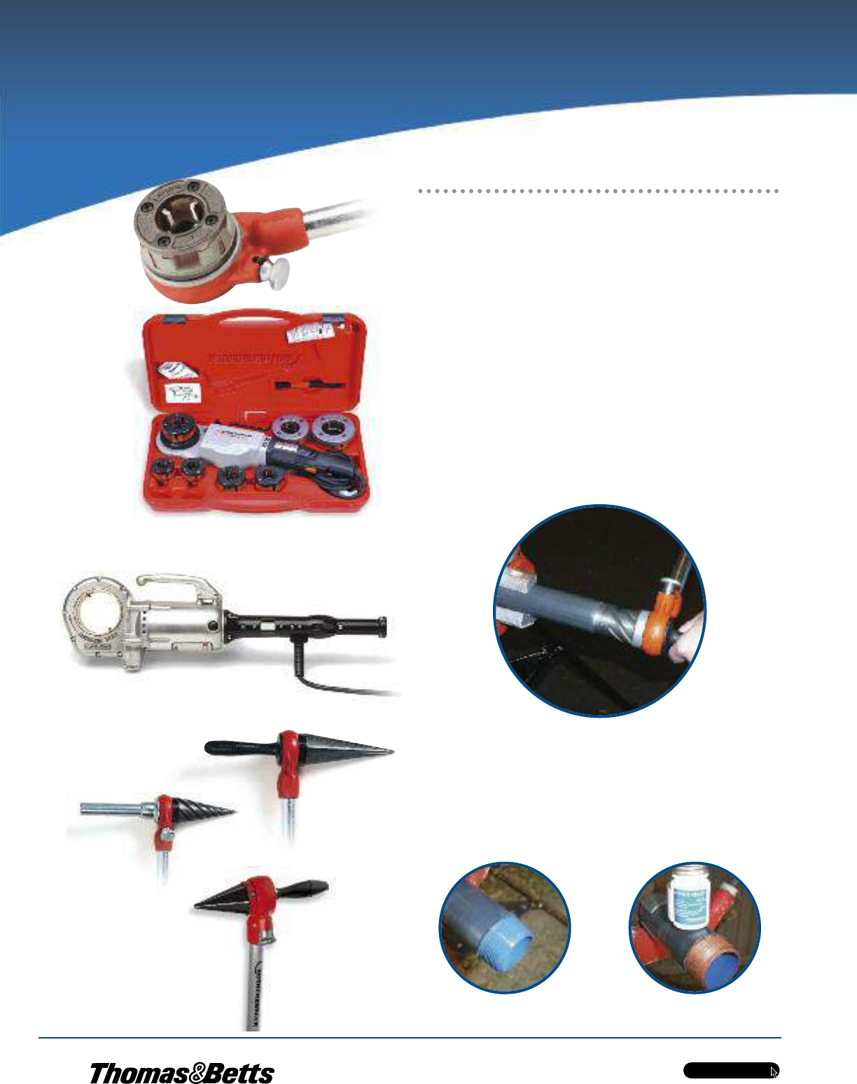
w w w . t n b . c a
PVC-Coated Products
H78
OCALTM
OcalTM Urethane Patching Compound
(see page H54)
Hand-Held Manual Threading
Manual, ratchet-style threaders, such as the Rothenberger SUPER CUT ratchet
threader or Ridgid 12R, are typically used for smaller size conduit. The ratchet
knob indicates forward and reverse. Die heads snap in from both sides and lock
in place. (Ridgid 12R includes ratchet and handle only.)
Hand-Held Powered Threading
The Rothenberger MINI-COLLINSTM and Ridgid 700 Power Drive are heavy-duty
hand-held power tools typically used for conduit up to 2 in. in diameter.
Hand-held power threaders such as the Rothenberger SUPERTRONICTM 2000
are available with die heads for PVC-coated conduit. The Rothenberger
MINI-COLLINSTM uses Rothenberger SUPER CUT dies, while the Ridgid 700
Power Drive is designed for Ridgid 12R dies. Optional tool cases are available.
Ream the conduit with approved reamers. Spiral and straight-style reamers are both acceptable.
KOPR-SHIELD®
(see page H54)
The threads must be dressed per NEC Article 300.6 [a]: “Where unusually
corrosive elements require additional protection, it is recommended that threads
be zinc coated with a hot dipped process or equivalent.”
Use a good quality degreaser and apply Ocal interior touch-up compound
or T&B KOPR-SHIELD®.
Ridgid 12R
Rothenberger MINI-COLLINSTM
ROTH00074
(see page H50)
Rothenberger SUPERTRONICTM 2000
P71259C
(see page H49)
Ridgid Reamers
Rothenberger Reamer
70289
(see page H52)
Installation Guidelines
Threading
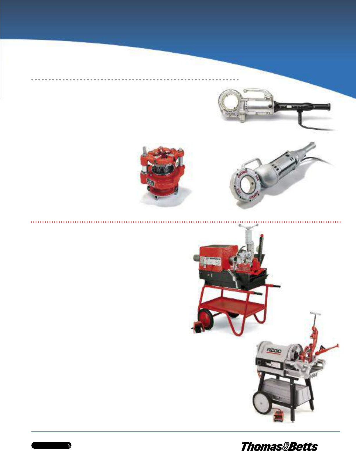
w w w . t n b . c a
PVC-Coated Products
H79
OCALTM
Ridgid 700 Power Drive (“Power
Pony”)
Geared Threading
Geared threaders will thread 2-1/2 in. through 6 in. PVC coated conduit.
However, geared threaders are typically only used for 5 in. and 6 in. conduit.
The cutting dies are adjustable and will not require pencil cutting the conduit.
The geared threader requires a clamp screw
to secure the conduit, and the clamp screw
will penetrate the PVC coating. Make certain
the clamp screw is tight; otherwise, it will slip
around the conduit and tear the coating.
After the threading process is complete,
touch up the penetrated area with OCALTM
exterior PVC patching compound
(see pages H54 – H55).
Ream the conduit and dress the threads
as previously described.
Stationary Power Threading
Rothenberger RHINOTM
The Rothenberger RHINOTM threading machine featured on page H49, Catalogue
No. P00551C, which comes equipped with jaws for PVC-coated conduit up to
4 in., is the recommended choice for threading OcalTM PVC-coated conduit.
With the Rothenberger RHINOTM, you won’t need to pencil cut or score the PVC
because this machine uses a roller cutter and will remove 1/4 in. of the PVC
coating. Cuttings will fall onto the screen on the lower portion of the machine.
Machines that use centrifugal force (slap chucks) — other than the
Rothenberger RHINOTM, Catalogue No. P00551C — to tighten the jaws around
the conduit can be used, but only with shell clamps attached. These types of
threaders will damage the PVC coating without the use of shell clamps.
Ridgid®Model 1224
Stationary power threading machines such as the Ridgid 1224 have the
capacity to thread rigid conduit from 1/2 in. to 4 in. The standard jaw inserts
with these units are intended to secure uncoated rigid conduit. The teeth of the
standard jaw inserts will penetrate the PVC coating, but not bite into the steel.
As a result, the standard jaw inserts will grind the PVC coating off the conduit.
To prevent this, shell-style clamps or jaw inserts for coated conduit may be used.
•Shell Clamps — Range: 1/2 in. to 3-1/2 in.
To properly clamp the conduit, the shell style clamps described earlier can be
used on conduit sizes from 1/2 in. to 3-1/2 in. However, for 4 in. conduit, there is
not enough room in the chuck to accommodate both the 4 in. conduit and shell
clamps.
•Jaw inserts for coated conduit — Range: 1/2 in. to 4 in.
The jaw inserts for coated conduit have teeth that will penetrate the PVC coating
and bite into the conduit itself. Ridgid Catalogue No. 26187 is the jaw insert for
coated conduit used in the Ridgid 1224 threading machine.
Ridgid Geared Threader (“Hog Head”)
Rothenberger RHINO
TM
P00551C
(see page H49)
Ridgid 1224
Installation Guidelines
Rothenberger MINI-COLLINSTM
ROTH00074
(see page H50)
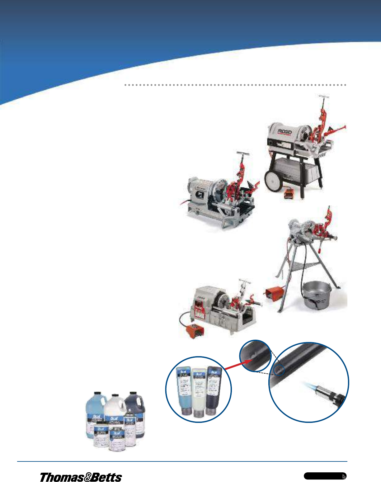
w w w . t n b . c a
PVC-Coated Products
H80
OCALTM
Stationary Power Threading
(cont’d)
Ridgid®Model 1224 (cont’d)
The jaw inserts for coated conduit will leave slits in the PVC jacket. You will
need to touch up slits with Ocal exterior PVC patching compound (see pages
H54 – H55). Since an extra step is required with the special jaw inserts, most
installers usually use them only for 4 in. conduit with the Ridgid 1224 threading
machine.
Make sure the stationary machine is set up for NPT threading. All machines can
cut straight threads; however, not all machines can cut both tapered and straight
threads. Always make sure the thread cutting oil is clean and of the type
recommended by the machine manufacturer.
Ridgid®Models 300 and 535
Stationary power threading machines such as the Ridgid 300 and Ridgid 535
have the capacity to thread rigid conduit from 1/2 in. to 2 in. The standard jaw
inserts for these units are intended to secure uncoated rigid conduit. The teeth
of the standard jaw inserts will penetrate the PVC coating, but not bite into the
steel. As a result, the standard jaw inserts will grind the PVC coating off the
conduit. To prevent this, shell style clamps or jaw inserts for coated conduit may
be used.
•Shell Clamps — Range: 1/2 in. to 1-1/2 in.
To properly clamp the conduit, the shell style clamps described earlier can be used on
conduit sizes from 1/2 in. to 1-1/2 in. However, for 2 in. conduit, there is not enough
room in the chuck to accommodate both the 2 in. conduit and shell clamps
•Jaw Inserts for Coated Conduit — Range: 1/2 in. to 2 in.
The jaw inserts for coated conduit have teeth that will penetrate the PVC coating
and bite into the conduit itself. Ridgid Catalogue No. 97365 is the jaw insert for coated
conduit used in the Ridgid 300 and 535 threaders. The jaw inserts for coated conduit
will leave slits in the PVC jacket. You will need to touch up these slits with Ocal exterior
patching compound (see pages H54 — H55). Since an extra step is required with the
special jaw inserts, most installers only use them for 2 in. conduit with the Ridgid 300
and 535 machines.
There is no need to pencil cut or score the PVC because these threading
machines use a roller cutter and remove 1/4 in. of the PVC coating.
Cuttings simply fall onto the screen on the lower portion of the
machine.
Ridgid 300
Compact Threader
Ridgid 300 Power Drive Complete
Ridgid 1224
Installation Guidelines
Ridgid Model 535
OcalTM Heat-Cure Patch
(see page H55)
OcalTM Heat-Cure Patch offers a thicker
consistency at higher ambient temperatures than standard
air-cure compounds, ensuring better coverage and a more
effective patch in warm weather applications.
OcalTM Air-Cure Patching Compounds
(see page H54)

w w w . t n b . c a
PVC-Coated Products
H81
OCALTM
Hand Bending
A standard hand bender can be used for saddles, offsets and conventional
bending. For PVC-coated conduit, the next larger shoe size from the EMT size
should be used. The chart below shows the catalogue numbers of the hand
benders on page H48 and the corresponding size of PVC-coated conduit on
which they should be used.
Hydraulic Bending
This is the preferred style of bending for 2-1/2 in. and larger size conduit.
The shoe assembly should be of the design for PVC-coated conduit.
The roller wheel and/or slide bar will accommodate PVC-coated conduit without
the need for machining.
Note:
•Sequential bends can be manufactured by OcalTM upon request
•5 in. and 6 in. conduit must be bent at the factory
00946 3728137282
Chicago Bender
Ridgid Hand Bender
(see page H48)
Greenlee Hydraulic Bending Tool
Shoe for Greenlee Hydraulic Bending Tool
Cat. No. Conduit Size (in.)
35220 1/2
35225 3/4
2424A8 1
Never use any type of lubricant on the shoes. Use rubbing alcohol to clean the shoe prior to bending.
Installation Guidelines
Bending
w w w . t n b . c a
PVC-Coated Products
H82
OCALTM
Industry Standards — NEMA
NEMA Standards
Publication No. RN 1 — 2005
Section 3 — External Coatings
3.1 Thickness
The thickness of polyvinyl chloride (PVC) coatings shall be a nominal 0.040 in.
(1.02 mm). The tolerance on the coating thickness shall be +0.010 in.
(+0.25 mm) or -0.005 in. (-0.13 mm).
3.2 Coating Material
The PVC coating shall have the properties specified in Table 3-1.
Underwriter Laboratories, Inc. (UL)
333 Pfingsten Road, Northbrook, IL 60062
UL 6-2007 Safety Standard for Electrical Rigid Metal Conduit — Steel
Property Minimum
Requirement
ASTM
Test Method
Hardness:
Shore A
Shore D
75
25
D 2240
D 2240
Tensile Strength 2,000 psi D 638
Elongation 200% D 638
Dielectric strength 325 volts per mil D 149
Brittleness temperature 5° F D 1790
PROPERTIES OF PVC COATINGS — TABLE 3.1
Property Requirements* Test Method
Abrasion resistance 200 hours, no failure ASTM G6
Bendability, radius
(at 73.4° ± 1.8°F) (at 23° ± 16.8°F)
9 in.
(228.6 mm) ASTM G10
Artificial weathering Minimum 1,000 hours,
no adverse effect ASTM G153
TYPICAL PHYSICAL PROPERTIES OF PVC-COATED RIGID CONDUIT AND IMC — TABLE 3.2
* The above requirements are based on testing a 0.040 in. (1.02 mm) PVC coating applied
over NPS 3⁄4 (21) galvanized rigid steel conduit. See Section 1 for information on the
ASTM test methods.
3.3 Application of Coating
3.3.1 Cleaning
The exterior surface that is to receive the coating shall be free of grease, oil,
dirt and other extraneous matter. The surface shall be cleaned in such a man-
ner that the gal vanized surface of the conduit is not harmed or eroded.
3.3.2 Priming
The cleaned exterior surface shall be primed with an adhesive suitable for use
with the PVC coating material to be applied.
3.3.3 Coating
The PVC material shall be applied in powder, plastisol or pellet form by a
manufacturing method which will produce a finished product conforming to
these standards.
3.4 Elbows
Coated elbows shall be used with coated conduit. The thickness of the coating
on elbows shall be in accordance with Section 3.1.
3.5 Couplings
Coated couplings shall be used with coated conduit. The thickness of the
coating on couplings shall be at least equal to the thickness of the coating on
the conduit.
Each coated coupling shall have a flexible PVC sleeve which extends from each
end of the coupling and which will overlap the PVC coating on the conduit when
the coupling has been installed on the conduit.
The length of the sleeve extension(s) shall be at least equivalent to the nominal
conduit size for sizes up through NPS 2 (53). For sizes NPS 2-1/2 (63) through
NPS 6 (155), the length of the sleeve extension(s) shall be at least 2 in.
(50.8 mm).
The PVC sleeve shall be a nominal thickness of 0.040 in. (1.02 mm). The inside
diameter (I.D.) of the overlapping sleeve shall be less than the outside diameter
(O.D.) of the PVC-coated conduit.
3.6 Workmanship and Appearance
The PVC coating shall be free of blisters, bubbles, and pinholes. The PVC coating
shall be continuous over the entire length of the conduit except at the threads
and shall be holiday-free at the time of manufacture.
A holiday is herein defined as an electrical discontinuity of less than 80,000
ohms equivalent resistance sensed with a cellulose sponge wet with a suitable
electrolyte and measured with an appropriate low voltage direct-current
instrument. A suitable electrolyte is a solution containing tap water, 3.0% salt
(sodium chloride) and 0.5% liquid detergent.
The inside of the PVC-coated conduit, couplings and elbows shall be free of the
PVC coating material.
All sleeve extensions shall be square cut.
3.7 Performance Requirements
Typical physical requirements for PVC-coated conduit are given in Table 3-2.
3.8 Adhesion
The adhesion of the PVC coating to the conduit shall be greater than the strength
of the coating itself. This shall be determined by making two circumferential cuts,
above 1⁄2 in. (12.7 mm) apart, through the plastic to the substrate. A third cut
shall be made perpendicular to and crossing the circumferential cuts. The edge
of the plastic shall be carefully lifted with a knife to form a plastic tab. This tab
shall be pulled perpendicular to the conduit with a pair of pliers. The plastic tab
shall tear rather than any additional coating film separating from the substrate.
Head Office
19295 25th Avenue
Surrey, BC V3Z 3X1
Tel: 778-545-9916
Fax: 778-545-3099
Toll Free: 1-888-467-7626
Terrace
5000 Pohle Avenue
Terrace, BC V8G 4S8
Tel: 250-635-6379
Prince George
2255 S. Quinn Street
Prince George, BC V2N 2X4
Tel: 250-563-0575
Kitimat
622 Commercial Avenue
Kitimat, BC V8C 2C5
Tel: 250-632-3774
Fort Nelson
PO Box 3266 - 5016 48th Avenue
Fort Nelson, BC V0C 1R0
Tel: 250-233-8570
Dawson Creek
1101 97th Avenue
Dawson Creek, BC V1G 1N5
Tel: 250-782-4896
Williams Lake
527 S. MacKenzie Avenue
Williams Lake, BC V2G 1C8
Tel: 250-392-7795
Vernon
5203 24th Street
Vernon, BC V1T 8X7
Tel: 250-545-2191
Penticton
401 Okanagan Avenue
Penticton, BC V2A 3K1
Tel: 250-492-4032
Kamloops
B-983 Camosun Crescent
Kamloops, BC V2C 6G1
Tel: 250-374-3191
Cranbrook
Unit A #800 Industrial Road. #2
Cranbrook, BC V1C 4C9
Tel: 250-489-4591
Parksville
#105 - 425 E. Stanford Avenue
Parksville, BC V9P 2N4
Tel: 250-954-1797
Duncan
5286 Polkey Road
Duncan, BC V9L 6W3
Tel: 250-748-3377
Courtenay
2615 Moray Place
Courtenay, BC V9N 8A9
Tel: 250-334-0338
Campbell River
1030 B - 9th Avenue
Campbell River, BC V9W 4C2
Tel: 250-287-9265
Surrey
13055 80th Avenue
Surrey, BC V3W 3B1
Tel: 604-596-7111
Richmond
12360 Vickers Way
Richmond, BC V6V 1H9
Tel: 604-273-1981
Langley
#101 - 20550 Duncan Way
Langley, BC V3A 7A3
Tel: 604-533-1275
Burnaby
3935 2nd Avenue
Burnaby, BC V5C 3W9
Tel: 604-292-4800
Lighting Specialist
Tel: 778-545-9916
Projects Group
Tel: 604-596-7111
Data Communications Group
Tel: 778-545-9916
Process, Automation &
Controls Group
Tel: 778-545-9916
Unit 9, 7223 68 Avenue,
Edmonton, Alberta T6B 3T6
