1000321795 Catalog
2016-10-06
: Pdf 1000321795-Catalog 1000321795-Catalog B5 unilog
Open the PDF directly: View PDF ![]() .
.
Page Count: 72

Product Catalogue
Providing Protection for
Automotive Wiring Harnesses
A Member of the ABB Group

Welcome to
Thomas & Betts
Introduction
2
At Thomas & Betts, our focus is on improving your business
performance by providing practical, reliable electrical
products & services. To connect & protect for life. To solve
everyday problems in the area’s of Wire & Cable Management,
Cable Protection, Power Connection & Control and Safety.
Our extensive engineering, supply chain management
and technical sales support teams are committed to
understanding everything that impacts your ability to
accomplish your business objectives by reducing your total
cost of ownership.
Whether you are designing, installing, operating, maintaining
or owning an office building, off-shore platform, hospital,
or a high speed train, power generating plant, machine
equipment, manufacturing or automotive production
facility, Thomas & Betts engineered products fit and
function in your application while providing superior
performance, sustainability, and value throughout the
project life cycle.
All our brands are built upon four product & service
solution platforms. Platforms that address you or your
customers’ critical electrical & lighting needs covering the
protection of data, energy, processes, assets and personal
safety. Beyond hi-performance application characteristics,
Thomas & Betts products, information and services facilitate
and speed up your time critical assembly, installation or
maintenance process.

3
Contents
Conduit 4 -14
NC 6 - 7
CTPA 8 - 9
HNC 10
CPC 11
PP/DSPP 12 - 13
PKC 14
HTC 14
Hinged fittings 15 - 34
Hinged Joiners 16
Hinged Elbows 17
T Pieces 18 - 19
Y Pieces 20 - 21
Shrouds 22
X Pieces 23
Custom Hinged Manifolds 24
Split Manifolds 25
Circular Manifolds 26
Interfaces 27 - 46
Amp Superseal 28
Amp Junior & Mini Timer 29
Ampseal 30 - 31
Deutsch DT 32 - 33
Deutsch DTP04 34
Deutsch DRC50 35
FCI Apex 36
Bosch compact 37
Delphi Series 38 - 39
Molex MX93286 Series 40 - 41
Kostal 42
Milflex ABS 43
Sumito 43
DIN 72585 44
Circular Connectors 45
Accessories 46
Contents
Sealed Fittings 47 - 63
Straights 48 - 49
Elbows 50 - 51
90˚ flanges 52
T-Pieces 53
X Pieces 54
Manifolds 55
Circular UNEF Connector Interfaces 56
Solenoid Connector Interfaces 57
Reducing Bushes 58
Cable Glands 59
Accessories 60 - 61
Clips 62 - 63
Technical 64 - 69
Thomas & Betts • tel +44 (0)1675 468222 • www.harnessflex.com
A Member of the ABB Group

4
Thomas & Betts • tel +44 (0)1675 468222 • www.harnessflex.com
Selection Table for Conduit
Catalogue Page Number 6 8 10 11 12 12 13 14
Long Term Static temp. (ºC) Min -40 -40 -50 -45 -20 -20 -60 -45
Long Term Static temp. (ºC) Max 120 120 110 135 90 90 260 200
UV Resistance nnnn nnnn nnnn nnnn nnoo nnno nnnn nnnn
Flexibility nnno nnno nnnn nnno nnnn nnno nnnn nooo*
Fatigue Life nnno nnno nnnn nnno nnnn nnnn nnno nooo*
Halogen Free l l l l l l l
Self Extinguishing l l l l – l l l
External Wear Resistance nnnn nnoo nnno nnno nooo n noo nnnn nnnn
Slit version available l l – – – Slit only ––
Conduits
NC
(Polyamide 6)
CTPA
(Polyamide 6)
HNC
(Polyamide 12)
CPC
(FR Co-polyester)
PP
(Polypropylene)
DSPP
(Modified Polypropylene)
PKC
(Polyetheretherketone)
HTC
(Modified Nylon)
Key: S = Suitable, L = Limited Suitability, U = Unsustainable, NT = Not Tested. All chemicals tested for resistance at 33oC.
Maximum Performance= nnnn
IRM 903 (ASTM Oil No.2) S S S S S S S S
Diesel Oil S S S S S S S S
Ethylene Glycol (Anti-freeze) S S S S S S S S
Lubricating Oil S S S S S S S S
Methyl Alcohol L L S S S S S S
Parafin Oil S S S S S S S S
Petrol S S S S S S S S
Sodium Chloride S S S S S S S S
Sodium Hydroxide (10%) S S S S S S S S
Transformer Oil S S S S S S SS
Urea S S S NT NT NT S S
Vegetable Oil S S S S S S S S
Sea (Water) S S S S S S S S
Chemical Resistance
Selection Table for Conduit

Design Interaction
5
Thomas & Betts • tel +44 (0)1675 468222 • www.harnessflex.com
Ingress Protection (I.P.) ratings
Harnessflex hinged systems are rated at IP40. Harnessflex
sealed systems are rated at IP66, 67, 68 (2 BAR for 30mins) &
69k. Only when using Harnessflex conduit.
Product Specifications
All Harnessflex fittings are manufactured from Polyamide
6,6 (PA 6,6) and are black in colour. Other colours and
materials can be made available to achieve specific
customer requirements. Product datasheets and dimension
charts are available for the full Harnessflex range - please
submit your request via our website or call the Harnessflex
technical support desk.
Design Data
Harnessflex parts are developed in house using the following
CAD systems:
• AutoDesk Inventor
• AutoDesk AutoCAD
Drawing files are available in the following CAD formats
(as well as the versitile PDF format):
DWG, DXF, DWF, IGES, STEP, STL, PRT, ASM, IPT, IAM.
Pre-production Samples
From CAD data we are able to produce accurate
representations of final manufactured products, using a 3D
printing process. Prototype fittings are typically produced in
Duraform PA, a material that gives similar performance in
tests to PA 6,6. Prototype extrusions can be manufactured
in a variety of materials (please contact us for details). This
process allows a product design to be validated before the
part is tooled for manufacture.
Technical Support
Worldwide sales support via our experienced engineers.
Please contact us to discuss any of our products, or the
possibility of developing a solution specific to your needs.
Design Interaction
A Member of the ABB Group

Description
Flexible standard weight nylon (PA6)
conduit is a general-purpose conduit
suitable for automotive harness
applications. It can withstand extremes
of temperatures and resists automotive
oils and solvents. It is extremely tough
and has a high impact strength and
fatigue life.
Solid NC conduits provide protection
against mechanical shock and ingress of
water whilst maintaining their form
through tight bend radii.
ADR approved for hazardous vehicles.
Applications
NC standard weight is extensively used
in harnesses on HGV, off road vehicles
and marine applications where a
superior protection against impact and
mechanical shock is preferred. The
conduit is used for both chassis and
engine applications and can be used in
a wide range of temperatures.
Polyamide 6 is highly resistant to all
hydrocarbon based oils and fluids and
many types of solvents.
NC is designed for connection to all
Harnessflex sealed and hinged
system fittings
NC conduits are available in a range of
popular sizes. The standard colour is
black with other colours including
orange for hybrid vehicles also being
available on request.
6
Thomas & Betts • tel +44 (0)1675 468222 • www.harnessflex.com
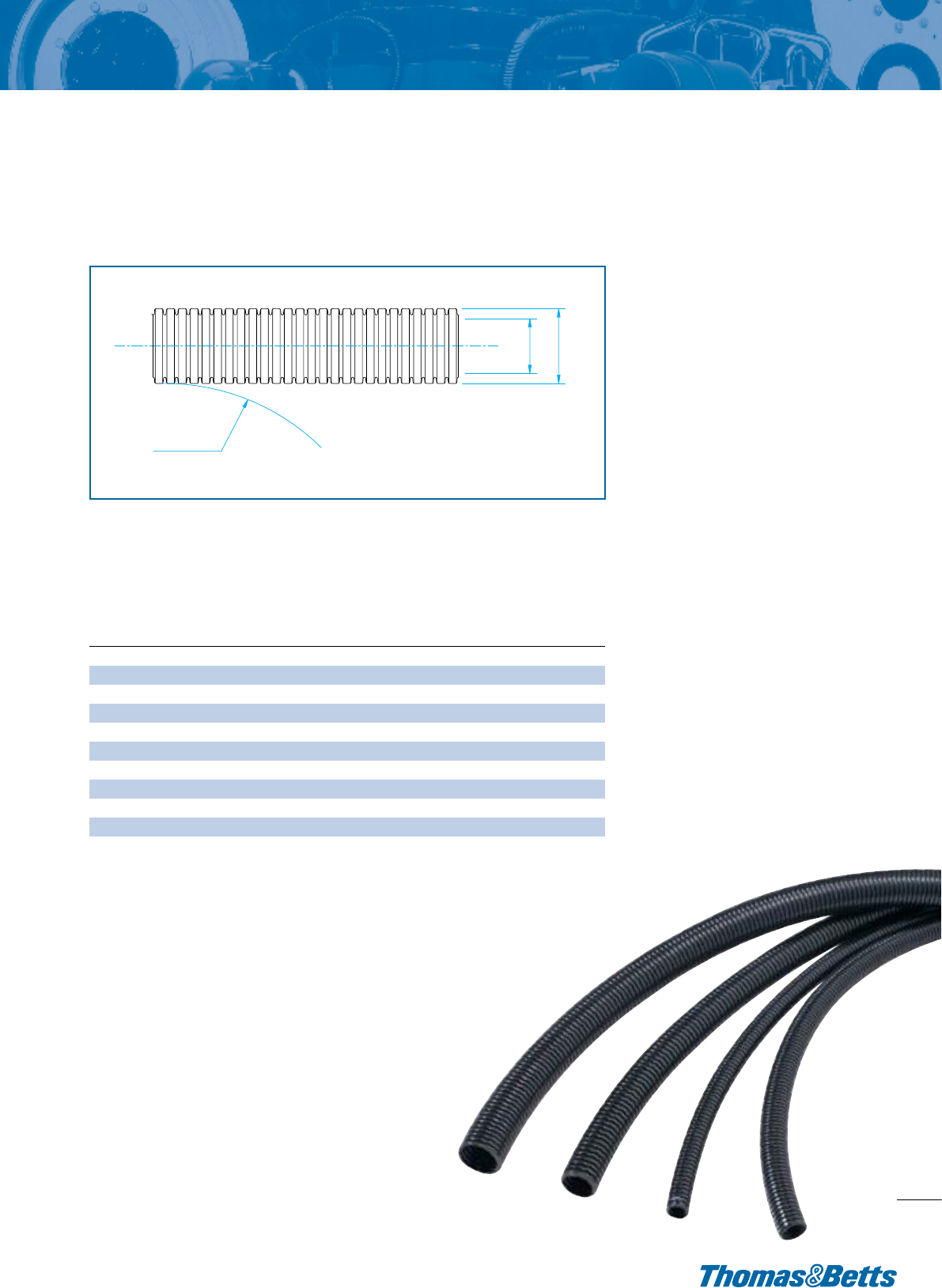
NC conduit configurations and dimensions
C
Configuration/nominal dimensions/part numbers
NC Standard Weight, Polyamide 6
General Purpose Conduit
B A
Nominal Min Min Static
Part Conduit Size O/D Bore Bend Rad. Length
Number (NC) NW A B B (m)
NC06 06 4.5 7.1 4.5 5 100
NC08 08 7.5 10.0 6.5 15 100
NC10 10 8.5 11.5 8.4 15 100
NC12 12 10 13.0 9.9 20 100
NC16 16 13 16.0 11.8 30 100
NC20 20 17 21.2 16.6 35 50
NC25 25 22 25.6 21.3 40 50
NC28 28 23 28.5 22.6 45 50
NC30 30 26 31.6 26.0 50 50
NC32 32 29 34.5 28.8 55 50
NC40 40 36 42.5 34.8 65 25
NC50 50 48 54.5 46.9 70 25
- To order, quote part number and reel length.
- For colours other than standard black also add colour, ie for orange /OR, /RD for red conduit.
** NOTE: dimensions are in mm.

General Purpose Conduit
Thomas & Betts • tel +44 (0)1675 468222 • www.harnessflex.com
NC Slit Standard Weight, Polyamide 6
General Purpose Conduit
NC Slit conduit configurations and dimensions
B A
C
Configuration/nominal dimensions/part numbers
Nominal Min Min Static
Part Conduit Size O/D Bore Bend Rad. Length
Number (NC) NW A B B (m)
NC06-S 06 4.5 7.1 4.5 5 100
NC08-S 08 7.5 1 10.0 6.5 15 100
NC10-S 10 8.5 11.5 8.4 15 100
NC12-S 12 10 13.0 9.9 20 100
NC16-S 16 13 16.0 11.8 30 100
NC20-S 20 17 21.2 16.6 35 50
NC25-S 25 22 25.6 21.3 40 50
NC28-S 28 23 28.5 22.6 45 50
NC30-S 30 26 31.6 26.0 50 50
NC32-S 32 29 34.5 28.8 55 50
NC40-S 40 36 42.5 34.8 65 25
NC50-S 50 48 54.5 46.9 70 25
Hints & Tips
Kwikcut is the ideal cutting tool for all
non-metallic conduits upto 32mm.
Cutting Instructions
Place the conduit between the cutting
blade and lower support, squeeze
the handles and rotate the conduit for
a clean, easy cut. Spare blades
are available.
Part Numbers
• Kwikcut
• Kwikcut-Blade
A Member of the ABB Group
Durable construction
Providing enhanced resistance to
compression and impact forces
•
1
PA6 material
Providing fire retardant properties,
halogen free and low smoke emissions
•
2
Harsh environment capability
Providing a wide operating temperature range
•
3
- To order, quote part number and reel length.
- For colours other than standard black also add colour, ie for orange /OR, /RD for red conduit.
** NOTE: dimensions are in mm.
7

8
Thomas & Betts • tel +44 (0)1675 468222 • www.harnessflex.com
CTPA, Lightweight, Polyamide 6
Flexible Conduit
Description
Flexible lightweight nylon (PA6) conduit
is a general-purpose conduit suitable for
automotive harness applications. It can
withstand extremes of temperatures and
resists automotive oils and solvents. It is
extremely tough and has a high impact
strength and fatigue life.
CTPA conduits provide protection
against mechanical shock and ingress of
water whilst maintaining their form
through tight bend radii.
Applications
Lightweight convoluted tube used for
interior harnesses offering limited
mechanical protection to provide
abrasion resistance and enhance the
aesthetics of the harness.
• Extremely light and fexible.
• Resistant to oils and solvents.
Configuration/nominal dimensions/part numbers
Nominal Min Min Static
Part Conduit Size O/D Bore Bend Rad. Length
Number (NC) NW A B B (m)
CTPA08 08 7.5 10.0 6.5 10 100
CTPA10 10 8.5 11.5 8.7 15 100
CTPA12 12 10 13.0 10.1 20 100
CTPA16 16 13 16.0 11.8 35 100
CTPA20 20 17 21.2 16.9 45 100
CTPA25 25 22 25.6 21.3 45 100
CTPA28 28 23 28.5 23.1 45 100
CTPA30 30 26 31.6 26.0 50 50
CTPA32 32 29 34.5 28.8 55 50
CTPA40 40 36 42.5 35.0 65 25
CTPA50 50 48 54.5 46.0 90 25
CTPA conduit configurations and dimensions
C
B A
Lightweight design
Ideal for automotive harness fabrication
•
1
Enhanced flexibility
Ideal for use in installations where space
is limited
•
2
PA6 material
Providing fire retardant properties and
halogen free emissions
•
3
- To order, quote part number and reel length.
- For colours other than standard black also add colour, ie for orange /OR, /RD for red conduit.
** NOTE: dimensions are in mm.
Flexible Conduit
9
Thomas & Betts • tel +44 (0)1675 468222 • www.harnessflex.com
A Member of the ABB Group
CTPA Slit, Lightweight, Polyamide 6
Flexible Conduit
Hints & Tips
Kwikcut is the ideal cutting tool for all
non-metallic conduits upto 32mm.
Cutting Instructions
Place the conduit between the cutting
blade and lower support, squeeze
the handles and rotate the conduit for
a clean, easy cut. Spare blades
are available.
Part Numbers
• Kwikcut
• Kwikcut-Blade
Configuration/nominal dimensions/part numbers
Nominal Min Min Static
Part Conduit Size O/D Bore Bend Rad. Length
Number (NC) NW A B B (m)
CTPA08-S 08 7.5 10.0 6.5 10 100
CTPA10-S 10 8.5 11.5 8.7 15 100
CTPA12-S 12 10 13.0 10.1 20 100
CTPA16-S 16 13 16.0 11.8 35 100
CTPA20-S 20 17 21.2 16.9 45 100
CTPA25-S 25 22 25.6 21.3 45 100
CTPA28-S 28 23 28.5 23.1 45 100
CTPA30-S 30 26 31.6 26.0 50 50
CTPA32-S 32 29 34.5 28.8 55 50
CTPA40-S 40 36 42.5 35.0 65 25
CTPA50-S 50 48 54.5 46.0 90 25
CTPA conduit configurations and dimensions
B A
C
Lightweight design
Ideal for automotive harness fabrication
•
1
Enhanced flexibility
Ideal for use in installations where space
is limited
•
2
PA6 material
Providing fire retardant properties and
halogen free emissions
•
3
- To order, quote part number and reel length.
- For colours other than standard black also add colour, ie for orange /OR, /RD for red conduit.
** NOTE: dimensions are in mm.

10
Thomas & Betts • tel +44 (0)1675 468222 • www.harnessflex.com
HNC Standard Weight, Polyamide 12
Low Temperature, Extra Flexible Conduit
Description
HNC standard weight conduit is made
from polyamide 12 and is specially
formulated to meet the environmental
and mechanical requirements for the
exterior of working vehicles.
HNC conduit also provides protection
against mechanical shock and ingress
of water whilst maintaining its form
through tight bend radii. It has been
specifically designed to cope with
extremes of temperature combined with
repeated movement and vibration.
Applications
HNC conduit is particularly used in
applications requiring repeated flexing
coupled with low temperature
impact toughness.
Robotics, rapid or continuous motion
applications demanding high fatique life
and extra flexibility are covered by
HNC which is also used in low
temperature environments.
HNC Standard weight conduit
is designed for connection to all
Harnessflex hinged and sealed fittings.
Contact us for slit conduit options.
Extra Flexible Conduit
Configuration/nominal dimensions/part numbers
Nominal Min Min Static
Part Conduit Size O/D Bore Bend Rad. Length
Number (NC) NW A B B (m)
HNC08 08 7.5 10.0 6.2 15 100
HNC12 12 10 13.0 9.9 25 100
HNC16 16 13 15.8 11.7 30 100
HNC20 20 17 21.2 16.6 35 50
HNC25 25 22 25.3 21.0 40 50
HNC28 28 23 28.5 21.7 45 50
HNC32 32 29 34.5 27.7 55 50
HNC40 40 36 42.5 35.5 60 25
HNC50 50 48 54.5 46.6 70 25
*NOTE: dimensions are in mm
HNC conduit configurations and dimensions
C
B A
Harsh environment capability
Providing high performance at extremely low temperatures
•
1
Enhanced flexibility
Ideal for use in installations where space is limited
•
2
Durable construction
Providing enhanced resistance to compression
and impact forces
•
3
PA12 material
Providing high impact resistance and very
high flexibility at low temperatures.
•
4

Flame Retardant Conduit
11
Thomas & Betts • tel +44 (0)1675 468222 • www.harnessflex.com
CPC Medium Weight (FR Co-polyester)
Flame Retardant Conduit
Description
CP standard weight conduit is made
from flame retardant co-polyester,
which is a halogen free, low smoke
and very low toxicity material. It has
excellent high and low temperature
properties.
CP conduits provide protection against
mechanical shock and ingress of
water whilst maintaining their form
through tight bend radii. This material
demonstrates excellent chemical
resistance to greases, hydrocarbons,
fuels and oils.
Applications
CP is particularly used in applications
requiring low fire hazard performance, it
is lightweight and retains its flexibility at
extremes of temperature. CP is designed
for use in the interior and exterior of
vehicles and marine passenger cabins.
CP is designed for connection to all
Harnessflex Hinged and Sealed fittings.
Contact us for slit options.
Hints & Tips
Kwikcut is the ideal cutting tool for all
non-metallic conduits upto 32mm.
Cutting Instructions
Place the conduit between the cutting
blade and lower support, squeeze
the handles and rotate the conduit for
a clean, easy cut. Spare blades
are available.
Part Numbers
• Kwikcut
• Kwikcut-Blade
Configuration/nominal dimensions/part numbers
Nominal Min Min Static
Part Conduit Size O/D Bore Bend Rad. Length
Number (NC) NW A B B (m)
CPC08 08 7.5 9.8 6.2 20 50
CPC12 12 10 13.0 9.4 25 50
CPC16 16 13 16.0 11 30 50
CPC20 20 17 21.2 16.1 40 50
CPC25 25 22 25.3 21.0 45 50
CPC28 28 23 28.5 22.5 45 50
CPC32 32 29 34.5 27.2 55 50
CPC40 40 36 42.5 34.2 60 25
CPC50 50 48 54.1 46.0 70 25
*NOTE: dimensions are in mm
CPC conduit configurations and dimensions
B A
C
A Member of the ABB Group

12
Thomas & Betts • tel +44 (0)1675 468222 • www.harnessflex.com
Modified PP Medium Weight Polypropylene
Conduit
Polypropylene Conduit
Modified PP, medium weight
Polypropylene conduit
Description
PP is a flexible conduit made from
Polypropylene.
PP conduits provide very good acid
resistance, they have very good flexibility
and a very high fatigue life.
Applications
PP is particularly used in lighter
applications where compression strength
and LFH is not so important. The main
property of this conduit, being acid
resistance.
• Halogen free - not self-extinguishing.
• PP conduits are available in a range
of popular sizes. The conduit comes
in black only.
• PP is designed for connection to all
Harnessflex Sealed and Hinged
system fittings.
Configuration/nominal dimensions/part numbers
Nominal Min Min Static
Part Conduit Size O/D Bore Bend Rad. Length
Number (NC) NW A B B (m)
PP08 08 7.5 10.0 6.4 15 100
PP10 10 8.5 11.5 8.6 20 100
PP12 12 10 13.0 9.6 25 50
PP16 16 13 16.2 11.2 35 50
PP20 20 17 21.2 16.9 35 50
PP25 25 22 25.6 21.5 40 50
PP28 28 23 28.5 23.2 45 50
PP32 32 29 34.5 29.1 55 50
*NOTE: dimensions are in mm
**For slit conduit options add -S to part number eg PP08-S/100m
Modified PP conduit configurations and dimensions
C
B A
Lightweight design
Ideal for automotive harness fabrication
•
1
Enhanced flexibility
Ideal for use in installations where space
is limited
•
2
Modified PP material
Providing enhanced fire and low temperature
impact and chemical resistant properties
•
3

Polyketone Super Low Fire Hazard Conduit
13
Thomas & Betts • tel +44 (0)1675 468222 • www.harnessflex.com
Deep Section Modified Slit PP
Polypropylene, Medium weight conduit
Description
DSPP conduit is made from a flame
retarded material. DSPP slit conduits
provide protection against mechanical
shock whilst maintaining its form
through tight bend radii.
Applications
DSPP has a deep section to maintain the
conduit shape during bending. Deep
Section Conduits are supplied in slit
form to facilitate rapid cable installation
and are designed for connection to all
Harnessflex hinged fittings.
Nominal Min Min Static
Part Conduit Size O/D Bore Bend Rad. Length
Number (NC) NW A B B (m)
DSPP08 08 7.5 10.0 6.6 10 100
DSPP12 12 10 13.0 8.5 18 100
DSPP16 16 13 16.2 11.1 32 100
DSPP20 20 17 21.2 15.0 40 100
DSPP28 28 23 28.5 21.7 50 100
DSPP32 32 29 34.5 27.7 58 50
DSPP40 40 36 42.5 34.6 80 25
DSPP50 50 48 54.5 46.5 100 25
*NOTE: dimensions are in mm
Deep Section PP Configuration/nominal dimensions/part numbers
A Member of the ABB Group
Durable construction
Providing enhanced resistance to
compression and impact forces
•
1
Deep section
Prevents slit form from opening
when bent around tight radii
•
2
Modified PP material
Providing enhanced fire and low
temperature impact and chemical
resistant properties
•
3
Modified Slit PP Deep Section Medium Weight
Polypropylene Conduit

14
Thomas & Betts • tel +44 (0)1675 468222 • www.harnessflex.com
High Temperature Conduit
HTC High Temperature Conduit
Description
A standard weight conduit suitable
for static applications where elevated
temperatures are present. High
compression strength and excellent
chemical resistance made from specially
modified Nylon.
Applications
This conduit has been developed for
use in engine areas where elevated
temperatures occur. Suitable for long
term exposure to 175˚c.
Configuration/nominal dimensions/part numbers
Nominal Min Min Static
Part Conduit Size O/D Bore Bend Rad. Length
Number (NC) NW A B B (m)
HTC12 12 10 13.0 10.0 40 25
HTC16 16 13 15.8 11.9 45 25
HTC20 20 17 21.2 16.5 65 25
HTC25 25 22 25.6 21.3 75 25
HTC28 28 23 28.5 22.7 85 25
HTC32 32 29 34.5 28.8 100 25
HTC40 40 36 42.5 35.2 120 25
HTC50 50 48 54.5 46.5 140 25
*NOTE: dimensions are in mm
HTC conduit configurations and dimensions
C
B A
PKC Standard Weight Polyketone
Super Low Fire Hazard Conduit
Description
Super Low Fire Hazard PK is a standard
weight conduit, which offers superior
mechanical strength as well as high
radiation and chemical protection often
in extreme temperatures. It is a unique
product manufactured from a specialist
polymer, for use in the most demanding
applications.
Peek is a truly high performance conduit.
Applications
This conduit with its high specification
performance is used in some of the
most demanding applications for
flexible conduit.
It is often found in Aerospace, Off-
shore, Military, Heat treatment, Nuclear,
Petrochemical and Marine application.
Configuration/nominal dimensions/part numbers
Nominal Min Min Static
Part Conduit Size O/D Bore Bend Rad. Length
Number (NC) NW A B B (m)
PKC12 12 10 13.0 10.0 35 25
PKC16 16 13 15.8 11.9 45 25
PKC20 20 17 21.2 16.6 60 25
PKC28 28 23 28.5 21.7 65 25
PKC32 32 29 34.5 27.7 80 25
*NOTE: dimensions are in mm
PKC conduit configurations and dimensions
B A
C

Hinged Fittings
15
Thomas & Betts • tel +44 (0)1675 468222 • www.harnessflex.com
Hinged Interfaces
Hinged fittings allow for protection or cables at breakouts,
harness servicability and for the conduit system to self level. They
are designed to protect against high pressure washing, excessive
cable strain and mechanical abrasion. Variety, flexibility and
assembly speed are inherent in all Harnessflex fittings.
Quality & Standards
Manufacturing is controlled in accordance with BS EN ISO 9001
whilst ongoing testing & approval to international standards,
eg: ADR, provides any additional confidence required to specify
appropriate Harnessflex products across the widest variety of
automotive applications including hazardous or aggressive
environments.
All components comply with End of Life Vehicle (ELV) directive
EU2000/53/EC. Harnessflex also comply to ISO14001 -
Environmental Standard
Capabilities
Through our internal design team we are able to offer unique
solutions, specific to our customers applications. Using the
latest 3D CAD modelling software we are able to
communicate new product designs quickly and efficiently.
Rapid prototype parts can be made to order to enable
product evaluation early on in the design cycle.
If you have a requirement for a dedicated hinged fitting
please contact us to discuss your requirement.
DesignFeatures
1. Radiussed internal form of
conduit protects cables
from abrassion.
2. Internal backstop (found on
all hinged fittings) alleviates
any potential problems
caused by unevenly cut
conduit.
Hinged Fittings
Hints & Tips
1. Multiple breakouts can be achieved from any NC20,
NC25 or NC28 exit using our ST splitter range.
See page 45 for details.
2. JPS & EPS fittings can be used as conduit enlargers
or reducers.
3. Combining multiple XPS fittings (page 23) creates a
self levelling manifold, ideal for engine bay or
transmission applications.
1
2
A Member of the ABB Group

16
Thomas & Betts • tel +44 (0)1675 468222 • www.harnessflex.com
External Hinged Joiners
External Hinged Joiners
Description
One-piece joiner and elbow hinged
fittings allow a variety of conduit
size variations.
These fittings are designed to snap
together over all types of slit and unslit
conduit thus maintaining maximum
conduit bore.
Can be used as a reducer as well as
an enlarger.
Conduit Sizes Conduit Sizes
External (NC) (NW)
Joiner A B A B C D E F
JPS1208 12 08 10 7.5 38 16 10 10
JPS1212 12 12 10 10 36 16 10 10
JPS1612 16 12 13 10 36 21 10 10
JPS1616 16 16 13 13 36 21 10 10
JPS2008 20 08 17 7.5 38 26 12 10
JPS2012 20 12 17 10 38 26 12 10
JPS2016 20 16 17 13 38 26 12 10
JPS2020 20 20 17 17 38 26 12 12
JPS2520 25 20 22 17 39 33 12 12
JPS2525 25 25 22 22 39 33 13 13
JPS2820 28 20 23 17 39 33 13 13
JPS2825 28 25 23 22 39 33 13 13
JPS2828 28 28 23 23 39 33 13 13
*NOTE: dimensions are in mm
External hinged joiners dimensions
C
D
F
A B
E
One-piece external design
Unrestricted bore and quick assembly requiring no tools
•
1
Multiple size configurations
Provides the right conduit size combination to suit all applications
•
2
High pull-off strength
Conduit corrugations sit tightly into joiner junctions
•
3
Conduit size labels
Each junction indicates nominal
conduit size to aid installation
•
4
•
1
•
2
•
3
•
4

External Hinged Elbows
17
Thomas & Betts • tel +44 (0)1675 468222 • www.harnessflex.com
A Member of the ABB Group
C
F
A
B
G
D
E
External Hinged Elbows
Description
One-piece joiner and elbow hinged
fittings allow a variety of conduit
size variations.
These fittings are designed to snap
together over all types of slit and unslit
conduit thus maintaining maximum
conduit bore.
Can be used as a reducer as well as
an enlarger.
External hinged elbows dimensions
Conduit Sizes Conduit Sizes
External (NC) (NW)
Joiner A B A B C D E F G
EPS08S08 08 08 7.5 7.5 38 29 20 10 10
EPS12S12 12 12 10 10 38 29 20 10 10
EPS0820 08 20 7.5 17 41 41 25 10 12
EPS1608 16 08 10 7.5 34 34 21 10 10
EPS1612 16 12 13 10 34 34 21 10 10
EPS1616 16 16 13 13 34 34 21 10 10
EPS2008 20 08 17 7.5 41 39 26 12 10
EPS2012 20 12 17 10 41 41 26 10 10
EPS2016 20 16 17 13 41 41 26 12 10
EPS2020 20 20 17 17 41 41 26 12 12
EPS2520 25 20 22 17 48 48 33 13 12
EPS2525 25 25 22 22 48 48 33 13 13
EPS2812 28 12 23 10 48 48 33 13 10
EPS2816 28 16 23 13 48 48 33 13 10
EPS2820 28 20 23 17 48 48 33 13 12
EPS2825 28 25 23 22 48 48 33 13 13
EPS2828 28 28 23 23 48 48 33 13 13
*NOTE: dimensions are in mm
One-piece external design
Unrestricted bore and quick
assembly requiring no tools
•
1
Multiple size configurations
Provides the right conduit size
combination to suit all applications
•
2
High pull-off strength
Conduit corrugations sit tightly into
joiner junctions
•
3
Conduit size labels
each junction indicates nominal
conduit size to aid installation
•
4
•
1
•
4
•
2
•
3

18
Thomas & Betts • tel +44 (0)1675 468222 • www.harnessflex.com
External Hinged T-pieces
Description
One-piece symmetrical 3 junction fittings
allow a variety of conduit size variations.
These fittings are designed to snap
together over all types of slit and unslit
conduit thus maintaining maximum
conduit bore.
External T-piece dimensions
A
B
C
External T-piece dimensions
DF
GI
H
E
•
1
•
2
•
3
•
4
One-piece external design
Unrestricted bore and quick
assembly requiring no tools
•
1
Multiple size configurations
Provides the right conduit size combination to suit all applications
•
2
High pull-off strength
Conduit corrugations sit tightly into joiner junctions
•
3
Conduit size labels
Each junction indicates nominal conduit size to aid installation
•
4
•
5
Integral retaining clips
Retains conduit in position during assembly
•
5

External Hinged T-pieces
19
Thomas & Betts • tel +44 (0)1675 468222 • www.harnessflex.com
Conduit Sizes
Part (NC) (NW) Nominal Dimensions
Number A B C A B C D E F G H I
TPS080808 08 08 08 7.5 7.5 7.5 45.2 31.1 17 10 10 10
TPS081208 08 12 08 7.5 10 7.5 45.2 31.1 17 10 10 10
TPS081612 08 16 12 7.5 13 10 45.2 31.1 17 10 10 10
TPS100808 10 08 08 8.5 7.5 7.5 45.2 31.1 17 10 10 10
TPS101010 10 10 10 8.5 8.5 8.5 45.2 31.1 17 10 10 10
TPS101012 10 10 12 8.5 8.5 13 45.2 31.1 17 10 10 10
TPS120808 12 08 08 10 7.5 7.5 45.2 31.1 17 10 10 10
TPS120812 12 08 12 10 7.5 10 45.2 31.1 17 10 10 10
TPS121010 12 10 10 10 8.5 8.5 45.2 31.1 17 10 10 10
TPS121012 12 10 12 10 8.5 10 45.2 31.1 17 10 10 10
TPS121208 12 12 08 10 10 7.5 45.2 31.1 17 10 10 10
TPS121210 12 12 10 10 10 7.5 45.2 31.1 17 10 10 10
TPS121212 12 12 12 10 10 10 45.2 31.1 17 10 10 10
TPS121612 12 16 12 10 13 10 45.2 31.1 21 10 10 10
TPS160808 16 08 08 13 7.5 7.5 49.1 34.8 21 10 10 10
TPS160812 16 08 12 13 7.5 10 49.1 34.8 21 10 10 10
TPS160816 16 08 16 13 7.5 13 49.1 34.8 21 10 10 10
TPS161012 16 10 12 13 8.5 10 49.1 34.8 21 10 10 10
TPS161016 16 10 16 13 8.5 13 49.1 34.8 21 10 10 10
TPS161212 16 12 12 13 10 10 49.1 34.8 21 10 10 10
TPS161216 16 12 16 13 10 13 49.1 34.8 21 10 10 10
TPS161608 16 16 08 13 13 7.5 49.1 34.8 21 10 10 10
TPS161612 16 16 12 13 13 10 49.1 34.8 21 10 10 10
TPS161616 16 16 16 13 13 13 49.1 34.8 21 10 10 10
TPS162012 16 20 12 13 17 10 49.1 34.8 21 10 10 10
TPS162016 16 20 16 13 17 13 49.1 34.8 21 10 10 10
TPS200816 20 08 16 17 7.5 13 56.5 41.0 26 12 10 10
TPS200820 20 08 20 17 7.5 17 56.5 41.0 26 12 10 12
TPS201016 20 10 16 17 8.5 13 56.5 41.0 26 12 10 10
TPS201020 20 10 20 17 8.5 17 56.5 41.0 26 12 10 12
TPS201216 20 12 16 17 10 13 56.5 41.0 26 12 10 10
TPS201220 20 12 20 17 10 17 56.5 41.0 26 12 10 12
TPS201612 20 16 12 17 13 10 56.5 41.0 26 12 10 10
TPS201616 20 16 16 17 13 13 56.5 41.0 26 12 10 10
TPS201620 20 16 20 17 13 17 56.5 41.0 26 12 10 12
TPS202012 20 20 12 17 17 10 56.5 41.0 26 12 12 10
TPS202016 20 20 16 17 17 13 56.5 41.0 26 12 12 10
TPS202020 20 20 20 17 17 17 56.5 41.0 26 12 12 12
TPS202516 20 25 16 17 22 13 64.5 48.5 33 12 13 10
TPS250820 25 08 20 22 7.5 17 64.5 48.5 33 13 10 12
TPS250825 25 08 25 22 7.5 22 64.5 48.5 33 13 10 13
TPS251025 25 10 25 22 8.5 22 64.5 48.5 33 13 10 13
TPS251220 25 12 20 22 10 17 64.5 48.5 33 13 10 12
TPS251225 25 12 25 22 10 22 64.5 48.5 33 13 10 13
TPS251620 25 16 20 22 13 17 64.5 48.5 33 13 12 12
TPS251625 25 16 25 22 13 22 64.5 48.5 33 13 12 13
TPS252020 25 20 20 22 17 17 64.5 48.5 33 13 13 12
TPS252025 25 20 25 22 17 22 64.5 48.5 33 13 13 13
*NOTE: dimensions are in mm
Conduit Sizes
Part (NC) (NW) Nominal Dimensions
Number A B C A B C D E F G H I
TPS252520 25 25 20 22 22 17 64.5 48.5 33 13 10 12
TPS252525 25 25 25 22 22 22 64.5 48.5 33 13 10 13
TPS280820 28 08 20 23 7.5 17 64.5 48.5 33 13 10 12
TPS280828 28 08 28 23 7.5 23 64.5 48.5 33 13 10 13
TPS281020 28 10 20 23 8.5 17 64.5 48.5 33 13 10 12
TPS281028 28 10 28 23 8.5 23 64.5 48.5 33 13 10 13
TPS281220 28 12 20 23 10 17 64.5 48.5 33 13 10 13
TPS281225 28 12 25 23 10 22 64.5 48.5 33 13 10 12
TPS281228 28 12 28 23 10 23 64.5 48.5 33 13 10 13
TPS281620 28 16 20 23 13 17 64.5 48.5 33 13 10 12
TPS281625 28 16 25 23 13 22 64.5 48.5 33 13 10 13
TPS281628 28 16 28 23 13 23 64.5 48.5 33 13 10 13
TPS282020 28 20 20 23 17 17 64.5 48.5 33 13 12 12
TPS282025 28 20 25 23 17 22 64.5 48.5 33 13 12 13
TPS282028 28 20 28 23 17 23 64.5 48.5 33 13 12 13
TPS282525 28 25 25 23 22 22 64.5 48.5 33 13 13 13
TPS282528 28 25 28 23 22 23 64.5 48.5 33 13 13 13
TPS282828 28 28 28 23 23 23 64.5 48.5 33 13 13 13
TPS300830 30 8 30 26 7.5 26 72 55.3 39 12 10 12
TPS301230 30 12 30 26 10 26 72 55.3 39 12 10 12
TPS301625 30 16 25 26 13 2 72 55.3 39 12 10 12
TPS301630 30 16 30 26 13 26 72 55.3 39 12 10 12
TPS302016 30 20 16 26 17 13 72 55.3 39 12 12 10
TPS302020 30 20 20 26 17 17 72 55.3 39 12 12 12
TPS302025 30 20 25 26 17 2 72 55.3 39 12 12 12
TPS302030 30 20 30 26 17 26 72 55.3 39 12 12 12
TPS302525 30 25 25 26 22 22 72 55.3 39 12 12 12
TPS303025 30 30 25 26 26 22 72 55.3 39 12 12 12
TPS303030 30 30 30 26 26 26 72 55.3 39 12 12 12
TPS321625 32 16 25 29 13 22 72.0 55.3 39 13 10 13
TPS321632 32 16 32 29 13 29 72.0 55.3 39 13 10 13
TPS322532 32 25 32 29 22 29 72.0 55.3 39 13 10 13
TPS322025 32 20 25 29 17 22 72.0 55.3 39 13 12 13
TPS322028 32 20 28 29 17 23 72.0 55.3 39 13 12 13
TPS322032 32 20 32 29 17 29 72.0 55.3 39 13 12 13
TPS322525 32 25 25 29 22 22 72.0 55.3 39 13 13 13
TPS322532 32 25 32 29 22 29 72.0 55.3 39 13 13 13
TPS323225 32 32 25 29 29 22 72.0 55.3 39 13 13 13
TPS323232 32 32 32 29 29 29 72.0 55.3 39 13 13 13
TPS401232 40 12 32 36 10 29 85 65 47 15 10 12
TPS401240 40 12 40 36 10 36 87 65 47 15 10 15
TPS401632 40 16 32 36 13 29 85 65 47 15 10 12
TPS401640 40 16 40 36 13 36 87 65 47 15 10 15
TPS402040 40 20 40 36 17 36 87 65 47 15 12 15
TPS402540 40 25 40 36 22 36 87 65 47 15 12 15
TPS402840 40 28 40 36 23 36 87 65 47 15 12 15
TPS404032 40 40 32 36 36 29 85 70 47 15 15 12
TPS404040 40 40 40 36 36 36 87 70 47 15 15 15
*NOTE: dimensions are in mm
A Member of the ABB Group

20
Thomas & Betts • tel +44 (0)1675 468222 • www.harnessflex.com
External Hinged Y-pieces
Description
One-piece asymmetrical 3 junction
fittings allow a variety of conduit
variations.
These fittings are designed to snap
together over all types of slit and unslit
conduit thus maintaining maximum
conduit bore.
External Y-piece dimensions
BA
C
External Y-piece dimensions
H
30˚
E
F G
D
•
1
•
2
•
3
•
4
•
2
•
2
One-piece external design
Unrestricted bore and quick
assembly requiring no tools
•
1
Multiple size configurations
Provides the right conduit size
combination to suit all applications
•
2
High pull-off strength
Conduit corrugations sit tightly
into joiner junctions
•
3
Conduit size labels
Each junction indicates nominal
conduit size to aid installation
•
4

Conduit Sizes
Part (NC) (NW) Nominal Dimensions
Number A B C A B C D E F G H
YPS252516 25 25 16 22 22 13 67 56 10 13 10
YPS252520 25 25 20 22 22 17 77 60 10 13 12
YPS252525 25 25 25 22 22 22 91 67 10 13 13
YPS282012 28 20 12 23 17 10 54 49 10 13 10
YPS282016 28 20 16 23 17 13 54 49 10 12 10
YPS282020 28 20 20 23 17 17 54 49 10 12 12
YPS282512 28 25 12 23 22 10 67 56 10 12 10
YPS282516 28 25 16 23 22 13 67 56 10 13 10
YPS282520 28 25 20 23 22 17 77 60 10 13 12
YPS282525 28 25 25 23 22 22 91 67 10 13 13
YPS282808 28 28 08 23 23 7.5 67 56 10 13 10
YPS282812 28 28 12 23 23 10 67 56 10 13 10
YPS282816 28 28 16 23 23 13 67 56 10 13 10
YPS282820 28 28 20 23 23 17 77 60 10 13 12
YPS282825 28 28 25 23 23 22 91 67 12 13 13
YPS282828 28 28 28 23 23 23 91 67 12 13 13
YPS322516 32 25 16 29 22 13 100 75 12 13 10
YPS322520 32 25 20 29 22 17 100 76 12 13 12
YPS322525 32 25 25 29 22 22 100 79 12 13 13
YPS322532 32 25 32 29 22 29 100 82 12 13 13
YPS323216 32 32 16 29 29 13 100 75 12 13 10
YPS323220 32 32 20 29 29 17 100 76 12 13 12
YPS323225 32 32 25 29 29 22 100 79 12 13 13
YPS323232 32 32 32 29 29 29 100 82 13 13 13
YPS403212 40 32 12 36 29 10 133 91 15 12 10
YPS403216 40 32 16 36 29 13 133 92 15 12 10
YPS403225 40 32 25 36 29 22 133 92 15 12 12
YPS403228 40 32 28 36 29 23 133 92 15 12 12
YPS404012 40 40 12 36 36 10 135 93 15 15 10
YPS404016 40 40 16 36 36 13 135 93 15 15 10
YPS404025 40 40 25 36 36 22 135 93 15 15 12
YPS404028 40 40 28 36 36 23 135 93 15 15 12
YPS404032 40 40 32 36 36 29 135 96 15 15 12
YPS404040 40 40 40 36 36 36 135 100 15 15 15
*NOTE: dimensions are in mm
External Hinged Y-pieces
21
Thomas & Betts • tel +44 (0)1675 468222 • www.harnessflex.com
Conduit Sizes
Part (NC) (NW) Nominal Dimensions
Number A B C A B C D E F G H
YPS080808 08 08 08 7.5 7.5 7.5 55 37 10 10 10
YPS080812 08 08 12 7.5 7.5 10 55 37 10 10 10
YPS081208 08 12 08 7.5 10 7.5 55 37 10 10 10
YPS101010 10 10 10 8.5 8.5 8.5 55 37 10 10 10
YPS120808 12 08 08 10 7.5 7.5 55 37 10 10 10
YPS120810 12 08 10 10 7.5 8.5 55 37 10 10 10
YPS121010 12 10 10 10 8.5 8.5 55 37 10 10 10
YPS121208 12 12 08 10 10 7.5 55 37 10 10 10
YPS121210 12 12 10 10 10 8.5 55 37 10 10 10
YPS121212 12 12 12 10 10 10 55 37 10 10 10
YPS160812 16 08 12 13 7.5 10 55 37 10 10 10
YPS161010 16 10 10 13 8.5 8.5 55 40 10 10 10
YPS161208 16 12 08 13 10 7.5 55 40 10 10 10
YPS161210 16 12 10 13 10 8.5 55 40 10 10 10
YPS161212 16 12 12 13 10 10 55 40 10 10 10
YPS161608 16 16 08 13 13 7.5 55 40 10 10 10
YPS161610 16 16 10 13 13 8.5 55 40 10 10 10
YPS161612 16 16 12 13 13 10 55 40 10 10 10
YPS200808 20 08 08 17 7.5 7.5 43 37 12 10 10
YPS201208 20 12 08 17 10 7.5 43 37 12 10 10
YPS201210 20 12 10 17 10 8.5 43 37 12 10 10
YPS201212 20 12 12 17 10 10 43 37 12 10 10
YPS201608 20 16 08 17 13 7.5 43 37 12 10 10
YPS201612 20 16 12 17 13 10 48 40 12 10 10
YPS201616 20 16 16 17 13 13 48 40 12 10 10
YPS202008 20 20 08 17 17 7.5 56 45 12 10 10
YPS202010 20 20 10 17 17 8.5 58 45 12 12 10
YPS202012 20 20 12 17 17 10 58 45 12 12 10
YPS202016 20 20 16 17 17 13 64 48 12 12 10
YPS252012 20 20 12 22 17 10 54 49 13 12 10
YPS252016 25 20 16 22 17 13 54 49 10 12 10
YPS252020 25 20 20 22 17 17 54 49 10 12 12
YPS252508 25 25 08 22 22 7.5 67 56 10 12 10
YPS252510 25 25 10 22 22 8.5 67 56 10 13 10
YPS252512 25 25 12 22 22 10 67 56 10 13 10
*NOTE: dimensions are in mm
A Member of the ABB Group
Conduit size labels
Each junction indicates nominal
conduit size to aid installation

E
ØC
BA
GF
D INTERNAL
22
Thomas & Betts • tel +44 (0)1675 468222 • www.harnessflex.com
External Hinged Protective Shrouds
External hinged protective shrouds configurations
External Hinged Protective Shrouds
Description
One-piece cover providing protection for
in-line connectors, fuse links, circuit
breakers and splicing areas.
The CPS shrouds can be used as a
harness datum, due to the interated
cable tie/fir tree facility.
The strong construction allows for the
protection of delicate connections, or
as an alternative when an interface/
backshell isn’t available.
These fittings are designed to snap
together over all types of slit and unslit
conduit thus maintaining maximum
conduit bore.
Conduit Sizes Conduit Sizes
External Internal (NC) (NW)
Joiner Diameter A B A B C D E F G
CPS341212 35 12 12 10 10 38 73 100 10 10
CPS421212 43 12 12 10 10 47 77 104 10 10
CPS421616 43 16 16 13 13 47 77 104 10 10
CPS421620 43 16 20 13 17 47 77 104 10 12
CPS422020 43 20 20 17 17 47 77 104 12 12
*NOTE: dimensions are in mm
•
1
•
2
One-piece external design
Unrestricted bore and quick
assembly requiring no tools
•
1
High pull-off strength
Conduit corrugations sit tightly
into joiner junctions
•
2
Ease of installation
Provides easy access to
re-enter after installation
•
3
•
3

X-Pieces
23
Thomas & Betts • tel +44 (0)1675 468222 • www.harnessflex.com
X-Pieces
Description
Two-piece symmetrical 4 junction
fittings providing a variety of conduit
size combinations.
These fittings are designed to snap
together over all types of slit and unslit
conduit thus maintaining maximum
conduit bore.
In addition, several fittings can be
snapped together to provide multiple
outlets without the need of short
conduit joints.
Conduit Sizes Conduit Sizes Conduit Overall
Part (NC) (NW) Engagement Dimensions
Number A B C D A B C D E F G H I J K
XPS1208 12 08 12 08 10 7.5 10 7.5 9.5 7.0 9.5 7.0 42 3 5.5 38.0
*NOTE: dimensions are in mm
External X-piece dimensions
Configuration/part numbers
A Member of the ABB Group
High pull-off strength
Conduit corrugations sit tightly
into joiner junctions
Ease of installation
Provides easy access to
re-enter after installation
F
G
E
H
A C
B
D
K
I
J
•
1
•
2
•
3
Compact design
Reducing distance
between centres
•
1
High pull-off strength
Conduit corrugations
sit tightly into joiner
junctions
•
2
Snap together
Fittings can be linked
together for multiple
outlet options without
the need for short
conduit joints
•
3

24
Thomas & Betts • tel +44 (0)1675 468222 • www.harnessflex.com
Custom Hinged Manifolds
Nominal dimensions
Custom Hinged Manifolds
Description
One-piece hinged fittings designed
to suit specific project or application
requirements.
For Blanking Caps see page 46.
Conduit Sizes Conduit Sizes Overall
Product (NC) (NW) Dimensions
Number Type A B C D E F G H I J K L M N O P R Weight
MPS100 1 12 08 20 20 25 12 10 10 12 12 13 12 98 43 28 28 59 22
MPS101 2 20 16 16 08 25 - 12 10 10 10 13 - 97 - - - - 23
MPS102 2 16 08 16 08 25 - 10 10 10 10 13 - 97 - - - - 23
MPS103 2 16 16 16 08 25 - 10 10 10 10 13 - 97 - - - - 23
*NOTE: dimensions are in mm
I
I
Nominal dimensions
•
1
•
2
Outlets can
be blanked
•
2
Multiple outlet
options
•
1

Split Manifolds
25
Thomas & Betts • tel +44 (0)1675 468222 • www.harnessflex.com
Split Manifolds
Description
Two identical half shells snap together
to give a 5-way conduit manifold.
This fitting is designed to fit different
types of slit and unslit conduit including
NC, CPTA, modified PP and deep
section PP.
Additional configurations possible
(dependent on volume). Contact us
for details.
For Blanking Caps see page 46.
Split manifold dimensions
Conduit Sizes Nominal
Product (NC) Dimensions
Number A B C D E F G H I J K L M
MPS121212-2020 12 12 12 20 20 10 7 10 10 10 59 92 32
MPS122812-2020 12 28 12 20 20 10 12 10 10 10 67 92 32
MPS201220-2020 20 12 20 20 20 12 7 12 10 10 59 92 32
MPS202820-2020 20 28 20 20 20 12 12 12 10 10 67 92 32
MPS251225-2020 25 12 25 20 20 11 7 11 10 10 59 92 32
MPS252825-2020 25 28 25 20 20 11 12 11 10 10 67 92 32
*NOTE: dimensions are in mm
Configuration/part numbers
A Member of the ABB Group
Outlets can be blanked
•
2
Part fitting
•
3
Multiple outlet options
•
1
•
1
•
2
•
3

26
Thomas & Betts • tel +44 (0)1675 468222 • www.harnessflex.com
Accessories
In-line Hinged Circular Manifolds
in-line circular manifolds dimensions
In-line Hinged Circular Manifolds
Description
One-piece straight fittings providing
in-line ‘customised’ combinations of
multiple conduit breakouts.
ST break out disk configuration can be
made to order, for more details see
website for specification and ordering
sheet.
Nominal dimensions
Nominal
Part Conduit A DImensions
Number NC NW B C D
CI16-A31 16 13 62 45 10
CI20-A31 20 17 62 45 12
CI25-A31 25 22 62 45 13
CI32-A31 32 29 62 45 13
*NOTE: dimensions are in mm
Part Breakout Type
Number 1 2 3 4 5 6
ST31-100 NC08 NC08 NC08 BLANK NC08 NC08
ST31-101 NC12 NC12 NC08 BLANK BLANK NC12
ST31-102 NC08 NC08 NC08 NC08 NC08 NC08
*NOTE: other configurations available on request

Interfaces
27
Thomas & Betts • tel +44 (0)1675 468222 • www.harnessflex.com
Interfaces
Vehicle electrical system faults are often traced to problems
at the cable entry points of electrical connectors. Harnessflex
connector interfaces are designed to protect against the high
pressure wash-down, excessive cable strain and mechanical
abrasion identified as the principle causes. Variety, flexibility
and assembly speed are inherent in all Harnessflex fittings.
Quality & Standards
Manufacturing is controlled in accordance with BS EN ISO 9001
whilst ongoing testing & approval to international standards,
eg: ADR, provides any additional confidence required to specify
appropriate Harnessflex products across the widest variety of
automotive applications including hazardous or aggressive
environments.
All components comply with End of Life Vehicle (ELV) directive
EU2000/53/EC. Harnessflex also comply to ISO14001 -
Environmental Standard
Capabilities
Harnessflex works closely with many blue chip companies in
the development of protection for electrical connectors (a
critical area of an engine harness).
Our experienced internal design team use 3D CAD modelling
software to produce various concepts for customer approval.
Interfaces
Once a design is selected, a rapid prototype of the interface
can be supplied to enable a pre-production harness to be
assembled.
These prototype parts can be used for validation purposes,
due to the close approximation of properties of the material
used in the prototyping process and Polyamide 6,6 used in
our injection moulded components (see page 46 for material
specification).
With Harnessflex’s history of connector interface design and
our understanding of customers requirements, we are well
placed to produce bespoke designs to integrate any electrical
connector into a harness design.
Hints & Tips
1. Interfaces can be used in areas where electrical
connectors are vulnerable to high pressure washing.
2. Our interfaces offer strain relief to crimped contacts.
3. When our 90º swivel elbows are used with interfaces they
allow the harness to self level.
4. Using our part CI-MF-90, in addition to a standard 90º
swivel fitting, a 180º swivel bend is possible.
A Member of the ABB Group

28
Thomas & Betts • tel +44 (0)1675 468222 • www.harnessflex.com
Configurations/part numbers (AMP Superseal)
External connector interface dimensions
external straight connector interface external 900 elbow connector interface
Nominal dimensions (AMP Superseal)
A B C D A B C D
CI08-AS1 23.6 16.1 18 10 CI08-90-AS1 37.5 30.3 18 10
CI08-AS2 22.4 20.5 18 10 CI08-90-AS2 33.3 30.3 18 10
CI08-AS3 22.4 26.5 18 10 CI08-90-AS3 33.3 30.3 18 10
CI08-AS4 34 33 18 10 CI08-90-AS4 37 30.3 18 10
CI10-AS2 34 21 20 10 CI10-90-AS2 35 38 19 10
CI10-AS3 34 27 20 10 CI10-90-AS3 35 38 19 10
CI10-AS4 34 33 20 10 CI10-90-AS4 41.2 38 19 10
CI12-AS1 23.6 16.1 18 10 CI12-90-AS1 33.3 30.3 18 10
CI12-AS2 22.4 20.5 18 10 CI12-90-AS2 33.3 30.3 20.5 10
CI12-AS3 22.4 26.5 18 10 CI12-90-AS3 33.3 30.3 26.7 10
CI12-AS4 34 33 19 10 CI12-90-AS4 37 30.3 33 10
*NOTE: dimensions are in mm
Part No.
Straight
Interface
Part No.
90º Elbow
Swivel Interface
Description
Single junction straight and 90° elbow
fittings providing high integrity
connections between AMP Superseal or
Junior timer connectors and Harnessflex
conduit systems.
These fittings are designed to snap
together over all types of slit and unslit
conduit thus maintaining maximum
conduit bore.
In addition, 90° elbow versions allow
the conduit to swivel 360° around the
connector housing, sufficient to avoid
the problems associated with one-piece
interfaces of overflexing due to
movement or vibration.
AMP Superseal
External Hinged Connector Interfaces
Connector
Part No.
Straight
Interface
Part No.
90º Elbow
Swivel Interface
Conduct Size
(NC) (NW)
CI08-AS1 CI08-90-AS1 08 7.5 AMP Superseal 1-way
CI08-AS2 CI08-90-AS2 08 7.5 AMP Superseal 2-way
CI08-AS3 CI08-90-AS3 08 7.5 AMP Superseal 3-way
CI08-AS4 CI08-90-AS4 08 7.5 AMP Superseal 4-way
CI10-AS2 CI10-90-AS2 10 8.5 AMP Superseal 2-way
CI10-AS3 CI10-90-AS3 10 8.5 AMP Superseal 3-way
CI10-AS4 CI10-90-AS4 10 8.5 AMP Superseal 4-way
CI12-AS1 CI12-90-AS1 12 10 AMP Superseal 1-way
CI12-AS2 CI12-90-AS2 12 10 AMP Superseal 2-way
CI12-AS3 CI12-90-AS3 12 10 AMP Superseal 3-way
CI12-AS4 CI12-90-AS4 12 10 AMP Superseal 4-way
*NOTE: dimensions are in mm
Ref
High pull-off strength
Conduit corrugations sit tightly
into joiner junctions
•
1
Conduit size labels
Each junction indicates
nominal conduit size
to aid installation
•
3
Integral
overcentre facility
Holds conduit securely
in place during
harness fabrication
•
2
Straight or 90˚ elbow versions
Compact design ideal for use
where space is limited
•
4
Elbow swivels
For easy installation
•
5
•
1
•
2
•
3
•
4
•
5

Part No.
Straight
Interface
Part No.
90º Elbow
Swivel Interface
Connector
Part No.
Straight
Interface
Part No.
90º Elbow
Swivel Interface
Conduct Size
(NC) (NW) Ref
External Hinged Connector Interfaces
29
Thomas & Betts • tel +44 (0)1675 468222 • www.harnessflex.com
External connector interface dimensions
external straight connector interface external 900 elbow connector interface
Nominal dimensions (AMP Junior timer)
A B C D A B C D
CI08-AM2 24.9 21.3 18 10 CI08-90-AM2 35.7 30.3 21.3 7
CI08-AM3 24.9 27.2 18 10 CI08-90-AM3 35.7 30.3 27.2 7
CI08-AM4 37 32 19 10 CI08-90-AM4 39.5 30.3 32 7
CI10-AM2 37 21 19 10 CI10-90-AM2 37.5 38 21.3 10
CI10-AM3 37 27 19 10 CI10-90-AM3 37.5 38 27.2 10
CI10-AM4 37 32 19 10 CI10-90-AM4 41.2 38 32 10
CI12-AM2 24.9 21.3 18 10 CI12-90-AM2 35.7 30.3 21.3 7
CI12-AM3 24.9 27.2 18 10 CI12-90-AM3 35.7 30.3 27.2 7
CI12-AM4 37 32 19 10 CI12-90-AM4 39.5 30.3 32 7
Nominal dimensions (AMP Mini timer)
A B C D A B C D
CI12-X01 34 16.2 19.6 10 CI12-90-XO1 37 30.3 19 10
*NOTE: dimensions are in mm
Configurations/part numbers (AMP Mini timer)
Configurations/part numbers (AMP Junior timer)
CI08-AM2 CI08-90-AM2 08 7.5 AMP Junior timer 2-way
CI08-AM3 CI08-90-AM3 08 7.5 AMP Junior timer 3-way
CI08-AM4 CI08-90-AM4 08 7.5 AMP Junior timer 4-way
CI10-AM2 CI10-90-AM2 10 8.5 AMP Junior timer 2-way
CI10-AM3 CI10-90-AM3 10 8.5 AMP Junior timer 3-way
CI10-AM4 CI10-90-AM4 10 8.5 AMP Junior timer 4-way
CI12-AM2 CI12-90-AM2 12 10 AMP Junior timer 2-way
CI12-AM3 CI12-90-AM3 12 10 AMP Junior timer 3-way
CI12-AM4 CI12-90-AM4 12 10 AMP Junior timer 4-way
*NOTE: dimensions are in mm
CI12-X01 CI12-90-X01 12 10 AMP Mini timer 1-way
AMP Junior & Mini Timer
External Hinged Connector Interfaces
A Member of the ABB Group
Conduit size labels
Each junction indicates
nominal conduit size to aid installation
•
3
Integral
overcentre
facility
Holds conduit
securely in place
during harness
fabrication
•
2
Straight or 90˚ elbow versions
Compact design ideal for use
where space is limited
•
4
Elbow swivels
For easy installation
•
5
•
1
•
2
•
3
•
4
•
5
High pull-off strength
Conduit corrugations sit tightly
into joiner junctions
•
1

30
Thomas & Betts • tel +44 (0)1675 468222 • www.harnessflex.com
External connector interface dimensions (Ampseal - Straight)
external straight connector interface
B
D
C
E
Conduit
Insertion
A
Description
A range of straight and 90° elbow
fittings offering a compact and high
integrity connection between Ampseal
automotive connectors and Harnessflex
conduit systems.
These interfaces provide complete cable
protection right up to the connector
They also provide strain relief and
protection from high pressure washing,
helping to maintain the sealing integrity
of the connector.
The 90° elbow allows the conduit to
swivel 360° around the connector
housing, sufficient to avoid the
problems associated with one-piece
interfaces of over flexing due to
movement or vibration.
These fittings are designed to snap
together over all types of slit and unslit
conduit thus maintaining maximum
conduit bore.
For connector part numbers. look up
table see page 71.
AMPSEAL 16
External Hinged Connector Interfaces
Nominal dimensions (Ampseal - Straight)
Part Number Connector
Conduit Size
A B C D E
CI08-AT2PL 2 Way NC08 23 18 34 12
CI08-AT3PL 3 Way NC08 28 18 33 11
CI08-AT4PL 4 Way NC08 29 23 39 13
CI12-AT4PL 4 Way NC12 29 23 37 11
CI12-AT6PL 6 Way NC12 29 23 37 11
CI12-AT8PL 8 Way NC12 32 23 37 11
CI12-AT12PL 12 Way NC12 41 23 37 11
CI16-AT8PL 8 Way NC16 32 23 37 11
CI16-AT12PL 12 Way NC16 41 23 37 11
CI20-AT20PL 20 Way NC20 41 23 48 12
*NOTE: dimensions are in mm
Configurations/part numbers (Ampseal - 90˚ elbow)
Part No. (NC) (NW) B C D E
CI08-90-AT2LP 08 7.5 37.3 25 17 7.1
CI08-90-AT2LR 08 7.5 37.3 25 20 7.1
CI08-90-AT3LP 08 7.5 39.8 29 17.1 7.1
CI08-90-AT3LR 08 7.5 39.8 29 17.1 7.1
CI08-90-AT4LP 08 7.5 40.8 29.4 20.6 7.1
CI08-90-AT4LR 08 7.5 40.8 29.4 20.6 7.1
CI08-90-AT6LP 08 7.5 42.8 29.4 22.5 7.1
CI08-90-AT6LR 08 7.5 42.8 29.4 22.5 7.1
*NOTE: dimensions are in mm
Conduit Size

External Hinged Connector Interfaces
31
Thomas & Betts • tel +44 (0)1675 468222 • www.harnessflex.com
External connector interface dimensions (Ampseal - 90˚ elbow)
external 900 elbow connector interface
D B
E
Conduit
Insertion
A
C
Configurations/part numbers (Ampseal - 90˚ elbow)
Part No. (NC) (NW) B C D E
CI12-90-AT2LP 12 10 38 23 20 7.1
CI12-90-AT2LR 12 10 38 23 20 7.1
CI12-90-AT3LP 12 10 40.2 27.1 17.1 7.1
CI12-90-AT3LR 12 10 40.2 27.1 17.1 7.1
CI12-90-AT4LP 12 10 41.1 27.5 20.6 7.1
CI12-90-AT4LR 12 10 41.1 27.5 20.6 7.1
CI12-90-AT6LP 12 10 43.1 27.5 22.5 7.1
CI12-90-AT6LR 12 10 43.1 27.5 22.5 7.1
*NOTE: LP = Plug, LR = Receptacle **NOTE: dimensions are in mm
Conduit Size
Nominal dimensions (Ampseal - 90˚ elbow)
Part No. (NC) (NW) B C D E
CI08-90-AT2PL 2 Way NC08 49 32 20 7.1
CI08-90-AT3PL 3 Way NC08 49 34 20 7.1
CI08-90-AT4PL 4 Way NC08 53 34 23 7.1
CI12-90-AT2PL 2 Way NC12 49 32 20 7.1
CI12-90-AT3PL 3 Way NC12 49 34 20 7.1
CI12-90-AT4PL 4 Way NC12 53 35 23 7.1
*NOTE: dimensions are in mm
Conduit Size
A Member of the ABB Group
Straight or 90˚ elbow versions
Compact design ideal for use
where space is limited
•
4
Elbow swivels
For easy installation
•
5
•
1•
2
•
4
•
5
•
3
High pull-off strength
Conduit corrugations sit tightly
into joiner junctions
•
1
Integral
overcentre
facility
Holds conduit
securely in place
during harness
fabrication
•
2
Conduit size labels
Each junction indicates
nominal conduit size to aid installation
•
3
32
Thomas & Betts • tel +44 (0)1675 468222 • www.harnessflex.com
C
B
D
External connector interface dimensions
(straight connector)
(90˚ connector)
A
BC
D
Description
Single junction straight and 90° elbow
fittings providing high integrity
connections between Deutsch DT
connectors and Harnessflex conduit
systems.
These fittings are designed to snap
together over all types of slit and unslit
conduit thus maintaining maximum
conduit bore.
In addition, 90° elbow versions allow
the conduit to swivel 360° around the
connector housing, sufficient to avoid
the problems associated with one-piece
interfaces of overflexing due to
movement or vibration.
The functionality of a connector when
attached to a Harnessflex Product
depends on the application, installation
and operational criteria determined by
the user.
For connector part no’s. look up table
see page 71.
Deutsch - DT series
External Hinged Connector Interfaces
A

External Hinged Connector Interfaces
33
Thomas & Betts • tel +44 (0)1675 468222 • www.harnessflex.com
Nominal dimensions (DEUTSCH DT)
A B C D A B C D
CI08-DT2 26 16 18 7 CI08-90-DT2 36 30 19 7
CI08-DT3 30 22 24 12 CI08-90-DT3 44 30 23 7
CI08-DT4 42 18 27 12 CI08-90-DT4 48 30 25 7
CI08-DT6 42 22 27 12 CI08-90-DT6 48 34 25 7
CI12-DT2 26 16 18 7 CI12-90-DT2 36 30 19 7
CI12-DT3 29 22 24 7 CI12-90-DT3 44 30 23 7
CI12-DT4 40 18 27 7 CI12-90-DT4 48 30 25 7
CI12-DT6 40 22 27 10 CI12-90-DT6 48 34 25 7
CI12-DT8 40 25 30 10 CI12-90-DT8 63 37 30 10
- - - - CI12-90-DT12 68 36 38 10
- - - - CI16-90-DT8 63 37 30 10
CI16-DT12 44 24 40 10 CI16-90-DT12 68 36 38 10
*NOTE: dimensions are in mm
Configurations/part numbers (DEUTSCH DT)
CI08-DT2 CI08-90-DT2 08 7.5 2-way
CI08-DT3 CI08-90-DT3 08 7.5 3-way
CI08-DT4 CI08-90-DT4 08 7.5 4-way
CI08-DT6 CI08-90-DT6 08 7.5 6-way
CI12-DT2 CI12-90-DT2 12 10 2-way
CI12-DT3 CI12-90-DT3 12 10 3-way
CI12-DT4 CI12-90-DT4 12 10 4-way
CI12-DT6 CI12-90-DT6 12 10 6-way
CI12-DT8 CI12-90-DT8 12 10 8-way
- CI12-90-DT12 12 10 12-way
- CI16-90-DT8 16 13 8-way
CI16-DT12 CI16-90-DT12 16 13 12-way
*NOTE: dimensions are in mm
Part No.
Straight
Interface
Part No.
90º Elbow
Swivel Interface
Part no.
straight
interface
Part no.
900 elbow
swivel interface
Conduit Size
(NC) (NW)
A Member of the ABB Group
Connector
Ref
Integral overcentre facility
Holds conduit securely in place during harness fabrication
•
Conduit size labels
Each junction indicates nominal conduit size to aid installation
•
Straight or 90˚ elbow versions
Compact design ideal for use where space is limited
•
High pull-off strength
Conduit corrugations sit tightly into interface junction
•
Deflects water from connector
During high pressure cleaning
•

Nominal dimensions (Deutsch DTP04)
A
E
F
B
C
Part Number Conduit size A Nominal Dimensions (mm)
(NC) (NW) B C D E F
CI12-90-DTP04 12 7.5 10 27 37 25 28
16-90-DTP04 - - - 27 35 25 27
*NOTE: dimensions are in mm
Deutsch DTP04 interfaces
D
34
Thomas & Betts • tel +44 (0)1675 468222 • www.harnessflex.com
External Hinged Connector Interfaces
Description
Single compact 90° elbow fitting
providing a dual orientation high
integrity connection between the
Deutsch DTP04 and Harnessflex
conduit systems.
These fittings are designed to snap
together over all types of slit and unslit
conduit thus maintaining maximum
conduit bore.
The 16-90-DTP04 adaptor will snap into
the outlet of a 16mm hinged fitting
including types ‘Y’ (YPS), ‘T’ (TPS),
elbows (EPS) and joiners (JPS).
For connector part no’s. look up table
see page 71.
Deutsch - DTP04 Series
External Hinged Connector Interfaces

Nominal dimensions (Deutsch DRC50)
Conduit sizes (NC) (NW) Nominal Dimensions (mm)
A B C A B C D E F G H I
CI121212-DRC50 12 12 12 10 10 10 8 8 8 50 92 36
CI122812-DRC50 12 28 12 10 23 10 8 10 8 58 92 36
CI201220-DRC50 20 12 20 17 10 17 10 8 10 50 92 36
CI202820-DRC50 20 28 20 17 23 17 10 10 10 58 92 36
CI251225-DRC50 25 12 25 22 10 22 10 8 10 50 92 36
CI252825-DRC50 25 28 25 22 23 22 10 10 10 58 92 36
*NOTE: dimensions are in mm
Deutsch DRC50 interfaces
External Connector Interfaces
35
Thomas & Betts • tel +44 (0)1675 468222 • www.harnessflex.com
Description
Two identical half shells snap together
onto the twin outlets of the Deutsch
DRC50 interface giving a 3-way
conduit fitting.
These fittings are designed to snap
together over all types of slit and unslit
conduit thus maintaining maximum
conduit bore.
Deutsch - DRC50
External Connector Interfaces
A Member of the ABB Group

A
A
B
B
C
C
DD
E
E
FCI Automotive Apex Interfaces
36
Thomas & Betts • tel +44 (0)1675 468222 • www.harnessflex.com
FCI Automotive Apex Hinged Interfaces
Description
Single junction, straight and 90° elbow
fittings providing high integrity
connections between FCI Apex
connectors or Junior timer connectors
and Harnessflex conduit systems.
These fittings are designed to snap
together over all types of slit and unslit
conduit thus maintaining maximum
conduit bore.
In addition, 90° elbow versions allow
the conduit to swivel 360° around the
connector housing, sufficient to avoid
the problems associated with one-piece
interfaces of overflexing due to
movement or vibration.
For connector part no’s. look up table
see page 71.
FCI Automotive Apex Hinged Interfaces
Nominal dimensions (FCI))
B C D E B C D E
CI08-FCI02 25 17 33 12
CI08-90-FCI02 31 19 48 10
CI08-FCI03 34 17 34 12
CI08-90-FCI03 35 19 49 10
CI08-FCI04 39 17 34 12
CI08-90-FCI04 38 19 49 10
CI12-FCI02 25 17 27 7 CI12-90-FCI02 32 19 48 10
CI12-FCI03 35 17 29 7 CI12-90-FCI03 37 19 49 10
CI12-FCI04 38 17 29 7 CI12-90-FCI04 38 19 49 10
CI12-FCI14 53 26 34 10 CI08-90-FCI14 38 24 57 10
CI16-FCI14 53 26 59 10 CI12-90-FCI14 38 24 57 10
16-FCI14 53 26 33 n/a CI16-90-FCI14 38 24 57 10
CI17-FCI10 39.2 25.5 44 10.6 CI08-90-FCS02 30 19 33 10
CI25-FCI50 56 37 50.7 13
*NOTE: dimensions are in mm
Part No.
Straight
Interface
Part No.
90º Elbow
Swivel Interface

Configurations/part numbers (BOSCH Compact)
CI08-BC2 CI08-90-BC2 08 7.5 2-way
CI08-BC3 CI08-90-BC3 08 7.5 3-way
CI08-BC4 CI08-90-BC4 08 7.5 4-way
CI12-BC2 CI12-90-BC2 12 10 2-way
CI12-BC3 CI12-90-BC3 12 10 3-way
CI12-BC4 CI12-90-BC4 12 10 4-way
CI28-BC40 - 28 23 40-way
*NOTE: dimensions are in mm
Nominal dimensions (BOSCH Compact)
A B C D A B C D
CI08-BC2 25 21.3 18 10 CI08-90-BC2 33.3 30.3 20.5 10
CI08-BC3 25 26.7 18 10 CI08-90-BC3 33.3 30.3 26.7 10
CI08-BC4 25 29 18 10 CI08-90-BC4 37 30.3 33 10
CI12-BC2 25 21.3 18 10 CI12-90-BC2 33.3 30.3 20.5 10
CI12-BC3 25 26.7 18 10 CI12-90-BC3 33.3 30.3 26.7 10
CI12-BC4 25 29 18 10 CI12-90-BC4 37 30.3 33 10
CI28-BC40 44.4 40 - - - - - - -
*NOTE: dimensions are in mm
External connector interface dimensions
external straight connector interface external 900 elbow connector interface
Connector
Ref
Part No.
Straight
Interface
Part No.
Straight
Interface
Part No.
90º Elbow
Swivel Interface
Part No.
90º Elbow
Swivel Interface
Conduct Size
(NC) (NW)
External Hinged Connector Interfaces
37
Thomas & Betts • tel +44 (0)1675 468222 • www.harnessflex.com
Description
Single junction, straight and 90° elbow
fittings providing high integrity
connections between various Bosch
compact connectors and Harnessflex
conduit systems.
These fittings are designed to snap
together over all types of slit and unslit
conduit thus maintaining maximum
conduit bore.
In addition, 90° elbow versions allow
the conduit to swivel 360° around the
connector housing, sufficient to avoid
the problems associated with one-piece
interfaces of overflexing due to
movement or vibration.
For connector part no’s. look up table
see page 71.
Bosch Compact External Hinged Connector Interfaces
A Member of the ABB Group
Integral overcentre facility
Holds conduit securely in place during harness fabrication
•
Conduit size labels
Each junction indicates nominal conduit size to aid installation
•
Straight or 90˚ elbow versions
Compact design ideal for use where space is limited
•
High pull-off strength
Conduit corrugations sit tightly into interface junction
•
Deflects water from connector
During high pressure cleaning
•

External connector interface dimensions
A
B
C
Conduit Insertion D
GT153 connector interface
External straight
connector interface
External 900 elbow
connector interface
GT284 connector interface
38
Thomas & Betts • tel +44 (0)1675 468222 • www.harnessflex.com
Description
Single junction, straight and 90° elbow
fittings providing high integrity
connections between various Delphi
series connectors and Harnessflex
conduit systems.
These fittings are designed to snap
together over all types of slit and unslit
conduit thus maintaining maximum
conduit bore.
In addition, 90° elbow versions allow
the conduit to swivel 360° around the
connector housing, sufficient to avoid
the problems associated with one-piece
interfaces of overflexing due to
movement or vibration.
For connector part no’s. look up table
see page 71.
Delphi Series External Hinged Connector Interfaces

Nominal dimensions
Configurations/part numbers (Delphi Metripack)
CI08-DE001 CI08-90-DE001 08 7.5 2-way
CI08-MP2 CI08-90-MP2 08 7.5 2-way
CI08-MP3 CI08-90-MP3 08 7.5 3-way
C108-MMP2 C108-90-MMP2 08 7.5 2-way
CI12-90-MP2 12 10 2-way
CI12-90-MP3 12 10 3-way
CI12-90-MMP3 12 10 2-way
CI08-WP2 CI08-90-WP2 08 7.5 2-way
CI12-90-WP2 12 10 2-way
CI08-PTD2 CI08-90-PTD2 08 7.5 2-way
CI12-90-PTD2 12 10 2-way
CI08-GT153 CI08-90-GT153 08 7.5 -
CI12-90-GT153 12 10 -
12-GT284 CI12-90-GT284 12 10 -
16-GT284 CI16-90-GT284 16 13 -
*NOTE: dimensions are in mm
Connector
Type
Part no.
straight
interface
Part No.
Straight
Interface
Part no.
900 elbow
swivel interface
Part No.
90º Elbow
Swivel iInterface
Conduct Size
(NC) (NW)
Part Ref. Connector System
MP Delphi Metri-Pack To suit Metripack
MMP Delphi Metri-Pack To suit Metripack
WP Delphi Weatherpack To suit Weatherpack
PTD Power Timer
GT Delphi Metri-Pack Series 150 and 180
A B C D A B C D
CI08-DE001 18 17 17 6 CI08-90-DE001 32 30 17.5 7.3
CI08-MP2 20 16 28.9 12.3 CI08-90-MP2 35 42 29.5 7.3
CI08-MP3 43 20 28 10 CI08-90-MP3 56.9 30 20 10
CI08-MMP2 30 17 18 10 CI08-90-MMP2 45 30 19 7.3
- - - - CI12-90-MP2 20 42 30.5 7.3
- - - - CI12-90-MP3 56.9 31 20 10
- - - - CI12-90-MMP2 - - - -
CI08-WP2 31.3 16.1 28.3 10 CI08-90-WP2 45.2 33.3 19.5 10
- - - - CI12-90-WP2 45.2 34.3 19.5 10
CI08-PTD2 20.2 20.5 18 14.7 CI08-90-PTD2 33.8 30 22 10
- - - - CI12-90-PTD2 33.8 21 22 10
CI08-GT153 38 24 16 10 CI08-90-GT153 53 31 19 7
- - - - CI12-90-GT153 53 32 19 10
12-GT284 37.3 21.3 40 29.5 CI12-90-GT284 62.6 44.4 - 10
16-GT284 37.3 21.3 40 29.5 CI16-90-GT284 62.6 44.4 - -
*NOTE: dimensions are in mm
External Hinged Connector Interfaces
39
Thomas & Betts • tel +44 (0)1675 468222 • www.harnessflex.com
For connector part no’s. look up table
see page 71.
A Member of the ABB Group

Kostal Hinged Interfaces
40
Thomas & Betts • tel +44 (0)1675 468222 • www.harnessflex.com
D
C
E
A
B
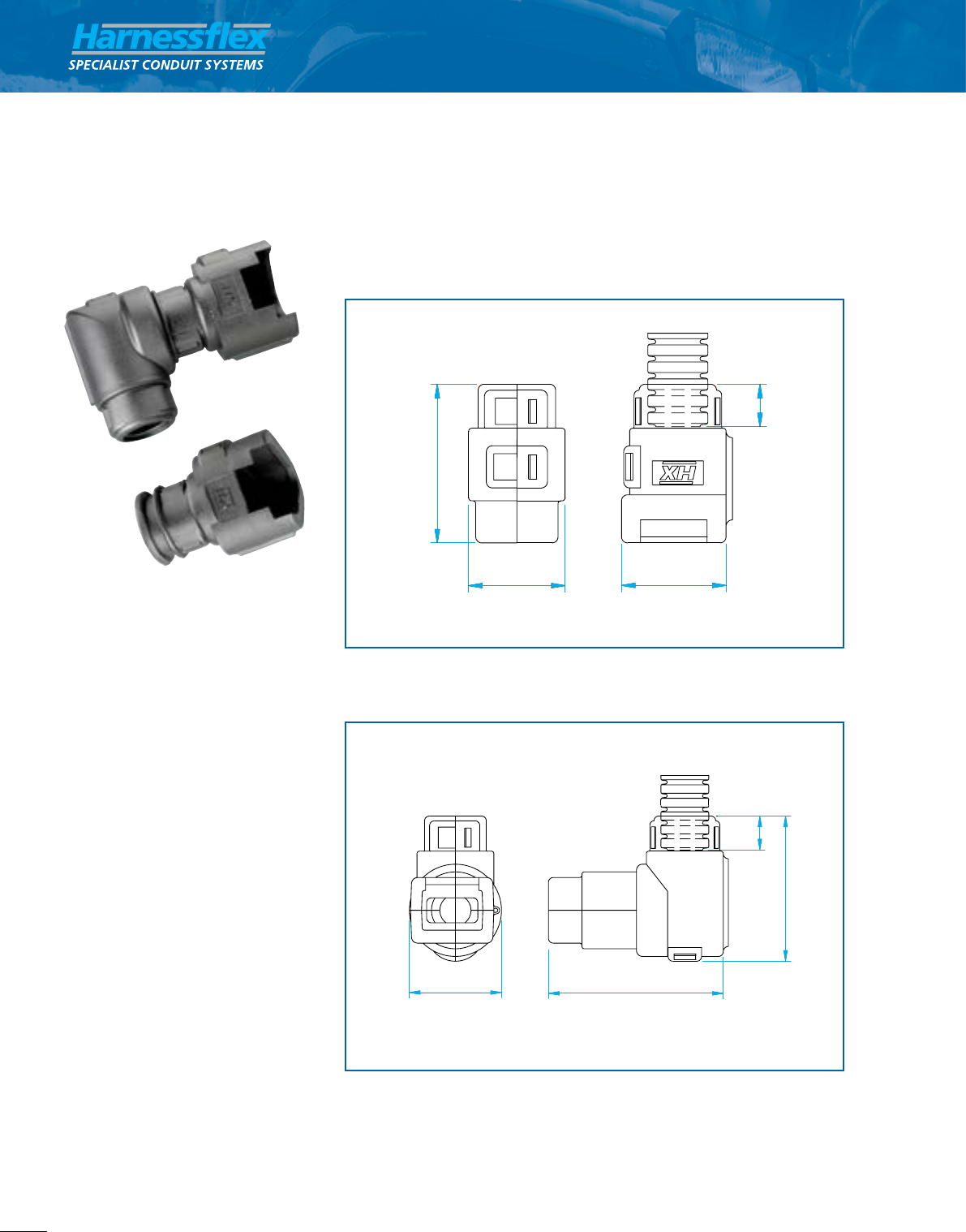
External connector interface dimensions
Configurations/part numbers
Molex MX 93286 Series External Split Connector
Interfaces
Description
Split type customised interface fittings
providing high integrity connections
to the Molex 93286 series of
connectors and Harnessflex conduit
systems.
The system offers connections to all
types of slit and un-slit Harnessflex
conduit systems multiple configurations
both straight and at right angles
to the connector to offer the maximum
flexibility and space utilisation
for harness design.
Additionally using the male type fitting
the interface can be connected to
Harnessflex hinged JPS, EPS , YPS
and TPS fitting for multiple cable
configuration outlet options.
The interfaces provide a cable routing
solution whilst also offering mechanical,
abrasion and jet washing
protection for both the connector and
cabling.
Part No Part No Conduit
straight 90° elbow Size (E)
interface interface NC NW
M28-MX93286 M28-90-MX93286 - -
CI28-MX93286 CI28-90-MX93286 28 23
CI32-MX93286 CI32-90-MX93286 32 29
CI40-MX93286 CI40-90-MX93286 40 36
*NOTE: dimensions are in mm **NOTE: other configurations available on request
Part No
straight
interface A B C D
M28-MX93286 56.6 77.5 38.3 113.2
CI28-MX93286 56.6 77.5 38.3 113.2
CI32-MX93286 56.6 77.5 38.3 113.2
CI40-MX93286 56.6 83.3 46.8 113.2
*NOTE: dimensions are in mm **NOTE: other configurations available on request

Molex Interfaces
41
Thomas & Betts • tel +44 (0)1675 468222 • www.harnessflex.com
A Member of the ABB Group
D
B
A
C
E
90° External connector interface dimensions
Configurations/part numbers
Part No
90° elbow
interface A B C D
M28-90-MX93286 43.8 66.6 38.3 125.6
CI28-90-MX93286 43.8 66.6 38.3 125.6
CI32-90-MX93286 43.8 66.6 38.3 125.6
CI40-90-MX93286 43.8 68.5 46.8 131.4
*NOTE: dimensions are in mm **NOTE: other configurations available on request
•
1
•
2
Split external design
Unrestricted bore and quick assembly no tools required
•
1
Multiple Configuration options
Provides the right conduit and outlet position option
•
2
High strength
Provides protection and security for connector and cable
outlet options without the need for short conduit joints
•
3
•
3
•
2

42
Thomas & Betts • tel +44 (0)1675 468222 • www.harnessflex.com
External connector interface dimensions
Nominal dimensions (PG Thread LK20)
Configurations/part numbers (Kostal Interface)
A
B
C
A
G B
øC
NC/NW
øD
BORE
E
F A/F
øC
NC/NW
A
B
G
D
E
F A/F
From
NC/NW
To
NC/NW
From
NC/NW
To
NC/NW
NC/NW
B
øA
C
NC/NW
øA
B
A
A
D
C
H
A
B
C
A
G B
øC
NC/NW
øD
BORE
E
F A/F
øC
NC/NW
A
B
G
D
E
F A/F
From
NC/NW
To
NC/NW
From
NC/NW
To
NC/NW
NC/NW
B
øA
C
NC/NW
øA
B
A
A
D
C
H
A B
C
A
G B
øC
NC/NW
øD
BORE
E
F A/F
øC
NC/NW
A
B
G
D
E
F A/F
From
NC/NW
To
NC/NW
From
NC/NW
To
NC/NW
NC/NW
B
øA
C
NC/NW
øA
B
A
A
D
C
H
Nominal dimensions (Kostal Interface)
Description
Clip-on elbow interface for Kostal in-line
connector.
Kostal Hinged Interfaces
Part No.
90º Elbow Conduit Size (A)
Swivel Interface (NC) (NW) B C D E
CI08-90-K2C 08 7.5 27.4 30 19.5 10
CI08-90-K3C 08 7.5 27.4 31.4 19.5 10
CI12-90-K2C 12 10 27.4 31 19.5 10
CI12-90-K3C 12 10 27.4 32.4 19.5 10
*NOTE: dimensions are in mm
Part No.
Straight Conduit Size (A)
Interface (NC) (NW) B C D E
CI16-LK20 16 13 51 28 34 10
*NOTE: dimensions are in mm
Thread Thread
Part No. Type Length A/F I.D
PG21-LK20 PG21 12.2 37.8 22.6
*NOTE: dimensions are in mm
CI08-90-K2C
CI16-LK20

Millflex Hinged ABS Interfaces
43
Thomas & Betts • tel +44 (0)1675 468222 • www.harnessflex.com
External connector interface dimensions
A
B
C
Nominal dimensions
conduit A dimensions
Part No. (NC) (NW) B C
CI08-MF2 8 7.5 35.6 10
CI10-MF2 10 8.5 35.6 10
CI12-MF2 12 10 35.6 10
*NOTE: dimensions are in mm
Description
Clip-on straight interface for Millflex
ABS connectors.
Millflex Hinged ABS Interfaces
A Member of the ABB Group
Special Customised Products
Interface dimensions
A B
C
A
G B
øC
NC/NW
øD
BORE
E
F A/F
øC
NC/NW
A
B
G
D
E
F A/F
From
NC/NW
To
NC/NW
From
NC/NW
To
NC/NW
NC/NW
B
øA
C
NC/NW
øA
B
A
A
D
C
H
Nominal dimensions
Sumitomo 4 way
Description
Single junction, straight and 90° elbow
fittings providing high integrity connections
between Sumitomo connectors and
Harnessflex conduit systems.
These fittings are designed to snap
together over all types of slit and unslit
conduit thus maintaining maximum
conduit bore.
In addition, 90° elbow versions allow the
conduit to swivel 360° around the
connector housing, sufficient to avoid the
problems associated with one-piece
interfaces of overflexing due to
movement or vibration.
Sumitomo Hinged Interface
Conduit Size Dimensions
Part No. (NC) (NW) B C D E
CI08-SU4 08 7.5 16.2 29.4 35.0 12.3
CI08-90-SU4 08 7.5 48.2 19.6 34.4 7.3
*NOTE: 180º versions are available **NOTE: dimensions are in mm

44
Thomas & Betts • tel +44 (0)1675 468222 • www.harnessflex.com
Special Customised Products
Interface dimensions
A B
C
A
G B
øC
NC/NW
øD
BORE
E
F A/F
øC
NC/NW
A
B
G
D
E
F A/F
From
NC/NW
To
NC/NW
From
NC/NW
To
NC/NW
NC/NW
B
øA
C
NC/NW
øA
B
A
A
D
C
H
A
B
C
A
G B
øC
NC/NW
øD
BORE
E
F A/F
øC
NC/NW
A
B
G
D
E
F A/F
From
NC/NW
To
NC/NW
From
NC/NW
To
NC/NW
NC/NW
B
øA
C
NC/NW
øA
B
A
A
D
C
H
Nominal dimensions
Conduit Size Dimensions
Part No. (NC) (NW) B C D
CI08-72585 08 7.5 40.9 24.9 10
CI12-72585 12 10 40.9 24.9 10
*NOTE: dimensions are in mm
Description
Circular interface to fit DIN 72585 STYLE
connectors.
Connector is free to swivel after
interface is installed.
Dimensions
Part No. A B C
BP72585 26.3 23.8 17.8
*NOTE: dimensions are in mm
Description
Plastic IP67 blanking plug to seal female
DIN 72585 circular connectors.
Prevents the ingress of water/dust,
during transport or harness storage.
DIN 72585 Hinged Interface

Special Customised Products
45
Thomas & Betts • tel +44 (0)1675 468222 • www.harnessflex.com
Hinged fitting
interface shell fitting size thread size
body size (NC) (NW)
NEPA14-16 14 16 13 13/16’’-20 UNEF
NEPA16-20 16 20 17 15/16’’-20 UNEF
NEPA24-28 24 28 23 17/16”-18 UNEF
CI20-CCU100 18/16 20 17 1’’-20 UNEF
CI20-CCU119 18/16 20 17 13/16’’-18 UNEF
CI28-CCU131 24 28 23 15/16’’-18 UNEF
CI28-CCU138 24 28 23 13/8’’-18 UNEF
*NOTE: dimensions are in mm
INTERFACE
ELBOW
STRAIGHT
'T' PIECE
'Y' PIECE
HINGED FITTING
FITTING SIZE
BORE ØD
A
ØB
C
Interface for circular connector configurations
Interface for circular connector dimensions
interface shell fitting size
body size (NC) (NW) A B C D
NEPA14-16 14 16 13 14.4 25.3 25.0 12.5
NEPA16-20 16 20 17 14.4 30.0 26.3 16.4
NEPA24-28 24 28 23 17.0 42.0 29.8 22.8
CI20-CCU100 18/16 20 17 11 30.0 26.0 16.4
CI20-CCU119 18/16 20 17 11 33.0 26.0 16.5
CI28-CCU131 24 28 23 13 41.5 30.0 22.8
CI28-CCU138 24 28 23 13 41.5 30.0 22.8
*NOTE: dimensions are in mm
Description
Fitting provides connection between
electrical circular connectors and hinged
conduit system.
Due to the innovative design, the
interface can freely rotate without any
harness movement.
These fittings are designed to snap
together over all types of slit and unslit
conduit thus maintaining maximum
conduit bore.
Interfaces for Circular Connectors
A Member of the ABB Group

46
Thomas & Betts • tel +44 (0)1675 468222 • www.harnessflex.com
Multi-way Reducers
A C
B
multiple reduced
size conduits
multi-way reducer
hinged fitting
Multi-way reducer configurations
Configuration/part numbers
Blanking caps
Description
One-piece, multi-way breakout inserts
providing reducing options to a variety
of conduit sizes from a single hinged
fitting junction.
These reducers can accomodate all types
of slit and unslit conduit and may be
used with all Harnessflex hinged fittings.
Accessories
Multi-way Reducers
Conduit Size
Part No. (NC) (NW)
BPST08 8 7.5
BP08 8 7.5
BP20 20 17
*NOTE: dimensions are in mm
Part No. To Conduit Size To Conduit Size
Multi-way From Conduit Size (NC) (NW)
Reducer (NC) (NW) A B C D A B C D
ST20-2x08 20 17 8 8 – – 7.5 7.5 – –
ST20-12 20 17 12 – – – 10 – – –
STN25-3x08 20 22 8 8 8 – 7.5 7.5 7.5 –
ST25-12 20 22 12 8 – – 10 – – –
ST25-1208 20 22 12 8 – – 10 7.5 – –
ST28-4x08 20 23 8 8 8 8 7.5 7.5 7.5 7.5
ST30-4x08 30 26 8 8 8 – 7.5 7.5 7.5 7.5
ST32-4x08 32 29 8 8 8 – 7.5 7.5 7.5 7.5
Full compatibility
Suitable for use with all Harnessflex
hinged fittings
•
1
Overcentre facility
When used with external T-pieces the
reducer is held securely in place during
harness fabrication
•
2
High pull-off strength
Reducer sits tightly into hinged fitting
junctions
•
3
•
1
•
2
•
3
Ø
Ø
176°
176°

Sealed Fittings
47
Thomas & Betts • tel +44 (0)1675 468222 • www.harnessflex.com
Sealed Fittings
A wide range of sealed fittings rated at IP66, 67, 68 (2 bar 30
mins) & 69K are available and complete the product offering
for vehicle wiring applications.
Quality & Standards
Manufacturing is controlled in accordance with BS EN ISO 9001
whilst ongoing testing & approval to international standards,
eg: UL recognition, TUV & LCIE, provides any additional
confidence required to specify appropriate Harnessflex products
across the widest variety of automotive applications including
hazardous or aggressive environments.
All components comply with End of Life Vehicle (ELV) directive
EU2000/53/EC. Harnessflex also comply to ISO14001 -
Environmental Standard
Capabilities
Through our internal design team we are able to offer
unique solutions, specific to our customers applications.
Using the latest 3D CAD modelling software we are able to
communicate new product designs quickly and efficiently.
Rapid prototype parts can be made to order to enable
product evaluation early on in thr design cycle.
If you have a requirement for a dedicated sealed fitting please
contact us to discuss your requirements.
Sealed Fittings
Hints & Tips
1. The anti-vibration spring clips can be released easily if
access is needed - no tool required.
2. In order to maintain the IP rating of the sealed
fittings face sealing washers must be used with all
threaded fittings.
3. By using an SC swivel clamping ring (page 61), an IP40
rotating joint can be achieved.
4. Our sealed T & X pieces and our sealed manifolds have
inspection covers, which can be removed during
installation to aid cable routing.
A Member of the ABB Group

48
Thomas & Betts • tel +44 (0)1675 468222 • www.harnessflex.com
Straight fitting configurations
cap nut sealing bush fitting body
flat sealing
washer
Straight fitting dimensions
A
G
C D E F
B
C
B
NC/NW
Conduit
Insertion
E
C
D D
C
B
Conduit
Insertion
E
NC/NW
A B
B
Conduit
Insertion
D
Ø C
NC/NW
A
B
Ø C
øA
B
C
NC/NW
D
C
D B
Conduit
Insertion
E
Straight swivel fitting dimensions
note: order fitting bodies, cap nuts and sealing bushes separately
Other thread options available including PF, PG, NPT and
UNEF - contact us for further information.
Description
Straight compression type fittings
incorporating fixed or swivel male
threads to provide connection to
knockouts and threaded entries.
These fittings are designed for use with
all types of slit and unslit conduit thus
maintaining maximum conduit bore.
See page 58 for details on reducing
options which enable each straight
fitting to accommodate a variety of
conduit sizes.
Order fitting bodies, cap nuts and
sealing bushes separately.
Straight Fittings
IP66/67/68 Sealing bush
Protects against ingress of water and dust
•
1
Choice of threads
Available with metric,
PG fixed male threads,
NPT & PF
•
3
Cap-nut retention ring
Ensures integrity of assembly
under extreme vibration
(suits NC10-32 size fittings)
•
2
Includes flat seal washer
Provides seal between panel/bulkhead
and fitting
•
4
•
1•
2
•
3
•
4

note: order fitting bodies, cap nuts and sealing bushes separately
Other thread options available including PF, PG, NPT and
UNEF - contact us for further information.
A B C D E F G
Min
Bore Thread A/F Size
Conduit Sizes
(NC) (NW)
Thread
Size
Part No.
Fitting Body Cap Nut
Sealing
Bush
Straight Fittings
49
Thomas & Betts • tel +44 (0)1675 468222 • www.harnessflex.com
Nominal dimensions (metric versions)
A B C D E F G
Min
Bore Thread A/F Size
Nominal dimensions (PG versions)
Configurations/part numbers (metric versions)
Conduit Sizes
(NC) (NW)
Thread
Size
Part No.
Fitting Body Cap Nut
Sealing
Bush
AB12-M16 CN07 SRN07 10 8.5 M16x1.5
AB12-M20 CN07 SRN07 10 8.5 M20x1.5
AB12-M16 CN09 SRN09 12 10 M16x1.5
AB12-M20 CN09 SRN09 12 10 M20x1.5
AB16-M16 CN11 SRN11 16 13 M16x1.5
AB16-M20 CN11 SRN11 16 13 M20x1.5
AB20-M20 CN16 SRN16 20 17 M20x1.5
AB25-M25 CN21 SRN21 25 22 M25x1.5
AB25-M25 CN28 SRN28 28 23 M25x1.5
AB32-M32 CN32 SRN29 32 29 M32x1.5
AB40-M40 CN36 SRN36 40 36 M40x1.5
AB50-M50 CN48 SRN48 50 48 M50x1.5
*NOTE: order fitting bodies, cap nuts and sealing bushes separately
34 12 23 11 M16x1.5 22 17
37 14 23 15 M20x1.5 27 17
34 12 26 11 M16x1.5 22 17
37 14 26 15 M20x1.5 27 17
35 12 26 11 M16x1.5 27 17
37 14 26 15 M20x1.5 27 11
39 14 31 15 M20x1.5 30 20
43 15 39 19 M25x1.5 38 21
43 15 39 19 M25x1.5 38 21
49 16 46 26 M32x1.5 46 27
59 16 58 31 M40x1.5 59 35
59 16 72 41 M50x1.5 73 35
*NOTE: dimensions are in mm and refer to an overall assembly
Nominal dimensions (swivel metric versions)Configurations/part numbers (swivel metric versions)
ABS12-M16 CN07 SRN07 10 8.5 M16x1.5
ABS12-M20 CN07 SRN07 10 8.5 M20x1.5
ABS12-M16 CN09 SRN09 12 10 M16x1.5
ABS12-M20 CN09 SRN09 12 10 M20x1.5
ABS16-M16 CN11 SRN11 16 13 M16x1.5
ABS16-M20 CN11 SRN11 16 13 M20x1.5
ABS20-M20 CN16 SRN16 20 17 M20x1.5
ABS25-M25 CN21 SRN21 25 22 M25x1.5
ABS25-M25 CN28 SRN28 28 23 M25x1.5
ABS32-M32 CN32 SRN29 32 29 M32x1.5
*NOTE: order fitting bodies, cap nuts and sealing bushes separately
**Other thread options available including PF, PG, NPT and UNEF - contact us
for further information
44.5 11 23 12 M16x1.5 24 17
44.5 11 23 12 M20x1.5 24 17
44.5 11 23 12 M16x1.5 24 17
44.5 11 23 12 M20x1.5 24 17
46.5 12 26 12 M16x1.5 30 20
44.5 11 26 12 M20x1.5 30 20
47 11 31 16 M20x1.5 33 22.5
52 12 39 19 M25x1.5 42.5 22.5
52 12 39 19 M25x1.5 42.5 22.5
58.5 17 46.5 26.5 M32x1.5 51 26
*NOTE: dimensions are in mm and refer to an overall assembly
AB12-PG09 CN07 SRN07 10 8.5 PG09
AB12-PG11 CN07 SRN07 10 8.5 PG11
AB12-PG13 CN07 SRN07 10 8.5 PG13.5
AB12-PG09 CN09 SRN09 12 10 PG09
AB12-PG11 CN09 SRN09 12 10 PG11
AB12-PG13 CN09 SRN09 12 10 PG13.5
AB16-PG09 CN11 SRN11 16 13 PG09
AB16-PG11 CN11 SRN11 16 13 PG11
AB16-PG13 CN11 SRN11 16 13 PG13.5
AB20-PG16 CN16 SRN16 20 17 PG16
AB25-PG21 CN21 SRN21 25 22 PG21
AB25-PG21 CN28 SRN28 28 23 PG21
AB32-PG29 CN32 SRN32 32 29 PG29
AB40-PG36 CN36 SRN36 40 36 PG36
AB50-PG48 CN48 SRN48 50 48 PG48
*NOTE: order fitting bodies, cap nuts and sealing bushes separately
**Part numbers for NPT and PF threads available on request
Configurations/part numbers (PG versions)
32 10 23 10 PG09 22 17
32 10 23 14 PG11 22 17
32 10 23 16 PG13.5 22 17
32 10 23 10 PG09 22 17
32 10 23 14 PG11 22 17
32 10 26 16 PG13.5 27 17
32 10 26 10 PG09 27 17
32 10 26 14 PG11 27 17
32 10 26 16 PG13.5 27 17
35 11 31 18 PG16 30 20
40 12 39 23 PG21 38 21
40 12 39 23 PG21 38 21
45 12 46 31 PG29 46 27
55 12 58 38 PG36 59 35
55 12 72 50 PG48 73 35
*NOTE: dimensions are in mm and refer to an overall assembly
A B C D E F G
Min
Bore Thread A/F Size
Conduit Sizes
(NC) (NW)
Thread
Size
Part No.
Fitting Body Cap Nut
Sealing
Bush
A Member of the ABB Group

50
Thomas & Betts • tel +44 (0)1675 468222 • www.harnessflex.com
In-line Hinged Circular Manifolds
90º elbow configurations
cap nut sealing bush fitting body
face sealing washer
A
C
H
D
E
F
G
B
90º fitting dimensions
C
B
NC/NW
Conduit
Insertion
E
C
D D
C
B
Conduit
Insertion
E
NC/NW
A B
B
Conduit
Insertion
D
Ø C
NC/NW
A
B
Ø C
øA
B
C
NC/NW
D
C
D B
Conduit
Insertion
E
A
C
H
D
E
F
G
B
90º swivel fitting dimensions
Description
90° compression type fittings
incorporating fixed or swivel male
threads to provide connection to
knockouts and threaded entries.
These fittings are designed for use with
all types of slit and unslit conduit thus
maintaining maximum conduit bore.
See page 58 for details on reducing
options which enable each straight
fitting to accommodate a variety of
conduit sizes.
Order fitting bodies, cap nuts and
sealing bushes separately.
90º elbows
IP66, IP67 & IP68 Sealing
SRN sealing bush protects against ingress
of water and dust
•
1
90˚ swept elbow
Avoids cable
damage and
abrasion
•
3
Cap-nut retention ring
Ensures integrity of assembly
under extreme vibration
(suits NC10-32 size elbows)
•
2
Choice
of threads
Available with
metric, PG fixed
male threads and
optional face
sealing washer
•
4
•
1
•
2
•
3
•
4

90º Elbows
51
Thomas & Betts • tel +44 (0)1675 468222 • www.harnessflex.com
Nominal dimensions (metric versions)
A B C D E F G H
Min
Bore Thread
Nominal dimensions (PG versions)
Conduit Sizes
(NC) (NW)
Thread
Size
Part No.
Elbow Body
Cap Nut Sealing
Bush
Face Sealing
Sasher
AB12-M16-90 CN07 SRN07 SWM16 10 8.5 M16x1.5
AB12-M16-90 CN09 SRN09 SWM16 12 10 M16x1.5
AB12-M20-90 CN09 SRN09 SWM20 12 10 M20x1.5
AB16-M16-90 CN11 SRN11 SWM16 16 13 M16x1.5
AB16-M20-90 CN11 SRN11 SWM20 16 13 M20x1.5
AB20-M20-90 CN16 SRN16 SWM20 20 17 M20x1.5
AB25-M25-90 CN21 SRN21 SWM25 25 22 M25x1.5
AB25-M25-90 CN28 SRN28 SWM25 25 23 M25x1.5
AB32-M32-90 CN32 SRN29 SWM32 32 29 M32x1.5
AB40-M40-90 CN36 SRN36 SWM40 40 36 M40x1.5
AB50-M50-90 CN48 SRN48 SWM50 50 48 M50x1.5
*NOTE: order elbow bodies, cap nuts, sealing bushes separately
Configurations/part numbers (metric versions)
AB12-PG09-90 CN07 SRN07 SWPG09 10 8.5 PG09
AB12-PG09-90 CN09 SRN09 SWPG09 12 10 PG09
AB16-PG11-90 CN11 SRN11 SWPG11 16 13 PG11
AB16-PG13-90 CN11 SRN13 SWPG13 16 13 PG13.5
AB20-PG16-90 CN16 SRN16 SWPG16 20 17 PG16
AB25-PG21-90 CN21 SRN21 SWPG21 25 22 PG21
AB25-PG21-90 CN28 SRN21 SWPG21 28 23 PG21
AB32-PG29-90 CN32 SRN29 SWPG29 32 29 PG29
AB40-PG36-90 CN36 SRN36 SWPG36 40 36 PG36
AB50-PG48-90 CN48 SRN48 SWPG48 50 48 PG48
*NOTE: order elbow bodies, cap nuts, sealing bushes and face sealing washers separately
Configurations/part numbers (PG versions)
46 12 23 11 M16x1.5 19 46 17
46 12 23 11 M16x1.5 19 46 17
46 12 23 11 M20x1.5 19 46 17
46 12 26 15 M16x1.5 22 48 17
46 13 26 15 M20x1.5 27 49 17
47 13 31 15 M20x1.5 27 51 20
56 15 39 20 M25x1.5 33 62 21
56 15 39 20 M25x1.5 33 62 21
66 16 46 26 M32x1.5 40 76 27
77 16 59 34 M40x1.5 48 93 35
94 16 72 40 M50x1.5 59 114
35*NOTE: dimensions are in mm and refer to an overall assembly
46 10 23 11 PG09 22 44 17
46 10 23 11 PG09 22 44 17
46 10 26 14 PG11 25 46 17
46 10 26 14 PG13.5 25 46 17
46 12 31 15 PG16 28 50 20
56 12 39 22 PG21 36 59 21
56 12 39 22 PG21 36 59 21
66 12 46 29 PG29 44 72 27
79 12 58 39 PG36 54 89 35
94 12 72 51 PG48 68 110 35
Nominal dimensions (swivel metric versions)
ABS12-M16-90 CN07 SRN07 SWM16 10 8.5 M16x1.5
ABS16-M16-90 CN11 SRN11 SWM16 16 13 M16x1.5
ABS20-M20-90 CN16 SRN16 SWM20 20 17 M20x1.5
ABS25-M25-90 CN21 SRN21 SWM25 25 22 M25x1.5
ABS32-M32-90 CN32 SRN29 SWM32 32 29 M32x1.5
ABS40-M40-90 CN36 SRN36 SWM40 40 36 M40x1.5
ABS50-M50-90 CN48 SRN48 SWM50 50 48 M50x1.5
*NOTE: order elbow bodies, cap nuts, sealing bushes and face sealing washers separately.
**Other thread options available including PF, PG, NPT and UNEF - contact us for further information.
Configurations/part numbers (swivel metric versions)
45 12 23 12 M16x1.5 24 45 17
46 12 26 12 M16x1.5 24 46 17
48 11 31 16 M20x1.5 27 48 20
56 12 39 19 M25x1.5 34 59 21
66 17 46 26 M32x1.5 42 71 27
76 18 59 35 M40x1.5 54 90 35
92 16 72 45 M50x1.5 70 112 35
A B C D E F G H
Min
Bore Thread
Conduit Sizes
(NC) (NW)
Thread
Size
Part No.
Elbow Body
Cap Nut Sealing
Bush
Face Sealing
Sasher
A B C D E F G H
Min
Bore Thread
Conduit Sizes
(NC) (NW)
Thread
Size
Part No.
Elbow Body
Cap Nut Sealing
Bush
Face Sealing
Sasher
A Member of the ABB Group

52
Thomas & Betts • tel +44 (0)1675 468222 • www.harnessflex.com
90º flanges
90˚ flange configurations and nominal dimensions
Configurations/part numbers (metric versions)
flange body
sealing bush
cap nut
Nominal dimensions
A
B
G
FH
ø6
J
E
D
C
I
Description
90° elbow compression type fittings
providing a 4 hole panel mounting
facility. These fittings are designed for
use with all types of slit and unslit
conduit thus maintaining maximum
conduit bore.
See page 58 for details on reducing
options which enable each straight
fitting to accommodate a variety of
conduit sizes.
Please note:
For extending the capability of sealed
fittings, consult us for the following:
clamping rings, end sleeves/end caps,
grommet seals, locknuts, face sealing
washers, thread reducers/enlargers.
90º flanges
Part No. Conduit Sizes Conduit Sizes
Flange Body Cap Nut Sealing Bush (NC) (NW)
AB32-F90 CN32 SRN29 32 29
AB40-F90 CN36 SRN36 40 36
AB50-F90 CN48 SRN48 50 48
*NOTE: order flange bodies, cap nuts and sealing bushes separately
Part No. Min Bore
Flange Body A B C D E F G H I J
AB32-F90 66 54 46 36 95 36 17 63 53 27
AB40-F90 86 73 63 46 115 30 27 77 64 35
AB50-F90 86 73 73 59 125 30 30 86 77 35
*NOTE: dimensions are in mm and refer to an overall assembly
IP67 Sealing bush
Protects against ingress of water and dust
•
1
90˚ flange design
Avoids cable damage
and abrasion
•
3
Cap-nut retention ring
Ensures integrity of assembly under
extreme vibration (only NC32 size flange)
•
2
Integral O ring face seal
Provides seal between
panel/bulkhead and fitting
•
4
•
1
•
2
•
3
•
4

T-Pieces
53
Thomas & Betts • tel +44 (0)1675 468222 • www.harnessflex.com
-
-
TPB20
TPB28
TPB32
*NOTE: dimensions are in mm and refer to an overall assembly
68
69
80
95
109
50
51
58
71
84
39
38
43
52
61
27
31
35
43
51
Nominal dimensions
DEF
TP12
TP16
TP20
TP28
T-piece configurations and nominal dimensions
TP12
TP12
TP16
TP20
TP28
TP28
Part No.
T-piece
with bracket
Configurations/part numbers
Sealing
Bush
CN07
CN09
CN11
CN16
CN21
CN28
CN32
SRN07
SRN09
SRN11
SRN16
SRN21
SRN28
SRN29
Cap Nut
-
-
-
TPB20
TPB28
TPB28
TPB32
*NOTE: order T-piece bodies, cap nuts and sealing bushes separately
Part No.
T-piece
no bracket
Part No.
T-piece
with bracket
Part No.
T-piece
no bracket
G
cap nut sealing bush
T-piece body
D
A
B
C
E
F
G
ø6
H
17
17
20
21
27
H
10
12
16
20
25
28
32
A
Conduit Sizes
(NC)
10
12
16
20
25
28
32
10
12
16
20
25
28
32
C
B
8.5
10
13
17
22
23
29
8.5
10
13
17
22
23
29
8.5
10
13
17
22
23
29
A
Conduit Sizes
(NW)
C
B
Description
Symmetrical, 3 junction compression
type fittings providing a variety of
conduit size configurations.
These fittings are designed for use with
all types of slit and unslit conduit thus
maintaining maximum conduit bore.
See page 58 for details on reducing
options which enable each straight
fitting to accommodate a variety of
conduit sizes.
Accessories
For extending the capability of sealed
fittings, consult us for the following:
clamping rings, end sleeves/end caps,
grommet seals, locknuts, face sealing
washers, thread reducers/enlargers.
Order T-piece bodies, cap nuts and
sealing bushes separately.
T-Pieces
A Member of the ABB Group
IP67 Sealing bush
Protects against ingress of water and dust
•
1Optional mounting bracket
Provides external fixing for larger T-pieces
•
4
Cap-nut retention ring
Ensures integrity of assembly under
extreme vibration (only NC32 size flange)
•
2Removable IP67 inspection lid
Provides easy access to cables during
installation
•
5
Smooth contoured internal form
Protects cables from damage during installation
•
3
•
1
•
2
•
3
•
4
•
5

54
Thomas & Betts • tel +44 (0)1675 468222 • www.harnessflex.com
X-Piece
X-piece configurations and dimensions
X-piece part numbers and dimensions
X-Piece
Conduit Sizes Conduit Sizes
Part No. Cap Sealing (NC) (NW)
X-Piece Nut Bush A B C D A B C D
XP20 CN16 SRN16 20 20 20 20 17 17 17 17
*NOTE: order X-piece bodies, cap nuts and sealing bushes separately
Part No.
X-Piece E F G H
XP20 80 80 35 20
*NOTE: dimensions are in mm
Nominal dimensions
Description
Symmetrical 4 junction compression
type fitting providing a variety of
conduit size configurations.
These fittings are designed for use
with all types of unslit conduit thus
maintaining maximum conduit bore.
See page 58 for details on reducing
options which enable each straight
fitting to accommodate a variety of
conduit sizes.
Accessories
For extending the capability of sealed
fittings, consult us for the following:
clamping rings, end sleeves / end caps,
grommet seals, locknuts, face sealing
washers, thread reducers / enlargers.
Order X-piece bodies, cap nuts and
sealing bushes separately.
Removable IP67 inspection lid
Provides easy access to cables during installation
•
4
Cap-nut retention ring
Ensures integrity of assembly under extreme vibration
•
2
Full compatibility
Suitable for use with all Harnessflex sealed fittings
•
Smooth contoured internal form
Protects cables from damage during installation
•
3
IP67 Sealing bush
Protects against the ingress of water and dust
•
1

•
1
•
2
•
3
•
4
•
5
Manifolds
55
Thomas & Betts • tel +44 (0)1675 468222 • www.harnessflex.com
Manifolds
Description
Asymmetrical 4 junction compression
fitting.
These fittings are designed for use with
all types of unslit conduit thus
maintaining maximum conduit bore.
Accessories
For extending the capability of sealed
fittings, consult us for the following:
clamping rings, end sleeves / end caps,
grommet seals, locknuts, face sealing
washers, thread reducers / enlargers.
Order manifold bodies, cap nuts and
sealing bushes separately.
ø6
Manifold configurations and dimensions
Configurations/part numbers
Nominal dimensions
cap nut sealing bush
manifold body
A
B B
C
DE
F
HG
Conduit Sizes Conduit Sizes
Part No. Cap Nut Sealing Bush (NC) (NW)
Manifold Body A B A B A B A B
TPM2512 CN21 CN07 SRN21 SRN07 25 10 22 8.5
TPM2512 CN21 CN09 SRN21 SRN09 25 12 22 10
TPM2512 CN28 CN07 SRN28 SRN07 28 10 23 8.5
TPM2512 CN28 CN09 SRN28 SRN09 28 12 23 10
*NOTE: order manifold bodies, cap nuts and sealing bushes separately
Part No.
Manifold Body C D E F G H
TPM2512 105 74 55 40 21 17
*NOTE: dimensions are in mm and refer to an overall assembly
A Member of the ABB Group
Integral mounting bracket
Provides secure external fixing point
•
4
Cap-nut retention ring
Ensures integrity of assembly under extreme
vibration
•
2
Removable IP67 inspection lid
Provides easy access to cables during installation
•
5
Smooth contoured internal form
Protects cables from damage during installation
•
3
IP67 Sealing bush
Protects against the ingress of water and dust
•
1
A

56
Thomas & Betts • tel +44 (0)1675 468222 • www.harnessflex.com
Circular UNEF Connector Interfaces
Conduit Sizes
(NC) (NW)
Thread
Size
Part No.
Interface
Body
Thread
Size
Part No.
Interface
Body
Cap Nut
Sealing
Bush
Face
Sealing
Washer
Configurations/part numbers
A
E
C D B
Circular connector interface dimensions
Nominal dimensions
A B C D E
MPA01 30 24 23 5/8”-24 UNEF 17
MPA03 33 36 31 1”-20 UNEF 20
MPA04 32 37 31 13/16”-18 UNEF 20
MPA05 37 44 39 17/16”-18 UNEF 21
MPA08 30 32 23 3/4”-20 UNEF 17
*NOTE: dimensions are in mm and refer to overall assembly
MPA01 CN07 SRN07 SWPG07 10 8.5 5/8”-24 UNEF
MPA01 CN09 SRN09 SWPG07 12 10 5/8”-24 UNEF
MPA03 CN16 SRN16 SWM20 20 17 1”-20 UNEF
MPA04 CN16 SRN16 SWPG16 20 17 13/16”-18 UNEF
MPA05 CN21 SRN21 SWM25 25 22 17/16”-18 UNEF
MPA05 CN28 SRN28 SWM25 28 23 17/16”-18 UNEF
MPA08 CN07 SRN07 SWPG09 10 8.5 3/4”-20 UNEF
MPA08 CN09 SRN09 SWPG09 12 10 3/4”-20 UNEF
*NOTE: order interface bodies, cap nuts, sealing bushes and sealing washers separately
Description
Straight compression type fittings
providing connection between military
style circular connections and conduit
systems.
These fittings are designed for use with
all types of unslit conduit thus
maintaining maximum conduit bore.
See page 58 for details on reducing
options which enable each straight
fitting to accommodate a variety of
conduit sizes.
Accessories
For extending the capability of sealed
fittings, consult us for the following:
clamping rings, end sleeves/end caps,
grommet seals, locknuts, face sealing
washers, thread reducers/enlargers.
Order interface bodies, cap nuts and
sealing bushes separately.
Specials available upon request,
please contact our technical
department for further details.
Circular UNEF Connector Interfaces

Solenoid Connector Interfaces
57
Thomas & Betts • tel +44 (0)1675 468222 • www.harnessflex.com
Description
Screw-thread straight and elbow
connectable interfaces for circular
solenoids, sensors and switches. These
fittings are designed for use with all
types of unslit conduit thus maintaining
maximum conduit bore. See page 58 for
details on reducing options which
enable each straight fitting to
accommodate a variety of conduit sizes.
Accessories
For extending the capability of sealed
fittings, consult us for the following:
clamping rings, end sleeves/end caps,
grommet seals, locknuts, face sealing
washers, thread reducers/enlargers.
Solenoid Connector Interfaces
Solenoid interface dimensions
Nominal dimensions
Nominal
Part Number Thread Dimensions Nut
Elbow Fitting A B C D Colour
SC-M24-90 M24x1.0 31 3 8.5 40.5 Black
SC-M27-90 M27x1.0 34 40 4 0.5 Grey
*NOTE: dimensions are in mm
Nominal
Part Number Thread Dimensions Nut
Straight Fitting A B C D Colour
SC-M24-S M24x1.0 31 53 - Black
SC-M27-S M27x1.0 34 54 - Grey
*NOTE: dimensions are in mm
Part Suitable for Number Dimensions
Number Connector Type of Pins A B C D
RSG02 M27 2 25.0 3.5 18.7 23.0
RSG03 M27 3 25.3 3.5 18.0 21.0
RSG04 M27 4 25.3 3.5 18.7 23.0
RSG05 M24 2 22.5 3.5 18.0 23.0
RSG06 M24 3 22.3 3.5 18.0 21.0
*NOTE: dimensions are in mm
RSGP01 Socket Part No. (single) RSGP01 (chain form) RSGP01-C
A Member of the ABB Group

58
Thomas & Betts • tel +44 (0)1675 468222 • www.harnessflex.com
Reducing Bushes
Configurations/nominal dimensions/part numbers
From Conduit Size To Conduit Size
Part No. Part No. NC NW NC NW
CN09-08 RSB12-08 12 10 08 7.5
CN11-08 RSB16-08 16 13 08 7.5
CN11-12 RSB16-12 16 13 12 10
CN16-08 RSB20-08 20 17 08 7.5
CN16-12 RSB20-12 20 17 12 10
CN16-16 RSB20-16 20 17 16 13
CN21-12 RSB25-12 25 22 12 10
CN21-16 RSB25-16 25 22 16 13
CN21-20 RSB25-20 25 22 20 17
CN21-12 RSB28-12 28 23 12 10
CN21-16 RSB28-16 28 23 16 13
CN21-20 RSB28-20 28 23 20 17
CN32-20 RSB32-20 32 29 20 17
CN32-25 RSB32-25 32 29 25 22
CN32-28 RSB32-28 32 29 28 23
*NOTE: dimensions are in mm
C
B
NC/NW
Conduit
Insertion
E
C
D D
C
B
Conduit
Insertion
E
NC/NW
A B
B
Conduit
Insertion
D
Ø C
NC/NW
A
B
Ø C
øA
B
C
NC/NW
D
C
D B
Conduit
Insertion
E
Cap nut and reducing sealing bushes
Reducing Bushes

Cable Glands
59
Thomas & Betts • tel +44 (0)1675 468222 • www.harnessflex.com
Description
Straight compression type cable glands
IP68 5 bar incorporating fixed male
threads to provide secure cable
connections through knockouts and
threaded entries.
Accessories
For extending the capability of
Harnessflex cable glands, see page 60
for locknuts, face sealing washers and
blanking plugs for unused entries.
Cable Glands
FEDCB
A
PG Thread A/F size
Part No.
Cable OD
Range
FEDCB
A
Thread A/F size
Part No.
Cable OD
Range
Configurations/nominal dimensions/part numbers (metric versions)
Configurations/nominal dimensions/part numbers (PG versions)
B
E
F A
C
D
23.5
27
33
45.5
55.5
68
79
21
24
30
41
50
60
70
34.5
37
40
49
55
65
67
M16x1.5
M20x1.5
M25x1.5
M32x1.5
M40x1.5
M50x1.5
M63x1.5
9
10
11
12
13
12
12
CGS-M16
CGS-M20
CGS-M25
CGS-M32
CGS-M40
CGS-M50
CGS-M63
*NOTE: OD = oustside diameter **NOTE: dimensions are in mm
4.0 - 10.0
6.0 - 12.0
13.0 - 18.0
17.0 - 25.0
24.0 - 32.0
24.0 - 38.5
35.0 - 44.0
19
23.5
27
27
30
33
45.5
55.5
17
21
24
24
27
30
41
50
31
33.5
35
36
38.5
40
48
55
PG7
PG9
PG11
PG13.5
PG16
PG21
PG29
PG36
8
8
8
9
10
11
11
13
CGS-PG07
CGS-PG09
CGS-PG11
CGS-PG13
CGS-PG16
CGS-PG21
CGS-PG29
CGS-PG36
*NOTE: OD = oustside diameter **NOTE: dimensions are in mm
2.0 - 6.5
4.0 - 10.0
6.0 - 12.0
6.0 - 12.0
10.0 - 14.0
13.0 - 18.0
17.0 - 25.0
24.0 - 32.0
Cable gland configurations
A Member of the ABB Group

60
Thomas & Betts • tel +44 (0)1675 468222 • www.harnessflex.com
Locknuts & Face Sealing Washers
Accessories
Locknut dimensions
Face sealing washer dimensions
A
B
Part No. Thread size A B (A/F)
LNP-M16 M16x1.5 7 19
LNP-M20 M20x1.5 8 23
LNP-M25 M25x1.5 9 28
LNP-M32 M32x1.5 9 36
LNP-M40 M40x1.5 10 46
LNP-M50 M50x1.5 10 60
Face sealing washer
Part No. Thread A
SWM16 M16 1.5
SWM20 M20 1.5
SWM25 M25 1.5
SWM32 M32 1.5
SWM40 M40 1.5
SWM50 M50 1.5
Part No. Thread size A
SWPG07 PG07 1.2
SWPG09 PG09 1.2
SWPG11 PG11 1.2
SWPG13 PG13.5 1.2
SWPG16 PG16 1.2
SWPG21 PG21 1.2
SWPG29 PG29 1.2
SWPG36 PG36 1.2
SWPG48 PG48 1.2
Part No. Thread size A B (A/F)
LNP-PG07 PG07 5 19
LNP-PG09 PG09 5 22
LNP-PG11 PG11 5 24
LNP-PG13 PG13.5 6 27
LNP-PG16 PG16 6 30
LNP-PG21 PG21 7 36
LNP-PG29 PG29 7 46
LNP-PG36 PG36 9 56
LNP-PG48 PG48 9 59
Integral cable tie grooves
With twin location points to assist
fixing to conduit or connector
•
1Multiple cable carrying capacity
Provides cable breakout facility in
situations where sealing is not required
•
3
Internal location lip
Provides internal protection
during cable installation
•
2
•
1
•
2
•
3
•
1
•
4
Part Conduit Size Outlet Dia Nominal Dimensions
Number NC NW Range A B C
ESN12 12 10 4 - 8 28 17 19
ESN16 16 13 5 - 9 35 17 23
ESN20 20 17 7 - 14 42 20 28
ESN25 25 22 9 - 17 50 21 31
ESN28 28 23 14 - 22 50 21 34
ESN32 32 29 16 - 32 53 27 40
ESN40 40 36 16 - 30 56 35 50
Part Conduit Size Outlet Dia Nominal Dimensions
Number NC NW Range A B C
EK03-08 08 7.5 3 19 13 14
EK03-08 10 8.5 3 19 13 14
EK05 12 10 5 22 14 17
End caps configurations and dimensions
A
B
C
End sleeve configurations and dimensions
A
B
D
C
A
Multi-function design
Can be used as flexible conduit size
coupler or electrical connector end
cover
•
4

Part No. Thread size A
SWPG07 PG07 1.2
SWPG09 PG09 1.2
SWPG11 PG11 1.2
SWPG13 PG13.5 1.2
SWPG16 PG16 1.2
SWPG21 PG21 1.2
SWPG29 PG29 1.2
SWPG36 PG36 1.2
SWPG48 PG48 1.2
Part No. Thread size A B (A/F)
LNP-PG07 PG07 5 19
LNP-PG09 PG09 5 22
LNP-PG11 PG11 5 24
LNP-PG13 PG13.5 6 27
LNP-PG16 PG16 6 30
LNP-PG21 PG21 7 36
LNP-PG29 PG29 7 46
LNP-PG36 PG36 9 56
LNP-PG48 PG48 9 59
•
1
•
2
High pull-off strength
Split C ring design sits tightly
into conduit corrugations
•
2
Swivel capability
Converts sealed fittings into freely
rotating IP40 fittings for dynamic
applications
•
1
Accessories
61
Thomas & Betts • tel +44 (0)1675 468222 • www.harnessflex.com
Accessories
A Member of the ABB Group
Part Conduit Size Nominal Dimensions
Number NC NW A B C
CES12 12 10 8 15 16
CES16 16 13 9.5 15 18
CES20 20 17 13.5 18 25
CES28 28 23 20.5 20 32
CES32 32 29 25.7 20 38
CES40 40 36 32.3 25 46
CES50 50 48 43.7 25 58
Part Conduit Size
Number NC NW
SC16HX 16 13
SC20HX 20 17
SC28HX 28 23
SC32HX 32 29
SC40HX 40 36
SC50HX 50 48
Replaces SRN seal to provide a rotating joint.
Push in one piece fitting leaving a smooth exit from conduit when fittings not used.
Part Conduit Size
Number NC NW A
SEG12 12 10 8
SEG20 20 17 16
GROM08 8 7.5 8
GROM12 12 10 12
*Smoothbore
One piece slit insert providing abrasion protection for cables passing through a
hinged junction where conduit is not used.
C
B
NC/NW
Conduit
Insertion
E
C
D D
C
B
Conduit
Insertion
E
NC/NW
A B
B
Conduit
Insertion
D
Ø C
NC/NW
A
B
Ø C
øA
B
C
NC/NW
D
C
D B
Conduit
Insertion
E
Swivel C ring configurations and dimensions
C
B
NC/NW
Conduit
Insertion
E
C
D D
C
B
Conduit
Insertion
E
NC/NW
A B
B
Conduit
Insertion
D
Ø C
NC/NW
A
B
Ø C
øA
B
C
NC/NW
D
C
D B
Conduit
Insertion
E
End cap configurations and dimensions
C
B
NC/NW
Conduit
Insertion
E
C
D D
C
B
Conduit
Insertion
E
NC/NW
A B
B
Conduit
Insertion
D
Ø C
NC/NW
A
B
Ø C
øA
B
C
NC/NW
D
C
D B
Conduit
Insertion
E
Smooth entry grommet
configurations and dimensions

62
Thomas & Betts • tel +44 (0)1675 468222 • www.harnessflex.com
Conduit Clips
Part No. Conduit Size
Clip (NC) (NW) A B C D E F
HCB08 08 7.5 23 23 13 12 4 8
HCB12 12 10 23 23 13 12 4 8
HCB16 16 13 27 27 15 14 5 9
HCB20 20 17 34 35 20 18 6 10
HCB28 28 23 44 44 23 21 6 10
HCB32 32 29 53 52 27 23 6 10
HCB40 40 36 65 63 32 27 6 10
HCB50 50 48 81 77 39 32 6 10
*NOTE: dimensions are in mm
A/F
Counter-
Bore Size
Fixing
Hole
Size
Conduit Clips
Description
One piece non-metallic conduit clips
providing secure mounting points
for conduit systems within a
Harnessflex system.
These fittings are designed to snap
together over all types of slit and unslit
conduit thus maintaining maximum
conduit bore.
Conduit with lid configurations and dimensions
B
A
D
E
F
C
Configuration/nominal dimensions/part numbers
One-piece design overcentre facility
Holds conduit securely in place during
harness fabrication
•
1
Integral hinged lid
Provides added security when
closed and can be removed if not
required
•
3
Internal conduit location step
Prevents lateral movement of
conduit even when lid is open
•
2
Integral fixing hole
Provides centre location point
with hexagonal counter-bore for
use with captive nuts
•
4
•
1
•
2
•
3
•
4

P-Clips & Modular Conduit Clips
63
Thomas & Betts • tel +44 (0)1675 468222 • www.harnessflex.com
Nominal dimensions
Conduit Clip Base Unit A B C D E F Colour
MCS22-08 MCB22 NC08 NW7.5 7 22 16 6.2 22 Black
MCS22-12 MCB22 NC12 NW10 10 25 17.5 6.2 22 Grey
*NOTE: Order base unit and conduit clip separately **NOTE: dimensions are in mm
Configuration/nominal dimensions/part numbers
Conduit Size
P-Clip (NC) (NW) A B C D E
PCS10 10 8.5 31 13 5 16 1.5
PCS12 12 10 33 13 5 17 1.5
PCS16 16 13 36 13 5 19 1.5
PCS20 20 17 41 13 5 21 1.5
PCS25 25 22 45 13 5 23 1.5
PCS32 32 29 53 13 5 27 1.5
PCS40 40 36 76 25 14 38 2.4
PCS50 50 48 86 25 14 43 2.4
*NOTE: dimensions are in mm
Metallic P-clip configurations and dimensions
B
A
C
Fixing Hole
Size
Modular conduit clip
D
metallic P-clip
E
Description
One-piece, metallic P-clips providing
secure mounting points for conduit
systems within a harness installation.
These clips are designed to accomodate
all Harnessflex slit and unslit conduits.
Description
One-piece, non metallic conduit clips
providing secure mounting points
for conduit systems within a
harness installation.
Base unit provides a strong and secure
location, while rotating conduit clip
prevents detatchment through vibration.
These clips are designed to snap
together and securely locate Harnessflex
slit and unslit conduits.
Conduit Clips
A
B
Conduit Clip
Base Unit
D
C
øF
øE
A
B
Conduit Clip
Base Unit
D
C
øF
øE
A Member of the ABB Group

64
Thomas & Betts • tel +44 (0)1675 468222 • www.harnessflex.com
Storage Recommendation
Storage recommendation for polyamide products
Polyamide is widely and successfully used for products in the
electrical and electronics industries. Thanks to its excellent
mechanical and physical properties over a wide range of
application temperatures and its very good weather
resistance, polyamide can be used to make products for
interior and external use that meet the most stringent
of demands.
As a hygroscopic material, polyamide has the ability to absorb
moisture in molecular form into the plastic matrix. As the
moisture content goes up, product properties may change
slightly. Absorbed water acts as a plasticiser reducing
strengths and moduli and increasing the toughness of the
polyamide.
Although at room temperature the stiffness and strength of
PA6 is more reduced by the moisture uptake than those of
PA66, this difference can be considered to be non-significant.
PA6 absorbs more water than PA66, especially under high
humidity conditions. But the resulting dimensional change is
still of a similar order.
The following chart shows how the moisture content of
polyamides comes into balance with the ambient air in a
normal climate of 50% relative humidity and 23°C:
Material In air (23°C / 50% rh)
Polyamide 6 3.0-3.5% by weight
Polyamide 66 2.5-3.0% by weight
To maintain balanced moisture content, Harnessflex
recommends storing products under the following
conditions:
Storage temp Processing temp. Rel. humidity
18°C to 30°C >18°C >30%
At lower processing temperatures and in particular when
subjected to unnatural drying, corrugated pipes display
increased flexural rigidity.
In the very dry winter months the moisture balance may go
down slightly as the material releases moisture to the
environment (owing to lower relative humidity). Compared to
natural outdoor conditions* at around 0°C (40... 80% rh),
the humidity in heated rooms may drop by half to below
20% rh if no humidification is present. (Even extremely dry
regions such as the Sahara Desert record average humidity of
20% to 60% rh.) (*Central European climate.)
If products from an outside environment are brought into a
heated processing area, the change in
climate may suddenly cause temporary de-moisturisation
around the edges. After one or two days in the
processing area a natural balance will be restored.
Observing this storage recommendation ensures optimum
processability and material properties
12
10
8
6
4
2
0
0 20 40 60 80
PA66
PA6
PPA
Relative humidity %
Equilibrium moisture content %
Storage Recommendation
for Polyamide Products
PA46

Index of Ingress Protection
65
Thomas & Betts • tel +44 (0)1675 468222 • www.harnessflex.com
IP suitability ratings are a system for classifying the degree of protection provided by enclosures of electrical equipment. The higher the number, the greater
the degree of protection; they apply ONLY to properly installed equipment. The numerals stand for the following:
Protection against Solid Bodies
Degree of protection for persons against access to hazardous parts inside
the enclosure and/or against the ingress of solid foreign objects.
Protection against Water
Degree of protection of equipment inside enclosures against damage from
the ingress of water.
0No protection
Ingress Protection (IP) Rating according to EN 60529/DIN 40050
IP68 IP68
1Objects greater than 50 mm, accidental touch by hands
2Objects greater than 12 mm, accidental touch by fingers
3Objects greater than 2.5 mm, e.g. tools/wires
4Objects greater than 1 mm, e.g. tools/wires/small wires
5Protected against dust - limited ingress (no harmful deposits)
6Totally protected against dust (Dust-tight)
0No protection
1Protected against vertically falling drops of water
2Protected against direct sprays of water up to 15°
from vertical
3Protected against sprays of water to 60° from vertical
4Protected against water sprayed from all directions -
limited ingress permitted
5Protected against low pressure jets of water from all
directions - limited ingress permitted
6Protected against strong pressure jets of water, heavy
seas- limited ingress permitted
7Protection against the Effects of immersion between
15cm - 1 m
8Protection against long periods of immersion under a
quoted pressure. E.g. 2 bar at 24 hours
9k IP69k Automotive standard DIN40050 and signifies
resistance to high pressure jets of water (up to 80bar)
from any angle.
The first digit stands for:
Protection against Dust
The second digit stands for:
Protection against Water
installation but is not
suitable as a rotating
joint in constantly
moving applications
rotating joint within
constantly moving
applications
IPxx suitability ratings are a system for classifying the
degree of protection provided by enclosures of electrical
equipment. The higher the number, the greater the
degree of protection, in accordance with standards
EN 60529 / DIN 40050-9.
Protection standrards
• Protection against solid bodies
• Protection against liquids
Protection against Solid Bodies Protection against Liquids
0
1
2
03
0
4
05
6
0
1
2
3
4
5
6
7
8
9
No protection
Protected against solid bodies
of 50mm and greater, (e.g. accidental
contact with the hand)
Protected against solid bodies
of 12.5mm and greater, (e.g. accidental
touch by fingers)
Protected against solid bodies
of 2.5mm and greater, (e.g. tools
and wires)
Protected against solid bodies
of 1mm or greater, (e.g. thin tools
and fine wires)
Protected against dust - limited
ingress (no harmfull deposits)
Totally protected against dust
(Dust-tight)
No protection
Protected against vertically falling
drops of water (condensation)
Protected against drops of water
falling up to 15º from the vertical
Protected against drops of water
falling up to 60º from the vertical
Protected against splashing water
from all directions
Protection against jets of water from
all directions
Protection against powerful jets of
water from all directions
Protected against the effects of
temporary immersion in water
Protected against the continuous
effects of immersion in water having
regard to specific conditions
IP69k Automotive standard DIN40050
signifies resistance to high pressure
jets (up to 80bar) from any angle
Index of
Ingress Protection
IP suitability ratings are a system for classifying the degree of protection provided by enclosures of electrical equipment. The higher the number, the greater
the degree of protection; they apply ONLY to properly installed equipment. The numerals stand for the following:
Protection against Solid Bodies
Degree of protection for persons against access to hazardous parts inside
the enclosure and/or against the ingress of solid foreign objects.
Protection against Water
Degree of protection of equipment inside enclosures against damage from
the ingress of water.
0No protection
Ingress Protection (IP) Rating according to EN 60529/DIN 40050
IP68 IP68
1Objects greater than 50 mm, accidental touch by hands
2Objects greater than 12 mm, accidental touch by fingers
3Objects greater than 2.5 mm, e.g. tools/wires
4Objects greater than 1 mm, e.g. tools/wires/small wires
5Protected against dust - limited ingress (no harmful deposits)
6Totally protected against dust (Dust-tight)
0No protection
1Protected against vertically falling drops of water
2Protected against direct sprays of water up to 15°
from vertical
3Protected against sprays of water to 60° from vertical
4Protected against water sprayed from all directions -
limited ingress permitted
5Protected against low pressure jets of water from all
directions - limited ingress permitted
6Protected against strong pressure jets of water, heavy
seas- limited ingress permitted
7Protection against the Effects of immersion between
15cm - 1 m
8Protection against long periods of immersion under a
quoted pressure. E.g. 2 bar at 24 hours
9k IP69k Automotive standard DIN40050 and signifies
resistance to high pressure jets of water (up to 80bar)
from any angle.
The first digit stands for:
Protection against Dust
The second digit stands for:
Protection against Water
installation but is not
suitable as a rotating
joint in constantly
moving applications
rotating joint within
constantly moving
applications
The first digit stands for
protection against
solid bodies
The second digit
stands for protection
against water
IP Classification
IP
IP suitability ratings are a system for classifying the degree of protection provided by enclosures of electrical equipment. The higher the number, the greater
the degree of protection; they apply ONLY to properly installed equipment. The numerals stand for the following:
Protection against Solid Bodies
Degree of protection for persons against access to hazardous parts inside
the enclosure and/or against the ingress of solid foreign objects.
Protection against Water
Degree of protection of equipment inside enclosures against damage from
the ingress of water.
0No protection
Ingress Protection (IP) Rating according to EN 60529/DIN 40050
IP68 IP68
1Objects greater than 50 mm, accidental touch by hands
2Objects greater than 12 mm, accidental touch by fingers
3Objects greater than 2.5 mm, e.g. tools/wires
4Objects greater than 1 mm, e.g. tools/wires/small wires
5Protected against dust - limited ingress (no harmful deposits)
6Totally protected against dust (Dust-tight)
0No protection
1Protected against vertically falling drops of water
2Protected against direct sprays of water up to 15°
from vertical
3Protected against sprays of water to 60° from vertical
4Protected against water sprayed from all directions -
limited ingress permitted
5Protected against low pressure jets of water from all
directions - limited ingress permitted
6Protected against strong pressure jets of water, heavy
seas- limited ingress permitted
7Protection against the Effects of immersion between
15cm - 1 m
8Protection against long periods of immersion under a
quoted pressure. E.g. 2 bar at 24 hours
9k IP69k Automotive standard DIN40050 and signifies
resistance to high pressure jets of water (up to 80bar)
from any angle.
The first digit stands for:
Protection against Dust
The second digit stands for:
Protection against Water
installation but is not
suitable as a rotating
joint in constantly
moving applications
rotating joint within
constantly moving
applications
67
7=
A Member of the ABB Group

66
Thomas & Betts • tel +44 (0)1675 468222 • www.harnessflex.com
Nylon (PA) 6
Nylon (PA) 6 - Used on: All Harnessflex NC and CTPA nylon conduits
Properties Test Method Value Unit
General
Density ISO 1183 1.13 g/cm3
Melting Point ISO 11357-1/-3 220 °C
Mechanical
Tensile Strength ISO 527 55 (con) MPa
Elongation at break ISO 527 >50 (con) %
Youngs Modulus ISO 527 3100 (Dry) MPa
Charpy impact strength ISO 179 DNB (Dry) kJ/m2
Charpy notched impact strength 11 (Dry) kJ/m2
IZOD impact strength ISO 180C DNB (Dry) kJ/m2
IZOD notched impact strength ISO 180A 4 (Dry) kJ/m2
Thermal
Heat Distortion Temperature-A ISO 75 100 °C
Heat Distortion Temperature-B ISO 75 >200 °C
Flammability
Flammability UL94 HB N/A
Electrical
Dielectric strength IEC 243 14 (Dry) MV/m
Surface Resistivity IEC 93 15 (Dry) log10Ω
Volume Resistivity IEC 93 15 (Dry) log10Ω
Comparative Tracking Index IEC 112 >600 V
Notes
DNB = Did not break, Dry = Dry as moulded, Con = Conditioned 168hrs @ 23°C, 50 % RH.
All tests undertaken at 23°C where applicable.
Chemical resistance
Nylon 6 Harnessflex conduits are resistant to all underbonnet oils, greases, fuels, cleaning fluids and synthetic fluids.
Like all Nylons they are resistant to weak acids but not resistant to strong or oxidizing acids.
Peek (PolyEtheretherKetone)
PEEK (PolyEtheretherKetone) - Used on: PKC conduit
Properties Test Method Value Unit
General
Density ISO 1183 1.32 g/cm3
Melting Point DEC 343 °C
Mechanical
Tensile Strength ISO 527 97 MPa
Elongation at break ISO 527 <60 %
Youngs Modulus ISO 527 3600 MPa
Charpy impact strength 2mm notch ISO 179 35 kJ/m2
Charpy impact 0.25mm notch ISO179 8.2 kJ/m2
IZOD impact strength ISO 180 DNB kJ/m2
IZOD impact strength 0.25mm notch ISO 180 6.4 kJ/m2
Thermal
Heat Distortion Temperature-A ISO 75 152 °C
Heat Distortion Temperature-B ISO 75 °C
Flammability
Flammability UL94 V0 N/A

Material Data Sheet
67
Thomas & Betts • tel +44 (0)1675 468222 • www.harnessflex.com
Electrical
Dielectric strength IEC 243 190 kV/m-1
Surface Resistivity IEC 93
Volume Resistivity IEC 93 4.9 1016Ω cm
Comparative Tracking Index I EC 112 150 V
Notes
DNB = Did not break. All tests undertaken at 23°C where applicable. This linear aromatic polymer is semi-crystalline and is widely regarded as
the highest performance thermoplastic material currently available. A summary of key physical properties is as follows:
High Temperature Performance
PEEK polymer and compounds typically have a glass transition temperature of 143°C and a melting temperature of 343°C and a Continuous Use
Temperature of 260°C (UL 746B).
Wear Resistance
PEEK polymer has excellent friction and wear properties exhibiting outstanding wear resistance over wide ranges of pressure, velocity,
temperature and counterfacial roughness.
Chemical Resistance
PEEK polymer has excellent resistance to a wide range of chemical environments, even at elevated temperatures. The only common environment
which dissolves PEEK polymer is concentrated sulphuric acid.
Fire, Smoke and Toxicity
PEEK polymer is highly stable and requires no flame-retardant additives to achieve a V-0 rating at 1.4mm thickness. The composition and
inherent purity of the material results in extremely low smoke and toxic gas emission in fire situations.
Hydrolysis Resistance
PEEK polymer and compounds are not chemically attacked by water or pressurized steam. Components which are constructed from these materials
retain a high level of mechanical properties when continuously conditioned in water at elevated temperatures and pressures.
Electrical Properties
The electrical properties of PEEK™ polymer are maintained over a wide frequency and temperature.
Nylon (PA) 66 - Heat Stabilised
Nylon (PA) 66 - Heat stabilised - Used on: All Harnessflex un-reinforced nylon fittings
Properties Test Method Value Unit
General
Density ISO 1183 1.14 g/cm3
Melting Point ISO 1218 263 °C
Mechanical
Tensile Strength ISO 527 95 (Dry) MPa
Elongation at break ISO 527 23 (Dry) %
Youngs Modulus ISO 527 3400 (Dry) MPa
Flexural Modulus ISO 178 2850 (Dry) MPa
Charpy impact strength ISO 179 DNB (Dry) kJ/m2
Charpy notched impact strength 6 (Dry) kJ/m2
IZOD impact strength ISO 180C DNB (Dry) kJ/m2
IZOD notched impact strength ISO 180A 5 (Dry) kJ/m2
Thermal
Heat Distortion Temperature @1.8Mpa ISO 75-2 85 °C
Heat Distortion Temperature @ 0.45MPa ISO 75-2 230 °C
Flammability
Flammability UL94 V2 N/A
Glow wire flammability @ 1.5mm IEC 695-2-1/2 850 (Con) °C
Electrical
Dielectric strength IEC 243 60 (Dry) MV/m
Surface Resistivity IEC 60093 1E+15 Ω Ω
Volume Resistivity IEC 60093 1E+15 Ω.cm
Comparative Tracking Index IEC 60112 600 V
A Member of the ABB Group

68
Thomas & Betts • tel +44 (0)1675 468222 • www.harnessflex.com
Key
1. Moisture absorption, saturation at +23°C and 50% RH (ref. DIN53495).
2. Dry as moulded.
3. Test speed 5mm/min.
4. Test speed 1mm/min.
5. Glow wire applied during 30secs, temperature 750°C, thickness 1.6mm.
Notes
DNB = Did not break, Dry = Dry as moulded, Con = Conditioned 168hrs @ 23°C, 50 % RH.
All tests undertaken at 23°C where applicable.
Chemical resistance
Polyamide (Nylon) 66 Harnessflex fittings are resistant to all underbonnet oils, greases, fuels, cleaning and synthetic fluids. Like all Nylons they
are resistant to weak acids but not resistant to strong or oxidizing acids.
Nylon (PA) 66 - 30% Glass Fibre Filled
Nylon (PA) 66 - 30% Glass Fibre Filled - Used on SC-M27 and SC-M24 swivel nuts
Properties Test Method Value Unit
General
Density ISO 1183 1.36 g/cm3
Moisture Absorption (1) Sim to ISO 62 1.6 %
Mechanical (2)
Tensile stress at yield/break (3) ISO 527 195 N/mm2
Elongation at break ISO 527 3 %
Modulus of elasticity (4) ISO 527 10000 N/mm2
IZOD notched impact strength @ +23°C ISO 180/1A 13 kJ/m2
@ -30°C 10 kJ/m2
Thermal
Heat deflection temperature (HDT) ISO 75/A 250 °C
Ball pressure test IEC 60695-10-2 >200 °C
Flammability
Flammability (1.6mm thickness) UL94 HB
Oxygen index ISO4589 24 %
Glow wire test extinguishing time (5) IEC60695-2-1/1 <15 s
Hot wire ignition (HWI) (1.5mm thickness) IEC60695-2-20 >15 s
High current arc ignition (HAI) (0.7mm thickness) IEC60947 >120 No of arcs
Electrical (2)
Dielectric strength IEC 60243-1 >30 kV/mm
Specific surface resistivity IEC 60093 1015 Ω
Specific volume resistivity EC 60093 1015 Ω.cm
Dielectric constant @ 100Hz IEC60250 3.8
@ 1MHz 3.5
Dissipation factor @ 100Hz IEC60250 90 x10-4
@ 1MHz 160 x10-4
Comparative Tracking Index IEC 60112 600 V
Electrolytic corrosion IEC 60426 A1.2 –

Properties Test Method Value Unit
General
Density ISO 1183 0.96 g/cm3
Hardness shore A (5 sec) ISO 868 56 -
Brittleness temperature ISO 812 -62 °C
Flammability UL94 HB -
Stress/strain properties ISO 37 (II)
Flow Direction
Tensile strength 3.8 MPa
Modulus 100% 2.7 MPa
Elongation at break 280 %
cross direction
Tensile strength 5.1 MPa
Modulus 100% 1.9 MPa
Elongation at break 470 %
Tear Strength (cross direction)
Trouser ISO 34 A 7 kN/m
Un-nicked angle ISO 34 B (a) 22 kN/m
Compression set ISO 815
72h/23°C 22 %
72h/70°C 26 %
72h/100°C 34 %
Hot Air Ageing ISO 188
1000h/125°C
Change in hardness 2 pts
Retention tensile strength 90 %
Retention - elongation at break 96 %
336h/150°C
Change in hardness 0 pts
Retention tensile strength 90 %
Retention elongation at break 87 %
Volume swell ISO 1817
72h/100°C water +3 %
168h/100°C ASTM oil 1 +43 %
168h/100°C ref fuel B +91 %
Notes
Tests are conducted on injection moulded plaques. All tests undertaken at 23°C where applicable.
Chemical resistance
TPV fittings are resistant to:
Water, acids, ethanol, glycerol, methanol and propanol, hydraulic brake fluid and antifreeze.
Large volume swell (>60%) is experienced with certain oils and fuels.
Approvals
Individual parts are approved to different standards including NFR 13-903. Others are manufacturer specific or are new
developments and may not be approved to certain standards. Please contact the technical office for specific enquiries.
Material Data Sheet
69
Thomas & Betts • tel +44 (0)1675 468222 • www.harnessflex.com
SRN SWM SEG ESN EK
Thermoplastic Elastomer TPV
Thermoplastic Elastomer TPV - Used on: sealing products
A polypropylene based elastomer designed primarily for demanding automotive applications. This material exhibits excellent
compression set, flex fatigue and high and low temperature performance.
A Member of the ABB Group

70
Thomas & Betts • tel +44 (0)1675 468222 • www.harnessflex.com
12-GT284 39
16-90-DTP04 34
16-FC114 36
16-GT284 39
28TY62 31
AB12-M16 49
AB12-M16-90 51
AB12-M20 49
AB12-M20-90 51
AB12-PG09 49
AB12-PG09-90 51
AB12-PG11 49
AB16-M16 49
AB16-M16-90 51
AB16-M20 49
AB16-M20-90 51
AB16-PG11 49
AB16-PG11-90 51
AB16-PG13 49
AB16-PG13-90 51
AB20-M20 49
AB20-M20-90 51
AB20-PG16 49
AB20-PG16-90 51
AB25-M25 49
AB25-M25-90 51
AB25-PG21 49
AB25-PG21-90 51
AB32-F90 52
AB32-M32 49
AB32-M32-90 51
AB32-PG29 49
AB32-PG29-90 51
AB40-F90 52
AB40-M40 49
AB40-M40-90 51
AB40-PG36 49
AB40-PG36-90 51
AB50-F90 52
AB50-M50 49
AB50-M50-90 51
AB50-PG48 49
AB50-PG48-90 51
ABS12-M16 49
ABS12-M20 49
ABS16-M16 49
ABS16-M20 49
ABS20-M20 49
ABS25-M25 49
ABS32-M32 49
BP72585 44
BPST08 46
BP08 46
BP20 46
CES12 61
CES16 61
CES20 61
CES28 61
CES32 61
CES40 61
CES50 61
CGS-M16 59
CGS-M20 59
CGS-M25 59
CGS-M32 59
CGS-M40 59
CGS-M50 59
CGS-M63 59
CGS-PG07 59
CGS-PG09 59
CGS-PG11 59
CGS-PG13 59
CGS-PG16 59
CGS-PG21 59
CGS-PG29 59
CGS-PG36 59
CI08-72585 44
CI08-90-AM2 29
CI08-90-AM3 29
CI08-90-AM4 29
CI08-90-AS1 28
CI08-90-AS2 28
CI08-90-AS3 28
CI08-90-AS4 28
CI08-90-AT2LP 31
CI08-90-AT2LR 31
CI08-90-AT3LP 31
CI08-90-AT3LR 31
CI08-90-AT4LP 31
CI08-90-AT4LR 31
CI08-90-AT6LP 31
CI08-90-AT6LR 31
CI08-90-AT2PL 30
CI08-90-AT3PL 30
CI08-90-AT4PL 30
CI08-90-BC2 37
CI08-90-BC3 37
CI08-90-BC4 37
C108-90-DE001 39
CI08-90-DT2 33
CI08-90-DT3 33
CI08-90-DT4 33
CI08-90-DT6 33
CI08-90-FC102 36
CI08-90-FC103 36
CI08-90-FC104 36
CI08-90-FC114 36
CI08-90-FCS02 36
CI08-90-GT153 39
CI08-90-K2C 42
CI08-90-K3C 42
CI08-90-MMP2 39
CI08-90-MP2 39
CI08-90-MP3 39
CI08-90-PTD 39
CI08-90-SU4 43
CI08-90-WP2 39
C108-90-TY002 31
CI08-AM2 29
CI08-AM3 29
CI08-AM4 29
CI08-AS1 28
CI08-AS2 28
CI08-AS3 28
CI08-AS4 28
CI08-AT2PL 30
CI08-AT3PL 30
CI08-AT4PL 30
CI08-BC2 37
CI08-BC3 37
CI08-BC4 37
C108-DE001 39
CI08-DT2 33
CI08-DT3 33
CI08-DT4 33
CI08-DT6 33
CI08-FC102 36
CI08-FC103 36
CI08-FC104 36
CI08-GT153 39
CI08-MF2 43
CI08-MMP2 39
CI08-MP2 39
CI08-MP3 39
CI08-PTD2 39
CI08-SU4 43
C108-TY002 31
CI08-WP2 39
CI10-90-AM2 29
CI10-90-AM3 29
CI10-90-AM4 29
CI10-90-AS2 28
CI10-90-AS3 28
CI10-90-AS4 28
CI10-AM2 29
CI10-AM3 29
CI10-AM4 29
CI10-AS2 28
CI10-AS3 28
CI10-AS4 28
CI10-MF2 43
CI121212-DRC50 35
CI122812-DRC50 35
CI12-72585 44
CI12-90-AM2 29
CI12-90-AM3 29
CI12-90-AM4 29
CI12-90-AS1 28
CI12-90-AS2 28
CI12-90-AS3 28
CI12-90-AS4 28
CI12-90-AT2LP 31
CI12-90-AT2LR 31
CI12-90-AT3LP 31
CI12-90-AT3LR 31
CI12-90-AT4LP 31
CI12-90-AT4LR 31
CI12-90-AT6LP 31
CI12-90-AT6LR 31
CI12-90-AT2PL 30
CI12-90-AT3PL 30
CI12-90-AT4PL 30
CI12-90-BC2 37
CI12-90-BC3 37
CI12-90-BC4 37
CI12-90-DT12 33
CI12-90-DT2 33
CI12-90-DT3 33
CI12-90-DT4 33
CI12-90-DT6 33
CI12-90-DT8 33
CI12-90-DTP04 34
CI12-90-FC102 36
CI12-90-FC103 36
CI12-90-FC104 36
CI12-90-FC114 36
CI12-90-GT153 39
CI12-90-K2C 42
CI12-90-K3C 42
CI12-90-MMP2 39
CI12-90-MP2 39
CI12-90-MP3 39
CI12-90-PTD 39
CI12-90-WP2 39
CI12-90-X01 29
CI12-AM2 29
CI12-AM3 29
CI12-AM4 29
CI12-AS1 28
CI12-AS2 28
CI12-AS3 28
CI12-AS4 28
CI12-AT12PL 30
CI12-AT4PL 30
CI12-AT6PL 30
CI12-AT8PL 30
CI12-BC2 37
CI12-BC3 37
CI12-BC4 37
CI12-DT2 33
CI12-DT3 33
CI12-DT4 33
CI12-DT6 33
CI12-DT8 33
CI12-FC102 36
CI12-FC103 36
CI12-FC104 36
CI12-FC114 36
CI12-MF2 43
CI12-X01 29
CI16-90-DT12 33
CI16-90-DT8 33
CI16-90-FC114 36
CI16-A31 26
CI16-AT12PL 30
CI16-AT8PL 30
CI16-DT12 33
CI16-FC114 36
CI16-LK20 42
CI17-FC110 36
CI201220-DRC50 35
CI202820-DRC50 35
CI20-A31 26
CI20-A31 31
CI20-AT20PL 30
CI20-CCU100 45
CI20-CCU119 45
CI251225-DRC50 35
CI252825-DRC50 35
CI25-A31 26
CI25-A31 31
CI25-FC150 36
CI28-90-BC40 37
CI28-BC40 37
CI28-CCU131 45
CI28-CCU138 45
CI28-MX93286 40
CI28-90-MX93286 41
CI32-A31 26
CI32-A31 31
CI32-MX93286 40
CI32-90-MX93286 41
CI40-MX93286 40
CI40-90-MX93286 41
CN09-08 58
CN11-08 58
CN11-12 58
CN16-08 58
CN16-12 58
CN16-16 58
CN21-12 58
CN21-16 58
CN21-20 58
CN32-20 58
CN32-25 58
CN32-28 58
CPC08 11
CPC12 11
CPC16 11
CPC20 11
CPC25 11
CPC32 11
CPC40 11
CPC50 11
CPS341212 22
CPS421212 22
CPS421616 22
CPS421620 22
CPS422020 22
CTPA08 8
CTPA08-S 9
CTPA10 8
CTPA10-S 9
CTPA12 8
CTPA12-S 9
CTPA16 8
CTPA16-S 9
CTPA20 8
CTPA20-S 9
CTPA25 8
CTPA25-S 9
CTPA28 8
CTPA28-S 9
CTPA30 8
CTPA30-S 9
CTPA32 8
CTPA32-S 9
CTPA40 8
CTPA40-S 9
CTPA50 8
CTPA50-S 9
DSPP08 13
DSPP12 13
DSPP16 13
DSPP20 13
DSPP28 13
DSPP32 13
DSPP40 13
DSPP50 13
EK03-08 60
EK05 60
EPS0820 17
EPS08S08 17
EPS12S12 17
EPS1608 17
EPS1612 17
EPS2012 17
EPS2016 17
EPS2008 17
EPS2020 17
EPS2520 17
EPS2525 17
EPS2812 17
EPS2816 17
EPS2820 17
EPS2825 17
EPS2828 17
ESN12 60
ESN16 60
ESN20 60
ESN25 60
ESN28 60
ESN32 60
ESN40 60
GROM08 61
GROM12 61
HCB08 62
HCB12 62
HCB16 62
HCB20 62
HCB28 62
HCB32 62
HCB40 62
HCB50 62
HNC08 10
HNC12 10
HNC16 10
HNC20 10
HNC25 10
HNC32 10
HNC40 10
HNC50 10
HTC12 14
HTC16 14
HTC20 14
HTC25 14
HTC28 14
HTC32 14
JPS1208 16
JPS1212 16
JPS1612 16
JPS1616 16
JPS2008 16
JPS2012 16
JPS2016 16
JPS2020 16
JPS2520 16
JPS2525 16
JPS2820 16
JPS2825 16
JPS2828 16
K21-LH 44
LNP-M16 60
LNP-M20 60
LNP-M25 60
LNP-M32 60
LNP-M40 60
LNP-M50 60
LNP-PG07 60
LNP-PG09 60
LNP-PG11 60
LNP-PG13 60
LNP-PG16 60
LNP-PG21 60
LNP-PG29 60
LNP-PG36 60
LNP-PG48 60
MCB22 63
MCS22-08 63
MCS22-12 63
MPA01 56
MPA02 56
MPA03 56
MPA04 56
MPA05 56
MPA06 56
MPA07 56
MPA08 56
MPA09 56
MPA10 56
MPA11 56
MPS100 24
MPS101 24
MPS102 24
MPS103 24
MPS121212-2020 25
MPS122812-2020 25
MPS201220-2020 25
MPS202820-2020 25
MPS251225-2020 25
MPS252825-2020 25
M28-MX93286 40
M28-90-MX93286 41
NC06 6
NC06-S 7
NC08 6
NC08-S 7
NC10 6
NC10-S 7
NC12 6
NC12-S 7
NC16 6
NC16-S 7
NC20 6
NC20-S 7
NC25 6
NC25-S 7
NC28 6
NC28-S 7
NC30 6
NC30-S 7
NC32 6
NC32-S 7
NC40 6
NC40-S 7
NC50 6
NC50-S 7
NEPA14-16 45
NEPA16-20 45
NEPA24-28 45
PCS10 63
PCS12 63
PCS16 63
PCS20 63
PCS25 63
PCS32 63
PCS40 63
PCS50 63
PG21-LK20 42
PKC12 14
PKC16 14
PKC20 14
PKC28 14
PKC32 14
PP08 12
PP10 12
PP12 12
PP16 12
PP20 12
PP25 12
PP32 12
RSB12-08 58
RSB16-08 58
RSB16-12 58
RSB20-08 58
RSB20-12 58
RSB20-16 58
RSB25-12 58
RSB25-16 58
RSB25-20 58
RSB28-12 58
RSB28-16 58
RSB28-20 58
RSB32-20 58
RSB32-25 58
RSB32-28 58
RSG02 57
RSG03 57
RSG04 57
RSG05 57
RSG06 57
SC16 61
SC20 61
SC28 61
SC32 61
SC40 61
SC50 61
SC-M24-90 57
SC-M24-S 57
SC-M27-90 57
SC-M27-S 57
SEG12 61
SEG20 61
ST20-12 46
ST20-2x08 46
ST25-12 46
ST25-1208 46
ST28-4x08 46
ST30-4x08 46
ST32-4x08 46
ST31-100 25
ST31-101 25
ST31-102 25
STN25-3x08 46
SWM16 60
SWM20 60
SWM25 60
SWM32 60
SWM40 60
SWM50 60
SWPG07 60
SWPG09 60
SWPG11 60
SWPG13 60
SWPG16 60
SWPG21 60
SWPG29 60
SWPG36 60
SWPG48 60
TP12 53
TP16 53
TP20 53
TP28 53
TP32 53
TPB20 53
TPB28 53
TPB32 53
TPM2512 55
TPS080808 19
TPS081208 19
TPS081612 19
TPS100808 19
TPS101010 19
TPS101012 19
TPS120808 19
TPS120812 19
TPS121010 19
TPS121012 19
TPS121208 19
TPS121210 19
TPS121212 19
TPS121612 19
TPS160808 19
TPS160812 19
TPS160816 19
TPS161012 19
TPS161016 19
TPS161212 19
TPS161216 19
TPS161608 19
Index
Part No. Page Part No. Page Part No. Page Part No. Page Part No. Page Part No. Page Part No. Page

Part No. Page
Interfaces
71
Thomas & Betts • tel +44 (0)1675 468222 • www.harnessflex.com
TPS161612 19
TPS161616 19
TPS162012 19
TPS162016 19
TPS200816 19
TPS200820 19
TPS201016 19
TPS201020 19
TPS201216 19
TPS201220 19
TPS201612 19
TPS201616 19
TPS201620 19
TPS202012 19
TPS202016 19
TPS202020 19
TPS202516 19
TPS250820 19
TPS250825 19
TPS251025 19
TPS251220 19
TPS251225 19
TPS251620 19
TPS251625 19
TPS252020 19
TPS252025 19
TPS252520 19
TPS252525 19
TPS280820 19
TPS280828 19
TPS281020 19
TPS281028 19
TPS281220 19
TPS281225 19
TPS281228 19
TPS281620 19
TPS281625 19
TPS281628 19
TPS282020 19
TPS282025 19
TPS282028 19
TPS282525 19
TPS300830 19
TPS301230 19
TPS301625 19
TPS301630 19
TPS302016 19
TPS302020 19
TPS302025 19
TPS302030 19
TPS302525 19
TPS303025 19
TPS303030 19
TPS321632 19
TPS282528 19
TPS282828 19
TPS321625 19
TPS321632 19
TPS322025 19
TPS322028 19
TPS322032 19
TPS322525 19
TPS322532 19
TPS323225 19
TPS323232 19
TPS401232 19
TPS401240 19
TPS401632 19
TPS401640 19
TPS402040 19
TPS402540 19
TPS402840 19
TPS404032 19
TPS404040 19
XP20 54
XPS1208 23
YPS080808 21
YPS080812 21
YPS081208 21
YPS101010 21
YPS120808 21
YPS120810 21
YPS121010 21
YPS121208 21
YPS121210 21
YPS121212 21
YPS160812 21
YPS161010 21
YPS161208 21
YPS161210 21
YPS161212 21
YPS161608 21
YPS161610 21
YPS161612 21
YPS200808 21
YPS201208 21
YPS201210 21
YPS201212 21
YPS201608 21
YPS201612 21
YPS201616 21
YPS202008 21
YPS202010 21
YPS202012 21
YPS202016 21
YPS252012 21
YPS252016 21
YPS252020 21
YPS252508 21
YPS252510 21
YPS252512 21
YPS252516 21
YPS252520 21
YPS252525 21
YPS282012 21
YPS282016 21
YPS282020 21
YPS282512 21
YPS282516 21
YPS282520 21
YPS282525 21
YPS282808 21
YPS282812 21
YPS282816 21
YPS282820 21
YPS282825 21
YPS282828 21
YPS322032 21
YPS322516 21
YPS322520 21
YPS322525 21
YPS322532 21
YPS323216 21
YPS323220 21
YPS323225 21
YPS323232 21
YPS403212 21
YPS403216 21
YPS403225 21
YPS403228 21
YPS404012 21
YPS404016 21
YPS404025 21
YPS404028 21
YPS404032 21
YPS404040 21
Part No. Ref No. Notes
• All Colour and Wire • All Bosch Kompact • All Colour • All Colour and Key
CI08-180-K2C
CI08-72585
CI08-90-AM2 347887-3 •
CI08-90-AM3 1-827578-1 •
CI08-90-AM4 281804-1 •
CI08-90-AS1 282079-2 •
CI08-90-AS2 282080-1 •
CI08-90-AS3 282087-1 •
CI08-90-AS4 282088-1 •
CI08-90-AT2LP 776427-1 •
CI08-90-AT2LR
CI08-90-AT2PL 776427-1 •
CI08-90-AT3LP 776427-1 •
CI08-90-AT3LR
CI08-90-AT3PL 776427-1 •
CI08-90-AT4LP 776487-1 •
CI08-90-AT4LR
CI08-90-AT4PL 776487-1 •
CI08-90-AT6LP 776433-1 •
CI08-90-AT6LR
CI08-90-BC2 1 928 403 137 •
CI08-90-BC3 1 928 403 110 •
CI08-90-BC4 1 928 403 112 •
CI08-90-DE001
CI08-90-DT2 DT06-2S •
CI08-90-DT2C
CI08-90-DT3 DT06-3S •
CI08-90-DT4 DT06-4S •
CI08-90-DT6 DT06-6S •
CI08-90-FCI02
CI08-90-FCI03
CI08-90-FCI04
CI08-90-FCI14
CI08-90-FCS02
CI08-90-GT153
CI08-90-K2C
CI08-90-K3C
CI08-90-MMP2
CI08-90-MP2
CI08-90-MP3
CI08-90-NV001
CI08-90-PTD2
CI08-90-S
CI08-90-SU4
CI08-90-WP2
CI08-AM2 347887-3 •
CI08-AM3 1-827578-1 •
CI08-AM4 281804-1 •
CI08-AS1 282079-2 •
CI08-AS2 282080-1 •
CI08-AS3 282087-1 •
CI08-AS4 282088-1 •
CI08-AT2PL 776427-1 •
CI08-AT3PL 776427-1 •
CI08-AT4PL 776487-1 •
CI08-AT6PL 776433-1 •
CI08-BC2 1 928 403 137 •
CI08-BC3 1 928 403 110 •
CI08-BC4 1 928 403 112 •
CI08-DE001 12078090
CI08-DT2 DT06-2S •
CI08-DT3 DT06-3S •
CI08-DT6 DT06-6S •
CI08-F2W
CI08-FCI02
CI08-FCI03
CI08-FCI04
CI08-GT153
CI08-GT153-Z
CI08-MF2
CI08-MMP2
CI08-MP2
CI08-MP3
CI08-NV001
CI08-PTD2
CI08-SU4
CI08-TY002 184002-1 •
CI08-WP2
CI08-WS2
CI10-90
CI10-90-AM2 347887-3 •
CI10-90-AM3 1-827578-1 •
CI10-90-AM4 281804-1 •
CI10-90-AS2 282080-1 •
CI10-90-AS3 282087-1 •
CI10-90-AS4 282088-1 •
CI10-AM2 347887-3 •
CI10-AM3 1-827578-1 •
CI10-AM4 281804-1 •
CI10-AS2 282080-1 •
CI10-AS3 282087-1 •
CI10-AS4 282088-1 •
CI10-MF2
CI121212-DRC50
CI122812-DRC50
CI12-90-AM2 347887-3 •
CI12-90-AM3 1-827578-1 •
CI12-90-AM4 281804-1 •
CI12-90-AS1 282079-2 •
CI12-90-AS2 282080-1 •
CI12-90-AS3 282087-1 •
CI12-90-AS4 282088-1 •
CI12-90-AT2LP 776427-1 •
CI12-90-AT2LR
CI12-90-AT2PL 776427-1 •
CI12-90-AT3LP 776427-1 •
CI12-90-AT3LR
CI12-90-AT3PL 776427-1 •
CI12-90-AT4LP 776487-1 •
CI12-90-AT4LR
CI12-90-AT4PL 776487-1 •
CI12-90-AT6LP 776433-1 •
CI12-90-AT6LR
CI12-90-BC2 1 928 403 137 •
CI12-90-BC3 1 928 403 110 •
CI12-90-BC4 1 928 403 112 •
CI12-90-DT12 DT06-12SA •
CI12-90-DT2 DT06-2S •
CI12-90-DT3 DT06-3S •
CI12-90-DT4 DT06-4S •
CI12-90-DT6 DT06-6S •
CI12-90-DT8 DT06-8SA •
CI12-90-DTP04
CI12-90-FCI02
CI12-90-FCI03
CI12-90-FCI04
CI12-90-FCI14
CI12-90-GT153
CI12-90-K2C
CI12-90-K3C
CI12-90-MMP2
CI12-90-MP2
CI12-90-MP3
CI12-90-WP2
CI12-90-X01
CI12-AM2 347887-3 •
CI12-AM3 1-827578-1 •
CI12-AM4 281804-1 •
CI12-AS1 282079-2 •
CI12-AS2 282080-1 •
CI12-AS3 282087-1 •
CI12-AS4 282088-1 •
CI12-AT12PL 776494-1 •
CI12-AT4PL 776487-1 •
CI12-AT6PL 776433-1 •
CI12-AT8PL 776494-1 •
CI12-BC2 1 928 403 137 •
CI12-BC3 1 928 403 110 •
CI12-BC4 1 928 403 112 •
CI12-DT2 DT06-2S •
CI12-DT3 DT06-3S •
CI12-DT4 DT06-4S •
CI12-DT6 DT06-6S •
CI12-DT8 DT06-8SA •
CI12-FCI02
CI12-FCI03
CI12-FCI04
CI12-FCI14
CI12-MF2
CI12-WP2
CI12-X01
CI16-90-AT8PL 776494-1 •
CI16-90-DT12 DT06-12SA •
CI16-90-DT8 DT06-8SA •
CI16-90-FCI14
CI16-AT12PL 776494-1 •
CI16-AT8PL 776494-1 •
CI16-DT12 DT06-12SA •
CI16-DT8 DT06-8SA •
CI16-FCI14
CI16-LK20
CI17-FCI10
CI201220-DRC50
CI202820-DRC50
CI20-A31
CI20-AT12PL 776494-1 •
CI251225-DRC50
CI252825-DRC50
CI25-A31
CI25-FCI50
CI28-90-25
CI28-BC40
CI28-CCU138
CI32-A31
CI-DT2C
CI-FCS02
CI-K2C
CI-K3C
CI-MF-90
CIS-90
Part No. Ref No. Notes Part No. Ref No. Notes Part No. Ref No. Notes
Part No. Page Part No. Page Part No. Page Part No. Page Part No. Page Part No. Page Part No. Page
A Member of the ABB Group

Harnessflex
UK Head Office
Station Road, Coleshill,
Birmingham, B46 1HT
T +44 (0) 1675 468 222
F +44 (0) 1675 464 930
E sales@harnessflex.co.uk
I www.harnessflex.co.uk
The content of the Thomas & Betts catalogue has been carefully checked for accuracy at the time of print. However,
Thomas & Betts doesn’t give any warranty of any kind, express or implied, in this respect and shall not be liable for
any loss or damage that may result from any use or as a consequence of any inaccuracies in or any omissions from the
information which it may contain.
Copyright Thomas & Betts 2011. Copyright in these pages is owned by Thomas & Betts except where otherwise indicated.
No part of this publication may be reproduced, copied or transmitted in any form or by any means, without our prior
written permission. Images, trade marks, brands, designs and technology are also protected by other intellectual property
rights and may not be reproduced or appropriated in any manner without written permission of their respective owners.
Thomas & Betts reserves the right to change and improve any product specifications or other mentions in the catalogue
at its own discretion and at any time. These conditions of use are governed by the laws of the Netherlands and the courts
of Amsterdam shall have exclusive jurisdiction in any dispute.
Harnessflex was established in 1984 and is a leading designer and manufacturer of
flexible conduit systems and connector interfaces, protecting critical electrical and
electronic wiring assemblies in the automotive industry. Our cable protection systems
are principally focussed on chassis and engine manufacturers within bus, truck,
agricultural vehicle and heavy machinery markets.
LIT-138GBR 12/13 • Designed by www.uc4.co.uk
A Member of the ABB Group
