TB03300002E 1000321951 Catalog
1000443136-Catalog 1000443136-Catalog 1000443136-Catalog B4 unilog cesco-content
1000506622-Brochure 1000506622-Brochure 1000506622-Brochure B5 unilog cesco-content
1000264990-Catalog 1000264990-Catalog 1000264990-Catalog B1 unilog cesco-content
2016-06-25
: Pdf 1000321951-Catalog 1000321951-Catalog B1 unilog
Open the PDF directly: View PDF ![]() .
.
Page Count: 118 [warning: Documents this large are best viewed by clicking the View PDF Link!]
CA08104001E For more information, visit: www.eaton.com/consultants
April 2016
Contents
Motor Starters and Contactors—Low Voltage 30.0-1
Sheet 30
22
23
24
25
26
27
28
29
30
31
32
33
34
35
36
37
38
39
40
41
42
4 3
001
Motor Starters and
Contactors—Low Voltage
Motor Starters and Contactors—Low Voltage
Manual Motor Control
MS Starter with Hand/Auto . . . . . . . . . . . . . . . . . . . . . . . . . . . . . . . . . . . . . 30.1-1
MS Manual Motor Starters . . . . . . . . . . . . . . . . . . . . . . . . . . . . . . . . . . . . . 30.1-2
Type B100 . . . . . . . . . . . . . . . . . . . . . . . . . . . . . . . . . . . . . . . . . . . . . . . . . . . 30.1-3
XT Manual Motor Protectors . . . . . . . . . . . . . . . . . . . . . . . . . . . . . . . . . . . 30.1-4
Lighting Contactors
Non-Combination Lighting Contactors . . . . . . . . . . . . . . . . . . . . . . . . . . . . . 30.2-1
Electrically Held Non-Combination—CN35 . . . . . . . . . . . . . . . . . . . . . . . . . . 30.2-2
Mechanically Held Non-Combination—C30CNM . . . . . . . . . . . . . . . . . . . 30.2-5
Magnetically Latched—202 . . . . . . . . . . . . . . . . . . . . . . . . . . . . . . . . . . . . . 30.2-9
Enclosed Combination Type—ECL . . . . . . . . . . . . . . . . . . . . . . . . . . . . . . . 30.2-11
NEMA Motor Starters—Electromechanical
NEMA Motor Starters Freedom Series. . . . . . . . . . . . . . . . . . . . . . . . . . . . 30.3-1
C440 Series . . . . . . . . . . . . . . . . . . . . . . . . . . . . . . . . . . . . . . . . . . . . . . . . . . 30.3-11
C441 Motor Insight Motor Protection Relays. . . . . . . . . . . . . . . . . . . . . . . 30.3-13
C440/XT Electronic Overload Relay . . . . . . . . . . . . . . . . . . . . . . . . . . . . . . 30.3-15
XT IEC Power Control . . . . . . . . . . . . . . . . . . . . . . . . . . . . . . . . . . . . . . . . . 30.3-20
EMS Electronic Motor Starter . . . . . . . . . . . . . . . . . . . . . . . . . . . . . . . . . . . 30.3-34
Reduced Voltage—Electromechanical
General Description . . . . . . . . . . . . . . . . . . . . . . . . . . . . . . . . . . . . . . . . . . . 30.4-1
Autotransformer. . . . . . . . . . . . . . . . . . . . . . . . . . . . . . . . . . . . . . . . . . . . . . 30.4-2
Part Winding . . . . . . . . . . . . . . . . . . . . . . . . . . . . . . . . . . . . . . . . . . . . . . . . . 30.4-3
Wye-Delta . . . . . . . . . . . . . . . . . . . . . . . . . . . . . . . . . . . . . . . . . . . . . . . . . . . 30.4-4
Reduced Voltage—Solid-State
General Description . . . . . . . . . . . . . . . . . . . . . . . . . . . . . . . . . . . . . . . . . . . 30.5-1
S801 Solid-State Reduced Voltage Soft Starter . . . . . . . . . . . . . . . . . . . . . 30.5-6
S811 Solid-State Reduced Voltage Soft Starter . . . . . . . . . . . . . . . . . . . . . 30.5-10
S611 Solid-State Reduced Voltage Soft Starter . . . . . . . . . . . . . . . . . . . . . 30.5-18
DS6 Soft Start Controllers . . . . . . . . . . . . . . . . . . . . . . . . . . . . . . . . . . . . . . 30.5-26
DS7 Soft Start Controllers . . . . . . . . . . . . . . . . . . . . . . . . . . . . . . . . . . . . . . 30.5-35
PSG Series DC Power Supplies. . . . . . . . . . . . . . . . . . . . . . . . . . . . . . . . . . 30.5-44
Enclosures
General Information. . . . . . . . . . . . . . . . . . . . . . . . . . . . . . . . . . . . . . . . . . . 30.6-1
Enclosure Dimensions . . . . . . . . . . . . . . . . . . . . . . . . . . . . . . . . . . . . . . . . . 30.6-3
Group Control—Multi-Pak . . . . . . . . . . . . . . . . . . . . . . . . . . . . . . . . . . . . . . . . 30.7-1
Specifications:
See Eaton’s Product Specification Guide, available on CD or on the Web.
CSI Format: . . . . . . . . . . . . . . . . . . . . . . . 1995 2010
Sections 16481, Sections 26 29 13.11,
16484, 26 29 13.13,
16485, 26 29 13.15,
16902 26 29 05
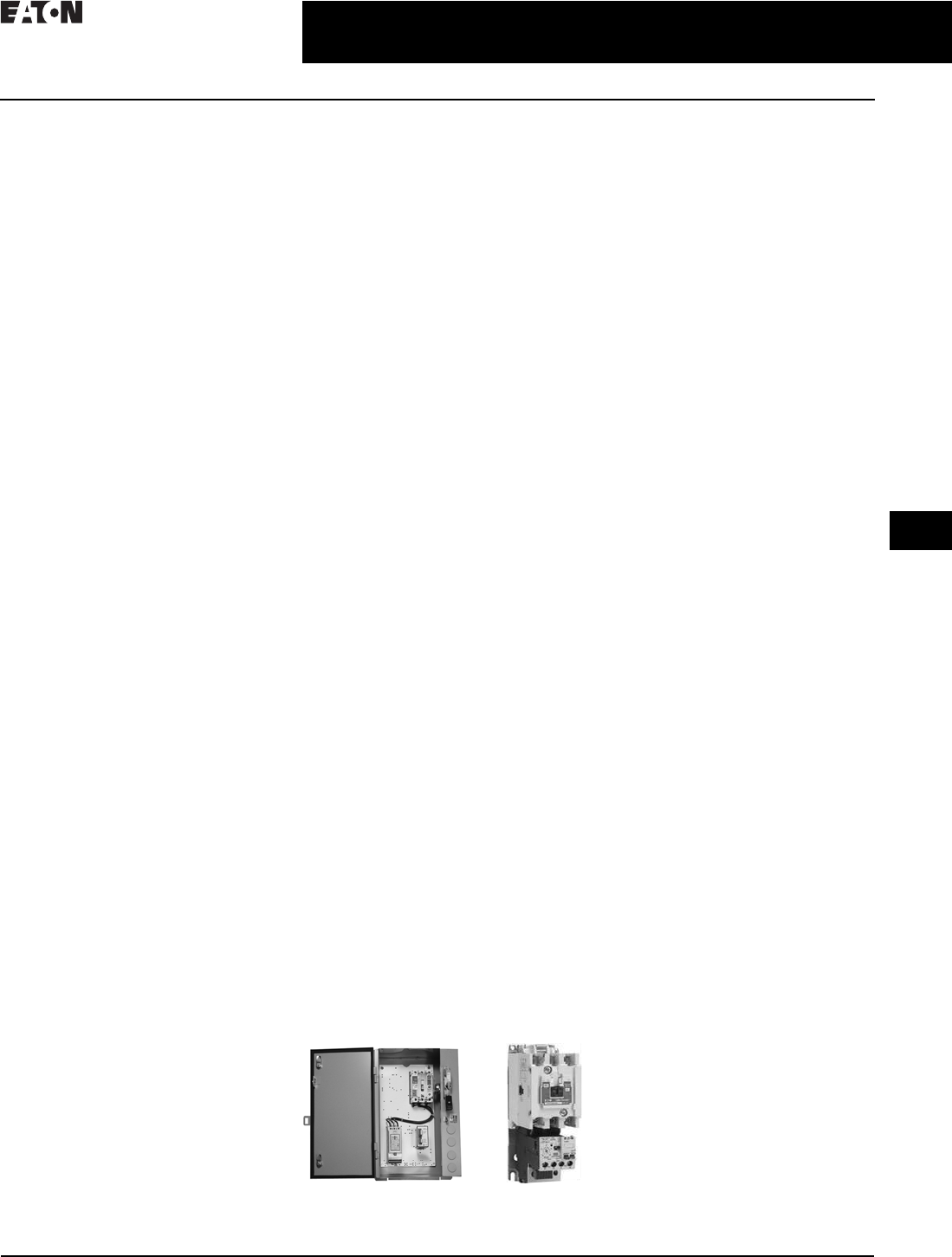
Enclosed S801 Soft Start and Freedom NEMA
Starter with C440 Electronic Overload Relay

30.0-2
For more information, visit: www.eaton.com/consultants CA08104001E
April 2016
Motor Starters and Contactors—Low Voltage
Sheet 30
22
23
24
25
26
27
28
29
30
31
32
33
34
35
36
37
38
39
40
41
42
4 3
002
This page intentionally left blank.
CA08104001E For more information, visit: www.eaton.com/consultants
30.1-1
April 2016
Motor Starters and Contactor—Low Voltage
Sheet 30
22
23
24
25
26
27
28
29
30
31
32
33
34
35
36
37
38
39
40
41
42
4 3
Manual Motor Control
Type MS
003
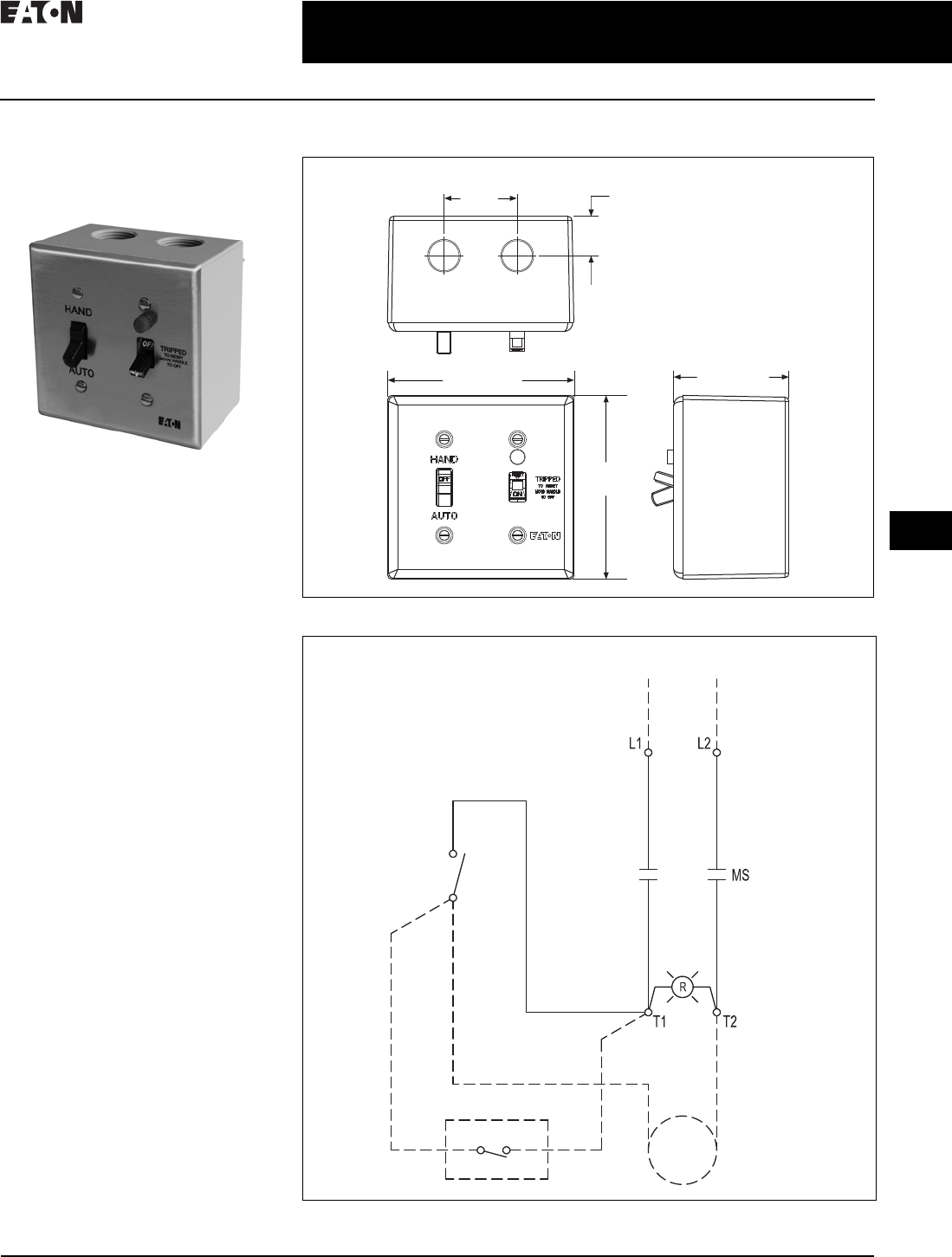
MS Starters with Hand /Auto
Maximum 1 hp, 120/277 Volts
Single-Phase
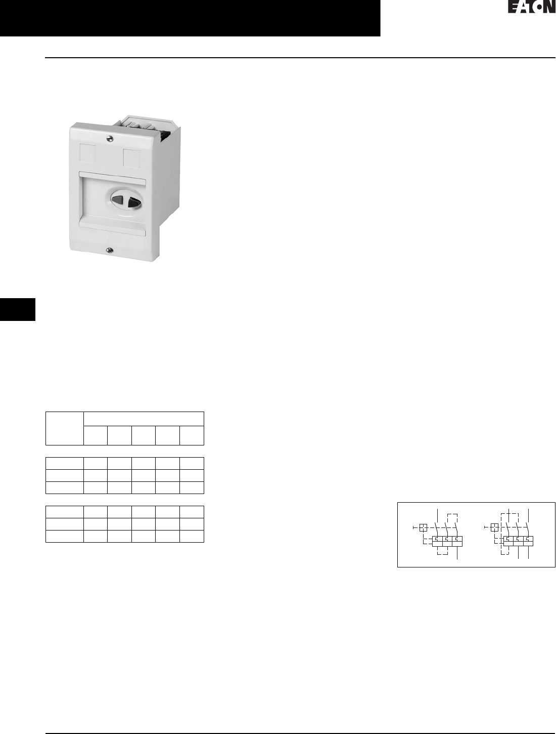
General Purpose Type 1 Enclosed MS
Starter with Hand/Auto and Pilot Light
General Description
The enclosed manual motor starter
is a cost-effective solution offering
local and remote control capability,
overload protection, and running
light indication on small single-phase
motor applications for 10% less than
competitive devices.
Features
■Hand/Auto switch allows starter
control locally or from a remote
source such as a building
■Keyed heater packs ensure proper
positioning
■Ease of installation and wiring
■Trip-free handle can be locked in the
OFF position with optional handle
guard accessory (MSLG)
■Red RUN pilot light provides
indication status
Applications
■HVAC
■Commercial construction
■Exhaust fans
Standards and Certifications
■UL® 60967-4-1
Specifications
■1 hp at 120/240 V, single-phase
■0.40–16 FLA
■NEMA® Type 1 enclosure
Resources
■Catalog number: MST02RN1PH
■Volume 5, Tab 3.1—NEMA Manual
Starters
■www.eaton.mmshoa.com
Technical Data
Figure 30.1-1. Dimensions in Inches (mm)
Figure 30.1-2. Wiring Diagram
Dimensions in inches. Not to be used for construction purposes unless approved.
4.55
(115.6)
1.81
(46.0)
0.98
(24.9)
4.61 (117.1) 2.85 (72.4)
115–230 V
1 hp / 230 V
HAND–Toggle Closed
AUTO–Toggle Open
AUTO
HAND
Pilot Light
(If Used)
Motor
Thermostat
30.1-2
For more information, visit: www.eaton.com/consultants CA08104001E
April 2016
Motor Starters and Contactor—Low Voltage
Sheet 30
22
23
24
25
26
27
28
29
30
31
32
33
34
35
36
37
38
39
40
41
42
4 3
Manual Motor Control
Type B100
004
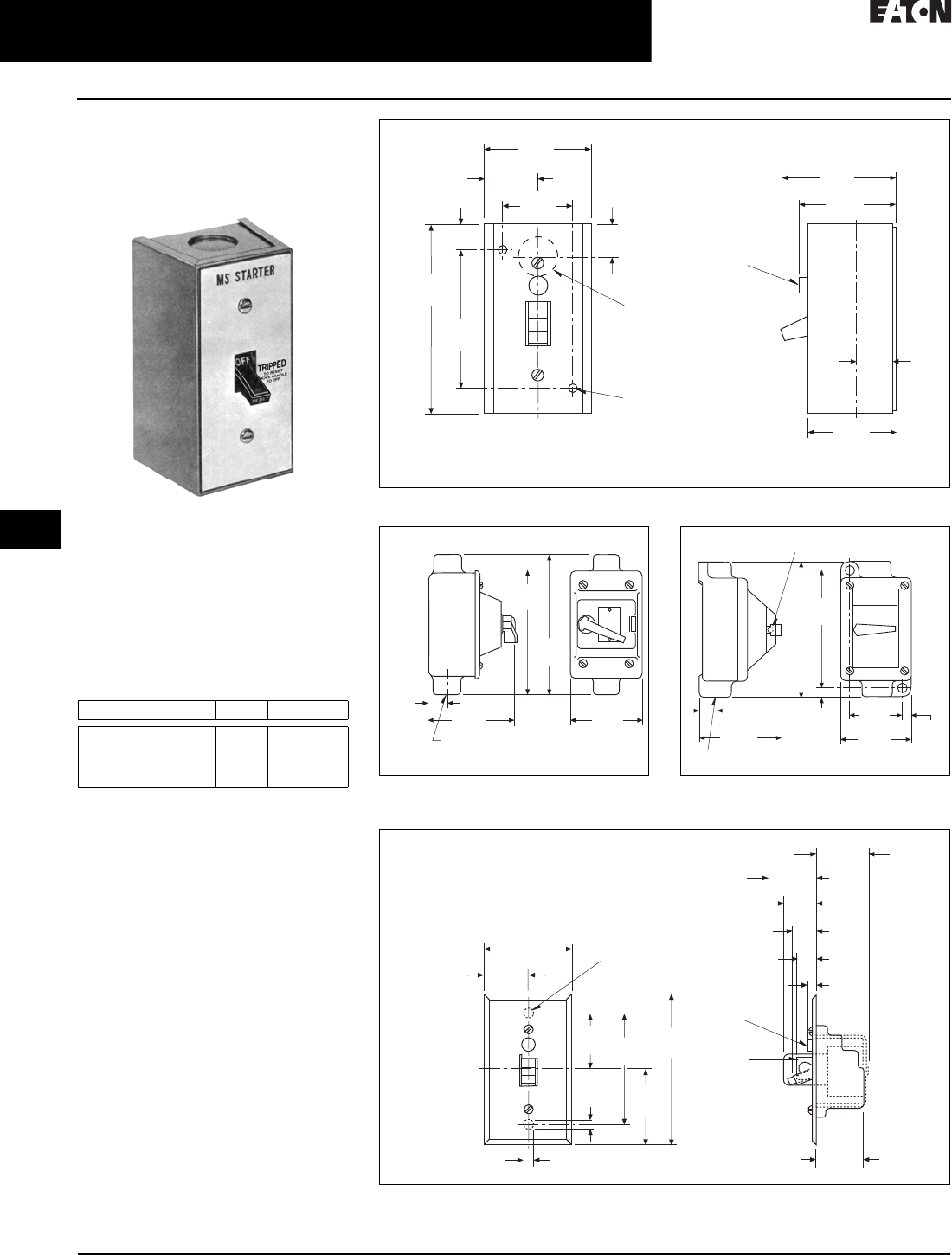
MS Manual Starters
Maximum 1 hp, 120/277 Volts
Single-Phase
General Purpose Type 1 Enclosed
MS Starter
Application Description
MS manual single-phase starters are
designed to give positive, accurate,
trouble-free overload protection to
single-phase motors rated up to 1 hp.
Typical applications are fans, machine
tools, motors, HVAC, and so on.
Table 30.1-1. MS Ratings
Enclosures
■Type 1: General Purpose
■Type 1: Flush Mounted, General
Purpose
■Type 3, 4, 5: Watertight
■Type 7D: Class I, Group D Hazardous
Locations
■Type 9E, F, G: Class II, Groups E, F, G
Hazardous Locations
■Red pilot light available for NEMA® 1,
factory-installed or field-installed kit
Typical Specifications
Manual single-phase starters shall be
Eaton’s Type MS or approved equal for
motors rated not greater than 1 hp. They
shall be built and tested in accordance
with the applicable NEMA standards.
The starter shall have a “quick-make,
quick-break” toggle mechanism. The
overload shall have a field adjustment
allowing up to ±10% variance in ratings
of the nominal heater value.
Volts hp Po les
120/240 V, 277 Vac
120/240 Vdc
240 Vdc
32 Vdc
1
1
1/4
1/4
1 or 2
2
1
1 or 2
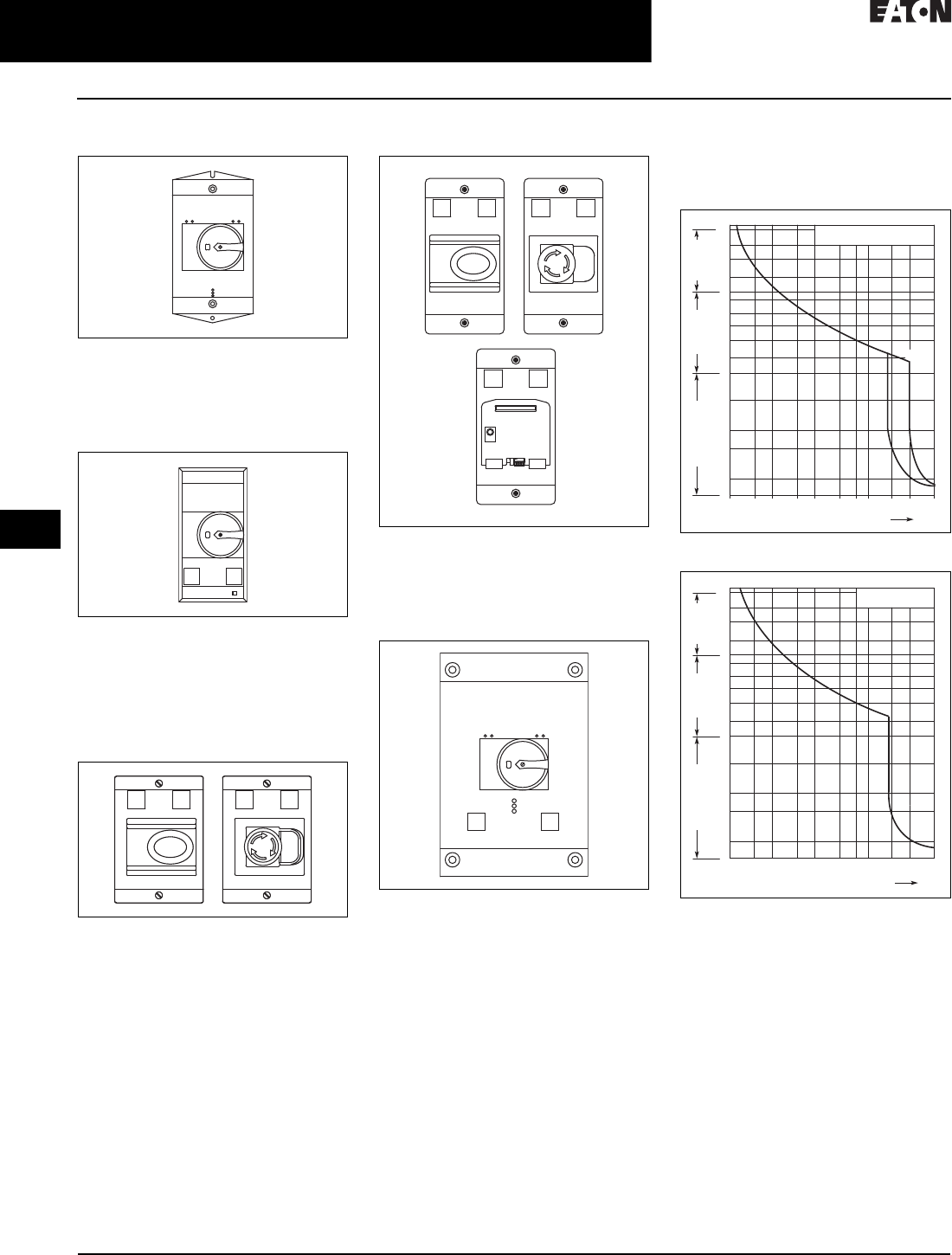
Figure 30.1-3. Type 1 Enclosures (Boxes and Covers)
Figure 30.1-4. Watertight (Cast Aluminum) Figure 30.1-5. Hazardous Location
(Cast Aluminum)
Figure 30.1-6. Flush Plates
13/64 Diameter
2 Mounting Holes
1/2 Diameter Conduit
3 Single Knockouts
1 in Each End & Back
As Shown
Indicating Light
(When Used)
KO
KO
KO
KO
1.56
(39.6)
0.88
(22.4)
0.55
(14.0)
4.16
(105.7)
3.06
(77.7)
2.38
(60.5)
2.11
(53.6)
2.55
(64.8)
1.19
(30.2)
0.73
(18.5)
1.97
(50.0)
Typical Front View
(Single Unit)
Typical Side View
3/4 Inch Pipe Top
5.81
(147.6)
2.91
(73.7)
5.13
(130.3)
0.75
(19.1) 3.63
(92.2)
3/4 Inch Pipe Top
19/64 Diameter Lockout Hole
0.81
(20.6) 0.42
(10.7)
5.88
(149.4)
6.72
(170.7)
3.94
(100.1) 3.50
(88.9)
2.63
(66.8) 0.44
(11.2)
Dimensions in inches. Not to be used for construction purposes unless approved.
Mounting Purposes
(2) Holes
Indicating
Light
Handle
Guard
1 Unit
2.75
(69.9)
1.38
(35.1)
1.53
(38.9)
1.64
(41.7)
0.78
(19.8)
0.34
(8.6)
1.52
(38.6)
1.06
(26.9)
0.66
(16.8)
0.31
(7.9)
3.28
(83.3)
1.64
(41.7)
0.22
(5.6)
4.50
(114.3)
2.25
(57.2)
CA08104001E For more information, visit: www.eaton.com/consultants
30.1-3
April 2016
Motor Starters and Contactor—Low Voltage
Sheet 30
22
23
24
25
26
27
28
29
30
31
32
33
34
35
36
37
38
39
40
41
42
4 3
Manual Motor Control
Type B100
005
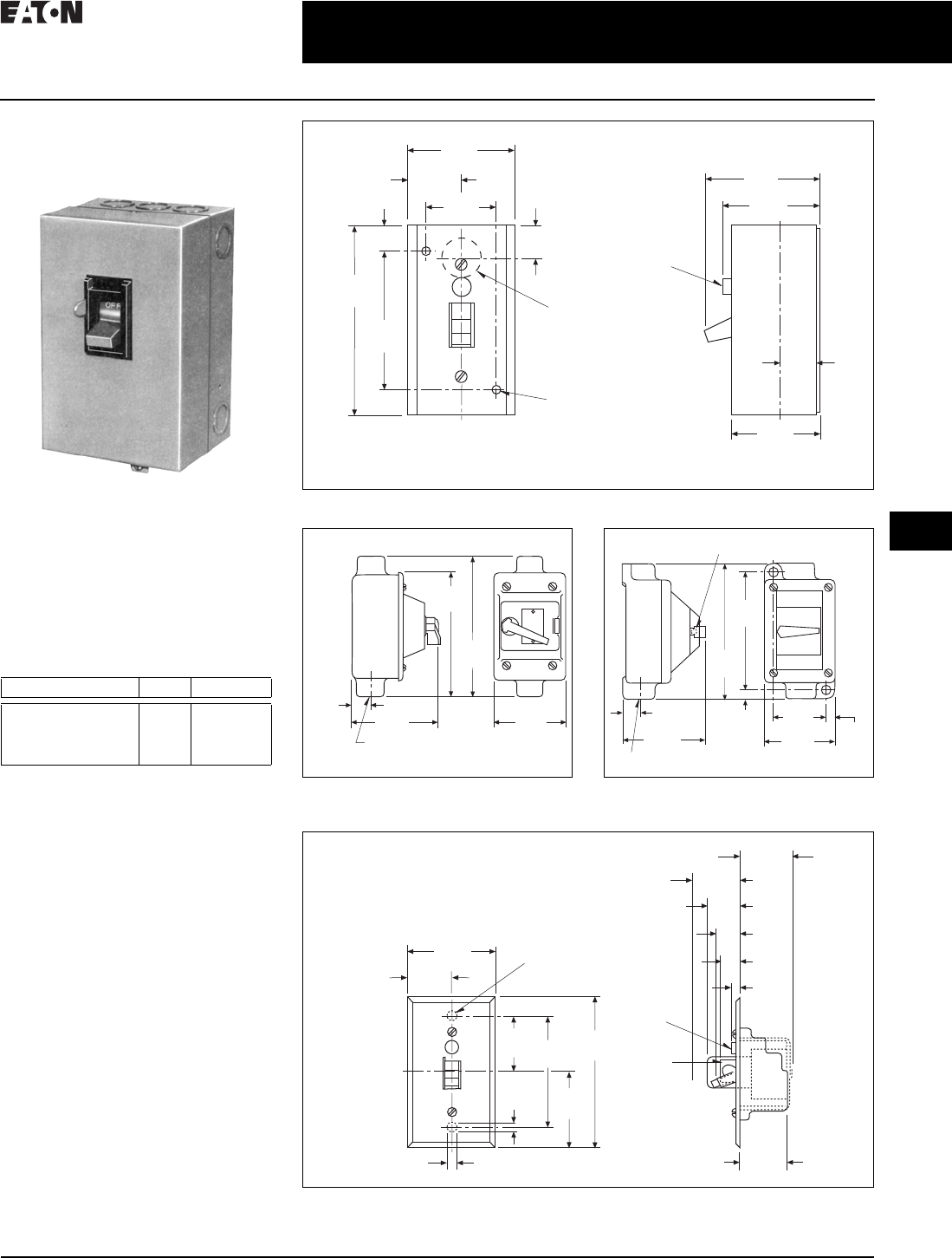
Type B100
Maximum 10 hp, 600 Volts
General Purpose Type 1 Enclosed
B100 Starter
General Description
MS manual single-phase starters are
designed to give positive, accurate,
trouble-free overload protection to
single-phase motors rated up to 1 hp.
Typical applications are fans, machine
tools, motors, HVAC, and so on.
Table 30.1-2. MS Ratings
Enclosures
■Type 1: General Purpose
■Type 1: Flush Mounted, General
Purpose
■Type 3, 4, 5: Watertight
■Type 7D: Class I, Group D Hazardous
Locations
■Type 9E, F, G: Class II, Groups E, F, G
Hazardous Locations
■Red pilot light available for NEMA® 1,
factory-installed or field-installed kit
Typical Specifications
Manual single-phase starters shall be
Eaton’s Type MS or approved equal for
motors rated not greater than 1 hp. They
shall be built and tested in accordance
with the applicable NEMA standards.
The starter shall have a “quick-make,
quick-break” toggle mechanism. The
overload shall have a field adjustment
allowing up to ±10% variance in ratings
of the nominal heater value.
Volts hp Po les
120/240 V, 277 Vac
120/240 Vdc
240 Vdc
32 Vdc
1
1
1/4
1/4
1 or 2
2
1
1 or 2
Figure 30.1-7. Type 1 Enclosures (Boxes and Covers)
Figure 30.1-8. Watertight (Cast Aluminum) Figure 30.1-9. Hazardous Location
(Cast Aluminum)
Figure 30.1-10. Flush Plates
13/64 Diameter
2 Mounting Holes
1/2 Diameter Conduit
3 Single Knockouts
1 in Each End & Back
As Shown
Indicating Light
(When Used)
KO
KO
KO
KO
1.56
(39.6)
0.88
(22.4)
0.55
(14.0)
4.16
(105.7)
3.06
(77.7)
2.38
(60.5)
2.11
(53.6)
2.55
(64.8)
1.19
(30.2)
0.73
(18.5)
1.97
(50.0)
Typical Front View
(Single Unit)
Typical Side View
3/4 Inch Pipe Top
5.81
(147.6)
2.91
(73.7)
5.13
(130.3)
0.75
(19.1) 3.63
(92.2)
3/4 Inch Pipe Top
19/64 Diameter Lockout Hole
0.81
(20.6) 0.42
(10.7)
5.88
(149.4)
6.72
(170.7)
3.94
(100.1) 3.50
(88.9)
2.63
(66.8) 0.44
(11.2)
Dimensions in inches. Not to be used for construction purposes unless approved.
Mounting Purposes
(2) Holes
Indicating
Light
Handle
Guard
1 Unit
2.75
(69.9)
1.38
(35.1)
1.53
(38.9)
1.64
(41.7)
0.78
(19.8)
0.34
(8.6)
1.52
(38.6)
1.06
(26.9)
0.66
(16.8)
0.31
(7.9)
3.28
(83.3)
1.64
(41.7)
0.22
(5.6)
4.50
(114.3)
2.25
(57.2)
30.1-4
For more information, visit: www.eaton.com/consultants CA08104001E
April 2016
Motor Starters and Contactor—Low Voltage
Sheet 30
22
23
24
25
26
27
28
29
30
31
32
33
34
35
36
37
38
39
40
41
42
4 3
Manual Motor Control
Type XT
006
XT Manual Motor Protectors
Maximum 50 hp, 600 Volts
General Purpose Type 1 Enclosure
XTPBXENCF40
General Description
XTPB (pushbutton) and XTPR (toggle)
are an economical and global solution
to manual starting. They have a full
spectrum of accessories nd enclosures
to meet various application needs.
They can be utilized in single- and
three-phase applications. They feature
thermal protection with built-in over-
loads, bi-metalic and electronic.
Table 30.1-3. XTP Ratings
Frame
Size
Maximum Horsepower
115
Vac
200
Vac
240
Vac
480
Vac
600
Vac
Single-Phase AC (see Wiring Diagram)
XTPB-B 2 3 5 — —
XTPR-B 2 3 5 — —
XTPR-D 3 5 10 — —
Three-Pole, Three-Phase AC
XTPB-B — 5 7.5 15 20
XTPR-B — 7.5 10 20 25
XTPR-D — 15 15 40 50
Enclosures
■OPEN, IP40, 55, 65, NEMA 1, 3R, 4X,
12, 13
■Red, green and white indicates
available, field installable, without
change in enclosure rating (light is
not UL)
Typical Specifications
Manual starters shall be Eaton’s XT or
approved equal for motors rated not
greater than 50 hp. They shall be built
and tested in accordance with the
applicable IEC and UL standards.
Features and Benefits
■ON/OFF rotary handle with
lockout provision
■Visible trip indication
■Class 10 overload protection
■Phase loss sensitivity
■Ambient temperature compensa-
tion to IEC/EN 60947, VDE 0660
■Fixed short-circuit trip—14 times
maximum setting of overload
FLA dial
■Type 2 coordination per IEC 947
■Identification markers standard on
starter faceplate
■Motor applications from 0.1 A to 65 A
■Built-in heater and magnetic trip
elements to protect the motor
■Adjustment dial for setting
motor FLA
■DIN rail mount
■Terminal types available:
❑Screw terminals
❑Screw (line) and spring cage
(load) terminals
❑Spring cage terminals
■Accessories include:
❑Front and side auxiliary contacts
❑Trip indicating contacts
❑Tamperproof cover for OLR dial
❑Undervoltage release
❑Shunt trip
❑Through-the-door operators
❑Enclosures
❑Three-phase side connecting links
Standards and Certifications
■CE approved
■UL listed File No. E245398
■UL 508 group motor and Type E
compliant
■IEC/EN 60947
■CSA File 229767, Class 3211-05
■DIN VDE 0660 Part 100, Part 101 and
Part 102
Product Selection
When ordering, specify catalog
numbers according to the following
stipulations:
■XT manual motor protectors are
selected based on the overload
current range required for a given
motor. This current range is deter-
mined from the motor full load
ampere rating and motor service
factor usually found on the motor
nameplate.
■For motors with service factors
less than 1.15, multiply the
motor FLA by 0.90 to select
appropriate MMP.
Example: For motor having FLA
of 6.4 A and service factor of 1.0
(6.4 A x 0.90 = 5.76 A) select catalog
number XTPB6P3B01.
See Application Note AP03402001E.
■For motor with service factor of
1. 15 o r g r e a t e r, use motor
nameplate full load amperes to
select the appropriate MMP.
Example: For motor having FLA of
11 A and Service factor of 1.15, select
catalog number XTPR012BC1.
Figure 30.1-11. XTPB, XTPR Single- and
Two-Pole Circuits with DC and AC Current
135
246
I > I > I >
135
246
I > I > I >
CA08104001E For more information, visit: www.eaton.com/consultants
30.1-5
April 2016
Motor Starters and Contactor—Low Voltage
Sheet 30
22
23
24
25
26
27
28
29
30
31
32
33
34
35
36
37
38
39
40
41
42
4 3
Manual Motor Control
Type XT
007
Catalog Number Selection
Table 30.1-4. XT Manual Motor Protector Catalog Numbering System
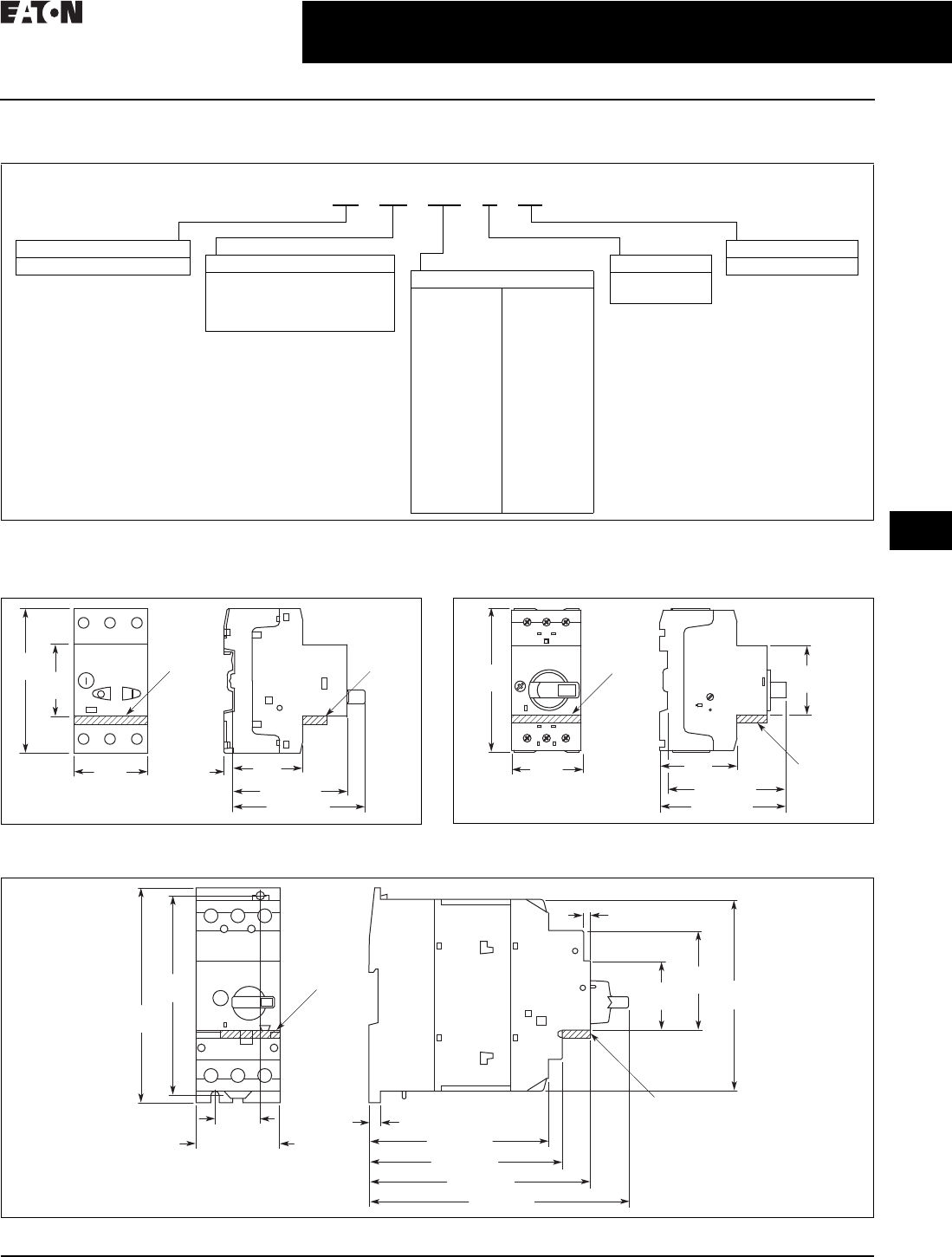
Dimensions
Approximate Dimensions in Inches (mm)
Figure 30.1-12. Manual Motor Protectors—XTPB Figure 30.1-13. Manual Motor Protectors, Manual Transformer
Protectors—XTPR…B
Figure 30.1-14. Manual Motor Protector—XTPR…DC1
XT PR 012 BC1
Type
PB = Manual motor
protector—pushbutton
PR = Manual motor
protector—rotary
Designation
XT = XT IEC power control
Trip Class
C1 = Class 10
Frame Size
B= 45 mm
D= 55 mm
Current Ratings
Frame B
P16 = 0.16 A
P25 = 0.25 A
P40 = 0.40 A
P63 = 0.63 A
001 = 1 A
1P6 = 1.6 A
2P5 = 2.5 A
004 = 4 A
6P3 = 6.3 A
010 = 10 A
012 = 12 A
016 = 16 A
020 = 20 A
025 = 25 A
032 = 32 A
Frame D
016 = 16 A
025 = 25 A
032 = 32 A
040 = 40 A
050 = 50 A
058 = 58 A
063 = 63 A
0.22
(5.5)
1.77
(45.0)
1.77
(45.0)
3.66
(93.0)
1.73
(44.0)
2.91 (74.0)
3.35 (85.0)
XTPAXFA _XTPAXFA _
1.77
(45.0)
3.66
(93.0) 1.77
(45.0)
1.97
(50.0)
3.46 (88.0)
3.70 (94.0)
XTPAXFA _
XTPAXFA _
1.18
(30.0) 0.30 (7.5)
4.65 (118.0)
5.00 (127.0)
5.71 (145.0)
6.73 (171.0)
2.17 (55.0)
5.12
(130.0)
5.57
(140.0)
4.92
(125.0)
2.56
(65.0)
1.77
(45.0)
0.16 (4.0)
XTPAXFA _
XTPAXFA _
30.1-6
For more information, visit: www.eaton.com/consultants CA08104001E
April 2016
Motor Starters and Contactor—Low Voltage
Sheet 30
22
23
24
25
26
27
28
29
30
31
32
33
34
35
36
37
38
39
40
41
42
4 3
Manual Motor Control
Type XT
008
Dimensions
Figure 30.1-15. Frame B (0.1–32 A) XTPR
Rotary Manual Motor Protectors
H x W x D
6.30 x 3.94 x 5.12
(160.0 x 100.0 x 130.0)
Figure 30.1-16. Frame B (0.1–32 A) XTPR
Rotary Manual Motor Protectors with
XTPAXFAEM20 Early-Make Front-Mount
Auxiliary Contact
H x W x D
6.30 x 3.94 x 5.12
(160.0 x 100.0 x 130.0)
Figure 30.1-17. XTPB Pushbutton Manual
Motor Protectors
H x W x D
5.08 x 3.55 x 4.54
(129.0 x 90.2 x 115.2)
Figure 30.1-18. XTPB Pushbutton Manual
Motor Protectors
H x W x D
6.22 x 3.15 x 4.59
(158.0 x 80.0 x 116.5)
Figure 30.1-19. Frame D (10–65 A) Rotary
Motor Protective Circuit Breakers
H x W x D
9.45 x 6.30 x 7.76
(240.0 x 160.0 x 197.0)
Wiring Diagrams
MMP Tripping Characteristics
Figure 30.1-20. XTPB, XTPR Frame B
Figure 30.1-21. XTPR Frame D
2
5
20
50
200
1
2
5
10
20
40
1
2
5
10
20
2h
1.5 2346810 15 20 30
XTPB, XTPR Frame B
XTPT
Seconds
Milli-seconds Minutes
x Rated Operational Current
XTPR Frame D
2
5
20
50
200
1
2
5
10
20
40
1
2
5
10
20
2h
1.5 2346810 15 20 30
Seconds
Milli-seconds Minutes
x Rated Operational Current
CA08104001E For more information, visit: www.eaton.com/consultants
30.2-1
April 2016
Motor Starters and Contactors—Low Voltage
Sheet 30
22
23
24
25
26
27
28
29
30
31
32
33
34
35
36
37
38
39
40
41
42
4 3
Lighting Contactors
Non-Combination Lighting Contactors
009
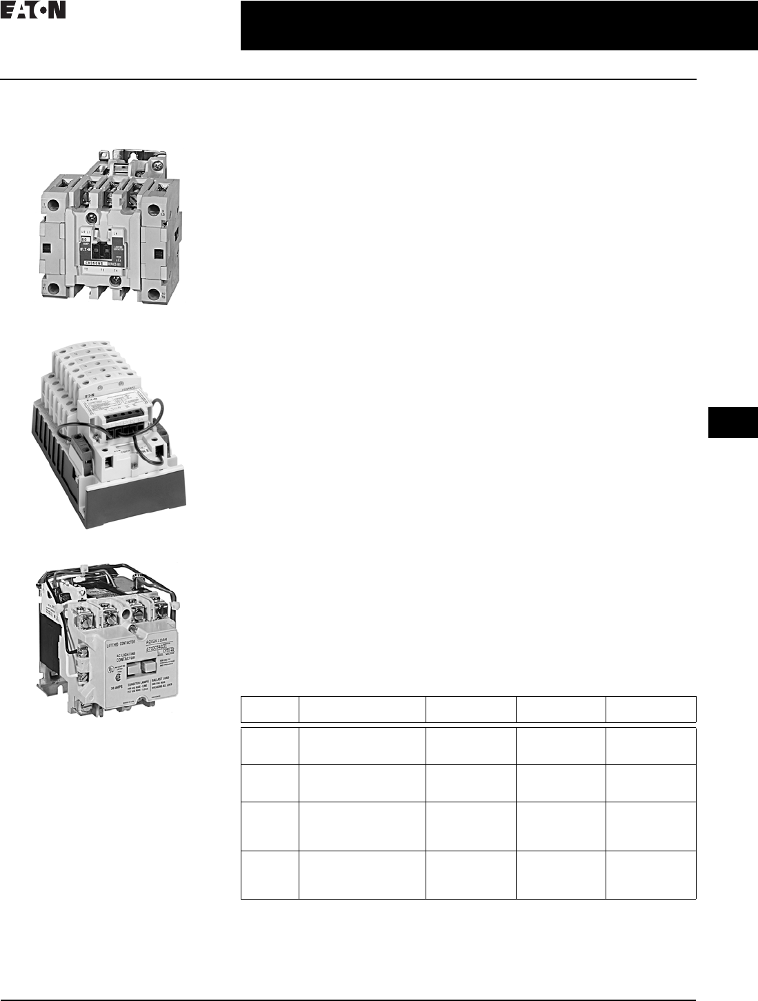
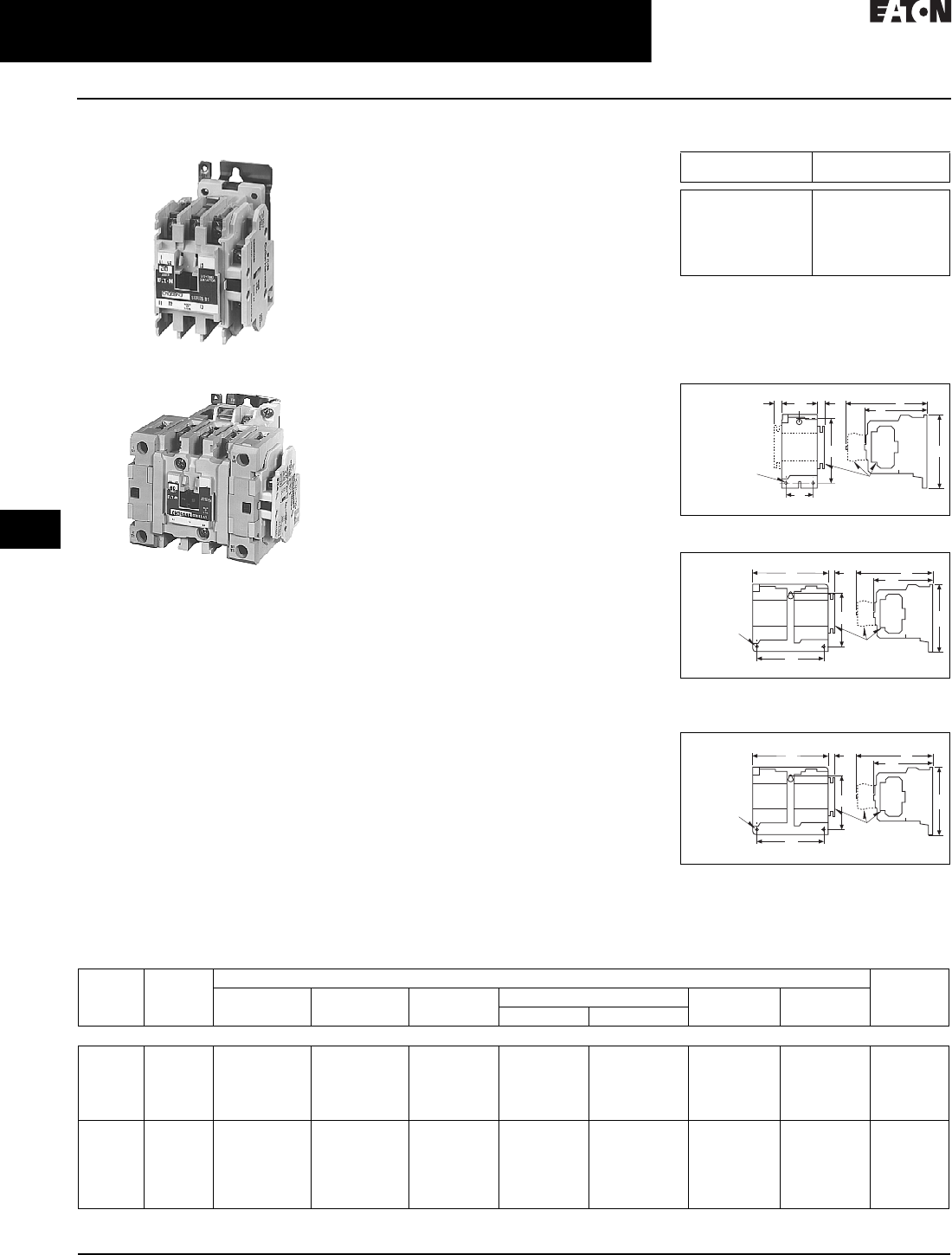
Non-Combination
Lighting Contactors
60 Ampere, Five-Pole Electrically Held
30 Ampere, 12-Pole Mechanically Held
30 Ampere, Four-Pole Magnetically Latched
General Description
Lighting contactors are designed to
provide a safe, convenient means for
local or remote switching of tungsten
(incandescent filament) or ballast
(fluorescent and mercury arc) lamp
loads. They are also suitable for other
loads such as low pressure and high
pressure sodium lamp loads and
other non-motor (resistive) loads.
They are not recommended for
most sign flashing loads.
These lighting contactors are designed
to withstand the large initial inrush
currents of tungsten lamp loads with-
out contact welding. The full family
of lighting contactors does not require
derating.
Application Description
Loads:
Ballast Lamps—Fluorescent, mercury
vapor, metal halide sodium vapor,
quartz—600 V maximum.
Filament Lamps
—Incandescent, infra-
red,
heating—480 V maximum, line-to-
line; 277 V maximum line-to-neutral.
Resistance Heating—Radiant and
convection heating, furnaces and ovens.
Typical Specifications
Electrically Held Lighting Contactors—
Eaton’s CN35 or approved equal are
rated for lighting loads of 10–300 A.
They are built and tested in accordance
with applicable NEMA standards.
Mechanically Held Lighting Contactors—
Eaton’s C30CNM or approved equal are
rated for lighting loads of 30 A. They
shall be capable of being supplied in
a 2–12 pole single unit configuration.
These contactors are designed to with-
stand the large initial inrush currents
of tungsten and ballast lamp loads as
well as non-motor (resistive) loads
without contacts welding. The contac-
tor is capable of being operated such
that it will not switch to “OFF” during
the control power circuit power failures.
Magnetically Latched Lighting
Contactors—A202 or approved equal
are rated for lighting loads of 30–
4000 A. Magnetically latched enclosed
combination lighting contactors are
Type ECL12 (breaker) or ECL13 (fusible)
or approved equal for loads up to
30–200 A when integral short-circuit
protection is required.
These contactors are designed
to withstand the large initial inrush
currents of tungsten and ballast lamp
loads as well as non-motor (resistive)
loads without contacts welding.
The contactors are capable of being
“mechanically held” via a magnetic
latch design using a permanent
magnet. The contactor is operated
by a RUN signal and a STOP signal
preventing the contactor from switch-
ing to “OFF” during control circuit
power failure.
Table 30.2-1. Lighting Contactor Comparison
Ampere
Rating
Number
of Poles
Electrically
Held
Mechanically
Held
Magnetically
Latched
10
20
30
2, 3, 4
2, 3, 4, 6, 9, 12
2, 3, 4, 5, 6, 9, 12
CN35
CN35
CN35
—
—
—
—
—
—
30
30
60
1–12
2, 3, 4, 5, 6, 8, 10, 12
2, 3, 4, 5, 6, 8, 10, 12
C30CNE
—
—
C30CNM
—
—
—
A202
A202
60
100
100
200
2, 3, 4, 5
2, 3, 4, 5
2, 3, 4, 5, 6, 8, 10, 12
2, 3, 4, 5, 6, 8, 10, 12
CN35
CN35
—
—
—
—
—
—
—
—
A202
A202
200
300
300
400
2, 3, 4, 5
2, 3, 4, 5
2, 3
2, 3
CN35
CN35
—
—
—
—
—
—
—
—
A202
A202
30.2-2
For more information, visit: www.eaton.com/consultants CA08104001E
April 2016
Motor Starters and Contactors—Low Voltage
Sheet 30
22
23
24
25
26
27
28
29
30
31
32
33
34
35
36
37
38
39
40
41
42
4 3
Lighting Contactors
Electrically Held—CN35
010
CN35-Open (ECL03-Enclosed)
20 Ampere
60 Ampere
General Description
Lighting contactors are designed to han-
dle the switching of tungsten (incandes-
cent filament) or ballast (fluorescent and
mercury arc) lamp loads as well as other
non-motor (resistive) loads. Ratings of
10–400 A, 1–12 poles, open or NEMA 1,
3R, 4/4X and 12 enclosed.
Application Description
Loads:
Ballast Lamps—Fluorescent,
mercury vapor, sodium vapor,
quartz—600 V maximum.
Filament Lamps—Incandescent,
infrared, heating—480 V maximum.
Resistance Heating—Radiant
and convection heating, furnaces
and ovens.
Cover Control—See Enclosed
Control Product Guide PG.3.02.T.E
start-stop and hand-off-auto only.
Enclosures
Open, NEMA Type 1, 3R, 4/4X and 12.
Auxiliary Contacts
Eaton’s CN35 lighting contactors
include a NO maintaining auxiliary
contact mounted on right-hand side
(on 10 A, two- and three-pole devices,
auxiliary contact occupies 4th power
pole position—no increase in width).
Enclosed devices include a NO auxiliary
contact only on the right-hand contactor.
The 10–60 A devices will accept addi-
tional auxiliary contacts on the top
and/or sides. The 100–400 A sizes will
accept side-mounted auxiliaries only.
Typical Specifications
Electrically-held lighting contactors
are Eaton Type CN35 or ELC03, or
approved equal for lighting loads of
10–300 A. They are built and tested
in accordance with applicable
NEMA standards.
These contactors are designed to
withstand the large initial inrush
currents of tungsten and ballast lamp
loads as well as non-motor (resistive)
loads without contact welding. Contac-
tors are capable of accepting up to 8
auxiliary contacts—top and/or side
up to 60 A and side only up to 400 A.
Contactors are capable of being
operated by AC or DC control.
Table 30.2-2. Ratings—CN35 AC Lighting
Contactors—Electrically Held
1Listed ampere ratings are based on a maxi-
mum load voltage of 480 V for tungsten
lamp applications and 600 V for ballast or
mercury vapor type applications.
2Additional power poles mounted on side(s)
of contactor.
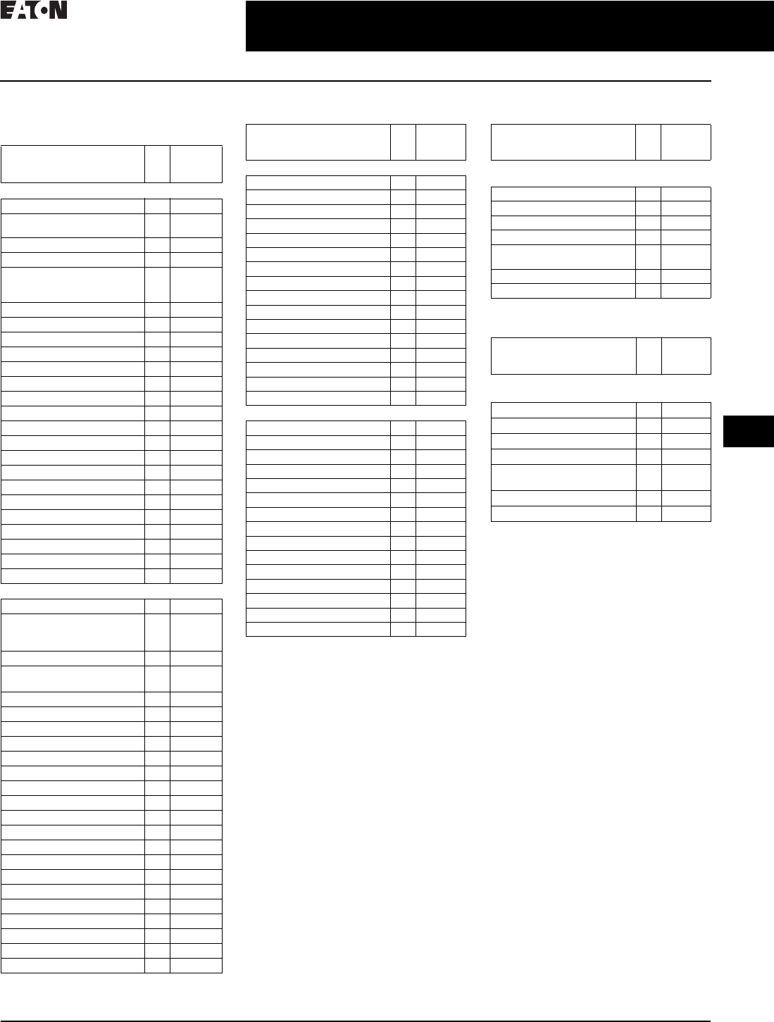
Figure 30.2-1. Open Type
Figure 30.2-2. Open Type, 20–30 A Sizes,
Four–Six Poles
Figure 30.2-3. Open Type, 20–30 A Sizes,
Four–Six Poles
3See “Auxiliary Contacts” for type and
location of auxiliary contacts supplied.
Table 30.2-3. Approximate Dimensions and Shipping Weights
4Center mounting slot at bottom on 10–30 A sizes only.
Maximum
Ampere Rating 1
Number
of Poles
10
20
30
60
100, 200, 300
400
2, 3, 4
2, 3, 4, 6, 9, 12
2, 3, 4, 5, 6, 9, 12
2, 3, 4 2, 5 2
2, 3, 4, 5
2, 3
GG
A
Top
Mtd.
Aux.
Side
Mtd.
Aux.
Top
Mtd.
Aux.
Mtg. Holes for
#10-32 Screws Auxiliary
Contacts√
A
U
X
A
U
X
D
F
C
B
E
Top
Mtd.
Aux.
Top
Mtd.
Aux.
Top
Mtd.
Aux.
Side
Mtd.
Aux.
3 Mtg. Holes
for #10-32
Screws Auxiliary
Contacts√
AGF
C
A
U
X
E
D
B
Top
Mtd.
Aux.
Top
Mtd.
Aux.
Top
Mtd.
Aux.
Side
Mtd.
Aux.
3 Mtg. Holes
for #10-32
Screws Auxiliary
Contacts√
AGF
C
A
U
X
E
D
B
Ampere
Rating
Number
of Poles
Dimensions in Inches (mm) Shipping
Weight
Lbs (kg)
Wide
A
High
B
Deep
C
Mounting F G
D 4E
Open Type
10
20–30
20–30
20–30
20–30
2–4
2–3
4–6
9
12
2.00 (50.8)
2.00 (50.8)
4.20 (106.7)
10.50 (266.7)
10.50 (266.7)
3.88 (98.5)
3.88 (98.5)
4.35 (110.5)
5.75 (146.0)
5.75 (146.0)
3.49 (88.6)
3.49 (88.6)
3.52 (89.4)
4.52 (114.8)
4.52 (114.8)
1.50 (38.1)
1.50 (38.1)
3.50 (88.9)
4.50 (114.3)
4.50 (114.3)
3.38 (85.9)
3.38 (85.9)
3.86 (98.0)
5.00 (127.0)
5.00 (127.0)
4.90 (124.5)
4.90 (124.5)
4.90 (124.5)
—
—
0.54 (13.7)
0.54 (13.7)
0.54 (13.7)
—
—
1.4 (0.63)
1.45 (0.65)
2.9 (1.3)
4.35 (1.96)
5.8 (2.6)
60
60
60
100
200
300
2–3
4
5
2–3
2–3
2–3
2.56 (65.1)
3.46 (87.8)
4.36 (110.7)
3.54 (89.9)
7.05 (179.1)
7.05 (179.1)
5.05 (128.3)
5.05 (128.3)
5.05 (128.3)
7.17 (182.1)
9.11 (231.4)
13.12 (333.2)
4.44 (112.8)
4.44 (112.8)
4.44 (112.8)
5.94 (150.9)
7.25 (184.2)
7.78 (184.2)
2.00 (50.8)
2.00 (50.8)
2.00 (50.8)
3.00 (76.2)
6.00 (152.4)
6.00 (152.4)
4.50 (114.3)
4.50 (114.3)
4.50 (114.3)
6.63 (168.4)
8.50 (215.9)
12.50 (317.5)
5.80 (147.3)
5.80 (147.3)
5.80 (147.3)
—
—
—
0.54 (13.7)
0.54 (13.7)
0.54 (13.7)
0.54 (13.7)
—
—
3.4 (1.53)
3.5 (1.57)
3.55 (1.59)
9 (4.1)
20 (9.0)
23 (10.35)
CA08104001E For more information, visit: www.eaton.com/consultants
30.2-3
April 2016
Motor Starters and Contactors—Low Voltage
Sheet 30
22
23
24
25
26
27
28
29
30
31
32
33
34
35
36
37
38
39
40
41
42
4 3
Lighting Contactors
Electrically Held—CN35
011
Enclosed Box Selection
Table 30.2-4. Type 1 Non-combination Lighting
Contactors—Electrically Held—CN35
Table 30.2-5. Type 3R, 4/4X, 12 Non-combination
Lighting Contactors—Electrically Held—CN35
Table 30.2-6. Type 1 Combination
Lighting Contactors
Table 30.2-7. Type 3R, 4/4X, 12 Combination
Lighting Contactors
Ampere Size
(Poles)
Box
No.
Shipping
Weight
Lbs (kg)
Contactors—without Control Power Transformers
10 A (2P, 3P, 4P) 1 5 (2.3)
10 A (2P, 3P, 4P, 5P, 6P)
w/top adders
2 7.3 (3.3)
10 A (9P, 10P, 12P, 20P) 3 9.5 (4.3)
20 A (2P, 3P) 1 5.2 (2.4)
20 A (2P, 3P, 4P, 5P, 6P)
w/top adders &
6P w/o top adder
2 7.3 (3.3)
20 A (9P, 10P, 12P, 20P) 3 9 (4.1)
20 A (9P, 12P) w/top adders 3 9.3 (4.2)
30 A (2P, 3P) 1 5.3 (2.4)
30 A
(2P, 3P, 4P) w/top adders
2 7.3 (3.3)
30 A (5P, 6P) 3 9.0 (4.1)
30 A (5P, 6P) w/top adders 3 9.2 (4.2)
30 A (9P, 10P, 12P, 20P) 3 9.5 (4.3)
30 A (9P, 12P) w/top adders 3 9.7 (4.4)
60 A (2P, 3P) 1 7 (3.2)
60 A (2P, 3P) w/top adders 3 9.8 (4.4)
60 A (4P, 5P, 6P, 9P, 10P, 12P) 3 9.5 (4.3)
60 A (4P, 5P) w/top adders 3 10 (4.5)
100 A (2P, 3P) 4 35 (16)
100 A (4P, 5P, 6P, 9P) 4 60 (27)
200 A (2P, 3P) 4 70 (32)
200 A (4P, 5P, 6P) 10 133 (60)
300 A (2P, 3P) 10 113 (51)
300 A (4P, 5P, 6P) 10 136 (62)
400 A (2P, 3P) 10 125 (57)
Contactors—with Control Power Transformers
10 A (2P, 3P, 4P) 2 11 (5.0)
10 A (2P, 3P, 4P, 5P, 6P, 9P,
10P, 12P, 20P) w/top
adders
313.1 (5.9)
20 A (2P, 3P, 4P, 6P) 2 11 (5.0)
20 A (2P, 3P, 4P, 5P, 6P) w/top
adders
313.1 (5.9)
20 A (9P, 10P, 12P, 20P) 3 13.5 (6.1)
20 A (9P, 12P) w/top adders 3 13.5 (6.1)
30 A (2P, 3P, 4P) 2 12 (5.4)
30 A
(2P, 3P, 4P) w/top adders
313.1 (5.9)
30 A (5P, 6P) 2 12.5 (5.7)
30 A (5P, 6P) w/top adders 3 13.5 (6.1)
30 A (9P, 10P, 12P, 20P) 3 13.9 (6.3)
30 A (9P, 12P) w/top adders 3 14.1 (6.4)
60 A (2P, 3P) 2 12.8 (5.8)
60 A (2P, 3P) w/top adders 3 14 (6.4)
60 A (4P, 5P, 6P, 9P, 10P, 12P) 3 14 (6.4)
60 A (4P, 5P) w/top adders 3 14.2 (6.4)
100 A (2P, 3P) 4 39 (18)
100 A (4P, 5P, 6P, 9P) 4 67 (30)
200 A (2P, 3P) 10 117 (53)
200 A (4P, 5P, 6P) 10 140 (64)
300 A (2P, 3P) 10 120 (54)
300 A (4P, 5P, 6P) 10 143 (65)
400 A (2P, 3P) 10 132 (60)
Ampere Size
(Poles)
Box
No.
Shipping
Weight
Lbs (kg)
Contactors—without Control Power Transformers
10 A (2P, 3P, 4P, 5P, 6P) 5 12 (5.4)
10 A (9P, 10P, 12P, 20P) 7 20 (9.1)
20 A (2P, 3P, 4P, 5P) 5 12 (5.4)
20 A (6P) 5 14 (6.4)
20 A (9P, 10P, 12P, 20P) 7 20 (9.1)
30 A (2P, 3P, 4P) 5 13 (5.9)
30 A (5P, 6P) 6 14 (6.4)
30 A (9P, 10P, 12P, 20P) 7 20 (9.1)
60 A (2P, 3P, 4P) 5 13 (5.9)
60 A (5P, 6P) 6 16 (7.3)
60 A (9P, 10P, 12P) 7 22 (10)
100 A (2P, 3P) 8 49 (22)
100 A (4P, 5P, 6P, 9P) 8 57 (26)
200 A (2P, 3P) 8 110 (50)
300 A (2P, 3P) 10 113 (51)
400 A (2P, 3P) 10 125 57)
Contactors—with Control Power Transformers
10 A (2P, 3P, 4P, 5P, 6P) 5 16 (7.3)
10 A (9P, 10P, 12P, 20P) 7 20 (9)
20 A (2P, 3P, 4P, 5P) 5 16 (7.3)
20 A (6P, 9P, 10P, 12P, 20P) 7 24 (11)
30 A (2P, 3P, 4P) 6 18 (8.2)
30 A (5P, 6P) 6 18 (8.2)
30 A (9P, 10P, 12P, 20P) 7 24 (11)
60 A (2P, 3P) 6 21 (10)
60 A (4P, 5P, 6P) 6 23 (10)
60 A (9P, 10P, 12P) 7 22 (10)
100 A (2P, 3P) 8 56 (25)
100 A (4P, 5P, 6P, 9P) 8 64 (29)
200 A (2P, 3P) 8 117 (53)
300 A (2P, 3P) 10 120 (54)
400 A (2P, 3P) 10 132 (60)
Ampere Size Box
No.
Shipping
Weight
Lbs (kg)
Electrically Held—3P Only—with or without
Control Power Transformers
30 A A 35 (16)
60 A A 36 (16)
100 A C 65 (30)
200 A with disconnect switch D 110 (50)
200 A with thermal-magnetic
breaker
E 150 (68)
300 A E 160 (73)
400 A E 170 (77)
Ampere Size
(Device)
Box
No.
Shipping
Weight
Lbs (kg)
Electrically Held—3P Only—with or without
Control Power Transformers
30 A A 35 (16)
60 A A 36 (16)
100 A C 65 (30)
200 A with disconnect switch D 110 (50)
200 A with thermal-magnetic
breaker
E 150 (68)
300 A E 160 (73)
400 A E 170 (77)
For enclosure box dimensions,
refer to Page 30.6-3.

30.2-4
For more information, visit: www.eaton.com/consultants CA08104001E
April 2016
Motor Starters and Contactors—Low Voltage
Sheet 30
22
23
24
25
26
27
28
29
30
31
32
33
34
35
36
37
38
39
40
41
42
4 3
Lighting Contactors
Electrically Held—Technical Data—CN35
012
Table 30.2-8. AC Magnet Coil Data
Table 30.2-9. DC Magnet Coil Data
■UL Insulation Rating—Class 130 (B),
105°C temperature rise
■Operational Limits—85–110%
of rated voltage for AC coils and
80%–110% of rated voltage for
DC coils
Coil Data Notes
P.U. = Pickup time is the average time
taken from closing of the coil
circuit to main contact touch.
D.O. = Dropout time is the average
time taken from opening of
the coil circuit to main contact
separation.
Cold = Coil data with a cold coil.
Hot = Coil data with a hot coil.
All data is based on a standard
contactor with no auxiliary devices
and a 120 Vac or 24 Vdc magnet coil.
Coil data has a ±5% range depending
on the application, therefore specific
data may vary.
Description Contactor Catalog Number/Size
CN35AN
10 A
CN35BN
20 A
CN35DN
30 A
CN35GN
60 A
CN35KN
100 A
CN35NN
200 A
CN35SN
300 A
CN35TN
400 A
Frame size 45 mm 45 mm 45 mm 65 mm 90 mm 180 mm 180 mm 180 mm
AC Magnet Coil Data
Pickup volts—cold
Pickup volts—hot
Pickup voltamperes
Pickup watts
Sealed voltamperes
Sealed watts
74%
78%
100
65
10
3.1
74%
78%
100
65
10
3.1
74%
78%
100
65
10
3.1
74%
78%
230
95
28
7. 8
72%
76%
390
11 2
49.8
13
75%
77%
11 5 8
240
100
27.2
75%
77%
11 5 8
240
100
27.2
75%
77%
11 5 8
240
100
27.2
Dropout volts—cold
Dropout volts—hot
Pickup time (ms)
Dropout time (ms)
45%
46%
12
12
45%
46%
12
12
45%
46%
12
12
49%
50%
20
14
50%
52%
14
11
63%
64%
23
15
63%
64%
23
15
63%
64%
23
15
Coil operating range –15% to +10%
Magnet coil data
UL listed rating
Class 130 (B)—105 °C Temperature Rate
Operating temperature –20 °C to +65 °C
Maximum operating
altitude
6000
Mechanical life 20,000,000 10,000,000 6,000,000 5,000,000 5,000,000 5,000,000
Wire Range
Power terminals 12–16
stranded,
12–14 solid
Cu
12–16
stranded,
12–14 solid
Cu
8–16
stranded
10 –14 solid
Cu
3–14 (upper) &/or
6–14 (lower)
Stranded or solid
Cu
1/0–14 Cu 350 kcmil–6 Cu 350 kcmil–8 Cu 600 kcmil–2/0 Cu
Control Terminals 12–16 Stranded
12–14 Solid Cu
Contact Kit Part No.
Two-po le
Three-Pole
N/A
N/A
N/A
N/A
N/A
N/A
6-65-7
6-65-8
6-43-5
6-43-6
6-44
6-44-2
6-45
6-45-2
6-45
6-45-2
Auxiliary contact
rating
A600, P300
See Page 30.2-5
Description Contactor Catalog Number/Size
CN35AN
10 A
CN35BN
20 A
CN35DN
30 A
CN35GN
60 A
CN35KN
100 A
CN35NN
200 A
CN35SN
300 A
CN35TN
400 A
Frame size 45 mm 45 mm 45 mm 65 mm 90 mm 180 mm 180 mm 180 mm
Volts 24 V
DC Magnet Coil Data
Pickup volts—hot
Pickup voltamperes
Pickup watts
Sealed voltamperes
Sealed watts
80%
3.2
76.8
0.14
3.36
80%
3.2
76.8
0.14
3.36
80%
3.2
76.8
0.14
3.36
60%
6.2
88.4
0.21
4.96
61%
12.0
288.0
0.20
4.75
61%
12.0
288.0
0.20
4.75
61%
12.0
288.0
0.20
4.75
67%
18
400.0
0.22
5.3
Dropout volts—hot
Pickup time (ms)
Dropout time (ms)
60%
22
17
60%
22
17
60%
22
17
29%
20
13
22%
38
14
22%
38
14
22%
38
14
25%
53
14
Maximum operating
altitude
3600 2400
CA08104001E For more information, visit: www.eaton.com/consultants
30.2-5
April 2016
Motor Starters and Contactors—Low Voltage
Sheet 30
22
23
24
25
26
27
28
29
30
31
32
33
34
35
36
37
38
39
40
41
42
4 3
Lighting Contactors
Mechanically Held, 30 A, 2–12 Pole—C30CNM
013
Type C30CNM—Open
(ECC—Enclosed)
C30CNM
General Description
Eaton’s C30CNM 30 A mechanically
held lighting contactors are designed
for industrial, commercial and outdoor
lighting applications where efficient
control is required. The mechanically
held operation ensures that the con-
tactor will not switch to OFF during
control power failure. It also ensures
the removal of coil from the circuit for
noise-free operation and the elimination
of all coil losses after the contactor is
latched. The control module micropro-
cessor validates the control signal
before operation, so it will not respond
to momentary voltage spikes of noise.
The operation command has a built-in
0.4 second delay to avoid multiple
short-term commands that can cause
contact fatigue or failure. Also, the
feedback loop prevents the contactor
from getting out of sequence with
switches, even after power failures.
Typical Specifications
Mechanically held lighting contactors
are Eaton Type C30CNM or approved
equal and are rated for lighting loads
of 30 A. They are capable of being
supplied in a 2–12 pole single unit
configuration.
These contactors are designed to with-
stand the large initial inrush currents of
tungsten and ballast lamp loads as well
as non-motor (resistive) loads without
contact welding. The contactor is capable
of being operated such that it will not
switch to OFF during control circuit
power failures.
Operation
Three-wire control is the choice for use
with momentary devices allowing
operation from multiple locations. A
momentary pulse of energy operates
the contactor while a second pulse on
an alternate leg returns the contactor
to its original state.
Two-wire control is the choice for single
output automatic operation or for
operation from single-pole devices.
When voltage is applied to the input
terminals the contactor is latched into
position (coil is removed from the circuit
while control voltage is continuously
supplied). When control voltage is re-
moved, the latch is disengaged and the
contactor is returned to its original state.
Technical Data and Specifications
Main Power Poles
Table 30.2-10. Maximum AC Voltage and
Ampere Ratings
Table 30.2-11. Maximum Horsepower Rating
Table 30.2-12. Control Module
Table 30.2-13. Other Control Module
Characteristics
Auxiliary Contacts Rating:
■600 A, 24 Vdc, 24 VA
Ambient Temperature:
■–13 °F to +104 °F (–25 °C to +40 °C)
Mounting Position:
■Vertical three-point mounting only
Coil:
■Inrush 248 VA
■Sealed 28 VA
Wire Size
Table 30.2-14. Wire Specifications
18 AWG stranded only.
Enclosed Box Selection
Table 30.2-15. Type 1 Non-combination
Lighting Contactors—C30CN 2
2Consult factory for combination enclosures.
Table 30.2-16. Type 3R, 4X and 12 Non-
combination Lighting Contactors—C30CN 3
3Consult factory for combination enclosures.
Load
Ty p e
Amps
Continuous
Poles
Single-
Phase
Three-
Phase
Ballast 30 347 Vac 600 Vac
General use 30 600 Vac 600 Vac
Tungsten 20 277 Vac 480 Vac
AC resistive 30 600 Vac 600 Vac
Normal Starting Duty
Volts Horsepower
Single-Pole, Single-Phase
110 – 1 2 0
220–240
1
2
Three-Pole, Three-Phase
200–208
220–240
440–480
550–600
3
5
10
15
Input
Voltage
Steady-State
Current at Rated
Voltage (mA)
Maximum
VA
12–24 Vdc 42 2
24 Vac 80 5
115–120 Vac 83 12
200–277 Vac 91 30
Description Specification
Minimum pulse duration
(Three-wire control module)
250 ms
Maximum allowable
Leakage current
1.8 mA
EMI 35 V/m
Surge transient peak 6 kV
Frequency range 40–70 Hz
Component Number
of
Cables
Wire Range
(Solid or
Stranded)
Wire
Te m p .
Power
Poles
1 14–8 AWG 75 ºC Cu
214–8 AWG 175 ºC Cu
Coil 1 or 2 18–14 AWG 60 /75 ºC
Cu
Control
Module
1 22–12 AWG 60º/75 ºC
Cu
Auxiliary
Contacts
1 or 2 22–12 AWG 60/75 ºC
Cu
Ampere Size
(Poles)
Box
No.
Shipping
Weight
Lbs (kg)
Lighting Contactors—
without Control Power Transformers
30 A (2–12) 2 9 (4.1)
Lighting Contactors—
with Control Power Transformers
30 A (2–12) 3 13.5 (5.9)
Ampere Size
(Poles)
Box
No.
Shipping
Weight
Lbs (kg)
Lighting Contactors—
without Control Power Transformers
30 A (2–12) 6 14 (6.4)
Lighting Contactors—
with Control Power Transformers
30 A (2–12) 7 20 (9.1)
For enclosure box dimensions,
refer to Page 30.6-3.
30.2-6
For more information, visit: www.eaton.com/consultants CA08104001E
April 2016
Motor Starters and Contactors—Low Voltage
Sheet 30
22
23
24
25
26
27
28
29
30
31
32
33
34
35
36
37
38
39
40
41
42
4 3
Lighting Contactors
Mechanically Held, 30 A, 2–12 Pole—C30CNM
014
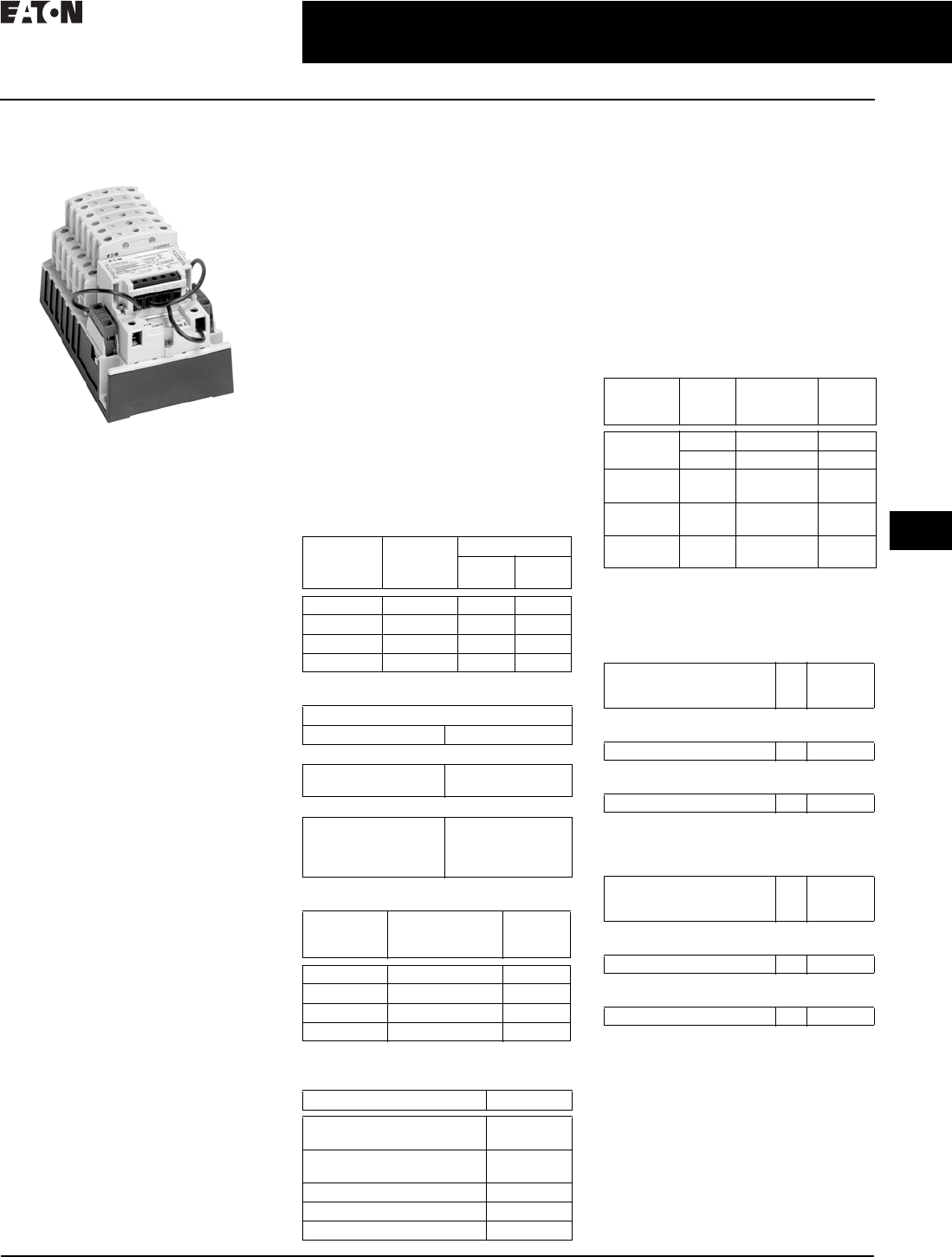
Components
Electrically Held Base Contactor
Electrically Held Base Contactor
The C30CNE20_0 electrically held base
contactor contains a 2NO power pole
as standard and will allow the addition
of power poles to build an electrically
held contactor up to 12 poles maximum.
A mechanically held module kit can
also be added to convert the electrically
held contactor into a mechanically held
contactor in the field.
Table 30.2-17. Electrically Held Base Contactor
1When ordering, select required contactor
by Catalog Number and replace the magnet
coil alpha designation in the Catalog
Number (...) with the proper Code Suffix
from Table 30.2-18.
Table 30.2-18. Coil Base Voltage (Digit 8)
Power
Poles
Catalog
Number 1
2NO C30CNE200
Voltage
(Digit 8)
Code
Suffix
115–120 V 60 Hz/110 V 50 Hz
230–240 V 60 Hz/220 V 50 Hz
460–480 V 60 Hz/440 V 50 Hz
575–600 V 60 Hz/550 V 50 Hz
200–208 V 60 Hz
A
B
C
D
E
265–277 V 60 Hz/240 V 50 Hz
24 V 60 Hz/20 V 50 Hz
28 V 60Hz/24 V 50 Hz
347 V 60 Hz
H
T
V
X
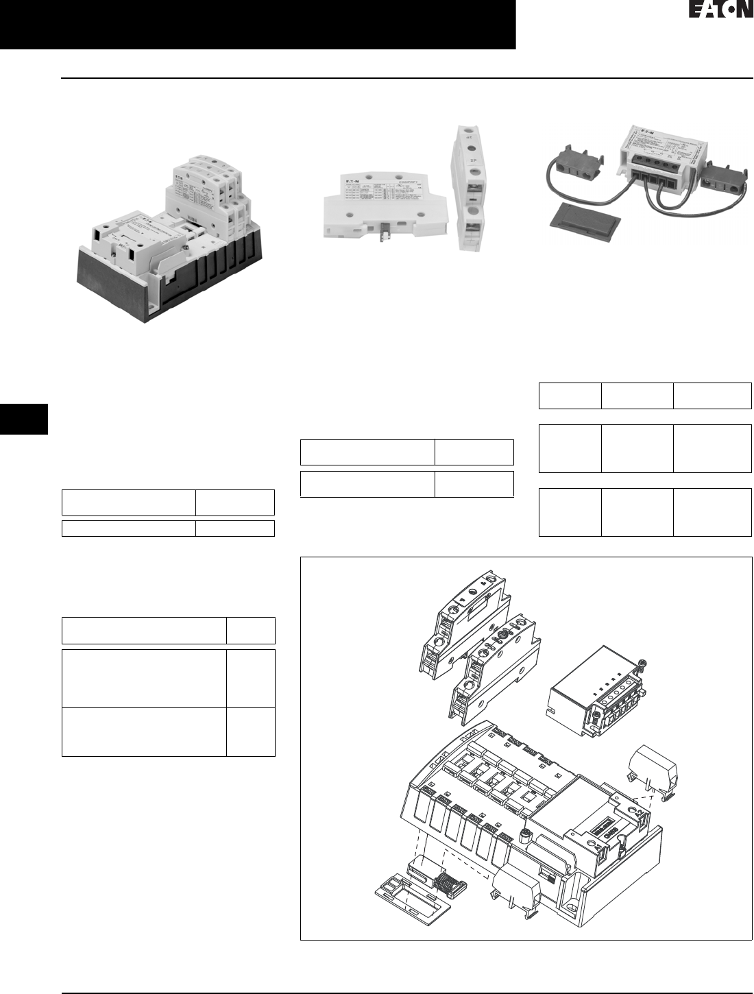
Power Poles
Power Poles
The C30CNM contactor accepts up to a
maximum six single- or double-pole
(or combinations) power poles. These
can be used to form up to:
■12NO poles maximum when six
double-poles are used in NO positions
(1–6) or 8NC poles maximum with
four double-poles in the NC position
(1–4) and 4NO poles with two double-
poles in the 2NO positions (5–6)
Table 30.2-19. Power Poles
Mechanically Held Module Kits
Conversion Kits
These kits are for converting electri-
cally held contactors to mechanically
held units. Kits include control mod-
ule, latch, latch cover and auxiliary
contacts plus installation instructions.
Conversion kits are suitable for coil
voltages of 277 V and below.
Table 30.2-20. Mechanically Held Module Kits
Figure 30.2-4. C30CNM Components—Exploded View
Power
Poles
Catalog
Number
Single-pole
Double-pole
C320PRP1
C320PRP2
Coil
Volt s
Control
Vol ts
Catalog
Number
Two-Wire
24–277 Vac 110–120 Vac
200–277 Vac
24 Vac
12–24 Vdc
C320MH2WA0
C320MH2WH0
C320MH2WT0
C320MH2WT1
Three-Wire
24–277 Vac 110–120 Vac
200–277 Vac
24 Vac
12–24 Vdc
C320MH3WA0
C320MH3WH0
C320MH3WT0
C320MH3WT1
CA08104001E For more information, visit: www.eaton.com/consultants
30.2-7
April 2016
Motor Starters and Contactors—Low Voltage
Sheet 30
22
23
24
25
26
27
28
29
30
31
32
33
34
35
36
37
38
39
40
41
42
4 3
Lighting Contactors
Mechanically Held, 30 A, 2–12 Pole—C30CNM
015
Auxiliary Contacts
Auxiliary Contacts
A mechanically held contactor with
a two-wire control module uses 1NC
auxiliary contact as standard for the
control wiring circuit. The mechanically
held contactor with a three-wire control
module uses 1NO–1NC auxiliary
contacts as standard for the control
wiring circuit. See Ta b l e 3 0 . 2 - 2 1 for
possible additional auxiliary contact
configurations.
Table 30.2-21. Auxiliary Contact Configurations
Table 30.2-22. Auxiliary Contact Blocks
Replacement Parts
Magnetic Coils for the Base Contactor
Magnetic Coils
Table 30.2-23. Magnetic Coils
Wiring Diagrams
Figure 30.2-5. C30CNM Wiring Diagram
Two-Wire Three-Wire
None
1NO (single-pole)
2NO (double-pole)
None
1NC (double-pole)
1NO (double-pole)
1NC (double-pole)
1NO–1NC
(NO single-pole
NC double-pole)
2NO–1NC
(double pole)
1NO–1NC (double-pole)
—
—
Auxiliary
Block
Catalog
Number
Single-pole
Double-pole
C320AMH1
C320AMH2
Coil
Volt age
Catalog
Number
115–120 V 60 Hz/110 V 50 Hz
230–240 V 60 Hz/220 V 50 Hz
460–480 V 60 Hz/440 V 50 Hz
575–600 V 60 Hz/550 V 50 Hz
200–208 V 60 Hz
9-3242-1
9-3242-2
9-3242-3
9-3242-4
9-3242-5
265–277 V 60 Hz/240 V 50 Hz
24 V 60 Hz/20 V 50 Hz
28 V 60 Hz/24 V 50 Hz
347 V 60 Hz
9-3242-6
9-3242-7
9-3242-8
9-3242-9
1
2
Line Load
3
4
5
6
C30CNE Electrically Held
View A
CONTROL
Refer to View “B” for Control Connections
Optional
Auxiliary
Contacts
Optional
Auxiliary
Contacts
A1 A2
Coil
Coil
Voltage
ON and OFF Pushbuttons
View B
Optional Pilot Devices for Electrically Held Contactor
O
FF AUTO
SS
* If Used
O
FF
O
N
AUTO
A1
L2L1
A2
*
Fuse
*Fuse
Remote
OFF
Remote
ON
ON
ON
Pushbutton
OFF
Pushbutton
OFF
Coil
Auxiliary
ContactAuxiliary
Contact
OFF/ON or OFF/AUTO Selector Switch
A1
L2L1
A2
*
Fuse
*Fuse
Remote
Device
ON
OFF
Coil
Auxiliary
Contact
OFF/ON/AUTO or HAND/OFF/AUTO Selector Switch
A1
L2L1
A2
*
Fuse
*Fuse
Remote
Device
ON
OFF
Coil
Auxiliary
Contact

30.2-8
For more information, visit: www.eaton.com/consultants CA08104001E
April 2016
Motor Starters and Contactors—Low Voltage
Sheet 30
22
23
24
25
26
27
28
29
30
31
32
33
34
35
36
37
38
39
40
41
42
4 3
Lighting Contactors
Mechanically Held, 30 A, 2–12 Pole—C30CNM
016
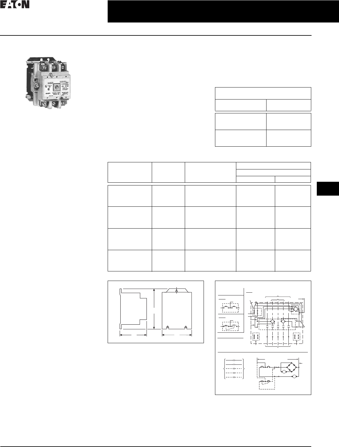
Figure 30.2-6. C30CNM Wiring Diagram
Dimensions
Figure 30.2-7. Approximate Dimensions in Inches (mm)
1
2
Line Load
3
4
5
6
C30CNM Mechanically Held
Refer to View “A” for 2-/3-Wire Control Options
2-WIRE CONTROL
Refer to View “B” for Control Connections
View A
Optional
“N/O”
Aux.
Contacts
Optional
“NC”
Aux.
Contact
P1
A1
C
L
A2
P2 P3
Electronic-Module
Not Used
P4 P5
Coil
Coil
Voltage
3-WIRE CONTROL
Refer to View “C” for Control Connections
Optional
“N/O”
Aux.
Contacts
Optional
“NC”
Aux.
Contact
P1
A1
L
C
O
A2
P2 P3
Electronic-Module
P4 P5
Coil
Coil
Voltage
OFF/ON or OFF/AUTO Selector Switch
View B
Optional Pilot Devices for 2-Wire Control
P1
A1A2
P2 P3
Electronic-Module
P4 P5
Fuse
Fuse
Coil
Voltage
Control
Voltage
O
FF
O
N
(AUTO)
SS
Coil
HAND/OFF/AUTO or ON/OFF/AUTO Selector Switch
P1
A1A2
P2 P3
Electronic-Module
P4 P5
Fuse
Fuse
Coil
Voltage
*
*
*
*
*
*
*
*
* If Used
* If Used
Control
Voltage Remote
Device
O
FF
O
N
AUTO
Coil
ON & OFF Pushbuttons
View C
Optional Pilot Devices for 3-Wire Control
P1
A1A2
P2 P3
Electronic-Module
P4 P5
Fuse
Fuse
Coil
Voltage
Control
Voltage Coil
”NO“
Auxiliary
”NC“
Auxiliary
O
FF
O
N
Remote
O
FF
Remote
O
N
OFF/ON Selector Switch with Spring Return to Center
P1
A1A2
P2 P3
Electronic-Module
P4 P5
Fuse
Fuse
Coil
Voltage
Control
Voltage Coil
”NO“
Auxiliary
”NC“
Auxiliary
ON
OFF
O
FF
O
N
O
FF
O
N
O
FF
O
N
O
FF
O
N
ON ON ON ON ON ON
P1
A1 A2
P2 P3 P4 P5
P1 P2 P3 P4 P5
.35
(9.0)
NOTE:
1 Mounting dimensions remain the same
for 1 to 12 poles.
2 Line and Load terminals are interchangeable.
3 Up to 2NO and 2NC auxiliary contacts can be
added onto the base product.
4 Same power pole can be configured as
NO type or NC type in pole positions 1 – 4;
NO type only in positions 5 – 6.
SIDE VIEW TOP VIEW END VIEW
Power
Pole
Optional
Power
Pole
Optional “NC”
Aux Contacts
Optional “NO”
Aux Contacts
Mounting Holes
Accept
#10 Screws
2 “NO”
Aux
Contacts
1 “NO”
Aux
Contact
2 “NC”
Aux
Contacts
1 “NC”
Aux
Contact
3.86 (98.0)
.35 (9.0)
4.18 (106.2)
3.75 (95.3)
6.50
(165.1)
3.86
(98.0)
.59 (14.9)
7. 3 9
(187.6)
.22 (5.5)
CA08104001E For more information, visit: www.eaton.com/consultants
30.2-9
April 2016
Motor Starters and Contactors—Low Voltage
Sheet 30
22
23
24
25
26
27
28
29
30
31
32
33
34
35
36
37
38
39
40
41
42
4 3
Lighting Contactors
Magnetically Latched (Mechanically Held)—A202
017
A202–Open (ECL04–Enclosed)
60 Ampere Size
General Description
AC lighting contactors provide a safe
convenient means for local or remote
switching of relatively large tungsten,
fluorescent or mercury arc lamp loads.
They are also suitable for low pressure
and high pressure sodium lamp loads.
These lighting contactors are designed
to withstand the large initial inrush
currents of tungsten lamp loads with-
out contact welding. They are full rated
and do not require derating as do stan-
dard motor control contactors.
Operation (Magnetic Latch)
A permanent magnet is built into the
contactor structure that will maintain
the contactor in its energized state
indefinitely without using control
power. When energized, a DC current
is applied to the latch coil producing
a magnetic field that reinforces the
polarity of the permanent magnet,
pulling in the contactor. The current
to the coil is disconnected by the coil
clearing interlock. In order to drop out
the contactor, it is necessary to apply
a field through the STOP coil in the
reverse direction to the permanent
magnet. This momentarily cancels the
magnetic attraction and the contactor
drops out.
Enclosures
Open and NEMA Types 1, 3R, 4X and 12.
Specifications
■Te r m i n a l s :
❑All except
30 A devices . . . . . . . . . . . . Al/Cu
❑30 A devices . . . . . . . . . . . Cu only
■Ballast load 600 Vac, breaking
all lines
■Tungsten lamp loads, maximum volts:
❑Line-to-line. . . . . . . . . . . . 480 Vac
❑Line-to-neutral. . . . . . . . . 277 Vac
Typical Specifications
Magnetically-held lighting contactors
are Eaton’s Type A202 or approved
equal for lighting loads of 30–400 A.
Magnetically-held combination lighting
contactors are Type ECL15 (breaker) or
ECL13 (fusible) or approved equal for
loads of 30–200 A when integral short
circuit protection is required.
These contactors are designed
to withstand the large initial inrush
currents of tungsten and ballast lamp
loads as well as non-motor (resistive)
loads without contacts welding.
The contactors are capable of being
“magnetically held” via a magnetic
latch design using a permanent
magnet. The contactor shall be
operated by a RUN signal and a STOP
signal preventing the contactor from
switching to “OFF” during control
circuit power failures.
Table 30.2-24. Ratings—Latched AC
Lighting Contactors
Table 30.2-25. Non-Combination Lighting Contactors—6 to 12 Pole
Figure 30.2-8. Open Type
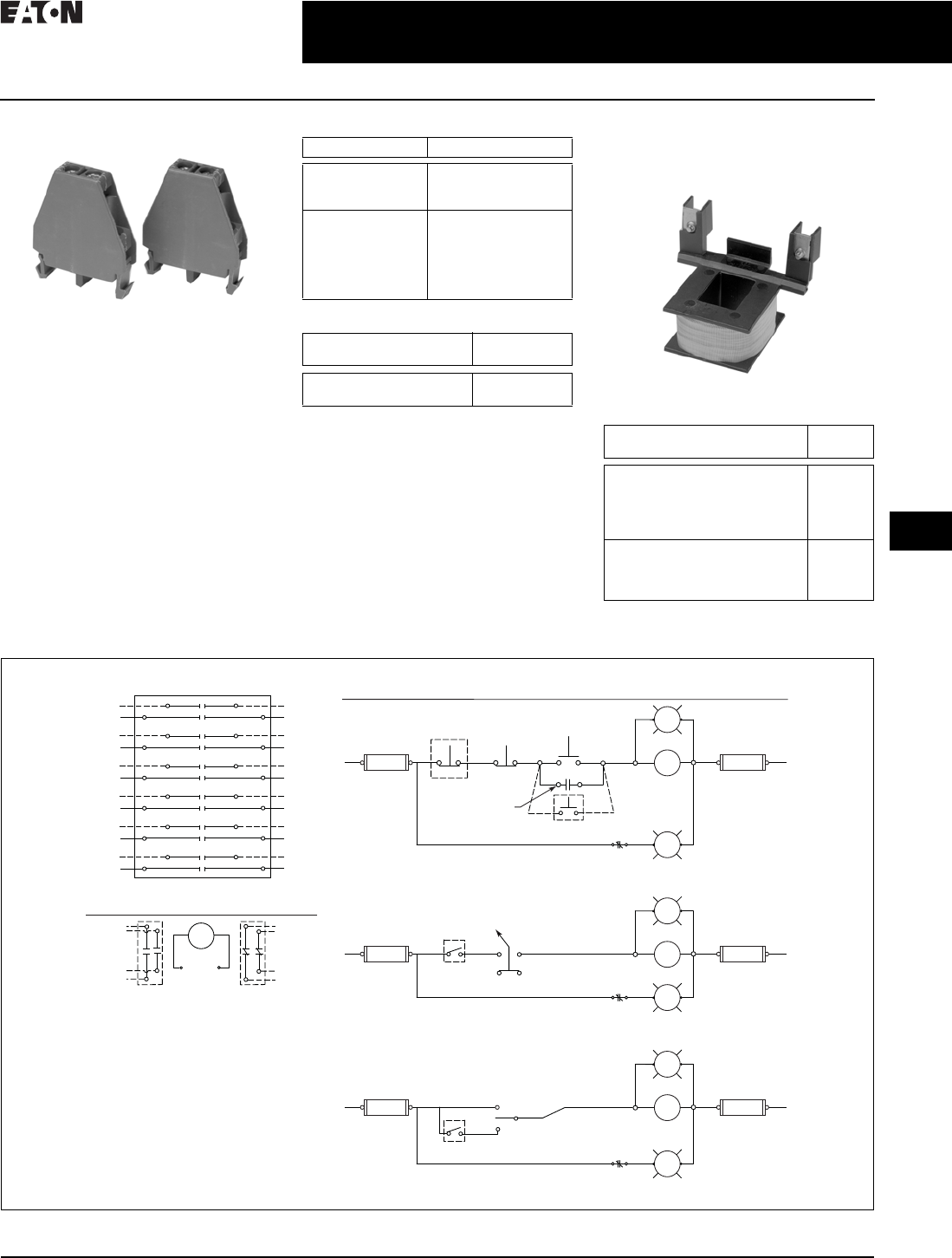
Figure 30.2-9. Connection Diagram
For enclosure box dimensions,
refer to Page 30.6-3.
Holding Circuit Auxiliary Contact or
Pushbutton Station not Included
Continuous Amperes
(Enclosed)
Number
of Poles
30
60
100
2, 3, 4, 5, 6, 8, 10, 12
2, 3, 4, 5, 6, 8, 10, 12
2, 3, 4, 5, 6, 8, 10, 12
200
300
400
2, 3, 4, 5, 6, 8, 10, 12
2, 3
2, 3
Continuous
Amperes
(Enclosed)
Number
of Poles
Pole
Configuration
Dimensions in Inches (mm)
Open Type
Wide A High B
30 6
8
10
12
3 x 3
4 x 4
5 x 5
4 x 4 x 4
7. 1 3 ( 1 8 1. 1 )
7. 1 3 ( 1 8 1. 1 )
10.63 (270.0)
12.38 (314.5)
4.46 (113.3)
4.46 (113.3)
4.46 (113.3)
6.88 (174.8)
60 6
8
10
12
3 x 3
4 x 4
5 x 5
5 x 5 x 2
7. 1 3 ( 1 8 1. 1 )
10.63 (270.0)
10.63 (270.0)
15.00 (381.0)
4.46 (113.3)
4.46 (113.3)
4.46 (113.3)
6.88 (174.8)
100 6
8
10
12
3 x 3
5 x 3
5 x 5
5 x 5 x 2
9.75 (247.7)
12.38 (314.5)
15.00 (381.0)
34.13 (866.9)
6.88 (174.8)
6.88 (174.8)
6.88 (174.8)
27.50 (698.5)
200 6
8
10
12
3 x 3
5 x 3
5 x 5
5 x 5 x 2
9.75 (247.7)
12.38 (314.5)
15.00 (381.0)
34.13 (866.9)
6.88 (174.8)
6.88 (174.8)
6.88 (174.8)
27.50 (698.5)
C
B
A
Connections for
Control Stations
Elementary Diagram
Separate Control
Connections for Contactor
Front View Diagram
Off
23
1
1
Momentary
Pushbutton
Top
Auxiliary
Contact“C”
(Not Supplied)
L2
Control
Module
Line
When Supplied
Red
Maintained
Pushbutton
Fig. A
On
Off
23
Line
M
Load
Off
Momentary
Pushbutton
1
1
1
3
2
Off On
Maintained
Pushbutton
N.O.
N.C.
Top
Red
White M
M
“C”
L2
Red
Red
Black
Auxiliary
Contact
(When Used)
Connect separate control
lines to the No. 1 terminal
on the remote control
station and to the “L2”
terminal on the contactor.
Auxiliary
Contact
(When Used)
Poles to Load
Black
33
N.C. N.O.
2
2
White
On
Fig. B
Fig. 1
8
8
8
8
8
M
On Off
M
~~
+
–
Red
M
M
M
M
~~
+
–
On
Control Voltage Lines
On
Off

30.2-10
For more information, visit: www.eaton.com/consultants CA08104001E
April 2016
Motor Starters and Contactors—Low Voltage
Sheet 30
22
23
24
25
26
27
28
29
30
31
32
33
34
35
36
37
38
39
40
41
42
4 3
Lighting Contactors
Magnetically Latched (Mechanically Held)—A202
018
Enclosed Box Selection
Table 30.2-26. Type 1 Non-combination
Lighting Contactors—Magnetically
Latched—A202
Table 30.2-27. Type 3R, 4/4X, 12
Non-combination Lighting Contactors—
Magnetically Latched—A202
Table 30.2-28. Type 1 Combination Lighting
Contactors
Table 30.2-29. NEMA 3R, 4/4X, 12 Combination
Lighting Contactors
Ampere Size
(Poles)
Box
No.
Shipping
Weight
Lbs (kg)
Contactors—without Control Power Transformers
30 A (2P, 3P, 4P, 5P) 2 8.5 (3.9)
30 A (6P, 8P, 10P, 12P) 3 13 (5.9)
30 A (20P) 4 35 (16)
60 A (2P, 3P, 4P, 5P) 2 8.7 (3.9)
60 A (6P, 8P, 10P, 12P) 3 13.5 (6.1)
60 A (20P) 4 40 (18)
100 A (2P, 3P, 4P, 5P) 4 40 (18)
100 A (6P, 8P, 10P, 12P) 9 85 (39)
100 A (20P) 9 100 (45)
200 A (2P, 3P, 4P, 5P) 4 46 (21)
200 A (6P, 8P, 10P, 12P) 9 95 (43)
200 A (20P) 9 110 (50)
300 A (2P, 3P) 10 115 (52)
400 A (2P, 3P) 10 125 (57)
Contactors—with Control Power Transformers
30 A (2P, 3P, 4P, 5P) 2 12.5 (5.7)
30 A (6P, 8P, 10P, 12P) 3 17 (7.7)
30 A (20P) 4 39 (18)
60 A (2P, 3P, 4P, 5P) 2 12.7 (5.8)
60 A (6P, 8P, 10P) 3 17.5 (7.9)
60 A (12P) 9 87 (39)
60 A (20P) 4 44 (20)
100 A (2P, 3P, 4P, 5P) 4 47 (21)
100 A (6P, 8P, 10P, 12P) 9 92 (42)
100 A (20P) 9 107 (49)
200 A (2P, 3P, 4P, 5P) 4 53 (24)
200 A (6P, 8P, 10P, 12P) 9 102 (46)
200 A (20P) 9 117 (53)
300 A (2P, 3P) 10 122 (55)
400 A (2P, 3P) 10 132 (60)
Ampere Size
(Poles)
Box
No.
Shipping
Weight
Lbs (kg)
Contactors—without Control Power Transformers
30 A (2P, 3P, 4P, 5P) 5 13 (5.9)
30 A (6P, 8P, 10P, 12P) 7 21 (10)
30 A (20P) 8 46 (21)
60 A (2P, 3P, 4P, 5P) 5 14 (6.4)
60 A (6P, 8P, 10P, 12P) 7 22 (10)
60 A (20P) 8 48 (22)
100 A (2P, 3P, 4P, 5P) 8 50 (23)
100 A (6P, 8P, 10P,12P) 9 58 (26)
100 A (20P) 10 100 (45)
200 A (2P, 3P, 4P, 5P) 8 52 (24)
200 A (20P) 10 105 (48)
300 A (2P, 3P) 10 113 (51)
400 A (2P, 3P) 10 125 (57)
Contactors—with Control Power Transformers
30 A (2P, 3P) 6 15 (6.8)
30 A (4P, 5P, 6P, 8P, 10P, 12P) 7 28 (13)
30 A (20P) 8 54 (25)
60 A (2P, 3P) 6 16 (7.3)
60 A (4P, 5P, 6P, 8P, 10P, 12P) 7 29 (13)
60 A (20P) 8 55 (25)
100 A (2P, 3P, 4P, 5P) 8 57 (26)
100 A (6P, 8P, 10P, 12P) 9 65 (30)
100 A (20P) 10 112 (51)
200 A (2P, 3P, 4P, 5P) 8 59 (27)
300 A (2P, 3P) 10 120 (54)
400 A (2P, 3P) 10 132 (60)
Ampere Size Box
No.
Shipping
Weight
Lbs (kg)
Magnetically Latched—Non-reversing (3P Only)—
with or without Control Power Transformers
30 A A 35 (16)
60 A A 36 (16)
100 A C 65 (30)
200 A with disconnect switch D 110 (50)
200 A with thermal-
magnetic breaker
E 150 (68)
300 A E 140 (64)
400 A E 190 (86)
Ampere Size Box
No.
Shipping
Weight
Lbs (kg)
Magnetically Latched—Non-reversing (3P Only)—
with or without Control Power Transformers
30 A A 35 (16)
60 A A 36 (16)
100 A C 65 (30)
200 A with disconnect switch D 110 (50)
200 A with thermal-
magnetic breaker
E 150 (68)
300 A with disconnect switch 72” 375 (170)
300 A with thermal-
magnetic breaker
E 160 (73)
400 A with disconnect switch 72” 425 (193)
400 A with thermal-
magnetic breaker
E210 (95)
For enclosure box dimensions,
refer to Page 30.6-3.

CA08104001E For more information, visit: www.eaton.com/consultants
30.2-11
April 2016
Motor Starters and Contactors—Low Voltage
Sheet 30
22
23
24
25
26
27
28
29
30
31
32
33
34
35
36
37
38
39
40
41
42
4 3
Lighting Contactors
Electrically Held and Magnetically Latched Combination Lighting, Three-Pole Only—Type ECL
019
Combination Lighting
Contactors
Types ECL12, ECL13, ECL14
and ECL15
General Description
Catalog Number ECL12, ECL13, ECL14
and ECL15 combination lighting con-
tactors offer convenient installation of
switching and overcurrent protection
in a single enclosure. Combination
lighting contactors are ideally suited
for industrial and commercial lighting
applications or where a lighting circuit
may have to be disconnected for peri-
odic maintenance. They may also be
applied on resistance heating loads.
Typical Specifications
Magnetically latched combination
lighting contactors are Eaton’s Type
ECL15 (breaker) or ECL13 (fusible) or
approved equal for loads of 30–200 A
when integral short-circuit protection
is required.
These contactors are designed to
withstand the large initial inrush
currents of tungsten and ballast lamp
loads as well as non-motor (resistive)
loads without contact welding. The
contactors are capable of being
“magnetically held” via a magnetic
latch design using a permanent magnet.
The contactor shall be operated by
a RUN signal and a STOP signal
preventing the contactor from switch-
ing to “OFF” during control circuit
power failures.
Electrically held combination lighting
contactors are Eaton Type ECL14
(breaker) or ECL12 (fusible) or
approved equal for loads of 30–400 A
when integral short-circuit protection
is required.
These contactors shall be designed to
withstand the large initial inrush cur-
rents of tungsten and ballast lamp loads
as well as non-motor (resistive) loads
without contact welding. Contactors
shall be capable of accepting up to eight
auxiliary contacts—top and/or side up to
60 A and side only up to 400 A. Contac-
tors shall be capable of being operated
by AC or DC control.
Features
■Disconnect devices—either a
Series C circuit breaker or a fusible
disconnect switch
■Handle mechanism—flange
mounted
■UL listed
■UL service entrance approved for
NEMA 3R outdoor enclosure
■Extra room for modifications such
as a 24-hour time clock
Catalog Number Selection
Table 30.2-30. Enclosed Lighting Contactor Catalog Numbering System
1For normally closed poles, see PG03300001E.
2C30CN available in 30 A only.
EC L 12 D 1 A 3 E - X
Design
L= CN35 or A202 lighting contactor
C= C30CN lighting contactor
Class
03 = Non-combination electrically held lighting contactor
04 = Non-combination mechanically held/magnetically
latched lighting contactor
12 = Combination electrically held lighting contactor—
fusible disconnect
13 = Combination magnetically latched lighting
contactor—fusible disconnect
14 = Combination electrically held lighting
contactor—thermal-magnetic circuit breaker
15 = Combination magnetically latched lighting
contactor—thermal-magnetic circuit breaker
Ampere Size 2
A= 10 A
B= 20 A
C= 30 A
D= 60 A
E= 100 A
F= 200 A
G= 300 A
H= 400 A
J= 600 A
Enclosure Types
1 = Type 1—General purpose
2 = Type 3R—Rainproof
3 = Type 4—Watertight (painted)
4 = Type 4X—Watertight (304-grade stainless steel)
6 = Type 7/9—Explosion proof
8 = Type 12—Dust-tight
9 = Type 4X—Watertight (316-grade stainless steel)
Coil Voltage
A= 120/60 110/50
B= 240/60 220/50
C= 480/60 440/50
D= 600/60 550/50
E= 208/60
G= 550/50
H= 277/60
J= 208–240/60
K= 240/50
L= 380/50
M= 415/50
P= 12 Vdc
Q= 24 Vdc
R= 48 Vdc
S= 125 Vdc
T= 24/60
U= 24/50
V= 32/50
W= 48/60
X= 104–120/60
Y= 48/50
Z= By description
Modification Codes
(See PG03300001E)
Number of Poles 1
1, 2, 3, 4, 5, 6, 7, 8, 9 = Poles required
A = 10 Poles
B = 12 Poles
C = 20 Poles
Combination Devices = Three-pole only
Disconnect Fuse Clip Ratings
A= None
B= 30 A/250 V R
C= 30 A/600 V R
D= 60 A/250 V R
E= 30 A/600 V R
F= 100 A/250 V R
G= 100 A/600 V R
H= 200 A/250 V R
J= 200 A/600 V R
K= 400 A/250 V R
L= 400 A/600 V R
M= 600 A/250 V R
N= 600 A/600 V R
P= 800 A/600 V R
T= By description
Thermal-Magnetic Breaker Ratings
A= None
D= 20 A
E= 30 A
F= 60 A
G= 100 A
H= 200 A
J= 300 A
K= 400 A
L= 600 A
M= 800 A
T= By description
30.2-12
For more information, visit: www.eaton.com/consultants CA08104001E
April 2016
Motor Starters and Contactors—Low Voltage
Sheet 30
22
23
24
25
26
27
28
29
30
31
32
33
34
35
36
37
38
39
40
41
42
4 3
Lighting Contactors
E
lectrically Held and Magnetically Latched Combination Lighting, Three-Pole Only—Type ECL
020
Table 30.2-31. Ratings—Latched ELC15
Series C Circuit Breaker Disconnect
Table 30.2-32. ELC13—Fusible Disconnect
Switch
Table 30.2-33. Ratings—Electrically-held
ELC14 Series C Circuit Breaker Disconnect
1UL ballast and resistive ratings only.
Table 30.2-34. ELC12—Fusible
Disconnect Switch
2UL ballast and resistive ratings only.
Continuous
Amperes
(Enclosed)
Circuit Breaker
Ampere
Rating
System
Voltage
30
60
100
200
30
60
100
200
600
600
600
600
Continuous
Amperes
(Enclosed)
Fuse Clip
Ampere
Rating
System
Vol ta ge
30
60
100
200
30
60
100
200
250, 600
250, 600
250, 600
250, 600
Continuous
Amperes
(Enclosed)
Circuit Breaker
Ampere
Rating
System
Voltage
30
60
100
30
60
100
600
600
600
200
300
400 1
200
300
400
600
600
600
Continuous
Amperes
(Enclosed)
Fuse Clip
Ampere
Rating
System
Volta ge
30
60
100
30
60
100
250, 600
250, 600
250, 600
200
300
400 2
200
300
400
250, 600
250, 600
250, 600
Table 30.2-35. Factory Modifications
Description Enclosure Used On
Standard Combination
Control transformers:
480 to 120 V control transformer
100 VA extra capacity transformer
200 VA extra capacity transformer
240 to 120 V control transformer with fuse in holder
208 to 120 V control transformer with fuse in holder
415 to 110 V control transformer with fuse in holder
277 to 120 V control transformer with fuse in holder
Any
■
■
■
■
■
■
■
■
■
■
■
■
■
■
Lightning arrester
Undervoltage relay
On-off pushbutton
Hand-off-auto selector switch
Any
■
■
■
■
Addition of photoelectric receptacle and relay with
photo cell Installed (two-wire circuit)
—
■■
24-hour time clock, 120 V
24-hour time clock with day omission, 120 V
7-day time clock, 120 V
Cover plate for use in place of watertight hub on enclosure top
—■
■
■
■
■
■
■
■
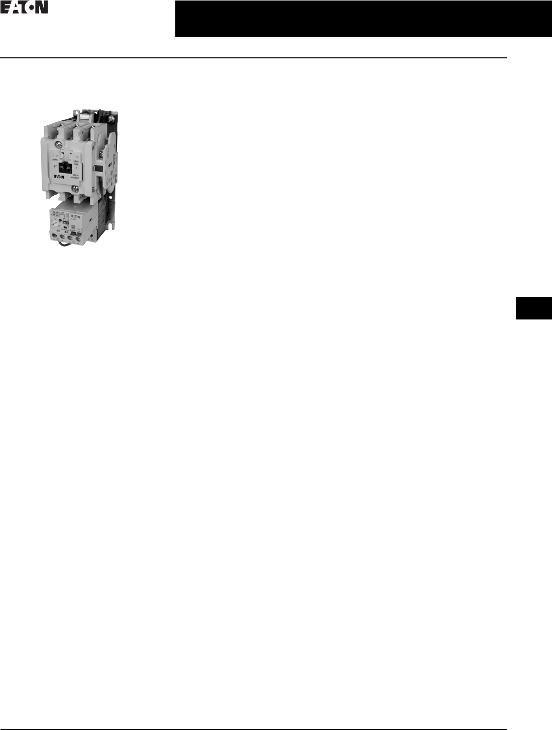
CA08104001E For more information, visit: www.eaton.com/consultants
30.3-1
April 2016
Motor Starters and Contactors—Low Voltage
Sheet 30
22
23
24
25
26
27
28
29
30
31
32
33
34
35
36
37
38
39
40
41
42
4 3
Motor Starters—Electromechanical
Freedom Line—General Description
021
NEMA Motor Starters
Freedom Series
NEMA AN19DN0A5E005
NEMA Size 1
General Description
The Freedom Series starters and
contactors listed in this catalog
feature a compact, space-saving
design and high strength, impact
and temperature-resistant insulating
materials. Starters and contactors
are available in the NEMA (National
Electrical Manufacturers’ Association)
style. The NEMA devices are sized
based on traditional NEMA
classifications.
Features
Freedom NEMA
■Adjustable bimetallic ambient
compensated overload relays
with interchangeable heater
packs—available in three basic sizes,
covering applications up to 900 hp—
reducing the number of different
contactor/overload relay combina-
tions that have to be stocked. Fixed
heater overloads are optional
■Electronic overload relay (C440)
available as a stand-alone unit
and assembled with a Freedom
contactor
■A full line of snap-on accessories—
top and side mounted auxiliary
contacts, solid-state and pneumatic
timers, etc.
■Straight-through wiring—line lugs
at top, load lugs at bottom
■Horizontal or vertical mounting
on upright panel for application
freedom
■Screw type power terminals have
captive, backed-out self-lifting
pressure plates with ± screws—
reduced wiring time
■Accessible terminals for easy wiring.
Optional fingerproof shields avail-
able to prevent electrical shock
■Top located coil terminals conve-
nient and readily accessible. 45 mm
contactor magnet coils have three
terminals, permitting either top or
diagonal wiring—easy to replace
European or U.S. style starters
or contactors without changing
wiring layout
■Designed to meet or exceed NEMA,
UL, CSA, VDE, BS and other interna-
tional standards and listings
■American engineering—built by
Eaton, using the latest in statistical
process control methods to pro-
duce high quality, reliable products
■Sized based on standard NEMA
classifications
■Easy coil change and inspectable/
replaceable contacts
■Available in open and NEMA Type 1,
3R, 4/4X and 12 enclosures
Standards and Certifications
■Standard: Designed to meet or
exceed UL, NEMA and CSA
■UL listed: UL File #E1491, Guide
#NLDX—Open; UL File #E176513—
Enclosed Combination Motor Con-
trollers; UL File #E19224—Enclosed
Non-Combination Motor Controllers;
UL File #E195239—Enclosed Power
Conversion Equipment
■CSA certified: CSA File #LR353,
Class #321104 Open and NEMA 1
Enclosed
Certified Type 2 Coordination
Eaton’s Freedom Series NEMA start-
ers are now UL certified to achieve IEC
947 Type 2 coordination against
100,000 A short-circuit fault currents.
Any brand of properly selected fuse
can be used. Type 2 coordination
means that the starter will be suitable
for further use following a short-circuit
fault.
Short-Circuit Protection
Fuses and inverse-time circuit breakers
may be selected per Article 430, Part D
of the National Electrical Code® to
protect motor branch circuits from
fault conditions. If higher ratings or
settings are required to start the motor,
do not exceed the maximum as listed
in Exception No. 2, Article 430.52.
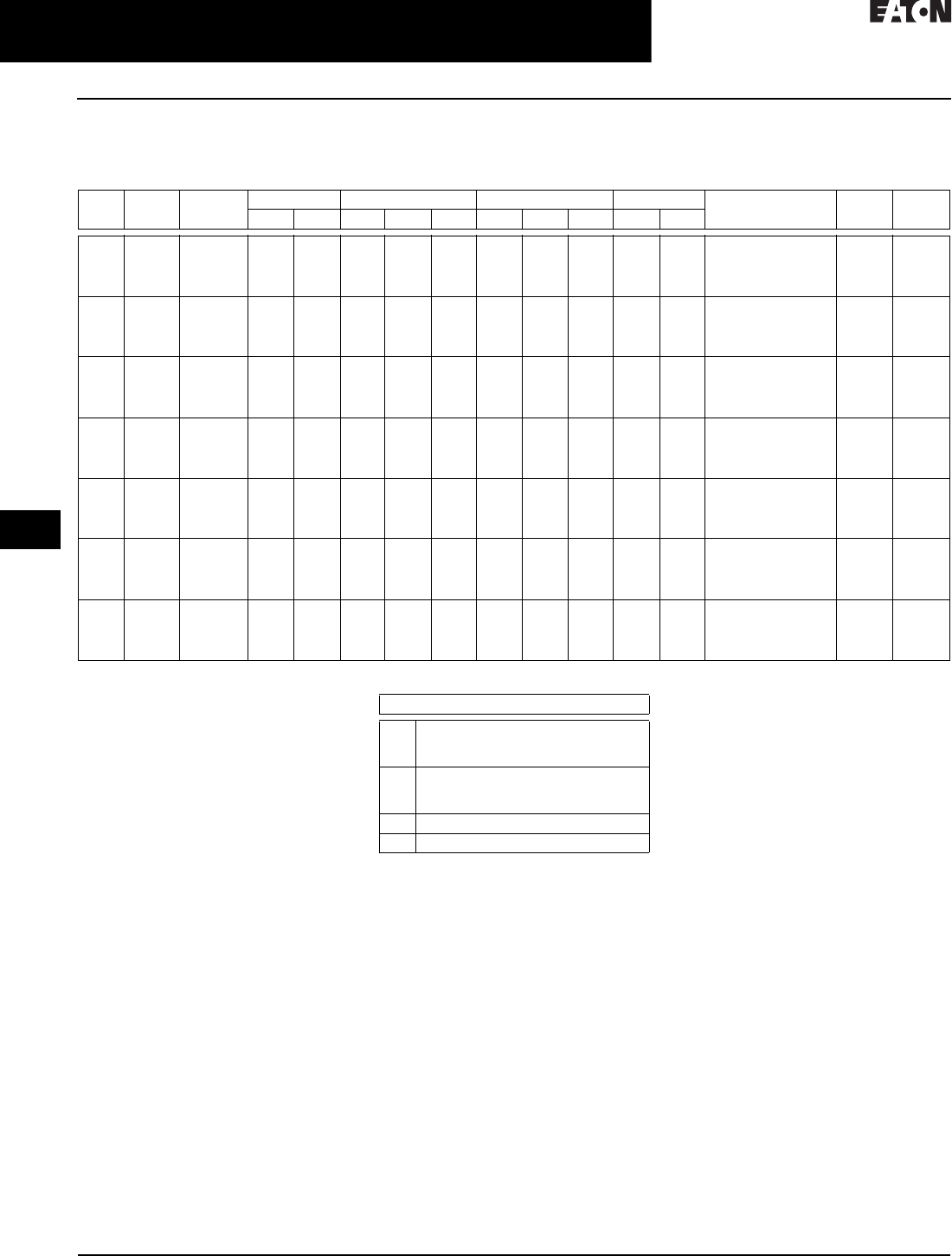
30.3-2
For more information, visit: www.eaton.com/consultants CA08104001E
April 2016
Motor Starters and Contactors—Low Voltage
Sheet 30
22
23
24
25
26
27
28
29
30
31
32
33
34
35
36
37
38
39
40
41
42
4 3
Motor Starters—Electromechanical
Freedom Line—Technical Data—NEMA Contactors and Starters
022
Technical Data
NEMA Sizes 00-8
Table 30.3-1. AC Coil Data
General Coil Data
■Coil Offering—tape wound:
❑NEMA Sizes 00–0
❑UL insulation rating: Class 130 (B)
■Coil Offering—encapsulated:
❑NEMA Sizes 1–3
❑UL insulation rating: Class 130 (A)
■Coil Offering—encapsulated:
❑NEMA Sizes 4–5
❑UL insulation rating: Class 155 (F)
■Operational Limits:
❑85% to 110% of rated voltage—AC
❑80% to 110% of rated voltage—DC
Table 30.3-2. Coil Data Notes
All data is based on a standard
contactor with no auxiliary devices
and a 120 Vac or 24 Vdc magnet coil.
Coil data has a ±5% range depending
on the application, therefore specific
data may vary.
NEMA
Sizes
Motor
Voltage
Maximum
hp Rating
P.U. Volts P.U. Sealed D.O. Volts Maximum Operation
Rate Operations/Hour
P. U .
Time ms
D.O.
Time ms
Cold Hot VAR VA Watts VAR VA Watts Cold Hot
00 200
230
460
575
1-1/2
1-1/2
2
2
74% 78% 64 80 49 7.1 7.5 2.4 45% 46% 12,000 12 12
0200
230
460
575
3
3
5
5
74% 78% 78 100 65 9.2 10 3.1 45% 46% 12,000 12 12
1200
230
460
575
7-1/2
7-1/2
10
10
74% 78% 210 230 95 27 28 7.8 49% 50% 12,000 20 14
2200
230
460
575
10
15
25
25
74% 78% 210 230 95 27 28 7.8 49% 50% 12,000 20 14
3200
230
460
575
25
30
50
50
72% 76% 374 390 112 48 49.8 13 50% 52% 7200 14 11
4200
230
460
575
40
50
100
100
73% 76% 1132 1158 240 96 100 27.2 54% 56% 2400 28 14
5200
230
460
575
75
100
200
200
75% 77% 1132 1158 240 96 100 27.2 63% 64% 2400 25 13
Description
P.U. Pickup time is the average time taken
from closing of the coil circuit to main
contact touch.
D.O. Dropout time is the average time taken
from opening of the coil circuit to main
contact separation.
Cold Coil data with a cold coil.
Hot Coil data with a hot coil.

CA08104001E For more information, visit: www.eaton.com/consultants
30.3-3
April 2016
Motor Starters and Contactors—Low Voltage
Sheet 30
22
23
24
25
26
27
28
29
30
31
32
33
34
35
36
37
38
39
40
41
42
4 3
Motor Starters—Electromechanical
Freedom Line—Technical Data—NEMA Contactors and Starters
023
Table 30.3-3. DC Coil Data
General Coil Data
■Coil Offering—tape wound:
❑NEMA Sizes 00–0
❑UL insulation rating: Class 130 (B)
■Coil Offering—encapsulated:
❑NEMA Sizes 1–3
❑UL insulation rating: Class 130 (A)
■Coil Offering—encapsulated:
❑NEMA Sizes 4–5
❑UL insulation rating: Class 155 (F)
■Operational Limits:
❑85% to 110% of rated voltage—AC
❑80% to 110% of rated voltage—DC
Table 30.3-4. Coil Data Notes
All data is based on a standard
contactor with no auxiliary devices
and a 120 Vac or 24 Vdc magnet coil.
Coil data has a ±5% range depending
on the application, therefore specific
data may vary.
NEMA
Sizes
Motor
Voltage
P.U. Sealed D.O. Volts
(Hot)
P. U .
Time ms
D.O.
Time ms
Maximum Operation
Rate Operations/Hour
Mechanical
Life Millions
Amperes Watts Volts (Hot) Amperes Watts
00 and 0 12
24
48
120
6.4
3.2
1.6
0.64
76.8
76.8
76.8
76.8
80%
80%
80%
80%
0.28
0.14
0.07
0.028
3.36
3.36
3.36
3.36
60%
60%
60%
60%
22
22
22
22
17
17
17
17
3600
3600
3600
3600
5
5
5
5
1 and 2 12
24
48
120
15.4
6.2
2.9
1.1
126
88.4
76.2
67.3
68%
60%
56%
53%
0.42
0.21
0.11
0.041
4.98
4.96
5.04
4.87
30%
29%
28%
29%
21
20
20
20
12
13
14
16
3600
3600
3600
3600
2
2
2
2
312
24
48
120
24
12
6.1
2.5
293
288
295
298
65%
61%
62%
61%
0.40
0.20
0.097
0.038
4.84
4.75
4.67
4.57
23%
22%
22%
22%
39
38
37
37
14
14
14
16
3600
3600
3600
3600
2
2
2
2
4 and 5 24
48
120
240
18
9.0
3.3
1.7
400
400
450
440
67%
67%
65%
64%
0.22
0.11
0.05
0.02
5.3
5.2
5.4
4.9
25%
25%
28%
26%
53
49
56
49
14
16
19
21
2400
2400
2400
2400
2
2
2
2
Description
P.U. Pickup time is the average time taken
from closing of the coil circuit to main
contact touch.
D.O. Dropout time is the average time taken
from opening of the coil circuit to main
contact separation.
Cold Coil data with a cold coil.
Hot Coil data with a hot coil.

30.3-4
For more information, visit: www.eaton.com/consultants CA08104001E
April 2016
Motor Starters and Contactors—Low Voltage
Sheet 30
22
23
24
25
26
27
28
29
30
31
32
33
34
35
36
37
38
39
40
41
42
4 3
Motor Starters—Electromechanical
Freedom Line—Technical Data—NEMA
024
Table 30.3-5. Specifications—Sizes 00–3
Description Contactor Catalog Number/Size
CN15A
NEMA Size 00
CN15B
NEMA Size 0
CN15D
NEMA Size 1
CN15G
NEMA Size 2
CN15K
NEMA Size 3
Configuration
Number of poles
Auxiliary contacts, standard
Add-on auxiliary contacts
2, 3, 4
4th pole NO (1)
Top (4) or side (4)
2, 3
Side NO (1)
Top (4) or side (3)
2, 3, 4, 5
Side NO (1)
Top (4) or side (3)
2, 3, 4, 5
Side NO (1)
Top (4) or side (3)
2, 3
Side NO (1)
Left side (4) or right side (3)
Frame size 45 mm 45 mm 65 mm 65 mm 90 mm
Maximum voltage rating 600 Vac 600 Vac 600 Vac 600 Vac 600 Vac
Continuous ampere ratings (I) 9 A 18 A 27 A 45 A 90 A
Maximum horsepower (hp)
Single-phase 115 V
230 V
1/3
1
1
2
2
3
3
7-1/2
7-1/2
15
Three-phase 200 V
230 V
460 V
575 V
1-1/2
1-1/2
2
2
3
3
5
5
7-1/2
7-1/2
10
10
10
15
25
25
25
30
50
50
Coil operating range % of rated voltage –15% to +10% –15% to +10% –15% to +10% –15% to +10% –15% to +10%
Operating temperature
Maximum operating altitude in feet (m)
Mechanical life
–20 °C to +65 °C
6000 (1828)
20,000,000
–20 °C to +65 °C
6000 (1828)
20,000,000
–20 °C to +65 °C
6000 (1828)
10,000,000
–20 °C to +65 °C
6000 (1828)
10,000,000
–20 °C to +65 °C
6000 (1828)
6,000,000
Electrical life (480 V/60 Hz)
AC-3
AC-4
4,000,000
90,000
3,000,000
85,000
5,000,000
200,000
3,500,000
62,000
1,700,000
80,000
Wire range
Power terminals 12–16 stranded,
12–14 solid Cu
8–16 stranded,
10–14 solid Cu
8–14 stranded
or solid Cu
2–14 (upper) and/or
6–14 (lower)
stranded or solid Cu
1/0–14 Cu
Control terminals 12–16 stranded,
12–14 solid Cu
12–16 stranded,
12–14 solid Cu
12–16 stranded,
12–14 solid Cu
12–16 stranded,
12–14 solid Cu
12–16 stranded
12–14 solid Cu
Power terminal torque
Line and load—lb-in
7 15 20 40 (14–8 AWG)
45 (6–4 AWG)
50 (3 AWG)
35 (14–10 AWG)
40 (8 AWG)
45 (6–4 AWG)
50 (3–1/0 AWG)
Auxiliary contact rating A600, P300

CA08104001E For more information, visit: www.eaton.com/consultants
30.3-5
April 2016
Motor Starters and Contactors—Low Voltage
Sheet 30
22
23
24
25
26
27
28
29
30
31
32
33
34
35
36
37
38
39
40
41
42
4 3
Motor Starters—Electromechanical
Freedom Line—Technical Data—NEMA
025
Table 30.3-6. Specifications—Sizes 4–5
Description Contactor Catalog Number/Size
CN15N
NEMA Size 4
CN15S
NEMA Size 5
Configuration
Number of poles
Auxiliary contacts, standard
Add-on auxiliary contacts
2, 3
Side NO (1)
Left side (3) or right side (4)
2, 3
Side NO (1)
Left side (3) or right side (4)
Frame size 180 mm 180 mm
Maximum voltage rating 600 Vac 600 Vac
Continuous ampere ratings (i) 135 A 270 A
Maximum horsepower (hp)
Single-phase 115 V
230 V
—
—
—
—
Three-phase 200 V
230 V
460 V
575 V
40
50
100
100
75
100
200
200
Coil operating range % of rated voltage –15% to +10% –15% to +10%
Operating temperature
Maximum operating altitude in feet (m)
Mechanical life
–20 °C to +65 °C
6000 (1828)
5,000,000
–20 °C to +65 °C
6000 (1828)
5,000,000
Electrical life (480 V/60 Hz)
AC-3
AC-4
800,000
70,000
500,000
34,000
Wire range
Power terminals Open—3/0–8 Cu;
Enclosed—250 kcmil–6 Cu/Al
750 kcmil—2 or
(2) 250 kcmil–3/0 Cu/Al
Control terminals 12–16 stranded, 12–14 solid Cu 12–16 stranded, 12–14 solid Cu
Power terminal torque
Line and load—lb-in
200 550
Auxiliary contact rating A600, P300

30.3-6
For more information, visit: www.eaton.com/consultants CA08104001E
April 2016
Motor Starters and Contactors—Low Voltage
Sheet 30
22
23
24
25
26
27
28
29
30
31
32
33
34
35
36
37
38
39
40
41
42
4 3
Motor Starters—Electromechanical
Freedom Line—Technical Data—NEMA
026
Table 30.3-7. 380V , 50 Hz Starters—Maximum hp Ratings
Table 30.3-8. Motor FLA Current Ranges
1Size 1 Lower Current Range for motor hp range 1/4 hp to 2 hp at 460 V.
Table 30.3-9. Wire (75 °C) Sizes—AWG or kcmil—NEMA Sizes 00–2—Open and Enclosed
2Two compartment box lug.
Table 30.3-10. Overload Relay UL/CSA Contact Ratings Control Circuit 3
3DC ratings cover Freedom Series coils only.
Table 30.3-11. Electronic Overload Relays up to 1500 A
Description NEMA Size
123 4 5 6
Maximum hp 10 25 50 75 150 300
Description NEMA Size
1 1123456
1.15 to
1.25 S.F.
0.47–3.81 3.15–27.00 3.15–45.00 9.90–90.00 9.90–135.00 38.30–270.00 38.30–540.00
1.0 S.F.
0.51–4.14 3.43–27.00 3.43–45.00 10.80–90.00 10.80–135.00 41.70–270.00 41.70–540.00
NEMA
Size
Cu
Only
Power Terminals—Line
00
0
1
2
#12–#16 stranded, #12–#14 solid
#8–#16 stranded, #10–#14 solid
#8–#14 stranded or solid
#3–#14 (upper) and/or #6–#14 (lower) stranded or solid 2
AC Volts 120 V 240 V 480 V 600 V
NC Contact B600
Make and break amperes
Break amperes
Continuous amperes
30
3
5
15
1.5
5
7. 5
0.75
5
6
0.6
5
NO Contact C600
Make and break amperes
Break amperes
Continuous amperes
15
1.5
2.5
7. 5
0.75
2.5
3.375
0.375
2.5
3
0.3
2.5
Description Specification
45 mm 55 mm
Capacity
Load terminals
Terminal capacity
Tightening torque
12–10 AWG (4–6 mm2)
8–6 AWG (6–16 mm2)
20–25 lb-in (2.3–2.8 Nm)
25–30 lb-in (2.8–3.4 Nm)
6–1 AWG (16–50 mm2)
25–30 lb-in (2.8–3.4 Nm)
Input, auxiliary contact and remote reset terminals
Terminal capacity
Tightening torque
2 x (18–12) AWG
5.3 lb-in (0.8–1.2 Nm)
2 x (18–12) AWG
5.3 lb-in (0.8–1.2 Nm)
Voltages
Insulation voltage Ui (three-phase)
Insulation voltage Ui (control)
690 Vac
500 Vac
690 Vac
500 Vac
Rated impulse withstand voltage
Overvoltage category/pollution degree
6000 Vac
III/3
6000 Vac
III/3
Table 30.3-12. Wire (75 °C) Sizes—
AWG or kcmil—NEMA Sizes 00–2
Open and Enclosed
4Minimum per NEC. Maximum wire size:
Sizes 00–0 to 8 AWG and Sizes 1–2 to
2 AWG.
Table 30.3-13. Wire (75 °C) Sizes—
AWG or kcmil—NEMA Sizes 3–8—
Open and Enclosed
Table 30.3-14. C306 Control Terminals—
Cu Only
Te rm i n a l W i r e
Size 4
Catalog
Number
Power Terminals—Load—Cu Only
(Stranded or Solid)
32 A
75 A
45 A
14–6 AWG
14–2 AWG
14–6 AWG
C306DN3B
C306GN3B
C396A_
NEMA
Size
Wire
Size
C306 Power Terminals—Line and Load
310–14 AWG Al Cu
4 Open–#8–#3/0 Cu
Enclosed–#6 250 kcmil–Al Cu
5 750 kcmil–#2 or
(2) #3/0 250 kcmil–Al Cu
Description
(2) #12–#16 stranded
(2) #12–#14 solid
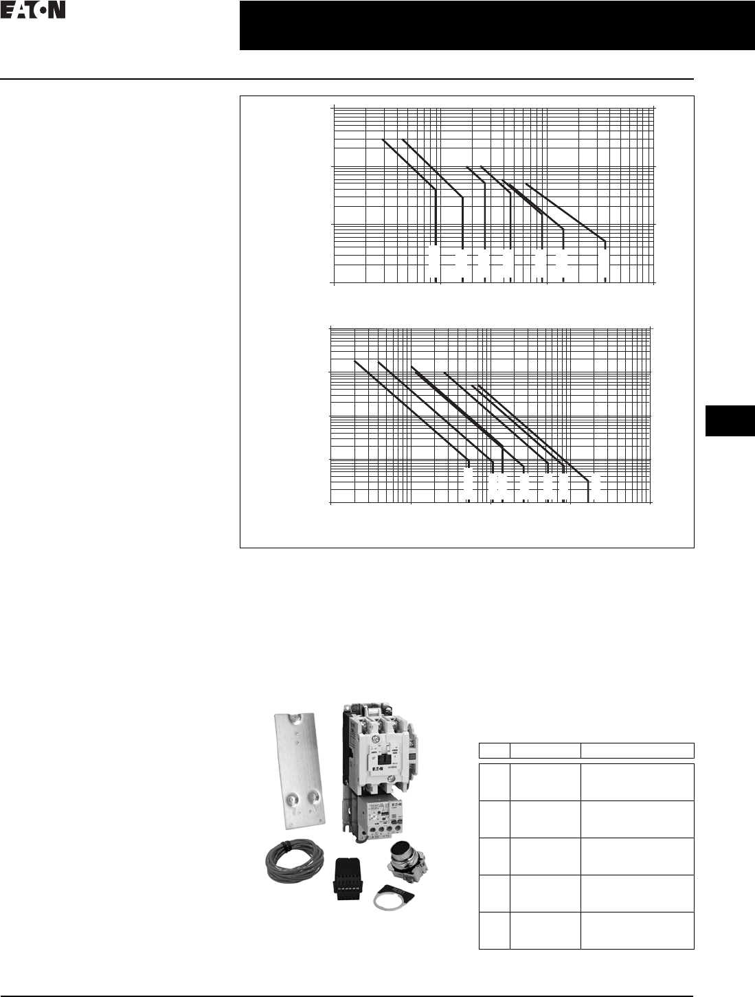
CA08104001E For more information, visit: www.eaton.com/consultants
30.3-7
April 2016
Motor Starters and Contactors—Low Voltage
Sheet 30
22
23
24
25
26
27
28
29
30
31
32
33
34
35
36
37
38
39
40
41
42
4 3
Motor Starters—Electromechanical
Freedom Line—Technical Data
027
Electrical Life—AC-3 and AC-4
Utilization Categories
Life Load Curves
Eaton’s Freedom Series NEMA
contactors have been designed
and manufactured for superior life
performance in any worldwide
application. All testing has been based
on requirements as found in NEMA
and UL standards and conducted by
Eaton. Actual application life may
vary depending on environmental
conditions and application duty cycle.
Utilization Categories
AC-1—Non-inductive or slightly
inductive loads, such as resistance
furnaces and heating.
AC-2—Starting of slip-ring motors.
AC-3—Squirrel cage motors; starting,
switching off motors during running.
AC-4—Squirrel cage motors; starting,
plugging, inching or jogging.
Note: AC-3 tests are conducted at rated
device currents and AC-4 tests are conducted
at six times rated device currents. All tests
have been run at 460 V, 60 Hz.
Contactor Choice
■Decide what utilization category
your application is and choose the
appropriate curve
■Locate the intersection of the
life-load curve of the appropriate
contactor with the applications
operational current (Ie), as found
on the horizontal axis
■Read the estimated contact life
along the vertical axis in number
of operational cycles
Figure 30.3-10. AC-3 and AC-4 Utilization Categories
AN19 Competitive Retrofit Kits
The retrofit kits provide a packaged
solution to replace competitive starters
with the Freedom AN19 starter using
existing hole patterns. Suitable for
replacement of Allen-Bradley,
Square D, GE and Siemens starters.
Kit contents
■Competitive mounting plate
■AN19 starter
■Remote reset module
■NO 10250T pushbutton
■RESET pushbutton legend plate
■16 gauge control wire
Table 30.3-15. AN19 Competitive Retrofit Kit—
Product Selection
NEMA AC-3 Load Life, Sizes 00 – 5, 480 V 60 Hz
100,000,000
10,000,000
1,000,000
100,000 9
110
Break Amperes 100 1000
18 27 45 90 135 270
Size 00
Size 0
Size 1
Size 2
Size 3
Size 4
Size 5
Operations Operations
NEMA AC-4 Load Life, Sizes 00 – 5, 480 V 60 Hz
100,000,000
Size 00
Size 0
Size 1
Size 2
Size 3
Size 4
Size 5
10,000,000
1,000,000
100,000
10,000 10854
110
Break Amperes
100 1000 10,000
153 270 540 822 1620
Size Description Catalog Number
1 120 Vac coil,
4–20 A
overload
AN19DN0A5E020-CRK
2 120 Vac coil,
9–45 A
overload
AN19GN0A5E045-CRK
3 120 Vac coil,
20–100 A
overload
AN19KN0A5E100-CRK
4 120 Vac coil,
28–140 A
overload
AN19NN0A5E140-CRK
5 120 Vac coil,
60–300 A
overload
AN19SN0A5E300-CRK
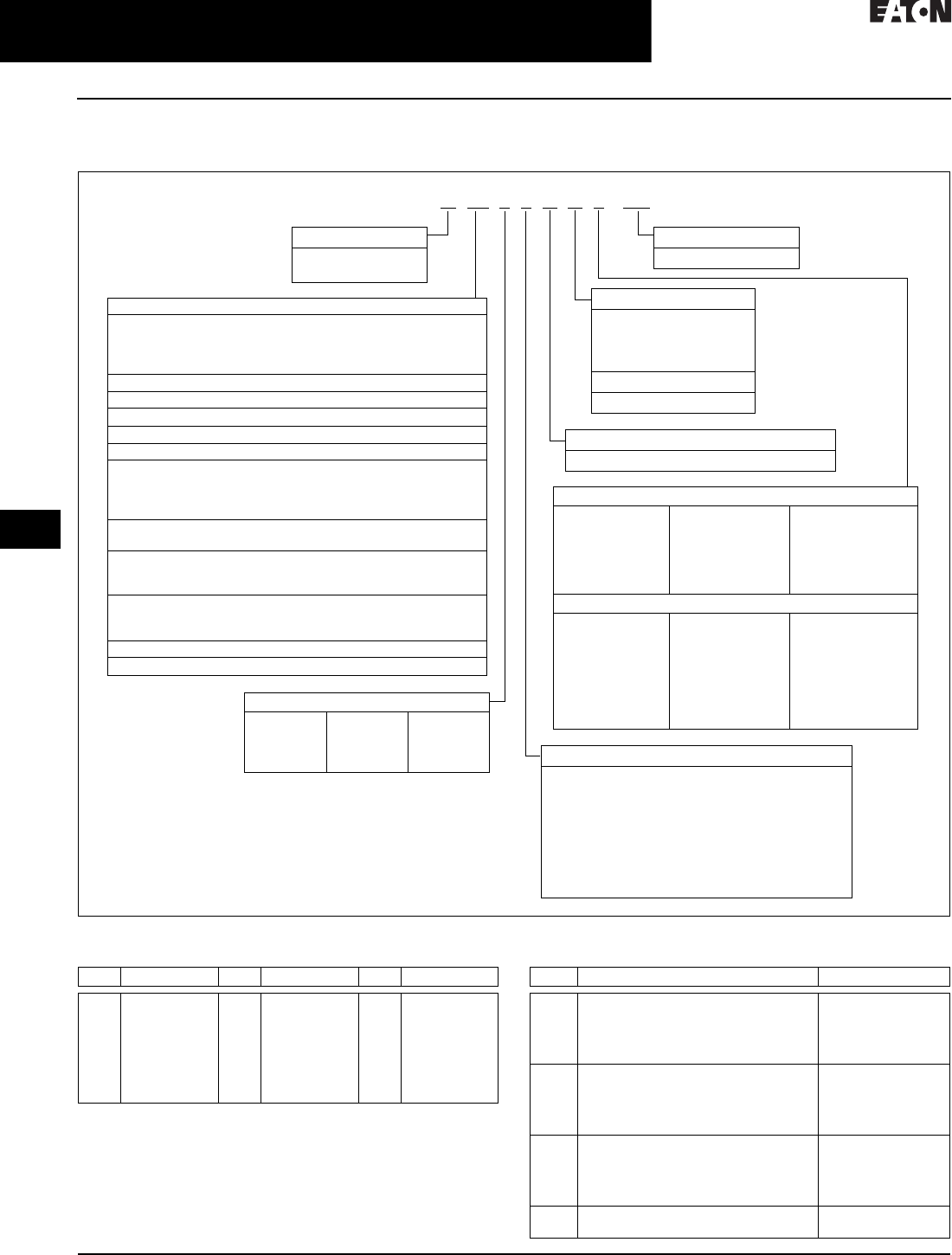
30.3-8
For more information, visit: www.eaton.com/consultants CA08104001E
April 2016
Motor Starters and Contactors—Low Voltage
Sheet 30
22
23
24
25
26
27
28
29
30
31
32
33
34
35
36
37
38
39
40
41
42
4 3
Motor Starters—Electromechanical
Freedom Line—Product Selection
028
Catalog Number Selection
Table 30.3-16. NEMA Freedom Line Enclosed Control Catalog Numbering System
1Use for Sizes 0–3, HMCP 600 V applications only.
Table 30.3-17. Magnetic Coil Codes (System Voltage) 2
2When control power transformer modification codes (C1–C11)
are used or when starter class includes CPT (i.e., ECN07, 18) see
Table 30.3-18 for system voltage code.
Table 30.3-18. Control Power Transformer Codes (System Voltage)
E C N 22 2 1 A A F -
Design
N= Freedom NEMA
2= A200
Modification Codes
(See PG03300001E)
Coil Voltage and/or Control Transformers
See Table 30.3-17 and Table 30.3-18
Class
01
= Non-reversing contactor—three-pole
Non-reversing contactor—two-pole
Non-reversing contactor—four-pole
Non-reversing contactor—five-pole
02
= Reversing contactor—three-pole
05
= Non-combination non-reversing starter
06
= Non-combination reversing starter
07
= Non-combination non-reversing starter with CPT
08
= Non-combination single-phase non-reversing starter
16
= Combination non-reversing starter—fusible disconnect
Combination non-reversing starter—non-fusible disconnect
Special enclosure combination non-reversing starter
fusible/non-fusible disconnect
17
= Combination reversing starter—fusible disconnect
Combination reversing starter—non-fusible disconnect
18
= Combination reversing starter—fusible disconnect with CPT
Combination reversing starter—non-fusible disconnect
with CPT
22
= Combination non-reversing starter—circuit breaker
Special enclosure combination non-reversing starter—
circuit breaker
23
= Combination reversing starter—circuit breaker
24
= Combination non-reversing starter—circuit breaker with CPT
Disconnect Fuse Clip Ratings
A= None
B= 30 A/250 V R
C= 30 A/600 V R
D= 60 A/250 V R
E= 60 A/600 V R
F= 100 A/250 V R
G= 100 A/600 V R
H= 200 A/250 V R
J= 200 A/600 V R
K= 400 A/250 V R
L= 400 A/600 V R
M= 600 A/250 V R
N= 600 A/600 V R
P= 800 A/600 V L
Q= 1200 A/600 V L
R= 1600 A/600 V L
S= 2000 A/600 V L
T= By description
HMCP/E or Breaker Ratings
A= None
B= 3 A
C= 7 A
D= 15 A
E= 30 A
F= 50 A
W= 70 A
G= 100 A
H= 150 A
J= 250 A
K= 400 A
L= 600 A
M= 800 A
N= 1000 A
P= 1200 A
Q= 2000 A
R= 3000 A
T= By description
5= 3 A 1
6= 7 A 1
7= 15 A 1
8= 30 A 1
9= 50 A 1
I= 100 A 1
Cover Control
Type 1 non-combination
All others
E22 style combination
(Contact Eaton)
Contactors
3 = Three-pole
Enclosure Type
1 = Type 1—General purpose
2 = Type 3R—Rainproof
3 = Type 4—Watertight (painted steel)
4 = Type 4X—Watertight (304-Grade stainless steel)
5 = Type 4X—Corrosion (nonmetallic)
6 = Type 7/9—Bolted hazardous location
7 = Type 7/9—Threaded hazardous location
8 = Type 12—Dust-tight
9 = Type 4X—316-Grade stainless steel
NEMA Size
A= Size 00
0= Size 0
1= Size 1
2= Size 2
3 = Size 3
4 = Size 4
5 = Size 5
6 = Size 6
7 = Size 7
8 = Size 8
9 = Size 9
Code Magnet Coil Code Magnet Coil Code Magnet Coil
A
B
C
D
E
G
H
J
120/60 110/50
240/60 220/50
460/60 440/50
575/60 550/50
208/60
550/50
277/60
208–240/60
K
L
M
P
Q
R
S
T
240/50
380/50
415/50
12 Vdc
24 Vdc
48 Vdc
125 Vdc
24/60
U
V
W
X
Y
Z
24/50
32/50
48/60
104–120/60
48/50
By description
Code Primary Secondary
B
C
D
E
H
240/480–220/440 wired for 240 V
240/480–220/440 wired for 480 V
600/60–550/50
208/60
277/60
120/60–110/50
120/60–110/50
120/60–110/50
120/60
120/60
L
M
Q
R
S
380/50
415/50
208/60
240/480–220/440 wired for 240 V
240/480–220/440 wired for 480 V
110/50
110/50
24
24
24
T
U
V
W
X
600/60
277/60
380/50
415/50
240/480/600 wired for 480 V
24
24
24
24
120
Y
Z
240/480/600 wired for 480 V
By description
24
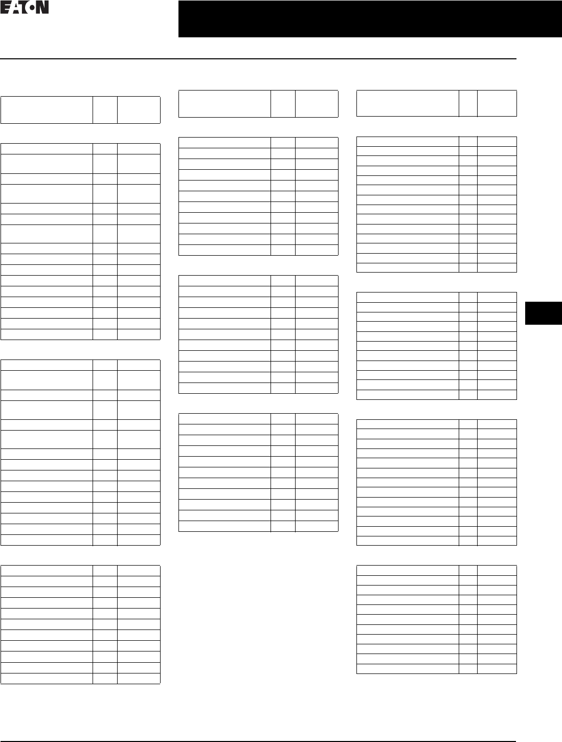
CA08104001E For more information, visit: www.eaton.com/consultants
30.3-9
April 2016
Motor Starters and Contactors—Low Voltage
Sheet 30
22
23
24
25
26
27
28
29
30
31
32
33
34
35
36
37
38
39
40
41
42
4 3
Motor Starters—Electromechanical
Freedom Line—Technical Data
029
Enclosed Box Selection
Table 30.3-19. Type 1 Freedom Contactors
1Consult factory.
Table 30.3-20. Type 3R, 4/4X, 12 Freedom
Contactors
2Consult factory.
Note: All Type 7 and 9, see PG03300001E.
Table 30.3-21. Type 1 Freedom
Non-combination Starters
3Consult factory.
For enclosure box dimensions,
refer to Page 30.6-3.
NEMA Size
(Poles)
Box
No.
Shipping
Weight
Lbs (kg)
Non-reversing Contactors—
without Control Power Transformers
00 (2P, 3P, 4P) 1 5.25 (2.4)
00 (2P, 3P, 4P)
with top adders
2 7.3 (3.3)
0 (2P, 3P, 4P) 1 5.25 (2.4)
0 (2P, 3P, 4P)
with top adders
2 7.3 (3.3)
0 (5P) 2 7.3 (3.3)
1 (2P, 3P) 1 7.9 (3.6)
1 (2P, 3P)
with top adders
311 (5.0)
1 (4P, 5P) 2 8.3 (3.8)
2 (2P, 3P, 4P 5P) 2 8.5 (3.9)
3 (2P, 3P) 4 35 (16)
4 (2P, 3P) 4 47 (21)
5 10 113 (51)
6 F1E 325 (148)
7 F1E 1
8 F1E 1
9 F1E 1
Non-reversing Contactors—
with Control Power Transformers
00 (2P, 3P, 4P) 2 12 (5.4)
00 (2P, 3P, 4P, 5P)
with top adders
315 (6.8)
0 (2P, 3P, 4P, 5P) 2 12 (5.4)
0 (2P, 3P, 4P, 5P)
with top adders
315 (6.8)
1 (2P, 3P) 2 12.2 (5.5)
1 (2P, 3P)
with top adders
3 12.5 (5.7)
1 (4P, 5P) 2 12.6 (5.7)
2 (2P, 3P, 4P, 5P) 2 12.8 (5.8)
3 (2P, 3P) 4 40 (18)
4 (2P, 3P) 4 52 (24)
5 10 120 (54)
6 F1E 335 (152)
7 F1E 1
8 F1E 1
9 F1E 1
Three-Pole Reversing Contactors—
without Control Power Transformers
00 2 7.8 (3.5)
028 (3.6)
1311 (5.0)
2312 (5.4)
3 4 67 (30)
4 4 154 (70)
5 10 170 (77)
6 F1E 425 (193)
7 F1E 1
8 F1E 1
9 F2E 1
NEMA Size
(Poles)
Box
No.
Shipping
Weight
Lbs (kg)
Non-reversing Contactors—
without Control Power Transformers
00 5 14 (6.4)
0 (2P, 3P, 4P) 5 14 (6.4)
1 (2P, 3P, 4P, 5P) 5 15 (6.8)
2 (2P, 3P, 4P, 5P) 5 15.5 (7.0)
3 (2P, 3P) 8 45 (20)
4 (2P, 3P) 8 56 (25)
5 10 140 (64)
6 F1E 385 (175)
7 F1E 2
8 F1E 2
9 F1E 2
Non-reversing Contactors—
with Control Power Transformers
00 5 18 (8.2)
0 (2P, 3P, 4P) 5 18 (8.2)
1 (2P, 3P, 4P, 5P) 6 19 (8.6)
2 (2P, 3P, 4P, 5P) 6 19.5 (8.9)
3 (2P, 3P) 8 52 (24)
4 (2P, 3P) 8 63 (29)
5 10 147 (67)
6 F1E 405 (184)
7 F1E 2
8 F1E 2
9 F1E 2
Three-Pole Reversing Contactors—
with or without Control Power Transformers
00 6 18 (8.2)
0618 (8.2)
1619 (8.6)
2619 (8.6)
3 8 47 (21)
4 9 69 (31)
5 10 170 (77)
6 F1E 495 (225)
7 F1E 2
8 F1E 2
9 F2E 2
NEMA Size Box
No.
Shipping
Weight
Lbs (kg)
Non-reversing Starters—
without Control Power Transformers
00 1 7 (3.2)
00 with top adders/SSOL 2 10 (4.5)
017.1 (3.2)
0 with top adders/SSOL 2 10 (4.5)
117.9 (3.6)
1–2 with top adders/SSOL 3 11.5 (5.2)
2 2 8.5 (3.9)
3 4 35 (16)
4 4 47 (21)
5 10 139 (63)
6 F1E 360 (163)
7 F1E 3
8 F1E 3
9 F1E 3
Non-reversing Starters—
with Control Power Transformers
00 3 15 (6.8)
0315 (6.8)
1316 (7.3)
2316.2 (7.4)
3 4 42 (19)
4 4 54 (25)
5 10 146 (66)
6 F1E 385 (175)
7 F1E 3
8 F1E 3
9 F1E 3
Reversing Starters—
without Control Power Transformers
00 2 8 (3.6)
028 (3.6)
0 with top adders 3 11 (5)
1313 (5.9)
1 with top adders 3 13.4 (6.1)
2315 (6.8)
3 4 43 (20)
4 9 65 (30)
5 10 165 (75)
6 F1E 450 (204)
7 F1E 3
8 F2E 3
9 F2E 3
Reversing Starters—
with Control Power Transformers
00 with top adders 3 15 (6.8)
0315 (6.8)
1 with top adders 3 17 (7.7)
2319 (8.6)
3 4 50 (23)
4 9 72 (33)
5 10 172 (78)
6 F1E 495 (225)
7 F1E 3
8 F2E 3
9 F2E 3

30.3-10
For more information, visit: www.eaton.com/consultants CA08104001E
April 2016
Motor Starters and Contactors—Low Voltage
Sheet 30
22
23
24
25
26
27
28
29
30
31
32
33
34
35
36
37
38
39
40
41
42
4 3
Motor Starters—Electromechanical
Freedom Line—Technical Data
030
Table 30.3-22. Type 3R, 4/4X, 12 Freedom
Non-combination Starters
1Consult factory.
Table 30.3-23. Type 1 Freedom
Combination Starters
2Consult factory.
Table 30.3-24. Type 1 Freedom Non-reversing
Combination Starters—Narrow Enclosure
Table 30.3-25. Type 3R, 4/4X, 12 Freedom
Combination Starters
3Consult factory.
NEMA Size /
IEC Frame
Box
No.
Shipping
Weight
Lbs (kg)
Non-reversing Starters—
without Control Power Transformers
0514.3 (6.5)
1 5 15.3 (6.9)
2716 (7.3)
3 8 46 (21)
4 8 60 (27)
5 10 150 (68)
6 F1E 415 (188)
7 F1E 1
8 F1E 1
9 F1E 1
Non-reversing Starters—
with Control Power Transformers
0618 (8.2)
1619 (8.6)
2 6 20 (9)
3 8 53 (24)
4 8 67 (30)
5 10 157 (71)
6 F1E 1
7 F1E 1
8 F1E 1
9 F1E 1
Reversing Starters—
with or without Control Power Transformers
0 7 18.5 (8.4)
1 7 19.5 (8.9)
2 7 21 (10)
3 8 48 (22)
4 9 72 (33)
5 10 175 (79)
6 F1E 525 (238)
7 F1E 1
8 F2E 1
9 F2E 1
NEMA Size
(Device)
Box
No.
Shipping
Weight
Lbs (kg)
Non-reversing —
with and without Control Power Transformers
0 A 37 (17)
1 A 38 (17)
2 A 39 (18)
3 C 72 (33)
4 (HMCP) C 90 (41)
4 (Disconnect switch) D 150 (68)
5 E 180 (82)
6 F1E 435 (197)
7 F2E 2
8 F2E 2
9 F2E 2
Reversing —
with and without Control Power Transformers
0 B 42 (19)
1 B 43 (20)
2 B 44 (20)
3 C 84 (38)
4 D 173 (79)
5 F1E 2
6 F1E 550 (250)
7 F2E 2
8 F2E 2
922
Non-reversing—Oversized
0–1–2 B 44 (20)
NEMA Size Box
No.
Shipping
Weight
Lbs (kg)
NEMA 1 Enclosed
0–1–2 I 35 (16)
NEMA 12 Enclosed
0–1–2 I 36 (16)
NEMA 12 Enclosed with Safety Door Interlock
0–1–2 I 37 (17)
NEMA Size
(Device)
Box
No.
Shipping
Weight
Lbs (kg)
Non-reversing—
with and without Control Power Transformers
0 A 37 (17)
1 A 38 (17)
2 A 39 (18)
3 C 72 (33)
4 (HMCP) C 90 (41)
4 (Disconnect switch) D 150 (68)
5 E 180 (82)
6 F1E 435 (197)
7 F2E 3
8 F2E 3
9 F2E 3
Reversing—
with and without Control Power Transformers
0 B 42 (19)
1 B 43 (20)
2 B 44 (20)
3 C 84 (38)
4 D 173 (79)
5 E 550 (250)
6 F1E 3
7 F2E 3
8 F2E 3
933
Non-reversing—Oversized
0–1–2 B 44 (20)
For enclosure box dimensions,
refer to Page 30.6-3.
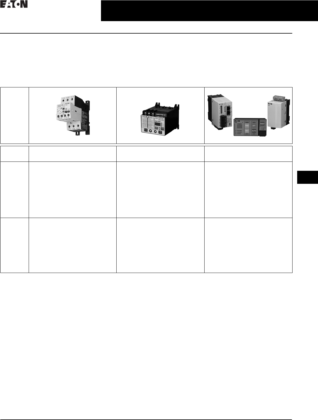
CA08104001E For more information, visit: www.eaton.com/consultants
30.3-11
April 2016
Motor Starters and Contactors—Low Voltage
Sheet 30
22
23
24
25
26
27
28
29
30
31
32
33
34
35
36
37
38
39
40
41
42
4 3
Motor Starters—Electromechanical
C440 Series
031
C440 Series
Overview
Eaton’s C400 series of advanced motor protection offers innovative solutions with varying levels of capability.
From basic monitoring and protection to advanced motor management and efficiency calculations, the C400 series
has the exact solution to meet the needs of your application.
Table 30.3-26. C440 Series Comparison
Product
C440 C441 C445
Range 0.3–1500 A
Up to 690 Vac (50/60 Hz)
1–540 A
Up to 600 Vac (50/60 Hz)
0.3–800 A
Up to 690 Vac (20–80 Hz)
Up to 4160 Vac w/PTs
Features Selectable trip class (10 A, 10, 20, 30), ground
fault and phase imbalance protections
Flexible communication options for both
monitoring and control
Highly configurable line (voltage), load
(power) and motor (current) monitoring
and protection
Optional remote user interface allows
user to configure and monitor without
opening a panel door
All-in-one design reduces inventory costs
by covering 1–540 A applications with only
two SKU numbers
Full line, load and motor system coverage,
including advanced monitoring and
protection algorithms
USB connectivity (both inside and outside
the control panel door) provide monitoring
and configuration with a PC
Multiple predefined operating modes with
corresponding control station options
Global modular design allows for
customization of system to match exact
customer needs
Benefits Extends the life of plant assets with
selectable motor protection features
Status LED provides added assurance
that valuable assets are protected by
indicating the overload operational status
Advanced diagnostics allow for quick and
accurate identification of the root source
of motor, pump or power quality faults
Configurable low-power trip capability
provides superior protection for smaller
motors, slow speed motors and lightly
loaded large motors
Voltage Loss Restart ability removes
the need for users to manually restart
motors after momentary voltage dips by
automatically staggering restarts
Multiple embedded fieldbus options
allow integration into widest range of PLC
and DCS control systems without additional
modules or supply power
Motor efficiency, motor torque and
peak energy monitoring enhance users’
understanding of their application

30.3-12
For more information, visit: www.eaton.com/consultants CA08104001E
April 2016
Motor Starters and Contactors—Low Voltage
Sheet 30
22
23
24
25
26
27
28
29
30
31
32
33
34
35
36
37
38
39
40
41
42
4 3
Motor Starters—Electromechanical
C441 Motor Insight
032
Table 30.3-27. Features
Note: Not all options are standard. Please consult factory.
Table 30.3-28. Supporting Documentation
Features C440 C441 C445
Protection
Thermal overload ■■■
Phase loss ■■■
Selectable trip class ■■■
Ground fault ■■■
Current unbalance — ■■
Voltage unbalance — ■■
Phase reversal — ■■
Jam — ■■
Under/overpower trip — ■■
Under/overvoltage trip — ■■
Under/overcurrent trip — ■■
Under/overfrequency — — ■
Stall — — ■
Instantaneous overcurrent — — ■
PTC (motor temperature) — — ■
Energy deviations — — ■
Voltage loss restart — — ■
Control
Hard wire/local reset ■■■
Network/electronic reset ■■■
Programmable alarms — ■■
Programmable trips — ■■
Multiple operation modes — — ■
Control user interface — — ■
Motor Control Center Availability
IEC—Power Xpert CX®■—■
IEC—Power Xpert CXH™ ■—■
NEMAT—Freedom ■■■
NEMA—FlashGard®■■■
NEMA—Freedom ARC ■■■
NEMA—Aftermarket buckets ■■■
Features C440 C441 C445
Monitoring
Thermal capacity ■■■
Phase currents ■■■
Current unbalance ■■■
Ground fault current ■■■
Frequency — ■■
Voltage unbalance — ■■
Phase voltages — ■■
Real power (kW) — ■■
Under/overpower trip — ■■
Under/overvoltage trip — ■■
Under/overcurrent trip — ■■
Motor start time/count — — ■
Motor efficiency — — ■
Motor torque — — ■
Energy (kWh) — — ■
Apparent power (kVA) — — ■
Trip snapshot — — ■
Communications
Modbus® RTU ■■■
PROFIBUS®■■■
Modbus TCP ■■■
EtherNet/IP ■■■
DeviceNet™ ■■Future
USB — — ■
Description Publication number
Motor Control and Protection Catalog CA08100006E
C441 User Manual MN04209001E
C445 User Manual MN042001EN
EIP-Assist Tag Generation Tool User Manual MN181001EN
FlashGard NEMA MCC Brochure BR04302001E
Power Xpert CX IEC MCC Brochure BR043003EN
Power Xpert CXH IEC MCC Brochure BR043008EN
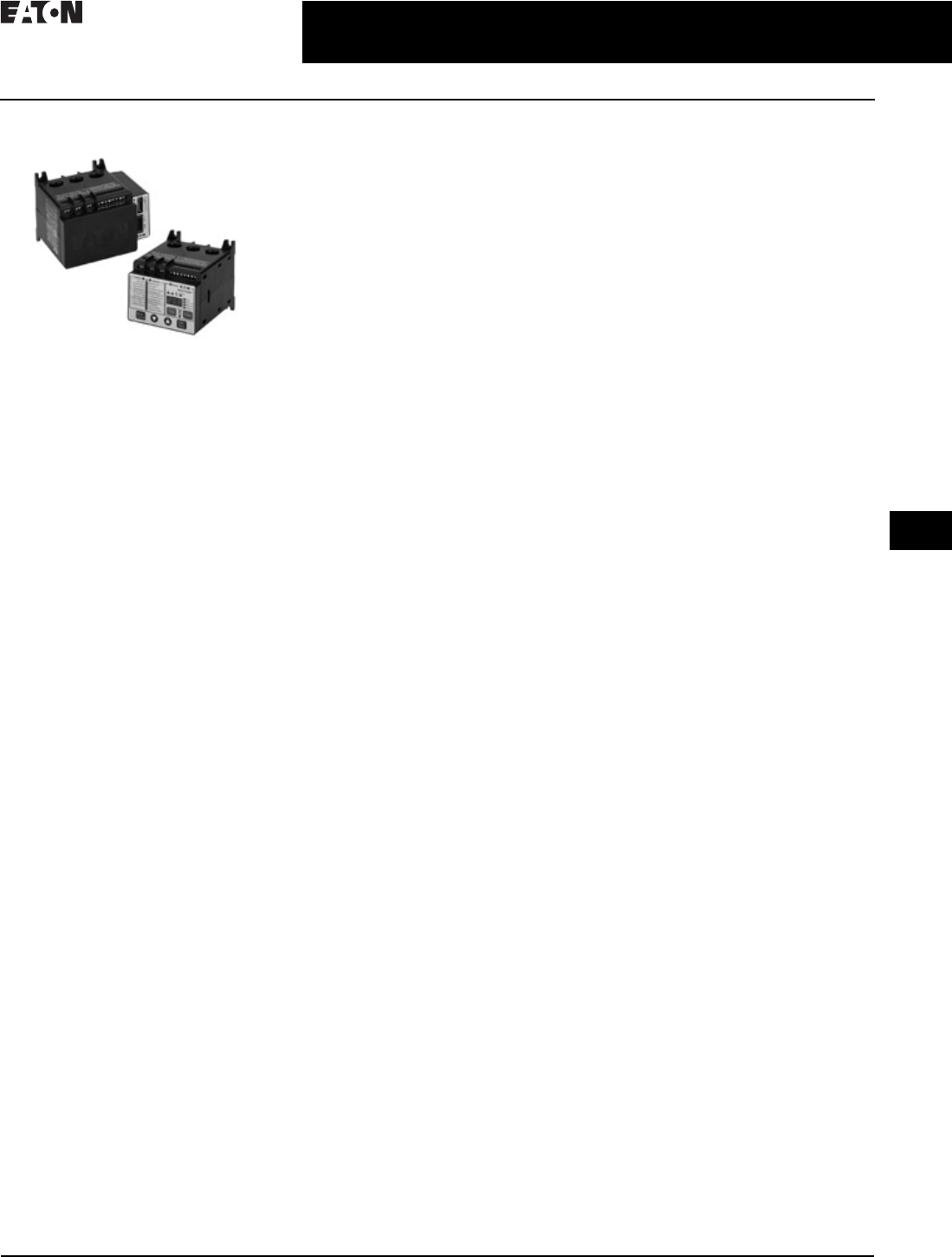
CA08104001E For more information, visit: www.eaton.com/consultants
30.3-13
April 2016
Motor Starters and Contactors—Low Voltage
Sheet 30
22
23
24
25
26
27
28
29
30
31
32
33
34
35
36
37
38
39
40
41
42
4 3
Motor Starters—Electromechanical
C441 Motor Insight
033
C441 Motor Insight
C441 Motor Insight Overload
and Monitoring Relay
General Description
Eaton’s C441 Motor Insight®, the
first product in the intelligent power
control solutions family, is a highly
configurable motor, load and line
protection device with power monitor-
ing, diagnostics and flexible communi-
cations, allowing the customer to save
energy, optimize their maintenance
schedules and configure greater
system protection, thus reducing
overall costs and downtime.
C441 Motor Insight is available in
either a line-powered or 120 Vac
control powered design, capable of
monitoring voltages up to 660 Vac.
Each of these units is available in
a 1–9 A or a 5–90 A FLA model. With
external CTs, C441 Motor Insight
can protect motors up to 540 A FLA.
Available add-on accessories
include communication modules
for Modbus®, DeviceNet™ and
PROFIBUS®, all with I/O options.
For ease-of-use and operator
safety, C441 Motor Insight offers a
remote display that mounts easily
with two 30 mm knockouts.
Features
Size/Range
■Broad FLA range of 1–540 A
■Selectable trip class (5–30)
■Four operating voltage options
❑Line-powered from 240 Vac,
480 Vac, 600 Vac
❑Control-powered from 120 Vac
Motor Control
■Two output relays
❑One B300 Form C fault relay and
one B300 ground fault shunt relay
❑
Other relay configurations
are
available, including one Form A
and one Form B SPST (fault
and auxiliary relays) allowing
programmable isolated relay
behavior and unique voltages
■One external remote reset terminal
■Trip status indicator
Motor Protection
■Thermal overload
■Jam/stall protection
■Current level alarming
■Current imbalance
■Current phase loss
■Ground fault
■Phase reversal
Load Protection
■Undercurrent
■Low power (kW)
■High power (kW)
Line Protection
■Overvoltage
■Undervoltage
■Voltage imbalance
■Voltage phase loss
Monitoring Capabilities
■Current—average and phase rms
■Voltage—average and phase rms
■Power—motor kW
■
Power factor
■Frequency
■Thermal capacity
■Run hours
■Ground fault current
■Current imbalance %
■Voltage imbalance %
■Motor starts
■Motor run hours
Options
■Type 1, 12 remote display
■Type 3R remote display kit
■Communication modules
❑Modbus
❑Modbus with I/O
❑DeviceNet with I/O
❑PROFIBUS with I/O
❑Modbus TCP with I/O
(contact product line)
❑EtherNet/IP with I/O
(contact product line)
Benefits
Reliability and Improved Uptime
■Advanced diagnostics allows for
quick and accurate identification
of the root source of a motor, pump
or power quality fault; reducing
troubleshooting time and the loss of
productivity, reducing repeat faults
due to misdiagnosis, and increasing
process output and profitability
■Provides superior protection
of motors and pumps before
catastrophic failure occurs
■Increases profitability with greater
process uptime and throughput,
reduced costs per repair, reduced
energy consumption and extended
equipment life
■Adjustments to overload configura-
tion can be made at any time
Safety
■IP 20 rated terminal blocks
■Terminal blocks are set back
from the display to reduce
operator shock hazard
■Remote display (optional) does
not require that the operator open
the panel to configure the device
Flexibility
■Communications modules
❑Offered in a variety of
configurations
❑External snap-on modules
provide support for multiple
communications protocols
■Advanced power, voltage and
current monitoring capabilities
■Communications modules
and remote display can be
used simultaneously
■Highly configurable fault and
reset characteristics for numerous
applications
■Fully programmable isolated
fault and auxiliary relays
Ease of Use
■Bright LED display with easy-to-
understand setting and references
■Powered from line voltage or
120 Vac control power
■Remote display powered from
base unit
■Full word descriptions and units
on user interface
Standards and Certifications
■cULus listed NKCR, NKCR7, 508
■UL 1053 applicable sections for
ground fault detection
■CSA certified (Class 3211-02)
■CE
■NEMA
■IEC EN 60947-4-1
■RoHS
30.3-14
For more information, visit: www.eaton.com/consultants CA08104001E
April 2016
Motor Starters and Contactors—Low Voltage
Sheet 30
22
23
24
25
26
27
28
29
30
31
32
33
34
35
36
37
38
39
40
41
42
4 3
Motor Starters—Electromechanical
C441 Motor Insight
034
Product Selection
Table 30.3-29. C441 Motor Insight
Table 30.3-30. C441 Motor Insight CT Multiplier and Wire Wrap Schedule
1Underscore indicates Operating Voltage Code required.
Operating Voltage Codes:
2Any manufacturer’s CTs may be used.
Accessories
Table 30.3-31. Communication Modules
Type 3R Kit with Remote Display Mounted Inside
C441 Motor Insight offers several accessories for the
customer’s ease of use and safety:
■Types 1 and 12 remote display
■Type 3R remote display kit
■Mounting plate adapter
Features and Benefits
■Remote display unit:
❑Same user interface as the overload relay
❑Enhanced operator safety—operator can configure
the overload without opening the enclosure door
■Type 3R kit mounts with standard 30 mm holes
■Mounting plate for retrofit in existing installations
Table 30.3-32. Type 3R Kit with Remote Display Mounted Inside
Communication Cables
The remote display requires a communication cable
to connect to the C441 Motor Insight overload relay:
Table 30.3-33. Communication Cable Lengths
Table 30.3-34. Current Transformer Kits
For more information about technical data and
specifications as well as dimensions, see Volume 5—
Motor Control and Protection, CA08100006E, Section 31.
Power
Source
Monitoring
Range
Current
Range
Catalog
Number
240 Vac (170–264) 170–264 Vac 1–9 A
5–90 A
C441BA
C441BB
480 Vac (323–528) 323–528 Vac 1–9 A
5–90 A
C441CA
C441CB
600 Vac (489–660) 489–660 Vac 1–9 A
5–90 A
C441DA
C441DB
120 Vac (93.5–132) 170–660 Vac 1–9 A
5–90 A
C4410109NOUI
C4410590NOUI
Catalog
Number
1
Motor
FLA
No. of
Loops
No. of
Conductors
Through
CT Primary
CT
Multiplier
Setting
External
CT Kit
Catalog
Number
2
Current Range: 5–90 A
C441_B and
C4410590NOUI
5–22.5 A
6.67–30 A
3
2
4
3
4
3
—
—
10–45 A
20–90 A
1
0
2
1
2
1
—
—
Current Range: 1–9 A
C441_A and
C4410109NOUI
1–5 A
2–9 A
1
0
2
1
2
1
—
—
60–135 A
120–270 A
240–540 A
0
0
0
1
1
1
150–(150:5)
300–
(300:5)
600–
(600:5)
C441CTKIT150
C441CTKIT300
C441CTKIT600
Code Voltage
B240 Vac
C480 Vac
D600 Vac
<empty> 120 Vac control power
Description I/O Catalog
Number
Modbus
Modbus communication module None C441M
Modbus communication module 4IN/2OUT 120 Vac C441N
24 Vdc C441P
DeviceNet
DeviceNet communication module 4IN/2OUT 120 Vac C441K
24 Vdc C441L
PROFIBUS
PROFIBUS communication module 4IN/2OUT 120 Vac C441S
24 Vdc C441Q
EtherNet/IP and Modbus TCP
Ethernet-based communication module 4IN/2OUT 120 Vac C441R
24 Vdc C441T
Description Catalog
Number
Remote display Types 1 and 12 (UL 508)
Type 3R kit for remote display (UL 508)
Conversion plate
C4411
C4413
C441CMP1
Length in Inches (meters) Catalog
Number
9.8 (0.25)
39.4 (1.0)
D77E-QPIP25
D77E-QPIP100
78.7 (2.0)
118.1 (3.0)
D77E-QPIP200
D77E-QPIP300
Description Catalog
Number
Three 150:5 CTs to be used with C441 Motor Insight
Three 300:5 CTs to be used with C441 Motor Insight
Three 600:5 CTs to be used with C441 Motor Insight
C441CTKIT150
C441CTKIT300
C441CTKIT600
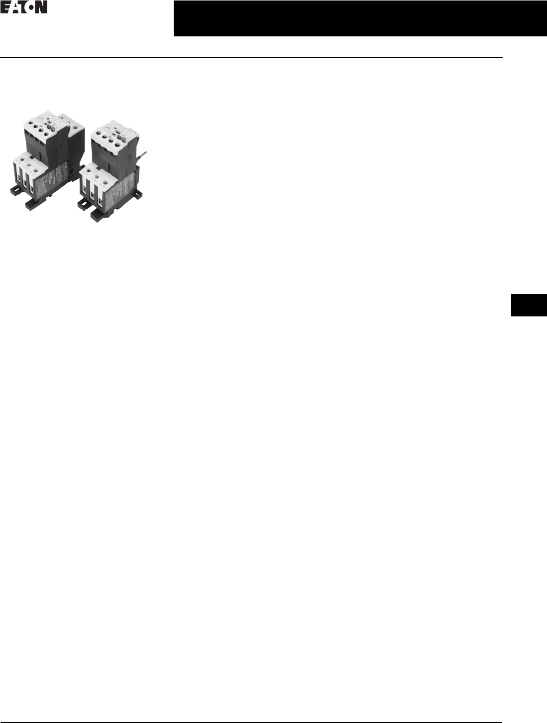
CA08104001E For more information, visit: www.eaton.com/consultants
30.3-15
April 2016
Motor Starters and Contactors—Low Voltage
Sheet 30
22
23
24
25
26
27
28
29
30
31
32
33
34
35
36
37
38
39
40
41
42
4 3
Motor Starters—Electromechanical
C440/XT Electronic Overload Relay
035
C440/XT Electronic
Overload Relay
C440/XT Electronic Overload Relay
General Description
Eaton’s electronic overload relay (EOL)
is the most compact, high-featured,
economical product in its class.
Designed on a global platform, the
new EOL covers the entire power
control spectrum, including NEMA,
IEC and DP contactors. The NEMA
and DP versions are offered with
the C440 designation while the IEC
offering has the XT designation. The
electronic design provides reliable,
accurate and value-driven protection
and communications capabilities in a
single compact device. It is the flexible
choice for any application requiring
easy-to-use, reliable protection.
Eaton has a long history of innovations
and product development in motor
control and protection, including both
traditional NEMA, as well as IEC con-
trol. It was from this experience that
the C440 was developed, delivering
new solutions to meet today’s
demands.
C440 is a self-powered electronic
overload relay available up to 100 A
as a self-contained unit. With external
CTs, C440 can protect motor up
to 1500 FLA. Available add-on
accessories include remote reset
capability and communication
modules with I/O for DeviceNet,
PROFIBUS and Modbus.
Features
■Reliable, accurate, electronic
motor protection
■Easy to select, install and maintain
■Compact size
■Flexible, intelligent design
■Global product offering—
available with NEMA, IEC and
DP power control
Size/Range
■Broad FLA range (0.33–1500 A)
■Selectable trip class (10A, 10, 20, 30)
■Direct mounting to NEMA, IEC and
DP contactors
■Most compact electronic overload in
its class
Motor Control
■Two B600 alarm (NO) and fault
(NC) contacts
■Test/Trip button
Motor Protection
■Thermal overload
■Phase loss
■Selectable (ON/OFF)
phase imbalance
■Selectable (ON/OFF) ground fault
User Interface
■Large FLA selection dial
■Trip status indicator
■Operating mode LED
■DIP switch selectable trip class,
phase imbalance and ground fault
■Selectable Auto/Manual reset
Feature Options
■Remote reset
❑120 Vac
❑24 Vac
❑24 Vdc
■Tamper-proof cover
■Communications modules
❑Modbus RTU RS-485
❑DeviceNet with I/O
❑PROFIBUS with I/O
❑Modbus RTU with I/O (Q4 2010)
❑EtherNet/IP (planned)
❑Smartwire (planned)
Benefits
Reliability and Improved Uptime
■C440 provides the users with peace
of mind knowing that their assets
are protected with the highest level
of motor protection and communi-
cation capability in its class
■Extends the life of plant assets
with selectable motor protection
features such as trip class, phase
imbalance and ground fault
■Protects against unnecessary
downtime by discovering changes
in your system (line/load) with
remote monitoring capabilities
■Status LED provides added
assurance that valuable assets
are protected by indicating the
overload operational status
Flexibility
■Available with NEMA, IEC and
DP contactors
■Improves return on investment by
reducing inventory carrying costs
with wide FLA adjustment (5:1) and
selectable trip class
■Design incorporates built-in ground
fault protection, thus eliminating the
need for separate CTs and modules
■Flexible communication with
optional I/O enables easy integration
into plant management systems for
remote monitoring and control
■Available as an open component
and in enclosed control and motor
control center assemblies
Monitoring Capabilities
■Individual phase currents rms
■Average three-phase current rms
■Thermal memory
■Fault indication (overload, phase
loss, phase imbalance, ground fault)
Safety
■IP 20 rated terminal blocks
■Available in Eaton’s industry-leading
FlashGard MCCs
■Tested to the highest industry
standards, such as UL, CSA,
CE and IEC
■RoHS compliant
Standards and Certifications
■UL
■CSA
■CE
■NEMA
■IEC/EN 60947 VDE 0660
■ISO 13849-1 (EN954-1)
■RoHS
■ATEX directive 94/9/EC
■Equipment Group 2, Category 2
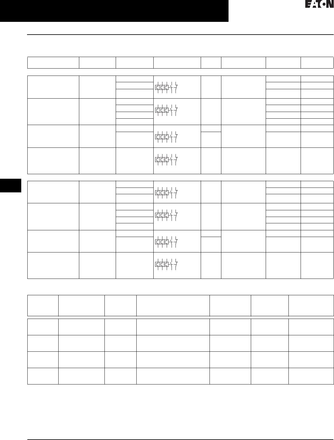
30.3-16
For more information, visit: www.eaton.com/consultants CA08104001E
April 2016
Motor Starters and Contactors—Low Voltage
Sheet 30
22
23
24
25
26
27
28
29
30
31
32
33
34
35
36
37
38
39
40
41
42
4 3
Motor Starters—Electromechanical
C440/XT Electronic Overload Relay
036
Product Selection
Table 30.3-35. XT Electronic Overload Relays
Table 30.3-36. XT Electronic Overload Relays for Use with Large Frame XT Contactors (L–R)
Use CTs and 1–5 A XT overload relay. CT kit does not include overload relay (order separately).
For Use with
XT Contactor Frame
For Use with
Contactor
Overload
Range (Amps)
Contact
Sequence
Frame
Size
Auxiliary Contact
Configuration
Ty p e C a t a l o g
Number
For Direct Mount to XT Contactors
B XTCE007B…,
XTCE009B…,
XTCE012B…,
XTCE015B…
0.33–1.65 45 mm NO-NC ZEB12-1,65 XTOE1P6BCS
1–5 ZEB12-5 XTOE005BCS
4–20 ZEB12-20 XTOE020BCS
CXTCE018C…,
XTCE025C…,
XTCE032C
0.33–1.65 45 mm NO-NC ZEB32-1,65 XTOE1P6CCS
1–5 ZEB32-5 XTOE005CCS
4–20 ZEB32-20 XTOE020CCS
9–45 ZEB32-45 XTOE045CCS
D XTCE040D…,
XTCE050D…,
XTCE065D…,
XTCE072D…
9–45 45 mm NO-NC ZEB65-45 XTOE045DCS
20–100 55 mm ZEB65-100 XTOE100DCS
F, G XTCE080F…,
XTCE095F…,
XTCE115G…,
XTCE150G…,
XTCE170G…
20–100 55 mm NO-NC ZEB150-100 XTOE100GCS
With Ground Fault for Direct Mount to XT Contactors
B XTCE007B…,
XTCE009B…,
XTCE012B…,
XTCE015B…
0.33–1.65 45 mm NO-NC ZEB12-1.65-GF XTOE1P6BGS
1–5 ZEB12-5-GF XTOE005BGS
4–20 ZEB12-20-GF XTOE020BGS
CXTCE018C…,
XTCE025C…,
XTCE032C
0.33–1.65 45 mm NO-NC ZEB32-1.65-GF XTOE1P6CGS
1–5 ZEB32-5-GF XTOE005CGS
4–20 ZEB32-20-GF XTOE020CGS
9–45 ZEB32-45-GF XTOE045CGS
D XTCE040D…,
XTCE050D…,
XTCE065D…,
XTCE072D…
9–45 45 mm NO-NC ZEB65-45-GF XTOE045DGS
20–100 55 mm ZEB65-100-GF XTOE100DGS
F, G XTCE080F…,
XTCE095F…,
XTCE115G…,
XTCE150G…,
XTCE170G…
20–100 55 mm NO-NC ZEB150-100-GF XTOE100GGS
XT
Contactor
Frame
For Use with
IEC Contactor
Ampere Range
(AC-3)
CT Range
(Ampere)
Description CT Kit
Catalog
Number
Te r m i n a l
Size
Overload
Relay
Catalog
Number
L, M 185–500 60–300 300: 5 panel-mount
CT kit with integrated lugs
ZEB-XCT300 750 kcmil
(2) 250 kcmil
3/0 Cu/Al
XTOE005CCSS
M, N 300–820 120–600 600: 5 panel-mount
CT kit with integrated,
pass-through holes
ZEB-XCT600 (2) 750 kcmil
3/0 Cu/Al
XTOE005CCSS
N 580–1000 200–1000 1000: 5 panel-mount
CT kit with integrated,
pass-through holes
ZEB-XCT1000 (3) 750 kcmil
3/0 Cu/Al
XTOE005CCSS
R 1600 300–1500 1500: 5 panel-mount
CT kit with integrated,
pass-through holes
ZEB-XCT1500 (4) 750 kcmil
1/0 Cu/Al
XTOE005CCSS
2469896
9795
2469896
9795
2469896
9795
2469896
9795
2469896
9795
2469896
9795
2469896
9795
2469896
9795

CA08104001E For more information, visit: www.eaton.com/consultants
30.3-17
April 2016
Motor Starters and Contactors—Low Voltage
Sheet 30
22
23
24
25
26
27
28
29
30
31
32
33
34
35
36
37
38
39
40
41
42
4 3
Motor Starters—Electromechanical
C440/XT Electronic Overload Relay
037
Table 30.3-37. XT Electronic Overload Relays for Separate Mount
Table 30.3-38. C440 Electronic Overload Relays for Direct Mount to Freedom Series Contactors
1CN15 contactor listed is non-reversing with a 120 Vac coil. For more options, see Volume 5—Motor Control and Protection, CA08100006E,
Tab 33, Section 33.1.
Table 30.3-39. C440 Electronic Overload Relays for Use with NEMA Contactors Sizes 4–8
Use CTs and 1–5 A C440 overload relay. CT kit does not include overload relay (order separately).
Table 30.3-40. C440 Electronic Overload Relays for Separate Mount
Overload
Range (Amps)
Frame
Size
Contact
Sequence
Type Overload Relay
Catalog Number
Overload Relay with Ground
Fault Catalog Number
Overload Relay
0.33–1.65 45 mm ZEB32-1.65/KK XTOE1P6CCSS XTOE1P6CGSS
1–5 ZEB32-5/KK XTOE005CCSS XTOE005CGSS
4–20 ZEB32-20/KK XTOE020CCSS XTOE020CGSS
9–45 ZEB32-45/KK XTOE045CCSS XTOE045CGSS
20–100 55 mm ZEB150-100/KK XTOE100GCSS XTOE100GGSS
For Use with Freedom
NEMA Contactor Size
For Use with
Contactor 1
Overload
Range (Amps)
Standard Feature Set
Catalog Number
Standard Feature Set with
Ground Fault Catalog Number
00 CN15AN3_B 0.33–1.65 C440A1A1P6SF00 C440A2A1P6SF00
1–5 C440A1A005SF00 C440A2A005SF00
4–20 C440A1A020SF00 C440A2A020SF00
0 CN15BN3_B 0.33–1.65 C440A1A1P6SF0 C440A2A1P6SF0
1–5 C440A1A005SF0 C440A2A005SF0
4–20 C440A1A020SF0 C440A2A020SF0
1 CN15DN3_B 0.33–1.65 C440A1A1P6SF1 C440A2A1P6SF1
1–5 C440A1A005SF1 C440A2A005SF1
4–20 C440A1A020SF1 C440A2A020SF1
9–45 C440A1A045SF1 C440A2A045SF1
2 CN15GN3_B 1–5 C440A1A005SF2 C440A2A005SF2
4–20 C440A1A020SF2 C440A2A020SF2
9–45 C440A1A045SF2 C440A2A045SF2
3 CN15KN3_ 20–100 C440B1A100SF3 C440B2A100SF3
For Use with NEMA
Contactor Size
CT Range
(Ampere)
Description CT Kit
Catalog Number
Te r m i n a l
Size
Overload Relay
Catalog Number
4 and 5 60–300 300: 5 panel-mount
CT kit with integrated,
pass-through holes
ZEB-XCT300 750 kcmil
(2) 250 kcmil
3/0 Cu/Al
C440A1A005SAX
6 120–600 600: 5 panel-mount
CT kit with integrated,
pass-through holes
ZEB-XCT600 (2) 750 kcmil
3/0 Cu/Al
C440A1A005SAX
7 200–1000 1000: 5 panel-mount
CT kit with integrated,
pass-through holes
ZEB-XCT1000 (3) 750 kcmil
3/0 Cu/Al
C440A1A005SAX
8 300–1500 1500: 5 panel-mount
CT kit with integrated,
pass-through holes
ZEB-XCT1500 (4) 750 kcmil
1/0 Cu/Al
C440A1A005SAX
Overload
Range
Frame
Size
Overload Relay
Catalog Number
Overload Relay with
Ground Fault Catalog Number
0.33–1.65 45 mm C440A1A1P6SAX C440A2A1P6SAX
1–5 C440A1A005SAX C440A2A005SAX
4–20 C440A1A020SAX C440A2A020SAX
9–45 C440A1A045SAX C440A2A045SAX
20–100 55 mm C440B1A100SAX C440B2A100SAX
1359795
2469896

30.3-18
For more information, visit: www.eaton.com/consultants CA08104001E
April 2016
Motor Starters and Contactors—Low Voltage
Sheet 30
22
23
24
25
26
27
28
29
30
31
32
33
34
35
36
37
38
39
40
41
42
4 3
Motor Starters—Electromechanical
C440/XT Electronic Overload Relay
038
Table 30.3-41. Type AN19/59 Freedom Series Starters—Non-Reversing and Reversing
1Underscore (_) indicates coils suffix required, see Coil Suffix table below.
2Underscore (_) indicates OLR designation required, see C440 FLA Range table below.
3Starter not shipped as an assembled unit. Order NEMA Size 4 contactor (CN15NN3A) plus current transformers (ZEB-XCT300) and 1–5 A C440
overload relay (C440A1A005SELAX or C440A2A005SELAX).
4NEMA Size 5 starter available with 60–300 A panel-mounted CTs. Starter shipped as an assembled unit with 1–5 A C440 overload relay
(C440A1A005SELAX or C440A2A005SELAX).
Table 30.3-42. Coil Suffix Codes Table 30.3-43. C440 FLA Range (FVNR and FVR Starters Only)
5Starter not shipped as an assembled unit. Order NEMA Size 4
contactor (CN15NN3A) plus current transformers (ZEB-XCT300)
and 1–5 A C440 overload relay (C440A1A005SELAX or
C440A2A005SELAX).
NEMA
Size
Continuous
Ampere
Rating
Service Limit
Current Rating
(Amps)
Maximum UL Horsepower Three-Pole
Non-Reversing 12
Catalog Number
Three-Pole
Reversing 12
Catalog Number
Single-Phase Three-Phase
115 V 230 V 208 V 240 V 480 V 600 V
C440 Electronic Overload Relays
00
0
9
18
11
21
1/3
1
1
2
1-1/2
3
1-1/2
3
2
5
2
5
AN19AN0_ 5E _
AN19BN0_ 5E _
AN59AN0_ 5E _
AN59BN0_ 5E _
1
2
3
27
45
90
32
52
104
2
3
—
3
7-1/2
—
7-1/2
10
25
7-1/2
15
30
10
25
50
10
25
50
AN19DN0_ 5E _
AN19GN0_ 5E _
AN19KN0_ 5E _
AN59DN0_ 5E _
AN59GN0_ 5E _
AN59KN0_ 5E _
4 3
5 4
135
270
156
311
—
—
—
—
40
75
50
100
100
200
100
200
3
AN19SN0_ 5E _
3
AN59SN0_ 5E _
C440 with Ground Fault Electronic Overload Relays
00
0
9
18
11
21
1/3
1
1
2
1-1/2
3
1-1/2
3
2
5
2
5
AN19AN0_ 5G _
AN19BN0_ 5G _
AN59AN0_ 5G _
AN59BN0_ 5G _
1
2
3
27
45
90
32
52
104
2
3
—
3
7-1/2
—
7-1/2
10
25
7-1/2
15
30
10
25
50
10
25
50
AN19DN0_ 5G _
AN19GN0_ 5G _
AN19KN0_ 5G _
AN59DN0_ 5G _
AN59GN0_ 5G _
AN59KN0_ 5G _
4 3
5 4
135
270
156
311
—
—
—
—
40
75
50
100
100
200
100
200
3
AN19SN0_ 5G _
3
AN59SN0_ 5G _
Suffix Coil Volts and Hertz
A
B
C
120/60 or 110/50
240/60 or 220/50
480/60 or 440/50
D
E
H
600/60 or 550/50
208/60
277/60
J
K
L
208–240/60
240/50
380–415/50
N
T
U
550/50
24/60, 24/50
24/50
V
W
Y
32/50
48/60
48/50
NEMA Size OLR Code FLA Range OLR Code FLA Rating
00 1P6 0.33–1.65 A 020 4.0–20 A
005 1.0–5.0 A — —
01P6 0.33–1.65 A 020 4.0–20 A
005 1.0–5.0 A — —
11P6 0.33–1.65 A 020 4.0–20 A
005 1.0–5.0 A 045 9.0–45 A
2005 1.0–5.0 A 045 9.0–45 A
020 4.0–20 A — —
3100 20–100 A — —
4 5300 — — 60–300 A
5 5300 60–300 A — —
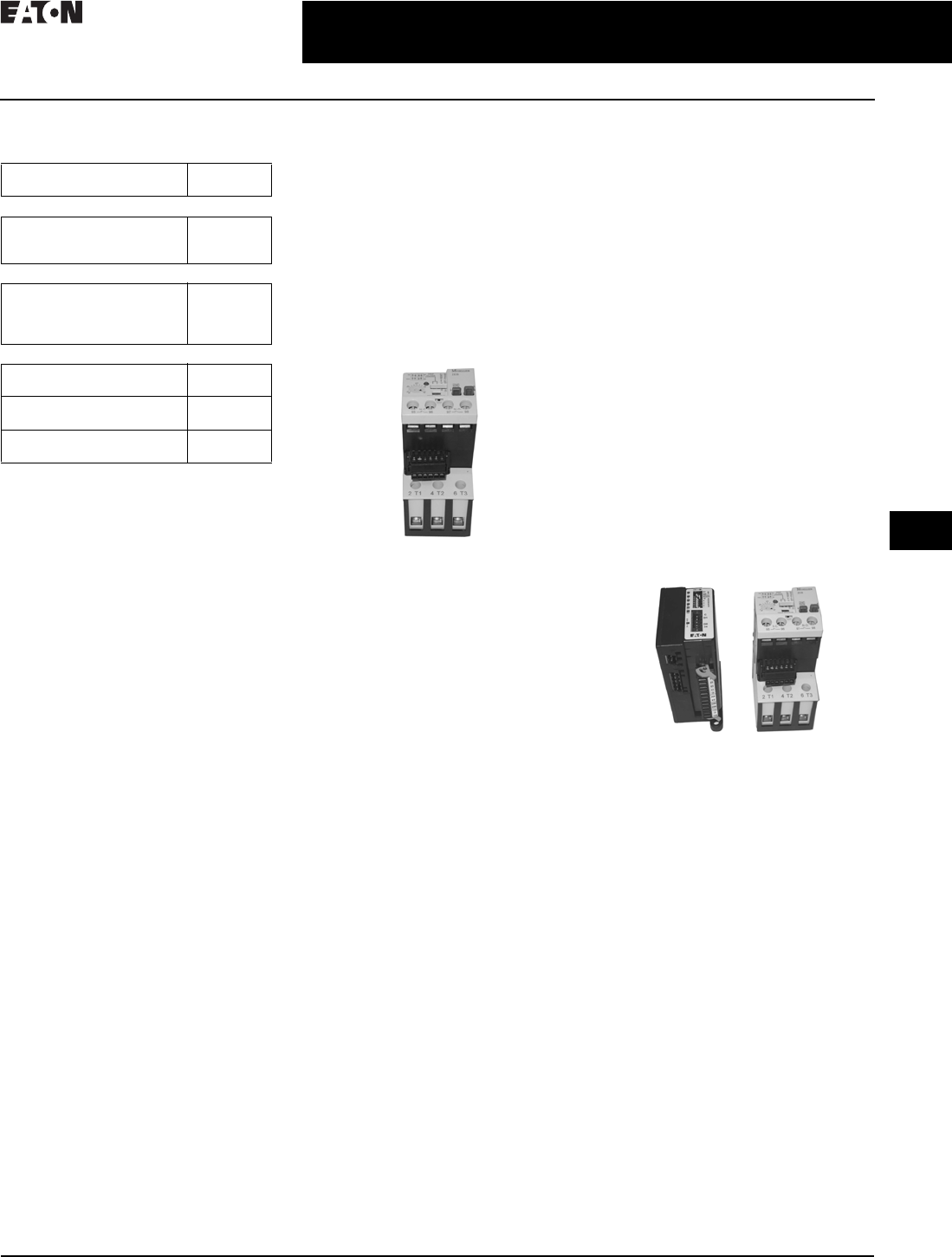
CA08104001E For more information, visit: www.eaton.com/consultants
30.3-19
April 2016
Motor Starters and Contactors—Low Voltage
Sheet 30
22
23
24
25
26
27
28
29
30
31
32
33
34
35
36
37
38
39
40
41
42
4 3
Motor Starters—Electromechanical
C440/XT Electronic Overload Relay
039
Accessories
Table 30.3-44. CT Kits
1Customer can wire remote-mounted button
to reset module (i.e., 22 mm pushbutton,
catalog number M22-D-B-GB14-K10).
Communication
The C440 is provided with two levels of
communication capability.
Basic Communication via Expansion
Module—Monitoring Only
Basic communication on the C440
is accomplished using an expansion
module. The expansion module
plugs into the expansion bay on
the C440 overload relay, enabling
communications with the overload via
their Modbus RTU (RS-485) network.
No additional parts are required.
Basic Communication—Modbus
Advanced Communication—
Monitoring and Control
C440 also has the ability to communi-
cate on industrial protocols such as
DeviceNet, PROFIBUS, Modbus RTU
and Modbus TCP, and Ethernet
(planned) while providing control
capability using I/O.
An expansion module (mentioned
earlier) combined with a communica-
tion adapter and a communication
module allows easy integration onto
the customer’s network.
Advanced Communication—
Communication Module
The communication adapter comes
standard with four inputs and two
outputs (24 Vdc or 120 Vac) while
providing the customer with flexible
mounting options (DIN rail or panel).
For more information about technical
data and specifications as well as
dimensions, see Volume 5—Motor
Control and Protection, CA08100006E,
Section 31.
Advanced Communication—
Communication Adapter
with Communication Module
Description Catalog
Number
Safety Cover
Clear Lexan® cover that mounts
on top of the FLA dial and
DIP switches when closed
ZEB-XSC
Reset Bar
Assembles to the top of the
overload to provide a larger
target area for door-mounted
reset operators
ZEB-XRB
Remote Reset
Remote reset module
(24 Vdc) 1
C440-XCOM
Remote reset module
(120 Vac) 1
ZEB-XRR-120
Remote reset module
(24 Vac) 1
ZEB-XRR-24
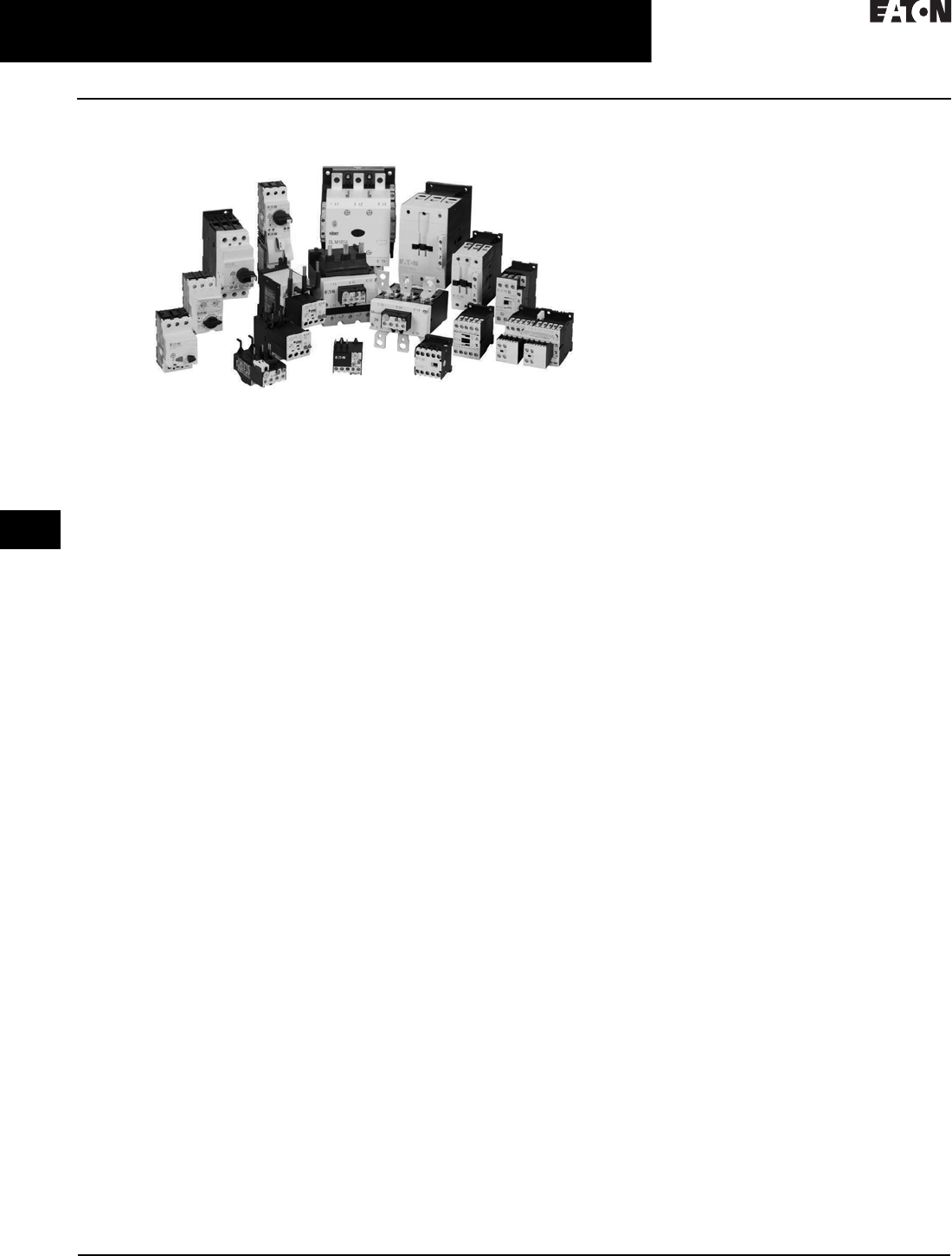
30.3-20
For more information, visit: www.eaton.com/consultants CA08104001E
April 2016
Motor Starters and Contactors—Low Voltage
Sheet 30
22
23
24
25
26
27
28
29
30
31
32
33
34
35
36
37
38
39
40
41
42
4 3
Motor Starters—Electromechanical
XT IEC Power Control
040
XT IEC Power Control
XT IEC Power Control
Product Overview
The XT line of IEC power control offers
starting and protection solutions ideal
for control panels.
Innovations in the design and develop-
ment allow users to reduce material
costs, reduce installation effort, and
enhance panel safety and performance
all in a compact design. Some of these
key innovations include:
■Toolless assembly of manual motor
controllers and reversing contactors
■Low coil consumption
■Front accessibility to coil terminations
■Built-in surge suppression on
electronic coils
■Built-in auxiliary contact for
contactors up to 32 A in a
45 mm frame
■Finger-safe and back-of-hand
proof ratings
■Direct PLC control on 185–2000 A
contactors
The XT line includes a large offering
of power control components and
accessories that cover a broad range
of applications and ratings:
■Three-pole contactors to 2000 A
■Four-pole contactors to 200 A
■Capacitor contactors to 680 kvar
■Mini contactors to 9 A
■Relays to 16 A
■Thermal overload relays to 630 A
■Electronic overload relays to 1500 A
■Manual motor protectors to 65 A
■Manual motor controllers and
combination motor controllers
to 65 A
Contactors and Starters
Product Description
The Eaton XT contactors and starters
includes non-reversing and reversing
contactors, overload relays and a
variety of related accessories. Because
XT meets IEC, UL®, CSA® and CE
standards, it is the perfect product
solution for IEC applications all over
the world. The compact, space
saving and easy to install
XT
line of IEC
contactors and starters is the efficient
and effective solution for customer
applications from 7 A to 2450 A.
Application Description
The XT line of IEC power control was
engineered to provide highly effective
control and protection for a variety of
loads, including motors, compressors,
pumps, resistive, capacitor banks,
isolation, and others. XT also includes
IEC ratings for lighting applications
as well.
XT contactors can be used in safety
applications according to EN 954-1,
EN ISO 13849-1 and IEC 62061 up to
Category 4, Pl e and SIL 3. Information
concerning safety-related
characteris-
tics (B10 and B10d
values) is available
online. The auxiliary contact modules
and built-in auxiliary contacts meet
IEC EN 60947-5-1 Annex L (positively
driven) and IEC EN 60947-4-1 Annex F
(mirror contacts).
Features and Benefits
■AC control from 12 V to 600 V
50/60 Hz
■DC control from 12 V to 220 V
■Available with screw or spring
cage terminals
■Reversing or non-reversing
contactors and starters
■AC-3 contactor ratings to 1000 A and
AC-1 contactor ratings to 2000 A
■Non-reversing starters to 650 A
■Panel or DIN rail mounting to 65 A
■IP20 finger and back-of-hand proof
■Large ambient temperature range,
–25 to 50 °C (–13 to 122 °F)
■AC and DC controlled contactors in
the same compact frame
■Low power consumption AC and
DC coils
■Built-in NO or NC auxiliary contacts
to 32 A
■Plug-in accessories for reduced
installation time
■Coil replacement on Frames C–N
(18–820 A)
■Contact replacement on Frames D–N
(40 –820 A)
■Integrated suppressor 7–150 A DC
operated contactors and 185–2000 A
AC and DC operated contactors
Standards and Certifications
■IEC EN 60947
■CE approved
■UL
■CSA
■ATEX
■RoHS
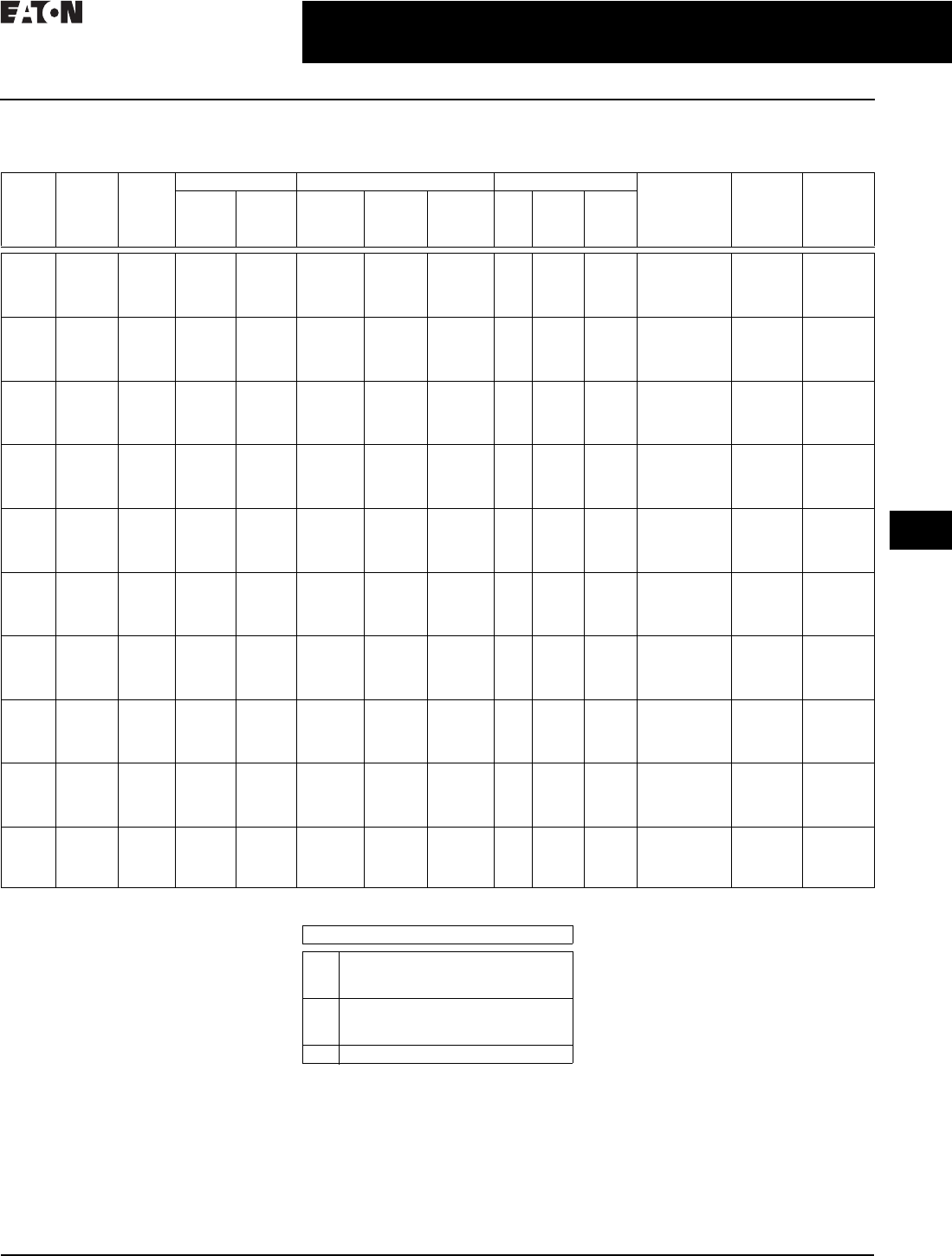
CA08104001E For more information, visit: www.eaton.com/consultants
30.3-21
April 2016
Motor Starters and Contactors—Low Voltage
Sheet 30
22
23
24
25
26
27
28
29
30
31
32
33
34
35
36
37
38
39
40
41
42
4 3
Motor Starters—Electromechanical
XT IEC Power Control
041
Technical Data
Table 30.3-45. XT Coil Data
Integrated suppressor
7–150 A DC operated contactors
and 185–2000 A AC and DC operated
contactors.
Table 30.3-46. Coil Data Notes
All data is based on a standard
contactor and a 120 Vac or 24 Vdc
magnet coil. Coil data has a ±5%
range depending on the application,
therefore, specific data may vary.
XT
Frame
Motor
Volt age
Max.
hp
Rating
P.U. (x Uc) P.U. Sealed Maximum
Operation
Rate
Operations/
Hour
P. U .
Time ms
D.O.
Time ms
AC DC VA Watts Watts
(DC)
VA Watts Wa tts
(DC)
B200
230
460
575
5
5
10
10
0.8–1.1 0.8–1.1 30 23 4.5 4.4 1.4 4.5 9000 21 18
C200
230
460
575
10
10
20
25
0.8–1.1 0.7–1.2 67 50 12.0 9 2.6 0.5 5000 22 14
D200
230
460
575
20
25
50
60
0.8–1.1 0.7–1.2 178 117 24.0 19 5.3 0.5 5000 18 13
F200
230
460
575
25
40
75
100
0.8–1.1 0.7–1.2 345 190 90.0 30 7.1 1.3 3600 20 14
G200
230
460
575
40
60
125
125
0.8–1.1 0.7–1.2 170 130 149.0 3.1 2.1 2.1 3600 33 41
H200
230
460
575
60
75
150
200
0.8–1.15 0.8–1.15 210 180 180 2.6 2.1 2.1 3000 60 40
L200
230
460
575
100
125
250
300
0.7–1.15 07–1.15 250
380
(300 A)
200
250
(300 A)
200
250
(300 A)
4.3 3.3 3.3 3000 100
80
(300 A)
80
110
(300 A)
M200
230
460
575
150
200
400
500
0.7–1.15 0.7–1.15 450 350 350 4.3 3.3 3.3 2000 80 80
N200
230
460
575
350
420
850
980
0.7–1.15 0.7–1.15 800 700 700 7.5 6.5 6.5 1000 70 70
R200
230
460
575
560
640
1200
1300
0.7–1.15 0.7–1.15 1600 1400 1400 15.0 13.0 13.0 1000 70 40
Description
P.U. Pickup time is the average time taken
from closing of the coil circuit to main
contact touch.
D.O. Dropout time is the average time taken
from opening of the coil circuit to main
contact separation.
Cold Coil data with a cold coil.

30.3-22
For more information, visit: www.eaton.com/consultants CA08104001E
April 2016
Motor Starters and Contactors—Low Voltage
Sheet 30
22
23
24
25
26
27
28
29
30
31
32
33
34
35
36
37
38
39
40
41
42
4 3
Motor Starters—Electromechanical
XT IEC Power Control
042
Table 30.3-47. Specifications
Frame R N M L H G F D C B
Catalog Number Series XTCE1600 XTCE750 XTCE500 XTCE300A XTCE225A XTCE150 XTCE095 XTCE072 XTCE032 XTCE015
Electrical Data
AC-3 at 400 V (A) 1600 750 500 300 225 150 95 72 32 15.5
Electrical Life 300,000 1,400,000 1,500,000 1,500,000 1,500,000 1,300,000 1,300,000 750,000 1,300,000 800,000
Maximum Operating Freq.
AC-3 (Ops./h)
380 500 850 850 1000 800 800 800 800 1000
AC-1 at 40 °C (A) 2200 1102 857 490 386 190 130 98 45 22
Max. Nominal Power
460 V (hp)
1200 600 400 250 150 125 75 40 20 10
General
Mechanical Life 5,000,000 5,000,000 7,000,000 10,000,000 10,000,000 10,000,000 10,000,000 10,000,000 10,000,000 10,000,000
Width (mm) 515 250 160 140 140 90 90 55 45 45
Height (mm) 392 296 200 200 164 170 170 115 85 68
Depth (mm) 252 232 216 216 208 150 150 132.1 97 75
Weight (kg) 32 15 8 8 6.5 2 2 0.9 0.42 0.23
Min. Ambient
Temperature (°C)
–25 –25 –25 –25 –25 –25 –25 –25 –25 –25
Max. Ambient
Temperature (°C)
60 60 60 60 60 60 60 60 60 60
Contacts
Wire Range
Solid or Stranded (AWG)
2/0–500
kcmil
2/0–500
kcmil
1/0–250
kcmil
2/0–500
kcmil
1/0–350
kcmil
8–3/0 8–3/0 14–1 14–8 18–14
Power Terminal Torque
Lb/In (Nm)
311 (35) 213 (24) 213 (24) 213 (24) 213 (24) 123.9 (14) 123.9 (14) 29.2 (3.3) 26.6 (3) 10.6 (1.2)
Control Circuit 18–14 18–14 18–14 18–14 18–14 18–14 18–14 18–14 18–14 18–14
Control Terminal Torque 10.6 (1.2) 10.6 (1.2) 10.6 (1.2) 10.6 (1.2) 10.6 (1.2) 10.6 (1.2) 10.6 (1.2) 10.6 (1.2) 10.6 (1.2) 10.6 (1.2)
Auxiliary Contacts
Number of Auxiliary Contact
Modules in Basic Unit
4444400011
Number of Additional
Auxiliary Contact Modules
4444488644
Ie AC-15/230 V (A) 6 6 6 6 6 6 6 6 4 4
Mounting Method
Dimensions of Drilled Hole
Width A (mm])
430 165 130 130 120 70 70 45 35 35
Dimensions of Drilled Hole
Height B (mm)
270 215 180 180 160 156 156 105 75 60
Mounting Screws 4xM6 4xM6 4xM6 4xM6 4xM6 4xM6 4xM6 2xM4 2xM4 2xM4
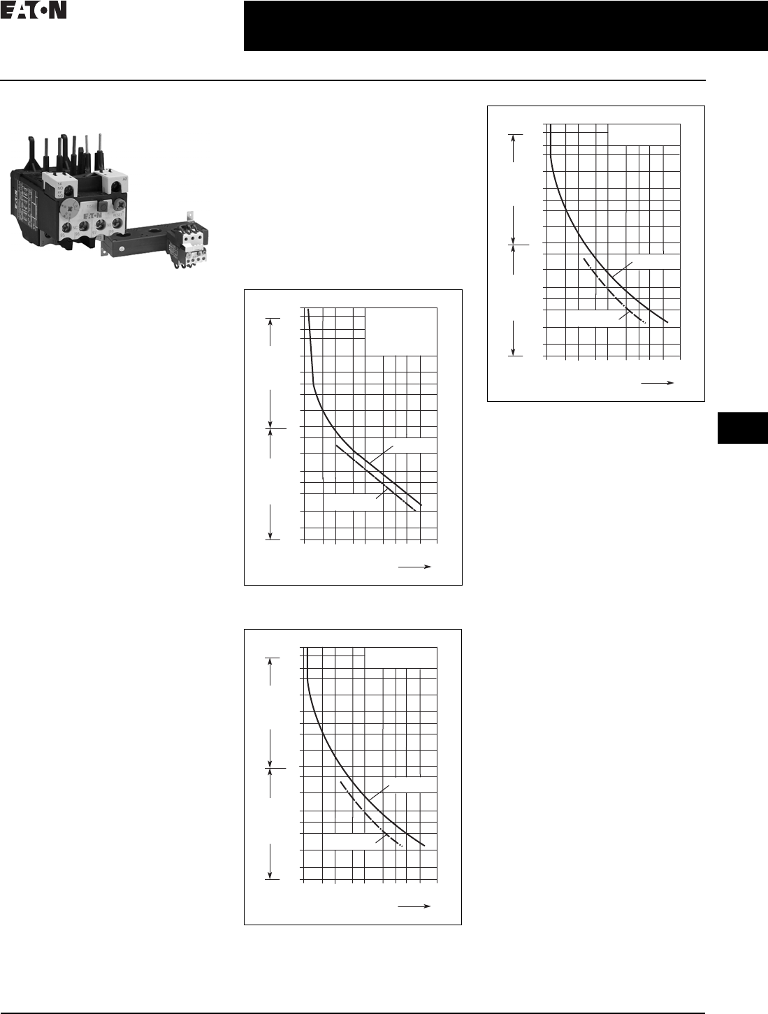
CA08104001E For more information, visit: www.eaton.com/consultants
30.3-23
April 2016
Motor Starters and Contactors—Low Voltage
Sheet 30
22
23
24
25
26
27
28
29
30
31
32
33
34
35
36
37
38
39
40
41
42
4 3
Motor Starters—Electromechanical
Thermal Overload Relays
043
Thermal Overload Relays
XTOB, XTOT Overload Relays
Product Description
The XT line of IEC motor thermal
overload relays provides an efficient
motor protection solution, available
up to 630 A. XTOB units can be
directly mounted to the contactor
or mounted separately.
Features and Benefits
■Direct connect up to 250 A
■Stand alone and CT type up to 630 A
■Large thermal overcurrent range
■Test button
■Manual/automatic selectable reset
■NO-NC auxiliary as standard
■Class 10A (to 250 A)
■Class 30 (CT type)
Standards and Certifications
■IEC EN 60947
■CE approved
■UL
■CSA
■ATEX
■RoHS
Note: Short-circuit protection: Observe
the maximum permissible fuse of the
contactor with direct device mounting.
See MN03402001E for more information
on overload relays for Frames B–G.
Trip Class: 10A
Suitable for protection of EEx e-motors.
EC prototype test certificate available
upon request. See manuals MN03402001E
and MN03407001E.
Instructional Leaflets
■Pub51221: XTOB, D Frame overload
relays (inside of packaging)
■Pub51222: XTOB, B–C Frame over-
load relays (inside of packaging)
Tripping Characteristics
These tripping characteristics are the
mean values of the spread at 20 °C
ambient temperature in a cold state.
Tripping time depends on response
current. With devices at operating
temperature, the tripping time
of the overload relay reduces to
approximately 25% of the read off
value. Specific characteristics for
each individual setting range can be
found in MN03402001E.
Figure 30.3-11. XTOB...BC1, XTOB...CC1,
XTOB...DC1
Figure 30.3-12. XTOB...GC1
Figure 30.3-13. XTOB...HC1, XTOB...LC1
2h
100
60
40
20
10
6
4
2
1
40
20
10
6
4
2
1
0.6
XTOB...BC1,
XTOB...CC1,
XTOB...DC1
1 1.5 2 3 4 68 10 15 20
x Setting Current
2-Phase
Seconds Minutes
3-Phase
2h
100
60
40
20
10
6
4
2
1
40
20
10
6
4
2
1
0.6
XTOB...GC1
1 1.5 2 3 4 68 10 15 20
x Setting Current
2-Phase
Seconds Minutes
3-Phase
2h
100
60
40
20
10
6
4
2
1
40
20
10
6
4
2
1
0.6
XTOB...HC1,
XTOB...LC1
1 1.5 2 3 4 68 10 15 20
x Setting Current
2-Phase
Seconds Minutes
3-Phase

30.3-24
For more information, visit: www.eaton.com/consultants CA08104001E
April 2016
Motor Starters and Contactors—Low Voltage
Sheet 30
22
23
24
25
26
27
28
29
30
31
32
33
34
35
36
37
38
39
40
41
42
4 3
Motor Starters—Electromechanical
Thermal Overload Relays
044
Technical Data
Table 30.3-48. Direct Mount to XT Contactors—For Use with XT Contactor Frame
Frame Overload
Releases, Ir
Contact
Sequence
Contact
Configuration
For Use with
Contactor
Ampere Range
Fuse Type 1
Coordination,
gG/gL
Ty p e 2
Coordination,
gG/gL
Maximum
Circuit
Breaker
CEC/
NEC
Fuse
Catalog
Number
B 0.1–0.16
0.16–0.24
0.24–0.4
0.4–0.6
1NO-1NC
1NO-1NC
1NO-1NC
1NO-1NC
7–15 A
7–15 A
7–15 A
7–15 A
25
25
25
25
0.5
1
2
4
25
25
25
25
3
3
3
3
XTOBP16BC1
XTOBP24BC1
XTOBP40BC1
XTOBP60BC1
0.6–1
1–1.6
1.6–2.4
2.4–4
1NO-1NC
1NO-1NC
1NO-1NC
1NO-1NC
7–15 A
7–15 A
7–15 A
7–15 A
25
25
25
25
4
6
10
16
25
25
25
25
3
6
6
15
XTOB001BC1
XTOB1P6BC1
XTOB2P4BC1
XTOB004BC1
4–6
6–10
9–12
12–16
1NO-1NC
1NO-1NC
1NO-1NC
1NO-1NC
7–15 A
7–15 A
9–15 A
12–15 A
25
50
50
50
20
25
25
25
25
25
25
30
20
35
45
45
XTOB006BC1
XTOB010BC1
XTOB012BC1
XTOB016BC1
C 0.1–0.16
0.16–0.24
0.24–0.4
0.4–0.6
1NO-1NC
1NO-1NC
1NO-1NC
1NO-1NC
18–32 A
18–32 A
18–32 A
18–32 A
25
25
25
25
0.5
1
2
4
25
25
25
25
3
3
3
3
XTOBP16CC1
XTOBP24CC1
XTOBP40CC1
XTOBP60CC1
0.6–1
1–1.6
1.6–2.4
2.4–4
1NO-1NC
1NO-1NC
1NO-1NC
1NO-1NC
18–32 A
18–32 A
18–32 A
18–32 A
25
25
25
25
4
6
10
16
25
25
25
25
3
6
6
15
XTOB001CC1
XTOB1P6CC1
XTOB2P4CC1
XTOB004CC1
4–6
6–10
10–16
16–24
24–32
1NO-1NC
1NO-1NC
1NO-1NC
1NO-1NC
1NO-1NC
18–32 A
18–32 A
18–32 A
18–32 A
25–32 A
25
50
63
100
125
20
25
35
35
63
25
25
30
30
30
20
25
25
25
25
XTOB006CC1
XTOB010CC1
XTOB016CC1
XTOB024CC1
XTOB032CC1
D6–10
10–16
16–24
24–40
1NO-1NC
1NO-1NC
1NO-1NC
1NO-1NC
40–72 A
40–72 A
40–72 A
40–72 A
50
63
63
125
25
35
50
63
25
25
30
125
25
25
25
125
XTOB010DC1
XTOB016DC1
XTOB024DC1
XTOB040DC1
40–57
50–65
65–75
1NO-1NC
1NO-1NC
1NO-1NC
50–72 A
65–72 A
72 A
160
160
200
80
100
125
150
150
150
150
200
200
XTOB057DC1
XTOB065DC1
XTOB075DC1
F–G 25–35
35–50
50–70
70–100
1NO-1NC
1NO-1NC
1NO-1NC
1NO-1NC
80–170 A
80–170 A
80–170 A
80–170 A
125
160
250
315
100
125
160
200
125
150
150
400
125
200
200
400
XTOB035GC1
XTOB050GC1
XTOB070GC1
XTOB100GC1
95–125
120–150
145–175
1NO-1NC
1NO-1NC
1NO-1NC
80–170 A
80–170 A
150–170 A
315
315
315
200
200
200
500
600
600
400
600
600
XTOB125GC1
XTOB150GC1
XTOB175GC1
2 4 6 98 96 A214/
22
97 95
2 4 6 98 9614/
22
97 95
2469896
97 95
2469896
97 95
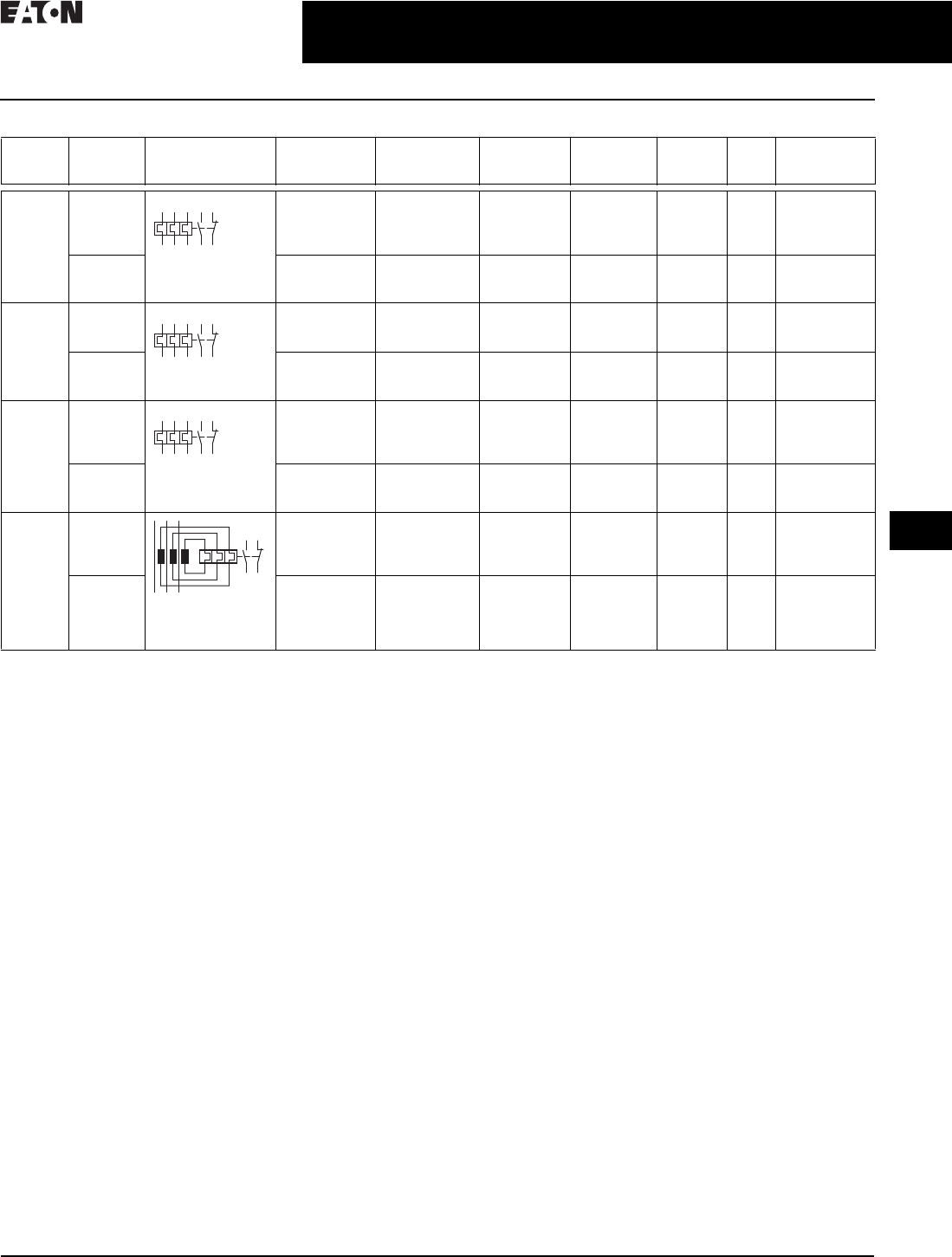
CA08104001E For more information, visit: www.eaton.com/consultants
30.3-25
April 2016
Motor Starters and Contactors—Low Voltage
Sheet 30
22
23
24
25
26
27
28
29
30
31
32
33
34
35
36
37
38
39
40
41
42
4 3
Motor Starters—Electromechanical
Thermal Overload Relays
045
Table 30.3-49. Separate Mount to XT Contactors—For Use with XT Contactor Frame
1For separate mounting, short-circuit Type 1 rating is 500 A and short-circuit Type 2 rating is 400 A.
2The main current parameters are defined by the main current wiring that is used.
3Go datasheet.moeller.net for more information complete data sheet by Article number.
Frame Overload
Releases, Ir
Contact
Sequence
Contact
Configuration
For Use with
Contactor
Ampere Range
Fuse Type 1
Coordination,
gG/gL
Ty p e 2
Coordination,
gG/gL
Maximum
Circuit
Breaker
CEC/
NEC
Fuse
Catalog
Number
F–G 25–35
35–50
50–70
70–100
1NO-1NC
1NO-1NC
1NO-1NC
1NO-1NC
80–170 A
80–170 A
80–170 A
80–170 A
125
160
250
315
100
125
160
200
125
150
150
400
125
200
200
400
XTOB035GC1S
XTOB050GC1S
XTOB070GC1S
XTOB100GC1S
95–125
120–150
145–175
1NO-1NC
1NO-1NC
1NO-1NC
80–170 A
80–170 A
150–170 A
315
315
315
250
250
250
500
600
600
400
600
600
XTOB125GC1S
XTOB150GC1S
XTOB175GC1S
H 50–70
70–100
95–125
1NO-1NC
1NO-1NC
1NO-1NC
185–250 A
185–250 A
185–250 A
250
315
315
160
200
250
150
400
500
200
400
400
XTOB070HC1
XTOB100HC1
XTOB125HC1
120–160
160–220
200–250
1NO-1NC
1NO-1NC
1NO-1NC
185–250 A
185–250 A
225–250 A
400
400 1
400 1
250
315 1
315 1
600
600
600
600
800
700
XTOB160HC1
XTOB220HC1
XTOB250HC1
L 50–70
70–100
95–125
120–160
1NO-1NC
1NO-1NC
1NO-1NC
1NO-1NC
185–250 A
185–250 A
185–250 A
185–250 A
250
315
315
400
160
200
250
250
150
400
500
600
200
400
400
600
XTOB070LC1
XTOB100LC1
XTOB125LC1
XTOB160LC1
160–220
200–250
200–300
1NO-1NC
1NO-1NC
1NO-1NC
185–250 A
225–250 A
225–300 A
400 1
400 1
630 1
315 1
315 1
630 1
600
600
600
800
700
700
XTOB220LC1
XTOB250LC1
XTOB300LC1
M–N
(CT
Operated)
42–63
60–90
85–125
110 – 1 6 0
1NO-1NC
1NO-1NC
1NO-1NC
1NO-1NC
300–500 A
300–500 A
300–500 A
300–500 A
—
—
—
—
—
—
—
—
150
250
500
600
200
250
400
600
XTOT063C3S
XTOT090C3S
XTOT125C3S
XTOT160C3S
160–240
190–290
270–400
360–540
420–630
1NO-1NC
1NO-1NC
1NO-1NC
1NO-1NC
1NO-1NC
300–500 A
300–500 A
300–500 A
500 A
630 A
—
—
—
—
—
—
—
—
—
—
600
600
100 0
600
600
700
700
1000
1000
1000
XTOT240C3S
XTOT290C3S
XTOT400C3S
XTOT540C3S
XTOT630C3S
2469896
97 95
24 6
12 5
98 96
97 95
24 6
12 5
98 96
97 95
98 96
97 95
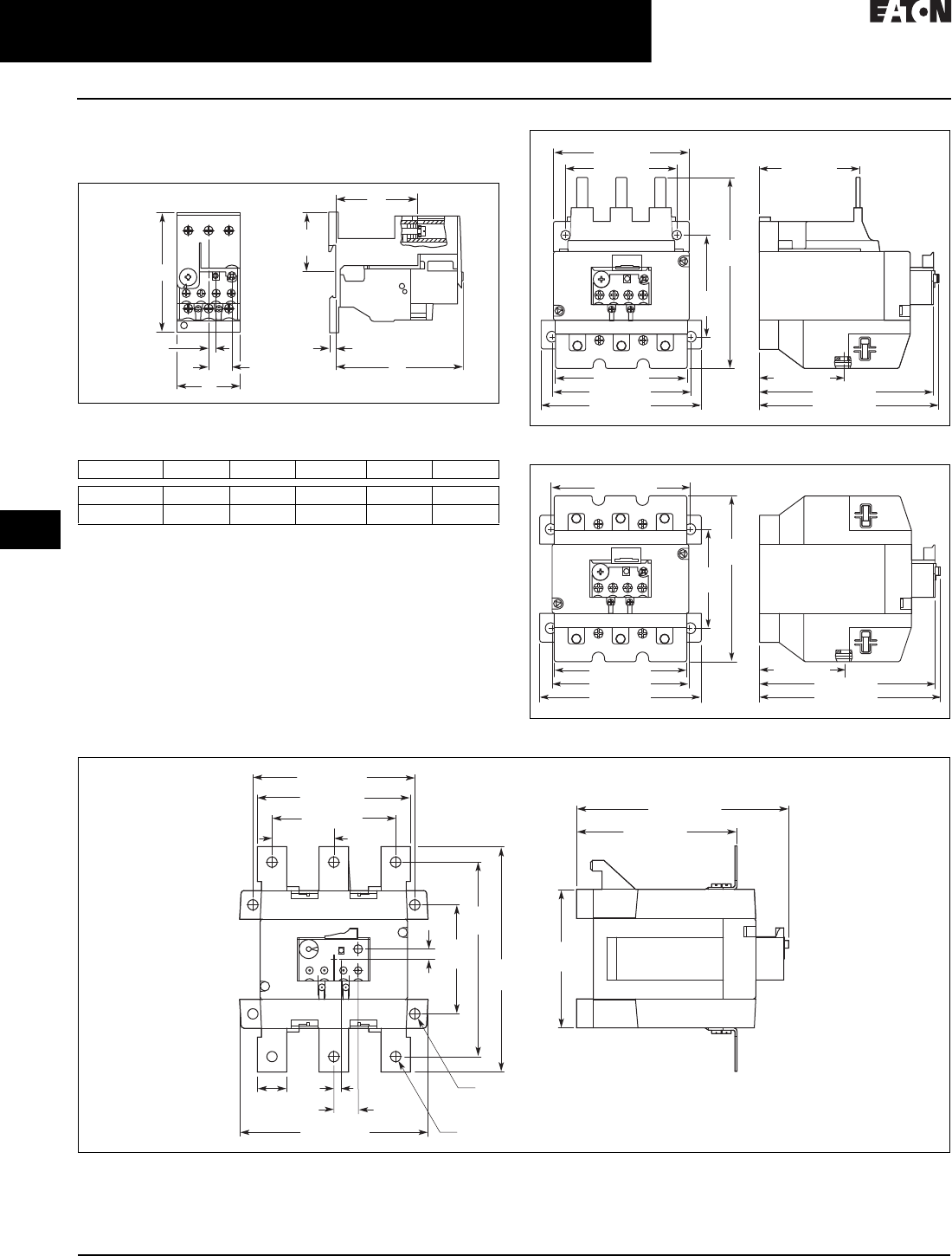
30.3-26
For more information, visit: www.eaton.com/consultants CA08104001E
April 2016
Motor Starters and Contactors—Low Voltage
Sheet 30
22
23
24
25
26
27
28
29
30
31
32
33
34
35
36
37
38
39
40
41
42
4 3
Motor Starters—Electromechanical
Thermal Overload Relays
046
Dimensions
Approximate Dimensions in Inches (mm)
Figure 30.3-14. Frames B–C, XTOBXDINC DIN Rail or Panel Mount
Adapter and Frame D, XTOBXDIND DIN Rail or Panel Mount Adapter Figure 30.3-15. Frames F–G, XTOB…GC1 Overload Relay
Figure 30.3-16. Frames F–G, XTOB…G1CS Overload Relay
Figure 30.3-17. Frames L and H, XTOB…LC1, HC1 Overload Relay
HWD D1D2
XTOB…CC1 3.46 (85.0) 1.77 (45.0) 3.56 (90.5) 2.30 (58.3) 0.15 (3.8)
XTOB…DC1 3.39 (86.0) 2.36 (60.0) 4.41 (112.0) 3.17 (80.5) 0.19 (4.7)
0.20 (5.0)
H
0.65 (16.5)
D2
1.67
(42.5)
W
D
D1
5.43
(138.0)
2.48 (63.0)
5.08 (129.0)
3.94 (100.0)
5.28 (134.0)
2.91
(74.0)
4.65 (118.0)
3.90 (99.0)
3.15 (80.0)
3.74 (95.0)
2.87 (73.0)
2.48 (63.0)
5.08 (129.0)
5.28 (134.0)
4.76
(121.0)
2.91
(74.0)
3.94 (100.0)
3.90 (99.0)
4.65 (118.0)
3.74 (95.0)
4.76 (121.0)
4.33 (110.0)
3.78 (96.0)
5.04 (128.0)
2.91
(74.0)
5.67
(144.0)
6.65
(169.0)
1.89 (48.0)
0.98
(25.0)
0.20
(5.0) 0.65
(16.5)
5.67 (144.0)
14.37 (11.0)
3.70
(94.0)
0.28
(7.0)
0.28 (7.0) Dia.
0.43 (11.0) Dia.
*
**
*
** * = OFF
** = RESET/ON
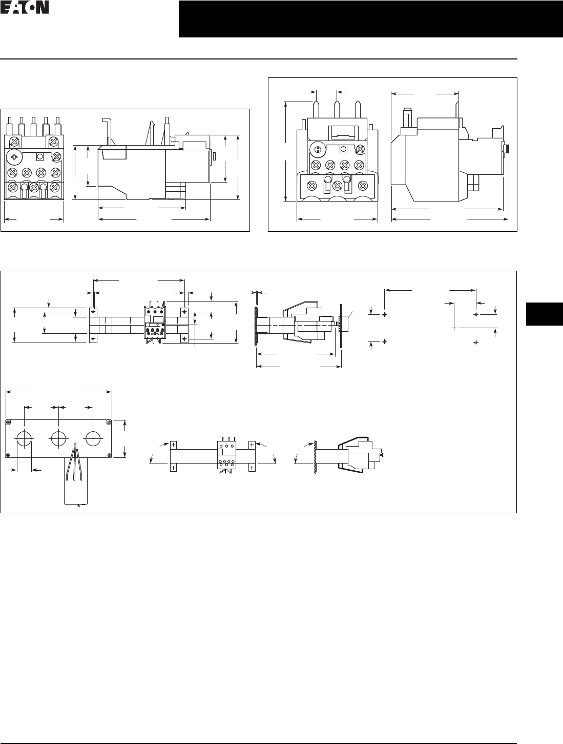
CA08104001E For more information, visit: www.eaton.com/consultants
30.3-27
April 2016
Motor Starters and Contactors—Low Voltage
Sheet 30
22
23
24
25
26
27
28
29
30
31
32
33
34
35
36
37
38
39
40
41
42
4 3
Motor Starters—Electromechanical
Thermal Overload Relays
047
Dimensions
Approximate Dimensions in Inches (mm)
Figure 30.3-18. Frames B–C, XTOB…BC1 and XTOB…CC1 Overload
Relays
Figure 30.3-19. Frame D, XTOB…DC1 Overload Relay
Figure 30.3-20. XTOT…C3S Current Transformer Operated Overload Relay
1.77 (45.0) 3.27 (83.0)
2.56 (65.0)
1.89
(48.0)
1.40
(35.5)
1.56
(39.5)
1.16
(29.5)
2.36 (60.0) 4.02 (102.0)
3.76 (95.5)
2.03
(51.5)
3.12
(79.2)
0.80
(20.3)
0.30 (7.5)
1.02
(26.0)
2.17
(55.0)
0.83 (21.0)
3.35
(85.0)
7.28 (185.0)
2.80
(71.0) 1.73 (44.0) 1.30
(33.0)
0.31 (8.0) 0.17 (4.3) 7.28 (185.0)
M4
1.73
(44.0)
1.02 (26.0)
2.17
(55.0)
0.06 (1.5)
6.26 (159.0)
6.77–9.84
(172.0–250.0)
*
*
* = RESET/ON
90° 90°
7.87 (200.0)
2.56
(65.0)
2.56
(65.0)
2.80
(71.0)
1.06
(27.0)
90°
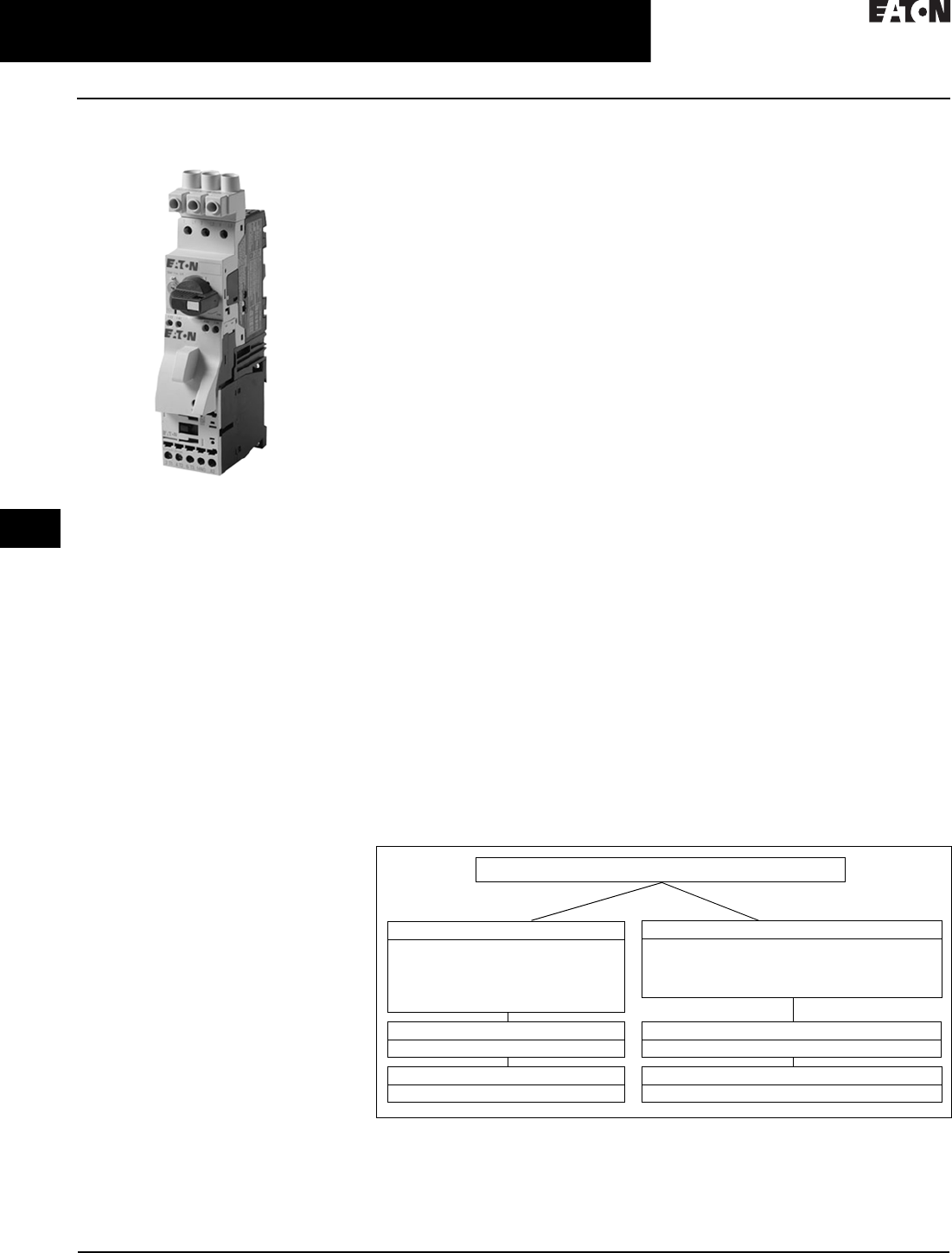
30.3-28
For more information, visit: www.eaton.com/consultants CA08104001E
April 2016
Motor Starters and Contactors—Low Voltage
Sheet 30
22
23
24
25
26
27
28
29
30
31
32
33
34
35
36
37
38
39
40
41
42
4 3
Motor Starters—Electromechanical
Combination Motor Controllers
048
Combination Motor Controllers
Combination Motor Controllers
General Description
Eaton’s XT IEC open non-reversing and
reversing manual motor controllers
combine a manual motor protector
with an IEC contactor(s) to provide a
complete motor protection solution by
combining motor disconnect function,
thermal overload protection, magnetic
short-circuit protection and remote
control operation in one compact,
assembled unit. these assembled
manual motor controllers cover motors
with FLA ratings from 0.10 A to 65 A.
The UL 508 Type F labeled combination
motor controller (CMC) includes a line
side adapter (LSA). These assembled
combination motor controllers cover
motors with FLA ratings from 0.10 A
to 65 A.
Application Description
The XT IEC non-reversing and
reversing manual and combination
motor controllers can be used in the
following applications:
Group Motor Control
Manual motor controllers (MMCs)
are ideal for group motor applications
where an upstream breaker or fuse
provides protection for two or more
motors. XT manual motor controllers
(MMC) combine a manual motor
protector, a wiring connector link
and IEC contactor.
Individual Branch Circuit for Motor Loads
Combination motor controller (CMC),
consisting of a line side adapter, manual
motor protector, wiring connector link
and IEC contactor, provide an efficient
means to build an entire branch circuit.
The XT CMC is UL 508 Type F approved,
meaning it is “self-protected” and
doesn’t require the use of an additional
fuse or breaker for short circuit protec-
tion. This approval means CMC’s can be
used in place of a traditional fuse-starter
and breaker-starter motor circuit.
Based around two key functional
components (MMP and contactor),
the CMC is a very cost effective means
to build a branch circuit. Fuses and
breakers must be oversized to prevent
tripping during motor start up, and
thus these oversized devices can
no longer protect the motor. To
compensate for this, a motor overload
relay is necessary to protect the motor.
The manual motor protector was
invented in Germany by Moeller to
correct this inefficiency. The MMP
operates similarly to a circuit breaker,
except the inrush (magnetic) protection
is set to 14 times the running current,
thus accounting for motor start-up
current without the necessity to over-
size. A overcurrent dial was added to
the face of the MMP to serve as the
motor overload protection. This
“motor protective circuit breaker”, as
it is referred to in Europe, now accom-
plishes all four key functions of a motor
branch circuit: disconnect, short circuit,
motor controller and motor overload
protection. With the addition of a
contactor, users have the ability to
remotely control the starter device.
Whether a single motor application or
a multiple motor application, CMCs
are an ideal solution for machinery
OEMs and panel builders.
Features
■ON/OFF rotary handle with
lockout provision
■Visible trip indication
■Test trip function
■Motor applications from
0.10 A to 65 A
■Class 10 overload protection
■Built-in heater and magnetic trip
elements to protect the motor
■Phase loss sensitivity
■Type 2 coordination
■Ambient compensated up
to 55 °C (140 °F)
■Control inputs located at front of
starter for easy access and wiring
■Wide range of coils
■DIN rail mount—XTSC…BB_
■Mounting plates—XTSC…BC_,
XTSC…D motor controllers
■Adjustment dial for setting
motor FLA
■Short-circuit trip at 14 times the
maximum setting of the FLA
adjustment dial
■UL 508 Type F CMC high fault
short-circuit ratings
■1NO-1NC auxiliary contact as
standard on manual motor controller
and combination motor controller
Standards and Certifications
■UL 508 Type F combination
motor controller
■IEC Type 2 Approved per
IEC 60947-4-1
■UL Listed File No. E245398
■CE Mark
Figure 30.3-21. MMC and CMC Applications
Note: Technical Paper AP03402001E. Line side adapters are not required for non-U.S.
applications. Most countries outside of the U.S. classify the MMP as a motor-protective
circuit breaker.
1SCPD = Short-circuit protective device (circuit breaker, fuses).
2MMC = Manual motor controller
Combination Motor Controller
XTFC/XTFR
Line Side Adapter (LSA)
Not required
Line Side Adapter (LSA)
Required—factory assembled
XTIEC Manual and Combination Motor Controllers
Manual Motor Controller
Use in group installation applications.
Upstream SCPD 1 is required and must
be sized smaller than the maximum
upstream SCPD 1 rating on each MMC 2
used. Tap rules should also be observed.
UL 508 Type F Combination Motor Controller
Use for single motor branch circuits or use multiple
CMC’s for a multiple motor panel applications. No
additional SCPD 1 is required in the branch, as these
devices are “self-protected”.
Manual Motor Controller
XTSC/XTSR
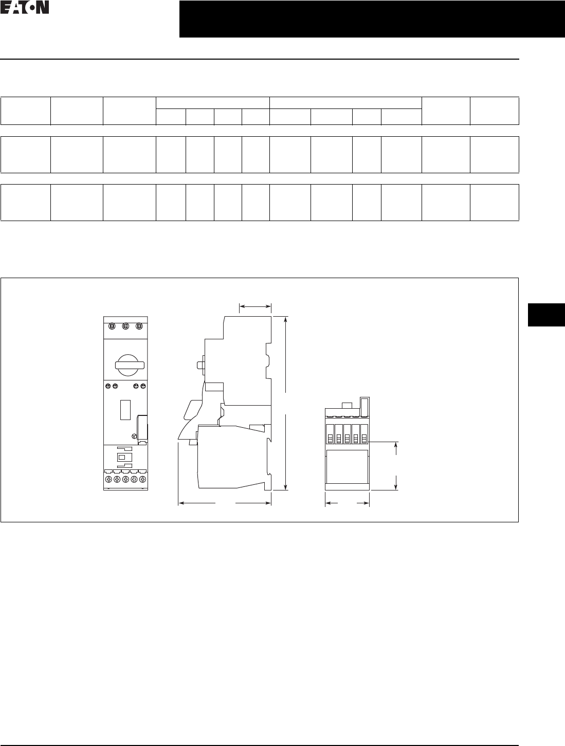
CA08104001E For more information, visit: www.eaton.com/consultants
30.3-29
April 2016
Motor Starters and Contactors—Low Voltage
Sheet 30
22
23
24
25
26
27
28
29
30
31
32
33
34
35
36
37
38
39
40
41
42
4 3
Motor Starters—Electromechanical
Combination Motor Controllers
049
Technical Data
Table 30.3-50. Combination Motor Controller Ratings
Dimensions
Approximate Dimensions in Inches (mm)
Figure 30.3-22. XTSC…BB_
Frame MMP/
Frame
Contactor
FLA
Maximum
Adjustment
Short Circuit
Release—Irm
(Amperes)
Three-Phase Hp UL Three-Phase kW IEC Non-
Reversing
Catalog
Reversing
Catalog
200 V 240 V 480 V 600 V 220–240 V 380–415 V 500 V 660–690 V
Manual Motor Controller/Starter Combinations
B/B
B/C
D/C
D/D
16
32
32
65
224
448
448
882
3
7. 5
7. 5
15
3
10
10
15
10
20
20
40
7. 5
25
30
30
4
7. 5
7. 5
18.5
7. 5
15
15
34
9
22
17.5
37
12.5
30
22
55
XTSC_____
XTSC_____
XTSC_____
XTSC_____
XTSR_____
XTSR_____
XTSR_____
XTSR_____
Combination Motor Controllers (CMC), UL 508 Type F
B/B
B/C
D/C
D/D
16
32
32
65
224
448
448
882
3
7. 5
7. 5
15
5
10
10
15
10
20
25
40
7. 5
—
30
30
4
7. 5
7. 5
18.5
7. 5
15
15
34
9
22
17.5
37
12.5
30
22
55
XTFC_____
XTFC_____
XTFC_____
XTFC_____
XTFR______
XTFR______
XTFR______
XTFR______
1.96 (49.7)
to Terminals
1.77
(45.0)
3.77
(95.7)
7.03
(178.5)
1.28 (32.5)
to Terminals
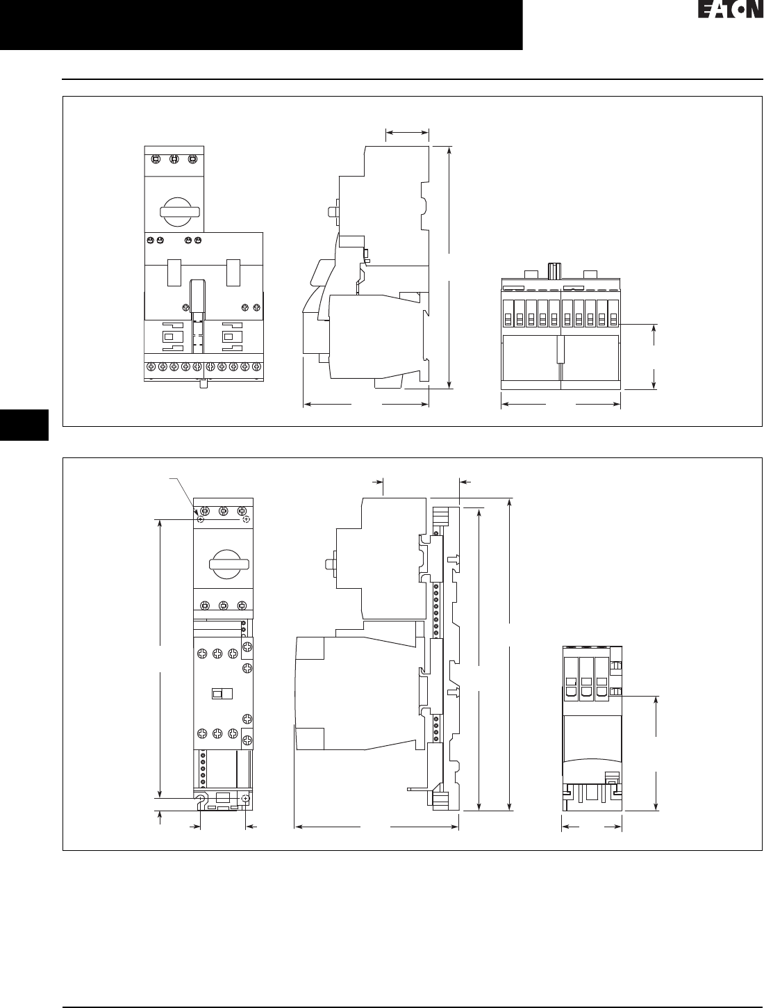
30.3-30
For more information, visit: www.eaton.com/consultants CA08104001E
April 2016
Motor Starters and Contactors—Low Voltage
Sheet 30
22
23
24
25
26
27
28
29
30
31
32
33
34
35
36
37
38
39
40
41
42
4 3
Motor Starters—Electromechanical
Combination Motor Controllers
050
Figure 30.3-23. XTSR…BB_
Figure 30.3-24. XTSC…BC_
1.96 (49.7)
to Terminals
3.55
(90.3)
1.28 (32.5)
to Terminals
3.75
(95.3)
7.22
(183.4)
Mounting Holes
for M4 Screws
or #8 Screws
(4 Places)
1.34
(34.0)
8.30 (210.8)
Mounting
0.35 (9.0)
3.42
(86.8)
to Terminals
1.78
(45.2)
2.26 (57.5)
to Terminals
4.89
(124.3)
9.01
(228.8)
9.28
(235.7)
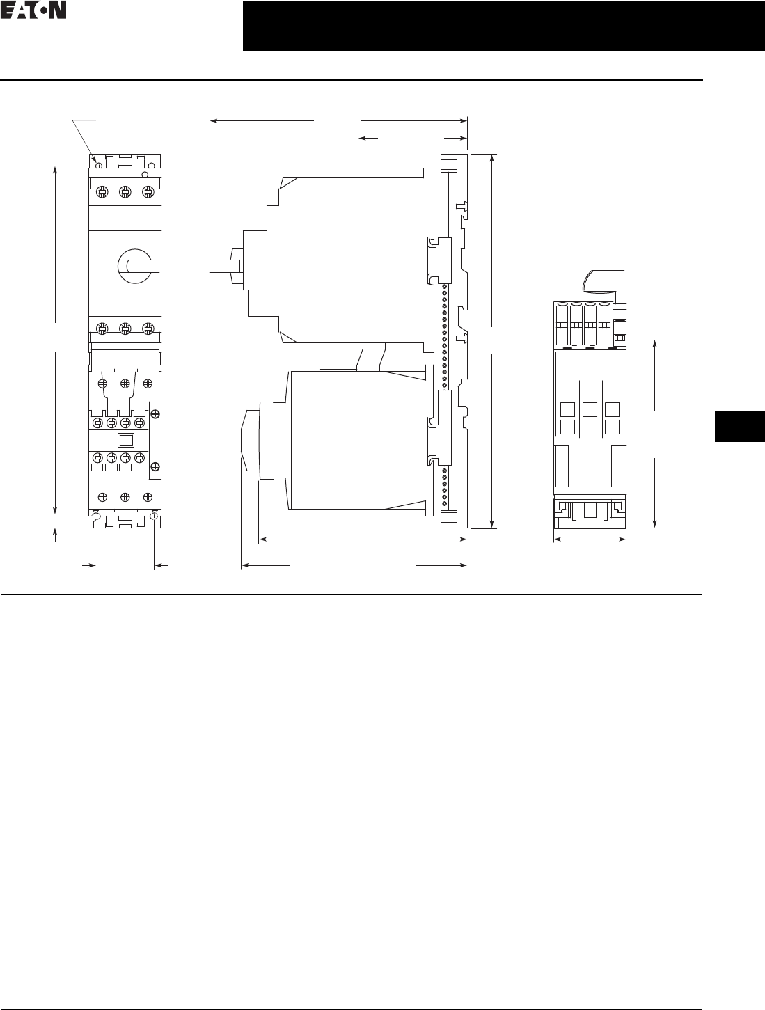
CA08104001E For more information, visit: www.eaton.com/consultants
30.3-31
April 2016
Motor Starters and Contactors—Low Voltage
Sheet 30
22
23
24
25
26
27
28
29
30
31
32
33
34
35
36
37
38
39
40
41
42
4 3
Motor Starters—Electromechanical
Combination Motor Controllers
051
Figure 30.3-25. XTSC…DD
5.62
(142.8)
to Coil
Terminals
3.28 (83.4)
to Terminals
7.72 (196.0)
6.24
(158.5)
6.78 (172.1)
to Optional Aux. Contacts
Mounting Holes for
M5 Screws or #10 Screws
(4 Places)
2.17
(55.0)
1.71 (43.4)
Mounting
10.47 (266.0)
Mounting
0.35 (9.0)
11.18
(284.0)
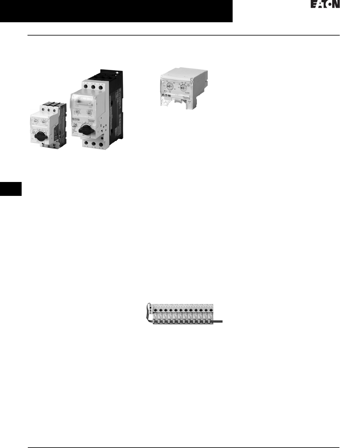
30.3-32
For more information, visit: www.eaton.com/consultants CA08104001E
April 2016
Motor Starters and Contactors—Low Voltage
Sheet 30
22
23
24
25
26
27
28
29
30
31
32
33
34
35
36
37
38
39
40
41
42
4 3
Motor Starters—Electromechanical
XT Electronic Manual Motor Protector
052
XT Electronic Manual
Motor Protector
XT Electronic Manual Motor Protector
General Description
The XT Electronic Manual Motor
Protector provides the same
functionality as the XT thermal manual
motor protector, but with an added
level of flexibility and selectability. The
XTPE incorporates electronic control
technology to enable more options and
larger dial setting ranges. The trip units
are interchangeable, allowing users
to exchange as needed using the same
base. The reduced number of part
numbers decreases bill of material
complexity while reducing inventory
demands. The XTPE electronic
manual motor protector includes
the following features:
■4:1 maximum to minimum
overcurrent dial setting range
■Selectable trip class (5, 10, 15, 20)
■Interchangeable trip units
■Three base units (12, 32 and 65 A)
■Common accessories with the XTPR
Features and Benefits
Advanced Trip Unit
In addition to the selectability, the XTPE
is also available with an advanced trip
unit that can communicate system
data and protector data through
SmartWire-DT®. SmartWire-DT is an
innovative cost-effective connection
technology that enables quick installa-
tion of control wiring to the starter
through a single green cable. When
on SmartWire-DT, the XTPE can
communicate the following:
■Current values
❑Maximum phase current
❑Overload warning
■Diagnostics data
❑Overload fault
❑Cause of trip (overcurrent or short
circuit)
❑Phase loss
❑Trip via TEST
■Status messages
❑Control unit type
❑Overload setting
❑Time-lag
❑Switching status
XTPE Electronic MMP
The XTPE Electronic MMP provides
the selectability, control, and insight
options that give panel builders and
OEMs the solutions necessary to
enhance motor control designs while
reducing total costs.
Standards and Certifications
■CE approved
■UL Listed File No. E36332
■UL 508 group motor and Type E
■IEC/EN 60947
■CSA File 012528, Class 3211-05
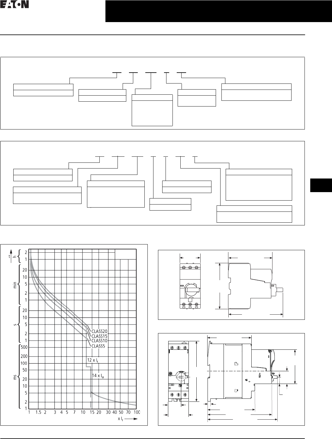
CA08104001E For more information, visit: www.eaton.com/consultants
30.3-33
April 2016
Motor Starters and Contactors—Low Voltage
Sheet 30
22
23
24
25
26
27
28
29
30
31
32
33
34
35
36
37
38
39
40
41
42
4 3
Motor Starters—Electromechanical
XT Electronic Manual Motor Protector
053
Catalog Number Selection
Table 30.3-51. XT—Manual Motor Protector Catalog Numbering System
Table 30.3-52. XT—Combinations Catalog Numbering System
Trip Characteristics
Figure 30.3-26. XT Electronic Manual Motor Controllers
Dimensions
Approximate Dimensions in Inches (mm)
Figure 30.3-27. XT Electronic MMP—B Frame
Figure 30.3-28. XT Electronic MMP—D Frame
XT PE 004 BCS
Type
PE = Electronic MMP
Designation
XT = XT line of IEC control
Overload Release
1P2 = 0.3–1.2 A
004 = 1–4 A
012 = 3–12 A
032 = 8–32 A
065 = 16–65 A
Trip Type
CS = Standard
CA = Advanced (SmartWire-DT)
MMP Frame
B = 45 mm
D = 55 mm
Type
FCE = Electronic combination
motor controller
Designation
XT = XT line of IEC control
XT FCE 004 B C CS A
Overload Release
1P2 = 0.3–1.2 A
004 =1–4 A
012 =3–12 A
032 =8–32 A MMP Frame
B = 45 mm Trip Type
CS = Selectable class 5, 10, 15, 20
CA = Selectable, advanced
Coil Voltage
A= 110 V 50 Hz, 120 V 60 Hz
B= 220 V 50 Hz, 240 V 60 Hz
F= 230 V 50 Hz
T= 24 V 50/60 Hz
TD= 24 Vdc
Contactor Frame
C = 45 mm
XTPE …
1.77
(45.0)
4.72 (120.0)
3.79 (96.2)
3.98
(101.0)
4.65 (118.0)
2.22
(56.5)
2.17
(55.0)
1.38
(35.0)
6.30
(160.0)
0.57
(14.5)
1.28
(32.5)
0.22 (5.5)
5.00 (127.0)
6.77 (172.0)
7.36 (187.0)
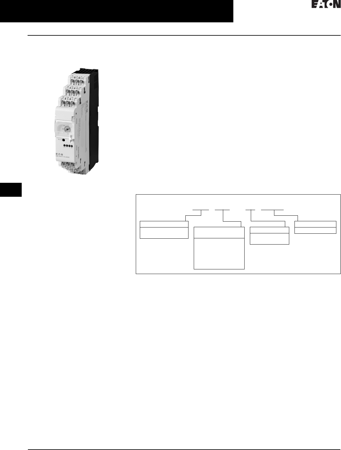
30.3-34
For more information, visit: www.eaton.com/consultants CA08104001E
April 2016
Motor Starters and Contactors—Low Voltage
Sheet 30
22
23
24
25
26
27
28
29
30
31
32
33
34
35
36
37
38
39
40
41
42
4 3
Motor Starters—Electromechanical
EMS—Electronic Motor Starter
054
EMS—Electronic
Motor Starter
EMS—Electronic Motor Starter
General Description
The electronic motor starter (EMS)
is the latest technology in safe and effi-
cient motor starting from Eaton’s
Electrical Sector. The EMS is a full
starter with built-in solid-state contacts
and integral overload protection. Its
compact size and high-electrical life
make it an ideal replacement for the
traditional contactor/overload relay
starter configuration.
Application Description
A versatile solution, the EMS also
supports the following installation
applications:
■Logistics
■Conveyer control
■Production machines
■To o l i n g m achine s
■Packaging machines
■Small elevators
Features and Benefits
Multifunctional
The EMS comes with an optional
reversing start feature, eliminating
the need for an additional contactor.
The optional E-stop functionality
eliminates the need for a separate
E-stop contactor. Available with
SmartWire-DT connection, reducing
installation cost and providing
communication means of critical data.
Extended Life
High-electrical life provides up to
30 million operations. The EMS is ideal
for customer applications requiring
multiple motor start/stops per hour.
Easy Installation
The EMS comes equipped with
push-in terminals for quick and easy
wiring of power and control circuits.
Push-in terminals provide 60% time
savings over screw-in terminals and
better contact against vibrations.
Standards and Certifications
■UL
Safety Rated
Functional safety is growing in
importance for the machinery OEM.
The EMS is rated at SIL3 per IEC 62061
and PLe per ISO® 13849, meeting the
most stringent of safety requirements.
The EMS carries IEC and UL short-
circuit ratings, with 100 kAIC UL short-
circuit rating when mated with 30 A
Class J fuse.
Catalog Number Selection
Table 30.3-53. EMS—Electronic Motor Starter Catalog Numbering System
EMS ROS T 2.4 24VDC
Configuration/
Function
DO = Non-reversing
DOS = Non-reversing
with E-stop
RO = Reversing
ROS = Reversing
with E-stop
Device Type
EMS = Electronic
motor starter
Ampere Rating
2.4 = 2.4 A
9=9 A
Control Voltage
24VDC = 24 Vdc
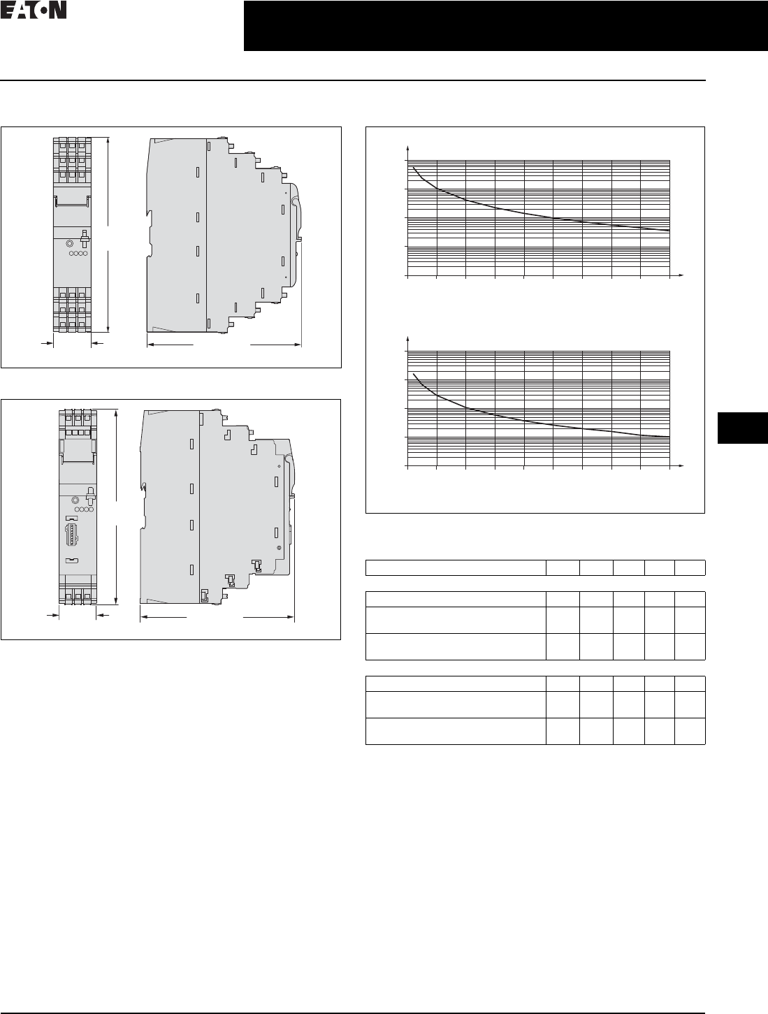
CA08104001E For more information, visit: www.eaton.com/consultants
30.3-35
April 2016
Motor Starters and Contactors—Low Voltage
Sheet 30
22
23
24
25
26
27
28
29
30
31
32
33
34
35
36
37
38
39
40
41
42
4 3
Motor Starters—Electromechanical
EMS—Electronic Motor Starter
055
Dimensions
Figure 30.3-29. EMS without SmartWire-DT
Figure 30.3-30. EMS with SmartWire-DT
Figure 30.3-31. Trip Type EMS
Table 30.3-54. Rated Operational Current EMS-…-SWD
1.18
(30.0)
6.18
(157.0)
4.86 (123.5)
1.18
(30.0) 4.88 (124.0)
6.18
(157.0)
Temperature (ºC) 40 45 50 55 60
EMS-…- 2,4 - SWD
Stand-alone device 2.4 2.4 2.4 2.4 2.4
Connected in series, with a distance
equal to one housing width
2.4 2.4 2.4 2.4 2.4
Connected in series, without
any distance
2.4 2.4 2.4 2.4 —
EMS-…- 9 - SWD
Stand-alone device 9 9 9 9 7.6
Connected in series, with a distance
equal to one housing width
997.67.65.2
Connected in series, without
any distance
7.6 6.8 5.2 2.4 —
[s]
12345678910I / In
1
10
100
1000
60 40
30 20
600 400
300 200
64
32
0.6 0.4
0.3 0.2
0
10
[s]
12345678910I / In
1
10
100
1000
60 40
30 20
600 400
300 200
64
32
0.6 0.4
0.3 0.2
0
10 A
EMS-…-9-…(Ir > 4A)
EMS-…-2,4-…
EMS-…-9-…(Ir ≤ 4A)

30.3-36
For more information, visit: www.eaton.com/consultants CA08104001E
April 2016
Motor Starters and Contactors—Low Voltage
Sheet 30
22
23
24
25
26
27
28
29
30
31
32
33
34
35
36
37
38
39
40
41
42
4 3
056
This page intentionally left blank.

CA08104001E For more information, visit: www.eaton.com/consultants
30.4-1
April 2016
Motor Starters & Contactors—Low Voltage
Sheet 30
22
23
24
25
26
27
28
29
30
31
32
33
34
35
36
37
38
39
40
41
42
4 3
Reduced Voltage—Electromechanical
General Description
057
Low Voltage Reduced Voltage
Starter Selection Guide
In general, the application will determine the type of starter required. In cases where more than one type starter will meet
the application requirements, reference to the table below will show which starter is best suited for the application.
Table 30.4-1. Reduced Voltage Starting Characteristics and Index
1Includes autotransformer magnetizing current.
General Application
The following factors should be
considered when applying reduced-
voltage starters to a squirrel cage
motor-driven load.
1. The motor characteristics that will
satisfy the starting requirements of
the load.
2. The source of power and the effect
the motor starting current will have
on the line voltage.
3. The load characteristics and the
effect the motor starting torque will
have on the driven parts
during acceleration.
The starter protection required to
protect the load, motor, starter, cables
and power source during overload,
undervoltage and fault conditions.
A typical NEMA B motor started with
full voltage will develop as much as
150% full-load torque when started with
a starting current of around 600% full-
load current. These values may exceed
the mechanical limitations of the load
or electrical limitations of the source, or
both.
A reduced-voltage or reduced-inrush
starter will reduce both starting current
and starting torque. Care must be taken
when meeting power company limita-
tions that the motor will produce suffi-
cient torque to accelerate the load to
near rated speed.
Part-winding starters are suited to
low starting torque loads such as
fans, blowers and m-g sets. Autotrans-
former starters should be used with
“hard to start” loads such as reciprocat-
ing compressors, grinding mills, and
pumps. Wye-delta starters are applica-
ble to high inertia loads with long accel-
eration times which as centrifugal
compressors and centrifuges.
All starters, in addition to overload pro-
tection, will provide either low voltage
release or low voltage protection
depending upon the pilot device used
with the starter. Low voltage release,
where power is applied to the motor
after a power failure, can be obtained by
using a two-wire pilot device
(temperature, switch and so on). Low
voltage protection, where power is not
applied to the motor after a power failure
until restarted by an operator, can be
obtained by using three-wire control
such as START STOP pushbuttons.
Closed transition wye-delta types
require adequate ventilation to remove
resistor heat.
Eaton also offers a line of solid-state
reduced-voltage starters known as
Easy-start.
Solid-state starters are ideally suited for
many loads including conveyor applica-
tions since they provide controlled accel-
eration from zero to full load.
UL listing—Combination E176513,
Non-Combination E19224.
Starting Characteristics
Figure 30.4-1. Autotransformer Starting Figure 30.4-2. Wye-Delta or Part
Winding Starting Figure 30.4-3. Solid-State Starter
Starter
Ty p e
Starting Characteristics Expressed in %
of Rated Starting Values (Approximate)
Remarks
Page
Motor
Voltage
Motor
Current
Line
Current
To r q u e
Autotransformer
Class ECA42
80% Tap
65% Tap
50% Tap
80
65
50
80
65
50
67 1
45 1
28 1
64
42
25
The adjustable voltage taps permit wide adjustment of characteristics
in the field.
30.4-2
Part winding
Class ECA45
100 65 65 50 Requires part winding motor. A nine-lead 230/460 V dual voltage motor
may be used in 230 V applications. Closed transition.
30.4-3
Wye-delta
Class ECA48
Class ECA51
100 33 33 33 Requires delta wound motor with wye connections.
Ideal for long accelerations. Closed transition is available.
30.4-4
Solid-state
S801/811
S611
DS6/DS7
Ramps
0–100%
Adjustable
0–92%
Adjustable
0–92%
Adjustable
0–85%
Compatible with NEMA Design A, B or C motors.
Adjustable ramp up and ramp down.
30.5-1
thru
30.5-49
700
600
500
400
300
200
100
0
Full Voltage Starting
Full Load Current
Autotransformer
Starting on 65% T ap
Motor Speed Full Load
Speed
Line Current, % of Full Load
700
600
500
400
300
200
100
0
Full Voltage Starting
Part Winding Starting
Wye-Delta Starting
(Closed Transition)
Full Load Current
Line Current, % of Full Load
Motor Speed Full Load
Speed
700
600
500
400
300
200
100
0
KVA
Torque
Line Current, % of Full Load
10080604020
Motor Speed Full Load Speed
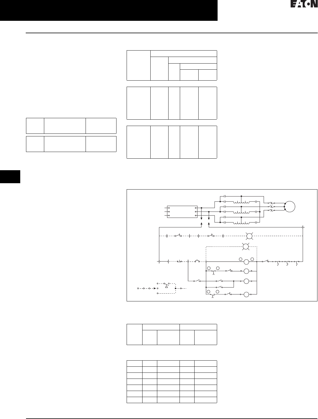
30.4-2
For more information, visit: www.eaton.com/consultants CA08104001E
April 2016
Motor Starters & Contactors—Low Voltage
Sheet 30
22
23
24
25
26
27
28
29
30
31
32
33
34
35
36
37
38
39
40
41
42
4 3
Reduced Voltage—Electromechanical
Autotransformer Type
058
General Description
Autotransformer type starters are
the most widely used reduced-voltage
starter because of their efficiency and
flexibility. All power taken from the line,
except transformer losses, is transmit-
ted to the motor to accelerate the load.
Taps on the transformer allow adjust-
ment of the starting torque and inrush to
meet the requirements of most applica-
tions. The following characteristics are
produced by the three voltage taps:
Table 30.4-2. Starting Characteristics
1Not included 50 hp and below.
2Includes transformer magnetizing current.
Closed transition is standard on all
sizes ensuring a smooth transition
from reduced to full voltage. Since
the motor is never disconnected from
the line there is no interruption of line
current which can cause a second
inrush during transition.
Duty cycle of these starters is as follows:
up to 200 hp, 15 seconds on each
4 minutes for 1 hour, repeated after
2 hours. Over 200 hp, three periods
of 30 seconds ON, 30 seconds OFF
repeated after 1 hour.
Design Features
Contactors—(1S) (2S) (Run)
A three-pole (1S) 3 and a three-pole
contactor (2S) connect the motor to the
auto-transformer for reduced-voltage
starting (see Table 30.4-3 for size).
A three-pole contactor (Run) bypasses
the autotransformer and connects the
motor for full-voltage across-the-line
running (see Table 30.4-3 for size).
Ta p S t a r t i n g To r q u e
% Locked
To r q u e
Line Inrush
% Locked
Ampere
50% 1
65%
80%
25%
42%
64%
28% 2
45% 2
67% 2
Table 30.4-3. NEMA Contactor Size
Guidelines within Autotransformer Starters
31S is two-pole on sizes 7 and 8.
Operation (Refer to Schematic Diagram)
Closing the START button or other pilot
device energizes the start contactor
(1S). The interlock (1S) closes, energiz-
ing the timing relay (TR) and contactor
(2S) which seal in through the interlock
(2S). With the (1S) and (2S) contactors
closed, the motor is connected through
the autotransformer for reduced-volt-
age start. After a preset time interval, the
(TRTO) contacts time open, de-energiz-
ing contactor (1S) and connecting the
autotransformer as a reactor in series
with the motor. Interlock (1S) immedi-
ately energizes the run contactor (R)
which seals in through its interlock (R).
The run contacts are now closed, and
the motor is running at full voltage.
Start contactor (2S) and relay (TR) are
de-energized when interlock (R) opens.
An overload, opening the STOP push-
button or other pilot device de-ener-
gizes the (R) contactor removing the
motor from the line.
Other Types
Autotransformer starters are also
available in combination and reversing
types.
Figure 30.4-4. Typical Schematic Diagram
Table 30.4-4. Type 1, 3R, 4/4X, 12 Freedom
Reduced Voltage Enclosures
4Non-combination and breaker.
5Consult factory.
Maximum
hp
NEMA Size
Starter Contactor
Run Starting
(1S)
(3-Pole)
(2S)
(3-Pole)
230 V, 60 Hz
15
30
50
100
200
300
450
2
3
4
5
6
7
8
2
3
4
5
6
7
8
2
3
4
5
6
6 3
7 3
2
3
4
5
6
6
7
460–575 V, 60 Hz
25
50
100
200
400
600
900
2
3
4
5
6
7
8
2
3
4
5
6
7
8
2
3
4
5
6
6 3
7 3
2
3
4
5
6
6
7
TB1 TB1 Stop Start
TB2 TB3
T.O. = Timed Opening
TB3
PS
Auto
Hand
Off
TB1TB1
T.C. = Timed Closing
OL T1
T2
T3 Motor
L1
L2
L3
L1
L2
L3
RVNR AUTOXFMR (3-coil)
CKT BKR
or
SW & FU
#1
#2
#3
Stopped
Run
1S
TBX2
TR
T.C.
54
A1 A2
TR
On-Delay
1.5 – 15 Sec.
TB4
95 96
OL
B
G
R
E
27
86
D
C
2S
A1 A2
R
A1 A2
1S 55
53
52
2S
TR
T.O.
51
85
1S
2S
OTT OTT OTT
"C""E" "D"
Auto-Transformer
Overtemp SWa
R
1S
78910
R
R
2S
R
2S
R
2S
3C
3E
3D
5D
5E
5C
1D
1E
1C
100%
80%
65%
50%
0%
100%
80%
65%
50%
0%
100%
80%
65%
50%
0%
1S
1S
1S
Size Type 1 Type 3R, 4X, 12
Box
No.
Shipping
Weight
Lbs (kg)
Box
No.
Shipping
Weight
Lbs (kg)
Class 42: Autotransformer—Non-combination
Class 43: Autotransformer—with Disconnect
Class 44: Autotransformer—with HMCP
2–4 E2 124 (56) E2 149 (68)
5 F1E 885 (402) F1E 1010 (459)
6 4F1E 1220 (554) F1E 1345 (611)
6 3F2E 1400 (636) F2E 1525 (692)
7 F2E 5F2E 5
8 F2E 5F2E 5
955 55
For enclosure box dimensions,
refer to Page 30.6-3.
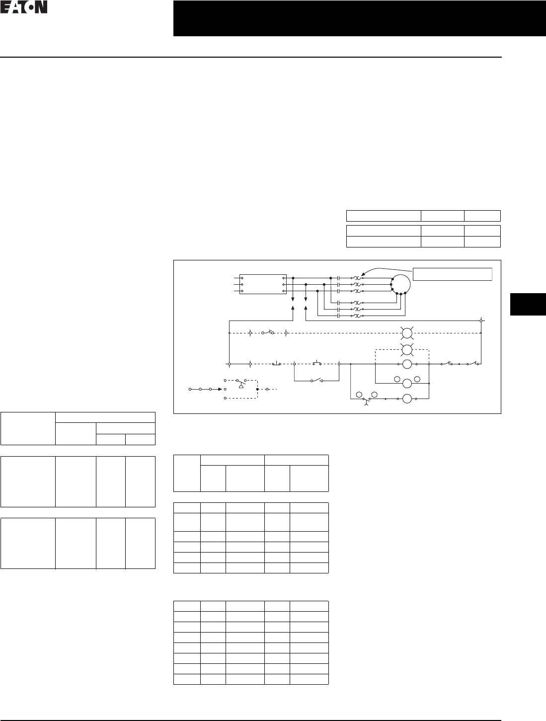
CA08104001E For more information, visit: www.eaton.com/consultants
30.4-3
April 2016
Motor Starters & Contactors—Low Voltage
Sheet 30
22
23
24
25
26
27
28
29
30
31
32
33
34
35
36
37
38
39
40
41
42
4 3
Reduced Voltage—Electromechanical
Part-Winding Type
059
General Description
Part-winding starting provides conve-
nient, economical one-step acceleration
at reduced current where the power
company specifies a maximum or
limits the increments of current drawn
from the line. These starters can be
used with nine-lead dual-voltage
motors on the lower voltage and with
special part-winding motors designed
for any voltage. When used with dual-
voltage motors, it should be estab-
lished that the torque produced by
the first half-winding will accelerate the
load sufficiently so as not to produce
a second undesirable inrush when the
second half-winding is connected to the
line. Most motors will produce a start-
ing torque equal to between 1/2 to 2/3
of NEMA standard values with half of
the winding energized and draw about
2/3 of normal line current inrush.
Design Features
Contactors—(1M) (2M)
A three-pole contactor (1M) connects
only the first half-winding of the motor
for reduced inrush current on starting
(see table below for size). A three-pole
contactor (2M) connects the second
half-winding of the motor for running
(see table below for size).
Table 30.4-5. NEMA Contactor Size
Guidelines within Part Winding Starters
Maximum
hp
NEMA Size
Starter Contactor
(1M) (2M)
230 V, 60 Hz
15
25
50
75
150
300
1 PW
2 PW
3 PW
4 PW
5 PW
6 PW
1
2
3
4
5
6
1
2
3
4
5
6
460–575 V, 60 Hz
15
40
75
150
350
600
1 PW
2 PW
3 PW
4 PW
5 PW
6 PW
1
2
3
4
5
6
1
2
3
4
5
6
Overload Relay—(OL)
Two three-pole Type B overload
relays provide starting and running
overcurrent protection.
Timing Relay—(TR)
An electrically operated pneumatic
relay provides accurate, adjustable
start-to-run transfer timing.
Other Types
Part-winding Type ECN45 starters are
also available in combination (Type 46
and 47), reversing and three-point
(primary resistor) types.
Operation (Refer to Schematic Diagram)
Closing the START button or other pilot
device energizes the start contactor
(1M) which seals in through its inter-
lock (1M) and energizes the timer (TR).
The (1M) contacts connect the first
half-winding of the motor across the
line. After a preset time interval, the
timer (TRTC) contact closes energizing
contactor (2M). The (2M) contact con-
nects the second half-winding of the
motor across-the-line.
Opening the STOP button or other
pilot device de-energizes contactors
(1M), (2M) and timer (TR), removing
the motor from the line.
Table 30.4-6. Contactor Sequence
Figure 30.4-5. Typical Schematic Diagram
Table 30.4-7. Type 1, 3R, 4/4X, 12 Freedom
Reduced Voltage Enclosures
1Consult factory.
2Non-combination and breaker.
3Fusible.
Contactor Start Run
1M ●●
2M — ●
Select Overload Heater Packs for 50%
of Rated Full Load Motor Current
L1
L2
L3
L1
L2
L3
Part Winding
CKT BKR
or
SW & FU
#1
#2
#3
1M
2M
OL
OL
T1
T7
T2
T3
T8
T9
Motor
Stopped
Run
1M
TBX2
TB1 TB1 Stop Start
TB2 TB3
78
1M
1M
T.C. = Timed Closing
TB3
PS
Auto
Hand
Off
TB1TB1
TR
T.C.
5A1 A2
2M
A1 A2
TR
On-Delay 1.5 – 15 Sec.
TB4
95 96 95 96
(1M) (2M)
OL OL
A
G
R
E
27
86
Size Type 1 Type 3R, 4X, 12
Box
No.
Shipping
Weight
Lbs (kg)
Box
No.
Shipping
Weight
Lbs (kg)
Class 45: Part Winding—Non-combination
2PW 3 25 (11) 7 75 (34)
3PW–
4PW
9 47 (21) 9 95 (43)
5PW E 125 (47) E 180 (82)
6PW F1E 780 (354) F1E 880 (400)
7PW F2E 1F2E 1
8PW F2E 1F2E 1
Class 46: Part Winding—with Disconnect
Class 47: Part Winding—with Thermal-Magnetic
Trip Circuit Breaker
2PW C 68 (31) C 88 (40)
3PW D 162 (74) D 190 (86)
4PW E 230 (104) E 270 (123)
5PW F1E 440 (200) F1E 530 (241)
6PW 2F1E 440 (200) F1E 620 (281)
6PW 3F2E 515 (234) F2E 1
7PW F2E 1F2E 1
8PW F2E 1F2E 1
For enclosure box dimensions,
refer to Page 30.6-3.
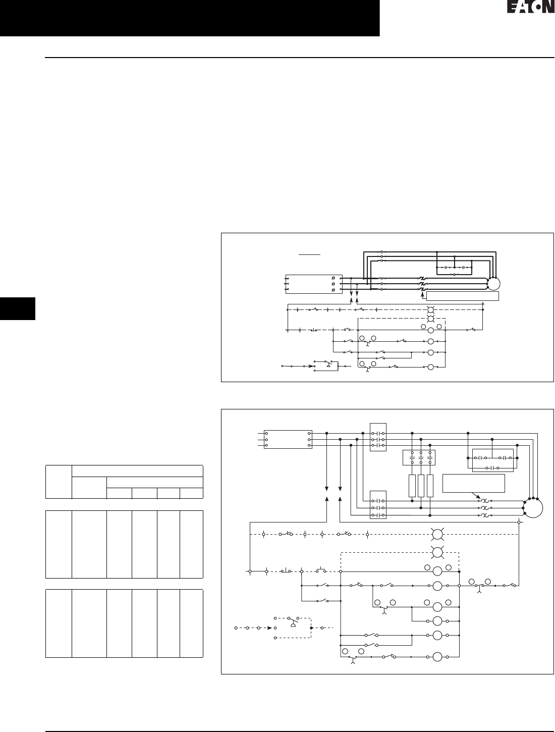
30.4-4
For more information, visit: www.eaton.com/consultants CA08104001E
April 2016
Motor Starters & Contactors—Low Voltage
Sheet 30
22
23
24
25
26
27
28
29
30
31
32
33
34
35
36
37
38
39
40
41
42
4 3
Reduced Voltage—Electromechanical
Wye-Delta Type
060
General Description
Wye-delta type starters are applied
extensively to industrial air condition-
ing installations because they are par-
ticularly suited for starting motors
driving high inertia loads with resulting
long acceleration times. They are not,
however, limited to this application.
When six- or 12-lead delta-connected
motors are started wye-connected,
approximately 58% of line voltage is
applied to each winding and the motor
develops 33% of full-voltage starting
torque and draws 33% of normal
locked-rotor current from the line.
When the motor is accelerated, it is
reconnected for normal data operation.
Design Features
Contactors—(1S) (1M) (2S) (2M)
A three-pole contactor (1S) 1 shorts
the motor leads T4-T5-T6 during
starting to connect motor in wye
(see Ta b l e 3 0 . 4 - 8 for size).
A three-pole contactor (1M) energizes
motor leads T1-T2-T3 for both wye and
delta connections (see Ta b l e 3 0 . 4 - 8
for size).
A three-pole contactor (2S) connects
resistors in series with the motor wind-
ings during the start-to-run transition
period (see Table 30.4-8 for size).
A three-pole contactor (2M) energizes
the motor leads T4-T5-T6 during run-
ning to connect the motor in delta
(see Ta b l e 3 0 . 4 - 8 for size).
Table 30.4-8. NEMA Contactor Size Guidelines
11S is two-pole on sizes 7 and 8.
Max.
hp
NEMA Size
Starter Contactor
(1M) (2M) (1S) (2S)
230 V, 60 Hz
10
25
50
75
150
300
500
800
1 YD
2 YD
3 YD
4 YD
5 YD
6 YD
7 YD
8 YD
1
2
3
4
5
6
7
8
1
2
3
4
5
6
7
8
1
2
3
4
4
5
6 1
7 1
1
1
1
2
3
4
5
6
460–575 V, 60 Hz
15
40
75
150
300
700
1000
1500
1 YD
2 YD
3 YD
4 YD
5 YD
6 YD
7 YD
8 YD
1
2
3
4
5
6
7
8
1
2
3
4
5
6
7
8
1
2
3
4
4
5
6 1
7 1
1
1
1
2
3
4
5
6
Operation (Refer to Schematic Diagram)
Closing the START button or other pilot
device energizes contactor (1S) whose
contacts connect the motor in a wye
connection. Interlock (1S) closes, ener-
gizing contactor (1M) and timer (TR).
The (1M) contacts energize the motor
windings in a wye. After a preset time
interval, timer (TRTC) contact closes
energizing contactor (2S). Interlock (2S)
opens, dropping out contactor (1S).
The motor is now energized in series
with the resistors. Interlock (1S) closes,
energizing contactor (2M), bypassing
the resistors and energizing the
delta connected motor at full voltage.
Interlock opens, de-energizes the timer
(TR) opening timer (TRTC) thus energiz-
ing contactor (2S).
An overload, opening the STOP button
or other pilot device de-energizes con-
tactors (1M) and (2M), removing the
motor from the line. (TRP) de-energizes
and locks out the control circuit if the
duty cycle of the transition resistors
is exceeded.
Wye-delta Class ECN51 closed transition
starters are also available in combina-
tion types and Class ECN48 open
transition non-combination and
combination starters.
Figure 30.4-6. Wye-Delta—Open Transition
Figure 30.4-7. Wye-Delta—Closed Transition
51
Elementary Diagram
Select Overload Heater Coils for 58%
of Rated Full Load Motor Current
TB4
TBX2
ON-Delay 1.5-15 Seconds
54 55
52
53
5 6
RRun
Stopped
G
7 8
Stop Start
Motor
T1
T3
T2
T5
1S
1S
1S
T4
T6
OL
1M
2M
1S 2M
1S
1M
2M
OL
9596
TR
A2
1S
A1
A2
1M
A1
A2
2M
A1
27
86
1S
1M
TR
1S
T.C.
E
Auto
TB1
TB1
TB1
TB2 TB3
TB1
Hand
OFF
TB3
PS
Shop Note:
Refer to Figure 2. Connect Green Ground
Wire to Panel Using Hole Located Adjacent
to Transformer ’s Mounting Foot.
L1L1
L2L2
L3L3
Wye-Delta Open Transition
Circuit Breaker
or Switch
and Fuse
1
2
3
T.O. = Timed Opening
T.C. = Timed Closing
85
TR
T. O .
1S
5578
2M
TB1 TB1 Stop Start
TB2 TB3
TB3
PS
Auto
Hand
Off
TB1TB1
1S
1M
TR
T.C.
55
TRP
E
27
8
1M
A1 A2
2M
A1 A2
1S 56
54
53
1S
1M
2S
A1 A2
52
6
TR
T.C.
13
27
TR
E
1S
A1 A2
51
2M 2S
Stopped
Run
On-Delay 1.5 – 15 Sec.
G
R
T.O. = Timed Opening
T.C. = Timed Closing
TB4
95 96
14
TRP
T.O.
TBX2
2M
1M
T1A
T2A
T3A
OL T1
T2
T3
Motor
T6
T4
T5
1S 1S
1S
2S
T1B
T2B
T3B
L1
L2
L3
L1
L2
L3
Wye-Delta
Closed Transition
CKT BKR
or
SW & FU
#1
#2
#3
Resistor
Resistor
Resistor
Select Overload Heater Coils
for 58% of Rated Full Load
Motor Current

CA08104001E For more information, visit: www.eaton.com/consultants
30.4-5
April 2016
Motor Starters & Contactors—Low Voltage
Sheet 30
22
23
24
25
26
27
28
29
30
31
32
33
34
35
36
37
38
39
40
41
42
4 3
Reduced Voltage—Electromechanical
Wye-Delta Type
061
Table 30.4-9. Type 1, 3R, 4/4X, 12 Freedom Reduced Voltage Enclosures
1Non-combination and breaker.
2Fusible.
3Consult factory.
Size Type 1 Type 3R, 4X, 12
Box No. Shipping Weight
Lbs (kg)
Box No. Shipping Weight
Lbs (kg)
Classes 48 & 51: Wye-Delta—Non-combination
Classes 49 & 52: Wye-Delta—with Disconnect
Classes 50 & 53: Wye-Delta—with Thermal
Magnetic Trip Circuit Breaker
2YD–4YD E 185 (84) E 225 (102)
5YD F1E 605 (275) F1E 705 (320)
6YD 1F1E 635 (288) F1E 735 (334)
6YD 2F2E 715 (325) F2E 830 (377)
7YD F2E 3F2E 3
8YD F2E 3F2E 3
For enclosure box dimensions,
refer to Page 30.6-3.

30.4-6
For more information, visit: www.eaton.com/consultants CA08104001E
April 2016
Motor Starters & Contactors—Low Voltage
Sheet 30
22
23
24
25
26
27
28
29
30
31
32
33
34
35
36
37
38
39
40
41
42
4 3
062
This page intentionally left blank.
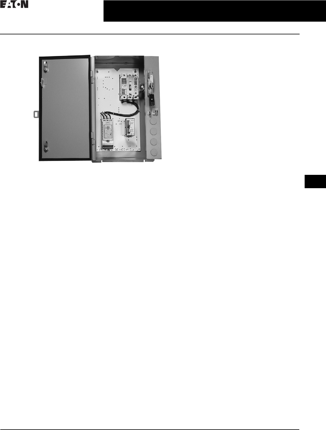
CA08104001E For more information, visit: www.eaton.com/consultants
30.5-1
April 2016
Motor Starters & Contactors—Low Voltage
Sheet 30
22
23
24
25
26
27
28
29
30
31
32
33
34
35
36
37
38
39
40
41
42
4 3
Reduced Voltage—Solid-State
General Description—Solid-State Reduced Voltage
063
Solid-State Reduced Voltage Starters
Reduced Voltage Starters
General Description
Eaton offers a complete line of solid-
state reduced voltage devices ranging
from fractional horsepower applica-
tions to 1000 A devices. The line comes
in voltages from 200 to 600 Vac and
operates on 50 or 60 Hz applications.
Units can be ordered as open
components or mounted in enclosures
(NEMA 1, 3R, 4X and 12). Motor
control center (MCC) mounting is
also possible with units through 700 hp
fitting inside of a standard MCC.
These soft starters provide reduced
voltage starting of AC induction motors.
Motor voltage is controlled by means
of back-to-back SCRs (silicon controlled
rectifiers) providing a smooth, stepless
start (and stop) of the motor driven load.
For more information, please
visit the Eaton Web site at
www.eaton.com/electrical.
Designed to control acceleration and
deceleration of three-phase motors,
products are available from 0.25 to
50 A and are suitable for mounting in a
variety of enclosures including Type 1,
12, 3R, 4, 4X and 7/9.
Application Description
Eaton’s soft starters can be applied in
a wide array of customer applications.
Typical benefits of soft starters include:
■Reduced starting torque stress on
mechanical equipment, allowing
longer life of belts, gears, pulleys and
motor shafts commonly weakened
during “across-the-line” starting
■Reduction of voltage drop during
starting on weak utility systems
where the performance of nearby
equipment would be negatively
affected
■Reduced inrush current during
starting which can result in lower
utility bills due to the reduction in
peak current demand charges
■Smooth, stepless starting of a
motor, allowing superior flexibility
over typical electromechanical
starting methods
■Ability to start large loads on backup
generators during power outages
■Elimination of the water-hammer
effect in hydraulic systems, which
can help to eliminate additional pipe
hangers and extend the life of the
system, pumps, valves and gaskets
Typical Applications
■Centrifugal and screw compressors
■Material handling equipment
■Fans and blowers
■Pumps
■Cranes and hoists
■Food processing
■Machinery
■Rock crushers
■HVAC industry
Enclosure Types
Airborne particulate may be detrimental
to starter performance and reliability,
so caution must be exercised in
choosing the enclosure best suited
to the environment. The NEMA rating
of the enclosure defines its ability
to withstand the ingress of foreign
particulate as described below:
NEMA 1
A general purpose, indoor-type
enclosure.
NEMA 12
A dust-tight and drip-tight enclosure
for indoor industrial applications.
NEMA 3R
Enclosures are intended for outdoor
use, primarily to provide a degree of
protection against falling rain, sleet
and external ice formation.
NEMA 4
A watertight and dust-tight enclosure
for either indoor or outdoor use.
NEMA 4X
Identical to NEMA 4, with the additional
requirement that the enclosure be
corrosion-proof as well.
NEMA 7/9
Enclosures capable of preventing the
entrance of dust and withstanding
pressure resulting from an internal
explosion of specified gas.

30.5-2
For more information, visit: www.eaton.com/consultants CA08104001E
April 2016
Motor Starters & Contactors—Low Voltage
Sheet 30
22
23
24
25
26
27
28
29
30
31
32
33
34
35
36
37
38
39
40
41
42
4 3
Reduced Voltage—Solid-State
General Description
064
Catalog Number Selection
Table 30.5-1. Solid-State Enclosed Control Catalog Numbering System
EC S 90 S 1 C A A
Type
S = Solid-state
Class
90 = Non-combination reduced voltage
soft starter—S801
91 = Combination reduced voltage
soft starter—fusible disconnect—S801
92 = Combination reduced voltage
soft starter—circuit breaker—S801
93 = Non-combination reduced voltage
soft starter—S811
94 = Combination reduced voltage
soft starter—fusible disconnect—S811
95 = Combination reduced voltage
soft starter—circuit breaker—S811
Amperes
S801/S811
Q= 37
S= 66
V= 105
W= 135
Y= 180
Z= 240
1= 304
2= 360
3= 420
4= 500
5 = 650
6 = 720
7 = 850
8 = 1000
Voltage
B = 230 V
C = 460 V
D = 575 V
E = 200 V
Q = 24 Vdc
Cover Control
See Ta b l e 3 0 . 6 - 3 for options
Disconnect Fuse Clip Ratings
A= None
B= 30 A/250 V R
C= 30 A/600 V R
D= 60 A/250 V R
E= 60 A/600 V R
F= 100 A/250 V R
G= 100 A/600 V R
H= 200 A/250 V R
J= 200 A/600 V R
K= 400 A/250 V R
L= 400 A/600 V R
M= 600 A/250 V R
N= 600 A/600 V R
P= 800 A/600 V L
Q= 1200 A/600 V L
R= 1600 A/600 V L
S= 2000 A/600 V L
T= By description
Breaker
A= None
B= 3 A
C= 7 A
D= 15 A
E= 30 A
F= 50 A
W= 70 A
G= 100 A
H= 150 A
J= 250 A
K= 400 A
L= 600 A
P= 1200 A
Q= 1600 A
Enclosure Type
1 = Type 1
2 = Type 3R
3 = Type 4
4 = Type 4X (304-Grade SS)
6 = Type 7/9
8 = Type 12
9 = Type 4X (316-Grade SS)

CA08104001E For more information, visit: www.eaton.com/consultants
30.5-3
April 2016
Motor Starters & Contactors—Low Voltage
Sheet 30
22
23
24
25
26
27
28
29
30
31
32
33
34
35
36
37
38
39
40
41
42
4 3
Reduced Voltage—Solid-State
General Description
065
Table 30.5-2. Solid-State Product Comparison
Table 30.5-3. Application and Environmental Considerations
The installation environment for a solid-state reduced voltage starter is of a prime concern. Conditions such as ambient
temperature, altitude and the presence of corrosives or moisture must all be considered when choosing the appropriate
starter size and enclosure type.
Note: Consult factory for applications outside of these parameters for additional information and sizing requirements.
Description S801
Soft Starter
S811 Communicating
Soft Starter
Maximum current range
Start type
Operating voltage
1–1000 A
Ramp or current limit
200–600 Vac
1–1000 A
Ramp or current limit
200–600 Vac
Operating frequency
Control voltage
Kick start
47–63 Hz
24 Vdc
0–2 seconds adjustable
47–63 Hz
24 Vdc
0–2 seconds adjustable
Ramp time range
Initial torque setting
Current limit setting
0.5–180 seconds
0%–85%
0%–550%
0.5–180 seconds
0%–85%
0%–550%
Soft stop
Pump control option
Overtemperature protection
0–60 seconds
Yes
Yes
0–60 seconds
Yes
Yes
Overload
Overload setting
Trip class setting
Phase loss/unbalance
Jam
Stall
Phase reversal
Yes
30%–100%
5, 10, 20 and 30
Yes
Yes
Yes
Yes
Yes
30%–100%
5, 10, 20 and 30
Yes
Yes
Yes
Yes
Jog
Extended start
LED status indication
LED fault indication
Yes
Yes
Yes
Yes
Yes
Yes
LCD—Yes
LCD—Yes
Description S801
Soft Starter
S811 Communicating
Soft Starter
Temperature—operating (No derating)
Current rating (50 ºC)
Limited duty cycle (50 ºC)
–25º C to +40 ºC
100%
Fully rated
–30 ºC to +50 ºC
100%
Fully rated
Current rating (60 ºC)
Limited duty cycle (60 ºC)
Temperature—storage
Altitude (meters)
10% reduction
Continuous duty cycle at 90%
–40 ºC to +70 ºC
2000
Consult factory
Consult factory
–50 ºC to +70 ºC
2000

30.5-4
For more information, visit: www.eaton.com/consultants CA08104001E
April 2016
Motor Starters & Contactors—Low Voltage
Sheet 30
22
23
24
25
26
27
28
29
30
31
32
33
34
35
36
37
38
39
40
41
42
4 3
Reduced Voltage—Solid-State
General Description
066
Multi-Motor Operation
The S801/S811 line can be used
to control multiple motors if the
following conditions are met:
■The current rating of the S801/S811
should be equal to or greater than
the total of the individual motor
full load amperes and the S801/S811
overload must be set for the
cumulative full load amperes
of the motors
■Individual motor overcurrent
protection is provided by
other devices
■The motors should not be
mechanically coupled together,
i.e., two motors on same shaft
■NEC and local code requirements
for individual motor protection
and branch short circuit protection
are met
■Motors are closely matched in total
load and size
Frequent Starting/Stopping
The number of starts and stops
allowable depends upon many factors.
The most important ones are:
1. Set level of the starting current limit
2. Start time
3. Run time
4. Off time before next start
The number of starts per hour is based
on the current carrying capacity of
the SCRs. A high start/stop duty may
require the oversizing of a soft starter.
If a high number of multiple starts
occur, the starter may trip due to the
overload protection for the motor or
it may trip on overtemperature of the
soft starter. In this situation, it is advis-
able to wait a period of 10 minutes
before restarting to avoid damage to
the soft starter and motor and allow
the units to cool down. The motor
manufacturer should be consulted
about the effect of a high number
of multiple starts on motor life.
Starting Torque
The reduced voltage applied to the
motor results in reduced inrush
current and a soft start. However,
it reduces the starting torque of the
motor. The relationship is as follows:
EXAMPLE: A 100 hp, 1800 RPM, 460 V
NEMA B motor draws six times full
load amperes for starting, and starting
torque is 150% of full load torque.
If the same motor were started with
the S801 at 300% current limit, then
the available torque would be:
1/4 x 150% full load torque =
37.5% full load torque available
Heat Generation
Due to the voltage drop that occurs
across a SCR, there is heat generated
in the unit. For sizing an enclosure
or box size for the soft starters, it is
important to account for this heat
generation.
The S801/S811 lines use a bypass
contactor, so heat generation is mini-
mized. During steady-state conditions,
it generates about the same amount of
heat as an across-the-line starter of the
same size. During start and stopping
ramps it will generate three watts of
heat per ampere.
EXAMPLE: A 100 hp, 480 V NEMA B
motor has a full load current of 125
amperes. A typical soft start on this
motor is 300% current limit for 40
seconds. The heat generation during
this time period is:
125 amperes x 300% =
375 watts for 40 seconds
At the end of the ramp, the bypass
contactor closes and total heat genera-
tion is reduced to much lower levels.
NEMA Design C and D Motors,
Wound Rotor Motors
These motors are used due to their
high starting torque characteristics.
When high starting currents and high
starting torques are required, it may be
necessary to order the extended ramp
option and oversize the soft starter to
match the application requirements.
Consult the factory for application con-
siderations.
Torque at reduced current
Torque at full current
----------------------------------------------------------------------
=
Current at reduced voltage2
Current at full voltage
--------------------------------------------------------------------------
3002
600
------------ 90,000
360,000
--------------------- ==

CA08104001E For more information, visit: www.eaton.com/consultants
30.5-5
April 2016
Motor Starters & Contactors—Low Voltage
Sheet 30
22
23
24
25
26
27
28
29
30
31
32
33
34
35
36
37
38
39
40
41
42
4 3
Reduced Voltage—Solid-State
General Description
067
Solid-State Reduced
Voltage Starters
Enclosed Box Selection
Table 30.5-4. Non-combination Solid-State
Reduced Voltage
1Enclosure space will also accommodate for
an DC Power Supply, two four-pole relays,
CPT, and terminal blocks. Also includes
space for a DNA module or MOV.
2Contact Eaton for Box Dimensions not
shown in PG03300001E.
Note: All Type 7 and 9, see PG03300001E.
Table 30.5-5. Combination Solid-State
Reduced Voltage
3Enclosure space will also accommodate for
an DC Power Supply, two four-pole relays,
CPT, and terminal blocks. Also includes
space for a DNA module or MOV.
4Same as footnote 3, but CPT is not included.
Upsize to B1 enclosure to include space for a
CPT and a full voltage bypass contactor.
Rating SSRV Non-combination
Box No. 1
37 A
66 A
105 A
135 A
180 A
S801/S811
S801/S811
S801/S811
S801/S811
S801/S811
7A
7A
7A
B1
C
240 A
304 A
360 A
420 A
500 A
S801/S811
S801/S811
S801/S811
S801/S811
S801/S811
2
2
2
10
10
650 A
720 A
850 A
S801/S811
S801/S811
S801/S811
10
10
10
1000 A S801/S811 10
Rating SSRV Comb. with
Fuses
Comb. with
HMCP
Box No. 3Box No. 3
37 A
66 A
105 A
135 A
180 A
S801/S811
S801/S811
S801/S811
S801/S811
S801/S811
B1
C
D
D
E
A1 4
A1
B1
C
E
240 A
304 A
360 A
420 A
500 A
S801/S811
S801/S811
S801/S811
S801/S811
S801/S811
F1E
F1E
F1E
F1E
F1E
E
E
E
E
E
650 A
720 A
850 A
S801/S811
S801/S811
S801/S811
F1E
F1E
F1E
F1E
F1E
F1E
1000 A S801/S811 F1E F1E
For enclosure box dimensions,
refer to Page 30.6-3.
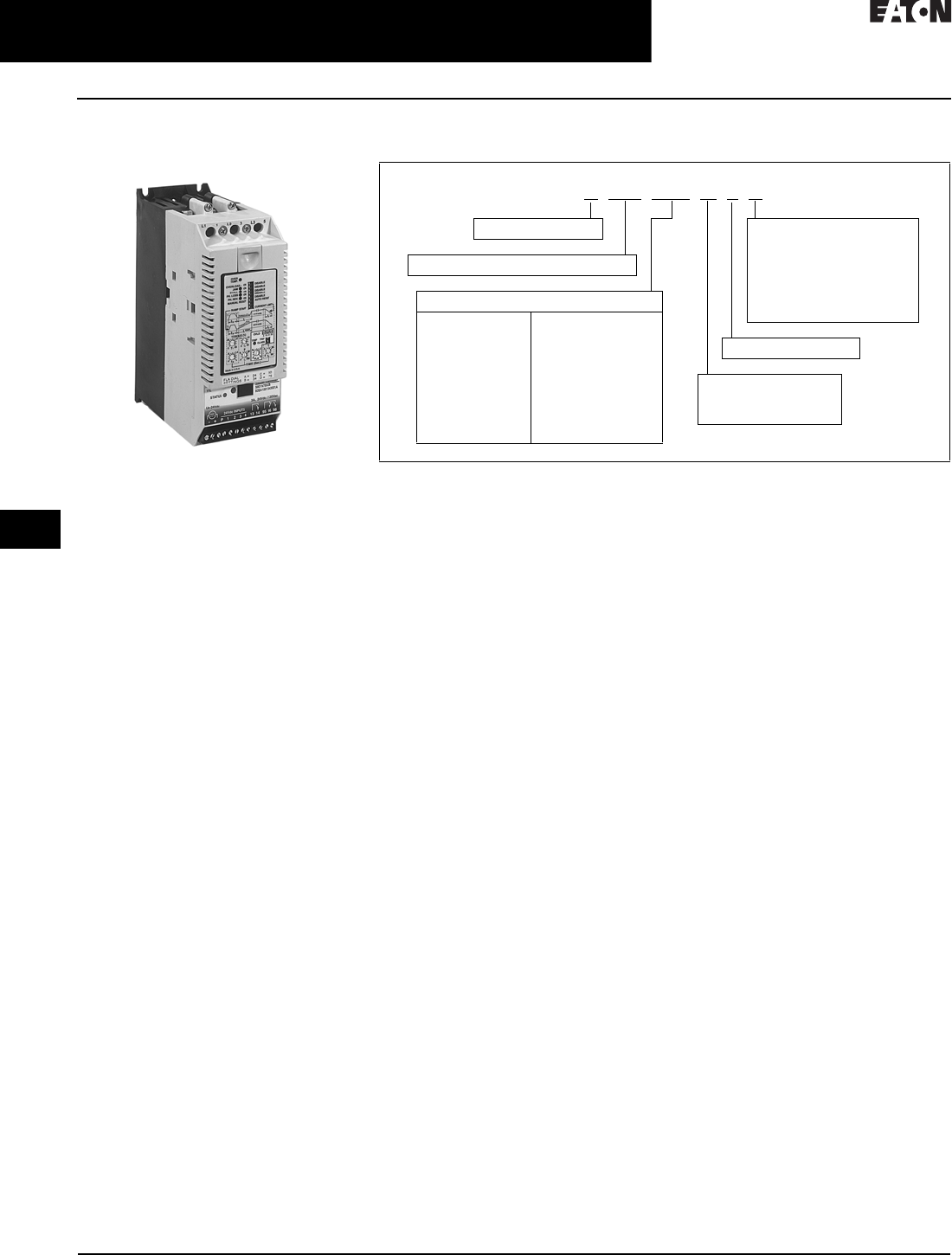
30.5-6
For more information, visit: www.eaton.com/consultants CA08104001E
April 2016
Motor Starters & Contactors—Low Voltage
Sheet 30
22
23
24
25
26
27
28
29
30
31
32
33
34
35
36
37
38
39
40
41
42
4 3
Reduced Voltage—Solid-State
S801 Solid-State Reduced Voltage Starter
068
S801 Solid-State Reduced
Voltage Soft Starter
S801 Reduced Voltage Soft Starters
General Description
Eaton’s S801 line of reduced voltage
soft starters is very compact, multi-
functional, easy-to-install and
easy-to-program. Designed to control
acceleration and deceleration of three-
phase motors, the line is available in
current ranges from 12 to 1000 A and
is suitable for mounting in motor
control centers or in enclosed control
(NEMA 1, 4, 4X and 12) applications.
This product line is designed to compete
head-to-head with the high-end soft
starter market, offering improved
performance and dramatically smaller
size versus the competition. By having
the over-load functionality and bypass
contactors built into the unit, it reduces
the amount of wiring required during
installation and offers huge space
savings in the panel or enclosure.
The product is also designed to be
small enough to replace an existing
across-the-line starter (NEMA or IEC)
in the existing enclosure. This allows
customers to upgrade their existing
motor control centers and enclosed
control by replacing the starter they
have today with a soft starter, gaining
the benefits of lower utility charges,
longer component life and less stress
on products and material systems.
This size benefit allows users to save
the expense of replacing the existing
structure or adding a new one to
house a much larger soft starter.
Application Description
The S801 line uses a total of six SCRs
to control the motor (three matched
pairs). The unit has a built-in overload
Catalog Number Selection
Table 30.5-6. S801 Open Soft Starters Catalog Numbering System
1Not available on U-Frame.
2U-Frame 500 A unit does not have IEC Certification.
that is adjustable from 30% to 100% of
rating and can be set for Trip Class 5,
10, 20 or 30. It also provides additional
protection for jam, stall, phase reversal,
phase loss, overtemperature, under-
voltage and so on. Along with the
overload, the unit has a built-in run
bypass contactor. This device is closed
when the soft starter is up to speed
providing a low impedance bypass for
the SCRs and significantly reducing the
amount of heat that is generated in the
soft starter.
The S801 is designed to work with
three-phase motors in a delta (three-
lead) configuration. The S801 works
with all motors from fractional horse-
power up to motors requiring 1000 A
of steady-state current. The built-in
overload (in ranges from 12 to 1000 A)
and run bypass contactor makes
installation and setup quick and easy.
The overload also offers some
advanced protective functions to give
additional motor protection.
With the pump control option, it is the
number one soft starter available for
pumping applications. The unique soft
stopping control provides a smooth
transition for stopping a motor and
eliminating the “water-hammer”
effect that can damage pipes, valves
and pumps.
Features
■Built-in overload protection:
❑30%–100% adjustment range
❑Trip Class 5, 10, 20 and 30
❑Jam
❑Stall
❑Phase reversal
❑Phase loss/unbalance
❑Shorted SCR detection
❑Overtemperature
■Selectable ramp or current
limit start.
■Kick Start:
❑Adjustable from 0%–85%
initial torque
❑0–2.0 seconds adjustment time
■Ramp Start:
❑Adjustable from 0%–85%
initial torque
❑0.5–180 seconds adjustment time
■Current Limit Start:
❑Adjustable from 0%–550% FLA
❑0.5–180 seconds adjustment time
■Soft Stop:
❑Adjustable from 0%–60 seconds
■Built-in run bypass contact
■24 Vdc control
■IP20 finger protection
■Optional pump control
Standards and Certifications
■IEC 947 compliant
■EN 60947-4-2
■CE marked
■CSA certified
■UL listed
B= Level sensing
D= Inside the delta
L= Extended ramp start
S= Standard soft starter
overload
W= Without CIM (control
interface module)
S 801 N66 N 3 S
S = Soft Starter
801 = Non-combination Soft Starter
Ampacity Rating
N37 = 37 A
N66 = 66 A
R10 = 105 A
R13 = 135 A
T18 = 180 A
T24 = 240 A
T30 = 304 A
U36 = 360 A
U42 = 420 A
U50 = 500 A 2
V36 = 360 A
V42 = 420 A
V50 = 500 A
V65 = 650 A
V72 = 720 A
V85 = 850 A
V10 = 1000 A
N= No options
P= Pump control
V= 690 V option 1
3 = Three-pole device
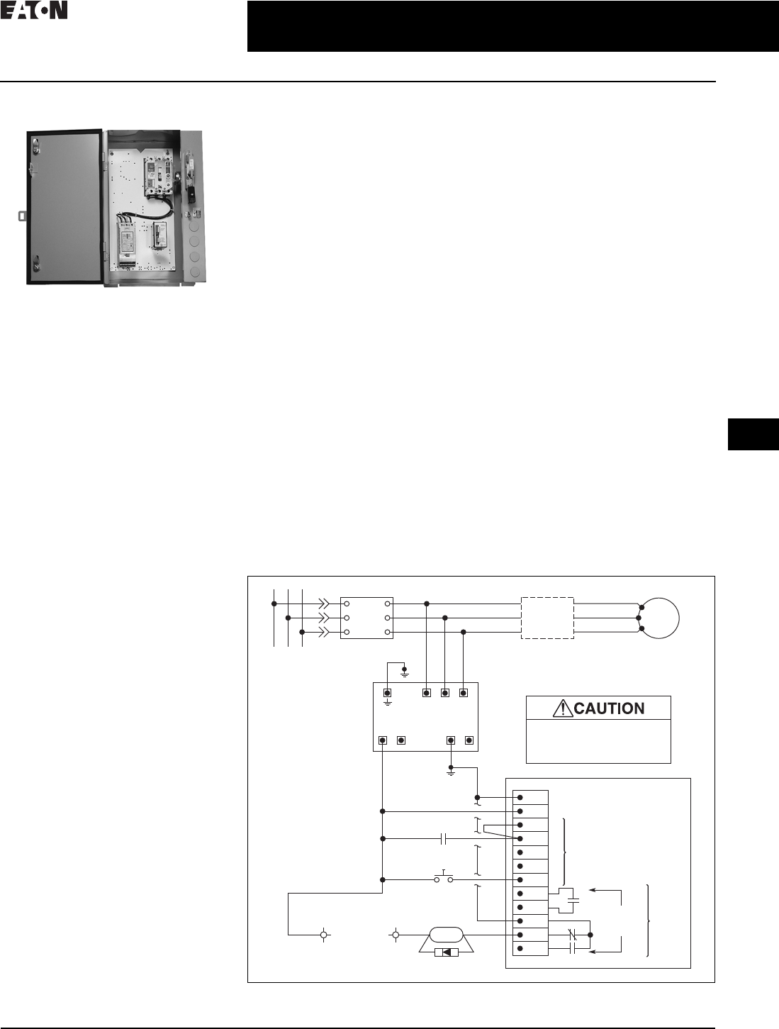
CA08104001E For more information, visit: www.eaton.com/consultants
30.5-7
April 2016
Motor Starters & Contactors—Low Voltage
Sheet 30
22
23
24
25
26
27
28
29
30
31
32
33
34
35
36
37
38
39
40
41
42
4 3
Reduced Voltage—Solid-State
S801 Solid-State Reduced Voltage Starter
069
S801 Enclosed Soft Starter
Enclosed S801 Soft Starter
General Description
24 Vdc Control—S801 soft starters
superiority begins with the control
package that features 24 Vdc control
running a digital signal processor, or
DSP, and using a low impedance run
circuit, all of which contribute to the
S801 soft starter’s safety, advanced
functionality and compact size.
Built-in Overload Protection—With
most wye-delta starters, many of the
advanced features of the S801 are
functions that must be added at the
expense of cost and space. The S801
soft starter, for example, has built-in
overload protection (overloads must
be added to wye-delta starters). So,
S801 soft starters are more compact,
easier to wire and less costly than their
wye-delta counterparts.
Reduced Power Consumption—The
S801 soft starter costs less in terms
of power consumption. An S801 soft
starter also reduces line brown-outs
and decreases overall energy usage.
For example, an S801 soft starter
controls peak power demand while
a full-voltage starter can apply
600–800% FLA on startup.
Lower Starting Torque—System cost
savings are significant with an S801
soft starter versus a full voltage starter.
With an S801 soft starter, mechanical
components can have longer life or
be reduced in size because of lower
starting torque values (250–500% FLA
current with SSRV).
Fewer Mechanical Problems—Because
an S801 soft starter reduces stress on
a system by eliminating the jolts and
violent speed variations that full-voltage
starters introduce to a process,
fewer mechanical breakdowns
occur, improving the quality of
the product and process.
Features and Benefits
■Longer Life of System Equipment —
With the impressive list of control
and protective functions, this new
line of products is designed to sig-
nificantly increase the protection
it offers to system equipment (e.g.,
motors, belts, pumps and so on).
The benefit of increased system
equipment protection is longer
life and longer system equipment
uptime
■Reduced Power Draw—Power
control features like Ramp Start,
Current Limit Start and Jog Forward
provide maximum flexibility in
selecting start profiles, minimizing
both mechanical and electrical
stress while maximizing motor
performance
■Improved Safety—S801 soft
starters offer fingerproof deadfront
construction, reducing the chance
of electrical shock. With the use
of 24 Vdc control power, pilot
devices and relays can be
operated more safely
■System Cost Savings—With
improved reliability, longer life of
system equipment, reduced power
draw, space savings and improved
safety, you enjoy the benefit of a
significant improvement in system
uptime and a reduction in system
downtime resulting in overall
system cost saving
■Time Savings—Time savings in
using S801 soft starters are achieved
through a quick and easy setup
procedure, user-friendly operational
design, the longer life of system
equipment and improved safety
■Productivity—Overall, S801 soft
starters significantly improve your
productivity by saving you time and
money. This is demonstrated by
longer product life, longer runs
between breakdowns and the
ease of installation and operation
Standards and Certifications
Enclosed Control
■UL 508
■IEC 947-4-2
■EN 60947.2
■CE marked EMC/LV directives
■CSA–22.2
Schematic Diagram
Figure 30.5-1. Wiring Diagram
01
02
03
L1
L2
L3
L1
IT Soft Start
L2
L3
T1
T2 Motor
T3
T1
T2
T3
L1
Power Supply
480 Vac–24 Vdc
L2 L3
++
–
–
(–)
(Diode)
(+)
–
+
P
MX
Reset
1
224V Inputs
DC Only
Terminal Board
Applying Voltages Other Than
24 Vdc to Terminals P Thru 4
May Cause Serious Damage
to Soft-Start Control Board
3
4
Run
Internal
Auxiliary
Contacts
Fault
1
4
13
14
95
96
96
Customer
Control
Device
2
(+)
98
24 Vdc
or
120 Vac
MX
+–

30.5-8
For more information, visit: www.eaton.com/consultants CA08104001E
April 2016
Motor Starters & Contactors—Low Voltage
Sheet 30
22
23
24
25
26
27
28
29
30
31
32
33
34
35
36
37
38
39
40
41
42
4 3
Reduced Voltage—Solid-State
S801 Solid-State Reduced Voltage Starter
070
Technical Data and Specifications
Base Ratings
Table 30.5-8 below is the base ratings for the S801 soft
starter. The tables included in this catalog are meant to
be a selection table for different applications, but to
match a unit to your exact application, consult with
your local Eaton representative or visit our Web site at
www.eaton.com/electrical.
Table 30.5-7. Standard-Duty Ratings
Table 30.5-8. Standard-Duty Rating Open Soft Starters
115 sec. start, 300% inrush, 40 °C, 1 start every 15 minutes. If these start parameters are exceeded, please refer to 290 mm V-Frame, 500 A starter.
2U-Frame 500 A does not have IEC Certification.
Severe-Duty Ratings
Motor applications and customer needs come in many
different varieties. With the standard and severe duty rating
tables, we have attempted to provide guidelines on what
the S801 soft starter is capable of. If the application falls under
these categories, you can use these charts. For other applica-
tions, or when a question arises, contact Eaton Corporation
to assist you in selecting the proper soft starter.
Table 30.5-9. Severe-Duty Ratings
Table 30.5-10. Severe-Duty Rating Open Soft Starters
3U-Frame 500 A unit does not have IEC Certification.
Starting
Method
Ramp Current %
of FLA
Ramp Time
Seconds
Starts per
Hour
Ambient
Temperature
vs. Soft start
vs. Full voltage
vs. Wye-delta
vs. 80% RVAT
vs. 65% RVAT
vs. 50% RVAT
300%
500%
350%
480%
390%
300%
30
10
20
20
20
20.
3
3
3
2
3
4
50°C
50°C
50°C
50°C
50°C
50°C
Frame
Size
Maximum
Current
Three-Phase Motor Catalog
Number
kW Rating (50 Hz) hp Rating (60 Hz)
230 380–400 440 200 V 230 V 460 V 575 V
Volt Volt Volt 1.0SF 1.15SF 1.0SF 1.15SF 1.0SF 1.15SF 1.0SF 1.15SF
N37
66
10
18.5
18.5
30
18.5
37
10
20
10
15
10
20
10
20
25
50
20
40
30
60
30
50
S801N37N3S
S801N66N3S
R105
135
30
40
55
63
59
80
30
40
25
30
40
50
30
40
75
100
60
75
100
125
75
100
S801R10N3S
S801R13N3S
T180
240
304
51
75
90
90
110
160
110
147
185
60
75
100
50
60
75
60
75
100
60
75
100
150
200
250
125
150
200
150
200
300
150
200
250
S801T18N3S
S801T24N3S
S801T30N3S
U 360
420
500
110
129
150
185
220
257
220
257
300
125
150
150
100
125
150
150
175
200
125
150
150
300
350
400
250
300
350
350
450
500
300
350
450
S801U36N3S
S801U42N3S
S801U50N3S 12
V 360
420
500
650
720
850
1000
110
129
150
200
220
257
315
185
220
257
355
400
475
560
220
257
300
425
450
500
600
125
150
150
250
—
—
—
100
125
150
200
—
—
—
150
175
200
250
300
350
400
125
150
150
200
250
300
350
300
350
400
500
600
700
800
250
300
350
450
500
600
700
350
450
500
600
700
900
1000
300
350
450
500
600
700
800
S801V36N3S
S801V42N3S
S801V50N3S
S801V65N3S
S801V72N3S
S801V85N3S
S801V10N3S
Starting
Method
Ramp Current %
of FLA
Ramp Time
Seconds
Starts per
Hour
Ambient
Temperature
vs. Soft start
vs. Full voltage
vs. Wye-delta
vs. 80% RVAT
vs. 65% RVAT
vs. 50% RVAT
450%
500%
350%
480%
390%
300%
30
10
65
25
40
60
4
10
3
4
4
4
50 °C
50 °C
50 °C
50 °C
50 °C
50 °C
Frame
Size
Maximum
Current
Three-Phase Motor Catalog
Number
kW Rating (50 Hz) hp Rating (60 Hz)
230 380–400 440 200 V 230 V 460 V 575 V
Volt Volt Volt 1.0SF 1.15SF 1.0SF 1.15SF 1.0SF 1.15SF 1.0SF 1.15SF
N22
42
5.5
11
10
18.5
11
22
5
10
5
10
7-1/2
15
5
10
15
30
10
25
20
40
15
30
S801N37N3S
S801N66N3S
R65
80
15
22
30
40
33
45
15
25
15
20
20
30
15
25
50
60
40
50
50
75
50
60
S801R10N3S
S801R13N3S
T115
150
192
33
45
55
59
80
100
63
90
110
30
50
60
30
40
50
40
50
75
30
50
60
75
100
150
75
100
125
100
150
200
100
125
150
S801T18N3S
S801T24N3S
S801T30N3S
U 240
305
365
75
90
110
110
160
185
147
185
220
75
100
125
60
75
100
75
100
150
75
100
125
200
250
300
150
200
250
200
300
350
200
250
300
S801U36N3S
S801U42N3S
S801U50N3S 3
V 240
305
365
420
480
525
600
75
90
110
129
147
160
185
110
160
185
220
257
280
315
147
185
220
257
295
335
375
75
100
125
150
150
150
200
60
75
100
125
150
150
150
75
100
150
150
200
200
250
75
100
125
150
150
150
200
200
250
300
350
400
450
500
150
200
250
300
350
350
450
200
300
350
450
500
500
600
200
250
300
350
450
450
500
S801V36N3S
S801V42N3S
S801V50N3S
S801V65N3S
S801V72N3S
S801V85N3S
S801V10N3S

CA08104001E For more information, visit: www.eaton.com/consultants
30.5-9
April 2016
Motor Starters & Contactors—Low Voltage
Sheet 30
22
23
24
25
26
27
28
29
30
31
32
33
34
35
36
37
38
39
40
41
42
4 3
Reduced Voltage—Solid-State
S801 Solid-State Reduced Voltage Starter
071
Features
■Able to fit in place of existing
starters
■Smallest unit on the market today
■Very easy to install, wire and program
■Reduces initial torque on motor
and loads
■Able to control the maximum
inrush current
Benefits
■Reduced wear on belts, gears,
chains, clutches, shafts and bearings
■Allows for controlling the inrush
current to the motor and reducing
electrical charges due to peak
energy demand
■Reduced inrush current leads to
more stable power grid and can
lower peak demand charges
■Elimination of water-hammer,
which can reduce installed cost of
pipe hangers and extend existing
system life
■Less shock to product on conveyor
lines and material handling gear
■24 Vdc control enhances personnel
and equipment safety
Table 30.5-11. Technical Data
1U-Frame 500 A unit does not have IEC Certification.
Soft Starter
(Partial Catalog Number)
S801
N37
S801
N66
S801
R10
S801
R13
S801
T18
S801
T24
S801
T30
S801
U36
S801
U42
S801
U50 1
S801
V36
S801
V42
S801
V50
S801
V65
S801
V72
S801
V85
S801
V10
Maximum current capacity 37 66 105 135 180 240 304 360 420 500 360 420 500 650 720 850 1000
Dimensions in Inches (mm)
Width
Height
Depth
Weight in lbs (kg)
2.60 (66.1)
7.38 (187.4)
6.63 (168.4)
5.80 (2.6)
4.38 (111.3)
7.92 (201.2)
7.03 (178.6)
10.50 (4.8)
7.65 (194.3)
12.71 (322.8)
6.69 (169.9)
48.00 (21.8)—
with lugs
41.00 (18.6) —
without lugs
7.73 (196.3)
12.72 (323.1)
7.08 (179.9)
48.00 (21.8)—
with lugs
41.00 (18.6) —
without lugs
11.04 (280.4)
16.57 (420.9)
7.69 (195.3)
103.00 (46.0)—with lugs
91.00 (41.4)—without lugs
General Information
Bypass mechanical lifespan
Insulating voltage (Ui)
Ramp time range
Resistance to vibration
Resistance to shock
10 M
660 V
0.5–180 seconds (0.5–360 seconds extended ramp)
3g
15g
Electrical Information
Operating voltage
Operating frequency
Overload setting
Trip c l ass
200–600 V
47–63 Hz
30%–100%
5, 10, 20 and 30
Cabling Capacity (IEC 947)
Number of conductors
Wire sizes
Type of connectors
1
14–2
Box lug
1
14–4/0
Box lug
1 or 2
2/0 to 500 kcmil
Add-on lug kit
— — — 2, 4 or 6
2/0 to 500 kcmil
Add-on lug kit
Control Wiring (12-Pin)
Wire sizes in AWG
Number of conductors (stranded)
Torque requirements in lb-in.
Solid, stranded or flexible
maximum size in mm2
22–14
2 (or one AWG 12)
3.5
3.31
Control Power Requirements
Voltage range (24 V ± 10%)
Steady state current amperes
Inrush current amperes
Ripple
21.6–26.4
1.0
10
1%
— — — 21.6–26.4
1.4
10
1%
Relays (1) Class A and C
Voltage AC—maximum
Voltage DC—maximum
Amperes—maximum
240
120
3
Environment
Temperature—operating
Temperature—storage
Altitude
Humidity
Operating position
Pollution degree (IEC 947-1)
Impulse withstand voltage
(IEC 947-4-1)
–30 ºC to +50 ºC (no derating) consult factory for operation >50 ºC
–50 ºC to +70 ºC
<2000 m—consult factory for operation >2000 m
<95% noncondensing
Any
3
4000 V
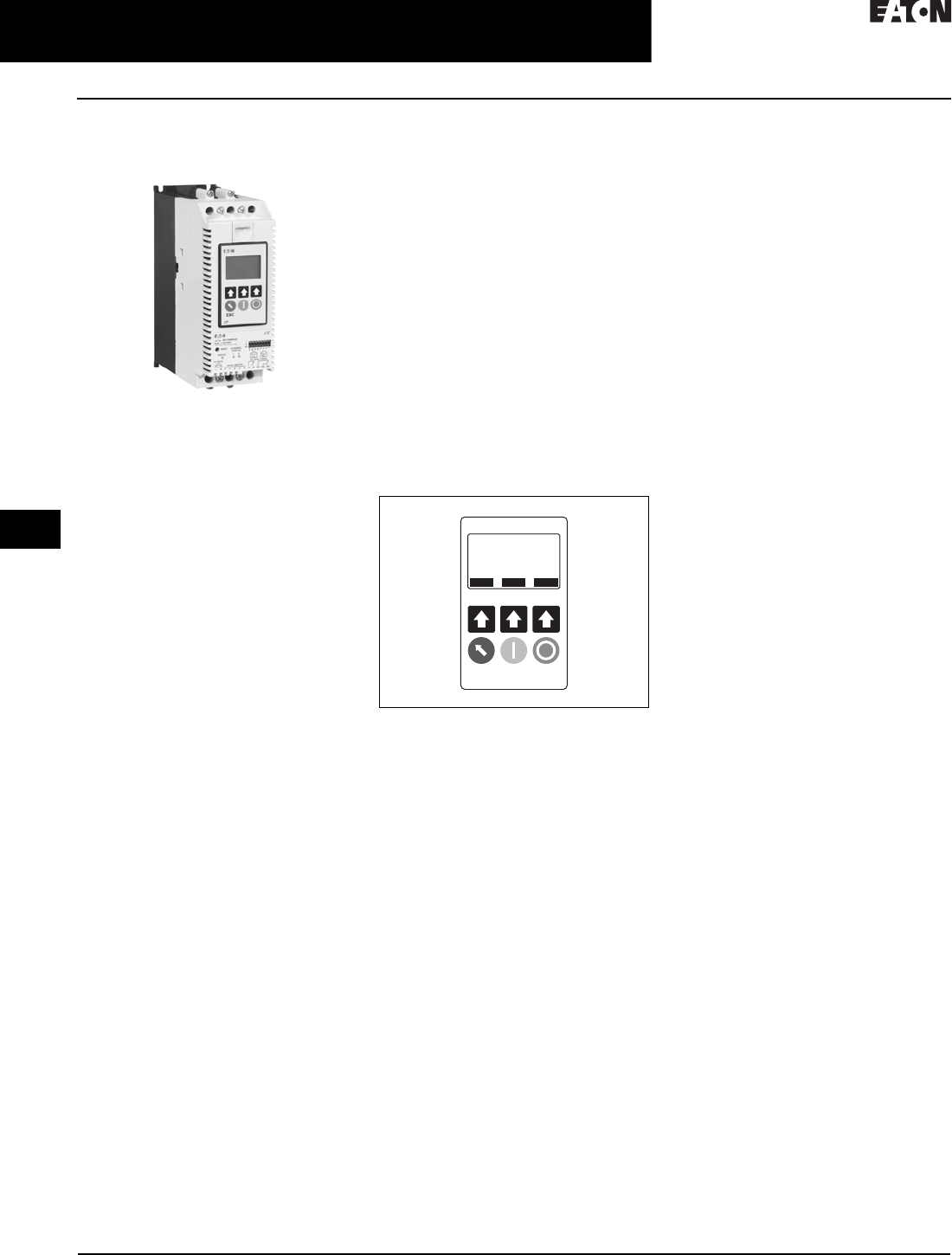
30.5-10
For more information, visit: www.eaton.com/consultants CA08104001E
April 2016
Motor Starters & Contactors—Low Voltage
Sheet 30
22
23
24
25
26
27
28
29
30
31
32
33
34
35
36
37
38
39
40
41
42
4 3
Solid-State Starters
S811 Solid-State Reduced Voltage Starter
072
S811 Solid-State Reduced
Voltage Soft Starters
S811 Soft Starter
General Description
The S811 from Eaton offers all the
popular features of the S801, but adds
enhanced functionality with the new
DIM (Digital Interface Module) and
communications capabilities.
The S811 reduced voltage soft starter
is very compact, multi-functional,
easy to install and easy to program.
Designed to control the acceleration
and deceleration of three-phase
motors up to 690 V, the line is available
from 11 A through 1000 A.
The S811 is designed to be a complete
package combining the SCRs, bypass
contactor and overload in one, very
compact unit. The S811 is available
as a component for panel mounting,
in motor control centers or in enclosed
control (NEMA Type 1, 3R, 4, 4X, 7/9
and 12).
Application Description
Designed to control the acceleration
and deceleration of three-phase
motors, the S811 soft starter uses
silicon controlled rectifiers (SCRs) to
control the voltage to soft start and
soft stop the motor. After the motor is
started, internal run bypass contactors
close, resulting in the motor running
directly across-the-line. The built-in
solid-state overload protects the motor
from overload conditions with sophis-
ticated algorithms that model true
motor heating, resulting in better
motor protection and fewer nuisance
trips. Advanced protective and
diagnostic features reduce downtime.
A voltage ramp start or current limit
start is available. Kick start is available
in either starting mode. The soft stop
option allows for a ramp stop time that
is longer than the coast to stop time.
The pump control option provides a
smooth transition for starting and
stopping a motor and eliminating
the “water-hammer” effect that can
damage pipes, valves and pumps.
The S811 offers an impressive array of
advanced protective features. Not only
are the protective features selectable,
but many offer variable settings allow-
ing the user to fine-tune the starter to
meet specific system requirements.
The S811 has an easy to use Digital
Interface Module (DIM) that allows the
user to configure the device and to
read system parameters. The DIM
includes an LCD display and keypad to
scroll through the various menus. The
DIM allows the user to modify control
parameters, enable or disable protec-
tions, set communication variables,
monitor system parameters such as
line voltages and currents, and access
the fault queue.
Figure 30.5-2. Digital Interface Module (DIM)
The DIM can be removed from the
S811 and remote mounted. Kits are
available to door mount the DIM,
enabling users to safely configure,
commission, monitor and trouble-
shoot the system at the electrical panel
without opening the enclosure door.
The S811 has built-in communications
capabilities that enable the soft starter
to be connected to a variety of
networks, including DeviceNet™,
Ethernet, Modbus®and PROFIBUS.
Multiple control components can be
connected to one Eaton gateway that
concentrates data from the devices
into a single node. Configuration is
simple—a single press of the gateway’s
Auto Configuration button sets the
system up for default operation.
This automatically configures the I/O
assemblies to the system devices.
The data from these devices are then
assembled into a single input and
output messages.
The S811 communication parameters
can be configured with the DIM or
through the network using CH Studio
Component Manager.
Advanced communication configura-
tion settings provide the system
integrator with powerful tools to
facilitate system optimization.
Features and Benefits
■The DIM provides an intuitive,
easy-to-use human interface with
powerful configuration capabilities
to maximize system performance
■Door or device mounted DIM
enables users to safely configure,
commission, monitor and trouble-
shoot the system at the electrical
panel without opening the
enclosure door
■System operating parameters
can be monitored enterprise-wide
through a communications network.
Increase uptime by providing data
for process management and
preventive diagnostics
■Run bypass mode greatly reduces
internal heating created by the
greater power dissipation in
the SCRs. Bypass contactor directly
connects the motor to the line and
improves system efficiency by
reducing internal power losses
■Internal solid-state overload
protection provides accurate cur-
rent measurement and trip settings.
Sophisticated algorithms solve
a series of differential equations
that model true motor heating and
cooling, resulting in superior motor
overload protection while minimizing
nuisance trips. Advanced selectable
protective features safeguard the
motor and system against a variety
of system faults
■Internal run bypass contactors and
overload protection eliminate the
need for additional devices, reducing
enclosure sizes, minimizing installa-
tion and wiring time and reducing
overall assembly size and cost
■Wide range of overload FLA settings
(31–100% of rated current) and a
selectable trip class (5–30) offers
users the flexibility to fine-tune the
starter to match specific application
requirements
ESC
ONLN SS OXFDO1 H STOP
Monitoring
PREV NEXT ENTER

CA08104001E For more information, visit: www.eaton.com/consultants
30.5-11
April 2016
Motor Starters & Contactors—Low Voltage
Sheet 30
22
23
24
25
26
27
28
29
30
31
32
33
34
35
36
37
38
39
40
41
42
4 3
Solid-State Starters
S811 Solid-State Reduced Voltage Starter
073
■Variable ramp times and torque
control settings provide unlimited
starting configurations, allowing for
maximum application flexibility
■Kick-start feature enables soft
starting of high friction loads
■Soft stop control for applications
where an abrupt stop of the load
is not acceptable
■Pump control option with sophisti-
cated pump algorithms on both
starting and stopping that minimize
the pressure surges that cause
water hammer. The pump control
option will maximize the life of the
pump and piping systems while
minimizing the downtime caused
by system failure
■Six SCRs control all three motor
phases, providing smooth accelera-
tion and deceleration performance
■Soft acceleration and deceleration
reduces wear on belts, gears, chains,
clutches, shafts and bearings
■Reduce the peak inrush current
stress on the power system
■Minimize peak starting torque to
diminish mechanical system wear
and damage
■24 Vdc control module enhances
personnel and equipment safety.
■Removable, lockable control terminal
block reduces maintenance costs.
Also provides the opportunity for
OEMs to reduce assembly and
test costs by using pre-assembled
wire harnesses
Protective Features
All protective features can be
configured, enabled or disabled
with the DIM or through the
communications network.
Motor Overload
The S811 includes electronic overload
protection as standard. The overload
meets applicable requirements for a
motor overload protective device. The
overload protects the motor from over
heat conditions with the use of sophisti-
cated algorithms that model true motor
heating, resulting in superior motor
protection and fewer nuisance trips.
The S811 calculates a thermal memory
value. A 100% value represents the
maximum safe temperature of the
motor. When the thermal memory
value reaches 100%, an overload trip
will occur removing power to the
motor. Upon trip, the S811 stores the
calculated motor heating value and
will not allow a motor re-start until the
motor has sufficiently cooled. This
feature ensures the motor will not be
damaged by repeated overload trip,
reset and re-start cycles.
The thermal memory value can be
monitored through the DIM or the
communications network. The thermal
memory value can be of great use in
determining an impending overload
trip condition. Alarms can be imple-
mented in the process monitoring
system warning of an impending
trip before a trip occurs halting the
process. Costly system downtime
can be avoided.
The trip current is adjusted to match
the specific application requirements
by entering the motor nameplate full
load current rating and trip class. The
FLA adjustment includes a 3 to 1
adjustment range. The overload trip
class is adjustable from class 5
through class 30. The overload is
ambient temperature compensated—
meaning its trip characteristics will
not vary with changes in ambient
temperature. The overload protection
can be enabled, disabled, or disabled
on start.
Short Circuit
The use of a short-circuit protective
device in coordination with the S811
is required in branch motor circuits
by most electrical codes. Short-circuit
coordination ratings with both fuses
and Eaton’s molded case circuit
breakers are available providing
customers with design flexibility. The
S811 has short circuit coordination
ratings as an open component, an
enclosed starter, and in a motor
control center.
Jam
Excessive current and torque up to
locked rotor levels can occur in a jam
condition. The condition can result in
stress and damage to the motor, load,
mechanical system, and the electrical
distribution system. Jam protection
prevents the stress and damage from a
jam during normal run. After the
motor is started, a current greater than
300% FLA setting will cause the starter
to trip on a jam fault.
Stall
Excessive current and torque up to
locked rotor levels can occur in a stall
condition. The condition can lead to an
overload trip and result in stress and
damage to the motor, load, mechanical
system, and the electrical distribution
system. Stall protection prevents
stress and damage to a motor that has
not come up to speed, or stalled after
the soft start time. The S811 will trip to
protect the system in the event that the
motor did not get to the rated speed in
the defined soft start period. A current
greater than 200% FLA at the end of
the soft start period will cause the
starter to trip on a stall fault.
Pole Over Temperature
High ambient temperatures, extended
ramp times and high duty cycle condi-
tions may cause the S811 power pole
conductors to reach a temperature that
exceeds their thermal rating. The S811
is equipped with sensors that monitor
the temperature of the power poles.
Over temperature protection occurs
if the device’s thermal capacity is
exceeded. The soft starter will trip
in over temperature conditions,
preventing device failure.
The device pole temperature value
can be monitored through the DIM or
the communications network. This
feature can be of use in determining
an impending over temperature trip
condition. Alarms can be implemented
in the process monitoring system
warning of an impending trip before a
trip occurs, halting the process. Costly
system shutdown can be avoided.
Phase Loss
Loss of a phase can cause a significant
increase in the current drawn in the
remaining two phases. Phase loss
can lead to motor damage before an
eventual overload trip occurs. Phase
loss is typically an indication of a
failure in the electrical distribution
system. The S811 will detect a phase
loss and trip if any phase current drops
below a preset value. The phase loss
trip level is adjustable from 0% to
100% of the average of the other two
phase levels with an adjustable trip
delay of 0.1 to 60 seconds.
Phase Imbalance
Phase current or voltage imbalance
can cause a significant increase in the
current drawn in the remaining two
phases. Phase imbalance can lead to
motor damage before an eventual
overload trip. Phase imbalance is
typically an indication of a failure in
the electrical distribution system or
the motor. The S811 will detect both
current and voltage phase imbalances
and trip if any phase becomes
imbalanced as compared to the
average of the other two phases.
The phase current imbalance trip level
is adjustable from 0% to 100% of the
average of the current in the other two
phases with an adjustable trip delay of
0.1 to 60 seconds.

30.5-12
For more information, visit: www.eaton.com/consultants CA08104001E
April 2016
Motor Starters & Contactors—Low Voltage
Sheet 30
22
23
24
25
26
27
28
29
30
31
32
33
34
35
36
37
38
39
40
41
42
4 3
Solid-State Starters
S811 Solid-State Reduced Voltage Starter
074
The phase voltage imbalance trip level
is adjustable from 0% to 100% of the
average of the voltage in the other two
phases with an adjustable trip delay of
0.1 to 60 seconds.
Reset Mode
The S811 can be set up for automatic
or manual reset on trip. The manual
reset mode requires the operator to
physically press the RESET button
located on the soft starter. The over-
load can be manually reset through
the DIM or through the communica-
tions network. The overload can also
be electrically reset by energizing
a 24 Vdc input on the control
terminal block.
The automatic reset mode allows the
soft starter to be automatically reset as
soon as the trip condition is no longer
present. With the automatic reset
mode, after the fault is no longer pres-
ent, the motor will be restarted as soon
as a valid start signal is present.
Phase Reversal
The S811 can determine if the proper
line phase sequence is present by
default. The device will trip if the line
phase sequence is something other
than A-B-C. The S811 can be config-
ured to operate under reversed
phase conditions (A-C-B).
Shorted SCR Detection
The S811 monitors the operation of the
power poles and will trip under a
shorted SCR condition.
Open SCR Detection
The S811 monitors the operation of the
power poles and will trip under an
open SCR condition.
Low Current
Low current conditions can be a result
of a loss of load or a failure in the
mechanical system. The S811 has low
current protection that will trip if the
average rms current falls below a
preset value. The low current protec-
tion can be programmed as a percent
of motor FLA from 0% to 100%.
Low Voltage
Low voltage conditions can result from
disturbances in the electrical power
distribution system. Low voltage
conditions can cause a malfunction
and damage to electrical equipment.
The S811 has low voltage protection
that will trip if the average rms
voltage falls below a preset value.
The low voltage protection can be
programmed as a percent of nominal
voltage from 1% to 99% with a
trip delay of 0.1 to 60 seconds.
High Voltage
High voltage conditions can result from
disturbances in the electrical power
distribution system. High voltage
conditions can cause malfunctions
or failures of electrical equipment.
The S811 has high voltage protection
that will trip if the average rms voltage
is greater than a preset value. The high
voltage protection can be programmed
as a percent of nominal voltage from
101% to 120% with a trip delay of 0.1 to
60 seconds.
Monitoring Capabilities
The S811 has an impressive array of
system monitoring capabilities that
allow users to access real time process
and diagnostic data. This data can be
viewed at the device with the DIM or
through a communications network.
Data over a communications network
can provide valuable insight into the
condition of the equipment and pro-
cesses. Maintenance and production
personnel can monitor critical opera-
tional and maintenance data from a
central control station that can be
located far away from the production
facility. Process data can be monitored
to determine system anomalies that
may indicate a need for preventive
maintenance or an impeding failure.
Adjustments made through the com-
munications network can reduce costs
by minimizing the time traveling to the
location where the motor controls are
located. When faults do occur, real
time fault data can assist maintenance
in troubleshooting and planning repair
resources. Remote reset signals can
be given to tripped devices without
the need for manual intervention by
maintenance personnel.
Average Line Current
Provides the average of the three-
phase rms line currents in amps,
accurate to within 2%. Current data
can be used to indicate a need for
maintenance. Increased currents in
a fixed load application can indicate
a reduction in system efficiencies
and performance, signifying system
maintenance is due.
Average Pole Current
Provides the average of the three-
phase rms pole currents in amps,
accurate to within 2%. The pole
current is the current through the
soft starter. The line and pole current
will be identical in in-line applications,
and will differ in inside-the-delta
applications.
Average line current as a % FLA
Provides the average rms line
current as a percentage of the S811
FLA setting.
Three-Phase Line Currents
Provides three rms phase line currents
in amps, accurate to within 2%.
Imbalances or changes in the relative
phase current to one another can
indicate anomalies in the motor or
electrical distribution system.
Three-Phase Pole Currents
Provides three rms phase pole
currents in amps, accurate to within
2%. The pole current is the current
through the soft starter. The line and
pole current will be identical in in-line
applications, and will differ in inside-
the-delta applications.
Three-Phase Line Voltages
Provides the individual rms three-
phase line voltages. Imbalances or
changes in the relative phase voltage
to one another can indicate anomalies
in the motor or electrical distribution
system. Voltage can be used to
monitor electrical distribution system
performance. Warnings, alarms and
system actions to low or high voltage
conditions can be implemented.
Percent Thermal Memory
Provides the real time calculated
thermal memory value. The S811
calculates thermal memory value. A
100% value represents the maximum
safe temperature of the motor. When
the thermal memory value reaches
100%, an overload trip will occur,
removing power to the motor.
The thermal memory value can be of
great use in determining an impending
overload trip condition. Alarms can be
implemented in the process monitor-
ing system warning of an impending
trip before a trip occurs, halting the
process. Costly system downtime can
be avoided.
DC Control Voltage
Monitors level of the 24 Vdc control
voltage. Fluctuations in control voltage
can cause component malfunction and
failure. System control voltage data
can be used to implement warnings,
alarms and system actions to low or
high voltage conditions.
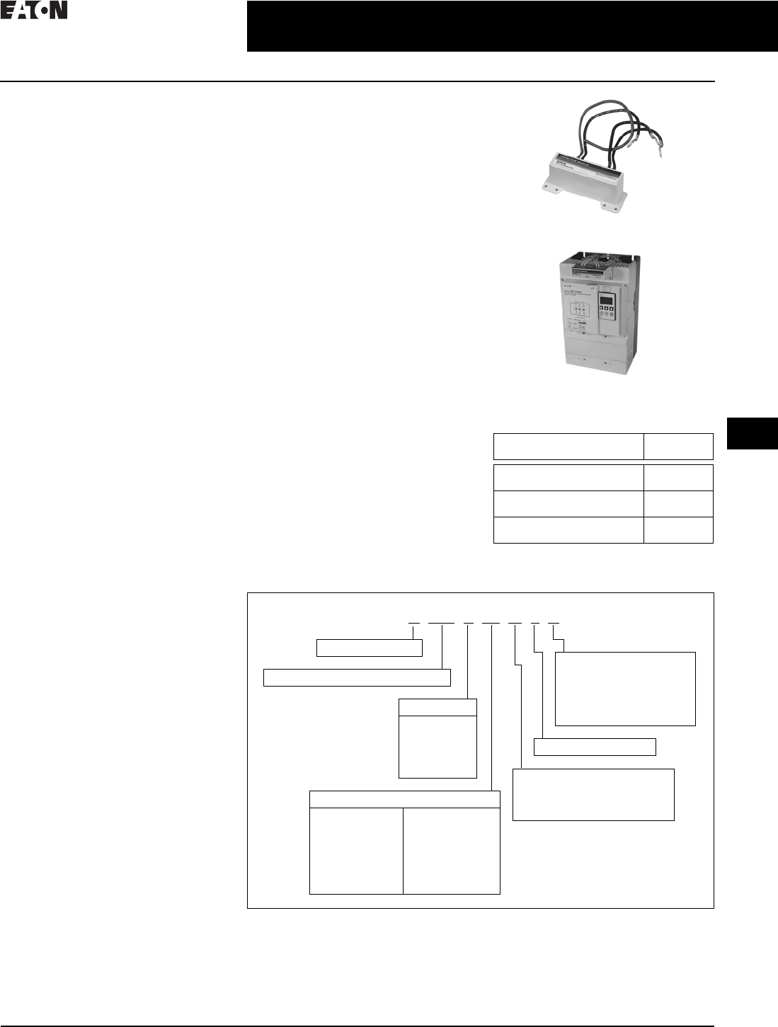
CA08104001E For more information, visit: www.eaton.com/consultants
30.5-13
April 2016
Motor Starters & Contactors—Low Voltage
Sheet 30
22
23
24
25
26
27
28
29
30
31
32
33
34
35
36
37
38
39
40
41
42
4 3
Solid-State Starters
S811 Solid-State Reduced Voltage Starter
075
Pole Temperature
Increases in pole temperature are
caused by increases in ambient
temperature, start/stop times and
start duty cycles. Changes in pole
temperatures represent a change
in system operating conditions.
Identifying unexpected operating
conditions or changes can prompt
maintenance and aid in process
evaluation activities.
Device Temperature
An increase in device temperature is
a strong indication of an increase in
ambient temperature. High ambient
temperature operation can be identi-
fied with the device temperature data.
Ambient temperature increases can be
due to loss of enclosure cooling fans
or blocked venting. High ambient
temperatures will reduce the life of all
electrical equipment in the enclosure.
Start Count
Start count data can be used to
monitor system output, schedule
preventative maintenance, identify
system anomalies and identify
changes in system operation.
Diagnostics
Fault Queue
Current fault and a fault queue
containing the last nine system
faults can be read through the DIM
or communications network. Fault
identification can minimize trouble-
shooting time and cost. The fault
queue can be remotely accessed
through a communications network
to assist in planning maintenance
resources. Thirty different faults
can be identified by the S811.
Control Status
The S811 provides data that represents
system conditions that can be read
through the DIM or the communica-
tions network. This data identifies the
status of the system and the control
commands the system is requesting
of the S811. This can be used for
advanced troubleshooting and
system integration activities.
Breaker Status
The S811 has provisions to read and
display circuit breaker status. Eaton
communicating cover control or
other communicating protective
device is required to take advantage
of this feature.
User Manual
A comprehensive user manual is avail-
able and can be downloaded free of
charge from www.eaton.com/electri-
cal by performing a document search
for MN03902002E.
Accessories
Surge Suppressors
A surge suppressor can mount on
either the line or load side of the
S811 soft starter. It is designed to
clip the line voltage (or load side
induced voltage).
Surge Suppressor
Surge Suppressor Mounted on
a 200 mm Device
Table 30.5-12. Surge Suppressors
Catalog Number Selection
Table 30.5-13. S811 Open Soft Starters Catalog Numbering System
1U-Frame 500 A unit does not have IEC Certification.
2Not available in U-Frame.
Description Catalog
Number
600 V MOV for 65 mm
and 110 mm units
EMS38
600 V MOV for 200 mm and
290 mm units
EMS39
690 V MOV for 200 mm and
290 mm units
EMS41
S 811 T 30 N 3 S
Ampacity Rating
37 = 37 A
66 = 66 A
10 = 105 A
13 = 135 A
18 = 180 A
24 = 240 A
30 = 304 A
36 = 360 A
42 = 420 A
50 = 500 A 1
65 = 650 A
72 = 720 A
85 = 850 A
10 = 1000 A
Frame Size
N= 65 mm
R= 110 mm
T= 200 mm
U= 200 mm
V= 290 mm
811 = Non-combination Soft Starter
N= No options
P= Pump control
V= 690 V option
(Frame T18 through V85) 2
S= Standard soft starter
(configurable for edge
or level control)
D= Inside-the-delta
L= Extended ramp start
W= Without DIM
S = Soft starter
3 = Three-pole device
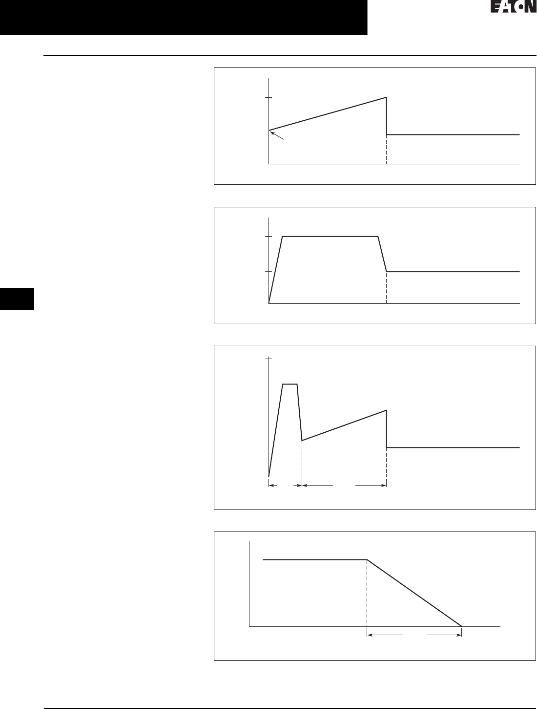
30.5-14
For more information, visit: www.eaton.com/consultants CA08104001E
April 2016
Motor Starters & Contactors—Low Voltage
Sheet 30
22
23
24
25
26
27
28
29
30
31
32
33
34
35
36
37
38
39
40
41
42
4 3
Solid-State Starters
S811 Solid-State Reduced Voltage Starter
076
Operation
Starting and Stopping Modes
The S811 has a variety of starting and
stopping methods to provide superior
performance in the most demanding
applications. The motor can be started
in either Voltage Ramp Start or Current
Limit Start mode. Kick Start and Soft
Stop are available within both starting
modes.
Voltage Ramp Start
Provides a voltage ramp to the motor
resulting in a constant torque increase.
The most commonly used form of soft
start, this start mode allows you to
set the initial torque value and the
duration of the ramp to full voltage
conditions. Bypass contactors close
after ramp time.
■Adjustable initial torque 0–85%
of locked rotor torque
■Adjustable ramp time 0.5–180
seconds (can be extended with
factory modification)
Current Limit Start
Limits the maximum current available
to the motor during the start phase.
This mode of soft starting is used
when it becomes necessary to limit the
maximum starting current due to long
start times or to protect the motor. This
start mode allows you to set the maxi-
mum starting current as a percentage
of locked rotor current and the dura-
tion of the current limit. Bypass con-
tactors close after current limit time.
■Maximum current of 0–85% locked
rotor current
■Adjustable ramp time 0.5–180
seconds (can be extended with
factory modification)
Kick Start
Selectable feature in both Voltage
Ramp Start and Current Limit Start
modes. Provides a current and torque
“kick” for 0 to 2.0 seconds. This
provides greater initial current to
develop additional torque to break-
away a high friction load.
■0–85% of locked rotor torque
■0–2.0 seconds duration
Soft Stop
Allows for a controlled stopping of a
load. Used when a stop-time that is
greater than the coast-to-stop time is
desired. Often used with high friction
loads where a sudden stop may cause
system or load damage.
■Stop time = 0–60 seconds
Figure 30.5-3. Starting Characteristics—Ramp Start
Figure 30.5-4. Starting Characteristics—Current Limit Start
Figure 30.5-5. Starting Characteristics—Kick Start
Figure 30.5-6. Starting Characteristics—Soft Stop
Run (FLA)
100%
Locked Rotor Torque
Time (Seconds)
Initial
Torque
Run
Max.
Allowed
100%
FLA
Current
Time (Seconds)
100%
Locked Rotor Torque
Ramp
Time (Seconds)
Kick
Start
Run (FLA)
Ramp
Time (Seconds)
Run

CA08104001E For more information, visit: www.eaton.com/consultants
30.5-15
April 2016
Motor Starters & Contactors—Low Voltage
Sheet 30
22
23
24
25
26
27
28
29
30
31
32
33
34
35
36
37
38
39
40
41
42
4 3
Solid-State Starters
S811 Solid-State Reduced Voltage Starter
077
Product Selection
Motor applications and customer needs
come in many different varieties. With
the standard and severe duty rating
tables, we have attempted to provide
guidelines on what the S811 soft
starter is capable of. If the application
falls under these categories, you can
use these charts. For other applica-
tions, or when a question arises,
consult with your local Eaton
Representative or call our Technical
Resource Center at (877) ETN-CARE.
Table 30.5-14. Standard-Duty Ratings
Table 30.5-15. Product Selection—Standard-Duty Rating Open Soft Starters
1500 A rating does not have IEC Certification.
Table 30.5-16. Severe-Duty Ratings
Starting
Method
Ramp Current
% of FLA
Ramp Time
Seconds
Starts
per Hour
Ambient
Temperature
vs. Soft start
vs. Full voltage
vs. Wye-delta
vs. 80% RVAT
vs. 65% RVAT
vs. 50% RVAT
300%
500%
350%
480%
390%
300%
30 sec.
10 sec.
20 sec.
20 sec.
20 sec.
20 sec.
3
3
3
2
3
4
50 °C
50 °C
50 °C
50 °C
50 °C
50 °C
Frame
Size
Max.
Current
Three-Phase Motor Catalog
Number
kW Rating (50 Hertz) hp Rating (60 Hertz)
230 380–400 440 200 V 230 V 460 V 575 V
Volt Volt Volt 1.0SF 1.15SF 1.0SF 1.15SF 1.0SF 1.15SF 1.0SF 1.15SF
N37
66
10
18.5
18.5
30
18.5
37
10
20
10
15
10
20
10
20
25
50
20
40
30
60
30
50
S811N37N3S
S811N66N3S
R105
135
30
40
55
63
59
80
30
40
25
30
40
50
30
40
75
100
60
75
100
125
75
100
S811R10N3S
S811R13N3S
T180
240
304
51
75
90
90
110
160
110
147
185
60
75
100
50
60
75
60
75
100
60
75
100
150
200
250
125
150
200
150
200
300
150
200
250
S811T18N3S
S811T24N3S
S811T30N3S
U 360
420
500
110
120
150
185
220
257
220
257
300
125
150
150
100
125
150
150
175
200
125
150
150
300
350
400
250
300
350
350
450
500
300
350
450
S811U36N3S
S811U42N3S
S811U50N3S 1
V 360
420
500
650
720
850
100 0
110
129
150
200
220
257
315
185
220
257
355
400
475
560
220
257
300
425
450
500
600
125
150
150
250
—
—
—
100
125
150
200
—
—
—
150
175
200
250
300
350
400
125
150
150
200
250
300
350
300
350
400
500
600
700
800
250
300
350
450
500
600
700
350
450
500
600
700
900
100 0
300
350
450
500
600
700
800
S811V36N3S
S811V42N3S
S811V50N3S
S811V65N3S
S811V72N3S
S811V85N3S
S811V10N3S
Starting
Method
Ramp Current
% of FLA
Ramp Time
Seconds
Starts
per Hour
Ambient
Temperature
vs. Soft start
vs. Full voltage
vs. Wye-delta
vs. 80% RVAT
vs. 65% RVAT
vs. 50% RVAT
450%
500%
350%
480%
390%
300%
30 sec.
10 sec.
65 sec.
25 sec.
40 sec.
60 sec.
4
10
3
4
4
4
50 °C
50 °C
50 °C
50 °C
50 °C
50 °C
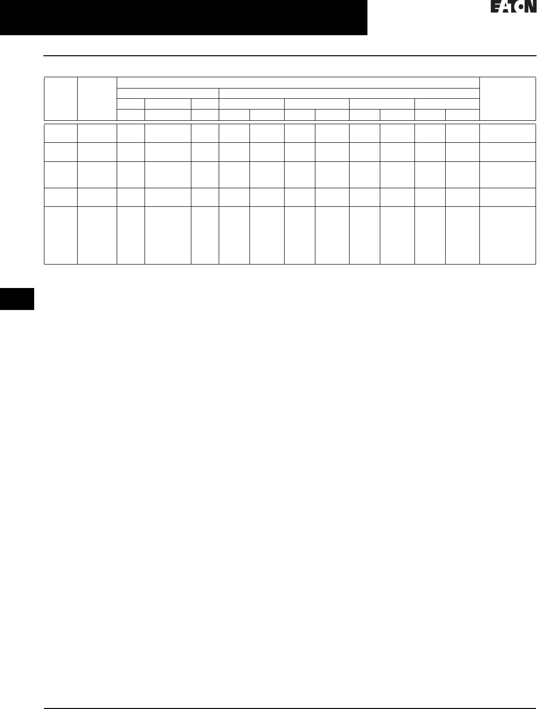
30.5-16
For more information, visit: www.eaton.com/consultants CA08104001E
April 2016
Motor Starters & Contactors—Low Voltage
Sheet 30
22
23
24
25
26
27
28
29
30
31
32
33
34
35
36
37
38
39
40
41
42
4 3
Solid-State Starters
S811 Solid-State Reduced Voltage Starter
078
Table 30.5-17. Product Selection—Severe-Duty Rating Open Soft Starters
Frame
Size
Maximum
Current
Three-Phase Motor Catalog
Number
kW Rating (50 Hertz) hp Rating (60 Hertz)
230 380–400 440 200 V 230 V 460 V 575 V
Volt Volt Volt 1.0SF 1.15SF 1.0SF 1.15SF 1.0SF 1.15SF 1.0SF 1.15SF
N22
42
5.5
11
10
18.5
11
22
5
10
5
10
7-1/2
15
5
10
15
30
10
25
20
40
15
30
S811N37N3S
S811N66N3S
R65
80
15
22
30
40
33
45
15
25
15
20
20
30
15
25
50
60
40
50
50
75
50
60
S811R10N3S
S811R13N3S
T115
150
192
33
45
55
59
80
100
63
90
110
30
50
60
30
40
50
40
50
75
30
50
60
75
100
150
75
100
125
100
150
200
100
125
150
S811T18N3S
S811T24N3S
S811T30N3S
U 240
305
75
90
110
160
147
185
75
100
60
75
75
100
75
100
200
250
150
200
200
300
200
250
S811U36N3S
S811U42N3S
V 240
305
365
420
480
525
600
75
90
110
129
147
160
185
110
160
185
220
257
280
315
147
185
220
257
295
335
375
75
100
125
150
150
150
200
60
75
100
125
150
150
150
75
100
150
150
200
200
250
75
100
125
150
150
150
200
200
250
300
350
400
450
500
150
200
250
300
350
350
450
200
300
350
450
500
500
600
200
250
300
350
450
450
500
S811V36N3S
S811V42N3S
S811V50N3S
S811V65N3S
S811V72N3S
S811V85N3S
S811V10N3S

CA08104001E For more information, visit: www.eaton.com/consultants
30.5-17
April 2016
Motor Starters & Contactors—Low Voltage
Sheet 30
22
23
24
25
26
27
28
29
30
31
32
33
34
35
36
37
38
39
40
41
42
4 3
Solid-State Starters
S811 Solid-State Reduced Voltage Starter
079
Technical Data and Specifications
Table 30.5-18. Specifications—S811 Soft Starter
1U-Frame 500 A unit does not have IEC Certification.
2UR Recognized Product.
Soft Starter
(Partial Catalog Number)
S811
N37
S811
N66
S811
R10
S811
R13
S811
T18
S811
T24
S811
T30
S811
U36
S811
U42
S811
U50
1
S811
V36
S811
V42
S811
V50
S811
V65
S811
V72
S811
V85
S811
V10
2
Maximum current capacity
37 66 105 135 180 240 304 360 420 500 360 420 500 650 720 850 1000
FLA range 11–
37
20–
66
32–
105
42–
135
56–
180
75–
240
95–
304
11 2 –
360
131 –
420
156 –
500
112 –
360
131–
420
156–
500
203–
650
225–
720
265–
580
320–
1000
Dimensions
Width in inches (mm) 2.66 (67.6) 4.42 (112.2) 7.67 (194.8) 7.73 (196.3) 11.05 (280.6)
Height in inches (mm) 7.38 (187.4) 7.92 (201.2) 12.71 (322.9) 12.72 (323.1) 16.57 (420.8)
Depth in inches (mm) 6.48 (164.5) 6.64 (168.7) 6.39 (162.4) 7.08 (179.9) 7.35 (186.6)
Weight in lbs (kg) 5.80 (2.6) 10.50 (4.8) 48.00 (21.8) with lugs
41.00 (18.6) without lugs
48.00 (21.8) with lugs
41.00 (18.6) without lugs
103.00 (46.8) with lugs
91.00 (41.4) without lugs
General Information
Bypass mechanical
lifespan
10 million
Insulating voltage Ui 660 V
Ramp time range 0.5–180 seconds (0.5–360 seconds extended ramp)
Resistance to vibration 3g
Resistance to shock 15g
Electrical Information
Operating voltage 200–600 V
Operating frequency 47–63 Hz
Overload setting 30–100%
Trip c lass 5, 10, 20 and 30
Cabling Capacity (IEC 947)
Number of conductors One One One or two
—— —
Two, four or six
Wire sizes 14–2 14–4/0 4 AWG to 500 kcmil
—— —
2/0 to 500 kcmil
Type of connectors Box lug Add-on lug kit
Control Wiring (12-Pin)
Wire sizes in AWG 22–14
Number of conductors
(stranded)
Two
(or one AWG 12)
Torque requirements
in lb-in
3.5
Solid, stranded or flexible
maximum size in mm
2
3.31
Control Power Requirements
Voltage range (24 V ± 10%) 21.6–26.4
Steady state current amps 1.0 1.0 1.0
—— —
1.4
Inrush current amps 10 10 10
—— —
10
Ripple 1%
Relays (1) Class A and C
Voltage AC—maximum 240
Voltage DC—maximum 120
Amperes—maximum 3
Environment
Temperature—operating –30 °C to +50 °C (no derating) consult factory for operation > +50 °C
Temperature—storage –50 °C to +70 °C
Altitude <2000m—consult factory for operation > 2000m
Humidity <95% noncondensing
Operating position Any
Pollution degree IEC 947-1 3
Impulse withstand voltage
IEC 947-4-1
6000 V
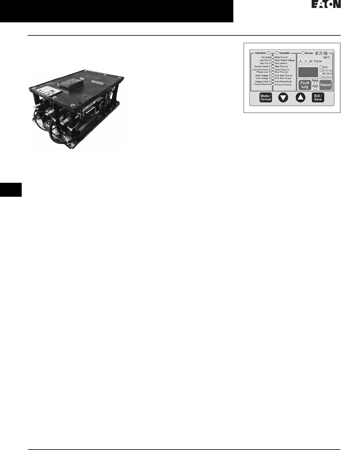
30.5-18
For more information, visit: www.eaton.com/consultants CA08104001E
April 2016
Motor Starters & Contactors—Low Voltage
Sheet 30
22
23
24
25
26
27
28
29
30
31
32
33
34
35
36
37
38
39
40
41
42
4 3
Solid-State Starters
S611 Solid-State Reduced Voltage Soft Starter
080
S611 Solid-State Reduced
Voltage Soft Starter
S611 Solid-State Soft Starter
General Description
Eaton revolutionized the reduced
voltage control marketplace with its
advanced feature set and user-friendly
user interface module to enhance
system performance and to reduce
commissioning times. The S611 adds
enhanced functionality with network
communications, metering, monitor-
ing and diagnostics capabilities.
The Eaton line of S611 reduced voltage
soft starters is multi-functional, easy to
install and easy to program. Designed
to control the acceleration and deceler-
ation of three-phase motors up to
600 V, the line is available from 26 to
414 A.
The S611 is designed to be a complete
package, combining the SCRs,
bypass contactor and overload in
one compact unit.
Application Description
Designed to control the acceleration
and deceleration of three-phase
motors, the S611 soft starter uses
silicon controlled rectifiers (SCRs)
to control the voltage to soft start and
soft stop the motor. After the motor is
started, internal run bypass contactors
close, resulting in the motor running
directly across-the-line. The built-in
solid-state overload protects the
motor from overload conditions with
sophisticated algorithms that model
true motor heating, resulting in better
motor protection and fewer nuisance
trips. Advanced protective and
diagnostic features reduce downtime.
A voltage ramp start or current limit
start is available. Kick start is available
in either starting mode. The soft stop
option allows for a ramp stop time that
is longer than the coast to stop time.
The pump control option provides
a smooth transition for starting and
stopping a motor and for eliminating
the “water-hammer” effect that can
damage pipes, valves and pumps.
The S611 offers an impressive array of
advanced protective features. Not only
are the protective features selectable,
but many offer variable settings allow-
ing the user to fine-tune the starter to
meet specific system requirements.
The S611 has an easy-to-use user
interface module (UI) that allows the
user to configure the device and to read
system parameters. The UI includes
an LED display and a keypad to scroll
through the various parameters. The
UI allows the user to modify control
parameters, enable or disable protec-
tions, set communication variables,
monitor system parameters such as
line voltages and currents, and access
the fault queue.
Figure 30.5-7. User Interface
The UI can be removed from the
S611 and be remote mounted. Kits
are available to door mount the UI,
enabling users to safely configure,
commission, monitor and trouble-
shoot the system at the electrical panel
without opening the enclosure door.
This will help eliminate the possibility
of an arc flash incident.
Communications
The S611 has built-in communication
capabilities through two communica-
tions ports to connect the soft starter
to a variety of networks, including
Modbus (native), DeviceNet™ and
PROFIBUS.
The S611 communication parameters
can be configured with the UI.
Advanced communication configura-
tion settings provide the system
integrator with powerful tools to
facilitate system optimization.
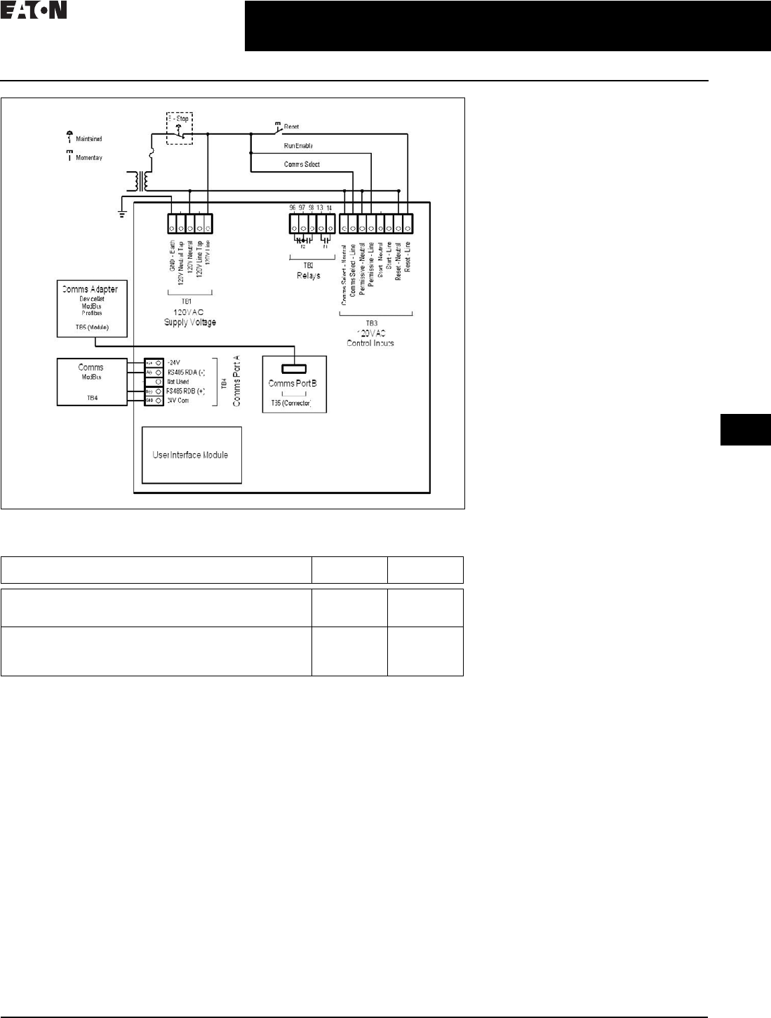
CA08104001E For more information, visit: www.eaton.com/consultants
30.5-19
April 2016
Motor Starters & Contactors—Low Voltage
Sheet 30
22
23
24
25
26
27
28
29
30
31
32
33
34
35
36
37
38
39
40
41
42
4 3
Solid-State Starters
S611 Solid-State Reduced Voltage Soft Starter
081
Figure 30.5-8. Control Wiring Diagram
Table 30.5-19. Network Communications Reference
Features and Benefits
■The UI (user interface module)
provides an intuitive, easy-to-use
human interface with powerful
configuration capabilities to
maximize system performance
■Door or device mounted UI enables
users to safely configure, commis-
sion, monitor and troubleshoot
the system at the electrical panel
without opening the enclosure
door, eliminating the possibility
of an arc flash incident
■System operating parameters
can be monitored enterprise-wide
through a communications network.
Increase uptime by providing data
for process management and
preventive diagnostics
■Run Bypass mode greatly reduces
internal heating created by the
greater power dissipation in the
SCRs. Bypass contactor directly
connects the motor to the line and
improves system efficiency by
reducing internal power losses
■Internal solid-state overload
protection provides accurate
current measurement and trip
settings. Sophisticated algorithms
solve a series of differential
equations that model true motor
heating and cooling, resulting in
superior motor overload protection
while minimizing nuisance trips.
Advanced selectable protective
features safeguard the motor
and system against a variety of
system faults
Description Style
Number
Catalog
Number
Modbus communication adapter without I/O
Modbus communication adapter with 120 Vac I/O
Modbus communication adapter with 24 Vdc I/O
3-2372-001A
3-2372-003B
3-2372-004B
C441M
C441N
C441P
DeviceNet communication adapter with 120 Vac I/O
DeviceNet communication adapter with 24 Vdc I/O
PROFIBUS communication adapter with 120 Vac I/O
PROFIBUS communication adapter with 24 Vdc I/O
3-2372-001B
3-2372-002B
3-2398-001B
3-2398-002B
C441K
C441L
C441S
C441Q
■Internal run bypass contactors
and overload protection eliminate
the need for additional devices,
reducing enclosure sizes, minimiz-
ing installation and wiring time,
and reducing overall assembly
size and cost
■Wide range of overload FLA settings
(50–100% of rated frame current)
and a selectable trip class (5–30)
offers users the flexibility to fine-
tune the starter to match specific
application requirements
■Variable ramp times and torque
control settings provide unlimited
starting configurations, allowing for
maximum application flexibility
■Kick-start feature enables soft
starting of high friction loads
■Soft stop control for applications
where an abrupt stop of the load
is not acceptable
■Pump control option with sophisti-
cated pump algorithms on both
starting and stopping that minimize
the pressure surges that cause
water hammer. The pump control
option will maximize the life of the
pump and piping systems while
minimizing the downtime caused
by system failure
■Six SCRs control all three motor
phases, providing smooth accelera-
tion and deceleration performance
■Soft acceleration and deceleration
reduces wear on belts, gears, chains,
clutches, shafts and bearings
■Reduce the peak inrush current’s
stress on the power system
■Minimize peak starting torque to
diminish mechanical system wear
and damage
■120 Vac control voltage enhances
ease of connections
Protective Features
All protective features can be
configured, enabled or disabled
with the UI or through the
communications network.

30.5-20
For more information, visit: www.eaton.com/consultants CA08104001E
April 2016
Motor Starters & Contactors—Low Voltage
Sheet 30
22
23
24
25
26
27
28
29
30
31
32
33
34
35
36
37
38
39
40
41
42
4 3
Solid-State Starters
S611 Solid-State Reduced Voltage Soft Starter
082
Motor Overload
The S611 includes electronic overload
protection as standard. The overload
meets applicable requirements for a
motor overload protective device.
The overload protects the motor from
overheat conditions with the use of
sophisticated algorithms that model
true motor heating, resulting in
superior motor protection and fewer
nuisance trips.
The S611 calculates a thermal memory
value. A 100% value represents the
maximum safe temperature of the
motor. When the thermal memory
value reaches 100%, an overload trip
will occur removing power to the
motor. Upon trip, the S611 stores the
calculated motor heating value and
will not allow a motor re-start until
the motor has sufficiently cooled. This
feature ensures the motor will not be
damaged by repeated overload trip,
reset and re-start cycles.
The thermal memory value can be
monitored through the UI or the
communications network. The thermal
memory value can be of great use in
determining an impending overload
trip condition. Alarms can be imple-
mented in the process monitoring
system warning of an impending
trip before a trip occurs halting the
process. Costly system downtime
can be avoided.
The trip current is adjusted to match
the specific application requirements
by entering the motor nameplate full
load current rating and trip class. The
FLA adjustment includes a 2 to 1
adjustment range. The overload trip
class is adjustable from class 5
through class 30. The overload is
ambient temperature compensated—
meaning its trip characteristics will not
vary with changes in ambient tempera-
ture. The overload protection can be
enabled, disabled, or disabled on start.
Short Circuit
The use of a short-circuit protective
device in coordination with the S611
is required in branch motor circuits
by most electrical codes. Short-circuit
coordination ratings with both fuses
and Eaton molded-case circuit breakers
are available providing customers with
design flexibility. The S611 has short-
circuit coordination ratings as an open
component, an enclosed starter, and in
a motor control center.
Jam
Excessive current and torque up to
locked rotor levels can occur in a jam
condition. The condition can result in
stress and damage to the motor, load,
mechanical system and the electrical
distribution system. Jam protection
prevents the stress and damage from a
jam during normal run. After the
motor is started, a current greater than
300% FLA setting will cause the starter
to trip on a jam fault.
Stall
Excessive current and torque up to
locked rotor levels can occur in a stall
condition. The condition can lead to
an overload trip and can result in
stress and damage to the motor, load,
mechanical system and the electrical
distribution system. Stall protection
prevents stress and damage to a
motor that has not come up to speed,
or stalled after the soft start time. The
S611 will trip to protect the system in
the event that the motor did not get
to the rated speed in the defined soft
start period. A current greater than
200% FLA at the end of the soft start
period will cause the starter to trip on a
stall fault.
Pole Over Temperature
High ambient temperatures, extended
ramp times and high duty cycle condi-
tions may cause the S611 power pole
conductors to reach a temperature that
exceeds their thermal rating. The S611
is equipped with sensors that monitor
the temperature of the power poles.
Overtemperature protection occurs
if the device’s thermal capacity is
exceeded. The soft starter will trip
in overtemperature conditions,
preventing device failure.
The device pole temperature value
can be monitored through the UI or
the communications network. This
feature can be of use in determining
an impending overtemperature trip
condition. Alarms can be implemented
in the process monitoring system
warning of an impending trip before a
trip occurs, halting the process. Costly
system shutdown can be avoided.
Phase Loss
Loss of a phase can cause a significant
increase in the current drawn in the
remaining two phases. Phase loss
can lead to motor damage before an
eventual overload trip occurs. Phase
loss is typically an indication of a
failure in the electrical distribution
system. The S611 will detect a phase
loss and trip if any phase current drops
below a preset value. The phase loss
trip level is adjustable from 0% to
100% of the average of the other two
phase levels with an adjustable trip
delay of 0.1–60 seconds.
Phase Imbalance
Phase current or voltage imbalance
can cause a significant increase in the
current drawn in the remaining two
phases. Phase imbalance can lead to
motor damage before an eventual
overload trip. Phase imbalance is
typically an indication of a failure in
the electrical distribution system or
the motor. The S611 will detect both
current and voltage phase imbalances
and trip if any phase becomes
imbalanced as compared to the
average of the other two phases.
The phase current imbalance trip level
is adjustable from 0% to 100% of the
average of the current in the other two
phases with an adjustable trip delay of
0.1–60 seconds.
The phase voltage imbalance trip level
is adjustable from 0% to 100% of the
average of the voltage in the other two
phases with an adjustable trip delay of
0.1–60 seconds.
Reset Mode
The S611 can be set up for automatic
or manual reset on trip. The manual
reset mode requires the operator to
physically press the RESET button
located on the soft starter. The
overload can be manually reset
through the UI or through the
communications network.
The automatic reset mode allows the
soft starter to be automatically reset as
soon as the trip condition is no longer
present. With the automatic reset
mode, after the fault is no longer
present, the motor will be restarted as
soon as a valid start signal is present.

CA08104001E For more information, visit: www.eaton.com/consultants
30.5-21
April 2016
Motor Starters & Contactors—Low Voltage
Sheet 30
22
23
24
25
26
27
28
29
30
31
32
33
34
35
36
37
38
39
40
41
42
4 3
Solid-State Starters
S611 Solid-State Reduced Voltage Soft Starter
083
Phase Reversal
The S611 can determine if the proper
line phase sequence is present by
default. The device will trip if the line
phase sequence is something other
than A-B-C. The S611 can be config-
ured to operate under reversed phase
conditions (A-C-B).
Shorted SCR Detection
The S611 monitors the operation of the
power poles and will trip under a
shorted SCR condition.
Open SCR Detection
The S611 monitors the operation of the
power poles and will trip under an
open SCR condition.
Low Current
Low current conditions can be a result
of a loss of load or a failure in the
mechanical system. The S611 has low
current protection that will trip if the
average rms current falls below a
preset value. The low current protec-
tion can be programmed as a percent
of motor FLA from 0% to 100%.
Low Voltage
Low voltage conditions can result from
disturbances in the electrical power
distribution system. Low voltage
conditions can cause a malfunction
and damage to electrical equipment.
The S611 has low voltage protection
that will trip if the average rms
voltage falls below a preset value.
The low voltage protection can be
programmed as a percent of nominal
voltage from 1% to 99% with a trip
delay of 0.1–60 seconds.
High Voltage
High voltage conditions can result
from disturbances in the electrical
power distribution system. High
voltage conditions can cause
malfunctions or failures of electrical
equipment. The S611 has high voltage
protection that will trip if the average
rms voltage is greater than a preset
value. The high voltage protection
can be programmed as a percent of
nominal voltage from 101% to 120%
with a trip delay of 0.1–60 seconds.
Monitoring Capabilities
The S611 has an impressive array of
system monitoring capabilities that
allow users to access real-time process
and diagnostic data. This data can be
viewed at the device with the UI or
through a communications network.
Data over a communications network
can provide valuable insight into the
condition of the equipment and
processes. Maintenance and produc-
tion personnel can monitor critical
operational and maintenance data from
a central control station that can be
located far away from the production
facility. Process data can be monitored
to determine system anomalies that
may indicate a need for preventive
maintenance or an impeding failure.
Adjustments made through the
communications network can reduce
costs by minimizing the time traveling
to the location where the motor controls
are located. When faults do occur, real-
time fault data can assist maintenance
in troubleshooting and planning repair
resources. Remote reset signals can be
given to tripped devices without the
need for manual intervention by
maintenance personnel.
Average Line Current
Provides the average of the three
phase rms line currents in amperes,
accurate to within 2%. Current data
can be used to indicate a need for
maintenance. Increased currents in a
fixed load application can indicate a
reduction in system efficiencies and
performance, signifying system
maintenance is due.
Average Pole Current
Provides the average of the three-phase
rms pole currents in amperes, accurate
to within 2%. The pole current is the
current through the soft starter. The line
and pole current will be identical in
in-line applications, and will differ in
inside-the-delta applications.
Average Line Current as a % FLA
Provides the average rms line current as
a percentage of the S611 FLA setting.
Three-Phase Line Currents
Provides three rms phase line currents
in amperes, accurate to within 2%.
Imbalances or changes in the relative
phase current to one another can
indicate anomalies in the motor or
the electrical distribution system.
Three-Phase Pole Currents
Provides three rms phase pole currents
in amperes, accurate to within 2%. The
pole current is the current through the
soft starter. The line and pole current
will be identical in in-line applications.
Three-Phase Line Voltages
Provides the individual rms three-
phase line voltages. Imbalances or
changes in the relative phase voltage
to one another can indicate anomalies
in the motor or the electrical distribu-
tion system. Voltage can be used to
monitor electrical distribution
system performance.
Warnings, alarms and system actions
to low or high voltage conditions can
be implemented.
Percent Thermal Memory
Provides the real-time calculated
thermal memory value. The S611
calculates thermal memory value. A
100% value represents the maximum
safe temperature of the motor. When
the thermal memory value reaches
100%, an overload trip will occur,
removing power to the motor.
The thermal memory value can be of
great use in determining an impending
overload trip condition. Alarms can be
implemented in the process monitor-
ing system warning of an impending
trip before a trip occurs, halting the
process. Costly system downtime can
be avoided.
Pole Temperature
Increases in pole temperature are
caused by increases in ambient
temperature, start/stop times and
start duty cycles. Changes in pole
temperatures represent a change
in system operating conditions.
Identifying unexpected operating
conditions or changes can prompt
maintenance and aid in process
evaluation activities.
Power Monitoring
S611 does monitor the power and it
can be displayed on the UI.
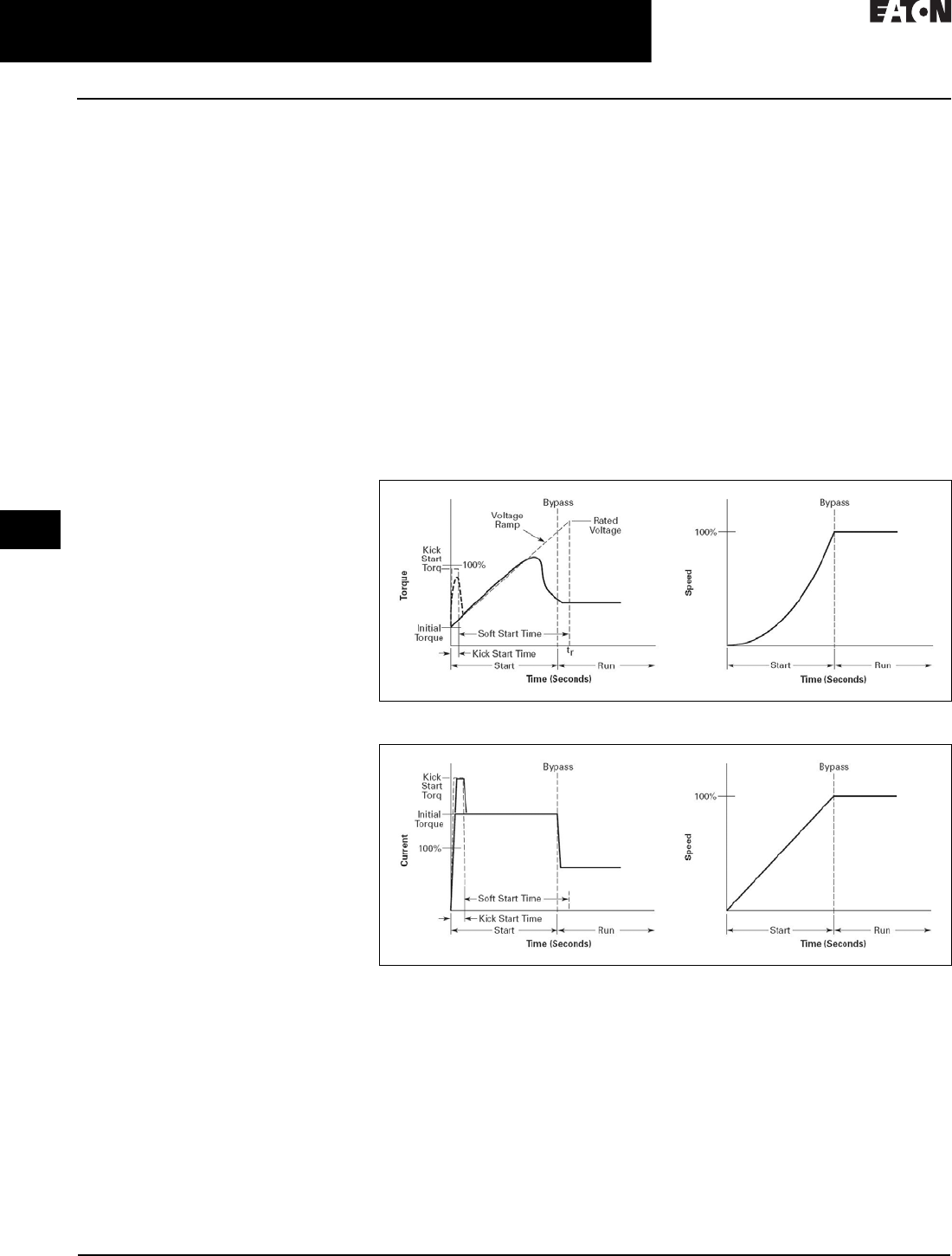
30.5-22
For more information, visit: www.eaton.com/consultants CA08104001E
April 2016
Motor Starters & Contactors—Low Voltage
Sheet 30
22
23
24
25
26
27
28
29
30
31
32
33
34
35
36
37
38
39
40
41
42
4 3
Solid-State Starters
S611 Solid-State Reduced Voltage Soft Starter
084
Diagnostics
Fault Queue
Current fault and a fault queue
containing the last nine system
faults can be read through the UI
or the communications network. Fault
identification can minimize trouble-
shooting time and cost, and prevent
arc flash incidents. The fault queue
can be remotely accessed through
a communications network to assist
in planning maintenance resources.
30 different faults can be identified by
the S611.
Control Status
The S611 provides data that represents
system conditions that can be read
through the UI or the communications
network. This data identifies the
status of the system and the control
commands the system is requesting
of the S611. This can be used for
advanced troubleshooting and
system integration activities.
Operation
Starting and Stopping Modes
The S611 has a variety of starting and
stopping methods to provide superior
performance in the most demanding
applications. The motor can be started
in either Voltage Ramp Start or Current
Limit Start mode. Kick Start and
Soft Stop are available within both
starting modes.
Voltage Ramp Start
Provides a voltage ramp to the motor
resulting in a constant torque increase.
The most commonly used form of soft
start, this start mode allows you to
set the initial torque value and the
duration of the ramp to full voltage
conditions. Bypass contactors close
after ramp time.
■Adjustable initial torque 0–85% of
locked rotor torque
■Adjustable ramp time 0.5–
180 seconds (can be extended
with factory modification)
Current Limit Start
Limits the maximum current available
to the motor during the start phase.
This mode of soft starting is used
when it becomes necessary to limit the
maximum starting current due to long
start times or to protect the motor.
This start mode allows you to set
the maximum starting current as
a percentage of locked rotor current
and the duration of the current limit.
Bypass contactors close after current
limit time.
■Maximum current of 0–85% locked
rotor current
■Adjustable ramp time 0.5–
180 seconds (can be extended
with factory modification)
Kick Start
Selectable feature in both Voltage
Ramp Start and Current Limit Start
modes. Provides a current and torque
“kick” for 0–2.0 seconds. This
provides greater initial current to
develop additional torque to break-
away a high friction load.
■0–85% of locked rotor torque
■0–2.0 seconds duration
Soft Stop
Allows for a controlled stopping of a
load. Used when a stop-time that is
greater than the coast-to-stop time is
desired. Often used with high friction
loads where a sudden stop may cause
system or load damage.
■Stop time = 0–60 seconds
Figure 30.5-9. Ramp Start
Figure 30.5-10. Current Limit Start

CA08104001E For more information, visit: www.eaton.com/consultants
30.5-23
April 2016
Motor Starters & Contactors—Low Voltage
Sheet 30
22
23
24
25
26
27
28
29
30
31
32
33
34
35
36
37
38
39
40
41
42
4 3
Solid-State Starters
S611 Solid-State Reduced Voltage Soft Starter
085
Figure 30.5-11. Kick Start Graphic
Figure 30.5-12. Stop Ramp Graphic
Edge and Level Sensing Control
Edge or level sensing is selected
with the Start Control parameter in
the Advanced Configuration Menu.
Factory default is level sensing.
Edge Sensing
Edge sensing requires 120 Vac power
be momentarily applied to the Start
terminal (with the Permissive terminal
120 Vac) to initiate a start under all
conditions. After a stop or fault occurs,
the 120 Vac must be removed, then
reapplied to pin 1 before another start
can occur. This control configuration
should be used when restarting of
the motor after a fault or stop must
be supervised manually or as a part
of a control scheme. The cycling of
120 Vac power to the Permissive
terminal before starting is required
regardless of the position of the auto
reset parameter.
Level Sensing
Level sensing will enable a motor to
restart after a fault is cleared without
cycling 120 Vac to the Permissive
terminal as long as:
■Permissive terminal is supplied
with 120 Vac
■The auto reset parameter is set
to enabled
■All faults have cleared or have
been reset
This control configuration should be
used where it is desirable to restart a
motor after a fault without additional
manual or automatic control. An
example of this condition would be
on a remote pumping station where it
is desirable to automatically restart a
pump after a power outage without
operator intervention.
If the auto reset feature is used,
CAUTION must be exercised to
ensure that any restart occurs in
a safe manner.

30.5-24
For more information, visit: www.eaton.com/consultants CA08104001E
April 2016
Motor Starters & Contactors—Low Voltage
Sheet 30
22
23
24
25
26
27
28
29
30
31
32
33
34
35
36
37
38
39
40
41
42
4 3
Solid-State Starters
S611 Solid-State Reduced Voltage Soft Starter
086
Product Selection
Motor applications and customer
needs come in many different
varieties. The standard and severe-
duty rating tables provide guidelines
on what the soft starter is capable of.
If the application falls under these
categories, use these charts. For other
applications, or when a question
arises, consult a local Eaton
Representative or call the Eaton
Technical Resource Center.
Table 30.5-20. S611 Horsepower Ratings—300% FLA at 15 Seconds at 50°C
Options
Pump Control
For pump control option, change the 9th digit in the Catalog Number to P.
Table 30.5-21. S611 Horsepower Ratings—Pump Control Option
Standards and Certifications
■IEC 60947-4-2
■UL listed
■CSA certified (3211 06)
Maximum
Current
Amperes
60 Hz Catalog
Number
200 V 230 V 460 V 575–600 V
1.0 SF 1.15 SV 1.0 SF 1.15 SV 1.0 SF 1.15 SV 1.0 SF 1.15 SV
52
65
77
15
20
20
10
15
20
15
20
25
15
20
20
40
50
60
30
40
50
50
60
75
40
50
60
S611A052N3S
S611A065N3S
S611A077N3S
99
125
156
30
40
50
25
30
40
30
40
60
30
40
50
75
100
125
60
75
100
100
125
150
75
100
125
S611B099N3S
S611B125N3S
S611C156N3S
180
242
302
60
75
100
50
60
75
60
75
100
60
75
100
150
200
250
125
150
200
150
250
350
150
200
250
S611C180N3S
S611D242N3S
S611E302N3S
361
414
125
150
100
125
150
N/A
125
150
300
350
250
250
350
450
300
350
S611E361N3S
S611F414N3S
Maximum
Current
Amperes
60 Hz Catalog
Number
200 V 230 460 V 575–600 V
1.0 SF 1.15 SV 1.0 SF 1.15 SV 1.0 SF 1.15 SV 1.0 SF 1.15 SV
52
65
77
15
20
20
10
15
20
15
20
25
15
20
20
40
50
60
30
40
50
50
60
75
40
50
60
S611A052P3S
S611A065P3S
S611A077P3S
99
125
156
30
40
50
25
30
40
30
40
60
30
40
50
75
100
125
60
75
100
100
125
150
75
100
125
S611B099P3S
S611B125P3S
S611C156P3S
180
242
302
60
75
100
50
60
75
60
75
100
60
75
100
150
200
250
125
150
200
150
250
350
150
200
250
S611C180P3S
S611D242P3S
S611E302P3S
361
414
125
150
100
125
150
N/A
125
150
300
350
250
250
350
450
300
350
S611E361P3S
S611F414P3S

CA08104001E For more information, visit: www.eaton.com/consultants
30.5-25
April 2016
Motor Starters & Contactors—Low Voltage
Sheet 30
22
23
24
25
26
27
28
29
30
31
32
33
34
35
36
37
38
39
40
41
42
4 3
Solid-State Starters
S611 Solid-State Reduced Voltage Soft Starter
087
Technical Data and Specifications
Table 30.5-22. Specifications—S611 Solid-State Soft Starter
Soft Starter
(Partial Catalog Number)
S611A052 S611A065 S611A072 S611B099 S611B125 S611C156 S611C180 S611D242 S611E302 S611E361 S611F414
Maximum
current capacity
52 65 77 99 125 156 180 242 302 361 414
FLA range 26–52 32.5–65 38.5–77 48–99 62.5–125 78–156 90–180 120–242 151–302 180.5–361 207–414
Dimensions—Inches (mm)
Width 11.58 (294.1) 11.58 (294.1) 11.58 (294.1) 11.58 (294.1) 17.56 (446.0) 17.56 (446.0)
Height 19.45 (494.0) 19.45 (494.0) 20.83 (529.1) 20.83 (529.1) 31.15 (791.2) 31.15 (791.2)
Depth 7.46 (189.5) 7.46 (189.5) 8.37 (212.6) 8.37 (212.6) 9.54 (242.3) 9.54 (242.3)
Weight in lbs (kg) 24 (11) 24 (11) 33 (15) 38 (15) 86 (39) 102 (46)
General Information
Bypass mechanical
lifespan
10 million
Insulating voltage 660 V
Ramp time range 0.5–180 seconds
Resistance to vibration 1g
Resistance to shock Meets ITSA standards
Electrical Information
Operating voltage 130–600 V
Operating frequency 47–63 Hz
Overload setting (frame) 50–100% FLA
Trip c las s 5, 10, 20 and 30
Cabling Capacity (IEC 947)
Number of conductors One One One One One One One One
Two Two Two
Wire sizes 14–2/0 14–2/0 14–2/0 14–2/0 2–600
kcmil
2–600
kcmil
2–600
kcmil
2–600
kcmil
2–600
kcmil
2–600
kcmil
2–600
kcmil
Type of connectors Lug
Control Wiring
Wire sizes in AWG 22–12
Number of conductors Two (or one 12–14 AWG)
Torque requirements 3.5 lb-in
Maximum size 12 AWG
Control Power Requirements
Voltage range
(24 V ±10%)
108–132
Steady-state
current amperes
0.375 0.375 0.375 0.375 0.375 0.375 0.375 0.75 0.75 0.75 —
Inrush current amperes 0.5 0.5 0.5 0.5 0.5 0.5 0.5 1 1 1 —
Ripple 1%
Relays (1) Class A and C
Voltage AC—maximum 120
Voltage DC—maximum 24
Amperes—maximum 3
Environment
Temperature—operating –20 °C to +50 °C
Temperature—storage –40 °C to +85 °C
Altitude <2000 m, derate 0.5% per 100 m >2000 m
Humidity <95% noncondensing
Operating position Vertical, line side up
Pollution degree
IEC 947-1
3
Impulse withstand
voltage IEC 947-4-1
6000V
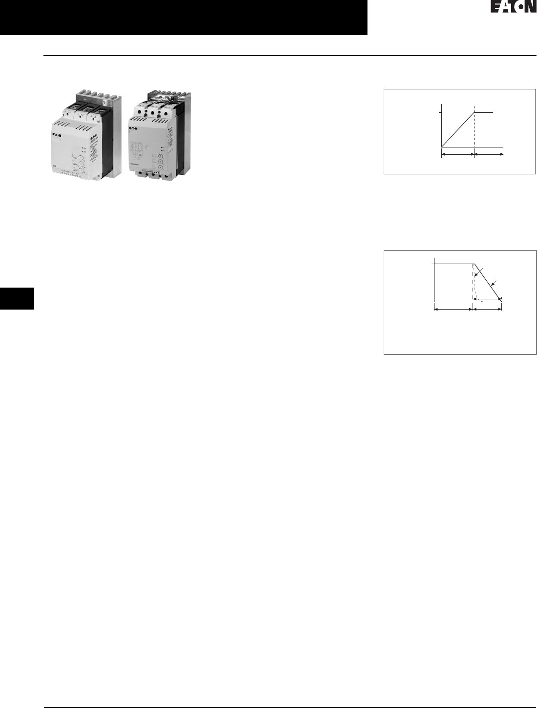
30.5-26
For more information, visit: www.eaton.com/consultants CA08104001E
April 2016
Motor Starters & Contactors—Low Voltage
Sheet 30
22
23
24
25
26
27
28
29
30
31
32
33
34
35
36
37
38
39
40
41
42
4 3
Reduced Voltage—Solid-State
DS6 Soft Start Controllers
088
DS6 Soft Start Controllers
DS6 Soft Start Controllers
General Description
Eaton’s DS6 line of reduced voltage
solid-state soft start controllers is very
compact, multi-functional, easy to install
and easy to commission. Designed to
control the acceleration and deceleration
of three-phase motors, the device is
available for current ranges from
40 to 180 A.
Application Description
With its small size, it can easily fit in
place of existing soft starters, wye-delta
starters, or across-the-line NEMA
and IEC starters. This feature allows
easy upgrades to existing systems.
The product is designed to be wired
in the three-phase line feeding the
three motor input leads as is done
for normal across-the-line starting. The
starter uses silicon controlled
rectifiers (SCRs) to ramp the voltage
to the motor, providing smooth
acceleration and deceleration of the
load. After the motor is started, the
internal run bypass contactor closes,
resulting in the motor running directly
across-the-line. Internal run bypass
significantly reduces the heat generated
as compared to non-bypass starters.
The soft stop option allows for a ramp
stop time that may be longer than
the coast-to-stop time. An external
over-load protection is needed.
Operation
Voltage Ramp Start
This start method provides a voltage
ramp to the motor, resulting in a
constant torque increase. This most
commonly used form of soft start
mode allows you to set the initial
voltage value and the duration of the
ramp to full voltage conditions.
Bypass contactor(s) close after ramp
time has elapsed.
■Adjustable initial voltage 30–92%
of full voltage
■Adjustable ramp time 1–30 seconds
Soft Stop
Allows for a controlled stopping of
load. Used when a stop-time that is
greater than the coast-to-stop time is
desired. Often used with high friction
loads where a sudden stop may cause
system or product damage. Setting the
soft stop time to a value of 0 turns off
this feature.
■Soft stop time = 0–30 seconds
Figure 30.5-13. Start Ramp
Figure 30.5-14. Stop Ramp
Bypass
Speed
Time (Seconds)
Start Run
100%
Speed
Time (Seconds)
Run Soft Stop
100%
1 = Coast to Stop (Speed)
2 = Soft Stop Ramp (Voltage)
3 = Soft Stop Time
1
2
3

CA08104001E For more information, visit: www.eaton.com/consultants
30.5-27
April 2016
Motor Starters & Contactors—Low Voltage
Sheet 30
22
23
24
25
26
27
28
29
30
31
32
33
34
35
36
37
38
39
40
41
42
4 3
Reduced Voltage—Solid-State
DS6 Soft Start Controllers
089
Features and Benefits
■Run Bypass mode greatly reduces
internal heating created by the
power dissipation across the SCRs.
The bypass contactor directly
connects the motor to the line
and improves system efficiency
by reducing internal power losses
■Less heat minimizes enclosure size
and cooling requirements, and
maximizes the life of all devices
in the enclosure
■LED displays device status and
provides fault indication
■Variable ramp times and voltage
control (torque control) settings
provide unlimited starting configu-
rations, allowing for maximum
application flexibility
■Soft stop control suits applications
where an abrupt stop of the load
is not acceptable. Soft acceleration
and deceleration reduces wear on
belts, gears, chains, clutches, shafts
and bearings
■Minimizes the peak inrush current’s
stress on the power system
■Manages peak starting torque to
diminish mechanical system wear
and damage
■24 Vdc control module enhances
personnel and equipment safety
Protective Features
■There are two auxiliary relays—
❑First relay is a TOR relay that
closes when the TOR is achieved
(internal bypass relays close)
❑The second relay is a RUN relay
that closes when the RUN signal
is initiated and opens when RUN
signal is removed. It remains
closed during stop ramp time,
if set to a value greater than 0.
The RUN relay will also open
if a fault occurs
■Mains connection—The mains
connection is monitored for an
open condition and/or undervoltage
■Motor connection—The motor
connection is monitored for an
open condition
■SCR faults—SCR performance is
monitored during the ramp cycle
for proper operation
■Heat sink over/under temperature—
High ambient temperatures,
extended ramp times and high duty
cycle conditions may cause the DS6
to exceed its thermal rating. When
temperature goes under –5 °C,
unit will trip as well. The DS6 is
equipped with sensors that monitor
the temperature of the device. The
soft starter will trip in over/under
temperature conditions, preventing
device failure
■Bypass relay—The DS6 can detect if
the bypass relay fails to close after
the ramp start or opens while the
motor is running. The DS6 will
trip on a bypass dropout fault if
either of these conditions occur.
The device does not start when
bypass relay is closed and start
signal is applied
■24 Vdc low voltage—If the control
voltage falls below 20 Vdc at any
time during operation, the unit
will fault
Standards and Certifications
■IEC 60947-4-2
■EN 60947-4-2
■UL listed (E251034)
■CSA certified
■CE marked
■C-Tick
Additional Information
■Instruction Leaflet IL03901001E

30.5-28
For more information, visit: www.eaton.com/consultants CA08104001E
April 2016
Motor Starters & Contactors—Low Voltage
Sheet 30
22
23
24
25
26
27
28
29
30
31
32
33
34
35
36
37
38
39
40
41
42
4 3
Reduced Voltage—Solid-State
DS6 Soft Start Controllers
090
Product Selection
DS6 Soft Start Horsepower Ratings
Please refer to Application Note AP03900001E for additional information on proper size selection.
Table 30.5-23. DS6 Soft Start Controllers—Horsepower Ratings—
10 Second Ramp, 1 Start per Hour, 300% Current Limit at 40 °C
1Maximum values may be higher than allowed per NEC 430.52 and UL 508A 31.1.
2XTOBXDIND panel mounting adapter must be used with this overload.
3XTOBXTLL line and load lugs must be used with this overload.
4ZEB-XCT300 current transformer must be used with this overload.
Table 30.5-24. 10 Second Ramp, 1 Start per Hour, 400% Current Limit at 40 °C
5Maximum values may be higher than allowed per NEC 430.52 and UL 508A 31.1.
6XTOBXDIND panel mounting adapter must be used with this overload.
7ZEB-XCT300 current transformer must be used with this overload.
Rated
Current
Amperes
Motor Power (hp) Maximum
Allowable
Breaker Size 1
Maximum
Allowable
Fuse Size 1
Recommended
XTOB Overload
Recommended
C440 Overload
Catalog
Number
200 V 230 V 460 V
40
52
65
10
15
20
10
20
25
30
40
50
HFD3150L
HFD3200L
HJD3250
150 A Class RK5
200 A Class RK5
200 A Class RK5
XTOB040DC1 2
XTOB057DC1 2
XTOB065DC1 2
C440A1A045SAX
C440B1A100SAX
C440B1A100SAX
DS6-34DSX041N0-N
DS6-34DSX055N0-N
DS6-34DSX068N0-N
77
96
124
25
30
40
30
30
50
60
75
100
HKD3300
HKD3350
HKD3400
300 A Class RK5
350 A Class RK5
500 A Class RK5
XTOB100GC1S
XTOB100GC1S
XTOB125GC1S
C440B1A100SAX
C440B1A100SAX
C440A1A005SAX 4
DS6-34DSX081N0-N
DS6-34DSX099N0-N
DS6-34DSX134N0-N
156
180
50
60
60
75
125
150
HLD3450
HLD3500
500 A Class RK5
500 A Class RK5
XTOB160LC1 3
XTOB220LC1 3
C440A1A005SAX 4
C440A1A005SAX 4
DS6-34DSX161N0-N
DS6-34DSX196N0-N
Rated
Current
Amperes
Motor Power (hp) Maximum
Allowable
Breaker Size 5
Maximum
Allowable
Fuse Size 5
Recommended
XTOB Overload
Recommended
C440 Overload
Catalog
Number
200 V 230 V 460 V
27
34
40
7. 5
10
15
10
10
15
20
30
30
HFD3150L
HFD3200L
HJD3250
150 A Class RK5
200 A Class RK5
200 A Class RK5
XTOB040DC1
XTOB040DC1
XTOB057DC1 6
C440A1A045SAX
C440A1A045SAX
C440A1A045SAX
DS6-34DSX041NO-N
DS6-34DSX055NO-N
DS6-34DSX068NO-N
52
65
80
15
20
30
20
25
30
40
50
75
HKD3300
HKD3350
HKD3350
300 A Class RK5
350 A Class RK5
500 A Class RK5
XTOB057DC1 6
XTOB100GC1S
XTOB100GC1S
C440B1A100SAX
C440B1A100SAX
C440B1A100SAX
DS6-34DSX081NO-N
DS6-34DSX099NO-N
DS6-34DSX134NO-N
96
124
30
40
40
50
75
100
HLD3450
HLD3500
500 A Class RK5
500 A Class RK5
XTOB100GC1S
XTOB150GC1S
C440B1A100SAX
C440A1A005SAX 7
DS6-34DSX161NO-N
DS6-34DSX196NO-N

CA08104001E For more information, visit: www.eaton.com/consultants
30.5-29
April 2016
Motor Starters & Contactors—Low Voltage
Sheet 30
22
23
24
25
26
27
28
29
30
31
32
33
34
35
36
37
38
39
40
41
42
4 3
Reduced Voltage—Solid-State
DS6 Soft Start Controllers
091
DS6 Soft Start kW Ratings
Please refer to Application Note AP03900001E for additional information on proper size selection.
Table 30.5-25. DS6 Soft Start Controllers—kW Ratings According to IEC 60947-4-2—
10 Second Ramp, 1 Start per Hour, 300% Current Limit at 40 °C
1Maximum values may be higher than allowed per NEC 430.52 and UL 508A 31.1.
2XTOBXDIND panel mounting adapter must be used with this overload.
3XTOBXTLL line and load lugs must be used with this overload.
4ZEB-XCT300 current transformer must be used with this overload.
Table 30.5-26. 10 Second Ramp, 1 Start per Hour, 400% Current Limit at 40 °C
5Maximum values may be higher than allowed per NEC 430.52 and UL 508A 31.1.
6XTOBXDIND panel mounting adapter must be used with this overload.
7XTOBXTLL line and load lugs must be used with this overload.
8ZEB-XCT300 current transformer must be used with this overload.
Considerations
1. Either XTOB, C306 or C440 series
or equivalent overload protection
devices may be selected.
2. Contactor is optional for normal
applications. It is recommended
for mains isolation.
Power Supply
Eaton’s PSG and ELC power supplies
are recommended as a compact and
low-cost source for 24 Vdc power. The
light-weight, DIN rail mounted devices
have a wide input voltage range,
and robust screw terminals make
these power supplies easy to install
and use. These power supplies are
available in 1A and 2A models.
Table 30.5-27. Power Supply Selection
Rated
Current
Amperes
Motor Power (kW) Maximum
Allowable
Breaker Size 1
Maximum
Allowable
Fuse Size 1
Recommended
XTOB Overload
Recommended
C440 Overload
Catalog
Number
230 V 400 V
41
55
68
11
15
15
22
30
37
HFD3150L
HFD3200L
HJD3250
150 A Class RK5
200 A Class RK5
200 A Class RK5
XTOB057DC1 2
XTOB057DC1 2
XTOB070GC1 2
C440A1A045SAX
C440B1A100SAX
C440B1A100SAX
DS6-34DSX041N0-N
DS6-34DSX055N0-N
DS6-34DSX068N0-N
81
99
134
22
30
30
45
55
75
HKD3300
HKD3350
HKD3400
300 A Class RK5
350 A Class RK5
500 A Class RK5
XTOB100GC1S
XTOB100GC1S
XTOB150GC1S
C440B1A100SAX
C440B1A100SAX
C440A1A005SAX 4
DS6-34DSX081N0-N
DS6-34DSX099N0-N
DS6-34DSX134N0-N
160
196
45
55
90
110
HLD3450
HLD3500
500 A Class RK5
500 A Class RK5
XTOB160LC1 3
XTOB220LC1 3
C440A1A005SAX 4
C440A1A005SAX 4
DS6-34DSX161N0-N
DS6-34DSX196N0-N
Rated
Current
Amperes
Motor Power (kW) Maximum
Allowable
Breaker Size 5
Maximum
Allowable
Fuse Size 5
Recommended
XTOB Overload
Recommended
C440 Overload
Catalog
Number
230 V 400 V
28.8
37.5
46
7. 5
11
11
11
18.5
22
HFD3150L
HFD3200L
HJD3250
150 A Class RK5
200 A Class RK5
200 A Class RK5
XTOB040DC1
XTOB040DC1
XTOB057DC1 6
C440A1A045SAX
C440A1A045SAX
C440B1A100SAX
DS6-34DSX041NO-N
DS6-34DSX055NO-N
DS6-34DSX068NO-N
56
68
90
15
18.5
22
30
37
45
HKD3300
HKD3350
HKD3350
300 A Class RK5
350 A Class RK5
500 A Class RK5
XTOB065DC1 6
XTOB100GC1S
XTOB100GC1S
C440B1A100SAX
C440B1A100SAX
C440B1A100SAX
DS6-34DSX081NO-N
DS6-34DSX099NO-N
DS6-34DSX134NO-N
106
134
30
37
55
75
HLD3450
HLD3500
500 A Class RK5
500 A Class RK5
XTOB160LC1 7
XTOB160LC1 7
C440A1A005SAX 8
C440A1A005SAX 8
DS6-34DSX161NO-N
DS6-34DSX196NO-N
Description Catalog
Number
85–264 V input and 24 V output
380–480 V input and 24 V output
ELC-PS01
PSS25F
100–240 Vac input and 24 Vdc output
380–480 Vac input and 24 Vdc output
PSG60E
PSG60F

30.5-30
For more information, visit: www.eaton.com/consultants CA08104001E
April 2016
Motor Starters & Contactors—Low Voltage
Sheet 30
22
23
24
25
26
27
28
29
30
31
32
33
34
35
36
37
38
39
40
41
42
4 3
Reduced Voltage—Solid-State
DS6 Soft Start Controllers
092
Technical Data and Specifications
Table 30.5-28. DS6 Soft Start Controllers
Description Unit DS6-34DSX041N0-N DS6-34DSX055N0-N DS6-34DSX068N0-N DS6-34DSX081N0-N
General
Standards — IEC/EN 60947-4-2 IEC/EN 60947-4-2 IEC/EN 60947-4-2 IEC/EN 60947-4-2
Certifications UL/CE/C-Tick/CSA UL/CE/C-Tick/CSA UL/CE/C-Tick/CSA UL/CE/C-Tick/CSA
Ambient temperature
(operation)
°C 0 to 40 °C, above 40 °C
derate linearly by 1% of
rated current per Celsius
to 60 °C
0 to 40 °C, above 40 °C
derate linearly by 1% of
rated current per Celsius
to 60 °C
0 to 40 °C, above 40 °C
derate linearly by 1% of
rated current per Celsius
to 60 °C
0 to 40 °C, above 40 °C
derate linearly by 1% of
rated current per Celsius
to 60 °C
Ambient temperature
(storage)
°C –25 °C to +5 5 °C –25 °C to +55 °C –25 °C to +55 °C –25 °C to +55 °C
Altitude — 0–1000 m, above 1000 m
derate linearly by 1% of
rated current per 100 m to
a maximum of 2000 m
0–1000 m, above 1000 m
derate linearly by 1% of
rated current per 100 m to
a maximum of 2000 m
0–1000 m, above 100 0m
derate linearly by 1% of
rated current per 100 m to
a maximum of 2000 m
0–1000 m, above 1000 m
derate linearly by 1% of
rated current per 100 m to
a maximum of 2000 m
Installation — Vertical Vertical Vertical Vertical
Protection degree — IP20 IP20 IP20 IP20
Protection against contact — Back of hand and finger-
proof (from front face)
Back of hand and finger-
proof (from front face)
Back of hand and finger-
proof (from front face)
Back of hand and finger-
proof (from front face)
Overvoltage category/
pollution degree
— II/2 II/2 II/2 II/2
Shock resistance — 8g/11 ms 8g/11 ms 8g/11 ms 8g/11 ms
Vibration resistance
according to EN 60721-3-2
— 2M2 2M2 2M2 2M2
Dimensions in inches (mm)
(W x H x D)
— 3.66 x 6.89 x 5.47
(93.0 x 175.0 x 138.9)
3.66 x 6.89 x 5.47
(93.0 x 175.0 x 138.9)
3.66 x 6.89 x 5.47
(93.0 x 175.0 x 138.9)
3.66 x 6.89 x 5.47
(93.0 x 175.0 x 138.9)
Weight in lbs (kg) — 4.00 (1.8) 4.00 (1.8) 4.00 (1.8) 4.00 (1.8)
Main Circuit
Rated operation voltage V 200–460 Vac 200–460 Vac 200–460 Vac 200–460 Vac
Mains frequency Hz 50/60 Hz 50/60 Hz 50/60 Hz 50/60 Hz
Rated impulse
withstand voltage
Uimp 1.2/
50 µs
4 kV 4 kV 4 kV 4 kV
Rated operation current Ie40 52 65 77
Motor Power Ratings
200 V hp 10 15 20 25
230 V hp 10 20 25 30
460 V hp 30 40 50 60
230 V kW 11 15 15 22
400 V kW 22 30 37 45
Overload cycle according
to EN 60947-4-2
— 40 A: AC53a; 3–5; 75–10 52 A: AC53a; 3–5; 75–10 65 A: AC53a; 3–5; 75–10 77 A: AC53a; 3–5; 75–10

CA08104001E For more information, visit: www.eaton.com/consultants
30.5-31
April 2016
Motor Starters & Contactors—Low Voltage
Sheet 30
22
23
24
25
26
27
28
29
30
31
32
33
34
35
36
37
38
39
40
41
42
4 3
Reduced Voltage—Solid-State
DS6 Soft Start Controllers
093
Table 30.5-28. DS6 Soft Start Controllers (Continued)
Description Unit DS6-34DSX041N0-N DS6-34DSX055N0-N DS6-34DSX068N0-N DS6-34DSX081N0-N
Wire Specifications
Power terminals (box terminals)
Single conductor
Terminal torque
AWG
lb-in
12–2/0
53–80
12–2/0
53–80
12–2/0
53–80
12–2/0
53–80
Control signals
Single conductor
Terminal torque
AWG
lb-in
16 min.
3.5
16 min.
3.5
16 min.
3.5
16 min.
3.5
Power Section
Rated impulse withstand voltage Uimp 1.2 /
50 µs
4 kV 4 kV 4 kV 4 kV
Control Commands
Supply voltage control board
Nominal voltage
Nominal current ramp, TOR
Current peak (closing shorting contactors)
Us
Vdc
mA
+24 Vdc +10%/–15%
65
600 mA/50 ms
+24 Vdc +10%/–15%
65
600 mA/50 ms
+24 Vdc +10%/–15%
65
600 mA/50 ms
+24 Vdc +10%/–15%
65
600 mA/50 ms
Voltage to the control terminals
(rated control voltage)
DC driven —+24 Vdc +10%/–15% +24 Vdc +10%/–15% +24 Vdc +10%/–15% +24 Vdc +10%/–15%
Input current at 24 Vdc mA 14 14 14 14
Relay Outputs
Number of relays — 2 (TOR, ready) 2 (TOR, ready) 2 (TOR, ready) 2 (TOR, ready)
Maximum voltage V 250 Vac, 60 Vdc 250 Vac, 60 Vdc 250 Vac, 60 Vdc 250 Vac, 60 Vdc
Maximum current A 3 A, resistive 3 A, resistive 3 A, resistive 3 A, resistive
Soft Start Functions
Ramp times
Start ramp
Stop ramp
s
s
1–30
0–30
1–30
0–30
1–30
0–30
1–30
0–30
Initial voltage % line voltage — 30–92% 30–92% 30–92% 30–92%
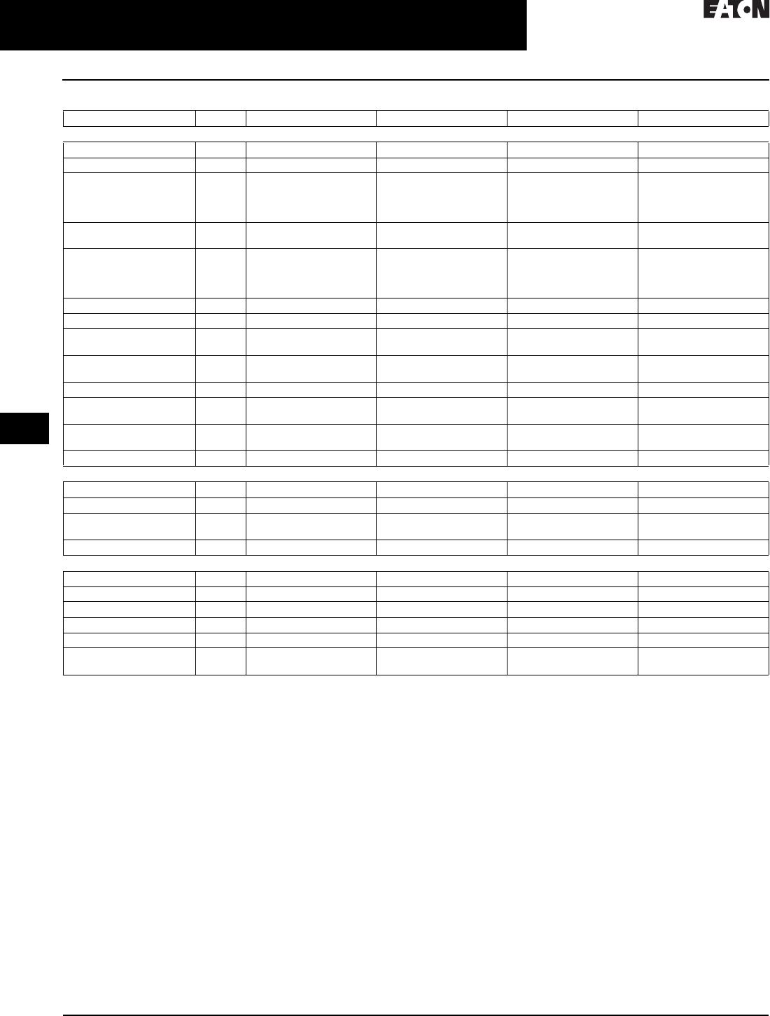
30.5-32
For more information, visit: www.eaton.com/consultants CA08104001E
April 2016
Motor Starters & Contactors—Low Voltage
Sheet 30
22
23
24
25
26
27
28
29
30
31
32
33
34
35
36
37
38
39
40
41
42
4 3
Reduced Voltage—Solid-State
DS6 Soft Start Controllers
094
Table 30.5-28. DS6 Soft Start Controllers (Continued)
Description Unit DS6-34DSX099N0-N DS6-34DSX134N0-N DS6-34DSX161N0-N DS6-34DSX196N0-N
General
Standards — IEC/EN 60947-4-2 IEC/EN 60947-4-2 IEC/EN 60947-4-2 IEC/EN 60947-4-2
Certifications/marking — UL/CE/C-Tick/CSA UL/CE/C-Tick/CSA UL/CE/C-Tick/CSA UL/CE/C-Tick/CSA
Ambient temperature
(operation)
°C 0 to 40 °C, above 40 °C
derate linearly by 1% of
rated current per Celsius
to 60 °C
0 to 40 °C, above 40 °C
derate linearly by 1% of
rated current per Celsius
to 60 °C
0 to 40 °C, above 40 °C
derate linearly by 1% of
rated current per Celsius
to 60 °C
0 to 40 °C, above 40 °C
derate linearly by 1% of
rated current per Celsius
to 60 °C
Ambient temperature
(storage)
°C –25 °C to +55 °C –25 °C to +55 °C –25 °C to +55 °C –25 °C to +55 °C
Altitude — 0–1000 m, above 1000 m
derate linearly by 1% of
rated current per 100 m to
a maximum of 2000 m
0–1000 m, above 1000 m
derate linearly by 1% of
rated current per 100 m to
a maximum of 2000 m
0–1000 m, above 1000 m
derate linearly by 1% of
rated current per 100 m to
a maximum of 2000 m
0–1000 m, above 1000 m
derate linearly by 1% of
rated current per 100 m to
a maximum of 2000 m
Installation — Vertical Vertical Vertical Vertical
Protection degree — IP20 IP20 IP20 IP20
Protection against contact — Back of hand and finger-
proof (from front face)
Back of hand and finger-
proof (from front face)
Back of hand and finger-
proof (from front face)
Back of hand and finger-
proof (from front face)
Overvoltage category/
pollution degree
— II/2 II/2 II/2 II/2
Shock resistance — 8g/11 ms 8g/11 ms 8g/11 ms 8g/11 ms
Vibration resistance
according to EN 60721-3-2
— 2M2 2M2 2M2 2M2
Dimensions in inches (mm)
(W x H x D)
— 3.66 x 6.89 x 5.47
(93.0 x 175.0 x 138.9)
4.25 x 8.46 x 7.01
(108.0 x 214.9 x 178.1)
4.25 x 8.46 x 7.01
(108.0 x 214.9 x 178.1)
4.25 x 8.46 x 7.01
(108.0 x 214.9 x 178.1)
Weight in lbs (kg) — 4.00 (1.8) 8.16 (3.7) 8.16 (3.7) 8.16 (3.7)
Main Circuit
Rated operation voltage V 200–460 Vac 200–460 Vac 200–460 Vac 200–460 Vac
Mains frequency Hz 50/60 Hz 50/60 Hz 50/60 Hz 50/60 Hz
Rated impulse
withstand voltage
Uimp 1.2 /
50 µs
4 kV 4 kV 4 kV 4 kV
Rated operation current Ie96 124 156 180
Motor Power Ratings
200 V hp 30 40 50 60
230 V hp 30 50 60 75
460 V hp 75 100 125 150
230 V kW 30 30 45 55
400 V kW 55 75 90 110
Overload cycle according
to EN 60947-4-2
— 96A: AC53a; 3–5; 75–10 124A: AC53a; 3–5; 75–10 156A: AC53a; 3–5; 75–10 180A: AC53a; 3–5; 75–10

CA08104001E For more information, visit: www.eaton.com/consultants
30.5-33
April 2016
Motor Starters & Contactors—Low Voltage
Sheet 30
22
23
24
25
26
27
28
29
30
31
32
33
34
35
36
37
38
39
40
41
42
4 3
Reduced Voltage—Solid-State
DS6 Soft Start Controllers
095
Table 30.5-28. DS6 Soft Start Controllers (Continued)
Description Unit DS6-34DSX099N0-N DS6-34DSX134N0-N DS6-34DSX161N0-N DS6-34DSX196N0-N
Wire Specifications
Power terminals (box terminals)
Single conductor
Terminal torque
AWG
lb-in
12–2/0
53–80
12 AWG–350 kcmil
44–123
12 AWG–350 kcmil
44–123
12 AWG–350 kcmil
44–123
Control signals
Single conductor
Terminal torque
AWG
lb-in
16 min.
3.5
16 min.
3.5
16 min.
3.5
16 min.
3.5
Power Section
Rated impulse
withstand voltage
Uimp 1.2 /
50 µs
4 kV 4 kV 4 kV 4 kV
Control Commands
Supply voltage control board
Nominal voltage
Nominal current ramp, TOR
Current peak (closing shorting contactors)
Us
Vdc
mA
+24 Vdc +10%/–15%
65
600 mA/50 ms
+24 Vdc +10%/–15%
65
600 mA/50 ms
+24 Vdc +10%/–15%
65
600 mA/50 ms
+24 Vdc +10%/–15%
65
600 mA/50 ms
Voltage to the control terminals
(rated control voltage)
DC driven — +24 Vdc +10%/–15% +24 Vdc +10%/–15% +24 Vdc +10%/–15% +24 Vdc +10%/–15%
Input current at 24 Vdc mA 14 14 14 14
Relay Outputs
Number of relays — 2 (TOR, ready) 2 (TOR, ready) 2 (TOR, ready) 2 (TOR, ready)
Maximum voltage V 250 Vac, 60 Vdc 250 Vac, 60 Vdc 250 Vac, 60 Vdc 250 Vac, 60 Vdc
Maximum current A 3 A, resistive 3 A, resistive 3 A, resistive 3 A, resistive
Soft Start Functions
Ramp times
Start ramp
Stop ramp
s
s
1–30
0–30
1–30
0–30
1–30
0–30
1–30
0–30
Initial voltage % line voltage — 30–92% 30–92% 30–92% 30–92%
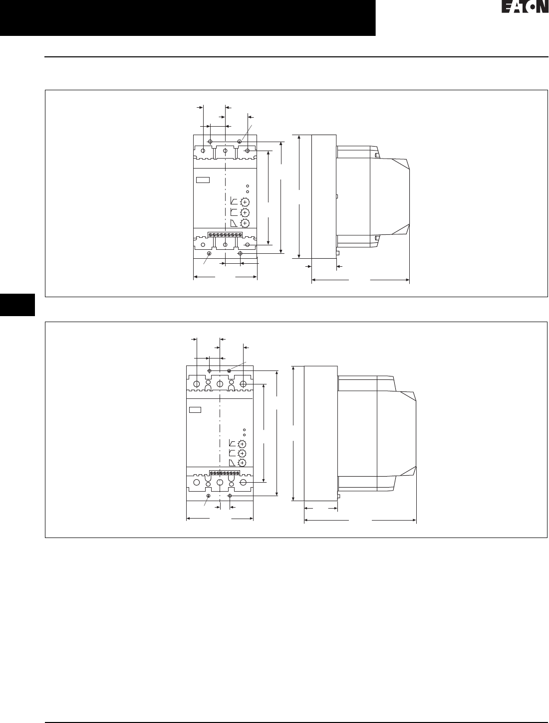
30.5-34
For more information, visit: www.eaton.com/consultants CA08104001E
April 2016
Motor Starters & Contactors—Low Voltage
Sheet 30
22
23
24
25
26
27
28
29
30
31
32
33
34
35
36
37
38
39
40
41
42
4 3
Reduced Voltage—Solid-State
DS6 Soft Start Controllers
096
Dimensions—Approximate Dimensions in Inches (mm)
Figure 30.5-15. 25–75 hp Models
Figure 30.5-16. 100–150 hp Models
PE
1.18
(30.0)
PE
1.18
(30.0)
0.88
(22.5)
0.88
(22.5)
3.66
(93.0)
5.08
(129.0)
6.34
(161.0)
1.38
(35.0) 5.47
(139.0)
6.89
(175.0)
1.38
(35.0) 1.38
(35.0)
0.59
(15.0)
0.59
(15.0)
4.25
(108.0)
2.07
(52.5) 7. 0 1
(178.0)
8.47
(215.0)
PE
PE
6.22
(158.0)
7.87
(200.0)
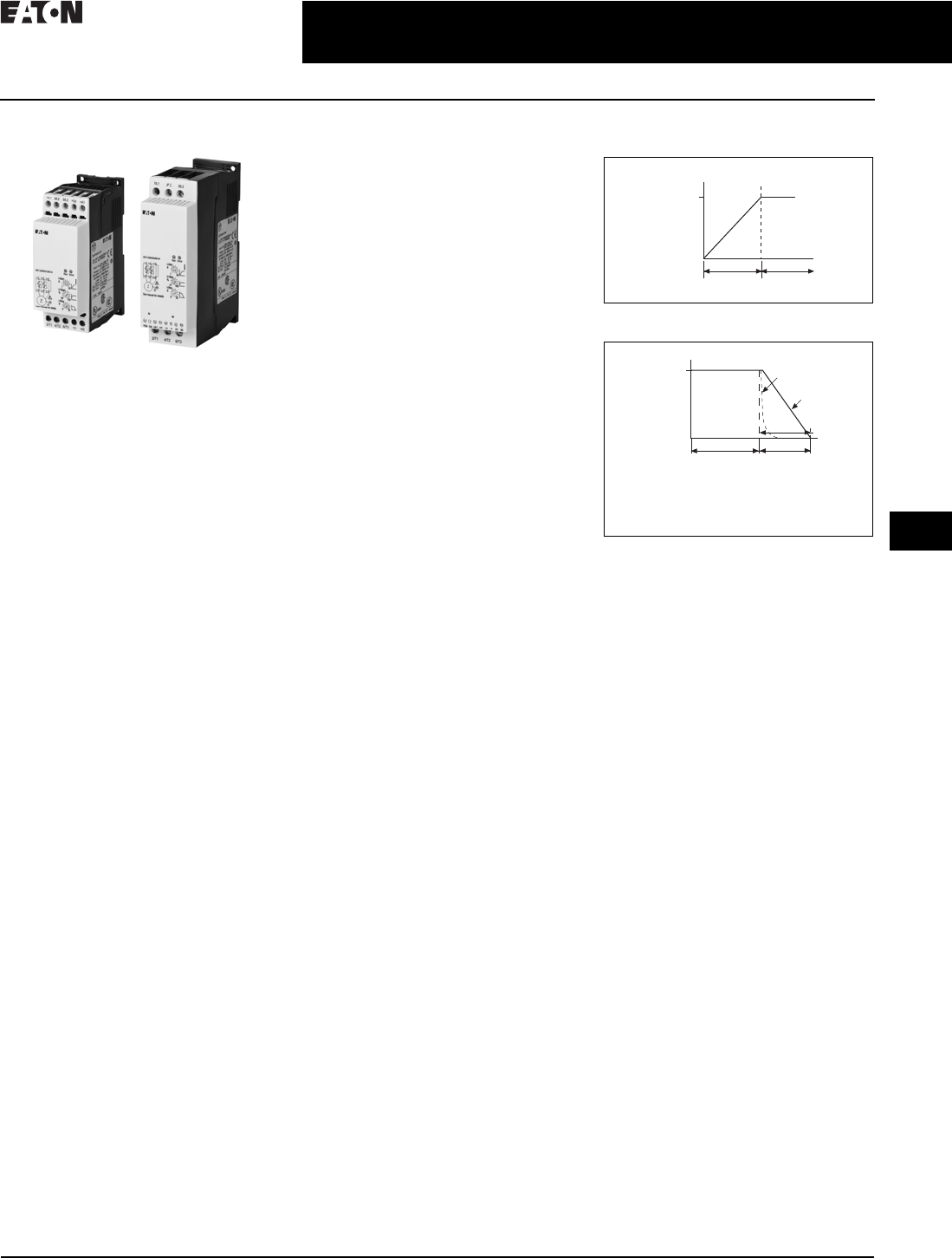
CA08104001E For more information, visit: www.eaton.com/consultants
30.5-35
April 2016
Motor Starters & Contactors—Low Voltage
Sheet 30
22
23
24
25
26
27
28
29
30
31
32
33
34
35
36
37
38
39
40
41
42
4 3
Reduced Voltage—Solid-State
DS7 Soft Start Controllers
097
DS7 Soft Start Controllers
DS7 Soft Start Controllers
General Description
Eaton’s DS7 line of reduced voltage
solid-state soft start controllers is very
compact, multi-functional, easy to
install and easy to commission.
Designed to control the acceleration
and deceleration of three-phase
motors, the device is available for
current ranges from 4–32 A in four
frame sizes.
Application Description
With its small size, it can easily fit in
place of existing soft starters, wye-delta
starters, or across-the-line NEMA® and
IEC starters. This feature allows easy
upgrades to existing systems. The
product is designed to be wired in
the three-phase line feeding the three
motor input leads as is done for
normal across-the-line starting. The
starter uses silicon controlled rectifiers
(SCRs) to ramp the voltage to the
motor, providing smooth acceleration
and deceleration of the load. After
the motor is started, the internal run
bypass relay closes, resulting in the
motor running directly across-the-line.
Internal run bypass significantly reduces
the heat generated as compared to
non-bypass starters. The soft stop
option allows for a ramp stop time that
may be longer than the coast-to-stop
time. An external overload protection
relay is needed.
Operation
Voltage Ramp Start
This start method provides a voltage
ramp to the motor, resulting in a
constant torque increase. This most
commonly used form of soft start
mode allows you to set the initial
voltage value and the duration of the
ramp to full voltage conditions.
■Adjustable initial voltage 30–92%
of full voltage (120/230 Vac control
voltage)
■Adjustable initial voltage 30–100%
of full voltage (24 Vac/Vdc control
voltage)
■Adjustable ramp time 1–30 seconds
■Bypass relays close at the end the
ramp time (TOR)
Soft Stop
Allows for a controlled stopping of
load. Used when a stop-time that is
greater than the coast-to-stop time is
desired. Often used with high friction
loads where a sudden stop may cause
system or product damage. Setting the
soft stop time to a value of 0 turns off
this feature.
■Soft stop time = 0–30 seconds
Figure 30.5-17. Start Ramp
Figure 30.5-18. Stop Ramp
Auxiliary Contacts
Auxiliary contacts are provided to
indicate soft start controller status.
Frame Size 1 (4A to 12A)—One Relay
The auxiliary relay indicates when the
soft starter is at Top-of-Ramp (TOR).
Frame Size 2 (16A to 32A)—Two Relays
One auxiliary relay indicates when the
soft starter is at Top-of-Ramp (TOR).
One auxiliary relay indicates that a RUN
command is present, including start
ramp, bypass and stop ramp times.
Bypass
Speed
Time (Seconds)
Start Run
100%
Speed
Time (Seconds)
Run Soft Stop
100%
1 = Coast to Stop (Speed)
2 = Soft Stop Ramp (Voltage)
3 = Soft Stop Time
1
2
3

30.5-36
For more information, visit: www.eaton.com/consultants CA08104001E
April 2016
Motor Starters & Contactors—Low Voltage
Sheet 30
22
23
24
25
26
27
28
29
30
31
32
33
34
35
36
37
38
39
40
41
42
4 3
Reduced Voltage—Solid-State
DS7 Soft Start Controllers
098
Features and Benefits
■Run bypass mode greatly reduces
internal heating created by the
power dissipation across the SCRs.
The bypass relay directly connects
the motor to the line and improves
system efficiency by reducing
internal power losses
■Less heat minimizes enclosure size
and cooling requirements, and
maximizes the life of all devices
in the enclosure
■LED displays device status and
provides fault indication
■Variable ramp times and voltage
control (torque control) settings
provide unlimited starting configu-
rations, allowing for maximum
application flexibility
■Soft stop control suits applications
where an abrupt stop of the load
is not acceptable. Soft acceleration
and deceleration reduces wear on
belts, gears, chains, clutches, shafts
and bearings
■Minimizes the peak inrush current’s
stress on the power system. Peak
starting torque can be managed to
diminish mechanical system wear
and damage
■24 Vac/Vdc control voltage enhances
personnel and equipment safety.
120/230 Vac control voltage is
also available
■Auxiliary relays indicate status of
the soft start controllers
❑The TOR relay is active until
motor stop command is received
and/or the soft start controller
detects a fault condition
❑RUN relay is active during
the start ramp, bypass and
stop ramp
Protective Features
■Mains connection—The mains
connection is monitored for a phase
loss and/or undervoltage during
ramp up
■Motor connection—The motor
connection is monitored for an open
condition during the ramp
■SCR faults—SCR performance is
monitored during the ramp cycle
for proper operation
■Heat sink over/under temperature—
High ambient temperatures, extended
ramp times and high duty cycle
conditions may cause the DS7 to
exceed its thermal rating. When
temperature goes under –5 °C, unit
will trip as well. The DS7 is equipped
with sensors that monitor the
temperature of the device. The
soft starter will trip in over/under
temperature conditions, preventing
device failure
■Warning is indicated for an over-
temperature condition for the
next start
■Bypass relay
❑The DS7 can detect if the bypass
relay fails to close after the ramp
start or opens while the motor is
running
❑The DS7 will also detect a condi-
tion whereas the bypass relay is
closed when the RUN command
is given
❑The DS7 will trip on a bypass
dropout fault if either of these
conditions occur
Standards and Certifications
■IEC 60947-4-2
■EN 60947-4-2
■UL listed
■CSA certified
■CE marked
■C-Tick
Additional Information
■Instruction Leaflet IL03901001E

CA08104001E For more information, visit: www.eaton.com/consultants
30.5-37
April 2016
Motor Starters & Contactors—Low Voltage
Sheet 30
22
23
24
25
26
27
28
29
30
31
32
33
34
35
36
37
38
39
40
41
42
4 3
Reduced Voltage—Solid-State
DS7 Soft Start Controllers
099
Product Selection
DS7 Soft Start Horsepower Ratings
Please refer to Application Note AP03901006E for additional information on proper size selection.
Table 30.5-29. DS7 Soft Start Controllers—Horsepower Ratings—10 Second Ramp, One Start per Hour, 300% Current Limit at 40 °C 1
1Actual motor FLAs vary. Verify these devices cover the motor specific FLA.
2Selections are based on motor FLA value at 480 V.
3Not to be used with 230 V.
424 Vac/Vdc device.
5120/230 Vac device.
Table 30.5-30. DS7 Soft Start Controllers—Horsepower Ratings—10 Second Ramp, One Start per Hour, 400% Current Limit at 40 °C 6
6Actual motor FLAs vary. Verify these devices cover the motor specific FLA.
7Selections are based on motor FLA value at 480 V.
8Not to be used with 230 V.
924 Vac/Vdc device.
j120/230 Vac device.
Rated
Current
Amperes
Motor Power (hp) Maximum
Allowable
Breaker Size
Maximum
Allowable
Fuse Size
Recommended
XTOB Overload
(Direct Connect) 2
Recommended
XTOE Overload
2
MMP 2Connection
Kit to MMP
Catalog
Number
200 V 230 V 480 V
3.7 0.75 0.75 2 HFD3015 15A Class RK5 XTOB004BC1 XTOE005BCS XTPR004BC1 XTPAXTPCB DS7-340SX004NO-N 4
DS7-342SX004NO-N 5
6.9 1.5 2 3 HFD3015 15A Class RK5 XTOB006BC1 3XTOE020BCS XTPR6P3BC1 XTPAXTPCB DS7-340SX007NO-N 4
DS7-342SX007NO-N 5
7.8 2 2 5 HFD3020 20A Class RK5 XTOB010BC1 XTOE020BCS XTPR010BC1 XTPAXTPCB DS7-340SX009NO-N 4
DS7-342SX009NO-N 5
11 3 3 7.5 HFD3030 20A Class RK5 XTOB012BC1 XTOE020BCS XTPR012BC1 XTPAXTPCB DS7-340SX012NO-N 4
DS7-342SX012NO-N 5
15.2 3 5 10 HFD3035 25A Class RK5 XTOB016CC1 XTOE020CCS XTPR016BC1 XTPAXTPCC DS7-340SX016NO-N 4
DS7-342SX016NO-N 5
22 5 7.5 15 HFD3060 40A Class RK5 XTOB024CC1 XTOE045CCS XTPR025BC1 XTPAXTPCC DS7-340SX024NO-N 4
DS7-342SX024NO-N 5
32 7.5 10 20 HFD3070 50A Class RK5 XTOB032CC1 XTOE045CCS XTPR032BC1 XTPAXTPCC DS7-340SX032NO-N 4
DS7-342SX032NO-N 5
Rated
Current
Amperes
Motor Power (hp) Maximum
Allowable
Breaker Size
Maximum
Allowable
Fuse Size
Recommended
XTOB Overload
(Direct Connect) 7
Recommended
XTOE Overload
7
MMP 7Connection
Kit to MMP
Catalog
Number
200 V 230 V 480 V
3 0.5 0.5 1.5 HFD3015 15A Class RK5 XTOB004BC1 XTOE005BCS XTPR004BC1 XTPAXTPCB DS7-340SX004NO-N 9
DS7-342SX004NO-N j
4.8 1 1 3 HFD3015 15A Class RK5 XTOB006BC1 8XTOE020BCS XTPR6P3BC1 XTPAXTPCB DS7-340SX007NO-N 9
DS7-342SX007NO-N j
6.9 1.5 2 3 HFD3020 20A Class RK5 XTOB006BC1 XTOE020BCS XTPR6P3BC1 XTPAXTPCB DS7-340SX009NO-N 9
DS7-342SX009NO-N j
9 2 2 5 HFD3030 20A Class RK5 XTOB010BC1 XTOE020BCS XTPR010BC1 XTPAXTPCB DS7-340SX012NO-N 9
DS7-342SX012NO-N j
11 3 3 7.5 HFD3035 25A Class RK5 XTOB016CC1 XTOE020CCS XTPR016BC1 XTPAXTPCC DS7-340SX016NO-N 9
DS7-342SX016NO-N j
17.5 5 5 10 HFD3060 40A Class RK5 XTOB016CC1 XTOE045CCS XTPR016BC1 XTPAXTPCC DS7-340SX024NO-N 9
DS7-342SX024NO-N j
22 5 7.5 15 HFD3070 50A Class RK5 XTOB024CC1 XTOE045CCS XTPR025BC1 XTPAXTPCC DS7-340SX032NO-N 9
DS7-342SX032NO-N j

30.5-38
For more information, visit: www.eaton.com/consultants CA08104001E
April 2016
Motor Starters & Contactors—Low Voltage
Sheet 30
22
23
24
25
26
27
28
29
30
31
32
33
34
35
36
37
38
39
40
41
42
4 3
Reduced Voltage—Solid-State
DS7 Soft Start Controllers
100
DS7 Soft Start kW Ratings
Please refer to Application Note AP03901006E for additional information on proper size selection.
Table 30.5-31. DS7 Soft Start Controllers—kW Ratings According to IEC 60947-4-2—
10 Second Ramp, One Start per Hour, 300% Current Limit at 40 °C 1
1Actual motor FLAs vary. Verify these devices cover the motor specific FLA.
2Selections are based on motor FLA value at 480 V.
3Not to be used with 230 V.
424 Vac/Vdc device.
5120/230 Vac device.
Table 30.5-32. DS7 Soft Start Controllers—kW Ratings According to IEC 60947-4-2—
10 Second Ramp, One Start per Hour, 400% Current Limit at 40 °C 6
6Actual motor FLAs vary. Verify these devices cover the motor specific FLA.
7Selections are based on motor FLA value at 480 V.
8Not to be used with 230 V.
924 Vac/Vdc device.
j120/230 Vac device.
Considerations
1. Either XTOB or XTOE or equivalent
overload protection devices may
be selected. In addition, manual
motor protectors—MMP series
can also be considered.
2. Isolation contactor is required for
mains isolation.
24 Vdc Control Power
Eaton’s ELC power supplies are
recommended as a compact and
low-cost source for 24 Vdc power. The
light-weight, DIN rail mounted devices
have a wide input voltage range and
robust screw terminals make these
power supplies easy to install and use.
These power supplies are available in
1A and 2A models.
AC Control Power
24, 120 or 230 Vac may be used for
control power in accordance with the
model requirements.
Table 30.5-33. DC Power Supply Selection
Rated
Current
Amperes
Motor Power (kW) Maximum
Allowable
Breaker Size
Maximum
Allowable
Fuse Size
Recommended
XTOB Overload
(Direct Connect) 2
Recommended
XTOE Overload 2
MMP 2Connection
Kit to MMP
Catalog
Number
230 V 400 V
3.8 0.75 1.5 HFD3015 15A Class RK5 XTOB004BC1 XTOE005BCS XTPR004BC1 XTPAXTPCB DS7-340SX004NO-N 4
DS7-342SX004NO-N 5
7 1.5 3 HFD3015 15A Class RK5 XTOB006BC1 3XTOE020BCS XTPR6P3BC1 XTPAXTPCB DS7-340SX007NO-N 4
DS7-342SX007NO-N 5
9 2.2 4 HFD3020 20A Class RK5 XTOB010BC1 XTOE020BCS XTPR010BC1 XTPAXTPCB DS7-340SX009NO-N 4
DS7-342SX009NO-N 5
12 3 5.5 HFD3030 20A Class RK5 XTOB012BC1 XTOE020BCS XTPR012BC1 XTPAXTPCB DS7-340SX012NO-N 4
DS7-342SX012NO-N 5
16 4 7.5 HFD3035 25A Class RK5 XTOB016CC1 XTOE020CCS XTPR016BC1 XTPAXTPCC DS7-340SX016NO-N 4
DS7-342SX016NO-N 5
24 5.5 11 HFD3060 40A Class RK5 XTOB024CC1 XTOE045CCS XTPR025BC1 XTPAXTPCC DS7-340SX024NO-N 4
DS7-342SX024NO-N 5
32 7.5 15 HFD3070 50A Class RK5 XTOB032CC1 XTOE045CCS XTPR032BC1 XTPAXTPCC DS7-340SX032NO-N 4
DS7-342SX032NO-N 5
Rated
Current
Amperes
Motor Power (kW) Maximum
Allowable
Breaker Size
Maximum
Allowable
Fuse Size
Recommended
XTOB Overload
(Direct Connect) 7
Recommended
XTOE Overload 7
MMP 7Connection
Kit to MMP
Catalog
Number
230 V 400 V
2.5 0.33 1 HFD3015 15A Class RK5 XTOB004BC1 XTOE005BCS XTPR004BC1 XTPAXTPCB DS7-340SX004NO-N 9
DS7-342SX004NO-N j
3.8 0.75 1.5 HFD3015 15A Class RK5 XTOB006BC1 8XTOE020BCS XTPR6P3BC1 XTPAXTPCB DS7-340SX007NO-N 9
DS7-342SX007NO-N j
7 1.5 3 HFD3020 20A Class RK5 XTOB006BC1 XTOE020BCS XTPR6P3BC1 XTPAXTPCB DS7-340SX009NO-N 9
DS7-342SX009NO-N j
9 2.2 4 HFD3030 20A Class RK5 XTOB010BC1 XTOE020BCS XTPR010BC1 XTPAXTPCB DS7-340SX012NO-N 9
DS7-342SX012NO-N j
12 3 5.5 HFD3035 25A Class RK5 XTOB016CC1 XTOE020CCS XTPR016BC1 XTPAXTPCC DS7-340SX016NO-N 9
DS7-342SX016NO-N j
16 4 7.5 HFD3060 40A Class RK5 XTOB016CC1 XTOE045CCS XTPR016BC1 XTPAXTPCC DS7-340SX024NO-N 9
DS7-342SX024NO-N j
24 5.5 11 HFD3070 50A Class RK5 XTOB024CC1 XTOE045CCS XTPR025BC1 XTPAXTPCC DS7-340SX032NO-N 9
DS7-342SX032NO-N j
Description Catalog
Number
85–264 V input and 24 V output
380–480 V input and 24 V output
ELC-PS01
PSS25F

CA08104001E For more information, visit: www.eaton.com/consultants
30.5-39
April 2016
Motor Starters & Contactors—Low Voltage
Sheet 30
22
23
24
25
26
27
28
29
30
31
32
33
34
35
36
37
38
39
40
41
42
4 3
Reduced Voltage—Solid-State
DS7 Soft Start Controllers
101
Technical Data and Specifications
Table 30.5-34. DS7 Soft Start Controllers
Rated Control Circuit
Voltage 24 Vac/Vdc
Voltage 110/230 Vac
Unit DS7-340SX004NO-N
DS7-342SX004NO-N
DS7-340SX007NO-N
DS7-342SX007NO-N
DS7-340SX009NO-N
DS7-342SX009NO-N
DS7-340SX012NO-N
DS7-342SX012NO-N
General
Standards — IEC/EN 60947-4-2;
GB14048.6; UL508;
CSA-C22.2 No 0-M91;
CSA-C22.2 No 14-05 CE
marking
IEC/EN 60947-4-2;
GB14048.6; UL508;
CSA-C22.2 No 0-M91;
CSA-C22.2 No 14-05 CE
marking
IEC/EN 60947-4-2;
GB14048.6; UL508;
CSA-C22.2 No 0-M91;
CSA-C22.2 No 14-05 CE
marking
IEC/EN 60947-4-2;
GB14048.6; UL508;
CSA-C22.2 No 0-M91;
CSA-C22.2 No 14-05 CE
marking
Certifications/marking — UL/CE/CSA/C-Tick UL/CE/CSA/C-Tick UL/CE/CSA/C-Tick UL/CE/CSA/C-Tick
Ambient temperature
(operation)
°C 0 to 40 °C, above 40 °C derate
linearly by 1% of rated
current per Celcius to 60 °C
0 to 40 °C, above 40 °C derate
linearly by 1% of rated
current per Celcius to 60 °C
0 to 40 °C, above 40 °C derate
linearly by 1% of rated
current per Celcius to 60 °C
0 to 40 °C, above 40 °C derate
linearly by 1% of rated
current per Celcius to 60 °C
Ambient temperature
(storage)
°C –25 °C to +55 °C –25 °C to +55 °C –25 °C to +55 °C –25 °C to +55 °C
Altitude — 0–1000 m, above 1000 m
derate linearly by 2.5% of
rated current per 100 m to a
maximum of 2000 m
0–1000 m, above 1000 m
derate linearly by 2.5% of
rated current per 100 m to a
maximum of 2000 m
0–1000 m, above 1000 m
derate linearly by 2.5% of
rated current per 100 m to a
maximum of 2000 m
0–1000 m, above 1000 m
derate linearly by 2.5% of
rated current per 100 m to a
maximum of 2000 m
Installation — Vertical Vertical Vertical Vertical
Protection class — IP20 IP20 IP20 IP20
Protection class applies
to the front and operator
control and display
elements. Protection type
from all sides is IP00.
— With optional covers from
the NZM range, protection
type IP40 from all sides can
be achieved
With optional covers from
the NZM range, protection
type IP40 from all sides can
be achieved
With optional covers from
the NZM range, protection
type IP40 from all sides can
be achieved
With optional covers from
the NZM range, protection
type IP40 from all sides can
be achieved
Busbar tag shroud — Back of hand and finger-proof
(from front face)
Back of hand and finger-proof
(from front face)
Back of hand and finger-proof
(from front face)
Back of hand and finger-proof
(from front face)
Overvoltage category/
pollution degree
— II/2 II/2 II/2 II/2
Shock resistance — 8g/11 ms 8g/11 ms 8g/11 ms 8g/11 ms
Vibration resistance
according to EN 60721-3-2
— 2M2 2M2 2M2 2M2
Mean heat dissipation at
rated duty cycle
W 0.2 0.35 0.35 0.6
Radio interference — B B B B
Dimensions (W x H x D) mm 45 x 130 x 95 45 x 130 x 95 45 x 130 x 95 45 x 130 x 95
in 1.77 x 5.12 x 3.74 1.77 x 5.12 x 3.74 1.77 x 5.12 x 3.74 1.77 x 5.12 x 3.74
Weight kg 0.35 0.35 0.35 0.35
lb 0.77 0.77 0.77 0.77
Main Circuit
Rated operational voltage V 230–460 Vac 230–460 Vac 230–460 Vac 230–460 Vac
Mains frequency Hz 50/60 Hz 50/60 Hz 50/60 Hz 50/60 Hz
Rated operation current
AC 53
Ie47912
Motor Power Ratings
200 V hp 0.75 1.5 2 3
230 V hp 0.75 2 2 5
480 V hp 2 3 5 10
230 V kW 0.75 1.5 2.2 3
400V kW 1.5 3 4 5.5
Overload cycle according
to EN 60947-4-2
— 4 A: AC53a; 3-5; 75-10 7 A: AC53a; 3-5; 75-10 9 A: AC53a; 3-5; 75-10 12 A: AC53a; 3-5; 75-10

30.5-40
For more information, visit: www.eaton.com/consultants CA08104001E
April 2016
Motor Starters & Contactors—Low Voltage
Sheet 30
22
23
24
25
26
27
28
29
30
31
32
33
34
35
36
37
38
39
40
41
42
4 3
Reduced Voltage—Solid-State
DS7 Soft Start Controllers
102
Table 30.5-34. DS7 Soft Start Controllers (Continued)
Rated Control Circuit
Voltage 24 Vac/Vdc
Voltage 110/230 Vac
Unit DS7-340SX004NO-N
DS7-342SX004NO-N
DS7-340SX007NO-N
DS7-342SX007NO-N
DS7-340SX009NO-N
DS7-342SX009NO-N
DS7-340SX012NO-N
DS7-342SX012NO-N
Wire Specifications
Power terminals
Single conductor—solid or stranded
Terminal torque
AWG
lb-in
18–10
11
18–10
11
18–10
11
18–10
11
Control signals
Single conductor—solid or stranded
Terminal torque
AWG
lb-in
18–10
11
18–10
11
18–10
11
18–10
11
Power Section
Rated impulse withstand voltage Uimp
1.2/ 50 µs
4 kV 4 kV 4 kV 4 kV
Rated insulation voltage — 500 500 500 500
Control Commands—Vac/Vdc
Supply voltage control board Us nominal Vdc 20.4–26.4 20.4–26.4 20.4–26.4 20.4–26.4
Current consumption at 24 Vac/Vdc mA 1.6 1.6 1.6 1.6
Pickup voltage — +17.3 to +27 +17.3 to +27 +17.3 to +27 +17.3 to +27
Dropout voltage — +3 to 0 +3 to 0 +3 to 0 +3 to 0
Relay Outputs
Number of relays — 1 (TOR) 1 (TOR) 1 (TOR) 1 (TOR)
Maximum voltage Vac 250 250 250 250
Maximum current A 1 A 1 A 1 A 1 A
Soft Start Functions
Ramp times
Start ramp
Stop ramp
s
s
1–30
0–30
1–30
0–30
1–30
0–30
1–30
0–30
Initial voltage % line voltage — 30–100% 30–100% 30–100% 30–100%
Control Commands—Vac
Supply voltage control board Us nominal Vac 102–253 102–253 102–253 102–253
Current consumption at 24 Vac/VdcmA4444
Pickup voltage Vac 102–230 102–230 102–230 102–230
Dropout voltage Vac 0–28 0–28 0–28 0–28
Relay Outputs
Number of relays — 1 (TOR) 1 (TOR) 1 (TOR) 1 (TOR)
Maximum voltage Vac 250 250 250 250
Maximum current A 3 A 3 A 3 A 3 A
Soft Start Functions
Ramp times
Start ramp
Stop ramp
s
s
1–30
0–30
1–30
0–30
1–30
0–30
1–30
0–30
Initial voltage % line voltage — 30–92% 30–92% 30–92% 30–92%

CA08104001E For more information, visit: www.eaton.com/consultants
30.5-41
April 2016
Motor Starters & Contactors—Low Voltage
Sheet 30
22
23
24
25
26
27
28
29
30
31
32
33
34
35
36
37
38
39
40
41
42
4 3
Reduced Voltage—Solid-State
DS7 Soft Start Controllers
103
Table 30.5-34. DS7 Soft Start Controllers (Continued)
Rated Control Circuit
Voltage 24 Vac/Vdc
Voltage 110/230 Vac
Unit DS7-340SX016NO-N
DS7-342SX016NO-N
DS7-340SX024NO-N
DS7-342SX024NO-N
DS7-340SX032NO-N
DS7-342SX032NO-N
General
Standards — IEC/EN 60947-4-2;
GB14048.6; UL508;
CSA-C22.2 No 0-M91;
CSA-C22.2 No 14-05 CE marking
IEC/EN 60947-4-2;
GB14048.6; UL508;
CSA-C22.2 No 0-M91;
CSA-C22.2 No 14-05 CE marking
IEC/EN 60947-4-2;
GB14048.6; UL508;
CSA-C22.2 No 0-M91;
CSA-C22.2 No 14-05 CE marking
Certifications/marking — UL/CE/CSA/C-Tick UL/CE/CSA/C-Tick UL/CE/CSA/C-Tick
Ambient temperature
(operation)
°C 0 to 40 °C, above 40 C derate linearly
by 1% of rated current per Celcius
to 60 °C
0 to 40 °C, above 40 C derate linearly
by 1% of rated current per Celcius
to 60 °C
0 to 40 °C, above 40 C derate linearly
by 1% of rated current per Celcius
to 60 °C
Ambient temperature
(storage)
°C –25 °C to +55 °C –25 °C to +55 °C –25 °C to +55 °C
Altitude — 0–1000 m, above 1000 m derate
linearly by 2.5% of rated current
per 10 0m to a maximum of 2000 m
0–1000 m, above 1000 m derate
linearly by 2.5% of rated current
per 10 0m to a maximum of 2000 m
0–1000 m, above 1000 m derate
linearly by 2.5% of rated current
per 10 0m to a maximum of 2000 m
Installation — Vertical Vertical Vertical
Protection class — IP20 IP20 IP20
Protection class applies to
the front and operator
control and display ele-
ments. Protection type
from all sides is IP00.
— With optional covers from the NZM
range, protection type IP40 from all
sides can be achieved
With optional covers from the NZM
range, protection type IP40 from all
sides can be achieved
With optional covers from the NZM
range, protection type IP40 from all
sides can be achieved
Busbar tag shroud — Back of hand and finger-proof
(from front face)
Back of hand and finger-proof
(from front face)
Back of hand and finger-proof
(from front face)
Overvoltage category/
pollution degree
— II/2 II/2 II/2
Shock resistance — 8g/11 ms 8g/11 ms 8g/11 ms
Vibration resistance
according to EN 60721-3-2
— 2M2 2M2 2M2
Mean heat dissipation at
rated duty cycle
W 0.8 1.1 1.5
Radio interference — B B B
Dimensions (W x H x D) mm 45 x 150 x 118 45 x 150 x 118 45 x 150 x 118
in 1.77 x 5.12 x 3.74 1.77 x 5.12 x 3.74 1.77 x 5.12 x 3.74
Weight kg 0.4 0.4 0.4
lb 0.88 0.88 0.88
Main Circuit
Rated operational voltage V 230–460 Vac 230–460 Vac 230–460 Vac
Mains frequency Hz 50/60 Hz 50/60 Hz 50/60 Hz
Rated operation current
AC 53
Ie16 24 32
Motor Power Ratings
200 V hp 3 5 10
230 V hp 5 7.5 10
480 V hp 10 15 25
230 V kW 4 5.5 7.5
400 V kW 7.5 11 15
Overload cycle according
to EN 60947-4-2
— 16 A: AC53a; 3-5; 75-10 24 A: AC53a; 3-5; 75-10 32 A: AC53a; 3-5; 75-10
30.5-42
For more information, visit: www.eaton.com/consultants CA08104001E
April 2016
Motor Starters & Contactors—Low Voltage
Sheet 30
22
23
24
25
26
27
28
29
30
31
32
33
34
35
36
37
38
39
40
41
42
4 3
Reduced Voltage—Solid-State
DS7 Soft Start Controllers
104
Table 30.5-34. DS7 Soft Start Controllers (Continued)
Rated Control Circuit
Voltage 24 Vac/Vdc
Voltage 110/230 Vac
Unit DS7-340SX016NO-N
DS7-342SX016NO-N
DS7-340SX024NO-N
DS7-342SX024NO-N
DS7-340SX032NO-N
DS7-342SX032NO-N
Wire Specifications
Power terminals
Single conductor—solid or stranded
Terminal torque
AWG
lb-in
18–6
11
18–6
11
18–6
11
Control Signals
Single conductor—solid or stranded
Terminal torque
AWG
lb-in
18–10
11
18–10
11
18–10
11
Power Section
Rated impulse withstand voltage Uimp
1.2/ 50 µs
4 kV 4 kV 4 kV
Rated insulation voltage — 500 500 500
Control Commands—Vac/Vdc
Supply voltage control board Us nominal Vdc 20.4–26.4 20.4–26.4 20.4–26.4
Current consumption at 24 Vac/Vdc mA 1.6 1.6 1.6
Pickup voltage — +17.3 to +27 +17.3 to +27 +17.3 to +27
Dropout voltage — +3 to 0 +3 to 0 +3 to 0
Relay Outputs
Number of relays — 2 (TOR, Ready) 2 (TOR, Ready) 2 (TOR, Ready)
Maximum voltage Vac 250 250 250
Maximum current A 1 A 1 A 1 A
Soft Start Functions
Ramp times
Start ramp
Stop ramp
s
s
1–30
0–30
1–30
0–30
1–30
0–30
Initial voltage % line voltage — 30–100% 30–100% 30–100%
Control Commands—Vac
Supply voltage control board Us nominal Vac 102–253 102–253 102–253
Current consumption at 102–253 Vac mA 4 4 4
Pickup voltage Vac 102–230 102–230 102–230
Dropout voltage Vac 0–28 0–28 0–28
Relay Outputs
Number of relays — 2 (TOR, Run) 2 (TOR, Run) 2 (TOR, Run)
Maximum voltage Vac 250 250 250
Maximum current A 3 A 3 A 3 A
Soft Start Functions
Ramp times
Start ramp
Stop ramp
s
s
1–30
0–30
1–30
0–30
1–30
0–30
Initial voltage % line voltage — 30–92% 30–92% 30–92%

CA08104001E For more information, visit: www.eaton.com/consultants
30.5-43
April 2016
Motor Starters & Contactors—Low Voltage
Sheet 30
22
23
24
25
26
27
28
29
30
31
32
33
34
35
36
37
38
39
40
41
42
4 3
Reduced Voltage—Solid-State
DS7 Soft Start Controllers
105
Dimensions—Approximate Dimensions in Inches (mm)
Figure 30.5-19. Frame Size 1
Figure 30.5-20. Frame Size 2
5.12
(130.0)
3.74
(95.0)
M4
1.38
(35.0)
1.78
(45.0)
4.80
(122.0)
4.92
(125.0)
Catalog Numbers
DS7-340SX004N0-N DS7-342SX004N0-N
DS7-340SX007N0-N DS7-342SX007N0-N
DS7-340SX009N0-N DS7-342SX009N0-N
DS7-340SX012N0-N DS7-342SX012N0-N
5.91
(150.0)
4.65
(118.0)
M4
1.38
(35.0)
1.78
(45.0)
5.51
(140.0)
Catalog Numbers
DS7-340SX016N0-N DS7-342SX016N0-N
DS7-340SX024N0-N DS7-342SX024N0-N
DS7-340SX032N0-N DS7-342SX032N0-N
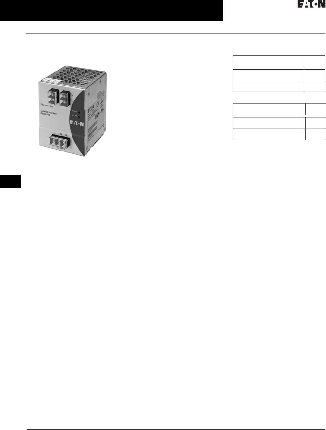
30.5-44
For more information, visit: www.eaton.com/consultants CA08104001E
April 2016
Motor Starters & Contactors—Low Voltage
Sheet 30
22
23
24
25
26
27
28
29
30
31
32
33
34
35
36
37
38
39
40
41
42
4 3
Reduced Voltage—Solid-State
PSG Series DC Power Supplies
106
PSG Series
DC Power Supplies
PSG Series
General Description
Eaton’s PSG Series of power supplies
is designed to be a high-performance,
high-quality line of products covering
a majority of 24 Vdc control applica-
tions. With global certifications,
compact size and an impressive
operating temperature range, the
PSG Series fits a wide variety of
applications at a competitive price.
Eight models are offered, from 2.5 A
up to 20 A with both single- and three-
phase input voltage models available.
Application Description
The PSG Series is a line of general-
purpose power supplies for use in a
wide variety of industrial control
applications. Applications include
communication networks, sensors,
PLCs and many other electrical
systems.
Each model is equipped with a rugged
metal housing, heavy-duty screw
terminals and a variety of protection
features, making the PSG one of the
most versatile industrial power supply
lines on the market.
Features, Benefits and Functions
■Universal input voltages: 85–264 Vac
for single-phase units, 320–575 Vac
for three-phase units
■Rugged aluminum housing stands
up to harsh environments
■Current surge (power boost) of 1.5
times nominal current for 1 second
allows branch protection and
powering of high pickup loads
■Wide operating temperature range:
–20° C to +75 °C (derating above
50 °C)
■Adjustable DC voltage output
■LED indicating light for DC OK
simplifies troubleshooting
■Compact size, with common depth
and height across all models, allows
for common panel depths and
family consistency
■MTBF up to 800,000 hours ensures
uptime and reliability
■Heavy-duty screw terminals with
finger-safe protective cover allow
use of ring-lug terminals
■All-metal DIN rail mounting
hardware
■Class 1, Division 2 hazardous
location rated
Standards and Certifications
■UL/cUL listed—UL 508 (industrial
control equipment)
■cURus—UL 60950-1
■IEC
■EN
■German safety
■CSA certified (contact Eaton for
certification dates and status)
■CE marked
■RoHS compliant
Product Selection
Table 30.5-35. Power Supply—Single-Phaseþ
Table 30.5-36. Power Supply—Three-Phaseþ
Description Catalog
Number
85–264 Vac input, 24 Vdc/2.5 A output
85–264 Vac input, 24 Vdc/5 A output
PSG60E
PSG120E
85–264 Vac input, 24 Vdc/10 A output
85–264 Vac input, 24 Vdc/20 A output
PSG240E
PSG480E
Description Catalog
Number
320–575 Vac input, 24 Vdc/2.5 A output
320–575 Vac input, 24 Vdc/5 A output
PSG60F
PSG120F
320–575 Vac input, 24 Vdc/10 A output
320–575 Vac input, 24 Vdc/20 A output
PSG240F
PSG480F

CA08104001E For more information, visit: www.eaton.com/consultants
30.5-45
April 2016
Motor Starters & Contactors—Low Voltage
Sheet 30
22
23
24
25
26
27
28
29
30
31
32
33
34
35
36
37
38
39
40
41
42
4 3
Reduced Voltage—Solid-State
PSG Series DC Power Supplies
107
Technical Data and Specifications
Table 30.5-37. PSG Series DC Power Supplies
1Ratings for single-phase models are at 115 Vac; three-phase models are at 400 Vac.
285–264 Vac (DC input range 120–375 Vdc).
3320–575 Vac (DC input range 450–800 Vdc).
Capacity PSG60E
60W
PSG120E
120W
PSG240E
240W
PSG480E
480W
PSG60F
60W
PSG120F
120W
PSG240F
240W
PSG480F
480W
Input
Nominal voltage 100–240 Vac 100–240 Vac 100–240 Vac 100–240 Vac 3 x 400–500
Vac
3 x 400–500
Vac
3 x 400–500
Vac
3 x 400–500
Vac
Voltage range 22223333
Frequency
47–63 Hz
(0 Hz at DC
input)
47–63 Hz
(0 Hz at DC
input)
47–63 Hz
(0 Hz at DC
input)
47–63 Hz
(0 Hz at DC
input)
47–63 Hz
(0 Hz at DC
input)
47–63 Hz
(0 Hz at DC
input)
47–63 Hz
(0 Hz at DC
input)
47–63 Hz
(0 Hz at DC
input)
Nominal current 11.1 A 1.4 A 2.9 A 5.7 A 0.3 A 0.5 A 0.8 A 1.6 A
Inrush current
limitation 1
30 A <80 A N/A N/A <30 A <30 A <40 A <50 A
Mains buffering at
nominal load (typ.) 1
>20 ms >35 ms >20 ms >20 ms >30 ms >35 ms >35 ms >20 ms
Turn-on time <2.5 sec <1 sec <1 sec <1 sec <2 sec <1 sec <1 sec <1 sec
Internal fuse T3.15 AH/250 V T3.15 AH/250 V T6.3AH/250 V F10H/250 V 3.15AH/500 V 3.15AH/500 V 3.15AH/500 V 3.15AH/500V
External fusing 6 A, 10 A or
16 A
6 A, 10 A or
16 A
10 A or 16 A 10 A or 16 A 3 x circuit
breakers 6 A,
10 A or 16 A
3 x circuit
breakers 6 A,
10 A or 16 A
3 x circuit
breakers 6 A,
10 A or 16 A
3 x circuit
breakers 6 A,
10 A or 16 A
Leakage current <1 mA <1 mA <3.5 mA <1 mA <3.5 mA <3.5 mA <3.5 mA <3.5 mA
Output
Nominal output
voltage
24 Vdc ± 2% 24 Vdc ± 2% 24 Vdc ± 2% 24 Vdc ± 2% 24 Vdc ± 2% 24 Vdc ± 2% 24 Vdc ± 2% 24 Vdc ± 2%
Adjustment range 22–28 Vdc 22–28 Vdc 22–28 Vdc 22–28 Vdc 22–28 Vdc 22–28 Vdc 22–28 Vdc 22–28 Vdc
Nominal current 2.5 A 5 A 10 A 20 A 2.5 A 5 A 10 A 20 A
Startup with
capacitive loads
Max. 8000 µF Max. 10,000 µF Max. 10,000 µF Max. 10,000 µF Max. 10,000 µF Max. 10,000 µF Max. 10,000 µF Max. 10,000 µF
Max. power
dissipation idling nom-
inal load approx.
10 W 22.5 W 42.5 W 72 W 9 W 18 W 36 W 72 W
Efficiency (at 400 Vac
and nominal values)
>85% typ >84% typ >84% typ >86% typ >86% at 3 x
400 Vac;
>85% at 3 x
500 Vac
>86% at 3 x
400 Vac;
>85% at 3 x
500 Vac
>86% at 3 x
400 Vac;
>85% at 3 x
500 Vac
>86% at 3 x
400 Vac;
>85% at 3 x
500 Vac
Current surge
(at 24 Vdc)
3.75 A 7.5 A 15 A 30 A 3.75 A 7.5 A 15 A 30 A
Current surge time/
cycle
1 sec. (at 10-
sec. intervals)
1 sec. (at 10-
sec. intervals)
1 sec. (at 10-
sec. intervals)
1 sec. (at 10-
sec. intervals)
1 sec. (at 10-
sec. intervals)
1 sec. (at 10-
sec. intervals)
1 sec. (at 10-
sec. intervals)
1 sec. (at 10-
sec. intervals)
Residual ripple/peak
switching (20 MHz)
<50 mV/
<240 mVpp
<50 mV/
<240 mVpp
<50 mV/
<240 mVpp
<50 mV/
<240 mVpp
<50 mV/
<240 mVpp
<50 mV/
<240 mVpp
<50 mV/
<240 mVpp
<50 mV/
<240 mVpp
Parallel operation With O-ring
Diode
With O-ring
Diode
With O-ring
Diode
With O-ring
Diode
With O-ring
Diode
With O-ring
Diode
With O-ring
Diode
With O-ring
Diode
Galvanic Isolation
Input/output 4 kVAC (type
test)/3 kVAC
(routine test)
4 kVAC (type
test)/3 kVAC
(routine test)
4 kVAC (type
test)/3 kVAC
(routine test)
4 kVAC (type
test)/3 kVAC
(routine test)
4 kVAC (type
test)/3 kVAC
(routine test)
4 kVAC (type
test)/3 kVAC
(routine test)
4 kVAC (type
test)/3 kVAC
(routine test)
4 kVAC (type
test)/3 kVAC
(routine test)
Input/ground 1.5 kVAC (type
test)/1.5 kVAC
(routine test)
1.5 kVAC (type
test)/1.5 kVAC
(routine test)
1.5 kVAC (type
test)/1.5 kVAC
(routine test)
1.5 kVAC (type
test)/1.5 kVAC
(routine test)
1.5 kVAC (type
test)/1.5 kVAC
(routine test)
1.5 kVAC (type
test)/1.5 kVAC
(routine test)
1.5 kVAC (type
test)/1.5 kVAC
(routine test)
1.5 kVAC (type
test)/1.5 kVAC
(routine test)
Output/ground 1.5 kVAC (type
test)/500 Vac
(routine test)
1.5 kVAC (type
test)/500 Vac
(routine test)
1.5 kVAC (type
test)/500 Vac
(routine test)
1.5 kVAC (type
test)/500 Vac
(routine test)
1.5 kVAC (type
test)/500 Vac
(routine test)
1.5 kVAC (type
test)/500 Vac
(routine test)
1.5 kVAC (type
test)/500 Vac
(routine test)
1.5 kVAC (type
test)/500 Vac
(routine test)
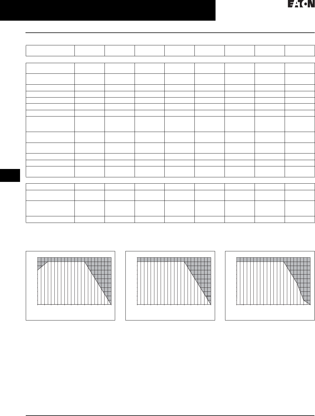
30.5-46
For more information, visit: www.eaton.com/consultants CA08104001E
April 2016
Motor Starters & Contactors—Low Voltage
Sheet 30
22
23
24
25
26
27
28
29
30
31
32
33
34
35
36
37
38
39
40
41
42
4 3
Reduced Voltage—Solid-State
PSG Series DC Power Supplies
108
Table 30.5-37. PSG Series DC Power Supplies (Continued)
110 to 150 Hz, 0.35 mm acc. 50 m/s/s, single amplitude (5G max.) for 90 min. in each X, Y, Z direction, in acc. with IEC 68-2-6.
230G (300 m/s/s) in all directions according to IEC 68-2-27.
Power Derating Curves
Figure 30.5-21. Vertical Mounting Position
PSG60E
Figure 30.5-22. Vertical Mounting Position
PSG60F, PSG120E, PSG120F, PSG480E,
PSG480F
Figure 30.5-23. Vertical Mounting Position
PSG240E, PSG240F
Capacity PSG60E
60W
PSG120E
120W
PSG240E
240W
PSG480E
480W
PSG60F
60W
PSG120F
120W
PSG240F
240W
PSG480F
480W
General/Physical Data
Housing material Aluminum
(Al5052)
Aluminum
(Al5052)
Aluminum
(Al5052)
Aluminum
(Al5052)
Aluminum
(Al5052)
Aluminum
(Al5052)
Aluminum
(Al5052)
Aluminum
(Al5052)
Signals Green LED for
DC OK
Green LED for
DC OK
Green LED for
DC OK
Green LED for
DC OK
Green LED for
DC OK
Green LED for
DC OK
Green LED for
DC OK
Green LED for
DC OK
MTBF >800,000 hrs >800,000 hrs >300,000 hrs >300,000 hrs >500,000 hrs >500,000 hrs >300,000 hrs >300,000 hrs
Dimensions (L) 121 mm 121 mm 121 mm 121 mm 121 mm 121 mm 121 mm 121 mm
Dimensions (W) 32 mm 50 mm 85 mm 160 mm 70 mm 70 mm 85 mm 160 mm
Dimensions (H) 120 mm 115 mm 118.5 mm 115 mm 118.5 mm 118.5 mm 120.5 mm 115 mm
Weight (kg) 0.37 0.54 1.04 1.8 0.56 0.72 0.77 1.71
Operating temperature –20°C to
+75°C (>50°C
derating)
–20°C to
+75°C (>50°C
derating)
–20°C to
+75°C (>50°C
derating)
–20°C to
+75°C (>50°C
derating)
–20°C to
+75°C (>50°C
derating)
–20°C to
+75°C (>50°C
derating)
–20°C to
+75°C (>50°C
derating)
–20°C to
+75°C (>50°C
derating)
Storage temperature –25°C to
+85°C
–25°C to
+85°C
–25°C to
+85°C
–25°C to
+85°C
–25°C to
+85°C
–25°C to
+85°C
–25°C to
+85°C
–25°C to
+85°C
Operating humidity <95% RH, non-
condensing
<95% RH, non-
condensing
<95% RH, non-
condensing
<95% RH, non-
condensing
<95% RH, non-
condensing
<95% RH, non-
condensing
<95% RH, non-
condensing
<95% RH, non-
condensing
Vibration (operating) 11111111
Pollution degree22222222
Climatic class 3K3 according
to EN 60721
3K3 according
to EN 60721
3K3 according
to EN 60721
3K3 according
to EN 60721
3K3 according
to EN 60721
3K3 according
to EN 60721
3K3 according
to EN 60721
3K3 according
to EN 60721
Safety and Protection
Transient surge voltage Varistor Varistor Varistor Varistor Varistor Varistor Varistor Varistor
Surge voltage protection
against internal surge
Yes Yes Yes Yes Yes Yes Yes Yes
Safety class Class I
with ground
connection
Class I
with ground
connection
Class I
with ground
connection
Class I
with ground
connection
Class I
with ground
connection
Class I
with ground
connection
Class I
with ground
connection
Class I
with ground
connection
Shock 22222222
Load (%)
Ambient Temperature (°C)
-20 -10 0 10 20 30 40 50 60 70 80 85
110
100
90
80
70
60
50
40
30
20
10
0
Load (%)
Ambient Temperature (°C)
-20 -10 0 10 20 30 40 50 60 70 80 85
110
100
90
80
70
60
50
40
30
20
10
0
Load (%)
Ambient Temperature (°C)
-20 -10 0 10 20 30 40 50 60 70 80 85
110
100
90
80
70
60
50
40
30
20
10
0
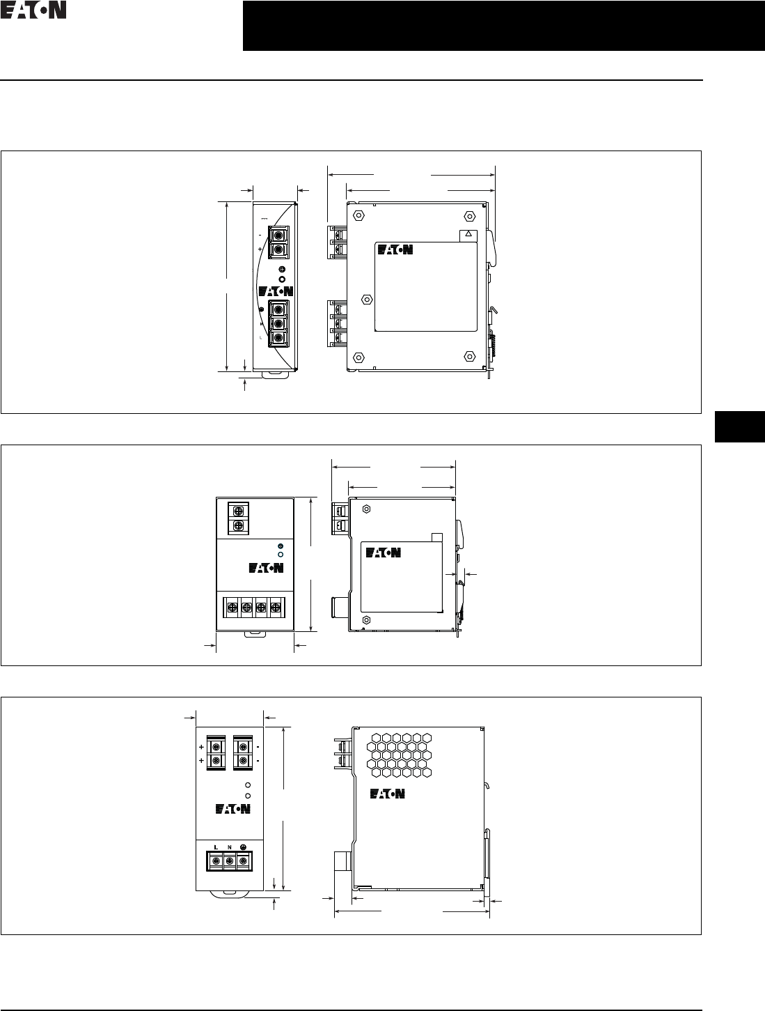
CA08104001E For more information, visit: www.eaton.com/consultants
30.5-47
April 2016
Motor Starters & Contactors—Low Voltage
Sheet 30
22
23
24
25
26
27
28
29
30
31
32
33
34
35
36
37
38
39
40
41
42
4 3
Reduced Voltage—Solid-State
PSG Series DC Power Supplies
109
Dimensions—Approximate Dimensions in mm
Note: Dimensions are for reference only.
Figure 30.5-24. PSG60E
Figure 30.5-25. PSG60F
Figure 30.5-26. PSG120E
32.0 ±0.5
5.0 ±0.2
Catalog Number:
PSG60E
24V 2.5A
Adjust
DC OK
100-240V~1.5A
50-60Hz
SPEC LABEL
CAUTION
HOT SURFACE
121.0 ±0.5
105.2 ±0.5
120.5 ±0.5
70.0 ±0.5
SPEC LABEL
121.0
±0.5
111. 4 ±0.5
96.5 ±0.5
6.6
±0.1
115.0 ±0.6
13.0 4.0
5.5
121.0
±0.2
DC 24V 5A
AC 100-240V 2A
50-60 Hz
Adjust
DC OK
50.0 ±0.2
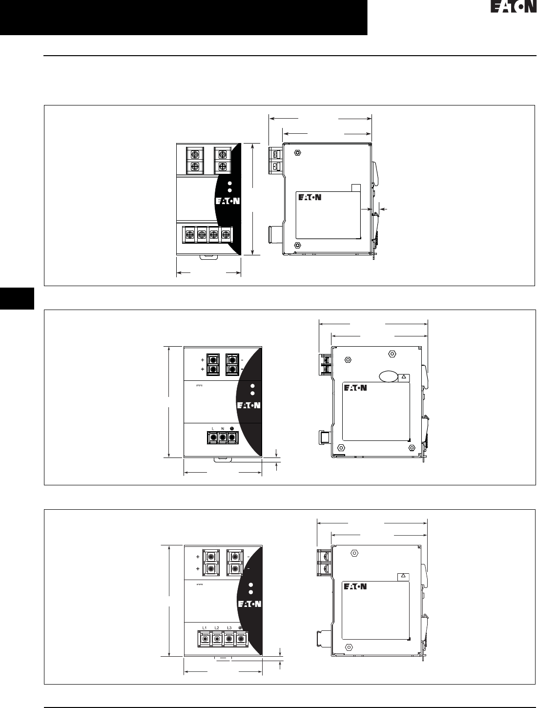
30.5-48
For more information, visit: www.eaton.com/consultants CA08104001E
April 2016
Motor Starters & Contactors—Low Voltage
Sheet 30
22
23
24
25
26
27
28
29
30
31
32
33
34
35
36
37
38
39
40
41
42
4 3
Reduced Voltage—Solid-State
PSG Series DC Power Supplies
110
Dimensions—Approximate Dimensions in mm (Continued)
Note: Dimensions are for reference only.
Figure 30.5-27. PSG120F
Figure 30.5-28. PSG240E
Figure 30.5-29. PSG240F
70.0 ±0.5
121.0
±0.5
111. 3 ±0.5
96.4 ±0.5
SPEC LABEL
Adjust
DC OK
6.6
±0.1
5.0 ±0.2
SPEC LABEL
CAUTION
HOT SURFACE
Catalog Number:
PSG240E
Adjust
DC OK
24V 10A
100-240V~5A
50-60Hz
121.0 ±0.5
105.2 ±0.5
118.5 ±0.5
85.0 ±0.5
Catalog Number:
PSG240F
Adjust
DC OK
24V 10A
3-Phase 400-500V~0.8A 50-60Hz
5.0 ±0.2
SPEC LABEL
CAUTION
HOT SURFACE
121.0 ±0.5
105.2 ±0.5
120.5 ±0.5
85.0 ±0.5
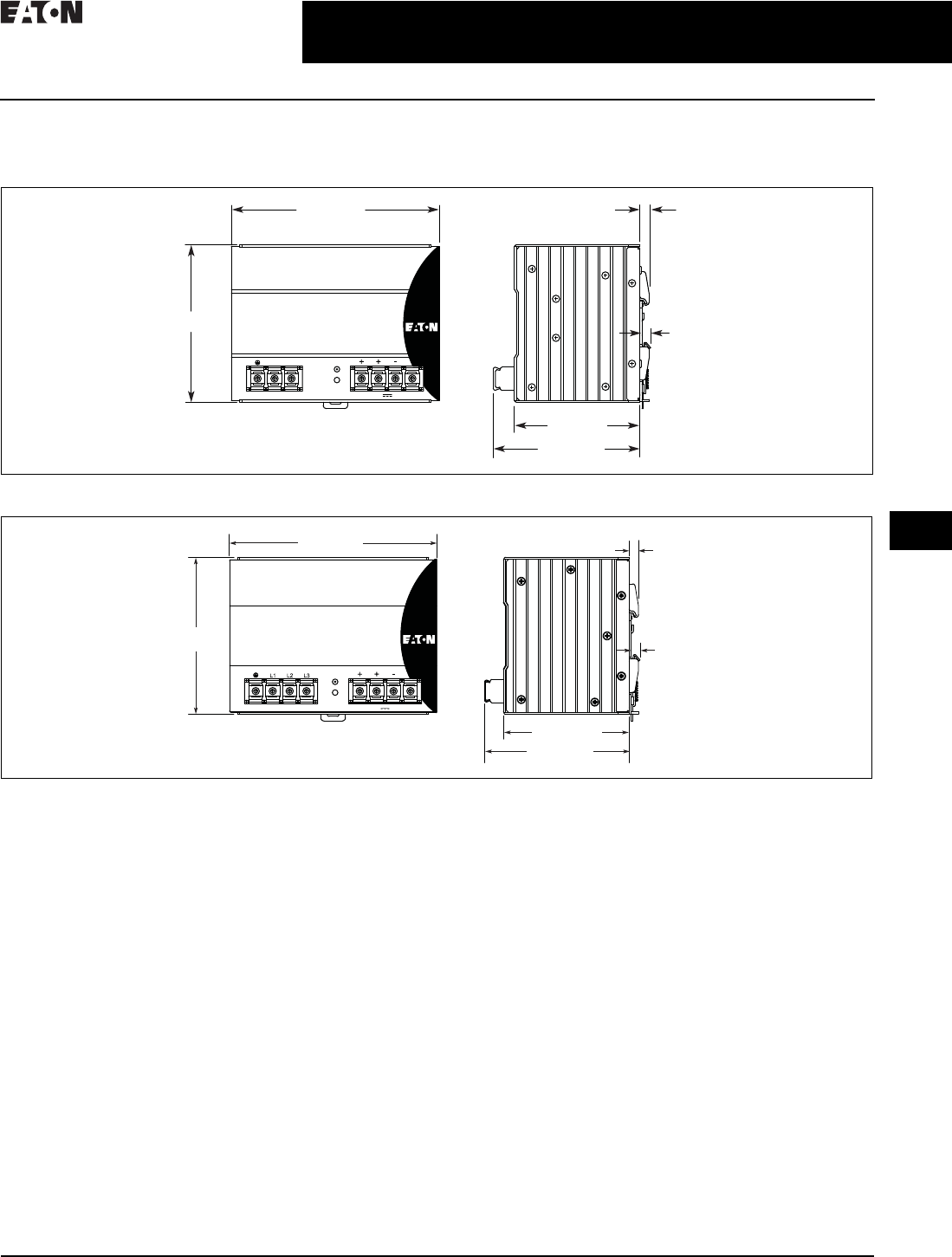
CA08104001E For more information, visit: www.eaton.com/consultants
30.5-49
April 2016
Motor Starters & Contactors—Low Voltage
Sheet 30
22
23
24
25
26
27
28
29
30
31
32
33
34
35
36
37
38
39
40
41
42
4 3
Reduced Voltage—Solid-State
PSG Series DC Power Supplies
111
Dimensions—Approximate Dimensions in mm (Continued)
Note: Dimensions are for reference only.
Figure 30.5-30. PSG480E
Figure 30.5-31. PSG480F
121.0 ±0.5
24V 20A
Catalog Number:
PSG480E
100-240V~ 7 A 50-60Hz
160.0 ±0.5 7. 1
6.6 ±0.1
111. 4 ±0.5
96.6 ±0.5
N L Adjust
DC OK
121.0 ±0.5
160.0 ±0.5
96.6 ±0.5
111. 4 ±0.5
Catalog Number:
PSG480F
24V 20A
3-Phase 400-500V~1.4A 50-60Hz
Adjust
DC OK
7. 1
6.6 ±0.1

30.5-50
For more information, visit: www.eaton.com/consultants CA08104001E
April 2016
Motor Starters & Contactors—Low Voltage
Sheet 30
22
23
24
25
26
27
28
29
30
31
32
33
34
35
36
37
38
39
40
41
42
4 3
112
This page intentionally left blank.
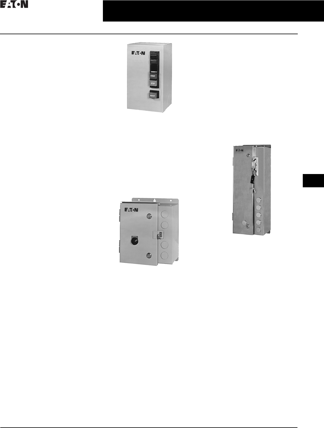
CA08104001E For more information, visit: www.eaton.com/consultants
30.6-1
April 2016
Motor Starters and Contactors—Low Voltage
Sheet 30
22
23
24
25
26
27
28
29
30
31
32
33
34
35
36
37
38
39
40
41
42
4 3
Enclosures
General Information
113
General Information—
Technical Reference
Enclosure Types
Enclosures provide mechanical and
electrical protection for operator and
equipment. Brief descriptions of the
various types of Eaton’s enclosures
offered by Eaton are given below. See
NEMA Standards Publication No. 250
for more comprehensive descriptions,
definitions and/or test criteria.
Ty p e 1
Type 1 (Conforms to IP40)—for Indoor Use
Suitable for most applications where
unusual service conditions do not
exist and where a measure of protec-
tion from accidental contact with
enclosed equipment is required.
Designed to meet tests for rod entry
and rust resistance. Enclosure is sheet
steel, treated to resist corrosion.
Depending on the size, knockouts are
provided on the top, bottom and
sometimes on the side.
Ty p e 3 R
Type 3R (Conforms to IP52)—for
Outdoor Use
Primarily intended for applications
where falling rain, sleet or external ice
formations are present. Gasketed
cover. Designed to meet tests for rain,
rod entry, external icing and rust resis-
tance. Enclosure is sheet steel, treated
to resist corrosion. Depending on the
size, a blank cover plate is attached to
the top (for a conduit hub) and knock-
outs are provided on the bottom.
Cover-mounted pilot device holes are
provided and covered with hole plugs.
Type 4 (Conforms to IP65)—for Indoor or
Outdoor Use
Provide measure of protection from
splashing water, hose-directed water
and wind blown dust or rain.
Constructed of sheet steel with
gasketed cover.
Designed to meet tests for hose-down,
external icing and corrosion protec-
tion. When conduit connections are
specified, enclosure has two watertight
hubs (power) installed top and bottom
or one control hub installed in
bottom—depending on size.
Cover-mounted pilot device holes are
provided and covered with hole plugs.
Ty p e 4 X
Type 4X (Conforms to IP65)—for Indoor or
Outdoor Use
Provide measure of protection from
splashing water, hose-directed water,
wind blown dust, rain and corrosion.
Constructed of stainless steel with
gasketed cover. Designed to meet
same tests as Type 4 except enclosure
must pass a 200-hour salt spray corro-
sion resistance test.
Provided as 304-grade stainless steel
as standard. Select 316-grade option
for improved corrosion resistance.
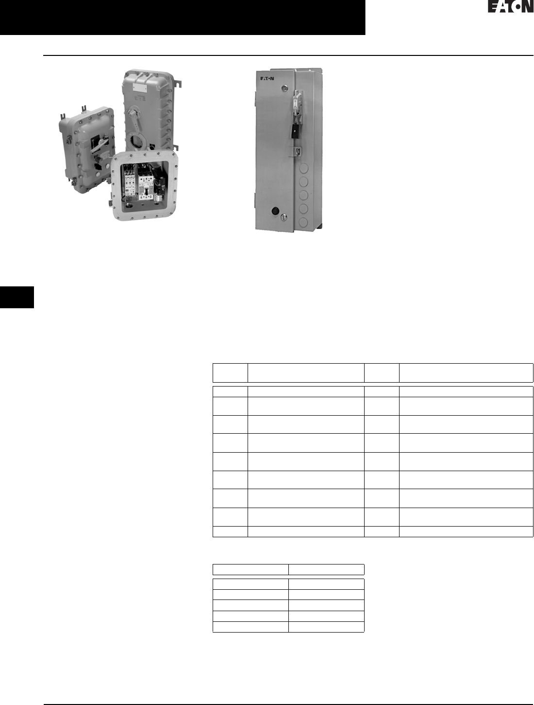
30.6-2
For more information, visit: www.eaton.com/consultants CA08104001E
April 2016
Motor Starters and Contactors—Low Voltage
Sheet 30
22
23
24
25
26
27
28
29
30
31
32
33
34
35
36
37
38
39
40
41
42
4 3
Enclosures
General Information
114
Type 7 & 9 Bolted
Type 7/9—for Hazardous Gas Locations
For use in Class I, Group B, C or D;
Class II, Groups E, F and Class III
indoor locations as defined in the
National Electrical Code. Type 7/9
enclosures must withstand the pres-
sure generated by explosion of
internally trapped gases and be able to
contain the explosion so that gases in
the surrounding atmosphere are not
ignited. Under normal operation, the
surface temperature of the enclosure
must be below the point where it could
ignite explosive gases present in the
surrounding atmosphere. Designed to
meet explosion, temperature and
hydrostatic design tests.
Ty p e 1 2
Type 12—(Conforms to IP62)—
for Indoor Use
Provide a degree of protection from
dripping liquids (non-corrosive),
falling dirt and dust. Designed to meet
tests for drip, dust and rust resistance.
Constructed of sheet steel. Hole plugs
cover pilot device holes. There are no
knockouts, hub cover plates or hubs
installed.
Many Eaton Type 12 enclosures are
suitable for use in Class II, Division 2,
Group G and Class III, Divisions 1 and
2 locations as defined in the National
Electrical Code.
Type 12—Safety Interlock
The Type 12 enclosure can be ordered
with a safety interlock on the door that
can be padlocked off. A vault-type door
latch system is used. A tapered plate
holds the gasketed door tight against
the case edge to provide a positive
seal. The special door interlock
consists of the door handle and a
screwdriver operated cover defeater.
The cover defeater and the disconnect
interlock defeater are both recessed
screwdriver operated devices which
cannot be manipulated with other
types of tools.
Table 30.6-1. IEC IP Index of Protection Ratings
Table 30.6-2. NEMA Standard to
IP Equivalence
1st
Number
Description 2nd
Number
Description
0 No protection 0 No protection
1 Protection against solid objects
greater than 50 mm
1 Protection against vertically falling
drops of water
2 Protection against solid objects
greater than 12 mm
2 Protection against dripping water
when tilted up to 15 degrees
3 Protection against solid objects
greater than 2.5 mm
3 Protection against spraying water
4 Protection against solid objects
greater than 1 mm
4 Protection against splashing water
5 Total protection against dust—
limited ingress (dust protected)
5 Protection against water jets
6 Total protection against dust
(dust-tight)
6 Protection against heavy seas
— — 7 Protection against the effects of
immersion
— — 8 Protection against submersion
Ty p e I P
140
3R 52
465
4X 65
12 62

CA08104001E For more information, visit: www.eaton.com/consultants
30.6-3
April 2016
Motor Starters and Contactors—Low Voltage
Sheet 30
22
23
24
25
26
27
28
29
30
31
32
33
34
35
36
37
38
39
40
41
42
4 3
Enclosures
General Information
115
Table 30.6-3. Enclosure Selection and Reference Chart—Box Dimensions in Inches (mm)
Note: See Eaton’s Enclosed Control guide or Web site for further details on enclosures.
Table 30.6-4. Noncombination Solid-State Reduced Voltage
Box Dimensions
1Enclosure space will also accommodate for a DC Power Supply, two
four-pole relays, a CPT and terminal blocks. Also includes space for a
DNA module or MOV.
2Same as footnote 1, but CPT is not included. Upsize to 7A enclosure to
include space for a CPT and a full voltage bypass contactor.
Table 30.6-5. Combination Solid-State Reduced Voltage Box Dimensions
3Enclosure space will also accommodate for a DC Power Supply, two
four-pole relays, a CPT and terminal blocks. Also includes space for a
DNA module or MOV.
4Enclosure may be reduced to an A1, with all space for all items as in
footnote 3, excluding relays and CPTs.
5Same as footnote 3, but CPT is not included. Upsize to B1 enclosure to
include space for a CPT and a full voltage bypass contactor.
Note: For enclosure box dimensions, refer to table above.
Box Designation NEMA Enclosure Type Width Height Depth
1 1 5.62 (142.7) 9.51 (241.6) 4.81 (122.2)
2 1 7.73 (196.3) 12.60 (320.0) 5.84 (148.3)
3 1 12.65 (321.3) 13.85 (351.8) 6.40 (162.6)
4 1 11.66 (296.2) 25.99 (660.1) 8.03 (204.0)
5 12, 3R, 4X 9.84 (250.0) 13.31 (338.1) 6.70 (170.2)
6 12, 3R, 4X 12.01 (305.1) 14.39 (365.5) 6.70 (170.2)
6A 12, 3R, 4X 12.01 (305.1) 14.39 (365.5) 8.44 (214.4)
7 12, 3R, 4X 12.26 (311.4) 14.37 (365.0) 6.70 (170.2)
7A 12, 3R, 4X 16.26 (413.0) 14.37 (365.0) 10.90 (276.9)
8 12, 3R, 4X 14.25 (362.0) 12.10 (307.3) 8.47 (215.1)
9 1, 12, 3R 4X 25.50 (647.7) 29.10 (739.1) 8.41 (213.6)
10 1, 12, 3R 4X 20.00 (508.0) 47.85 (1215.4) 10.48 (266.2)
A 1 10.50 (266.7) 27.06 (687.3) 6.66 (169.2)
A 12, 3R, 4X 10.50 (266.7) 28.98 (736.1) 6.66 (169.2)
A1 1 10.50 (266.7) 27.06 (687.3) 8.49 (215.6)
A1 12, 3R, 4X 10.50 (266.7) 28.98 (736.1) 8.49 (215.6)
B 1 15.50 (393.7) 23.06 (585.7) 6.66 (169.2)
B 12, 3R, 4X 15.50 (393.7) 24.98 (634.5) 6.66 (169.2)
B1 1 15.50 (393.7) 23.06 (585.7) 10.90 (276.9)
B1 12, 3R, 4X 15.50 (393.7) 24.98 (634.5) 10.90 (276.9)
C 1 20.50 (520.7) 30.50 (774.7) 8.44 (214.4)
C 12, 3R, 4X 20.50 (520.7) 32.36 (822.0) 8.44 (214.4)
D 1 29.50 (749.3) 35.00 (889.0) 8.75 (222.3)
D 12, 3R, 4X 29.50 (749.3) 38.10 (967.7) 8.75 (222.3)
E 1, 12, 3R, 4X 28.00 (711.2) 61.75 (1568.5) 10.68 (271.3)
F1E 1, 12, 3R, 4X 37.00 (940.0) 74.75 (1898.7) 19.25 (489.0)
F2E 1, 12, 3R, 4X 42.00 (1066.8) 92.90 (2360.0) 19.25 (489.0)
P1 1 8.50 (215.9) 32.98 (837.7) 6.66 (169.2)
P3 1 18.86 (479.0) 38.40 (975.4) 8.47 (215.1)
P5 1 21.00 (533.4) 48.40 (1229.4) 8.97 (227.8)
P7 1 28.80 (731.5) 60.58 (1538.7) 19.28 (489.7)
I 1, 12 8.62 (219.0) 27.06 (687.3) 6.66 (169.2)
J 1, 12, 3R 8.00 (203.2) 16.50 (419.1) 17.23 (437.6)
K 1, 12, 3R 8.00 (203.2) 19.50 (495.3) 7.23 (183.6)
L 1, 12, 3R 15.87 (403.1) 16.50 (419.1) 7.23 (183.6)
M 1, 12 15.87 (403.1) 24.50 (622.3) 7.23 (183.6)
Ampere
Rating
SSRV Non-
combination
Ampere
Rating
SSRV Non-
combination
Box No. 1Box No. 1
0.8–27
37
50
66
105
135
180
S752
S801/S811
S752
S801/S811
S801/S811
S801/S811
S801/S811
6A 2
7A
6A 2
7A
7A
B1
C
304
360
420
500
S801/S811
S801/S811
S801/S811
S801/S811
G1
G1
10
10
650
720
850
S801/S811
S801/S811
S801/S811
10
10
10
240
S801/S811 G1 1000 S801/S811 10
Ampere
Rating
SSRV Comb.
with
Fuses
Comb.
with
HMCP
Ampere
Rating
SSRV Comb.
with
Fuses
Comb.
with
HMCP
Box
No.
3
Box
No.
3
Box
No.
3
Box
No.
3
0.8–27
37
50
66
105
135
180
S752
S801/S811
S752
S801/S811
S801/S811
S801/S811
S801/S811
B1
4
B1
C
C
D
D
E
A1
5
A1
5
A1
5
A1
B1
C
E
304
360
420
500
S801/S811
S801/S811
S801/S811
S801/S811
F1E
F1E
F1E
F1E
E
E
E
E
650
720
850
S801/S811
S801/S811
S801/S811
F1E
F1E
F1E
F1E
F1E
F1E
240 S801/S811 F1E E 1000 S801/S811 F1E F1E

30.6-4
For more information, visit: www.eaton.com/consultants CA08104001E
April 2016
Motor Starters and Contactors—Low Voltage
Sheet 30
22
23
24
25
26
27
28
29
30
31
32
33
34
35
36
37
38
39
40
41
42
4 3
116
This page intentionally left blank.
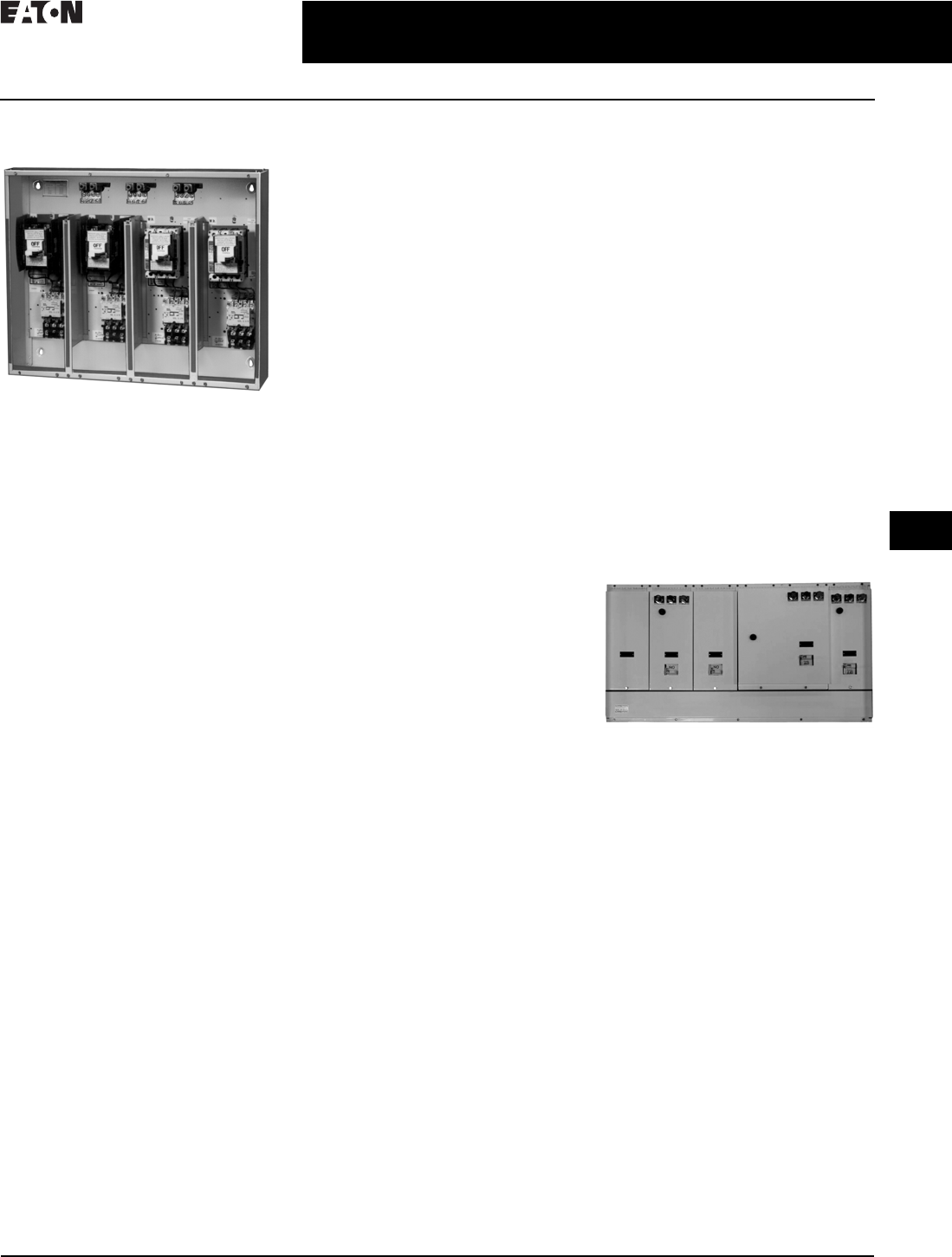
CA08104001E For more information, visit: www.eaton.com/consultants
30.7-1
April 2016
Motor Starters & Contactors—Low Voltage
Sheet 30
22
23
24
25
26
27
28
29
30
31
32
33
34
35
36
37
38
39
40
41
42
4 3
Group Control
Group Control Multi-Pak
117
Group Control Multi-Pak
Multi-Pak Four Compartment Enclosure
Showing Variety of Possible Equipment
Module Combinations Available
Application Description
Eaton’s Multi-Pak Group Control is
designed to save time, space, and
expense in installing motor control
devices—whether for residential,
commercial, or industrial buildings.
The modular assembly allows versatile,
on-the-job arrangement of Sizes 1
through 4 combination starters with
ambient compensated relays, incoming
or feeder circuit breakers or fusible dis-
connect switches, pushbuttons, control
transformers, timers, relays, and fuses.
The enclosures and separate, pre-wired
modules are field-stocked and can be
ordered individually, permitting field tai-
loring to suit the application.
Benefits
■Enclosures and pre-wired equip-
ment modules are individually avail-
able from stock. Each shipping
carton contains complete mounting
and installation instructions
■Cuts installation time by 25 percent.
The pre-wired modules can be
installed easily, using only a
screwdriver, at the job site
■Saves space over individually
mounted control
■Can be wall or rack mounted
■Has flexible panel space for
auxiliary control items. Barriers
can be removed to provide
oversized compartments
■Eliminates square duct or cable
entrance box
■Simplifies wiring
■Permits quick, easy additions
and rearrangements
■UL listed—E69852, Guide NITW
Enclosure Features
The Type 1 enclosures are partitioned
into either four or six compartments,
to hold combination starter modules,
incoming or feeder circuit breakers, fus-
ible switches, or other auxiliary devices.
The barriers can be removed to provide
oversized spaces. Each enclosure holds
up to four Size 1 or 2 full-voltage, non-
reversing combination starter modules;
up to two Size 3 or 4 starter modules,
or a combination of both size ranges.
The compartments have hinged doors,
interlocked to prevent opening when the
breaker switch is in the ON position. The
disconnect operating mechanism can be
padlocked in the OFF position.
The Multi-Pak enclosure adapts easily
to installation requirements. Multiple
units can be arranged to suit the space
available—horizontally on a single line
or two-high. Knockouts are provided at
the top, bottom and sides of the enclo-
sures for conduit connection. Conduit
can be installed and cables pulled as
dictated by the construction schedule.
Combination starter modules and
incoming or feeder devices can be
installed days, months or years later.
In addition to the barrier compartments,
the enclosure contains two wiring
troughs. The top section is a wireway
fitted with three power terminal straps,
each having terminals for extension
to adjoining enclosures and to all four
compartments. The incoming line and
extension terminals are suitable for
either copper or aluminum conductors,
from No. 6 to 350 kcmil. At the bottom
of the enclosure is another wiring
trough for interconnecting wiring
and outgoing cables.
Hinging of the front doors provides
for easy access to each module.
The doors are also gasketed with a
fire-retardant material. Knockouts
are provided on the doors for the
mounting of pushbuttons and
indicating lights.
The enclosure and wireway cover plates
come in ASA-70 light gray enamel. An
identification card retainer is mounted
on each compartment door. A dust- and
weather-resistant enclosure to house
the Type 1 enclosure is also available.
Typical Six Compartment Multi-Pak
After Assembly
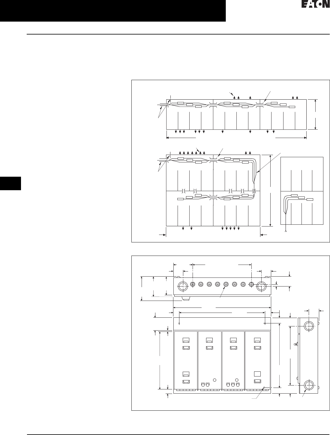
30.7-2
For more information, visit: www.eaton.com/consultants CA08104001E
April 2016
Motor Starters & Contactors—Low Voltage
Sheet 30
22
23
24
25
26
27
28
29
30
31
32
33
34
35
36
37
38
39
40
41
42
4 3
Group Control
Group Control Multi-Pak
118
Combination Starter Modules
Eaton’s starter modules consist of
a Class A200 magnetic line-starter,
prewired with a motor circuit protector
or a fusible DS disconnect switch on a
panel. Full-voltage non-reversing and
reversing, combination starters are
available. An external reset button is
mounted on the starter module door.
With its versatile, modular design, the
Multi-Pak starter permits a variety of
motor control groupings. One module
can contain many different arrange-
ments of devices, such as combination
linestarter with control transformers,
and/or relays, or two feeder circuit
breakers, or fusible switches.
The contactor design comprises a glass
polyester case with silver-cadmium
oxide alloy contacts, straight-through
wiring, out-front terminals, molded
coils, stainless steel kickout springs,
U-type magnet, and a shock absorber
baseplate.
The circuit breakers, equipped with
adjustable magnetic trip elements,
protect against short circuits. Standard
three-pole, inverse-time, and ambient
compensated thermal overload relays
protect against overload.
Fusible switches are equipped to
accept either 250 V or 600 V Class H, K,
and R cartridges fuses, with capacities
as listed by Underwriters Laboratories
for overcurrent protection.
ON-OFF operating mechanisms are
molded
from an ABS fire-resistant
material.
Components of each module have
individual printed labels identifying
size, voltage, ampere rating and so on.
The labels also contain a schematic
drawing reference number covering
the wiring of
the component contained
in the module.
Technical Data
Dimensions and Wiring Arrangements
Four compartment enclosures are
32.00 inches (812.8 mm) wide, 26.00
inches (660.4 mm) high, and 7.00 inches
(177.8 mm) deep with provisions for
four-bolt wall mounting. Six compart-
ment enclosures are an additional
16.00 (406.4) inches wide. Enclosures
may be grouped together by nippling
through knockouts provided.
Load and control conduits may enter
at the top or bottom. Starter wiring
diagram and overload heater installa-
tion instructions are attached to each
starter door.
Dust and weather-resistant enclosures
for four or six module units are available.
These enclosures are 34.00 inches
(863.6 mm) or 50.00 inches (1270.0 mm)
wide, 31.00 inches (787.4 mm) high,
and 11.75 inches (298.5 mm) deep.
Figure 30.7-1. Wiring Arrangements
Figure 30.7-2. Type 1 Enclosures—Dimensions in Inches (mm)
Outgoing Conduits May Be All
at T op, All at Bottom or Mixed
Outgoing Conduits May Be All
at Top, All at Bottom or Mixed One Compartment Used
to Feed Supply to Bottom
Supply Feed Thru Nipples
Supply Feed Thru Nipples
Incoming Line
at Top or Side
(Either End)
Incoming Line
at Top or Side
(Either End)
26
52
H-Units at 32 Inches (812.8 mm) Each
1, 2 or 3 Units at 32 Inches (812.8 mm) Each
6.38
(162.1)
6.13
(155.7)
8.50
(215.9)
7. 0 0
(177.8 )
(8) Knockouts on
2-3/4 Centers (Top 8 Bottom)
(8) 1/2, 3/4, 1 Inch Knockouts
32.00
(812.8) 28.00
(711.2)
5.50
(139.7)
18.63
(473.1)
0.25
(6.4)
0.63
(16.0)
22.00
(558.8)
20.00
(508.0)
2.00
(50.8)
3.00
(76.2)
1.25
(31.8)
(4) Mounting Holes for 5/16 Bolts (8) 2, 2-1/2 Inch
Knockouts
3.38
(85.9)
Note: For Six
Compartment
Enclosure
Add 16 Inches
to Width.
2.00
(50.8)
3.00
(76.2)
3.38
(85.9)
3.00
(76.2)
2.00
(50.8)
3.00
(76.2)
