Volume 7 Tab 3 1000322668 Catalog
111800-Attachment 111800-Attachment 111800-Attachment 786678 Batch5 unilog cesco-content
2016-10-06
: Pdf 1000322668-Catalog 1000322668-Catalog B5 unilog
Open the PDF directly: View PDF ![]() .
.
Page Count: 208 [warning: Documents this large are best viewed by clicking the View PDF Link!]

Volume 7—Logic Control, Operator Interface and Connectivity Solutions CA08100008E—June 2013 www.eaton.com V7-T3-1
3
3
3
3
3
3
3
3
3
3
3
3
3
3
3
3
3
3
3
3
3
3
3
3
3
3
3
3
3
3
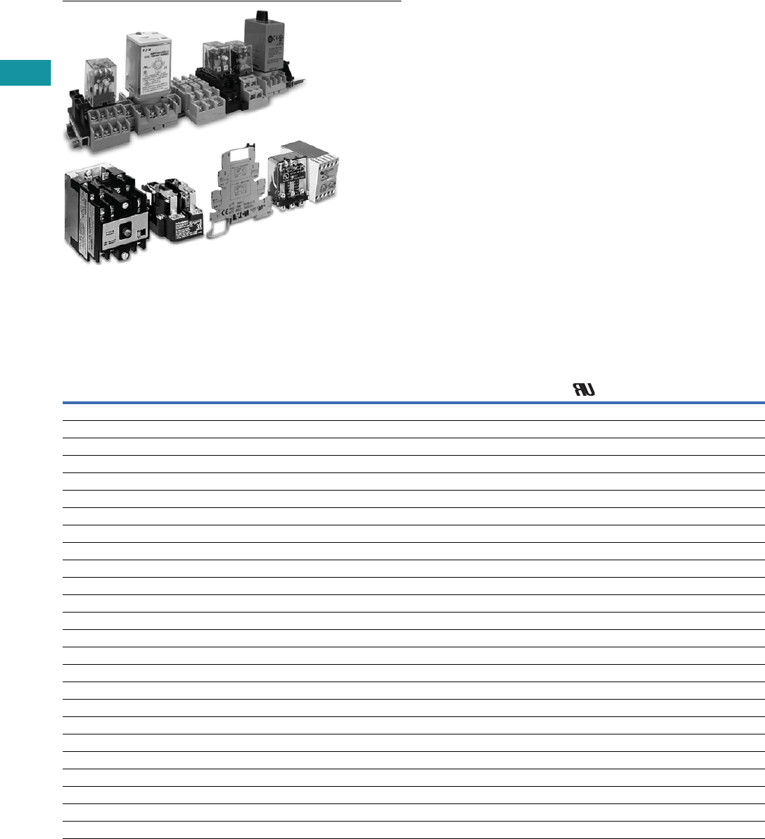
Control Relays and Timers
easyRelay Programmable Relays
D96 Series Solid-State Relay
Universal TR Series Timing Relay
D1 Series General Purpose Relay
Safety Relay
3.1 Relay Products
Control Relays and Timers Comparison . . . . . . . . . . . . . . . . . . . . . . . . V7-T3-2
3.2 XR Series Terminal Block Relays
Standard, OptoCoupler and High Current
Catalog Number Selection . . . . . . . . . . . . . . . . . . . . . . . . . . . . . . . . . . V7-T3-3
3.3 Programmable Relays
easy500, easy700, easy800, easy802/806 Relays and
MFD-Titan Multi-Function Displays
Product Overview . . . . . . . . . . . . . . . . . . . . . . . . . . . . . . . . . . . . . . . . V7-T3-19
3.4 General Purpose Plug-In Relays
General Purpose Relays—D1, D2, D3, D4, D5, D7, D8 and D9 Series
Product Selection Guide . . . . . . . . . . . . . . . . . . . . . . . . . . . . . . . . . . . . V7-T3-49
3.5 General Purpose Open Style Relays
9575H Series 3000 Relay
9575H Series 3000—Type AA, AC and DC. . . . . . . . . . . . . . . . . . . . . . V7-T3-122
3.6 Solid-State Relays
D93, D96 and D99 Series
Product Overview . . . . . . . . . . . . . . . . . . . . . . . . . . . . . . . . . . . . . . . . V7-T3-126
3.7 Machine Tool Relays
D15, BF/BFD, AR/ARD and D26 Series
Product Overview. . . . . . . . . . . . . . . . . . . . . . . . . . . . . . . . . . . . . . . . . V7-T3-145
3.8 Timing Relays
Universal TR, TR and TMR Series
Product Selection Guide . . . . . . . . . . . . . . . . . . . . . . . . . . . . . . . . . . . . V7-T3-171
3.9 Alternating Relays
D85 Series
Product Description . . . . . . . . . . . . . . . . . . . . . . . . . . . . . . . . . . . . . . . V7-T3-192
3.10 Safety Relays
ESR5 Series
Product Description . . . . . . . . . . . . . . . . . . . . . . . . . . . . . . . . . . . . . . . V7-T3-197
3.11 easySafety
ES4P Series
Product Description . . . . . . . . . . . . . . . . . . . . . . . . . . . . . . . . . . . . . . . V7-T3-203
V7-T3-2 Volume 7—Logic Control, Operator Interface and Connectivity Solutions CA08100008E—June 2013 www.eaton.com
3
3
3
3
3
3
3
3
3
3
3
3
3
3
3
3
3
3
3
3
3
3
3
3
3
3
3
3
3
3
V7-T3-2 Volume 7—Logic Control, Operator Interface and Connectivity Solutions CA08100008E—June 2013 www.eaton.com
3
3
3
3
3
3
3
3
3
3
3
3
3
3
3
3
3
3
3
3
3
3
3
3
3
3
3
3
3
3
3.1
Control Relays and Timers
Relay Product Overview
Relay Products
Contents
Description Page
Terminal Block Relays . . . . . . . . . . . . . . . . . . . . . . V7-T3-3
Programmable Relays . . . . . . . . . . . . . . . . . . . . . . V7-T3-19
General Purpose Plug-In Relays . . . . . . . . . . . . . . . V7-T3-49
General Purpose Type AA Relays . . . . . . . . . . . . . V7-T3-122
Solid-State Relays . . . . . . . . . . . . . . . . . . . . . . . . . V7-T3-126
Machine Tool Relays . . . . . . . . . . . . . . . . . . . . . . . V7-T3-145
Timing Relays . . . . . . . . . . . . . . . . . . . . . . . . . . . . V7-T3-171
Alternating Relays . . . . . . . . . . . . . . . . . . . . . . . . . V7-T3-192
Safety Relays . . . . . . . . . . . . . . . . . . . . . . . . . . . . V7-T3-197
Control Relays and Timers Comparison
Selection Guide by Catalog Number Prefix
Relays Type Mounting Contacts
Maximum
Amperage
(AC) UL CSA CE
Page
Number
9575H3 General purpose Panel mount Fixed 40A — ■■■V7-T3-123
AR/ARD Machine tool Panel mount Convertible 10A — ■■—V7-T3-158
BF/BFD Machine tool Panel mount Fixed 10A ■—■—V7-T3-152
D2PF Full featured plug-in DIN rail / panel mount Fixed 10A ■—■■V7-T3-60
D2PR Standard plug-in DIN rail / panel mount / flange Fixed 10A ■—■■V7-T3-60
D3PF Full featured plug-in DIN rail / panel mount Fixed 16A ■—■■V7-T3-70
D3PR Standard plug-in DIN rail / panel mount Fixed 16A ■—■■V7-T3-70
D4PR Standard plug-in DIN rail / panel mount Fixed 10A ■—■■V7-T3-79
D5PF Full featured plug-in DIN rail / panel mount Fixed 16A ■—■■V7-T3-84
D5PR Standard plug-in DIN rail / panel mount / PC board Fixed 16A ■—■■V7-T3-84
D7PF Full featured plug-in DIN rail / panel mount Fixed 20A ■—■■V7-T3-93
D7PR Standard plug-in DIN rail / panel mount / flange Fixed 20A ■—■■V7-T3-94
D8PR Standard plug-in DIN rail / panel mount / flange Fixed 30A ■—■■V7-T3-107
D9PR Standard plug-in Panel mounting Fixed 25A ■—■—V7-T3-113
D15 Machine tool DIN rail / panel mount Fixed 10A — ■■■V7-T3-147
D26 Machine tool Panel or channel mount Convertible 10A — ■■—V7-T3-163
D85 Alternating relays DIN rail / panel mount Fixed 10A ■■—■V7-T3-193
D1PF Full featured plug-in DIN rail / panel mount Fixed 20A ■—■■V7-T3-54
D1PR Standard plug-in DIN rail / panel mount Fixed 20A ■—■■V7-T3-54
easyRelay Programmable relay DIN rail Fixed 8A — ■■■V7-T3-23
TMR5 Timing relay (non-programmable) DIN rail / panel mount Fixed 10A ■■—■V7-T3-184
TMR6 Timing relay (non-programmable) DIN rail / panel mount Fixed 10A ■■—■V7-T3-188
TR Timing relay (programmable) DIN rail / panel mount Fixed 10A — ■■—V7-T3-181
Universal TR Timing relay (programmable) DIN rail Fixed 8A — ■■■V7-T3-177
XR Terminal block relay DIN rail Fixed 6A, 10A ■——■V7-T3-5

Volume 7—Logic Control, Operator Interface and Connectivity Solutions CA08100008E—June 2013 www.eaton.com V7-T3-3
3
3
3
3
3
3
3
3
3
3
3
3
3
3
3
3
3
3
3
3
3
3
3
3
3
3
3
3
3
3
Volume 7—Logic Control, Operator Interface and Connectivity Solutions CA08100008E—June 2013 www.eaton.com V7-T3-3
3
3
3
3
3
3
3
3
3
3
3
3
3
3
3
3
3
3
3
3
3
3
3
3
3
3
3
3
3
3
3.2
Control Relays and Timers
Ter m i n a l Bl o c k Rel ay s
Terminal Block Relays
Contents
Description Page
Terminal Block Relays
Standard Terminal Block Relays . . . . . . . . . . . . V7-T3-4
OptoCoupler Terminal Block Relays . . . . . . . . . V7-T3-12
High Current Terminal Block Relays . . . . . . . . . V7-T3-15
XR Series Accessories . . . . . . . . . . . . . . . . . . . V7-T3-18
Catalog Number Selection
XR Series—Overview
Description
XR = XR terminal block relay
XR U1D12 G
Poles
1 =1PDT
2 =2PDT
Connection Type
U =Screw
P = Spring
R = Replacement relay
Gold-Flashed Contacts
Blank =No
G =Yes
Type
D = Standard relay
S = Octocoupler (solid-state)
H = High current
Voltage
12 = 12 Vdc
24 = 24 Vdc
24U = 24 Vac/Vdc
120U = 120 Vac/110 Vdc
230U = 230 Vac/220 Vdc

V7-T3-4 Volume 7—Logic Control, Operator Interface and Connectivity Solutions CA08100008E—June 2013 www.eaton.com
3
3
3
3
3
3
3
3
3
3
3
3
3
3
3
3
3
3
3
3
3
3
3
3
3
3
3
3
3
3
V7-T3-4 Volume 7—Logic Control, Operator Interface and Connectivity Solutions CA08100008E—June 2013 www.eaton.com
3
3
3
3
3
3
3
3
3
3
3
3
3
3
3
3
3
3
3
3
3
3
3
3
3
3
3
3
3
3
3.2
Control Relays and Timers
Ter m i na l Bl o c k R el ay s
Standard Terminal Block Relay
Contents
Description Page
Standard Terminal Block Relays
Product Selection . . . . . . . . . . . . . . . . . . . . . . . V7-T3-5
Technical Data and Specifications . . . . . . . . . . V7-T3-6
Electrical Schematics . . . . . . . . . . . . . . . . . . . . V7-T3-11
Dimensions . . . . . . . . . . . . . . . . . . . . . . . . . . . V7-T3-11
OptoCoupler Terminal Block Relays . . . . . . . . . . . V7-T3-12
High Current Terminal Block Relays . . . . . . . . . . . V7-T3-15
XR Series Accessories . . . . . . . . . . . . . . . . . . . . . V7-T3-18
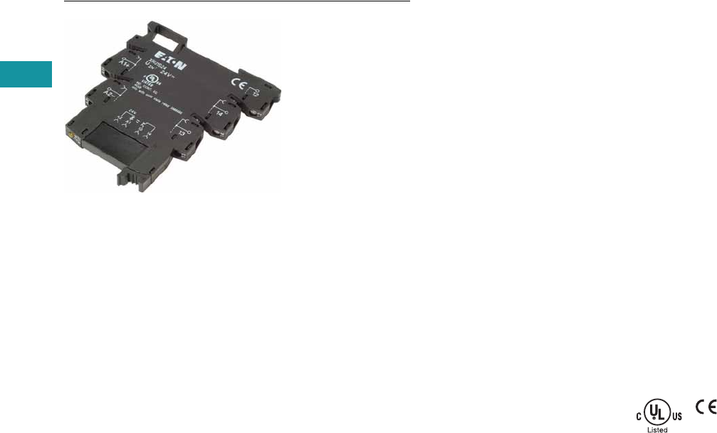
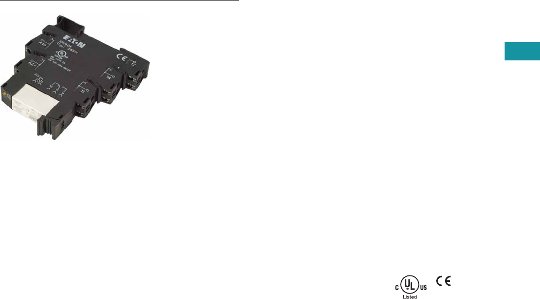
Standard Terminal Block Relays
Product Description
The XR Series Terminal
Block Relays are ideal for
applications that require a
high switching capacity and
long electrical service life.
The relays are plug-in
interfaces that connect to
basic terminal blocks. The
XR Series uses screw or
spring-cage technology, as
well as offers quick system
wiring, superior safety
features, clear labeling and
a high level of modularity.
Application Description
Used in automation systems,
electromechanical relays
guarantee a safe connection
between process I/O and
electronic controls. The
following functions are
covered by relay coupling
elements:
●Electrical isolation
between the input and
output circuits
●Independence of the type
of switching current (AC
and DC)
●High short-term overload
resistance in the event of
short circuits or voltage
peaks
●Low switching losses
●Ease of operation
Features
●Pluggable relay allows for
field replacement
●Functional plug-in bridges
●Choice of screw
connections or spring-cage
connection
●LED status indication
●DIN rail mount
●Only 6.2 mm wide for
single-pole versions,
14 mm wide for double-
pole
●All common input
voltages between
12 Vdc to 120 Vac
●Gold-plated contacts
available
●Equipped with a robust,
miniature relay:
●IP67 protection
●Environmentally friendly,
cadmium-free contact
material
●Easy, cost-effective
installation and
replacement using the
engagement lever
Standards and Certifications
●cULus listed
●CE
Volume 7—Logic Control, Operator Interface and Connectivity Solutions CA08100008E—June 2013 www.eaton.com V7-T3-5
3
3
3
3
3
3
3
3
3
3
3
3
3
3
3
3
3
3
3
3
3
3
3
3
3
3
3
3
3
3
Volume 7—Logic Control, Operator Interface and Connectivity Solutions CA08100008E—June 2013 www.eaton.com V7-T3-5
3
3
3
3
3
3
3
3
3
3
3
3
3
3
3
3
3
3
3
3
3
3
3
3
3
3
3
3
3
3
3.2
Control Relays and Timers
Ter m i n a l Bl o c k Rel ay s
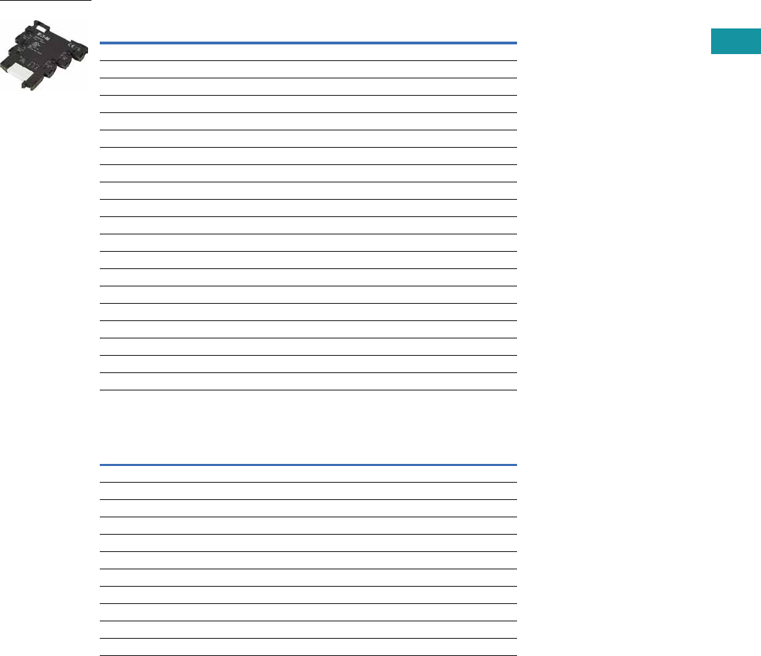
Product Selection
Standard Terminal Block Relays
Standard Replacement Relays
Note
1 Voltage is the rating at the base. It may not match the voltage on the specific replacement relay.
Gold-Plated
Contacts
Rated
Current
Supply
Voltage
Standard
Pack
Catalog
Number
1PDT Screw Connection
No 6A 12 Vdc 10 XRU1D12
No 6A 120 Vac/110 Vdc 10 XRU1D120U
Yes 6A 120 Vac/110 Vdc 10 XRU1D120UG
No 6A 24 Vdc 10 XRU1D24
No 6A 24 Vac/Vdc 10 XRU1D24U
Yes 6A 24 Vac/Vdc 10 XRU1D24UG
No 6A 230 Vac/220 Vdc 10 XRU1D230U
1PDT Spring Cage Connection
No 6A 12 Vdc 10 XRP1D12
No 6A 120 Vac/110 Vdc 10 XRP1D120U
No 6A 24 Vdc 10 XRP1D24
No 6A 24 Vac/Vdc 10 XRP1D24U
No 6A 230 Vac/220 Vdc 10 XRP1D230U
DPDT Screw Connection
No 6A 12 Vdc 10 XRU2D12
No 6A 120 Vac/110 Vdc 10 XRU2D120U
No 6A 24 Vdc 10 XRU2D24
No 6A 24 Vac/Vdc 10 XRU2D24U
No 6A 230 Vac/220 Vdc 10 XRU2D230U
Gold-Plated
Contacts
Rated
Current
Supply
Voltage 1
Standard
Pack
Catalog
Number
1PDT
No 6A 12 Vdc 10 XRR1D12
No 6A 120 Vac/110 Vdc 10 XRR1D120U
Yes 6A 120 Vac/110 Vdc 10 XRR1D120UG
No 6A 24 Vdc 10 XRR1D24
Yes 6A 24 Vdc 10 XRR1D24G
DPDT
No 6A 12 Vdc 10 XRR2D12
No 6A 120 Vac/110 Vdc 10 XRR2D120U
No 6A 24 Vdc 10 XRR2D24
No 6A 230 Vac/220 Vdc 10 XRR2D230U
XRU1D 24U

V7-T3-6 Volume 7—Logic Control, Operator Interface and Connectivity Solutions CA08100008E—June 2013 www.eaton.com
3
3
3
3
3
3
3
3
3
3
3
3
3
3
3
3
3
3
3
3
3
3
3
3
3
3
3
3
3
3
V7-T3-6 Volume 7—Logic Control, Operator Interface and Connectivity Solutions CA08100008E—June 2013 www.eaton.com
3
3
3
3
3
3
3
3
3
3
3
3
3
3
3
3
3
3
3
3
3
3
3
3
3
3
3
3
3
3
3.2
Control Relays and Timers
Ter m i na l Bl o c k R el ay s
Technical Data and Specifications
Standard 1PDT Screw Connection Terminal Block Relays
Note
1The separating plate, XRAPLCESK, should be installed for voltages greater than 250V (L1, L2, L3) between identical terminal points of adjacent modules.
Potential bridging is then possible with the XRAFBST bridge system.
Catalog Number XRU1D12 XRU1D24 XRU1D24U XRU1D120U
Replacement Relay XRR1D12 XRR1D24 XRR1D24 XRR1D120U
Input voltage 12 Vdc 24 Vdc 24 Vac/Vdc 120 Vac/110 Vdc
Connection Data
Rigid solid AWG (mm2) 26–14 (0.14–2.5) 26–14 (0.14–2.5) 26–14 (0.14–2.5) 26–14 (0.14–2.5)
Flexible stranded AWG (mm2) 26–14 (0.14–2.5) 26–14 (0.14–2.5) 26–14 (0.14–2.5) 26–14 (0.14–2.5)
Input Data for 1PDT Screw Connection Versions
Input voltage 12 Vdc 24 Vdc 24 Vac/Vdc 120 Vac/110 Vdc
Permissible range See Page V7-T3-10 See Page V7-T3-10 See Page V7-T3-10 See Page V7-T3-10
Typical input current 15.3 mA 9 mA 11 mA (24 Vac)/8.5 mA (24 Vdc) 3.5 mA (120 Vac)/3 mA (110 Vdc)
Typical response time 5 ms 5 ms 6 ms 6 ms
Typical release time 8 ms 8 ms 15 ms 15 ms
Input protection Polarity protection diode,
free-wheeling diode
Polarity protection diode,
free-wheeling diode
Bridge rectifier Bridge rectifier
Output Data
Contact type 1PDT 1PDT 1PDT 1PDT
Contact material AgSnO AgSnO AgSnO AgSnO
Max. switching voltage 250 Vac/Vdc 1250 Vac/Vdc 1250 Vac/Vdc 1250 Vac/Vdc 1
Min. switching voltage 12 Vac/Vdc 12 Vac/Vdc 12 Vac/Vdc 12 Vac/Vdc
Limiting continuous current 6A 6A 6A 6A
Min. switching current 10 mA 10 mA 10 mA 10 mA
Min. switching power 120 mW 120 mW 120 mW 120 mW
Miscellaneous Data
Ambient temp range –4° to 140°F (–20° to 60°C) –4° to 140°F (–20° to 60°C) –4° to 140°F (–20° to 60°C) –4° to 140°F (–20° to 60°C)
Rated operating mode 100% operating factor 100% operating factor 100% operating factor 100% operating factor
Inflammability class V0, in accordance with UL 94 V0, in accordance with UL 94 V0, in accordance with UL 94 V0, in accordance with UL 94
Mechanical service life 2 x 10⁷ cycles 2 x 10⁷ cycles 2 x 10⁷ cycles 2 x 10⁷ cycles

Volume 7—Logic Control, Operator Interface and Connectivity Solutions CA08100008E—June 2013 www.eaton.com V7-T3-7
3
3
3
3
3
3
3
3
3
3
3
3
3
3
3
3
3
3
3
3
3
3
3
3
3
3
3
3
3
3
Volume 7—Logic Control, Operator Interface and Connectivity Solutions CA08100008E—June 2013 www.eaton.com V7-T3-7
3
3
3
3
3
3
3
3
3
3
3
3
3
3
3
3
3
3
3
3
3
3
3
3
3
3
3
3
3
3
3.2
Control Relays and Timers
Ter m i n a l Bl o c k Rel ay s
Standard 1PDT Screw Connection Terminal Block Relays with Gold Contacts
Notes
1The separating plate, XRAPLCESK, should be installed for voltages greater than 250V (L1, L2, L3) between identical terminal
points of adjacent modules. Potential bridging is then possible with the XRAFBST bridge system.
2If the maximum values are exceeded, the gold layer is destroyed and the values in parentheses apply.
Catalog Number XRU1D24UG XRU1D120UG
Replacement Relay XRR1D24G XRR1D120UG
Input voltage 24 Vac/Vdc 120 Vac/110 Vdc
Connection Data
Rigid solid AWG (mm2) 26–14 (0.14–2.5) 26–14 (0.14–2.5)
Flexible stranded AWG (mm2) 26–14 (0.14–2.5) 26–14 (0.14–2.5)
Input Data for 1PDT Screw Connection Versions with Gold Contacts
Input voltage 24 Vac/Vdc 120 Vac/110 Vdc
Permissible range See Page V7-T3-10 See Page V7-T3-10
Typical input current 11 mA (24 Vac)/8.5 mA (24 Vdc) 3.5 mA (120 Vac)/3 mA (110 Vdc)
Typical response time 6 ms 6 ms
Typical release time 15 ms 15 ms
Input protection Bridge rectifier Bridge rectifier
Output Data
Contact type 1PDT 1PDT
Contact material AgSnO, gold plated 1AgSnO, gold plated 1
Max. switching voltage 30 Vac/36 Vdc (250 Vac/Vdc) 230 Vac/36 Vdc (250 Vac/Vdc) 2
Min. switching voltage 100 mV (12 Vac/Vdc) 2100 mV (12 Vac/Vdc) 2
Limiting continuous current 50 mA (6A) 250 mA (6A) 2
Min. switching current 1 mA (10 mA) 21 mA (10 mA) 2
Min. switching power 100 mW (120 mW) 2100 mW (120 mW) 2
Miscellaneous Data
Ambient temp range –4° to 140°F (–20° to 60°C) –40° to 131°F (–20° to 55°C)
Rated operating mode 100% operating factor 100% operating factor
Inflammability class V0, in accordance with UL 94 V0, in accordance with UL 94
Mechanical service life 2 x 10⁷ cycles 2 x 10⁷ cycles

V7-T3-8 Volume 7—Logic Control, Operator Interface and Connectivity Solutions CA08100008E—June 2013 www.eaton.com
3
3
3
3
3
3
3
3
3
3
3
3
3
3
3
3
3
3
3
3
3
3
3
3
3
3
3
3
3
3
V7-T3-8 Volume 7—Logic Control, Operator Interface and Connectivity Solutions CA08100008E—June 2013 www.eaton.com
3
3
3
3
3
3
3
3
3
3
3
3
3
3
3
3
3
3
3
3
3
3
3
3
3
3
3
3
3
3
3.2
Control Relays and Timers
Ter m i na l Bl o c k R el ay s
Standard 1PDT Spring Cage Terminal Block Relays
Note
1The separating plate, XRAPLCESK, should be installed for voltages greater than 250V (L1, L2, L3) between identical terminal points of adjacent modules.
Potential bridging is then possible with the XRAFBST bridge system.
Catalog Number XRP1D12 XRP1D24 XRP1D24U XRP1D120U
Replacement Relay XRR1D12 XRR1D24 XRR1D24 XRR1D120U
Input voltage 12 Vdc 24 Vdc 24 Vac/Vdc 120 Vac/110 Vdc
Connection Data
Rigid solid AWG (mm2) 26–14 (0.14–2.5) 26–14 (0.14–2.5) 26–14 (0.14–2.5) 26–14 (0.14–2.5)
Flexible stranded AWG (mm2) 26–14 (0.14–2.5) 26–14 (0.14–2.5) 26–14 (0.14–2.5) 26–14 (0.14–2.5)
Input Data for 1PDT Spring Cage Versions
Input voltage 12 Vdc 24 Vdc 24 Vac/Vdc 120 Vac/110 Vdc
Permissible range See Page V7-T3-10 See Page V7-T3-10 See Page V7-T3-10 See Page V7-T3-10
Typical input current 15.3 mA 9 mA 11 mA (24 Vac)/8.5 mA (24 Vdc) 3.5 mA (120 Vac)/3 mA (110 Vdc)
Typical response time 5 ms 5 ms 6 ms 6 ms
Typical release time 8 ms 8 ms 15 ms 15 ms
Input protection Polarity protection diode,
free-wheeling diode
Polarity protection diode,
free-wheeling diode
Bridge rectifier Bridge rectifier
Output Data
Contact type 1PDT 1PDT 1PDT 1PDT
Contact material AgSnO AgSnO AgSnO AgSnO
Max. switching voltage 250 Vac/Vdc 1250 Vac/Vdc 1250 Vac/Vdc 1250 Vac/Vdc 1
Min. switching voltage 12 Vac/Vdc 12 Vac/Vdc 12 Vac/Vdc 12 Vac/Vdc
Limiting continuous current 6A 6A 6A 6A
Min. switching current 10 mA 10 mA 10 mA 10 mA
Min. switching power 120 mW 120 mW 120 mW 120 mW
Miscellaneous Data
Ambient temp range –4° to 140°F (–20° to 60°C) –4° to 140°F (–20° to 60°C) –4° to 140°F (–20° to 60°C) –4° to 131°F (–20° to 55°C)
Rated operating mode 100% operating factor 100% operating factor 100% operating factor 100% operating factor
Inflammability class V0, in accordance with UL 94 V0, in accordance with UL 94 V0, in accordance with UL 94 V0, in accordance with UL 94
Mechanical service life 2 x 10⁷ cycles 2 x 10⁷ cycles 2 x 10⁷ cycles 2 x 10⁷ cycles

Volume 7—Logic Control, Operator Interface and Connectivity Solutions CA08100008E—June 2013 www.eaton.com V7-T3-9
3
3
3
3
3
3
3
3
3
3
3
3
3
3
3
3
3
3
3
3
3
3
3
3
3
3
3
3
3
3
Volume 7—Logic Control, Operator Interface and Connectivity Solutions CA08100008E—June 2013 www.eaton.com V7-T3-9
3
3
3
3
3
3
3
3
3
3
3
3
3
3
3
3
3
3
3
3
3
3
3
3
3
3
3
3
3
3
3.2
Control Relays and Timers
Ter m i n a l Bl o c k Rel ay s
Standard DPDT Screw Connection Terminal Block Relays
Note
1The separating plate, XRAPLCESK, should be installed for voltages greater than 250V (L1, L2, L3) between identical terminal points of adjacent modules.
Potential bridging is then possible with the XRAFBST bridge system.
Catalog Number XRU2D12 XRU2D24 XRU2D24U XRU2D120U
Replacement Relay XRR2D12 XRR2D24 XRR2D24 XRR2D120U
Input voltage 12 Vdc 24 Vdc 24 Vac/Vdc 120 Vac/110 Vdc
Connection Data
Rigid solid AWG (mm2) 26–14 (0.14–2.5) 26–14 (0.14–2.5) 26–14 (0.14–2.5) 26–14 (0.14–2.5)
Flexible stranded AWG (mm2) 26–14 (0.14–2.5) 26–14 (0.14–2.5) 26–14 (0.14–2.5) 26–14 (0.14–2.5)
Input Data for 1PDT Spring Cage Versions
Input voltage 12 Vdc 24 Vdc 24 Vac/Vdc 120 Vac/110 Vdc
Permissible range See Page V7-T3-10 See Page V7-T3-10 See Page V7-T3-10 See Page V7-T3-10
Typical input current 33 mA 18 mA 17.5 mA 4.5 mA (120 Vac)/4.2 mA (110 Vdc)
Typical response time 8 ms 8 ms 8 ms 7 ms
Typical release time 10 ms 10 ms 10 ms 10 ms
Input protection Polarity protection diode,
free-wheeling diode
Polarity protection diode,
free-wheeling diode
Bridge rectifier Bridge rectifier
Output Data
Contact type 2PDT Single contact, 2PDT Single contact, 2PDT Single contact, 2PDT
Contact material AgNi AgNi AgNi AgNi
Max. switching voltage 250 Vac/Vdc 1250 Vac/Vdc 1250 Vac/Vdc 1250 Vac/Vdc 1
Min. switching voltage 5V 5V 5V 5V
Limiting continuous current 6A 6A 6A 6A
Max. inrush current 15A (300 ms) 15A (300 ms) 15A (300 ms) 15A (300 ms)
Min. switching current 10 mA 10 mA 10 mA 10 mA
Min. switching power 50 mW 50 mW 50 mW 50 mW
General Data
Ambient temp range –4° to 140°F (–20° to 60°C) –4° to 140°F (–20° to 60°C) –4° to 140°F (–20° to 60°C) –4° to 140°F (–20° to 60°C)
Rated operating mode 100% operating factor 100% operating factor 100% operating factor 100% operating factor
Inflammability class V0, in accordance with UL 94 V0, in accordance with UL 94 V0, in accordance with UL 94 V0, in accordance with UL 94
Mechanical service life 3 x 10⁷ cycles 3 x 10⁷ cycles 3 x 10⁷ cycles 3 x 10⁷ cycles
V7-T3-10 Volume 7—Logic Control, Operator Interface and Connectivity Solutions CA08100008E—June 2013 www.eaton.com
3
3
3
3
3
3
3
3
3
3
3
3
3
3
3
3
3
3
3
3
3
3
3
3
3
3
3
3
3
3
V7-T3-10 Volume 7—Logic Control, Operator Interface and Connectivity Solutions CA08100008E—June 2013 www.eaton.com
3
3
3
3
3
3
3
3
3
3
3
3
3
3
3
3
3
3
3
3
3
3
3
3
3
3
3
3
3
3
3.2
Control Relays and Timers
Ter m i na l Bl o c k R el ay s
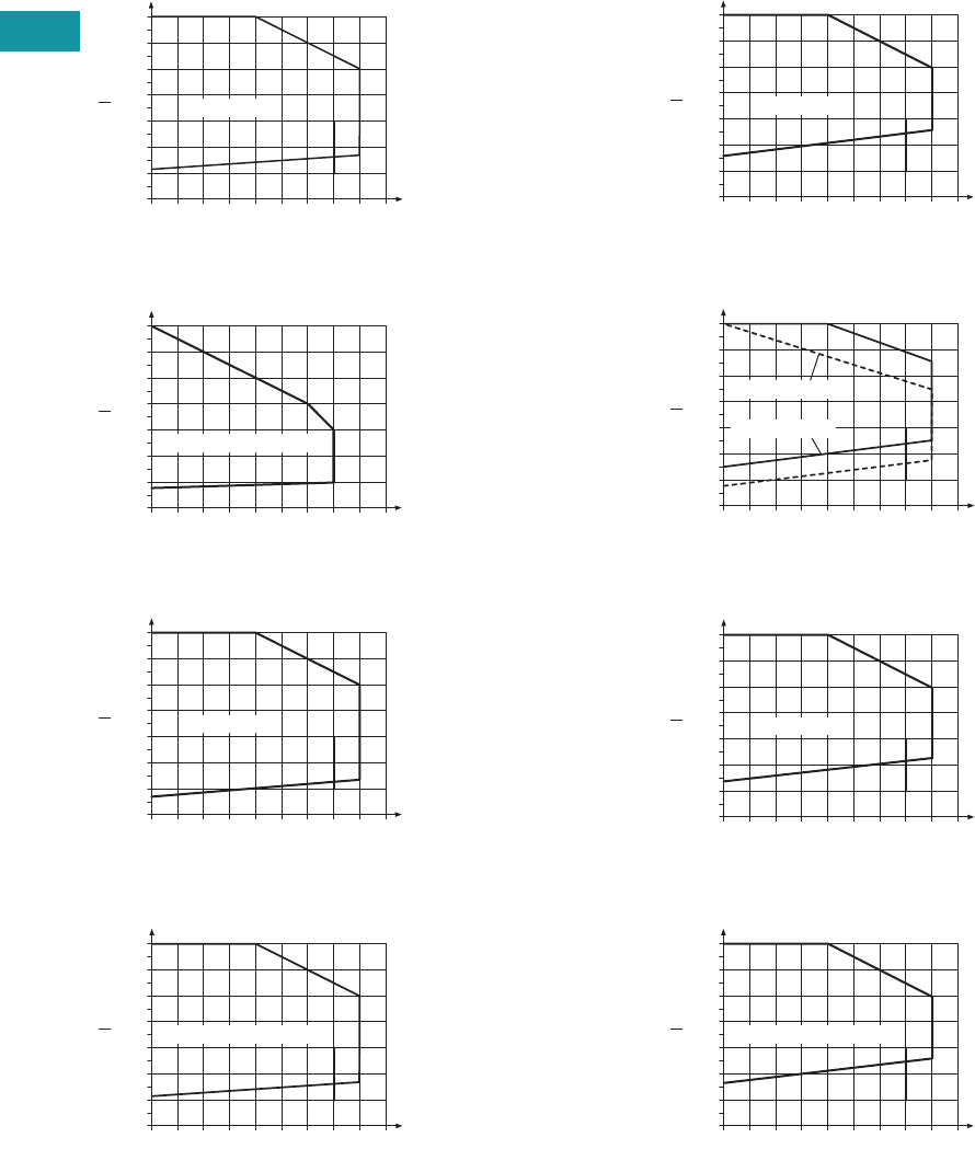
Permissible Range Diagrams
1PDT Relay Modules
Operating Range Voltage for 12 Vdc
Operating Range Voltage for 120 Vac/110 Vdc
Operating Range Voltage for 24 Vdc
Operating Range Voltage for 24 Vac/Vdc
DPDT Relay Modules
Operating Range Voltage for 12 Vdc
Operating Range Voltage for 120 Vac/110 Vdc
Operating Range Voltage for 24 Vdc
Operating Range Voltage for 24 Vac/Vdc
Notes
General Conditions — Direct alignment in the block, all devices 100% operating factor, horizontal or vertical mounting.
Curve A — Maximum permissible continuous operating voltage Umax with limiting continuous current on the contact side (see respective technical data).
Curve B — Minimum permissible relay operate voltage Uop after pre-excitation 1) (see respective technical data).
1Pre-excitation: Relay has been operated in a thermally steady state at the ambient temperature TU with nominal voltage UN and limiting continuous current on the contact side (see respective
technical data) (warm coil). After being switched off for a short time, the relay must reliably pick up again at Uop.
1.4
1.3
1.2
1.1
1.0
0.9
0.8
0.7
20 25 30
A
B
35 40 45 50 55 60 65
U
UN
TN [°C]
UN = 12 Vdc
1.4
1.3
1.2
1.1
1.0
0.9
0.8
0.7
20 25 30
A
B
35 40 45 50 55 60 65
U
UN
TN [°C]
UN = 110 Vdc/120 Vac
1.4
1.3
1.2
1.1
1.0
0.9
0.8
0.7
20 25 30
A
B
35 40 45 50 55 60 65
U
UN
TN [°C]
UN = 24 Vdc
1.4
1.3
1.2
1.1
1.0
0.9
0.8
0.7
20 25 30
A
B
35 40 45 50 55 60 65
U
UN
TN [°C]
UN = 24 Vdc/24 Vac
1.4
1.3
1.2
1.1
1.0
0.9
0.8
0.7
20 25 30
A
B
35 40 45 50 55 60 65
U
UN
TN [°C]
UN = 12 Vdc
1.4
1.3
1.2
1.1
1.0
0.9
0.8
0.7
20 25 30
A
B
35 40 45 50 55 60 65
U
UN
TN [°C]
UN = 120 Vac
UN = 110 Vdc
1.4
1.3
1.2
1.1
1.0
0.9
0.8
0.7
20 25 30
A
B
35 40 45 50 55 60 65
U
UN
TN [°C]
UN = 24 Vdc
1.4
1.3
1.2
1.1
1.0
0.9
0.8
0.7
20 25 30
A
B
35 40 45 50 55 60 65
U
UN
TN [°C]
UN = 24 Vdc/24 Vac
Volume 7—Logic Control, Operator Interface and Connectivity Solutions CA08100008E—June 2013 www.eaton.com V7-T3-11
3
3
3
3
3
3
3
3
3
3
3
3
3
3
3
3
3
3
3
3
3
3
3
3
3
3
3
3
3
3
Volume 7—Logic Control, Operator Interface and Connectivity Solutions CA08100008E—June 2013 www.eaton.com V7-T3-11
3
3
3
3
3
3
3
3
3
3
3
3
3
3
3
3
3
3
3
3
3
3
3
3
3
3
3
3
3
3
3.2
Control Relays and Timers
Ter m i n a l Bl o c k Rel ay s
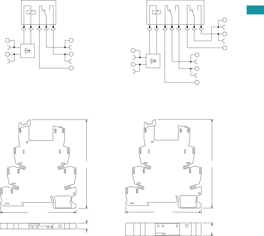
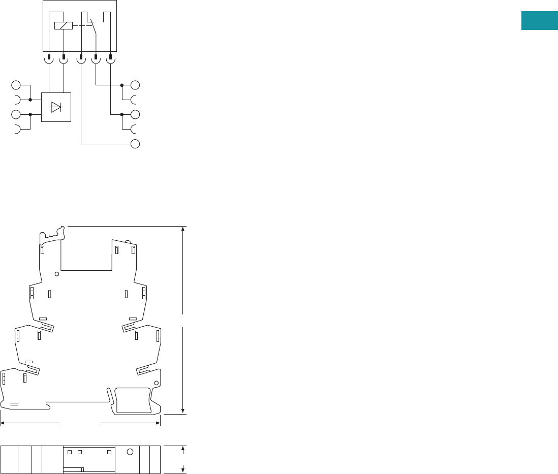
Electrical Schematics
1PDT Terminal Block Relays DPDT Terminal Block Relays
Dimensions
Approximate Dimensions in Inches (mm)
Standard 1PDT Terminal Block Relays Standard DPDT Terminal Block Relays
11
14
12
A2
A1
12
22
24
21
A2
A1
11
14
3.70 (94.0)
0.24 (6.2)
3.15 (80.0)
3.70 (94.0)
0.55 (14.0)
3.15 (80.0)
V7-T3-12 Volume 7—Logic Control, Operator Interface and Connectivity Solutions CA08100008E—June 2013 www.eaton.com
3
3
3
3
3
3
3
3
3
3
3
3
3
3
3
3
3
3
3
3
3
3
3
3
3
3
3
3
3
3
V7-T3-12 Volume 7—Logic Control, Operator Interface and Connectivity Solutions CA08100008E—June 2013 www.eaton.com
3
3
3
3
3
3
3
3
3
3
3
3
3
3
3
3
3
3
3
3
3
3
3
3
3
3
3
3
3
3
3.2
Control Relays and Timers
Ter m i na l Bl o c k R el ay s
OptoCoupler Terminal Block Relay
Contents
Description Page
Standard Terminal Block Relays . . . . . . . . . . . . . . V7-T3-4
OptoCoupler Terminal Block Relays
Product Selection . . . . . . . . . . . . . . . . . . . . . . . V7-T3-13
Technical Data and Specifications . . . . . . . . . . . V7-T3-13
Electrical Schematic . . . . . . . . . . . . . . . . . . . . . V7-T3-14
Dimensions . . . . . . . . . . . . . . . . . . . . . . . . . . . V7-T3-14
High Current Terminal Block Relays . . . . . . . . . . . V7-T3-15
XR Series Accessories . . . . . . . . . . . . . . . . . . . . . V7-T3-18
OptoCoupler Terminal Block Relays
Product Description
The XR Series OptoCoupler
Terminal Block Relays can be
used in all applications and
consist of a pluggable
miniature OptoCoupler and a
basic terminal block. The XR
Series uses screw or spring-
cage technology, as well as
offers quick system wiring,
superior safety features, clear
labeling and a high level of
modularity.
Application Description
The XR Series OptoCoupler
relays can be used as an input
or output interface. They
provide the typical reliability
of OptoCouplers and are
especially suited for high
operating frequencies.
Features
●Pluggable relay allows for
field replacement
●Functional plug-in bridges
●LED status indication
●DIN rail mount
●Only 6.2 mm wide
●Switching capacity up to 24
Vdc/3A
●IP67-protected optical
electronics
●Wear-resistant and bounce-
free switching
●Insensitive to shock and
vibration
●Integrated protection
circuit
●Zero voltage switch at AC
output
Standards and Certifications
●cULus listed
●CE

Volume 7—Logic Control, Operator Interface and Connectivity Solutions CA08100008E—June 2013 www.eaton.com V7-T3-13
3
3
3
3
3
3
3
3
3
3
3
3
3
3
3
3
3
3
3
3
3
3
3
3
3
3
3
3
3
3
Volume 7—Logic Control, Operator Interface and Connectivity Solutions CA08100008E—June 2013 www.eaton.com V7-T3-13
3
3
3
3
3
3
3
3
3
3
3
3
3
3
3
3
3
3
3
3
3
3
3
3
3
3
3
3
3
3
3.2
Control Relays and Timers
Ter m i n a l Bl o c k Rel ay s
Product Selection
OptoCoupler Terminal Block Relays
OptoCoupler Replacement Relays
Technical Data and Specifications
Pluggable Power OptoCoupler (Solid-State) Terminal Block Relays
Note
1Voltage is the rating at the base. It may not match the voltage on the specific replacement relay.
Rated Current Supply Voltage Standard Pack
Catalog
Number
2A 120 Vac/110 Vdc 10 XRU1S120U
2A 24 Vdc 10 XRU1S24
Rated Current Supply Voltage 1Standard Pack
Catalog
Number
2A 24 Vdc 18 XRR1S24
2A 120 Vac/110 Vdc 10 XRR1S120U
XRU1S24
Catalog Number XRU1S24 XRU1S120U
Replacement Relay XRR1S24 XRR1S120U
Input voltage 24 Vdc 120 Vac/110 Vdc
Connection Data
Rigid solid AWG (mm2) 26–14 (0.14–2.5) 26–14 (0.14–2.5)
Flexible stranded AWG (mm2) 26–14 (0.14–2.5) 26–14 (0.14–2.5)
Input Data
Input voltage 24 Vdc 120 Vac/110 Vdc
Permissible range 0.8–1.2 0.8 –1.1
Typical input current 9 mA 4 mA
Switching level 1 signal (“H”) >0.8 >0.8
Switching level 0 signal (“L”) <0.4 <0.25
Typical switch-on time 20 μS 6 ms
Typical turn-off time 500 μS 10 ms
Input protection Polarity protection diode,
free-wheeling diode
Bridge rectifier
Output Data
Max. switching voltage 33 Vdc 33 Vdc
Min. switching voltage 3 Vdc 3 Vdc
Limiting continuous current 3A (See derating curve) 3A (See derating curve)
Max. inrush current 15A (10 ms) 15A (10 ms)
Output circuit 2-conductor floating 2-conductor floating
Output protection Polarity protection, surge protection Polarity protection, surge protection
Voltage drop at maximum
limiting continuous current
< 200 mV < 200 mV
General Data
Ambient temp range –4° to 140°F (–20° to 60°C) –4° to 140°F (–20° to 60°C)
Rated operating mode 100% operating factor 100% operating factor
Inflammability class V0, in accordance with UL 94 V0, in accordance with UL 94
Mechanical service life 2 x 10⁷ cycles 2 x 10⁷ cycles

V7-T3-14 Volume 7—Logic Control, Operator Interface and Connectivity Solutions CA08100008E—June 2013 www.eaton.com
3
3
3
3
3
3
3
3
3
3
3
3
3
3
3
3
3
3
3
3
3
3
3
3
3
3
3
3
3
3
V7-T3-14 Volume 7—Logic Control, Operator Interface and Connectivity Solutions CA08100008E—June 2013 www.eaton.com
3
3
3
3
3
3
3
3
3
3
3
3
3
3
3
3
3
3
3
3
3
3
3
3
3
3
3
3
3
3
3.2
Control Relays and Timers
Ter m i na l Bl o c k R el ay s
Derating Curve
OptoCoupler
Electrical Schematic
Pluggable Power OptoCoupler (Solid-State)
Terminal Block Relays
Dimensions
Approximate Dimensions in Inches (mm)
Pluggable Power OptoCoupler (Solid-State)
Terminal Block Relays
0
0
1
2
3
10 20 30
Ambient Temperature (°C)
Load Current (A)
40 50 60
13+
14
A2
A1
3.70 (94.0)
0.24 (6.2)
3.15 (80.0)
Volume 7—Logic Control, Operator Interface and Connectivity Solutions CA08100008E—June 2013 www.eaton.com V7-T3-15
3
3
3
3
3
3
3
3
3
3
3
3
3
3
3
3
3
3
3
3
3
3
3
3
3
3
3
3
3
3
Volume 7—Logic Control, Operator Interface and Connectivity Solutions CA08100008E—June 2013 www.eaton.com V7-T3-15
3
3
3
3
3
3
3
3
3
3
3
3
3
3
3
3
3
3
3
3
3
3
3
3
3
3
3
3
3
3
3.2
Control Relays and Timers
Ter m i n a l Bl o c k Rel ay s
High Current Terminal Block Relay
Contents
Description Page
Standard Terminal Block Relays . . . . . . . . . . . . . . . V7-T3-4
OptoCoupler Terminal Block Relays . . . . . . . . . . . . V7-T3-12
High Current Terminal Block Relays
Product Selection . . . . . . . . . . . . . . . . . . . . . . . V7-T3-16
Technical Data and Specifications . . . . . . . . . . V7-T3-16
Electrical Schematic . . . . . . . . . . . . . . . . . . . . . V7-T3-17
Dimensions . . . . . . . . . . . . . . . . . . . . . . . . . . . V7-T3-17
XR Series Accessories . . . . . . . . . . . . . . . . . . . . . V7-T3-18
High Current Terminal Block Relays
Product Description
The XR Series Relays include
products designed to meet
high continuous current and/
or long electrical service life
applications. The XR Series
Relays are plug-in interfaces
that connect to basic terminal
blocks that use screw
connection technology.
Overall width is 14 mm.
Application Description
These relays are best suited
for applications that require
higher continuous load
currents than miniature
relays can carry and switch.
They can withstand inrush
currents or brief overloads
without damage, and allow
for continuous load currents
of up to 10A. The XR Series
Relay boasts an average
service life of the contacts
that is two or three times
the normal life of a less
powerful relay, resulting in
service cost savings.
Features
●14 mm wide
●Pluggable relay allows for
field replacement
●Convenient plug-in bridge
system
●LED status indication
●DIN Rail Mount
●IP67-protected optical
electronics
●Wear-resistant and bounce-
free switching
●Insensitive to shock and
vibration
●Integrated protection
circuit
●Zero voltage switch at AC
output
●Environmentally friendly,
cadmium-free contact
material
●Electrical isolation
between input and output
Standards and Certifications
●cULus listed
●CE
V7-T3-16 Volume 7—Logic Control, Operator Interface and Connectivity Solutions CA08100008E—June 2013 www.eaton.com
3
3
3
3
3
3
3
3
3
3
3
3
3
3
3
3
3
3
3
3
3
3
3
3
3
3
3
3
3
3
V7-T3-16 Volume 7—Logic Control, Operator Interface and Connectivity Solutions CA08100008E—June 2013 www.eaton.com
3
3
3
3
3
3
3
3
3
3
3
3
3
3
3
3
3
3
3
3
3
3
3
3
3
3
3
3
3
3
3.2
Control Relays and Timers
Ter m i na l Bl o c k R el ay s
Product Selection
High Current Terminal Block Relays
High Current Replacement Relays
Technical Data and Specifications
High Current Terminal Block Relays (1PDT)
Notes
1Voltage is the rating at the base. It may not match the voltage on the specific replacement relay.
2The separating plate, XRAPLCESK, should be installed for voltages greater than 250V (L1, L2, L3) between identical terminal points of adjacent modules.
Potential bridging is then possible with the XRAFBST bridge system.
3The current rating for the normally open contact (#14) is 10A. The current rating for the normally closed contact (#12) is 6A and can be increased to 10A by bridging the
two #12 contact connections.
Rated Current Supply Voltage Standard Pack
Catalog
Number
10A 12 Vdc 10 XRU1H12
10A 120 Vac/110 Vdc 10 XRU1H120U
10A 24 Vdc 10 XRU1H24
10A 24 Vac/Vdc 10 XRU1H24U
Rated Current Supply Voltage 1Standard Pack
Catalog
Number
10A 24 Vdc 10 XRR1H24
10A 24 Vac/Vdc 10 XRR1H24U
10A 12 Vdc 10 XRR1H12
10A 120 Vac/110 Vdc 10 XRR1H120U
Catalog Number XRU1H12 XRU1H24 XRU1H24U XRU1H120U
Replacement Relay XRR1H12 XRR1H24 XRR1H24U XRR1H120U
Input voltage 12 Vdc 24 Vdc 24 Vac/Vdc 120 Vac/110 Vdc
Connection Data
Rigid solid AWG (mm2) 26–14 (0.14–2.5) 26–14 (0.14–2.5) 26–14 (0.14–2.5) 26–14 (0.14–2.5)
Flexible stranded AWG (mm2) 26–14 (0.14–2.5) 26–14 (0.14–2.5) 26–14 (0.14–2.5) 26–14 (0.14–2.5)
Input Data for 1PDT Spring Cage Versions
Input voltage 12 Vdc 24 Vdc 24 Vac/Vdc 120 Vac/110 Vdc
Permissible range See Page V7-T3-10 See Page V7-T3-10 See Page V7-T3-10 See Page V7-T3-10
Typical input current 33 mA 18 mA 17.5 mA 4.5 mA (120 Vac)/4.2 mA (110 Vdc)
Typical response time 8 ms 8 ms 8 ms 7 ms
Typical release time 10 ms 10 ms 10 ms 10 ms
Input protection Polarity protection diode,
free-wheeling diode
Polarity protection diode,
free-wheeling diode
Bridge rectifier Bridge rectifier
Output Data
Contact type Single contact, 1PDT Single contact, 1PDT Single contact, 1PDT Single contact, 1PDT
Contact material AgNi AgNi AgNi AgNi
Max. switching voltage 250 Vac/Vdc 2250 Vac/Vdc 2250 Vac/Vdc 2250 Vac/Vdc 2
Min. switching voltage 12 Vac/Vdc 12 Vac/Vdc 12 Vac/Vdc 12 Vac/Vdc
Limiting continuous current 10A 310A 310A 310A 3
Max. inrush current 30A (300 ms) 30A (300 ms) 30A (300 ms) 30A (300 ms)
Min. switching current 100 mA 100 mA 100 mA 100 mA
Min. switching power 1.2W 1.2W 1.2W 1.2W
Miscellaneous Data
Ambient temp range –4° to 140°F (–20° to 60°C) –4° to 140°F (–20° to 60°C) –4° to 140°F (–20° to 60°C) –4° to 140°F (–20° to 60°C)
Rated operating mode 100% operating factor 100% operating factor 100% operating factor 100% operating factor
Inflammability class V0, in accordance with UL 94 V0, in accordance with UL 94 V0, in accordance with UL 94 V0, in accordance with UL 94
Mechanical service life 3 x 10⁷ cycles 3 x 10⁷ cycles 3 x 10⁷ cycles 3 x 10⁷ cycles
XRU1H24
Volume 7—Logic Control, Operator Interface and Connectivity Solutions CA08100008E—June 2013 www.eaton.com V7-T3-17
3
3
3
3
3
3
3
3
3
3
3
3
3
3
3
3
3
3
3
3
3
3
3
3
3
3
3
3
3
3
Volume 7—Logic Control, Operator Interface and Connectivity Solutions CA08100008E—June 2013 www.eaton.com V7-T3-17
3
3
3
3
3
3
3
3
3
3
3
3
3
3
3
3
3
3
3
3
3
3
3
3
3
3
3
3
3
3
3.2
Control Relays and Timers
Ter m i n a l Bl o c k Rel ay s
Electrical Schematic
High Current Terminal Block Relays
Dimensions
Approximate Dimensions in Inches (mm)
High Current Terminal Block Relays
11
14
12
A2
A1
3.70 (94.0)
0.55 (14.0)
3.15 (80.0)
V7-T3-18 Volume 7—Logic Control, Operator Interface and Connectivity Solutions CA08100008E—June 2013 www.eaton.com
3
3
3
3
3
3
3
3
3
3
3
3
3
3
3
3
3
3
3
3
3
3
3
3
3
3
3
3
3
3
V7-T3-18 Volume 7—Logic Control, Operator Interface and Connectivity Solutions CA08100008E—June 2013 www.eaton.com
3
3
3
3
3
3
3
3
3
3
3
3
3
3
3
3
3
3
3
3
3
3
3
3
3
3
3
3
3
3
3.2
Control Relays and Timers
Ter m i na l Bl o c k R el ay s
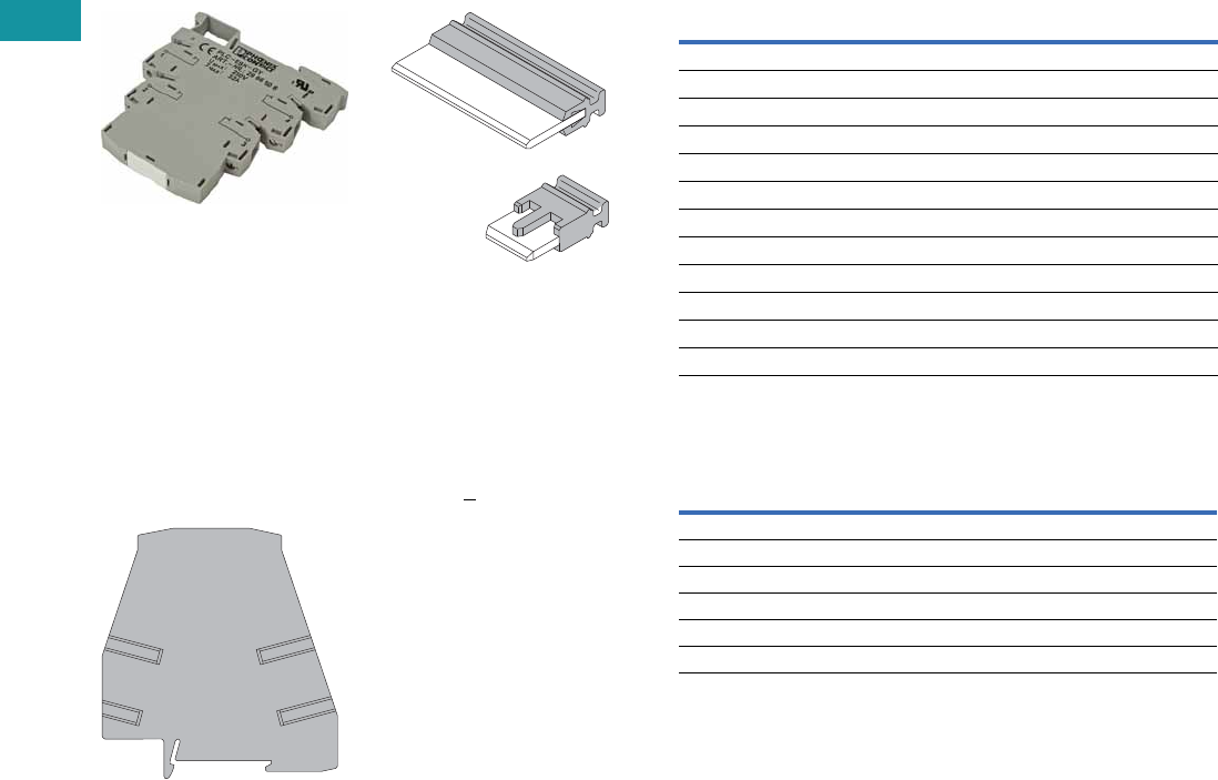
XR Series Accessories
Product Description
Power Terminal Block
The XRAPLCESK power
terminal block has the same
shape as the relay modules
and is used to feed in the
bridging potentials. The
nominal current is 32A. When
the total current is less than
or equal to 6A, supply can
take place directly at the
connecting terminal blocks of
one of the connected relays.
End Cover
The XRAATPBK end cover
is required at the start and
stop of a relay strip. It can
also be used for visual
separation of groups of
relays as well as separating
relays with voltages greater
than 250V and separating
neighboring bridges with
different potentials. It is
equipped with pre-scored
break out points at the
bridging positions so that
individual bridges can be
passed through as needed.
It may also be necessary to
use the end cover between
adjacent relays when three
phases (L1, L2, L3) are
used on the contact side
of the relay.
Bridges
The XRAFBST colored,
insulated plug-in bridge
system reduces wiring
time by up to 70% compared
to conventionally wired
relays. The XRAFBST2,
2-position bridges, are
suited for bridging a smaller
number of relays and total
currents <6A. When a circuit
is supplied from both sides,
the circuit can be opened at
any point, allowing all other
modules to continue being
supplied at the same time.
The XRAFBST500 allow up
to 80 modules to be bridged
at one time. If bridges with
different potentials meet in
neighboring modules, the
end cover XRAATPBK
should be used. All bridges
are equipped with a groove
for removal with a standard
screwdriver.
Product Selection
XR Series Accessories
Technical Data and Specifications
Power Terminal Block
Note
1The separating plate, XRAPLCESK, should be installed for voltages greater than 250V
(L1, L2, L3) between identical terminal points of adjacent modules. Potential bridging is
then possible with the XRAFBST bridge system.
Color
Standard
Pack
Catalog
Number
2-Position Snap-In Jumper
Red 10 XRAFBST2RD
Blue 10 XRAFBST2BU
Gray 10 XRAFBST2GY
80-Position Snap-In Jumper
Red 5 XRAFBST500RD
Blue 5 XRAFBST500BU
Gray 5 XRAFBST500GY
Power Terminal Block
Gray 5 XRAPLCESK
End Cover
Black 5 XRAATPBK
Description Specification
Connection Data
Rigid solid AWG (mm2) 24–10 (0.2–4)
Flexible stranded AWG (mm2) 24–10 (0.2–4)
Miscellaneous Data
Max. current 32A
Max. voltage 250 Vac 1
Volume 7—Logic Control, Operator Interface and Connectivity Solutions CA08100008E—June 2013 www.eaton.com V7-T3-19
3
3
3
3
3
3
3
3
3
3
3
3
3
3
3
3
3
3
3
3
3
3
3
3
3
3
3
3
3
3
Volume 7—Logic Control, Operator Interface and Connectivity Solutions CA08100008E—June 2013 www.eaton.com V7-T3-19
3
3
3
3
3
3
3
3
3
3
3
3
3
3
3
3
3
3
3
3
3
3
3
3
3
3
3
3
3
3
3.3
Control Relays and Timers
Programmable Relays
Programmable Relays
Contents
Description Page
Programmable Relays
easy500/700/800 Programmable Relays . . . . . V7-T3-20
easy802/806 Programmable Relays
with SmartWire-DT . . . . . . . . . . . . . . . . . . . . V7-T3-26
easyRelay and MFD Expansion Modules . . . . . V7-T3-30
MFD-Titan Multi-Function Displays . . . . . . . . . V7-T3-33
easyRelay Communication Modules . . . . . . . . V7-T3-40
easyRelay Power Supplies, Accessories
and Software . . . . . . . . . . . . . . . . . . . . . . . . . V7-T3-43
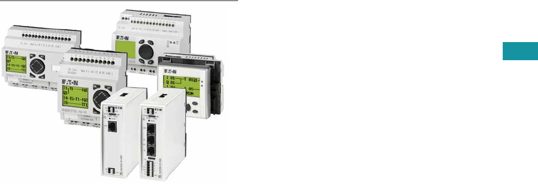
Product Overview
The easyRelays combine
timers, relays, counters,
special functions, inputs and
outputs into one compact
device that is easily
programmed. The easyRelay
family of products provides an
exceptional level of flexibility
together with a substantial
savings of commissioning
time and effort.
The easyRelays are available
in more than 35 styles that
support from 12 I/O up to
a network of up to 320 I/O
points, providing the ideal
solution for lighting, energy
management, industrial
control, irrigation, pump
control, HVAC and home
automation.
Once easyRelays are
installed, changes are
easily accomplished through
front panel programming,
eliminating the need
to change wiring and
minimizing downtime.
The easy802/806 relays are
even more powerful than
the easy800 series and
include an integrated
SmartWire-DT gateway.
Conventional hardwiring
to pushbuttons, selector
switches, pilot devices and
contactors can now be
eliminated, allowing for a
dramatic increase in panel
wiring productivity. For more
information on SmartWire-DT
and how it can increase
productivity, go to
www.eaton.com/smartwiredt.
Application Description
The easyRelays excel in
traditional applications where
multiple
relays, timers and
pushbuttons
are used.
Applications span residential,
commercial and industrial
installations.
Typical control
applications are:
●Lighting controls
●Duplex pump controls
●Water fountain controls
●Parking garage access
controls
●Refrigeration control
system
●Greenhouse temperature
and ventilation controls
●Booster pump controls
See publication no.
AP05013001E for the
easyRelay application guide.
Download from
www.eaton.com/easyrelays.
V7-T3-20 Volume 7—Logic Control, Operator Interface and Connectivity Solutions CA08100008E—June 2013 www.eaton.com
3
3
3
3
3
3
3
3
3
3
3
3
3
3
3
3
3
3
3
3
3
3
3
3
3
3
3
3
3
3
V7-T3-20 Volume 7—Logic Control, Operator Interface and Connectivity Solutions CA08100008E—June 2013 www.eaton.com
3
3
3
3
3
3
3
3
3
3
3
3
3
3
3
3
3
3
3
3
3
3
3
3
3
3
3
3
3
3
3.3
Control Relays and Timers
Programmable Relays
easy500/700/800 Programmable Relays
Contents
Description Page
easy500/700/800 Programmable Relays
System Overview . . . . . . . . . . . . . . . . . . . . . . . V7-T3-21
Product Selection . . . . . . . . . . . . . . . . . . . . . . . V7-T3-23
Technical Data and Specifications . . . . . . . . . . . V7-T3-24
Dimensions . . . . . . . . . . . . . . . . . . . . . . . . . . . V7-T3-25
easy802/806 Programmable Relays
with SmartWire-DT . . . . . . . . . . . . . . . . . . . . . . . V7-T3-26
easyRelay and MFD Expansion Modules . . . . . . . V7-T3-30
MFD-Titan Multi-Function Displays . . . . . . . . . . . . V7-T3-33
easyRelay Communication Modules . . . . . . . . . . . V7-T3-40
easyRelay Power Supplies, Accessories
and Software . . . . . . . . . . . . . . . . . . . . . . . . . . . V7-T3-43
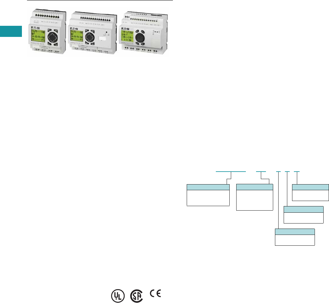
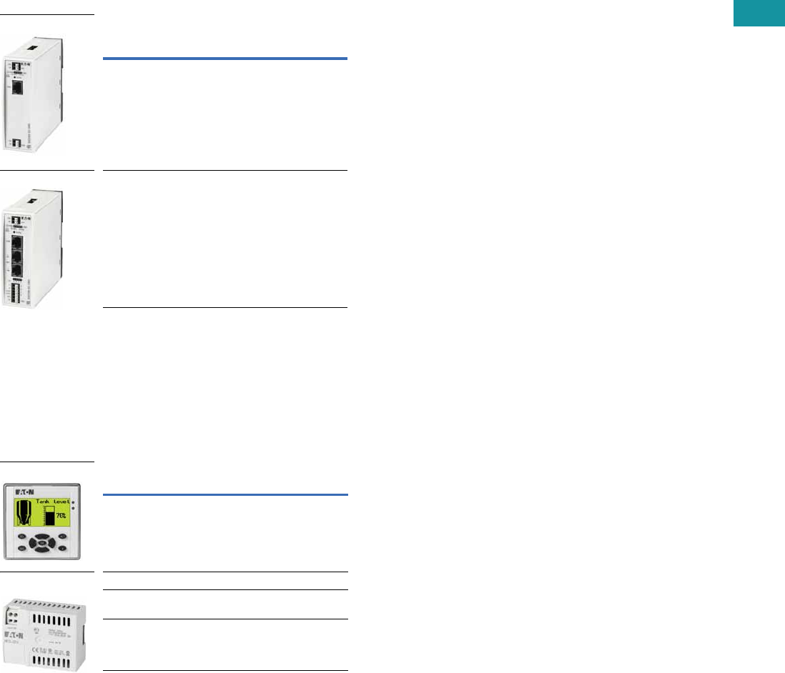
easy500/700/800 Programmable Relays
Product Description
Three families make up the
easyRelay programmable
relay product line. All models
are available with and without
displays. DIN rail mounted.
easy500—for controlling
small applications with up
to 12 input/output signals.
Connectable to Ethernet.
easy700—for controlling
medium-sized applications
with 20 I/O points (expandable
to 40 I/O points). Connectable
to Ethernet and bus systems.
easy800—for controlling
large-scale applications
with 20 points, expandable
to 40 points locally, and
expandable using the
easyNet network up to
320 I/O points. Connectable
to Ethernet and bus systems.
The easyNet integrated
network provides easy and
inexpensive linking of up
to eight easy800 devices
over a distance of up to
1000 meters. Each easy800
device can run its own
program, or be used as a
distributed input/output
module. Connect up to
eight controllers with up
to 40 I/O to obtain 320 I/O.
Standards
●CSA C22.2 No. 142-M1987
●CSA C22.2 No. 213-M1987
●EN 55011
●EN 50178
●EN 61131-2
●IEC EN 61000-4
●IEC 60068-2-6
●IEC 60068-2-27
●UL 508
Certifications
●UL
●CSA
●CE
●CSA Class I, Div. 2,
Groups A, B, C, D;
Temp. Code T3C
●C-Tick
●GOST-R
●Ukrain-GOST
Shipping Approvals
●Bureau Veritas
●Det Norske Veritas
●Germanischer Lloyd
●Lloyd’s Register of Shipping
Catalog Number Selection
easy500/700/800
Note: Not all combinations are possible. See selection tables.
Display
Blank = Display
X = No display
Digital Outputs
R = Relay
T = Transistor
Clock
C = Clock
Blank = No clock
Digital Inputs
AB = 24 Vac
AC = 110–240 Vac
DA = 12 Vdc
DC = 24 Vdc
Module Type
EASY5xx = 500 Series
EASY7xx = 700 Series
EASY8xx = 800 Series
EASY512 -AC-RC
Volume 7—Logic Control, Operator Interface and Connectivity Solutions CA08100008E—June 2013 www.eaton.com V7-T3-21
3
3
3
3
3
3
3
3
3
3
3
3
3
3
3
3
3
3
3
3
3
3
3
3
3
3
3
3
3
3
Volume 7—Logic Control, Operator Interface and Connectivity Solutions CA08100008E—June 2013 www.eaton.com V7-T3-21
3
3
3
3
3
3
3
3
3
3
3
3
3
3
3
3
3
3
3
3
3
3
3
3
3
3
3
3
3
3
3.3
Control Relays and Timers
Programmable Relays
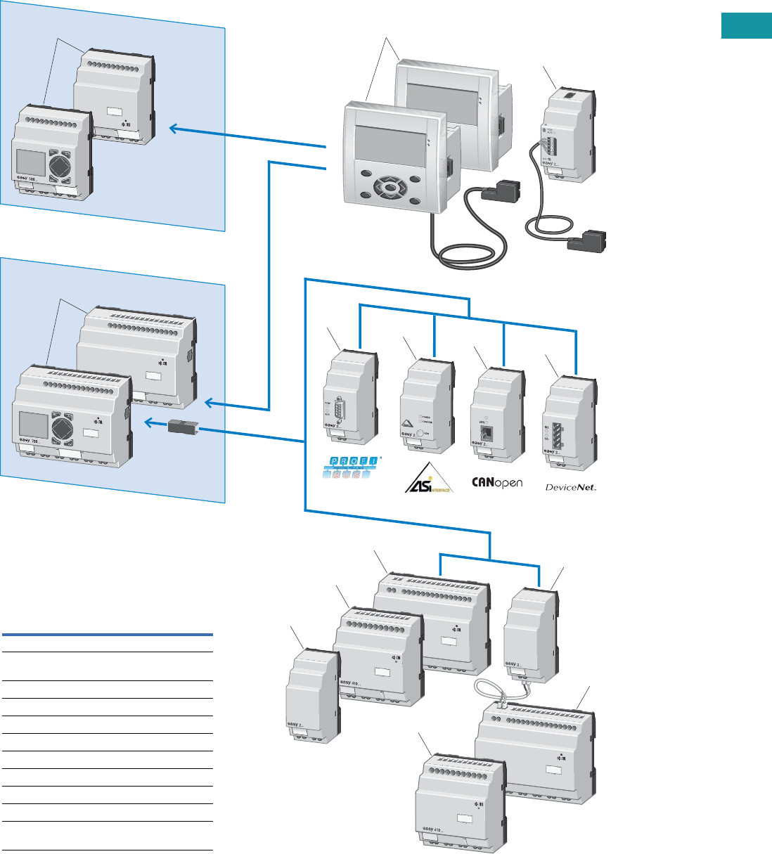
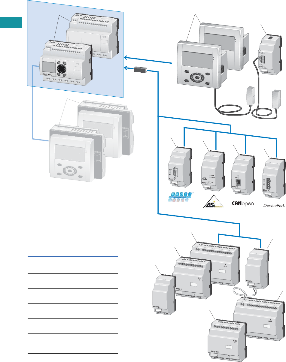
System Overview
easy500/700 Programmable Relays
5
6
8
7
4
3
9
11
10
11
12
10
1
2
Item Description
1 easy500 basic devices, standalone
2 easy700 basic devices, expandable:
digital inputs/outputs, bus systems
3 MFD-Titan remote text display
4 Ethernet gateway
5 PROFIBUS-DP bus module
6 AS-Interface bus module
7 CANopen bus module
8 DeviceNet bus module
9 Output expansion
10, 11 I/O expansions
12 Coupling module for the remote connection
of a digital input/output expansion
V7-T3-22 Volume 7—Logic Control, Operator Interface and Connectivity Solutions CA08100008E—June 2013 www.eaton.com
3
3
3
3
3
3
3
3
3
3
3
3
3
3
3
3
3
3
3
3
3
3
3
3
3
3
3
3
3
3
V7-T3-22 Volume 7—Logic Control, Operator Interface and Connectivity Solutions CA08100008E—June 2013 www.eaton.com
3
3
3
3
3
3
3
3
3
3
3
3
3
3
3
3
3
3
3
3
3
3
3
3
3
3
3
3
3
3
3.3
Control Relays and Timers
Programmable Relays
easy800 Programmable Relay
4
5
7
6
3
2
8
9, 12
10
12
10
11
13
1
Item Description
1 easy800 basic devices, expandable:
digital inputs/outputs and bus systems,
easyNet onboard
2 MFD-Titan remote text display
3 Ethernet gateway
4 PROFIBUS-DP bus module
5 AS-Interface bus module
6 CANopen bus module
7 DeviceNet bus module
8 Output expansion
9, 10 I/O expansions
11 Coupling module for the remote connection of
a digital input/output expansion
12 I/O expansion
13 MFD-Titan multi-function display
Volume 7—Logic Control, Operator Interface and Connectivity Solutions CA08100008E—June 2013 www.eaton.com V7-T3-23
3
3
3
3
3
3
3
3
3
3
3
3
3
3
3
3
3
3
3
3
3
3
3
3
3
3
3
3
3
3
Volume 7—Logic Control, Operator Interface and Connectivity Solutions CA08100008E—June 2013 www.eaton.com V7-T3-23
3
3
3
3
3
3
3
3
3
3
3
3
3
3
3
3
3
3
3
3
3
3
3
3
3
3
3
3
3
3
3.3
Control Relays and Timers
Programmable Relays
Product Selection
easy500 Programmable Relays (Standalone)
easy700 Programmable Relays (Expandable and Networkable)
easy800 Programmable Relays (Expandable and Networkable)
Note
1 Analog inputs optional. Use of analog inputs will result in a decrease in the same number of available digital inputs.
Inputs Outputs Catalog
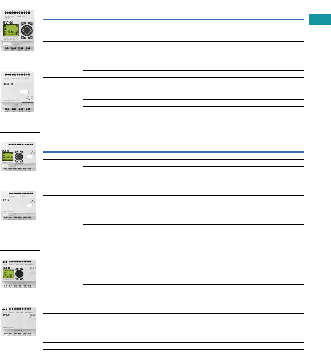
NumberDescription 24 Vac 110–240 Vac 12 Vdc 24 Vdc Analog 1Relay Transistor
Display
12 I/O, no clock — 8 — — — 4 — EASY512-AC-R
———8 2 4 — EASY512-DC-R
12 I/O, clock8 ———2 4 — EASY512-AB-RC
—8 ——— 4 — EASY512-AC-RC
——8 —2 4 — EASY512-DA-RC
———8 2 4 — EASY512-DC-RC
———8 2 —4 EASY512-DC-TC
No Display
12 I/O, clock8 ———2 4 — EASY512-AB-RCX
—8 ——— 4 — EASY512-AC-RCX
——8 —2 4 — EASY512-DA-RCX
———8 2 4 — EASY512-DC-RCX
———8 2 —4 EASY512-DC-TCX
Inputs Outputs Catalog
NumberDescription 24 Vac 110–240 Vac 12 Vdc 24 Vdc Analog 1Relay Transistor
Display
18 I/O, clock12 ———4 6 — EASY719-AB-RC
—12——— 6 — EASY719-AC-RC
——12—4 6 — EASY719-DA-RC
———124 6 — EASY719-DC-RC
20 I/O, clock———12 4 —8 EASY721-DC-TC
No Display
18 I/O, clock12 ———4 6 — EASY719-AB-RCX
—12——— 6 — EASY719-AC-RCX
——12—4 6 — EASY719-DA-RCX
———124 6 — EASY719-DC-RCX
20 I/O, clock———12 4 —8 EASY721-DC-TCX
Inputs Outputs Catalog
NumberDescription 110–240 Vac 24 Vdc Analog 1Relay Transistor Analog
Display
18 I/O, clock 12 — — 6 — — EASY819-AC-RC
—124 6 —— EASY819-DC-RC
19 I/O, clock — 12 4 6 — 1 EASY820-DC-RC
20 I/O, clock — 12 4 — 8 — EASY821-DC-TC
21 I/O, clock — 12 4 — 8 1 EASY822-DC-TC
No Display
18 I/O, clock 12 — — 6 — — EASY819-AC-RCX
—124 6 —— EASY819-DC-RCX
19 I/O, clock — 12 4 6 — 1 EASY820-DC-RCX
20 I/O, clock — 12 4 — 8 — EASY821-DC-TCX
21 I/O, clock — 12 4 — 8 1 EASY822-DC-TCX
easy500—Display
easy500—No Display
easy700—Display
easy700—No Display
easy800—Display
easy800—No Display

V7-T3-24 Volume 7—Logic Control, Operator Interface and Connectivity Solutions CA08100008E—June 2013 www.eaton.com
3
3
3
3
3
3
3
3
3
3
3
3
3
3
3
3
3
3
3
3
3
3
3
3
3
3
3
3
3
3
V7-T3-24 Volume 7—Logic Control, Operator Interface and Connectivity Solutions CA08100008E—June 2013 www.eaton.com
3
3
3
3
3
3
3
3
3
3
3
3
3
3
3
3
3
3
3
3
3
3
3
3
3
3
3
3
3
3
3.3
Control Relays and Timers
Programmable Relays
Technical Data and Specifications
easy500 Series
easy700 Series
easy800 Series
Note
1Relay = 8A (10A to UL) with resistive load, 3A with inductive load. Transistor outputs = 0.5A/24 Vdc, maximum four outputs switchable in parallel.
Type EASY512-AB… EASY512-AC… EASY512-DA… EASY512-DC-R… EASY512-DC-TC.
Supply voltage 24 Vac 100–240 Vac 12 Vdc 24 Vdc 24 Vdc
Heat dissipation 5 VA 5 VA 2W 2W 2W
Continuous current outputs 18A 8A 8A 8A 0.5A
Short-circuit proof with power factor 1 Line protection B16, 600 A —
Short-circuit proof with power factor 0.7…0.7 Line protection B16, 900 A —
Mounting On 35 mm DIN rail or screw mounting with ZB4-101-GF1 mounting feet
Connection cables
Solid 0.2–4.0 mm2 (AWG 22–12) 0.2–4.0 mm2 (AWG 22–12) 0.2–4.0 mm2 (AWG 22–12) 0.2–4.0 mm2 (AWG 22–12) 0.2–4.0 mm2 (AWG 22–12)
Flexible 0.2–2.5 mm2 (AWG 22–12) 0.2–2.5 mm2 (AWG 22–12) 0.2–2.5 mm2 (AWG 22–12) 0.2–2.5 mm2 (AWG 22–12) 0.2–2.5 mm2 (AWG 22–12)
Degree of protection IP20 IP20 IP20 IP20 IP20
RFI suppression EN 55011, EN 55022 Class B, IEC 61000-6-1, 2, 3, 4
Ambient operating temperature –25° to 55°C –25° to 55°C –25° to 55°C –25° to 55°C –25° to 55°C
Transport and storage temperature –40° to 70°C –40° to 70°C –40° to 70°C –40° to 70°C –40° to 70°C
Hazardous location CSA Class I, Div. 2, Groups A, B, C, D; Temp. Code T3C
Type EASY719-AB… EASY719-AC… EASY719-DA… EASY719-DC-RC… EASY721-DC-TC.
Supply voltage 24 Vac 100–240 Vac 12 Vdc 24 Vdc 24 Vdc
Heat dissipation 7 VA 10 VA 3.5W 3.5W 3.5W
Continuous current outputs 18A 8A 8A 8A 0.5A
Short-circuit proof with power factor 1 Line protection B16, 600A Line protection B16, 600A Line protection B16, 600A Line protection B16, 600A —
Short-circuit proof with power factor 0.7…0.7 Line protection B16, 900A Line protection B16, 900A Line protection B16, 900A Line protection B16, 900A —
Mounting On 35 mm DIN rail or screw mounting with ZB4-101-GF1 mounting feet
Connection cables
Solid 0.2–4.0 mm2 (AWG 22–12) 0.2–4.0 mm2 (AWG 22–12) 0.2–4.0 mm2 (AWG 22–12) 0.2–4.0 mm2 (AWG 22–12) 0.2–4.0 mm2 (AWG 22–12)
Flexible 0.2–2.5 mm2 (AWG 22–12) 0.2–2.5 mm2 (AWG 22–12) 0.2–2.5 mm2 (AWG 22–12) 0.2–2.5 mm2 (AWG 22–12) 0.2–2.5 mm2 (AWG 22–12)
Degree of protection IP20 IP20 IP20 IP20 IP20
RFI suppression EN 55011, EN 55022 Class B, IEC 61000-6-1, 2, 3, 4
Ambient operating temperature –25° to 55°C –25° to 55°C –25° to 55°C –25° to 55°C –25° to 55°C
Transport and storage temperature –40° to 70°C –40° to 70°C –40° to 70°C –40° to 70°C –40° to 70°C
Hazardous location CSA Class I, Div. 2, Groups A, B, C, D; Temp. Code T3C
Type EASY819-AC… EASY819-DC-RC… EASY820-DC-RC… EASY821-DC-TC… EASY822-DC-TC.
Supply voltage 100–240 Vac 24 Vdc 24 Vdc 24 Vdc 24 Vdc
Heat dissipation 10 VA 3.4W 3.4W 3.4W 3.4W
Continuous current outputs 18A 8A 8A 8A 0.5A
Short-circuit proof with power factor 1 Line protection B16, 600A Line protection B16, 600A Line protection B16, 600A Line protection B16, 600A —
Short-circuit proof with power factor 0.7…0.7 Line protection B16, 900A Line protection B16, 900A Line protection B16, 900A Line protection B16, 900A —
Mounting On 35 mm DIN rail or screw mounting with ZB4-101-GF1 mounting feet
Connection cables
Solid 0.2–4.0 mm2 (AWG 22–12) 0.2–4.0 mm2 (AWG 22–12) 0.2–4.0 mm2 (AWG 22–12) 0.2–4.0 mm2 (AWG 22–12) 0.2–4.0 mm2 (AWG 22–12)
Flexible 0.2–2.5 mm2 (AWG 22–12) 0.2–2.5 mm2 (AWG 22–12) 0.2–2.5 mm2 (AWG 22–12) 0.2–2.5 mm2 (AWG 22–12) 0.2–2.5 mm2 (AWG 22–12)
Degree of protection IP20 IP20 IP20 IP20 IP20
RFI suppression EN 55011, EN 55022 Class B, IEC 61000-6-1, 2, 3, 4
Ambient operating temperature –25° to 55°C –25° to 55°C –25° to 55°C –25° to 55°C –25° to 55°C
Transport and storage temperature –40° to 70°C –40° to 70°C –40° to 70°C –40° to 70°C –40° to 70°C
Hazardous location CSA Class I, Div. 2, Groups A, B, C, D; Temp. Code T3C
Volume 7—Logic Control, Operator Interface and Connectivity Solutions CA08100008E—June 2013 www.eaton.com V7-T3-25
3
3
3
3
3
3
3
3
3
3
3
3
3
3
3
3
3
3
3
3
3
3
3
3
3
3
3
3
3
3
Volume 7—Logic Control, Operator Interface and Connectivity Solutions CA08100008E—June 2013 www.eaton.com V7-T3-25
3
3
3
3
3
3
3
3
3
3
3
3
3
3
3
3
3
3
3
3
3
3
3
3
3
3
3
3
3
3
3.3
Control Relays and Timers
Programmable Relays
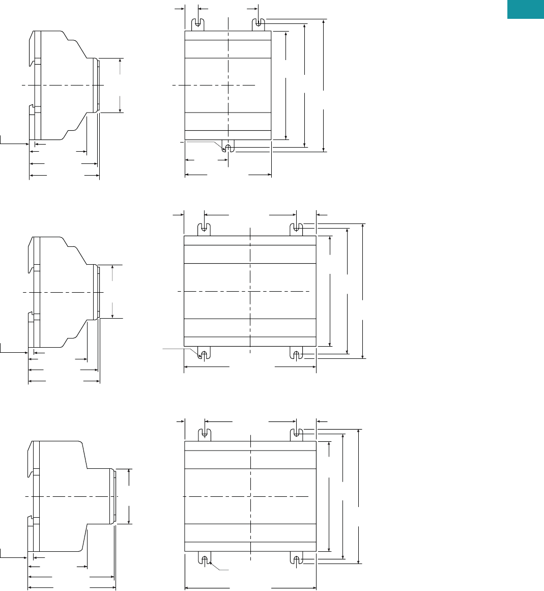
Dimensions
Approximate Dimensions in Inches (mm)
easy500 Series, Drawing Number MD05013001E
easy700 Series, Drawing Number MD05013002E
easy800 Series, Drawing Number MD05013003E
2.81 (71.5)
1.41
(35.8)
3.54
(90.0) 4.02
(102.0)
4.33
(110.0)
1.97 (50.0)0.42 (10.8)
(M4) 0.157
(3.9) Dia.
2.28 (58.0)
1.77
(45.0)
0.18 (4.5)
2.22 (56.5)
1.87 (47.5)
easy500
4.23 (107.5)
3.54
(90.0)
4.02
(102.0)
4.33
(110.0)
2.96 (75.0)0.64 (16.3) 0.64 (16.3)
(M4) 0.157
(3.9) Dia.
easy700
2.28 (58.0)
2.22 (56.5)
1.87 (47.5)
1.77
(45.0)
0.18 (4.5)
4.23 (107.5)
3.54
(90.0)
4.02
(102.0)
4.33
(110.0)
2.96 (75.0)0.64 (16.3)
(M4) 0.157
(3.9) Dia.
0.64 (16.3)
2.83 (72.0)
1.77
(45.0)
2.78 (70.5)
1.91 (48.5)
easy800
0.18 (4.5)
V7-T3-26 Volume 7—Logic Control, Operator Interface and Connectivity Solutions CA08100008E—June 2013 www.eaton.com
3
3
3
3
3
3
3
3
3
3
3
3
3
3
3
3
3
3
3
3
3
3
3
3
3
3
3
3
3
3
V7-T3-26 Volume 7—Logic Control, Operator Interface and Connectivity Solutions CA08100008E—June 2013 www.eaton.com
3
3
3
3
3
3
3
3
3
3
3
3
3
3
3
3
3
3
3
3
3
3
3
3
3
3
3
3
3
3
3.3
Control Relays and Timers
Programmable Relays
easy802/806 Programmable Relays with SmartWire-DT
Contents
Description Page
easy500/700/800 Programmable Relays . . . . . . . . V7-T3-20
easy802/806 Programmable Relays with SmartWire-DT
Product Selection . . . . . . . . . . . . . . . . . . . . . . . V7-T3-27
Accessories. . . . . . . . . . . . . . . . . . . . . . . . . . . . V7-T3-27
Technical Data and Specifications . . . . . . . . . . . V7-T3-28
Dimensions. . . . . . . . . . . . . . . . . . . . . . . . . . . . V7-T3-29
easyRelay and MFD Expansion Modules . . . . . . . V7-T3-30
MFD-Titan Multi-Function Displays . . . . . . . . . . . . V7-T3-33
easyRelay Communication Modules . . . . . . . . . . . V7-T3-40
easyRelay Power Supplies, Accessories
and Software . . . . . . . . . . . . . . . . . . . . . . . . . . . V7-T3-43
easy802/806 Programmable Relays with SmartWire-DT
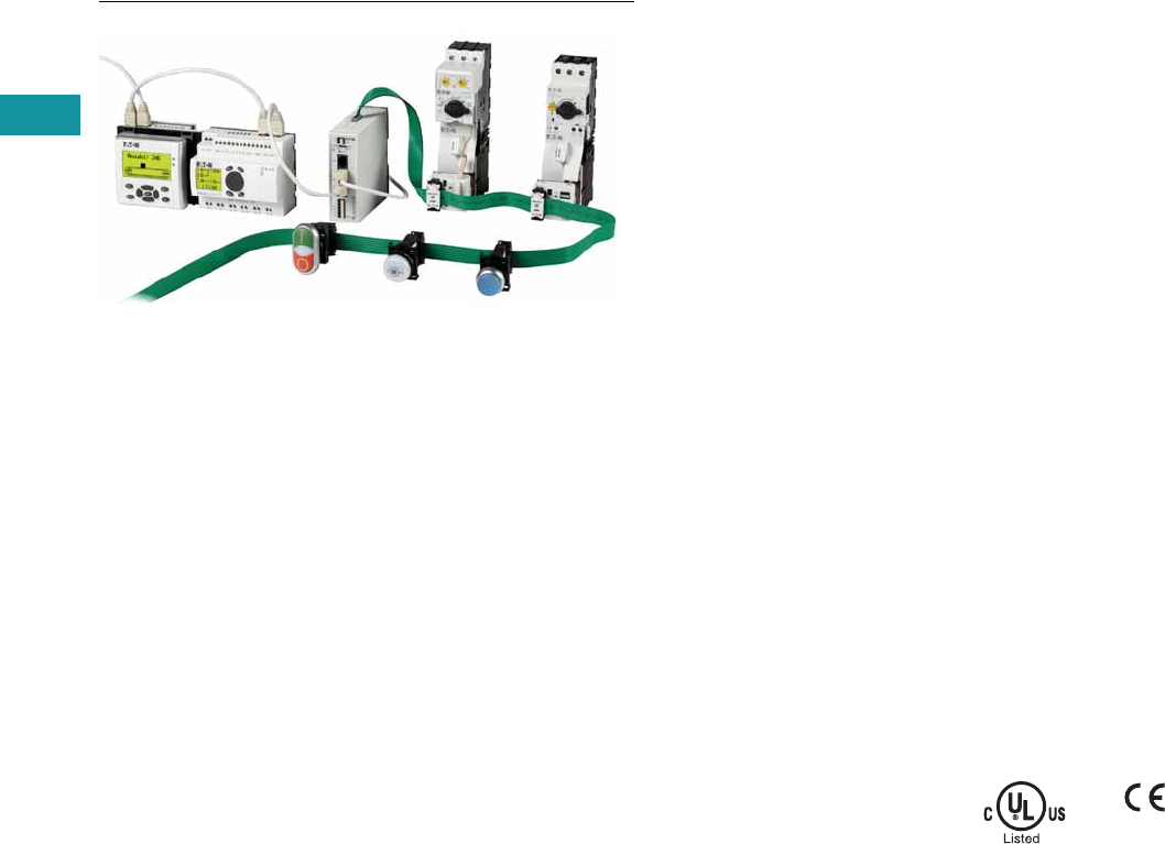
Product Description
SmartWire-DT is a high-
performance system that can
be used to quickly and easily
connect motor control
components such as relays,
contactors, pilot devices,
manual motor protectors,
soft starters 1 and variable
frequency drives 1 as well
as digital and analog input/
output modules. On the new
easy800 with integrated
SmartWire-DT master, up to
99 SmartWire-DT devices in
total with up to 166 inputs/
outputs can be connected
via the SmartWire-DT line.
All required supply voltages,
including those for bus
devices as well as 24 Vdc for
the contactors, are provided
directly with the flat eight-
pole SmartWire-DT bus line.
This reduces wiring effort and
troubleshooting and saves
time and costs.
Note
1Soft starters and variable frequency
drives will be available with direct
SmartWire-DT connectivity in late 2013.
The easy802 features a POW
power feeder for regulating
power to the device as well
as the SmartWire-DT devices.
A second AUX power feeder
provides the connected
contactors with 24 Vdc. A
separate 24 Vdc power
supply is required to provide
24 Vdc power to the easy802
or easy806 controllers. The
configuration of the
SmartWire-DT devices is
undertaken at a touch of
the provided Configuration
button. LEDs provide
feedback on the connecting
states on the device and
the SmartWire-DT line. The
serial interface serves for
programming as well as for
connection of a remote text
display, touch panel or for
connection to the Ethernet.
In addition to the functionality
of the easy802, the easy806
also features four fast inputs
(5 kHz). Two of the four
inputs can also be configured
as fast outputs (5 kHz)
(transistor 24 Vdc, 0.1A).
In addition to the additional
inputs/outputs on easy806,
there is a connection option
to the easyNet. Up to eight
EASY806-DC-SWD
controllers
can be connected via
easyNet, allowing up to
1360 inputs/outputs.
For more information on
SmartWire-DT and related
components, see Ta b 9 of
this volume or go to
www.eaton.com/smartwiredt.
Standards
●EN 50178
●IEC/EN 60947
●UL 508
Certifications
●cULus
●CE
●C-Tick
Volume 7—Logic Control, Operator Interface and Connectivity Solutions CA08100008E—June 2013 www.eaton.com V7-T3-27
3
3
3
3
3
3
3
3
3
3
3
3
3
3
3
3
3
3
3
3
3
3
3
3
3
3
3
3
3
3
Volume 7—Logic Control, Operator Interface and Connectivity Solutions CA08100008E—June 2013 www.eaton.com V7-T3-27
3
3
3
3
3
3
3
3
3
3
3
3
3
3
3
3
3
3
3
3
3
3
3
3
3
3
3
3
3
3
3.3
Control Relays and Timers
Programmable Relays
Product Selection
Control relay for connection of SmartWire-DT and
simultaneously for supply of power to the SmartWire-DT
devices, such as switchgear and contactors.
easy800 with SmartWire-DT
Remote Displays
Both the easy802 and easy806 controllers can be connected to
a MFD remote display or a XV touch panel display with Galileo.
Accessories
Accessories—easy800
Supply
Voltage Description Catalog Number
24 Vdc Control relay with
SmartWire-DT
EASY802-DC-SWD
24 Vdc Control relay with
SmartWire-DT, four inputs,
two of which can be used as
outputs (transistor 24 Vdc,
0.1A), easyNet onboard
EASY806-DC-SWD
EASY802-DC-SWD
EASY806-DC-SWD
Description Catalog Number
MFD display, NEMA 4X indoor rated MFD-80
24 Vdc power / communication module MFD-CP4
easy802/806 to MFD-CP4 communication
cable, 1.5m
EU4A-RJ45-CAB2
easy802/806 to XV HMI communication
cable, 2m
EU4A-RJ45-CAB1
MFD-80
MFD-CP4

V7-T3-28 Volume 7—Logic Control, Operator Interface and Connectivity Solutions CA08100008E—June 2013 www.eaton.com
3
3
3
3
3
3
3
3
3
3
3
3
3
3
3
3
3
3
3
3
3
3
3
3
3
3
3
3
3
3
V7-T3-28 Volume 7—Logic Control, Operator Interface and Connectivity Solutions CA08100008E—June 2013 www.eaton.com
3
3
3
3
3
3
3
3
3
3
3
3
3
3
3
3
3
3
3
3
3
3
3
3
3
3
3
3
3
3
3.3
Control Relays and Timers
Programmable Relays
Technical Data and Specifications
easy802/806 Programmable Relays with SmartWire-DT
Note
1Use power-feed modules if the cable length of the SWD line causes excessive voltage drop.
Description Unit Specification
Ambient Climatic Conditions
Cold to IEC 60068-2-1, heat to IEC 60068-2-2, damp heat, constant, to IEC 60068-2-78;
cyclical to IEC 60068-2-30; temperature change to IEC 68000-2-14
Operating ambient temperature °C (°F) –25° to +55° (–13° to +131°)
Condensation Prevent condensation by means of suitable measures
LCD display (reliable legible) °C (°F) 0° to +55° (32° to +131°)
Storage °C (°F) –40° to +70° (–40° to +158°)
Relative humidity, noncondensing (IEC EN 60068-2-30) % 5 to 95
Air pressure (in operation) hPa 795 up to 1080
Ambient Mechanical Conditions
Protection type EN 50178, IEC 60529, VBG4 IP20
Vibrations (IEC EN 60068-2-6)
Constant amplitude: easy800-SWD; 3.5 mm Hz 5–8.4
Constant acceleration: easy800-SWD: 1g Hz 8.4–150
Mechanical shock resistance (IEC EN 60068-2-27)
semi-sinusoidal 15g / 11 ms
Shocks 18
Drop (IEC EN 60068-2-31) Drop height mm 50
Free fall, packaged (IEC EN 60068-2-32) m 0.3
Electromagnetic Compatibility (EMC)
Electrostatic discharge (ESD), to IEC EN 61000-4-2
Air discharge kV 8
Contact discharge kV 6
Electromagnetic fields (RFI), to IEC EN 61000-4-3
0.8–1.0 GHz V/m 10
1.4–2.0 GHz V/m 3
2.0–2.7 GHz V/m 1
Radio interference suppression EN 55011 Class B
Burst, to IEC EN 61000-4-4
Supply cables kV 2
Signal cables kV 2
easyNet kV 2
SWD-line kV 2
Power pulses (surge), to IEC EN 61000-4-5 (supply cables, symmetrical) kV 1
Radiated RFI, to IEC EN 61000-4-6 V 10
Insulation Resistance
Overvoltage category III
Pollution degree 2
Clearance in air and creepage distances EN 50178, UL 508, CSA C22.2, No. 142
Insulation resistance EN 50178
Terminal Capacity
Solid, minimum to maximum mm20.2 to 1.5 (AWG 24–16)
Flexible with ferrule, minimum to maximum mm20.2 to 1.5 (AWG 24–16)
DC POW Rated Operational Voltage
Rated value UeVdc, (%) 24 DC (–15/+20)
Permissible range 1Vdc 20.4–28.8
Residual ripple % < 5
Protection against polarity reversal Yes
Input current
At rated operating voltage mA easy802: 500 / easy806: 900
Inrush current and duty factor 12.5A for 6 ms
Voltage dips (IEC EN 61131-2) ms 10
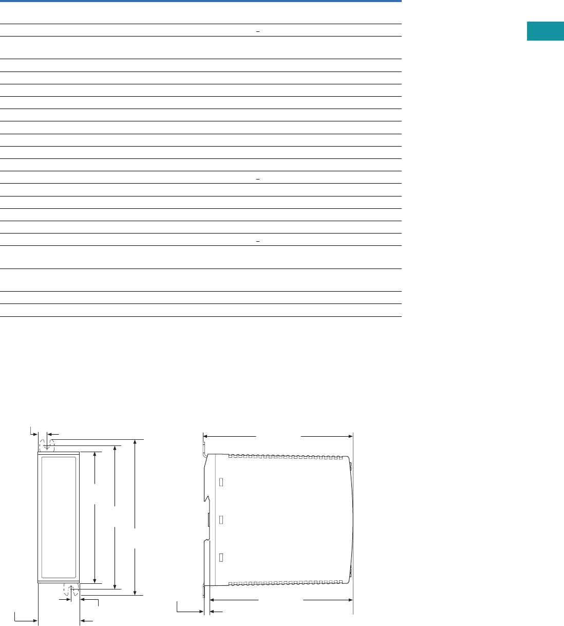
Volume 7—Logic Control, Operator Interface and Connectivity Solutions CA08100008E—June 2013 www.eaton.com V7-T3-29
3
3
3
3
3
3
3
3
3
3
3
3
3
3
3
3
3
3
3
3
3
3
3
3
3
3
3
3
3
3
Volume 7—Logic Control, Operator Interface and Connectivity Solutions CA08100008E—June 2013 www.eaton.com V7-T3-29
3
3
3
3
3
3
3
3
3
3
3
3
3
3
3
3
3
3
3
3
3
3
3
3
3
3
3
3
3
3
3.3
Control Relays and Timers
Programmable Relays
easy802/806 Programmable Relays with SmartWire-DT, continued
Notes
1If present.
2If contactors with a higher total power consumption are connected, an EU5C-SWD-PF1 or EU5C-SWD-PF2 power-feed module must be used.
Dimensions
Approximate Dimensions in Inches (mm)
easy802 and easy806 Controllers
Description Unit Specification
Heat dissipation
At 24 Vdc W easy802: max. 5 / easy806: max. 6
Fuse A > 3
Potential isolation (easy800-SWD)
To auxiliary 1Yes
To easyNet 1Yes
To serial interface Yes
To easyLink 1No
To inputs 1No
To outputs 1No
To SWD 1No
DC AUX Rated Operational Voltage (easy800-SWD)
Rated value UeVdc, (%) 24 (–15/+20)
Permissible range UAUX Vdc 20.4–28.8
Residual ripple % < 5
Input current 2 (max.) A 2 (UL) / 3 (CE)
Rated operational voltage of the 24 Vdc stations V UAUX –0.3V
Protection against polarity reversal Yes
Short-circuit strength No
Fuse A < 2 (UL) external fuse with FAZ B2
Heat dissipation
At 24 Vdc W Normally 1
Potential isolation (easy800-SWD)
To POW power supply, inputs and outputs Yes
To PC interface (COM), easyNet Yes
To SWD Yes
4.33
(110.0)
1.38 (35.0)
0.30 (7.5)
0.30 (7.5)
4.72
(120.0)
5.12
(130.0)
4.94 (125.5)
0.18 (4.5) 4.72 (120.0)
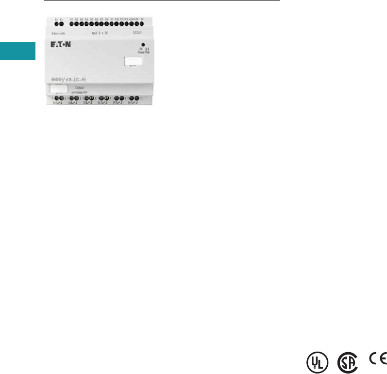
V7-T3-30 Volume 7—Logic Control, Operator Interface and Connectivity Solutions CA08100008E—June 2013 www.eaton.com
3
3
3
3
3
3
3
3
3
3
3
3
3
3
3
3
3
3
3
3
3
3
3
3
3
3
3
3
3
3
V7-T3-30 Volume 7—Logic Control, Operator Interface and Connectivity Solutions CA08100008E—June 2013 www.eaton.com
3
3
3
3
3
3
3
3
3
3
3
3
3
3
3
3
3
3
3
3
3
3
3
3
3
3
3
3
3
3
3.3
Control Relays and Timers
Programmable Relays
easyRelay Expansion Modules
Contents
Description Page
easy500/700/800 Programmable Relays . . . . . . . . V7-T3-20
easy802/806 Programmable Relays
with SmartWire-DT . . . . . . . . . . . . . . . . . . . . . . . V7-T3-26
easyRelay and MFD Expansion Modules
Product Selection . . . . . . . . . . . . . . . . . . . . . . . V7-T3-31
Technical Data and Specifications . . . . . . . . . . V7-T3-31
Dimensions . . . . . . . . . . . . . . . . . . . . . . . . . . . V7-T3-32
MFD-Titan Multi-Function Displays . . . . . . . . . . . . V7-T3-33
easyRelay Communication Modules . . . . . . . . . . . V7-T3-40
easyRelay Power Supplies, Accessories
and Software . . . . . . . . . . . . . . . . . . . . . . . . . . . V7-T3-43
easyRelay and MFD Expansion Modules
Product Description
Expansion modules are
available for increasing the
input/output of the easy700/
800 and MFD-Titan multi-
function displays to 24 inputs
and up to 16 outputs.
Expansion modules can be
mounted directly to the
easy700 or easy800 relays
or up to 98 ft (30m) away
using coupling module
EASY200-EASY.
Standards
●CSA C22.2 No. 142-M1987
●CSA C22.2 No. 213-M1987
●EN 55011
●EN 50178
●EN 61131-2
●IEC EN 61000-4
●IEC 60068-2-6
●IEC 60068-2-27
●UL 508
Certifications
●UL
●CSA
●CE
●CSA Class I, Div. 2,
Groups A, B, C, D;
Temp. Code T3C
●C-Tick
●GOST-R
●Ukrain-GOST
Shipping Approvals
●Bureau Veritas
●Det Norske Veritas
●Germanischer Lloyd
●Lloyd’s Register of Shipping
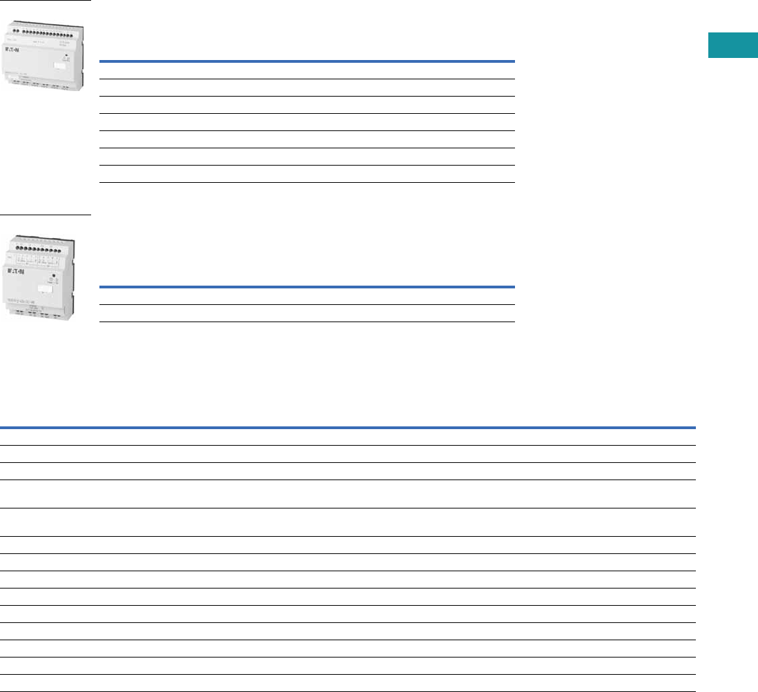
Volume 7—Logic Control, Operator Interface and Connectivity Solutions CA08100008E—June 2013 www.eaton.com V7-T3-31
3
3
3
3
3
3
3
3
3
3
3
3
3
3
3
3
3
3
3
3
3
3
3
3
3
3
3
3
3
3
Volume 7—Logic Control, Operator Interface and Connectivity Solutions CA08100008E—June 2013 www.eaton.com V7-T3-31
3
3
3
3
3
3
3
3
3
3
3
3
3
3
3
3
3
3
3
3
3
3
3
3
3
3
3
3
3
3
3.3
Control Relays and Timers
Programmable Relays
Product Selection
Digital I/O Expansion Modules
Can be used via easyLink.
Analog I/O Expansion Modules
Can be used via easyLink.
Technical Data and Specifications
easyRelay I/O Expansion Modules
Supply Voltage Digital Inputs
Outputs Catalog
NumberRelay 10A (UL) Transistor
100–240 Vac 12 6 — EASY618-AC-RE
24 Vdc 12 6 — EASY618-DC-RE
24 Vdc 12 — 8 EASY620-DC-TE
24 Vdc64—EASY410-DC-RE
24 Vdc 6 — 4 EASY410-DC-TE
24 Vdc — 2 — EASY202-RE
For distributed connection of a digital input/output expansion at up to 98 ft (30m) distance EASY200-EASY
Supply
Voltage
Inputs Digital Outputs
Analog
Outputs
Catalog
Number
Digital/
Analog
Can Be Used
for Digital Relay 10A (UL) Transistor
24 Vdc 1/2 2 — 2 1 EASY406-DC-ME
24 Vdc 1/6 2 — 2 2 EASY411-DC-ME
Type EASY202-RE EASY618-AC-RE EASY618-DC-RE EASY620-DC-TE EASY200-EASY
Supply voltage — 100 – 240 Vac 24
Vac
24
Vac
—
Heat dissipation 1W 10 VA 4W 4W 1W
Continuous current outputs 18A 8A 8A 0.5A —
Short-circuit proof with
power factor 1
Line protection
B16, 600A
Line protection
B16, 600A
Line protection
B16, 600A
Line protection
B16, 600A
—
Short-circuit proof with
power factor 0.7…0.7
Line protection
B16, 900A
Line protection
B16, 900A
Line protection
B16, 900A
Line protection
B16, 900A
—
Connection cables
Solid 0.2–4.0 mm2 (AWG 22–12) 0.2–4.0 mm2 (AWG 22–12) 0.2–4.0 mm2 (AWG 22–12) 0.2–4.0 mm2 (AWG 22–12) 0.2–4.0 mm2 (AWG 22–12)
Flexible 0.2–2.5 mm2 (AWG 22–12) 0.2–2.5 mm2 (AWG 22–12) 0.2–2.5 mm2 (AWG 22–12) 0.2–2.5 mm2 (AWG 22–12) 0.2–2.5 mm2 (AWG 22–12)
Degree of protection IP20 IP20 IP20 IP20 IP20
RFI suppression EN 55011, EN 55022 Class B, IEC 61000-6-1,2,3,4
Ambient operating temperature –25° to 55°C –25° to 55°C –25° to 55°C –25° to 55°C –25° to 55°C
Transport and storage temperature –40° to 70°C –40° to 70°C –40° to 70°C –40° to 70°C –40° to 70°C
Certification, standards
EN 50178, IEC/EN 60947, UL, CSA
Mounting On 35 mm DIN rail or screw mounting with ZB4-101-GF1 mounting feet
EASY618_
EASY406_
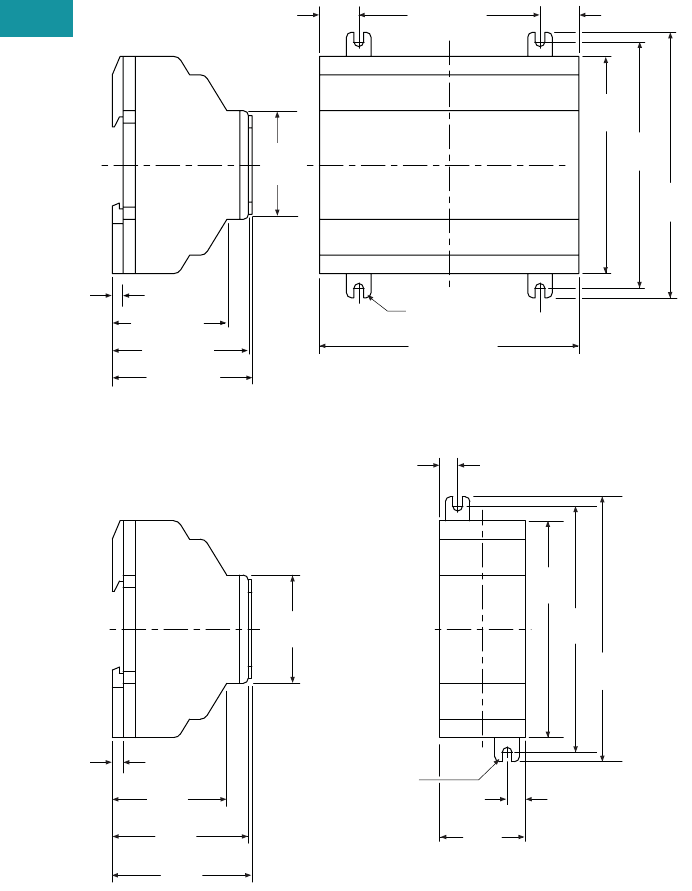
V7-T3-32 Volume 7—Logic Control, Operator Interface and Connectivity Solutions CA08100008E—June 2013 www.eaton.com
3
3
3
3
3
3
3
3
3
3
3
3
3
3
3
3
3
3
3
3
3
3
3
3
3
3
3
3
3
3
V7-T3-32 Volume 7—Logic Control, Operator Interface and Connectivity Solutions CA08100008E—June 2013 www.eaton.com
3
3
3
3
3
3
3
3
3
3
3
3
3
3
3
3
3
3
3
3
3
3
3
3
3
3
3
3
3
3
3.3
Control Relays and Timers
Programmable Relays
Dimensions
Approximate Dimensions in Inches (mm)
easy600 Series, Drawing Number MD05013002E
EASY202-RE/EASY200-EASY/EASY205-ASI Series, Drawing Number MD05013012E
4.23 (107.5)
3.54
(90.0)
4.02
(102.0)
4.33
(110.0)
2.96 (75.0)0.64 (16.3)
(M4) 0.157
(3.9) Dia.
0.64 (16.3)
easy600
2.28 (58.0)
0.18 (4.5)
2.22 (56.5)
1.87 (47.5)
1.77
(45.0)
(M4) 0.157
(3.9) Dia.
0.30
(7.5)
4.33
(110.0)
4.02
(102.0)
3.54
(90.0)
0.30
(7.5)
1.40
(35.5)
1.87
(47.5)
2.22
(56.5)
0.18
(4.5)
1.77
(45.0)
2.28
(58.0)
easy200
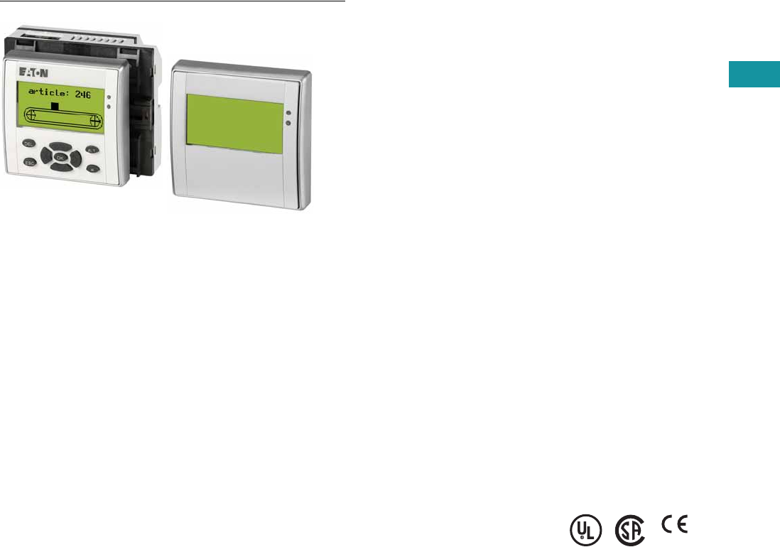
Volume 7—Logic Control, Operator Interface and Connectivity Solutions CA08100008E—June 2013 www.eaton.com V7-T3-33
3
3
3
3
3
3
3
3
3
3
3
3
3
3
3
3
3
3
3
3
3
3
3
3
3
3
3
3
3
3
Volume 7—Logic Control, Operator Interface and Connectivity Solutions CA08100008E—June 2013 www.eaton.com V7-T3-33
3
3
3
3
3
3
3
3
3
3
3
3
3
3
3
3
3
3
3
3
3
3
3
3
3
3
3
3
3
3
3.3
Control Relays and Timers
Programmable Relays
MFD-Titan Multi-Function Displays
Contents
Description Page
easy500/700/800 Programmable Relays . . . . . . . . V7-T3-20
easy802/806 Programmable Relays
with SmartWire-DT . . . . . . . . . . . . . . . . . . . . . . . V7-T3-26
easyRelay and MFD Expansion Modules . . . . . . . V7-T3-33
MFD-Titan Multi-Function Displays
System Overview . . . . . . . . . . . . . . . . . . . . . . . V7-T3-34
Product Selection . . . . . . . . . . . . . . . . . . . . . . . V7-T3-35
Accessories . . . . . . . . . . . . . . . . . . . . . . . . . . . V7-T3-36
Technical Data and Specifications . . . . . . . . . . V7-T3-37
Dimensions . . . . . . . . . . . . . . . . . . . . . . . . . . . V7-T3-38
easyRelay Communication Modules . . . . . . . . . . . V7-T3-40
easyRelay Power Supplies, Accessories
and Software . . . . . . . . . . . . . . . . . . . . . . . . . . . . V7-T3-43
MFD-Titan Multi-Function Displays
Product Description
The MFD-Titan multi-function
displays can be used as
remote text
displays for
easy500, easy700, easy800
and easy802/806 relays or
can be configured as
standalone or networked
multi-function displays. As a
multi-function display, the
MFD-Titan combines the
control functions of an
easy800 with a door-mounted
graphics display.
MFD-Titan multi-function
display is comprised of three
parts: display, controller and
I/O modules. Match each
piece to the needs of your
application. If you need to
both monitor and modify
parameters within your
application, choose the MFD-
80-B display. The
preprogrammed and user
programmable buttons give
you the capability to make
small changes to the way your
application is running, start or
stop a process, or change
your program completely.
Select a controller with or
without easyNet support, and
with AC or DC power. Finally,
add the MFD I/O module that
best suits your application.
MFD-Titan—for controlling
small applications that require
graphic visualization and for
large-scale applications with
20 points, expandable to 40
points locally, and expandable
using the easyNet network
up to 320 I/O points.
The MFD-Titan display can be
linked to the easy500/700/
800 models to provide an
enhanced text based operator
interface.
The easyNet integrated
network provides easy and
inexpensive linking of up to
eight MFD-Titan devices over
a distance of up to 1000
meters. Each MFD-Titan
device can run its program,
or be used as a distributed
input/output module. Connect
up to eight controllers with up
to 40 I/O to obtain 320 I/O.
Standards
●CSA C22.2 No. 142-M1987
●CSA C22.2 No. 213-M1987
●EN 55011
●EN 50178
●EN 61131-2
●IEC EN 61000-4
●IEC 60068-2-6
●IEC 60068-2-27
●UL 508
Certifications
●UL
●CSA
●CE
●CSA Class I, Div. 2,
Groups A, B, C, D;
Temp. Code T3C
●C-Tick
●GOST-R
●Ukrain-GOST
Shipping Approvals
●Bureau Veritas
●Det Norske Veritas
●Germanischer Lloyd
●Lloyd’s Register of Shipping
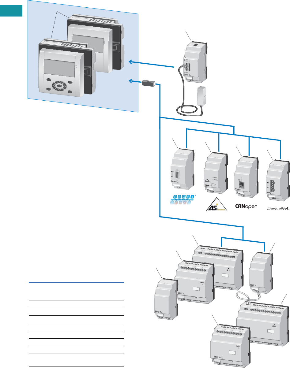
V7-T3-34 Volume 7—Logic Control, Operator Interface and Connectivity Solutions CA08100008E—June 2013 www.eaton.com
3
3
3
3
3
3
3
3
3
3
3
3
3
3
3
3
3
3
3
3
3
3
3
3
3
3
3
3
3
3
V7-T3-34 Volume 7—Logic Control, Operator Interface and Connectivity Solutions CA08100008E—June 2013 www.eaton.com
3
3
3
3
3
3
3
3
3
3
3
3
3
3
3
3
3
3
3
3
3
3
3
3
3
3
3
3
3
3
3.3
Control Relays and Timers
Programmable Relays
System Overview
MFD-Titan Multi-Function Display
3
4
6
5
2
7
9
10
9
11
8, 10
1
Item Description
1 MFD-Titan, consisting of:
display/operating unit, power supply unit,
CPU module, I/O module
2 Ethernet gateway
3 PROFIBUS-DP bus module
4 AS-Interface bus module
5 CANopen bus module
6 DeviceNet bus module
7 Output expansion
8, 9, 10 I/O expansions
11 Coupling module for the remote connection
of a digital input/output expansion
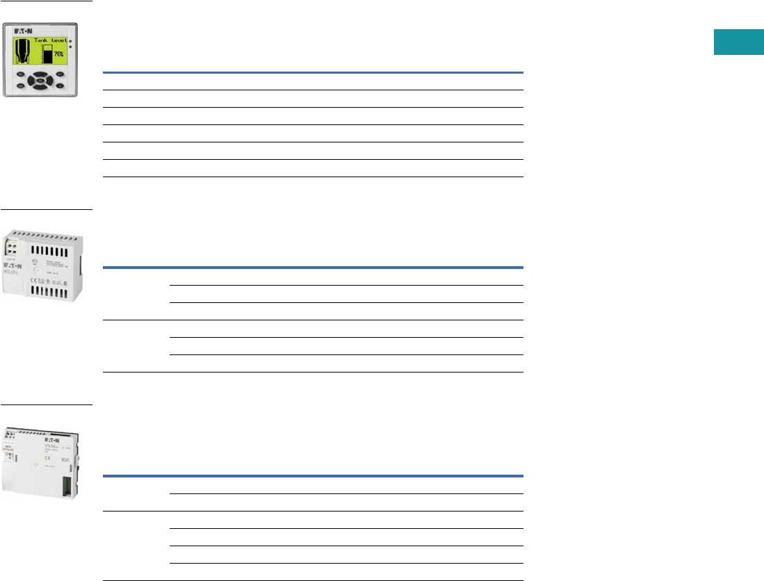
Volume 7—Logic Control, Operator Interface and Connectivity Solutions CA08100008E—June 2013 www.eaton.com V7-T3-35
3
3
3
3
3
3
3
3
3
3
3
3
3
3
3
3
3
3
3
3
3
3
3
3
3
3
3
3
3
3
Volume 7—Logic Control, Operator Interface and Connectivity Solutions CA08100008E—June 2013 www.eaton.com V7-T3-35
3
3
3
3
3
3
3
3
3
3
3
3
3
3
3
3
3
3
3
3
3
3
3
3
3
3
3
3
3
3
3.3
Control Relays and Timers
Programmable Relays
Product Selection
MFD-Titan Display/Operator Units
Monochrome display 132 x 64 pixels with switchable backlight and
removable front frame.
MFD-Titan Text/Graphics Display Power Module
For use with MFD-Titan displays for use as remote text/graphics display.
MFD-Titan Controller Modules
For use with MFD-Titan display/operator units.
Add MFD-Titan I/O modules as needed.
Notes
1 To order an MFD display with custom engraving, a marking file with the required text and/or graphics must be created
as a Labeleditor ZIP file. The ZIP file has to be sent to the Eaton factory, and the name of the file must be referenced
in the order notes section. To download the Labeleditor configuration software, please visit www.eaton.com/software.
2 To obtain a NEMA 4X indoor rating on MFD displays with keypads, use with a protective membrane cover MFD-XM-80.
Description Keypad
Eaton
Logo
Custom
Engraving
Catalog
Number
MFD display, NEMA 4X indoor rated — — — MFD-80-X
MFD display, NEMA 4X indoor rated — ■—MFD-80
MFD display, NEMA 4X indoor rated — — ■MFD-80-ETCH 1
MFD display with keypad 2■——MFD-80-B-X
MFD display with keypad 2■■—MFD-80-B
MFD display with keypad 2——■MFD-80-B-ETCH 1
Supply
Voltage Description
Catalog
Number
100–240 Vac AC power supply / communication module (no cable) MFD-AC-CP4
AC module for easy500/700 relays and cable MFD-CP4-500-CAB5 MFD-AC-CP4-500
AC module for easy800 relays and cable MFD-CP4-800-CAB5 MFD-AC-CP4-800
24 Vdc DC power supply / communication module (no cable) MFD-CP4
DC module for easy500/700 relays and cable MFD-CP4-500-CAB5 MFD-CP4-500
DC module for easy800 relays and cable MFD-CP4-800-CAB5 MFD-CP4-800
Supply
Voltage Description
Catalog
Number
100–240 Vac Program and screen memory MFD-AC-CP8-ME
Program and screen memory, with easyNet MFD-AC-CP8-NT
24 Vdc Program and screen memory MFD-CP8-ME
Program and screen memory, with easyNet MFD-CP8-NT
Double program and screen memory (as MFD-CP8) MFD-CP10-ME
Double program and screen memory (as MFD-CP8), with easyNet MFD-CP10-NT
MFD-80-B
MFD-CP4
MFD-CP
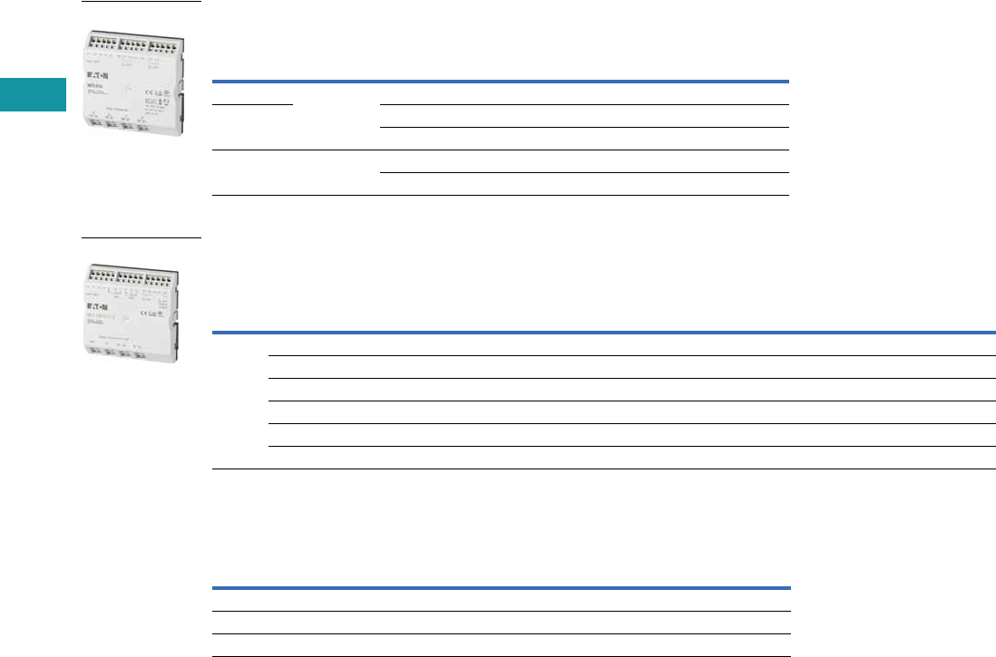
V7-T3-36 Volume 7—Logic Control, Operator Interface and Connectivity Solutions CA08100008E—June 2013 www.eaton.com
3
3
3
3
3
3
3
3
3
3
3
3
3
3
3
3
3
3
3
3
3
3
3
3
3
3
3
3
3
3
V7-T3-36 Volume 7—Logic Control, Operator Interface and Connectivity Solutions CA08100008E—June 2013 www.eaton.com
3
3
3
3
3
3
3
3
3
3
3
3
3
3
3
3
3
3
3
3
3
3
3
3
3
3
3
3
3
3
3.3
Control Relays and Timers
Programmable Relays
MFD-Titan I/O Modules
For use with MFD-Titan controller modules.
MFD-Titan I/O Modules with Temperature Detection
For use with MFD-CP8-_ 2 and MFD-CP10-_ MFD-Titan controller modules.
Accessories
Miscellaneous Parts
Notes
1 Analog inputs optional. Use of analog inputs will result in a decrease in the same number of available digital inputs
2 Version 8 and higher MFD-CP8_ controllers are compatible with the temperature detection modules.
Supply
Voltage Description
Inputs Outputs Catalog
NumberDigital Analog 1Relay Transistor Analog
100–240 Vac 16 I/O 12 — 4 — — MFD-AC-R16
24 Vdc 12 4 4 — — MFD-R16
12 4 — 4 — MFD-T16
24 Vdc 17 I/O 12 4 4 — 1 MFD-RA17
12 4 — 4 1 MFD-TA17
Supply
Voltage
Inputs Outputs
Catalog
NumberDigital
Can Be Used
For Analog Pt100
Relay
10A (UL) Transistor Analog Temperature Ranges
24 Vdc 6 2 2 — 4 — –40° to +90°C/0° to +250°C/0° to +400°C MFD-TP12-PT-A
6 2 2 — 4 — –200° to +200°C/0° to +850°C MFD-TP12-PT-B
6 2 — — 4 — –40° to +90°C/0° to +250°C MFD-TP12-NI-A
6 2 2 — 4 1 –40° to +90°C/0° to +250°C/0° to +400°C MFD-TAP13-PT-A
6 2 2 — 4 1 –200° to +200°C/0° to +850°C MFD-TAP13-PT-B
6 2 — — 4 1 –40° to +90°C/0° to +250°C MFD-TAP13-NI-A
Description Catalog Number
MFD-Titan display protective membrane cover MFD-XM-80
MFD-Titan display protective plastic cover MFD-XS-80
MFD-Titan display DIN rail mount kit MFD-TS-144
MFD-R16
MFD-TP_

Volume 7—Logic Control, Operator Interface and Connectivity Solutions CA08100008E—June 2013 www.eaton.com V7-T3-37
3
3
3
3
3
3
3
3
3
3
3
3
3
3
3
3
3
3
3
3
3
3
3
3
3
3
3
3
3
3
Volume 7—Logic Control, Operator Interface and Connectivity Solutions CA08100008E—June 2013 www.eaton.com V7-T3-37
3
3
3
3
3
3
3
3
3
3
3
3
3
3
3
3
3
3
3
3
3
3
3
3
3
3
3
3
3
3
3.3
Control Relays and Timers
Programmable Relays
Technical Data and Specifications
MFD-80, MFD-CP4, MFD-CP8
MFD-Titan I/O Modules
MFD-CP4 and CP8 Communication Modules
Note
1Relay = 8A with resistive load, 3A with inductive load.
Transistor outputs = 0.5A/24 Vdc, maximum four outputs switchable in parallel.
Type MFD-80… MFD-CP4/CP8
Connection cables
Solid — 0.2–4.0 mm2 (AWG 22–12)
Flexible — 0.2–2.5 mm2 (AWG 22–12)
Degree of protection IP65 IP20
RFI suppression EN 55011, EN 55022 Class B, IEC 61000-6-1, 2, 3, 4 EN 55011, EN 55022 Class B, IEC 61000-6-1, 2, 3, 4
Ambient operating temperature Clearly legible at –5° to 50°C –25° to 55°C
Transport and storage temperature –40° to 70°C –40° to 70°C
Hazardous location CSA Class I, Div. 2, Groups A, B, C, D; Temp. Code T3C CSA Class I, Div. 2, Groups A, B, C, D; Temp. Code T3C
Type MFD-AC-R16 MFD-R16 MFD-RA17 MFD-T16 MFD-TA17
Supply voltage Supply via
MFD-CP8 module
Supply via
MFD-CP8 module
Supply via
MFD-CP8 module
Supply via
MFD-CP8 module
Supply via
MFD-CP8 module
Heat dissipation 0.5W 0.5W 0.5W 0.5W 0.5W
Continuous current outputs 18A 8A 8A 0.5A 0.5A
Short-circuit proof with
power factor 1
Line protection
B16, 600A
Line protection
B16, 600A
Line protection
B16, 600A
——
Short-circuit proof with
power factor 0.7…0.7
Line protection
B16, 600A
Line protection
B16, 600A
Line protection
B16, 600A
——
Connection cables
Solid 0.2–4.0 mm2 (AWG 22–12) 0.2–4.0 mm2 (AWG 22–12) 0.2–4.0 mm2 (AWG 22–12) 0.2–4.0 mm2 (AWG 22–12) 0.2–4.0 mm2 (AWG 22–12)
Flexible 0.2–2.5 mm2 (AWG 22–12) 0.2–2.5 mm2 (AWG 22–12) 0.2–2.5 mm2 (AWG 22–12) 0.2–2.5 mm2 (AWG 22–12) 0.2–2.5 mm2 (AWG 22–12)
Degree of protection IP20 IP20 IP20 IP20 IP20
RFI suppression EN 55011, EN 55022 Class B, IEC 61000-6-1,2,3,4
Ambient operating temperature –25° to 55°C –25° to 55°C –25° to 55°C –25° to 55°C –25° to 55°C
Transport and storage temperature –40° to 70°C –40° to 70°C –40° to 70°C –40° to 70°C –40° to 70°C
Mounting Snap fitted to
MFD-CP8 module
Snap fitted to
MFD-CP8 module
Snap fitted to
MFD-CP8 module
Snap fitted to
MFD-CP8 module
Snap fitted to
MFD-CP8 module
Type MFD-80… MFD-CP4-… MFD-CP8… MFD-AC-CP8…
Supply voltage Supply from -CP 24 Vdc 24 Vdc 100–240 Vac
Heat dissipation 3W 1.5W 3W 8 VA
Mounting Front mounting in 2 x 22.5 mm
Standard drill holes
Snap fitted to MFD-80 Snap fitted to MFD-80 or on 35 mm DIN rail or screw mounting with
ZB4-101-GF1 mounting feet
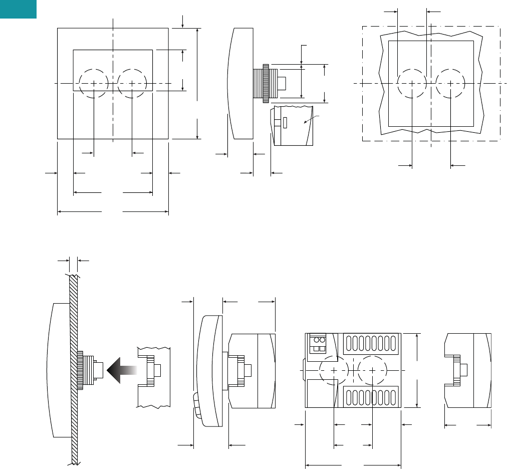
V7-T3-38 Volume 7—Logic Control, Operator Interface and Connectivity Solutions CA08100008E—June 2013 www.eaton.com
3
3
3
3
3
3
3
3
3
3
3
3
3
3
3
3
3
3
3
3
3
3
3
3
3
3
3
3
3
3
V7-T3-38 Volume 7—Logic Control, Operator Interface and Connectivity Solutions CA08100008E—June 2013 www.eaton.com
3
3
3
3
3
3
3
3
3
3
3
3
3
3
3
3
3
3
3
3
3
3
3
3
3
3
3
3
3
3
3.3
Control Relays and Timers
Programmable Relays
Dimensions
Approximate Dimensions in Inches (mm)
MFD-80 Series, Drawing Number MD05013005E
MFD-CP4, MFD-80 and MFD-CP4 Series Combined, Drawing Number MD013013E
3.41
(86.5)
2.44
(62.0)
1.11
(28.3)
1.18 ± 0.01
(30.0) ± 0.2
3.41
(86.5)
1.26
(32.0)
0.67
(17.0)
1.18
(30.0)
0.88 + 0.02
(22.3) + 0.4
0.54
(13.7)
0.79
(20.0)
1.11
(28.3)
0.89
(22.5)
1.18
(30.0)
Template for Holes, Scale 1:1
MFD-80
MFD-CP…
MFD-80
2.28
(58.0)
1.18
(30.0)
2.95
(75.0)
0.89
(22.5)
1.43
(36.2)
1.70
(43.2)
1-6 -0.24
(0.04)
1.08
(27.5)
0.81
(20.5)
0.89
(22.5)
MFD-CP4
MFD-80
MFD-CP4
MFD-CP4
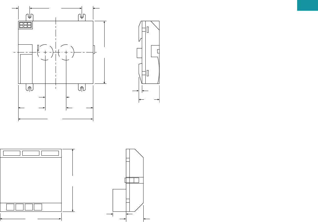
Volume 7—Logic Control, Operator Interface and Connectivity Solutions CA08100008E—June 2013 www.eaton.com V7-T3-39
3
3
3
3
3
3
3
3
3
3
3
3
3
3
3
3
3
3
3
3
3
3
3
3
3
3
3
3
3
3
Volume 7—Logic Control, Operator Interface and Connectivity Solutions CA08100008E—June 2013 www.eaton.com V7-T3-39
3
3
3
3
3
3
3
3
3
3
3
3
3
3
3
3
3
3
3
3
3
3
3
3
3
3
3
3
3
3
3.3
Control Relays and Timers
Programmable Relays
Approximate Dimensions in Inches (mm)
MFD-CP8 Series, Drawing Number MD05013006E
MFD-R/MFD-T I/O Module, Drawing Number MD05013007E
0.640
(16.3)
2.95
(75.0)
3.54
(90.0)
4.23
(107.5)
0.64
(16.3)
0.18
(4.5)
1.53
(38.8)
1.16
(29.5)
1.53
(38.8)
1.18 ± 0.01
(30.0 ± 0.2)
MFD-CP8
3.47
(88.1)
3.54
(90.0)
0.75
(19.0) 0.98
(25.0)
MFD-R and MFD-T I/O
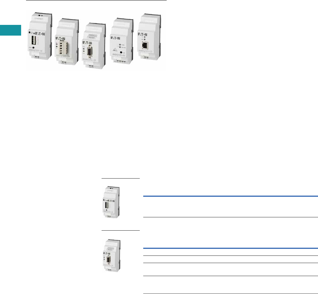
V7-T3-40 Volume 7—Logic Control, Operator Interface and Connectivity Solutions CA08100008E—June 2013 www.eaton.com
3
3
3
3
3
3
3
3
3
3
3
3
3
3
3
3
3
3
3
3
3
3
3
3
3
3
3
3
3
3
V7-T3-40 Volume 7—Logic Control, Operator Interface and Connectivity Solutions CA08100008E—June 2013 www.eaton.com
3
3
3
3
3
3
3
3
3
3
3
3
3
3
3
3
3
3
3
3
3
3
3
3
3
3
3
3
3
3
3.3
Control Relays and Timers
Programmable Relays
easyRelay Communication Modules
Contents
Description Page
easy500/700/800 Programmable Relays . . . . . . . . V7-T3-20
easy802/806 Programmable Relays
with SmartWire-DT . . . . . . . . . . . . . . . . . . . . . . . V7-T3-26
easyRelay and MFD Expansion Modules . . . . . . . V7-T3-33
MFD-Titan Multi-Function Displays . . . . . . . . . . . . V7-T3-33
easyRelay Communication Modules
Technical Data and Specifications . . . . . . . . . . V7-T3-41
Dimensions . . . . . . . . . . . . . . . . . . . . . . . . . . . V7-T3-41
easyRelay Power Supplies, Accessories
and Software . . . . . . . . . . . . . . . . . . . . . . . . . . . V7-T3-43
easyRelay
Communication Modules
Product Description
Four network modules are
available for easily connecting
to world-standard networks.
The network modules can be
used with the easy700/800
programmable relays and
MFD-Titan multi-function
displays.
Available communication
modules support:
●DeviceNet
●PROFIBUS-DP
●AS-Interface
●CANopen
All modules operate
exclusively as nodes on
the given network.
Product Selection
The Ethernet gateway connects devices provided with an RS-232 serial
interface with the Ethernet network. This gateway can be used with easy500
as well as easy700/800 relays and MFD-Titan displays.
Ethernet Gateway Module
Network Interface Modules
Note
1 To set up the Ethernet gateway, download the EASY209-SE configuration software at www.eaton.com/easyrelays.
Description
Catalog
Number
Ethernet gateway Serial interface easyRelay or MFD-…CP8/CP10_ to
Ethernet, for connecting to easyOPC server,
easySoft or easyCom
EASY209-SE 1
Description
Catalog
Number
DeviceNet interface module Addresses available 0 to 63 EASY222-DN
PROFIBUS-DP interface module Device addresses available 1 to 126 EASY204-DP
AS-Interface interface module with
4 in and 4 out
Device: 4 inputs, 4 outputs, 4 parameter bits
Addresses available 0 to 31
EASY205-ASI
CANopen interface module Addresses available 1 to 127 EASY221-CO
EASY209-SE
EASY204-DP
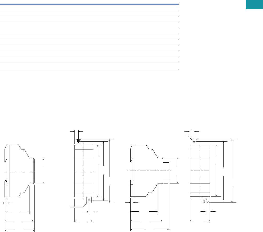
Volume 7—Logic Control, Operator Interface and Connectivity Solutions CA08100008E—June 2013 www.eaton.com V7-T3-41
3
3
3
3
3
3
3
3
3
3
3
3
3
3
3
3
3
3
3
3
3
3
3
3
3
3
3
3
3
3
Volume 7—Logic Control, Operator Interface and Connectivity Solutions CA08100008E—June 2013 www.eaton.com V7-T3-41
3
3
3
3
3
3
3
3
3
3
3
3
3
3
3
3
3
3
3
3
3
3
3
3
3
3
3
3
3
3
3.3
Control Relays and Timers
Programmable Relays
Technical Data and Specifications
easy700/800/MFD Communication Interface Modules
EASY204-DP, EASY205-ASI, EASY221-CO, EASY222-DN, EASY209-SE 1
Notes
1EASY209-SE is also compatible with easy500 programmable relays.
2EASY204-DP dissipates 2W.
Dimensions
Approximate Dimensions in Inches (mm)
EASY202-RE/EASY200-EASY/EASY205-ASI/
EASY209-SE Series, Drawing Number MD05013012E
EASY221-CO/EASY222-DN Series,
Drawing Number MD05013010E
Description Specification
Supply voltage 24 Vdc
Heat dissipation 21W
Connection cables
Solid 0.2–4.0 mm2 (AWG 22–12)
Flexible 0.2–2.5 mm2 (AWG 22–12)
Degree of protection IP20
RFI suppression EN 55011, EN 55022 Class B, IEC 61000-6-1,2,3,4
Ambient operating temperature –25° to +55°C
Transport and storage temperature –40° to +70°C
Certification, standards EN 50178, IEC/EN 60947, UL, CSA
Mounting On 35 mm DIN rail or screw mounting with ZB4-101-GF1 mounting feet
(M4) 0.157
(3.9) Dia.
0.30
(7.5)
4.33
(110.0)
4.02
(102.0)
3.54
(90.0)
0.30
(7.5)
1.40
(35.5)
1.87
(47.5)
2.22
(56.5)
0.18
(4.5)
1.77
(45.0)
2.28
(58.0)
EASY202-RE
EASY200-EASY
EASY205-ASI
2.64
(67.0)
1.77
(45.0)
0.18
(4.5)
2.22
(56.5)
1.87
(47.5)
(M4) 0.157
(3.9) Dia.
0.30
(7.5)
4.33
(110.0)
4.02
(102.0)
3.54
(90.0)
0.30
(7.5)
1.40
(35.5)
EASY222-DN
EASY221-CO
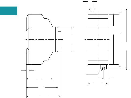
V7-T3-42 Volume 7—Logic Control, Operator Interface and Connectivity Solutions CA08100008E—June 2013 www.eaton.com
3
3
3
3
3
3
3
3
3
3
3
3
3
3
3
3
3
3
3
3
3
3
3
3
3
3
3
3
3
3
V7-T3-42 Volume 7—Logic Control, Operator Interface and Connectivity Solutions CA08100008E—June 2013 www.eaton.com
3
3
3
3
3
3
3
3
3
3
3
3
3
3
3
3
3
3
3
3
3
3
3
3
3
3
3
3
3
3
3.3
Control Relays and Timers
Programmable Relays
EASY204-DP Series,
Drawing Number MD05013011E
2.44
(62.0)
1.77
(45.0)
0.18
(4.5)
2.22
(56.5)
1.87
(47.5)
(M4) 0.157
(3.9) Dia.
0.30
(7.5)
4.33
(110.0)
4.02
(102.0)
3.54
(90.0)
0.30
(7.5)
1.40
(35.5)
EASY204-DP

Volume 7—Logic Control, Operator Interface and Connectivity Solutions CA08100008E—June 2013 www.eaton.com V7-T3-43
3
3
3
3
3
3
3
3
3
3
3
3
3
3
3
3
3
3
3
3
3
3
3
3
3
3
3
3
3
3
Volume 7—Logic Control, Operator Interface and Connectivity Solutions CA08100008E—June 2013 www.eaton.com V7-T3-43
3
3
3
3
3
3
3
3
3
3
3
3
3
3
3
3
3
3
3
3
3
3
3
3
3
3
3
3
3
3
3.3
Control Relays and Timers
Programmable Relays
easyRelay Power Supplies, Accessories and Software
Contents
Description Page
easy500/700/800 Programmable Relays . . . . . . . . V7-T3-20
easy802/806 Programmable Relays
with SmartWire-DT . . . . . . . . . . . . . . . . . . . . . . . V7-T3-26
easyRelay and MFD Expansion Modules . . . . . . . V7-T3-30
MFD-Titan Multi-Function Displays . . . . . . . . . . . . V7-T3-33
easyRelay Communication Modules . . . . . . . . . . . V7-T3-40
easyRelay Power Supplies, Accessories
and Software
Accessories . . . . . . . . . . . . . . . . . . . . . . . . . . . V7-T3-44
Technical Data and Specifications . . . . . . . . . . V7-T3-46
Wiring Diagram . . . . . . . . . . . . . . . . . . . . . . . . V7-T3-46
Dimensions . . . . . . . . . . . . . . . . . . . . . . . . . . . V7-T3-47
easyRelay Power
Supplies, Accessories
and Software
Product Description
Power Supplies—12 Vdc
and 24 Vdc power supplies
for applications where only
100–240 Vac is available.
Accessories—Memory
modules, cables and other
components to complete
your automation solutions.
Software—The easySoft
software is used to program
all of the easyRelays and
MFD-Titan displays. The
Windows®-based software
provides straightforward
circuit diagram input and
editing and the diagrams can
be displayed in the format
desired. When easy800
and MFD-Titan controllers are
connected using easyNet,
all connected devices can
be accessed and their
programs loaded from a
single controller.
easySoft includes an
integrated offline simulation
tool that allows users to
test a circuit diagram
before commissioning.
Product Selection
Power supply units are
primary switched-mode
power supplies that are
optimally suited for the
easyRelay and easySafety
product series in terms of
functions and design. The
new and high-performance
power supply units support
safe operation in plants and
machines. They are simple
and flexible in handling.
Fast diagnosis of the voltage
output: continuous light on
the LED—fault-free
operation; flashing on the
LED—short circuit or
overload on voltage output.
●Suitable for worldwide
use due to wide range
input from 85V to 264 Vac,
50/60 Hz
●Output voltages can be
connected in parallel to
increase power output or
for redundant operation to
achieve greater system
availability
●Compliance with
international standards and
approvals
The primary switched-mode
power supply units can be
used everywhere:
●Safety extra low voltage
(SELV to EN 60 950)
●Radio interference Class B
to EN 55 011 and EN 55 022
for use in industrial and
public networks
Power Supply Units
Rated input voltage 100–240 Vac, single-phase.
Input Voltage
Range
Rated Output
Voltage
Output Voltage
Setting Range
Rated Output
Power
Rated Output
Current Catalog Number
100–240 Vac 24 Vdc/12 Vdc — 8W 0.35A/20 mA EASY200-POW
24 Vdc — 30W 1.25A EASY400-POW
24 Vdc — 60W 2.5A EASY500-POW
24 Vdc — 100W 4.2A EASY600-POW
EASY…-POW
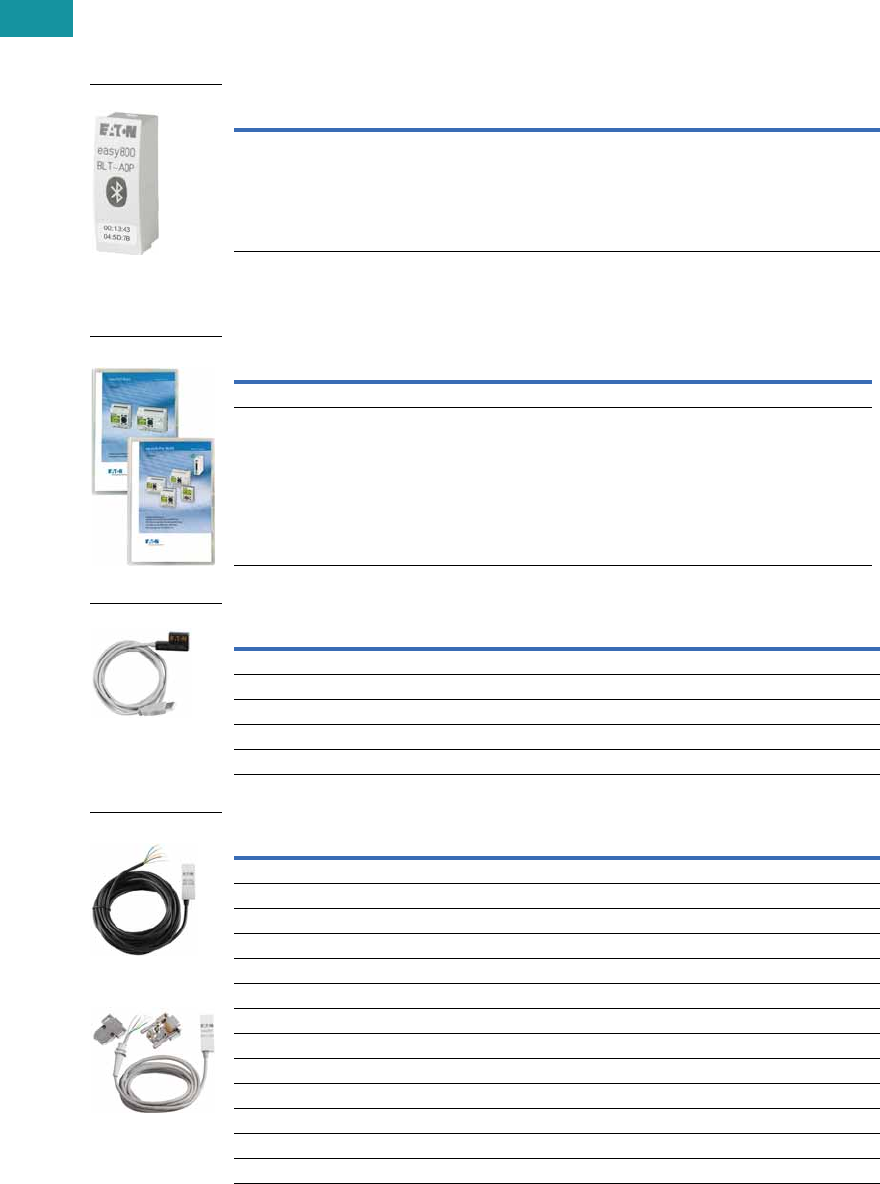
V7-T3-44 Volume 7—Logic Control, Operator Interface and Connectivity Solutions CA08100008E—June 2013 www.eaton.com
3
3
3
3
3
3
3
3
3
3
3
3
3
3
3
3
3
3
3
3
3
3
3
3
3
3
3
3
3
3
V7-T3-44 Volume 7—Logic Control, Operator Interface and Connectivity Solutions CA08100008E—June 2013 www.eaton.com
3
3
3
3
3
3
3
3
3
3
3
3
3
3
3
3
3
3
3
3
3
3
3
3
3
3
3
3
3
3
3.3
Control Relays and Timers
Programmable Relays
Bluetooth Adapter
Conveniently commission and service machines and other equipment remotely.
●Simple communication
with easy800 or MFD-Titan
from outside loud and/or
dangerous areas
●An 8-digit PIN security
code prevents
unauthorized remote
access
●Simple recognition in
Windows 7
●Full online functionality
with easySoft-Pro
V6.91or higher
●Has all necessary radio
type approvals for USA,
Canada and Europe
Bluetooth Adapter
Accessories
Programming Software
Programming Cables
Cables and Connectors
Description Catalog Number
easy800/MFD Bluetooth adapter EASY800-BLT-ADP
The Blue tooth adapter provides wireless connectivity to easySoft-Pro for easy programming
download and upload. Use it with the easyRemote Display Android App for simple and fast access
to your easy800 relays up to a distance of 10 meters.
Description Catalog Number
Programming software for easy500/700 EASY-SOFT-BASIC
Programming software for easy800, easy 802/806 and MFD-Titan
includes SWD-Assist for configuration of the SmartWire-DT network
EASY-SOFT-PRO
Description Catalog Number
easy500/700 to PC programming cable—USB EASY-USB-CAB
easy500/700 to PC programming cable—RS-232 EASY-PC-CAB
easy800/MFD to PC programming cable—RS-232 EASY800-PC-CAB
easy800/MFD to PC programming cable—USB EASY800-USB-CAB
easy802/806 to PC programming cable—USB, 2m EU4A-RJ45-USB-CAB1
Description Catalog Number
easy500/700 to MFD-CP4 communication cable, 5m MFD-CP4-500-CAB5
easy800 to MFD-CP4 communication cable, 5m MFD-CP4-800-CAB5
easy800 to MFD-CP8 communication cable, 2m MFD-800-CAB
easy800 to MFD-CP8 communication cable, 5m MFD-800-CAB5
easy800 modem, printer, programming cable EASY800-MO-CAB
easy802/806 to MFD-CP4 communication cable, 1.5m EU4A-RJ45-CAB2
easy802/806 to XV HMI communication cable, 2m EU4A-RJ45-CAB1
easy800/MFD easyNet cable, 0.3m networking cable EASY-NT-30
easy800/MFD easyNet cable, 0.8m networking cable EASY-NT-80
easy800/MFD easyNet cable, 1.5m networking cable EASY-NT-150
easy800/MFD easyNet cable (cable only, no connectors, see EASY-NT-RJ45), 100m EASY-NT-CAB
RJ45 network connectors for easyNet cable (EASY-NT-CAB), 10/pack EASY-NT-RJ45
easy800/MFD network termination resistor, 2/pack EASY-NT-R
EASY800-BLT-ADP
easySoft
EASY-USB-CAB
MFD-CP4-800-CAB5
EASY800-MO-CAB
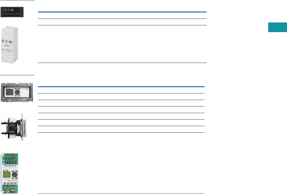
Volume 7—Logic Control, Operator Interface and Connectivity Solutions CA08100008E—June 2013 www.eaton.com V7-T3-45
3
3
3
3
3
3
3
3
3
3
3
3
3
3
3
3
3
3
3
3
3
3
3
3
3
3
3
3
3
3
Volume 7—Logic Control, Operator Interface and Connectivity Solutions CA08100008E—June 2013 www.eaton.com V7-T3-45
3
3
3
3
3
3
3
3
3
3
3
3
3
3
3
3
3
3
3
3
3
3
3
3
3
3
3
3
3
3
3.3
Control Relays and Timers
Programmable Relays
Memory Storage Modules
Miscellaneous Parts
Description Catalog Number
easy500/700 32K memory storage module EASY-M-32K
easy800/MFD 256K memory storage module EASY-M-256K
easy800/MFD 512K memory storage module EASY-M-512K
Description Catalog Number
easy500 panel window SKF-FF4
easy700/800 panel window SKF-FF6
easy500/700/800 panel window mounting kit to front mount units SKF-HA
High current input adapter, six-channel EASY256-HCI
Base to expander, interface connector EASY-LINK-DS
easy500 relay simulator EASY412-DC-SIM-NA
Mounting feet, 9/pack ZB4-101-GF1
Grounding kit ZB4-102-KS1
EASY-M-32K
EASY-M-256K
Panel Window
Mounting Kit
Simulator
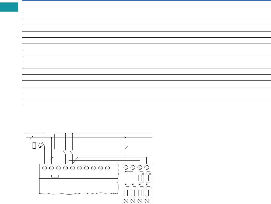
V7-T3-46 Volume 7—Logic Control, Operator Interface and Connectivity Solutions CA08100008E—June 2013 www.eaton.com
3
3
3
3
3
3
3
3
3
3
3
3
3
3
3
3
3
3
3
3
3
3
3
3
3
3
3
3
3
3
V7-T3-46 Volume 7—Logic Control, Operator Interface and Connectivity Solutions CA08100008E—June 2013 www.eaton.com
3
3
3
3
3
3
3
3
3
3
3
3
3
3
3
3
3
3
3
3
3
3
3
3
3
3
3
3
3
3
3.3
Control Relays and Timers
Programmable Relays
Technical Data and Specifications
easyRelay Power Supplies
Wiring Diagram
EASY256-HCI
Type EASY200-POW EASY400-POW
Supply voltage 100–240 Vac 100–240 Vac
Maximum range 85–264 Vac 85–264 Vac
Output voltage 24 Vdc (±3%) 24 Vdc (±3%)
Output current (rated value) 0.25A 1.25A
Overcurrent limitation form 0.3A 1.4A
Short-circuit proof (secondary) Yes Yes
Overload proof Yes Yes
Potential isolation (prim/sec.) Yes, SELV, (to EN 600950, VDE 805) Yes, SELV, (to EN 600950, VDE 805)
Others Additional output voltage 12 DC, 20 mA Additional output voltage 12 DC, 20 mA
Connection cables
Solid 0.2–4.0 mm2 (AWG 22–12) 0.2–4.0 mm2 (AWG 22–12)
Flexible 0.2–2.5 mm2 (AWG 22–12) 0.2–2.5 mm2 (AWG 22–12)
Degree of protection IP20 IP20
RFI suppression EN 55011, EN 55022 Class B, IEC 61000-6-1, 2, 3, 4 EN 55011, EN 55022 Class B, IEC 61000-6-1, 2, 3, 4
Ambient operating temperature –25° to 55°C –25° to 55°C
Transport and storage temperature –40° to 70°C –40° to 70°C
Mounting On 35 mm DIN rail or screw mounting with ZB4-101-GF1 mounting feet
L
N
> 1 A
S..S..
L
115/230 Vh Input 115/230 Vh
N N I1 I2 I3 I4 I5 NN1 2
3456
.....
EASY5..-AC-..
EASY7..-AC-..
EASY256-HCI

Volume 7—Logic Control, Operator Interface and Connectivity Solutions CA08100008E—June 2013 www.eaton.com V7-T3-47
3
3
3
3
3
3
3
3
3
3
3
3
3
3
3
3
3
3
3
3
3
3
3
3
3
3
3
3
3
3
Volume 7—Logic Control, Operator Interface and Connectivity Solutions CA08100008E—June 2013 www.eaton.com V7-T3-47
3
3
3
3
3
3
3
3
3
3
3
3
3
3
3
3
3
3
3
3
3
3
3
3
3
3
3
3
3
3
3.3
Control Relays and Timers
Programmable Relays
Dimensions
Approximate Dimensions in Inches (mm)
EASY200-POW/EASY256-HCI and EASY400-POW Series, Drawing Number MD05013004E
MFD-XS-80 and MFD-XM-80 Series, Drawing Number MD05013009E
SKF-FF4 and SKF-FF6 Series, Drawing Number MD05013014E
2.81
(71.5)
1.41
(35.8)
3.54
(90.0)
4.02
(102.0)
4.33
(110.0)
1.97
(50.0)
0.42
(10.8)
1.77
(45.0)
0.18
(4.5)
2.22
(56.5)
1.87
(47.5)
(M4) .157
(3.9) Dia.
0.30
(7.5)
0.30
(7.5)
1.40
(35.5)
3.54
(90.0)
4.02
(102.0)
4.33
(110.0)
EASY400-POW EASY256-HCI
EASY200-POW
0.98
(25.0)
3.74
(95.0)
3.41
(86.5)
3.48
(88.5)
3.48
(88.5)
0.89
(22.5)
MFD-XS-80 MFD-XM-80
3.70
(94.0)
2.99
(76.0)
0.98
(25.0)
0.63
(16.0)
0.63
(16.0)
5.12
(130.0)
2.99
(76.0)
0.98
(25.0)
SKF-FF4 SKF-FF6
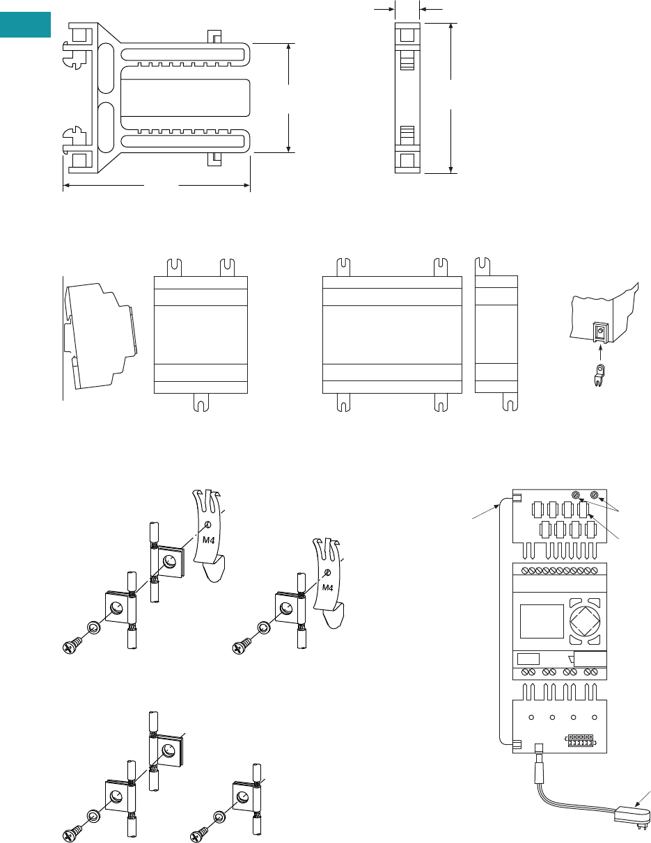
V7-T3-48 Volume 7—Logic Control, Operator Interface and Connectivity Solutions CA08100008E—June 2013 www.eaton.com
3
3
3
3
3
3
3
3
3
3
3
3
3
3
3
3
3
3
3
3
3
3
3
3
3
3
3
3
3
3
V7-T3-48 Volume 7—Logic Control, Operator Interface and Connectivity Solutions CA08100008E—June 2013 www.eaton.com
3
3
3
3
3
3
3
3
3
3
3
3
3
3
3
3
3
3
3
3
3
3
3
3
3
3
3
3
3
3
3.3
Control Relays and Timers
Programmable Relays
Approximate Dimensions in Inches (mm)
SKF-HA Series, Drawing Number MD05013015E
ZB4-101-GF1 Mounting Feet
ZB4-102-KS1 Series—
Grounding the Screen for Top-Hat Rail
ZB4-102-KS1 Series—
Grounding the Screen for Mounting Plate
EASY412-DC-SIM-NA Series
2.60
(66.0)
0.43
(11.0)
3.23
(82.0)
1.89
(48.0)
SKF-HA
Fitting on 35 mm Top-Hat Rail Fitting on Mounting Plate (Horizontal)
ZB4-101-GF1
* 3 mounting feet are sufcient
**
**
ESC OK
DEL ALT
Digital Inputs
Connection
Cable
Power Supply Unit
Connect Outputs
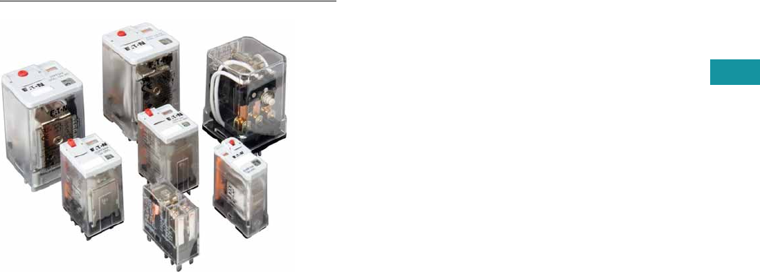
Volume 7—Logic Control, Operator Interface and Connectivity Solutions CA08100008E—June 2013 www.eaton.com V7-T3-49
3
3
3
3
3
3
3
3
3
3
3
3
3
3
3
3
3
3
3
3
3
3
3
3
3
3
3
3
3
3
Volume 7—Logic Control, Operator Interface and Connectivity Solutions CA08100008E—June 2013 www.eaton.com V7-T3-49
3
3
3
3
3
3
3
3
3
3
3
3
3
3
3
3
3
3
3
3
3
3
3
3
3
3
3
3
3
3
3.4
Control Relays and Timers
General Purpose Plug-In Relays
General Purpose Plug-In Relay
Contents
Description Page
D1PR/D1PF Series . . . . . . . . . . . . . . . . . . . . . . . . . V7-T3-53
D2PR/D2PF Series . . . . . . . . . . . . . . . . . . . . . . . . . V7-T3-58
D3PR/D3PF Series . . . . . . . . . . . . . . . . . . . . . . . . . V7-T3-68
D4 Series . . . . . . . . . . . . . . . . . . . . . . . . . . . . . . . . V7-T3-78
D5PR/D5PF Series . . . . . . . . . . . . . . . . . . . . . . . . . V7-T3-82
D7PR/D7PF Series . . . . . . . . . . . . . . . . . . . . . . . . . V7-T3-91
D8 Series . . . . . . . . . . . . . . . . . . . . . . . . . . . . . . . . V7-T3-106
D9 Series . . . . . . . . . . . . . . . . . . . . . . . . . . . . . . . . V7-T3-112
Accessories . . . . . . . . . . . . . . . . . . . . . . . . . . . . . . V7-T3-116
Product Selection Guide
General Purpose Relay Selection Characteristics
●Current rating: 1A–30A
●Contact arrangement:
SPDT, DPDT, 3PDT, 4PDT,
etc.
●Coil voltage: 6V–240 Vac/
6V–110 Vdc
●Mounting options: socket,
flange, DIN rail, panel
●Specifications: CSA, CE,
IEC, NEMA, UL, etc.
●Other: Physical
dimensions, maximum
voltage, mechanical/
electrical life, etc.
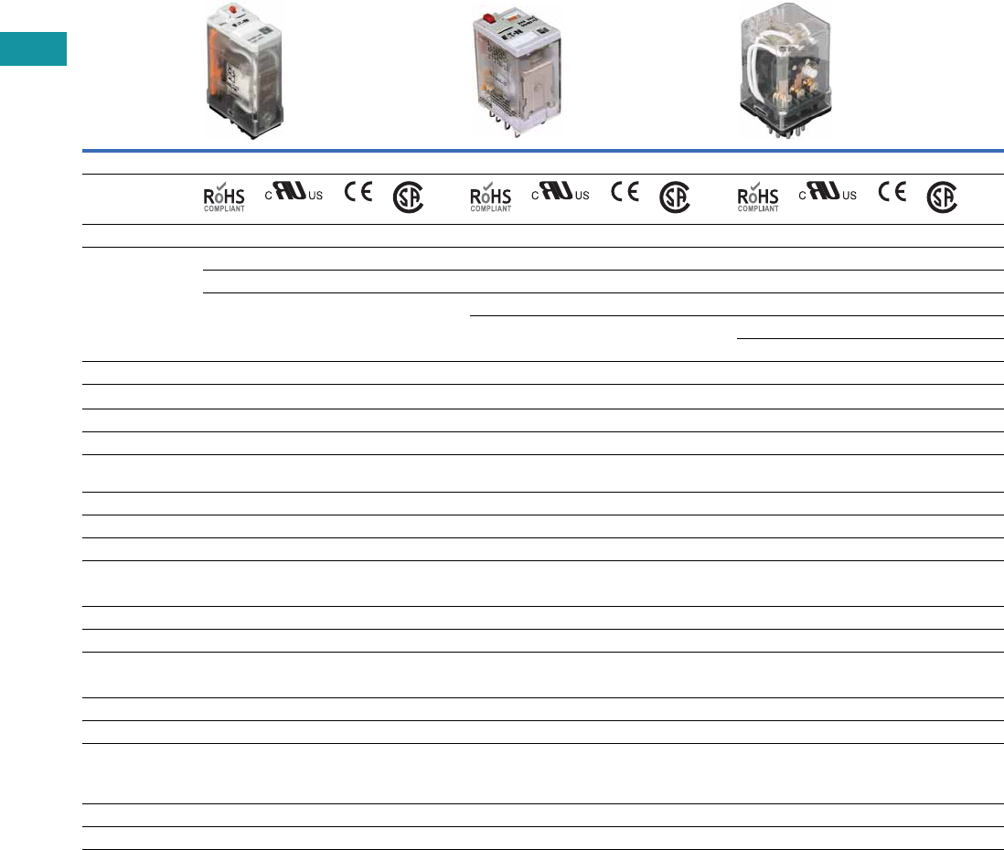
V7-T3-50 Volume 7—Logic Control, Operator Interface and Connectivity Solutions CA08100008E—June 2013 www.eaton.com
3
3
3
3
3
3
3
3
3
3
3
3
3
3
3
3
3
3
3
3
3
3
3
3
3
3
3
3
3
3
V7-T3-50 Volume 7—Logic Control, Operator Interface and Connectivity Solutions CA08100008E—June 2013 www.eaton.com
3
3
3
3
3
3
3
3
3
3
3
3
3
3
3
3
3
3
3
3
3
3
3
3
3
3
3
3
3
3
3.4
Control Relays and Timers
General Purpose Plug-In Relays
General Purpose Plug-In Relays
Relay Series D1PR/D1PF D2PR/D2PF D3PR/D3PF
Approvals
Features
Polycarbonate cover Polycarbonate cover Polycarbonate cover
Indicator lamp and pushbutton available Indicator lamp and pushbutton available Indicator lamp and pushbutton available
Panel and DIN mounting Panel, DIN and flange mounting Panel and DIN mounting
Latching 8- or 11-pin octal plug-in
Latching (D3PR version)
Contact Data
Configuration SPDT DPDT DPDT Latching 4PDT DPDT 3PDT
Max. allowable load 20A 10A 3A 10A 16A 16A 16A
Material Silver alloy Silver alloy Silver alloy
Dielectric strength
between poles
1500V 1500V 1500V
Coil Data
AC 6 to 240 Vac 6 to 240 Vac 6 to 240 Vac
DC 6 to 110 Vdc 6 to 110 Vdc 6 to 110 Vdc
Power
VA (Vac) 0.9 VA 1.2 VA 3 VA 1.4W (D3PR and D3PF)
Watts (Vdc) 0.7W 0.9W 2 VA 1.64W (D3PR5 latching)
General Data
Ambient temperature
Storage –40° to 185°F (–40° to 85°C) –40° to 185°F (–40° to 85°C) –40° to 185°F (–40° to 85°C)
Operational –40° to 131°F (–40° to 55°C) –40° to 131°F (–40° to 55°C) –40° to 131°F (–40° to 55°C)
Response time 20 milliseconds 20 milliseconds 20 milliseconds
Life
Mechanical operations 10 million 10 million 5 million (D3PR and D3PF)
10 million (D3PR5 latching)
Electrical operations 100,000 200,000 100,000
Page Numbers V7-T3-53 to V7-T3-57 V7-T3-58 to V7-T3-67 V7-T3-68 to V7-T3-77
Volume 7—Logic Control, Operator Interface and Connectivity Solutions CA08100008E—June 2013 www.eaton.com V7-T3-51
3
3
3
3
3
3
3
3
3
3
3
3
3
3
3
3
3
3
3
3
3
3
3
3
3
3
3
3
3
3
Volume 7—Logic Control, Operator Interface and Connectivity Solutions CA08100008E—June 2013 www.eaton.com V7-T3-51
3
3
3
3
3
3
3
3
3
3
3
3
3
3
3
3
3
3
3
3
3
3
3
3
3
3
3
3
3
3
3.4
Control Relays and Timers
General Purpose Plug-In Relays
General Purpose Plug-In Relays, continued
Relay Series D4 D5PR/D5PF D7PR/D7PF
Approvals
Features
Polycarbonate cover Polycarbonate cover Polycarbonate cover
Indicator lamp available Indicator lamp and pushbutton available Indicator lamp and pushbutton available
Panel and DIN mounting Panel, DIN and flange mounting Panel and DIN mounting
Socket has built-in hold-down spring
Contact Data
Configuration SPDT DPDT DPDT 3PDT SPDT DPDT 3PDT 4PDT
Max. allowable load 10A at 250 Vac 5A at 240 Vac 16A 16A 20A 15A 15A 15A
Material AgCdO Silver alloy Silver alloy
Dielectric strength 5000V 1500V 1500V 1500V 2500V 2500V
Coil Data
AC 6 to 240 Vac 6 to 240 Vac 6 to 240 Vac
DC 6 to 110 Vdc 6 to 110 Vdc 6 to 110 Vdc
Power
VA (Vac) 0.9 VA 3 VA 1.2 VA 1.2 VA 1.5 VA 1.5 VA
Watts (Vdc) 0.5W 1.4W 0.9W 0.9W 1.4W 1.5W
General Data
Ambient temperature
Storage –40° to 158°F (–40° to 70°C) –40° to 185°F (–40° to 85°C) –40° to 185°F (–40° to 85°C)
Operational –40° to 158°F (–40° to 70°C) –40° to 131°F (–40° to 55°C) –40° to 131°F (–40° to 55°C)
Response time 15 milliseconds 20 milliseconds 20 milliseconds (30 milliseconds for latching)
Life
Mechanical operations 10 million 5 million 10 million
Electrical operations 100,000 100,000 100,000 100,000 200,000 200,000
Page Numbers V7-T3-78 to V7-T3-81 V7-T3-82 to V7-T3-90 V7-T3-91 to V7-T3-105
V7-T3-52 Volume 7—Logic Control, Operator Interface and Connectivity Solutions CA08100008E—June 2013 www.eaton.com
3
3
3
3
3
3
3
3
3
3
3
3
3
3
3
3
3
3
3
3
3
3
3
3
3
3
3
3
3
3
V7-T3-52 Volume 7—Logic Control, Operator Interface and Connectivity Solutions CA08100008E—June 2013 www.eaton.com
3
3
3
3
3
3
3
3
3
3
3
3
3
3
3
3
3
3
3
3
3
3
3
3
3
3
3
3
3
3
3.4
Control Relays and Timers
General Purpose Plug-In Relays
General Purpose Plug-In Relays, continued
Relay Series D8 D9
Approvals
Features
Dust cover Dust cover
Panel, DIN and flange mounting Pushbutton available
Quick-connect and screw terminals Panel mounting
Screw terminals
Contact Data
Configuration
SPST-NO DPST-NO
4PST
NO NC
Max. allowable load 30A at
220 Vac
25A at
220 Vac
25A at
220 Vac
8A at
220 Vac
Material AgCdO AgCdO
Dielectric strength 4000V 4000V
Coil Data
AC 6 to 240 Vac 24 to 240 Vac
DC 12 to 24 Vdc 12 to 110 Vdc
Power
VA (Vac) 2.5 VA 2.6 VA
Watts (Vdc) 1.9W 2.0W
General Data
Ambient temperature
Storage –4° to 185°F (–20° to 85°C) –13° to 140°F (–25° to 60°C)
Operational –4° to 131°F (–20° to 55°C) –13° to 140°F (–25° to 60°C)
Response time 30 milliseconds 50 milliseconds
Life
Mechanical operations 5 million 1 million
Electrical operations 100,000 100,000
Page Numbers V7-T3-106 to V7-T3-111 V7-T3-112 to V7-T3-115
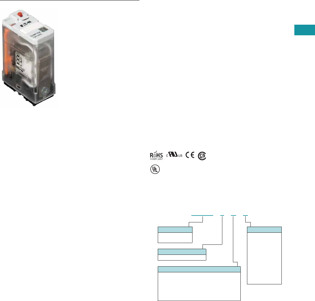
Volume 7—Logic Control, Operator Interface and Connectivity Solutions CA08100008E—June 2013 www.eaton.com V7-T3-53
3
3
3
3
3
3
3
3
3
3
3
3
3
3
3
3
3
3
3
3
3
3
3
3
3
3
3
3
3
3
Volume 7—Logic Control, Operator Interface and Connectivity Solutions CA08100008E—June 2013 www.eaton.com V7-T3-53
3
3
3
3
3
3
3
3
3
3
3
3
3
3
3
3
3
3
3
3
3
3
3
3
3
3
3
3
3
3
3.4
Control Relays and Timers
General Purpose Plug-In Relays
D1 Series Relay
Contents
Description Page
D1PR/D1PF Series
Product Selection . . . . . . . . . . . . . . . . . . . . . . . V7-T3-54
Accessories . . . . . . . . . . . . . . . . . . . . . . . . . . . . V7-T3-55
Technical Data and Specifications . . . . . . . . . . . V7-T3-56
Wiring Diagram . . . . . . . . . . . . . . . . . . . . . . . . . V7-T3-57
Dimensions . . . . . . . . . . . . . . . . . . . . . . . . . . . . V7-T3-57
D2PR/D2PF Series . . . . . . . . . . . . . . . . . . . . . . . . . V7-T3-58
D3PR/D3PF Series . . . . . . . . . . . . . . . . . . . . . . . . . V7-T3-68
D4 Series . . . . . . . . . . . . . . . . . . . . . . . . . . . . . . . . V7-T3-78
D5PR/D5PF Series . . . . . . . . . . . . . . . . . . . . . . . . . V7-T3-82
D7PR/D7PF Series . . . . . . . . . . . . . . . . . . . . . . . . . V7-T3-91
D8 Series . . . . . . . . . . . . . . . . . . . . . . . . . . . . . . . . V7-T3-106
D9 Series . . . . . . . . . . . . . . . . . . . . . . . . . . . . . . . . V7-T3-112
Accessories . . . . . . . . . . . . . . . . . . . . . . . . . . . . . . V7-T3-116
D1PR/D1PF Series
Product Description
The D1 Series of relay
provides a compact single-
pole relay capable of handling
20A. Multiple feature and
voltage options allow for the
perfect fit for any application.
Features
D1PR
●Compact relay capable of
breaking relatively large
load currents
●Panel and DIN rail
mounting
D1PF
●The contact operation
can be easily checked by
Push-to-Test button
●Flag indicator shows relay
status in manual or
powered condition
●LED status lamp shows
coil ON or OFF status—
ideal for use in low light
applications
●Push-to-Test button allows
for manual operation of
relay without the need for
coil power
●Lock-down door holds
pushbutton and contacts in
the operate position when
activated
●Finger-grip cover allows
operator to remove relays
from sockets easily
●ID tag/write label to
identify relays in multiple-
relay circuits
●Bipolar LED allows for
reverse polarity
applications
Standards and Certifications
When used with
accompanying Eaton
screw terminal socket.
Catalog Number Selection
D1PR/D1PF Series
UL Listed
D 1 P F 1 A A
Family Type
D1PF
D1PR
Contact Configuration
1 = SPDT
Standard Features
Blank = Mechanical flag indicator
(only with D1PR)
A = LED test button, flag indicator,
lock-down door, finger-grip cover,
ID tag (only with D1PF)
1 = LED and mechanical flag indicator
Coil Voltage
A = 120 Vac
A1 = 110 Vdc
B = 240 Vac
P = 6 Vac
P1 = 6 Vdc
R = 12 Vac
R1 = 12 Vdc
T = 24 Vac
T1 = 24 Vdc
W = 48 Vac
W1 = 48 Vdc
V7-T3-54 Volume 7—Logic Control, Operator Interface and Connectivity Solutions CA08100008E—June 2013 www.eaton.com
3
3
3
3
3
3
3
3
3
3
3
3
3
3
3
3
3
3
3
3
3
3
3
3
3
3
3
3
3
3
V7-T3-54 Volume 7—Logic Control, Operator Interface and Connectivity Solutions CA08100008E—June 2013 www.eaton.com
3
3
3
3
3
3
3
3
3
3
3
3
3
3
3
3
3
3
3
3
3
3
3
3
3
3
3
3
3
3
3.4
Control Relays and Timers
General Purpose Plug-In Relays
Product Selection
D1PR/D1PF Relay/Socket Quick Reference
D1PR/D1PF Series
Relay
Type Socket Clip
Module
Type
ID
Tag Jumper
D1PR1 D1PAA PMC-1781 B — —
D1PF1 D1PAA PMC-1781 B — —
Coil
Voltage
Contact
Configuration
Coil Resistance
(Ohms)
Catalog
Number
Full Featured
6 Vac SPDT 12.2 D1PF1AP
6 Vdc SPDT 47 D1PF1AP1
12 Vac SPDT 46 D1PF1AR
12 Vdc SPDT 188 D1PF1AR1
24 Vac 50/60 Hz SPDT 180 D1PF1AT
24 Vdc SPDT 750 D1PF1AT1
48 Vac SPDT 720 D1PF1AW
48 Vdc SPDT 2600 D1PF1AW1
110 Vdc SPDT 13,800 D1PF1AA1
120 Vac 50/60 Hz SPDT 4430 D1PF1AA
240 Vac 50/60 Hz SPDT 15,720 D1PF1AB
Plain Cover with LED Indicator
6 Vac SPDT 12.2 D1PR11P
6 Vdc SPDT 47 D1PR11P1
12 Vac SPDT 46 D1PR11R
12 Vdc SPDT 188 D1PR11R1
24 Vac 50/60 Hz SPDT 180 D1PR11T
24 Vdc SPDT 750 D1PR11T1
48 Vac SPDT 720 D1PR11W
48 Vdc SPDT 2600 D1PR11W1
240 Vac 50/60 Hz SPDT 15,720 D1PR11B
110 Vdc SPDT 13,800 D1PR11A1
120 Vac SPDT 4430 D1PR11A
24 Vac 50/60 Hz SPDT 180 D1PR1T
Plain Cover
6 Vac SPDT 12.2 D1PR1P
6 Vdc SPDT 47 D1PR1P1
12 Vac SPDT 46 D1PR1R
12 Vdc SPDT 188 D1PR1R1
24 Vdc SPDT 750 D1PR1T1
48 Vac SPDT 720 D1PR1W
48 Vdc SPDT 2600 D1PR1W1
110 Vdc SPDT 13,800 D1PR1A1
120 Vac 50/60 Hz SPDT 4430 D1PR1A
240 Vac SPDT 15,270 D1PR1B
D1PF Series Relay

Volume 7—Logic Control, Operator Interface and Connectivity Solutions CA08100008E—June 2013 www.eaton.com V7-T3-55
3
3
3
3
3
3
3
3
3
3
3
3
3
3
3
3
3
3
3
3
3
3
3
3
3
3
3
3
3
3
Volume 7—Logic Control, Operator Interface and Connectivity Solutions CA08100008E—June 2013 www.eaton.com V7-T3-55
3
3
3
3
3
3
3
3
3
3
3
3
3
3
3
3
3
3
3
3
3
3
3
3
3
3
3
3
3
3
3.4
Control Relays and Timers
General Purpose Plug-In Relays
Accessories
D1PR/D1PF Sockets and Accessories
Note
1Protection Category (Finger Safe), EN 60529: IP20.
Type
Module
Size
Nominal Voltage
(Max. for Sockets)
Nominal
Current Mounting Style Wire Size
Wire
Connection
Standard
Pack
Catalog
Number
Socket B 300 20 Panel/DIN rail 12 /14 (2) AWG, 4 /2.5 (2) mm2Screw clamping 10 D1PAA 1
Flange mount adapter — — — Flange — — 25 PFC-D11
Metal spring clip — — — — — — 25 PMC-1781
Protection diode B 6 to 250 Vdc — — — — 20 MOD-BD250
LED indicator B 24 Vac/Vdc — — — — 20 MOD-BLG24
B 120/240 Vac/Vdc — — — — 20 MOD-BLG240
MOV suppressor B 120 Vac/Vdc — — — — 20 MOD-BMV120
B 24 Vac/Vdc — — — — 20 MOD-BMV24
B240 Vac/Vdc—— — — 20MOD-BMV240
Plastic DIN rail end stop — — — — — — 25 PFP-P

V7-T3-56 Volume 7—Logic Control, Operator Interface and Connectivity Solutions CA08100008E—June 2013 www.eaton.com
3
3
3
3
3
3
3
3
3
3
3
3
3
3
3
3
3
3
3
3
3
3
3
3
3
3
3
3
3
3
V7-T3-56 Volume 7—Logic Control, Operator Interface and Connectivity Solutions CA08100008E—June 2013 www.eaton.com
3
3
3
3
3
3
3
3
3
3
3
3
3
3
3
3
3
3
3
3
3
3
3
3
3
3
3
3
3
3
3.4
Control Relays and Timers
General Purpose Plug-In Relays
Technical Data and Specifications
D1PF/D1PR Relay Specifications
Description D1PR D1PF
Contact Characteristics
Contact rating 20A 20A
Terminal style Plug-in Plug-in
Contact materials Silver alloy Silver alloy
Maximum switching voltage 300V 300V
Switching current at voltage—resistive 20A at 120 Vac 50/60 Hz 20A at 120 Vac 50/60 Hz
20A at 277 Vac 50/60 Hz 20A at 277 Vac 50/60 Hz
20A at 28 Vdc 20A at 28 Vdc
Switching current at voltage 1/2 hp at 120 Vac 1/2 hp at 120 Vac
1 hp at 277 Vac 1 hp at 277 Vac
Pilot duty B300 B300
Minimum switching requirement 100 mA at 5 Vdc (0.5W) 100 mA at 5 Vdc (0.5W)
Coil Characteristics
Operating range
% of nominal (AC) 85 to 110% 85 to 110%
% of nominal (DC) 80 to 110% 80 to 110%
Average consumption 0.9 VA 0.9 VA
0.7W 0.7W
Dropout voltage threshold 15% (AC) 15% (AC)
10% (DC) 10% (DC)
Performance
Electrical life (UL 508) operations at rated current 100,000 operations 100,000 operations
Mechanical life operations unpowered 10,000,000 operations 10,000,000 operations
Response time 20 ms 20 ms
Dielectric strength
Between coil and contact Vac (rms) 2500V (rms) 2500V (rms)
Between poles Vac (rms) 1500V (rms) 1500V (rms)
Environment
Ambient air temperature around the device
Storage –40° to 131°F (–40° to 55ºC) –40° to 131°F (–40° to 55°C)
Operation –40° to 185°F (–40° to 85ºC) –40° to 185°F (–40° to 85°C)
Vibration resistance—operational 3 g-n at 10–55 Hz 3 g-n at 10–55 Hz
Shock resistance 10 g-n 10 g-n
Degree of protection IP40 IP40
Features
Cover options Plain cover Full featured
Features Mechanical flag indicator (optional LED) Locking pushbutton/
Bipolar LED/
Removable ID tag/
Mechanical flag indicator
Product certifications RoHS/UL/CE/CSA RoHS/UL/CE/CSA
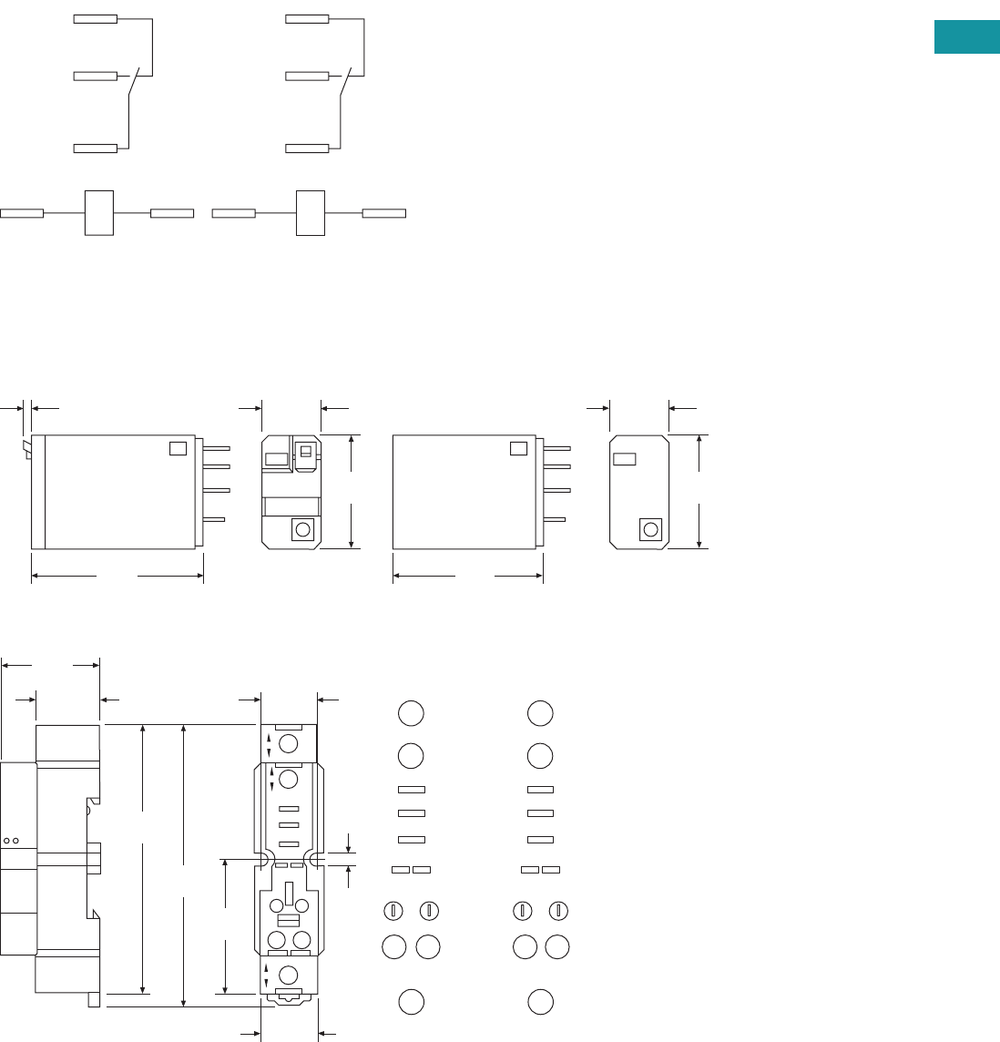
Volume 7—Logic Control, Operator Interface and Connectivity Solutions CA08100008E—June 2013 www.eaton.com V7-T3-57
3
3
3
3
3
3
3
3
3
3
3
3
3
3
3
3
3
3
3
3
3
3
3
3
3
3
3
3
3
3
Volume 7—Logic Control, Operator Interface and Connectivity Solutions CA08100008E—June 2013 www.eaton.com V7-T3-57
3
3
3
3
3
3
3
3
3
3
3
3
3
3
3
3
3
3
3
3
3
3
3
3
3
3
3
3
3
3
3.4
Control Relays and Timers
General Purpose Plug-In Relays
Wiring Diagram
D1PF/D1PR
Dimensions
Approximate Dimensions in Inches (mm)
D1PF/D1PR
D1PAA
NEMA
1
5
9
13 14
IEC
12
14
11
A1 A2
0.10
(2.1)
0.53
(14.0)
1.10
(27.9)
1.60
(40.6)
0.53
(14.0)
1.10
(27.9)
1.40
(35.5)
1.57
(40.0)
1.18
(30.0)
0.74
(19.0)
0.67
(17.0)
3.33
(84.0)
3.14
(80.0)
0.82
(21.0)
0.16
(4.0)
9
14 13
1
5
COM
N.C.
N.O.
14 13
Module
Input
Input
1
5
Input
9
Input
NEMA
11
A2 A1
12
14
COM
N.C.
N.O.
14 13
Module
Input
Input
1
5
Input
9
Input
IEC
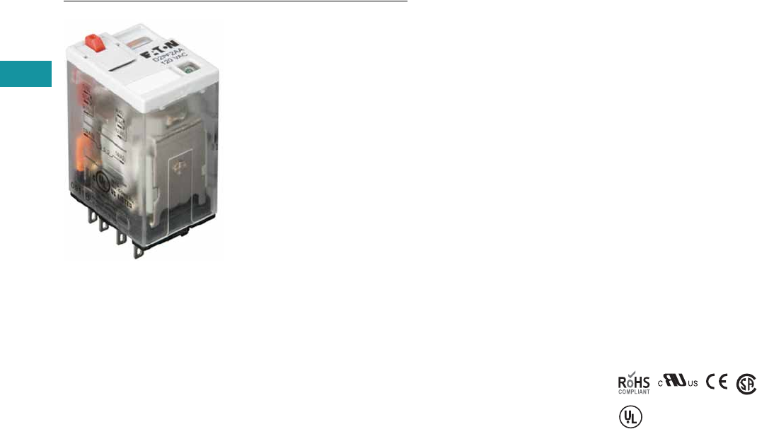
V7-T3-58 Volume 7—Logic Control, Operator Interface and Connectivity Solutions CA08100008E—June 2013 www.eaton.com
3
3
3
3
3
3
3
3
3
3
3
3
3
3
3
3
3
3
3
3
3
3
3
3
3
3
3
3
3
3
V7-T3-58 Volume 7—Logic Control, Operator Interface and Connectivity Solutions CA08100008E—June 2013 www.eaton.com
3
3
3
3
3
3
3
3
3
3
3
3
3
3
3
3
3
3
3
3
3
3
3
3
3
3
3
3
3
3
3.4
Control Relays and Timers
General Purpose Plug-In Relays
D2 Series Relay
Contents
Description Page
D1PR/D1PF Series . . . . . . . . . . . . . . . . . . . . . . . . . V7-T3-53
D2PR/D2PF Series
Catalog Number Selection . . . . . . . . . . . . . . . . V7-T3-59
Product Selection . . . . . . . . . . . . . . . . . . . . . . . V7-T3-59
Accessories. . . . . . . . . . . . . . . . . . . . . . . . . . . . V7-T3-61
Technical Data and Specifications . . . . . . . . . . . V7-T3-62
Wiring Diagrams . . . . . . . . . . . . . . . . . . . . . . . . V7-T3-63
Dimensions. . . . . . . . . . . . . . . . . . . . . . . . . . . . V7-T3-64
D3PR/D3PF Series . . . . . . . . . . . . . . . . . . . . . . . . . V7-T3-68
D4 Series . . . . . . . . . . . . . . . . . . . . . . . . . . . . . . . . V7-T3-78
D5PR/D5PF Series . . . . . . . . . . . . . . . . . . . . . . . . . V7-T3-82
D7PR/D7PF Series . . . . . . . . . . . . . . . . . . . . . . . . . V7-T3-91
D8 Series . . . . . . . . . . . . . . . . . . . . . . . . . . . . . . . . V7-T3-106
D9 Series . . . . . . . . . . . . . . . . . . . . . . . . . . . . . . . . V7-T3-112
Accessories . . . . . . . . . . . . . . . . . . . . . . . . . . . . . . V7-T3-116
D2PR/D2PF Series
Product Description
The D2 Series is a compact
line of relays with quick
response time and long life.
Available in DPDT, 4PDT and
DPDT latching configurations.
Features
D2PR
●Ultra-high sensitivity relay
with quick response
●High reliability, long life
●Panel, DIN rail and flange
mounting
●Small size
D2PF
●
Flag indicator shows relay
status in manual or powered
condition
●
Bipolar LED status lamp
allows for reverse polarity
applications
●
Shows coil ON or OFF
status
●
Ideal in low light
conditions
●
Color-coded pushbutton
identifies AC coils with red
or DC coils with blue
pushbuttons
●
Allows for manual
operation of relay without
the need for coil power
●
Ideal for field service
personnel to test control
circuits
●
Lock-down door, when
activated, holds pushbutton
and contacts in the operate
position
●
Excellent for analyzing
circuit problems
●
Finger-grip cover allows
operator to remove relays
from sockets more easily
than conventional relays
●
White plastic ID tag/write
label used for identification
of relays in multi-relay
circuits
Standards and Certifications
When used with
accompanying Eaton
screw terminal socket.
UL Listed
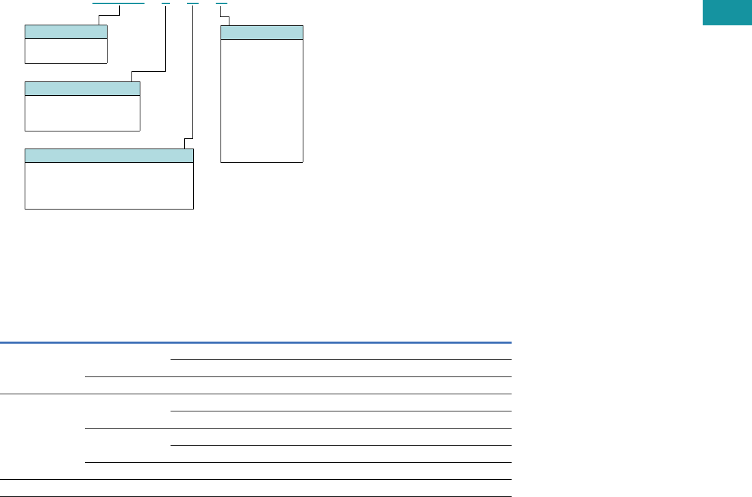
Volume 7—Logic Control, Operator Interface and Connectivity Solutions CA08100008E—June 2013 www.eaton.com V7-T3-59
3
3
3
3
3
3
3
3
3
3
3
3
3
3
3
3
3
3
3
3
3
3
3
3
3
3
3
3
3
3
Volume 7—Logic Control, Operator Interface and Connectivity Solutions CA08100008E—June 2013 www.eaton.com V7-T3-59
3
3
3
3
3
3
3
3
3
3
3
3
3
3
3
3
3
3
3
3
3
3
3
3
3
3
3
3
3
3
3.4
Control Relays and Timers
General Purpose Plug-In Relays
Catalog Number Selection
D2PF/D2PR 1
Product Selection
D2PF/D2PR Relay/Socket Quick Reference
Note
1For deciphering catalog numbers. Do not use for ordering as not all combinations are readily available.
Relay
Type Socket Clip
Module
Type
ID
Tag Jumper
D2PR2, D2PF2 D2PAL PWC-D24 B PWF-D2P D2PJ1
PQC-1782 — — —
D2PA6 PQC-1342 None — —
D2PR4, D2PF4 D2PAP PWC-D24 B PWF-D2P D2PJ1
PQC-1782 — — —
D2PA7 PWC-D24 B — —
PQC-1782 B — —
D2PA6 PQC-1342 None — —
D2PR5 D2PA4 PYC-A1 None — —
Family Type
D2PF
D2PR
Contact Configuration
2 = DPDT
4 = 4PDT
5 = DPDT latching
Standard Features
Blank = Plain cover (only with D2PR)
A = LED test button, flag indicator,
lock-down door, finger-grip cover,
ID tag (only with D2PF)
D 2 P F 2 A A
Coil Voltage
A = 120 Vac
A1 = 110 Vdc
B = 240 Vac
P = 6 Vac
P1 = 6 Vdc
R = 12 Vac
R1 = 12 Vdc
T = 24 Vac
T1 = 24 Vdc
W = 48 Vac
W1 = 48 Vdc

V7-T3-60 Volume 7—Logic Control, Operator Interface and Connectivity Solutions CA08100008E—June 2013 www.eaton.com
3
3
3
3
3
3
3
3
3
3
3
3
3
3
3
3
3
3
3
3
3
3
3
3
3
3
3
3
3
3
V7-T3-60 Volume 7—Logic Control, Operator Interface and Connectivity Solutions CA08100008E—June 2013 www.eaton.com
3
3
3
3
3
3
3
3
3
3
3
3
3
3
3
3
3
3
3
3
3
3
3
3
3
3
3
3
3
3
3.4
Control Relays and Timers
General Purpose Plug-In Relays
D2PF/D2PR Series
Coil
Voltage
Contact
Configuration
Coil Resistance
(Ohms)
Catalog
Number
Full Featured Style
6 Vac DPDT 9.6 D2PF2AP
6 Vdc DPDT 40 D2PF2AP1
12 Vac DPDT 46 D2PF2AR
12 Vdc DPDT 160 D2PF2AR1
24 Vac DPDT 180 D2PF2AT
24 Vdc DPDT 650 D2PF2AT1
48 Vdc DPDT 2600 D2PF2AW1
110/125 Vdc DPDT 11,000 D2PF2AA1
120 Vac DPDT 4430 D2PF2AA
220/240 Vac DPDT 15,720 D2PF2AB
12 Vac 4PDT 46 D2PF4AR
12 Vdc 4PDT 160 D2PF4AR1
24 Vac 4PDT 180 D2PF4AT
24 Vdc 4PDT 650 D2PF4AT1
48 Vdc 4PDT 2600 D2PF4AW1
110/125 Vdc 4PDT 11,000 D2PF4AA1
120 Vac 4PDT 4430 D2PF4AA
220/240 Vac 4PDT 15,720 D2PF4AB
Plain Cover Style
6 Vdc DPDT 40 D2PR2P1
12 Vdc DPDT 160 D2PR2R1
24 Vac DPDT 180 D2PR2T
24 Vdc DPDT 650 D2PR2T1
48 Vdc DPDT 2600 D2PR2W1
110/125 Vdc DPDT 11,000 D2PR2A1
120 Vac DPDT 4430 D2PR2A
220/240 Vac DPDT 15,720 D2PR2B
6 Vac 4PDT 9.6 D2PR4P
6 Vdc 4PDT 40 D2PR4P1
12 Vac 4PDT 46 D2PR4R
12 Vdc 4PDT 160 D2PR4R1
24 Vac 4PDT 180 D2PR4T
24 Vdc 4PDT 650 D2PR4T1
110/125 Vdc 4PDT 11,000 D2PR4A1
120 Vac 4PDT 4430 D2PR4A
220/240 Vac 4PDT 15,720 D2PR4B
Latching Style
24 Vac DPDT 180 D2PR5T
24 Vdc DPDT 650 D2PR5T1
110 Vac DPDT 11,000 D2PR5A
D2PF Series Relay

Volume 7—Logic Control, Operator Interface and Connectivity Solutions CA08100008E—June 2013 www.eaton.com V7-T3-61
3
3
3
3
3
3
3
3
3
3
3
3
3
3
3
3
3
3
3
3
3
3
3
3
3
3
3
3
3
3
Volume 7—Logic Control, Operator Interface and Connectivity Solutions CA08100008E—June 2013 www.eaton.com V7-T3-61
3
3
3
3
3
3
3
3
3
3
3
3
3
3
3
3
3
3
3
3
3
3
3
3
3
3
3
3
3
3
3.4
Control Relays and Timers
General Purpose Plug-In Relays
Accessories
D2PF/D2PR Sockets and Accessories
Note
1Protection category (finger safe), EN 60529: IP20.
Type
Module
Size
Nominal Voltage
(Max. for Sockets)
Nominal
Current Mounting Style Wire Size
Wire
Connection
Standard
Pack
Catalog
Number
Socket B 300 12 DIN rail/panel 14/16 (2) AWG, 2.5/1.5 (2) mm2Elevator 1 D2PAL 1
None 300 10 DIN rail/panel 12/14 (2) AWG, 4/2.5 (2) mm2Screw clamping 10 D2PA6
B 300 10 DIN rail/panel 14/16 (2) AWG, 2.5/1.5 (2) mm2Elevator 1 D2PAP 1
B 300 10 DIN rail/panel 12/14 (2) AWG, 4/2.5 (2) mm2Screw clamping 10 D2PA7 1
None 300 10 DIN rail/panel 12/14 (2) AWG, 4/2.5 (2) mm2Screw clamping 5 D2PA4
Flange mount adapter — — — Flange — — 25 PFC-D2D72
Plastic ejector clip — — — — — — 10 PWC-D24
Metal spring clip — — — — — — 25 PQC-1782
—— —— — — 25PQC-1342
Hold-down spring — — — — — — 100 PYC-A1
Protection diode B 6 to 250 Vdc — — — — 20 MOD-BD250
LED indicator B 24 Vac/Vdc — — — — 20 MOD-BLG24
B 120/240 Vac/Vdc — — — — 20 MOD-BLG240
MOV suppressor B 120 Vac/Vdc — — — — 20 MOD-BMV120
B 24 Vac/Vdc — — — — 20 MOD-BMV24
B240 Vac/Vdc—— — — 20MOD-BMV240
Coil bus jumpers — — — — — — 10 D2PJ1
Plastic DIN rail end stop — — — — — — 25 PFP-P

V7-T3-62 Volume 7—Logic Control, Operator Interface and Connectivity Solutions CA08100008E—June 2013 www.eaton.com
3
3
3
3
3
3
3
3
3
3
3
3
3
3
3
3
3
3
3
3
3
3
3
3
3
3
3
3
3
3
V7-T3-62 Volume 7—Logic Control, Operator Interface and Connectivity Solutions CA08100008E—June 2013 www.eaton.com
3
3
3
3
3
3
3
3
3
3
3
3
3
3
3
3
3
3
3
3
3
3
3
3
3
3
3
3
3
3
3.4
Control Relays and Timers
General Purpose Plug-In Relays
Technical Data and Specifications
D2PF/D2PR Relay Specifications
Description D2PR2/D2PR4 D2PR5 D2PF
Contact Characteristics
Contact rating 10A 5A 10A
Terminal style Plug-in Plug-in Plug-in
Contact materials Silver alloy Silver (gold flashed) Silver alloy
Maximum switching voltage 300V 250 Vac/125 Vdc 300V
Switching current at voltage—resistive 10A at 120 Vac
50/60 Hz
3A at 250 Vac 10A at 277 Vac
50/60 Hz|
8A at 277 Vac
50/60 Hz
— 8A at 120 Vac
50/60 Hz
8A at 28 Vdc 5A at 30 Vdc 8A at 28 Vdc
Switching current at voltage 1/3 hp at 120 Vac
1 hp at 277 Vac
1/8 hp at 250 Vac 1/3 hp at 120 Vac
1 hp at 277 Vac
Pilot duty B300 — B300
Minimum switching requirement 100 mA at 5 Vdc
(0.5W)
100 mA, 1 Vdc 100 mA at 5 Vdc
(0.5W)
Coil Characteristics
Operating range
% of nominal (AC) 85 to 110% 80 to 110% 85 to 110%
% of nominal (DC) 80 to 110% 80 to 110% 80 to 110%
Average consumption 1.2 VA — 1.2 VA
0.9W — 0.9W
Dropout voltage threshold 15% (AC) 30% (AC) 15% (AC)
10% (DC) 10% (DC) 10% (DC)
Performance
Electrical life (UL 508) operations at rated current 200,000 200,000 200,000
Mechanical life operations unpowered 10,000,000 100,000,000 10,000,000
Response time 20 ms — 20 ms
Dielectric strength
Between coil and contact Vac (rms) 1500 rms — 1500 rms
Between poles Vac (rms) 1500 rms — 1500 rms
Environment
Ambient air temperature around the device
Operation –40° to 131°F (–40° to 55°C) — –40° to 131°F (–40° to 55°C)
Storage –40° to 185°F (–40° to 85°C) — –40° to 185°F (–40° to 85°C)
Vibration resistance—operational 3 g-n at 10–55 Hz — 3 g-n at 10–55 Hz
Shock resistance 10 g-n — 10 g-n
Degree of protection IP40 — IP40
Features
Cover options Plain cover Plain cover Full featured
Features Mechanical flag indicator Latching Locking pushbutton/
Bipolar LED/
Removable ID tag/
Mechanical flag indicator
Product certifications RoHS/UL/CE/CSA UL/CE/CSA RoHS/UL/CE/CSA

Volume 7—Logic Control, Operator Interface and Connectivity Solutions CA08100008E—June 2013 www.eaton.com V7-T3-63
3
3
3
3
3
3
3
3
3
3
3
3
3
3
3
3
3
3
3
3
3
3
3
3
3
3
3
3
3
3
Volume 7—Logic Control, Operator Interface and Connectivity Solutions CA08100008E—June 2013 www.eaton.com V7-T3-63
3
3
3
3
3
3
3
3
3
3
3
3
3
3
3
3
3
3
3
3
3
3
3
3
3
3
3
3
3
3
3.4
Control Relays and Timers
General Purpose Plug-In Relays
Wiring Diagrams
D2PF2/D2PR2
D2PF4/D2PR4
NEMA
1
5
9
4
8
12
13 14
IEC
42
44
41
12
14
11
A1 A2
IEC
42
44
41
32
34
31
22
24
21
12
14
11
A1 A2
NEMA
4
8
12
3
7
11
2
6
10
1
5
9
13 14
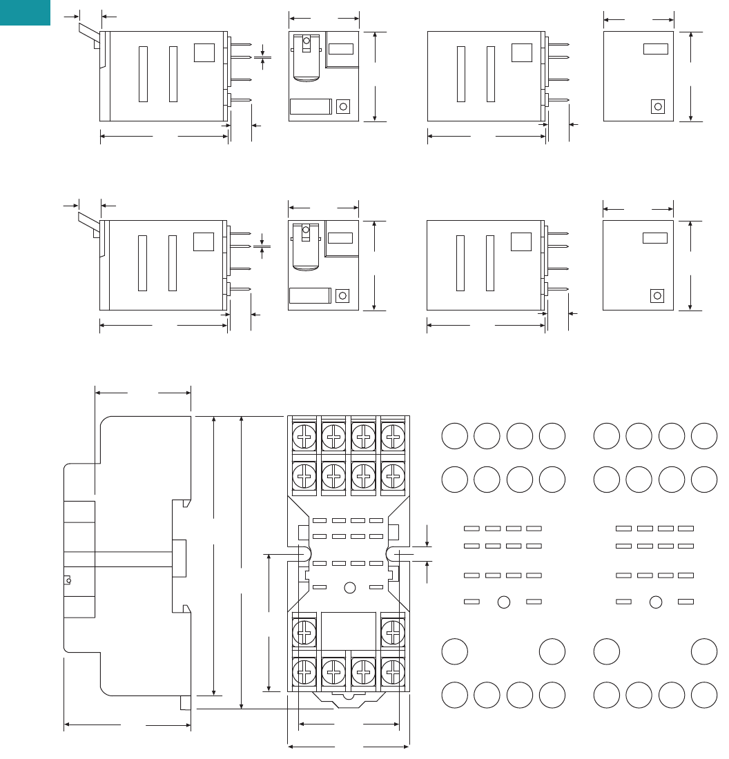
V7-T3-64 Volume 7—Logic Control, Operator Interface and Connectivity Solutions CA08100008E—June 2013 www.eaton.com
3
3
3
3
3
3
3
3
3
3
3
3
3
3
3
3
3
3
3
3
3
3
3
3
3
3
3
3
3
3
V7-T3-64 Volume 7—Logic Control, Operator Interface and Connectivity Solutions CA08100008E—June 2013 www.eaton.com
3
3
3
3
3
3
3
3
3
3
3
3
3
3
3
3
3
3
3
3
3
3
3
3
3
3
3
3
3
3
3.4
Control Relays and Timers
General Purpose Plug-In Relays
Dimensions
Approximate Dimensions in Inches (mm)
D2PF2/D2PR2
D2PF4/D2PR4
D2PA6
1.10
(27.9)
1.54
(39.1)
0.27
(7.0) 0.02
(0.5)
0.24
(6.0)
0.83
(21.0)
1.40
(35.5)
1.10
(27.9)
0.83
(21.0)
0.24
(6.0)
1.10
(27.9)
1.54
(39.1)
0.27
(7.0) 0.02
(0.5)
0.24
(6.0)
0.83
(21.0)
1.40
(35.5)
1.10
(27.9)
0.83
(21.0)
0.24
(6.0)
2.71
(69.0)
2.51
(64.0)
1.0 0
(25.4)
9
5
14
8
3
7
6
2
1
1
4
1
2
1
3
1
0
1
0.89
(22.7)
1.20
(30.7)
0.17
(4.3)
Dia.
Typ.
1.25
(32.0)
41 31 21 11
A2 A1
42 32 22 12
44 34 24 14
N.C.
N.O.
COM
INPUT
8765
4321
14 13
9
10
11
12
0.71
(18.0)
INPUT
8
4
75
6
31
2
10
11
12
14 13
9
N.C.
N.O.
COM
INPUT
8765
4321
14 13
9
10
11
12
NEMAIEC
INPUT
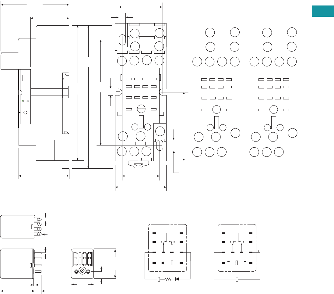
Volume 7—Logic Control, Operator Interface and Connectivity Solutions CA08100008E—June 2013 www.eaton.com V7-T3-65
3
3
3
3
3
3
3
3
3
3
3
3
3
3
3
3
3
3
3
3
3
3
3
3
3
3
3
3
3
3
Volume 7—Logic Control, Operator Interface and Connectivity Solutions CA08100008E—June 2013 www.eaton.com V7-T3-65
3
3
3
3
3
3
3
3
3
3
3
3
3
3
3
3
3
3
3
3
3
3
3
3
3
3
3
3
3
3
3.4
Control Relays and Timers
General Purpose Plug-In Relays
Approximate Dimensions in Inches (mm)
D2PA7
D2PR5
A2
41
A1
31 21
11
42
24
34
14
44
12
22
32
INPUT
COM
N.O.
N.C.
4321
5
86
7
12 11 10
14 13
9
0.14
(3.8)
1.0 0
(25.4)
1.55
(39.5)
0.25
(6.4)
0.82
(21.0)
0.14
(3.80)
3.30
(84.0)
3.11
(79.0)
1.57
(40.0)
1.18
(30.0)
2.40
(61.0)
1.18
(30.0)
44 14
11
12 10
INPUT
INPUT
31
14
A2
41
13 9
A1
21
11
3
4 2 1
8
32
42
5
22 12
34
7
24
6
0.74
(19.0)
MODULE
INPUT
IEC
INPUT
14
12
9
13
11 10
41
2
3
6
7
5
8
INPUT
COM
N.O.
N.C.
4321
5
86
7
12 11 10
14 13
9
MODULE
INPUT
NEMA
INPUT
0.10
(2.5)
0.02
(0.5)
0.24
(6.1)
0.25
(6.4)
0.85
(21.6)
Max.
1.10
(27.9)
Max.
14 – 0.05 (1.3) Dia. x 0.09 (2.3)
Elliptic Holes
0.02 (0.5)
1.42 (36.1)
Max.
1
5
9
13
4
8
121110
14
RESET R
1
5
9
13
4
8
121110
14
RESET
SET
Terminal Arrangement/Internal Connections (Bottom View)
AC DC
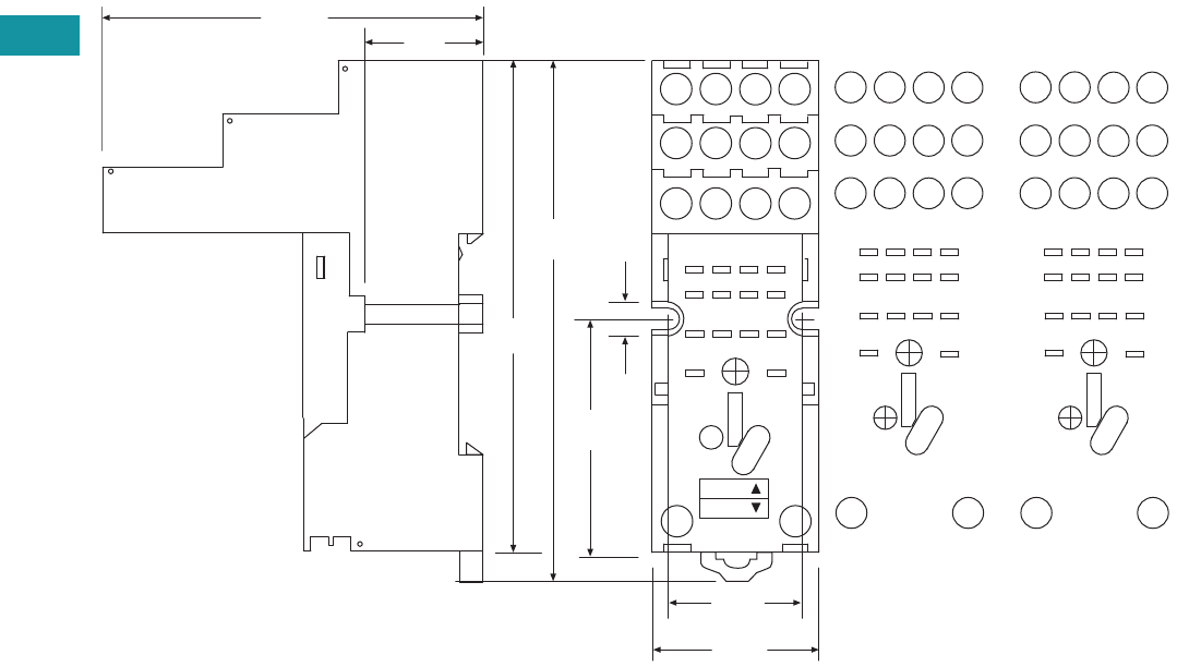
V7-T3-66 Volume 7—Logic Control, Operator Interface and Connectivity Solutions CA08100008E—June 2013 www.eaton.com
3
3
3
3
3
3
3
3
3
3
3
3
3
3
3
3
3
3
3
3
3
3
3
3
3
3
3
3
3
3
V7-T3-66 Volume 7—Logic Control, Operator Interface and Connectivity Solutions CA08100008E—June 2013 www.eaton.com
3
3
3
3
3
3
3
3
3
3
3
3
3
3
3
3
3
3
3
3
3
3
3
3
3
3
3
3
3
3
3.4
Control Relays and Timers
General Purpose Plug-In Relays
Approximate Dimensions in Inches (mm)
D2PAP
A2 INPUT A1
44
41
42 32 22 12
14
34 24
21
31 11
1
2
3
4
5
6
7
8
9
10
11
12
14 13
0.90
(22.0)
1.06
(26.9)
2.40
(61.0) 0.74
(19.0)
3.11
(79.0)
3.34
(85.0)
1.49
(38.0)
0.20
(5.6)
MODULE
INPUT
COM
INPUT
N.O.
N.C.
1
A1
12
5
9
11
14
INPUT
A2
14
3
4
7
8
11
12
32
42
41 31
34
44
13
2
6
10
22
21
24
NEMA:
IEC:
IEC
14 13
INPUT
4
8
12
2
31
6
75
10
11 9
1
2
3
4
5
6
7
8
9
10
11
12
14 13
MODULE
INPUT
COM
INPUT
N.O.
N.C.
NEMA
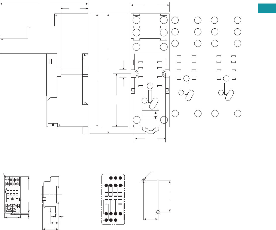
Volume 7—Logic Control, Operator Interface and Connectivity Solutions CA08100008E—June 2013 www.eaton.com V7-T3-67
3
3
3
3
3
3
3
3
3
3
3
3
3
3
3
3
3
3
3
3
3
3
3
3
3
3
3
3
3
3
Volume 7—Logic Control, Operator Interface and Connectivity Solutions CA08100008E—June 2013 www.eaton.com V7-T3-67
3
3
3
3
3
3
3
3
3
3
3
3
3
3
3
3
3
3
3
3
3
3
3
3
3
3
3
3
3
3
3.4
Control Relays and Timers
General Purpose Plug-In Relays
Approximate Dimensions in Inches (mm)
D2PAL
D2PA4 Socket for D2PR5 DPDT Latching Relays Only
A1
12
11
14
INPUT
A2
42
41
44
N.O.
INPUT
COM
N.C.
41
5
8
9
12
14 13
1.49
(38.0)
0.20
(5.6)
0.92
(23.5)
1.06
(27.0)
3.11
(79.0)
3.34
(85.0)
2.40
(61.0) 0.74
(19.0)
A1
INPUT
A2
14 13
12
5
9
11
14
41
8
12
42
41
44
NEMA:
IEC:
MODULE
INPUT
IEC
1
5
9
INPUT
14
4
8
12
13
N.O.
INPUT
COM
N.C.
41
5
8
9
12
14 13
MODULE
INPUT
NEMA
Two 0.17 (4.3) x 0.20 (5.1)
Mounting Holes
2.83
(71.9)
Max.
0.16
(4.1)
1.18
(30.0)
0.65 (16.5)
(22.09 0.20)
0.0080.870 +
–
+
–
(58.92 0.10)
0.0042.320 +
–
+
–
0.24 (6.1)
8 7 6 5
12 11 10
414 13
9
321
Mounting Holes
Two 0.18 (4.6) Dia. or M4
(Two 0.16 (4.1) Dia. or M3)
Terminal Arrangement
(Top View)
1.16
(29.5)
Max.
Max.
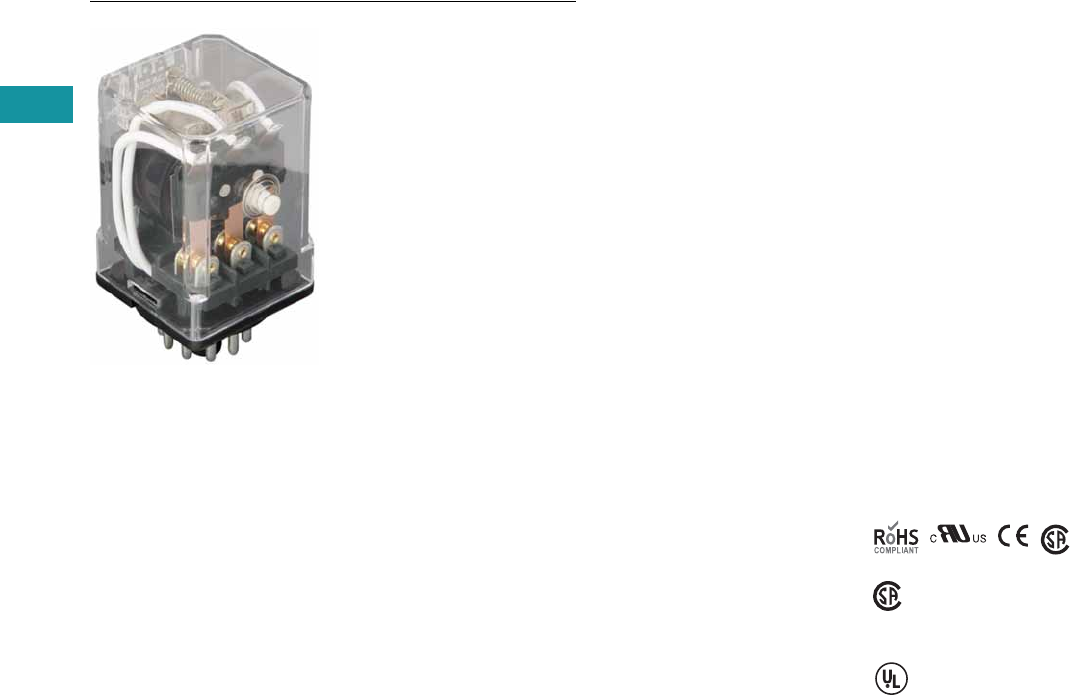
V7-T3-68 Volume 7—Logic Control, Operator Interface and Connectivity Solutions CA08100008E—June 2013 www.eaton.com
3
3
3
3
3
3
3
3
3
3
3
3
3
3
3
3
3
3
3
3
3
3
3
3
3
3
3
3
3
3
V7-T3-68 Volume 7—Logic Control, Operator Interface and Connectivity Solutions CA08100008E—June 2013 www.eaton.com
3
3
3
3
3
3
3
3
3
3
3
3
3
3
3
3
3
3
3
3
3
3
3
3
3
3
3
3
3
3
3.4
Control Relays and Timers
General Purpose Plug-In Relays
D3 Series Relay
Contents
Description Page
D1PR/D1PF Series . . . . . . . . . . . . . . . . . . . . . . . . . V7-T3-53
D2PR/D2PF Series . . . . . . . . . . . . . . . . . . . . . . . . . V7-T3-58
D3PR/D3PF Series
Catalog Number Selection . . . . . . . . . . . . . . . . V7-T3-69
Product Selection . . . . . . . . . . . . . . . . . . . . . . . V7-T3-69
Accessories. . . . . . . . . . . . . . . . . . . . . . . . . . . . V7-T3-71
Technical Data and Specifications . . . . . . . . . . . V7-T3-72
Dimensions. . . . . . . . . . . . . . . . . . . . . . . . . . . . V7-T3-73
D4 Series . . . . . . . . . . . . . . . . . . . . . . . . . . . . . . . . V7-T3-78
D5PR/D5PF Series . . . . . . . . . . . . . . . . . . . . . . . . . V7-T3-82
D7PR/D7PF Series . . . . . . . . . . . . . . . . . . . . . . . . . V7-T3-91
D8 Series . . . . . . . . . . . . . . . . . . . . . . . . . . . . . . . . V7-T3-106
D9 Series . . . . . . . . . . . . . . . . . . . . . . . . . . . . . . . . V7-T3-112
Accessories . . . . . . . . . . . . . . . . . . . . . . . . . . . . . . V7-T3-116
D3PR/D3PF Series
Product Description
The D3 Series of relays
provides excellent
functionality in a popular
octal base design. Rigid
pins and guide allow for
quick and easy installation
with little risk of damage.
Features
D3PR
●Compact relay capable of
breaking relatively large
load currents
●Panel and DIN rail
mounting
●8- or 11-pin octal plug-in
D3PF
●The contact operation can
be easily checked by Push-
to-Test button
●Flag indicator shows relay
status in manual or
powered condition
●LED status lamp shows
coil ON or OFF status—
ideal for use in low light
applications
●Push-to-Test button allows
for manual operation of
relay without the need for
coil power
●Lock-down door holds
pushbutton and contacts in
the operate position when
activated
●Finger-grip cover allows
operator to remove relays
from sockets easily
●ID tag/write label to
identify relays in multiple-
relay circuits
●Bipolar LED allows for
reverse polarity
applications
Standards and Certifications
When used with
accompanying Eaton
screw terminal socket
(for D3PF only)
(CSA approval
not applicable to
D3PR5 Relays)
UL Listed
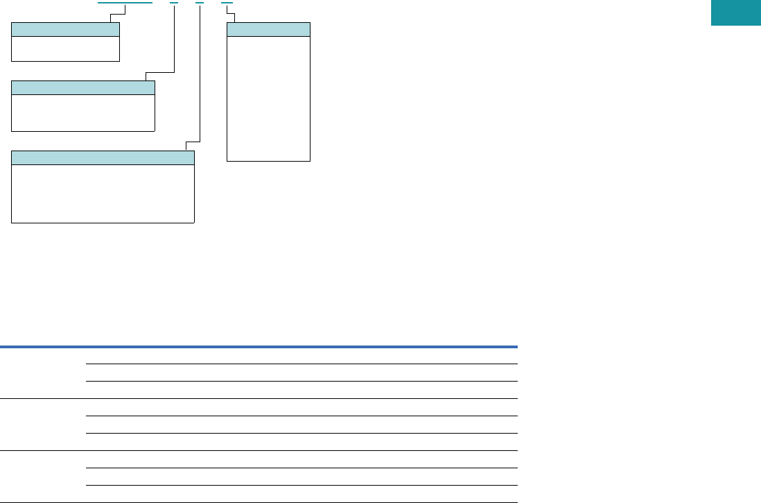
Volume 7—Logic Control, Operator Interface and Connectivity Solutions CA08100008E—June 2013 www.eaton.com V7-T3-69
3
3
3
3
3
3
3
3
3
3
3
3
3
3
3
3
3
3
3
3
3
3
3
3
3
3
3
3
3
3
Volume 7—Logic Control, Operator Interface and Connectivity Solutions CA08100008E—June 2013 www.eaton.com V7-T3-69
3
3
3
3
3
3
3
3
3
3
3
3
3
3
3
3
3
3
3
3
3
3
3
3
3
3
3
3
3
3
3.4
Control Relays and Timers
General Purpose Plug-In Relays
Catalog Number Selection
D3PR/D3PF Series 1
Product Selection
D3 Relay/Socket Quick Reference
Notes
1For deciphering catalog numbers. Do not use for ordering as not all combinations are readily available.
2D3PR only.
Relay
Type Socket Clip
Module
Type
ID
Tag Jumper
D3PR2, D3PF2 D3PA6 PQC-1332 A — D3PJ1
D3PAL8 PQC-1351 A PWF-D3D5 —
D3PA2 PQC-1351 None — —
D3PR3, D3PF3 D3PA7 PQC-1332 A — D3PJ1
D3PAL11 PQC-1351 A PWF-D3D5 —
D3PA3 PQC-1351 None — —
D3PR5 D3PA7 PQC-1351 A — D3PJ1
D3PAL11 PQC-1351 A PWF-D3D5 —
D3PA3 PQC-1351 None — —
D 3 P R 2 1 A
Family Type
D3PR = Standard relay
D3PF = Full featured relay
Coil Voltage
A = 120 Vac
A1 = 110 Vdc
B = 240 Vac
P = 6 Vac
P1 = 6 Vdc
R = 12 Vac
R1 = 12 Vdc
T = 24 Vac
T1 = 24 Vdc
W = 48 Vac
W1 = 48 Vdc
Contact Configuration
2 = DPDT (8-pin)
3 = 3PDT (11-pin)
5
= DPDT latching (11-pin)
2
Options
Blank = Plain cover relay (D3PR only)
A = LED test button, flag indicator,
lock-down door, finger-grip cover,
ID tag (D3PF only)
1 =
Indicating light (D3PR only)

V7-T3-70 Volume 7—Logic Control, Operator Interface and Connectivity Solutions CA08100008E—June 2013 www.eaton.com
3
3
3
3
3
3
3
3
3
3
3
3
3
3
3
3
3
3
3
3
3
3
3
3
3
3
3
3
3
3
V7-T3-70 Volume 7—Logic Control, Operator Interface and Connectivity Solutions CA08100008E—June 2013 www.eaton.com
3
3
3
3
3
3
3
3
3
3
3
3
3
3
3
3
3
3
3
3
3
3
3
3
3
3
3
3
3
3
3.4
Control Relays and Timers
General Purpose Plug-In Relays
D3PR/D3PF Series
Coil
Voltage
Contact
Configuration
Coil Resistance
(Ohms)
Catalog
Number
Full Featured Style
120 Vac DPDT 1700 D3PF2AA
240 Vac DPDT 7200 D3PF2AB
12 Vdc DPDT 120 D3PF2AR1
24 Vdc DPDT 470 D3PF2AT1
48 Vdc DPDT 1800 D3PF2AW1
120 Vac 3PDT 1700 D3PF3AA
220/240 Vac 3PDT 7200 D3PF3AB
6 Vdc 3PDT 32 D3PF3AP1
24 Vac 3PDT 72 D3PF3AT
24 Vdc 3PDT 470 D3PF3AT1
48 Vdc 3PDT 1800 D3PF3AW1
Latching Style
120 Vac DPDT 10,000 D3PR5A
110/125 Vdc DPDT 9000 D3PR5A1
240 Vac DPDT 36,000 D3PR5B
12 Vdc DPDT 90 D3PR5R1
24 Vac DPDT 470 D3PR5T
24 Vdc DPDT 350 D3PR5T1
48 Vdc DPDT 1400 D3PR5W1
Plain Cover with LED Indicator
120 Vac DPDT 1700 D3PR21A
24 Vac DPDT 72 D3PR21T
24 Vdc DPDT 470 D3PR21T1
220/240 Vac 3PDT 7200 D3PR31B
24 Vac 3PDT 72 D3PR31T
24 Vdc 3PDT 470 D3PR31T1
Plain Cover Style
120 Vac DPDT 1700 D3PR2A
110/125 Vdc DPDT 10,000 D3PR2A1
220/240 Vac DPDT 7200 D3PR2B
6 Vac DPDT 4.2 D3PR2P
6 Vdc DPDT 32 D3PR2P1
12 Vac DPDT 18 D3PR2R
12 Vdc DPDT 120 D3PR2R1
24 Vac DPDT 72 D3PR2T
24 Vdc DPDT 470 D3PR2T1
48 Vac DPDT 290 D3PR2W
48 Vdc DPDT 1800 D3PR2W1
120 Vac 3PDT 1700 D3PR3A
110/125 Vdc 3PDT 10,000 D3PR3A1
220/240 Vac 3PDT 7200 D3PR3B
12 Vac 3PDT 18 D3PR3R
12 Vdc 3PDT 120 D3PR3R1
24 Vac 3PDT 72 D3PR3T
24 Vdc 3PDT 470 D3PR3T1
48 Vdc 3PDT 1800 D3PR3W1
D3 Series Relay

Volume 7—Logic Control, Operator Interface and Connectivity Solutions CA08100008E—June 2013 www.eaton.com V7-T3-71
3
3
3
3
3
3
3
3
3
3
3
3
3
3
3
3
3
3
3
3
3
3
3
3
3
3
3
3
3
3
Volume 7—Logic Control, Operator Interface and Connectivity Solutions CA08100008E—June 2013 www.eaton.com V7-T3-71
3
3
3
3
3
3
3
3
3
3
3
3
3
3
3
3
3
3
3
3
3
3
3
3
3
3
3
3
3
3
3.4
Control Relays and Timers
General Purpose Plug-In Relays
Accessories
D3PR/D3PF Series Sockets and Accessories
Note
1Protection category (finger safe), EN 60529: IP20.
Type
Module
Size
Nominal Voltage
(Max. for Sockets)
Nominal
Current Mounting Style Wire Size
Wire
Connection
Standard
Pack
Catalog
Number
Socket A 300 16 DIN rail/panel 12/14 (2) AWG, 4/2.5 (2) mm2Screw clamping 1 D3PA6 1
A 300 12 DIN rail/panel 12/14 (2) AWG, 4/2.5 (2) mm2Elevator 10 D3PAL8 1
None 300/600 15/10 DIN rail/panel 12/14 (2) AWG, 4/2.5 (2) mm2Screw clamping 10 D3PA2
A 600 5 DIN rail/panel 12/14 (2) AWG, 4/2.5 (2) mm2Screw clamping 1 D3PA7 1
A 300 12 DIN rail/panel 12/14 (2) AWG, 4/2.5 (2) mm2Elevator 10 D3PAL11 1
None 300/600 15/5 DIN rail/panel 12/14 (2) AWG, 4/2.5 (2) mm2Screw clamping 10 D3PA3
Metal spring clip — — — — — — 25 PQC-1332
—— —— — — 10PQC-1351
Protection diode A 6 to 250 Vdc — — — — 20 MOD-AD250
LED indicator A 24 Vac/Vdc — — — — 20 MOD-ALG24
A 120/240 Vac/Vdc — — — — 20 MOD-ALG240
MOV suppressor A 120 Vac/Vdc — — — — 20 MOD-AMV120
A 24 Vac/Vdc — — — — 20 MOD-AMV24
A240 Vac/Vdc —— — — 20MOD-AMV240
R/C suppressor A 6 to 24 Vac/Vdc — — — — 20 MOD-RC24
A 110 to 240 Vac/Vdc — — — — 20 MOD-RC240
Write-on plastic labels — — — — — — 10 PWF-D3D5
Coil bus jumpers — — — — — — 10 D3PJ1
Plastic DIN rail end stop — — — — — — 25 PFP-P

V7-T3-72 Volume 7—Logic Control, Operator Interface and Connectivity Solutions CA08100008E—June 2013 www.eaton.com
3
3
3
3
3
3
3
3
3
3
3
3
3
3
3
3
3
3
3
3
3
3
3
3
3
3
3
3
3
3
V7-T3-72 Volume 7—Logic Control, Operator Interface and Connectivity Solutions CA08100008E—June 2013 www.eaton.com
3
3
3
3
3
3
3
3
3
3
3
3
3
3
3
3
3
3
3
3
3
3
3
3
3
3
3
3
3
3
3.4
Control Relays and Timers
General Purpose Plug-In Relays
Technical Data and Specifications
D3PR/D3PF Series Relay Specifications
Description D3PR D3PF
D3PR5
(Latching)
Contact Characteristics
Contact rating 16A 16A 16A
Terminal style Octal Octal 11-pin octal
Contact materials Silver alloy Silver alloy Silver alloy
Maximum switching voltage 300V 300V 300V
Switching current at voltage—resistive 16A at 277 Vac
50/60 Hz
16A at 277 Vac
50/60 Hz
16A at 277 Vac
50/60 Hz
16A at 120 Vac
50/60 Hz
16A at 120 Vac
50/60 Hz
—
16A at 28 Vdc 16A at 28 Vdc 16A at 28 Vdc
Switching current at voltage 1/2 hp at 240 Vac 1/2 hp at 240 Vac 1/2 hp at 240 Vac
1/3 hp at 120 Vac 1/3 hp at 120 Vac 1/3 hp at 120 Vac
Pilot duty B300 B300 B300
Minimum switching requirement 100 mA at 5 Vdc
(0.5W)
100 mA at 5 Vdc
(0.5W)
100 mA at 5 Vdc
(0.5W)
Coil Characteristics
Operating range
% of nominal (AC) 85 to 110% 85 to 110% 85 to 110%
% of nominal (DC) 80 to 110% 80 to 110% 80 to 110%
Average consumption 3 VA 3 VA 2 VA
1.4W 1.4W 1.64W
Dropout voltage threshold 15% (AC) 15% (AC) 15% (AC)
10% (DC) 10% (DC) 10% (DC)
Performance
Electrical life (UL 508) operations at rated current 100,000 operations 100,000 operations 100,000 operations
Mechanical life operations unpowered 5,000,000 operations 5,000,000 operations 10,000,000 operations
Response time 20 ms 20 ms 30 ms
Dielectric strength
Between coil and contact Vac (rms) 1500V (rms) 1500V (rms) 2500V (rms)
Between poles Vac (rms) 1500V (rms) 1500V (rms) 1500V (rms)
Environment
Ambient air temperature around the device
Storage –40° to 185°F (–40° to 85°C) –40° to 185°F (–40° to 85°C) –40° to 185°F (–40° to 85°C)
Operation –40° to 131°F (–40° to 55°C) –40° to 131°F (–40° to 55°C) –40° to 131°F (–40° to 55°C)
Vibration resistance—operational 3 g-n at 10–55 Hz 3 g-n at 10–55 Hz 3 g-n at 10–55 Hz
Shock resistance 10 g-n 10 g-n 10 g-n
Degree of protection IP40 IP40 IP40
Features
Cover options Plain cover Full Featured Latching
Features Mechanical flag indicator Bipolar LED/
Locking pushbutton/
Removable ID tag/
Mechanical flag indicator
—
Product certifications RoHS/UL/CE/CSA RoHS/UL/CE/CSA RoHS/UL/UR
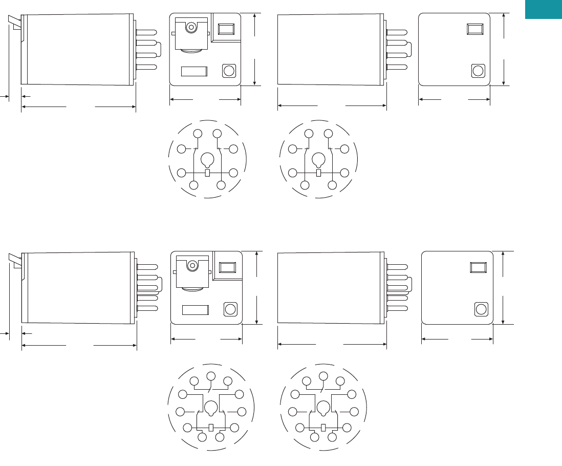
Volume 7—Logic Control, Operator Interface and Connectivity Solutions CA08100008E—June 2013 www.eaton.com V7-T3-73
3
3
3
3
3
3
3
3
3
3
3
3
3
3
3
3
3
3
3
3
3
3
3
3
3
3
3
3
3
3
Volume 7—Logic Control, Operator Interface and Connectivity Solutions CA08100008E—June 2013 www.eaton.com V7-T3-73
3
3
3
3
3
3
3
3
3
3
3
3
3
3
3
3
3
3
3
3
3
3
3
3
3
3
3
3
3
3
3.4
Control Relays and Timers
General Purpose Plug-In Relays
Dimensions
Approximate Dimensions in Inches (mm)
D3PR2/D3PF2
D3PR3/D3PF3
2.10
(50.3)
2.20
(55.2)
0.24
(6.1) 1.37
(34.8)
1.39
(35.3)
14
11
A1
12 22
24
A2
31
1.39
(35.3)
1.37
(34.8)
IEC
1
2
3
45
6
7
8
NEMA
2.10
(50.3)
2.20
(55.2)
0.24
(6.1) 1.37
(34.8)
1.39
(35.3)
1
2
3
4
567
8
9
10
11
1.39
(35.3)
1.37
(34.8)
NEMA
11
A1
14
12
22 21 24
32
34
A2
31
IEC
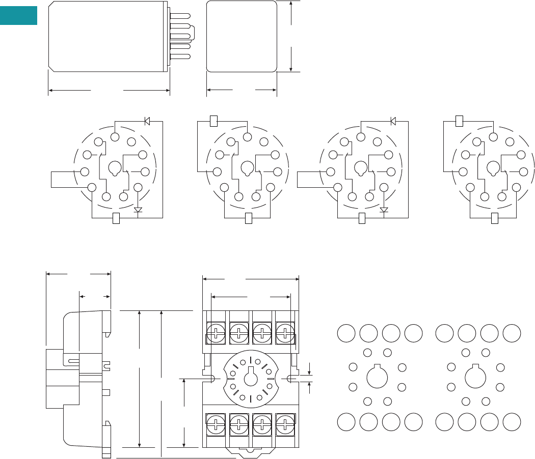
V7-T3-74 Volume 7—Logic Control, Operator Interface and Connectivity Solutions CA08100008E—June 2013 www.eaton.com
3
3
3
3
3
3
3
3
3
3
3
3
3
3
3
3
3
3
3
3
3
3
3
3
3
3
3
3
3
3
V7-T3-74 Volume 7—Logic Control, Operator Interface and Connectivity Solutions CA08100008E—June 2013 www.eaton.com
3
3
3
3
3
3
3
3
3
3
3
3
3
3
3
3
3
3
3
3
3
3
3
3
3
3
3
3
3
3
3.4
Control Relays and Timers
General Purpose Plug-In Relays
Approximate Dimensions in Inches (mm)
D3PR5—Octal Base Latching Relay
D3PA2
)CD( lioC lauD)CA( lioC elgniS
2.40
(61.0)
11
A1
14
12
22 21 24
32
34
A2
31
1.39
(35.3)
1.37
(34.8)
COMMON
RESET
SET
11
A1
14
12
22 21 24
32
34
A2
31
SET
RESET
COIL
COIL
2
1
IEC
)CD( lioC lauD)CA( lioC elgniS
1
2
3
4
567
8
9
10
11
COMMON
RESET
SET
1
2
3
4
567
8
9
10
11
SET
RESET
COIL
COIL
2
1
NEMA
3546
8 21
0.16
(4.2)
7
1.29
(33.0)
1.60
(40.0)
2.12
(54.0)
2.02
(51.0)
0.97
(24.6)
14 12 22 24
A1 11 21 A2
3
4
2
1
6
5
8
7
INPUT
1.01
(25.6)
INPUT
0.59
(15.0)
IEC
34
21
6
87
3
4
2
1
6
5
8
7
INPUT INPUT
NEMA
5

Volume 7—Logic Control, Operator Interface and Connectivity Solutions CA08100008E—June 2013 www.eaton.com V7-T3-75
3
3
3
3
3
3
3
3
3
3
3
3
3
3
3
3
3
3
3
3
3
3
3
3
3
3
3
3
3
3
Volume 7—Logic Control, Operator Interface and Connectivity Solutions CA08100008E—June 2013 www.eaton.com V7-T3-75
3
3
3
3
3
3
3
3
3
3
3
3
3
3
3
3
3
3
3
3
3
3
3
3
3
3
3
3
3
3
3.4
Control Relays and Timers
General Purpose Plug-In Relays
Approximate Dimensions in Inches (mm)
D3PA3
3
4
5
6
7
11
2
1
10
8
9
2.06
(52.0)
2.32
(59.0)
2.16
(54.8)
2.05
(52.0)
0.97
(24.6)
1.60 Dia.
(40.0)
1.02
(25.0)
5
14
A1 A2
11 31
34
12
22 24
21
32
11
1
39
10
2
48
67
INPUT INPUT
IEC
5
4
57
6
3
210
111
8
9
11
1
39
10
2
48
67
INPUT INPUT
NEMA
3 54 6
8 21
0.16
(4.2)
7
1.29
(33.0)
1.60
(40.0)
2.12
(54.0)
2.02
(51.0)
0.97
(24.6)
14 12 22 24
A1 11 21 A2
3
4
2
1
6
5
8
7
INPUT
1.01
(25.6)
INPUT
0.59
(15.0)
IEC
34
21
65
87
3
4
2
1
6
5
8
7
INPUT INPUT
NEMA
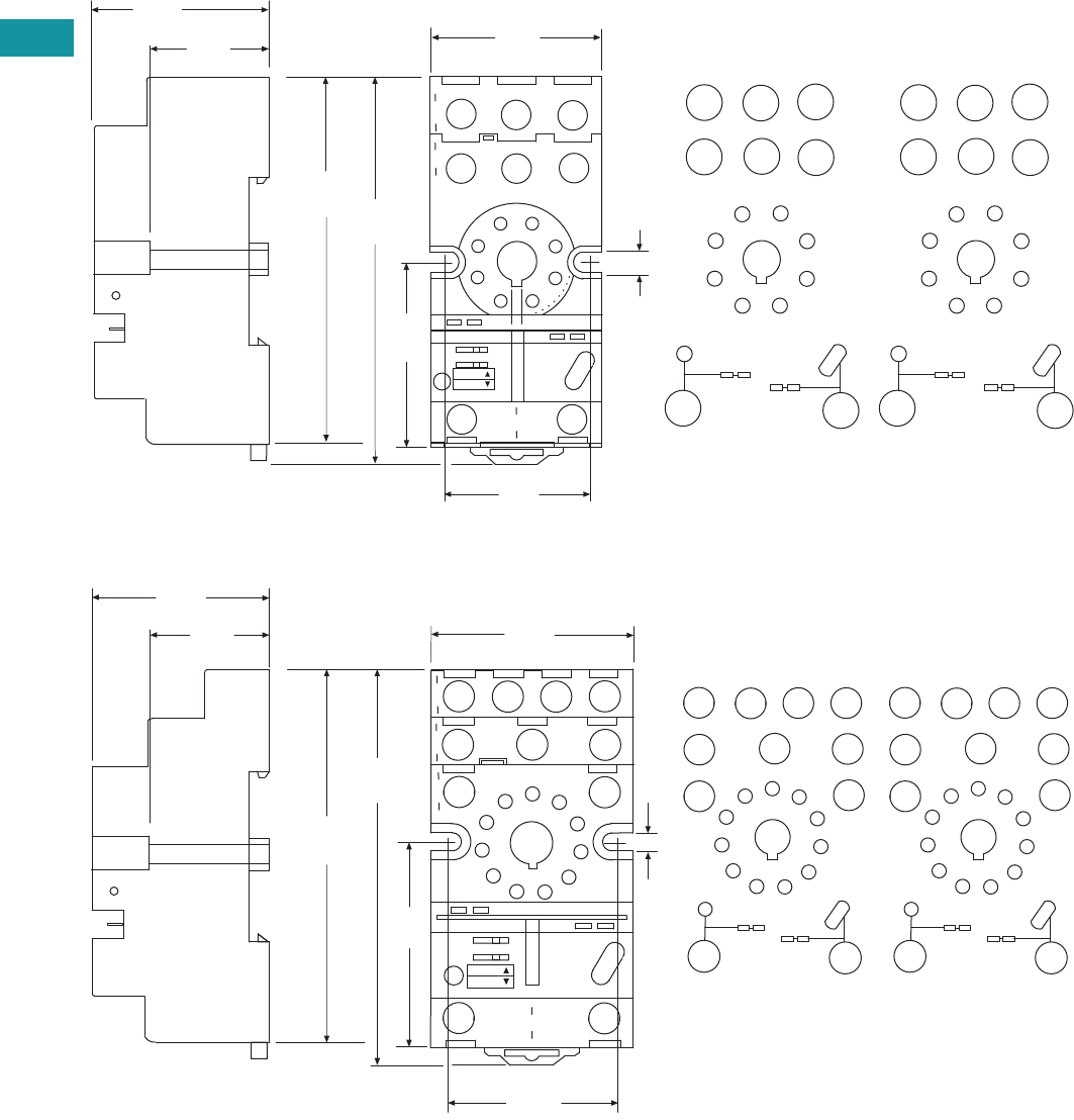
V7-T3-76 Volume 7—Logic Control, Operator Interface and Connectivity Solutions CA08100008E—June 2013 www.eaton.com
3
3
3
3
3
3
3
3
3
3
3
3
3
3
3
3
3
3
3
3
3
3
3
3
3
3
3
3
3
3
V7-T3-76 Volume 7—Logic Control, Operator Interface and Connectivity Solutions CA08100008E—June 2013 www.eaton.com
3
3
3
3
3
3
3
3
3
3
3
3
3
3
3
3
3
3
3
3
3
3
3
3
3
3
3
3
3
3
3.4
Control Relays and Timers
General Purpose Plug-In Relays
Approximate Dimensions in Inches (mm)
D3PA6
D3PA7
1.42
(36.0)
0.15
(3.8)
1.10
(27.9)
11
4
1
12
14
3
A2
7
5
22
21
24
68
A1
2
2.86
(72.0)
1.45
(37.0)
INPUT
INPUT
3.00
(76.0)
1.58
(40.0)
1.20
(30.0)
Coil Jumper Buss
A1
A2
54
7
81
2
63
21 14
24
11 1 2
22
MODULE
INPUT
INPUT
NEMA:
IEC:
IEC
2
7Coil Jumper Buss
54
7
81
2
63
63
8
5 1 4
MODULE
INPUT
INPUT
NEMA
1.50
(38.0)
0.15
(3.8)
5
3.01
(76.0)
1.45
(37.0)
3.18
(81.0)
1.58
(40.0)
1.35
(34.2)
34 14
31 21
32 22
24
11
12
11
1
3
9
10
2
4
8
6
7
A1
A2
Coil Jumper Buss
MODULE
INPUT
INPUT
11
4
1
12
14
3
A2
10
5
22
21
24
6
7
A1
2
INPUT
INPUT
34
9
31
11
32
8
1.10
(27.9)
IEC
NEMA:
IEC:
5
93
11
6
5
7
8
1
4
11
1
3
9
10
2
4
8
6
7
10 Coil Jumper Buss 2
MODULE
INPUT
INPUT
NEMA
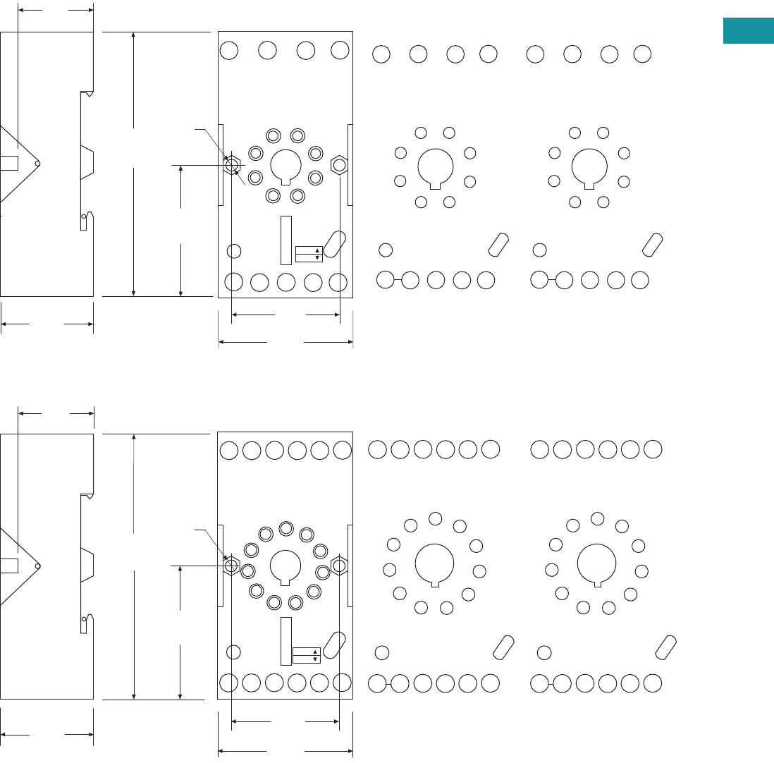
Volume 7—Logic Control, Operator Interface and Connectivity Solutions CA08100008E—June 2013 www.eaton.com V7-T3-77
3
3
3
3
3
3
3
3
3
3
3
3
3
3
3
3
3
3
3
3
3
3
3
3
3
3
3
3
3
3
Volume 7—Logic Control, Operator Interface and Connectivity Solutions CA08100008E—June 2013 www.eaton.com V7-T3-77
3
3
3
3
3
3
3
3
3
3
3
3
3
3
3
3
3
3
3
3
3
3
3
3
3
3
3
3
3
3
3.4
Control Relays and Timers
General Purpose Plug-In Relays
Approximate Dimensions in Inches (mm)
D3PAL8
D3PAL11
11
7
7
INPUT A1INPUT A2
A2
7
A2
8
21
21
A1
12
56
24
4
22
3
14
2
12
24 22 14
11
A2 21 A1A2
1
2
8
7
3
4
5
6
2.95
(75.0)
1.45
(37.0)
0.12
(30.0)
1.49
(38.0)
0.12
(3.10)
0.86
(22.0)
1.06
(27.0)
INPUT INPUT
MODULE
INPUT
IEC
465 3
17782
1
2
8
7
3
4
5
6
INPUT INPUT
MODULE
INPUT
NEMA
NEMA:
IEC:
INPUT A1
10
INPUT A2
2
A1
A2 A2 31 21 11
10 11
10 612
14
34 24
32 22 12
97
84
3
5
11
A2 31 21 A1
14
34 24 22 12
32
A2
4
3
9
8
75
6
1
10
11
2
4
3
9
8
75
6
1
10
11
2
2.95
(75.0)
INPUT
INPUT
0.86
(22.0)
1.06
(27.0)
1.45
(37.0)
1.49
(38.0)
0.12
(30.0)
NEMA:
IEC:
0.12
(3.1)
MODULE
INPUT
IEC
10 1
11 62
3
9754
10
8
INPUT
INPUT
MODULE
INPUT
NEMA
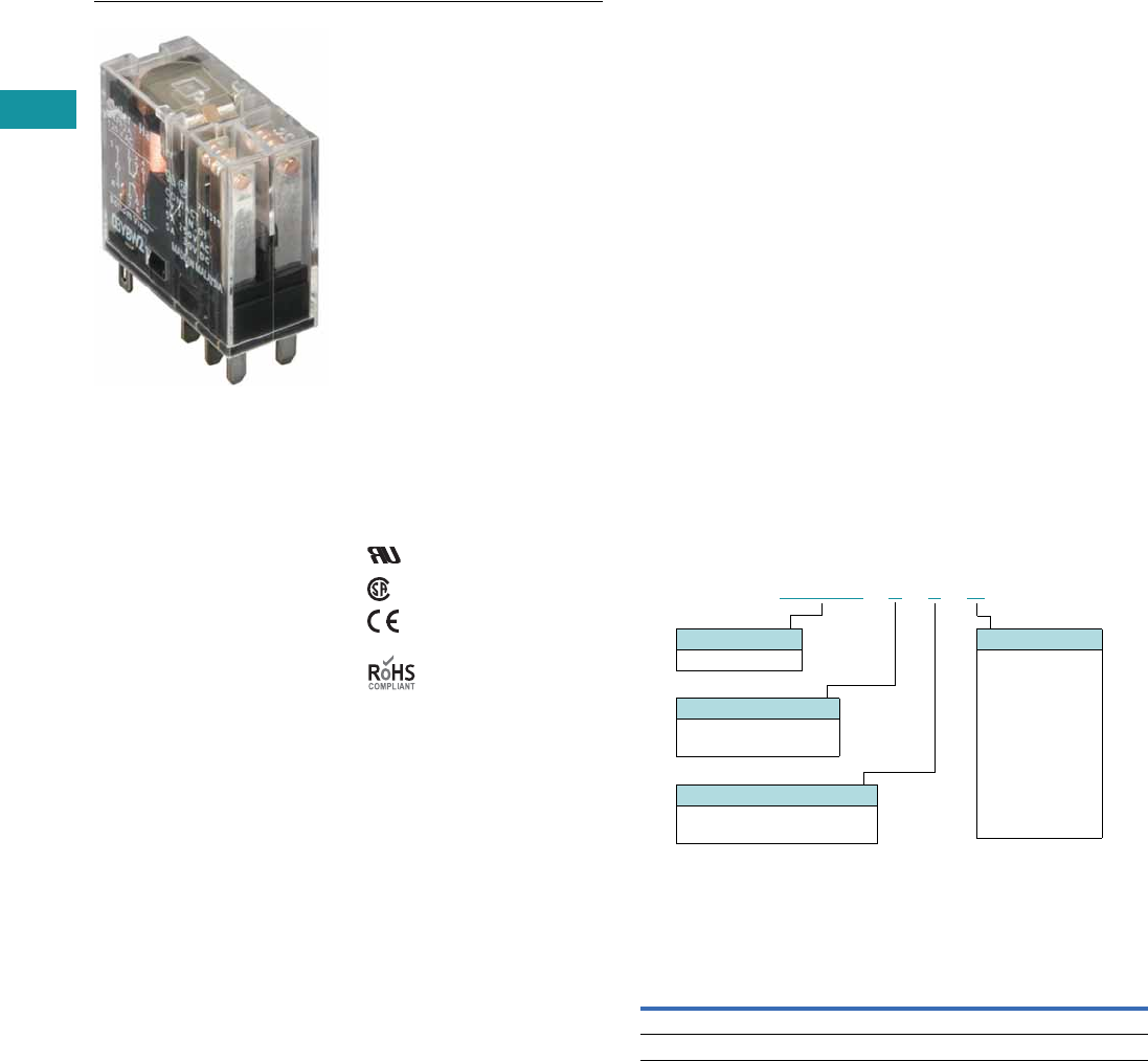
V7-T3-78 Volume 7—Logic Control, Operator Interface and Connectivity Solutions CA08100008E—June 2013 www.eaton.com
3
3
3
3
3
3
3
3
3
3
3
3
3
3
3
3
3
3
3
3
3
3
3
3
3
3
3
3
3
3
V7-T3-78 Volume 7—Logic Control, Operator Interface and Connectivity Solutions CA08100008E—June 2013 www.eaton.com
3
3
3
3
3
3
3
3
3
3
3
3
3
3
3
3
3
3
3
3
3
3
3
3
3
3
3
3
3
3
3.4
Control Relays and Timers
General Purpose Plug-In Relays
D4 Series Relay
Contents
Description Page
D1PR/D1PF Series . . . . . . . . . . . . . . . . . . . . . . . . . V7-T3-53
D2PR/D2PF Series . . . . . . . . . . . . . . . . . . . . . . . . . V7-T3-58
D3PR/D3PF Series . . . . . . . . . . . . . . . . . . . . . . . . . V7-T3-68
D4 Series
Technical Data and Specifications . . . . . . . . . . . V7-T3-80
Dimensions. . . . . . . . . . . . . . . . . . . . . . . . . . . . V7-T3-81
D5PR/D5PF Series . . . . . . . . . . . . . . . . . . . . . . . . . V7-T3-82
D7PR/D7PF Series . . . . . . . . . . . . . . . . . . . . . . . . . V7-T3-91
D8 Series . . . . . . . . . . . . . . . . . . . . . . . . . . . . . . . . V7-T3-106
D9 Series . . . . . . . . . . . . . . . . . . . . . . . . . . . . . . . . V7-T3-112
Accessories . . . . . . . . . . . . . . . . . . . . . . . . . . . . . . V7-T3-116
D4 Series
Product Description
The D4 Series is a slim-form
relay designed to fit into tight
spaces. The retaining clip is
built in to the socket to
provide easy and secure
assembly.
Features
●Slim-styled power relay
●Socket has built-in hold-
down clip
●Panel or DIN rail mounting
Standards and Certifications
File # E1491, E65657
File # LR701519
Catalog Number Selection
D4 Series 1
Product Selection
D4 Relay/Socket Quick Reference
Notes
1For deciphering catalog numbers. Do not use for ordering as not all combinations are
readily available.
2Socket has built-in hold-down spring.
D 4 P R 11A
Family Type
D4PR
Contact Configuration
1 = SPDT
2 = DPDT
Options
Blank = Plain cover
1 =
Indicating light
Coil Voltage
A = 120 Vac
A1 = 110 Vdc
B = 240 Vac
P = 6 Vac
P1 = 6 Vdc
R = 12 Vac
R1 = 12 Vdc
T = 24 Vac
T1 = 24 Vdc
W = 48 Vac
W1 = 48 Vdc
Relay Type Socket Hold-Down Clip
D4PR1 D4PA1 2
D4PR2 D4PA2 2
Volume 7—Logic Control, Operator Interface and Connectivity Solutions CA08100008E—June 2013 www.eaton.com V7-T3-79
3
3
3
3
3
3
3
3
3
3
3
3
3
3
3
3
3
3
3
3
3
3
3
3
3
3
3
3
3
3
Volume 7—Logic Control, Operator Interface and Connectivity Solutions CA08100008E—June 2013 www.eaton.com V7-T3-79
3
3
3
3
3
3
3
3
3
3
3
3
3
3
3
3
3
3
3
3
3
3
3
3
3
3
3
3
3
3
3.4
Control Relays and Timers
General Purpose Plug-In Relays
D4 Series
Voltage/Poles
Standard
Pack
Catalog
Number Voltage/Poles
Standard
Pack
Catalog
Number
DIN Rail Sockets DPDT with Indicating Light
Single-pole 10 D4PA1 120 Vac 1 D4PR21A
Two-pole 10 D4PA2 110 Vdc 1 D4PR21A1
SPDT with Indicating Light 240 Vac 1 D4PR21B
120 Vac 1 D4PR11A 6 Vac 50 D4PR21P
110 Vdc 1 D4PR11A1 6 Vdc 1 D4PR21P1
240 Vac 1 D4PR11B 12 Vac 50 D4PR21R
6 Vac 50 D4PR11P 12 Vdc 1 D4PR21R1
6 Vdc 50 D4PR11P1 24 Vac 1 D4PR21T
12 Vac 50 D4PR11R 24 Vdc 1 D4PR21T1
12 Vdc 1 D4PR11R1 48 Vdc 50 D4PR21W1
24 Vac 1 D4PR11T Standard DPDT
24 Vdc 1 D4PR11T1 120 Vac 1 D4PR2A
48 Vdc 50 D4PR11W1 110 Vdc 50 D4PR2A1
Standard SPDT 240 Vac 50 D4PR2B
120 Vac 1 D4PR1A 6 Vac 50 D4PR2P
110 Vdc 50 D4PR1A1 6 Vdc 1 D4PR2P1
240 Vac 50 D4PR1P 12 Vac 50 D4PR2R
6 Vac 1 D4PR1P1 12 Vdc 1 D4PR2R1
6 Vdc 50 D4PR1R 24 Vac 1 D4PR2T
12 Vac 1 D4PR1R1 24 Vdc 1 D4PR2T1
12 Vdc 1 D4PR1R1-A2 48 Vdc 1 D4PR2W1
24 Vac 1 D4PR1T
24 Vdc 1 D4PR1T1
48 Vdc 1 D4PR1W1
D4 Series Relay

V7-T3-80 Volume 7—Logic Control, Operator Interface and Connectivity Solutions CA08100008E—June 2013 www.eaton.com
3
3
3
3
3
3
3
3
3
3
3
3
3
3
3
3
3
3
3
3
3
3
3
3
3
3
3
3
3
3
V7-T3-80 Volume 7—Logic Control, Operator Interface and Connectivity Solutions CA08100008E—June 2013 www.eaton.com
3
3
3
3
3
3
3
3
3
3
3
3
3
3
3
3
3
3
3
3
3
3
3
3
3
3
3
3
3
3
3.4
Control Relays and Timers
General Purpose Plug-In Relays
Technical Data and Specifications
D4 Series
Description
Resistive Load
(p.f. = 1)
Inductive Load
(p.f. = 0.4, L/R = 7 ms)
D4PR1
Rated load 250 Vac 10A 250 Vac 7.5A
30 Vdc 10A 30 Vdc 5A
Carry current 10A 10A
Max. operating voltage 380 Vac/125 Vdc 380 Vac/125 Vdc
Max. operating current 10A 10A
Contact material AgCdO AgCdO
Max. switching capacity 2500 VA 1875 VA
300W 150W
Min. permissible load 100 mA, 5 Vdc 100 mA, 5 Vdc
Pickup voltage (max.) 80% AC/70% DC 80% AC/70% DC
Dropout voltage (min.) 30% AC/15% DC 30% AC/15% DC
Voltage (max.) 110% 110%
Mechanical life (min.) 10,000,000 AC/20,000,000 DC 10,000,000 AC/20,000,000 DC
Electrical life at all contact ratings (min.) 100,000 100,000
Maximum hp ratings 1/3 hp (125 Vac) 1/3 hp (125 Vac)
1/2 hp (250 Vac) 1/2 hp (250 Vac)
1/2 hp (277 Vac) 1/2 hp (277 Vac)
D4PR2
Rated load 240 Vac 5A 250 Vac 2A
30 Vdc 5A 30 Vdc 3A
Carry current 5A 5A
Max. operating voltage 380 Vac/125 Vdc 380 Vac/125 Vdc
Max. operating current 5A 5A
Contact material AgCdO AgCdO
Max. switching capacity 1250 VA 500 VA
150W 90W
Min. permissible load 10 mA, 5 Vdc 10 mA, 5 Vdc
Pickup voltage (max.) 80% AC/70% DC 80% AC/70% DC
Dropout voltage (min.) 30% AC/15% DC 30% AC/15% DC
Voltage (max.) 110% 110%
Mechanical life (min.) 10,000,000 AC/20,000,000 DC 10,000,000 AC/20,000,000 DC
Electrical life at all contact ratings (min.) 100,000 100,000
Maximum hp ratings 1/6 hp (120 Vac) 1/6 hp (120 Vac)
1/3 hp (240 Vac) 1/3 hp (240 Vac)
1/3 hp (265 Vac) 1/3 hp (265 Vac)
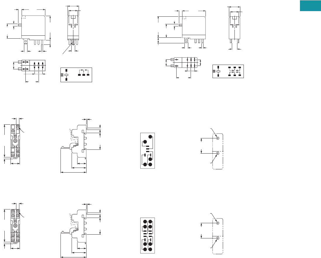
Volume 7—Logic Control, Operator Interface and Connectivity Solutions CA08100008E—June 2013 www.eaton.com V7-T3-81
3
3
3
3
3
3
3
3
3
3
3
3
3
3
3
3
3
3
3
3
3
3
3
3
3
3
3
3
3
3
Volume 7—Logic Control, Operator Interface and Connectivity Solutions CA08100008E—June 2013 www.eaton.com V7-T3-81
3
3
3
3
3
3
3
3
3
3
3
3
3
3
3
3
3
3
3
3
3
3
3
3
3
3
3
3
3
3
3.4
Control Relays and Timers
General Purpose Plug-In Relays
Dimensions
Approximate Dimensions in Inches (mm)
D4PR1 D4PR2
D4PA1
D4PA2
1
243
5
1.14
(29.0)
Max.
1.14
(29.0)
Max.
0.51
(13.0)
Max.
0.10
(2.5) 0.39
(10.0)
0.16
(4.0)
0.08
(2.0)
0.79
(20.0)
0.19
(4.8)
0.30
(7.5)
0.20
(5.2)
0.69
(17.5)
0.20
(5.2)
Terminal Arrangement/
Internal Connections
(Bottom View)
0.02
(0.5)
0.02
(0.5)
5 – 0.035 x 0.12
(0.9 x 3)
Elliptic Holes
1.14
(29.0)
Max.
1.10
(28.0)
Max.
0.01
(2.5)
0.24
(6.0)
0.79
(20.0) 0.08
(2.0)
0.10
(2.6)
0.02
(0.5)
0.30
(7.5)
0.35
(8.9)
0.02
(0.5)
0.02
(0.5)
1
8765
234
0.76
(19.4) Terminal Arrangement/
Internal Connections
(Bottom View)
0.16
(4.0)
0.51
(13.0)
Max. 0.39
(10.0)
0.28
(7.1) 0.08
(2.0)
Five
3.5 x 0.32
(88.9 x 8.0)
2.82
(71.6)
Max.
0.16
(4.1)
0.77
(19.6)
Max.
0.77 (19.6)
1.18 (30.0)
2.13 (54.1) Max.
1.180 0.002
(29.97 0.05)
1.40
(35.6)
0.16
(4.1)
Dia. Holes
15
3
2
4
M3 or
3.30 (0.13)
Dia. Holes
0.17 (4.2)
Dia. Holes
Mounting HolesTerminal Arrangement
0.28
(7.1) 0.08
(2.0)
Eight
3.5 x 0.32
(88.9 x 8.0)
2.82
(71.6)
Max.
0.16
(4.1)
0.77
(19.6)
Max.
0.77 (19.6)
1.18 (30.0)
2.13 (54.1) Max.
1.180 0.002
(29.97 0.05)
1.40
(35.6)
0.16
(4.1)
Dia. Holes
18
5
72
3
4
6
M3 or
0.13 (3.30)
Dia. Holes
0.17 (4.2)
Dia. Holes
Mounting HolesTerminal Arrangement
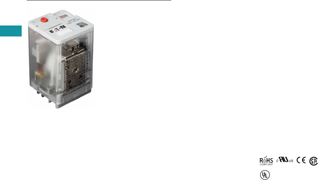
V7-T3-82 Volume 7—Logic Control, Operator Interface and Connectivity Solutions CA08100008E—June 2013 www.eaton.com
3
3
3
3
3
3
3
3
3
3
3
3
3
3
3
3
3
3
3
3
3
3
3
3
3
3
3
3
3
3
V7-T3-82 Volume 7—Logic Control, Operator Interface and Connectivity Solutions CA08100008E—June 2013 www.eaton.com
3
3
3
3
3
3
3
3
3
3
3
3
3
3
3
3
3
3
3
3
3
3
3
3
3
3
3
3
3
3
3.4
Control Relays and Timers
General Purpose Plug-In Relays
D5 Series Relay
Contents
Description Page
D1PR/D1PF Series . . . . . . . . . . . . . . . . . . . . . . . . . V7-T3-53
D2PR/D2PF Series . . . . . . . . . . . . . . . . . . . . . . . . . V7-T3-58
D3PR/D3PF Series . . . . . . . . . . . . . . . . . . . . . . . . . V7-T3-68
D4 Series . . . . . . . . . . . . . . . . . . . . . . . . . . . . . . . . V7-T3-78
D5PR/D5PF Series
Catalog Number Selection . . . . . . . . . . . . . . . . V7-T3-83
Product Selection . . . . . . . . . . . . . . . . . . . . . . . V7-T3-83
Accessories. . . . . . . . . . . . . . . . . . . . . . . . . . . . V7-T3-85
Technical Data and Specifications . . . . . . . . . . . V7-T3-86
Wiring Diagrams . . . . . . . . . . . . . . . . . . . . . . . V7-T3-87
Dimensions . . . . . . . . . . . . . . . . . . . . . . . . . . . V7-T3-88
D7PR/D7PF Series . . . . . . . . . . . . . . . . . . . . . . . . . V7-T3-91
D8 Series . . . . . . . . . . . . . . . . . . . . . . . . . . . . . . . . V7-T3-106
D9 Series . . . . . . . . . . . . . . . . . . . . . . . . . . . . . . . . V7-T3-112
Accessories . . . . . . . . . . . . . . . . . . . . . . . . . . . . . . V7-T3-116
D5PR/D5PF Series
Product Description
The D5 Series is rated at
16A and is available in full-
featured and plain cover
styles.
Features
D5PR
●Industrial rated 300V, 16A
relay in two-pole and three-
pole configurations
●Compact design can be
panel or DIN rail mounted
D5PF
●Flag indicator shows relay
status in manual or
powered condition
●LED status lamp shows
coil ON or OFF status—
ideal for use in low light
applications
●Push-to-Test button allows
for manual operation of
relay without the need for
coil power
●Lock-down door holds
pushbutton and contacts in
the operate position when
activated
●Finger-grip cover allows
operator to remove relays
from sockets easily
●ID tag/write label to
identify relays in multiple-
relay circuits
●Bipolar LED allows for
reverse polarity
applications
Standards and Certifications
When used with
accompanying Eaton
screw terminal socket
(D5PF only)
UL Listed

Volume 7—Logic Control, Operator Interface and Connectivity Solutions CA08100008E—June 2013 www.eaton.com V7-T3-83
3
3
3
3
3
3
3
3
3
3
3
3
3
3
3
3
3
3
3
3
3
3
3
3
3
3
3
3
3
3
Volume 7—Logic Control, Operator Interface and Connectivity Solutions CA08100008E—June 2013 www.eaton.com V7-T3-83
3
3
3
3
3
3
3
3
3
3
3
3
3
3
3
3
3
3
3
3
3
3
3
3
3
3
3
3
3
3
3.4
Control Relays and Timers
General Purpose Plug-In Relays
Catalog Number Selection
D5 Series
Product Selection
D5 Relay/Socket Quick Reference
Family Type
D5PR = Standard relay
D5PF = Full featured relay
Contact Configuration
2 = DPDT
3 = 3PDT
D 5 P R 3 1 A
Coil Voltage
A = 120 Vac
A1 = 110 Vdc
B = 240 Vac
G1 = 74 Vdc
P = 6 Vac
P1 = 6 Vdc
R = 12 Vac
R1 = 12 Vdc
T = 24 Vac
T1 = 24 Vdc
W = 48 Vac
W1 = 48 Vdc
Options
Blank = Plain cover (D5PR only)
A = LED test button, flag indicator,
lock-down door, finger-grip cover,
ID tag (D5PF only)
1 = Indicating light (D5PR only)
Relay
Type Socket Clip
Module
Type
ID
Tag Jumper
D5PR2, D5PF2,
D5PR3, D5PF3
D5PAL PQC-1351 A PWF-D3D5 D3PJ1
D5PA2 PQC-1351 None — —
D5PA3L PQC-1351 None — —
D5PA3S PQC-1351 None — —
V7-T3-84 Volume 7—Logic Control, Operator Interface and Connectivity Solutions CA08100008E—June 2013 www.eaton.com
3
3
3
3
3
3
3
3
3
3
3
3
3
3
3
3
3
3
3
3
3
3
3
3
3
3
3
3
3
3
V7-T3-84 Volume 7—Logic Control, Operator Interface and Connectivity Solutions CA08100008E—June 2013 www.eaton.com
3
3
3
3
3
3
3
3
3
3
3
3
3
3
3
3
3
3
3
3
3
3
3
3
3
3
3
3
3
3
3.4
Control Relays and Timers
General Purpose Plug-In Relays
D5 Series
Coil
Voltage
Contact
Configuration
Coil Resistance
(Ohms)
Catalog
Number
Full Featured
120 Vac DPDT 1700 D5PF2AA
110/125 Vdc DPDT 10,000 D5PF2AA1
220/240 Vac DPDT 7200 D5PF2AB
12 Vdc DPDT 120 D5PF2AR1
24 Vac DPDT 72 D5PF2AT
24 Vdc DPDT 470 D5PF2AT1
48 Vdc DPDT 1800 D5PF2AW1
120 Vac 3PDT 1700 D5PF3AA
110/125 Vdc 3PDT 10,000 D5PF3AA1
220/240 Vac 3PDT 7200 D5PF3AB
12 Vdc 3PDT 120 D5PF3AR1
24 Vac 3PDT 72 D5PF3AT
24 Vdc 3PDT 470 D5PF3AT1
Plain Cover with LED
110/125 Vdc DPDT 10,000 D5PR21A1
6 Vac DPDT 4.2 D5PR21P
6 Vdc DPDT 32 D5PR21P1
12 Vac DPDT 18 D5PR21R
12 Vdc DPDT 120 D5PR21R1
24 Vdc DPDT 470 D5PR21T1
48 Vac DPDT 290 D5PR21W
48 Vdc DPDT 1800 D5PR21W1
120 Vac 3PDT 1700 D5PR31A
110/125 Vdc 3PDT 10,000 D5PR31A1
6 Vdc 3PDT 32 D5PR31P1
12 Vac 3PDT 18 D5PR31R
12 Vdc 3PDT 120 D5PR31R1
24 Vdc 3PDT 470 D5PR31T1
48 Vdc 3PDT 1800 D5PR31W1
Side Flange Cover
220/240 Vac DPDT 7200 D5PR24B
6 Vac DPDT 4.2 D5PR24P
6 Vdc DPDT 32 D5PR24P1
12 Vac DPDT 18 D5PR24R
12 Vdc DPDT 120 D5PR24R1
24 Vac DPDT 72 D5PR24T
24 Vdc DPDT 470 D5PR24T1
48 Vac DPDT 290 D5PR24W
D5 Series Relay

Volume 7—Logic Control, Operator Interface and Connectivity Solutions CA08100008E—June 2013 www.eaton.com V7-T3-85
3
3
3
3
3
3
3
3
3
3
3
3
3
3
3
3
3
3
3
3
3
3
3
3
3
3
3
3
3
3
Volume 7—Logic Control, Operator Interface and Connectivity Solutions CA08100008E—June 2013 www.eaton.com V7-T3-85
3
3
3
3
3
3
3
3
3
3
3
3
3
3
3
3
3
3
3
3
3
3
3
3
3
3
3
3
3
3
3.4
Control Relays and Timers
General Purpose Plug-In Relays
D5 Series, continued
Accessories
D5 Sockets and Accessories
Note
1Protection category (finger safe), EN 60529: IP20.
Coil
Voltage
Contact
Configuration
Coil Resistance
(Ohms)
Catalog
Number
Plain Cover
120 Vac DPDT 1700 D5PR2A
110/125 Vdc DPDT 10,000 D5PR2A1
220/240 Vac DPDT 7200 D5PR2B
74 Vdc DPDT 4800 D5PR2G1
6 Vac DPDT 4.2 D5PR2P
6 Vdc DPDT 32 D5PR2P1
12 Vac DPDT 18 D5PR2R
12 Vdc DPDT 120 D5PR2R1
24 Vac DPDT 72 D5PR2T
24 Vdc DPDT 470 D5PR2T1
48 Vac DPDT 290 D5PR2W
48 Vdc DPDT 1800 D5PR2W1
120 Vac 3PDT 1700 D5PR3A
110/125 Vdc 3PDT 10,000 D5PR3A1
220/240 Vac 3PDT 7200 D5PR3B
74 Vdc 3PDT 4800 D5PR3G1
6 Vac 3PDT 4.2 D5PR3P
6 Vdc 3PDT 32 D5PR3P1
12 Vac 3PDT 18 D5PR3R
12 Vdc 3PDT 120 D5PR3R1
24 Vac 3PDT 72 D5PR3T
24 Vdc 3PDT 470 D5PR3T1
48 Vdc 3PDT 1800 D5PR3W
48 Vdc 3PDT 1800 D5PR3W1
Type
Module
Size
Nominal Voltage
(Max. for Sockets)
Nominal
Current Mounting Style Wire Size
Wire
Connection
Standard
Pack
Catalog
Number
Socket A 300 25 DIN rail 10 /14 (2) AWG, 6/2.5 (2) mm2Elevator 10 D5PAL 1
None 300 15 DIN rail/panel 12/14 (2) AWG, 4/2.5 (2) mm2Screw clamping 10 D5PA2
None 300 15 Chassis (Output): 16 AWG, 1 mm2Solder 10 D5PA3L
None 300 15 Chassis (Output): 16 AWG, 1 mm2Solder 10 D5PA3S
Metal spring clip — — — — — — 10 PQC-1351
Protection diode A 6 to 250 Vdc — — — — 20 MOD-AD250
LED indicator A 24 Vac/Vdc — — — — 20 MOD-ALG24
A 120/240 Vac/Vdc — — — — 20 MOD-ALG240
MOV suppressor A 120 Vac/Vdc — — — — 20 MOD-AMV120
A 24 Vac/Vdc — — — — 20 MOD-AMV24
A240 Vac/Vdc —— — — 20MOD-AMV240
R/C suppressor A 6 to 24 Vac/Vdc — — — — 20 MOD-RC24
A 110 to 240 Vac/Vdc — — — — 20 MOD-RC240
Write-on plastic labels — — — — — — 10 PWF-D3D5
Coil bus jumpers — — — — — — 10 D3PJ1
Plastic DIN rail end stop — — — — — — 25 PFP-P
D5 Series Relay

V7-T3-86 Volume 7—Logic Control, Operator Interface and Connectivity Solutions CA08100008E—June 2013 www.eaton.com
3
3
3
3
3
3
3
3
3
3
3
3
3
3
3
3
3
3
3
3
3
3
3
3
3
3
3
3
3
3
V7-T3-86 Volume 7—Logic Control, Operator Interface and Connectivity Solutions CA08100008E—June 2013 www.eaton.com
3
3
3
3
3
3
3
3
3
3
3
3
3
3
3
3
3
3
3
3
3
3
3
3
3
3
3
3
3
3
3.4
Control Relays and Timers
General Purpose Plug-In Relays
Technical Data and Specifications
D5 Series
Description D5PR D5PF
Contact Characteristics
Contact rating 16A 16A
Terminal style Plug-in Plug-in
Contact materials Silver alloy Silver alloy
Maximum switching voltage 300V 300V
Switching current at voltage—resistive
16A at 277 Vac 50/60 Hz 16A at 277 Vac 50/60 Hz
16A at 120 Vac 50/60 Hz 16A at 120 Vac 50/60 Hz
16A at 28 Vdc 16A at 28 Vdc
Switching current at voltage 1/2 hp at 240 Vac 1/2 hp at 240 Vac
1/3 hp at 120 Vac 1/3 hp at 120 Vac
Pilot duty B300 B300
Minimum switching requirement 100 mA at 5 Vdc (0.5W) 100 mA at 5 Vdc (0.5W)
Coil Characteristics
Operating range
% of nominal (AC) 85 to 110% 85 to 110%
% of nominal (DC) 80 to 110% 80 to 110%
Average consumption 3 VA
1.4W
3 VA
1.4W
Drop-out voltage threshold 10%/15% (AC)
10% (DC)
10%/15% (AC)
10% (DC)
Performance
Electrical life (UL 508) operations at rated current 100,000 operations 100,000 operations
Mechanical life operations unpowered 5,000,000 operations 5,000,000 operations
Response time 20 ms 20 ms
Dielectric strength
Between coil and contact Vac (rms) 1500V (rms) 1500V (rms)
Between poles Vac (rms) 1500V (rms) 1500V (rms)
Environment
Ambient air temperature around the device
Storage –40° to 185°F (–40° to 85°C) –40° to 185°F (–40° to 85°C)
Operation –40° to 131°F (–40° to 55°C) –40° to 131°F (–40° to 55°C)
Vibration resistance—operational 3 g-n at 10–55 Hz 3 g-n at 10–55 Hz
Shock resistance 10 g-n 10 g-n
Degree of protection IP40 IP40
Features
Cover options Flange/plain cover with LED Full featured
Features Mechanical flag indicator
(LED optional)
Bipolar LED/
Mechanical flag indicator/
Locking pushbutton/
Removable ID tag
Product certifications RoHS/UL/CE/CSA RoHS/UL/CE/CSA
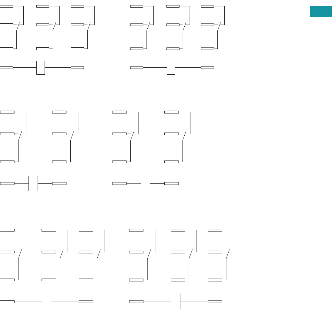
Volume 7—Logic Control, Operator Interface and Connectivity Solutions CA08100008E—June 2013 www.eaton.com V7-T3-87
3
3
3
3
3
3
3
3
3
3
3
3
3
3
3
3
3
3
3
3
3
3
3
3
3
3
3
3
3
3
Volume 7—Logic Control, Operator Interface and Connectivity Solutions CA08100008E—June 2013 www.eaton.com V7-T3-87
3
3
3
3
3
3
3
3
3
3
3
3
3
3
3
3
3
3
3
3
3
3
3
3
3
3
3
3
3
3
3.4
Control Relays and Timers
General Purpose Plug-In Relays
Wiring Diagrams
D5PA3L and D5PA3S
D5PR2/D5PF2 DPDT
D5PR3/D5PF3 3PDT
COM
N.O.
N.C.
INPUT
A1 A2
11
12
31 21
34 24
32 22
14
IEC
COM
N.O.
N.C.
INPUT
B
A
7
4
1
9
8
56
23
NEMA
A1
11
14
12
A2
21
24
22
IEC
A
7
4
1
B
9
6
3
NEMA
A1 A2
11
12
31 21
34 24
32 22
14
IEC
B
A
7
4
1
9
8
56
23
NEMA

V7-T3-88 Volume 7—Logic Control, Operator Interface and Connectivity Solutions CA08100008E—June 2013 www.eaton.com
3
3
3
3
3
3
3
3
3
3
3
3
3
3
3
3
3
3
3
3
3
3
3
3
3
3
3
3
3
3
V7-T3-88 Volume 7—Logic Control, Operator Interface and Connectivity Solutions CA08100008E—June 2013 www.eaton.com
3
3
3
3
3
3
3
3
3
3
3
3
3
3
3
3
3
3
3
3
3
3
3
3
3
3
3
3
3
3
3.4
Control Relays and Timers
General Purpose Plug-In Relays
Dimensions
Approximate Dimensions in Inches (mm)
D5PR and D5PF
D5PA2
1.97
(50.0)
0.20
(6.1) 1.37
(34.9)
1.40
(35.4)
2.10
(53.1)
1.37
(34.9)
1.40
(35.4)
3.14
(80.0)
0.15
(3.8)
9 8
B
3.00
(76.0)
32
7
A
1
1.69
(43.0)
1.53
(39.0)
65
1.37
(35.0)
4
1.03
(26.0)
21 31 11
22 32 12
24 34 14
A2 A1
6
32
54
1
B
987
AINPUT
COM
N.C.
N.O.
1.50
(38.0)
0.40
(10.0)
IEC
INPUT
BA
79 8
21
3
45
6
6
32
54
1
B
987
AINPUT
COM
N.C.
N.O.
NEMA
INPUT
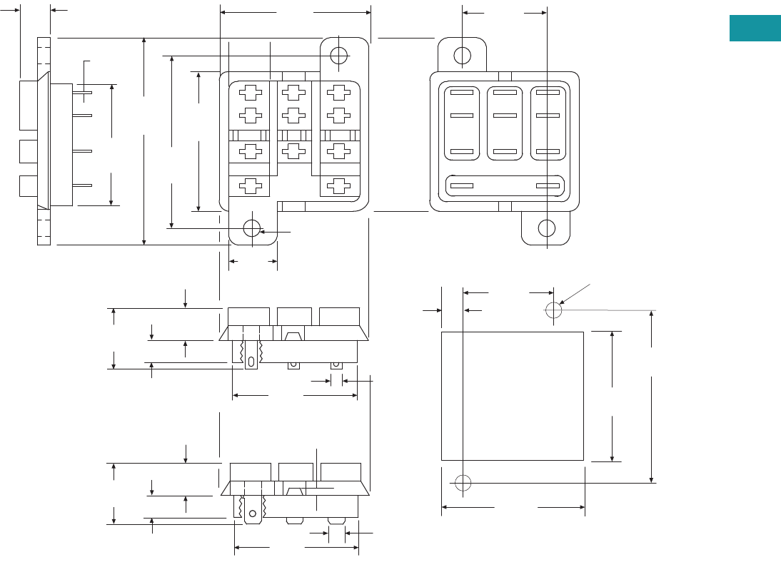
Volume 7—Logic Control, Operator Interface and Connectivity Solutions CA08100008E—June 2013 www.eaton.com V7-T3-89
3
3
3
3
3
3
3
3
3
3
3
3
3
3
3
3
3
3
3
3
3
3
3
3
3
3
3
3
3
3
Volume 7—Logic Control, Operator Interface and Connectivity Solutions CA08100008E—June 2013 www.eaton.com V7-T3-89
3
3
3
3
3
3
3
3
3
3
3
3
3
3
3
3
3
3
3
3
3
3
3
3
3
3
3
3
3
3
3.4
Control Relays and Timers
General Purpose Plug-In Relays
Approximate Dimensions in Inches (mm)
D5PA3L and D5PA3S
0.63
(16.2)
2.03
(51.0)
Solder Type Terminals
0.24
(6.1)
0.29
(7.5)
1.37
(34.7)
0.50
(2.5)
1.37
(34.7)
1.68
(42.8)
1.50
(38.1)
0.13
(3.3)
0.16 Dia.
(4.2)
2 Holes
0.30
(7.5)
0.02
(0.5)
1.25
(31.7)
4
7
1
A B
5
8
2
0.87
(22.2)
6
9
3
0.28
(5.3)
1.39
(35.4)
1.27
(32.3)
1.68
(42.6)
Recommended
Chassis Cutout 0.87
(22.2)
0.16 (3.9)
Dia. Holes
3/16 Q.C. Type Terminals 0.19 (4.7)
0.18
(4.7)
Typ.
1.37
(34.7)
0.63
(16.2)
0.24
(6.1)
0.29
(7.5)

V7-T3-90 Volume 7—Logic Control, Operator Interface and Connectivity Solutions CA08100008E—June 2013 www.eaton.com
3
3
3
3
3
3
3
3
3
3
3
3
3
3
3
3
3
3
3
3
3
3
3
3
3
3
3
3
3
3
V7-T3-90 Volume 7—Logic Control, Operator Interface and Connectivity Solutions CA08100008E—June 2013 www.eaton.com
3
3
3
3
3
3
3
3
3
3
3
3
3
3
3
3
3
3
3
3
3
3
3
3
3
3
3
3
3
3
3.4
Control Relays and Timers
General Purpose Plug-In Relays
Approximate Dimensions in Inches (mm)
D5PAL
A2 A1
72
INPUT
12
1
14
4
11
7
22
3
32
2
21
24
9
34
5
6
31
8
12
14
11
22 32
21
24 34
31
A2 A1
Coil Jumper
Buss
BA
987
654
1
2
3
INPUT
MODULE
INPUT
COM
N.O.
N.C.
1.40
(36.0)
2.48
(63.0)
3.62
(92.0)
3.70
(96.0)
NEMA:
IEC:
IEC
INPUTINPUT
1
4
7
32
9
5
6
8
BA
Coil Jumper
Buss
BA
987
654
1
2
3
INPUT
MODULE
INPUT
COM
N.O.
N.C.
NEMA
INPUTINPUT
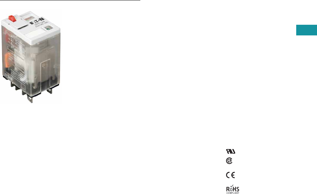
Volume 7—Logic Control, Operator Interface and Connectivity Solutions CA08100008E—June 2013 www.eaton.com V7-T3-91
3
3
3
3
3
3
3
3
3
3
3
3
3
3
3
3
3
3
3
3
3
3
3
3
3
3
3
3
3
3
Volume 7—Logic Control, Operator Interface and Connectivity Solutions CA08100008E—June 2013 www.eaton.com V7-T3-91
3
3
3
3
3
3
3
3
3
3
3
3
3
3
3
3
3
3
3
3
3
3
3
3
3
3
3
3
3
3
3.4
Control Relays and Timers
General Purpose Plug-In Relays
D7 Series Relay
Contents
Description Page
D1PR/D1PF Series . . . . . . . . . . . . . . . . . . . . . . . . . V7-T3-53
D2PR/D2PF Series . . . . . . . . . . . . . . . . . . . . . . . . . V7-T3-58
D3PR/D3PF Series . . . . . . . . . . . . . . . . . . . . . . . . . V7-T3-68
D4 Series . . . . . . . . . . . . . . . . . . . . . . . . . . . . . . . . V7-T3-78
D5PR/D5PF Series . . . . . . . . . . . . . . . . . . . . . . . . . V7-T3-82
D7PR/D7PF Series
Catalog Number Selection . . . . . . . . . . . . . . . . V7-T3-92
Product Selection . . . . . . . . . . . . . . . . . . . . . . . V7-T3-92
Accessories . . . . . . . . . . . . . . . . . . . . . . . . . . . . V7-T3-95
Technical Data and Specifications . . . . . . . . . . . V7-T3-96
Wiring Diagrams . . . . . . . . . . . . . . . . . . . . . . . . V7-T3-98
Dimensions . . . . . . . . . . . . . . . . . . . . . . . . . . . . V7-T3-99
D8 Series . . . . . . . . . . . . . . . . . . . . . . . . . . . . . . . . V7-T3-106
D9 Series . . . . . . . . . . . . . . . . . . . . . . . . . . . . . . . . V7-T3-112
Accessories . . . . . . . . . . . . . . . . . . . . . . . . . . . . . . V7-T3-116
D7PR/D7PF Series
Product Description
The D7 Series is a cost-
effective control relay with
high dielectric strength and
high current-carrying capacity.
Features
D7PR
●Arc barrier equipped relay
with high dielectric
strength
●Panel and DIN rail
mounting
D7PF
●Flag indicator shows relay
status in manual or
powered condition
●Bipolar LED status lamp
allows for reverse polarity
applications
●Shows coil ON or OFF
status
●Ideal in low light
conditions
●Color-coded pushbutton
identifies AC coils with red
or DC coils with blue
pushbuttons
●Allows for manual
operation of relay
without the need for
coil power
●Ideal for field service
personnel to test
control circuits
●Lock-down door, when
activated, holds
pushbutton and contacts in
the operate position
●Excellent for analyzing
circuit problems
●Finger-grip cover allows
operator to remove relays
from sockets more easily
than conventional relays
●White plastic ID tag/write
label used for identification
of relays in multi-relay
circuits
Standards and Certifications
File # E37317, E65657
File # LR217017,
LR217069
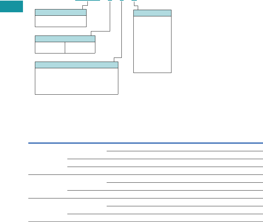
V7-T3-92 Volume 7—Logic Control, Operator Interface and Connectivity Solutions CA08100008E—June 2013 www.eaton.com
3
3
3
3
3
3
3
3
3
3
3
3
3
3
3
3
3
3
3
3
3
3
3
3
3
3
3
3
3
3
V7-T3-92 Volume 7—Logic Control, Operator Interface and Connectivity Solutions CA08100008E—June 2013 www.eaton.com
3
3
3
3
3
3
3
3
3
3
3
3
3
3
3
3
3
3
3
3
3
3
3
3
3
3
3
3
3
3
3.4
Control Relays and Timers
General Purpose Plug-In Relays
Catalog Number Selection
D7 Series
Product Selection
D7 Relay/Socket Quick Reference
D 7 P R 1 1 A
Contact Configuration
1 = SPDT
2 = DPDT
3 = 3PDT
4 = 4PDT
Options
Blank = Plain cover (D7PR only)
A = LED test button, flag indicator,
lock-down door, finger-grip cover,
ID tag (D7PF only)
1 = Indicating light (D7PR only)
Family Type
D7PR = Standard relay
D7PF = Full featured relay
Coil Voltage
A = 120 Vac
A1 = 110 Vdc
B = 240 Vac
P =6 Vac
P1 =6 Vdc
R = 12 Vac
R1 = 12 Vdc
T = 24 Vac
T1 = 24 Vdc
W = 48 Vac
W1 = 48 Vdc
Relay
Type Socket/Adapter Clip
Module
Type ID Tag Jumper
D7PR1, D7PR2,
D7PF1, D7PF2
D7PAA PQC-1342 B — —
PQC-1349 B — —
D7PA9 PQC-1342 None — —
PFC-D2D72 — None — —
D7PR3, D7PF3 D7PAB PQC-1783 A — —
PMC-1783 A — —
PFC-D73 — None — —
D7PR4, D7PF4 D7PAD PQC-1784 A — —
PMC-1784 A — —
PFC-D74 — None — —
Volume 7—Logic Control, Operator Interface and Connectivity Solutions CA08100008E—June 2013 www.eaton.com V7-T3-93
3
3
3
3
3
3
3
3
3
3
3
3
3
3
3
3
3
3
3
3
3
3
3
3
3
3
3
3
3
3
Volume 7—Logic Control, Operator Interface and Connectivity Solutions CA08100008E—June 2013 www.eaton.com V7-T3-93
3
3
3
3
3
3
3
3
3
3
3
3
3
3
3
3
3
3
3
3
3
3
3
3
3
3
3
3
3
3
3.4
Control Relays and Timers
General Purpose Plug-In Relays
D7 Series
Coil
Voltage
Contact
Configuration
Coil Resistance
(Ohms)
Catalog
Number
Full Featured
120 Vac SPDT 4430 D7PF1AA
6 Vac SPDT 9.6 D7PF1AP
6 Vdc SPDT 40 D7PF1AP1
12 Vac SPDT 46 D7PF1AR
24 Vdc SPDT 650 D7PF1AT1
48 Vac SPDT 788 D7PF1AW
48 Vdc SPDT 2600 D7PF1AW1
120 Vac DPDT 4430 D7PF2AA
110/125 Vdc DPDT 11,000 D7PF2AA1
220/240 Vac DPDT 15,720 D7PF2AB
6 Vac DPDT 9.6 D7PF2AP
6 Vdc DPDT 40 D7PF2AP1
12 Vac DPDT 46 D7PF2AR
12 Vdc DPDT 160 D7PF2AR1
24 Vac DPDT 180 D7PF2AT
24 Vdc DPDT 650 D7PF2AT1
48 Vac DPDT 788 D7PF2AW
48 Vdc DPDT 2600 D7PF2AW1
120 Vac 3PDT 2770 D7PF3AA
6 Vac 3PDT 6 D7PF3AP
6 Vdc 3PDT 25 D7PF3AP1
12 Vac 3PDT 25.3 D7PF3AR
24 Vac 3PDT 103 D7PF3AT
24 Vdc 3PDT 400 D7PF3AT1
48 Vac 3PDT 412 D7PF3AW
48 Vdc 3PDT 1600 D7PF3AW1
120 Vac 4PDT 2220 D7PF4AA
110/125 Vdc 4PDT 7340 D7PF4AA1
240 Vac 4PDT 9120 D7PF4AB
6 Vac 4PDT 5.4 D7PF4AP
6 Vdc 4PDT 24 D7PF4AP1
12 Vac 4PDT 21.2 D7PF4AR
12 Vdc 4PDT 96 D7PF4AR1
24 Vac 4PDT 84.5 D7PF4AT
24 Vdc 4PDT 388 D7PF4AT1
48 Vdc 4PDT 1550 D7PF4AW
48 Vac 4PDT 410 D7PF4AW1
D7 Series Relay

V7-T3-94 Volume 7—Logic Control, Operator Interface and Connectivity Solutions CA08100008E—June 2013 www.eaton.com
3
3
3
3
3
3
3
3
3
3
3
3
3
3
3
3
3
3
3
3
3
3
3
3
3
3
3
3
3
3
V7-T3-94 Volume 7—Logic Control, Operator Interface and Connectivity Solutions CA08100008E—June 2013 www.eaton.com
3
3
3
3
3
3
3
3
3
3
3
3
3
3
3
3
3
3
3
3
3
3
3
3
3
3
3
3
3
3
3.4
Control Relays and Timers
General Purpose Plug-In Relays
D7 Series, continued
Coil
Voltage
Contact
Configuration
Coil Resistance
(Ohms)
Catalog
Number
Plain Cover with LED
120 Vac SPDT 4430 D7PR11A
110/125 Vdc SPDT 11,000 D7PR11A1
6 Vac SPDT 9.6 D7PR11P
12 Vac SPDT 46 D7PR11R
12 Vdc SPDT 160 D7PR11R1
24 Vac SPDT 180 D7PR11T
24 Vdc SPDT 650 D7PR11T1
48 Vdc SPDT 2600 D7PR11W1
120 Vac 3PDT 2770 D7PR31A
240 Vac 3PDT 12100 D7PR31B
24 Vac 3PDT 103 D7PR31T
24 Vdc 3PDT 400 D7PR31T1
48 Vdc 3PDT 1600 D7PR31W1
120 Vac 4PDT 2220 D7PR41A
12 Vdc 4PDT 100 D7PR41R1
24 Vdc 4PDT 388 D7PR41T1
Plain Cover
120 Vac SPDT 4430 D7PR1A
110/125 Vdc SPDT 11000 D7PR1A1
220/240 Vac SPDT 15720 D7PR1B
6 Vac SPDT 9.6 D7PR1P
12 Vdc SPDT 160 D7PR1R1
24 Vac SPDT 180 D7PR1T
24 Vdc SPDT 650 D7PR1T1
48 Vdc SPDT 2600 D7PR1W1
120 Vac DPDT 4430 D7PR2A
110/125 Vdc DPDT 11000 D7PR2A1
220/240 Vac DPDT 15720 D7PR2B
6 Vac DPDT 9.6 D7PR2P
6 Vdc DPDT 40 D7PR2P1
12 Vac DPDT 46 D7PR2R
12 Vdc DPDT 160 D7PR2R1
24 Vac DPDT 180 D7PR2T
24 Vdc DPDT 650 D7PR2T1
120 Vac 3PDT 2770 D7PR3A
240 Vac 3PDT 12100 D7PR3B
6 Vac 3PDT 6 D7PR3P
12 Vac 3PDT 25.3 D7PR3R
12 Vdc 3PDT 100 D7PR3R1
24 Vac 3PDT 103 D7PR3T
24 Vdc 3PDT 400 D7PR3T1
48 Vdc 3PDT 1600 D7PR3W1
120 Vac 4PDT 2220 D7PR4A
110/125 Vdc 4PDT 7340 D7PR4A1
240 Vac 4PDT 9120 D7PR4B
6 Vac 4PDT 5.4 D7PR4P
24 Vac 4PDT 84.5 D7PR4T
24 Vdc 4PDT 388 D7PR4T1
48 Vdc 4PDT 1550 D7PR4W1
D7 Series Relay

Volume 7—Logic Control, Operator Interface and Connectivity Solutions CA08100008E—June 2013 www.eaton.com V7-T3-95
3
3
3
3
3
3
3
3
3
3
3
3
3
3
3
3
3
3
3
3
3
3
3
3
3
3
3
3
3
3
Volume 7—Logic Control, Operator Interface and Connectivity Solutions CA08100008E—June 2013 www.eaton.com V7-T3-95
3
3
3
3
3
3
3
3
3
3
3
3
3
3
3
3
3
3
3
3
3
3
3
3
3
3
3
3
3
3
3.4
Control Relays and Timers
General Purpose Plug-In Relays
Accessories
D7 Sockets and Accessories
Note
1Protection category (finger safe), EN 60529: IP20.
Type
Module
Size
Nominal Voltage
(Max. for Sockets)
Nominal
Current Mounting Style Wire Size
Wire
Connection
Standard
Pack
Catalog
Number
Socket B 300 16 DIN rail/panel 12/14 (2) AWG, 4/2.5 (2) mm2Screw clamping — D7PAA 1
None 300 10 DIN rail/panel 12/14 (2) AWG, 4/2.5 (2) mm2Screw clamping 1 D7PA9
A 300 16 DIN rail/panel 12/14 (2) AWG, 4/2.5 (2) mm2Screw clamping — D7PAD 1
A 300 16 DIN rail/panel 12/14 (2) AWG, 4/2.5 (2) mm2Screw clamping — D7PAB 1
Flange mount adapter — — — Flange — — 25 PFC-D2D72
— — — Flange — — 25 PFC-D73
— — — Flange — — 25 PFC-D74
Metal spring clip — — — — — — 25 PQC-1342
Plastic ID clip — — — — — — 10 PQC-1349
Metal spring clip — — — — — — 25 PQC-1784
Plastic ID clip — — — — — — 10 PMC-1784
Hold-down spring — — — — — — 25 PYC-B2
Metal spring clip — — — — — — 10 PQC-1783
Plastic ID clip — — — — — — 10 PMC-1783
Protection diode A 6 to 250 Vdc — — — — 20 MOD-AD250
LED indicator A 24 Vac/Vdc — — — — 20 MOD-ALG24
A 120/240 Vac/Vdc — — — — 20 MOD-ALG240
MOV suppressor A 120 Vac/Vdc — — — — 20 MOD-AMV120
A 24 Vac/Vdc — — — — 20 MOD-AMV24
A240 Vac/Vdc —— — — 20MOD-AMV240
R/C suppressor A 6 to 24 Vac/Vdc — — — — 20 MOD-RC24
A 110 to 240 Vac/Vdc — — — — 20 MOD-RC240
Protection diode B 6 to 250 Vdc — — — — 20 MOD-BD250
LED indicator B 24 Vac/Vdc — — — — 20 MOD-BLG24
B 120/240 Vac/Vdc — — — — 20 MOD-BLG240
MOV suppressor B 120 Vac/Vdc — — — — 20 MOD-BMV120
B 24 Vac/Vdc — — — — 20 MOD-BMV24
B240 Vac/Vdc—— — — 20MOD-BMV240
Plastic DIN rail end stop — — — — — — 25 PFP-P

V7-T3-96 Volume 7—Logic Control, Operator Interface and Connectivity Solutions CA08100008E—June 2013 www.eaton.com
3
3
3
3
3
3
3
3
3
3
3
3
3
3
3
3
3
3
3
3
3
3
3
3
3
3
3
3
3
3
V7-T3-96 Volume 7—Logic Control, Operator Interface and Connectivity Solutions CA08100008E—June 2013 www.eaton.com
3
3
3
3
3
3
3
3
3
3
3
3
3
3
3
3
3
3
3
3
3
3
3
3
3
3
3
3
3
3
3.4
Control Relays and Timers
General Purpose Plug-In Relays
Technical Data and Specifications
D7PR Relay
Description D7PR (SPDT) D7PR (DPDT) D7PR (3PDT) D7PR (4PDT)
Contact Characteristics
Contact rating 20A 15A 15A 15A
Terminal style Plug-in Plug-in Plug-in Plug-in
Contact materials Silver alloy Silver alloy Silver alloy Silver alloy
Maximum switching voltage 300V 300V 300V 300V
Switching current at voltage—resistive 20A at 277 Vac 50/60 Hz 15A at 120 Vac 50/60 Hz 15A at 120 Vac 50/60 Hz 15A at 120 Vac 50/60 Hz
20A at 120 Vac 50/60 Hz 12A at 277 Vac 50/60 Hz 12A at 277 Vac 50/60 Hz 12A at 277 Vac 50/60 Hz
— 10A at 277 Vac 50/60 Hz — —
20A at 28 Vdc 12A at 28 Vdc 12A at 28 Vdc 12A at 28 Vdc
Switching current at voltage 1/2 hp at 120 Vac 1/2 hp at 120 Vac 1/2 hp at 120 Vac 1/2 hp at 120 Vac
1 hp at 250 Vac 1 hp at 250 Vac 3/4 hp at 250 Vac 3/4 hp at 250 Vac
Pilot duty B300 B300 B300 B300
Minimum switching requirement 100 mA at 5 Vdc (0.5W) 100 mA at 5 Vdc (0.5W) 100 mA at 5 Vdc (0.5W) 100 mA at 5 Vdc (0.5W)
Coil Characteristics
Operating range
% of nominal (AC) 85 to 110% 85 to 110% 85 to 110% 85 to 110%
% of nominal (DC) 80 to 110% 80 to 110% 80 to 110% 80 to 110%
Average consumption 1.2 VA 1.2 VA 1.5 VA 1.5 VA
0.9W 0.9W 1.4W 1.5W
Dropout voltage threshold 15% (AC) 15% (AC) 15% (AC) 15% (AC)
10% (DC) 10% (DC) 10% (DC) 10% (DC)
Performance
Electrical life (UL 508) operations at rated current 100,000 operations 100,000 operations 200,000 operations 200,000 operations
Mechanical life operations unpowered 10,000,000 operations 10,000,000 operations 10,000,000 operations 10,000,000 operations
Response time 20 ms 20 ms 20 ms 20 ms
Dielectric strength
Between coil and contact Vac (rms) 2500V (rms) 2500V (rms) 2500V (rms) 2500V (rms)
Between poles Vac (rms) 1500V (rms) 1500V (rms) 2500V (rms) 2500V (rms)
Environment
Ambient air temperature around the device
Operation –40° to 131°F (–40° to 55°C) –40° to 131°F (–40° to 55°C) –40° to 131°F (–40° to 55°C) –40° to 131°F (–40° to 55°C)
Storage –40° to 185°F (–40° to 85°C) –40° to 185°F (–40° to 85°C) –40° to 185°F (–40° to 85°C) –40° to 185°F (–40° to 85°C)
Vibration resistance—operational 3 g-n at 10–55 Hz 3 g-n at 10–55 Hz 3 g-n at 10–55 Hz 3 g-n at 10–55 Hz
Shock resistance 10 g-n 10 g-n 10 g-n 10 g-n
Degree of protection IP40 IP40 IP40 IP40
Features
Cover options Plain cover Plain cover Plain cover Plain cover
Features Mechanical flag indicator
(optional LED)
Mechanical flag indicator
(optional LED)
Mechanical flag indicator
(optional LED)
Mechanical flag indicator
(optional LED)
Product certifications RoHS/UL/CE/CSA RoHS/UL/CE/CSA RoHS/UL/CE/CSA RoHS/UL/CE/CSA

Volume 7—Logic Control, Operator Interface and Connectivity Solutions CA08100008E—June 2013 www.eaton.com V7-T3-97
3
3
3
3
3
3
3
3
3
3
3
3
3
3
3
3
3
3
3
3
3
3
3
3
3
3
3
3
3
3
Volume 7—Logic Control, Operator Interface and Connectivity Solutions CA08100008E—June 2013 www.eaton.com V7-T3-97
3
3
3
3
3
3
3
3
3
3
3
3
3
3
3
3
3
3
3
3
3
3
3
3
3
3
3
3
3
3
3.4
Control Relays and Timers
General Purpose Plug-In Relays
D7PF Relay
Description D7PF (SPDT) D7PF (DPDT) D7PF (3PDT) D7PF (4PDT)
Contact Characteristics
Contact rating 20A 15A 15A 15A
Terminal style Plug-in Plug-in Plug-in Plug-in
Contact materials Silver alloy Silver alloy Silver alloy Silver alloy
Maximum switching voltage 300V 300V 300V 300V
Switching current at voltage—resistive
20A at 277 Vac 50/60 Hz 15A at 120 Vac 50/60 Hz 15A at 120 Vac 50/60 Hz 15A at 120 Vac 50/60 Hz
20A at 277 Vac 50/60 Hz 12A at 277 Vac 50/60 Hz 12A at 277 Vac 50/60 Hz 12A at 277 Vac 50/60 Hz
— 10A at 277 Vac 50/60 Hz — —
20A at 28 Vdc 12A at 28 VDC 12A at 28 Vdc 12A at 28 Vdc
Switching current at voltage 1/2 hp at 120 Vac 1/2 hp at 120 Vac 3/4 hp at 250 Vac 1/2 hp at 120 Vac
1 hp at 250 Vac 1 hp at 250 Vac 1/2 hp at 120 Vac 3/4 hp at 250 Vac
Pilot duty B300 B300 B300 B300
Minimum switching requirement 100 mA at 5 Vdc (0.5W) 100 mA at 5 Vdc (0.5W) 100 mA at 5 Vdc (0.5W) 100 mA at 5 Vdc (0.5W)
Coil Characteristics
Operating range
% of nominal (AC) 85 to 110% 85 to 110% 85 to 110% 85 to 110%
% of nominal (DC) 80 to 110% 80 to 110% 80 to 110% 80 to 110%
Average consumption 1.2 VA 1.2 VA 1.5 VA 1.5 VA
0.9W 0.9W 1.4W 1.5W
Dropout voltage threshold 15% (AC) 15% (AC) 15% (AC) 15% (AC)
10% (DC) 10% (DC) 10% (DC) 10% (DC)
Performance
Electrical life (UL 508) operations at rated current 100,000 operations 100,000 operations 200,000 operations 200,000 operations
Mechanical life operations unpowered 10,000,000 operations 10,000,000 operations 10,000,000 operations 10,000,000 operations
Response time 20 ms 20 ms 20 ms 20 ms
Dielectric strength
Between coil and contact Vac (rms) 2500V (rms) 2500V (rms) 2500V (rms) 2500V (rms)
Between poles Vac (rms) 1500V (rms) 1500V (rms) 2500V (rms) 2500V (rms)
Environment
Ambient air temperature around the device
Operation –40° to 131°F (–40° to 55°C) –40° to 131°F (–40° to 55°C) –40° to 131ºF (–40° to 55°C) –40° to 131°F (–40° to 55°C)
Storage –40° to 185°F (–40° to 85°C) –40° to 185°F (–40° to 85°C) –40° to 185ºF (–40° to 85°C) –40° to 185°F (–40° to 85°C)
Vibration resistance—operational 3 g-n at 10–55 Hz 3 g-n at 10–55 Hz 3 g-n at 10–55 Hz 3 g-n at 10–55 Hz
Shock resistance 10 g-n 10 g-n 10 g-n 10 g-n
Degree of protection IP40 IP40 IP40 IP40
Features
Cover options Full featured Full featured Full featured Full featured
Features Locking pushbutton/
Bipolar LED/
Removable ID tag/
Mechanical flag indicator
Locking pushbutton/
Bipolar LED/
Removable ID tag/
Mechanical flag indicator
Locking pushbutton/
Bipolar LED/
Removable ID tag/
Mechanical flag indicator
Locking pushbutton/
Bipolar LED/
Removable ID tag/
Mechanical flag indicator
Product certifications RoHS/UL/CE/CSA RoHS/UL/CE/CSA RoHS/UL/CE/CSA RoHS/UL/CE/CSA
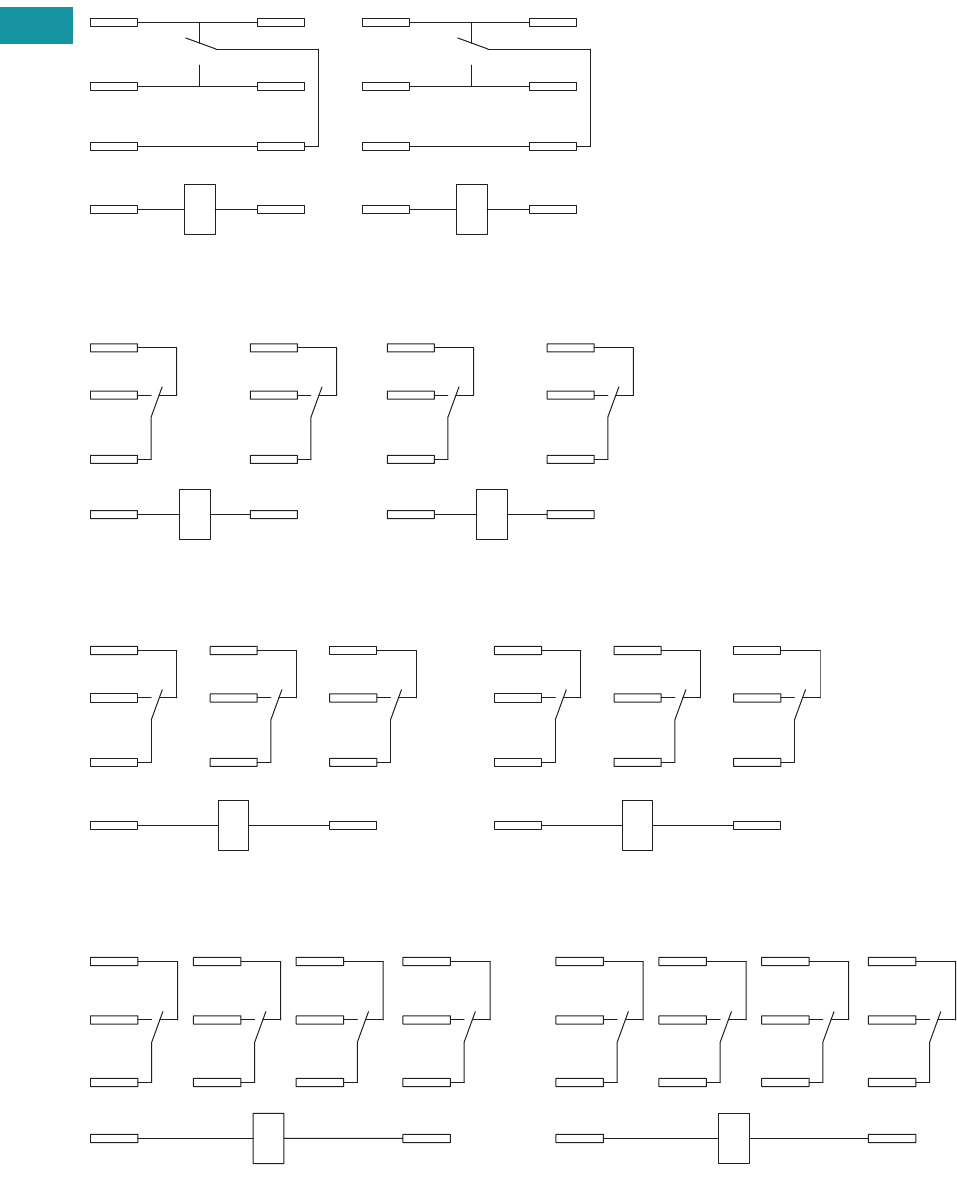
V7-T3-98 Volume 7—Logic Control, Operator Interface and Connectivity Solutions CA08100008E—June 2013 www.eaton.com
3
3
3
3
3
3
3
3
3
3
3
3
3
3
3
3
3
3
3
3
3
3
3
3
3
3
3
3
3
3
V7-T3-98 Volume 7—Logic Control, Operator Interface and Connectivity Solutions CA08100008E—June 2013 www.eaton.com
3
3
3
3
3
3
3
3
3
3
3
3
3
3
3
3
3
3
3
3
3
3
3
3
3
3
3
3
3
3
3.4
Control Relays and Timers
General Purpose Plug-In Relays
Wiring Diagrams
D7PR1/D7PF1
D7PR2/D7PF2
D7PR3/D7PF3
D7PR4/D7PF4
A2
A1
11
14
12
41
44
42
IEC
5
13
9
1
8
12
14
4
NEMA
42
44
12
14
A1
11
A2
41
IEC
4
8
1
5
13
12
14
9
NEMA
11
A1
14
21
24
12 22
41
44
42
A2
IEC
9
13
5
10
6
12
12
8
4
14
NEMA
A1 A2
11 21
14 24
31
34
22
12 32
44
41
42
IEC
13 14
10
911
56
12
7
3
12
4
8
NEMA
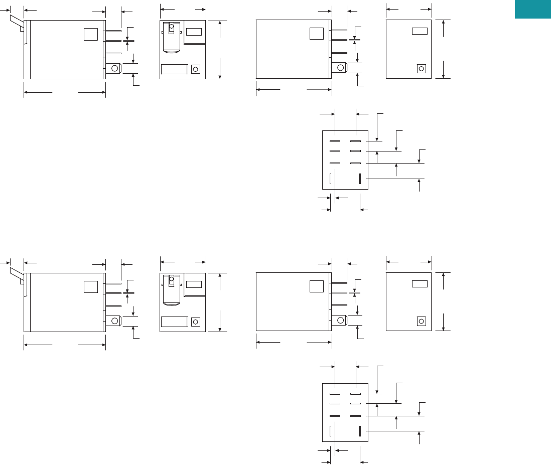
Volume 7—Logic Control, Operator Interface and Connectivity Solutions CA08100008E—June 2013 www.eaton.com V7-T3-99
3
3
3
3
3
3
3
3
3
3
3
3
3
3
3
3
3
3
3
3
3
3
3
3
3
3
3
3
3
3
Volume 7—Logic Control, Operator Interface and Connectivity Solutions CA08100008E—June 2013 www.eaton.com V7-T3-99
3
3
3
3
3
3
3
3
3
3
3
3
3
3
3
3
3
3
3
3
3
3
3
3
3
3
3
3
3
3
3.4
Control Relays and Timers
General Purpose Plug-In Relays
Dimensions
Approximate Dimensions in Inches (mm)
D7PR1/D7PF1
D7PR2/D7PF2
0.16
(4.7)
0.23
(5.9)
0.30
(7.5)
0.38
(9.9)
0.55
(14.1)
0.08
(2.1)2X
0.83
(21.0)
1.10
(27.9)
0.19
(4.8)
0.02
(0.5)
0.29
(7.4)
1.40
(35.5)
0.83
(21.0)
1.10
(27.9)
1.54
(39.1)
0.29
(7.4)
0.02
(0.5)
0.19
(4.8)
0.27
(7.0)
0.16
(4.7)
0.23
(5.9)
0.30
(7.5)
0.38
(9.9)
0.55
(14.1)
0.08
(2.1)2X
0.83
(21.0)
1.10
(27.9)
0.19
(4.8)
0.02
(0.5)
0.29
(7.4)
1.40
(35.5)
0.83
(21.0)
1.10
(27.9)
1.54
(39.1)
0.29
(7.4)
0.02
(0.5)
0.19
(4.8)
0.27
(7.0)
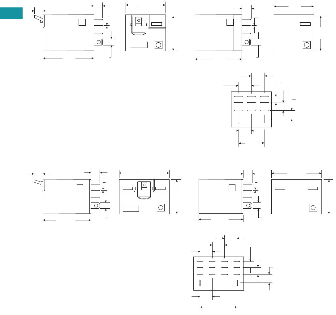
V7-T3-100 Volume 7—Logic Control, Operator Interface and Connectivity Solutions CA08100008E—June 2013 www.eaton.com
3
3
3
3
3
3
3
3
3
3
3
3
3
3
3
3
3
3
3
3
3
3
3
3
3
3
3
3
3
3
V7-T3-100 Volume 7—Logic Control, Operator Interface and Connectivity Solutions CA08100008E—June 2013 www.eaton.com
3
3
3
3
3
3
3
3
3
3
3
3
3
3
3
3
3
3
3
3
3
3
3
3
3
3
3
3
3
3
3.4
Control Relays and Timers
General Purpose Plug-In Relays
Approximate Dimensions in Inches (mm)
D7PR3/D7PF3
D7PR4/D7PF4
1.60
(40.0)
1.10
(27.9)
1.20
(30.8)
0.27
(7.0)
0.26
(6.6)
0.79
(20.0)
0.19
(4.7)
0.23
(5.9)0.26
(6.7)
0.39
(9.9)2X
0.19
(4.8)
0.02
(0.5)
0.39
(9.9)
0.39
(9.9)
1.20
(30.8)
1.10
(27.9)
0.02
(0.5)
0.19
(4.8)
0.29
(7.4)
1.40
(35.5)
1.60
(40.6)
1.60
(40.6)
1.54
(39.1)
0.02
(0.5)
0.19
(4.8)
0.38
(9.9)
0.16
(4.7)
0.23
(5.9) 0.26
(6.7)
1.18
(29.9)
0.38
(9.9)2X
1.10
(27.9)
0.38
(9.9)
0.38
(9.9)
0.26
(6.6)
1.10
(27.9)
1.40
(35.5)
0.19
(4.8)
0.29
(7.4) 0.02
(0.5)
0.27
(7.0)
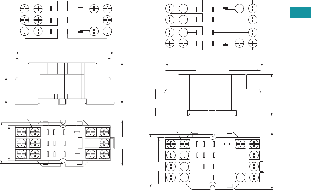
Volume 7—Logic Control, Operator Interface and Connectivity Solutions CA08100008E—June 2013 www.eaton.com V7-T3-101
3
3
3
3
3
3
3
3
3
3
3
3
3
3
3
3
3
3
3
3
3
3
3
3
3
3
3
3
3
3
Volume 7—Logic Control, Operator Interface and Connectivity Solutions CA08100008E—June 2013 www.eaton.com V7-T3-101
3
3
3
3
3
3
3
3
3
3
3
3
3
3
3
3
3
3
3
3
3
3
3
3
3
3
3
3
3
3
3.4
Control Relays and Timers
General Purpose Plug-In Relays
Approximate Dimensions in Inches (mm)
D7PA3 D7PA4
1.44
(36.6)
1.27
(32.5)
1
2
3
4
5
7
8
911
10
6
Combination Slotted/Phillips
Head Screws 6-32 x 5/16"
2.58 (67.5) Max.
2.74 (69.8)
0.65
(16.6)
1.59
(40.5)
Max.
1.09
(27.8)
Max.
Wiring Diagram (Top View)
1
2
3
4
6
10
11
7
58
9
1
2
5
6
3
4
7
8
9
1214
11
13
10
1.83
(46.5)
1.63
(41.4)
2.58 (67.5) Max.
2.74 (69.8)
Combination Slotted/Phillips
Head Screws 6-32 x 5/16"
0.65
(16.6)
1.98
(50.5)
Max.
1.09
(27.8)
Max.
Wiring Diagram (Top View)
2
3
4
6
1
5
8
7
13
9
10
11
14
12
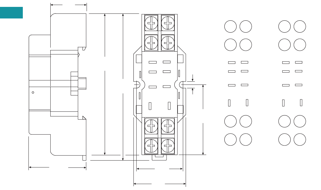
V7-T3-102 Volume 7—Logic Control, Operator Interface and Connectivity Solutions CA08100008E—June 2013 www.eaton.com
3
3
3
3
3
3
3
3
3
3
3
3
3
3
3
3
3
3
3
3
3
3
3
3
3
3
3
3
3
3
V7-T3-102 Volume 7—Logic Control, Operator Interface and Connectivity Solutions CA08100008E—June 2013 www.eaton.com
3
3
3
3
3
3
3
3
3
3
3
3
3
3
3
3
3
3
3
3
3
3
3
3
3
3
3
3
3
3
3.4
Control Relays and Timers
General Purpose Plug-In Relays
Approximate Dimensions in Inches (mm)
D7PA9 Standard Mount
8
5
1.02
(26.0)
1.17
(29.0)
4
14
12
1.03
(26.0)
0.16
(4.0)
1
13
1.26
(32.0)
9
2.73
(69.0)
2.52
(64.0)
44
42
14
12
41 11
A2 A1
N.C.
N.O.
COM
INPUT
85
4
1
14 13 14 13
12 9
0.71
(18.0)
IEC
INPUT
8
4
14
5
1
13
12 9
N.C.
N.O.
COM
INPUT
85
4
1
12 9
NEMA
INPUT
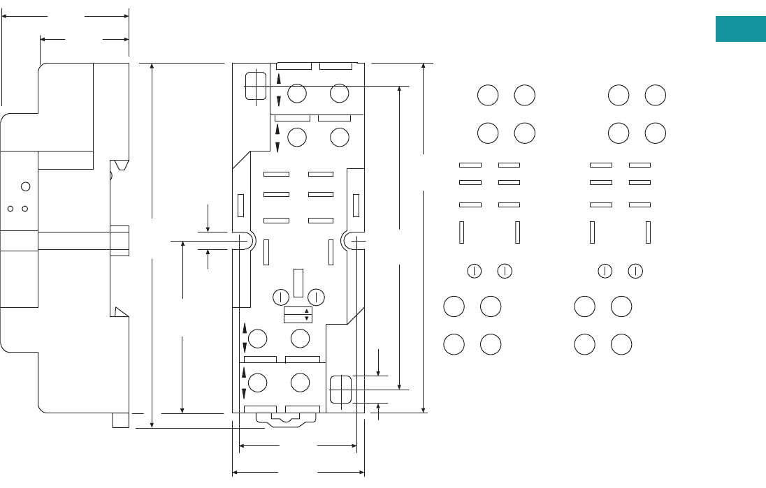
Volume 7—Logic Control, Operator Interface and Connectivity Solutions CA08100008E—June 2013 www.eaton.com V7-T3-103
3
3
3
3
3
3
3
3
3
3
3
3
3
3
3
3
3
3
3
3
3
3
3
3
3
3
3
3
3
3
Volume 7—Logic Control, Operator Interface and Connectivity Solutions CA08100008E—June 2013 www.eaton.com V7-T3-103
3
3
3
3
3
3
3
3
3
3
3
3
3
3
3
3
3
3
3
3
3
3
3
3
3
3
3
3
3
3
3.4
Control Relays and Timers
General Purpose Plug-In Relays
Approximate Dimensions in Inches (mm)
D7PAA
COM
N.O.
N.C.
INPUT
INPUT
1.18
(30.0)
0.24
(6.0)
2.67
(68.0)
3.14
(80.0)
1.18
(30.0)
3.33
(84.0)
1.57
(40.0)
11
41
A1
A2
12
42
14
44
1.06
(26.0)
12 9
14 13
41
85
41 11
A2 A1
42 12
14
44
85
41
14 13
12 9
INPUT INPUT
0.16
(4.0)
0.74
(19.0)
NEMA:
IEC:
MODULE
INPUT
IEC
COM
N.O.
N.C.
INPUT
INPUT
912
13
14
41
8 5
85
41
14 13
12 9
MODULE
INPUT
NEMA
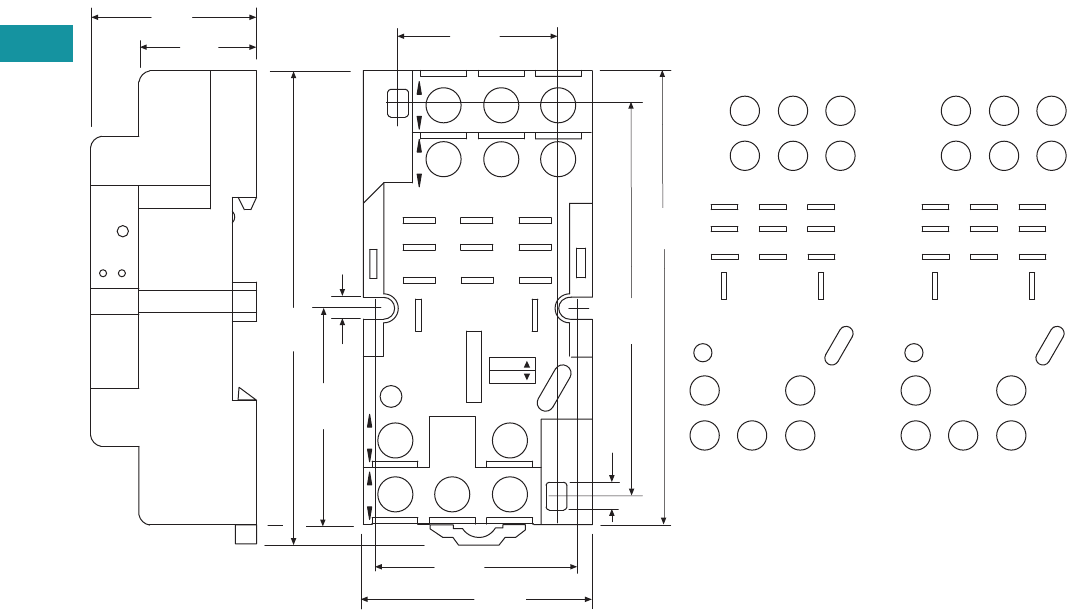
V7-T3-104 Volume 7—Logic Control, Operator Interface and Connectivity Solutions CA08100008E—June 2013 www.eaton.com
3
3
3
3
3
3
3
3
3
3
3
3
3
3
3
3
3
3
3
3
3
3
3
3
3
3
3
3
3
3
V7-T3-104 Volume 7—Logic Control, Operator Interface and Connectivity Solutions CA08100008E—June 2013 www.eaton.com
3
3
3
3
3
3
3
3
3
3
3
3
3
3
3
3
3
3
3
3
3
3
3
3
3
3
3
3
3
3
3.4
Control Relays and Timers
General Purpose Plug-In Relays
Approximate Dimensions in Inches (mm)
D7PAB
N.C.
N.O.
COM
INPUT
0.16
(4.0)
0.24
(6.0)
2.67
(68.0)
3.14
(80.0)
1.18
(30.0)
3.33
(84.0)
1.57
(40.0)
21 1141
12 10 9
INPUT
14
A2
13
A1
INPUT
8
4
42 22
65
21
44 24
12
14
A2
21
41
A1
11
44
42
14
12
24
22
421
865
12 10 9
14 13
1.57
(40.0)
1.45
(37.0)
1.10
(28.0)
0.74
(19.0)
MODULE
INPUT
IEC
NEMA:
IEC:
INPUT
N.C.
N.O.
COM
INPUT
1314
10 9
12
4
8
2
6
1
5
421
865
12 10 9
14 13
MODULE
INPUT
NEMA
INPUT
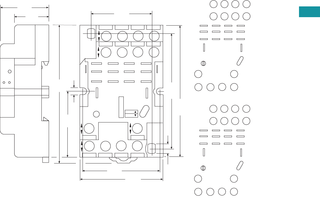
Volume 7—Logic Control, Operator Interface and Connectivity Solutions CA08100008E—June 2013 www.eaton.com V7-T3-105
3
3
3
3
3
3
3
3
3
3
3
3
3
3
3
3
3
3
3
3
3
3
3
3
3
3
3
3
3
3
Volume 7—Logic Control, Operator Interface and Connectivity Solutions CA08100008E—June 2013 www.eaton.com V7-T3-105
3
3
3
3
3
3
3
3
3
3
3
3
3
3
3
3
3
3
3
3
3
3
3
3
3
3
3
3
3
3
3.4
Control Relays and Timers
General Purpose Plug-In Relays
Approximate Dimensions in Inches (mm)
D7PAD
INPUT
N.O.
N.C.
COM
1.96
(50.0)
0.24
(6.0)
2.67
(68.0)
3.14
(80.0)
1.18
(30.0)
A2
14
12
41
INPUT INPUT
A1
13
9
10
11
21
31
11
6
7
24
34
8
44
2
3
4
42 22
32
5
14
1
12
41
A2
11
21
A1
31
2232
42 12
34 2444 14
4321
8765
12 11 10 9
1.81
(46.0)
1.41
(36.0)
0.74
(19.0)
NEMA:
IEC:
MODULE
INPUT
IEC
INPUT
INPUT
N.O.
N.C.
COM
14
12
13
9
10
11
6
7
8
2
3
4
5
1
4321
8765
12 11 10 9
MODULE
INPUT
NEMA
INPUT
0.16
(4.0)
3.33
(84.0)
1.57
(40.0)
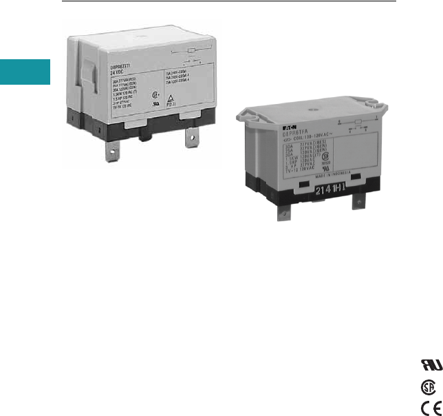
V7-T3-106 Volume 7—Logic Control, Operator Interface and Connectivity Solutions CA08100008E—June 2013 www.eaton.com
3
3
3
3
3
3
3
3
3
3
3
3
3
3
3
3
3
3
3
3
3
3
3
3
3
3
3
3
3
3
V7-T3-106 Volume 7—Logic Control, Operator Interface and Connectivity Solutions CA08100008E—June 2013 www.eaton.com
3
3
3
3
3
3
3
3
3
3
3
3
3
3
3
3
3
3
3
3
3
3
3
3
3
3
3
3
3
3
3.4
Control Relays and Timers
General Purpose Plug-In Relays
D8 Series Relay
Contents
Description Page
D1PR/D1PF Series . . . . . . . . . . . . . . . . . . . . . . . . . V7-T3-53
D2PR/D2PF Series . . . . . . . . . . . . . . . . . . . . . . . . . V7-T3-58
D3PR/D3PF Series . . . . . . . . . . . . . . . . . . . . . . . . . V7-T3-68
D4 Series . . . . . . . . . . . . . . . . . . . . . . . . . . . . . . . . V7-T3-78
D5PR/D5PF Series . . . . . . . . . . . . . . . . . . . . . . . . . V7-T3-82
D7PR/D7PF Series . . . . . . . . . . . . . . . . . . . . . . . . . V7-T3-91
D8 Series
Catalog Number Selection . . . . . . . . . . . . . . . . V7-T3-107
Product Selection . . . . . . . . . . . . . . . . . . . . . . . V7-T3-107
Technical Data and Specifications . . . . . . . . . . . V7-T3-108
Dimensions. . . . . . . . . . . . . . . . . . . . . . . . . . . . V7-T3-109
D9 Series . . . . . . . . . . . . . . . . . . . . . . . . . . . . . . . . V7-T3-112
Accessories . . . . . . . . . . . . . . . . . . . . . . . . . . . . . . V7-T3-116
D8 Series
Product Description
The D8 Series power relays
are perfect for loads up to
30A, with versions for flange
mounting and e-clip mounting
available.
Features
●Allows switching of 25A
and 30A loads
●A high-capacity, high-
withstand voltage relay
compatible with
momentary voltage drops
●No contact chattering for
momentary voltage drops
up to 50% of rated voltage
●UL Class B construction
standard
●Wide-range AC-activated
coil that handles 100 to 120
Vac at either 50
or 60 Hz
●Panel, DIN rail and flange
mounting
Standards and Certifications
File # E1491
File # LR701520

Volume 7—Logic Control, Operator Interface and Connectivity Solutions CA08100008E—June 2013 www.eaton.com V7-T3-107
3
3
3
3
3
3
3
3
3
3
3
3
3
3
3
3
3
3
3
3
3
3
3
3
3
3
3
3
3
3
Volume 7—Logic Control, Operator Interface and Connectivity Solutions CA08100008E—June 2013 www.eaton.com V7-T3-107
3
3
3
3
3
3
3
3
3
3
3
3
3
3
3
3
3
3
3
3
3
3
3
3
3
3
3
3
3
3
3.4
Control Relays and Timers
General Purpose Plug-In Relays
Catalog Number Selection
D8 Series 1
Product Selection
D8 Relay/Socket Quick Reference
D8 Series 2
Notes
1 For deciphering catalog numbers. Do not use for ordering as not all combinations are readily available.
2 Additional coil voltages available—consult Sales Office or Customer Support Center.
Relay
Type
Mounting
Bracket
Adapter Track/
Panel Mount
Front Connecting
Sockets Track/
Panel Mount
D8PR6TE D8PA5 D8PA1 D8PA2
D8PR7TE D8PA5 D8PA1 D8PA2
Type
Standard
Pack
Catalog
Number
SPST E-Bracket
Coil voltage
24 Vac 1 D8PR6TET
24 Vdc 1 D8PR6TET1
SPST Flange Mount
120 Vac 1 D8PR6TFA
24 Vdc 1 D8PR6TFT1
DPST E-Bracket
Coil voltage
120 Vac 1 D8PR7TEA
DPST Flange Mount
120 Vac 1 D8PR7TFA
24 Vdc 1 D8PR7TFT1
Sockets
DIN rail adapter 10 D8PA1
Screw terminal adapter 10 D8PA2
Bracket adapter 10 D8PA5
Accessory
DIN rail end stop 100 PFP-M
D 8 P R 6T E A
Family Type
D8PR
Contact Configuration
6 = SPST-NO
7 = DPST-NO
Options
TE = E-bracket
TF = Flange mount
Coil Voltage
A = 120 Vac
B = 240 Vac
R1 = 12 Vdc
T = 24 Vac
T1 = 24 Vdc
D8 Series Relay

V7-T3-108 Volume 7—Logic Control, Operator Interface and Connectivity Solutions CA08100008E—June 2013 www.eaton.com
3
3
3
3
3
3
3
3
3
3
3
3
3
3
3
3
3
3
3
3
3
3
3
3
3
3
3
3
3
3
V7-T3-108 Volume 7—Logic Control, Operator Interface and Connectivity Solutions CA08100008E—June 2013 www.eaton.com
3
3
3
3
3
3
3
3
3
3
3
3
3
3
3
3
3
3
3
3
3
3
3
3
3
3
3
3
3
3
3.4
Control Relays and Timers
General Purpose Plug-In Relays
Technical Data and Specifications
Coil Resistance
D8 Relays
Coil Data
Coil Voltage Ohms mA
24 Vac 303 71
110/120 Vac 5260 20.4
220/240 Vac 21,000 10.2
12 Vdc 75 158
24 Vdc 303 79
Description D8PR6 D8PR7
Rated load 220 Vac 30A 220 Vac 25A
Carry current 30A 25A
Max. operating voltage 250 Vac 250 Vac
Max. switching current 30A 25A
Contact material AgCdO AgCdO
Max. switching capacity 6600 VA 5500 VA
Min. permissible load 100 mA at 5 Vdc 100 mA at 5 Vdc
Mechanical life (min.) 5,000,000 operations 5,000,000 operations
Electrical life at all contact ratings (min.) 100,000 operations 100,000 operations
Maximum hp ratings 1-1/2 hp (120 Vac)
3 hp (240/265/277 Vac)
1-1/2 hp (120 Vac)
3 hp (240/265/277 Vac)
Coil Voltage Must Operate Must Release Maximum Voltage
24 Vdc/Vac, 12 Vdc 75% maximum 15% minimum 110%
120 Vac 75V 18V 132V
240 Vac 150V 36V 264V

Volume 7—Logic Control, Operator Interface and Connectivity Solutions CA08100008E—June 2013 www.eaton.com V7-T3-109
3
3
3
3
3
3
3
3
3
3
3
3
3
3
3
3
3
3
3
3
3
3
3
3
3
3
3
3
3
3
Volume 7—Logic Control, Operator Interface and Connectivity Solutions CA08100008E—June 2013 www.eaton.com V7-T3-109
3
3
3
3
3
3
3
3
3
3
3
3
3
3
3
3
3
3
3
3
3
3
3
3
3
3
3
3
3
3
3.4
Control Relays and Timers
General Purpose Plug-In Relays
Dimensions
Approximate Dimensions in Inches (mm)
D8PR6TF
D8PR7TF
Two 0.18 (4.5) Dia. Holes
or M4 Tapped Holes
2.70 (68.5) Max.
1.32 (33.5)
Max. 0.08 (2.0)
1.85
(47.0)
Max.
0.18
(4.5)
0.03
(0.8)
2.36 (60.0)
1.99 (50.5)
Max.
0.25 (6.4)
0.43
(11.0)
0.12 (3.0)
01
46
2.362 0.007
(60.0 0.2)
Mounting Holes
(Bottom View)
Terminal Arrangement/
Internal Connections
(Top View)
Two 0.18 (4.5) Dia. Holes
or M4 Tapped Holes
2.70 (68.5) Max.
1.32 (33.5)
Max. 0.08 (2.0)
1.85
(47.0)
Max.
0.18
(4.5)
0.03
(0.8)
2.36 (60.0)
1.99 (50.5)
Max.
0.25 (6.4)
0.43
(11.0)
0.12
(3.0)
01
24
68
2.362 0.007
(60.0 0.2)
Mounting Holes
(Bottom View)
Terminal Arrangement/
Internal Connections
(Top View)
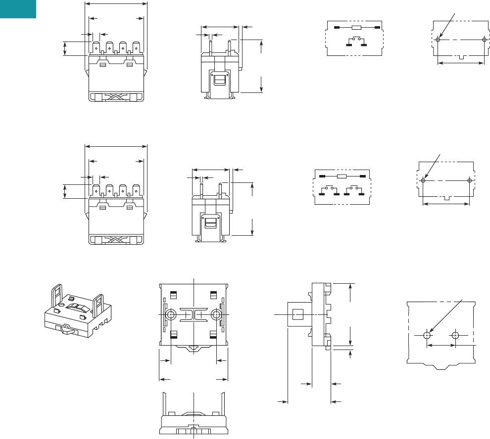
V7-T3-110 Volume 7—Logic Control, Operator Interface and Connectivity Solutions CA08100008E—June 2013 www.eaton.com
3
3
3
3
3
3
3
3
3
3
3
3
3
3
3
3
3
3
3
3
3
3
3
3
3
3
3
3
3
3
V7-T3-110 Volume 7—Logic Control, Operator Interface and Connectivity Solutions CA08100008E—June 2013 www.eaton.com
3
3
3
3
3
3
3
3
3
3
3
3
3
3
3
3
3
3
3
3
3
3
3
3
3
3
3
3
3
3
3.4
Control Relays and Timers
General Purpose Plug-In Relays
Approximate Dimensions in Inches (mm)
D8PR6TE with D8PA5 Bracket Attached
D8PR7TE with D8PA5 Bracket Attached
D8PA1
Note: Minimum spacing around relay = 0.20 inches (5 mm).
Two 0.18 (4.5) Dia. Holes
or M4 Tapped Holes
1.32 (33.5)
Max. 0.08 (2.0)
2.09
(53.0)
Max.
0.03
(0.8)
2.07 (52.5) Max.
1.99
(50.5) Max.
0.25 (6.4)
0.43
(11.0)
01
46
1.574 0.003
(40.0 0.1)
Mounting Holes
(Bottom View)
Terminal Arrangement/
Internal Connections
(Top View)
Two 0.18 (4.5) Dia. Holes
or M4 Tapped Holes
1.32 (33.5)
Max 0.08 (2.0)
2.09
(53.0)
Max.
0.03
(0.8)
2.07 (52.5) Max.
1.99
(50.5) Max.
0.25 (6.4) 01
24
68
1.574 0.003
(40.0 0.1)
Mounting Holes
(Bottom View)
Terminal Arrangement/
Internal Connections
(Top View)
0.43
(11.0)
2.19 (55.5)
Max.
2.03
(51.5)
Max.
0.20
(5.0)
1.574 0.003
(40.0 0.1)
1.39 (35.2)
Max.
0.57
(14.5)
1.574 0.003
(40.0 0.1)
Two M4 or
0.18 (4.5) Dia. Holes
Mounting Holes
(Bottom View)

Volume 7—Logic Control, Operator Interface and Connectivity Solutions CA08100008E—June 2013 www.eaton.com V7-T3-111
3
3
3
3
3
3
3
3
3
3
3
3
3
3
3
3
3
3
3
3
3
3
3
3
3
3
3
3
3
3
Volume 7—Logic Control, Operator Interface and Connectivity Solutions CA08100008E—June 2013 www.eaton.com V7-T3-111
3
3
3
3
3
3
3
3
3
3
3
3
3
3
3
3
3
3
3
3
3
3
3
3
3
3
3
3
3
3
3.4
Control Relays and Timers
General Purpose Plug-In Relays
Approximate Dimensions in Inches (mm)
D8PA2
D8PA5 PFP-M DIN Rail End Stop
2.19 (55.5)
Max.
0.36 (9.2)
2.03
(51.5)
Max.
0.20
(5.0)
1.574 0.003
(40.0 0.1) 1.81 (46.0)
Max.
0.98
(25.0)
1.574 0.003
(40.0 0.1)
Two M4 or
0.18 (4.5) Dia. Holes
Two M3.5 Screws
for Coil
Four M4 Screws
for Contact
0.31 (8.0)
Mounting Holes
(Bottom View)
0.78
(19.7)
0.12
(3.0)
0.17
(4.4)
0.20
(5.0)
0.20
(5.0)
1.20 (50.0)
1.18
(30.0)
1.81
(46.0)
1.57
(40.0)
1.02
(26.0)
0.94
(24.0)
0.70
(17.8)
0.94
(24.0)
0.27
(7.0)
0.39
(10.0)
Two
0.18 (4.5)
Dia. Holes
1.574 0.003
(40.0 0.1)
Mounting
Holes
(Bottom View)
Two M4 or 0.18 (4.5)
Dia. Holes
1.97
(50.0)
0.45
(11.5)
1.47
(37.3)
1.39
(35.3)
0.39
(10.0)
0.39
(10.0)
0.19
(4.8) 0.05
(1.3)
0.24
(6.2)
0.07
(1.8)
0.07
(1.8)
M4 x 8 Pan
Head Screw
M4 Spring Washer
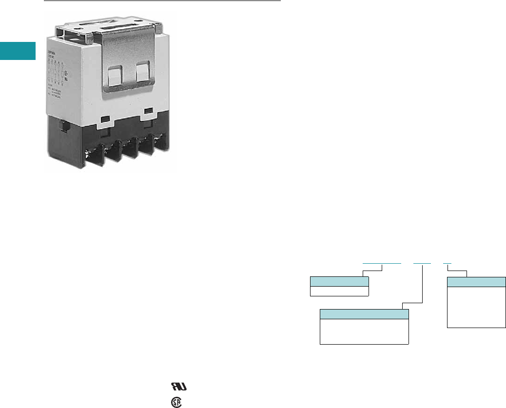
V7-T3-112 Volume 7—Logic Control, Operator Interface and Connectivity Solutions CA08100008E—June 2013 www.eaton.com
3
3
3
3
3
3
3
3
3
3
3
3
3
3
3
3
3
3
3
3
3
3
3
3
3
3
3
3
3
3
V7-T3-112 Volume 7—Logic Control, Operator Interface and Connectivity Solutions CA08100008E—June 2013 www.eaton.com
3
3
3
3
3
3
3
3
3
3
3
3
3
3
3
3
3
3
3
3
3
3
3
3
3
3
3
3
3
3
3.4
Control Relays and Timers
General Purpose Plug-In Relays
D9 Series Relay
Contents
Description Page
D1PR/D1PF Series . . . . . . . . . . . . . . . . . . . . . . . . . V7-T3-53
D2PR/D2PF Series . . . . . . . . . . . . . . . . . . . . . . . . . V7-T3-58
D3PR/D3PF Series . . . . . . . . . . . . . . . . . . . . . . . . . V7-T3-68
D4 Series . . . . . . . . . . . . . . . . . . . . . . . . . . . . . . . . V7-T3-78
D5PR/D5PF Series . . . . . . . . . . . . . . . . . . . . . . . . . V7-T3-82
D7PR/D7PF Series . . . . . . . . . . . . . . . . . . . . . . . . . V7-T3-91
D8 Series . . . . . . . . . . . . . . . . . . . . . . . . . . . . . . . . V7-T3-106
D9 Series
Product Selection . . . . . . . . . . . . . . . . . . . . . . . V7-T3-113
Technical Data and Specifications . . . . . . . . . . . V7-T3-113
Dimensions. . . . . . . . . . . . . . . . . . . . . . . . . . . . V7-T3-114
Accessories . . . . . . . . . . . . . . . . . . . . . . . . . . . . . . V7-T3-116
D9 Series
Product Description
The four-pole D9 Series is
ideal for three-phase motor
applications. Various contact
configurations are available.
Features
●Ideal for three-phase motor
control applications
●No contact chattering for
momentary voltage drops
up to 50% of rated voltage
●Push-to-Test button is a
standard feature to check
contact operation
●Mounting bracket is
supplied with relay
Standards and Certifications
File # E1491
File # LR701520
Catalog Number Selection
Contact Configuration
8B = 4PST-NO
9B = 3PST-NO/SPST-NC
10B = DPST-NO/DPST-NC
Family Type
D9PR
D 9 P R 8 B A
Coil Voltage
A = 120 Vac
B = 240 Vac
R1 = 12 Vdc
T = 24 Vac
T1 = 24 Vdc

Volume 7—Logic Control, Operator Interface and Connectivity Solutions CA08100008E—June 2013 www.eaton.com V7-T3-113
3
3
3
3
3
3
3
3
3
3
3
3
3
3
3
3
3
3
3
3
3
3
3
3
3
3
3
3
3
3
Volume 7—Logic Control, Operator Interface and Connectivity Solutions CA08100008E—June 2013 www.eaton.com V7-T3-113
3
3
3
3
3
3
3
3
3
3
3
3
3
3
3
3
3
3
3
3
3
3
3
3
3
3
3
3
3
3
3.4
Control Relays and Timers
General Purpose Plug-In Relays
Product Selection
D9 Series
Technical Data and Specifications
Coil Resistance
D9PR Specifications
Catalog
Number
Catalog
Number
4PST-NO Power Relay DPST-NO/DPST-NC Power Relay
Coil voltage Coil voltage
24 Vac D9PR8BT 24 Vac D9PR10BT
120 Vac D9PR8BA 120 Vac D9PR10BA
240 Vac D9PR8BB 24 Vac D9PR10BT1
24 Vdc D9PR8BT1
3PST-NO/SPST-NC Power Relay
120 Vac D9PR9BA
Coil Voltage Ohms mA Coil Voltage Ohms mA
24 Vac — 75 12 Vdc 72 167
120 Vac — 21.6 24 Vdc 288 83
240 Vac — 10.8 110 Vdc 6050 18
Description
NO Contacts
Resistive Load (p.f. = 1)
NC Contacts
Resistive Load (p.f. = 1)
Rated load 220 Vac 25A
30 Vdc 25A
220 Vac 8A
30 Vdc 8A
Carry current 25A 8A
Max. operating voltage 250 Vac/125 Vdc 250 Vac/125 Vdc
Max. switching current 25A 8A
Max. switching capacity 5500 VA
750W
1760 VA
240 W
Min. permissible load 100 mA at 24 Vdc 100 mA at 24 Vdc
Mechanical life (min.) 1,000,000 operations 1,000,000 operations
Electrical life at all contact ratings (min.) 100,000 operations 100,000 operations
Maximum hp ratings 1-1/2 hp (120 Vac)
3 hp (240/265/277 Vac)
Three-phase 3 hp (240/265/277 Vac) 30,000 cycles
Three-phase 5 hp (240/265/277 Vac) 30,000 cycles
1-1/2 hp (120 Vac)
3 hp (240/265/277 Vac)
Three-phase 3 hp (240/265/277 Vac) 30,000 cycles
Three-phase 5 hp (240/265/277 Vac) 30,000 cycles

V7-T3-114 Volume 7—Logic Control, Operator Interface and Connectivity Solutions CA08100008E—June 2013 www.eaton.com
3
3
3
3
3
3
3
3
3
3
3
3
3
3
3
3
3
3
3
3
3
3
3
3
3
3
3
3
3
3
V7-T3-114 Volume 7—Logic Control, Operator Interface and Connectivity Solutions CA08100008E—June 2013 www.eaton.com
3
3
3
3
3
3
3
3
3
3
3
3
3
3
3
3
3
3
3
3
3
3
3
3
3
3
3
3
3
3
3.4
Control Relays and Timers
General Purpose Plug-In Relays
Coil Data
Terminal Arrangements
Dimensions
Approximate Dimensions in Inches (mm)
D9PR
Coil Voltage Must Operate Must Release Maximum Voltage
24 Vdc/Vac, 12 Vdc, 110 Vdc 75% maximum 10% minimum 110%
120 Vac 75V 18V 132V
240 Vac 150V 36V 264V
A2 A1
44 43
34 33
24 23
14 13
A2 A1
42 41
34 33
24 23
14 13
A2 A1
42 41
34 33
24 23
14 13
D9PR8 D9PR9 D9PR10
2.03
(51.5)
Max.
1.70
(43.2)
2.52
(64.0)
Max.
1.378 0.004
(35.0 0.1)
0.08
(2.0)
0.30
(7.6)
2.17
(55.2)
1.36
(34.5)
Max.
0.17
(4.3)
Two M4 or
0.18 (4.5) Dia.
Ten M3.5
Screw Terminal Brackets
Mounting Holes
(Bottom View)

Volume 7—Logic Control, Operator Interface and Connectivity Solutions CA08100008E—June 2013 www.eaton.com V7-T3-115
3
3
3
3
3
3
3
3
3
3
3
3
3
3
3
3
3
3
3
3
3
3
3
3
3
3
3
3
3
3
Volume 7—Logic Control, Operator Interface and Connectivity Solutions CA08100008E—June 2013 www.eaton.com V7-T3-115
3
3
3
3
3
3
3
3
3
3
3
3
3
3
3
3
3
3
3
3
3
3
3
3
3
3
3
3
3
3
3.4
Control Relays and Timers
General Purpose Plug-In Relays
Approximate Dimensions in Inches (mm)
Mounting Bracket
Mounting Holes
1.37
(35.0)
0.95
(24.0)
1.18
(30.0)
1.73
(44.0)
1.14
(29.0)
0.35
(9.0)
0.17
(4.4)
1.10
(28.0)
0.28
(7.0)
1.378 0.004
(35.0 1.0)
Two M4 or
0.18 (4.5) Dia. Two M4
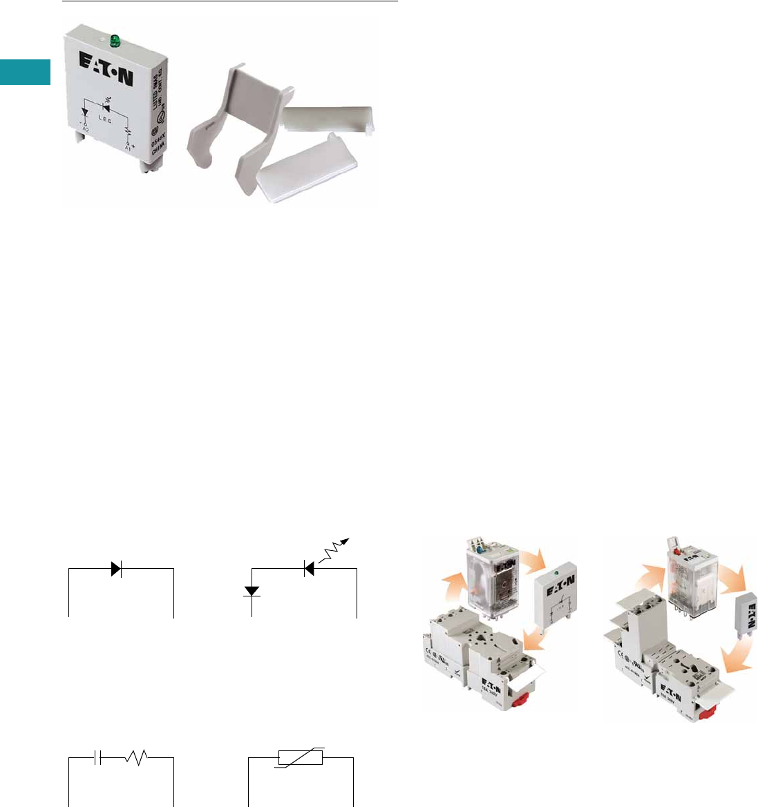
V7-T3-116 Volume 7—Logic Control, Operator Interface and Connectivity Solutions CA08100008E—June 2013 www.eaton.com
3
3
3
3
3
3
3
3
3
3
3
3
3
3
3
3
3
3
3
3
3
3
3
3
3
3
3
3
3
3
V7-T3-116 Volume 7—Logic Control, Operator Interface and Connectivity Solutions CA08100008E—June 2013 www.eaton.com
3
3
3
3
3
3
3
3
3
3
3
3
3
3
3
3
3
3
3
3
3
3
3
3
3
3
3
3
3
3
3.4
Control Relays and Timers
General Purpose Plug-In Relays
Accessories
Contents
Description Page
D1PR/D1PF Series . . . . . . . . . . . . . . . . . . . . . . . . . V7-T3-53
D2PR/D2PF Series . . . . . . . . . . . . . . . . . . . . . . . . . V7-T3-58
D3PR/D3PF Series . . . . . . . . . . . . . . . . . . . . . . . . . V7-T3-68
D4 Series . . . . . . . . . . . . . . . . . . . . . . . . . . . . . . . . V7-T3-78
D5PR/D5PF Series . . . . . . . . . . . . . . . . . . . . . . . . . V7-T3-82
D7PR/D7PF Series . . . . . . . . . . . . . . . . . . . . . . . . . V7-T3-91
D8 Series . . . . . . . . . . . . . . . . . . . . . . . . . . . . . . . . V7-T3-106
D9 Series . . . . . . . . . . . . . . . . . . . . . . . . . . . . . . . . V7-T3-112
Accessories
MOD Modules . . . . . . . . . . . . . . . . . . . . . . . . . V7-T3-117
Relay Clips . . . . . . . . . . . . . . . . . . . . . . . . . . . . V7-T3-118
Coil Bus Jumpers . . . . . . . . . . . . . . . . . . . . . . . V7-T3-120
Write-On Plastic Labels/ID Tags . . . . . . . . . . . . V7-T3-120
Flange Mount Adapters . . . . . . . . . . . . . . . . . . V7-T3-121
Accessories
Accessories Selection Guide
Eaton offers a variety of
simple-to-install relay
accessories that allow you to
customize the features of a
relay system to meet your
exact needs.
The MOD Module System
Eaton’s plug-in modules are a
simple way to add
functionality to your relay
without the hassle of messy
wiring and additional
mounting of external
electronics. They are available
in a variety of configurations
to meet the needs of almost
any application.
Circuit Diagrams
Diode Circuit
The diode module protects
external drive circuitry from
inductive voltages generated
when removing coil voltages.
RC Circuit
Snubs back EMF of relay coil.
LED Circuit
The LED status lamp verifies
that power is being supplied
to the coil. Ideal for both AC
and DC applications. Polarity
sensitive for DC applications.
Metal Oxide Varistor (MOV)
Circuit
The MOV circuit protects
by shunting potentially
damaging electrical spikes
away from the relay coil. Ideal
for AC and DC applications.
A2 A1
+
A2 A1
A2 A1
+
A2 A1
System Diagrams
The MOD Module System
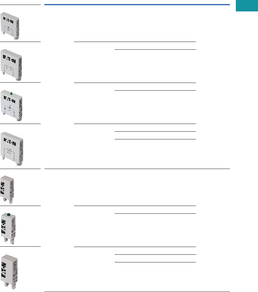
Volume 7—Logic Control, Operator Interface and Connectivity Solutions CA08100008E—June 2013 www.eaton.com V7-T3-117
3
3
3
3
3
3
3
3
3
3
3
3
3
3
3
3
3
3
3
3
3
3
3
3
3
3
3
3
3
3
Volume 7—Logic Control, Operator Interface and Connectivity Solutions CA08100008E—June 2013 www.eaton.com V7-T3-117
3
3
3
3
3
3
3
3
3
3
3
3
3
3
3
3
3
3
3
3
3
3
3
3
3
3
3
3
3
3
3.4
Control Relays and Timers
General Purpose Plug-In Relays
MOD Modules
Eaton’s relay accessories
provide a complete solution
for add-on modules and
identification tags.
MOD Modules
Module
Size Description Nominal Voltage
Catalog
Number
Mating
Sockets
A Protection diode 6–250 Vdc MOD-AD250 D3PA6, D3PAL8,
D3PA7, D3PAL11,
D5PAL, D7PAB,
D7PAD
R/C suppressor 6–24 Vac MOD-RC24
110–240 Vac MOD-RC240
LED indicator 24 Vac MOD-ALG24
120/240 Vac MOD-ALG240
MOV suppressor 24 Vac MOD-AMV24
120 Vac MOD-AMV120
240 Vac MOD-AMV240
B Protection diode 6–250 Vdc MOD-BD250 D1PAA, D2PAL,
D2PAP, D2PA7,
D7PAA
LED indicator 24 Vac MOD-BLG24
120/240 Vac MOD-BLG240
MOV suppressor 24 Vac MOD-BMV24
120 Vac MOD-BMV120
240 Vac MOD-BMV240
MOD-AD250
MOD-ALG_
MOD-RC_
MOD-AMV_
MOD-BD250
MOD-BLG_
MOD-BMV_

V7-T3-118 Volume 7—Logic Control, Operator Interface and Connectivity Solutions CA08100008E—June 2013 www.eaton.com
3
3
3
3
3
3
3
3
3
3
3
3
3
3
3
3
3
3
3
3
3
3
3
3
3
3
3
3
3
3
V7-T3-118 Volume 7—Logic Control, Operator Interface and Connectivity Solutions CA08100008E—June 2013 www.eaton.com
3
3
3
3
3
3
3
3
3
3
3
3
3
3
3
3
3
3
3
3
3
3
3
3
3
3
3
3
3
3
3.4
Control Relays and Timers
General Purpose Plug-In Relays
Relay Clips
Eaton offers a variety of relay
clips designed to improve the
performance and
functionality within an
electrical panel.
Metal Hold-Down Clips
Metal hold-down clips, or
spring clips, are ideal for use
where high heat or humid
conditions are a factor. These
clips hold their shape and
tension and are designed
to withstand harsh
environments. All clips
are made of corrosion-
resistant stainless steel.
Metal Hold-Down Clips
Catalog
Number Mating Sockets Mating Relays
PMC-1781 D1PAA D1PR, D1PF
PQC-1782 D2PAL, D2PAP, D2PA7 D2PR2, D2PF2, D2PR3, D2PF4
PQC-1342 D2PA6, D7PAA, D7PA9 D2PR4, D2PF4
PQC-1332 D3PA6, D3PA7 D3PR2, D3PF2, D3PR3, D3PF3
PQC-1351 D3PAL8, D3PA2, D3PAL11, D3PA3,
D5PAL, D5PA2, D5PA3L, D5PA3S
D3PR2, D3PF2, D3PR3, D3PF4, D5PR, D5PF
PQC-1783 D7PAB D7PR1, D7PF1, D7PR2, D7PF3
PQC-1784 D7PAD D7PR4, D7PF4
PYC-A1 D2PA4 D2PR5
PYC-B2 D7PA3, D7PA4 D7PR1, D7PR2, D7PR4
PMC-1781
PQC-1782
PQC-1342
PQC-1332
PQC-1351
PQC-1783
PQC-1784
PYC- _
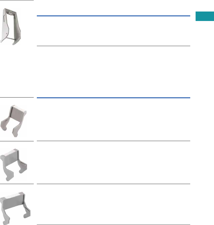
Volume 7—Logic Control, Operator Interface and Connectivity Solutions CA08100008E—June 2013 www.eaton.com V7-T3-119
3
3
3
3
3
3
3
3
3
3
3
3
3
3
3
3
3
3
3
3
3
3
3
3
3
3
3
3
3
3
Volume 7—Logic Control, Operator Interface and Connectivity Solutions CA08100008E—June 2013 www.eaton.com V7-T3-119
3
3
3
3
3
3
3
3
3
3
3
3
3
3
3
3
3
3
3
3
3
3
3
3
3
3
3
3
3
3
3.4
Control Relays and Timers
General Purpose Plug-In Relays
Plastic Ejector/
Hold-Down Clips
These clips are great for
applications where sockets
are located in dense or tight
areas. They allow for quick,
safe and firm securing of
relays in the sockets with the
added benefit that the relay
can be ejected with one
finger. Plastic clips also aid in
keeping operators’ fingers
away from live circuits. The
optional snap-in identification
tag allows for custom
marking of sockets when
used in multi-socket
applications.
Plastic ID Clips
Plastic ID clips allow for easy
circuit identification in multi-
relay applications. They are
designed for labeling and
are not ideal for securing
the relay in the socket.
Plastic Ejector/Hold-Down Clips
Plastic ID Clips
Catalog
Number Mating Sockets Mating Relays
PWC-D24 D2PAL, D2PAP, D2PA7 D2PF2, D2PF4
Catalog
Number Mating Sockets Mating Relays
PQC-1349 D7PAA D7PF1, D7PF2
PMC-1783 D7PAB D7PF1, D7PF2
PMC-1784 D7PAD D7PF4
PWC-D24
PQC-1349
PMC-1783
PMC-1784
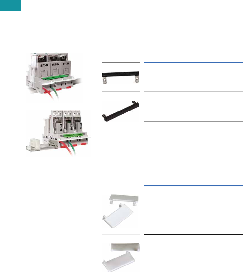
V7-T3-120 Volume 7—Logic Control, Operator Interface and Connectivity Solutions CA08100008E—June 2013 www.eaton.com
3
3
3
3
3
3
3
3
3
3
3
3
3
3
3
3
3
3
3
3
3
3
3
3
3
3
3
3
3
3
V7-T3-120 Volume 7—Logic Control, Operator Interface and Connectivity Solutions CA08100008E—June 2013 www.eaton.com
3
3
3
3
3
3
3
3
3
3
3
3
3
3
3
3
3
3
3
3
3
3
3
3
3
3
3
3
3
3
3.4
Control Relays and Timers
General Purpose Plug-In Relays
Coil Bus Jumpers
Eaton’s coil bus jumpers
allow inputs to be bridged
to adjacent sockets without
additional wiring, making
multi-relay connections quick
and easy. The easy-to-install
design requires no tools and
can be complete in a matter
of seconds.
System Diagrams
Coil Bus Jumpers 1
Write-On Plastic Labels/ID Tags
These convenient plastic
labels snap easily onto
the relay socket for clear
identification in multi-relay
panels. The hinged design
makes wiring simple and
allows for angular adjustment
of the tag to improve
readability in the panel.
Marking with a standard
permanent marker creates
a smudge-free surface.
Coil Bus Jumpers
Write-On Plastic Labels/ID Tags
Note
1 Jumpers in photo are colored green to improve visibility,
actual jumpers are black.
Catalog
Number Mating Sockets
D2PJ1 D2PAL, D2PAP
D3PJ1 D3PA6, D3PA7, D5PAL
Catalog
Number Mating Sockets
PWF-D2P D2PAL, D2PAP
PWF-D3D5 D3PAL8, D3PAL11, D5PAL
D2PJ1
D3PJ1
PWF-D2P
PWF-D3D5
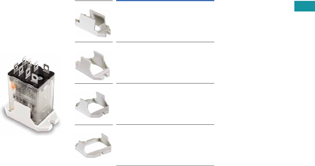
Volume 7—Logic Control, Operator Interface and Connectivity Solutions CA08100008E—June 2013 www.eaton.com V7-T3-121
3
3
3
3
3
3
3
3
3
3
3
3
3
3
3
3
3
3
3
3
3
3
3
3
3
3
3
3
3
3
Volume 7—Logic Control, Operator Interface and Connectivity Solutions CA08100008E—June 2013 www.eaton.com V7-T3-121
3
3
3
3
3
3
3
3
3
3
3
3
3
3
3
3
3
3
3
3
3
3
3
3
3
3
3
3
3
3
3.4
Control Relays and Timers
General Purpose Plug-In Relays
Flange Mount Adapters
Eaton’s relay flange mount
adapters create a modular
approach to flexible
mounting options. Each low-
cost adapter allows for panel
mounting of a standard
control relay and can
eliminate the need for
asocket.
Unit with Flange Mount
Adapter
Flange Mount Adapters
Catalog
Number Mating Relay
PFC-D11 D1PF1, D1PR1
PFC-D2D72 D2P, D7PF2, D7PR2
PFC-D73 D7PF3, D7PR3
PFC-D74 D7PF4, D7PR4
PFC-D11
PFC-D2D72
PFC-D73
PFC-D74
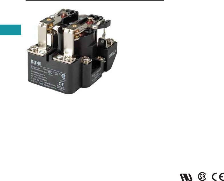
V7-T3-122 Volume 7—Logic Control, Operator Interface and Connectivity Solutions CA08100008E—June 2013 www.eaton.com
3
3
3
3
3
3
3
3
3
3
3
3
3
3
3
3
3
3
3
3
3
3
3
3
3
3
3
3
3
3
V7-T3-122 Volume 7—Logic Control, Operator Interface and Connectivity Solutions CA08100008E—June 2013 www.eaton.com
3
3
3
3
3
3
3
3
3
3
3
3
3
3
3
3
3
3
3
3
3
3
3
3
3
3
3
3
3
3
3.5
Control Relays and Timers
General Purpose Open Style Relays
9575H Series 3000 Relay
Contents
Description Page
9575H Series 3000—Type AA, AC and DC
Product Selection . . . . . . . . . . . . . . . . . . . . . . . V7-T3-123
Accessories. . . . . . . . . . . . . . . . . . . . . . . . . . . . V7-T3-123
Technical Data and Specifications . . . . . . . . . . . V7-T3-124
Dimensions. . . . . . . . . . . . . . . . . . . . . . . . . . . . V7-T3-125
9575H Series 3000—Type AA, AC and DC
Product Description
Type AA panel-mounted
relays are rated (each pole)
40A up to 300 Vac, 50/60 Hz;
5A at 480/600 Vac, 50/60 Hz
and 40A at 28 Vdc.
Application Description
9575H Series 3000 relays are
ideal for applications when
controlling smaller loads,
such as single-phase motors.
Standards and Certifications
●UL listed, E1491
●CSA 41729
●CE: EN60947-4-1,
EN60947-5-1

Volume 7—Logic Control, Operator Interface and Connectivity Solutions CA08100008E—June 2013 www.eaton.com V7-T3-123
3
3
3
3
3
3
3
3
3
3
3
3
3
3
3
3
3
3
3
3
3
3
3
3
3
3
3
3
3
3
Volume 7—Logic Control, Operator Interface and Connectivity Solutions CA08100008E—June 2013 www.eaton.com V7-T3-123
3
3
3
3
3
3
3
3
3
3
3
3
3
3
3
3
3
3
3
3
3
3
3
3
3
3
3
3
3
3
3.5
Control Relays and Timers
General Purpose Open Style Relays
Product Selection
When Ordering, Specify
Catalog number and magnet
coil code letter. Example: for
DPDT relay with auxiliary
switch and a 120V 50/60 Hz
coil, order Catalog Number
9575H3A010.
Type AA Relays 1
Accessories
Enclosure 3
Notes
1There are no “repair parts” available for these relays.
2Underscore indicates missing code suffix for magnet coil—see Selection table above.
3Only 9575H3 relays without an auxiliary switch should be mounted in the 9575H2449
enclosure.
Relay Style
Catalog
Number 2
Relay (DPDT) 9575H3_000
Relay with auxiliary switch 9575H3_010
Relay with blowout magnets 9575H3_100
Relay with auxiliary switch and
blowout magnets
9575H3_110
9575H Series 3000
Relay
Description
Catalog
Number
NEMA 1 Enclosure 9575H2449
Coil Voltage Selection
Coil Voltage Hz Suffix Code
Volts AC
120 50/60 A
240 50/60 B
480/440 60/50 C
600/550 60/50 D
208 50/60 E
277 50/60 H
6 50/60 J
12 50/60 K
24 50/60 L
48 50/60 M
Volts D C
110 — P
220 — Q
6—R
12 — S
24 — T
48 — W

V7-T3-124 Volume 7—Logic Control, Operator Interface and Connectivity Solutions CA08100008E—June 2013 www.eaton.com
3
3
3
3
3
3
3
3
3
3
3
3
3
3
3
3
3
3
3
3
3
3
3
3
3
3
3
3
3
3
V7-T3-124 Volume 7—Logic Control, Operator Interface and Connectivity Solutions CA08100008E—June 2013 www.eaton.com
3
3
3
3
3
3
3
3
3
3
3
3
3
3
3
3
3
3
3
3
3
3
3
3
3
3
3
3
3
3
3.5
Control Relays and Timers
General Purpose Open Style Relays
Technical Data and Specifications
Relay Specifications
Coil
●Pull-in voltage: 80%
DC coils, 85% AC coils
of nominal voltage
or less at 25ºC
●Dropout voltage: 10%
of nominal voltage
or more at 25ºC
●Coil resistance: ±10%
measured at 25ºC
●Max. DC coil dissipation
capability: 4 watts DC
continuous at 25ºC
Contacts
●Contact combination:
DPDT
●Contact rating each pole
(main contacts): Each pole
rated 40 amps up to 300
Vac, 50/60 Hz, 5 amps at
480/600 Vac 50/60 Hz,
0.75 PF load. 1-1/2 hp
motor load (each pole) at
120–600 Vac, 50/60 Hz.
2 hp motor load at
200–600 Vac, 50/60 Hz
only when using both
poles to switch both sides
of load, 40 amps at 28 Vdc
resistive load each pole.
NEMA A 600 pilot duty
50/60 Hz
●Additional contact ratings
for relays with blowout
magnets: 10A at 110 Vdc
resistive, 4A at 225 Vdc
resistive, 2A at 325 Vdc
resistive. For inductive
loads, contacts must be
derated accordingly.
●Contact material: Silver
cadmium oxide, gold
flashed. 5/16 in
(7.9 mm) diameter standard
Dielectric Withstanding Voltage
●Between open contacts:
1500 Vrms
●All other mutually insulated
conductive elements:
2200 Vrms
Miscellaneous
●Coil terminals: 6–32
screws
●Contact terminals: 8-–32
screws
●Main base material:
Molded phenolic, UL
recognized (QMFZ2)
●Weight (DPDT Relay):
11 oz (311 g rams )
approximately
●Weight (DPDT Relay with
auxiliary switch) 14.5 oz
(411 grams) approximately
Auxiliary Switch Specifications
●Contact combination:
SPDT
●Contact rating: Auxiliary
switch rated 10 amps at
125 or 250 Vac, resistive
load; 1/4 hp at 125 or 250
Vac, motor load; 0.4 amps
at 125 Vdc or 0.20 amps at
250 Vdc, resistive load; 3
amps at 125 Vac lamp load.
All AC ratings are 50/60 Hz
●Dielectric withstanding
voltage: 500 Vac rms
between open contacts,
1500 Vac rms between all
other mutually insulated
conductive elements
●Terminals: 4–40 round
head screws for auxiliary
contacts standard
Average Operating Times (Milliseconds)
Temperature Ranges
Operation DPDT Relay DPDT Relay with Auxiliary Switch
Pickup 40 50
Dropout 35 35
Temperature AC DC
Operating range –30º to 55ºC –30º to 55ºC
Non-operating range –30º to 100ºC –30º to 100°C
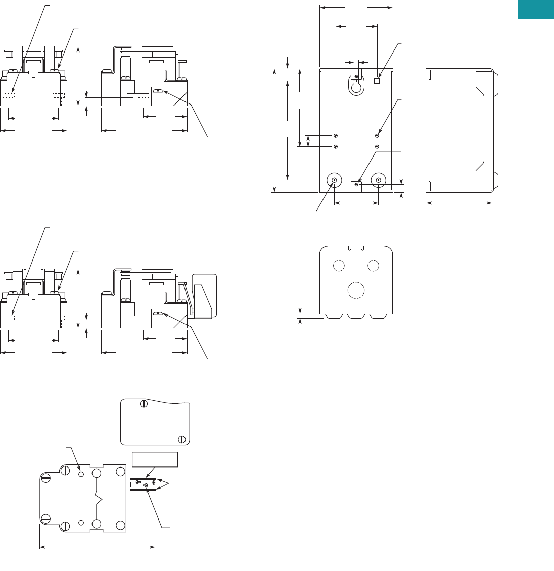
Volume 7—Logic Control, Operator Interface and Connectivity Solutions CA08100008E—June 2013 www.eaton.com V7-T3-125
3
3
3
3
3
3
3
3
3
3
3
3
3
3
3
3
3
3
3
3
3
3
3
3
3
3
3
3
3
3
Volume 7—Logic Control, Operator Interface and Connectivity Solutions CA08100008E—June 2013 www.eaton.com V7-T3-125
3
3
3
3
3
3
3
3
3
3
3
3
3
3
3
3
3
3
3
3
3
3
3
3
3
3
3
3
3
3
3.5
Control Relays and Timers
General Purpose Open Style Relays
Dimensions
Approximate Dimensions in Inches (mm)
9575H3 DPDT Relay
9575H3 DPDT Relay with Auxiliary SPDT Switch
9575H2449
2.25
(58.7)
Max.
8-32 Machine Screw on
Contact Terminals (6 Places)
Mounting Holes 0.187 (4.75) Dia. (2 Places)
0.38
(9.5)
1.87 (47.5) 1.62
(41.1)
6-32
Machine Screw
on Coil
Terminals
(2 Places)
2.50 (63.5) 3.12 (79.2) Max.
2.25
(58.7)
Max.
8-32 Machine Screw on
Contact Terminals (6 Places)
Mounting Holes 0.187 (4.75) Dia. (2 Places)
0.38
(9.5)
1.87 (47.5) 1.62
(41.1)
6-32
Machine Screw
on Coil
Terminals
(2 Places)
AUX. SWITCH
MARKING SURFACE
2.50 (63.5) 3.12 (79.2) Max.
Mounting Holes (2)
Screw Terminals
(4-40) RHMS
with External
Tooth Lockwashers
(3 Places)
Insulators
(2 Sides)
4.44 (112.7) Max.
NC
10A 1/4 hp 125 OR 250 Vac
0.4A at 125 Vdc, 0.2A at 250 Vdc
3A 125 Vac “LAMP”
278 VA 125/250 Vac P.D.
NO COM
RELAY TOP VIEW
0.159" (4) Dia.
10-32 Tap
Typ. 4 Places
0.36" (9.1)
Typ. 2 Places
0.218" (5.5) Dia.
Typ. 2 Places
0.218"
(5.5)
Dia.
0.56"
(4.3)
3.55"
(90.1)
4.50"
(114.3)
5.63"
(142.9) 0.50"
(2.7)
3.31"
(84.2)
1.88"
(47.6)
0.136" (3.4) Dia.
8-32 Tap
Typ. 2 Places
2.00"
(50.8)
3.00"
(76.2)
0.20"
(5.1)
0.230" (5.8)
Square Hole

V7-T3-126 Volume 7—Logic Control, Operator Interface and Connectivity Solutions CA08100008E—June 2013 www.eaton.com
3
3
3
3
3
3
3
3
3
3
3
3
3
3
3
3
3
3
3
3
3
3
3
3
3
3
3
3
3
3
3.6
Control Relays and Timers
Solid-State Relays
Solid-State Relays
Contents
Description Page
Solid-State Relays
D93 Series . . . . . . . . . . . . . . . . . . . . . . . . . . . . V7-T3-127
D96 Series . . . . . . . . . . . . . . . . . . . . . . . . . . . . V7-T3-134
D99 Series . . . . . . . . . . . . . . . . . . . . . . . . . . . . V7-T3-139
Product Overview
Catalog Number Selection
Solid-State Relays—D93, D96 and D99 Series
Note
1For D96208ACZ3, output voltage is 3–150 Vdc.
Input Voltage
1 = 90–280 Vac
2 = 3–32 Vdc
3 = 3.5–32 Vdc
4 = 4–15 Vdc
5 = 20–50 Vdc
Output Type
C = SCR
T =Triac
M =MOSFET
Turn On Type
Z = Zero cross
R = Random
D =DC switch
Output Voltage
1 = 2–60 Vdc
2 = 24–280 Vac 1
3 = 3–200 Vdc
4 = 48–480 Vac
6 = 48–600 Vac
Current
Output current in amps
Contact Configuration
A = SPST-NO
B = SPST-NC
C = DPST-NO
D = DPST-NC
Description
D93 = Hockey puck
D96 = Compact
D99 = DIN rail
D 9 3 32 5 A M D 2

Volume 7—Logic Control, Operator Interface and Connectivity Solutions CA08100008E—June 2013 www.eaton.com V7-T3-127
3
3
3
3
3
3
3
3
3
3
3
3
3
3
3
3
3
3
3
3
3
3
3
3
3
3
3
3
3
3
3.6
Control Relays and Timers
Solid-State Relays
D93 Series—Solid-State Relays
Contents
Description Page
D93 Series
Product Selection . . . . . . . . . . . . . . . . . . . . . V7-T3-128
Accessories . . . . . . . . . . . . . . . . . . . . . . . . . . . V7-T3-128
Technical Data and Specifications . . . . . . . . . . V7-T3-129
Dimensions . . . . . . . . . . . . . . . . . . . . . . . . . . . V7-T3-133
D96 Series . . . . . . . . . . . . . . . . . . . . . . . . . . . . . . . V7-T3-134
D99 Series . . . . . . . . . . . . . . . . . . . . . . . . . . . . . . . V7-T3-139
D93 Series
Product Description
Eaton’s D93 series of solid-
state relays is a line of heavy-
duty industrial relays in the
common “hockey puck”
package. The removable,
finger-safe cover and optional
accessories make the D93
safe and easy to install in a
variety of applications.
Models are available in a
variety of input voltages and
switch types up to 75A.
Application Description
A solid-state relay (SSR) can
perform many applications
that an electromechanical
relay can perform. The SSR
differs in that it has no
moving mechanical parts
within it and has some
distinct advantages over an
electromechanical relay.
When used correctly in the
intended application, the SSR
provides a high degree of
reliability, a long service life,
significantly reduced
electromagnetic interference,
fast response and high
vibration resistance.
Applications for the SSR
typically include equipment
that requires high cycling
rates, low acoustical or
electrical noise, or high
vibration resistance. Some
examples are medical
equipment, heating/cooling
equipment, lighting control
and pumps/compressors,
among others.
Features and Benefits
●All solid-state circuitry with
no moving parts to wear
●Compact, panel mounting
for flexible installation
●Isolated input and output
terminals to protect the
system from electrical
noise
●Internal snubber circuitry
to protect the SSR from
transients
Standards and Certifications
●UL/cUL recognized—
UL 508
●CSA certified
●CE marked
●RoHS compliant
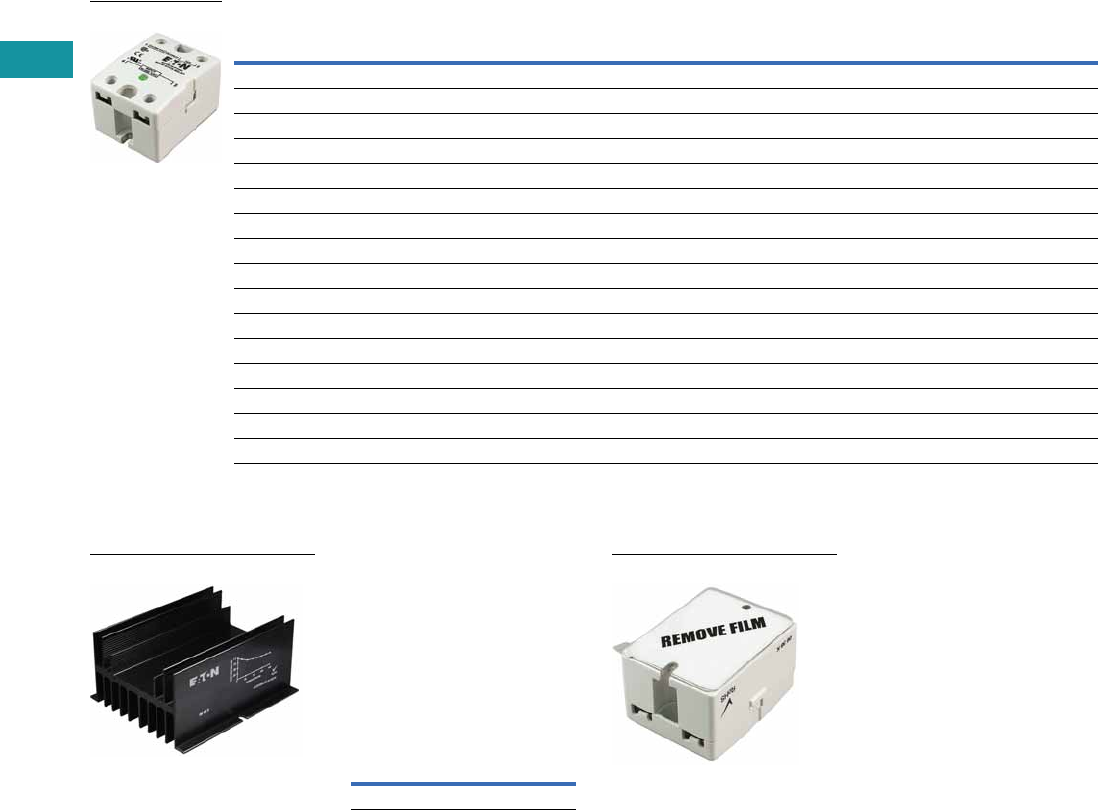
V7-T3-128 Volume 7—Logic Control, Operator Interface and Connectivity Solutions CA08100008E—June 2013 www.eaton.com
3
3
3
3
3
3
3
3
3
3
3
3
3
3
3
3
3
3
3
3
3
3
3
3
3
3
3
3
3
3
3.6
Control Relays and Timers
Solid-State Relays
Product Selection
D93 Series
Accessories
D93 Series—Heat Sink
Eaton’s D93HS1 heat sink is
specifically designed to be
used with D93 solid-state
relays. It is pre-drilled and
tapped, and matches the heat
dissipation requirements for
relays up to 50A.
Heat Sink Accessory
Note: Always ensure that all
details of the application are
considered when determining
heat dissipation requirements,
including ambient temperature.
The D93 relays must be firmly
mounted to the heat sink using a
suitable thermally conductive
grease or thermal transfer pad.
D93 Series—Thermal
Transfer Pad
The D93TP1 is a self-
adhesive transfer pad
designed for use with
Eaton’s D93 solid-state
relays. When used properly,
it will adequately conduct the
heat to a heat sink without
the use of grease.
Input Voltage Output Voltage
Contact
Configuration Switching Type
Rated Current
Load (Amps) Catalog Number
90–280 Vac 24–280 Vac SPST-NO Zero cross 10 D93210ACZ1
3–32 Vdc 24–280 Vac SPST-NO Zero cross 10 D93210ACZ2
3–32 Vdc 24–280 Vac SPST-NO Triac 10 D93210ATZ2
90–280 Vac 24–280 Vac SPST-NO Zero cross 25 D93225ACZ1
3–32 Vdc 24–280 Vac SPST-NO Zero cross 25 D93225ACZ2
3–32 Vdc 24–280 Vac SPST-NO Triac 25 D93225ATZ2
90–280 Vac 24–280 Vac SPST-NO Zero cross 40 D93240ACZ1
3–32 Vdc 24–280 Vac SPST-NO Zero cross 40 D93240ACZ2
3–32 Vdc 24–280 Vac SPST-NO Triac 40 D93240ATZ2
90–280 Vac 24–280 Vac SPST-NO Zero cross 50 D93250ACZ1
3–32 Vdc 24–280 Vac SPST-NO Zero cross 50 D93250ACZ2
90–280 Vac 24–280 Vac SPST-NO Zero cross 75 D93275ACZ1
3–32 Vdc 24–280 Vac SPST-NO Zero cross 75 D93275ACZ2
3–32 Vdc 3–200 Vdc SPST-NO MOSFET 12 D93312AMD2
3–32 Vdc 3–200 Vdc SPST-NO MOSFET 25 D93325AMD2
3–32 Vdc 3–200 Vdc SPST-NO MOSFET 40 D93340AMD2
D93210ACZ1
D93HS1
Description
Catalog
Number
Heat sink D93HS1
D93TP1

Volume 7—Logic Control, Operator Interface and Connectivity Solutions CA08100008E—June 2013 www.eaton.com V7-T3-129
3
3
3
3
3
3
3
3
3
3
3
3
3
3
3
3
3
3
3
3
3
3
3
3
3
3
3
3
3
3
3.6
Control Relays and Timers
Solid-State Relays
Technical Data and Specifications
D93 Series
Description Units D93210ACZ1 D93210ACZ2 D93210ATZ2 D93225ACZ1 D93225ACZ2 D93225ATZ2
Output Characteristics
Contact configuration SPST-NO SPST-NO SPST-NO SPST-NO SPST-NO SPST-NO
Switching device SCR SCR Triac SCR SCR Triac
Current rating A 10 10 10 25 25 25
Switching type Zero cross Zero cross Zero cross Zero cross Zero cross Zero cross
Maximum rate of rise off state voltage (DV/DT) V/us 200 250 700 500 500 250
Incandescent lamp ampere rating (rms) A 8 16 16 16 16 16
Motor load rating (rms) A 4.5 8 8 8 8 8
Min. load current to maintain on mA 50 120 250 120 120 120
Non-repetitive surge current (1 cycle) A 83 250 1000 250 250 250
Max. rms overload current (1 second) A 24 80 50 40 40 80
Max. off state leakage current (rms) mA 8 10 10 8 10 10
Peak blocking voltage Vpk 600 300 — 600 600 —
Typical on state voltage drop (rms) Vac 1.6 1.6 1.35 1.6 1.6 1.6
Max. on state voltage drop (rms) Vac 1.6 1.6 1.6 1.6 1.6 1.6
Max. I2t for fusing (A2) 72 300 1700 312 250 300
Input Characteristics
Must release voltage V 10 AC 1 DC 10 AC 10 AC 1 DC 1 DC
Typical input impedance ohms 13k Current regulator 16–25k 13k Current regulator 1.5k
Nominal input current at 5 Vdc or 240 Vac mA 20 2 12 20 16 2
Reverse polarity protection NA Yes NA NA Yes Yes
Performance Characteristics
Operating time (response time)
ON ms8.38.38.38.38.38.3
OFF ms 8.3 8.3 8.3 8.3 8.3 8.3
Rated insulation voltage—input to input Vac 4000 4000 4000 4000 4000 4000
Dielectric strength—terminal to chassis Vac 4000 4000 4000 4000 4000 4000
Environment
Product certifications UR, CSA, CE UR, CSA, CE UR, CSA, CE UR, CSA, CE UR, CSA, CE UR, CSA, CE
Ambient air temperature
Storage °C –40 to 100 –40 to 100 –40 to 100 –40 to 100 –40 to 100 –40 to 100
Operating °C –40 to 80 –40 to 80 –40 to 80 –40 to 80 –40 to 80 –40 to 80
Degree of protection IP20 IP20 IP20 IP20 IP20 IP20
Miscellaneous Characteristics
Thermal resistance (junction to case) °C/W 3.5 3.5 1.45 1.02 1.02 1.45
Weight g (oz) 100 (3.5) 100 (3.5) 100 (3.5) 100 (3.5) 100 (3.5) 100 (3.5)
LED—input Green Green Green Green Green Green
Input terminals M3.5 M3.5 M3.5 M3.5 M3.5 M3.5
Output terminals M4 M4 M4 M4 M4 M4
Terminal torque (max.) Nm 1.0 1.0 1.0 1.0 1.0 1.0

V7-T3-130 Volume 7—Logic Control, Operator Interface and Connectivity Solutions CA08100008E—June 2013 www.eaton.com
3
3
3
3
3
3
3
3
3
3
3
3
3
3
3
3
3
3
3
3
3
3
3
3
3
3
3
3
3
3
3.6
Control Relays and Timers
Solid-State Relays
D93 Series, continued
Description Units D93240ACZ1 D93240ACZ2 D93240ATZ2 D93250ACZ1 D93250ACZ2
Output Characteristics
Contact configuration SPST-NO SPST-NO SPST-NO SPST-NO SPST-NO
Switching device SCR SCR Triac SCR SCR
Current rating A 40 40 40 50 50
Switching type Zero cross Zero cross Zero cross Zero cross Zero cross
Maximum rate of rise off state voltage (DV/DT) V/us 500 500 250 500 500
Incandescent lamp ampere rating (rms) A 30 30 20 39 39
Motor load rating (rms) A 14 14 14 14 14
Min. load current to maintain on mA 250 250 50 250 250
Non-repetitive surge current (1 cycle) A 625 625 250 520 520
Max. rms overload current (1 second) A 80 80 80 100 100
Max. off state leakage current (rms)mA101010108
Peak blocking voltage Vpk 600 600 600 600 600
Typical on state voltage drop (rms) Vac 1.6 1.6 1.6 1.1 1.8
Max. on state voltage drop (rms) Vac 1.6 1.6 1.6 1.8 1.8
Max. I2t for fusing (A2) 1250 1250 438 1250 1250
Input Characteristics
Must release voltage V 10 AC 1 DC 1 DC 10 AC 1 DC
Typical input impedance ohms 13k ACL 1.5k 13k Current regulator
Nominal input current at 5 Vdc or 240 Vac mA 20 16 2 20 16
Reverse polarity protection N/A Yes Yes NA Yes
Performance Characteristics
Operating time (response time)
ON ms 8.3 8.3 8.3 8.3 8.3
OFF ms 8.3 8.3 8.3 8.3 8.3
Rated insulation voltage—input to input Vac 4000 4000 4000 4000 4000
Dielectric strength—terminal to chassis Vac 4000 4000 4000 4000 4000
Environment
Product certifications UR, CSA, CE UR, CSA, CE UR, CSA, CE UR, CSA, CE UR, CSA, CE
Ambient air temperature
Storage °C –40 to 100 –40 to 100 –40 to 100 –40 to 100 –40 to 100
Operating °C –40 to 80 –40 to 80 –40 to 80 –40 to 80 –40 to 80
Degree of protection IP20 IP20 IP20 IP20 IP20
Miscellaneous Characteristics
Thermal resistance (junction to case) °C/W 0.9 0.9 0.95 0.63 0.63
Weight g (oz) 100 100 100 135 (4.8) 135 (4.8)
LED—input Green Green Green Green Green
Input terminals M3.5 M3.5 M3.5 M3.5 M3.5
Output terminals M6M6M6M6M6
Terminal torque (max.) Nm 1.0 1.0 1.0 1.0 1.0

Volume 7—Logic Control, Operator Interface and Connectivity Solutions CA08100008E—June 2013 www.eaton.com V7-T3-131
3
3
3
3
3
3
3
3
3
3
3
3
3
3
3
3
3
3
3
3
3
3
3
3
3
3
3
3
3
3
3.6
Control Relays and Timers
Solid-State Relays
D93 Series, continued
Description Units D93275ACZ1 D93275ACZ2 D93312AMD2 D93325AMD2 D93340AMD2
Output Characteristics
Contact configuration SPST-NO SPST-NO SPST-NO SPST-NO SPST-NO
Switching device SCR SCR MOSFET MOSFET MOSFET
Current rating A 75 75 12 25 40
Switching type Zero cross Zero cross DC switching DC switching DC switching
Maximum rate of rise off state voltage (DV/DT) V/us 500 500 NA NA NA
Incandescent lamp ampere rating (rms) A 39 39 NA NA NA
Motor load rating (rms) A 25 25 NA NA NA
Min. load current to maintain on mA 250 250 20 20 20
Non-repetitive surge current (1 cycle) A 1150 1150 27 50 90
Max. rms overload current (1 second) A 150 150 NA NA NA
Max. off state leakage current (rms) mA 10 10 8 8 8
Peak blocking voltage Vpk 600 600 — — —
Typical on state voltage drop (rms) Vac 1.8 1.8 1.6 1.6 1.6
Max. on state voltage drop (rms) Vac 1.8 1.8 2.83 2.83 2.83
Max. I2t for fusing (A2) 5000 5000 NA NA NA
Input Characteristics
Must release voltage V 10 AC 1 DC 1 DC 1 DC 1 DC
Typical input impedance ohms 13k Current regulator 1k 1k 1k
Nominal input current at 5 Vdc or 240 Vac mA 20 16 10 10 10
Reverse polarity protection NA Yes No No No
Performance Characteristics
Operating time (response time)
ON ms 8.3 8.3 300 μs 600 μs 600 μs
OFF ms 8.3 8.3 1 2.6 2.6
Rated insulation voltage—input to input Vac 4000 4000 4000 4000 4000
Dielectric strength—terminal to chassis Vac 4000 4000 2500 2500 2500
Environment
Product certifications UR, CSA, CE UR, CSA, CE UR, CSA, CE UR, CSA, CE UR, CSA, CE
Ambient air temperature
Storage °C –40 to 100 –40 to 100 –40 to 100 –40 to 100 –40 to 100
Operating °C –40 to 80 –40 to 80 –40 to 80 –40 to 80 –40 to 80
Degree of protection IP20 IP20 IP20 IP20 IP20
Miscellaneous Characteristics
Thermal resistance (junction to case) °C/W 0.6 0.63 1.06 1.06 0.63
Weight g (oz) 200 135 (4.8) 110 (3.9) 110 (3.9) 135 (4.8)
LED—input Green Green Green Green Green
Input terminals M3.5 M3.5 M3.5 M3.5 M3.5
Output terminals M6M6M4M4M6
Terminal torque (max.) Nm 1.0 1.0 1.0 1.0 1.0

V7-T3-132 Volume 7—Logic Control, Operator Interface and Connectivity Solutions CA08100008E—June 2013 www.eaton.com
3
3
3
3
3
3
3
3
3
3
3
3
3
3
3
3
3
3
3
3
3
3
3
3
3
3
3
3
3
3
3.6
Control Relays and Timers
Solid-State Relays
Temperature Derating Curves
10 Amp Styles
25 Amp Styles
40 and 50 Amp Styles
75 Amp Styles
Load Current (amps rms)
16
14
12
10
8
6
4
2
20° 40° 60° 80° 100°
Max. Ambient Temperature (°C)
6" x 6" x 1/8" aluminum plate
Free air mounting
0
Heat sink
with 1°C/W
thermal
resistance
Load Current (amps rms)
40
35
30
25
20
15
10
5
20° 40° 60° 80° 100°
Max. Ambient Temperature (°C)
Mounted on heat sink with
1°C/W thermal resistance
(sink to ambient)
5" x 6" x 1/8"
aluminum
plate 1.5°C/W
Load Current (amps rms)
90
80
70
50
40
30
20
10
20° 40° 60° 80° 100°
Max. Ambient Temperature (°C)
Mounted on heat sink with
1°C/W thermal resistance
0
0.14°C/W (50A)
5" x 6" x 1/8"
aluminum plate
Load Current (amps rms)
75
60
45
40
30
20
10
20° 40° 60° 80°
Max. Ambient Temperature (°C)
030°0° 10° 70°
50°
90
95
100
105
110
Max. Allowable Temperature
5" x 6" x 1/8"
aluminum plate
0.14°C/W
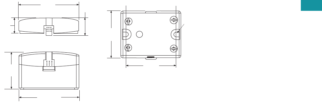
Volume 7—Logic Control, Operator Interface and Connectivity Solutions CA08100008E—June 2013 www.eaton.com V7-T3-133
3
3
3
3
3
3
3
3
3
3
3
3
3
3
3
3
3
3
3
3
3
3
3
3
3
3
3
3
3
3
3.6
Control Relays and Timers
Solid-State Relays
Dimensions
Approximate Dimensions in Inches (mm)
D93 Series
2.28
(57.9) 0.66
(16.8)
0.6
(15.1)
1.4
(35.9)
2.28
(57.9)
Screw Terminals
1.74
(44.1)
0.18
(4.4)
1.87
(47.5)
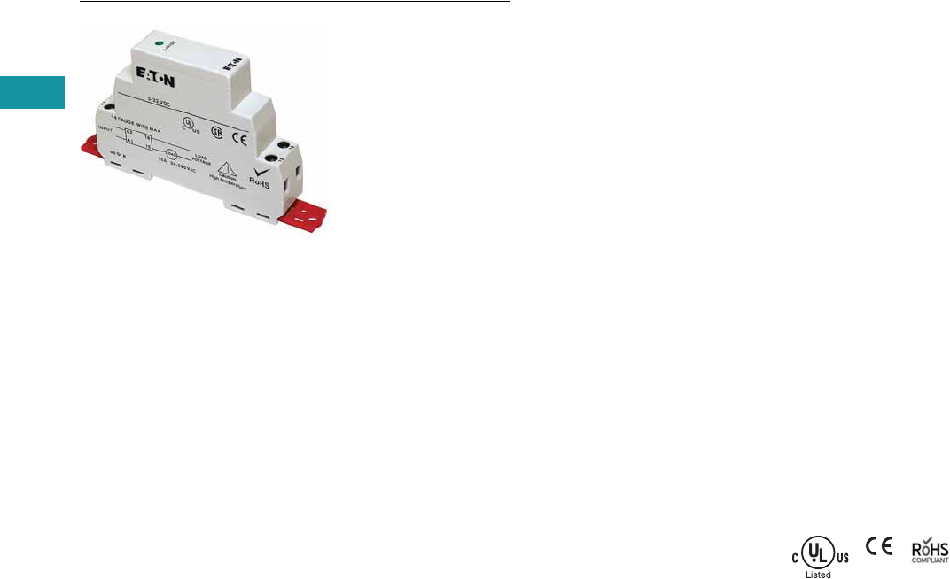
V7-T3-134 Volume 7—Logic Control, Operator Interface and Connectivity Solutions CA08100008E—June 2013 www.eaton.com
3
3
3
3
3
3
3
3
3
3
3
3
3
3
3
3
3
3
3
3
3
3
3
3
3
3
3
3
3
3
3.6
Control Relays and Timers
Solid-State Relays
D96 Series—Solid-State Relays
Contents
Description Page
D93 Series . . . . . . . . . . . . . . . . . . . . . . . . . . . . . . V7-T3-127
D96 Series
Product Selection . . . . . . . . . . . . . . . . . . . . V7-T3-135
Technical Data and Specifications . . . . . . . . . . V7-T3-136
Dimensions . . . . . . . . . . . . . . . . . . . . . . . . . . . V7-T3-138
D99 Series . . . . . . . . . . . . . . . . . . . . . . . . . . . . . . V7-T3-139
D96 Series
Product Description
Eaton’s D96 series of
solid-state relays is a
technologically advanced set
of electronic relays for tough
applications and harsh
environments. The compact
17.5 mm wide package
with an integrated heat sink
provides easy mounting
in tight spaces.
Application Description
A solid-state relay (SSR) can
perform many applications
that an electromechanical
relay can perform. The SSR
differs in that it has no
moving mechanical parts
within it and has some
distinct advantages over an
electromechanical relay.
When used correctly in the
intended application, the SSR
provides a high degree of
reliability, a long service life,
significantly reduced
electromagnetic interference,
fast response and high
vibration resistance.
Applications for the SSR
typically include equipment
that requires high cycling
rates, low acoustical or
electrical noise, or high
vibration resistance. Some
examples are medical
equipment, heating/cooling
equipment, lighting control
and pumps/compressors,
among others.
Features and Benefits
●All solid-state circuitry has
no moving parts to wear
●Integral heat sink
eliminates the need for
added accessories and
installation
●Flexible mounting allows
DIN rail or panel mounting
without additional
hardware or tools
●Isolated input and output
terminals protect the
system from electrical
noise
●Internal snubber circuitry
protects the SSR from
transients
Standards and Certifications
●UL/cUL listed—UL 508
●CSA certified
●CE marked
●RoHS compliant
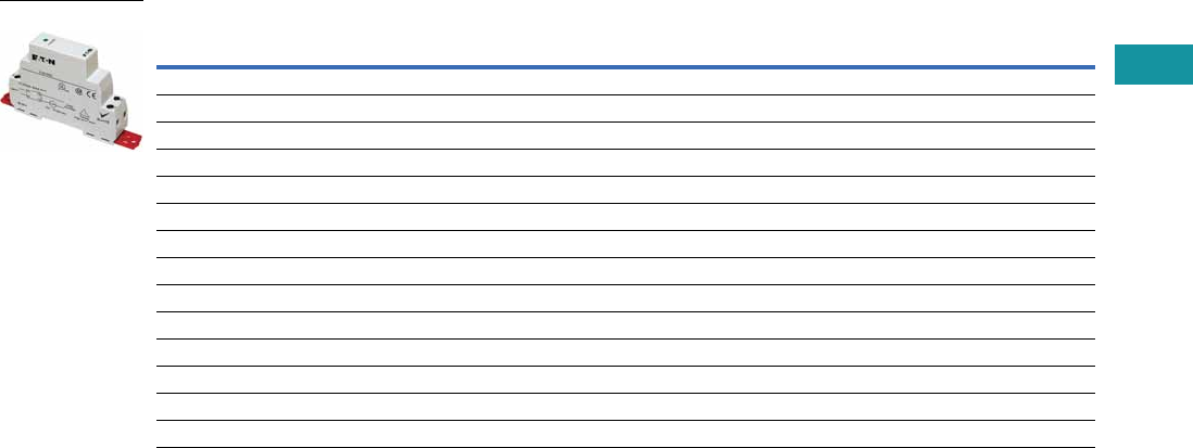
Volume 7—Logic Control, Operator Interface and Connectivity Solutions CA08100008E—June 2013 www.eaton.com V7-T3-135
3
3
3
3
3
3
3
3
3
3
3
3
3
3
3
3
3
3
3
3
3
3
3
3
3
3
3
3
3
3
3.6
Control Relays and Timers
Solid-State Relays
Product Selection
D96 Series
Input Voltage Output Voltage
Contact
Configuration Switching Type
Rated Current
Load (Amps) Catalog Number
3.5–32 Vdc 3–50 Vdc SPST-NO DC switch 15 D96115ACZ3
3.5–32 Vdc 3–150 Vdc SPST-NO DC switch 8 D96208ACZ3
90–280 Vac 24–280 Vac SPST-NO Random 10 D96210ACR1
3–32 Vdc 24–280 Vac SPST-NO Random 10 D96210ACR2
90–280 Vac 24–280 Vac SPST-NO Zero cross 10 D96210ACZ1
3–32 Vdc 24–280 Vac SPST-NO Zero cross 10 D96210ACZ2
3–32 Vdc 24–280 Vac SPST-NC Random 10 D96210BCR2
90–280 Vac 48–480 Vac SPST-NO Random 10 D96410ACR1
3–32 Vdc 48–480 Vac SPST-NO Random 10 D96410ACR2
90–280 Vac 48–480 Vac SPST-NO Zero cross 10 D96410ACZ1
3–32 Vdc 48–480 Vac SPST-NO Zero cross 10 D96410ACZ2
90–280 Vac 48–600 Vac SPST-NO Random 10 D96610ACR1
90–280 Vac 48–600 Vac SPST-NO Zero cross 10 D96610ACZ1
3–32 Vdc 48–600 Vac SPST-NO Zero cross 10 D96610ACZ2
D96115ACZ3

V7-T3-136 Volume 7—Logic Control, Operator Interface and Connectivity Solutions CA08100008E—June 2013 www.eaton.com
3
3
3
3
3
3
3
3
3
3
3
3
3
3
3
3
3
3
3
3
3
3
3
3
3
3
3
3
3
3
3.6
Control Relays and Timers
Solid-State Relays
Technical Data and Specifications
D96 Series
Description Units D96210ACZ1 D96210ACZ2 D96210ACR1 D96210ACR2 D96115ACZ3 D96208ACZ3 D96210BCR2
Output Characteristics
Contact configuration SPST-NO SPST-NO SPST-NO SPST-NO SPST-NO SPST-NO SPST-NC
Switching device SCR SCR SCR SCR MOSFET MOSFET SCR
Current rating A10101010158 10
Switching type Zero cross Zero cross Random turn on Random turn on DC switching DC switching Random turn on
Maximum zero turn-on voltage (Vpk) V 35 35 35 35 NA NA 35
Maximum rate of rise off state voltage (DV/DT) V/us 500 500 500 500 NA NA 500
Incandescent lamp ampere rating (rms) A 8 8 8 8 NA NA 8
Motor load rating (rms) A 4.5 4.5 4.5 4.5 NA NA 4.5
Min. load current to maintain on mA 50 50 50 50 20 20 50
Non-repetitive surge current (1 cycle) A 500 500 500 500 50 35 500
Max. rms overload current (1 second) A 24 24 24 24 24 17 24
Max. off state leakage current (rms)mA10101010101010
Typical on state voltage drop (rms) V 1.25 AC 1.25 AC 1.25 AC 1.25 AC 1.25 DC 1.25 DC 1.25 AC
Max. on state voltage drop (rms) V 1.6 AC 1.6 AC 1.6 AC 1.6 AC 1.6 DC 1.6 DC 1.6 AC
Max. I2t for fusing (A2) 1250 1250 1250 1250 NA NA 1250
Input Characteristics
Must release voltage V 10 AC 1 DC 10 AC 1 DC 1 DC 1 DC 1 DC
Typical input impedance ohms 16–25k Current regulator 16–25k ACL Current regulator Current regulator ACL
Nominal input current at 5 Vdc or 240 Vac mA 12 16 12 16 12 12 12
Reverse polarity protection NA Yes NA Yes Yes Yes Yes
Performance Characteristics
Operating time (response time)
ON ms 40 8.3 8.3 8.3 5 5 8.3
OFF ms 80 8.3 8.3 8.3 5 5 8.3
Rated insulation voltage—input to input Vac 2500 2500 4000 4000 2500 2500 4000
Dielectric strength—terminal to chassis Vac 2500 2500 2500 2500 2500 2500 2500
Environment
Product certifications UL, CSA, CE UL, CSA, CE UL, CSA, CE UL, CSA, CE UL, CSA, CE UL, CSA, CE UL, CSA, CE
Ambient air temperature
Storage °C –40 to 100 –40 to 100 –40 to 100 –40 to 100 –40 to 100 –40 to 100 –40 to 100
Operating °C –30 to 80 –30 to 80 –30 to 80 –30 to 80 –30 to 80 –30 to 80 –30 to 80
Degree of protection IP20 IP20 IP20 IP20 IP20 IP20 IP20
Miscellaneous Characteristics
Thermal resistance (junction to case) °C/W 0.66 0.66 0.66 0.66 0.66 0.66 0.66
Integral heat sink °C/W 4.0 4.0 4.0 4.0 4.0 4.0 4.0
Weight g (oz) 127 (4.1) 127 (4.1) 127 (4.1) 127 (4.1) 127 (4.1) 127 (4.1) 127 (4.1)
LED—input Green Green Green Green Green Green Green
Terminal wire capacity AWG (mm2) 14 (2.1) 14 (2.1) 14 (2.1) 14 (2.1) 14 (2.1) 14 (2.1) 14 (2.1)
Terminal torque (max.) in-lb (Nm) 7.1 (0.8) 7.1 (0.8) 7.1 (0.8) 7.1 (0.8) 7.1 (0.8) 7.1 (0.8) 7.1 (0.8)
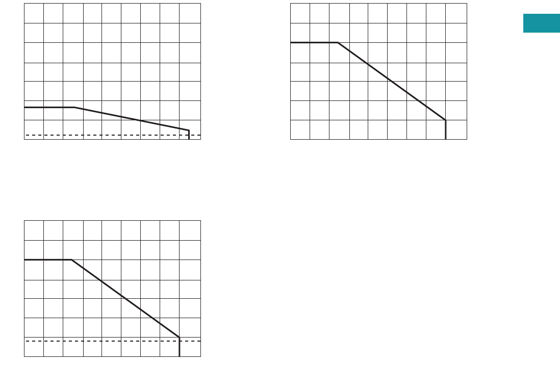
Volume 7—Logic Control, Operator Interface and Connectivity Solutions CA08100008E—June 2013 www.eaton.com V7-T3-137
3
3
3
3
3
3
3
3
3
3
3
3
3
3
3
3
3
3
3
3
3
3
3
3
3
3
3
3
3
3
3.6
Control Relays and Timers
Solid-State Relays
Temperature Derating Curves
8 Amp Style
10 Amp Style
15 Amp Style
Max. Ambient Temperature (°C)
0° 10° 20° 30° 40° 50° 60° 70° 80° 90°
85°
35
30
25
20
15
10
8
5
0
Load Current (amps rms)
1.5
Max. Ambient Temperature (°C)
0° 10° 20° 30° 40° 50° 60° 70° 80° 90°
14
12
10
8
6
4
2
0
Load Current (amps rms)
1.8
Ambient Temperature (°C)
0° 10° 20° 30° 40° 50° 60° 70° 80° 90°
24
18
15
12
9
6
3
0
Current (amps DC)
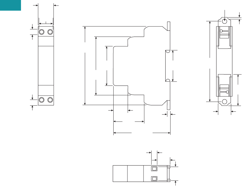
V7-T3-138 Volume 7—Logic Control, Operator Interface and Connectivity Solutions CA08100008E—June 2013 www.eaton.com
3
3
3
3
3
3
3
3
3
3
3
3
3
3
3
3
3
3
3
3
3
3
3
3
3
3
3
3
3
3
3.6
Control Relays and Timers
Solid-State Relays
Dimensions
Approximate Dimensions in Inches (mm)
D96 Series
0.69
(17.6)
1.40
(35.6)
1.78
(45.3)
0.20
(5.0)
0.56
(14.2)
0.27
(6.9)
0.55
(14.9)
0.62
(15.8)
0.24
(6.0)
2.63
(66.8)
3.54
(90.0)
2.56 Max.
(65.0)
0.63
(16.0)
1.36
(34.6)
0.13
(3.4)
1.39
(35.2)
3.64
(92.4)
0.20
(5.0)
0.07
(1.7)
0.56
(14.3)

Volume 7—Logic Control, Operator Interface and Connectivity Solutions CA08100008E—June 2013 www.eaton.com V7-T3-139
3
3
3
3
3
3
3
3
3
3
3
3
3
3
3
3
3
3
3
3
3
3
3
3
3
3
3
3
3
3
3.6
Control Relays and Timers
Solid-State Relays
D99 Series—Solid-State Relays
Contents
Description Page
D93 Series . . . . . . . . . . . . . . . . . . . . . . . . . . . . . . . V7-T3-127
D96 Series . . . . . . . . . . . . . . . . . . . . . . . . . . . . . . . V7-T3-134
D99 Series
Product Selection . . . . . . . . . . . . . . . . . . . . . V7-T3-140
Technical Data and Specifications . . . . . . . . . . V7-T3-141
Dimensions . . . . . . . . . . . . . . . . . . . . . . . . . . . V7-T3-144
D99 Series
Product Description
Eaton’s D99 series of solid-
state relays is a line of
heavy-duty industrial relays
with an integrated heat sink.
The attached metal hardware
can be used for DIN rail or
panel mounting.
Models are available in a
variety of input voltages in
10A, 25A and 40A sizes.
Application Description
A solid-state relay (SSR) can
perform many applications
that an electromechanical
relay can perform. The SSR
differs in that it has no
moving mechanical parts
within it and has some
distinct advantages over an
electromechanical relay.
When used correctly in the
intended application, the SSR
provides a high degree of
reliability, a long service life,
significantly reduced
electromagnetic interference,
fast response and high
vibration resistance.
Applications for the SSR
typically include equipment
that requires high cycling
rates, low acoustical or
electrical noise, or high
vibration resistance. Some
examples are medical
equipment, heating/cooling
equipment, lighting control
and pumps/compressors,
among others.
Features and Benefits
●All solid-state circuitry has
no moving parts to wear
●Integral heat sink
eliminates the need for
added accessories and
installation
●Flexible mounting allows
DIN rail or panel mounting
without additional
hardware or tools
●Isolated input and output
terminals protect the
system from electrical
noise
●Internal snubber circuitry
protects the SSR from
transients
Standards and Certifications
●UL/cUL listed—UL 508
●CSA certified
●CE marked
●RoHS compliant
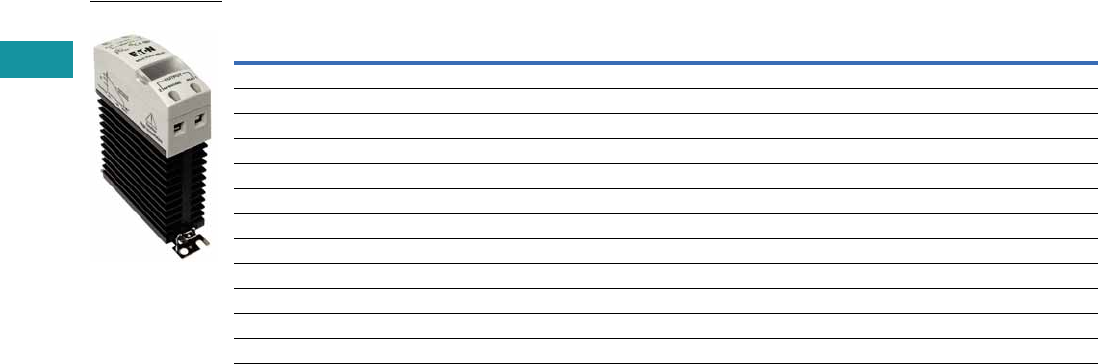
V7-T3-140 Volume 7—Logic Control, Operator Interface and Connectivity Solutions CA08100008E—June 2013 www.eaton.com
3
3
3
3
3
3
3
3
3
3
3
3
3
3
3
3
3
3
3
3
3
3
3
3
3
3
3
3
3
3
3.6
Control Relays and Timers
Solid-State Relays
Product Selection
D99 Series
Input Voltage Output Voltage
Contact
Configuration Switching Type
Rated Current
Load (Amps) Catalog Number
90–280 Vac 24–280 Vac SPST-NO Zero cross 10 D99210ACZ1
3–32 Vdc 24–280 Vac SPST-NO Zero cross 10 D99210ACZ2
90–280 Vac 24–280 Vac SPST-NO Zero cross 25 D99225ACZ1
3–32 Vdc 24–280 Vac SPST-NO Zero cross 25 D99225ACZ2
90–280 Vac 24–280 Vac SPST-NO Zero cross 40 D99240ACZ1
3–32 Vdc 24–280 Vac SPST-NO Zero cross 40 D99240ACZ2
90–280 Vac 48–600 Vac SPST-NO Zero cross 10 D99610ACZ1
3–32 Vdc 48–600 Vac SPST-NO Zero cross 10 D99610ACZ2
90–280 Vac 48–600 Vac SPST-NO Zero cross 25 D99625ACZ1
3–32 Vdc 48–600 Vac SPST-NO Zero cross 25 D99625ACZ2
90–280 Vac 48–600 Vac SPST-NO Zero cross 40 D99640ACZ1
3–32 Vdc 48–600 Vac SPST-NO Zero cross 40 D99640ACZ2
D99210ACZ1

Volume 7—Logic Control, Operator Interface and Connectivity Solutions CA08100008E—June 2013 www.eaton.com V7-T3-141
3
3
3
3
3
3
3
3
3
3
3
3
3
3
3
3
3
3
3
3
3
3
3
3
3
3
3
3
3
3
3.6
Control Relays and Timers
Solid-State Relays
Technical Data and Specifications
D99 Series
Description Units D99210ACZ1 D99210ACZ2 D99225ACZ1 D99225ACZ2 D99240ACZ1 D99240ACZ2
Output Characteristics
Contact configuration SPST-NO SPST-NO SPST-NO SPST-NO SPST-NO SPST-NO
Switching device SCR SCR SCR SCR SCR SCR
Current rating A 10 10 25 25 40 40
Switching type Zero cross Zero cross Zero cross Zero cross Zero cross Zero cross
Maximum zero turn-on voltage (Vpk) V 35 35 35 35 35 35
Maximum rate of rise off state voltage (DV/DT) V/us 500 200 500 500 500 500
Incandescent lamp ampere rating (rms) A 8 8 16 16 20 20
Motor load rating (rms) A 4.5 4.5 8 8 14 14
Min. load current to maintain on mA 50 50 120 120 250 250
Non-repetitive surge current (1 cycle) A 83 83 800 800 800 800
Max. rms overload current (1 second) A 24 24 40 40 100 100
Max. off state leakage current (rms) mA 10 10 10 10 10 10
Typical on state voltage drop (rms) Vac 1.25 1.25 1.35 1.35 1.6 1.6
Max. on state voltage drop (rms) Vac 1.6 1.6 1.8 1.8 1.6 1.6
Max. I2t for fusing (A2) 83 83 3700 3700 3700 83
Input Characteristics
Must release voltage V 10 AC 1 DC 10 AC 1 DC 10 AC 1 DC
Typical input impedance ohms 16–25k Current regulator 16–25k Current regulator 13k Current regulator
Nominal input current at 5 Vdc or 240 Vac mA 12 12 12 12 16 16
Reverse polarity protection NA Yes NA Yes NA Yes
Performance Characteristics
Operating time (response time)
ON ms8.38.38.38.38.310
OFF ms 8.3 8.3 8.3 8.3 8.3 10
Rated insulation voltage—input to input Vac 4000 4000 4000 4000 4000 4000
Dielectric strength—terminal to chassis Vac 4000 4000 4000 4000 4000 4000
Environment
Product certifications UL, CSA, CE UL, CSA, CE UL, CSA, CE UL, CSA, CE UL, CSA, CE UL, CSA, CE
Ambient air temperature
Storage °C –40 to 100 –40 to 100 –40 to 100 –40 to 100 –40 to 100 –40 to 100
Operating °C –30 to 80 –30 to 80 –30 to 80 –30 to 80 –30 to 80 –30 to 80
Degree of protection IP20 IP20 IP20 IP20 IP20 IP20
Miscellaneous Characteristics
Thermal resistance (junction to case) °C/W 1.5 1.5 1.5 0.43 1.5 0.43
Integral heat sink °C/W 2.2 2.2 2.2 2.2 2.2 2.2
Weight g (oz) 320 (11.3) 320 (11.3) 320 (11.3) 326 (11.5) 320 (11.3) 332 (11.7)
LED—input Green Green Green Green Green Green
Terminal wire capacity AWG (mm2) 8 (10) 8 (10) 8 (10) 8 (10) 8 (10) 8 (10)
Terminal torque (max.) in-lb (Nm) 12.5 (1.4) 12.5 (1.4) 12.5 (1.4) 12.5 (1.4) 12.5 (1.4) 12.5 (1.4)

V7-T3-142 Volume 7—Logic Control, Operator Interface and Connectivity Solutions CA08100008E—June 2013 www.eaton.com
3
3
3
3
3
3
3
3
3
3
3
3
3
3
3
3
3
3
3
3
3
3
3
3
3
3
3
3
3
3
3.6
Control Relays and Timers
Solid-State Relays
D99 Series, continued
Description Units D99610ACZ1 D99610ACZ2 D99625ACZ1 D99625ACZ2 D99640ACZ1 D99640ACZ2
Output Characteristics
Contact configuration SPST-NO SPST-NO SPST-NO SPST-NO SPST-NO SPST-NO
Switching device SCR SCR SCR SCR SCR SCR
Current rating A 10 10 25 10 40 40
Switching type Zero cross Zero cross Zero cross Zero cross Zero cross Zero cross
Maximum zero turn-on voltage (Vpk) V 35 35 35 35 35 35
Maximum rate of rise off state voltage (DV/DT) V/us 200 200 700 700 500 500
Incandescent lamp ampere rating (rms) A 8 8 16 16 20 20
Motor load rating (rms) A 4.5 4.5 8 8 14 14
Min. load current to maintain on mA 80 80 250 250 250 250
Non-repetitive surge current (1 cycle) A 83 83 1000 1000 800 800
Max. rms overload current (1 second) A 24 24 50 50 100 100
Max. off state leakage current (rms) mA 10 10 10 10 10 10
Typical on state voltage drop (rms) Vac 1.25 1.25 1.35 1.35 1.6 1.6
Max. on state voltage drop (rms) Vac 1.6 1.6 1.6 1.6 1.6 1.6
Max. I2t for fusing (A2) 83 83 1700 1700 3700 3700
Input Characteristics
Must release voltage V 10 AC 1 DC 10 AC 1 DC 10 AC 1 DC
Typical input impedance ohms 16–25k Current regulator 16–25k Current regulator 13k Current regulator
Nominal input current at 5 Vdc or 240 Vac mA 12 16 12 16 16 16
Reverse polarity protection NA Yes NA Yes NA Yes
Performance Characteristics
Operating time (response time)
ON ms 8.33 8.3 8.33 8.3 10 10
OFF ms 8.33 8.3 8.33 8.3 10 10
Rated insulation voltage—input to input Vac 4000 4000 4000 4000 4000 4000
Dielectric strength—terminal to chassis Vac 4000 4000 4000 4000 4000 4000
Environment
Product certifications UL, CSA, CE UL, CSA, CE UL, CSA, CE UL, CSA, CE UL, CSA, CE UL, CSA, CE
Ambient air temperature
Storage °C –40 to 100 –40 to 100 –40 to 100 –40 to 100 –40 to 100 –40 to 100
Operating °C –30 to 80 –30 to 80 –30 to 80 –30 to 80 –30 to 80 –30 to 80
Degree of protection IP20 IP20 IP20 IP20 IP20 IP20
Miscellaneous Characteristics
Thermal resistance (junction to case) °C/W 1.8 1.8 0.43 0.43 0.43 0.43
Integral heat sink °C/W 2.2 2.2 2.2 2.2 2.2 2.2
Weight g (oz) 320 (11.3) 321 (11.3) 326 (11.5) 326 (11.5) 332 (11.7) 332 (11.7)
LED—input Green Green Green Green Green Green
Terminal wire capacity AWG (mm2) 8 (10) 9 (10) 8 (10) 8 (10) 8 (10) 8 (10)
Terminal torque (max.) in-lb (Nm) 12.5 (1.4) 12.5 (1.4) 12.5 (1.4) 12.5 (1.4) 12.5 (1.4) 12.5 (1.4)
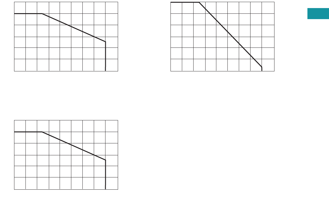
Volume 7—Logic Control, Operator Interface and Connectivity Solutions CA08100008E—June 2013 www.eaton.com V7-T3-143
3
3
3
3
3
3
3
3
3
3
3
3
3
3
3
3
3
3
3
3
3
3
3
3
3
3
3
3
3
3
3.6
Control Relays and Timers
Solid-State Relays
Temperature Derating Curves
10 Amp Styles
25 Amp Styles
40 Amp Styles
Ambient Temperature (°C)
0° 10° 20° 30° 40° 50° 60° 70° 80° 90°
12
10
8
6
4
2
0
Current in amps
Ambient Temperature (°C)
0° 10° 20° 30° 40° 50° 60° 70° 80° 90°
25
20
15
10
5
0
Current in amps
Ambient Temperature (°C)
0° 10° 20° 30° 40° 50° 60° 70° 80° 90°
40
30
25
20
15
10
0
Current in amps
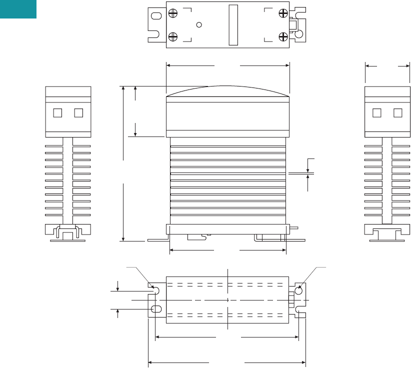
V7-T3-144 Volume 7—Logic Control, Operator Interface and Connectivity Solutions CA08100008E—June 2013 www.eaton.com
3
3
3
3
3
3
3
3
3
3
3
3
3
3
3
3
3
3
3
3
3
3
3
3
3
3
3
3
3
3
3.6
Control Relays and Timers
Solid-State Relays
Dimensions
Approximate Dimensions in Inches (mm)
D99 Series
1.20
(30.0)
4.20
(107.0)
0.50 (11.9)
0.05
(1.20)
1.20
(30.0)
3.20
(80.0)
Input
Output
+
21
–
3.10
(77.5)
3.70
(92.9)
4.00
(102.0)
0.20 (5.0)
Radius
0.20 (5.0)
Radius
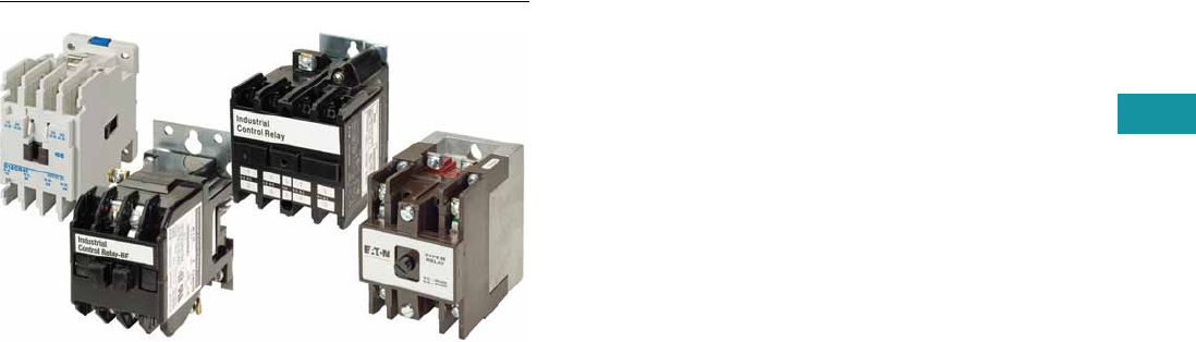
Volume 7—Logic Control, Operator Interface and Connectivity Solutions CA08100008E—June 2013 www.eaton.com V7-T3-145
3
3
3
3
3
3
3
3
3
3
3
3
3
3
3
3
3
3
3
3
3
3
3
3
3
3
3
3
3
3
3.7
Control Relays and Timers
Machine Tool Relays
Machine Tool Relays
Contents
Description Page
Machine Tool Relays
D15 Series—Freedom 600V Multipole . . . . . . . V7-T3-146
BF/BFD Series—Fixed Contact
Industrial Control . . . . . . . . . . . . . . . . . . . . . . V7-T3-151
AR/ARD Series—Convertible Contact
Industrial Control . . . . . . . . . . . . . . . . . . . . . . V7-T3-157
D26 Series—Type M, 600 Vac Multipole
with Convertible Contacts . . . . . . . . . . . . . . . V7-T3-162
D26 Series—Type M, DC Multipole
with Convertible Contacts . . . . . . . . . . . . . . . V7-T3-167
Product Overview
Eaton’s machine tool relay
offering includes a variety of
NEMA type relays. Included
in this are open style relays
and relays with convertible
or side-mount contacts. Also
included in this family are a
variety of accessories to
match the application,
including suppressors, timing
contacts and enclosures. The
relay coils are available in a
variety of line and control
level voltages.
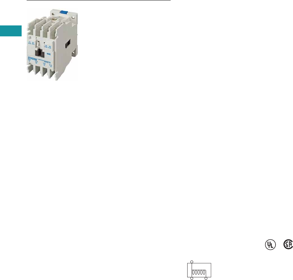
V7-T3-146 Volume 7—Logic Control, Operator Interface and Connectivity Solutions CA08100008E—June 2013 www.eaton.com
3
3
3
3
3
3
3
3
3
3
3
3
3
3
3
3
3
3
3
3
3
3
3
3
3
3
3
3
3
3
3.7
Control Relays and Timers
Machine Tool Relays
D15 Series—Freedom 600V Multipole
Contents
Description Page
D15 Series—Freedom 600V Multipole
Product Selection . . . . . . . . . . . . . . . . . . . . . . . V7-T3-147
Accessories . . . . . . . . . . . . . . . . . . . . . . . . . . . V7-T3-148
Technical Data and Specifications . . . . . . . . . . V7-T3-149
Dimensions . . . . . . . . . . . . . . . . . . . . . . . . . . . V7-T3-150
BF/BFD Series—Fixed Contact
Industrial Control . . . . . . . . . . . . . . . . . . . . . . . . . V7-T3-151
AR/ARD Series—Convertible Contact
Industrial Control . . . . . . . . . . . . . . . . . . . . . . . . . V7-T3-157
D26 Series—Type M, 600 Vac Multipole
with Convertible Contacts . . . . . . . . . . . . . . . . . V7-T3-162
D26 Series—Type M, DC Multipole
with Convertible Contacts . . . . . . . . . . . . . . . . . V7-T3-167
D15 Series—Freedom 600V Multipole
Product Description
Contact poles on the D15
relay are of the fixed design
and are not convertible. The
basic four-pole relay will
accept a front-mounted
contact pole deck and/or side-
mounted contact blocks (one
per side). In addition, a side-
mounted solid-state timer or
a front-mounted pneumatic
timer can be added to the
relay. Only one front-
mounted attachment can be
added to the basic relay.
Application Description
Side-mounted contact
blocks can be used to
provide additional poles
in applications where a
pneumatic timer is installed
on the front of the relay.
They can also be used where
panel depth is restricted.
The maximum number of
contacts recommended per
relay is eight, six of which can
be NC. When a pneumatic
timer is used, the maximum
recommended number of
NC contacts is three.
Relays with DC coils are
supplied with a coil clearing
NC contact mounted on the
side of the relay.
Features and Benefits
●600V, 10A continuous
thermal current
●State indicator visually
shows relay ON or OFF
status
●Relay base has mounting
holes on 35 x 60 mm
centers, permitting direct
replacement of
competitive relays
●Relay also mounts on
35 mm DIN rail as standard
●Magnet coil has three
terminals, permitting either
top or diagonal wiring—
easy to replace European
or U.S. relays without
changing wiring layout
●Contact pole terminals
have captive, backed-out,
self-lifting pressure plates
with ± screws—reduced
wiring time
●All terminals are shrouded
or
“finger-proofed” to
reduce possibility
of
electrical shock
Standards and Certifications
●UL
●CSA certified
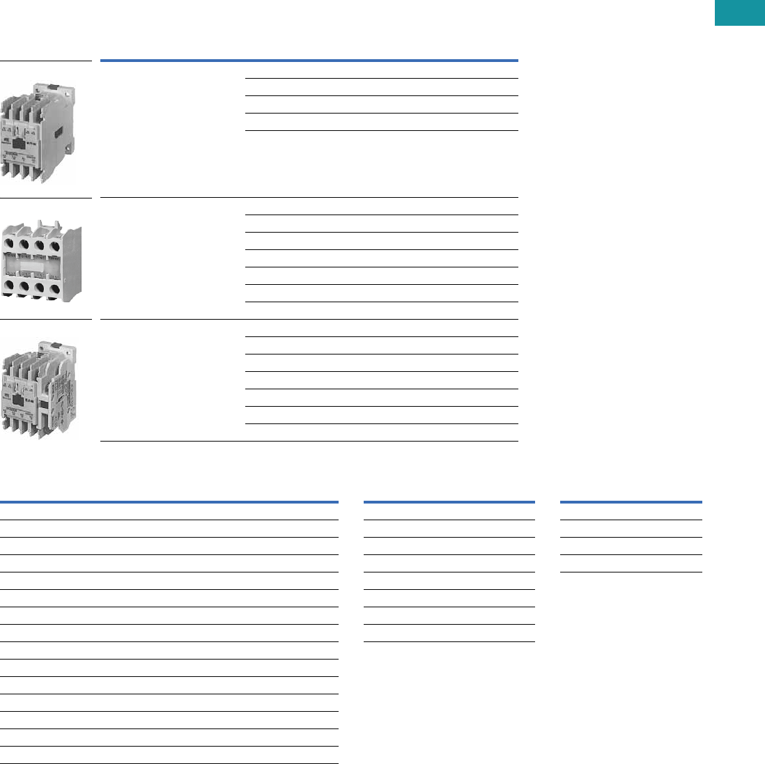
Volume 7—Logic Control, Operator Interface and Connectivity Solutions CA08100008E—June 2013 www.eaton.com V7-T3-147
3
3
3
3
3
3
3
3
3
3
3
3
3
3
3
3
3
3
3
3
3
3
3
3
3
3
3
3
3
3
3.7
Control Relays and Timers
Machine Tool Relays
Product Selection
When Ordering, Specify
Catalog number and magnet coil code letter. Example: For a four-pole relay having
4NO contacts with a 120V 60 Hz coil, order Catalog Number D15CR40AB.
Factory-Assembled Multipole Relays
Additional Contact Poles Magnet Coil Selection
Notes
1Underscore indicates missing code suffix for magnet coil—see Magnet Coil Selection table above.
2Not all suffix codes available: consult Customer Support Center.
Number of
Poles
Type of Contacts Open Type
NO NC Catalog Number 1
440D15CR40_B
31D15CR31_B
22D15CR22_B
13D15CR13_B
04D15CR04_B
6
(four-pole relay with two-pole
front-mounted deck)
60D15CR60_B
51D15CR51_B
42D15CR42_B
33D15CR33_B
24D15CR24_B
15D15CR15_B 2
06D15CR06_B 2
8
(four-pole relay with four-pole
front-mounted deck)
80D15CR80_B
71D15CR71_B
62D15CR62_B
53D15CR53_B
44D15CR44_B
35D15CR35_B 2
26D15CR26_B 2
D15CR40_B
D15CR60_B
D15CR80_B
Description
Catalog
Number
Front Contact Pole Deck
1NO-1NC C320KGT3
2NO C320KGT4
2NC C320KGT5
1NO (early closing)–1NC (late opening) C320KGT7
4NO C320KGT13
3NO-1NC C320KGT14
2NO-2NC C320KGT15
1NO-3NC C320KGT16
4NC C320KGT17
Side-Mounted Contact Blocks
1NO-1NC C320KGS3
2NO C320KGS4
2NC C320KGS5
1NO (early closing)–1NC (late opening) C320KGS7
AC Coils
Volts and Hertz
Code
Suffix
DC Coils
Volts
Code
Suffix
120/60 or 110/50 A12 R1
240/60 or 220/50 B24 T1
480/60 or 440/50 C48 W1
600/60 or 550/50 D120 A1
208/60 E
277/60 H
208–240/60 J
24/60 T

V7-T3-148 Volume 7—Logic Control, Operator Interface and Connectivity Solutions CA08100008E—June 2013 www.eaton.com
3
3
3
3
3
3
3
3
3
3
3
3
3
3
3
3
3
3
3
3
3
3
3
3
3
3
3
3
3
3
3.7
Control Relays and Timers
Machine Tool Relays
Accessories
Pneumatic Timer Attachment
Maximum Ampere Ratings
Attachment mounts on top of
any Freedom Series relay
(top-mounted auxiliary
contacts can not be installed
on device when timer is
used). Timer unit has DPST
timed contacts—circuits in
each pole must be the same
polarity. Units are convertible
from OFF to ON delay or
vice-versa.
Finger Protection Shields
Snap-on shields for both
contactors and starters
provide IEC Type IP20
Finger Protection. Prevents
accidental contact with line/
load terminals.
Adhesive Dust Cover
These adhesive stickers
come 25 to a package and
provide extra protection from
contaminants when applied
to the sides of Freedom D15.
Adhesive covers are easily
applied to side opening
where auxiliaries are not
installed and provide extra
protection from metal filings
and other debris.
Solid-State ON DELAY Timer 1
This timer is designed to be
wired in series with the
load (typically a coil). When
the START button is pushed
(power applied to timer), the
ON delay timing function
starts. At the completion of
the set timing period, timer
and series wired load will
both be energized.
Timing Range
Catalog
Number
0.1 to 30 seconds C320TP1
10 to 180 seconds C320TP2
Volts AC
Description 120 240 480 600
Make 30 15 7.5 6
Break 3 1.5 0.75 0.6
C320 Pneumatic
Timer Attachment
Application
Catalog
Number
D15 C320LS1
Description
Catalog
Number
25 to a package C320DSTCVR
Timing Range
Catalog
Number 234
0.1 to 1.0 seconds C320TDN1_
1 to 30 seconds C320TDN30_
30 to 300 seconds C320TDN300_
5 to 30 minutes C320TDN3000_
Solid-State Timer
Metal Mounting Plate
Fits all D15 multipole relays.
Mounting Channel (DIN Rail)
Designed for DIN rail
mounting of Freedom
Series relays.
Transient Suppressor Kits
These kits limit high voltage
transients produced in the
control circuit when power is
removed from the contactor
or starter coil. There are three
separate suppressors for use
on 24–120V, 208–240V or 27–
480V coils respectively.
These devices mount directly
to the coil terminals.
Notes
1Side mounted on Freedom Series NEMA 00–2, D15, IECA-K and C25D, C25E and C25F frame.
2Add operating voltage suffix to catalog number; A = 120V, B = 240V, E = 208V.
3Rated 0.5 ampere pilot duty—not to be used on larger contactors.
4Terminal connections are quick connects only. Two per side.
5Suppressor is compatible with coil voltages/ranges as shown, both 50 and 60 Hz.
Description
Catalog
Number
Metal mounting plate C321MP1
C32MP1
Description
Catalog
Number
1 meter length XBANS3575P
DIN Rail
Description
Coil Voltage
50/60 Hz 5
Catalog
Number
Transient 24/120V C320TS1
Suppressor 208/240V C320TS2
277/480V C320TS3
C320TS2
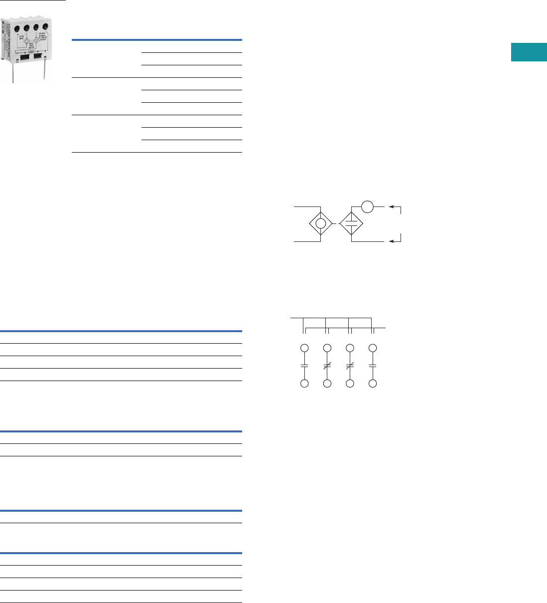
Volume 7—Logic Control, Operator Interface and Connectivity Solutions CA08100008E—June 2013 www.eaton.com V7-T3-149
3
3
3
3
3
3
3
3
3
3
3
3
3
3
3
3
3
3
3
3
3
3
3
3
3
3
3
3
3
3
3.7
Control Relays and Timers
Machine Tool Relays
AC/DC Interface Module—
Controller Coil Voltage Ranges
Technical Data and Specifications
Contact Ratings—NEMA A600
Contact Ratings—NEMA P300
Magnet Coil Data
Controller Catalog
Number Prefix
Controller
Size or Rating
Coil Range
Volts AC
AE16, AE17, AE56,
AE57, CE15, CE55
A–F 24–240
G–K 48–240
L–N 110–240
AN16, AN56,
CN15, CN55
00–0 24–240
1–2 48–240
3 110–240
CN35 10–30A 24–240
60A 48–240
100A 110–240
C320DC
Continuous Thermal Rating: 10A
AC Volts Make Break
120 60 6.0
240 30 3.0
480 15 1.5
600 12 1.2
Continuous Thermal Rating: 5A
DC Volts Make/Break Amperes
125 1.1
250 0.55
AC
Voltage
Pickup Sealed
VA Watts VA Watts
12–600V 80 49 7.5 2.4
DC
Voltage
Pickup Sealed
Amps Watts VA Watts
12 6.4 76.8 0.28 3.36
24 3.2 76.8 0.14 3.36
48 1.6 76.8 0.07 3.36
120 0.64 76.8 0.028 3.36
The Catalog Number C320DC
Interface Module is an
optically isolated solid-state
switch that provides a means
of operating AC coils with a
24 Vdc control signal. It acts
as a space-saving interposing
relay that can switch a
specified 50/60 Hz AC source
to the contactor or starter coil.
The module may be directly
attached to the coil terminals
of any Freedom Series
contactor or starter—NEMA
Sizes 00–3, D15, IEC Sizes
A–N and lighting contactors
10–100A. It also has
provisions for DIN rail
mounting.
The module will operate coils
within the voltage ranges
shown in the table to the left.
Design Characteristics
●DC input: 24V ±10% at
mA nominal
●AC operating voltage:
24–240 Vac ±10%
50/60 Hz
●AC current rating:
10A make (inrush),
1A break (sealed)
Typical Application—Solid-State Switch
Example of Terminal Marking with 2NO and 2NC Contacts
Relay terminals are identified
by a two-digit number in
accordance with International
Standards approved by
CENELEC (European
Committee for Electro-
technical Standardization).
The number is marked on
the relay and is used to
identify location and status
of the contacts.
The first digit indicates the
location of the contact on the
relay. The numbering begins
with 1 and continues without
a break from left to right.
The second digit indicates
the status of the contacts
(NO or NC). Terminal marking
1 and 2 mean NC and 3 and
4mean NO.
24 Vdc
Input
Observe
Polarity on
Module
24–240 Vac
50/60 Hz
Contactor Coil
Location
13 21 31 43
14 22 32 44
Status
(NO or NC)
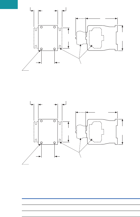
V7-T3-150 Volume 7—Logic Control, Operator Interface and Connectivity Solutions CA08100008E—June 2013 www.eaton.com
3
3
3
3
3
3
3
3
3
3
3
3
3
3
3
3
3
3
3
3
3
3
3
3
3
3
3
3
3
3
3.7
Control Relays and Timers
Machine Tool Relays
Dimensions
Approximate Dimensions in Inches (mm)
D15 Four-Pole Relay
D15 Six- and Eight-Pole Relays
Dimensions and Shipping Weights
Description Dimension C
Shipping Weights
Lbs (kg)
Relay only 3.30 (83.8) 1.3 (0.6)
Relay with timer attachment 5.55 (141.0) 1.5 (0.7)
Relay with front contact pole deck 4.66 (118.4) 1.7 (0.8)
2.36
(59.9)
2.96
(75.2)
1.36
(34.5) Optional Additional
Contact Poles
or Accessories
Mtg. Holes for
M4 or #8 Screws
1.8
(45.7)
C
0.54
(13.7)
0.54
(13.7)
Side
Mtd.
Blk.
Frt.
Mtd.
Acc.
4.66
(118.4)
2.36
(59.9)
2.96
(75.2)
1.36
(34.5) Optional Additional
Contact Poles
or Accessories
Mtg. Holes for
M4 or #8 Screws
1.8
(45.7)
0.54
(13.7)
0.54
(13.7)
Side
Mtd.
Blk.
Frt.
Mtd.
Acc.
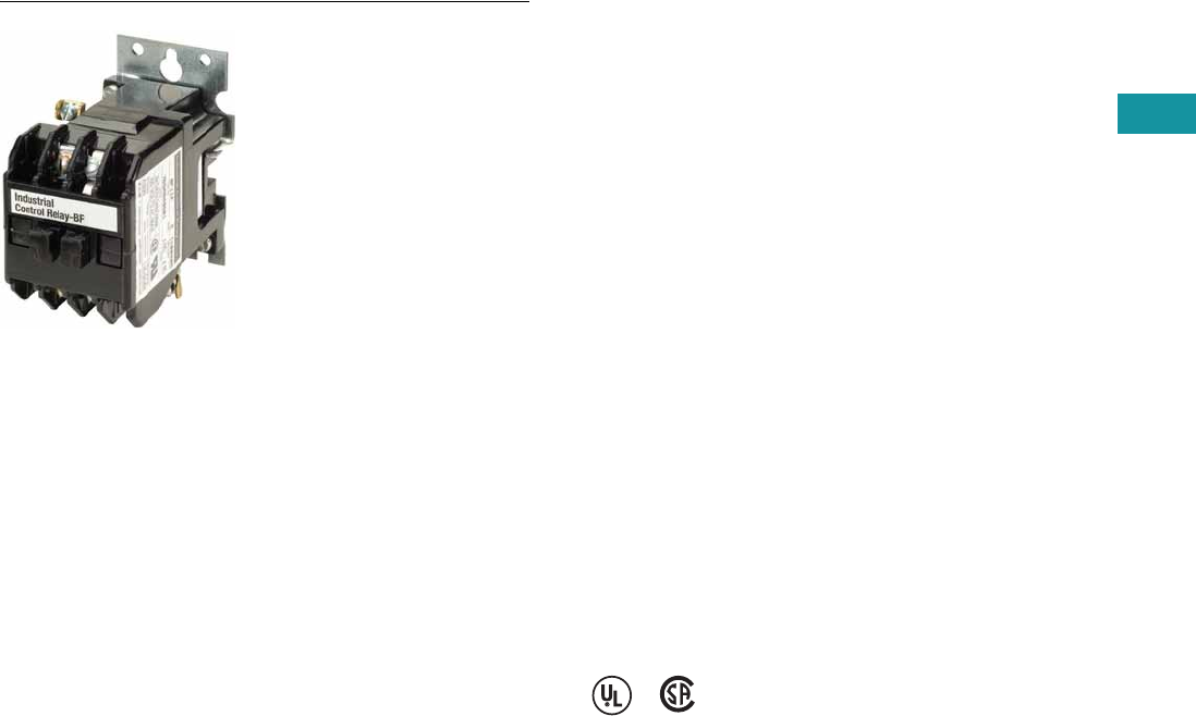
Volume 7—Logic Control, Operator Interface and Connectivity Solutions CA08100008E—June 2013 www.eaton.com V7-T3-151
3
3
3
3
3
3
3
3
3
3
3
3
3
3
3
3
3
3
3
3
3
3
3
3
3
3
3
3
3
3
3.7
Control Relays and Timers
Machine Tool Relays
BF/BFD Series—Fixed Contact Industrial Control
Contents
Description Page
D15 Series—Freedom 600V Multipole. . . . . . . . . . V7-T3-146
BF/BFD Series—Fixed Contact Industrial
Control
Product Selection . . . . . . . . . . . . . . . . . . . . . . . V7-T3-152
Options . . . . . . . . . . . . . . . . . . . . . . . . . . . . . . . V7-T3-154
Technical Data and Specifications . . . . . . . . . . V7-T3-155
Dimensions . . . . . . . . . . . . . . . . . . . . . . . . . . . V7-T3-156
AR/ARD Series—Convertible Contact
Industrial Control . . . . . . . . . . . . . . . . . . . . . . . . . V7-T3-157
D26 Series—Type M, 600 Vac Multipole
with Convertible Contacts . . . . . . . . . . . . . . . . . . V7-T3-162
D26 Series—Type M, DC Multipole
with Convertible Contacts . . . . . . . . . . . . . . . . . . V7-T3-167
BF/BFD Series—Fixed Contact Industrial Control
Product Description
Type BF is AC operated, 300V
maximum, and the BFD is DC
operated, 250V. Fixed contact
relays are available in any
combination of NO and NC
from two to 12 poles. BF and
BFD relays have captive
clamp terminals fully
accessible from the front,
a molded coil with low
operating temperature and
silver alloy contacts suitable
for low voltage circuits.
Features and Benefits
Wiring to Relay
●In parallel with coil—one
timed and up to 12
instantaneous contacts, or
●In series with coil—up
to 12 timed contacts in
one relay
Permanent Magnet Latch
●Field mountable on Catalog
Number BF; factory
installed on BFD
●Latch coil continuously
rated
●Latch plunger adjustable
for optimum performance
Standards and Certifications
●UL recognized, UL File No.
E19223 (AC relays only)
●CSA certified, File No.
LR39402-6, LR28548-10,
11 (AC and DC relays)
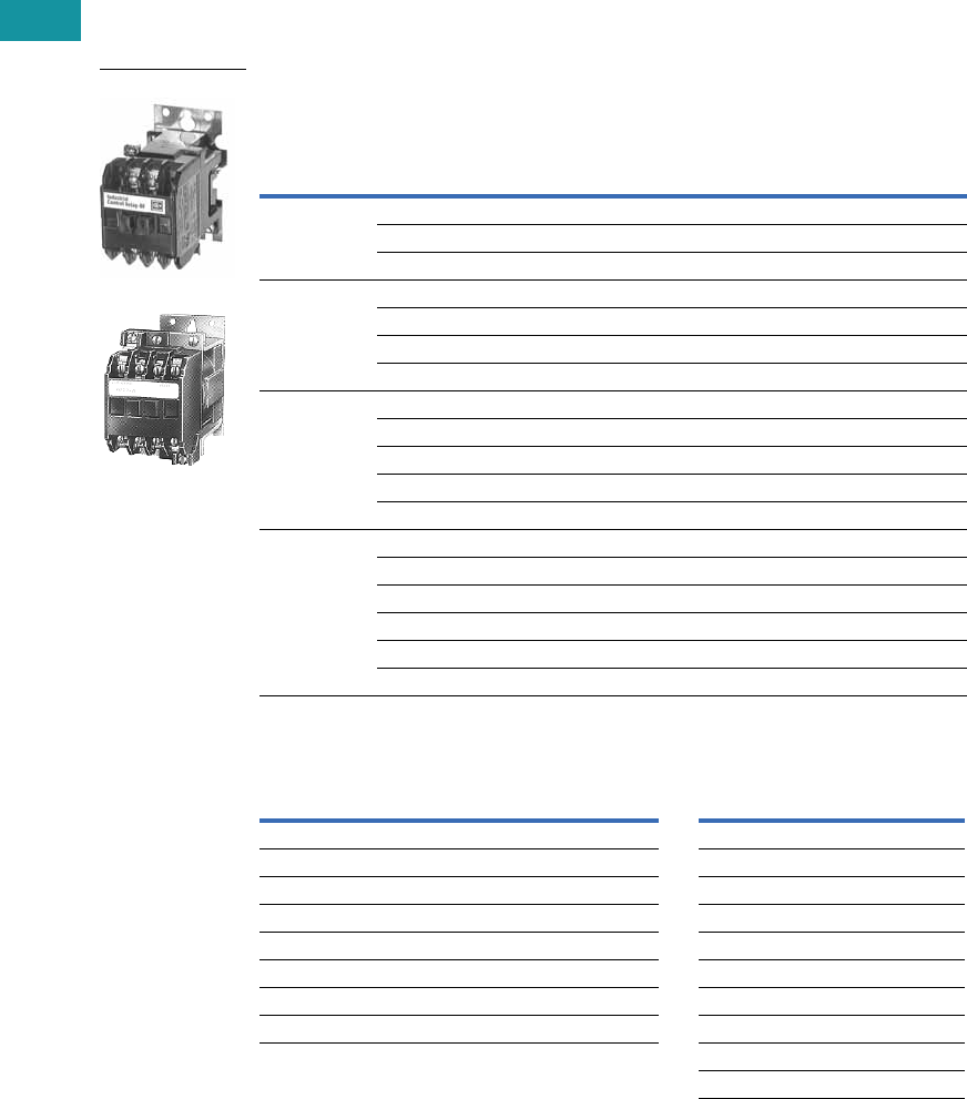
V7-T3-152 Volume 7—Logic Control, Operator Interface and Connectivity Solutions CA08100008E—June 2013 www.eaton.com
3
3
3
3
3
3
3
3
3
3
3
3
3
3
3
3
3
3
3
3
3
3
3
3
3
3
3
3
3
3
3.7
Control Relays and Timers
Machine Tool Relays
Product Selection
When Ordering, Specify
●Catalog number of basic relay
●If a coil voltage other than listed is required, select the suffix code from the Coil Voltage table and
substitute it for the last letter in the catalog number. Example: BF80V for a 110/60 AC coil
Complete Relay—Type BF and BFD, Two-, Three-, Four- and Six-Pole 1
Coil Voltage
Notes
1 Relays listed above with equal number of NO and NC contact poles are specially priced—1NO and 1NC pole
are supplied at no additional charge.
2 Consult Customer Support Center for availability.
Number
of Poles
Type of Contact
BF 300 Vac Basic Relays
120/60, 110/50 AC Coil
BFD 250 Vdc Basic
Relays
120 DC Coil
NO (Form A) NC (Form B)
Catalog
Number
Catalog
Number
220BF20F BFD20S
11BF11F BFD11S
02BF02F BFD02S
330BF30F BFD30S
21BF21F BFD21S 2
12BF12F BFD12S
03BF03F BFD03S
440BF40F BFD40S
31BF31F BFD31S
22BF22F BFD22S
13BF13F BFD13S
04BF04F BFD04S
660BF60F BFD60S
51BF51F BFD51S
42BF42F BFD42S
33BF33F BFD33S
24BF24F BFD24S
06BF06F BFD06S
BF Coils BFD Coils
Volts AC Hz Suffix Code Volts DC Suffix Code
12 60 H6C
24 60 I12 D
48 60 J24 L
110 60 V38 N
110/120 50/60 F48 M
208 60 K72 E
220/240 50/60 G95 B
440 60 C120 S
130 U
240 T
Type BF
Type BFD
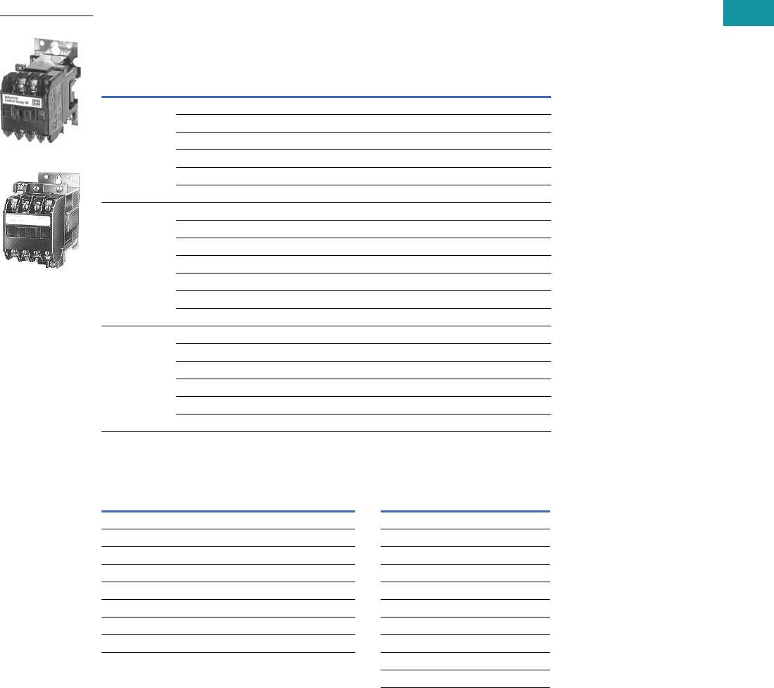
Volume 7—Logic Control, Operator Interface and Connectivity Solutions CA08100008E—June 2013 www.eaton.com V7-T3-153
3
3
3
3
3
3
3
3
3
3
3
3
3
3
3
3
3
3
3
3
3
3
3
3
3
3
3
3
3
3
3.7
Control Relays and Timers
Machine Tool Relays
When Ordering, Specify
●Catalog number of basic relay
●If a coil voltage other than listed is required, select the suffix code from the Coil Voltage table and
substitute it for the last letter in the catalog number. Example: BF80V for a 110/60 AC coil
Complete Relay—Type BF and BFD, Eight-, 10- and 12-Pole 1
Coil Voltage
Notes
1 Relays listed above with equal number of NO and NC contact poles are specially priced—1NO and 1NC pole
are supplied at no additional charge.
2 Consult Customer Support Center for availability.
Number
of Poles
Type of Contact
BF 300 Vac Basic Relays
120/60, 110/50 AC Coil
BFD 250 Vdc Basic
Relays
120 DC Coil
NO (Form A) NC (Form B)
Catalog
Number
Catalog
Number
88 0 BF80F BFD80S
71BF71F BFD71S
62BF62F BFD62S
53BF53F BFD53S
44BF44F BFD44S
08BF08F BFD08S
10 10 0 BF100F BFD100S
82BF82F BFD82S 2
73BF73F 2BFD73S
64BF64F BFD64S
55BF55F BFD55S 2
46BF46F BFD46S
28BF28F BFD28S
12 12 0 BF120F BFD120S
84BF84F BFD84S
75BF75F BFD75S
66BF66F BFD66S
57BF57F BFD57S
48BF48F BFD48S
BF Coils BFD Coils
Volts AC Hz Suffix Code Volts DC Suffix Code
12 60 H6C
24 60 I12 D
48 60 J24 L
110 60 V38 N
110/120 50/60 F48 M
208 60 K72 E
220/240 50/60 G95 B
440 60 C120 S
130 U
240 T
Type BF
Type BFD
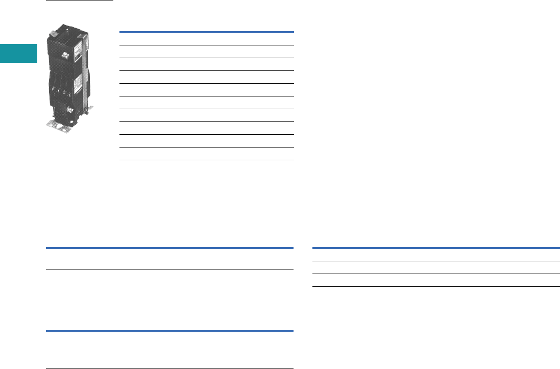
V7-T3-154 Volume 7—Logic Control, Operator Interface and Connectivity Solutions CA08100008E—June 2013 www.eaton.com
3
3
3
3
3
3
3
3
3
3
3
3
3
3
3
3
3
3
3
3
3
3
3
3
3
3
3
3
3
3
3.7
Control Relays and Timers
Machine Tool Relays
Permanent Magnet Latch
Options
FASTON Push-On Terminals
Overlapping Contacts
NEMA 1 Enclosure for Relay Types
Notes
1For panel mount, add Suffix F.
2Consult Customer Support Center for availability.
Coil
Volts Coil Hz
Catalog
Number
AC Relays
24 60 BFMLI 2
48 60 BFMLJ 2
110/120 50/60 BFMLF
220/240 50/60 BFMLG
DC Relays
24 — BFMLL
48 — BFMLM
120 — BFMLS
240 — BFMLT
Permanent Magnet
Latch, Relay Mounted
Description
Code
Letter
Catalog
Number
Insert letter F after relay type designation in listed catalog
number. Example: BFF20F or BFDF20S
F—
Description
Code
Letter
Catalog
Number
NO contact closes before corresponding NC contact opens—
supplied as NO/NC set(s). Insert letter A after relay
type designation in listed catalog number. Example: BFA22F
or BFDAF22S
A—
Description
Code
Letter
Catalog
Number
BF, AR—all poles — 4977D40G04
BFD—4–8 poles — 4977D40G04
ARD—4–8 poles — 4977D40G04

Volume 7—Logic Control, Operator Interface and Connectivity Solutions CA08100008E—June 2013 www.eaton.com V7-T3-155
3
3
3
3
3
3
3
3
3
3
3
3
3
3
3
3
3
3
3
3
3
3
3
3
3
3
3
3
3
3
3.7
Control Relays and Timers
Machine Tool Relays
Technical Data and Specifications
General Specifications
Permanent Magnet Latch Specifications
BF Relay Electrical Ratings—NEMA A300
Maximum Current Maximum VA
Volts Cont. Make Break Make Break
120 10 60 6 7200 720
240 10 30 3 7200 720
Horsepower Ratings (UL Recognized) DC Rating—NEMA P300
AC Volts Maximum Current Max. Make
or Break (VA)Phase 115 230 Volts Cont. Make Break
1 1/6 1/2 125 5.0 1.1 1.1 138
3 — 1 250 5.0 0.55 0.55 138
Resistive Rating
125 Vdc 3A
250 Vdc 1.5A
Coil Power Requirements
AC 72 VA open, 22 VA closed
DC 12 watts (nominal), 250V max.
Item Specification
Unlatching power requirements Open gap: 24 VA AC
Closed gap: 7 VA
Burden: 4 watts (AC)

V7-T3-156 Volume 7—Logic Control, Operator Interface and Connectivity Solutions CA08100008E—June 2013 www.eaton.com
3
3
3
3
3
3
3
3
3
3
3
3
3
3
3
3
3
3
3
3
3
3
3
3
3
3
3
3
3
3
3.7
Control Relays and Timers
Machine Tool Relays
Contact Arrangements—BF and BFD Relays
Note: NO = Normally Open NC = Normally Closed
Dimensions
Approximate Dimensions in Inches (mm)
BF Relay with Permanent
Magnet Latch and Solid-
State Timer
BFD Relay with Solid-State
Timer
BF and BFD Relay Dimensions
2 Poles 3 Poles 4 Poles
6 Poles
Rear
Front
Rear
Center
12 Poles
Rear
Center
Front Front
8 Poles
Rear
Front
10 Poles
A
BC
3.13
(79.5)
1.97
(50)
D
E
3.13
(79.5)
1.69
(42.9)
Number
of Poles
A
BF Only
B
BF w/Latch
C
BF w/Timer
D
BFD Only
E
BFD w/Timer
4 3.22 (81.8) 6.22 (158.0) 5.88 (149.4) 4.03 (102.4) 7.06 (179.3)
8 4.19 (106.4) 7.19 (182.6) 6.88 (174.8) 4.97 (126.2) 8.00 (203.2)
12 4.81 (122.2) 7.81 (198.4) 7.50 (190.5) 5.63 (143.0) 8.66 (220.0)
Enclosures—NEMA 1 for BF, BFD, AR and ARD
NEMA 1 for BF, BFD, AR and ARD Dimensions
Poles
Catalog
Number
A
NEMA 1
Relays without Attachments
All BF, AR, ARD 5.34 (135.6)
4 – 8 BFD 5.34 (135.6)
10, 12 BFD 7.97 (202.4)
Relays with Attachments
All BF, AR, ARD 7.97 (202.4)
5.66
(143.8)
3.38 (85.9)
2.83
(71.9)
1.72
(43.7)
0.25 (6.4) Dia.
Mtg. Holes (3)
0.19 (4.8)
A
1.69 (42.9) 0.38 x 0.5
(9.7 x 12.7)
Conduit
(2 Top, 2 Bottom)
6.59
(167.4) 4.5
(114.3) 0.63
(16)
1.05
(26.7)
KO KO KO
KO KO KO
KO
KO
1.72
(43.7)
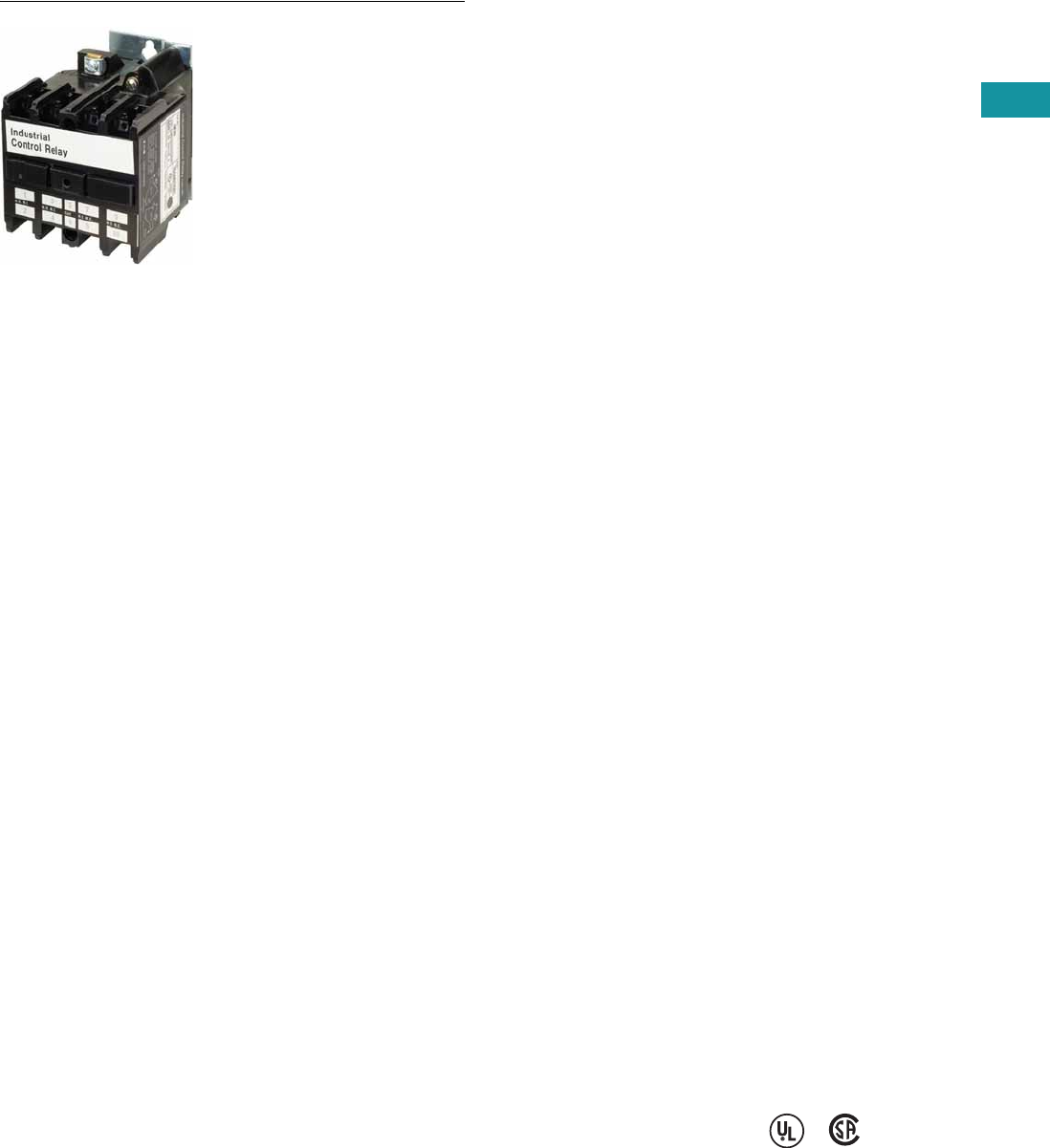
Volume 7—Logic Control, Operator Interface and Connectivity Solutions CA08100008E—June 2013 www.eaton.com V7-T3-157
3
3
3
3
3
3
3
3
3
3
3
3
3
3
3
3
3
3
3
3
3
3
3
3
3
3
3
3
3
3
3.7
Control Relays and Timers
Machine Tool Relays
AR/ARD Series—Convertible Contact Industrial Control
Contents
Description Page
D15 Series—Freedom 600V Multipole. . . . . . . . . . V7-T3-146
BF/BFD Series—Fixed Contact Industrial
Control . . . . . . . . . . . . . . . . . . . . . . . . . . . . . . . . . V7-T3-151
AR/ARD Series—Convertible Contact
Industrial Control
Product Selection . . . . . . . . . . . . . . . . . . . . . . . V7-T3-158
Accessories . . . . . . . . . . . . . . . . . . . . . . . . . . . V7-T3-159
Options . . . . . . . . . . . . . . . . . . . . . . . . . . . . . . . V7-T3-159
Technical Data and Specifications . . . . . . . . . . V7-T3-160
Dimensions . . . . . . . . . . . . . . . . . . . . . . . . . . . V7-T3-161
D26 Series—Type M, 600 Vac Multipole
with Convertible Contacts . . . . . . . . . . . . . . . . . . V7-T3-162
D26 Series—Type M, DC Multipole
with Convertible Contacts . . . . . . . . . . . . . . . . . . V7-T3-167
AR/ARD Series—Convertible Contact Industrial Control
Product Description
The AR/ARD relays are
electromechanical convertible
contact relays. AR relays are
AC devices and the ARD is
for DC applications.
Application Description
Type AR and ARD relays are
designed for use on machine
tools, process lines,
conveyors and similar
automatic and semi-
automatic equipment.
Features and Benefits
Permanent Magnet Latch
By energizing the relay coil,
the latch attachment “sets”
(when the base relay’s
armature/crossbar assembly
has closed) holding the relay
ON, even after the relay coil
has been de-energized. The
clearing coil on the latch is
energized to release the
armature/crossbar assembly.
●Field mountable to four-
and six-pole
●Latch plunger is adjustable
●Latch coil continuously
rated
●Unlatching power
requirements
●Open gap: 24 VA
●Closed gap: 7 VA
●Burden: 4 watts AC, 6
watts DC
Surge Suppressor
●Mounts in contact cavity of
AR relays
●Limits high transient
voltages resulting from de-
energizing relay coil or
other electromechanical
devices
●Protects sensitive
instruments and solid-state
devices
●120 Vac maximum, not
used on Vdc
●For noise suppression, see
Catalog Number SS-56
starter mounted surge
suppressor.
Operation
AR relays are available in
either
four- or six-pole
configurations.
AR relays are
easily converted
to eight- or
10-poles simply by adding a
four-pole deck. In addition,
mechanical latch attachments
are available with four- and
six-pole relays.
Contacts are convertible from
NO to NC, to provide any
combination desired up to a
maximum of 10. For the ARD,
the number of poles cannot
exceed four NC in any pole
configuration. Wide spacing
of contacts simplifies
installation, contact testing and
maintenance. Contacts are
electrically and mechanically
isolated from each other.
Overlap contacts are also
available in one or two sets.
These contacts should be
mounted in the center pole
positions. AC and DC contact
cartridges should not be used
in the same relay.
Standards and Certifications
●UL File No. E19223
●CSA File No. LR39402-6,
LR54517 and LR54520
Reference Information
●ART, ARTD: IL 14510,
IL 14485
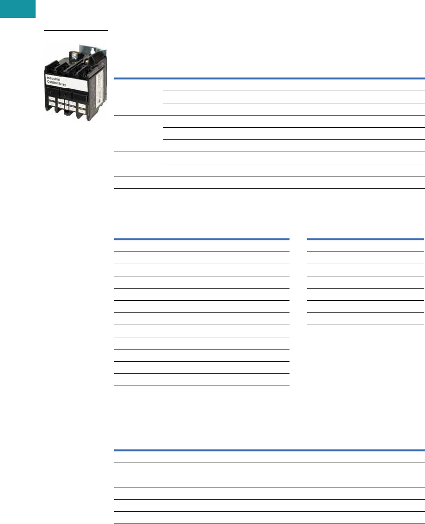
V7-T3-158 Volume 7—Logic Control, Operator Interface and Connectivity Solutions CA08100008E—June 2013 www.eaton.com
3
3
3
3
3
3
3
3
3
3
3
3
3
3
3
3
3
3
3
3
3
3
3
3
3
3
3
3
3
3
3.7
Control Relays and Timers
Machine Tool Relays
Product Selection
When Ordering, Specify
●Catalog number of basic relay with 120/60, 110/50 AC coil from AR/ARD Relays table.
●If a coil voltage other than listed is required, select the suffix code from the Coil Voltage table below
and substitute it for the last letter in the catalog number. Example: AR64V for a 110/60 AC coil.
AR/ARD Relays
Coil Voltage
Contact Cartridges—600V
Notes
1 Will not accept top-mounted latch or timers.
2 Contact Customer Support Center for availability.
3 Standard cartridges are sold in cartons of four cartridges. Catalog number is for single cartridge.
4 Overlap contact cartridges are sold in sets of two cartridges. Catalog number is for sets of two.
Number
of Poles
Contact
AR 600 Vac Relays
120/60, 110/50 AC Coil
ARD 600 Vdc Relays
120 DC Coil
NO NC
Blank
Cavities
Catalog
Number
Catalog
Number
4 004AR4A ARD4S
202AR420A ARD420S
400AR440A ARD440S
6 006AR6A ARD6S
402AR640A —
600AR660A ARD660S
8 1602AR860A ARD860S 2
800AR880A ARD880S
10 110 0 0 AR10100A ARD10100S
AR Coils ARD Coils
Volts AC Hz Suffix Code Volts DC Suffix Code
12 60 F12 D
24 60 I24 L
48 60 G48 M
110 60 V95 B
110/120 50/60 A120 S
208 60 B130 U
220/240 50/60 W240 T
277 60 C
380/440 50/60 H
440/480 50/60 X
550 60 D
550/600 50/60 E
Terminal
Type
Standard Contact
Cartridge
Overlap Contact
Cartridge
Catalog
Number 3
Catalog
Number 4
AC Cartridges
With clamp terminals ARC AROC
With screw terminals ARCR AROCR
DC Cartridges
With clamp terminals ARDC ARDOC
With screw terminals ARDCR ARDOCR
AR/ARD Relays
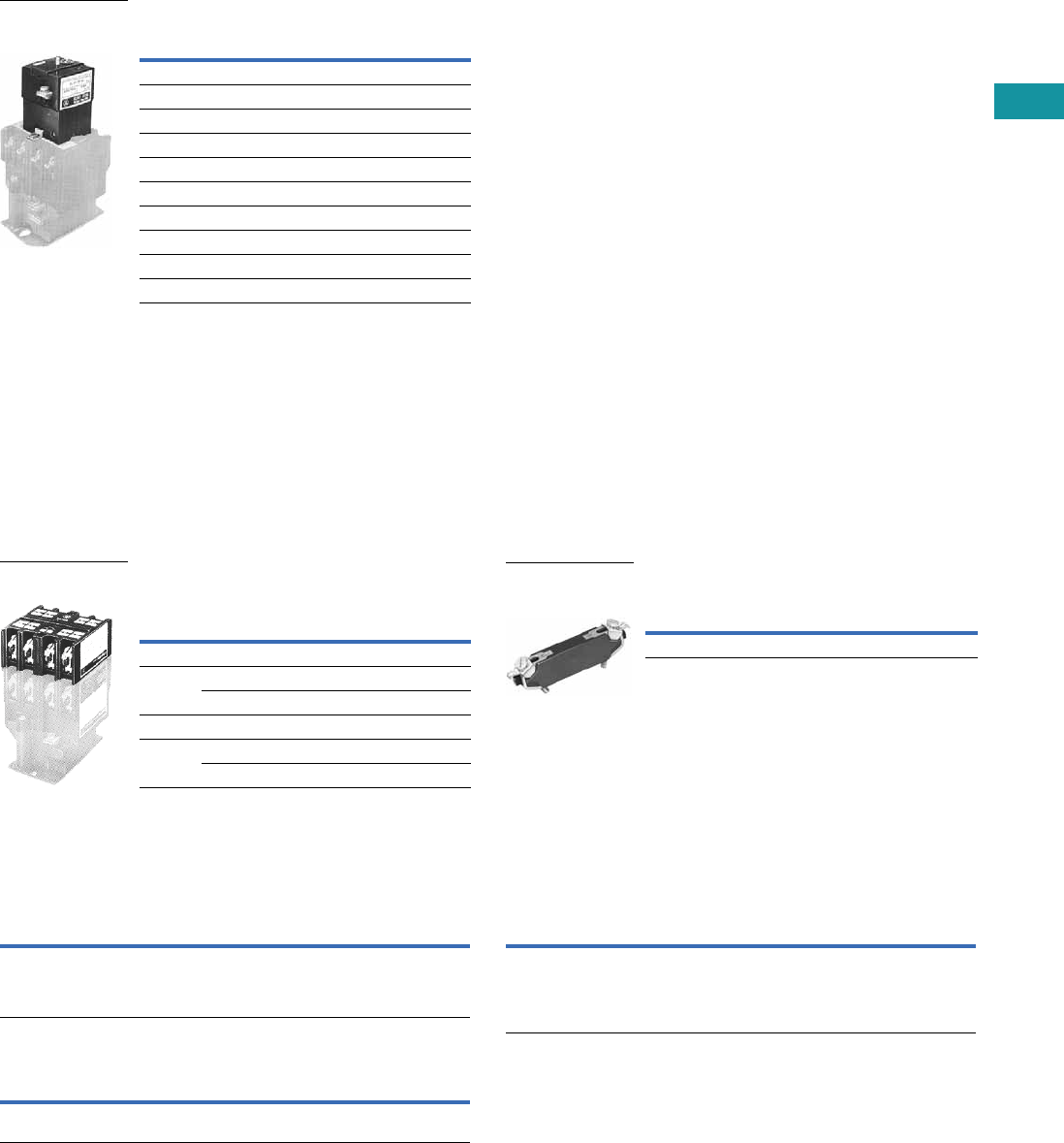
Volume 7—Logic Control, Operator Interface and Connectivity Solutions CA08100008E—June 2013 www.eaton.com V7-T3-159
3
3
3
3
3
3
3
3
3
3
3
3
3
3
3
3
3
3
3
3
3
3
3
3
3
3
3
3
3
3
3.7
Control Relays and Timers
Machine Tool Relays
Permanent Magnet Latch
Accessories
Four-Pole Top Deck Adder
●
Increases contact capacity from four/six-poles to eight/10-poles
●Mounts on top of basic relay using three screws
●Will not interfere with wiring, testing or convertible cartridges
●Screw terminals for ring connectors available; to order, add
Suffix R to catalog number listed below
Four-Pole Top Deck Adder Surge Suppressor
Options
Convertible Contacts
Screw Terminals
Overlapping Contacts
Note
1Consult Customer Support Center for availability.
Operating
Volts Coil Hz
Catalog
Number
For AC Control Circuits
24 60 ARMLI
48 60 ARMLG
120 60/50 ARMLA
240 60/50 ARMLW
For DC Control Circuits
24 — ARMLL
48 — ARMLM
120 — ARMLS
240 — ARMLT
ARML Permanent
Magnet Latch for
AR/ARD Relays
No. of
Poles
Contacts
Catalog
Number NO NC
Blank
Cavities
With 600 Vac Cartridges
4 202 ARA20
400 ARA40
With 600 Vdc Cartridges
4 202 ARDA20
400 ARDA40
Four-Pole Top
Deck Adder
Catalog
Number
Surge Suppressor ARSS
ARSS Surge
Suppressor for
AR Relays
Description
Code
Letter
Catalog
Number
AR and ARD relays listed are supplied with NO contacts that
are easily converted to NC. If both NO and NC poles are
required, order by catalog number. Example: four-pole relay
with 1NO and 3NC contacts, order AR413A.
1—
Description
Code
Letter
Catalog
Number
For ring-type connectors, add suffix R to the catalog number.
Example: AR420AR.
R—
Description
Code
Letter
Catalog
Number
NO contact closes before corresponding NC contact opens —
supplied as NO/NC sets of two cartridges. Insert letter S after
relay type designation in listed catalog number. Example:
AR402AS. Specify the number of sets required: S for one set
and S2 for two sets.
S or
S2 1
—

V7-T3-160 Volume 7—Logic Control, Operator Interface and Connectivity Solutions CA08100008E—June 2013 www.eaton.com
3
3
3
3
3
3
3
3
3
3
3
3
3
3
3
3
3
3
3
3
3
3
3
3
3
3
3
3
3
3
3.7
Control Relays and Timers
Machine Tool Relays
Technical Data and Specifications
General
Contact Ratings—600 Vac Cartridge NEMA A600
Maximum Current Maximum VA
Volts Cont. Make Break Make Break
120 10 60 6 7200 720
240 10 30 3 7200 720
480 10 15 1.5 7200 720
600 10 12 1.2 7200 720
DC Cartridges—NEMA P600
Maximum Current Maximum VA
Volts Continuous
Make or
Break
Make or
Break
125 5 1.10 138
250 5 0.55 138
600 5 0.20 138
Resistive Rating
125 Vdc 3A
250 Vdc 1.5A
Coil Power Requirements
AC 96 VA open, 14 VA closed
DC 14 watts open, 250V max.
Voltage AR Relays ARD Relays
Pickup voltage (max.) 85% 65%
Dropout voltage (min.) 60% 15%
Voltage (max.) 110% 110%
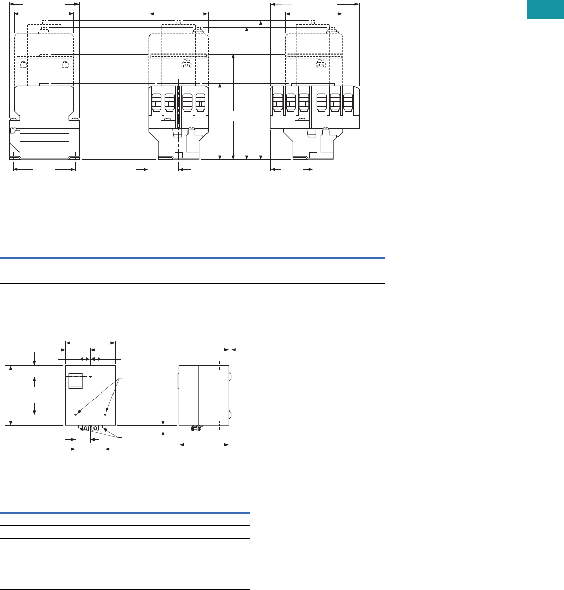
Volume 7—Logic Control, Operator Interface and Connectivity Solutions CA08100008E—June 2013 www.eaton.com V7-T3-161
3
3
3
3
3
3
3
3
3
3
3
3
3
3
3
3
3
3
3
3
3
3
3
3
3
3
3
3
3
3
3.7
Control Relays and Timers
Machine Tool Relays
Dimensions
Approximate Dimensions in Inches (mm)
Four- and Six-Pole with Four-Pole Adder, Solid-State Timer and Mechanical Latch
Four- and Six-Pole with Four-Pole Adder, Solid-State Timer and Mechanical Latch
Enclosures—NEMA 1 for BF, BFD, AR and ARD
Enclosures—NEMA 1 for BF, BFD, AR and ARD
Relay
Catalog
Number
A
Four-, Six-Pole Relays
B
Relay Adder
C
Relay with Timer
D
Relay with Latch
AR 3.56 (90.4) 4.94 (125.5) 6.00 (152.4) 6.39 (162.3)
ARD 4.63 (117.6) 6.00 (152.4) 7.06 (179.3) 7.45 (189.2)
Poles
Catalog
Number
Dimension A
NEMA 1
Relays without Attachments
All BF, AR, ARD 5.34 (135.6)
4–8 BFD 5.34 (135.6)
10, 12 BFD 7.97 (202.4)
Relays with Attachments
All BF, AR, ARD 7.97 (202.4)
A
Base Relay
Adder Deck
S.S. Timer
Latch
B
C
D
1.44 (36.6)
End View, 4- and 6-Pole Side View, 4-Pole Side View, 6-Pole
3.13
(79.5)
2.75 (69.9) 2.88 (73.2)
3.44 (87.4)
2.88 (73.2)
4.09 (103.9)
2.05
(52.1) C
L
C
L
C
L of Mounting Slots
(2) for 0.164 Screws
of Mounting Slots
(2) for 0.164 Screws
of Mounting Slots
(2) for 0.164 Screws
5.66
(143.8)
3.38 (85.9)
2.83
(71.9)
1.72
(43.7)
0.25 (6.4) Dia.
Mtg. Holes (3)
0.19 (4.8)
A
1.69 (42.9) 0.38 x 0.5
(9.7 x 12.7)
Conduit
(2 Top, 2 Bottom)
6.59
(167.4) 4.5
(114.3) 0.63
(16)
1.05
(26.7)
KO KO KO
KO KO KO
KO
KO
1.72
(43.7)

V7-T3-162 Volume 7—Logic Control, Operator Interface and Connectivity Solutions CA08100008E—June 2013 www.eaton.com
3
3
3
3
3
3
3
3
3
3
3
3
3
3
3
3
3
3
3
3
3
3
3
3
3
3
3
3
3
3
3.7
Control Relays and Timers
Machine Tool Relays
D26 Series—Type M, 600 Vac Multipole with Convertible Contacts
Contents
Description Page
D15 Series—Freedom 600V Multipole. . . . . . . . . . V7-T3-146
BF/BFD Series—Fixed Contact Industrial
Control. . . . . . . . . . . . . . . . . . . . . . . . . . . . . . . . . V7-T3-151
AR/ARD Series—Convertible Contact
Industrial Control . . . . . . . . . . . . . . . . . . . . . . . . . V7-T3-157
D26 Series—Type M, 600 Vac Multipole
with Convertible Contacts
Product Selection . . . . . . . . . . . . . . . . . . . . . . . V7-T3-163
Technical Data and Specifications . . . . . . . . . . V7-T3-165
Dimensions . . . . . . . . . . . . . . . . . . . . . . . . . . . V7-T3-166
D26 Series—Type M, DC Multipole
with Convertible Contacts . . . . . . . . . . . . . . . . . V7-T3-167
D26 Series—Type M, 600 Vac Multipole with Convertible Contacts
Product Description
Relays can be ordered as
complete devices in any pole
combination up to a
maximum of 12NO or 8NC
and 4NO poles, or can be
assembled from components
shown on Page V7-T3-164.
Relay base assembly
(D26MB) will accept from 1
to 4 rear poles (D26MPR,
D26MPS and/or D26MPL).
Features
Contact poles D26MPR and
D26MPF in 2- through 8-pole
relays are convertible NO to
NC or vice versa. Simply
reverse the terminal screws
and rotate the unit pole 180°
(in either direction).
Options
Adding a front deck, the total
number of poles can be
increased to 8, all convertible
NO to NC.
Adding a D26MF, 4-pole fixed
NO attachment, builds a 12-
pole relay with 8 convertible
poles and 4 fixed NO poles.
Relays with mechanical latch
are available in any
convertible pole combination
up to eight poles maximum.
To obtain overlapping
contacts, use D26MPS (NO
early closing) and D26MPL
(NC late opening) rear poles,
in related circuits.
Standards and Certifications
●UL listed—Class No.
NKCR2, File E1230(N)
●CSA certified—File LR353
Normally Closed
Contact
Normally Open
Contact

Volume 7—Logic Control, Operator Interface and Connectivity Solutions CA08100008E—June 2013 www.eaton.com V7-T3-163
3
3
3
3
3
3
3
3
3
3
3
3
3
3
3
3
3
3
3
3
3
3
3
3
3
3
3
3
3
3
3.7
Control Relays and Timers
Machine Tool Relays
Product Selection
Complete AC Relays
When Ordering, Specify
●Catalog number and magnet coil suffix letter.
●Example: For a 4-pole relay having 4NO contacts, order Catalog Number D26MR40, with a 120V,
60 Hz coil, order D26MR40A.
●For fast delivery and minimum inventory, it is recommended that component parts or complete
relays with NO poles be ordered.
Complete AC Relays—Open Type
Magnet Coil Selection
Notes
1 10- and 12-Poles: The 6 and 8 contact relays (without mechanical latch only) listed above can be provided
with four additional NO non-convertible contacts. Add suffix number 4 to above listed catalog number plus
magnet coil suffix. Example: For a 12 contact relay, order D26MR804A.
2 Consult Customer Support Center for availability.
Number
of Contacts
Type of Contact Relay Only
Relay with
Mechanical Latch
NO (Form A) NC (Form B)
Catalog
Number
Catalog
Number
220D26MR20 D26MR202
11D26MR11 D26MR112
02D26MR02 D26MR022
330D26MR30 D26MR302
21D26MR21 D26MR212
12D26MR12 D26MR122
03D26MR03 D26MR032
440D26MR40 D26MR402
31D26MR31 D26MR312
22D26MR22 D26MR222
13D26MR13 D26MR132
04D26MR04 D26MR042
6 160D26MR60 D26MR602
51D26MR51 D26MR512
42D26MR42 D26MR422
33D26MR33 D26MR332
24D26MR24 D26MR242
15D26MR15 D26MR152
06D26MR06 D26MR062
8 180D26MR80 D26MR802
71D26MR71 D26MR712
62D26MR62 D26MR622
53D26MR53 D26MR532
44D26MR44 D26MR442
35D26MR35 D26MR352
26D26MR26 D26MR262
17D26MR17 D26MR172
08D26MR08 D26MR082
Volts/Hertz Suffix Code Volts/Hertz Suffix Code
120/60–110/50 A32/60 2V
240/60–220/50 B12/60 2R
208/60 2E6/60 P
24/60 T380/50 2L
277/60 H480/60 or 440/50 C
600/60 or 550/50 2D
4-Pole
4-Pole with Latch
4-Pole with Pneumatic
Timer Attachment
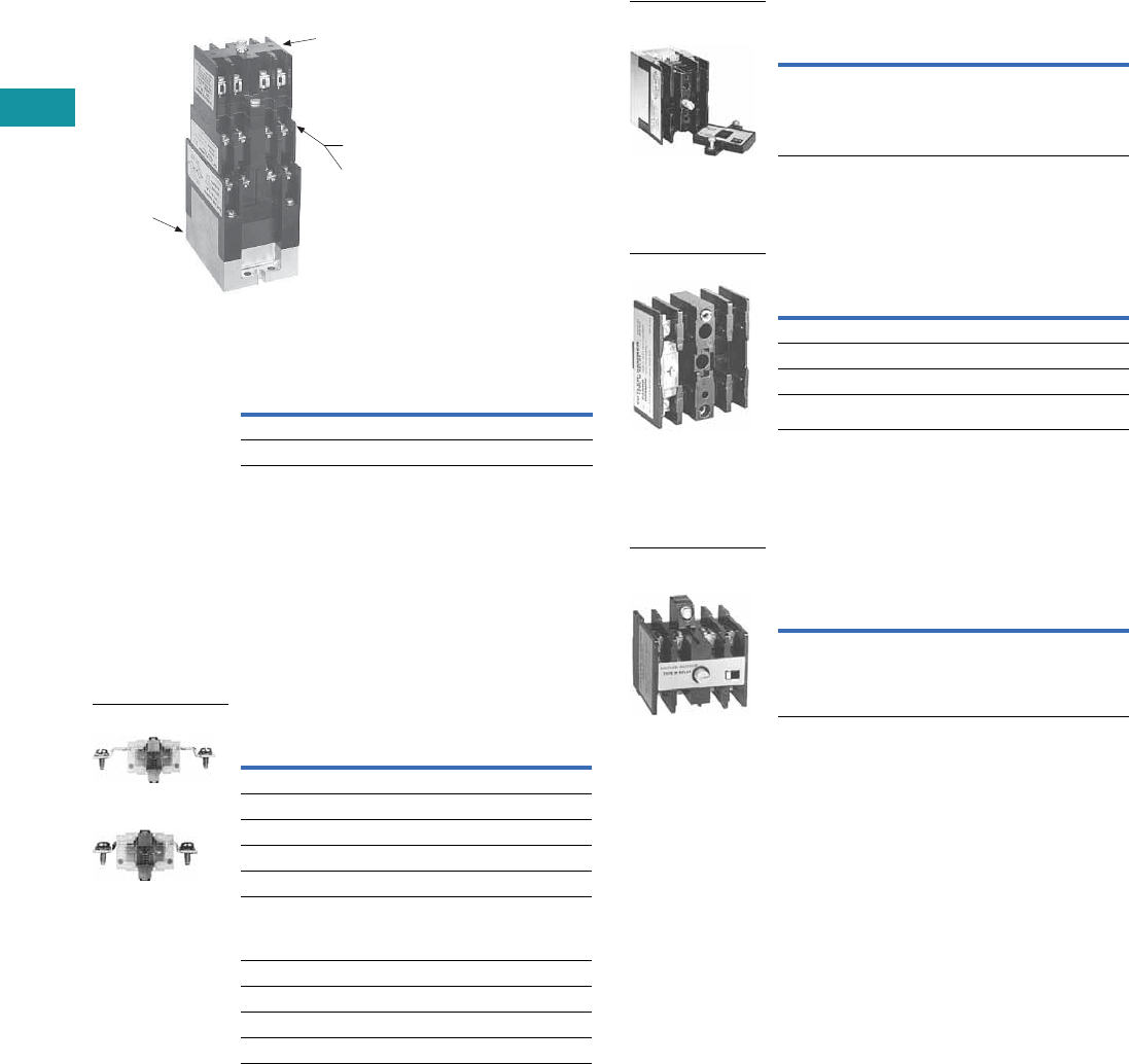
V7-T3-164 Volume 7—Logic Control, Operator Interface and Connectivity Solutions CA08100008E—June 2013 www.eaton.com
3
3
3
3
3
3
3
3
3
3
3
3
3
3
3
3
3
3
3
3
3
3
3
3
3
3
3
3
3
3
3.7
Control Relays and Timers
Machine Tool Relays
Relay Component Parts Location
Relay with Pneumatic Timer Attachment
Factory Installed (without Relay Contacts)
The relays listed above will
accept up to four catalog
number D26MPR contacts
(convertible—NO or NC) for
instantaneous operation.
Order contacts separately.
For additional information
on timer attachment, see
Page V7-T3-165.
For assembly of relays from
component parts and relay
accessories, see components
tables below.
Separate Contacts
Contact
Positions 1
Timer
Operation
Catalog
Number 2
4ON delayD26MR005
4 OFF delay D26MR006
D26MB
Relay Base
Assembly
D26MF
Front Attachment
Timer Attachments or
Mechanical Latch
D26MD10
Front Deck
Pneumatic Timer or
Mechanical Latch
D26MF
Front Attachment
Description
Catalog
Number
Convertible Contacts
Rear pole—NO D26MPR
Rear pole—NC D26MPR02
Front pole—NO D26MPF
Front pole—NC D26MPF02
Gold plated
(for low power circuits)
Rear pole—NO D26MPR03
Front pole—NO D26MPF03
Non-Convertible Contacts
Rear pole NO early closing 3D26MPS
Rear pole NC late opening 3D26MPL
Rear Pole
Front Pole
Relay Base Assembly (without Poles)
Basic four-pole D26 relay
without contacts. Provision
for adding one to four poles
as needed, D26MPR,
D26MPL and/or D26MPS
rear pole type.
Front Deck (Convertible Contact Poles)
Provides up to four additional
front pole type D26MPF
contacts. Convertible, NO
to NC.
Four-Pole Front Attachment
(4NO Fixed Circuit)
Can be added to any two- to
eight-pole Type M, D26 relay
to provide up to a 12-pole
relay. Four NO, non-
convertible contacts are
included in this assembly.
Notes
1Number of available instantaneous contact positions (order contacts
separately—Catalog Number D26MPR).
2Consult Customer Support Center for availability.
3To obtain overlapping contacts, these two special poles must be used in related circuits.
4Add magnet coil suffix letter, see Page V7-T3-163. Example: D26MBA.
Description
Catalog
Number
Relay base assembly D26MB 4
Relay Base
Assembly
Description
Catalog
Number
Front Deck with …
1NO contact pole D26MD10
2NO contact poles D26MD20
4NO contact poles D26MD40
Rear Pole
Description
Catalog
Number
Front attachment D26MF
Four-Pole Front
Attachment
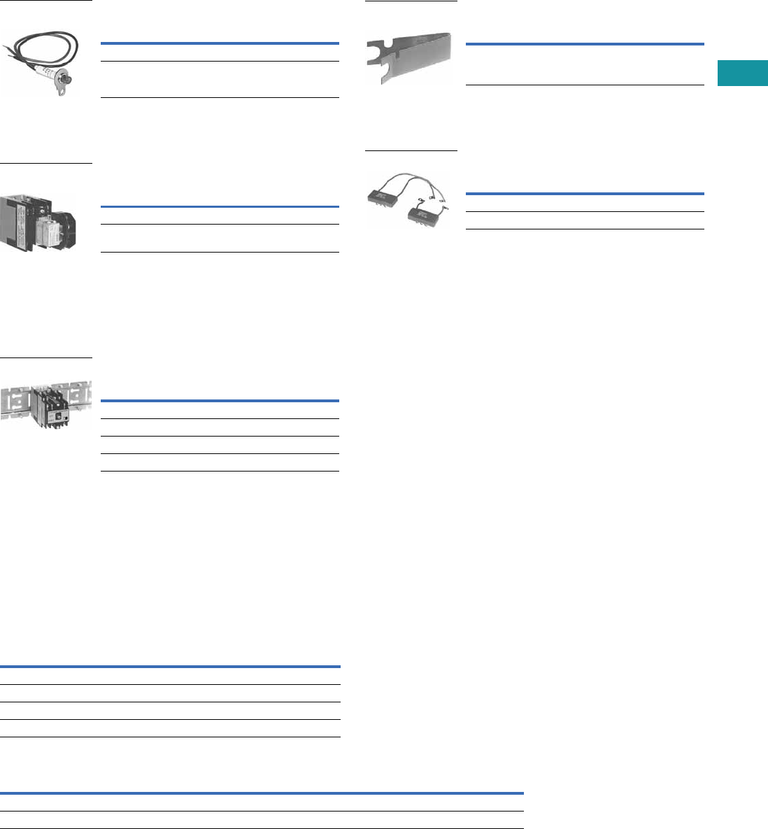
Volume 7—Logic Control, Operator Interface and Connectivity Solutions CA08100008E—June 2013 www.eaton.com V7-T3-165
3
3
3
3
3
3
3
3
3
3
3
3
3
3
3
3
3
3
3
3
3
3
3
3
3
3
3
3
3
3
3.7
Control Relays and Timers
Machine Tool Relays
Relay State Indicating Light
Light provided with leads and
bracket for mounting on two-
to 12-pole relays. May be
used to monitor state
of magnet coil or relay
contact operation.
Pneumatic Timer Attachment
Attachment mounts on any 0-
to four-pole D26 relay without
latch. Timer unit has DPDT
timed contacts (circuits in
each pole must be the same
polarity). Adjustable timing
range—0.1 to 180 seconds,
repeat accuracy ±10%.
Units are convertible from
OFF delay to ON delay or
vice versa.
Mounting Channel
Pre-spaced mounting for
adjacent relay installation.
Indexed for cutting to desired
length. Captive mounting
screws provided in channel
for easier installation.
Technical Data and Specifications
General
Note
1For DC contact ratings, see Page V7-T3-169.
Description
Catalog
Number
120 Vac, 50/60 Hz D26MAP120
240 Vac, 50/60 Hz D26MAP240
Relay State
Indicating Light
Description
Catalog
Number
ON delay D26MTE
OFF delay D26MTD
Pneumatic Timer
Attachment
Description
Catalog
Number
10 in length for 4 relays D26MC4
20 in length for 8 relays D26MC8
30 in length for 12 relays D26MC12
40 in length for 16 relays D26MC16
Mounting Channel
Contact Ratings (Amperes) A600
AC Volts 1
Make and
Emergency
Interrupting
Capacity Break
Continuous
Thermal Rating
120 60 6 10
240 30 3 10
480 15 1.5 10
600 12 1.2 10
Coil Power Operating Time
Watts VA Range in
MillisecondsRelay Inrush Sealed Inrush Sealed
Two- to 12-pole 95.0 9 155 22 Pickup: 6–13
Latch coil 18.5 11 41 17 Dropout: 8–26
Manual Test Accessory
Tool to manually hold relays
in the energized position for
circuitry testing on completed
panel. (10 per box, order in
multiples of 10.)
Transient Suppressor
May be mounted on any
120 Vac relay magnet coil
or latch coil or 120 Vdc latch
coil—connects directly across
coil terminals. All DC magnet
coils have a built-in varistor
for transient suppression.
Limits high voltage transients
produced in the circuit when
power is removed from the
coil.
Description
Catalog
Number
Manual test accessory D26MTA
Manual Test Accessory
Description
Catalog
Number
Magnet coil transient suppressor D26MAS1
Latch coil transient suppressor D26MAS2
Transient Suppressor
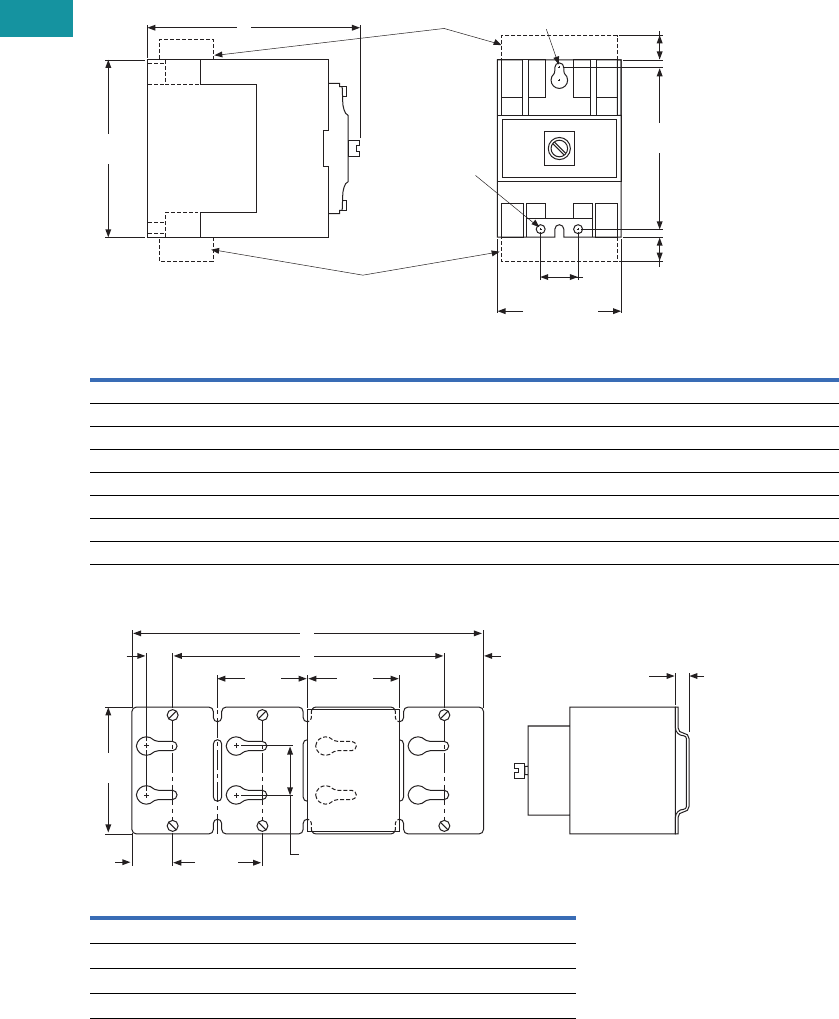
V7-T3-166 Volume 7—Logic Control, Operator Interface and Connectivity Solutions CA08100008E—June 2013 www.eaton.com
3
3
3
3
3
3
3
3
3
3
3
3
3
3
3
3
3
3
3
3
3
3
3
3
3
3
3
3
3
3
3.7
Control Relays and Timers
Machine Tool Relays
Dimensions
Approximate Dimensions in Inches (mm)
AC and DC D26 Relays
Mounting Channel
Note: Channel mounts through keyholes with #10 screws
(two each end and one every fourth relay). Relays mount with screws
captive in channel. All screws must be tightened firmly.
AC Relay
D26
DC Relay
D26 Dimension A
Ship. Wt.
Lbs (kg)
1–4 poles 1–3 poles 4.00 (101.6) 2.5 (1.1)
1–4 poles with timer D26 or D87 1–3 poles with timer D26 or D87 6.00 (152.4) 3.3 (1.5)
1–4 poles with latch 1–2 poles with latch 6.13 (155.7) 3.5 (1.6)
1–4 poles with d26mf 1–3 poles with D26MF 5.81 (147.6) 2.8 (1.3)
5–8 poles 4–7 poles 5.25 (133.4) 2.8 (1.3)
5–8 poles with timer D87 4–7 poles with timer D87 7.25 (184.2) 3.5 (1.6)
5–8 poles with latch 3–6 poles with latch 7.31 (185.7) 3.8 (1.7)
9–12 poles 8–11 poles 7.00 (177.8) 3.0 (1.4)
Catalog
Number Dimension A Dimension B
D26MC16 40 (1016) 37.5 (952.5)
D26MC12 30 (762) 27.5 (698.5)
D26MC8 20 (508) 17.5 (444.5)
D26MC4 10 (254) 7.5 (190.5)
2.38 (60.5)
Max.
D26MAS2
D26MAS1
0.75
(19.1)
3.13
(79.5)
0.44
(11.2)
0.44
(11.2)
3.50
(88.9)
A
1 Slot
#10 Screw
2 Holes
#10 Screw
2.50
(63.5)
2.50
(63.5)
2.38
(60.5)
B
0.69
(17.5)
1.06
(26.9)
A
1.25
(31.8)
3.63
(92.2)
1.38
(35.1)
0.38
(9.7)
Type
M
Relay
D26
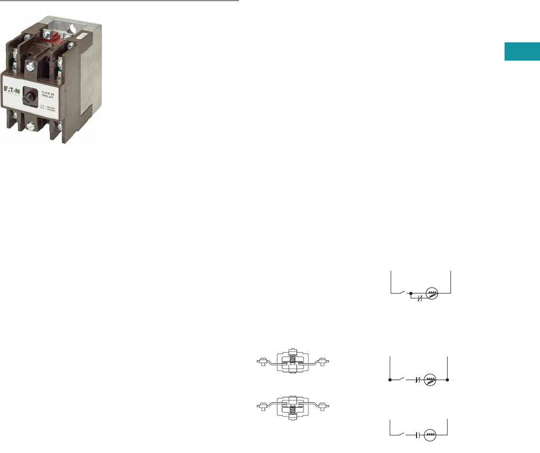
Volume 7—Logic Control, Operator Interface and Connectivity Solutions CA08100008E—June 2013 www.eaton.com V7-T3-167
3
3
3
3
3
3
3
3
3
3
3
3
3
3
3
3
3
3
3
3
3
3
3
3
3
3
3
3
3
3
3.7
Control Relays and Timers
Machine Tool Relays
D26 Series—Type M, DC Multipole with Convertible Contacts
Contents
Description Page
D15 Series—Freedom 600V Multipole. . . . . . . . . . V7-T3-146
BF/BFD Series—Fixed Contact Industrial
Control . . . . . . . . . . . . . . . . . . . . . . . . . . . . . . . . . V7-T3-151
AR/ARD Series—Convertible Contact
Industrial Control . . . . . . . . . . . . . . . . . . . . . . . . . V7-T3-157
D26 Series—Type M, 600 Vac Multipole
with Convertible Contacts . . . . . . . . . . . . . . . . . . V7-T3-162
D26 Series—Type M, DC Multipole
with Convertible Contacts
Product Selection . . . . . . . . . . . . . . . . . . . . . . . V7-T3-168
Technical Data and Specifications . . . . . . . . . . V7-T3-169
Dimensions . . . . . . . . . . . . . . . . . . . . . . . . . . . V7-T3-170
D26 Series—Type M, DC Multipole with Convertible Contacts
Product Description
Type M, DC multipole
relays are physically and
mechanically similar to
the (D26) Type M AC
relays described on Page
V7-T3-163. They differ only in
the electrical ratings and
available pole combinations
due to the use of a normally
closed late opening, coil
clearing contact, factory
wired to the pickup winding
of the magnet coil. (Contact is
shown as L in figure to the
right.) Magnet coil has built-in
varistor for transient
suppression.
The mechanically latched
relay has one extra contact,
normally open early closing,
factory wired in series with
the winding of the
intermittent rated latch coil.
(Contact is shown as S in
figure to the right.)
Component parts for
these relays are the same
as those listed for the (D26)
Type M AC relays on Page
V7-T3-163, except for the
Indicating Light, which is not
applicable to a DC relay.
Contact poles D26MPR and
D26MPF in 2- to 7-pole relays
are convertible NO to NC or
vice versa. Simply reverse the
terminal screws and rotate
the unit pole 180° (in either
direction).
Latch Operation
With the latch coil de-
energized, energizing the
relay coil will pick up the relay
and mechanically latch it in
the pickup position. With the
relay coil de-energized,
energizing the latch coil will
allow the relay to drop out.
Convertible Contacts
Normally Closed
Contact
Normally Open
Contact
LS1
LS1
LS1 L
S
DC Input
DC Input
DC Type M Relay
DC Type M Relay
with Latch
Pick-Up
Pick-Up
L = NC Late Opening
L = NC Late Opening
S = NO Early Closing
Relay
Coil
Latch
Coil
Hold
(Not Used)
Release
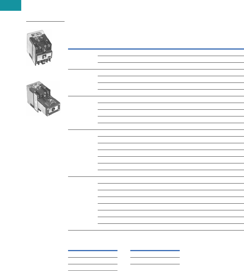
V7-T3-168 Volume 7—Logic Control, Operator Interface and Connectivity Solutions CA08100008E—June 2013 www.eaton.com
3
3
3
3
3
3
3
3
3
3
3
3
3
3
3
3
3
3
3
3
3
3
3
3
3
3
3
3
3
3
3.7
Control Relays and Timers
Machine Tool Relays
Product Selection
Complete DC Relays
When Ordering, Specify
●Catalog number and magnet coil suffix letter.
●Example: For a 4-pole relay having 4NO contacts, order Catalog Number D26MRD40, with a
120 Vdc coil, order D26MRD40A1.
Complete DC Relays—Open Type
Magnet Coil Selection
Notes
1 Relay has additional factory wired normally closed coil clearing contact (see diagram).
2 10- and 11-Poles: The 6 and 7 contact relays (without mechanical latch only) listed above can be provided with four
additional NO non-convertible contacts. Add suffix number 4 to above listed catalog number plus magnet coil suffix.
Example: For an 11 contact relay, order D26MRD704A1.
Number
of Contacts
Type of Contact 1Relay Only
Relay with
Mechanical Latch
NO (Form A) NC (Form B)
Catalog
Number
Catalog
Number
22 0 D26MRD20 D26MRD202
11D26MRD11 D26MRD112
02D26MRD02 D26MRD022
33 0 D26MRD30 D26MRD302
21D26MRD21 D26MRD212
12D26MRD12 D26MRD122
03D26MRD03 D26MRD032
44 0 D26MRD40 D26MRD402
31D26MRD31 D26MRD312
22D26MRD22 D26MRD222
13D26MRD13 D26MRD132
04D26MRD04 D26MRD042
6 260D26MRD60 D26MRD602
51D26MRD51 D26MRD512
42D26MRD42 D26MRD422
33D26MRD33 D26MRD332
24D26MRD24 D26MRD242
15D26MRD15 D26MRD152
06D26MRD06 D26MRD062
7 2 70D26MRD70 —
61D26MRD61 —
52D26MRD52 —
43D26MRD43 —
34D26MRD34 —
25D26MRD25 —
16D26MRD16 —
07D26MRD07 —
Volts/Hertz Suffix Code Volts/Hertz Suffix Code
12 R1 120 A1
24 T1 240 B1
48 W1
3-Pole
3-Pole with Latch
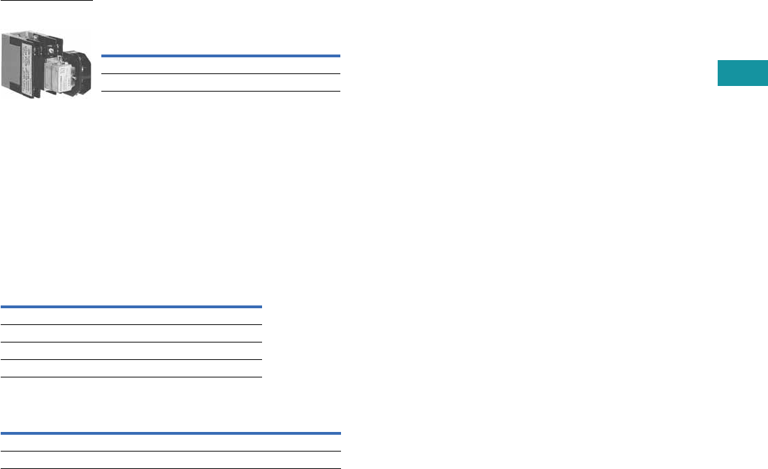
Volume 7—Logic Control, Operator Interface and Connectivity Solutions CA08100008E—June 2013 www.eaton.com V7-T3-169
3
3
3
3
3
3
3
3
3
3
3
3
3
3
3
3
3
3
3
3
3
3
3
3
3
3
3
3
3
3
3.7
Control Relays and Timers
Machine Tool Relays
Relay with Pneumatic Timer Attachment
(without Relay Contacts)
The relays listed above will
accept up to three catalog
number D26MPR contacts
(convertible—NO or NC) for
instantaneous operation.
Order contacts separately.
For additional information
on timer attachment, see
Page V7-T3-165.
Technical Data and Specifications
General
Notes
1Number of available instantaneous contact positions (order contacts
separately—Catalog Number D26MPR).
2Contact ratings do not apply to contacts D26MPL and D26MPS.
For AC contact ratings, see Page V7-T3-165.
Contact
Positions 1
Timer
Operation
Catalog
Number
3ON delayD26MRD005
3 OFF delay D26MRD006
3-Pole with Timer
Attachment
Contact Ratings (Amperes) 2
DC Volts
Inductive
Make/Break
Resistive
Make/Break
28 7.0 10.0
48 2.5 10.0
120 1.1 2.0
240 0.2 0.4
Coil Power Operating Time
Watts Average
MillisecondsRelay Inrush Sealed
Two- to 11-pole 168 13.2 Pickup: 10
Latch coil 21.6 intermittent 21.6 intermittent Dropout: 16
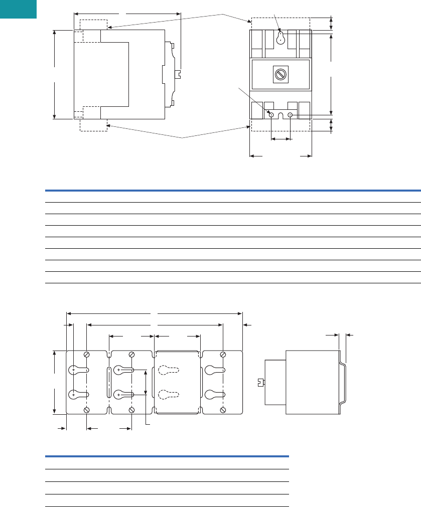
V7-T3-170 Volume 7—Logic Control, Operator Interface and Connectivity Solutions CA08100008E—June 2013 www.eaton.com
3
3
3
3
3
3
3
3
3
3
3
3
3
3
3
3
3
3
3
3
3
3
3
3
3
3
3
3
3
3
3.7
Control Relays and Timers
Machine Tool Relays
Dimensions
Approximate Dimensions in Inches (mm)
AC and DC D26 Relays
Mounting Channel
Note: Channel mounts through keyholes with #10 screws
(two each end and one every fourth relay). Relays mount with screws
captive in channel. All screws must be tightened firmly.
AC Relay
D26
DC Relay
D26 Dimension A
Ship. Wt.
Lbs (kg)
1–4 poles 1–3 poles 4.00 (101.6) 2.5 (1.1)
1–4 poles with timer D26 or D87 1–3 poles with timer D26 or D87 6.00 (152.4) 3.3 (1.5)
1–4 poles with latch 1–2 poles with latch 6.13 (155.7) 3.5 (1.6)
1–4 poles with D26MF 1–3 poles with D26MF 5.81 (147.6) 2.8 (1.3)
5–8 poles 4–7 poles 5.25 (133.4) 2.8 (1.3)
5–8 poles with timer D87 4–7 poles with timer D87 7.25 (184.2) 3.5 (1.6)
5–8 poles with latch 3–6 poles with latch 7.31 (185.7) 3.8 (1.7)
9–12 poles 8–11 poles 7.00 (177.8) 3.0 (1.4)
Catalog
Number Dimension A Dimension B
D26MC16 40 (1016) 37.5 (952.5)
D26MC12 30 (762) 27.5 (698.5)
D26MC8 20 (508) 17.5 (444.5)
D26MC4 10 (254) 7.5 (190.5)
2.38 (60.5)
Max.
D26MAS2
D26MAS1
0.75
(19.1)
3.13
(79.5)
0.44
(11.2)
0.44
(11.2)
3.50
(88.9)
A
1 Slot
#10 Screw
2 Holes
#10 Screw
2.50
(63.5)
2.50
(63.5)
2.38
(60.5)
B
0.69
(17.5)
1.06
(26.9)
A
1.25
(31.8)
3.63
(92.2)
1.38
(35.1)
0.38
(9.7)
Type
M
Relay
D26

Volume 7—Logic Control, Operator Interface and Connectivity Solutions CA08100008E—June 2013 www.eaton.com V7-T3-171
3
3
3
3
3
3
3
3
3
3
3
3
3
3
3
3
3
3
3
3
3
3
3
3
3
3
3
3
3
3
3.8
Control Relays and Timers
Ti m i n g R e l ay s
Timing Relays
Contents
Description Page
Timing Relays
Universal TR Series . . . . . . . . . . . . . . . . . . . . . V7-T3-176
TR Series . . . . . . . . . . . . . . . . . . . . . . . . . . . . . V7-T3-180
TMR5 Series . . . . . . . . . . . . . . . . . . . . . . . . . . . V7-T3-183
TMR6 Series . . . . . . . . . . . . . . . . . . . . . . . . . . . V7-T3-187
TMRP Series . . . . . . . . . . . . . . . . . . . . . . . . . . V7-T3-189
Product Selection Guide
Function Code Cross-Reference Guide
Notes
1Applies to TRN model only.
2Applies to TRF model only.
3The E5-248 is battery powered and has three programmable trigger functions.
This product may perform somewhat differently from the standard timing relays.
Refer to the operator instructions for details.
Timer Series
Function Description Universal TR TR TMR5 TMR6 TMRP E5-248 3
1 Asymmetrical flasher, pause first lp — R/P — — RC DLY
2 Asymmetrical flasher, pulse first li — Y — — RC
3 ON delay and OFF delay with control contact ER — ————
4 ON delay and single shot leading edge voltage controlled EWu — ————
5 ON delay and single shot leading edge control contact EWs — ————
6 Single shot leading and single shot trailing edge with control contact WsWa — ————
7 Pulse sequence monitoring Wt — ————
8 ON delay, power triggered E A 1N—A—
9 Single shot leading edge voltage controlled Wu B 1T—C—
10 OFF delay/signal OFF delay R E 2F — D OFF DLY
11 Single shot leading edge with control input Ws F 2C/G — H SS
12 Single shot trailing edge with control input Wa — ————
13 ON delay control signal start, trailing edge OFF Es — ————
14 Flasher, pause first Bp C 1L—B—
15 Retriggerable single shot — — W/D — E SS
16 Flasher, ON first — D 1——F —
17 ON delay control signal start, leading edge OFF — A 2———ON DLY
18 Flasher—control signal start, pause first — B 2— — — RC DLY
19 Flasher—control signal start, ON first — C 2———RC
20 Signal ON/OFF delay — D 2————
21 ON/OFF delay — — — — I —
22 Single pulse generator — — — — G OS
23 Memory latch — — — — J —
24 True OFF delay — — — X — —
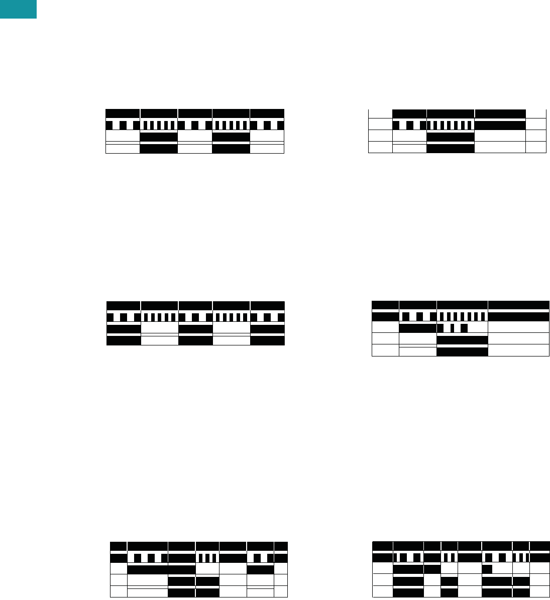
V7-T3-172 Volume 7—Logic Control, Operator Interface and Connectivity Solutions CA08100008E—June 2013 www.eaton.com
3
3
3
3
3
3
3
3
3
3
3
3
3
3
3
3
3
3
3
3
3
3
3
3
3
3
3
3
3
3
3.8
Control Relays and Timers
Ti m in g R el ay s
Product Overview
Timer Function Descriptions
Function #1—Universal TR, TMR5, E5-248
Asymmetrical Flasher, Pause First
Repeat Cycle, OFF/ON Delay
When the supply voltage U
is applied, the set interval t1
begins. After the interval t1
has expired, the output relay
R switches into ON position
and the set interval t2 begins.
After the interval t2 has
expired, the output relay
switches into OFF position.
The output relay is triggered
at the ratio of t1:t2 until the
supply voltage is interrupted.
Function #2—Universal TR, TMR5, E5-248
Asymmetrical Flasher, Pulse First
Repeat Cycle, ON/OFF Delay
When the supply voltage U
is applied, the output relay R
switches into the ON position
and the set interval t1 begins.
After the interval t1 has
expired, the output relay R
switches into OFF position
and the set interval t2 begins.
After the interval t2 has
expired, the output relay
switches into ON position.
The output relay is triggered
at the ratio of t1:t2 until the
supply voltage is interrupted.
Function #3—Universal TR
ON Delay and OFF Delay with Control Contact
The supply voltage U must
be constantly applied to the
device. When the control
contact S is closed, the set
interval t1 begins. After the
interval t1 has expired, the
output relay R switches into
ON position. If the control
contact is opened, the set
interval t2 begins. After the
interval t2 has expired, the
output relay R switches into
OFF position. If the control
contact is opened before the
interval t1 has expired, the
interval already expired is
erased and is restarted with
the next cycle.
Input Power (U)
LED U/t*
Output LED**
Output Relay (R)
t2t1 t1 t1t2
Input Power (U)
LED U/t*
Output LED**
Output Relay (R) t2t1 t1 t1t2
Input Power (U)
LED U/t*
Trigger Signal (S)
Output LED**
Output Relay (R) t1 <t1t2
Function #4—Universal TR
ON Delay and Single Shot Leading Edge Voltage Controlled
When the supply voltage U
is applied, the set interval t1
begins. After the interval t1
has expired, the output relay
R switches into ON position
and the set interval t2 begins.
After the interval t2 has
expired, the output relay
switches into OFF position. If
the supply voltage is
interrupted before the interval
t1 + t2 has expired, the
interval already expired is
erased and is restarted
when the supply voltage is
next applied.
Function #5—Universal TR
ON Delay and Single Shot Leading Edge Control Contact
The supply voltage U must
be constantly applied to the
device. When the control
contact S is closed, the set
interval t1 begins. After the
interval t1 has expired, the
output relay R switches into
ON position and the set
interval t2 begins. After the
interval t2 has expired, the
output relay R switches into
OFF position. During the
interval, the control contact is
ignored. A new cycle can only
be initiated when the cycle
has been completed.
Function #6—Universal TR
Single Shot Leading and Single Shot Trailing Edge
with Control Contact
Asymmetrical Signal ON/OFF Delay
The supply voltage U must
be constantly applied to the
device. When the control
contact S is closed, the
output relay R switches to
the ON position and the set
interval t1 begins. After the
interval t1 has expired, the
output relay R switches into
OFF position. If the control
contact S is opened, the
output relay again switches to
the ON position and the set
interval t2 begins. After the
interval t2 has expired, the
output relay R switches into
OFF position. During
the interval, the control
contact is ignored. During
the interval, the control
contact can be operated
any number of times.
Input Power (U)
LED U/t*
Output LED**
Output Relay (R) t1 t2
Input Power (U)
LED U/t*
Trigger Signal (S)
Output LED**
Output Relay (R) t1 t2
t2t2t1 t1
Input Power (U)
LED U/t*
Trigger Signal (S)
Output LED**
Output Relay (R)

Volume 7—Logic Control, Operator Interface and Connectivity Solutions CA08100008E—June 2013 www.eaton.com V7-T3-173
3
3
3
3
3
3
3
3
3
3
3
3
3
3
3
3
3
3
3
3
3
3
3
3
3
3
3
3
3
3
3.8
Control Relays and Timers
Ti m i n g R e l ay s
Function #7—Universal TR
Pulse Sequence Monitoring
When the supply voltage U
is applied, the set interval t1
begins and the output relay
R switches to the ON
position. After the interval
t1 has expired, the interval
t2 begins. As long as the
control switch S is closed
and opened within the
interval t2, the relay will
remain in the ON position.
If the control switch is not
closed and opened within
the interval t2, the relay
will change to the OFF
position until supply
voltage U is interrupted
and reapplied.
Function #8—Universal TR, TRN, TMR5, TMRP
ON Delay, Power Triggered
Delay ON Make
When the supply voltage U
is applied, the set interval t
begins. After the interval t
has expired, the output relay
R switches to the ON
position. The relay will remain
in that position until supply
voltage U is interrupted.
Function #9—Universal TR, TRN, TMR5, TMRP
Single Shot Leading Edge Voltage Controlled
Interval ON/Interval (Power Start)
When the supply voltage U
is applied, the output relay R
switches to the ON position
and set interval t begins.
After the interval t has
expired, the output relay R
switches to the OFF position.
The relay will remain in that
position until supply voltage U
is interrupted. If the supply
voltage is interrupted prior to
interval t timing out, the relay
will immediately switch to the
OFF position.
Input Power (U)
LED U/t*
Trigger Signal (S)
Output LED**
Output Relay (R) t1 <t2 <t2 t2<t2
Input Power (U)
LED U/t*
Output LED**
Output Relay (R) t<t
Input Power (U)
LED U/t*
Output LED**
Output Relay (R) t<t
Function #10—Universal TR, TRF, TMR5, TMRP, E5-248
OFF Delay/Signal OFF Delay
Delay ON Release
The supply voltage U must
be constantly applied to the
device. When the control
contact S is closed, the
output relay R switches to
the ON position. When the
control contact is opened,
interval t begins. After the
interval t has expired, the
output relay R switches
to the OFF position. If the
control contact S is closed
before interval t expires,
the output relay will remain
in the ON position until the
control switch opens, at
which time the interval t
will begin again.
Function #11—Universal TR, TRF, TMR5, TMRP, E5-248
Single Shot Leading Edge with Control Input
Single Shot/One Shot (Signal Start)/Momentary Interval
The supply voltage U must
be constantly applied to the
device. When the control
contact S is closed, the
output relay R switches to
the ON position and the set
interval t begins. After the
interval t has expired, the
output relay R switches to
the OFF position. The control
contact is ignored during the
interval t, and a new cycle
cannot be started until the
set interval t has timed out.
Function #12—Universal TR
Single Shot Trailing Edge with Control Input
The supply voltage U must
be constantly applied to the
device. When the control
contact S is closed and
reopened, the output relay
R switches to the ON
position and the set interval t
begins. After the interval t
has expired, the output
relay R switches to the
OFF position. The control
contact is ignored during
the interval t, and a new
cycle must be started
after the set interval t has
timed out.
Input Power (U)
LED U/t*
Trigger Signal (S)
Output LED**
Output Relay (R) <tt
Input Power (U)
LED U/t*
Trigger Signal (S)
Output LED**
Output Relay (R) tt
Input Power (U)
LED U/t*
Trigger Signal (S)
Output LED**
Output Relay (R) tt
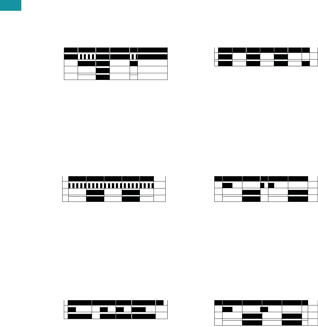
V7-T3-174 Volume 7—Logic Control, Operator Interface and Connectivity Solutions CA08100008E—June 2013 www.eaton.com
3
3
3
3
3
3
3
3
3
3
3
3
3
3
3
3
3
3
3
3
3
3
3
3
3
3
3
3
3
3
3.8
Control Relays and Timers
Ti m in g R el ay s
Function #13—Universal TR
ON Delay Control Signal Start, Trailing Edge OFF
The supply voltage U must
be constantly applied to the
device. When the control
switch S is applied, the set
interval t begins. After the
interval t has expired, the
output relay R switches to
the ON position. The relay
will remain in that position
until the control switch
opens. If the control switch is
opened prior to interval t
timing out, the relay will
remain in the OFF position
and any elapsed time will be
erased.
Function #14—Universal TR, TRN, TMR5, TMRP
Flasher, Pause First
Cycle 1 (Power Start, OFF First)
When the supply voltage U
is applied, the set interval t
begins. After the interval t
has expired, the output relay
R switches to the ON
position and set interval t will
begin again. After interval t
has expired, the relay will
switch to the OFF position
for the set interval t. This
cycle will repeat at a 1:1
ratio until supply voltage U
is interrupted.
Function #15—TMR5, TMRP, E5-248
Watchdog
Retriggerable Single Shot
The supply voltage U must
be constantly applied to the
device. When the control
switch S is applied, the relay
switches to the ON position
and the set interval t begins.
After the interval t has
expired, the output relay R
switches to the OFF position.
Closing the control switch
during interval t will reset the
time. Continuous cycling of
the trigger signal at a rate
faster than the preset time
will cause the relay to remain
in the ON position.
Input Power (U)
LED U/t*
Trigger Signal (S)
Output LED**
Output Relay (R) t<t
Input Power (U)
LED U/t*
Output LED**
Output Relay (R) t<ttttt
Input Power (U)
Trigger Signal (S)
Output Relay (R) t<t<tt
Function #16—TRN, TMRP
Flasher, ON First
Cycle 3 (Power Start, ON First)
When the supply voltage U
is applied, the relay switches
to the ON position and set
interval t begins. After the
interval t has expired, the
output relay R switches to
the OFF position and set
interval t will begin again.
After interval t has expired,
the relay will again switch to
the ON position for the set
interval t. This cycle will
repeat at a 1:1 ratio until
supply voltage U is
interrupted.
Function #17—TRF, E5-248
ON Delay Control Signal Start, Leading Edge OFF
The supply voltage U must
be constantly applied to the
device. When the control
switch S is applied, the set
interval t begins. After the
interval t has expired, the
output relay R switches to
the ON position. The relay
will remain in that position
until the control switch has
opened and closed. If the
control switch is opened and
closed prior to interval t
timing out, the relay will
remain in the OFF position
and any elapsed time will be
erased.
Function #18—TRF, E5-248
Flasher—Control Signal Start, Pause First
The supply voltage U must
be constantly applied to the
device. When the control
switch S is closed, the set
interval t begins. After the
interval t has expired, the
output relay R switches to
the ON position and set
interval t will begin again.
After interval t has expired,
the relay will switch to the
OFF position for the set
interval t. This cycle will
repeat at a 1:1 ratio until
supply voltage U is
interrupted. The control
switch is ignored during
the cycle.
Input Power (U)
Output LED**
Output Relay (R) ttttt<tt
Input Power (U)
Trigger Signal
Output LED**
Output Relay (R) tt
Input Power (U)
Trigger Signal
Output LED**
Output Relay (R) tttt<t
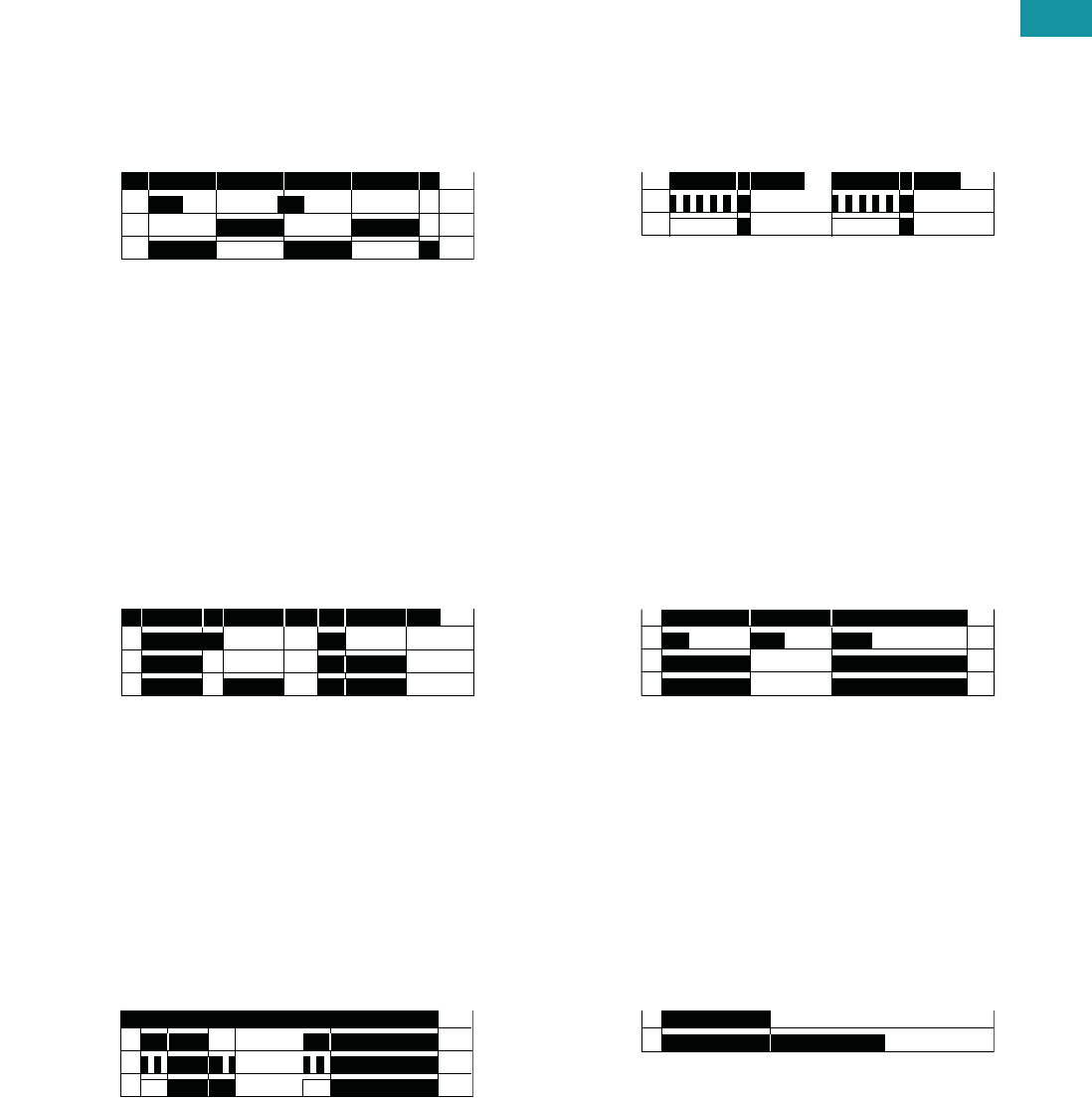
Volume 7—Logic Control, Operator Interface and Connectivity Solutions CA08100008E—June 2013 www.eaton.com V7-T3-175
3
3
3
3
3
3
3
3
3
3
3
3
3
3
3
3
3
3
3
3
3
3
3
3
3
3
3
3
3
3
3.8
Control Relays and Timers
Ti m i n g R e l ay s
Function #19—TRF, E5-248
Flasher—Control Signal Start, ON First
The supply voltage U must
be constantly applied to the
device. When the control
switch S is closed, the relay
switches to the ON position
and set interval t begins.
After the interval t has
expired, the output relay R
switches to the OFF position
and set interval t will begin
again. After interval t has
expired, the relay will again
switch to the ON position
for the set interval t. This
cycle will repeat at a 1:1
ratio until supply voltage U
is interrupted. The control
switch is ignored during
the cycle.
Function #20—TRF
Signal ON/OFF Delay
The supply voltage U must
be constantly applied to the
device. When the control
switch S is closed, the relay
switches to the ON position
and set interval t begins.
After the interval t has
expired with the control
switch still closed, the output
relay R switches to the OFF
position. When the control
switch is opened, the relay
will switch to the ON position
again and the interval t will
begin. If the control switch is
closed and opened within the
interval t, the relay will remain
in the ON position until
interval t has timed out after
the control switch is opened.
Function #21—TMRP
ON/OFF Delay
Make/Break with Control Switch Trigger
The supply voltage U must
be constantly applied to the
device. When the control
switch S is closed, the set
interval t begins. After the
interval t has expired, the
output relay R switches to
the ON position. When the
control switch is opened,
interval t will begin again.
After interval t has timed out,
the relay will switch to the
OFF position. If supply
voltage U is removed at any
time, the relay will return to
the OFF position.
Input Power (U)
Trigger Signal
Output LED**
Output Relay (R) <tt ttt
Input Power (U)
Trigger Signal
Output LED**
Output Relay (R) t t <t t
Input Power (U)
Trigger Signal
Output LED**
Output Relay (R) tt t
Function #22—TMRP, E5-248
Single Pulse Generator, Voltage Controlled
When the supply voltage U
is applied, the set interval t
begins. After the interval t
has expired, the relay will
switch to the ON position for
0.5 seconds before returning
to the OFF position. Supply
voltage U must be removed
and reapplied to repeat the
pulse.
Function #23—N/A
Memory Latch
Control Switch Make
The supply voltage U must
be constantly applied to the
device. Output changes state
with every closure of the
control switch S (leading
edge).
Function #24—TMR6
True OFF Delay
When the supply voltage U
is applied, the relay switches
to the ON position. When
supply power is removed, set
time interval t begins. After
interval t has expired, the
relay switches to the OFF
position and will remain there
until supply power U is
applied again.
Input Power (U)
Output LED**
Output Relay (R) tt
Input Power (U)
Trigger Signal
Output LED**
Output Relay (R)
Input Power (U)
Output Relay (R) t

V7-T3-176 Volume 7—Logic Control, Operator Interface and Connectivity Solutions CA08100008E—June 2013 www.eaton.com
3
3
3
3
3
3
3
3
3
3
3
3
3
3
3
3
3
3
3
3
3
3
3
3
3
3
3
3
3
3
3.8
Control Relays and Timers
Ti m in g R el ay s
Universal TR Series
Contents
Description Page
Universal TR Series
Product Selection . . . . . . . . . . . . . . . . . . . . . . . V7-T3-177
Technical Data and Specifications . . . . . . . . . . V7-T3-177
Wiring Diagrams . . . . . . . . . . . . . . . . . . . . . . . V7-T3-178
Dimensions . . . . . . . . . . . . . . . . . . . . . . . . . . . V7-T3-179
TR Series . . . . . . . . . . . . . . . . . . . . . . . . . . . . . . . . V7-T3-180
TMR5 Series . . . . . . . . . . . . . . . . . . . . . . . . . . . . . V7-T3-183
TMR6 Series . . . . . . . . . . . . . . . . . . . . . . . . . . . . . V7-T3-187
TMRP Series . . . . . . . . . . . . . . . . . . . . . . . . . . . . . V7-T3-189
Universal TR Series
Product Description
Eaton’s Universal TR Series
timers are our most flexible
and cost-effective timing
relays available. Products are
available with up to seven
user-selectable functions and
seven user-selectable time
ranges. Each unit is DIN rail
mountable with a direct
connection, eliminating the
need for additional sockets.
The Universal TR Series
timers are available in SPDT
and DPDT contact
configurations, and have a
compact IEC-style footprint
and a universal input voltage
range for AC and DC
applications.
Application Description
A timing relay is a simple
form of time-based control,
allowing the user to open or
close the contacts based on
a specified timing function.
The Universal TR Series
timers are equipped with a
set of selector switches,
which can easily be set to a
specific function and time,
thereby reducing the number
of product variations required.
The universal input voltage
(either 12–240 Vac/Vdc or
24–240 Vac/Vdc, depending
on the model) further
reduces the number of
product variations.
The Universal TR Series
timers are ideal for high-
variability operations, such
as systems integrators,
distributors, and small
equipment manufacturers.
The compact design saves
panel space, and the low
cost and high flexibility of
the units reduce inventory
requirements.
Features
●Multiple user-selectable
timing functions and timing
ranges in a single unit
reduce product variations
and stock keeping units
(SKUs)
●Universal input voltages
from 12 or 24 to 240 Vac or
Vdc eliminate the need to
order and stock separate
coil voltages
●Compact, DIN rail
mountable case reduces
panel size
●Advanced LED indication
makes troubleshooting
easy
●Staggered terminal
locations allow access
to lower-level terminals
after wiring
●SPDT or DPDT contacts
with 8A ratings
Standards and Certifications
●cULus listed
●CE marked
●RoHS compliant
●IEC/EN 61812
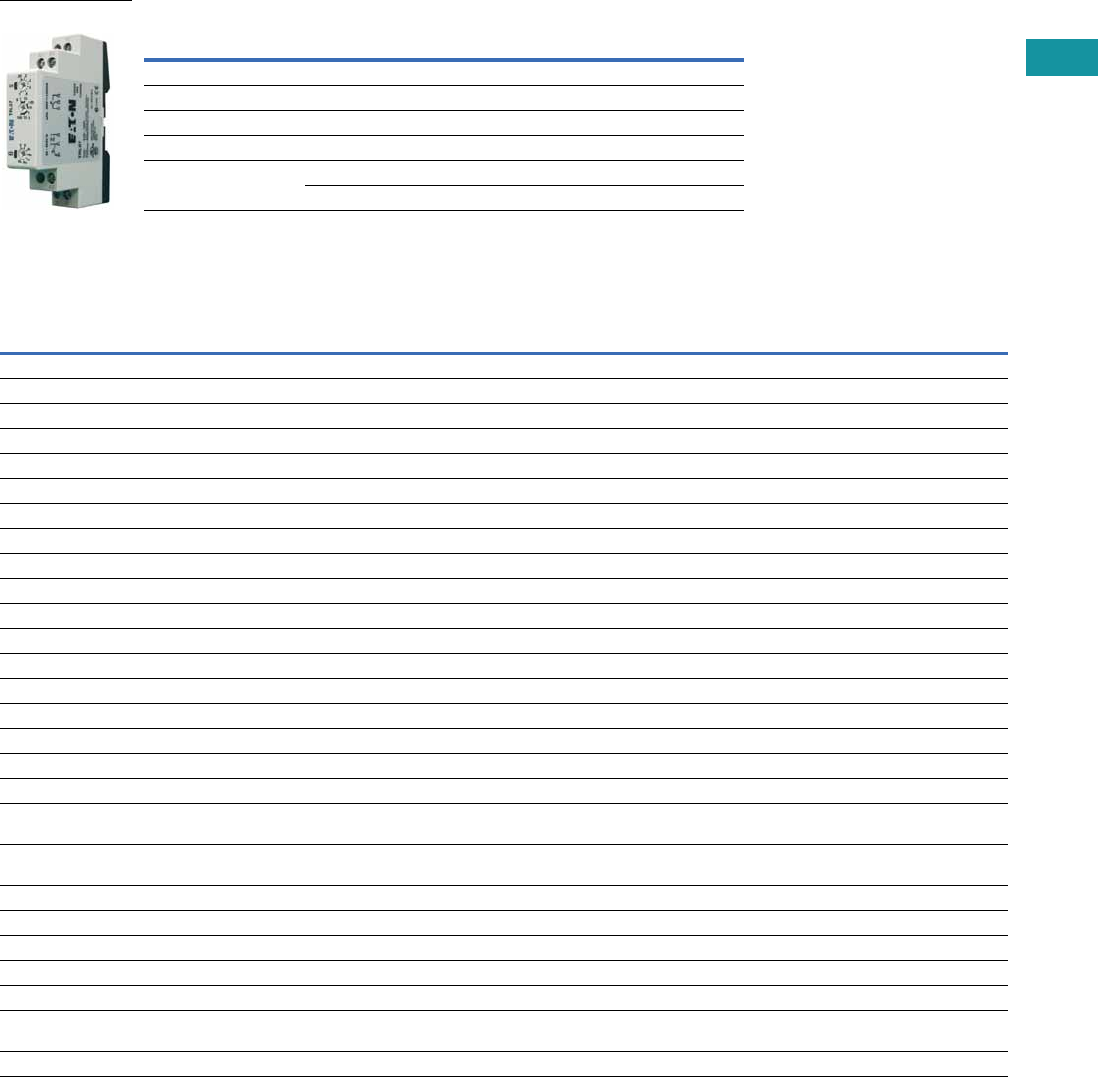
Volume 7—Logic Control, Operator Interface and Connectivity Solutions CA08100008E—June 2013 www.eaton.com V7-T3-177
3
3
3
3
3
3
3
3
3
3
3
3
3
3
3
3
3
3
3
3
3
3
3
3
3
3
3
3
3
3
3.8
Control Relays and Timers
Ti m i n g R e l ay s
Product Selection
Universal TR Timing Relays
Technical Data and Specifications
Universal TR Timing Relays
Note
1Refer to Function Code Cross-Reference Guide on Page V7-T3-171 for function details.
Supply Voltage Description
Catalog
Number
4-Function
24–240 Vac/Vdc Compact DIN rail mount, SPDT TRL04
7-Function
24–240 Vac/Vdc Compact DIN rail mount, SPDT TRL07
12–240 Vac/Vdc Compact DIN rail mount, DPDT TRL27
Asymmetrical pulse generator, DPDT TRW27
Single-Pole Model
Description TRL04 TRL07 TRL27 TRW27
Functions 1E, R, Wu, Bp E, R, Wu, Bp, Ws, Wa, Es E, R, Wu, Bp, Ws, Wa, Es Ii, Ip, ER, Ewu, Ews, WsWa, Wt
Time range 0.05 sec to 100 hours 0.05 sec to 100 hours 0.05 sec to 100 hours 0.05 sec to 100 hours
Input
Supply voltage 24–240 Vac/Vdc 24–240 Vac/Vdc 12–240 Vac/Vdc 12–240 Vac/Vdc
Rated supply frequency +10% /–15% +10% /–15% ±10% ±10%
Rated consumption 4 VA (1.5W) 4 VA (1.5W) 6 VA (2W) 6 VA (2W)
Duty cycle 100% 100% 100% 100%
Reset time 100 ms 100 ms 100 ms 100 ms
Residual ripple for DC 10% 10% 10% 10%
dropout voltage >30% of rated supply voltage >30% of rated supply voltage >30% of rated supply voltage >30% of rated supply voltage
Overvoltage category III (in accordance with IEC 60664-1) III (in accordance with IEC 60664-1) III (in accordance with IEC 60664-1) III (in accordance with IEC 60664-1)
Rated surge voltage 4 kV 4 kV 4 kV 4 kV
Output
Contact configuration SPDT (one changeover contact) SPDT (one changeover contact) DPDT (two changeover contacts) DPDT (two changeover contacts)
Rated voltage 250 Vac 250 Vac 250 Vac 250 Vac
Switching capacity 2000 VA (8A/250V) 2000 VA (8A/250V) 2000 VA (8A/250V) 2000 VA (8A/250V)
Fusing 8A fast acting 8A fast acting 8A fast acting 8A fast acting
Mechanical life 20 x 10^6 operations 20 x 10^6 operations 20 x 10^6 operations 20 x 10^6 operations
Electrical life 2 x 10^5 operations at 1000 VA load,
resistive
2 x 10^5 operations at 1000 VA load,
resistive
2 x 10^5 operations at 1000 VA load,
resistive
2 x 10^5 operations at 1000 VA load,
resistive
Switching frequency Max. 6/min. at 1000 VA resistive load
(in accordance with IEC 60947-5-1)
Max. 6/min. at 1000 VA resistive load
(in accordance with IEC 60947-5-1)
Max. 6/min. at 1000 VA resistive load
(in accordance with IEC 60947-5-1)
Max. 6/min. at 1000 VA resistive load
(in accordance with IEC 60947-5-1)
Overvoltage category III (in accordance with IEC 60664-1) III (in accordance with IEC 60664-1) III (in accordance with IEC 60664-1) III (in accordance with IEC 60664-1)
Rated surge voltage 4 kV 4 kV 4 kV 4 kV
Control Signal
Loadable Yes Yes Yes Yes
Maximum cable length 10m 10m 10m 10m
Trigger level (sensitivity) Automatic adaption to
supply voltage
Automatic adaption to
supply voltage
Automatic adaption to
supply voltage
Automatic adaption to
supply voltage
Minimum control pulse length DC 50 ms/AC 100 ms DC 50 ms/AC 100 ms DC 50 ms/AC 100 ms DC 50 ms/AC 100 ms

V7-T3-178 Volume 7—Logic Control, Operator Interface and Connectivity Solutions CA08100008E—June 2013 www.eaton.com
3
3
3
3
3
3
3
3
3
3
3
3
3
3
3
3
3
3
3
3
3
3
3
3
3
3
3
3
3
3
3.8
Control Relays and Timers
Ti m in g R el ay s
Universal TR Timing Relays, continued
Terminal Capacity
Wiring Diagrams
Single-Pole, Double-Throw Units (SPDT)—
TRL04 and TRL07
Double-Pole, Double-Throw Units (DPDT)—
TRL27 and TRW27
Description TRL04 TRL07 TRL27 TRW27
Accuracy
Base accuracy ±1% of maximum scale value ±1% of maximum scale value ±1% of maximum scale value ±1% of maximum scale value
Adjustment accuracy <5% of maximum scale value <5% of maximum scale value <5% of maximum scale value <5% of maximum scale value
Repetition accuracy <0.5% or ±5 ms <0.5% or ±5 ms <0.5% or ±5 ms <0.5% or ±5 ms
Temperature influence <0.01% /°C <0.01% /°C <0.01% /°C <0.01% /°C
Physical
Ambient temperature –25 to 55°C –25 to 55°C –25 to 55°C –25 to 55°C
Storage temperature –25 to 70°C –25 to 70°C –25 to 70°C –25 to 70°C
Relative humidity 15% to 85% (in accordance
with IEC 60721-3-3 Class 3K3)
15% to 85% (in accordance
with IEC 60721-3-3 Class 3K3)
15% to 85% (in accordance
with IEC 60721-3-3 Class 3K3)
15% to 85% (in accordance
with IEC 60721-3-3 Class 3K3)
Pollution degree 2, if built in 3 (in accordance
with IEC 60664-1)
2, if built in 3 (in accordance
with IEC 60664-1)
2, if built in 3 (in accordance
with IEC 60664-1)
2, if built in 3 (in accordance
with IEC 60664-1)
Housing material Self-extinguishing plastic housing,
IP40 rating
Self-extinguishing plastic housing,
IP40 rating
Self-extinguishing plastic housing,
IP40 rating
Self-extinguishing plastic housing,
IP40 rating
Mounting Mounted on DIN rail TS 35 according
to EN 60715, any position
Mounted on DIN rail TS 35 according
to EN 60715, any position
Mounted on DIN rail TS 35 according
to EN 60715, any position
Mounted on DIN rail TS 35 according
to EN 60715, any position
Terminal rating Shockproof terminal connection
according to VBG 4 (PZ1 required),
IP20 rating
Shockproof terminal connection
according to VBG 4 (PZ1 required),
IP20 rating
Shockproof terminal connection
according to VBG 4 (PZ1 required),
IP20 rating
Shockproof terminal connection
according to VBG 4 (PZ1 required),
IP20 rating
Tightening torque Max. 1 Nm Max. 1 Nm Max. 1 Nm Max. 1 Nm
Description
1 x 0.5 to 2.5 mm2 with/without multicore cable end
1 x 4 mm2 without multicore cable end
2 x 0.5 to 1.5 mm2 with/without multicore cable end
2 x 2.5 mm2 flexible without multicore cable end
15
16 18
A2
A1 B1
A1
A2
15
16 18
R
U =
(+)
(–)
S(Used only for
control switch
triggered functions)
15
16 18
25
26 28
A2
A1 B1
A1
A2
15
16 18
R
25
26 28
R
U =
(+)
(–)
S(Used only for
control switch
triggered functions)
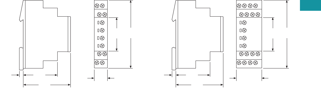
Volume 7—Logic Control, Operator Interface and Connectivity Solutions CA08100008E—June 2013 www.eaton.com V7-T3-179
3
3
3
3
3
3
3
3
3
3
3
3
3
3
3
3
3
3
3
3
3
3
3
3
3
3
3
3
3
3
3.8
Control Relays and Timers
Ti m i n g R e l ay s
Dimensions
Approximate Dimensions in Inches (mm)
17.5 mm (TRL04 and TRL07) 35 mm (TRL27 and TRW27)
0.20
(5.0)
1.73
(44.0)
2.36
(60.0)
0.69
(17.5)
1.77
(45.0)
3.43
(87.0)
0.20
(5.0)
1.73
(44.0)
2.36
(60.0)
1.38
(35.0)
1.77
(45.0)
3.43
(87.0)
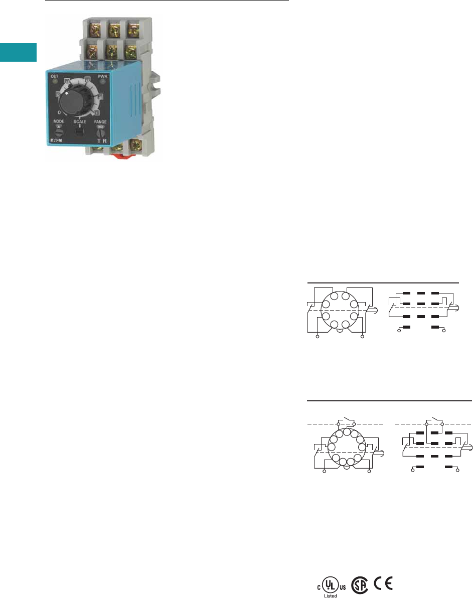
V7-T3-180 Volume 7—Logic Control, Operator Interface and Connectivity Solutions CA08100008E—June 2013 www.eaton.com
3
3
3
3
3
3
3
3
3
3
3
3
3
3
3
3
3
3
3
3
3
3
3
3
3
3
3
3
3
3
3.8
Control Relays and Timers
Ti m in g R el ay s
TR Series
Contents
Description Page
Universal TR Series . . . . . . . . . . . . . . . . . . . . . . . . V7-T3-176
TR Series
Catalog Number Selection . . . . . . . . . . . . . . . . V7-T3-181
Product Selection . . . . . . . . . . . . . . . . . . . . . . . V7-T3-181
Accessories . . . . . . . . . . . . . . . . . . . . . . . . . . . V7-T3-181
Technical Data and Specifications . . . . . . . . . . V7-T3-182
Dimensions . . . . . . . . . . . . . . . . . . . . . . . . . . . V7-T3-182
TMR5 Series . . . . . . . . . . . . . . . . . . . . . . . . . . . . . V7-T3-183
TMR6 Series . . . . . . . . . . . . . . . . . . . . . . . . . . . . . V7-T3-187
TMRP Series . . . . . . . . . . . . . . . . . . . . . . . . . . . . . V7-T3-189
TR Series
Product Description
The upgraded TR Series
Timing Relays are designed
to meet most timing
requirements by offering
more flexibility in range of
input voltage, timing range
and functionality. Use a rotary
switch to choose from
20 selectable time ranges
from 0.1 second to 600
hours. We offer both a power
triggered and signal triggered
model—each with expanded
operation modes. There is a
green LED to indicate when
power is ON and an orange
LED when output is ON.
Features
●20 time ranges and 10
timing functions
●Time delays from 0.1 sec
to 600 hrs
●Space-saving, compact
package
●High repeat accuracy of
±0.2%
●LED indication
●Standard 8- or 11-pin and
11-blade termination
●2 Form C DPDT delayed
output contacts
●10A contact rating
Operation
TRNP and TRNB
TRFP and TRFB
Standards and Certifications
●cULus listed
●CSA
●CE marked
●TUV
Internal Connections
2
36
7
45
18
(
–
/
–
)(
–
/+)
1
(
–
/
–
)
2 3
4 5 6
7 8 9
A B
(
–
/+)
TRNBTRNP
Internal Connections
210
(
–
/+)
3
67
45
111
8
9
(
–
/
–
)
2
(
–
/+)
1
(
–
/
–
)
3
4 5 6
7 8 9
A B
Start
Start
TRFP TRFB
External
Control
Signal
External
Control
Signal
TUV
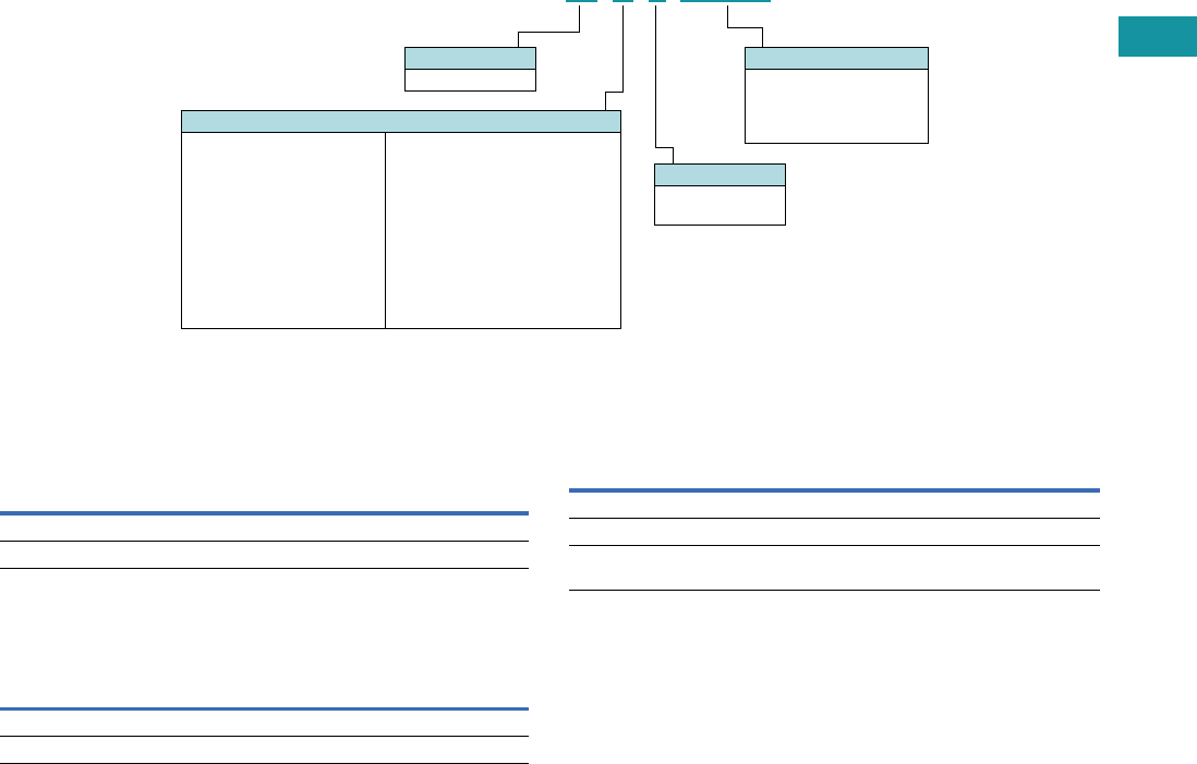
Volume 7—Logic Control, Operator Interface and Connectivity Solutions CA08100008E—June 2013 www.eaton.com V7-T3-181
3
3
3
3
3
3
3
3
3
3
3
3
3
3
3
3
3
3
3
3
3
3
3
3
3
3
3
3
3
3
3.8
Control Relays and Timers
Ti m i n g R e l ay s
Catalog Number Selection
Product Selection
TR Plug-In Timing Relays—Power Triggered
TR Plug-In Timing Relays—Signal Triggered
Accessories
Sockets for Use with TR Timers—Standard Pack of 10
Operational Mode
N = Power Triggered
A = ON delay
B = Interval
C = Flasher (pause first)
D = Flasher (ON first)
F = Signal Triggered
A = ON delay, control signal start
(leading edge OFF)
B = Flasher, control signal start
(pause first)
C = Flasher, control signal Start
(ON first)
D = Signal ON/OFF delay
E = OFF delay
F = Single shot leading edge with
control input
Input Voltage
24AD = 24 Vac
(50/60 Hz)/24 Vdc
240AC = 100–240 Vac
(50/60 Hz)
Model Type
P = Pin/octal
B = Blade style
Family Type
TR
TR N P 240 AC
Octal Blade
Coil Voltage
Catalog
Number
Catalog
Number
24 Vac/Vdc TRNP24AD TRNB24AD
100–240 Vac TRNP240AC TRNB240AC
Octal Blade
Coil Voltage
Catalog
Number
Catalog
Number
24 Vac/Vdc TRFP24AD TRFB24AD
100–240 Vac TRFP240AC TRFB240AC
Timing Relay Terminal Style
Catalog
Number
TRNP 8-pin octal D3PA2
TRFP 11-pin octal D3PA3
TRNB, TRFB 0.187 in solder/QC terminals
(blade style)
D5PA2
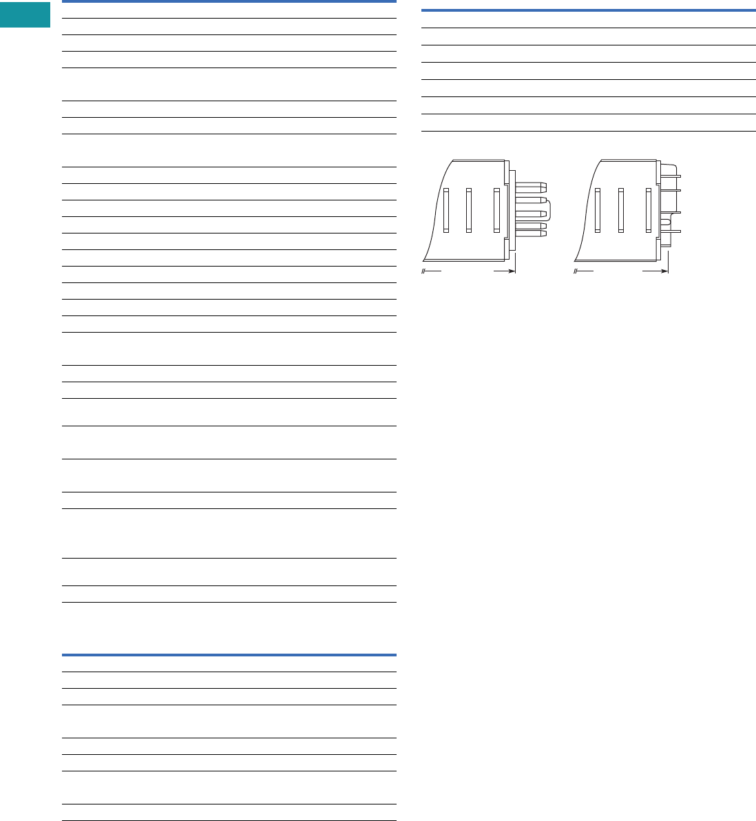
V7-T3-182 Volume 7—Logic Control, Operator Interface and Connectivity Solutions CA08100008E—June 2013 www.eaton.com
3
3
3
3
3
3
3
3
3
3
3
3
3
3
3
3
3
3
3
3
3
3
3
3
3
3
3
3
3
3
3.8
Control Relays and Timers
Ti m in g R el ay s
Technical Data and Specifications
General
TR Series Contact Ratings
Dimensions
Approximate Dimensions in Inches (mm)
TR Series Dimensions and Weights
Note
1For the value of the error against a preset time, whichever value is larger should apply.
Description Specification
Operation system Solid-state CMOS circuit
Time range 0.1 sec to 600 hours
Pollution degree 2 (IE60664-1)
Overvoltage category III (IE60664-1)
Rated operational voltage
240 AC 100–240 Vac (50/60 Hz)
24 AC 24 Vac (50/60 Hz)/24 Vdc
12 DC 12 Vdc
Voltage tolerance
240 AC 85–264 Vac (50/60 Hz)
24 AC 20.4–26.4 Vac (50/60 Hz)/21.6–26.4 Vdc
12 DC 10.8–13.2 Vdc
Input OFF voltage Rated voltage x 10% minimum
Ambient operating temperature –4 to 149°F (–20 to 65°C)
Reset time 100 ms maximum
Repeat error ± 0.2%, ± 20 ms 1
Voltage error ± 0.2%, ± 20 ms 1
Temperature error ± 0.5%, ± 20 ms 1
Setting error ± 10% maximum
Insulation resistance 100M ohm minimum (500 Vdc)
Dielectric strength
Between power and output terminals 2000 Vac, 1 minute
Between contacts of different poles 2000 Vac, 1 minute
Between contacts of same pole 1000 Vac, 1 minute
Vibration resistance 10–55 Hz amplitude 0.5 mm;
2 hrs in each of 3 axes
Shock resistance
Operating extremes 10G
Damage limits —
TRNP, TRFP 40G (3x in each of 3 axes)
TRNB, TRFB 10G (3x in each of 3 axes)
Power consumption (approx.)
240 AC 6.5 VA TRNP, TRNB/6.6 VA TRFP, TRFB
240 Vac/60 Hz 11.6 VA TRNP, TRNB/12.1 VA TRFP, TRFB
24 AC (AC/DC) 3.4 VA–1.7W TRNP, TRNB/3.5 VA–1.7W TRFP,
TRFB
12 DC 1.6W
Description Specification
Contact configuration 2 Form C, DPDT (delayed output)
Allowable voltage/current 240 Vac, 30 Vdc/10A
Max. permissible operating frequency 1800 cycles per hour
Rated load
Resistive 10A, 240 Vac/30 Vdc
Inductive 7A, 240 Vac/30 Vdc
Horsepower rating 1/6 hp 120 Vac, 1/3 hp 240 Vac
Life
Electrical 500,000 operations minimum (resistive)
Mechanical 50,000,000 operations minimum
Description Specification
Dimensions
TRNP, TRFP 1.58H x 1.42W x 3.07D in. (40H x 36W x 77.9D mm)
TRNB, TRFB 1.58H x 1.42W x 2.95D in. (40H x 36W x 74.9D mm)
Weights
TRNP 87g
TRFP 89g
TRNB, TRFB 85g
3.07 (77.9)
Pin (P) Type Blade (B) Type
2.95 (74.9)
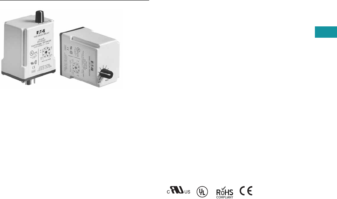
Volume 7—Logic Control, Operator Interface and Connectivity Solutions CA08100008E—June 2013 www.eaton.com V7-T3-183
3
3
3
3
3
3
3
3
3
3
3
3
3
3
3
3
3
3
3
3
3
3
3
3
3
3
3
3
3
3
3.8
Control Relays and Timers
Ti m i n g R e l ay s
TMR5 Series
Contents
Description Page
Universal TR Series . . . . . . . . . . . . . . . . . . . . . . . . V7-T3-176
TR Series . . . . . . . . . . . . . . . . . . . . . . . . . . . . . . . . V7-T3-180
TMR5 Series
Catalog Number Selection . . . . . . . . . . . . . . . . V7-T3-184
Product Selection . . . . . . . . . . . . . . . . . . . . . . . V7-T3-184
Accessories . . . . . . . . . . . . . . . . . . . . . . . . . . . V7-T3-184
Technical Data and Specifications . . . . . . . . . . V7-T3-185
Wiring Diagrams . . . . . . . . . . . . . . . . . . . . . . . . V7-T3-185
Dimensions . . . . . . . . . . . . . . . . . . . . . . . . . . . V7-T3-186
TMR6 Series . . . . . . . . . . . . . . . . . . . . . . . . . . . . . V7-T3-187
TMRP Series . . . . . . . . . . . . . . . . . . . . . . . . . . . . . V7-T3-189
TMR5 Series
Product Description
The TMR5 Series Time
Delay Relays are designed
for a broad range of
OEM applications. The
TMR5 Series offers
non-programmable plug-in
style timers with a variety
of functions available. Each
unit offers a single function
and single input voltage, and
operates over a defined time
delay range. Units with fixed
time delays are also available.
Eaton also offers
customization
capabilities for
these timers—remote
adjustments, special pin
configurations, and more.
Contact us to discuss your
specific application and
design of a custom timer.
Features
●Single timing range for
each unit
●Ranges available from
0.02 sec to 24 hours
●Wide variety of functions
available
●Plugs into standard 8- or
11-pin socket
●10A DPDT output contacts
●Can be easily customized
to meet your needs
Standards and Certifications
●cRUus
●UL listed (with Eaton socket)
●RoHS compliant
●CE marked
with
Eaton
socket

V7-T3-184 Volume 7—Logic Control, Operator Interface and Connectivity Solutions CA08100008E—June 2013 www.eaton.com
3
3
3
3
3
3
3
3
3
3
3
3
3
3
3
3
3
3
3
3
3
3
3
3
3
3
3
3
3
3
3.8
Control Relays and Timers
Ti m in g R el ay s
Catalog Number Selection
Product Selection
TMR5 Time Delay Relays
Accessories
Accessories for Use with TMR5 Time Delay Relays
Notes
1Indicates DUAL knob unit. All dual knob units can have independently selectable and
adjustable ON and OFF times. If different ON and OFF times are desired, add two codes for
time ranges in the part number. The first code listed indicates the first timing range of the
unit (OFF time for R, ON time for Y) and the second code indicates the second timing range
(ON time for R, OFF Time for Y).
2Fixed time delay settings are available for orders of 50 pieces or more. Contact EatonCare for
additional information at 877-ETN-CARE (386-2273).
Operational Mode
8-Pin Octal Sockets 11-Pin Octal Sockets
N=ON delay
T= Interval ON
L= Flasher-pause-first
R = Repeat cycle 1
(OFF time first followed by
ON time and repeating)
Y = Repeat cycle 1
(ON time first followed by
OFF time and repeating)
F= OFF delay, control switch trigger
C= Single shot, control switch trigger
W= Watchdog, control switch trigger
(retriggerable single shot)
P= OFF delay, power trigger
G= Single shot, power trigger
D= Watchdog, power trigger (retriggerable
single shot)
TMR5 N05 120
Input Voltage
120 = 120 Vac/Vdc
24 = 24 Vac/Vdc
12 = 12 Vac/Vdc
240 = 240 Vac/Vdc
Timing Range 2
04 = 0.05–5 sec
05 = 0.1–10 sec
08 = 0.6–60 sec
12 = 3–300 sec
15 = 0.3–30 min
16 = 0.6–60 min
22 = 6 sec–10 min
Family Type
TMR5
All configurations from Catalog Number Selection are available.
Input
Voltage Socket
Timing
Range
Catalog
Number
ON Delay
120 Vac/Vdc 8-pin 0.1–10 sec TMR5N05120
0.6–60 sec TMR5N08120
24 Vac/Vdc 0.1–10 sec TMR5N0524
0.6–60 sec TMR5N0824
OFF Delay, Control Switch Trigger
120 Vac/Vdc 11-pin 0.1–10 sec TMR5F05120
0.6–60 sec TMR5F08120
24 Vac/Vdc 0.1–10 sec TMR5F0524
0.6–60 sec TMR5F0824
Interval ON
120 Vac/Vdc 8-pin 0.1–10 sec TMR5T05120
0.6–60 sec TMR5T08120
24 Vac/Vdc 0.1–10 sec TMR5T0524
0.6–60 sec TMR5T0824
Single Shot, Control Switch Trigger
120 Vac/Vdc 11-pin 0.1–10 sec TMR5C05120
0.6–60 sec TMR5C08120
24 Vac/Vdc 0.1–10 sec TMR5C0524
0.6–60 sec TMR5C0824
Repeat Cycle
(OFF Time First Followed by ON Time and Repeating)
120 Vac/Vdc 8-pin 0.1–10 sec TMR5R05120
0.6–60 sec TMR5R08120
24 Vac/Vdc 0.1–10 sec TMR5R0524
0.6–60 sec TMR5R0824
Repeat Cycle
(ON Time First Followed by OFF Time and Repeating)
120 Vac/Vdc 8-pin 0.1–10 sec TMR5Y05120
0.6–60 sec TMR5Y08120
24 Vac/Vdc 0.1–10 sec TMR5Y0524
0.6–60 sec TMR5Y0824
Description Standard Pack
Catalog
Number
8-pin socket 10 D3PA2
11-pin socket 10 D3PA3-A2
Hold-down spring 10 D65CHDS
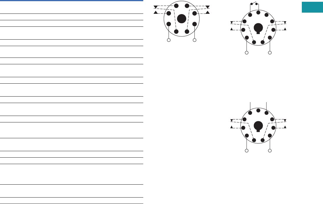
Volume 7—Logic Control, Operator Interface and Connectivity Solutions CA08100008E—June 2013 www.eaton.com V7-T3-185
3
3
3
3
3
3
3
3
3
3
3
3
3
3
3
3
3
3
3
3
3
3
3
3
3
3
3
3
3
3
3.8
Control Relays and Timers
Ti m i n g R e l ay s
Technical Data and Specifications
TMR5 Time Delay Relays
Description Specification
Voltage tolerance
AC operation +10/–15% of nominal at 50/60 Hz
DC operation +10/–15% of nominal
Load burden 2 VA
Setting accuracy
Maximum setting (adjustable) +5%, –0%
Minimum setting (adjustable) +0%, –50%
Fixed time delay
< 2 seconds +1%
0.1–2 seconds ±5%
Repeat accuracy (constant voltage and temperature)
> 2 seconds delay ±0.1%
0.1–2 seconds delay ±2%
Reset time
ON Delay/interval/repeat cycle 0.1 second
OFF Delay/single shot/watchdog 0.04 second
Startup time (time from when power is applied until unit is timing)
120 and 240V units 0.05 second
12, 24 and 48V units 0.08 second
Maintain function time (time unit
continues to time after power is
removed)
0.01 second
Temperature
12–120V input voltage –18 to 150°F (–28 to 65°C)
240V input voltage –18 to 122°F (–28 to 50°C)
Insulation voltage 2000V
Output contacts DPDT 10A @ 240 Vac/30 Vdc,
1/2 hp @ 120/240 Vac (NO contacts)
1/3 hp @ 120/240 Vac (NC contacts)
B300 and R300; AC-15 and DC-13
Life
Mechanical 10,000,000 operations
Full load 100,000 operations
Wiring Diagrams
Wiring for 8-Pin Units Wiring for 11-Pin Control
Switch Trigger Units
Wiring for 11-Pin Power
Tri g ge r U n i t s
1
(DC)+
L1
−(DC)
L2
8
Input Voltage
4
36
27
5
1
(DC)+
L1
(DC)−
L2
11
Input Voltage
Control
Switch
48
39
6
210
75
1
(DC)+
L1
(DC)−
L2
−+
11
Input Voltage
* Should Be Same Voltage
as Input Voltage
Power
Trigger *
48
39
6
210
75
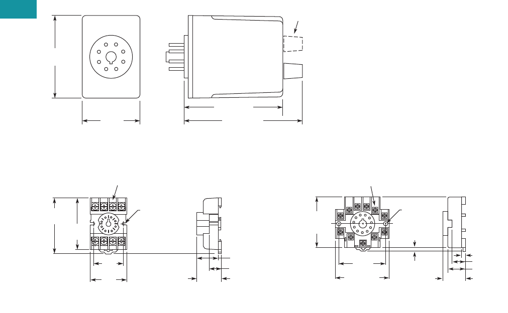
V7-T3-186 Volume 7—Logic Control, Operator Interface and Connectivity Solutions CA08100008E—June 2013 www.eaton.com
3
3
3
3
3
3
3
3
3
3
3
3
3
3
3
3
3
3
3
3
3
3
3
3
3
3
3
3
3
3
3.8
Control Relays and Timers
Ti m in g R el ay s
Dimensions
Approximate Dimensions in Inches (mm)
TMR5
D3PA2 Socket D3PA3 Socket
2.40
(61.0)
Dual Knob
Only
1.70
(43.2)
2.90 (73.7)
3.50 (88.9)
0.97
(24.6)
Max.
0.82 (20.8)
0.58 (14.7)
2.03
(51.6)
Two 0.165
(4.2) Dia.
Slots
2.14
(54.3)
1.60
(40.6)
Max.
1.30
(33.0)
6–32 x 0.312 Combination
Head Screw and Pressure Clamping Plate
(8 places)
Tolerances: ± 0.010
± (0.25)
Unless Otherwise Shown
6–32 x 0.312 Combination
Head Screw and Pressure Clamp
(11 places)
2.05
(52.1)
Max.
2.33 (59.2)
Max.
2.06
(52.3)
0.97
(24.6)
0.77 (19.6)
0.58 (14.7)
0.15 (3.8)
0.13–0.16
(3.2–4.0)
Two 0.17
(4.3) Dia.
Holes
Tolerances: ± 0.010
± (0.25)
Unless Otherwise Shown
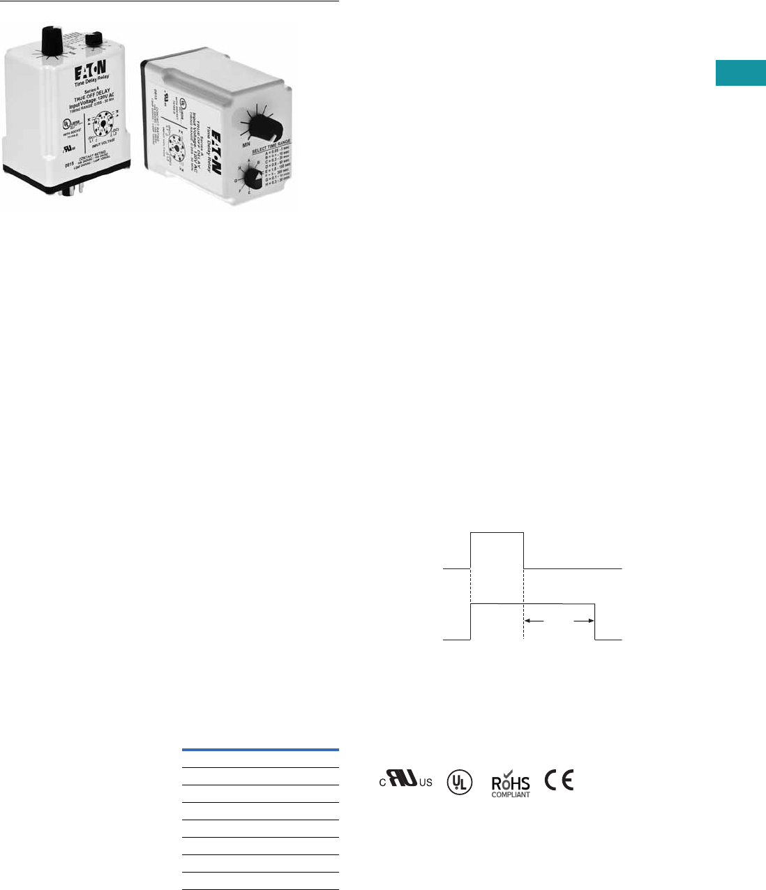
Volume 7—Logic Control, Operator Interface and Connectivity Solutions CA08100008E—June 2013 www.eaton.com V7-T3-187
3
3
3
3
3
3
3
3
3
3
3
3
3
3
3
3
3
3
3
3
3
3
3
3
3
3
3
3
3
3
3.8
Control Relays and Timers
Ti m i n g R e l ay s
TMR6 Series
Contents
Description Page
Universal TR Series . . . . . . . . . . . . . . . . . . . . . . . . V7-T3-176
TR Series . . . . . . . . . . . . . . . . . . . . . . . . . . . . . . . . V7-T3-180
TMR5 Series . . . . . . . . . . . . . . . . . . . . . . . . . . . . . V7-T3-183
TMR6 Series
Catalog Number Selection . . . . . . . . . . . . . . . . V7-T3-188
Product Selection . . . . . . . . . . . . . . . . . . . . . . . V7-T3-188
Accessories . . . . . . . . . . . . . . . . . . . . . . . . . . . V7-T3-188
Technical Data and Specifications . . . . . . . . . . V7-T3-188
Wiring Diagram . . . . . . . . . . . . . . . . . . . . . . . . V7-T3-188
Dimensions . . . . . . . . . . . . . . . . . . . . . . . . . . . V7-T3-188
TMRP Series . . . . . . . . . . . . . . . . . . . . . . . . . . . . . V7-T3-189
TMR6 Series
Product Description
Most electronic time delay
relays with an OFF delay
function require input voltage
to be applied continuously
in order to operate correctly.
However, there are many
applications where this is
not possible—-keeping a
relay energized for some
amount of time after input
voltage has been removed.
Eaton’s TMR6 true OFF
delay product provides
this function even when
input voltage is removed.
It duplicates the operation
of the older OFF delay
pneumatic time delay relays.
Features
●Provides OFF delay
function without requiring
input voltage during OFF
time delay
●Duplicates operation of
pneumatic OFF delay
timers
●Each unit has eight timing
ranges built in, covering
0.05 seconds to
30 minutes
●Selecting a range is easy
using a rotary switch
(no math is required or
DIP switches to set)
●Uses industry-standard
8-pin octal socket
●10A DPDT output contacts
Timing Ranges
Select one of the eight timing
ranges using the selector
knob, and then adjust the
time within that range for an
accurate delay setting.
Timing Ranges
Dial Setting Timing Range
A 0.05–5 sec.
B 0.1–10 sec.
C 0.3–30 sec.
D 0.6–60 sec.
E 1.8–180 sec.
F 3–300 sec.
G 0.1–10 min.
H 0.3–30 min
Operation
True OFF Delay
Upon application of input
voltage, the relay is
energized. When the input
voltage is removed, the
preset time begins. At the
end of the preset time, the
relay is de-energized.
Voltage must be applied for
a minimum of 0.1 second to
assure proper operation.
Any application of the input
voltage during the preset
time will keep the relay
energized and reset the time
delay. No external trigger
switch is required.
True OFF Delay
Standards and Certifications
●cRUus
●UL listed (with Eaton socket)
●RoHS compliant
●CE marked
Delay
Input
Power
(Voltage)
Output
(Load)
ON
OFF
ON
OFF
with
Eaton
socket
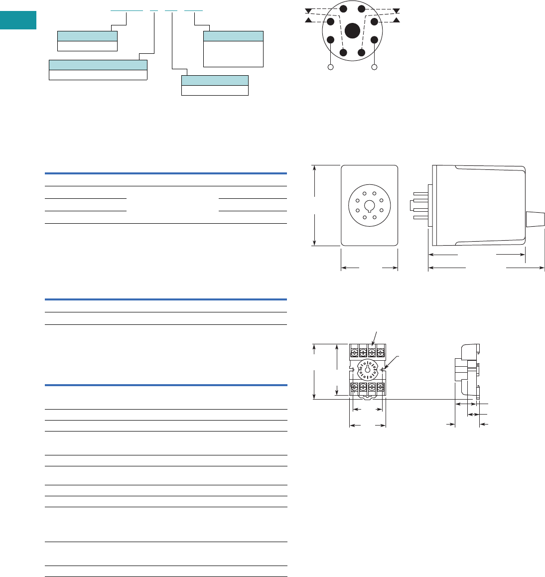
V7-T3-188 Volume 7—Logic Control, Operator Interface and Connectivity Solutions CA08100008E—June 2013 www.eaton.com
3
3
3
3
3
3
3
3
3
3
3
3
3
3
3
3
3
3
3
3
3
3
3
3
3
3
3
3
3
3
3.8
Control Relays and Timers
Ti m in g R el ay s
Catalog Number Selection
Product Selection
TMR6 True OFF Delay Relays
Accessories
Accessories for Use with TMR6 Time Delay Relays
Technical Data and Specifications
TMR6 Time Delay Relays
Wiring Diagram
Wiring for 8-Pin Units
Dimensions
Approximate Dimensions in Inches (mm)
TMR6
D3PA2 Socket
Input
Voltage
Timing
Range
Catalog
Number
True OFF Delay
120 Vac/Vdc 0.05 sec–30 min
(user selectable, 8 ranges)
TMR6X00120
24 Vac/Vdc TMR6X0024
240 Vac/Vdc TMR6X00240
Description Standard Pack
Catalog
Number
8-pin socket 10 D3PA2
Hold-down spring 10 D65CHDS
Description Specification
Voltage tolerance
AC operation +10/–15% of nominal at 50/60 Hz
DC operation +10/–15% of nominal
Load burden 2 VA
Setting accuracy
Maximum setting (adjustable) +5%, –0%
Minimum setting (adjustable) +0%, –50%
Repeat accuracy (constant voltage
and temperature)
±0.1% or 50 ms, whichever is greater
Temperature –18 to 150°F (–28 to 65°C)
Insulation voltage 2,000V
Output contacts DPDT 10A @ 240 Vac/30 Vdc,
1/2 hp @ 120/240 Vac (NO contacts)
1/3 hp @ 120/240 Vac (NC contacts)
B300 and R300; AC-15 and DC-13
Life
Mechanical 2,000,000 operations
Full load 100,000 operations
Operational Mode
X= True OFF delay
TMR6 X00 120
Input Voltage
120 = 120 Vac/Vdc
24 = 24 Vac/Vdc
240 = 240 Vac/Vdc
Timing Range
00 = Programmable
Family Type
TMR6
All configurations from Catalog Number Selection are available.
1
(DC)+
L1
−(DC)
L2
8
Input Voltage
4
36
27
5
2.40
(61.0)
1.70
(43.2)
2.90 (73.7)
3.50 (88.9)
0.97
(24.6)
Max.
0.82 (20.8)
0.58 (14.7)
2.03
(51.6)
Two 0.165
(4.2) Dia.
Slots
2.14
(54.3)
1.60
(40.6)
Max.
1.30
(33.0)
6–32 x 0.312 Combination
Head Screw and Pressure Clamping Plate
(8 places)
Tolerances: ± 0.010
± (0.25)
Unless Otherwise Shown

Volume 7—Logic Control, Operator Interface and Connectivity Solutions CA08100008E—June 2013 www.eaton.com V7-T3-189
3
3
3
3
3
3
3
3
3
3
3
3
3
3
3
3
3
3
3
3
3
3
3
3
3
3
3
3
3
3
3.8
Control Relays and Timers
Ti m i n g R e l ay s
TMRP Series
Contents
Description Page
Universal TR Series . . . . . . . . . . . . . . . . . . . . . . . . V7-T3-176
TR Series . . . . . . . . . . . . . . . . . . . . . . . . . . . . . . . . V7-T3-180
TMR5 Series . . . . . . . . . . . . . . . . . . . . . . . . . . . . . V7-T3-183
TMR6 Series . . . . . . . . . . . . . . . . . . . . . . . . . . . . . V7-T3-187
TMRP Series
Product Selection . . . . . . . . . . . . . . . . . . . . . . . V7-T3-190
Technical Data and Specifications . . . . . . . . . . V7-T3-190
Wiring Diagrams . . . . . . . . . . . . . . . . . . . . . . . . V7-T3-191
Dimensions . . . . . . . . . . . . . . . . . . . . . . . . . . . V7-T3-191
TMRP Series
Product Description
Eaton’s TMRP Series timers
combine flexibility with ease
of use and installation to
make the most versatile timer
in our offering. The thumb-
wheel setting design allows
for quick selection and review
of up to 10 timing functions
and seven timing ranges. The
TMRP units can be mounted
in a 1/16 DIN cutout or on a
DIN rail with our D3 series
sockets. Input voltage is 12–
240 Vac/Vdc to work with all
popular control voltages.
Application Description
A timing relay is a simple
form of time-based control,
allowing the user to open or
close the contacts based on
a specified timing function.
The TMRP series is equipped
with a set of thumb-wheel
style selector switches, which
can easily be set to a specific
function and time, thereby
reducing the number of
product variations required.
The universal input voltage
of 12–240 Vac/Vdc further
reduces the number of
product variations.
The TMRP timers are ideal
for high-variability operations,
such as systems integrators,
distributors, and small equip-
ment manufacturers. The
flexible enclosure design
allows for back-panel mounting,
through-panel mounting, or
DIN rail mounting.
Features
●Multiple user-selectable
timing functions and timing
ranges in a single unit
reduce product variations
and stock keeping units
(SKUs)
●Universal input voltages
from 12–240 Vac/Vdc
eliminate the need to
order and stock separate
coil voltages
●Timing ranges up to 9990
hours
●Dual LED indication makes
troubleshooting easy
●Flexible design for back-
panel, through-panel
(45 mm x 45 mm cutout),
or DIN rail mounting
●SPDT or DPDT contacts
with 12A ratings
●Plastic dust cover keeps
out contaminants and
eliminates accidental set
point changes
●Use with standard Eaton
D3 sockets—see Technical
Data and Specifications
LED Indicator
Standards and Certifications
●UL recognized
●CE marked
●RoHS compliant
LED Description Function
Solid green “Input” Supply voltage present
Solid red “Output” Relay energized
Slowly flashing red “Output” Timing cycle activated, relay not energized
Rapidly flashing red “Output” Timing cycle activated, relay energized
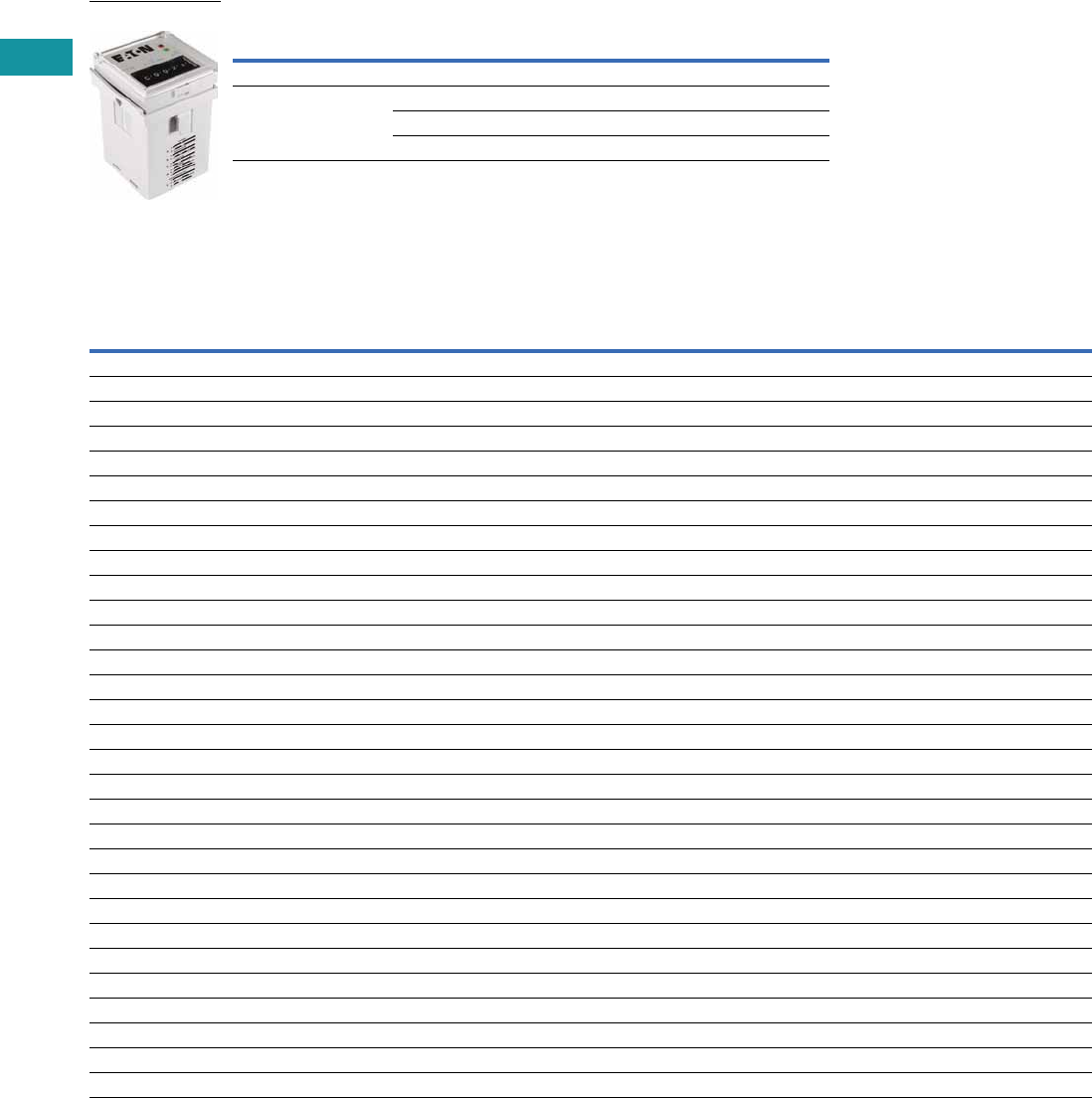
V7-T3-190 Volume 7—Logic Control, Operator Interface and Connectivity Solutions CA08100008E—June 2013 www.eaton.com
3
3
3
3
3
3
3
3
3
3
3
3
3
3
3
3
3
3
3
3
3
3
3
3
3
3
3
3
3
3
3.8
Control Relays and Timers
Ti m in g R el ay s
Product Selection
TMRP Timing Relays
Technical Data and Specifications
TMRP Timing Relays
Note
1Refer to Function Code Cross-Reference Guide on Page V7-T3-171 for function details.
Supply Voltage Description
Catalog
Number
10-Function
12–240 Vac/Vdc Control switch trigger, DPDT TMRP5100
Control switch trigger, SPDT TMRP5101
Power trigger, DPDT TMRP5102
TMRP5100
Description TMRP5100 TMRP5101 TMRP5102
Functions 1A, B, C, D, E, F, G, H, I, J A, B, C, D, E, F, G, H, I, J A, B, C
Time range 0.1 sec to 9,990 hours 0.1 sec to 9,990 hours 0.1 sec to 9,990 hours
Input
Supply voltage 12–240 Vac/Vdc 12–240 Vac/Vdc 12–240 Vac/Vdc
Supply voltage tolerance ±15% ±15% ±15%
Rated consumption 2.5 VA (2W) maximum 2.5 VA (2W) maximum 2.5 VA (2W) maximum
Reset time 150 ms 150 ms 150 ms
Reverse polarity protection Yes Yes Yes
Operate time 25 ms maximum 25 ms maximum 25 ms maximum
Release time 25 ms maximum 25 ms maximum 25 ms maximum
Rated surge voltage 4 kV 4 kV 4 kV
Output
Contact configuration DPDT SPDT DPDT
Contact rating (AC) 12A resistive at 120, 240 UL 508 12A resistive at 120, 240 UL 508 12A resistive at 120, 240 UL 508
Contact rating (DC) 12A resistive at 30 UL 508 12A resistive at 30 UL 508 12A resistive at 30 UL 508
Contact rating horsepower 1/2 at 120 Vac, 1 at 240 Vac 1/2 at 120 Vac, 1 at 240 Vac 1/2 at 120 Vac, 1 at 240 Vac
Contact rating pilot duty A300, 720 VA at 240 Vac A300, 720 VA at 240 Vac A300, 720 VA at 240 Vac
Minimum load 12V/100 mA 12V/100 mA 12V/100 mA
Contact material Silver-nickel 90/10 Silver-nickel 90/10 Silver-nickel 90/10
Contact resistance 100 milliohms max. at 1A 12 Vdc 100 milliohms max. at 1A 12 Vdc 100 milliohms max. at 1A 12 Vdc
Mechanical life—full load 10 million operations 10 million operations 10 million operations
Electrical life—full load 100,000 operations 100,000 operations 100,000 operations
Control Signal
Minimum control pulse length 50 ms minimum 50 ms minimum 50 ms minimum
Accuracy
Repetition accuracy 0.10% at constant voltage and temperature 0.10% at constant voltage and temperature 0.10% at constant voltage and temperature
Physical
Ambient temperature –10 to 55°C –10 to 55°C –10 to 55°C
Storage temperature –40 to 85°C –40 to 85°C –40 to 85°C
Mounting Use with D3PA3 socket Use with D3PA2 socket Use with D3PA2 socket

Volume 7—Logic Control, Operator Interface and Connectivity Solutions CA08100008E—June 2013 www.eaton.com V7-T3-191
3
3
3
3
3
3
3
3
3
3
3
3
3
3
3
3
3
3
3
3
3
3
3
3
3
3
3
3
3
3
3.8
Control Relays and Timers
Ti m i n g R e l ay s
Wiring Diagrams
TMRP5100 TMRP5101 TMRP5102
Dimensions
Approximate Dimensions in Inches (mm)
TMRP Series
External Control Switch
Instant if 6–7 Shorted
INPUT
5
111
2
3
4
67
8
9
10
External Control Switch
INPUT
4
1
2
3
5
8
7
6
INPUT
4
1
2
3
5
8
7
6
0.06
(1.5)
1.88
(47.8)
1.88
(47.8)
FUNCTION
A 0 0 0 S
TIME
SET
TIME
BASE
OUTPUT
INPUT
2.83
(71.9)
1.76
(44.7)
0.25
(6.4)
0.64
(16.3)
3.15
(80.0)
1
2
3
4
5
6
7
8
R.045
8-Pin Octal Base
1
2
3
4
5
6
7
8
11-Pin Octal Base
9
10
11
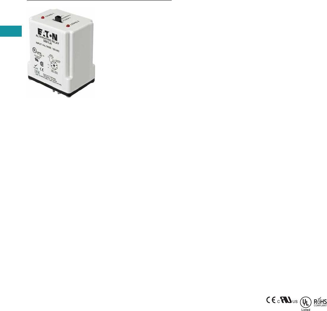
V7-T3-192 Volume 7—Logic Control, Operator Interface and Connectivity Solutions CA08100008E—June 2013 www.eaton.com
3
3
3
3
3
3
3
3
3
3
3
3
3
3
3
3
3
3
3
3
3
3
3
3
3
3
3
3
3
3
3.9
Control Relays and Timers
Alternating Relays
D85 Series—Alternating Relays
Contents
Description Page
D85 Series—Alternating Relays
Product Selection . . . . . . . . . . . . . . . . . . . . . . . V7-T3-193
Accessories . . . . . . . . . . . . . . . . . . . . . . . . . . . V7-T3-193
Technical Data and Specifications . . . . . . . . . . V7-T3-194
Wiring Diagrams . . . . . . . . . . . . . . . . . . . . . . . V7-T3-194
Dimensions . . . . . . . . . . . . . . . . . . . . . . . . . . . V7-T3-196
Product Description
Alternating relays are used
in applications where the
optimization of load usage is
required by equalizing the run
time of two loads. They are
also used where additional
capacity is required in case
of excess load requirements.
This alternating action is
initiated by a control switch—
such as a float switch, manual
switch, timing relay, pressure
switch or other isolated
contact. Each time the
initiating switch is opened,
the output relay contacts will
change state, thus alternating
the two loads. Two LED
indicators show the status of
the output relay.
The D851 and D852 Series
Relays are used with one
control switch and are
available in either SPDT or
DPDT output configurations
with or without a selector
switch to lock in one
sequence. The D852X Series
Relays are available in DPDT
cross-wired output
configurations for use with
one or two control switches
(LEAD and LAG).
The D853 Series is designed
for use with three-switch
applications (LEAD, LAG and
STOP). The D853 Series
combines a standard DPDT
Cross-Wired alternating relay,
contactor auxiliary contacts,
and a control relay into one
compact and economical
product. This saves space
and labor, while reducing the
number of components
needed. The D853 Series
uses Sequence On–
Simultaneous Off (S.O.S.O.)
operation, where the two
loads are energized
sequentially, but remain on
together until the STOP
switch is opened. This device
also protects against failure of
the STOP and LEAD
switches. If both switches
fail, the two pump motors will
be energized simultaneously
when the LAG switch is
closed.
Each of the D85 Series
alternating relays is available
with an optional three-
position selector switch,
which allows the unit to
alternate the two loads as
normal, or lock the relay to
one load or the other. By
locking the alternating relay to
one load, the other load can
be removed for service
without rewiring the first load
for continuous operation. The
selector switch has a low
profile to prevent any
accidental actuation.
Features
●For duplex loads
●Works with one-, two-, or
three-switch applications
●Compact plug-in design
using industry standard
sockets
●10A SPDT or DPDT output
configurations
●Optional low profile
selector switch to lock in
one sequence
●Two LEDs indicate relay
status
●D853 Series replaces
separate components in
duplex panel—saving
space and reducing labor
Standards and
Certifications
●CE
●cRUus
●UL listed 1
●RoHS compliant
Note
1When used with appropriate Eaton
socket.

Volume 7—Logic Control, Operator Interface and Connectivity Solutions CA08100008E—June 2013 www.eaton.com V7-T3-193
3
3
3
3
3
3
3
3
3
3
3
3
3
3
3
3
3
3
3
3
3
3
3
3
3
3
3
3
3
3
3.9
Control Relays and Timers
Alternating Relays
Product Selection
D85 Series—Alternating Relays 1
Accessories
D85 Series—Alternating Relays
Note
1 Contact Eaton for relays for 3-switch applications (Lead-Lag-Stop).
Output Contacts
Control
Voltage Socket
Catalog
Number
SPDT 12 Vac 8-pin D851NR
SPDT 24 Vac 8-pin D851NT
SPDT 120 Vac 8-pin D851NA
SPDT 240 Vac 8-pin D851NB
SPDT w/selector switch 12 Vac 8-pin D851LR
SPDT w/selector switch 24 Vac 8-pin D851LT
SPDT w/selector switch 120 Vac 8-pin D851LA
SPDT w/selector switch 240 Vac 8-pin D851LB
DPDT 12 Vac 11-pin D852NR
DPDT 24 Vac 11-pin D852NT
DPDT 120 Vac 11-pin D852NA
DPDT 240 Vac 11-pin D852NB
DPDT w/selector switch 12 Vac 11-pin D852LR
DPDT w/selector switch 24 Vac 11-pin D852LT
DPDT w/selector switch 120 Vac 11-pin D852LA
DPDT w/selector switch 240 Vac 11-pin D852LB
DPDT cross-wired 12 Vac 8-pin D852XNR
DPDT cross-wired 24 Vac 8-pin D852XNT
DPDT cross-wired 120 Vac 8-pin D852XNA
DPDT cross-wired 240 Vac 8-pin D852XNB
DPDT cross-wired w/selector switch 12 Vac 8-pin D852XLR
DPDT cross-wired w/selector switch 24 Vac 8-pin D852XLT
DPDT cross-wired w/selector switch 120 Vac 8-pin D852XLA
DPDT cross-wired w/selector switch 240 Vac 8-pin D852XLB
Description
Standard
Pack
Catalog
Number
8-pin socket 10 D3PA2
11-pin socket 10 D3PA3-A2
Hold-down spring 10 D65CHDS

V7-T3-194 Volume 7—Logic Control, Operator Interface and Connectivity Solutions CA08100008E—June 2013 www.eaton.com
3
3
3
3
3
3
3
3
3
3
3
3
3
3
3
3
3
3
3
3
3
3
3
3
3
3
3
3
3
3
3.9
Control Relays and Timers
Alternating Relays
Technical Data and Specifications
D85 Series—Alternating Relays
Wiring Diagrams
D851 Series Relays, SPDT D852 Series Relays, DPDT
Typical Installations for SPDT and DPDT Alternating Relays,
Standard Installation
In the OFF state (standard
installation), the control
switch is open, the
alternating relay is in the
LOAD A position, and both
loads (M1 and M2) are off.
When the control switch
closes, it energizes the first
load (M1). The red LED
marked “LOAD A” glows. As
long as the control switch
remains closed, M1 remains
energized.
When the control switch
opens, the first load (M1) is
turned off and the alternating
relay toggles to the LOAD B
position. When the control
switch closes again, it
energizes the second load
(M2). The red LED marked
“LOAD B” glows.
Description Specification
Voltage tolerance +10%/-15% of control voltage at 50/60 Hz
Load (burden) Less than 3 VA
Output contacts 10A resistive at 240 Vac / 30 Vdc, 1/2 hp at 120/240 Vac (NO), 1/3 hp at 120/240 Vac (NC)
Mechanical life 10,000,000 operations
Electrical life 100,000 operations
Temperature –20° to 150°F (–28° to 65°C)
Transient protection 10,000 volts for 20 microseconds
Indicator LEDs 2 LEDs marked LOAD A and LOAD B
Optional selector switch settings ALTERNATE, LOCK LOAD A, LOCK LOAD B
Load A: Pin 2
Load B: Pin 8
1
4
Input
Voltage
Control
Switch
L2 L1
36
27
8
5
1
Load A: Pins 3 or 11
Load B: Pins 1 or 9
L2L1
11
Input
Voltage
Control
Switch
48
39
6
210
75
L1
SPDT
Control
Switch
O/L
O/L
1
2
8
3
4
5
L2
M1
M2
D852X Series Relays,
DPDT Cross-Wired
D853 Series Relays,
Three-Switch Applications
Typical Installations for SPDT and DPDT Alternating Relays,
Anti-Bounce Installation
When the control switch
opens, the second load (M2)
is turned off, the alternating
relay toggles back to the
LOAD A position, and the
process can be repeated
again. On relays with DPDT
contacts, two pilot lights can
be used for remote indication
of LOAD A or LOAD B status.
To eliminate any bounce
condition of the control
switch, the addition of a
second switch (OFF) along
with two auxiliary contacts is
recommended as shown in
the Anti-Bounce Installation.
1
Lead
Lag
Load
B
Load
A
L1 L2
8
Input
Voltage
4
36
27
5
1
Lead
Lag
Load
B
Load
A
L1 L2
Stop
8
Input Voltage
4
36
27
5
SPDT
Control
Switch
L1
1
2
3
4
5
Off
M1
M1
M2
L2
M2
8
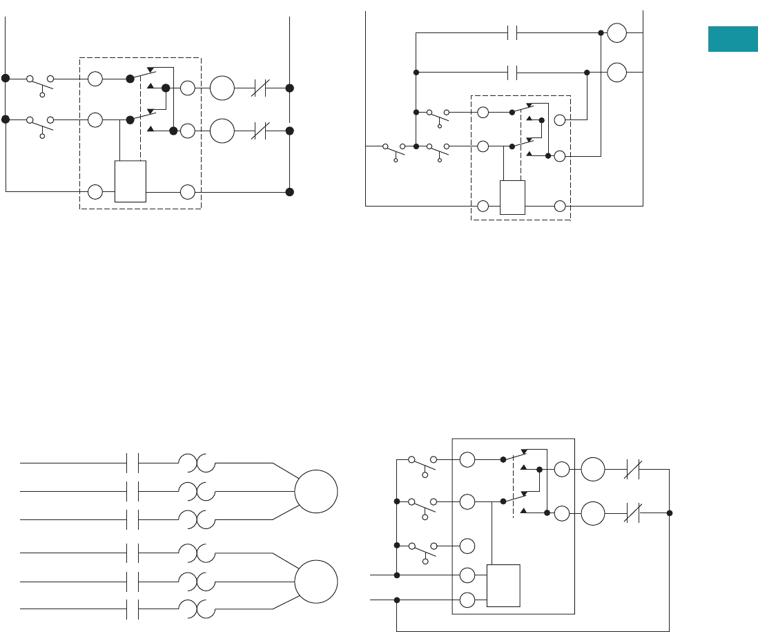
Volume 7—Logic Control, Operator Interface and Connectivity Solutions CA08100008E—June 2013 www.eaton.com V7-T3-195
3
3
3
3
3
3
3
3
3
3
3
3
3
3
3
3
3
3
3
3
3
3
3
3
3
3
3
3
3
3
3.9
Control Relays and Timers
Alternating Relays
Typical Installations for DPDT Cross-Wired Alternating
Relays, Standard Installation
In the OFF state, both the LEAD control switch and the LAG
control switch are open, the alternating relay is in the LOAD A
position, and both loads are off. When the LEAD control switch
closes, it energizes the first load (M1). The red LED marked
“LOAD A” glows. As long as the LEAD control switch remains
closed, M1 remains energized. If the LAG control switch closes,
it energizes the second load (M2).
When the LAG control switch opens, the second load (M2) is
turned off. When the LEAD control switch opens, the first load
(M1) is turned off and the alternating relay toggles to the LOAD
B position.
Typical Installations for DPDT Cross-Wired Alternating
Relays, Anti-Bounce Installation
When the LEAD control switch closes, it turns on the second
load (M2). The red LED marked “LOAD B” glows. If the LAG
control switch closes, it will energize the first load (M1). When
the LAG control switch opens, the first load (M1) is turned off.
When the LEAD control switch opens, the second load (M2) is
turned off, the alternating relay toggles back to the LOAD A
position, and the process can be repeated again.
To eliminate any bounce condition of the control switch, the
addition of a second switch (OFF) along with two auxiliary
contacts is recommended as shown in the Anti-Bounce
Installation.
Typical Installations for DPDT Cross-Wired Relays for Three-Switch Applications
In the OFF state, all three switches are open, the alternating relay
is in the LOAD A position, and both loads are off. No action
happens with the alternating relay or either load when the STOP
switch closes. When the LEAD switch closes, Load #1 (M1) turns
on. When the LAG switch closes, Load #2 (M2) turns on. Both
loads remain on as long as all three switches are closed.
When the LAG switch opens, Load #2 (M2) remains on because
the STOP switch is still closed. When the LEAD switch opens,
Load #1 (M1) remains on because the STOP switch is still
closed. When the STOP switch opens, both Load #1 (M1) and
Load #2 (M2) are turned off simultaneously.
The alternating relay toggles to the LOAD B position. The entire
cycle is then repeated, but with Load #2 (M2) energized first
followed by Load #1 (M1). This type of operation is known as
“Sequence On–Simultaneously Off (S.O.S.O.)”—the two loads
are energized sequentially, but remain on together until the
STOP switch is opened.
If both the STOP switch and LEAD switch fail to close and turn
on the first load, both loads will be turned on simultaneously
when the LAG switch is closed.
L1
Lag
Lead
Cross-Wired
O/L
O/L
1
2
8
3
7
6
L2
M1
M2
Lag
Off Lead
L2
L1
M1
Cross-Wired
M2
1
2
3
7
6
M1
M2
8
L1
Motor
1
Motor
2
L2
L3
L1
M1
M1
M1
M2
M2
M2
M2
M1
L2 L1
Lag
Switch
Lead
Switch
Stop
Switch
L2
L3
1
2
4
8
7
3
6
O/L
O/L
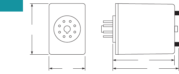
V7-T3-196 Volume 7—Logic Control, Operator Interface and Connectivity Solutions CA08100008E—June 2013 www.eaton.com
3
3
3
3
3
3
3
3
3
3
3
3
3
3
3
3
3
3
3
3
3
3
3
3
3
3
3
3
3
3
3.9
Control Relays and Timers
Alternating Relays
Dimensions
Approximate Dimensions in Inches (mm)
D85 Series—Alternating Relays
2.4
(60)
1.7
(43)
2.9
(74) 3.1
(79)
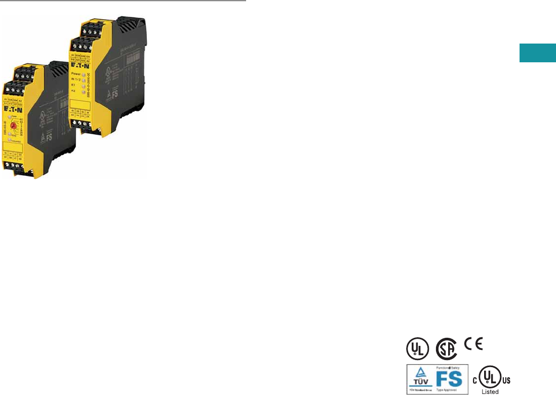
Volume 7—Logic Control, Operator Interface and Connectivity Solutions CA08100008E—June 2013 www.eaton.com V7-T3-197
3
3
3
3
3
3
3
3
3
3
3
3
3
3
3
3
3
3
3
3
3
3
3
3
3
3
3
3
3
3
3.10
Control Relays and Timers
Safety Relays
Safety Relays
Contents
Description Page
Safety Relays
Product Selection . . . . . . . . . . . . . . . . . . . . . . . V7-T3-198
Technical Data and Specifications . . . . . . . . . . V7-T3-199
Dimensions . . . . . . . . . . . . . . . . . . . . . . . . . . . V7-T3-202
Product Description
Safety relays are intended to
reliably monitor the signals
from safety devices at all
times and switch off quickly
and reliably in an emergency.
Single-channel and dual
channel versions are available
for the construction of safety
applications. The internal
logic of the safety relays
monitors the safety circuits
(emergency stop, guard door,
and so on) and activates the
enable paths in a fault-free
condition. Upon actuation of
the safety device or in the
even of a fault, the enable
paths are switched off. Any
faults that occur in the control
circuit, such as ground fault,
cross connection fault or wire
breakage are also detected.
Application Description
Eaton’s ESR5 safety relays
provide optimal safety and a
high degree of reliability on
plant machinery. Applications
that meet the highest
safety requirements in
accordance with EN 954-1,
EN ISO 13849-1 up to PL e
and accordance with
IEC 62061 up to SILCL 3
can be realized with the
ESR5 safety relay.
Compatible with a wide
variety of safety devices:
●Emergency stops
●Rope pulls
●Two-hand control stations
●Light curtain (OSSD)
●Gate enable device
●Safety switches
Features
●Use for the highest
safety requirements in
accordance with EN 954-1
EN ISO 13849-1,
IEC 62061 and EC 61508
●Suitable for the world
market with UL, cUL
certifications and TÜV
Rhineland functional
safety certifications
●Applicable for EN 60204
stop categories 0 or 1
●Plug-in screw terminals
for fast and fault-free
replacement
●Multi-voltage versions
(24–230 Vac/Vdc) for a
flexible range of application
●Delayed and non-delayed
contact expansions
accommodate a wide
variety of applications
Standards and
Certifications
●UL 508; CSA-C22.2 No
14-95; CE Marked
●UL/cUL file number:
E29184
●Degree of protection: IP20
●TÜV Rhineland certified
●UL/cULus listed
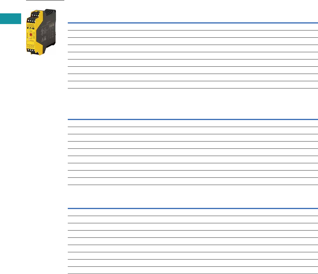
V7-T3-198 Volume 7—Logic Control, Operator Interface and Connectivity Solutions CA08100008E—June 2013 www.eaton.com
3
3
3
3
3
3
3
3
3
3
3
3
3
3
3
3
3
3
3
3
3
3
3
3
3
3
3
3
3
3
3.10
Control Relays and Timers
Safety Relays
Product Selection
Technical Overview
Application Overview
Application Overview, continued
Notes
1 Laser scanners or light curtains with OSSD outputs.
2 All main units can also be reset automatically or manually.
Single
Channel
Dual
Channel
Safety
Output (NO)
Safety
Output (NO)
(Delayed)
Output
Delay
Signal
Output
(NC)
Feedback
Output
Control
Voltage
Removable
Terminal
Blocks
Type of
Unit Catalog Number
■ — 4 — — 1 — 24 Vac/Vdc ■ Main ESR5-NO-41-24VAC-DC
■ ■ 2 — —1 —24 Vac/Vdc■ Main ESR5-NO-21-24VAC-DC
■ ■ 3 — —1 —24 Vac/Vdc■ Main ESR5-NO-31-24VAC-DC
■ ■ 3 — —1 —230 Vac ■ Main ESR5-NO-31-230VAC
■ ■ 3 — —1 —24–230 Vac/Vdc■ Main ESR5-NO-31-AC-DC
■ ■ 2 2 0.1–30s — — 24 Vdc ■ Main ESR5-NV3-30
—■ 2 — —1 —24 Vac/Vdc■ Main ESR5-NZ-21-24VAC-DC
■ — 5 — — 1 1 24 Vac/Vdc ■ Expansion ESR5-NE-51-24VAC-DC
■ — — 4 0.3–3s 1 1 24 Vdc ■ Expansion ESR5-VE3-42
Emergency
Stop
Safety
Switches
Light Curtain/
OSSD 1
Two-Hand Control
(EN 574 Type III C)
Contact
Expansion Off-Delayed
Cross Circuit
Recognition
Monitored
Manual Reset 2Catalog Number
■ ■ —— ——— — ESR5-NO-41-24VAC-DC
■ ■ —— ——■ — ESR5-NO-21-24VAC-DC
■ ■ —— ——■ — ESR5-NO-31-24VAC-DC
■ ■ —— ——■ ■ ESR5-NO-31-230VAC
■ ■ —— ——■ ■ ESR5-NO-31-AC-DC
■ ■ ■ ——■ ■ ■ ESR5-NV3-30
—■ — ■ —— ■ — ESR5-NZ-21-24VAC-DC
——— — ■ —— — ESR5-NE-51-24VAC-DC
——— — ■ ■ —— ESR5-VE3-42
Single
Channel
Dual
Channel
Stop Category
EN 60204
Control Category
to EN 954-1
Achievable PL per
ISO 13849-1
Achievable SIL per
EN IEC 62061 Catalog Number
■ —0 2 PL d SIL 3 ESR5-NO-41-24VAC-DC
■ ■ 04 PL e SIL 3 ESR5-NO-21-24VAC-DC
■ ■ 04 PL e SIL 3 ESR5-NO-31-24VAC-DC
■ ■ 04 PL e SIL 3 ESR5-NO-31-230VAC
■ ■ 04 PL e SIL 3 ESR5-NO-31-AC-DC
■ ■ 0/1 4 PL e SIL 3 ESR5-NV3-30
—■ 04 PL e SIL 3 ESR5-NZ-21-24VAC-DC
■ —0 4 PL e SIL 3 ESR5-NE-51-24VAC-DC
■ —1 3 PL d SIL 2 ESR5-VE3-42
Safety Relays

Volume 7—Logic Control, Operator Interface and Connectivity Solutions CA08100008E—June 2013 www.eaton.com V7-T3-199
3
3
3
3
3
3
3
3
3
3
3
3
3
3
3
3
3
3
3
3
3
3
3
3
3
3
3
3
3
3
3.10
Control Relays and Timers
Safety Relays
Technical Data and Specifications
Safety Relay
Description Unit ESR5-NO-21_ ESR5-NO-41_ ESR5-NO-31-24VAC-DC ESR5-NZ-21_
General
Standards EN ISO 13849-1, IEC 62061,
IEC 61508, DIN EN 50178,
UL/CUL listed
EN ISO 13849-1, IEC 62061,
IEC 61508, DIN EN 50178,
UL/CUL listed
EN ISO 13849-1, IEC 62061,
IEC 61508, DIN EN 50178,
UL/CUL listed
EN ISO 13849-1, IEC 62061,
IEC 61508, DIN EN 50178,
UL/CUL listed
Type-dependent standards ———EN 574 Part no. IIIC
Lifespan, mechanical—c (contacts) x 10610 10 10 10
Maximum operating frequency Ops/h 3600 3600 3600 3600
Climatic proofing Cold according to
EN 60068-2-1, dry heat
according to EN60068-2-2,
damp heat according to
EN 60068-2-3
Dry heat according to
EN60068-2-2, damp heat
according to EN 60068-2-3
Cold according to
EN 60068-2-1, dry heat
according to EN60068-2-2,
damp heat according to
EN 60068-2-3
Dry heat according to
EN60068-2-2, damp heat
according to EN 60068-2-3
Ambient temperature °F (°C) –4° to 131° (–20° to 55°) –4° to 131° (–20° to 55°) –4° to 131° (–20° to 55°) –4° to 131° (–20° to 55°)
Ambient temperature storage °F (°C) –13° to 167° (–25° to 75°) –13° to 167° (–25° to 75°) –13° to 167° (–25° to 75°) –13° to 167° (–25° to 75°)
Mounting position Any Any Any Any
Vibration resistance (IEC/EN 60068-2-6) 2g, frequency: 10–150 Hz,
amplitude: 0.15 mm
2g, frequency: 10–150 Hz,
amplitude: 0.15 mm
2g, frequency: 10–150 Hz,
amplitude: 0.15 mm
2 g, frequency: 10–150 Hz,
amplitude: 0.15 mm
Shock resistance (IEC 60068-2-27) ————
Protection type
Housing IP20 IP20 IP20 IP20
Terminals IP20 IP20 IP20 IP20
Protection against direct contact when
actuated from front (IEC 0106 Part 100)
Finger- and back-of-hand
proof
Finger- and back-of-hand
proof
Finger- and back-of-hand
proof
Finger- and back-of-hand
proof
Weight kg 0.17 0.22 0.17 0.22
Terminal capacity
Solid or flexible mm21 x (0.2–2.5)
2 x (0.2–1)
1 x (0.2–2.5)
2 x (0.2–1)
1 x (0.2–2.5)
2 x (0.2–1)
1 x (0.2–2.5)
2 x (0.2–1)
Flexible with ferrule mm21 x (0.25–2.5)
2 x (0.25–1)
1 x (0.25–2.5)
2 x (0.25–1)
1 x (0.25–2.5)
2 x (0.25–1)
1 x (0.25–2.5)
2 x (0.25–1)
Solid or stranded AWG 24–12 24–12 24–12 24–12
Terminal screw
Pozidriv screwdriverSize2222
Flat-blade screwdriver mm 0.6 x 3.5 0.6 x 3.5 0.6 x 3.5 0.6 x 3.5
Max. tightening torque Nm 0.6 0.6 0.6 0.6
Main Contacts
Rated impulse withstand voltage—Uimp Vac 6000 4000 4000 6000
Overvoltage category/pollution degree
Outside III/2 III/2 III/2 III/2
Inside ————
Rated insulation voltage—UiVac 250 250 250 250
Rated operating voltage—UeVac 230 230 230 230
Rated operation current
AC-15
230V (360 ops./h)—IeA5454
230V (3600 ops./h)—IeA3333
DC-13
24V (360 ops./h)—IeA6464
24V (3600 ops./h)—IeA 3 2.5 3 2.5
Max. summation current of all poles
24 Vac/Vdc devices A 72 72 72 72
230 Vac devices A————
Square of the total current
(and total current)
of all current paths
72 A2 (6 + 6) 72 A2 (4.2 + 4.2 + 4.2 + 4.2) 72 A2 (4.9 + 4.9 + 4.9) 72 A2 (6 + 6)
Short-circuit protection
Max. fuse A gG/gL 10 6 10 6

V7-T3-200 Volume 7—Logic Control, Operator Interface and Connectivity Solutions CA08100008E—June 2013 www.eaton.com
3
3
3
3
3
3
3
3
3
3
3
3
3
3
3
3
3
3
3
3
3
3
3
3
3
3
3
3
3
3
3.10
Control Relays and Timers
Safety Relays
Safety Relay, continued
Description Unit ESR5-NO-21_ ESR5-NO-41_ ESR5-NO-31-24VAC-DC ESR5-NZ-21_
Power Supply Circuit
Actuating voltage 50/60 Hz Vac 24 24 24 24
Actuating voltage—UsVdc24242424
Voltage tolerance pick-up voltage x e0.85–1.1 0.85–1.1 0.85–1.1 0.85–1.1
Power consumption
AC operated 50/60 Hz VA ————
AC operated 50/60 Hz W 3.4 3.4 3.4 3
DC operated W 1.6 1.6 1.6 1.5
Fuse for control circuit supply
24V Short-circuit proof Short-circuit proof Short-circuit proof Short-circuit proof
115/230V ————
Control Circuit
Rated output voltage Vdc 24 24 24 24
Rated operational current mA S12, S22: 30, S34: 45 S12: 65, S34: 40 S12, S22: 30, S34: 45 S11, S21: 60, Y2: 45
Resistance—R 50225022
Short-circuit current A 2.3 2.3 2.3 2.3
Response time ms 100 65 100 50
Recovery time ms————
Response time with reset monitoring—tA1 ms————
Response time without reset monitoring—tA2 ms 100 65 100 50
Reset time—tR/tR1 ms Single-channel 45;
dual-channel 10
45 Single-channel 45;
dual-channel 10
20
Minimum on duration—tMms————
Recovery time—tWms Approx. 1000 Approx. 1000 Approx. 1000 Approx. 1000
Synchronous monitoring time—tSms———500
Electromagnetic Compatibility (EMC)
Emitted interference EN 61000-6-4 EN 61000-6-4 EN 61000-6-4 EN 61000-6-4
Interference immunity According to EN 61000-6-2,
EN 62061
According to EN 61000-6-2 According to EN 61000-6-2,
EN 62061
According to EN 61000-6-2

Volume 7—Logic Control, Operator Interface and Connectivity Solutions CA08100008E—June 2013 www.eaton.com V7-T3-201
3
3
3
3
3
3
3
3
3
3
3
3
3
3
3
3
3
3
3
3
3
3
3
3
3
3
3
3
3
3
3.10
Control Relays and Timers
Safety Relays
Safety Relay, continued
Description Unit ESR5-NO-31-230VAC
ESR5-NO-31-24V-
230VAC-DC ESR5-NV3_ ESR5-VE3_ ESR5-NE-51_
General
Standards EN ISO 13849-1, IEC 62061,
IEC 61508, DIN EN 50178,
UL/CUL listed
EN ISO 13849-1, IEC 62061,
IEC 61508, DIN EN 50178,
UL/CUL listed
EN ISO 13849-1, IEC 62061,
IEC 61508, DIN EN 50178,
UL/CUL listed
EN ISO 13849-1, IEC 62061,
IEC 61508, DIN EN 50178,
UL/CUL listed
EN ISO 13849-1, IEC 62061,
IEC 61508, DIN EN 50178,
UL/CUL listed
Type-dependent standards EN 60204
(if applicable)
EN 60204
(if applicable)
EN 60204
(if applicable)
——
Lifespan, mechanical—c (contacts) x 10610 10 10 10 10
Maximum operating frequency Ops/h 3600 3600 3600 900 3600
Climatic proofing Dry heat according to
EN60068-2-2, damp heat
according to EN 60068-2-3
Dry heat according to
EN60068-2-2, damp heat
according to EN 60068-2-3
Cold in accordance with:
EN 60068-2-1, dry heat in
accordance with EN
60068-2-2, humidity
storage test in accordance
with 60068-2-78
Dry heat according to
EN60068-2-2, damp heat
according to EN 60068-2-3
Dry heat according to
EN60068-2-2, damp heat
according to EN 60068-2-3
Ambient temperature °F (°C) –4° to 131° (–20° to 55°) –4° to 131° (–20° to 55°) –4° to 113° (–20° to 45°) –4° to 131° (–20° to 55°) –4° to 131° (–20° to 55°)
Ambient temperature storage °F (°C) –13° to 167° (–25° to 75°) –13° to 167° (–25° to 75°) –13° to 167° (–25° to 75°) –13° to 167° (–25° to 75°) –13° to 167° (–25° to 75°)
Mounting position Any Any Any Any Any
Vibration resistance (IEC/EN 60068-2-6) 2g, frequency: 10–150 Hz,
amplitude: 0.15 mm
2g, frequency: 10–150 Hz,
amplitude: 0.15 mm
2g, frequency: 10–150 Hz,
amplitude: 0.15 mm
2g, frequency: 10–150 Hz,
amplitude: 0.15 mm
2g, frequency: 10–150 Hz,
amplitude: 0.15 mm
Shock resistance (IEC 60068-2-27)—————
Protection type
Housing IP40 IP40 IP20 IP20 IP20
Terminals IP20 IP20 IP20 IP20 IP20
Protection against direct contact when
actuated from front (IEC 0106 Part 100)
Finger- and back-of-hand
proof
Finger- and back-of-hand
proof
Finger- and back-of-hand
proof
Finger- and back-of-hand
proof
Finger- and back-of-hand
proof
Weight kg 0.3 0.3 0.17 0.17 0.22
Terminal capacity
Solid or flexible mm21 x (0.2–2.5)
2 x (0.2–1)
1 x (0.2–2.5)
2 x (0.2–1)
1 x (0.2–2.5)
2 x (0.2–1)
1 x (0.2–2.5)
2 x (0.2–1)
1 x (0.2–2.5)
2 x (0.2–1)
Flexible with ferrule mm21 x (0.25–2.5)
2 x (0.25–1)
1 x (0.25–2.5)
2 x (0.25–1)
1 x (0.25–2.5)
2 x (0.25–1)
1 x (0.25–2.5)
2 x (0.25–1)
1 x (0.25–2.5)
2 x (0.25–1)
Solid or stranded AWG 24–12 24–12 24–12 24–12 24–12
Terminal screw
Pozidriv screwdriverSize22222
Flat-blade screwdriver mm 0.6 x 3.5 0.6 x 3.5 0.6 x 3.5 0.6 x 3.5 0.6 x 3.5
Max. tightening torque Nm 0.6 0.6 0.6 0.6 0.6
Main Contacts
Rated impulse withstand voltage—Uimp Vac 6000 6000 4000 4000 4000
Overvoltage category/pollution degree
Outside III/2 III/2 III/2 III/2 III/2
Inside —————
Rated insulation voltage—UiVac 250 250 250 250 250
Rated operating voltage—UeVac 230 230 230 230 230
Rated operation current
AC-15
230V (360 ops./h)—IeA44—54
230V (3600 ops./h)—IeA33333
DC-13
24V (360 ops./h)—IeA44—64
24V (3600 ops./h)—IeA2.52.5332.5
Max. summation current of all poles
24 Vac/Vdc devices A 50 50 49 50 50
230 Vac devices A 50 50 — — —
Square of the total current
(and total current)
of all current paths
50 A2 (4 + 4 + 4) 50 A2 (4 + 4 + 4) 50 A2 (4 + 4 + 4) 49 A2
(3.5 + 3.5 + 3.5 + 3.5)
50 A2
(3.7 + 3.7 + 3.7 + 3.7
+ 3.7)
Short-circuit protection
Max. fuse A gG/gL 6 6 10 10 6
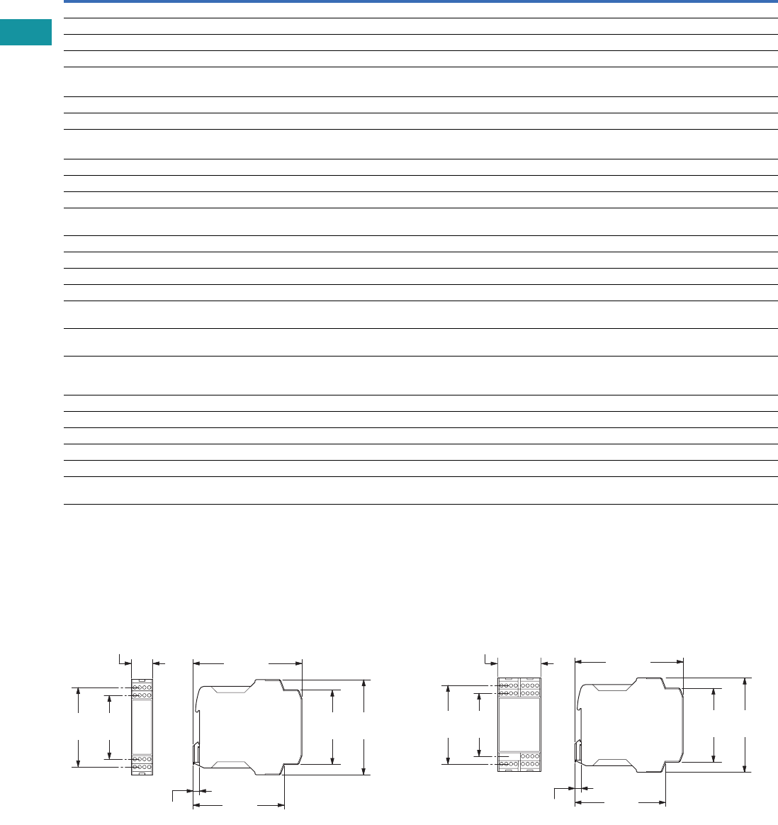
V7-T3-202 Volume 7—Logic Control, Operator Interface and Connectivity Solutions CA08100008E—June 2013 www.eaton.com
3
3
3
3
3
3
3
3
3
3
3
3
3
3
3
3
3
3
3
3
3
3
3
3
3
3
3
3
3
3
3.10
Control Relays and Timers
Safety Relays
Safety Relay, continued
Dimensions
Approximate Dimensions in Inches (mm)
Safety Relays, Contact Expansion Modules
ESR5_ 24 Vac/Vdc ESR5_ 230 Vac
Description Unit ESR5-NO-31-230VAC
ESR5-NO-31-24V-
230VAC-DC ESR5-NV3_ ESR5-VE3_ ESR5-NE-51_
Power Supply Circuit
Actuating voltage 50/60 Hz Vac 230 24–230 — — 24
Actuating voltage—UsVdc—230242424
Voltage tolerance pick-up voltage x e0.85–1.1 0.85–1.1 0.85–1.1 0.85–1.1 0.8–1.1
Power consumption
AC operated 50/60 Hz VA —————
AC operated 50/60 Hz W 5.8 5.8 — — 2.2
DC operated W 2.9 2.9 1.8 2 2.2
Fuse for control circuit supply
24V — Short-circuit proof — — —
115/230V Short-circuit proof Short-circuit proof — — —
Control Circuit
Rated output voltage Vdc 24 24 24 24 24
Rated operational current mA S10, S12, S22: 35, S34,
S35: 45
S10, S12, S22: 35, S34,
S35: 45
S12, S22: 3.5, S34, S35: 7 A1, A2: 84, K1/K2: 5 A1, A2: 92
Resistance—R 11 11 500 — —
Short-circuit current A 0.7 0.7 0.1 — —
Response time ms 250 250 150 20 20
Recovery time ms—————
Response time with reset
monitoring—tA1
ms 60 60 150 20 20
Response time without reset
monitoring—tA2
ms 250 250 150 20 20
Reset time—tR/tR1 ms 20 20 20 (non-delayed enable
paths); 100 (min. delayed
enable paths)
0.3–3 s (+50%)
adjustable
20
Minimum on duration—tMms—————
Recovery time—tWms Approx. 1000 Approx. 1000 Approx. 330 Approx. 1000 —
Synchronous monitoring time—tSms—————
Electromagnetic Compatibility (EMC)
Emitted interference EN 61000-6-4 EN 61000-6-4 EN 61000-6-4 EN 61000-6-4 EN 61000-6-4
Interference immunity According to
EN 61000-6-2
According to
EN 61000-6-2
According to EN 61000-6-2,
EN 62061
According to
EN 61000-6-2
According to
EN 61000-6-2
0.88
(22.5)
0.26
(6.6)
4.51
(114.5)
3.74
(95.1)
3.26
(82.8)
2.62
(66.5)
3.06
(77.6)
3.90
(99.0)
0.26
(6.6)
4.51
(114.5)
3.74
(95.1)
3.06
(77.6)
3.90
(99.0)
3.26
(82.8)
2.62
(66.5)
1.77
(45.0)

Volume 7—Logic Control, Operator Interface and Connectivity Solutions CA08100008E—June 2013 www.eaton.com V7-T3-203
3
3
3
3
3
3
3
3
3
3
3
3
3
3
3
3
3
3
3
3
3
3
3
3
3
3
3
3
3
3
3.11
Control Relays and Timers
easySafety
easySafety
Contents
Description Page
easySafety
Product Selection . . . . . . . . . . . . . . . . . . . . . . . V7-T3-204
Accessories . . . . . . . . . . . . . . . . . . . . . . . . . . . V7-T3-204
Technical Data and Specifications . . . . . . . . . . V7-T3-205
Dimensions . . . . . . . . . . . . . . . . . . . . . . . . . . . V7-T3-208
Product Description
The easySafety control relay
for safety-related applications
monitors all commonly used
safety devices and also takes
over the required control tasks
for the machine. Packed with
a host of conventional safety
relays in the form of safety
function blocks, easySafety
not only features integrated
safety functions but also
standard functions in a single
device—all in one.
In addition to the safety circuit
diagram containing the safety
configuration, the safety
control relay also contains a
standard circuit diagram. This
circuit diagram can be used
for standard tasks, such as
the processing of diagnostics
signals or general control
tasks of a machine.
Application Description
Because of the large number
of safety function blocks,
the user can tackle a large
number of application options
with only one device. The
user can also respond
directly
to future and changing
application requirements.
This saves financial resources
and offers future investment
security. Last but not least,
it reduces the stock-keeping
required for special safety
relays. The easySafety meets
the requirements of
Category 4 to EN 954‐1, PL e
to EN ISO 13849‐1, SILCL 3
to EN IEC 62061 and SIL 3 to
EN IEC 61508. With easySafety,
it is possible to implement
applications meeting the
most stringent safety
requirements.
Safety function blocks:
●Emergency stop
●Guard door monitoring
with and without interlock/
guard locking
●Two-hand control (EN 574)
●Electro-sensitive protective
devices (light curtains)
●Light curtain muting
●Enable switch
●Start device
●Operating mode selector
●Safety timing relay
●Overspeed monitoring
●Feedback loop monitoring
(EDM)
●Zero speed monitoring
Features
●All-in-one: Safety and
control functions combined
in one device
●Simple configuration
through prefabricated and
tested safety components
●Direct state display and
increased machine
availability due to fast
error diagnosis through
integrated display
●Multistep password
concept prevents
unwanted manipulation
Standards and
Certifications
●Product standards:
CE marked; UL 508;
CSA C22.20.4-04;
CSA 22.2 No. 142-MI1987
●UL CCN: NRAQ
●CSA File No. 012528
●CSA Class No. 2252-81
and 2252-01
●TÜV Rhineland certified
●Degree of Protection IEC:
IP20
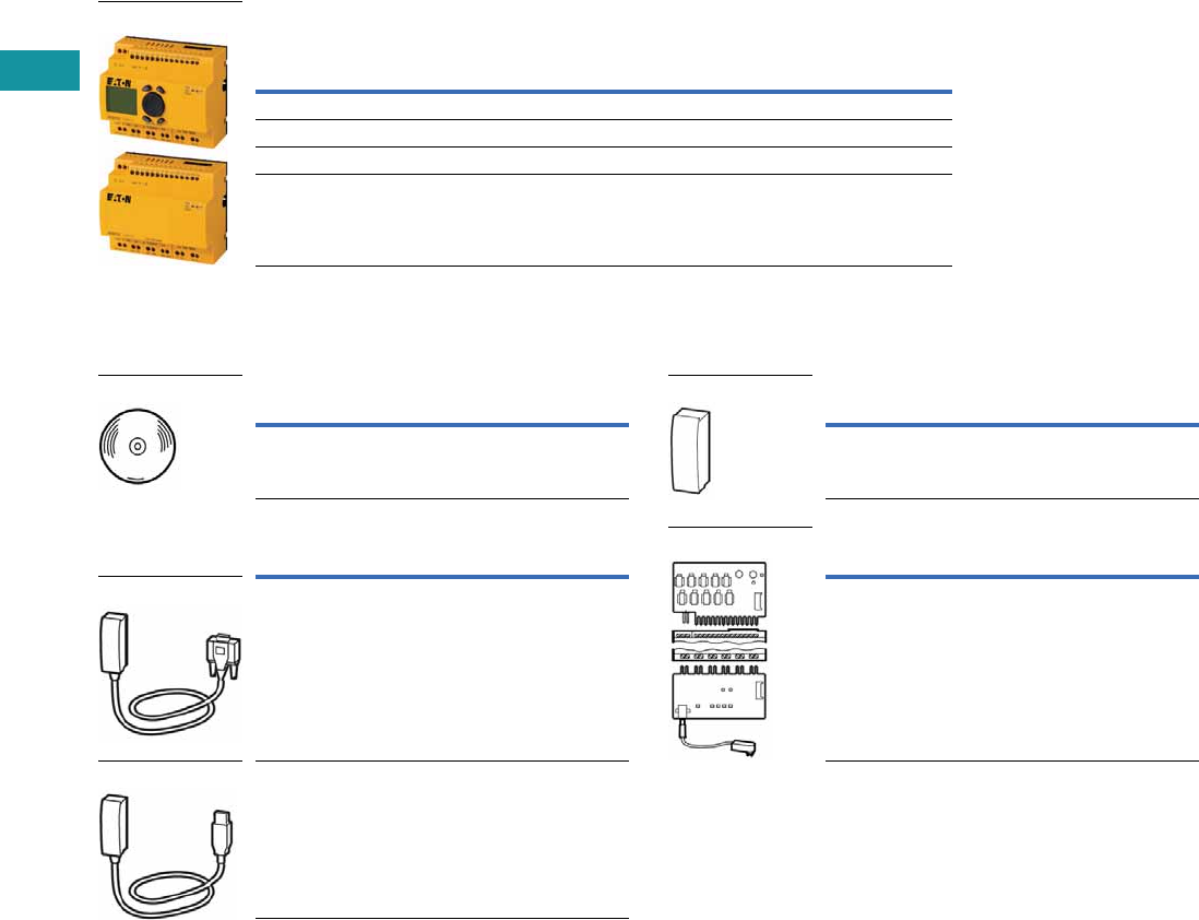
V7-T3-204 Volume 7—Logic Control, Operator Interface and Connectivity Solutions CA08100008E—June 2013 www.eaton.com
3
3
3
3
3
3
3
3
3
3
3
3
3
3
3
3
3
3
3
3
3
3
3
3
3
3
3
3
3
3
3.11
Control Relays and Timers
easySafety
Product Selection
easySafety Relays 1
Accessories
Programming Software
Programming Cables
Memory Card
Input/Output Simulator
Notes
1EN 954-1: 1996, Category 4.
EN ISO 13849-1: 2006, PL e (Performance Level).
IEC 61508: 1998, SIL 3 (Safety Integrity Level).
IEC 62061: 2005, SILCL 3 (Safety Integrity Level Claim Limit).
Expandable: standard inputs/outputs and standard bus systems.
24 Vdc supply voltage.
2Operating systems:
Windows® 2000 SP4, Windows XP SP1, Windows Vista (32 bit).
Inputs (Safety)
Outputs
(Safety)
Outputs
(Safety)
Outputs
(Safety) Display +
KeypadDigital 6A Relay Transistor Test Signal Catalog Number
14 1 (redundant) 4 4 — ES4P-221-DMXX1
14 1 (redundant) 4 4 Yes ES4P-221-DMXD1
144—4—ES4P-221-DRXX1
144—4YesES4P-221-DRXD1
easySafety
Description Catalog Number
easySoft-Safety
(including easySoftPro) 2
ESP-SOFT
Description Catalog Number
SUB-D, nine-pole, serial, 2m EASY800-PC-CAB
USB, 2m EASY800-USB-CAB
easySoft
SUB-D Cable
USB Cable
Description Catalog Number
256 kB module ES4A-MEM-CARD1
Description Catalog Number
With plug-in power supply unit
100–240 Vac/24 Vdc
ES4A-221-DMX-SIM
Memory Card
Input/Output Simulator

Volume 7—Logic Control, Operator Interface and Connectivity Solutions CA08100008E—June 2013 www.eaton.com V7-T3-205
3
3
3
3
3
3
3
3
3
3
3
3
3
3
3
3
3
3
3
3
3
3
3
3
3
3
3
3
3
3
3.11
Control Relays and Timers
easySafety
Technical Data and Specifications
easySafety Relay
Description Unit ES4P_
General
Standards EN 55011, EN 55022, IEC/EN 61000-4, IEC 60068-2-6,
IEC 60068-2-27, EN 954-1: Category 4,
EN ISO 13849-1: PL e, EN IEC 62061: SILCL 3, EN IEC 61508: SIL 3
Dimensions (W x H x D) mm 107.5 (6 space units) x 90 x 72
Mounting Top-hat rail IEC/EN 60715, 35 mm or screw fixing using fixing brackets ZB4-101-GF1 (accessories)
Times
Inputs
Maximum duration of external test pulse ms 1
Semi-conductor output
Off test pulse ms <1
Switch-off delay ms <0.15
Terminal Capacity
Solid mm2 0.2–4 (AWG 22–12)
Flexible with ferrule mm2 0.2–2.5 (AWG 22–12)
Standard screwdriver mm 3.5 x 0.8
Maximum tightening torque Nm 0.6
Ambient Climatic Conditions
Operating ambient temperature °C –25 to +55, low temperatures to IEC 60068-2-1, high temperatures to IEC 60068-2-2
Condensation Prevent condensation by means of suitable measures
LCD display (clearly legible) °C 0 to +55
Storage °C –40 to +70
Relative humidity, noncondensing (IEC/EN 60068-2-30) % 5 to 95
Air pressure (in operation) hPa 795 to 1080
Ambient Mechanical Conditions
Protection type, IEC/EN 60529 IP20
Vibrations (IEC/EN 60068-2-6)
Constant amplitude 0.15 mm Hz 10 to 57
Constant acceleration, 2g Hz 57 to 150
Mechanical shock resistance (IEC/EN 60068-2-27)
semi-sinusoidal 15g/11 ms
Shocks 18
Drop to IEC/EN 60068-2-31 Drop mm 50
Mounting position Horizontal/vertical
Electromagnetic Compatibility (EMC) According
to IEC/EN 61000-6-2
Electrostatic discharge (IEC/EN 61000-4-2, Level 3, ESD)
Air discharge kV 8
Contact discharge kV 6
Radio interference suppression (EN 55011) EN 55011 Class B, EN 55022 Class B
Power pulses (surge) (IEC/EN 61000-4-5, Level 2) kV 1 (supply cables, symmetrical)
Insulation Resistance
Overvoltage category/pollution degree III/2
Clearance in air and creepage distances EN 50178, UL 508, CSA C22.2, No. 142, EN 60664-1:2003
Insulation resistance EN 50178
Backup/Accuracy of the Real-Time Clock
Accuracy of the real-time clock s/day Normally ±5 (±0.5 h/year)
Repetition Accuracy of Timing Relays in
Standard Circuit
Accuracy of timing relay (of value) % ±0.02
Resolution
Range “S” ms 5
Range “M:S” s 1
Retentive Memory
Write cycles of the retentive memory (minimum) 10,000,000,000 (1010) (read/write cycles)

V7-T3-206 Volume 7—Logic Control, Operator Interface and Connectivity Solutions CA08100008E—June 2013 www.eaton.com
3
3
3
3
3
3
3
3
3
3
3
3
3
3
3
3
3
3
3
3
3
3
3
3
3
3
3
3
3
3
3.11
Control Relays and Timers
easySafety
easySafety Relay, continued
Description Unit ES4P_
Power Supply
Rated operational voltage Ue V 24 Vdc (–15/+20%)
Permissible range Vdc 20.4 to 28.8
Ripple % 5
Interfaces
EASYNet (CAN-based)
Bus termination (first and last station) Yes
Control operating mode EASYNet
Number of users Maximum 8
NET Network
Stations Number Maximum 8
Data transfer rate/distance 1000 Kbit/s, 6m
500 Kbit/s, 25m
250 Kbit/s, 60m
125 Kbit/s, 125m
50 Kbit/s, 300m
20 Kbit/s, 700m
10 Kbit/s, 1000m
Bus lengths greater than 40m can only be achieved with enhanced cross-section conductors and
terminal adapters
Potential isolation
From power supply Yes
From the inputs Yes
From the outputs Yes
From the PC interface, memory card, NET network, EASYLink Yes
Bus termination (first and last station) Yes
Terminal type RJ45
Digital Inputs 24 Vdc
Number 14
Inputs can be used as analog inputs —
Status display LCD display (if provided)
Potential isolation
From power supply No
Between digital inputs No
From the outputs Yes
From PC interface, memory card, EASYLink No
From network EASYNet Yes
Rated operational voltage Ue Vdc 24
At signal “0” Ue Vdc <5
At signal “1” Ue Vdc >15
Clock Outputs
Number 4
Voltage Vdc 24
Electrical isolation No

Volume 7—Logic Control, Operator Interface and Connectivity Solutions CA08100008E—June 2013 www.eaton.com V7-T3-207
3
3
3
3
3
3
3
3
3
3
3
3
3
3
3
3
3
3
3
3
3
3
3
3
3
3
3
3
3
3
3.11
Control Relays and Timers
easySafety
easySafety Relay, continued
Description Unit ES4P_
Relay Outputs
Number 4 for ES4P-…-DR_, 1 redundant for ES4P-…-DM_
Outputs in groups of 1
Parallel switching of outputs to increase power Not permissible
Protection of an output relay Fuse: 6A gG, circuit breaker with characteristic C: 24 Vdc 4A, Short-circuit current <250A
Potential isolation
From power supply Yes
From the inputs Yes
From PC interface, memory card, EASYNet, EASYLink Yes
Safe isolation according to EN 50178 Vac 300
Basic insulation Vac 600
Lifespan, mechanical Operations x 106 10
Contacts
Conventional thermal current A 6
Rated impulse withstand voltage Uimp contact coil kV 6
Rated operational voltage Ue Vac 250
Rated insulation voltage Ui Vac 250
Safe isolation to EN 50178 between coil and contact Vac 300
Making capacity
AC-15, 230 Vac, 3A Operations 80,000
DC-13, 24 Vdc, 5A, 0.1 Hz Operations 40,000
Switching frequency
Mechanical operations x 106 10
Switching frequency Hz 10
UL/CSA
UL 508 B300/R300
Transistor Outputs
Number 4
Rated operational voltage Ue Vdc 24
Permissible range Ue Vdc 20.4–28.8
Ripple % 5
Protection against polarity reversal Yes (Caution: A short-circuit will result if 0V or GND is applied to the outputs in the event that the
supply voltage is connected to the wrong poles.)
Potential isolation
From power supply Yes
From the inputs Yes
From PC interface, memory card, network, EASYNet, EASYLink Yes
Rated operational current at signal “1” DC Ie A Maximum 0.5
At signal “1” with Ie = 0.5A V U = Ue –1 V
Short-circuit protection Yes, thermal
Short-circuit tripping current for RA 10 m ohms A 0.7 Ie2 per output
Total short-circuit current A 8
Peak short-circuit current A 16
Thermal cutout Yes
Maximum operating frequency at constant resistive load RL <100 kO
(dependant on program and load)
Ops/h 40,000
Parallel connection of outputs No
Status indication of the outputs LCD display (if provided)
Inductive load
Without external suppressor circuit
Duty factor T0.95 ≈ 3 x T0.65 = 3 x L/R T0.95 = Time in ms, until 95% of the
steady-state current has been reached
With external suppressor circuit
Utilization factor g 1
Duty factor % DF 100
Maximum switching frequency, maximum duty factor Operations Depending on the suppressor circuit
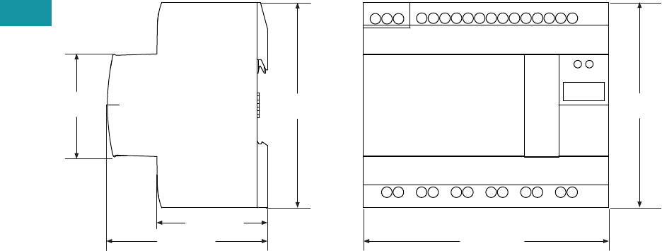
V7-T3-208 Volume 7—Logic Control, Operator Interface and Connectivity Solutions CA08100008E—June 2013 www.eaton.com
3
3
3
3
3
3
3
3
3
3
3
3
3
3
3
3
3
3
3
3
3
3
3
3
3
3
3
3
3
3
3.11
Control Relays and Timers
easySafety
Dimensions
Approximate Dimensions in Inches (mm)
ESR5_
1.87 (47.5)
2.68 (68.0)
1.77
(45.0) 3.54
(90.0)
4.23 (107.5)
3.54
(90.0)
