Product Detail Manual
2016-10-06
: Pdf 1000324074-Attachment 1000324074-Attachment B5 unilog
Open the PDF directly: View PDF ![]() .
.
Page Count: 29
V2-T2-144 Volume 2—Commercial Distribution CA08100003E—December 2014 www.eaton.com
2
2.5
Transfor mers
Distribution Transformers
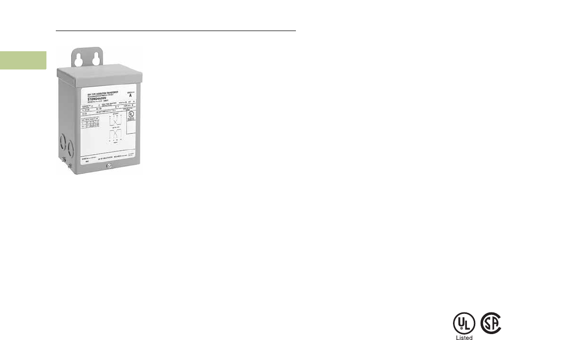
Type EP
Buck-Boost and Low Voltage Lighting Transformers
Product Description
Note: The following pages
provide listings for most standard
transformer ratings and catalog
numbers. For other ratings or
catalog numbers not shown,
or for special enclosure types
(including stainless steel), refer
to Eaton.
Types EP, EPT
●Encapsulated design
●Suitable for indoor or
outdoor applications
●Totally enclosed, non-
ventilated enclosures
●Enclosures are
NEMA 3R rated
●Mountable in any position
indoors and upright-only
outdoors
●180ºC insulation system
●115°C rise standard;
80°C rise optional
●Available in single-phase
ratings through 7.5 kVA
Application Description
A buck-boost transformer is
used to provide an economical
method of correcting a lower
or higher voltage rating more
suitable for efficient operation
of electrical equipment.
Type EP buck-boost
transformers are small kVA,
single-phase transformers
with dual primary and dual
secondary windings, and
are usually connected as
autotransformers by using
one unit for single-phase
applications and either two
or three units banked for three-
phase operation. They are
primarily used for motor
operation and should not be
used for motor control circuits,
to correct fluctuating line
voltage or to obtain a neutral
on a delta system. Buck-boost
transformers are ideally suited
for use with low voltage
lighting systems, such as
outdoor lighting.
Features, Benefits
and Functions
●60 Hz operation
●600 volt class insulation
●Short-term overload
capability as required
by ANSI
●Meet NEMA ST-20
sound levels
Standards and Certifications
●UL listed
●CSA certified
Industry Standards
All Eaton dry-type distribution
and control transformers are
built and tested in accordance
with applicable NEMA, ANSI
and IEEE Standards. All
600 volt class transformers
are UL listed unless
otherwise noted.
Seismically Qualified
Eaton-manufactured dry-type
distribution transformers are
seismically qualified, and
exceed requirements of the
International Building Code
(IBC) and California Code
Title 24.
Catalog Number Selection
Please refer to Section 2.7
Page V2-T2-187.

Volume 2—Commercial Distribution CA08100003E—December 2014 www.eaton.com V2-T2-145
2
2.5
Trans for mers
Distribution Transformers
Product Selection
For quick selection data,
refer to the tables on this
and the following pages.
Selection Requirements
You should have the following
information before selecting a
buck-boost transformer:
Line Voltage
The voltage that you want
to buck (decrease) or boost
(increase). This can be found
by measuring the supply line
voltage with a voltmeter.
Load Voltage
The voltage at which your
equipment is designed to
operate. This is listed on
the nameplate of the
load equipment.
Load Amperes or Load kVA
You do not need to know
both—one or the other is
sufficient for selection
purposes. This information
usually can be found on the
nameplate of the equipment
that you want to operate.
Frequency
The supply line frequency
must be the same as the
frequency of the equipment
to be operated—Eaton’s
buck-boost transformers
operate at 60 Hz only.
Phase
The supply line should be
the same as the equipment
to be operated—either single-
or three-phase.
Transformer Interconnection
For three-phase applications,
interconnections of
transformers should be
made in a junction box.
Two or three transformers
may be used depending
on an open delta (2) or
wye (3) connection.
5-Step Selector
The tables that follow will
simplify the selection of the
buck-boost transformers.
There are no calculations
needed; simply follow these
five steps:
1. Refer to the table having
the same output voltage
as the equipment you
want to operate. For
example, if you are
installing a 240 volt
6 kVA single-phase
load use selection table
on the page.
2. Select the available line
voltage across the top of
the chart that is closest
to the actual supply
voltage. Therefore, for
example, if the available
line voltage is 213 volts,
use the 212 volt column.
3. Read down the column
until you reach an output
kVA or amps rating equal
to or greater than the
load requirements. Since
6 kVA, in the example, is
not listed, use the next
higher rating, or 7.5 kVA.
4. Read across to the far
left columns for the
catalog number and
quantity of transformers
for your application. In
this case, you will need
one (1) catalog number
S10N06P01P.
5. Connect the buck-boost
transformer(s) you have
selected in accordance
with the connection
diagram specified at the
bottom of the available
line voltage column. In
this example, Diagram
“F” would be used.
Note: For single-phase
connections and three-phase
open delta connections, inputs
and outputs may be reversed.
kVA capacity remains constant.
Additional Product Selection
information begins on
Page V2-T2-189.
120 x 240 Volts to 12/24 Volts
120 x 240 Volts to 16/32 Volts
240 x 480 Volts to 24/48 Volts
Note
Frame drawings/dimensions information begins on Page V2-T2-215.
kVA °C Temp. Rise Frame Weight Lbs (kg) Catalog Number
0.05 115 FR52 7 (3) S10N04A81N
0.10 115 FR54 7 (3) S10N04A82N
0.15 115 FR55 8 (4) S10N04A83N
0.25 115 FR57P 12 (5) S10N04P26P
0.50 115 FR57P 13 (5) S10N04P51P
0.75 115 FR58AP 21 (10) S10N04P76P
1 115 FR67P 31 (14) S10N04P01P
1.5 115 FR67P 40 (18) S10N04P16P
2 115 FR68P 40 (18) S10N04P02P
3 115 FR176 65 (29) S10N04A03N
5 115 FR177 113 (51) S10N04A05N
7.5 115 FR178 123 (55) S10N04A07N
kVA °C Temp. Rise Frame Weight Lbs (kg) Catalog Number
0.05 115 FR52 7 (3) S10N06A81N
0.10 115 FR54 7 (3) S10N06A82N
0.15 115 FR55 8 (4) S10N06A83N
0.25 115 FR57P 12 (5) S10N06P26P
0.50 115 FR57P 13 (5) S10N06P51P
0.75 115 FR58AP 21 (10) S10N06P76P
1 115 FR67P 31 (14) S10N06P01P
1.5 115 FR67P 40 (18) S10N06P16P
2 115 FR68P 40 (18) S10N06P02P
3 115 FR176 65 (29) S10N06A03N
5 115 FR177 113 (51) S10N06A05N
7.5 115 FR178 123 (55) S10N06A07N
kVA °C Temp. Rise Frame Weight Lbs (kg) Catalog Number
0.05 115 FR52 7 (3) S20N08A81N
0.10 115 FR54 7 (3) S20N08A82N
0.15 115 FR55 8 (4) S20N08A83N
0.25 115 FR57P 12 (5) S20N08P26P
0.50 115 FR57P 13 (5) S20N08P51P
0.75 115 FR58AP 21 (10) S20N08P76P
1 115 FR67P 31 (14) S20N08P01P
1.5 115 FR67P 40 (18) S20N08P16P
2 115 FR68P 40 (18) S20N08P02P
3 115 FR176 65 (29) S20N08A03N
5 115 FR177 113 (51) S20N08A05N
7.5 115 FR178 123 (55) S20N08A07N

V2-T2-146 Volume 2—Commercial Distribution CA08100003E—December 2014 www.eaton.com
2
2.5
Transfor mers
Distribution Transformers
Single-Phase 115 Volt Output Required, 60 Hz
Notes
1Additional wiring trough may be required.
2Refer to Page V2-T2-172 for buck-boost wiring diagrams.
Output voltage for lower input voltage can be found by: x Input Actual Voltage = Output New Voltage.
Output kVA available at reduced input voltage can be found by: x Output kVA = New kVA Rating.
Frame drawings/dimensions information begins on Page V2-T2-215.
Units
Required 1
Unit
kVA
Input Available Voltage
Catalog Number
84 91 96 100 102
Output Output Output Output Output
kVA Amps kVA Amps kVA Amps kVA Amps kVA Amps
1 0.05 — — — — 0.24 2.09 — — — — S10N04A81N
1 0.05 0.13 1.14 0.18 1.56 — — 0.31 2.70 0.36 3.13 S10N06A81N
1 0.10 — — — — 0.48 4.17 — — — — S10N04A82N
1 0.10 0.26 2.29 0.36 3.12 — — 0.62 5.41 0.72 6.25 S10N06A82N
1 0.15 — — — — 0.72 6.25 — — — — S10N04A83N
1 0.15 0.39 3.44 0.54 4.69 — — 0.93 8.12 1.08 9.37 S10N06A83N
1 0.25 — — — — 1.2 10.4 — — — — S10N04P26P
1 0.25 0.659 5.73 0.899 7.81 — — 1.56 13.5 1.8 15.6 S10N06P26P
1 0.50 — — — — 2.4 20.8 — — — — S10N04P51P
1 0.50 1.32 11.5 1.8 15.6 — — 3.11 27.1 3.59 31.2 S10N06P51P
1 0.75 — — — — 3.6 31.2 — — — — S10N04P76P
1 0.75 1.98 17.2 2.7 23.4 — — 4.67 40.6 5.39 46.8 S10N06P76P
1 1 ————4.7941.7————S10N04P01P
1 1 2.64 22.9 3.59 31.2 — — 6.23 54.1 7.19 62.5 S10N06P01P
1 1.5————7.262.5————S10N04P16P
1 1.5 3.95 34.4 5.39 46.9 — — 9.34 81.2 10.8 93.7 S10N06P16P
1 2 ————9.5883.3————S10N04P02P
1 2 5.27 45.8 7.19 62.5 — — 12.5 108 14.4 125 S10N06P02P
1 3 ————14.37125.1————S10N04A03N
1 3 7.92 68.7 10.77 93.6 — — 18.69 162.3 21.57 187.5 S10N06A03N
1 5 ————23.95208.5————S10N04A05N
1 5 13.2 115 18 156 — — 31.15 270.5 35.95 312.5 S10N06A05N
1 7.5————36 312————S10N04A07N
1 7.5 19.8 172 27 234 — — 46.7 406 53.9 468 S10N06A07N
Connection Diagram 2DBB C A
Rated Output Voltage
Rated Input Voltage
----------------------------------- ------------------
Actual Input Voltage
Rated Input Voltage
------------------ ---------------------------------

Volume 2—Commercial Distribution CA08100003E—December 2014 www.eaton.com V2-T2-147
2
2.5
Trans for mers
Distribution Transformers
Single-Phase 115 Volt Output Required, 60 Hz
Notes
1Additional wiring trough may be required.
2Refer to Page V2-T2-172 for buck-boost wiring diagrams.
Output voltage for lower input voltage can be found by: x Input Actual Voltage = Output New Voltage.
Output kVA available at reduced input voltage can be found by: x Output kVA = New kVA Rating.
Frame drawings/dimensions information begins on Page V2-T2-215.
Units
Required 1
Unit
kVA
Input Available Voltage
Catalog Number
105 127 130 138 146
Output Output Output Output Output
kVA Amps kVA Amps kVA Amps kVA Amps kVA Amps
1 0.05 0.48 4.17 0.54 4.58 — — 0.29 2.5 — — S10N04A81N
1 0.05 — — — — 0.41 3.54 — — 0.23 1.98 S10N06A81N
1 0.10 0.96 8.33 1.1 9.17 — — 0.58 5.0 — — S10N04A82N
1 0.10 — — — — 0.82 7.08 — — 0.46 3.95 S10N06A82N
1 0.15 1.44 12.5 1.6 13.7 — — 0.87 7.5 — — S10N04A83N
1 0.15 — — — — 1.3 10.6 — — 0.69 5.93 S10N06A83N
1 0.25 2.39 20.8 2.63 22.9 — — 1.44 12.5 — — S10N04P26P
1 0.25 — — — — 2.03 17.7 — — 1.14 9.88 S10N06P26P
1 0.50 4.79 41.6 5.27 45.8 — — 2.87 25 — — S10N04P51P
1 0.50 —— — — — 4.07 35.4 — — 2.27 19.8 S10N06P51P
1 0.75 7.19 62.4 7.9 68.7 — — 4.31 37.5 — — S10N04P76P
1 0.75 — — — — 6.1 53.1 — — 3.41 29.6 S10N06P76P
1 1 9.58 83.3 10.5 91.7 — — 5.75 50 — — S10N04P01P
1 1 — — — — 8.14 70.8 — — 4.55 39.5 S10N06P01P
1 1.5 14.4 125 15.8 137 — — 8.62 75 — — S10N04P16P
1 1.5 — — — — 12.2 106 — — 6.82 59.3 S10N06P16P
1 2 19.2 16.7 21.1 183 — — 11.5 100 — — S10N04P02P
1 2 — — — — 16.3 142 — — 9.10 79.2 S10N06P02P
1 3 28.7 249.9 31.5 275.1 — — 17.3 150 — — S10N04A03N
1 3 — — — — 24.4 212.4 — — 13.6 118.5 S10N06A03N
1 5 47.9 416.5 52.5 458.5 — — 28.7 250 — — S10N04A05N
1 5 — — — — 40.7 354 — — 22.7 197.5 S10N06A05N
1 7.5 71.9 624 79 687 — — 43.1 357 — — S10N04A07N
1 7.5 — — — — 61 531 — — 34.1 296 S10N06A07N
Connection Diagram 2AAA B B
Rated Output Voltage
Rated Input Voltage
-- - --------------------------------- ----------------
Actual Input Voltage
Rated Input Voltage
---------------------- -----------------------------

V2-T2-148 Volume 2—Commercial Distribution CA08100003E—December 2014 www.eaton.com
2
2.5
Transfor mers
Distribution Transformers
Single-Phase 120 Volt Output Required, 60 Hz
Notes
1Additional wiring trough may be required.
2Refer to Page V2-T2-172 for buck-boost wiring diagrams.
Output voltage for lower input voltage can be found by: x Input Actual Voltage = Output New Voltage.
Output kVA available at reduced input voltage can be found by: x Output kVA = New kVA Rating.
Frame drawings/dimensions information begins on Page V2-T2-215.
Units
Required 1
Unit
kVA
Input Available Voltage
Catalog Number
88 95 100 104 106
Output Output Output Output Output
kVA Amps kVA Amps kVA Amps kVA Amps kVA Amps
1 0.05 — — — — 0.25 2.09 — — — — S10N04A81N
1 0.05 0.14 1.15 0.19 1.56 — — 0.33 2.70 0.38 3.13 S10N06A81N
1 0.10 — — — — 0.50 4.17 — — — — S10N04A82N
1 0.10 0.28 2.29 0.38 3.12 — — 0.65 5.41 0.75 6.25 S10N06A82N
1 0.15 — — — — 0.75 6.25 — — — — S10N04A83N
1 0.15 0.41 3.44 0.56 4.69 — — 0.98 8.12 1.12 9.37 S10N06A83N
1 0.25— —— —1.2510.4— — — — S10N04P26P
1 0.25 0.687 5.73 0.937 7.81 — — 1.62 13.5 1.87 15.6 S10N06P26P
1 0.50————2.520.8————S10N04P51P
1 0.50 1.37 11.5 1.87 15.6 — — 3.25 27.1 3.75 31.2 S10N06P51P
1 0.75— —— —3.7531.2— — — — S10N04P76P
1 0.75 2.06 17.2 2.82 23.4 — — 4.87 40.6 5.62 46.8 S10N06P76P
1 1 ————5 41.7—————S10N04P01P
1 1 2.75 22.9 3.75 31.2 — — 6.5 54.1 7.5 62.5 S10N06P01P
1 1.5————7.562.5————S10N04P16P
1 1.5 4.12 34.4 5.62 46.9 — — 9.75 81.2 11.2 93.7 S10N06P16P
1 2 ————10 83.3————S10N04P02P
1 2 5.5 45.8 7.5 62.5 — — 13 108 15 125 S10N06P02P
1 3 — — — — 15 125.1 — — — — S10N04A03N
1 3 8.25 68.7 11.25 93.6 — — 19.5 162.3 22.5 187.5 S10N06A03N
1 5 — — — — 25 208.5 — — — — S10N04A05N
1 5 13.75 114.5 18.75 156 — — 32.5 270.5 37.5 312.5 S10N06A05N
1 7.5————37.5312————S10N04A07N
1 7.5 20.6 172 28.2 234 — — 48.7 406 56.2 468 S10N06A07N
Connection Diagram 2DBBCA
Rated Output Voltage
Rated Input Voltage
----------------------------------- ------------------
Actual Input Voltage
Rated Input Voltage
------------------ ---------------------------------

Volume 2—Commercial Distribution CA08100003E—December 2014 www.eaton.com V2-T2-149
2
2.5
Trans for mers
Distribution Transformers
Single-Phase 120 Volt Output Required, 60 Hz
Notes
1Additional wiring trough may be required.
2Refer to Page V2-T2-172 for buck-boost wiring diagrams.
Output voltage for lower input voltage can be found by: x Input Actual Voltage = Output New Voltage.
Output kVA available at reduced input voltage can be found by: x Output kVA = New kVA Rating.
Frame drawings/dimensions information begins on Page V2-T2-215.
Units
Required 1
Unit
kVA
Input Available Voltage
Catalog Number
109 132 136 144 152
Output Output Output Output Output
kVA Amps kVA Amps kVA Amps kVA Amps kVA Amps
1 0.05 0.5 4.17 0.55 4.58 — — 0.3 2.5 — — S10N04A81N
1 0.05 — — — — 0.43 3.54 — — 0.24 1.98 S10N06A81N
1 0.10 1.0 8.33 1.1 9.17 — — 0.6 5.0 — — S10N04A82N
1 0.10 — — — — 0.85 7.08 — — 0.48 3.95 S10N06A82N
1 0.15 1.5 12.5 1.6 13.7 — — 0.9 7.5 — — S10N04A83N
1 0.15 — — — — 1.27 10.6 — — 0.71 5.93 S10N06A83N
1 0.25 2.5 20.8 2.75 22.9 — — 1.5 12.5 — — S10N04P26P
1 0.25 — — — — 2.12 17.7 — — 1.19 9.88 S10N06P26P
1 0.50 5 41.6 5.5 45.8 — — 3 25 — — S10N04P51P
1 0.50 — — — — 4.25 35.4 — — 2.37 19.8 S10N06P51P
1 0.75 7.5 62.4 8.25 68.7 — — 4.5 37.5 — — S10N04P76P
1 0.75 — — — — 6.37 53.1 — — 3.56 29.6 S10N06P76P
1 1 10 83.3 11 91.7 — — 6 50 — — S10N04P01P
1 1 ————8.570.8——4.7539.5S10N06P01P
1 1.5 15 125 16.5 137 — — 9 75 — — S10N04P16P
1 1.5 — — — — 12.7 106 — — 7.12 59.3 S10N06P16P
1 2 20 167 22 183 — — 12 100 — — S10N04P02P
1 2 — — — — 17 142 — — 9.5 79.2 S10N06P02P
1 3 30 249.9 33 275.1 — — 18 150 — — S10N04A03N
1 3 — — — — 25.5 212.4 — — 14.25 118.5 S10N06A03N
1 5 50 416.5 55 458.5 — — 30 250 — — S10N04A05N
1 5 — — — — 42.5 354 — — 23.7 197.5 S10N06A05N
1 7.5 75 624 82.5 687 — — 45 375 — — S10N04A07N
1 7.5 — — — — 63.7 531 — — 35.6 296 S10N06A07N
Connection Diagram 2AAA B B
Rated Output Voltage
Rated Input Voltage
-- - --------------------------------- ----------------
Actual Input Voltage
Rated Input Voltage
---------------------- -----------------------------

V2-T2-150 Volume 2—Commercial Distribution CA08100003E—December 2014 www.eaton.com
2
2.5
Transfor mers
Distribution Transformers
Single-Phase 230 Volt Output Required, 60 Hz
Notes
1Additional wiring trough may be required.
2Refer to Page V2-T2-172 for buck-boost wiring diagrams.
Output voltage for lower input voltage can be found by: x Input Actual Voltage = Output New Voltage.
Output kVA available at reduced input voltage can be found by: x Output kVA = New kVA Rating.
Frame drawings/dimensions information begins on Page V2-T2-215.
Units
Required 1
Unit
kVA
Input Available Voltage
Catalog Number
199 203 207 209 216
Output Output Output Output Output
kVA Amps kVA Amps kVA Amps kVA Amps kVA Amps
1 0.05 — — — — 0.43 1.88 0.48 2.08 — — S10N04A81N
1 0.05 0.31 1.36 0.36 1.56 — — — — 0.72 3.12 S10N06A81N
1 0.10— — — — 0.863.750.964.17— — S10N04A82N
1 0.10 0.62 2.71 0.72 3.12 — — — — 1.44 6.25 S10N06A82N
1 0.15— — — — 1.295.621.446.25— — S10N04A83N
1 0.15 0.93 4.06 1.08 4.69 — — — — 2.16 9.37 S10N06A83N
1 0.25 — — — — 2.15 9.37 2.39 10.4 — — S10N04P26P
1 0.25 1.55 6.77 1.8 7.81 — — — — 3.59 15.6 S10N06P26P
1 0.50— — — — 4.3118.74.7920.8— — S10N04P51P
1 0.50 3.11 13.5 3.6 15.6 — — — — 7.19 31.2 S10N06P51P
1 0.75— — — — 6.4628.27.1931.2— — S10N04P76P
1 0.75 4.66 20.3 5.4 23.4 — — — — 10.8 46.8 S10N06P76P
1 1 — — — — 8.6237.59.5841.7— — S10N04P01P
1 1 6.23 27.1 7.2 31.2 — — — — 14.4 62.5 S10N06P01P
1 1.5 — — — — 12.9 56.2 14.4 62.5 — — S10N04P16P
1 1.5 9.34 40.6 10.8 46.9 — — — — 21.6 93.7 S10N06P16P
1 2 — — — — 17.2 75 19.2 83.3 — — S10N04P02P
1 2 12.5 54.2 14.4 62.5 — — — — 28.7 125 S10N06P02P
1 3 — — — — 25.8 112.5 28.7 125.1 — — S10N04A03N
1 3 18.6 81.3 21.6 93.6 — — — — 43.2 187.5 S10N06A03N
1 5 — — — — 43.1 187.5 47.9 208.5 — — S10N04A05N
1 5 31.1 135.5 36 156 — — — — 72 312.5 S10N06A05N
1 7.5 — — — — 64.6 282 71.9 312 — — S10N04A07N
1 7.5 46.6 203 54 234 — — — — 108 468 S10N06A07N
Connection Diagram 2GF G F E
Rated Output Voltage
Rated Input Voltage
----------------------------------- ------------------
Actual Input Voltage
Rated Input Voltage
------------------ ---------------------------------

Volume 2—Commercial Distribution CA08100003E—December 2014 www.eaton.com V2-T2-151
2
2.5
Trans for mers
Distribution Transformers
Single-Phase 230 Volt Output Required, 60 Hz
Notes
1Additional wiring trough may be required.
2Refer to Page V2-T2-172 for buck-boost wiring diagrams.
Output voltage for lower input voltage can be found by: x Input Actual Voltage = Output New Voltage.
Output kVA available at reduced input voltage can be found by: x Output kVA = New kVA Rating.
Frame drawings/dimensions information begins on Page V2-T2-215.
Units
Required 1
Unit
kVA
Input Available Voltage
Catalog Number
219 242 246 253 260
Output Output Output Output Output
kVA Amps kVA Amps kVA Amps kVA Amps kVA Amps
1 0.05 0.96 4.16 1.0 4.38 — — 0.53 2.29 — — S10N04A81N
1 0.05 — — — — 0.77 3.34 — — 0.41 1.77 S10N06A81N
1 0.10 1.92 8.33 2.01 8.75 — — 1.05 4.58 — — S10N04A82N
1 0.10 — — — — 1.53 6.67 — — 0.82 3.54 S10N06A82N
1 0.15 2.87 12.5 3.02 13.1 — — 1.58 6.87 — — S10N04A83N
1 0.15 — — — — 2.3 10.0 — — 1.22 5.31 S10N06A83N
1 0.25 4.79 20.8 5.03 21.9 — — 2.63 11.5 — — S10N04P26P
1 0.25 — — — — 3.83 16.7 — — 2.04 8.85 S10N06P26P
1 0.50 9.58 41.6 10.1 43.7 — — 5.27 22.9 — — S10N04P51P
1 0.50 — — — — 7.67 33.3 — — 4.07 17.7 S10N06P51P
1 0.75 14.4 62.4 15.1 65.6 — — 7.9 34.4 — — S10N04P76P
1 0.75 — — — — 11.5 50 — — 6.11 26.6 S10N06P76P
1 1 19.2 83.3 20.1 87.5 — — 10.5 45.8 — — S10N04P01P
1 1 ————15.366.7——8.1535.4
S10N06P01P
1 1.5 28.7 125 30.2 131 — — 15.8 68.7 — — S10N04P16P
1 1.5 — — — — 23 100 — — 12.2 53.1 S10N06P16P
1 2 38.3 167 40.2 175 — — 21.1 91.7 — — S10N04P02P
1 2 — — — — 30.7 133 — — 16.3 70.8 S10N06P02P
1 3 57.6 249.9 60.3 262.5 — — 31.5 137.4 — — S10N04A03N
1 3 — — — — 45.9 200.1 — — 24.4 106.2 S10N06A03N
1 5 96 416.5 100.5 437.5 — — 52.5 229 — — S10N04A05N
1 5 — — — — 76.5 333.5 — — 40.7 177 S10N06A05N
1 7.5 144 624 151 656 — — 79 344 — — S10N04A07N
1 7.5 — — — — 115 500 — — 61.1 266 S10N06A07N
Connection Diagram 2EEE F F
Rated Output Voltage
Rated Input Voltage
-- - --------------------------------- ----------------
Actual Input Voltage
Rated Input Voltage
---------------------- -----------------------------

V2-T2-152 Volume 2—Commercial Distribution CA08100003E—December 2014 www.eaton.com
2
2.5
Transfor mers
Distribution Transformers
Single-Phase 240 Volt Output Required, 60 Hz
Notes
1Additional wiring trough may be required.
2Refer to Page V2-T2-172 for buck-boost wiring diagrams.
Output voltage for lower input voltage can be found by: x Input Actual Voltage = Output New Voltage.
Output kVA available at reduced input voltage can be found by: x Output kVA = New kVA Rating.
Frame drawings/dimensions information begins on Page V2-T2-215.
Units
Required 1
Unit
kVA
Input Available Voltage
Catalog Number
208 212 216 218 225
Output Output Output Output Output
kVA Amps kVA Amps kVA Amps kVA Amps kVA Amps
1 0.05 — — — — 0.45 1.88 0.5 2.08 — — S10N04A81N
1 0.05 0.32 1.35 0.38 1.56 — — — — 0.75 3.12 S10N06A81N
1 0.10 — — — — 0.9 3.75 1.0 4.17 — — S10N04A82N
1 0.10 0.65 2.71 0.75 3.12 — — — — 1.5 6.25 S10N06A82N
1 0.15 — — — — 1.35 5.62 1.5 6.25 — — S10N04A83N
1 0.15 0.98 4.06 1.12 4.69 — — — — 2.25 9.37 S10N06A83N
1 0.25 — — — — 2.25 9.37 2.5 10.4 — — S10N04P26P
1 0.25 1.62 6.77 1.87 7.81 — — — — 3.75 15.6 S10N06P26P
1 0.50 — — — — 4.5 18.7 5 20.8 — — S10N04P51P
1 0.50 3.25 13.5 3.75 15.6 — — — — 7.5 31.2 S10N06P51P
1 0.75— — — — 6.7528.27.5 31.2— — S10N04P76P
1 0.75 4.87 20.3 5.62 23.4 — — — — 11.2 46.8 S10N06P76P
1 1 — — — — 9 37.5 10 41.7 — — S10N04P01P
1 1 6.5 27.1 7.5 31.2 — — — — 15 62.5 S10N06A01
1 1.5 — — — — 13.5 56.2 15 62.5 — — S10N04P16P
1 1.5 9.75 40.6 11.2 46.9 — — — — 22.5 93.7 S10N06P16P
1 2 — — — — 18 75 20 83.3 — — S10N04P02P
1 2 13 54.2 15 62.5 — — — — 30 125 S10N06P02P
1 3 — — — — 27 112.5 30 125.1 — — S10N04A03N
1 3 19.5 81.3 22.5 93.6 — — — — 45 187.5 S10N06A03N
1 5 ————45 18750 208——S10N04A05N
1 5 32.5 135 37.5 156 — — — — 75 312 S10N06A05N
1 7.5 — — — — 67.5 282 75 312 — — S10N04A07N
1 7.5 48.7 203 56.2 234 — — — — 112 468 S10N06A07N
Connection Diagram 2GF G F E
Rated Output Voltage
Rated Input Voltage
----------------------------------- ------------------
Actual Input Voltage
Rated Input Voltage
------------------ ---------------------------------

Volume 2—Commercial Distribution CA08100003E—December 2014 www.eaton.com V2-T2-153
2
2.5
Trans for mers
Distribution Transformers
Single-Phase 240 Volt Output Required, 60 Hz
Notes
1Additional wiring trough may be required.
2Refer to Page V2-T2-172 for buck-boost wiring diagrams.
Output voltage for lower input voltage can be found by: x Input Actual Voltage = Output New Voltage.
Output kVA available at reduced input voltage can be found by: x Output kVA = New kVA Rating.
Frame drawings/dimensions information begins on Page V2-T2-215.
Units
Required 1
Unit
kVA
Input Available Voltage
Catalog Number
229 252 256 264 272
Output Output Output Output Output
kVA Amps kVA Amps kVA Amps kVA Amps kVA Amps
1 0.05 1.0 4.16 1.05 4.38 — — 0.55 2.29 — — S10N04A81N
1 0.05 — — — — 0.8 3.33 — — 0.42 1.77 S10N06A81N
1 0.10 2.0 8.33 2.1 8.75 — — 1.1 4.58 — — S10N04A82N
1 0.10 — — — — 1.6 6.67 — — 0.85 3.54 S10N06A82N
1 0.15 3.0 12.5 3.15 13.1 — — 1.65 6.87 — — S10N04A83N
1 0.15 — — — — 2.4 10.0 — — 1.27 5.31 S10N06A83N
1 0.25 5 20.8 5.25 21.9 — — 2.75 11.5 — — S10N04P26P
1 0.25— —— —4 16.7— — 2.128.85S10N06P26P
1 0.50 10 41.6 10.5 43.7 — — 5.5 22.9 — — S10N04P51P
1 0.50 — — — — 8 33.3 — — 4.25 17.7 S10N06P51P
1 0.75 15 62.4 15.7 65.6 — — 8.25 34.4 — — S10N04P76P
1 0.75— —— —12 50 — — 6.3726.6S10N06P76P
1 1 20 83.3 21 87.5 — — 11 45.8 — — S10N04P01P
1 1 ————1666.7——8.535.4S10N06P01P
1 1.5 30 125 31.5 131 — — 16.5 68.7 — — S10N04P16P
1 1.5 — — — — 24 100 — — 12.7 53.1 S10N06P16P
1 2 40 167 42 175 — — 22 91.7 — — S10N04P02P
1 2 — — — — 32 133 — — 17 70.8 S10N06P02P
1 3 60 249.9 63 262.5 — — 33 137.4 — — S10N04A03N
1 3 — — — — 48 200.1 — — 25.5 106.2 S10N06A03N
1 5 100 416.5 105 437.5 — — 55 229 — — S10N04A05N
1 5 — — — — 80 333 — — 42.5 177 S10N06A05N
1 7.5 150 624 157 656 — — 82.5 344 — — S10N04A07N
1 7.5 — — — — 120 500 — — 63.7 266 S10N06A07N
Connection Diagram 2EEE F F
Rated Output Voltage
Rated Input Voltage
-- - --------------------------------- ----------------
Actual Input Voltage
Rated Input Voltage
---------------------- -----------------------------

V2-T2-154 Volume 2—Commercial Distribution CA08100003E—December 2014 www.eaton.com
2
2.5
Transfor mers
Distribution Transformers
Three-Phase Open Delta Connection 230 Volt Output Required, 60 Hz
Notes
1Additional wiring trough may be required.
2Refer to Page V2-T2-172 for buck-boost wiring diagrams.
Output voltage for lower input voltage can be found by: x Input Actual Voltage = Output New Voltage.
Output kVA available at reduced input voltage can be found by: x Output kVA = New kVA Rating.
Frame drawings/dimensions information begins on Page V2-T2-215.
Units
Required 1
Unit
kVA
Input Available Voltage
Catalog Number
199 203 207 209 216
Output Output Output Output Output
kVA Amps kVA Amps kVA Amps kVA Amps kVA Amps
2 0.05 — — — — 0.75 1.87 0.83 2.08 — — S10N04A81N
2 0.05 0.54 1.35 0.62 1.56 — — — — 1.24 3.12 S10N06A81N
2 0.10 — — — — 1.49 3.75 1.66 4.17 — — S10N04A82N
2 0.10 1.08 2.71 1.24 3.12 — — — — 2.49 6.25 S10N06A82N
2 0.15 — — — — 2.24 5.62 2.49 6.25 — — S10N04A83N
2 0.15 1.62 4.06 1.87 4.69 — — — — 3.73 9.37 S10N06A83N
2 0.25 — — — — 3.3 9.37 4.15 10.4 — — S10N04P26P
2 0.25 2.7 6.77 3.11 7.81 — — — — 6.22 15.6 S10N06P26P
2 0.50 — — — — 7.47 18.7 8.3 20.8 — — S10N04P51P
2 0.50 5.39 13.5 6.22 15.6 — — — — 12.4 31.2 S10N06P51P
2 0.75 — — — — 11.2 28.2 12.4 31.2 — — S10N04P76P
2 0.75 8.09 20.3 9.33 23.4 — — — — 18.7 46.8 S10N06P76P
2 1 — — — — 14.9 37.5 16.6 41.7 — — S10N04P01P
2 1 10.8 27.1 12.4 31.2 — — — — 24.9 62.5 S10N06P01P
2 1.5 — — — — 22.4 56.2 24.9 62.5 — — S10N04P16P
2 1.5 16.2 40.6 18.7 46.9 — — — — 37.3 93.7 S10N06P16P
2 2 — — — — 29.9 75 33.2 83.3 — — S10N04P02P
2 2 21.6 54.2 24.9 62.5 — — — — 49.8 125 S10N06P02P
2 3 — — — — 44.7 112.5 49.8 125.1 — — S10N04A03N
2 3 32.4 81.3 32.7 93.6 — — — — 74.7 187.5 S10N06A03N
2 5 — — — — 74.7 187 83 208 — — S10N04A05N
2 5 53.9 135 62.2 156 — — — — 124 312.5 S10N06A05N
2 7.5 — — — — 112 282 124 312 — — S10N04A07N
2 7.5 80.9 203 93.3 234 — — — — 187 468 S10N06A07N
Connection Diagram 2LKL K I
Rated Output Voltage
Rated Input Voltage
----------------------------------- ------------------
Actual Input Voltage
Rated Input Voltage
------------------ ---------------------------------

Volume 2—Commercial Distribution CA08100003E—December 2014 www.eaton.com V2-T2-155
2
2.5
Trans for mers
Distribution Transformers
Three-Phase Open Delta Connection 230 Volt Output Required, 60 Hz
Notes
1Additional wiring trough may be required.
2Refer to Page V2-T2-172 for buck-boost wiring diagrams.
Output voltage for lower input voltage can be found by: x Input Actual Voltage = Output New Voltage.
Output kVA available at reduced input voltage can be found by: x Output kVA = New kVA Rating.
Frame drawings/dimensions information begins on Page V2-T2-215.
Units
Required 1
Unit
kVA
Input Available Voltage
Catalog Number
219 242 246 253 260
Output Output Output Output Output
kVA Amps kVA Amps kVA Amps kVA Amps kVA Amps
2 0.05 1.66 4.17 1.74 4.37 — — 0.91 2.29 — — S10N04A81N
2 0.05 — — — — 1.33 3.33 — — 0.70 1.77 S10N06A81N
2 0.10 3.32 8.33 3.48 8.75 — — 1.83 4.58 — — S10N04A82N
2 0.10 — — — — 2.65 6.67 — — 1.41 3.54 S10N06A82N
2 0.15 4.98 12.5 5.23 13.1 — — 2.74 6.87 — — S10N04A83N
2 0.15 — — — — 3.98 10.0 — — 2.12 5.13 S10N06A83N
2 0.25 8.3 20.8 8.71 21.9 — — 4.56 11.5 — — S10N04P26P
2 0.25 — — — — 6.64 16.7 — — 3.52 8.85 S10N06P26P
2 0.50 16.6 41.7 17.4 43.7 — — 9.73 22.9 — — S10N04P51P
2 0.50 — — — — 13.3 33.3 — — 7.05 17.7 S10N06P51P
2 0.75 24.9 62.4 26.1 65.6 — — 13.7 34.4 — — S10N04P76P
2 0.75 — — — — 19.9 50 — — 10.6 26.6 S10N06P76P
2 1 33.2 83.3 34.8 87.5 — — 18.3 45.8 — — S10N04P01P
2 1 ————26.566.7——14.135.4S10N06P01P
2 1.5 49.8 125 52.3 131 — — 27.4 68.7 — — S10N04P16P
2 1.5 — — — — 39.8 100 — — 21.2 53.1 S10N06P16P
2 2 66.4 167 69.7 175 — — 36.5 91.7 — — S10N04P02P
2 2 — — — — 53.1 133 — — 28.2 70.8 S10N06P02P
2 3 99.6 249.9 104.4 262.5 — — 54.9 137.4 — — S10N04A03N
2 3 — — — — 79.5 200 — — 42.3 106.2 S10N06A03N
2 5 166 417 174 437 — — 91.3 229 — — S10N04A05N
2 5 — — — — 133 333 — — 70.5 177 S10N06A05N
2 7.5 249 624 261 656 — — 137 344 — — S10N04A07N
2 7.5————199500——106266S10N06A07N
Connection Diagram 2III KK
Rated Output Voltage
Rated Input Voltage
-- - --------------------------------- ----------------
Actual Input Voltage
Rated Input Voltage
---------------------- -----------------------------

V2-T2-156 Volume 2—Commercial Distribution CA08100003E—December 2014 www.eaton.com
2
2.5
Transfor mers
Distribution Transformers
Three-Phase Open Delta Connection 240 Volt Output Required, 60 Hz
Notes
1Additional wiring trough may be required.
2Refer to Page V2-T2-172 for buck-boost wiring diagrams.
Output voltage for lower input voltage can be found by: x Input Actual Voltage = Output New Voltage.
Output kVA available at reduced input voltage can be found by: x Output kVA = New kVA Rating.
Frame drawings/dimensions information begins on Page V2-T2-215.
Units
Required 1
Unit
kVA
Input Available Voltage
Catalog Number
208 212 216 218 225
Output Output Output Output Output
kVA Amps kVA Amps kVA Amps kVA Amps kVA Amps
2 0.05 — — — — 0.73 1.87 0.87 2.08 — — S10N04A81N
2 0.05 0.56 1.35 0.65 1.56 — — — — 1.3 3.12 S10N06A81N
2 0.10 — — — — 1.56 3.75 1.73 4.17 — — S10N04A82N
2 0.10 1.13 2.71 1.3 3.12 — — — — 2.6 6.25 S10N06A82N
2 0.15 — — — — 2.34 5.62 2.6 6.25 — — S10N04A83N
2 0.15 1.69 4.06 1.95 4.69 — — — — 3.9 9.37 S10N06A83N
2 0.25——— — — 3.9 9.374.3310.4— — S10N04P26P
2 0.25 2.81 6.77 3.25 7.81 — — — — 6.49 15.6 S10N06P26P
2 0.50— — — — 7.7918.78.6620.8— — S10N04P51P
2 0.50 5.63 13.5 6.5 15.6 —— — — — 13 31.2 S10N06P51P
2 0.75— — — — 11.728.213 31.2— — S10N04P76P
2 0.75 8.44 20.3 9.75 23.4 — — — — 19.5 46.8 S10N06P76P
2 1 — — — — 15.6 37.5 17.3 41.7 — — S10N04P01P
2 1 11.3 27.1 13 31.2 — — — — 26 62.5 S10N06P01P
2 1.5 — — — — 23.4 56.2 26 62.5 — — S10N04P16P
2 1.5 16.9 40.6 19.5 46.9 — — — — 39 93.7 S10N06P16P
2 2 — — — — 31.2 75 34.6 83.3 — — S10N04P02P
2 2 22.5 54.2 26 62.5 — — — — 52 125 S10N06P02P
2 3 — — — — 46.8 112.5 51.9 125.1 — — S10N04A03N
2 3 33.9 81.3 39 93.6 — — — — 78 187.5 S10N06A03N
2 5 — — — — 77.9 187 86.6 208 — — S10N04A05N
2 5 56.3 135 65 156 — — — — 130 312 S10N06A05N
2 7.5 — — — — 117 282 130 312 — — S10N04A07N
2 7.5 84.4 203 97.5 234 — — — — 195 468 S10N06A07N
Connection Diagram 2LKL K I
Rated Output Voltage
Rated Input Voltage
----------------------------------- ------------------
Actual Input Voltage
Rated Input Voltage
------------------ ---------------------------------

Volume 2—Commercial Distribution CA08100003E—December 2014 www.eaton.com V2-T2-157
2
2.5
Trans for mers
Distribution Transformers
Three-Phase Open Delta Connection 240 Volt Output Required, 60 Hz
Notes
1Additional wiring trough may be required.
2Refer to Page V2-T2-172 for buck-boost wiring diagrams.
Output voltage for lower input voltage can be found by: x Input Actual Voltage = Output New Voltage.
Output kVA available at reduced input voltage can be found by: x Output kVA = New kVA Rating.
Frame drawings/dimensions information begins on Page V2-T2-215.
Units
Required 1
Unit
kVA
Input Available Voltage
Catalog Number
229 252 256 264 272
Output Output Output Output Output
kVA Amps kVA Amps kVA Amps kVA Amps kVA Amps
2 0.05 1.73 4.16 1.82 4.37 — — 0.95 2.29 — — S10N04A81N
2 0.05 — — — — 1.38 3.33 — — 0.74 1.77 S10N06A81N
2 0.10 3.46 8.33 3.64 8.75 — — 1.91 4.58 — — S10N04A82N
2 0.10 — — — — 2.77 6.67 — — 1.47 3.54 S10N06A82N
2 0.15 5.19 12.5 5.45 13.1 — — 2.86 6.87 — — S10N04A83N
2 0.15— — — — 4.1510.0— — 2.215.31S10N06A83N
2 0.25 8.66 20.8 9.09 21.9 — — 4.76 11.5 — — S10N04P26P
2 0.25— — — — 6.9216.7— — 3.688.85S10N06P26P
2 0.50 17.3 41.6 18.2 43.7 — — 9.53 22.9 — — S10N04P51P
2 0.50— — — — 13.833.3— — 7.3617.7S10N06P51P
2 0.75 26 62.4 27.3 65.6 — — 14.3 34.4 — — S10N04P76P
2 0.75 — — — — 20.8 50 — — 11 26.6 S10N06P76P
2 1 34.6 83.3 36.4 87.5 — — 19.1 45.8 — — S10N04P01P
2 1 — — — — 27.7 66.7 — — 14.7 35.4 S10N06P01P
2 1.5 51.9 125 54.5 131 — — 28.6 68.7 — — S10N04P16P
2 1.5 — — — — 41.5 100 — — 22.1 53.1 S10N06P16P
2 2 69.3 167 72.7 175 — — 38.1 91.7 — — S10N04P02P
2 2 — — — — 55.4 133 — — 29.4 70.8 S10N06P02P
2 3 103.8 249.9 109.2 262.5 — — 57.3 137.4 — — S10N04A03N
2 3 — — — — 83.1 200 — — 44.1 106.2 S10N06A03N
2 5 173 416 182 437 — — 95.3 229 — — S10N04A05N
2 5 — — — — 138 333 — — 73.6 177 S10N06A05N
2 7.5 260 624 273 656 — — 143 344 — — S10N04A07N
2 7.5 — — — — 208 500 — — 110 266 S10N06A07N
Connection Diagram 2III KK
Rated Output Voltage
Rated Input Voltage
-- - --------------------------------- ----------------
Actual Input Voltage
Rated Input Voltage
---------------------- -----------------------------

V2-T2-158 Volume 2—Commercial Distribution CA08100003E—December 2014 www.eaton.com
2
2.5
Transfor mers
Distribution Transformers
WARNING! Three-phase autotransformers should never be used to obtain four-wire output with three-wire input. Four-wire output
requires four-wire wye input.
Three-Phase Wye Connection 208 Volt Output Required, 60 Hz
Notes
1Additional wiring trough may be required.
2Refer to Page V2-T2-172 for buck-boost wiring diagrams.
Output voltage for lower input voltage can be found by: x Input Actual Voltage = Output New Voltage.
Output kVA available at reduced input voltage can be found by: x Output kVA = New kVA Rating.
Frame drawings/dimensions information begins on Page V2-T2-215.
Units
Required 1
Unit
kVA
Input Available Voltage
Catalog Number
152 164 173 180 184
Output Output Output Output Output
kVA Amps kVA Amps kVA Amps kVA Amps kVA Amps
3 0.05————0.752.08————S10N04A81N
3 0.05 0.41 1.15 0.56 1.56 — — 0.98 2.71 1.12 3.12 S10N06A81N
3 0.10————1.504.17————S10N04A82N
3 0.10 0.82 2.29 1.12 3.12 — — 1.95 5.41 2.25 6.25 S10N06A82N
3 0.15————2.256.25————S10N04A83N
3 0.15 1.24 3.44 1.69 4.69 — — 2.92 8.12 3.73 9.37 S10N06A83N
3 0.25————3.7510.4————S10N04P26P
3 0.25 2.06 5.73 2.81 7.81 — — 4.87 13.5 5.62 15.6 S10N06P26P
3 0.50————7.520.8————S10N04P51P
3 0.504.1211.55.6215.6— — 9.7527.111.231.2S10N06P51P
3 0.75————11.231.2————S10N04P76P
3 0.756.1917.28.4423.4— — 14.640.616.846.8S10N06P76P
3 1 ————15 41.7————S10N04P01P
3 1 8.25 22.9 11.2 31.2 — — 19.5 54.1 22.5 62.5 S10N06P01P
3 1.5————22.562.5————S10N04P16P
3 1.5 12.4 34.4 16.9 46.9 — — 29.2 81.2 33.7 93.7 S10N06P16P
3 2 ————30 83.3————S10N04P02P
3 2 16.5 45.8 22.5 62.5 — — 39 108 45 125 S10N06P02P
3 3 ————45 125————S10N04A03N
3 3 24.7 68.7 33.6 93.6 — — 58.5 162.3 67.5 187.5 S10N06A03N
3 5 ————75 208————S10N04A05N
3 5 41.2 115 56.2 156 — — 97.5 271 112 312 S10N06A05N
3 7.5————112312————S10N04A07N
3 7.5 61.9 172 84.4 234 — — 146 406 168 468 S10N06A07N
Connection Diagram 2PNN O M
Rated Output Voltage
Rated Input Voltage
----------------------------------- ------------------
Actual Input Voltage
Rated Input Voltage
------------------ ---------------------------------

Volume 2—Commercial Distribution CA08100003E—December 2014 www.eaton.com V2-T2-159
2
2.5
Trans for mers
Distribution Transformers
WARNING! Three-phase autotransformers should never be used to obtain four-wire output with three-wire input. Four-wire output
requires four-wire wye input.
Three-Phase Wye Connection 208 Volt Output Required, 60 Hz
Notes
1Additional wiring trough may be required.
2Refer to Page V2-T2-172 for buck-boost wiring diagrams.
Output voltage for lower input voltage can be found by: x Input Actual Voltage = Output New Voltage.
Output kVA available at reduced input voltage can be found by: x Output kVA = New kVA Rating.
Frame drawings/dimensions information begins on Page V2-T2-215.
Units
Required 1
Unit
kVA
Input Available Voltage
Catalog Number
189 229 236 250 264
Output Output Output Output Output
kVA Amps kVA Amps kVA Amps kVA Amps kVA Amps
3 0.05 1.5 4.16 1.65 4.58 — — 0.9 2.5 — — S10N04A81N
3 0.05 — — — — 1.27 3.54 — — 0.71 1.98 S10N06A81N
3 0.10 3.0 8.33 3.3 9.17 — — 1.8 5.0 — — S10N04A82N
3 0.10 — — — — 2.55 7.08 — — 1.42 3.95 S10N06A82N
3 0.15 4.5 12.5 4.95 13.7 — — 2.7 7.5 — — S10N04A83N
3 0.15 — — — — 3.82 10.6 — — 2.14 5.93 S10N06A83N
3 0.25 7.5 20.8 8.25 22.9 — — 4.5 12.5 — — S10N04P26P
3 0.25 — — — — 6.35 17.7 — — 3.56 9.88 S10N06P26P
3 0.50 15 41.6 16.5 45.8 — — 9 25 — — S10N04P51P
3 0.50 — — — — 12.7 35.4 — 7.12 19.3 S10N06P51P
3 0.75 22.5 62.4 24.7 68.7 — — 13.5 37.5 — — S10N04P76P
3 0.75— —— —19 53.1— — 10.729.3S10N06P76P
3 1 30 83.3 33 91.7 — — 18 50 — — S10N04P01P
3 1 ————25.570.8——14.239.5S10N06P01P
3 1.5 45 125 49.5 137 — — 27 75 — — S10N04P16P
3 1.5 — — — — 38.2 106 — — 21.4 59.3 S10N06P16P
3 2 60 167 66 183 — — 361 100 — — S10N04P02P
3 2 ————51 142——28.579.2S10N06P02P
3 3 90 249.9 99 275.1 — — 54 150 — — S10N04A03N
3 3 — — — — 76.5 212.4 — — 46.2 118.5 S10N06A03N
3 5 150 416 165 458 — — 90 250 — — S10N04A05N
3 5 — — — — 127 354 — — 71.2 198 S10N06A05N
3 7.5 225 624 274 687 — — 135 375 — — S10N04A07N
3 7.5————190531——107293S10N06A07N
Connection Diagram 2MMM N N
Rated Output Voltage
Rated Input Voltage
-- - --------------------------------- ----------------
Actual Input Voltage
Rated Input Voltage
---------------------- -----------------------------

V2-T2-160 Volume 2—Commercial Distribution CA08100003E—December 2014 www.eaton.com
2
2.5
Transfor mers
Distribution Transformers
WARNING! Three-phase autotransformers should never be used to obtain four-wire output with three-wire input. Four-wire output
requires four-wire wye input.
Three-Phase Wye Connection 230 Volt Output Required, 60 Hz
Notes
1Additional wiring trough may be required.
2Refer to Page V2-T2-172 for buck-boost wiring diagrams.
Output voltage for lower input voltage can be found by: x Input Actual Voltage = Output New Voltage.
Output kVA available at reduced input voltage can be found by: x Output kVA = New kVA Rating.
Frame drawings/dimensions information begins on Page V2-T2-215.
Units
Required 1
Unit
kVA
Input Available Voltage
Catalog Number
183 192 199 208 218
Output Output Output Output Output
kVA Amps kVA Amps kVA Amps kVA Amps kVA Amps
3 0.05 — — 0.83 2.08 — — 1.65 4.58 1.66 4.17 S10N04A81N
3 0.05 0.62 1.56 — — 0.54 1.35 — — — — S10N06A81N
3 0.10 — — 1.66 4.17 — — 3.3 9.17 3.32 8.35 S10N04A82N
3 0.10 1.25 3.12 — — 1.08 2.71 — — — — S10N06A82N
3 0.15 — — 2.49 6.25 — — 4.95 13.7 4.98 12.5 S10N04A83N
3 0.15 1.87 4.69 — — 1.62 4.06 — — — — S10N06A83N
3 0.25 — — 4.15 10.4 — — 8.2 22.9 8.3 20.9 S10N04P26P
3 0.25 3.11 7.81 — — 2.70 6.77 — — — — S10N06P26P
3 0.50 — — 8.3 20.8 — — 16.5 45.8 16.6 41.7 S10N04P51P
3 0.50 6.22 15.6 — — 5.39 13.5 — — — — S10N06P51P
3 0.75 — — 12.4 31.2 — — 24.7 68.8 24.9 62.6 S10N04P76P
3 0.75 9.33 23.4 — — 8.09 20.3 — — — — S10N06P76P
3 1 — — 16.6 41.7 — — 33 91.7 33.2 83.5 S10N04P01P
3 1 12.5 31.2 — — 10.8 27.1 — — — — S10N06P01P
3 1.5 — — 24.9 62.5 — — 49.5 137 49.8 125 S10N04P16P
3 1.5 18.7 46.9 — — 16.2 40.6 — — — — S10N06P16P
3 2 — — 33.2 83.3 — — 66 183 66.4 167 S10N04P02P
3 2 24.9 62.5 — — 21.6 54.2 — — — — S10N06P02P
3 3 — — 49.8 125.1 — — 99 275 99.6 250.5 S10N04A03N
3 3 37.5 93.6 — — 32.4 81.3 — — — — S10N06A03N
3 5 — — 83 208 — — 165 458 166 417 S10N04A05N
3 5 62.2 156 — — 53.9 135 — — — — S10N06A05N
3 7.5 — — 124 312 — — 247 688 249 626 S10N04A07N
3 7.5 93.3 234 — — 80.9 203 — — — — S10N06A07N
Connection Diagram 2NNS M Q
Rated Output Voltage
Rated Input Voltage
----------------------------------- ------------------
Actual Input Voltage
Rated Input Voltage
------------------ ---------------------------------

Volume 2—Commercial Distribution CA08100003E—December 2014 www.eaton.com V2-T2-161
2
2.5
Trans for mers
Distribution Transformers
WARNING! Three-phase autotransformers should never be used to obtain four-wire output with three-wire input. Four-wire output
requires four-wire wye input.
Three-Phase Wye Connection 230 Volt Output Required, 60 Hz
Notes
1Additional wiring trough may be required.
2Refer to Page V2-T2-172 for buck-boost wiring diagrams.
Output voltage for lower input voltage can be found by: x Input Actual Voltage = Output New Voltage.
Output kVA available at reduced input voltage can be found by: x Output kVA = New kVA Rating.
Frame drawings/dimensions information begins on Page V2-T2-215.
Units
Required 1
Unit
kVA
Input Available Voltage
Catalog Number
242 245 253 260 265
Output Output Output Output Output
kVA Amps kVA Amps kVA Amps kVA Amps kVA Amps
3 0.05 1.74 4.37 — — 0.91 2.29 — — — — S10N04A81N
3 0.05 — — 1.33 3.33 — — 0.70 1.77 0.62 1.56 S10N06A81N
3 0.10 3.48 8.75 — — 1.83 4.58 — — — — S10N04A82N
3 0.10 — — 2.65 6.67 — — 1.41 3.54 1.25 3.12 S10N06A82N
3 0.15 5.23 13.1 — — 2.74 6.87 — — — — S10N04A83N
3 0.15 — — 3.98 10.0 — — 2.12 5.31 1.87 4.69 S10N06A83N
3 0.25 8.71 21.9 — — 4.56 11.5 — — — — S10N04P26P
3 0.25 — — 6.63 16.7 — — 3.52 8.85 3.11 7.81 S10N06P26P
3 0.50 17.4 43.7 — — 9.31 22.9 — — — — S10N04P51P
3 0.50 — — 13.3 33.3 — — 7.05 17.7 6.22 15.6 S10N06P51P
3 0.75 26.1 65.6 — — 13.7 34.4 — — — — S10N04P76P
3 0.75 — — 19.9 50 — — 10.6 26.6 9.33 23.4 S10N06P76P
3 1 34.8 87.5 — — 18.3 45.8 — — — — S10N04P01P
3 1 — — 26.5 66.7 — — 14.1 35.4 12.5 31.2 S10N06P01P
3 1.5 52.3 131 — — 27.4 68.7 — — — — S10N04P16P
3 1.5 — — 39.8 100 — — 21.2 53.1 18.7 46.9 S10N06P16P
3 2 69.7 175 — — 36.6 91.6 — — — — S10N04P02P
3 2 — — 53.1 133 — — 28.2 70.8 24.9 62.5 S10N06P02P
3 3 104.4 262.5 — — 54.9 137.4 — — — — S10N04A03N
3 3 — — 79.5 200 — — 42.3 106.2 37.5 93.6 S10N06A03N
3 5 174 437 — — 91.3 229 — — — — S10N04A05N
3 5 — — 133 333 — — 70.5 177 62.2 156 S10N06A05N
3 7.5 261 656 — — 137 344 — — — S10N04A07N
3 7.5 — — 199 500 — — 106 266 93.3 234 S10N06A07N
Connection Diagram 2QQR R S
Rated Output Voltage
Rated Input Voltage
-- - --------------------------------- ----------------
Actual Input Voltage
Rated Input Voltage
---------------------- -----------------------------

V2-T2-162 Volume 2—Commercial Distribution CA08100003E—December 2014 www.eaton.com
2
2.5
Transfor mers
Distribution Transformers
WARNING! Three-phase autotransformers should never be used to obtain four-wire output with three-wire input. Four-wire output
requires four-wire wye input.
Three-Phase Wye Connection 240 Volt Output Required, 60 Hz
Notes
1Additional wiring trough may be required.
2Refer to Page V2-T2-172 for buck-boost wiring diagrams.
Output voltage for lower input voltage can be found by: x Input Actual Voltage = Output New Voltage.
Output kVA available at reduced input voltage can be found by: x Output kVA = New kVA Rating.
Frame drawings/dimensions information begins on Page V2-T2-215.
Units
Required 1
Unit
kVA
Input Available Voltage
Catalog Number
190 200 208 218 228
Output Output Output Output Output
kVA Amps kVA Amps kVA Amps kVA Amps kVA Amps
3 0.05 — — 0.86 2.08 — — 0.86 2.08 1.73 4.17 S10N04A81N
3 0.05 0.65 1.65 — — 1.27 3.05 — — — — S10N06A81N
3 0.10 — — 1.73 4.17 — — 1.73 4.17 3.46 8.34 S10N04A82N
3 0.10 1.3 3.12 — — 2.55 6.12 — — — — S10N06A82N
3 0.15 — — 2.59 6.25 — — 2.59 6.25 5.20 12.5 S10N04A83N
3 0.15 1.95 4.69 — — 3.82 9.16 — — — — S10N06A83N
3 0.25 — — 4.32 10.4 — — 4.32 10.4 8.66 20.9 S10N04P26P
3 0.25 3.25 7.81 — — 6.3 15.1 — — — — S10N06P26P
3 0.50 — — 8.65 20.8 — — 8.65 20.8 17.3 41.7 S10N04P51P
3 0.50 6.5 15.6 — — 12.7 30.4 — — — — S10N06P51P
3 0.75 — — 13 31.2 — — 13 31.2 26 62.6 S10N04P76P
3 0.75 9.75 23.4 — — 19.2 46 — — — — S10N06P76P
3 1 — — 17.3 41.7 — — 17.3 41.7 34.6 83.4 S10N04P01P
3 1 13 31.2 — — 25.5 61.2 — — — — S10N06P01P
3 1.5 — — 25.9 62.5 — — 25.9 62.5 52 125 S10N04P16P
3 1.5 19.5 46.9 — — 38.2 91.6 — — — — S10N06P16P
3 2 — — 34.6 83.3 — — 34.6 83.3 69.3 167 S10N04P02P
3 2 26 62.5 — — 51 122.4 — — — — S10N06P02P
3 3 — — 51.9 125.1 — — 51.9 125.1 103.8 250.2 S10N04A03N
3 3 39 93.6 — — 76.5 183.6 — — — — S10N06A03N
3 5 — — 86.5 208 — — 86.5 208 173 417 S10N04A05N
3 5 65 156 — — 127.2 305.2 — — — — S10N06A05N
3 7.5 — — 130 312 — — 130 312 260 626 S10N04A07N
3 7.5 97.5 234 — — 192 460 — — — — S10N06A07N
Connection Diagram 2NNM R Q
Rated Output Voltage
Rated Input Voltage
----------------------------------- ------------------
Actual Input Voltage
Rated Input Voltage
------------------ ---------------------------------

Volume 2—Commercial Distribution CA08100003E—December 2014 www.eaton.com V2-T2-163
2
2.5
Trans for mers
Distribution Transformers
WARNING! Three-phase autotransformers should never be used to obtain four-wire output with three-wire input. Four-wire output
requires four-wire wye input.
Three-Phase Wye Connection 240 Volt Output Required, 60 Hz
Notes
1Additional wiring trough may be required.
2Refer to Page V2-T2-172 for buck-boost wiring diagrams.
Output voltage for lower input voltage can be found by: x Input Actual Voltage = Output New Voltage.
Output kVA available at reduced input voltage can be found by: x Output kVA = New kVA Rating.
Frame drawings/dimensions information begins on Page V2-T2-215.
Units
Required 1
Unit
kVA
Input Available Voltage
Catalog Number
252 256 264 272 277
Output Output Output Output Output
kVA Amps kVA Amps kVA Amps kVA Amps kVA Amps
3 0.05 1.85 4.37 — — 0.95 2.29 — — — — S10N04A81N
3 0.05 — — 1.39 3.33 — — 0.74 1.77 0.65 1.56 S10N06A81N
3 0.10 3.64 8.75 — — 1.91 4.58 — — — — S10N04A82N
3 0.10 — — 2.77 6.67 — — 1.47 3.54 1.3 3.12 S10N06A82N
3 0.15 5.46 13.1 — — 2.86 6.87 — — — — S10N04A83N
3 0.15 — — 4.16 10.0 — — 2.21 5.31 1.95 4.69 S10N06A83N
3 0.25 9.09 21.9 — — 4.76 11.5 — — — — S10N04P26P
3 0.25 — — 6.93 16.7 — — 3.68 8.85 3.25 7.81 S10N06P26P
3 0.50 18.2 43.7 — — 9.53 22.9 — — — — S10N04P51P
3 0.50 — — 13.9 33.3 — — 7.36 17.7 6.5 15.6 S10N06P51P
3 0.75 27.3 65.6 — — 14.3 34.4 — — — — S10N04P76P
3 0.75 — — 20.8 50 — — 11 26.6 9.75 23.4 S10N06P76P
3 1 36.4 87.5 — — 19.1 45.8 — — — — S10N04P01P
3 1 — — 27.7 66.7 — — 14.7 35.4 13 31.2 S10N06P01P
3 1.5 54.6 131 — — 28.6 68.7 — — — — S10N04P16P
3 1.5 — — 41.6 100 — — 22.1 53.1 19.5 46.9 S10N06P16P
3 2 72.8 175 — — 38.1 91.7 — — — — S10N04P02P
3 2 — — 55.4 133 — — 29.5 70.8 26 62.5 S10N06P02P
3 3 109.2 262.5 — — 57.3 137.4 — — — — S10N04A03N
3 3 — — 83.1 200 — — 44.1 106.2 39 93.6 S10N06A03N
3 5 182 437 — — 95.3 229 — — — — S10N04A05N
3 5 — — 139 333 — — 73.6 177 65 156 S10N06A05N
3 7.5 273 656 — — 143 344 — — — — S10N04A07N
3 7.5 — — 208 500 — — 110 266 97.5 234 S10N06A07N
Connection Diagram 2QQR R S
Rated Output Voltage
Rated Input Voltage
-- - --------------------------------- ----------------
Actual Input Voltage
Rated Input Voltage
---------------------- -----------------------------

V2-T2-164 Volume 2—Commercial Distribution CA08100003E—December 2014 www.eaton.com
2
2.5
Transfor mers
Distribution Transformers
WARNING! Three-phase autotransformers should never be used to obtain four-wire output with three-wire input. Four-wire output
requires four-wire wye input.
Three-Phase Wye Connection 460 Volt Output Required, 60 Hz
Notes
1Additional wiring trough may be required.
2Refer to Page V2-T2-172 for buck-boost wiring diagrams.
Output voltage for lower input voltage can be found by: x Input Actual Voltage = Output New Voltage.
Output kVA available at reduced input voltage can be found by: x Output kVA = New kVA Rating.
Frame drawings/dimensions information begins on Page V2-T2-215.
Units
Required 1
Unit
kVA
Input Available Voltage
Catalog Number
406 418 432 438
Output Output Output Output
kVA Amps kVA Amps kVA Amps kVA Amps
3 0.05 — — 1.66 2.08 — — 3.22 4.04 S10N04A81N
3 0.05 1.25 1.57 — — 2.49 3.12 — — S10N06A81N
3 0.10 — — 3.31 4.15 — — 6.62 8.31 S10N04A82N
3 0.10 2.49 3.12 — — 4.97 6.24 — — S10N06A82N
3 0.15 — — 4.97 6.24 — — 9.94 12.48 S10N04A83N
3 0.15 3.73 4.68 — — 7.46 9.36 — — S10N06A83N
3 0.25 — — 8.28 10.39 — — 16.6 20.84 S10N04P26P
3 0.25 6.22 7.81 — — 12.4 15.56 — — S10N06P26P
3 0.50 — — 16.6 20.84 — — 33.2 41.67 S10N04P51P
3 0.50 12.5 15.69 — — 24.69 31.25 — — S10N06P51P
3 0.75 — — 24.8 31.12 — — 49.6 62.25 S10N04P76P
3 0.75 18.7 23.47 — — 37.3 46.82 — — S10N06P76P
3 1 — — 33.1 41.54 — — 66.2 83.09 S10N04P01P
3 1 24.9 31.25 — — 49.7 62.38 — — S10N06P01P
3 1.5 — — 49.7 62.38 — — 99.4 124.75 S10N04P16P
3 1.5 37.3 46.94 — — 74.6 93.63 — — S10N06P16P
3 2 — — 66.3 83.22 — — 133 166.93 S10N04P02P
3 2 49.7 62.38 — — 99.5 124.88 — — S10N06P02P
3 3 — — 99.3 124.64 — — 198.6 249.27 S10N04A03N
3 3 74.6 93.63 — — 149 187.01 — — S10N06A03N
3 5 — — 166 208.35 — — 322 404.16 S10N04A05N
3 5 125 156.89 — — 249 312.53 — — S10N06A05N
3 7.5 — — 248 311 — — 496 622 S10N04A07N
3 7.5 187 235 — — 373 468 — — S10N06A07N
Connection Diagram 2RRQ Q
Rated Output Voltage
Rated Input Voltage
----------------------------------- ------------------
Actual Input Voltage
Rated Input Voltage
------------------ ---------------------------------

Volume 2—Commercial Distribution CA08100003E—December 2014 www.eaton.com V2-T2-165
2
2.5
Trans for mers
Distribution Transformers
WARNING! Three-phase autotransformers should never be used to obtain four-wire output with three-wire input. Four-wire output
requires four-wire wye input.
Three-Phase Wye Connection 460 Volt Output Required, 60 Hz
Notes
1Additional wiring trough may be required.
2Refer to Page V2-T2-172 for buck-boost wiring diagrams.
Output voltage for lower input voltage can be found by: x Input Actual Voltage = Output New Voltage.
Output kVA available at reduced input voltage can be found by: x Output kVA = New kVA Rating.
Frame drawings/dimensions information begins on Page V2-T2-215.
Units
Required 1
Unit
kVA
Input Available Voltage
Catalog Number
424 436 450
Output Output Output
kVA Amps kVA Amps kVA Amps
3 0.05 — 1.7 2.1 — — — S10N04A81N
3 0.05 1.3 1.56 — — 2.6 3.13 S10N06A81N
3 0.10 — — 3.5 4.2 — — S10N04A82N
3 0.10 2.6 3.12 — — 5.2 6.25 S10N06A82N
3 0.15 — 5.2 6.25 — — S10N04A83N
3 0.15 3.9 4.68 — — 7.8 9.38 S10N06A83N
3 0.25 — — 8.7 10.4 — — S10N04P26P
3 0.25 6.5 7.82 — — 13 15.6 S10N06P26P
30.50——17.420.9——S10N04P51P
3 0.501315.6——2631.2S10N06P51P
30.75——2631.2——S10N04P76P
3 0.75 19.5 23.4 — — 39 46.9 S10N06P76P
31——3542——S10N04P01P
3 1 26 31.2 — — 52 62.5 S10N06P01P
3 1.5 — — 52 62.5 — — S10N04P16P
3 1.5 39 46.8 — — 78 93.8 S10N06P16P
32——6982.9——S10N04P02P
3 2 52 62.5 — — 104 125 S10N06P02P
3 3 — — 104 125 — — S10N04A03N
3 3 78 93.8 — — 156 187.6 S10N06A03N
3 5 — — 174 209.2 — — S10N04A05N
3 5 130 156.3 — — 260 312.7 S10N06A05N
3 7.5 — — 260 312 — — S10N04A07N
3 7.5 195 234 — — 390 469 S10N06A07N
Connection Diagram 2RRQ
Rated Output Voltage
Rated Input Voltage
-- - --------------------------------- ----------------
Actual Input Voltage
Rated Input Voltage
---------------------- -----------------------------

V2-T2-166 Volume 2—Commercial Distribution CA08100003E—December 2014 www.eaton.com
2
2.5
Transfor mers
Distribution Transformers
Single-Phase Required, 60 Hz
Single-Phase Required, 60 Hz
Notes
1Additional wiring trough may be required.
2Refer to Page V2-T2-172 for buck-boost wiring diagrams.
Output voltage for lower input voltage can be found by: x Input Actual Voltage = Output New Voltage.
Output kVA available at reduced input voltage can be found by: x Output kVA = New kVA Rating.
Frame drawings/dimensions information begins on Page V2-T2-215.
Units
Required 1
Unit
kVA
Input Available Voltage/Output Voltage
Catalog Number
200/240 230/277 346/380 362/380
Output Output Output Output
kVA Amps kVA Amps kVA Amps kVA Amps
1 0.25 1.25 5.2 1.44 5.2 1.98 5.2 3.95 10.4 S20N08P26P
1 0.50 2.50 10.4 2.88 10.4 3.95 10.4 7.90 20.8 S20N08P51P
1 0.75 3.75 15.6 4.32 15.6 5.93 15.6 11.9 31.2 S20N08P76P
1 1 5.00 20.8 5.76 20.8 7.90 20.8 15.8 41.6 S20N08P01P
1 1.5 7.50 31.2 8.64 31.2 11.9 31.2 23.8 62.5 S20N08P16P
1 2 10.0 41.6 11.5 41.6 15.8 41.6 31.6 83.3 S20N08P02P
1 3 15.0 62.5 17.3 62.5 23.8 62.5 47.5 125.0 S20N08A03N
1 5 25.0 104.0 28.8 104.0 39.5 104.0 79.0 208.0 S20N08A05N
1 7.5 37.5 156.0 43.2 156.0 59.3 156.0 118.6 312.0 S20N08A07N
Connection Diagram 2BBFE
Units
Required 1
Unit
kVA
Input Available Voltage/Output Voltage
Catalog Number
378/416 416/457 436/480 458/480
Output Output Output Output
kVA Amps kVA Amps kVA Amps kVA Amps
1 0.25 2.16 5.2 2.38 5.2 2.50 5.2 4.99 10.4 S20N08P26P
1 0.50 4.33 10.4 4.76 10.4 4.99 10.4 9.98 20.8 S20N08P51P
1 0.75 6.49 15.6 7.14 15.6 7.49 15.6 15.0 31.2 S20N08P76P
1 1 8.65 20.8 9.52 20.8 9.98 20.8 20.0 41.6 S20N08P01P
1 1.5 13.0 31.2 14.3 31.2 15.0 31.2 30.0 62.5 S20N08P16P
1 2 17.3 41.6 19.0 41.6 20.0 41.6 40.0 83.3 S20N08P02P
1 3 26.0 62.5 28.6 62.5 30.0 62.5 60.0 125.0 S20N08A03N
1 5 43.3 104.0 47.6 104.0 49.9 104.0 99.8 208.0 S20N08A05N
1 7.5 64.9 156.0 71.4 156.0 74.9 156.0 149.8 312.0 S20N08A07N
Connection Diagram 2FFFE
Rated Output Voltage
Rated Input Voltage
----------------------------------- ------------------
Actual Input Voltage
Rated Input Voltage
------------------ ---------------------------------

Volume 2—Commercial Distribution CA08100003E—December 2014 www.eaton.com V2-T2-167
2
2.5
Trans for mers
Distribution Transformers
Single-Phase Required, 60 Hz
Notes
1Additional wiring trough may be required.
2Refer to Page V2-T2-172 for buck-boost wiring diagrams.
Output voltage for lower input voltage can be found by: x Input Actual Voltage = Output New Voltage.
Output kVA available at reduced input voltage can be found by: x Output kVA = New kVA Rating.
Frame drawings/dimensions information begins on Page V2-T2-215.
Units
Required 1
Unit
kVA
Input Available Voltage/Output Voltage
Catalog Number
277/230 480/456 504/480 528/480
Output Output Output Output
kVA Amps kVA Amps kVA Amps kVA Amps
1 0.25 1.44 6.26 5.23 11.4 5.47 11.4 2.75 5.72 S20N08P26P
1 0.50 2.88 12.5 10.4 22.8 10.9 22.8 5.49 11.4 S20N08P51P
1 0.75 4.33 18.8 15.7 34.2 16.4 34.2 8.24 17.2 S20N08P76P
1 1 5.76 25.0 20.9 45.6 21.8 45.6 11.0 22.9 S20N08P01P
1 1.5 8.64 37.6 31.3 68.4 32.8 68.4 16.5 34.3 S20N08P16P
1 2 11.5 50.1 41.8 91.2 43.7 91.2 22.0 45.8 S20N08P02P
1 3 17.3 75.3 62.7 136.0 65.2 136.0 33.0 68.8 S20N08A03N
1 5 28.8 125.3 104.5 227.0 108.0 227.0 54.9 114.4 S20N08A05N
1 7.5 43.2 187.9 156.8 341.0 163.0 341.0 82.4 171.6 S20N08A07N
Connection Diagram 2BEEF
Rated Output Voltage
Rated Input Voltage
-- - --------------------------------- ----------------
Actual Input Voltage
Rated Input Voltage
---------------------- -----------------------------

V2-T2-168 Volume 2—Commercial Distribution CA08100003E—December 2014 www.eaton.com
2
2.5
Transfor mers
Distribution Transformers
Three-Phase Required, 60 Hz
Three-Phase Required, 60 Hz
Notes
1Refer to Page V2-T2-172 for buck-boost wiring diagrams.
2Additional wiring trough may be required.
Output voltage for lower input voltage can be found by: x Input Actual Voltage = Output New Voltage.
Output kVA available at reduced input voltage can be found by: x Output kVA = New kVA Rating.
Frame drawings/dimensions information begins on Page V2-T2-215.
Unit
kVA
Input Available Voltage/Output Voltage
Catalog Number
362/380 346/416 430/473 400/480 436/480
Output Output Output Output Output
kVA Amps kVA Amps kVA Amps kVA Amps kVA Amps
0.25 6.52 10.4 3.75 5.2 4.26 5.2 4.33 5.2 4.33 5.2 S20N08P26P
0.50 13.0 20.8 7.50 10.4 8.52 10.4 8.65 10.4 8.65 10.4 S20N08P51P
0.75 19.6 31.2 11.2 15.6 12.8 15.6 13.0 15.6 13.0 15.6 S20N08P76P
1 26.1 41.6 15.0 20.8 17.0 20.8 17.3 20.8 17.3 20.8 S20N08P01P
1.5 39.1 62.4 22.5 31.2 25.5 31.2 26.0 31.2 26.0 31.2 S20N08P16P
2 52.2 83.2 30.0 41.6 34.1 41.6 34.6 41.6 34.6 41.6 S20N08P02P
3 78.4 125.0 45.0 62.5 51.2 62.5 52.0 62.5 52.0 62.5 S20N08A03N
5 130.4 208.0 75.1 104.0 85.2 104.0 86.6 104.0 86.6 104.0 S20N08A05N
7.5 195.6 312.0 112.6 156.0 127.8 156.0 129.9 156.0 129.9 156.0 S20N08A07N
Connection Diagram 1INKNK
Units Required 223232
Unit
kVA
Input Available Voltage/Output Voltage
Catalog Number
460/483 457/380 504/480 528/480
Output Output Output Output
kVA Amps kVA Amps kVA Amps kVA Amps
0.25 8.7 10.44.126.259.0810.94.765.72S20N08P26P
0.50 17.420.88.2312.518.221.89.5111.4S20N08P51P
0.75 26.131.212.318.827.232.814.317.2S20N08P76P
1 34.841.616.525.036.343.719.022.9S20N08P01P
1.5 52.262.424.737.554.565.528.534.3S20N08P16P
2 69.683.232.950.072.687.438.045.8S20N08P02P
3 104.6 125.0 49.5 75.2 109.7 131.3 57.2 68.8 S20N08A03N
5 174.0 208.0 82.3 125.1 181.6 218.4 95.1 114.4 S20N08A05N
7.5 261.0 312.0 123.5 187.6 272.4 327.6 142.7 171.6 S20N08A07N
Connection Diagram 1INIK
Units Required 22322
Rated Output Voltage
Rated Input Voltage
----------------------------------- ------------------
Actual Input Voltage
Rated Input Voltage
------------------ ---------------------------------

Volume 2—Commercial Distribution CA08100003E—December 2014 www.eaton.com V2-T2-169
2
2.5
Trans for mers
Distribution Transformers
Three-Phase Open Delta Connection 480 Volt Output Required, 60 Hz
Notes
1Additional wiring trough may be required.
2On transformers supplied with standard taps, taps must be placed at nominal settings.
3Refer to Page V2-T2-172 for buck-boost wiring diagrams.
Autotransformers can be used only where local electric codes permit and isolation of the two circuits is not required.
Output voltage for lower input voltage can be found by: x Input Actual Voltage = Output New Voltage.
Output kVA available at reduced input voltage can be found by: x Output kVA = New kVA Rating.
Frame drawings/dimensions information begins on Page V2-T2-215.
Units Required 1
Input Available Voltage
Catalog Number 2
600 575 575
Output Output Output
kVA Amps kVA Amps kVA Amps
2 4.35.1————S20N11P51P
2 ————4.14.9S60G11P51P
2 6.57.8————S20N11P76P
2 ————6.27.4S60G11P76P
2 8.6 10.3 — — — — S20N11P01P
2 ————8.39.9S60G11P01P
2 13.0 15.6 — — — — S20N11P16P
2 — — — — 12.4 14.9 S60G11P16P
2 17.2 20.6 — — — — S20N11P02P
2 — — — — 16.5 19.8 S60G11P02P
2 25.831————S20N11S03N
2 — — — — 24.8 29.8 S60G11P03P
2 43.2 51.9 — — — — S20N11S05N
2 ————41 49.3S60G11S05N
2 65 78.1 — — — — S20N11S07N
2 ————62 74.5S60G11S07N
2 86 103.4 — — — — S20N11S10N
2——8399.8——S60G11S10N
2 130 156.3 — — — — S20N11S15N
2 — — 124 149.1 — — S60N11S15N
2 216 259.8 — — — — T20P11S25EE
2 — — 207 248.9 — — S60J11S25N
2 324 389.7 — — — — T20P11S37EE
2 432 519.6 — — — — T20P11S50EE
Connection Diagram 3IJT
Rated Output Voltage
Rated Input Voltage
-- - --------------------------------- ----------------
Actual Input Voltage
Rated Input Voltage
---------------------- -----------------------------

V2-T2-170 Volume 2—Commercial Distribution CA08100003E—December 2014 www.eaton.com
2
2.5
Transfor mers
Distribution Transformers
Single-Phase 480 Volt Output Required, 60 Hz
Notes
1Additional wiring trough may be required.
2On transformers supplied with standard taps, taps must be placed at nominal settings.
3Refer to Page V2-T2-172 for buck-boost wiring diagrams.
Autotransformers can be used only where local electric codes permit and isolation of the two circuits is not required.
Output voltage for lower input voltage can be found by: x Input Actual Voltage = Output New Voltage.
Output kVA available at reduced input voltage can be found by: x Output kVA = New kVA Rating.
Frame drawings/dimensions information begins on Page V2-T2-215.
Units Required 1
Input Available Voltage
Catalog Number 2
600 575 575
Output Output Output
kVA Amps kVA Amps kVA Amps
1 2.55.2————S20N11P51P
1 ————2.45 S60G11P51P
1 3.77.7————S20N11P76P
1 ————3.67.5S60G11P76P
1 5.010.4————S20N11P01P
1 ————4.810 S60G11P01P
1 7.515.6————S20N11P16P
1 ————7.215 S60G11P16P
1 1020.8————S20N11P02P
1 ————9.620 S60G11P02P
1 1531.2————S20N11S03N
1 — — — — 14.3 29.7 S60G11P03P
1 2552————S20N11S05N
1 ————2450S60G11S05N
1 37.578.1————S20N11S07N
1 ————3675S60G11S07N
1 50104.1————S20N11S10N
1 — — 43 100 — — S60G11S10N
1 75 156.2 — — — — S20N11S15N
1 — — 72 150 — — S60N11S15N
1 125260.4————T20P11S25EE
1 — — 120 250 — — S60J11S25N
1 187389.6————T20P11S37EE
1 250520.8————T20P11S50EE
Connection Diagram 3EHU
Rated Output Voltage
Rated Input Voltage
----------------------------------- ------------------
Actual Input Voltage
Rated Input Voltage
------------------ ---------------------------------

Volume 2—Commercial Distribution CA08100003E—December 2014 www.eaton.com V2-T2-171
2
2.5
Trans for mers
Distribution Transformers
Accessories
Please refer to Section 2.7 Page V2-T2-191.
Technical Data and Specifications
Frequency
Eaton buck-boost
transformers are designed
for 60 Hz operation.
Overload Capability
Short-term overload is
designed into transformers as
required by ANSI. Dry-type
distribution transformers will
deliver 200% nameplate load
for one-half hour, 150% load
for one hour, and 125% load
for four hours without being
damaged, provided that a
constant 50% load precedes
and follows the overload.
See ANSI C57.96-01.250
for additional limitations.
Continuous overload capacity
is not deliberately designed
into a transformer because
the design objective is to be
within the allowed winding
temperature rise with
nameplate loading.
Insulation System and
Temperature Rise
Industry standards classify
insulation systems and rise as
shown below:
Insulation System
Classification
The design life of transformers
having different insulation
systems is the same—the
lower-temperature systems
are designed for the same life
as the higher-temperature
systems.
Enclosures
Eaton encapsulated buck-
boost transformers use a
NEMA 3R rated enclosure.
Winding Terminations
Primary and secondary
windings are terminated in
the wiring compartment.
Encapsulated units have
copper leads or stabs brought
out for connections. Lugs
are not supplied with
these transformers. Eaton
recommends that external
cables be rated 90°C
(sized at 75°C ampacity) for
encapsulated designs.
Series-Multiple Windings
Series-multiple windings
consist of two similar coils
in each winding that can be
connected in series or parallel
(multiple). Transformers with
series-multiple windings are
designated with an “x” or
“/” between the voltage
ratings, such as voltages of
“120/240” or “240 x 480.”
If the series-multiple winding
is designated by an “x,” the
winding can be connected
only for a series or parallel.
With the “/” designation,
a mid-point also becomes
available in addition to the
series or parallel connection.
As an example, a 120 x 240
winding can be connected for
either 120 (parallel) or 240
(series), but a 120/240
winding can be connected for
120 (parallel), 240 (series) or
240 with a 120 mid-point.
Ambient
+
Winding
Rise
+
Hot
Spot
=
Temp.
Class
40°C 55°C 10°C 105°C
40°C 80°C 30°C 150°C
25°C 135°C 20°C 180°C
40°C 115°C 30°C 185°C
40°C 150°C 30°C 220°C
Sound Levels
All Eaton 600 volt class
general-purpose dry-type
distribution transformers are
designed to meet NEMA
ST-20 sound levels listed
here. These are the sound
levels measured in a
soundproof environment.
Actual sound levels
measured at an installation
will likely be higher due to
electrical connections and
environmental conditions.
Lower sound levels are
available and should be
specified when the
transformer is going to be
installed in an area where
sound may be a concern.
For additional information,
please refer to Section 2.7
Page V2-T2-194.
Note: When installation is to be
made on a grounded system,
consideration must be given to
the resulting voltage. Thus, on a
208 grounded wye/120 system,
the voltage can be boosted to 240
volts but the voltage to ground
will be 139 volts. If 240/120 volts
with a mid-point ground is
needed, a standard two-winding
transformer must be used.
The following formulas can
be used to calculate specific
requirements.
For single-phase:
For three-phase:
Average Sound Levels
LOAD kVA
Load Voltage x
Full Line Amperes
1000
--------------------------------------------=
LOAD kVA
Line Load Voltage x 1 73 x
Full Load Amperes
1000
------------------------------------------------------------------=
NEMA ST-20 Average Sound Level, dB
Equivalent Winding
kVA Range
Self-Cooled Ventilated (up to 1.2 kV) Encapsulated
(up to 1.2 kV)K-Factor 1, 4, 9 K-Factor 13, 20
3.00 and below 40 40 45
3.01 to 9.00 40 40 45
9.01 to 15.00 45 45 50
15.01 to 30.00 45 45 50
30.01 to 50.00 45 48 50
50.01 to 75.00 50 53 55
75.01 to 112.50 50 53 55
112.51 to 150.00 50 53 55
150.01 to 225.00 55 58 57
225.01 to 300.00 55 58 57
300.01 to 500.00 60 63 59
500.01 to 700.00 62 65 61
700.01 to 1000.00 64 67 63
Greater than 1000 Consult factory Consult factory Consult factory
V2-T2-172 Volume 2—Commercial Distribution CA08100003E—December 2014 www.eaton.com
2
2.5
Transfor mers
Distribution Transformers
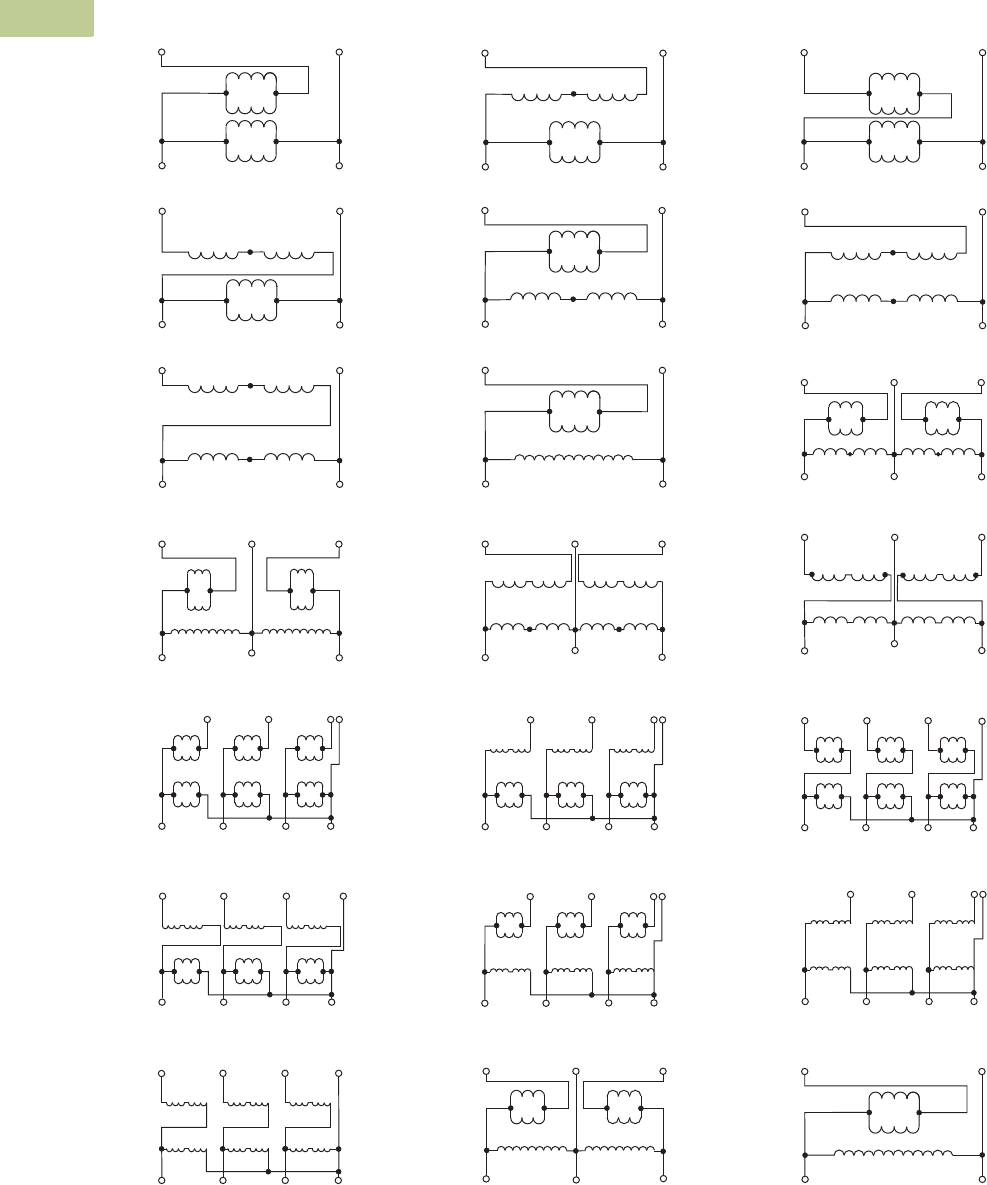
Wiring Diagrams
Buck-Boost Transformers Wiring Diagrams
Note
1WARNING! If input is three-wire, “neutral” connection must be isolated and insulated! When used to supply a three-phase, four-wire load, the source must be three-phase, four-wire wye.
H4 H3
H1H2
H4 H3
H1H2
Neutral
H4 H3
H1H2
High Voltage
Low Voltage
X2 X4 X2 X4 X2 X4
X1 X3 X1 X3 X1 X3
Low Voltage Neutral
High Voltage
X3 X4
X1 X2
X3 X4
X1 X2
X3 X4
X1 X2
H3 H1 H3 H1 H3 H1
H2 H4 H2 H4 H2H4
X1
H4 H3
H1H2
H4 H3
H1H2
Neutral
H4 H3
H1H2
X3 X1 X3 X1 X3
Low Voltage
High Voltage
X2 X4 X2 X4 X2 X4
Low Voltage Neutral
High Voltage
X3 X4
X1 X2
H4 H3
H1H2
X3 X4
X1 X2
H4 H3
H1H2
X3 X4
X1 X2
H4 H3
H1H2
X1
Neutral
X2
X3
X4
X1
X2
X3
X4
X1
X2
X3
X4
Low Voltage
High Voltage
H3
H2
H1
H4
H3
H2
H1
H4
H3
H2
H1
H4
High Voltage
Low Voltage
H4 H3 H2 H1 H1 H2 H3 H4
X1 X2 X3 X4 X4 X3 X2 X1
High Voltage
X3 X4
X2X1
H1
H2
Low Voltage
High Voltage
X3 X4
X2X1
H1H2H4 H3
Low Voltage
Low Voltage
High Voltage
X3 X4X2X1
H4 H3
H1H2
Low Voltage
High Voltage
X3 X4
X2X1
H4 H3
H1H2
Low Voltage
X3 X4X2X1
H4 H3
H1H2
High Voltage
Low Voltage
X3 X4X2X1
H1H2H4 H3
High Voltage
Neutral
X2 X4 X2 X4 X2 X4
High Voltage
Low Voltage
H3 H1 H3 H1 H3 H1
H2 H4 H2 H4 H2H4
X1 X3 X1 X3 X1 X3
Low Voltage
X3 X4
X1 X2
H4 H3
H1H2
X3 X4
X1 X2
H4 H3
H1H2
X3 X4
X1 X2
H4 H3
H1H2
Neutral
High Voltage
High Voltage
X3 X4
X2X1
H1
H4
Low Voltage
Low Voltage
X3 X4
X2X1
H4 H3
H1H2
High Voltage
Low Voltage
High Voltage
H4 H3 H2 H1 H1 H2 H3 H4
X4 X3 X2 X1X1 X2 X3 X4
Low Voltage
High Voltage
X3 X4X2X1
H1H2H4 H3
High Voltage
Low Voltage
X4 X3
X1X2
X3 X4
X2X1
H4 H3 H2 H1 H1 H2 H3 H4
High Voltage
Low Voltage
H4 H1 H1 H4
X4 X3
X1X2
X3 X4
X2X1
X4 X3
X3 X4
High Voltage
Low Voltage
H2 H1 H1 H2
X1
X2
X2X1
Diagram A Diagram B Diagram C
Diagram D Diagram E Diagram F
Diagram G Diagram H Diagram I
Diagram J Diagram K Diagram L
Diagram M 1Diagram N 1Diagram O 1
Diagram P 1Diagram Q 1Diagram R 1
Diagram S 1Diagram T Diagram U
