OPM 1038 S 2 8 10 Brochure
163037-Brochure 163037-Brochure 163037-Brochure B4 unilog cesco-content
170949-Brochure 170949-Brochure 170949-Brochure B4 unilog cesco-content
616713-Attachment 616713-Attachment 616713-Attachment 051712 Batch6 unilog cesco-content
616713-Attachment 616713-Attachment 616713-Attachment 051712 Batch7 unilog cesco-content
2016-06-25
: Pdf 1000325861-Brochure 1000325861-Brochure B1 unilog
Open the PDF directly: View PDF ![]() .
.
Page Count: 3
Materials: Grey Thermoplastic
UL Flammability: UL 94VO
Horsepower Rating of Switch:
3PH V 240 480 600
HP 5 10 15
Agency Information:
UL (see table below)
CSA Certified, C22.2 No. 39, Class 6225-01, File 47235
IEC (see table below)
Shipping Weight: Approx. 335g (.74 lb.)
Carton Quantity: 1
Physical Characteristics:
• Small size matches 45mm IEC starter width.
• Fits #8-18 AWG stranded wire, #10-18 AWG solid wire.
• 3-pole version.
• Handle and shaft required for through-the-door operation.
(See ordering information on page 2).
Product Features:
• “Open” fuse indication lights.
• Finger-safe terminals. (Qualified as IP2O per IEC529)
• Cam action handle for easy module removal.
• 35mm DIN-rail or screw panel mounting (#8 screw, 1 1⁄4˝ long).
• Dead front construction. No exposed contacts for added safety.
• Option for remote “open fuse” status indication feature available
(reduces downtime).
• Offered with Class CC rejection clips or European 10mm x
38mm clips to meet global needs.
• Wire ready: Saves time as terminals are ready to accept
wires.
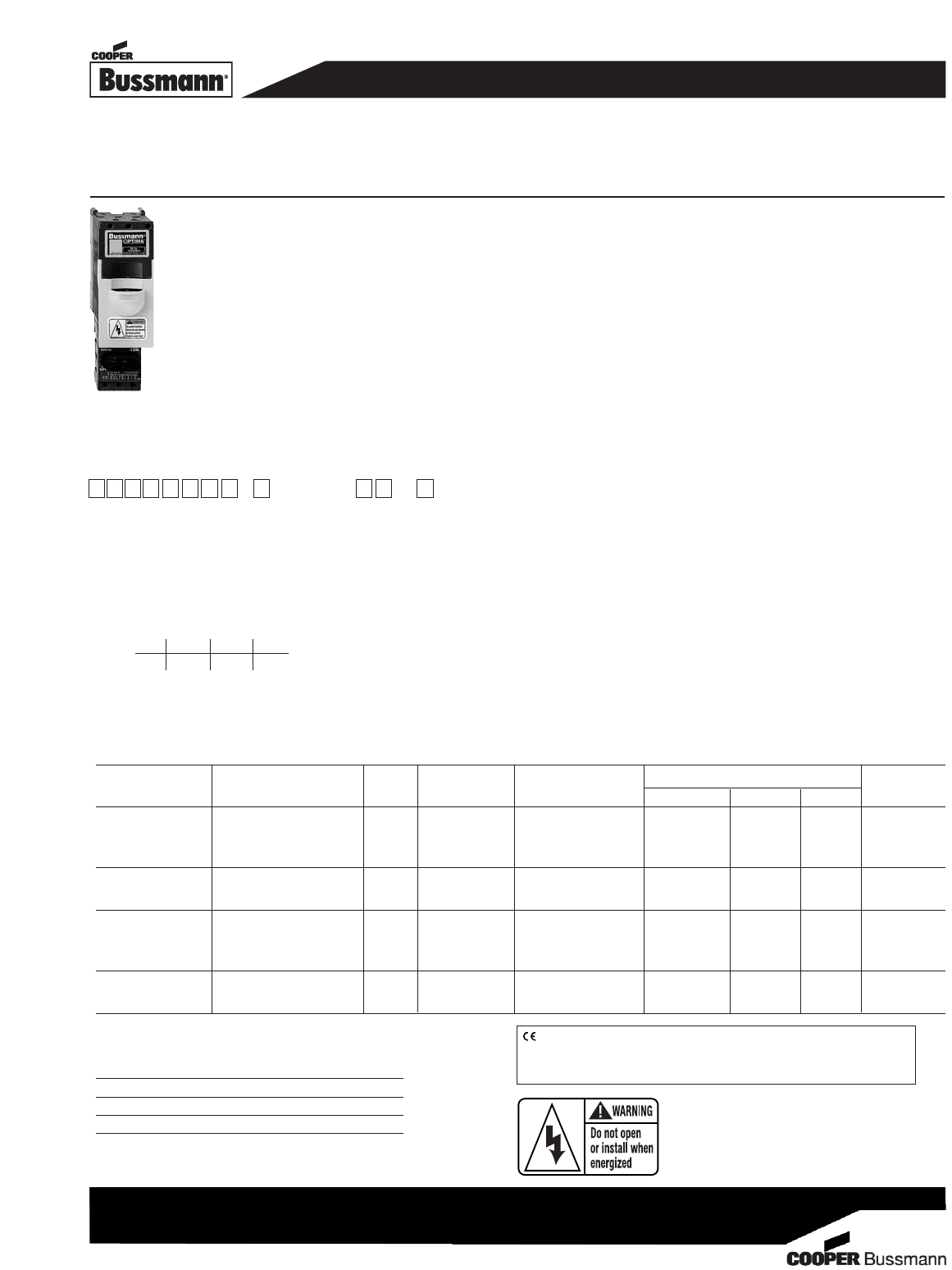
OPTIMA™OPM-1038
Overcurrent Protection Module - Fuseholder and Switch Series
Disconnect Switch for 13⁄32˝ x 1 1⁄2˝ (10mm x 38mm) Fuses
Catalog SC Remote Open UL Information
Number Electrical Rating Rating Clips Fuse Indication Std. File Guide IEC
OPM-1038SW 30A, 600Vac UL/CSA * Non-rejection No Recognized
(Max. 3 Watts per fuse) 10 x 38mm or
32A, 660Vac IEC 13/32” x 1-1/2” UL 508 E161278 NLRV2 IEC 947-3
OPM-1038RSW 30A, 600Vac UL/CSA 100kA Rejection No Listed
UL 508 E161278 NLRV
OPM-1038SWC 30A, 600V UL/CSA * Non-rejection Yes Recognized
(Max. 3 Watts per fuse) 10 x 38mm or
32A, 660Vac IEC 13/32” x 1-1/2” UL 508 E161278 NLRV2 IEC 947-3
OPM-1038RSWC 30A, 600Vac UL/CSA 100kA Rejection Yes Listed
Class CC UL 508 E161278 NLRV
*Rating varies depending on fuse used in module, 100kA maximum..
Recommended Fuse Types:
Class CC Midget (non-rejection)
LP-CC KTK
KTK-R FNM
FNQ-R FNQ
Spare Fuseholder: Part No. 5TPH
CE logo denotes compliance with European Union Low Voltage Directive
(50-1000Vac, 75-1500Vdc). Refer to Data Sheet: 8002 or contact
Bussmann Application Engineering at 636-527-1270 for more information.
Applies to OPM-1038SW and OPM-1038RSW.
O P M - 1 0 3 8 S W
Series Fuse Type Communication
C- Communication
Feature
Blank - 10 x 38mm
or 13/32” x 1-1/2”
R- Class CC
Catalog Symbol:
0210 BU-SB10138 Page 1 of 3 Data Sheet 1103
Ordering Information for External Handle*:
OPTIMA Module + CDRKBS12 + Handle + Shaft
= Complete Disconnect Switch (without fuses)
1. Order Cooper Bussmann part number CDRKBS12.
2. Select the appropriate handle style (Selector or Pistol).
3. Select the shaft corresponding to the handle type and
mounting depth required.
*All switchable OPM-1038 modules come standard with a small black handle Cooper
Bussmann part number CDRKBS12 must be ordered for all through-the-door applications.
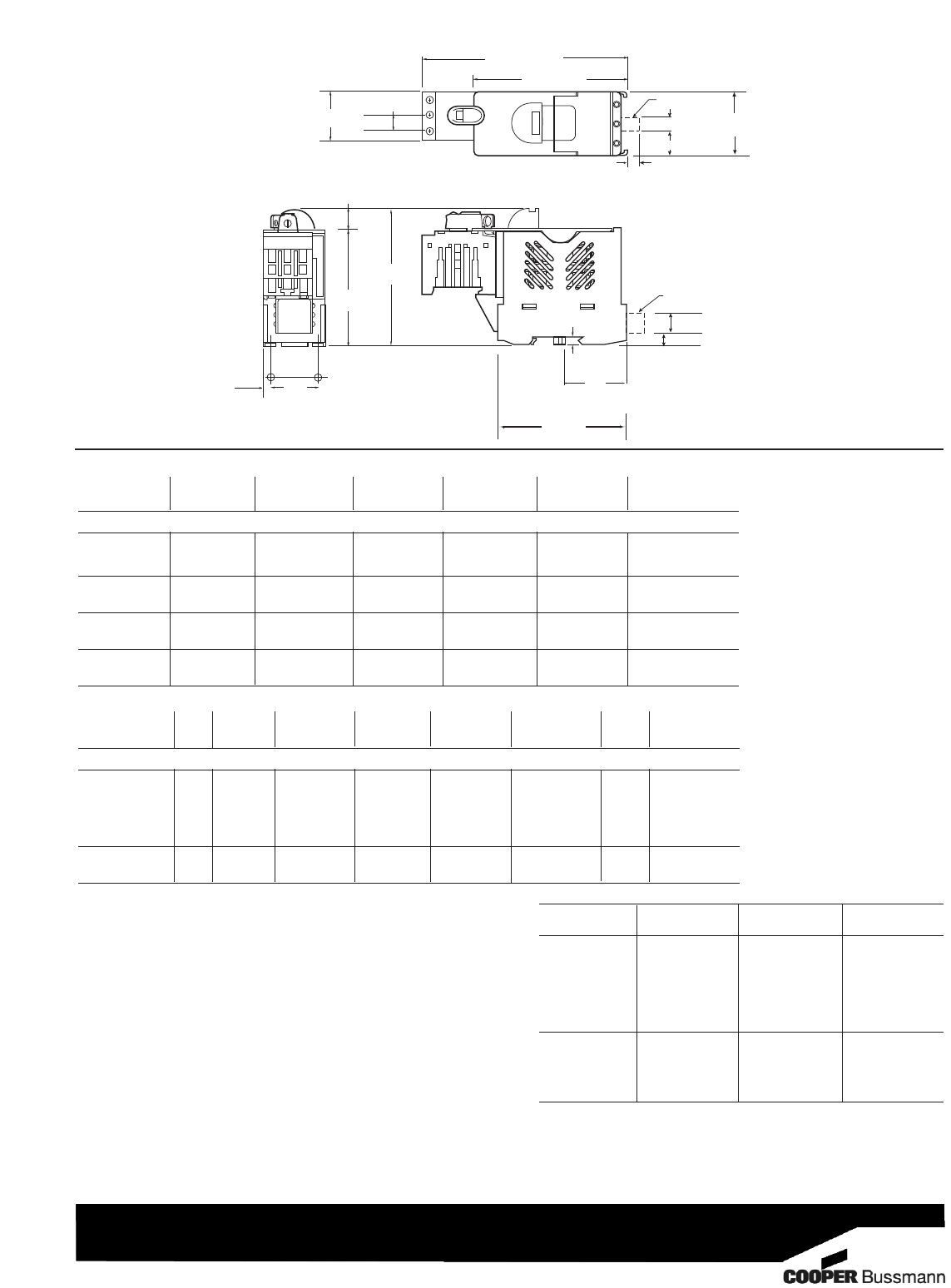
Dimensional Data
Extended Shafts - Shaft Dimension (6x6mm )
For Handle Mounting Shaft Catalog
Type Depth** Length Number
4.2 - 5.0˝ 3.3˝ (85mm) BDS85S
5.0 - 5.8˝ 4.1˝ (105mm) BDS105S
5.6 - 6.4˝ 4.7˝ (120mm) BDS120S
Selector 6.0 - 6.7˝ 5.1˝ (130mm) BDS130S
7.1 - 8.7˝ 7.1˝ (180mm) BDS180S
10.7 - 11.5˝ 9.8˝ (250mm) BDS250S
13.8 - 14.6˝ 13.0˝ (330mm) BDS330S
6.2 - 6.7˝ 5.9˝ (150mm) BDS150
7.0 - 7.5˝ 6.7˝ (170mm) BDS170
Pistol 10.7 - 11.3˝ 10.4˝ (265mm) BDS265
16.0 - 16.6˝ 15.8˝ (400mm) BDS400
20.0 - 20.5˝ 19.7˝ (500mm) BDS500
**Mounting depth is the distance from the outside of the door to the disconnect switch. Shaft
can be cut to desired length.
4.25∑ (± 0.03)
(108.0mm) (± 0.76)
(6.9mm)
(18.8mm)
(7.9mm)
BUSS
5.72∑ (± 0.045)
(145.3mm) (± 1.14)
0.43∑ (± .03)
(10.9mm) (± .76)
1.38∑
(35.0mm)
0.23
∑
1.86
∑
(5.8mm)
3.17∑
(80.5mm)
1.312∑
(± 0.01)
(33.3mm)
(± 0.25)
Panel Mounting
Hole Pattern
(47.2mm)
Panel Mounting
Hole Pattern
3.74∑ (± 0.03)
(95.0mm) (± 0.76)
0.57∑ (± 0.03)
(14.5mm) (± 0.76)
0.27∑
0.31∑
Communication
Port
0.74∑
0.50∑ (12.7mm)
Communication
Port
0.44∑ (11.2mm)
2T1 1L1
3L2
5L3
4T 2
6T3
1.76∑
3.60
∑
(91.4mm)
(44.7mm)
0.224∑
(5.6mm)
Selector Handles - for use with shafts 0.24˝ x 0.24˝ ( 6x6mm)
NEMA IEC Color Defeatable Padlockable Weight Catalog
type type (lbs) number
All marked both O/l & Off/On
1 IP54 Black — — 0.09 CBDH1S
1 IP54 Red/Yel — — 0.09 CBDH2S
1 IP54 Black — Yes 0.12 CBDH15S
1 IP54 Red/Yel — Yes 0.12 CBDH16S
1,3R,12 IP65 Black — Yes 0.16 CBDH3S
1,3R,12 IP65 Red/Yel — Yes 0.16 CBDH4S
1,3R,12 IP65 Black Yes Yes 0.16 CBDH5S
1,3R,12 IP65 Red/Yel Yes Yes 0.16 CBDH6S
Pistol Handles - for use with shafts 0.24˝ x 0.24˝ ( 6x6mm)
NEMA IEC Color Marking Length Defeatable Padlockable Weight Catalog
type type inches/mm (lbs) number
All marked both O/l & Off/On
1,3R,12 IP65 Black O/l & Off/On 1.8/45 Yes Yes 0.28 BDH56
1,3R,12 IP65 Red/Yel O/l & Off/On 1.8/45 Yes Yes 0.28 BDH57
1,3R,12 IP65 Black O/l & Off/On 2.6/65 Yes Yes 0.29 BDH58
1,3R,12 IP65 Red/Yel O/l & Off/On 2.6/65 Yes Yes 0.29 BDH59
1,3R,12,4,4X IP66 Black O/l & Off/On 2.6/65 Yes Yes 0.29 CDHXB65L6
1,3R,12,4,4X IP66 Red/Yel O/l & Off/On 2.6/65 Yes Yes 0.29 CDHXY65L6
0210 BU-SB10138 Page 2 of 3 Data Sheet 1103
Status Output Specifications:
*Minimum operating voltage: 460Vac, 3-phase
*Maximum operating voltage: 620Vac, 3-phase
Status output maximum conducting current: 40mA
Status output maximum on resistance: 35 ohms
@ 40mA
Status output typical off resistance: >10 Mohm
Status output maximum turn-on and
turn-off delay: 850 milli-second
Status Output Interface Specifications:
Rated Voltage: Recommended 5-35Vdc, 300Vac max.
Rated Current: 40mA max.
Wire Size: #28-14 AWG
Torque: 2.25 lb. in.
Open Fuse Indicator Status Output Description:
The open fuse indicator status output acts very much like
an on/off switch. With all three fuses in place and operating
properly, this status output has a high resistance value of
greater than ten mega-ohms. When one or more of the
fuses are open, the status output becomes turned-on with
a resistance value less than 35 ohms. This status output
withstands voltage (ac or dc) up to 35V at off-state
and conducts current up to 40 milli-amps at on-state.
Applying voltage and current exceeding these limits will
result in damage to the components inside this status
output device permanently. There is some time-delay when
the status output changes on/off state. The open fuse
communications or status output device includes optical
isolators within the unit.
Communications output states:
Fuse Good NO - High Resistance, >10 megohms
Opened Fuse NC - Low Resistance, < 35 ohms
OPEN FUSE INDICATION
Note: Operating this device beyond the above limits will
cause permanent damage to the components on
the board.
For applications requiring status output below a system
voltage of 460V, contact Bussmann.
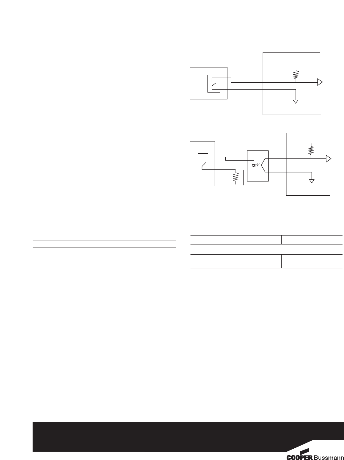
The examples shown below illustrate typical interface to
Programmable Logic Controllers.
STATUS
OUTPUT
TTL
Digital
Input
PC / PLC
Vcc (5V to 35V)
Pull up
Resistor
(> 1K)
EXAMPLE 1: DIRECT INTERFACE TO PC/PLC
PC / PLC
EXAMPLE 2: INTERFACE TO PC / PLC WITH OPTICAL ISOLATION
Current-
Limiting
Resistor
Optical
Isolator TTL
Digital
Input
Vcc (5V to 35V)
ISOLATED AC OR DC
POWER SOURCE
STATUS
OUTPUT
Pull up
Resistor
(> 1K)
Note: When energized (switch in the “on” position), a low load terminal voltage will
be present when fuses are open or when pullout module is removed. The
leakage current is limited to .5mA maximum.
Example of Output Voltage with three open fuses or pullout module removed.
Catalog Number OPM-1038RSW, OPM-1038SW OPM-1038-RSWC, OPM-1038SWC
Types of Indication Standard Communication
System Voltage Load Terminal Voltage
(1L1-3L2-5L3) (2T1-4T2-6T3)
125Vdc * 12Vdc * 31Vdc *
480Vac, 3-phase 26Vac 56Vac
600Vac, 3-phase 33Vac 88Vac
There is no voltage at the load terminals (2T1-4T2-6T3) on the switch version
(SW suffix) when the switch is in the “off” position.
*The communication device requires a minimum circuit voltage (1L1-3L2-5L3) of
460V for the status indicating device to operate. Below 460V, but above 120V, the
indicator lights will luminate, but there will not be any communication status output.
© 2010 Cooper Bussmann
St. Louis, MO 63178
www.cooperbussmann.com
0210 BU-SB10138 Page 3 of 3 Data Sheet 1103
The only controlled copy of this Data Sheet is the electronic read-only version located on the Cooper Bussmann Network Drive. All other copies of
this document are by definition uncontrolled. This bulletin is intended to clearly present comprehensive product data and provide technical informa-
tion that will help the end user with design applications. Cooper Bussmann reserves the right, without notice, to change design or construction of any
products and to discontinue or limit distribution of any products. Cooper Bussmann also reserves the right to change or update, without notice, any
technical information contained in this bulletin. Once a product has been selected, it should be tested by the user in all possible applications.
