Volume 15 1000328170 Catalog
2016-10-06
: Pdf 1000328170-Catalog 1000328170-Catalog B5 unilog
Open the PDF directly: View PDF ![]() .
.
Page Count: 166 [warning: Documents this large are best viewed by clicking the View PDF Link!]

Electrical Sector Solutions
Volume 15:
Solar Inverters
Electrical
Balance
of System
and
Product line Product name
Model Number
Model Number
Model Number
Model Number
Model Number
Model Number
Model Number
Model Number
Model Number
A
D
C
B
Our roots in the electrical business run deep. Eaton is a global
technology leader in electrical components and systems for
power quality, distribution and control. Our industry leading
products and services are designed to deliver:
•
Reliability
•
Efficiency
•
Safety
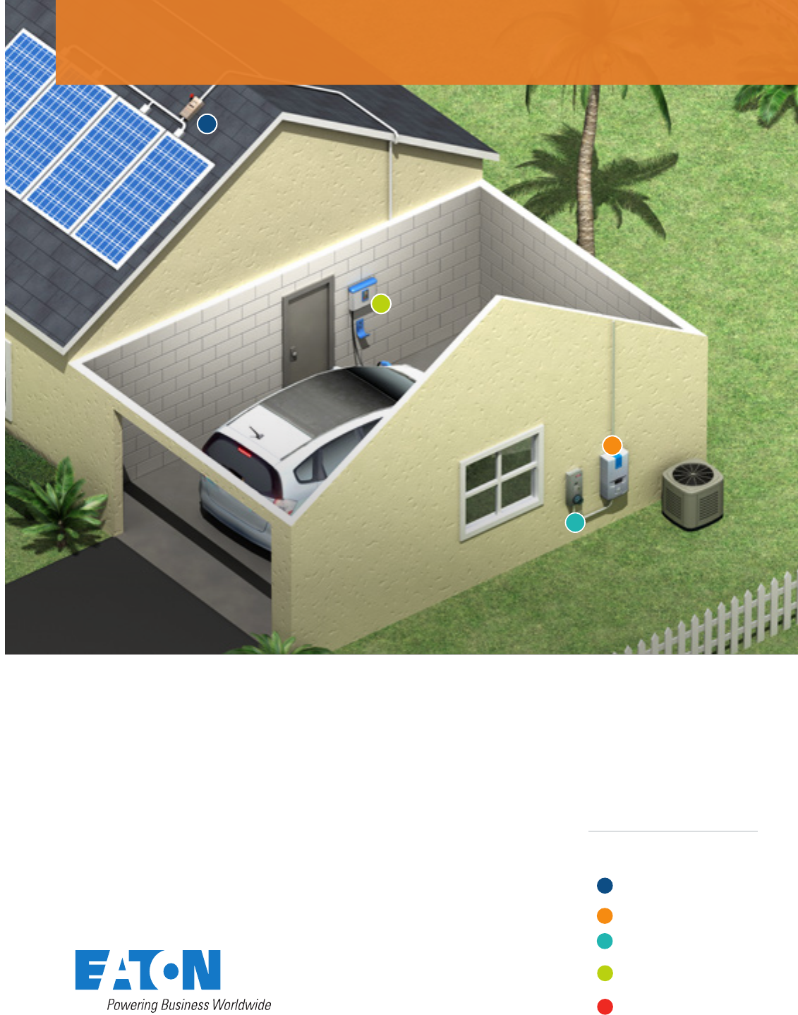
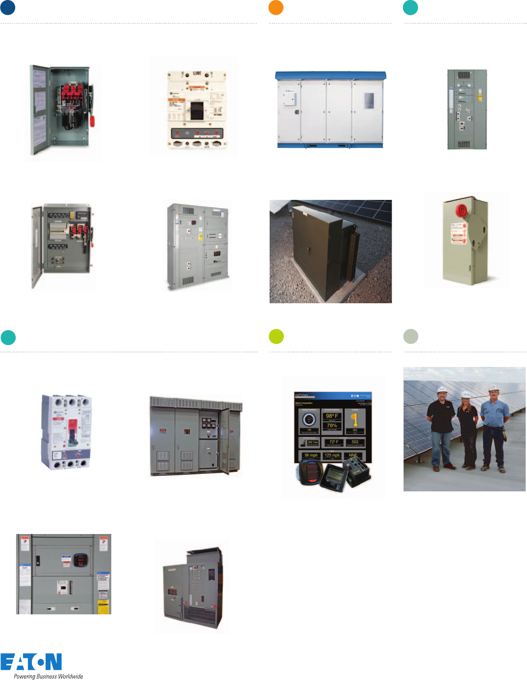
Residential solar solutions
Electrical Balance of System for
Eaton Solar
One-stop BOS shopping
We can assemble a package
of Balance of System (BOS)
equipment that is ready to be
installed. You will have one
vendor, one purchase order,
one delivery schedule and a
single point of accountability.
• We can customize our
solutions to the physical
dimensions of your home
• Our BOS solutions will
work with many photovoltaic
(PV) panel manufacturers
• We offer a wide range
of solar power solutions
Eaton product
solutions combine:
• DC switching
(UL98 and UL98B)
• Robust inverter technology –
same reliable technology
that is used in our UPS
systems (UL1741)
• AC switching and protection
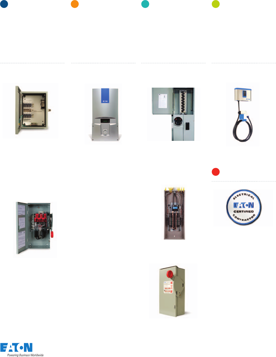
Residential Installations
EATON’S ELECTRICAL
BALANCE OF SYSTEM
DC combiners and
switches (600 Vdc)
Solar inverters (600 Vdc)
AC meter breakers,
loadcenters and switches
Electric vehicle
charging
Eaton Certified
Contractor Network
A
B
C
D
For more information, visit
www.eaton.com/solar
www.eaton.com/plugin
Solar inverters
(600 Vdc)AC meter breakers, load
centers and switches
BC
DC disconnect switches
Solar-ready loadcenter
EV charging station
DC combiner boxes
• Combines input photo-
voltaic strings forming
a single output
• Options include
string monitoring
and surge protection
• Isolates photovoltaic source
• Provides rooftop disconnect
required by re departments
Solar inverters: 3.8 kW - 7 kW
AC disconnect switches
Solar-ready meter breaker
Eaton’s solutions for
protecting and switching
DC current are designed
and tested to meet
UL1741, UL98 and UL98B
requirements for solar
electrical balance of
system equipment.
Eaton’s solar inverters
use the same robust,
reliable technology we
put in our uninterrupt-
ible power systems
(UPS). Solar inverters are
designed and tested to
meet UL1741 standards.
Eaton’s AC switching and
protection solutions are
designed to meet 2008
NEC® Article 690.64(B)(2)
sizing requirements for
solar photovoltaic systems.
Eaton is uniquely
positioned to create a safe
and reliable infrastructure
that supports the use of
electric vehicles. Our
family of charging solutions
is the most robust, exible
offering on the market.
• Isolates utility feed
• Complete family of
circuit breakers for
all applications
• CEC rated for
97% efciency
• Integral AC/DC switching
with four-string combiner
Electric vehicle
charging
Eaton Certied
Contractor Network
D
F
DC combiners and
switches (600 Vdc)
A
Electrical Balance of System for Residential Installations

We know space is always at
a premium. That’s why we
offer totally integrated power
control and management
solutions like inverters and solar
switchboards. These space-
savings lineups house the
system’s DC switching
equipment, solar inverter and
AC switching equipment. The
equipment is pre-configured for
easy installation, saving space,
time and cost.
We can also help you customize
your electrical system package
to the requirements of your
facility, including the physical
dimensions of your building
or installation. In addition, our
regional satellites and service
centers are knowledgeable
about local electrical codes and
regulations in your area, which
allows us to customize your
solutions accordingly.
Eaton product
solutions combine:
• DC switching
(UL98 and UL98B)
• DC combiners (UL1741)
• Robust inverter technology
• AC switching and protection
• Integrated metering
• Customized packaging
and pre-configuration
As your single-source supplier for a solar balance of
system package, Eaton can help you build a solar
system tailored to the needs of a retail, commercial
or institutional site with a focus on:
•
Reliability
•
Efficiency
•
Safety
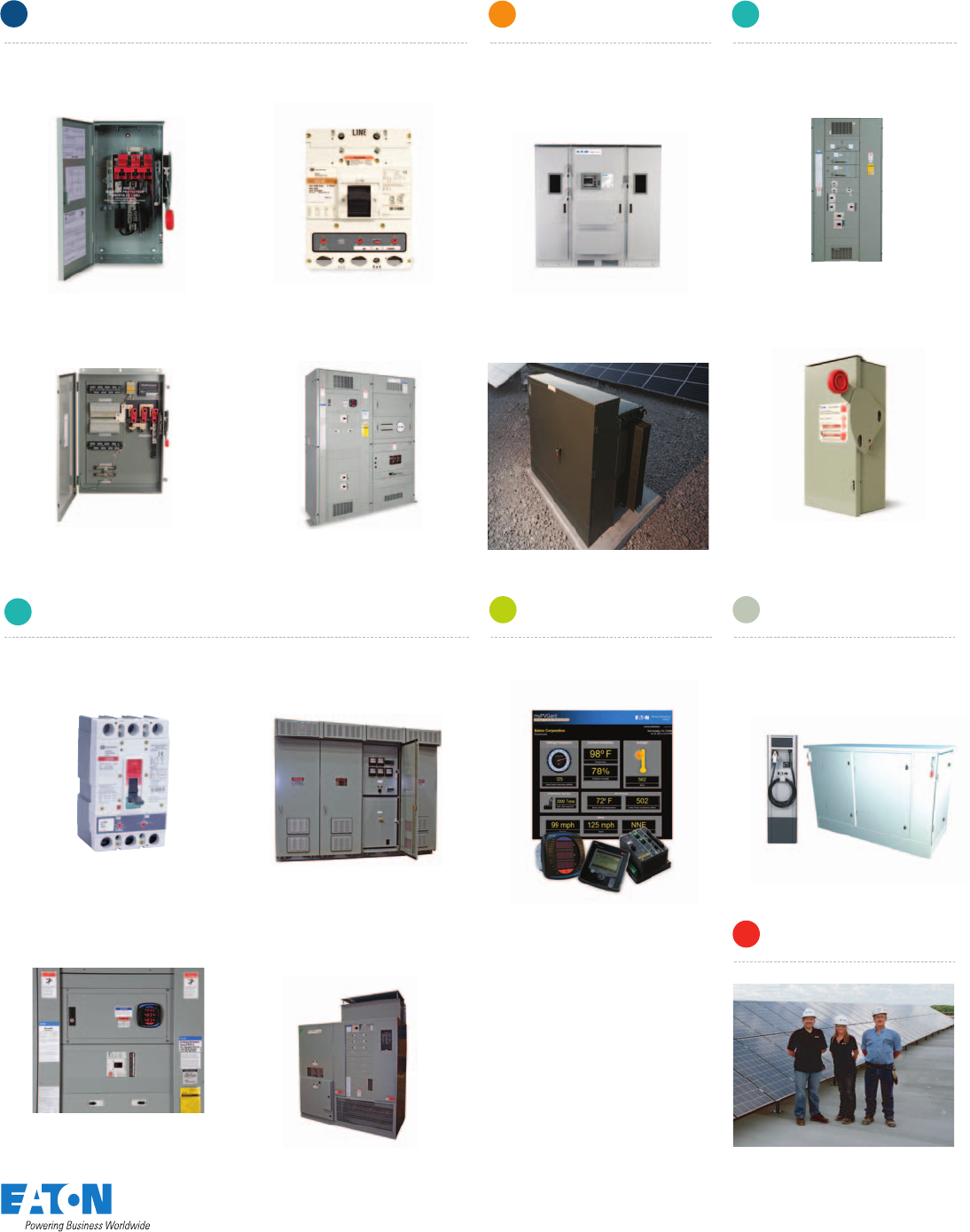
Electrical Balance of System for
B
E
F
C
C
D
A
Commercial Installations
EATON’S ELECTRICAL
BALANCE OF SYSTEM
DC combiners, switches
and switched combiners
(600 Vdc)
Solar inverters (600 Vdc)
and solar transformers
AC switchgear
Monitoring and metering
Electric vehicle charging
Electrical solar services
A
E
D
C
B
F
A
A
Commercial solar solutions
For more information, visit
www.eaton.com/solar
www.eaton.com/plugin
Solar inverters
(600 Vdc) and
solar transformers
BC
CAC switchgear Monitoring
and metering Electric vehicle
charging
Electrical
solar services
D E
F
DC switched combiners DC switchboards AC disconnect switches
DC disconnect switches
AC circuit breakers
DC circuit breakers
Low voltage and medium
voltage transformers
and substations
Commercial-scale
solar inverters –
250kW through 500kW
Custom Solar Switchboards
AC switchboards
Meters and software Electric vehicle charging
and integrated power
stations for solar canopies
Medium voltage
AC switchgear
DC combiners, switches
and switched combiners (600 Vdc)
A
Electrical Balance of System for Commercial Installations
Medium voltage
step-up transformer
©2010 Photo courtesy of Cooper Power Systems
AC switchgear
B
E
C
D
A
Our roots in the electrical industry run deep. As a bankable
partner with 100 years of innovation, we are your single
source supplier of electrical balance of system solutions to
help improve:
•
Reliability
•
Efficiency
•
Safety
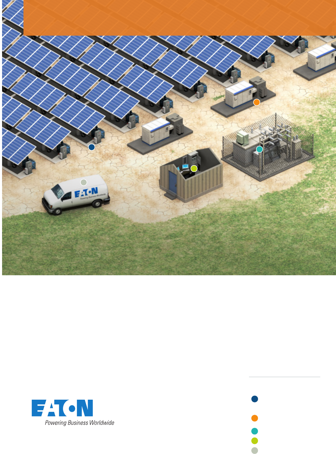
Electrical Balance of System for
Eaton provides complete
electrical balance of system
solutions from the combiners,
to the inverter, to the medium
voltage interconnection to
the grid.
Our NEMA 3R enclosures and
outdoor electrical houses help
protect equipment from the
elements and keep it operating.
Eaton can also help support
solar farms once they are
operating. We offer an extensive
selection of operations training
for electrical power systems
equipment, and we are a leader
in electrical safety training.
We can even help monitor
and manage solar system
performance with our remote
performance monitoring services.
Eaton product
solutions combine:
• DC switching
(UL98 and UL98B)
• DC combiners (UL1741)
• Robust inverter technology –
same reliable technology
that is used in our battery
storage inverters
• AC switchgear
• Integrated metering
• Customized packaging
and pre-configuration
Utility Installations
EATON’S ELECTRICAL
BALANCE OF SYSTEM
DC combiners, switches
and switched combiners
(1000 Vdc)
Solar inverters (1000 Vdc)
and solar transformers
AC switchgear
Monitoring and metering
Electrical solar services
A
E
D
C
B
Utility solar solutions
Solar inverters
(1000 Vdc) and
solar transformers
BC1
AC disconnect switches
Medium voltage
step-up transformer
AC circuit breakers
Low voltage and medium
voltage transformers
and substations
Utility-scale solar inverters –
250kW through 500kW
AC switchboards
Meters and software
Medium voltage
AC switchgear
DC combiners, switches
and switched combiners (1000 Vdc)
A
Switched combiners DC switchboards
DC disconnect switches DC circuit breakers
AC switchgear
C
Custom Solar Switchboards
CAC switchgear Monitoring
and metering
DElectrical
solar services
E
For more information, visit
www.eaton.com/solar
Electrical Balance of System for Utility Installations
©2010 Photo courtesy of Cooper Power Systems

Eaton’s Electrical Services and Systems engineers
can help manage the power of the sun. We offer the
convenience of turnkey project teams who can design,
build and support your solar power system.
Design
Pre-installation services
Eaton’s Electrical Services and
Systems (EESS) team can help
you choose a solar system that
makes technical and financial
sense. Our comprehensive solar
site assessment service evaluates
topics like optimal panel place-
ment, estimated revenues and
projected maintenance costs.
And our experienced power
system engineers can design
a solar system that will always
operate at peak performance.
Build
Installation services
Our field service engineers can
install, start up and commission
any manufacturer’s solar power
equipment quickly using our
efficient, standardized processes.
Your solar system will be up and
running safely and reliably.
Support
Post-installation services
Eaton’s remote performance mon-
itoring services track solar power
outputs and identify trends over
time. That makes it easier to spot
performance trends.
Additional services
Eaton offers many additional
services that help keep
workers safe and clean,
reliable power flowing.
• Arc flash hazard analysis
and solutions
• Power reliability studies
• LEED certification audits
Services and support
Commercial and Utility
Electrical
Solar Services

For more information, visit
www.eaton.com/solar
Design
• Solar site assessments including technical and nancial analysis
• Solar system design including shading and annual kWh output analysis
• Photovoltaic panel design
• Electrical balance of system design
• Monitoring system design (meters and software)
• Building connection and substation design
• Turnkey construction project management,
including design and procurement services
• Turnkey construction projects
• Photovoltaic panel installation
• Electrical balance of system installation
• Monitoring system installation (meters and software)
• Building infrastructure connection
• Substation construction
• Utility grid interconnection, synchronizing and controls
• Solar system commissioning and performance verication
Build
Support
• Remote performance monitoring (metering and data collection)
• Ongoing energy production monitoring and rebate certications
• Building energy audits
• Site power quality, load shedding and future expansion analysis
• Maintenance
• Operations training for site personnel
• Safety training
Volume 15—Solar Inverters and
Electrical Balance of System
Tab 1—Residential and Light Commercial . . . . . . . . . V15-T1-1
Tab 2—Commercial and Utility . . . . . . . . . . . . . . . . . . . V15-T2-1
Tab 3—Solar OEM . . . . . . . . . . . . . . . . . . . . . . . . . . . . . V15-T3-1
Tab 4—AC Power Distribution . . . . . . . . . . . . . . . . . . . V15-T4-1
Appendix 1—Eaton Terms & Conditions . . . . . . . . . . . V15-A1-1
Appendix 2—Catalog Parent Number Index . . . . . . . . V15-A2-1
Appendix 3—Alphabetical Product Index . . . . . . . . . . V15-A3-1
15
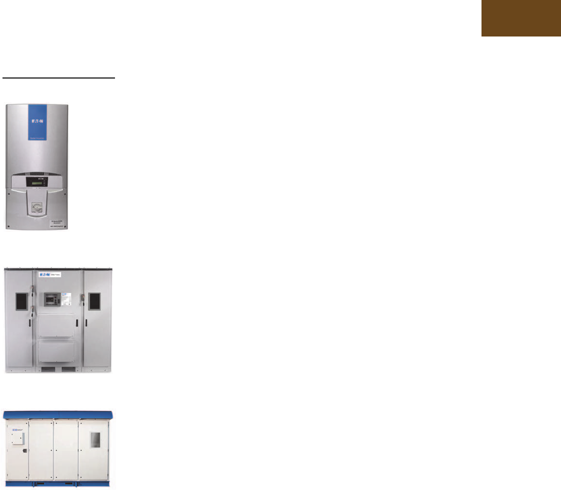
Eaton Grid-Tied Solar Inverter
(3.8–7 kW)
Power Xpert™ Solar 250 kW Inverter
Power Xpert Solar 1500 kW Inverter

Copyright
Dimensions, Weights and Ratings
Dimensions, weights and ratings given in this catalog are approximate and should not
be used for construction purposes. Drawings containing exact dimensions are available
upon request. All listed product specifications and ratings are subject to change without
notice. Photographs are representative of production units.
Terms and Conditions
All prices and discounts are subject to change without notice. When price changes
occur, they are published in Eaton’s Price and Availability Digest (PAD). All orders
accepted by Eaton’s Electrical Sector are subject to the general terms and conditions
as set forth in Appendix 1—Eaton Terms & Conditions.
Technical and Descriptive Publications
This catalog contains brief technical data for proper selection of products. Further
information is available in the form of technical information publications and illustrated
brochures. If additional product information is required, contact your local Eaton
Products Distributor, call 1-800-525-2000 or visit our website at www.eaton.com.
Compliance with Nuclear Regulation 10 CFR 21
Eaton products are sold as commercial grade products not intended for application in
facilities or activities licensed by the United States Nuclear Regulatory Commission
for atomic purposes, under 10 CFR 21. Further certification will be required for use of
these products in a safety-related application in any nuclear facility licensed by the
U.S. Nuclear Regulatory Commission.
WARNING
The installation and use of Eaton products should be in accordance with the provisions
of the U.S. National Electrical Code® and/or other local codes or industry standards that
are pertinent to the particular end use. Installation or use not in accordance with these
codes and standards could be hazardous to personnel and/or equipment.
Copyright ©2015 Eaton, All Rights Reserved.
These catalog pages do not purport to cover all details or variations in equipment, nor to provide for
every possible contingency to be met in connection with installation, operation or maintenance.
Should further information be desired or should particular problems arise which are not covered
sufficiently for the purchaser’s purposes, the matter should be referred to the local Eaton Products
Distributor or Sales Office. The contents of this catalog shall not become part of or modify any prior
or existing agreement, commitment or relationship. The sales contract contains the entire
obligation of Eaton’s Electrical Sector. The warranty contained in the contract between the parties
is the sole warranty of Eaton. Any statements contained herein do not create new warranties or
modify the existing warranty.

Volume 15—Solar Inverters and Electrical Balance of System CA08100018E—April 2014 eaton.com/solar i
Introduction
Eaton is a global leader in power distribution, power quality,
control and automation, and monitoring products.
At Eaton, we believe a reliable, efficient and safe power system is the foundation of every
successful enterprise. Through innovative technologies, cutting-edge products and our highly
skilled services team, we empower businesses around the world to achieve a powerful advantage.
In addition, Eaton is committed to creating and maintaining powerful customer relationships built
on a foundation of excellence. From the products we manufacture to our dedicated customer
service and support, we know what’s important to you.
Solutions
Eaton takes the complexity out of power systems management with a holistic and strategic
approach, leveraging our industry-leading technology, solutions and services. We focus on
the following three areas in all we do:
●Reliability—maintain the
appropriate level of power
continuity without
disruption or unexpected
downtime
●Efficiency—minimize
energy usage, operating
costs, equipment footprint
and environmental impact
●Safety—identify and
mitigate electrical hazards
to protect what you value
most
Using the Eaton Catalog Library
As we grow, it becomes increasingly difficult to include all products in one or two comprehensive
catalogs. Knowing that each user has their specific needs, we have created a library of catalogs for our
products that when complete, will contain 15 volumes. Since the volumes will continuously be a work
in progress and updated, each volume will stand alone. Refer to our volume directory, MZ08100001E,
for a quick glance of where to look for the products you need. The 15 volumes include:
●Volume 1—Residential
and Light Commercial
(CA08100002E)
●Volume 2—Commercial
Distribution (CA08100003E)
●Volume 3—Power
Distribution and Control
Assemblies (CA08100004E)
●Volume 4—Circuit
Protection (CA08100005E)
●Volume 5—Motor Control
and Protection
(CA08100006E)
●Volume 6—Solid-State
Motor Control
(CA08100007E)
●Volume 7—Logic Control,
Operator Interface and
Connectivity Solutions
(CA08100008E)
●Volume 8—Sensing
Solutions (CA08100010E)
●Volume 9—Original
Equipment Manufacturer
(CA08100011E)
●Volume 10—Enclosed
Control (CA08100012E)
●Volume 11—Vehicle and
Commercial Controls
(CA08100013E)
●Volume 12—Aftermarket,
Renewal Parts and Life
Extension Solutions
(CA08100014E)
●Volume 13—Counters,
Timers and Tachometers
(CA08100015E)—Available
in electronic format only
●Volume 14—Fuses
(CA08100016E)—Available
in electronic format only
●Volume 15—Solar Inverters
and Electrical Balance of
System (CA08100018E)
These volumes are not all-inclusive of every product, but they are meant to be an overview
of our product lines. For our full range of product solutions and additional product information,
consult Eaton.com/electrical and other catalogs and product guides in our literature library.
These references include:
●The Consulting Application
Guide (CA08104001E)
●The Eaton Power Quality
Product Guide (COR01FYA)
If you don’t have the volume that contains the product or information that you are looking for,
not to worry. You can access every volume of the catalog library at Eaton.com/electrical in the
Literature Library.
By installing our Automatic Tab Updater (ATU), you can be sure you always have the most recent
version of each volume and tab.

ii Volume 15—Solar Inverters and Electrical Balance of System CA08100018E—April 2014 eaton.com/solar
Introduction
Icons
Green Leaf
Eaton Green Solutions are products, systems or solutions that represent Eaton
benchmarks for environmental performance. The green leaf symbol is our
promise that the solution has been reviewed and documented as offering
exceptional, industry-leading environmental benefits to customers, consumers
and our communities. Though all of Eaton’s products and solutions are
designed to meet or exceed applicable government standards related to
protecting the environment, our products with the Green Leaf designation
further provide “exceptional environmental benefit.”
Learn Online
When you see the Learn Online icon, go to Eaton.com/electrical and search for
the product or training page. There you will find 100-level training courses,
podcasts, webcasts or games and puzzles to learn more.
Drawings Online
When you see the Drawings Online icon, go to Eaton.com/electrical and find the
products page. There you will find a tab that includes helpful product drawings
and illustrations.
Contact Us
If you need additional help, you can find contact information
under the Customer Care heading of Eaton.com/electrical.

Volume 15—Solar Inverters and Electrical Balance of System CA08100018E—April 2014 eaton.com/solar V15-T1-1
1
1
1
1
1
1
1
1
1
1
1
1
1
1
1
1
1
1
1
1
1
1
1
1
1
1
1
1
1
1
Residential and Light Commercial
Eaton Grid-Tied Solar Inverter
(3.8–7 kW)
Solar Power Center Loadcenters and
Meter Breakers
Residential Electric Vehicle Charging
1.1 Eaton Grid-Tied Solar Inverter (3.8–7 kW)
Product Overview . . . . . . . . . . . . . . . . . . . . . . . . . . . . . . . . . . . . . . . . V15-T1-2
Features and Benefits . . . . . . . . . . . . . . . . . . . . . . . . . . . . . . . . . . . . . V15-T1-2
Application Description . . . . . . . . . . . . . . . . . . . . . . . . . . . . . . . . . . . . V15-T1-2
Standards and Certifications . . . . . . . . . . . . . . . . . . . . . . . . . . . . . . . . V15-T1-2
Product Selection/Technical Data and Specifications . . . . . . . . . . . . . V15-T1-3
1.2 Solar Power Center Loadcenters and Meter Breakers
Product Description. . . . . . . . . . . . . . . . . . . . . . . . . . . . . . . . . . . . . . . V15-T1-4
Application Description . . . . . . . . . . . . . . . . . . . . . . . . . . . . . . . . . . . . V15-T1-5
Features and Benefits . . . . . . . . . . . . . . . . . . . . . . . . . . . . . . . . . . . . . V15-T1-5
Standards and Certifications . . . . . . . . . . . . . . . . . . . . . . . . . . . . . . . . V15-T1-5
Catalog Number Selection . . . . . . . . . . . . . . . . . . . . . . . . . . . . . . . . . V15-T1-6
Product Selection . . . . . . . . . . . . . . . . . . . . . . . . . . . . . . . . . . . . . . . . V15-T1-7
Additional Information . . . . . . . . . . . . . . . . . . . . . . . . . . . . . . . . . . . . V15-T1-8
1.3 Residential Electric Vehicle Charging
Charging Stations . . . . . . . . . . . . . . . . . . . . . . . . . . . . . . . . . . . . . . . . V15-T1-9
Level 1 Universal Receptacle . . . . . . . . . . . . . . . . . . . . . . . . . . . . . . . V15-T1-11
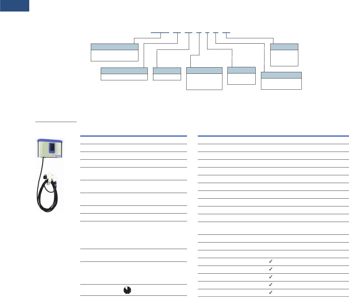
Level 1 Charging Station . . . . . . . . . . . . . . . . . . . . . . . . . . . . . . . . . . . V15-T1-13
Level 2 Charging Station . . . . . . . . . . . . . . . . . . . . . . . . . . . . . . . . . . . V15-T1-16
Electric Vehicle Simulator . . . . . . . . . . . . . . . . . . . . . . . . . . . . . . . . . . V15-T1-19
Electric Vehicle Charging Station Pedestal . . . . . . . . . . . . . . . . . . . . . V15-T1-21

V15-T1-2 Volume 15—Solar Inverters and Electrical Balance of System CA08100018E—April 2014 eaton.com/solar
1
1
1
1
1
1
1
1
1
1
1
1
1
1
1
1
1
1
1
1
1
1
1
1
1
1
1
1
1
1
1.1
Eaton Grid-Tied Solar Inverter (3.8–7 kW)
Eaton Grid-Tied Solar Inverter (3.8–7 kW)
Contents
Description Page
Eaton Grid-Tied Solar Inverter (3.8–7 kW)
Product Selection/Technical Data
and Specifications . . . . . . . . . . . . . . . . . . . . . V15-T1-3
Product Overview
The Eaton Grid-Tied Solar
Inverter’s breakthrough
technology and features
deliver maximum return on
investment for consumers.
Eaton solar inverter units
offer the highest efficiency
and voltage operating ranges
available in order to maximize
energy yield.
Installation time and costs
are greatly reduced through
packaging the combiner box,
AC/DC disconnects and wire
raceway with the inverter.
The design also simplifies
service on the unit through
a two-piece modular
configuration, which allows
the wiring box to remain
connected and mounted if
the need ever arises to
replace the power module.
Features and Benefits
Ratings
●3800W, 4000W, 5000W,
6000W, 7000W
Maximum Energy Harvest
●97% CEC efficiency
●Broad voltage operating
range (105–500 Vdc)
for superior performance
in low light and high
temperature environments
●Transformerless design
Saves Installation Time
and Cost
●Integrated PV system
AC/DC disconnect switch
●Four branch circuit–rated
negative and positive
fused inputs
●Integrated NEC®-compliant
wire raceway
Versatility in Installation
●Field-selectable voltage
output: 208/240/277 Vac
●LCD display with side
pushbutton for nighttime
monitoring
●NEMA® 3R enclosure
●Two-piece modular design
Eaton Value
●A global leader in inverter
technology
●Complete balance of
system provider
●Eaton reputation for
quality, support, and
service
●Installation certification via
Eaton Certified Contractor
Network (ECCN)
Application Description
Available in four individual
sizes: 4 kW, 5 kW, 6 kW and
7 kW respectively. The 4 kW
unit has the ability to be field-
converted to output 3.8 kW
to accommodate lower rated
AC loadcenters. This inverter
family is to be used in grid-
tied applications only, thus
having the ability to feed
power to the utility grid. The
design focus of these
residential/light commercial
inverters was on maximizing
energy harvest and
minimizing installation time
and cost. The inverters boast
an extremely high efficiency
and a wide DC voltage
operating range, while fully
integrating the complete
balance of system into the
unit, including a four-string
DC combiner, a DC
disconnect switch, an AC
disconnect switch and a
wire raceway.
Standards and
Certifications
●ETL Listed (in compliance
with UL® Std 1741)
●CSA® Listed (Std C22.2
No. 107.1)
●CEC Listed

Volume 15—Solar Inverters and Electrical Balance of System CA08100018E—April 2014 eaton.com/solar V15-T1-3
1
1
1
1
1
1
1
1
1
1
1
1
1
1
1
1
1
1
1
1
1
1
1
1
1
1
1
1
1
1
1.1
Eaton Grid-Tied Solar Inverter (3.8–7 kW)
Product Selection/Technical Data and Specifications
Eaton Grid-Tied Solar Inverter (3.8–7 kW)
Description PV240 PV250 PV260 PV270
Input (DC)
Nominal DC voltage 360V 360V 360V 360V
Maximum DC voltage 600V 600V 600V 600V
System startup voltage 150V 150V 150V 150V
Shutdown voltage Typical 80V Typical 80V Typical 80V Typical 80V
MPPT voltage range 105–500V 105–500V 105–500V 105–500V
Full rating voltage range 225–500V 200–500V 200–500V 200–500V
Maximum DC current 19A 26A 32A 37A
Number of DC input terminals 4 4 4 4
Output (AC)
Nominal AC power at 240 Vac and 277 Vac 3800W 4000W 5000W 6000W 7000W
Nominal AC power at 208 Vac 3800W 3800W 4600W 6000W 7000W
Maximum AC power at 240 Vac and 277 Vac 3800W 4000W 5000W 6000W 7000W
Maximum AC power at 208 Vac 3800W 3800W 4600W 6000W 7000W
Nominal AC voltage 208V/240V/277V 208V/240V/277V 208V/240V/277V 208V/240V/277V
Nominal frequency 60 Hz 60 Hz 60 Hz 60 Hz
Disconnection time of excess operational frequency range <0.16 sec <0.16 sec <0.16 sec <0.16 sec
Nominal AC current at 208 Vac 18.3A 18.3A 22.1A 28.9A 33.7A
Nominal AC current at 240 Vac 15.8A 16.7A 20.8A 25.0A 29.2A
Nominal AC current at 277 Vac 13.7A 14.4A 18.1A 21.7A 25.3A
Maximum AC current at 208 Vac 18.3A 18.5A 22.5A 30.0A 35.0A
Maximum AC current at 240 Vac 15.8A 18.5A 22.5A 28.5A 33.2A
Maximum AC current at 277 Vac 13.7A 16.4A 20.5A 24.6A 28.7A
Power factor > 0.99 > 0.99 > 0.99 > 0.99
Efficiency
Peak efficiency 97.50% 97.50% 97.50% 97.50%
CEC efficiency 97% 97% 97% 97%
General Data
Topology Transformerless Transformerless Transformerless Transformerless
Dimensions (W/H/D) inches 17.1/33.3/8.3 17.1/33.3/8.3 17.1/33.3/8.3 17.1/33.3/8.3
Weight (lbs) 86 90 101 101
Power consumption: standby/night < 7W/< 0.2W < 7W/< 0.2W < 7W/< 0.2W < 7W/< 0.2W
DC insulation resistance > 4M ohms > 4M ohms > 4M ohms > 4M ohms
Enclosure NEMA 3R NEMA 3R NEMA 3R NEMA 3R
Heat dissipation Force air cooling, variable fan speed according to temperature on heat sink
Operating temperature range –25 to +50ºC –25 to +50ºC –25 to +50ºC –25 to +50ºC
Humidity 0 to 95%, noncondensing 0 to 95%, noncondensing 0 to 95%, noncondensing 0 to 95%, noncondensing
Communication RS-232/Super-485 RS-232/Super-485 RS-232/Super-485 RS-232/Super-485
Ground fault protection Internal GFCI and Isolation detection function, in accordance with UL 1741
Disconnect Integrated AC and DC switch Integrated AC and DC
switch
Integrated AC and DC
switch
Integrated AC and DC
switch
Certifications ETL (in compliance with UL 1741), CSA, CEC
DC surge protection 4 kV 4 kV 4 kV 4 kV
AC surge protection 6 kV 6 kV 6 kV 6 kV
V15-T1-4 Volume 15—Solar Inverters and Electrical Balance of System CA08100018E—April 2014 eaton.com/solar
1
1
1
1
1
1
1
1
1
1
1
1
1
1
1
1
1
1
1
1
1
1
1
1
1
1
1
1
1
1
1.2
Solar Power Center Loadcenters and Meter Breakers
Solar Power Center Loadcenters and Meter Breakers
Contents
Description Page
Solar Power Center Loadcenters and Meter Breakers
Features . . . . . . . . . . . . . . . . . . . . . . . . . . . . . . V15-T1-5
Standards and Certifications . . . . . . . . . . . . . . V15-T1-5
Product Selection. . . . . . . . . . . . . . . . . . . . . . . V15-T1-7
Additional Information . . . . . . . . . . . . . . . . . . . V15-T1-8
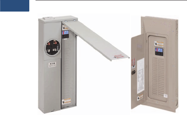
Solar Power Center Loadcenters and Meter Breakers
Product Description
Eaton’s Solar Power Centers
combine both utility power
and solar photovoltaic (PV)
power into one enclosure.
Solar Power Centers can be
applied as a component
of a complete PV electrical
system. Eaton offers the
most complete line of
Balance of System (BOS)
products in the industry,
along with a wide
variety of configurations
including loadcenters and
meter breakers.
The Solar Power Centers
feature industry-exclusive
factory-installed permanent
markings, which help to
ensure National Electrical
Code® (NEC) compliance.
Required by the NEC, these
markings enable quick and
easy identification of product
ratings and location of the
parallel energy source
disconnect. Prior to installation
,
contact your local utility to
confirm approval.
Product Types
Loadcenters are enclosures
specifically designed to house
the branch circuit breakers
and wiring required to
distribute power to individual
circuits. They contain either
a main breaker when used at
the service entrance point or
a main lug when used as a
sub-panel to add circuits to
existing service. The main
breaker protects the entire
panel and can be used as a
service disconnect. The
branch breakers protect the
wires leading to individual
electrical loads such as
fixtures and outlets.
Meter breakers are service
entrance equipment that
consist of a single meter
socket and loadcenter (circuit
breaker distribution section)
or meter socket and main
breaker combined in one
enclosure. Sometimes called
Combos, All-in-Ones, Meter
Centers or Meter Mains,
these units are increasing in
popularity as the socket and
loadcenter or main breaker
are located in one location,
thus providing the contractor
with a labor and material
savings when installing.
Meter breakers are most
often sold in the western,
southwestern and
southeastern United States.
The popularity of meter
breakers is continuing to
increase as more utilities
deregulate and pass the
responsibility of supplying
watthour meter sockets on
to the electrical contractor.

Volume 15—Solar Inverters and Electrical Balance of System CA08100018E—April 2014 eaton.com/solar V15-T1-5
1
1
1
1
1
1
1
1
1
1
1
1
1
1
1
1
1
1
1
1
1
1
1
1
1
1
1
1
1
1
1.2
Solar Power Center Loadcenters and Meter Breakers
Application Description
How to Size a Solar-Ready
Loadcenter or a Meter Breaker
for your Solar Application
The National Electrical Code
(2008) Section 690.64(B)(2)/
(2011) Section 705.12(D)(2)
states: “The sum of the
ampere ratings of overcurrent
devices in circuits supplying
power to a busbar or
conductor shall not exceed
120 percent of the rating of
the busbar or conductor.”
For example: A 200A main
breaker loadcenter + a
backfed 70A PV breaker =
270A = 120% of the 225A
busbar rating. In 2014, 120%
was extended to 125% of the
conductor rating.
Note: Check with local utility for
exact requirements.
Features and Benefits
Solar Power Center
●Up to 225A rated copper
bussing maximizes solar
source up to 70A for
standard units
●100A, 125A and 200A main
breakers available factory
installed, which provides
additional flexibility in
PV sizing
●Main breaker and PV
backfed main are located
at opposite ends of the
distribution panel
●Single-phase, three-wire
120/240 Vac
●Overhead and underground
feed applications
●Padlocking provisions
●Surface and flush designs
available
●Top or bottom exit of
load wiring
●Limited lifetime warranty
for Type CH and 10-year
warranty for Type BR
Loadcenters
●Type CH features plug-on
neutral loadcenters and
breakers that enable the
contractor to connect the
breaker directly to the
neutral bar, eliminating the
need for wiring a pigtail
●Type CH features unique
stab design, which
provides a tight connection
to the bus
●Top or bottom feed
●Straight-in wiring saves
labor and material
●Only one panel for either
application—no
modifications necessary
●Extra 1.50-inch (38.1 mm)
knockout for bundling
enables easier installation
●Drywall marking on
enclosure indicates proper
mounting depth for flush
applications
●Unique sandalwood finish
is aesthetically appealing
with scratch-resistant
powder coating
●Silver flash plated copper
bus provides superior
conductivity
Meter Breakers
●Meter socket and
distribution section are
located in one enclosure,
which provides labor and
material savings
●EUSERC / West Coast and
Non-EUSERC designs
●Ring, ringless and lever
bypass designs
●7-inch-deep designs
available, which is ideal for
stucco homes
●Endwall knockouts are
easily accessible for future
wiring without damaging
stucco
Standards and Certifications
●Complies with NEC (2008)
Section 690.64(B) / (2011)
Section 705.12(D), which
identifies the acceptable
installation and marking
requirements for utility
interactive solar inverters
●UL Listed
●Non-EUSERC
●EUSERC/West Coast
Panel Main Breaker
Ampere Rating
Standard Bus
Ampere Rating
Maximum Total Ampere Rating of
all PV Backfed Mains
Maximum Ampere Rating of
Panel Mains + PV Mains
100 100 20 120
100 125 50 150
125 125 25 150
200 200 40 240
200 225 70 270
225 225 45 270
400 400 80 480
V15-T1-6 Volume 15—Solar Inverters and Electrical Balance of System CA08100018E—April 2014 eaton.com/solar
1
1
1
1
1
1
1
1
1
1
1
1
1
1
1
1
1
1
1
1
1
1
1
1
1
1
1
1
1
1
1.2
Solar Power Center Loadcenters and Meter Breakers
Catalog Number Selection
Solar Power Center Loadcenters
Solar Power Center Meter Breakers
Note
1See product selection table on next page for valid catalog strings. Contact the Eaton Flex Center with questions or if you can not find the right catalog string.
Loadcenters
CH = 3/4-inch Type CH
BR = 1-inch Type BR
Circuits
32 = 32 spaces, 32 circuits
42 = 42 spaces, 42 circuits
60 = 60 spaces, 120 circuits
2040 = 20 spaces, 40 circuits
4242 = 42 spaces, 42 circuits
CH 32 PV PN 200
Construction
Blank = Standard
PN = Plug-on neutral
Main Breaker Amperes
200 = 200A
Enclosure
Blank = NEMA Type 1 indoor with
combination trim
R= NEMA Type 3R rainproof
Solar Power Center
Photovoltaic rated
Circuits
1224 = 12 spaces, 24 circuits
2040 = 20 spaces, 40 circuits
3042 = 30 spaces, 42 circuits
3242 = 32 spaces, 42 circuits
4040 = 40 spaces, 40 circuits
4242 = 42 spaces, 42 circuits
MBE 2040 PV 200 BT S
Main Breaker Amperes
100 = 100A
125 = 125A
200 = 200A
Solar Power Center
Photovoltaic rated
Circuits
MB = 1-inch Type BR, ring style
MBE = 1-inch Type BR, EUSERC
MBED = 1-inch Type BR, 7.00-inch-
deep EUSERC
MBX = 1-inch Type BR, ringless lever
bypass
CMBE = 3/4-inch Type CH, EUSERC
CMBX = 3/4-inch Type CH, ringless
lever bypass
Mounting
S= Surface
F= Flush
Breaker Feed 1
BT= Bottom and top
B= Bottom only
T= Top only

Volume 15—Solar Inverters and Electrical Balance of System CA08100018E—April 2014 eaton.com/solar V15-T1-7
1
1
1
1
1
1
1
1
1
1
1
1
1
1
1
1
1
1
1
1
1
1
1
1
1
1
1
1
1
1
1.2
Solar Power Center Loadcenters and Meter Breakers
Product Selection
Solar Power Center Meter Breakers
Type CH Meter Breakers
Type BR Meter Breakers
Solar Power Center Loadcenters
Type CH Plug-On Neutral Loadcenters
Type BR Loadcenters
Notes
1For box size information, refer to Electrical Sector Solutions—Volume 1: Residential and Light Commercial, Tab 1, CA08100002E.
2Type BR main breaker factory installed. All other units Type CSR.
3Type CSR main breaker factory installed.
4Rainproof panels are furnished with hub closure plates. For rainproof hubs or box size information, refer to Electrical Sector Solutions—Volume 1: Residential and Light Commercial, Tab 1,
CA08100002E.
5Requires the use of Type CHNT breakers.
Max. Number
of 3/4-Inch
Spaces
Max. Number
of Circuits
Main
Breaker
(A)
Bus
Rating
(A)
Max. PV
Input (A) Mounting
Service
Design Bus kAIC Enclosure
1Catalog Number
Combination Service Entrance Devices—EUSERC (Side-by-Side Construction)
32 42 200 225 70 Flush UG Cu 22 7 CMBE3242PV200BF
32 42 200 225 70 Surface UG Cu 22 7 CMBE3242PV200BS
42 42 200 225 70 Flush UG/OH Cu 22 12 CMBE4242PV200BF
42 42 200 225 70 Surface UG/OH Cu 22 12 CMBE4242PV200BS
42 42 200 225 70 Surface OH Cu 22 12 CMBE4242PV200TS
Combination Service Entrance Devices—Non-EUSERC—Lever Bypass (Over/Under Construction)
32 42 200 225 70 Surface UG/OH Cu 22 14 CMBX3242PV200TS
Max. Number
of 1-Inch
Spaces
Max. Number
of Circuits
Main
Breaker
(A)
Bus
Rating
(A)
Max. PV
Input (A) Mounting
Service
Design Bus kAIC Enclosure
1Catalog Number
Combination Service Entrance Devices—EUSERC (Side-by-Side Construction)
12 24 100 2125 50 Flush UG/OH Al 10 2 MBE1224PV100BTF
12 24 100 2125 50 Surface UG/OH Al 10 2 MBE1224PV100BTS
12 24 125 2125 25 Flush UG/OH Al 10 2 MBE1224PV125BTF
12 24 125 2125 25 Surface UG/OH Al 10 2 MBE1224PV125BTS
20 40 200 225 70 Flush UG/OH Cu 22 18 MBE2040PV200BTF
20 40 200 225 70 Surface UG/OH Cu 22 18 MBE2040PV200BTS
30 42 200 225 70 Flush UG Cu 22 7 MBE3042PV200BF
30 42 200 225 70 Surface UG Cu 22 7 MBE3042PV200BS
40 40 200 225 70 Flush UG/OH Cu 22 12 MBE4040PV200BTF
40 40 200 225 70 Surface UG/OH Cu 22 12 MBE4040PV200BTS
Combination Service Entrance Devices—EUSERC—7-Inch-Deep Design
30 42 200 225 70 Semi-flush UG Cu 22 — MBED3042PV200BF
Combination Service Entrance Devices—Non-EUSERC (Over/Under Construction)
20 40 200 225 70 Surface UG/OH Cu 22 — MB2040PV200BTS
Combination Service Entrance Devices—Non-EUSERC—Lever Bypass (Over/Under Construction)
20 40 200 225 70 Surface UG/OH Cu 22 — MBX2040PV200BTS
Max. Number
of 3/4-Inch
Spaces
Max. Number
of Circuits
Main
Breaker
(A) 3
Bus
Rating
(A)
Max. PV
Input (A) Mounting Enclosure Bus kAIC
Box
Size 4
Cover
Included Catalog Number
32 32 200 225 70 Combination NEMA 1 Cu 25 J Yes CH32PVPN200
42 42 200 225 70 Combination NEMA 1 Cu 25 K Yes CH42PVPN200
60 120 5200 225 70 Combination NEMA 1 Cu 25 N Yes CH60PVPN200
Max. Number
of 1-Inch
Spaces
Max. Number
of Circuits
Main
Breaker
(A) 3
Bus
Rating
(A)
Max. PV
Input (A) Mounting Enclosure Bus kAIC
Box
Size 4
Cover
Included Catalog Number
20 40 200 225 70 Combination NEMA 1 Cu 25 D1 Yes BR2040PV200
20 40 200 225 70 Surface NEMA 3R Cu 25 D1R Yes BR2040PV200R 4
42 42 200 225 70 Combination NEMA 1 Cu 25 L2 Yes BR4242PV200
42 42 200 225 70 Surface NEMA 3R Cu 25 L2R Yes BR4242PV200R 4

V15-T1-8 Volume 15—Solar Inverters and Electrical Balance of System CA08100018E—April 2014 eaton.com/solar
1
1
1
1
1
1
1
1
1
1
1
1
1
1
1
1
1
1
1
1
1
1
1
1
1
1
1
1
1
1
1.2
Solar Power Center Loadcenters and Meter Breakers
Contact the Eaton Flex
Center (1-800-330-6479 or
flexcenterlincoln@eaton.com)
for additional solar features
including different device
availability, main breaker, bus
and solar input ratings.
Additional Information
Loadcenter and
accessories—reference
Volume 1—Residential and
Light Commercial,
CA08100002E, Tab 1.
Meter breaker and
accessories—reference
Volume 1—Residential and
Light Commercial,
CA08100002E, Tab 1.
Replacement parts for Solar
Power Centers.
●Meter breaker:
●Deadfront
●Swing door
●Utility pull section cover
●Loadcenter:
●Combination cover
●NEMA 3R covers
●NEMA 3R deadfronts
Replacement Parts
Meter Breaker
Loadcenter
Meter Breaker Deadfront Swing Door Utility Pull Section Cover Breaker Cover Deep
CMBE3242PV200BF MBICVR6PV MBFCVR7PVCH MBUCVR2PV —
CMBE3242PV200BS
CMBE4242PV200BF MBICVR23PV MBFCVR5PVCHB MBUCVR4PV —
CMBE4242PV200BS
CMBE4242PV200TS MBICVR23PV MBFCVR5PVCHT MBUCVR4PV —
CMBX3242PV200TS CMBXDICVR1PV CMBXDFCVR1PV — —
MBE1224PV100BTF MBICVR25PV MBFCVR13PV MBUCVR3PV —
MBE1224PV100BTS
MBE1224PV125BTF
MBE1224PV125BTS
MBE2040PV200BTF MBICVR30PV MBFCVR14PV MBDCVR4PV —
MBE2040PV200BTS
MBE3042PV200BF MBICVR31PV MBFCVR7PVBR MBUCVR2PV —
MBE3042PV200BS
MBE4040PV200BTF MBICVR24PV MBFCVR5PVBR MBUCVR4PV —
MBE4040PV200BTS
MBED3042PV200BF N/A MBEDFCVR2PV MBEDUCVR1PV MBEDDCVR2PV
MB2040PV200BTS MBICVR1PV MBFCVR2PV — —
MBX2040PV200BTS ARP03070CHPV ARP03071CHPV — —
NEMA 1 Combination Cover NEMA 3R Cover NEMA 3R Deadfront
CH32PVPN200 CH8JFPV — —
CH42PVPN200 CH8KFPV — —
CH60PVPN200 CH8NFPV — —
BR2040PV200 BRCOVC35PV — —
BR4242PV200 BRCOVC53PV — —
Raintight
BR2040PV200R — BR3RDOOR9PV BR3RDF11PV
BR4242PV200P — BR3RDOOR13PV BR3RDF15PV

Volume 15—Solar Inverters and Electrical Balance of System CA08100018E—April 2014 eaton.com/solar V15-T1-9
1
1
1
1
1
1
1
1
1
1
1
1
1
1
1
1
1
1
1
1
1
1
1
1
1
1
1
1
1
1
1.3
Residential Electric Vehicle Charging
Charging Stations
Charging Stations
Contents
Description Page
Charging Stations
Product Overview . . . . . . . . . . . . . . . . . . . . . . V15-T1-10
Level 1 Universal Receptacle . . . . . . . . . . . . . . . . V15-T1-11
Level 1 Charging Station . . . . . . . . . . . . . . . . . . . . V15-T1-13
Level 2 Charging Station . . . . . . . . . . . . . . . . . . . . V15-T1-16
Electric Vehicle Simulator . . . . . . . . . . . . . . . . . . . V15-T1-19
Electric Vehicle Charging Station Pedestal . . . . . . V15-T1-21
Charging Stations
Product Description
Eaton’s established
excellence in both the
automotive and electrical
distribution/control industries
have created a perfect
platform for all electrical
vehicle charging needs.
Whether it’s a residential
system, a commercial
endeavor or a system to
support fleet electric
vehicles, Eaton has the
products and the depth of
experience to support,
install and service electric
vehicle chargers.
Features
●Eaton has been managing
power systems (electrical,
fluid, and air) for over 100
years
●Eaton is a Tier 1
Automotive Supplier. This
connectivity with the major
automotives enables Eaton
to be on the forefront of
emerging vehicle
technologies
●Turnkey installation
solutions through Eaton
Engineering Services (EES)
and Eaton Certified
Contractor Network
(ECCN) throughout the
United States and Canada
●Eaton is the only provider
of a full family of electric
vehicle charging products
●Eaton provides a one
stop solution for all your
electrical distribution
needs
●Restricted accessibility
options such as credit
card and radio frequency
identification (RFID)
V15-T1-10 Volume 15—Solar Inverters and Electrical Balance of System CA08100018E—April 2014 eaton.com/solar
1
1
1
1
1
1
1
1
1
1
1
1
1
1
1
1
1
1
1
1
1
1
1
1
1
1
1
1
1
1
1.3
Residential Electric Vehicle Charging
Charging Stations
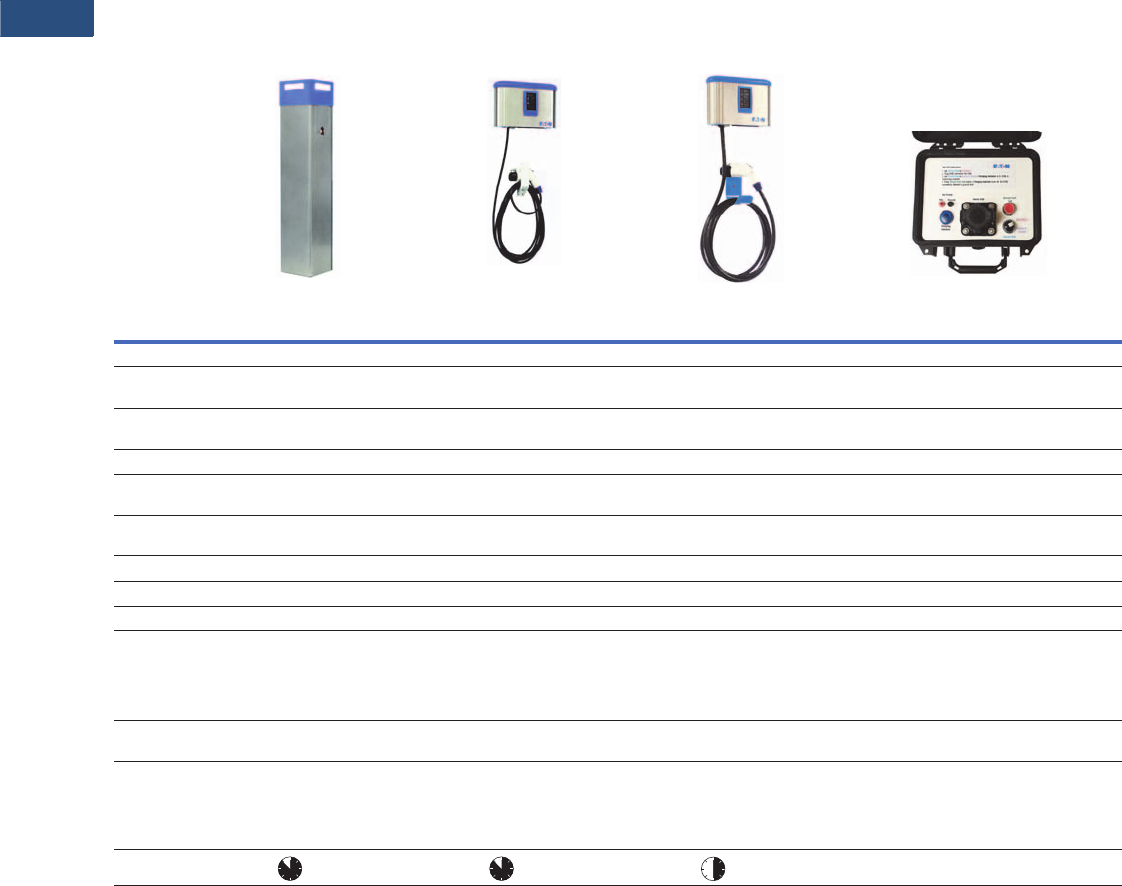
Product Overview
Vehicle Chargers
Description
Level 1
Universal Receptacle
Level 1
Charging Station
Level 2
Charging Station Electric Vehicle Simulator
Input voltage 110/120 Vac 110/120 Vac 208/240 Vac —
Input amperage 20A, 40A or 80A
(1–4 vehicles)
16A 16A or 30A —
Max power Up to 1.9W at
16A per connection
1.9 kW (L116 style) 3.8 kW (L216 style)
7.2 kW (L230 style)
—
Mount Pedestal/bollard Wallmount or pedestal Wallmount or pedestal —
Safety specifications UL 2594 for EV use
cUL 2594 for EV use
ETL Listed to UL 2594/2231/1998
cETL Listed
ETL Listed to UL 2594/2231/1998
cETL Listed
—
Enclosure NEMA 3R
stainless steel
NEMA 3R
stainless steel
NEMA 3R
stainless steel
—
Quick and easy installation Yes Yes Yes —
Ground fault protection Yes Yes Yes —
Overcurrent protection Yes Yes Yes —
Features 1-4 multi-vehicle support
Integrated high-efficiency LED lighting
Build-to-order customization available
SAE J1772™ compliant
Permanent or cord-and-plug wallmount
Quick and easy installation
Build-to-order customization available
SAE J1772 compliant
Permanent or cord-and-plug wallmount
Quick and easy installation
Build-to-order customization available
—
Options Utility grade, sub-metering,
access control
High-efficiency, LED site-lighting,
sub-metering
High-efficiency, LED site-lighting,
sub-metering
—
Applications/markets Single and multi-family homes, parking
garages, university campuses, truck
stops, restaurants, airports,
municipalities, shopping centers,
corporate offices, hotels
Single and multi-family homes, real
estate developers, builders, military
bases, government city centers, schools,
small offices
Single and multi-family homes, real
estate developers, builders, government
city centers, schools, small offices
—
Charge time —
Volume 15—Solar Inverters and Electrical Balance of System CA08100018E—April 2014 eaton.com/solar V15-T1-11
1
1
1
1
1
1
1
1
1
1
1
1
1
1
1
1
1
1
1
1
1
1
1
1
1
1
1
1
1
1
1.3
Residential Electric Vehicle Charging
Level 1 Universal Receptacle
Level 1 Universal Receptacle
Contents
Description Page
Charging Stations . . . . . . . . . . . . . . . . . . . . . . . . . V15-T1-9
Level 1 Universal Receptacle
Product Selection . . . . . . . . . . . . . . . . . . . . . . . V15-T1-12
Technical Data and Specifications . . . . . . . . . . V15-T1-12
Dimensions . . . . . . . . . . . . . . . . . . . . . . . . . . . V15-T1-12
Level 1 Charging Station . . . . . . . . . . . . . . . . . . . . V15-T1-13
Level 2 Charging Station . . . . . . . . . . . . . . . . . . . . V15-T1-16
Electric Vehicle Simulator . . . . . . . . . . . . . . . . . . . V15-T1-19
Electric Vehicle Charging Station Pedestal . . . . . . V15-T1-21
Level 1 Universal Receptacle
Product Description
Eaton's 120 Vac Level 1
Universal Receptacle
Charging Station provides a
safe, reliable means for
charging up to four vehicles
at a time. It is the perfect
solution for buildings that
require multiple-vehicle
charging, such as apartments
and offices.
This innovative charging
station provides a universal
receptacle for up to four EVs.
It’s perfect for charging
electric cars, e-bikes, NEVs,
electric service vehicles and
golf carts, simultaneously.
For applications that require
more than four vehicles to be
charged, Eaton’s Level 1
Universal Receptacle
Charging Stations can be
connected in a series with
optional utility-grade
sub-metering.
Features
●Perfect for charging electric
vehicles (with their
respective cordsets),
e-bikes, NEVs, electric
service vehicles, and
golf carts
●110/120 Vac
●20, 40, and 80A units
available
●Charge up to four vehicles
●Pedestal and bollard styles
available
●Locking provision to
prevent cordset theft
●Support hook to prevent
unintentional unplugging
with heavier EV cordsets
●Charging stations can be
connected in series
●NEMA 5-20 T-slot
receptacles
●Rugged stainless steel
construction
●Indoor/outdoor rated
●Optional LED lighting
available
●Optional utility grade
sub-metering
●Customization available
Standards and Certifications
●NEC 625 compliant
●UL Listed to UL 2594 for
EV use
Catalog Number Selection
Level 1 Universal Receptacle
EVSE CR 4 P
Type
EVSE = Electric Vehicle
Supply Equipment
Level
CR = Universal
receptacle
Mount
P = Pedestal
B = Bollard
Number of
Receptacles
1 = One outlet
2 = Two outlets
4 = Four outlets
V15-T1-12 Volume 15—Solar Inverters and Electrical Balance of System CA08100018E—April 2014 eaton.com/solar
1
1
1
1
1
1
1
1
1
1
1
1
1
1
1
1
1
1
1
1
1
1
1
1
1
1
1
1
1
1
1.3
Residential Electric Vehicle Charging
Level 1 Universal Receptacle
Product Selection
Level 1 Universal Receptacle
Technical Data and Specifications
Level 1 Universal Receptacle
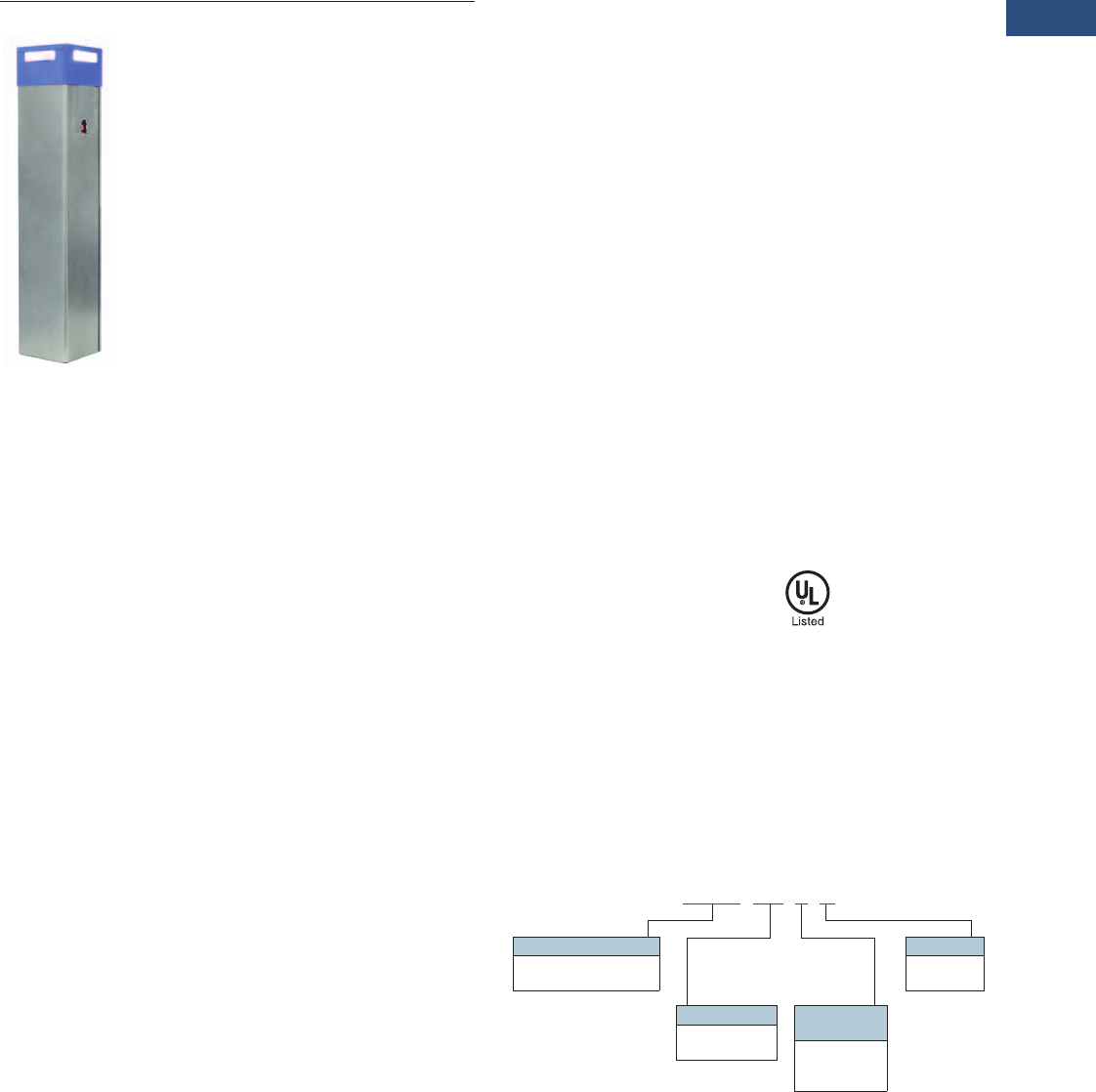
Dimensions
Approximate Dimensions in Inches (mm)
Pedestal
Bollard
Description
Input voltage 110/120 Vac
Input amperage 20A, 40A or 80A
(1–4 vehicles)
Max power Up to 1.9W at
16A per connection
Mount Pedestal/bollard
Safety specifications UL 2594 for EV use
cUL 2594 for EV use
Enclosure NEMA 3R
stainless steel
Quick and easy
installation
Yes
Ground fault protection Yes
Overcurrent protection Yes
Features 1–4 multi-vehicle support
Integrated high-efficiency LED lighting
Build-to-order customization available
Options Utility grade, sub-metering,
access control
Applications/markets Single and multi-family homes, parking
garages, university campuses, truck
stops, restaurants, airports,
municipalities, shopping centers,
corporate offices, hotels
Charge time
Description Specification
Electrical Input
Voltage 110/120 Vac
Amperage 20A, 40A, 80A (pedestal for 1–4 vehicles)
Electrical Output
Power Up to 1.9 kW at 16A per connection
Connection 1-4 NEMA 5-20T receptacles
(pedestal mount)
Physical/Environmental
Weight 50 lbs
Operating temperature –30° to 50°C
Enclosure rating NEMA Type 3R
Safety
Listed to UL 2594 for EV use
Listed to cUL for EV use
Ground fault protection
Overcurrent protection
Level 1
Universal Receptacle
40.60
(1031.2)
50.17
(1274.3)
10.04
(255.0)
10.21
(259.3)
10.21
(259.3)
10.21
(259.3)
36.17
(918.7)
26.60
(675.6)
Volume 15—Solar Inverters and Electrical Balance of System CA08100018E—April 2014 eaton.com/solar V15-T1-13
1
1
1
1
1
1
1
1
1
1
1
1
1
1
1
1
1
1
1
1
1
1
1
1
1
1
1
1
1
1
1.3
Residential Electric Vehicle Charging
Level 1 Charging Station
Level 1 Charging Station
Contents
Description Page
Charging Stations . . . . . . . . . . . . . . . . . . . . . . . . . V15-T1-9
Level 1 Universal Receptacle . . . . . . . . . . . . . . . . V15-T1-11
Level 1 Charging Station
Catalog Number Selection . . . . . . . . . . . . . . . . V15-T1-14
Product Selection . . . . . . . . . . . . . . . . . . . . . . . V15-T1-14
Technical Data and Specifications . . . . . . . . . . V15-T1-14
Dimensions . . . . . . . . . . . . . . . . . . . . . . . . . . . V15-T1-15
Level 2 Charging Station . . . . . . . . . . . . . . . . . . . . V15-T1-16
Electric Vehicle Simulator . . . . . . . . . . . . . . . . . . . V15-T1-19
Electric Vehicle Charging Station Pedestal . . . . . . V15-T1-21
Level 1 Charging Station
Product Description
Eaton offers a full family of
reliable, responsible electric
vehicle (EV) chargers for
residential applications.
Our established excellence in
the automotive and electrical
distribution and control
industries allows us to
provide a wide range of
innovative EV charging
solutions to suit your
individual needs. In addition,
the Eaton Certified Contractor
Network (ECCN) can provide
turnkey services, from design
to installation.
This 120 Vac charging station
provides an economical and
versatile EV charging
solution.
Features
●Provides an economical
and versatile solution for
charging electric vehicles
●110/120 Vac
●16A units available
●Wallmount and pedestal
styles
●Quick and easy installation
●Rugged stainless steel
construction
●Indoor/outdoor rated
●Auto-reset feature
●Hardwire connected
●Optional advanced cord
management to protect
SAE J1772 connector
●Standard 24 foot cord
●Optional LED lighting
available
●Optional utility grade
sub-metering
●Customization available
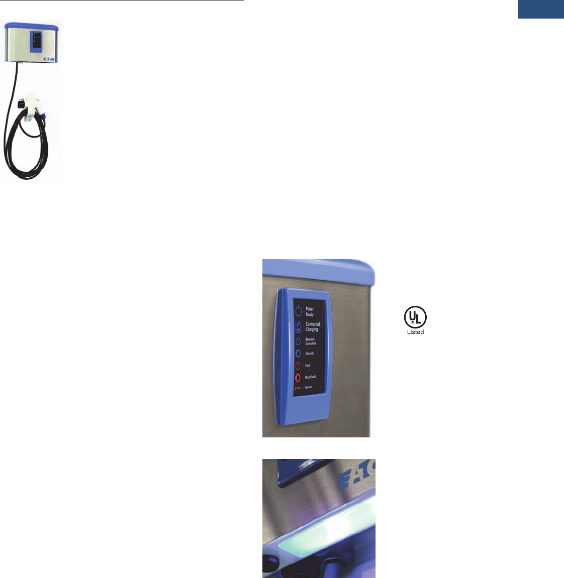
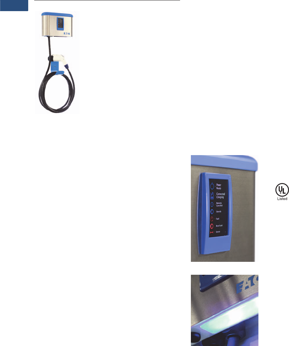
Intuitive User Interface
Optional LED Lighting
Standards and Certifications
●SAE J1772 compliant
connector
●ETL listed to
UL 2594/2231/1998
V15-T1-14 Volume 15—Solar Inverters and Electrical Balance of System CA08100018E—April 2014 eaton.com/solar
1
1
1
1
1
1
1
1
1
1
1
1
1
1
1
1
1
1
1
1
1
1
1
1
1
1
1
1
1
1
1.3
Residential Electric Vehicle Charging
Level 1 Charging Station
Catalog Number Selection
Level 1 Charging Station
Product Selection
Level 1 Charging Station
Technical Data and Specifications
Level 1 Charging Station
EVSE L1 30 H L B W
Type
EVSE = Electric Vehicle
Supply Equipment
Level
L1 = Level 1 (110/120 Vac)
Mount
W = Wall
P = Pedestal
D = Dual
Connection
H = Hardwired
C = Cord-and-plug
connected
Lighting
N = None
L = LED
Cord Management
B = Basic
A = Advanced
Amperage
16 = 16A
Description
Input voltage 110/120 Vac
Input amperage 16A
Max power 1.9 kW (L116 style)
Mount Wallmount or pedestal
Safety specifications UL 2594 for EV Use
cUL 2594 for EV Use
Enclosure NEMA 3R
stainless steel
Quick and easy
installation
Yes
Ground fault protection Yes
Overcurrent protection Yes
Features SAE J1772 compliant
Permanent or cord-and-plug wallmount
Quick and easy installation
Build-to-order customization available
Options High-efficiency, LED site-lighting,
sub-metering
Applications/markets Single and multi-family homes, real
estate developers, builders, military
bases, government city centers,
schools, small offices
Charge time
Level 1 Charging
Station
Description Specification
Electrical Input
Voltage 110/120 Vac
Amperage 16A (L116 Style)
Connection Hardwired connected
Electrical Output
Power 1.9 kW (L116 Style)
Connector SAE J1772
Cable length 24 feet
Physical/Environmental
Weight 23 lbs
Operating temperature –30° to 50°C
Status indicators 5 LEDs: “Power/Ready”, “Connected/Charging”,
“Remotely Controlled”, “Fault” and “Service”
Push buttons Two buttons: “Override” and “Reset Fault”
Enclosure rating NEMA Type 3R—stainless steel
Safety
ETL Listed to UL 2594/2231/1998
cETL Listed
Interlocked power protection
Ground fault protection
Overcurrent protection

Volume 15—Solar Inverters and Electrical Balance of System CA08100018E—April 2014 eaton.com/solar V15-T1-15
1
1
1
1
1
1
1
1
1
1
1
1
1
1
1
1
1
1
1
1
1
1
1
1
1
1
1
1
1
1
1.3
Residential Electric Vehicle Charging
Level 1 Charging Station
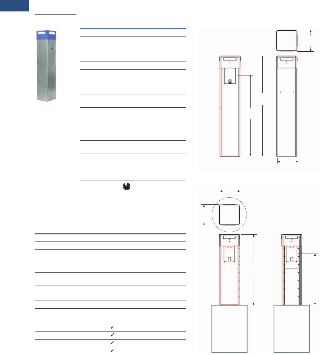
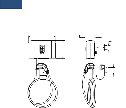
Dimensions
Approximate Dimensions in Inches (mm)
(Advanced cord management)
Level 1 Charging Station
10.07
(255.8)
5.34
(135.6)
15.20
(386.1)
3.00
(76.2)
2.50
(63.5)
V15-T1-16 Volume 15—Solar Inverters and Electrical Balance of System CA08100018E—April 2014 eaton.com/solar
1
1
1
1
1
1
1
1
1
1
1
1
1
1
1
1
1
1
1
1
1
1
1
1
1
1
1
1
1
1
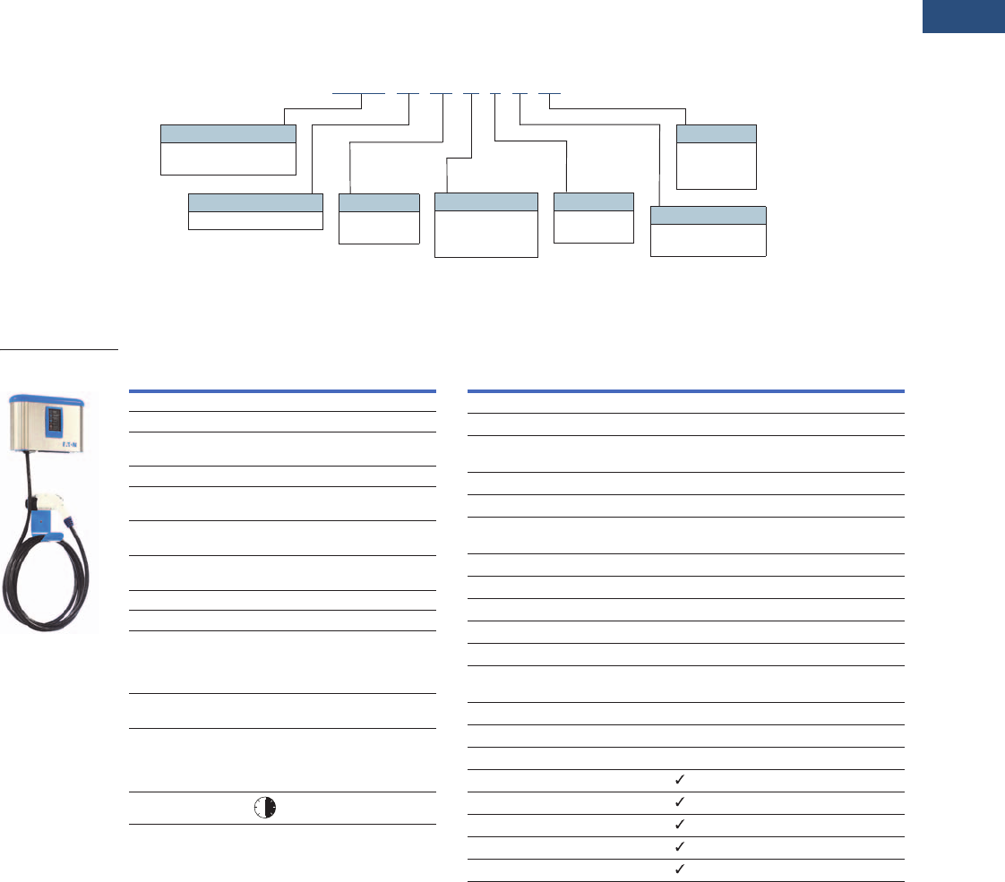
1.3
Residential Electric Vehicle Charging
Level 2 Charging Station
Level 2 Charging Station
Contents
Description Page
Charging Stations . . . . . . . . . . . . . . . . . . . . . . . . . V15-T1-9
Level 1 Universal Receptacle . . . . . . . . . . . . . . . . V15-T1-11
Level 1 Charging Station . . . . . . . . . . . . . . . . . . . . V15-T1-13
Level 2 Charging Station
Catalog Number Selection . . . . . . . . . . . . . . . . V15-T1-17
Product Selection. . . . . . . . . . . . . . . . . . . . . . . V15-T1-17
Technical Data and Specifications . . . . . . . . . . V15-T1-17
Dimensions . . . . . . . . . . . . . . . . . . . . . . . . . . . V15-T1-18
Electric Vehicle Simulator . . . . . . . . . . . . . . . . . . . V15-T1-19
Electric Vehicle Charging Station Pedestal . . . . . . V15-T1-21
Level 2 Charging Station
Product Description
Using an industry standard
J1772 30A or 70A connector,
the Level 2 charging station
will easily fill a depleted all-
electric vehicle battery in
three to four hours while the
owner is working, shopping
or sleeping. The Level 2
charging station is ideal for
residential or commercial EV
charging applications.
Features
●Charge electric vehicles up
to 5 times faster than with
a vehicle’s cordset
●208/240 Vac
●16 and 30A units available
●Wallmount and pedestal
styles
●Quick and easy installation
●Rugged stainless steel
construction
●Indoor/outdoor rated
●Auto-reset feature
●Hardwire connected
●Optional advanced cord
management to protect
SAE J1772 connector
●Standard 24 foot cord
●Optional LED lighting
available
●Optional utility grade
sub-metering
●Customization available
Intuitive User Interface
Optional LED Lighting
Standards and Certifications
●SAE J1772 compliant
connector
●ETL listed to UL 2594/
2231/1998
Volume 15—Solar Inverters and Electrical Balance of System CA08100018E—April 2014 eaton.com/solar V15-T1-17
1
1
1
1
1
1
1
1
1
1
1
1
1
1
1
1
1
1
1
1
1
1
1
1
1
1
1
1
1
1
1.3
Residential Electric Vehicle Charging
Level 2 Charging Station
Catalog Number Selection
Level 2 Charging Station
Product Selection
Level 2 Charging Station
Technical Data and Specifications
Level 2 Charging Station
EVSE L2 30 H L B W
Type
EVSE = Electric Vehicle
Supply Equipment
Level
L2 = Level 2 (208/240 Vac)
Mount
W = Wall
P = Pedestal
D = Dual
Connection
H = Hardwired
C = Cord-and-plug
connected
Lighting
N = None
L = LED
Cord Management
B = Basic
A = Advanced
Amperage
16 = 16A
30 = 30A
Description
Input voltage 208/240 Vac
Input amperage 16A or 30A
Max power 3.8 kW (L216 style)
7.2 kW (L230 style)
Mount Wallmount or pedestal
Safety specifications ETL Listed to UL 2594/2231/1998
cETL Listed
Enclosure NEMA 3R
stainless steel
Quick and easy
installation
Yes
Ground fault protection Yes
Overcurrent protection Yes
Features SAE J1772 compliant
Permanent or cord-and-plug wallmount
Quick and easy installation
Build-to-order customization available
Options High-efficiency, LED site-lighting,
sub-metering
Applications/markets Single and multi-family homes,
real estate developers, builders,
government city centers, schools,
small offices
Charge time
Level 2 Charging
Station
Description Specification
Electrical Input
Voltage 208/240 Vac
Amperage 16A (L116 Style)
30A (L230 Style)
Connection Hardwired connected
Electrical Output
Power 3.8 kW (L216 Style)
7.2 kW (L230 Style)
Connector SAE J1772
Cable length 24 feet
Physical/Environmental
Weight 23 lbs
Operating temperature –30° to 50°C
Status indicators 5 LEDs: “Power/Ready”, “Connected/Charging”,
“Remotely Controlled”, “Fault” and “Service”
Push buttons Two buttons: “Override” and “Reset Fault”
Enclosure rating NEMA Type 3R—stainless steel
Safety
ETL Listed to UL 2594/2231/1998
cETL Listed
Interlocked power protection
Ground fault protection
Overcurrent protection
V15-T1-18 Volume 15—Solar Inverters and Electrical Balance of System CA08100018E—April 2014 eaton.com/solar
1
1
1
1
1
1
1
1
1
1
1
1
1
1
1
1
1
1
1
1
1
1
1
1
1
1
1
1
1
1
1.3
Residential Electric Vehicle Charging
Level 2 Charging Station
Dimensions
Approximate Dimensions in Inches (mm)
(Advanced cord management)
Level 2 Charging Station
10.07
(255.8)
5.34
(135.6)
15.20
(386.1)
3.00
(76.2)
2.50
(63.5)

Volume 15—Solar Inverters and Electrical Balance of System CA08100018E—April 2014 eaton.com/solar V15-T1-19
1
1
1
1
1
1
1
1
1
1
1
1
1
1
1
1
1
1
1
1
1
1
1
1
1
1
1
1
1
1
1.3
Residential Electric Vehicle Charging
Electric Vehicle Simulator
Electric Vehicle Simulator
Contents
Description Page
Charging Stations . . . . . . . . . . . . . . . . . . . . . . . . . V15-T1-9
Level 1 Universal Receptacle . . . . . . . . . . . . . . . . V15-T1-11
Level 1 Charging Station . . . . . . . . . . . . . . . . . . . . V15-T1-13
Level 2 Charging Station . . . . . . . . . . . . . . . . . . . . V15-T1-16
Electric Vehicle Simulator
Catalog Number Selection . . . . . . . . . . . . . . . . V15-T1-20
Technical Data and Specifications . . . . . . . . . . V15-T1-20
Dimensions . . . . . . . . . . . . . . . . . . . . . . . . . . . V15-T1-20
Electric Vehicle Charging Station Pedestal . . . . . . V15-T1-21
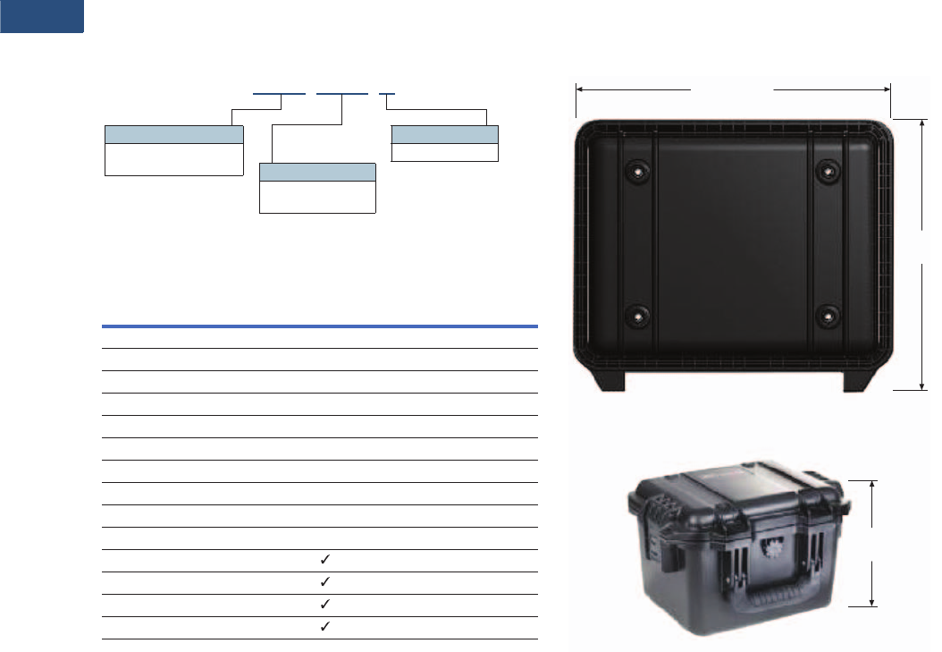
Electric Vehicle Simulator
Product Description
To ensure correct installation
of Electric Vehicle Chargers,
Eaton introduces the EVSE
Electric Vehicle Simulator.
Eaton’s EV Simulator allows
installers to immediately test
the functionality of the EVSE
on-site during installation.
Features
●Confirm proper operation
of any J1772 compliant
EVSE without the need of
an actual electric vehicle
●Rugged case is perfect for
service personnel
●Easy-to-follow testing
instructions printed on unit
●Ready to charge
●Ground fault simulation
●Charging indicator
●Pilot signal test points for
oscilloscopes
Easy to Follow Test
Instructions
V15-T1-20 Volume 15—Solar Inverters and Electrical Balance of System CA08100018E—April 2014 eaton.com/solar
1
1
1
1
1
1
1
1
1
1
1
1
1
1
1
1
1
1
1
1
1
1
1
1
1
1
1
1
1
1
1.3
Residential Electric Vehicle Charging
Electric Vehicle Simulator
Catalog Number Selection
Electric Vehicle Simulator
Technical Data and Specifications
Electric Vehicle Simulator
Dimensions
Approximate Dimensions in Inches (mm)
Electric Vehicle Simulator
Description Specification
Electrical Input
Voltage 120/208/240 Vac
Connection J1772 inlet
Physical/Environmental
Operating temperature –30° to 50°C
Status indicator One light: “Charging”
Push buttons One button: “Ground Fault”
Switch One switch: “Ready/Not Ready”
Test points (banana jack receptacles) Pilot (1 kHz PWM signal) ground
Tests EVSE Safety and Functionality
EVSE ability to charge vehicle
Confirm interlocked power
Confirm ground fault detection
J1772 “handshake” compatibility
EVSE TEST B
Type
EVSE = Electric Vehicle
Supply Equipment Project
Test = Electric Vehicle
Simulator
Troubleshooting
B = Basic
10.62 (269.7)
9.80
(248.9)
6.87
(174.5)
Volume 15—Solar Inverters and Electrical Balance of System CA08100018E—April 2014 eaton.com/solar V15-T1-21
1
1
1
1
1
1
1
1
1
1
1
1
1
1
1
1
1
1
1
1
1
1
1
1
1
1
1
1
1
1
1.3
Residential Electric Vehicle Charging
Electric Vehicle Charging Station Pedestal
Electric Vehicle Charging Station Pedestal
Contents
Description Page
Charging Stations . . . . . . . . . . . . . . . . . . . . . . . . . V15-T1-9
Level 1 Universal Receptacle . . . . . . . . . . . . . . . . V15-T1-11
Level 1 Charging Station . . . . . . . . . . . . . . . . . . . . V15-T1-13
Level 2 Charging Station . . . . . . . . . . . . . . . . . . . . V15-T1-16
Electric Vehicle Simulator . . . . . . . . . . . . . . . . . . . V15-T1-19
Electric Vehicle Charging Station Pedestal
Technical Data and Specifications . . . . . . . . . . V15-T1-22
Wiring Diagram . . . . . . . . . . . . . . . . . . . . . . . . V15-T1-22
Dimensions . . . . . . . . . . . . . . . . . . . . . . . . . . . V15-T1-22
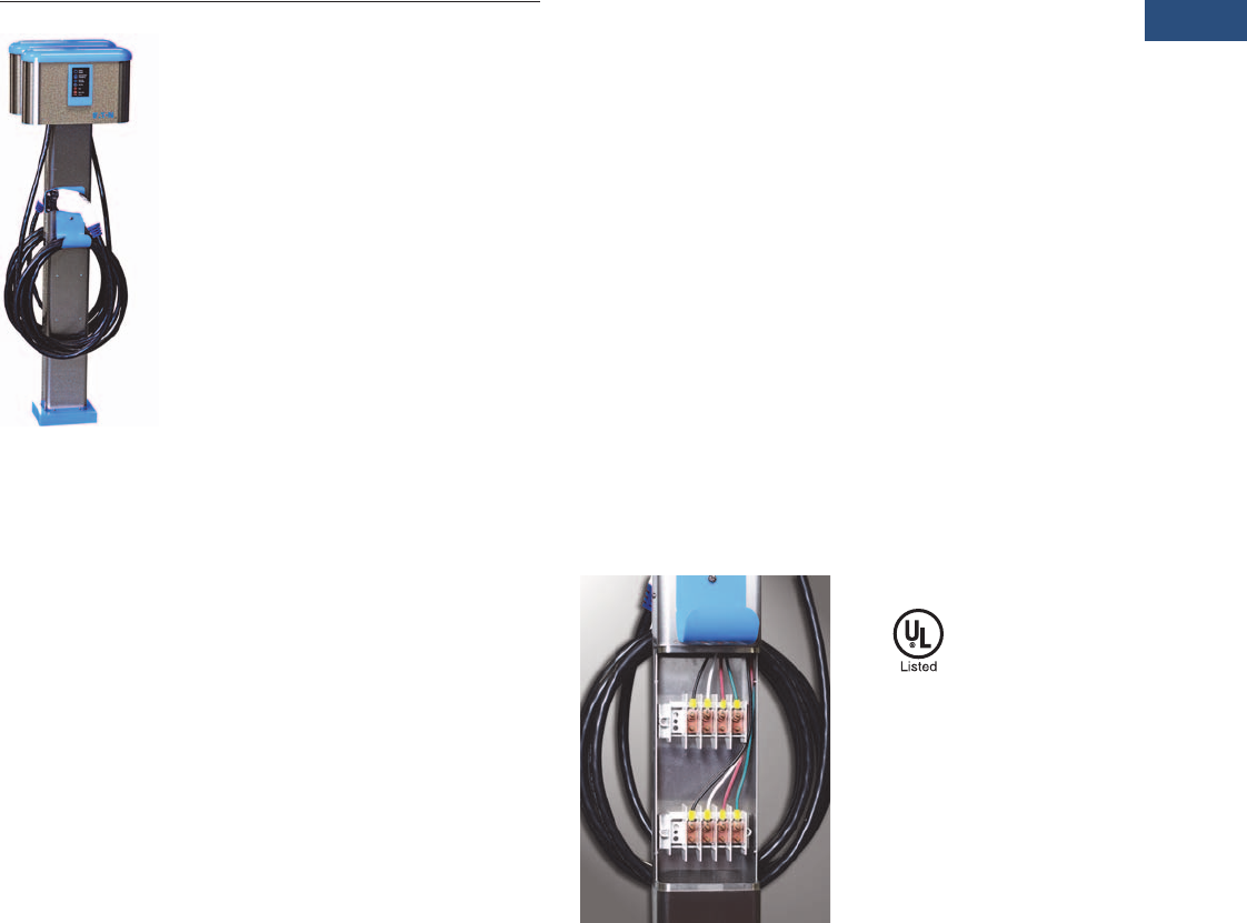
Electric Vehicle Charging Station Pedestal
Product Description
Plug-in electric vehicles
are becoming popular due
to rising fuel costs and
environmental concerns.
Eaton’s EV Charging Station
provides a safe and reliable
means to quickly power up
electric vehicles.
Features
●EV Charging Pedestals ship
with EV Chargers mounted
and pre-wired
●Single or dual EVSE
pedestal options
●Available with Eaton Level
1 and Level 2 charging
stations
●Quick and easy installation
●Rugged stainless steel
construction
●Indoor/outdoor rated
●Standard 24 foot cord
●Optional utility-grade sub-
metering
●Greater flexibility for
external installations
●Dual EVSE pedestal option
allows for multiple vehicle
charging
●Customization available
Pedestal Wiring Standards and Certifications
●UL 1773/50/50E
V15-T1-22 Volume 15—Solar Inverters and Electrical Balance of System CA08100018E—April 2014 eaton.com/solar
1
1
1
1
1
1
1
1
1
1
1
1
1
1
1
1
1
1
1
1
1
1
1
1
1
1
1
1
1
1
1.3
Residential Electric Vehicle Charging
Electric Vehicle Charging Station Pedestal
Technical Data and Specifications
Electric Vehicle Charging Station Pedestal
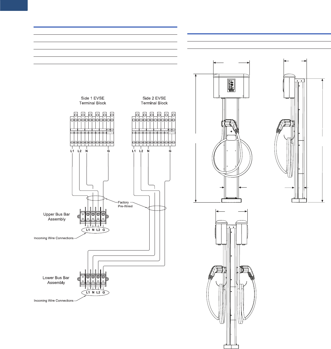
Wiring Diagram
Electric Vehicle Charging Station Pedestal
Dimensions
Approximate Dimensions in Inches (mm)
Electric Vehicle Charging Station Pedestal
Description Specification
Weight (lbs)
Single EVSE—mount pedestal 42 lbs
Dual EVSE—mount pedestal 65 lbs
Enclosure
Rating/material NEMA 3R—stainless steel
Description
Single EVSE pedestal—H x W x D 54.06 (1373.1) x 15.20 (386.1) x 9.70 (246.4)
Dual EVSE pedestal—H x W x D 54.06 (1373.1) x 15.20 (386.1) x 13.30 (337.8)
54.06
(1373.1)
15.20
(386.1)
52.15
(1324.6)
9.71
(246.6)
13.34
(338.8)
4.00
(101.6)
6.00
(152.4)

Volume 15—Solar Inverters and Electrical Balance of System CA08100018E—September 2015 eaton.com/solar V15-T2-1
2
2
2
2
2
2
2
2
2
2
2
2
2
2
2
2
2
2
2
2
2
2
2
2
2
2
2
2
2
2
Commercial and Utility
Power Xpert Solar 250 kW Inverter
Power Xpert Solar 1500/1650 kW
Inverter
Pow-R-Line C Group-Mounted
Distribution Switchboard
600 Vdc Per Pole and 1000 Vdc
Disconnect
2.1 Power Xpert Solar 250 kW Inverter
Product Description . . . . . . . . . . . . . . . . . . . . . . . . . . . . . . . . . . . . V15-T2-2
2.2 Power Xpert Solar 1500/1650 kW Inverter
Product Description . . . . . . . . . . . . . . . . . . . . . . . . . . . . . . . . . . . . V15-T2-8
2.3 DC Disconnects
Product Description . . . . . . . . . . . . . . . . . . . . . . . . . . . . . . . . . . . . V15-T2-13
2.4 Switchboards—Solar Applications
Pow-R-Line C Distribution Switchboards
Product Description . . . . . . . . . . . . . . . . . . . . . . . . . . . . . . . . . . . . V15-T2-21
Integrated Facility Switchboard
Product Description . . . . . . . . . . . . . . . . . . . . . . . . . . . . . . . . . . . . V15-T2-23
2.5 Panelboards—Solar Applications
Introduction
Product Selection Guide . . . . . . . . . . . . . . . . . . . . . . . . . . . . . . . . . V15-T2-25
EZ Box and EZ Trim
Product Description . . . . . . . . . . . . . . . . . . . . . . . . . . . . . . . . . . . . V15-T2-26
Pow-R-Line C Panelboards . . . . . . . . . . . . . . . . . . . . . . . . . . . . . . . . . V15-T2-29
Type PRL1a. . . . . . . . . . . . . . . . . . . . . . . . . . . . . . . . . . . . . . . . . . . V15-T2-37
Type PRL2a. . . . . . . . . . . . . . . . . . . . . . . . . . . . . . . . . . . . . . . . . . . V15-T2-41
Type PRL3a. . . . . . . . . . . . . . . . . . . . . . . . . . . . . . . . . . . . . . . . . . . V15-T2-45
Type PRL4. . . . . . . . . . . . . . . . . . . . . . . . . . . . . . . . . . . . . . . . . . . . V15-T2-49
Types PRL1a, 2a, 3a and 4 Modifications . . . . . . . . . . . . . . . . . . . . V15-T2-59
Regional Manufacturing Facilities . . . . . . . . . . . . . . . . . . . . . . . . . . V15-T2-68
2.6 Solar Services
Product Group Overview . . . . . . . . . . . . . . . . . . . . . . . . . . . . . . . . V15-T2-70
Solar Renewable Analysis and Consultation. . . . . . . . . . . . . . . . . . V15-T2-71
Solar Design . . . . . . . . . . . . . . . . . . . . . . . . . . . . . . . . . . . . . . . . . . V15-T2-72
Turnkey Services. . . . . . . . . . . . . . . . . . . . . . . . . . . . . . . . . . . . . . . V15-T2-75
Solar Monitoring . . . . . . . . . . . . . . . . . . . . . . . . . . . . . . . . . . . . . . . V15-T2-77
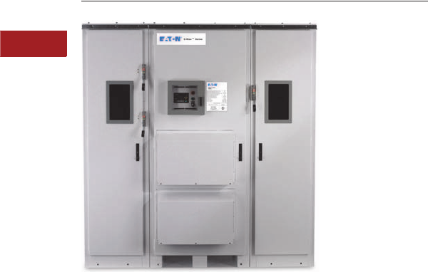
V15-T2-2 Volume 15—Solar Inverters and Electrical Balance of System CA08100018E—September 2015 eaton.com/solar
2
2
2
2
2
2
2
2
2
2
2
2
2
2
2
2
2
2
2
2
2
2
2
2
2
2
2
2
2
2
2.1
Power Xpert Solar 250 kW Inverter
Power Xpert Solar 250 kW Inverter
Contents
Description Page
Power Xpert Solar 250 kW Inverter
Standards and Certifications . . . . . . . . . . . . . . V15-T2-3
Catalog Number Selection . . . . . . . . . . . . . . . . V15-T2-4
Product Selection. . . . . . . . . . . . . . . . . . . . . . . V15-T2-5
Technical Data and Specifications . . . . . . . . . . V15-T2-6
Dimensions . . . . . . . . . . . . . . . . . . . . . . . . . . . V15-T2-7
Power Xpert Solar 250 kW Inverter
Product Description
The Eaton Power Xpert Solar
250 kW Inverter incorporates
Eaton’s programmable logic
controllers (PLCs), advanced
variable frequency drives
and protective relays. Every
critical component inside the
Power Xpert Solar 250 kW
Inverter is proven to be
reliable based on the known
life cycles of high volume
industrial and electrical
control equipment.
Engineered for ease-of-
installation, operation, and
maintenance, the Power
Xpert Solar 250 kW Inverter
contains the intelligence to
automate the commissioning,
operation, and shut down
procedures with minimal
physical action. These robust
utility-interactive three-phase
inverters are based on
Eaton’s mature motor-drive
assembly featuring Eaton’s
Active Front End© (AFE)
control technology.
The Power Xpert Solar 250
kW inverter is designed
specifically for 480 Vac three-
phase utility (grid) applications
and 600 Vdc (open circuit)
PV systems. It is an excellent
choice for either indoor or
outdoor installations from
a company known for its
state-of-the-art electrical
products and industry support.
●CEC 96% efficiency
●>99% MPPT efficiency—
3rd Party verified
●Earliest startup—latest
shutdown with DC
excitation and zero load
grid sync
●Minimized offline nuisance
events with superior fault
tolerance of a utility grade
electric protection relay
Features and Benefits
Dual-Stage 250 kW inverter
with hysteresis, 2 x 125 kW
design, provides optimum
efficiency in lower irradiance
conditions. Offers less
stressful power-stage
operation for improved
inverter longevity. Seamless
dual-inverter operation.
Grid Sensor based vector
control ensures precise
synchronism and fast
response to grid dynamics,
ensuring a stable operation
and an improved solar
energy harvesting.
Advanced Proportional
Integral Derivative (PID)
control enables precise
synchronization to the grid,
finer current and power limits.
Improved temperature limits,
better reactive power or power
factor control.
DC excitation algorithm and
system control Smart PV
energy utilization over wasteful
utility-based methods of
energizing the transformer.
Faster morning “wake-up”
and power export. Faster
mid-day re-connect improves
energy harvesting during
utility anomalies and outages,
minimal-stress “zero-crossing”
grid connection process, less
part-count for improved
solar-system reliability.
Large DC bus capacitors
smart, extremely low ripple-
current on the PV array makes
for a better, trouble-free solar-
module operation. Reduced
stress on solar modules and
wiring control algorithm
ensures lower stress on
isolation transformer over
adverse environmental
conditions.
Inverter re-combiner box
with DC circuit breaker
option available:
●Optional inverter re-
combiner box with DC
breakers to meet NEC®
2011 requirements for safe
DC disconnect, eliminating
the need for external DC
disconnects
●DC breaker option
eliminates the need to
replace DC fuses, allowing
cost and time savings
(lowering O&M costs)
●Current sensing of each
DC input is available for
array zone monitoring; DC
input current is reported to
inverter controller, which
makes it available via
Modbus®

Volume 15—Solar Inverters and Electrical Balance of System CA08100018E—September 2015 eaton.com/solar V15-T2-3
2
2
2
2
2
2
2
2
2
2
2
2
2
2
2
2
2
2
2
2
2
2
2
2
2
2
2
2
2
2
2.1
Power Xpert Solar 250 kW Inverter
●DC breakers can be
individually turned off,
allowing isolation of a
defective sub-array while
allowing other sub-arrays
to operate. This feature
enhances de-bugging
procedures and maximizes
fault-tolerance
●DC breakers are available
on different configurations
and ampacity (90A DC,
100A DC, 125A DC, 150A
DC, 175A DC, 200A DC
and 225A DC)
Inverter grounding bus
on DC and AC sides allows
installation as per NEC 690.47
(C) (1), (2), or (3), should the
facility POCC have a bonded
equipment-ground to the
facility’s grounding electrode
system.
Maximum power point:
Fast (mSec based) response
time with variable step-size
control reacts to sudden
changes, improved current
response for low-irradiance
periods, sudden-onset shading
and grid outages, superior
solar-energy harvesting
Isolation-transformer-based
solar inverter which operates
with all photovoltaic modules
(technologies), negative and
positive grounded PV systems.
Eaton Logic Controller
(ELC) watch-dog system
that ensures greater system
integration and information
response for display and stored
performance data. It Isolates
controls from external
interference (anti-hacking)
Rich standard features
and options list
●Full-load DC switch
disconnect and AC breaker,
lockout/tagout compatible
●Lockable display and
controls door with window
sealed against the elements
●Configurable utility
connection
●Three-wire delta (A/B/C),
no neutral required
●Four-wire wye (A/B/C/N),
N-sensing only
●100 kA surge protection
●200 kAIC AC breaker
●Large DC and AC
conductor gland plates
on bottom and
immediate sides
●Color, menu-driven
display
●Indicator lights (LEDs)
and selection switch
●Remote, field-duplicable
up-fits
– Remote indicators
(LEDs)
– Remote OFF
(shutdown)
●AC view-window for
visible blade disconnect
●Infrared inspection ports
for DC and AC cabinets
●CEC approved 2% PBI
power meter
●Internal heater for
humidity and cold
temperature control
●Multiple DC input
(combiner) with fuse
and breaker options
●SunSpec Alliance
compatible monitoring
(gateway)
Two-cabinet design Inverter
and isolation transformer
that enables integration into
electrical rooms, provides
better package for roof-top
installations, is easier to
receive, lift, transport and
secure, design category(s)
seismic complaint,
terminated transformer
cables included.
Easy maintenance by
Eaton’s Electrical Services
& Systems (EESS)
●No ladder required to
service cooling-system air
filters; ground-level access
●Three-door design ensures
wide opening for limited-
access locations
●Country and worldwide
local services
Commissioning support
through country and
worldwide local services.
Remote monitoring interface
support via Modbus/TCP with
an RJ 45 plug, and a terminal
block supplying additional I/O
and a 120 Vac power supply
for compatibility with third
party monitoring applications.
Advanced anti-islanding
function, which prevents the
operation of the inverter in
the event of a utility outage.
AC overcurrent protection
and safety inverter is
equipped with a 200 kAIC AC
breaker that is operable from
the outside of the unit via
lockout/tagout–capable
handle.
No need for AC fuse
replacements, minimizing
O&M costs.
Inverter doors are fitted with
mechanical interlocks that
will safely shut down the
inverter if doors are opened.
Human Machine Interface
(HMI): A color touch screen
LCD display that represents
the status screens during
normal operation and
additional screens with
password protection for
access to configuration,
troubleshooting, and service.
Standards and Certifications
●UL® 1741 2nd Edition
January 2010
●IEEE® 1547
●NFPA 70, National
Electrical Code® (NEC)
●CEC Listed (California
Energy Commission)
●Seismic qualified to IBC/
CBC
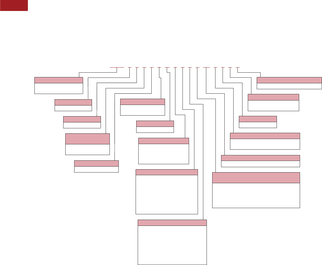
V15-T2-4 Volume 15—Solar Inverters and Electrical Balance of System CA08100018E—September 2015 eaton.com/solar
2
2
2
2
2
2
2
2
2
2
2
2
2
2
2
2
2
2
2
2
2
2
2
2
2
2
2
2
2
2
2.1
Power Xpert Solar 250 kW Inverter
Catalog Number Selection
The catalog number is
what determines the exact
product feature set. The base
configuration and subsequent
catalog number of the
Power Xpert Solar
250 kW Inverter is
SOX23111B1092M0011.
Power Xpert Solar 250 kW inverter
SOX 23111B1092M0011
Part String
SOX = Power Xpert
Solar Inverter
Power Range
2 = 250 kW
Reserved
3 = None
Utility Connection
Configuration
1 = Delta
2 = Wye
AC Output Voltage
1 = 480 Vac Recombiner OCPD—Fusing
0 = No OCPD
2 = 4 x 300A
3 = 8 x 150A
4 = 6 x 225A
5 = 6 x 200A
6 = 8 x 175A
7 = 8 x 125A
9 = Breaker option
Viewing Windows
1 = None
2 = DC section
3 = AC section
4 = AC and DC section
Reserved
B = None
Ground Scheme
1 = Negative ground
2 = Positive ground
Destination Market—Language
1 = USA/English
IR Inspection Port
1 = None
6 = AC and DC cabinets
Reserved
0 = No options
Revenue-Grade Meter
0 = No meter
1 = Revenue-grade meter included
Inverter Communication
M = Modbus/TCP protocol (Ethernet-based)
Recombiner OCPD—DC Breaker with
Shunt Trip and Current Sensors
0 = OCPD circuit breaker without shunt trip
and current sensors
1 = OCPD circuit breaker with shunt trip
and current sensors
2 = Not applicable (fuse option)
Recombiner OCPD—DC Breaker
1 = 16 x 90A
2 = 14 x 100A
3 = 12 x 125A
4 = 8 x 150A
5 = 8 x 175A
6 = 7 x 200A
7 = 6 x 225A
9 = Fuse option

Volume 15—Solar Inverters and Electrical Balance of System CA08100018E—September 2015 eaton.com/solar V15-T2-5
2
2
2
2
2
2
2
2
2
2
2
2
2
2
2
2
2
2
2
2
2
2
2
2
2
2
2
2
2
2
2.1
Power Xpert Solar 250 kW Inverter
Product Selection
Overcurrent Protection Device—Fusing Option
Overcurrent Protection Device—DC Breaker Option, without Shunt Trip and Current
Overcurrent Protection Device—DC Breaker Option, with Shunt Trip and Current
Note
1Catalog numbers are not limited to the examples shown. More combinations may be obtained from catalog numbering system, see Page V15-T2-4.
Recombiner OCPD—
Fusing
Utility Connection
Configuration
Ground
Scheme
Viewing
Windows
Revenue
Grade Meter
Catalog
Number 1
No OCPD Delta Negative ground None Not included SOX23111B1092M0011
4 x 300A fuse Delta Positive ground None Not included SOX23112B1292M0011
6 x 225A fuse Delta Negative ground DC section Not included SOX23111B2492M0011
6 x 200A fuse Wye Positive ground DC section Not included SOX23212B2592M0011
8 x 175A fuse Wye Negative ground AC section Not included SOX23211B3692M0011
8 x 150A fuse Wye Positive ground AC section Not included SOX23212B3392M0011
8 x 125A fuse Wye Negative ground AC and DC section Not included SOX23211B4792M0011
Recombiner OCPD—
DC Breaker
Utility Connection
Configuration
Ground
Scheme
Viewing
Windows
Revenue
Grade Meter
Catalog
Number 1
16 x 90A Delta Negative ground AC and DC section Not included SOX23111B4910M0011
14 x 100A Delta Positive ground None Not included SOX23112B1920M0011
12 x 125A Delta Negative ground None Not included SOX23111B1930M0011
8 x 150A Wye Positive ground DC section Not included SOX23212B2940M0011
8 x 175A Wye Negative ground DC section Not included SOX23211B2950M0011
7 x 200A Wye Positive ground AC section Not included SOX23212B3960M0011
6 x 225A Wye Negative ground AC section Not included SOX23211B3970M0011
Recombiner OCPD—
DC Breaker
Utility Connection
Configuration
Ground
Scheme
Viewing
Windows
Revenue
Grade Meter
Catalog
Number 1
16 x 90A Delta Positive ground AC and DC Section Not included SOX23112B4911M0011
14 x 100A Delta Negative ground AC and DC Section Not included SOX23111B4921M0011
12 x 125A Delta Positive ground None Not included SOX23112B1931M0011
8 x 150A Wye Negative ground None Not included SOX23211B1941M0011
8 x 175A Wye Positive ground DC Section Not included SOX23212B2951M0011
7 x 200A Wye Negative ground DC Section Not included SOX23211B2961M0011
6 x 225A Wye Positive ground AC Section Not included SOX23212B3971M0011

V15-T2-6 Volume 15—Solar Inverters and Electrical Balance of System CA08100018E—September 2015 eaton.com/solar
2
2
2
2
2
2
2
2
2
2
2
2
2
2
2
2
2
2
2
2
2
2
2
2
2
2
2
2
2
2
2.1
Power Xpert Solar 250 kW Inverter
Technical Data and Specifications
AC Output Specifications—Factory Default
DC Input Specifications
Mechanical Specifications
Certifications
Notes
1400A AC breaker.
2Factory default is delta three-wire.
3Factory default is 400 Vdc.
Description Specification
Maximum continuous output power 250 kW
Weighted efficiency (CEC) 96%
Maximum continuous output current 312A
Maximum fault current output 365A for 8ms
Maximum branch overcurrent protection 400A 1
Nominal operating voltage Three-phase 480 Vac
Operating voltage range 423–528 Vac
Nominal operating frequency 60 Hz
Operating frequency range 57.0–60.5 Hz
Tare loss 70W
Total harmonic distortion < 3% THD
Power factor > 0.99
Utility connection Delta three-wire (A,B,C);
wye four-wire (A,B,C,N) 2
Description Specification
DC maximum input voltage 600 Vdc
DC maximum power point tracking range (MPPT) 300–500 Vdc
DC operating range 300–600 Vdc
DC input start 400 Vdc 3
DC operating current nominal 860A
Maximum DC ISC input 1340A
Factory configured PV array grounding Positive/negative
Description Specification
Operating temperature range without
power fold back
–20º to 50ºC
Storage temperature range –30º to 70ºC
Enclosure rating UL Type 3R
Enclosure(s) construction Polyester powder coated cold rolled steel
Relative humidity 0 to 95% noncondensing
Inverter weight 4000 lbs (1814 kg)
Transformer weight 2850 lbs (1293 kg)
Inverter envelope dimensions in
inches (mm) H x W x D
94.00 x 93.00 x 46.00
(2387.6 x 2362.2 x 1168.4)
Transformer dimensions in
inches (mm) H x W x D
64.00 x 50.00 x 40.00
(1625.6 x 1270.0 x 1016.0)
Inverter and transformer mounting Pad mount—not free standing
Isolation transformer—external Delta/wye
Cooling Air convection
Max altitude (before potential derating) 3300 ft (1000m)
Air flow/inverter 1700 cfm 3
Seismic rating successfully evaluated Seismic qualified to IBC/CBC
Description
UL 1741 2nd Ed Jan 2010, IEEE 1547
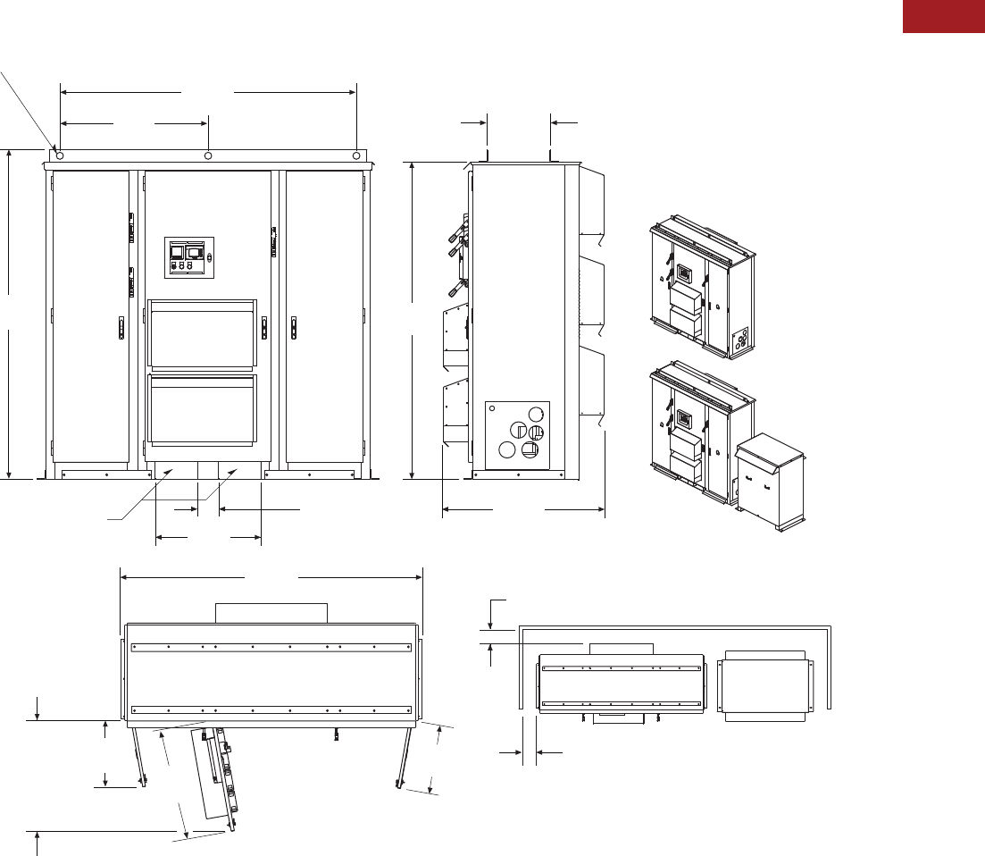
Volume 15—Solar Inverters and Electrical Balance of System CA08100018E—September 2015 eaton.com/solar V15-T2-7
2
2
2
2
2
2
2
2
2
2
2
2
2
2
2
2
2
2
2
2
2
2
2
2
2
2
2
2
2
2
2.1
Power Xpert Solar 250 kW Inverter
Dimensions
Approximate Dimensions in inches (mm)
Power Xpert Solar 250 kW Inverter Dimensions and Connection Diagrams
Front ISO
View with
Transformer
Fork Lift Pockets
Top View Minimum Clearance to Wall
Minimum Clearance,
Wall to Air Duct
Minimum Equipmant Clearance,
Greater Personel Clearance
Recommended
Front ISO View
Inv. Unit Only
Top View
with Doors Open
84.25
(2140.0)
42.13
(1070.1)
93.58
(2376.9)
6.00
(152.4)
30.00
(762.0)
97.25
(2470.2)
21.40
(543.6)
36.00
(914.4)
22.00
(558.8)
8.00
(203.2)
45.42
(1153.7)
90.05
(2287.3)
18.06
(458.7)
8.00
(203.2)
X6 ø 2.00 (50.8) Lifting Holes
35.70
(906.8)
From Front
of Unit Doors
Open 80º
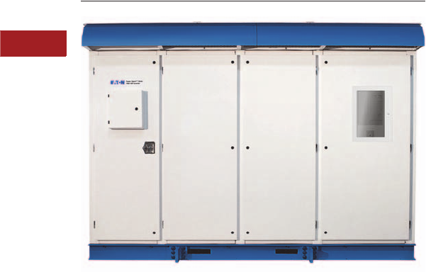
V15-T2-8 Volume 15—Solar Inverters and Electrical Balance of System CA08100018E—September 2015 eaton.com/solar
2
2
2
2
2
2
2
2
2
2
2
2
2
2
2
2
2
2
2
2
2
2
2
2
2
2
2
2
2
2
2.2
Power Xpert Solar 1500/1670 kW Inverter
Power Xpert Solar 1500/1670 kW Inverter
Contents
Description Page
Power Xpert Solar 1500/1670 kW Inverter
Features and Benefits . . . . . . . . . . . . . . . . . . . V15-T2-9
Standards and Certifications . . . . . . . . . . . . . . V15-T2-9
Catalog Number Selection . . . . . . . . . . . . . . . . V15-T2-10
Technical Data and Specifications . . . . . . . . . . V15-T2-11
Dimensions . . . . . . . . . . . . . . . . . . . . . . . . . . . V15-T2-12
Power Xpert Solar 1500/1670 kW Inverter
Product Description
The Power Xpert® Solar MW
scale inverter is a rugged,
robust and reliable solar
inverter designed with
Eaton engineering’s 100-year
tradition of safety and
reliability. Designed for
utility applications the Power
Xpert Solar 1500/1670 is the
world’s largest PV inverter
and sets the new standard in
reliability and performance.
The inverter is outdoor-
rated, and no extra shelter
(canopy) or environmental
protection is needed in
order for the equipment to
sustain operation in harsh
environments (rain, dust,
snow and sun). This makes
the Power Xpert Solar inverter
not only an economical and
cost-effective solution but
capable of rapid deployment
and installation.
Availability is optimized by
a complete fault tolerant
design. This inverter is
composed by three blocks
of 500 kW (555 kW), which
can be individually isolated in
the unlikely event of a fault,
allowing the inverter to
operate at partial power
until field service arrives
on site. This provides
for higher reliability and
availability than using
multiple smaller inverters.
The Power Xpert Solar
inverter provides the
most cost-effective
solution in the market
for the following reasons:
●Fully outdoor rated
enclosure—no extra
shelter or environmental
protection needed
●Inverter includes:
●Recombiner box
with fuses
●Load brake rated DC
disconnect switches
●AC circuit breaker for
AC disconnection
●AC and DC surge
suppression
●True MW design—
one inverter is needed
for 1.5 MW/1.67 MW
station providing the
lowest cost of
installation and
operation:
– Fewer cement pads,
less excavation and
less cement
– Reduced field labor
for cabling and wiring
due to fewer units
needed
– Direct-coupling,
throat connection
with step-up
transformer
●Fault tolerance design—
inverter is able to run at
partial power (1/3, 2/3 of
full power)
●High reliability due to
conservatively rated
components, film
capacitors and liquid
cooling
●No active power de-rating
for up to ±0.91 power
factor support
●SCADA communication
via Modbus® TCP

Volume 15—Solar Inverters and Electrical Balance of System CA08100018E—September 2015 eaton.com/solar V15-T2-9
2
2
2
2
2
2
2
2
2
2
2
2
2
2
2
2
2
2
2
2
2
2
2
2
2
2
2
2
2
2
2.2
Power Xpert Solar 1500/1670 kW Inverter
Features and Benefits
●True MW scale inverter
allows for maximum cost
savings on installation of
inverter and transformer.
It also enables a skidless
solution as there is only
one inverter and a simple
pad-mount transformer
to be installed
●Inverter can be configured
as a 1.5 MW or 1.67 MW
for maximum output power
optimization. Depending
on the MPPT range for the
array, the inverter output
power can be set to
1.5 MW or 1.67 MW
●Power factor support at
rated power. The inverter
will supply full rate power
(1.5 MW or 1.67 MW), and
still provide support for up
to a ±0.91 power factor
range. This provides cost
optimization especially
on projects with a power
factor support requirement
●Maximum flexibility on grid
support. Power Xpert Solar
grid and frequency ride
through settings are
flexible and can be
changed to meet local
utility or special grid
requirements
●Maximum DC/AC ratio
(array Isc ): Maximum array
short-circuit current (Isc )
cannot be higher than
4480 ADC. As long as this
limit is maintained, the
inverter warranty will not
be voided
●The inverter voltage and
frequency disturbance
characteristics are set and
controlled by a widely
accepted protection relay
SEL-751A. This device is
well known by utilities
and enables one extra
protection layer for safe
inverter shutdown under
abnormal grid conditions
●Direct-coupling throat
connection between the
inverter and transformer
enables cost savings on
cables, conduits and pad
installation. The throat
connection has been
implemented using Eaton’s
vast experience on low
voltage switchgear with
connection to a step-up
transformer
●DC grounding configuration
is available as positive and
negative schemes
●A recombiner box with
maximum flexibility is
available. The standard
configurations for number
of DC inputs, DC fuse
current and cable size are
shown in the Catalog
Number Selection graphic
on Page V15-T2-10.
The DC fuse ratings
available are 160 A, 200 A,
250 A, 315 A, 350 A, 355 A
and 400 A
●Array Zone monitoring is
possible with the option
of current sensing on each
DC input. This option
allows current monitoring
of the ungrounded DC
polarity inputs. Each DC
input current measurement
is stored on the internal
inverter controller and
available to a plant
monitoring device via
Modbus TCP
●Fiber optics communication
connection is available for
large plants, where inverter
stations are placed at a far
distance from the plant
central controller or
monitoring device
●Optional auxiliary I/O ports
provide an effective way
of cost-savings when
external devices need
to be monitored, such
as step-up transformer
measurements (liquid
temperature, pressure
and level). The standard
offering is 6 digital inputs
and 1 analog input.
Other options are available,
please consult factory
●A revenue grade meter in
the low voltage side of the
step-up transformer is also
present as an option.
Please consult an Eaton
representative for further
information
Standards and Certifications
●
The 1500 kW and 1670 kW
inverters are certified by
Intertek per UL
®
1741
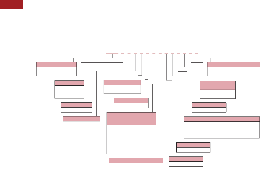
V15-T2-10 Volume 15—Solar Inverters and Electrical Balance of System CA08100018E—September 2015 eaton.com/solar
2
2
2
2
2
2
2
2
2
2
2
2
2
2
2
2
2
2
2
2
2
2
2
2
2
2
2
2
2
2
2.2
Power Xpert Solar 1500/1670 kW Inverter
Catalog Number Selection
The catalog number system
is what determines the
product configuration. The
base configuration and
subsequent catalog number
of the Power Xpert Solar
1500/1670 kW Inverter is
SOX66T1010000000.
Power Xpert Solar 1500/1670 kW Inverter
Part String
SOX = Power Xpert
Solar Inverter
Power Range
5 = 1500 kW
6 = 1670 kW
7 = Other
Frequency
6 = 60 Hz
Reserved
0 = No options
Weather Package
0 = Standard (–20 °C to 50 °C)
1 = Cold weather (–40 °C to 50 °C)
Customer Auxiliary
Power
0 = None
1 = 3 A at 120 Vac
Ground Scheme
1 = Negative ground
2 = Positive ground
Recombiner OCPD—Fusing
Fuse Ratings (160 A, 200 A, 250 A,
315 A, 350 A, 355 A and 400 A)
0 = No OCPD
1 = 16 fused inputs
2 = 18 fused inputs
3 = 20 fused inputs
4 = 22 fused inputs
5 = 24 fused inputs
6 = Others (consult Eaton)
Transformer/Auxiliary Monitoring
0 = None
1 = Transformer Standard Monitoring (6 x DIs and 1 x AI)
2 = Custom monitoring configuration
(needs to be specified)
AC Connection
T = Throat (direct-couple)
SOX 56T1010000000
DC Input Current (Zone) Monitoring
0 = None
1 = DC input current monitored
Reserved
0 = No options
Reserved
0 = No options
Reserved
0 = No options

Volume 15—Solar Inverters and Electrical Balance of System CA08100018E—September 2015 eaton.com/solar V15-T2-11
2
2
2
2
2
2
2
2
2
2
2
2
2
2
2
2
2
2
2
2
2
2
2
2
2
2
2
2
2
2
2.2
Power Xpert Solar 1500/1670 kW Inverter
Technical Data and Specifications
Power Xpert Solar
Description 1500 kW 1670 kW
AC Output
Nominal apparent power AC at 50 °C 1650 kVA 1831 kVA
Rated output power AC at 50 °C 1500 kW 1666 kW
Nominal output current 2707 A 2707 A
Maximum continuous output current at 50 °C 3000 A 3000 A
Nominal operating voltage 320 Vac 357 Vac
Operating voltage range (withstand) +/–10% +/–10%
Nominal operating frequency 60 Hz 60 Hz
Operating frequency range 57–63 Hz 57–63 Hz
Total harmonic distortion at rated power Per IEEE 1547 Per IEEE 1547
Power factor at rated power ± 0.91 adjustable power factor (zero to unity) ± 0.91 adjustable power factor (zero to unity)
AC configuration Delta three-wire or wye ungrounded Delta three-wire or wye ungrounded
DC Input
Number of DC inputs Customer specified fuse arrangement (16–24 input pairs) Customer specified fuse arrangement (16–24 input pairs)
Maximum input voltage open circuit, VOC 1000 Vdc 1000 Vdc
MPPT DC voltage range for full power production 500–1000 Vdc 550–1000 Vdc
MPPT DC voltage range for CEC weighted efficiency 500–800 Vdc 550–800 Vdc
Nominal DC operating current DC 3100 ADC 3100 ADC
PV array grounding Negative and positive (optional) Negative and positive (optional)
DC monitoring Optional current sensors on each DC input Optional current sensors on each DC input
Maximum array Isc connected to inverter 4480 ADC 4480 ADC
Efficiency and Losses
CEC weighted efficiency 98% 98.5%
Maximum inverter efficiency 98.6% 98.7%
Nighttime power consumption 333 W 335 W
Protection
AC disconnect AC circuit breaker with LOTO AC circuit breaker with LOTO
AC surge suppression Yes, monitored by inverter SCADA Yes, monitored by inverter SCADA
DC disconnect Load brake switch disconnect Load brake switch disconnect
DC surge suppression Yes, monitored by inverter SCADA Yes, monitored by inverter SCADA
Ground fault monitoring Yes, monitored by inverter SCADA Yes, monitored by inverter SCADA
Insulation monitoring Optional Optional
Communications and Controls
Communications with plant central controller Modbus (TCP) copper and fiber connection available Modbus (TCP) copper and fiber connection available
Power metering Optional power metering device in LV side of step-up transformer Optional power metering device in LV side of step-up transformer
HMI Yes Yes
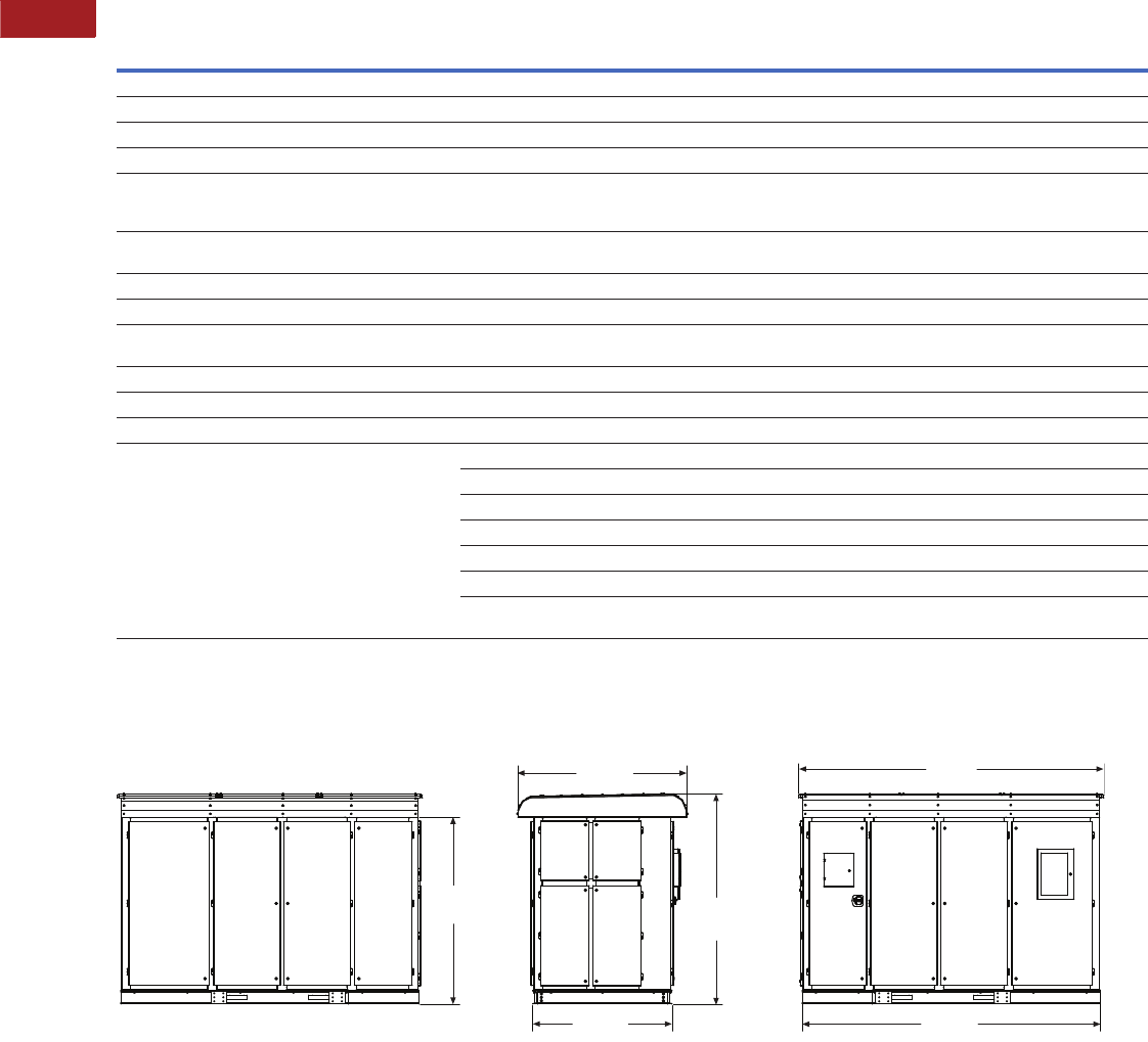
V15-T2-12 Volume 15—Solar Inverters and Electrical Balance of System CA08100018E—September 2015 eaton.com/solar
2
2
2
2
2
2
2
2
2
2
2
2
2
2
2
2
2
2
2
2
2
2
2
2
2
2
2
2
2
2
2.2
Power Xpert Solar 1500/1670 kW Inverter
Power Xpert Solar, continued
Dimensions
Approximate Dimensions in Inches (mm)
Note
1Preliminary.
Description 1500 kW 1670 kW
Mechanical
Operating temperature range full power –20 °C to 50 °C –20 °C to 50 °C
Optional extended temperature range (cold weather package) –40 °C to 50 °C –40 °C to 50 °C
Storage temperature range –30 °C to 70 °C –30 °C to 70 °C
Enclosure protection Outdoor rated
NEMA® 4 for controls equipment
NEMA 3R for magnetics and switchgear
Outdoor rated
NEMA 4 for controls equipment
NEMA 3R for magnetics and switchgear
Enclosure painting Powder-coated cold-rolled steel with corrosion-resistant
hardware and fittings
Powder-coated cold-rolled steel with corrosion-resistant
hardware and fittings
Relative humidity 0 to 100% condensing 0 to 100% condensing
Inverter mounting Pad or skid mount Pad or skid mount
Cooling Independent, self-contained, closed-loop liquid cooling
and air forced convection
Independent, self-contained, closed-loop liquid cooling
and air forced convection
Maximum operating altitude 3300 ft (higher altitudes possible with derating) 3300 ft (higher altitudes possible with derating)
Inverter dimensions in inches (H x W x D) 196 x 131 x 62 96 x 131 x 62
Design Features
Grid management features (optional) LVRT LVRT
HVRT HVRT
ZVRT ZVRT
FRT FRT
Ramp control Ramp control
Frequency droop Frequency droop
Grid management features adjustable to meet FERC, WECC
and ERCOT requirements
Grid management features adjustable to meet FERC, WECC
and ERCOT requirements
133.90
(3401.1)
130.80
(3322.3)
61.10
(1551.9)
74.20
(1884.7)
82.00
(2082.8) 92.30
(2344.4)

Volume 15—Solar Inverters and Electrical Balance of System CA08100018E—September 2015 eaton.com/solar V15-T2-13
2
2
2
2
2
2
2
2
2
2
2
2
2
2
2
2
2
2
2
2
2
2
2
2
2
2
2
2
2
2
2.3
DC Disconnects
600 Vdc Single-Pole Disconnects
600 Vdc Single-Pole Disconnect
Contents
Description Page
600 Vdc Single-Pole Disconnects
Features . . . . . . . . . . . . . . . . . . . . . . . . . . . . . . V15-T2-14
Standards and Certifications . . . . . . . . . . . . . . V15-T2-14
Wiring Diagrams. . . . . . . . . . . . . . . . . . . . . . . . V15-T2-14
Dimensions . . . . . . . . . . . . . . . . . . . . . . . . . . . V15-T2-15
600 Vdc Single-Pole Disconnects
Product Description
Eaton’s offering of PV
switches have multiple poles
factory-wired, and they are
approved for NEC Article 690
applications right from the
box. Other manufacturers
require the contractor to add
jumpers to a two- or three-
pole switch, add a neutral,
and add labels to meet this
requirement. For fusible
switches, the Eaton PV
single-pole switch requires
only one fuse per switch—
saving the customer at least
one fuse on each switch.
Application Description
When photovoltaic panels
convert the sun’s energy into
electricity, the power
generated is direct current
(DC). Typically, the systems
are designed with DC system
voltages in the 400–600V
range. This is much higher
voltage than typically found in
building systems. The higher
voltage, when combined with
the lack of a current sine
wave with zero crossings,
creates a number of
challenges in wiring,
particularly when switching
circuits on and off.
DC circuits consist of two
wires—a positive and a
negative. In most PV
systems, one of these wires
is grounded (like a neutral in
an AC system). Which of the
two wires is grounded is
specified by the solar panel
manufacturer. The more
common application is a
negative ground, and the
location of this bond is usually
found at the inverter. Per the
National Electrical Code
(NEC) Section 690.5(A), only
the current-carrying
ungrounded conductor should
be switched. Thus, in a
negative-grounded system,
only the positive wire is
switched.
Unlike AC systems that
possess a current sine wave
with zero crossings, the
interruption of higher voltage
DC circuits requires an
increased air gap to safely
and quickly interrupt and
break the arc. Within this
family of switches, the
increased gap is
accomplished by wiring
multiple poles of a single
switch in series for safe arc
interruption. The UL 98 listing
of these products does not
permit multiple circuits to be
switched by one switch.

V15-T2-14 Volume 15—Solar Inverters and Electrical Balance of System CA08100018E—September 2015 eaton.com/solar
2
2
2
2
2
2
2
2
2
2
2
2
2
2
2
2
2
2
2
2
2
2
2
2
2
2
2
2
2
2
2.3
DC Disconnects
600 Vdc Single-Pole Disconnects
Features
Standard Features
●All switches are single-pole
and suitable for switching
one circuit
●Clear polycarbonate
deadfront to guard against
accidental contact with live
parts
●NEC 690.17–compliant
labeling warning that the
switch terminals may be
energized in the open
position
●NEC 690.14.(C) 2 required
“PV System Disconnect”
label included
●Isolated ground terminals
(neutral) for grounded
conductors
●Ground lug for equipment
grounding conductor
●NEMA 3R, 12 and 4X
stainless enclosures
●Fusible and non-fusible
configurations—Class R
fuse clips standard
●Fuse clips are located on
the center pole to ensure
that both fuse clips are de-
energized—meets NEC
Article 690.16, which
requires isolation of the
fuse from all potential
supply sources
●Available for Flex Center
modifications (windows,
pilot lights, 316 grade
stainless, and so on)
Standards and Certifications
●UL 98 listed
●Marked as suitable for NEC
690 PV applications up to
600 Vdc
●OSHPD Special Seismic
Certification Preapproval
(OSP)
Wiring Diagrams
Non-Fusible 600 Vdc
Fusible 600 Vdc (Class R Fuse Clips—One Fuse Required Per Switch)
Notes
1UL 98 limits the conductor current sizing to 75°C. 90°C wire may be terminated per Article 110.14(C); however, the maximum current capacity is limited to NEC Table 310.16, 75°C column.
2N3R has 250 kcmil–#6 Cu/Al max lug capacity. NEMA12 and 4X have 300 kcmil–#6 Cu/Al.
Wiring Diagram
Ampere
Rating NEMA 3R NEMA 12 NEMA 4X
Lug Capacity
Main and Neutral
(Isolated Ground) 1Ground Lug
Non-Fused Construction 30 DH161URKN DH161UDKN DH161UWKN #2–#14 Cu/Al #4–#14 Cu/Al
60 DH162URKN DH162UDKN DH162UWKN #2–#14 Cu/Al #4–#14 Cu/Al
100 DH163URKN DH163UDKN DH163UWKN 1/0–#14 Cu/Al #4–#14 Cu/Al
200 DH164URKN DH164UDKN DH164UWKN 300 kcmil—#6 Cu/Al 2#2–#14 Cu/Al
400 DH165URKN DH165UDKN DH165UWKN (1) 750 kcmil—1/0 or
(2) 300 kcmil—1/0 Cu/Al
250 kcmil—#6 Cu/Al
600 DH166URKN DH166UDKN DH166UWKN (1) 750 kcmil—1/0 and
(1) 600 kcmil—#2 Cu/Al
250 kcmil—#6 Cu/Al
Wiring Diagram
Ampere
Rating NEMA 3R NEMA 12 NEMA 4X
Lug Capacity
Main and Neutral
(Isolated Ground) 1Ground Lug
Fused Construction 30 DH161NRK DH161NDK DH161NWK #2–#14 Cu/Al #4–#14 Cu/Al
60 DH162NRK DH162NDK DH162NWK #2–#14 Cu/Al #4–#14 Cu/Al
100 DH163NRK DH163NDK DH163NWK 1/0–#14 Cu/Al #4–#14 Cu/Al
200 DH164NRK DH164NDK DH164NWK 300 kcmil—#6 Cu/Al 2#2–#14 Cu/Al
400 DH165NRK DH165NDK DH165NWK (1) 750 kcmil—1/0 or
(2) 300 kcmil—1/0 Cu/Al
250 kcmil—#6 Cu/Al
600 DH166NRK DH166NDK DH166NWK (1) 750 kcmil—1/0 and
(1) 600 kcmil—#2 Cu/Al
250 kcmil—#6 Cu/Al
Line
Grounded
Conductor
Junction Block
Load
Line
Grounded
Conductor
Junction Block
Load
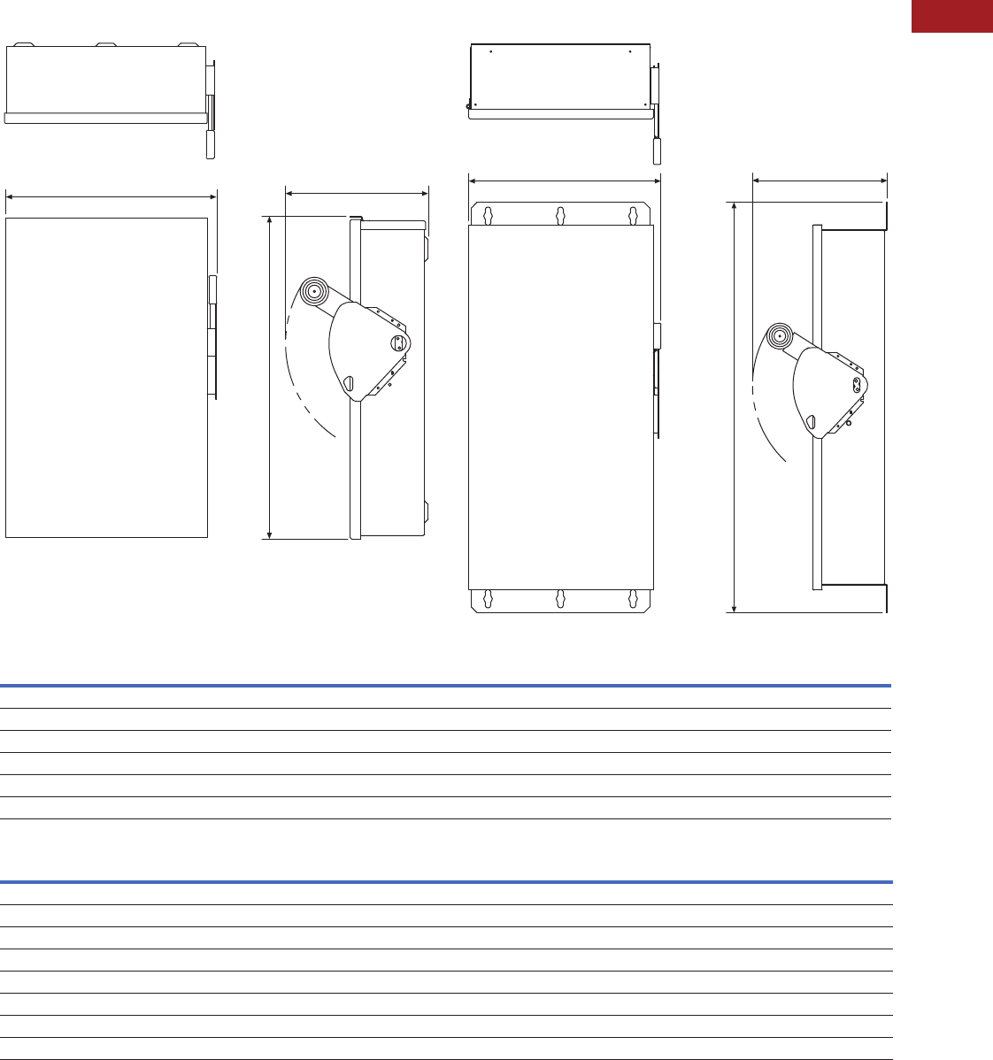
Volume 15—Solar Inverters and Electrical Balance of System CA08100018E—September 2015 eaton.com/solar V15-T2-15
2
2
2
2
2
2
2
2
2
2
2
2
2
2
2
2
2
2
2
2
2
2
2
2
2
2
2
2
2
2
2.3
DC Disconnects
600 Vdc Single-Pole Disconnects
Dimensions
Approximate Dimensions in Inches (mm)
Type 3R Solar Switch Type 12-3R and 4X Solar Switch
Type 3R Solar Switch
Type 12-3R and 4X Solar Switch
Note
1UL 98 limits the conductor current sizing to 75°C. 90°C wire may be terminated per Article 110.14(C); however, the maximum current capacity is limited to NEC Table 310.16, 75°C column.
Ampere Rating A B C Main Lug Capacity 1Ground Lug Capacity
30 16.35 (415.3) 8.87 (225.3) 9.89 (251.2) #2 AWG–#14 AWG Cu/Al #4 AWG–#14 AWG Cu/Al
60 16.35 (415.3) 8.87 (225.3) 9.89 (251.2) #2 AWG–#14 AWG Cu/Al #4 AWG–#14 AWG Cu/Al
100 22.15 (562.6) 11.84 (300.7) 9.89 (251.2) 1/0 AWG–#14 AWG Cu/Al #4 AWG–#14 AWG Cu/Al
200 28.27 (718.1) 16.66 (423.2) 11.26 (286.0) 250 kcmil–#6 AWG Cu/Al #2 AWG–#14 AWG Cu/Al
400 45.00 (1143.0) 24.12 (612.6) 12.39 (314.7) (1) 750 kcmil—1/0 or (2) 300 kcmil—1/0 Cu/Al 250 kcmil—#6 AWG Cu/Al
600 52.50 (1333.5) 25.12 (638.0) 14.07 (357.4) (1) 750 kcmil—1/0 and (1) 600 kcmil—#2 AWG Cu/Al 250 kcmil—#6 AWG Cu/Al
Ampere Rating A B C Main Lug Capacity 1Ground Lug Capacity
30 Non-fusible 14.14 (359.2) 8.76 (222.5) 10.22 (259.6) #2 AWG–#14 AWG Cu/Al #4 AWG–#14 AWG Cu/Al
30 Fusible 19.08 (484.6) 8.76 (222.5) 10.22 (259.6) #2 AWG–#14 AWG Cu/Al #4 AWG–#14 AWG Cu/Al
60 Non-fusible 14.14 (359.2) 8.76 (222.5) 10.22 (259.6) #2 AWG–#14 AWG Cu/Al #4 AWG–#14 AWG Cu/Al
60 Fusible 19.08 (484.6) 8.76 (222.5) 10.22 (259.6) #2 AWG–#14 AWG Cu/Al #4 AWG–#14 AWG Cu/Al
100 24.95 (633.7) 11.79 (299.5) 10.22 (259.6) 1/0 AWG–#14 AWG Cu/Al #4 AWG–#14 AWG Cu/Al
200 35.38 (898.7) 16.95 (430.5) 11.63 (295.4) 300 kcmil–#6 AWG Cu/Al #2 AWG–#14 AWG Cu/Al
400 57.47 (1459.7) 24.12 (612.6) 12.43 (315.7) (1) 750 kcmil—1/0 or (2) 300 kcmil—1/0 Cu/Al 250 kcmil—#6 AWG Cu/Al
600 63.00 (1600.2) 26.34 (669.0) 14.25 (362.0) (1) 750 kcmil—1/0 and (1) 600 kcmil—#2 AWG Cu/Al 250 kcmil—#6 AWG Cu/Al
BC
A
BC
A
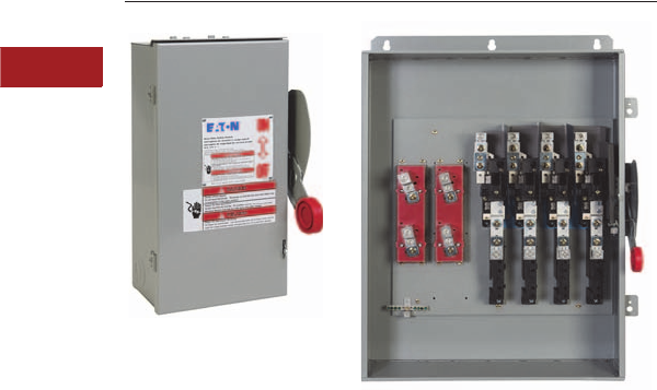
V15-T2-16 Volume 15—Solar Inverters and Electrical Balance of System CA08100018E—September 2015 eaton.com/solar
2
2
2
2
2
2
2
2
2
2
2
2
2
2
2
2
2
2
2
2
2
2
2
2
2
2
2
2
2
2
2.3
DC Disconnects
600 Vdc Per Pole and 1000 Vdc Disconnects
600 Vdc Per Pole and 1000 Vdc Disconnect
Contents
Description Page
600 Vdc Per Pole and 1000 Vdc Disconnects
Features . . . . . . . . . . . . . . . . . . . . . . . . . . . . . . V15-T2-17
Standards and Certifications . . . . . . . . . . . . . . V15-T2-17
Catalog Number Selection . . . . . . . . . . . . . . . . V15-T2-17
Wiring Diagrams . . . . . . . . . . . . . . . . . . . . . . . V15-T2-18
Dimensions . . . . . . . . . . . . . . . . . . . . . . . . . . . V15-T2-19
600 Vdc Per Pole and 1000 Vdc Disconnects
Product Description
The latest addition to Eaton's
solar disconnect family of
products is the UL Listed 600
Vdc per pole, bi-directional
disconnect. Listed to the
UL 98B standard, this design
has the capacity to switch
multiple circuits of up to 600
Vdc each. Also included in the
line are 1000 Vdc disconnects,
designed for use in large
scale projects where the
higher voltage helps drive
improved efficiencies.
The use of renewable
energy sources is on the rise.
Photovoltaic (PV) systems are
among the fastest growing of
the new green technologies,
and they are being installed
on a variety of building types
and landscapes throughout
North America. This results in
a growing need for products
to meet the requirements of
these systems. Eaton’s
lineup of 600 Vdc per pole
and 1000 Vdc switches are
tested and listed to the
rigorous UL 98B standard, in
line with NEC 690 Code
requirements for PV
installations.
Application Description
Switching devices primarily
designed for DC service
require design features to
increase the total arcing
voltage. This can be achieved
by designing larger single air
gaps and multiple gaps in
series, or by using magnetic
fields to force arc movement.
In this safety switch design,
Eaton uses magnetic fields,
created with the use of
permanent magnets, to
stretch the arc. These
products are not polarity
sensitive, so they can be
used on either negative or
positive grounded systems,
and they provide protection
regardless of whether the
current flow is in the
“normal” direction or is
reversed (possible due to
miswiring or under a fault
condition).
Note: Photos shown above—
Left: 60A, 3 circuit, 600 Vdc
per pole, NEMA 3R.
Right: 200A, 4 circuit, 600 Vdc
per pole, NEMA 4, w/ isolated
grounded return terminals.
Grounded PV systems
A large number of PV
systems in North America to
date are grounded systems.
These systems will be either
positive grounded or negative
grounded. In a positive
grounded system, the
disconnect will switch (break)
the negative (–) conductor
only. Conversely, in a
negative grounded system,
the disconnect will switch
(break) the positive (+)
conductor only. It is important
that the disconnect applied
within a grounded PV system
be properly rated for that
specific system. Eaton’s
lineup of switches (600 Vdc
and 1000 Vdc) are designed
and UL Listed for use in both
positive and negative
grounded applications—one
switch can be used on either
system.
Ungrounded PV systems
Somewhat less common
today are ungrounded
(floating) PV systems. These
use transformerless inverters
and, relative to the
disconnects within the
system, both the positive (+)
and the negative (–)
conductors are switched.
Eaton is proud to also offer
a series of disconnects
(600 Vdc and 1000 Vdc) for
ungrounded systems.
Safety
The incorporation of the
modified heavy duty safety
switch mechanism provides a
visible means of disconnect
when the switch handle is in
the OFF position. Blade
disengagement from the
stationary contact can be
seen when viewing the
switch base.
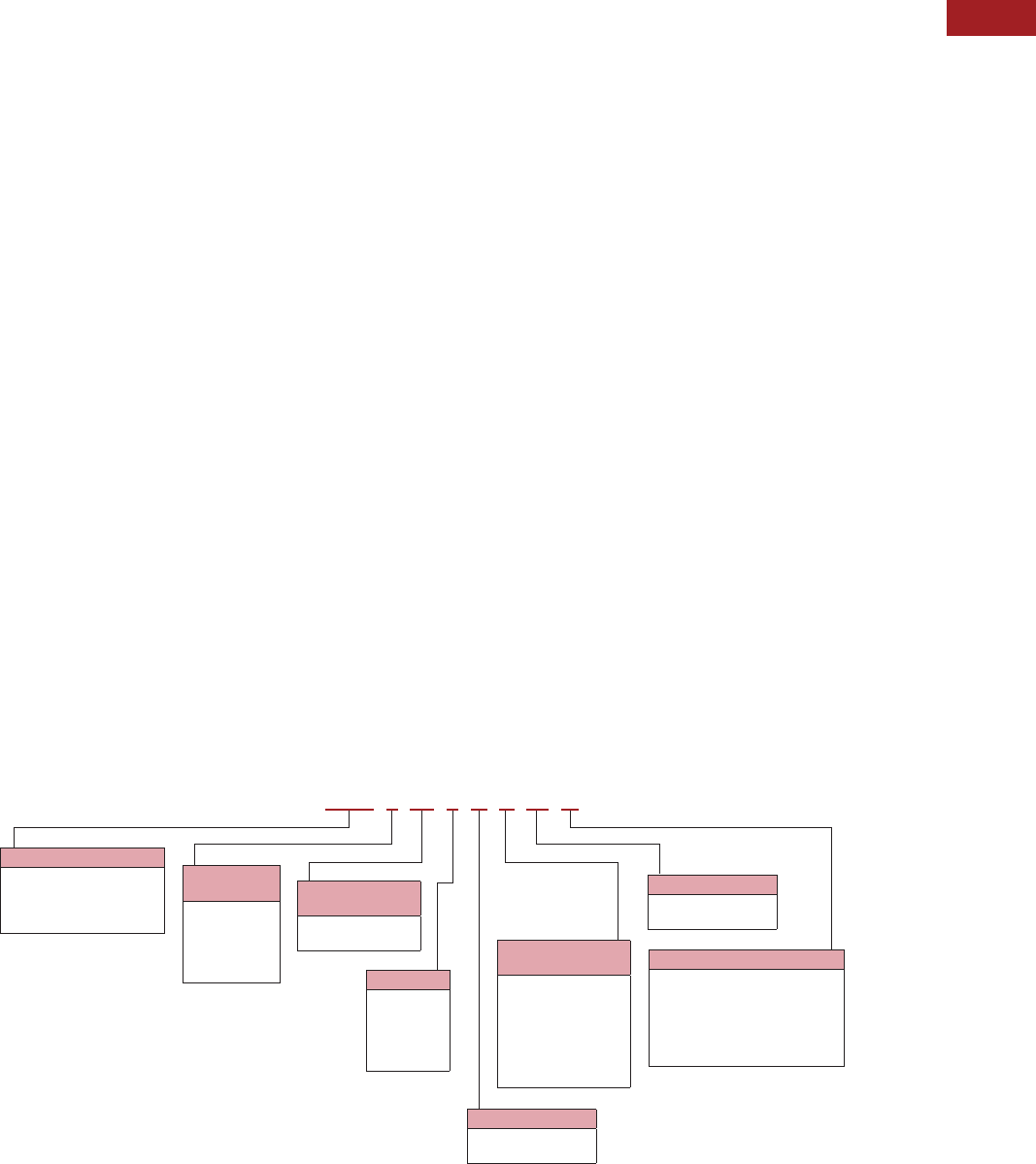
Volume 15—Solar Inverters and Electrical Balance of System CA08100018E—September 2015 eaton.com/solar V15-T2-17
2
2
2
2
2
2
2
2
2
2
2
2
2
2
2
2
2
2
2
2
2
2
2
2
2
2
2
2
2
2
2.3
DC Disconnects
600 Vdc Per Pole and 1000 Vdc Disconnects
Features
Standard Features
●UL Listed to the UL 98B
standard
●Marked as suitable for NEC
690 PV applications per
UL 1741 requirements
●Suitable for use on positive
and negative grounded
systems, not polarity
sensitive
●Bi-directional functionality;
will break high-energy DC
arc regardless of direction
of current flow
●Ampacity range—30, 60,
100, 200 and 400A
●Clear polycarbonate
deadfront shield
●Equipment ground
●NEMA 3R, 4 and 4X
stainless steel enclosures
●Flex Center modification
available, such as viewing
windows, pilot lights and
more
600 Vdc Specific Features
●First UL Listed 600 Vdc per
pole, bi-directional solution
in the market
●2-, 3-, 4- and 6-circuit
configurations for
grounded systems
●1-, 2- and 3-circuit
configurations for
ungrounded systems
●Fusible and non-fusible
●Grounded configurations
include isolated return
terminals. Exceptions
include 6-circuit 30, 60,
100A, and 4-circuit 400A
●Suitable for use on a circuit
capable of delivering up to
10,000A, 600 Vdc
1000 Vdc Specific Features
●1-, 2- and 3-circuit
configurations for both
grounded and ungrounded
systems
●Fusible and non-fusible
●Factory-installed jumpers
●Grounded configurations
include isolated return
terminals. Exceptions
include 2-circuit 400A
●Suitable for use on a circuit
capable of delivering up to
10,000A, 1000 Vdc
Standards and Certifications
Listed to the UL 98B
standard in-line with
NEC 690 Code requirements
for PV installations.
Catalog Number Selection
DC Disconnects
Note
1Not all configurations for ampere rating and number of circuits are available. All circuit configurations can be found in the product dimension tables.
Number of
Circuits 1
1=1 circuit
2= 2 circuits
3= 3 circuits
4= 4 circuits
6=6 circuit Accessories/Options
Blank = No accessories
2= 1NO/1NC auxiliary contact
3= 2NO/2NC auxiliary contact
W= Viewing window
J= Factory-converted Class J
fuse provisions
Switch Series
M = DC photovoltaic
applications
Ampacity
1= 30A
2= 60A
3= 100A
4= 200A
5= 400A
Maximum System
Voltage
06 = 600 Vdc
10 = 1000 Vdc NEMA Enclosure
Rating
R= NEMA 3R
P= NEMA 4
(painted steel)
W= NEMA 4X,
stainless 304
X= NEMA 4X,
stainless 316
Class and Type
DCG = DC disconnect/
grounded system
DCU = DC disconnect/
ungrounded system
Protection
F = Fusible
U = Non-fusible
DCG 306 1 U R M

V15-T2-18 Volume 15—Solar Inverters and Electrical Balance of System CA08100018E—September 2015 eaton.com/solar
2
2
2
2
2
2
2
2
2
2
2
2
2
2
2
2
2
2
2
2
2
2
2
2
2
2
2
2
2
2
2.3
DC Disconnects
600 Vdc Per Pole and 1000 Vdc Disconnects
Wiring Diagrams
600 Vdc/Pole Wiring Diagrams (30–400A) 1000 Vdc/Pole Wiring Diagrams (30–400A)
Note: Majority of grounded configurations have isolated return terminals.
Due to enclosure size limitations, 600 Vdc exceptions include 6-circuit 30,
60, 100A; 4-circuit 400A; 1000 Vdc exceptions include 2-circuit 400A.
DC Disconnect Lug Capacity
600 Vdc Non-Fusible and Fusible 1000 Vdc Non-Fusible and Fusible
Legend
VIndicates grounded conductor terminal included with isolated lugs for each circuit.
XIndicates no grounded conductor terminal included.
WIndicates only non-fusible version includes grounded conductor terminal with isolated lug for
each circuit.
Notes
1All lug capacities shown are for standard lugs. For options, including compression type, consult factory.
2All lugs are Cu/Al rated.
3UL 98/98B limits the conductor current sizing to 75°C. 90°C wire may be terminated per Article 110.14(C); however, the maximum current capacity is limited to NEC Table 310.16, 75°C column.
Grounded
Ungrounded
S2L
S1L
S1 S2
2-Circuit
S2L
S3
S1L S3L S4L
S1 S2 S4
4-Circuit
S2L
S3
S1L S3L S4L
S1 S2 S4
6-Circuit
S5
S5L S6L
S6
S2L
S3
S1L S3L
S1 S2
3-Circuit
S2
+
S2L
+
S1L
+
S1L
–
S2L
–
+
S1 –
S1 –
S2
3-Circuit
S3
–
S3L
–
S3L
+
+
S3
S2
+
S2L
+
S1L
+
S1L
–
S2L
–
+
S1 –
S1 –
S2
2-Circuit
S1L
+
S1L
–
+
S1 –
S1
1-Circuit
S2L
S1L S2L S3
S1L S3L
S2
+
S1L
+
S2L
+
S1L
–
S1L
+
S1L
–
S2L
–
S2L
+
S1L
+
S1L
–
S2L
–
S1 S2 S1
+
S1 –
S1 +
S1 –
S1 –
S2 S2
+
+
S1 –
S1 –
S2 S3
+–
S3
Grounded
Ungrounded
1-Circuit 2-Circuit 3-Circuit
1-Circuit 2-Circuit 3-Circuit
S1 S1L S2L
S3L
+
S3L
–
Maximum
Vdc System
Voltage
Ampere
Rating
Lug Capacity 123
Main Solid Return (for Grounded Conductor) Equipment Ground
Input Output Input Output Input Output
600 30 #2–#14 AWG #2–#14 AWG 1/0–#14 AWG 1/0–#14 AWG #4–#14 AWG #4–#14 AWG
60 #2–#14 AWG #2–#14 AWG 1/0–#14 AWG 1/0–#14 AWG #4–#14 AWG #4–#14 AWG
100 1/0–#14 AWG 1/0–#14 AWG 1/0–#14 AWG 1/0–#14 AWG #4–#14 AWG #4–#14 AWG
200 300 kcmil–#6 300 kcmil–#6 300 kcmil–#6 300 kcmil–#6 #4–#14 AWG 1/0–#14
400 (1) 750 kcmil–1/0
and (1) 600 kcmil–#2
(1) 750 kcmil–1/0
and (1) 600 kcmil–#2
(2) 750 kcmil–1/0 (2) 750 kcmil–1/0 #4–#14 AWG 250 kcmil–#6
1000 30 #2–#14 AWG #2–#14 AWG #2–#14 AWG #2–#14 AWG #4–#14 AWG #4–#14 AWG
60 #2–#14 AWG #2–#14 AWG #2–#14 AWG #2–#14 AWG #4–#14 AWG #4–#14 AWG
100 1/0–#14 AWG 1/0–#14 AWG 1/0–#14 AWG 1/0–#14 AWG #4–#14 AWG #4–#14 AWG
200 300 kcmil–#6 300 kcmil–#6 300 kcmil–#6 300 kcmil–#6 #4–#14 AWG 1/0–#14
400 (1) 750 kcmil–1/0
and (1) 600 kcmil–#2
(1) 750 kcmil–1/0
and (1) 600 kcmil–#2
(2) 750 kcmil–1/0 (2) 750 kcmil–1/0 #4–#14 AWG 250 kcmil–#6
Grounded Systems Ungrounded Systems
Number of Circuits Number of Circuits
Amperes12346123
30 VVXXX
60 VVXXX
100 VVXXX
200 VVVVVXXX
400 VVVWXX
600 V
Grounded Systems Ungrounded Systems
Number of Circuits Number of Circuits
Amperes123123
30 VX XX
60 VX XX
100 VX XX
200 VVVXXX
400 VWXX
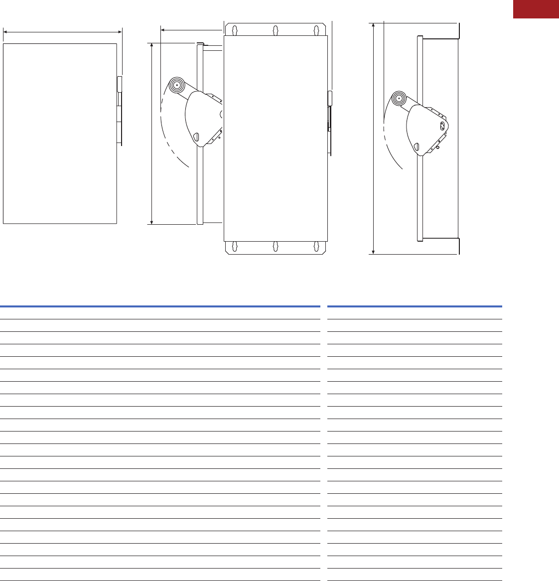
Volume 15—Solar Inverters and Electrical Balance of System CA08100018E—September 2015 eaton.com/solar V15-T2-19
2
2
2
2
2
2
2
2
2
2
2
2
2
2
2
2
2
2
2
2
2
2
2
2
2
2
2
2
2
2
2.3
DC Disconnects
600 Vdc Per Pole and 1000 Vdc Disconnects
Dimensions
Approximate Dimensions in Inches (mm)
NEMA Type 3R NEMA Type 4, 4X Stainless
600 Vdc Non-Fusible and Fusible
Notes
1NEMA Type 4 and 4X stainless steel enclosures are suitable for mounting in either vertical or horizontal positions. NEMA Type 3R enclosures must be mounted vertically.
2For smaller NEMA 3R enclosure, consult factory.
Ampere
Rating
Number of
Circuits
NEMA Type 3R 1NEMA Types 4, 4X Stainless 1
ABCD ABCD
Grounded
30, 60 3 16.27 (413.3) 8.87 (225.3) 9.89 (251.2) 5.25 (133.4) 19.08 (484.6) 8.76 (222.5) 10.22 (259.6) 5.50 (139.7)
30, 60 6 19.08 (484.6) 12.88 (327.2) 10.22 (259.6) 5.50 (139.7) 19.08 (484.6) 12.88 (327.2) 10.22 (259.6) 5.50 (139.7)
100 3 21.99 (558.5) 11.84 (300.7) 9.89 (251.2) 5.25 (133.4) 24.95 (633.7) 11.79 (299.5) 10.22 (259.6) 5.50 (139.7)
100 6 24.95 (633.7) 16.13 (409.7) 10.22 (259.6) 5.50 (139.7) 24.95 (633.7) 16.13 (409.7) 10.22 (259.6) 5.50 (139.7)
200 2 35.38 (898.7) 16.54 (420.1) 11.63 (295.4) 6.44 (163.6) 35.38 (898.7) 16.54 (420.1) 11.63 (295.4) 6.44 (163.6)
200 3 35.38 (898.7) 16.54 (420.1) 11.63 (295.4) 6.44 (163.6) 35.38 (898.7) 16.54 (420.1) 11.63 (295.4) 6.44 (163.6)
200 4 35.38 (898.7) 24.46 (621.3) 11.63 (295.4) 6.44 (163.6) 35.38 (898.7) 24.46 (621.3) 11.63 (295.4) 6.44 (163.6)
200 6 39.18 (995.2) 30.18 (766.6) 11.63 (295.4) 6.44 (163.6) 39.18 (995.2) 30.18 (766.6) 11.63 (295.4) 6.44 (163.6)
400 22 57.47 (1459.7) 24.12 (612.6) 12.43 (315.7) 7.19 (182.6) 57.47 (1459.7) 24.12 (612.6) 12.43 (315.7) 7.19 (182.6)
400 23 57.47 (1459.7) 24.12 (612.6) 12.43 (315.7) 7.19 (182.6) 57.47 (1459.7) 24.12 (612.6) 12.43 (315.7) 7.19 (182.6)
400 24 57.47 (1459.7) 24.12 (612.6) 12.43 (315.7) 7.19 (182.6) 57.47 (1459.7) 24.12 (612.6) 12.43 (315.7) 7.19 (182.6)
Ungrounded
30, 60 1 16.27 (413.3) 8.87 (225.3) 9.89 (251.2) 5.25 (133.4) 19.08 (484.6) 8.76 (222.5) 10.22 (259.6) 5.50 (139.7)
30, 60 3 19.08 (484.6) 12.88 (327.2) 10.22 (259.6) 5.50 (139.7) 19.08 (484.6) 12.88 (327.2) 10.22 (259.6) 5.50 (139.7)
100 1 21.99 (558.5) 11.84 (300.7) 9.89 (251.2) 5.25 (133.4) 24.95 (633.7) 11.79 (299.5) 10.22 (259.6) 5.50 (139.7)
100 3 24.95 (633.7) 16.13 (409.7) 10.22 (259.6) 5.50 (139.7) 24.95 (633.7) 16.13 (409.7) 10.22 (259.6) 5.50 (139.7)
200 1 35.38 (898.7) 16.54 (420.1) 11.63 (295.4) 6.44 (163.6) 35.38 (898.7) 16.54 (420.1) 11.63 (295.4) 6.44 (163.6)
200 2 35.38 (898.7) 16.54 (420.1) 11.63 (295.4) 6.44 (163.6) 35.38 (898.7) 16.54 (420.1) 11.63 (295.4) 6.44 (163.6)
200 3 35.38 (898.7) 24.46 (621.3) 11.63 (295.4) 6.44 (163.6) 35.38 (898.7) 24.46 (621.3) 11.63 (295.4) 6.44 (163.6)
400 21 57.47 (1459.7) 24.12 (612.6) 12.43 (315.7) 7.19 (182.6) 57.47 (1459.7) 24.12 (612.6) 12.43 (315.7) 7.19 (182.6)
400 22 57.47 (1459.7) 24.12 (612.6) 12.43 (315.7) 7.19 (182.6) 57.47 (1459.7) 24.12 (612.6) 12.43 (315.7) 7.19 (182.6)
BC
A
A

V15-T2-20 Volume 15—Solar Inverters and Electrical Balance of System CA08100018E—September 2015 eaton.com/solar
2
2
2
2
2
2
2
2
2
2
2
2
2
2
2
2
2
2
2
2
2
2
2
2
2
2
2
2
2
2
2.3
DC Disconnects
600 Vdc Per Pole and 1000 Vdc Disconnects
Approximate Dimensions in Inches (mm)
1000 Vdc Non-Fusible (Fusible Available at 200A and 400A)
Notes
1NEMA Type 4 and 4X stainless steel enclosures are suitable for mounting in either vertical or horizontal positions. NEMA Type 3R enclosures must be mounted vertically.
2For smaller NEMA 3R enclosure, consult factory.
Ampere
Rating
Number of
Circuits
NEMA Type 3R 1NEMA Types 4, 4X Stainless 1
ABCD ABCD
Grounded
30, 60 1 16.27 (413.3) 8.87 (225.3) 9.89 (251.2) 5.25 (133.4) 14.14 (359.2) 8.76 (222.5) 10.22 (259.6) 5.50 (139.7)
30, 60 2 19.08 (484.6) 12.88 (327.2) 10.22 (259.6) 5.50 (139.7) 19.08 (484.6) 12.88 (327.2) 10.22 (259.6) 5.50 (139.7)
100 1 21.99 (558.5) 11.84 (300.7) 9.89 (251.2) 5.25 (133.4) 24.95 (633.7) 11.79 (299.5) 10.22 (259.6) 5.50 (139.7)
100 2 24.95 (633.7) 16.13 (409.7) 10.22 (259.6) 5.50 (139.7) 24.95 (633.7) 16.13 (409.7) 10.22 (259.6) 5.50 (139.7)
200 1 35.38 (898.7) 16.95 (430.5) 11.63 (295.4) 6.44 (163.6) 35.38 (898.7) 16.95 (430.5) 11.63 (295.4) 6.44 (163.6)
200 2 35.38 (898.7) 24.57 (624.1) 11.63 (295.4) 6.44 (163.6) 35.38 (898.7) 24.57 (624.1) 11.63 (295.4) 6.44 (163.6)
200 3 35.38 (898.7) 24.57 (624.1) 11.63 (295.4) 6.44 (163.6) 35.38 (898.7) 24.57 (624.1) 11.63 (295.4) 6.44 (163.6)
400 21 57.47 (1459.7) 24.12 (612.6) 12.43 (315.7) 7.19 (182.6) 57.47 (1459.7) 24.12 (612.6) 12.43 (315.7) 7.19 (182.6)
400 22 57.47 (1459.7) 24.12 (612.6) 12.43 (315.7) 7.19 (182.6) 57.47 (1459.7) 24.12 (612.6) 12.43 (315.7) 7.19 (182.6)
Ungrounded
30, 60 1 16.27 (413.3) 8.87 (225.3) 9.89 (251.2) 5.25 (133.4) 14.14 (359.2) 8.76 (222.5) 10.22 (259.6) 5.50 (139.7)
30, 60 2 19.08 (484.6) 12.88 (327.2) 10.22 (259.6) 5.50 (139.7) 19.08 (484.6) 12.88 (327.2) 10.22 (259.6) 5.50 (139.7)
100 1 21.99 (558.5) 11.84 (300.7) 9.89 (251.2) 5.25 (133.4) 24.95 (633.7) 11.79 (299.5) 10.22 (259.6) 5.50 (139.7)
100 2 24.95 (633.7) 16.13 (409.7) 10.22 (259.6) 5.50 (139.7) 24.95 (633.7) 16.13 (409.7) 10.22 (259.6) 5.50 (139.7)
200 1 35.38 (898.7) 16.54 (420.1) 11.63 (295.4) 6.44 (163.6) 35.38 (898.7) 16.54 (420.1) 11.63 (295.4) 6.44 (163.6)
200 2 35.38 (898.7) 16.54 (420.1) 11.63 (295.4) 6.44 (163.6) 35.38 (898.7) 16.54 (420.1) 11.63 (295.4) 6.44 (163.6)
200 3 35.38 (898.7) 24.46 (621.3) 11.63 (295.4) 6.44 (163.6) 35.38 (898.7) 24.46 (621.3) 11.63 (295.4) 6.44 (163.6)
400 21 57.47 (1459.7) 24.12 (612.6) 12.43 (315.7) 7.19 (182.6) 57.47 (1459.7) 24.12 (612.6) 12.43 (315.7) 7.19 (182.6)
400 22 57.47 (1459.7) 24.12 (612.6) 12.43 (315.7) 7.19 (182.6) 57.47 (1459.7) 24.12 (612.6) 12.43 (315.7) 7.19 (182.6)
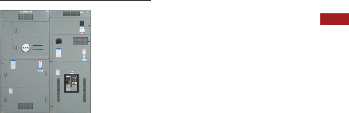
Volume 15—Solar Inverters and Electrical Balance of System CA08100018E—September 2015 eaton.com/solar V15-T2-21
2
2
2
2
2
2
2
2
2
2
2
2
2
2
2
2
2
2
2
2
2
2
2
2
2
2
2
2
2
2
2.4
Switchboards—Solar Applications
Group Mounted Switchboards
Pow-R-Line C Group-Mounted Distribution Switchboard
Contents
Description Page
Pow-R-Line C Distribution Switchboards
Integrated Facility Switchboard . . . . . . . . . . . . V15-T2-23
Pow-R-Line C Distribution Switchboards
Product Description
Eaton’s Pow-R-Line C
distribution switchboards
combine a space-saving
design with modular
construction and increased
system ratings to provide
economical and dependable
electrical system distribution
and protection.
Application Description
Whether providing access for
solar systems to main
distribution systems or
combining outputs of multiple
inverters, Eaton’s Pow-R-Line
C switchboards are available
for customization for many
applications, including
backfeed scenarios.
Refer to Eaton’s Consulting
Application Guide.
Features, Benefits
and Functions
Pow-R-Line C designates
a family of distribution
switchboards, incorporating
design concepts that fit
the ever-increasing need
for applications on high
short-circuit systems,
while retaining maximum
safety and convenience
throughout the line.
●6000A maximum main
bus rating
●600 Vac and below
●600 Vdc and below
●Front or rear accessible
●Type 1 or Type 3R
enclosures
●ANSI-61 gray powder
coat paint finish
●Microprocessor-based
metering and monitoring
devices
●Utility metering provisions
●Surge protective devices
(SPD)
●Ground fault protection
on mains and distribution
devices
●Busway and transformer
connections
●Complete protective device
accessory capability
●65 kAIC bus bracing
standard; optional 100
or 200 kAIC
●Standard tin-plated
aluminum bus; optional
copper- or silver-plated
copper bus
●Standard bus ampacities
based on UL heat test
ratings. Optional density
rated bus systems are
also available
Main and Individually
Mounted Devices
●Magnum® SB insulated
case circuit breakers, 800–
5000A, fixed or drawout
●Magnum DS power circuit
breakers, 800–5000A,
fixed or drawout
●Molded case circuit
breakers, 400–2500A,
fixed mounted
●Bolted pressure switches,
800–5000A
●FDPW fusible switches,
400–1200A
Group-Mounted
Distribution Devices
●Molded case circuit
breakers, 15–1200A
●FDPW fusible switches,
30–1200A
Front Accessible
Front-accessible switchboards
align at the rear, enabling
them to be placed against
a wall (Pow-R-Line C front
accessible). If the main
section is deeper than others,
due to physical size of the
main device, the necessary
off-set in line-up will occur in
front, and the main section
will be accessible from the
side as well as from the front.
Standard front accessible
switchboards will align at
the front and rear.
Rear Accessible
Rear-accessible switchboards
align at the front and the rear.
Bus maintenance and cable
entry and exit require rear
access.

V15-T2-22 Volume 15—Solar Inverters and Electrical Balance of System CA08100018E—September 2015 eaton.com/solar
2
2
2
2
2
2
2
2
2
2
2
2
2
2
2
2
2
2
2
2
2
2
2
2
2
2
2
2
2
2
2.4
Switchboards—Solar Applications
Group Mounted Switchboards
Standard Switchboard Height
Standard Pow-R-Line C
switchboard height is
90 inches (2286.0 mm).
Group Mounting
Group-mounted circuit
protective devices are an
assembly of units mounted
on a panelboard type base
(panelboard construction).
Units may be molded case
breakers, or FDPW fusible
switches. Circuit protective
devices are accessible from
the front.
A main molded case breaker
or main FDPW fusible switch,
within the sizes listed for
panelboard design, can
be included in the panel-
mounted assembly in lieu
of a separate, individually
mounted unit.
Space Only for Future Devices
Group-Mounted Construction
Where space only for future
circuit protective devices is
required, the proper space
and a blank filler plate will
be supplied. Connections
and mounting hardware are
not included.
Provision for Future Devices
Where provisions for future
circuit protective devices
are required, space for the
device, corresponding vertical
bus, device connectors and
the necessary mounting
hardware will be supplied.
Busbar System
Standard bus in the
switchboards is tin-plated
aluminum. Silver-plated
copper and tin-plated copper
are also available.
Main bus and sub-main
buses meet UL and NEMA
standards for temperature
rise on all Pow-R-Line C
switchboards. Special bus
densities are available.
Overcurrent Devices
To properly select and size
overcurrent devices for use in
a switchboard, the allowable
temperature rise must be
taken into account as to its
effect on the tripping
characteristics of the
devices in question.
Accordingly, Article 220
of the NEC requires
overcurrent devices to be
rated not less than 125% of
the continuous load they are
protecting. To comply with
this, an 80% derating factor
must be used with all
overcurrent devices such
as molded case breakers
and FDPW fusible switches
unless they are tested
and marked as 100%
rated devices.
Short-Circuit Rating
Standard bus and connectors
on all switchboards are rated
for use on systems capable
of producing up to 65,000A
rms symmetrical short-circuit
current at the incoming
terminals.
Increased bus short-circuit
ratings equal to that of
connected switchboard
devices, up to 200,000A rms
symmetrical, are available
in most Pow-R-Line C
switchboards when approved
main devices are installed.
Contact Eaton for more
information. UL labeled
switchboard sections are
marked with their applicable
short-circuit rating.
Provision for Busway
Entrance and Exit
Busway connections to
switchboard sections include
cutout and drilling in the
top of the switchboard with
riser connections from the
switchboard device or bus, up
to the point where the bus
duct enters the switchboard.
No connections are furnished
external to the switchboard.
Note: In all transactions
involving busway attached to
switchboards, it is essential that
information regarding orientation
of the busway with respect to the
front of the switchboard be
supplied to the coordinating
assembly plant.
On Pow-R-Line C
switchboards, solid busbar is
used to connect the bus duct
to the individually mounted
main device, main or sub-main
switchboard bus, or vertical
main bus of panel mounted
circuit protective device
panels. Busway fed by group-
mounted branch devices are
cable connected.
Aluminum riser connections
are standard. Copper- or
silver-plated copper is
available as a modification.
Transitions
Transition structures are
required for connecting
switchboards to the
secondary of power center
transformer (dry or liquid
filled), motor control centers,
and for other special
switchboard configurations
such as “L” or “U” shaped
lineups. In some applications,
an extra structure complete
with connections is required;
in others, where switchboard
depth and space permit, only
the connection conductors
are required. Refer to factory
for these applications.
Standards and Certifications
●Meets NEMA Standard
PB-2 and UL 891
●Seismically qualified
Product Selection
For complete application and
pricing information, contact
your local Eaton sales office.
Technical Data and
Specifications
Service
●120/240V, single-phase,
three-wire
●240/120V, 208Y/120V,
415Y/240V, 480Y/277V or
600Y/347V three-phase,
four-wire
●600 Vdc
Main Bus Rating
●400–5000A
Service Section
●Main circuit breaker,
400–5000A
●Main fusible switch,
400–5000A
●Main lugs only,
400–6000A
Metering Sections
●Tenant main disconnects
and meter sockets (200A
maximum self-contained
metered circuits)
●Hot sequence
metering circuits
●Cold sequence metering
circuits (WCMS only)
●Optional rear barriered
wireways or load side
pull sections for cable
exit requirements
●Sections for metered
circuits larger than 200A
available with 400A
continuous rated self-
contained sockets or
with CT compartment
and transformer rated
socket in combination
with disconnect

Volume 15—Solar Inverters and Electrical Balance of System CA08100018E—September 2015 eaton.com/solar V15-T2-23
2
2
2
2
2
2
2
2
2
2
2
2
2
2
2
2
2
2
2
2
2
2
2
2
2
2
2
2
2
2
2.4
Switchboards—Solar Applications
Integrated Facility Switchboards
Integrated Facility Switchboard
Contents
Description Page
Pow-R-Line C Distribution Switchboards . . . . . . . . V15-T2-21
Integrated Facility Switchboards
Features, Benefits and Functions . . . . . . . . . . . V15-T2-24
Standards and Certifications . . . . . . . . . . . . . . V15-T2-24
Product Selection . . . . . . . . . . . . . . . . . . . . . . . V15-T2-24
Additional Information . . . . . . . . . . . . . . . . . . . V15-T2-24
An Eaton
Green Solution
Integrated Facility Switchboard
Product Description
Eaton’s Integrated Facility
Switchboards use the
modular Pow-R-Line C group-
mounted switchboard design
to integrate traditionally
separate electrical distribution
and control equipment into a
single space-saving factory
assembled and connected
package.
The service entrance
equipment can be integrated
with multiple lighting
and appliance branch
panelboards into a compact
front-accessible group-
mounted switchboard. Where
multiple panelboards are
used in the same electrical
room as a conventional
distribution switchboard or
power panelboards, the
integrated design will
significantly reduce
equipment space
requirements, as well as
reduce installation time
and cost.
Other associated equipment
can also be integrated into
the assembly, including
dry-type distribution
transformers, time clock
space, lighting control,
electronic controls, surge
protective devices, metering
and energy monitoring
devices. Depending upon
the application, other user-
defined equipment such as a
subsystem control package
may also be incorporated.
Application Description
Eaton’s Integrated Facility
Switchboards are designed
to meet specific needs for:
●Solar/alternative energy
integration projects
●Retail chain stores
●Commercial offices
●High rise buildings
●Correctional facilities
●Agricultural facilities
●Industrial facilities
●Hospitals/health
care facilities
●Educational facilities
Whether the application is a
multi-site prototype or single
application, integrated
switchboards offer time and
space-saving features.
For complete application
description, refer to Eaton’s
Consulting Application Guide.

V15-T2-24 Volume 15—Solar Inverters and Electrical Balance of System CA08100018E—September 2015 eaton.com/solar
2
2
2
2
2
2
2
2
2
2
2
2
2
2
2
2
2
2
2
2
2
2
2
2
2
2
2
2
2
2
2.4
Switchboards—Solar Applications
Integrated Facility Switchboards
Features, Benefits and Functions
Front Accessible
Integrated Facility
Switchboards are front
accessible and align at the
rear, enabling them to be
placed against a wall. Most
switchboards align at the
front and the rear. If the main
section is deeper than others,
due to physical size of the
main device, the necessary
off-set in line-up will occur in
front, and the main section
will be accessible from the
side as well as from the front.
Standard Switchboard Height
Switchboard height is
90 inches (2286.0 mm).
A limited offering of
78-inch (1981.2 mm) high
equipment is available.
Consult the factory for
specific applications.
Switchboard Shipping Splits
The sections can be shipped
as specified by the customer
to meet specific requirements.
For retrofit applications,
single-piece switchboard
structures can be shipped to
facilitate movement through
limited access doorways, etc.
Factory Interconnections
Most sub-panels are fed from
the main distribution panel
feeder circuit breakers using
copper cable sized per the
NEC and UL.
Space Savings
The space-saving
switchboard installation
provides additional usable
floor space. For example:
●Retail stores—floor space
for sales
●Offices—additional
storage, cubicle
●Health care—additional
work area
●Retrofits—ability to fit
existing rooms
Site Construction Savings
Timely installation of the
electrical system typically is
a key element on the critical
path for any project.
Along with the time to
install the equipment, other
expenses include the time to
handle all of the loose pieces
of equipment arriving on a job
site and ensuring it reaches
the proper trades person.
With Eaton’s Integrated
Facility Switchboards,
one piece of equipment is
typically shipped to a job
site virtually eliminating
these issues.
The equipment may also be
used for temporary power
on job sites, further reducing
construction expenses
and times.
Standards and Certifications
●Meets NEMA Standard
PB-2 and UL 891
●Panelboards mounted
inside the sections meet
NEMA PB-1 and UL 67
●Other equipment is
UL listed as applicable
and appropriate
Product Selection
For complete application and
pricing information, contact
your local Eaton sales office.
Additional Information
For information on reverse
feed breaker applications,
please see Consulting
Application Guide—
Molded-Case Circuit
Breakers & Enclosures,
CA08104001E, Tab 27.
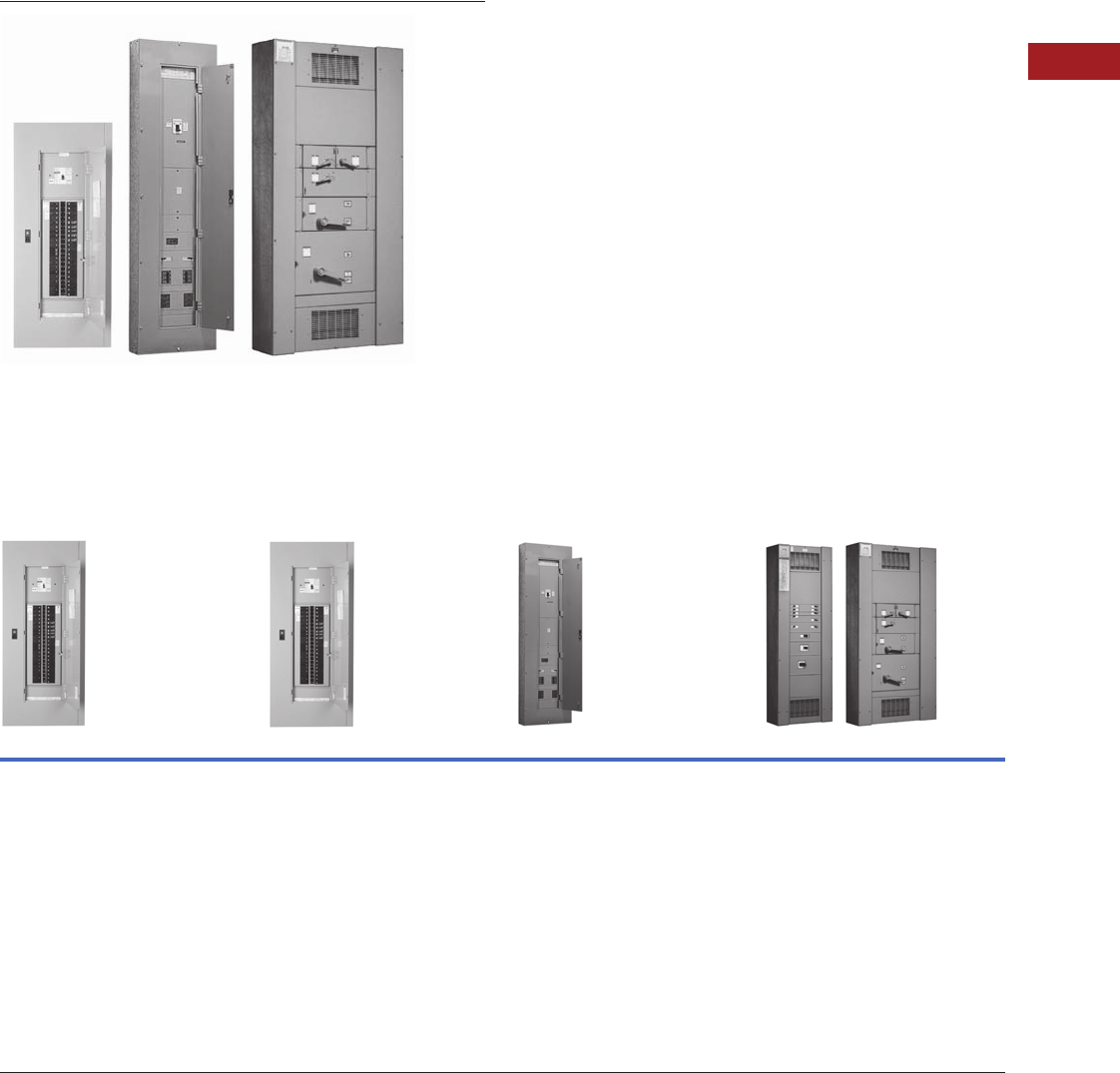
Volume 15—Solar Inverters and Electrical Balance of System CA08100018E—September 2015 eaton.com/solar V15-T2-25
2
2
2
2
2
2
2
2
2
2
2
2
2
2
2
2
2
2
2
2
2
2
2
2
2
2
2
2
2
2
2.5
Panelboards—Solar Applications
Introduction
Solar Panelboards
Contents
Description Page
Introduction
Product Selection Guide
EZ Box and EZ Trim . . . . . . . . . . . . . . . . . . . . . . . . V15-T2-26
Pow-R-Line C Panelboards . . . . . . . . . . . . . . . . . . V15-T2-29
Type PRL1a . . . . . . . . . . . . . . . . . . . . . . . . . . . V15-T2-37
Type PRL2a . . . . . . . . . . . . . . . . . . . . . . . . . . . V15-T2-41
Type PRL3a . . . . . . . . . . . . . . . . . . . . . . . . . . . V15-T2-45
Type PRL4 . . . . . . . . . . . . . . . . . . . . . . . . . . . . V15-T2-49
Types PRL1a, 2a, 3a, 4
Modifications Selection Guide . . . . . . . . . . . . V15-T2-59
Regional Manufacturing Facilities . . . . . . . . . . . . . V15-T2-68
Product Selection Guide
Product Types
Type PRL1a Type PRL2a Type PRL3a Type PRL4
Bolt-On or Plug-On Circuit Breakers
240 Vac Maximum
Main lugs only
400A maximum
Main Circuit breaker
400A maximum
Branch circuit breakers
100A maximum,
Single-, two- and three-pole
Bolt-On Circuit Breakers
240 or 480Y/277 Vac; 125/250 Vdc Maximum
Main lugs only
400A maximum
Main circuit breaker
400A maximum
Branch circuit breakers
100A maximum,
Single-, two- and three-pole
Bolt-On Circuit Breakers
240, 480 or 600 Vac; 250 Vdc Maximum
Main lugs only
800A maximum
Main circuit breaker
600A maximum
Branch circuit breakers
225A maximum,
Single-, two- and three-pole
Circuit Breakers or Fusible Switches
240, 480 or 600 Vac; 600 Vdc Maximum
Main lugs only
1200A maximum
Main circuit breaker
1200A maximum
Main fusible switch
1200A maximum
Branch circuit breakers
1200A maximum,
Single-, two- and three-pole
Branch fusible switches
1200A maximum,
two- and three-pole
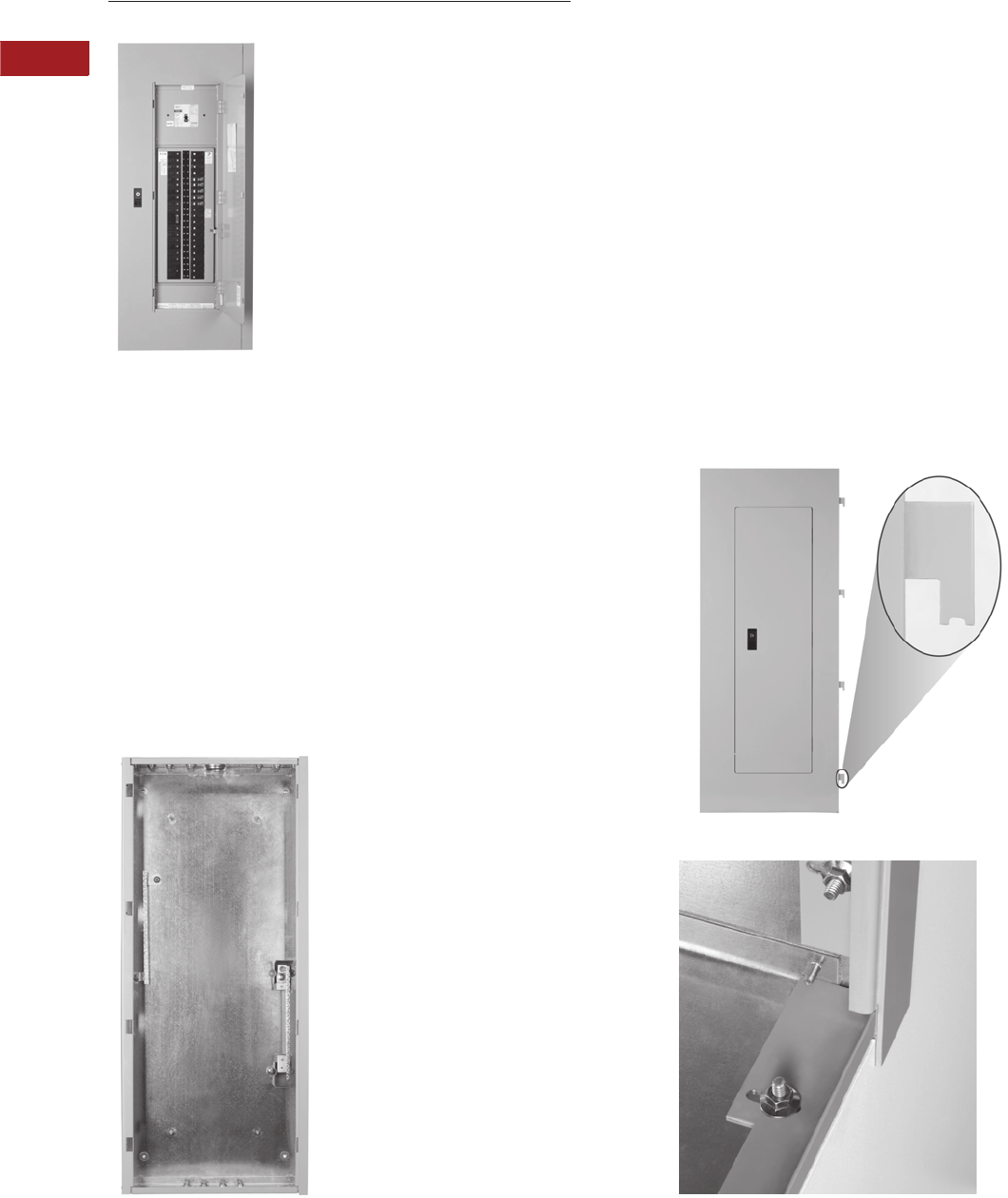
V15-T2-26 Volume 15—Solar Inverters and Electrical Balance of System CA08100018E—September 2015 eaton.com/solar
2
2
2
2
2
2
2
2
2
2
2
2
2
2
2
2
2
2
2
2
2
2
2
2
2
2
2
2
2
2
2.5
Panelboards—Solar Applications
EZ Box and EZ Trim
Type PRL1a Panelboard
Contents
Description Page
Introduction. . . . . . . . . . . . . . . . . . . . . . . . . . . . . . V15-T2-25
Product Selection Guide . . . . . . . . . . . . . . . . . V15-T2-25
EZ Box and EZ Trim
Standards and Certifications . . . . . . . . . . . . . . V15-T2-27
Product Selection. . . . . . . . . . . . . . . . . . . . . . . V15-T2-28
Pow-R-Line C Panelboards . . . . . . . . . . . . . . . . . . V15-T2-29
Type PRL1a . . . . . . . . . . . . . . . . . . . . . . . . . . . V15-T2-37
Type PRL2a . . . . . . . . . . . . . . . . . . . . . . . . . . . V15-T2-41
Type PRL3a . . . . . . . . . . . . . . . . . . . . . . . . . . . V15-T2-45
Type PRL4 . . . . . . . . . . . . . . . . . . . . . . . . . . . . V15-T2-49
Types PRL1a, 2a, 3a, 4
Modifications Selection Guide . . . . . . . . . . . V15-T2-59
Regional Manufacturing Facilities . . . . . . . . . . V15-T2-68
Product Description
Eaton’s EZ Box™ and EZ Trim™
represents the first significant
change in panelboard box and
trim designs in more than a
half-century. The EZ Box and
EZ Trim have been designed
for faster, more secure and
safer installations. The new
EZ Box and EZ Trim are
provided standard for Eaton’s
Pow-R-Line 1a and Pow-R-
Line 2a lighting panelboards,
as well as the Pow-R-Line 3a
and Pow-R-Line 3E mid-range
panelboard.
Flange Detail
Features
●Virtually eliminates sharp
edges
●Trim installs in seconds
rather than minutes
●Door-in-door is standard
●Ability to adjust flush box
to wall irregularities
●Trim installs without the
need for tools
●No exposed hardware
(because there is none)
The EZ Box flanges are bent
and painted, which virtually
eliminates the sharp edges
associated with traditional
boxes. Additionally, all steel
panelboard chassis parts are
painted. This significantly
reduces potential injury for
material handlers and
installers. Each flange is
adjustable outward up to
3/4-inch (19.1 mm). This
feature allows the installer to
adjust flush box applications
to be level and flat with the
finished wall after the wall
material is installed to help
correct wall irregularities. The
new box flange also provides
the means for attaching the
EZ Trim.
Standalone Trim and Bottom Flange Hanger with Notch
Corner Flange Detail
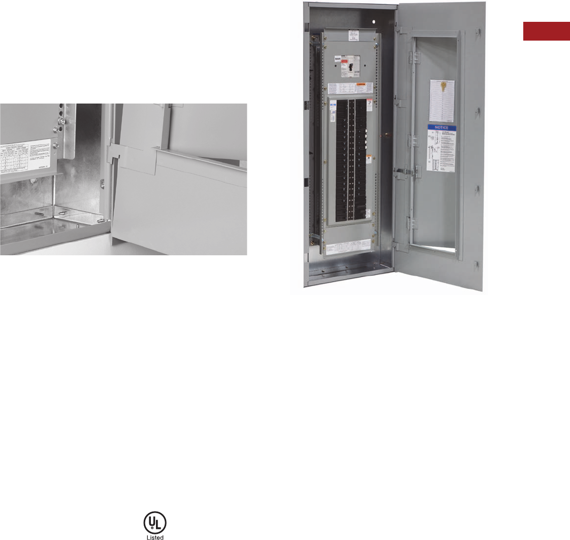
Volume 15—Solar Inverters and Electrical Balance of System CA08100018E—September 2015 eaton.com/solar V15-T2-27
2
2
2
2
2
2
2
2
2
2
2
2
2
2
2
2
2
2
2
2
2
2
2
2
2
2
2
2
2
2
2.5
Panelboards—Solar Applications
EZ Box and EZ Trim
Fast Installation
The EZ Trim incorporates a
groundbreaking design that
installs in seconds, rather
than minutes. The standard
trim features include door-in-
door construction; no
exposed hardware and
no tools are required for
installation.
Each EZ Trim includes
hangers attached on the right
side. The bottom trim hanger
has a notch in its base. To
install, the bottom hanger is
inserted into the bottom right
side box flange opening,
resting the notch on the
flange.
Trim Hanger Inserted Into Box Flange
The balance of the hangers
are aligned with the other
flange openings and pushed
in. When all hangers are in
the box flange, the trim is
lifted up slightly to clear the
notch on the bottom hanger,
and the trim in self-supported
on the EZ Box.
The installation is completed
by swinging the trim to the
closed position, then lifting
and pushing slightly to the
right. The trim will drop into
place totally secured. The
multi-point catches on the left
side of the trim will lock into
the left side box flange
openings.
To prevent the trim from
being removed by non-
authorized persons, a unique
sliding means automatically
latches in place when the
trim door is closed. Along
with a new lock, the EZ Trim
offers a high degree of door
security.
Standards and
Certifications
When used with Eaton’s
panelboard chassis, EZ Boxes
and EZ Trims meet the
following applicable industry
standards:
●UL 50 listed
●NEMA Standard PB1
●Federal specifications
●National Electrical Code
Trim Hanging on Surface Mounted Box

V15-T2-28 Volume 15—Solar Inverters and Electrical Balance of System CA08100018E—September 2015 eaton.com/solar
2
2
2
2
2
2
2
2
2
2
2
2
2
2
2
2
2
2
2
2
2
2
2
2
2
2
2
2
2
2
2.5
Panelboards—Solar Applications
EZ Box and EZ Trim
Product Selection
Boxes and Trims Only—Type 1
Types PRL1a, PRL2a and PRL3a (400A Maximum)
Type PRL3a (600A)
Type PRL3a (800A)
Note
1EZ Box must be used with EZ Trim.
Box Dimensions—Inches (mm) Height
YS Box LT Trim EZ Box 1EZ Trim 1
Catalog
Number
Catalog
Number
Catalog
Number
Catalog
Number
20.00 W x 5.75 D
(508.0 W x 146.1 D)
36.00 (914.4) YS2036 LT2036S or F EZB2036R EZT2036S or F
42.00 (1066.8) YS2042 LT2042S or F EZB2042R EZT2042S or F
48.00 (1219.2) YS2048 LT2048S or F EZB2048R EZT2048S or F
60.00 (1524.0) YS2060 LT2060S or F EZB2060R EZT2060S or F
72.00 (1828.8) YS2072 LT2072S or F EZB2072R EZT2072S or F
90.00 (2286.0) YS2090 LT2090S or F EZB2090R EZT2090S or F
Box Dimensions—Inches (mm) Height
YS Box LT Trim EZ Box 1EZ Trim 1
Catalog
Number
Catalog
Number
Catalog
Number
Catalog
Number
20.00 W x 5.75 D
(508.0 W x 146.1 D)
36.00 (914.4) YS2036 LTV2036S or F EZB2036R EZTV2036S or F
48.00 (1219.2) YS2048 LTV2048S or F EZB2048R EZTV2048S or F
60.00 (1524.0) YS2060 LTV2060S or F EZB2060R EZTV2060S or F
72.00 (1828.8) YS2072 LTV2072S or F EZB2072R EZTV2072S or F
90.00 (2286.0) YS2090 LTV2090S or F EZB2090R EZTV2090S or F
Box Dimensions—Inches (mm) Height
YS Box LT Trim
Catalog
Number
Catalog
Number
28.00 W x 5.75 D 36.00 (914.4) YS2836 LTV2836S or F
48.00 (1219.2) YS2848 LTV2848S or F
60.00 (1524.0) YS2860 LTV2860S or F
72.00 (1828.8) YS2872 LTV2872S or F
90.00 (2286.0) YS2890 LTV2890S or F
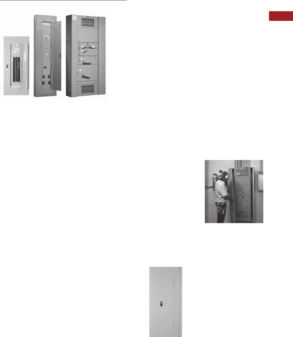
Volume 15—Solar Inverters and Electrical Balance of System CA08100018E—September 2015 eaton.com/solar V15-T2-29
2
2
2
2
2
2
2
2
2
2
2
2
2
2
2
2
2
2
2
2
2
2
2
2
2
2
2
2
2
2
2.5
Panelboards—Solar Applications
Pow-R-Line C Panelboards
Pow-R-Line C Panelboards
Contents
Description Page
Introduction . . . . . . . . . . . . . . . . . . . . . . . . . . . . . . V15-T2-25
Product Selection Guide. . . . . . . . . . . . . . . . . . V15-T2-25
EZ Box and EZ Trim . . . . . . . . . . . . . . . . . . . . . . . . V15-T2-26
Pow-R-Line C Panelboards
Type PRL1a . . . . . . . . . . . . . . . . . . . . . . . . . . . V15-T2-37
Type PRL2a . . . . . . . . . . . . . . . . . . . . . . . . . . . V15-T2-41
Type PRL3a . . . . . . . . . . . . . . . . . . . . . . . . . . . V15-T2-45
Type PRL4 . . . . . . . . . . . . . . . . . . . . . . . . . . . . V15-T2-49
Types PRL1a, 2a, 3a, 4
Modifications Selection Guide . . . . . . . . . . . . V15-T2-59
Regional Manufacturing Facilities . . . . . . . . . . . . . V15-T2-68
Product Description
Distribution Panelboards
Eaton’s assembled
panelboards are designed for
sequence phase connection
of branch circuit devices. This
allows complete flexibility of
circuit arrangement (single-,
two- or three-pole) to allow
balance of the electrical load
on each phase.
Sturdy, rigid chassis
assembly ensures accurate
alignment of interior with
panel front; prevents flexing
and minimizes possibility
of loosening or damage to
current carrying parts during
and after installation.
Four-point in-and-out
adjustment of panel interior
is provided to meet critical
depth dimensions on
flush installations. This
compensates for possible
misalignment of box at
installation.
Main lugs are mechanical
solderless type and approved
for copper or aluminum
conductors.
Enclosures
Boxes are code-gauge
galvanized steel, which
include a painted box finished
in ANSI-61 light gray to match
the trim.
Standard panelboard cabinets
are designed for indoor use.
Alternate types are available
for indoor and special
purpose applications.
All enclosures are furnished
in accordance with
Underwriters Laboratories
standards and include wiring
gutters with proper wire
bending space. Special
cabinets can be provided
at an additional charge.
The box dimensions shown
are inside dimensions. For
outside dimensions, add
1/4-inch (6.4 mm).
Standard panelboard boxes are
supplied
without knockouts
(blank endwalls).
Fronts
Fronts (trims) for all
panelboards are made of
code-gauge steel and have a
high durability ANSI-61 light
gray finish applied by a baked-
on polyester powder coating
paint system.
The fronts for lighting and
appliance branch circuit
panelboards and small power
distribution panelboards
include a door with rounded
corners and concealed
hinges. A flush-type latch and
lock assembly is included.
All locks are keyed alike.
These trims are available in
both surface- and flush-
mounted designs.
EZ Trim Features Standard
Door-in-Door with No
Exposed Hardware or
Sharp Edges (no Tools are
Required for Installation)
The Three-Piece Trim for
Larger Power Distribution
Panelboards Provides for
Easy Handling and
Installation
Fronts for power distribution
panelboards utilize a unique
breaker front cover design
in which each device has a
dedicated bolt-on steel cover.
The individual covers form
a single deadfront for the
panelboard that is used in
conjunction with two wiring
gutter covers to complete the
trim. A door is not finished as
part of the standard offering
on these panelboards but can
be provided, for an additional
charge, using a deeper than
standard box.

V15-T2-30 Volume 15—Solar Inverters and Electrical Balance of System CA08100018E—September 2015 eaton.com/solar
2
2
2
2
2
2
2
2
2
2
2
2
2
2
2
2
2
2
2
2
2
2
2
2
2
2
2
2
2
2
2.5
Panelboards—Solar Applications
Pow-R-Line C Panelboards
Application Description
Whether providing access
for solar systems to inverter
inputs or combining outputs
from multiple inverters,
Eaton’s Pow-R-Line C
panelboards are available
for customization for any
application, including
backfeed scenarios.
Panelboard
Selection Factors
In selecting a panelboard,
the following factors must
be considered:
●Service (voltage and
frequency)
●Interrupting capacity
(fully or series rated)
●Ampere rating of main
●Ampere ratings of
branches
●Environment
Panelboard
Short-Circuit Rating
The short-circuit rating
of Eaton’s assembled
panelboards are test
verified by, and listed with,
Underwriters Laboratories
(UL). Generally, these
ratings are that of the lowest
interrupting rated device in
the panel.
Service Entrance Equipment
The National Electrical Code
(NEC) requires that:
●A panel used as service
entrance equipment
must be located near
the point where the
supply conductors enter
the building
●A panelboard having main
lugs only shall have a
maximum of six service
disconnects to de-energize
the entire panelboard from
the supply conductors.
Where more than six
disconnects are required,
a main service disconnect
must be provided
●A disconnectable electrical
bond must be provided
between the neutral and
ground
●A service entrance type
UL label must be factory
installed
●Ground fault protection
of equipment shall be
provided for each service
disconnect rated 1000A
or more if the electrical
service is a solidly
grounded wye system of
more than 150V to ground,
but not exceeding 600V
phase-to-phase
Note: Service entrance panels
must be identified as such on
the order.
Panelboard Standards
In 2008, both the National
Electrical Code (Article 408)
and UL 67 were updated
to remove the mandated
42-circuit limitation. Eaton
offers panelboards with more
than 42 circuits for those
jurisdictions that have
adopted the 2008 NEC
or later.
For jurisdictions that have| not
adopted the 2008 or
later version of the National
Electrical Code, the 42-circuit
limitation for Lighting
and Appliance Branch
Panelboards remains in place.
Check with your local code
officials to determine specific
jurisdiction status.
Panelboard Installation
NEC requires that the
operating handle of the
topmost mounted device be
no more than 6 feet 7 inches
(2006.6 mm) above the
finished floor and should be
installed per NEC and
manufacturer’s instructions.
Additional boxes and fronts
are required when the
components required for
one panelboard exceed the
standard box dimensions.
Multi-Section Panelboards
When two or more separate
enclosures are required,
separate fronts for each box
are standard. A common
front can be furnished at
additional charge.
Interconnecting Multi-
Section Panelboards
When a panelboard, for
connection to one feeder,
must be furnished in more
than one section (Box), each
section must be furnished
with main bus and terminals
of the same rating, unless a
main overcurrent device is
provided in each section.
Sub-feed or through-feed
provisions must also be
included (and priced) to
provide connection capability
to the second section.
Note: Sub-feed or through-feed
lugs cannot be used on any
panelboard that is not protected
by a single main overcurrent
device either in the panelboard
or immediately upstream, i.e.,
service entrance panelboards
with main lugs only using the six
disconnect rule.
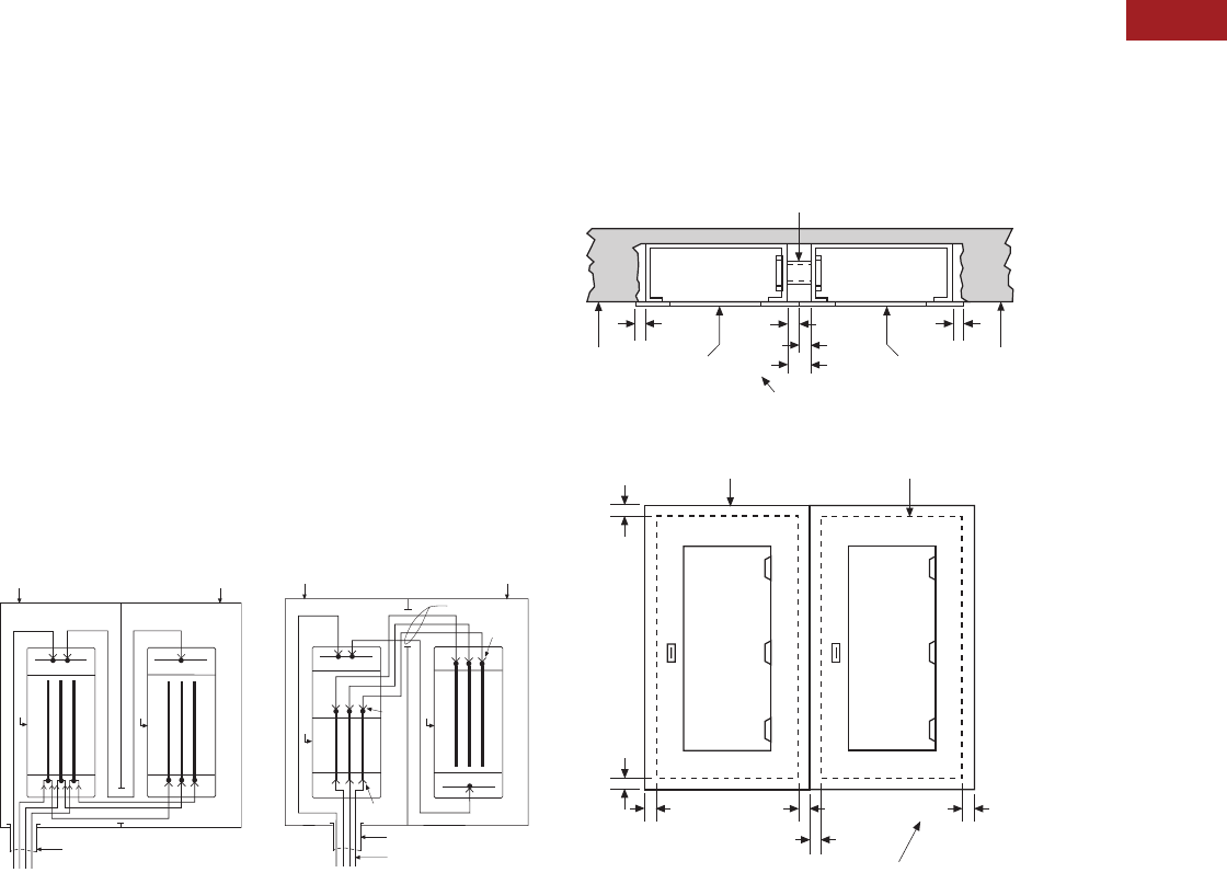
Volume 15—Solar Inverters and Electrical Balance of System CA08100018E—September 2015 eaton.com/solar V15-T2-31
2
2
2
2
2
2
2
2
2
2
2
2
2
2
2
2
2
2
2
2
2
2
2
2
2
2
2
2
2
2
2.5
Panelboards—Solar Applications
Pow-R-Line C Panelboards
Sub-Feed Lugs
Sub-feed lugs (see figure
below) are one means of
interconnecting multi-section
panels. The sub-feed (second
set of) lugs are mounted
directly beside the main lugs.
These are required in each
section except the last panel
in the lineup. The feeder
cables are brought into the
wiring gutter of the first
section and connected to
the main lugs. Another set
of the same size cables are
connected to the sub-feed
lugs (Section 1) and are
carried over to the main lugs
of the adjacent panel. Cross
connection cables are not
furnished by Eaton. Sub-feed
lugs are only available on main
lug only panels.
Note: Sub-feed lugs may
not be used on main lug only
(six disconnect rule) service
entrance panels.
Sub-Feed Lugs
Through-Feed Lugs
Through-feed lugs (see figure
below) are another method
to interconnect multi-section
panelboards. The incoming
feeder cables are connected
to the main lugs or main
breaker at the bottom of
panel (Section 1). Another
set of lugs (through-feed)
are located at the opposite
end of the main bus. The
interconnecting cables are
connected to the through-
feed lugs in Section 1 and are
carried over to the main lugs
in Section 2. The connection
arrangement could be
reversed, i.e., main lugs at
top; through-feed lugs at
bottom end of panel. Cross
cables are not furnished
by Eaton.
Note: Through-feed lugs
may not be used on main lug
only (six disconnect rule) service
entrance panels.
Through-Feed Lugs
Box Box
Conduit
Neutral Neutral
Panel
Panel
Section 1 Section 2
Section 1 Section 2
Box Box
Conduit
Neutral
Panel
Panel
Neutral
Main
Lugs
Thru-
Feed
Lugs
Main
Lugs
Cross Cables
Incoming Feeder Cables
Multiple Section
Panelboard—Flush Mounted
Shown below is the standard
method for flush mounting
multiple section lighting and
distribution panelboards using
standard flush trims.
Multiple Section Panelboard Flush Mounted—
Dimensions in Inches (mm)
Overcurrent Protection
The following requirements
will be found in the NEC:
Each lighting and appliance
branch circuit panelboard
shall be individually protected
on the supply side by not
more than two main circuit
breakers or two sets of fuses
having a combined rating not
greater than that on the
panelboard.
Contractor to Mount Boxes
1-1/2-inch (38.1 mm) Apart to
Allow for 3/4-inch (19.1 mm)
Extension on Both Flush Trims
Two Section
Panelboard
(Flush Mounting)
Flush Trim Extends 3/4-inch
(19.1 mm) Beyond Outside
of Box on All Four Sides
Outside Edge of Box
Trim
Wall Wall
Trim Trim
Conduit Nipple for Cross Wiring by Contractor
3/4
(19.1)
3/4
(19.1)
1 1/2
(38.1)
Top Section
View
3/4
(19.1)
3/4
(19.1)
3/4
(19.1)
3/4
(19.1)
3/4
(19.1) 3/4
(19.1)
3/4
(19.1)
3/4
(19.1)
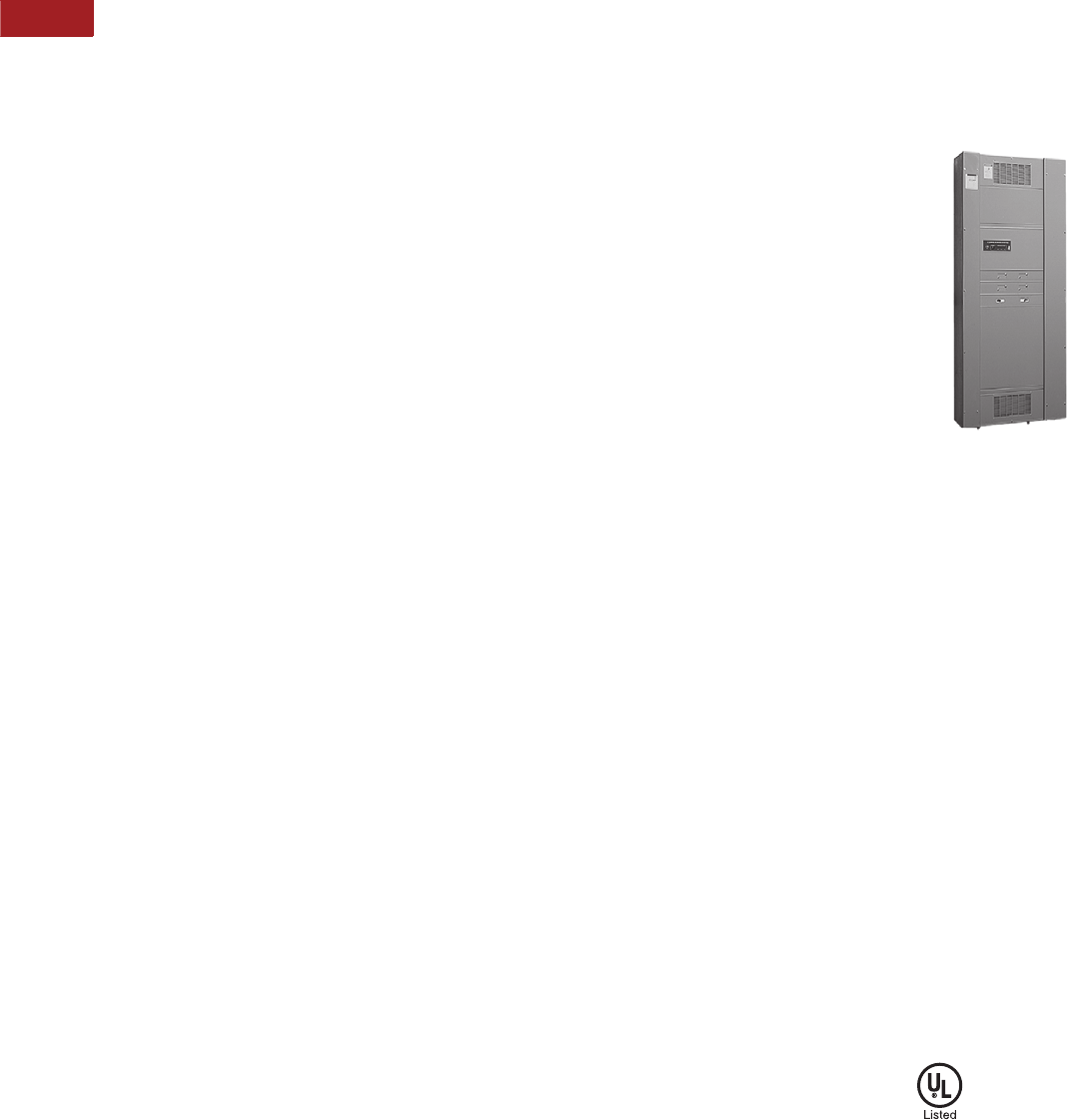
V15-T2-32 Volume 15—Solar Inverters and Electrical Balance of System CA08100018E—September 2015 eaton.com/solar
2
2
2
2
2
2
2
2
2
2
2
2
2
2
2
2
2
2
2
2
2
2
2
2
2
2
2
2
2
2
2.5
Panelboards—Solar Applications
Pow-R-Line C Panelboards
Ambient Temperatures
The primary function of an
overcurrent device is to
protect the conductor
and its insulation against
overheating. In selecting
the size of the devices and
conductors, consideration
should be given to the
ambient temperature
surrounding the conductors
within and external to the
panelboard. Cumulative
heating within the panelboard
may cause premature
operation of the overcurrent
protective devices.
Underwriters Laboratories
test procedures are based,
in part, on 80% loading of
panelboard branch circuit
devices. The NEC limits
the loading of overcurrent
devices in panelboards
to 80% of rating where in
normal operation the load will
continue for three hours or
more. Further derating may
be required, depending on
such factors as ambient
temperature, duty cycle,
frequency or altitude.
Exception: There is one
exception to this rule in both
UL and NEC. It applies to
assemblies and overcurrent
devices that have been listed
for continuous duty at 100%
of its rating.
Special Conditions
Standard panelboards,
assembled with standard
components, are adequate
for most applications.
However, special
consideration should be
given to those required for
application under special
conditions such as:
●Excessive vibration
or shock
●Frequencies above
60 cycles
●Altitudes above 6600 feet
(2011.7m)
●Damp environment
(possible fungus growth)
●Compliance with federal,
state and municipal
electrical codes and
standards
Seismic Considerations
The Uniform Building Code®
and the International Building
Code, as well as local and
state building codes, place
an emphasis on seismic
building design requirements.
Electrical distribution systems
are treated as attachments to
the building and therefore, fall
into this category.
All Eaton panelboards are
seismic qualified at the
highest possible level,
and have been tested in
accordance with ANSI
C37.81. This standard
quantifies actual earthquake
conditions, as well as
equipment seismic capability.
Harmonic Currents
Standard panelboard neutrals
are rated for 100% of the
panelboard current. However,
since harmonic currents can
cause overheated neutrals,
an option is provided for
neutrals to be rated at 200%
(1200A maximum neutral for
600A main bus) of the
panelboard phase current.
Panelboards with the 200%
rated neutral are UL listed as
suitable for use with non-
linear loads.
Prior to specifying the 200%
rated neutral, Eaton
recommends a harmonic
survey be conducted of the
distribution system, be it new
or existing.
Surge Protective Devices
The quality of power feeding
sensitive electronic loads is
critical to the reliable operation
of any facility. In modern
offices, hospitals, and
manufacturing facilities, the
most frequent causes of
microprocessor-based
equipment downtime and
damage are voltage transients
and electrical noise.
Electrical loads and
microprocessor-based
equipment are highly
susceptible to both high and
low energy transients. High
energy transients include
lightning induced surges and
power company switching.
These high energy transients
can destroy components
instantly.
More frequently the electrical
system experiences low
energy transients and high
frequency noise.
The effects of continual low
energy transients and high
frequency noise can cause
erratic equipment
performance or sudden
failure of electronic circuit
board components.
Eaton can provide protective
and diagnostic systems
integral to panelboards.
The surge protective device
(SPD) is integrated into the
panelboards using a “zero
lead length” direct busbar
connection.
Pow-R-Line 4
The SPD protects sensitive
electronic equipment from the
damaging effects of high and
low energy transients, as well
as high frequency noise.
Standards and
Certifications
Eaton’s panelboards are
designed to meet the
following applicable
industry standards,
except where noted:
●Underwriters Laboratories:
●Panelboards: UL 67
●Cabinets and Boxes:
UL 50
Note: Only panelboards
containing UL listed devices
can be UL labeled.
●National Electrical Code
●NEMA Standards: PB 1
●Federal Specification
W-P-115c:
●Circuit Breakers—
Type I Class I
●Fusible Switch—
Type II Class I

Volume 15—Solar Inverters and Electrical Balance of System CA08100018E—September 2015 eaton.com/solar V15-T2-33
2
2
2
2
2
2
2
2
2
2
2
2
2
2
2
2
2
2
2
2
2
2
2
2
2
2
2
2
2
2
2.5
Panelboards—Solar Applications
Pow-R-Line C Panelboards
Technical Data and Specifications
Panelboard Selection Guide
Terminal Wire Ranges, Pressure-Type Al/Cu Terminals Except as Noted
Note: All terminal sizes are based
on wire ampacities corresponding
to those shown in NEC Table
310.16 under the 75°C insulation
columns (75°C wire). The use of
smaller size, (in circular mills),
regardless of insulation
temperature rating, is not
permitted.
Where copper-aluminum
terminals are supplied on
designated panelboard types,
best results are obtained if a
suitable joint compound is
applied when aluminum
conductors are used.
Check Eaton’s standard
terminal sizes versus
customer requirements.
In particular, 400 and 800A
breakers often require
nonstandard lugs.
Optional 750 kcmil
mechanical screw-type
terminals are available
upon request. Panelboard
dimensions may be affected,
refer to Eaton.
Standard Main Lug Terminals
Maximum
Voltage Rating
Maximum Main
Rating (Amperes)
AC Interrupting Capacity
rms Symmetrical Amperes (kA)
Panelboard
Type
Device
Type AC DC MLO Main Device
Branch Circuits
Ampere Range
Sub-Feed Breaker
Maximum Amperes Fully Rated Series Rated
PRL1a Breaker 240 — 400 400 15–100 400 10–22 22–100
PRL2a Breaker 240 250 400 400 15–100 400 65 65–200
Breaker 480Y/277 250 400 400 15–100 400 14 22–150
PRL2R Breaker 240 — 225 225 15–100 — 10–22 22–200
Breaker 480Y/277 — 225 225 15–100 — 14 22–100
PRL3a Breaker 240 250 800 600 15–225 600 10–200 22–200
Breaker 480 250 800 600 15–225 600 14–100 22–150
Breaker 600 250 800 600 15–225 600 14–35 —
PRL4B Breaker 240 600 1200 1200 15–1200 — 10–200 22–200
Breaker 480 600 1200 1200 15–1200 — 14–200 22–150
Breaker 600 600 1200 1200 15–1200 — 14–200 —
PRL4F Fusible 240 250 1200 1200 30–1200 — 100–200 —
Fusible 600 250 1200 1200 30–1200 — 100–200 —
Wire Size Ranges for Ampere Capacity
Panel Type 100A 225A 250A 400A 600A 800A 1200A
PRL1a #12–1/0 #6–300 kcmil — (2) #4–500 kcmil — — —
PRL2a #12–1/0 #6–300 kcmil — (2) #4–500 kcmil — — —
PRL3a #12–1/0 — #6–350 kcmil (2) #4–500 kcmil (2) #4–500 kcmil (3) #4–500 kcmil —
PRL4 — — #4–500 kcmil (2) #4–500 kcmil (2) #4–500 kcmil (3) #4–500 kcmil (4) #4–500 kcmil

V15-T2-34 Volume 15—Solar Inverters and Electrical Balance of System CA08100018E—September 2015 eaton.com/solar
2
2
2
2
2
2
2
2
2
2
2
2
2
2
2
2
2
2
2
2
2
2
2
2
2
2
2
2
2
2
2.5
Panelboards—Solar Applications
Pow-R-Line C Panelboards
Standard Circuit Breaker Terminals
Breaker Type Ampere Rating Wire Range
BAB, QBHW, BABRSP,
HQP, QPHW
15–70 #14–#4
90–100 #8–1/0
EDB, EDS, ED, EDH, EDC 100–225 #4–4/0 or #6–300 kcmil
EGB, EGE, EGS, EGH 15–50 #14–3/0 AL/CU
60–125 #6–3/0 AL/CU
EHD, FDB, FD,
HFD, FDC, HFDDC 1
15–100 #14–1/0
125–225 #4–4/0
FCL 15–100 #14–1/0
GHB, HGHB, GHQ,
GHQRSP
15–20 #14–#10
25–100 #10–1/0
EGB, EGS, EGH 15–50 #14–1/0
60–125 #6–2/0
JD, HJD, JDC, HJDDC 170–250 #4–350 kcmil
DK 250–350 250–500 kcmil
400 (2) 3/0–250 kcmil or (1) 3/0–500 kcmil
KD,
HKD, KDC, HKDDC, 1
CKD, CHKD
225 (1) #3–350 kcmil
350 (2) 3/0–250 kcmil or
400 (2) 3/0–250 kcmil or (1) 3/0–500 kcmil
LHH 150–400 #2–500 kcmil
150–400 (2) #2–500 kcmil
150–400 (1) 500–750 kcmil
LGE, LGH, LGC,
LGU, LHH 2
250–400 (1) #2–500 kcmil
500–600 (2) #2–500 kcmil
LD, HLD, LDC, HLDDC 1
CLD, CHLD
300–500 (2) 250–350 kcmil
600 (2) 400–500 kcmil
MDL, HMDL, HMDLDC 1
CMDL, CHMDL
400–600 (2) #1–500 kcmil
700–800 (3) 3/0–400 kcmil
ND, HND, CND, CHND, NDC,
CNDC
800–1000 (3) 3/0–400 kcmil
1200 (4) 4/0–500 kcmil
LCL 125–225 (1) #6–350 kcmil
250–400 (1) #4–250 kcmil and (1) 3/0–600 kcmil
FB-P 15–100 #14–1/0
LA-P 70–225 #6–350 kcmil
250–400 (1) #4–250 kcmil and (1) 3/0–600 kcmil
NB-P, NBDC 1300–700 (2) #1–500 kcmil
800 (3) 3/0–400 kcmil
FDPW Switch Terminals
Notes
1Suitable for DC applications only.
2LHH is 400A maximum.
Ampere Rating Wire Range
30 #14–1/0
60 #14–1/0
100 #14–1/0
200 #4–300 kcmil
400 250–750 kcmil or (2) 3/0–250 kcmil
600 (2) #4–600 kcmil or (4) 3/0–250 kcmil
800 (3) 250–750 kcmil or (6) 3/0–250 kcmil
1200 (4) 250–750 kcmil or (8) 3/0–250 kcmil

Volume 15—Solar Inverters and Electrical Balance of System CA08100018E—September 2015 eaton.com/solar V15-T2-35
2
2
2
2
2
2
2
2
2
2
2
2
2
2
2
2
2
2
2
2
2
2
2
2
2
2
2
2
2
2
2.5
Panelboards—Solar Applications
Pow-R-Line C Panelboards
Selection Guide
Molded Case Circuit Breaker Ratings
Note: Circuit breakers equal or exceed Federal Specification W-C-375b requirements for the particular class associated with each circuit breaker type.
Notes
1DC ratings apply to substantially non-inductive circuits.
215 and 20A single-pole switching duty rated for fluorescent applications.
3Single-, two- and three-pole HACR rated.
4DC rated single-pole, 15–70A only.
5Two- and three-pole HACR rated.
Breaker
Type
Continuous
Ampere Rating
Number
of Poles
Maximum
Voltage
AC
UL Listed Interrupting Ratings—kA Symmetrical Amperes
AC Rating Volts DC Rating Volts 1
120/240 240 277 480 600 125 250
BAB 23, HQP 23 15–70 1 120 10 ——————
15–100 2 120/24010——————
15–100 2, 3 240 — 10—————
BABRP, BABRSP 215–30 1 120 10——————
15–30 2 120/24010 ——————
QBGF, QBGFEP,
QPGF, QPGFEP,
QBAF, QBAG
15–40 1 120 10 ——————
15–50 2 120/24010 ——————
15–20 1 120 10 ——————
15–20 2 120/24010 ——————
QBHW 23, QPHW 23 15–70 1 120 22 ——————
15–100 2 120/24022——————
15–100 2, 3 240 — 22—————
QBHGF, QBHGFEP,
QPHGF, QPHGFEP
15–30 1 120 22 ——————
15–30 2 120/24022 ——————
GQ, GHQ 2, GHQRSP,
GHB 23
15–20 1 277 65 — 14 — — — —
15–100 41 277 65 — 14 — — 14 —
15–100 42, 3 480Y/277 — 65 — 14 — — 14
HGHB 2,
GHBGFEP
15–30 1 277 65 — 25 — — — —
15–60 1 277 — — 14 — — — —
GHBS 15–30 1 277 65 — 14 — — — —
15–30 2 480Y/277 — 65 — 14 — — —
EHD 23 15–100 1 277 — — 14 — — 10 —
15–100 2, 3 480 — 18 — 14 — — 10
EGB 15–125 1 277 35 35 18 — — 10 —
15–125 2, 3 480 — 35 — 18 — — 10
EGS 15–125 1 277 100 — 35 — — 35 —
15–125 2, 3 480 — 100 — 35 — — 35
EGH 15–125 1 277 200 — 65 — — 42 —
15–125 2, 3 480 — 200 — 65 — — 42
FDB 5,
FD 23
15–150 2, 3 600 — 18 — 14 14 — 10
15–150 1 277 — — 35 — — 10 —
15–225 2, 3 600 — 65 — 35 18 — 10
HFD 23 15–150 1 277 — — 65 — — 10 —
15–225 2, 3 600 — 100 — 65 25 — 22

V15-T2-36 Volume 15—Solar Inverters and Electrical Balance of System CA08100018E—September 2015 eaton.com/solar
2
2
2
2
2
2
2
2
2
2
2
2
2
2
2
2
2
2
2
2
2
2
2
2
2
2
2
2
2
2
2.5
Panelboards—Solar Applications
Pow-R-Line C Panelboards
Selection Guide, continued
Molded Case Circuit Breaker Ratings, continued
Note: Circuit breakers equal or exceed Federal Specification W-C-375b requirements for the particular class associated with each circuit breaker type.
Notes
1DC ratings apply to substantially non-inductive circuits.
2Two- and three-pole HACR rated.
3100% rated circuit breaker.
4DC rating not available with electronic trip.
5Available with integral ground fault protection.
6100k based on NEMA test procedure.
Breaker
Type
Continuous
Ampere Rating
Number
of Poles
Volts
AC
UL Listed Interrupting Ratings—kA Symmetrical Amperes
AC Rating Volts DC Rating Volts 1
120/240 240 277 480 600 125 250
FDC 215–225 2, 3 600 — 200 — 100 35 — 22
FCL 15–100 2, 3 480 — 200 — 150 — — —
EDB 2100–225 2, 3 240 —22 ———10 —
EDS 2100–225 2, 3 240 —42 ———10 —
ED 2100–225 2, 3 240 —65———10—
EDH 2100–225 2, 3 240 —100———10—
EDC 2100–225 2, 3 240 —200———10 —
EGB 215–125 1, 2, 3 240 — 25 — 18 — — —
EGE 215–125 1, 2, 3240 ————18 ——
EGS 215–125 1, 2, 3 240 — 85 — 35 22 — —
EGH 215–125 1, 2, 3 240 — 100 — 65 25 — —
JD 270–250 2, 3 600 — 65 — 35 18 — 10
HJD 270–250 2, 3 600 — 100 — 65 25 — 22
JDC 270–250 2, 3 600 — 200 — 100 35 — 22
DK 250–400 2, 3 240 —65 ————10
KD, CKD 3100–400 2, 3 600 — 65 — 35 25 — 10 4
HKD, CHKD 3100–400 2, 3 600 — 100 — 65 35 — 22 4
LHH 5150–400 2, 3 480 — 100 — 65 35 — 42
KDC 100–400 2, 3 600 — 200 — 100 65 — 22 4
LCL 5125–400 2, 3 600 — 200 — 200 100 — —
LGE 250–600 3 600 — 65 — 35 18 — 22
LGC 5250–600 2, 3 600 — 200 — 100 50 — 42
LGU 5250–600 2, 3 600 — 200 — 150 65 — 50
LD 5, CLD 35 300–600 2, 3 600 — 65 — 35 25 — 22 4
LGH 250–600 3 600 — 100 — 65 35 — 22
HLD 5, CHLD 35 300–600 2, 3 600 — 100 — 65 35 — 25 4
LDC 5, CLDC 35 300–600 2, 3 600 — 200 — 100 50 — 25 4
MDL 5, CMDL 35 400–800 2, 3 600 — 65 — 50 25 — 22 4
HMDL 5, CHMDL 35 400–800 2, 3 600 — 100 — 65 35 — 25 4
ND 5, CND 35 600–1200 2, 3 600 — 65 — 50 25 — —
HND 5, CHND 35 600–1200 2, 3 600 — 100 — 65 35 — —
NDC 5, CNDC 35 600–1200 2, 3 600 — 200 — 100 65 — —
Integrally Fused, Current Limiting Circuit Breakers
FB-P 15–100 2, 3 600 — 200 — 200 200 — 6
LA-P 70–400 2, 3 600 — 200 — 200 200 — 6
NB-P 300–800 2, 3 600 — 200 — 200 200 — 6
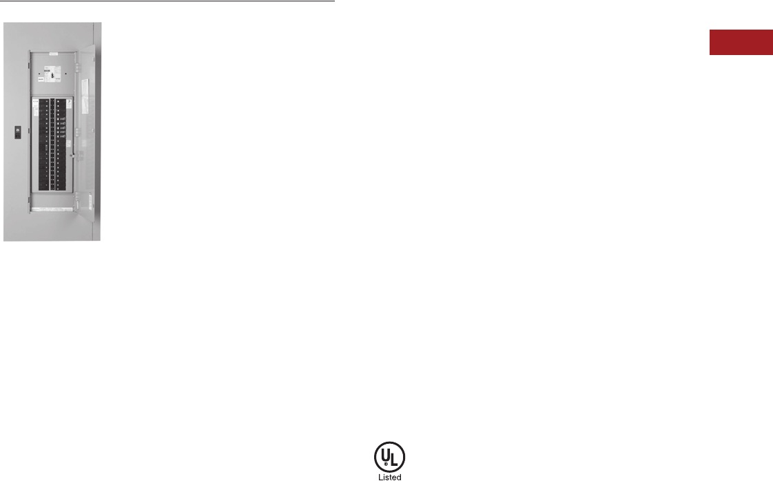
Volume 15—Solar Inverters and Electrical Balance of System CA08100018E—September 2015 eaton.com/solar V15-T2-37
2
2
2
2
2
2
2
2
2
2
2
2
2
2
2
2
2
2
2
2
2
2
2
2
2
2
2
2
2
2
2.5
Panelboards—Solar Applications
Pow-R-Line C Panelboards
Type PRL1a
Contents
Description Page
Introduction . . . . . . . . . . . . . . . . . . . . . . . . . . . . . . V15-T2-25
Product Selection Guide. . . . . . . . . . . . . . . . . . V15-T2-25
EZ Box and EZ Trim . . . . . . . . . . . . . . . . . . . . . . . . V15-T2-26
Pow-R-Line C Panelboards . . . . . . . . . . . . . . . . . . V15-T2-29
Type PRL1a
Type PRL2a . . . . . . . . . . . . . . . . . . . . . . . . . . . V15-T2-41
Type PRL3a . . . . . . . . . . . . . . . . . . . . . . . . . . . V15-T2-45
Type PRL4 . . . . . . . . . . . . . . . . . . . . . . . . . . . . V15-T2-49
Types PRL1a, 2a, 3a, 4
Modifications Selection Guide . . . . . . . . . . . . V15-T2-59
Regional Manufacturing Facilities . . . . . . . . . . . . . V15-T2-68
Type PRL1a
Product Description
●240 Vac maximum
●Three-phase four-wire,
three-phase three-wire,
single-phase three-wire,
single-phase two-wire
●400A maximum mains
●100A maximum branch
breakers
●Bolt-on or plug-on branch
breakers
●Each branch connector is
capable of up to a total of
140A maximum by breaker
ampere rating
●Factory assembled
●Refer to Page V15-T2-29
for additional information
Application Description
●Lighting branch panelboard
●Fully rated or series rated
●Interrupting ratings up to
200 kA symmetrical
●Suitable for use as Service
Entrance Equipment, when
specified on the order
●See Pages V15-T2-29
through V15-T2-36 for
additional information
Standards and Certifications
●UL 67, UL 50
●Federal Specification
W-P-115c
●Refer to Page V15-T2-29
for additional information

V15-T2-38 Volume 15—Solar Inverters and Electrical Balance of System CA08100018E—September 2015 eaton.com/solar
2
2
2
2
2
2
2
2
2
2
2
2
2
2
2
2
2
2
2
2
2
2
2
2
2
2
2
2
2
2
2.5
Panelboards—Solar Applications
Pow-R-Line C Panelboards
Product Selection
PRL1a
Ampere
Rating
Interrupting
Rating (kA Sym.)
240 Vac
Breaker
Typ e
Main Lug Only
100 — —
225 — —
400 — —
Main Breaker
100 10 BAB
100 18 EHD
100 22 QBHW
100 22 EDB
100 42 EDS
100 65 ED
100 65 FD, FDE
100 100 EDH
100 100 HFD, HFDE
225 22 EDB
225 42 EDS
225 65 ED
225 100 EDH
250 65 JD
250 100 HJD
250 200 JDC
400 65 DK
400 65 KD
400 100 HKD
400 100 LHH
400 200 KDC
Type PRL1a
PRL1a Branch Circuit Breakers
Notes
1Single-pole breakers are rated 120 Vac maximum.
250A devices are available as two-pole only.
3GFCI for 5 mA personnel protection.
4GFP for 30 mA equipment protection.
5Arc fault circuit breaker.
6HID (High Intensity Discharge) rated breaker.
7Switching Neutral Breaker. single-pole device requires two-pole space, two-pole device
requires three-pole space.
8Solenoid operated breaker.
Bolt-on = BAB, QBHW, QBGF, QBHGF, QBGFEP, QBHGFEP, QBAF, QBAG, QBHAF, QBHAG
Plug-on = HQP, QPHW, QPGF, QPHGF, QPGFEP, QPHGFEP
Ampere
Rating
Interrupting
Rating (kA Sym.)
240 Vac 1
Breaker
Typ e
15–60 10 BAB, HQP
70 10 BAB, HQP
80–100 10 BAB, HQP
15–50 210 QBGF, QPGF 3
15–50 210 QBGFEP, QPGFEP 4
15–20 10 QBCAF 5
15–60 10 BAB-D, HQP-D 6
15–30 10 BAB-C, HQP-B 7
15–30 10 BABRP 8
15–30 10 BABRSP 8
15–60 22 QBHW, QPHW
70 22 QBHW, QPHW
80–100 22 QBHW, QPHW
15–30 22 QBHGF, QPHGF 3
15–30 22 QBHGFEP, QPHGFEP 4
15–20 22 QBHCAF 5
Provision — —

Volume 15—Solar Inverters and Electrical Balance of System CA08100018E—September 2015 eaton.com/solar V15-T2-39
2
2
2
2
2
2
2
2
2
2
2
2
2
2
2
2
2
2
2
2
2
2
2
2
2
2
2
2
2
2
2.5
Panelboards—Solar Applications
Pow-R-Line C Panelboards
Box Sizing and Selection
Approximate Dimensions in Inches (mm)
Assembled Circuit
Breaker Panelboards and
Lighting Controls
Box size and box and trim
catalog numbers for all
standard panelboard
types are found on
Page V15-T2-40.
Instructions
1. Using description of the
required panelboard,
select the rating and
type of main required.
2. Count the total number
of branch circuit poles,
including provisions,
required in the
panelboard. Do not
count main breaker
poles. Convert two-
or three-pole branch
breaker to single-poles,
i.e., three-pole breaker,
count as three poles.
Determine sub-feed
breaker or through-feed
lug requirements.
3. Select the main ampere
rating section from table
on Page V15-T2-40.
4. Select panelboard type
from first column, main
breaker frame, if
applicable, from second
column, and sub-feed
breaker frame, if
applicable, from the
third column.
5. From Step #2, determine
the number of branch
circuits in Column 4.
6. Read box size, box and
trim catalog numbers
across columns to the
right. Specify surface
or flush mounting on
the order.
Cabinets
Fronts are code-gauge
steel, ANSI-61 light gray
painted finish.
Boxes are code-gauge
galvanized steel without
knockouts. Standard depth
is 5-3/4 inches (146.1 mm).
Standard width is 20 inches
(508.0 mm). An optional
28-inch (711.2 mm) wide
box is available.
Top and Bottom Gutters
5-1/2 inches (139.7 mm)
minimum.

V15-T2-40 Volume 15—Solar Inverters and Electrical Balance of System CA08100018E—September 2015 eaton.com/solar
2
2
2
2
2
2
2
2
2
2
2
2
2
2
2
2
2
2
2
2
2
2
2
2
2
2
2
2
2
2
2.5
Panelboards—Solar Applications
Pow-R-Line C Panelboards
Approximate Dimensions in Inches (mm)
PRL1a Panelboard Sizing
Note
1Smaller panelboard box sizes are available if required. Contact Eaton for application information.
Panelboard
Types
Main Breaker Types
and Mounting Position
(H) = Horizontal
(V) = Vertical
Sub-Feed Breaker Types
and Mounting Position
(H) = Horizontal
(V) = Vertical
Maximum No. of
Branch Circuits
Including
Provisions
Box Dimensions 1
YS Box
Catalog
Number
LT Trim
Catalog
Number
EZ Box
Catalog
Number
EZ Trim
Catalog
NumberHeight Width Depth
100A
Main breaker BAB, QBHW
(H)
—15
36.00 (914.4) 20.00 (508.0) 5.75 (146.1)
YS2036 LT2036S or F EZB2036R EZT2036S or F
—27
48.00 (1219.2) 20.00 (508.0) 5.75 (146.1)
YS2048 LT2048S or F EZB2048R EZT2048S or F
—39
48.00 (1219.2) 20.00 (508.0) 5.75 (146.1)
YS2048 LT2048S or F EZB2048R EZT2048S or F
—42
60.00 (1524.0) 20.00 (508.0) 5.75 (146.1)
YS2060 LT2060S or F EZB2060R EZT2060S or F
Main lugs or
main breaker
EHD
FD, HFD
(V)
—18
36.00 (914.4) 20.00 (508.0) 5.75 (146.1)
YS2036 LT2036S or F EZB2036R EZT2036S or F
—30
48.00 (1219.2) 20.00 (508.0) 5.75 (146.1)
YS2048 LT2048S or F EZB2048R EZT2048S or F
—42
48.00 (1219.2) 20.00 (508.0) 5.75 (146.1)
YS2048 LT2048S or F EZB2048R EZT2048S or F
Main lugs or main
breaker with 100A
through-feed lugs or
sub-feed breaker
EHD
FD
HFD
(V)
EHD
FD
HFD
(V)
18
48.00 (1219.2) 20.00 (508.0) 5.75 (146.1)
YS2048 LT2048S or F EZB2048R EZT2048S or F
30
48.00 (1219.2) 20.00 (508.0) 5.75 (146.1)
YS2048 LT2048S or F EZB2048R EZT2048S or F
42
60.00 (1524.0) 20.00 (508.0) 5.75 (146.1)
YS2060 LT2060S or F EZB2060R EZT2060S or F
225A
Main lugs or
main breaker
EDB, EDS, ED,
EDH, FD, HFD
(V)
—18
36.00 (914.4) 20.00 (508.0) 5.75 (146.1)
YS2036 LT2036S or F EZB2036R EZT2036S or F
—30
48.00 (1219.2) 20.00 (508.0) 5.75 (146.1)
YS2048 LT2048S or F EZB2048R EZT2048S or F
—42
48.00 (1219.2) 20.00 (508.0) 5.75 (146.1)
YS2048 LT2048S or F EZB2048R EZT2048S or F
Main lugs or main
breaker with 225A
throughfeed lugs or
sub-feed breaker
FD, HFD,
EDS, ED,
EDH
(V)
FD, HFD,
EDS, ED,
EDH
(V)
18
48.00 (1219.2) 20.00 (508.0) 5.75 (146.1)
YS2048 LT2048S or F EZB2048R EZT2048S or F
30
60.00 (1524.0) 20.00 (508.0) 5.75 (146.1)
YS2060 LT2060S or F EZB2060R EZT2060S or F
42
60.00 (1524.0) 20.00 (508.0) 5.75 (146.1)
YS2060 LT2060S or F EZB2060R EZT2060S or F
400A
Main breaker DK, KD, HKD,
KDC, LHH
(V)
—18
48.00 (1219.2) 20.00 (508.0) 5.75 (146.1)
YS2048 LT2048S or F EZB2048R EZT2048S or F
—30
60.00 (1524.0) 20.00 (508.0) 5.75 (146.1)
YS2060 LT2060S or F EZB2060R EZT2060S or F
—42
60.00 (1524.0) 20.00 (508.0) 5.75 (146.1)
YS2060 LT2060S or F EZB2060R EZT2060S or F
Main lugs or main
breaker with 225A
through-feed lugs or
sub-feed breaker
DK, KD, HKD,
KDC, LHH
(V)
FD, HFD,
EDS, ED,
EDH
(V)
18
60.00 (1524.0) 20.00 (508.0) 5.75 (146.1)
YS2060 LT2060S or F EZB2060R EZT2060S or F
30
60.00 (1524.0) 20.00 (508.0) 5.75 (146.1)
YS2060 LT2060S or F EZB2060R EZT2060S or F
42 72.00 (1828.8)
20.00 (508.0) 5.75 (146.1)
YS2072 LT2072S or F EZB2072R EZT2072S or F
Main breaker with 400A
through-feed lugs or
sub-feed breaker
DK, KD, HKD,
KDC, LHH
(V)
DK, KD,
HKD, KDC
(V)
18 72.00 (1828.8)
20.00 (508.0) 5.75 (146.1)
YS2072 LT2072S or F EZB2072R EZT2072S or F
30 72.00 (1828.8)
20.00 (508.0) 5.75 (146.1)
YS2072 LT2072S or F EZB2072R EZT2072S or F
42 90.00 (2286.0)
20.00 (508.0) 5.75 (146.1)
YS2090 LT2090S or F EZB2090R EZT2090S or F

Volume 15—Solar Inverters and Electrical Balance of System CA08100018E—September 2015 eaton.com/solar V15-T2-41
2
2
2
2
2
2
2
2
2
2
2
2
2
2
2
2
2
2
2
2
2
2
2
2
2
2
2
2
2
2
2.5
Panelboards—Solar Applications
Pow-R-Line C Panelboards
Type PRL2a
Contents
Description Page
Introduction . . . . . . . . . . . . . . . . . . . . . . . . . . . . . . V15-T2-25
Product Selection Guide. . . . . . . . . . . . . . . . . . V15-T2-25
EZ Box and EZ Trim . . . . . . . . . . . . . . . . . . . . . . . . V15-T2-26
Pow-R-Line C Panelboards . . . . . . . . . . . . . . . . . . V15-T2-29
Type PRL1a . . . . . . . . . . . . . . . . . . . . . . . . . . . V15-T2-37
Type PRL2a
Type PRL3a . . . . . . . . . . . . . . . . . . . . . . . . . . . V15-T2-45
Type PRL4 . . . . . . . . . . . . . . . . . . . . . . . . . . . . V15-T2-49
Types PRL1a, 2a, 3a, 4
Modifications Selection Guide . . . . . . . . . . . . V15-T2-59
Regional Manufacturing Facilities . . . . . . . . . . . . . V15-T2-68
Type PRL2a
Product Description
●480Y/277 Vac maximum
(125 Vdc)
●Three-phase four-wire,
three-phase three-wire,
single-phase three-wire,
single-phase two-wire
●400A maximum mains
●100A maximum branch
breakers
●Bolt-on branch breakers
●Each branch connector is
capable of up to a total of
140A maximum by breaker
ampere rating
●Factory assembled
●Refer to Page V15-T2-20
for additional information
Application Description
●Lighting branch panelboard
●Fully rated or series rated
●Interrupting ratings up to
200 kA symmetrical
●Suitable for use as Service
Entrance Equipment, when
specified on the order
●See Pages V15-T2-20
through V15-T2-36 for
additional information
Standards and Certifications
●UL 67, UL 50
●Federal Specification
W-P-115c
●Refer to Page V15-T2-20
for additional information
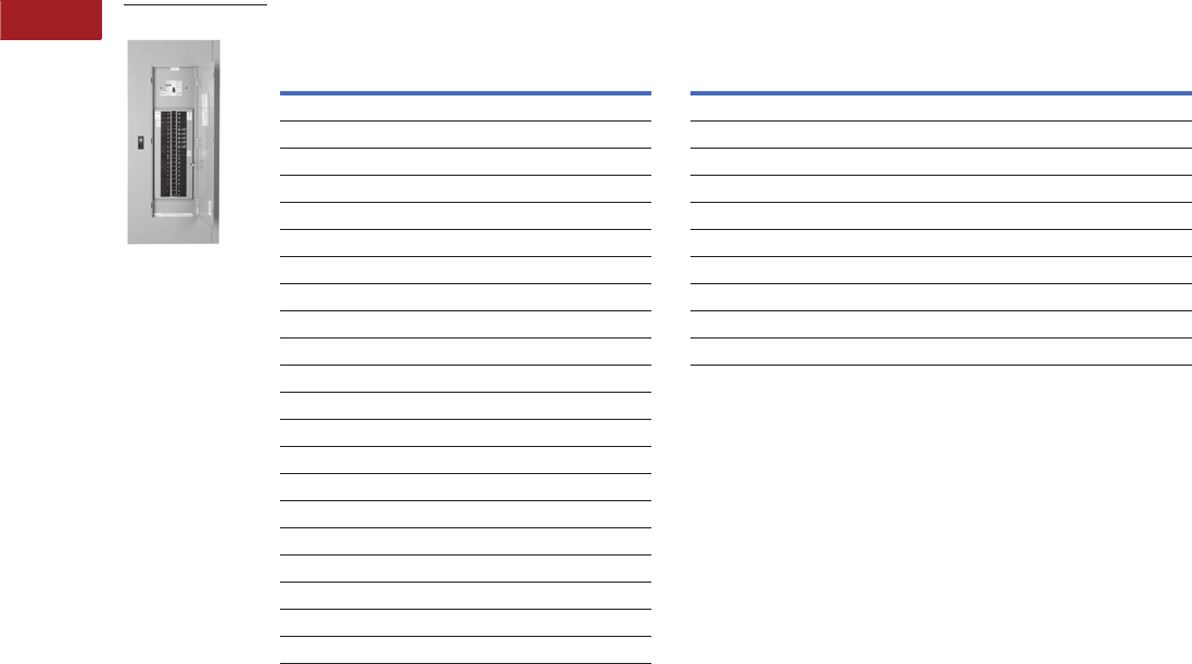
V15-T2-42 Volume 15—Solar Inverters and Electrical Balance of System CA08100018E—September 2015 eaton.com/solar
2
2
2
2
2
2
2
2
2
2
2
2
2
2
2
2
2
2
2
2
2
2
2
2
2
2
2
2
2
2
2.5
Panelboards—Solar Applications
Pow-R-Line C Panelboards
Product Selection
PRL2a PRL2a Branch Circuit Breakers
Notes
1Interrupting ratings in this column are applicable to 120 Vac for single-pole breakers.
2Must be used on 480Y/277V grounded wye systems only.
3Remote controllable breaker.
4GFP for 30 mA equipment protection. Requires two-pole spaces. 277 Vac only.
5HID (High Intensity Discharge) rated breaker.
Ampere
Rating
Interrupting Rating
(kA Symmetrical) Breaker
Type240 Vac 480Y/277 Vac 125/250 Vdc
Main Lug Only
100 — — — —
225 — — — —
400 — — — —
Main Breaker
100 65 14 14 GHB
100 18 14 10 EHD
100 65 35 10 FD, FDE
100 100 65 22 HFD, HFDE
100 200 100 22 FDC
225 65 — — ED
225 65 35 10 FD, FDE
225 100 65 22 HFD, HFDE
225 200 100 22 FDC
250 65 35 10 JD
250 100 65 22 HJD
250 200 100 22 JDC
400 65 35 10 KD
400 100 65 22 HKD
400 100 65 — LHH
400 200 100 22 KDC
Type PRL2a
Ampere
Rating
Interrupting Rating
(kA Symmetrical) Breaker
Typ e240 Vac 1480Y/277 Vac 125/250 Vdc
15–20 65 14 — GHQ 2
15–20 65 14 14 GHB 2
25–60 65 14 14 GHB 2
70–100 65 14 14 GHB 2
15–30 65 25 — HGHB 2
15–20 65 14 — GHQRSP 3
15–30 65 14 — GHBS 23
15–60 — 14 — GHBGFEP 24
15–20 — 14 — GHBHID 25
Provision — — — —

Volume 15—Solar Inverters and Electrical Balance of System CA08100018E—September 2015 eaton.com/solar V15-T2-43
2
2
2
2
2
2
2
2
2
2
2
2
2
2
2
2
2
2
2
2
2
2
2
2
2
2
2
2
2
2
2.5
Panelboards—Solar Applications
Pow-R-Line C Panelboards
Box Sizing and Selection
Approximate Dimensions in Inches (mm)
Assembled Circuit
Breaker Panelboards and
Lighting Controls
Box size and box and trim
catalog numbers for all
standard panelboard
types are found on
Page V15-T2-44.
Instructions
1. Using description of the
required panelboard,
select the rating and
type of main required.
2. Count the total number
of branch circuit poles,
including provisions,
required in the
panelboard. Do not
count main breaker
poles. Convert two-
or three-pole branch
breaker to single-poles,
i.e., three-pole breaker,
count as three poles.
Determine sub-feed
breaker or through-feed
lug requirements.
3. Select the main ampere
rating section from table
on Page V15-T2-44.
4. Select panelboard
type from first column,
main breaker frame, if
applicable, from second
column, and sub-feed
breaker frame, if
applicable, from the
third column.
5. From Step #2, determine
the number of branch
circuits in Column 4.
6. Read box size, box and
trim catalog numbers
across columns to the
right. Specify surface
or flush mounting on
the order.
Cabinets
Fronts are code-gauge
steel, ANSI-61 light gray
painted finish.
Boxes are code-gauge
galvanized steel without
knockouts. Standard depth
is 5-3/4 inches (146.1 mm).
Standard width is 20 inches
(508.0 mm). An optional
28-inch (711.2 mm) wide
box is available.
Top and Bottom Gutters
5-1/2 inches (139.7 mm)
minimum.

V15-T2-44 Volume 15—Solar Inverters and Electrical Balance of System CA08100018E—September 2015 eaton.com/solar
2
2
2
2
2
2
2
2
2
2
2
2
2
2
2
2
2
2
2
2
2
2
2
2
2
2
2
2
2
2
2.5
Panelboards—Solar Applications
Pow-R-Line C Panelboards
Approximate Dimensions in Inches (mm)
PRL2a Panelboard Sizing
Note
1Smaller panelboard box sizes are available if required. Contact Eaton for application information.
Panelboard
Types
Main Breaker Types
and Mounting Position
(H) = Horizontal
(V) = Vertical
Sub-Feed Breaker Types
and Mounting Position
(H) = Horizontal
(V) = Vertical
Maximum No. of
Branch Circuits
Including
Provisions
Box Dimensions 1
YS Box
Catalog
Number
LT Trim
Catalog
Number
EZ Box
Catalog
Number
EZ Trim
Catalog
NumberHeight Width Depth
100A
Main breaker
BAB, QBHW
(H)
—15
36.00 (914.4) 20.00 (508.0) 5.75 (146.1)
YS2036 LT2036S or F EZB2036R EZT2036S or F
—27
48.00 (1219.2) 20.00 (508.0) 5.75 (146.1)
YS2048 LT2048S or F EZB2048R EZT2048S or F
—39
48.00 (1219.2) 20.00 (508.0) 5.75 (146.1)
YS2048 LT2048S or F EZB2048R EZT2048S or F
—42
60.00 (1524.0) 20.00 (508.0) 5.75 (146.1)
YS2060 LT2060S or F EZB2060R EZT2060S or F
Main lugs or
main breaker
EHD
FD, HFD, FDE
HFDE
(V)
—18
36.00 (914.4) 20.00 (508.0) 5.75 (146.1)
YS2036 LT2036S or F EZB2036R EZT2036S or F
—30
48.00 (1219.2) 20.00 (508.0) 5.75 (146.1)
YS2048 LT2048S or F EZB2048R EZT2048S or F
—42
48.00 (1219.2) 20.00 (508.0) 5.75 (146.1)
YS2048 LT2048S or F EZB2048R EZT2048S or F
Main lugs or main breaker
with 100A through-feed
lugs or sub-feed breaker
EHD
FD, FDE
HFD, HFDE
(V)
EHD
FD
HFD
(V)
18
48.00 (1219.2) 20.00 (508.0) 5.75 (146.1)
YS2048 LT2048S or F EZB2048R EZT2048S or F
30
48.00 (1219.2) 20.00 (508.0) 5.75 (146.1)
YS2048 LT2048S or F EZB2048R EZT2048S or F
42
60.00 (1524.0) 20.00 (508.0) 5.75 (146.1)
YS2060 LT2060S or F EZB2060R EZT2060S or F
225A
Main lugs or
main breaker
EDB, EDS, ED,
EDH, FD, HFD
FDE, HFDE
(V)
—18
36.00 (914.4) 20.00 (508.0) 5.75 (146.1)
YS2036 LT2036S or F EZB2036R EZT2036S or F
—30
48.00 (1219.2) 20.00 (508.0) 5.75 (146.1)
YS2048 LT2048S or F EZB2048R EZT2048S or F
—42
48.00 (1219.2) 20.00 (508.0) 5.75 (146.1)
YS2048 LT2048S or F EZB2048R EZT2048S or F
JD, HJD
JDC
(V)
—18
60.00 (1524.0) 20.00 (508.0) 5.75 (146.1)
YS2060 LT2060S or F EZB2060R EZT2060S or F
—30
60.00 (1524.0) 20.00 (508.0) 5.75 (146.1)
YS2060 LT2060S or F EZB2060R EZT2060S or F
— 42 72.00 (1828.8)
20.00 (508.0) 5.75 (146.1)
YS2072 LT2072S or F EZB2072R EZT2072S or F
Main lugs or main breaker
with 225A through-feed
lugs or sub-feed breaker
EHD, FD, HFD,
EDB, EDS, ED,
EDH
FDE, HFDE
(V)
EHD, FD, HFD,
EDB, EDS, ED,
EDH (V)
18
48.00 (1219.2) 20.00 (508.0) 5.75 (146.1)
YS2048 LT2048S or F EZB2048R EZT2048S or F
30
48.00 (1219.2) 20.00 (508.0) 5.75 (146.1)
YS2048 LT2048S or F EZB2048R EZT2048S or F
42
60.00 (1524.0) 20.00 (508.0) 5.75 (146.1)
YS2060 LT2060S or F EZB2060R EZT2060S or F
JD, HJD
JDC
(V)
EHD, FD, HFD,
EDB, EDS, ED,
EDH (V)
18
60.00 (1524.0) 20.00 (508.0) 5.75 (146.1)
YS2060 LT2060S or F EZB2060R EZT2060S or F
30 72.00 (1828.8)
20.00 (508.0) 5.75 (146.1)
YS2072 LT2072S or F EZB2072R EZT2072S or F
42 72.00 (1828.8)
20.00 (508.0) 5.75 (146.1)
YS2072 LT2072S or F EZB2072R EZT2072S or F
400A
Main lugs or
main breaker
DK, KD, HKD,
KDC, LHH
(V)
— 18 60.00 (1524.0) 20.00 (508.0) 5.75 (146.1)
YS2060 LT2060S or F EZB2060R EZT2060S or F
— 30 60.00 (1524.0) 20.00 (508.0) 5.75 (146.1)
YS2060 LT2060S or F EZB2060R EZT2060S or F
—42
72.00 (1828.8)
20.00 (508.0) 5.75 (146.1)
YS2072 LT2072S or F EZB2072R EZT2072S or F
Main lugs or main breaker
with 225A through-feed
lugs or sub-feed breaker
DK, KD, HKD,
KDC, LHH
(V)
EHD, FD, HFD,
EDB, EDS, ED,
EDH (V)
18 60.00 (1524.0) 20.00 (508.0) 5.75 (146.1)
YS2060 LT2060S or F EZB2060R EZT2060S or F
30
72.00 (1828.8)
20.00 (508.0) 5.75 (146.1)
YS2072 LT2072S or F EZB2072R EZT2072S or F
42
72.00 (1828.8)
20.00 (508.0) 5.75 (146.1)
YS2072 LT2072S or F EZB2072R EZT2072S or F
Main lugs or main breaker
with 400A through-feed
lugs or sub-feed breaker
DK, KD, HKD,
KDC, LHH
(V)
JD, HJD, JDC,
DK, KD,
HKD, KDC
(V)
18
72.00 (1828.8)
20.00 (508.0) 5.75 (146.1)
YS2072 LT2072S or F EZB2072R EZT2072S or F
30
90.00 (2286.0)
20.00 (508.0) 5.75 (146.1)
YS2090 LT2090S or F EZB2090R EZT2090S or F
42
90.00 (2286.0)
20.00 (508.0) 5.75 (146.1)
YS2090 LT2090S or F EZB2090R EZT2090S or F
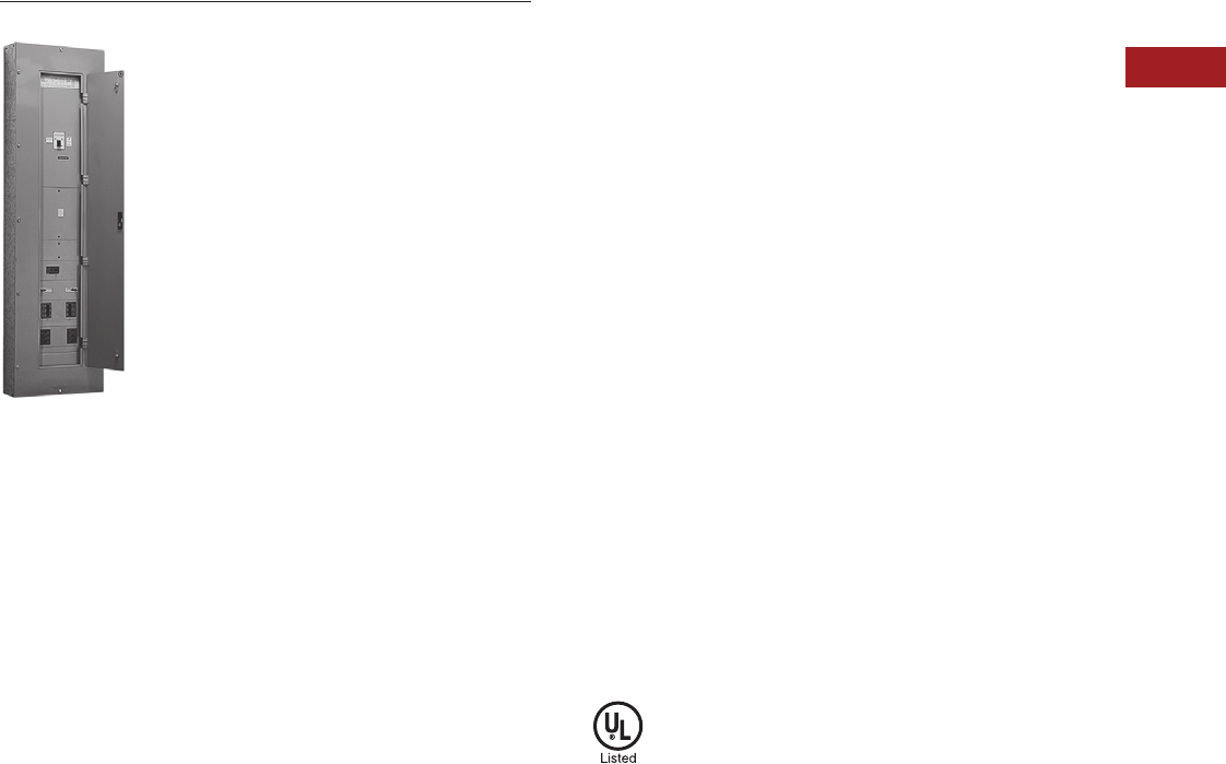
Volume 15—Solar Inverters and Electrical Balance of System CA08100018E—September 2015 eaton.com/solar V15-T2-45
2
2
2
2
2
2
2
2
2
2
2
2
2
2
2
2
2
2
2
2
2
2
2
2
2
2
2
2
2
2
2.5
Panelboards—Solar Applications
Pow-R-Line C Panelboards
Type PRL3a
Contents
Description Page
Introduction . . . . . . . . . . . . . . . . . . . . . . . . . . . . . . V15-T2-25
Product Selection Guide. . . . . . . . . . . . . . . . . . V15-T2-25
EZ Box and EZ Trim . . . . . . . . . . . . . . . . . . . . . . . . V15-T2-26
Pow-R-Line C Panelboards . . . . . . . . . . . . . . . . . . V15-T2-29
Type PRL1a . . . . . . . . . . . . . . . . . . . . . . . . . . . V15-T2-37
Type PRL2a . . . . . . . . . . . . . . . . . . . . . . . . . . . V15-T2-41
Type PRL3a
Type PRL4 . . . . . . . . . . . . . . . . . . . . . . . . . . . . V15-T2-49
Types PRL1a, 2a, 3a, 4
Modifications Selection Guide . . . . . . . . . . . . V15-T2-59
Regional Manufacturing Facilities . . . . . . . . . . . . . V15-T2-68
Type PRL3a
Product Description
●600 Vac maximum
(250 Vdc)
●Three-phase four-wire,
three-phase three-wire,
single-phase three-wire,
single-phase two-wire
●800A maximum main lugs
●600A maximum main
breaker
●225A maximum branch
breakers
●Bolt-on branch breakers
●Factory assembled
●Refer to Page V15-T2-29
for additional information
Application Description
●Lighting panelboard or
power distribution
panelboard
●Fully rated or series rated
●Interrupting ratings up to
200 kA symmetrical
●Suitable for use as Service
Entrance Equipment, when
specified on the order
●See Pages V15-T2-29
through V15-T2-36 for
additional information
Standards and Certifications
●UL 67, UL 50
●Federal Specification
W-P-115c
●Refer to Page V15-T2-29
for additional information

V15-T2-46 Volume 15—Solar Inverters and Electrical Balance of System CA08100018E—September 2015 eaton.com/solar
2
2
2
2
2
2
2
2
2
2
2
2
2
2
2
2
2
2
2
2
2
2
2
2
2
2
2
2
2
2
2.5
Panelboards—Solar Applications
Pow-R-Line C Panelboards
Product Selection
PRL3a
Notes
1 800A MLO requires 28-inch (711.2 mm) wide box.
2 100,000 based on NEMA test procedure.
3 Top feed only.
4 Requires 6.50-inch (165.1 mm) deep box. Not available in Type 3R, 12, 4 and 4X enclosures.
5 100% rated circuit breaker. Requires copper bus. Not available in Type 12, 4 and 4X enclosures.
Ampere
Rating
Interrupting Rating (kA Symmetrical) Breaker
Type240 Vac 480 Vac 600 Vac 250 Vdc
Main Lug Only
100 ———— —
250 ———— —
400 ———— —
600 ———— —
800 1———— —
Main Breaker
100 18 14 — 10 EHD
100 18141410 FDB
100 22 — — — EDB
100 42 — — — EDS
100 65 — — — ED
100 100 — — — EDH
100 65351810 FD, FDE
100 100 65 25 22 HFD, HFDE
100 200 100 35 22 FDC
100 200 150 — — FCL
100 200 200 200 100 2FB-P 3
225 22 — — — EDB
225 42 — — — EDS
225 65 — — — ED
225 100 — — EDH
225 200 — — — EDC
225 65351810 FD, FDE
225 100 65 25 22 HFD, HFDE
225 200 100 35 22 FDC
250 65351810 JD
250 100 65 25 22 HJD
250 200 100 35 22 JDC
400 65——10 DK
400 65352510 KD
400 100 65 35 22 HKD
400 100 65 — — LHH
400 200 100 65 22 KDC
400 65——— LCL 4
400 200 200 200 100 2LA-P 34
600 65351822 LGE
600 100 65 35 22 LGH
600 200 100 50 42 LGC
600 65352522 LD
600 100 65 35 25 HLD
600 200 100 50 25 LDC
600 65352522 CLD 5
600 100 65 35 25 CHLD 5
600 200 100 50 25 CLDC 5
Type PRL3a

Volume 15—Solar Inverters and Electrical Balance of System CA08100018E—September 2015 eaton.com/solar V15-T2-47
2
2
2
2
2
2
2
2
2
2
2
2
2
2
2
2
2
2
2
2
2
2
2
2
2
2
2
2
2
2
2.5
Panelboards—Solar Applications
Pow-R-Line C Panelboards
PRL3a Branch Circuit Breakers PRL3a Branch Circuit Breakers, continued
Notes
150A devices are available as two-pole only.
2Single-pole breaker rated 120 Vac.
3Two-pole breaker rated 120/240 Vac.
4Arc fault circuit breaker.
5HID (High Intensity Discharge) rated breaker.
6Switching Neutral Breaker. single-pole device requires two-pole space, two-pole device
requires three-pole space.
7Solenoid operated breaker.
8Single-pole breaker rated 277 Vac.
9For use on 480Y/277V systems only.
jAIC rating for two- and three-pole breakers only.
kMaximum of six breakers per panel, 175–225A.
Ampere
Rating
Interrupting Rating (kA Symmetrical) Breaker
Type240 Vac 480 Vac 600 Vac 250 Vdc
15–60 10 23 ———BAB
15–6010———BAB-H
70 10 23 ———BAB
70 10———BAB-H
80–100 10 23 ———BAB
80–10010———BAB-H
15–50 110 23 ———QBGF
15–50 110———QBGFEP
15–20 10 23 ———QBCAF
4
15–60 10 23 ———BAB-D
5
15–30 10 23 ———BAB-C
6
15–30 10 2———BABRP
7
15–30 10 2———BABRSP
7
15–60 22 23 ———QBHW
15–6022———QBHW-H
70 22 23 ———QBHW
70 22———QBHW-H
80–100 22 23 ———QBHW
80–10022———QBHW-H
15–3022———QBHGF
15–3022———QBHGFEP
15–20 22 23 ———QBHCAF
4
15–20 65 14 89 — — GHQ
15–20 65 14 89 — 14 GHB
Ampere
Rating
Interrupting Rating (kA Symmetrical) Breaker
Type240 Vac 480 Vac 600 Vac 250 Vdc
25–60 65 14 89 — 14 GHB
70–100 65 14 89 — 14 GHB
15–30 65 25 89 — — HGHB
15–20 65 14 89 — 14 GHQRSP 7
15–30 65 14 89 — 14 GHBS 7
15–60 — 14 89 — — GHBGFEP
15–20 — 14 89 — — GHBHID 5
15–60 18 j14 8— 10 EHD
70–100 18 j14 8— 10 EHD
15–60 18 V14 14 10 FDB
70–10018141410FDB
110–150 18 14 14 10 FDB
15–60 65 j35 818 10 FD, FDE
70–100 65 j35 818 10 FD, FDE
110–225 65 j35 18 10 FD k, FDE
15–60 100 j65 825 22 HFD, HFDE
70–100 100 j65 825 22 HFD, HFDE
110–225 100 j65 25 22 HFD k, HFDE
15–60 200 100 35 22 FDC
70–100 200 100 35 22 FDC
110–225 200 100 35 22 FDC k
100–225 22 — — — EDB k
100–225 42 — — — EDS k
100–22565———ED k
100–225 100 — — — EDH k
100–225 200 — — — EDC k
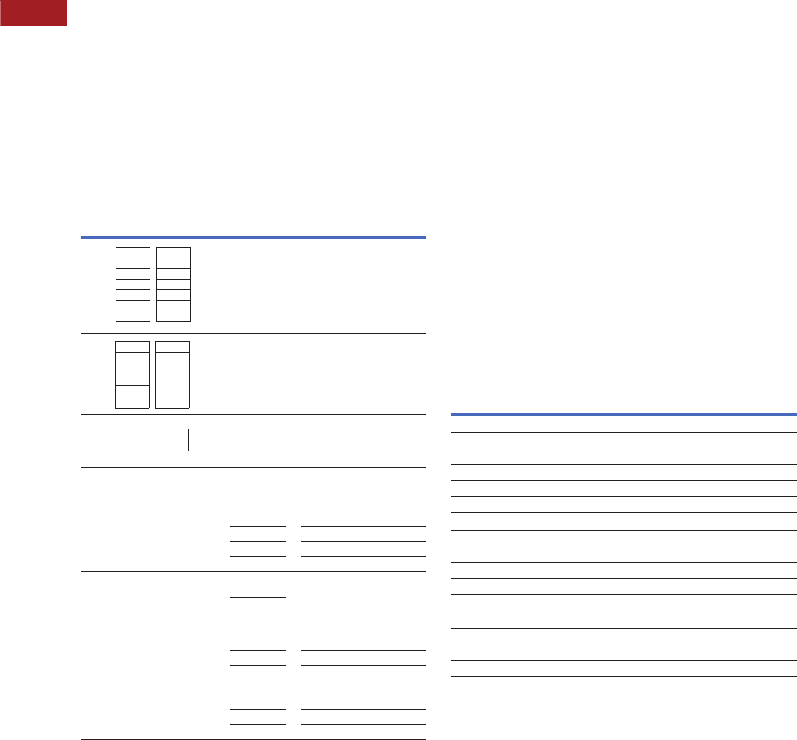
V15-T2-48 Volume 15—Solar Inverters and Electrical Balance of System CA08100018E—September 2015 eaton.com/solar
2
2
2
2
2
2
2
2
2
2
2
2
2
2
2
2
2
2
2
2
2
2
2
2
2
2
2
2
2
2
2.5
Panelboards—Solar Applications
Pow-R-Line C Panelboards
Box Sizing and Selection
Approximate Dimensions in Inches (mm)
Panel Layout Instructions
1. S e l e c t :
a. Required mains (lugs or breaker).
b. Neutral where required.
c. Branch circuits as required.
2. Layout panel as shown below, using appropriate
“X” dimensions.
3. Using total X units (panel height) find box height in inches
(mm) and box catalog number from table below. (When total
X units come out to an uneven number, use next highest
number; i.e., if total X comes out 25X, use 31X.)
Layout—PRL3a
Notes
1GHB, HGHB and GHQ breakers cannot be mixed on same connector as BAB, QBHW, BABRP
and BABRSP.
2Maximum of six breakers per panel.
3Horizontal mounted 15–150A main breakers EHD, FDB, FD, FDE, HFD, HFDE and FDC, will be
furnished as branch breaker construction. Branch breakers single-, two- or three-pole as
required, may be located opposite these main breakers.
4If optional terminal kit 3TA225FDK is required, use 10X.
5FB-P and LA-P top mounting only.
6LCL or LA-P main breaker requires 6-1/2-inch (165.1 mm) deep box.
Poles
6 - 3X
12 - 5X
18 - 8X
24 - 10X
30 - 13X
36 - 15X
42 - 18X
BAB, QBHW, QBCAF,
BABRP, BABRSP, QBHCAF
GHQ, GHB, HGHB
1
1X
2X
3X
EDB, EDS, ED,
EDH, EDC,
EHD, FDB, FD, FDE,
HFD, FDC, HFDE
150A max. per branch breaker
(300A max. per connector)
2X
2-Pole
EDB, EDS, ED,
EDH, EDC
FD, HFD, FDC,
2 FDE, HFDE
3X
three-pole
Neutral
Section
5X 100–250A
8X 400–800A
11X 800A with through-feed lug
Main Lug
Section
2X 100A
5X 250A
8X 400–600A
14X 800A
Main
Breaker
Section
Horizontal
Mounting
2X
2-Pole
EHD, FDB, FD,
HFD, FDC, FDE, HFDE
3X
three-pole
EDB, EDS, ED,
EDH, EDC 3
Vertical
Mounting
7X EHD, FDB, FD, FDE, HFD, FDC,
HFDE, EDB, EDS, ED, EDH, EDC 4
9X FCL, FB-P 5
14X JD, HJD, JDC
15X DK, KD, HKD, KDC, LHH
17X LD, HLD, LDC, CLD, CHLD, CLDC
18X LGE, LGH, LGC
21X LCL, LA-P 56
1-Pole
2-Pole
1-Pole
2-Pole
1-Pole
2-Pole
3-pole
2- or 3-pole
Layout Example
1. Description of Panel
Type PRL3a three-phase, four-wire, 120/208 Vac flush
mounting. Panel to have short-circuit rating of 22,000
symmetrical amperes. Main breaker 400A, three-pole,
bottom mounting. Branch circuits bolt-on as follows:
12–200A single-pole QBHW
1–200A three-pole ED
1–225A three-pole ED
2. Layout Information from Layout—PRL3a table (left):
a. 400A Neutral. . . . . . . . . . . . .= 8X
b. 12-poles of QBHW . . . . . . . .= 5X
c. Two three-pole ED breakers . . = 6X
d. Main breaker, 400A,
Three-pole DK . . . . . . . . . . .= 15X
Total Height. . . . . . . . . . . . .= 34X
3. From Box Tabulation—PRL3a table (below):
a. 34X Height (use 40X box)
b. Box Height 72 inches (1828.8 mm)
c.
Box Catalog Number. . . . . . . .
YS2072 or EZB2072R
Box Tabulation—PRL3a
Cabinets
Fronts are code-gauge steel,
ANSI-61 light gray painted
finish.
Boxes are code-gauge
galvanized steel without
knockouts. Standard depth is
5-3/4 inches (146.1 mm).
Standard widths are:
20-inch (508.0 mm)
100–600A.
28-inch (711.2 mm)
800A.
Standard Depth
5-3/4 inches (146.1 mm).
Top and Bottom Gutters
5-1/2 inches (139.7 mm)
minimum.
Side Gutters
4 inches (101.6 mm)
minimum.
“X”
Units
YS Box
Catalog
Number
LT Trim
Catalog
Number
EZ Box
Catalog
Number
EZ Trim
Catalog
NumberBox Height
100–400A
14X 36.00 (914.4) YS2036 LT2036S or F EZB2036R EZT2036S or F
23X 48.00 (1219.2) YS2048 LT2048S or F EZB2048R EZT2048S or F
31X 60.00 (1524.0) YS2060 LT2060S or F EZB2060R EZT2060S or F
40X 72.00 (1524.0) YS2072 LT2072S or F EZB2072R EZT2072S or F
53X 90.00 (2286.0) YS2090 LT2090S or F EZB2090R EZT2090S or F
600A
23X 48.00 (1219.2) YS2048 LTV2048S or F EZB2048R EZTV2048S or F
31X 60.00 (1524.0) YS2060 LTV2060S or F EZB2060R EZTV2060S or F
40X 72.00 (1524.0) YS2072 LTV2072S or F EZB2072R EZTV2072S or F
53X 90.00 (2286.0) YS2090 LTV2090S or F EZB2090R EZTV2090S or F
800A
23X 48.00 (1219.2) YS2848 LTV2848S or F ——
31X 60.00 (1524.0) YS2860 LTV2860S or F — —
40X 72.00 (1524.0) YS2872 LTV2872S or F — —
53X 90.00 (2286.0) YS2890 LTV2890S or F — —
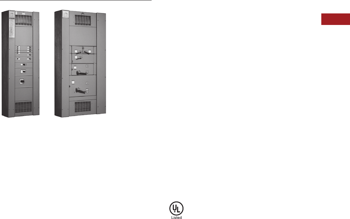
Volume 15—Solar Inverters and Electrical Balance of System CA08100018E—September 2015 eaton.com/solar V15-T2-49
2
2
2
2
2
2
2
2
2
2
2
2
2
2
2
2
2
2
2
2
2
2
2
2
2
2
2
2
2
2
2.5
Panelboards—Solar Applications
Pow-R-Line C Panelboards
Type PRL4B Circuit Breaker and Type PRL4F Fusible Panelboards
Type PRL4
Contents
Description Page
Introduction . . . . . . . . . . . . . . . . . . . . . . . . . . . . . . V15-T2-25
Product Selection Guide. . . . . . . . . . . . . . . . . . V15-T2-25
EZ Box and EZ Trim . . . . . . . . . . . . . . . . . . . . . . . . V15-T2-26
Pow-R-Line C Panelboards . . . . . . . . . . . . . . . . . . V15-T2-29
Type PRL1a . . . . . . . . . . . . . . . . . . . . . . . . . . . V15-T2-37
Type PRL2a . . . . . . . . . . . . . . . . . . . . . . . . . . . V15-T2-41
Type PRL3a . . . . . . . . . . . . . . . . . . . . . . . . . . . V15-T2-45
Type PRL4
Types PRL1a, 2a, 3a, 4
Modifications Selection Guide . . . . . . . . . . . . V15-T2-59
Regional Manufacturing Facilities . . . . . . . . . . . . . V15-T2-68
Type PRL4
Product Description
●600 Vac maximum
(600 Vdc)
●Three-phase, four-wire,
three-phase three-wire,
single-phase three-wire,
single-phase two-wire
●PRL4B circuit breaker
panelboard
●PRL4F fusible switch
panelboard
●1200A maximum mains
●1200A maximum branch
devices
●Bolt-on branch devices
●Factory assembled
●Refer to Page V15-T2-29
for additional information
Application Description
●Power distribution
panelboard
●Fully rated or series rated
●Interrupting ratings up to
200 kA symmetrical
●Suitable for use as Service
Entrance Equipment, when
specified on the order
●See Pages V15-T2-29
through V15-T2-36 for
additional information
Standards and Certifications
●UL 67, UL 50
●Federal Specification
●W-P-115c
●Refer to Page V15-T2-29
for additional information
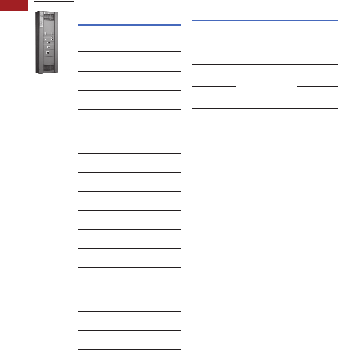
V15-T2-50 Volume 15—Solar Inverters and Electrical Balance of System CA08100018E—September 2015 eaton.com/solar
2
2
2
2
2
2
2
2
2
2
2
2
2
2
2
2
2
2
2
2
2
2
2
2
2
2
2
2
2
2
2.5
Panelboards—Solar Applications
Pow-R-Line C Panelboards
Product Selection
PRL4 Main Lugs and Main Breakers PRL4 Main Fusible Switches
Notes
1For ground fault protection on main devices, see Modification 14 on Page V15-T2-63 or
Modification 15 on Page V15-T2-63
2For use on DC systems only.
3100% rated breaker. Requires copper bus. Not available in Type 12, 4 and 4X enclosures.
4Breaker only available in three-pole frame.
5Requires 44-inch (1117.6 mm) wide box.
6For ground fault protection on main devices, see Modification 15 on Page V15-T2-63.
7Fuses not included. Specify required fuse clips on all switches.
8Class J Fuse provisions are applicable only to 600V units. When required, use dimensions of
600V units for all voltages 600 and below.
9No DC rating on 600, 800 and 1200A switches
Ampere
Rating
Interrupting Rating
(kA Symmetrical)
600 Vdc
Breaker
Type240 Vac 480 Vac 600 Vac 250 Vdc
Main Lug Only
250——————
400——————
600——————
800——————
1200——————
Main Breaker 1
25065351810—JD
250 100 65 25 22 — HJD
250 — — — 42 35 HJDDC 2
250 200 100 35 22 — JDC
250200200———LCL
400 65 — — 10 — DK
40065352510—KD
400653525——CKD 34
400 100 65 35 22 — HKD
400 — — — 42 35 HKDDC 2
400 100 65 35 42 — LHH
400 100 65 35 — — CHKD 34
400 200 100 65 22 — KDC
400200200———LCL
400 200 200 200 — — LA-P
60065351822—LGE
1
600 100 65 35 22 — LGH 1
600 200 100 50 42 — LGC
600 200 150 65 50 — LGU
60065352522—LD
600653525——CLD 3
600 100 65 35 25 — HLD
600 — — — 42 35 HLDDC 2
600 100 65 35 — — CHLD 3
600 200 100 50 25 — LDC
600 200 100 50 — — CLDC 3
80065502522—MDL
800 100 65 35 25 — HMDL
800———4235HMDLDC
2
800655025——CMDL 3
800 100 65 35 — — CHMDL 3
800 200 200 200 — — NB-P
800655025——ND
800 100 65 35 — — HND
800 200 100 65 — — NDC
800655025——CND 35
800 100 65 35 — — CHND 35
800 200 100 65 — — CNDC 35
1200 65 50 25 — — ND
1200 100 65 35 — — HND
1200 200 100 65 — — NDC
1200 65 50 25 — — CND 35
1200 100 65 35 — — CHND 35
1200 200 100 65 — — CNDC 35
1200 — — — 42 50 NBDC 2
Type PRL4
Ampere
Rating
Interrupting Rating (kA Symmetrical)
240 Vac 480 Vac Device Type
Main Fusible Switch 240 Vac, 250 Vdc 678
200 See Page V15-T2-39 FDPB
400 FDPW
600 9FDPW
800 9FDPW
1200 9FDPW
Main Fusible Switch 600 Vac 67
200 See Page V15-T2-39 FDPB
400 FDPW
600 9FDPW
800 9FDPW
1200 9FDPW

Volume 15—Solar Inverters and Electrical Balance of System CA08100018E—September 2015 eaton.com/solar V15-T2-51
2
2
2
2
2
2
2
2
2
2
2
2
2
2
2
2
2
2
2
2
2
2
2
2
2
2
2
2
2
2
2.5
Panelboards—Solar Applications
Pow-R-Line C Panelboards
PRL4 Branch Devices PRL4 Branch Devices, continued
Notes
150A devices are available as two-pole only.
2Single-pole breakers rated 120 Vac.
3Two-pole breakers rated 120/240 Vac.
4Arc fault circuit breaker.
5Single-pole breakers rated 277 Vac.
6For use on DC systems only.
7At 480V, must be used on 480Y/277V grounded wye systems only.
8AIC rating for two- and three-pole breakers only.
9100% rated breaker. Requires copper bus. Not available in Type 12, 4 and 4X enclosures.
jBreaker only available in three-pole frame.
kAvailable in single branch mounting only.
Ampere
Rating
Interrupting Rating (kA Symmetrical)
600 Vdc
Breaker
Typ e240 Vac 480 Vac 600 Vac 250 Vdc
15–60 10 23 — — ——BAB
15–60 10 — — — — BAB-H
70–100 10 23 — — ——BAB
70–100 10 — — — — BAB-H
15–50 110 23 — — ——QBGF
15–20 10 23 — — ——QBCAF
4
15–60 22 23 — — ——QBHW
15–60 22 — — — — QBHW-H
70–100 22 23 — — ——QBHW
70–100 22 — — — — QBHW-H
15–30 22 23 — — ——QBHGF
15–20 22 23 — — — — QBHCAF 4
15–20 65 214 5— ——GHQ 7
15–60 65 214 5—14—GHB 7
70–100 65 214 5—14—GHB 7
15–30 65 225 5— ——HGHB 7
15–60 18 814 5—10—EHD
70–100 18 814 5—10—EHD
15–6018141410—FDB
70–100 18 14 14 10 — FDB
110–150 18 14 14 10 — FDB
15–60 65 835 518 10 — FD, FDE
70–100 65 835 518 10 — FD, FDE
110–225 65 835 18 10 — FD, FDE
15–60 100 865 525 22 — HFD, HFDE
70–100 100 865 525 22 — HFD, HFDE
110–225 100 865 25 22 — HFD, HFDE
15–60 200 100 35 22 — FDC
70–100 200 100 35 22 — FDC
110–225 200 100 35 22 — FDC
15–100 200 150 — — — FCL
15–150 — — — 42 35 HFDDC 6
100–225 22 — — — — EDB
100–225 42 — — — — EDS
100–225 65 — — — — ED
100–225 100 — — — — EDH
100–225 200 — — — — EDC
70–225 65 35 18 10 — JD
25065351810—JD
70–225 100 65 25 22 — HJD
Ampere
Rating
Interrupting Rating (kA Symmetrical)
600 Vdc
Breaker
Type240 Vac 480 Vac 600 Vac 250 Vdc
250 100 65 25 22 — HJD
70–250———42 35 HJDDC 6
70–225 200 100 35 22 — JDC
250 200 100 35 22 — JDC
125–250 200 200 — — — LCL
250–400 65 — — 10 — DK
100–400 65 35 25 10 — KD
100–400 65 35 25 — — CKD 9jk
100–400 100 65 35 22 — HKD
100–400———4235 HKDDC
6
100–400 100 65 35 — — CHKD 9jk
125–400 100 65 35 42 — LHH
100–400 200 100 65 22 — KDC
200–400 200 200 — — — LCL
250–600 65 35 18 22 — LGE
300–600 65 35 25 22 — LD
300–600 65 35 25 — — CLD 9
250–600 100 65 35 22 — LGH
300–600 100 65 35 25 — HLD
300–600———4235 HLDDC
6
300–600 100 65 35 — — CHLD 1
250–600 200 100 35 42 — LGC
300–600 200 100 50 25 — LDC
300–600 200 100 50 25 — CLDC 1
250–600 200 150 65 50 — LGU
400–800 65 50 25 22 — MDL
400–800 100 65 35 25 — HMDL
300–800———4235 HMDLDC
6
400–800 65 50 25 — — CMDL 1
400–800 100 65 35 — — CHMDL 1
400–800 65 50 25 — — ND
400–800 100 65 35 — — HND
400–800 200 100 65 — — NDC
400–800 65 50 25 — — CND 12
400–800 100 65 35 — — CHND 12
400–800 200 100 65 — — CNDC 12
600–1200 65 50 25 — — ND
600–1200 100 65 35 — — HND
600–1200 200 100 65 — — NDC
600–1200 65 50 25 — — CND 12
600–1200 100 65 35 — — CHND 12
600–1200 200 100 65 — — CNDC 12
700–1200———4250 NBDC
6

V15-T2-52 Volume 15—Solar Inverters and Electrical Balance of System CA08100018E—September 2015 eaton.com/solar
2
2
2
2
2
2
2
2
2
2
2
2
2
2
2
2
2
2
2
2
2
2
2
2
2
2
2
2
2
2
2.5
Panelboards—Solar Applications
Pow-R-Line C Panelboards
PRL4 Branch Devices, continued FDPW and FDPB Switch Ratings, 240 or 600 Vac
Notes
1100 kAIC based on NEMA test procedure.
2Fuses not included. Specify required fuse clips on all switches. (T fuse clips not
available for 200/200 twin switches.)
3When branches of a twin unit are of different ampere ratings, as a 30–60 twin unit, price
and layout as a 60–60 twin unit; when a 60–100 twin unit, price and layout as a 100–100
twin unit.
4No DC rating on 600, 800 and 1200A switches.
5Class J fuse provisions are applicable to 600V units. When required, use price and
dimensions of 600V units for all voltages 600V and below.
6Twin 200A switches are not available with Class R fuse clips at 600V.
7When shunt trip is required, 400–600A switches used with Class R fuses are rated 100 kAIC.
Ampere
Rating
Interrupting Rating (kA Symmetrical) Breaker
Type240 Vac 480 Vac 600 Vac 250 Vdc
Integrally Fused, Current Limiting Circuit Breaker
15–100 200 200 200 1FB-P
125–225 200 200 200 1LA-P
250–400 200 200 200 1LA-P
400–600 200 200 200 1NB-P
700–800 200 200 200 1NB-P
Fusible Switches 240 Vac, 250 Vdc 2
30/30 3See table at the right FDPW-Twin
60/60 3FDPW-Twin
100/100 3FDPW-Twin
200/200 FDPB-Twin
100 FDPW-Single
200 FDPB-Single
400 See table at the right FDPW-Single
600 4FDPW-Single
800 4FDPW-Single
1200 4FDPW-Single
Fusible Switches 600 Vac 2
30/30 3See table at the right FDPW-Twin
60/60 3FDPW-Twin
100/100 3FDPW-Twin
200/200 5FDPB-Twin
100 FDPW-Single
200 FDPB-Single
400 See table at the right FDPW-Single
600 4FDPW-Single
800 4FDPW-Single
1200 4FDPW-Single
Ampere
Rating
Fuse
Class
Used
Short-Circuit
Ratings
(kA Symmetrical)
30–100 R, J 5200
200 Single R, J 5200
200 Twin R 6, J 5, T 200
400, 600 7R 7, J 5, T 200
800, 1200 7L200
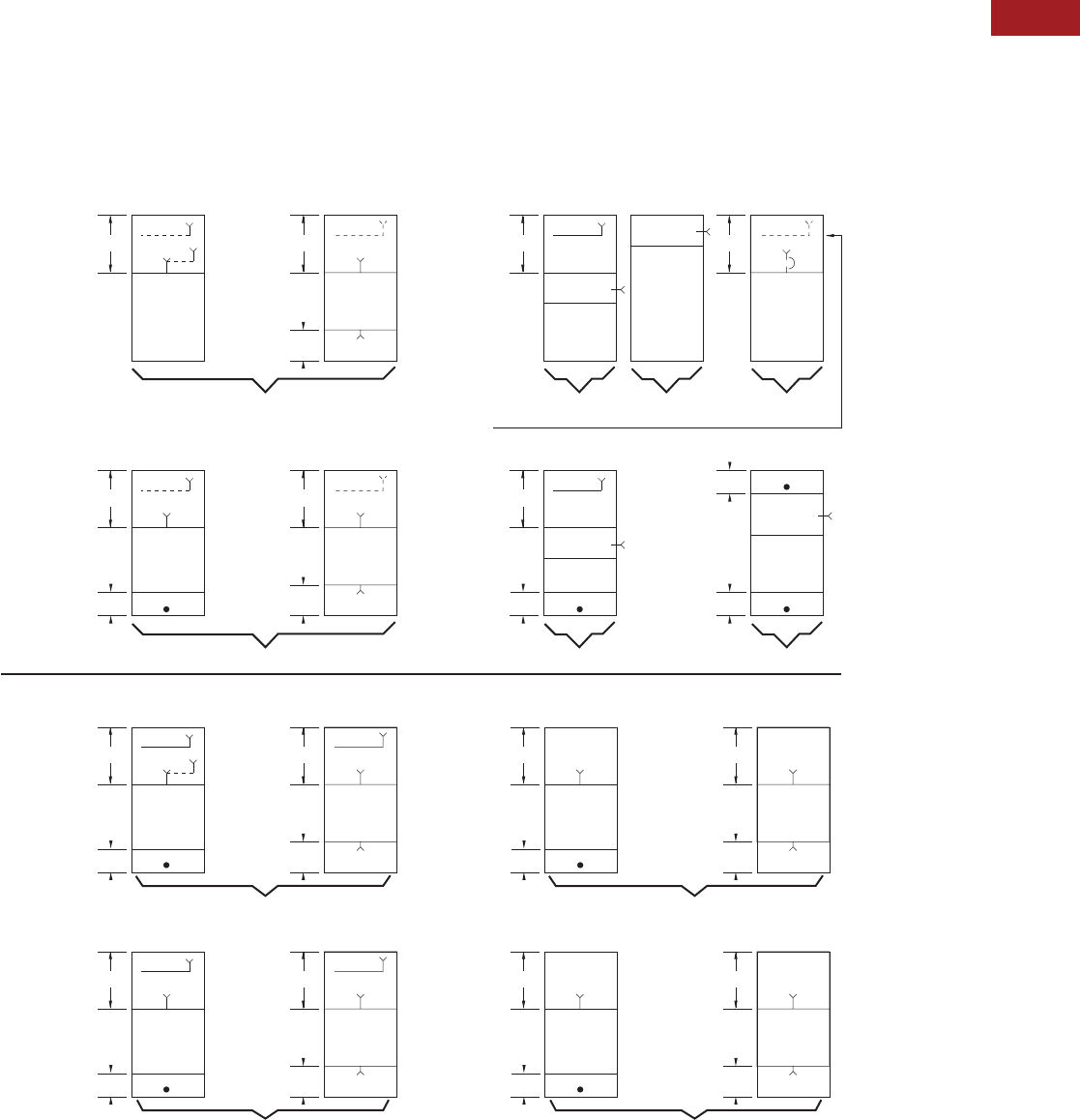
Volume 15—Solar Inverters and Electrical Balance of System CA08100018E—September 2015 eaton.com/solar V15-T2-53
2
2
2
2
2
2
2
2
2
2
2
2
2
2
2
2
2
2
2
2
2
2
2
2
2
2
2
2
2
2
2.5
Panelboards—Solar Applications
Pow-R-Line C Panelboards
Box Sizing and Selection—PRL4B
Approximate Dimensions in Inches (mm)
Main Lug Only (MLO), Main Breaker, Neutral, Through-Feed Lug
(TFL) and Sub-Feed Lug (SFL) “X” Space Requirements. (For
other configurations not shown, refer to Eaton.)
*= Space available for branch devices. For device sizing,
see Page V15-T2-55.
•= Blank means no bus under cover, to meet NEC cable
bending space.
PRL4B Layout
Note
1Sub-feed lugs are available 250–600A. For 600A, use 1200A “A” space.
*
10X
7X Through-
Feed Lugs
*
10X NN
MLO, SFL MLO, TFL
3Ph 4W, 3Ph 3W
250A a, 400A a,
600A a, 800A
Standard Main Lug, Through-Feed and Sub-Feed Lugs a
(500 kcmil Maximum)
Main Breaker with Neutral (when required)
(500 kcmil Maximum)
*
7X
*
NN
3Ph 4W,
3Ph 3W
250A, 400A,
600A, 800A
*
12X
7X Through-
Feed Lugs
*
12X NN
MLO MLO, TFL
3Ph 4W, 3Ph 3W
1200A
36-inch
(914.4 mm)
Minimum
Width
Main Breaker
Main Breaker
*
3Ph 3W3Ph 4W
800A Vertically Mtd. MDL Main Breaker only in 24-inch (609.6 mm) wide box.
Available with 38X and 50X Panel Height only.
19X
Blank
2X
*
7X
*
N
3Ph 3W
1200A
36-inch
(914.4 mm)
Minimum
Width
Main Breaker
3Ph 4W
Blank
2X Blank
2X
Blank
2X
Main Breaker
*
9X Through-
Feed Lugs
*
20X NN
MLO, SFL MLO, TFL
3Ph 4W
250A a, 400A a,
600A a, 800A
Optional Main Lugs, Through-Feed and Sub-Feed Lugs a (750 kcmil Maximum)
*
20X
11X Through-
Feed Lugs
*
20X NN
MLO MLO, TFL
3Ph 4W
1200A
36-inch
(914.4 mm)
Minimum
Width Blank
5X
*
9X Through-
Feed Lugs
*
13X
3Ph 3W
250A, 400A,
600A, 800A
*
15X
11X Through-
Feed Lugs
*
15X
120A
36-inch
(914.4 mm)
Minimum
Width Blank
5X
Blank
20X
Blank
13X
3X
3Ph 3W
3X
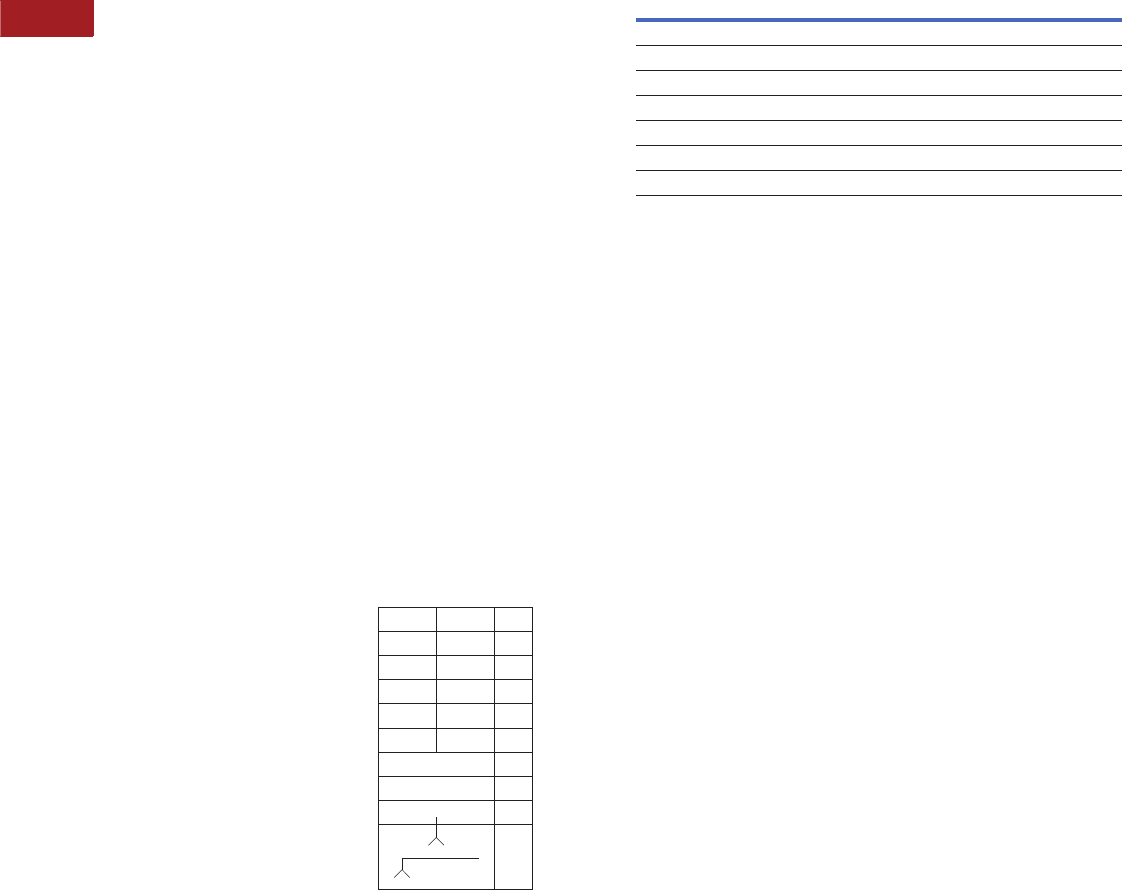
V15-T2-54 Volume 15—Solar Inverters and Electrical Balance of System CA08100018E—September 2015 eaton.com/solar
2
2
2
2
2
2
2
2
2
2
2
2
2
2
2
2
2
2
2
2
2
2
2
2
2
2
2
2
2
2
2.5
Panelboards—Solar Applications
Pow-R-Line C Panelboards
Approximate Dimensions in Inches (mm)
Panel Layout and Dimensions
To determine the dimensions
of a given panelboard
enclosure, make a layout
sketch by fitting together
the main, branch and lug
modules according to the
appropriate tables in the
layout guide. Assign “X”
units to each module as
shown and obtain a total
“X” number.
The height of the enclosure is
related to the total “X” units
in the layout as shown in
table on right. Three standard
box heights are available to
accommodate any and all
layout arrangements. “X”
unit totals that do not exactly
match those in table on right
must be rounded off to the
next highest standard (26X,
38X, 50X).
If a calculated “X” total for a
panel exceeds 50X, the panel
must be split into two or
more separate sections with
“X” space for through-feed
lugs figured in for all but one
section. If a neutral is
required, a separate neutral
bar and appropriate “X”
space must be included in
each section.
Layout Example
●1–PRL4B panelboard,
480Y/277 volt, three-phase
four-wire 65 kA, 800A,
main lug, consisting of:
●12–20A/single-pole HFD
●2–250A/three-pole HJD
●1–400A/three-pole HKD
Reference PRL4B Layout
Example
1. From layout guide, total
“X” height of panel =
26X, (which is a design
standard and no rounding
off is necessary).
2. From table on right,
enclosure height for
26X panel = 57 inches
(1447.8 mm).
3. Width = 24 inches
(609.6 mm)—directly
from layout guide.
4. Enclosure depth =
11.31 inches (287.0 mm)
—standard for all PRL4
panelboards.
PRL4B Layout Example
20A/1P 20A/1P 1X
20A/1P 20A/1P 1X
20A/1P 20A/1P 1X
20A/1P 20A/1P 1X
20A/1P 20A/1P 1X
20A/1P 20A/1P 1X
250A/3P 3X
250A/3P 3X
400A/3P 4X
Main 800A
Lugs
Neutral
10X
Total = 26X
Box Dimensions—PRL4B
Top and Bottom Gutters
10.63-inch (269.9 mm) minimum.
Side Gutters—Minimum
24.00-inch (609.6 mm) wide box—5.00-inch (127.0 mm).
36.00-inch (914.4 mm) wide box—6.00-inch (152.4 mm).
44.00-inch (1117.6 mm) wide box—8.00-inch (203.2 mm).
Notes
1Box depth is 10.40 inches (264.2 mm), cover adds 0.90 inches (22.9 mm) to depth.
800A maximum bus size in 24.00-inch (609.6 mm) wide box. Flush trims
not available on PRL4B panels.
“X”
Units
Catalog
Number Height Width Depth 1
26X BX2457 57.00 (1447.8) 24.00 (609.6) 11.31 (287.0)
38X BX2473 73.50 (1866.9) 24.00 (609.6) 11.31 (287.0)
50X BX2490 90.00 (2286.0) 24.00 (609.6) 11.31 (287.0)
38X BX3673 73.50 (1866.9) 36.00 (914.4) 11.31 (287.0)
50X BX3690 90.00 (2286.0) 36.00 (914.4) 11.31 (287.0)
38X BX4473 73.50 (1866.9) 44.00 (1117.6) 11.31 (287.0)
50X BX4490 90.00 (2286.0) 44.00 (1117.6) 11.31 (287.0)
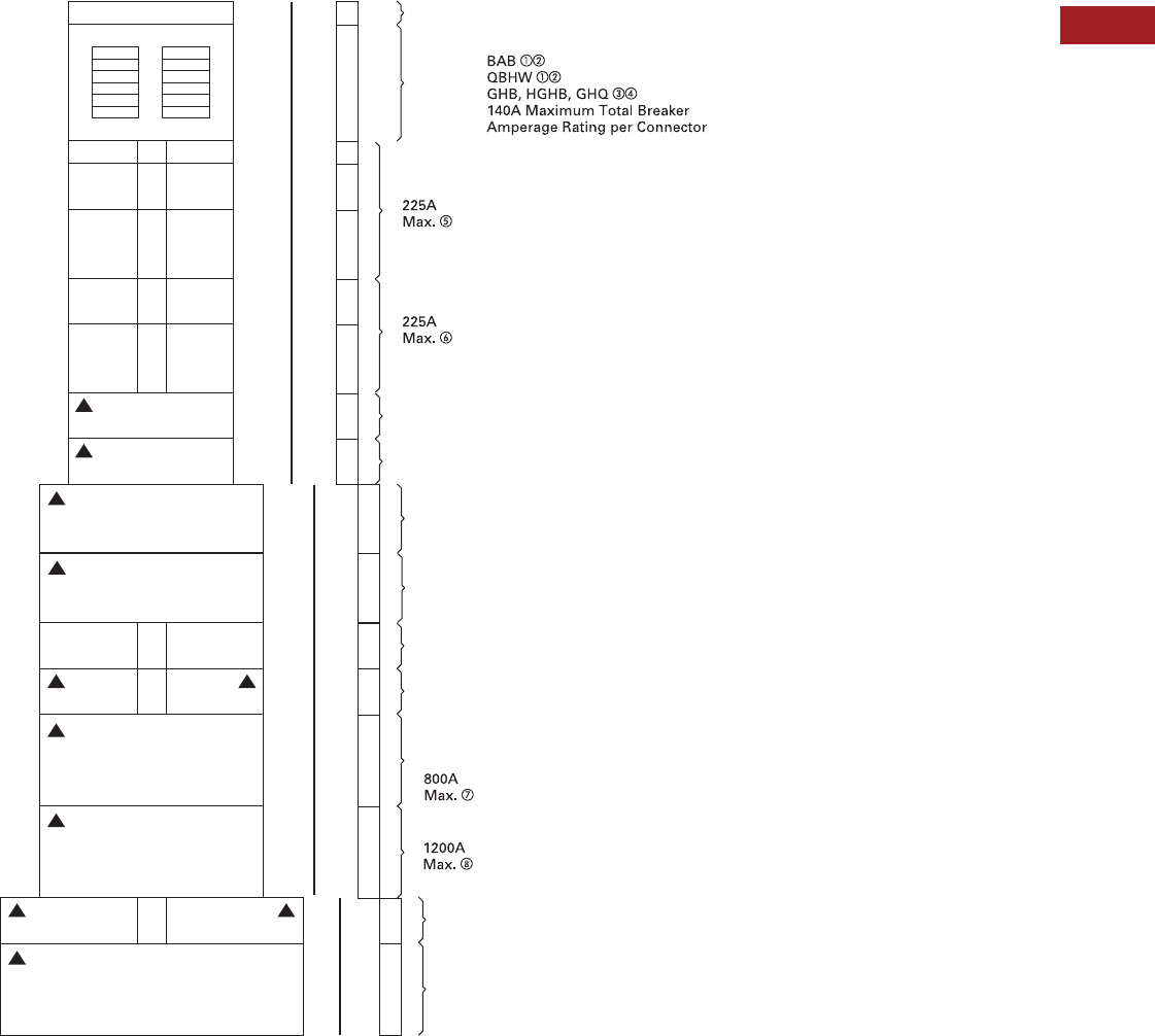
Volume 15—Solar Inverters and Electrical Balance of System CA08100018E—September 2015 eaton.com/solar V15-T2-55
2
2
2
2
2
2
2
2
2
2
2
2
2
2
2
2
2
2
2
2
2
2
2
2
2
2
2
2
2
2
2.5
Panelboards—Solar Applications
Pow-R-Line C Panelboards
Layout for Branch and Horizontally Mounted Main Devices Layout—PRL4B
Notes
1BAB and QBHW breakers with shunt trips require one additional pole space, i.e., single-pole is two-pole size, two-pole is three-pole size, and three-pole is four-pole size.
2If panel contains only BAB or QBHW branch breakers, use a PRL1a panelboard.
3GHB, HGHB or GHQ breakers cannot be mixed on same subchassis as BAB, QBHW.
4If panel contains only GHB, HGHB or GHQ branch breakers, use a PRL2a panelboard.
5When only one single-pole breaker of the group is required on either side of chassis, the single-pole breaker space required changes from 1X to 2X.
6Minimum 36-inch (914.4 mm) wide box is required if optional #6–300 kcmil lug is required.
7MDL main breaker in 24-inch (609.6 mm) wide box, refer to Page V15-T2-53.
8Optional 750 kcmil terminal requires 44-inch (1117.6 mm) wide box.
9For use on DC systems only.
See Page V15-T2-53 for MLO or Neutral and Vertically Mounted Mains space requirements.
Breaker to Fusible Transition, All Widths
3X
3X
6X
6X
4X
6X
1X
12X
20X
1X
2X
3X
2X
4X
3X
3X
4X
Filler
Sub Panel
400 Amp. Maximum Bus Rating
1P 1P
2P 2P
3P 3P
2P 2P
3P 3P
2 or 3P
2 or 3P
3P
Load
2 or 3P 2 or 3P
2 or 3P 2 or 3P
2 or 3P
2 or 3P
2 or 3P 2 or 3P
2 or 3P
EHD,
FDB, FD, FDE
HFD, HFDE, FDC, HFDDC
18
Poles
100A
Max.
DK, KD, HKD,
KDC
EDB, EDS, ED, EDH, EDC
JD, HJD, JDC, HJDDC
250A
Max.
400A
Max.
DK, KD, HKD, KDC, HKDDC
CKD, CHKD, LHH
600A
Max.
LGE, LGH, LGC, LGU
100A
Max. FCL, FB-P
250A
Max. JD, HJD, JDC
400A
Max. LCL, LA-P
MDL, HMDL, HMDLDC
CMDL, CHMDL
ND, HND, NDC
400A
Max.
800A
Max. NB-P, NBDC
44-Inch (1117.6 mm) Wide Box
24-Inch (609.6 mm) Wide Box
36-Inch (914.4 mm) Wide Box
1200A
Max. CND, CHND, CNDC
42
Poles
6X
2 or 3P
Load
600A
Max.
LD, HLD, CLD, CHLD, LDC, HLDDC
9
9
9
9
9
9
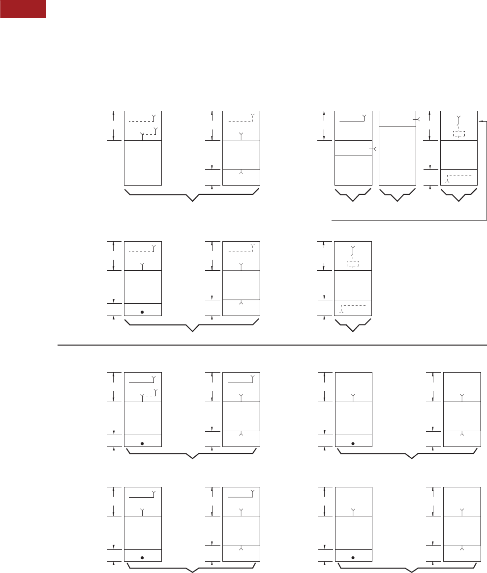
V15-T2-56 Volume 15—Solar Inverters and Electrical Balance of System CA08100018E—September 2015 eaton.com/solar
2
2
2
2
2
2
2
2
2
2
2
2
2
2
2
2
2
2
2
2
2
2
2
2
2
2
2
2
2
2
2.5
Panelboards—Solar Applications
Pow-R-Line C Panelboards
Box Sizing and Selection—PRL4F
Approximate Dimensions in Inches (mm)
Main Lug (MLO), Main Switch, Neutral, Through-Feed (TFL)
and Sub-Feed Lug (SFL) “X” Space Requirements. (For other
configurations not shown, refer to Eaton.)
*= Space available for branch devices. For device sizing,
see Page V15-T2-58.
•= Blank means no bus under cover, to meet NEC cable
bending space.
PRL4F Layout
Notes
1Sub-feed lugs are available 250–600A. For 600A, use 1200A “A” space.
2800A and 1200A mains available only in vertical mounting.
*
10X
7X Through-
Feed Lugs
*
10X NN
MLO, SFL MLO, TFL
3Ph 4W, 3Ph 3W
250A a, 400A a,
600A a, 800A
Standard Main Lug, Through-Feed and Sub-Feed Lugs a
(500 kcmil Maximum)
Main Switch with Neutral (when required)
(500 kcmil Maximum)
*
7X
*
N
3Ph 4W,
3Ph 3W
200A, 400A,
600A
*
12X
7X
*
12X NN
MLO MLO, TFL
3Ph 4W, 3Ph 3W
1200A
Main Switch
Main Switch
*
3Ph 3W3Ph 4W
400A and 600A Vertically Mounted Main Switch
22X
Blank Through-Feed
Lugs
2X
800A,
1200A
*
9X Through-
Feed Lugs
*
20X NN
MLO, SFL MLO, TFL
3Ph 4W
250A a, 400A a,
600A a, 800A
Optional Main Lugs, Through-Feed and Sub-Feed Lugs a (750 kcmil Maximum)
*
20X
11X Through-
Feed Lugs
*
20X NN
MLO MLO, TFL
3Ph 4W
1200A
Blank
5X
*
9X Through-
Feed Lugs
*
13X
3Ph 3W
250A, 400A,
600A, 800A
*
15X
11X Through-
Feed Lugs
*
15X
1200A
Blank
5X
Blank
20X
Blank
13X
3X
3Ph 3W
N
7X
*
3Ph 4W
800A 25X
1200A 26X
N
7X
800A and 1200A Vertically Mounted
Main Switch b
36-inch (914.4 mm) or
44-inch (1117.6 mm)
Wide Box
3X
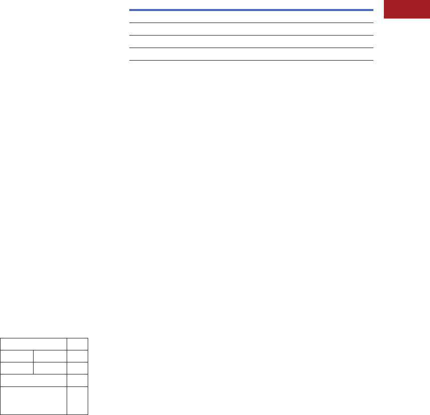
Volume 15—Solar Inverters and Electrical Balance of System CA08100018E—September 2015 eaton.com/solar V15-T2-57
2
2
2
2
2
2
2
2
2
2
2
2
2
2
2
2
2
2
2
2
2
2
2
2
2
2
2
2
2
2
2.5
Panelboards—Solar Applications
Pow-R-Line C Panelboards
Approximate Dimensions in Inches (mm)
Panel Layout and Dimensions
To determine the dimensions
of a given panelboard
enclosure, make a layout
sketch by fitting together the
main, branch and lug modules
according to the appropriate
tables in the layout guide.
Assign “X” units to each
module as shown and obtain
a total “X” number.
The height of the enclosure is
related to the total “X” units
in the layout as shown in
table on right. Three standard
box heights are available to
accommodate any and all
layout arrangements. “X”
unit totals that do not exactly
match those in table on
right must be rounded off
to the next higher standard
(38X, 50X).
If a calculated “X” total for a
panel exceeds 50X, the panel
must be split into two or
more separate sections with
“X” space for through-feed
lugs figured in for all but
one section. If a neutral is
required, a separate neutral
bar and appropriate “X”
space must be included in
each section.
Layout Example
●PRL4F, three-phase
four-wire, 208Y/120 volt
complete with 400A main
switch and the following
branches:
●One 200A/three-pole
●Two 100A/three-pole
●Two 30A/three-pole
Panel to have short-circuit
rating of 100 kA symmetrical.
Reference PRL4F Layout
Example
1. From layout guide,
total “X” height of
panel = 43X.
2. Rounded off to next
higher standard = 50X.
3. From table on right,
enclosure height for 50X
panel = 90 inches
(2286.0 mm).
4. Width = 36 inches
(914.4 mm).
5. Enclosure depth is
standard for all PRL4
panelboards = 11.31
inches (287.0 mm).
Type PRL4F
Layout Example
400A Neutral 7X
30A/3P 30A/3P 4X
100A/3P 100A/3P 4X
200A/3P 6X
400A three-pole
Main Switch
(Vertical Mounted)
22X
Total = 43X
Box Dimensions—PRL4F
Top and Bottom Gutters
10.63 inches (269.9 mm) minimum.
Side Gutters—Minimum
●36-inch (914.4 mm) wide box:
●8-inch (203.2 mm)—200A maximum
●6-inch (152.4 mm)—400–1200A maximum
●44-inch (1117.6 mm) wide box:
●10-inch (254.0 mm)—200A maximum
●8-inch (203.2 mm)—400–1200A
Notes
1Box depth is 10.40-inch (264.2 mm), cover adds 0.90-inch (22.8 mm) to depth.
Flush trims not available on PRL4F panels.
“X”
Units
Catalog
Number Height Width Depth 1
38X BX3673 73.50 (1866.9) 36.00 (914.4) 11.31 (287.0)
50X BX3690 90.00 (2286.0) 36.00 (914.4) 11.31 (287.0)
38X BX4473 73.50 (1866.9) 44.00 (1117.6) 11.31 (287.0)
50X BX4490 90.00 (2286.0) 44.00 (1117.6) 11.31 (287.0)
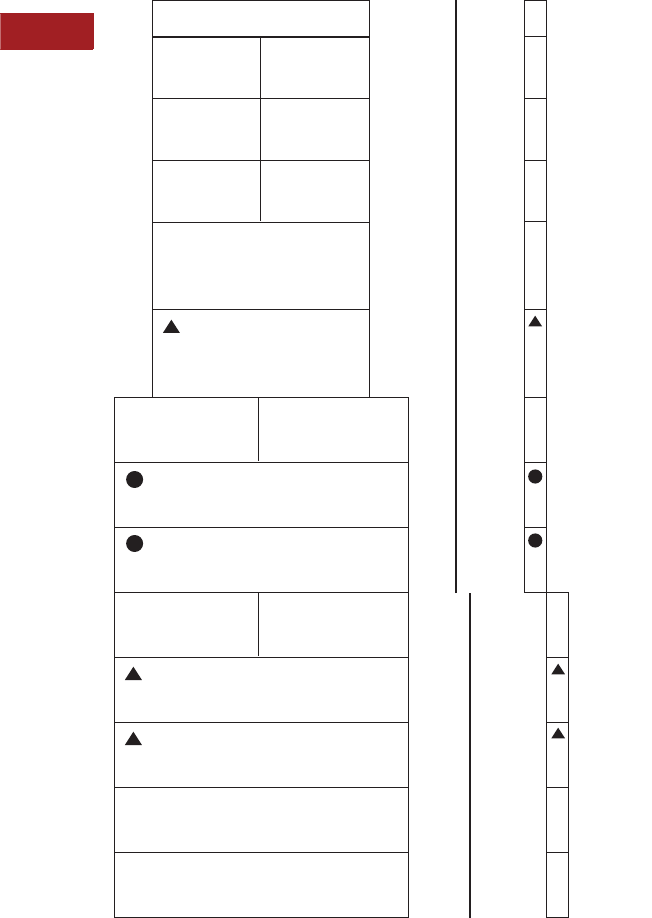
V15-T2-58 Volume 15—Solar Inverters and Electrical Balance of System CA08100018E—September 2015 eaton.com/solar
2
2
2
2
2
2
2
2
2
2
2
2
2
2
2
2
2
2
2
2
2
2
2
2
2
2
2
2
2
2
2.5
Panelboards—Solar Applications
Pow-R-Line C Panelboards
Layout for Branch and Horizontally Mounted Main Device—PRL4F
▲Fusible switch may be used as horizontally main.
●400 and 600A horizontally mounted feeder switches in 36-inch (914.4 mm) or 44-inch (1117.6 mm) wide box. 400 and 600A horizontally mounted
main switches only in 44-inch (1117.6 mm) wide box. For vertically mounted main, see Page V15-T2-56 for sizing.
Note: See Page V15-T2-56 for MLO or Neutral and Vertically Mounted Main space requirements.
1X
4X
4X
4X
5X
6X
5X
9X
15X
400A
Branch Switch
200A
Main or Branch Switch
100A
Fusible to Breaker Transition
Requires 1X Filler
30A 30A
60A 60A
100A
250V Max.
100A
250V Max.
100A 100A
44-inch (1117.6 mm) Wide Box 36-inch (914.4 mm) Wide Box
600A
Branch Switch
200A 200A
400A
Main or Branch
600A
Main or Branch
800A
Branch
1200A
Branch
9X
11X
11X
(11X With
Shunt Trip)
(11X With
Shunt Trip)
(16X With
Shunt Trip)
(16X With
Shunt Trip)
11X
6X
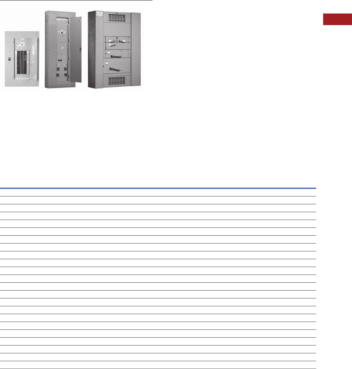
Volume 15—Solar Inverters and Electrical Balance of System CA08100018E—September 2015 eaton.com/solar V15-T2-59
2
2
2
2
2
2
2
2
2
2
2
2
2
2
2
2
2
2
2
2
2
2
2
2
2
2
2
2
2
2
2.5
Panelboards—Solar Applications
Types PRL1a, 2a, 3a and 4 Modifications
Panelboards and Lighting Controls
Contents
Description
Introduction . . . . . . . . . . . . . . . . . . . . . . . . . . . . . . V15-T2-25
Product Selection Guide. . . . . . . . . . . . . . . . . . V15-T2-25
EZ Box and EZ Trim . . . . . . . . . . . . . . . . . . . . . . . . V15-T2-26
Pow-R-Line C Panelboards . . . . . . . . . . . . . . . . . . V15-T2-29
Type PRL1a . . . . . . . . . . . . . . . . . . . . . . . . . . . V15-T2-37
Type PRL2a . . . . . . . . . . . . . . . . . . . . . . . . . . . V15-T2-41
Type PRL3a . . . . . . . . . . . . . . . . . . . . . . . . . . . V15-T2-45
Type PRL4 . . . . . . . . . . . . . . . . . . . . . . . . . . . . V15-T2-49
Types PRL1a, 2a, 3a, 4
Modifications Selection Guide
Regional Manufacturing Facilities. . . . . . . . . . . V15-T2-68
Types PRL1a, 2a, 3a, 4
Modifications Selection Guide
Modifications—Alphabetical Index
Modification Item
Available on Panelboard Types
PRL1a PRL2a PRL3a PRL4B PRL4F
Ambient compensating breakers 1 No No Yes Yes —
Bus density 2 Yes Yes Yes Yes Yes
Cabinets—special: Types 2, 3R, 4, 4X, 12 3 Yes Yes Yes Yes Yes
Complete assembly 4 Yes Yes Yes Yes Yes
Compression type lugs, mains only 5 Yes Yes Yes Yes Yes
Concealed trim clamps (LT trim) 6 Yes Yes Yes No No
Conduit covers 7 Yes Yes Yes Yes Yes
Copper lugs 8 Yes Yes Yes Yes Yes
Copper main bus 9, 9a, 9b Yes Yes Yes Yes Yes
Directory frame—metal 10 Yes Yes Yes Yes Yes
Doors, special 11 Yes Yes Yes Yes Yes
Fungus-proof 12 Yes Yes Yes Yes Yes
Ground bar 13 Yes Yes Yes Yes Yes
Electronic trip units 14 No No No Yes —
Ground fault protection (zero sequence) 15 No No No Yes Yes
Handle lockoff device 16 Yes Yes Yes Yes Std.
Hinges, special (LT trim) 17 Yes Yes Yes Yes Yes
Increased dimensions 18 Yes Yes Yes No No
Increased panel bus rating 19 Yes Yes Yes No No
Interiors to fit existing boxes 20 Yes Yes Yes Yes Yes
Locks, special (LT trim) 21 Yes Yes Yes Yes Yes
Molded case switches 22 Yes Yes Yes Yes No
Nameplates engraved 23 Yes Yes Yes Yes Yes

V15-T2-60 Volume 15—Solar Inverters and Electrical Balance of System CA08100018E—September 2015 eaton.com/solar
2
2
2
2
2
2
2
2
2
2
2
2
2
2
2
2
2
2
2
2
2
2
2
2
2
2
2
2
2
2
2.5
Panelboards—Solar Applications
Types PRL1a, 2a, 3a and 4 Modifications
Modifications—Alphabetical Index, continued
Modification Item
Available on Panelboard Types
PRL1a PRL2a PRL3a PRL4B PRL4F
Neutral rated 200% 24 Yes Yes Yes Yes Yes
Painting and special coating 25 Yes Yes Yes Yes Yes
Permanent circuit numbers 26 Yes Yes Yes Yes Yes
Remote control switches (ASCO 920) 27 No No Yes No No
Service entrance 28 Yes Yes Yes Yes Yes
Shunt trips 29 Yes Yes Yes Yes Yes
Split bus or meter loop 30 No No Yes No No
Metering devices 31 No No No Yes Yes
Sub-metering, IQ Energy Sentinel 32 No No No Yes No
Sub-feed breakers 33 Yes Yes Yes No No
Sub-feed lugs 34 Yes Yes Yes Yes Yes
Tamperproof screws (LT trim) 35 Yes Yes Yes Yes Yes
Through-feed lugs 36 Yes Yes Yes Yes Yes
Time clock space only 37 Yes Yes Yes — —
Touchup paint 38 Yes Yes Yes Yes Yes
Surge protective device (SPD) 39 Yes Yes Yes Ye Yes
Terminals, copper only for breakers 40 Yes Yes Yes Yes —

Volume 15—Solar Inverters and Electrical Balance of System CA08100018E—September 2015 eaton.com/solar V15-T2-61
2
2
2
2
2
2
2
2
2
2
2
2
2
2
2
2
2
2
2
2
2
2
2
2
2
2
2
2
2
2
2.5
Panelboards—Solar Applications
Types PRL1a, 2a, 3a and 4 Modifications
1. Ambient Compensating Breakers
For ambient compensating breakers (where available) in lieu of
standard breakers, add 10 percent to panelboard branch breaker
and to main breaker list prices, if required. (Not UL listed.)
2. Bus Density
Main bus ampere rating is determined by UL listed temperature
test. For 750A per square inch aluminum or 1000A per square inch
copper, make price addition as follows:
Modification 2
3. Special Cabinet (Box) Construction
Modification 3
4. Complete Assembly
Complete assembly of panelboard box, interior and trim prior to
shipment when required.
5. Compression Main Lugs—Al/Cu Burndy Range Taking
For other terminal types and box sizes, refer to Eaton.
Modification 5—Compression Lug Data
Modification 5—Box Height Additions
6. Concealed Trim Clamps—LT Trim
Modification 6
7. Conduit Covers
Fabricated sheet metal to cover open conduits above and/or
below standard Type 1 box.
Modification 7
Note
1At 600A, PRL3a requires the addition of density rated copper bus for Type 3R or 12 enclosure.
Panel Type Maximum Amperes
Aluminum—750A per Square Inch
PRL1a, 2a 100
225
400
PRL3a 250
400
PRL4 400
800
Copper—1000A per Square Inch
PRL1a, 2a 100
225
400
PRL3a 250
600
PRL4 400
1200
Modification
Type 1 Enclosure
28-inch (711.2 mm) wide in place of standard 20-inch
(508.0 mm) wide PRL1a, PRL2a, PRL3a
Type 2 Enclosure
(Drip-proof with gasketed trim) PRL1a, PRL2a, PRL3a 20-inch (508.0 mm) wide
Type 3R Enclosure
PRL1a, PRL2a 20-inch (508.0 mm) wide
PRL1a, PRL2a 28-inch (711.2 mm) wide
PRL3a 1 20-inch (508 mm) wide
(600A maximum)
PRL3a 1 28-inch (711.2 mm) wide
(600A maximum)
PRL4 24-inch (609.6 mm) or 36-inch (914.4) wide only
Type 12 Enclosure
PRL1a, PRL2a 20-inch (508.0 mm) wide
PRL1a, PRL2a 28-inch (711.2 mm) wide
PRL3a 1 20-inch (508 mm) wide
(600A maximum)
PRL3a 1 28-inch (711.2 mm) wide
(600A maximum)
PRL4 24-inch (609.6 mm) or 36-inch (914.4) wide only
Must also add bus density price from Modification 2 for PRL4
Type 4 Enclosure or Type 4X Stainless Steel Enclosure
Refer to Eaton
Main
Amperes
Wire Range by Panel Type
PRL1a and PRL2a PRL3a PRL4
100 (1) #1–1/0 or
(1) 2/0–300 kcmil
——
125 — (1) #4–2/0 or
(1) 2/0–300 kcmil
—
225 (1) 2/0–300 kcmil or
(1) 4/0–500 kcmil
——
250 — (1) 2/0–350 kcmil or
(1) 4/0–500 kcmil
(2) 500–750 kcmil
400 (2) 4/0–300 kcmil or
(2) 500–750 kcmil
(2) 4/0–300 kcmil or
(2) 500–750 kcmil
(2) 500–750 kcmil
600 — (2) 2/0–500 kcmil or
(2) 500–750 kcmil
(2) 500–750 kcmil
800 — — (3) 500–750 kcmil
1200 — — (4) #2–600 kcmil or
(4) 500–750 kcmil
Main Amperes PRL1a, PRL2a
PRL3a without
Neutral
PRL3a with
Neutral
100 0 0X 0X
225 0 — —
250 — 2X 5X
400 0 0X 0X
600 — 0X 0X
Maximum size for PRL1a and PRL2a panels:
1–750 kcmil per phase, or 2–500 kcmil per phase.
For PRL4 panels, see layout pages.
Description
Add per panel PRL1a, PRL2a, PRL3a
Cover Type
Conduit Enclosing Shield (open back)
PRL1a, PRL2a, PRL3a, PRL4—Refer to Eaton
Conduit Enclosure (solid back)
PRL1a, PRL2a, PRL3a, PRL4—Refer to Eaton

V15-T2-62 Volume 15—Solar Inverters and Electrical Balance of System CA08100018E—September 2015 eaton.com/solar
2
2
2
2
2
2
2
2
2
2
2
2
2
2
2
2
2
2
2
2
2
2
2
2
2
2
2
2
2
2
2.5
Panelboards—Solar Applications
Types PRL1a, 2a, 3a and 4 Modifications
8. Copper Lugs
Optional copper mechanical main lugs only. (Includes main
incoming neutral lug.)
Modification 8
Modification 8—Box Height Additions
9. Copper Main Bus
Modification 9
Available in PRL1a, PRL2a, PRL3a and PRL4
9a. Silver-Plated Copper Main Bus
Modification 9a
Available in PRL1a, PRL2a, PRL3a and PRL4
9b. Tin-Plated Copper Main Bus (PRL1a, 2a, 3a, Only)
Modification 9b
10. Directory Frame—Metal
Modification 10
11. Trim and Door Modifications—Special Fronts and Doors
Modification 11
12. Fungus Proofing
For fungus proofing external portions of circuit breakers and all
non-metallic parts, add 10 percent of total panelboard list price.
For fungus proofing fusible switches and all non-metallic parts,
add 20 percent of total panelboard list price.
13. Ground Bar
Modification 13
Notes
1Extra depth box is required. Box will be 12.82-inch (325.6 mm) deep.
2For PRL1a, 2a, 3a and Column Type panelboards. The insulated/isolated ground bar includes
a standard ground bar.
Main
Amperes
Wire Range and Number
of Lugs Per Phase
100 (1) #14–1/0
225 (1) #6–250 kcmil
250 (1) #6–250 kcmil
400 (2) #1/0–600 kcmil
600 (2) #1/0–600 kcmil
800 (2) #1/0–600 kcmil
1200 (3) #1/0–600 kcmil
Main
Amperes
PRL1a,
PRL2a
PRL3a
without Neutral
PRL3a
with Neutral PRL4
100 0 0X 0X —
225 0 — — —
250 — 0X 0X 0X
400 0 0X 0X 0X
600 — 1X 1X 0X
800 — — — 0X
1200 — — — 0X
Panel Type
PRL1a, PRL2a, PRL3a
Frame Type
Metal frame, plastic cover
Description
Door-in-door, one door over interior and one which exposes gutter. (LT Trim)
(PRL1a, PRL2a, PRL3a only)
Common trim for two section panels with boxes bolted together. (LT Trim)
(PRL1a, PRL2a, PRL3a only)
Standard flush lock with quarter turn fasteners at top and bottom of trim door (LT Trim)
(standard on doors 48-inch (1219.2 mm) high and over). (PRL1a, PRL2a, PRL3a only)
To provide a trim with a lockable door for PRL4 panels (door-in-door is standard with this adder).
Includes National lock with standard keying. 1
Add per panel
Description Bar Type
Panel Type
PRL1a
PRL2a
PRL3a
PRL4
Aluminum terminal bar for aluminum or
copper cable
Standard,
insulated/isolated 2
Copper terminal bar for copper cable only Standard,
insulated/isolated 2
Column Type
In Pull Box
In Gutter
Aluminum terminal bar for aluminum or
copper cable
Standard,
insulated/isolated 2
Copper terminal bar for copper cable only Standard,
insulated/isolated 2

Volume 15—Solar Inverters and Electrical Balance of System CA08100018E—September 2015 eaton.com/solar V15-T2-63
2
2
2
2
2
2
2
2
2
2
2
2
2
2
2
2
2
2
2
2
2
2
2
2
2
2
2
2
2
2
2.5
Panelboards—Solar Applications
Types PRL1a, 2a, 3a and 4 Modifications
14. Electronic Trip Units
Modification 14—Applies to Digitrip 310 and 310+ Trip Units
15. Zero Sequence Ground Fault Protection
For main devices only (circuit breakers or FDPW switch) in PRL4
assembled panels. Available in 250–1200A panels.
Price includes current monitors, ground bar, static sensor, shunt
trip, necessary space, mounting and connecting in panelboards.
Price does not include circuit breaker or FDPW switch.
Zero sequence ground fault is available with the following family
of main devices:
Modification 15
16. Circuit Breaker Handle Lockoff Devices
Modification 16
17. Special Hinges—LT Trim
Piano hinges in lieu of standard hinges.
18. Increased Dimensions (PRL1a, PRL2a and PRL3a Only)
Type 1 Enclosure Only
Modification 18
19. Increased Panel Main Bus Rating (Three-Phase Four-Wire,
Single-Phase Three-Wire)
Modification 19
20. Interior and Fronts to Fit Existing Boxes
Refer to Eaton.
21. Special Locks
Modification 21
Notes
1Main breaker only.
PRL4 with door includes National lock with standard keying. See Modification 11.
Description
K-, L- and M-Frame Circuit Breaker (three-pole only)
Digitrip RMS310 LS
Digitrip RMS310 LSI
Digitrip RMS310 LSG 1
Digitrip RMS310 LSIG 1
N-Frame circuit breaker
Digitrip RMS310 LS
Digitrip RMS310 LSI
Digitrip RMS310 LSG 1
Digitrip RMS310 LSIG 1
Digiview Ammeter for 310+ Trip Unit
Main Device
JD, KD, LD, MDL, ND, LCL, LA-P, NB-P
FDPW switches
(400–1200A)
Breaker Types
Non-Padlockable
BAB, QBHW, GHB, EHD, FDB, FD, ED, EDH, EDC, HQP, QPHW
JD, KD, MDL, ND
Padlockable
EHD, FDB, FD, HFD, FDC, ED, EDH, EDC, GHB, BAB, QBHW, HQP, QPHW, EGB, EGS, EGH
JD, KD, LD, MDL, ND, FDE, HFDE
Description
Increased End Gutters
4 inch (101.6 mm) Top or Bottom
7 inch (177.8 mm) Top or Bottom
12 inch (304.8 mm) Top or Bottom
Increased Side Gutters
4 inch (101.6 mm) Left or Right
7 inch (177.8 mm) Left or Right
12 inch (304.8 mm) Left or Right
Main Bus
Ampere Rating Panel Type
100–225/250 PRL1a, PRL2a, PRL3a
225–400
600 (PRL3a)
250–400 PRL4
400–600
600–800
800–1200
Description
LT Ty p e Tri m
Yale 511S with rosette
Yale 4651S (LL803 Key)
Master keying—above locks or standard lock—per panelboard
Corbin 15767 (Cat. #60 Key)
PRL1a, PRL2a, PRL3a
Tee handle and 3-point catch
PRL1a, PRL2a, PRL3a
COMPX metal lock with standard keying
PRL1a, PRL2a, PRL3a
COMPX metal lock with GE75 keyway
PRL1a, PRL2a, PRL3a, PRL4
EZ Type Trim
Standard Lock, Keyed GE75
Standard Lock, Keyed to Corbin TEU-1
Standard Lock, Keyed to Corbin Cat 60
Standard Lock, Keyed to Corbin WEM1

V15-T2-64 Volume 15—Solar Inverters and Electrical Balance of System CA08100018E—September 2015 eaton.com/solar
2
2
2
2
2
2
2
2
2
2
2
2
2
2
2
2
2
2
2
2
2
2
2
2
2
2
2
2
2
2
2.5
Panelboards—Solar Applications
Types PRL1a, 2a, 3a and 4 Modifications
22. Molded Case Switches (Three-Pole, Two-Pole)
Modification 22
23. Nameplates, Engraved
Modification 23
24. Neutral Rated 200%
Modification 24
Modification 24—Box Height Additions
Note: Dimensions based on mechanical lugs. For
compression or copper lugs, refer to Eaton.
For 800 and 1200A PRL4 with 200% neutral, refer to Eaton.
25. Painting and Special Coatings
Standard boxes are code-gauge galvanized sheet steel. Standard
trims are code-gauge sheet steel with a rust inhibiting
phosphatized coating and finished with ANSI-61.
Modification 25
26. Permanent Circuit Numbers
Modification 26
27. Remote Control Switches—ASCO 920 (Three-Pole, Two-Pole)
Electrically operated, mechanically held remote control switch
directly mounted to panelboard bus for total or split bus
switching applications.
(For split bus applications, make price addition from
Modification 30.)
480 Vac maximum short-circuit rating of panelboard is
22 kAIC maximum.
Includes complete installation in the panelboard with a screw
cover over the switch compartment.
Pushbuttons or other control devices are not included.
For control circuit modifications, refer to Eaton.
Modification 27—Remote Control Switches
(PRL3a Only)
Modification 27—Remote Control Switch Modifications
28. Service Entrance
To provide a Service Entrance Label as detailed under the
“Service Entrance Equipment” in application considerations.
Only panelboards meeting these requirements can be labeled as
such. The requirement for a Service Entrance Label must be
noted on order entry. Includes neutral disconnect link and
Service Entrance Equipment Label. (Ground bar not included—
see Modification 13.)
Modification 28
Not UL Listed
Breaker Frame Maximum Volts Maximum Amperes
EHD 480 100
FD 600 225
JD 600 250
DK 240 400
KD 600 400
LD 600 600
MDL 600 800
ND 600 1200
Type
Mastic back and installed by purchaser, per nameplate
Fixed to panel trim with two screws or rivets, per nameplate
PRL1a, PRL2a, PRL3a only
Main Bus Rating Neutral Rating
100 225
225 450
250 500
400 800
600 1200
Main Bus Rating Neutral Rating PRL1a, PRL2a PRL3a PRL4
100 225 0 0X —
225 450 0 — —
250 500 — 3X 0X
400 800 0 3X 0X
600 1200 — 3X 0X
Description
Painted boxes (ANSI-61)
Painted trims or boxes (other than ANSI-61)
Description
To provide permanently attached MicartaT circuit numbers.
Switch Rating Amperes
30, 60, 75, 100, 150, 200, 225
Description
Two-wire control relay
Three-wire control relay
Control power transformer
To provide hinged cover in place of standard screw cover
Panel Type
PRL1a, PRL2a, PRL3a, PRL4

Volume 15—Solar Inverters and Electrical Balance of System CA08100018E—September 2015 eaton.com/solar V15-T2-65
2
2
2
2
2
2
2
2
2
2
2
2
2
2
2
2
2
2
2
2
2
2
2
2
2
2
2
2
2
2
2.5
Panelboards—Solar Applications
Types PRL1a, 2a, 3a and 4 Modifications
29. Shunt Trip for Main or Branch Circuit Breaker and FDPW Switches
For tripping device from a remote point. Voltage and frequency
must be specified. Wiring to terminal blocks is not included.
Standard leads extend 18-inches (457.2 mm) out of device.
Factory-installed 120, 240 or 480 Vac shunt trips are available
with UL listing as shown in table below. Underwriters
Laboratories listing is not available for shunt trip mounted on
molded case switches.
Modification 29
30. Split Bus or Meter Loop (250A Max.,
3Ph 4W, 3Ph 3W, 1Ph 3W, 1Ph 2W)
Panel type PRL3a only. For enclosure size, refer to Eaton.
Modification 30
31. Metering Devices (PRL4 Only)
IQ digital metering for incoming service. Devices are installed in
chassis mounted compartment with hinged door. Standard CTs
(1200A maximum) are included with devices. Requires copper
bus at 1200A.
Modification 31
32. Sub-Metering IQ Multi-Point Submeter II (PRL4 Only)
Microprocessor-based breaker-mounted device to monitor
power and energy (kW, kWH, kW demand). Device mounts on
the load side of three-pole F-, J- and K-Frame feeder breakers.
Units are shipped with the interior for field installation. Minimum
box width of 36 inches (914.4 mm) is required.
Modification 32
33. Sub-Feed Breakers
Modification 33—Panel Types PRL1a, PRL2a, PRL3a
One Breaker Per Panel
Note: 225A maximum on Column Type panels. Sub-feed breaker not
available on PRL3a panel with subchassis.
Device
BAB, QBHW
Requires one additional pole space, i.e., single-pole is two-pole size, two-pole is three-pole size
and three-pole is four-pole size.
GHB (three-pole only)
All other circuit breakers
FDPW switch (400–1200A)
Main Bus Amperes
100–250
Device Box Height Addition
IQ 130 with CTs and display 13X
IQ 130 with CTs, no display 13X
IQ 140 with CTs and display 13X
IQ 140 with CTs, no display 13X
IQ 150 with CTs and display 13X
IQ 150 with CTs, no display 13X
IQ 210 with CTs 13X
IQ 220 with CTs 13X
IQ 230 with CTs 13X
IQ 230M with CTs 13X
IQ 250 with CTs and display 13X
IQ 250 with CTs, no display 13X
IQ 260 with CTs and display 13X
IQ 260 with CTs, no display 13X
PXM 2250 with CTs and display 13X
PXM 2250 with CTs, no display 13X
PXM 2260 with CTs and display 13X
PXM 2260 with CTs, no display 13X
PXM 2270 with CTs and display 13X
PXM 2270 with CTs, no display 13X
IQ Energy Sentinel
F-Frame three-pole (150A maximum)
J-Frame three-pole
K-Frame three-pole
Maximum
Amperes
Number
of Poles
Breaker
Type
Interrupting Rating
(kA Symmetrical)
Box Height
Addition
PRL3a240V 480V
100 2 EHD 18 14 NA
150 2 FDB 18 14 NA
225 2 FD 6535NA
225 2 HFD 100 65 NA
225 2 FDC 200 100 NA
225 2 EDB 22 — NA
225 2 EDS 42 — NA
225 2 ED 65 — NA
225 2 EDH 100 — NA
225 2 JD 65 35 14X
225 2 HJD 100 65 14X
225 2 JDC 200 100 14X
250 2 JD 65 35 14X
250 2 HJD 100 65 14X
250 2 JDC 200 100 14X
400 2 DK 65 — 15X
400 2 KD 65 35 15X
400 2 HKD 100 65 15X
400 2 KDC 200 100 15X
100 3 EHD 18 14 NA
150 3 FDB 18 14 NA
225 3 FD 6535NA
225 3 HFD 100 65 NA
225 3 FDC 200 100 NA
225 3 EDB 22 — NA
225 3 EDS 42 — NA
225 3 ED 65 — NA
225 3 EDH 100 — NA
225 3 JD 65 35 14X
225 3 HJD 100 65 14X
225 3 JDC 200 100 14X
250 3 JD 65 35 14X
250 3 HJD 100 65 14X
250 3 JDC 200 100 14X
400 3 DK 65 — 15X
400 3 KD 65 35 15X
400 3 HKD 100 65 15X
400 3 KDC 200 100 15X

V15-T2-66 Volume 15—Solar Inverters and Electrical Balance of System CA08100018E—September 2015 eaton.com/solar
2
2
2
2
2
2
2
2
2
2
2
2
2
2
2
2
2
2
2
2
2
2
2
2
2
2
2
2
2
2
2.5
Panelboards—Solar Applications
Types PRL1a, 2a, 3a and 4 Modifications
Modification 33—Panel Type PRL3a Only. Two Breakers Per
Panel—Twin Mounted
34. Sub-Feed Lugs (3Ph 4W, 3Ph 3W, 1Ph 3W, 1Ph 2W)
Note: Not available on service entrance panels with main lugs only (six
disconnect rule).
Mechanical Al/Cu lugs. Compression or copper lugs requires
additional price adder from Modification 5—Compression Lug
Data or Modification 8 as appropriate.
Available on main lug panels only.
Modification 34
35. Tamperproof Screws—LT Trim
Modification 35
36. Through-Feed Lugs (3Ph 4W, 3Ph 3W, 1Ph 3W, 1Ph 2W)
Note: 225 amperes maximum on Column Type panels. Not available on
service entrance panels with main lugs only (six disconnect rule).
Mechanical Al/Cu lugs. Compression or copper lugs requires
additional price adder from Modification 5—Compression Lug
Data or Modification 8 as appropriate.
Not available on panels with sub-feed breaker.
Modification 36
37. Time Clock Space Only
Includes box, trim, door and mounting pan.
Modification 37
38. Touchup Paint
Modification 38
Notes
1Refer to PRL4 layout.
2Refer to panelboard sizing charts.
Maximum
Amperes
Number
of Poles
Breaker
Type
Interrupting Rating
(kA Symmetrical) Box Height
Addition
PRL3a240 Volts 480 Volts
225 2 JD 65 35 20X
225 2 HJD 100 65 20X
225 2 JDC 200 100 20X
250 2 JD 65 35 20X
250 2 HJD 100 65 20X
250 2 JDC 200 100 20X
225 3 JD 65 35 20X
225 3 HJD 100 65 20X
225 3 JDC 200 100 20X
250 3 JD 65 35 20X
250 3 HJD 100 65 20X
250 3 JDC 200 100 20X
Main Amperes
Box Height
Addition
Panel Types PRL1a, PRL2a
100–225 0X
Panel Type PRL3a
100–250 1X
Panel Type PRL4 1
250–400 0X
600 4X
Description
Tamperproof screws for trims, in lieu of standard screws.
Main Amperes Box Height Addition
Panel Types PRL1a, PRL2a
100 2
225 2
400 2
Panel Type PRL3a
100 2X
250 5X
400 8X
600 8X
800 14X
Panel Type PRL4 2
250 7X
400 7X
600 7X
800 7X
1200 5X
Enclosure Type
Ty p e 1
PRL1a, PRL2a, PRL3a (24-inch (609.6 mm) space)
PRL1a, PRL2a, PRL3a (36-inch (914.4mm) space)
Ty p e 3 R
PRL1a, PRL2a, PRL3a (24-inch (609.6 mm) space)
Description
12 oz. spray can. ANSI-61 light gray indoor
Case Lot of 12—12 oz. spray cans. ANSI-61 light gray indoor single style

Volume 15—Solar Inverters and Electrical Balance of System CA08100018E—September 2015 eaton.com/solar V15-T2-67
2
2
2
2
2
2
2
2
2
2
2
2
2
2
2
2
2
2
2
2
2
2
2
2
2
2
2
2
2
2
2.5
Panelboards—Solar Applications
Types PRL1a, 2a, 3a and 4 Modifications
39. Surge Protective Device (SPD)
Type PRL1a, PRL2a and PRL 3a and Panelboards
Package includes SPD unit connected to the panelboard bus.
Available for all enclosure types.
Sizing:
PRL1a, PRL2a: Add 7 inches (177.8 mm) to the standard box
height.
PRL3a: Add 4X for 100–200 kA SPD
units.
Type PRL4 and Elevator Control Panelboards
Package includes SPD unit and integral circuit breaker
disconnect (30A) connected to the panel bus.
Available for all enclosure types.
The SPD unit and integral circuit breaker disconnect will require
7X of chassis space. (Only available in 36-inches (914.4 mm) or
44-inches (1117.6 mm) wide enclosure.)
Modification 39
Description kA/Phase
Surge Current Rating 50 80 100 120 160 200 250 300 400
SPD Package Options
Basic
LEDs monitor L-N, L-G, L-L and N-G
PRL1a, PRL2a, PRL3a ■■■■■■———
PRL4, Elevator Control Panelboard ■■■■■■■■■
Standard Feature Package
LEDs monitor L-N, L-G, L-L and N-G
EMI/RFI filtering
Audible alarm with disable switch
Form C relay contact
PRL1a, PRL2a, PRL3a ■■■■■■———
PRL4, Elevator Control Panelboard ■■■■■■■■■
Standard Package
LEDs monitor L-N, L-G, L-L and N-G
EMI/RFI filtering
Audible alarm with disable switch
Form C relay contact
Six digit LCD display
Counts surges in all modes
Non-volatile memory (no battery backup)
Reset button designed to prevent
accidental resets
PRL1a, PRL2a, PRL3a ■■■■■■———
PRL4, Elevator Control Panelboard ■■■■■■■■■
40. Copper Wire Only Terminals for Molded Case Circuit Breakers
(To replace standard Al/Cu terminals.)
Modification 40
Note
1Requires 15A branch breaker for cable connection—three-pole (three-phase) or
two-pole (single-phase). (Add breaker separately, not included in price.)
Breaker
Frame
Maximum Breaker
Ampere Rating
Terminal
Material
Wire
Range
F 225 Copper #4–4/0
J 250 Stainless Steel #4–350
K 225 Copper (1) #3–350
350 Copper (1) 250–500
400 Copper (2) 3/0–250
L 600 Copper (2) 250–500
M 600 Copper (2) #2/0–500
800 Copper (3) #3/0–300
N 700 Copper (2) #2/0–500
1000 Copper (3) #3/0–500
1200 Copper (4) #3/0–400

V15-T2-68 Volume 15—Solar Inverters and Electrical Balance of System CA08100018E—September 2015 eaton.com/solar
2
2
2
2
2
2
2
2
2
2
2
2
2
2
2
2
2
2
2
2
2
2
2
2
2
2
2
2
2
2
2.5
Panelboards—Solar Applications
Regional Manufacturing Facilities
Manufacturing Plant Locations
Main Plant
Sumter
845 Corporate Circle
P.O. Box 2258
Sumter, SC 29150
(803) 481-3131
Satellite Plants
Atlanta
7000 Highlands Parkway SE
Suite 102
Smyrna, GA 30082
Fax (770) 433-1863
Phone (678) 309-4260
Baltimore
7451 Coca Cola Drive
Suite C
Hanover, MD 21076
Fax (410) 796-7755
Phone (410) 796-7777
Chicago
220 Windy Point Drive
Glendale Heights, IL 60139
Fax (630) 260-6303
Phone (630) 860-3569
Cleveland
12875 Corporate Drive
Suite E
Parma, OH 44130
Fax (216) 433-0545
Phone (216) 433-0616
Dallas
631 Westport Parkway
Suite 100
Grapevine, TX 76051
Fax (817) 251-6249
Phone (817) 251-6797
Denver
2450 Airport Road
Suite C
Aurora, CO 80011
Fax (303) 366-9993
Phone (303) 366-2080
Hartford
40A International Drive
Windsor, CT 06095
Fax (860) 298-1305
Phone (860) 298-1306
Houston
10810 West Little York
Suite 100
Houston, TX 77041
Fax (713) 688-3764
Phone (713) 688-8430
Los Angeles
Electrical Sector—Satellite
11120 Philadelphia Street
Mira Loma, CA 91752
Fax (951) 685-3775
Phone (951) 685-5788
New Jersey
96 Stemmers Lane
Westampton, NJ 08060
Fax (609) 835-4777
Phone (609) 835-4230
Orlando
9436 Southridge Park Court
Suite 100
Orlando, FL 32819
Fax (407) 841-9135
Phone (407) 264-9301
Phoenix
921 South Park Lane
Tempe, AZ 85281
Fax (480) 449-4223
Phone (480) 449-4222
Raleigh
2933 S. Miami Boulevard
Suite 111
Durham, NC 27703
Fax (919) 572-9751
Phone (919) 544-7074
St. Louis
56 Soccer Park Road
Fenton, MO 63026
Fax (636) 717-3590
Phone (636) 717-3500
San Francisco
20923 Cabot Boulevard
Hayward, CA 94545
Fax (510) 784-8980
Phone (510) 784-8981
Seattle
1604 15th Street SW
Suite 114
Auburn, WA 98001
Fax (253) 833-5058
Phone (253) 833-5021
•
•
•
•
•
•
•
•
•
•
•
★
•
•
•
SEATTLE
SAN FRANCISCO
LOS ANGELES
DENVER
DALLAS
HOUSTON
CHICAGO
BALTIMORE
ATLANTA
ST. LOUIS
HARTFORD
SUMTER
CLEVELAND
•
RALEIGH
•
PHOENIX
ORLANDO
NEW JERSEY

Volume 15—Solar Inverters and Electrical Balance of System CA08100018E—September 2015 eaton.com/solar V15-T2-69
2
2
2
2
2
2
2
2
2
2
2
2
2
2
2
2
2
2
2
2
2
2
2
2
2
2
2
2
2
2
2.5
Panelboards—Solar Applications
Regional Manufacturing Facilities
Satellites
A unique concept of
facilities close to customer
locations, assuring fast
delivery of standard- and
custom-assembled
equipment when
it’s needed.
Located at strategic locations
throughout the United States,
these facilities manufacture
and deliver standard or
custom-assembled
panelboards, switchboards
and enclosed circuit
breakers…when and where
you need them. And, when
you have an emergency, they
can have your equipment
ready in hours.
Highly trained and
experienced personnel will
manage your order and
ensure that you receive on-
time delivery of high quality
equipment that meets your
specifications.
Special Configurations
The unique capabilities of
these plants and people can
provide solutions for special
products to meet special
needs.
Typical examples include
special dimensions, retrofit
equipment and panelboard
interiors to fit existing boxes.
Speedy Delivery
●Panelboards: from one to
five days.
●Switchboards: between
five and 10 days.
●Assembled Enclosed Circuit
Breakers: from one to
10 days.
Save Time and Money
No matter your location, you
will save time and money
when ordering from a
satellite. For more
information, contact your
Eaton representative or
authorized distributor.
Additional Information
For information on reverse
feed breaker applications,
please see Consulting
Application Guide—
Molded-Case Circuit
Breakers & Enclosures,
CA08104001E, Tab 27.

V15-T2-70 Volume 15—Solar Inverters and Electrical Balance of System CA08100018E—September 2015 eaton.com/solar
2
2
2
2
2
2
2
2
2
2
2
2
2
2
2
2
2
2
2
2
2
2
2
2
2
2
2
2
2
2
2.6
Solar Services
Product Group Overview
Contents
Description Page
Product Group Overview
Solar Renewable Analysis and Consultation . . V15-T2-71
Solar Design. . . . . . . . . . . . . . . . . . . . . . . . . . . V15-T2-72
Turnkey Services . . . . . . . . . . . . . . . . . . . . . . . V15-T2-75
Solar Monitoring . . . . . . . . . . . . . . . . . . . . . . . V15-T2-77
Product Group Overview
Eaton has created several
key support groups, for the
direct purpose of providing
the highest quality service
available today in the
renewable energy market
segment. These valued-
added support capabilities
allow us to provide a level
of service above all other
manufacturers and regional
independent organizations.
Below is a description of the
groups involved in completing
any successful solar
photovoltaic turnkey project
from design through
construction. Equipment
startup and system
commissioning and even
long-term maintenance
requirements are part of
Eaton’s strengths.
Features
●Feasibility studies
●AC interconnection
analysis
●DC and photovoltaic
system engineering
●Turnkey construction
●Utility interconnection
substations
●Equipment manufacturer
●Equipment and system
commissioning
●Monitoring services
●Long term maintenance
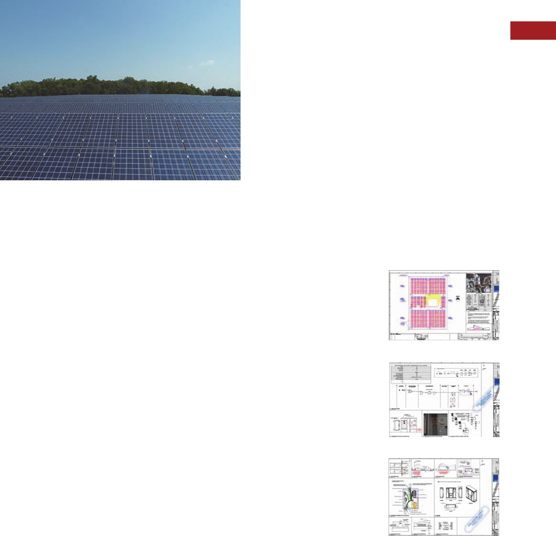
Volume 15—Solar Inverters and Electrical Balance of System CA08100018E—September 2015 eaton.com/solar V15-T2-71
2
2
2
2
2
2
2
2
2
2
2
2
2
2
2
2
2
2
2
2
2
2
2
2
2
2
2
2
2
2
2.6
Solar Services
Solar Renewable Analysis and Consultation
Contents
Description Page
Product Group Overview. . . . . . . . . . . . . . . . . . . . V15-T2-70
Solar Renewable Analysis and Consultation
Solar Design . . . . . . . . . . . . . . . . . . . . . . . . . . . . . V15-T2-72
Turnkey Services . . . . . . . . . . . . . . . . . . . . . . . . . . V15-T2-75
Solar Monitoring . . . . . . . . . . . . . . . . . . . . . . . . . . V15-T2-77
Solar Renewable Analysis and Consultation
Product Overview
Eaton’s team can provide a
cost-effective review with
recommendations that
maximizes solar renewable
energy production. Eaton’s
approach investigates all or
some of the following:
●Analysis of solar
production potential by
applying various methods
of fixed, tilt and tracking
systems
●Analysis of electrical
interconnect feasibility and
power usage
●Analysis of term-term
maintenance and
monitoring options and
associated costs
●Development of Life-Cycle-
Cost-Analysis (LCCA) for
potential solar sites
●Initial analysis via use of
Google-Earth photographs
if feasible
●If required, specific site
visits to further investigate
the above
●If required, site visual audit
of electrical equipment
operating conditions
●Establishing a “Solar
Production Index” when
evaluating multiple sites
●Identify any potential
issues with equipment life
expectancy and warranty
fulfillment obligations
Our analysis starts with the
following premises that have
been communicated to us by
developers:
●Need to maximize solar
energy production with
expected 20-year solar
variations
●Estimated construction
costs identified and
technical opinion of project
completion from a
technical and construction
standpoint
●Preliminary review of any
potential civil or structural
issues involving potential
solar sites
●Best practice
recommendations for long-
term monitoring to ensure
maximum uptime and
energy production to
match the financial model
●Need for experienced
analysis of hardware
supplied, life expectancy
and potential issues with
warranty fulfillment
obligations
●Recommendations for
ongoing maintenance,
operations and failure
response
Product Description
Eaton’s Electrical Services &
Systems Group has extensive
experience in electrical power
distribution systems design,
installation, start-up,
commissioning,
maintenance, trouble-
shooting, life-extension and
ongoing monitoring of
operating parameters as well
as failure indicators. We have
added expertise and direct
experience in the area of
solar renewable energy
projects, therefore providing
developers and investors a
non-biased technical review
of potential solar sites.
Terms and Conditions
Eaton can provide the above
services in accordance with
Eaton Standard Terms and
Conditions or other mutually
acceptable terms at either a
fixed price or a time-and-
material basis. If you have
any questions or requests,
please contact your local
Eaton Engineering Services &
Systems office today.
Roof and Wind Analysis
Electrical Design
Construction Details

V15-T2-72 Volume 15—Solar Inverters and Electrical Balance of System CA08100018E—September 2015 eaton.com/solar
2
2
2
2
2
2
2
2
2
2
2
2
2
2
2
2
2
2
2
2
2
2
2
2
2
2
2
2
2
2
2.6
Solar Services
Solar Design
Contents
Description Page
Product Group Overview . . . . . . . . . . . . . . . . . . . V15-T2-70
Solar Renewable Analysis and Consultation . . . . . V15-T2-71
Solar Design
Product Description . . . . . . . . . . . . . . . . . . . . . V15-T2-74
Turnkey Services. . . . . . . . . . . . . . . . . . . . . . . . . . V15-T2-75
Solar Monitoring . . . . . . . . . . . . . . . . . . . . . . . . . . V15-T2-77
Solar Design
Product Overview
Interconnection Analysis
Services
Power system analysis
services offer a focused and
systematic approach to
enhance performance and
design, validate equipment
selection, and simulate
response to abnormal
conditions. Typical analysis
services performed during
design of new renewable
generation sites include:
●Short-Circuit Analysis—
Calculation of the available
short-circuit currents at
equipment locations
throughout the power
system. Evaluation of
equipment ratings ensures
equipment can withstand,
and, where applicable,
interrupt an electrical fault.
Results are critical for
proper system design,
including specification and
selection of equipment
●Protective Device
Coordination—
Determination of
necessary characteristics,
ratings, and settings for
electrical protective
devices
●Arc Flash Analysis—
Calculation of arc flash
hazards associated with
energized work at locations
throughout the power
system in accordance with
NFPA 70E, IEEE1584,
National Electric Safety
Code, and Z462
requirements
●Load Flow Analysis—
Analysis of the system’s
capacity to supply electrical
energy from the renewable
energy source to the utility
or customer under steady-
state conditions,
determination of
appropriate continuous
ratings for electrical
equipment, and optimal
placement and
characteristics of reactive
power compensation
equipment
●Harmonic Analysis—
Evaluation of harmonic
currents on the electrical
system introduced by the
renewable energy source
and application of harmonic
mitigation equipment and
design techniques
●Transient Stability
Analysis—Evaluation of
dynamic behavior of the
renewable source and
system voltages during
transient conditions such
as system faults or start-up
●Switching Transient
Analysis—Analysis of
system behavior during
switching conditions to
identify possible damaging
voltage transients. Results
are used to design and
specify mitigation
equipment such as
snubbers
Electrical Design Services
Eaton’s electrical design
services can extend from the
point of utility connect to the
equipment. Design services
are integrated with analysis
services, resulting in a
complete engineered
solution. The level of design
detail can be customized
from minimal design
consultation and advice to a
complete design package
with specifications and
drawings.
Typical design services
include:
●Distribution System
Design—Design and
specification of the
electrical distribution
system from the point of
interconnection to
generation equipment
●Substation Design—
Complete substation
design service is available,
including ground grid
analysis and design,
substation layout,
equipment specification,
protection, and control
●Protection and Control—
Design of advanced
electrical protection and
control including
transmission line
protection, system
automation, advanced
metering and smart grid
capabilities

Volume 15—Solar Inverters and Electrical Balance of System CA08100018E—September 2015 eaton.com/solar V15-T2-73
2
2
2
2
2
2
2
2
2
2
2
2
2
2
2
2
2
2
2
2
2
2
2
2
2
2
2
2
2
2
2.6
Solar Services
Solar Design
DC Engineering Services
One-line diagram of the
power system is critical to
support the system
evaluation and analysis. The
one-line diagram shows the
identification and ratings of
electrical equipment such as:
transformers, cables, circuit
breakers, protective relays,
fuses, switches, current
transformers, potential
transformers, surge arresters,
and so on. ANSI device
numbers identify protective
relay types. The one-line
diagram is typically provided
with each type of power
system study. Electrical one-
line diagram, showing DC and
AC portions of the system, to
include the following:
●Solar module
manufacturer, type and
catalog number; number of
module strings, number of
modules per string (DC)
●Make, model, DC kW
rating of solar panels
●Make, model, AC kW rating
of inverter(s)
●Make, model, voltage, and
current interrupt rating of
all AC and DC disconnect
switches
●Make and model of all
lightning arrestors and
surge suppression
equipment
●Make and model of
combiner boxes and fuses
●Make, model and rating of
all circuit breakers and
electrical panels
●Make and model of the
utility meter
●Size, insulation rating, and
temperature rating of
system wiring and nominal
voltage present on
each line
●Complete electrical circuit
back to customer’s utility
connection. All customer
electrical panels related to
the PV system shall be
shown. Such panels shall
be labeled with the make,
model, bus rating and
customer designation. The
main circuit breaker shall
also be labeled with the
make and rating (if
applicable)
●Proper compliance with all
authorities having
jurisdiction
●Step up transformer, MV
switchgear, and point of
utility connection
Typical DC connection
drawing, showing the
following:
●Typical termination for a
solar module string
●Typical panel to panel
termination
●Typical combiner box
termination
●Develop cable routing and
interconnection details
●Step up transformer, MV
switchgear, point of utility
connection equipment
●Grounding plan
Equipment layout drawing(s),
showing locations for the
following:
●Solar modules
●Combiner boxes
●Disconnect switches
●Inverters
●Conduit routing
●Existing panel,
switchboard, or switchgear
connection
●Step up transformer, MV
switchgear, point of utility
connection arrangement
Cable and conduit schedule,
to show:
●Cable/conduit ID
●From/To destinations
●Voltages, AC or DC
●Cable and conduit sizing
●Number of conductors/
sets per phase
●Insulation type
Power Systems Engineering
is an integral part of Eaton’s
electrical service capabilities.
The combined Eaton
Electrical Services & Systems
team can provide a full scope
of design and construction
management services to
support your project needs:
●Engineering and design
●Multi-vendor equipment
supply
●Turnkey projects and
construction management
●Installation services
●Power quality and load
measurements
●Power quality investigation
●Energy management
studies
●Renewable energy
applications
Electrical Design Submittals
Eaton can prepare an
equipment specification by
using an approved single line
diagram(s); knowledge of
physical environment
restrictions; the application of
the electrical equipment; the
equipment manufacturer’s
standards and options; the
latest manufacturing industry
standards; and a thorough
knowledge of the latest local
and national codes and
regulations for installation of
the equipment.
Eaton can develop equipment
layout or arrangement plans
that will identify the location
of the equipment based upon
the customer’s physical
restrictions. Once the
equipment location has
been determined, foundation
designs, equipment
grounding, and raceway
routing designs will be
developed and issued
for approval.
Eaton can provide the
following minimum design
elements for the design
deliverables:
●Title sheet
●Existing site plan
●PV array layout
●Electrical one-line
diagram sheet
●Equipment location plan
●Equipment specifications
●100% design drawings and
other information as
needed to enable accurate
procurement and
installation required to
construct the project

V15-T2-74 Volume 15—Solar Inverters and Electrical Balance of System CA08100018E—September 2015 eaton.com/solar
2
2
2
2
2
2
2
2
2
2
2
2
2
2
2
2
2
2
2
2
2
2
2
2
2
2
2
2
2
2
2.6
Solar Services
Solar Design
Product Description
Eaton’s Power System
Engineering team is your ally
to provide analysis and design
for connecting renewable and
alternative energy generation
to the utility grid. Our
experience and North
American coverage make
Eaton the choice to analyze
and design the electrical
distribution system and
substation for wind and solar
farm projects.
Our power system engineers
bring extensive skills and
expertise to power system
analysis and design. Active
participation in technical
societies such as IEEE and
collaboration with a variety of
utilities and industries
ensures that our engineers
are knowledgeable about
today’s cutting edge
engineering techniques.

Volume 15—Solar Inverters and Electrical Balance of System CA08100018E—September 2015 eaton.com/solar V15-T2-75
2
2
2
2
2
2
2
2
2
2
2
2
2
2
2
2
2
2
2
2
2
2
2
2
2
2
2
2
2
2
2.6
Solar Services
Turnkey Services
Contents
Description Page
Product Group Overview. . . . . . . . . . . . . . . . . . . . V15-T2-70
Solar Renewable Analysis and Consultation . . . . . V15-T2-71
Solar Design . . . . . . . . . . . . . . . . . . . . . . . . . . . . . V15-T2-72
Turn key S e r vi c e s
Product Description . . . . . . . . . . . . . . . . . . . . . V15-T2-76
Solar Monitoring . . . . . . . . . . . . . . . . . . . . . . . . . . V15-T2-77
Turnkey Services
Product Overview
Services for Solar
Photovoltaic Power
Pre-installation services
●Solar site assessments
including technical and
financial analysis
●Solar system design
including shading and
annual kWh output analysis
●Photovoltaic panel
selection
●Electrical balance of
system design
●Monitoring system design
(meters and software)
●Building connection and
substation design
Installation services
●Solar photovoltaic panel
installation
●Electrical balance of
system installation
●Building infrastructure
connection
●Utility grid interconnection
up to 345 kV substations,
synchronizing and controls
●Solar system
commissioning and
performance verification
PV System Commissioning
●Eaton can provide start up
and commissioning
services for the solar array,
DC equipment, inverters
and all AC equipment up to
the point of connection
●Eaton can supply all test
equipment and labor to
properly test the PV
system
●Eaton can complete the
required field verification of
the solar system
components from the PV
panels to the electrical AC
grid connection.
Acceptance will involve
several steps starting at
factory testing through
final site system
performance evaluations,
with ongoing reporting and
evaluation
●Eaton can supply complete
close out documentation
including final test reports,
O&M manuals, training and
as built drawings
Post-installation services
●Remote performance
monitoring (metering and
data collection)
●Ongoing energy production
monitoring and rebate
certifications
●Site power quality, load
shedding and future
expansion analysis
●Maintenance
●Operations training for site
personnel
●Safety training
●Access to around-the-clock
customer support
Other services
●Arc flash hazard analysis
and solutions
●Power reliability studies
●LEED certification audits
●Building energy audits
Equipment Solutions for Solar
Photovoltaic Power
DC switching and
protection
●DC solar disconnect
switches
●DC solar integrated
disconnect combiner
switch
●DC string level and array
level monitoring
Inverters
●Solar inverters
●String Inverters,
commercial inverters,
utility class inverters
AC switching and
protection
●AC solar switchboards and
panelboards
●AC solar load centers
●AC disconnect switches
●AC circuit breakers
●Low voltage and medium
voltage AC switchgear
●Low voltage and medium
voltage transformers
Packaging
●Integrated Solar System
(ISS)
●Integrated Power
Assembly (IPA)
Monitoring and metering
●Metering solutions
compatible with Eaton and
other manufacturers’
equipment
●Customized metering
solutions
●Web-enabled data
collection and monitoring
●Cellular and satellite
communications

V15-T2-76 Volume 15—Solar Inverters and Electrical Balance of System CA08100018E—September 2015 eaton.com/solar
2
2
2
2
2
2
2
2
2
2
2
2
2
2
2
2
2
2
2
2
2
2
2
2
2
2
2
2
2
2
2.6
Solar Services
Turnkey Services
Product Description
Eaton’s turnkey project
capabilities can help you build
your solar business without
adding staff or assets. With
decades of experience in
managing electrical power,
we know what it takes to
design and install a power
system that generates clean,
reliable power.

Volume 15—Solar Inverters and Electrical Balance of System CA08100018E—September 2015 eaton.com/solar V15-T2-77
2
2
2
2
2
2
2
2
2
2
2
2
2
2
2
2
2
2
2
2
2
2
2
2
2
2
2
2
2
2
2.6
Solar Services
Solar Monitoring
Contents
Description Page
Product Group Overview. . . . . . . . . . . . . . . . . . . . V15-T2-70
Solar Renewable Analysis and Consultation . . . . . V15-T2-71
Solar Design . . . . . . . . . . . . . . . . . . . . . . . . . . . . . V15-T2-72
Turnkey Services . . . . . . . . . . . . . . . . . . . . . . . . . . V15-T2-75
Solar Monitoring
Product Description . . . . . . . . . . . . . . . . . . . . . V15-T2-78
Solar Monitoring
Product Overview
PVGard® is a web-based solar
monitoring system that can
transmit via hard wire land
lines or wireless
communications from field
acquired measurement
parameters. Data parameters
monitored and displayed can
include but not be limited to
the following measurements
and displays:
Photovoltaic power output
performance measurement
transducers
●AC current and voltage
●DC current and voltage
●Kilowatt-hour meter
Meteorological data
measurements
●Ambient air temperature
●Relative humidity
●Barometric pressure
●Wind speed
●Wind direction
●Rainfall
●Global horizontal irradiance
●Solar cell temperature
Real time data at minimal of
15 minute intervals
●AC current, voltage and
kilowatt hours
●Solar plane of array
irradiance
●Ambient temperature and
wind speed
Calculated parameters
●AC power output
●Sunlight conversion
efficiency to AC and DC
power
●Inverter DC to AC power
conversion efficiency
●Avoided pollutant
emissions of CO2, SOx,
and NOx gases
Inverter monitored data
●Watt-hour
●AC and DC voltage and
current
●AC frequency
●Cumulated watt-hours
●Inverter error codes
●Inverter conversion
efficiency
●DC string level and
re-combiner current
monitoring
Inverter System Sensors—
(Enhanced monitoring
parameters)
●Internal equipment
enclosure temperatures
and humidity
●Internal dust/smoke alarm
levels within enclosures
●Water intrusion detector
(floor water)
●Breaker trip or operation
●Fan and heater circuit
operation
●Load current of main circuit
breakers
●Transformer monitoring
and alarms
●Relay status/health and
Inverter error codes
alarming
●Safe-solar detection and
protection
●Quarterly performance
reports to be e-mailed to
site personnel
●Alarm conditions will be
e-mailed and text-message
to site personnel/Eaton
●Alarm and operating
conditions will be
summarized in quarterly
report
●Inverter health index
The monitoring and
display software permits
customization to incorporate
descriptive text, schematic
diagrams, and user-specific
data.
PVGard also provides the
capability to generate the
following type of graphs:
●Average plots of irradiance
●Average plots of ambient
temperature and module
temperature
●Daily value or totals of
energy production
●Peak daily power
●Peak daily module
temperature
●Peak daily irradiance plot
over a specific month
●Monthly values of energy
production
●Incident solar irradiance
●Cumulated yearly voided
emissions of CO2, SOx,
and NOx gases

V15-T2-78 Volume 15—Solar Inverters and Electrical Balance of System CA08100018E—September 2015 eaton.com/solar
2
2
2
2
2
2
2
2
2
2
2
2
2
2
2
2
2
2
2
2
2
2
2
2
2
2
2
2
2
2
2.6
Solar Services
Solar Monitoring
The displayed data can also
incorporate a looping
background of pictures from
the site, graphic overlays of
the solar power generation in
watts and watt-hours for each
inverter. Other display
capabilities:
●Project location on globe
coordinates with zoom-in
and out capability
●Current weather conditions
●Power generation from the
total system and/or the
individual solar power
arrays
●Historic power generation
●Solar power system
environmental impact
●Educational power point
presentation (optional)
●Installed solar power
electrical system overview
and single line diagram
The display system can be
capable of being programmed
periodically to show
additional information related
to scheduled maintenance.
Product Description
Eaton’s PVGard Engineered
Monitoring system is a web-
based system that monitors
and proactively manages PV
array equipment, inverters,
AC equipment and weather
parameters. Eaton builds in
custom algorithms to track
multiple inputs in order to
improve and maintain system
performance. For example
PVGard alerts users to
underperforming panels and
can schedule maintenance on
inverters when expected
production values are shown
to be lower than optimal
performance.
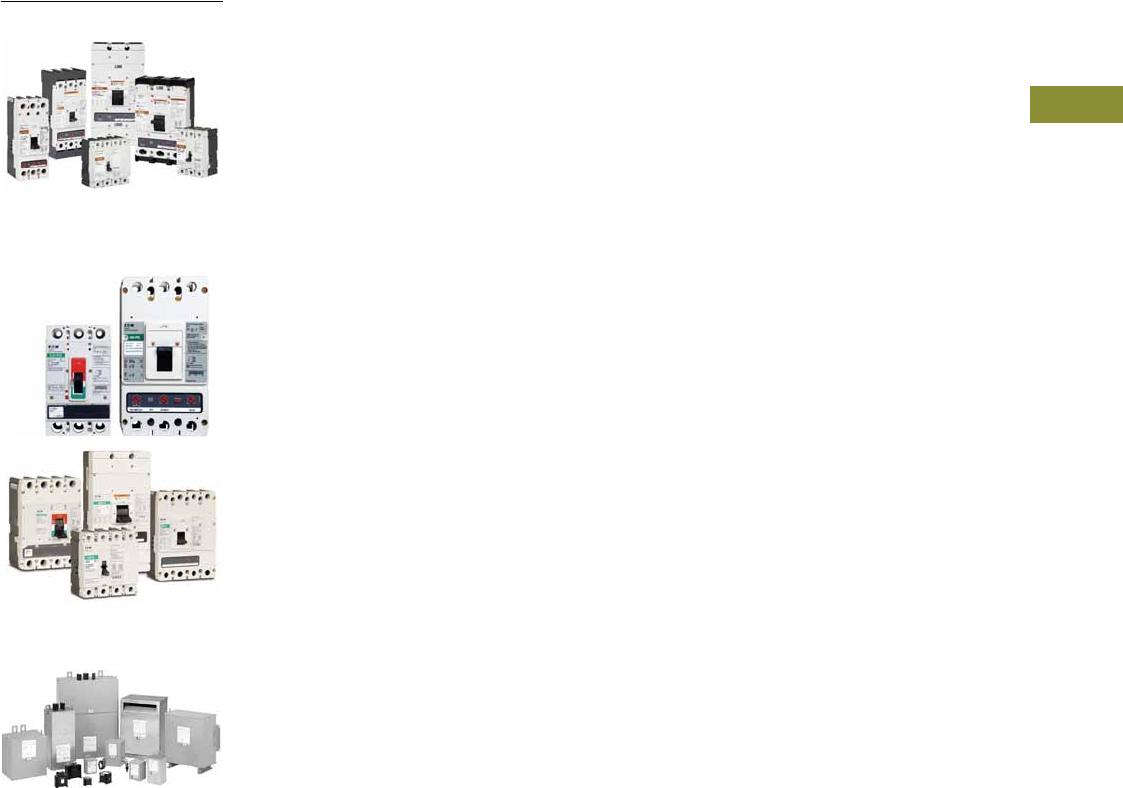
Volume 15—Solar Inverters and Electrical Balance of System CA08100018E—May 2016 eaton.com/solar V15-T3-1
3
3
3
3
3
3
3
3
3
3
3
3
3
3
3
3
3
3
3
3
3
3
3
3
3
3
3
3
3
3
Solar OEM
Direct Current Circuit Breakers
PVGard Solar Photovoltaic
Circuit Breakers
Dry-Type Transformer Family
3.1Direct Current Circuit Breakers
Product Description. . . . . . . . . . . . . . . . . . . . . . . . . . . . . . . . . . . . . . . V15-T3-2
Catalog Number Selection . . . . . . . . . . . . . . . . . . . . . . . . . . . . . . . . . V15-T3-4
Product Selection . . . . . . . . . . . . . . . . . . . . . . . . . . . . . . . . . . . . . . . . V15-T3-5
Accessories. . . . . . . . . . . . . . . . . . . . . . . . . . . . . . . . . . . . . . . . . . . . . V15-T3-12
Wiring Diagrams . . . . . . . . . . . . . . . . . . . . . . . . . . . . . . . . . . . . . . . . . V15-T3-14
Dimensions. . . . . . . . . . . . . . . . . . . . . . . . . . . . . . . . . . . . . . . . . . . . . V15-T3-15
3.2 PVGard Solar Circuit Breakers—
600 Vdc Per-Pole and 1000 Vdc Poles-in-Series
Product Overview . . . . . . . . . . . . . . . . . . . . . . . . . . . . . . . . . . . . . . . . V15-T3-16
Product Description. . . . . . . . . . . . . . . . . . . . . . . . . . . . . . . . . . . . . . . V15-T3-16
Application Description . . . . . . . . . . . . . . . . . . . . . . . . . . . . . . . . . . . . V15-T3-17
Features. . . . . . . . . . . . . . . . . . . . . . . . . . . . . . . . . . . . . . . . . . . . . . . . V15-T3-17
Standards and Certications . . . . . . . . . . . . . . . . . . . . . . . . . . . . . . . . V15-T3-17
Product Selection . . . . . . . . . . . . . . . . . . . . . . . . . . . . . . . . . . . . . . . . V15-T3-18
Accessories. . . . . . . . . . . . . . . . . . . . . . . . . . . . . . . . . . . . . . . . . . . . . V15-T3-20
Technical Data and Specications . . . . . . . . . . . . . . . . . . . . . . . . . . . . V15-T3-24
Dimensions. . . . . . . . . . . . . . . . . . . . . . . . . . . . . . . . . . . . . . . . . . . . . V15-T3-27
Wiring Diagrams . . . . . . . . . . . . . . . . . . . . . . . . . . . . . . . . . . . . . . . . . V15-T3-28
3.3 DC Switch Disconnectors
Product Description. . . . . . . . . . . . . . . . . . . . . . . . . . . . . . . . . . . . . . . V15-T3-29
Application Description . . . . . . . . . . . . . . . . . . . . . . . . . . . . . . . . . . . . V15-T3-29
Features. . . . . . . . . . . . . . . . . . . . . . . . . . . . . . . . . . . . . . . . . . . . . . . . V15-T3-29
Standards and Certications . . . . . . . . . . . . . . . . . . . . . . . . . . . . . . . . V15-T3-29
Product Selection . . . . . . . . . . . . . . . . . . . . . . . . . . . . . . . . . . . . . . . . V15-T3-30
Technical Data and Specications . . . . . . . . . . . . . . . . . . . . . . . . . . . . V15-T3-34
Dimensions. . . . . . . . . . . . . . . . . . . . . . . . . . . . . . . . . . . . . . . . . . . . . V15-T3-37
3.4 DC Switches
Product Description. . . . . . . . . . . . . . . . . . . . . . . . . . . . . . . . . . . . . . . V15-T3-40
3.5DC Switched Combiners
Product Description. . . . . . . . . . . . . . . . . . . . . . . . . . . . . . . . . . . . . . . V15-T3-41
3.6 Dry-Type Distribution Transformers
Encapsulated Transformers
Product Description . . . . . . . . . . . . . . . . . . . . . . . . . . . . . . . . . . . . V15-T3-42
Ventilated Transformers/Open Core-Coil Assemblies
Product Description . . . . . . . . . . . . . . . . . . . . . . . . . . . . . . . . . . . . V15-T3-43
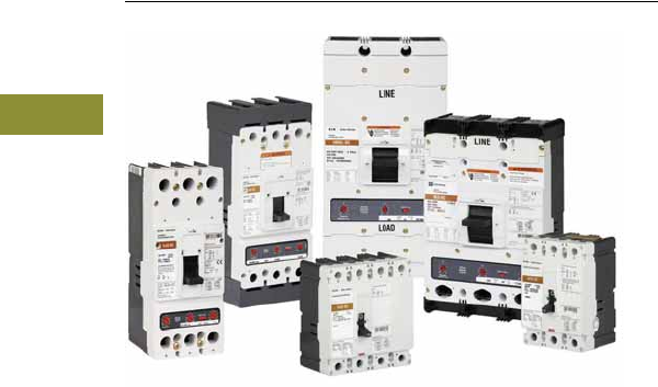
V15-T3-2 Volume 15—Solar Inverters and Electrical Balance of System CA08100018E—May 2016 eaton.com/solar
3
3
3
3
3
3
3
3
3
3
3
3
3
3
3
3
3
3
3
3
3
3
3
3
3
3
3
3
3
3
3.1
Direct Current Circuit Breakers
Specialty Breakers
Direct Current Circuit Breakers
Contents
Description Page
Direct Current Circuit Breakers
Catalog Number Selection. . . . . . . . . . . . . . . . V15-T3-4
Product Selection. . . . . . . . . . . . . . . . . . . . . . . V15-T3-5
Accessories . . . . . . . . . . . . . . . . . . . . . . . . . . . V15-T3-12
Wiring Diagrams . . . . . . . . . . . . . . . . . . . . . . . V15-T3-14
Dimensions . . . . . . . . . . . . . . . . . . . . . . . . . . . V15-T3-15
Direct Current Circuit Breakers
Product Description
DC (direct current)
systems and applications
are becoming commonplace
as alternative energy sources
have expanded and the
number of DC devices
and data centers using DC
power has swelled.
Eaton offers molded case
circuit breakers and switches
to meet circuit protection and
switching requirements for a
host of different DC end use
requirements. Applications
include UPS battery supply
circuits, solar systems and
electric vehicle charging, as
well as commercial and
industrial distribution.
Current ratings are available
from 15 to 2500A, with
a full scale of voltage and
interrupting ratings to address
needs ranging from standard
to the highest performance.
Optional internal accessories
provide remote tripping and
indication of breaker status.
The DC breaker family is
UL® 489 listed and exceeds
the requirements in UL 489
Supplement SC for UPS
applications. Eaton breakers
may be applied in both
ungrounded and select
grounded applications, with
poles connected in series
to operate at the maximum
voltages shown on Page
V15-T3-3. To use DC circuit
breakers on 600V grounded
systems, three poles in series
must be connected on the
ungrounded leg.
The HFDDC through
HMDLDC DC breakers
use the same internal and
external accessories as
their Series C or Series G
AC frame equivalents. NBDC
and PBDC use the same
internal and external
accessories as standard
NB and PB breakers.
Many of the Eaton AC
molded case circuit breakers
carry 250 Vdc ratings for
ungrounded systems. Refer
to Volume 4—Circuit
Protection, CA08100005E,
Tab 2 for these interrupting
tables.

Volume 15—Solar Inverters and Electrical Balance of System CA08100018E—May 2016 eaton.com/solar V15-T3-3
3
3
3
3
3
3
3
3
3
3
3
3
3
3
3
3
3
3
3
3
3
3
3
3
3
3
3
3
3
3
3.1
Direct Current Circuit Breakers
Specialty Breakers
Quick Reference Direct Current Circuit Breakers
UL 489 Interrupting Capacity Ratings
IEC 60947-2 Interrupting Capacity Ratings
Notes
1DC ratings apply to substantially non-inductive circuits. Time constants per UL 489.
2EGEDC through HMDLDC have been tested up to 300 Vdc to allow for battery charging voltages. 750 Vdc is common in transportation applications.
HFDDC, four-pole 750 Vdc is available up to 150A maximum. 300 Vdc and 750 Vdc are not UL 489 listed voltage ratings.
3Four-pole frame with two-poles connected in parallel.
See Page V15-T3-14 for series connection diagrams. Use NEC® rated cable to connect/short poles in series as shown.
Circuit Breaker
Type
Maximum
Amperes
Interrupting Capacity (kA)
Poles in
Series
Volts DC 1
125
Poles in
Series 250 2
Poles in
Series 500 600
Poles in
Series 750 2
EGEDC 100 10 135 235 — 3 — —
EGSDC 100 35 142 250 — 3 — —
EGHDC 100 42 150 265 — 3 — —
HFDDC 225 42 150 2 — 42 342 4
JGEDC 250 35 135 2 — 35 3 — —
JGSDC 250 42 142 2 — 50 3 — —
JGHDC 250 50 150 2 — 65 3 — —
HJDDC 250 42 150 2 — 42 3 — —
HKDDC 400 42 150 2 — 42 3 — —
LGEDC 600 22 122 2 — 35 3 — —
LGSDC 600 22 122 2 — 50 3 — —
LGHDC 600 50 150 2 — 65 3 — —
HLDDC 600 42 150 2 — 35 3 — —
HLDDC 31200 42 150 2 — — — — —
HMDLDC 800 42 150 2 — 35 3 — —
NBDC 1200 42 150 2 — 50 3 — —
PBDC 2500 42 165 2 — 65 3 — —
Circuit Breaker
Type
Maximum
Amperes
125 Volts DC Poles in
Series
250 Volts DC Poles in
Series
600 Volts DC Poles in
SeriesIcu Ics Icu Ics Icu Ics
EGEDC 100 10 10 1 10 10 2 — — —
EGSDC 100 35 35 1 35 35 2 — — —
EGHDC 100 42 42 1 42 42 2 — — —
JGEDC 250 22 22 1 22 22 2 — — —
JGSDC 250 22 22 1 22 22 2 — — —
JGHDC 250 42 42 1 42 42 2 — — —
HJDDC 250 — — — — — — 20 10 3
LGEDC 600 22 22 1 22 22 2 — — —
LGSDC 600 22 22 1 22 22 2 — — —
LGHDC 600 42 42 1 42 42 2 — — —
HLDDC 600 — — — — — — 20 10 3
HMDLDC 800 — — — — — — 20 10 3
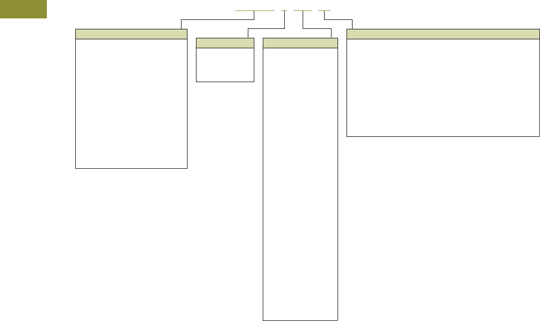
V15-T3-4 Volume 15—Solar Inverters and Electrical Balance of System CA08100018E—May 2016 eaton.com/solar
3
3
3
3
3
3
3
3
3
3
3
3
3
3
3
3
3
3
3
3
3
3
3
3
3
3
3
3
3
3
3.1
Direct Current Circuit Breakers
Specialty Breakers
Catalog Number Selection
DC Circuit Breaker
Frame
EGEDC = Series G—E (100A max.)
EGSDC = Series G—E (100A max.)
EGHDC = Series G—E (100A max.)
HFDDC = Series C—F (225A max.)
JGEDC = Series G—J (250A max.)
JGSDC = Series G—J (250A max.)
JGHDC = Series G—J (250A max.)
HJDDC = Series C—J (250A max.)
HKDDC = Series C—K (400A max.)
LGEDC = Series G—L (600A max.)
LGSDC = Series G—L (600A max.)
LGHDC = Series G—L (600A max.)
HLDDC = Series C—L (1200A max.)
HMDLDC = Series C—M (800A max.)
NBDC = NB (1200A max.)
PBDC = PB (2500A max.)
Number of Poles
1 = Single-pole
2 = Two-pole
3 = Three-pole
4 = Four-pole
Trip Unit Ampere Rating
015 =15A
020 =20A
025 =25A
030 =30A
035 =35A
040 =40A
045 =45A
050 =50A
060 =60A
070 =70A
080 =80A
090 =90A
100 =100A
110 =110A
125 =125A
150 =150A
175 =175A
200 =200A
225 =225A
250 =250A
300 =300A
350 =350A
400 =400A
450 =450A
500 =500A
600 =600A
700 =700A
800 =800A
900 =900A
1000 = 1000A
1200 = 1200A
1600 = 1600A
2000 = 2000A
2500 = 2500A
Suffix
Series C, NB and PB Frames
K = Molded case switch
L = Line and load terminals, F-Frame
MW = 135% magnetic trip unit, without terminals
W = Without terminals
Series G Frames
FFG = Fixed thermal, fixed magnetic trip unit, with terminals
FFW = Fixed thermal, fixed magnetic trip unit, without terminals
FAG = Fixed thermal, adjustable magnetic trip unit, with terminals
FAW = Fixed thermal, adjustable magnetic trip unit, without terminals
KSG = Molded case switch, with terminals
KSW = Molded case switch, without terminals
HFDDC 3150 W

Volume 15—Solar Inverters and Electrical Balance of System CA08100018E—May 2016 eaton.com/solar V15-T3-5
3
3
3
3
3
3
3
3
3
3
3
3
3
3
3
3
3
3
3
3
3
3
3
3
3
3
3
3
3
3
3.1
Direct Current Circuit Breakers
Specialty Breakers
Product Selection
Type EGEDC DC Circuit Breakers—
Three-Pole High Interrupting Capacity 35 kAIC at 500 Vdc
Type EGSDC DC Circuit Breakers—
Three-Pole High Interrupting Capacity 50 kAIC at 500 Vdc
Maximum
Continuous
Ampere Rating
at 40°C
Complete Circuit Breaker
with Terminals
Complete Circuit Breaker
without Terminals
Catalog
Number
Catalog
Number
25 EGEDC3025FFG EGEDC3025FFW
30 EGEDC3030FFG EGEDC3030FFW
35 EGEDC3035FFG EGEDC3035FFW
40 EGEDC3040FFG EGEDC3040FFW
45 EGEDC3045FFG EGEDC3045FFW
50 EGEDC3050FFG EGEDC3050FFW
60 EGEDC3060FFG EGEDC3060FFW
70 EGEDC3070FFG EGEDC3070FFW
80 EGEDC3080FFG EGEDC3080FFW
90 EGEDC3090FFG EGEDC3090FFW
100 EGEDC3100FFG EGEDC3100FFW
Maximum
Continuous
Ampere Rating
at 40°C
Complete Circuit Breaker
with Terminals
Complete Circuit Breaker
without Terminals
Catalog
Number
Catalog
Number
25 EGSDC3025FFG EGSDC3025FFW
30 EGSDC3030FFG EGSDC3030FFW
35 EGSDC3035FFG EGSDC3035FFW
40 EGSDC3040FFG EGSDC3040FFW
45 EGSDC3045FFG EGSDC3045FFW
50 EGSDC3050FFG EGSDC3050FFW
60 EGSDC3060FFG EGSDC3060FFW
70 EGSDC3070FFG EGSDC3070FFW
80 EGSDC3080FFG EGSDC3080FFW
90 EGSDC3090FFG EGSDC3090FFW
100 EGSDC3100FFG EGSDC3100FFW
Type EGHDC DC Circuit Breakers—
Three-Pole High Interrupting Capacity 65 kAIC at 500 Vdc
Maximum
Continuous
Ampere Rating
at 40°C
Complete Circuit Breaker
with Terminals
Complete Circuit Breaker
without Terminals
Catalog
Number
Catalog
Number
25 EGHDC3025FFG EGHDC3025FFW
30 EGHDC3030FFG EGHDC3030FFW
35 EGHDC3035FFG EGHDC3035FFW
40 EGHDC3040FFG EGHDC3040FFW
45 EGHDC3045FFG EGHDC3045FFW
50 EGHDC3050FFG EGHDC3050FFW
60 EGHDC3060FFG EGHDC3060FFW
70 EGHDC3070FFG EGHDC3070FFW
80 EGHDC3080FFG EGHDC3080FFW
90 EGHDC3090FFG EGHDC3090FFW
100 EGHDC3100FFG EGHDC3100FFW
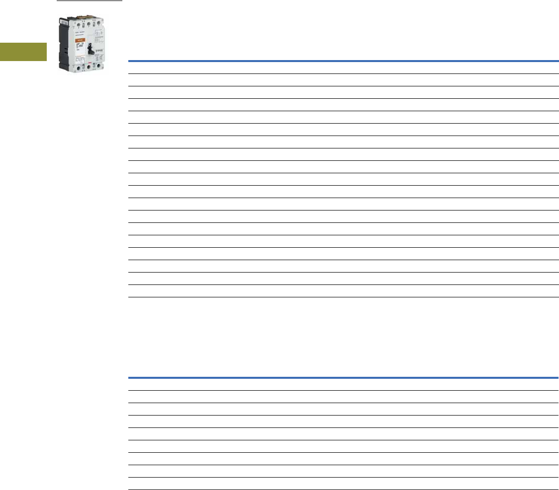
V15-T3-6 Volume 15—Solar Inverters and Electrical Balance of System CA08100018E—May 2016 eaton.com/solar
3
3
3
3
3
3
3
3
3
3
3
3
3
3
3
3
3
3
3
3
3
3
3
3
3
3
3
3
3
3
3.1
Direct Current Circuit Breakers
Specialty Breakers
Type HFDDC DC Circuit Breakers—
Three-Pole High Interrupting Capacity 42 kAIC at 600 Vdc
Type JGEDC DC Circuit Breakers—
Three-Pole High Interrupting Capacity 35 kAIC at 600 Vdc
Notes
1 For breaker without terminals, replace "L" with "W" at end of catalog number.
2 For complete breaker, order individual frame, trip unit and terminals for field installation.
Maximum
Continuous
Ampere Rating
at 40°C
Complete Circuit Breaker with Line and Load Terminals 1
Single-Pole Two-Pole Three-Pole Four-Pole
Catalog
Number
Catalog
Number
Catalog
Number
Catalog
Number
15 HFDDC1015L HFDDC2015L HFDDC3015L HFDDC4015L
20 HFDDC1020L HFDDC2020L HFDDC3020L HFDDC4020L
25 HFDDC1025L HFDDC2025L HFDDC3025L HFDDC4025L
30 HFDDC1030L HFDDC2030L HFDDC3030L HFDDC4030L
35 HFDDC1035L HFDDC2035L HFDDC3035L HFDDC4035L
40 HFDDC1040L HFDDC2040L HFDDC3040L HFDDC4040L
45 HFDDC1045L HFDDC2045L HFDDC3045L HFDDC4045L
50 HFDDC1050L HFDDC2050L HFDDC3050L HFDDC4050L
60 HFDDC1060L HFDDC2060L HFDDC3060L HFDDC4060L
70 HFDDC1070L HFDDC2070L HFDDC3070L HFDDC4070L
80 HFDDC1080L HFDDC2080L HFDDC3080L HFDDC4080L
90 HFDDC1090L HFDDC2090L HFDDC3090L HFDDC4090L
100 HFDDC1100L HFDDC2100L HFDDC3100L HFDDC4100L
110 HFDDC1110L HFDDC2110L HFDDC3110L HFDDC4110L
125 HFDDC1125L HFDDC2125L HFDDC3125L HFDDC4125L
150 HFDDC1150L HFDDC2150L HFDDC3150L HFDDC4150L
175 — HFDDC2175L HFDDC3175L —
200 — HFDDC2200L HFDDC3200L —
225 — HFDDC2225L HFDDC3225L —
Maximum
Continuous
Ampere Rating
at 40°C
Complete
Breaker
Circuit Breaker
Frame Only 2
Thermal-Magnetic
Trip Unit
Standard
Terminals
Catalog
Number
Catalog
Number
Catalog
Number
Catalog
Number
70 JGEDC3070FAG JGEDC3250NN JT3070FA T250FJ
90 JGEDC3090FAG JGEDC3250NN JT3090FA T250FJ
100 JGEDC3100FAG JGEDC3250NN JT3100FA T250FJ
125 JGEDC3125FAG JGEDC3250NN JT3125FA T250FJ
150 JGEDC3150FAG JGEDC3250NN JT3150FA T250FJ
175 JGEDC3175FAG JGEDC3250NN JT3175FA T250FJ
200 JGEDC3200FAG JGEDC3250NN JT3200FA T250FJ
225 JGEDC3225FAG JGEDC3250NN JT3225FA T250FJ
250 JGEDC3250FAG JGEDC3250NN JT3250FA T250FJ
HFDDC
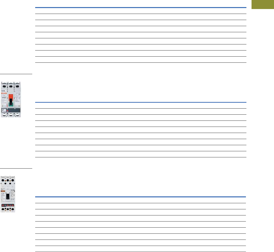
Volume 15—Solar Inverters and Electrical Balance of System CA08100018E—May 2016 eaton.com/solar V15-T3-7
3
3
3
3
3
3
3
3
3
3
3
3
3
3
3
3
3
3
3
3
3
3
3
3
3
3
3
3
3
3
3.1
Direct Current Circuit Breakers
Specialty Breakers
Type JGSDC DC Circuit Breakers—
Three-Pole High Interrupting Capacity 50 kAIC at 600 Vdc
Type JGHDC DC Circuit Breakers—
Three-Pole High Interrupting Capacity 65 kAIC at 600 Vdc
Type HJDDC DC Circuit Breakers—
Three-Pole High Interrupting Capacity 42 kAIC at 600 Vdc
Note
1 For complete breaker, order individual frame, trip unit and terminals for field installation.
Maximum
Continuous
Ampere Rating
at 40°C
Complete
Breaker
Circuit Breaker
Frame Only 1
Thermal-Magnetic
Trip Unit
Standard
Terminals
Catalog
Number
Catalog
Number
Catalog
Number
Catalog
Number
70 JGSDC3070FAG JGSDC3250NN JT3070FA T250FJ
90 JGSDC3090FAG JGSDC3250NN JT3090FA T250FJ
100 JGSDC3100FAG JGSDC3250NN JT3100FA T250FJ
125 JGSDC3125FAG JGSDC3250NN JT3125FA T250FJ
150 JGSDC3150FAG JGSDC3250NN JT3150FA T250FJ
175 JGSDC3175FAG JGSDC3250NN JT3175FA T250FJ
200 JGSDC3200FAG JGSDC3250NN JT3200FA T250FJ
225 JGSDC3225FAG JGSDC3250NN JT3225FA T250FJ
250 JGSDC3250FAG JGSDC3250NN JT3250FA T250FJ
Maximum
Continuous
Ampere Rating
at 40°C
Complete
Breaker
Circuit Breaker
Frame Only 1
Thermal-Magnetic
Trip Unit
Standard
Terminals
Catalog
Number
Catalog
Number
Catalog
Number
Catalog
Number
70 JGHDC3070FAG JGHDC3250NN JT3070FA T250FJ
90 JGHDC3090FAG JGHDC3250NN JT3090FA T250FJ
100 JGHDC3100FAG JGHDC3250NN JT3100FA T250FJ
125 JGHDC3125FAG JGHDC3250NN JT3125FA T250FJ
150 JGHDC3150FAG JGHDC3250NN JT3150FA T250FJ
175 JGHDC3175FAG JGHDC3250NN JT3175FA T250FJ
200 JGHDC3200FAG JGHDC3250NN JT3200FA T250FJ
225 JGHDC3225FAG JGHDC3250NN JT3225FA T250FJ
250 JGHDC3250FAG JGHDC3250NN JT3250FA T250FJ
Maximum
Continuous
Ampere Rating
at 40°C
Circuit Breaker
Frame Only 1
Thermal-Magnetic
Trip Unit
Standard
Terminals
Catalog
Number
Catalog
Number
Catalog
Number
70 HJDDC3250F JT3070T TA250KB
90 HJDDC3250F JT3090T TA250KB
100 HJDDC3250F JT3100T TA250KB
125 HJDDC3250F JT3125T TA250KB
150 HJDDC3250F JT3150T TA250KB
175 HJDDC3250F JT3175T TA250KB
200 HJDDC3250F JT3200T TA250KB
225 HJDDC3250F JT3225T TA250KB
250 HJDDC3250F JT3250T TA250KB
JGHDC3250NN
HJDDC3250
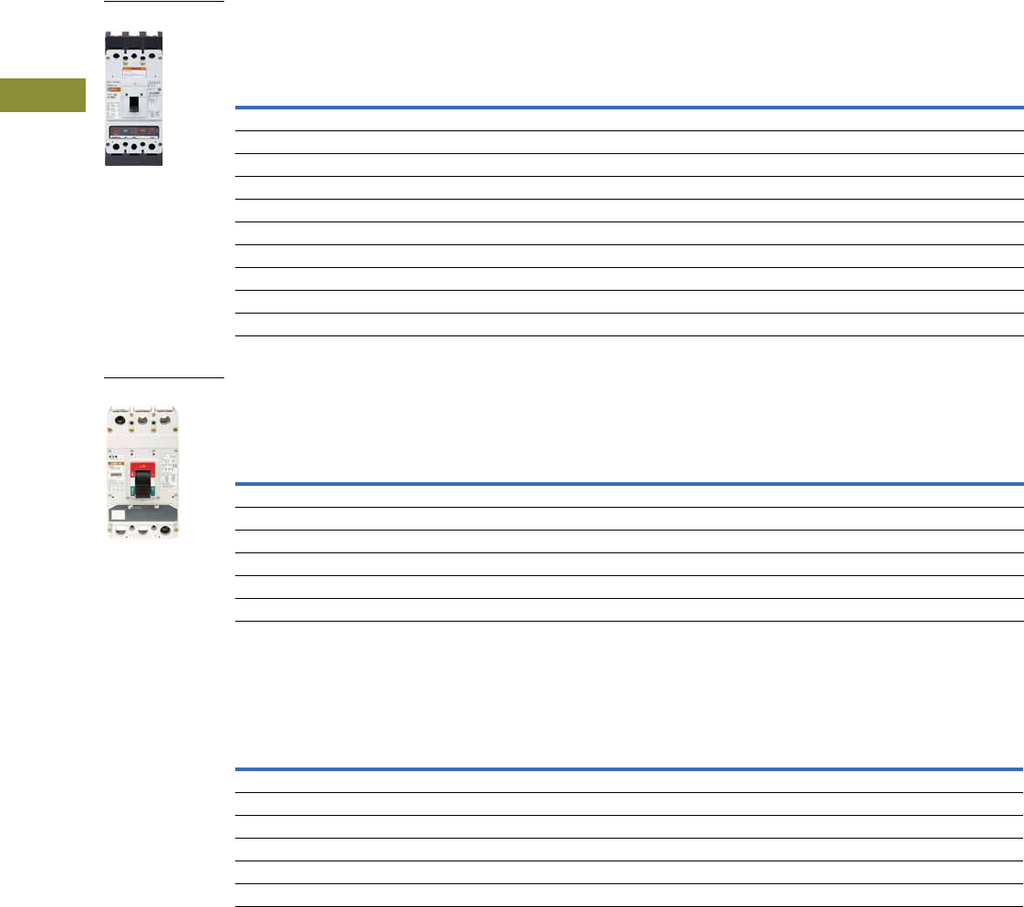
V15-T3-8 Volume 15—Solar Inverters and Electrical Balance of System CA08100018E—May 2016 eaton.com/solar
3
3
3
3
3
3
3
3
3
3
3
3
3
3
3
3
3
3
3
3
3
3
3
3
3
3
3
3
3
3
3.1
Direct Current Circuit Breakers
Specialty Breakers
Type HKDDC DC Circuit Breakers—
Three-Pole High Interrupting Capacity 42 kAIC at 600 Vdc
Type LGEDC DC Circuit Breakers—
Three-Pole High Interrupting Capacity 35 kAIC at 600 Vdc
Type LGSDC DC Circuit Breakers—
Three-Pole High Interrupting Capacity 50 kAIC at 600 Vdc
Notes
1 For complete breaker, order individual frame, trip unit and terminals for field installation.
2 Three-pole kit.
Maximum
Continuous
Ampere Rating
at 40°C
Circuit Breaker
Frame Only 1
Thermal-Magnetic
Trip Unit
Standard
Terminals
Catalog
Number
Catalog
Number
Catalog
Number
100 HKDDC3400F KT3100T TA300K
125 HKDDC3400F KT3125T TA300K
150 HKDDC3400F KT3150T TA300K
175 HKDDC3400F KT3175T TA300K
200 HKDDC3400F KT3200T TA300K
225 HKDDC3400F KT3225T TA300K
250 HKDDC3400F KT3250T TA350K
300 HKDDC3400F KT3300T TA350K
350 HKDDC3400F KT3350T TA350K
400 HKDDC3400F KT3400T 3TA400K 2
Maximum
Continuous
Ampere Rating
at 40°C
Complete
Breaker
Circuit Breaker
Frame Only 1
Thermal-Magnetic
Trip Unit
Standard
Terminals
Catalog
Number
Catalog
Number
Catalog
Number
Catalog
Number
250 LGEDC3250FAG LGEDC3630NN LT3250FA TA350LK
300 LGEDC3300FAG LGEDC3630NN LT3300FA TA350LK
350 LGEDC3350FAG LGEDC3630NN LT3350FA TA350LK
400 LGEDC3400FAG LGEDC3630NN LT3400FA TA350LK
500 LGEDC3500FAG LGEDC3630NN LT4500FA 3TA632LK 2
600 LGEDC3600FAG LGEDC3630NN LT3600FA 3TA632LK 2
Maximum
Continuous
Ampere Rating
at 40°C
Complete
Breaker
Circuit Breaker
Frame Only 1
Thermal-Magnetic
Trip Unit
Standard
Terminals
Catalog
Number
Catalog
Number
Catalog
Number
Catalog
Number
250 LGSDC3250FAG LGSDC3630NN LT3250FA TA350LK
300 LGSDC3300FAG LGSDC3630NN LT3300FA TA350LK
350 LGSDC3350FAG LGSDC3630NN LT3350FA TA350LK
400 LGSDC3400FAG LGSDC3630NN LT3400FA TA350LK
500 LGSDC3500FAG LGSDC3630NN LT4500FA 3TA632LK 2
600 LGSDC3600FAG LGSDC3630NN LT3600FA 3TA632LK 2
HKDDC3400
LGEDC3630NN

Volume 15—Solar Inverters and Electrical Balance of System CA08100018E—May 2016 eaton.com/solar V15-T3-9
3
3
3
3
3
3
3
3
3
3
3
3
3
3
3
3
3
3
3
3
3
3
3
3
3
3
3
3
3
3
3.1
Direct Current Circuit Breakers
Specialty Breakers
Type LGHDC DC Circuit Breakers—
Three-Pole High Interrupting Capacity 65 kAIC at 600 Vdc
Type HLDDC DC Circuit Breakers—
Three-Pole High Interrupting Capacity 35 kAIC at 600 Vdc
Type HLDDC DC Circuit Breakers—
Two-Pole High Interrupting Capacity 50 kAIC at 250 Vdc 34
Notes
1 For complete breaker, order individual frame, trip unit and terminals for field installation.
2 Three-pole kit.
3 Includes breaker frame, trip unit and terminals.
4 Four-pole breaker with two poles wired in parellel.
Maximum
Continuous
Ampere Rating
at 40°C
Complete
Breaker
Circuit Breaker
Frame Only 1
Thermal-Magnetic
Trip Unit
Standard
Terminals
Catalog
Number
Catalog
Number
Catalog
Number
Catalog
Number
250 LGHDC3250FAG LGHDC3630NN LT3250FA TA350LK
300 LGHDC3300FAG LGHDC3630NN LT3300FA TA350LK
350 LGHDC3350FAG LGHDC3630NN LT3350FA TA350LK
400 LGHDC3400FAG LGHDC3630NN LT3400FA TA350LK
500 LGHDC3500FAG LGHDC3630NN LT4500FA 3TA632LK 2
600 LGHDC3600FAG LGHDC3630NN LT3600FA 3TA632LK 2
Maximum
Continuous
Ampere Rating
at 40°C
Circuit Breaker
Frame Only 1
Thermal-Magnetic
Trip Unit
Standard
Terminals
Catalog
Number
Catalog
Number
Catalog
Number
300 HLDDC3600F LT3300T TA602LD
350 HLDDC3600F LT3350T TA602LD
400 HLDDC3600F LT3400T TA602LD
450 HLDDC3600F LT3450T TA602LD
500 HLDDC3600F LT3500T TA602LD
600 HLDDC3600F LT3600T 3TA603LDK 2
Maximum
Continuous
Ampere Rating
at 40°C
Complete
Breaker
Catalog
Number
600 HLDDC20600
700 HLDDC20700
800 HLDDC20800
900 HLDDC20900
1000 HLDDC21000
1200 HLDDC21200
HLDDC

V15-T3-10 Volume 15—Solar Inverters and Electrical Balance of System CA08100018E—May 2016 eaton.com/solar
3
3
3
3
3
3
3
3
3
3
3
3
3
3
3
3
3
3
3
3
3
3
3
3
3
3
3
3
3
3
3.1
Direct Current Circuit Breakers
Specialty Breakers
Type HMDLDC DC Circuit Breakers—
Three-Pole High Interrupting Capacity 35 kAIC at 600 Vdc
Type NBDC DC Circuit Breakers—
Three-Pole High Interrupting Capacity 50 kAIC at 600 Vdc
Type PBDC DC Circuit Breakers—
Three-Pole High Interrupting Capacity 65 kAIC at 600 Vdc
Notes
1 Includes frame and trip unit. Order terminals or connectors separately.
2 For complete breaker, order individual frame, trip unit and terminals for field installation.
Maximum
Continuous
Ampere Rating
at 40°C
Circuit Breaker
Frame Only 1
Thermal-Magnetic
Trip Unit
Standard
Terminals
Catalog
Number
Catalog
Number
Catalog
Number
300 HMDLDC3800F MT3300T TA700MA1
350 HMDLDC3800F MT3350T TA700MA1
400 HMDLDC3800F MT3400T TA700MA1
450 HMDLDC3800F MT3450T TA700MA1
500 HMDLDC3800F MT3500T TA700MA1
600 HMDLDC3800F MT3600T TA700MA1
700 HMDLDC3800F MT3700T TA700MA1
800 HMDLDC3800F MT3800T TA800MA2
Maximum
Continuous
Ampere Rating
at 40°C
Complete Circuit Breaker Factory
Assembled without Terminals 2
Standard
Terminals
Catalog
Number
Includes Magnetic
Trip Unit Calibrated at 135%
Catalog
Number
700 NBDC3700MW Included TA1000NB1
800 NBDC3800MW Included TA1000NB1
900 NBDC3900MW Included TA1000NB1
1000 NBDC31000MW Included TA1000NB1
1200 NBDC31200MW Included TA1200NB1
Maximum
Continuous
Ampere Rating
at 40°C
Complete Circuit Breaker
Factory Assembled
without Terminals 2
Standard Rear
Connectors
Catalog
Number
Includes Magnetic
Trip Unit Calibrated at 135%
Catalog
Number
1600 PBDC31600W Included BA2000PB
2000 PBDC32000W Included BA2000PB
2500 PBDC32500W Included BA2500PB
HMDLDC3800F

Volume 15—Solar Inverters and Electrical Balance of System CA08100018E—May 2016 eaton.com/solar V15-T3-11
3
3
3
3
3
3
3
3
3
3
3
3
3
3
3
3
3
3
3
3
3
3
3
3
3
3
3
3
3
3
3.1
Direct Current Circuit Breakers
Specialty Breakers
DC Breaker Terminal Wire Ranges
Molded Case Switches
Eaton’s DC molded case switches are used in applications requiring a compact, high-capacity disconnect. They are UL 489 listed and
have automatic high instantaneous current protection. These devices do not provide overload protection.
Molded Case Switches
Note
1Four-pole frame with two-pole connected in parallel.
Breaker
Frame
Maximum Breaker
Ampacity
Terminal Body
Material Wire Type
AWG Wire Range/
Number of Conductors
Metric Wire
Range mm2
Number of
Terminals Included
Standard Terminal
Catalog Number
EGEDC, EGSDC, EGHDC 100 Aluminum Cu/Al 14–1/0 2.5–50 3 3TA125EF
HFDDC 20 Steel Cu/Al 14–10 (1) 2.5–4 (1) 3 3T20FB
100 Steel Cu/Al 14–1/0 (1) 2.5–50 (1) 3 3T100FB
225 Aluminum Cu/Al 4–4/0 (1) 25–95 (1) 3 3TA225FD
JGEDC, JGSDC, JGHDC 250 Stainless steel Cu 4–350 (1) 25–185 (1) 1 T250FJ
HJDDC 250 Aluminum Cu/Al 4–350 kcmil (1) 25–185 (1) 1 TA250KB
HKDDC 225 Aluminum Cu/Al 3–350 kcmil (1) 35–185 (1) 1 TA300K
350 Aluminum Cu/Al 250–500 kcmil (1) 120–240 (1) 1 TA350K
400 Aluminum Cu/Al 3/0–250 kcmil (2) 95–120 (1) 3 3TA400K
LGEDC, LGSDC, LGHDC 400 Aluminum Cu/Al 2–500 (1) 35–240 (1) 1 TA350LK
630 Aluminum Cu/Al 2–500 kcmil (2) 35–240 (2) 1 TA632L
630 Aluminum Cu/Al 2–500 kcmil (2) 35–240 (2) 3 3TA632LK
HLDDC 500 Aluminum Cu/Al 3/0–350 kcmil (2) 95–150 (2) 1 TA602LD
600 Aluminum Cu/Al 400–500 kcmil (2) 185–240 (2) 3 3TA603LDK
HMDLDC 600 Aluminum Cu/Al 1–500 kcmil (2) — 1 TA700MA1
800 Aluminum Cu/Al 3/0–400 kcmil (3) — 1 TA800MA2
NBDC 700 Aluminum Cu/Al 3/0–400 kcmil (3) 95–185 (3) 1 TA1000NB1
800 Aluminum Cu/Al 3/0–400 kcmil (3) 95–185 (3) 1 TA1000NB1
900 Aluminum Cu/Al 3/0–400 kcmil (3) 95–185 (3) 1 TA1000NB1
1000 Aluminum Cu/Al 3/0–400 kcmil (3) 95–185 (3) 1 TA1000NB1
1200 Aluminum Cu/Al 4/0–500 kcmil (4) 120–240 (4) 1 TA1200NB1
Maximum
Continuous
Ampere Rating
at 40°C
Interrupting Capacity
(Volts DC)
Poles in
Series
With Line and Load Terminals Without Line and Load Terminals
Catalog
Number
Catalog
Number
600 Vdc Maximum
100 42 3 HFDDC3100KL HFDDC3100KW
150 42 3 HFDDC3150KL HFDDC3150KW
225 42 3 HFDDC3225KL HFDDC3225KW
250 65 3 JGKDC3250KSG JGKDC3250KSW
250 42 3 HJDDC3250K HJDDC3250KW
400 35 3 HKDDC3400K HKDDC3400KW
65 3 LGKDC3400KSG LGKDC3400KSW
600 65 3 LGKDC3630KSG LGKDC3630KSW
35 3 HLDDC3600K HLDDC3600WK
800 35 3 HMDLDC3800K HMDLDC3800WK
500 Vdc Maximum
100 65 3 EGK3100KSG EGK3100KSW
250 Vdc Maximum
100 50 2 HFDDC2100KL HFDDC2100KW
150 50 2 HFDDC2150KL HFDDC2150KW
225 50 2 HFDDC2225KL HFDDC2225KW
1200 50 1HLDDC21200K 1HLDDC21200WK 1

V15-T3-12 Volume 15—Solar Inverters and Electrical Balance of System CA08100018E—May 2016 eaton.com/solar
3
3
3
3
3
3
3
3
3
3
3
3
3
3
3
3
3
3
3
3
3
3
3
3
3
3
3
3
3
3
3.1
Direct Current Circuit Breakers
Specialty Breakers
Accessories
Internal Accessories
Note
1F-Frame circuit breakers are factory sealed. Underwriters Laboratories requires that internal accessories be installed at the factory. Internal accessories are UL listed for factory installation
under E7819. Where local codes and standards permit and UL listing is not required, internal accessories can be field installed. Accessory installation should be done before the circuit breaker
is mounted and connected.
One accessory can be mounted per pole, per breaker. Factory installation of accessories is available. Contact Eaton for assistance with part number configuration.
Description
Factory
Installation
(HFDDC)
Field Installation Kits
HFDDC 1
EGEDC, EGSDC,
EGHDC
JGEDC,
JGSDC,
JGHDC
LGEDC,
LGSDC,
LGHDC HJDDC HKDDC HLDDC HMDLDC NBDC PBDC
Right-Pole Mounting
Auxiliary switch
1A-1B A06 A1X1PK AUX1A1BPK AUX1A1BPK A1X2PK A1X13PK A1X4PK A1X4PK 4980D16G05 2602D32G14
2A-2B A13 A2X1RPK AUX2A2BPK AUX2A2BPK A2X2PK A2X3PK A2X4PK A2X4PK 4980D16G06 2602D32G15
Alarm switch
1 make/1 break B06 A1L1RPK ALM1M1BEPK ALM1M1BJPK A1L2RPK A1L3RPK A1L4RPK A1L4RPK — —
Auxiliary and alarm combo
1A-1B, 1 make/1
break
C05 AAL1RPK AUXALRMEPK AUXALRMJPK AAL2RPK AAL3RPK AA114RPK AA114RPK — —
Left-Pole Mounting
Shunt trip
12 Vdc S02 SNT1LP03K SNT012CPK SNT012CPK SNT2P04K SNT3P04K SNT4LP03K SNT4LP03K 2606D58G14 2606D59G28
24 Vdc S02 SNT1LP03K SNT060CPK SNT060CPK SNT2P04K SNT3P04K SNT4LP03K SNT4LP03K 2606D58G13 2606D59G27
48 Vdc S06 SNT1LP08K SNT060CPK SNT060CPK SNT2P06K SNT3P06K SNT4LP23K SNT4LP23K 2606D58G12 2606D59G26
60 Vdc S06 SNT1LP08K SNT060CPK SNT060CPK SNT2P06K SNT3P06K SNT4LP23K SNT4LP23K 2606D58G11 2606D59G25
125 Vdc S10 SNT1LP12K SNT120CPK SNT120CPK SNT2P11K SNT3P11K SNT4LP26K SNT4LP26K 2606D58G10 2606D59G24
250 Vdc S14 SNT1LP18K — — SNT2P14K SNT3P14K SNT4LP14K SNT4LP14K 2606D58G09 2606D59G23
120 Vac S06 SNT1LP12K SNT120CPK SNT120CPK SNT2P11K SNT3P11K SNT4LP11K SNT4LP11K 2060D58G05 2060D59G19
Undervoltage release
12 Vdc U30 UVH1LP20K UVR012DPK UVR012DPK UVH2LP20K UVH3LP20K UVH4LP20K UVH4LP20K 372D032G06 4976D85G11
24 Vdc U34 UVH1LP21K UVR024DPK UVR024DPK UVH2LP21K UVH3LP21K UVH4LP21K UVH4LP21K 372D032G07 4976D85G12
48 Vdc U38 UVH1LP22K UVR048DPK UVR048DPK UVH2LP22K UVH3LP22K UVH4LP22K UVH4LP22K 372D032G08 4976D85G13
125 Vdc U42 UVH1LP26K UVR125DPK UVR125DPK UVH2LP26K UVH3LP26K UVH4LP26K UVH4LP26K 372D032G09 4976D85G17
250 Vdc U46 UVH1LP28K UVR250DPK UVR250DPK UVH2LP28K UVH3LP28K UVH4LP28K UVH4LP28K 372D032G10 4976D85G18
120 Vac U14 UVH1LP08K UVR120APK UVR120APK UVH2LP08K UVH3LP08K UVH4LP08K UVH4LP08K 373D632G05 5674D29G01

Volume 15—Solar Inverters and Electrical Balance of System CA08100018E—May 2016 eaton.com/solar V15-T3-13
3
3
3
3
3
3
3
3
3
3
3
3
3
3
3
3
3
3
3
3
3
3
3
3
3
3
3
3
3
3
3.1
Direct Current Circuit Breakers
Specialty Breakers
Jumpers
Jumpers must be ordered separately. Priced individually.
HFDDC Frame
JGEDC, JGSDC, JGHDC Frames
HKDDC Frame
LGEDC, LGSDC, LGHDC Frames
Note
1 Not UL Listed; Non UL listed jumpers used in a UL application may need to be qualified by the OEM in their assembly.
This may take place with UL or another certified testing agency.
Description
Maximum
Amperes
Catalog
Number
Single copper jumper 60 DC1F060 1
100 DC1F100 1
125 DC1F125 1
225 DC1F225 1
Package of 2 aluminum jumpers 100 DC2FD100A
Package of 3 aluminum jumpers 100 DC3FD100A
Description
Maximum
Amperes
Catalog
Number
Single aluminum jumper 250 DC1JG250A 1
Package of 2 aluminum jumpers 250 DC2JG250A 1
Package of 20 aluminum jumpers 250 DC20JG250A 1
Description
Maximum
Amperes
Catalog
Number
Single copper jumper 400 DC1K400 1
Package of 2 aluminum jumpers 400 DC2KD400A 1
Package of 3 aluminum jumpers 400 DC3KD400A 1
Description
Maximum
Amperes
Catalog
Number
Package of 2 aluminum jumpers 400 DC2LG400A
Package of 3 aluminum jumpers 400 DC3LG400A
Package of 30 aluminum jumpers 400 DC30LG400A
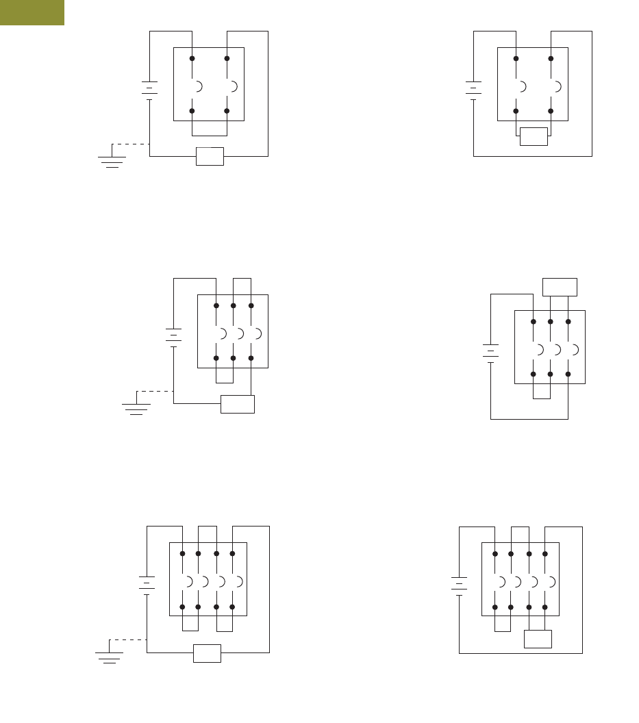
V15-T3-14 Volume 15—Solar Inverters and Electrical Balance of System CA08100018E—May 2016 eaton.com/solar
3
3
3
3
3
3
3
3
3
3
3
3
3
3
3
3
3
3
3
3
3
3
3
3
3
3
3
3
3
3
3.1
Direct Current Circuit Breakers
Specialty Breakers
Wiring Diagrams
Series Connection Diagrams for DC Application 12
250 Vdc Maximum—Two Poles in Series
500 Vdc or 600 Vdc Maximum—Three Poles in Series
750 Vdc Maximum—Four Poles in Series
Notes
1Poles in series connection is customer supplied. Use rated cable per NEC.
2For grounded systems, all poles in series must be connected on non-grounded terminal, with load connected to grounded terminal.
Load (A)
Suitable for use on ungrounded systems, or grounded
systems that have one end of load (A) connected to
grounded terminal, opposite poles in series connection.
Load
Suitable for use on ungrounded systems only.
Suitable for use on ungrounded systems, or grounded
systems that have one end of load (A) connected to
grounded terminal, opposite poles in series connection.
Suitable for use on ungrounded systems only.
Load (A)
Load
Load (A)
Load
Suitable for use on ungrounded systems, or grounded
systems that have one end of load (A) connected to
grounded terminal, opposite poles in series connection.
Suitable for use on ungrounded systems only.

Volume 15—Solar Inverters and Electrical Balance of System CA08100018E—May 2016 eaton.com/solar V15-T3-15
3
3
3
3
3
3
3
3
3
3
3
3
3
3
3
3
3
3
3
3
3
3
3
3
3
3
3
3
3
3
3.1
Direct Current Circuit Breakers
Specialty Breakers
Dimensions
Approximate Dimensions in Inches (mm)
DC Breaker Dimensions
Frame
Number
of Poles Width Height Depth
EGEDC, EGSDC, EGHDC 3 3.00 (76.2) 5.50 (139.7) 2.99 (75.9)
HFDDC 1 1.38 (35.1) 6.00 (152.4) 3.38 (86.0)
2 2.75 (70.0) 6.00 (152.4) 3.38 (86.0)
3 4.13 (105.0) 6.00 (152.4) 3.38 (86.0)
4 5.50 (139.7) 6.00 (152.4) 3.38 (86.0)
JGEDC, JGSDC, JGHDC 3 4.13 (104.9) 7.00 (177.8) 3.57 (90.7)
HJDDC 2, 3 4.13 (105.0) 10.00 (254.0) 4.06 (103.1)
HKDDC 2, 3 5.50 (139.7) 10.13 (257.3) 4.10 (104.1)
LGEDC, LGSDC, LGHDC 3 5.48 (139.2) 10.13 (257.3) 4.09 (103.9)
600A Max. HLDDC 2, 3 8.25 (209.6) 10.75 (273.1) 4.06 (103.1)
1200A Max. HLDDC 4 11.00 (279.4) 10.75 (273.1) 4.06 (103.1)
HMDLDC 2, 3 8.25 (209.6) 16.00 (406.4) 4.06 (103.1)
NBDC 3 8.25 (209.6) 16.00 (406.4) 5.50 (139.7)
PBDC 3 12.06 (306.3) 22.06 (560.3) 9.06 (230.1)
V15-T3-16 Volume 15—Solar Inverters and Electrical Balance of System CA08100018E—May 2016 eaton.com/solar
3
3
3
3
3
3
3
3
3
3
3
3
3
3
3
3
3
3
3
3
3
3
3
3
3
3
3
3
3
3
3.2
PVGard Solar Circuit Breakers
Specialty Breakers
600 Vdc Per-Pole 1000 Vdc Poles-in-Series
PVGard Solar Photovoltaic Circuit Breakers
Contents
Description Page
PVGard Solar Circuit Breakers—600 Vdc Per-Pole
and 1000 Vdc Poles-in-Series
Application Description . . . . . . . . . . . . . . . . . . V15-T3-17
Features . . . . . . . . . . . . . . . . . . . . . . . . . . . . . . V15-T3-17
Standards and Certifications . . . . . . . . . . . . . . V15-T3-17
Product Selection. . . . . . . . . . . . . . . . . . . . . . . V15-T3-18
Accessories . . . . . . . . . . . . . . . . . . . . . . . . . . . V15-T3-20
Technical Data and Specifications . . . . . . . . . . V15-T3-24
Dimensions . . . . . . . . . . . . . . . . . . . . . . . . . . . V15-T3-27
Wiring Diagrams . . . . . . . . . . . . . . . . . . . . . . . V15-T3-28
PVGard Solar Circuit Breakers—600 Vdc Per-Pole and 1000 Vdc Poles-in-Series
Product Overview
●Two PVGard lineups
●600 Vdc per-pole breaker
and switch. Each pole
rated 600 Vdc
●1000 Vdc poles-in-series
breaker and switch.
Requires poles in series
connection
●Both options UL 489B
listed for solar photovoltaic
circuit protection
●50°C calibration
●Offers both 100% and
80% rated breakers
●Handle bi-directional
current flow
Product Description
Photovoltaic (PV) systems
convert the energy of the sun
into electrical power that is
fed directly into the electric
grid. Within the balance of
system (BOS), direct current
(DC) circuit breakers protect
the wiring connected from
the PV modules to the
combiner or the inverter,
while also behaving as
a disconnect.
Eaton is a global leader in
circuit protection and brings
this expertise to bear in the
photovoltaic market. PVGard
solar circuit breakers are part
of a product family that
combines a disconnect with
circuit protection in a single,
compact, resettable device
to protect and isolate DC
circuits as needed in
photovoltaic systems.
PVGard breakers can replace
fuses, fuse holders and
disconnects in combiner box
and inverter applications—
saving space, streamlining
design, purchasing and
receiving, and reducing spare
parts requirements.
There are two PVGard lineups
to choose from: the industry-
exclusive, 600 Vdc per-pole
breakers and switches
designed for residential and
light commercial applications
and 1000 Vdc poles-in-series
breakers and switches for
commercial and utility scale
applications.
PVGard 600 Vdc Per-Pole Lineup
Only Eaton can offer this
breakthrough breaker that will
save significant space, time
and cost. As a single-circuit-
per-pole device, it allows
space savings of up to 66%
when compared to traditional
poles-in-series disconnects,
switches and breakers. In
addition, it eliminates the
need for jumpers for poles-in-
series connection—saving on
installation time, labor and
even inventory.
PVGard 1000 Vdc
Poles-in-Series Lineup
This 1000 Vdc poles-in-series
lineup provides reliable and
safe disconnect means and
overcurrent protection in
a single, compact device for
commercial and utility scale
PV systems. This solution
does not require jumpers
with the breaker/switch to
be a UL 489B listed device,
providing reliability and
flexibility in design without
limitation on implementation
of the breaker/switch. If
needed, cost-effective Eaton
jumpers can be included.

Volume 15—Solar Inverters and Electrical Balance of System CA08100018E—May 2016 eaton.com/solar V15-T3-17
3
3
3
3
3
3
3
3
3
3
3
3
3
3
3
3
3
3
3
3
3
3
3
3
3
3
3
3
3
3
3.2
PVGard Solar Circuit Breakers
Specialty Breakers
Application Description
Photovoltaic (PV) systems
convert the energy of the sun
into electrical power that is
fed directly into the electric
grid. PVGard circuit breakers
are used to protect the wiring
from the modules to the
combiner box or inverter from
overcurrents, and to provide
an isolation mechanism.
Eaton offers a complete line of
UL 489 Listed multi-purpose
600 Vdc poles-in-series
breakers and switches, as
well as protection for the
AC side of the inverter.
Features
PVGard breakers are uniquely
designed with these features:
●Meets the higher voltage
and lower fault current
levels of solar systems
●Tested to extreme ambient
conditions from –40ºC to
+90ºC
●Full complement of
accessories for status,
signalling, and on/off
operation remotely
●Can handle bi-directional
flow of current
●Can be applied in
grounded, ungrounded
or bi-polar systems
●Meets and exceeds the
standards of UL 489B for
photovoltaic molded case
circuit breakers and
molded case switches
●Available both standard
(80%-rated) and 100%-
rated breakers
●50ºC calibration
●Ability to open on signal
from DC arc or ground fault
detector
●Wide range of current
ratings increases options
for matching incoming
strings
●Eliminates fuse stocking
costs and matching issues
Designed specifically for
high- and low-temperature
demands of PV installations,
PVGard circuit breakers
undergo extreme ambient
cycling tests, and carry a
robust operating temperature
range. Trip units calibrate at
100% and 80% of nameplate
current in a 50ºC ambient,
ensuring continuous
operation in higher
temperature environments
typical to solar.
Rigorous third-party testing
includes limited and standard
fault current tests, electrical
and mechanical endurance,
di-electric voltage withstand
and temperature tests.
Eaton’s PVGard products are
stand-alone devices without
requiring jumpers to be
UL 489B listed devices.
PVGard breakers are available
with a full complement of
accessories to provide string
status, enable remote trip,
on/off operation, and can
be customized to site
requirements.
Standards and Certifications
●Designed to meet UL 489B
for solar photovoltaic circuit
protection
●UL File E350638, Category
Control Number DIUR
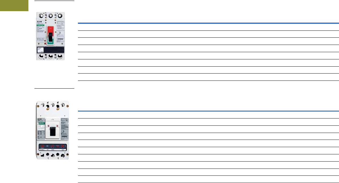
V15-T3-18 Volume 15—Solar Inverters and Electrical Balance of System CA08100018E—May 2016 eaton.com/solar
3
3
3
3
3
3
3
3
3
3
3
3
3
3
3
3
3
3
3
3
3
3
3
3
3
3
3
3
3
3
3.2
PVGard Solar Circuit Breakers
Specialty Breakers
Product Selection
Catalog number includes breaker frame and trip unit. Order terminals separately. See Page V15-T3-22.
For complete internal and external accessories, see accessory section of each frame.
JG PVS Frame, 250A Maximum, 600 Vdc Per Pole, 1.2 kA 1
KD PVS Frame, 400A Maximum, 600 Vdc Per Pole, 3 kA 1
Note
1 Terminals not included with frames.
Number Poles/
600 Vdc Circuits
80% Rated 100% Rated
Current Rating Amperes Trip Unit Catalog Number Catalog Number
90 3 Fixed thermal, fixed magnetic JGPVS3090W CJGPVS3090W
100 3 Fixed thermal, fixed magnetic JGPVS3100W CJGPVS3100W
125 3 Fixed thermal, fixed magnetic JGPVS3125W CJGPVS3125W
150 3 Fixed thermal, fixed magnetic JGPVS3150W CJGPVS3150W
175 3 Fixed thermal, fixed magnetic JGPVS3175W CJGPVS3175W
200 3 Fixed thermal, fixed magnetic JGPVS3200W CJGPVS3200W
225 3 Fixed thermal, fixed magnetic JGPVS3225W CJGPVS3225W
250 3 Fixed thermal, fixed magnetic JGPVS3250W CJGPVS3250W
Number Poles/
600 Vdc Circuits
80% Rated 100% Rated
Current Rating Amperes Trip Unit Catalog Number Catalog Number
100 3 Fixed thermal, fixed magnetic KDPVS3100W CKDPVS3100W
125 3 Fixed thermal, fixed magnetic KDPVS3125W CKDPVS3125W
150 3 Fixed thermal, fixed magnetic KDPVS3150W CKDPVS3150W
175 3 Fixed thermal, fixed magnetic KDPVS3175W CKDPVS3175W
200 3 Fixed thermal, fixed magnetic KDPVS3200W CKDPVS3200W
225 3 Fixed thermal, fixed magnetic KDPVS3225W CKDPVS3225W
250 3 Fixed thermal, fixed magnetic KDPVS3250W CKDPVS3250W
300 3 Fixed thermal, fixed magnetic KDPVS3300W CKDPVS3300W
350 3 Fixed thermal, fixed magnetic KDPVS3350W CKDPVS3350W
400 3 Fixed thermal, fixed magnetic KDPVS3400W CKDPVS3400W
JG PVS Frame
KD PVS Frame
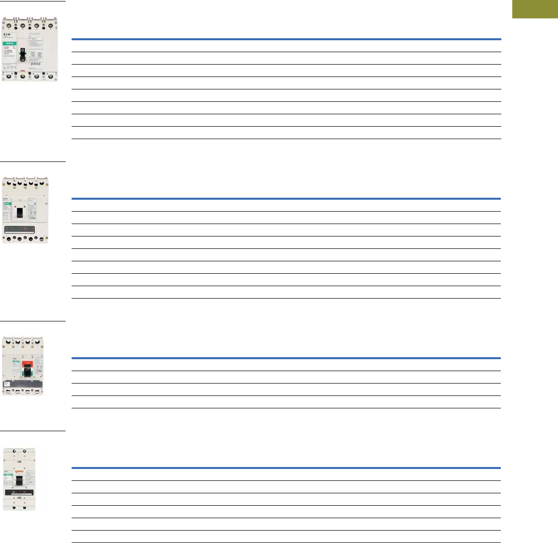
Volume 15—Solar Inverters and Electrical Balance of System CA08100018E—May 2016 eaton.com/solar V15-T3-19
3
3
3
3
3
3
3
3
3
3
3
3
3
3
3
3
3
3
3
3
3
3
3
3
3
3
3
3
3
3
3.2
PVGard Solar Circuit Breakers
Specialty Breakers
Catalog number includes breaker frame and trip unit. Order terminals separately. See Page V15-T3-22.
FD PV Frame, 100A Maximum, 1000 Vdc, 3 kA 1
KD PV Frame, 250A Maximum, 1000 Vdc, 5 kA 1
LG PV Frame, 400A Maximum, 1000 Vdc, 5 kA 1
MDL PV Frame, 600A Maximum, 1000 Vdc, 7.5 kA 1
Note
1 Terminals not included with frames.
80% Rated 100% Rated
Current Rating Amperes Poles in Series Trip Unit Catalog Number Catalog Number
30 4 Fixed thermal, fixed magnetic FDPV4030W CFDPV4030W
40 4 Fixed thermal, fixed magnetic FDPV4040W CFDPV4040W
50 4 Fixed thermal, fixed magnetic FDPV4050W CFDPV4050W
60 4 Fixed thermal, fixed magnetic FDPV4060W CFDPV4060W
70 4 Fixed thermal, fixed magnetic FDPV4070W CFDPV4070W
80 4 Fixed thermal, fixed magnetic FDPV4080W CFDPV4080W
90 4 Fixed thermal, fixed magnetic FDPV4090W CFDPV4090W
100 4 Fixed thermal, fixed magnetic FDPV4100W CFDPV4100W
80% Rated 100% Rated
Current Rating Amperes Poles in Series Trip Unit Catalog Number Catalog Number
125 4 Fixed thermal, fixed magnetic KDPV4125W CKDPV4125W
150 4 Fixed thermal, fixed magnetic KDPV4150W CKDPV4150W
175 4 Fixed thermal, fixed magnetic KDPV4175W CKDPV4175W
200 4 Fixed thermal, fixed magnetic KDPV4200W CKDPV4200W
225 4 Fixed thermal, fixed magnetic KDPV4225W CKDPV4225W
250 4 Fixed thermal, fixed magnetic KDPV4250W CKDPV4250W
300 4 Fixed thermal, fixed magnetic KDPV4300W CKDPV4300W
350 4 Fixed thermal, fixed magnetic KDPV4350W CKDPV4350W
80% Rated 100% Rated
Current Rating Amperes Poles in Series Trip Unit Catalog Number Catalog Number
250 4 Fixed thermal, fixed magnetic LGPV4250FFW CLGPV4250FFW
300 4 Fixed thermal, fixed magnetic LGPV4300FFW CLGPV4300FFW
350 4 Fixed thermal, fixed magnetic LGPV4350FFW CLGPV4350FFW
400 4 Fixed thermal, fixed magnetic LGPV4400FFW CLGPV4400FFW
80% Rated 100% Rated
Current Rating Amperes Poles in Series Trip Unit Catalog Number Catalog Number
300 3 Fixed thermal, fixed magnetic MDLPV3300W CMDLPV3300W
350 3 Fixed thermal, fixed magnetic MDLPV3350W CMDLPV3350W
400 3 Fixed thermal, fixed magnetic MDLPV3400W CMDLPV3400W
450 3 Fixed thermal, fixed magnetic MDLPV3450W CMDLPV3450W
500 3 Fixed thermal, fixed magnetic MDLPV3500W CMDLPV3500W
600 3 Fixed thermal, fixed magnetic MDLPV3600W CMDLPV3600W
FD PV Frame
KD PV Frame
LG PV Frame
MDL PV Frame

V15-T3-20 Volume 15—Solar Inverters and Electrical Balance of System CA08100018E—May 2016 eaton.com/solar
3
3
3
3
3
3
3
3
3
3
3
3
3
3
3
3
3
3
3
3
3
3
3
3
3
3
3
3
3
3
3.2
PVGard Solar Circuit Breakers
Specialty Breakers
Accessories
Available Accessories
●Auxiliary switch
●Shunt trip
●Electrical operator
●Alarm lockout
●Undervoltage release
●Terminals
●Lock-off devices
●End cap kits
●Rotary handle mechanisms
●Flexible shaft handle
mechanisms
Optional modifications
●Freeze testing
For complete internal and external accessories, see the
accessory section of each frame.
External Accessories
Description Frame
Catalog
Number
Imperial Base Mounting Hardware
0.164-32 x 1.5-inch pan-head steel screws and lockwashers FD PV BMH1
0.250-20 x 1.5 inch pan-head steel screws and lockwashers KD PV
KD PVS
BMH3
—JG PVSN/A
—LG PVN/A
0.3125-18 x 1.25 inch filister-head steel screws and
lockwashers and flat washers
MDL PV BMH5
Metric Base Mounting Hardware
M4–0.7 x 38 mm pan-head steel screws and lockwashers FD PV BMH1M
M6–0.7 x 38 mm pan-head steel screws and lockwashers KD PV
KD PVS
BMH3M
— JG PVS Included 1
— LG PV Included 1
M8-1.25 x 35 mm pan-head steel screws and lockwashers MDL PV BMH5M
Interphase Barriers
FD PV IPB1
KD PV
KD PVS
IPB3
JG PVS FJIPBK 2
LG PV IPB3
MDL PV IPB4
Non-Padlockable Handle Block
FD PV LKD1
KD PV
KD PVS
LKD3
JG PVS N/A
LG PV N/A
MDL PV LKD4
Padlockable Handle Lock Hasp 3
FD PV PLK1
KD PV
KD PVS
PLK3
JG PVS FJPHL
LG PV LPHL
MDL PV HLK4
Factory Modifications—Freeze Testing to –40ºC 4
Molded Case Switches
Eaton’s DC molded case
switches (MCS) are used in
applications requiring a
compact, high capacity
disconnect. PVGard 1000 Vdc
MCS are UL 489B listed and
have automatic instantaneous
current protection. These
devices do not provide
overload protection.
Molded Case Switches
Notes
1Base mounting hardware is included with a circuit breaker or a molded case switch
(included with breaker). If required separately, order 66A2546G02.
2Individually priced.
3Locks in ON and OFF position.
4Add 20% to list price.
Frame Modification Code
FD PV F01
JG PVS F01
KD PV and KD PVS F01
LG PV F01
MDL PV F01
Special calibration—contact Eaton for availability
Maximum Continuous
Ampere Rating at 50°C
Interrupting
Capacity Vdc
Poles in
Series
Catalog
Number
1000 Vdc Maximum
100 3000 4 FDPV4100KW
200 5000 4 KDPV4200KW
250 5000 4 KDPV4250KW
350 5000 4 KDPV4350KW
400 5000 4 LGPV4400KSW
600 7500 3 MDLPV3600KSW

Volume 15—Solar Inverters and Electrical Balance of System CA08100018E—May 2016 eaton.com/solar V15-T3-21
3
3
3
3
3
3
3
3
3
3
3
3
3
3
3
3
3
3
3
3
3
3
3
3
3
3
3
3
3
3
3.2
PVGard Solar Circuit Breakers
Specialty Breakers
Internal Accessories—Right Pole Mounting
Internal Accessories—Left Pole Mounting
Notes
1Underwriters Laboratories requires that internal accessories for the FD PV be installed at the factory. Internal accessories are UL listed for factory installation
under E7819. Where local codes and standards permit and UL listing is not required, internal accessories can be field installed. Accessory installation should be
done before the circuit breaker is mounted and connected.
One accessory can be mounted per pole, per breaker.
FD PV 1JG PVS
KD PV
KD PVS LG PV MDL PV
Factory
Modification
Code
Field Kit
Catalog
Number
Factory
Modification
Code
Field Kit
Catalog
Number
Factory
Modification
Code
Field Kit
Catalog
Number
Factory
Modification
Code
Field Kit
Catalog
Number
Factory
Modification
Code
Field Kit
Catalog
Number
Auxiliary Switch
1A-1B A06 A1X1PK A1 AUX1A1BPK A06 A1X3PK A1 AUX1A1BPK A06 A1X4PK
2A-2B A13 A2X1RPK A2 AUX2A2BPK A13 A2X3PK A2 AUX2A2BPK A13 A2X4PK
Alarm Switch
1 make/1 break B06 A1L1RPK B1 ALM1M1BJPKL B06 A1L3RPK B1 ALM1M1BJPK B06 A1L4RPK
Auxiliary and Alarm Combo
1A-1B, 1 make/1 break C05 AAL1RPK B2w AUXALRMJPK C05 AAL3RPK B2 AUXALRMJPK C05 AA114RPK
FD PV 1JG PVS
KD PV
KD PVS LG PV MDL PV
Factory
Modification
Code
Field Kit
Catalog
Number
Factory
Modification
Code
Field Kit
Catalog
Number
Factory
Modification
Code
Field Kit
Catalog
Number
Factory
Modification
Code
Field Kit
Catalog
Number
Factory
Modification
Code
Field Kit
Catalog
Number
Shunt Trip
12 Vdc S02 SNT1LP03K S4 SNT012CPK S42 SNT3P04K S4 SNT012CPK S02 SNT4LP03K
24 Vdc S02 SNT1LP03K S1 SNT060CPK S42 SNT3P04K S1 SNT060CPK S02 SNT4LP03K
48 Vdc S06 SNT1LP08K S1 SNT060CPK S50 SNT3P06K S1 SNT060CPK S86 SNT4LP23K
60 Vdc S06 SNT1LP08K S1 SNT060CPK S50 SNT3P06K S1 SNT060CPK S86 SNT4LP23K
125 Vdc S10 SNT1LP12K S5 SNT125DPK S10 SNT3P11K S2 SNT120CPK S42 SNT4LP26K
250 Vdc S14 SNT1LP18K ——S14 SNT3P14K — — S14 SNT4LP14K
120 Vac S10 SNT1LP12K S2 SNT120CPK S10 SNT3P11K S2 SNT120CPK S10 SNT4LP11K
Undervoltage Release
12 Vdc U30 UVH1LP20K —— T02UVH3LP20K U1 UVR012DPK T02 UVH4LP20K
24 Vdc U34 UVH1LP21K U2 UVR024CPK T02 UVH3LP21K U2 UVR024DPK T06 UVH4LP21K
48 Vdc U38 UVH1LP22K U4 UVR048DPK T10 UVH3LP22K U4 UVR048DPK T10 UVH4LP22K
60 Vdc — — U4 UVR048DPK ———— ——
125 Vdc U42 UVH1LP26K U6 UVR125DPK T14 UVH3LP26K U6 UVR125DPK T14 UVH4LP26K
250 Vdc U46 UVH1LP28K U8 UVR250DPK T18 UVH3LP28K U8 UVR250DPK T18 UVH4LP28K
120 Vac U14 UVH1LP08K U5 UVR120APK U18 UVH3LP08K U5 UVR120APK U18 UVH4LP08K

V15-T3-22 Volume 15—Solar Inverters and Electrical Balance of System CA08100018E—May 2016 eaton.com/solar
3
3
3
3
3
3
3
3
3
3
3
3
3
3
3
3
3
3
3
3
3
3
3
3
3
3
3
3
3
3
3.2
PVGard Solar Circuit Breakers
Specialty Breakers
PVGard Solar Circuit Breaker Terminal Offering
Endcap Kits
Notes
1Three terminals with terminal shield as a kit.
2Three terminals with two interphase barriers as a kit.
Breaker
Frame
Maximum
Breaker
Ampacity
Terminal Body
Material Wire Type
AWG Wire Range/
Number of Conductors
Metric Wire
Range mm2
Number of
Terminals
Included
Standard
Terminal
Catalog
Number Comments
FD PV 50 Steel Cu/Al 14–4 (1) 2.5–25 (1) 3 3TA50FB
100 Aluminum Cu/Al 6–300 kcmil (1) 16–150 (1) 3 3TA225FDK Includes 3P terminal cover
100 Copper Cu 4–4/0 (1) 25–95 (1) 3 3T225FD
JG PVS 250 Aluminum Cu/Al #8–350 kcmil (1) — — TA250FJ
250 Aluminum Cu/Al (2) 2/0–(2) 4/0 — 13TA251FJK1
250 Aluminum Cu/Al (2) 2/0–(2) 4/0 — 23TA251FJK2
250 Copper Cu #4–350 kcmil (1) — — T250FJ
KD PV
KD PVS
225 Aluminum Cu/Al 3–350 kcmil (1) 35–185 (1) 1 TA300K
250 Aluminum Cu/Al 250–500 kcmil (1) 120–240 (1) 1 TA350K
250 Aluminum Cu/Al 3/0–250 kcmil (2) 95–120 (1) 4 4TA400K Contains interphase barriers
250 Aluminum Cu/Al 2/0–250 kcmil (2) or 2/0–500 kcmil (1) 70–240 (2) 4 4TA401K
300 Aluminum Cu/Al 3/0–250 kcmil (2) 95–120 (2) 4 4TA401K Contains interphase barriers
350 Aluminum Cu/Al 3/0–250 kcmil (2) 95–120 (2) 4 4TA401K Contains interphase barriers
225 Copper Cu 3–350 kcmil (1) 35–185 (1) 1 T300K
250 Copper Cu 250–500 kcmil (1) 120–240 (1) 1 T350K
250 Copper Cu 3/0–250 kcmil (2) 95–120 (1) 4 4T400K Contains interphase barriers
300 Copper Cu 3/0–250 kcmil (2) 95–120 (2) 4 4TA401K Contains interphase barriers
350 Copper Cu 3/0–250 kcmil (2) 95–120 (2) 4 4TA401K Contains interphase barriers
LG PV 400 Aluminum Cu/Al 2–500 kcmil (2) 35–240 (2) 4 4TA632LK Includes 4P terminal cover
250 Copper Cu 2–500 kcmil (1) 35–240 (1) 1 T350LK
400 Copper Cu 2–500 kcmil (2) 35–240 (2) 4 4T632LK Includes 4P terminal cover
MDL PV 300 Aluminum Cu/Al 1–500 kcmil (2) — 1 TA700MA1
600 Aluminum Cu/Al 3/0–400 kcmil (3) — 1 TA800MA2
Breaker Frame Number of Poles Thread Type Thread Size Catalog Number
FD PV 4 Imperial 10–32 KPEK14
4 Metric M–5 KPEKM14
JG PVS 3 Imperial — FJ3RTDK
3 Metric — FJ3RTWK
KD PV 4 Imperial 0.312–18 KPEK34
4 Metric M–8 KPEKM34
KD PVS 3 Imperial — KPEK3
3 Metric — KPEKM3
LG PV 4 Imperial — N/A
4 Metric M-10 L4RTWK
MDL PV 3 Imperial — —
3 Metric — —

Volume 15—Solar Inverters and Electrical Balance of System CA08100018E—May 2016 eaton.com/solar V15-T3-23
3
3
3
3
3
3
3
3
3
3
3
3
3
3
3
3
3
3
3
3
3
3
3
3
3
3
3
3
3
3
3.2
PVGard Solar Circuit Breakers
Specialty Breakers
Jumpers
Jumpers must be ordered separately. Priced individually.
FD PV Frame
JG PVM, JG PVMD Frames
KD PV, KD PVM, KD PVMD Frames
LG PV Frame
Note
1 Not UL Listed; Non UL listed jumpers used in a UL application may need to be qualified by the OEM in their assembly.
This may take place with UL or another certified testing agency.
Description
Maximum
Amperes
Catalog
Number
Single copper jumper 60 DC1F060 1
100 DC1F100 1
125 DC1F125 1
225 DC1F225 1
Package of 2 aluminum jumpers 100 DC2FD100A
Package of 3 aluminum jumpers 100 DC3FD100A
Description
Maximum
Amperes
Catalog
Number
Single aluminum jumper 250 DC1JG250A 1
Package of 2 aluminum jumpers 250 DC2JG250A 1
Package of 20 aluminum jumpers 250 DC20JG250A 1
Description
Maximum
Amperes
Catalog
Number
Single copper jumper 400 DC1K400 1
Package of 2 aluminum jumpers 400 DC2KD400A 1
Package of 3 aluminum jumpers 400 DC3KD400A 1
Description
Maximum
Amperes
Catalog
Number
Package of 2 aluminum jumpers 400 DC2LG400A
Package of 3 aluminum jumpers 400 DC3LG400A
Package of 30 aluminum jumpers 400 DC30LG400A

V15-T3-24 Volume 15—Solar Inverters and Electrical Balance of System CA08100018E—May 2016 eaton.com/solar
3
3
3
3
3
3
3
3
3
3
3
3
3
3
3
3
3
3
3
3
3
3
3
3
3
3
3
3
3
3
3.2
PVGard Solar Circuit Breakers
Specialty Breakers
Technical Data and Specifications
●Thermal-magnetic circuit
breakers
●Designed to meet UL 489B
for solar photovoltaic circuit
protection
●100% rated of the
continuous current rating
●50°C calibrated
●Can be applied in
grounded, ungrounded or
bi-polar systems
●Ability to open on signal
from DC arc or ground fault
detector
●Two PVGard lineups
●UL File EE350638,
Category Control
Number DIUR
●600 Vdc per-pole breaker
and switch
– Each pole rated
600 Vdc
●1000 Vdc poles-in-series
breaker and switch
– Requires poles in
series connection
Quick Reference PVGard Solar Circuit Breakers
600 Vdc Per-Pole
PVGard 600 Vdc Current Ratings by Frame
UL 489B Interrupting Capacity (kA) 600 Vdc Per-Pole
Quick Reference PVGard Solar Circuit Breakers
1000 Vdc Poles-in-Series
PVGard 1000 Vdc Current Ratings by Frame
UL 489B Interrupting Capacity (kA) 1000 Vdc
Circuit
Breaker Type
Minimum
Amperes
Maximum
Amperes kA Rating
JG PVS 90 250 1.2
KD PVS 100 400 3
Circuit
Breaker Type
Minimum
Amperes
Maximum
Amperes kA Rating
Poles in
Series
FD PV 30 100 3 4
KD PV 125 350 5 4
LG PV 250 400 5 4
MDL PV 300 600 7.5 3
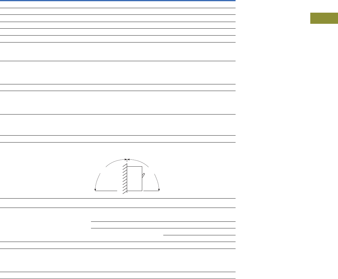
Volume 15—Solar Inverters and Electrical Balance of System CA08100018E—May 2016 eaton.com/solar V15-T3-25
3
3
3
3
3
3
3
3
3
3
3
3
3
3
3
3
3
3
3
3
3
3
3
3
3
3
3
3
3
3
3.2
PVGard Solar Circuit Breakers
Specialty Breakers
PVGard 600 Vdc Per-Pole Solar PV Circuit Breakers (100% and 80% Rated Frames)
Notes
1Line/top side connection only PVGard FD PVS breakers.
2Three terminals with terminal shield as a kit.
3Three terminals with two interphase barriers as a kit.
4Not UL 489B recognized size for maximum of 400A breaker.
JG PVS KD PVS
Number of 600 Vdc circuits 3 3
Maximum voltage rating 600 Vdc 600 Vdc
Ampere range 90–250A 100–400A
Interrupting capacity at 600 Vdc 1.2 kA 3 kA
Time constant 1 ms 1 ms
Trip unit type Thermal-magnetic Thermal-magnetic
Rated impulse withstand voltage
Main conducting paths
Auxiliary circuits
8 kV
4 kV
8 kV
4 kV
Endurance
Mechanical operations
Electrical operations
Maximum switching frequency
10,000
400
240 per hour
6000
400
240 per hour
Third-party certification UL 489B UL 489B
Environment
Design ambient temperature
Maximum current at 60°C, as % of rated current
Maximum current at 70°C, as % of rated current
50°C
93%
85%
50°C
93%
85%
Operating temperature range
Storage temperature range
Suitable for freeze temperatures to –40°C
Relative humidity
–20°C to +50°C
–20°C to +70°C
Option
0 to 95% noncondensing
–20°C to +50°C
–20°C to +70°C
Option
0 to 95% noncondensing
Suitable for reverse-feed applications Yes Yes
Mounting—permissible mounting position
Connection diagrams
Terminations
Al/Cu wire TA250FJ: (1) #8–350 kcmil TA300K: (1) #3–350 kcmil
3TA251FJK1: (2) 2/0–(2) 4/0 2TA350K: (1) 250–500 kcmil
3TA251FJK2: (2) 2/0–(2) 4/0 3TA403K: (2) 1/0–400 kcmil
3TA402K: (1) 500–-750 kcmil 4
Cu wire T250FJ: (1) #4–350 kcmil T300K: (1) #3–350 kcmil
Dimensions in inches (mm)
Height
Width
Depth
7.00 (177.8)
4.13 (104.9)
3.57 (90.7)
10.13 (257.3)
5.50 (139.7)
4.10 (104.1)
Weight in lbs 6.6 11.42
90º
90º
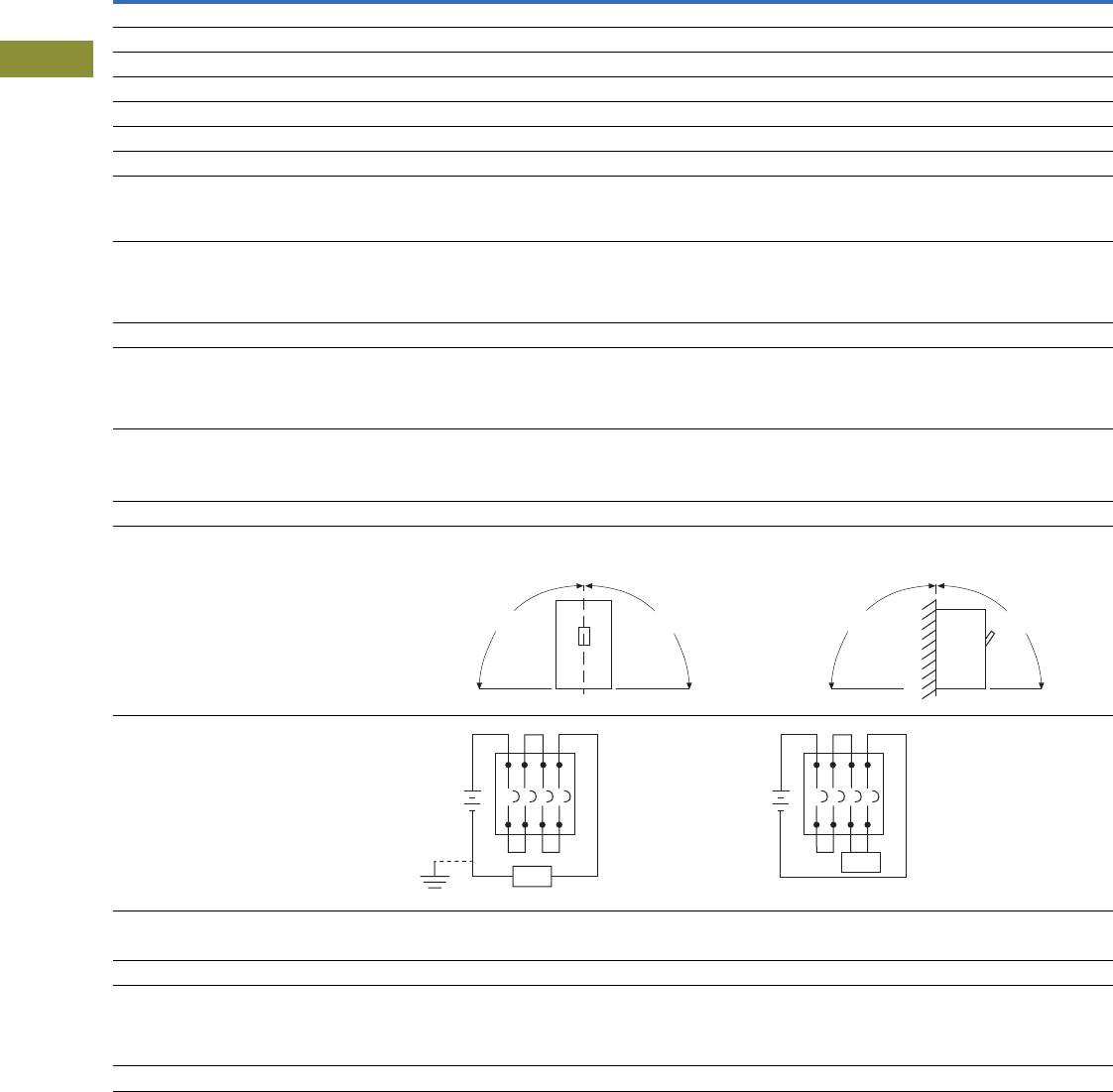
V15-T3-26 Volume 15—Solar Inverters and Electrical Balance of System CA08100018E—May 2016 eaton.com/solar
3
3
3
3
3
3
3
3
3
3
3
3
3
3
3
3
3
3
3
3
3
3
3
3
3
3
3
3
3
3
3.2
PVGard Solar Circuit Breakers
Specialty Breakers
PVGard 1000 Vdc Solar PV Circuit Breakers (100% and 80% Rated Frames)
Notes
1Suitable for use on ungrounded systems, or grounded systems that have one end of load (A) connected to grounded terminal, opposite poles in series connection.
2Suitable for use on ungrounded systems only.
FD PV KD PV LG PV MDL PV
Number of poles 4443
Maximum voltage rating 1000 Vdc 1000 Vdc 1000 Vdc 1000 Vdc
Maximum current rating 100A 350A 400A 600A
Interrupting capacity at 1000 Vdc 3 kA 5 kA 5 kA 7.5 kA
Time constant 1 ms 1 ms 1 ms 1 ms
Ampere range 15–100A 125–350A 250–400A 300–600A
Trip unit type Thermal-magnetic Thermal-magnetic Thermal-magnetic Thermal-magnetic
Rated impulse withstand voltage
Main conducting paths
Auxiliary circuits
8 kV
4 kV
8 kV
4 kV
8 kV
4 kV
8 kV
4 kV
Endurance
Mechanical operations
Electrical operations
Maximum switching frequency
10,000
1000
300 per hour
10,000
400
240 per hour
8000
400
240 per hour
8000
400
240 per hour
Third-party certification UL 489B UL 489B UL 489B UL 489B
Environment
Design ambient temperature
Maximum current at 60°C, as % of rated current
Maximum current at 70°C, as % of rated current
50°C
91%
88%
50°C
91%
88%
50°C
93%
88%
50°C
93%
88%
Operating temperature range
Storage temperature range
Suitable for freeze temperatures to –40°C
Relative humidity
–20°C to +50°C
–20°C to +70°C
Option
0 to 95% noncondensing
–20°C to +50°C
–20°C to +70°C
Option
0 to 95% noncondensing
–20°C to +50°C
–20°C to +70°C
Option
0 to 95% noncondensing
–20°C to +50°C
–20°C to +70°C
Option
0 to 95% noncondensing
Suitable for reverse-feed applications Yes Yes Yes Yes
Mounting—permissible mounting position
Connection diagrams 1 2
Terminations
Al/Cu wire #6–300 kcmil (2) 3/0–250 kcmil (2) #2–500 kcmil (3) 3/0–400 kcmil
Cu wire #4–4/0 (2) 3/0–250 kcmil (2) #2–500 kcmil (3) 3/0–300 kcmil
Dimensions in inches (mm)
Height
Width
Depth
6.00 (152.4)
5.50 (139.7)
3.38 (85.9)
10.13 (257.3)
7.22 (183.4)
4.09 (103.9)
10.13 (257.3)
7.22 (183.4)
4.09 (103.9)
16.00 (406.4)
8.25 (209.5)
4.06 (103.1)
Weight in lbs 6 20 20 29
90º
90º
90º
90º
Load
(A)
Load

Volume 15—Solar Inverters and Electrical Balance of System CA08100018E—May 2016 eaton.com/solar V15-T3-27
3
3
3
3
3
3
3
3
3
3
3
3
3
3
3
3
3
3
3
3
3
3
3
3
3
3
3
3
3
3
3.2
PVGard Solar Circuit Breakers
Specialty Breakers
Dimensions
Approximate Dimensions in Inches (mm)
PVGard Solar Circuit Breakers—600 Vdc Per-Pole
PVGard Solar Circuit Breakers—1000 Vdc Poles-in-Series
Frame
Number of
Circuits in
a Frame Width Height Depth
JG PVS 3 4.13 (104.9) 7.00 (177.8) 3.44 (87.4)
KD PVS 3 5.49 (139.4) 10.13 (257.2) 4.31 (109.6)
Frame
Number
of Poles Width Height Depth
FD PV 4 5.50 (139.7) 6.00 (152.4) 3.38 (86.0)
KD PV 4 7.22 (183.4) 10.13 (257.3) 4.09 (103.9)
LG PV 4 7.22 (183.4) 10.13 (257.3) 4.09 (103.9)
MDL PV 3 8.25 (209.6) 16.00 (406.4) 4.06 (103.1)
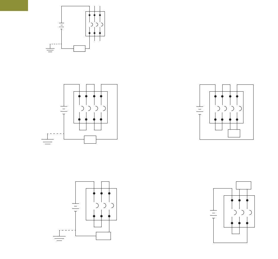
V15-T3-28 Volume 15—Solar Inverters and Electrical Balance of System CA08100018E—May 2016 eaton.com/solar
3
3
3
3
3
3
3
3
3
3
3
3
3
3
3
3
3
3
3
3
3
3
3
3
3
3
3
3
3
3
3.2
PVGard Solar Circuit Breakers
Specialty Breakers
Wiring Diagrams
Series Connection Diagrams for DC Application 12
JF PVS, KD PVS—600 Vdc Per-Pole
FD PV, KD PV, LG PV—1000 Vdc Maximum—Four Poles-in-Series
MDL PV—1000 Vdc Maximum—Three Poles in Series
Notes
1Poles in series connection is customer supplied. Use rated cable per NEC.
2For grounded systems, all poles in series must be connected on non-grounded terminal, with load connected to grounded terminal.
Load
Suitable for grounded or ungrounded systems.
Suitable for quantity (3) 600 Vdc circuits.
Load (A)
Load
Suitable for use on ungrounded systems, or grounded
systems that have one end of load (A) connected to
grounded terminal, opposite poles in series connection.
Suitable for use on ungrounded systems only.
Suitable for use on ungrounded systems, or grounded
systems that have one end of load (A) connected to
grounded terminal, opposite poles in series connection.
Suitable for use on ungrounded systems only.
Load (A)
Load
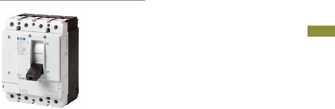
Volume 15—Solar Inverters and Electrical Balance of System CA08100018E—May 2016 eaton.com/solar V15-T3-29
3
3
3
3
3
3
3
3
3
3
3
3
3
3
3
3
3
3
3
3
3
3
3
3
3
3
3
3
3
3
3.3
DC Switch Disconnectors
DC Switch Disconnectors
Contents
Description
DC Switch Disconnectors
Product Selection . . . . . . . . . . . . . . . . . . . . . . . V15-T3-30
Technical Data and Specifications . . . . . . . . . . V15-T3-34
Dimensions . . . . . . . . . . . . . . . . . . . . . . . . . . . V15-T3-37
DC Switch Disconnectors
Product Description
Switch disconnectors N…DC
in the special version for up to
1500 Vdc can be used on
single- or two-poles. They
comply with the isolation
properties for earthed IT
networks. Accessories, such
as bridge kits, connection
terminals and door coupling
rotary handles, enable
individual installation in the
most varied types of
distribution systems. Auxiliary
switches, voltage releases
and remote operators
facilitate signalling and
automation.
Application Description
●Switch disconnectors for
nominal system voltage up
to 1500 Vdc
●Suitable for cabinets with
ambient temperatures up
to 70°C
●Main switch before DC/AC
converter fulfills NEC
requirements
●Safely switching in
combiner boxes enables
effective operation in case
of maintenance with
breaking capacity under
load up to 4x nominal
current
●Bi-directional functionality
of switch contacts for array
protection suitable for
grounded or ungrounded
systems
Features
●Switch disconnectors N
can be combined with
voltage releases NZM...-
XU, NZM...-XA and
auxiliary contacts, as well
as with remote operator
NZM...-XR
●For DC switching, series
connection of all four
current paths is needed
●Standard equipment:
screw-type connection,
frame terminal available
as an option
●For non-earthed networks
(e.g., IT), the installation
must be configured such
that the likelihood of a
double earth fault is
negligibly small
●Switches can not be
combined with
withdrawable units and/or
connection on rear
●N4-4-...S15-DC supply from
the bottom only
Standards and Certifications
●IEC/EN 60947-3
●Main switch characteristics
including positive drive to
IEC/EN 60204 and
VDE 0113
●Isolating characteristics to
IEC/EN 60947 and
VDE 0660
●Busbar tag shroud to
VDE 0160 Part 100
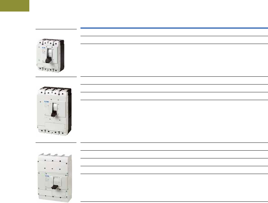
V15-T3-30 Volume 15—Solar Inverters and Electrical Balance of System CA08100018E—May 2016 eaton.com/solar
3
3
3
3
3
3
3
3
3
3
3
3
3
3
3
3
3
3
3
3
3
3
3
3
3
3
3
3
3
3
3.3
DC Switch Disconnectors
Product Selection
Switch Disconnectors for 1000/1500 Vdc, Single- and Two-Pole
Rated Operational
Current Rated =
Uninterrupted
Current
In = Iu
Short-Circuit
Protective
Device Fuse
gR-Characteristic
Screw
Connection
Units per
Package
1000 Vdc
Fixed Mounted
1500 Vdc
Fixed Mounted
Catalog
Number
Catalog
Number
160A 200A S 1 N2-4-160-S1-DC N2-4-160-S15-DC
200A 200A S 1 N2-4-200-S1-DC N2-4-200-S15-DC
250A 200A S 1 N2-4-250-S1-DC N2-4-250-S15-DC
320A 500A S 1 N3-4-320-S1-DC N3-4-320-S15-DC
400A 500A S 1 N3-4-400-S1-DC N3-4-400-S15-DC
500A 500A S 1 N3-4-500-S1-DC N3-4-500-S15-DC
550A 500A S 1 N3-4-550-S1-DC N3-4-550-S15-DC
800A — S 1 N4-4-800-S1-DC N4-4-800-S15-DC
1000A — S 1 N4-4-1000-S1-DC N4-4-1000-S15-DC
1250A — S 1 N4-4-1250-S1-DC N4-4-1250-S15-DC
1400A — S 1 N4-4-1400-S1-DC N4-4-1400-S15-DC
1600A — S 1 N4-4-1600-S1-DC N4-4-1600-S15-DC
N2-4
N3-4
N4-4
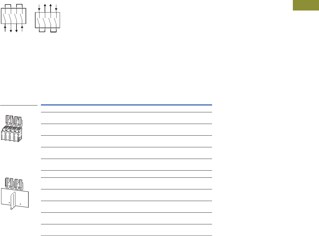
Volume 15—Solar Inverters and Electrical Balance of System CA08100018E—May 2016 eaton.com/solar V15-T3-31
3
3
3
3
3
3
3
3
3
3
3
3
3
3
3
3
3
3
3
3
3
3
3
3
3
3
3
3
3
3
3.3
DC Switch Disconnectors
Bridge Kits
Two-Pole (+ and –) on
One Side
●Model contains parts for
upper or lower row of
switchgear side for four-
pole switches N...-S1(S15)-
DC that are used as
two-pole switches for DC
●Each link connects two
contacts in series
●Incoming unit and outgoing
at bottom according to the
switching diagrams
●N4-4-... ≥1250A at 65°C
alternate connection at
bottom through module
plates NZM4-4-XKM2S-
1600
●N4-4-...S15-DC supply from
the bottom only
Bridge Kits NZM...-XKV...2P...
Note
1 Includes cooling unit.
Detailed assignment taking into account ambient temperature, degree of protection and fitting position as listed
in tables on Pages V15-T3-34 and V15-T3-35.
Rated Operational
Current In
Protection
Class For Use With
Units Per
Package
Catalog
Number
Including Cover
225A at 40°C
170A at 65°C
IP2X N2-4-...S1-(S15)-DC 1 NZM2-4-XKV2P
250A at 40°C
190A at 65°C
IP2X N2-4-...S1-(S15)-DC 1 1NZM2-4-XKV2P-K
517A at 40°C
435A at 65°C
IP2X N3-4-...S1-(S15)-DC 1 NZM3-4-XKV2P
550A at 40°C
468A at 65°C
IP2X N3-4-...S1-(S15)-DC 1 1NZM3-4-XKV2P-K
1400A at 40°C
1260A at 65°C
IP2X N4-4-...S1-(S15)-DC 1 NZM4-4-XKV2P
Including Insulation Plates and Phase Separator
238A at 40°C
180A at 65°C
IP00 N2-4-...S1-(S15)-DC 1 NZM2-4-XKVI2P
250A at 40°C
213A at 65°C
IP00 N2-4-...S1-(S15)-DC 1 1NZM2-4-XKVI2P-K
534A at 40°C
451A at 65°C
IP00 N3-4-...S1-(S15)-DC 1 NZM3-4-XKVI2P
550A at 40°C
501A at 65°C
IP00 N3-4-...S1-(S15)-DC 1 1NZM3-4-XKVI2P-K
1600A at 40°C
1500A at 65°C
IP00 N4-4-...S1-(S15)-DC 1 1NZM4-4-XKV2P-K
Bridge Kits
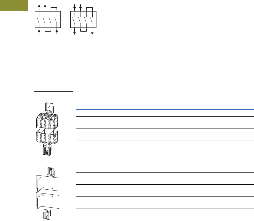
V15-T3-32 Volume 15—Solar Inverters and Electrical Balance of System CA08100018E—May 2016 eaton.com/solar
3
3
3
3
3
3
3
3
3
3
3
3
3
3
3
3
3
3
3
3
3
3
3
3
3
3
3
3
3
3
3.3
DC Switch Disconnectors
Two-Pole (+ and –)
Double Sided
●Model contains parts for
upper and lower row of
switchgear side for four-
pole switches N...-S1(S15)-
DC that are used as
two-pole switches for DC
●Each link connects three
contacts in series
●Incoming unit and outgoing
at bottom or top, according
to the switching diagrams
Bridge Kits NZM...-XKV...2POU...
Note
1 Includes cooling unit.
Detailed assignment taking into account ambient temperature, degree of protection and fitting position as listed
in tables on Pages V15-T3-34 and V15-T3-35.
Rated Operational
Current In
Protection
Class For Use With
Units Per
Package
Catalog
Number
Including Cover
200A at 40°C
160A at 65°C
IP2X N2-4-...S1-(S15)-DC 1 NZM2-4-XKV2POU
225A at 40°C
170A at 65°C
IP2X N2-4-...S1-(S15)-DC 1 1NZM2-4-XKV2POU-K
400A at 40°C
388A at 65°C
IP2X N3-4-...S1-(S15)-DC 1 NZM3-4-XKV2POU
517A at 40°C
435A at 65°C
IP2X N3-4-...S1-(S15)-DC 1 1NZM3-4-XKV2POU-K
Including Insulation Plates and Phase Separator
213A at 40°C
160A at 65°C
IP00 N2-4-...S1-(S15)-DC 1 NZM2-4-XKVI2POU
238A at 40°C
180A at 65°C
IP00 N2-4-...S1-(S15)-DC 1 1NZM2-4-XKVI2POU-K
501A at 40°C
418A at 65°C
IP00 N3-4-...S1-(S15)-DC 1 NZM3-4-XKVI2POU
534A at 40°C
451A at 65°C
IP00 N3-4-...S1-(S15)-DC 1 1NZM3-4-XKVI2POU-K
Bridge Kits
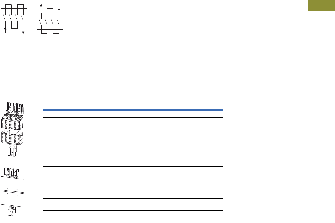
Volume 15—Solar Inverters and Electrical Balance of System CA08100018E—May 2016 eaton.com/solar V15-T3-33
3
3
3
3
3
3
3
3
3
3
3
3
3
3
3
3
3
3
3
3
3
3
3
3
3
3
3
3
3
3
3.3
DC Switch Disconnectors
Single-Pole (+ and –)
Double Sided
●Model contains parts for
upper and lower row of
switchgear side for four-
pole switches N...-S1(S15)-
DC that are used as single-
pole switches for DC
●Each link connects four
contacts in series (plus
or minus)
●Incoming unit and outgoing
at bottom or top, according
to the switching diagrams
Bridge Kits NZM...-XKV...1P...
Note
1 Includes cooling unit.
Detailed assignment taking into account ambient temperature, degree of protection and fitting position as listed
in tables on Pages V15-T3-34 and V15-T3-35.
Rated Operational
Current In
Protection
Class For Use With
Units Per
Package
Catalog
Number
Including Cover
200A at 40°C
160A at 65°C
IP2X N2-4-160(200)S1-(S15)-DC 1 NZM2-4-XKV1P
225A at 40°C
170A at 65°C
IP2X N2-4-...S1-(S15)-DC 1 1NZM2-4-XKV1P-K
400A at 40°C
388A at 65°C
IP2X N3-4-320-S1(S15)-DC 1 NZM3-4-XKV1P
517A at 40°C
435A at 65°C
IP2X N3-4-400(500)-S1(S15)-DC 1 1NZM3-4-XKV1P-K
Including Insulation Plates
213A at 40°C
160A at 65°C
IP00 N2-4-...S1-(S15)-DC 1 NZM2-4-XKVI1P
238A at 40°C
180A at 65°C
IP00 N2-4-200(250)-S1-(S15)-DC 1 1NZM2-4-XKVI1P-K
501A at 40°C
418A at 65°C
IP00 N3-4-...-S1(S15)-DC 1 NZM3-4-XKVI1P
534A at 40°C
451A at 65°C
IP00 N3-4-500(550)-S1(S15)-DC 1 1NZM3-4-XKVI1P-K
Bridge Kits

V15-T3-34 Volume 15—Solar Inverters and Electrical Balance of System CA08100018E—May 2016 eaton.com/solar
3
3
3
3
3
3
3
3
3
3
3
3
3
3
3
3
3
3
3
3
3
3
3
3
3
3
3
3
3
3
3.3
DC Switch Disconnectors
Technical Data and Specifications
Reduction of the rated
operating current (derating)
at different ambient
temperatures, fitting
positions, degrees of
protection and jumper kits.
Temperature Impact, Derating
Rated Operating Current Amperes
Load Disconnector
Switch
Touch
Protection Jumper Kit
Fitting
Position
Load
Disconnector
Switch 20°C 30°C 35°C 40°C 45°C 50°C 55°C 60°C 65°C 70°C
N2-4-160-S1(15)-DC IP2X NZM2-4-XKV2P
NZM2-3-XKV2POU-K
NZM2-3-XKV1P-K
Vertical 160 160 160 160 160 160 160 160 160 160
IP00 NZM2-4-XKVI2P
NZM2-3-XKVI2POU-K
NZM2-3-XKVI1P-K
Horizontal 160 160 160 160 160 160 160 160 160 160
IP2X NZM2-3-XKV1P-K
NZM2-4-XKV2P
Vertical 160 160 160 160 160 160 160 160 160 152
Vertical 160 160 160 160 160 160 160 160 152 144
N2-4-200-S1(15)DC IP00 NZM2-4-XKVI2P-K Vertical 200 200 200 200 200 200 200 200 200 200
Horizontal 200 200 200 200 200 200 200 200 200 190
IP2X NZM2-4-XKV2P-K Vertical 200 200 200 200 200 200 200 200 190 180
IP00 NZM2-4-XKVI2P
NZM2-4-XKVI2POU-K
NZM2-4-XKVI1P-K
Horizontal 200 200 200 200 200 200 200 190 180 170
IP2X NZM2-4-XKV2P
NZM2-4-XKV2POU-K
NZM2-4-XKV1P-K
Vertical 200 200 200 200 200 200 190 180 170 160
IP00 NZM2-4-XKVI2POU
NZM2-4-XKVI1P
Horizontal 200 200 200 200 200 190 180 170 160 —
IP2X NZM2-4-XKV2POU
NZM2-4-XKV1P
Vertical 200 200 200 200 190 180 170 160 — —
Horizontal 200 200 200 190 180 170 160 — — —
N2-4-250-S1(15)-DC IP00 NZM2-4-XKVI2P-K Vertical 250 250 250 250 250 250 238 225 213 200
Horizontal 250 250 250 250 250 238 225 213 200 —
IP2X NZM2-4-XKV2P-K Horizontal 250 250 250 250 238 225 213 200 — —
IP00 NZM2-4-XKVI2P
NZM2-4-XKVI2POU-K
NZM2-4-XKVI1P-K
Horizontal 250 250 250 238 225 213 200 — — —
IP2X NZM2-4-XKV2P
NZM2-4-XKV2POU-K
NZM2-4-XKV1P-K
Vertical 250 250 238 225 213 200 — — — —
IP00 NZM2-4-XKVI2POU
NZM2-4-XKVI1P
Horizontal 250 238 225 213 200 — — — — —

Volume 15—Solar Inverters and Electrical Balance of System CA08100018E—May 2016 eaton.com/solar V15-T3-35
3
3
3
3
3
3
3
3
3
3
3
3
3
3
3
3
3
3
3
3
3
3
3
3
3
3
3
3
3
3
3.3
DC Switch Disconnectors
Temperature Impact, Derating, continued
Rated Operating Current Amperes
Load Disconnector
Switch
Touch
Protection Jumper Kit
Fitting
Position
Load
Disconnector
Switch 20°C 30°C 35°C 40°C 45°C 50°C 55°C 60°C 65°C 70°C
N3-4-320-S1(15)-DC IP2X NZM3-4-XKV2P
NZM3-4-XKV2POU
NZM3-4-XKV1P
Vertical 320 320 320 320 320 320 320 320 320 320
IP00 NZM3-4-XKVI2P
NZM3-4-XKVI2POU
NZM3-4-XKVI1P
Horizontal 320 320 320 320 320 320 320 320 320 320
N3-4-400-S1(15)-DC IP2X NZM3-4-XKV2P
NZM3-4-XKV2POU-K
NZM3-4-XKV1P-K
Vertical 400 400 400 400 400 400 400 400 400 400
IP00 NZM3-4-XKVI2P
NZM3-4-XKVI2POU
NZM3-4-XKVI1P
Horizontal 400 400 400 400 400 400 400 400 400 388
IPX2 NZM3-4-XKV2POU Vertical 400 400 400 400 400 400 400 400 388 —
NZM3-4-XKV1P Horizontal 400 400 400 400 400 400 400 388 376 —
N3-4-500-S1(15)-DC IP00 NZM3-4-XKVI2P-K Vertical 500 500 500 500 500 500 485 470 455 440
Horizontal 500 500 500 500 500 485 470 455 440 425
IP2X NZM3-4-XKV2P-K Vertical 500 500 500 500 485 470 455 440 425 410
IP00 NZM3-4-XKVI2P
NZM3-4-XKVI2POU-K
NZM3-4-XKVI1P-K
Horizontal 500 500 500 485 470 455 440 425 410 400
IP2X NZM3-4-XKV2P
NZM3-4-XKV2POU-K
NZM3-4-XKV1P-K
Vertical 500 500 485 470 455 440 425 410 400 —
IP00 NZM3-4-XKVI2POU
NZM3-4-XKVI1P
Horizontal 500 485 470 455 440 425 410 400 —
N3-4-550-S1(15)-DC IP00 NZM3-4-XKVI2P-K Vertical 550 550 550 550 550 550 534 517 501 484
Horizontal 550 550 550 550 550 534 517 501 484 468
IP2X NZM3-4-XKV2P-K Vertical 550 550 550 550 534 517 501 484 468 451
IP00 NZM3-4-XKVI2P
NZM3-4-XKVI2POU-K
NZM3-4-XKVI1P-K
Horizontal 550 550 550 534 517 501 484 468 451 435
IP2X NZM3-4-XKV2P
NZM3-4-XKV2POU-K
NZM3-4-XKV1P-K
Vertical 550 550 534 517 501 484 468 451 435 418
IP00 NZM3-4-XKVI2POU
NZM3-4-XKVI1P
Horizontal 550 534 517 501 484 468 451 435 418 402
N4-4-800-S1(15)-DC IP2X NZM4-4-XKV2P Vertical 800 800 800 800 800 800 800 800 800 800
Horizontal 800 800 800 800 800 800 800 800 800 800
N4-4-1000-S1(15)-DC IP2X NZM4-4-XKV2P Vertical 1000 1000 1000 1000 1000 1000 1000 1000 1000 1000
Horizontal 1000 1000 1000 1000 1000 1000 1000 1000 1000 1000
N4-4-1250-S1(15)-DC IP2X NZM4-4-XKV2P Vertical 1250 1250 1250 1250 1250 1250 1250 1250 1250 1250
Horizontal 1250 1250 1250 1250 1250 1250 1250 1250 1250 1250
N4-4-1400-S1(15)-DC IP00 NZM4-4-XKV2P-K Vertical 1400 1400 1400 1400 1400 1400 1400 1400 1400 1400
Horizontal 1400 1400 1400 1400 1400 1400 1400 1400 1400 1400
IP2X NZM4-4-XKV2P Vertical 1400 1400 1400 1400 1358 1330 1302 1274 1260 —
Horizontal 1400 1400 1400 1358 1330 1302 1274 1260 — —
N4-4-1600-S1(15)-DC IP00 NZM4-4-XKV2P-K Vertical 1600 1600 1600 1600 1576 1552 1528 1512 1500 1472
Horizontal 1600 1600 1600 1576 1552 1528 1512 1500 1472 1448

V15-T3-36 Volume 15—Solar Inverters and Electrical Balance of System CA08100018E—May 2016 eaton.com/solar
3
3
3
3
3
3
3
3
3
3
3
3
3
3
3
3
3
3
3
3
3
3
3
3
3
3
3
3
3
3
3.3
DC Switch Disconnectors
Switch Disconnectors 1000 Vdc
Switch Disconnectors 1500 Vdc
Note: N...S1-DC and N...S15-DC cannot be combined with plug-in or withdrawable units and/or in case of rear connection.
Description
N2-4-...-S1-DC
Max. 250A
N3-4-...-S1-DC
Max. 550A
N4-4-...-S1-DC
Max. 1600A
Rated operational voltage UeVdc 1000 1000 1000
Rated insulation voltage UiVdc 1000 1000 1000
Rated impulse withstand voltage
Main contacts
Auxiliary contacts
Uimp V
V
8000
6000
8000
6000
8000
6000
Category of utilization DC-22A DC-22A DC-22A
Rated uninterrupted current with terminal jumpers
at 40°C
at 65°C
Iu
Iu
A
A
250
250
550
500
1600
1500
Rated operating current IeA 250 550 1600
Rated switch-on and switch-off capacity
Rated short-time withstand current t = 1s Icw
A
kA
1200
3, 6
2200
6, 6
6400
25 (0, 1s)
Rated conditional short-circuit current
With backup fuse up to 1000V
IqkA
A gR/gPV
15
200
15
2 x 250
—
—
Maximum operating frequency S/h 120 60 60
Lifespan
Mechanical
Electrical (of which max. 50% trip by N/U release)
Operations
Operations
20,000
1000
15,000
1000
10,000
500
Overvoltage category III III III
Degree of pollution 3 3 3
Power loss at rated current
Load disconnector switch
Jumper kit for each jumper fitted
Iu
P
P
A
W
W
160 200 250
27 42 66
1 1, 5 2
320 400 500 550
62 96 150 182
4 6 9, 5 11
800 1000 1250 1600
81 127 177 290
0, 6 1 1, 6 2, 6
Description
N2-4-...-S15-DC
Max. 250A
N3-4-...-S15-DC
Max. 550A
N4-4-...-S15-DC
Max. 1600A
Rated operational voltage UeVdc 1500 1500 1500
Rated insulation voltage UiVdc 1500 1500 1500
Rated impulse withstand voltage
Main contacts
Auxiliary contacts
Uimp V
V
10,000
6000
10,000
6000
10,000
6000
Category of utilization DC-22A DC-22A DC-22A
Rated uninterrupted current with terminal jumpers
at 40°C
at 65°C
Iu
Iu
A
A
250
250
550
500
1600
1500
Rated operating current IeA 250 550 1600
Rated switch-on and switch-off capacity
Rated short-time withstand current t = 1s Icw
A
kA
1200
3, 6
2200
6, 6
6400
25 (0, 1s)
Maximum operating frequency S/h 120 60 60
Lifespan
Mechanical
Electrical (of which max. 50% trip by N/U release)
Operations
Operations
20,000
1000
15,000
1000
10,000
500
Overvoltage category III III III
Degree of pollution 2 2 3
Power loss at rated current
Load disconnector switch
Jumper kit for each jumper fitted
Iu
P
P
A
W
W
160 200 250
27 42 66
1 1, 5 2
320 400 500 550
62 96 150 182
4 6 9, 5 11
800 1000 1250 1600
81 127 177 290
0, 6 1 1, 6 2, 6
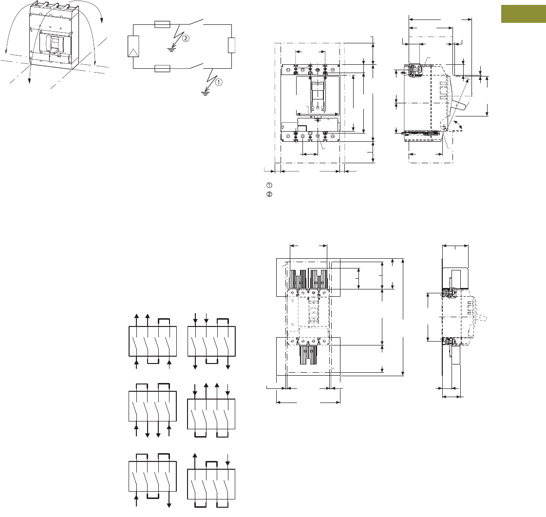
Volume 15—Solar Inverters and Electrical Balance of System CA08100018E—May 2016 eaton.com/solar V15-T3-37
3
3
3
3
3
3
3
3
3
3
3
3
3
3
3
3
3
3
3
3
3
3
3
3
3
3
3
3
3
3
3.3
DC Switch Disconnectors
Central Fitting Position IT Network Including the
Possibility of a Double-
Ground Fault
In ungrounded networks (for
example, IT) the installation
has to be done in a way to
keep the likelihood of a
double-ground fault
neglectably low.
Depending on the use of
jumper kits and on the layout
of the single- or two-pole
circuit, the following
maximum rated operating
voltage levels have to be
respected to make sure
that—even in case of a
double-ground fault—safe
switch-on and switch-off is
possible in accordance with
utilization category DC22-A.
Rated Operating Voltage
Ue Maximum IT Network
90˚
90˚
90˚
90˚
500 Vdc
1000 Vdc
1500 Vdc
Dimensions
Approximate Dimensions in Inches (mm)
Switch Disconnectors, Four-Pole N2-4...DC
Jumper Kit, NZM2-4-XKVI...
2.76
(70.0)
N
12
3
5.31
(135.0)
0.77
(19.5)
5.71
(145.0)
3.15
(80.0)
2.85
(72.5)
7.24
(184.0)
≥ 3.54
(90.0)
5.51
(140.0)
SW5
≥ 0.20
(5.0) 21
1.38
(35.0)
Blowout area, minimum clearance to other parts.
Minimum clearance to adjacent parts.
0.98
(25.0)
M8
x 22
R 124
4.06
(103.0)
5.86
(149.0)
0.96
(24.5) 0.12
(3.0)
3.74
(95.0)
3.10
(78.7)
≤ 90°
M4 x 85/20
3.94
(100.0)
≥ 3.54
(90.0)
≥ 0.20
(5.0)
0.20
(5.0)
1
2
7.24
(184.0)
5.51
(140.0)
8.27
(210.0)
≥ 0.20
(5.0)
≥ 3.54
(90.0)
≥ 0.20
(5.0)
12
15.16
(385.0)
4.80
(122.0)
6.30
(160.0)
3.35
(85.0)
2.74
(69.6)
≥ 3.54
(90.0)
3.96
(100.5)
1.24
(31.5) 2.34
(59.5)
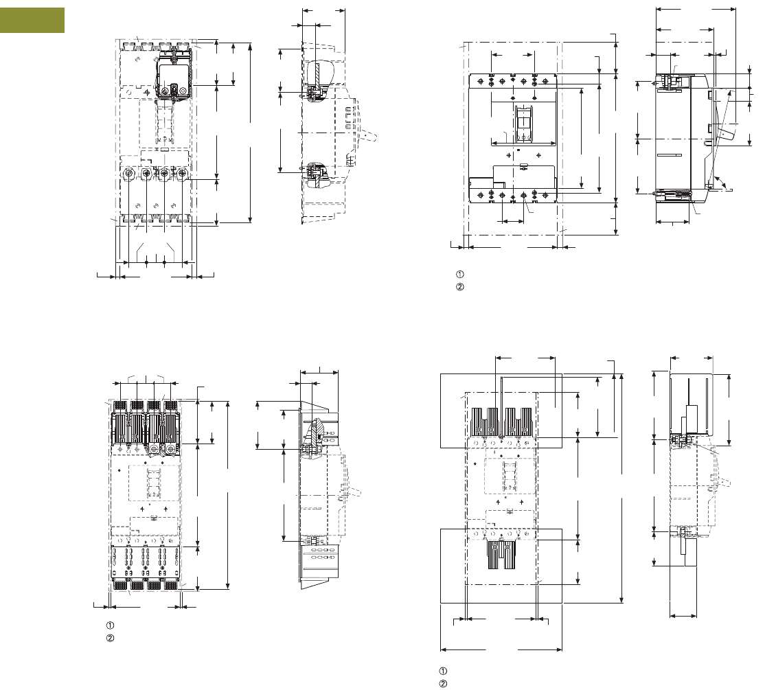
V15-T3-38 Volume 15—Solar Inverters and Electrical Balance of System CA08100018E—May 2016 eaton.com/solar
3
3
3
3
3
3
3
3
3
3
3
3
3
3
3
3
3
3
3
3
3
3
3
3
3
3
3
3
3
3
3.3
DC Switch Disconnectors
Approximate Dimensions in Inches (mm)
Jumper Kit, NZM2-4-XKV...
Jumper Kit, NZM3-4-XKV...
Switch Disconnectors, Four-Pole, N3-4...DC
Jumper Kit, NZM3-4-XKVI...
1
2
2
1
≥ 0.20
(5.0)
≥ 0.20
(5.0)
1.38
(35.0)
5.51
(140.0)
≥ 3.54
(90.0)
≥ 3.54
(90.0)
3.27
(83.0)
13.74
(349.0)
7.24
(184.0)
6.30
(160.0)
3.27
(83.0)
0.98
(25.0)
3.35
(85.0)
1
2
9.72
(247.0)
2
1
1.77 (45.0)
4.53
(115.0)
≥ 4.72
(120.0)
10.83
(275.0)
19.88
(505.0)
7.28
(185.0)
4.06
(103.0)
1.22
(31.0)
5.08
(129.0) 4.15
(105.5)
≥ 4.72
(120.0)
≥ 0.20
(5.0) ≥ 0.20
(5.0)
Blowout area, minimum clearance to other parts.
Minimum clearance to adjacent parts.
1
2
Blowout area, minimum clearance to other parts.
Minimum clearance to adjacent parts.
≤ 90°
N
3.54
(90.0) 0.81
(20.5)
≥ 4.72
(120.0)
3
12
5.31
(135.0)
8.50
(216.0)
9.21
(234.0)
10.8
(275.0)
4.86
(123.4)
4.61
(117.0)
1.77
(45.0)
7.28
(185.0)
6.54
(166.0)
4.74
(120.5)
2.74
(69.7)
SW5
M10 x 30
R 205
M5 x 75
≥ 0.20
(5.0) ≥ 0.20
(5.0)
≥ 4.72
(120.0)
0.20
(5.0)
1.22
(31.0)
1.16
(29.5)
1.10
(28.0)
3.74
(95.0)
1
2
≥ 0.20
(5.0)
≥ 0.20
(5.0)
12
24.25
(616.0)
6.25
(158.8)
9.73
(247.1)
7.26
(184.5)
6.71
(170.5)
6.38
(162.0)
10.83
(275.0)
3.62
(91.9)
2.83
(71.8)
M10 x 35
7.54
(191.6)
4.53
(115.1)
Blowout area, minimum clearance to other parts.
Minimum clearance to adjacent parts.
≥ 4.72
(120.0)
≥ 4.72
(120.0)
7.28
(185.0)
12.80
(325.0)
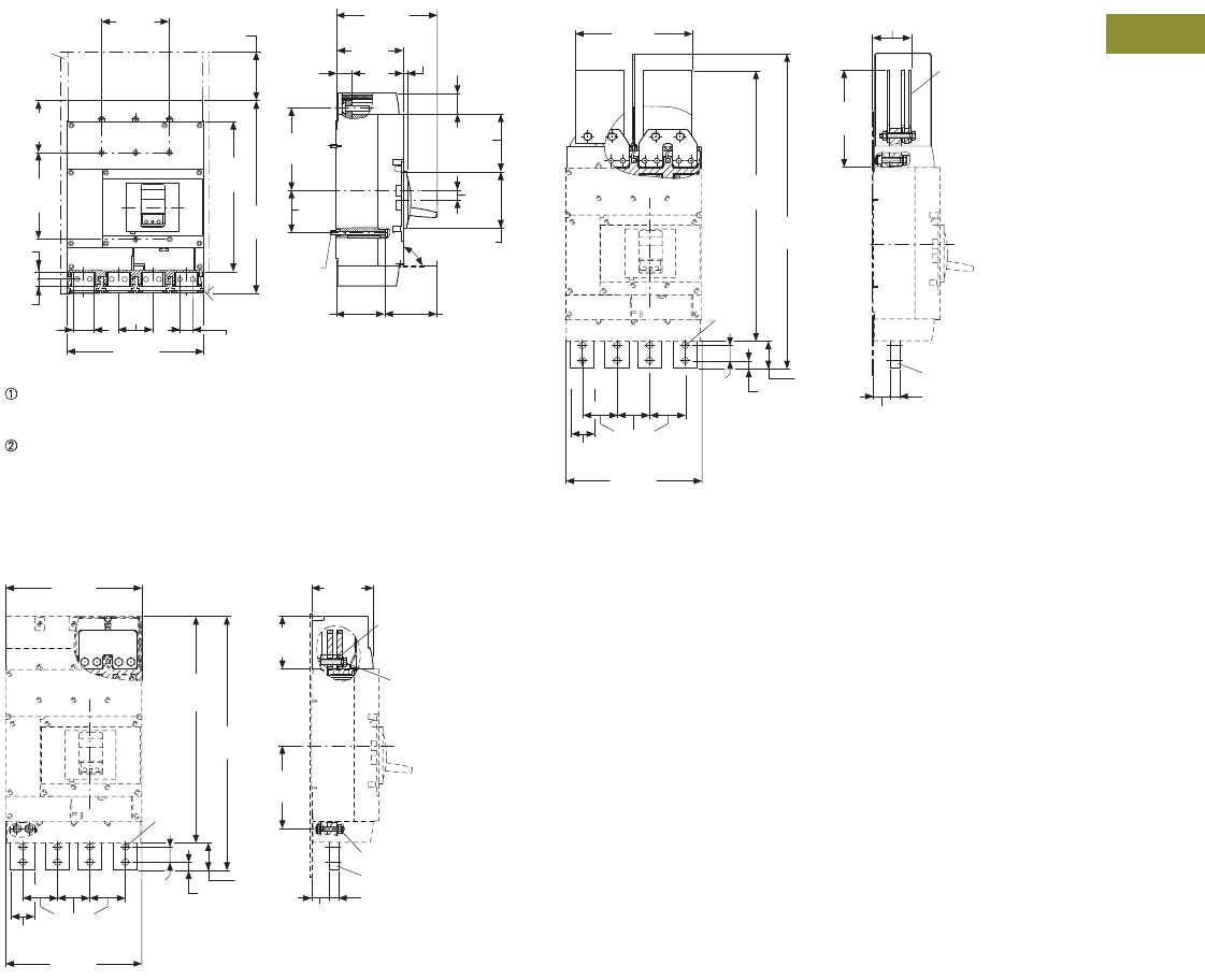
Volume 15—Solar Inverters and Electrical Balance of System CA08100018E—May 2016 eaton.com/solar V15-T3-39
3
3
3
3
3
3
3
3
3
3
3
3
3
3
3
3
3
3
3
3
3
3
3
3
3
3
3
3
3
3
3.3
DC Switch Disconnectors
Approximate Dimensions in Inches (mm)
Switch Disconnectors, Four-Pole, N4-4...DC
Jumper Kit, NZM4-4-XKV2P
Jumper Kit, NZM4-4-XKV2P-K
1
2
≤ 90°
5.51
(140.0)
2
3
4.25
(108.0)
7.09
(180.0)
12.32
(313.0)
15.79
(401.0)
0.59
(15.0)
0.59
(15.0)
1.77
(45.0)
2.76
(70.0)
11.02
(280.0)
0.98
(25.0)
6.75
(171.5)
1.30
(33.0)
0.31
(8.0)
8.15
(207.0)
5.43
(138.0)
3.44
(87.5)
1.73
(44.0)
M5 x
110
4.69
(119.0)
4.61
(117.0)
0.83
(21.0)
3.94
(100.0)
3.94
(100.0)
Ø
0.41
(
10.5)
N
≥ 3.94
(100.0)
Blowout area, minimum clearance to other parts.
≤ 690V: 3.94 (100.0)
≤ 1500V: 7.87 (200.0)
Minimum clearance to adjacent parts.
≤ 1000V: 0.59 (15.0)
≤ 1500V: 2.76 (70.0)
18.35
(466.0)
11.02
(280.0)
20.55
(522.0)
1.26
(32.0) 0.63
(16.0)
2.20
(56.0)
4.92
(125.0)
NZM4-4-XKV2P
4.27
(108.5)
M10 x 60
SW 16
6.75
(171.5)
NZM4-4-XKM2S-1600
SW 16
1.30
(33.0)
0.79
(20.0)
Ø
0.51
(
13.0)
11.02
(280.0)
1.97
(50.0)
2.76
(70.0)
11.02
(280.0)
1.97
(50.0)
2.76
(70.0)
3.17
(80.5)
9.45
(240.0)
24.13
(613.0)
25.47
(647.0)
7.91
(201.0)
NZM4-4-XKV2P-K
NZM4-4-XKM2S-1600
1.26
(32.0) 0.63
(16.0)
2.20
(56.0) 0.79
(20.0)
1.30
(33.0)
Ø
0.51
(
13.0)
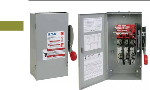
V15-T3-40 Volume 15—Solar Inverters and Electrical Balance of System CA08100018E—May 2016 eaton.com/solar
3
3
3
3
3
3
3
3
3
3
3
3
3
3
3
3
3
3
3
3
3
3
3
3
3
3
3
3
3
3
3.4
DC Switches
600 Vdc and 1000 Vdc Disconnects
Contents
Description
DC Switches
DC Switches
Product Description
Eaton’s new offering of PV
switches have multiple poles
factory-wired, and they are
approved for NEC Article 690
applications right from the
box. Other manufacturers
require the contractor to add
jumpers to a two- or three-
pole switch, add a neutral,
and add labels to meet this
requirement. For fusible
switches, the new Eaton PV
switch requires only one fuse
per switch—saving the
customer at least one fuse
on each switch.
For more information on
Eaton's DC Switches, please
see Ta b 2 . 4 of this catalog.

Volume 15—Solar Inverters and Electrical Balance of System CA08100018E—May 2016 eaton.com/solar V15-T3-41
3
3
3
3
3
3
3
3
3
3
3
3
3
3
3
3
3
3
3
3
3
3
3
3
3
3
3
3
3
3
3.5
DC Switched Combiners
DC Switched Combiners
Contents
Description
DC Switched Combiners
DC Switched Combiners
Product Description
The Eaton switched combiner
(ESC) unites Eaton’s 600 Vdc
solar disconnect and source-
combiner box in one
convenient enclosure (1000
Vdc Switched Combiners
available late 2012).
For more information on
Eaton’s DC Switched
Combiners, please see
Tab 2.5 of this catalog.
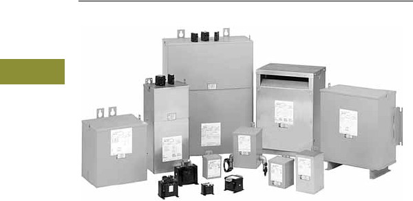
V15-T3-42 Volume 15—Solar Inverters and Electrical Balance of System CA08100018E—May 2016 eaton.com/solar
3
3
3
3
3
3
3
3
3
3
3
3
3
3
3
3
3
3
3
3
3
3
3
3
3
3
3
3
3
3
3.6
Dry-Type Distribution Transformers
Encapsulated Transformers
Dry-Type Transformer Family
Contents
Description Page
Encapsulated Transformers
Ventilated Transformers/
Open Core-Coil Assemblies . . . . . . . . . . . . . . . . V15-T3-43
Encapsulated Transformers
Product Description
Eaton’s family of
encapsulated transformers
is ideally suited for harsh
outdoor environments.
Their standard enclosure is
NEMA® 3R rated, and are
also available in NEMA 3R
stainless steel, or NEMA 4X
enclosures. The core and
coil assembly is completely
embedded in a sand and
resin compound that seals
out moisture and other
contaminants.
Please refer to Volume 2—
Commercial Distribution,
CA08100003E, Tab 2 for
more information.

Volume 15—Solar Inverters and Electrical Balance of System CA08100018E—May 2016 eaton.com/solar V15-T3-43
3
3
3
3
3
3
3
3
3
3
3
3
3
3
3
3
3
3
3
3
3
3
3
3
3
3
3
3
3
3
3.6
Dry-Type Distribution Transformers
Vent ilated Transformers/Open Core-Coil A ssemblies
Dry-Type Transformer Family
Contents
Description Page
Encapsulated Transformers . . . . . . . . . . . . . . . . . . V15-T3-42
Ventilated Transformers/
Open Core-Coil Assemblies
Ventilated Transformers/Open Core-Coil Assemblies
Product Description
Eaton offers a complete
line of ventilated and totally
enclosed non-ventilated
transformers, in a variety of
K-factor ratings and efficiency
levels. Please refer to
Volume 2—Commercial
Distribution, CA08100003E,
Tab 2 for additional
information on Eaton’s
standard product offering.
In addition to these standard
products, Eaton also offers
custom design capabilities
to meet the specific
requirements of the solar
industry. We offer special
dimensions and layouts to
meet a specific customer’s
needs. We can also design
transformers to meet CEC
weighted-efficiency levels, or
other efficiency levels if
necessary. Please contact
your local Eaton
representative for additional
information on Eaton’s
custom design capabilities.
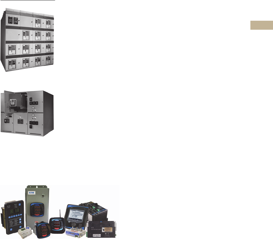
Volume 15—Solar Inverters and Electrical Balance of System CA08100018E—August 2013 eaton.com/solar V15-T4-1
4
4
4
4
4
4
4
4
4
4
4
4
4
4
4
4
4
4
4
4
4
4
4
4
4
4
4
4
4
4
AC Power Distribution
Magnum DS Switchgear
Indoor Type VCP-W Metal-Clad
Switchgear Assembly (5/15 kV shown)
Metering Products Family
Eaton offers a full range of AC power distribution products to help you complete your electrical
system. This table of contents provides references to other catalogs in our library where you can
access selection and technical data for these products.
Low Voltage Switchboards
Refer to Volume 2—Commercial Distribution,
CA08100003E, Tab 4—Switchboards
Low Voltage Switchgear
Refer to Volume 3—Power Distribution and Control Assemblies,
CA08100004E, Tab 4—Low Voltage Switchgear
Medium Voltage Switchgear
Refer to Volume 3—Power Distribution and Control Assemblies,
CA08100004E, Tab 7—Medium Voltage Switchgear
Tr a n s fo rm e r s
Refer to Consulting Application Guide,
CA08104001E, Tab 16—Substation Transformers
AC Metering
Refer to Volume 3—Power Distribution and Control Assemblies,
CA08100004E, Tab 9—Metering Devices, Protective Relays,
Software and Connectivity
AC Monitoring
Refer to Volume 5—Motor Control and Protection,
CA08100006E, Tab 5—Motor Protection and Monitoring
Power Xpert Software
Refer to Volume 3—Power Distribution and Control Assemblies,
CA08100004E, Tab 9—Metering Devices, Protective Relays,
Software and Connectivity
Other Services
Refer to Consulting Application Guide,
CA08104001E, Tab 41—Power System Studies,
Field Services (E-ESS)

Volume 15—Solar Inverters and Electrical Balance of System CA08100018E—August 2013 eaton.com/solar V1-A1-1
Appendix 1—Eaton Terms & Conditions
Effective Date: November 1, 2008
Eaton Terms & Conditions
Contents
Description Page
Terms and Conditions of Sale. . . . . . . . . . . . . . . . . V1-A1-1
Terms of Payment . . . . . . . . . . . . . . . . . . . . . . . . . V1-A1-2
Freight . . . . . . . . . . . . . . . . . . . . . . . . . . . . . . . . . . V1-A1-3
Warranty . . . . . . . . . . . . . . . . . . . . . . . . . . . . . . . . . V1-A1-3
Selling Policy (Supersedes Selling Policy 25-000, dated February 20, 2006)
Terms and Conditions of Sale
The Terms and Conditions of
Sale set forth herein, and any
supplements which may be
attached hereto, constitute
the full and final expression
of the contract for the sale
of products or services
(hereinafter referred to as
Product(s) or Services by
Eaton Corporation
(hereinafter referred to as
Seller) to the Buyer, and
supersedes all prior
quotations, purchase orders,
correspondence or
communications whether
written or oral between the
Seller and the Buyer.
Notwithstanding any contrary
language in the Buyer’s
purchase order,
correspondence or other
form of acknowledgment,
Buyer shall be bound by
these Terms and Conditions
of Sale when it sends a
purchase order or otherwise
indicates acceptance of this
contract, or when it accepts
delivery from Seller of the
Products or Services.
THE CONTRACT FOR SALE
OF THE PRODUCTS OR
SERVICES IS EXPRESSLY
LIMITED TO THE TERMS
AND CONDITIONS OF SALE
STATED HEREIN. ANY
ADDITIONAL OR DIFFERENT
TERMS PROPOSED BY
BUYER ARE REJECTED
UNLESS EXPRESSLY
AGREED TO IN WRITING BY
SELLER. No contract shall
exist except as herein
provided.
Complete Agreement
No amendment or
modification hereto nor any
statement, representation or
warranty not contained herein
shall be binding on the Seller
unless made in writing by an
authorized representative of
the Seller. Prior dealings,
usage of the trade or a course
of performance shall not be
relevant to determine the
meaning of this contract even
though the accepting or
acquiescing party had
knowledge of the nature
of the performance and
opportunity for objection.
Quotations
Written quotations are valid
for 30 days from its date
unless otherwise stated in
the quotation or terminated
sooner by notice.
Verbal quotations, unless
accepted, expire the same
day they are made.
A complete signed order
must be received by Seller
within 20 calendar days of
notification of award,
otherwise the price and
shipment will be subject to
re-negotiation.
Termination and Cancellation
Any order may be terminated
by the Buyer only by written
notice and upon payment
of reasonable termination
charges, including all costs
plus profit.
Seller shall have the right to
cancel any order at any time
by written notice if Buyer
breaches any of the terms
hereof, becomes the subject
of any proceeding under state
or federal law for the relief
of debtors, or otherwise
becomes insolvent or
bankrupt, generally does not
pay its debts as they become
due or makes an assignment
for the benefit of creditors.
V1-A1-2 Volume 15—Solar Inverters and Electrical Balance of System CA08100018E—August 2013 eaton.com/solar
Appendix 1—Eaton Terms & Conditions
Effective Date: November 1, 2008
Prices
All prices are subject to
change without notice. In the
event of a price change, the
effective date of the change
will be the date of the new
price or discount sheet, letter
or telegram. All quotations
made or orders accepted
after the effective date will be
on the new basis. For existing
orders, the price of the
unshipped portion of an order
will be the price in effect at
time of shipment.
Price Policy—Products and
Services
When prices are quoted as
firm for quoted shipment, they
are firm provided the following
conditions are met:
1. The order is released
with complete
engineering details.
2. Shipment of Products are
made, and Services
purchased are provided
within the quoted
lead time.
3. When drawings for
approval are required
for any Products, the
drawings applicable to
those Products must be
returned within 30*
calendar days from the
date of the original
mailing of the drawings
by Seller. The return
drawings must be
released for manufacture
and shipment and must
be marked “APPROVED”
or “APPROVED AS
NOTED.” Drawing
re-submittals which are
required for any other
reason than to correct
Seller errors will not
extend the 30-day period.
* 60 days for orders
through contractors
to allow time for their
review and approval
before and after
transmitting them
to their customers.
If the Buyer initiates or in
any way causes delays
in shipment, provision of
Services or return of approval
drawings beyond the periods
stated above, the price of the
Products or Services will be
increased 1% per month
or fraction thereof up to a
maximum of 18 months from
the date of the Buyer’s order.
For delays resulting in
shipment or provision of
Services beyond 18 months
from the date of the Buyer’s
order, the price must be
renegotiated.
Price Policy—BLS
Refer to Price Policy 25-050.
Minimum Billing
Orders less than $1,000 will
be assessed a shipping and
handling charge of 5% of the
price of the order, with a
minimum charge of $25.00
unless noted differently on
Product discount sheets.
Taxes
The price does not include
any taxes. Buyer shall be
responsible for the payment
of all taxes applicable to, or
arising from the transaction,
the Products, its sale, value,
or use, or any Services
performed in connection
therewith regardless of
the person or entity
actually taxed.
Terms of Payment
Products
Acceptance of all orders is
subject to the Buyer meeting
Seller’s credit requirements.
Terms of payment are subject
to change for failure to meet
such requirements. Seller
reserves the right at any time
to demand full or partial
payment before proceeding
with a contract of sale as a
result of changes in the
financial condition of the
Buyer. Terms of Payment are
either Net 30 days from the
date of invoice of each
shipment or carry a cash
discount based on Product
type. Specific payment terms
for Products are outlined in
the applicable Product
discount schedules.
Services
Terms of payment are net
within 30 days from date of
invoice for orders amounting
to less than $50,000.00.
Terms of payment for orders
exceeding $50,000.00 shall
be made according to the
following:
1. Twenty percent (20%) of
order value with the
purchase order payable
30 days from date of
invoice.
2. Eighty percent (80%) of
order value in equal
monthly payments over
the performance period
payable 30 days from
date of invoice.
Except for work performed (i)
under a firm fixed price basis
or (ii) pursuant to terms of a
previously priced existing
contract between Seller and
Buyer, invoices for work
performed by Seller shall
have added and noted on
each invoice a charge of 3%
(over and above the price of
the work) which is related
to Seller compliance with
present and proposed
environmental, health, and
safety regulations associated
with prescribed requirements
covering hazardous materials
management and employee
training, communications,
personal protective
equipment, documentation
and record keeping
associated therewith.
Adequate Assurances
If, in the judgment of Seller,
the financial condition of the
Buyer, at any time during the
period of the contract, does
not justify the terms of
payment specified, Seller
may require full or partial
payment in advance.
Delayed Payment
If payments are not made in
accordance with these terms,
a service charge will, without
prejudice to the right of Seller
to immediate payment, be
added in an amount equal to
the lower of 1.5% per month
or fraction thereof or the
highest legal rate on the
unpaid balance.
Volume 15—Solar Inverters and Electrical Balance of System CA08100018E—August 2013 eaton.com/solar V1-A1-3
Appendix 1—Eaton Terms & Conditions
Effective Date: November 1, 2008
Freight
Freight policy will be listed on
the Product discount sheets,
or at option of Seller one of
the following freight terms
will be quoted.
F.O.B.—P/S—Frt./Ppd. and
Invoiced
Products are sold F.O.B. point
of shipment freight prepaid
and invoiced to the Buyer.
F.O.B.—P/S—Frt./Ppd.
and Allowed
Products sold are delivered
F.O.B. point of shipment,
freight prepaid and included
in the price.
F.O.B. Destination—Frt./Ppd.
and Allowed
At Buyer’s option, Seller will
deliver the Products F.O.B.
destination freight prepaid
and 2% will be added to the
net price.
The term “freight prepaid”
means that freight charges
will be prepaid to the
accessible common carrier
delivery point nearest the
destination for shipments
within the United States and
Puerto Rico unless noted
differently on the Product
discount sheets. For any
other destination contact
Seller’s representative.
Shipment and Routing
Seller shall select the point of
origin of shipment, the
method of transportation, the
type of carrier equipment and
the routing of the shipment.
If the Buyer specifies a
special method of
transportation, type of carrier
equipment, routing, or
delivery requirement, Buyer
shall pay all special freight
and handling charges.
When freight is included in
the price, no allowance will
be made in lieu of
transportation if the Buyer
accepts shipment at factory,
warehouse, or freight station
or otherwise supplies its own
transportation.
Risk of Loss
Risk of loss or damage to the
Products shall pass to Buyer
at the F.O.B. point.
Concealed Damage
Except in the event of F.O.B.
destination shipments, Seller
will not participate in any
settlement of claims for
concealed damage.
When shipment has been
made on an F.O.B. destination
basis, the Buyer must unpack
immediately and, if damage is
discovered must:
1. Not move the Products
from the point of
examination.
2. Retain shipping container
and packing material.
3. Notify the carrier in
writing of any apparent
damage.
4. Notify Seller
representative within
72 hours of delivery.
5. Send Seller a copy of
the carrier’s inspection
report.
Witness Tests/Customer
Inspection
Standard factory tests may be
witnessed by the Buyer
at Seller’s factory for an
additional charge calculated
at the rate of $2,500 per day
(not to exceed eight (8) hours)
per Product type. Buyer may
final inspect Products at the
Seller’s factory for $500 per
day per Product type.
Witness tests will add one (1)
week to the scheduled
shipping date. Seller will
notify Buyer fourteen (14)
calendar days prior to
scheduled witness testing
or inspection. In the event
Buyer is unable to attend, the
Parties shall mutually agree
on a rescheduled date.
However, Seller reserves
the right to deem the witness
tests waived with the right to
ship and invoice Products.
Held Orders
For any order held, delayed
or rescheduled at the request
of the Buyer, Seller may, at
its sole option (1) require
payment to be based on any
reasonable basis, including
but not limited to the contract
price, and any additional
expenses, or cost resulting
from such a delay; (2) store
Products at the sole cost and
risk of loss of the Buyer; and/
or (3) charge to the Buyer
those prices under the
applicable price policy.
Payment for such price,
expenses and costs, in any
such event, shall be due by
Buyer within thirty (30) days
from date of Seller’s invoice.
Any order so held delayed or
rescheduled beyond six (6)
months will be treated as a
Buyer termination.
Drawing Approval
Seller will design the
Products in line with, in
Seller’s judgment, good
commercial practice. If at
drawing approval Buyer
makes changes outside of
the design as covered in their
specifications, Seller will then
be paid reasonable charges
and allowed a commensurate
delay in shipping date based
on the changes made.
Drawing Re-Submittal
When Seller agrees to do so
in its quotation, Seller shall
provide Buyer with the first
set of factory customer
approval drawing(s) at Seller’s
expense. The customer
approval drawing(s) will be
delivered at the quoted
delivery date. If Buyer
requests drawing changes
or additions after the initial
factory customer approval
drawing(s) have been
submitted by Seller, the
Seller, at its option, may
assess Buyer drawing
charges. Factory customer
approval drawing changes
required due to
misinterpretation by Seller
will be at Seller’s expense.
Approval drawings generated
by Bid Manager are excluded
from this provision.
Warranty
Warranty for Products
Seller warrants that the
Products manufactured by
it will conform to Seller’s
applicable specifications and
be free from failure due to
defects in workmanship and
material for one (1) year from
the date of installation of
the Product or eighteen (18)
months from the date of
shipment of the Product,
whichever occurs first.
In the event any Product fails
to comply with the foregoing
warranty Seller will, at its
option, either (a) repair or
replace the defective
Product, or defective part or
component thereof, F.O.B.
Seller’s facility freight
prepaid, or (b) credit Buyer
for the purchase price of the
Product. All warranty claims
shall be made in writing.
Seller requires all non-
conforming Products be
returned at Seller’s expense
for evaluation unless
specifically stated otherwise
in writing by Seller.
This warranty does not
cover failure or damage
due to storage, installation,
operation or maintenance not
in conformance with Seller’s
recommendations and
industry standard practice
or due to accident, misuse,
abuse or negligence. This
warranty does not cover
reimbursement for labor,
gaining access, removal,
installation, temporary power
or any other expenses, which
may be incurred in connection
with repair or replacement.
This warranty does not
apply to equipment not
manufactured by Seller.
Seller limits itself to
extending the same warranty
it receives from the supplier.
V1-A1-4 Volume 15—Solar Inverters and Electrical Balance of System CA08100018E—August 2013 eaton.com/solar
Appendix 1—Eaton Terms & Conditions
Effective Date: November 1, 2008
Extended Warranty for Products
If requested by the Buyer and
specifically accepted in
writing by Seller, the
foregoing standard warranty
for Products will be extended
from the date of shipment for
the period and price indicated
below:
●24 months—2% of
Contract Price
●30 months—3% of
Contract Price
●36 months—4% of
Contract Price
Special Warranty (In and Out)
for Products
If requested by the Buyer
and specifically accepted in
writing by Seller, Seller will,
during the warranty period
for Products, at an additional
cost of 2% of the contract
price, be responsible for the
direct cost of:
1. Removing the Product
from the installed
location.
2. Transportation to the
repair facility and return
to the site.
3. Reinstallation on site.
The total liability of Seller for
this Special Warranty for
Products is limited to 50%
of the contract price of the
particular Product being
repaired and excludes
expenses for removing
adjacent apparatus, walls,
piping, structures, temporary
service, etc.
Warranty for Services
Seller warrants that the
Services performed by it
hereunder will be performed
in accordance with generally
accepted professional
standards.
The Services, which do not
so conform, shall be
corrected by Seller upon
notification in writing by the
Buyer within one (1) year
after completion of the
Services.
Unless otherwise agreed to in
writing by Seller, Seller
assumes no responsibility
with respect to the suitability
of the Buyer’s, or its
customer’s, equipment or
with respect to any latent
defects in equipment not
supplied by Seller. This
warranty does not cover
damage to Buyer’s, or its
customer’s, equipment,
components or parts
resulting in whole or in part
from improper maintenance
or operation or from their
deteriorated condition. Buyer
will, at its cost, provide Seller
with unobstructed access
to the defective Services,
as well as adequate free
working space in the
immediate vicinity of the
defective Services and such
facilities and systems,
including, without limitation,
docks, cranes and utility
disconnects and connects,
as may be necessary in order
that Seller may perform its
warranty obligations. The
conducting of any tests shall
be mutually agreed upon and
Seller shall be notified of, and
may be present at, all tests
that may be made.
Warranty for Power Systems
Studies
Seller warrants that any
power systems studies
performed by it will conform
to generally accepted
professional standards. Any
portion of the study, which
does not so conform, shall
be corrected by Seller upon
notification in writing by the
Buyer within six (6) months
after completion of the study.
All warranty work shall be
performed in a single shift
straight time basis Monday
through Friday. In the event
that the study requires
correction of warranty items
on an overtime schedule,
the premium portion of such
overtime shall be for the
Buyer’s account.
Limitation on Warranties for
Products, Services and Power
Systems Studies
THE FOREGOING
WARRANTIES ARE
EXCLUSIVE EXCEPT FOR
WARRANTY OF TITLE.
SELLER DISCLAIMS ALL
OTHER WARRANTIES
INCLUDING ANY IMPLIED
WARRANTIES OF
MERCHANTABILITY
AND FITNESS FOR A
PARTICULAR PURPOSE.
CORRECTION OF NON-
CONFORMITIES IN THE
MANNER AND FOR THE
PERIOD OF TIME PROVIDED
ABOVE SHALL CONSTITUTE
SELLER’S SOLE LIABILITY
AND BUYER’S EXCLUSIVE
REMEDY FOR FAILURE OF
SELLER TO MEET ITS
WARRANTY OBLIGATIONS,
WHETHER CLAIMS OF
THE BUYER ARE BASED
IN CONTRACT, IN TORT
(INCLUDING NEGLIGENCE
OR STRICT LIABILITY), OR
OTHERWISE.
Asbestos
Federal Law requires that
building or facility owners
identify the presence,
location and quantity of
asbestos containing material
(hereinafter “ACM”) at work
sites. Seller is not licensed to
abate ACM. Accordingly, for
any contract which includes
the provision of Services,
prior to (i) commencement of
work at any site under a
specific Purchase Order, (ii) a
change in the work scope of
any Purchase Order, the
Buyer will certify that the
work area associated with the
Seller’s scope of work
includes the handling of Class
II ACM, including but not
limited to generator wedges
and high temperature gaskets
which include asbestos
materials. The Buyer shall, at
its expense, conduct
abatement should the
removal, handling,
modification or reinstallation,
or some or all of them, of said
Class II ACM be likely to
generate airborne asbestos
fibers; and should such
abatement affect the cost
of or time of performance
of the work then Seller shall
be entitled to an equitable
adjustment in the schedule,
price and other pertinent
affected provisions of
the contract.
Compliance with Nuclear
Regulation
Seller’s Products are sold as
commercial grade Products
not intended for application in
facilities or activities licensed
by the United States Nuclear
Regulatory Commission for
atomic purposes. Further
certification will be required
for use of the Products in any
safety-related application in
any nuclear facility licensed
by the U.S. Nuclear
Regulatory Commission.
Volume 15—Solar Inverters and Electrical Balance of System CA08100018E—August 2013 eaton.com/solar V1-A1-5
Appendix 1—Eaton Terms & Conditions
Effective Date: November 1, 2008
Returning Products
Authorization and shipping
instructions for the return
of any Products must be
obtained from Seller before
returning the Products.
When return is occasioned
due to Seller error, full credit
including all transportation
charges will be allowed.
Product Notices
Buyer shall provide the user
(including its employees) of
the Products with all Seller
supplied Product notices,
warnings, instructions,
recommendations, and
similar materials.
Force Majeure
Seller shall not be liable for
failure to perform or delay
in performance due to fire,
flood, strike or other labor
difficulty, act of God, act of
any governmental authority or
of the Buyer, riot, embargo,
fuel or energy shortage, car
shortage, wrecks or delays in
transportation, or due to any
other cause beyond Seller’s
reasonable control. In the
event of delay in performance
due to any such cause, the
date of delivery or time for
completion will be extended
by a period of time reasonably
necessary
to overcome the
effect of such delay.
Liquidated Damages
Contracts which include
liquidated damage clauses for
failure to meet shipping or job
completion promises are not
acceptable or binding on
Seller, unless such clauses
are specifically accepted in
writing by an authorized
representative of the Seller at
its headquarters office.
Patent Infringement
Seller will defend or, at its
option, settle any suit or
proceeding brought against
Buyer, or Buyer’s customers,
to the extent it is based upon
a claim that any Product or
part thereof, manufactured by
Seller or its subsidiaries and
furnished hereunder,
infringes any United States
patent, other than a claim of
infringement based upon use
of a Product or part thereof in
a process, provided Seller is
notified in reasonable time
and given authority,
information and assistance
(at Seller’s expense) for the
defense of same. Seller shall
pay all legal and court costs
and expenses and court-
assessed damages awarded
therein against Buyer
resulting from or incident to
such suit or proceeding. In
addition to the foregoing, if at
any time Seller determines
there is a substantial question
of infringement of any United
States patent, and the use of
such Product is or may be
enjoined, Seller may, at its
option and expense: either (a)
procure for Buyer the right to
continue using and selling the
Product; (b) replace the
Product with non-infringing
apparatus; (c) modify the
Product so it becomes non-
infringing; or (d) as a last
resort, remove the Product
and refund the purchase
price, equitably adjusted for
use and obsolescence. In no
case does Seller agree to pay
any recovery based upon its
Buyer’s savings or profit
through use of Seller’s
Products whether the use be
special or ordinary. The
foregoing states the entire
liability of Seller for patent
infringement.
The preceding paragraph
does not apply to any claim of
infringement based upon: (a)
any modification made to a
Product other than by Seller;
(b) any design and/or
specifications of Buyer to
which a Product was
manufactured; or (c) the use
or combination of Product
with other products where
the Product does not itself
infringe. As to the above-
identified claim situations
where the preceding
paragraph does not apply,
Buyer shall defend and hold
Seller harmless in the same
manner and to the extent as
Seller’s obligations described
in the preceding paragraph.
Buyer shall be responsible for
obtaining (at Buyer’s
expense) all license rights
required for Seller to be able
to use software products in
the possession of Buyer
where such use is required in
order to perform any Service
for Buyer.
With respect to a Product or
part thereof not manufactured
by Seller or its subsidiaries,
Seller will attempt to obtain
for Buyer, from the supplier(s),
the patent indemnification
protection normally provided
by the supplier(s) to
customers.
Limitation of Liability
THE REMEDIES OF THE
BUYER SET FORTH IN THIS
CONTRACT ARE EXCLUSIVE
AND ARE ITS SOLE
REMEDIES FOR ANY
FAILURE OF SELLER
TO COMPLY WITH ITS
OBLIGATIONS HEREUNDER.
NOTWITHSTANDING
ANY PROVISION IN THIS
CONTRACT TO THE
CONTRARY, IN NO EVENT
SHALL SELLER BE LIABLE
IN CONTRACT, IN TORT
(INCLUDING NEGLIGENCE
OR STRICT LIABILITY) OR
OTHERWISE FOR DAMAGE
TO PROPERTY OR
EQUIPMENT OTHER THAN
PRODUCTS SOLD
HEREUNDER, LOSS OF
PROFITS OR REVENUE,
LOSS OF USE OF
PRODUCTS, COST OF
CAPITAL, CLAIMS OF
CUSTOMERS OF THE
BUYER OR ANY SPECIAL,
INDIRECT, INCIDENTAL OR
CONSEQUENTIAL
DAMAGES WHATSOEVER,
REGARDLESS OF WHETHER
SUCH POTENTIAL
DAMAGES ARE
FORESEEABLE OR IF
SELLER HAS BEEN ADVISED
OF THE POSSIBILITY OF
SUCH DAMAGES.
THE TOTAL CUMULATIVE
LIABILITY OF SELLER
ARISING FROM OR
RELATED TO THIS
CONTRACT WHETHER
THE CLAIMS ARE BASED
IN CONTRACT, IN TORT
(INCLUDING NEGLIGENCE
OR STRICT LIABILITY) OR
OTHERWISE, SHALL NOT
EXCEED THE PRICE OF THE
PRODUCT OR SERVICES
ON WHICH SUCH LIABILITY
IS BASED.
Volume 15—Solar Inverters and Electrical Balance of System CA08100018E—September 2015 eaton.com/solar V1-A2-1
Appendix 2—Catalog Parent Number Index
A
AAL . . . . . . . . . . . V15-T3-20
AA1 . . . . . . . . . . . V15-T3-20
ALM . . . . . . . . . . V15-T3-20
AUX . . . . . . . . . . . V15-T3-20
A1L . . . . . . . . . . . V15-T3-20
A1X . . . . . . . . . . . V15-T3-20
A2X . . . . . . . . . . . V15-T3-20
B
BA20 . . . . . . . . . . V15-T3-10
BA25 . . . . . . . . . . V15-T3-10
BMH . . . . . . . . . . V15-T3-19
BX . . . . . . . . . . . . V15-T2-54, V15-T2-57
C
CFDPV. . . . . . . . . V15-T3-18
CJGPVS. . . . . . . . V15-T3-17
CKDPV. . . . . . . . . V15-T3-18
CKDPVS . . . . . . . V15-T3-17
CLGPV. . . . . . . . . V15-T3-18
CMDLPV . . . . . . . V15-T3-18
E
EGE . . . . . . . . . . . V15-T3-5
EGH. . . . . . . . . . . V15-T3-5
EGS . . . . . . . . . . . V15-T3-5
EZB2 . . . . . . . . . . V15-T2-28, V15-T2-40, V15-T2-44, V15-T2-48
EZTV . . . . . . . . . . V15-T2-28
EZT2 . . . . . . . . . . V15-T2-28, V15-T2-40, V15-T2-44, V15-T2-48
F
FDPV . . . . . . . . . . V15-T3-18
H
HFD . . . . . . . . . . . V15-T3-6
HJD . . . . . . . . . . . V15-T3-7
HKD. . . . . . . . . . . V15-T3-8
HLD . . . . . . . . . . . V15-T3-9
HMDL . . . . . . . . . V15-T3-10
I
IPB. . . . . . . . . . . . V15-T3-19
J
JGE . . . . . . . . . . . V15-T3-6
JGH . . . . . . . . . . . V15-T3-7
JGPVS . . . . . . . . . V15-T3-17
JGS . . . . . . . . . . . V15-T3-7
JT3 . . . . . . . . . . . V15-T3-6, V15-T3-7
K
KDPV . . . . . . . . . . V15-T3-18
KDPVS. . . . . . . . . V15-T3-17
KPE . . . . . . . . . . . V15-T3-21
KT. . . . . . . . . . . . V15-T3-8
L
LGE . . . . . . . . . . V15-T3-8
LGH . . . . . . . . . . V15-T3-9
LGPV . . . . . . . . . V15-T3-18
LGS . . . . . . . . . . V15-T3-8
LKD . . . . . . . . . . V15-T3-19
LT. . . . . . . . . . . . V15-T3-8, V15-T3-9
LTV2. . . . . . . . . . V15-T2-28, V15-T2-48
LT20. . . . . . . . . . V15-T2-28, V15-T2-40, V15-T2-44, V15-T2-48
LT3. . . . . . . . . . . V15-T3-8
LT4. . . . . . . . . . . V15-T3-8
L4R . . . . . . . . . . V15-T3-21
M
MDLPV . . . . . . . V15-T3-18
MT . . . . . . . . . . . V15-T3-10
N
NB . . . . . . . . . . . V15-T3-10
NZM. . . . . . . . . . V15-T3-29–V15-T3-31
N2-4 . . . . . . . . . . V15-T3-28
N3-4 . . . . . . . . . . V15-T3-28
N4-4 . . . . . . . . . . V15-T3-28
P
PB . . . . . . . . . . . V15-T3-10
PLK . . . . . . . . . . V15-T3-19
S
SNT1 . . . . . . . . . V15-T3-20
SNT3 . . . . . . . . . V15-T3-20
T
TA10 . . . . . . . . . V15-T3-10
TA12 . . . . . . . . . V15-T3-10
TA3 . . . . . . . . . . V15-T3-21
TA30 . . . . . . . . . V15-T3-8
TA35 . . . . . . . . . V15-T3-8, V15-T3-9
TA60 . . . . . . . . . V15-T3-9
TA7 . . . . . . . . . . V15-T3-21
TA70 . . . . . . . . . V15-T3-10
TA8 . . . . . . . . . . V15-T3-21
TA80 . . . . . . . . . V15-T3-10
T250. . . . . . . . . . V15-T3-6, V15-T3-7
T30. . . . . . . . . . . V15-T3-21
T35. . . . . . . . . . . V15-T3-21
U
UVH . . . . . . . . . . V15-T3-20
UVR . . . . . . . . . . V15-T3-20
Y
YS2 . . . . . . . . . . V15-T2-28, V15-T2-40, V15-T2-44, V15-T2-48
V1-A2-2 Volume 15—Solar Inverters and Electrical Balance of System CA08100018E—September 2015 eaton.com/solar
Appendix 2—Catalog Parent Number Index
Numerics
3TA . . . . . . . . . . . V15-T3-21
3TA4 . . . . . . . . . . V15-T3-8
3TA6 . . . . . . . . . . V15-T3-8, V15-T3-9
3T2 . . . . . . . . . . . V15-T3-21
3T20 . . . . . . . . . . V15-T3-11
4TA . . . . . . . . . . . V15-T3-21
4T4 . . . . . . . . . . . V15-T3-21
4T6 . . . . . . . . . . . V15-T3-21
Volume 15—Solar Inverters and Electrical Balance of System CA08100018E—September 2015 eaton.com/solar V1-A3-1
Appendix 3—Alphabetical Product Index
A
AC Metering . . . . . . . . . . . . . . . . . . . . . . . . . . . . . . . . . . . . V15-T4-1
AC Monitoring . . . . . . . . . . . . . . . . . . . . . . . . . . . . . . . . . . . V15-T4-1
Accessories
Molded Case Circuit Breakers, Specialty Breakers,
Direct Current
Auxiliary Switch . . . . . . . . . . . . . . . . . . . . . . . . . . . V15-T3-12
Shunt Trip . . . . . . . . . . . . . . . . . . . . . . . . . . . . . . . . V15-T3-12
Undervoltage Release Mechanism . . . . . . . . . . . . V15-T3-12
Molded Case Circuit Breakers, Specialty Breakers,
PVGard Solar Photovoltaic
Alarm Switch . . . . . . . . . . . . . . . . . . . . . . . . . . . . . V15-T3-20
Auxiliary and Alarm Combo . . . . . . . . . . . . . . . . . . V15-T3-20
Auxiliary Switch . . . . . . . . . . . . . . . . . . . . . . . . . . . V15-T3-20
End Cap Kits . . . . . . . . . . . . . . . . . . . . . . . . . . . . . . V15-T3-21
Imperial Base Mounting Hardware. . . . . . . . . . . . . V15-T3-19
Interphase Barrier. . . . . . . . . . . . . . . . . . . . . . . . . . V15-T3-19
Metric Base Mounting Hardware . . . . . . . . . . . . . . V15-T3-19
Non-Padlockable Handle Block. . . . . . . . . . . . . . . . V15-T3-19
Padlockable Handle Lock Hasp . . . . . . . . . . . . . . . V15-T3-19
PVGard Solar Circuit Breaker Terminal . . . . . . . . . . V15-T3-21
Shunt Trip . . . . . . . . . . . . . . . . . . . . . . . . . . . . . . . . V15-T3-20
Undervoltage Release . . . . . . . . . . . . . . . . . . . . . . V15-T3-20
Alarm Switch
Molded Case Circuit Breakers, Speciality Breakers,
PVGard Solar Circuit Breakers
Accessories . . . . . . . . . . . . . . . . . . . . . . . . . . . . . . V15-T3-20
Auxiliary and Alarm Combo
Molded Case Circuit Breakers, Speciality Breakers,
PVGard Solar Circuit Breakers
Accessories . . . . . . . . . . . . . . . . . . . . . . . . . . . . . . V15-T3-20
Auxiliary Switch
Molded Case Circuit Breakers, Speciality Breakers,
Direct Current
Accessories . . . . . . . . . . . . . . . . . . . . . . . . . . . . . . V15-T3-12
Molded Case Circuit Breakers, Speciality Breakers,
PVGard Solar Circuit Breakers
Accessories . . . . . . . . . . . . . . . . . . . . . . . . . . . . . . V15-T3-20
B
Bridge Kits
DC Switch Disconnectors . . . . . . . . . . . . V15-T3-29–V15-T3-31
D
DC Disconnects
600 Vdc Per Pole and 1000 Vdc Disconnect. . . . . . . V15-T2-16
600 Vdc Single-Pole Disconnect . . . . . . . . . . . . . . . . V15-T2-13
DC Switch Disconnectors . . . . . . . . . . . . . . . . . . . . . . . . . V15-T3-27
DC Switched Combiners. . . . . . . . . . . . . . . . . . . . . . . . . . V15-T3-39
DC Switches . . . . . . . . . . . . . . . . . . . . . . . . . . . . . . . . . . . V15-T3-38
Direct Current Circuit Breakers
Molded Case Circuit Breakers, Specialty . . . . . . . . . . V15-T3-2
Dry-Type Distribution Transformers
Encapsulated Transformers . . . . . . . . . . . . . . . . . . . V15-T3-40
Ventilated Transformers/Open Core-Coil Assemblies V15-T3-41
E
Eaton Grid-Tied Solar Inverter (3.8–7 kW) . . . . . . . . . . . . . . V15-T1-2
Eaton Terms & Conditions. . . . . . . . . . . . . . . . . . . . . . . . . . . V1-T1-1
Freight . . . . . . . . . . . . . . . . . . . . . . . . . . . . . . . . . . . . . . V1-T1-3
Limitation of Liability . . . . . . . . . . . . . . . . . . . . . . . . . . . V1-T1-5
Terms and Conditions of Sale . . . . . . . . . . . . . . . . . . . . V1-T1-1
Terms of Payment . . . . . . . . . . . . . . . . . . . . . . . . . . . . . V1-T1-2
Warranty . . . . . . . . . . . . . . . . . . . . . . . . . . . . . . . . . . . . V1-T1-3
Electric Vehicle Charging Station Pedestal
Charging Stations . . . . . . . . . . . . . . . . . . . . . . . . . . . V15-T1-21
Electric Vehicle Simulator
Charging Stations . . . . . . . . . . . . . . . . . . . . . . . . . . . V15-T1-19
Encapsulated Transformers
Dry-Type Distribution Transformers . . . . . . . . . . . . . V15-T3-40
Endcap Kits
Molded Case Circuit Breakers, Speciality Breakers,
PVGard Solar Circuit Breakers
Accessories. . . . . . . . . . . . . . . . . . . . . . . . . . . . . . . V15-T3-21
EZ Box and EZ Trim
Panelboards . . . . . . . . . . . . . . . . . . . . . . . V15-T2-26–V15-T2-28
G
Group-Mounted Switchboards
Pow-R-Line C Distribution Switchboards. . . . . . . . . . V15-T2-21
I
Imperial Base Mounting Hardware
Molded Case Circuit Breakers, Speciality Breakers,
PVGard Solar Circuit Breakers
Accessories. . . . . . . . . . . . . . . . . . . . . . . . . . . . . . . V15-T3-19
Integrated Facility Switchboards . . . . . . . . . . . . . . . . . . . . V15-T2-23
Interphase Barriers
Molded Case Circuit Breakers, Speciality Breakers,
PVGard Solar Circuit Breakers
Accessories. . . . . . . . . . . . . . . . . . . . . . . . . . . . . . . V15-T3-19
L
Level 1 Charging Station
Charging Stations . . . . . . . . . . . . . . . . . . . . . . . . . . . V15-T1-13
Level 1 Universal Receptacle
Charging Stations . . . . . . . . . . . . . . . . . . . . . . . . . . . V15-T1-11
Level 2 Charging Station
Charging Stations . . . . . . . . . . . . . . . . . . . . . . . . . . . V15-T1-16
Low Voltage Switchboards . . . . . . . . . . . . . . . . . . . . . . . . . V15-T4-1
Low Voltage Switchgear . . . . . . . . . . . . . . . . . . . . . . . . . . . V15-T4-1
M
Medium Voltage Switchgear . . . . . . . . . . . . . . . . . . . . . . . . V15-T4-1
Metric Base Mounting Hardware
Molded Case Circuit Breakers, Speciality Breakers,
PVGard Solar Circuit Breakers
Accessories. . . . . . . . . . . . . . . . . . . . . . . . . . . . . . . V15-T3-19
Modifications
Panelboards . . . . . . . . . . . . . . . . . . . . . . . . . . . . . . . . V15-T2-59
V1-A3-2 Volume 15—Solar Inverters and Electrical Balance of System CA08100018E—September 2015 eaton.com/solar
Appendix 3—Alphabetical Product Index
N
Non-Padlockable Handle Block
Molded Case Circuit Breakers, Speciality Breakers,
PVGard Solar Circuit Breakers
Accessories . . . . . . . . . . . . . . . . . . . . . . . . . . . . . . V15-T3-19
O
Other Services . . . . . . . . . . . . . . . . . . . . . . . . . . . . . . . . . . V15-T4-1
P
Padlockable Handle Lock Hasp
Molded Case Circuit Breakers, Speciality Breakers,
PVGard Solar Circuit Breakers
Accessories . . . . . . . . . . . . . . . . . . . . . . . . . . . . . . V15-T3-19
Panelboards
EZ Box and EZ Trim. . . . . . . . . . . . . . . . . V15-T2-26–V15-T2-28
Modifications. . . . . . . . . . . . . . . . . . . . . . . . . . . . . . . V15-T2-59
Pow-R-Line C Panelboards . . . . . . . . . . . . . . . . . . . . V15-T2-29
Regional Manufacturing Facilities . . . . . . . . . . . . . . . V15-T2-68
Power Xpert Software. . . . . . . . . . . . . . . . . . . . . . . . . . . . . V15-T4-1
Power Xpert Solar 1500/1650 kW Inverter . . . . . . . . . . . . . V15-T2-8
Power Xpert Solar 250 kW Inverter . . . . . . . . . . . . . . . . . . V15-T2-2
Solar (PV) Systems Interconnect. . . . . . . . . . . . . . . . . V15-T2-2
Pow-R-Line C Distribution Switchboards
Group-Mounted Switchboards . . . . . . . . . . . . . . . . . V15-T2-21
Pow-R-Line C Panelboards . . . . . . . . . . . . . . . . . . . . . . . . V15-T2-29
Type PRL1a . . . . . . . . . . . . . . . . . . . . . . . . . . . . . . . . V15-T2-37
Type PRL2a . . . . . . . . . . . . . . . . . . . . . . . . . . . . . . . . V15-T2-41
Type PRL3a . . . . . . . . . . . . . . . . . . . . . . . . . . . . . . . . V15-T2-45
Type PRL4. . . . . . . . . . . . . . . . . . . . . . . . . . . . . . . . . V15-T2-49
PVGard Solar Circuit Breaker Terminal
Molded Case Circuit Breakers, Speciality Breakers,
PVGard Solar Circuit Breakers
Accessories . . . . . . . . . . . . . . . . . . . . . . . . . . . . . . V15-T3-21
PVGard Solar Circuit Breakers
Molded Case Circuit Breakers, Specialty . . . . . . . . . V15-T3-15
R
Regional Manufacturing Facilities
Panelboards. . . . . . . . . . . . . . . . . . . . . . . . . . . . . . . . V15-T2-68
Residential Electric Vehicle Charging
Charging Stations
Electric Vehicle Charging Station Pedestal. . . . . . . V15-T1-21
Electric Vehicle Simulator. . . . . . . . . . . . . . . . . . . . V15-T1-19
Level 1 Charging Station . . . . . . . . . . . . . . . . . . . . V15-T1-13
Level 1 Universal Receptacle . . . . . . . . . . . . . . . . . V15-T1-11
Level 2 Charging Station . . . . . . . . . . . . . . . . . . . . V15-T1-16
S
Shunt Trip
Molded Case Circuit Breakers, Speciality Breakers,
Direct Current
Accessories . . . . . . . . . . . . . . . . . . . . . . . . . . . . . . V15-T3-12
Molded Case Circuit Breakers, Speciality Breakers,
PVGard Solar Circuit Breakers
Accessories . . . . . . . . . . . . . . . . . . . . . . . . . . . . . . V15-T3-20
Solar (PV) Systems Interconnect
Power Xpert Solar 250 kW Inverter . . . . . . . . . . . . . . . V15-T2-2
Solar Power Center Loadcenters and Meter Breakers . . . . V15-T1-4
Solar Services
Product Group Overview . . . . . . . . . . . . . . . . . . . . . . V15-T2-70
Solar Design. . . . . . . . . . . . . . . . . . . . . . . . . . . . . . . . V15-T2-72
Solar Monitoring . . . . . . . . . . . . . . . . . . . . . . . . . . . . V15-T2-77
Solar Renewable Analysis and Consultation . . . . . . . V15-T2-71
Turnkey Services . . . . . . . . . . . . . . . . . . . . . . . . . . . . V15-T2-75
Solar-Ready Loadcenters and Meter Breakers . . . . . . . . . . V15-T1-4
Specialty Breakers
Molded Case Circuit Breakers
Direct Current Circuit Breakers . . . . . . . . . . . . . . . . . V15-T3-2
PVGard Solar Circuit Breakers. . . . . . . . . . . . . . . . . V15-T3-15
Switchboards
Integrated Facility Switchboards . . . . . . . . . . . . . . . . V15-T2-23
T
Transformers . . . . . . . . . . . . . . . . . . . . . . . . . . . . . . . . . . . . V15-T4-1
Type PRL1a
Pow-R-Line C Panelboards . . . . . . . . . . . . . . . . . . . . V15-T2-37
Type PRL2a
Pow-R-Line C Panelboards . . . . . . . . . . . . . . . . . . . . V15-T2-41
Type PRL3a
Pow-R-Line C Panelboards . . . . . . . . . . . . . . . . . . . . V15-T2-45
Type PRL4
Pow-R-Line C Panelboards . . . . . . . . . . . . . . . . . . . . V15-T2-49
U
Undervoltage Release
Molded Case Circuit Breakers, Speciality Breakers,
PVGard Solar Circuit Breakers
Accessories. . . . . . . . . . . . . . . . . . . . . . . . . . . . . . . V15-T3-20
Undervoltage Release Mechanism
Molded Case Circuit Breakers, Speciality Breakers,
Direct Current
Accessories. . . . . . . . . . . . . . . . . . . . . . . . . . . . . . . V15-T3-12
V
Ventilated Transformers/Open Core-Coil Assemblies
Dry-Type Distribution Transformers. . . . . . . . . . . . . . V15-T3-41
Numerics
600 Vdc Per Pole and 1000 Vdc Disconnect
DC Disconnects . . . . . . . . . . . . . . . . . . . . . . . . . . . . . V15-T2-16
600 Vdc Single-Pole Disconnect
DC Disconnects . . . . . . . . . . . . . . . . . . . . . . . . . . . . . V15-T2-13
