Cree CPY 250 Series Installation Instructions Directions
170299-Installationsheet 170299-InstallationSheet 170299-InstallationSheet B5 unilog cesco-content
124761-Installationsheet 124761-InstallationSheet 124761-InstallationSheet Batch9 unilog cesco-content
2016-08-16
: Pdf 1000332012-Installationsheet 1000332012-InstallationSheet B3 unilog
Open the PDF directly: View PDF ![]() .
.
Page Count: 2
CPY250™
LED CANOPY LUMINIARE
INSTALLATION INSTRUCTIONS
1 of 2 CI391X01R0
IMPORTANT SAFEGUARDS
When using electrical equipment, basic safety precautions should always be followed
including the following:
READ AND FOLLOW ALL SAFETY INSTRUCTIONS
1. To reduce the risk of electrical shock, turn off power supply before installation or
servicing.
2. This luminaire must be installed in accordance with the NEC or your local electrical
code. If you are not familiar with these codes and requirements, consult a qualied
electrician.
3. DO NOT lift luminaire by the power leads.
SAVE THESE INSTRUCTIONS FOR FUTURE REFERENCE
TO INSTALL:
DIRECT MOUNT - CANOPY APPLICATIONS
NOTE: For use with XA-BXCCJBOX accessory or
customer supplied junction box and stem.
STEP 1:
Cut a 2.0” hole for stem into canopy. For
installation using alignment template instructions
refer to “Alignment Template (Optional)” section.
NOTE: Luminaire can be mounted to an existing
hole in canopy up to 4” diameter.
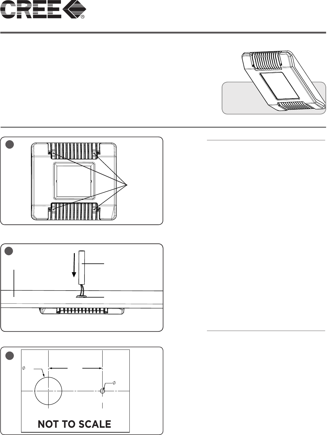
STEP 2:
To mount luminaire to canopy, insert and tighten
(4) supplied Phillips hex head self-drilling sheet
metal screws as shown in Figure 1.
STEP 3:
From above canopy feed leads from luminaire
through customer supplied 3/4” NPT Stem.
Screw customer supplied NPT Stem into
luminaire hub. See Figure 2.
STEP 4:
Attach customer supplied junction box to
the other end of the customer supplied 3/4”
NPT Stem and make wiring connections into
customer supplied junction box per “Electrical
Connections” section.
STEP 5:
Apply sealant around stem, hub and alignment
screw for a complete seal.
ALIGNMENT TEMPLATE (OPTIONAL)
STEP 1:
Reference Figure 3 for alignment. Insert supplied
#8 screw into alignment hole on luminaire. See
Figure 4 (on back page).
STEP 2:
Cut a 2.0” hole into the desired location of
the canopy to mount the threaded hub of the
luminaire. See Figure 3.
STEP 3:
4” away from the Stem Hole, drill a 0.325” hole,
Alignment Hole, using a 11/32” drill bit for the
alignment screw. See Figure 3.
1
Insert
Mounting
Screws
2
3/4” NPT Stem
(Provided by customer)
Canopy
Luminaire Hub
2.00”
0.325”
4.00”
3
Stem Hole
Alignment Hole
2 of 2 CI391X01R0
www.cree.com/lighting
© 2013 Cree, Inc. All rights reserved. For informational purposes only. Content is subject to change.
See www.cree.com/lighting for warranty and specifications. Cree® and the Cree logo are registered
trademarks.
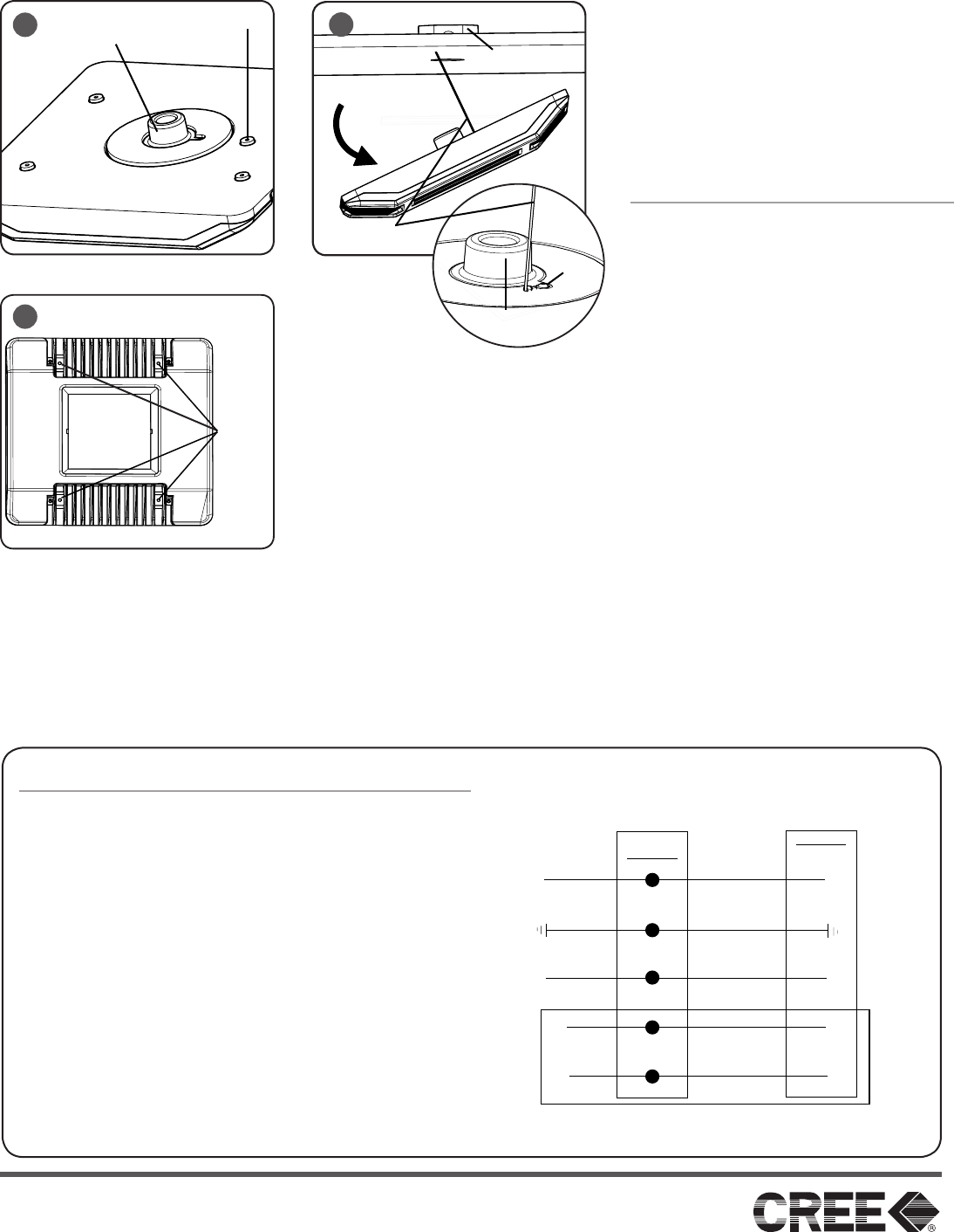
STEP 4:
Bring luminaire to canopy and insert threaded
hub into the 2.0” Stem Hole that was cut in
Step 2. Rotate luminaire until alignment screw
seats into the 0.325” Alignment Hole that was
cut in Step 3. See Figure 4.
STEP 5:
Continue to Step 2 in “Direct Mount - Canopy
Applications” section.
DIRECT MOUNT OVER JUNCTION BOX
NOTE: For use with customer supplied
junction box. Junction box must be 4” square
or octagon.
STEP 1:
Attach Air Craft Cable, provided in the
hardware bag, using supplied #8 pan head
screw to luminaire near the threaded hub as
shown in Figure 5.
STEP 2:
Attach other end of the Air Craft Cable to the
customer supplied junction box using supplied
#8 pan head screw. Then carefully let the
fixture hang down for wiring. See Figure 5.
STEP 3:
Make wiring connections into junction box per
“Electrical Connections” section.
STEP 4:
To mount luminaire to ceiling, feed the
threaded hub into the junction box, making
sure no wires are pinched and luminaire is
flushed with ceiling.
STEP 5:
Insert and tighten (4) supplied sheet metal
screws to metal ceiling. If ceiling isn’t metal
use appropriate customer supplied hardware.
See Figure 6.
ELECTRICAL CONNECTIONS
STEP 1:
Make the following Electrical Connections :
a. Connect the black fixture lead to the voltage supply
position of the terminal block or Hot 1 (for 208/240V
wiring).
b. Connect the white fixture lead to the neutral supply
position of the terminal block or Hot 2 (for 208/240V
wiring).
c. Connect the green or green/yellow ground lead to the
green wire position of the terminal block.
d. If Dimming is an option; connect the violet dimming
positive lead to the supply dimming positive lead.
e. If Dimming is an option; connect the grey dimming
negative lead to the supply dimming negative lead.
LINE
OR HOT 1
GREEN
LINE-BLACK
GROUND-GREEN
NEUTRAL-WHITE
DIM (-) GREY
DIM (+) VIOLET
NEUTRAL
OR HOT 2
VIOLET
GREY
SUPPLY WIRING
(DIMMING OPTIONAL)
LUMINAIRE
JUNCTION
BOX
Junction
Box
5
6
Insert
Mounting
Screws
4Alignment Hole
Threaded Hub
Air Craft
Cable
Threaded
Hub
Cable
Hole
